Manual Com-Server++, Com-Server PoE 3x Isolated, Com ...
232
Manual Com-Server++ Com-Server PoE 3x Isolated Com-Server 20mA Release 2.11, February 2017 Typ 58665, 58662, 58664 Firmware 1.35 or higher SN 02511425 or higher W&T
-
Upload
khangminh22 -
Category
Documents
-
view
0 -
download
0
Transcript of Manual Com-Server++, Com-Server PoE 3x Isolated, Com ...

ManualCom-Server++Com-Server PoE 3x IsolatedCom-Server 20mA
Release 2.11, February 2017Typ 58665, 58662, 58664 Firmware 1.35 or higher SN 02511425 or higher
W&T

W&T
© 02/2017 by Wiesemann und Theis GmbHMicrosoft, MS-DOS, Windows, Winsock and Visual Basicare registered trademarks of the Microsoft Corporation.
ST is a registered trademark of AT&T Lightguide Cable Con-nectors.
Subject to error and alteration:Since it is posssible that we make mistakes, you mustn’t use any of our statements without verification. Please, inform us of any error or misunderstanding you come about, so we can identify and eliminate it as soon as possible.
Carry out your work on or with W&T products only to the ex-tent that they are described here and after you have complete-ly read and understood the manual or guide. We are not liable for unauthorized repairs or tampering. When in doubt, check first with us or with your dealer.

W&T
Introduction The Com-Server++ 58665, Com-Server PoE 3x Isolated 58662 and Com-Server 20mA 58664 represent a uniform platform for linking serial interfaces such as RS232, RS422/485 and 20mA/TTY to TCP/IP networks. The standard modes for transparent tunneling of serial data (e.g. through virtual COM ports) are implemented. The Com-Server++ includes additio-nal protocols and modes (e.g. UDP, TCP client, FTP client/server, etc.) as well as expanded functions for structuring the data interchange.
In addition to all the standard applications implemented in the firmware, this reference manual also describes the inte-gration possibilities for your own applications.

W&T
Content
1 Quickstart ���������������������������������������������������������������� 91.1 Flow chart – Network installation using WuTility ...............101.2 Overview of configuration menu .......................................111.3 Factory defauls settings ....................................................12
2 Assigning the IP address ��������������������������������������� 132.1 Configuring network parameters with WuTility .................142.2 Assigning the IP using DHCP protocol ...............................172.2.1 Manual activation of DHCP ..........................................172.2.2 System name ................................................................182.2.3 Lease time ..................................................................182.2.4 Reserved IP addresses .................................................192.4.5 Dynamic IP addresses .................................................192.3 Assigning the IP using the ARP command .........................202.4 Assigning the IP using the serial port ...............................232.5 IP Address Conflict Detect ................................................25
3 Supply voltage ������������������������������������������������������� 273.1 Supply voltage 58665, 58664 and 58662 .........................28
4 Network interface �������������������������������������������������� 314.1 Ethernet interface .............................................................32
5 The serial ports ����������������������������������������������������� 355.1 Serial combi-port RS232/422/485 ....................................365.1.1 Opening the Com-Server .............................................365.1.2 Mode selection ...........................................................365.2 RS232 mode (factory default) ...........................................375.3 RS422/485 mode .............................................................385.4 20mA/TTY interface .........................................................41
6 LED displays ���������������������������������������������������������� 436.1 LED displays .....................................................................44
7 Configuration access to the Com-Server ����������������� 477.1 Configuration menu structure...........................................487.2 Configuration via Telnet ...................................................507.2.1 Navigation within the Telnet menu ..............................507.3 Configuration via Browser - Web Based Management ........527.3.1 Activating WBM with the WuTility-Tool ........................527.3.2 Activating WBM via the serial interface ........................527.3.3 Activating WBM from the configuration menu..............537.3.4 Starting and navigating the WBM .................................54

5
W&T
Subject to error and alteration
8 The basis configuration of the Com-Server ������������ 578.1 Save your settings ............................................................588.2 Menu: INFO System ..........................................................598.3 Menu: SETUP System ........................................................608.3.1 Menu: SETUP System r Setup TCP/IP...........................608.3.2 Menu: SETUP System r System Password ....................648.3.3 Menu: SETUP System r System Name ..........................658.3.4 Menu: SETUP System r Logfile ....................................658.3.5 Menu: SETUP System r Flash Update...........................678.3.6 Menu: SETUP System r Factory Defaults .....................678.3.7 Menu: SETUP System r Reset ......................................678.3.8 Menü: SETUP System r Link Speed ..............................678.4 Menu ... r TCP/IP Mode r System Options .......................69
9 Configuration of the serial port ����������������������������� 719.1 The serial parameters (Menu: UART Setup) .......................729.1.1 Baud rate, Data bits, Stop bits, Parity ..........................729.1.2 The handshake modes ................................................739.1.3 Receive Buffer (InQueue) .............................................779.1.4 FIFO Send/Rec (only Com-Server 3x Isolated) ..............789.2 TCP-/UDP port numbers (Menu: TCP/IP Mode) ..................79
10 Packetizing serial datagrams ��������������������������������� 8110.1 Packet Options ...............................................................8210.1.1 Startsequence/Endsequence .....................................8310.1.2 Startsequence + Lengthfield ......................................8610.1.3 Interpacket Delay ......................................................8810.1.4 Fixed Packet Length ..................................................89
11 Mode TCP-Server ���������������������������������������������������� 9111.1 The Com-Server as TCP server .......................................9211.1.1 Configuration of the local port number .....................9311.1.2 Optional settings ......................................................93
12 Mode TCP Client ����������������������������������������������������� 9712.1 The Com-Server as TCP client .........................................9812.1.1 TCP client mode with fixed destination system .........9912.1.2 TCP client mode with serial addressing ...................10212.1.3 Optional settings ....................................................10412.1.4 Deactivating TCP client mode ..................................107
13 Data transfer per UDP ������������������������������������������ 11113.1 Der Com-Server als UDP-Peer .......................................11213.1.1 Setting the local UDP port number ..........................11313.1.2 UDP clientmode with fixed destination system ........11413.1.3 UDP client mode serial addressing ..........................11513.1.4 Optional settings ....................................................11713.1.5 Deactivating UDP mode ...........................................118

W&T
14 UDP Bus Mode ������������������������������������������������������ 11914.1 Function of UDP Bus Mode ...........................................12014.1.3 Optional settings ....................................................12214.1.4 Deactivating UDP mode ...........................................123
15 The Windows COM port redirector ����������������������� 12515.1 Overview ......................................................................12615.2 Download & installation of the W&T COM redirector .....12715.2.1 Installation of the W&T COM port redirector ............12715.2.2 Uninstalling the W&T COM Port Redirector .............12815.3 Set up virtual COM ports ..............................................12915.3.1 Optional settings on the Com-Server .......................129
16 Box-to-Box mode ��������������������������������������������������� 13316.1 Box-to-Box application .................................................13416.1.1 Configuring Box-to-Box mode .................................13516.1.2 Optional settings ....................................................13616.1.3 Deactivating Box to Box Mode .................................138
17 Mode FTP-Server �������������������������������������������������� 14117.1 The Com-Server as FTP server ......................................14217.1.1 Activating FTP-Server mode .....................................14217.1.2 Supported FTP commands and functiuons ..............14317.1.3 Optional settings ....................................................144
18 Mode FTP-Client ��������������������������������������������������� 14518.1 The Com-Server as FTP client .......................................14618.1.1 Configuring the destination address and port no. ...14718.1.3 FTP client with serial protocol .................................15018.1.4 Closing the FTP connection .....................................15218.1.5 Deactivating FTP client mode ..................................15318.1.6 Application examples .............................................154
19 Mode Telnet Server ���������������������������������������������� 15719.1 The Com-Server as Telnet server ..................................15819.1.1 Activating Telnet-Server mode ................................15819.1.2 Optional Settings ....................................................159
20 Mode Telnet Client ����������������������������������������������� 16120.1 The Com-Server as Telnet client ...................................16220.1.1 Destination address and port number .....................16220.1.2 Optional settings ....................................................16420.1.3 Deactivating Telnet client mode ..............................165
21 Mode SLIP-Router ������������������������������������������������� 16721.1 SLIP mode ....................................................................168

W&T
21.1.1 Configuring the SLIP mode ......................................16921.1.2 Optional settings ....................................................17121.1.3 Deactivating SLIP router mode ................................17121.1.4 Application example ...............................................17221.1.5 Configuring the Com-Server via SLIP .......................173
22 OPC data transfer ������������������������������������������������ 17522.1 Overview ......................................................................17622.2 Download and installation of the W&T OPC server ........17722.2.1 Installation of the W&T OPC server ..........................17722.2.2 Deinstallation of the OPC server ..............................17822.3 Configuration of the OPC server ...................................17922.3.1 Optional settings on the Com-Server .......................17922.3.2 Incorporating the Com-Server into the OPC Server ...18122.3.3 Structuring the serial data .......................................18222.4 Serial OPC variables .....................................................183
23 Mode InQueueCopy ���������������������������������������������� 18523.1 InQueue Copy ..............................................................18623.1.2 Configuring InQueueCopy .......................................187
24 Status and error messages ���������������������������������� 18924.1 Menu Setup Port x r Port State ....................................190
25 Expanded services of the Com-Server ������������������ 19325.1 The control port...........................................................19425.2 Reset Com-Server port .................................................20125.3 Com-Server reset .........................................................20225.4 Up-/downloading configuration data ...........................20325.5 Inventory taking per UDP/8513 ...................................20525.6 SNMP management ......................................................207
26 Firmware-Update of the Com-Server ��������������������� 20926.1 Where do I get the current firmware? ...........................21026.2 Network firmware update under Windows ...................21126.3 Incomplete and interrupted updates ............................214
Appendix ������������������������������������������������������������������� 215Used ports and network security ..........................................216Serial assignment of the IP address under Windows .............220WuTility - Inventory and management tool ...........................225Hardware-Reset to factory defaults.......................................226Technical data and formfactor 58665 ..................................227Technical data and formfactor 58662 ..................................228Technical data and formfactor 58664 ..................................229
Index ������������������������������������������������������������������������� 230

W&T

9
W&T
Subject to error and alteration
1 Quickstart
Already experienced users of Com-Servers will find on the two following
pages a flow chart with the essential steps for start-up as well as a comple-
te overview of the configuration menu. Detailed information can be found
then in the following sections.

10
W&T
1�1 Flow chart – Network installation using WuTility
Com-Server
Network
Selectdevice in
inventory list
Enter IP address,subnet mask,
gateway
Finish
Button:IP address
StartWuTility
InstallWuTility withproduct CD
WuTilityinstalled?
Windows PCwith TCP/IP
Select site
Connectsupply voltage
Connectnetwork cable
Obtain IPaddress, subnetmask, gateway
no
yes

11
W&T
Subject to error and alteration
1�2 Overview of configuration menu
INFO System Cable TypeMAC addressSOFTW Date/REVHARDW RevRun Time
IP-Address (0.0.0.0)Subnet MaskGateway
MTU (560-1460)
System Port List
Keep Alive Time 30sRetransm. Timeouts
Standard Gateway (0.0.0.0)Route 1Route 2Route 3Route 4
DestinationNetmaskGateway
DNS-Server
DHCP ClientSETUP System Setup TCP/IP
System PasswordSystem Name
Flash UpdateFactory DefaultsResetLink Speed (Auto, 10|100BT, HD|FD)
SAVE Setup
SETUP Port 0 Port State
UART Setup
TCP/IP Mode
Connection State
Flush Buffer
Logout
(1)
Packet OptionsInterpacket DelayFixed Packet Length
Wake-on-LAN
Logfile
Factory defaults are printed bold(1)
To activate the new settingsalways save using SAVE Setup
with Telnet or the LOGOUTlink on the web pages. In WBMuse the link Logout and click
Save!
IP Address Conflict detect
230,4k
TCP Client
UDP Client
Telnet Client
FTP Client
Box to Box(TCP)
SLIP Router
System Options
Server PortServer IP/URLSpecial Options
Error StateClear Port ModeBaud
Data Bits
Stopbit
Handshake
Standard BaudratesSpecial Baud Divisor
153,6k115,2k5760038400192009600
4800
2400120060030015011075720050
87
NoneHardwareSoftwareSpecial
12
Pin: RTSPin: DTRPin: CTSPin: DSRXON/XOFFXON/XOFF (Filter)
Local Port TCP/UDP
Inactivity TimeoutConnect. TimeoutDisconnect CharClient: "C"+AddrResponse Mode
Server PortServer IP/URLSpecial Options
Client: "C"+Addr
Disconnect CharWrite: "C"+Addr
Server PortServer IP/URLSpecial Options
Disconnect CharInactivity TimeoutSerial 0d -> 0d00
Auto FTPFTP Client LoginInactivity TimeoutConnect. TimeoutProtocol Char
Server Port Server IP/URLSpecial OptionsServer PortServer IP
Net AddressSLIP-Net Routing
Network Delay
Telnet Echo
Controlport TCP
Receive Buffer (InQueue): 32-4094 Bytes
Port List
Telnet Port (TCP)FTP Port (TCP)Reset Port (TCP)
InQueue Copy Local Copy PortAccepted Copy-Slave IPs
TCP Server Activ. Packet Options
FTP Server Activate yes/no
Telnet Server Activate yes/no
Activ. Packet Options
Activ. Packet Options
Activ. Packet Options
Start-/Endsequ.Startsequ. + Length Filed
Parity NONEEVENODD
SPACEMARK
SETUP Port 1
SETUP Port 2
Byte counter
Send/Rec FIFO
TLS(SSL) Encryption

12
W&T
1�3 Factory defauls settings
The list contains an overview of the most important settings. For many applications, such as the W&T COM Port Redirector, no additional configurations need to be made besides assig-ning the network base parameters. Detailed information on the respective parameters can be found in later sections of this manual.
Network settingsHardware connection: Auto negotiatingIP address: 0.0.0.0Gateway address: 0.0.0.0Subnet mask: 255.0.0.0DHCP: Active
1To prevent unintended address assignments or changes, we recommend deactivating the DHCP protocol
if it is not expressly used in the respective network environ-ment.
Serial settingsHardware connection: RS232Baud rate: 9600Data bits: 8Parity: NOStop bits: 1Handshake: NoneFifo: OFF
Configuration accessPer Telnet using TCP port 1111
Network applications / Operating mode(suitable for use with W&T COM redirector)TCP server ports, port no. A-C: 8000, 8100, 8200Control port TCP, port no. A-C: 9094, 9194, 9294

13
W&T
Subject to error and alteration
2 Assigning the IP address
The Com-Server is factory set to IP address 0.0.0.0. Before you can make
the entry in the Com-Server, you need to specify an IP address that is valid
for your network. Your system administrator will provide you with this. The
IP address must be unique within the network!
. ... using management tool WuTility
. ... using the ARP command
. ... using DHCP protokoll
. Assigning IP address, subnet mask and gateway address
through the serial port
. IP Address Conflict Detect

14
W&T Assigning the IP address
2�1 Configuring network parameters with WuTility
WuTility is the central inventorying and management tool for all W&T network devices. In addition to convenient assigning of the IP parameters, WuTility also provides quick access to device configurations, the ability to perform firmware up-dates, managing configuration profiles, etc.
WuTility can be directly installed from the included product CD. Current versions are always available on our website at http://www.wut.de. From there you can navigate using the menu tree on the left side.
Products & Downloads r Com-Server r Software-Tools
After extracting the ZIP file you install WuTility by double-clicking on the file wutility_***.msi. Start WuTility using
Start r All Programs r W&T Software Toolkit r WuTility
2�2�1 Applications and prerequisitesIP assignment using WuTility works regardless of the current network parameters of the Com-Server and the computer used. This means that even if the Com-Server does not have IP parameters consistent with the respective network, WuTility can be used to overwrite them. Likewise, WuTility can be used to assign any values not consistent with the network the PC is located in.
• The PC and Com-Server must be located in the same physi-cal network. This means you cannot assign values through a router.
• Any firewalls and network security packages installed on the PC must allow communication between WuTility and the Com-Server based on UDP broadcasts. If necessary these must be correspondingly configured or temporarily turned off.

15
W&T Assigning the IP address
Subject to error and alteration
• If the Com-Server does not have its factory default settings and there is a system password assigned, this must be known in order to make changes using WuTility.
Step 1: Start the assignment dialogWuTility automatically searches the local network for connec-ted W&T network devices and creates an inventory list. This search process can be repeated manually as often as desired by clicking on the Scan button:
Within the inventory list you can identify the desired Com-Server based on its MAC address. For initial installations its IP address is 0.0.0.0.
Select the Com-Server and click on the IP address button:

16
W&T Assigning the IP address
Step 2: Assign the IP parametersThe Static option allows you to assign fixed basic parameters while simultaneously disabling DHCP and BOOTP protocols in the Com-Server. Enter the desired values for IP address, subnet mask and gateway address in the corresponding entry fields. The DHCP option enables DHCP protocol in the Com-Server, and operation with a static IP address is no longer possible (see IP Assignment using DHCP Protocol for detailed information)
If the remaining configuration of the Com-Server is done using a Web browser, activate the option Web-Based-Manage-ment (WBM). If you are not using the standard HTTP port 80, change the port number to the desired value.
Clicking on the Next button assigns the network parameters to the Com-Server. After acknowledging the resulting mes-sage, all the columns in the WuTility device list are filled in with information.
If necessary, the remaining configuration of the Com-Server is done using Telnet or Web-Based-Management. Click on the Telnet or Browser button.
Telnet: Browser:
Additional information can be found in the section Configura-tion Accesses for the Com-Server.

17
W&T Assigning the IP address
Subject to error and alteration
2�2 Assigning the IP using DHCP protocol
DHCP protocol is activated by the factory default settings, so that in network environments dynamic IP assignment is sufficient for connecting the Com-Server to the network. The following parameters can be assigned using DHCP:
• IP address• Subnet mask• Gateway address
2�2�1 Manual activation of DHCP
To prevent unintended address assignments or address chan-ges, DHCP protocol is automatically deactivated when using all other methods for assigning the IP parameters. The follo-wing methods are then available for later activation of DHCP.
• Management-Tool WuTilitySelect the desired Com-Server from the device list and click on the IP Address button. In the following dialog check the option DHCP and then click on Next.
• Telnet-/WBM configurationIn the menu branch SETUP System r Setup TCP/IP r
DHCP Client you can activate DHCP protocol. For detailed information, see the section Menu: SETUP System.
1A set static IP address is deleted after DHCP is activated and the associated automatic reset. The Com-
Server automatically sets this to 0.0.0.0 and starts sending DHCP requests.

18
W&T Assigning the IP address
2�2�2 System name
To support any automatic updating of the DNS system by the DHCP server, the Com-Server identifies itself within the DHCP protocol with its system name. The factory default setting for this is COMSERVER- followed by the last three places of the Ethernet address. For example the factory set system name of a Com-Server with the Ethernet address 00:c0:3d:01:02:03 is COMSERVER-010203. The system name of the Com-Server can be changed in the configuration. For additional information refer to the section Menu: SETUP System r System Name.
2�2�3 Lease time
The lease time determined and transmitted by the DHCP server specifies the Time-To-Live of the assigned IP address. After half the lease time has expired, the Com-Server attempts to extend the time for the assigned DHCP server and up up-date the address. If this is not possible by the time the lease time expires, for example because the DHCP server can no longer be reached, the Com-Server deletes the IP address and starts a new cyclical search for alternate DHCP servers for the purpose of assigning a new IP address.
Because of the absent clock, the lease time associated with the current IP address is no longer available after a reset. After the restart therefore a corresponding update request is issued with the original DHCP server. If the latter is not resolvable at this point in time, the Com-Server deletes the IP address and starts a new cyclical search for alternate DHCP servers.
If DHCP is activated, the remaining lease time together with the current IP address is displayed in the menu item SE-TUP System r Setup TCP/IP r IP-Address using the format hh:mm:ss.

19
W&T Assigning the IP address
Subject to error and alteration
2�2�4 Reserved IP addresses
If the Com-Server is used as a TCP server or UDP peer, it provides services which other clients in the network can also make use of as needed. To open a connection, they of course need the current IP address for the Com-Server, so that in such situations it makes sense to reserve a particular IP address for the Com-Server on the DHCP server. This is ge-nerally done by linking the IP address to the unique Ethernet address of the Com-Server, which can be found on the sticker attached to the housing.
EN = 00c0:3d01:02035xxxx [TB numberand/or model name]OK +0123456789
Ethernet address
2�4�5 Dynamic IP addresses
Fully dynamic address assignment, whereby the Com-Server gets a different IP address every time it is restarted or after the lease time has expired, only makes sense in network environments with automatic cross-connection between the DHCP and DNS services. This means when a new IP address is assigned to the Com-Server, the DHCP server then automati-cally updates the DNS system as well. The new address is as-sociated with the respective domain name. If in doubt, consult your system administrator for detailed information about your network environment.

20
W&T Assigning the IP address
2�3 Assigning the IP using the ARP command
RequirementsThis method can only be used if the Com-Server does not al-ready have an IP address, i.e. the entry is 0.0.0.0. To change an IP address, use one of the other methods described in this section or use the configuration menu over Telnet. If the Com-Server has any other value, this access is disabled.
When the factory setting is in effect as well as after a manual changeover from static to DHCP, the method for assigning the IP described in this section functions only after a delay of approx. 2 minutes after a reset or after power-up.
This method does not work across networks, e.g. through routers. This means the PC and Com-Server used for assi-gning must be connected to the same physical network seg-ment. Only IP addresses whose Net-ID is identical to that of the assigning computer can be assigned.
1To avoid unintended changes to the IP address, the DHCP client of the Com-Server is automatically deactiva-
ted when configuring using a static ARP entry.
Step 1Read off the Ethernet address of the Com-Server from the stik-ker on the side of the housing.
EN = 00c0:3d01:02035xxxx [TB numberand/or model name]OK +0123456789
Ethernet address
Insert a static entry into the ARP table of the computer using the following command line:
arp -s [IP address] [Ethernet address]
i Older Windows systems only accept a static ent-ry if there is a dynamic one already present. Here you should first ping another network station.

21
W&T Assigning the IP address
Subject to error and alteration
E.g. under Windows:arp -s 172.16.231.10 00-C0-3D-00-12-FF
E.g under UNIX/Linux: arp -s 172.16.231.10 00:C0:3D:00:12:FF
1The IP addresses must be without leading zeros in all Windows environments. Otherwise the entry is incor-
rectly interpreted by the system and an incorrect IP address is assigned to the Com-Server. In Windows Vista and newer the prompt cmd.exe necessary for invoking the ARP command must be started using Administrator rights.
Step 2Use the following command line to ping the Com-Server with the desired IP address:
ping 10.40.21.12
The Com-Server takes the IP address of the first network pa-cket sent to it as its own and saves it in non-volatile memory. The ping requests of the PC are then replied.
It is not possible to configure the subnet mask and gateway

22
W&T Assigning the IP address
address using a static ARP entry. These need to be set in a separate Telnet configuration session (see section Basic Confi-guration of the Com-Server).

23
W&T Assigning the IP address
Subject to error and alteration
2�4 Assigning the IP using the serial port
After a Com-Server reset a time window of around 1-2 se-conds is available on port A, during which you can assign a new IP address, subnet mask and gateway address by ente-ring at least 3 „x“.
In contrast to other methods described above, this serial me-thod functions regardless of whether the Com-Server already has an IP address or not. The procedure can be repeated as often as desired. The appendix contains the detailed procedu-re under Windows.
Preparations/requirementsFirst connect the serial port A of the Com-Server to a com-puter. For a standard PC or laptop, you will need a crossed RS232 cable (=Null modem cable, see RS232 mode).
1The model 58664 Com-Server 20mA features a TTY interface and cannot therefore be connected directly to
the standard COM port (RS232) of a PC.
Any serial terminal program can be used for assigning. The following transmission parameters must be set regardless of any other settings in the Com-Server:
9600 baud, no parity, 8 data bits, 1 Stop bit, no Handshake
Start the serial configuration modeReset the Com-Server by interrupting the power. While the Com-Server is starting up, use the terminal program to send the letter x at least three times. The COM-Server will then re-turn the prompt IPno.+<Enter>:.
Assigning the IP settingsUse the usual format (xxx.xxx.xxx.xxx) to enter the IP address, and end the entry by pressing <Enter>. If the ent-ry was accepted, the acknowledgement is the assigned IP address. Otherwise you will get a FAIL message followed by the last current IP address.

24
W&T Assigning the IP address
Together with the IP address, the subnet mask and gateway address can also be assigned serially. The entry is separated by commas and follows the IP address. Entering as shown in the following example will assign IP address 172.17.231.99, subnet mask 255.255.255.0 and gateway 172.17.231.52 to the Com-Server
Exampel: Assigning the IP address:IP no.+<ENTER>: <- Com-Server
172.17.231.99 -> Com-Server
Example: Assigning IP address, Subnet mask and gatewayIP no.+<ENTER>: <- Com-Server
172.17.231.99, 255.255.255.0,172.17.231.1 -> Com-Server
Option: Activating Web Based Management (WBM)To further configure the Com-Server you can use either Telnet protocol or an Internet browser, although only Telnet is an option in the Com-Server as shipped from the factory. You can activate Web Based Management as part of the serial IP assignment. To do this, enter +w[Portno.] directly after the IP address or address string. Here Portno. is the desired TCP port in decimal format.
Exampel 1: Assigning the IP adress and WBM on Port 80.xxx... -> Com-Server
IP no.+<ENTER>: <- Com-Server
172.17.231.99+w80 -> Com-Server
172.17.231.99-1 <- Com-Server
Exampel 2: Assigning IP address, subnet mask, gateway and activating WBM on port 8800.
xxx... -> Com-Server
IP no.+<ENTER>: <- Com-Server
172.17.231.99,255.255.0.0,172.17.231.1+w8800 -> Com-Server
172.17.231.99,255.255.0.0,172.17.231.1+w8800 <- Com-Server

25
W&T Assigning the IP address
Subject to error and alteration
2�5 IP Address Conflict Detect
Firmware version 1.31 and higher enables the Com-Server++ to detect and display an IP address conflict. This function is deactivated by default and can be activated in the following menu branch:
SETUP System
Setup TCP/IP...
IP Address Conflict Detect...
When the Com-Server is restarted there is an active check for any address conflicts. During normal running the monito-ring is passive. Details on this functionality can be found in RFC5227, IPv4 Address Conflict Detection.
Indication of an address conflictThe Com-Server++ indicates a detected address conflict by rapid flashing (approx. 3x/s) of the Error LED. In addition a message including the competing MAC address is generated in the Error State (Setup Port x r Port State r Error State).
When using a static IP address the conflict is only indicated. The Com-Server continues to use this IP address. In a DHCP environment the Com-Server informs the responsible DHCP server, resets the IP address and waits for assignment of a corrected IP address.
1IP address conflicts generally lead to communication problems which are difficult to diagnose. Please therefo-
re inform the responsible administrator in such cases.

26
W&T Assigning the IP address

27
W&T
Subject to error and alteration
3 Supply voltage
. Com-Server++
. Com-Server PoE 3x Isolated
. Com-Server 20mA

28
W&T Supply voltage
3�1 Supply voltage 58665, 58664
The models 58665, 58664 and 58662 can also be operated either using PoE or from an external power supply. Connec-ting an external supply voltage and a PoE infrastructure at the same time is not permitted.
The current draw can be found in the technical appendix.
3�1�1 Power over Ethernet
In PoE environments (Power-over-Ethernet, IEEE802.3af) power is provided by the network infrastructure. The Com-Server supports both phantom power using data pairs 1/2 and 3/6 as well as power feed using the unused wire pairs 4/5 and 7/8.
The models 58665, 58664 and 58662 are devices in PoE Po-wer Class 1 (power consumption 0.44 to 3.84W).
3�1�2 External supply
As an alternative to PoE power supply the Com-Servers can also be powered by an external power supply connected to the screw terminals on the underside of the housing. AC or DC power may be used, whereby the following limit values must be observed:
• AC: 18Vrms (- 10%) - 30Vrms (+10%)• DC: 12V (-10%) - 48V (+10%)
(before SN 2283238 24V (-10%) - 48V (+10%))
When powering with DC voltage polarity must be observed:
+12-48V DC
L+MGND

29
W&T Supply voltage
Subject to error and alteration
1Only potential-free power supplies may be used for po-wering the models 58665, 58664 and 58662. Their re-
ference ground for the output voltage must not have a direct connection to the PE conductor.

30
W&T Supply voltage

31
W&T
Subject to error and alteration
4 Network interface
. Ethernet interface
. 10/100BaseT autonegotiating
. Power-over-Ethernet
32
W&T Network interface
4�1 Ethernet interface
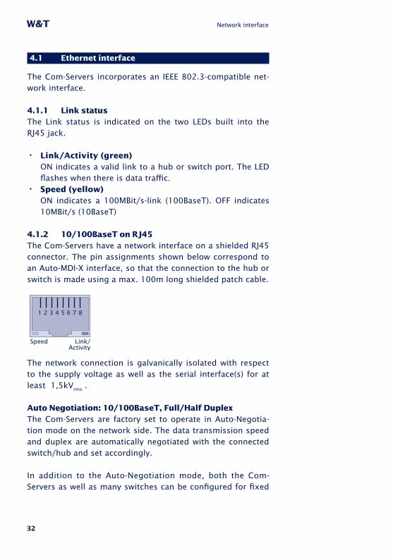
The Com-Servers incorporates an IEEE 802.3-compatible net-work interface.
4�1�1 Link statusThe Link status is indicated on the two LEDs built into the RJ45 jack.
• Link/Activity (green)ON indicates a valid link to a hub or switch port. The LED flashes when there is data traffic.
• Speed (yellow)ON indicates a 100MBit/s-link (100BaseT). OFF indicates 10MBit/s (10BaseT)
4�1�2 10/100BaseT on RJ45The Com-Servers have a network interface on a shielded RJ45 connector. The pin assignments shown below correspond to an Auto-MDI-X interface, so that the connection to the hub or switch is made using a max. 100m long shielded patch cable.
Speed Link/Activity
1 2 3 4 5 6 7 8
The network connection is galvanically isolated with respect to the supply voltage as well as the serial interface(s) for at least 1,5kVrms .
Auto Negotiation: 10/100BaseT, Full/Half DuplexThe Com-Servers are factory set to operate in Auto-Negotia-tion mode on the network side. The data transmission speed and duplex are automatically negotiated with the connected switch/hub and set accordingly.
In addition to the Auto-Negotiation mode, both the Com-Servers as well as many switches can be configured for fixed

33
W&T Network interface
Subject to error and alteration
transmission parameters with respect to speed and duplex. To prevent communications problems (duplex mismatch), only the following two combinations are permissible:
• Both parties (switch and Com-Server) are operated in Auto-Negotiation mode.
• Both parties are configured for the same (fixed) transmissi-on speeds and duplex mode.
Use menu sequence Setup System r Link Speed to switch between Auto-Negotiation and fixed transmission speeds/ duplex mode.
Power-over-Ethernet - PoEThe Com-Servers can obtain power as defined in IEEE802.3af/Power-over-Ethernet. Either the data pairs or the unused wire pairs in 10/100BaseT may be used (see also the section Sup-ply Voltage).

34
W&T Network interface

35
W&T
Subject to error and alteration
5 The serial ports
. Serial combi-port RS232/RS422/RS485
. Mode selection
. 20mA/TTY port

36
W&T Serial interfaces
5�1 Serial combi-port RS232/422/485
The Com-Server++ 58665 and Com-Server PoE 3x Isolated come standard with an RS232/422/485 combi-ports whose modes are described below.
All external signal lines use ESD-immune interface compon-ents to provide protection against static discharges of up to 15kV per IEC 801-2, Level 4.
5�1�1 Opening the Com-Server
To open the Com-Server, plug the DB9 connector into the seri-al port. After tightening the two mounting screws, pull on the DB9 plug to remove the circuit board from the housing..
5�1�2 Mode selection
Switching between the modes is accomplished using the inter-nal DIL switches located on the respective interface module. The following table shows an overview of all modes:
Mode SW1 SW2 SW3 SW4 SW5 SW6 SW7 SW8
RS232 (*) OFF OFF OFF OFF OFF OFF OFF ON
RS422, RS4854-wire-bus-master
OFF OFF OFF OFF ON Term. OFF
RS485 4-wireautomatic control
OFF ON OFF OFF ON Term. OFF
RS485 2-wireautomatic control
ON ON OFF OFF OFF Term. OFF
(*) Factory default

37
W&T Serial interfaces
Subject to error and alteration
5�2 RS232 mode (factory default)
The pin configuration of the RS232 port is identical to that of a PC, which allows you to use standard cables.
DIP switch setting RS232
Mode SW1 SW2 SW3 SW4 SW5 SW6 SW7 SW8
RS232 OFF OFF OFF OFF OFF OFF OFF ON
1The terminating DIL switches SW6 and SW7 must never be in the ON position when using the module in
RS232 mode. This will result in a significant increase in the current draw and may cause the RS232 driver to fail.
Pin assignment and function RS232, D9 male
Pin Direction Signal Description Default Function (*)
1 IN DCD Data CarrierDetect
Ignored
2 IN RxD Receive Data Data in
3 OUT TxD Transmit Data Data out
4 OUT DTR Data TerminalReady
12V for existing TCP connection to a client or server
5 --- GND Signal Ground ---
6 IN DSR Data Set Ready Ignored
7 OUT RTS Ready To Send Handshake output+12V = ready to receive data- 12V = not ready to receive data
8 IN CTS Clear To Send Data output only if +3...12V
9 IN RI Ring Indicator Ignored
(*) Applies only to the hardware handshake setting

38
W&T Serial interfaces
5�3 RS422/485 mode
As opposed to RS232, an RS422 interface allows transmission distances of up to 1000 meters. The RS485 mode allows you to integrate corresponding 2- or 4-wire bus sytems into a TCP/IP network with the help of the Com-Server.
1Especial ly when using longer cable lengths in industrial environments, potential differences need to be
taken into consideration. To prevent transmission problems and hardware damage caused by this, we recommend galva-nic isolation using an external isolator (e.g. W&T RS422/485-Isolator Type 66201).
DIP switch settings
Mode SW1 SW2 SW3 SW4 SW5 SW6 SW7 SW8
RS422, RS4854-wire bus master
OFF OFF OFF OFF ON Term. OFF
RS485 4-wireautomatic control
OFF ON OFF OFF ON Term. OFF
RS485 2-wireautomatic control
ON ON OFF OFF OFF Term. OFF
Pin assignment and function RS422/485, DB9 male
Pin Direction Signal Description Default function (*)
1 OUT TxD A/- Transmit Data A Data out
2 IN RxD A/- Receive Data A Data in
3 OUT RTS A/- Ready To Send A Handshake out
4 IN CTS A/- Clear To Send A Handshake in
5 --- GND Signal Ground ---
6 OUT TxD B/+ Transmit Data B Data out
7 IN RxD B/+ Receive Data B Data in
8 OUT RTS B/+ Ready To Send B Handshake out
9 IN CTS B/+ Clear To Send B Handshake in
(*) Applies only to the hardware handshake setting

39
W&T Serial interfaces
Subject to error and alteration
Operation modesThe DIL switches are used to set the following modes:
• RS422, RS485 4-wire bus masterProvides one data and handshake channel each in each direction. The RS422/485 drivers and receivers are always active in this mode.
• RS485 4-wire with automatic controlOne data channel is available in each direction. The RS485 driver chip is automatically activated each time data is sent out and then disabled when data is finished sending. The receive channel is always active in this mode.
• RS485 2-wire bus with automatic controlOne data channel is available in each direction. The RS485 driver chip is automatically activated each time data is sent out and then disabled when data is finished sending. The receive channel is deactivated when the driver is on, and on when the driver is disabled.
Handshake for RS485 modesRS485 bus systems do not use flow control in the traditional sense for data integrity, but rather a logical protocol. The handshake procedure for the Com-Server must therefore be set to NO (see The serial parameters (Menu: UART Setup).
TerminatingAll RS485 modes require a termination network on the bus sytem which ensures a defined rest state in the high-ohmic phases of bus operation. Connection of the bus system with a termination network can be done in the interface by closing the DIP switches 6 and 7 on the module:

40
W&T Serial interfaces3
30O
33
0O
12
0O
+5V
SW6
SW7
Data In B
Data In A
Wiring examples
RS422 connection with hardware handshake
Com
-Ser
ver
RS4
22/4
85
Data Out AData Out B
Data In AData In B
Handshake Out AHandshake Out B
Handshake In AHandshake In B
RxD A (-)RxD B (+)TxD A (-)TxD B (+)CTS A (-)CTS B (+)RTS A (-)RTS B (+)
16273849
RS485 connection (4-wire bus master)
Com
-Ser
ver
RS4
22/4
85
Data Out AData Out B
Data In AData In B
Handshake Out AHandshake Out B
Handshake In AHandshake In B
16273849
RxD A (-)RxD B (+)TxD A (-)TxD B (+)
RxD A (-)RxD B (+)TxD A (-)TxD B (+)
RS485 connection 2-wire
Com
-Ser
ver
RS4
22/4
85
Data Out AData Out B
Data In AData In B
Handshake Out AHandshake Out B
Handshake In AHandshake In B
16273849
Bus A (-)Bus B (+)
Bus A (-)Bus B (+)
RS5
85
dev
ice
RS5
85
dev
ice
RS5
85
dev
ice
RS5
85
dev
ice
RS5
85
dev
ice

41
W&T Serial interfaces
Subject to error and alteration
5�4 20mA/TTY interface
Der Com-Server 20mA 58664 is equipped with a 20mA/TTY module.
1The maximum permissible baud rate of a Com-Server 20mA 58664 is 19.200 bit/s.
The send and receive loops can be operated through the ex-ternal interface circuit independently of each other either acti-vely or passively. In active mode the Com-Server provides the loop current for the respective 20mA loop, whereas in passive mode the connected device must provide the loop current. Ex-ample circuits for the module in active and passive mode can be found in the following section.
Pin assignment and function 20mA, DB9 male
Pin Direction Signal Description/function
1 OUT Data Out 20mA Current Out +20mA
2 OUT Data Out + Data Output+
3 OUT Data Out - Data Output-
4 -- Data Out GND Current Out Ground
5 IN HD/ Halbduplex control
6 OUT Data In 20mA Current In +20mA
7 IN Data In + Data Input+
8 IN Data In - Data Input-
9 -- Data In GND Current In Ground
Halbduplex-/2-wire-mode
Placing a GND level on Pin 5 of the SUB-D connector allows the module to be placed in half-duplex mode, in which there is echo suppression of the sent signals.

42
W&T Serial interfaces
Wiring examples
Com-Server Tx and Rx loop active
Com-Server Tx and Rx loop passive
Com-Server Tx loop active, Rx loop passive
Com
-Ser
ver
20
mA
RxD +RxD -
TxD +TxD -
Pass
ive
20
mA
dev
ice
Data Out 20mA
Data Out+
Data Out-
Data Out GND
Data In 20mA
Data In+
Data In-
Data In GND
1
2
3
4
6
7
8
9
Com
-Ser
ver
20
mA
RxD +RxD -
TxD +TxD - A
ctiv
e 2
0m
Adev
ice
Data Out 20mA
Data Out+
Data Out-
Data Out GND
Data In 20mA
Data In+
Data In-
Data In GND
1
2
3
4
6
7
8
9
Com
-Ser
ver
20
mA
RxD +RxD -
TxD +TxD - A
ctiv
e/pas
sive
20
mA
dev
ice
Data Out 20mA
Data Out+
Data Out-
Data Out GND
Data In 20mA
Data In+
Data In-
Data In GND
1
2
3
4
6
7
8
9

43
W&T
Subject to error and alteration
6 LED displays
. Power, Status , Error LED
. Network LEDs

44
W&T LED displays
6�1 LED displays
Power-LED Power Status
Error
Pow
er StatusError
A B C
On indicates that power is present on the external screw terminals or via PoE.
Status-LED Power Status
Error
Pow
er StatusError
A B C
Rapid continuous flashing = bootup, no IPRapid continuous flashing (approx. 3x/s) indicates that the Com-Server is in the bootup phase and/or has not yet been assigned an IP address. Please use WuTility for ex-ample to assign the Com-Server an IP address.Slow continuous flashing = connection Periodic flashing (1/s) indicates that the port has a valid connection to another network station. The status of the serial port can also be read out using WBM or the Com-Server‘s Telnet configuration tool.
Error-LED Power Status
Error
Pow
er StatusError
A B C
The Error LED uses various flashing patterns to indicate error conditions on the device or serial port. The error texts for the previous five serial faults and the associated system time (time between the last restart of the Com-Server and when the error occured) can also be read out using the Telnet configuration tool.
Rapid continuous flashing = IP address conflictThe IP Address Conflict Detect function is activated and the Com-Server has detected an IP address conflict. This means the current IP address of the Com-Server is also used by other stations in the network. To prevent further problems, please contact the responsible network admi-nistrator and have the conflict resolved.

45
W&T LED displays
Subject to error and alteration
2 x flashing = Check serial data formatThe serial port received at least one character with a parity or framing error (= parity error / framing error), or the data register of the serial receiver ship was written even though the previous character was not read out. Check the correctness of the serial parameters, the handshake proce-dure and the connection cable.3 x flashing = Check serial handshakeThe serial connected device is not responding to the hand-shake stop signal set by the Com-Server and continues to send data. The result can be that the serial ring memory is overwritten and data are lost. Check the handshake configuration of the device as well as the wiring of the connection cable.All LEDs on = Self-test errorThe self-test performed after each start or reset of the Com-Server could not be correctly finished. This error can occur when you have prematurely broken off a software update and the full operating software could not be trans-ferred. The Com-Server is no longer capable of being ope-rated in this condition. Repeat the software update over the network (see Firmware update of the Com-Server), and address the Com-Server using its assigned IP address.
If the fault cannot be remedied, the problem may lie with the hardware.
Speed Speed Link/Activity
OFF: Simultaneous illumination/flashing of the Link/Acti-vity LED means there is a link to a device at a rate of 10 MBit/s (10BaseT).ON: Simultaneous illumination/flashing of the Link/Acti-vity LED means there is a link to a device at a rate of 100 MBit/s (100BaseT)

46
W&T LED displays
Link/Activity Speed Link/Activity
OFF: The Com-Server is not detecting a Link pulse from a hub or switch. Check the cable or the hub port.ON: The Com-Server has a valid link to a hub or switch. The Speed LED indicates the data rate in this case.Flashing: The Com-Server is receiving or sending network packets

47
W&T
Subject to error and alteration
7 Configuration access to the Com-Server
After completing the hardware installation and assigning the IP address,
the remaining Com-Server configuration takes place over the network.
Here either a Telnet client or, after it has been activated, an Internet brow-
ser can be used.
. Telnet configuration under Windows
. Configuration with the Internet browser

48
W&T Configuration access to the Com-Server
7�1 Configuration menu structure
The setup of the Com-Server is treelike regardless of whether the configuration is used for a Telnet client or an Internet browser. An overview of all the levels can be found in the fol-lowing illustration.
Prior to configuration a valid IP address must have been already assigned to the Com-Server (see “Assigning the IP Address”). Access is then possible from virtually any computer having network access and an installed TCP/IP protocol.
A detailed description of both configuration access types, their conditions as well as the respective navigation within the menu tree can be found in the following section.
1HTTP protocol and its standard port 80 are fre quent targets of Web attacks. In order not to impair
data throughput of the applications and of the Com-Server, Web Based Management is therefore factory disabled. Ways of activating this as part of the startup process can be found in the section on Web Based Management.
i If you exit the configu-ration menu by closing the Telnet connection without first invoking SAVE Setup, the ori-ginal configuration is retained.

49
W&T Configuration access to the Com-Server
Subject to error and alteration
INFO System Cable TypeMAC addressSOFTW Date/REVHARDW RevRun Time
IP-Address (0.0.0.0)Subnet MaskGateway
MTU (560-1460)
System Port List
Keep Alive Time 30sRetransm. Timeouts
Standard Gateway (0.0.0.0)Route 1Route 2Route 3Route 4
DestinationNetmaskGateway
DNS-Server
DHCP ClientSETUP System Setup TCP/IP
System PasswordSystem Name
Flash UpdateFactory DefaultsReset
SETUP Port 0 Port State Connection State
SAVE Setup
Logout
(1)
Wake on LAN
Logfile
Link Speed (Auto, 10|100BT, HD|FD)
(1) Factory defaults are printed bold
Telnet:Transfer the se-lected parametersand save all settingsin non-volatile me-mory on the Com-Server
Browser:Transfer the se-lected parametersand save all settingsin non-volatile me-mory on the Com-Server
To activate the new settings
always save using SAVE Setup
with Telnet or the LOGOUT
link on the webpages
IP Address Conflict Detect
UART Setup
TCP/IP Mode
230,4k
TCP Client
UDP Client
Telnet Client
FTP Client
Box to Box(TCP)
SLIP Router
System Options
Server PortServer IP/URLSpecial Options
Error StateClear Port ModeBaud
Data Bits
Stopbit
Handshake
Standard BaudratesSpecial Baud Divisor
153,6k115,2k5760038400192009600
4800
2400120060030015011075720050
87
NoneHardwareSoftwareSpecial
12 Pin: RTS
Pin: DTRPin: CTSPin: DSRXON/XOFFXON/XOFF (Filter)
Local Port TCP/UDP
Inactivity TimeoutConnect. TimeoutDisconnect CharClient: "C"+AddrResponse Mode
Server PortServer IP/URLSpecial Options
Client: "C"+Addr
Disconnect CharWrite: "C"+Addr
Server PortServer IP/URLSpecial Options
Disconnect CharInactivity TimeoutSerial 0d -> 0d00
Auto FTPFTP Client LoginInactivity TimeoutConnect. TimeoutProtocol Char
Server Port Server IP/URLSpecial OptionsServer PortServer IP
Net AddressSLIP-Net Routing
Network DelayFlush Buffer
Telnet Echo
Controlport TCP
Receive Buffer (InQueue): 32-4094 Bytes
Port List
Telnet Port (TCP)FTP Port (TCP)Reset Port (TCP)
InQueue Copy
TCP Server Activ. Packet Options
FTP Server Activate yes/no
Telnet Server Activate yes/no
Packet Options
Activ. Packet Options
Activ. Packet Options
TLS(SSL) Encryption
Local Copy PortAccepted Copy-Slave IPs
Start-/Endsequ.Startsequ. + Length FiledInterpacket DelayFixed Packet Length
Parity NONEEVENODD
SPACEMARK
SETUP Port 1
SETUP Port 2
Byte Counter
Activ. Packet Options

50
W&T Configuration access to the Com-Server
7�2 Configuration via Telnet
On Unix/Linux systems as well as Windows up to XP the telnet client is included in the standard installation of the operating systems.
The TCP port number for the telnet configuration is configu-rable in menu path Setup Port x r TCP/IP Mode r Port List r
Telnet Configuration Port. The factory default port number is 1111, so that you must start the connection from within the telnet client using the corresponding parameter:
telnet [IP-Adresse] 1111
With Windows Vista the telnet client must be explicitly in-stalled together or after the fact. Here we recommend starting using the WuTility inventorying and management tool. If the telnet client is not installed on the respective system, an alter-nate telnet client (putty.exe) is automatically used.
If the connection could be opened and no system password is assigned (= factory default setting), you will see the following menu in your Telnet window. If a system password was confi-gured, this will be asked for in front of the menu.
***************************************
* Com-Server [model name] *
* “COMSERVER-0A1B2C” *
***************************************
1. INFO System
2. SETUP System
3. SETUP Port x (Serial)
4. SAVE Setup
7�2�1 Navigation within the Telnet menu
An overview of the entire Com-Server configuration menu is shown on the previous page. On the monitor you will see

51
W&T Configuration access to the Com-Server
Subject to error and alteration
always just one level of the selected menu. Simply entering the number of the desired menu and pressing the ENTER key takes you to the next level. Entering a q or pressing the EN-TER key takes you back to the previous menu level.
The last configured value of a menu item appears in paren-theses. If you make changes, the new value will appear at this point the next time the menu is opened. It only becomes effective in the Com-Server itself however if you have saved it using SAVE Setup.
As long as you do not open this menu item, you can move around in the entire menu and change values without actually changing anything.
1Positioning functions for the cursor (arrow keys) or correction actions (backspace, insert) are not available
within the telnet configuration and, if used, will result in faul-ty inputs. If you make a typing mistake, exit the menu item using <Enter> and then repeat the entire entry.

52
W&T Configuration access to the Com-Server
7�3 Configuration via Browser - Web Based Management
The Com-Server also allows configuration via HTTP protocol and a standard Internet browser. The menu structure of the WBM (Web Based Management) is compatible with the Telnet configuration.
7�3�1 Activating WBM with the WuTility-Tool
The Web-Based-Management of the Com-Server can be ac-tivated at any time using WuTility as part of assigning the network parameters. Select the Com-Server in the device list and then click on the IP address button. In the first window of the dialog enter the desired values for IP address, subnet mask and gateway and then click on the Continue button. In the following window activate the WBM option and enter the desired TCP port number. As a rule HTTP standard port 80 should be used. If use of port 80 is not possible or desired, then the deviating port number must be explicitly specified in the address line of the browser when opening the Com-Server homepage:
http://[IP-Adresse oder Hostname]:[Portnummer]
7�3�2 Activating WBM via the serial interface
When serially assigning the IP number, you can optionally specify the TCP port number under which the WBM should be accessible. To do this, first connect the RS232b port on the Com-Server and the COM port on your computer using a null modem cable. Start a terminal program and set the transmis-sion parameters to 9600 baud, 8 data bits, no parity and no handshake. During a reset of the Com-Server hold the x key down until after approx. 2 sec. the IPno.+<Enter>: prompt ap-pears. Now directly following the IP address enter the exten-ded address string +w[Portno.]. Portno. represents here the desired TCP port in decimal format. A value of 0 deactivates the WBM.

53
W&T Configuration access to the Com-Server
Subject to error and alteration
After finishing your entry by pressing the Return key, the values are stored in the non-volatile memory and you can im-mediately access the Com-Server and the set WBM port using your Internet browser.
1Additional information about serial configuration possibilities for the Com-Server can be found in the sec-
tions Assigning the IP Address.
Example 1:Here the IP address 172.17.231.99 is assigned to the Com-Server and +w80 is used to activate the WBM on the HTTP standard port.
xxx... -> Com-Server
IP no.+<ENTER>: <- Com-Server
172.17.231.99+w80 -> Com-Server
172.17.231.99 -1 <- Com-Server
Example 2:In this example the Com-Server gets an IP address, subnet mask and gateway. In addition +w8585 is entered to activate WBM on TCP port 8585.
xxx... -> Com-Server
IP no.+<ENTER>: <- Com-Server
172.17.231.99,255.255.0.0,172.17.231.1+w8585 -> Com-Server
172.17.231.99 ,255.255.0.0,172.17.231.1+w8585 <- Com-Server
7�3�3 Activating WBM from the configuration menu
If you want to activate WBM on an already operational Com-Server, you can do this via Telnet configuration. Start a Telnet session on port 1111 of the Com-Server. In the menu branch
SETUP System r Setup TCP/IP r System Port List r WBM Port
enter the decimal number of the desired TCP port under which you want to reach the WBM. Then press the Return key until you are back in the main menu and from there open the

54
W&T Configuration access to the Com-Server
SAVE Setup item. After you have quit the Telnet session, you can now access the Com-Server using an Internet browser.
7�3�4 Starting and navigating the WBM
To access the Web pages after activating the WBM, start your Internet browser and enter the IP address of the Com-Server and the configured port number in the address line:
http://[IP-Adresse]:[Portnummer]
If the HTTP standard port 80 was configured for WBM, you do not need to explicitly indicate the port number in the address line.
You will now be given the start page of the Com-Server with the system password prompt. The factory default setting is no system password, so that you can get to the configuration menu by simply actuating the login button.

55
W&T Configuration access to the Com-Server
Subject to error and alteration
NavigationSince the WBM of the Com-Server is session-oriented, you must use backlinks and corresponding control buttons to navigate to the individual Web pages. Using the Back function in the browser can lead to problems in accepting the set pa-rameters.
You can make as many settings as desired during a configura-tion session. Pressing the Send button in the respective pages pastes them to a clipboard. Once all the settings have been made, always exit the configuration session using Link Logout and the Save button there. Only then are the settings you made copied into the non-volatile memory of the Com-Server and activated.
The logout page then offers the following possibilities for ending the configuration session:
n
Save button causes the Com-Server to save all the changes you made in its non-volatile memory and quits the confi-guration session.

56
W&T Configuration access to the Com-Server
n The Abort button causes the Com-Server to reject all the settings you made and quits the configuration session.
n The Restore Defaults button resets the Com-Server to its original factory setting. All settings including the network parameters IP address, subnet mask and gateway address are lost.
n The Firmware Update button activates the mode in which the Com-Server expects a firmware update via TFTP pro-tocol (see section Firmware Update of the Com-Server). Update mode can be exited only by complete transmission of a valid firmware or by interrupting the supply voltage. When using the WuTility tool for the firmware update, this mode is automatically started. In this case a manual start is not necessary.
n Restarts the Com-Server, comparable with interrupting the supply voltage. Data from any other opened connections to the Com-Server are lost in this event.
1The functions located on the logout page of the Com-Server can also be found in the Telnet menu branch
SETUP System r Setup TCP/IP.

57
W&T
Subject to error and alteration
8 The basis configuration of the Com-Server
Here follows the explanation of all the configuration possibilities related to
the Com-Server operating system and which are not directly related to the
serial ports.
. Save settings
. Menu: INFO System
. Menu: SETUP System

58
W&T The basis configuration of the Com-Server
8�1 Save your settings
When configuring using either Telnet or Web Based Manage-ment, all the changes are first saved only temporarily in the Com-Server. To make sure the settings remain intact even after a reset or power failure, each configuration session must be ended with an explicit save procedure.
TelnetFrom the main menu select SAVE Setup. Respond with y to the Save Changes ? prompt. If a correct entry was made, the text Saving… will appear on the monitor, and the Com-Server saves all the settings you made in its non-volatile memory. Once the data have been saved, they are activated each time the Com-Server is turned on or reset.
Entering anything other than y or simply pressing the ENTER key returns you to the main menu without saving the values.
1Exceptions are the network parameters IP address, subnet mask and gateway, since these are also relevant
for the running configuration session. To save and activate these you must enter q to quit the Telnet configuration after executing SAVE Setup. The Com-Server then autonomously performs a reset and only then begins to work with the new settings.
Browser Exit the configuration session using the Link Logout and click on the Save button.

59
W&T The basis configuration of the Com-Server
Subject to error and alteration
8�2 Menu: INFO System
This menu allows you to call up device-specific parameters such as the version njmber and creation date of the firmware, MAC address of the unit, etc.
n Cable typeIndicates whether the connection to the hub/switch is using 10BaseT or 100BaseTX. The duplex procedure is also indicated (Full- or Half-Duplex).
n MAC addressShows the Ethernet address of the Com-Server. This num-ber is factory set and registered. It cannot be changed.
n SOFTW Date/Rev�Shows the creation date and version number of the opera-ting software in flash.
n HARDW Rev�Shows the version status of the Com-Server hardware.
n Run TimeShows the time in hours and minutes since the last Com-Server restart.

60
W&T The basis configuration of the Com-Server
8�3 Menu: SETUP System
This menu is for configuring all the parameters that pertain to the Com-Server operating system and are independent of the serial interface.
8�3�1 Menu: SETUP System r Setup TCP/IP
n IP-Address (Default= 0.0.0.0)Enter here the IP address if you want to change it. Please note that this number is not freely selectable, but rather needs to be specified based on the network address of the TCP/IP network. The format corresponds to the normal syntax (e.g. 172.16.231.5).
n Subnet Mask (Default = 255.0.0.0)Enter the subnet mask of the subnet in which the Com-Server is located (e.g. 255.255.255.0).
n Gateways (Default = 0.0.0.0)In this menu branch the IP address of the standard gate-way or router can be configured. If you have not confi-gured fixed routes, the standard gateway is used for all network packets whose destination IP address is not in the local subnet.
n Route 1 - 4 (Destination, Netmask, Gateway)In addition to the standard gateway, up to four fixed rou-tes can be defined. Packets whose destination addresses are in the networks configured here (=destination) are always sent through the gateway assigned to this route. A fixed route is only accepted and stored by the Com-Server if the following check is true:
Destination AND Netmask == Destination
1Changes to the system parameters IP address , Subnet Mask, Gateway and Route 1-4 cannot be activa-
ted right after saving. The Com-Server will use these values

61
W&T The basis configuration of the Com-Server
Subject to error and alteration
only after closing the current Telnet connection using q.
n DNS Server (Default: 0.0.0.0)The entry contains the IP address of the DNS server (Do-main Name System). The latter is needed in all client mo-des of the Com-Server (TCP, UDP, Telnet, FTP client) if the destination system is to be stored in the configuration not as a numerical IP address, but rather in the form of a host name or URL. The name is resolved by the Com-Server is done via UDP using standard port 53 reserved for the DNS.
The Time-To-Live of the IP address resolved for a host name is determined by the Time-To-Live parameter contai-ned in the response from the DNS server. After the name has been successfully resolved this time is displayed in the menu item Setup Port x r Port State r Connection State.
n MTU – Maximum Transfer Unit (Default: 560)This value determines the maximum size of a TCP/IP pak-ket. It refers to the number of bytes (excluding header) that can be sent in a packet. The smaller the MTU, the more network buffer overall is available in the Com-Server. The selectable range begins at 560 and ends at 1024 bytes. The values can be set in increments of 128 bytes (automatic correction).
n DHCP Client (Default: 1 = ON)The DHCP protocol is activated with the factory settings (menu entry = 1). The Com-Server attempts to find a DHCP server and get an IP address from it. Entering 0 deactiva-tes DHCP and the Com-Server works statically with the IP address assigned to it. More information on how DHCP works can be found in the section IP Assignment via DHCP Protocol.
1To prevent unintended address assignments or changes, we recommend deactivating the DHCP pro-
tocol if it is not expressly used in the respective network environment.

62
W&T The basis configuration of the Com-Server
n System Port ListFrom the respective submenus you can configure and disable the TCP and UDP port numbers under which the following configuration and control accesses for the Com-Server are reached. Entries are made in decimal. The value 0 disables the service.
The TCP/UDP ports with access to the serial port on the Com-Server can be configured from the submenu Setup Port x r TCP/IP Mode r Port List konfiguriert werden.
• WBM Port (Default = TCP/0) Chapter Configuration via Browser
• Telnet Configuration Port (Default = TCP/1111) Chapter Configuration via Telnet
• SNMP (Default = UDP/161) Chapter SNMP management
• Device Reset Port (Default = TCP/8888) Chapter Reset of the Com-Server
• Init Flash Update Port (Default = TCP/8002) Chapter Firmware update of the Com-Server
• Read Config Port (Default = TCP/8003) Chapter Up-/Download configuration data
• Write Config Port (Default = TCP/8004) Chapter Up-/Download configuration data
• Info Port (Default = UDP/8513) Chapter Inventory via UDP
1Changes to the factory default port numbers as well as disabling services should be done with cau-
tion, since they can result in malfunction of configuration and management tools such as WuTility. If for example the telnet configuration and WBM are disabled, you can no lon-ger configure the Com-Server. Restore the factory default values by performing a hardware reset of the Com-Server.

63
W&T The basis configuration of the Com-Server
Subject to error and alteration
n Wake on LAN (Default: deactive)Up to three Ethernet addresses for network components can be configured, which are enabled when there is a re-start of the Com-Server via Wake-on-LAN.
1For proper function of Wake-on-LAN it must be supported and activated by the BIOS and the net-
work card in the destination computer.
n Keep Alive Time (sec) (Default: 30s)If the keep-alive check is activated by entering and saving a value in second ticks, all TCP connections are monitored for network-side data traffic. If there is no network traffic within the set time, the Com-Server generates a keep-alive packet. If the partner does not answer this packet, the connection is reset in the Com-Server. This deletes any data still contained in the serial in- and output buffers.
Example: A TCP client has opened a connection to TCP server port 8000 of the Com-Server and the network con-nection is interrupted. After the set keep-alive time plus 2s for two repetitions has elapsed, the Com-Server closes the connection and is again ready for any other clients.
n Retransmission Timeouts (ms) (Default: 240)This timeout determines what time must elapse before network packets are repeated if necessary. In most net-works the default setting of 240ms can be used. Only when there are very long latency times between the Com-Server and its respective communications partner would you need to increase this value.
n IP Address Conflict Detect (Default: deactive)Firmware version 1.31 and higher enables the Com-Ser-ver to detect and display an IP address conflict. An active check is performed each time the Com-Server is restar-ted. Only passive monitoring is performed during normal

64
W&T The basis configuration of the Com-Server
running. Details on this functionality can be found in RFC5227, IPv4 Address Conflict Detection.
If the Com-Server detects that its current IP address is also being used by another station in the local network, it indi-cates this conflict by rapid flashing of the Error LED. In ad-dition a corresponding message including the competing MAC address is generated in the Error State (Setup Port x r Port State r Error State).
When using a static IP address the conflict is only indica-ted. The Com-Server continues to use this IP address. In a DHCP environment the Com-Server informs the responsib-le DHCP server, resets the IP address and waits for assign-ment of a corrected IP address.
1IP address conflicts generally lead to communication problems which are difficult to diagnose. Please the-
refore inform the responsible administrator in such cases.
8�3�2 Menu: SETUP System r System Password
The system password, which consists of any 31 (max.) cha-racters, protects against any subsequent configuration and control access to the Com-Server.
· Telnet configuration menu (Default = 1111/TCP)· WBM (if enabled)· Init Flash Update Port (Default = 8002/TCP)· Read the configuration file (Default = 8003/TCP)· Write the configuration file (Default = 8004/TCP)· Reset Com-Server (Default = 8888/TCP)· Reset Port Status (Default = 9084/TCP)· Controlport (Default = 9094/TCP)· SNMP (Default = 161/UDP)
On Telnet port 1111 and on WBM port the system password is prompted as soon as the connection is opened. For all other

65
W&T The basis configuration of the Com-Server
Subject to error and alteration
associated TCP ports the password must be null-terminated (=[password] + 0x00) and sent to the Com-Server no later than 2s after the TCP connection has been established. Que-ries from SNMP managers are only responded to by the Com-Server if the community corresponds to the system password.
For additional information on using system passwords in conjunction with the configuration and control ports, see the section Expanded Services of the Com-Server.
8�3�3 Menu: SETUP System r System Name
The freely configurable system name consisting of max. 31 characters is used to identify the Com-Server. This name is displayed as an opening message in the client for all Telnet sessions.
If the tag <wutl> is used inside the system name, the Com-Server replaces it each time there is an output or communica-tion with the last three places of its Ethernet address.
8�3�4 Menu: SETUP System r Logfile
The Logfile contains the last (max. 3000) connections and connection attempts for configuration accesses by the Com-Server with the associated time stamp and address parame-ters.
Accesses to the following services are registered:
· Telnet configuration menu (Default = 1111/TCP)· WBM (if enabled)· Init Flash Update Port (Default = 8002/TCP)

66
W&T The basis configuration of the Com-Server
· Read the configuration file (Default = 8003/TCP)· Write the configuration file (Default = 8004/TCP)· Reset Com-Server (Default = 8888/TCP)· Reset Port Status (Default = 9084/TCP)
n Activate Logfile (Default= 0 = OFF)A 1 activates recording. In addition the Save Interval must be configured to a valid value.
n Save Interval (min) (Default= 0)Configuration of the time interval in minutes at which the Logfile is written to the non-volatile memory of the Com-Server.
1Saving the Logfi le has an inf luence on the latencies of the serial data transmission. We re-
commending configuring the Save Interval only as low as absolutely necessary. When timeouts occur in serial data exchange, logging should be disabled on a test basis.
n Delete LogfileDeletes the entire Logfile including the non-volatile stored entries.
Reading/Viewing the LogfileThe Logfile can be viewed using the Web Based Management of the Com-Server under Setup System r Logfile r Load. The Logfile can be downloaded via TFTP. The name to be specified in the TFTP client must be wut_cs_logfile. (Note period at the end!)

67
W&T The basis configuration of the Com-Server
Subject to error and alteration
8�3�5 Menu: SETUP System r Flash Update
Before you activate the update mode, make sure that you have quit any active network connections. Then confirm with „y“. The update mode is indicated by lighting of the Status LED on the Com-Server.
WuTility automatically enables update mode through TCP port 8002. Manual enabling is therefore only necessary if this port is blocked, such as by a firewall.
1You may quit the update mode only by either completely performing the update or by means of a re-
set, i.e. turning off the power!.
8�3�6 Menu: SETUP System r Factory Defaults
Enter a y to restore the factory default settings.
1Resetting the non-volatile memory causes loss of all the settings which deviate from the default values, inclu-
ding the IP address.
8�3�7 Menu: SETUP System r Reset
Select this menu item to perform a software reset on the Com-Server. First your Telnet connection is properly closed.
1All data from any still open network connections are lost.
8�3�8 Menü: SETUP System r Link Speed
The Com-Server is factory set for autonegotiation. Data trans-mission speed and duplex procedure are automatically negot-iated with the connected switch/hub and set correspondingly.

68
W&T The basis configuration of the Com-Server
In addition to autonegotiation, the Com-Servers as well as many manageable switches can be configured for fixed transmission parameters with respect to speed and duplex procedure. To prevent communications problems (duplex mis-match), only the following two combinations are permitted:
• Both parties (switch and Com-Server) are operated in Auto-Negotiation mode (recommended).
• Both parties are configured for the same (fixed) transmissi-on speeds and duplex mode.
1Changing the link speed is activated only after saving and exiting the telnet or WBM session by means
of an automatic Com-Server reset. Data from any open net-work connections is lost. If the newly selected setting is not supported by the port used on the switch ort hub, the Com-Server may then not be accessible.

69
W&T The basis configuration of the Com-Server
Subject to error and alteration
8�4 Menu ��� r TCP/IP Mode r System Options
n Network Delay [10ms-Ticks]Default: 0000)
This value specifies the minimum delay time of the Com-Server after serial data have arrived. After this time has expired, it packs the data into a network packet and sends them to the respective communications partner. The de-fault setting 0 means the attempt is made to send the data as quickly as possible. The resulting high time transparen-cy does however bring with it the drawback of a higher number of network packets.
If the serial transmission takes place in predictable block sizes, this value can be adjusted to optimize the network load. There is also the advantage that the serial blocks are transmitted within a network packets, so that they arrive at the receiver bundled.
Example:You are using serial data blocks of 25 bytes each and transmission parameters of 9600 baud, 8 data bits, no pa-rity and 1 stop bit. Each block thus has a length of approx. 26ms (1/9600 * 10 bits * 25 bytes). If the network delay is set here to a value of 3 (=30ms), each block is sent to the receiver with a network packet.
1The situation described here applies only to a non overloaded and error-free network. If there are inter-
ruptions in the data flow on the network side, any serially accumulated data are also sent in larger network packets. For secure closed transmission of serial datagrams in a network packet we recommend the use of Packet Options. For details, see the section on Packetizing serial data-grams.

70
W&T The basis configuration of the Com-Server
n Flush BufferDefault: active
If this switch is active, the serial buffer is cleared each time a new connection is opened; any residual data which cannot be transmitted (e.g. handshake stop of the serial terminal device) are thus lost. But if you connect a termi-nal device to the Com-Server which for example requires a longer handshake stop for program reasons, you can pre-vent clearing of the buffer by deactivating the switch. In this way multiple connections can be opened one after the other on the network side and the data are accumulated in the buffer until they are sent.
n Packet OptionsDefault: deactive
The Packet Options in this menu branch are criteria which allow the Com-Server to detect the start and end of con-tiguous datagrams in serial receiving. They allow a serial datagram to be sent to the communication partner closed in a network packet. In addition to start/end sequences and fixed packet lengths, pauses can also be triggered in the data stream.
For details, see the section on Packetizing serial data-grams.

71
W&T
Subject to error and alteration
9 Configuration of the serial port
. Configuring the serial transmission parameters
In addition to the usual settings for baud rate, data bits, parity and stop
bits, the various handshake procedures and available special functions of
the individual control signals are explained here.
. Setting the TCP/UDP services with access to the serial port

72
W&T Configuration of the serial port
9�1 The serial parameters (Menu: UART Setup)
All RS232 parameters relevant to operation are configured in the submenu Setup Port x r UART Setup. An overview of the entire configuration tree can be found in the section Structure of the Configuration Menu.
If you are using the device in conjunction with the W&T COM Port Redirector, it is not necessary to configure the serial parameters in the Com-Server. The COM Port Redirector auto-matically sets the parameters needed by the serial application in the Com-Server.
1The settings only become active after saving with SAVE Setup or pressing Save on the Logout page.
9�1�1 Baud rate, Data bits, Stop bits, Parity
The desired transmission parameters can be selected by en-tering the corresponding designation in the respective branch of the menu tree. Invoking Save Setup in the master menu or Save on the WBM logout page saves the changes you made in the non-volatile memory of the Com-Server and simultaneous-ly activates them.
Freely selectable baud rate (Special Baud Divisor)In the submenu Special Baud Divisor you can enter any desi-red divisor for generating the baud rate. This makes it possib-le to work even with non-standard baud rates. The baud rate and divisor are calculated using the following formulas.
n Com-Server++ 58665, Com-Server 20mA 58664
Divisor= 83*106
32*BaudrateBaudrate=
32*Divisor83*106
The maximum baud rate of RS232/422/485 Com-Server ports is 230,4kBd, which corresponds to a divisor of 11.
1The maximum permissible baud rate of a Com-Server 20mA 58664 is 19.200 bit/s.

73
W&T Configuration of the serial port
Subject to error and alteration
n Com-Server PoE 3x Isolated6
Divisor=64*Baudrate
Baudrate=64*Divisor
7,3728*10 7,3728*106
The maximum baud rate of the Com-Server 3x Isolated is 115,2kBd, which corresponds to a divisor of 1. 230,4kBd is only available as standard baudrate.
The currently configured baud rate is displayed when selec-ting the submenu SETUP Port x (serial) r UART Setup.
9�1�2 The handshake modes
(SETUP Port x r UART Setup r Handshake)
This menu provides three standard modes for flow control of the serial port. As opposed to these predefined handshake profiles, you can use the Special submenu to specify the func-tion of each control signal individually. Details on the control line functions are contained in the description of the submenu Handshakle r Special.
1The model Com-Server 20mA 58664 only supports the data channels Rx and Tx. No hardware handshake or
other access to the control lines is possible with this model.
n Hardware handshakeFlow control is handled using the RTS and CTS signals. The Com-Server only sends data to the serial device if the CTS input is High. In the opposite direction the Com-Server indicates readiness using the RTS line.
Function control signal: RTS: Flow Control DTR: Show Connection CTS: Flow Control DSR: NO

74
W&T Configuration of the serial port
n Software handshakeThe software handshake is implemented using the two ASCII characters (11H)=XON and (13H)=XOFF. In the stan-dard setting Software Handshake these two codes are con-sidered by the Com-Server as control characters and are filtered out from the actual data flow in both directions. This filtering can be turned off individually for each data direction in the Special submenu.
Function control signal: RTS: NO (Default HIGH) DTR: NO (Default HIGH) CTS: NO DSR: NO
n NO handshakeTurns off any hardware or software flow control for the serial interface. All the data are output to the connected terminal device regardless of the status of the inputs CTS and DSR. Any impending overflow of the serial input buffer is not signalled by the Com-Server. The setting NO Hand-shake makes sense for any data transmission that uses a serial protocol for data integrity or flow control.
Function control signal: RTS: NO (Default HIGH) DTR: NO (Default HIGH) CTS: NO DSR: NO
n SpecialHere it is possible to configure the function of the con-trol lines differently from the three predefined protocols. Toggle between on and off by entering the menu number of the desired function. Settings made here are correspon-dingly overwritten by selecting one of the three predefined handshake modes.
n Pin: RTS & Pin: DTRThe following functions can be assigned to the outputs RTS and DTR:

75
W&T Configuration of the serial port
Subject to error and alteration
1� Flow Control – If this function is turned on, the Com-Server handles the RS232 flow control through the corresponding output. The ready state for serial data is signaled by a HIGH signal (+3...12V). If the me-mory limit of the input buffer is reached, the line is set to LOW (-3...-12V).2� Show Connection – The output is switched to the serial port depending on an existing TCP connection. HIGH (+3...12V) indicates an existing connection.3� NO (Default=HIGH) – The outputs are not used by the Com-Server and carry a constant HIGH level (+3...12V).4� NO (Default=LOW) – The outputs are not used by the Com-Server and carry a constant LOW level (-3...-12V).
n PIN: CTS und PIN: DSRThe inputs CTS and DSR can be assigned the following functions:1� Flow Control – The serial flow control is performed using the corresponding pin. Serial data are output only if the input was set to HIGH (+3...12V) by the con-nected terminal device.2� OPEN/CLOSE – Connection This option for TCP connection building and ending can be used to control connection building and ending in all Com-Server client operating modes. If the IP address and the TCP port are stored in the Com-Server, a HIGH level (+3...12V) on the corresponding input establishes a connection. The connection is closed with a LOW level (-3...-12V).3� Accept only by HIGH – Connection establish-ment of a TCP client is only accepted if a HIGH level (+3...12V) is present on the corresponding input. Li-kewise the connection is rejected when there is a LOW level.4� NO (Manual IN) – The selected input is ignored by the Com-Server.
n XON/XOFFHere the handshake can be configured for XON/XOFF

76
W&T Configuration of the serial port
separately for each data direction. XON/XOFF Receive switches processing of this control character for seri-al receiving on: After receipt of an XOFF sent by the RS232 terminal device, the Com-Server stops serial data output until it receives an XON. If XON/XOFF Send is turned on, the Com-Server generates an XOFF when it is no longer able to receive serial data.
n XON/XOFF (Filter)If XON/XOFF is turned off for flow control, this option can be used to separately determine for both data di-rections whether the Com-Server filters these control characters out of the actual data.1� Send-Filter (Data direction network r serial) If this option is turned on and XON or XOFF characters occur in the actuqal data, the Com-Server filters them out and does not pass them along to the terminal device. Select this mode generally for bi-directional RS232 connections, since otherwise you will have problems with data traffic. If the Send-Filter option is turnd off, all the data including the XON and XOFF characters are sent unfiltered on the RS232 interface. This mode only makes sense if the connected terminal device is a graphics printer whose data stream can be expected to contain handshake characters.2� Receive-Filter (Data direction serial r network) If this option is turned on, the Com-Server interprets the XON and XOFF characters sent by the serial termi-nal device as control bytes and does not insert them into the network data stream. This ensures that the re-cipient in the network only gets actual user data. If Re-ceive-Filter is turned off, the XON and XOFF characters sent by the serial terminal device are transmitted to the network together with the actual user data. This mode requires of the respective recipient in the network that it be able to separate actual data from control data.

77
W&T Configuration of the serial port
Subject to error and alteration
The currently selected parameters are shown in the top line of the UART Setup menu:
[Baud], [Parität], [Datenbits], [Stopbits], [Handshake]
Possible values for the handshake variables are:
Send filter Receive filter
[N] No handshake --- ---
[H] Hardware handshake --- ---
[S] Software handshake Xon/Xoff
ON ON
[Special] Special >settingconfiguration menu„Handshake Special“
--- ---
9�1�3 Receive Buffer (InQueue)
The Com-Server is factory configured with a serial input buffer capacity of 4094 bytes. The sub-menu Receive Buffer allows you to reduce this to 32 bytes, with only even values permit-ted.
In most applications the emphasis is on maximum data throughput, so we recommend not changing the maximum value of 4094. It does however make sense to reduce the value when working with serial protocols together with unre-liable or noisy network connections. This prevents datagram repetitions from being accumulated on the part of the serial master when there are connection errors and keeps them from being sent in bundled form after the connection is re-sumed.
1Please ensure that when communicating without serial flow control the Receive Buffer is at least as large
as required for the longest expected serial data packet.

78
W&T Configuration of the serial port
9�1�4 FIFO Send/Rec (only Com-Server PoE 3x Isolated)
The submenu allows the FIFO memory of the serial receiver component to be turned on and off. It is recommended that the FIFOs be turned on to reduce the system load especially when sending large data quantities at high baud rates above 57600. If for example you need a short delay in sending data as possible when working with serial protocols, the FIFOs should on the other hand be turned off.

79
W&T Configuration of the serial port
Subject to error and alteration
9�2 TCP-/UDP port numbers (Menu: TCP/IP Mode)
In the menu branch Setup Port x r TCP/IP Mode r Port List you can configure the TCP server ports for all services with access to the serial ports on the Com-Server. Changes to the port numbers must be set the same in the client-side commu-nication partner. A value of 0 disables the service.
1Changes to the factory-set port numbers as well as disabling services should be done with caution, since
these can result in a connection break to any connected com-munication partners such as the COM Port Redirector. If the Local Port is disabled, no data exchange with the serial con-nected device is possible. The default values can be restored by resetting the Com-Server to its factory default settings.
Local Port TCP (Default = 8000/Port A, 8100/Port B, 8200/Port C)Under this port number a data-transparent TCP connection to the serial port on the Com-Server is made available. The port is required for use in the operating modes TCP Server, COM Port Redirector and Box-to-Box.
For detailed information see chapter:Data transfer per TCP/IP-SocketsThe Windows COM port redirectorBox-to-Box mode
Controlport (Default = 9094/Port A, 9194/Port B, 9294/Port C)The control port allows configuration of the serial port on the Com-Server over the network. Use of the control port is required for operation together with the COM Port Redirector.
For detailed information see chapter:The Windows COM port redirectorThe Controlport

80
W&T Configuration of the serial port
Telnet Port/TCP (Default = 6000/Port A, 6100/Port B, 6200/Port C)The telnet port allows access to the serially connected device with a standard telnet client. The port is always required for Telnet Server mode.
For detailed information see chapter:Telnet Server
FTP Port/TCP (Default = 7000/Port A, 7100/Port B, 7200/Port C)The FTP port enables access to the serially connected device with a standard FTP client. The port is always required for FTP Server mode.
For detailed information see chapter:FTP Server
Reset Port Status (Default = 9084/Port A, 9184/Port B, 9284/Port C)For special applications this port offers the ability to carry out a forced reset of the Com-Server port: the parameters for the current connection are deleted.
For detailed information see chapter:Reset Com-Server Port

81
W&T
Subject to error and alteration
10 Packetizing serial datagrams
Some serial protocols monitor the synchronous reception of datagrams
with character delay time. When this timeout between two characters is ex-
ceeded the associated datagram is rejected or evaluated as a transmission
error. In such environments it may be necessary to send serial datagrams
closed in a packet on the network side as well.
. Packet Options
. Start-/Endsequence, Length Field
. Interpacket Delay
. Fixed Packet Length

82
W&T Packetizing serial datagrams
10�1 Packet Options
Packet Options in the menu path Setup Port x r TCP/IP Mode r SystemOptions are criteria which allow the Com-Server to detect the start and end of contiguous datagrams in serial receiving. They allow a serial datagram to be sent to the communication partner closed in a network packet. Such data-gram-optimized transmission is often necessary in tunneling and transmission of serial protocols which require synchro-nous reception of the data packets with a defined character delay time.
For serial protocols which emphasize the greatest possible latency-free transmission and shortest possible acknow-ledgement delay time, Packet Options should not be used. By factory default the Com-Server operates latency-optimized and sends received data as soon as possible to the respective communication partner.
1Regardless of how Packet Options is configured, the Com-Server sends all received data to the network-side
communication partner as soon as the set MTU is reached. The factory default setting for this is 560 bytes. In the menu path Setup System r Setup TCP/IP r MTU this can be in-creased to max. 1024 bytes.
The set Packet Options apply to the following Com-Server modes.
• TCP client• TCP server• UDP peer• COM redirector• Box-to-Box• OPC server

83
W&T Packetizing serial datagrams
Subject to error and alteration
10�1�1 Startsequence/Endsequence
The Com-Server sends the datagram when one of the two configured Start AND End sequences has been received. If the network send will be triggered only by an End Sequence, Start Sequence Size 1 and Start Sequence Size 2 must be configured to 0.
n Activate this Packet Option (Telnet)Activates the selected option for serial data reception.
n Start Sequence Size 1/2Enter the length of the respective Start Sequence in bytes. The max. length is 3. A value of 0 deactivates monitoring of the Start Sequence.
n Start Sequence 1/2Hexadecimal, space-delimited byte sequence of the re-spective Start Sequence. The input field is only activated if the sequence size was previously specified and sent to the Com-Server.
n End Sequence Size 1/2Enter the length of the End Sequence in bytes. The max. Length is 3.
n End Sequence 1/2Hexadecimal, space-delimited byte sequence of the re-spective End Sequence. The input field is only activated if the sequence size was previously specified and sent to the Com-Server.
n Additional BytesNumber of bytes which follow after the End Sequence 1 or 2 and belonging to the serial datagram (e.g. checksum)

84
W&T Packetizing serial datagrams
Example 1: Modbus/ASCII begins each datagram with the character : (0x3a). The end of the datagram is indicated by the character string CRLF (0x0d, 0x0a).
As soon as the Com-Server has received the character 0x3a, it collects more data until the End Sequence 0x0d 0x0a is recei-ved and then passes the datagram to the network.
Example 2:The block end of a serial protocol is indicated by the charac-ter strings CRLF or LFCR.

85
W&T Packetizing serial datagrams
Subject to error and alteration
The Com-Server collects incoming serial data until receipt of the End Sequence CRLF or LFCR and then passes the datagram to the network.
Example 3:The block end of a serial protocol is followed by the character ETX (0x03) followed by a 16-bit checksum.
The Com-Server collects incoming serial data until receipt of the character ETX (0x03) plus the next two following bytes and then passes the datagram to the network.

86
W&T Packetizing serial datagrams
10�1�2 Startsequence + Lengthfield
The Com-Server sends the datagram after reception of a Start Sequence and evaluation of a length specification contained in the datagram.
n Activate this Packet Option (Telnet)Activates the selected option for serial data reception.
n Start Sequence Size Enter the length of the Start Sequence in bytes. The max. Length is 3.
n Start SequenceHexadecimal, space-delimited byte sequence of the re-spective Start Sequence. The input field is only activated if the sequence size was previously specified and sent to the Com-Server.
n Length Field OffsetStart position of the length field within the serial datagram in bytes. Counting method beginning with 0.
n SizeLength of the length field in bytes. In the protocol field de-fined by Length Field Offset, Size and Byte Order, the Com-Server expects specification of the total length of the serial datagram, including any Start Sequence and appended checksum. If the length specification is defined differently within the serial protocol, a corresponding correction may be needed using the Additional Bytes option.
1Clean network-side packetizing is only assured if the serial datagrams do not exceed the MTU of the
Com-Server. The factory default setting for this is 560 bytes. In the menu path Setup System r Setup TCP/IP r MTU this can be extended to 1024 bytes.

87
W&T Packetizing serial datagrams
Subject to error and alteration
n Byte OrderOrganization of the length field (net order = high-byte-first; byte order = low-byte-first)
n Additional BytesAny number of bytes which may not be accounted for in the length specification of the serial protocol (e.g. Start Sequence, appended checksum, etc.). This means the con-tents of the field defined by Size may have to be corrected to the total length of the serial datagram using the Addi-tional Bytes option.
ExampleThe serial protocol shown in the following always starts with the character STX (0x02). In the Length field the length of the following data field (serial data) is specified without the checksum and without the previous fields. The Block End is indicated by a variable 16-bit checksum.
Description
Size [byte]Value
StartSequence
SerialAddress
Len-Field(Netorder)
SerialData
CRC16
1STX (02) any High/Low
1 2 x 2any
=
The following settings must be made on the Comt-Server for correct packeting of this protocol structure:
As soon as the Com-Server has received the character 0x02 it collects additional data. If the total number of incoming cha-

88
W&T Packetizing serial datagrams
racters is equal to the sum from the Length field and Additio-nal Bytes, the datagram is passed to the network.
10�1�3 Interpacket Delay
The Com-Server structures the serial data stream based on a configurable rest pause in ms for serial reception. This means after receipt of any character the following data are collected until no more characters have been received within the time set as Interpacket Delay. Only now is the datagram passed into the network.
n Activate this Packet Option (Telnet)Activates the selected option for serial data reception.
n Interpacket Delay Enter the desired Interpacket Delay in ms. The permissible minimum value is 3ms. The tolerance is approx. 1 charac-ter length, as results from the serial parameters which are set.
1Regardless of the configured Interpacket Delay the Com-Server sends incoming data to the network-side
communication partner only once the set MTU is reached. The factory default setting for this is 560 bytes. In the menu path Setup System r Setup TCP/IP r MTU this can be extended to 1024 bytes.
ExampleModbus/RTU separates datagrams using a rest pause of at least 3.5 character lengths. A baud rate of 9600 with data for-mat 1 start bit + 8 data bits + 1 stop bit results in a character length of approx. 1ms. For 3.5 character lengths this results a rounded-off Interpacket Delay of 4ms:

89
W&T Packetizing serial datagrams
Subject to error and alteration
10�1�4 Fixed Packet Length
The Com-Server structures datagrams based on a fix number of characters. This means datagrams are not passed to the network until the set number of characters has been received.
n Activate this Packet Option (Telnet)Activates the selected option for serial data reception.
n Fixed Packet Length Enter the desired number of characters.
1The value set under Fixed Packet Length is limited to the size of the MTU. The factory default setting for this
is 560 bytes. In the menu path Setup System r Setup TCP/IP r MTU this can be extended to 1024 bytes.
ExampleA serial device always replies to the polling from a master with a fixed datagram length of 30 bytes.
For correct packeting of this protocol the following settings must be made on the Com-Server:

90
W&T Packetizing serial datagrams

91
W&T
Subject to error and alteration
11 Mode TCP-Server
The most direct way to exchange data with a serial device connected to
the Com-Server is via TCP sockets. This is especially useful in cases where
communication needs to be integrated into your own programs. Compa-
rable to traditional telephony, TCP connections always consist of an active,
calling side (=Client) and a passive, call-answering side (=Server). The Com-
Server LC works like a TCP server and enables network clients to access the
serial connected device.
. The Com-Server as TCP-Server

92
W&T Mode TCP server
11�1 The Com-Server as TCP server
TCP is a connection-based protocol, i.e. during data transmis-sion there is a fixed connection between client and server. TCP possesses all the mechanisms for opening and closing a connection and ensuring errorless data transfer over the network.
The connection is controlled by the user program (client process), which opens (connect()) and closes (close()) the connection. Once a connection is established, data can be exchanged bidirectionally between the two processes. The Com-Server output all the data from the LAN to the serial prot and in return reads in all the data from the serial port in order to convey it to your client process.
It must be noted that only one TCP client at a time can be connected to the serial port of the Com-Server. If there is already a connection, any attempt from another client is re-jected until this first connection has been properly closed or ended by means of a reset.
1When there is no connection, the entry FREE must be visible in the Com-Server port menu SETUP Port x r
Port State r Connection State. If a connection is active, the entry In Use Port number <IP address> appears there.
Application examples TCP-Server mode• A separate client program should be created for polling
the device serially connected to the Com-Server. TCP sok-ket communication is supported by all modern program-ming and script languages.
• The communication program associated with the serial device offers as a standard feature the ability to specify an IP address/port number as the destination interface.

93
W&T Mode TCP server
Subject to error and alteration
11�1�1 Configuration of the local port number
SETUP Port x
TCP/IP Mode...
Port List...
Local Port TCP/UDP
To open a connection to the Com-Server, a client needs an IP address and the TCP port number. Direct access via TCP to the serial port of the Com-Server is done using the port number stored in the menu branch Setup Port x r TCP/IP Mode r Port List r Local port (TCP). Port number 8000 is pre-configured at the factory
11�1�2 Optional settings
Serial transmission parameters
SETUP Port x
UART Setup...
Baud, Parity, Data Bits,Stopbits, Handshake
Baud rate, data bits, parity and handshake procedure must conform to the connected serial device. For details see section Configuration of the Serial Port.
Serial receive buffer
SETUP Port x
UART Setup...
Receive Buffer...
The Com-Server has a variable serial receive buffer of approx. 4kB. The menu item allows this value to be reduced. Whether the serial receive buffer is automatically cleared when a con-nection is opened or any existing older data are sent to the

94
W&T Mode TCP server
application is determined by the Flush Buffer option. Details can be found in the section Basic configuration of the Com-Server.
Flush Buffer
SETUP Port x
TCP/IP Mode...
System Options...
Flush Buffer
This option determines whether when a network-side connec-tion is opened to the Com-Server the serial receive buffer is cleared (Flush Buffer = 1) or any existing data are sent to the client application (Flush Buffer = 0). Details can be found in the section Basic configuration of the Com-Server.
Packeting options for serial receive data
SETUP Port x
TCP/IP Mode...
TCP ServerActiv. Packet Options
System OptionsPacket Options
...
When sending serial protocols such as Modbus/RTU, it is of-ten necessary to send serial received datagrams also closed on the network side in a TCP packet. The menu paths shown above offer various ways to parameterize serial packet limits (pause times, start-/end sequences, datagram lengths) and to activate their processing for the respective mode. Details can be found in the section Packeting of serial datagrams.

95
W&T Mode TCP server
Subject to error and alteration
Network Delay
SETUP Port x
TCP/IP Mode...
System Options...
Network Delay
In its default setting the Com-Server attempts to sent the seri-ally arriving data to the network-side application with as little delay as possible. Particularly when working with host serial protocols it may be necessary to send the protocol blocks enclosed in a network packet if possible. The option Network Delay in Setup Setup Port x r Setup TCP/IP r System Options allows an artificial delay in transmission for this purpose. De-tails can be found in section Menu ... Setup TCP/IP r System Options.
Keep Alive Time
SETUP SystemSetup TCP/IP
Keep Alive Time...
The factory default setting for the keep-alive check is 30 se-conds. I.e. if there is no data traffic the Com-Server checks during the set time interval to see whether the connected network application can be reached. If there is no reply, for example due to a break in the network infrastructure, the Com-Server resets the connection internally and thus enables a new connection to be opened. Details can be found in sec-tion Menu SETUP System r Setup TCP/IP.

96
W&T Mode TCP server

97
W&T
Subject to error and alteration
12 Mode TCP Client
Triggered by serial data reception or a serial control line the Com-Server
opens the connection to a TCP server in TCP-Client mode as needed.
. TCP-Client mode with static addressing
. TCP-Client mode with serial addressing
. Connection opening and closing control

98
W&T Mode TCP client
12�1 The Com-Server as TCP client
In contrast to the passive TCP server mode, in TCP client mode the Com-Server independently opens connections to a TCP server located in the network. The destination IP address and destination port number needed for this can either be stored in the configuration or sent serially to the Com-Server before the actual user data. A trigger for opening the connec-tion could be serially received characters or status change of a handshake procedure. The connection is closed on a time basis or when a particular serial character is received.
If there is no connection to the TCP server currently active, the portitself can also be a TCP server and accept connections from clients on its default TCP port or on the port configured in the menu branch Setup Port x r TCP/IP Mode r Port Num-ber.
After basic startup of the Com-Server and setting the serial transmission parameters in accordance with the connected device, the TCP client mode is configured in the Submenu Se-tup Port x r TCP Mode r TCP-Client.
Application examples TCP-Client mode• The message generated irregularly from a serial device
connected to the Com-Server should be received with a program specifically designed as a TCP server.

99
W&T Mode TCP client
Subject to error and alteration
12�1�1 TCP client mode with fixed destination system
SETUP Port x
TCP/IP Mode...
TCP Client...
Server PortServer IP/URL
n Server PortPort number that the application (TCP server process) addresses on the computer.
Format: decimal
n Server IP/URLIP address or URL of the computer on which your applicati-on (TCP server process) is active.
Format: Dot notation or URL
1A URL can only be assigned in conjunction with a valid DNS server. The name used is not allowed to
contain space characters (0x20), nor can the first cha-racter be a decimal (0x2E). A server IP or URL is deleted by entering 0.0.0.0. For additional information refer to the section Menu: Setup SYSTEM r Setup TCP/IP r DNS-Server.
Opening the TCP connectionAfter saving the connection data the Com-Server waits to re-ceive any serial character. This is the trigger for opening the connection and is sent to the TCP server together with the following data.
Alternately the connection can also be triggered via hardware depending on the status of a handshake input on the serial port (CTS or DSR). Details can be found in section Handshake modes r Special r Pin: CTS and Pin: DSR.

100
W&T Mode TCP client
Closing the TCP connection
SETUP Port x
TCP/IP Mode...
TCP Client...
Special OptionsInactivity TimeoutDisconnect CharConnection Timeout
To close the connection the following methods from the Sub-menu ...TCP Client r Special Options are available. If connec-tion control is configured using the handshake inputs CTS or DSR, the connection is also closed when this line drops.
n Inactivity Timeout Default: 30
Here you can specify the value for a timer. When the specified time expires, the Com-Server port closes the connection. The timer is reset if there is an active network connection when data are being exchanged. If no data are set within the specified time, the Com-Server port closes the connection to the TCP server. InactivityTimeout = 0 deactivates the connection closing after a timeout.
1 tick: 1 secondFormat: decimal
n Disconnect CharDefault: 0
If the Com-Server receives the character defined here at the serial port, the connection to the TCP server is closed. The character itself is not sent to the TCP server. Default value is 0 (=deactivated).
Format: decimal

101
W&T Mode TCP client
Subject to error and alteration
n Connection Timeout Default: 300
This value is a connection timeout that is only effective together with an activated Inactivity Timeout . After the Inactivity Timeout expires, the Com-Server tries to send any still existing, unsent user data for the duration of the Connection Timeout. If it receives no reply from the TCP server within this time, you may assume the connection is „hanging“; the data are then rejected and the connection reset. To prevent unintended loss of data, make this value sufficiently large. Connection Timeout = 0 deactivates re-setting of the connection after a timeout.
1 tick: 1 SecondFormat: decimal

102
W&T Mode TCP client
12�1�2 TCP client mode with serial addressing
SETUP Port x
TCP/IP Mode...
TCP Client...
Special OptionsClient: "C"+Addr
In this mode the address data for the server are not per-manently configured, but rather transmitted serially to the Com-Server as an ASCII string in front of the actual data. This makes it possible to open connections to changing TCP ser-vers.
n Client: „C“+AddrDefault: deactive
Activating this switch activates the TCP client mode to al-ternating TCP servers. The address of the TCP server need not be permanently configured, rather it is send as an AS-CII string in front on the user data on the serial port. The string for addressing is not included in the send. There are two possibilities for string format:
1. The parameters Server Port and Server IP/URL are zero.
C[IP address or URL],[port number]<CR>
Example:
C172.16.231.101,4800<CR>
Cwww.comserver.com,9100<CR>
2. The parameter Server Port contains the Default Port (e.g. 4800), Server IP/URL contains the first three bytes of the IP address (e.g.172.16.231.0).
C 4.Byte IP address <CR>
(z.B. „C101<CR>“)
1A URL can only be assigned in conjunction with a valid DNS server. The name used is not allowed to

103
W&T Mode TCP client
Subject to error and alteration
contain space characters (0x20), nor can the first cha-racter be a decimal (0x2E). A server IP or URL is deleted by entering 0.0.0.0.For additional information refer to the section Menu: Setup SYSTEM r Setup TCP/IP r DNS-Server.
Opening the TCP connectionIf serial addressing is used, the Com-Server waits to receive a valid address string. Any data arriving prior to receipt of a valid addressing are rejected.
Closing the TCP connectionAs with using fixed destination parameters, the connection can be closed using the options Inactivity Timeout and Dis-connect Char.

104
W&T Mode TCP client
12�1�3 Optional settings
Using the following optional settings in the submenu ...TCP Client r Special Options various special functions can be ac-tivated and deactivated. These apply both for operation with fixed or serial addressing.
Response Mode (Default: deaktiv)
SETUP Port x
TCP/IP Mode...
TCP Client...
Special OptionsResponse Mode
In Response Mode the application is informed of the net-work-side connection status of the Com-Server in the serial terminal device by the output of special characters. This function is only available in TCP client mode.
The following messages are output on the serial port:
C (connected)The connection was successfully opened. There is a TCP connection to the server.
N (not connected)The connection was not successfully opened. There is no response from the TCP server.
D (disconnected)The connection attempt was rejected by the TCP ser-ver, or a previously existing connection was normally closed by the TCP server or Com-Server.
Ixxx�xxx�xxx�xxx (invoked by ...) A client application on the indicated station successful-ly opened a TCP connection to the Com-Server (e.g. 172.20.20.1).

105
W&T Mode TCP client
Subject to error and alteration
Serial transmission parameters
SETUP Port x
UART Setup...
Baud, Parity, Data Bits,Stopbits, Handshake
Baud rate, data bits, parity and handshake procedure must conform to the connected serial device. For details see section Configuration of the Serial Port.
Serial receive buffer SETUP Port x
UART Setup...
Receive Buffer...
The Com-Server has a variable serial receive buffer of approx. 4kB. The menu item allows this value to be reduced. Whether the serial receive buffer is automatically cleared when a con-nection is opened or any existing older data are sent to the application is determined by the Flush Buffer option. Details can be found in the section Basic configuration of the Com-Server.
Packeting options for serial receive data
SETUP Port x
TCP/IP Mode...
TCP Client...
Special OptionsActiv. Packet Options
Packet OptionsSystem Options
When sending serial protocols such as Modbus/RTU, it is of-ten necessary to send serial received datagrams also closed on the network side in a TCP packet. The menu paths shown above offer various ways to parameterize serial packet limits (pause times, start-/end sequences, datagram lengths) and to

106
W&T Mode TCP client
activate their processing for the respective mode. Details can be found in the section Packeting of serial datagrams.
Network Delay
SETUP Port x
TCP/IP Mode...
System Options...
Network Delay
In its default setting the Com-Server attempts to sent the seri-ally arriving data to the network-side application with as little delay as possible. Particularly when working with host serial protocols it may be necessary to send the protocol blocks enclosed in a network packet if possible. The option Network Delay in Setup Setup Port x r Setup TCP/IP r System Options allows an artificial delay in transmission for this purpose. De-tails can be found in section Menu ... Setup TCP/IP r System Options.
Keep Alive Time
SETUP SystemSetup TCP/IP
Keep Alive Time...
The factory default setting for the keep-alive check is 30 se-conds. I.e. if there is no data traffic the Com-Server checks during the set time interval to see whether the connected network application can be reached. If there is no reply, for example due to a break in the network infrastructure, the Com-Server resets the connection internally and thus enables a new connection to be opened. Details can be found in sec-tion Menu SETUP System r Setup TCP/IP.

107
W&T Mode TCP client
Subject to error and alteration
12�1�4 Deactivating TCP client mode
Set the following parameters in the menu branch SETUP Port x r TCP/IP Mode r TCP Client to a value of 0 and save this change:
... r Server Port
... r Special Options r Client: „C“+Addr
Alternately you may use the function SETUP Port x r Port Sta-te r Clear Port Mode. The Connection State in the Submenu SETUP Port x r Port State must then be named FREE.
12�1�5 Application: Client/Server mode between Com-Server-Ports
There are various ways of connecting two or more Com-Server ports together in this mode. All involved Com-Server ports must be configured for TCP client mode and may then alter-nately connect to each other when there are data on the serial port. After the data has been send the connection is closed either by the Inactivity Timeout or the Disconnect Character.
When the clients have changing IP addresses, for example in the case of connections via DSL routers with NAT, alternating operation of the Com-Servers in TCP client mode can also be used as an alternative to Box-to-Box mode. Under Server IP/URL the host name of the counterpart is used instead of the numerical IP address. In this case the Com-Server obtains the current IP address first via DNS before the TCP connection is opened. Updating of the DNS system when there is an IP address change must be done by the DSL router itself or by another component with appropriate client service (e.g. DynDNS).
Serial addressing (Parameter Client: „C“+Addr) also makes changing connections between multiple Com-Server ports possible. In this case the addressing must be generated by the serial devices.

108
W&T Mode TCP client
Example 1: A control program polls a measuring device; the measuring device is passive
A B
serial connection
Intranet /Internet
Configuration menu:r TCP/IP Mode r TCP-Client
Com-Server A- Server Port: 8000- Server IP: IP address Com-Server B- Client“C“+Addr.: deactiveCom-Server B- Server Port: 0000- Server IP: 0.0.0.0- Client“C“+Addr.: deactive
Example 2: A control program polls a measuring device; the measuring devicve can actively send data to the control pro-gram
A B
serial connection
Intranet /Internet
Configuration menu:r TCP/IP Mode r TCP-Client
Com-Server A- Server Port: 8000- Server IP: IP address Com-Server B- Client“C“+Addr.: deactiveCom-Server B- Server Port: 8000- Server IP: IP address Com-Server A- Client“C“+Addr.: deactive

109
W&T Mode TCP client
Subject to error and alteration
Example 3: A control program polls multiple measuring devi-ces; the measuring devices can (e.g. in case of error) indepen-dently send data to the control program
CBA
Intranet /Internet
Configuration menu:r TCP/IP Mode r TCP-Client
Com-Server A- Server Port: 8000- Server IP: IP address Com-Server B- Client“C“+Addr.: deactiveCom-Server B, C, ...- Server Port: 8000- Server IP: IP address Com-Server A- Client“C“+Addr.: deactive
The control program addresses the measuring devices through the serial portin the following format: C[IP address],[port number]<CR>
Example: C172.10.230.10,8000<CR>

110
W&T Mode TCP client

111
W&T
Subject to error and alteration
13 Data transfer per UDP
Instead of TCP, communication with the serially connected devices can also
take place via UDP. This method offers several advantages over TCP when
the data are secured already within a serial protocol in creating your own
software.
. The Com-Server as UDP client

112
W&T Mode UDP peer
13�1 Der Com-Server als UDP-Peer
UDP is a connection-less and unsecured datagram service. During data transmission there is no fixed connection bet-ween the communicating network stations. Datagrams are addressed to the destination in the network without there being any reply referencing the success or failure of the sen-ding. Any repetition of lost data packets is solely the respon-sibility of higher level protocols.
Data direction network r serialDue to the connectionless functionality of UDP the Com-Server port must always be configured for data exchange using UDP datagrams. This can be accomplished either by setting up a static destination host or by activating serial addressing using the option Client:“C“+address.
If the Com-Server is configured in this way as a UDP client, all UDP datagrams which are addressed to the configured local port number are accepted. The data range of the UDP proto-col is send transparent to the serially connected device.
Data direction serial r networkThere are two ways to specify the network destination for re-ceived serial data. One is static using the menu items ...UDP Client r Server Port and Server IP/URL. Alternately the option Client:“C“+Addr. can be enabled, whereby the destination pa-rameter IP address and JURL and port number are expected in the serial data stream before the actual user data.
Packeting of the serial data into corresponding UDP data-grams can be affected using the various functions of Packet Options.

113
W&T Mode UDP peer
Subject to error and alteration
13�1�1 Setting the local UDP port number
SETUP Port x
TCP/IP Mode...
Port List...
Local Port TCP/UDP
To send a UDP datagram to the Com-Server, the sender needs the IP address of the Com-Server as well as its UDP port num-ber on which the data are received. Access to the serial port on the Com-Server per UDP takes place through the port spe-cified in the above menu branch. The factory default setting is 8000.
The Com must be prepared for receiving UDP datagrams by specifying static destination parameters or by enabling serial addressing in the menu path UDP Client.
The entire data range of received UDP packets is sent transpa-rent to the serially connected device.

114
W&T Mode UDP peer
13�1�2 UDP clientmode with fixed destination system
SETUP Port x
TCP/IP Mode...
UDP Client...
Server PortServer IP/URL
n Server PortPort number that the application (TCP server process) addresses on the computer.
Format: decimal
n Server IP/URLIP address or URL of the computer on which your applicati-on (TCP server process) is active.
Format: Dot notation or URL
1A URL can only be assigned in conjunction with a valid DNS server. The name used is not allowed to
contain space characters (0x20), nor can the first cha-racter be a decimal (0x2E). A server IP or URL is deleted by entering 0.0.0.0. For additional information refer to the section Menu: Setup SYSTEM r Setup TCP/IP r DNS-Server.
All incoming serial data are sent to the configured destination system in UDP datagrams. Without using Packet Options you cannot affect the network-side division of the data into UDP datagrams. To ensure that serially associated data blocks are also sent closed in a UDP datagram, Packet Options offers possibilities for parameterizing serial packet limits (pause times, start-/end sequences, lengths). For details, see the sec-tion Packetizing serial datagrams.

115
W&T Mode UDP peer
Subject to error and alteration
13�1�3 UDP client mode serial addressing
SETUP Port x
TCP/IP Mode...
UDP Client...
Special OptionsClient: "C"+AddrDisconnect Char
In this node the address data of the destination system are not permanently configured, but rather sent serially to the Com-Server as an ASCII string before the actual user data. This makes it possible to make connections to changing UDP servers.
n Client: „C“+Addr Default: deactive
Activating this switch activates UDP client mode to alter-nating UDP peers. The address of the UDP peer need not be permanently configured, rather it is send as an ASCII string in front on the user data on the serial port. The string for addressing is not included in the send. There are two possibilities for string format:
1. The parameters Server Port and Server IP/URL are zero.C[IP address or URL],[port number]<CR>
Example:
C172.16.231.101,4800<CR>
Cwww.comserver.com,9100<CR>
2. The parameter Server Port contains the Default Port (e.g. 4800), Server IP/URL contains the first three bytes of the IP address (e.g.172.16.231.0).C 4.Byte IP address <CR>
(e.g. „C101<CR>“)
1A URL can only be assigned in conjunction with a valid DNS server. The name used is not allowed to
contain space characters (0x20), nor can the first cha-racter be a decimal (0x2E). A server IP or URL is deleted

116
W&T Mode UDP peer
by entering 0.0.0.0. For additional information refer to the section Menu: Setup SYSTEM r Setup TCP/IP r DNS-Server.
n Disconnect CharDefault: 0
This parameter is only processed if the parameter Client: „C“+Addr is activated. If the Com-Server receives the cha-racter configured here at its serial port, it deletes the last serially received UDP server address. The character itself is not sent. The preset value is 0.

117
W&T Mode UDP peer
Subject to error and alteration
13�1�4 Optional settings
The following optional settings allow you to activate and deactivate various special functions. These apply to fixed as well as serial addressing.
Special Options r Write „C“+Addr (Default: deactive)
SETUP Port x
TCP/IP Mode...
UDP Client...
Special OptionsWrite: "C"+Addr
Set this switch to active (1) to output the sender address in ASCII format before outputting the data for a UDP datagram to the serial port. The string always contains 22 characters.
C IP-Addresse, Portnummer (z.B. „C172.016.231.101,04800“)
Serial transmission parameters
SETUP Port x
UART Setup...
Baud, Parity, Data Bits,Stopbits, Handshake
Baud rate, data bits, parity and handshake procedure must conform to the connected serial device. For details see section Configuration of the Serial Port.
Packeting options for serial receive data
SETUP Port x
TCP/IP Mode...
UDP ClientSpecial Options
System OptionsPacket Options
Activ. Packet Options

118
W&T Mode UDP peer
When sending serial protocols such as Modbus/RTU, it is of-ten necessary to send serial received datagrams also closed on the network side in a TCP packet. The menu paths shown above offer various ways to parameterize serial packet limits (pause times, start-/end sequences, datagram lengths) and to activate their processing for the respective mode. Details can be found in the section Packeting of serial datagrams.
13�1�5 Deactivating UDP mode
Set the following parameters in the menu branch SETUP Port x r TCP/IP Mode r UDP Client to a value of 0 and save this change:
... r Server Port
... r Special Options r Client: „C“+Addr
Alternately you may use the function SETUP Port x r Port Sta-te r Clear Port Mode. The Connection State in the Submenu SETUP Port x r Port State must then be named FREE.

119
W&T
Subject to error and alteration
14 UDP Bus Mode
UDP Bus Mode projects the behavior of an RS485 bus with master/slave
protocol on to the network. Polling of the serial master is sent via broad-
cast to the Com-Server which is configured as a slave. The reply from the
contacted slave is then addressed or likewise sent back to the master in a
broadcast.
. Configuration of the bus master
. Configuration of the bus slave(s)
. Replacement for IP-Bus-Mode

120
W&T UDP bus mode
14�1 Function of UDP Bus Mode
The Com-Server configured in UDP Bus Mode as a master sends all received serial data as a broadcast into the network to the configured UDP port. All slave Com-Servers active on the addressed UDP port receive these data and forward them to their serial devices with no content changes. The devices addressed in the course of this protocol will then formulate and send their reply.
In the opposite direction from the slave(s) to the master, network transmission can be directly addressed. If the reply from a particular serial device also needs to be visible to all other slaves, this data direction also needs to be handled as a broadcast.
When using UDP Bus Mode the following prerequisites and peculiarities need to be taken into account:
• UDP Bus Mode replaces the IP Bus Mode of previous Com-Server generations. The modes are however not mutually compatible, so that no mixed installations are possible.
• The serial devices must send their data with their own security protocol. Since the Com-Servers use connection-less and unsecured UDP as the network protocol, they cannot pro-vide data security.
• Since transmission is via broadcast in at least one directi-on, all devices which form a UDP bus belong to the same sub-net. This means the subnet mask and the network section of the IP address must be identical in all Com-Servers. Cross-net-work communication using routers is not possible.

121
W&T UDP bus mode
Subject to error and alteration
14�1�1 Configuring the local port numberA UDP port number must be set on both the master as well as the slave Com-Servers. The contents of all UDP datagrams addressed to the Com-Server and this UDP port number are received and their data forwarded to the serial device.
SETUP Port x
TCP/IP Mode...
Port List...
Local Port TCP/UDP
14�1�2 Configuring the destination parameters
SETUP Port x
TCP/IP Mode...
UDP Client...
Server PortServer IP/URL
Configuration on the UDP bus mastern Server port
Port number that was configured as a local port number for the UDP Bus slaves.
Format: decimal
n Server IP/URLTo ensure sending of the UDP datagrams as broadcasts, configure the broadcast address 255.255.255.255 here.
Configuration on the UDP bus slaven Server port
Port number that was configured as a local port number for the UDP Bus master.
Format: decimal

122
W&T UDP bus mode
n Server IP/URLIf the UDP datagrams need to be sent addressed to the UDP Bus master, enter here the IP address of the UDP Bus master. TO also send in this direction via broadcast, confi-gure here broadcast address 255.255.255.255.
14�1�3 Optional settings
Serial transmission parameters
SETUP Port x
UART Setup...
Baud, Parity, Data Bits,Stopbits, Handshake
Baud rate, data bits, parity and handshake procedure must conform to the connected serial device. For details see section Configuration of the Serial Port.
Packeting options for serial receive data
SETUP Port x
TCP/IP Mode...
UDP ClientSpecial Options
System OptionsPacket Options
Activ. Packet Options
When sending serial protocols such as Modbus/RTU, it is of-ten necessary to send serial received datagrams also closed on the network side in a TCP packet. The menu paths shown above offer various ways to parameterize serial packet limits (pause times, start-/end sequences, datagram lengths) and to activate their processing for the respective mode. Details can be found in the section Packeting of serial datagrams.

123
W&T UDP bus mode
Subject to error and alteration
14�1�4 Deactivating UDP mode
Set the following parameters in the menu branch SETUP Port x r TCP/IP Mode r UDP Client to a value of 0 and save this change:
... r Server Port
... r Special Options r Client: „C“+Addr
Alternately you may use the function SETUP Port x r Port Sta-te r Clear Port Mode. The Connection State in the Submenu SETUP Port x r Port State must then be named FREE.

124
W&T UDP bus mode

125
W&T
Subject to error and alteration
15 The Windows COM port redirector
With the COM Port Redirector available for Windows 9x, NT, 2000, XP,
Vista, 7, 8, 8.1 (incl. 64-bit and server editions) the virtual COM ports are
installed in the respective system. These behave in a serial application
exactly like normal local ports, but are actually located on Com-Servers
located in the network. In this way serially communicating programs can
profit from the advantages of network transmission without changing a
single line of program code.
. Download and installation of the COM redirector
. Configuration of the COM port redirector
. TCP ports used

126
W&T The Windows COM port redirector
15�1 Overview
The W&T COM Port Redirector implemented as a Windows core driver provides virtual COM ports which behave like local standard ports with respect to opening applications.
Configuration is registry-based using the COM Port Redirector configuration tool from the Windows start menu. With older versions you find a corresponding applet in the control panel. The COM Port Redirector supports all serial W&T COM Servers as well as W&T LAN modems. In addition, the Soft Link func-tion (license required) allows serial applications to be coupled for any computer.
1The following sections describe a quick start-up which is sufficient for many applications. More detailed
information for all configuration options for the W&T Com Port Redirector can be found in the online help.

127
W&T The Windows COM port redirector
Subject to error and alteration
15�2 Download & installation of the W&T COM redirector
The latest version of the COM Port Redirector as well as addi-tional tools, application descriptions and FAQs can always be downloaded from our Web site http://www.wut.de. The simp-lest way to navigate from there is by using the menu tree on the left side of the page. Follow the
Downloads r Com-Servers
path to get to the website containing a direct link to the COM Port Redirector.
Use of the W&T COM Port Redirector in connection with Com-Servers is free and not subject to any licensing requirements.
15�2�1 Installation of the W&T COM port redirector
System requirements for installing the W&T Com Port Redi-rector:
• Operating system Windows NT, 2000, XP, Vista, Win 7, 8, 8.1, 10 (including all Server and 64Bit editions)
• Login as administrator or with administrator rights
1Installation of the W&T Com Port Redirector is done as an update to any already existing older versions. All
settings and connection parameters are saved and remain available unchanged. To prevent restarting of the computer when your are finished, quit all applications and services which are actively accessing COM ports before performing the update.
After downloading and unpacking the archive, start the MSI or exe file to start installation. In addition to setting up the core

128
W&T The Windows COM port redirector
driver, a link to the configuration tool in the Windows Start menu under W&T COM Port Redirector is created.
15�2�2 Uninstalling the W&T COM Port Redirector
The W&T COM Port Redirector is uninstalled using Windows software administration. Start the Software applet in the control panel and there select the entry W&T COM Port Redi-rector. Clicking on the Remove button removes the COM Port Redirector from the system.

129
W&T The Windows COM port redirector
Subject to error and alteration
15�3 Set up virtual COM ports
To set up a new virtual COM port, start the COM Port Redirec-tor configuration applet in the control panel and click on the Com-Server button. A dialog box opens which you fill in and then click on OK. All settings can also be corrected later by editing the corresponding entry in the port list. Once all your entries have been made, click on OK. It is not normally neces-sary to restart Windows in order to use the new COM port.
TCP-PortThe entry field TCP Port in the dialog box contains the TCP port used for transporting the serial user data. To communi-cate with a Port A of a Com-Server configured with the factory default settings, you must use the pre-configured value 8000.
In addition to the indicated TCP port for user data transport, the COM Port Redirector uses an additional TCP connection for exchanging configuration and status information. The port number used for this is always calculated from the for-mula data port + 1094 (e.g. 8000 + 1094 = 9094). If – for example when a firewall is present – you need to deviate from the prescribed TCP port, the TCP ports entered in the COM Port Redirector must also be set correspondingly in the Com-Server:
15�3�1 Optional settings on the Com-Server
By default the Com-Server is in TCP Server mode, so that for use with the COM Port Redirector you must first configure only the network-specific basic parameters IP address, subnet mask and gateway address. It is not necessary to set serial transmission parameters (e.g. baud rate), since these are de-termined by the serial application and automatically set in the Com-Server by the COM Port Redirector.

130
W&T The Windows COM port redirector
Local Port and Control Port
SETUP Port x
TCP/IP Mode...
Port List...
Local Port TCP/UDPControl Port TCP
If a TCP port which differs from the factory default setting was entered in the COM Port Redirector, the corresponding values must also be configured in the above menu paths of the Com-Server. The Control Port Number used by the COM Port Redirector is always calculated using the formula Data Port + 1094.
Packeting options for serial receive data
SETUP Port x
TCP/IP Mode...
TCP ServerActiv. Packet Options
System OptionsPacket Options
...
When sending serial protocols such as Modbus/RTU, it is of-ten necessary to send serial received datagrams also closed on the network side in a TCP packet. The menu paths shown above offer various ways to parameterize serial packet limits (pause times, start-/end sequences, datagram lengths) and to activate their processing for the respective mode. Details can be found in the section Packeting of serial datagrams.

131
W&T The Windows COM port redirector
Subject to error and alteration
Network Delay
SETUP Port x
TCP/IP Mode...
System Options...
Network Delay
In its default setting the Com-Server attempts to sent the seri-ally arriving data to the network-side application with as little delay as possible. Particularly when working with host serial protocols it may be necessary to send the protocol blocks enclosed in a network packet if possible. The option Network Delay in Setup Setup Port x r Setup TCP/IP r System Options allows an artificial delay in transmission for this purpose. De-tails can be found in section Menu ... Setup TCP/IP r System Options.
Keep Alive Time
SETUP SystemSetup TCP/IP
Keep Alive Time...
The factory default setting for the keep-alive check is 30 se-conds. I.e. if there is no data traffic the Com-Server checks during the set time interval to see whether the connected network application can be reached. If there is no reply, for example due to a break in the network infrastructure, the Com-Server resets the connection internally and thus enables a new connection to be opened. Details can be found in sec-tion Menu SETUP System r Setup TCP/IP.

132
W&T The Windows COM port redirector

133
W&T
Subject to error and alteration
16 Box-to-Box mode
In „Box to Box“ mode any two Com-Server serial ports can be logically
linked to each other over the network. The two connected serial terminal
devices are in constant online contact in this mode. Optionally communica-
tion can be encrypted via TLS/SSL for protected transmission of the serial
data in the network.
. Typical applications
. Configuration of Box-to-Box connections
. Activation of TLS/SSL protected transmission.

134
W&T Box-to-Box mode
16�1 Box-to-Box application
This mode is based on a permanent TCP connection between two serial ports on Com-Servers distributed in the network. One of these ports acts as the master, the other as slave, though from the view of the serial data it makes no diffe-rence which device is acting as master or slave. The master port functions as a TCP client and is thereby responsible for opening (after configuration or reset) and closing (after deac-tivating Box-to-Box mode).
On the network side, Box-to-Box mode only exchanges data when there are serial user data present. As long as the keep-alive check is deactivated in the Com-Servers, there is no acknowledgement traffic beyond the TCP protocol. (see chapter Menu SETUP System r Setup TCP/IP). Optionally the network-side connection can be encrypted via TLS.
As a consequence of the permanent connection, both Com-Servers in a Box-to-Box connection must have fixed IP addres-ses. It is not possible to operate using host names and URLs with the Com-Server LC. If this is necessary – such as in con-junction with DSL connections – the TCP client mode can be replaced with COM-Servers of the Highspeed generation.
Typical applications• Replacing complex serial star topology wiring, such as in
small business systems• Serial connections over longer distances. A pair of Com-
Servers replaces two line drivers and offers in addition er-ror correction using the Ethernet transmission procedure.
• Serial remote commection using already existing Ethernet-Internetwork connections (routers, bridges, etc.). Confi-dentiality of the data can be secured on the network side through optional use of TLS/SSL.
• Implementing serial connections with frequently changing operating sites without additional cable expenditure - sim-ply plug into the Ethernet cable!

135
W&T Box-to-Box mode
Subject to error and alteration
16�1�1 Configuring Box-to-Box mode
1Only the Master port is configured for „Box to Box“ mode;Slave ID address, slave port number as well as any
use of TLS encryption are configured only on the master port! Settings in the Special Options submenu and parameterizing of the serial port can and must be done on both ports (see examples at the end of this section).
SETUP Port x
TCP/IP Mode...
Box to Box...
Slave PortSlave IP
n Slave Port (set only for master port)Port of the serial Com-Server Slave port. The following port numbers are pre-configured at the factory:
• Port A = 8000 (all models with only one serial port)• Port B = 8100• Port C = 8200• Port D = 8300
n Slave IP-Address (set only for master port)IP address of the Com-Server in which the Slave port is located.
Once you have entered all the parameters in the Com-Server port menu, press the ENTER key several times to return to the main menu and save the entries with SAVE Setup. The message Saving... appears, then Box to Box mode is activated. The entry Box to Box Master now appears in the SETUP Port x r Port State r Connection State menu. The connection sta-tus can be read at any time in this menu both for the Master and for the Slave port. In addition, both Status LEDs for the respective Com-Server ports begin to flash cyclically at appro-ximately 1x a second.

136
W&T Box-to-Box mode
16�1�2 Optional settings
The following optional settings allow enabling/disabling va-rious special functions. With the exception of TLS(SSL) encryp-tion these can be set independently of each other on either the master or the slave.
Serial transmission parameters
SETUP Port x
UART Setup...
Baud, Parity, Data Bits,Stopbits, Handshake
Baud rate, data bits, parity and handshake procedure must conform to the connected serial device. For details see section Configuration of the Serial Port.
Serial receive buffer
SETUP Port x
UART Setup...
Receive Buffer...
The Com-Server has a variable serial receive buffer of approx. 4kB. The menu item allows this value to be reduced. Whether the serial receive buffer is automatically cleared when a con-nection is opened or any existing older data are sent to the application is determined by the Flush Buffer option. Details can be found in the section Basic configuration of the Com-Server.
TLS (SSL) Encryption
SETUP Port x
TCP/IP Mode...
Box to Box...
TLS(SSL) Encryption
The TCP connection between Box-to-Box master and slave is TLS/SSL encrypted. When sending time-critical serial protocols

137
W&T Box-to-Box mode
Subject to error and alteration
the slightly increased latencies caused by the TLS protocol may need to be taken into account.
Packeting options for serial receive data
SETUP Port x
TCP/IP Mode...
Box to BoxActiv. Packet Options
System OptionsPacket Options
When sending serial protocols such as Modbus/RTU, it is of-ten necessary to send serial received datagrams also closed on the network side in a TCP packet. The menu paths shown above offer various ways to parameterize serial packet limits (pause times, start-/end sequences, datagram lengths) and to activate their processing for the respective mode. Details can be found in the section Packeting of serial datagrams.
Network Delay
SETUP Port x
TCP/IP Mode...
System Options...
Network Delay
In its default setting the Com-Server attempts to sent the seri-ally arriving data to the network-side application with as little delay as possible. Particularly when working with host serial protocols it may be necessary to send the protocol blocks enclosed in a network packet if possible. The option Network Delay in Setup Setup Port x r Setup TCP/IP r System Options allows an artificial delay in transmission for this purpose. De-tails can be found in section Menu ... Setup TCP/IP r System Options.

138
W&T Box-to-Box mode
16�1�3 Deactivating Box to Box Mode
As with setting up the Box-to-Box connection, proper disab-ling of this mode is also done using the Box-to-Box master. Set the following parameters in the menu path SETUP Port x r TCP/IP Mode r Box to Box to a value of 0 and save this change:
... r Slave Port
Without the associated Box-to-Box-Master Box-to-Box-Slave mode can only be quit using SETUP Port x r Port State r
Clear Port Mode.
The Connection State in the sub-menu SETUP Port x r Port State must then be FREE.

139
W&T Box-to-Box mode
Subject to error and alteration
15�1�4 Sampleconfigurations for Box to Box mode
Box-to-Box Master Box-to-Box Slave
SETUP Port 0
TCP/IP Mode
Box to Box
Slave Port
Slave IP address172.016.231.005
8000
IP address: 172.16.231.8Port number of Port A: 8000
SETUP Port 0
TCP/IP Mode
IP address: 172.16.231.5Port number of Port A: 8000
Intranet /Internet
...
...
...
...
...
UART SetupBaudParityData BitsStopbitHandshake
...
...
...
...
...
UART SetupBaudParityData BitsStopbitHandshake
Serial connection tunneledthrough the network
The address parameters of the slave as well as any activation of TLS encryption are configured only on the master Com-Ser-ver. The serial transmission parameters (baud rate, data bits etc.) and the optional use of the packet options must on the other hand be set in both Com-Servers to conform with the connected devices.

140
W&T Box-to-Box mode

141
W&T
Subject to error and alteration
17 Mode FTP-Server
The FTP, which is based on TCP, is a standard protocol for file transmissi-
on. In the mode as FTP server an FTP client can send files to the Com-Ser-
ver whose contents are sent to the serially connected device. In the other
direction, serial data arriving at the Com-Server from the FTP client can be
written to a file.
. The Com-Server as FTP server

142
W&T Mode FTP server
17�1 The Com-Server as FTP server
This mode can be used when the send data are in file format and the action will always be started from your TCP/IP com-puter.
If the FTP-Server service is enabled in the Com-Server, connec-tions to configured port numbers are accepted by FTP clients. Using the example of the destination-oriented FTP client al-ways included with Windows the invoking looks like this:
ftp [IP-Number] oder ftp [Host name]
After entering the FTP command you can acknowledge the polling of the login name using ENTER.
17�1�1 Activating FTP-Server mode
SETUP Port x
TCP/IP Mode...
Port List...
FTP Port TCPFTP Server
Activate yes/no
n FTP Port TCPDecimal port number at which the FTP-Server service of the Com-Server is reached. The factory default setting is 21.
n Activate yes/noActivating the service on the port number configured in the Port List. The Com-Server only accepts connections if the FTP-Service is enabled in this menu branch.

143
W&T Mode FTP server
Subject to error and alteration
17�1�2 Supported FTP commands and functiuons
The Com-Server accepts the following FTP commands:
n PUT [local file] [remote file] Sending the file local file to the Com-Server for the pur-pose of outputting on the serial port. Since no remote file exists, enter any character here for this.
n GET [remote file] [local file]Reading characters from the RS232 in local file. For re-mote file enter any desired letter, or encode a time-based termination criterion for data transfer. A maximum 3-digit number can be entered for this purpose, whereby one tock equals one second. If remote file does not contain a value in the valid range, the GET command is ended 30 seconds after the last read character.
Example: The command GET 5 /user/cs_in writes all data serially received by the Com-Server to the file cs_in in the /user directory. If a pause of at least 5s occurs in the serial data stream, the Com-Server ends the GET command.
Details on invoking commands in the respective FTP client software can be found in their documentation.
n ASCIITransmission in ASCII mode
n IMAGETransmission in binary mode
n QUITEnds the FTP session

144
W&T Mode FTP server
17�1�3 Optional settings
Serial transmission parameters
SETUP Port x
UART Setup...
Baud, Parity, Data Bits,Stopbits, Handshake
Baud rate, data bits, parity and handshake procedure must conform to the connected serial device. For details see section Configuration of the Serial Port.
Keep Alive-Time
SETUP SystemSetup TCP/IP
Keep Alive Time...
The factory default setting for the keep-alive check is 30 se-conds. I.e. if there is no data traffic the Com-Server checks during the set time interval to see whether the connected network application can be reached. If there is no reply, for example due to a break in the network infrastructure, the Com-Server resets the connection internally and thus enables a new connection to be opened. Details can be found in sec-tion Menu SETUP System r Setup TCP/IP.
Flush Buffer
SETUP Port x
TCP/IP Mode...
System Options...
Flush Buffer
This option determines whether when a network-side connec-tion is opened to the Com-Server the serial receive buffer is cleared (Flush Buffer = 1) or any existing data are sent to the client application (Flush Buffer = 0). Details can be found in the section Basic configuration of the Com-Server.

145
W&T
Subject to error and alteration
18 Mode FTP-Client
FTP, which depends on TCP, is a complete, session-oriented, general pur-
pose file transfer protocol. If the Com-Server is configured as an FTP client,
the connection to an FTP server is automatically opened, triggered by serial
data reception. It is possible both to automatically write serial data to files
and to open files from the FTP server for serial outputting.
. Configuration of the Com-Server as FTP client
. Application examples for FTP-Client mode

146
W&T Mode FTP client
18�1 The Com-Server as FTP client
This mode enables automated writing and reading of files to and from any standard FTP server. The IP address/URL of the FTP server are permanently stored in the setup of the Com-Server. Two different methods are available for handling the login procedure and control commands. Either all the infor-mation such as user name, password, file command etc. are permanently stored in the setup of the Com-Server, or they are sent serially using a special control string in front of the actual user data.
Application examples for FTP-Client mode• Automated and paperless archiving of errors, status- and
fault messages for any devices. Sporadically or only occa-sionally occurring messages can be stored in a file using standard software.
• Embedded systems with a serial interface use simple ASCII commands to get access to higher level file systems.

147Subject to error and alteration
Mode FTP client
18�1�1 Configuring the destination address and port no�
SETUP Port x
TCP/IP Mode...
FTP Client...
Server PortServer IP/URL
Regardless of whether the FTP protocol is handled automati-cally or with the help of the serial protocol string, the address data for the respective FTP server must be configured in this submenu.
n Server PortPort number that the FTP server addresses (Standard-FTP-Port: 21)
Format: decimal
n Server IP/URLIP address or URL of the TCP/IP computer on which the FTP-Server is active.
Format: Dot notation or URL
1A URL can only be assigned in conjunction with a valid DNS server. The name used is not allowed to
contain space characters (0x20), nor can the first cha-racter be a decimal (0x2E). A server IP or URL is deleted by entering 0.0.0.0. For additional information refer to the section Menu: Setup SYSTEM r Setup TCP/IP r DNS-Server.

148
W&T Mode FTP client
18�1�2 The automatic FTP client modeThis mode is recommended whenever you need to execute the same command over and over again. The FTP commands are configured in the Com-Server. The latter opens a con-nection to the FTP server when it receives data at the serial port. It sends the login and runs the configured file command (getting serial data and saving as a file or reading a file from the FTP server and outputting at the serial port). Closing the FTP session and TCP connection is time-based or optionally by using a reserved character (Protocol Char).
Activation and configuration
SETUP Port x
TCP/IP Mode...
FTP ClientSpecial Options
Auto FTPFTP Client Login
n Auto FTPSet this switch to active to activate the automatic FTP cli-ent.
n FTP Client LoginEnter the FTP commands one after the other. If a com-mand sequence is already configured, it is displayed when opening the menu and can be overwritten.
n LoginLogin name for the FTP server
n PasswordLogin password for the FTP server
n [TYPE A/TYPE I]Transmission mode (ASCII/binary). The complete string TYPE A or TYPE I in all caps.

149Subject to error and alteration
Mode FTP client
n [STOR/APPE/RETR/LIST] [dir/file]
Open connection Close connection
LIST RETR
Directory File
The connection is opened when any character is received at the serial port. This character is not sent.
The connection is closed when the FTP server has sent all data.
APPE STOR
File File
The connection is opened when the first character to be sent is received at the serial port.
The connection is closed when no serial data have arrived during the time period specified under Inacti-vity Timeout or when the Protocol Char was received.
1A maximum of 80 characters are available for all commands! Commands are case sensitive.
Opening the automatic FTP connectionAfter saving the connection data, the Com-Server waits to re-ceive any serial character. This is the trigger for opening the connection. After successful login on the FTP server using the configured password, the stored command is executed. In the case of STOR or APPE the connection-triggering character is sent and written to the file.

150
W&T Mode FTP client
18�1�3 FTP client with serial protocol
This mode is recommended where constantly changing com-mands with different files need to be executed.
FTP commands for the FTP client
TYPE A or I Activation of ASCII or binary mode
STOR File Saves all serially received data in File
APPE File Saves all serially received data to the file end of File
RETR File Outputs File to the serial port
DELE File Deletes File
LIST Directory Outputs the directory contents on the serial port
RESET Generates a software reset of the Com-Server. This com-mand may only be used if there is no active connection to the FTP server
The sequence of the FTP commands is given to the Com-Server port on the serial interface. The Com-Server gets the command sequence, opens the connection to the FTP server and gives an OK to start data transmission.
Activation and configuration
SETUP Port x
TCP/IP Mode...
FTP Client...
Special OptionsAuto FTPProtocol Char
n Auto FTPSet this switch to deactive to activate the serial protocol of the FTP-Client
n Protocol Char Default: 0
Choose and enter here a character with which the se-quence of FTP commands will be separated from the user data stream. The pre-adjustment is 0. With an ASCII-data transfer (TYPE A) the receipt of the protocol character in the data stream causes a shut down of the connection. If

151Subject to error and alteration
Mode FTP client
the transmission takes place with TYPE I (binary), the oc-currence of the protocol character in the data stream will be ignored. The only possibility for a disconnection in this case is by way of an inactivity timeout.
Format: decimal
Opening the FTP connectionAfter saving the configuration data the Com-Server waits to receive a valid serial login string in the following format.
In serial generation of the login string, the individual com-mands are separated from each other by a linefeed (0x0a). The character configured under Protocol Char must be sent as a terminator. This results in the 3 following formats for the login string:
login<0x0a>
password<0x0a>
TYPE I oder TYPE A<0x0a>
STOR, RETR, APPE oder LIST dir/remote file<0x0a>
<Protocol Char>
login<0x0a>
password<0x0a>
DELE dir/remote file<0x0a>
<Protocol Char>
RESET<0x0a>
<Protocol Char>
1Please note capitalization of the commands. A maximum of 128 characters are available for the
complete login string! Specific examples with all the entries needed for receiving and sending a file can be found in the following section Application examples.

152
W&T Mode FTP client
18�1�4 Closing the FTP connection
SETUP Port x
TCP/IP Mode...
FTP Client...
Special OptionsInactivity TimeoutConnection TimeoutProtocol Char
Regardless of whether you are working with Automatic mode or the serial protocol, the FTP connection is closed either time-based or, for ASCII transmission, with the help of the Protocol Chars.
n Inactivity Timeout Default: 30sConfigure a timeout in seconds for the FTP commands APPE(nd) and STOR for breaking off the connection. If du-ring the time set here no serial data are received, the FTP client closes the connection to the FTP server. 0 deactiva-tes the timeout and corresponds to a setting of infinite. In this case you must configure the parameter Protocol Char.
Format: decimal
n Protocol Char Default: 0
When sending user data in ASCII format (TYPE A) with the STOR or APPE command, reception of the Protocol Char in the user data stream results in stopping data transmission and closing of the network connection. This applies also to the value 0, which results in monitoring of the data traffic for null bytes (0x00). For binary transmissions (TYPE I), the presence of the Protocol Char in the user data stream is ignored. In this case the connection can only be closed via Inactivity Timeout.
Format: decimal

153Subject to error and alteration
Mode FTP client
n Connection Timeout Default: 300s
This value is a connection timeout which is only effec-tive together with an activated Inactivity Timeout. After the Inactivity Timeout expires the Com-Server attempts to transmit any existing, unsent serial user data for the duration of the Connection Timeout. If during this time it does not receive any reply from the FTP server, it assumes a hung connection. The data are rejected and the connec-tion reset. To prevent unintended data loss, set this value accordingly high. A value of 0 deactivates the Connection Timeout.
18�1�5 Deactivating FTP client mode
Set the following parameters in the menu branch SETUP Port x r TCP/IP Mode r FTP Client to a value of 0 and save this change:
... r Server Port
... r Server IP/URL
Alternately you may use the function SETUP Port x r Port Sta-te r Clear Port Mode. The Connection State in the Submenu SETUP Port x r Port State must then be named FREE.

154
W&T Mode FTP client
18�1�6 Application examples
Example 1: Opening and closing the connection1. Send the command string to the serial port. If the com-
plete string was received, the Com-Server begins to open the connection and process the commands.
2. If the functions can be executed one after the other, you get the string OK + Protocol Char.
3. Then the actual user data are sent, depending on the command either from the serial port to the network or the reverse.
4. In case of error the FTP server sends the error code + Protocol Char + Protocol Char.
5. The connection is automatically closed in either case, and you receive the end code + Protocol Char from the FTP server.
Example 2:User egon having the password happy wants to output the file /etc/hosts in ASCII format. The value 003 (Ctrl C) is entered as Protocol Char. The protocol would look as follows:
Com-Server Serial device
<----- egon<lf>happy<lf>TYPE A<lf>RETR /etc/hosts<lf><Ctrl C>
-----> OK<Ctrl C>
-----> [Content of file]<Ctrl C>
-----> 221 Goodbye<Ctrl C>
Example 3:User egon having the password happy would like to insert binary data to the end of the file /usr/egon/config. The va-lue 003 (Ctrl C) is entered as Protocol Char. The protocol would look as follows:

155Subject to error and alteration
Mode FTP client
Com-Server Serial device
<----- egon<lf>happy<lf>TYPE A<lf>APPE /usr/egon/config<lf><Ctrl C>
-----> OK<Ctrl C>
<----- [binary data]
-----> 221 Goodbye<Ctrl C>
Example 4:User egon having the password happy would like to view the file /usr/private and transfer the data in ASCII. The file does not exist however. The protocol would look as follows:
Com-Server Serial device
<----- egon<lf>happy<lf>TYPE A<lf>RETR /usr/private<lf><Ctrl C>
-----> 550 usr/private: No such file or directory<Ctrl C><Ctrl C>
-----> 221 Goodbye<Ctrl C>

156
W&T Mode FTP client

157
W&T
Subject to error and alteration
19 Mode Telnet Server
Telnet is a terminal emulation protocol. Data transmission is character-
oriented. Telnet allows bi-directional character exchange between the TCP/
IP computer and the serial terminal device connected to the Com-Server.
. Com-Server as Telnet server

158
W&T Mode Telnet Server
19�1 The Com-Server as Telnet server
This mode allows character-oriented data to be exchanged between a network side telnet client application and the seri-ally connected device on the Com-Server.
If the telnet server service is activated in the Com-Server, con-nections from telnet clients are accepted on the configured port number.
19�1�1 Activating Telnet-Server mode
SETUP Port x
TCP/IP Mode...
Port List...
Telnet Port TCPTelnet Server
Activate yes/no
n Telnet Port TCPDecimal port number at which the telnet server service can be reached. The factory default setting is 23.
n Activate yes/noActivating the service on the port number configured in the Port List. The Com-Server only accepts connections if the telnet service is activated in this menu branch.

159
W&T Mode Telnet Server
Subject to error and alteration
19�1�2 Optional Settings
Telnet Echo
SETUP Port x
TCP/IP Mode...
Telnet Server...
Telnet Echo
When opening a Telnet session, negotiation between the sta-tions takes place on the network side to determine who will generate the echo of the characters sent by the client. Either the client application generates a local echo, or the Telnet server generates a remote echo by immediately returning all received data. The Telnet echo option on the Com-Server is defined as follows:
Telnet Echo = active (default)The Com-Server negotiates a remote echo with the client application, and the local echo is turned off. In this case the device serially connected to the Com-Server must ge-nerate the echo.
Telnet Echo = disabledThe Com-Server tells the client application when opening the connection that it will not generate an echo, which results there in activation of the local echo. The local echo may have to be manually activated on the Telnet client.
Serial transmission parameters
SETUP Port x
UART Setup...
Baud, Parity, Data Bits,Stopbits, Handshake
Baud rate, data bits, parity and handshake procedure must conform to the connected serial device. For details see section Configuration of the Serial Port.

160
W&T Mode Telnet Server
Flush Buffer
SETUP Port x
TCP/IP Mode...
System Options...
Flush Buffer
This option determines whether when a network-side connec-tion is opened to the Com-Server the serial receive buffer is cleared (Flush Buffer = 1) or any existing data are sent to the client application (Flush Buffer = 0). Details can be found in the section Basic configuration of the Com-Server.

161
W&T
Subject to error and alteration
20 Mode Telnet Client
Telnet is a protocol for terminal emulation. Data transmission is character-
oriented. In Telnet Client mode the Com-Server opens the connection to
the configured telnet server starting with the reception of serial data.
. The Com-Server as Telnet-Client

162
W&T Mode Telnet Client
20�1 The Com-Server as Telnet client
This mode is the simplest way to implement terminal emu-lation on a serial terminal device and thereby to effect direct communication with the TCP/IP station on which the Telnet server is active. The Com-Server opens the connection as soon as the serial port has received a character.
20�1�1 Destination address and port number
SETUP Port x
TCP/IP Mode...
Telnet Client...
Server PortServer IP/URL
n Server Port (23)Port number that the Telnet server addresses (Standard-Telnet-Port: 23)
Format: decimal
n Server IP/URLIP address or URL of the TCP/IP computer on which the Telnet-Server is active.
Format: Dot notation or URL
1A URL can only be assigned in conjunction with a valid DNS server. The name used is not allowed to
contain space characters (0x20), nor can the first cha-racter be a decimal (0x2E). A server IP or URL is deleted by entering 0.0.0.0.For additional information refer to the section Menu: Setup SYSTEM r Setup TCP/IP r DNS-Server.

163
W&T Mode Telnet Client
Subject to error and alteration
Opening the Telnet connectionAfter saving the connection data the Com-Server waits to re-ceive any serial character. This is the trigger for opening the connection.
Closing the Telnet connectionTo close the Telnet connection, use the following methods available in the Submenu ...Telnet Client r Special Options.
n Special Options r Inactivity TimeoutDefault: 30s
Here you can specify the value for a timer. When the specified time expires, the Com-Server port closes the connection. The timer is reset if there is an active network connection when data are being exchanged. If no data are set within the specified time, the Com-Server port closes the connection to the TCP server. InactivityTimeout = 0 deactivates the connection closing after a timeout.
Format: decimal
n Special Options r Disconnect CharDefault: 0
When the Com-Server port receives the character confi-gured here at its serial port, the Com-Server port closes the connection to the Telnet server. It is important that this value not be used within a Telnet session, since this would result in premature closing. The character itself is not sent. The factory set value is 0. Disconnect Char = 0 deactivates this mode
Format: decimal

164
W&T Mode Telnet Client
20�1�2 Optional settings
Serial transmission parameters
SETUP Port x
UART Setup...
Baud, Parity, Data Bits,Stopbits, Handshake
Baud rate, data bits, parity and handshake procedure must conform to the connected serial device. For details see section Configuration of the Serial Port.
Special Options r Serial 0D->0D00
SETUP Port x
TCP/IP Mode...
Telnet Client...
Special OptionsSerial 0D->0D00
If this switch is activated, an 00H is appended to the serially received character 0DH: in other words, 0DH 00H is sent over the network. This option may have to be activated for sending binary files.

165
W&T Mode Telnet Client
Subject to error and alteration
20�1�3 Deactivating Telnet client mode
Set the following parameters in the menu branch SETUP Port x r TCP/IP Mode r Telnet Client to a value of 0 and save this change:
... r Server Port
... r Server IP/URL
Alternately you may use the function SETUP Port x r Port Sta-te r Clear Port Mode. The Connection State in the Submenu SETUP Port x r Port State must then be named FREE.

166
W&T Mode Telnet Client

167
W&T
Subject to error and alteration
21 Mode SLIP-Router
SLIP router mode enables serial devices with their own TCP/IP stack to be
incorporated into an Ethernet. When the Com-Servers are used in pairs,
remote Ethernet segments can also be integrated into the main network in
this mode using a serial standard cable.
. Configuration of SLIP

168
W&T Mode SLIP router
21�1 SLIP mode
In this mode the Com-Servers functions as a router. All net-work packets whose destination address is within the confi-gured subnet are routed over the serial interface using SLIP. All arriving serial SLIP packets are passed along to the local Ethernet network.
Application examples for the Com-Server as SLIP-Router• A Com-Server in SLIP mode can be used as a network in-
terface for devices with their own serial port based TCP/IP stack.
• Connection of two IP/Ethernet networks via serial cable with a maximum distance of 1000m. For this the Com-Servers configured as SLIP routers are used in pairs.

169
W&T Mode SLIP router
Subject to error and alteration
21�1�1 Configuring the SLIP mode
1You may not configure for SLIP routing in the same Telnet session in which the IP address, the subnet mask
or the gateway address for the Com-Server was already changed. After you make such serttings you must first close the Telnet connection using q and then reopen
SETUP Port x
TCP/IP Mode...
SLIP Router...
Net AddressSLIP Net Routing
n Net AddressEnter here the network address of the serially connected subnet you want to route to via SLIP.
n SLIP-Net Routing Default: active
If this parameter has a value of 1, the Com-Server func-tions as described like a router for the subnet specified under Net Address. If the parameter is 0, the Com-Server is transparent, i.e. all packets directed to the IP address of the Com-Server are forwarded as SLIP packets to the serial port. The destination IP address (IP address of the Com-Server) is replaced by the parameter Net Address. This allows you to assign individual IP addresses to the connected SLIP computers (=Net Address) without having to assign a separate subnet for each connection.
1Excluded from this procedure are packets for the Telnet configuration port 1111 of the Com-Server!

170
W&T Mode SLIP router
The following sketch shows the various ways of processing the IP packets depending on the SLIP-Net Routing parameter.
Com ServerEthernet
RS232
Paketrahmen:
172.16.231.2
172.16.231.3
172.16.231.1
192.1.1.12
ping 192.1.1.12
ping 172.16.231.1
= 192.1.1.12ping 172.16.231.1
= 172.16.231.1
SLIP IP datagramEthernet IP datagram
= 192.1.1.12= 172.16.231.1Destination IP:
Source IP:
ping 192.1.1.2This IP address is not routed!
... r SLIP Router r Net Address = 192.1.1.0 / SLIP-Net Routing = 1
... r SLIP Router r Net Address = 192.1.1.12 / SLIP-Net Routing = 0
1Access to the network port of a Com-Server functioning as a SLIP router can take place only from a computer
located in the same subnet. In the above example, this would mean that access via Telnet, browser or ping to the Com-Ser-ver in Ethernet 1 must be made from a computer also located in Ethernet 1.

171
W&T Mode SLIP router
Subject to error and alteration
21�1�2 Optional settings
Serial transmission parameters
SETUP Port x
UART Setup...
Baud, Parity, Data Bits,Stopbits, Handshake
When using in pairs, both Com-Servers used as SLIP routers must be configured identically for baud rate, parity, data bits and stop bits.
Software handshake cannot be used as serial flow control in SLIP mode, since it cannot be precluded that the Xon and Xoff characters used for this will not occur within the SLIP packets. Instead, use the hardware handshake settings or – for small data quantities – NO handshake.
More details can be found in the section Configuration of the Serial Port.
1The model Com-Server 20mA 58664 only supports the data channels Rx and Tx. No hardware handshake or
other access to the control lines is possible with this model.
21�1�3 Deactivating SLIP router mode
Set the parameter Net Address to zero (0.0.0.0) in the SETUP Port x r TCP/IP Mode r SLIP Router, or use the menu SETUP Port x r Port State r Clear Port Mode. The Connection State in the Submenu SETUP Port x r Port State must then be na-med FREE.

172
W&T Mode SLIP router
21�1�4 Application example
Connecting two IP networks over serial cableIn SLIP router mode paired use of two Com-Servers allows two IP/Ethernet networks to be connected over a serial RS232/422 cable. The prerequisite is that the two networks must belong to different IP networks.
The gateway in the TCP/IP stacks of the computer must un-der some conditions be configured to the IP address of the respective Com-Server. If there are additional routers in the network and these are capable of RIP protocol (Routing Infor-mation Protocol), the routing will work without explicit confi-guration of the gateway address.
The serial transmission parameters for both Com-Servers must be identical. Only hardware handshake may be used for flow control. The use of software handshake is not possible due to the Xon and Xoff characters which the Com-Servers process.
1The maximum serial transmission speed is 230.400 baud. Transmission of the entire Ethernet-side band-
width is not possible.
The following sketch shows a sample configuration for paired use of Com-Servers as SLIP router
RS232RS422
Ethernet 1:172.16.210.0Subnet mask:255.255.255.0
Ethernet 2:172.16.111.0Subnet mask:255.255.255.0
Configuration Com-Server 1:IP address: 172.16.210.100Subnet mask: 255.255.255.0
Slip Net Address: 172.16.111.0Slip-Net Routing: 1
Configuration Com-Server 2:IP address: 172.16.111.100Subnet mask: 255.255.255.0
Slip Net Address: 172.16.210.0Slip-Net Routing: 1
Com Server1
Com Server2

173
W&T Mode SLIP router
Subject to error and alteration
21�1�5 Configuring the Com-Server via SLIP
It is possible to open a UDP connection for configuring some Com-Server parameters through the serial connection bet-ween the Com-Server and the connected SLIP computer. The SLIP packets must be directed to the IP address 10.0.0.1 and UDP port 1111. These packets are not forwarded to the Ether-net, but rather are processed by the Com-Server and answe-red as appropriate.
The packets consist of IP and UDP headers as well as the con-figuration data, and are exchanged between the Com-Server and the SLIP computer per SLIP.
Format of the configuration dataThe configuration data always start with the TYPE field, which specifies the packet type, followed by the LEN field, which specifies the length of the configuration data in bytes. Next follows a list of parameters having any length, whose content and length is indicated by a defined number (PARAM_NO).
TYPE
BYTE
LEN
BYTE
PARAMETER
TYPEDEF
PARAM_NO
BYTE
PARAMETER
TYPEDEF
PARAM_NO
BYTE
...
The parameter listThe following Com-Server parameters can be written and/or read. Parameters of data type long or unsigned int are sent in net order, with the high byte first and the low byte last.
PARAM_NO Parameter name Data type RD/WR
1 Setup TCP/IP r IP-Address long (32 bit) rd+wr
2 Setup TCP/IP r Subnet Mask long (32 bit) rd+wr
3 Setup TCP/IP r Gateway long (32 bit) rd+wr
4 Setup TCP/IP r MTU unsigned int (16 bit) rd+wr
5 ... r SLIP Router r Net-Address long (32 bit) rd+wr
6 ... r SLIP Router r SLIP-Net-Routing unsigned int (16 bit) rd+wr
16 MAC address char[6] (6 bytes) rd
17 Software version unsigned int (16 bit) rd

174
W&T Mode SLIP router
Packet types (byte TYPE)The following three packet types are used for sending confi-guration data:
• TYPE = 1: Writing parameters in the Com-ServerThis packet is sent by the SLIP computer to the Com-Server. The Com-Server carries out the configuration and deletes the packet. A packet for configuring the IP address and subnet mask would look as follows
TYPE
1
LEN
10
IP-AdressePARAM_NO
1
Subnet MaskPARAM_NO
0 1 2 3 7 8 12
FF FF FF 00(255.255.255.0)
AC 19 EF 01(172.16.231.1)
2
• TYPE = 2: Request for reading parametersThis packet is sent by the SLIP computer to the Com-Server. The Com-Server sends a response type (TYPE=3) with the contents of the requested parameters. The packet contains the fields TYPE and LEN and a list of the desired parameter numbers (PARAM_NO). A packet for reading the MTU and the MAC address would look as follows:
TYPE
2
LEN
2
PARAM_NO
4
PARAM_NO
0 1 2 3 8
16
• TYPE = 3: Response to a request for reading parameters
The Com-Server uses this packet to reply to a request for reading parameters (TYPE=2). It is used for sending the requested parameter contents. This packet is constructed like TRYPE 1. The reply to a request for parameters MTU and MAC address would look as follows:
TYPE
3
LEN
10
MTUPARAM_NO
4
MAC addressPARAM_NO
0 1 2 3 7 8 12
00 C0 3D 00 30 DB02 00(512)
16

175
W&T
Subject to error and alteration
22 OPC data transfer
OPC (Ole for Process Control) is the standard software interface for manuf-
acturer-neutral acquisition of external data sources from within visualizati-
on and SCADA systems. Regardless of whether in process-, automation- or
building technology, the W&T OPC Server takes care of TCP/IP communi-
cation with the Com-Server. Both data directions for the serial devices are
represented as DA items of OPC Standard 3.0.
. OPC = Ole for Process Control
. Download and installation of the OPC server
. Configuration of the OPC server
. Configuration of the Com-Server
. TCP ports

176
W&T OPC data transfer
22�1 Overview
The W&T OPC-Server Version 4 conforms to OPC Data Access 3.0 as well as OPC Alarms & Events 1.10. It is implemented as a background service, whereby client connections as well are possible without any active user login on the respective computer. Configuration is file-based using the separate configuration program described in the following sections. In addition to the serial Com-Servers, the following W&T product families are also supported:
• Web-IO Digital (and Digital-E/A Com-Server) • Web-IO Analog • Web-IO Climate
The OLE server name which needs to be specified for the OPC clients in order to connect to the server, is Wiesemann-Theis.Network-IO for OPC DA and Wiesemann-Theis.Network-Events for OPC A&E.
1The following sections describe a quick start-up which is sufficient for many applications. More detailed informa-
tion for all configuration options for the W&T OPC Server can be found in the online help.
i This description refers to the OPC Server Version 4.00 and hig-her. Installation and configuration of earlier versions differs consi-derably in parts. If in doubt, please use the online help for the cur-rently installed version.

177
W&T OPC data transfer
Subject to error and alteration
22�2 Download and installation of the W&T OPC server
The latest version of the W&T OPC server as well as additional tools, application descriptions and FAQs can always be down-loaded from our Web site http://www.wut.de. The simplest way to navigate from there is by using the menu tree on the left side of the page. Follow the
Downloads r Com-Servers
path to get to the website containing a direct link to the W&T OPC server.
Use of the WT OPC server in connection with W&T products is free and not subject to any licensing requirements.
22�2�1 Installation of the W&T OPC server
System requirements for installing the W&T OPC Server:
• Operating system > Windows NT inkl. 64bit and server editions
• Login als administrator or with administrator rights
1Installation of Version 4.xx of the W&T OPC Server is done in parallel with any already existing older versi-
ons 3.xx. This means existing client projects with connections to 3.xx version OPC servers remain unaffected and may have to be manually reset for communication with the new OPC Server 4.xx.
After downloading and unpacking the archive, start the MSI file to start installation. In addition to setting up the core dri-ver, whereby a new program group names W&T OPC Server Version 4 is created. This contains the following files:

178
W&T OPC data transfer
n - OPC-Server configurationConfiguration tool for OPC server service
n - Minimal OPC-ClientOPC client application for testing purposes
n - ManualOnline documentation and help. A context-specific start can also be done by pressing the F1 key within the confi-guration tool
22�2�2 Deinstallation of the OPC server
The W&T OPC Server is uninstalled using Windows software administration. Start the Software applet in the control panel and there select the entry W&T OPC Server. Clicking on the Remove button removes the OPC Server from the system.

179
W&T OPC data transfer
Subject to error and alteration
22�3 Configuration of the OPC server
The OPC Server is implemented as a background service, and can be used without a user login. Configuration is file-based, whereby the configuration files contain general options and a device list. Any number of these files may be stored under any desired names. This allows you for example to preserve earlier work states or administer alternate configurations.
The configuration which the OPC Server actually uses is on the other hand stored under a pre-defined name in the Windows standard directory for common application data. It is automa-tically read when the configuration program is started, and as log as it it open the title line shows „Active configuration“ instead of the actual file name.
1All changes made from within the configuration tool do not become active until the menu item File r Save
has been invoked as the active configuration.
22�3�1 Optional settings on the Com-Server
Starting from the factory default setting, only the three net-work-specific parameters IP Address, Subnet Mask and Gate-way Address need to be configured in order to operate the Com-Server. It is not necessary to set the serial transmission parameters such as baud rate, since these are automatically made by the OPC Server.

180
W&T OPC data transfer
Local Port und Control Port
SETUP Port x
TCP/IP Mode...
Port List...
Local Port TCP/UDPControl Port TCP
If a TCP port differing from the factory default set 8000 was entered in the OPC server, the corresponding values must also be configured in the menu branches of the Com-Server shown above. The Control Port Number used by the OPC ser-ver is always calculated from the formula Data Port + 1094.
Keep Alive Time
SETUP SystemSetup TCP/IP
Keep Alive Time...
The factory default setting for the keep-alive check is 30 se-conds. I.e. if there is no data traffic the Com-Server checks during the set time interval to see whether the connected network application can be reached. If there is no reply, for example due to a break in the network infrastructure, the Com-Server resets the connection internally and thus enables a new connection to be opened. Details can be found in sec-tion Menu SETUP System r Setup TCP/IP.

181
W&T OPC data transfer
Subject to error and alteration
22�3�2 Incorporating the Com-Server into the OPC Server
After starting the OPC configuration tool, click on the New serial device button to start the dialog for integrating a Com-Server:
The required connection data for the Com-Server, consisting of the IP address, TCP port and system password, are entered into the corresponding fields of the following window.
The serial transmission parameters, which are also configu-rable here, must agree with those for the serial connected device.

182
W&T OPC data transfer
22�3�3 Structuring the serial data
In order to be able to represent the received RS232 data for OPC as string variables, the data must first be broken down into packets. Packet limits are recognized here either based on pauses or by the occurrence of special character se-quences. Character sequences are always indicated indirectly as decimal numbers.
Examples:1.) End string: +++ r Input: 43,43,432.) End string: CRLF r Input: 13, 10

183
W&T OPC data transfer
Subject to error and alteration
22�4 Serial OPC variables
The OPC Standards Data Access 3.0 (DA 3.0) and Alarm&Events (A&E) are supported by separate OPC Server instances.
If the client used does not support the browser function for servers and items available in the system, the following na-mes must be used:
OPC server DA 3.0: Wiesemann-Theis.Network-IO
OPC server A&E: Wiesemann-Theis.Network-Events
Serial communication for each installed Com-Server takes place using the following variables. In contrast to the OPC Server names, these can be freely set using the configuration tool:
TxD: (VT_BSTR, W): RS232 send data, assigned values are out-put over the serial port.
RxD: (VT_BSTR, R): RS232 receive data (the last text packet which arrived from the serial port).
N: (VT_I4, R/W): Packet counter, is incremented by 1 each time a text packet is received.

184
W&T OPC data transfer

185
W&T
Subject to error and alteration
23 Mode InQueueCopy
. Distribution of serial data streams to multiple stations

186
W&T Mode InQueueCopy
23�1 InQueue Copy
InQueueCopy enables reproducing the serial input data of the Com-Server to up to six slave applications. These must be designed as TCP clients and connect to the configured Local Copy Port. In combination with the W&T COM Port Redirector it is also possible to user serially communicating programs.
The InQueueCopy function works independently of the main mode used, such as Box-to-Box, COM Port Redirector, etc. All TCP packets to be sent on this main connection are also sent to the clients connected to whichever Local Copy Port is set. Data received within the slave connections are ignored and rejected by the Com-Server.
To prevent unauthorized access to the Copy Ports, access can be limited to particular IP addresses.
IP/Ethernet
Data
Serial port
Ethernet
MasterConnection
OutQueue
InQueue
Copy
Local CopyPort 1 / TCP
Local CopyPort 6 / TCP
Typical Applications• Distribution of the data polled within a master connection
from a serial device (e.g. scanners, scales, etc.) to multiple stations.
• Logging serial data streams on up to six network stations.

187
W&T Mode InQueueCopy
Subject to error and alteration
23�1�2 Configuring InQueueCopy
SETUP Port x
TCP/IP Mode...
InQueueCopy...
Local Copy PortAccepted Copy-Slave IPs
n Local Copy PortTCP-Server port on which copies of the serial input data of the Com-Server are made available. To prevent conflicts with other standard ports on the Com-Server we recom-mend selecting a port number > 10,000 as the Local Copy Port.
Your own TCP socket applications connect directly to this port number. Serially communicating programs can also be used for receiving in conjunction with the W&T COM Port Redirector. In this case the Local Copy Port configu-red here must be assigned to the virtual COM port.
The Com-Server++ and Com-Server 20mA support max. 14 direct copy connections via TCP. If the copy connection is made through a virtual COM port on our COM Port Redi-rector, the number is reduced to 7. For the Com-Server 3x Isolated the limits are 24 and 12 connections, whereby the value is understood to be the sum of all three ports. If for example there are 12 copy connections to Port A and 12 copy connections to Port B, no more copy connections can be opened to Port C.
n Accepted Copy-Slave IPsIf at least one of the six possible entries is not equal to 0.0.0.0, the Com-Server allows connections to the Local Copy Port only from the explicitly configured IP addresses.
1If the InQueueCopy function is activated, the status as well as the number of slave connections is displayed
in the menu Setup Port x r Port State r Connection State.

188
W&T Mode InQueueCopy

189
W&T
Subject to error and alteration
24 Status and error messages
. Status messages of the menu Port State
. Resetting a fixed mode: Clear Port Mode

190
W&T Status and error messages
24�1 Menu Setup Port x r Port State
In this menu you will find information about the configured TCP/IP mode of the Com-Server port, the status of the net-work connection and a listing of error which occured. In addi-tion, Clear Port Mode can be used to clear a fixed set mode.
n Connection StateThis menu permits online connection control. The display is organized as follows:
Connection State
FREE
Connection State
TCP ClientDNS: [URL] = [IP-Adresse] [DNS-TTL]Locked: Port 2000 (172.016.231.001)
Connection State
In Use: Port 2000 (172.016.231.001)
Configured TCP/IP mode
Connection state client mode:Unlock:
Locked:
Scanning:
Disconnect:
Server address
Client address
DNS result
The port is configured for the indicated mode but hasno active connection.The port is configured for the indicated mode and hasan active connection to the configured server.The Com-Server wants to open a connection andsearches for the configured server.(in Box-to-Box mode the slave or master port)The Com-Server wants to open a connection but it isrefused by the server.
The port is in standard mode andhas no connection
The port is in server mode and has aconnection to the process having theport no. 2000 on the TCP/IP stationhaving IP address 172.16.231.1
The port is configured as a TCP clientand has a connection to the serverprocess having port no. 2000 on IPstation having IP address 172.16.231.1
The display is updated by exiting and then reselecting the menu item Connection State.
n Byte CounterCounters for serial transmitted and received bytes since the last reset.

191
W&T Status and error messages
Subject to error and alteration
n Error StateThis list shows the errors which occured on the port. If more than five errors have occured since the Com-Server was last reset or since the last time the error table was cleared, the oldest entry is always overwritten. The most recent entry is in first position and the oldest in last po-sition. Preceding each entry ius the time when the error occured in hours and minutes since the last time the Com-Server was reset. You can clear the eror table in order to have all the entries available again.
No halt on XOFF/RTS/DTRThe connected serial device does not respond to the stop signal set by the Com Server and continues to send data. The result may be overwriting of the serial ring buffer and loss of data. Please check to be sure the handshake configurations for the devices agree and the connection cable is properly wired.
Overrun ErrorThe data register of the serial receiver component was written even though the previous character could not be read out. Since this is a purely device-internal event, this error message is strongly indicative of a Com Ser-ver hardware error.
Parity ErrorA character received on the serial port has an incorrect or missing parity bit. Please check that the transmissi-on parameters for the Com Server and the correspon-ding serial terminal device are the same. Parity errors can also be caused by use of excessively long cable.
Framing ErrorA character received on the serial port does not fit in the time frame that results from the configured trans-mission parameters (baud rate, start bit, data bits,

192
W&T Status and error messages
parity bit, stop bits). Please check here also that the Com Server and serial terminal device configurations are the same.
n Clear Port ModeUse this command to simply and easily revert the port to standard TCP/IP mode. The previously configured TCP/IP mode (TCP-, UDP-, Telnet-, FTP-Client, Box to Box, Bus IP Mode) is deleted.
1The changes made using Clear Port Mode are also effective without SAVE Setup after exiting the menu, i.e.
they are saved directly in the non-volatile memory.

193
W&T
Subject to error and alteration
25 Expanded services of the Com-Server
In the preceding sections we explained all the standard processes that are
implemented in the Com-Server. These client/server processes cover the
majority of the application possibilities for the Com-Server. Implementati-
on of more complex scenarios often requires however that the software be
individually adapted.
For users who make use of socket programming, the Com-Server offers
additional functions beyond pure data transfer.
. The control port and its data structure
. Status requests and configuration of the serial port
. Resetting the Com-Server
. Uploading/downloading of the configuration data
. Inventory taking per UDP
. SNMP management

194
W&T Expanded services of the Com-Server
25�1 The control port
The TCP client and TCP server processes for sending data to the serial port of the Com-Server do not allow influencing the serial port itself. But some applications make it necessary that the status and configuration of the port be known and capab-le of being changed at all times.
Parallel with the data connection to the Local Port, a control connection can be opened on the TCP controlport. Through this connection it is possible to read out the current status of the port (handshake lines and error states) or to despatch commands. The user data itself is only transported through the actual data connection.
The TCP port number of the control port is stored in the menu branch Setup Port x r TCP/IP Mode r Control port. The following port numbers are pre-configured at the factory:
• Port A = 9094• Port B = 9194• Port C = 9294
1The control connection can only be opened if the Com-Server port functions as a TCP server. In Box to Box
mode this service is not available.
The data- andcontrol ports are independent of each other. They may be individually opened and closed whenever desi-red.
Use of the system passwordIf a system password has been configured (see section Basic Configuration of the Com-Server), this must be null-termi-nated ([password] + 0x00) and sent to the Com-Server via the Control Port within 2s after a connection has been suc-cessfully opened. If the Com-Server does not receive a correct or even any password within this time, it sends the message PASSWD? followed by a null byte (0x00) to the client and clo-ses the TCP connection.

195
W&T Expanded services of the Com-Server
Subject to error and alteration
If no system password is configured, you can begin with ex-change of the info structures immediately after the TCP con-nection is opened, as described in the following.
25�1�1 The control structure
For the purpose of exchanging information and commands, data records having a defined length and structure are ex-changed through this connection.
To request an info structure (completely filled data record from the Com-Server port), you only need to send any desired character to the control port. To despatch a command, the Com-Server expects the complete structure (30 bytes) in a TCP packet. If no allocatable data (e.g. just half of a structure) pass through the contro port, the reply is still an info struc-ture. The declaration of the structures is made in C language. Note for all structures:
A word correspons to a 16-bit-Integer
A char corresponds to a byte (8bit)
Hex convention: 0x preceding the value
The info structure has a fixed length of 30 bytes and is com-prised of the following individual structures:
#pragma pack(1) //Structure components have 1-byt bounderiestypedef struct _rem_box_cntrl{ char zero_1; COM_ERROR _ce; COM_STAT _cs; BOX_CNTRL _bc; char zero_2;} REM_BOX_CNTRL;#pragma pack()
zero_1/zero_2The two characters zero_1 and zero_2 are the start and end characters of the structure and must always be zero.

196
W&T Expanded services of the Com-Server
The structure COM_ERRORThe COM_ERROR structure has a length of one WORD (16-bit integer) and contains all the error states of the serial port.
typedef struct _com_error{ union { word error_flags; struct _err_flags { word f_data : 1; //not used/reserved word f_net : 2; //not used/reserved word f_com : 1; //Set when COM port error detected word f_break : 1; //Reflect the break flag word f_cts_time : 1; //Time out while waiting on CTS word f_dsr_time : 1; //Time out while waiting on DSR word f_rlsd_time : 1; //Time out while waiting on RLSD (CD) word f_overrun : 1; //Overrun error word f_parity : 1; //Parity error word f_frame : 1; //Framing error word f_status : 1; //not used/reserved word no_use_1 : 1; //not used word no_use_2 : 1; //not used word f_rx_over : 1; //Ring buffer overrun after handshake word no_use_3 : 1; //not used }; };
} COM_ERROR;
The structure COM_STATThe COM_STAT structure has a length of three WORDS (16-bit integer) and contains the status of the handshake lines as well as the number of bytes which are in the send and receive buf-fers of the serial port. It also allows you to directly influence the handshake lines and buffer.
typedef struct _com_stat{ union { word com_flags; struct _com_flags { word cts_hold :1; //CTS line -LowByte word dsr_hold :1; //DSR line | word ri_hold :1; //not used/reserved |is set with every word rlsd_hold :1; //reserved/reserved |received packet word dtr_hold :1; //DTR line | word rts_hold :1; //RTS line | word x_receive :1; //XOFF received | word x_send :1; //XOFF was send -

197
W&T Expanded services of the Com-Server
Subject to error and alteration
word break_mode :1; //1 = set_break was set - HighByte //0 = clear_break was set | word dummy :1; //not used | word send_xoff :1; //Send XOFF asynchron | word flush_rd :1; //Flush serial input buffer | word flush_wr :1; //Flush serial output buffer| word set_rts_dtr :1; //set RTS to rts_hold and | //DTR to dtr_hold | word set_break :1; //Independent setting break | //mode | word clear_break :1; //Independent clearing break | //mode - }; }; word cbInQue; //Receive byte count of COM ring buffer word cbOutQue; //Transmit byte count of COM ring buffer} COM_STAT;
Flushing buffers and influencing the handshake:1) Copy the complete structure of an info packet received by
the Com-Server port and fill in the HighByte of the COM_STAT structure.
2) All commands whose flags have the value 1 are executed. If you set the flag set_rts_dtr, be sure that you also set the flags rts_hold and dtr_hold in the LowByte correspondingly as well.
1Depend ing on how the Com-Se rve r and t he box_cntrl.f_flags structure are configured, the RTS and
DTR signals will be used for a LOCK/UNLOCK display or for serial flow control. In this case the Com-Server itself takes over control of these pins. The command flag set_rts_dtr should therefore be used only for the following setting of the box_cntrl.f_flags structure:
f_rts_disable und f_dtr_disable = 1 f_inx_dtr und f_inx_rts = 0
Sending a break signalThe set_break/clear_break flags can be used to activate/deactivate break mode and send a break signal to the seri-ally connected device. Activated break mode is signaled by break_mode=1. After setting set_break, break mode is ac-

198
W&T Expanded services of the Com-Server
tivated and break signal is generated. The level of the data output remains inverted until break mode is deactivated again by setting clear_break.
Structure BOX_CNTRLThe BOX_CNTRL structure (20 bytes) is used to store the port configuration (baud rate, data bits, parity, stop bits, handsha-king, timing values, etc.). Here you can influence the parame-ters and how they are saved.
typedef struct _box_cntrl { struct_baud_fifo { char baud :5; // Baud rate for channel // 11 = 230400 6 = 2400 // 14 = 153600 7 = 1200 // 15 = 115200 8 = 600 // 0 = 57600 9 = 300 // 1 = 38400 10 = 150 // 2 = 19200 16 = 110 // 3 = 9600 12 = 75 // 5 = 4800 13 = 50 // Baudrates are coded within the first 5 bits char fifo_aktiv :1; // ignored by models 58661, 58665, 58664 char fifo :2; // ignored by models 58661, 58665, 58664 }; char bits;
word RLS_time_out; //Timer before f_rlsd_time will be set word CTS_time_out; //Timer before f_cts_time will be set word DSR_time_out; //Timer before f_dsr_time will be set char XONChar; //Char excepted as XON char XOFFChar; //Char excepted as XOFF word hs_on_limit; //if number of free bytes in ring buffer //> hs_on_limit then clearing handshake stop word hs_off_limit; //if number of free bytes in ring buffer //< hs_off_limit then setting handshake stop char PEChar; //Replace this char if serial parity error (function //must be enabled first by setting f_flags.f_pechar=1)
// 00xx.xxxx data bits, stop bits, parity//////////////////////
10 = 7 data bits11 = 8 data bits0 = 1 stop bit1 = 2 stop bits1 = parity enable0 = odd parity1 = even parity1 = stick parity (stick/odd = MARK stick/even = SPACE) ignored by model 58662

199
W&T Expanded services of the Com-Server
Subject to error and alteration
struct _commands { unsigned char save_command :4; //Save COM-Configuation //0 = no save //1 = save without EEPROM Update //2 = save with EEPROM Update unsigned char clear_error :1; //1 = clear error in display/lamps unsigned char set_fact_def :1; //1 = set factory defaults and reset unsigned char free_cmd :2; //not used }; union { word hs_flags; struct_hs_flags { word f_ cts_connect :1; // word f_ dsr_connect :1; // word f_cts_accept :1; // word f_dsr_accept :1; // word no_use0 :12;// not used }; }; union { word f_flags; struct _f_flags { word f_rts_disable :1; //RTS will not change at LOCK/UNLOCK word f_dtr_disable :1; //DTR will not change at LOCK/UNLOCK word f_outx :1; //Enable softw. handshake while sending word f_inx :1; //Enable softw. handshake while receiv. word f_outx_cts :1; //Enable hardware handshake on CTS word f_outx_dsr :1; //Enable hardware handshake on DSR word f_inx_dtr :1; //Enable hardware handshake on DTR word f_inx_rts :1; //Enable hardware handshake on RTS word f_parity :1; //Enable parity check & error report word f_pechar :1; //Enable replacement of received char word f_inxfilter :1; //Enable xon/xoff filter while receiving word f_outxfilter :1; //Enable xon/xoff filter while sending word f_rts_default :1; //1 = While RTS is not used, RTS //is active word f_dtr_default :1; //1 = While DTR is not used, DTR //is active word f_user_time :1; //not used word clr_err_char :1; //1= If Com-Server is in client mode, //serial chars with framing or parity //errors will not open the connection }; };} BOX_CNTRL;
Configuring the serial port1. Copy the complete structure of an info packet received by
the Com-Server and fill in the BOX_CNTRL structure. This allows you to read out the default values and only enter the values you want to change.

200
W&T Expanded services of the Com-Server
2. To work with the configuration, the value save_command in the structure has to be set. save_command = 2 causes the Com-Server to save this configuration in non-volatile memory and to use it again after a restart. A 1 does not overwrite the non-volatile memory, i.e. after a restart the old configuration is used.
Functions of the RS232 outputs RTS and DTRIf the flags f_rts_disable and f_dtr_disable are set to 0, the corresponding RS232 output uses an enable level to signal to signal an active connection between the serial port and a client in the network. If the Com-Server itself is configured as a TCP client, a constant enable level is output, regardless of whether there is an active connection or not.
Alternately a 1 in the flags f_inx_rts and f_inx_dtr can assign the function of serial flow control to the respective RS232 output. If flow control is enabled, the corresponding flag for the LOCK/UNLOCK display must have the value 1 (= LOCK/UNLOCK display disabled).
If the respective RS232 output does not have the function of either LOCK/UNLOCK display or flow control, the flags f_rts_default and f_dtr_default can be used to specify the default state after a Com-Server reset (1=Enable, 0=lock level).
1The model Com-Server 20mA 58664 only supports the data channels Rx and Tx. No hardware handshake or
other access to the control lines is possible with this model.

201
W&T Expanded services of the Com-Server
Subject to error and alteration
25�2 Reset Com-Server port
Factory default = 9084, 9184, 9284/TCP for ports A, B, C
For special applications this port makes it possible to carry out a forced reset of the Com-Server port. All current connec-tions to the serial port are immediately closed, regardless of whether the respective partner is reachable.
1The factory default port number under which this service can be reached is configured and deactivated
in the menu branch SETUP System r Setup TCP/IP r System Port List
1For automatic detection and preventing the TCP connections from hanging, we recommend using the
keep-alive function of the Com-Server.
Use of the system passwordIf a system password has been configured (see section „Basic Configuration of the Com-Server“), this must be null-termi-nated (=[password] + 0x00) and sent to the Com-Server via the Control Port within 2s after a connection has been suc-cessfully opened. If the Com-Server does not receive a correct or even any password within this time, it sends the message PASSWD? followed by a null byte (0x00) to the client and clo-ses the TCP connection.
If no system password is configured, then as the example shows the Com-Server immediately closes the TCP connection as soon as it has been established and performs a port reset.
1When invoking this service, the contents of the serial in- and output buffer are lost. The port can be opened
by any desired station and should only be used in extreme cases! No data excepting the password are permitted to be transported through this connection! The port is opened by a host and then immediately closed by the Com-Server.

202
W&T Expanded services of the Com-Server
25�3 Com-Server reset
Factory default: 8888/TCP
The reset socket has been implemented in case the Com-Server ever needs to be completely reset. If a connection is opened on this port, the Com-Server immediately closes it again and then performs a software reset.
1The factory default port number under which this service can be reached is configured and deactivated
in the menu branch SETUP System r Setup TCP/IP r System Port List
Use of the system passwordIf a system password has been configured (see section „Basic Configuration of the Com-Server“), this must be null-termi-nated (=[password] + 0x00) and sent to the Com-Server via the Control Port within 2s after a connection has been suc-cessfully opened. If the Com-Server does not receive a correct or even any password within this time, it sends the message PASSWD? followed by a null byte (0x00) to the client and clo-ses the TCP connection.
If no system password is configured, then as the example shows the Com-Server immediately closes the TCP connection as soon as it has been established and performs a port reset.
1Following this reset all the buffer contents are deleted and any still active connections are closed - the
Com-Server is in its base state! This reset can be performed from any station and should be done only in extreme cases.

203
W&T Expanded services of the Com-Server
Subject to error and alteration
25�4 Up-/downloading configuration data
Factory default: 8003/TCP=read, 8004/TCP = write
These services allow you to read out the configuration data for the Com-Server stored in the non-volatile memory and send it to another Com-Server. Especially when installing a large number of Com-Servers having the same settings this methjod eliminates having to open a Telnet configuration con-nection for each individual unit.
1The factory default port number under which these services can be reached is configured and deactivated
in the menu branch SETUP System r Setup TCP/IP r System Port List
Use of the system passwordIf a system password has been configured (see section Basic Configuration of the Com-Server), this must be null-termi-nated (=[password] + 0x00) and sent to the Com-Server via the Control Port within 2s after a connection has been suc-cessfully opened. If the Com-Server does not receive a correct or even any password within this time, it sends the message PASSWD? followed by a null byte (0x00) to the client and clo-ses the TCP connection.
If no system password is configured, the Com-Server expects or sends the configuration data directly after the TCP connec-tion has been established.
Reading out the configuration data on port 8003All the client application needs to do is open a TCP connec-tion to Port 8003 of the Com-Server. The Com-Server accepts it, automatically sends its 2048-byte long configuration and then closes the connection to the client.
The client application can store this data now in a binary file and use it for downloading to other Com-Servers.

204
W&T Expanded services of the Com-Server
Writing configuration data on port 8004Uploading to a Com-Server is analogous to reading out the configuration data. After opening a TCP connection to Port 8004 of the Com-Server, the latter expects the 2048 bytes for a new configuration. After the client closes the TCP connec-tion, the Com-Server saves the data in its non-volatile memory and performs a reset.
The value of the IP address remains unaffected by a configu-ration upload.
ApplicationTo operate multiple Com-Servers having the same configura-tion, you must first assign each unit with its own IP address. Then use Telnet to fully configure a Com-Server with the desired parameters and use Port 8003 to read the non-volatile memory out. The file thus created can now be uploaded to the remaining Com-Servers.
1The procedure described here is a substitute for the relatively time-consuming configuration using a Telnet
session. All the settings are saved in the non-volatile memo-ry and are still available after a reset or power loss. Only a factory default reset overwrites the settings assigned by the factory set standard values.
25�4�1 Up-/downloading under Windows
For Windows computers you can also up- or download the configuration data using the W&T tool WuTility, which is also used for the firmware update. You can find a corresponding download link on the Web data sheet pages for the Com-Ser-vers at the following address: http://www.wut.de

205
W&T Expanded services of the Com-Server
Subject to error and alteration
25�5 Inventory taking per UDP/8513
UDP port 8513 allows you to open an info-structure with de-vice-specific information from the Com-Server. After receipt of a network packet with any contents directed to this port, the Com-Server replies with the info-packet. By configuring the request packet as a broadcast, you can inventory all the W&T devices located in the local network.
1The factory default port number under which this service can be reached is configured and deactivated
in the menu branch SETUP System r Setup TCP/IP r System Port List.
25�5�1 The infopaket
Each infopacket consists of 3-6 data structures. BOX_VERSION contains information on the respective model of the Com-Ser-ver and its firmware status. The structure BOX_DESCRIPT pro-vides the network-relevant data such as MAC- and IP-address. The 3.-6. structure PORT_DESCRIPT provides information about the configured mode and the current connection status of the individual ports. The total length of the InfoPacket is calculated as follows: 10 + 22 + (port_no x 10) bytes.
#pragma pack(1)typedef struct _BOX_VERSION // ( 10 byte ) { unsigned int version; // 0x10: 1.0 (Version of this structure) unsigned int sw_rev; // z.B. 1.24 (0x1501) unsigned int hw_rev; // C2_EURO = 2.0 (0x0002) // C4_MINI = 4.0 (0x0004) // C5_100BT = 5.0 (0x0005) // C8_LOW_VOLTAGE = 8.0 (0x0008) // C90 Com-Server++ = 9.0 (0x0009) unsigned int reserved[2];
}BOX_VERSION;
typedef struct _BOX_DESCRIPT // ( 22 byte) { unsigned char mac_addr[6]; // MAC address of Com-Server unsigned long IP_number; // IP address of Com-Server unsigned long gateway; // Gateway unsigned long subnet_mask; // Subnet mask unsigned int MTU; // MTU unsigned int port_anz; // Number of serial ports of Com-Server
}BOX_DESCRIPT; // (port_anz * 10 byte)

206
W&T Expanded services of the Com-Server
typedef struct _PORT_DESCRIPT // ( 10 byte ) { union { unsigned int wState; struct _new_type { unsigned char port_type;//0x01 = serial port (serial CPU port) //0x02 = Serial port (UART port) //0x03 = reserved //0x04 = Digital E/A //0x05 = reserved //0x06 = W&T Dual Port RAM unsigned char state; //0=free, 1=connect, 2=waits }; }; unsigned int mode; //0x0001 = TCP client //0x0002 = TELNET client //0x0003 = FTP client //0x0004 = Box2Box client (active) //0x0005 = UDP Send/ReceiveMode //0x0006 = MULTI PORT (DPRAM, SERIAL PROT.) // 0x0007 = SNMP agent // 0x0008 = Box2Box server (passive) // 0x0010 = SLIP router // 0x0020 = PPP router (in preparation) // 0x0030 = Box2Box bus system: Slave box // 0x0040 = Box2Box bus system: Master box unsigned long remote_IP; // if state == CONNECT, else 0 unsigned int remote_port; // if state == CONNECT, else 0
}PORT_DESCRIPT;
typedef struct _WT_INTERN3 // ** all parameters in Hostorder/Low Byte First ** { BOX_VERSION bv; // Port = UDP_BOX_INFO_8513 BOX_DESCRIPT bd; PORT_DESCRIPT pd[ACT_PROCESS]; } WT_INTERN3;#pragma pack()
1All variables of types Integer and Long are mapped in host order, i.e. the low-value bytes come first. The IP
address 172.17.2.3 appears for example in byte order 3, 2, 17, 172.
UDP packets are connectionless and unsecure datagrams. Es-pecially when using broadcasts the Com-Server‘s own request as well as reply packet can get lost. To reliably ascertain all the Com-Servers installed in a subnet you should therefore repeat the broadcase if necessary.

207
W&T Expanded services of the Com-Server
Subject to error and alteration
25�6 SNMP management
Many networks are managed through a central network ma-nagement system using SNMP protocol. For this purpose the Com-Server supports parts of the MIB2 for read access via SNMPv1.
A private branch with associated MIB which provides read and write access to all the configuration parameters of the Com-Server is in preparation.
1The factory default port number under which this service can be reached is configured and deactivated
in the menu branch SETUP System r Setup TCP/IP r System Port List.
1If a system password was configured in the Com- Server, queries from SNMP managers are only answered
if the community contained there corresponds to the system password.

208
W&T Expanded services of the Com-Server

209
W&T
Subject to error and alteration
26 Firmware-Update of the Com-Server
Since the operating software is under constant develpoment, this device
also allows you to perform a firmware update. The available upload variati-
ons are described here.
. Where do I get the current firmware?
. Network firmware update under Windows

210
W&T Firmware update of the Com-Server
26�1 Where do I get the current firmware?
The most current firmware including update tools and a revi-sion list is published on our Web site at the following address:
http://www.wut.de
From there it is easiest to navigate using the Search function located on the left side. In the entry field first enter the mo-del number of your device. Select Firmware in the associated selection box and click on the Go button.
This takes you directly to the page with the most up-to-date firmware for your Com-Server model.
If you do not know the model number, you can find it on the sticker located on the narrow side of the enclosure, likewise the Ethernet address.
Model number
EN = 00c0:3d01:02035xxxx [TB numberand/or model name]OK +0123456789
1In particular if the sticker indicates an TB number as the part number, it is possible that the Com-Server
has a special, customer-specific firmware or configuration. Please contact the responsible administrator in such cases before the update.

211
W&T Firmware update of the Com-Server
Subject to error and alteration
26�2 Network firmware update under Windows
Required is a PC running Windows >NT with a network con-nection and activated TCP/IP stack. For the update process you need two files which, as already mentioned, are available for download from our Web site at http://www.wut.de.
• The executable update tool for transferring the firmware to the Com-Server.
• The file with the new firmware for transferring to the Com-Server.
It is not necessary to do any special preparation in the Com-Server for a firmware update. You only need to close all data, control and configuration connections.
1The factory default port number under which the services required for firmware update can be reached
are configured and deactivated in the menu branch SETUP System r Setup TCP/IP r System Port List
Highlight the desired Com-Server in the WuTility inventory list. The Firmware button starts the Update dialog box in which you must specify the file name of the new firmware (*.uhd). After checking the compatibility of the specified firmware for the selected Com-Server, WuTility activates the Next button which starts the actual file upload.
Additional information can also be found in the WuTility onli-ne help.
1Never interrupt the update process by pulling the power plug or pressing the reset button. The Com-Server
will be non-operational after an incomplete update.

212
W&T Firmware update of the Com-Server
26�2�1 Update in routed environments
The WuTility Update Wizard divides itself on the network side into three steps, whereby the specified TCP and UDP services are used:
1. Identification/Inventory of the deviceDestination port Com-Server: UDP/8513
2. Initialization of the update processDestination port Com-Server: TCP/ 8002
3. Upload firmwareDestination port Com-Server: UDP/69 (TFTP)
The previously described automatic processing of the update requires that any security components (firewalls, routers ...) used between WuTility and the Com-Server allow transparent communication via these services.
The TFTP port is required for actual sending of the firmware. Identification and initializing however can be done manually.
Manual device entry in the inventory listIf UDP port 8513 for example is blocked by a firewall, auto-matic inventorying using WuTility is not possible. In this case the Com-Server can be manually entered in the inventory list using the menu item Add device.
Enter the IP address of the Com-Server in the corresponding entry field and click on OK to close the dialog box. The device is added to the inventory list.

213
W&T Firmware update of the Com-Server
Subject to error and alteration
Highlight the desired Com-Server in the WuTility inventory list with the right mouse button and choose Properties.
Highlight the line Component#0 r Platform Code and enter the value 9.0 for the Com-Server++, 58665 and Com-Server 20mA, 58664 in the corresponding entry field For the Com-Server 3x Isolated, 58662 enter the value 9.2.
Manual initializing of the update processFor security reasons the Com-Server must first be initialized for receiving new firmware. This initializing is done using Tel-net or Web-Based-Management:
Telnet: SETUP System r Flash updateWBM: Logout page r Button Firmware update
1Act ivat ing update mode c loses a l l open TCP connections to the Com-Server. At the same time all
network services (including PING) are stopped. A return to standard mode is only possible by sending firmware or perfor-ming a hardware reset of the Com-Server.

214
W&T Firmware update of the Com-Server
26�3 Incomplete and interrupted updates
The Com-Server automatically detects an incomplete or in-terrupted firmware transmission – caused for example by a power or network failure – and after a restart automatically re-sumes update mode. The update can in this case be restarted under the previous IP address.
It may be that the Com-Server must be manually added to the WuTility inventory list for this purpose. For details, see the previous section.

215
W&T
Subject to error and alteration
Appendix
. Overview of the port numbers
. Example: Serial assignment of the IP address under Windows
. Technical Data

216
W&T Appendix
Used ports and network security
The port numbers factory set in the Com-Server:
Port-/Socket- number
Application
- Password- protection?
configurable?
8000 (TCP) Socket server port A no yes
8100, 21 (TCP) Socket server port B no yes
8200 (TCP) Socket server Port C no yes
1111 (TCP) Telnet configuration port yes yes
9094 (TCP) Control port Port A yes yes
9194 (TCP) Control port Port B yes yes
9294 (TCP) Control port Port C yes yes
9084 (TCP) Reset port status port A yes yes
9184 (TCP) Reset port status port B yes yes
9284 (TCP) Reset port status port C yes yes
8888 (TCP) Reset Com-Server yes yes
8002 (TCP)17 Initialize firmware update yes yes
8003 (TCP) Read configuration data yes yes
8004 (TCP) Write configuration data yes yes
8513 (UDP) Inventory no yes
161 (UDP) SNMP yes yes
The following port numbers are deactivated with the factory defaults. They will be used if Web Based Management is acti-vated or in case of a firmware update.
Port-/Socket- number
Application
- Password- protection?
Configurable?
80 (TCP) Web-Based-Management yes yes
69 (UDP) Firmware update yes no
1Each port number may be used for just one service in the Com-Server. If differing numbers are used for
changeable ports, be sure that these are not assigned in du-plicate.

217
W&T Appendix
Subject to error and alteration
The Com-Server and network securityNetwork security has rightly taken on added significance in recent times. All the experts are in agreement that there can be no such thing as absolute security given today’s level of technology. Every customer must decide for himself what the appropriate balance is between security, functionality and cost for his specific circumstances.
In order to provide the customer with the greatest possible flexibility which is oriented towards changing security re-quirements from a pure testing and installation environment to critical production applications, the safety measures have been made highly customer-configurable. The present docu-ment provides an overview of the safety measures which have been implemented and can be used on the Com-Servers. It is presumed here that the original W&T firmware (without any customer modifications) is being used. Additional details can be found in the respective sections of this manual.
The authorization concept of the Com-ServerControl and configuration access to the Com-Servers is pro-tected by the system password. The factory default setting is for no system password, so that anyone logging in has full access to the corresponding settings and functions. To prevent unauthorized access, it is therefore recommended that a system password be used. Additional measures in this regard, such as the composition and regular changing of this password, should be taken by the customer in an organizatio-nal way.
The system password is transmitted to the Com-Server wit-hout encoding. It must therefore be ensured if necessary that password-protected access can be gained only over an Intra-net which the customer deems to be safe. For access over the public Internet, additional measures such as the addition of a VPN tunnel (Virtual Private Network) should be taken. This is
218
W&T Appendix
however a general issue for network security for which each customer must find the appropriate solutions.
Ports with special functionsIn addition to access over Telnet or Web Based Management, there are a variety of functions which can be activated over various TCP or UDP ports. These are shown in the previous table. Details can be found in the indicated sections of this manual.
• SNMP(see section on SNMP management)To incorporate the Com-Server into an SNMP-based net-work management system, parts of the MIB2 are made read-accessible. This access is protected in that the sys-tem password must be used as a community string.
• Inventorytool(see section on Inventorying via UDP)Like all intelligent components from W&T, the Com-Servers can be accessed through the WuTility tool. Information is read from UDP port 8513. No writing can be done over this path.
• Firmware-Update(see section on Firmware-Update of the Com-Servers)Initialization of a firmware update takes place on the sy-stem password-protected TCP port 8002. Only the opera-ting system of the Com-Server is updated after a firmware update. The configuration data (IP address, gateway, serial parameters, modes, etc.) are retained.
• Reading/writing the configuration data(see section on Up-/Download of the configuration data)The WuTility tool as well as a customer’s own applications can be used to read from and write to Com-Servers. Both of the TCP ports 8003 and 8004 used for this are protec-ted by the system password.

219
W&T Appendix
Subject to error and alteration
• Com-Server Reset and Port Reset(see section on Reset Com-Server-Port and Reset the Com-Servers)The TCP ports 8888, 9084/9184/9284 allow resetting of fixed modes of a port and for fully resetting the Com-Ser-ver. All the ports are not configurable and are protected by the system password.
• Controlport(see section on The Control Port)The TCP control ports (factory defaults 9094/9194/9294 for ports A/B/C) allow the COM port redirector as well as a customer’s own applications to configure the serial trans-mission parameters and control lines of the individual serial ports on a Com-Server. All ports are protected by the system password.

220
W&T Appendix
Serial assignment of the IP address under Windows
Serial assigning of the IP address and even the subnet mask and gateway address can be done using the free mini-terminal program „Easyterm“, which has been optimized especially for this task. Alternately of course you can use any other terminal program such as that included with Windows or Hyperterminal as described here.
EasytermThe most current version of the tool can be downloaded from our Web site at http://www.wut.de.
The simplest way to navigate from there is by using the pro-duct overview on the left side of the page. Follow the
Downloads -> Com-Server
path to get to the menu branch containing a direct download link for the tool.
After starting the program, you must simply select the COM port the Com-Server is connected to from the lower pull-down menu and then click on the Open button. All serial transmissi-on parameters are already preset.

221
W&T Appendix
Subject to error and alteration
Now turn the Com-Server on and off to reset it and while it is starting up hold down the „x“ key (lower case, no Caps Lock!). After about 2-3 seconds the prompt IP no.:+<ENTER>: will ap-pear in the terminal window.
1Der Com-Server 20mA 58664 verfügt über eine TTY-Schnittstelle und kann daher nicht direkt an den Stan-
dard COM-Port (RS232) eines PC‘s angeschlossen werden.
Now enter the IP address you want to assign in the usual dot notation (e.g. 172.17.10.10). There will be no immediate echo of characters, so the individual inputs will not be seen on the monitor. Only after you have pressed Return to confirm is the completely entered IP address returned by the Com-Server.
Each separated by a comma, this method can also be used to assign subnet mask and gateway address.
Example 1 Assigning only the IP address:
172.15.222.5 <ENTER>
Example 2 Assigning IP address, Subnet Mask, Gateway:
172.15.222.5,255.255.0.0,172.15.222.1 <ENTER>
Example 3 Assigning IP address, Subnet Mask, Gateway and activating Web Based Management on TCP port 80:
172.15.222.5,255.255.0.0,172.15.222.100+80 <ENTER>
1To avoid unintended changes to the IP address, the DHCP client of the Com-Server is automatically deactiva-
ted when configuring using the serial port.
1I f you have made improper entr ies or typing mistakes, the Com-Server will return FAIL followed by

222
W&T Appendix
its actual current IP address. The procedure must then be repeated.
HyperterminalTo serially assign the IP address you can also use Hyperter-minal, which is bundled with Windows. Start this procedure under Start r Programs r Accessories r Hyperterminal.
1.) In the first window you assign a name for the connection you wish to build. this allows you to directly start Hyper-terminal with the correct transmission parameters the next time you want to assign an IP address:
2. In the lower selection box of the following window please select only the COM port to which the Com-Server is con-nected.

223
W&T Appendix
Subject to error and alteration
3. The transmission parameters are 9600 baud, 8 data bits, no parity, no protocol:
4. After you have confirmed the settings with OK, you will find yourself in the actual terminal window. All keyboard entries are output thorugh the selected COM port. Now turn the Com-Server on and off to reset it and while it is starting up hold down the „x“ key (lower case, no Caps Lock!). After about 2-3 seconds the prompt IP no.:+<EN-TER>: will appear in Hyperterminal.

224
W&T Appendix
5. Now enter the IP address you want to assign in the usual dot notation (e.g. 172.17.10.10). There will be no immedi-ate echo of characters, so the individual inputs will not be seen on the monitor. Only after you have pressed Return to confirm is the completely entered IP address returned by the Com-Server.
1To avoid unintended changes to the IP address, the DHCP client of the Com-Server is automatically deactiva-
ted when configuring using the serial port.

225
W&T Appendix
Subject to error and alteration
WuTility - Inventory and management tool
In Windows environments the WuTility Tool can also be used for inventory and management of Com-Server installations. Pressing a button lists all the Com-Servers located in the local network together with their key data. Following are the most interesting functions which can be run directly from the list:
o Assigning the IP address, even if the currently set address does not fit in the local network
o Copying of entire configuration blocks from one Com-Server to any other
o Creating and archiving configurationso Firmware updates
Where do I obtain this tool?The latest version is always published on our Web pages at the following address:
http://www.wut.de
The simplest way to navigate from there is by using the pro-duct overview on the left side of the page. Follow the
Downloads -> Com-Server
path to get to the menu branch containing a direct download link for the tool.

226
W&T Appendix
Hardware-Reset to factory defaults
In addition to resetting the Com-Server to its factory defaults using the Telnet configuration (Port 1111), this can also be done via hardware. For this purpose the Com-Server has a jumper on the board. For normal operation this jumper must be out. To set the factory defaults, proceed as follows:
• Power off the Com-Server and open the enclosure• Close the jumper and reconnect the supply voltage. An
internal self-test will be performed during which messages will be issued on serial port A. The Fail messages in the lines Port A: and TP Test: can be ignored.
• The self-test will be finished in approx. 20s, at which point the factory defaults are active.
• Turn off the Com-Server, open the jumper and close up the housing again.
1Resetting the non-volatile memory results in a loss of all the settings which are different from the factory
defaults, including the IP address.

227
W&T Appendix
Subject to error and alteration
Technical data and formfactor 58665
Supply voltage ���Power-over-EthernetExternal supply...... DC... AC
37 - 57V DC from PSE
12 - 48V DC (+/- 10%)18 - 30Vrms +/- 10%)
Current draw typ. 55mA @ 24VDCPoE Class 1 (0,44 - 3,84W)
Permissible ambient temperatur ���... storage... operation
-40 ... +70°C0 ... +60°C
Permissible relative humidity 0 ... 95% (not condensing)
Network 10/100BaseT, RJ45 for STP cables
Galvanic Isolation Network: 1,5kV rms
Dimensions approx. 105 x 75 x 22mm,
Weight approx. 150g
Serial ports 1 x RS232/422/485 configurable,DB9/Male
Baud rates 50 bis 230.400 kBit/s
Data formats 7, 8 daten bits, 1, 2 stop bitsNO, EVEN, ODD, MARK, SPACE Parity
Flow control Hardware handshake orXon/Xoff protocol
Front view 58661, 58665, 58664
Bottom side 58661, 58665, 58664
Serial Port Power NetworkStatus
17 75
23
10
8
Error
Measure in mm. +/-1mm

228
W&T Appendix
Technical data and formfactor 58662
Supply voltage ���Power-over-EthernetExternal supply...... DC... AC
37 - 57V DC from PSE
12 - 48V DC (+/- 10%)9 - 30Vrms +/- 10%)
Current draw typ. 110mA @ 24VDC
Permissible ambient temperatur ���... storage... operation, non-cascaded... operation, cascaded
-40 ... +70°C0 ... +60°C0 ... +50°C
Permissible relative humidity 0 ... 95% (not condensing)
Network 10/100BaseT, RJ45 for STP cables
Galvanic Isolation Network: 1,5kV rms
Dimensions approx. 105 x 75 x 45mm,
Weight approx. 190g
Serial ports 3 x RS232/422/485 configurable,DB9/Male
Baud rates 50 bis 230.400 kBit/s
Data formats 7, 8 daten bits, 1, 2 stop bitsNO, EVEN, ODD Parity
Flow control Hardware handshake orXon/Xoff protocol
Front view 58662 Bottom side 58662
17 75
45
10
8
Pow
er
Netw
orkStatu
sError
AB C
ABC
Measure in mm, +/-1mm

229
W&T Appendix
Subject to error and alteration
Technical data and formfactor 58664
Supply voltage ���Power-over-EthernetExternal supply...... DC... AC
37 - 57V DC from PSE
12 - 48V DC (+/- 10%)18 - 30Vrms +/- 10%)
Current draw typ. 90mA @ 24VDCPoE Class 1 (0,44 - 3,84W)
Permissible ambient temperatur ���... storage... operation
-40 ... +70°C0 ... +60°C
Permissible relative humidity 0 ... 95% (not condensing)
Network 10/100BaseT, RJ45 for STP cables
Galvanic Isolation Network: 1,5kV rms
Dimensions approx. 105 x 75 x 22mm,
Weight approx. 150g
Serial ports 1 x 20mA/TTY, DB9/Male
Baud rates 50 bis 19.200 kBit/s
Data formats 7, 8 daten bits, 1, 2 stop bitsNO, EVEN, ODD, MARK, SPACE Parity
Flow control Xon/Xoff protocol, No handshake
Front view 58661, 58665, 58664
Bottom side 58661, 58665, 58664
Serial Port Power NetworkStatus
17 75
23
10
8
Error
Measure in mm. +/-1mm

230
W&T Index
Index
Symbole2-wire bus 394-wire bus 3920mA interface 41, 73, 229
AA&E 183APPE 149ASCII 143Auto Negotiation 32
BBaud Divisor 72baud rate 198BOX_CNTRL 198
CCable Type 59Clear Port Mode 192COM_ERROR 196COM redirector 125COM_STAT 196connection status 190Connection Timeout 153control port 194Controlport 79CTS 74, 75
DDA 3.0 183data bits 198DHCP 17, 61DHCP Client 61Disconnect Char
100, 116, 163DNS 61DNS Server 61DNS-Server 61
DNS status 190DSR 74, 75DTR 73, 75, 200
EEasyterm 220Encryption 136Endsequence 83Error State 191
FFactory Defaults 67firmware update 211Fixed Packet Length 89fixed routes 60flashing patterns 44Flash Update 67Flow Control 75formfactor 227framing error 45Framing Error 191FTP-Client 146FTP Client Login 148Full Duplex 32
GGateway 60, 221GET 143
HHalf Duplex 32Handshake 74handshake lines 196Handshake Special 74Hardware Handshake 73HARDW Rev. 59Hyperterminal 222
IIMAGE 143Inactivity Timeout 152, 163

231
W&T Index
InQueue 77InQueueCopy 186Interpacket Delay 88IP address 13, 60, 220IP address conflict 25, 44
Kkeep alive 63keep alive check 63Keep Alive Time 63
LLease time 18Link speed 67Link status 32LIST 149Local Copy Port 187Local Port 79Logfile 65
MMAC address 20, 59Master port 135MTU 61
NNetwork Delay 69No halt on XOFF/RTS/DTR
191NO Handshake 72, 74
OOPC server 177OPC-Server 177OPC variables 183
Pparity 72, 198parity error 45Pin assignment 37Port State 190PUT 143
QQUIT 143
RReceive-Filter 76Reset Com-Server 62Reset Port Status 80Reset via configuration 67Response Mode 104RETR 149Retransmission Timeouts 63RJ45 32RS232 37RS232 interface 37RTS 73, 75, 200Run Time 59
SSerial IP assignment 220Show Connection 75Slave IP-Address 135Slave Port 135SLIP-Net Routing 169SLIP-Router 168SNMP 65Software Handshake 74SOFTW Date/Rev. 59SSL 136Startsequence 83Startsequence + Lengthfield
86stop bits 72, 198

232
W&T Index
STOR 149Subnet Mask 24, 60, 221System Name 18, 65System Options 69System Password 64System Port List 62
TTechnical data 227Telnet-Client 162Telnet configuration 62Terminating 39TLS 136TTY interface 41, 73, 229TYPE A 148TYPE I 148
WWake on LAN 63WuTility 14, 225
XXON/XOFF 76XON/XOFF (Filter) 76