Machines in the First Colonial Empires
23
117 E.B. Paz et al., A Brief Illustrated History of Machines and Mechanisms, History of Mechanism and Machine Science 10, DOI 10.1007/978-90-481-2512-8_6, © Springer Science+Business Media B.V. 2010 For different historically well-known reasons, the Modern Age began in Europe and it expanded with its political and cultural influence to other geographical areas by establishing European colonial empires, which have endured to the present day. The influence of European technological superiority is evident in society evolution, and mechanical engineering played a relevant role. In this evolution, Spain and Portugal had begun to overtake other European nations since the end of the fifteenth century, which is why the first colonial empires were basically from the Iberian kingdoms. Specific centres were founded for the study of science and technology that facilitated this worldwide geographical expansion. Going round the world was an exploration task requiring mechanical engineering but later, keeping the new trade routes as permanent ways needs a lot of engineering support. Overseas mineral resources required new machinery to mine them. During the sixteenth and seventeenth centuries, the two Iberian empires were unified for long periods so that the Spanish Crown was the most powerful both from political and economic viewpoints. Thus, the Spanish skill and influence in navigation permitted Spanish establishment in all five continents. It was said that “the Sun never set” over the dominions of King Philip II. During this Golden Age, the rapid rise of literature, the plastic arts, and music took place simultaneously to the lesser-known but highly relevant developments in other fields like engineering and architecture. This occurred mainly at the end of the sixteenth century and the beginning of the seventeenth century. Hydraulics saw a spectacular evolution with the construction of waterwheels, irrigation ditches, dams, mills, aqueducts, and other water-based devices for the production of power and distribution of water. Within this framework, a need arose for highly qualified professionals as engi- neers in the service of the Spanish Crown. Nevertheless, a scarcity of those techni- cal professionals is made quite evident in a letter written by Francés de Álava, in the second half of the sixteenth century in which he wrote: “The persons I know in Spain who are engaged in the service of His Majesty as engineers.… All of them are foreigners, and I do not know a single Spaniard who knows the half of what they do, although I have racked my brains…”. Chapter 6 Machines in the First Colonial Empires
Transcript of Machines in the First Colonial Empires
117E.B. Paz et al., A Brief Illustrated History of Machines and Mechanisms, History of Mechanism and Machine Science 10, DOI 10.1007/978-90-481-2512-8_6, © Springer Science+Business Media B.V. 2010
For different historically well-known reasons, the Modern Age began in Europe and it expanded with its political and cultural influence to other geographical areas by establishing European colonial empires, which have endured to the present day. The influence of European technological superiority is evident in society evolution, and mechanical engineering played a relevant role.
In this evolution, Spain and Portugal had begun to overtake other European nations since the end of the fifteenth century, which is why the first colonial empires were basically from the Iberian kingdoms. Specific centres were founded for the study of science and technology that facilitated this worldwide geographical expansion.
Going round the world was an exploration task requiring mechanical engineering but later, keeping the new trade routes as permanent ways needs a lot of engineering support. Overseas mineral resources required new machinery to mine them.
During the sixteenth and seventeenth centuries, the two Iberian empires were unified for long periods so that the Spanish Crown was the most powerful both from political and economic viewpoints. Thus, the Spanish skill and influence in navigation permitted Spanish establishment in all five continents. It was said that “the Sun never set” over the dominions of King Philip II.
During this Golden Age, the rapid rise of literature, the plastic arts, and music took place simultaneously to the lesser-known but highly relevant developments in other fields like engineering and architecture. This occurred mainly at the end of the sixteenth century and the beginning of the seventeenth century. Hydraulics saw a spectacular evolution with the construction of waterwheels, irrigation ditches, dams, mills, aqueducts, and other water-based devices for the production of power and distribution of water.
Within this framework, a need arose for highly qualified professionals as engi-neers in the service of the Spanish Crown. Nevertheless, a scarcity of those techni-cal professionals is made quite evident in a letter written by Francés de Álava, in the second half of the sixteenth century in which he wrote: “The persons I know in Spain who are engaged in the service of His Majesty as engineers.… All of them are foreigners, and I do not know a single Spaniard who knows the half of what they do, although I have racked my brains…”.
Chapter 6Machines in the First Colonial Empires

118 6 Machines in the First Colonial Empires
The strategic interest in mechanical engineering also remains evident with the milestone publication “The Twenty-One Books of Devices and Machines”, which was written around the year 1570 by order of the Catholic Philip II, King of Spain. This work are a large number of machine designs from the period that are classified accord-ing to their functions. There are descriptions of pumps, mills, cranes, and other machines, mainly powered by water, wind, gravity, or animal traction.
This machine encyclopaedia, as some historians call it, is of unknown author-ship. It was initially attributed to Juanelo Turriano who was famous at the time for the invention of a water-raising device in Toledo. However, later studies seem to credit the work to Pedro Juan de Lastanosa or a combination of different authors.
Another outstanding personality was Jerónimo de Ayanz y Beaumont, who in 1606 was granted rights for inventions (something like patents) for more than 50 devices. This happened after the most prestigious scientists in the kingdom, at the request of King Philip II and his successor, were convinced of the utility, the correct working, and the rigorous scientific methods on which all those machines were based.
The technology rapidly spread through manuscripts, which were frequently the work of unknown authors. An emblematic example of this is a single volume writ-ten by Francisco Lobato, an inhabitant of Medina del Campo who, in less than 40 pages, compiled notes on technology between 1547 and 1585.
These popular reflections were little appreciated at the time, which is probably why most anonymous reflections have been lost. This would have been also the case with Francisco Lobato if he would not have written down his reflections on the back of a copy of Ptolemy’s geography (published in Rome in 1508).
On Raising Water
Pumping water was fundamental to mining, as well as for supplying water to cities and agricultural environments. Water also had to be baled out of ships during long voyages.
Among the notes that Francisco Lobato wrote “so as to remember” and “so his children might know”, is a description of a machine for raising water from a well to a height of two persons, as shown in Fig. 6.1. It was based on what the author calls a screw device, which is an Archimedes screw that is driven by a gearwheel.
Its peculiarity is that the author considers that one-third of the water raised can be used to turn the gearwheel and keep the device going, while the other two-thirds can be used for irrigation, driving a mill.
In the work “The Twenty-One Books of Devices and Machines”, several water-raising devices, like Archimedes’ screw (shown in Chapter 3) were mentioned and illustrated. They include a machine that is based on several spiral screws of this type in series to thereby enhance its water-raising capacity. It also makes extensive refer-ence to other hydraulic devices such as pumps and water-raising mechanisms.
Figure 6.2 shows a force pump similar to that of Ctesibius, as shown in Chapter 3. The text recommends using these pumps to raise water to great heights, but only in small quantities due to the weight of the water.

119On Raising Water
Fig. 6.1 Machine for raising water (From a well from Francisco Lobato’s manuscript [50])
Fig. 6.2 Force pump (From the Twenty-One Books of Devices and Machines [3])

120 6 Machines in the First Colonial Empires
The text underlines the importance of using machine parts of the right size. The traction is animal, which is indicative of the machine’s power, and it shows a worm- gear assembly as well as a crankshaft that drives the pump alternately by forcing a flow from one of the two compartments into which the pump is divided. The water passes through a short, horizontal pipe to a tube that pours it into a tank
Jerónimo de Ayanz invented a screw pump, Fig. 6.3a, that is also based on Ctesibius’s design and on other similar devices that were used during the Renaissance. It differs for the cylinders that are threaded inside and are operated by a gearwheel to drive two lanterns mounted on the screw axle. The pistons are positioned at the ends of the screw, and they screw into the cylinder, producing high pressure in a flow of water. It worked smoothly without the abrupt movements of earlier piston pumps.
He also invented the pump in Fig. 6.3b, which was highly efficient in pumping water out of ships in the event of a storm or a gunfire attack. Two persons were sufficient to operate the four pistons by using a simple rocker-arm with counter-weights. Transmission is made by two lanterns, which simultaneously engage two racks that are attached to the rods. The end of each rod has a piston so that, at any
Fig. 6.3 Pump designs by Jerónimo de Ayanz: (a) Screw pump. (b) Pump for ships [49]

121On Raising Water
time, two pumps are at the intake phase and the other two are at the outlet phase. In and out pipes are connected to each of the four cylinders. Discharge valves can also be noted in the illustration.
The most ingenious system of the time for raising water was prepared around 1565 to mitigate the need for water in Toledo as a result of its demographic growth. Juanelo Turriano built a device capable of overcoming the more than 100 m difference in the level between the river Tagus and the reservoirs of the Alcázar in Toledo. With a flow of over 12,400 L of water per day, the task would seem an impossible challenge if we bear in mind the apparatus available during that period.
The current of the Tagus itself served as the driving force as well as supplying the water needed for the city. It was the machine’s size that made it significant as a work of mechanical engineering, since its constituent parts had already been described in Arab treatises, as reported in Chapter 4.
We have no complete drawing of Juanelo’s device but there is a manuscript description with a rough diagram that is shown in Fig. 6.4, as made by the Precentor of Évora (Portugal) in 1604.
Fig. 6.4 Manuscript page by the Precentor of Évora on the Juanelo pumping system [2]

122 6 Machines in the First Colonial Empires
Both the device and way it worked were very curious at that time. These facts contributed to its inventor’s fame and the name by which it became popularly known, “The Dancing Machine”. A contemporary traveller named Kenelm Digby wrote, when referring to the device, “…and so the two sides of the machine were like two legs that trod the water in turn”. This gives strength to a reconstruction that has been proposed by N. García Tapia concerning the existence of arches for col-lecting water from both sides of a vertical system.
Juanelo made use of previous knowledge of water-raising procedures. His machine did not represent any actual progress in mechanical systems, but it was undoubtedly a great feat of engineering for the time, both in size and complexity. The size of its parts and the involved forces were a considerable challenge for the technical know-how of that period. In addition, since it was a machine with so many moving parts, it is to be noted that the dynamic effects would be significant, and its joints were sub-jected to considerable tribological actions. From today’s viewpoint, if it was not for the eyewitness accounts that have reached us, it could be doubted that the machine really worked other than as a model or as a curious mechanism to amaze visitors, but not as a supply system for a town with a large population. Juanelo evidently avoided suction systems, not only because of the height but also because of the amount of flow to be pumped, and therefore he based his machine on a series of cups that were installed on arms as the most appropriate solution. The different documents of the period and later studies enabled Ladislao Reti to make a fairly close reconstruction of the mechanical device, in 1967, which is shown in Fig. 6.5.
The illustration shows how the river current operated two waterwheels with paddles. The first waterwheel moved a mechanism with a waterwheel that raised the water several metres to a reservoir tank. The second used another connecting rod-crank-based mechanism to operate the rocking movement of the vertical sys-tems that are called towers, which enabled the water to be raised from the reservoir under atmospheric pressure.
The machine was designed to overcome any difference in level, since, as the water came in contact with the air, no excesses of pressure occurred due to the pumping height, as would happen in a pipe system. A larger difference in level only required an increase of the number of sequentially connected towers. The tower diagram in Fig. 6.6a shows two working positions for the device that are based on a set of pivoted buckets and cups that raised the water in stages, due to the backward and forward motion of the cups. When the water reached the top, it was fed through some pipes to the next tower, and so on until it reached its final destination.
Fig. 6.5 Diagram of Juanelo’s device in Toledo. Ladislao Reti’s reconstruction

123On Mills
García Tapia’s reconstruction in Fig. 6.6b of Juan Ramos’s diagram shows there were two input and two output arches, that were situated either side of the tower. When the first cup was introduced into the arch to take water, the opposite one was raised by pass-ing the water on to the next, and each container was full when its opposite was empty. Thus, the water flowed continuously with a co-ordinated and precise movement.
The “dancing machine” supplied the city during the decades when it was the imperial capital. Former technology advances made such a costly supply system unnecessary, which is why it is now only known through graphic reconstructions and models.
On Mills
Milling was of great economic importance in the first colonial empires because several industrial and agricultural sectors were dependent of it. Many mills were set up under State licence and not only for tax reasons.
Wheat and oil were the staple diet of the founding settlers of the Iberian empires. The words aceña (watermill) and almazara (oil mill), of Arab origin were used in Spanish to denote these machines which gives some idea of how extensively they were used in agriculture. The creation of sugar cane plantations overseas also required the installation of milling machines, to which were significantly given the name of “ingenio”, which in Spanish means “device” or “apparatus” with great ingenuity. Mills were also linked to colonial mining.
Fig. 6.6 (a) Detail of the positions of the towers for raising water using pivoted arms and cups [128]. (b) A three-dimensional reconstruction of the tower by Nicolás García Tapia [51]

124 6 Machines in the First Colonial Empires
As for the energy needed to drive them, river courses with sufficient flow were not always at the hand. Wind energy or flesh-and-blood traction (men or animals) were the resources that were used also extensively.
The descriptions found in the Twenty-One Books deal with some simple mecha-nisms like the “modern flour mill” in Fig. 6.7, that is powered by a flow of water directed towards a horizontal-drive waterwheel. This mill is compared to others, and it is stated that the one in this illustration gives better results than man-powered mills using a rod to turn a crank. In addition, there is a section devoted to the study of the most appropriate slope for the pipes bearing the water flow to the horizontal wheel in order to improve the efficiency of horizontal wheel drives.
Some other illustrations from these books show examples of more complicated mill mechanisms than the above one. Figure 6.8 shows a sugar mill mechanism powered by a waterwheel that combines a speed reducer with a transmission between the lantern and the worm wheel. It is a unique solution since the drive-wheel itself is simultaneously a crown that drives the rod, and a crank mechanism that allows the sugar cane to be cut automatically, ready for crushing. The set of mechanisms enables the cutting and crushing operations in synchronised work.
Indeed, in the sixteenth century, efforts were made to find new sources of energy and work to replace animal power. Not only water and wind energy were used but also the force of gravity for mills, waterwheels, cranes, and pumps were attempted. Along these lines, attempts were made to extrapolate the use of the small, pre-existing mills for designing large cereal mills.
A relevant example is shown in Fig. 6.9 for mill flour where the milling stone is located at the top of the machine on the base that is sketched. The text gives a warn-ing that this type of machine works with counterweights by using heavy weights that are situated at considerable heights. As a result, it had a high milling capacity but it may often have suffered damage to its components. This mill has a more complicated drive mechanism: there are three parallel horizontal shafts, with a
Fig. 6.7 “Modern mill” for flour (From the Twenty-One Books of Devices and Machines [3])

Fig. 6.8 Sugar mill (From the Twenty-One Books of Devices and Machines [3])
Fig. 6.9 High efficiency flour mill mechanism (From the Twenty-One Books of Devices and Machines [3])

126 6 Machines in the First Colonial Empires
two-stage reduction and an upright outlet shaft. It has two lantern transmissions and a gear wheel that is equipped with a greater number of more point shaped teeth than the wheels in Fig. 6.8. Finally, there is a crown-and-lantern transmission. The input shaft incorporates some additional wheels to serve as a flywheel to get more uni-form movement. A ratchet mechanism can also be noted on one of the wheels.
The above counterweight mill design gave rise to lengthy legal litigation con-cerning the licences for inventions between the Spaniard P. Juan de Lastanosa and the New World settler Ruy Lope de Luna. This legal dispute was settled with a Solomon judgement by dividing the profits between both the designers.
There are other several references to flour mills, like the one in Fig. 6.10, where power is provided by a vertical paddle wheel that is driven by the current of water in the river at the bottom of the machine. This kind of drive element was used when the river course lacked sufficient gradient but had a large volume of flowing water.
In this example, it was interesting that it is possible to adjust the height of the water-wheel and to adapt the position of the paddles according to the level of the water. This was done by turning two screws. The lantern was very long so that it would engage the crown of the noria no matter what height the noria was set at.
Instead of using the force of the water, in other designs of mills, power was supplied by a man or animal (flesh-and-blood mills). Francisco Lobato’s manuscript
Fig. 6.10 Adjustable flour mill (From the Twenty-One Books of Devices and Machines [3])

127On Mills
contains detailed descriptions of some of these mills. Although he was a cultured man, his drawings are of poor quality due to his poor experience in machine designs when compared to other authors.
Figure 6.11 shows a mill that is driven with a wheel with tread bars that a man can stand on. The text gives a rough idea of the part sizes, the number of teeth that are required for the wheels and the number of lantern spindles that are needed to obtain a correct transmission ratio.
Jerónimo de Ayanz presented a mill that he had invented with two parallel stages with a flesh-and-blood driven treadmill, but with animals inside instead of men. Figure 6.12 shows this mill together with the gear and lantern transmission to mul-tiply the speed at the output of the device.
Another example of an animal-driven machine is the sophisticated mill in Fig. 6.13, again from the Twenty-One Books, which can run several tasks in paral-lel. Of especial interest in this drawing is the variety of operations that are obtained
Fig. 6.11 Flesh-and-blood mill powered by a man on the large wheel [50]

128 6 Machines in the First Colonial Empires
Fig. 6.12 Jerónimo de Ayanz’s animal treadmill [49]
Fig. 6.13 Animal-powered mill (From the Twenty-One Books of Devices and Machines [3])

129On Mills
from the different mechanisms, but all of which are operated by the same upright shaft to which the animal is harnessed.
The machine at the top is crushing gunpowder with two pestles for each mortar. One stage below, there are wheels for cleaning and polishing weapons. Below, there is a flour mill whose design is similar to the previous ones. Advice is reported on how to locate the machine on the shaft support and to separate the housings.
The Twenty-One Books of Devices and Machines also refer to the use of this type of mills in fortresses. One of this machines is mentioned operating in the city of Seville as an exception when it would seem more logical to use the flow of a river. One of the machine stages is used for crushing gunpowder and a series of mortars can be noted at the top of the illustration, as they are driven by a horizontal shaft that is fitted with projecting tongues to act as simple cams.
A discussion is reported on the utility of these mills when they are compared to alternative water mills. The author also gives his opinion concerning the feasibility of a device, which lets us to think that the machine in question never existed but it is rather a design by the author by grouping together other known machines. The animal drive around the upright shaft gives an idea of the machine’s size and power.
For other applications, the mill is a windmill, as in Fig. 6.14. Referring to it, the writer assures us that this windmill is very common in Flanders, Germany, and France, but not in Spain or Italy because the winds in these regions are not suitable for driving them as there are no normal and very intense winds in those countries.
Francisco Lobato’s manuscript also contains references to the no-longer existing windmill in Almagro that is reported in Fig. 6.15. He claims that this windmill was
Fig. 6.14 Windmill (From the Twenty-One Books of Devices and Machines [3])

130 6 Machines in the First Colonial Empires
the most costly seen in Spain at that time. It was driven by a horizontal shaft that is positioned on a small hill of 40 ft high and it operates several speed multipliers, which is why, the text states “… although the sails turned slowly, it brought great swiftness, alacrity and fury when cutting…”.
In many places and particularly overseas, there were fast-flowing but inappropri-ate rivers for hydraulic power because of their small (or almost non-existent) dif-ference in water level. However, mechanical genius of the time managed to overcome this difficulty by building floating mills.
Figure 6.16 depicts floating flour mills that were noted in many parts of Italy by Jerónimo de Ayanz and the anonymous author of the Twenty-One Books. The anchor allowed them to adapt to the rise and fall of the river. The wheels that are powered by water from beneath had to be placed in pairs or be wider than other types of mill wheels, since the slow running water often did not provide enough force to turn them. Consequently, it was quite usual for them not to be able to grind much grain unless they were on fast-flowing rivers.
Figure 6.17 shows a device for sieving flour with the aid of cranks. The assembly at the right of the illustration is shown as an automated alternative, with a flywheel and two cranks. It points out that the two cranks should be the same size. This machine was important because it was attempting to automate and to increase the production of other processes inside the factories which from the mill houses were converted. The flour drops into box T while the bran piles up at S in an almost non-stop process.
Fig. 6.15 Almagro windmill (From Francisco Lobato’s manuscript [50])

131On Mills
Jerónimo de Ayanz’s innovative and perfectionist mind led him to replace mill-wheels with bronze or iron cylinders, as Fig. 6.18 shows. Thus, finer flour was obtained in greater quantities, superseding earlier portable milling machines with metal rollers that were designed by other inventors.
At the left of the drawing in Fig. 6.18 there is a lever with stop positions that can be moved backwards and forwards to operate the machine. The work is done by the machine and the operator has only to supervise and intervene without having to make any great physical effort.
Fig. 6.16 Floating mills. (a) By Jerónimo de Ayanz [49]. (b) From the Twenty-One Books of Devices and Machines [3]
Fig. 6.17 Flour sieve (From the Twenty-One Books of Devices and Machines [3])

132 6 Machines in the First Colonial Empires
On the following page of the manuscript by Ayanz, the more human role of the operator is made more explicit in a civilisation that had declared against slavery. Philip II’s moral concerns had led him to organise a social security system for the labourers in El Escorial that included the right to a pension.
Figure 6.19 explains a backward and forward mechanism. A man is able to operate the machine by pressing a foot pedal and pulling a cable with the help of a system of levers and counterweights. The man generates a backward and forward motion on two gear sectors and it is transmitted to a wheel and then to a horizontal shaft whose movement can be used for several applications. In the illustration, the example show how to move a noria with pitchers. This type of backward and forward motion device has some forerunners like, for example, the designs by Leonardo da Vinci.
It is worth noting in Fig. 6.19 the presence of a lever with a counterweight. A comparative measurement of the efficiency of the different machines may be obtained by the position of the weight on the rocker arm.
Fig. 6.18 Jerónimo de Ayanz’s metal roller mill [49]
Fig. 6.19 Jerónimo de Ayanz’s backward and forward motion machine [49]

133On Other Devices
On Lifting Devices
In the Twenty-One Books there are also devices, like that in Fig. 6.20 that are used for lifting building workers in a kind of cage. Elevation was achieved by some manually operated drums that took up the rope by using a pulley system. It could also be used for bringing down persons like, for example, to mining galleries.
There are comments in the text that point to the advantages of using pulleys and multiple ropes to reduce the weight of each cord when lifting very heavy weights.
The great works of architecture that were carried out during the Iberian Empire also required lifting devices. Many of those devices are attributed to Juan de la Herrera who used them to build the monastery El Escorial. These cranes added nothing new to the designs from the Renaissance period like those that are described in Chapter 5.
On Other Devices
It is not easy to summarise all the other types of machines contained in the “Twenty-One Books of Devices and Machines”, which is why only a few examples are given below.
Overseas relations required the enlargement of ports, but mainly the building of new ones. Pile driving machines were frequently used in the period. Figure 6.21a shows one of the machines of this kind. It was manually operated by pulling ropes to raise the hammer with the use of pulleys. The way of joining the ropes to the pulleys and hammer is shown in detail in Fig. 6.21b.
Many of those machines were suited for craftwork in workshops.The machine in Fig. 6.22a consists of a hydraulic press with a crankshaft to drive
an articulated mechanism. This move swing hammers that strike a wedge for press-ing by means of a crossbeam. The machine is shown during its operation in Fig. 6.22b.
Fig. 6.20 Machine for lifting and lowering workers (From the Twenty-One Books of Devices and Machines [3])

134 6 Machines in the First Colonial Empires
Fig. 6.21 (a) Pile driving machine. (b) Detail of the device (From the Twenty-One Books of Devices and Machines [3])
Fig. 6.22 (a) Wax press. (b) Detail of pressing (From the Twenty-One Books of Devices and Machines [3])

135On Other Devices
Another device, shown in Fig. 6.23, is as a machine for beating and washing clothes with water. A small flow of water at halfway along the water wheel radius is used to operate the device by producing the movement of a shaft bearing two radial actuators that act as the pendulum motion of the washing components. This is a device that is similar to the one by Vittorio Zonca that is mentioned in Chapter 5 (Fig. 5.24). The difference between the two devices is the propulsion method, which is more efficient in this example because the water supply is constant with a uniform flow, and it will provide an uninterrupted motion.
The shape of the cams is practically the same, which seems to suggest that knowledge was not only transmitted orally but that the author of “The Twenty-One Books” might have seen a drawing of this kind of device (probably Zonca’s) or might even have been familiar with a machine that had actually been built.
Fig. 6.23 Clothes washing device (From the Twenty-One Books of Devices and Machines [3])
Fig. 6.24 Paddle agitator used in the Potosí mines [49]

136 6 Machines in the First Colonial Empires
On Machinery and Precious Metals
A chapter on the Spanish Empire can hardly fail to mention the gold and silver from the Indies, as this also gave rise to the numerous designs and uses of machinery.
An example of this is the paddle agitator developed by Ayanz in 1606 for pro-cessing the silver from Potosí, as shown in Fig. 6.24.
Precious metals were shipped to Europe in ingots, but later it was decided to produce coins directly in the colonies. Coin factories or mints were established for this purpose (like in Mexico in 1535 and Lima in 1565), and they were equipped with suitable machinery. From the time of Antiquity, coins had been made with a die and a hammer, and also with hand-presses, but in the seventeenth century, mint-ing were mechanised.
Specific machines were built for rolling precious metals and making the coins. Minting and rolling machines from Germany were installed in the coin factories on the Peninsula and then in America. Machines were those proposed by private busi-ness in 1729 like, for example, for the Lima Mint, as mentioned by Glenn Stephen Murray in his book “The Royal Machine of the Segovia Mint”.
In contrast to hand-presses, like in Fig. 6.25a, in 1,725 machines like the one in Fig. 6.25b were installed with lead balls acting as flywheels to accumulate the energy that is required for minting.
The initial process for rolling a metal sheet can be seen in Fig. 6.26, where it is given a prior pass to smooth it. In the book on the Segovia Mint, the writer José María Izaga shows the rolling mill in Fig. 6.27, as installed in Potosí in 1769. The rollers can be noted in the centre of the photograph and they are driven by gear-wheels to which movement is transmitted from a lantern. The wheels are made of wood with replaceable teeth, and the entire machine was built in Seville.
Fig. 6.25 (a) Hand-minting press [127]. (b) Flywheel minting press from the Lima Mint [85]

137On Machinery and Precious Metals
Fig. 6.26 Rolling machine (From the Lima Mint [85])
Fig. 6.27 Photograph of a rolling mill installed in Potosí [85]
138 6 Machines in the First Colonial Empires
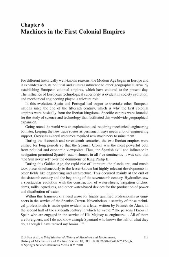
Other frequently used machines of the time for mining applications were drain-age machines, since water was a constant concern in the mines of New Spain. Figure 6.28 shows one of these machines, with no original parts, as it was used in a mine in Pachuca.
On Automatons
In the book by José A. García-Diego on Juanelo’s clocks and automatons, the engi-neer’s main activity is made clear that he was a clockmaker for the Emperor as well as an automaton designer. However, there are doubts on his authorship of the most famous works like the automaton of the Lady of Vienna.
Juanelo’s popular reputation is a mixture of confirmed historical facts and other stories, but distinguishing the line separating fact from fiction is not easy.
Many suppositions have been made regarding a famous automaton which suppos-edly accompanied Juanelo through the streets of Toledo. This was known as “The Stick Man”, about which written sources and other references exist. Figure 6.29 alludes to the street in Toledo dedicated to “The Stick Man”. The text reads: “Toledo Legends, ‘The Stick Man’. Along this street passed the wooden automaton built by Juanelo Turriano, clockmaker to Charles V, to the amazement and perplexity of the crowd”.
Fig. 6.28 Mine drainage device, used in the San Nicolás de Bari mine (Pachuca) [127]

139On Automatons
Fig. 6.29 Reference to the “Stick Man” in Toledo