LTI LaserSoft MapSmart User's Guide for Android - Laser Tech
134
LaserSoft ® MapSmart ® Android™ 5.x User’s Guide 6 th Edition © LTI 2021 MapSmart ® Android™ 3210011 @LaserTechnologyInc @Laser-Technology @LaserTechnologyInc @LaserTechInc_ @LaserTechPro [email protected] 6912 S. Quentin St, Suite A Centennial, CO 80112 1.303.649.1000
-
Upload
khangminh22 -
Category
Documents
-
view
0 -
download
0
Transcript of LTI LaserSoft MapSmart User's Guide for Android - Laser Tech

LaserSoft®
MapSmart® Android™ 5.xUser’s Guide 6th Edition
© L
TI 2
021 M
ap
Smart
® A
nd
roid
™ 3
210011
@LaserTechnologyInc
@Laser-Technology
@LaserTechnologyInc
@LaserTechInc_
@LaserTechPro
6912 S. Quentin St, Suite ACentennial, CO 80112
1.303.649.1000

LTI LaserSoft MapSmart User’s Guide 6th Edition Android Part Number 3210011
Copyright Notice: Information in this document is subject to change without notice and does not represent a commitment on the part of Laser Technology, Inc. No part of this manual may be reproduced in any form or by any means, electronic or mechanical, including photocopying, recording, or information storage and retrieval systems, for any purpose other than the purchaser’s personal use, without the express written consent of Laser Technology, Inc.
Copyright © Laser Technology, Inc., 2017-2021. All rights reserved. Printed in the United States of America.
First Edition: February 2017 Second Edition: September 2017 Third Edition: July 2018 Fourth Edition: April 2019 Fifth Edition: November 2020 Sixth Edition: July 2021
Trademarks: TruPulse, TruPoint and MapStar are registered trademarks of Laser Technology, Inc. All other trademarks are the property of their respective owner.
Patents: This product is covered by pending patent applications and the following issued patents: 5,696,705
5,859,693
How to Contact LTI: Street Address: 6912 S. Quentin Street Suite A Centennial, CO 80112 USA
Phone:
Fax: Web Site: Email:
1-303-649-10001-800-790-7364 (USA and Canada)[email protected]

LTI LaserSoft MapSmart User’s Guide 6th Edition AndroidTable of Contents
Page 1
Copyright © [2021] Laser Technology, Inc. All rights reserved. Unauthorized duplication, in whole or in part, is strictly prohibited.
Table of Contents
Section 1 - Introducing MapSmart for Android ............................................................................ 5Technical Specifications ........................................................................................................................... 5Warranty Information .............................................................................................................................. 5What's New ............................................................................................................................................ 6Instrument Configurations........................................................................................................................ 6
Section 2 - Get MapSmart .............................................................................................................. 7Program Licensing ................................................................................................................................... 7Launch MapSmart ................................................................................................................................... 10About the Main Menu............................................................................................................................... 10Categories .............................................................................................................................................. 11
Add A Category ................................................................................................................................ 11Add A Subcategory ........................................................................................................................... 12Delete A Category............................................................................................................................. 12Delete A Subcategory........................................................................................................................ 13
GPS Points .............................................................................................................................................. 14To Save a GPS Point for Future Use ................................................................................................... 14To Access and Use a Saved GPS Point ................................................................................................ 14
GPS Settings ........................................................................................................................................... 15Materials................................................................................................................................................. 16
To Build the Materials List in MapSmart .............................................................................................. 16To Build the Materials List on a PC and Transfer to the Android Device ................................................. 17
Help ....................................................................................................................................................... 18MapSmart Settings .................................................................................................................................. 19About MapSmart ..................................................................................................................................... 20
Section 3 - Data Collection Methods............................................................................................. 21Overview of Mapping Methods.................................................................................................................. 21Radial with Azimuth Method ..................................................................................................................... 22
About Selecting the Origin Point......................................................................................................... 22Volume with Azimuth............................................................................................................................... 22Radial with Angle Method......................................................................................................................... 23
About Selecting the Origin Point......................................................................................................... 23Volume with Angle .................................................................................................................................. 23Range Triangulation Method .................................................................................................................... 24
About Selecting the Control Points ..................................................................................................... 24Geometry Messages.......................................................................................................................... 25
Baseline Offset Method ............................................................................................................................ 25About Selecting the Origin and Baseline ............................................................................................. 25
Mapping Indoors ..................................................................................................................................... 26
Section 4 - Collect Data .................................................................................................................. 27Hardware Setup Notes............................................................................................................................. 27
TruPulse 200B/360B/R ...................................................................................................................... 27Calibrate the compass in a TruPulse 360B/R................................................................................. 27
TruPulse 200X .................................................................................................................................. 28TruPoint 200h................................................................................................................................... 28MapStar TruAngle Setup Notes .......................................................................................................... 28
Quick Start for TruPulse 200X + TruAngle System ........................................................................ 28Pair a Laser with an Android Device .......................................................................................................... 29
Bluetooth Setup - TruPulse 200X, 360B, 360R, 200B, TruPoint 200h..................................................... 29Start a New Survey.................................................................................................................................. 30
File Name......................................................................................................................................... 30Device ............................................................................................................................................. 31Method ............................................................................................................................................ 31Units................................................................................................................................................ 31GPS ................................................................................................................................................. 31Reminders........................................................................................................................................ 31Instrument Height ............................................................................................................................ 32

LTI LaserSoft MapSmart User’s Guide 6th Edition AndroidTable of Contents
Page 2
Copyright © [2021] Laser Technology, Inc. All rights reserved. Unauthorized duplication, in whole or in part, is strictly prohibited.
Traverse/Target/Feature Height......................................................................................................... 32Import a File .................................................................................................................................... 32Resection ......................................................................................................................................... 32
Set Control Points/Origin.......................................................................................................................... 33Radial With Angle ............................................................................................................................. 34Radial with Azimuth .......................................................................................................................... 34Range Triangulation.......................................................................................................................... 34Baseline Offset ................................................................................................................................. 35
Use GPS to Set Control Points/Origin......................................................................................................... 36To Set a GPS Origin for Radial with Angle Surveys............................................................................... 36To Set a GPS Origin for Radial with Azimuth and Baseline Offset Surveys.............................................. 37To Set a GPS Origin for Range Triangulation Surveys .......................................................................... 37
Use Resection to Set Control Point/Origin.................................................................................................. 38Re-Open a Saved Resection Survey.................................................................................................... 38
Data Collection Screen Overview .............................................................................................................. 40Data Collection Screen Overview Detail .............................................................................................. 41Icon Description Table ...................................................................................................................... 44
Background Maps .................................................................................................................................... 46Define the Orientation of Features ............................................................................................................ 48
Radial with Angle.............................................................................................................................. 48Radial with Azimuth .......................................................................................................................... 48Range Triangulation.......................................................................................................................... 48Baseline Offset ................................................................................................................................. 49
Adding Data Points to the Survey ............................................................................................................. 49Add a Point Using a Laser.................................................................................................................. 50Radial with Angle - TruPulse 200X + TruAngle .................................................................................... 50Add a Point Manually ........................................................................................................................ 51
Radial with Angle ....................................................................................................................... 51Radial with Azimuth.................................................................................................................... 52Range Triangulation & Baseline Offset ......................................................................................... 52
Add Points to a Saved Survey ............................................................................................................ 53Radial with Angle Method - TruPulse 200X or TruSpeed Sxb + TruAngle ........................................ 53Baseline Offset Method -TruPulse 200X, TruSpeed Sxb or TruPoint 200h........................................ 53Range Triangulation Method -TruPulse 200X, TruSpeed Sxb or TruPoint 200h ................................ 53
Add a Point Using GPS Only............................................................................................................... 54Add a Line Feature .................................................................................................................................. 55Add a Curve Feature................................................................................................................................ 56Add an Area Feature................................................................................................................................ 57Delete a Point ......................................................................................................................................... 58Re-shoot a Point...................................................................................................................................... 59
Reshoot Last Point ............................................................................................................................ 59Reshoot Any Point: ........................................................................................................................... 59Add a Photo ..................................................................................................................................... 60
Move to a New Position ........................................................................................................................... 61Radial with Angle - TruPulse 200X + TruAngle .................................................................................... 61Radial with Azimuth .......................................................................................................................... 62Range Triangulation.......................................................................................................................... 64Baseline Offset ................................................................................................................................. 64
About Target/Instrument Height............................................................................................................... 65
Section 5 - Review Data.................................................................................................................. 66File Properties ......................................................................................................................................... 66Point Detail ............................................................................................................................................. 67
Navigate Point Detail......................................................................................................................... 67Display Tabular Data......................................................................................................................... 69Display Raw Data.............................................................................................................................. 70Display Map View.............................................................................................................................. 71Display Description ........................................................................................................................... 72
Zoom Options ......................................................................................................................................... 73

LTI LaserSoft MapSmart User’s Guide 6th Edition AndroidTable of Contents
Page 3
Copyright © [2021] Laser Technology, Inc. All rights reserved. Unauthorized duplication, in whole or in part, is strictly prohibited.
Section 6 - Edit Data ....................................................................................................................... 74Edit a Data Point ..................................................................................................................................... 74Edit a Point Series ................................................................................................................................... 76Edit a Feature ......................................................................................................................................... 77
Change the Feature Type .................................................................................................................. 78Adjust Point Order ............................................................................................................................ 80
Flip a Data Point...................................................................................................................................... 81Flip the Most Recently Added Data Point............................................................................................. 81Flip Any Data Point in the Survey ....................................................................................................... 82
Section 7 - Calculations and Volume ............................................................................................ 83Distance ................................................................................................................................................. 84
Point to Point Distance ...................................................................................................................... 84Point to Line Distance ....................................................................................................................... 85Area of Traverse ............................................................................................................................... 86Area of Side Shots ............................................................................................................................ 87Area of Non-CP Points ....................................................................................................................... 88Area of All Points .............................................................................................................................. 89Area of Feature ................................................................................................................................ 90
Closure ................................................................................................................................................... 91Closed Traverse................................................................................................................................ 91Open Traverse.................................................................................................................................. 92Traverse Results ............................................................................................................................... 93
Volume................................................................................................................................................... 94Volume Data Collection Screen Overview............................................................................................ 94Perform a Volume Measurement ........................................................................................................ 95
Step 1: Review Necessary Equipment .......................................................................................... 95Step 2: Assess the Stockpile & Prepare to Measure....................................................................... 95Step 3: Take Measurements........................................................................................................ 95Step 4: Perform Calculations ....................................................................................................... 99Step 5: Create a Volume Report .................................................................................................. 100
Verify Mid-Survey Traverse Accuracy - Check Tool............................................................................... 101Create & Use a Survey Template File.................................................................................................. 102
Height .................................................................................................................................................... 105Missing Line ............................................................................................................................................ 106Find Stored Calculation Results................................................................................................................. 107
Section 8 - Reports ......................................................................................................................... 108Save a Report ......................................................................................................................................... 108Save and Send a Report........................................................................................................................... 110Manage Saved Reports ............................................................................................................................ 111
Send a Saved Report......................................................................................................................... 111Delete a Saved Report ............................................................................................................................. 112Transfer Reports/Data to a PC.................................................................................................................. 113Delete All Saved Reports.......................................................................................................................... 115
Section 9 - Pick Lists ...................................................................................................................... 116Add a Pick List Note................................................................................................................................. 116Select a Pick List Note.............................................................................................................................. 117Delete a Pick List Note ............................................................................................................................. 117Create a Pick List on the Computer ........................................................................................................... 118

LTI LaserSoft MapSmart User’s Guide 6th Edition AndroidTable of Contents
Page 4
Copyright © [2021] Laser Technology, Inc. All rights reserved. Unauthorized duplication, in whole or in part, is strictly prohibited.
Appendix A - MapSmart for Android Quick Start Guide.............................................................. 119Step 1 for All Lasers - Add WLAN, Install MapSmart, Get Licensed .............................................................. 119TruPulse 360B/R ..................................................................................................................................... 119
Step 2 - Toggle On Bluetooth ............................................................................................................ 119Step 3 - Change Units of Measure to Feet (if necessary) ...................................................................... 120Step 4 - Connect TruPulse 360B/R with Android Device via Bluetooth ................................................... 120Final Step TruPulse 360B/R - Set Up & Get a Shot In........................................................................... 120
TruPulse 200X + TruAngle ....................................................................................................................... 121Step 2 - Toggle On Bluetooth ............................................................................................................ 121Step 3 - Change Units of Measure to Feet........................................................................................... 121Step 4 - Toggle On Electronic Filter (if using a reflective target) ........................................................... 121Step 5 - Sync Android Device with TruPulse 200X via Bluetooth ........................................................... 121Final Step TruPulse 200X - Set Up & Get a Shot In .............................................................................. 122
TruPoint 200h ......................................................................................................................................... 123Step 2- Toggle On Bluetooth Link....................................................................................................... 123Step 3 - Toggle ON Electronic Filter.................................................................................................... 123Step 4 - Connect TruPoint 200h to Tablet ........................................................................................... 123Final Step for TruPoint 200h - Setting Up For Your First Shot ............................................................... 123
Access MapSmart Help............................................................................................................................. 124
Appendix B - Conversion Table (Inches to Decimal Feet) .......................................................... 125
Appendix C - Troubleshooting Tips .............................................................................................. 126TruPulse 200X + TruAngle or TruPulse 360R/B.......................................................................................... 127TruPoint 200h ......................................................................................................................................... 128
Appendix D - TruPulse 360 Magnetic Interference Guidelines................................................... 129
Appendix E - Additional Information............................................................................................. 130Localization............................................................................................................................................. 130Serial Data Format .................................................................................................................................. 130
Appendix F - Uninstall MapSmart.................................................................................................. 131Uninstall MapSmart ................................................................................................................................. 131Delete Remaining Files............................................................................................................................. 132

LTI LaserSoft MapSmart User’s Guide 6th Edition AndroidSection 1 - Introducing MapSmart for Android
Page 5
Copyright © [2021] Laser Technology, Inc. All rights reserved. Unauthorized duplication, in whole or in part, is strictly prohibited.
Section 1 - Introducing MapSmart for AndroidThank you for purchasing LaserSoft® MapSmart® for Android from Laser Technology, Inc. (LTI). MapSmart is a field data collection program that professionals in any industry can use to measure anything. Combine Laser Technology's highly accurate surveying instruments with MapSmart for a complete mapping solution.
LTI surveying instruments can automatically enter data into MapSmart, which can create two-dimensional (2D) and three-dimensional (3D) maps. Depending on the location and environmental challenges dictated by the field, MapSmart can include GPS coordinate data or simply provide XYZ coordinates of mapped points.
MapSmart survey files can be downloaded to a computer and imported into most CAD-based programs capable of reading a DXF file. Reports can also be opened in Microsoft® Excel and many GPS visualization programs capable of reading a GPX file or KML file (Google Earth).
Technical Specifications
LaserSoft MapSmart has been designed to run on Android operating platforms for use in conjunction with Laser Technology surveying instruments.
Warranty Information
For purchases including lasers, a copy of the LTI Limited Warranty should have shipped with the order. If needed, please contact LTI to obtain a copy of the LTI Limited Warranty. See the inside front cover for LTI contact information.
NOTE The tablet package includes the associated product literature, such as manuals and warranties. It is your responsibility to contact the manufacturing company to register the Data Collector.
Specification Description
Application Version MapSmart for Android Version 5.2
Operating Systems Android version 6 - 10
Supported Devices Most smart devices running Android 6 - 10** Please check LTI web site for current compatibility (http://www.lasertech.com/MapSmart-Software.aspx)
Connectivity Bluetooth® or WLAN depending on laser used
Compatible Lasers • TruPoint 200h• TruPulse 200X• TruPulse 360R**• TruPulse 360** with Bluetooth• TruPulse 200*** with Bluetooth
** Only TruPulse 360, 360R, and 200 Bluetooth-enabled lasers displaying the menu option "BT_Enc" in the heads-up display are compatible for use with a TruAngle. Older models of these lasers may not display this option and are not compatible for use with a TruAngle.
*** To send commands from the Android device to TruPulse 200 Bluetooth-enabled lasers (i.e. utilize remote fire), the laser firmware version must be A 2.26 B 2.51 or newer.
Hardware • Optional - MapStar TruAngle for use with TruPulse lasers listed above• Recommended X-Grip & Mounting Claw for phones/tablets if using
with a tripod, 7" version available via LTI, other sizes available here:http://www.rammount.com/search?search_type=search&query=xgrip
Supported Languages English, French, Simplified Chinese, and Indonesian; template is available for translation

LTI LaserSoft MapSmart User’s Guide 6th Edition AndroidSection 1 - Introducing MapSmart for Android
Page 6
Copyright © [2021] Laser Technology, Inc. All rights reserved. Unauthorized duplication, in whole or in part, is strictly prohibited.
What's New
LaserSoft MapSmart is an updated version of Laser Technology's MapSmart program for devices running Windows Mobile 6 or newer. When combined with a TruPulse or TruPoint 200h, this laser-based data collection app can be used to capture measurements of anything anywhere. While the Windows Mobile version of MapSmart is still supported by Laser Technology, MapSmart for Android provides many feature enhancements including:
• Add a point using GPS only and without requiring a laser shot.• Enable Background Maps in 8 different styles from Google and ArcGIS.• Change GPS point color so points may display more clearly when
Background Maps are enabled.• Add support from the TruPoint 200h laser.• Add KML output format.
Instrument Configurations
MapSmart Android is designed to work with all possible instrument configurations:
• TruPulse 200B with or without TruAngle • TruPulse 360B/R with or without TruAngle (Figure 1A) • TruPulse 200X with or without TruAngle (Figure 1B)• TruPoint 200h
(A) (B) Figure 1

LTI LaserSoft MapSmart User’s Guide 6th Edition AndroidSection 2 - Get MapSmart
Page 7
Copyright © [2021] Laser Technology, Inc. All rights reserved. Unauthorized duplication, in whole or in part, is strictly prohibited.
Section 2 - Get MapSmartMapSmart downloads free from the Google Play Store, but requires a license key purchased from Laser Technology to access full functionality. MapSmart will work unlicensed for a 30-day trial period from the date of initial download. To get the MapSmart app from Google Play:
1. Use the Google Play search function to find “LaserSoft MapSmart.”2. Tap the MapSmart icon to install the app as you would any other Google Play
application (Figure 2).3. Find the MapSmart icon on the smart device.4. Tap the MapSmart icon to display the licensing screen (Figure 3).
Program Licensing
Upon any purchase of MapSmart, Laser Technology generates a customer account on its License Manager website (http://license.lasertechpartners.com/CustomerLogin.aspx) that allows you to generate license keys. The first time MapSmart is started, a short video will play before the licensing screen is displayed. MapSmart can be used for 30 days from the date of download before a license key is required (Figure 4A). Tap the Demo button to proceed past the licensing screen and use the program. At the end of 30 days, MapSmart cannot be used without a license key.
Figure 3
About the 30-day Trial:• The Demo Status is located in the box below the App title. The status changes
depending on how may days are left in the trial. In Figure 4A the status is“You have 30 days remaining in your free MapSmart trial.”
• MapSmart is fully functional during the trial period. Surveys made during thistime are accessible during the trial and can be re-accessed when the programis licensed.
• Contact an authorized dealer near you to purchase a license key or call LTI formore information (1-800-790-7364 or 1-303-649-1000).
Figure 2
Continued on Next Page

LTI LaserSoft MapSmart User’s Guide 6th Edition AndroidSection 2 - Get MapSmart
Page 8
Copyright © [2021] Laser Technology, Inc. All rights reserved. Unauthorized duplication, in whole or in part, is strictly prohibited.
To generate a license key:
1. Notate the temporary password you received from [email protected] open License Manager, http://license.lasertechpartners.com/CustomerLogin.aspx.If you follow the “License Manager website” link from MapSmart licensing screen onyour smart device, your Machine ID was automatically copied to the clipboard.
2. Tap the “Email” field to bring up the keyboard. Enter the email address associated withyour purchase and the temporary password. Click [Submit] to log in (Figure 4B).If you do not have your temporary password, click the [Request Password] link at thetop of the screen. Once successfully logged in, the “Obtain License Key” page displays.
3. Upon logging in, your purchase is displayed (Figure 4C).• Machine ID: If you followed the link from your smart device (Figure 4A),
tap and hold the Machine ID field to paste the value. Or, enter the Machine IDmanually (Figure 4C).
• Purchase ID: Copy, tap and hold the “Purchase ID” in the Purchases Table(Figure 4C) and select the “Copy” option. Paste, tap and hold the “Purchase ID”field (Figure 4D) and select the “Paste” option (Figure 4E).
Continued on Next Page
(B) (C) (D) (E) Figure 4
(A)

LTI LaserSoft MapSmart User’s Guide 6th Edition AndroidSection 2 - Get MapSmart
Page 9
Copyright © [2021] Laser Technology, Inc. All rights reserved. Unauthorized duplication, in whole or in part, is strictly prohibited.
4. Click [Submit] and your license key will display below the entry fields, as well as in the Purchases Table.5. Copy, tap and hold, or notate the License Key (Figure 5A) and return to MapSmart (Figure 5B).6. Paste or enter the key in the “Enter License Key” field and tap “Start” (Figure 5C). Tap and hold
the “Enter License Key” file to display a prompt for pasting, then tap [Start].
If an incorrect key is entered, the MapSmart Main Menu will not be displayed. Instead, the display will return to the device home screen.
For assistance contact: [email protected] or call 1-877-696-2584.
Please provide your name, company name, purchase ID (if known) as well as the Machine ID displayed on the Android device.
(A) (B) (C)
Figure 5

LTI LaserSoft MapSmart User’s Guide 6th Edition AndroidSection 2 - Get MapSmart
Page 10
Copyright © [2021] Laser Technology, Inc. All rights reserved. Unauthorized duplication, in whole or in part, is strictly prohibited.
Launch MapSmart
To launch the MapSmart app:
About the Main Menu
Figure 7 shows the MapSmart Main menu.
1. Find the MapSmart icon on the smart device (Figure 6A).2. Tap the MapSmart icon (Figure 6B).
If licensed, the Main Menu will display (Figure 7).
(A)
(B) Figure 6
Figure 7
• Tap the back arrow () at the top of the screen to leave MapSmart.
• Tap the Menu button in the upper right corner of the screen to access:
• Categories• GPS Points • GPS Settings • Materials• Help • MapSmart Settings• About MapSmart
• Tap [New Survey] to begin a new survey
• Tap [Saved Surveys] to select an existing map and:
• Open* • Delete• Send MapSmart file via email
• Tap [Exit] to close MapSmart and return to the Android device main screen
* For more detail on opening a saved Resection survey, see Page 38.

LTI LaserSoft MapSmart User’s Guide 6th Edition AndroidSection 2 - Get MapSmart
Page 11
Copyright © [2021] Laser Technology, Inc. All rights reserved. Unauthorized duplication, in whole or in part, is strictly prohibited.
Categories
Categories with accompanying subcategories may be created to help add clarity to field measurements stored using MapSmart. Categories and subcategories must be created prior to starting a new data collection project. Custom category list options are available for selection from drop-down menus in the MapSmart Description Detail screen.
Add A Category
1. Tap the Menu icon in the upper-right corner of the screen (Figure 8A).2. Tap [Categories] from the list of options (Figure 8B).3. Tap [Add] below the Categories menu (Figure 8C).4. Enter a new category name and tap [Save] (Figure 8D).5. The new Category will appear in the list of categories in alphabetical order (Figure 8E).
(A) (B) (C)
(D) (E) Figure 8

LTI LaserSoft MapSmart User’s Guide 6th Edition AndroidSection 2 - Get MapSmart
Page 12
Copyright © [2021] Laser Technology, Inc. All rights reserved. Unauthorized duplication, in whole or in part, is strictly prohibited.
Add A Subcategory NOTE In order to create a subcategory, a category must have already been built that the subcategory will be assigned to.
1. Access the Category Management screen (Steps 1 & 2 from the "Add A Category" section, Page 11).2. Tap the Category under which the subcategories will nest so that the Category name is highlighted
in blue (Figure 9A) and tap [Add] below the Subcategories menu.3. Enter the new Subcategory name and tap [Save] (Figure 9B).4. The new Subcategory will appear in the list of subcategories in alphabetical order (Figure 9C).
Delete A Category NOTE Deleting a Category also deletes all the Subcategories that are associated with it. Category and subcategory deletions cannot be undone; they can only be re-created.
1. Access the Category Management screen (Steps 1 & 2 from the “Add A Category” section, Page 11).2. Tap the Category to select it. Category is highlighted in blue when selected, and then tap [Delete] below
the Categories menu (Figure 10A).3. Tap [OK] to confirm the deletion (Figure 10B).
(A) (B) (C) Figure 9
(A) (B) Figure 10

LTI LaserSoft MapSmart User’s Guide 6th Edition AndroidSection 2 - Get MapSmart
Page 13
Copyright © [2021] Laser Technology, Inc. All rights reserved. Unauthorized duplication, in whole or in part, is strictly prohibited.
Delete A Subcategory NOTE Individual Subcategories can be deleted one at a time. Also, deleting an entire Category will delete all associated Subcategories at once along with the Category. Category and Subcategory deletions cannot be undone; they can only be re-created.
1. Access the Category Management screen (Steps 1 & 2 from the “Add A Category” section, Page 11).2. Tap the Category field to access its associated Subcategories list, then tap the Subcategory to select it.
The subcategory is highlighted in blue when selected. 3. Tap [Delete] below the Subcategories menu (Figure 11A).4. Tap [OK] to confirm the deletion (Figure 11B).
(A) (B) Figure 11

LTI LaserSoft MapSmart User’s Guide 6th Edition AndroidSection 2 - Get MapSmart
Page 14
Copyright © [2021] Laser Technology, Inc. All rights reserved. Unauthorized duplication, in whole or in part, is strictly prohibited.
GPS Points
GPS coordinates can be saved for re-use using the GPS Points option in the MapSmart menu (Figure 12A). Using saved GPS points can be a time-saver for resection surveys that use stockpile bin templates. Control points for these surveys are usually the left and right side of the bin opening. Instead of standing at those points each time to log them, you can do it only once and then select them from a drop-down list for all future surveys of the bin contents.
To Save a GPS Point for Future Use
1. Tap the Menu button and select GPS Points (Figure 12A).2. Enter a Name and/or Antenna Height for the point in the Name field and then tap [Start Fix] to search
for satellites (Figure 12B and Figure 12C). HRMS and number of satellites will begin to display at the top of the screen. Coordinates will update in the Longitude/Latitude/Altitude cells until [Save] is tapped at which time that coordinate is logged for re-use.
3. When beginning a resection survey (Page 38), tapping the Define Left CP and Define Right CP column titles will bring up the list of saved GPS points to choose from (Figure 12D).
• Start FixTap this to begin searching for satellites. Data will update until [Save] is tapped to accept a position.
• GPS Points List Any saved GPS points listed can be opened and edited or deleted if necessary. Figure 12C shows the information associated with saved GPS point "CP1."
• Name - Enter a name to add a new GPS point.• Latitude/Longitude/Altitude
After [Start Fix] is initiated, these fields will continue to update with position information until [Submit] is tapped.
• Antenna Ht Enter the height of the antenna here. If using a tablet or phone with no external antenna, enter the height of that device to get correct elevation information.
To Access and Use a Saved GPS PointWhen beginning a resection survey (Page 38), tapping the Define Left CP and Define Right CP column titles will bring up the list of saved GPS points to choose from (Figure 12D above).
(A) (B) (C) (D) Figure 12

LTI LaserSoft MapSmart User’s Guide 6th Edition AndroidSection 2 - Get MapSmart
Page 15
Copyright © [2021] Laser Technology, Inc. All rights reserved. Unauthorized duplication, in whole or in part, is strictly prohibited.
GPS Settings
When the GPS checkbox is marked on the New File Settings screen (Figure 30 on Page 30), MapSmart automatically uses position information from Android location services for the survey Origin (equipment position) or control points. Alternately, Location Services can be by-passed by tapping the Device drop-down list and selecting an external GPS device that is connected to the Android device via Bluetooth. After the Origin is captured, all subsequent GPS coordinates are mathematically calculated based on that initial position.
The GPS Settings screen (Figure 13A) contains some settings options for surveys that incorporate GPS. It includes the ability to review and capture incoming coordinate data and verify accuracy without having to create a survey.
NOTE The GPS Settings menu option (Figure 13B) is only visible when a survey file is NOT open.
Start Fix Tap this to begin searching for satellites. Data will update until [Submit] is tapped to accept a position (Figure 13B). [Pause Fix] may be tapped to stop reporting position data.
Device Select Locations Services; or if there is an external GPS device connected to the Android device, select the device from the drop-down menu and MapSmart will receive position information directly from the GPS device. MapSmart supports most external GPS devices that connect to the Android device via Bluetooth.
Latitude/Longitude/Altitude After [Start Fix] is initiated, these fields will continue to update with position information until [Submit] is tapped.
Antenna HtEnter the height of the antenna here. If using an Android device with no external antenna, enter the height of that device to get correct elevation information.
Start surveys with GPS• Checked: Use GPS for all new MapSmart surveys. The GPS checkbox
on the New File Settings screen will default as checked when starting a survey.
• Not Checked: The GPS checkbox will default as unchecked when starting a survey.
DMSDegrees, Minutes, Seconds
• Checked: Position data is displayed using degrees, minutes, and seconds format.
• Not Checked: Position data is displayed using decimal degrees format.
NOTE For more information on how to save a GPS point for future use, see Page 14.
Figure 13
(A)
(B)

LTI LaserSoft MapSmart User’s Guide 6th Edition AndroidSection 2 - Get MapSmart
Page 16
Copyright © [2021] Laser Technology, Inc. All rights reserved. Unauthorized duplication, in whole or in part, is strictly prohibited.
Materials
In addition to calculating volume, MapSmart can also calculate an associated weight for the material. To calculate the associated weight, it is necessary to create the Materials List which includes the densities of the materials that will be encountered in a survey. There are two ways to build a materials list: the list can be built within the MapSmart program or it can be built as a text file on a PC and then copied over to a specific directory on the Android device.
To Build the Materials List in MapSmart
1. Open MapSmart on the Android device.
2. Tap the Menu button and select Materials (Figure 14A) to display the Stored Material Properties screen (Figure 14B).
3. Enter the Name and Density of a material.4. Select the desired units (lbs/ft^3 or kg/m^3).5. Tap [Add] to add the material and density to the Materials list.6. Repeat steps 2-4 until the list is complete (Figure 14C).7. Tap the Back Arrow () to exit the Stored Material Properties screen.
Additional Information for Managing Materials within MapSmart:
• Materials are listed in alphabetical order. To navigate to a specific material in the list,
tap or until the desired material displays.• To delete an item from the list, tap to select it and then tap [Delete].
A message box will be displayed, prompting to confirm the deletion.• Select [Delete] to delete the material from the list.• Select [Cancel] to return to Stored Material Properties screen
without deleting the material from the list.• Tap the Back arrow () to return to the MapSmart main screen.• Once a material has been added to the Materials List, its name and density cannot be edited.• To change a material, delete it and then add the name and density as a new material in the list.
(A) (B) (C) Figure 14
34
5
7
6

LTI LaserSoft MapSmart User’s Guide 6th Edition AndroidSection 2 - Get MapSmart
Page 17
Copyright © [2021] Laser Technology, Inc. All rights reserved. Unauthorized duplication, in whole or in part, is strictly prohibited.
To Build the Materials List on a PC and Transfer to the Android Device
• The Materials List text file name is Densities.lti.• A program such as Microsoft Notepad can be used to create the text file. Be sure to
assign the correct file name (Densities.lti). The MapSmart program will not recognize any other file name as the Materials List.
• Enter one item per line (Figure 15A).Material name|(shift”\”)numerical value|density units(lbs/ft^3 or kg/m^3) (^ = shift"6")Example = GRAVEL|7|lbs/ft^3
• Left justify text and do not indent text.• The text file can be transferred via cable from the PC to the Android device.• Densities.lti file location on the Android device: D:\MapSmart\Data. MapSmart
will not locate the Materials List if you store it in any other location (Figure 15B).
(A)
(B) Figure 15

LTI LaserSoft MapSmart User’s Guide 6th Edition AndroidSection 2 - Get MapSmart
Page 18
Copyright © [2021] Laser Technology, Inc. All rights reserved. Unauthorized duplication, in whole or in part, is strictly prohibited.
Help
MapSmart Help includes information about the mapping methods, meanings of icons, how to traverse, and how to correct any errors that might have been made during the mapping process. Help is located as a menu option in the upper right corner of the MapSmart screen at any time the program is open (Figure 16A).
Tap [Help] from the menu to display the MapSmart Help Menu (Figure 16B).
(A)
(B)
Figure 16
Help Menu Options:• Getting Started
• Bluetooth Laser Connection - correct the laser connection.• Mapping Methods
• Radial with Angle - notes for setting up and icon descriptions
• Radial with Azimuth - notes for setting up and icon descriptions
• Range Triangulation - notes for settings up, point orientation, and icon descriptions
• Baseline Offset - notes for setting up, defining point orientation, and icon descriptions
• Volume with Angle - Notes for setting up and measuring a volume with simplified Data Collection screen
• Corrections• Correct Heights - forgot to adjust a point height
or the height of a group of points while mapping? See the steps to correct it here.
• Correct Notes - forgot to uncheck auto? See the steps to correct it here.
• Fix Point Orientation - forgot to change from left to right or right to left when mapping points? See how to correct it here.
• Move Control Point - is the area too big to map from one position? See how to move to a new Control Point with the Radial with Angle mapping method.
• Move CP (TruPulse 200X) - Radial with Angle• Move CP (TruPulse 360B) - Radial with Azimuth
• Utilities• Conversion Table - Find decimal feet conversions for entry
field such as Target/Feature/Instrument Heights or manual distance entry.
• Email Tech Support - If a crash happens, re-open the survey and use this feature to send a diagnostics file and/or the MS4D file to technical support for assistance.
• About MapSmart - find the software version number and Laser Technology contact information.

LTI LaserSoft MapSmart User’s Guide 6th Edition AndroidSection 2 - Get MapSmart
Page 19
Copyright © [2021] Laser Technology, Inc. All rights reserved. Unauthorized duplication, in whole or in part, is strictly prohibited.
MapSmart Settings
MapSmart survey file Settings can be found by tapping the Menu button any time survey file is open - then select MapSmart Settings (Figure 17A) to see the current settings and make adjustments to them, if necessary (Figure 17B).
Instrument Height• Measured from the ground to the center of the sighting scope (Page 32).
Target Height, Feature Height, Origin Height, or CP1/CP2 Heights The height of the target where the laser's sighting scope will be aimed - options displayed depend on the selected mapping method:
• Radial with Angle - Target height• Radial with Azimuth - Target height• Range Triangulation - CP1 and CP2 target heights• Baseline Offset - Origin height and feature height
Project Note Enter a note in the free-form text field to record any information associated with the current map. An unlimited number of characters may be entered. The entire Project Note is downloaded to thePC as part of the RAW, ASC, CSV and PDF downloaded reports.
Email Address for Reports Enter an email address that will automatically be used when emailing MapSmart reports for data transfer.
Store Notes• Checked: Each time a data point is added, the Description Detail screen
will display so a descriptive note may be entered or a category/subcategory classification can be assigned.
• Not checked: Each time a data point is added, the Description Detail screen does not display; however, notes can be added through Point Detail > Edit Point (Page 74).
Recall Last Note• Checked: The Description Detail screen will display the last note
used in the note field each time it is opened.• Not checked: The note field in the Description detail screen will be blank
each time it is opened.
Beep• Checked: The Android device emits a beep when it receives measurement data.• Not checked: The Android device does not emit a beep when it receives measurement data.
Plot Labels• Checked: The point number assigned to each point is displayed on the Data Collection screen.• Not checked: The point number assigned to each point is not displayed on the Data Collection screen.
Plot Notes• Checked: The point note assigned to each point is displayed on the Data Collection screen.• Not checked: The point note assigned to each point is not displayed on the Data Collection screen.
Reminders• Checked: Each time a new survey file is created, a reminder will be displayed prior to the
Data Collection screen. The reminder content depends on which mapping method was selected on the New File Settings screen (Page 30).
• Not checked: No reminders are displayed.
Figure 17
(A)
(B)

LTI LaserSoft MapSmart User’s Guide 6th Edition AndroidSection 2 - Get MapSmart
Page 20
Copyright © [2021] Laser Technology, Inc. All rights reserved. Unauthorized duplication, in whole or in part, is strictly prohibited.
About MapSmart
MapSmart version information can be found by tapping the Menu button at any time.Then select About MapSmart (Figure 18A) to see the current version information (Figure 18B).
(A) (B) Figure 18

LTI LaserSoft MapSmart User’s Guide 6th Edition AndroidSection 3 - Data Collection Methods
Page 21
Copyright © [2021] Laser Technology, Inc. All rights reserved. Unauthorized duplication, in whole or in part, is strictly prohibited.
Section 3 - Data Collection MethodsMapSmart offers six unique data collection methods that enable users with various equipment combinations and terrain challenges to map successfully. This section provides an overview of the six methods. Professional training on mapping methods in combination with the use of LTI measurement devices is encouraged. Contact LTI for training options.
When deciding which method to use, you will need to consider:
• Terrain of the site.• Relative locations of the features to be mapped.• Equipment that will be used. For example, will a compass
or TruAngle be used in combination with the laser?
Overview of Mapping Methods
Method Requirements Compatible Hardware
Radial with Angle Clear line of sight from the Origin point to each feature being mapped. TruPulse Series + MapStar TruAngle
Volume with Angle Simplified Radial with Angle user interface designed specifically for volume surveys. Clear line of sight from each equipment position to the Base and Pile points measured from that position.
TruPulse Series + MapStar TruAngle
Radial with Azimuth Clear line of sight from the Origin point to each feature being mapped. Proper care and procedure when using a compass in the vicinity of magnetic objects such as cars, utilities, buildings, etc.
TruPulse 360B TruPulse 360R
Volume with Azimuth Simplified Radial with Azimuth user interface designed specifically for volume surveys. Clear line of sight from each equipment position to the Base and Pile points measured from that position. Proper care and procedure when using a compass in the vicinity of magnetic objects such as cars, utilities, buildings, etc.
TruPulse 360B TruPulse 360R
Range Triangulation Able to occupy (stand over) every feature to be mapped. Clear line of sight from each feature to the control points.
TruPulse 200X TruPulse 200B TruPoint 200h
Baseline Offset Able to walk a straight line from one end of the area to the other. Clear line of sight to the Origin and to each feature from a point along this straight line (the baseline).
TruPulse 200X TruPulse 200B TruPoint 200h

LTI LaserSoft MapSmart User’s Guide 6th Edition AndroidSection 3 - Data Collection Methods
Page 22
Copyright © [2021] Laser Technology, Inc. All rights reserved. Unauthorized duplication, in whole or in part, is strictly prohibited.
Radial with Azimuth Method
This method requires the use of the TruPulse 360 Series laser.
• A handheld compass may be used, but mapping would be more difficult due to target sighting inconsistencies and a potential accuracy reduction, depending upon the particular compass used.
• Magnetic objects on or near the site may compromise the accuracy of your measurements. See Appendix D (Page 129) for a chart describing best practices for avoiding magnetic interference.
In this method, the user pivots about an Origin point and shoots to any features in view. MapSmart uses the distance and azimuth (heading in degrees referenced to North) to the feature to calculate X, Y, and Z coordinates for each feature. Figure 19 shows how a campground perimeter could be mapped using the Radial with Azimuth method.
Option 1:To map this site, position the equipment at the Origin or CP1. Next, take distance and azimuth measurements to as many perimeter features as can be seen. Here, perimeter shots would be taken to the river bank on one side and a fence on the other side. Once the features are measured, select any one of them as the new Control Point (new CP), and move to that point in order to measure the features not visible from CP1. If desired, a new control point may also be set by using the Create New Control Point feature.
Option 2:Use the Back Mode by positioning a target at the Origin or CP1 and move around with the TruPulse 360 to shoot back to CP1 from each feature.
About Selecting the Origin PointThe Origin point, also referred to as a control point or CP, defines where to begin collecting data. It can be located anywhere among the features to be mapped. It is a good idea to start from the point with the best visibility to most, if not all, of the features to be mapped.
When choosing an Origin:
• Remember, if every feature to be mapped cannot be seen, set a new Control Point (Page 65). Later move to that point, and continue mapping.
• Consider plot scaling when choosing an Origin. Avoid making a map with imperceptible clusters of points caused by one point being significantly removed from the rest.
Volume with Azimuth
The Volume with Azimuth mapping method follows the same general rules as the Radial with Azimuth mapping method. The only difference between to the two is that the Data Collection screen displays differently. When Volume with Azimuth is selected, the user is presented with specific tools for performing a volume measurement and the calculations that accompany it (Page 99).
Figure 19

LTI LaserSoft MapSmart User’s Guide 6th Edition AndroidSection 3 - Data Collection Methods
Page 23
Copyright © [2021] Laser Technology, Inc. All rights reserved. Unauthorized duplication, in whole or in part, is strictly prohibited.
Radial with APage 61ngle Method
This method is similar to the Radial with Azimuth method, but requires the use of a TruPulse 200X with a MapStar TruAngle (see table on Page 21). The use of the TruAngle is preferred in areas where there may be too much magnetic interference for a TruPulse 360 model laser with an internal compass to be as accurate as typical.
In this method, the user pivots about an Origin point and shoots to any features in view. MapSmart uses the distance and angle measured (in degrees from a user-defined reference Azimuth, or zero) to calculate X, Y, and Z coordinates for each feature. Figure 20 shows how the same campground perimeter would be mapped using the Radial with Angle method.
To map this scene, physically move to the Origin also referred to as a Control Point or as CP, then define the reference azimuth (zero angle) to a reference point. The reference point should be a permanent object such as a fire hydrant or some other visible object. Then begin taking distance and angle measurements to as many features as can be seen. Once the features are measured, select any one of them as the new Control Point, and move to that point in order to measure the features not visible from CP1. If desired, a new control point may also be set by using the New Control Point feature.
• To get the most accurate encoder measurements, use of a tripod is strongly recommended in order to meet the stability requirements of the MapStar TruAngle.
• The Back Mode is not available with the Radial with Angle method.
About Selecting the Origin Point The Origin point, also referred to as a control point or CP, defines where to begin collecting data. It can be located anywhere among the features to be mapped. It is a good idea to start from the point with the best visibility to most, if not all, of the features to be mapped.
When choosing an Origin and reference point:
• Remember, if every feature to be mapped cannot be seen, set a new Origin point (Page 61). Later, move to that point, and continue mapping.
• Consider plot scaling when choosing an Origin. Avoid making a map with imperceptible clusters of points caused by one point being significantly removed from the rest.
• If actual X, Y, Z coordinates are not used, the reference point may be any identifiable, permanent object visible from the Origin (CP1). As an example, you could use a telephone pole, street sign, or building corner as your reference point. You won't need to shoot the reference point, just site it with the laser and zero the MapStar TruAngle.
Volume with Angle
The Volume with Angle mapping method follows the same general rules as the Radial with Angle mapping method. The only difference between to the two is that the Data Collection screen displays differently. When Volume with Angle is selected, the user is presented with specific tools for performing a volume measurement and the calculations that accompany it (Page 99).
Figure 20

LTI LaserSoft MapSmart User’s Guide 6th Edition AndroidSection 3 - Data Collection Methods
Page 24
Copyright © [2021] Laser Technology, Inc. All rights reserved. Unauthorized duplication, in whole or in part, is strictly prohibited.
Range Triangulation Method
In Range Triangulation, two measurements are required to log each point. To log a point: occupy the feature, shoot to CP1, and then to CP2 from that feature. The two measurements are made between two carefully positioned control points. A control point can be a feature already at the survey site, such as a tree, or it can be an installed point, such as a reflective target.
You shoot from each feature to the control points which forms a triangle, and in some cases measure from the control points to the feature. The feature and the two control points form a triangle, and the geometry of the triangle is used to determine X, Y, Z coordinates for each feature. Figure 21 shows how the same campground perimeter would be measured using the Range Triangulation method. The operator started this map by walking along the river bank and shooting back to the control points.
To map this scene, stand at a feature and shoot back to Control Point 1 (CP1), then to Control Point 2 (CP2). In Figure 21, the black lines represent the measurements taken between the control points and two features along the river bank.
• This method is cost-effective because only the laser is required, no compass or encoder is necessary.
• The user must measure from each feature to the control points.
About Selecting the Control Points Range Triangulation uses the geometry of a triangle to calculate each coordinate. Two control points and the feature form the points of the triangle. Select control points that can be seen from all features. However, if the view to any feature is blocked, set new control points (Page 64) to gain a better vantage point and successfully map each feature.
When choosing control points and mapping features:
• Features that are in between or in-line with the control points are very difficult or impossible to map.• Features that are farther than 3 times the distance between the control points will cause geometry
warnings and may not be accurate. For example, if your control points are 100 feet apart, the features should not be more than 300 feet away from a control point.
• Looking at Figure 21, points further along the river bank would have the buildings blocking the view to CP2. At the top of the MapSmart Data Collection screen, there are two icons for setting a new control point, one for CP1 and one for CP2. Select the correct option for the control point to be moved, move the equipment to the new control point, and continue logging points.
In this example, the operator could not see both control points from every spot along the river bank. The operator defined the corner of the structure as the new CP2 by walking to the structure and shooting to CP1 and CP2. Figure 22 shows how the operator continued mapping using the new CP2.
Figure 21
Figure 22

LTI LaserSoft MapSmart User’s Guide 6th Edition AndroidSection 3 - Data Collection Methods
Page 25
Copyright © [2021] Laser Technology, Inc. All rights reserved. Unauthorized duplication, in whole or in part, is strictly prohibited.
Depending on the positions of the control points in relation to features, feature locations can sometimes produce poor or invalid data points. Features that fall within the hatched area between the control points or outside of the figure '8' shape will be difficult to map. Set new control points to map those features (Page 64).
Geometry Messages There are two situations that produce a geometry message in Range Triangulation as follows:
• Geometry Warning If the feature (data point) being mapped falls into the invalid area (Figure 23), it can present a possible error. The user can choose to accept marginal data and add the point anyway or select cancel and re-measure the point.
• Geometry Error The distances to the control points or feature do not geometrically form a triangle. The user probably missed the shot to a point.
In either situation, clear the error message and re-shoot (or manually re-enter) the distances, making sure there is a clear line-of-sight to the targets.
Baseline Offset Method
The Baseline Offset method is similar to Range Triangulation in that two measurements are required to log each point (feature). To begin, select a suitable object to serve as an Origin point. The baseline is an imaginary line that runs from the Origin point along the path of the survey site. The baseline may run in any direction as long as it is perfectly straight. For example, a fence or sidewalk edge could serve as a baseline. Figure 24 shows how the same campground perimeter would be mapped using the Baseline Offset method.
To map this scene, start by establishing the Origin point, and then walk along the baseline. In Figure 24, a reflective target was installed at the intersection of the fence and the road and was used as the Origin. The fence that borders the campground is straight, so it is a suitable baseline. After establishing the Origin, walk along the baseline (the fence), and stop directly across from the target feature at a 90º angle to the baseline, and take two measurements. Take the first measurement to the baseline Origin (reflective target in this example), and take the second measurement to the feature itself. Then, travel along the baseline and continue to measure each feature in this same way.
About Selecting the Origin and Baseline Before starting a survey, select an Origin and a baseline. The baseline is a straight line that starts at the Origin and runs along the path of the survey site. When choosing a baseline, keep in mind that the user must be able to stand directly across from (and see) each feature while facing perpendicular to the baseline.
The Origin can be any feature that is already at the site, such as a tree, or it can be an installed point that is convenient to use (such as a traffic cone or a target mounted on a tripod). The Origin marks one end of the baseline, beyond which points cannot be mapped. Also, the Baseline may run through the center of features to be measured as the Left/Right tool may be used to map on either the left or right side of the baseline.
NOTE When choosing the Origin, baseline, and mapping features, if the baseline and Origin are too far away from the features that need to mapped, the estimation of the 90º angle will induce more error in the feature's location. In addition, the scale of your plot will be large and you will see little detail.
Figure 23
Figure 24

LTI LaserSoft MapSmart User’s Guide 6th Edition AndroidSection 3 - Data Collection Methods
Page 26
Copyright © [2021] Laser Technology, Inc. All rights reserved. Unauthorized duplication, in whole or in part, is strictly prohibited.
Mapping Indoors
Four of the data collection methods also work for indoor sites. Radial with Azimuth Method and TruPulse 360 model lasers are not recommended. The results will be the same; except on a smaller scale. Figure 25 shows an example of an indoor as-built survey, measured using the Range Triangulation method. The operator measured the location of windows in a house and used two adjacent corners as control points.
Mapping indoors has a few additional considerations:
• If space constraints or accuracy requirements prevent the laser to measure distances, use a tape measure and manually enter the distance into MapSmart.
• A wall in the room could serve as the baseline when using the Baseline Offset data collection method.
• Two corners of the room could serve as control points when using the Range Triangulation data collection method.
Figure 25

LTI LaserSoft MapSmart User’s Guide 6th Edition AndroidSection 4 - Collect Data
Page 27
Copyright © [2021] Laser Technology, Inc. All rights reserved. Unauthorized duplication, in whole or in part, is strictly prohibited.
Section 4 - Collect DataOnce the equipment has been configured, the software has been installed and licensed, and the measurement method has been determined, it is time to begin collecting data. Ensure all equipment is powered on.
If at any time the smart device shuts down or locks up during the data collection process, power the device back on and re-open MapSmart to resume data collection. Data is automatically saved after each measurement to allow data collection to continue seamlessly.
Hardware Setup Notes
TruPulse 200B/360B/R Ensure that the laser's measurement mode is set to HD (Horizontal Distance) or SD (Slope Distance). When using a reflector, ensure the electronic filter is turned on AND that the mechanical foliage filter is affixed to the laser lens. The laser Bluetooth function needs to be turned on with "BT_On" selected. If using a TruAngle, select the Bluetooth options “BT_Enc” instead. Set the desired measurement units in the laser to feet or meter. Refer to the TruPulse 200B, 360B or TruPulse 360R manual for further instruction.
Calibrate the compass in a TruPulse 360B/R1. Stand outdoors facing +/-15 of North; ensure there are no large metal objects
in close vicinity. See Appendix D (Page 129) for more details on magnetic hygiene.2. While looking through the scope of the laser, long press the down arrow button
until "Units" displays.3. Short press the down arrow until “H_Ang” displays and press Fire to select the option.4. Short press the down arrow until “HACAL” displays and press Fire to select the option. 5. Short press the down arrow one time so the display rotates between “HACAL” and “Yes.”
Press fire to select the option (“C1_Fd” will display in the scope) and begin this routine:
At each laser position, starting with (shown in Figure 26), press Fire and wait about one second before shifting the laser to the next position:
6. Once the Step 5 is complete, look through the scope to see a message of “PASS” or “Fail.” If the display reports a Fail, repeat Step 5 making each rotation/fire press deliberate and one second each. See TruPulse 360B/R user's manual for further assistance with compass calibration.
Figure 26

LTI LaserSoft MapSmart User’s Guide 6th Edition AndroidSection 4 - Collect Data
Page 28
Copyright © [2021] Laser Technology, Inc. All rights reserved. Unauthorized duplication, in whole or in part, is strictly prohibited.
TruPulse 200X Ensure that the laser's measurement mode is set to HD (Horizontal Distance) or SD (Slope Distance). When using a reflector, ensure the electronic filter is turned on AND that the mechanical foliage filter is affixed to the laser lens. The laser Bluetooth function needs to be turned on with “BT_Enc” selected if using a TruAngle, and “BT_On” selected if not. Set the desired measurement units in the laser to feet/in or meter/cm. Refer to the TruPulse 200X manual for further instruction.
NOTE When mapping with a retro reflector, ensure that the electronic filter is turned on AND that the mechanical filter is affixed to the laser lens. If these filters are not used, close range measurements (10 ft or less) may permanently damage the laser. Please see the hardware manual for further details.
TruPoint 200h Ensure that the laser's measurement mode is set to HD (Horizontal Distance) or SD (Slope Distance). When using a reflector, ensure the electronic filter is turned on AND that the mechanical foliage filter is affixed to the laser lens. The laser Bluetooth function needs to be turned on with Classic (On_BT) selected. Set the desired measurement units in the laser to feet/in or meter/cm. Refer to the TruPoint 200h manual for further instruction.
MapStar TruAngle Setup Notes The MapStar TruAngle provides the horizontal angle necessary for 3D mapping from one position using the Radial with Angle mapping method. A user-defined zero is set and all angle measurements from that specific position are based upon that zero. In order to operate this device:
• Connect the laser to the TruAngle with the 4-pin cable included in the mapping package.• Ensure the laser Bluetooth option is set for BT_Enc.• Refer to the hardware user’s guide for operation instructions.
Quick Start for TruPulse 200X + TruAngle System1. Connect laser to TruAngle with 4-pin to 4-pin cable.2. Power on the TruAngle, screen displays “ind” (index) (Figure 27A).3. Rotate the TruAngle until screen displays flashing “0.00.”4. Turn on Bluetooth (BT_ENC) in the laser and pair it to the Android device (see Page 29 for further explanation).5. Aim the laser at desired reference (0˚) point, tighten down the TruAngle so it cannot rotate or move off target,
use the fine adjust if necessary and press the left-hand button (or fire the laser) to zero. The “0.00” will stop flashing (Figure 27B).
6. Press fire on the laser a second time to add the reference target as a point in your survey.
(A) (B)
Figure 27

LTI LaserSoft MapSmart User’s Guide 6th Edition AndroidSection 4 - Collect Data
Page 29
Copyright © [2021] Laser Technology, Inc. All rights reserved. Unauthorized duplication, in whole or in part, is strictly prohibited.
Pair a Laser with an Android Device
In order for data to be received from the laser to an Android Device, the two must be paired via Bluetooth. Once the laser has been paired to a Android device via Bluetooth, the pairing process described here does not have to be done again unless the laser is intentionally unpaired or the Android device is reformatted.
Bluetooth Setup - TruPulse 200X, 360B, 360R, 200B, TruPoint 200h
1. Find and tap the Settings icon on the Android Device (Figure 28).2. Tap [Bluetooth] on the Settings list (Figure 29A).
If Bluetooth is listed as “OFF,” toggle it to “ON.”3. Tap the laser device's serial number which should be listed in the AVAILABLE DEVICES
section (Figure 29B). If it is not listed, tap search (or scan) for devices and/or ensure that the laser's Bluetooth is set to “BT_Enc” for Radial with Angle surveys and “BT_On” for Radial with Azimuth, Range Triangulation or Baseline Offset surveys.
Bluetooth PIN Information: TruPulse 200X PIN = 1234 TruPulse 200B/360B/360R PIN = 1111TruPoint 200h = No PIN Required
4. Accept any Passkey by tapping [Pair], if prompted (Figure 29C).
5. Once successfully paired, the laser serial number will display in the Paired Devices section (Figure 29D).
NOTE If the laser is powered off when viewing the current or available Bluetooth devices in range of the Android device, the laser may be described as “Not Connected” even if the two have already been paired. Power the laser on and the device should then display as a paired device.
(A)
(B)
(C)
(D) Figure 29
Figure 28

LTI LaserSoft MapSmart User’s Guide 6th Edition AndroidSection 4 - Collect Data
Page 30
Copyright © [2021] Laser Technology, Inc. All rights reserved. Unauthorized duplication, in whole or in part, is strictly prohibited.
Start a New Survey
From the Main Menu, tap [New Survey] to create a new survey map. The New File Settings screen will display (Figure 30).
To fill out the New File Settings screen:
File Name Additional information regarding file name entry:
• File names may include any combination of alphanumeric characters (1500 max).• Four invalid characters include / \ & or space.• An error message will be displayed if the file name includes invalid character(s).• Clear the message by clicking [OK] and enter a name using valid characters.• Duplicate file names are not allowed. If an existing name is entered, a prompt will appear
indicating that a Duplicate File Name was entered. In order to proceed, the name must be changed.
Figure 30
1. Enter/Select the following: • File name: Enter a file name (a unique name for the map,
dates are often used).• Device: Tap to select equipment from the Device list.• Method: Tap to select desired mapping method. The
methods listed are filtered to list only the methods that pertain to the selected device.
• Check boxes:• Feet - Tap to select feet as measurement unit.• Meters - Tap to select meters as measurement
unit.• GPS - Tap to include GPS coordinates for the
survey, to have the ability to plot individual GPS points, and for the option to include background maps on the Data Collection screen.
• Reminders: Tap to display reminders that may help throughout the mapping process.
• Inst. Ht: Enter instrument height (Page 32).• Target Ht: Enter the target height (retro reflector, if used).• Resection: Tap to set an instrument position based on two
known XYZ or GPS coordinates (not available for all mapping methods).
2. Tap [Next] to proceed to Set Origin or Control Points depending on the selected mapping method, GPS, and/or Resection options.

LTI LaserSoft MapSmart User’s Guide 6th Edition AndroidSection 4 - Collect Data
Page 31
Copyright © [2021] Laser Technology, Inc. All rights reserved. Unauthorized duplication, in whole or in part, is strictly prohibited.
Device Tap the Device drop-down list to select one of the available LTI product(s) being used (Figure 31).
Method
Units Tap to select either Feet or Meters to match the units setting on the laser.
GPS Tap to include GPS coordinates for the survey, to have the ability to plot individual GPS points, and for the option to include background maps on the Data Collection screen.
Reminders When the Reminders box is checked, reminder messages are displayed throughout the data collection session that will assist in the data collection process. Reminders vary depending on the mapping method chosen at the New File Settings screen (Figure 30, Page 30). If the box is unchecked, no reminder messages will displaywhile mapping. It is possible to toggle this option at any time during the mapping session using the MapSmart Settings Menu.
Device
Radialwith
AzimuthRange
TriangulationRadial
with AngleBaselineOffset
TruPulse 360B/R
TruPulse 200B
TruPulse 200B with TruAngle
TruPulse 200X
TruPulse 200X with TruAngle
TruPoint 200h
NOTE Only LTI Bluetooth or WLAN model mapping lasers work with MapSmart for Android. Units that require a cable are incompatible with the app.
Select one of the data collection methods availablebased on the device(s) selected (Figure 32A and B).For detailed information on each of these mapping methods, see Page 21
(A) (B) Figure 32
Figure 31

LTI LaserSoft MapSmart User’s Guide 6th Edition AndroidSection 4 - Collect Data
Page 32
Copyright © [2021] Laser Technology, Inc. All rights reserved. Unauthorized duplication, in whole or in part, is strictly prohibited.
Instrument Height Enter the distance from the ground to the center of the sighting scope (Figure 33).
Traverse/Target/Feature Height
A target height can be entered for retro reflectors, non-reflective targets, or features with known heights.
Available height settings vary depending upon the data collection method selected:
• Radial & Volume with Angle: Target Height; Traverse Target Height• Radial & Volume with Azimuth: Target Height; Traverse Target Height• Range Triangulation: CP1 Target Height• Baseline Offset: Origin Target Height and Feature Target Height
During data collection, height values may be changed through the MapSmart Settings Menu (Page 30) by changing the values at the top of the Data Collection screen, or through editing options (Page 40).
Traverse Target Height: To traverse (or create/assign a new Control Point) in MapSmart means that the entire area to map cannot be viewed from one position, and the equipment setup must be moved to one or more additional locations in order to map all the necessary points. The user should carry traffic cones or reflective targets with them for use in marking or shooting in the spot to which they plan to move. When shooting a cone or target to mark a new Control Point, enter the height of that target in the Traverse TH field when prompted.
Import a File Refer to Page 103 for explanation/information.
Resection Refer to Page 38 for explanation/information.
TruPulse Model
Figure 33

LTI LaserSoft MapSmart User’s Guide 6th Edition AndroidSection 4 - Collect Data
Page 33
Copyright © [2021] Laser Technology, Inc. All rights reserved. Unauthorized duplication, in whole or in part, is strictly prohibited.
Set Control Points/Origin
Tapping [Next] from the New File Settings screen moves ahead to the Set Origin screen (and/or reference azimuth/angle) for the survey. The specific screen displayed depends upon which equipment and data collection method will be used to create the survey as well as whether or not GPS or Resection are utilized (Figure 34).Possibilities for setting the Origin-with MapSmart's available options:
MapSmart does not require GPS or any known coordinate to set the Origin in a new survey. If the instrument position is unknown, the survey can be started with the default coordinates 0, 0, 0 and all the points will be related to each other based on that starting position. There are options to enter a known X, Y, Z coordinate upon which all other measurements are based.The appearance of the Set Origin screen(s) depends on the selected mapping method as shown in Figure 34.
Mapping MethodSet CP/Origin
OptionsRadial
with AzimuthRange
TriangulationRadial
with AngleBaselineOffset
Standard GPS
Resection & Resection + GPS
Mapping Method Set Origin Screen(s)Radial with Angle/
TruPulse 200X
Radial with Azimuth
Range Triangulation
Baseline Offset
Figure 34

LTI LaserSoft MapSmart User’s Guide 6th Edition AndroidSection 4 - Collect Data
Page 34
Copyright © [2021] Laser Technology, Inc. All rights reserved. Unauthorized duplication, in whole or in part, is strictly prohibited.
Radial With Angle After choosing and physically locating the Origin and reference point, complete the Set Origin screen (Figure 34 on Page 33). Note that default values (zeros) have been assigned. There are two options:
Option 1 Choose to keep the default values of 0, 0, 0 coordinates and 0.00 Reference Azimuth. Tap [Next] to advance to the Radial with Angle Data Collection screen.
OR
Option 2 If starting from a known coordinate position, enter the known X, Y (or X, Y, Z) coordinate for that instrument position and the desired Reference Azimuth. Tap [Next] to advance to the Radial with Angle Data Collection screen.
Radial with Azimuth After choosing and physically locating Control Point 1 (the Origin) and calibrating the laser compass,complete the New File Settings screen, and the Set Origin screen (Figure 34 on Page 33). There are two options for completing the Set Origin screen:
Option 1 Choose to keep the default values of 0, 0, 0. Tap [Next] to advance to the Data Collection screen.
OR
Option 2 If starting from a known coordinate position, enter the known XYZ coordinate for that instrument position. Tap [Next] to advance to the Data Collection screen, or tap the back arrow () in the upper left corner of the screen to return to the Data Collection screen.
Range Triangulation After determining the two control points (CP1 and CP2), complete the Set Control Points screen (Figure 34 on Page 33). Accept the default values, if desired, and tap [Next].
NOTE X, Y, Z values may be entered for CP1 and CP2.
Set CP2 Manually
1. Tap in the fields to enter the X, Y, Z coordinates of CP2, or, if using 0, 0, 0 for CP1, measure the distance to CP2 and enter it as the X coordinate for CP2, leaving the others 0.0.
2. Tap [Next] to advance to the next screen.
Set CP2 Using the Laser & a Compass:
1. Tap [HD AZ CP2] to set CP2 using the laser to automatically enter the location (Figure 35).
2. With the equipment centered over CP1, aim at the point you designated as CP2 and press the Fire button on the laser. The measured distance value will display in the HD field.
3. Tap [Next] to advance to the Range Triangulation Data Collection screen, or tap the back arrow () in the upper left hand corner to return to the New File Settings screen.
Figure 35

LTI LaserSoft MapSmart User’s Guide 6th Edition AndroidSection 4 - Collect Data
Page 35
Copyright © [2021] Laser Technology, Inc. All rights reserved. Unauthorized duplication, in whole or in part, is strictly prohibited.
Baseline Offset After choosing the Origin and the baseline of the scene, complete the Set Origin screen (Figure 34 on Page 33). These default values are used in most cases - but may be edited.
Set Origin Manually Using Default or Known Values
1. Notice that zero-values appear. These default values are used in most cases. The only time other values might be entered is if there are known X, Y, Z values for the Origin. Measure the Origin Height and enter it in the Origin height field.
2. Notice the Reference Azimuth field says “90.00.” This will orient the baseline in an easterly direction and can be changed if desired. If this value is not known, accept the default.
3. Tap [Next] to continue to the Baseline Offset Data Collection screen.

LTI LaserSoft MapSmart User’s Guide 6th Edition AndroidSection 4 - Collect Data
Page 36
Copyright © [2021] Laser Technology, Inc. All rights reserved. Unauthorized duplication, in whole or in part, is strictly prohibited.
Use GPS to Set Control Points/Origin
MapSmart can set the Origin of any new survey using a GPS coordinate from location services (including coordinate data routed to location services from an external GPS unit) in the Android device being used. MapSmart can also bypass Android location services and receive data directly from an GPS unit that is connected to the Android device via Bluetooth. Once a GPS Origin (or Origin and reference position if using the Radial with Angle mapping method) has been set, all points measured in a survey will include a GPS coordinate that is mathematically calculated based on that Origin coordinate.
If the GPS checkbox is marked in the New File Settings screen (Figure 30 on Page 30), the Set Origin screen for the survey will display as follows depending on the mapping method selected.
NOTE In addition to logging new GPS coordinates, GPS Origins/Reference coordinates may be set using saved GPS coordinates in MapSmart. Any coordinate that was saved using the GPS Points screen (Page 14) can be recalled by tapping screen titles to display a list of GPS coordinates to select from; the screen titles vary depending on the mapping method and options selected when starting a new file. Active screen titles appear red in color: Occupy Survey Origin, Occupy Reference Point, Occupy CP1, Occupy CP2, Define Left CP and Define Right CP.
To Set a GPS Origin for Radial with Angle Surveys
1. Position the Android device (or external GPS device) directly over the Origin point.2. Tap [Start Fix] to begin searching for satellites (Figure 36A). MapSmart will begin searching for satellites,
and reporting the number found and the HRMS value.
What is HRMS? HRMS is the horizontal distance from truth within which at least 63% of the recorded positions fall. Using a higher accuracy GPS device delivers a smaller HRMS. Smaller HRMS equals more accurate data.
3. Enter an antenna height (the height above ground of your Android device or external antenna).4. GPS coordinate information will continue to update every time a lower HRMS value is detected.
When the displayed value is acceptable, tap [Next] to lock the position.5. Repeat steps 1 & 3 to set the reference coordinate for the survey, and tap [Next] to continue to the Data
Collection screen (Figure 36B). Aim at the reference point and zero the TruAngle. Ensure that the reference position is at least 100 feet/30 meters away and that there is a clear line of sight to it from the Origin.
NOTE Tap [Pause Fix] at any time to stop reporting satellite data.
(A) (B) Figure 36

LTI LaserSoft MapSmart User’s Guide 6th Edition AndroidSection 4 - Collect Data
Page 37
Copyright © [2021] Laser Technology, Inc. All rights reserved. Unauthorized duplication, in whole or in part, is strictly prohibited.
To Set a GPS Origin for Radial with Azimuth and Baseline Offset Surveys
1. Position the Android device (or external GPS device) directly over the Origin point.2. Tap [Start Fix] to begin searching for satellites. MapSmart will begin searching for
satellites, and reporting the number found and the HRMS value.
What is HRMS? HRMS is the horizontal distance from truth within which at least 63%of the recorded positions fall. Using a higher accuracy GPS device delivers a smaller HRMS. Smaller HRMS equals more accurate data.
3. Enter an antenna height (the height of your Android device or external antenna).4. GPS coordinate information will continue to update every time a lower HRMS value is detected.
When the displayed value is acceptable, tap [Next] to lock the position and continue to the Data Collection screen.
NOTE Tap [Pause Fix] at any time to stop reporting satellite data.
To Set a GPS Origin for Range Triangulation Surveys
1. Position the Android device (or external GPS device) directly over CP1.2. Tap [Start Fix] to begin searching for satellites. MapSmart will begin searching for satellites,
and reporting the number found and the HRMS value.
What is HRMS? HRMS is the horizontal distance from truth within which at least 63% of the recorded positions fall. Using a higher accuracy GPS device delivers a smaller HRMS. Smaller HRMS equals more accurate data.
3. Enter an antenna height (the height above ground of your Android device or external antenna).
4. GPS coordinate information will continue to update every time a lower HRMS value is detected. When the displayed value is acceptable, tap [Occupy CP2] to lock the position.
Alternative: Tap [Occupy CP2] stand at the position of CP2, and tap [Start Fix]. GPS coordinate information will continue to update every time a lower HRMS value is detected. When the displayed value is acceptable, tap [Next] to lock the position.
NOTE Tap [Pause Fix] at any time to stop reporting satellite data
Mapping Methods Set Origin Screen
Radial with Angle/TruPulse 200X + GPS Radial with Azimuth + GPS
Radial & Volume with Azimuth + GPSBaseline Offset + GPS
Figure 37
Set Origin Screen
Figure 38

LTI LaserSoft MapSmart User’s Guide 6th Edition AndroidSection 4 - Collect Data
Page 38
Copyright © [2021] Laser Technology, Inc. All rights reserved. Unauthorized duplication, in whole or in part, is strictly prohibited.
Use Resection to Set Control Point/Origin
MapSmart can set the Origin of any new survey using two known XYZ or GPS coordinates to essentially triangulate the Origin position. Once an Origin is created using the Resection feature, all points measured in a survey will be correctly positioned related to that Origin. When Resection is used without GPS, two known XYZ coordinates can be entered. When Resection is used with GPS, two known GPS coordinates can be entered or selected from a list of previously logged GPS Points (Page 14).
If the Resection checkbox is marked in the New File Settings screen (Figure 30), the Set Origin screen for the survey will display as follows depending on the mapping method selected (Figure 34 on Page 33).
Re-Open a Saved Resection Survey When opening a resection survey, there are two options:
Option 1Shoot additional data points: Open the survey, and then select [YES] when prompted “Shoot CPs to add new records?” After that, shoot in the left and right CPs the same as when a brand new resection file is created. This must be done because the Origin can be set up anywhere in view of the original CPs and doing so provides the flexibility of not knowing or marking where the Origin was when the resection survey was originally shot.
OR
Option 2Continue to do maintenance or reporting tasks: Reporting and maintenance tasks involve all the functionality of the program EXCEPT for adding new data points. For example, functions could include performing calculations, editing existing data points, or creating reports. To do just maintenance or reporting tasks, open the survey, and then select [NO] when prompted "Shoot CPs to add new records?
Mapping Method Set Origin Screens
Radial with Angle/TruPulse 200X + Resectionor
Radial with Azimuth + Resection using TruPulse 360B or TruPulse 360R
Figure 41
Figure 39
Figure 40

LTI LaserSoft MapSmart User’s Guide 6th Edition AndroidSection 4 - Collect Data
Page 39
Copyright © [2021] Laser Technology, Inc. All rights reserved. Unauthorized duplication, in whole or in part, is strictly prohibited.
To set the Origin using Resection for Radial with Angle or Radial with Azimuth surveys:
1. Ensure the laser is connected to the Android device and software via Bluetooth (Page 29).2. Shoot to the left CP.3. Enter the known XYZ coordinate for the left CP and enter the target height (TH).4. Tap [Next].5. Shoot to the right CP.6. Enter the known XYZ coordinate for the right CP and enter the target height (TH).7. Tap [Next] to proceed to the Data Collection screen. MapSmart has created a coordinate for
the instrument position upon which all future measurements for the survey are based. To see the coordinate values, check Point Detail (Page 67).
NOTE If the Resection and GPS checkboxes are marked in the New File Settings screen (Figure 30 on Page 30), the Set Origin screen for the survey will display as follows depending on the mapping method selected (Figure 42).
To set the Origin using Resection AND GPS for Radial with Angle or Radial with Azimuth surveys:
1. Ensure the laser is connected to the Android device and software via Bluetooth (Page 29).2. Shoot to the left CP.3. Enter the known GPS coordinate for the left CP and enter its target height (TH). A previously defined
GPS Point can be selected from a drop-down list by tapping [Define Left CP]. For more information on how to save GPS point for future use, see Page 14.
4. Tap [Next].5. Shoot to the right CP.6. Enter the known GPS coordinate for the right CP and enter its target height (TH). A previously defined
GPS Point can be selected from a drop-down list by tapping [Define Right CP]. For more information on how to save GPS point for future use, see Page 14.
7. Tap [Next] to proceed to the Data Collection screen. MapSmart has created a coordinate for the instrument position upon which all future measurements for the survey are based. To see the Origin coordinate values, check Point Detail (Page 67).
Mapping Method Set Origin Screens
Radial with Angle/TruPulse 200X GPS + Resection
Radial with Azimuth + GPS & Resection
Figure 42

LTI LaserSoft MapSmart User’s Guide 6th Edition AndroidSection 4 - Collect Data
Page 40
Copyright © [2021] Laser Technology, Inc. All rights reserved. Unauthorized duplication, in whole or in part, is strictly prohibited.
Data Collection Screen Overview
After control point(s) and/or Origin has been set, one of the following Data Collection screens will display depending on the selected mapping method and whether 2D or 3D was chosen on the New File Settings screen. Each screen view is shown in Figure 43.
Radial with Angle Radial with Azimuth
Range Triangulation Baseline Offset
Figure 43

LTI LaserSoft MapSmart User’s Guide 6th Edition AndroidSection 4 - Collect Data
Page 41
Copyright © [2021] Laser Technology, Inc. All rights reserved. Unauthorized duplication, in whole or in part, is strictly prohibited.
Data Collection Screen Overview Detail Figure 44 displays the MapSmart Data Collection screen.
Item / Icon Description
Laser Communication & Battery Indicator
Indicates Bluetooth laser connection and battery status.For TruPulse 200X, 200B, 360B and 360R lasers, MapSmart will automatically search for a connected laser to use upon arrival to the data collection screen. This indicator will display as an Hourglass during the time the app is attempting to connect - and it will change to green or yellow status once connected. If no connection is achieved, or if there is a disconnection, tap the icon to re-establish the connection. If no connection can be achieved, please replace the laser battery.
Background Maps When GPS is checked on the Set Origin screen for any survey, the Background Maps icon will display. Tap this icon to change the color of measurement points and/or to turn on background maps (options from ArcGIS or Google) in place of the white background.
Report Management Create, save, and send reports in various formats.
Figure 44
The Data Collection screen changes slightly when GPS is used. When the GPS checkbox is checked on the New Survey screen and is used to set a survey Origin, the Data Collection screen displays slightly differently. The Point Detail icon is moved into the drop down menu, the Report Management icon is moved to the right and a new icon for GPS Settings is displayed between the Laser Connection Indicator and the Report Management icon.

LTI LaserSoft MapSmart User’s Guide 6th Edition AndroidSection 4 - Collect Data
Page 42
Copyright © [2021] Laser Technology, Inc. All rights reserved. Unauthorized duplication, in whole or in part, is strictly prohibited.
Menu Access Point Detail (displays as an option when a survey is open), Categories, GPS Points, GPS Settings, Materials, Help, File Properties, Settings, and About MapSmart.
Auto Option When the Store Notes option is ON (Page 19), this is an Auto Note feature.When checked, as data points are added (point, line, curve, or area) the Description Detail screen will be displayed for the first data point. That same Object Name and point note, will be assigned to the successive notes added, until a different feature type is selected or this option is turned OFF.
When not checked and the Store Notes option is ON, as data points are added (point, line, curve, area, or vehicle) the Description Detail screen will be displayed after each data point added.
Edit/Calculate Use these tools to edit a single point or feature as well as to get quick measurements from any point to any other point or line in the display area.
GPS Point When GPS is checked on the Set Origin screen for any survey, the GPS Point icon will display. Tap this icon to plot a GPS point using GPS only and not a laser measurement.
Camera Tap this icon to take a photo or series of photos associated with the last measured point or feature. Photos are named after the point and stored with saved reports (Page 60).
Display Area Shows the data points. The display is updated as points are added, changed, or deleted.
Zoom Options Use touch zoom functionality to zoom in to and out of the display area (Page 73). Touch and drag to pan. Icons are also available for zooming when using the stylus or if wearing gloves.
Radial with AzimuthAdditional Icon
This icon appears at the bottom of the Radial with Azimuth Data Collection screen in order to perform an additional function that is not necessary in any of the other mapping methods.
Manual MeasurementEntry
Ruler icon - tap to enter a measurement value in the event that a target cannot be acquired by the laser (target and laser are too close to each other or the target is obscured).
Baseline/Range Additional Icons
These icons appear at the bottom of Range Triangulation and Baseline Offset Data Collection screens in order to perform additional functions that are not necessary using the Radial with Angle mapping method.
• Use the left/right arrows to tell MapSmart on which side of the baseline or on which side of the line between CP1 and CP2 in which evidence is located prior to taking the measurement.
• Use Flip Point to correct any point that was inadvertently placed on the wrong side - tap it to instantly move the point to the opposite side.
• The Reshoot, or button changes to after the first shot is taken when using the Range Triangulation and Baseline Offset mapping methods because they both require two measurements to map each point or feature.
• Move CP2 is only necessary in the Range Triangulation mapping method.
Remote Fire Use to fire the laser without physically pressing the fire button on the device.
Instruction Line Shows the status of the current map and prompts for data entry.
Item / Icon Description

LTI LaserSoft MapSmart User’s Guide 6th Edition AndroidSection 4 - Collect Data
Page 43
Copyright © [2021] Laser Technology, Inc. All rights reserved. Unauthorized duplication, in whole or in part, is strictly prohibited.
Tool Bar Appears to the upper left of the Display Area. Each button has a unique image so its function can be associated with the command or task. The Help screens list the buttons and names/functions. Tap a button to select or deselect it. Point, line, curve, area, and vehicle buttons are filled black while active, and remain active until deselected or another button is selected.
Target Height & Instrument Height
Target Height: The height on a target where the laser's sighting scope will be aimed. In Baseline Offset, this field will be labeled FH (Feature Height): the height on the feature where the laser's sighting scope will be aimed.
Instrument Height (3D only): the height from the ground to the center of the laser’s sighting scope
The displayed values are carried over from the New File Settings screen and exist here so that heights can be adjusted temporarily, and then returned to default.
Filename & Mapping Method
Displays the filename entered in the New File Settings screen as well as the selected mapping method for the survey.
Item / Icon Description

LTI LaserSoft MapSmart User’s Guide 6th Edition AndroidSection 4 - Collect Data
Page 44
Copyright © [2021] Laser Technology, Inc. All rights reserved. Unauthorized duplication, in whole or in part, is strictly prohibited.
Icon Description Table
Icon Description See Page
Laser Connection Indicator - Indicates that a laser is connected laser battery is good/sufficient. This icon will change from No Laser to Green or Yellow upon the first measurement taken.
41
- Change laser batteries as soon as possible.
- No laser is connected/communicating.
- The app is working to connect to the laser.
Fire - Tap to fire the laser remotely. 50
Point Feature - Tap to select (white area becomes shaded black) and add a point feature to the map.
49
Line Feature - Tap to select (white area becomes shaded black) and add a line feature to the map.
55
Curve Feature - Tap to select (white area becomes shaded black) and add a curve feature to the map.
56
Area Feature - Tap to select (white area becomes shaded black) and add an area feature to the map.
57
GPS Point - Plot a point using GPS only. 54
Camera - Add a photo of a measurement. 60
Delete Point - Tap to delete a data point from the map. 58
Reshoot - Tap to reshoot any measurement. For mapping methods that require two data points to create a measurement, the icon will switch to (R1) to indicate that the first measurement has been taken and can be reshot if necessary.
59
Assign Control Point - Tap to choose an existing point in the survey and move instrument position (or CP1 target) to it.
61
Assign Control Point (2) - Tap to choose an existing point in the survey and move CP2 target to it.
Create New Control Point - Tap to create and move to a new control point.
61
Edit Point - Found on the Point Detail screen (not the main Data Collection screen); tap to edit the heights or notes associated with any point.
74
Edit Point Series - Tap to edit heights for a group of points or to change a group of points into a feature.
76

LTI LaserSoft MapSmart User’s Guide 6th Edition AndroidSection 4 - Collect Data
Page 45
Copyright © [2021] Laser Technology, Inc. All rights reserved. Unauthorized duplication, in whole or in part, is strictly prohibited.
Edit Feature - Tap to edit heights for the group of data points that make up a line, curve, or area feature or to adjust the point order of any feature.
77
Zoom In - Tap to zoom in the map display area. 73
Zoom Out - Tap to zoom out the map display area.
Zoom All - Tap to zoom to the map display area view that includes all of the points in the display screen.
Ruler (Manual Measurement Entry) - Tap to enter a measurement value in the event that a target cannot be acquired by the laser (target and laser are too close to each other or the target is obscured).
51
Flip Point - Tap to flip the last measured data point from Left to Right orientation or vice versa.
81
Left/Right Arrow - Tap to indicate on which side of the Baseline or the line between CP2 and CP1 that the next data point will be assigned. When tapped, the gray arrow will turn red to indicate the orientation change.
48
Fore shot/Back shot - Icon indicates if you are occupying the Origin and shooting at a feature or if you are occupying the feature and shooting back to the Origin. This option is available when using the Radial with Azimuth mapping method ONLY.
48
Background Maps - Tap to change GPS point color and/or add background maps from ArcGIS or Google options.
46
Report Management - Tap to save and/or email reports from the map data of the open survey file (DXF, CSV, etc.).
108
Save Reports - tap to save and/or email reports from the map data of the open survey file (.DXF, .CSV, etc.).
108
Point Detail - tap to display the Point Detail screen. This icon appears to the right of the Save icon at the top right of the screen if the Android device has finer display resolution.
67
Icon Description See Page

LTI LaserSoft MapSmart User’s Guide 6th Edition AndroidSection 4 - Collect Data
Page 46
Copyright © [2021] Laser Technology, Inc. All rights reserved. Unauthorized duplication, in whole or in part, is strictly prohibited.
Background Maps
When the GPS checkbox is marked on the New File Settings screen (Figure 19 on Page 20), MapSmart offers the ability to display background maps on the data collection screen with eight options. In addition to background maps display, the GPS Point color can be changed so that they display properly on top of the different colors that can be presented when background maps are enabled.
Background Map Options:
• ArcGIS Streets• ArcGIS Streets with Relief• ArcGIS Terrain with Labels• ArcGIS Topographic• Google Hybrid Map• Google Normal Map• Google Satellite Map• Google Terrain Map• Plain Background (default white)
The Background Maps menu contains some settings options for surveys that incorporate GPS. It includes the ability to review and capture incoming coordinate data and verify accuracy without having to create a survey.
NOTE The Background Maps menu option is only visible when GPS is selected on the New File Settings screen.
To enable Background Maps:
1. Open or begin a GPS-enabled survey and tap the Background Maps icon (Figure 45A).2. Select a map option from the list that displays (Figure 45B). MapSmart will always open with
the default white background.3. The Data Collection screen displays with the selected background map enabled (Figure 45C).
(A) (B) (C) Figure 45

LTI LaserSoft MapSmart User’s Guide 6th Edition AndroidSection 4 - Collect Data
Page 47
Copyright © [2021] Laser Technology, Inc. All rights reserved. Unauthorized duplication, in whole or in part, is strictly prohibited.
To Set Point Color:
1. Open or begin a GPS-enabled survey.
2. Tap the Background Maps icon (Figure 46A) and select “Set Point Color”.
3. Tap the color to apply to the points (Figure 46B).4. The points display in the selected color (Figure 46C).
(A) (B) (C) Figure 46

LTI LaserSoft MapSmart User’s Guide 6th Edition AndroidSection 4 - Collect Data
Page 48
Copyright © [2021] Laser Technology, Inc. All rights reserved. Unauthorized duplication, in whole or in part, is strictly prohibited.
Define the Orientation of Features
When mapping features, it is necessary to consider each feature's orientation relative to the Origin or Control Points in a survey.
Radial with Angle In this method, all shots are fore shots meaning that the user occupies a known position and shoots to an unknown. It is not necessary to define feature orientation. This applies to Volume with Angle surveys as well.
Radial with Azimuth In this method, any shot taken can be defined as either a fore shot or a back shot. Fore shots indicate that the Origin is being occupied and a measurement is being taken to a feature. Back shots indicate that a feature is being occupied and a measurement is being taken to the Origin.
Range Triangulation While using the Range Triangulation mapping method, points that will be mapped may be located on either side of the line that connects CP1 to CP2. The left/right arrow button at the bottom of the Data Collection screen (Figure 48) tells MapSmart on which side of the line to place the point. Before measuring, determine which side is appropriate for the point and ensure the left/right arrow is toggled appropriately. Tapping the left/right icon with the stylus will toggle the view.
Figure 47
Fore Shot - From the Origin, measure to a feature or target in the survey.
Back Shot - From a feature in the survey, measure to the Origin.
Flip Point - If a measurement is accidentally placed in the wrong orientation, tap the Flip Point icon at the bottom of the screen to instantly move the point to the correct orientation. For more information about Flip Point functionality, see Page 81.
Figure 48
Right - Determined from the perspective of standing at CP2 and looking at CP 1; when the right arrow is highlighted, the feature will display to the right of the Control Points.
Left - Determined from the perspective of standing at CP2 and looking at CP1; when the left arrow is highlighted, the feature will display to the left of the Control Points.
Flip Point - If a measurement is accidentally placed on the wrong side of the control points, tap the Flip Point icon at the bottom of the screen to instantly move the point to the correct side of the control points. For more information about Flip Point functionality, see Page 81.

LTI LaserSoft MapSmart User’s Guide 6th Edition AndroidSection 4 - Collect Data
Page 49
Copyright © [2021] Laser Technology, Inc. All rights reserved. Unauthorized duplication, in whole or in part, is strictly prohibited.
Baseline Offset While using the Baseline Offset mapping method, points that will be mapped may be located on either side of the baseline. The left/right arrow button at the bottom of the Data Collection screen (Figure 49) tells MapSmart on which side of the baseline to place the point. Before measuring, determine which side is appropriate for the point and ensure the left/right arrow is toggled appropriately. Tapping the left/right arrow icon with the stylus will toggle the view.
Adding Data Points to the Survey
• When you tap the Point , Line , Curve , or Area icon, it will shade to black and be the active type until changed.
• The Store Notes checkbox in Settings (Page 19) only controls Point features. The Description Detail screen will always display for Line, Curve and Area features (Page 67).
• Data points may be added to any feature automatically from the laser, or manually with the Ruler button.• After taking a shot with the laser, an audible sound, or beep, signifies that measurement data has been
successfully received. If there is no beep and the screen does not change, make sure the connection icon is green, the device's volume is turned up and press fire again.
• When the Description Detail screen displays, a Note may be entered for a Point feature, if desired. When it is displayed for a Line, Curve or Area feature, a Name must be entered or picked from the Name list. Again, a note is optional.
• When using AUTO mode, the Note will be repeated for all Point features and the Feature Name and note will be repeated for all Line, Curve, Area and Vehicle features. Uncheck AUTO to change the Name or Note.
• Example screens shown below are for 3D surveys, 2D files will not show the Instr and Target Ht fields.• Different feature types are given different colors on the map:
• Points: black (default)• Lines: black• Curves: blue• Areas: green
Figure 49
Right - Determined from the perspective of standing a position along the baseline that is perpendicular to the feature and facing the Origin; when the right arrow is highlighted, the feature will display to the right side of the baseline.
Left - Determined from the perspective of standing a position along the baseline that is perpendicular to the feature and facing the Origin; when the left arrow is highlighted, the feature will display to the left of the baseline.
Flip Point - If a measurement is accidentally placed on the wrong side of the baseline, tap the Flip Point icon at the bottom of the screen to instantly move the point to the correct side of the baseline. For more information about Flip Point functionality, see Page 81.
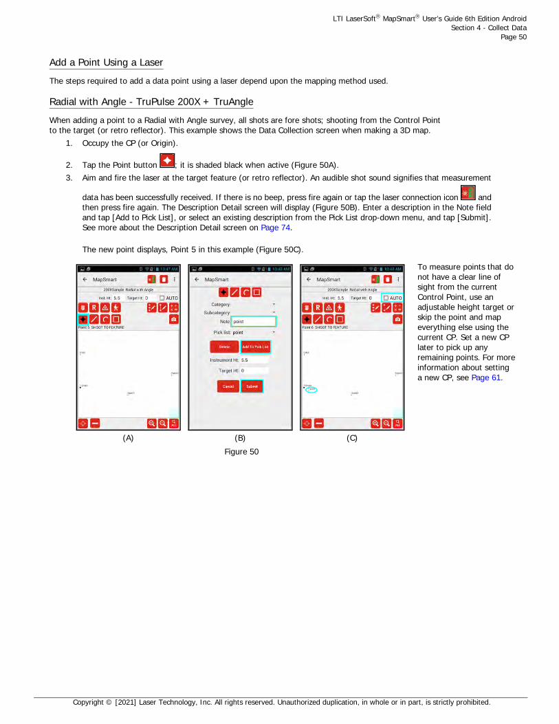
LTI LaserSoft MapSmart User’s Guide 6th Edition AndroidSection 4 - Collect Data
Page 50
Copyright © [2021] Laser Technology, Inc. All rights reserved. Unauthorized duplication, in whole or in part, is strictly prohibited.
Add a Point Using a Laser The steps required to add a data point using a laser depend upon the mapping method used.
Radial with Angle - TruPulse 200X + TruAngle When adding a point to a Radial with Angle survey, all shots are fore shots; shooting from the Control Point to the target (or retro reflector). This example shows the Data Collection screen when making a 3D map.
1. Occupy the CP (or Origin).
2. Tap the Point button ; it is shaded black when active (Figure 50A).3. Aim and fire the laser at the target feature (or retro reflector). An audible shot sound signifies that measurement
data has been successfully received. If there is no beep, press fire again or tap the laser connection icon and then press fire again. The Description Detail screen will display (Figure 50B). Enter a description in the Note field and tap [Add to Pick List], or select an existing description from the Pick List drop-down menu, and tap [Submit]. See more about the Description Detail screen on Page 74.
The new point displays, Point 5 in this example (Figure 50C).
(A) (B) (C)
To measure points that do not have a clear line of sight from the current Control Point, use an adjustable height target or skip the point and map everything else using the current CP. Set a new CP later to pick up any remaining points. For more information about setting a new CP, see Page 61.
Figure 50

LTI LaserSoft MapSmart User’s Guide 6th Edition AndroidSection 4 - Collect Data
Page 51
Copyright © [2021] Laser Technology, Inc. All rights reserved. Unauthorized duplication, in whole or in part, is strictly prohibited.
Add a Point Manually If using a tape instead of a laser, data points can be entered manually in MapSmart surveys.
Radial with Angle
1. Tap the ruler icon at the bottom of the screen (Figure 51A).2. Enter the HD value measured with a tape and the ANG value as displayed on the
TruAngle when aiming at the target using the onscreen keyboard. Tap [OK] (Figure 51B).3. Enter a description in the Note field and tap [Add to Pick List] (or select an existing
description from the Pick List drop-down menu) and tap [Submit] (Figure 51C).4. The new point displays, Point 6 in this example (Figure 51D).
NOTE Refer to the conversion chart in Appendix B (Page 125) to equate fractional inches shown on a measuring tape to feet (the decimal equivalent required by MapSmart). The conversion chart is also available within MapSmart's built-in help (Page 18).
(A) (B) (C) (D) Figure 51

LTI LaserSoft MapSmart User’s Guide 6th Edition AndroidSection 4 - Collect Data
Page 52
Copyright © [2021] Laser Technology, Inc. All rights reserved. Unauthorized duplication, in whole or in part, is strictly prohibited.
Radial with Azimuth1. Tap the Ruler icon at the bottom of the screen (Figure 52A). 2. Enter the HD value measured with a tape.3. Aim and fire the laser at the target to capture the azimuth value (Figure 52B). The AZ field
will automatically populate with the azimuth value from the laser. Tap [OK] (Figure 52C).4. Enter a description in the Note field and tap [Add to Pick List] or select an existing description
from the Pick List drop-down menu) and tap [Submit] (Figure 52D).5. The new point displays, Point 5 in this example (Figure 52E).
NOTE Refer to the conversion chart in Appendix B (Page 137) to equate fractional inches shown on a measuring tape to feet (the decimal equivalent required by MapSmart). The conversion chart is also available within MapSmart'sbuilt-in help (Page 18).
Range Triangulation & Baseline OffsetManual measurement entry works the similarly to the Radial with Angle method as described above. Instead of HD and ANG as entry options, HD and INC display. INC can be left as “0” if it is not known and a height for the measurement can be edited later on. Manual measurement entry works for either the first or second measurement required to log a data point using the Range Triangulation or Baseline Offset mapping methods.
(A) (B) (C)
(E) (E) Figure 52

LTI LaserSoft MapSmart User’s Guide 6th Edition AndroidSection 4 - Collect Data
Page 53
Copyright © [2021] Laser Technology, Inc. All rights reserved. Unauthorized duplication, in whole or in part, is strictly prohibited.
Add Points to a Saved Survey It is possible to revisit a scene and add data points to an existing survey. The steps to complete this process differ slightly depending on the equipment combination in use. The following steps assume that you have left a nail (or some other target) at your instrument position(s) and reference; or Origin; or CPs, when the original survey was mapped.NOTE To verify that you have correctly re-entered the survey, shoot in a point that was mapped in the original survey. The new point should be on top of or very close to the point shot in the original survey."
Radial with Angle Method - TruPulse 200X or TruSpeed Sxb + TruAngle
1. Set up on the last instrument position occupied when the original survey was mapped.2. Power on all equipment.3. Open QuickMap and tap [Saved Surveys].4. Zero the TruAngle:
a. If there was only one instrument position in the survey (the Origin), aim the laser at the original reference point for the survey and zero the TruAngle on that point.
b. If there was more than one instrument position in the survey, aim the laser at the previous instrument position (not the original reference) and zero the TruAngle on that point. NOTE For help with zeroing a TruAngle, see Page 28.
5. Begin adding new data points to the survey.
Baseline Offset Method -TruPulse 200X, TruSpeed Sxb or TruPoint 200h
1. Set up a target on the Origin point used when the original survey was mapped.2. Place the laser along the same Baseline used in the original survey.3. Power on all equipment.4. Open QuickMap and tap [Saved Surveys].5. Begin adding new data points to the survey.
Range Triangulation Method -TruPulse 200X, TruSpeed Sxb or TruPoint 200h
1. Set up targets on the exact same CP1 and CP2 points used when the original survey was mapped. NOTE Be sure to measure the Target Height on CP1.
2. Power on all equipment.3. Open QuickMap and tap [Saved Surveys].4. Begin adding new data points to the survey.

LTI LaserSoft MapSmart User’s Guide 6th Edition AndroidSection 4 - Collect Data
Page 54
Copyright © [2021] Laser Technology, Inc. All rights reserved. Unauthorized duplication, in whole or in part, is strictly prohibited.
Add a Point Using GPS Only Radial with Angle/Radial with Azimuth/Range Triangulation only. GPS is not available for the Baseline Offset mapping method.
1. Position the Android device (or external GPS device) directly over the Origin Point.
2. Tap the GPS Point icon (Figure 53A). 3. Tap [Start Fix] to begin searching for satellites (Figure 53B). MapSmart will report the number of satellites found
and the HRMS value. Enter an Antenna Ht. (the height above the ground of your Android device or external GPS antenna. GPS coordinate information will continue to update every time a lower HRMS value is detected. When the displayed value is acceptable, tap [Save] to lock the position (Figure 53C).
What is HRMS? HRMS is the horizontal distance from the truth within which at least 63% of the recorded positions fall. Using a higher accuracy GPS device delivers a smaller HRMS. Smaller HRMS equals more accurate data.
4. <optional> Enter a description in the Note field and tap [Add to Pick List] (or select an existing description from the Pick List drop-down menu) and tap [Submit] (Figure 53D).
5. The new point displays, Point 2 in this example (Figure 53E).
(A) (B) (C)
(D) (E) Figure 53

LTI LaserSoft MapSmart User’s Guide 6th Edition AndroidSection 4 - Collect Data
Page 55
Copyright © [2021] Laser Technology, Inc. All rights reserved. Unauthorized duplication, in whole or in part, is strictly prohibited.
Add a Line Feature
1. Tap the Line button (Figure 54A).2. Aim and fire the laser at the target or CPs, depending on which method you’re using. 3. The first shot to a new Line feature will bring up the Description Detail screen and you are required
to enter a new Feature Name or pick one from the list. Tap [Submit].NOTE AUTO mode may now be used to add points to the same Line without seeing Description Detail screen
4. The new line data point displays. In this example, the line includes Point 3 (Figure 54C) and then Point 4 was added (Figure 54D).
Important notes about adding line features:• Data points that make up the line feature must be added in sequential order.• To insert a data point out of order, add it as a point feature and then use
the Edit Point option to change the feature type from point to line (Page 76).
(A) (B) (C) (D) Figure 54

LTI LaserSoft MapSmart User’s Guide 6th Edition AndroidSection 4 - Collect Data
Page 56
Copyright © [2021] Laser Technology, Inc. All rights reserved. Unauthorized duplication, in whole or in part, is strictly prohibited.
Add a Curve Feature
1. Tap the Curve button (Figure 55A).2. Aim and fire the laser at the target or CPs, depending on which method you’re using. 3. The first shot to a new Curve feature will bring up the Description Detail screen and you are required
to enter a new Feature Name or pick one from the list. Tap [Submit].NOTE AUTO mode may now be used to add points to the same Curve without seeing Description Detail screen
4. The new curve data point displays, Point 3 in this example (Figure 55C).5. As the rest of the curve is mapped, it displays as shown in Figure 55D and Figure 55E.
(A) (B) (C) (D)
(E)
Important notes about adding curve features:
• Data points that make up the curve feature must be added in sequential order.• To insert a data point out of order, add it as a point feature and then use the Edit
Point option to change the feature type from point to curve (Page 77).• Keep in mind that the Data Collection screen is a dynamic display. As data
points are added, the curve's appearance may change. Due to physical limitations of the, curves may appear more jagged than expected.
Figure 55

LTI LaserSoft MapSmart User’s Guide 6th Edition AndroidSection 4 - Collect Data
Page 57
Copyright © [2021] Laser Technology, Inc. All rights reserved. Unauthorized duplication, in whole or in part, is strictly prohibited.
Add an Area Feature
1. Tap the Area button (Figure 56A).2. Aim and fire the laser at the target or CPs, depending on which method you’re using. 3. The first shot to a new Area feature will bring up the Description Detail screen and you are required
to enter a new Feature Name or pick one from the list. Tap [Submit].NOTE AUTO mode may now be used to add points to the same Area without seeing Description Detail screen
4. The new area data points (Points 3 and 4 in this example) display (Figure 56C and Figure 56D).5. As the rest of the area is mapped, it displays as shown in Figure 56C-57F.
(A) (B) (C) (D)
(E) (F)
Important notes about adding area features:
• Data points that make up the area feature must be added in sequential order.
• To insert a data point out of order, add it as a point feature and then use the Edit Point option to change the feature type from point to area (Page 77).
Figure 56
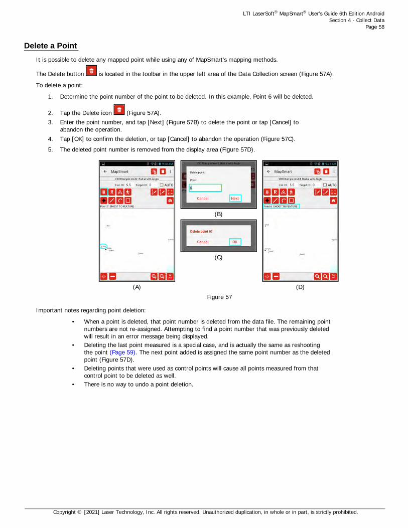
LTI LaserSoft MapSmart User’s Guide 6th Edition AndroidSection 4 - Collect Data
Page 58
Copyright © [2021] Laser Technology, Inc. All rights reserved. Unauthorized duplication, in whole or in part, is strictly prohibited.
Delete a Point
It is possible to delete any mapped point while using any of MapSmart's mapping methods.
The Delete button is located in the toolbar in the upper left area of the Data Collection screen (Figure 57A).
To delete a point:
1. Determine the point number of the point to be deleted. In this example, Point 6 will be deleted.
2. Tap the Delete icon (Figure 57A).3. Enter the point number, and tap [Next] (Figure 57B) to delete the point or tap [Cancel] to
abandon the operation.4. Tap [OK] to confirm the deletion, or tap [Cancel] to abandon the operation (Figure 57C).5. The deleted point number is removed from the display area (Figure 57D).
Important notes regarding point deletion:
• When a point is deleted, that point number is deleted from the data file. The remaining point numbers are not re-assigned. Attempting to find a point number that was previously deleted will result in an error message being displayed.
• Deleting the last point measured is a special case, and is actually the same as reshooting the point (Page 59). The next point added is assigned the same point number as the deleted point (Figure 57D).
• Deleting points that were used as control points will cause all points measured from that control point to be deleted as well.
• There is no way to undo a point deletion.
(A)
(B)
(C)
(D) Figure 57

LTI LaserSoft MapSmart User’s Guide 6th Edition AndroidSection 4 - Collect Data
Page 59
Copyright © [2021] Laser Technology, Inc. All rights reserved. Unauthorized duplication, in whole or in part, is strictly prohibited.
Re-shoot a Point
There are two ways to re-shoot a if something went wrong when the point was measured the first time.
Reshoot Last Point
The Reshoot button is located in the toolbar in the upper left area of the Data Collection screen (Figure 58) in all mapping methods. To re-shoot a point other than the last point measured, see Page 74. To re-shoot an established point:
1. Tap the Reshoot button (Figure 58A). Notice the [Cancel Reshoot] button has displayed, tap this button to abandon the operation at any time.
2. Follow the prompts in the Instruction Line (located below the toolbar above the display area) as you walk through re-shooting the point. For Baseline/Range surveys, two measurements must be taken to reshoot the last point.
3. The point number of the last shot taken will have the updated measurement assigned to it.
While using the Baseline Offset or Range Triangulation mapping methods, it is a common mistake to begin to execute the measurement without having moved the equipment position. Typically, this mistake is realized after taking the first shot of the 2-shot routine. It is possible to re-shoot JUST the first shot in the routine before the measured point exists on the map.
To re-shoot the first shot of the 2-measurement routine in a Baseline or Range survey:
1. After taking the first shot, to Origin in Baseline or to CP1 in Range, tap the Reshoot (1) button (Figure 58B).Move the equipment to the intended position, if necessary.
2. The Instruction Line directs to re-shoot to the Origin or to CP1 depending on what mapping method you are using. Take the measurement and then continue to take the 2nd shot in the routine to place the point on the map.
Reshoot Any Point:
(A) (B) Figure 58
1. Tap the Menu button on the Data Collection screen.
2. Select Point Detail from the drop-down list (Figure 59A). For devices with finer resolutions,
tap the Point Detail icon located at the top of the screen.
3. Select the point to re-shoot using the arrows of the Go To: field (Figure 59B).
4. Tap Reshoot icon to return to the Data Collection screen and reshoot the selected point number.
Radial with Angle: 1 measurement to the target will complete the reshoot.
Range Triangulation or Baseline Offset: 2 measurements will complete the reshoot. Range: CP1 & CP2. Baseline: Origin & Feature.
Select Point Detailor
Tap the icon at top of screen(A)
(B) Figure 59
Instruction Line Instruction Line

LTI LaserSoft MapSmart User’s Guide 6th Edition AndroidSection 4 - Collect Data
Page 60
Copyright © [2021] Laser Technology, Inc. All rights reserved. Unauthorized duplication, in whole or in part, is strictly prohibited.
Add a Photo From the Android device Camera, one or more photos may be added to each data point as it is measured. After adding
a data point to the survey, use the Camera icon to take a photo(s) of the evidence. Photos are stored in the folder with the survey reports and named to match the description of the data point. If more than one photo is taken, a (2), (3), etc. is placed after the photo description.
1. Tap the Camera icon on the Data Collection screen (Figure 60A).2. Aim/zoom to evidence (Figure 60B), and press the blue button at the bottom of the screen
to capture an image.3. Tap the checkmark icon in the lower right corner of the screen to accept the image.
If necessary, the image can be retaken.4. When prompted, tap [OK] to add another picture associated with the most recent measurement taken
or tap [Cancel] to return to the MapSmart Data Collection screen and continue mapping (Figure 60C).
NOTE These steps reflect the procedure for taking a photo when using the CT7 ruggedized tablet. If using a different Android device, steps 2 and 3 will be similar but may differ slightly from how they work on the CT7.
(A) (B) (C) Figure 60

LTI LaserSoft MapSmart User’s Guide 6th Edition AndroidSection 4 - Collect Data
Page 61
Copyright © [2021] Laser Technology, Inc. All rights reserved. Unauthorized duplication, in whole or in part, is strictly prohibited.
Move to a New Position
At times, when mapping an area, there is not visibility to every feature in the area from the Origin (initial control point). When it becomes necessary to move the equipment position, it can be done in two ways:
Radial with Angle - TruPulse 200X + TruAngle To assign a new Control Point:
1. If it doesn't already exist, create a point feature for the position to which you want to move.
2. Tap the Control Point icon (Figure 61A).3. Enter the point number for the new control point and tap [Next].
In this example, point 10 was selected (Figure 61B).4. Leave a target at the original equipment position, re-position and level equipment at the
new control point, double check instrument height and adjust if necessary.5. Aim at the original equipment position (that you moved from), and zero the TruAngle. Aim the laser at the original
CP, tighten down the brake, and press the Zero button on the TruAngle. The TruAngle display will show 0.00. Tap [OK] (Figure 61C). This step is imperative for keeping data points measured from the original position correctly related to the data points mapped from the new position.
6. Notice that point 1 now displays with a small square, and data point 10 (the new control point) now displays with the large square (Figure 61D).
NOTE When moving/traversing forward in a survey, always zero on the point you left from with one exception: Re-occupying Point 1 (the Origin) in a survey after having moved to one or more other CPs, use the Triangle icon to select Point 1, move back to Point 1, and then zero the TruAngle on the original reference for the survey (not on the point you left from when you returned to Point 1).
(A) (B) (C) (D) Figure 61

LTI LaserSoft MapSmart User’s Guide 6th Edition AndroidSection 4 - Collect Data
Page 62
Copyright © [2021] Laser Technology, Inc. All rights reserved. Unauthorized duplication, in whole or in part, is strictly prohibited.
Radial with Azimuth To assign a new Control Point:
1. If it doesn't already exist, create a point feature for the position to which you want to move.
2. Tap the Control Point icon (Figure 62A).3. Enter the point number for the new control point and tap [Next]. In this example, point 5 was selected (Figure 62B).4. Leave a target at the original equipment position, re-position and level equipment at the new control point, double
check instrument height and adjust if necessary.5. Notice that point 1 now displays with a small square, and data point 5 (the new control point) now displays with
the large square (Figure 62C). Point 5 is now the control point for the survey. For 3D surveys, verify the instrument height in the new position, and edit the Inst. Ht: field at the top of the Data Collection screen, if necessary, before continuing to take measurements.
(A) (B) (C) Figure 62

LTI LaserSoft MapSmart User’s Guide 6th Edition AndroidSection 4 - Collect Data
Page 63
Copyright © [2021] Laser Technology, Inc. All rights reserved. Unauthorized duplication, in whole or in part, is strictly prohibited.
To create a new control point:
1. Tap the Create Control Point icon (Figure 63A).2. Enter the target height for the new control point. The default note is CP, but can be changed.
Aim at the new control point and fire the laser (using remote fire or by pressing the FIRE button) and tap [Next] (Figure 63B).
3. Leave a target at the original equipment position, re-position and level equipment at the new control point, double check instrument height and adjust if necessary. Tap [OK] (Figure 63C).
4. Notice that a new CP (point 4) now displays with a large square, and data point 1 (the original control point) now displays with the small square (Figure 63D). Point 4 is now the control point for the survey.
NOTE A good way to verify that the new control point was correctly set is to measure a feature that was measured from the previous position to create a second point for that feature. If the move was successfully achieved, the two points will display directly on top of each other or very near to it. Open Traverse (Page 92) and Closed Traverse (Page 91) calculations can also be performed to check accuracy.
(A) (B) (C) (D) Figure 63

LTI LaserSoft MapSmart User’s Guide 6th Edition AndroidSection 4 - Collect Data
Page 64
Copyright © [2021] Laser Technology, Inc. All rights reserved. Unauthorized duplication, in whole or in part, is strictly prohibited.
Range Triangulation To assign a new CP1 or CP2:
1. If it doesn't already exist, create a point feature for the position to which you want to move.
2. Tap the Assign Control Point icon (Figure 64A) for CP1 or CP2 depending on which of the control points you want to move.
3. Enter the point number for the new control point and tap [Next]. In this example, point 3 was selected (Figure 64B).
4. Move the target for CP2 to the new position, verify the target height and adjust if necessary (Figure 64C).5. Notice that the line that once connected points 1 and 2 now connect points 2 and 3.
Point 3 has been successfully reassigned to CP2 (Figure 64D).
NOTE A good way to verify that the new control point was correctly set is to measure a feature that was measured from the previous position to create a second point for that feature. If the move was successfully achieved, the two points will display directly on top of each other or very near to it.
Baseline Offset Moving control points does not apply to the Baseline Offset mapping method. The Origin is the only CP and it is fixed.
(A) (B) (C) (D) Figure 64

LTI LaserSoft MapSmart User’s Guide 6th Edition AndroidSection 4 - Collect Data
Page 65
Copyright © [2021] Laser Technology, Inc. All rights reserved. Unauthorized duplication, in whole or in part, is strictly prohibited.
About Target/Instrument Height
It may become necessary to change the value for the Target Height. Each of the data collection methods includes a Target Height value which was entered on the New File Settings screen (Page 30) when the survey was created. The table below lists the Target Height value associated with each data collection method.
It may also become necessary to edit the Instrument Height (Page 32).
To change a Target or Instrument Height:
Although Target and Instrument heights are set on the New File Settings screen during file setup, they can be changed prior to each measurement on the Data Collection screen. If changed, the new height(s) will be carried through for the remainder of measurements in the map unless it is changed back by the user.
• If an existing data point is using an incorrect height value, the incorrect value may be edited using the MapSmart Menu option for Point Detail (Page 74).
• If a series of data points is using an incorrect height, the incorrect value may be edited by tapping the Edit Point Series icon on the Data Collection screen (Page 76).
• If a Feature is using an incorrect height value, the incorrect value may be edited using the Edit Feature icon on the Data Collection screen (Page 77).
Data Collection Method Target Height Options
Radial with Angle 3D Target Height
Radial with Azimuth 3D Target Height
Range Triangulation 3D CP1 & CP2 Target Height
Baseline Offset 3D Origin & Feature Height

LTI LaserSoft MapSmart User’s Guide 6th Edition AndroidSection 5 - Review Data
Page 66
Copyright © [2021] Laser Technology, Inc. All rights reserved. Unauthorized duplication, in whole or in part, is strictly prohibited.
Section 5 - Review DataAfter measurements have been taken, MapSmart can display file properties, the collected raw measurements, XYZ or GPS coordinates, associated heights and missing lines, and photos for each data point. In this section, find out how to review measurement data, turn plot labels and notes on and off and to zoom the Data Collection screen.
File Properties
To see a quick view of the survey properties, tap the Menu button , and then choose File Properties (Figure 65A). The survey properties display (Figure 65B). Tap OK to clear the survey properties window.
(A) (B) Figure 65

LTI LaserSoft MapSmart User’s Guide 6th Edition AndroidSection 5 - Review Data
Page 67
Copyright © [2021] Laser Technology, Inc. All rights reserved. Unauthorized duplication, in whole or in part, is strictly prohibited.
Point Detail
Use Point Detail to access raw measurement data, description info, a map view that displays XYZ/GPS coordinates for individual points, and/or the coordinate table for the survey.
Navigate Point DetailTo open and navigate Point Detail:
1. Tap the Menu button on the Data Collection screen (Figure 66A).2. Select Point Detail from the drop-down list (Figure 66B). For devices with finer resolutions, tap the
Point Detail icon located at the top of the screen.3. The Point Detail - Raw Data screen displays (Figure 66C). Point Detail includes modular functionality, which means
that the Description, Map View and Coordinate Table screens are displayed by swiping to the left.4. From the Raw Data screen, swipe to the left one time to display the Description screen (Figure 66D).5. From the Description screen, swipe to the left one time to display the Map View screen (Figure 66E).6. From the Map View screen, swipe to the left one time to display the Coordinate Table screen (Figure 66F).
(A)
Select Point Detailor
Tap the icon at top of screen(B)
(C)
(D) (E) (F) Figure 66

LTI LaserSoft MapSmart User’s Guide 6th Edition AndroidSection 5 - Review Data
Page 68
Copyright © [2021] Laser Technology, Inc. All rights reserved. Unauthorized duplication, in whole or in part, is strictly prohibited.
Field / Icon DescriptionPoint: Indicates which data point is currently selected. Information displayed on the
Raw Data, Description, and Map View screens is associated with the selected point.
GO TO: Choose a new data point for which to review values. Enter the data point in the GO TO field and then tap the checkmark icon to the right of the entry field to confirm. Double check that the new point number was selected by ensuring that it is listed as the Point: (X) in the upper left corner of the screen.
Tap to delete the current selected data point. A prompt to confirm the deletion will display so the deletion may be accepted or canceled (Page 58).
Tap to reshoot the current selected data point. The Data Collection screen will display with instruction line prompting to reshoot (or manually re-enter) the data point (Page 59).
Tap to display the Description Detail screen (Page 74) and edit the note description, feature type, or height for any data point.
Tap to edit heights for a group of points or to change a group of points into a feature.
Skips to the last measured data point in the survey file.
Moves to the next data point in the survey file.
Moves to the previous data point in the survey file.
Skips to the first data point in the survey file (the CP or Origin).
Tap the back arrow in the upper left corner of the Point Detail screen to leave Point Detail and return to the Data Collection screen.
Tap to change the orientation of the current selected data point from left to right or fore to back or vice versa in Range Triangulation, Baseline Offset, or Radial with Azimuth surveys. This icon is not available for Radial with Angle surveys.
NOTE If a measured point has any images associated with it, those images will appear in a list at the bottom of the Description screen in Point Detail (Figure 67).
• A long-press of the image name will bring up a full resolution view of the image.
• Tap [Delete] to remove the image from the data file, or tap [OK] to keep it.
Figure 67

LTI LaserSoft MapSmart User’s Guide 6th Edition AndroidSection 5 - Review Data
Page 69
Copyright © [2021] Laser Technology, Inc. All rights reserved. Unauthorized duplication, in whole or in part, is strictly prohibited.
Display Tabular Data The Point Detail Coordinate Table screen includes the point number, XYZ coordinate, and Note (if any) for each data point in an open survey in a tabular format.
To access the Coordinate Table screen:
1. Tap the Menu button on the Data Collection screen (Figure 68A).2. Select Point Detail from the drop-down list (Figure 68B). For devices with finer resolutions, tap the
Point Detail icon located at the top of the screen.3. The Point Detail - Raw Data screen displays. Point Detail includes modular functionality, which means
that the Description, Map View and Coordinate Table screens are displayed by swiping to the left.4. From the Raw Data screen, swipe to the left three times to display the Coordinate Table screen (Figure 68C).
NOTE To see continued data not available in the initial view, scroll down by tapping near the bottom of the Shot Table screen and swiping upward.
(A)
Select Point Detailor
Tap the icon at top of screen(B) (C)
Figure 68

LTI LaserSoft MapSmart User’s Guide 6th Edition AndroidSection 5 - Review Data
Page 70
Copyright © [2021] Laser Technology, Inc. All rights reserved. Unauthorized duplication, in whole or in part, is strictly prohibited.
Display Raw Data The Point Detail Raw Data screen displays measurement and description data assigned to each individual data point in an open survey. Data points may be reviewed, deleted, re-shot, and/or edited from this screen.To access the Raw Data screen:
1. Tap the Menu button on the Data Collection screen (Figure 69A).2. Select Point Detail from the drop-down list (Figure 69B). For devices with finer resolutions, tap the
Point Detail icon located at the top of the screen.3. The Point Detail - Raw Data screen displays (Figure 69C). Point Detail includes modular functionality, which
means that the Description, Map View, and Coordinate Table screens are displayed by swiping to the left.
The Point Detail - Raw Data screen displays differently depending on the mapping method selected when the survey was created. Here is a sample of the Raw Data screen for each mapping method:
NOTE To change the current selected point number in order to view the raw data values for a different point number,
enter the desired point number in the GO TO: field and tap the checkmark . The Point indicator in the upper left corner of the screen will display the current selected point number. Also, the up and down arrows can be used to navigate to other data points in the survey. For Radial with Azimuth, Range Triangulation and Baseline Offset surveys, the Flip Point icon also displays on this screen so a data point's orientation may be changed from left to right/fore to back or vice versa.
(A)
Select Point Detailor
Tap the icon at top of screen(B) (C)
Figure 69
Radial with Angle Radial with Azimuth Range Triangulation Baseline Offset
Figure 70

LTI LaserSoft MapSmart User’s Guide 6th Edition AndroidSection 5 - Review Data
Page 71
Copyright © [2021] Laser Technology, Inc. All rights reserved. Unauthorized duplication, in whole or in part, is strictly prohibited.
Display Map View The Point Detail Map View screen displays the survey plot and the XYZ coordinates of each data point in an open survey. Data points may be reviewed, deleted, re-shot, and/or edited from this screen.
To access the Map View screen:
1. Tap the Menu button on the Data Collection screen (Figure 71A).2. Select Point Detail from the drop-down list (Figure 71B). For devices with finer resolutions, tap the
Point Detail icon located at the top of the screen.3. The Point Detail - Raw Data screen displays. Point Detail includes modular functionality, which means
that the Description, Map View, and Coordinate Table screens are displayed by swiping to the left.4. From the Raw Data screen, swipe to the left two times to display the Map View screen (Figure 71C).
NOTE To change the current selected point number in order to view the XYZ/GPS values for a different
point number, enter the desired point number in the GO TO: field and tap the checkmark . The Point indicator in the upper left corner of the screen will display the current selected point number. Also, the up and down arrows can be used to navigate to other data points in the survey. For Radial with Azimuth, Range Triangulation and Baseline Offset surveys, the Flip Point icon also displays on this screen so a data point's orientation may be changed from left to right/fore to back or vice versa.
(A)
Select Point Detailor
Tap the icon at top of screen(B) (C)
Figure 71

LTI LaserSoft MapSmart User’s Guide 6th Edition AndroidSection 5 - Review Data
Page 72
Copyright © [2021] Laser Technology, Inc. All rights reserved. Unauthorized duplication, in whole or in part, is strictly prohibited.
Display Description The Point Detail Description screen displays the feature type, feature name, category/subcategory assignment, note, height, or missing line (width) applied to each data point in an open survey. Depending on the feature used and options utilized, data points may be reviewed, deleted, re-shot, and/or edited from this screen.
To display the Description screen:
1. Tap the Menu button on the Data Collection screen (Figure 72A).2. Select Point Detail from the drop-down list (Figure 72B). For devices with finer resolutions, tap the
Point Detail icon located at the top of the screen.3. The Point Detail - Raw Data screen displays. Point Detail includes modular functionality, which
means that the Description, Map View, and Coordinate Table screens are displayed by swiping to the left.4. From the Raw Data screen, swipe to the left one time to display the Description screen (Figure 72C).
NOTE To change the current selected point number in order to view the descriptions/attributes for a
different point number, enter the desired point number in the GO TO: field and tap the checkmark . The Point indicator in the upper left corner of the screen will display the current selected point number. Also, the up and down arrows can be used to navigate to other data points in the survey. For Radial with Azimuth, Range Triangulation and Baseline Offset surveys, the Flip Point icon also displays on this screen so a data point's orientation may be changed from left to right/fore to back or vice versa.
(A)
Select Point Detailor
Tap the icon at top of screen(B) (C)
Figure 72

LTI LaserSoft MapSmart User’s Guide 6th Edition AndroidSection 5 - Review Data
Page 73
Copyright © [2021] Laser Technology, Inc. All rights reserved. Unauthorized duplication, in whole or in part, is strictly prohibited.
Zoom Options
Any time a survey is open, the view of the Data Collection screen display area can be changed using zoom functionality.Use touch zoom functionality to zoom into and out of the display area. Touch and drag to pan. Icons are also available for zooming when using the stylus (or if wearing gloves). Zoom icons are located in the lower right corner of the Data Collection screen (Figure 73A).
Zoom Icon Descriptions
Zoom In Tap to magnify the current view, thus creating a smaller view of the survey area (Figure 73B).
(A) (B)
Zoom Out Tap to reduce the current view, thus creating a larger view of the survey area. This feature does not zoom farther away than the full view of the survey area.
Zoom All Tap to reset the display area to the default, 100% full map view.
Figure 73

Copyright © [2021] Laser Technology, Inc. All rights reserved. Unauthorized duplication, in whole or in part, is strictly prohibited.
LTI LaserSoft MapSmart User’s Guide 6th Edition AndroidSection 6 - Edit Data
Page 74
Section 6 - Edit DataAny data point in an open survey can be edited at any time. Data points can be edited individually or as a group if it becomes necessary to change data point heights for more than just one point. The measured data points adjust to any height changes.
Edit a Data Point
Individual data points are edited via the Point Detail screen. From the Point Detail Raw Data, Map View, or
Description screens, tap the Edit Point icon to bring up the Description Detail screen, from which all changes to selected data points can be made. Figure 74 shows the Description Detail screen as it appears in each mapping method.
Radial with AngleRadial with Azimuth Range Triangulation Baseline Offset
Figure 74
Continued on Next Page

Copyright © [2021] Laser Technology, Inc. All rights reserved. Unauthorized duplication, in whole or in part, is strictly prohibited.
LTI LaserSoft MapSmart User’s Guide 6th Edition AndroidSection 6 - Edit Data
Page 75
To edit an individual data point, access the Point Detail screen (Page 67): 1. With the Point Detail Raw Data, Map View
or Description screen displayed, select the data point to be edited using the GO TO field or the navigation arrows. The Point indicator in the upper left corner of the screen displays the current selected data point. In this example, Point 5 is selected.
2. Tap the Edit Point icon (Figure 75A) and the Description Detail screen displays (Figure 75B).
(A) (B) Figure 75
From the Description Detail screen, the following changes can be made to the selected data point:
• Change the Feature Type The current assigned feature type for the data point is highlighted in black. Tap the feature type it should be changed to in order to reassign the data point. See Page 78 for more detail.
• Change the Feature Name Enter a new name in the field. This option is only available for line, curve or area feature data points.
• Change the Category or Subcategory assignment Tap the drop-down lists to view the options and choose a new or different assignment.
• Change the Note Type the new note in the note field or select an existing note from the Pick List.
• Change Heights To adjust the Instrument Height, Target Height, Origin Height, CP Height or Feature Height for the data point, enter a new value into the relevant field.
NOTE Height options available on this screen depend on the mapping method selected when the map was created.
3. Tap [Submit] to save the changes or [Cancel] to forget them and return to the Data Collection screen.

Copyright © [2021] Laser Technology, Inc. All rights reserved. Unauthorized duplication, in whole or in part, is strictly prohibited.
LTI LaserSoft MapSmart User’s Guide 6th Edition AndroidSection 6 - Edit Data
Page 76
Edit a Point Series
The Edit Point Series function allows for the editing of height values associated with one or more data points. Additionally, a series of points may be converted to a line, curve or area feature (or to pile, base or projected base shots if using the Volume with Angle or Volume with Azimuth mapping method). The appearance of the Edit Point Series screen varies depending on the mapping method selected when the survey was created. Figure 76 shows the Edit Point Series screen as it appears in each mapping method.
To use the Edit Point Series function:
1. With a survey file open, tap the Edit Point Series icon on the Data Collection screen or on the Point Detail Raw Data or Description screens (Figure 77A).
2. Enter the start point number and the end point number of the series of data points to be edited (Figure 77B). If adjusting the height of just one data point, enter the same point number in the Start and End point fields.
3. Enter the new height value in the applicable field(s). The fields depend on the mapping method selected when the survey file was created. The survey in this example was done with the Radial with Angle mapping method.
4. Create a feature out of the series of points by selecting the line, curve, or area icon. If using the Volume with Angle or Volume with Azimuth mapping method, the “Change all to:” option lets you convert a series of points to Base, Projected Base, or Pile shots.
5. Tap [Submit] to save the changes, or tap [Cancel] to abandon the operation and return to the Data Collection screen.
Radial with Angle /Radial with Azimuth Range Triangulation Baseline Offset
Volume with Angle / Radial with Azimuth
Figure 76
(A) (B)
NOTE The Edit Point Series function is typically used to correct heights when the retro reflector, instrument height or other targets had been raised or lowered and the new target height had not been entered on the Data Collection screen at the time the measurements were taken. If unsure of the start and end point numbers, review the Point Detail Coordinate Table (Page 69) to help figure out what they are (by note description or measurement value, if necessary).
Figure 77

Copyright © [2021] Laser Technology, Inc. All rights reserved. Unauthorized duplication, in whole or in part, is strictly prohibited.
LTI LaserSoft MapSmart User’s Guide 6th Edition AndroidSection 6 - Edit Data
Page 77
Edit a Feature
The Edit Feature function allows for the editing of height values associated with all data points assigned to a specific feature. The appearance of the Edit Feature screen varies depending on the mapping method selected when the survey was created. Figure 78 shows the Edit Feature screen as it appears in each mapping method.
To use the Edit Feature function:
1. With a survey file open, tap the Edit Feature icon on the Data Collection screen (Figure 79A).2. Select the feature name to be edited (Figure 79B). The drop down list will include all features that
have been added to the survey by Feature name and Note as “Feature name”: “Note”.3. Enter the new height value in the applicable field(s). The fields depend on the mapping method
selected when the survey file was created. The survey in this example was done with the Radial with Angle mapping method (Figure 79C).
4. Tap [Submit] to save the changes, or tap [Cancel] to abandon the operation and return to the Data Collection screen.
NOTE The Edit Feature function is typically used to correct heights when the retro reflector, instrument height or other targets had been raised or lowered and the new target height had not been entered on the Data Collection screen at the time the measurements were taken. It allows for the target heights of all data points within the feature to be adjusted at one time.
Radial with AngleRadial with Azimuth Range Triangulation Baseline Offset
Figure 78
(A) (B) (C) Figure 79

Copyright © [2021] Laser Technology, Inc. All rights reserved. Unauthorized duplication, in whole or in part, is strictly prohibited.
LTI LaserSoft MapSmart User’s Guide 6th Edition AndroidSection 6 - Edit Data
Page 78
Change the Feature TypeData points that make up a line, curve, or area feature must be added in sequential order. If a data point is missed during a sequential measurement, it is possible to add the data point out of order by changing the feature type. Data points of any feature type can be changed to any other feature type at any time.
To change the feature type of a data point:
1. Tap the MapSmart Menu in the upper right corner of the Data Collection screen (Figure 80A) and then select Point Detail.
2. The Point Detail - Raw Data screen displays (Figure 80B). If the data point you want to change wasnot the last data point you added to the survey, enter the data point number in the GO TO field and
tap the Checkmark button . Verify that the current selected point (listed as "Point: X" in the upper leftarea of the screen) is the point number for the data point you want to change. For this example, point 5 will bechanged from a point feature to a line feature.
3. Tap the Edit Point icon (Figure 80B) and the Description Detail screen will display (Figure 80C). Notice that the Point Feature type is shaded black - the reason for this is that “Point” is the current feature type of the data point that will be changed in this example.
(A) (C)(B) Figure 80
Continued on Next Page

Copyright © [2021] Laser Technology, Inc. All rights reserved. Unauthorized duplication, in whole or in part, is strictly prohibited.
LTI LaserSoft MapSmart User’s Guide 6th Edition AndroidSection 6 - Edit Data
Page 79
4. Tap the Line feature icon (Figure 81A).5. The Connect Point screen displays (Figure 81B). Select a connection type and tap [Submit].
In this example, Point 5 is being inserted between Point 2 and Point 3. Choose one of the available options for connection:
• Beginning Select this option to connect the new data point in the feature group to the beginning of the feature.
• End Select this option to connect the new data point in the feature group to the end of the feature.
• Insert Select this option to connect the new data point in the feature group between two specific data points in the feature.
6. The data point has now been changed from a point feature to a line feature and is included in the line (Figure 81C).
(A) (B) (C) Figure 81

Copyright © [2021] Laser Technology, Inc. All rights reserved. Unauthorized duplication, in whole or in part, is strictly prohibited.
LTI LaserSoft MapSmart User’s Guide 6th Edition AndroidSection 6 - Edit Data
Page 80
Adjust Point Order The order sequence of points in an existing line, curve or area feature can be adjusted.
To adjust the order sequence of points in a feature:
1. With a survey file open, tap the Edit Feature icon on the Data Collection screen (Figure 82A).2. Select the feature to be edited from the Feature name drop-down list, and tap [Adjust Point Order] (Figure 82B).
In this example, point 6 will be moved before point 5 in the sequence to display the proper shape of the “Office” line feature.
3. Tap to highlight the point that needs to be moved. Point 5 in this example (Figure 82C).4. Tap the up or down arrows to move the point to the new position. For this example, Point 5 is moved down below
Point 6. (Figure 82D). As points are moved, the plot will update to display the change.5. Tap [Submit] to accept the change(s) and return to the Data Collection screen. Tap [Reset] to undo all point
moves and try again or tap [Cancel] to abandon the operation.
(A) (B) (C) (D) Figure 82

Copyright © [2021] Laser Technology, Inc. All rights reserved. Unauthorized duplication, in whole or in part, is strictly prohibited.
LTI LaserSoft MapSmart User’s Guide 6th Edition AndroidSection 6 - Edit Data
Page 81
Flip a Data Point
The Flip Point function can be used to change the orientation of a data point for surveys created with the Radial with Azimuth, Range Triangulation or Baseline Offset mapping methods. These mapping methods require assignment of points as Fore shots or Back shots and/or to the left or right of the baseline or the line between CP1 and CP2. If any data point(s) - whether part of a feature or not - was oriented incorrectly, it can be quickly and easily moved to the correct orientation. For more information about defining the orientation of data points, see Page 48.
Flip the Most Recently Added Data Point To flip the data point that was most recently added to a survey (the last shot taken):
1. Tap the Flip Point icon at the bottom center of the Data Collection screen (Figure 83A).2. The last measured data point in the survey will move to the opposite side of the line (Figure 83B).3. In this example, the data point (Point 3) orientation was on the left side of the line joining CP2 to CP1
and was flipped to the right side.
(A) (B)
NOTE To flip the most recently added data point back to its original orientation, tap the
Flip Point icon again.
Figure 83

Copyright © [2021] Laser Technology, Inc. All rights reserved. Unauthorized duplication, in whole or in part, is strictly prohibited.
LTI LaserSoft MapSmart User’s Guide 6th Edition AndroidSection 6 - Edit Data
Page 82
Flip Any Data Point in the Survey To flip any data point in the survey:
1. Tap the Menu button in the upper right corner of the screen (Figure 84A) and select Point Detail.2. The Point Detail - Raw Data screen displays (Figure 84B). If the data point you want to change was not
the last data point you added to the survey, enter the data point number in the GO TO field and tap the
Checkmark button (in this example, Point 2). Verify that the current selected point is the point number for the data point you want to change. Listed as “Point: 2” in the upper left area of the screen (Figure 84C). For this example, Point 2 will be flipped from the left side of the baseline to the right.
3. Tap the Flip Point icon (Figure 84C), and notice that the orientation for the point has changed from left to right (Figure 84D).
4. Tap the back arrow () in the upper left corner of the screen to leave Point Detail and return to the Data Collection screen. Notice that Point 2 has moved from the left to the right side of the baseline (Figure 84A and Figure 84E).
NOTE To flip a data point back to its original orientation, repeat these steps.
(A) (B) (C)
(D) (E) Figure 84

Copyright © [2021] Laser Technology, Inc. All rights reserved. Unauthorized duplication, in whole or in part, is strictly prohibited.
LTI LaserSoft MapSmart User’s Guide 6th Edition AndroidSection 7 - Calculations and Volume
Page 83
Section 7 - Calculations and VolumeMapSmart survey files include the ability to perform various calculations and measurements for Area, Closure, Height, Missing Line, Distance and/or Volume based on data points within the survey. The calculation options displayed on the Calculation Menu depend upon the data collection method used to collect the points. The table below lists the different types of calculations and the data collection methods within which they can be used. The results from the calculations are displayed on screen and may also be saved and appended to report data. For more information about reports, see Section 8 - Reports (Page 108).
Radial with Angle Radial with Azimuth
RangeTriangulation
BaselineOffset
SeePage
DistancePoint to Point 84
Point to Line 85
Area
Area of Traverse N/A N/A 86
Area of Side Shots N/A N/A 87
Area of Non-CP Points N/A N/A 88
Area of All Points 89
Area of Feature 90
ClosureClosed Traverse N/A N/A 91
Open Traverse N/A N/A 92
Volume N/A N/A 94
= option is available in this data collection method.N/A = option is not available in this data collection method.

Copyright © [2021] Laser Technology, Inc. All rights reserved. Unauthorized duplication, in whole or in part, is strictly prohibited.
LTI LaserSoft MapSmart User’s Guide 6th Edition AndroidSection 7 - Calculations and Volume
Page 84
Distance
At any time a survey is open, and the Data Collection screen is displayed, MapSmart can display measurement values for two types of distances:
• Point to Point Distance• Point to Line Distance
Point to Point DistanceTo use the Point to Point Distance feature to display the distance between any two measured data points in a survey:
1. Tap the Calculation Menu icon in the Edit/Measure toolbar in the upper right corner of the Data Collection screen and select Point to Point Distance (Figure 85A). In this example, the distance between points 4 and 10 is calculated.
2. Enter the point number of the first point - the point you are measuring from - and tap [Next] (Figure 85B).3. Enter the point number of the second point - the point you are measuring to - and tap [Next] (Figure 85C).4. The calculated measurements between the two points display (Figure 85D).
• Tap [Save] to save the measurement values to Results (Page 107).• Tap [Close] to close the results window and return to the Data Collection screen.
Explanation of Calculation Results
• SD: Slope Distance (Feet or Meters)• AZ: Angle from the first point to the second point based on the zero reference set when the survey
was started (Degrees)• INC: The inclination from the first point up or down to the second point (Degrees)• HD: Horizontal Distance (Feet or Meters)• VD: Vertical Distance from the first measured point up or down to the second measured point (Feet or Meters)
NOTE Any two data points can be selected, whether they are individual point features or part of a line, curve or area feature.
(A) (B) (C) (D) Figure 85

Copyright © [2021] Laser Technology, Inc. All rights reserved. Unauthorized duplication, in whole or in part, is strictly prohibited.
LTI LaserSoft MapSmart User’s Guide 6th Edition AndroidSection 7 - Calculations and Volume
Page 85
Point to Line Distance To use the Point to Line Distance feature to display the distance between a measured point and a line segment:
1. Tap the Calculation Menu icon in the Edit/Measure toolbar in the upper right corner of the Data Collection screen and select Point to Line Distance (Figure 86A). In this example, the distance between point 3 and the line between points 9 and 8 is calculated.
2. Enter the point number of the first point - the point you are measuring from - and tap [Next] (Figure 86B).3. Enter the point number for the first point in the line that you are measuring to and tap [Next] (Figure 86C).4. Enter the point number for the second point in the line that you are measuring to and tap [Next] (Figure 86D).
The calculated measurements between the two points display (Figure 86E).• An error message will display if a perpendicular line cannot be drawn between the data point and
the line segment.• Tap [Save] to save the measurement values to Results (Page 107).• Tap [Close] to close the results window and return to the Data Collection screen.
MapSmart can calculate the area of five different types of point structures in a survey. Area measurement options vary depending on which method was used to collect the data. Regarding area calculation results: If the survey file is in feet, square feet will be used until 1.00 acre is reached, after which decimal acres will be used. If the file is in meters, square meters will be used until 1.00 hectare is reached, after which decimal hectares will be used.
(A) (B) (C)
(D) (E)
Explanation of Calculation Results
• SDSlope Distance (Feet or Meters)
• AZAngle from the first point to the second point based on the zero reference set when the survey was started (Degrees)
• INCThe inclination from the first point up or down to the second point (Degrees)
• HDHorizontal Distance (Feet or Meters)
• VDVertical Distance from the first measured point up or down to the second measured point (Feet or Meters) Figure 86

Copyright © [2021] Laser Technology, Inc. All rights reserved. Unauthorized duplication, in whole or in part, is strictly prohibited.
LTI LaserSoft MapSmart User’s Guide 6th Edition AndroidSection 7 - Calculations and Volume
Page 86
Area of TraverseMapSmart can calculate the area of a traverse in Radial with Angle or Radial with Azimuth surveys. In order to get a correct calculation, the area of the closed traverse must be bound by the lines that connect each traverse point (Figure 87A). The traverse points must be shot in order in a clockwise or counter-clockwise manner for the area to be calculated correctly. If traverse points are not taken in order (Figure 87B), the traverse will result with lines that intersect each other; therefore, MapSmart cannot calculate a correct area measurement.
To calculate Area of Traverse:
1. From the Data Collection screen, tap the Calculate Menu icon (Figure 88A).2. Tap [Area] (Figure 88B), and then tap [Area of Traverse] (Figure 88C). 3. The Area of Traverse result screen will display (Figure 88D).
In this example, the Area of Traverse is 2,266.45 square feet.• Tap [Save] to save the measurement values to Results (Page 107).• Tap [Close] to close the results window and return to the Data Collection screen.
(A) (B) (C) (D) Figure 88
Figure 87

Copyright © [2021] Laser Technology, Inc. All rights reserved. Unauthorized duplication, in whole or in part, is strictly prohibited.
LTI LaserSoft MapSmart User’s Guide 6th Edition AndroidSection 7 - Calculations and Volume
Page 87
Area of Side Shots MapSmart can calculate an area of side shots in Radial with Angle and Radial with Azimuth surveys. This option calculates the area bound by lines that connect all of the side shots in a map. Remember that the side shots must be taken in sequential order. Figure 89 shows a traverse in which the side shots mark the boundary of a site.
To calculate Area of Side Shots:
1. From the Data Collection screen, tap the
Calculate Menu icon (Figure 90A).2. Tap [Area] (Figure 90B) and then tap [Area of Side Shots] (Figure 90C). 3. The Area of Side Shots Result screen will display (Figure 90D).
In this example, the Area of Side Shots is 185.94 square feet.
• Tap [Save] to save the measurement values to Results (Page 107).• Tap [Close] to close the results window and return to the
Data Collection screen.
(A) (B) (C) (D) Figure 90
Figure 89

Copyright © [2021] Laser Technology, Inc. All rights reserved. Unauthorized duplication, in whole or in part, is strictly prohibited.
LTI LaserSoft MapSmart User’s Guide 6th Edition AndroidSection 7 - Calculations and Volume
Page 88
Area of Non-CP Points MapSmart can calculate the area of all of the data points in a map, excluding Control Points (CP1 and CP2) using Range Triangulation method ONLY. The area of the non-CP points is represented by the red dotted line (Figure 91).
Figure 92D shows an example Results screen for the Area of non-CP Points calculation. In this example the result is expressed in square feet.
To calculate Area of Non-CP Points:
1. From the Data Collection screen, tap the
Calculate Menu icon (Figure 92A).2. Tap [Area] (Figure 92B) and then tap [Area of non-CP Points] (Figure 92C).3. Side shots must be taken sequentially to obtain a correct area calculation.
Tap [OK] (Figure 92D). 4. The Area of non-CP Points Result screen will display (Figure 92E).
In this example, the Area of All Points is 333.19 square feet.
• Tap [Save] to save the measurement values to Results (Page 107).• Tap [Close] to close the results window and return to the
Data Collection screen.
(A) (B) (C)
(D) (E) Figure 92
Figure 91

Copyright © [2021] Laser Technology, Inc. All rights reserved. Unauthorized duplication, in whole or in part, is strictly prohibited.
LTI LaserSoft MapSmart User’s Guide 6th Edition AndroidSection 7 - Calculations and Volume
Page 89
Area of All Points MapSmart can calculate the area of all points in surveys measured using any of the available data collection methods. The area of all points option calculates the area bound by lines that connect all of the data points in a map, including Control Points. The area of all points is represented by the red dotted line (Figure 93). Figure 94D shows an example Results screen for the Area of All Points calculation. In this example the result is expressed in square feet.
To calculate Area of All Points:
1. From the Data Collection screen,
tap the Calculate Menu icon (Figure 94A).2. Tap [Area] (Figure 94B) and then tap [Area of All Points] (Figure 94C). 3. The Area of All Points Result screen will display (Figure 94D).
In this example, the Area of All Points is 142.6 square feet.
• Tap [Save] to save the measurement values to Results (Page 107).• Tap [Close] to close the results window and return to the
Data Collection screen.
(A) (B) (C) (D) Figure 94
Figure 93

Copyright © [2021] Laser Technology, Inc. All rights reserved. Unauthorized duplication, in whole or in part, is strictly prohibited.
LTI LaserSoft MapSmart User’s Guide 6th Edition AndroidSection 7 - Calculations and Volume
Page 90
Area of Feature MapSmart can calculate the area of a feature in surveys measured using any of the available data collection methods. This option calculates the area bound by lines that connect all of the data points that are part of an Area Feature. The area of the feature is represented by the solid green line (Figure 95). Figure 96E shows an example Results screen for the Area of Feature calculation. In this example the result is expressed in square feet.To calculate Area of Feature:
1. From the Data Collection screen,
tap the Calculate Menu icon (Figure 96A).2. Tap [Area] (Figure 96B), then tap [Area of Feature] (Figure 96C).3. Select the Area Feature from the drop-down list (Figure 96D)
if there is more than one Area Feature in the survey and tap Next. 4. The Area of Feature Result screen will display (Figure 96E).
In this example, the Area of Feature is 118.98 square feet.• Tap [Save] to save the measurement values to Results (Page 107).• Tap [Close] to close the results window and return to the
Data Collection screen.
(A) (B) (C)
D) (E) Figure 96
Figure 95

Copyright © [2021] Laser Technology, Inc. All rights reserved. Unauthorized duplication, in whole or in part, is strictly prohibited.
LTI LaserSoft MapSmart User’s Guide 6th Edition AndroidSection 7 - Calculations and Volume
Page 91
Closure
A Closure calculation can be performed on a series of Traverse points that have been measured with the Radial with Azimuth or Radial with Angle data collection methods. Error in the traverse can be assessed using mis-tie and closure calculations. A closed traverse starts and ends at the same point; an open traverse starts and ends at different points.
Closed TraverseIn a closed traverse, the mis-tie is calculated by comparing the coordinates of the ending point to those of the starting point. If the calculated position of the ending point doesn't match the starting point exactly, there is a mis-tie between the two points. The mis-tie is the slope distance difference between these two points; the closure ratio is the ratio of the mis-tie to the length of the traverse. As an example, Figure 97 shows a polygon formed during a closed traverse that has error, the starting and ending points are not on top of each other.
When performing stockpile volume calculations, it is important to know that the final shot to the Origin matches up well to get the most accurate volume and/or tonnage measurements. A quick calculation can verify the traverse was closed properly.
To perform a Closed Traverse calculation:
1. From the Data Collection screen, tap the Calculate Menu icon (Figure 98A).2. Tap [Closure] (Figure 98B), then tap [Closed Traverse] (Figure 98C).3. Adjust the Start/End point of the traverse, if necessary, and tap [Next] (Figure 98D). 4. The Traverse Result screen will display (Figure 98E).
In this example, the mis-tie is 0.59 or approximately 7 inches.
• Tap [Save] to save the traverse results to Results (Page 107).• Tap [Close] to close the results window and return to the Data Collection screen.
NOTE See Page 93 for information about the Traverse Results screen.
(A) (B) (C)
D) (E) Figure 98
StartingPoint
EndingPoint
Figure 97

Copyright © [2021] Laser Technology, Inc. All rights reserved. Unauthorized duplication, in whole or in part, is strictly prohibited.
LTI LaserSoft MapSmart User’s Guide 6th Edition AndroidSection 7 - Calculations and Volume
Page 92
Open Traverse In an open traverse, linear mis-tie is calculated by comparing the coordinates of the ending point to known coordinates.
Figure 99 demonstrates mis-tie in an open traverse. If this were a road survey, and the survey started at one intersection and ended at another, the amount of error could be determined by comparing the traverse ending point to the known coordinates of the intersection. If there were no error here, the ending point would land exactly on the compare to point.
To perform an Open Traverse calculation:
1. From the Data Collection screen,
tap the Calculate Menu icon (Figure 100A).2. Tap [Closure] (Figure 100B), then tap [Open Traverse] (Figure 100C).3. Adjust the Start/End point of the traverse, if necessary, enter the Compare To XYZ values,
and tap [Next] (Figure 100D). 4. The Traverse Result screen will display (Figure 100E).
In this example, the mis-tie is 3.76.• Tap [Save] to save the traverse results to Results (Page 107).• Tap [Close] to close the results window and return to the Data Collection screen.
NOTE: See Page 93 for information about the Traverse Results screen.
(A) (B) (C)
(D) (E) Figure 100
Figure 99

Copyright © [2021] Laser Technology, Inc. All rights reserved. Unauthorized duplication, in whole or in part, is strictly prohibited.
LTI LaserSoft MapSmart User’s Guide 6th Edition AndroidSection 7 - Calculations and Volume
Page 93
Traverse Results The table below lists and describes the information provided on the Open/Closed Traverse Results screen (Figure 100 on Page 92).
Typical Closure Ratio Values
• TruPulse 360 series = 1:100 (1%) or lower.• TruPulse 200X and MapStar TruAngle = 1:500 (0.2%) or lower.
Suggestions if the results are outside of this typical range:
Check the dZ value:
• If it is large, look for an incorrect IH or TH value somewhere in the traverse and correct it. This may solve the problem, check the closure again. This can be quickly done by accessing Point Detail Raw Data screen (Page 70). Use the arrows to check the IH or TH values of each point for any possible mistakes.
• Verify that the tilt sensor offset in the laser is correct. If it is out of specification, it will need to be corrected and the survey must be performed again.
If the dX and/or dY values are large:
• Check for any distances, Azimuths or Angles between TRAV Points that look wrong and re-shoot if necessary. If shooting through brush make sure Filter mode is being used.
• If using a TruPulse 360, check the compass calibration. If it is off, re-calibrate the unit and perform the survey again.
• If using a MapStar TruAngle, check that the mechanical interface between the TruAngle base and the mounting point is tight and there is no slippage. If it is loose, tighten it firmly and perform the survey again.
After reviewing the results of the Closed Traverse Closure Results screen:
• Tap [Save] to append the result to the report data associated with this file.All stored results can be viewed on the Results screen (Page 107).
• Tap [Close] to return to the Data Collection screen.
Start/Compare Pt The point number that was selected as the first point of the traverse.
End point The point number that was selected as the last point of the traverse.
dX Delta value of the X-coordinate when the start point is compared to the end point. If there is no error in your traverse, this value will be '0'.
dY Delta value of the Y-coordinate when the start point is-compared to the end point. If there is no error in your traverse, this value will be '0'.
dZ Delta value of the Z-coordinate when the start point is compared to the end point. If there is no error in your traverse, this value will be '0'.
Mis-Tie The total error in the traverse, represented as the slope distance between the X, Y, and Z coordinates of the start point and end point of a closed traverse or the end point and compare to point in an open traverse.
Distance The total length of the traverse. The units associated with this value were defined on the New File Settings screen (feet or meters) when the file was created.
Closure Ratio (%) Ratio of the Mis-Tie to the Distance in the form 1:XXX; also represented as a percentage.

Copyright © [2021] Laser Technology, Inc. All rights reserved. Unauthorized duplication, in whole or in part, is strictly prohibited.
LTI LaserSoft MapSmart User’s Guide 6th Edition AndroidSection 7 - Calculations and Volume
Page 94
Volume
MapSmart can calculate the volume of a stockpile or of a void in surveys measured using the Radial/Volume with Azimuth or Radial/Volume with Angle data collection methods. This option requires that measurements are taken to the base of the pile and the surface of the pile. These base and surface measurements are used to set up the volume calculation once the survey has been completed. Volume calculation results are expressed in cubic feet or cubic meters and can include a tonnage value if a material density is entered by the user.
Volume Data Collection Screen Overview
NOTE For detailed descriptions on the additional icons displayed on the Volume Data Collection screen, see Page 40.
Figure 101 displays the MapSmart Volume Data Collection screen as seen when Volume with Angle or Volume with Azimuth is selected.
Figure 101
Icon Feature Type Description See Page
Base - Tap to select this feature prior to measuring in base shots from each instrument position around the pile. Base (toe) shots are measurements to the interface of the pile material and the ground. For a void, use Base shots to measure around the rim of the void.
97
Projected Base - Tap to select this feature prior to measuring points where material is up against one or more bin walls. Projected Base shots are measurements to the interface of the pile material and any wall where MapSmart assumes a 90 cut from the point on the wall to the toe.
103
Pile - Tap this feature prior to measuring points on the surface of the pile. Pile shots are measurements to the horizon, cuts, and irregularities on the surface of the material.
97
Shoot in New Control Point - Tap to shoot in a new control point and move instrument position.
97
Check - Tap the check feature to verify orientation after moving to new control points.
101

Copyright © [2021] Laser Technology, Inc. All rights reserved. Unauthorized duplication, in whole or in part, is strictly prohibited.
LTI LaserSoft MapSmart User’s Guide 6th Edition AndroidSection 7 - Calculations and Volume
Page 95
Perform a Volume Measurement This step-by-by-step volume measurement example is performed using the Volume with Azimuth data collection method without using GPS or Resection. In some stockpile locations, magnetic interference from surrounding metal objects may cause a problem with compass accuracy. In these cases, interference can be mitigated by doing a compass calibration on-site prior to surveying. In extreme cases where control points cannot be positioned away from large metal objects, it is better to use a TruAngle device and the Volume with Angle data collection method to capture electronic angles that are not affected by magnetic interference.
Step 1: Review Necessary Equipment• LTI laser measurement instrument with wireless communication capability: TruPulse 360B/R,
TruPulse 200X with TruAngle. • Tripod with a mount for the laser model and a bracket and cradle for the Android device. If not using a
Tripod, Android phones or tablets can be stored in a pocket. However, be mindful of maintaining a good pivot point with the laser and standing in a similar position at each control point. Depending on the level of accuracy desired, going tripod-free is an option.
• Android device running Android OS 4.1 or newer with MapSmart installed and licensed.• Optional: If using a TruAngle, a cable is required to connect the TruAngle to the TruPulse 200X.
However, there is no cable connection between the TruAngle and the Android device.• Reflectors mounted on tripods or tall traffic cones with reflective tape for placing at planned control points
as Traverse Targets (most common).
Step 2: Assess the Stockpile & Prepare to MeasureWith any of MapSmart's data collection methods, Volume measurements require a line-of-sight technique. In order to achieve the most accurate volume measurement results from a stockpile survey, the following steps are recommended:
1. Walk the area around the stockpile in order to get an idea of the number of vantage points (or control points) that are necessary to see the entire pile from all sides. Keep in mind that it's best to minimize the number as much as possible. Larger or oddly shaped piles can unavoidably require more control points.
2. Looking through the laser scope, determine how far back from the stockpile the control points must be in order to get the best view of where the pile meets the ground. The coloring of some aggregate or other materials and different levels of sunlight can make that interface more difficult to see if control point positioning is too close to the stockpile.
3. Keeping Number 1 and 2 in mind, place the Traverse Targets around the pile. Figure 102 shows an example of a stockpile that needs 4 traverse points in order to see the whole pile.
4. If necessary, calibrate the 360R or 360B compass in the laser.For more detailed instructions on tilt sensor or compass calibration, refer to the user's manual that was packaged with the laser. If using a laser with a TruAngle, only tilt sensor calibration is necessary.
5. Set up and level equipment centered over the first Control Point, also referred to as Control Point 1 or Origin.
Step 3: Take MeasurementsFor a more efficient work flow and easier troubleshooting if a mistake is made, it is recommended to measure the stockpiles from left to right in two phases: One left-to right phase for the base (the point of the stockpile where it interfaces with the ground) shots from each control point and one phase for the pile shots. Pile shots include the crest of the pile, any cuts or ridges on the pile, and some shots directly to the material. It is possible to go back and add a pile shot at any time from the current control point.
Additional information:
• There is no expected time for any given stockpile measurement from beginning to end; however, an average stockpile should take less than an hour to survey - and that time will improve as experience is gained.
• The number of shots it takes to complete a stockpile survey and get accurate results is based on the size of the pile and how irregular the shape is. As more stockpiles are surveyed, the number of shots taken usually decreases without affecting the accuracy of the end calculations because people start to understand how many shots are actually needed. Taking more shots than necessary applies to the rule of diminishing returns: There comes a point when additional shots have little to no effect on the resulting calculation and are simply a waste of time.
Figure 102

Copyright © [2021] Laser Technology, Inc. All rights reserved. Unauthorized duplication, in whole or in part, is strictly prohibited.
LTI LaserSoft MapSmart User’s Guide 6th Edition AndroidSection 7 - Calculations and Volume
Page 96
1. Ensure the laser and Android device are properly connected through the Android device's Settings menu.See Page 8 for Bluetooth/WLAN Communication Setup.
2. Tap the MapSmart icon to launch the program.3. Tap [New Survey] on the MapSmart Main screen (Figure 103A).4. Enter the information relevant to the stockpile measurement on the New File Settings screen (Figure 103B):
• File Name: Choose something that will help differentiate this stockpile measurement from any othersthat may be performed like today's date or a combination of the date and location.
• Device: Tap to select the laser model that will be used for the survey. For this example,TruPulse 360B will be used.
• Method: Tap to select a data collection method available for the laser model that will be used.In this example, Volume with Azimuth is selected.
• Check boxes:• Units - Tap to check Feet or Meters for measurement units.• GPS - Tap to check the box to include GPS coordinates in the survey.• Reminders - Tap to see reminders throughout the measurement process.
• Inst. Ht (Instrument Height): With a tripod, this measurement is done with a tape from the centerof the laser lens to the ground. Without a tripod, this measurement is done with a tape from centerof the measurer's eye to the ground (Page 65).
• Target Ht (Target Height): In most cases, this field will be left at "0." If measuring with a partnerwho plans to climb over the pile and hold a prism pole, the height of this target would be entered here.
• Resection: Check this box to create a triangulated Origin coordinate from two known XYZ or GPS coordinates.5. Tap [Next].6. Tap [Next] to accept default Origin values (zeros), OR enter a known Origin coordinate and tap [Next] (Figure 103C).7. The Volume with Azimuth Data Collection screen displays (Figure 103D).
(A) (B) (C) (D) Figure 103
Continued on Next Page

Copyright © [2021] Laser Technology, Inc. All rights reserved. Unauthorized duplication, in whole or in part, is strictly prohibited.
LTI LaserSoft MapSmart User’s Guide 6th Edition AndroidSection 7 - Calculations and Volume
Page 97
10. Once all Base and Pile shots and Projected Base if needed have been measured from the Origin position,
tap to initiate the Create New Control Point feature and move to the next control point (Figure 105A).11. Enter the target height for the new control point. The default note is CP, but can be changed. Aim at the new
control point and fire the laser (using remote fire or by pressing the FIRE button on the laser) (Figure 105B).12. Leave a target at the original equipment position, re-position and level equipment at the new control point,
double check instrument height and adjust if necessary. Tap [OK] (Figure 105C).13. Notice that a new CP point (Point 28) now displays with a large square, and data point 1 (the original control
point) now displays with the small square (Figure 105D). Point 28 is now the control point for the survey.
NOTE Make sure to leave a target (or at least mark the ground) at Point 1, the starting Control Point because it is necessary to shoot to it at the end of the survey. If a TruAngle is used (Radial with Angle data collection method), zero the TruAngle or TruPoint on the CP you just moved from before continuing measurements.
14. Repeat Steps 8-13 at this new CP and the rest of the planned CPs in the survey, until you have reached the final position around the pile.
8.Tap the Base icon . Aim and fire the laser to shoot in the points where the material and the ground meet until complete (Figure 104A).
9.Tap the Pile icon . Aim and fire the laser to shoot in the points of the stockpile itself including the horizon and any cuts or irregularities (Figure 104B)
(A) (B) Figure 104
(A) (B) (C) (D) Figure 105

Copyright © [2021] Laser Technology, Inc. All rights reserved. Unauthorized duplication, in whole or in part, is strictly prohibited.
LTI LaserSoft MapSmart User’s Guide 6th Edition AndroidSection 7 - Calculations and Volume
Page 98
15. At the last position, tap (Figure 106A).16. Aim and fire to a target at the Origin (the first equipment position that you set up to start the survey) and
enter the height of the target there to close out the survey (Figure 106B).17. Enter an instrument height for the target at the Origin and tap [OK] (Figure 106C). If using
a TruPulse 200X + TruAngle, move equipment to the Origin and zero the TruAngle back to the position you left from to complete the survey (Figure 106D).
(A) (B)
(C)
(D) Figure 106

Copyright © [2021] Laser Technology, Inc. All rights reserved. Unauthorized duplication, in whole or in part, is strictly prohibited.
LTI LaserSoft MapSmart User’s Guide 6th Edition AndroidSection 7 - Calculations and Volume
Page 99
Step 4: Perform CalculationsOnce the stockpile survey is completed, calculations can be run including the most common: volume (cubic yards) with optional tonnage (depending on material density). The following instructions describe how to obtain the volume and tonnage calculations for a stockpile.
1. Check the traverse closure before calculating a volume (Page 91). This action will produce a closure ratio. Closure ratio average tolerances are on Page 93. These tolerances guide a decision on whether or not to re-survey a stockpile for better results.
2. Tap the Calculate menu on the Data Collection screen (Figure 107A) and select Volume. The Volume Setup screen displays (Figure 107B).
a. When using the Volume with Azimuth or Volume with Angle data collection methods, the notes for Base, Pile and Projected Base are pre-selected.b. The Volume above option is not necessary unless there is a need to separate two material types in
the same pile or if part of a pile had been previously surveyed and that portion should be excluded from the volume result. Tap [Data Table] to review Z values and choose a correct Volume Above Z if separating materials. Use the "Enabled" checkbox to turn this feature On and Off.
c. Tap [Materials] to build a drop-down list of material types to receive a volume result in tons.3. Tap [Calculate] and the Volume Calculation screen displays (Figure 107C).a. Tap the Triangles box to remove the triangles and see only the contours of the pile (Figure 107D).
b. Tap the 3D check box to view and rotate the pile in 3D (Figure 107E).
(A) (B) (C)
(D) (E) Figure 107
2a
2b
2c 3

Copyright © [2021] Laser Technology, Inc. All rights reserved. Unauthorized duplication, in whole or in part, is strictly prohibited.
LTI LaserSoft MapSmart User’s Guide 6th Edition AndroidSection 7 - Calculations and Volume
Page 100
Step 5: Create a Volume ReportCreate a volume report that allows additional data entry fields and inclusion of the plots and one photo of the stockpile.
1. From the Volume Calculation screen, tap (Figure 108A).Enter optional information (Figure 108B):
• File name - The file name carries over as the survey name assigned on the New File Settings screen at the start of the survey. It can be changed.
• Report title - This is typically specific to the Stockpile; such as a number or number and material type.• Company - A company name can be entered here (whether it is a mine, stock yard, or contracting
company doing the measurements as a service).• Location - City or job site information can be entered here.• Picture - Tap to choose from any photos taken when the stockpile was measured.• Include Point Table - Check this box to include the coordinate table and note information with the report.
2. Tap Save or Save and Send to save the report and/or email it to your email address.
Sample Stockpile PDF Volume Report
(A) (B) Figure 108
Figure 109

Copyright © [2021] Laser Technology, Inc. All rights reserved. Unauthorized duplication, in whole or in part, is strictly prohibited.
LTI LaserSoft MapSmart User’s Guide 6th Edition AndroidSection 7 - Calculations and Volume
Page 101
Verify Mid-Survey Traverse Accuracy - Check Tool
The optional check tool can be used to verify orientation after moving to a new control point.
To use the Check tool:
1. Mark one Base shot with a target (large rock, etc.) that can be seen from both the current position and the next equipment position for comparison. In this example, point 7 is the comparison point (Figure 110A).
2. Tap and enter the comparison point number (the point measured from the previous position that will be measured to from the new position) and tap [Next] (Figure 110B).
3. The comparison results display (Figure 110C). Results help to determine that the traverse was performed correctly. In this example, point 7 and the check point are only 6 inches away from each other and well within the expected accuracy of the TruPulse 360R that was used for the survey.
4. Tap [Close] to return to the Data Collection screen (Figure 110D).
(A) (B) (C) (D) Figure 110

Copyright © [2021] Laser Technology, Inc. All rights reserved. Unauthorized duplication, in whole or in part, is strictly prohibited.
LTI LaserSoft MapSmart User’s Guide 6th Edition AndroidSection 7 - Calculations and Volume
Page 102
Create & Use a Survey Template FileThis section shows how to create a volume template survey.
1. Tap [New Survey] from the MapSmart main menu. Name it according to the bin that it is referencingso that it can be easily found each time the contents need to be measured. Tap [Next]. (Figure 111A).
2. Survey in all the fixed, recurring data points for the Template file (Figure 111B). In this example,the bottom corners of an empty bin are surveyed (this is particularly useful for bins that havesloping floors that have points below the material on the floor of the bin opening).
For shots at the bottom of a bin, use the “Base Shot” option.
NOTE If the bin floor is level, it is not necessary to use a template. Just start a new survey and measure in the binusing Projected Base shots for the wall/material interface. The template feature is useful for bins with slopingfloors where the material in the back of the bin is at a lower elevation that the material at the mouth of the bin.
3. Tap Report Management .4. Enter the Template file name and tap the report format drop-down menu to
select “Template (ms4dt)” (Figure 111C).
5. Tap Save . The template is now available for import and use in surveying the bin's contents.
(A) (B) (C) Figure 111
Continued on Next Page

Copyright © [2021] Laser Technology, Inc. All rights reserved. Unauthorized duplication, in whole or in part, is strictly prohibited.
LTI LaserSoft MapSmart User’s Guide 6th Edition AndroidSection 7 - Calculations and Volume
Page 103
To open and use a volume template survey:
1. Tap [New Survey] from the MapSmart Main screen. 2. Enter a file name and select the options for the equipment being used as well as the desired mapping method
and tap [Import] (Figure 112A).3. Tap the Import template drop-down menu and select the template file that will be used for the survey
and tap [OK] (Figure 112B).4. The template is imported into the new survey and displays on the data collection screen (Figure 112C).5. Survey in the contents of the bin as follows (Figure 112D):
• Tap to select the “Projected Base” tool and shoot in the projected base measurements. When Projected Base is selected, any measurements shot assume a 90 line from the measured point to the “Base” shots in the survey.
• Tap to select the “Pile” tool and shoot in the horizon, cuts and inconsistencies in the pile. These shots must also all have the same name. In this example, these shots were named “PILE.”
• Tap to select the “Base” tool and shoot in the points where the material touches the ground.
NOTE Pile, Base and Projected Base measurements can be added in any order. Switch freely between them.6. Review measurements in Point Detail at any time a survey file is open. Figure 112E shows the Coordinate Table for
this volume survey in Point Detail. Point Detail is found in the MapSmart menu. See Page 67 for more information about Point Detail.
(A) (B) (C)
(D) (E) Figure 112
Enlarged View of Display Area with Plot Notes Enabled

Copyright © [2021] Laser Technology, Inc. All rights reserved. Unauthorized duplication, in whole or in part, is strictly prohibited.
LTI LaserSoft MapSmart User’s Guide 6th Edition AndroidSection 7 - Calculations and Volume
Page 104
7. Tap the Calculate menu on the data collection screen and select volume. The Volume Setup screen displays (Figure 113A).
• When using the Volume with Azimuth or Volume with Angle data collection methods, the notes for Base, Pile and Projected Base are pre-selected.
• The Volume above option is not necessary unless there is a need to separate two material types in the same pile or if part of a pile had been previously surveyed and that portion should be excluded from the volume result.
• Tap [Materials] to build a drop-down list of material types to receive a volume result in tons.8. Tap [Calculate] and the Volume Calculation screen displays (Figure 113B). 9. Tap the check box for 3D to view and rotate the pile in 3D (Figure 113C).
(A) (B) (C) Figure 113

Copyright © [2021] Laser Technology, Inc. All rights reserved. Unauthorized duplication, in whole or in part, is strictly prohibited.
LTI LaserSoft MapSmart User’s Guide 6th Edition AndroidSection 7 - Calculations and Volume
Page 105
Height
MapSmart can apply a height to any point in a survey. When this option is selected from the calculate menu, a three-point height routine is launched that steps through each measurement and provides a resulting height value. The measurement can be re-shot as many times as necessary. Height results for any point can be reviewed in Point Detail's Description screen and are automatically included in MapSmart reports.
To add a height to any point in a survey:
1. From the Data Collection screen, tap the Calculate Menu icon (Figure 114A).2. Tap [Height] (Figure 114B).3. Enter/Change the point number, if necessary. The default point listed is the last measured point in the survey
(Figure 114C). Shoot a range to the object, this measurement can be anywhere on the object.4. The resulting range displays. Shoot to the base of the object (Figure 114D).5. The resulting slope to the base of the object displays. Shoot to the top of the object (Figure 114E).6. The height result displays (Figure 114F).
• Optional: Add a note describing the height measurement.• Tap [Save] to save the height result to the point and return to the Data Collection screen. To review a height
value, open Point Detail and swipe left once to see it listed on the Description screen for any point (Page 72).• Tap [X] to Cancel the height routine at any time.
(A) (B) (C)
(D) (E) (F) Figure 114

Copyright © [2021] Laser Technology, Inc. All rights reserved. Unauthorized duplication, in whole or in part, is strictly prohibited.
LTI LaserSoft MapSmart User’s Guide 6th Edition AndroidSection 7 - Calculations and Volume
Page 106
Missing Line
MapSmart can apply a missing line value to any point in a survey (to capture information such as slope at that point or distance from infrastructure). When this option is selected from the calculate menu, a two-point missing line routine is launched that steps through each measurement and provides a resulting missing line value. The measurement can be re-shot as many times as necessary. Missing line results for any point can be reviewed in Point Detail's Description screen and are automatically included in MapSmart reports. This feature is available in Radial with Azimuth and Radial with Angle surveys only.
To add a missing line value to any point in a survey:
1. From the Data Collection screen, tap the Calculate Menu icon (Figure 115A).2. Tap [Missing Line] (Figure 115B).3. Enter/Change the point number, if necessary. The default point listed is the last measured point in the survey
(Figure 115C). Shoot to the first point, for example, the top of a tree.4. The raw measurement values for the first point display. Shoot to the second point (for example, the power line
near the tree) (Figure 115D).5. The raw measurement values for the second point and for the resulting missing line display (Figure 115E).
• Optional: Add a note describing missing line measurement, such as “Danger Tree.”• Check the boxes of corresponding Missing Line results that should be saved with the point data (any or all).
Tap [Save] to save the Missing Line results to the point. To review a height value, open Point Detail and swipe left once to see it listed on the Description screen for any point (Page 72).
• Tap Back Arrow () to exit the Missing Line routine without saving.
(A) (B) (C)
(D) (E) Figure 115

Copyright © [2021] Laser Technology, Inc. All rights reserved. Unauthorized duplication, in whole or in part, is strictly prohibited.
LTI LaserSoft MapSmart User’s Guide 6th Edition AndroidSection 7 - Calculations and Volume
Page 107
Find Stored Calculation Results
At any time a survey file is open, the stored calculation results from area, closure, point to point, etc. can be viewed by accessing the Results option in the MapSmart menu.
1. Tap the MapSmart menu icon (Figure 116A).2. Tap [Results] (Figure 116B).3. The Results screen displays (Figure 116C). Any saved calculations done for the survey file are listed here.
NOTE If there were no saved calculations for the file, tapping [Results] will return to the Data Collection screen.
(A) (B) (C) Figure 116

LTI LaserSoft MapSmart User’s Guide 6th Edition AndroidSection 8 - Reports
Page 108
Copyright © [2021] Laser Technology, Inc. All rights reserved. Unauthorized duplication, in whole or in part, is strictly prohibited.
Section 8 - ReportsMapSmart can generate reports for survey data that are saved on the Android device and are transferable to a PC via cable connection or email. Saved reports can be created in a variety of different formats:
• PDF - PDF file.• GPS Exchange - GPX file that can be interchanged between GPS devices and software.
View data in GIS programs such as ArcGIS and others.• KML - KML file is a file format used to display geographic data in an Earth browser such as Google Earth.• ASCII - ASC “plain text” file.• Text - TXT file that can be opened with a text editor or spreadsheet program.• Spreadsheet - CSV file that can be opened with a spreadsheet program.• CAD - dxf file that can be opened with a CAD-based drawing program.• Raw - raw file that can be opened with a text editor, spreadsheet program or
many CAD-based drawing programs.• Graphic small - png file (picture of the points and features) that can be opened with
most graphics applications. The size of the images is 600x600.• Graphic large - png file (picture of the points and features) that can be opened with
most graphics applications. The size of the images is 1200x1200.• All Above Formats - will generate a copy of each format listed above.• Attributes (*.csv) - CSV spreadsheet file with Heights and Missing Line measurements included.• Attributes (*.txt) - TXT spreadsheet file with Heights and Missing Line measurements included.• Template (*.ms4dt) - allows the user to create a file of fixed data points that they routinely
want to start with.
Save a Report
1. With the survey file open, tap Report Management in the upper right corner of the screen (Figure 117A).2. Choose to keep the filename used when the survey was created or enter a new one. Tap the Report format drop
down list and select the Report format to be saved (Figure 117B).• When the Report data will be saved as a PDF file, tap the Font size drop-down menu to increase
the text size in the report.• When the Report data will be opened in a CAD program for diagramming, tap the Text size
drop-down menu to increase the text size of the plot labels.
3. Tap the Save icon (Figure 117C).4. The report has been saved on the Android device and appears in the Saved Reports section in the bottom half
of the screen (Figure 117D). Saved reports display in this section with the most recently saved reportat the top.
(A) (B) (C) (D)
Figure 117

LTI LaserSoft MapSmart User’s Guide 6th Edition AndroidSection 8 - Reports
Page 109
Copyright © [2021] Laser Technology, Inc. All rights reserved. Unauthorized duplication, in whole or in part, is strictly prohibited.
NOTE If using a cable to transfer saved reports to a PC, the reports can be found in the MapSmart folder. Withinthe MapSmart folder, a folder is automatically created and named after the survey. All reports and photos saved for a survey can be found in that folder (Figure 118).
Figure 118

LTI LaserSoft MapSmart User’s Guide 6th Edition AndroidSection 8 - Reports
Page 110
Copyright © [2021] Laser Technology, Inc. All rights reserved. Unauthorized duplication, in whole or in part, is strictly prohibited.
Save and Send a Report
To save and send a MapSmart report for a survey:1. Ensure the Android device has access to Wi-Fi and that an email account has been added.
2. With the survey file open, tap the Report Management icon in the upper right corner of the screen (Figure 119A).3. Choose to keep the filename used when the survey was created or enter a new one. Tap the Report Format drop down
list to select a format to save (Figure 119B). Also, tap the Text size drop-down menu to increase the text size of the plot labels when the data is opened in a CAD program for diagramming.
4. Tap the Save & Send icon (Figure 119C).5. The email options available on the Android device will display. In this example,
Gmail will be used to send the report (Figure 119D).6. The report file is automatically attached to the email (Figure 119E) and:
• Sends from the default email address set up on the Android device.• Sends to the email address(es) assigned in MapSmart Settings (Page 19) - or
a different email address can be entered.• Includes the report file name as the email subject line.
7. Tap Send (Figure 119E).
(A) (B) (C)
(D) (E)
NOTE If using a cable to transfer saved reports to a PC, the reports can be found in the MapSmart folder. Within the MapSmart folder, a folder is automatically created and named after the survey. All reports and photos saved for a survey can be found in that folder (Page 109 Figure 118).
Figure 119

LTI LaserSoft MapSmart User’s Guide 6th Edition AndroidSection 8 - Reports
Page 111
Copyright © [2021] Laser Technology, Inc. All rights reserved. Unauthorized duplication, in whole or in part, is strictly prohibited.
Manage Saved Reports
Reports saved on a Android device can be sent or deleted from within MapSmart. They can also be copied as a group to a PC using a cable connection. In order to manage saved reports for any survey, the survey must first be opened in MapSmart.
Send a Saved Report
1. Tap the Report Management icon in the upper right corner of the Data Collection screen (Figure 120A). All previously saved reports for any survey are accessed via the Report Management icon.
2. The Saved Reports section displays in the lower half of the Save screen. Tap the saved report you wish to send, and then tap the Send icon (Figure 120B).
3. The email options available on the Android device will display. In this example, Gmail will be used to send the report (Figure 120C).
4. The report file is automatically attached to the email (Figure 120D) and:• Sends from the default email address set up on the Android device.• Sends to the email address(es) assigned in MapSmart Settings (Page 19) or
a different email address can be entered.• Includes the report file name as the email subject line.
5. Tap Send (Figure 120D).
(A) (B) (C) (D) Figure 120

LTI LaserSoft MapSmart User’s Guide 6th Edition AndroidSection 8 - Reports
Page 112
Copyright © [2021] Laser Technology, Inc. All rights reserved. Unauthorized duplication, in whole or in part, is strictly prohibited.
Delete a Saved Report
1. Tap the Report Management icon in the upper right corner of the Data Collection screen (Figure 121A).2. The Saved Reports section displays in the lower half of the Save screen.
Tap the saved report you wish to delete, and then tap the Delete icon (Figure 121B).3. Tap [OK] to confirm the deletion of the report (Figure 121C), or tap [Cancel] to abandon the operation.4. The deleted report no longer appears in the Saved Reports section (Figure 121D).
(A) (B) (C) (D) Figure 121

LTI LaserSoft MapSmart User’s Guide 6th Edition AndroidSection 8 - Reports
Page 113
Copyright © [2021] Laser Technology, Inc. All rights reserved. Unauthorized duplication, in whole or in part, is strictly prohibited.
Transfer Reports/Data to a PC
In addition to email, saved reports can also be transferred to a PC via the USB cable that accompanies the Android device. When MapSmart is installed on a Android device, it creates a folder called MapSmart for storing program settings, reports, and MS4D format survey files. The MS4D survey files can only be opened within MapSmart and are located in a sub-folder called "Data." In addition to transferring survey reports to a PC, it is also a good idea to copy MS4D files over as well once all edits and changes to the survey are complete. An MS4D file can always be copied back over to the Android device if it becomes necessary to add more data points to a survey or make any other changes - and then reports can be re-created based on the updated file.
1. Connect the Android device to a PC with the USB cable that accompanies the device. Android devices typicallyconnect as if they are a "Removable Disk" or external hard drive. If you are not using a tablet purchased throughLTI, your device may connect differently. Please refer to the manual that shipped with your device to understandhow it connects to a PC.
2. Swipe down from the top of the Android device screen to display the connection options for the Androiddevice (Figure 122A).
3. Tap to select [Mount SD Card] from the USB computer connection options. If the Android device is set onlyto charge, it will not show up as a “Removable Disk” (Figure 122B).
NOTE Steps 2 and 3 typically only need to be done one time. The change is remembered bythe device and the device only needs to be connected to the PC via cable from this point forward.
4. On the PC, open File Explorer and select the Removable Disk option that coincides with the Android device.In this example, it is “Removable Disk (D:).” When the drive is selected, its contents display on the right sideof the File Explorer screen.
5. Double-click the MapSmart folder (Figure 122C).
(A) (B) (C) Figure 122
Continued on Next Page

LTI LaserSoft MapSmart User’s Guide 6th Edition AndroidSection 8 - Reports
Page 114
Copyright © [2021] Laser Technology, Inc. All rights reserved. Unauthorized duplication, in whole or in part, is strictly prohibited.
6. Double-click the folder that coincides with the survey name and the saved survey reports will display (Figure 123). Copy any of the individual reports, or copy the entire folder to transfer all the reports for the survey by highlighting them and then right-click/copy with your mouse.
7. Create a folder on your PC for storing your MapSmart reports and MS4D files. Double-click the folder, and then right-click/paste with your mouse.
Figure 123

LTI LaserSoft MapSmart User’s Guide 6th Edition AndroidSection 8 - Reports
Page 115
Copyright © [2021] Laser Technology, Inc. All rights reserved. Unauthorized duplication, in whole or in part, is strictly prohibited.
Delete All Saved Reports
For the purpose of managing the Android device's memory and resources, it can be helpful to delete reports and MS4D files from the Android device after they have been safely transferred to a PC (Figure 123). When MapSmart is installed on a Android device, it creates a folder called MapSmart for storing program settings, reports, and MS4D format survey files. The MS4D survey files can only be opened within MapSmart and are located in a sub-folder called “Data.” Do not delete the Data folder unless all the MS4D files have been placed safely on a PC. If the Data folder is deleted, it cannot be recovered and the deletion cannot be undone. As long as the MS4D files are kept on the Android device or somewhere on a PC, they can be opened in MapSmart to re-create any reports, if necessary.
1. Connect the Android device to a PC with the USB cable that accompanies the device. Android devices typically connect as if they are a “Removable Disk” or external hard drive. If you are not using a Android device purchased through LTI, your device may connect differently. Please refer to the manual that shipped with your device to understand how it connects to a PC.
2. Open File Explorer, select the Removable Disk option that coincides with the Android device. In this example, it is “Removable Disk (D:).” When the drive is selected, its contents display on the right side of the File Explorer screen. If your Android doesn't show up as a Removable Disk, see Steps 2 & 3 on Page 113.
3. Double-click the MapSmart folder (Figure 124).
4. Double-click the folder that coincides with the survey name and the saved survey reports will display (Figure 125). To delete all saved reports on the Android device, highlight all the survey folders and right-click/delete with your mouse.
Figure 124
Figure 125

LTI LaserSoft MapSmart User’s Guide 6th Edition AndroidSection 9 - Pick Lists
Page 116
Copyright © [2021] Laser Technology, Inc. All rights reserved. Unauthorized duplication, in whole or in part, is strictly prohibited.
Section 9 - Pick ListsThe Pick List is a collection of notes used to describe data points in MapSmart surveys. Notes are helpful for further clarifying data points during the diagramming process. Here are a few examples of some common Pick List notes:
SW = SidewalkFEN = Fence LineRIV = RiverRM1 = Room 1RM2 = Room 2BASE = Toe of StockpilePILE = Surface of Stockpile
There is only one Pick List per Android device and it is accessible universally across all surveys that are created in MapSmart. The Pick List can be created in two ways:
• Build as You GoAs data points are added to a survey, Pick List notes can be entered and include an option to Add to Pick List. This is a "build as you go" method for Pick List creation.
• Build In AdvanceCreate a Pick List on a PC, and then transfer it to the MapSmart Data folder on the Android device. If the Pick List is built this way, new notes can still be added at any time within MapSmart. Additionally, notes can be deleted from the Pick List at any time while adding or editing data points with MapSmart.
Add a Pick List Note
Each time a data point is added, MapSmart displays the Description Detail screen so that a description may be entered for that data point. An exception to this is if Auto is selected on the Data Collection screen. If Auto is selected, the last note entered is assigned to all the following data points until Auto is unchecked.
1. On the Description Detail screen (Figure 126), enter the desired description into the Note field.
2. Tap [Add to Pick List]. From now on, this note description will be available for selection from the drop-down menu under the Pick List field and will not have to be typed in again.
3. Tap [Submit] to save the note and return to the Data Collection screen.
Figure 126

LTI LaserSoft MapSmart User’s Guide 6th Edition AndroidSection 9 - Pick Lists
Page 117
Copyright © [2021] Laser Technology, Inc. All rights reserved. Unauthorized duplication, in whole or in part, is strictly prohibited.
Select a Pick List Note
Because Pick Lists are built by the user, the Pick List drop-down menu will be empty until notes have been added. Once a note has been added, that note will remain as an option in the Pick List drop-down menu unless deleted by the user.
1. On the Description Detail screen (Figure 127A), tap the drop-down arrow to the right of the Pick List field.
2. Tap to select the desired note for the data point. The selected item will appear in both the Pick list field and the Note field.
3. Tap [Submit] to save the note and return the Data Collection screen.
Delete a Pick List Note
1. On the Description Detail screen (Figure 127B), tap the drop-down arrow to the right of the Pick List field.
2. Tap the desired note. The selected item will appear in both the Pick List field and the Note field.
3. Tap [Delete] to delete the item.4. Tap [Submit] to return to the Data Collection screen.
(A)
(B) Figure 127

LTI LaserSoft MapSmart User’s Guide 6th Edition AndroidSection 9 - Pick Lists
Page 118
Copyright © [2021] Laser Technology, Inc. All rights reserved. Unauthorized duplication, in whole or in part, is strictly prohibited.
Create a Pick List on the Computer
The Pick List is a text file that is stored on the Android device. In addition tobuilding the pick list one shot at a time, an option exists to create a Pick List with multiple entries prior to using MapSmart. To accomplish this, a text file must be created on a computer and then transferred to the Android device.
• Use a program such as Microsoft Notepad to create the text file (Figure 128). Notepad is typically found by clicking on the Windows icon to access All Programs > Accessories on PCs running Windows Vista, Windows 7 or Windows 8.
• Enter one item per line as shown.• Left justify text and do not indent.• Save the Pick List notepad file as “picklist.txt.”
• The text file can be transferred to the Android device using Windows Explorer.
• See Page 116 for more information on connecting an Android device to a computer.
• The Pick List file must be saved to My Device\MapSmart\Data (Figure 129).• To make changes to an existing Pick List, edit the picklist.txt file stored
on the Android device.
Figure 128
Figure 129

LTI LaserSoft MapSmart User’s Guide 6th Edition AndroidAppendix A - MapSmart for Android Quick Start Guide
Page 119
Copyright © [2021] Laser Technology, Inc. All rights reserved. Unauthorized duplication, in whole or in part, is strictly prohibited.
Appendix A - MapSmart for Android Quick Start GuideThis quick reference guide is divided up by specific LTI lasers used with a ruggedized Android tablet. If using an Android device not purchased from LTI, the steps referencing tablet set up will be similar but may have some variances. Refer to the Android device’s manual for information on setting up Wi-Fi, email accounts, and connecting Bluetooth devices if necessary.
Step 1 for All Lasers - Add WLAN, Install MapSmart, Get Licensed
1. Turn on tablet, tap , tap to set SLEEP to NEVER.
2. Tap to select a Wi-Fi network and complete the process.
3. Tap , then tap to add a Google account or get assistance from IT to set up a dedicated email account for your reports.
4. Tap , then Search for: “LaserSoft MapSmart” and INSTALL the app.
5. From the Main screen, tap , then tap to open app.
6. Tap and hold to copy or notate Machine ID on paper.
7. Tap link, then log in with your Email and temporary password sent from LTI.
8. Paste or type the Machine ID into .
9. From the Purchases Table, copy and paste or type in your purchase ID into .
10. Tap , then copy or notate the License Key.
11. Tap , then paste or type in the License Key and then tap . 12. Charge the tablet. 13. For laser setup: go to Step 2 for TruPulse 360R/B for laser setup (below), go to Step 2 for
TruPulse 200X + TruAngle for laser setup (Page 121) or go to Step 2 for TruPoint 200h (Page 123).
TruPulse 360B/R
Step 2 - Toggle On Bluetooth
1. Press to power the unit on.
2. Long press until .
3. Press until .
4. Press then press until .
5. Press to confirm.

LTI LaserSoft MapSmart User’s Guide 6th Edition AndroidAppendix A - MapSmart for Android Quick Start Guide
Page 120
Copyright © [2021] Laser Technology, Inc. All rights reserved. Unauthorized duplication, in whole or in part, is strictly prohibited.
Step 3 - Change Units of Measure to Feet (if necessary)
1. Long press until .
2. Press then press until .
3. Press and then press again to accept feet/degrees as units of measurement.
Step 4 - Connect TruPulse 360B/R with Android Device via Bluetooth
1. Tap , then tap . 2. Turn on tablet Bluetooth.3. Tap the laser model/serial number under AVAILABLE DEVICES. 4. Enter PIN number: 1111 or accept any passkey. 5. Exit to the Main screen.
Final Step TruPulse 360B/R - Set Up & Get a Shot In **For standard surveys with no GPS or Resection options selected.
1. Power ON all components. 2. Calibrate the compass in the laser and enter compass declination.
3. Tap and then tap .
4. Enter file name, then tap and select equipment.
5. Tap , then select Units that match the laser.
6. Measure from center of laser to ground and enter value .
7. Measure center of prism to ground and enter value , then tap .Leave value 0.00 if not using a prism.
8. Leave all Origin values at zero (unless known equipment position) and tap .
9. At the top of the MapSmart screen, wait for to become .10. Aim and press (Fire) on the laser to add the first data point to the survey.11. Enter a description and tap [Submit].12. Finish the survey.

LTI LaserSoft MapSmart User’s Guide 6th Edition AndroidAppendix A - MapSmart for Android Quick Start Guide
Page 121
Copyright © [2021] Laser Technology, Inc. All rights reserved. Unauthorized duplication, in whole or in part, is strictly prohibited.
TruPulse 200X + TruAngle
Step 2 - Toggle On Bluetooth
1. Press to power the unit on.
2. Press until .
3. Press until .
4. Press to accept.
Step 3 - Change Units of Measure to Feet
1. Press until .
2. Press to scroll through unit options , .
3. Press to accept the units of measurement .
Step 4 - Toggle On Electronic Filter (if using a reflective target)
1. Press until .
2. Press to choose .
3. Press to accept selection.
4. Apply the mechanical filter to the front lens on the TruPulse 200X.
Step 5 - Sync Android Device with TruPulse 200X via Bluetooth
1. Tap , then tap . 2. Turn on the tablet’s Bluetooth.3. Tap the laser model/serial number under AVAILABLE DEVICES.4. Enter the PIN number: 1234 or accept any passkey.5. Exit to the Main screen.
Continued on Next Page

LTI LaserSoft MapSmart User’s Guide 6th Edition AndroidAppendix A - MapSmart for Android Quick Start Guide
Page 122
Copyright © [2021] Laser Technology, Inc. All rights reserved. Unauthorized duplication, in whole or in part, is strictly prohibited.
Final Step TruPulse 200X - Set Up & Get a Shot In *For standard survey with no GPS or Resection options selected.
1. Power ON all components.
2. Tap and then tap .
3. Enter file name, then tap and select equipment.
4. Tap and then enter Units that match the laser.
5. Measure from the center of laser to the ground and enter value .
6. Measure from the center of prism to the ground and enter value , then tap . Leave value 0.00 if not using a prism.
7. Leave all Origin values at zero and tap .
8. On the TruAngle, rotate 360 degrees until o becomes flashing .
9. Aim laser at desired reference point (or prism), then tighten the TruAngle brake and press on
laser and stops flashing.
10. Press again to add the Reference data point to your map.
11. Enter "REF" for the description and tap . Notice that turns into at the top of the MapSmart screen. Tap to refresh connection if necessary.
12. Finish the survey.

LTI LaserSoft MapSmart User’s Guide 6th Edition AndroidAppendix A - MapSmart for Android Quick Start Guide
Page 123
Copyright © [2021] Laser Technology, Inc. All rights reserved. Unauthorized duplication, in whole or in part, is strictly prohibited.
TruPoint 200h
Step 2- Toggle On Bluetooth Link
1. Long press and use the and buttons to
highlight the Wireless icon (highlighted by default).
2. Press the button to select the “ON BT” setting.
3. Press the Right Soft Key to accept the Bluetooth setting and return to the Measure screen. The TruPoint 200h is now ready to connect to a device.
Step 3 - Toggle ON Electronic Filter
1. Short press , use the and buttons to highlight the
Filter icon .
2. Press the button to turn on the Filter mode and return to the Measure screen. NOTE the Filter icon is displayed on the external LCD and in the scope display.
Step 4 - Connect TruPoint 200h to Tablet
1. Tap , then tap .2. Turn on tablet Bluetooth. 3. Tap the laser model/serial number under AVAILABLE DEVICES. 4. Choose “Yes” to pair with the laser. 5. Exit to main screen.
Final Step for TruPoint 200h - Setting Up For Your First Shot1. Power ON all components.
2. Tap , then tap .
3. Enter file name, then tap and select equipment.
4. Tap the method to use . Enter Units that match the laser.
5. Measure from center of laser to ground and enter value .
6. Measure center of prism to ground and enter value , then tap .
7. Leave all origin values at zero and tap .
8. Notice that turns into at the top of the MapSmart screen. Take your first shot to the Origin or CP1 and then take your second shot to the Feature or CP2.
9. Submit the Note screen to store the point and display it on the map.10. Finish mapping the rest of the scene.

LTI LaserSoft MapSmart User’s Guide 6th Edition AndroidAppendix A - MapSmart for Android Quick Start Guide
Page 124
Copyright © [2021] Laser Technology, Inc. All rights reserved. Unauthorized duplication, in whole or in part, is strictly prohibited.
Access MapSmart Help
Tap the Menu button and choose Help.
Get help with:
• Laser/Android device Bluetooth and/or WLAN connection:• Low voltage on tablet or laser can hinder Bluetooth connection.• Pair laser to only one device at a time.
• Available mapping methods.• Corrections to data point heights, notes, and orientation.• Moving Control Point and equipment to a new position.• Converting inches to decimal feet for manual distance entries.• Sending program diagnostics and/or survey MS4D file to
LTI technical support (while on Wi-Fi only).

Copyright © [2021] Laser Technology, Inc. All rights reserved. Unauthorized duplication, in whole or in part, is strictly prohibited.
LTI LaserSoft MapSmart User’s Guide 6th Edition AndroidAppendix B - Conversion Table (Inches to Decimal Feet)
Page 125
Appendix B - Conversion Table (Inches to Decimal Feet)
The chart below converts fractions of inches into decimal equivalents. Conversions are also available in MapSmart's built-in Help (Page 18).
Inches Feet Inches Feet Inches Feet Inches Feet
1/8” 0.0104 3 1/8” 0.2604 6 1/8” 0.5104 9 1/8” 0.7604
1/4” 0.0208 3 1/4” 0.2708 6 1/4” 0.5208 9 1/4” 0.7708
3/8” 0.0313 3 3/8” 0.2813 6 3/8” 0.5313 9 3/8” 0.7813
1/2” 0.0417 3 1/2” 0.2917 6 1/2” 0.5417 9 1/2” 0.7917
5/8” 0.0521 3 5/8” 0.3021 6 5/8” 0.5521 9 5/8” 0.8021
3/4” 0.0625 3 3/4” 0.3125 6 3/4” 0.5625 9 3/4” 0.8125
7/8” 0.0729 3 7/8” 0.3230 6 7/8” 0.5729 9 7/8” 0.8229
1” 0.0833 4” 0.3333 7” 0.5833 10” 0.8333
1 1/8” 0.0938 4 1/8” 0.3438 7 1/8” 0.5938 10 1/8” 0.8438
1 1/4” 0.1042 4 1/4” 0.3542 7 1/4” 0.6042 10 1/4” 0.8542
1 3/8” 0.1146 4 3/8” 0.3646 7 3/8” 0.6146 10 3/8” 0.8646
1 1/2” 0.1250 4 1/2” 0.3750 7 1/2” 0.6250 10 1/2” 0.8750
1 5/8” 0.1354 4 5/8” 0.3854 7 5/8” 0.6354 10 5/8” 0.8854
1 3/4” 0.1458 4 3/4” 0.3958 7 3/4” 0.6458 10 3/4” 0.8958
1 7/8” 0.1563 4 7/8” 0.4063 7 7/8” 0.6563 10 7/8” 0.9063
2” 0.1667 5” 0.4167 8” 0.6667 11” 0.9167
2 1/8” 0.1771 5 1/8” 0.4271 8 1/8” 0.6771 11 1/8” 0.9271
2 1/4” 0.1875 5 1/4” 0.4375 8 1/4” 0.6875 11 1/4” 0.9375
2 3/8” 0.1979 5 3/8” 0.4479 8 3/8” 0.6979 11 3/8” 0.9479
2 1/2” 0.2083 5 1/2” 0.4583 8 1/2” 0.7083 11 1/2” 0.9583
2 5/8” 0.2188 5 5/8” 0.4688 8 5/8” 0.7188 11 5/8” 0.9688
2 3/4” 0.2292 5 3/4” 0.4792 8 3/4” 0.7292 11 3/4” 0.9792
2 7/8” 0.2396 5 7/8” 0.4896 8 7/8” 0.7396 11 7/8” 0.9896
3” 0.2500 6” 0.5000 9” 0.7500 12” 1.000

LTI LaserSoft MapSmart User’s Guide 6th Edition AndroidAppendix C - Troubleshooting Tips
Page 126
Copyright © [2021] Laser Technology, Inc. All rights reserved. Unauthorized duplication, in whole or in part, is strictly prohibited.
Appendix C - Troubleshooting TipsNOTE MapSmart for Android does not support Android devices running Android operating systems older than 5.0. To check the version of the operating system of the Android device, navigate to “Settings” and then “About.” Remedy steps may vary slightly depending on the specific device used.
Problem Remedy
No communication between laser and the tablet.
• Make sure the battery has enough power and replace it if marginal.• Tap the Laser Connection Indicator icon at the top of the data collection
screen and try to take another measurement.• Ensure that the laser is paired to the tablet via Bluetooth (Page 29).
Lasers can only be paired to one device at a time.
MapSmart program closed unexpectedly.
If there is a 30-minute or more delay between shots, the laser will go to sleep. The connection to the tablet is lost which causes QuickMap to close unexpectedly. Re-establish check Bluetooth connection in tablet Settings, re-open QuickMap, and continue mapping. Go to QuickMap Help and select Email Tech Support to send a diagnostic file to [email protected].
The tablet locked up or doesn’t seem to be working properly.
Power the tablet off and back on again. Press and hold the power button to see the options for resetting the device. No matter what, each measurement is saved as it is taken, and no data will be lost.
An error message was displayed while working in QM3D.
Error messages are often self-explanatory. Clear the message and correct the error before proceeding. If the error continues, restart QM3D. If the error persists, reset the tablet (see above).Go to QuickMap Help and select Email Tech Support to send a diagnostic file to [email protected].
A 3D map was started without entering the applicable height values.
Enter the value on the Data Collection screen or the Settings screen (Page 19). If data points have already been added, enter the value(s) on the Edit Point Series screen (Page 76).
A point was accidentally deleted. Reshoot or manually re-add the data point. Point deletions cannot be undone.
Cannot see tablet as a “Removable Disk” when connection to a PC with the USB cable.
When the tablet is connected with the USB cable, swipe down from the top of the tablet screen and check the USB connection options. Ensure that “MTP (Media Transfer Protocol)” is selected.
Cannot save reports when trying to transfer them to a PC using a cable.
The tablet cannot be connected to the computer when reports are being saved. Unplug the cable, save the reports, and then plug the cable back in to access saved reports.
GPS coordinates won't display in the GPS Settings screen or New File screens.
Go to Settings/Location mode on the tablet and make sure it is ON.If using an external GPS, make sure it is running, paired to the tablet and selected in the Device field on the GPS Settings screen in QuickMap 3D.

LTI LaserSoft MapSmart User’s Guide 6th Edition AndroidAppendix C - Troubleshooting Tips
Page 127
Copyright © [2021] Laser Technology, Inc. All rights reserved. Unauthorized duplication, in whole or in part, is strictly prohibited.
TruPulse 200X + TruAngle or TruPulse 360R/B
Problem Remedy
No communication between laser and the Android device.
• Tap the Laser Connection Indicator icon at the top of the Data Collection screen and try to take another measurement.
• Verify that the Bluetooth feature in the laser is set to BT_Enc (when using a TruAngle) or BT_On (without a TruAngle).
• Ensure that the laser is paired to the Android device via Bluetooth (Page 29). Lasers can only be paired to one device at a time.
• If using a TruAngle: ensure that the 4pin to 4pin cable connecting the laser to the TruAngle laser connector is securely in place. Also verify that the TruAngle firmware is version 1.17 or better. Refer to the TruAngle manual for more information.
Points are displaying in a straight line (Radial with Angle mapping method).
• If using the Tribrach/Tribrach adapter, ensure the TruAngle is spinning on correct axis – and has not broken loose from the Tribrach adapter.
• Check the laser’s Bluetooth setting and make sure that it is set to BT_Enc.
• Ensure the TruAngle firmware is version 1.17 or newer. TruAngle firmware version 1.17 or newer: the laser sends distance and inclination values to the TruAngle. Next the TruAngle captures the horizontal angle and inputs that value into the serial string and sends it back to the laser. The serial string is then transmitted to the Android device via Bluetooth. TruAngle firmware Version 1.14 or older does not have this functionality, but can be updated to 1.17. Contact the LTI Service Department for details.
Results of Closed or Open Traverse are outside typical closure ratio values.
Typical Closure Ratio Values:• Impulse 200/MapStar
Compass or TruPulse 360 series = 1:100 (1%) or lower.
• TruPulse 200X and MapStar TruAngle = 1:500 (0.2%) or lower.
Check the dZ value.• If it is large, look for an incorrect IH or TH value somewhere in
the traverse and correct it. This may solve the problem, check the closure again.
• Verify that the tilt sensor offset in the TruPulse is good. If it is off more than ±0.1 degree, it will need to be corrected and the survey performed again.
If the dX and/or dY values are large it could be one of two things:• Check for any distances, Azimuths or Angles between trav points
that look wrong and re-shoot if necessary (if shooting through brush make sure Filter mode is being used).
• If you are using the TruPulse 360, re-calibrate the unit (Page 27) and perform the survey again.
If you are using the MapStar TruAngle, check that the mechanical interface between the TruAngle base and the mounting point is tight and there is no slippage. If it is loose, tighten it firmly and perform the survey again.

LTI LaserSoft MapSmart User’s Guide 6th Edition AndroidAppendix C - Troubleshooting Tips
Page 128
Copyright © [2021] Laser Technology, Inc. All rights reserved. Unauthorized duplication, in whole or in part, is strictly prohibited.
TruPoint 200h
Problem Remedy
No communication between thelaser and the Android device.
• Tap the Laser Connection Indicator icon at the top of the Data Collection screen and try to take another measurement.
• Verify that the Bluetooth feature in the laser is set to BT_On.• Ensure that the laser is paired to the Android device via
Bluetooth (Page 29). Lasers can only be paired to one device at a time.
TruPoint 200h Error Codes. E02 – Insufficient: The user released the fire button before the instrument acquired/validated the target.E03 – Unstable: The return signal from the target is varying too much.

Copyright © [2021] Laser Technology, Inc. All rights reserved. Unauthorized duplication, in whole or in part, is strictly prohibited.
LTI LaserSoft MapSmart User’s Guide 6th Edition AndroidAppendix D - TruPulse 360 Magnetic Interference Guidelines
Page 129
Appendix D - TruPulse 360 Magnetic Interference Guidelines
Minimum 6”• Metal Rim Eyeglasses
• Pen/Pencil
• Metal Watch Ban
• Pocket Knife
• Metal Zipper/Buttons
• Belt Buckle
• Batteries
• Binoculars
• Cell Phone
• Keys
• Camera
• Camcorder
• Survey Nails
• Metal Tape Measure
Minimum 18”• Clipboard
• Data Collector
• Computer
• GPS Antenna
• 2-Way Radio
• Hand Gun
• Hatchet
• Cell Phone Case w/ Magnetic Closure
Minimum 6’• Bicycle
• Fire Hydrant
• Road Sign
• Sewer Cap or Drain
• Steel Pole
• ATV
• Guy Wire
• Magnets
• Chain-Link Fence
• Barb-Wire Fence
• Trimble Nomad w/ Stylus Magnet
Minimum 15’• Electrical Box
• Small Car/Truck
• Powerline • Building Concrete & Steel
Minimum 30’• Large Truck • Metal Building • Heavy Machinery

LTI LaserSoft MapSmart User’s Guide 6th Edition AndroidAppendix E - Additional Information
Page 130
Copyright © [2021] Laser Technology, Inc. All rights reserved. Unauthorized duplication, in whole or in part, is strictly prohibited.
Appendix E - Additional InformationLocalization
English is the default language for most Android devices; however, it can be changed.
To change the language:
1. Power on the Android device.2. Tap the Settings icon on the device home screen.3. Tap [Language & Input]4. From the list of languages displayed, select the language to use for the
text display on the device.5. Press the Home button on the device to return to the device Home screen.
Serial Data Format
The MapSmart app accepts data from LTI instruments that use a data format which is based on the NMEA 0183 Standard for Marine Electronic Navigational Devices, Revision 2.0. For more detailed information about serial data format, refer to the user's manual that shipped with the LTI instrument.

LTI LaserSoft MapSmart User’s Guide 6th Edition AndroidAppendix F - Uninstall MapSmart
Page 131
Copyright © [2021] Laser Technology, Inc. All rights reserved. Unauthorized duplication, in whole or in part, is strictly prohibited.
Appendix F - Uninstall MapSmart
To completely uninstall MapSmart and all related files/reports:
1. Transfer any needed files/reports to a computer (Page 113).2. Uninstall the MapSmart app.3. Delete remaining files.
NOTE Save any needed files by generating reports and transferring them to a computer with MS4D files (Page 113).
Uninstall MapSmart
This example is based on the CT7 ruggedized tablet. Other Android devices may be very similar. Refer to the manual for the specific Android device used to find the process for uninstalling apps.
1. From the device home screen, tap Settings.2. Scroll down and select [Apps] from the Settings list (Figure 130A)3. Select [Manage apps] (Figure 130B).4. Scroll down and select MapSmart from the list of apps (Figure 130C).5. Tap [Uninstall] to remove the program (Figure 130D).
(A) (B) (C) (D) Figure 130

LTI LaserSoft MapSmart User’s Guide 6th Edition AndroidAppendix F - Uninstall MapSmart
Page 132
Copyright © [2021] Laser Technology, Inc. All rights reserved. Unauthorized duplication, in whole or in part, is strictly prohibited.
Delete Remaining Files
NOTE This will remove all previously saved files, reports and settings from the Android device - including the program licensing.
1. From the device home screen, tap the circular button at the bottom of the screen to access the installed apps.2. Tap the File Explorer icon (Figure 131A).3. Tap the [sdcard0] option (Figure 131B).4. Tap and hold the MapSmart folder (Figure 131C) to display
a list of file options and tap [Delete] (Figure 131D).5. Tap [OK] to confirm the deletion, or [Cancel] to abandon the operation (Figure 131E).
(A) (B) (C)
(D) (E) Figure 131