Low–cost Computer Vision Based Automatic Scoring of Shooting Targets
11
Low–cost Computer Vision Based Automatic Scoring of Shooting Targets Jacek Rudzinski and Marcin Luckner Warsaw University of Technology, Faculty of Mathematics and Information Science, pl. Politechniki 1, 00–661 Warsaw, Poland [email protected] [email protected] http://www.mini.pw.edu.pl/ ~ lucknerm/en/ Abstract. This paper introduces an automatic scoring algorithm on shooting target based on computer vision techniques. As opposed to pro- fessional solutions, proposed system requires no additional equipment and relies solely on existing straightforward image processing such as the Prewitt edge detection and the Hough transformation. Experimental results show that the method can obtain high quality scoring. The pro- posed algorithm detects holes with 99 percent, resulting in 92 percent after eliminating false positives. The average error on the automatic score estimation is 0.05 points. The estimation error for over 91 percent holes is lower than a tournament–scoring threshold. Therefore the system can be suitable for amateur shooters interested in professional (tournament- grade) accuracy. Keywords: Computer vision, Hough transform, Pattern recognition, Score estimation 1 Introduction This paper describes a low–cost computer vision based system for shooting target scoring. Typically, automatic scoring of shooting target is done by expensive equipment such as shooting targets scanners [6], optical evaluation systems [2], electronic shooting targets [13], or acoustic systems [3]. A cheaper alternative can be created using computer vision based automatic scoring systems. However, existing systems also require special equipment such as high–resolution digital camera [1], DH–CG320 capture card [8], or a laser [12]. Moreover, these solutions are designed as stationary systems for professional shooters. Our aim was a creation of a professional system that could be used by ama- teur shooters. Such system should estimate the score on a level accepted by an International Shooting Sport Federation (ISSF) as presented in Fig. 1. Since the solution is proposed to amateur shooters, the hardware require- ments should be fulfilled by any consumer grade cameras or mobile devices ca- pable of capturing image with at least 0.5 Mpix resolution.
Transcript of Low–cost Computer Vision Based Automatic Scoring of Shooting Targets

Low–cost Computer Vision Based Automatic
Scoring of Shooting Targets
Jacek Rudzinski and Marcin Luckner
Warsaw University of Technology, Faculty of Mathematics and Information Science,pl. Politechniki 1, 00–661 Warsaw, [email protected]
http://www.mini.pw.edu.pl/~lucknerm/en/
Abstract. This paper introduces an automatic scoring algorithm onshooting target based on computer vision techniques. As opposed to pro-fessional solutions, proposed system requires no additional equipmentand relies solely on existing straightforward image processing such asthe Prewitt edge detection and the Hough transformation. Experimentalresults show that the method can obtain high quality scoring. The pro-posed algorithm detects holes with 99 percent, resulting in 92 percentafter eliminating false positives. The average error on the automatic scoreestimation is 0.05 points. The estimation error for over 91 percent holesis lower than a tournament–scoring threshold. Therefore the system canbe suitable for amateur shooters interested in professional (tournament-grade) accuracy.
Keywords: Computer vision, Hough transform, Pattern recognition,Score estimation
1 Introduction
This paper describes a low–cost computer vision based system for shooting targetscoring. Typically, automatic scoring of shooting target is done by expensiveequipment such as shooting targets scanners [6], optical evaluation systems [2],electronic shooting targets [13], or acoustic systems [3].
A cheaper alternative can be created using computer vision based automaticscoring systems. However, existing systems also require special equipment such ashigh–resolution digital camera [1], DH–CG320 capture card [8], or a laser [12].Moreover, these solutions are designed as stationary systems for professionalshooters.
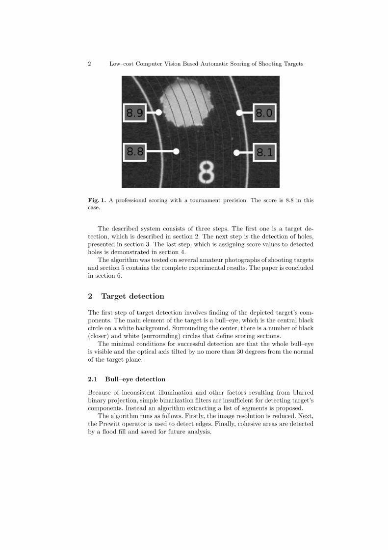
Our aim was a creation of a professional system that could be used by ama-teur shooters. Such system should estimate the score on a level accepted by anInternational Shooting Sport Federation (ISSF) as presented in Fig. 1.
Since the solution is proposed to amateur shooters, the hardware require-ments should be fulfilled by any consumer grade cameras or mobile devices ca-pable of capturing image with at least 0.5 Mpix resolution.
2 Low–cost Computer Vision Based Automatic Scoring of Shooting Targets
Fig. 1. A professional scoring with a tournament precision. The score is 8.8 in thiscase.
The described system consists of three steps. The first one is a target de-tection, which is described in section 2. The next step is the detection of holes,presented in section 3. The last step, which is assigning score values to detectedholes is demonstrated in section 4.
The algorithm was tested on several amateur photographs of shooting targetsand section 5 contains the complete experimental results. The paper is concludedin section 6.
2 Target detection
The first step of target detection involves finding of the depicted target’s com-ponents. The main element of the target is a bull–eye, which is the central blackcircle on a white background. Surrounding the center, there is a number of black(closer) and white (surrounding) circles that define scoring sections.
The minimal conditions for successful detection are that the whole bull–eyeis visible and the optical axis tilted by no more than 30 degrees from the normalof the target plane.
2.1 Bull–eye detection
Because of inconsistent illumination and other factors resulting from blurredbinary projection, simple binarization filters are insufficient for detecting target’scomponents. Instead an algorithm extracting a list of segments is proposed.
The algorithm runs as follows. Firstly, the image resolution is reduced. Next,the Prewitt operator is used to detect edges. Finally, cohesive areas are detectedby a flood fill and saved for future analysis.

Low–cost Computer Vision Based Automatic Scoring of Shooting Targets 3
(a)
(b)
Fig. 2. (a) Amateur photos of targets (b) Results of bull–eyes detection algorithm.Detected bull-eyes are marked with squares.
Before proceeding with objects’ analysis an additional feature, γp is calcu-lated for each pixel p. It is defined as the brightness difference between the pixeland its eight–point neighborhood P = {p1 . . . p8} as
γp = maxpx∈P
|lum(p)− lum(px)|, (1)
where lum returns a value (brightness) component of HSV model.
Now, each object from the list must satisfy the following two conditions to berecognized as a bull–eye. Each pixel lying on an edge must have it’s brightnessgreater than the calculated maximum difference: (1):
lum(p)− γp > 0, (2)
4 Low–cost Computer Vision Based Automatic Scoring of Shooting Targets
If almost all pixels satisfy the condition then the shape is a potential bull–eye.It will be accepted on the condition that its width and height are similar:
max(W,H)
min(W,H)< 2, (3)
where W and H are width and height respectively. The results of the algo-rithm applied to amateur photos in Fig. 2(a) are shown in Fig. 2(b). Detectedbull-eyes are marked with squares.
A detected bull–eye brings local information about a threshold for binariza-tion. Points inside the bull–eye are dark whereas, points on the edge are light.For both sets of points average values of colors are calculated. The followingprocedure is run for each component of color model individually. Firstly, pa-rameters of normal distribution are estimated for both sets. All points that liefarther than two standard deviations from the mean are removed to eliminate theinfluence of light elements on dark color estimation on a bull–eye. The thresholdfor binarization is set halfway between averages of dark and light points sets.
After the binarization, Thr set of points on the bull–eye’s edge will be usedas the source of information about geometry of rings projections.
2.2 Rings detection
The set of points on the bull–eye edge determines the approximate shape of themain ring. After corrections, selected points can be used for the parametrizationof the ring projection.
Correction The bull–eye was detected in the low–resolution image, while thering geometry should be detected in the original photo. For that reason thedetected points are only approximate. It can be assumed that a point from aring lies on the line determined by approximate point and the center of thetarget. Moreover, a distance between the points should be no more than 1
6of
the distance between rings as it is shown in Fig. 3.These conditions define a segment that includes the ring point. For the seg-
ment, the value V from HSV color model is calculated in each point. The segmenthas the minimum, the maximum, and the average values labeled as Vmin, Vmax,and Vavg respectively. For a given threshold α ∈ [0, 1] a point from the ring pringis calculated as
pring =
pmin if κ > 1− α
pmax if κ < α
pdiff if α < κ > 1− α,
(4)
where
κ =Vavg − Vmin
Vmax − Vmin
. (5)
The selected point can be the most brightnest pmax, the darkest pmin, or of thehighest difference between neighbors pdiff .

Low–cost Computer Vision Based Automatic Scoring of Shooting Targets 5
Fig. 3. Estimated points (dark) and actual rings’ points (light)
Selection Some points from the set can be taken as a part of the ring by amistake. To avoid such situation, several ellipses are generated from randomsubsets of points [9] using the following algorithm:
An ellipse e based on m random points is created [10,11]. Next, for eachellipse the following steps are completed
1. All points in the nearest neighborhood of ellipse’s center increase their coun-ters. The nearest neighborhood is defined by d, distance in the Manhattanmetric.
2. If a point with maximal counter is changed then go to the next step.3. If distance between the last point with maximal counter and a new one is
lower than d then add the ellipse e to a result list. In other case, remove allellipses from the result list.
Newly created ellipses are evaluated with distance criteria. A subset withminimal variation of distances between points and foci should be selected as abase for the final ellipse.
Parametrization An ellipse is given by the following equation:
F (x, y) = ax2 + bxy + cy2 + dx+ ey + f = 0. (6)
The parameters of the ellipse can be found using the least squares method [10].However, this method is numerically unstable and a stable solution was usedinstead [11]. A MATLAB implemetation is given below.
Ellipse parametrization
function a = fit_ellipse(x, y)
D1 = [x . 2, x .* y, y . 2]; % quadratic part of the

6 Low–cost Computer Vision Based Automatic Scoring of Shooting Targets
(a) (b) (c) (d)
Fig. 4. Holes detection. 4(a) A result of the Prewitt operator. 4(b) Hough transforma-tion results with a significant number of false positives. 4(c) A result of the Prewittoperator with erased rings. 4(d) Hough transformation results with a reduced numberof false positives.
design matrix
D2 = [x, y, ones(size(x))]; % linear part of the design
matrix
S1 = D1 * D1; % quadratic part of the scatter matrix
S2 = D1 * D2; % combined part of the scatter matrix
S3 = D2 * D2; % linear part of the scatter matrix
T = - inv(S3) * S2; % for getting a2 from a1
M = S1 + S2 * T; % reduced scatter matrix
M = [M(3, :) ./ 2; - M(2, :); M(1, :) ./ 2]; %
premultiply by inv(C1)
[evec, eval] = eig(M); % solve eigensystem
cond = 4 * evec(1, :) .* evec(3, :) - evec(2, :) . 2;
% evaluate aCa
a1 = evec(:, find(cond > 0)); % eigenvector for min.
pos. eigenvalue
a = [a1; T * a1]; % ellipse coefficients
MATLAB code for an ellipse parametrization based on [11]
3 Hole detection
After each shooting series, there should be no more than ten holes in the target.Each hole can be estimated by an ellipse and such ellipses can be detected usingthe Hough transformation [7].
The Hough transformation based ellipse center detection is a voting pro-cedure. The point that gets the greatest number of votes wins. All results ofHough transformations can be ordered by the number of votes given to thecenter. Among them twenty best results are taken for future analysis.
As an input for the Hough transformation results of the Prewitt operatorcan be used. The Prewitt operator is an edge detector that gave the best results

Low–cost Computer Vision Based Automatic Scoring of Shooting Targets 7
Fig. 5. Holes analysis. From the top: shapes created by the flood fill algorithm, detectededges, results of Hough transformation, and estimated centers of holes. The most rightexample is a false positive.
among tested. However, rings, numbers, and other marks of the target have a sig-nificant influence on Hough transformation results. In Fig. 4 an input image 4(a)and Hough transformation results 4(b) are shown. Among the best results thereare some false positives. Moreover, several existing holes are ignored becausetheir results are placed outside the first twenty.
The results can be improved when detected rings (section 2.2) are erasedfrom the image. In Fig. 4 an input image with erased rings 4(c) and Houghtransformation results 4(d) are shown. This time a number of false positives isscarce and all holes are detected.
As alternative to Hough transformation, the median filter was also tested butused method worked faster.
4 Hole analysis
The main aim of hole analysis is precise localization of hole center. Moreover, itcan be used to reduce a number of false positive results.
The analysis of detected holes has the following steps. Firstly, the shape ofhole is determined by the flood fill algorithm. If the algorithm is used on imagesdifferent than binary then a color tolerance has to be defined. The distancebetween colors can be calculated as a maximum difference between componentsof the RGB color model:
d(c1, c2) = max(|R(c1)−R(c2)|, |G(c1)−G(c2)|, |B(c1)−B(c2)|), (7)
where c1, c2 are colors and functions R,B,G calculate components of theRGB color model.

8 Low–cost Computer Vision Based Automatic Scoring of Shooting Targets
(a) (b)
Fig. 6. The shooting targets. 6(a) Target with one hole missing. 6(b) Target with allholes detected on a photograph tilted by 30 degrees.
In the next step, the Prewitt operator is used to detect edges. The edges arethen used as an input for the Hough transformation, which in turn is used todetect an ellipse center [4,5]. All steps are shown in Fig. 5.
Similarly as in the section 3 all results of Hough transformations can beordered by the number of votes given to the center. The rejection threshold iscalculated as 60 percent of the best result, which all results under the thresholdbeing rejected. Remaining holes are classified as valid.
5 Results
In this section tests for genuine shooting targets are presented.
5.1 Number of Detected Holes
The tests were done for 14 shooting targets with 152 holes total. Pictures of theshooting targets were taken under various angles as it is shown in Fig. 6. The holedetection algorithm marked 208 objects. Among this number 150 were correctlydetected holes and 58 were false positives. Details are given in Table 5.1. Foreach target the total number of holes (ALL) is shown as well as the number ofdetected ones (TP ). The quality of detection is calculated as TP
ALL. The number of
false positive (FP ) decision is shown and its signification calculated as FPFP+TP
.The detection results are very good. About 99 percent of holes were detected,
which is better than the results published in [1]. However, among all positivedecisions 28 percent were false positive.
The results of detection were used as input for the hole analysis describedin Section 4. The analysis rejected all false positive inputs except two. Thenegative aspect is that 13 correct holes were also eliminated. Details are givenin Table 2. For each target a number of positive (PI) and negative (NI) inputsfrom the detection is given. The quality of the analysis results is estimated by aclassification error for each group of inputs.
Low–cost Computer Vision Based Automatic Scoring of Shooting Targets 9
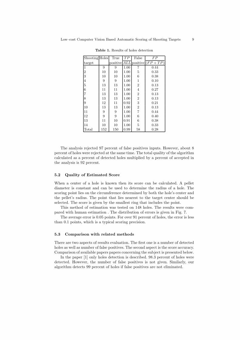
Table 1. Results of holes detection
Shooting Holes True TP False FP
target positive ALL positive (FP + TP )
1 9 9 1.00 7 0.442 10 10 1.00 5 0.333 10 10 1.00 6 0.384 9 9 1.00 1 0.105 13 13 1.00 2 0.136 11 11 1.00 4 0.277 13 13 1.00 2 0.138 13 13 1.00 2 0.139 12 11 0.92 3 0.2110 13 13 1.00 2 0.1311 9 9 1.00 7 0.4412 9 9 1.00 6 0.4013 11 10 0.91 6 0.3814 10 10 1.00 5 0.33Total 152 150 0.99 58 0.28
The analysis rejected 97 percent of false positives inputs. However, about 8percent of holes were rejected at the same time. The total quality of the algorithmcalculated as a percent of detected holes multiplied by a percent of accepted inthe analysis is 92 percent.
5.2 Quality of Estimated Score
When a center of a hole is known then its score can be calculated. A pelletdiameter is constant and can be used to determine the radius of a hole. Thescoring point lies on the circumference determined by both the hole’s center andthe pellet’s radius. The point that lies nearest to the target center should beselected. The score is given by the smallest ring that includes the point.
This method of estimation was tested on 148 holes. The results were com-pared with human estimation . The distribution of errors is given in Fig. 7.
The average error is 0.05 points. For over 91 percent of holes, the error is lessthan 0.1 points, which is a typical scoring precision.
5.3 Comparison with related methods
There are two aspects of results evaluation. The first one is a number of detectedholes as well as number of false positives. The second aspect is the score accuracy.Comparison of available papers papers concerning the subject is presented below.
In the paper [1] only holes detection is described. 98.3 percent of holes weredetected. However, the number of false positives is not given. Similarly, ouralgorithm detects 99 percent of holes if false positives are not eliminated.

10 Low–cost Computer Vision Based Automatic Scoring of Shooting Targets
Table 2. Results of holes analysis
Shooting Input Positive Negative False FP False FN
target input input positive NI negative PI
1 16 9 7 1 0.14 1 0.112 15 10 5 0 0.00 1 0.103 16 10 6 0 0.00 1 0.104 10 9 1 0 0.00 0 0.005 15 13 2 0 0.00 1 0.086 15 11 4 0 0.00 1 0.097 15 13 2 0 0.00 1 0.088 15 13 2 0 0.00 0 0.009 14 11 3 0 0.00 0 0.0010 15 13 2 0 0.00 1 0.0811 16 9 7 0 0.00 1 0.1112 15 9 6 0 0.00 0 0.0013 16 10 6 0 0.00 1 0.1014 15 10 5 1 0.20 1 0.10Total 208 158 58 2 0.03 13 0.08
In the papers [8,12] only the accuracy of the total score is given. In both casesit is 0.1 point. It looks similar to our results (the average error is 0.05 points andthe error is less than 0.1 for over 91)
In conclusion, our solution dedicated for amateur shooter gives similar resultsto the computer vision based systems for professional shooters.
6 Conclusions
In this paper, the issue of automatic scoring of shooting target is described. Theproposed solution divides the issue into three problems: target detection, holesdetection, and hole analysis.
The target detection based on a set of several basic algorithms is reliable. Itlocalizes targets on amateur photos if only minimal requirements are satisfied.
The implemented hole detection finds 99 percent of holes in photos of atleast 1 Mpix resolution.. Among detected holes false positives appear. Additionalanalysis eliminates most of them, with reduction of positive inputs to 92 percent.
The average error for the automatic score estimation is 0.05 points. For over91 percent of holes the error is less than 0.1 points. The result is similar to theresults of stationary systems for professional shooters.
The system is based on straightforward image processing such as the Pre-witt edge detection and the Hough transformation. Simple techniques togetherwith low requirements for processed images create possibility of developing thedescribed system as an application for mobile devices.

Low–cost Computer Vision Based Automatic Scoring of Shooting Targets 11
Fig. 7. Estimation errors distribution
References
1. Ali, F., Bin Mansoor, A.: Computer vision based automatic scoring of shootingtargets. In: INMIC 2008. IEEE International. pp. 515 –519 (2008)
2. Aviatronic Ltd.: SmartSCORE Users Manual (2005),http://www.smartscore.hu/kep/users_manual_en.pdf
3. C. Sanctuary, A. Sean, S.R.H.: Remote strafe scoring system. United States Patent4813877 (1989)
4. Chia, A., Leung, M., Eng, H.L., Rahardja, S.: Ellipse detection with hough trans-form in one dimensional parametric space. In: Image Processing, 2007. ICIP 2007.IEEE International Conference on. vol. 5, pp. 333–336 (2007)
5. Davies, E., Barker, S.: An analysis of hole detection schemes. pp. 285–290 (1990)6. DISAG-INTERNATIONAL: DISAG RM IV operating instruction (2005),
http://www.disag.de/download/manuals/rmiv_en.pdf
7. Duda, R.O., Hart, P.E.: Use of the hough transformation to detectlines and curves in pictures. Commun. ACM 15(1), 11–15 (Jan 1972),http://doi.acm.org/10.1145/361237.361242
8. Fan, X., Cheng, Q., Ding, P., Zhang, X.: Design of automatic target-scoring systemof shooting game based on computer vision. In: Automation and Logistics, 2009.ICAL ’09. IEEE International Conference on. pp. 825 –830 (aug 2009)
9. Fichler, M., Bolles, R.: Random sample consensus: A paradigm for model fittingwith applications to image analysis and automated cartography (1980)
10. Fitzgibbon, A. W.and Pilu, M., Fisher, R.B.: Direct least-squares fitting of ellipses21(5), 476–480 (May 1999)
11. Halir, R., Flusser, J.: Numerically Stable Direct Least Squares Fitting of Ellipses(1998), http://citeseerx.ist.psu.edu/viewdoc/summary?doi=10.1.1.1.7559
12. Liang, H., Kong, B.: A shooting training and instructing system based on imageanalysis pp. 961 –966 (aug 2006)
13. SIUS ASCOR: Electronic Scoring systems (2010),http://www.sius.com/downloads/docu/Usermanual_System7_e.pdf