Las Vegas Tenant and Exhibitor Guidelines Effective August ...
Upload
khangminh22Category
view
0download
0

Matthias Wessendorf, Technical Marketing Engineer
BRKDCN-2304
L4-L7 Service Integration in Multi-Tenant VXLAN EVPN Data Center Fabrics

© 2019 Cisco and/or its affiliates. All rights reserved. Cisco Public
Session Goals and Non-Goals
3
• Learn important requirements for designing enterprise-level Multi-Tenant DCs
• Learn technologies and building blocks needed to create Multi-Tenant networks
• Learn technologies and requirements for service attachment in Multi-Tenant DCs
• Not an ACI session
• No deep dive on Service Configuration itself
BRKDCN-2304

© 2019 Cisco and/or its affiliates. All rights reserved. Cisco Public
Related Sessions
• BRKDCN-2450-VXLAN EVPN Day-2 operation
• BRKDCT-3378-Building Data Center Networks with VXLAN BGP-EVPN
• BRKDCT-2404-VXLAN Deployment Models - A practical perspective
4BRKDCN-2304

Quick Break Before we Start

© 2019 Cisco and/or its affiliates. All rights reserved. Cisco Public
With Some Help of my Friends
I would like to thank all the people, who contributed to it.
• Max Ardica, Principal Engineer
• Lukas Krattiger, Principal Engineer
• Shyam Kapadia, Principal Engineer
6BRKDCN-2304

© 2019 Cisco and/or its affiliates. All rights reserved. Cisco Public 7
• Introduction
• Multi-Tenancy Functionality in Enterprise Data Centers
• Data Plane and Control Plane Considerations with VXLAN EVPN
• Layer 4-7 Services Integration
• Other useful Things?
• Fabric Provisioning and Management
• Conclusion
BRKDCN-2304

© 2019 Cisco and/or its affiliates. All rights reserved. Cisco Public
What is Multi-Tenancy?
• Multi-tenancy is an architecture in which a single instance of a software application serves multiple customers. Each customer is called a tenant.
8BRKDCN-2304

© 2019 Cisco and/or its affiliates. All rights reserved. Cisco Public
What Does this Mean for Data Centers?
9
Compute
NetworkStorage
SeparatedShared
Resources
Service Orchestration
BRKDCN-2304

© 2019 Cisco and/or its affiliates. All rights reserved. Cisco Public
Network Requirements
• Layer 3 Traffic Segmentation
• Layer 2 Traffic Segmentation
• Intelligent and Scalable Layer 2 Networks
• Data Center Interconnect
• Traffic Engineering
10BRKDCN-2304

© 2019 Cisco and/or its affiliates. All rights reserved. Cisco Public 11
• Introduction
• Multi-Tenancy Functionality in Enterprise Data Centers
• Data Plane and Control Plane Considerations with VXLAN EVPN
• Layer 4-7 Services Integration
• Other useful Things?
• Fabric Provisioning and Management
• Conclusion
BRKDCN-2304

Introduction

© 2019 Cisco and/or its affiliates. All rights reserved. Cisco Public
What is Multi-Tenancy for the Data Center Infrastructure?
• Process of creating an environment where resources are split and combined, based on consumption, demand, supply and policies
13BRKDCN-2304

© 2019 Cisco and/or its affiliates. All rights reserved. Cisco Public
Multi-Tenancy ”Layers”
14
Mechanism
Identifier VLAN ID, VNID, SGT, Label…
MP-BGP, MPLS, Distributed GW…
- Layer-2 Network segmentation- Layer-3 domain/Tenant separation
Fabric
Control
Functionality
- Push-Pull network orchestration
- L4-L7 Services network integration
- Orchestrator integration via APIs
BRKDCN-2304

© 2019 Cisco and/or its affiliates. All rights reserved. Cisco Public
Rules and Policies
15
• Applications, network services, and tenant identification
• Enforcement of separation between segments
• Providing network policy
• Controlled shared access to select networks and resources
Tenant-2
Tenant-1
Tenant-3
Multi-Tenant
Network
BRKDCN-2304
© 2019 Cisco and/or its affiliates. All rights reserved. Cisco Public 16
• Introduction
• Multi-Tenancy Functionality in Enterprise Data Centers
• Data Plane and Control Plane Considerations with VXLAN EVPN
• Layer 4-7 Services Integration
• Where to Head Next?
• Fabric Provisioning and Management
• Conclusion
Agenda
BRKDCN-2304

Multi-Tenancy Functionality in Enterprise Data Centers

© 2019 Cisco and/or its affiliates. All rights reserved. Cisco Public
• Layer 2 Network segmentation
• Micro-segmentation
• Layer 3 domain/Tenant separation
Multi-Tenancy Functionality
18
Mechanism
Identifier
Fabric Control
Functionality
BRKDCN-2304

Layer-2 Network Segmentation

© 2019 Cisco and/or its affiliates. All rights reserved. Cisco Public
Layer-2 Network Segmentation
• Prevents hosts in a given Layer-2 segment, from observing traffic of hosts in a different segment
• Separation of Broadcast/Flood domains into bridge domains/segments
• Splitting IP networks in smaller subnets
• Containment of the Fault domain to a given Layer-2 bridge domain
• VLAN is an overloaded notion ~ Layer-2 segment, Bridge-domain, Broadcast Domain, Flood Domain
20BRKDCN-2304

© 2019 Cisco and/or its affiliates. All rights reserved. Cisco Public
Network Segmentation
21
• Provides clear separation of Layer-2 segments in the network
• Leverages identifier in the frame tag or encapsulation
• Number of Layer-2 segment identifiers depends on a chosen namespace.
• For example: Dot1Q – 4096 VLANs, VXLAN – 16M VNIs
• Identification of a given frame’s tenant membership
• For example: VRF-lite, Symmetric IRB, etc.
BRKDCN-2304

Micro-segmentation
© 2019 Cisco and/or its affiliates. All rights reserved. Cisco Public
Network Fabric
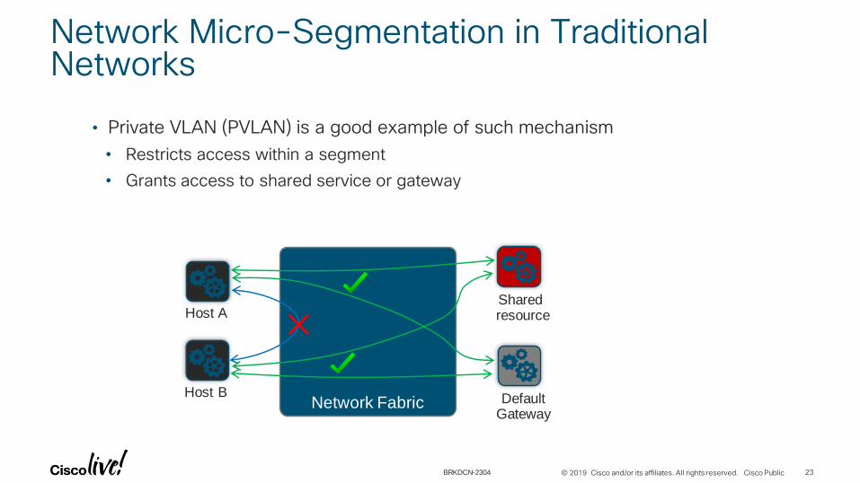
Network Micro-Segmentation in Traditional Networks
23
• Private VLAN (PVLAN) is a good example of such mechanism
• Restricts access within a segment
• Grants access to shared service or gateway
Host A
Host B
Shared resource
DefaultGateway
BRKDCN-2304

© 2019 Cisco and/or its affiliates. All rights reserved. Cisco Public 24
ACI Micro-segmentation
vDS Cisco AVS IP/MAC EPG Hyper-V vSwitch Open vSwitch Open vSwitch
VLAN or
VXLAN
VLAN or
VXLAN
VLAN or
VXLANVLANVLANVLAN
Microsegmentation Yes Yes Yes Yes Yes* Yes*
Intra-EPG Isolation Yes Yes* Yes Yes* Yes* Yes*
BRKDCT-3001: Leveraging Micro Segmentation to Build Comprehensive Data Center Security Architecture
BRKDCN-2304

Tenant Segmentation
© 2019 Cisco and/or its affiliates. All rights reserved. Cisco Public
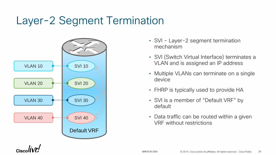
Default VRF
Layer-2 Segment Termination
26
• SVI – Layer-2 segment termination mechanism
• SVI (Switch Virtual Interface) terminates a VLAN and is assigned an IP address
• Multiple VLANs can terminate on a single device
• FHRP is typically used to provide HA
• SVI is a member of “Default VRF” by default
• Data traffic can be routed within a given VRF without restrictions
VLAN 10
VLAN 20
VLAN 30
VLAN 40
SVI 10
SVI 20
SVI 30
SVI 40
BRKDCN-2304

© 2019 Cisco and/or its affiliates. All rights reserved. Cisco Public
Tenant-B
Tenant-A
Default VRF
Restricting Forwarding between Segments withACL
27
• Access Control Lists (ACL) between VLANs
• Number and complexity of ACLs becomes too high
• No overlapping IP subnets between tenants
VLAN 10
VLAN 20
VLAN 30
VLAN 40
SVI 10
SVI 20
SVI 30
SVI 40
Destination
SourceVLAN 10 VLAN 20 VLAN 30 VLAN 40
VLAN 10 ✔ ✔ ✘ ✘
VLAN 20 ✔ ✔ ✘ ✘
VLAN 30 ✘ ✘ ✔ ✔
VLAN 40 ✘ ✘ ✔ ✔✘
BRKDCN-2304

© 2019 Cisco and/or its affiliates. All rights reserved. Cisco Public
Routing Domain – VRF
28
• Virtual Routing and Forwarding (VRF)
• Independent IPv4 and IPv6 address spaces
• Full unicast and multicast routing protocol support
• Two VRFs by default: Mgmt VRF and Default VRF
• All IP-based features in NX-OS are VRF aware
• Non-default VRFs are locally-significant on a router
• Data traffic is not routed across VRFs with the default configuration
VRF-B
VRF-AVLAN 10
VLAN 20
VLAN 30
VLAN 40
SVI 10
SVI 20
SVI 30
SVI 40
BRKDCN-2304

© 2019 Cisco and/or its affiliates. All rights reserved. Cisco Public
Question: How do we bring L2 and L3 separation together on a device andwithin a fabric?
29BRKDCN-2304

© 2019 Cisco and/or its affiliates. All rights reserved. Cisco Public 30
• Introduction
• Multi-Tenancy Functionality in Enterprise Data Center
• Data Plane and Control Plane Considerations with VXLAN EVPN
• Data plane
• Control plane: Underlay and Overlay
• Layer 4-7 Services Integration
• Other useful Things?
• Fabric Provisioning and Management
• Conclusion
Agenda
BRKDCN-2304
© 2019 Cisco and/or its affiliates. All rights reserved. Cisco Public
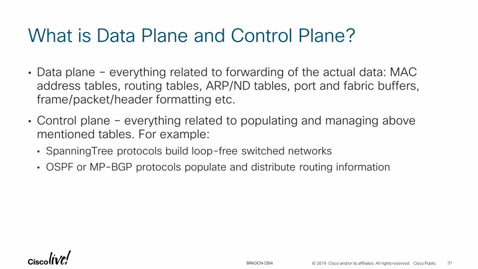
What is Data Plane and Control Plane?
• Data plane – everything related to forwarding of the actual data: MAC address tables, routing tables, ARP/ND tables, port and fabric buffers, frame/packet/header formatting etc.
• Control plane – everything related to populating and managing above mentioned tables. For example:
• SpanningTree protocols build loop-free switched networks
• OSPF or MP-BGP protocols populate and distribute routing information
31BRKDCN-2304

© 2019 Cisco and/or its affiliates. All rights reserved. Cisco Public
What is a Fabric?
32
Hosts
VM
OS
VM
OS
Virtual
Physical
BRKDCN-2304

© 2019 Cisco and/or its affiliates. All rights reserved. Cisco Public
What is a Fabric?
32
Hosts
VM
OS
VM
OS
Virtual
Physical
BRKDCN-2304

© 2019 Cisco and/or its affiliates. All rights reserved. Cisco Public
What is a Fabric?
32
Hosts
VM
OS
VM
OS
Virtual
Physical
Leaf
BRKDCN-2304

© 2019 Cisco and/or its affiliates. All rights reserved. Cisco Public
What is a Fabric?
32
Hosts
VM
OS
VM
OS
Virtual
Physical
Spine
Leaf
BRKDCN-2304

© 2019 Cisco and/or its affiliates. All rights reserved. Cisco Public
What is a Fabric?
32
Hosts
VM
OS
VM
OS
Virtual
Physical
Spine
Leaf
*Clos, Charles (Mar 1953). "A study of non-blocking switching networks". Bell System Technical Journal.
BRKDCN-2304

© 2019 Cisco and/or its affiliates. All rights reserved. Cisco Public
What is a Fabric?
32
Hosts
VM
OS
VM
OS
Virtual
Physical
L3
L2
Spine
Leaf
*Clos, Charles (Mar 1953). "A study of non-blocking switching networks". Bell System Technical Journal.
BRKDCN-2304

Data Plane
© 2019 Cisco and/or its affiliates. All rights reserved. Cisco Public
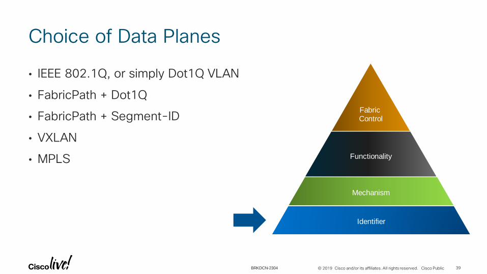
Choice of Data Planes
• IEEE 802.1Q, or simply Dot1Q VLAN
• FabricPath + Dot1Q
• FabricPath + Segment-ID
• VXLAN
• MPLS
39
Mechanism
Identifier
Fabric Control
Functionality
BRKDCN-2304

© 2019 Cisco and/or its affiliates. All rights reserved. Cisco Public
Classic Ethernet IEEE 802.1Q Format
• 12 bit namespace provides 4096 unique VLAN IDs
• Data-Plane based learning, also known as Flood & Learn
40
Classic Ethernet
Frame
Destination MAC (DMAC)
Source MAC (SMAC)
802.1QTPID
0x8100(16 bits)
TCI
PCP(3 bits)
CFI(1 bits)
VID(12 bits)
Ether Type (Etype)
Data (Payload)
CRC/FCS
4 bytes
DMAC SMAC 802.1Q Etype CRCPayload
VLAN ID12 bits
TPID = Tag Protocol Identifier, TCI = Tag Control Information, PCP = Priority Code Point, CFI = Canonical Format Indicator, VID = VLAN Identifier
BRKDCN-2304

© 2019 Cisco and/or its affiliates. All rights reserved. Cisco Public
Dot1Q Use Cases
• VLAN ID identifies the Layer-2 segment
• VLAN ID maps to the SVI that typically provides Default GW functionality
• Dot1q on the Sub-Interface typically identifies the VRF on the link between two routers
41
VRF-C
VRF-B
VRF-A
VRF-C
VRF-B
VRF-A
VLAN 10 VRF-A
VLAN 20 VRF-B
VLAN 30 VRF-C
VRF-lite
BRKDCN-2304
© 2019 Cisco and/or its affiliates. All rights reserved. Cisco Public
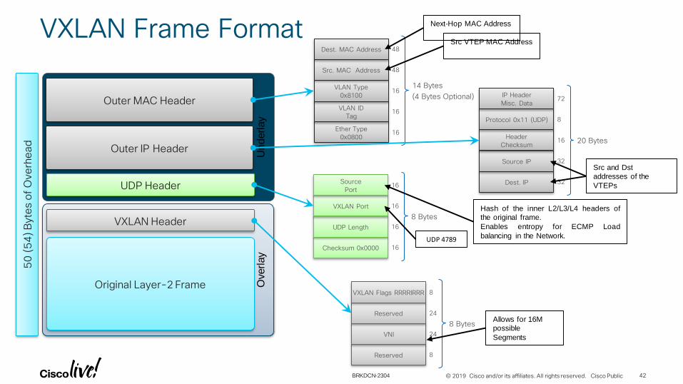
VXLAN Frame Format
42
Underlay
Outer IP Header
Outer MAC Header
UDP Header
VXLAN Header
Original Layer-2 Frame Overlay
14 Bytes
(4 Bytes Optional)
Ether Type
0x0800
VLAN ID
Tag
VLAN Type
0x8100
Src. MAC Address
Dest. MAC Address 48
48
16
16
16
20 Bytes
Dest. IP
Source IP
Header
Checksum
Protocol 0x11 (UDP)
IP Header
Misc. Data72
8
16
32
32
8 Bytes
Checksum 0x0000
UDP Length
VXLAN Port
Source
Port16
16
16
16
8 Bytes
Reserved
VNI
Reserved
VXLAN Flags RRRRIRRR 8
24
24
8
Src VTEP MAC Address
Next-Hop MAC Address
Src and Dst
addresses of the
VTEPs
Allows for 16M
possible
Segments
UDP 4789
Hash of the inner L2/L3/L4 headers of
the original frame.
Enables entropy for ECMP Load
balancing in the Network.
50
(5
4) B
yte
s o
f O
verh
ead
BRKDCN-2304

© 2019 Cisco and/or its affiliates. All rights reserved. Cisco Public
VXLAN Taxonomy (1)
43
Local LAN Segment
Physical Host
Local LAN Segment
Physical Host
Virtual Hosts
Local LAN Segment
Virtual Switch
Edge Device
Edge Device
Edge Device
IP Interface
BRKDCN-2304

© 2019 Cisco and/or its affiliates. All rights reserved. Cisco Public
VXLAN Taxonomy (2)
44
VTEP – VXLAN Tunnel End-Point
VNI/VNID – VXLAN Network Identifier
Local LAN Segment
Physical Host
Local LAN Segment
Physical Host
VTEP
VTEP
VTEP
VV
V
Encapsulation
Virtual Hosts
Local LAN Segment
Virtual Switch
BRKDCN-2304

© 2019 Cisco and/or its affiliates. All rights reserved. Cisco Public
How is this different from STP/802.1Q based deployments?
45BRKDCN-2304

© 2019 Cisco and/or its affiliates. All rights reserved. Cisco Public
Add a Control Plane as a Secret Sauce!
46BRKDCN-2304
Let’s Pick the Control Plane

© 2019 Cisco and/or its affiliates. All rights reserved. Cisco Public
Standards Based Control-Plane for Fabrics
• VXLAN with MP-BGP EVPN
• Nexus 9300/9500 can be Leaf, Spine, and Border Leaf.
• N5600 and N7000/7700 with F3/M3 for Spine, Leaf, and Border Leaf*
• *Check with your account team/partner for support matrix
48BRKDCN-2304

© 2019 Cisco and/or its affiliates. All rights reserved. Cisco Public
What Makes Control-Plane based Fabrics so Special?
49
• Underlay Control plane
• Discover and learn the fabric topology, i.e. location of fabric nodes
• Overlay Control plane
• Learn and distribute the end-host reachability information
• ARP suppression and Distributed Anycast Gateway Mechanism
Identifier
Fabric Control
Functionality
BRKDCN-2304

Underlay Control-Plane

© 2019 Cisco and/or its affiliates. All rights reserved. Cisco Public
Underlay Control-Plane for VXLAN with EVPN
51
• IGP such as OSPF or Layer-3 IS-IS or eBGP can be used:
• Full fabric topology view
• Shortest path unicast forwarding between leafs
• VTEPs IP reachability (typically routed loopback interfaces)
• Recommended choice is an IGP (OSPF or L3-ISIS)
• PIM-ASM or PIM-BiDir* for multicast underlay or Ingress Replication*
• VTEPs use this mechanism to forward BUM** traffic
(*depends on hardware) **BUM – Broadcast, Unknown Unicast, Multicast
BRKDCN-2304

Overlay Control-Plane

© 2019 Cisco and/or its affiliates. All rights reserved. Cisco Public
Overlay Control-Plane
• Use MP-BGP on the leaf nodes to distribute the end-host reachability information
53
End-Host Reachability Information Distribution
MAN/WAN
N1KV/OVS
External Subnet
Route Injection
iBGP Adjacencies
RR RR
Fabric Host/Subnet
Route InjectionMP-BGP Control Plane
Note: Route-Reflectors deployed for scaling purposes
BRKDCN-2304

© 2019 Cisco and/or its affiliates. All rights reserved. Cisco Public
Overlay Control-Plane for VXLAN with EVPN
• EVPN address family
• Layer-2 MAC and Layer-3 IP information distribution by Control-Plane (BGP)
• Forwarding is done in hardware, based on Control-Plane learnings (minimises flooding)
54BRKDCN-2304
© 2019 Cisco and/or its affiliates. All rights reserved. Cisco Public
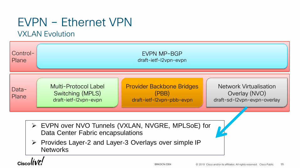
EVPN – Ethernet VPNVXLAN Evolution
55
Control-Plane
EVPN MP-BGPdraft-ietf-l2vpn-evpn
Data-Plane
Multi-Protocol Label Switching (MPLS)draft-ietf-l2vpn-evpn
Provider Backbone Bridges(PBB)
draft-ietf-l2vpn-pbb-evpn
Network VirtualisationOverlay (NVO)
draft-sd-l2vpn-evpn-overlay
EVPN over NVO Tunnels (VXLAN, NVGRE, MPLSoE) for Data Center Fabric encapsulations
Provides Layer-2 and Layer-3 Overlays over simple IP Networks
BRKDCN-2304

© 2019 Cisco and/or its affiliates. All rights reserved. Cisco Public
Protocol Learning & Distribution (1)VXLAN/EVPN
Host AMAC_A / IP_A Host B
MAC_B / IP_B
Virtual Switch
Host CMAC_C / IP_C
Host YMAC_Y / IP_Y
RR RR
V2V1
V3
1
1
1VTEPs advertise Host Routes (IP+MAC)within the Control-Plane
1
56
© 2019 Cisco and/or its affiliates. All rights reserved. Cisco Public
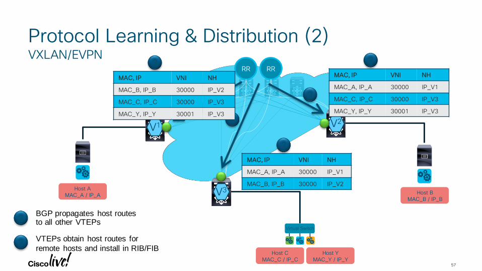
Protocol Learning & Distribution (2)VXLAN/EVPN
Host AMAC_A / IP_A Host B
MAC_B / IP_B
Virtual Switch
Host CMAC_C / IP_C
Host YMAC_Y / IP_Y
RR RR
V2V1
V3
22
2
2BGP propagates host routes to all other VTEPs
MAC, IP VNI NH
MAC_A, IP_A 30000 IP_V1
MAC_B, IP_B 30000 IP_V2
MAC, IP VNI NH
MAC_A, IP_A 30000 IP_V1
MAC_C, IP_C 30000 IP_V3
MAC_Y, IP_Y 30001 IP_V3
3VTEPs obtain host routes for
remote hosts and install in RIB/FIB
3 3
3
MAC, IP VNI NH
MAC_B, IP_B 30000 IP_V2
MAC_C, IP_C 30000 IP_V3
MAC_Y, IP_Y 30001 IP_V3
57

© 2019 Cisco and/or its affiliates. All rights reserved. Cisco Public
The Old Fashioned Way to Configure Default Gateway
• SVIs for Layer-2 segments configured on all Leaf nodes
• Full sync of ARP & MAC states of all VLANs across the Network
• Flooding to ALL nodes in the network
• Source and Destination VLAN has to exist on Switch where routing happens
• Unnecessary waste of resources
58BRKDCN-2304
© 2019 Cisco and/or its affiliates. All rights reserved. Cisco Public
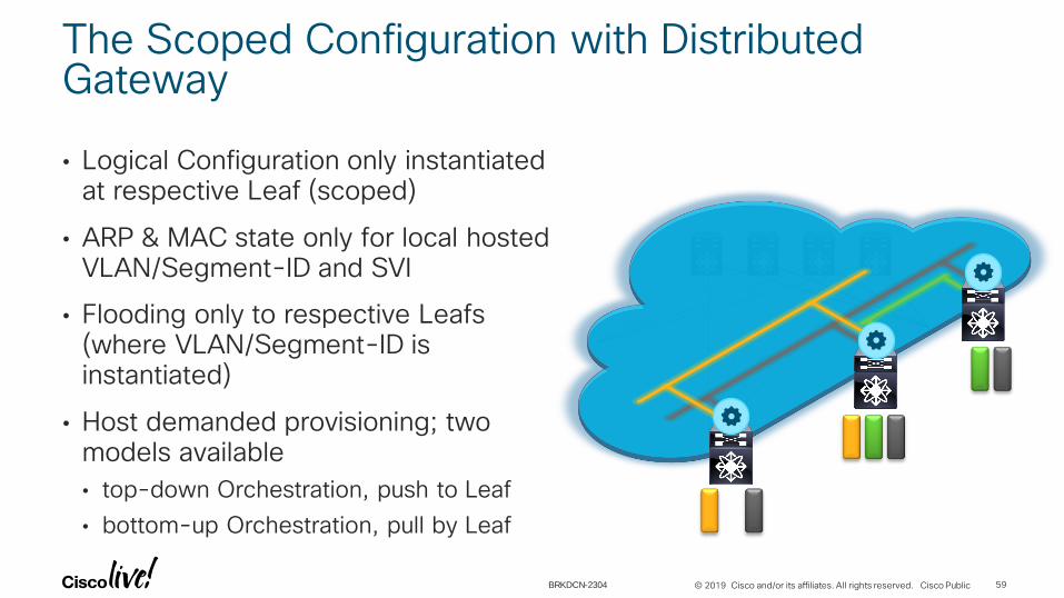
The Scoped Configuration with Distributed Gateway
• Logical Configuration only instantiated at respective Leaf (scoped)
• ARP & MAC state only for local hosted VLAN/Segment-ID and SVI
• Flooding only to respective Leafs(where VLAN/Segment-ID is instantiated)
• Host demanded provisioning; two models available
• top-down Orchestration, push to Leaf
• bottom-up Orchestration, pull by Leaf
59BRKDCN-2304

© 2019 Cisco and/or its affiliates. All rights reserved. Cisco Public
Data is Routed via Transit Segment
• Configured on all switches hosting VRF
• Additional Segment for Routing traffic (per VRF)
• From Host A via VLAN-43 routed to Segment “pink” reaching destination VLAN-55
• From Host Y via VLAN-55 routed to Segment “pink” reaching destination VLAN-43
• Used in Cisco VXLAN/EVPN and FabricPath with MP-BGP
60
Host YVLAN 55
Host AVLAN 43
BRKDCN-2304

© 2019 Cisco and/or its affiliates. All rights reserved. Cisco Public
VLAN VLAN VLAN
• VNIDs are utilised for providing isolation at Layer-2 and Layer-3 across the Fabric
• 802.1Q tagged frames received at the Leaf nodes from edge devices must be mapped to specific Segments
• The VLAN-to-Segment mapping is performed on a leaf device level
• VLANs become locally significant on the leaf node and 1:1 mapped to a Segment-ID
• VNIDs are globally significant, VLAN IDs are locally significant
Segment ID
N1KV/OVS Virtual Switch
VNI and VLAN IDs
61BRKDCN-2304

Let’s Sum It Up
© 2019 Cisco and/or its affiliates. All rights reserved. Cisco Public
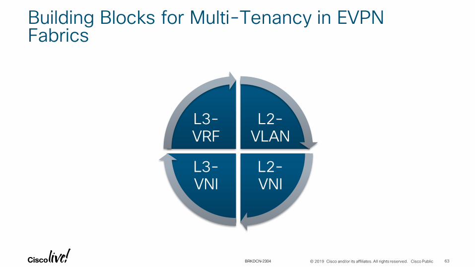
Building Blocks for Multi-Tenancy in EVPN Fabrics
63
L2-VLAN
L2-VNI
L3-VNI
L3-VRF
BRKDCN-2304
© 2019 Cisco and/or its affiliates. All rights reserved. Cisco Public
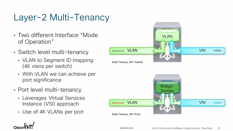
Layer-2 Multi-Tenancy
• Two different Interface “Mode of Operation”
• Switch level multi-tenancy
• VLAN to Segment ID mapping (4K vlans per switch)
• With VLAN we can achieve per port significance
• Port level multi-tenancy
• Leverages Virtual Services Instance (VSI) approach
• Use of 4K VLANs per port
64
VLAN
VLAN VNI
Multi-Tenancy (MT-Switch)
ethernet vxlan
Bridge-Domain
VLAN VNI
Multi-Tenancy (MT-Port)
vxlanethernet
BRKDCN-2304

© 2019 Cisco and/or its affiliates. All rights reserved. Cisco Public
L3 Separation – VRF
• Independent IPv4 and IPv6 address spaces
• Tenant Networks (VNIs) are mapped to VRFs
• Configuration is consistent across all Switches
• Data traffic is not routed across VRFs, so L3 and L2 Separation is ensured
65
VRF-B
VRF-AVNI10000
VNI 20000
VNI 30000
VNI 40000
SVI 10
SVI 20
SVI 30
SVI 40
BRKDCN-2304

© 2019 Cisco and/or its affiliates. All rights reserved. Cisco Public
Multi-Tenancy ”Layers”
66
Mechanism
Identifier VLAN ID, VNID
MP-BGP, EVPN, Anycast GW
- Layer-2 Network segmentation- Layer-3 domain/Tenant separation
Fabric
Control
Functionality
BRKDCN-2304
© 2019 Cisco and/or its affiliates. All rights reserved. Cisco Public 67
• Introduction
• Multi-Tenancy Functionality in Enterprise Data Center
• Data Plane and Control Plane Considerations with VXLAN EVPN
• Layer 4-7 Services Integration
• Types of Service Deployment
• How to attach Services Nodes?
• Service Node Deployment with VXLAN EVPN
• Other useful Things?
• Fabric Provisioning and Management
• Conclusion
Agenda
BRKDCN-2304
Layer 4-7 Services Integration

Types of Service Deployment

© 2019 Cisco and/or its affiliates. All rights reserved. Cisco Public
Prerequisites for Connecting Services
• In DC environments, Services may typically work in one of two modes:
• Transparent, also called Layer 2 ( also known as GO THROUGH)
• Routed, also called Layer 3 (also known as GO TO)
• Subnet default gateway configured on the firewall (most popular option)
• Subnet default gateway configured in the network and firewall is the routed next hop
• This will affect what network configurations are deployed in the fabric
• Be sure to define upfront the role of the service node (policy enforcement intra-tenant, inter-tenant, etc.)
70BRKDCN-2304

© 2019 Cisco and/or its affiliates. All rights reserved. Cisco Public
Intra-Tenant Services
Tenant-BTenant-A
VLAN 10
VLAN 20 VLAN 30
VLAN 40
• Filtering/policy enforcement between and within Segments for a Tenants
Intra-VRF, inter-subnets
Option 1 : FW as default GWOption 2 : PBR with FW as L3 hopOption 3 : FW in transparent (less common)
FW as default gateway
Apply PBR
Apply PBR
FW as L3 hop
71BRKDCN-2304

© 2019 Cisco and/or its affiliates. All rights reserved. Cisco Public
Inter-Tenants Services
Tenant-A
VLAN 10
VLAN 20
• Filtering/policy enforcement between Tenants
Inter-VRF
Tenant-B
VLAN 30
VLAN 40
Tenant-A
VLAN 10
VLAN 20
Tenant-B
VLAN 30
VLAN 40
FW as ‘fusion router’, interface dedicated per
tenant
Separate ‘fusion routing’ function
Per tenant physical FW or virtual context
72BRKDCN-2304

© 2019 Cisco and/or its affiliates. All rights reserved. Cisco Public
Tenant Edge ServicesFiltering for North-South Communication
Tenant-A
VLAN 10
VLAN 20
• Filtering/policy enforcement between Tenants and the external world
Internet/WAN
Tenant-B
VLAN 30
VLAN 40
Per tenant physical FW or virtual context
Tenant as a security zone: allows intra-tenant
communication
73BRKDCN-2304

© 2019 Cisco and/or its affiliates. All rights reserved. Cisco Public
Let’s Translate
• Tenant Edge Services Inter VRF
• Inter Tenant Services Inter VRF
• Intra Tenant Services Intra VRF/Inter-VLAN
74BRKDCN-2304

How to Attach Services Nodes?

© 2019 Cisco and/or its affiliates. All rights reserved. Cisco Public
Service Node Deployment Examples
76
OutsideInside
Primary
Secondary
Manag
em
ent
Netw
ork
Cluster Control
Links
M0/0
M0/0
M0/0
M0/0
Cluster Active/Standby
BRKDCN-2304

© 2019 Cisco and/or its affiliates. All rights reserved. Cisco Public
How to Physically Connect Service Nodes
FabricBGP AS#100
FabricBGP AS#100
Cluster Active/StandbyFor clustered systems vPC is OK
(Cluster nodes need to be attached to the same vPC pair)
For Active/Standby systems vPC is NOT a recommended choice
(no Multicast routing via vPC, no IPv6, etc.)77BRKDCN-2304

© 2019 Cisco and/or its affiliates. All rights reserved. Cisco Public
Where and How to Connect Services Nodes
RRRR
FabricBGP AS#100
L2BL1
H220.10.10.20(VLAN 111)
VRF-B
L1
H110.10.10.20(VLAN 40)
VRF-A
SL1
Internet/WAN
SL
L
BL
Service Leaf
Leaf
Border Leaf
• Border Leaf
• Inter-VRF
• External
• Service Leaf
• Intra-VRF, Inter-VLAN
• Leaf
• Not recommended
78BRKDCN-2304

Logical Connectivity to an EVPN Fabric

© 2019 Cisco and/or its affiliates. All rights reserved. Cisco Public
Transparent Insertion of Active/Standby Services
80
Failover
State
10 1011
11 12
13 13 12
• IGP
• 2 SVIs per VRF for peering to upstream Router
• BGP
• Needs only a single SVI per VRF
• Backup links between the standby service used in case of switchover to keep routing adjacencies up
Backup link
Primary link
BL Border Leaf
BL BL
BRKDCN-2304

© 2019 Cisco and/or its affiliates. All rights reserved. Cisco Public
Transparent Insertion of Active/Standby Services Same Border Leaf
81
• Peering is done between the same Border leafs in different VRFs
• Inter VRF Routing is done on the Border leaf via an external link
• Change MAC on SVI on Border leaf
Backup link
Primary link
Failover
State
10 1011
11 12
13 13 12
BL Border Leaf
BL BL
BL
BL
BL BL
BRKDCN-2304

© 2019 Cisco and/or its affiliates. All rights reserved. Cisco Public
Routed Insertion of Active/Standby Services
82
• 1 SVI per VRF for peering to ASA
• If switchover from A->S, VMAC is used (same IP/MAC and will be switched over)
• Backup links between the standby service used in case of switchover to keep routing adjacencies up
Failover
State
10 1011
11 12
13 13 12
Backup link
Primary link
BL Border Leaf
BL BL
BRKDCN-2304

© 2019 Cisco and/or its affiliates. All rights reserved. Cisco Public
Routed Insertion of Active/Standby Services Same Border Leaf
83
Backup link
Primary link
Failover
State
10 1011
11 12
13 13 12
• Peering is done between the same Border leafs in different VRFs.
• InterVRF routing is done on the Border leaf via external link
• Change MAC on SVI on Border
BL Border Leaf
BLBL
BL
BL
BL BL
BRKDCN-2304
© 2019 Cisco and/or its affiliates. All rights reserved. Cisco Public
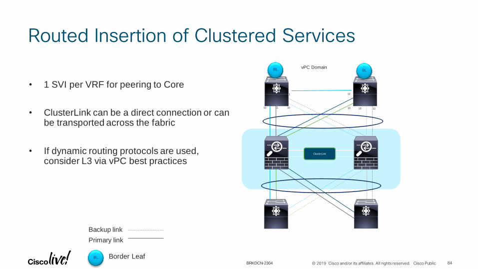
Routed Insertion of Clustered Services
84
• 1 SVI per VRF for peering to Core
• ClusterLink can be a direct connection or can be transported across the fabric
• If dynamic routing protocols are used, consider L3 via vPC best practices
ClusterLink
10 1011
11 12
13 13 12
vPC Domain
Backup link
Primary link
BL Border Leaf
BL BL
BRKDCN-2304

© 2019 Cisco and/or its affiliates. All rights reserved. Cisco Public
Transparent Insertion of Clustered Services
85
• 1 SVIs per VRF for peering to Core
• ClusterLink can be a direct connection or can be transported across the fabric
Backup link
Primary link
ClusterLink
10 1011
11 12
13 13 12
vPC Domain
BL Border Leaf
BL BL
BRKDCN-2304

EVPN External Connectivity

© 2019 Cisco and/or its affiliates. All rights reserved. Cisco Public
How to Integrate Service
87
RRRR
FabricBGP AS#100
L2BL1
H2
20.10.10.20
(VLAN 111)
VRF-B
L1
H1
10.10.10.20
(VLAN 40)
VRF-A
SL1
Internet/WAN
SL
L
BL
Service Leaf
Leaf
Border Leaf
3 Ways to route to or via a
Service:
• Dynamic/Static Routing
• Recursive Next Hop (RNH)
• Host Mobility Manager Route (HMM) Tracking
BRKDCN-2304

© 2019 Cisco and/or its affiliates. All rights reserved. Cisco Public
VXLAN/EVPN Fabric External Routing
• The Border Leaf/Spine provides Layer-2 and Layer-3 connectivity to external networks
• Flexible routing protocol options for external routing
• Today, VRF-lite allows to extend VRFs outside of the fabric
88
VBL
WAN
V2
V1
V3
BRKDCN-2304

© 2019 Cisco and/or its affiliates. All rights reserved. Cisco Public
Dynamic/Static Routing
89
RRRR
FabricBGP AS#100
L2BL1
H2
20.10.10.20
(VLAN 111)
VRF-B
Internet/WAN
L1
H1
10.10.10.20
(VLAN 40)
VRF-A
OSPF VRF-A
OSPF VRF-B
Firewall establishes routing adjacencies with both the
Border Leaf and the Edge Router
• Per-VRF routing adjacency or static routes between
Border Leaf and Firewall
• Per-VRF routing adjacency or static routes between
Firewall and Edge Router
Routes are summarised or only a default route is
injected into the fabric on a per-VRF basis
BRKDCN-2304

© 2019 Cisco and/or its affiliates. All rights reserved. Cisco Public
VXLAN/EVPN Fabric External Routing
90
V2
V1
V3
VBL
WAN
VRFA
VRFB
VRFC
VRFs for External Routing
need to exist on Border Leaf
Interface-Type Options:
• Physical Routed Ports
• Sub-Interfaces
• VLAN SVIs over Trunk Ports Peering Interface can
be in Global or Tenant VRF
BRKDCN-2304

© 2019 Cisco and/or its affiliates. All rights reserved. Cisco Public
VXLAN/EVPN Fabric External Routing (eBGP)
91
V2
V1
V3
VBL
WANAS# 65599
VRFA
VRFB
VRFC
# Sub-Interface Configuration
interface Ethernet1/1
no switchport
interface Ethernet1/1.10
encapsulation dot1q 10
vrf member VRF-A
ip address 10.254.254.1/30
# eBGP Configuration
router bgp 100
…
vrf VRF-A
address-family ipv4 unicast
advertise l2vpn evpn
aggregate-address 10.0.0.0/8 summary-only
neighbor 10.254.254.2 remote-as 65599
update-source Ethernet1/1.10
address-family ipv4 unicast
Ensure that non-necessary routes are not advertised towards the External Network
Advertise external learned routes
into EVPN (Route-Type 5)
Advertise an aggregate of the internal prefixes

© 2019 Cisco and/or its affiliates. All rights reserved. Cisco Public
VXLAN/EVPN Fabric External Routing (eBGP)
94
V2
V1
V3
VBL
WANAS# 65599
VRFA
VRFB
VRFC
# Interface Configuration
interface Ethernet1/1.10
encapsulation dot1q 10
vrf member VRF-A
ip address 10.254.254.2/30
# eBGP Configuration
router bgp 65599
…
vrf VRF-A
address-family ipv4 unicast
neighbor 10.254.254.1 remote-as 100
update-source Ethernet1/1.10
address-family ipv4 unicast
BRKDCN-2304

© 2019 Cisco and/or its affiliates. All rights reserved. Cisco Public
VXLAN/EVPN Fabric External Routing (OSPF)
95
V2
V1
V3
VBL
WAN
VRFA
VRFB
VRFC
# Sub-Interface Configuration
interface Ethernet1/1
no switchport
interface Ethernet1/1.10
encapsulation dot1q 10
vrf member VRF-A
ip address 10.254.254.1/30
ip router ospf 1 area 0.0.0.0
ip ospf network point-to-point
# BGP Configuration
router bgp 100
…
vrf VRF-A
address-family ipv4 unicast
advertise l2vpn evpn
redistribute bgp 100 route-map OSPF-BGP*
*Ensure that non-necessary routes are not advertised towards the External Network
Advertise external learned routes
into EVPN (Route-Type 5)
Redistribute internal prefixes with route-map
BRKDCN-2304

What about Static Routes
© 2019 Cisco and/or its affiliates. All rights reserved. Cisco Public
Check Availability of Static Routes Next Hop
• Problem with Redistributing Static Routes
• What happens if the Next Hop goes down?
• How to deploy this redundant?
• 2 Solutions
• Recursive Next Hop (RNH)
• Host Mobility Manager Tracking (HMM Tracking)
99BRKDCN-2304

© 2019 Cisco and/or its affiliates. All rights reserved. Cisco Public
99.99.99.0/24
Recursive Next Hop (RNH)
100
RRRR
FabricBGP AS#100
L2BL1
H2
20.10.10.20
(VLAN 111)
VRF-B
Internet/WAN
L1
H1
10.10.10.20
(VLAN 40)
VRF-A
BL1# Show ip route vrf VRF-B 20.20.10.2020.20.10.20/32, ubest/mbest: 1/0, attached
*via 20.20.10.20, Vlan1020, [190/0], 08:40:59, hmm
VTEP
10.10.10.21
L2# sh ip route vrf VRF-B 20.20.10.20
IP Route Table for VRF ”VRF-B"
'*' denotes best ucast next-hop
'**' denotes best mcast next-hop
'[x/y]' denotes [preference/metric]
'%<string>' in via output denotes VRF <string>
20.20.10.20/32, ubest/mbest: 1/0
*via 10.10.10.21%default, [200/0], 08:39:50, bgp-100, internal, tag 100
(evpn) segid: 50001 tunnelid: 0x1afb00c9 encap: VXLAN
L2#sh ip route vrf VRF-B 99.99.99.0
IP Route Table for VRF ”VRF-B"
'*' denotes best ucast next-hop
'**' denotes best mcast next-hop
'[x/y]' denotes [preference/metric]
'%<string>' in via output denotes VRF <string>
99.99.99.0/24, ubest/mbest: 1/0
*via 20.20.10.20, [1/0], 00:00:11, static segid: 50001 tunnelid: 0x1afb00c9 e
ncap: VXLAN
99.99.99.0/24VRF-B
20.20.10.20
BRKDCN-2304

© 2019 Cisco and/or its affiliates. All rights reserved. Cisco Public
HMM Tracking
101
RRRR
FabricBGP AS#100
L2BL1
H2
20.10.10.20
(VLAN 111)
VRF-B
Internet/WAN
L1
H1
10.10.10.20
(VLAN 40)
VRF-A
BL1# Show ip route vrf VRF-B 20.20.10.2020.20.10.20/32, ubest/mbest: 1/0, attached
*via 20.20.10.20, Vlan1020, [190/0], 08:40:59, hmmBL1# sh track
Track 2
IP Route 20.20.10.20 Reachability
Reachability is UP
3 changes, last change 08:40:33
VPN Routing/Forwarding table ”VRF-B"
BL1#
version 7.0(3)I5(2)
track 2 ip route 20.20.10.20 reachability hmm
vrf member VRF-B
vrf context VRF-B
vni 50001
ip route 99.99.99.0/0 20.20.10.20 track 2 tag 12345
Redistribute static route into BGP
VRF-B
20.20.10.20
99.99.99.0/24
99.99.99.0/24
VTEP
10.10.10.21
BRKDCN-2304

Policy Based Routing for EVPN

© 2019 Cisco and/or its affiliates. All rights reserved. Cisco Public
Spine
ComputeLeaf
BorderLeaf
Tenant VMs / servers Tenant VMs / servers
(App group 1/subnet1) (App group 2/subnet2)
Policy-Based Routing with VXLAN
• Redirect Layer-3 Traffic based on 5-tuple
• Only applicable to routed Traffic
• Service Redirection to Load-Balancers and Firewalls
• PBR policy needs to be applied to all leaves, to ensure symmetric traffic flows
103BRKDCN-2304

© 2019 Cisco and/or its affiliates. All rights reserved. Cisco Public
PBR rules on Leaf – L3VNI
Redirect to FW
PBR Support for the VXLAN BGP EVPN Fabric
104
Spine
Leaf
BLeaf
Tenant VMs / servers Tenant VMs / servers
(App group 1/subnet1) (App group 2/subnet2)
L3 VXLAN
feature pbr
ipv6 access-list bummy
statistics per-entry
10 permit ipv6 2001:10:1:1::20/128 any
ip access-list dummy
statistics per-entry
10 permit ip 10.1.1.20/32 any
route-map bummy permit 10
match ipv6 address bummy
set ipv6 next-hop 2001::DB8:800:200C:417A <== next-hop host behind some
intermediate VTEP
route-map dummy permit 10
match ip address dummy
set ip next-hop 10.1.1.40 <== next-hop host behind some intermediate VTEP
interface Vlan10
ip policy route-map dummy
ipv6 policy route-map bummy
BRKDCN-2304

© 2019 Cisco and/or its affiliates. All rights reserved. Cisco Public
PBR rules on Leaf – L3VNI
Redirect to FW
PBR Support for the VXLAN BGP EVPN Fabric
105
Spine
Leaf
BLeaf
Tenant VMs / servers Tenant VMs / servers
(App group 1/subnet1) (App group 2/subnet2)
L3 VXLAN
feature pbr
ipv6 access-list bummy
statistics per-entry
10 permit ipv6 2001:10:1:1::20/128 any
ip access-list dummy
statistics per-entry
10 permit ip 10.1.1.20/32 any
route-map bummy permit 10
match ipv6 address bummy
set ipv6 next-hop 2001::DB8:800:200C:417A <== next-hop host behind some
intermediate VTEP
route-map dummy permit 10
match ip address dummy
set ip next-hop 10.1.1.40 <== next-hop host behind some intermediate VTEP
interface Vlan2500
ip policy route-map dummy
ipv6 policy route-map bummy
BRKDCN-2304

Service Node Deployment in EVPN

Inter-VRF Scenario
© 2019 Cisco and/or its affiliates. All rights reserved. Cisco Public
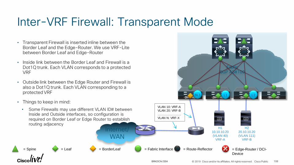
• Transparent Firewall is inserted inline between the Border Leaf and the Edge-Router. We use VRF-Lite between Border Leaf and Edge-Router
• Inside link between the Border Leaf and Firewall is a Dot1Q trunk. Each VLAN corresponds to a protected VRF
• Outside link between the Edge Router and Firewall is also a Dot1Q trunk. Each VLAN corresponding to a protected VRF
• Things to keep in mind:
• Some Firewalls may use different VLAN ID# between Inside and Outside interfaces, so configuration is required on Border Leaf or Edge Router to establish routing adjacency
Inter-VRF Firewall: Transparent Mode
108
RRRR
FabricBGP AS#100
L2BL1
H2
20.10.10.20
(VLAN 111)
VRF-B
= Spine RR = Route-Reflector= Leaf = Fabric Interface= BorderLeaf = Edge-Router / DCI-
Device
Internet/WAN
L1
H1
10.10.10.20
(VLAN 40)
VRF-A
VLAN 10: VRF-A
VLAN 20: VRF-B
…………………..
VLAN N: VRF-X
BRKDCN-2304
© 2019 Cisco and/or its affiliates. All rights reserved. Cisco Public
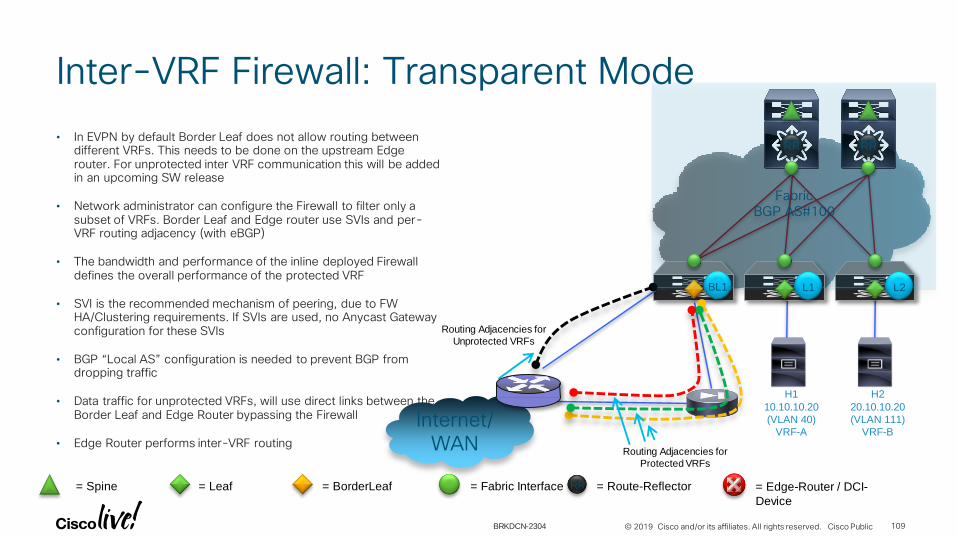
• In EVPN by default Border Leaf does not allow routing between different VRFs. This needs to be done on the upstream Edge router. For unprotected inter VRF communication this will be added in an upcoming SW release
• Network administrator can configure the Firewall to filter only a subset of VRFs. Border Leaf and Edge router use SVIs and per-VRF routing adjacency (with eBGP)
• The bandwidth and performance of the inline deployed Firewall defines the overall performance of the protected VRF
• SVI is the recommended mechanism of peering, due to FW HA/Clustering requirements. If SVIs are used, no Anycast Gateway configuration for these SVIs
• BGP “Local AS” configuration is needed to prevent BGP from dropping traffic
• Data traffic for unprotected VRFs, will use direct links between the Border Leaf and Edge Router bypassing the Firewall
• Edge Router performs inter-VRF routing
Inter-VRF Firewall: Transparent Mode
109
RRRR
L2BL1
H2
20.10.10.20
(VLAN 111)
VRF-BInternet/
WAN
L1
H1
10.10.10.20
(VLAN 40)
VRF-A
Routing Adjacencies for
Protected VRFs
Routing Adjacencies for
Unprotected VRFs
FabricBGP AS#100
= Spine RR = Route-Reflector= Leaf = Fabric Interface= BorderLeaf = Edge-Router / DCI-
Device
BRKDCN-2304

© 2019 Cisco and/or its affiliates. All rights reserved. Cisco Public
• H1 in VRF-A talks to H2 in VRF-B.
• VRF-A is protected by the Tenant-Edge Firewall, in Transparent mode
• VRF-B is unprotected.
• Traffic filtering and Policies enforcement occurs on step 4. Firewall acts as a transparent Layer 2 bridge.
• Traffic from Edge router to VRF-B traverses through a direct link between the Edge router and the Border Leaf
Inter-VRF Firewall: Transparent Mode
110
RRRR
FabricBGP AS#100
L2BL1
H2
20.10.10.20
(VLAN 111)
VRF-B
Internet/WAN
L1
H1
10.10.10.20
(VLAN 40)
VRF-A
eBGP for VRF-A
Contains Animations
Outer-DIP: BL1
Outer-SIP: L1
SMAC: L1_MAC
VNI50001
3
DMAC: BL1_MAC
DIP: 20.10.10.20
SIP: 10.10.10.20
SIP: 10.10.10.20
DIP: 20.10.10.20
SMAC: BL1_MAC
DMAC: CR1_MAC
VLAN 400
4
FW Policy Enforcement
= Spine RR = Route-Reflector= Leaf = Fabric Interface= BorderLeaf = Edge-Router / DCI-
Device / Core Router (CR)
DMAC: G_MAC
SMAC: H1_MAC
DIP: 20.10.10.20
SIP: 10.10.10.20
1
VLAN 40
BRKDCN-2304

© 2019 Cisco and/or its affiliates. All rights reserved. Cisco Public
• Depending on performance and scale requirements, a Per-VRF Firewall deployment model may be used. These Firewalls don’t need to be physical
• Each Firewall will filter traffic for a specific set of VRFs, and will require a separate link between Border Leaf and Edge-Router
Inter-VRF Firewall: Transparent Mode
111
RRRR
FabricBGP AS#100
L2BL1
H2
20.10.10.20
(VLAN 111)
VRF-B
Internet/WAN
L1
H1
10.10.10.20
(VLAN 40)
VRF-A
FW for VRF-C
FW for VRF-A
= Spine RR = Route-Reflector= Leaf = Fabric Interface= BorderLeaf = Edge-Router / DCI-
Device
BRKDCN-2304
© 2019 Cisco and/or its affiliates. All rights reserved. Cisco Public
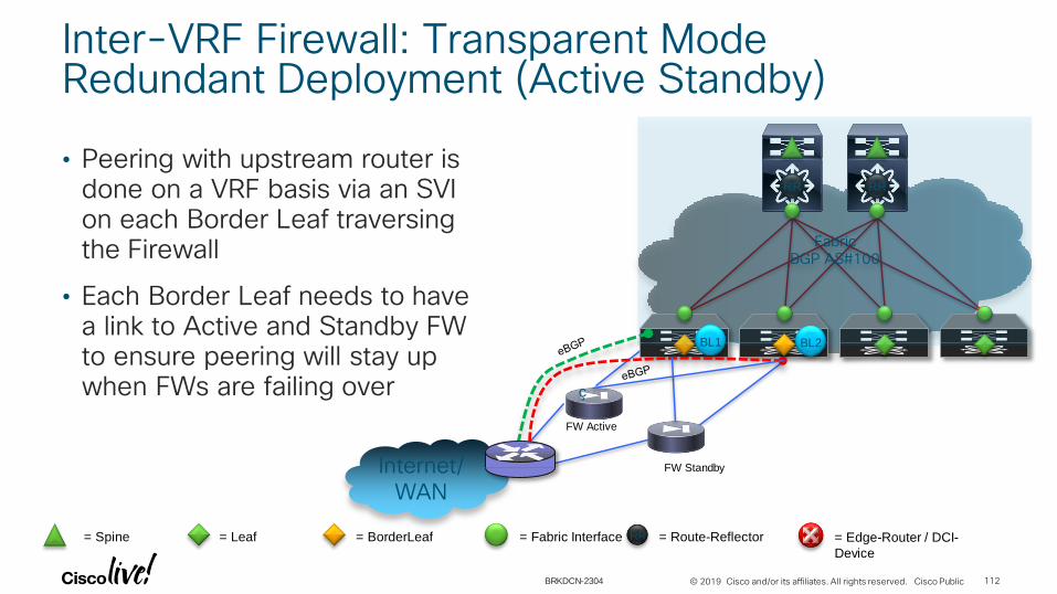
• Peering with upstream router is done on a VRF basis via an SVI on each Border Leaf traversing the Firewall
• Each Border Leaf needs to have a link to Active and Standby FW to ensure peering will stay up when FWs are failing over
Inter-VRF Firewall: Transparent Mode Redundant Deployment (Active Standby)
112
RRRR
FabricBGP AS#100
BL1
Internet/WAN
BL2
ç
FW Active
FW Standby
= Spine RR = Route-Reflector= Leaf = Fabric Interface= BorderLeaf = Edge-Router / DCI-
Device
BRKDCN-2304

© 2019 Cisco and/or its affiliates. All rights reserved. Cisco Public
• Peering is done on a VRF basis via an SVI on each Border Leaf to FW
• Each Border Leaf needs to have a link to Cluster member to ensure peering will stay up when FWs are failing over
• If dynamic routing protocols are used consider L3 via vPC best practices
Inter-VRF Firewall: Transparent Mode Redundant Deployment (Cluster)
113
RRRR
FabricBGP AS#100
BL1
Internet/WAN
BL2
= Spine RR = Route-Reflector= Leaf = Fabric Interface= BorderLeaf = Edge-Router / DCI-
Device
VPC Domain
ç
BRKDCN-2304

© 2019 Cisco and/or its affiliates. All rights reserved. Cisco Public
• When operating a Firewall in Routed mode, additional configuration is required:
• Per-VRF IGP routing adjacency between Border Leaf and Firewall
• Per-VRF IGP routing adjacency between Firewall and Edge Router
• Firewall establishes routing adjacencies with both the Border Leaf and the Edge Router, which in comparison to Transparent mode of operation requires twice as many subnets
Inter-VRF Firewall: Routed Mode (Layer 3)
114
RRRR
FabricBGP AS#100
L2BL1
H2
20.10.10.20
(VLAN 111)
VRF-B
Internet/WAN
L1
H1
10.10.10.20
(VLAN 40)
VRF-A
OSPF VRF-A
OSPF VRF-B
= Spine RR = Route-Reflector= Leaf = Fabric Interface= BorderLeaf = Edge-Router / DCI-
Device
BRKDCN-2304

© 2019 Cisco and/or its affiliates. All rights reserved. Cisco Public
• Peering is done on a VRF basis via an SVI on each Border Leaf to FW
• Each Border Leaf needs to have a link to Active and Standby FW to ensure peering will stay up when FWs are failing over
Inter-VRF Firewall: Routed ModeRedundant Deployment (Active Standby)
115
RRRR
FabricBGP AS#100
BL1
Internet/WAN
BL2
FW Active
FW Standby
= Spine RR = Route-Reflector= Leaf = Fabric Interface= BorderLeaf = Edge-Router / DCI-
Device
BRKDCN-2304
© 2019 Cisco and/or its affiliates. All rights reserved. Cisco Public
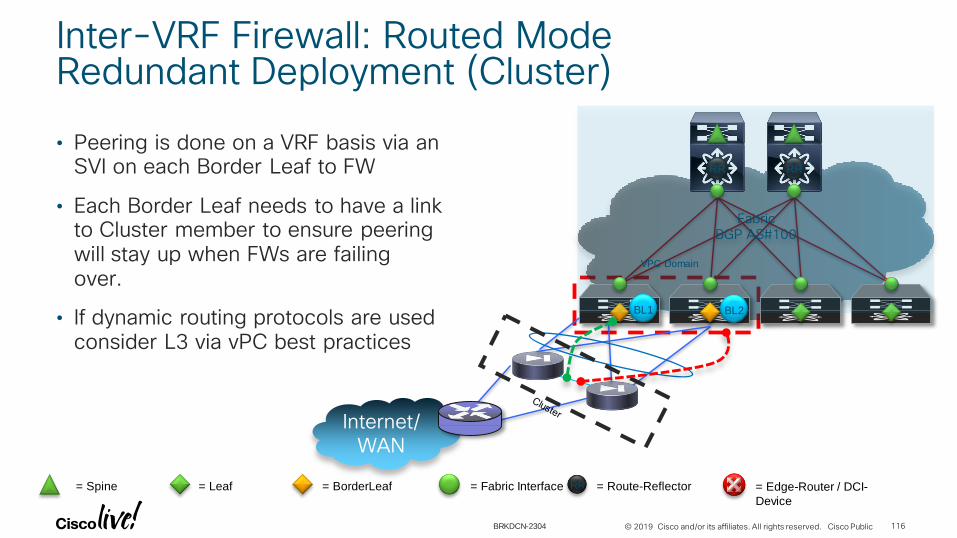
• Peering is done on a VRF basis via an SVI on each Border Leaf to FW
• Each Border Leaf needs to have a link to Cluster member to ensure peering will stay up when FWs are failing over.
• If dynamic routing protocols are used consider L3 via vPC best practices
Inter-VRF Firewall: Routed Mode Redundant Deployment (Cluster)
116
RRRR
FabricBGP AS#100
BL1
Internet/WAN
BL2
= Spine RR = Route-Reflector= Leaf = Fabric Interface= BorderLeaf = Edge-Router / DCI-
Device
VPC Domain
BRKDCN-2304

Intra-VRF Scenario

© 2019 Cisco and/or its affiliates. All rights reserved. Cisco Public
• Inter-VLAN traffic flows for a single VRF can also be filtered by the Firewall
• These secured VLANs are deployed in L2 forwarding mode, i.e. Layer 2 Profile is applied to these VLANs on Leaf nodes
• With Firewall in transparent mode, Border Leaf or Service Leaf becomes the VLAN termination point
• It is important to ensure that Firewall does not propagate STP BPDUs, as the ports on Leaf nodes should be configured with BPDU Guard
Intra-VRF, Inter-VLAN Firewall: Transparent Mode
118
RRRR
L2BL1
H2
20.10.10.20
(VLAN 111)
VRF-A
Internet/WAN
L1
H1
10.10.10.20
(VLAN 40)
VRF-A
= Spine RR = Route-Reflector= Leaf = Fabric Interface= BorderLeaf = Edge-Router / DCI-
Device
FabricBGP AS#100
BRKDCN-2304

© 2019 Cisco and/or its affiliates. All rights reserved. Cisco Public
FabricBGP AS#100
RRRR
L2SL1
H2
20.10.10.20
(VLAN 111)
VRF-A
L1
H1
10.10.10.20
(VLAN 40)
VRF-A
• Inside link between the Services Leaf and Firewall is a Dot1Q trunk. Each VLAN corresponds to a protected subnet
• Outside link between the Services Leaf and Firewall is also a Dot1Q trunk. Firewall in Transparent mode acts as a Layer 2 switch, bridging respective VLANs
• On Services Leaf these VLANs are terminated with SVIs, which are assigned to respective VRFs. These SVIs are the default gateways for the hosts
• Subsequent subnet prefixes are advertised via BGP into the Fabric
Intra-VRF, Inter-VLAN Firewall: Transparent Mode
119
= Spine RR = Route-Reflector= Leaf = Fabric Interface= BorderLeaf = Edge-Router / DCI-
Device
BRKDCN-2304
© 2019 Cisco and/or its affiliates. All rights reserved. Cisco Public
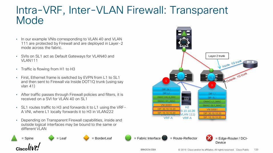
• In our example VNIs corresponding to VLAN 40 and VLAN 111 are protected by Firewall and are deployed in Layer-2 mode across the fabric.
• SVIs on SL1 act as Default Gateways for VLAN40 and VLAN111
• Traffic is flowing from H1 to H3
• First, Ethernet frame is switched by EVPN from L1 to SL1 and then sent to Firewall via Inside DOT1Q trunk (using say vlan 41)
• After traffic passes through Firewall policies and filters, it is received on a SVI for VLAN 40 on SL1
• SL1 routes traffic to H3 and forwards it to L1 using the VRF-A VNI, where L1 locally forwards it to H3 in VLAN222
• Depending on Transparent Firewall capabilities, inside and outside logical interfaces may be bound to the same or different VLAN
Intra-VRF, Inter-VLAN Firewall: Transparent Mode
120
H1
10.10.10.20
(VLAN 40)
VRF-A
H2
20.10.10.20
(VLAN 111)
VRF-A
RR
Layer 2 trunk
L1 SL1
H3
30.10.10.20
(VLAN 222)
VRF-A
DIP: SL1
SIP: L1
SMAC: H1_MAC
VNI 30001
1
DMAC: V40_G_MAC
DIP: 30.10.10.20
SIP: 10.10.10.20
DMAC: V40_G_MAC
SMAC: H1_MAC
DIP: 30.10.10.20
SIP: 10.10.10.20
2
VLAN 41/40
SIP: 10.10.10.20
DIP: 30.10.10.20
SMAC: L1_MAC
DMAC: H3_MAC
VLAN 222
= Spine RR = Route-Reflector= Leaf = Fabric Interface= BorderLeaf = Edge-Router / DCI-
Device
DIP: L1
SIP: SL1
SMAC: SL1_MAC
VNI 50001
3
DMAC: L1_MAC
DIP: 30.10.10.20
SIP: 10.10.10.20
BRKDCN-2304

© 2019 Cisco and/or its affiliates. All rights reserved. Cisco Public
• A Firewall in Routed mode can be connected to either a Border Leaf or a Service Leaf
• Inside link between the Service Leaf and Firewall is a .1Q trunk, where each VLAN corresponds to a protected subnet (VLAN)
• Protected VLANs are deployed in L2 forwarding mode on a Service Leaf and across the fabric
• Outside link is a layer 3 point-to-point link
• Firewall establishes an routing protocol ( OSPF or EIGRP or eBGP) routing adjacency with the Service Leaf over an Outside link
• On Firewall, protected VLANs are terminated with a BVI (bridged virtual interface) or its equivalent and are then advertised into IGP. These BVIs serve as the Default Gateway for protected VLANs
• On Service Leaf, prefixes received from Firewall via routing protocol are re-distributed into BGP
• Service Leaf advertises a 0.0.0.0/0 default route or specific routes reachability to Firewall over an IGP
Intra-VRF, Inter-VLAN Firewall: Routed Mode
121
H1
10.10.10.20
(VLAN 40)
VRF-A
H2
20.10.10.20
(VLAN 111)
VRF-A
RR
Layer 2 trunk
Default Gateway for
VLAN40 and VLAN111 serve as a
Default Gateways and corresponding
subnets are advertised in IGP
L1 SL1
H3
30.10.10.20
(VLAN 222)
VRF-A
VLAN 40 and VLAN 111
are protected VLANs
= Spine RR = Route-Reflector= Leaf = Fabric Interface= BorderLeaf = Edge-Router / DCI-
Device
BRKDCN-2304

© 2019 Cisco and/or its affiliates. All rights reserved. Cisco Public
• Load Balancer can connect to any Leaf, Services Leaf or a Border Leaf with Layer 3 point-to-point link
• Load Balancer establishes routing adjacency with the Leaf node via IGP (OSPF/EIGRP) over this link and also receives a default route from the Leaf node.
• Every configured VIP on Load Balancer is advertised into IGP as a /32 prefix
• These /32 prefixes are learned and redistributed into BGP on the Leaf node.
• On a sample diagram, H1 host is trying to retrieve HTTP web page from web-server at virtual IP VIP-X1: 50.10.10.100 which is configured on a Load-balancer
• Load Balancer retrieves necessary data from Server1 or Server 2
• Data is then returned to the H1 host
Load Balancer Integration using One-Arm Mode
122
H1
10.10.10.20
(VLAN 40)
VRF-A
Server1
20.10.10.11
(VLAN 111)
VRF-A
RR
L1 SL1
VIP-X1: 50.10.10.100
mapped to
Server 1: 20.10.10.11
Server 2: 20.10.10.12
Server2
20.10.10.12
(VLAN 111)
VRF-A
Load-Balancer
OSPF=>iBGP
= Spine RR = Route-Reflector= Leaf = Fabric Interface= BorderLeaf = Edge-Router / DCI-
Device
BRKDCN-2304

© 2019 Cisco and/or its affiliates. All rights reserved. Cisco Public
• It differs from the One-Arm mode in the following:
• “Back-end” communication with the applications servers happens over a dedicated “Services Segment” link.
• Load balancer is statically configured with the default route through the second arm (Services Segment)
Load Balancer Integration using Two-Arm Mode
123
H1
10.10.10.20
(VLAN 40)
VRF-A
Server1
20.10.10.11
(VLAN 111)
VRF-A
RR
L1 SL1
VIP-X1: 50.10.10.100
mapped to
Server 1: 20.10.10.11
Server 2: 20.10.10.12
Server2
20.10.10.12
(VLAN 111)
VRF-A
Load-Balancer
OSPF=>iBGP
= Spine RR = Route-Reflector= Leaf = Fabric Interface= BorderLeaf = Edge-Router / DCI-
Device
BRKDCN-2304

How to Attach Services Nodes in Multi-Pod or Multi-Site Deployments?
© 2019 Cisco and/or its affiliates. All rights reserved. Cisco Public
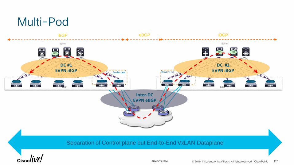
Multi-Pod
125
VXLAN Overlay
EVPN VRF/VRFs Space
Global Default VRF
Or User Space VRFs
Leaf
VTEP VTEP VTEP VTEPVTEPVTEP
Spine
RR RR
Border Leaf
DC #2EVPN iBGP
Inter-DCEVPN eBGP
Leaf
VTEPVTEPVTEPVTEP VTEP VTEP
Spine
RR
Border Leaf
DC #1EVPN iBGP
Separation of Control plane but End-to-End VxLAN Dataplane
RR
iBGP iBGPeBGP
BRKDCN-2304
© 2019 Cisco and/or its affiliates. All rights reserved. Cisco Public
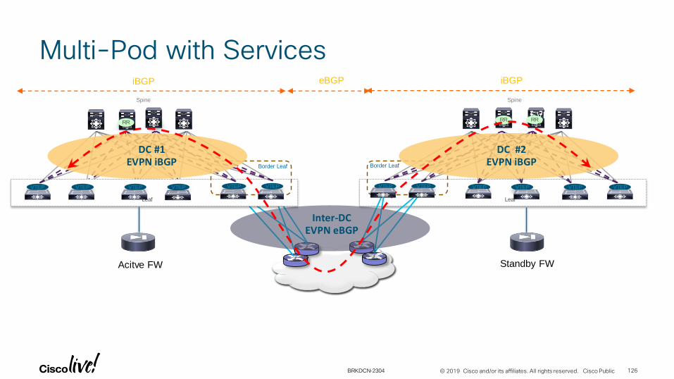
Multi-Pod with Services
126
VXLAN Overlay
EVPN VRF/VRFs Space
Global Default VRF
Or User Space VRFs
Leaf
VTEP VTEP VTEP VTEPVTEPVTEP
Spine
RR RR
Border Leaf
DC #2EVPN iBGP
Inter-DCEVPN eBGP
Leaf
VTEPVTEPVTEPVTEP VTEP VTEP
Spine
RR
Border Leaf
DC #1EVPN iBGP
RR
iBGP iBGPeBGP
Acitve FW Standby FW
BRKDCN-2304

© 2019 Cisco and/or its affiliates. All rights reserved. Cisco Public
Multi-Fabric
127
VXLAN Overlay
EVPN VRF/VRFs Space
Global Default VRF
Or User Space VRFs
Leaf
VTEPVTEPVTEPVTEP VTEP VTEP
Spine
Border Leaf
Leaf
VTEP VTEP VTEP VTEPVTEPVTEP
Spine
Border Leaf
DC #2iBGP
Inter-DCeBGP
DC #1iBGP
VXLAN EVPN Administrative Domain #1 VXLAN EVPN Administrative Domain #2
OTV/VPLS Domain
VLAN Hand-off
OTV OTV OTV OTV
Failure Domain Containment:
• Unknown Unicasts
• ARPs
• STP
Next hop Self Next hop Self
RR RR
RR RR
BRKDCN-2304

© 2019 Cisco and/or its affiliates. All rights reserved. Cisco Public
Multi-Fabric with Services
128
VXLAN Overlay
EVPN VRF/VRFs Space
Global Default VRF
Or User Space VRFs
Leaf
VTEPVTEPVTEPVTEP VTEP VTEP
Spine
Border Leaf
Leaf
VTEP VTEP VTEP VTEPVTEPVTEP
Spine
Border Leaf
DC #2iBGP
Inter-DCeBGP
DC #1iBGP
OTV/VPLS Domain
VLAN Hand-off
OTV OTV OTV OTV
Next hop Self Next hop Self
RR RR
RR RR
Acitve FW Standby FW
BRKDCN-2304

© 2019 Cisco and/or its affiliates. All rights reserved. Cisco Public
Multi-Fabric with Services
129
VXLAN Overlay
EVPN VRF/VRFs Space
Leaf
VTEPVTEPVTEPVTEP VTEP VTEP
Spine
Border Leaf
Leaf
VTEP VTEP VTEP VTEPVTEPVTEP
Spine
Border Leaf
DC #2iBGP
Inter-DCeBGP
DC #1iBGP
OTV/VPLS Domain
VLAN Hand-off
OTV OTV OTV OTV
Next hop Self Next hop Self
RR RR
RR RR
Cluster with
spanned split
Etherchannel
Cluster with
spanned split
Etherchannel
ARP and Cluster/IP MAC needs to be
filtered
Ensure Traffic symmetry going out of and into fabric
BRKDCN-2304

© 2019 Cisco and/or its affiliates. All rights reserved. Cisco Public
VXLAN Multi-Site and Network Services Integration
Spine SpineVXLAN EVPN
Site1
VTEP VTEP VTEP VTEP
VTEP VTEP
Spine SpineVXLAN EVPN
Site2
VTEP VTEP VTEP VTEP
VTEP VTEP
BGW
WAN
Standby FWActive FW
BGW BGW BGW
Inter-Site Network
Active FW Standby FW
Baremetal
Baremetal
Baremetal
Active and Standby pair deployed across Sites, enforcement for N-S and E-W flows
No issues with asymmetric flows
Various options possible (FW as endpoints gateway or fabric as endpoints gateway)
Independent Active/Standby pairs deployed in separate Sites
Need to avoid the creation of asymmetric paths crossing different active FW nodes
Only possible for N-S flows with perimeter FWs and host routes advertisement or with PBR
Spine SpineVXLAN EVPN
Site1
VTEP VTEP VTEP VTEP
VTEP VTEP
Spine SpineVXLAN EVPN
Site2
VTEP VTEP VTEP VTEP
VTEP VTEP
BGW
WAN
Active/Standby FW
Active/Standby FW BGW BGW BGW
Inter-Site Network
Baremetal
Baremetal
Active/Standby FW Active/Standby FW
Spine SpineVXLAN EVPN
Site1
VTEP VTEP VTEP VTEP
VTEP VTEP
Spine SpineVXLAN EVPN
Site2
VTEP VTEP VTEP VTEP
VTEP VTEP
BGW
WAN
BGW BGW BGW
Inter-Site Network
Active/Active FW Cluster Baremetal
Active/Active FW Cluster stretched across Sites
Split spanned ether-channel mode: not supported,
Individual mode: supported with Cisco ASA software for N-S and E-W flows
130BRKDCN-2304

Network Services Integration Models with VXLAN Multi-Site

Active/Standby Pair across Sites

© 2019 Cisco and/or its affiliates. All rights reserved. Cisco Public
Active and Standby pair deployed across Sites
Fabric
DCIInter-Site
Network
Spine Spine
VXLAN EVPN
Site1
VTEP VTEP VTEP VTEP
VTEP VTEP
….
Spine Spine
VXLAN EVPN
Site2
VTEP VTEP VTEP VTEP
VTEP VTEP
….Multi-Site
VIP1
Multi-Site
VIP2
BGW BGW BGW BGW
Active Standby133BRKDCN-2304

© 2019 Cisco and/or its affiliates. All rights reserved. Cisco Public
Active/Standby Pair across SitesDeployment Considerations
• Active/Standby model can be applied per context (i.e. can be deemed as ‘active/active’ support across contexts)
• Different deployment models
• FW as default gateway for the endpoints peering with the fabric (via IGP or BGP)
• FW as default gateway for the endpoints using static routing
• FW as default gateway for the endpoints peering directly with the external routers (fabric as L2)
• Fabric as default gateway and use of a perimeter FW
134BRKDCN-2304
© 2019 Cisco and/or its affiliates. All rights reserved. Cisco Public
1. FW as Default Gateway Peering with the Fabric
135BRKDCN-2304

© 2019 Cisco and/or its affiliates. All rights reserved. Cisco Public
Active/Standby Pair across SitesFW as Default Gateway Peering with the Fabric
External L3 Domain
Logical View
Site 1 Site 2
IGP/BGP Peering
• FW allows to apply intra-tenant security policies (east-west) and between an internal subnet and the external L3 domain (north-south) or a subnet in a different tenant (inter-tenant)
• FW inside network(s) deployed as L2-only can be extended across sites to allow flexible deployment for endpoints
• FW outside interface used to peer with the fabric
• The active FW can only peer with the leaf node(s) in the local fabric (on a L3 interface or regular SVI)
• No need to extend the FW outside BD across sites
Routing function of the VXLAN EVPN Fabric
Active Standby
1
BDs Extended via Multi-Site
Inter-Site
Network
136BRKDCN-2304
© 2019 Cisco and/or its affiliates. All rights reserved. Cisco Public
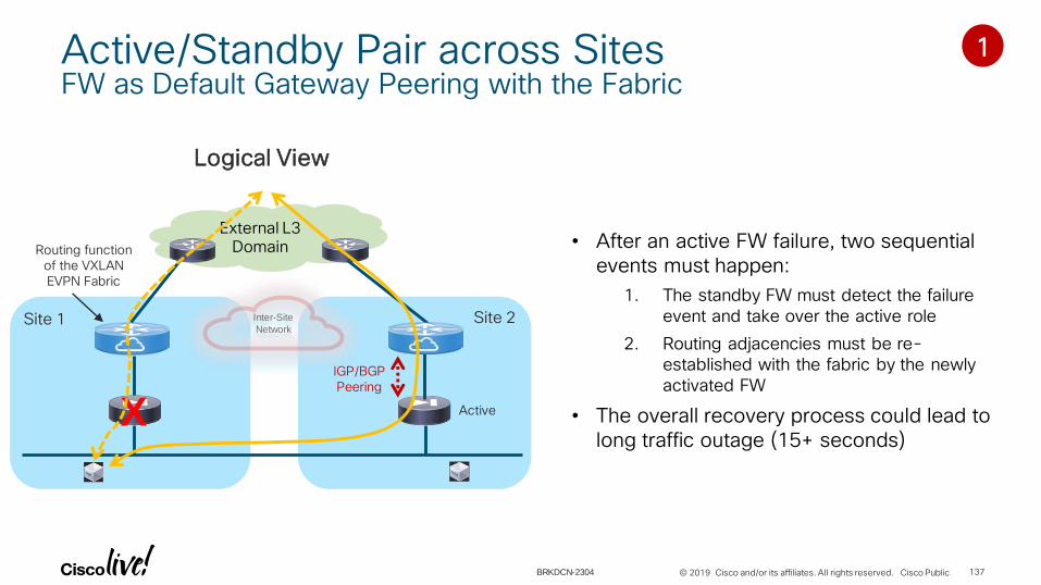
Active/Standby Pair across SitesFW as Default Gateway Peering with the Fabric
External L3 Domain
Logical View
Site 1 Site 2
IGP/BGP Peering
• After an active FW failure, two sequential events must happen:
1. The standby FW must detect the failure event and take over the active role
2. Routing adjacencies must be re-established with the fabric by the newly activated FW
• The overall recovery process could lead to long traffic outage (15+ seconds)
X Active
1
Inter-Site
Network
Routing function of the VXLAN EVPN Fabric
137BRKDCN-2304
© 2019 Cisco and/or its affiliates. All rights reserved. Cisco Public
Active/Standby Pair across SitesFW as Default Gateway Peering with the Fabric
External L3 Domain
Logical View
Site 1 Site 2
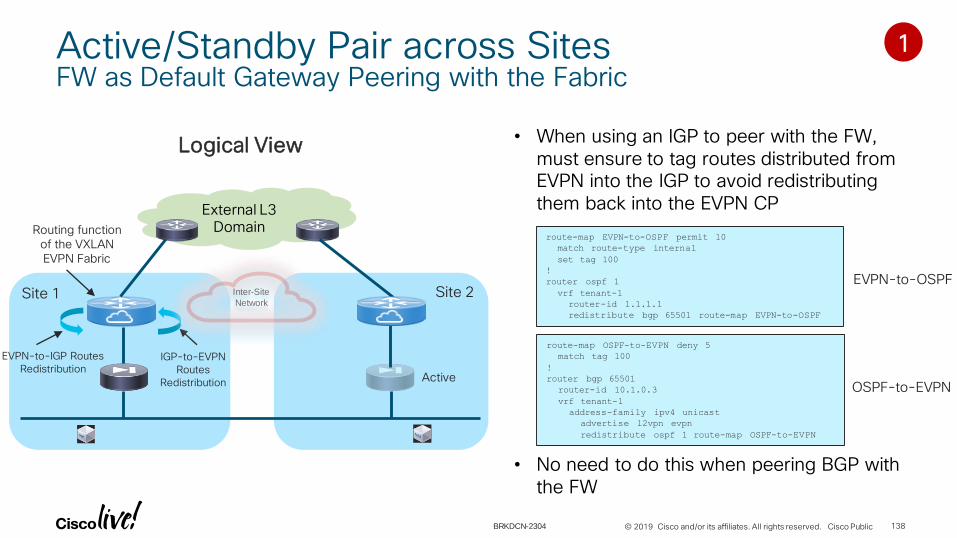
• When using an IGP to peer with the FW, must ensure to tag routes distributed from EVPN into the IGP to avoid redistributing them back into the EVPN CP
• No need to do this when peering BGP with the FW
EVPN-to-IGP Routes Redistribution
Active
1
IGP-to-EVPN Routes
Redistribution
route-map EVPN-to-OSPF permit 10
match route-type internal
set tag 100
!
router ospf 1
vrf tenant-1
router-id 1.1.1.1
redistribute bgp 65501 route-map EVPN-to-OSPF
route-map OSPF-to-EVPN deny 5
match tag 100
!
router bgp 65501
router-id 10.1.0.3
vrf tenant-1
address-family ipv4 unicast
advertise l2vpn evpn
redistribute ospf 1 route-map OSPF-to-EVPN
EVPN-to-OSPF
OSPF-to-EVPN
Inter-Site
Network
Routing function of the VXLAN EVPN Fabric
138BRKDCN-2304

© 2019 Cisco and/or its affiliates. All rights reserved. Cisco Public
2. FW as Default Gateway Using Static Routing with the Fabric
139BRKDCN-2304
© 2019 Cisco and/or its affiliates. All rights reserved. Cisco Public
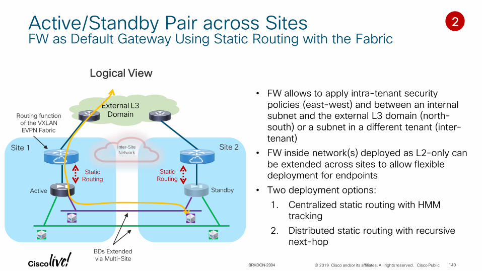
Active/Standby Pair across SitesFW as Default Gateway Using Static Routing with the Fabric
External L3 Domain
Logical View
Site 1 Site 2
• FW allows to apply intra-tenant security policies (east-west) and between an internal subnet and the external L3 domain (north-south) or a subnet in a different tenant (inter-tenant)
• FW inside network(s) deployed as L2-only can be extended across sites to allow flexible deployment for endpoints
• Two deployment options:
1. Centralized static routing with HMM tracking
2. Distributed static routing with recursive next-hop
Active Standby
2
BDs Extended via Multi-Site
Static Routing
Static Routing
Inter-Site
Network
Routing function of the VXLAN EVPN Fabric
140BRKDCN-2304

© 2019 Cisco and/or its affiliates. All rights reserved. Cisco Public
FW Using Static Routing with the FabricCentralized Static Routing with HMM Tracking (Configuration)
Fabric
DCI
Inter-Site
Network
Spine Spine
VXLAN EVPN
Site1VTEP VTEP VTEP VTEP
VTEP VTEP
….Spine Spine
VXLAN EVPN
Site2VTEP VTEP VTEP VTEP
VTEP VTEP
….Multi-Site
VIP1
Multi-Site
VIP2BGW BGW BGW BGW
Active Standby
vrf context VRF1
vni 50000
ip route <endpoint-subnet> <FW-IP> tag 12345 track 1
!
track 1 ip route <FW-IP> reachability hmm
vrf member VRF1
!
router bgp 65001
vrf customera
address-family ipv4 unicast
advertise l2vpn evpn
redistribute static route-map fabric-rmap-redist-subnet
FW-IP
Config applied only only on the leaf nodes
connected to the Active and Standby
FWs
141

© 2019 Cisco and/or its affiliates. All rights reserved. Cisco Public
FW Using Static Routing with the FabricCentralized Static Routing with HMM Tracking
Fabric
DCI
Inter-Site
Network
Spine Spine
VXLAN EVPN
Site1VTEP VTEP VTEP VTEP
VTEP VTEP
….Spine Spine
VXLAN EVPN
Site2VTEP VTEP VTEP VTEP
VTEP VTEP
….Multi-Site
VIP1
Multi-Site
VIP2BGW BGW BGW BGW
Active Standby
FW-IP
Traffic destined to endpoints behind the FW is always encapsulated toward the leaf node connected to the active FW
External L3 Domain
142BRKDCN-2304

© 2019 Cisco and/or its affiliates. All rights reserved. Cisco Public
FW Using Static Routing with the FabricDistributed Static Routing with Recursive Next-Hop (Configuration)
Fabric
DCI
Inter-Site
Network
Spine Spine
VXLAN EVPN
Site1VTEP VTEP VTEP VTEP
VTEP VTEP
….Spine Spine
VXLAN EVPN
Site2VTEP VTEP VTEP VTEP
VTEP VTEP
….Multi-Site
VIP1
Multi-Site
VIP2BGW BGW BGW BGW
Active Standby
vrf context VRF1
vni 50000
ip route <endpoint-subnet> <FW-IP>
FW-IP
Config applied on all the leaf nodes and also on the Border Gateways
143BRKDCN-2304

© 2019 Cisco and/or its affiliates. All rights reserved. Cisco Public
FW Using Static Routing with the FabricDistributed Static Routing with Recursive Next-Hop
Fabric
DCI
Inter-Site
Network
Spine Spine
VXLAN EVPN
Site1VTEP VTEP VTEP VTEP
VTEP VTEP
….Spine Spine
VXLAN EVPN
Site2VTEP VTEP VTEP VTEP
VTEP VTEP
….Multi-Site
VIP1
Multi-Site
VIP2BGW BGW BGW BGW
Active Standby
FW-IP
Traffic destined to endpoints behind the FW is always encapsulated toward the leaf node connected to the active FW
External L3 Domain
144BRKDCN-2304

© 2019 Cisco and/or its affiliates. All rights reserved. Cisco Public
FW Using Static Routing with the FabricCentralized vs. Distributed Static Routing
Centralized Static Routing with HMM
Tracking
Distributed Static Routing with Recursive Next-Hop
👍 Centralized configuration (few touch points)
👎 Convergence depending on HMM tracking and static routing redistribution into EVPN
👎 Scalability dependent on the number of routes to redistribute
👍 Simpler configuration
👍 Recursive Next-Hop functionality natively integrated into VXLAN EVPN
👍 Convergence only dependent on FW-IP discovery
👎 Distributed configuration (many touch points), can be simplified with a provisioning tool (DCNM)
145BRKDCN-2304

© 2019 Cisco and/or its affiliates. All rights reserved. Cisco Public
3. FW as Default Gateway Peering Directly with the External Routers
146BRKDCN-2304
© 2019 Cisco and/or its affiliates. All rights reserved. Cisco Public
Active/Standby Pair across SitesFW as Default Gateway Peering with the Fabric
External L3 Domain
Logical View
Site 1 Site 2
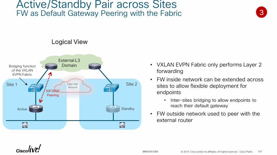
• VXLAN EVPN Fabric only performs Layer 2 forwarding
• FW inside network can be extended across sites to allow flexible deployment for endpoints
• Inter-sites bridging to allow endpoints to reach their default gateway
• FW outside network used to peer with the external router
Active Standby
3
Inter-Site
Network
IGP/BGP Peering
Bridging function of the VXLAN EVPN Fabric
147BRKDCN-2304

© 2019 Cisco and/or its affiliates. All rights reserved. Cisco Public
Active/Standby Pair across SitesFW as Default Gateway Peering with the Fabric
3
External L3 Domain
Site 1 Site 2IGP/BGP Peering
Active Standby
FW Outside Network is Not Stretched
• The active FW peers only with the external router(s) connected to the local site
• Longer convergence after a FW failover event (similar to the previous scenario)
• Optimal inbound/outbound traffic paths for the endpoints part of the site with the active FW
Inter-Site
Network
External L3 Domain
Site 1 Site 2IGP/BGP Peerings
Active Standby
FW Outside Network is Stretched
• The active FW peers with the external routers connected to all the sites
• No need to re-establish peering adjacencies after a FW failover traffic outage only dependent on FW failure detection mechanism
• Sub-optimal inbound/outbound traffic paths for the endpoints part of the site with the active FW
Inter-Site
Network
148

© 2019 Cisco and/or its affiliates. All rights reserved. Cisco Public
4. Fabric as Default Gateway and Use of a Perimeter FW
149BRKDCN-2304
© 2019 Cisco and/or its affiliates. All rights reserved. Cisco Public
Active/Standby Pair across SitesFabric as Default Gateway and Use of a Perimeter FW (Intra-Tenant)
External L3 Domain
Logical View
IGP/BGP Peering (or
Static Routing)
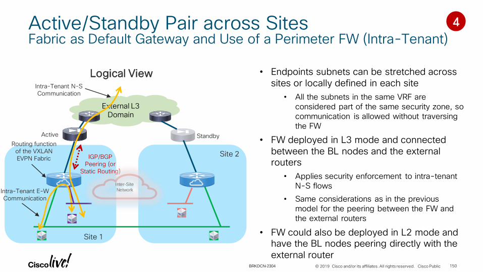
• Endpoints subnets can be stretched across sites or locally defined in each site
• All the subnets in the same VRF are considered part of the same security zone, so communication is allowed without traversing the FW
• FW deployed in L3 mode and connected between the BL nodes and the external routers
• Applies security enforcement to intra-tenant N-S flows
• Same considerations as in the previous model for the peering between the FW and the external routers
• FW could also be deployed in L2 mode and have the BL nodes peering directly with the external router
Intra-Tenant N-S Communication
Active Standby
4
Intra-Tenant E-W Communication
Site 1
Site 2
Inter-Site
Network
Routing function of the VXLAN EVPN Fabric
150BRKDCN-2304

© 2019 Cisco and/or its affiliates. All rights reserved. Cisco Public
Active/Standby Pair across SitesFabric as Default Gateway and Use of a Perimeter FW (Inter-Tenants)
External L3 Domain
Logical View
Site 1
Site 2
• Communication between subnets part of separate VRFs (tenants) can happen through the FW front-ending each VRF
• Use a a single FW with multiple interfaces (one for each VRF)
• Alternatively, use of a FW context dedicated to each VRF. The external network performs the role of “fusion routing” between FW contexts belonging to separate tenants
BDs Extended via Multi-Site
Active Standby
VRF Tenant 1
VRF Tenant 2
VRF Tenant 2
VRF Tenant 1
Inter-Tenants E-W Communication
Inter-Site
Network
Routing function of the VXLAN EVPN Fabric
151BRKDCN-2304

Independent Services in each Site
© 2019 Cisco and/or its affiliates. All rights reserved. Cisco Public
Fabric
DCI
Inter-Site
Network
Spine Spine
VXLAN EVPN
Site1
VTEP VTEP VTEP VTEP
VTEP VTEP
….
Spine Spine
VXLAN EVPN
Site2
VTEP VTEP VTEP VTEP
VTEP VTEP
….Multi-Site
VIP1
Multi-Site
VIP2
BGW BGW BGW BGW
Active/Standby Pair
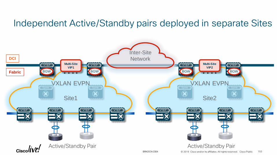
Independent Active/Standby pairs deployed in separate Sites
Active/Standby Pair153BRKDCN-2304

© 2019 Cisco and/or its affiliates. All rights reserved. Cisco Public
• Independent pairs of services deployed in each site can’t synchronize connection state between them
• Must avoid creating asymmetric traffic paths across separate stateful services
• For supporting workload mobility, the FW cannot be deployed as default gateway for the endpoints
• Deployment of perimeter FW and host route advertisement
• Intra-Tenant: FW enforcement for north-south flows
• Inter-Tenants: FW enforcement for east-west communication
Independent Active/Standby pairs deployed in separate SitesDeployment Considerations
154BRKDCN-2304
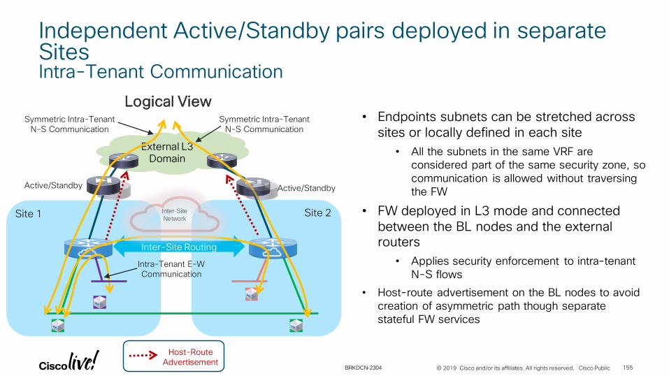
© 2019 Cisco and/or its affiliates. All rights reserved. Cisco Public
External L3 Domain
Logical View• Endpoints subnets can be stretched across
sites or locally defined in each site
• All the subnets in the same VRF are considered part of the same security zone, so communication is allowed without traversing the FW
• FW deployed in L3 mode and connected between the BL nodes and the external routers
• Applies security enforcement to intra-tenant N-S flows
• Host-route advertisement on the BL nodes to avoid creation of asymmetric path though separate stateful FW services
Symmetric Intra-Tenant N-S Communication
Active/Standby Active/Standby
Intra-Tenant E-W Communication
Site 1 Site 2
Symmetric Intra-Tenant N-S Communication
Independent Active/Standby pairs deployed in separate SitesIntra-Tenant Communication
Host-Route Advertisement
Inter-Site Routing
Inter-Site
Network
155BRKDCN-2304

© 2019 Cisco and/or its affiliates. All rights reserved. Cisco Public
Independent Active/Standby pairs deployed in separate SitesLocal Host-Route Advertisement
EP1 advertisement (AS-Path: 65001)
External L3 Domain
Active/Standby
Site 1AS 65001 BGP BGP
Site 2AS 65002
• When using BGP for peering between the fabric and the external router (FW or L3 device), by default local host routes are advertised with a better metric (because of AS-Path length)
EP1
EVPN Update for EP1
EVPN
EP1 advertisement (AS-Path:
65001,65002)
Best path to EP1 via Site 1
Active/Standby
External L3 Domain
Site 1AS 65001 IGP IGP
Site 2AS 65002
EP1 EP2
• When using an IGP for peering between the fabric and the external router (FW or L3 device), it is possible to redistribute only BGP internal (i.e. local) host-routes into the IGP
EVPN Update for EP1
EVPN
EP1 advertisement
X
EP1 advertisement filtered out
Only path to EP1 via Site 1
route-map EVPN-to-OSPF permit 10
match route-type internal
!
router ospf 1
vrf VRF1
router-id <RID>
redistribute bgp <ASN> route-map EVPN-to-OSPF
Configuration on BL Nodes in both sites
Active/Standby Active/Standby
156BRKDCN-2304

© 2019 Cisco and/or its affiliates. All rights reserved. Cisco Public
External L3 Domain
Logical View
Site 1 Site 2
BDs Extended via Multi-Site
Inter-Tenants E-W Communication
Independent Active/Standby pairs deployed in separate SitesInter-Tenants Communication
Host-Route Advertisement
• Communication between subnets part of separate VRFs (tenants) can happen through the FW front-ending each VRF
• Host route advertisement for local hosts between the fabric and the local FW
• Inter-site communication between hosts part of separate VRFs must traverse FWs deployed in both sites
• Host routes injected in the external L3 domain to allow this communication
VRF Tenant 1
VRF Tenant 2
VRF Tenant 2
VRF Tenant 1
Inter-Site
Network
Active/Standby Active/Standby
157BRKDCN-2304
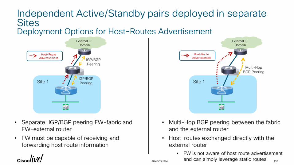
© 2019 Cisco and/or its affiliates. All rights reserved. Cisco Public
Independent Active/Standby pairs deployed in separate SitesDeployment Options for Host-Routes Advertisement
Site 1
External L3 Domain
IGP/BGP Peering
IGP/BGP Peering
Host-Route
Advertisement
• Separate IGP/BGP peering FW-fabric and FW-external router
• FW must be capable of receiving and forwarding host route information
Site 1
External L3 Domain
Multi-Hop BGP Peering
Host-Route
Advertisement
• Multi-Hop BGP peering between the fabric and the external router
• Host-routes exchanged directly with the external router
• FW is not aware of host route advertisement and can simply leverage static routes
158BRKDCN-2304

Active/Active Cluster across Sites

© 2019 Cisco and/or its affiliates. All rights reserved. Cisco Public
Active/Active FW Cluster stretched across SitesSplit-Spanned Ether-Channel Mode
Fabric
DCIInter-Site
Network
Spine Spine
VXLAN EVPN
Site1
VTEP VTEP VTEP VTEP
VTEP VTEP
….
Spine Spine
VXLAN EVPN
Site2
VTEP VTEP VTEP VTEP
VTEP VTEP
….Multi-Site
VIP1
Multi-Site
VIP2
BGW BGW BGW BGW
Cluster with split-spanned ether-channelMAC1/IP1 MAC1/IP1 MAC1/IP1 MAC1/IP1
Not supported, on radar for 2HCY19
Requires anycast IP service support across Sites
160
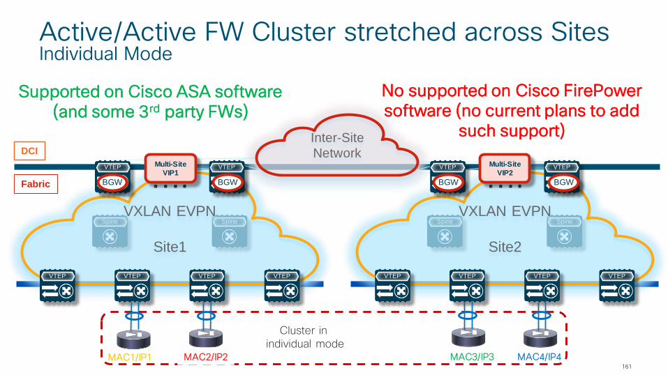
© 2019 Cisco and/or its affiliates. All rights reserved. Cisco Public
Active/Active FW Cluster stretched across SitesIndividual Mode
Fabric
DCI
Inter-Site
Network
Spine Spine
VXLAN EVPN
Site1
VTEP VTEP VTEP VTEP
VTEP VTEP
….
Spine Spine
VXLAN EVPN
Site2
VTEP VTEP VTEP VTEP
VTEP VTEP
….Multi-Site
VIP1
Multi-Site
VIP2
BGW BGW BGW BGW
Cluster in individual mode
MAC1/IP1 MAC2/IP2 MAC3/IP3 MAC4/IP4
Supported on Cisco ASA software (and some 3rd party FWs)
No supported on Cisco FirePowersoftware (no current plans to add
such support)
161

© 2019 Cisco and/or its affiliates. All rights reserved. Cisco Public
Active/Active FW Cluster in Individual ModeDeployment Considerations
• Each cluster FW node owns a separate identity (MAC/IP address)
• Communication on the Cluster Control Link (CCL) between FW nodes happens via Multi-Site (using a dedicated and extended L2VNI)
• Recommended to deploy the FW nodes in “one-arm” mode connected to a “Service BD” associated to an extended L2VNI
Simplifies the routing configuration on the FW nodes
• Recommended use of Policy Based Routing to redirect traffic to the local servicenode(s)
Only supported with 2nd generation leaf HW (EX and newer)
When specifying multiple next-hops in the same PBR statement, in VXLAN deployments traffic is load-balanced per flow across all of them by default
162BRKDCN-2304
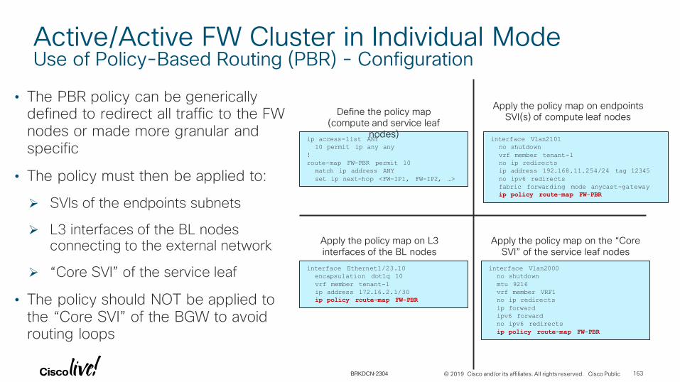
© 2019 Cisco and/or its affiliates. All rights reserved. Cisco Public
Active/Active FW Cluster in Individual ModeUse of Policy-Based Routing (PBR) - Configuration
• The PBR policy can be generically defined to redirect all traffic to the FW nodes or made more granular and specific
• The policy must then be applied to:
SVIs of the endpoints subnets
L3 interfaces of the BL nodes connecting to the external network
“Core SVI” of the service leaf
• The policy should NOT be applied to the “Core SVI” of the BGW to avoid routing loops
ip access-list ANY
10 permit ip any any
!
route-map FW-PBR permit 10
match ip address ANY
set ip next-hop <FW-IP1, FW-IP2, …>
Define the policy map (compute and service leaf
nodes)interface Vlan2101
no shutdown
vrf member tenant-1
no ip redirects
ip address 192.168.11.254/24 tag 12345
no ipv6 redirects
fabric forwarding mode anycast-gateway
ip policy route-map FW-PBR
Apply the policy map on endpoints SVI(s) of compute leaf nodes
interface Ethernet1/23.10
encapsulation dot1q 10
vrf member tenant-1
ip address 172.16.2.1/30
ip policy route-map FW-PBR
Apply the policy map on L3 interfaces of the BL nodes
interface Vlan2000
no shutdown
mtu 9216
vrf member VRF1
no ip redirects
ip forward
ipv6 forward
no ipv6 redirects
ip policy route-map FW-PBR
Apply the policy map on the “Core SVI” of the service leaf nodes
163BRKDCN-2304

© 2019 Cisco and/or its affiliates. All rights reserved. Cisco Public
Fabric
DCI
Inter-Site
Network
Spine Spine
VXLAN EVPN
Site1
VTEP VTEP VTEP VTEP
VTEP VTEP
….
Spine Spine
VXLAN EVPN
Site2
VTEP VTEP VTEP VTEP
VTEP VTEP
….Multi-Site
VIP1
Multi-Site
VIP2
BGW BGW BGW BGW
Cluster in individual mode
MAC1/IP1 MAC2/IP2 MAC3/IP3 MAC4/IP4
Use of Policy-Based Routing (PBR)Intra-Site East-West Communication (1)
PBR on endpoint SVI
PBR on Core SVI
164BRKDCN-2304

© 2019 Cisco and/or its affiliates. All rights reserved. Cisco Public
Fabric
DCI
Inter-Site
Network
Spine Spine
VXLAN EVPN
Site1
VTEP VTEP VTEP VTEP
VTEP VTEP
….
Spine Spine
VXLAN EVPN
Site2
VTEP VTEP VTEP VTEP
VTEP VTEP
….Multi-Site
VIP1
Multi-Site
VIP2
BGW BGW BGW BGW
Cluster in individual mode
MAC1/IP1 MAC2/IP2 MAC3/IP3 MAC4/IP4
Use of Policy-Based Routing (PBR)Intra-Site East-West Communication (2)
PBR on Core SVI
PBR on endpoint SVI
165BRKDCN-2304
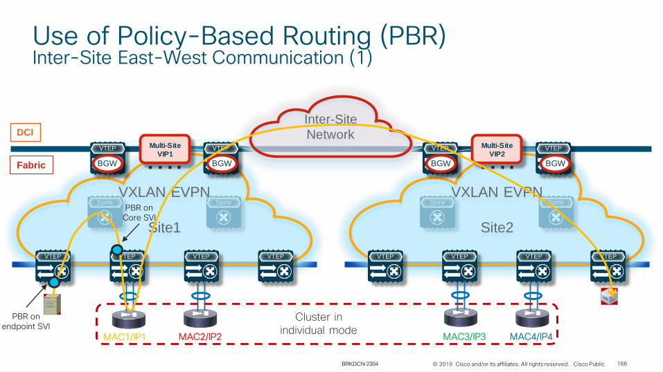
© 2019 Cisco and/or its affiliates. All rights reserved. Cisco Public
Fabric
DCI
Inter-Site
Network
Spine Spine
VXLAN EVPN
Site1
VTEP VTEP VTEP VTEP
VTEP VTEP
….
Spine Spine
VXLAN EVPN
Site2
VTEP VTEP VTEP VTEP
VTEP VTEP
….Multi-Site
VIP1
Multi-Site
VIP2
BGW BGW BGW BGW
Cluster in individual mode
MAC1/IP1 MAC2/IP2 MAC3/IP3 MAC4/IP4
Use of Policy-Based Routing (PBR)Inter-Site East-West Communication (1)
PBR on endpoint SVI
PBR on Core SVI
166BRKDCN-2304

© 2019 Cisco and/or its affiliates. All rights reserved. Cisco Public
Fabric
DCI
Inter-Site
Network
Spine Spine
VXLAN EVPN
Site1
VTEP VTEP VTEP VTEP
VTEP VTEP
….
Spine Spine
VXLAN EVPN
Site2
VTEP VTEP VTEP VTEP
VTEP VTEP
….Multi-Site
VIP1
Multi-Site
VIP2
BGW BGW BGW BGW
Cluster in individual mode
MAC1/IP1 MAC2/IP2 MAC3/IP3 MAC4/IP4
Use of Policy-Based Routing (PBR)Inter-Site East-West Communication (2)
PBR on Core SVI
PBR on endpoint SVI
PBR on Core SVI
Redirection over CCL link
167BRKDCN-2304

© 2019 Cisco and/or its affiliates. All rights reserved. Cisco Public
Fabric
DCI
Inter-Site
Network
Spine Spine
VXLAN EVPN
Site1
VTEP VTEP VTEP VTEP
VTEP VTEP
….
Spine Spine
VXLAN EVPN
Site2
VTEP VTEP VTEP VTEP
VTEP VTEP
….Multi-Site
VIP1
Multi-Site
VIP2
BGW BGW BGW BGW
Cluster in individual mode
MAC1/IP1 MAC2/IP2 MAC3/IP3 MAC4/IP4
Use of Policy-Based Routing (PBR)North-South Communication (1)
External L3 Domain
PBR on L3 interface
PBR on Core SVI
168BRKDCN-2304

© 2019 Cisco and/or its affiliates. All rights reserved. Cisco Public
Fabric
DCI
Inter-Site
Network
Spine Spine
VXLAN EVPN
Site1
VTEP VTEP VTEP VTEP
VTEP VTEP
….
Spine Spine
VXLAN EVPN
Site2
VTEP VTEP VTEP VTEP
VTEP VTEP
….Multi-Site
VIP1
Multi-Site
VIP2
BGW BGW BGW BGW
Cluster in individual mode
MAC1/IP1 MAC2/IP2 MAC3/IP3 MAC4/IP4
Use of Policy-Based Routing (PBR)North-South Communication (2)
External L3 Domain
PBR on Core SVI
PBR on endpoint SVI
169BRKDCN-2304

© 2019 Cisco and/or its affiliates. All rights reserved. Cisco Public 170
• Introduction
• Multi-Tenancy Functionality in Enterprise Data Center
• Data Plane and Control Plane Considerations with VXLAN EVPN
• Layer 4-7 Services Integration
• Other useful Things?
• Pervasive Load Balancing for EVPN
• Centralized Route Leaking in EVPN
• Fabric Provisioning and Management
• Conclusion
Agenda
BRKDCN-2304

Other Useful Things?

Pervasive Load Balancing for EVPN

© 2019 Cisco and/or its affiliates. All rights reserved. Cisco Public
Let’s Turn the Whole Fabric into a Load Balancer
173
• Servers/VMs/Containers can be distributed anywhere in the fabric
• Node health probes in data plane for directly attached nodes
• Stats at each switch - Analytics and telemetry provide details about when/how to grow capacity of servers (i.e., spawn VM/containers) and appliances (elastic data Center)
RRRR
FabricBGP AS#100
L2L3
H2
20.10.10.20
(VLAN 111)
VRF-A
L1
H1
10.10.10.20
(VLAN 40)
VRF-A
H3
30.30.30.20
(VLAN 30)
VRF-A
BRKDCN-2304

© 2019 Cisco and/or its affiliates. All rights reserved. Cisco Public
How Does This Work?
174
• Every Leaf has a load balancing configuration
• Which traffic has to be send to which destination Server
• Hashing is consistent across all leafs
• Wherever the packet with the destination of a load balanced service is entering the fabric, it is forwarded based on the configuration on the leaf.
RRRR
FabricBGP AS#100
L2L3
H2
20.10.10.20
(VLAN 111)
VRF-A
L1
H1
10.10.10.20
(VLAN 40)
VRF-A
H3
30.30.30.20
(VLAN 30)
VRF-A
1. Packet with destination VIP arrives at Ingress Leaf
2. Ingress Leaf selects destination server based on hashing
3. Ingress Leaf will send the packet to Egress Leaf with the selected server
4. Each server has an individual unique IP as well as the VIP configured
5. Return traffic is directly from selected server to the client
DMAC: G_MAC
SMAC: H1_MAC
DIP: VIP
SIP: 30.30.30.20
1
VLAN 30
VIP
DSID: L2
SSID: L3
SMAC: L3_MAC
VNI50001
3
DMAC: L2_MAC
DIP: VIP
SIP: 30.30.30.20
2
BRKDCN-2304

Centralized Route Leaking in EVPN
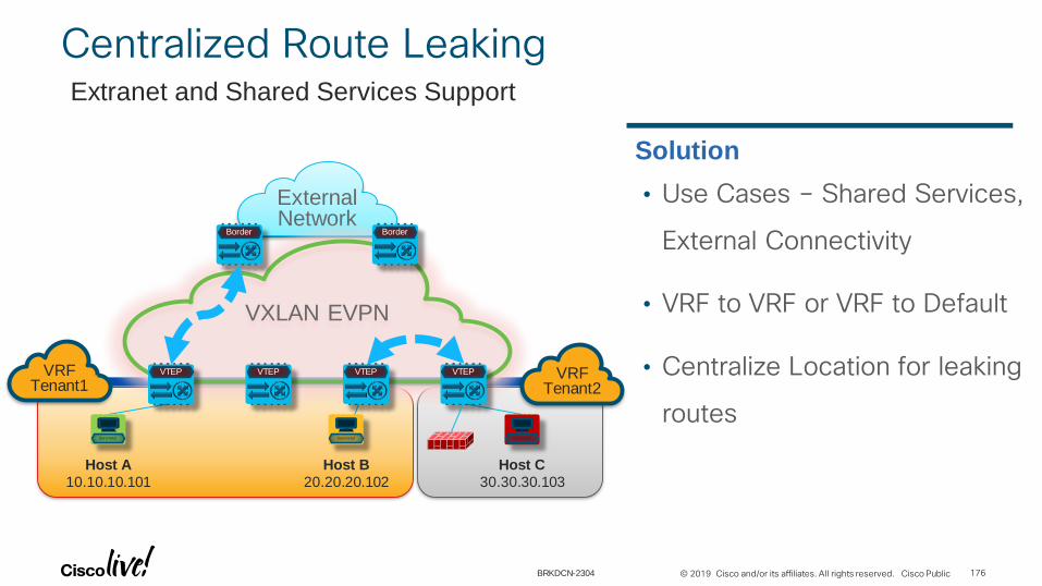
© 2019 Cisco and/or its affiliates. All rights reserved. Cisco Public
External Network
Baremetal
Host A
10.10.10.101
Baremetal
Host B
20.20.20.102
Baremetal
Host C
30.30.30.103
VXLAN EVPN
VTEP VTEP VTEP VTEP
Border Border
VRFTenant1
VRFTenant2
• Use Cases – Shared Services,
External Connectivity
• VRF to VRF or VRF to Default
• Centralize Location for leaking
routes
Solution
Centralized Route LeakingExtranet and Shared Services Support
176BRKDCN-2304

© 2019 Cisco and/or its affiliates. All rights reserved. Cisco Public
• We do NOT export already
imported routes
• Routes need to advertised
explicitly
• Routes need to be LESS specific
External Network
Baremetal
Host A
10.10.10.101
Baremetal
Host B
20.20.20.102
Baremetal
Host C
30.30.30.103
VXLAN EVPN
VTEP VTEP VTEP VTEP
Border Border
VRFTenant1
VRFTenant2
Guidelines
Centralized Route LeakingExtranet and Shared Services Support
vrf context Tenant1
vni 50001
rd auto
address-family ipv4 unicast
route-target both auto
route-target both auto evpn
route-target import 65501:50002
vrf context Tenant2
vni 50002
rd auto
address-family ipv4 unicast
route-target both auto
route-target both auto evpn
route-target import 65501:50001
router bgp 65501
vrf Tenant1
address-family ipv4 unicast
advertise l2vpn evpn
network 52.52.52.0/23 (subnet to reach in VRF Tenant2)
redistribute direct route-map FABRIC-RMAP-REDIST-SUBNET
vrf Tenant2
address-family ipv4 unicast
advertise l2vpn evpn
network 51.51.51.0/23 (subnet to reach in VRF Tenant1)
redistribute direct route-map FABRIC-RMAP-REDIST-SUBNET
interface Vlan10
no shutdown
vrf member Tenant1
ip address 10.10.10.1/24 tag 12345
fabric forwarding mode anycast-gateway
interface Vlan20
no shutdown
vrf member Tenant1
ip address 20.20.20.1/24 tag 12345
fabric forwarding mode anycast-gateway
interface Vlan30
no shutdown
vrf member Tenant2
ip address 30.30.30.1/24 tag 12345
fabric forwarding mode anycast-gateway
177BRKDCN-2304

Fabric Provisioning and Management
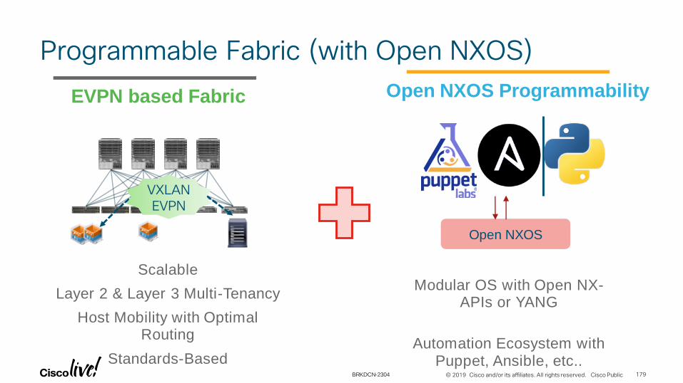
© 2019 Cisco and/or its affiliates. All rights reserved. Cisco Public
Programmable Fabric (with Open NXOS)
Open NXOS ProgrammabilityEVPN based Fabric
Scalable
Layer 2 & Layer 3 Multi-Tenancy
Host Mobility with Optimal Routing
Standards-Based
Modular OS with Open NX-APIs or YANG
Automation Ecosystem with Puppet, Ansible, etc..
VXLAN EVPN
Open NXOS
179BRKDCN-2304

© 2019 Cisco and/or its affiliates. All rights reserved. Cisco Public
DCNM Fabric Management
180
Comprehensive Management in today’s
data Center requires managing both the
Physical Infrastructure (Underlay) and the
Virtualised Networks existing on the fabric
(Overlay).
Programmable Fabric
Physical Network Underlay
VXLAN Overlay
On Demand Provisioning
BRKDCN-2304

© 2019 Cisco and/or its affiliates. All rights reserved. Cisco Public
Day 1+ Operations: Manage, Monitor Visualize, Search
Manage
Underlay:
• SDN Networks [VTEPs]
• Image Update [ISSU]
• View Fabric Topology
• Monitor Health, Events,
Performance
[cpu/mem/iface/syslog]
• Add Devices/Expand
Cisco Advantage:
• Turnkey Management
• Integrated Views
• Comprehensive Fabric Views
Challenge: Manage & Grow Underlay with minimal overhead & keep consistent intent
Deployed Fabric Monitor / Visualize /
Search / Update
181BRKDCN-2304

© 2019 Cisco and/or its affiliates. All rights reserved. Cisco Public
Day 1+ Operations: Overlay Visibility, Growth
Overlay Tasks:
• Visualize Overlays [VXLAN, VLAN, etc..]
• Add, Manage SDN Networks
• Shows VM Networking Path [vCenter]
• Find, Track VMs, Workloads [EPL]
• Find VN’s and VNI’s [VXLAN]
• View VXLAN E2E Connectivity [OAM]
• Identify Errors
• Validate Compliance
Cisco Advantage:
• Seamless Overlay/Underlay Correlation
• Easy to find workloads, VN’s, VNI’s on vast
fabric
• Easy to See Host-Network chain
Challenge: Manage / Monitor SDN Overlay’s across a large fabric
Monitor / Visualize / Search
182BRKDCN-2304
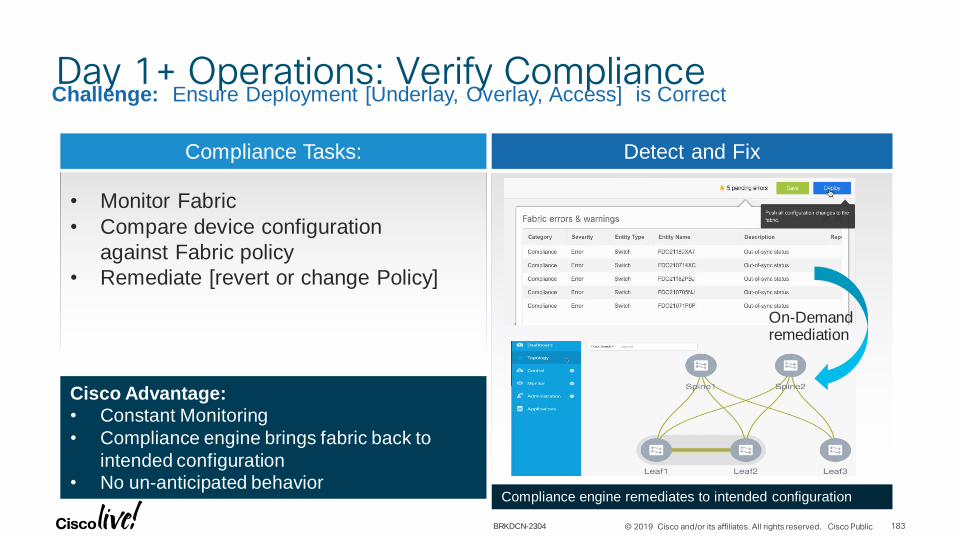
© 2019 Cisco and/or its affiliates. All rights reserved. Cisco Public
Day 1+ Operations: Verify Compliance
Compliance Tasks:
• Monitor Fabric
• Compare device configuration
against Fabric policy
• Remediate [revert or change Policy]
Cisco Advantage:
• Constant Monitoring
• Compliance engine brings fabric back to
intended configuration
• No un-anticipated behavior
Challenge: Ensure Deployment [Underlay, Overlay, Access] is Correct
Detect and Fix
Compliance engine remediates to intended configuration
On-Demand remediation
183BRKDCN-2304

Multi Tenancy and Service Integration with DCNM
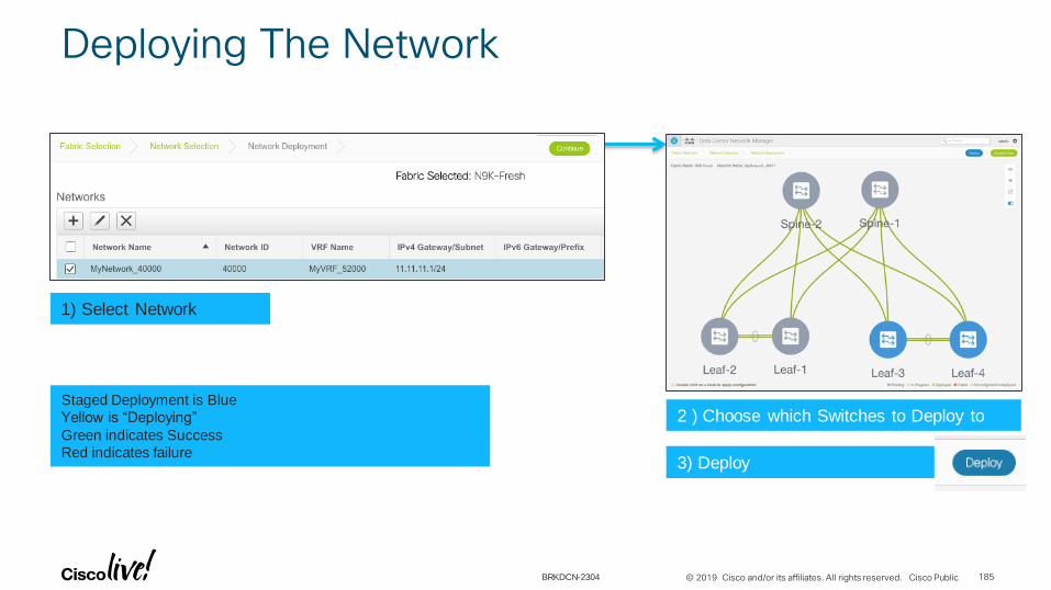
© 2019 Cisco and/or its affiliates. All rights reserved. Cisco Public
Deploying The Network
185
1) Select Network
3) Deploy
2 ) Choose which Switches to Deploy toStaged Deployment is Blue
Yellow is “Deploying”
Green indicates Success
Red indicates failure
BRKDCN-2304

© 2019 Cisco and/or its affiliates. All rights reserved. Cisco Public
Deploying The Network – Selecting Switches
186
• Double Click the Switches where you want the network
• Select “Apply to Switch”
• Select Deploy
• Green indicates success
Double-Click Deploy to this switch[De-Select to remove Network]
Select Ports if desired (Not necessary if default is ‘trunk’)
Ready to Deploy
In Progress Deployed
BRKDCN-2304

© 2019 Cisco and/or its affiliates. All rights reserved. Cisco Public
Controls
187
Preview
Add Switches to
Fabric
Refresh
Auto-Refresh on/off
Deploy Details
Show / Troubleshoot Deployment
These templates are customizable
BRKDCN-2304
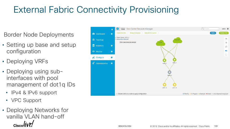
© 2019 Cisco and/or its affiliates. All rights reserved. Cisco Public
External Fabric Connectivity Provisioning
Border Node Deployments
• Setting up base and setup configuration
• Deploying VRFs
• Deploying using sub-interfaces with pool management of dot1q IDs
• IPv4 & IPv6 support
• VPC Support
• Deploying Networks for vanilla VLAN hand-off
188BRKDCN-2304

© 2019 Cisco and/or its affiliates. All rights reserved. Cisco Public
External Connectivity using VRF-LITE
189BRKDCN-2304

© 2019 Cisco and/or its affiliates. All rights reserved. Cisco Public
Verifying External Connectivity using VRF-LITE
190BRKDCN-2304
© 2019 Cisco and/or its affiliates. All rights reserved. Cisco Public
Cisco Webex Teams
Questions? Use Cisco Webex Teams (formerly Cisco Spark) to chat with the speaker after the session
Find this session in the Cisco Events Mobile App
Click “Join the Discussion”
Install Webex Teams or go directly to the team space
Enter messages/questions in the team space
How
1
2
3
4
191
cs.co/ciscolivebot#BRKDCN-2304
BRKDCN-2304
© 2019 Cisco and/or its affiliates. All rights reserved. Cisco Public
Don’t forget: Cisco Live sessions will be available for viewing on demand after the event at ciscolive.cisco.com
• Please complete your Online Session Survey after each session
• Complete 4 Session Surveys & the Overall Conference Survey (available from Thursday) to receive your Cisco Live T-shirt
• All surveys can be completed via the Cisco Events Mobile App or the Communication Stations
Complete your online session survey
192BRKDCN-2304

© 2019 Cisco and/or its affiliates. All rights reserved. Cisco Public
Demos in the Cisco Showcase
Walk-in self-paced
labs
Meet the engineer
1:1 meetings
Related sessions
Continue Your Education
193BRKDCN-2304

Thank you

Copyright © 2022 FDOKUMEN