
Kinsler Fuel Injection, Inc, 1834 THUNDERBIRD TROY ...
227
All Pages in this booklet © 2008
-
Upload
khangminh22 -
Category
Documents
-
view
5 -
download
0
Transcript of Kinsler Fuel Injection, Inc, 1834 THUNDERBIRD TROY ...

All Pages inthis booklet © 2008

Kinsler Fuel Injection, Inc, 1834 THUNDERBIRD TROY, MICHIGAN 48084 U.S.A.www.Kinsler.com Phone (248) 362-1145 Fax (248) 362-1032
2
TABLE OF CONTENTSWhy Kinsler?..............................................................................................Fuel Metering.............................................................................................Chevrolet Small Block V8...........................................................................Standard Port Configurations for Chevy Small Block V8..........................Kinsler “XTRA” Light Manifolds.............................................................Other Kinsler Small Block Chevrolet Manifolds.......................................Vintage Kinsler Small Block Chevrolet V8.................................................Ford Small Block V8..................................................................................4-Valve GM Manifolds..............................................................................Chevrolet Big Block V8 - Rectagular Port One-Piece................................Chevrolet Big Block V8 - 3-Piece...............................................................Cross-Ram for Chevrolet Big Block...........................................................Ford Big Block V8......................................................................................Other V8 Manifolds - Small Block Mopar.................................................4-Cylinder Manifolds - Chevrolet/Ford/TRD............................................V6 Manifolds - Chevrolet / Buick..............................................................Pontiac Maifolds........................................................................................6-Cylinder In-Line Manifold/Scat V4........................................................Crossram Manifolds...................................................................................Kinsler 4-Barrel Throttle Body..................................................................Kinsler Modular Throttle Bodies...............................................................Throttle Bodies..........................................................................................Throttle Bodies for Weber Conversions.....................................................EFI Adapter Plates for GMC Superchargers..............................................Fuel Systems and Components of Supercharged Engines..........................EFI Adapter Plates for PSI Superchargers..................................................Turbocharging.............................................................................................Plenum Logs...............................................................................................3-Piece Manifold Installation.....................................................................Throttle Shafts...........................................................................................Throttle Plates............................................................................................Ramtubes....................................................................................................Top Adapters-Special.................................................................................Throttle Synchronization at Idle................................................................Uni-Syn Throttle Synchronizer..................................................................How To Set Up Linkage.............................................................................Kinsler Billet Spring-Screw Universal Throttle Shaft Links......................Throttle Arms and Stop.............................................................................Linkage.......................................................................................................Cables and Accessories...............................................................................A Brief History of Fuel Injection...............................................................Comparison of Racing Fuel Injection Systems...........................................Constant Flow Fuel Injection Metering.....................................................Kinsler K-type Jets....................................................................................Nozzles : Constant Flow............................................................................Main Bypass Valves..................................................................................Kinsler Quick Disconnect Bypass Valve...................................................Kinsler Jet Selector Valve...........................................................................Secondary Bypass Valve............................................................................High Speed Bypass Valve..........................................................................Bypass Valves............................................................................................Pressure Charts..........................................................................................Barrel Valves...............................................................................................Barrel Valve Spools and Dual Rate Idle System.........................................Barrel Valve Mounting Brackets and Distribution Blocks.........................Nozzle Hoses.............................................................................................Basic Adjustments for Constant Flow Metering.......................................Setting the Leakage of a Barrel Valve Spool...............................................Indexing a Barrel Valve...............................................................................Basic Adjustments for Constant Flow Metering.......................................
Trouble Shooting Chart Constant Flow Fuel Metering System...............Plumbing Schematics................................................................................Vapor Separator Tank System..................................................................Turbocharged Constant Flow Fuel Injection System...............................Electronic Fuel Injection Basics................................................................Types of Fuel Management......................................................................Electric Fuel Pumps..................................................................................EFI Pressure Relief Valves........................................................................EFI Injectors.............................................................................................EFI Fuel Rails...........................................................................................Tooling to Machine Fuel Rails and Injector Mounting.............................Sensors for EFI Systems..........................................................................EFI Speed and Synchronization Signal Generators..................................EFI Connectors, Relays, and Accessories................................................EFI Plumbing............................................................................................Multi-Port EFI Systems...........................................................................Service and Modification of Injection by Kinsler.....................................Conversion of Carburetor Manifolds into Fuel Injection.........................Kinsler Injector/Nozzle Bosses................................................................Fuel Filters................................................................................................Shut-off Valves.........................................................................................Mechanical Fuel Pumps...........................................................................Mechanical Pump Installation..................................................................Drives for Mechanical Pump...................................................................Cog Belts and Pulleys..............................................................................Primer System..........................................................................................Fuel Tank Construction and Location......................................................Aluminum Tanks and Components..........................................................Fittings and Bungs....................................................................................Fittings.....................................................................................................Hose and Hose Ends: Stainless Steel Braid..............................................Fittings Sizes............................................................................................Check Valves............................................................................................Filter Foam...............................................................................................Air Filtration............................................................................................Air Density Gauge...................................................................................Fuel Analyzer Kit and Hydrometers.......................................................Understanding Fuels................................................................................Specific Gravity.......................................................................................Fuel Data..................................................................................................Orifice Theory..........................................................................................Important Facts.......................................................................................Manifold Maintenance and Hints............................................................Manifold Design......................................................................................Lucas Nozzle Placement..........................................................................Lucas Metering.........................................................................................Lucas Nozzles and Lines.........................................................................Fuel Requirements...................................................................................Adjusting the Metering Unit....................................................................Lucas Mechanical Fuel Pump..................................................................Lucas Notes.............................................................................................Lucas Plumbing........................................................................................Carburetor Fuel Supply...........................................................................U and L Bends / Connector Hose............................................................O-rings / Plastic Caps / Jet Nuts.............................................................Ignition....................................................................................................Misc........................................................................................................Apparel and Books.................................................................................
© 2008
379
11182023242728303133343637384142434445484950515253545556575960616264666870727475767883848588909596979899
100106107108109
110112115119120122124133137141144145151152154157158159161162167172173174177178179181182183187188189190191193196197198201202204205206207208209210211213214215217219221222223224

Kinsler Fuel Injection, Inc, 1834 THUNDERBIRD TROY, MICHIGAN 48084 U.S.A.www.Kinsler.com Phone (248) 362-1145 Fax (248) 362-1032
3
WHY KINSLER ?
Three-piece unit to fit Chevrolet and Pontiac small block V8
THE FEATURES THAT MAKE THE DIFFERENCE
BECAUSE THEY DO IT RIGHT
1) Three Piece Manifold The two sides of the manifold and the valley plate are completely separate.
A) Allows a perfect fit against the cylinder head even with a decked block or angle milled heads, or ifsomething just isn’t right somewhere. No more angle milling of the manifold!
B) Raising the ports In the past, if someone wanted to raise the ports in their manifold, say .200”, they hadto add material to the outside of the manifold, then grind the roof higher, then fill the floor. When theywere finally done, they had a compromise in the performance, as they had sharpened the curvature of theshort side of the runner.
The Kinsler Solution: Kinsler manifolds are machined to bolt directly onto the cylinder heads, withprecisely aligned ports. A Kinsler manifold can be machined to standard port profiles, variations of them,or to your special port layout.
If you have a super high port, or a very large or small port, Kinsler can custom machine one of ourmanifold blanks to bolt right onto your heads. © 2008

Kinsler Fuel Injection, Inc, 1834 THUNDERBIRD TROY, MICHIGAN 48084 U.S.A.www.Kinsler.com Phone (248) 362-1145 Fax (248) 362-1032
4© 2008
Let’s say you own a Kinsler Three-piece manifold for a small block Chevrolet, but you want to use it ona special head with ports that are moved up .300" higher than your old heads. Simply elongate or repositionthe bolt holes and slide the manifold up the head .300". This keeps the runner design in the manifolduntouched for peak performance, and saves you a ton of time and work!
A nice touch is that every manifold is supplied with 1/4" dowel pin holes at each end, so the manifold canbe positioned just right over the cylinder head ports, then a hole can be drilled in the head to match thedowel pin holes. To take care of the gap between the raised manifold and the valley plate, simply make analuminum strip with a seal groove and bolt it to the lower edgeof the manifold...or we can machine the strips. Up to a 3/8"gap can simply be filled with silicone.
D) Sealing it up Both the manifold and the valley platehave grooves for sealing them to each other. The valleyplate has sealing grooves on the bottom side at the frontand rear for sealing it to the top of the engine block.Simply squeeze silicone sealer into all the grooves and assemble. The valley plate also has a 10-32bolt hole at the front and rear, giving the option of bolting it to the top of the engine block.
3) Precision Ports Even in the racing industry, mostmanifolds come with as-cast ports, and they are oftennot in the proper location. Every manifold we make hasthe ports machine-cut exactly to its print. To ensureprecise location of the bolt holes to the ports, they areboth cut while the manifold is in the same fixture.
4) Port Wall Angles We pay a lot of attention to the angleof the roof, floor, and the two walls as they meet thegasket face. If the wall angles in the manifold do notmatch those in the cylinder head, the air will not flow aswell as it could.
5) Blended Ports After the ports are milled in, they are very carefullyhand blended to the runner in the casting for a totally smoothtransition. Most top engine developers have found that furtherporting work does not give them a power increase.
6) Separate Ramtube Adapters hold the ramtubes to the manifold.The ramtubes are secured by pinch clamps for easy removal toservice air filters, etc.
If you break a Pinch Clamp, you can simply install a new adapter.
Small block Chevy port close-up
2) Runner Design We constantly work with top engine developers to keep refining our runner designs.We change them whenever we find one that will workbetter. We can also make one to your specifications andmake it work for you.
Mating seal grooves
C) Correct for core shift in your heads Since it is easy tomove each manifold up or down, forward or rearward,perfect alignment can be obtained with cylinder headsthat don’t have the ports properly located. (This is acommon problem, especially with production heads).
Manifold o-ring detail

Kinsler Fuel Injection, Inc, 1834 THUNDERBIRD TROY, MICHIGAN 48084 U.S.A.www.Kinsler.com Phone (248) 362-1145 Fax (248) 362-1032
5
8.2Pounds
© 2008
1/2-20 thread brass inserts forconstant flow nozzles
Traditional bell 180°
Weights shown refer to a manifold side casting without throttle shafts, plates, or linkage.
4.0Pounds
‘Xtra Light’option on
V8:See
Page #18
Ramtube adapters
Tuning: All the adapters on the same model manifold have the same bolt pattern, so if you want totry different diameter ramtubes, simply bolt on another set of adapters and tubes. It is another way totailor the shape of the engine’s power curve.
Sealing: The ramtubes are sealed to the adapter with an o-ring seated into the inside diameter of theadapter. The adapters are sealed to the manifold with o-rings that seat into the top of the manifold.These o-rings keep out dirt and waterto prolong engine life, and there are nogaskets to blow out.
7) Ramtubes Our ramtubes are made from high quality aluminum to resist denting while maintaining their light weight. While this is more costly, they are truly a superior piece. If our 1800 ramtubes are shortened, they will slip into our adapters without having to turn the outside diameter, as they are made with the proper diameter all the way up the tube. If our traditional ramtubes are shortened, they must have the base remachined to fit the adapters, Part #7898, see Ramtubes Page #57-58.
8) Universal Nozzle Boss Most Kinsler manifolds are available with bosses that are tapped 13/16-16. These accept our adapter inserts to accommodate any type of nozzle/injector, (i.e. constant flow, EFI, Lucas, etc). To change from one type of nozzle or injector to another, simply remove the old inserts and install a new set. We also have dual bosses available on most of our units, and bolt-on bosses to go on the runners of any other brand or type of manifold.
Only aluminum manifolds should be ordered for off-road or marine use!!!
Caution: Magnesium is badly corroded by water or liquid alcohol. Monitor the magnesium where it contacts theengine coolant. Alcohol must not sit in a runner for more than a few hours.
9) Magnesium alloy manifolds and top adapters are available for most manifold models to reduce over 1/3 of the casting weight.

Kinsler Fuel Injection, Inc, 1834 THUNDERBIRD TROY, MICHIGAN 48084 U.S.A.www.Kinsler.com Phone (248) 362-1145 Fax (248) 362-1032
6 © 2008
15) Billet Spring-Screw Universal Throttle Shaft LinkageThe throttle shafts can be split in between therunners of the manifold and our patented SpringScrew linkage installed to ensure bind-free operation regardless of uneven installation bolting,(which will distort any manifold) or engine heating,(any brand of aluminum or magnesium manifold willgrow quicker as it heats than the steel throttle shaftdoes). This goes a long way to get rid of the oldstuck-throttle-into-the-wall blues! Optional on mostof our manifolds and we have kits that will allowinstallation of this linkage on any brand of manifold.
Throttle arm, stop, and spring
For safety these should never be used as the only throttle return spring(s). You must use aseparate spring(s) to return the throttles.
For safety there must also be a toe strap on the throttle pedal so the throttle can be pulled shutusing your foot in case the return springs break.
14) Rod Ends A small part, but so very important. We use high quality rod ends to give you the reliabilityand resistance to wear that you need in your race vehicle. The rod end has a plated body, chromatetreated steel race and a heat treated alloy steel hard-chrome plated ball.
Summary: No one else offers a system that even approaches the quality that we have described, and no one else gives you as much value per dollar. Top engine builders and racers tell us that these systems not only outperform anything else presently on the market, but that our calibrations let them dial the engine in so quickly that the time, wear and tear they save makes our system truly inexpensive compared to other brands they have used. They tell us that our manifolds not only work better, but that the precisely located, cut, and blended ports alone saves them more than the difference in cost between our manifold and those of our competitors.
16) Fuel Metering Our manifolds are available for ConstantFlow, Electronic (EFI), or Lucas Mechanical.
17) Special Customizing For an additional charge we will do just about anything you want...special paint, anodized colors, polishing, machining, etc.
10) Throttle Shafts Our standard throttle shafts are a milled-on-one-sidestyle made from a high strength steel alloy, then hard-nickel platedfor added wear resistance. We offer stainless steel as an option formaximum corrosion resistance, for boats operating in salt water, etc.Optional back-cut shafts, and streamline butterflies are available forincreased air flow, see Pages #55-56.
11) Bronze Bushings All of our manifolds and throttle bodies comestandard with bronze throttle shaft bushings for extra smooth throttleoperation and resistance to wear.
12) Throttle Arms & Stops These are heavy-duty to prevent slippage!Machined from 2024 high-strength aluminum and anodized blue.Grade 8 high-strength cap screws are used for clamping.
13) Torsion Safety Springs are available to help close the throttles in caseyour throttle linkage becomes disconnected.

Kinsler Fuel Injection, Inc, 1834 THUNDERBIRD TROY, MICHIGAN 48084 U.S.A.www.Kinsler.com Phone (248) 362-1145 Fax (248) 362-1032
7
FUEL METERING
Barrel valve mounted to a bracketattached to the manifold, this keeps the
barrel valve off the hot valley plate
Optional 16-port barrel valve with nozzlehoses: allows the use of down nozzlesand manifold port nozzles at the sametime; or two nozzles in the manifold,
ramtube, etc.
Xtra-Light barrel valve, hardanodized aluminum, cuts weight
of the barrel valve in half. ..saves 1/4 pound
We not only make our own complete line of metering equipment, but keep many other brands in stock. Wecarry all three basic types: Constant Flow, EFI, and Lucas Mechanical. We can set up any brand of manifoldto work with any type or brand of metering. We are glad to supply any seperate components you need, ortake your pieces and fit them into a complete system. We service fuel systems for engines with any number ofcylinders or rotors, from lawn mower engines to blown alcohol.
Flow Test and Calibration Service for Constant Flow, EFI, and Lucas:We offer flow testing to qualify each component, then a detailed calibration of the overall system tailored tothe particular engine combination, fuel, and use. Having calibrated thousands of systems, we have theexperience necessary to get the fuel curve very close just as the unit is bolted on. We also offer this serviceand reconditioning for other brands, new or used.
© 2008
1) Constant Flow Metering Used for many applications as it is very versatile, relatively inexpensive and the most rugged and reliable. We can supply components and systems to meter any type of fuel for any application. We can take a basic system of any brand and add extra components and metering circuits to it to make it perform better for a particular use.
A) Nozzles: We make nozzles for gasoline, alcohol, andnitromethane for use on normally aspirated (unblown),supercharged, and turbocharged engines. All of Kinslernozzles are flow tested at four pressures, matched, thenstamped with a flow code, see Pages #78-81.
Most barrel valves are made by simply drilling the fuel inlet holedown from the top until it intersects the nozzle hose outlet holesthat are drilled in from the side. These intersections are not onlyquite jagged, but the velocity of the fuel is too high to make thesharp turn out to the nozzle hoses.All of this creates great turbulence,which gives very poor fueldistribution. Kinsler barrel valvesare made with a large cavity inthe bottom, so the fuel can slowdown and make the turn. We alsodo a careful job of deburring theinside of the cavity, as well asmaking the inlet to the nozzlehose fitting nicely radiused.This all results in excellent fueldistribution.
B) Precision Distribution Barrel Valves: The Kinsler line ofbarrel valves have been developed with spools that arecomputer contoured to give proper metering for partthrottle operation. Other brands have no more than a simpleramp. We also make custom cut and flow tested spools tosolve tough part throttle problems for your new or usedunits, see Pages #97-98.

Kinsler Fuel Injection, Inc, 1834 THUNDERBIRD TROY, MICHIGAN 48084 U.S.A.www.Kinsler.com Phone (248) 362-1145 Fax (248) 362-1032
8
FUEL METERING
TPS boss and driver #7086 Kinslerremote TPS
mount assembly
Stainlesssteel fuelrail, silversolderedfor use
withalcohol
withspecialclampmount
Aluminumfuel rail for
use withgasoline
withstandardmount
stanchion
© 2008
3) Lucas Mechanical Metering was developed andmanufactured by the Lucas Aerospace Division in England.It was quite popular from 1955 to 1980 on Grand Prix, Can-Am, and other top performing sport racing cars, as well asalmost all of the World Champion Offshore Powerboats. Itwas the ultimate because it is timed, has precise distribution,and meters the fuel even at cranking, thus preventing theengine from getting washed down. Electronic metering hastaken over for the premium applications, but Lucas is stillused on vintage road race cars. We continue to providecomplete rebuilding service, and have a good supply of usedand new-old-stock metering units and parts.
2) Electronic Metering We sell various brands and types of electronic metering equipment to suit every application from street
rods to Indy cars. We can adapt any brand and type of electronic system to any manifold.
C) Vacuum Ports We can drill and tap the runners and supply plumbing and a junction block for vacuum modulated metering, vacuum accessories, or a remote idle air control (IAC) motor housing. We have the remote housings and idle air motors, see Page #145.
A) Fuel Rails We have the best selection in the industry: 8AN fitting size (.685" ID) and 12AN fitting size(.970" ID) for very high output engines; Pg 141. Mounting hardware and fuel rail fittings; Pg 141, 143.Stainless rails in 8AN fitting size (.655" ID), with custom up to 1.5" OD; corrosion proof with methanol,Pg 143. Hard anodized aluminum custom modular fuel rails, as we did for the GM Indy 500/IRL enginesfrom 1996-2003; Pg 142. We make our rails smooth on the outside… the finned ones may look “racier”,but they absorb more heat from the hot air around the engine and carry it back to the tank in the bypassfuel, which is bad.
B) Throttle Position SensorWe can machine any cornerof our manifolds to acceptour universal bolt-on TPSadapter. We have adaptersfor most types of sensors.We also offer a remotesensor mount which isactuated by a hex rod, seePage #149.
Several types of TPSadapters and drives
Kinsler Fuel Injection, Inc, 1834 THUNDERBIRD TROY, MICHIGAN 48084 U.S.A.www.Kinsler.com Phone (248) 362-1145 Fax (248) 362-1032
9
CONSTANT FLOW METERING• Kinsler precision barrel valve with fittings, mounting
bracket, and linkage to throttle shaft• Kinsler designed, computer ground barrel valve spool• Set of Kinsler flowed and precision matched nozzles,
1/2-20 thread with 1" ‘AS’ style deflectors• Kinsler assembled nozzle hoses with 90° ends• Kinsler brass 1/2-20 thread universal nozzle boss inserts
EFI• Kinsler universal boss inserts for EFI injectors• Machined for fuel rail mounting stanchion stud• Kinsler bolt-on TPS boss and drive coupler
LUCAS MECHANICAL• Kinsler universal boss inserts for Lucas mechanical
injection nozzles• Throttle shaft and throttle arm set up for linkage to
actuate cam on Lucas metering unit
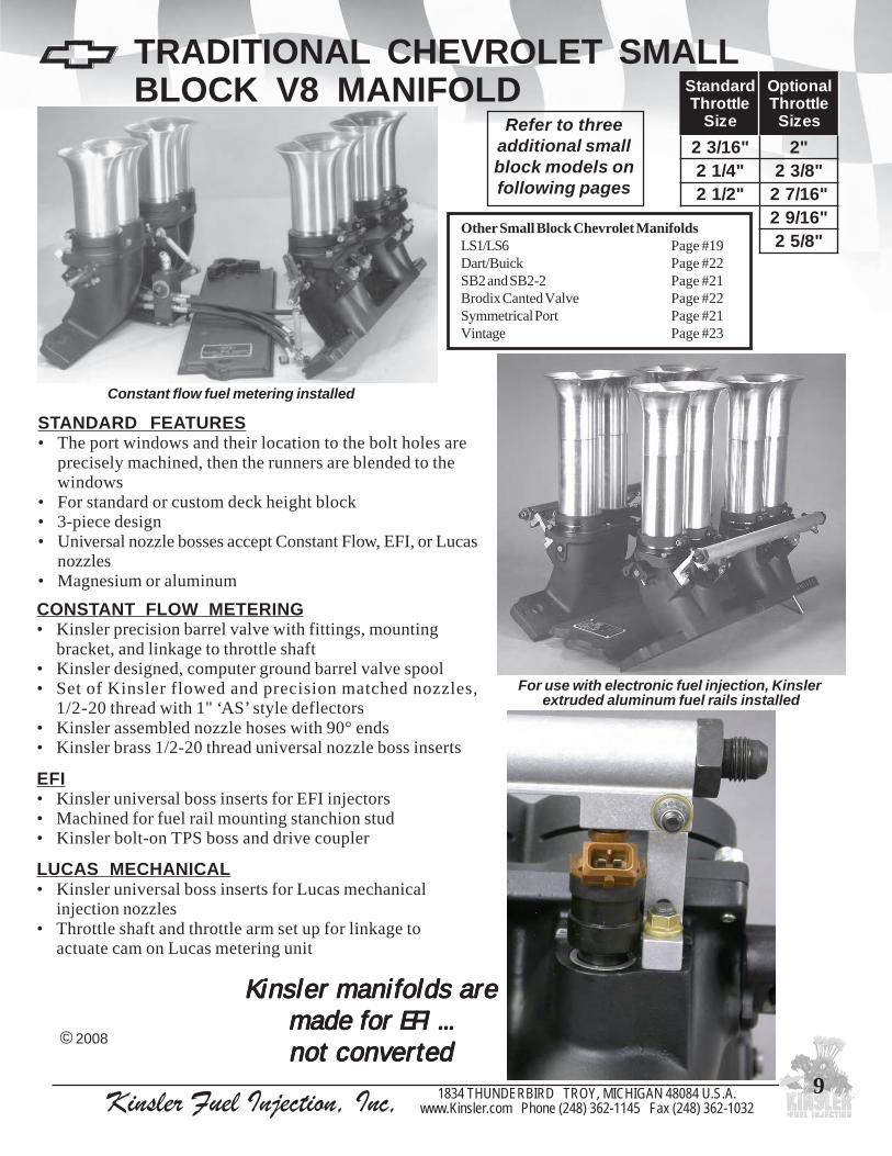
Constant flow fuel metering installed
TRADITIONAL CHEVROLET SMALLBLOCK V8 MANIFOLD
© 2008
dradnatSelttorhT
eziS
lanoitpOelttorhT
seziS"61/32 "2
"4/12 "8/32"2/12 "61/72
"61/92"8/52
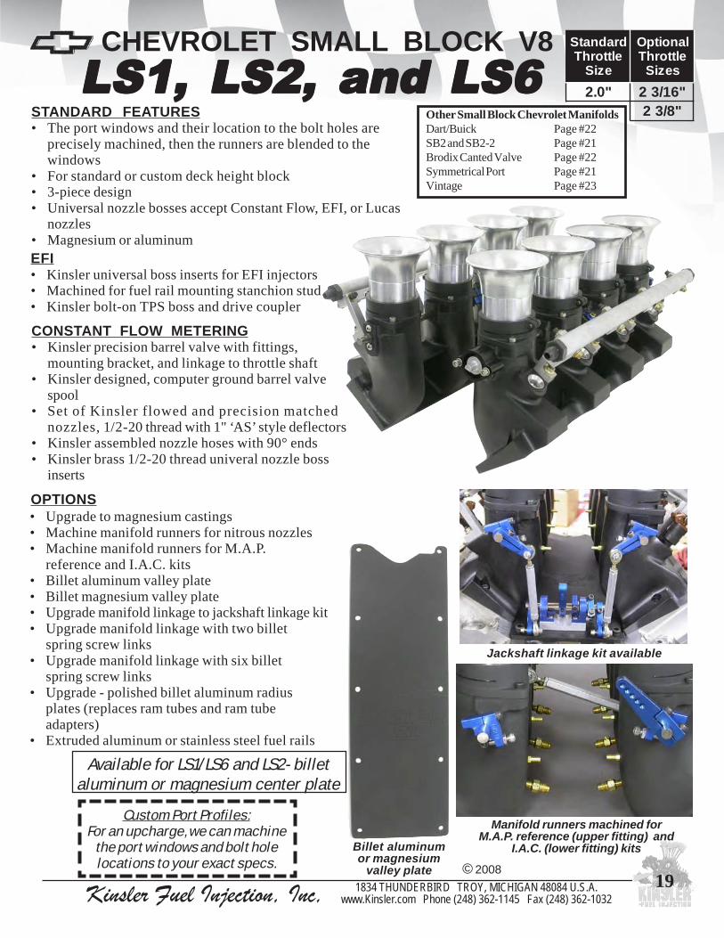
For use with electronic fuel injection, Kinsler extruded aluminum fuel rails installed
Refer to threeadditional smallblock models onfollowing pages
Kinsler manifolds areKinsler manifolds areKinsler manifolds areKinsler manifolds areKinsler manifolds aremade for EFI ...made for EFI ...made for EFI ...made for EFI ...made for EFI ...not convertednot convertednot convertednot convertednot converted
Other Small Block Chevrolet ManifoldsLS1/LS6 Page #19Dart/Buick Page #22SB2 and SB2-2 Page #21Brodix Canted Valve Page #22Symmetrical Port Page #21Vintage Page #23
STANDARD FEATURES• The port windows and their location to the bolt holes are
precisely machined, then the runners are blended to thewindows
• For standard or custom deck height block• 3-piece design• Universal nozzle bosses accept Constant Flow, EFI, or Lucas
nozzles• Magnesium or aluminum

Kinsler Fuel Injection, Inc, 1834 THUNDERBIRD TROY, MICHIGAN 48084 U.S.A.www.Kinsler.com Phone (248) 362-1145 Fax (248) 362-1032
10
OPTIONS• Kinsler billet spring-screw universal throttle shaft linkage• Back cut throttle shafts for increase air flow• Streamlined Throttle Plates• Valley plate for use on tall or custom deck engine blocks• Aluminum or stainless steel fuel rails for EFI• Longer nozzle hoses for ‘down’ nozzles• 16-port barrel valve (outlet block-off plugs available)• 16-nozzle system; barrel valve, nozzle hoses, nozzles• Barrel valve with 6 AN outlet ports• Special linkage setups for ease of customer installation• Angled ramtube adapters so K&N air filters can be installed• Delete bosses from manifold castings, to save weight!• ‘XTRA-LIGHT’ package on manifold castings• ‘XTRA-LIGHT’ barrel valve assembly• Titanium ramtube adapter bolts to save weight
© 2008
Small block Chevy manifold with Lucas Mechanical fuelinjection, note the nozzle bosses in ramtubes,
see Page # 54
Championship ski boat, engine built byPerformance Wholesale in Queensland, Australia
Other Small Block Chevrolet ManifoldsLS1/LS6 Page #19Dart/Buick Page #22SB2 and SB2-2 Page #21Brodix Canted Valve Page #22Symmetrical Port Page #21Vintage Page #23
TRADITIONAL CHEVROLET SMALLBLOCK V8 MANIFOLD
Wilkins Motorsport IHRA TopSportsman '99 Camaro
'XTRA LIGHT'2 5/8" throttle size manifold,
nozzle bosses removed from castings,optional port profile- All Pro 285 stage II
- CONTINUED -

Kinsler Fuel Injection, Inc, 1834 THUNDERBIRD TROY, MICHIGAN 48084 U.S.A.www.Kinsler.com Phone (248) 362-1145 Fax (248) 362-1032
11
STANDARD PORT CONFIGURATIONSFOR CHEVROLET SMALL BLOCK V8
We offer our manifold to fit many standard port profiles, optional port profiles, or your customport profile. If your cylinder head is not listed it doesn't mean we don't make it; call us.
STANDARD PORT PROFILESChevrolet : Bowtie (Fel Pro 1205 Gasket)Brodix : -8, -10, -11 , (Fel Pro 1206), ASCS, -11X, -11RI,
-12 (Fel Pro 1209)Dart : 220Edelbrock : standard 230
World Products : Sportsman IIAFR : standard 230
SHOWN ARE THREE OFTHE STANDARD PORT PROFILES :
Brodix -12 (Fel Pro 1209)
Brodix -11RI
Brodix -8, -10, -11 Fits Fel Pro 1206 / Mr. Gasket #111,most common Chevrolet small block aluminum heads
A FEW OF OUR MORE POPULAROPTIONAL PORT PROFILESBrodix : -12B, -12RI, All 12x12, & GB-2000Dart Oldsmobile : 14°, 18°Weldtech : 10X, 247, 262, 285 RVR, 287, 299,18°,
Hut 1, Hut 1.1, Hut 2, 12x12 - 275,286,296.Chevrolet : 18-degree standard and raised portAll-Pro : 227, 245, 265, 270JJ, 285 Stage II and IIIAlan Johnson Perf. Eng. : 120, 180, 210, and 230
World Products : S/RTorquerPro-Action Heads : Pro 23°, Pro 14° - 254, 265, 285, & 300Chapman : 10X, 12, 12x12, and 18o
Totally custom...to your specifications
Custom Port Profiles:For an upcharge, we can machine the port windows and bolt hole locations to your exact specs.
© 2007Brodix -12

Kinsler Fuel Injection, Inc, 1834 THUNDERBIRD TROY, MICHIGAN 48084 U.S.A.www.Kinsler.com Phone (248) 362-1145 Fax (248) 362-1032
12
Dragon ClawDragon ClawDragon ClawDragon ClawDragon Claw
LUCAS MECHANICAL• Kinsler universal boss inserts for Lucas
mechanical injection nozzles• Throttle shaft and throttle arm set
up for linkage to actuate Cam on Lucasmetering unit
EFI• Kinsler universal boss inserts for EFI injectors• Machined for fuel rail mounting stanchion stud• Kinsler bolt-on TPS boss and drive coupler
CONSTANT FLOW METERING• Kinsler precision barrel valve with fittings, mounting
bracket, and linkage to throttle shaft• Kinsler designed, computer ground barrel valve
spool• Set of Kinsler flowed and precision matched
nozzles, 1/2-20 thread with 1" ‘AS’ style deflectors• Kinsler assembled nozzle hoses with 90° ends• Machining of one nozzle location - inboard or
outboard; includes 1/2-20 thread brass universalnozzle boss inserts and sintered bronze air filters
CHEVROLET SMALL BLOCK V8
© 2008
STANDARD PORT PROFILESAlan Johnson Perf. Engr.: 12o 280 & 306All Pro : 270, 285, 286 seriesBrodix : GB2000 seriesPro-Action: 14o 285
Other Small Block Chevrolet ManifoldsLS1/LS6 Page #19Dart/Buick Page #22SB2 and SB2-2 Page #21Brodix Canted Valve Page #22Symmetrical Port Page #21Vintage Page #23
Extra wide throttle shaftbushing
Extend the service lifeunder severe racing
conditions. .300" min.width between the
throttle bores on a 3.0"bore unit!!
dradnatSelttorhT
eziS
lanoitpOelttorhT
seziS"2/12 "4/32"8/52 "9.2"61/112 "0.3"61/312
Kinsler Dragon Claw manifold with optionalJackshaft linkage kit and 16 nozzle system
3.0" MAX.THROTTLE !!
STANDARD FEATURES• The port windows and their location to the bolt
holes are precisely machined, then the runners areblended to the windows
• For standard or custom deck height block• 3-piece design• Universal nozzle bosses accept Constant Flow,
EFI, or Lucas nozzles• Magnesium or aluminum
Custom Port Profiles:For an upcharge, we
can machine the portwindows and bolthole locations toyour exact specs.

Kinsler Fuel Injection, Inc, 1834 THUNDERBIRD TROY, MICHIGAN 48084 U.S.A.www.Kinsler.com Phone (248) 362-1145 Fax (248) 362-1032
13
OPTIONS• Kinsler billet Spring-Screw universal throttle shaft linkage• Back cut throttle shafts for increase air flow• Streamlined Throttle Plates• Valley plate for use on tall or custom deck engine blocks• Aluminum or stainless steel fuel rails for EFI• Longer nozzle hoses for ‘down’ nozzles• 16-port barrel valve (outlet block-off plugs available)• 16-nozzle system; barrel valve, nozzles, nozzle hoses• Barrel valve with 6 AN outlet ports• Jackshaft linkage kit: stainless steel or titanium cross shaft• Special linkage setups for ease of customer installation• Angled ramtube adapters so K&N air filters can be installed• Machining of second nozzle boss location on manifold -
inboard or outboard; includes 1/2-20 thread brass universalnozzle boss inserts and sintered bronze air filters
• Delete bosses from manifold castings, to save weight!• ‘XTRA-LIGHT’ package on manifold castings• ‘XTRA-LIGHT’ barrel valve assembly• Titanium ramtube adapter bolts• Custom name tag
CHEVROLET SMALL BLOCK V8
© 2008
2-piece adjustable pulling arm includedwith Jackshaft linkage kit
Dragon ClawDragon ClawDragon ClawDragon ClawDragon Claw- CONTINUED -
Contoured flange detail
Inboard nozzle location
Nozzle lines with 45 degreeends and aluminum banjos
with air filters for ‘down’nozzles in cylinder head
Terry McCarl’s Wesmar/Kinsler poweredWorld of Outlaw sprint car
Dragon Clawfor ‘street’application
with EFI

Kinsler Fuel Injection, Inc, 1834 THUNDERBIRD TROY, MICHIGAN 48084 U.S.A.www.Kinsler.com Phone (248) 362-1145 Fax (248) 362-1032
14
360 ASCS Dragon Claw360 ASCS Dragon Claw360 ASCS Dragon Claw360 ASCS Dragon Claw360 ASCS Dragon Claw
CONSTANT FLOW METERING• Kinsler precision barrel valve with fittings, mounting
bracket, and linkage to throttle shaft• Kinsler designed, computer ground barrel valve spool• Set of Kinsler flowed and precision matched
nozzles, 1/2-20 thread with 5 1/2" ‘AS’ style deflectors• Kinsler assembled nozzle hoses with 45° ends• Machining of one nozzle location - inboard or outboard;
includes 1/2-20 thread brass universal nozzle boss insertsand sintered bronze air filters
CHEVROLET SMALL BLOCK V8 dradnatSelttorhT
eziS
lanoitpOelttorhT
seziS"2/12 "8/32
"61/72"8/52
Change 5 1/2” nozzles without removingmanifold from engine
Detail on manifold runners
Other Small Block Chevrolet ManifoldsLS1/LS6 Page #19Dart/Buick Page #22SB2 and SB2-2 Page #21Brodix Canted Valve Page #22Symmetrical Port Page #21Vintage Page #23
STANDARD FEATURES• ASCS port profile with standard bolt location
and port window• For standard or custom deck height block• 3-piece design• Universal nozzle bosses accept constant flow,
EFI, or Lucas nozzles• Dual milled precision ground milled style
one-piece hard-nickel plated throttle shafts• Jackshaft linkage kit• Magnesium or aluminum
Runners machined for magneto clearance
© 2008
Custom Port Profiles:For an upcharge, we can machine the port windows
and bolt hole locations to your exact specs.

Kinsler Fuel Injection, Inc, 1834 THUNDERBIRD TROY, MICHIGAN 48084 U.S.A.www.Kinsler.com Phone (248) 362-1145 Fax (248) 362-1032
15
OPTIONS• Streamlined Throttle Plates• Valley plate for use on tall or custom deck engine blocks• Longer nozzle hoses for ‘down’ nozzles• 16-port barrel valve (outlet block-off plugs available)• 16-nozzle system; barrel valve, nozzles, nozzle hoses• Barrel valve with 6AN outlet ports• Special linkage setups for ease of customer installation• Angled ramtube adapters so K&N air filters can be installed• Machining of ‘second’ nozzle boss location on manifold -
inboard or outboard; includes 1/2-20 thread brass universalnozzle boss inserts and sintered bronze air filters
• Delete bosses from manifold castings, to save weight!• ‘XTRA-LIGHT’ package on manifold castings• ‘XTRA-LIGHT’ barrel valve assembly• Titanium ramtube adapter bolts to save weight• Custom name tag
CHEVROLET SMALL BLOCK V8
© 2008
‘Smoothtorque and
power curve’obtained with
the Kinsler360 ASCS
Dragon Clawmanifold
Shown withoptional
‘outboard’ nozzlelocation
Ramtubes withrestrictors
Dropping inrestrictor
Ramtubes withoutrestrictors
Restrictor tubeinsert
O-ring seal for manifold toramtube adapter and backcut
throttle shaft
Cut away to show o-ring seal forramtube to ramtube adapter
4500
4600
4700
4800
4900
5000
5100
5200
5300
5400
5500
5600
5700
5800
5900
6000
6100
6200
6300
6400
6500
6600
6700
6800
6900
7000
7100
7200
7300
7400
7500
7600
7700
7800
7900
8000
RPM
Other Torque Dragon Claw Torque Other H.P. Dragon Claw H.P.
- CONTINUED - 360 ASCS Dragon Claw360 ASCS Dragon Claw360 ASCS Dragon Claw360 ASCS Dragon Claw360 ASCS Dragon Claw

Kinsler Fuel Injection, Inc, 1834 THUNDERBIRD TROY, MICHIGAN 48084 U.S.A.www.Kinsler.com Phone (248) 362-1145 Fax (248) 362-1032
16
CHEVROLET SMALL BLOCK V8
LUCAS MECHANICAL• Kinsler universal boss inserts for Lucas mechanical
injection nozzles• Throttle shaft and throttle arm set up for linkage to
actuate cam on Lucas metering unit
CONSTANT FLOW METERING• Kinsler precision barrel valve with fittings, mounting bracket,
and linkage to throttle shaft• Kinsler designed, computer ground barrel valve spool• Set of Kinsler flowed and precision matched nozzles,
1/2-20 thread with 1" ‘AS’ style deflectors• Kinsler assembled nozzle hoses with 90° ends• Kinsler brass 1/2-20 thread universal nozzle boss insertsEFI• Kinsler universal boss inserts for EFI injectors• Machined for fuel rail mounting stanchion stud• Kinsler bolt-on TPS boss and drive coupler
dradnatSelttorhT
eziS
lanoitpOelttorhT
seziS"61/112 "4/32
"61/312"9.2"0.3
STANDARD PORT PROFILESAlan Johnson Perf. Engr.: 12o 280 & 306All Pro : 270, 285, 286 seriesBrodix : GB2000 seriesPro-Action: 14o 285
Monster Monster Monster Monster Monster Manifold
Craig Dollansky driving the KaravanMotorsports #7 sprint car. photo by: Matt Hill
Other Small Block Chevrolet ManifoldsLS1/LS6 Page #19Dart/Buick Page #22SB2 and SB2-2 Page #21Brodix Canted Valve Page #22Symmetrical Port Page #21Vintage Page #23
Monstermanifold with
optionalpolished billet
aluminumradius plates
3.0" MAX.THROTTLE !!
© 2008
STANDARD FEATURES• The port windows and their location to the bolt holes are
precisely machined, then the runners are blended to thewindows
• For standard or custom deck height block• 3-piece design• Universal nozzle bosses accept Constant Flow, EFI, or Lucas
nozzles• Magnesium or aluminum
Extra wide throttle shaft bushingExtend the service life under severe racingconditions. .300" min. width between the
throttle bores on a 3.0" bore unit !!
Custom Port Profiles:For an upcharge, we can machine
the port windows and bolt holelocations to your exact specs.

Kinsler Fuel Injection, Inc, 1834 THUNDERBIRD TROY, MICHIGAN 48084 U.S.A.www.Kinsler.com Phone (248) 362-1145 Fax (248) 362-1032
17
CHEVROLET SMALL BLOCK V8
Optional ‘low-boss’ nozzle location
Jackshaft linkage kit and16 nozzle system installedwith optional silver paint
First A/Nostalgia Dragster in the 6’s
Dean Carter:NHRA World Champion in
Competition Eliminator
OPTIONS• Polished billet aluminum radiused entry plates• Back cut throttle shafts for increase air flow• Streamlined Throttle Plates• Valley plate for use on tall or custom deck engine blocks• Aluminum or stainless steel fuel rails for EFI• Longer nozzle hoses for ‘down’ nozzles• 16-port barrel valve (outlet block-off plugs available)• 16-nozzle system; barrel valve, nozzles, nozzle hoses• Barrel valve with 6 AN outlet ports• Jackshaft linkage kit: stainless steel or titanium cross shaft• Special linkage setups for ease of customer installation• Angled ramtube adapters so K&N air filters can be installed• Optional ‘low-boss’ nozzle boss location - lower on runner• Delete bosses from manifold castings, to save weight!• ‘XTRA-LIGHT’ package on manifold castings• ‘XTRA-LIGHT’ barrel valve assembly• Titanium ramtube adapter bolts to save weight
© 2008
Polished billet aluminumradiused inlet plates installed
Monster Monster Monster Monster Monster Manifold - CONTINUED -

Kinsler Fuel Injection, Inc, 1834 THUNDERBIRD TROY, MICHIGAN 48084 U.S.A.www.Kinsler.com Phone (248) 362-1145 Fax (248) 362-1032
18
KINSLER "XTRA LIGHT" MANIFOLDSWhen WeightSavings is a Must!
Engineered for Reliability: It wouldhave been easier and less expensive tosimply make a thinner flange to lightenthe manifold, but the flange bendingstrength goes up as the square of thethickness, so twice as thick is four timesas strong. This is why we kept the flangethick, but cut deep pockets into it - to givethe best strength to weight combination.
Xtra-Light package includes: valley plate withsecondary ribs removed
Details: The main bolting flange hasdeeply milled pockets in it, and has beenmill contoured all around the outside.The top been contoured around thebores, as well as the ramtube adaptersto remove significant material. Thevalley plate has the secondary ribsremoved, the sides and remaining ribthinned out, and the top surface milledto .100" thick. Also available without bosses on the manifold
for maximum weight savings.
Optional:XTRA-LIGHT barrel valve,hard-anodized aluminum,
cuts the weight of thebarrel valve in half...
saves 1/4 pound
Steve Kinser, 19-time World of Outlaw Champion
For Small Block Chevrolet, Moparand Ford
Others available on Special Order
3.53.53.53.53.5 POUNDSPOUNDSPOUNDSPOUNDSPOUNDS LIGHTERLIGHTERLIGHTERLIGHTERLIGHTER * than our standardsmall block V8 MAMAMAMAMAGNESIUMGNESIUMGNESIUMGNESIUMGNESIUM manifold !!!
* weight savings depends on port profile and throttle size
© 2008
Kinsler Fuel Injection, Inc, 1834 THUNDERBIRD TROY, MICHIGAN 48084 U.S.A.www.Kinsler.com Phone (248) 362-1145 Fax (248) 362-1032
19
CONSTANT FLOW METERING• Kinsler precision barrel valve with fittings,
mounting bracket, and linkage to throttle shaft• Kinsler designed, computer ground barrel valve
spool• Set of Kinsler flowed and precision matched
nozzles, 1/2-20 thread with 1" ‘AS’ style deflectors• Kinsler assembled nozzle hoses with 90° ends• Kinsler brass 1/2-20 thread univeral nozzle boss
inserts
EFI• Kinsler universal boss inserts for EFI injectors• Machined for fuel rail mounting stanchion stud• Kinsler bolt-on TPS boss and drive coupler
CHEVROLET SMALL BLOCK V8LS1, LS2, and LS6LS1, LS2, and LS6LS1, LS2, and LS6LS1, LS2, and LS6LS1, LS2, and LS6
© 2008
Available for LS1/LS6 and LS2- billetaluminum or magnesium center plate
OPTIONS• Upgrade to magnesium castings• Machine manifold runners for nitrous nozzles• Machine manifold runners for M.A.P.
reference and I.A.C. kits• Billet aluminum valley plate• Billet magnesium valley plate• Upgrade manifold linkage to jackshaft linkage kit• Upgrade manifold linkage with two billet
spring screw links• Upgrade manifold linkage with six billet
spring screw links• Upgrade - polished billet aluminum radius
plates (replaces ram tubes and ram tubeadapters)
• Extruded aluminum or stainless steel fuel rails
Billet aluminumor magnesium
valley plate
Manifold runners machined forM.A.P. reference (upper fitting) and
I.A.C. (lower fitting) kits
Jackshaft linkage kit available
Other Small Block Chevrolet ManifoldsDart/Buick Page #22SB2 and SB2-2 Page #21Brodix Canted Valve Page #22Symmetrical Port Page #21Vintage Page #23
"0.2 "61/32"8/32
dradnatSelttorhT
eziS
lanoitpOelttorhT
seziS
STANDARD FEATURES• The port windows and their location to the bolt holes are
precisely machined, then the runners are blended to thewindows
• For standard or custom deck height block• 3-piece design• Universal nozzle bosses accept Constant Flow, EFI, or Lucas
nozzles• Magnesium or aluminum
Custom Port Profiles:For an upcharge, we can machine
the port windows and bolt holelocations to your exact specs.

Kinsler Fuel Injection, Inc, 1834 THUNDERBIRD TROY, MICHIGAN 48084 U.S.A.www.Kinsler.com Phone (248) 362-1145 Fax (248) 362-1032
20
OTHER KINSLER SMALL BLOCKCHEVROLET MANIFOLDS
LS7 Cross- Ram
LS7STANDARD FEATURES• The port windows and their location to the
bolt holes are precisely machined, then therunners are blended to the windows
• For standard or custom deck height block• 3-piece design• Universal nozzle bosses accept Constant
Flow, EFI, or Lucas nozzles• Magnesium standard, aluminum on
special order
STANDARD FEATURES• The port windows and their location to the bolt holes are
precisely machined, then the runners are blended to thewindows
• For standard or custom deck height block• 3-piece design• Universal nozzle bosses accept Constant
Flow, EFI, or Lucas nozzles• Fits LS3 and L92 cylinder heads• Upper & lower (hidden) injector locations• Available IAC rail system, uses either
upper or lower inkector location• Transverse and counter-rotating individual
throttle shafts• Magnesium standard, aluminum on
special order
"8/32 "2
dradnatSelttorhT
eziS
lanoitpOelttorhT
seziS
"8/32 "4/12"61/72
"2/12"8/52"61/112
dradnatSelttorhT
eziS
lanoitpOelttorhT
seziS
Other Small Block Chevrolet ManifoldsLS1/LS6 Page #19Dart/Buick Page #22SB2 and SB2-2 Page #21Vintage Page #23
© 2008

Kinsler Fuel Injection, Inc, 1834 THUNDERBIRD TROY, MICHIGAN 48084 U.S.A.www.Kinsler.com Phone (248) 362-1145 Fax (248) 362-1032
21
Chevrolet’s C5-R Corvette using Kinsler’s C5-R manifoldon a Katech engine has won the production sports carclass at the 24 hours of Le Mans three years in a row
OTHER KINSLER SMALL BLOCKCHEVROLET MANIFOLDS Other Small Block Chevrolet Manifolds
LS1/LS6 Page #19Brodix Canted Valve Page #22Vintage Page #23C5-R (race head)
STANDARD FEATURES• The port windows and their location
to the bolt holes are preciselymachined, then the runners are blendedto the windows
• For standard or custom deck heightblock
• 3-piece design• Universal nozzle bosses accept
Constant Flow, EFI, or Lucas nozzles• Magnesium or aluminum
dradnatSelttorhT
eziS
lanoitpOelttorhT
seziS"2/12 "8/32
"61/72"8/52"61/112
Clements RacingEngines SB2 for WorldSports Car road racing
SB2 and SB2-2
With EFImetering
"8/32 "4/12"61/72
"2/12"8/52"61/112
dradnatSelttorhT
eziS
lanoitpOelttorhT
seziS
STANDARD FEATURES• The port windows and their location to the
bolt holes are precisely machined, then therunners are blended to the windows
• For standard or custom deck height block• 3-piece design• Universal nozzle bosses accept Constant Flow, EFI,
or Lucas nozzles• Magnesium standard, aluminum on special order
With constant flow metering
CHEVROLET SYMETRICALPORT
"4/12 "8/32"2/12 "61/72
"8/52"61/112
dradnatSelttorhT
eziS
lanoitpOelttorhT
seziS
STANDARD FEATURES• The port windows and their location to the
bolt holes are precisely machined, then therunners are blended to the windows
• For standard or custom deck height block• 3-piece design• Universal nozzle bosses accept Constant Flow, EFI, or Lucas
nozzles• Magnesium or aluminum © 2008

Kinsler Fuel Injection, Inc, 1834 THUNDERBIRD TROY, MICHIGAN 48084 U.S.A.www.Kinsler.com Phone (248) 362-1145 Fax (248) 362-1032
22
OTHER SMALL BLOCK CHEVROLETMANIFOLDS
© 2008
BRODIX CANTED VALVE dradnatSelttorhT
eziS
lanoitpOelttorhT
seziS"2/12 "8/32
"61/72"8/52"61/112
STANDARD FEATURES• The port windows and their location to the
bolt holes are precisely machined, then therunners are blended to the windows
• For standard or custom deck height block• 3-piece design• Universal nozzle bosses accept Constant Flow,
EFI, or Lucas nozzles• Magnesium or aluminum
With constant flow metering
Riolo Racing Engines smallblock Chev with Dart -Buick cylinder heads
DART - BUICKSTANDARDFEATURES• The port windows and
their location to the boltholes are preciselymachined, then therunners are blended tothe windows
• For standard or customdeck height block
• 3-piece design• Universal nozzle bosses
accept Constant Flow,EFI, or Lucas nozzles
• Magnesium oraluminum
With constant flow metering
"4/12 "8/32"2/12 "61/72
"8/52"61/112
dradnatSelttorhT
eziS
lanoitpOelttorhT
seziS
BRODIX BD-2000STANDARD FEATURES• The port windows and their location to
the bolt holes are precisely machined, thenthe runners are blended to the windows
• For standard or custom deck height block• 3-piece design• Universal nozzle bosses accept Constant
Flow, EFI, or Lucas nozzles• Magnesium or aluminum
"4/12 "8/32"2/12 "61/72
"8/52"61/112
dradnatSelttorhT
eziS
lanoitpOelttorhT
seziS
With constantflow metering
Kinsler Fuel Injection, Inc, 1834 THUNDERBIRD TROY, MICHIGAN 48084 U.S.A.www.Kinsler.com Phone (248) 362-1145 Fax (248) 362-1032
23
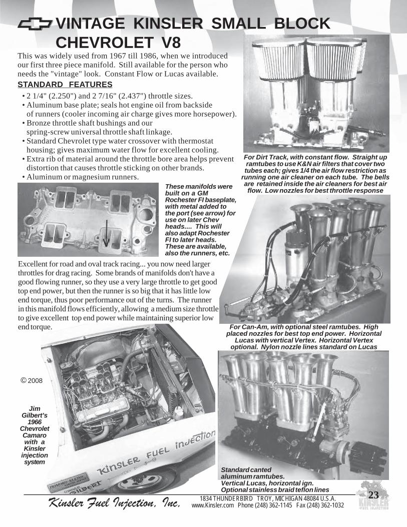
VINTAGE KINSLER SMALL BLOCKCHEVROLET V8
This was widely used from 1967 till 1986, when we introducedour first three piece manifold. Still available for the person whoneeds the "vintage" look. Constant Flow or Lucas available.
For Dirt Track, with constant flow. Straight upramtubes to use K&N air filters that cover twotubes each; gives 1/4 the air flow restriction as
running one air cleaner on each tube. The bellsare retained inside the air cleaners for best airflow. Low nozzles for best throttle response
Standard cantedaluminum ramtubes.Vertical Lucas, horizontal ign.Optional stainless braid teflon lines
JimGilbert’s
1966ChevroletCamarowith aKinsler
injectionsystem
© 2008
• 2 1/4" (2.250") and 2 7/16" (2.437") throttle sizes.• Aluminum base plate; seals hot engine oil from backside
of runners (cooler incoming air charge gives more horsepower).• Bronze throttle shaft bushings and our
spring-screw universal throttle shaft linkage.• Standard Chevrolet type water crossover with thermostat
housing; gives maximum water flow for excellent cooling.• Extra rib of material around the throttle bore area helps prevent
distortion that causes throttle sticking on other brands.• Aluminum or magnesium runners.
STANDARD FEATURES
These manifolds werebuilt on a GMRochester FI baseplate,with metal added tothe port (see arrow) foruse on later Chevheads.... This willalso adapt RochesterFI to later heads.These are available,also the runners, etc.
Excellent for road and oval track racing... you now need largerthrottles for drag racing. Some brands of manifolds don't have agood flowing runner, so they use a very large throttle to get goodtop end power, but then the runner is so big that it has little lowend torque, thus poor performance out of the turns. The runnerin this manifold flows efficiently, allowing a medium size throttleto give excellent top end power while maintaining superior lowend torque. For Can-Am, with optional steel ramtubes. High
placed nozzles for best top end power. HorizontalLucas with vertical Vertex. Horizontal Vertex
optional. Nylon nozzle lines standard on Lucas

Kinsler Fuel Injection, Inc, 1834 THUNDERBIRD TROY, MICHIGAN 48084 U.S.A.www.Kinsler.com Phone (248) 362-1145 Fax (248) 362-1032
24
FORD SMALL BLOCK V8
EFI· Kinsler universal nozzle boss inserts for EFI injectors· Machined for Kinsler fuel rail mounting stanchion studs· Kinsler bolt-on TPS boss and drive coupler
SVO portprofilewith
2 5/8"throttlesize andconstant
flowmetering
"4/12 "2"2/12 "61/32
"8/32"61/72"61/92
"8/52"61/112
dradnatSelttorhT
eziS
lanoitpOelttorhT
seziS
AVAILABLE FORSVO , Yates , TFS , Chapman
ORWINDSOR STWINDSOR STWINDSOR STWINDSOR STWINDSOR STYLEYLEYLEYLEYLECYLINDER HEADS
© 2008
Ford SVO port profile Kinsler aluminum rails for EFI
Windsor port profile with 2.0" throttle and EFI forstreet application
Michael Muray’sEFI Boss street
machine
CONSTANT FLOW METERING· Kinsler precision distribution barrel valve with
fittings, mounting bracket, and linkage hardware· Kinsler designed and computer ground barrel valve
spool· Set of Kinsler flowed and precision matched
nozzles, 1/2-20 thread· Kinsler built nitrile nozzle lines with 90-degree hose
ends· Kinsler brass 1/2-20 thread universal nozzle boss
inserts
STANDARD FEATURES• The port windows and their location to the bolt holes
are precisely machined, then the runners are blended tothe windows
• For standard or custom deck height block• 3-piece design• Universal nozzle bosses accept Constant Flow, EFI, or
Lucas nozzles• Billet valley plate for 9.2"W, 9.5"W, 351C,
or 289/302 block (8.2")• Magnesium or aluminum

Kinsler Fuel Injection, Inc, 1834 THUNDERBIRD TROY, MICHIGAN 48084 U.S.A.www.Kinsler.com Phone (248) 362-1145 Fax (248) 362-1032
25
FORD SMALL BLOCK V8OPTIONS• Kinsler billet spring-screw universal throttle shaft links.• Back cut throttle shafts for increased air flow• Valley plate for use on tall or custom deck engine blocks.• Aluminum or stainless steel fuel rails for EFI• 16-port barrel valve with block-off plugs• 16-nozzle system; barrel valve, nozzle lines, nozzles• Barrel valve with additional 6AN ports• Special linkage setups for ease of customer installation• 'Xtra-Light' package on manifold castings• Titanium ramtube adapter bolts• Machine manifold runners for nitrous nozzles• Machine manifold runners for M.A.P. reference and I.A.C. kits
Closeup of groove detail of manifold andvalley plate (without silicone installed)
We offer our manifold to fit several standard port profiles, many optional port profiles, or your customport profile. If your cylinder head is not listed, it doesn't mean we don't make it; call us.
Standard Port Profiles for Windsor are Fel Pro 1250 or 1262 gasket
Optional Port Profiles: Yates Nascar (shown below), alsoC3H High Port, Chapman, SC1, etc.
Custom Port Profiles:For an upcharge, we can machine the port windows and bolt hole locations to your exact specs.
© 2008
Standard Port Profile for the SVO (C3) and TFS (shown below)
- CONTINUED -

Kinsler Fuel Injection, Inc, 1834 THUNDERBIRD TROY, MICHIGAN 48084 U.S.A.www.Kinsler.com Phone (248) 362-1145 Fax (248) 362-1032
26
FORD MODULAR V84-VALVE OVAL PORT
© 2008
3-piece design withbillet aluminum
valley plate
3-VALVE OVAL PORT
Ford 3-valve manifold withoptional ‘inboard’ injectorbosses and custom blue air
box adapters
Custom PortProfiles:
For an upcharge,we can machine
the port windowsand bolt hole
locations to yourexact specs.
STANDARD FEATURES• The port windows and their location to the
bolt holes are precisely machined, then therunners are blended to the windows
• For standard or custom deck height block• 3-piece design• Universal nozzle bosses accept Constant
Flow, EFI, or Lucas nozzles• Billet center valley plate for 4.6 or 5.4• Aluminum standard, magnesium on special
order
Aluminum fuel railsand bolt-on TPS boss
installed for EFI
"4/12 "2"61/32"8/32"61/72
"2/12
dradnatSelttorhT
eziS
lanoitpOelttorhT
seziS
STANDARD FEATURES• The port windows and their location to the
bolt holes are precisely machined, then therunners are blended to the windows
• For standard or custom deck height block• 2-piece design• Universal nozzle bosses accept Constant
Flow, EFI, or Lucas nozzles• Aluminum standard, magnesium on special
order
"4/12 "2"61/32"8/32"61/72
"2/12
dradnatSelttorhT
eziS
lanoitpOelttorhT
seziS

Kinsler Fuel Injection, Inc, 1834 THUNDERBIRD TROY, MICHIGAN 48084 U.S.A.www.Kinsler.com Phone (248) 362-1145 Fax (248) 362-1032
27
4-VALVE GM MANIFOLDS
© 2008
OLDSMOBILE AURORA
CADILLAC NORTHSTAR
INDY RACING LEAGUE
STANDARD FEATURES• Throttle size: 2 1/4"• The port windows and their location to the
bolt holes are precisely machined, then therunners are blended to the windows
• For standard or custom deck height block• 3-piece design• Uses modular fuel rail• Magnesium standard, aluminum on special
order
STANDARD FEATURES• Throttle size: 2 1/4"• The port windows and their location to the
bolt holes are precisely machined, then therunners are blended to the windows
• For standard or custom deck height block• 2-piece design• Universal nozzle bosses accept Constant
Flow, EFI, or Lucas nozzles• Magnesium standard, aluminum on special
order
STANDARD FEATURES• Throttle size: various• The port windows and their location to the
bolt holes are precisely machined, then therunners are blended to the windows
• For standard or custom deck height block• 3-piece design• Uses modular fuel rail• Magnesium standard, aluminum on special
orderThese manifolds were made for the Oldsmobile and ChevroletIRL Indy Cars from 1997 to 2001. Used in conjunction with ourMonster Mesh fuel and oil filters, mechanical fuel pumps andK-140 pressure relief valves, these engines won 96% of the racesthey entered and won 5 manufacturer championships.

Kinsler Fuel Injection, Inc, 1834 THUNDERBIRD TROY, MICHIGAN 48084 U.S.A.www.Kinsler.com Phone (248) 362-1145 Fax (248) 362-1032
28
LUCAS MECHANICAL TIMED• Machined for Lucas 14mm nozzles• Extra throttle shaft length and throttle arm for
attachment of metering unit activation linkage
OPTIONS• Truck block (10.2" deck), thick flanges, no
spacers required• Longer nozzle hoses for 'down' nozzles• 16-port barrel valve with block-off plugs• 16-nozzle system; barrel valve, lines, nozzles• Barrel valve with 6 AN ports• Stainless steel throttle shafts for marine use• Special radiused entrance plates (replaces
ramtubes and adapters)• Special linkage setups for ease of customer
installation• Oval port manifold• Machine manifold runners for nitrous nozzles• Machine manifold runners for M.A.P. reference and I.A.C. kits
CHEVROLET ONE PIECE BIG BLOCK V8
CONSTANT FLOW METERING• Kinsler precision distribution barrel valve with
fittings and linkage• Kinsler designed and computer ground barrel
valve spool• Set of flowed and matched Kinsler nozzles• Set of Kinsler nitrile nozzle hoses with
90-degree ends• Nozzle boss positions: below throttle plates or
high in ramtube adapter above the throttle bores
EFI• Machined to accept EFI injector• Machined for Kinsler fuel rail mounting
stanchion stud• Kinsler bolt-on TPS boss and drive coupler
© 2008John Lohone’s EFI big block Chevrolet. Note the mechanicalfuel pump and ‘lower’ rail system for vacuum reference
Traditional Kinsler big block Chevroletmanifold with optional ‘low’ nozzle
location and nitrous nozzle ports
STANDARD FEATURES• The port windows and their location to the bolt
holes are precisely machined, then the runnersare blended to the windows
• Standard passenger block, 9.8" deck• One piece design, sealed floor to keep hot engine
oil away from backside of the runners, and sides left open to let air surround the runners
• Universal nozzle bosses accept Constant Flow,EFI, or Lucas nozzles
• Standard Chevrolet type water crossover with thermostat housing. Crossover has (3) boss areas for temperature sensing or coolant bypass
• Aluminum manifold and cast ramtube adapters

Kinsler Fuel Injection, Inc, 1834 THUNDERBIRD TROY, MICHIGAN 48084 U.S.A.www.Kinsler.com Phone (248) 362-1145 Fax (248) 362-1032
29
He’s flying!! Constant flow Kinsler in a flat-bottom boat
Mike Burton’s Roadster with 502 CID big block Chevrolet and F.A.S.T. EFI management system
CHEVROLET ONE PIECE BIG BLOCK V8
Lucas and "Shortie" ignition on Kinsler right angledrive. Note thick flange for use on truck blockwithout using spacer plates... gives a strongerflange, saves the cost of the spacer plates, andeliminates water leaks! This combination haswon many offshore powerboat championships
© 2005
© 2008STANDARD PORTPROFILEChevrolet rectangular port
- CONTINUED -
Custom Port Profiles:For an upcharge, we can machine the port windows and bolt hole locations to your exact specs.
If one engine is good, two are even better; some use four!

Kinsler Fuel Injection, Inc, 1834 THUNDERBIRD TROY, MICHIGAN 48084 U.S.A.www.Kinsler.com Phone (248) 362-1145 Fax (248) 362-1032
30
CHEVROLET THREE PIECE BIG BLOCK V8
© 2008
dradnatSelttorhT
eziS
lanoitpOelttorhT
seziS"2/12 "8/52
"61/112"61/312
"9.2"0.3
CONSTANT FLOW METERING• Kinsler precision barrel valve with fittings, mounting
bracket, and linkage to throttle shaft• Kinsler designed, computer ground barrel valve spool• Set of Kinsler flowed and precision matched
nozzles, 1/2-20 thread with 1" ‘AS’ style deflectors• Kinsler assembled nozzle hoses with 90° ends• Outboard nozzle location - includes 1/2-20 thread
brass universal nozzle boss inserts and sintered bronzeair filters
EFI• Kinsler universal boss inserts for EFI injectors• Machined for fuel rail mounting stanchion
stud• Kinsler bolt-on TPS boss and drive coupler
LUCAS MECHANICAL• Kinsler universal boss inserts for Lucas
mechanical injection nozzles• Throttle shaft and throttle arm set
up for linkage to actuate Cam on Lucasmetering unit
OPTIONS• Kinsler billet Spring-Screw universal throttle shaft linkage• Back cut throttle shafts for increase air flow• Streamlined Throttle Plates• Valley plate for use on tall or custom deck engine blocks• Aluminum or stainless steel fuel rails for EFI• Jackshaft linkage kit: stainless steel cross shaft• Canted ramtube adapters
Big blockDragon
Clawjackshaftlinkage
kit, pullsfront to
rear
Optionalcanted
ramtubeadapter
Custom Port Profiles:For an upcharge, we can machine
the port windows and bolt holelocations to your exact specs. Wecan do rectangular and oval ports.
STANDARD FEATURES• The port windows and their location to the bolt
holes are precisely machined, then the runners areblended to the windows
• For standard or custom deck height block• 3-piece design• Universal nozzle bosses accept Constant Flow,
EFI, or Lucas nozzles• Valley plate for passenger or truck block• 10 AN water ports at front and rear (other sizes
available on special order) cut out for center waterport where applicable
• Magnesium or aluminum

Kinsler Fuel Injection, Inc, 1834 THUNDERBIRD TROY, MICHIGAN 48084 U.S.A.www.Kinsler.com Phone (248) 362-1145 Fax (248) 362-1032
31
CROSS-RAM FOR CHEVROLET BIG BLOCK
STANDARD PORTPROFILEChevrolet rectangularport
OPTIONS• Magnesium manifold and
ramtube adapters• Stainless steel throttle shafts
for marine use• Special radiused entrance
plates (replaces ramtubes andadapters)
• Machine manifold runners fornitrous nozzles
• Machine manifold runners forMAP reference and IAC kitsfor EFI
• Kinsler precisiondistribution barrelvalve with computerground spool
• Nozzle hoses with90-degree ends
• Nozzle boss position:low near valve coveror high near throttlebores
• Machined for Lucas14mm nozzles
• Extra throttle shaftlength and throttle armto actuateLucas unit
© 2008
Using Kinsler cross-ram and Lucas timedmechanical injection (on gasoline !!!) Gary
Balough in the Ferraiuolo Brothers' Grant Kingmodified wins the Schaeffer 100 at Syracuse,
New York. RESULT: banned both Lucas timedinjection and gasoline at that track
NOTE:Cross-rammanifolds areconsiderablymoreexpensivethan verticalmanifolds. Ittakes a lot ofextra work todeveloprunners thatflow well, andthe design,castings, andmachining areconsiderablymorecomplicated.
STANDARD FEATURES• The port windows and their location to the bolt
holes are precisely machined, then the runnersare blended to the windows
• Standard passenger block, 9.8" deck• Universal nozzle bosses accept Constant Flow,
EFI, or Lucas nozzles• Standard Chevrolet type water crossover with
thermostat housing.• Aluminum manifold and cast ramtube adapters
Custom Port Profiles:For an upcharge, we can machine the port windows
and bolt hole locations to your exact specs.
dradnatSelttorhT
eziS
lanoitpOelttorhT
seziS
CONSTANT FLOW METERING
LUCAS MECHANICAL
EFI with aluminum fuel rails
Constant flow metering
EFI• Kinsler universal boss inserts for EFI injectors• Machined for Kinsler fuel rail mounting stanchion stud• Kinsler bolt-on TPS boss and drive coupler
"61/112 "8/32

Kinsler Fuel Injection, Inc, 1834 THUNDERBIRD TROY, MICHIGAN 48084 U.S.A.www.Kinsler.com Phone (248) 362-1145 Fax (248) 362-1032
32
CHEVROLET BIG BLOCK V8
PONTIAC PRO-STOCK
CHEVROLET SYMMETRICALPORT OR
OLDSMOBILE DRCE
DART BIG-CHIEF
EFI injector bosses inthe ramtube adapters
© 2008
STANDARD FEATURES• The port windows and their
location to the bolt holes areprecisely machined, then therunners are blended to thewindows
• For standard or custom deckheight block
• 3-piece design• Universal nozzle bosses for
Constant Flow, EFI, orLucas nozzles
• Also available for Dart's 140
Oldsmobile port profile• Magnesium or aluminum
Constant flow metering
Dick Asbe’s ‘Black Sheep’ dragboat with 557 CID big block
Chevrolet. Dart Big-Chief cylinderheads and Kinsler manifold with
constant flow metering
dradnatSelttorhT
eziS
lanoitpOelttorhT
seziS
dradnatSelttorhT
eziS
lanoitpOelttorhT
seziS
STANDARD FEATURES• The port windows and their location to the
bolt holes are precisely machined, then therunners are blended to the windows
• For standard or custom deck height block• 3-piece design• Universal nozzle bosses accept Constant
Flow, EFI, or Lucas nozzles• Magnesium or aluminum
STANDARD FEATURES• The port windows and their location to
the bolt holes are precisely machined,then the runners are blended to thewindows
• For standard or custom deck heightblock
• 3-piece design• Universal nozzle bosses accept
Constant Flow, EFI, or Lucas nozzles• Magnesium or aluminum
Constant flowmetering
with 1/2-20nozzles belowthrottle plates
dradnatSelttorhT
eziS
lanoitpOelttorhT
seziS
"9.2 "0.3"051.3
"9.2 "0.3"051.3
"9.2 "0.3"051.3

Kinsler Fuel Injection, Inc, 1834 THUNDERBIRD TROY, MICHIGAN 48084 U.S.A.www.Kinsler.com Phone (248) 362-1145 Fax (248) 362-1032
33
FORD BIG BLOCK V8
Dave Willoughby’s 4-wheel drive pull truck, 700 CIDFord A/R Hemi with constant flow metering
© 2008
TFS / SVO
With constantflow metering
A/R HEMI HEADS
SUPER COBRA JETSTANDARD FEATURES• The port windows and their location
to the bolt holes are preciselymachined, then the runners are blendedto the windows
• For standard or custom deckheight block
• 3-piece design• Universal nozzle bosses accept
Constant Flow, EFI, or Lucasnozzles
• Magnesium or aluminum
dradnatSelttorhT
eziS
lanoitpOelttorhT
seziS
dradnatSelttorhT
eziS
lanoitpOelttorhT
seziSSTANDARD FEATURES• The port windows and their location
to the bolt holes are preciselymachined, then the runners are blendedto the windows
• For standard or custom deck height• 3-piece design• Universal nozzle bosses accept
Constant Flow, EFI, or Lucas nozzles• Magnesium or aluminum
dradnatSelttorhT
eziS
lanoitpOelttorhT
seziS
STANDARD FEATURES• The port windows and their location to the bolt holes are precisely machined, then the• For standard or custom deck height block• 3-piece design• Universal nozzle bosses accept Constant Flow, EFI, or Lucas• Magnesium or aluminum
With constant flow metering
runners are blended to the windows
"9.2 "0.3"051.3
"9.2 "0.3"051.3
"8/32 "8/52"2/12 "61/112
"61/312"9.2"0.3

Kinsler Fuel Injection, Inc, 1834 THUNDERBIRD TROY, MICHIGAN 48084 U.S.A.www.Kinsler.com Phone (248) 362-1145 Fax (248) 362-1032
34© 2008
Mopar Monstermanifold
Mopar Dragon Clawmanifold
MOPAR MONSTER
MOPAR MANIFOLDSASCS DRAGON CLAW
MOPAR DRAGON CLAW
dradnatSelttorhT
eziS
lanoitpOelttorhT
seziS"61/112 "4/32
"61/312"9.2"0.3
dradnatSelttorhT
eziS
lanoitpOelttorhT
seziS"8/52 "4/32"61/112 "9.2"61/312 "0.3
dradnatSelttorhT
eziS
lanoitpOelttorhT
seziS"2/12 "8/52STANDARD FEATURES
• The port windows and their location to the bolt holes areprecisely machined, then the runners are blended to thewindows
• For standard or custom deck height block• 3-piece design• Universal nozzle bosses accept Constant Flow, EFI, or Lucas
nozzles• Magnesium• Dual milled precision ground milled style one-piece hard-
nickel plated throttle shafts• Jackshaft linkage kit• Set of Kinsler flowed and precision matched nozzles,
1/2-20 thread with 5 1/2" ‘AS’ style deflectors• Billet aluminum valley plate
STANDARD FEATURES• The port windows and their location
to the bolt holes are preciselymachined, then the runners areblended to the windows
• For standard or custom deck heightblock
• Universal nozzle bosses acceptConstant Flow, EFI, or Lucas nozzles
• Magnesium or aluminum• For W7 or W9 cylinder heads only• Inboard or Outboard nozzle location• Not supplied with valley plate
STANDARD FEATURES• The port windows and their location
to the bolt holes are preciselymachined, then the runners areblended to the windows
• For standard or custom deck height block• Universal nozzle bosses accept
Constant Flow, EFI, or Lucas nozzles• Magnesium or aluminum• For W7 or W9 cylinder heads only• Standard nozzle location with internal air bleeds• Optional ‘Lower’ nozzle location available• Not supplied with valley plate
ASCS Mopar DragonClaw manifold

Kinsler Fuel Injection, Inc, 1834 THUNDERBIRD TROY, MICHIGAN 48084 U.S.A.www.Kinsler.com Phone (248) 362-1145 Fax (248) 362-1032
35© 2008
MOPAR MANIFOLDS - CONTINUED -
426 HEMI dradnatSelttorhT
eziS
lanoitpOelttorhT
seziSSTANDARD FEATURES• The port windows and their locationto the bolt holes are preciselymachined, then the runners are blended to
the windows• For standard or custom deck height block• 3-piece design• Universal nozzle bosses accept Constant
Flow, EFI, or Lucas nozzles• Magnesium or aluminum• Designed to use Kinsler Idle Air Control
rail system
On W-7cylinder
head withconstant
flow
dradnatSelttorhT
eziS
lanoitpOelttorhT
seziSSTANDARD FEATURES• The port windows and their location to
the bolt holes are precisely machined, thenthe runners are blended to the windows
• For standard or custom deck height block• 3-piece design• Universal nozzle bosses accept Constant
Flow, EFI, or Lucas nozzles• Magnesium or aluminum
4-CYLINDER HEMISTANDARD FEATURES• The port windows and their location to
the bolt holes are precisely machined, thenthe runners are blended to the windows
• For standard or custom deck height block• Universal nozzle bosses accept Constant
Flow, EFI, or Lucas nozzles• Magnesium or aluminumAvailable exclusively through:
Gary Stanton Racing100 Memorial DriveNicholasville, KY 40356Tel: (859) 885-7354Fax: (859) 887-2799
dradnatSelttorhT
eziS
lanoitpOelttorhT
seziS"4/12 "61/32"2/12 "8/32
"61/72"8/52
SMALL BLOCK MOPAR
"61/32 "2"4/12 "8/32"2/12 "61/72
"61/92"8/52"61/112
"61/32 "2"4/12 "8/32"2/12 "61/72
"61/92"8/52"61/112

Kinsler Fuel Injection, Inc, 1834 THUNDERBIRD TROY, MICHIGAN 48084 U.S.A.www.Kinsler.com Phone (248) 362-1145 Fax (248) 362-1032
36
dradnatSelttorhT
eziS
lanoitpOelttorhT
seziS"61/32 "2
"4/12 "8/32"2/12 "61/72
"61/92"8/52
dradnatSelttorhT
eziS
lanoitpOelttorhT
seziS
4-CYLINDER IN-LINE MANIFOLDSWE CAN MAKE 4-CYLINDER MANIFOLDSTO FIT MOST ENGINES; GIVE US A CALL.
CHEVROLET
Chevroletwith
constantflow
metering
FORD
Ford withYates C3Hhigh port
profile andconstant
flow meter-ing
TRD
STANDARD FEATURES• The port windows and their location to
the bolt holes are precisely machined, thenthe runners are blended to the windows
• For standard or custom deck height block• Based on the 3-piece design• Universal nozzle bosses accept Constant
Flow, EFI, or Lucas nozzles• Magnesium or aluminum
STANDARD FEATURES• The port windows and their location to
the bolt holes are precisely machined,then the runners are blended to thewindows
• For standard or custom deck heightblock
• Based on the 3-piece design• Universal nozzle bosses accept Constant
Flow, EFI, or Lucas nozzles• Magnesium or aluminum
Constant flow metering with optionallight weight barrel valve
STANDARDFEATURES• The port windows and
their location to the boltholes are preciselymachined, then therunners are blendedto the windows
• For standard or customdeck height block
• Based on the 3-piecedesign
• Universal nozzle bossesaccept Constant Flow,
EFI, or Lucas
Developed with Ed Pink Racing Engines (EPRE)for Toyota 4-cylinder midget program
dradnatSelttorhT
eziS
lanoitpOelttorhT
seziS
• Magnesium standard,aluminum on special order
• O-ringed ports seal tohead
© 2008
"4/12 "2"2/12 "61/32
"8/32"61/72"61/92
"8/52"61/112
"8/52 "61/72"61/112"61/312
"4/32"9.2

Kinsler Fuel Injection, Inc, 1834 THUNDERBIRD TROY, MICHIGAN 48084 U.S.A.www.Kinsler.com Phone (248) 362-1145 Fax (248) 362-1032
37
V6 MANIFOLDSCHEVY 90° V6
Hill and William's turbocharged Buick V6with constant flow metering
Jim Crawford's stock-block Buick V6 powered theLola to a record of the fastest lap in unoffical
testing, animpressive 224.2 MPH© 2008
STANDARD FEATURES• The port windows and their location
to the bolt holes are precisely machined,then the runners are blended to the windows
• For standard or custom deck height block• 3-piece design• Universal nozzle bosses accept Constant Flow, EFI,
or Lucas nozzles• Magnesium or aluminum
"4/12 "8/32"2/12 "61/72
"61/92"8/52
dradnatSelttorhT
eziS
lanoitpOelttorhT
seziS
GMC Motorsport's S-15, the first truck to reach 200 MPHat Bonneville. Chevrolet 900 V6, engine built by Katech
Constant flow metering
Trans-Am Champion: Chevrolet 900 V6,engine built by Katech. Kinsler manifold with EFI
STANDARD FEATURES• The port windows and their location
to the bolt holes are precisely machined,then the runners are blended to the windows
• For standard or custom deck height block• 3-piece design• Universal nozzle bosses accept Constant Flow, EFI,
or Lucas nozzles• Vertical or lean-in models• Magnesium standard, aluminum on special order
Lean-in model with EFI
dradnatSelttorhT
eziS
lanoitpOelttorhT
seziS
BUICK V6 STAGE II
"4/12 "8/32"2/12 "61/72

Kinsler Fuel Injection, Inc, 1834 THUNDERBIRD TROY, MICHIGAN 48084 U.S.A.www.Kinsler.com Phone (248) 362-1145 Fax (248) 362-1032
38
PONTIAC MANIFOLDS
© 2008
STANDARD FEATURES• The port windows and their
location to the bolt holes are preciselymachined, then the runners areblended to the windows
• For standard or custom deck height block• 2-piece design uses factory or aftermarket lifter
valley cover.... we don’t supply it• Universal nozzle bosses accept Constant Flow,
EFI, or Lucas nozzles• Aluminum standard, magnesium on special order
PONTIAC SUPER DUTY
Front view with Kinsler aluminum EFI fuel rails
"61/32 "2"4/12 "8/32"2/12 "61/72
"8/52
dradnatSelttorhT
eziS
lanoitpOelttorhT
seziS
dradnatSelttorhT
eziS
lanoitpOelttorhT
seziS
‘437’ cylinder head
‘801’ cylinder head
dradnatSelttorhT
eziS
lanoitpOelttorhT
seziS
STANDARD FEATURES• The port windows and their
location to the bolt holes are preciselymachined, then the runners areblended to the windows
• For standard or custom deck height block• Universal nozzle bosses accept Constant
Flow, EFI, or Lucas nozzles• Aluminum standard, magnesium on special order
Many midget oval track sprint carswere powered by a Pontiac usingKinsler's constant flow metering
Pontiac's GTP-L Fiero used Kinslerconstant flow metering. Pontiac
dominated the IMSA classes then wenton to win the 24-hours of Daytona
"4/12 "8/32
"2/12 "8/52

Kinsler Fuel Injection, Inc, 1834 THUNDERBIRD TROY, MICHIGAN 48084 U.S.A.www.Kinsler.com Phone (248) 362-1145 Fax (248) 362-1032
39
SPORT - COMPACT MANIFOLDS
© 2008
dradnatSelttorhT
eziS
lanoitpOelttorhT
seziS
WE CAN MAKE 4-CYLINDER MANIFOLDSTO FIT MOST ENGINES; GIVE US A CALL.
STANDARD FEATURES• The port windows and their location to
the bolt holes are precisely machined, thenthe runners are blended to the windows
• Universal nozzle bosses accept ConstantFlow, EFI, or Lucas nozzles
• Magnesium or aluminum• Dual milled transverse throttle shafts• Optional ‘Upper’ rail assembly available• Billet linkage connector bar with ball
bearings and snap rings
K SERIES
F and H SERIES
dradnatSelttorhT
eziS
lanoitpOelttorhT
seziS"0.2 "2/12"4/12 "8/52"61/32
"8/32"61/72
dradnatSelttorhT
eziS
lanoitpOelttorhT
seziS"0.2 "2/12"4/12 "8/52"61/32
"8/32"61/72
STANDARD FEATURES• The port windows and their location to
the bolt holes are precisely machined, thenthe runners are blended to the windows
• Universal nozzle bosses accept ConstantFlow, EFI, or Lucas nozzles
• Magnesium or aluminum• Optional ‘Upper’ rail assembly available• Billet linkage connector bar with ball
bearings and snap rings

Kinsler Fuel Injection, Inc, 1834 THUNDERBIRD TROY, MICHIGAN 48084 U.S.A.www.Kinsler.com Phone (248) 362-1145 Fax (248) 362-1032
40
© 2008
SPORT - COMPACT MANIFOLDS
STANDARD FEATURES• The port windows and their location to
the bolt holes are precisely machined, thenthe runners are blended to the windows
• Universal nozzle bosses accept ConstantFlow, EFI, or Lucas nozzles
• Magnesium or aluminum• Optional ‘Upper’ rail assembly available• Billet linkage connector bar with ball
bearings and snap rings
dradnatSelttorhT
eziS
lanoitpOelttorhT
seziS"0.2 "2/12"4/12 "8/52"61/32
"8/32"61/72
4G63
D SERIES
STANDARD FEATURES• The port windows and their location to
the bolt holes are precisely machined, thenthe runners are blended to the windows
• Universal nozzle bosses accept ConstantFlow, EFI, or Lucas nozzles
• Billet aluminum base plate with castthrottle bodies
• Includes fuel rail, use of OEM pressurerelief valve optional
Looking for a B-series Honda ITB?We can do it!Please call or e-mail us for details and options.
1.6L SOHC ZC
‘Bisi Ezerioha - Bisimoto EngineeringWorld's Fastest All Motor SOHC Honda2006 Insight Unibody, F22A: 9.57; 145mph
Honda F-series ITB, custom designedfor Bisimoto Engineering
dradnatSelttorhT
eziS"018.1
"0.2"61/32
"4/12

Kinsler Fuel Injection, Inc, 1834 THUNDERBIRD TROY, MICHIGAN 48084 U.S.A.www.Kinsler.com Phone (248) 362-1145 Fax (248) 362-1032
41
6-CYLINDER IN-LINE MANIFOLD
© 2008
Dave Laney'soff-road sandbuggy with a
Scat V4 enginewith turbo-
charger.Kinsler's
constant flowfuel system
KinslerChevrolet-style V-4manifold
withconstant
flowmetering
STANDARD FEATURES• Standard throttle size: 2.680" x 1.860" oval• The port windows and their location to the
bolt holes are precisely machined, then therunners are blended to the windows
• For standard or custom deck height block• 2-piece design• Universal nozzle bosses accept Constant
Flow, EFI, or Lucas nozzles• Incorporates cast-in fuel rail, machined for Delco side feed EFI injectors• Uses hard-anodized fuel transfer tube between
the two manifold castings• Magnesium or aluminum
Adapters for ramtube mounting
V4 INJECTION MANIFOLDSTANDARD FEATURES• The port windows and their location to the bolt
holes are precisely machined, then the runnersare blended to the windows
• For standard or custom deck height block• 3-piece design• Universal nozzle bosses accept Constant Flow,
EFI, or Lucas nozzles• Magnesium or aluminum
Manifold assembled from two three-cylinder castings
dradnatSelttorhT
eziS
lanoitpOelttorhT
seziS
Chevrolet’s Baja champion, running L6 in-line manifold
GM L-6
"61/32 "8/32"4/12 "61/72"2/12 "61/92
"8/52"61/112

Kinsler Fuel Injection, Inc, 1834 THUNDERBIRD TROY, MICHIGAN 48084 U.S.A.www.Kinsler.com Phone (248) 362-1145 Fax (248) 362-1032
42
CROSSRAM MANIFOLDS
CHAPARRAL BIG BLOCKCHEVROLET
Designed for Jim Hall's Chaparral 2J Can-Am car. Magnesium manifold with 2.9"throttles; Lucas metering. About fifteenwere made.
The 2J car used a moveable Lexan skirt thatran 1/4" from the road all the way around theoutside of the car. Two fans sucked the airout to make the car a rolling suction cup.SCCA banned the car after one season asbeing beyond the technical and financialcapability of other racers.
Jim Kinsler was responsible for the manifoldand suction fans in 1968-1969, while hewas still in Research and Development atthe Chevrolet Engineering Center, Warren,Michigan.
GREENWOOD BIG BLOCK CHEVROLET
FABRICATEDLook closely.... this manifold was handfabricated in 1977 at Kinsler’s from sheetand bar aluminum for Charlie Kemp'sTrans Am Mustang. A crossram was theonly way to get the desired runner lengthswhile meeting the rule that the unit had tobe completely under the hood. UsedLucas metering.
A good flowing runner was developed,then exactly duplicated by forming fourstrips of aluminum over a pattern. Had2 7/16" throttles. The top road racingteams now have manifolds made ofcarbon fiber.
Kemp was quite successful.
© 2008
SMALL BLOCK CHEVROLETDesigned with small runners to give maximum low end torque for street use. Fits standard small port cylinderhead. Throttle body mounting flanges are for Weber IDA 45 mm. Cast aluminum only.
Four EFI IDA style throttle bodies withaluminum fuel rails and connector linkage
Each Kinsler log has a 2 1/4" throttle at the front withcross-connecting linkage; Lucas mechanical metering
This manifold was originally designed for JohnGreenwood, to fit completely under the hood ofhis Corvette.
Available in magnesium or aluminum. Customthrottle sizes are available for good top endpower combined with super low endcharacteristics.
Phosphorous bronze throttle shaft bushings andspring screw universal throttle shaft linkageeliminates any possible throttle bind; workssmooth!
Available for EFI, Constant Flow, or Lucasmetering.
Note: Crossram units cost about twice as muchas vertical types, as it takes a lot of extra workto develop a runner that flows well, and thedesign and castings are also considerably moreinvolved.
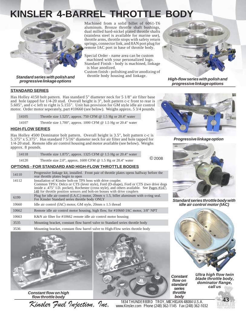
Kinsler Fuel Injection, Inc, 1834 THUNDERBIRD TROY, MICHIGAN 48084 U.S.A.www.Kinsler.com Phone (248) 362-1145 Fax (248) 362-1032
43
KINSLER 4-BARREL THROTTLE BODYMachined from a solid billet of 6061-T6aluminum. Bronze throttle shaft bushings,dual milled hard-nickel plated throttle shafts(stainless steel is available for marine use),throttle arms, throttle stops with safety returnsprings, connector link, and 8AN port plug forremote IAC port in base of throttle body.
Special Order - name area can be custom machined with your personalized logo.Standard Finish - body is machined, linkage is blue anodized.Custom finish - polishing and/or anodizing of throttle body housing and linkage.
© 2008
50141 retaw"[email protected],"525.1eziselttorhT
70141 retaw"[email protected],"007.1eziselttorhT
81141 retaw"[email protected],"578.1eziselttorhT
02141 retaw"[email protected],"0.2eziselttorhT
OPTIONS - FOR STANDARD AND HIGH-FLOW THROTTLE BODIES
HIGH-FLOW SERIESHas Holley 4500 Dominator bolt pattern. Overall height is 3.5", bolt pattern c-c is5.375" x 5.375". Has standard 7 5/16" diameter neck for air filter and hole tapped for1/4-20 stud. Remote idle air control housing and motor available (see below). Weighsapprox. 8 pounds.
01141 ehterofebyawflahsneposetalpelttorhtforiaptnorF.dellatsni,tikegaknilevissergorPnepootnigebsetalpelttorhtraer
21141 .relpuocevirdhtiwssobSPTno-tlobrelsniKfonoitallatsnIsgodevirdowt(STCrodroF,)epahs-D(droF,)elytsrevel(STCroocleD:s'SPTnommoC
eeS.elbaliavasrehtodna,)elytsssorc(retsehcoR,)tekcop.D.I"574.aedisni -741#segaP841 srelpuocevirdhtiwsessobno-tlobdnasrosnesnoitisopelttorhtrof
9916 .laesgnir-ohtiwmunimulatellib,5.1xmm02,rotom).C.A.I(lortnocriaeldirofgulPYLNOydobelttorhtseiresdradnatSrelsniKroF
06601 daerht5.1xmm02,elytsMG,rotom)CAI(lortnocriaeldI
26601 TPN"8/3,rotomCAI06601#rof,wolfhgih,gnisuohrotomlortnocriaeldietomeR
36601 gnisuohrotomlortnocriaeldietomer26601#rofretlifriaN&K
5353 ydobelttorhtseiresdradnatSotevlavlerrabwolftnatsnoc,tekcarbgnitnuoM
6353 ydobelttorhtseireswolF-hgiHotevlavlerrabwolftnatsnoc,tekcarbgnitnuoM
Standard series with polish andprogressive linkage options High-flow series with polish and
progressive linkage options
Progressive linkage option
Constant flow on highflow throttle body
Constantflow onstandard
seriesthrottlebody
Ultra high flow twinblade throttle body,dominator flange,
call us
STANDARD SERIESHas Holley 4150 bolt pattern. Has standard 5" diameter neck for 5 1/8" air filter baseand hole tapped for 1/4-20 stud. Overall height is 3", bolt pattern c-c front to rear is5.605", and c-c left to right is 5.155". Unit has provision for GM style idle air controlmotor. Order motor seperately, part #10660 (see below). Weighs approx. 5 3/4 pounds.
Standard series throttle body withidle air control motor (IAC)

Kinsler Fuel Injection, Inc, 1834 THUNDERBIRD TROY, MICHIGAN 48084 U.S.A.www.Kinsler.com Phone (248) 362-1145 Fax (248) 362-1032
44
KINSLER MODULAR THROTTLE BODIESFOR CUSTOM APPLICATIONS:
1 to 16 CYLINDERS1 to 16 CYLINDERS1 to 16 CYLINDERS1 to 16 CYLINDERS1 to 16 CYLINDERSIMPORT, VINTAGE, WEBER CARB, CONVERSIONS
MODELMC-215 andMC-225
SNOISNEMIDCISAB052-CM
TUOHTIWELZZON
SSOB
052-CM
HTIWELZZON
SSOB
052-CMHTIW
ESREVSNARTELTTORHT
STFAHSA "007.2 "007.3 "008.3
B "005.3 "005.4 "006.4
C "009.3 "009.3 "009.3
D "057.2 "057.2 "057.2
E "005.1 "005.1 "005.1
F "004.1 "004.1 "004.1
G "000.5 "000.5 "000.5Unmachined MC-215 Machined MC-215 throttle
body with Weber style detail
© 2008
MODELMC-180
MODELMC-250
Any boot or flange detailis available with any throttlesize... allows installation of larger throttles withoutmodifying your boot or cylinder head.
Machined for Kinsler universal nozzle bosses. Inserts can be installedfor constant flow nozzles (1/2-20 or 1/8" NPT thread) or EFI injectors (Bosch, Lucas,Rochester, etc.) (see Pg. #139). All throttle bodies are machined for Kinsler's bolt-onTPS boss and fuel rail stanchions. Custom throttle sizes available. Aluminum ormagnesium castings.
Each throttle assembly is port blended for smooth air flow and has bronze throttle shaftbushings, dual milled throttle shaft, billet aluminum throttle arm and billetaluminum throttle stop with safety return spring.
Multiple throttle bodies are mounted on a locator bar for a perfect fit and secureinstallation.... NO cutting, welding, broken boots due to improper alignment, orproblems with linkage binding. When enough room is available, Kinsler Spring-Screw universal throttle shaft linkage is installed (see Pg. #64-65). You canchange the port spacing by simply installing the throttle bodies on a new locatorbar; throttle shafts may require modification or replacement.
EFI four-cylinder
SNOISNEMIDCISAB081-CM 512-CM 522-CM
A "057.2 "002.3 "002.3
B "053.3 "008.3 "008.3
C "000.3 "000.3 "000.3
D "009.1 "002.2 "005.2
E "002.1 "005.1 "005.1
F "059.0 "002.1 "002.1
G "000.4 "000.4 "000.4
SEZISELTTORHTDRADNATS081-CM 512-CM 522-CM 052-CM
"734.1)mm5.63(
"059.1)mm5.94(
"059.1)mm5.94(
"781.2)mm5.55(
"265.1)mm7.93(
"0.2)mm8.05(
"0.2)mm8.05(
"052.2)mm75(
"786.1)mm8.24(
"001.2)mm3.35(
"001.2)mm3.35(
"573.2)mm3.06(
"018.1)mm64(
"781.2)mm5.55(
"781.2)mm5.55(
"734.2)mm9.16(
"009.1mm2.84(
"052.2)mm75(
"052.2)mm75(
"005.2)mm5.36(
"526.2)mm7.66(
Billet aluminumlocator bar

Kinsler Fuel Injection, Inc, 1834 THUNDERBIRD TROY, MICHIGAN 48084 U.S.A.www.Kinsler.com Phone (248) 362-1145 Fax (248) 362-1032
45Optional barrel valve
mounting bracket
THROTTLE BODIES
ZX THROTTLE BODYDesigned primarily for use on a smalldisplacement turbocharged engines.This compact throttle body (2.0" tall)allows options for many applications.
One piece billet aluminumconstruction. Includes bronze throttleshaft bushings, 3/8" dia. throttle shaft,Kinsler throttle stop with safety returnspring. O-ringed 4-bolt base flange with1.838" c-c and hose type inlet for 2 1/8"ID hose.
Available with barrel valve for constantflow metering or throttle positionsensor for EFI.
Throttle sizes, standard 1.870" ; optional 1.900" and 1.950".
Made for and sold through:Mr. Turbo4014 Hopper RoadHouston, Texas 77093 USATel: (281) 442-7113Fax: (281) 442-4472
HD SERIES THROTTLE BODYOffers great flexibili ty for manyapplications. Has a seperate ramtubeadapter with aluminum ramtube.
Billet aluminum housing with bronzethrottle shaft bushings, 3/8" dia. throttleshaft for strength, Kinsler billet throttlestop with safety return spring, and throttlearm. Kinsler spun aluminum ramtube canbe cut to different lengths for tuning.Removable pinch clamp ramtube, allowsusing any size ramtube with any sizethrottle bore. Also available with o-ringedtop and bottom flanges for centrifugalblower applications.
Available with barrel valve for constantflow metering, or throttle position sensorfor EFI.
Throttle sizes: 2 3/16", 2 1/4", 2 3/8", 2 7/16", 2 1/2", 2 5/8", and 2 11/16".
One piece billet aluminum body with bolt-ono-ringed turbo style hose flanges. Bronzethrottle shaft bushings, 3/8" dia. throttle shaft,Kinsler throttle stop with safety return spring.
Available with aluminum or stainless steelthrottle plate.
Throttle size: 2.9" ; other sizes can be specialordered.
© 2008
Six HD throttle bodies on sheet alumi-num manifold. 60-degree Chev V6
HD throttle body with optional radiusinlet plate and barrel valve
Jim McClure, owner of Master Performanceriding his Top Fuel Harley-Davidson drag bike. Uses
Kinsler fuel pump and fuel system components
HD throttle body withoptional barrel valve,ramtube, and adapter
Hill climbmotorcycle
THROTTLE BODY

Kinsler Fuel Injection, Inc, 1834 THUNDERBIRD TROY, MICHIGAN 48084 U.S.A.www.Kinsler.com Phone (248) 362-1145 Fax (248) 362-1032
46
THROTTLE BODIES
THROTTLE BODY MODEL 3.5PCast aluminum housing with 3 1/2" throttle plate.Large radius entrance with 5" diameter flange (likea standard Holley carb), to attach an air filter baseplate. Bronze throttle shaft bushings. Drilled andtapped on both sides for Kinsler throttle stop boss orbolt-on TPS boss, and has a 3.250" c-c squaremounting pattern, four 1/4" bolts. O-ringed onbottom for sealing. Has flat pad on the rear forvacuum port or bracket attachment. Throttle plate is.125" thick aluminum. Precision ground hard-nickel plated throttle shaft is 1/2"dia. through throttleplate and bushing area, milled on both sides forincreased air flow, turned to 3/8"dia. outside thebody housing.
Use on turbo intake; one or two on tunnel ram, etc.
On singleplenum
4-barrel intakemanifold withconstant flow
metering
© 2008 Kinsler PSI supercharger EFI adapter with four 3.5Pthrottle bodies; progressive linkage (see Page #51)
3.5P throttle body with TPS boss installed
3.5P throttle body installed on4150 Holley carb adapter plate
MONO VALVE THROTTLE BODYSingle throttle plate. 3.75", 4.0", 4.1" diameteravailable. Specify Holley 4150 or 4500 bolt pattern.
THROTTLE BODY MODEL VThrottle sizes: 3.0" and 3.250"
2.75" tall with 3.0" x 3.5" bolt pattern. Includesbronze throttle shaft bushings, 3/8" OD throttle shaftwith safety return spring. Billet aluminum. Availablewith aluminum or stainless steel throttle plate.

Kinsler Fuel Injection, Inc, 1834 THUNDERBIRD TROY, MICHIGAN 48084 U.S.A.www.Kinsler.com Phone (248) 362-1145 Fax (248) 362-1032
47
Custom made throttlebodies to fit directly
onto a Kawasaki 2-cylinderJet-ski engine using EFI
THROTTLE BODIES
© 2008
Billet aluminumthrottle body,polished.Throttle bores:2.362" to3.543" (60-90mm). Acceptstwin grooveTPS and FordIAC motor.Adapteravailable to useGM IAC motor.
THROTTLE BODY
ELBOW ADAPTER FOR MANIFOLDOften used on turbo and centrifugal superchargers.
Adapts 4150 Holley flanged carburetor manifold tothrotle body.
Has 3.54" (90mm) openning for throttle body.Cast aluminum.
Ideal for tunnel-ram conversion
Great bolt-onfor high output5.0 Mustangs
SB THROTTLE BODYOne piece billet aluminum body with 3-bolt flange. With bronzethrottle shaft bushings, 3/8" OD throttle shaft, Kinsler throttle stopwith safety return spring and stop boss. Accepts Kinsler bolt-onTPS boss.
Throttle size: 2 1/2", 2 5/8", and 2 11/16". Other sizes on specialorder.Available with aluminum or stainless steel throttle plates.Overall height is 2.1". Bore c-c is 2.850". Overall length is 7.4"with full radius.
Custom made throttle bodies to fit directly onto a Polaris 3-cylinder snowmobile engine, using constant flow
Custom made billetaluminum throttle
bodies to bolt on asreplacements for
Weber IDA carbure-tors for VolkswagenOval Track Midget.
Constant flow
Custom made throttle body for naturally aspirated orsupercharged application (with
use of plenum) using EFI

Kinsler Fuel Injection, Inc, 1834 THUNDERBIRD TROY, MICHIGAN 48084 U.S.A.www.Kinsler.com Phone (248) 362-1145 Fax (248) 362-1032
48
THROTTLE BODIESFOR WEBER CONVERSIONS
Small block Chev crossram with bolt-onthrottle bodies, with complete EFI system
Jaguar V-12 Weber intake manifold withKinsler flange style MC-215 modular throttle
bodies. For EFI with Kinsler aluminum fuel rails
Custom madebillet
aluminumthrottle bodies
to boltdirectly to a
Datsun4-cylinder
engine,constant flow
metering
We have throttle bodies in stock that will often bolt right on in place of Webercarbs, or we can custom make throttle bodies to your specifications.
IDA throttle body withwith fuel rail and TPS
REPLACEMENT THROTTLE BODIES FOR WEBER CARBURETORS
Type Bore Center to Center Throttle Size (mm) DCOE 90mm 40, 42, 45, 48, 50, & 55* IDF 90mm 40, 45, 48, & 50 IDA 120mm 48, & 50 IDA 3C 40, 44, 46, & 48 DCNF 48mm 40, 44, & 46
* special order
© 2008
Many configurations are available, most with single or dual injectorbosses. Some applications require a right and left hand unit.Various ramtube styles and lengths are available, see Page #57.
NOTE:These throttle bodies are NOT a direct factory replacement.They have the correct bolt pattern but linkage location andoverall height compared to a Weber carburetor may require thelinkage and/or air filter/air box to be altered vs. the factory setup.
“Weber” throttle body withwith fuel rail, and TPS

Kinsler Fuel Injection, Inc, 1834 THUNDERBIRD TROY, MICHIGAN 48084 U.S.A.www.Kinsler.com Phone (248) 362-1145 Fax (248) 362-1032
49
EFI ADAPTER PLATES FOR GMCSUPERCHARGERS
Open style for 6-71 or 8-71, with Kinsleraluminum fuel rails, TPS mount with linkage,
on Enderle Bugcatcher blower hatOptional idle air control motor
and remote housing #10662
Dual four-barrel adapter #16952 with twoKinsler High-Flow 4-barrel throttle bodies (seePage #43) and extruded aluminum fuel rails
© 2008
05961 rotcejni61,regrahcrepus17-8&17-6stif,elytsnepO
15961 rotcejni8,regrahcrepus17-8&17-6stif,elytsnepO
25961 regrahcrepus17-8&17-6stif,elytslerrab-4lauD
45961 regrahcrepus17-41stif,elytsnepO
65961 regrahcrepus17-41stif,elytslerrab-4lauD
06961 ,*tikliarleufMUNIMULADEDURTXEforiaProtcejni61,25961#dna05961#retpada17-6stiF
16961 ,*tikliarleufMUNIMULADEDURTXEforiaProtcejni8,15961#retpada17-6stiF
46961 ,*tikliarleufMUNIMULADEDURTXEforiaP65961#dna45961#retpada17-41stiF
26961 ,*tikliarleufLEETSSSELNIATSforiaP25961#dna05961#retpada17-6stiF
66961 ,*tikliarleufLEETSSSELNIATSforiaP65961#dna45961#retpada17-41stiF
6807 :gniraebllab,tnuomSPTetomermunimulatelliBmraelttorht,SPT;YLNOrosneselytsrevelMGroF
ees,yletarepesdlosylbmessaknilxehdna 941#egaP
7807 etomer6807#hcattaotetalpgnitnuommunimulatelliBsetalpretpadaIFEevobaehtfoynanotnuomSPT
Open style adapter #16951,fuel rails, 8 injectors, remote TPS adapter
Designed to inject the fuel directly into the opening of thesupercharger for best distribution. Fuel rails are utilized for highflow demands, to properly supply the injectors.... individual hoseswould not be adequate.
Available in 8 or 16 injector models. Any brand of dual o-ring EFIinjectors can be installed. When less injectors are used, Kinsler#10193 blank EFI injector bodies can be installed, see Page #140.Machined for Kinsler billet fuel stanchions, available withaluminum or stainless steel fuel rails. Enderle, Hilborn, or Crowerblower hats will bolt directly to the 6-71 EFI adapter, or you caninstall a cast four barrel adapter.
Billet 6061 aluminum, “show-quality polished”. Custom coloranodizing available. Standard 6-71 GMC bolt pattern or 14-71bolt pattern. Custom made units are available.
Pg. #149
See blownBig Block Chev
in Willys Street Rod,
* Kits include mounting stanchions, hardware, and AN fittings

Kinsler Fuel Injection, Inc, 1834 THUNDERBIRD TROY, MICHIGAN 48084 U.S.A.www.Kinsler.com Phone (248) 362-1145 Fax (248) 362-1032
50
BLOWER HATS FOR SUPERCHARGEDENGINES
© 2008
Flow Test and Calibration: We flow test newand used systems with single or multiple stagenozzle configurations, in or out of boost. We alsoflow test individual components, such as pumps,nozzles, and bypass valves.
Complete service, parts and systems. We can helpyou upgrade your existing fuel system, or do acomplete new one for you.
Type of System: The number of nozzles used willvary depending on the fuel, type of blower hat,and size of supercharger.Hat Nozzles Only: Injects all the fuel into the topof the supercharger. This system is the easiest tounderstand and tune, but the limited ability tochange the distribution makes this systeminadequate for large superchargers and high boostlevels.
Hilborn 4-port. Four 2 3/8"or 3" throttle plates
Blower Hats: Throttled air plenum used onthe inlet of a supercharged engine. Makesure the hat is large enough to support the airrequirement of the engine, but a hat thatis too large will cause some loss ofdriveability at part throttle; for dragracing this is not usually aproblem. For the racer whowants a big blower hatappearance but with gooddriveability, we internally block off part ofthe blower hat to reduce its air flow.... this isvery popular for the street.
Hat and Port Nozzles: The engine will idle andrun at small throttle angles on the hat nozzles only.As the RPM increases, fuel pressure rises, and theport check valve will open to allow fuel flow tothe port nozzles. Normally has at least one portnozzle in each runner of the intake manifold;allows the fuel distribution to be adjusted tocompensate for the air and fuel distribution errorscaused by the supercharger and intake manifold.
HilbornE-series hat.
Four 3"throttle plates
Hilborn H-series hat, sometimescalled a Shot-Gun. Two 5 1/4"
throttle plates
Enderle Birdcatcher hat. Forthrottle plate dia., see table.Shown with standard barrelvalve...high flow is in stock
A Overall Width 14.68" 18.00" 20.50"B Casting Width 12.37" 14.60" 16.50"C Length 15.30" 17.25" 20.00"D Bolt Center Length 13.25" 13.25" 15.31"E Bolt Center Width 4.44" 4.44" 4.44"F Outlet Width 4.00" 4.00" 4.10"G Outlet Length 12.25" 12.25" 15.06"H Bolt Hole Diameter .40" .40" .44"I Overall Height 5.20" 5.80" 6.44"J Throttle Plate Dia. 3.69" 4.38" 5.00"K Throttle Shaft Dia. .31" .44" .44"L Throttle Area Sq. In. 32.07" 45.20" 58.90"
SPECS FOR ENDERLE BLOWER HATS :BUG BIRD BUZZARD
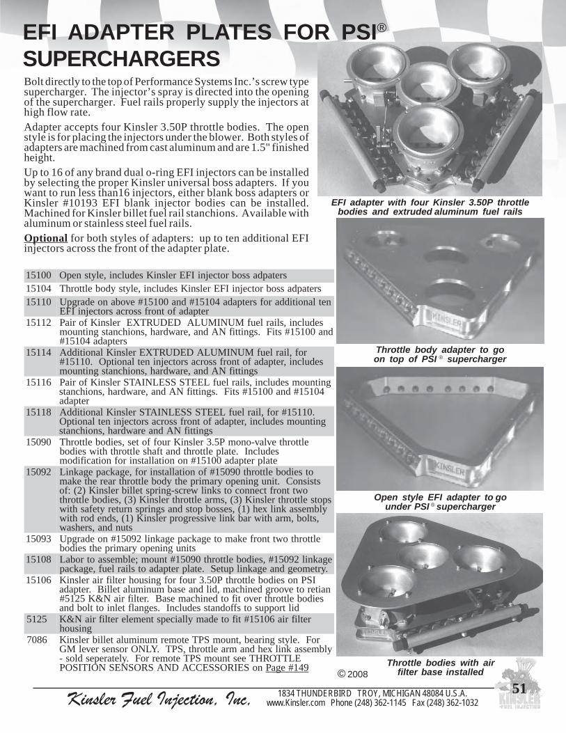
Kinsler Fuel Injection, Inc, 1834 THUNDERBIRD TROY, MICHIGAN 48084 U.S.A.www.Kinsler.com Phone (248) 362-1145 Fax (248) 362-1032
51
EFI ADAPTER PLATES FOR PSI®
SUPERCHARGERS
Open style EFI adapter to gounder PSI ® supercharger
Throttle body adapter to goon top of PSI ® supercharger
Throttle bodies with airfilter base installed© 2008
00151 sretapdassobrotcejniIFErelsniKsedulcni,elytsnepO40151 sretapdassobrotcejniIFErelsniKsedulcni,elytsydobelttorhT01151 netlanoitiddarofsretpada40151#dna00151#evobanoedargpU
retpadafotnorfssorcasrotcejniIFE21151 sedulcni,sliarleufMUNIMULADEDURTXErelsniKforiaP
dna00151#stiF.sgnittifNAdna,erawdrah,snoihcnatsgnitnuomsretpada40151#
41151 rof,liarleufMUNIMULADEDURTXErelsniKlanoitiddAsedulcni,retpadafotnorfssorcasrotcejninetlanoitpO.01151#
sgnittifNAdna,erawdrah,snoihcnatsgnitnuom61151 gnitnuomsedulcni,sliarleufLEETSSSELNIATSrelsniKforiaP
40151#dna00151#stiF.sgnittifNAdna,erawdrah,snoihcnatsretpada
81151 .01151#rof,liarleufLEETSSSELNIATSrelsniKlanoitiddAgnitnuomsedulcni,retpadafotnorfssorcasrotcejninetlanoitpO
sgnittifNAdnaerawdrah,snoihcnats09051 elttorhtevlav-onomP5.3relsniKruoffotes,seidobelttorhT
sedulcnI.etalpelttorhtdnatfahselttorhthtiwseidobetalpretpada00151#nonoitallatsnirofnoitacifidom
29051 otseidobelttorht09051#fonoitallatsnirof,egakcapegakniLstsisnoC.tinugninepoyramirpehtydobelttorhtraerehtekam
owttnorftcennocotsknilwercs-gnirpstellibrelsniK)2(:fospotselttorhtrelsniK)3(,smraelttorhtrelsniK)3(,seidobelttorht
ylbmessaknilxeh)1(,sessobpotsdnasgnirpsnruterytefashtiw,stlob,mrahtiwrabknilevissergorprelsniK)1(,sdnedorhtiw
stundna,srehsaw39051 elttorhtowttnorfekamotegakcapegaknil29051#noedargpU
stinugninepoyramirpehtseidob80151 egaknil29051#,seidobelttorht09051#tnuom;elbmessaotrobaL
.yrtemoegdnaegaknilputeS.etalpretpadaotsliarleuf,egakcap60151 ISPnoseidobelttorhtP05.3ruofrofgnisuohretlifriarelsniK
naiterotevoorgdenihcam,dildnaesabmunimulatelliB.retpadaseidobelttorhtrevotifotdenihcamesaB.retlifriaN&K5215#
diltroppusotsffodnatssedulcnI.segnalftelniottlobdna5215 retlifria60151#tifotedamyllaicepstnemeleretlifriaN&K
gnisuoh6807 roF.elytsgniraeb,tnuomSPTetomermunimulatellibrelsniK
ylbmessaknilxehdnamraelttorht,SPT.YLNOrosnesrevelMGELTTORHTeestnuomSPTetomerroF.yletarepesdlos-
noSEIROSSECCADNASROSNESNOITISOP 941#egaP
Bolt directly to the top of Performance Systems Inc.’s screw typesupercharger. The injector’s spray is directed into the openingof the supercharger. Fuel rails properly supply the injectors athigh flow rate.Adapter accepts four Kinsler 3.50P throttle bodies. The openstyle is for placing the injectors under the blower. Both styles ofadapters are machined from cast aluminum and are 1.5" finishedheight.Up to 16 of any brand dual o-ring EFI injectors can be installedby selecting the proper Kinsler universal boss adapters. If youwant to run less than16 injectors, either blank boss adapters orKinsler #10193 EFI blank injector bodies can be installed.Machined for Kinsler billet fuel rail stanchions. Available withaluminum or stainless steel fuel rails.Optional for both styles of adapters: up to ten additional EFIinjectors across the front of the adapter plate.
EFI adapter with four Kinsler 3.50P throttlebodies and extruded aluminum fuel rails

Kinsler Fuel Injection, Inc, 1834 THUNDERBIRD TROY, MICHIGAN 48084 U.S.A.www.Kinsler.com Phone (248) 362-1145 Fax (248) 362-1032
52
TURBOCHARGINGTurbocharging has tremendous potential, but very few have tapped it, as a proper installation is far moreinvolved than that for a GMC roots type belt driven supercharger. The following hints will help....1) Electronic fuel injection is the ultimate for turbos. The constant flow system cannot compensate throughout the whole range for
the boost pressure against the nozzle resisting fuel flow. The EFI system can be programmed to the peaks and valleysof the engine’s torque and horsepower, giving the potential to extract the most power and best driveability. An EFIsystem with programmable ignition curves will providefurther improvements as ignition timing is EXTREMELYimportant to a turbo engine. You want to run all thespark lead you can to burn the fuel before the exhaust valveopens, to reduce the exhaust temperature at the turbos, tokeep from burning them up.
2) One of the worst misconceptions is that ram tuning is notimportant when using a turbo. On the contrary, it isextremely important for power, and the exhaust tuningsharply increases throttle response as well.
© 2008
4) “Turbo Lag” is actually mostly fuel lag. If the fuel is put into theair before it enters the turbo, the fuel cools the incoming air, whichwill cause it to pick up more heat from the hot turbo. Also, the turbohas to compress more mass. All of this decreases system efficiency.In addition, the fuel has a long way to get to the engine, causing lag.Not to mention one pop back into that whole inlet system full offuel, and KABLOOM! Injection right at the inlet port sharplyincreases throttle response, efficiency, distribution, safety, and power!!!
5) When running over about 8 PSI of boost with gasoline, a good air-to-air intercooler is a must. Lowering the charge temperature will:
• Increase density, giving 15-20% more power• Give less tendency to detonate• Lower exhaust temperature, since lowering inlet temperature a given amount lowers exhaust about the same amount.
Theoretically, high exhaust temperature is desireable, but in reality,there is almost always too much...it burns up the turbos and pipes.
6) On large engines, two intercooler cores are used in series. This givesslightly more pressure drop than if in parallel, but lower chargetemperature and better performance, due to higher velocity of thecharge air scrubbing the walls of the intercooler.
7) In front engine cars, the intercooler is placed where the radiatorwould normally be, to get a good blast of the coldest air and shortducting. The radiator is placed to the side, behind, or in the fenders.
8) An exhaust system with divided turbine and exhaust collector will increase throttle response with the same top end horsepower. Great for sports cars.
9) The best system compresses air only, intercools it, then adds fuel at the ports. Look at the pictures carefully!
Purchase “Turbochargers” by HP books.
3) Use ported cylinder heads...allow the engine to breathe!!! You must get the air in and out for power.
Twin turbo 4.6L 3-valvemodular Ford Mustang with EFI
Two of Mark Stielow’s projects: ‘69 Camaro, twinturbos into Kinsler 18o small block Chevrolet I.R.EFI manifold (left) and ‘69 Chevelle, twin turbos
into plenum style EFI manifold (above)
Scat V4 with constant flow fuel injectionwith single turbo in a dune buggy

Kinsler Fuel Injection, Inc, 1834 THUNDERBIRD TROY, MICHIGAN 48084 U.S.A.www.Kinsler.com Phone (248) 362-1145 Fax (248) 362-1032
53
PLENUM LOGS
CHEVROLET SMALL BLOCKFits Moon small block Chev cross-ram. Castaluminum plenum logs are machined with thebolt pattern of a pair of IDA Weber throttle bodies.Center to center of runner bores: 3.470", 4.025",3.470"
Each log has provision for a 2 1/4" throttle at thefront with cross-connecting linkage, or they canbe supplied without the throttles. Ideal for turbo-charging.
Small blockChev crossram
with Lucasmechanical
timed injection
Logs with 2.5" throttle plates, onKinsler 3-piece Pontiac Pro-Stockmanifold with aluminum fuel rails
Log with no throttle plate. 2.9" ID hoseconnection and 3.0" runner outlets to manifold
Log with 2.5" throttle plate and2.5" runner outlets to manifold
© 2008
Available with a throttle at the inlet or plain.
Two throttle sizes available:2.5" throttle has 2.5" ID runner outlets.2.9" throttle has 2.9" or 3.0" ID runner outlets.
Center to center of runner bores: 3.300", 6.350", 3.300"
Each runner entrance has a generous radius cast into it.Logs have provision for balance tube between the pair.
'As cast' logs have a throttle body on each end at differentlengths, so the throttle shafts of both throttles will line upwith each other. For most applications only two throttlebodies are needed so the opposite end of the log ismachined off, and an end cap is installed. Logs can bemachined so there is a throttle body or hose attachment atboth ends.
Fits: Dart Big Chief, Dart/Olds 140, Pontiac Pro-Stock,and EB 650/800 cylinder heads.Fits one piece big block Chevrolet manifold
(modification required).
CHEVROLET BIG BLOCK

Kinsler Fuel Injection, Inc, 1834 THUNDERBIRD TROY, MICHIGAN 48084 U.S.A.www.Kinsler.com Phone (248) 362-1145 Fax (248) 362-1032
54
3-PIECE MANIFOLD INSTALLATION
Push silicone into grooves
© 2008
Check surfaces for flatness
INSTALLATIONThese instructions are for the typical Kinsler three piece injectionmanifold.
1) Make sure all intake gasket surfaces are clean and flat(especially around bolt holes and any water ports).If the manifold has been used, inspect the conditionof the entire assembly, including all linkage. Be sureto remove all the old silicone, and clean out thesealing grooves.
2) Check the fit of all the manifold pieces on the engineto be sure everything fits correctly before applyingany new silicone.
3) The valley plate has holes at both ends along theblock's register. Most racers find it much easier toinstall the plate if they drill and tap the block at eachend to secure it. The holes in the valley plate may notbe symmetrically located.... position the valley platecarefully, then use it as a drilling template.
BEFORE YOU BEGIN
Eddie Abrams’s Kinsler injected small blockChev U.S.D.B.A. flat bottom drag boat
Hooker Industries sponsored Vesco/Nish Streamliner,Kinsler small block Chev contant flow
A) It is very important to get silicone down into the bottom corners of boththe manifold and valley plate grooves, just flush to the surface... pushit in with your finger.
B) Put a bead of silicone along the surfaces on top of the grooves and matethe manifold to the valley plate. If the correctamount of silicone is used, about 1/16" - 1/8" will come out the top andbottom sides.
C) Install all the bolts and run them down just snug. Start torque sequencefrom the center bolts and work outward. Tighten the mounting boltsdown a little bit at a time to obtain an even crush. Do not overtighten!
Try to do the installation within twenty minutes. The surfaceof the silicone bead can set up quickly, causing a poor seal.

Kinsler Fuel Injection, Inc, 1834 THUNDERBIRD TROY, MICHIGAN 48084 U.S.A.www.Kinsler.com Phone (248) 362-1145 Fax (248) 362-1032
55
THROTTLE SHAFTS
We make out throttle shafts from special stress-proof steel, which makes themunusually strong and tough. We hard nickel coat them for excellent wear
resistance, then bake them to eliminate any embrittlement.
MATERIAL FOR THROTTLE SHAFTS
We use 3/8" diameter milled type shafts because they make a betterbearing than a 5/16" does and we get more strength than 5/16" withless air flow resistance! How?
A) 5/16" has so little cross-sectional area that it is usually slottedfor anything larger than 2" throttle bores. The place where thethe throttle plate screw goes is very weak, as the #8 screw holeremoves most of the remaining material!
B) A milled 3/8" shaft has 24% more cross-section after the #8screw hole is tapped into it than a 5/16" slotted shaft.
C) The 5/16" shaft presents a .312" wide restriction to the airflow.The milled 3/8" shaft is .188" wide after milling, plus .071"width of the throttle plate = .259" total, which is 17% less widththan the 5/16" slotted shaft.
D) BACK-CUT The milled 3/8" shaft is strong enough that wecan mill a flat on the backside of it .062" deep and still maintaingood strength. This leaves .126" shaft width, plus the .071"plate width = .197" total, which is 37% less width than the5/16" slotted shaft! This is optional on all our units andreplacement shafts.
E) STREAMLINED The ultimate shaft for air flow is theback-cut shaft with it’s leading and trailing edges machinedwith a radius from the OD of the shaft to the flat area of theback-cut. It is then blended and polished. This gives animproved aerodynamic shape. This is optional on all ourunits and replacement shafts.
© 2008
WE MAKE THE STRONGESTTHROTTLE SHAFTS IN THE INDUSTRY
We can make custom shafts to your print or sample.THROTTLE SHAFT BASICSAlternate Material 303 stainless steel for salt water marine use. These won’trust, but they are only 1/4 as strong as the stress proof steel, and wear muchquicker. Don’t use this material unless you really feel you need to.
STYLE
Milled A flat is machined halfway through the shaft for the throttle plate.
Slit A slit is cut through the middle of the shaft, leaving the shaft at it’sfull diameter.
MACHINING Each end of our flat for the throttle plate has a .010" radius to prevent a stress riser. We also break the edge of thetwo outside corners at each end of the flat. On our shafts with multiple throttle plates we are careful to machine all the flatsexactly at the same angle and plane. If the flats are not cut properly, the idle air distribution and part throttle operation will be poor.
RETEMAID LAIRETAM0674 "61/5 )"213.( leetsfoorpssertS1674 "8/3 )"573.( leetsfoorpssertS2545 "61/5 )"213.( leetssselniats3033545 "8/3 )"573.( leetssselniats303
Milled shaft
Slit shaft
Back-cut shaft
Streamlined shaft
Shown Actual Size
Ray Price’s Kinsler injected top fuelHarley Davidson drag bike
JasonMeyer’sKinslerinjected
WoOsprint
car

Kinsler Fuel Injection, Inc, 1834 THUNDERBIRD TROY, MICHIGAN 48084 U.S.A.www.Kinsler.com Phone (248) 362-1145 Fax (248) 362-1032
56
THROTTLE PLATES
CUSTOM THROTTLE PLATESWe make plates for just aboutANYTHING! Injection units, carbs,throttle bodies, etc. We have spinningfixtures for different angles and bolthole spacings.
REPLACEMENT THROTTLE PLATEWe STOCK and/or custom MAKEplates for all types of injection mani-folds and throttle bodies: HILBORN, CROWER, ENDERLE,
ENGLER, JACKSON, ALGON,RON'S, EVM, GM, HOLLEY, ETC.
QUALITY MACHINING
EACH KINSLER THROTTLE PLATEIS TURNED IN A LATHE !!!
A stamped plate can be bowed fromthe press, have varying edge angles,etc. Turning gives a flat, crisp edge,at the precise angle.
IMPORTANT FACTSDIAMETERMust be measured across the centerof the bolt holes. It is smaller than thethrottle bore to provide clearance forrotation, and material expansion ofthe plate from the engine heat duringa hot soak. The clearance variesdepending on the quantity of platesover a length of shaft.
Example : One-piece throttleshaft with four plates versus twoshafts with two plates each,joined with a Kinsler billetSpring-Screw Link... the lattercan run with less clearance. Asingle throttle plate can run witheven less. See Pages #64-65.
STANDARD KINSLERALUMINUM THROTTLE PLATES :
SCREW HOLESThrottle plate screw holes are largerthan the screw diameter to allow theplate to be adjusted for alignment inthe throttle bore.
ANGLEOur standard angle is 14o, rotating76o to wide open. This is good forsealing and non-sticking. Specialangles available on request.
THICKNESSWe use .062", .071", or .091"depending on the throttle bore sizeand the strength that is require for theplate. Do not use a plate that isthicker than needed, as that causesmore air flow restriction.
MATERIALOur standard plate material is 2024aluminum. This alloy has a very highbending strength. On special orderwe offer 304 stainless steel (.091"thick ONLY). We don’t recommendbrass (too soft) or cold rolled steel(too weak, rusts, and creates excessivewear on throttle bore).
STREAMLINEDFor an aerodynamic shape, the platehas the leading and trailing edgethinned to about one-half the originalthickness, then tapered and blendedto where the plate mounts on thethrottle shaft. Least air flow resistancewhen used with streamlined throttleshafts, see Page #55. This design isas strong as the standard in bending,but is much more expensive to make.
© 2008
NOTE : Due to machiningtolerances sizes may vary slightly !
#TRAP LAUTCARETEMAID
LANIMONSSENKCIHT
OTRETNECRETNECWERCSNO
SELOH01002 "273.1 "260. "0.121002 "325.1 "260. "0.141002 "796.1 "260. "0.161002 "367.1 "260. "0.181002 "708.1 "260. "0.102002 "278.1 "260. "0.122002 "798.1 "260. "0.142002 "799.1 "260. "0.162002 "741.2 "170. "0.182002 "971.2 "170. "5.103002 "281.2 "170. "5.123002 "242.2 "170. "5.143002 "542.2 "170. "5.163002 "742.2 "170. "5.183002 "792.2 "170. "5.104002 "263.2 "170. "5.124002 "563.2 "170. "5.144002 "763.2 "170. "5.164002 "924.2 "170. "5.184002 "234.2 "170. "5.105002 "434.2 "170. "5.125002 "294.2 "170. "5.145002 "594.2 "170. "5.165002 "794.2 "170. "5.185002 "455.2 "170. "5.106002 "755.2 "170. "5.126002 "716.2 "170. "5.146002 "026.2 "170. "5.166002 "076.2 "170. "5.186002 "276.2 "170. "5.107002 "576.2 "170. "5.127002 "286.2 "170. "5.147002 "586.2 "170. "5.177002 "408.2 "170. "5.187002 "708.2 "170. "5.108002 "298.2 "170. "5.118002 "598.2 "170. "5.128002 "798.2 "170. "5.148002 "799.2 "170. "5.168002 "799.2 "190. "5.188002 "741.3 "190. "5.1
09002 "594.3 "521. "0.1)SWERCS3(
ThinnedShaft

Kinsler Fuel Injection, Inc, 1834 THUNDERBIRD TROY, MICHIGAN 48084 U.S.A.www.Kinsler.com Phone (248) 362-1145 Fax (248) 362-1032
57
RAMTUBES
KINSLER 180 DEGREE BELLSPUN ALUMINUM RAMTUBESOur 180 degree bell aluminum ramtubes are formed from 6061-0alloy and have a nominal .070" thick wall. 180 degree bell ramtubeshave consistent wall thickness and inside/outside diameters.
These ramtubes use our special180o tapered bell design forincreased air flow.
KINSLER TRADITIONAL BELLSPUN ALUMINUM RAMTUBESOur traditional bell spun aluminum ramtubes are made from1100-0 alloy and have a nominal .080" thick wall. These ramtubeswill have slight variations in wall thickness and inside/outsidediameters.
#traP retemaiDedisnI mumixaMhtgneL
lanimoNedistuOretemaiD
laedI*denihcaM
edistuOretemaiD
lleBretemaiD
4087 )"61/311("018.1 "6 "069.1 "039.1 "081.3
7087 "000.2 "01 "042.2 "051.2 "505.3
0187 )"61/32("532.2ot"091.2 "01 "093.2 "043.2 "038.3
2187 )"61/32("091.2ot"571.2 "01 "583.2 "043.2 "038.3
1187 )"4/12("052.2 "01 "054.2 "563.2 "038.3
4187 )"8/32("573.2 "01 "065.2 "094.2 "521.4
6187 )"61/72("734.2 "01 "016.2 "565.2 "042.4
8187 )"2/12("005.2 "01 "566.2 "546.2 "083.4
2287 )"61/112("086.2 "01 "058.2 "587.2 "005.4
7077 "009.2 "9 "540.3 "899.2 "080.5
8077 "009.2 "11 "520.3 "899.2 "080.5
"400.-/+yravyamsretemaidedistuodenihcaM*ees,robaldnagninihcamebutmarlleblanoitidarT 45#egaP
Kinsler big block Chev with 180degree tapered bell ramtubes
© 2008
* Non-tapered, straight wall ramtube
#traP retemaiDedisnI mumixaMhtgneL
denihcaMedistuOretemaiD
lleBretemaiD
6087 "0.2 "7 "051.2 "009.3
8087 )"61/32("771.2 "9 "043.2 "011.4
3187 )"4/12("052.2 "9 "563.2 "571.4
5187 )"8/32("073.2 "9 "094.2 "082.4
7187 )"61/72("734.2 "9 "565.2 053.4
9187 )"2/12("005.2 "9 "546.2 "014.4
1287 )"8/52("526.2 "9 "567.2 "593.4*
3287 )"8/52("526.2 "11 "567.2 "593.4*
5287 )"8/52("526.2 "9 "567.2 "009.4
4287 )"61/112("086.2 "9 "587.2 "010.5
7287 )"4/32("057.2 "9 "278.2 "070.5
0387 )"61/312("218.2 "9 "839.2 "001.5
0177 "009.2 "9 "000.3 "032.5
3387 "0.3 "9 "001.3 "023.5
9887 deificepshtgnelotebutmarllebeerged081enihcaMremotsucyb
6987 noesurofecnaraelcrofhcton,llebebutmarenihcaMretpadapotesemais
How Do I Know What Size Ramtube I Need?
Measuring ramtube length
Do not measure the ramtube OutsideDiameter or Ramtube Adapter
Kinsler identifies ramtube size bymeasuring the Inside Diameter
of the base of the tube

Kinsler Fuel Injection, Inc, 1834 THUNDERBIRD TROY, MICHIGAN 48084 U.S.A.www.Kinsler.com Phone (248) 362-1145 Fax (248) 362-1032
58
Note: Kinsler spun aluminum ramtubescan be machined to fit Crower big and
small block Chevrolet injection manifolds.
GASKETS, O-RINGS, ANDTOP ADAPTERS
RAMTUBES
RESTRICTOR TUBESDesigned to meet rules that require at least a 3" length of restrictedsize. Inlet and outlet has a special radius and taper to provide asmooth transition of the pulse in the runner, going both up anddown. Restrictors are made to fit into a host ramtube. They canbe modified to fit into other inside diameter ramtubes. Made fromthin wall aluminum.
CARBON FIBER IRL STYLERAMTUBES AND ACCESSORIESKinsler carbon fiber IRL style ramtubes have moldedflange which is machined with bolt pattern 1.626" X2.226", 180º radiused bell.
OPTIONS
#7898 #7899 #7893 /#7894/#7895
0987 hsinif'ytilauQ-wohS'otsebutmarmunimula)8(hsiloP
2987 elbaliavarofllac,sebutmarmunimulanups)8(ezidonadnapid-etirb,hsiloPsroloc
3987 selzzonsacuLmm41rof,sessoB
4987 munimula1606,ssobelzzon3987#htiwesutsum-gniriaF
5987 )8(fotesnosgniriaf5987#dnasessob3987#dlew-robaldnalairetaMdedulcniTONsebutmar,sgniriafdnasessobsedulcni,sebutmarmunimula
7887 fotesnosgniriaf5987#dnasessobdaerhtepip"8/1dlew-robaldnalairetaMdedulcniTONsebutmar,sgniriafdnasessobsedulcni,sebutmarmunimula)8(
8887 fotesnosgniriaf5987#dnasessobdaerht02-2/1dlew-robaldnalairetaMdedulcniTONsebutmar,sgniriafdnasessobsedulcni,sebutmarmunimula)8(
8987 dnaretpadapotebutmartifotesabebutmarforetemaidedistuonrut-robaLthgiehotebutmartuc
9987 sretpadapotesemaisrofllebhctonsulp8987#saemas-robaL
1977 retemaidedisni"001.2ebutmar)"2/12("005.2tsohtifot
3977 retemaidedisni)"61/32("781.2ebutmar)"2/12("005.2tsohtifot
7977 retemaidedisni)"61/32("781.2ebutmar)"8/52("526.2tsohtifot
61572 llat"051.2llawderepat"072.2
91572 llat"051.3llawderepat"072.2
32572 llat"051.2llawderepat"074.2
72572 llat"051.2llawthgiarts"074.2
92572 llat"005.2llawthgiarts"074.2
15572 recapsllat"2/1,"072.2
35572 recapsllat"1,"072.2
95572 recapsllat"2/1,"074.2
16572 recapsllat"1,"074.2
20572 sebutmar"072.2rof'senob-god')61(foteS
70572 sebutmar"074.2rof'senob-god')61(foteS
CROWER RAMTUBESECTIONS
5227
rofnoitcesthgiartSkcolbgib"9.2reworC
noitcejnitelorvehCgnol"21,dlofinam
5427 regrahcrepusfopotdnatahrewolbneewtebstif,17-8/17-6,teksagneercsrewolB
6427 dlofinamtelorvehCkcolbgibreworCerob"9.2noretpadaebutmar,)4(fotes,steksaG
7427 dlofinamtelorvehCkcolbllamsreworCerob"5.2noretpadaebutmar,)4(fotes,steksaG
4427 stropesemais,noitcejnitelorvehCkcolbllamsnrobliH,)4(fotes,steksaG
8427 potdlofinamotsretpadaebutmar,dlofinamtelorvehCkcolbgibrelsniK,tesgnir-O
9427 potdlofinamotsretpadaebutmar,dlofinamtelorvehCkcolbllamseceip-3relsniK,tesgnir-O
0057 puthgiartsottelorvehCkcolbllams"61/32nrobliHnoelgnaeerged5strevnoc,sretpadapoT)4(fotes,sretlifriaelbuod)5015#relsniK(N&Khtiwesurofsebutmar
1057 0057#traptesevobaroftnemecalper,YLNOeno,retpadapoT© 2008
Dog boneto gounder
clampingscrews onoval bore

Kinsler Fuel Injection, Inc, 1834 THUNDERBIRD TROY, MICHIGAN 48084 U.S.A.www.Kinsler.com Phone (248) 362-1145 Fax (248) 362-1032
59
TOP ADAPTER - SPECIAL
Air cleaneradapters
installed onKinsler
Pontiac Pro-Stock
injectionmanifold
with EFI forstreet use
RADIUS PLATES FOR AIR FILTERS ONKINSLER BIG BLOCK CHEVROLET INJECTIONMANIFOLD
5587 eziserobelttorht"2/12rofetalpsuidaresemaislaudividnI
7587 eziserobelttorht"8/52rofetalpsuidaresemaislaudividnI
8587 eziserobelttorht"61/112rofetalpsuidaresemaislaudividnI
2687 esahcrupthgirtuo-sezisevobaehtfoyna,setalpsiudaresemais)4(foteS
4687 ebutmartsacehtsecalper,dlofinam8VWENfoesahcrupnoedargpUsetalpsuidarhtiwsebutmarmunimuladnasretpada
1787 eziserobelttorht"2/12rofetalpsuidarelgnislaudividnI
3787 eziserobelttorht"8/52rofetalpsuidarelgnislaudividnI
4787 eziserobelttorht"61/112rofetalpsuidarelgnislaudividnI
3497 munimulatellib,llat"2/1,"2/12rof,recapS
2897 munimulatellib,llat"1,"2/12rof,recapS
5497 munimulatellib,llat"2/1,"8/52rof,recapS
4897 munimulatellib,llat"1,"8/52rof,recapS
6497 munimulatellib,llat"2/1,"61/112rof,recapS
5897 munimulatellib,llat"1,"61/112rof,recapS
6787 esahcrupthgirtuo-sezisevobaehtfoyna,setalpsuidarelgnis)4(foteS
7787 esahcrupthgirtuo-sezisevobaehtfoyna,setalpsuidarelgnis)8(foteS
8787 tsacehtsecalper,dlofinamrednilyc-4WENfoesahcrupnoedargpUsetalpsuidarhtiwsebutmarmunimuladnasretpadaebutmar
9787 ebutmartsacehtsecalper,dlofinam8VWENfoesahcrupnoedargpUsetalpsuidarhtiwsebutmarmunimuladnasretpada
Fit all Kinsler big blockChev manifolds:Standard one-piecerectangular port, threepiece Dart Big-Chief,Pontiac Pro-Stock, andEPD. Has the same 4-bolt pattern and borecenters as the Kinsler bigblock Chev manifold.Billet aluminum, .750"overall height.
0577 retnecotretnecerob"003.3,eziserobelttorht"9.2laudividnI
1577 c-cerob"003.3,eziserobelttorht"0.3laudividnI
2577 c-cerob"004.3,eziserobelttorht"51.3laudividnI
4577 esahcrupthgirtuo-sezisevobaehtfoyna,setalpsuidar)4(foteS
5577 ebutmartsacehtsecalper,dlofinam8VWENfoesahcrupnoedargpUsetalpsuidarhtiwsebutmarmunimuladnasretpada
© 2008
SINGLE - Fits all of Kinsler big block 4-runner injection manifolds: Ford, Chevrolet, and Olds.
6677 eziserobelttorht"9.2laudividnI
7677 eziserobelttorht"0.3laudividnI
8677 eziserobelttorht"51.3laudividnI
0777 ebutmartsacehtsecalper,dlofinam8VWENfoesahcrupnoedargpUsetalpsuidarhtiwsebutmarmunimuladnasretpada
6577 "003.3,eziserobelttorht"9.2laudividnIretnecotretnecerob
7577 "003.3,eziserobelttorht"0.3laudividnIc-cerob
8577 "004.3,eziserobelttorht"51.3laudividnIc-cerob
0677 evobaehtfoyna,setalpsuidar)4(foteSesahcrupthgirtuo-sezis
1677
8VWENfoesahcrupnoedargpUebutmartsacehtsecalper,dlofinam
htiwsebutmarmunimuladnasretpadasetalpsuidar
RADIUSED INLET PLATES FOR KINSLER BIG BLOCK MANIFOLDS
RADIUSED DOUBLE INLET PLATESBolts to Kinsler 3-piece small block Chev, Mopar, and Pontiac manifolds,with 3-bolt pattern. Bore centers are 2.850" c-c. Billet aluminum, 1.550"overall height.
RADUISED SINGLE BORE INLET PLATESBolts to manifold using the 2-bolt pattern (3.740" c-c) of the Kinsler 3-pieceinjection manifold for small block Ford, and small block Chev with cylinderheads: Dart/Buick, SB2, Brodix Canted Valve or BD-2000, Chev SymmetricalPort, and LS-1. Billet aluminum, 1.750" overall height.
Radiused double inlet plate
‘Monster’ smallblock Chev with
radiused inlet plates
#7873 Radiusedsingle inlet plate
#7984 Spacer #7945 Spacer
Radius plates are available forDragon Claw and Monster manifolds
Ultra short style, bolts through radii

Kinsler Fuel Injection, Inc, 1834 THUNDERBIRD TROY, MICHIGAN 48084 U.S.A.www.Kinsler.com Phone (248) 362-1145 Fax (248) 362-1032
60
UNDERSTANDING THE IDLEIdle Speed is a balance of throttle plate opening and fuel rate.The unit should idle near the desired RPM with the properamount of fuel. Never richen up the fuel rate to reduce theidle RPM; back out the idle screw instead.Mechanical fuel injection systems require a rich idle mixturefor optimum throttle response since they do not have anaccelerator pump. Any time the idle speed is adjusted, thefuel rate at idle may need to be readjusted for best throttleresponse... set it so you get the best response when you snapthe throttles open with the vehicle out of gear. Enginesequipped with an automatic transmission require richer mix-tures "out of gear" to compensate for the load of the transmis-sion when "in gear".
THROTTLE SYNCHRONIZATION AT IDLE
If the throttle plates are not synchronized at an idle, then somecylinders will be rich or lean compared to others... these will NOTdevelop maximum power as quickly as the other cylinders whenthe engine is brought to wide open throttle. Sometimes at W.O.T.the problem clears up quickly, sometimes NOT. A rich cylindermay take a fraction of a second to several seconds to burn off theexcess fuel and raise combustion chamber temperature. A cylinderrunning lean at an idle is a prime candidate for serious enginedamage. When the engine is brought to wide open throttle, theoverheated spark plug may cause detonation.
SOLVING SYNCHRONIZATION PROBLEMSMake sure the throttle plates are not installed upside down. Theyare machined at an angle! (see THROTTLE PLATES on Page #56).Check the intake manifold for gasket leaks; worn shaft bushings,shafts, plates, etc.
Loctite ® #271 must be applied tosecure the throttle plate screws
Check synchronizationside to side using feeler gauges
Fig. 1
© 2008
See Pages #62-63"HOW TO SETUP LINKAGE"
1) Disconnect the cross hex link bar and work on each sideof the injection unit separately.
2) Back off the throttle stop idle screws all the way, so thethrottle plates will contact the throttle bores.
3) Loosen or remove all the throttle plate screws. BEVERY CAREFUL NOT TO DROP THEM INTO THEENGINE! Any New Kinsler manifold or manifoldsserviced by Kinsler have Loctited ® plate screws.The screws may require heat to break the bond.
4) While holding the throttle shaft in closed position, tap theshaft back and forth lightly to allow plates to centerthemselves in the throttle bore and rotate plate in thethrottle bore till gaps are equal on both sides of the plateat the location shown in Fig 1.
5) Install throttle plates and tighten screws using Loctite ®#271.
6) Do the same to the other side of the manifold.7) Reconnect cross hex link bar. Adjust it so both sides
maintain the closed position.8) Turn idle screws "in" to raise plates just off the throttle
bore. Depending on the engine displacement, throttlesize, and idle speed you want, the throttle plates will needto be open about .002" to .008". A small block Chevwill require about .003" - .004"
9) Check that both sides of the injection open at thesame rate. See How To Set Up Linkage on Pages #62-63.
DO THIS ONLY IF YOU CAN’T SYNCHRONIZE THETHROTTLES USING THE UNI-SYN.
If no problems are found:

Kinsler Fuel Injection, Inc, 1834 THUNDERBIRD TROY, MICHIGAN 48084 U.S.A.www.Kinsler.com Phone (248) 362-1145 Fax (248) 362-1032
61
UNI-SYN® THROTTLESYNCHRONIZER
WHY YOU NEED A UNI-SYNThe Uni-Syn ® displays the relative air flow of one cylindervs. another at an idle. If the throttle plates are not synchro-nized at an idle, they will not be synchronized at part throttle.This won’t be as important to a drag racer who launches hisvehicle from wide open throttle as it is for oval track, road, oroff-road racing where this can mean the difference of whogets out of the corner first.
HOW TO USETHE UNI-SYNMake surethere is goodseal betweenthe Uni-Synand theramtube.
On ManifoldsWITHOUTKinsler Spring-Screw Linkage:With the engine idling, place the Uni-Syn over the top of one ramtube onthe left side of the engine, while keeping the sight tube vertical. Adjustthe flow control wheel in the center of Uni-Syn until the float is halfwayup the sight tube. Check the rest of the cylinders on the left side of theengine to get an average reading. Now check the cylinders on the rightside and adjust the cross hex link until the average readings are the sameon both sides. If you are unable to achieve similar average readings, seesection on MANIFOLD INSTALLATION AND SETUP on Page #54.
On Manifolds WITH Kinsler Spring-Screw Linkage:Synchronize the front and rear throttles on the left side of the engine usingscrew "L". Now synchronize the front and rear throttles on the right byusing screw "R". Now synchronize the left side to the right side byadjusting the cross hex link. Kinsler's spring-screw linkage can beinstalled on most injection manifolds, see section on KINSLERBILLET SPRING-SCREW UNIVERSAL THROTTLE SHAFTLINKS on Pages #64-65.
TAKE THE GUESS WORK OUT OF SYNCHRONIZINGYOUR THROTTLES OR CARBS AT AN IDLE !
#6002
HOW THE UNIT WORKSThe Uni-Syn ® has a swiveling sight tube, so the unit can beused at any angle. The sight tube must be vertical. Air flowingbetween the flow control wheel and the housing creates adepression (vacuum), which pulls the float up the taperedsight tube. Rotating the wheel clockwise lowers it in thehousing’s tapered bore. This increases the vacuumsignal, which raises the float in the sight tube.
© 2008
2006 esabdenilmaof.aid"4/32,rezinorhcnyselttorhtnyS-inU
5995 evisehda-fleshtiwksidmaof,2006#roftiucsibretpadAsebutmarregralrof.D.O"2/13xkciht"2/1,gnikcab
1006 stif,maofhtiwetalpmunimula,2006#rofetalpretpadAretemaidedistuo"8/15otpullebebutmar
R
Reasonable synchronization is if all the flowchecks are within 3/4", the distance betweenany two lines on the sight tube.

Kinsler Fuel Injection, Inc, 1834 THUNDERBIRD TROY, MICHIGAN 48084 U.S.A.www.Kinsler.com Phone (248) 362-1145 Fax (248) 362-1032
62
HOW TO SET UP LINKAGE
FOUR BAR LINKAGEFour Bar Linkage is called "Four Bar", because it consists of four bars.Looking at Fig 1 : One bar is "Arm A", the second is "Arm B", the thirdis the "Hex Link". The fourth is whatever holds the two shafts inplace; a manifold casting, a bracket, etc. All the bars may be differentlengths.
THROTTLE SHAFT TRAVELSince most throttle plates have a 14o seat angle, they only have torotate 76o to be 90o to the throttle bore, which is wide open throttle.
THE SAFEST LINKAGEThe safest linkage is one in which the driven arm makes a 90o angleto the hex link at half travel, so the total travel is split evenly to bothsides of the 90o point... 38o to each side. This keeps well away fromhaving the driven arm go to an over-center position... see "CAU-TION" on "Uneven Four Bar Linkage", Page #63.
PARALLEL FOUR BAR LINKAGEParallel four bar linkage is when the hex link is made the samecenter-to-center (c-c) distance as the two shafts, and the c-c of "ArmA" is equal to "Arm B". As the arms rotate they will remain parallelto each other, and the Hex Link will remain parallel to the Base Line.The significance is that "Shaft A" will move the same number ofdegrees as "Shaft B" at every point, which is needed when linking theshafts on the left and right side of the manifold, see Fig 1.
PART THROTTLE AIR FLOWWhen using Parallel Linkage, the throttle shafts both rotate in thesame direction, so the lower edges of all the throttle plates slope tothe right or to the left. At part throttle this will direct the airdifferently to the ports on the right side of the engine versus the left.Some racers claim this gives rough part throttle operation. At wideopen throttle the throttle plates are all straight open, so it won't affectfull power.
OVER-UNDER LINKAGEVery difficult to set up properly. Over-Under linkage counter-rotates the throttle shafts allowing the throttle plates to be installedwith the lower edge of each throttle plate out toward the valve cover.This will direct the air the same to every port as the throttles areopened. While the geometry can be set satisfactory, it is never exact(see table in Fig 2), and if the arms are loosened, it is difficult to getthem back as they were... their initial angles are critical. Every shaftc-c distance and arm length combination requires different initialarm angles.
DRAWING LINKAGEMeasure the c-c of the two shafts to be connected. Though oneshaft may be higher than the other, for convenience draw the shaftsas horizontal. Draw a dashed Base Line and put the shaft centerson it. Draw an arc with the c-c of Arm-A. Draw another withthe c-c of Arm-B. Draw lines from the center of the shafts torepresent the initial trial position of the arms. The distancebetween these two points on the arcs is the length of the Hex-Link.Set the compass at this distance. Mark off 10o increments alongarc-A. Set the point of the compass on each of these and make amark on arc-B for each. Example: see the 40o and 40.5o marks inFig 2. Measuring the angles of the marks on arc-B allows a tableto be made of the relative movements. If the numbers are notsatisfactory, try other arm settings and/or Hex Link length.See "Shaft Rotation Ratio" on Page #63.
Throttle plates that rotate the same direction,use parallel linkage
Throttle plates that are opposite rotation,often use over-under linkage
© 2008
JACKSHAFT LINKAGE... BECOMING MUCH MORE POPULARThis is much more desireable than the over-under linkage, as it ismuch easier to set up and gives each shaft the exact same rotation.See Page #63, 69.
CENTER BELLCRANK LINKAGEThis also gives even shaft rotation, but there is not often enoughroom to fit it in. See Page #68.
DRIVEN 0 10.3 20.5 30.3 40.5 50.8 61.0 70.8 76.0
DRIVER 0 10 20 30 40 50 60 70 76o
o

Kinsler Fuel Injection, Inc, 1834 THUNDERBIRD TROY, MICHIGAN 48084 U.S.A.www.Kinsler.com Phone (248) 362-1145 Fax (248) 362-1032
63
THROTTLE STOPFuel injection throttle stops, shafts,etc., are not made to take all the forcethat can be exerted with the driver'sfoot at full throttle. A pedal stopshould be made, set at approximately1/16" under the throttle pedal atlightly loaded full opening, toabsorb excess force.
THROTTLE LINKAGEATTACHMENTThe throttle l inkage must beattached to the manifold at a pointwhere it will pull directly against athrottle stop at full throttle. Avoidattaching the linkage where the fullthrottle force would go through athrottle shaft to get to the stop, asthis could easily twist the shaft.
UNEVEN FOUR BAR LINKAGEThis linkage setup helps make amanifold or blower hat with very largethrottles much more driveable for roadracing or the street. Using the linkagein Fig 3, the first 30o of pedal travelonly moves the plates 15o. Thegeometry reverses as it approaches wideopen throttle, so at 80o of pedal travelthe plates have rotated the required 76o.Caution - The throttle spring must be onthe driver shaft. Shaft-A can't be thedriven arm as it comes too close toover-center, the condition where thecenterline of the hex link goes past thecenterline of the driven arm... then thelinkage can't be pulled back.
SHAFT ROTATION RATIOThe shaft rotation ratio at any instant is determined by the ratio of the lengths of the perpendiculars to the Hex Link that pass througheach shaft center. Example: In Fig 3, PB (1.10") divided by PA (.250") indicates 4.4o rotation of Shaft A to 1o for Shaft B in this position.
HOW TO SET UP LINKAGE
© 2008
!!! INCORRECT !!!Pulling arm on the oppisite end ofthe manifold from the throttle stop
CORRECTPulling arm installednext to throttle stop
JACKSHAFT LINKAGECounter-rotates the throttle shafts allowing the throttle plates to beinstalled with the lower edge of each throttle plate out toward the valvecover. This will direct the air the same to every port as the throttles areopened.
Easy to set up and gives each shaft the exact same rotation.See Page #62, 69.
CLEARANCE FOR LINKAGENo one ever got hurt because theyhad too much clearance! Considerthe engine’s shifted position dueto severe torque and vibration.Also consider body panel flexing.
TOE KILL SWITCHMount a spring loaded push-inignition kill switch where thetoe strap will contact it if thedriver's foot is pulled way back.Check it every time the vehicleis raced!
TOE STRAPMake a sturdy strap forthe throttle pedal thatpasses over the top of thedriver's foot so if thelinkage sticks, he canpull it back.
F F F F ForororororSafSafSafSafSafety...ety...ety...ety...ety...

Kinsler Fuel Injection, Inc, 1834 THUNDERBIRD TROY, MICHIGAN 48084 U.S.A.www.Kinsler.com Phone (248) 362-1145 Fax (248) 362-1032
64
Available on most Kinsler manifolds. Can be installed on most othermanufacturer's manifolds and special made units.
The Spring-Screw link with it's unique patented design acts as acombination slip and universal joint. It also has a screw fortorsionally phasing the shafts and a spring to keep any loosenessout of the joint.The bolt-on design allows ease of installation on an existing unit withouthaving to disassemble the manifold. The adjusting screw allowssynchronization of the front cylinders to the rear ones for smoother engineidling. 2024 aluminum, anodized blue; hard coated where the screw andrivet contact the tab for additional wear protection.
KINSLER SPRING-SCREW UNIVERSALTHROTTLE SHAFT LINKS
Made in "right" hand and "left" hand so that they can always be installed withthe screw facing outwards for ease of adjustment, yet have the torque fromthe "driving" shaft pushing directly against the screw rather than the spring inthe adjuster assembly.... this way the action is always positive. If pushedagainst the spring, a heavy load could compress it.
#4897
0884 ,"61/5 mraon,dnahtfel1884 ,"8/3 mraon,dnahtfel6884 ,"61/5 mraC-C"034.1,dnahtfel7884 ,"8/3 mraC-C"034.1,dnahtfel8884 ,"8/3 dneetisopponomraC-C"034.1,dnahtfel2884 ,"61/5 mraC-C"057.1,dnahtfel3884 ,"8/3 mraC-C"057.1,dnahtfel4884 ,"8/3 dneetisopponomraC-C"057.1,dnahtfel
0984 ,"61/5 mraon,dnahthgir1984 ,"8/3 mraon,dnahthgir6984 ,"61/5 mraC-C"034.1,dnahthgir7984 ,"8/3 mraC-C"034.1,dnahthgir8984 ,"8/3 dneetisopponomraC-C"034.1,dnahthgir2984 ,"61/5 mraC-C"057.1,dnahthgir3984 ,"8/3 mraC-C"057.1,dnahthgir4984 ,"8/3 dneetisopponomraC-C"057.1,dnahthgir
Determine style of link requiredand check for proper clearance
© 2008
Left hand Right hand
PATENTED
Installation on Hilborn Chevrolet manifold1. Cut the shaft withoutdisassembling manifold
2. Bolt-on Kinslerspring-screw linkage
#4891#4894 #4898#4881 #4883#4887 #4884#4888 #4893 #4897
MINIMUM.900"
CENTER-LINEOF
THROTTLESHAFT
NEEDMINIMUMOF .900"GAP IN
MANIFOLDFOR LINK
TO FIT
1.10
0".5
00"

Kinsler Fuel Injection, Inc, 1834 THUNDERBIRD TROY, MICHIGAN 48084 U.S.A.www.Kinsler.com Phone (248) 362-1145 Fax (248) 362-1032
65
1) Though a manifold may look quite rigid, itflexes when bolted down.
2) The throttle shaft is steel and the manifold ismagnesium or aluminum. As the manifoldheats or cools, it grows longer or shorter thanthe shaft, so the edges of the throttle plates arepushed into the sides of the throttle bores.This causes drag and greatly increases wearinto the sides of the throttle bores.
3) Due to production tolerances, we find that inmost brands of manifolds the throttle shaftbore in the front runners rarely lines upexactly with the one in the rear runners.... thisputs the throttle shaft in a bind.
4) If the throttle shaft has a slight twist in it, thefront throttle plates are open slightly morethan the rear ones. Without the Spring-Screwlink there is no way to correct it.
On Kiekhaefer Chev manifoldOn Crower Chev manifold
© 2008
KINSLER SPRING-SCREW UNIVERSALTHROTTLE SHAFT LINKS How these links can help YOU !
Our combination slip and universal spring-screwlinks fix all of these problems.
Installed on Kinsler Ford manifold
Installed on Kinsler Ford manifold
- CONTINUED - A manifold having a one piece throttle shaftgoing all the way through it can experiencethrottle sticking because :

Kinsler Fuel Injection, Inc, 1834 THUNDERBIRD TROY, MICHIGAN 48084 U.S.A.www.Kinsler.com Phone (248) 362-1145 Fax (248) 362-1032
66
THROTTLE ARMS
IDLE/STOP ARM
5555 sedulcni,tfahs"8/3,.cp2gnitsujdadaehtekcossselniats
stunmajhtiwswercs
6755 "8/3 ,tfahs ,retneckciht"361. C-C"034.12855 "61/5 ,tfahs ,edisthgirkciht"002. C-C"034.13855 "61/5 ,tfahs ,edistfelkciht"002. C-C"034.14855 "8/3 ,tfahs ,edisthgirkciht"002. C-C"034.15855 "8/3 ,tfahs ,edistfelkciht"002. C-C"034.16855 "61/5 ,tfahs ,edisthgirkciht"002. C-C"057.17855 "61/5 ,tfahs ,edistfelkciht"002. C-C"057.18855 "8/3 ,tfahs ,edisthgirkciht"002. C-C"057.19855 "8/3 ,tfahs ,edistfelkciht"002. C-C"057.1
Kinsler split style 2 piece arms are usefulanywhere, especially when an arm or stopneeds to be put in the center of a manifold.Throttle shafts do not have to be removed forinstallation.
2 PIECE ARMS
0255 "61/5 ,elgnis C-C"081.2-081.11255 "8/3 ,elgnis C-C"081.2-"081.12255 "2/1 ,elgnis C-C"081.2-"081.18255 "8/3 ,elgnis C-C"057.9755 "61/5 ,elbuod C-C"081.2-"081.10855 "8/3 ,elbuod C-C"081.2-"081.11855 "2/1 ,elbuod C-C"081.2-"081.1
#5490 installed on barrel valve
Kinsler throttle arms are light weight, but super strongbillet 2024-T4 aluminum. 10-32 Grade 8 socket headcap screws. Blue anodized. Custom color anodizingavailable; please call.
0945 "61/5 ,tfahs C-C"034.11945 "8/3 ,tfahs C-C"034.12945 "61/5 ,tfahs C-C"057.13945 "8/3 ,tfahs C-C"057.10755 "61/5 ,tfahs C-C"0.12755 "8/3 ,tfahs C-C"0.1
CABLE ACTIVATED ARMS
Close-upof cable
end detial
Machined to acceptbarrel type cable end.Mostly used on motor-cycles.
#5520
#5579
#5575
#5647
1 PIECE ARMS
#5491
#5493
#5572
SIDE CUT ARMS
#5576
#5589
#5585 #5584
#5588
#5528
© 2008
RELIEVED SURFACEFor additional rod endrotation while retaining fullthickness for bolt threads.
6555 "61/5 ,tfahs C-C"034.17555 "8/3 ,tfahs C-C"034.18555 "61/5 ,tfahs C-C"057.19555 "8/3 ,tfahs C-C"034.1
7465 ,leehwelbaclaud,tfahs"61/5.D.O"006.1,C-C"526.
8465 ,leehwelbaclaud,tfahs"8/3.D.O"006.1,C-C"526.
1755 "61/5 ,tfahs C-C"0.13755 "8/3 ,tfahs C-C"0.14755 "61/5 ,tfahs C-C"034.15755 "8/3 ,tfahs C-C"034.1
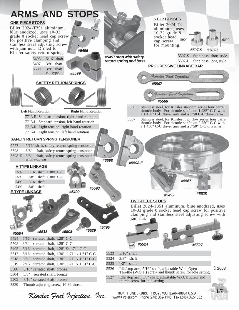
Kinsler Fuel Injection, Inc, 1834 THUNDERBIRD TROY, MICHIGAN 48084 U.S.A.www.Kinsler.com Phone (248) 362-1145 Fax (248) 362-1032
67
7755 renoisnetgnirpsnrruterytefas,tfahs"61/58955 renoisnetgnirpsnruterytefas,tfahs"8/3
E-8955 renoisnetgnirpsnruterytefas,tfahs"8/3raepotshtiw
ARMS AND STOPS
SAFETY RETURN SPRINGS
R-3177 noitatordnahthgir,noisnetdradnatSL-3177 noitatordnahtfel,noisnetdradnatSR-5177 noitatordnahthgir,noisnetthgiLL-5177 noitatordnahtfel,noisnetthgiL
Left Hand Rotation Right Hand Rotation
#5566
#5567
PROGRESSIVE LINKAGE BAR
6655 lerrabruofseiresdradnatsrelsniKrof,leetssselniatShtiwC-C"539.1nostfahselttorhtroF.ydobelttorht
mranevirdC-C057.adnamrarevirdC-C"034.1a7655 lerrabruofseireswolfhgihrelsniKrof,leetssselniatS
htiwC-C"057.2nostfahselttorhtroF.ydobelttorhtmranevirdC-C"057.adnamrarevirdC-C"034.1a
S-7055 elytstrohs,ssobpotSL-7055 elytsgnol,ssobpotS
#5497 stop with safetyreturn spring and boss
SAFETY RETURN SPRING TENSIONER
#5524
3255 tfahs"61/54255 tfahs"8/35255 tfahs"2/16255 nepOediWelbatsujda,tfahs"61/5,mrapots/eldI
gnitteseldirofwercsbmuhtdnawercs).T.O.W(elttorhT7255 dnawercs.T.O.Welbatsujda,tfahs"8/3,mrapots/eldI
gnitteseldirofwercsbmuht
TWO-PIECE STOPSBillet 2024-T351 aluminum, blue anodized, uses10-32 grade 8 socket head cap screw for positiveclamping and stainless steel adjusting screw withjam nut.
#5527
5507-S
.600".500"
5507-L
© 2008
#5496
6945 tfahs"61/57945 tfahs"8/39955 ,tfahs"8/3
epytrae #5599
ONE-PIECE STOPS
,,0055 eznorb,tfahsdetarres"61/54055 eznorb,tfahsdetarres"8/35055 eznorb,tfahsdetarres"61/79255 daerht23-01,wercsgnitsujdabmuhT
4945 "61/5 ,tfahsdetarres C-C"82.18055 "8/3 ,tfahsdetarres C-C"82.15945 "61/5 ,tfahsdetarres C-C"17.1&"82.17155 "61/5 ,tfahsdetarres C-C"13.1x"17.1,"03.18155 "8/3 ,tfahsdetarres C-C"13.1x"17.1,"03.19155 "61/7 ,tfahsdetarres C-C"13.1x"17.1,"03.1
Billet 2024-T351 aluminum,blue anodized, uses 10-32grade 8 socket head cap screwfor positive clamping andstainless steel adjusting screwwith jam nut. Drilled forKinsler safety return spring.
STOP BOSSESBillet 2024-T4aluminum, uses10-32 grade 8socket headcap screwfor mounting.
#5598 #5598-E
#5493 #5528
#5567
2955 "61/5 ,tfahs C-C"081.13955 "8/3 ,tfahs C-C"081.18945 "61/5 ,tfahs9945 "8/3 ,tfahs
H-TYPE LINKAGE
#5593#5499E-TYPE LINKAGE
#5529#5518#5495
#5504 #5508

Kinsler Fuel Injection, Inc, 1834 THUNDERBIRD TROY, MICHIGAN 48084 U.S.A.www.Kinsler.com Phone (248) 362-1145 Fax (248) 362-1032
68
BELLCRANK BEARINGS AND ARMS
9645 llarevo"526.1,elohtfahs.D.I"4/1elcrictlob"513.1htiwretemaid
5845 llarevo"096.1,elohtfahs.D.I"61/5elcrictlob"083.1htiwretemaid
Blue anodized 2024aluminum. Includesmounting bolts andelastic locknuts.The center-to-centermeasurement is fromthe center of the bellcrank bearing holeto the center of holein arm.
)"61/5(5845#)"4/1(9645#:gnisuretneC-oT-retneC
6845 "593.1 "034.13445 "090.2 "521.24445 "562.2 "003.22445
eviFeloH
mrA
"551.1"004.1"056.1"009.1"031.2
"581.1"034.1"086.1"039.1"061.2
7845 ,sgniraebllabdelaes,gnisuohmunimulAoitar1:1,stfahsgnitator-retnuoc.aid"8/3
ARMS FOR BELLCRANK BEARING
© 2008
90 DEGREE ANGLE LINKAGE DRIVE
Arms andhex link
assembliessold
seperately
PILLOW BLOCKS Billet aluminum
Center bellcrank linkage on smallblock Chevrolet cross-ram manifold
5955 "61/5 .grblacirehps.D.I .rtc.grbotesab"056. htdiw"021.1selohtnuom01#C-C"057.6955 "8/3 .grblacirehps.D.I .rtc.grbotesab"056. htdiw"021.1selohtnuom01#C-C"057.4955 "61/5 .grbllab.D.I .rtc.grbotesab"056. htdiw"021.1selohtnuom01#C-C"057.5365 "61/5 .grblacirehps.D.I .rtc.grbotesab"056. htdiw"021.1selohtnuom01#C-C"067.3365 "8/3 .grblacirehps.D.I .rtc.grbotesab"056. htdiw"021.1selohtnuom01#C-C"067.4365 "61/5 .grblacirehps.D.I .rtc.grbotesab"056.1 htdiw"056.1selohtnuom01#C-C"002.1dna"088.2365 "8/3 .grblacirehps.D.I .rtc.grbotesab"056.1 htdiw"056.1selohtnuom01#C-C"002.1dna"088.
Forstopboss
#5632#5594#5595 #5633
Aircraft qualitysealed ball bearing.Twelve #6 holes(.135" dia.) at 30o
increments. Twocenter hole sizes,each with adifferent boltcircle diameter.
BELLCRANK BEARING
OnKinslersmallblockChev
#5443
#5486
#5444 #5442
SHAFT MATERIAL
RETEMAID LAIRETAM0674 "61/5 )"213.( leetsfoorpssertS1674 "8/3 )"573.( leetsfoorpssertS2545 "61/5 )"213.( leetssselniats3033545 "8/3 )"573.( leetssselniats303
Precision ground and polished.Sold per inch.
#5487
#5487
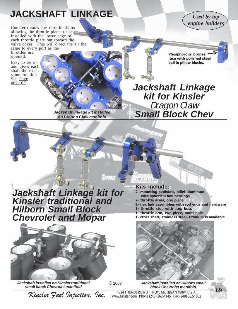
Kinsler Fuel Injection, Inc, 1834 THUNDERBIRD TROY, MICHIGAN 48084 U.S.A.www.Kinsler.com Phone (248) 362-1145 Fax (248) 362-1032
69© 2008
Used by topengine builders
Jackshaft installed on Kinsler traditionalsmall block Chevrolet manifold
Jackshaft installed on Hilborn smallblock Chevrolet manifold
Jackshaft Linkage kit forKinsler traditional andHilborn Small BlockChevrolet and Mopar
2- mounting pedistals, billet aluminum with spherical ball bearings2- throttle arms, one piece2- hex link assemblies with rod ends and hardware1- throttle stop with stop boss1- throttle arm, two piece, multi-hole1- cross shaft, stainless steel, titanium is available
Kits include:
Jackshaft Linkagekit for Kinsler
Dragon ClawSmall Block Chev
Counter-rotates the throttle shaftsallowing the throttle plates to beinstalled with the lower edge ofeach throttle plate out toward thevalve cover. This will direct the air thesame to every port as thethrottles areopened.
Easy to set upand gives eachshaft the exactsame rotation.See Page#62, 63.
Jackshaft linkage kit installedon Dragon Claw manifold
JACKSHAFT LINKAGE
Phosphorous bronzerace with polished steelball in pillow blocks.
V

Kinsler Fuel Injection, Inc, 1834 THUNDERBIRD TROY, MICHIGAN 48084 U.S.A.www.Kinsler.com Phone (248) 362-1145 Fax (248) 362-1032
70© 2008
CABLES & ACCESSORIESExcellent for actuating fuel injectionmanifolds or throttle bodies, carburetors,or shut off valves.
SHUT OFF CABLES
1045 teef2/112045 teef23045 teef2/124045 teef35045 teef2/136045 teef47045 teef2/148045 teef59045 teef2/150145 teef61145 teef2/162145 teef7
3145 teef2/174145 teef85145 teef2/186145 teef97145 teef2/198145 teef019145 teef2/1010245 teef111245 teef2/1112245 teef213245 teef2/1214245 teef31
Heavy duty, push-pull, 1/4-20thread for knob, 7/16-20 bulkheadwith jam nut for panel mounting.
10-32 male thread on working end;uses female rod end, clevis, or
quick release ball pivot.
Sealed on both ends.
Includes T-handle knob.
Cables are measured tip to tip.
Cable travel is approx.3.25" to 3.50".
0345 dutselam23-01xelamef23-011345 dutselam82-4/1xelamef23-013345 dutselam82-4/1xelamef82-4/1
Quick release, includes jamnut for stud.
Heavy duty, push-pull, 10-32male thread on both ends; uses
female rod ends, clevises, orquick release ball pivot.
Sealed on both ends.
Cables are measured tip to tip.
Cable travel is approx.3.25" to 3.50".
THROTTLE CABLES
2455 teef2/173455 teef84455 teef2/185455 teef96455 teef2/197455 teef018455 teef2/1019455 teef110555 teef2/1111555 teef212555 teef2/1213555 teef31
0355 teef2/111355 teef22355 teef2/123355 teef34355 teef2/135355 teef46355 teef2/147355 teef58355 teef2/159355 teef60455 teef2/161455 teef7
5345 ,esaelerkciuq,elgniSleetssselniats
8245 ,esaelerkciuq,lauDleetssselniats
6345 ,epytnwodtloBleetsdetalpmuimdac
7345 gnitnuomelpitlum,epyt-Umunimula,seloh
9245 detnirpton,daerhtelamef23-01,dnuoR
9345 'ffO-tuhS'detnirp,daerhtelamef23-01,epyt-T0445 'ffO-tuhS'detnirp,daerhtelamef02-4/1,epyt-T1445 detnirpton,daerhtelamef02-4/1,dnuoR
CABLE HANDLES
#5429 #5439
CLEVISES
5445 elamefdnahthgir23-016445 elamdnahthgir23-017445 elamefdnahthgir82-4/18445 elamdnahthgir82-4/1
0545 elamefdnahthgir42-61/51545 elamdnahthgir42-61/5
#5445 #5446
6" minimum bend radius50 lb max. pull load40 lb max. push load
BALL PIVOTS
Available for 1/4-28 and 10-32thread, round or t-type.
CABLE BRACKETSEasy cable mounting
to any flat surface.
#5435#5436
#5437
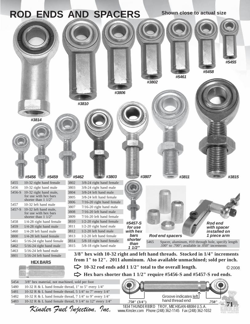
Kinsler Fuel Injection, Inc, 1834 THUNDERBIRD TROY, MICHIGAN 48084 U.S.A.www.Kinsler.com Phone (248) 362-1145 Fax (248) 362-1032
71
5645 htgnelyficeps,elohhguorht01#,munimula,recapSstnemercni"050.nielbaliava;"007.ot"001.
Rod end spacers
ROD ENDS AND SPACERS
#5455
#5458#5461
#3802
#3806
#3810
#3814
#3815#3811#3807#3803#5462#5459#54565545 elamefdnahthgir23-016545 elamdnahthgir23-01
S-6545 ,elamdnahthgir23-01srabxehhtiwesurof
"2/11nahtretrohs7545 elamdnahtfel23-01
S-7545 ,elamdnahtfel23-01srabxehhtiwesurof
"2/11nahtretrohs8545 elamefdnahthgir82-4/19545 elamdnahthgir82-4/10645 elamdnahtfel82-4/10083 elamefdnahtfel82-4/11645 elamefdnahthgir42-61/52645 elamdnahthgir42-61/53645 elamdnahtfel42-61/51083 elamefdnahtfel42-61/5
2083 elamefdnahthgir42-8/33083 elamdnahthgir42-8/34083 elamdnahtfel42-8/35083 elamefdnahtfel42-8/36083 elamefdnahthgir02-61/77083 elamdnahthgir02-61/78083 elamdnahtfel02-61/79083 elamefdnahtfel02-61/70183 elamefdnahthgir02-2/11183 elamdnahthgir02-2/12183 elamdnahtfel02-2/13183 elamefdnahtfel02-2/14183 elamefdnahthgir81-8/55183 elamdnahthgir81-8/5
4545 toofrepdlos,denihcamton,lairetamxeh"8/30845 "4/1yreve"5ot"1,daerhtelamefdnahL&R23-011845 "4/1yreve"7ot"4/15,daerhtelamefdnahL&R23-012845 "4/1yreve"9ot"4/17,daerhtelamefdnahL&R23-013845 "4/1yreve"21ot"4/19,daerhtelamefdnahL&R23-01
10-32 rod ends add 1 1/2" total to the overall length.
Hex bars shorter than 1 1/2" require #5456-S and #5457-S rod ends.© 2008
.750"Groove indicates lefthand thread end.750" (3/4")
Shown close to actual size
3/8" hex with 10-32 right and left hand threads. Stocked in 1/4" incrementsfrom 1" to 12". 2011 aluminum. Also available unmachined; sold per inch.HEX BARS
#5457-Sfor use
with hexbars
shorterthan
1 1/2”
Rod endwith spacerinstalled on1 piece arm

Kinsler Fuel Injection, Inc, 1834 THUNDERBIRD TROY, MICHIGAN 48084 U.S.A.www.Kinsler.com Phone (248) 362-1145 Fax (248) 362-1032
72
A BRIEF HISTORY OF FUEL INJECTIONCARBS TO CONSTANT FLOW, TO LUCAS MECHANICAL, AND FINALLY ELECTRONIC
ON TO ELECTRONICIn the late sixties various auto companies started serious electronic fuel injection (EFI) programs for better economy, driveability,and emissions. What needed to be done was obvious, but the progress was slow because of the difficulty of developing good lowcost injectors and electronic bits. The exciting thing about using electronics is that you can look at as many inputs as you wantto for very little money. Why? With any mechanical device, either carbs or injection, it is quite cumbersome and expensive tosum more than a few inputs. With electronics it is easy and cheap to sum as many as you want. So while only throttle angle orintake vacuum combined with engine speed had been used in most mechanical systems, now you could sense air, water, oil, andfuel temperature, barometer, rate of throttle opening, etc. With computing ability, it became easy to have complex maps of fuelmixture vs. RPM for various throttle angles, acceleration enrichment, controlled enrichment from cold starting to hot running, etc.Bosch was the clear leader in the early EFI work, introducing the system on the 1967 Volkswagen.
A drawback of both the Lucas and Bosch is that to get more than asimple straight line fuel curve you have to make a complex threedimensional fuel cam. Even today, an engine with a Lucas or Boschmechanical system with the simple straight line fuel curve runs quitewell, because the internal combustion engine is so beautifully forgiv-ing... it puts out almost full power from about three percent lean to aboutsix percent rich.
CARBS TO CONSTANT FLOWBack in the fifties it was either carbs or constant flow fuel injection. The basic cost for an out of the box carb was quite cheapcompared to injection. However, to get the mixture distribution right with the carb took a pretty smart person a lot of time, asboth the air distribution and the fuel distribution were tough to get right, and they changed with engine RPM and load. A reallygood running set of carbs would wind up costing a lot more than the injection, and even then carbs did poorly with combinationsof both straightaway acceleration and cornering as the floats and bowls hadn't been developed far enough. Even today's carbsdon't handle boating through rough waters well, as it's impossible to meter the fuel if it’s bouncing off the top of the float bowl.Don't get us wrong - we're not knocking carbs, as tens of millions of them have done an admirable job for many years when usedon the application they were designed for.If you bought a good set of individual runner injection, the airdistribution was just about perfect right out of the box, since all ofthe runners were cast the same and had a radiused bell at eachentrance. If your unit had a properly matched set of nozzles thefuel distribution had to be good, since there was one nozzle in eachrunner. Other advantages of the injection was that you couldchange the fuel mixture quickly by just changing one jet (evenfrom the dashboard while driving), and you could run alcohol andnitro. There were no carbs at the time that did a good job with thesefuels.
LUCAS MECHANICALIn the early sixties both Lucas and Bosch mechanical timed injectionbecame popular because of several nice features because they use thestroke of a piston to precisely meter the fuel. The fact that they are timedallows you to inject the fuel at just the right instant to avoid letting anygo through during valve overlap, thus giving better potential fueleconomy. These systems also meter the fuel well during engine startingand idle which prevents washing off the upper cylinder lube. The nozzlesare of a valve-and-seat design, so there is no dripping of the fuel into theengine on shutdown, even without a fuel shut-off valve. The throttleresponse is very crisp, as you get the new fuel rate within two revolutionsof the engine after moving the throttle pedal. Finally, the output of thepump is not a basic part of the metering system, so if the pump were tocavitate say 10%, it would have no effect on the mixture at all. All ofthese features make this system very popular for road race cars.
Most of the early injection was of the constant flow design,which to this day is the most rugged and dependable system. Thebasic fuel metering is done by sensing throttle angle and enginespeed. The throttle rotates a spool with a tapered ramp inside ametering block; it has a samll opening to the nozzles at an idle,which gets larger as the throttles are opened. Engine speed is sensed by using a positive displacement pump driven by the engine,so when the engine speed doubles, the output of the pump doubles. This system has always worked well for drag racing, where thefuel can easily be kept cool. In round track or road racing, the fuel gets hotter the longer you run, both from the track heat and thewarm fuel returning to the tank. Because the light ends in gasoline boil at about room temperature, or even lower if you have anyvacuum at the inlet of the pump caused by a restriction in the inlet line from the tank, the fuel pump doesn’t draw in all the fuel itshould, which causes a lean condition. The car will run just fine early in the race, but after a while it gets “lazy”.... the power andreaponse fall off and you may even burn a piston. The solution is to pressurize the pump inlet line so the fuel can’t boil. Ourvapor separator tank is the heart of an excellent off-the-shelf system that can take care of this. A nice feature of the constant flowsystem is that you can tailor bumps and dips into the fuel curve using special metering pieces that we have available. Whilealcohol doesn’t boil as easily as gasoline, it still requires a carefully plumbed inlet line to the pump to prevent lean-out.
1963 Maserati Mistral Lucasmechanical fuel metering system
Walt Kolodziej's 'Blue Meanie' smallblock Chev with Kinsler injection
© 2008

Kinsler Fuel Injection, Inc, 1834 THUNDERBIRD TROY, MICHIGAN 48084 U.S.A.www.Kinsler.com Phone (248) 362-1145 Fax (248) 362-1032
73
A BRIEF HISTORY OF FUEL INJECTIONIn the early seventies, EFI became more popular on passenger cars. It was very expensive compared to carbs, as the carbs had beendeveloped for many years to do a reasonable job while being mass produced using die castings. Just a couple of the EFI injectorscost as much as a carburetor. A V8 has as many as eight injectors, a complicated fuel rail, various sensors, and a complex wiringharness and electronic control unit (ECU). So why did they go to the EFI? It was a combination of political pressure due to fleeteconomy and emission requirements, image, startability, driveability, and the hopes that volume use and further research wouldlower the cost, which it certainly has.
Racing has been an innovative and progressive sport. Considering that Buick was 100% EFI in the mid-80s, it only makes sensethat there should be at least a couple of competition classes where the creative racer can dabble with the latest technology.There are a lot of systems and components available now and the cost has come down to an affordable range. EFI has arrived tostay !
So where does all this put us? Electronic fuel injection is becoming more advanced and sophisticated, so selecting the featuresneeded for an application can be confusing. Kinsler Fuel Injection can help you work through the choices to find the rightcomponents for your project.
We decided not to make our own electronic control because there are excellent ones available. We carry most brands of E.C.U.sand components, and make complete systems for any application. We have technicians who are glad to advise you on what to usefor your application. They are happy to assist you no matter what mix of brands you plan on using, or what you may alreadyhave. Give us a call!
Electronics surround us everywhere we go, and they are in theautomotive world to stay. EFI applied to the correct applicationsin racing can actually save money. A supercharged orturbocharged drag race engine costs from twenty to fifty thousanddollars. It can be destroyed in an instant if it isn't fueled properly.Most of the present mechanical fuel systems are a compromise onthese engines. EFI allows complete mapping of the engine,suppling the correct amount of fuel at every possible condition.Programmed meticulously, reliability will be gained using EFI.
In the early eighties the first race ECU's appeared in the speedindustry. They were quite basic, expensive, and tedious toprogram. Various sports cars tinkered with the EFI, and aFormula Vee series ran exclusively with it. A lot of thisequipment was initially supplied by Bosch, with advancementsbeing made by other companies that produced racing-onlyboxes.Because of its ability to handle a very complex engine fuel mapwith ease, EFI was literally snatched up by the F-1 cars in themid-eighties for their turbo motors. While the output of theseengines at about 750 horsepower from 92 cubic inches ongasoline looked impressive to most of the world in 1983, thedevelopers knew that they were making tremendous compro-mises to stay safe with the limitations of their mechanicalsystems. Within just a few years after introducing EFI, some F-1engines were dynoing at nearly 1,250 horsepower or 13.5horsepower per cube!! They ran about 1,000 horsepower on thetrack for qualifying and dropped back further for the actualrace. Any skepticism about the ability of EFI to run withmassive ignition interference, heat, or vibration was silenced.By the end of the eighties there were more than a dozen companiesmaking aftermarket and racing electronic control systems; severalof them being quite reputable with good solid products. The popular use of the systems was on road race, Indy cars, offshore raceboats and high performance street machines, all these having rather complex fuel requirements. Today, drag racing is seeinglimited use of EFI, both because of rule restrictions, and the relatively simple fuel requirements (wide open throttle only) for mosttype of engines operating on the drag strip... constant flow metering still works quite well there.
The control boxes now available for racing range from basic ones at $1,500-$3,000 with programming software, to extremelycomplex systems that sense everything you can think of at$5,500-$15,000 with programming aids and software that are veryuser friendly and will run on laptop computers. Add to all this thecost of injectors at $40-100 each for common types, wiringharness at $300 for the street type to $1,500 for a good raceharness, to $4,000 for super quality F-1 type harnesses. Fuel railsare $200 for the basic ones, $400 for high flow aluminum, to $800for custom built stainless steel. Add a manifold, fuel pump, filter,pressure relief valve, etc. and you go from a complete system forhigh performance street use at about $4,500, seriouson-track system at $7,000 to the most sophisticated at $11,000 to$21,000 including engineering time.
First Zytek 'white'ECU; 1984.
Used an EPROMchip that had to be'burned' outside ofthe ECU withhexidecimal code,then installed in theunit. It did have theluxury of havingtrim knobs forsome fieldadjusting.
Indy 500 winner, Treadway Racing’s car driven by ArieLuyendyk using Kinsler manifold, filters, p.r. valve
© 2008

Kinsler Fuel Injection, Inc, 1834 THUNDERBIRD TROY, MICHIGAN 48084 U.S.A.www.Kinsler.com Phone (248) 362-1145 Fax (248) 362-1032
74
COMPARISON OF RACINGFUEL INJECTION SYSTEMS
CONSTANTFLOW
NOZZLE
LUCASMECHANICAL
TIMEDNOZZLE
ELECTRONICINJECTOR
tsocmetsysgniretemecaretelpmoCdlofinamtuohtiwtubspmuphtiw 00.005,1$ 00.005,7$ fotsocsulp00.000,51$-00.005,2$
tinurotretupmocpotpal
ytilibadnepeD tnellecxE tnellecxE ylreporpscinortcelehtiwdoogyreVnoitacilppadednetniehtrofdetceles
enignetcaxeotetarbilacotytilibAtnemeriuqer dooGotriaF riafotrooP tnellecxeyreV
noitingidemmargorP+
retemomonydnoetarbilacotemiT sruoH4-1 sruoH2-1 yllacitamardseiravtub,sruoH21-2sdiaresudnaserutaefotgnidrocca
ro/dnalonahtemnurotytilibAsleufenahtemortin tnellecxE elbatonrorooP
ecnenetniamtnatsnocseriuqer-riaFtnenopmocmretgnolfoksirhgiH
eruliaf
cirehpsomtaotgnitsujdafleSsnoitidnoc oN racnoitcudorpnO
sledom seY
gnirudgniretemlortnoctinuseoDgnitrats
onroelttil;rooPgnirudnoitazimota
gniknarcdoogyreV tnellecxE
gnitratsfoesaE riaF doogyreV tnellecxE
evahteyeldinaelctesotytilibAesnopserelttorhtdoog rooP riaF tnellecxE
srotcejni/selzzonfonoitcnuF erusserpybreteMecifirossorcapord
on;ylnonoitazimotAnoitcnufgniretem
'ecifiro'ssorcaporderusserpybreteMelcycytuddellortnocyllacinortcelesulp
ytilauqnoitazimotarotcejni/elzzoNdooG--ot--rooPhgih(ot)MPRwol(
)MPRtnellecxE tnellecxE
TONsrotcejni/selzzonrofycnedneTffoenignegnittuhsretfapirdot
firoopyrev;rooPaesut'noduoy
evlavffo-tuhsdoogyreV tnellecxE
ymonoceleuF rooP riaF tnellecxE
srotcejni/selzzongninaelcfoesaE dooG riaF tnempiuqelaicepsevaht'noduoyfirooP
llarevofoecnanetniamfoesaEmetsys tnellecxE dooG riaF
Constant Flow Lucas Mechanical Electronic
© 2008

Kinsler Fuel Injection, Inc, 1834 THUNDERBIRD TROY, MICHIGAN 48084 U.S.A.www.Kinsler.com Phone (248) 362-1145 Fax (248) 362-1032
75
Steve Kinser, 19-time,World of Outlaw Sprint Car Champion
CONSTANT FLOW FUELINJECTION METERINGConstant flow systems are very flexible and costeffective for many types of racing, engineconfigurations, and fuels. They are capable ofsuppling a very wide range of fuel requirements. Thesystem can be easily configured and tuning isaccomplished by increasing or decreasing the systemsoperating pressure.
A constant flow system uses a mechanical fuel pumpto increase/decrease the supply flow to the injectionunit directly related to engine RPM. This variableflow creates pressure against the fixed orifices of themain bypass jet and the nozzles. The idle and thepart throttle fuel rate is controlled by utilizing a barrelvalve assembly. Kinsler can supply additionalbypasses and enrichment circuits to provide addedflexibility.
Basic components of a constant flow fuel injection system :
A) Air control - individual runner (I.R.) manifold or throttle body.B) Barrel valve assembly - barrel valve houses the spool. The
spool controls fuel for idle and part throttle. There is aselection of spools for different engines and fuels.
C) Nozzles - fixed orifice in the runner or plenum of intakemanifold. Sized for specific engine application and fuel beingused.
D) Nozzle hoses - connects barrel valve or distribution block tonozzles.
E) Main bypass jet can - houses poppet and spring for basic idlefuel pressure, holds main bypass jet.
F) Main bypass jet - this orifice works in conjunction with pumpand nozzles to set the overall fuel delivery of the system. Itcan be quickly changed to adjust the base fuel rate.
G) Fuel pump (mechanical) - positive displacement pump.H) Fuel pump drive - typically drives fuel pump at 1/2 engine
RPM. Can be mounted to camshaft or belt driven. I) Fuel shut-off valve - stops fuel flow to barrel valve to allow the
engine to be shut-off.J) Fuel filter - filters the fuel to protect nozzles, bypass valves,
and barrel valve.
Optional components :
K) Secondary bypass valve - allows tuning flexibility of partthrottle.
L) High speed bypass valve - allows tuning flexibility of higherRPM fuel delivery.
M) Electric lean-out or enrichment valve - special function valveto allow tuning of a specific area or range of the fuel delivery.
N) Kinsler Jet Selector Valve - holds eight main bypass jets.Allows main jet to be adjusted while engine is running.
O) Kinsler Vapor Separator Tank (VST) system - typically usedwhen the main fuel tank is mounted too far away from themechanical pump and a transfer pump is required. This Kinslerspecially designed system helps to prevent fuel boiling andpump inlet cavitation by maintaining pressure to themechanical pump inlet. Return fuel from the injection systemis routed back to this tank. See Pages #115-116 for details onVapor Separator Tank plumbing. © 2008

Kinsler Fuel Injection, Inc, 1834 THUNDERBIRD TROY, MICHIGAN 48084 U.S.A.www.Kinsler.com Phone (248) 362-1145 Fax (248) 362-1032
76
KINSLER K-TYPE JETS
TYPICAL INCREMENTS VERSUS APPLICATION The following are guidelines: .002" gasoline and small alcohol engines
.004" for typical alcohol V8
.004" to .008" for blown applications
.006" to .010" for high speed and secondary restrictor jets.
FEATURES OF THE K-TYPE JETS
EACH K-type jet is precisely machined and stamped with the "KINSLER" name to identify it. It has areamed orifice controlled within .0002", a precise radius leading to the orifice, and a regulated finish.
Every K-type jet is tailored on the flow bench to within 1% of the flow rate of the master reference jet ofits same size. Therefore, even though the increments between the K-type jets are very small (.002"available), the change in flow rate between each jet is controlled. Every jet of the same size flows thesame, if one jet is lost, an exact duplicate can be shipped immediately.
THAT IS WHY YOU NEED K-JETSA perfect fuel injection system is of little use to the owner unless he has a good set of jets to use with it.When using commercially made jets, it is not unusual when going .005" smaller in jet size (in an attemptto richen the unit), to actually find no fuel rate change, or perhaps go grossly rich, or even to go a bitleaner! This can make it impossible to "tune in" the engine for best power and consistency.
PRECISE ; ACCURATE ; CONSISTENT
IMPORTANT NOTES
A) When installing a K-type jet that is replacing a commerical jet, start with a K-type jet that is about .008" smaller. This is due to the efficient design of the K-type jets.
B) Always install the jet so that the number is facing up as the jet is dropped in, then the fuel will flow into theradiused side of the jet. After the jet can has been assembled, the number will be facing toward the poppet.
C) Make sure the jet can end has an o-ring receiving groove and that an o-ring is in place for the jet torest on. Note: the jet sealing o-ring should be replaced periodically to make sure that the compoundhas not "dried" out.
D) Any marks on the radius of a K-type jet were put there on purpose during the flow tailoring process.... leave them alone!
E) Never string the jets on a wire, as their entrance shapes will change as they move around on the wire!!! For storage use the Kinsler plastic jet holder case #3720.
ORDERING K-JETS
Kinsler K-type jet pricing is broken down into material and labor.For proper pricing, the labor charge and the jet blank price must be added together.
Drop in style jets give several advantages:No damage to the jet on installation or removal like some screw-in commercialjets, screwdriver nicks on the face of the inlet to any orifice can cause the flowsto change.The jet rests on an o-ring for a positive seal. No possible leakage which couldalter the flow, affecting the tuning of the engine.
K-Jet installedin jet canIMPORTANT - the labor charge to make a set of K-type jets is included in the basic labor
charge of flow testing and calibration of any fuel injection system, new or used.
0173 "200.ta"820.ot"410.:stejepyt-KLAICEPSekamotrobaL
1173 "200.ta"830.ot"030.:stejepyt-KLAICEPSekamotrobaL
2173 "200.ta"840.ot"040.:stejepyt-KLAICEPSekamotrobaL
3173 "200.ta"681.ot"050.;tejepyt-KdradnatsENOekamotrobaL
4173:sezisetats,stejepyt-K21ot8fotesytitnauqekamotrobaL
"200.ta"681.ot"050.)ezistejemasehtfosetitnauqelpitlumtseuqeryamuoy(
5173 stejdehctamevobaekamotknalbtejepyt-K
© 2008
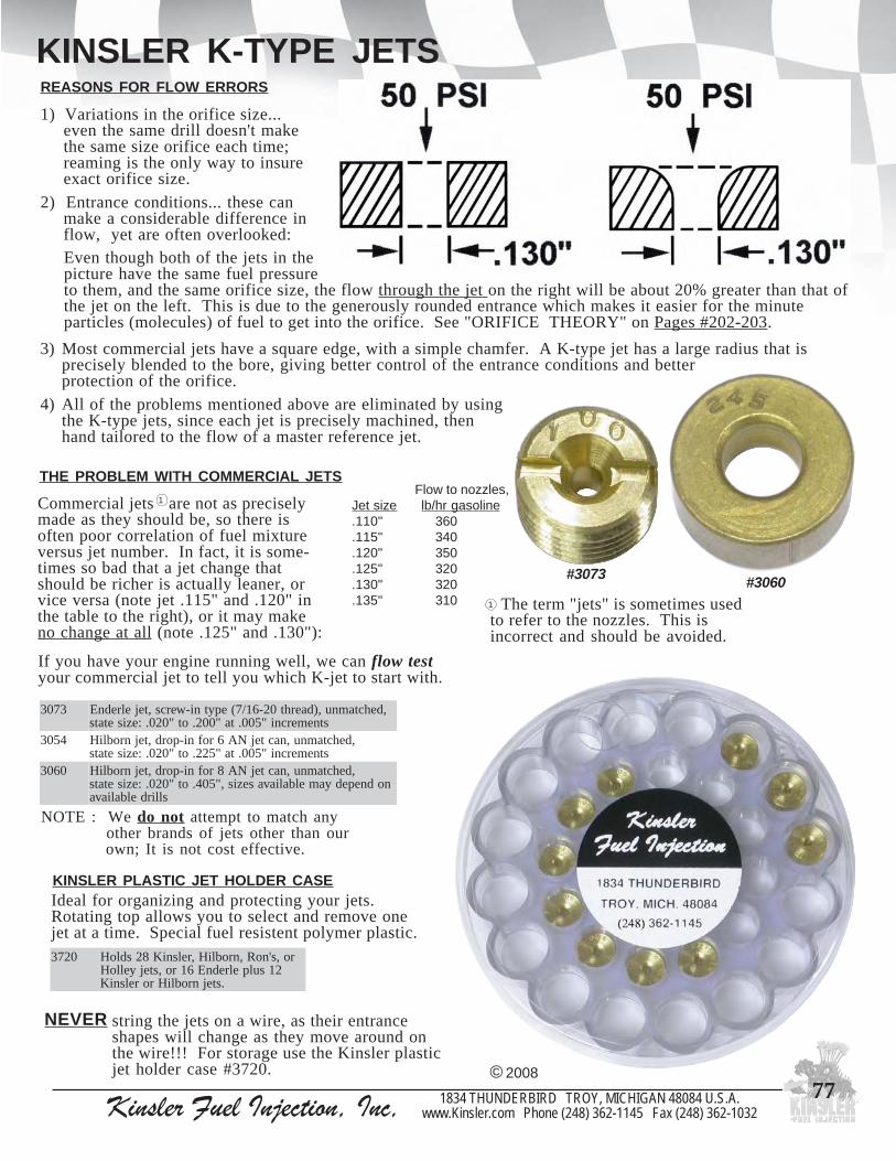
Kinsler Fuel Injection, Inc, 1834 THUNDERBIRD TROY, MICHIGAN 48084 U.S.A.www.Kinsler.com Phone (248) 362-1145 Fax (248) 362-1032
77
KINSLER K-TYPE JETS
Ideal for organizing and protecting your jets.Rotating top allows you to select and remove onejet at a time. Special fuel resistent polymer plastic.
KINSLER PLASTIC JET HOLDER CASE
THE PROBLEM WITH COMMERCIAL JETS Flow to nozzles,
Jet size lb/hr gasoline.110" 360.115" 340.120" 350.125" 320.130" 320.135" 310
If you have your engine running well, we can flow testyour commercial jet to tell you which K-jet to start with.
© 2008
NOTE : We do not attempt to match any other brands of jets other than our own; It is not cost effective.
3703 ,dehctamnu,)daerht02-61/7(epytni-wercs,tejelrednEstnemercni"500.ta"002.ot"020.:ezisetats
4503 ,dehctamnu,nactejNA6rofni-pord,tejnrobliHstnemercni"500.ta"522.ot"020.:ezisetats
0603 ,dehctamnu,nactejNA8rofni-pord,tejnrobliHnodnepedyamelbaliavasezis,"504.ot"020.:ezisetats
sllirdelbaliava
string the jets on a wire, as their entranceshapes will change as they move around onthe wire!!! For storage use the Kinsler plasticjet holder case #3720.
NEVER
0273 ro,s'noR,nrobliH,relsniK82sdloH21sulpelrednE61ro,stejyelloH
.stejnrobliHrorelsniK
#3073 #3060
REASONS FOR FLOW ERRORS
1) Variations in the orifice size...even the same drill doesn't makethe same size orifice each time;reaming is the only way to insureexact orifice size.
2) Entrance conditions... these canmake a considerable difference inflow, yet are often overlooked:Even though both of the jets in thepicture have the same fuel pressureto them, and the same orifice size, the flow through the jet on the right will be about 20% greater than that ofthe jet on the left. This is due to the generously rounded entrance which makes it easier for the minuteparticles (molecules) of fuel to get into the orifice. See "ORIFICE THEORY" on Pages #202-203.
3) Most commercial jets have a square edge, with a simple chamfer. A K-type jet has a large radius that isprecisely blended to the bore, giving better control of the entrance conditions and betterprotection of the orifice.
4) All of the problems mentioned above are eliminated by usingthe K-type jets, since each jet is precisely machined, thenhand tailored to the flow of a master reference jet.
The term "jets" is sometimes usedto refer to the nozzles. This isincorrect and should be avoided.
1
Commercial jets are not as preciselymade as they should be, so there isoften poor correlation of fuel mixtureversus jet number. In fact, it is some-times so bad that a jet change thatshould be richer is actually leaner, orvice versa (note jet .115" and .120" inthe table to the right), or it may makeno change at all (note .125" and .130"):
1

Kinsler Fuel Injection, Inc, 1834 THUNDERBIRD TROY, MICHIGAN 48084 U.S.A.www.Kinsler.com Phone (248) 362-1145 Fax (248) 362-1032
78
FUNCTION 1) The orifices in the nozzles meter the fuel to the engine in conjunction with the main bypass return jet and the fuel pump. 2) Control the distribution of fuel to each cylinder of the engine. 3) Atomize and direct the fuel being injected.
NOZZLES: CONSTANT FLOW
FLOWED AND MATCHEDCustomers spend lots of money having their cylinder heads airflowed and ported to get even flow characteristics, but then usenozzles that have fuel distribution as bad as 10-15%.Commercial nozzles just aren't made well enough. Very tinydifferences in the hole size and machining marks around theinlet or outlet of the fuel orifice makes significant changes infuel flow.
Nozzles are affected by the same problems as the return jets.Read "THE K-TYPE JETS" on Pages #76-77 and "ORIFICE THEORY" on Pages #202-203.
KINSLER STANDARD NOZZLE IDENTIFICATIONWe stamp our flowed nozzles with - the name "KINSLER"; a size reference; a flow code, and adeflector style-air orifice reference. Example: S-710 AS-78 explanation :
The 'S' indicates a nominal .0338" orifice - orifice sizes may vary + .0004" due to machining tolerances, so hand matching is still required.
The 710 is the flow code.AS is the deflector style (see deflector types on next page).78 refers to a .078" air orifice in the deflector, also referred to as the vacuum break restrictor.
An 'X' indicates a nozzle with .039" or larger fuel orifice. Example: X-39 930 AS-89The 'X' followed by 39 means a .039" fuel orifice; 930 is the flow code; ‘AS’ is deflector style;
89 refers to a .089" air orifice in the deflector.
The flow code is the pounds per hour (lbs/hr) of fuel flow at 30 PSI for one nozzle. Example: S-710 is really 71.0 lbs/hr at 30 PSI.
You can calculate the flow of a nozzle at any fuel pressure - see "ORIFICE THEORY" on Pages #202-203.
Kinsler nozzle sets are flowed and matched to within a 1% total spread in distribution. The orifices are radiusedand polished to promote even flow. Each nozzle is individually flow tested through a range of pressures and handmatched to a master reference nozzle. Should a nozzle not work into the master flow curve, it is discarded orresized for use in a larger set.
* + or - approx. 8% from flows shown at left(they code their inserts by orifice diameter number)
© 2008
relsniKelzzon
edoCwolF
repwolfrh/sblISP03taelzzon
lanimoNecifiro
ezis
.xorppAnrobliH
ezis
&reworC*elrednE
eziselzzon
561-E 5.61 "610. 4 61
002-F 0.02 "710. 5 71
042-G 0.42 "020. 6 02
082-H 0.82 "5120. 7 12
023-J 0.23 "5220. 8 22
063-K 0.63 "8320. 9 42
093-L 0.93 "520. --- 52
014-M 0.14 "9520. 01 62
074-N 0.74 "7720. --- 82
015-P 0.15 "9820. 21 92
055-P 0.65 "4920. 41 13
026-R 0.26 "8130. 61 23
017-S 0.17 "8330. 81 33
047-T 0.47 "9430. --- 53
297-T 2.97 "9530. 02 ---
008-U 0.08 "630. --- 63
048-V 0.48 "3730. 22 73
088-W 0.88 "830. 42 83
03993-X 0.39 "930. 72 93
o
‘A’ type;fuel discharged at 45 to body through notch cutin deflector, commonly called ‘whistle’ or notch
o
‘AS’ type;fuel discharged in line with body
through a diffuser screen, commonlycalled ‘screen tip’ or ‘shot-gun’

Kinsler Fuel Injection, Inc, 1834 THUNDERBIRD TROY, MICHIGAN 48084 U.S.A.www.Kinsler.com Phone (248) 362-1145 Fax (248) 362-1032
79
NOZZLE VENTING Vents allow air to pre-mix with fuel inside the nozzle for better atomization and eliminates enginevacuum from drawing fuel into the engine.
Externally vented - for normally aspirated engines (unblown) or supercharged engines with nozzles at blower inlet. Vented to the atmosphere; see AIR FILTRATION on Page #82.Internally vented - for normally aspirated engines. Vents from inside the runner of the manifold.Non-Vented and Z-type - for supercharged or turbocharged applications were the nozzle outlet is subject to manifold boost.
NOZZLES : CONSTANT FLOW
VENT LOCATION AND QUANTITYOne and three vent nozzles drip fuel into the engine onshut-down, may make motor hard to restart due to excess fuelin cylinders.
Four and six vent nozzles may drip fuel outside on shut-down,but reduces cylinder wash down.
AIR FILTERSee Pages #190-192 forFILTER FOAM ; K&N AIR FILTERS ; AIR BOXES
Example of Kinsler #2228 internally vented1/2-20 thread nozzle with 1" long ‘AS’ styledeflector.
Installed in Kinsler 3-piece manifold withconstant flow universal nozzle boss adapters.
Nozzle is vented back into the manifoldrunner, air filter on the ramtube keeps thevents clean.
Example of Kinsler internally vented1/2-20 thread nozzle with1" long ‘AS’ style deflector.
‘Down nozzle’ installed in cylinder head
Nozzle is vented into#2393 Kinsler1/2-20 aluminum banjowith sintered bronzeair filter.
See Page #80 for 1/8" NPT threadnozzles and holders that acceptscrew-in insert nozzles.
© 2008

Kinsler Fuel Injection, Inc, 1834 THUNDERBIRD TROY, MICHIGAN 48084 U.S.A.www.Kinsler.com Phone (248) 362-1145 Fax (248) 362-1032
80
NOZZLES : CONSTANT FLOWTHESE NOZZLES ARE PREMIUM RACE GRADE QUALITY ....
FLOW TESTED AND MATCHED AT FOUR DIFFERENT PRESSURES.
NOTE : Above par t numbers are for a singular nozzle. Change last digit of part number for number of nozzles in a set.© 2008
gnir-ohtiwslaes,xeh"8/5,daerhtthgiarts02-2/1relsniK1 1022 SA 4-TNI "063.1 "003.0 "066.1 ssarb dlofinamnrobliHdnarelsniK "4/1SA807*2 1122 SA 4-TNI "063.1 "045.0 "009.1 ssarb dlofinamnrobliHdnarelsniK "2/1SA807*3 1322 SA 4-TNI "063.1 "057.0 "011.2 ssarb 'selzzonnwoD';hcaerregnol;dlofinamrelsniK "4/3SA807*4 1222 SA 4-TNI "063.1 "000.1 "563.2 ssarb 'selzzonnwoD';hcaerregnol;dlofinamrelsniK "1SA807*5 1342 SA 4-TNI "063.1 "052.1 "516.2 ssarb 'selzzonnwoD';dedeenhcaerregnoL ---6 1532 SA 4-TNI "063.1 "005.1 "568.2 ssarb 'selzzonnwoD';dedeenhcaerregnoL ---7 1632 SA 4-TNI "063.1 "057.1 "511.3 ssarb 'selzzonnwoD';dedeenhcaerregnoL ---8 1732 SA 4-TNI "063.1 "000.2 "563.3 ssarb 'selzzonnwoD';dedeenhcaerregnoL ---9 1822 SA 4-TNI "063.1 "005.2 "568.3 ssarb 'selzzonnwoD';dedeenhcaerregnoL ---01 1832 SA 4-TNI "063.1 "005.3 "568.4 ssarb dlofinamSCSAnrobliH;dedeenhcaerregnoL ZSA"2/13-017*11 1542 SA 4-TNI "063.1 "005.5 "568.6 ssarb nrobliH,walCnogarD;dedeenhcaerregnoL "2/15SA017*
gnir-ognilaesdnatunmajhtiwxeh"8/5,epyt-T,daerhtthgiarts02-2/1relsniK21 1522 A 4-TNI "538.1 "574.0 "013.2 ssarb degrahcobrut;elbamiadetnevyllanretnI A907*31 1622 A 4-TNI "538.1 "057.0 "585.2 ssarb degrahcobrut;elbamiadetnevyllanretnI ---41 1922 A 4-TNI "538.1 "000.1 "538.2 ssarb degrahcobrut;elbamiadetnevyllanretnI ---
seidobdnatresnielzzonni-pordrelsniK51 1332 --- --- --- --- "513.0 ssarb noitubirtsidleuffotnemtsujdA ---61 0432 A 6-TXE "000.1 "074.0 "074.1 ssarb tresnievobasdloH.thgiarts,TPN"8/1 ---71 4432 SA 6-TXE "000.1 "005.0 "005.1 ssarb tresnievobasdloH.thgiarts,TPN"8/1 ---
xeh"61/7,elzzonthgiarts,TPN"61/1relsniK81 0902 A/N enon "590.1 A/N "590.1 ssarb langismuucavronoitcejnisuortiN ---
ydobotseerged09noitcennocesoh,ydob"61/7,eerged09TPN"8/1relsniK91 1012 )HL(A 4-TNI "581.1 "574.0 "578.1 ssarb nrobliHylraE,reworC,kcolBgiBrelsniK "4/1A107*
02 1012 )NWOD(A 4-TNI "581.1 "574.0 "578.1 ssarb selttorhtevobA,reworC,kcolBgiBrelsniK "4/1A107*12 1012 )HR(A 4-TNI "581.1 "574.0 "578.1 ssarb nrobliHylraE,reworC,kcolBgiBrelsniK "4/1A107*22 1612 )NWOD(A 4-TNI "581.1 "000.1 "526.2 ssarb nrobliHylraE,reworC,kcolBgiBrelsniK "1A107*
ydobotseerged09noitcennocesoh,ydob"61/7,eerged09TPN"8/1relsniK32 1112 SA 4-TNI "581.1 "003.0 "007.1 ssarb kcolbgibdnallamsnrobliHylraE "4/1SA107*42 1212 SA 4-TNI "581.1 "045.0 "059.1 ssarb kcolbgibdnallamsnrobliHylraE "2/1SA807*52 1312 SA 4-TNI "581.1 "057.0 "561.2 ssarb dedeenhcaerregnoL "4/3SA107*62 1412 SA 4-TNI "581.1 "000.1 "004.2 ssarb dedeenhcaerregnoL "1SA107*72 8932 --- --- --- --- --- --- ydobeerged09rofwercsnoitcepsnI B3X3-3F82 9932 --- --- --- --- --- --- wercsnoitcepsnirofteksaG F33F
xeh"61/7,selzzonthgiarts,TPN"8/1relsniK92 1102 A 3-TXE "590.1 "074.0 "565.1 ssarb skcolbgib&llams,sracdaor-pirD-noN ---03 1002 A 6-TXE "590.1 "074.0 "565.1 ssarb noskcaJ,s'noR,elrednE,nrobliH,relsniK "4/1A207*13 1912 A 6-TXE "063.1 "057.0 "516.2 ssarb dedeenhcaerregnoL ---23 1512 A 6-TXE "590.1 "000.1 "590.2 ssarb dedeenhcaerregnoL ---
rotcelfedfodnereppunitucegassapriaybdetnevyllanretni,epyt-Z,selzzonthgiarts,TPN"8/1relsniK33 1202 A ENO-TNI-Z "590.1 "074.0 "565.1 ssarb elzzontropdegrahcobruT ---43 1052 A ENO-TNI-Z "590.1 "000.1 "590.2 ssarb elzzontropdegrahcobruT ---53 1302 SA ENO-TNI-Z "590.1 "003.0 "593.1 ssarb elzzontropdegrahcobruT ---63 1402 SA ENO-TNI-Z "590.1 "000.1 "590.2 ssarb elzzontropdegrahcobruT ---
xeh"61/7,selzzonthgiarts,TPN"8/1relsniK73 1502 SA 6-TXE "590.1 "003.0 "593.1 ssarb MVEdnanoskcaJemoS;nrobliHylraE "4/1SA207*83 1602 SA 6-TXE "590.1 "005.0 "595.1 ssarb MVEdnanoskcaJemoS;nrobliHylraE "2/1SA207*93 1702 SA 6-TXE "590.1 "057.0 "548.1 ssarb dedeenhcaerregnoL "4/3SA207*04 1802 SA 6-TXE "590.1 "000.1 "590.2 ssarb dedeenhcaerregnoL "1SA207*14 1712 SA 6-TXE "590.1 "005.3 "595.4 ssarb dedeenhcaerregnoL ---
)epytelrednEsecalper(seidobdnatresnielzzonni-wercsrelsniK24 1032 --- --- --- --- "000.1 ssarb noitubirtsidleuffotnemtsujdA ---34 5232 A 3-TXE --- "005.0 "005.1 ssarb smarlennut;tresniecifiroriA ---44 2232 A enon --- "005.0 "005.1 ssarb enignenwolbfostroP ---54 A2232 A enon --- "000.1 "059.1 munimula enignenwolbfostroP ---64 1232 A 3-TXE --- "000.1 "059.1 munimula tahrewolbelrednE;tresniecifiroriA ---74 B3232 A enon --- "000.1 "059.1 ssarb enignenwolbfostroP ---84 A3232 A enon --- "000.1 "059.1 munimula enignenwolbfostroP ---94 B4232 A enon --- "057.0 "056.2 ssarb enignenwolbfostroP ---05 4232 A enon --- "057.0 "056.2 munimula enignenwolbfostroP ---15 6232 SA 3-TXE --- "003.0 "003.1 ssarb smarlennut;tresniecifiroriA ---25 7252 SA 3-TXE --- "005.0 "005.1 ssarb smarlennut,tresniecifiroriA ---35 8252 SA 3-TXE --- "057.0 "057.1 ssarb smarlennut;tresniecifiroriA ---45 9252 SA 3-TXE --- "000.1 "000.2 ssarb smarlennut;tresniecifiroriA ---55 7232 SA 3-TXE --- "003.0 "091.2 ssarb redlohelzzon'nwod'kciuB/traD ---65 8132 A ENO-TNI --- "000.1 "000.2 ssarb enignenwolbfostroP ---75 3132 SA ENO-TNI --- "000.1 "000.2 ssarb enignenwolbfostroP ---
.ON RELSNIK#TRAP
ROTCELFEDEPYT
TNEVRIA&EPYT
.ON
YDOBHTGNEL
ROTCELFEDHTGNEL
LLAREVOHTGNEL
YDOBLAIRETAM ESULACIPYT SECALPER
.ONNROBLIH
We can make variations of these nozzles for your special requirements - Just Call Us !!!

Kinsler Fuel Injection, Inc, 1834 THUNDERBIRD TROY, MICHIGAN 48084 U.S.A.www.Kinsler.com Phone (248) 362-1145 Fax (248) 362-1032
81
NOZZLES : CONSTANT FLOW
Kinsler FuelInjection
stocks a verywide range of
nozzles
Kinsler alsocan supply
specialmade
nozzle(s)for yourunique
requirements
© 2008
1 2 3 4 5 6 7 8 9 10 11
12 13 14
15
19 20 21 22 23 24 25 26 27
28
29 30 31 32 33 34 35 36 37 38 39 40 41
4243 44 45 46 47 48 49 50 51 52 53 54 55 56 57
16 17 18

Kinsler Fuel Injection, Inc, 1834 THUNDERBIRD TROY, MICHIGAN 48084 U.S.A.www.Kinsler.com Phone (248) 362-1145 Fax (248) 362-1032
82
FILTRATION
NOZZLE VENT FILTER BISCUITSThese biscuits made from filter foam,slip over the outside of the 1/8" NPTnozzle body to give complete protection.Washable and reusable, 45 ppi.
AIR FILTRATIONFOR NOZZLES
© 2008
3932TPN"8/1htiwojnabelzzon02-2/1munimulA
"8/1htiwretlifriaeznorbderetnis;tropelamefdaerhtelamTPN
4932 TPN"8/1htiweznorbderetnis,YLNOretlifriAdaerht
9732 elzzon02-2/1rof,munimula,YLNOydobojnaB
0932 ojnabelzzon02-2/1detalp,brab"8/3elgniS
1932 ojnabelzzon02-2/1detalp,brab"8/3lauD
2932 detalp,esohkcol-hsupNA6rof,eeT
0205 stiucsibretliftnevelzzonrelsniK)8(foteS1205 tiucsibretliftnevelzzonlaudividnI
#5021
#2393
6932 ,neercstelnielzzonrelsniKleetssselniatshsem07x08
#2396
#2392 #2390 #2391
Nozzles are a vital part of the fuel system.KEEPING THEM CLEAN IS A MUST !!!
Monster Mesh Series Filters
MonsterMesh
MegaMonster
Mesh UltraMonster
MeshMonster Mesh series filters part numbers anddescriptions, see Page #164
Ano-BRL Alum-BRL
Consult the plumbing schematic for the type offuel system being used and MAKE SURE thecorrect type and style of fuel filter is beinginstalled.
Fuel pump inlet: pumps are very sensitive todisturbance in the inlet hose. IT IS A MUST tohave the correct filter or it will damage the pumpand/or cause problems. NEVER have return fuelgoing back into the pump's inlet hose. As fuelleaves the pressurized side of the fuel system andenters a non-pressure area the fuel can flashvaporize, causing damage to the pump and erraticrunning conditions.
INSTALLATION
FOR CONSTANT FLOW SYSTEMWe recommend filtering all the fuel coming out of the pump so that all the bypass valves and the barrel valve receive filteredfuel. Do NOT use paper element filters on this type of system: bits of the paper element from the 'clean' side of the filter willclog the nozzles and/or glue on the element may dissolve in methanol causing the element to separate. Do NOT use paintstrainers or other cloth filters to fill the tank, as lint from them may plug the nozzles. Use our #5610 filter funnel (see Page#182) or a similar metal element strainer.
Filter funnel withremoveable element
Got surface area?#9031 Ano-BRL
element vs. #8370Monster Mesh
element
#9031
#8370
Excellent for oil, fuel, and transmission
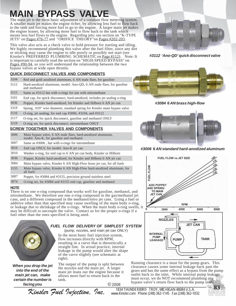
Kinsler Fuel Injection, Inc, 1834 THUNDERBIRD TROY, MICHIGAN 48084 U.S.A.www.Kinsler.com Phone (248) 362-1145 Fax (248) 362-1032
83
MAIN BYPASS VALVEThe main jet is the most basic adjustment of a constant flow metering system.A smaller main jet makes the engine richer, by allowing less fuel to flow backto the tank and forcing more fuel to go to the engine. A larger main jet makesthe engine leaner, by allowing more fuel to flow back to the tank whichmeans less fuel flows to the engine. Regarding jets: see section on "K-TYPEJETS" on Pages #76-77 and "ORIFICE THEORY"on Pages #202-203.
This valve also acts as a check valve to hold pressure for starting and idling.We highly recommend plumbing this valve after the fuel filter, since any dirtor sticking may cause the engine to idle poorly or possibly not start (seeKinsler's PREFERRED PLUMBING SCHEMATIC on Page #112). Note: Itis important to carefully read the section on "HIGH-SPEED BYPASS" onPages #90-94, so you will understand the relationship between the twobypass valves at wide open throttle.
#3006 6 AN standard hard-anodized aluminum
#3084 6 AN brass high-flow
When you drop the jetinto the end of the
main jet can, makecertain the number is
facing you
In the most basic fuel injection system,flow increases directly with RPM,resulting in a curve that is theoretically astraight line. In actual practice, internalleakage in the pump would alter the shapeof the curve slightly (see schematic atright).
The output of the pump is split betweenthe nozzles and the main jet. A largermain jet leans out the engine because itallows more fuel to return back to thetank.
FUEL FLOW DELIVERY OF SIMPLEST SYSTEM(pump, nozzles, and main jet can ONLY)
Running clearance is a must for the pump gears. Thisclearance causes some internal leakage back past thegears and has the same effect as a bypass from the pumpoutlet back to the inlet. While internal pump leakagemust occur, we do NOT recommend plumbing anybypass valve’s return flow back to the pump inlet.
#3112 ‘Ano-QD’ quick disconnect valve
NOTEThere is no one o-ring compound that works well for gasoline, methanol, andnitromethane. We therefore use one o-ring compound in the gas/methanol jetcans, and a different compound in the methanol/nitro jet cans. Using a fuel oradditive other than that specified may cause swelling of the main body o-ring,or leakage due to shrinkage of the o-rings. When the main body o-ring swells, itmay be difficult to uncouple the valve. Contact us for the proper o-rings if afuel other than the ones specified is being used.
© 2008
QUICK DISCONNECT VALVES AND COMPONENTS4013 enilosagrof,eralfelamNA6,munimuladezidonadlogdnadeR2113 enilosagrof,eralfelamNA6,DQ-onA:ledom,munimuladezidona-draH
lonahtemdna5113 enahtemortinhtiwesurofsgnir-ohtiwtub2113#saemaS1013 gnir-ognilaestejsedulcni,dezidona-drah,tcennocsidkciuqrof,pacdnE6303 nactejNA6nrobliHdnarelsniKrof,dezidona-drahrelsniK,teppoP9133 evlavssapybniamrelsniKrofgnirpsdradnats,retemaideriw"910.,gnirpS6113 2113#dna,4013#,6003#pacdnerof,gnilaestej,gnir-O7113 YLNOlonahtemdnaenilosag,tcennocsidkciuqrof,tesgnir-O9113 YLNOenahtemortin,tcennocsidkciuqrof,tesgnir-O
SCREW TOGETHER VALVES AND COMPONENTS6003 ,munimuladezidona-drah,eralfelamNA6,evlavssapybniaM
lonahtemdnaenilosagrof,K-onA:ledom7003 enahtemortinrofsgnir-ohtiwtub,6003#saemaS6103 nactejK-onA:ledomrof,YLNOpacdnE0103 nrobliHrorelsniK,ydobnactejNA6otpacdnerof,gnir-orehsaW6303 nactejNA6nrobliHdnarelsniKrof,dezidona-drahrelsniK,teppoP4803 sleufllarof,nactejssarbwolF-hgiHNA6relsniK,evlavssapybniaM5513 rof,munimuladezidona-drahwolF-hgiHNA6relsniK,evlavssapybniaM
sleuflla7803 leetssselniatsdnuorgnoisicerp,5513#dna4803#rof,teppoP4703 lonahtemdnaenilosag,pacdne5513#dna4803#rof,tesgnir-O

Kinsler Fuel Injection, Inc, 1834 THUNDERBIRD TROY, MICHIGAN 48084 U.S.A.www.Kinsler.com Phone (248) 362-1145 Fax (248) 362-1032
84
KINSLER QUICK DISCONNECT BYPASS VALVE
Be sure to shut off the enginebefore pulling apart the jet can, or fuel spillage will occur.
CAUTION
When you drop the jet into the end cap, be sure the number
is facing you
NOTEThere is no one o-ring compound that works well for gasoline, methanol,and nitromethane. We therefore use one o-ring compound in the gas and methanol jet cans, and a different compound in the alcohol/nitro jet cans. Using a fuel or additive other than that specified may cause swelling of the main body o-ring, or leakage due to shrinkage of the o-rings. When the main body o-ring swells, it may be difficult to uncouple the valve. Contact us for the proper o-rings if a fuel other than the ones specified is being used.
Valve can be used for other applications by using different spring and shim combinations.(For springs and shims see Page #95 BYPASS VALVES)
The quick disconnect bypass with hoses attached. Note: collar is rotated so that
the notch is not aligned with the pin; prevents accidental opening of the valve
The collar being pulled back after the notch is aligned with the pin
Use a twisting motion while pulling the valve apart
The two parts of the assembly are separated, with the jet in the end cap on the right, the jet is merely dropped out and the new one is inserted
NO WRENCHESNEEDED !!!
Simply slide back the
outer collar, pull the
main bodies apart, and
change the jet CAN BE USED ON ANY MAKE OF INJECTION UNIT :
ACCEPTS Kinsler K-type or Hilborn jets. Valve has 6 AN male flare ends and has a fully machined, hard anodized, stick-free poppet.
FAST and EASY JET CHANGES
Kinsler, Hilborn, Crower, Enderle, Ron’s, Jackson, etc.
© 2008
3104 Red and gold anodized aluminum, 6 AN male flare, for gasoline3112 Hard-anodized aluminum, model: Ano-QD, 6 AN male flare, for gasoline
and methanol3115 Same as #3112 but with o-rings for use with nitromethane3101 End cap, for quick disconnect, hard-anodized, includes jet sealing o-ring3036 Poppet, Kinsler hard-anodized, for Kinsler and Hilborn 6 AN jet can3319 Spring, .019" wire diameter, standard spring for Kinsler main bypass valve3116 O-ring, jet sealing, for end cap #3006, #3104, and #31123117 O-ring set, for quick disconnect, gasoline and methanol ONLY3119 O-ring set, for quick disconnect, nitromethane ONLY

Kinsler Fuel Injection, Inc, 1834 THUNDERBIRD TROY, MICHIGAN 48084 U.S.A.www.Kinsler.com Phone (248) 362-1145 Fax (248) 362-1032
85
KINSLER JET SELECTOR VALVE (JSV)
USE FOR... Sprint and Oval TrackRoad RacingBoats : Pleasure or RacingStreet DrivingPulling Trucks and TractorsLand SpeedOff-RoadDyno Tuning
DO NOT confuse the Kinsler Jet SelectorValve with Dial-A-Jet or others. Only the
Kinsler valve allows you to work with matchedK-type jets, and change all the jets.
Jets NOT included; must be ordered separately.See K-TYPE JETS on Pages #76-77
Lean the engine during caution laps to save fuel and prevent loading up. Fastest top speed can be found by running at full speed and dialing in different
jets. (Use caution if High speed bypass is installed in fuel system) Instant jet changes for extra fast adjustment in the vehicle. Adjust the fuel rate to suit any driving condition :
from cruising to all-out performance. Adjust for changing track conditions or controlling engine temperature.
The coarsley knurled aluminumknob is easy to grip, even while
wearing gloves!#3440
installationkit for
Jet Selector Valve
‘Xtra-Light’ Jet Selector Valve with fittings and trim plate 0.65 lbs.
4043 noitallatsni0443#htiwetelpmoc,evlaVrotceleSteJ'thgiL-artX'relsniKsgnittiferalfelamdezidonadrahNA6relsniKdnatik
3143 retemaidegral,pacotydobniamlaesot,gnir-O4143 lonahtemdnaenilosag,ydobniamottfahsrotorlaesot,gnir-O0343 swercsgnitnuomsedulcni,4043#rof,etalpmirT0443 :fostsisnoc,4043#roftiknoitallatsnI
dna,repapgnippal,snoitcurtsni,mihs,sgnirps,swercshtiwetalpmirtsgnir-oydoberapseerht
1643 evlav4043#'thgiL-artX'rof,bonK
Allows making jet changes while driving:
© 2008
#3404 ‘Xtra-Light’ valve
All the jets in the valve can be changedin a few minutes by simply removingthem and installing new ones.
Allows driver to select EIGHTdifferent main bypass jetswhile the engine is running.
Valve can be used with ANY brand of injection system.
Can be dash or remote mounted.
Hard anodized aluminum constructionfor long life and use with all fuels. (Different seals may be needed for fuel compatibility.... we have these).
Uses Kinsler matched jets in increments of .002" or greater; can also use Hilborn jets.
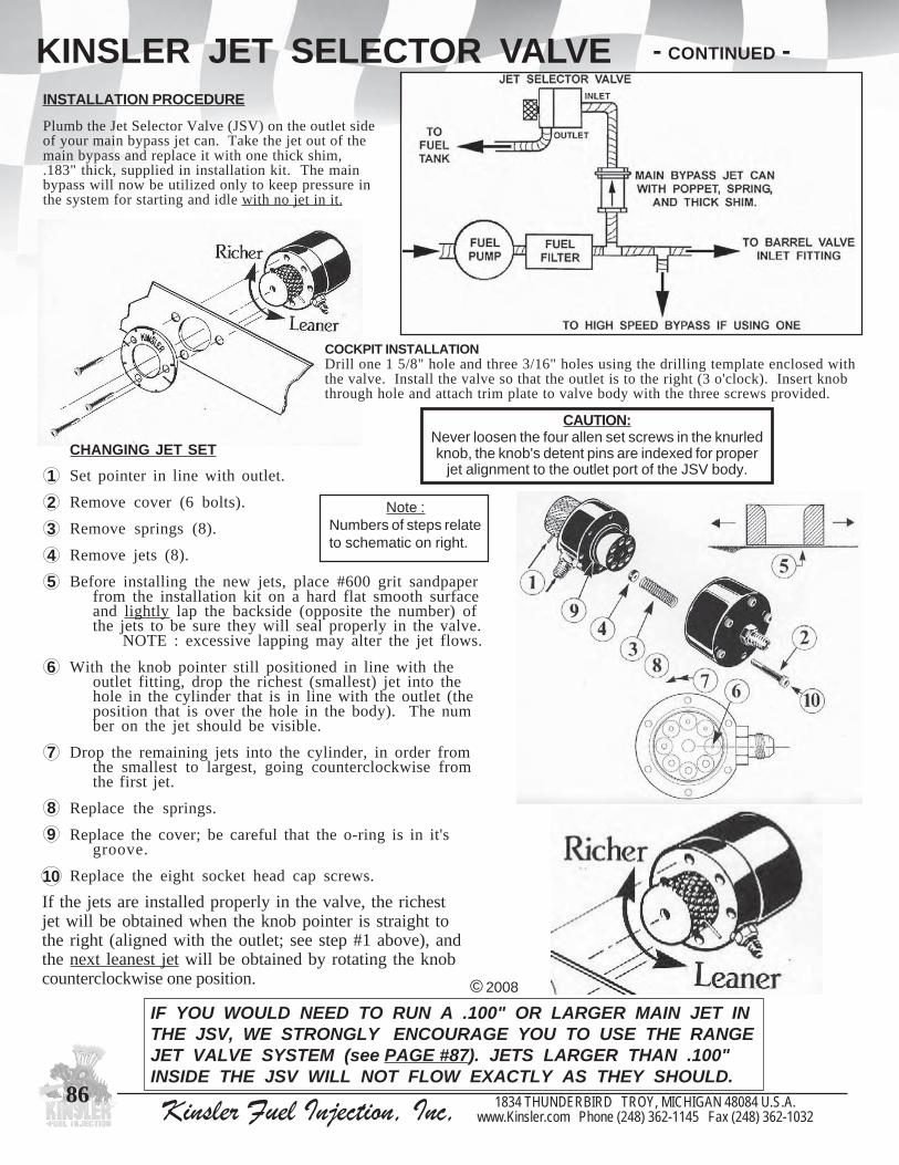
Kinsler Fuel Injection, Inc, 1834 THUNDERBIRD TROY, MICHIGAN 48084 U.S.A.www.Kinsler.com Phone (248) 362-1145 Fax (248) 362-1032
86
KINSLER JET SELECTOR VALVEINSTALLATION PROCEDURE
Plumb the Jet Selector Valve (JSV) on the outlet sideof your main bypass jet can. Take the jet out of themain bypass and replace it with one thick shim,.183" thick, supplied in installation kit. The mainbypass will now be utilized only to keep pressure inthe system for starting and idle with no jet in it.
If the jets are installed properly in the valve, the richestjet will be obtained when the knob pointer is straight tothe right (aligned with the outlet; see step #1 above), andthe next leanest jet will be obtained by rotating the knobcounterclockwise one position. © 2008
IF YOU WOULD NEED TO RUN A .100" OR LARGER MAIN JET INTHE JSV, WE STRONGLY ENCOURAGE YOU TO USE THE RANGEJET VALVE SYSTEM (see PAGE #87). JETS LARGER THAN .100"INSIDE THE JSV WILL NOT FLOW EXACTLY AS THEY SHOULD.
CAUTION:Never loosen the four allen set screws in the knurledknob, the knob's detent pins are indexed for proper
jet alignment to the outlet port of the JSV body.
COCKPIT INSTALLATIONDrill one 1 5/8" hole and three 3/16" holes using the drilling template enclosed withthe valve. Install the valve so that the outlet is to the right (3 o'clock). Insert knobthrough hole and attach trim plate to valve body with the three screws provided.
- CONTINUED -
Note :Numbers of steps relateto schematic on right.
CHANGING JET SET
Set pointer in line with outlet.
Remove cover (6 bolts).
Remove springs (8).
Remove jets (8).
Before installing the new jets, place #600 grit sandpaperfrom the installation kit on a hard flat smooth surfaceand lightly lap the backside (opposite the number) ofthe jets to be sure they will seal properly in the valve.
NOTE : excessive lapping may alter the jet flows.
With the knob pointer still positioned in line with theoutlet fitting, drop the richest (smallest) jet into thehole in the cylinder that is in line with the outlet (theposition that is over the hole in the body). The number on the jet should be visible.
Drop the remaining jets into the cylinder, in order fromthe smallest to largest, going counterclockwise fromthe first jet.
Replace the springs.
Replace the cover; be careful that the o-ring is in it'sgroove.
Replace the eight socket head cap screws.
12345
6
7
89
10

Kinsler Fuel Injection, Inc, 1834 THUNDERBIRD TROY, MICHIGAN 48084 U.S.A.www.Kinsler.com Phone (248) 362-1145 Fax (248) 362-1032
87
RANGE JET VALVEFOR USE WITH KINSLER JET SELECTOR VALVEWHEN DO YOU NEED IT ?
A Range Jet Valve is required when a Kinsler Jet Selector Valve is being installedand the main bypass jet exceeds .100" diameter. This is because very high flowthrough the Jet Selector causes enough turbulence to affect the stability of theflow through the jets in it. The accuracy of the valve is excellent when used withjets under .100".
HOW IT WORKS
The Range Jet creates a constant bypass around the Jet Selector Valve, so theflow passing through the Jet Selector is reduced.
An added bonus of the Range Jet Valve is that the jets in the Jet Selector Valvedon't have to be changed... if a richer or leaner set of jets is needed, merelychange the jet in the Range Valve to a smaller or larger one... this changes therange of all eight jets in the JetSelector Valve....much easier, quicker, and cheaper!
PLUMBING
Arrange the two 'tee' fittings asshown, so the flow to and from theRange Jet Valve will be flowingthrough the "straight through" sideof the tee.
Selecting the Jets required for Jet Selector and the Range Jet Valve
IMPORTANT NOTESAll of the data in this table is for K-type jets; the resultswill vary if commercially made jets are used. Be sure toread KINSLER K-TYPE JETS on Pages #76-77.
To figure out a jetting size combination, use the formulashown in ORIFICE THEORY on Pages #202-203.
WHAT RANGE JET SIZE TO START WITH ?Set up the Jet Selector Valve with .074" in the center position. The following table shows what Range Jetsize to use versus the jet size that you were using with only a main bypass jet can.
Main bypass jet Range Valve jet size can only jet size (with Selector Valve on .074" jet)
.100" .070"
.110" .086"
.120" .102"
.130" .112"
.140" .118
.150" .130"
.160" .146"
.170" .156"
.180" .174"
#3020 Kinsler Range Jet Valve Kit,includes two 6 AN swivel tee fittings
(does not include jets)
These jet increments are about twice as coarse as wewould recommend if there were no Range Jet Valve inthe system.... since there is always flow bypassingthrough the Range Jet, the effect of changing from onejet size to another in the Jet Selector is reduced by abouthalf. If the Range Jet Valve weren't in the system, wewould normally use .004" increments for most alcoholapplications and .002" for gasoline.
If using a Range Jet Valve,the jets in the Jet Selector Valve should be :
For alcohol .050" .058" .066" .074" .082" .090" .098" .106" (.008" increments)
For gasoline .062" .066" .070" .074" .078" .082" .086" .090" (.004" increments)
© 2008
Use this schematic with ourPREFERRED PLUMBINGSCHEMATIC on Page #112.It is important to locate thefuel filter on the main pumpoutlet so all the fuel will befiltered going to the engineand the main bypass, JetSelector, high speed, etc.
Note :

Kinsler Fuel Injection, Inc, 1834 THUNDERBIRD TROY, MICHIGAN 48084 U.S.A.www.Kinsler.com Phone (248) 362-1145 Fax (248) 362-1032
88
SECONDARY BYPASS VALVESince the engine makes less power at part throttle, it needs lessfuel. The spool in the barrel valve is the main control for partthrottle fuel delivery. At wide open throttle, the spool has alarge notch cut into it's side to pass all the fuel to the nozzlesunrestricted. As the throttles are closed, a tapered ramp groundinto the side of the spool reduces the passage to restrict flow tothe nozzles. When adjusting the hex-link to set the idle fuelrate, the spool is being re-positioned to make the passagewaylarger or smaller to the nozzles. If you remove the fitting fromthe top of the barrel valve, you can see this ramp. Because eachengine’s part throttle fuel requirement varies due to camshaft,manifold, and exhaust system selection, the fuel rate the rampdelivers at part throttle is seldom exactly what the engine needs,but the secondary can be used to tailor it.
A) Staging : An engine at the starting line being held at highRPM has the throttle open only a few degrees, butthe pump is putting out a lot of fuel. The fuel ratewill often be too rich and tend to load up theengine... the secondary can be used to lean it out.
B) Over-Run : After going through the traps, or at the end of astraight-away, when the throttles are snapped closed, the pump is still at high RPM. The pressure in thesystem goes quite high, especially with a small main jet and a jet restricted high speed bypass (or NO highspeed bypass). The secondary serves as a "dump-off" to reduce the high pressure, thus preventing an over-rich condition.
C) Idle : The secondary bypass pressure is usually set higher than the idle pressure, so the valve is normally NOTbypassing any fuel at an idle. In some special applications, like unblown nitro or highly superchargedengines, the secondary is adjusted to aid in controlling idle fuel pressure. In these systems the secondarybypass will be active at idle speeds and may also utilize a restrictor jet to limit or control the amount offlow that the circuit can bypass.
D) Cornering : If you run through the turns at part throttle and the engine loads up, or is sluggish coming out of them,install a lighter spring or reduce the shims in the secondary. If it lacks response or backfires out the intakewhen the throttle is depressed, install a heavier spring or more shims.
E) When used in conjunction with a Kinsler Vapor Separator Tank System : It may be necessary to reduce the pressure settingof the secondary bypass when installing a Vapor Separator Tank System. This is due to the down-stream pressure (VaporSeparator Tank pressure) acting against the secondary bypass outlet. Generally we find the secondary pressure will need tobe reduced by 3 PSI; the typical pressure in the VST. We recommend installing a Kinsler "bubble tight" one way checkvalve on the outlet of the secondary bypass. This will ensure that engine flooding cannot occur by fuel backflowing throughthe secondary and out to the nozzles when the engine is not running.
Applications of the ValveThe valve will often improve the performance of the engine for anyapplication: Drag Racing, Oval Track, Road Racing, Pulling Truckor Tractor, Street, Boat Racing, Hill-Climb, Mud or Sand Racing, etc.
Installation On a Kinsler, Hilborn, or Crower barrel valve, the secondary is plumbed to the barrel valve spool retainingfitting. Should the barrel valve fitting not have the provision for a secondary, it usually can be converted for it. OnEnderle and Jackson units, the system MUST first be converted to an external bypass jet (see Kinsler section on Enderlebarrel valve conversion, Page #114). Then the secondary bypass is connected to the "out" or “ret” fitting on the barrelvalve.
How The Secondary WorksThe flow to the secondary bypass is through a port in the tophalf of the barrel valve spool. The port is usually wide open toabout 20 degrees of throttle opening, then it begins to close off.It is completely closed at approx. 40 degrees of throttle opening,or about half throttle, so it has no affect on wide open throttlemetering. Depending on the exact spool positioning, the portmay actually be slightly closed off at an idle. The secondarybypass normally has a higher pressure setting than the mainbypass, so when the engine returns to idle speed, the secondarybypass poppet closes and allows the spring and poppet in themain jet can to regulate the idle fuel pressure.
FUEL REQUIREMENT versus THROTTLE OPENINGPast 40 degrees of throttle opening, the 3000 RPM curverequires little more fuel flow, because at that speed theengine is already getting all the air it can use. At 6000 RPM,the curve doesn't flatten until 60 degree throttle opening.Actual results vary due to throttle area and enginevolumetric efficiency.
© 2008
SECONDARY BYPASS tailors part throttle fuel flow.Beyond a 40 degree throttle opening, the barrel valve spoolshuts off the passage to the secondary bypass.
Barrel Valve Spool Ramp

Kinsler Fuel Injection, Inc, 1834 THUNDERBIRD TROY, MICHIGAN 48084 U.S.A.www.Kinsler.com Phone (248) 362-1145 Fax (248) 362-1032
89
0303 etelpmoc,evlavmunimuladezidonadraheralfelamNA6dradnatSdna,lonahtem,enilosagrof,smihsdna,gnirps,teppop:sedulcni,ylbmessa
)gniredronehwnoitacilppa.ortinyficeps(enahtemortin6303 dezidona-drah,noitarepoeerf-kcitsrofhtoomsyrev,denihcamylluf,teppoP
snactejNA6nrobliHdnarelsniKrof,munimula6103 evlav0303#rof,YLNOpacdnE0103 evlav0303#dnapacdne6103#rofgnir-orehsaW6703 :sedulcni,ylbmessaetelpmoc,evlavssarberalfelamNA6wolF-hgiH
enahtemortindna,lonahtem,enilosagrof,smihsdna,gnirps,teppop5803 evlav6703#rof,YLNOpacdnE6803 evlav6703#rof,ylnOydoB6513 ,ylbmessaetelpmoc,evlavdezidona-draheralfelamNA6wolF-hgiH
dna,lonahtem,enilosagrof,smihsdna,gnirps,teppop:sedulcnienahtemortin
0513 evlav6513#rof,YLNOpacdnE1513 evlav6513#rof,YLNOydoB7803 sevlav6513#dna6703#rofleetssselniats,denihcamylluf,teppoP4703 .ortinyficeps(6513#ro0513#dna6703#ro5803#rofpacdnestif,gnir-O
)gniredronehwnoitacilppa8803 hcnebwolfnoevlavssapybyradnocesfoerusserptesdnatsetwolf;robaL6613 lonahtem/enilosag,gnilaestej,gnir-O9103 dnuopmoc.P.E,enahtemortin/lonahtem,gnilaestej,gnir-O4203 nolfet,)erusserphgih(esuytudemertxerof,gnilaestej,gnir-O5353 lerrabnrobliHrorelsniK,eralfelamNA6,gnittifdezidona-drahrelsniK
evlav1253 evlavlerrabnrobliHrorelsniKrofgulpdezidona-drahrelsniK0103 gulprognittifyradnocesrelsniKrof,gnir-orehsaW9153 evlavlerrabnrobliHrorelsniK,retemaideriw"930.,loopsniaterotgnirpS2253 lonahtem/enilosag,tfahsloopsevlavlerrabnrobliHrorelsniK,gnir-O3403 gniraebsedivorp,loopsevlavlerrabdnagnirpsneewtebseog,ssarb,mihS
ecafrus
SECONDARY BYPASS VALVE
SPRINGS FOR 6 AN JET CANS
AdjustmentTo vary the amount of pressure needed to unseal the poppet inside the valve: The wire diameter(stiffness) of the spring is the primary adjustment; a stiffer spring gives a higher opening pressure(RPM). Shims are utilized for fine tuning. If the secondary opens at the right RPM, but bypassestoo much fuel, it's flow back to the tank can be restricted by putting a jet in it. Replacing a thickshim with an .080" jet is usually a good starting point. If installing a jet be sure there is a jetsealing o-ring.
Note: the jet sealing o-ring is equivalent to .060" of shim.
SECONDARY BYPASS VALVES
SHIMS FOR6 AN JETCANS
#3076 high-flow 6 AN brass valve
TroubleshootingFirst follow all steps in "System Troubleshooting," Pages #110-111.
1) Check to be sure that the poppet seals in the body. A small amountof dirt can cause the poppet to stick. Thoroughly clean thevalve and connecting hose assembly.
2) If adjusting the secondary valve doesn't seem to doanything, make sure the barrel valve spool has abypass port (see Page #108) and that the secondaryvalve is installed correctly.
3) Adjustments to the secondary valve should not affect wide openfuel mixture; if they do:A) Check to make sure the spool is indexed correctly in the barrel valve.B) Check the fit of the spool to the barrel valve block.
Approx. clearance is one-half of a thousandth of an inch.Too loose of a fit can cause fuel to leak out through thesecondary port at wide open throttle. Test the fit witha leak down meter, 1% or less is preferred at WOT.
© 2008
The secondarybypass is used totailor part throttlefuel rate ONLY; ithas no affect onwide open throttlemetering.
CAUTION - Using a spring that is too light, especially on a supercharged or turbocharged application may cause a backfire through the blower/turbo or into the plenum, causing damage.
#3010
#3519
#3522
#3043#3535
#3521
4303 kciht"381.-1:sedulcni,tikmihSsmihskciht"030.-6dnamihs
0403 ssarb,kciht"381.,mihS2403 ssarb,kciht"020.,mihS3403 ssarb,kciht"030.,mihS
3033 ,nactejNA6nrobliHdnarelsniKrof,tikgnirpS"420.,"120.,"910.,"810.,"610.:fostsisnoc
4033 ,nactejNA6nrobliHdnarelsniKrof,tikgnirpS"240.,"930.,"630.,"230.,"820.:fostsisnoc
6133 retemaideriw"610.:gnirpS
7133 retemaideriw"710.:gnirpS
8133 retemaideriw"810.:gnirpS
9133 retemaideriw"910.:gnirpS
1233 retemaideriw"120.:gnirpS
4233 retemaideriw"420.:gnirpS
8233 retemaideriw"820.:gnirpS
2333 retemaideriw"230.:gnirpS
6333 retemaideriw"630.:gnirpS
9333 retemaideriw"930.:gnirpS
2433 retemaideriw"240.:gnirpS
#3030 secondary bypass valve
- CONTINUED -

Kinsler Fuel Injection, Inc, 1834 THUNDERBIRD TROY, MICHIGAN 48084 U.S.A.www.Kinsler.com Phone (248) 362-1145 Fax (248) 362-1032
91
HIGH SPEED BYPASS VALVEFIRST TIME INSTALLATION OR FUEL SYSTEM NOT CALIBRATED BY KINSLERWhen installing a high speed bypass in the system for the first time, or on a system that presently hasone but it is not tuned properly:
1) Block off the high speed by capping off the hose, DO NOT INSTALL VALVE BACKWARDS,the valve may leak fuel which will cause inaccuracy in the following test.
2) Using only the main jet bypass valve, find the main jet that produces the best performance up toapproximately 500-1000 RPM beyond the peak torque of the engine.
3) Go .004" richer on the main jet (.002" to .008" is the range we see), and put the high speedbypass back in the system.
4) Adjust the high speed pressure higher (richer) and lower (leaner) to find the setting for bestperformance. If using a restrictor jet, try larger or smaller ones in increments of .004" to .010".As a larger restrictor jet is used, the pressure setting of the valve may have to be readjusted.
5) Try richer main jets.... adjust the high speed with each one to find the best overall performance.
© 2008
We can pressure testand set your high
speed bypass valve orprovide you with a
New Kinsler valve thatis set for your system.
HIGH SPEED ADJUSTMENTThe RPM at which the high speed bypass opens is determinedby the pressure setting of the valve. Curve "F" is the lowestsetting; the valve opens at 5000 RPM. Raising the pressure willgive curve "C", opening at 6000 RPM. Curve "E" opens at 7000RPM. Raising the RPM at which the new curve starts doesn'tchange it's slope.
CURVES FOR HIGH SPEED JETTING VERSUS HIGH SPEED SHIMMING OR SCREW ADJUSTMENTThe RPM at which the high speed bypass opens can be raised byadding shims (jet can type). Then the top end can be leaned outfurther by using a larger restrictor jet in the valve.
CURVES FOR TWO DIFFERENT MAIN JETSUSING THE SAME HIGH SPEED SETTINGFuel pressure is what opens the high speed bypass. With a largermain jet, the opening pressure will not be reached until a higher RPM.To retain the same high speed opening RPM with a larger main jet,you must lower the pressure setting of the high speed valve.
CURVES FOR HIGH-SPEEDJETTING vs. OPENING
PRESSURE
FUEL
FLO
W
HIGH SPEED RESTRICTOR JETTINGWith a blank jet (no orifice- not allowing the bypass to flow), thepressure and flow keep on going as though the high speed bypasswasn't there. Without any jet, the flow levels out as in curve "A",because the high speed lets a lot of fuel bypass back to the tank onthe top end. Curve "C" ; adding a restrictor jet gives someintermediate fuel curve. The smaller the jet, the closer the curve comesto the original one. Even without a jet, the bypass offers some internalrestriction, which makes curve "A" slope up slightly.
HIGH-SPEED JETTING
FUEL
FLO
W
RPM
2000 4000 6000 80000

Kinsler Fuel Injection, Inc, 1834 THUNDERBIRD TROY, MICHIGAN 48084 U.S.A.www.Kinsler.com Phone (248) 362-1145 Fax (248) 362-1032
90
HIGH SPEED BYPASS VALVE
WHEN THE JET ISDROPPED INTO THE END
OF THE VALVE MAKESURE THE NUMBER IS
FACING YOU
WHY YOU NEED A HIGH SPEED BYPASSA high speed bypass is needed to obtain maximum horsepower because theengine will experience a loss of volumetric efficiency at RPM above the peaktorque. At high RPM the inlet valves are open for such a small amount of timethat the cylinders do not have enough time to completely fill with fresh mixture:Fuel curve "A" shows the flow of a system with a main bypass jet only. Anengine with the same volumetric efficiency at all speeds would have this fuel raterequirement.Fuel curve "B" is the actual fuel requirement of a typical engine. Note that curve"A" is too rich at high engine speed, resulting in a loss of power.Fuel curve "C" represents the flow rate attained by using a richer main jet toobtain a steeper initial curve, then a high speed to break it over to follow theengine requirement.... A very close compromise to curve “B”.
TUNING TIPS AND BASIC ADJUSTMENTSTurning the screw "in" on a diaphragm type high speed or changing to a heavier spring, and/or adding more shims in a jet can type, willraise the pressure (RPM) at which the valve opens, making the system richer on the top end. The high speed is usually adjusted to startopening about 500-1000 RPM above peak torque. If a high speed is installed on a fuel system when it is calibrated by Kinsler, the main jetand high speed bypass setting should be very close for best power. However, if the system does not seem to have the ideal fuel rate “asreceived”:
1) If the fuel curve seems too rich throughout the RPM range, go to a leaner main jet.2) If just the top end seems rich; go lower on the high speed pressure setting until the high rpm mixture is correct. A) If the system has a restrictor jet, try going .004" - .010" larger per run. (Note: the calibrated pressure settings of the high speed should not require a major adjustment if the original main jet is being utilized.) Compare this with the results obtained by going lower on the valve pressure setting. B) If the system still seems rich after step "A" above, lower the opening pressure of the high speed by approximately 3 PSI.
CAUTION: We recommend you reinstall the original restrictor jet before lowering the pressure setting. C) If the engine still seems rich with the lower pressure setting, repeat step "A". While this method may require several runs of the engine it has be found to be a safe way to tune the system while avoiding engine damage from going too lean.3) If the system is adjusted to give a proper fuel curve, but the overall curve needs to be richened or leaned due to changes in the engine displacement, air density, weather, altitude, etc., adjust the high speed pressure for each main jet step you adjust.4) Tune the engine for best performance, not just what appears to be good plug readings.
IMPORTANT NOTE: When properly adjusted, a high speed bypass's engagement should not be felt by the driver.If the driver feels the high speed bypass engage because the engine's power increases dramatically, then either the main jet is adjusted toorich or the high speed is opening at too high a RPM. Either condition will cause the engine’s output to be lower than optimum. Thereshould be no sudden burst of power, only a steady strong pull.
THE HIGH SPEED ALSO BENEFITS THE MID-RANGE PERFORMANCEIf an engine is jetted to obtain maximum horsepower at high RPM without a high speed bypass, it would be lean around the peak torqueRPM (see fuel curve "A" compared to the engine fuel requirement, “B”). Unfortunately jetting rich enough for best mid-range power willcause the engine to run rich and lose power at high RPM. By installing a high speed bypass, separate control of the mid-range and highRPM fuel rates are possible. The main jet can be run richer for best mid-range performance, while using the high speed to lean the systemfor best power at high RPM.
RESTRICTOR JETSThe pressure setting of the high speed is used to control the RPM at which the valve opens, while therestrictor jet is used to limit the flow through it after it opens. The smaller the jet, the less fuel that canflow through the high speed and back to the tank, thus richening the system at higher RPM levels.In some Oval Track applications the use of a restrictor jet assures that the high speed does not dumpoff too much fuel at high RPM part throttle.... for example coming down a straight away and quicklyclosing the throttles causing a pressure spike. The high speed will open and start returning fuel. Therestrictor jet will then restrict the amount of fuel bypassed during this overrun condition.
If you own a high speed bypass valve that doesn't have a provision for a restrictor jet. Simply use a jetcan after the valve by removing the poppet and stretching the spring out to hold the jet in place. Makesure the jet can has a jet sealing o-ring.For better understanding of the operation of the restrictor jet see the fuel curves on Page #83.
© 2008
HIGH SPEEDOPENS

Kinsler Fuel Injection, Inc, 1834 THUNDERBIRD TROY, MICHIGAN 48084 U.S.A.www.Kinsler.com Phone (248) 362-1145 Fax (248) 362-1032
92
HIGH SPEED BYPASS VALVEADVANTAGE OF KINSLER'S DIAPHRAGM HIGH SPEED BYPASS VALVE
DIAPHRAGM VALVE AND COMPONENTS
The "E" dimension on the adjustment screwis the distance between the bottom of the
screw head and the top face of the nut
MEASURING THE "E" DIMENSIONA vernier caliper is the most accurate method formeasuring the "E" dimension, but a good steel scalewill suffice if read carefully. On every unitcalibrated by us, the 'as shipped' "E" dimension isrecorded on the tech sheet titled "A Few ImportantNotes". About .002" inch change in the "E"dimension gives one PSI change in pressure.
© 2008
#3904 Model: HR
#3903 Model: H
3093,mgarhpaidenerpoen,evlavssapybdeepshgihmgarhpaidrelsniK
NA6sedulcni,munimuladezidona-drah,lonahtemdnaenilosagH:ledom,sgnittiferalfelam
4093tejrotcirtserhtiwevlavssapybdeepshgihmgarhpaidrelsniK-drah,lonahtemdnaenilosag,mgarhpaidenerpoen,noisivorp
RH:ledom,sgnittiferalfelamNA6sedulcni,munimuladezidona
0593,mgarhpaidnolfet,evlavssapybdeepshgihmgarhpaidrelsniK
eralfelamNA6sedulcni,munimuladezidona-drah,YLNO.ortinH:ledom,sgnittif
1593tejrotcirtserhtiwevlavssapybdeepshgihmgarhpaidrelsniK
dezidonadrah,YLNO.ortin,mgarhpaidnolfet,noisivorpRH:ledom,sgnittiferalfelamNA6sedulcni,munimula
6293 hcnebwolfnoerusserpevlavmgarhpaidtesdnatsetwolfotrobaL
COMPONENTS9293 otdnuorgeraswercs,daerht42-21;tunkcoldnawercsgnitsujdA
noitarepohtoomsrofdnenodesuidarnehthtgnelcificeps2393 gnirpsdnawercsgnitsujdaneewtebseog;tsergnirpsreppU3393 mgarhpaiddnagnirpsneewtebseog;tsergnirpsrewoL7393 evlavmgarhpaiddeepshgihrofretemaideriw"480.dradnats;gnirpS1493 rewotdnamgarhpaidneewtebseog,nolfet;gnirpilS4493 YLNOlonahtemdnaenilosagrof,enerpoen;mgarhpaiD7493 YLNOenahtemortinrof,nolfet;mgarhpaiD
9493 eralfelamNA6xtelniTPNelam"4/1,ylbmessadoptejrotcirtseRgnir-ognilaestejdna,pacdne,gnir-orehsaw,gnirpssedulcni,teltuo
6103 munimuladezidona-drah,eralfelamNA6;9493#rofpacdnE0103 6103#dna9493#rof;gnir-orehsaW6113 6103#dna9493#rof,gnilaestej;gnir-O0716 "4/1xeralfelamNA6,munimuladezidona-drahrelsniK;gnittiF
TPNelam
The advantage of this valve over the "jet can" type used in the past is that ithas less internal friction on it’s moving parts, and it has a much larger areafor the pressure to act on for regulation, resulting in a valve that opens at thesame RPM every time. Easily adjusted using a blade screwdriver and a 7/16"wrench; no parts to drop or lose, no dealing with leaking fuel when changingpressure settings.
Using dial verniercalipers tomeasure the "E"dimension
"E" DIMENSION
CHANGEIN OPENINGPRESSURE5.1 + 1.3 PSI
CHANGEIN "E"
DIMENSION.010"
TURNSOF
SCREW1/4
The average pressure change was determined bytesting (5) valves between 40 and 90 PSI.
**
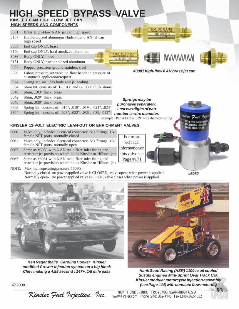
Kinsler Fuel Injection, Inc, 1834 THUNDERBIRD TROY, MICHIGAN 48084 U.S.A.www.Kinsler.com Phone (248) 362-1145 Fax (248) 362-1032
93
1803 deepshgihnactejNA6wolF-hgiHssarB7513 nactejNA6wolF-hgiHmunimuladezidona-draH
deepshgih5803 ssarb,YLNOpacdnE0513 munimuladezidona-drah,YLNOpacdnE6803 ssarb,YLNOydoB1513 munimuladezidona-drah,YLNOydoB7803 leetssselniatsdnuorgnoisicerp,teppoP
9803 foerusserpothcnebwolfnoevlavteserusserp;robaLtseuqer/noitacilppas'remotsuc
4703 gnilaestejdnaydobsedulcni,tesgnir-O4303 smihskciht"030.-6dna"381.-1:fostsisnoc,tikmihS0403 ssarb,kciht"381.,mihS2403 ssarb,kciht"020.,mihS3403 ssarb,kciht"030.,mihS3033 "420.,"120.,"910.,"810.,"610.:fostsisnoc,tikgnirpS4033 "240.,930.,"630.,"230.,"820.:fostsisnoc,tikgnirpS
HIGH SPEED BYPASS VALVEKINSLER 6 AN HIGH FLOW JET CAN HIGH SPEEDS AND COMPONENTS
NOTE: Maximum operating pressure: 150 PSINormally closed- no power applied valve is CLOSED, valve opens when power is applied.Normally open- no power applied valve is OPEN, valve closes when power is applied.
KINSLER 12-VOLT ELECTRIC LEAN-OUT OR ENRICHMENT VALVES
#3081 high-flow 6 AN brass jet can
Springs may bepurchased separately.Last two digits of part
number is wire diameter.example: Part #3339 = .039" wire diameter spring
Ken Regenthal’s ‘Carolina Hooker’ Kinslermodified Crower injection system on a big blockChev making a 4.88 second ; 147+, 1/8 mile pass Hank Scott Racing (HSR) 1100cc oil cooled
Suzuki engined Mini-Sprint Oval Track Car.Kinsler modular motorcycle injection assembly
(see Page #44) with constant flow metering© 2008
For moretechnical
information onthis valve seePage #171
#6062
0606 "4/1,sgnittifON,rotcennoclacirtcelesedulcni,ylnoevlaVdesolcyllamron,stropTPNelamef
1606 "4/1,sgnittifON,rotcennoclacirtcelesedulcni,ylnoevlaVnepoyllamron,stropTPNelamef
2606 dnagnittiftelnieralfelamNA6htiw0606#saemaSstejnrobliHrorelsniKsdlohhcihwnoisivorptejrotcirtser
3606 dnagnittiftelnieralfelamNA6htiw1606#saemaSstejnrobliHrorelsniKsdlohhcihwnoisivorptejrotcirtser

Kinsler Fuel Injection, Inc, 1834 THUNDERBIRD TROY, MICHIGAN 48084 U.S.A.www.Kinsler.com Phone (248) 362-1145 Fax (248) 362-1032
94
HIGH SPEED BYPASS VALVE
KINSLER K-140 VALVES
This valve has the highest flow capacity with the lowestpressure rise of any valve on the market. For most applicationsthe rise is under 1-PSI, since the total bypass flow for mostsystems is 600 lbs/hr or less.
Extremely smooth operation. The closing flow curve is within0.3 (3/10) PSI at any flow point on the opening curve. This isachieved by hardcoating, then microlapping all of the movingparts. This means the pressure in the fuel system will stay closeto the set point on both rising and falling engine RPM.
THE ULTIMATE HIGH SPEEDK-140K-140K-140K-140K-140
7693 ISP73-71,ylbmessaetelpmoC
8693 ISP15-62,ylbmessaetelpmoC9693 ISP08-43,ylbmessaetelpmoC0793 ISP601-94,ylbmessaetelpmoC1793 ISP321-75,ylbmessaetelpmoC2793 ISP251-27,ylbmessaetelpmoC
3793 gnirpslaicepsseriuqer,ISP032-88,ylbmessaetelpmoCsliatedrofllac,egakcap
1613xtelnielamefNA6,gnir-ognilaestejsah,redlohtejrotcirtseR
rotelni041-Kotnoyltceridswercs,teltuoeralfelamNA6gnir-ohtiwslaesdnagnittifteltuo
8893 daerht23-01,tunkcolhtiwwercsgnitsujdA9893 daerhtelam23-01,leetssselniatsderetnis,rehtaerbretliftneV
09021 ,tsergnirpsrewol:sedulcni,elyts'D',ylbmessamgarhpaiD)2(smgarhpaiddna,eltnip
19021 )seceipowt(YLNOlairetamtnemecalpermgarhpaiD78021 'rennI',gnirpS88021 'elddiM',gnirpS98021 'retuO',gnirpS
58021 ruof,dezidonakcalb,munimulatellib,tekcarbgnitnuom041-Ksretnec"09.1taselohgnitnuom
68021 "8/5,58021#rof,stnuoMnoitalosInoitarbiVruoffoteSdaerht"094.x23-8,rebbur,llat"2/1xretemaid
© 2008
#3989 #3161
Explodedview ofK-140
Close up oflive-action
pintle
Many valves can go into a "buzz"(hydraulic vibration); this valve ismore stable as it is the only valve onthe market with a unique springarrangement designed to control buzz.
The diaphragm has a swiveling "live"center pintle that closes down on theseat for very smooth operation. Boththe pintle and the seat are lapped forbubble tight close-off.
Hard anodized aluminum housingcomponents and a very compactdesign makes this piece lighter andeasier to install in the vehicle.Components are compatible withgasoline and methanol.
Seven different spring combinationsare available for a total adjustablerange of 17 - 230 PSI. There is alsoCUSTOM BUILDUP SERVICEavailable.
Accepts Kinsler or Hilborn jets... hasjet sealing o-ring for restrictor jet.
Valve is LIGHT, weighs 0.45 lbs.
The K-140 High Speed comescomplete with :1- 6 AN male flare inlet fitting, 8 ANport plug for unused inlet port3 AN port plug for pressure gauge port#3989 vent breather filter#3161 restrictor jet holder

Kinsler Fuel Injection, Inc, 1834 THUNDERBIRD TROY, MICHIGAN 48084 U.S.A.www.Kinsler.com Phone (248) 362-1145 Fax (248) 362-1032
95
BYPASS VALVES
KINSLER HIGH FLOW 6 AN JET CANSBody has a micro finished bore for stick free poppet travel and aprecision ground stainless steel poppet for long life. AcceptsKinsler or Hilborn jets... has jet sealing o-ring for accurate orificemetering.
Can be used for main, secondary, high speed, or port check. Unithas high flow rate versus opening pressure which makes this valveideal for jet can type high speed bypass when a large quantity offuel must be bypassed. Uses Kinsler's standard springs and shims.
Available in brass or hard anodized aluminum.Aluminum valve is 67% LIGHTER than the brass valve.
SPRINGS FOR 6 AN JET CANS
8 AN H-TYPE JET CAN
SPRINGS :
LABOR
© 2008
For pressure charts on spring and shim
combinations for Kinsler high flow 6 AN jet cans,
see PRESSURE CHARTS on Page #96
BRASS4803 ylbmessaetelpmoc,evlavssapybniaM
6703 ylbmessaetelpmoc,evlavssapybyradnoceS1803 ylbmessaetelpmoc,evlavssapybdeepshgiH5803 sgnir-osedulcni,evlavssarbrof,YLNOpacdnE6803 ssarb,YLNOydoB
0713 ylbmessaetelpmoc,smetsysLRInodesu,evlaverusserpytefaSISP551-051
2713 leufdegrahcrepusnodesuyllacipyt,evlavytefaspmuPISP002-091ylbmessaetelpmoc,smetsys
HARD ANODIZED ALUMINUM
5513 ylbmessaetelpmoc,evlavssapybniaM
6513 ylbmessaetelpmoc,evlavssapybyradnoceS7513 ylbmessaetelpmoc,evlavssapybdeepshgiH0513 sgnir-osedulcni,evlavdezidona-drahrof,YLNOpacdnE1513 munimuladezidona-drah,YLNOydoB
5713 ylbmessaetelpmoc,smetsysLRInodesu,evlaverusserpytefaSISP551-051
7713 leufdegrahcrepusnodesuyllacipyt,evlavytefaspmuPISP002-091ylbmessaetelpmoc,smetsys
PARTS FOR BRASS AND ALUMINUM VALVES
4703 dnaenilosag,gnilaestejdna,ydob,pacdnerof,tesgnir-Olonahtem
9703 enahtemortin,gnilaestejdna,ydob,pacdnerof,tesgnir-O7803 leetssselniatsdenedrahdnuorgnoisicerp,YLNOteppoP
8803 hcnebwolfno6513#dna6703#yradnocestesdnatsetwolF
9803 hcnebwolfno7513#dna1803#deepshgihtesdnatsetwolF
3033 ,nactejNA6nrobliHdnarelsniKrof,tikgnirpS"420.,"120.,"910.,"810.,"610.:fostsisnoc
4033 ,nactejNA6nrobliHdnarelsniKrof,tikgnirpS"240.,"930.,"630.,"230.,"820.:fostsisnoc
6133 retemaideriw"610.:gnirpS
7133 retemaideriw"710.:gnirpS
8133 retemaideriw"810.:gnirpS
9133 retemaideriw"910.:gnirpS
1233 retemaideriw"120.:gnirpS
4233 retemaideriw"420.:gnirpS
8233 retemaideriw"820.:gnirpS
2333 retemaideriw"230.:gnirpS
6333 retemaideriw"630.:gnirpS
9333 retemaideriw"930.:gnirpS
2493 retemaideriw"240.:gnirpS
SHIMS FOR 6 AN JET CANS
4303 kciht"381.-1:sedulcni,tikmihSsmihskciht"030.-6dnamihs
0403 ssarb,kciht"381.,mihS2403 ssarb,kciht"020.,mihS3403 ssarb,kciht"030.,mihS
SHIMS FOR 8 AN JET CANS
9503 "060.-)2(,smihs"020.-)4(:nactejNA8roftikmihSmihs"581.-)1(,smihs
5603 ssarb,ssenkcihtlanimon"020.:nactejNA8rofmihS6603 ssarb,ssenkcihtlanimon"060.:nactejNA8rofmihS7603 ssarb,ssenkcihtlanimon"581.:nactejNA8rofmihS
SPRINGS
4603
0503#dna1603#rofsgnirpselbaliavAxretemaideriw(,YLNOsnactejNA8;"525.1x"530.;"005.1x"820.)htgnelx"570.;"574.1x"160.;"524.1x"050.
"050.2x"080.;"005.1gniredronehwezisyficepS
8703 1sedulcni,nactejNA8rof,tikgnirpSsgnirpsthgieevobaehtfohcae
0313 'thgiL',nactejNA8rof,tikgnirpSISP04-3,tnemtrossagnirpsruof
1313 'yvaeH',nactejNA8rof,tikgnirpSISP003-83,tnemtrossagnirpsruof
8 AN HIGH FLOW JET CAN
1603 dnuorgnoisicerp,NA8,nactejssarBgnirpsdnateppopleetssselniats
0503 noisicerp,NA8,nactejmunimulAgnirpsdnateppopleetssselniatsdnuorg
2603 nactej0503#dna1603#rof,teppoP
5503 munimuladezidonadrah,NA8,nactejepyt-Hgnirpsdnateppophtiw
7503 munimuladezidonadrah,YLNO5503#rof,teppoP
8503 :YLNOnactejNA85503#roFretemaideriw740.ro"420.

Kinsler Fuel Injection, Inc, 1834 THUNDERBIRD TROY, MICHIGAN 48084 U.S.A.www.Kinsler.com Phone (248) 362-1145 Fax (248) 362-1032
96
BYPASS VALVE PRESSURE CHARTS
6 AN QUICK DISCONNECT TYPE VALVE ;#3104 AND #3112
HIGH FLOW BRASS ANDHARD-ANODIZED 6 AN ALUMINUMMAIN #3084 AND #3155 ;SECONDARY #3076 AND #3156 ;HIGH SPEED #3081 AND #3157
HARD-ANODIZED 6 AN ALUMINUM (ANO-K TYPE VALVE)MAIN #3006 AND SECONDARY #3030
© 2008
SMIHS "510. "610. "710. "810. "910. "120. "420. "820. "230. "630. "930. "240.ENON 5.0 5.0 2.1 5.1 0.2 1.2 3.2 4.3 9.5 3.21 4.41 4.53KCIHT-1 0.1 0.1 0.2 5.2 2.3 5.3 6.4 9.8 7.31 0.62 9.53 0.36KCIHT-2 4.1 6.1 8.2 5.3 4.4 0.5 1.7 8.31 5.12 4.93 8.45 4.09
SMIHS "510. "610. "710. "810. "910. "120. "420. "820. "230. "630. "930. "240.ENON 7.0 8.0 7.1 2.2 9.2 3.3 0.4 4.7 4.31 7.62 3.43 8.86KCIHT-1 2.1 4.1 6.2 5.3 5.4 2.5 9.6 2.41 2.32 6.14 9.06 6.401KCIHT-2 8.1 1.2 5.3 7.4 1.6 0.7 9.9 3.02 4.33 8.16 3.68 4.831
SMIHS "510. "610. "710. "810. "910. "120. "420. "820. "230. "630. "930. "240.ENON 3.0 3.0 7.0 9.0 3.1 3.1 1.1 9.0 4.2 5.5 4.5 5.81KCIHT-1 7.0 8.0 5.1 9.1 4.2 6.2 2.3 4.5 0.9 0.71 5.12 0.34KCIHT-2 1.1 2.1 1.2 8.2 4.3 8.3 2.5 3.9 8.51 5.82 6.93 8.66
THESE CHARTS APPLY TO KINSLER VALVES USINGKINSLER SPRINGS AND A JET SEALING O-RING*.
*NOTE: A jet sealing o-ring in the jet can is equivalent to .060" worth of shims. Kinsler and Hilborn jets are equivalent to approximately .180" of shims.
PRESSURES MAY VARY SLIGHTLY.
Tony ‘The Tiger’ Lang’s Top Fuel drag bike,supercharged injected nitro. Kawaski
0995 :sedulcni,retseterusserpeguagelgniS,stnemercniISP2htiweguagISP001-0
relpuocleviwselamefNA6
PRESSURE TESTER
See OurBarrel Valve
Leakage TesterPg. #107

Kinsler Fuel Injection, Inc, 1834 THUNDERBIRD TROY, MICHIGAN 48084 U.S.A.www.Kinsler.com Phone (248) 362-1145 Fax (248) 362-1032
97
BARREL VALVESOur valves feature 3 AN female nozzle hose ports that are spacedapart for good wrench clearance. All feature a High-Flowdistribution cavity with a removable o-ring plug. Can be installedon most Hilborn, Engler, Crower, and Ron's manifolds either as adirect bolt-on or using a Kinsler mounting adapter. These barrelvalves are made from 6061-T6 billet aluminum, then hard anodizedfor protection from corrosion by methanol.
TERMINOLOGYMounting Orientation: Barrel valves are usually mounted on individual runner
manifolds so that the secondary outlet fitting points toward the front of the engine,so the spool shaft protrudes toward the rear. Kinsler bottom mount barrel valves have10-32 threaded mounting holes in their base. Side mount has .170" clearance holesfor #8 attaching bolts, except BLH-T/BRH-T which have .250" clearance holes.
Nozzle Line Ports: Side exit refers to ports pointing towards valve covers of V8 engine.Front and rear exit refers to ports pointing towards the front and rear of a V8 engine.
BARREL VALVE ASSEMBLIESArms and inlet fittings sold seperately
#3502ARH
#3561ARH-XL
#3566BLH-T
#3563BLH-XL
#3509CRH
#3564CRH-XL
#3505PLH#3510
ARH-P
#3507D
© 2008
fo#traPetelpmoCylbmessA
fo#traPkcolBylnO
ledoM noitpircseD
1053 0953 HLA tfel,sedisehtfotuotixestropelzzon,wolfhgih,trop-8tnuommottob,noitatorloopsdnah
2053 1953 HRAthgir,sedisehtfotuotixestropelzzon,wolfhgih,trop-8
tinudradnatsehtsisiht(tnuommottob,noitatorloopsdnah)sdlofinamtelorvehCkcolbllamsrelsniKno
1653 1753 LX-HRA HRAnahtsselbl52.sithgiL-artX,2053#saemaS
0153 9953 P-HRA dnatnorfnostropelamefNA6owthtiw2053#saemaStnuommottob,ytivacnoitubirtsidforaer
1153 4753 P-HLA dnatnorfnostropelamefNA6owthtiw1053#saemaStnuommottob,ytivacnoitubirtsidforaer
3053 2953 HLB dnahtfel,raerdnatnorftixestropelzzon,wolfhgih,trop-8tnuommottob,noitatorloops
2653 2753 LX-HLB HLBnahtssel.bl52.sithgiL-artX,3053#saemaS
6653 6853 T-HLB edishguorhtselohgnitnuom"4/1owthtiw,3053#saemaStnuommottobro/dnaedis,kcolbfo
4053 3953 HRB thgir,raerdnatnorftixestropelzzon,wolfhgih,trop-8tnuommottob,noitatorloopsdnah
3653 3753 LX-HRB HRBnahtssel.bl52.sithgiL-artX,4053#saemaS
8053 7953 HLC tfel,edishcaetixestropelzzonruof,wolfhgih,trop-61tnuommottob,noitatorloopsdnah
9053 8953 HRC thgir,edishcaetixestropelzzonruof,wolfhgih,trop-61tnuommottob,noitatorloopsdnah
4653 5753 LX-HRC HRCnahtssel.bl3.sithgiL-artX,9053#saemaS
5053 4953 HLP tfel,raerdnatnorftixestropelzzonowt,wolfhgih,trop-4tnuomedis,noitatorloopsdnah
6053 5953 HRP thgir,raerdnatnorftixestropelzzonowt,wolfhgih,trop-4tnuomedis,noitatorloopsdnah
7053 6953 D tnuomedis,stropteltuodnatelnielamefNA6,trop-onoM
NOTE : When ordering a barrel valve, specify make and style ofmanifold, barrel valve spool shaft rotation*, fuel being used, andtype of racing.Our barrel valve assembly comes with a standard Kinsler spool,secondary outlet fitting, and mounting bolts.The throttle arm and inlet fitting are ordered separately.Optional spools are ordered as an Upgrade.
Right hand - looking at the end of the spool shaft (the screw driver slot end),it rotates clockwise from idle to wide open throttle.Left hand - looking at the end of the spool shaft (the screw driver slot end),it rotates counterclockwise from idle to wide open throttle.
* Rotation:

Kinsler Fuel Injection, Inc, 1834 THUNDERBIRD TROY, MICHIGAN 48084 U.S.A.www.Kinsler.com Phone (248) 362-1145 Fax (248) 362-1032
98
BARREL VALVE SPOOLS ANDDUAL RATE IDLE SYSTEMThese spools also fit Hilborn barrel valves with.575" diameter spool boreUNDERSTANDING THE SPOOLWe make a variety of ramp widths and depths, withvarious rates of ramp depth taper. What works wellfor a drag racer may not be correct for a road racer.The correct spool for an application is the one thatdelivers the proper amount of fuel at all the partthrottle opening angles. The correct spool for anengine equipped with a 2 1/16" injection manifoldis probably not the right one for a similar enginewith a 2 1/2" injection manifold. The air flowincrease per degree of throttle rotation using thelarger throttle will be greater than that of the smallerone, therefore requiring more fuel per degree ofspool rotation. Most of our competitors spoolswork well at idle and wide open throttle, but do notprovide the proper amount of fuel at part throttle.Since the ramp is fixed, the only way to achieve thefuel required at part throttle with one of thosespools is by richening the idle, which advances theentire ramp. Unfortunately, the idle is now too rich.Plug fouling and engine stumbling may occur.
#3523nextto
barrelvalve
model:BLH-T#3566
KINSLER BARREL VALVE SPOOLS
2553 elttorhtlluf-ediw"002.xpmarleufelttorhttrap-ediw"001.,K/Hpmarleuf
3553 pmarleufediw"002.,K/45
1553 elttorhttraptawolfdesaercni,pmarleufediw"002.,K/62K/45revo
6553 lluf-ediw"003.xpmarleufelttorhttrap-ediw"002.,K/32pmarleufelttorht
5553 pmarleufediw"003.,N/657553 K/45nodesab,pmarleufediw"052.,K/958553 K/45nodesab,pmarleufediw"053.,K/46
9553 lluf-ediw"052.xpmarleufelttorhttrap-ediw"002.,K/22pmarleufelttorht
0653 lluf-ediw"053.xpmarleufelttorhttrap-ediw"002.,K/42pmarleufelttorht
1041 leufyfidomdnaloopsevlavlerrabrelsniKweNeergedotrobaLnoitacificeps'edarG-ecaR'relsniKotevruc
5263 esohdna,sgnittif,evlaveldeen,doineloscirtcele:fostsisnoc,tiK
© 2008HILBORN BARREL VALVE SPOOLS
4163 pmarleufediw"002.,45#
6163 pmarleufediw"003.,65#7163 pmarleufediw"001.,75#8163 pmarleufediw"003.,16#9163 pmarleufediw"002.,86#0263 pmarleufediw"050.,17#1263 pmarleufediw"002.x"001.,77#
#3043
#3522#3010#3512
#6167
#3551
#3521 #3515
#3553
#3519
Ramp
V
SERVICE PARTS AND ACCESSORIES0103 1253#dna5153#rof,gnir-orehsaW
5153 eralfelamNA6,evlavlerrabnoteltuoyradnoces,gnittiF1253 evlavlerrabnoteltuoyradnoces,gulP
2153 ,gnir-osedulcni,evlavlerrabwolf-hgihfomottobrof,gulPytivac.D.I"057.htiwsevlavlerrabrof
7616 muniimuladezidonadrah,gnir-o+elamNA3,gulptroP3516 ssarb,gnir-o+elamNA3xeralfelamNA3,gnittiF9153 retemaideriw"930.,kcolbtsniagaloopssniater,gnirpS2253 kcolbottfahsloopslaes,gnir-O3403 loopsdnagnirpsneewtebseog,ssarb,mihsnihT
3253 lerrabnehwecalpnigulpmottobsdloh,etalpreniateRtekcarbaotnwoddetlobtonsievlav
SolenoidValve
NeedleValve
V
V
DUAL RATE IDLE SYSTEMAdjust the barrel valve spool for a“nice clean idle”, with the solenoid valve off.The rich idle is set forbest throttle response(see pg. #106) byadjusting the needlevalve to bypass fuelaround the spool afterthe 12-volt solenoidvalve has beenactivated. This is greatfor the street... use thelean idle at a trafficlight to eliminateexcess exhaust fumes,then switch to rich toaccelerate away.Great for race cars too.

Kinsler Fuel Injection, Inc, 1834 THUNDERBIRD TROY, MICHIGAN 48084 U.S.A.www.Kinsler.com Phone (248) 362-1145 Fax (248) 362-1032
99
BARREL VALVE MOUNTING BRACKETSAND DISTRIBUTION BLOCKS
#3528
#16174#16172
#7022
#7020
#1900
#1901
#1926
#1925
#1927
DISTRIBUTION BLOCKSOften called junction blocks (J-block), these pieces offer flexibility onplumbing your fuel, nitrous, and/or vacuum/pressure reference system.
0091 yllacipyt,telniNA8ro6yficeps,sgnittifelamNA3)8(tahrewolbelrednEromar-lennutnodesu
1091 ,)retnecni(troptelnielamefNA8,sgnittifelamNA3)8(noitacilppadegrahcrepusnoselzzontroprofdesuyllacipyt
5291 tropelamefNA8)1(xstropelamefNA6)3(6291 tropelamefNA6)1(xstropelamefNA3)4(7291 stropelamefNA6)2(xstropelamefNA3)8(7616 munimuladezidona-drah,gnir-o+elamNA3,gulptroP3516 ssarb,gnir-o+elamNA3xeralfelamNA3,gnittiF5216 ssarb,daerhtelamTPN"8/1xeralfelamNA3,gnittiF
ENDERLE BLOWER HAT BARREL VALVES - COMPLETE
07161 rehctacdriBroguB;YLNOenilosagnwolB
17161 rehctacdrazzuB,driB,guB;lonahtemdetcejnI27161 rehctacdriBroguB;YLNOlonahtemnwolB47161 rehctacdriBroguB;enahtemortinrolonahtemwolF-hgiHnwolB67161 rehctacdrazzuBro,driB,guB;enahtemortinwolF-hgiHnwolB
Plumb your High-speed bypass from the barrel valveRun a second high-speed bypass
Data aquisition portRun 2 or 3 sets of nozzles
KINSLER 6 AN BARREL VALVE ADAPTER BLOCK
8253 fomottobotstlob,raerdnatnorftixestropnoitubirtsidelamefNA6owTgnir-osedulcni,munimuladezidona-drah,sevlavlerrabwolF-hgiHrelsniK
© 2008
We also CUSTOM make mounting brackets.
0353 dlofinamreworCotevlavlerrabtnuommottobrelsniKstpadA
1353 elrednEot)7053#(evlavlerrabD:ledomrelsniKstpadAtahrewolb
2353 gibrelsniKotevlavlerrabtnuommottobrelsniKstpadAdlofinammar-ssorctelorvehCkcolb
8453 yllacipyt,tekcarbmunimulatelliblasrevinueceip-2raludoMesabmarlennutotevlavlerrabtnuomotdesu
0207 eceip-3relsniKotevlavlerrabtnuommottobrelsniKstpadAedisdnahthgirottesffo,dlofinamtelorvehCkcolbllams
2207 eceip-3relsniKotevlavlerrabtnuommottobrelsniKstpadAedisdnahtfelottesffo,dlofinamtelorvehCkcolbllams
3353 gniylF's'noRotevlavlerrabtnuommottobrelsniKstpadAsretnectlobcificeps,'telioT
4353 lanoitiddanaevlavlerrabehtsevomtub,3353#saemaS"021.2
3453 relsniKotnoevlavlerrabHRPro,HLP,D:sledomstpadAc-c"1.2,selohtlobrabrotacol081-CM
5353 dradnatsrelsniKotevlavlerrabtnuommottobrelsniKstpadAydobelttorhtlerrab-4seires
6353 -hgiHrelsniKotevlavlerrabtnuommottobrelsniKstpadAydobelttorhtlerrab-4seireswolF
#3533
#3535
#3543#3536
#3530
#3548#3532

Kinsler Fuel Injection, Inc, 1834 THUNDERBIRD TROY, MICHIGAN 48084 U.S.A.www.Kinsler.com Phone (248) 362-1145 Fax (248) 362-1032
100
NOZZLE HOSES - CUSTOM MADE DAILYTO THE LENGTHS AND FITTINGS YOU ORDER
STAINLESS STEEL3 AN NOZZLE TUBES
© 2008
NOZZLE LINES - BLACK NITRILEHose is 3/16" I.D., 500 psi maximum working pressure. Brasshose ends for corrosion resistance, barbed for secure engage-ment into hose and have outer aluminum collar crimped intoplace. Hose length is measured from the ends of the aluminumcollars that contact the hose ends.
We can supply individualcomponents or fabricatecustom tubing for fuelinjection manifolds,nitrous oxide systems, orvacuum system.
6891 gnibut7891#rof,NA3,tundnaeveelS
7891 .D.I"551.x.D.O"61/3,leetssselniats,elzzonrofebuT2891 rehctacdriB/guBelrednE,)8(fotesebutelzzoN
76161 )07161#(evlavlerrabrehctacguBelrednE,NA8,ebuTkcolbnoitubirtsid0091#otdeepshgihtuohtiw
86161 )27161#(evlavlerrabrehctacdriBelrednE,NA8,ebuTkcolbnoitubirtsid0091#otdeepshgihtuohtiw
96161 )27161#(evlavlerrabrehctacdriBelrednE,NA8,ebuTkcolbnoitubirtsid0091#otdeepshgihhtiw
3516 ssarb,gnir-o+elamNA3xeralfelamNA3,gnittiF5216 ssarb,daerhtelamTPN"8/1xeralfelamNA3,gnittiF
7691 elamefNA3xthgiartsleviwselamefNA3gnol"31otpu,eerged09leviws
8691 gnol"82ot"4/131,7691#saelytsemaS
1691 leviwselamefNA3xgnir-o+elamNA3gnol"31otpu,thgiarts
2691 gnol"82ot"4/131,1691#saelytsemaS
3691 elamefNA3xthgiartsleviwselamefNA3gnol"31otpu,thgiartsleviws
4691 gnol"82ot"4/131,3691#saelytsemaS
5691 09leviwselamefNA3xgnir-o+elamNA3gnol"31otpu,eerged
6691 gnol"82ot"4/131,5691#saelytsemaS9691 elamefNA3xeerged09leviwselamefNA3
gnol"31otpu,eerged09leviws0791 gnol"82ot"4/131,9691#saelytsemaS
45 degree hose endon ‘down’ nozzle
OPTIONS8891 sesohevobanodneesohfoecalpni,dneesohTPNelam"8/1
9891 dneesohfoecalpni,dneesohthgiartsleviwselamefNA6sesohevobano
7616 ot,munimuladezidonadrah,gnir-o+elamNA3,gulptroPevlavlerrabnitrop-teltuo-enil-elzzongulp
3516 ssarb,gnir-o+elamNA3xeralfelamNA3,gnittiF5216 ssarb,daerhtelamTPN"8/1xeralfelamNA3,gnittiF
1791 54leviwselamefNA3xgnir-o+elamNA3gnol"31otpu,eerged
2791 gnol"82ot"4/131,1791#saelytsemaS
3791 elamefNA3xthgiartsleviwselamefNA3gnol"31otpu,eerged54leviws
4791 gnol"82ot"4/131,3791#saelytsemaS
HOSE ENDS9791 brab"61/3xgnir-o+elamNA3,dneesoH6591 brab"61/3xthgiartsleviwselamefNA3,dneesoH7591 brab"61/3xeerged09leviwselamefNA3,dneesoH3891 brab"61/3xeerged54leviwselamefNA3,dneesoH
8591 sdneesohevobarof,rallocmunimulA TSUM reporpebesohotnodepmirc
9591 toofrepdecirp,esohelzzoN
Stainless lines
5791 elamefNA3xeerged09leviwselamefNA3gnol"31otpu,eerged54leviws
6791 gnol"82ot"4/131,5791#saelytsemaS
LENGTH
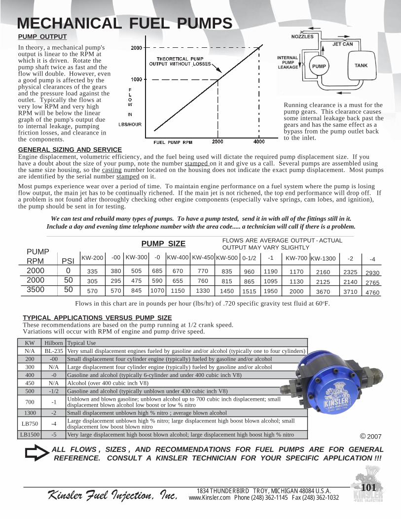
Kinsler Fuel Injection, Inc, 1834 THUNDERBIRD TROY, MICHIGAN 48084 U.S.A.www.Kinsler.com Phone (248) 362-1145 Fax (248) 362-1032
101
PUMP OUTPUTIn theory, a mechanical pump'soutput is linear to the RPM atwhich it is driven. Rotate thepump shaft twice as fast and theflow will double. However, evena good pump is affected by thephysical clearances of the gearsand the pressure load against theoutlet. Typically the flows atvery low RPM and very highRPM will be below the lineargraph of the pump's output dueto internal leakage, pumpingfriction losses, and clearance inthe components.
Running clearance is a must for thepump gears. This clearance causessome internal leakage back past thegears and has the same effect as abypass from the pump outlet backto the inlet.
MECHANICAL FUEL PUMPS
TYPICAL APPLICATIONS VERSUS PUMP SIZEThese recommendations are based on the pump running at 1/2 crank speed.Variations will occur with RPM of engine and pump drive speed.
GENERAL SIZING AND SERVICEEngine displacement, volumetric efficiency, and the fuel being used will dictate the required pump displacement size. If youhave a doubt about the size of your pump, note the number stamped on it and give us a call. Several pumps are assembled usingthe same size housing, so the casting number located on the housing does not indicate the exact pump displacement. Most pumpsare identified by the serial number stamped on it.
Most pumps experience wear over a period of time. To maintain engine performance on a fuel system where the pump is losingflow output, the main jet has to be continually richened. If the main jet is not richened, the top end performance will drop off. Ifa problem is not found after thoroughly checking other engine components (especially valve springs, cam lobes, and ignition),the pump should be sent in for testing.
We can test and rebuild many types of pumps. To have a pump tested, send it in with all of the fittings still in it.Include a day and evening time telephone number with the area code..... a technician will call if there is a problem.
ALL FLOWS , SIZES , AND RECOMMENDATIONS FOR FUEL PUMPS ARE FOR GENERALREFERENCE. CONSULT A KINSLER TECHNICIAN FOR YOUR SPECIFIC APPLICATION !!!
Flows in this chart are in pounds per hour (lbs/hr) of .720 specific gravity test fluid at 60oF.
KW-200
335
305
570
-00
380
295
570
KW-300
505
475
845
-0
685
590
1070
KW-400
670
655
1150
KW-500
835
815
1450
0-1/2
960
865
1515
-1
1190
1095
1950
KW-700
1170
1130
2000
KW-1300
2160
2125
3670
-2
2325
2140
3710
-4
2930
2765
4760
PUMP SIZEPUMPRPM PSI2000 02000 503500 50
FLOWS ARE AVERAGE OUTPUT - ACTUALOUTPUT MAY VARY SLIGHTLY
KW-450
770
760
1330
© 2007
WK nrobliH esUlacipyTA/N 532-LB )srednilycruofotenoyllacipyt(lohoclaro/dnaenilosagybdeleufsenignetnemecalpsidllamsyreV002 00- lohoclaro/dnaenilosagybdeleuf)yllacipyt(enignerednilycruoftnemecalpsidllamS003 A/N lohoclaro/dnaenilosagybdeleuf)yllacipyt(enignerednilycruoftnemecalpsidegraL004 0- )8Vhcnicibuc004rednudnarednilyc-6yllacipyt(lohocladnaenilosaG054 A/N )8Vhcnicibuc004revo(lohoclA005 2/1- )8Vhcnicibuc034rednunwolbnuyllacipyt(lohocladnaenilosaG
007 1- llams;tnemecalpsidhcnicibuc007otpulohoclanwolbnu;enilosagnwolbdnanwolbnUortin%wolrotsoobwollohoclanwolbtnemecalpsid
0031 2- lohoclanwolbegareva;ortin%hgihnwolbnutnemecalpsidllamS
057BL 4- llams;lohoclanwolbtsoobhgihtnemecalpsidegral;ortin%hgihnwolbnutnemecalpsidegraLortinnwolbtsoobwoltnemecalpsid
0051BL 5- ortin%hgihtsoobhgihtnemecalpsidegral;lohoclanwolbtsoobhgihtnemecalpsidegralyreV

Kinsler Fuel Injection, Inc, 1834 THUNDERBIRD TROY, MICHIGAN 48084 U.S.A.www.Kinsler.com Phone (248) 362-1145 Fax (248) 362-1032
102
MECHANICAL PUMPSCHANGING PUMP ROTATION:Gear-rotor style pumps are reversed by removing the cover and re-indexing it 180o. Pumps tendto change their flow when taken apart and reassembled. Disassembling the pump in the field isdiscouraged. It is recommended that the pump be sent to us, if the rotation needs to be changed.We will flow test the pump before and after changing it's rotation to be sure it is performingproperly.
Gear to Gear style pumps are reversed by removing the inlet and outlet fittings. Simply turn thebody 180o and install inlet and outlet fittings in the opposite end of the pump from the originalconfiguration. (Note: the original inlet port of the pump will now be the outlet port)
ALL FLOWS , SIZES , AND RECOMMENDATIONS FOR FUEL PUMPS ARE FOR GENERALREFERENCE. CONSULT A KINSLER TECHNICIAN FOR YOUR SPECIFIC APPLICATION !!!
GEAR TO GEAR DESIGNTYPICAL KW, WATERMAN, OR DSR.
GEAR-ROTOR DESIGNTYPICAL HILBORN OR ENDERLE
A pin or notch at the twelve o'clock position with the inlet fitting at the three o'clock position isregular rotation. A reverse rotation pump will have the pin or notch at six o'clock with the inletfitting at the three o'clock position.
LOOKING AT BOLT-ON PUMP COVER
© 2008
LOOKING AT PUMP COVER
REVERSE ROTATIONREGULAR ROTATIONThe required pump rotation can be determined by looking at the rotation of female drive hex at the mounting surface.A clockwise rotation female drive requires a regular rotation pump, counterclockwise requires a reverse rotation pump.
REGULAR ROTATION REVERSE ROTATION
LARGER HOSESIZES
ARE REQUIREDAT
PUMP SPEEDSOVER 4000 RPM
( 8000 engine RPM )
MINIMUM PLUMBING FOR INLET SUPPLY HOSE SPECIFICATIONS :pmup00-RSDronrobliH/003-002namretaWroWK *.D.I"61/7htiwesohNA8-
0-A08elrednE/pmup0-RSDronrobliH/004namretaWroWK *.D.I"61/7htiwesohNA8-2/1-RSDronrobliH/005ro054namretaWroWK *.D.I"61/9htiwesohNA01-
A08elrednE/1-RSDronrobliH/007ro006namretaWroWK *D.I"61/11htiwesohNA21-011elrednE/2-nrobliH/0031ro009namretaWroWK *.D.I"61/11htiwesohNA21-
0011-011ro099-011elrednE/4-nrobliH *.D.I"8/7htiwesohNA61-
*- I.D. of stainless steel braided hose
Gear to gear (above)and gear-rotor (below)style pumps with front
covers removed

Kinsler Fuel Injection, Inc, 1834 THUNDERBIRD TROY, MICHIGAN 48084 U.S.A.www.Kinsler.com Phone (248) 362-1145 Fax (248) 362-1032
103
MECHANICAL FUEL PUMPS
KW 500 pump and parts
KW FUEL PUMPSa) Side-by-side gear construction allows this pump to withstand higher fuel
pressure loads than other designs, with minimal flow losses. The gears and plates are coated with Polydyn TM dry film lubricant to reduce wear. The billet aluminum housing is hard anodized on the inside to reduce corrosion.
b) Pumps are available in sizes :KW/LW : 200, 300, 400, 450, 500 , 600, 700Large KW : 900, 1000, 1100, 1200, and 1300
c) Uses 3/8" male hex drive. Swivel base flange for ease of installation, allows indexing of inlet and outlet ports for clearance of inlet and outlet hoses.
d) Kinsler offers a complete line of AN hard anodized aluminum fittings. These fittings are light, resistant to methanol corrosion, give smooth flow, and good sealing.
e) All parts are available to customer. Allows for "emergency" field service.f) Interchangeable gears and spacers lets you quickly change the
displacement size of the fuel pump, bigger or smaller (within housing limits).
g) Pump can be driven either clockwise or counterclockwise without modification. Internal design allows either port to be inlet or outlet depending on rotation. Simply switch the inlet and outlet fittings.
KW 200 - 700 FUEL PUMPSHousing configuration consists of3-inlet ports (1-8 AN and 2-6 ANfemale) and 3-outlet ports (1-8 ANfemale and 2-6 AN female). Pumpwithout fittings weighs approx.1.95 lbs
LW “Lite-Weight” FUEL PUMPSHousing configuration consists of 1-inletport (8 AN female) and 3-outlet ports(1-8 AN female and 2-6 AN female incover). Pump without fittings weighsapprox. 1.45 lbs
© 2008
900-1300 series pumps have a larger housing,12 AN female inlet port and 8 AN female outlet port
4092 noitatorraluger002-WK5092 noitatoresrever002-WK8092 noitatorraluger003-WK9092 noitatoresrever003-WK2192 noitatorraluger004-WK3192 noitatoresrever004-WK4592 noitatorraluger054-WK5592 noitatoresrever054-WK6192 noitatorraluger005-WK7192 noitatoresrever005-WK0892 noitatorraluger055-WK1892 noitatoresrever055-WK0292 noitatorraluger006-WK1292 noitatoresrever006-WK4292 noitatorraluger007-WK5292 noitatoresrever007-WK
0092wolfdnaninurotrobaL
leufWL/WKweNtsetrellamsroseires009,pmup
1092wolfdnaninurotrobaL
,pmupleufWKweNtsetregraldnaseires0001
2392 noitatorraluger009-WK
3392 noitatoresrever009-WK6392 noitatorraluger0001-WK7392 noitatoresrever0001-WK0492 noitatorraluger0011-WK1492 noitatoresrever0011-WK4492 noitatorraluger0021-WK5492 noitatoresrever0021-WK
7492
,0021-WK,0011-WK,0001-WK,009-WKnoedargpUraeg0031ezisotputpeccaotytilibapachtiwpmupdliub
009(recapslanoitiddadnarevoctnorf0031sesu,tesspmupezisrehtorofdesuerasrecapsezistnereffid,)ylno
8492 noitatorraluger0031-WK9492 noitatoresrever0031-WK
KW 900 pump
FITTINGS - KINSLER HARD-ANODIZED ALUMINUM6616 gnir-ohtiwgulptropNA6
6516 gnir-o+elamNA6xeralfelamNA64406 gnir-o+elamNA8xeralfelamNA63406 gnir-o+elamNA8xeralfelamNA83016 gnir-o+elamNA8xelamefNA6,gnihsubrecudeR7716 gnir-o+elamNA8xeralfelamNA018716 gnir-o+elamNA8xeralfelamNA219716 gnir-o+elamNA21xeralfelamNA210016 gnir-o+elamNA21xeralfelamNA61
PUMP FLOW TESTING SERVICE
NEW‘Lite-Weight’ fuel pump !
When every bitof weight counts !
4192 noitatorraluger004-WL5192 noitatoresrever004-WL6592 noitatorraluger054-WL7592 noitatoresrever054-WL8192 noitatorraluger005-WL9192 noitatoresrever005-WL2892 noitatorraluger055-WL3892 noitatoresrever055-WL
LW ‘Lite-Weight’series pump
Service partsare available
for in-the-fieldrepairs

Kinsler Fuel Injection, Inc, 1834 THUNDERBIRD TROY, MICHIGAN 48084 U.S.A.www.Kinsler.com Phone (248) 362-1145 Fax (248) 362-1032
104
HILBORN FUEL PUMPSWe are an AUTHORIZED SALES and SERVICE CENTER for Hilborn fuel pumps.
a) Pumps are available in sizes : PG150C : -00 ; -0 ; Super -0 ; -1/2 ; -1PG175B : -2 ; -4PG250 : -5.
b) 3/8" male hex drive.c) New fuel pumps are supplied with Kinsler AN hard anodized aluminum fittings, also available for replacement.d) To change pump rotation, the front cover plate must be removed and re-indexed 180o. We strongly advise the customer not to do this once we have set up the pump, since the tolerances and output of the pump are sensitive to disassembly and reassembly.e) We cannot sell parts for Hilborn fuel pumps directly to the customer for user repair.
The PG150C is the current series fuel pump. It was preceded by PG150, the PG150A,and the PG150B. These numbers are on the casting, the actual pump displacementis designated by the first number of the serial number (which is stamped into the pumpcasting). Exceptions, if the pump was resized since new, the new size is designated bya -# at the end of the original serial number, example: originally 0-9632 which was asize -0, resized to a -1, the number will be 0-9632-1
MECHANICAL FUEL PUMPS
PG-150C -1/2
2131 pmupleufseiresC051-GPnrobliHweNtsetwolfdna,ni-nur,ecnaraelcotrobaL4131 pmupleufseiresB571-GPnrobliHweNtsetwolfdna,ni-nur,ecnaraelcotrobaL
NOTE - ALL Hilborn fuel pumps sold by Kinsler are clearanced, run-in, and flow tested !!
All PG-175 series pumpshave coated gears :0182 00- .tor.ger
1182 00- .tor.ver0082 0- .tor.ger1082 0- .tor.ver0282 0-repuS .tor.ger1282 0-repuS .tor.ver8182 2/1- .tor.ger9182 2/1- .tor.ver2082 1- .tor.ger3082 1- .tor.ver
4082 .tor.ger2-5082 .tor.ver2-6082 .tor.ger4-7082 .tor.ver4-
PG-150 series pumps:
© 2008
PHENOLIC INSULATOR PLATE
6725 taehevirdsetalusni,kciht"041.pmupleuflacinahcemmorf
PG-175B -2
noinoinoinoi
.
noinoinoinoi

Kinsler Fuel Injection, Inc, 1834 THUNDERBIRD TROY, MICHIGAN 48084 U.S.A.www.Kinsler.com Phone (248) 362-1145 Fax (248) 362-1032
105
Saleen S7Rtesting at
Willow Springsracetrack, Calif.
We supplyindependently -
throttled - runnermanifolds for all
of the factorysponsored
Saleen racecars.
CUSTOMERS IN ACTION
Terry McCarl at Knoxville World of Outlaws
Louie Carufel, 2005 Sprints On DirtRookie of the Year, 6th place overall
John MacKichan’s Speedway Motors Bonneville StreamlinerC/BGS 328.928 MPH E/FS 275.717 MPH
Aaron Polaski’s Willys:7.71 @ 181 with 100 H.P. hit of nitrous.System is street driven; Aaron says itruns nice and smooth.
November 4, 2005T-MAC Motorsports, Inc.Kinsler Fuel InjectionDear Mr. KinslerI would like to personally thank you for your support in 2005.We had a great year finishing 9th in the World of Outlaw pointstandings. As a manufacturer you will be happy to know thatwe also lead the World of Outlaws with 12 fast times (3 trackrecords) and 12 second fast times. This alone is an impressivestatistic; however we also raced the entire 100 race World ofOutlaw schedule with NO engine failures. We feel this is anamazing accomplishment and one we could not have acheivedwithout your involvement.
Again, I appreciate all you do for my race team and I amlooking forward to even more success in 2006.
Sincerely yours,Terry McCarl
© 2008
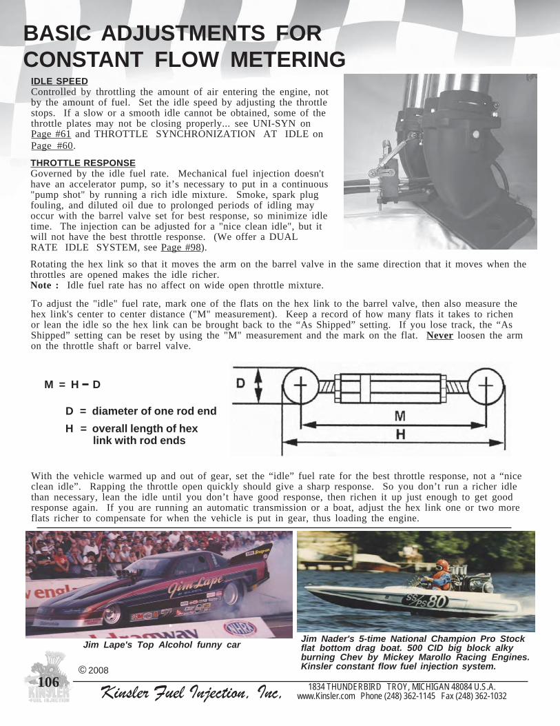
Kinsler Fuel Injection, Inc, 1834 THUNDERBIRD TROY, MICHIGAN 48084 U.S.A.www.Kinsler.com Phone (248) 362-1145 Fax (248) 362-1032
106
BASIC ADJUSTMENTS FORCONSTANT FLOW METERING
IDLE SPEEDControlled by throttling the amount of air entering the engine, notby the amount of fuel. Set the idle speed by adjusting the throttlestops. If a slow or a smooth idle cannot be obtained, some of thethrottle plates may not be closing properly... see UNI-SYN onPage #61 and THROTTLE SYNCHRONIZATION AT IDLE onPage #60.
With the vehicle warmed up and out of gear, set the “idle” fuel rate for the best throttle response, not a “niceclean idle”. Rapping the throttle open quickly should give a sharp response. So you don’t run a richer idlethan necessary, lean the idle until you don’t have good response, then richen it up just enough to get goodresponse again. If you are running an automatic transmission or a boat, adjust the hex link one or two moreflats richer to compensate for when the vehicle is put in gear, thus loading the engine.
© 2008
THROTTLE RESPONSEGoverned by the idle fuel rate. Mechanical fuel injection doesn'thave an accelerator pump, so it’s necessary to put in a continuous"pump shot" by running a rich idle mixture. Smoke, spark plugfouling, and diluted oil due to prolonged periods of idling mayoccur with the barrel valve set for best response, so minimize idletime. The injection can be adjusted for a "nice clean idle", but itwill not have the best throttle response. (We offer a DUALRATE IDLE SYSTEM, see Page #98).
Jim Lape's Top Alcohol funny car Jim Nader's 5-time National Champion Pro Stockflat bottom drag boat. 500 CID big block alkyburning Chev by Mickey Marollo Racing Engines.Kinsler constant flow fuel injection system.
D = diameter of one rod endH = overall length of hex link with rod ends
M = H D
Rotating the hex link so that it moves the arm on the barrel valve in the same direction that it moves when thethrottles are opened makes the idle richer.Note : Idle fuel rate has no affect on wide open throttle mixture.
To adjust the "idle" fuel rate, mark one of the flats on the hex link to the barrel valve, then also measure thehex link's center to center distance ("M" measurement). Keep a record of how many flats it takes to richenor lean the idle so the hex link can be brought back to the “As Shipped” setting. If you lose track, the “AsShipped” setting can be reset by using the "M" measurement and the mark on the flat. Never loosen the armon the throttle shaft or barrel valve.

Kinsler Fuel Injection, Inc, 1834 THUNDERBIRD TROY, MICHIGAN 48084 U.S.A.www.Kinsler.com Phone (248) 362-1145 Fax (248) 362-1032
107
SETTING THE LEAKAGE OF ABARREL VALVE SPOOLLEAKAGE SETTING BARREL VALVEA leakage test is done to determine how far the idle passageramp is open in the spool. The setting that works best for oneengine combination may not work for another becausevariables such as fuel pressure, throttle size, idle speed, andignition timing all affect the proper barrel valve “idle”opening. The idle setting, or spool indexing, affects the partthrottle fuel delivery. See sections on KINSLER BARRELVALVE SPOOLS, Pg. 98 and SETTING THE “IDLE” FUELRATE FOR BEST THROTTLE RESPONSE, Pg. 106
CONDITIONS THAT INFLUENCE THE REQUIRED LEAKAGEFuel system pressure, engine idle speed, and the load against the engine all affect the required leakage settingof the barrel valve spool.
1) Fuel Pressure at Idle ; Given two identical engines: if engine ‘A’'s fuel pressure is higher than engine ‘B’'s, because of aheavier spring behind the poppet in the main bypass, the barrel valve spool on Engine ‘A’ will need to be closed further tomaintain the same fuel idle flow.
2) Engine Idle Speed ; Is proportional to the idle air flow, which will affect the amount of fuel required. The more air, the morefuel needed to maintain the same air/fuel ratio.
3) Engine Load ; A Sprint Car which is push started "in gear" will have a significant load against the engine rightfrom the start. A drag car engine will start and idle "out of gear" with very little load, mainly the reciprocatingfriction of the engine and accessories. The Sprint Car engine will require more fuel due to the heavier load(increased load means additional horsepower requirement) to maintain a given RPM.
Fig. 1 cap off secondary outlet fitting
© 2008
LEAKAGE METERIncludes 6AN hose to barrel valve inlet.
0895 ;gniretemnwodkaeleguaglauDseguagISP001-0/ISP001-0esohleviwselamefNA6htiw
ylbmessa
#5980 Kinsler leakage tester
V
DIFFERENT STYLES OF LEAKAGE METERS1) Direct Percent Readout Style - displays the percent of
leakage on the gauge. Sun leak testers were like this.... nolonger made.
2) Pressure Differential Style - usually has two pressuregauges, pressure in and pressure out. The leakage is afunction of the differential value between the gaugereadings.
Examples: 100-PSI in and 70-PSI out, results in a leakageof 30-PSI, 30-PSI is 30% of 100-PSI.80-PSI in and 70-PSI out, results in a leakageof 10-PSI, 10-PSI is 12.5% of the 80-PSI inletpressure.
REMEMBER YOU WANT A PERCENTAGE !
To calculate this:
TESTING PROCEDURE
NOTES: A) PLEASE read the instructions for the leakage tester before using it.
B) Be consistent in the test method. Perform the test the same every time, this will help avoid errors.
C) The secondary bypass fitting MUST be capped off, see upper photo.D) Always use the same inlet pressure for repeatability.
1) Attach the leakage meter outlet hose to the barrel valve inlet fitting.2) Open the barrel valve to wide open throttle, turn the air pressure to the meter on and off to make sure that the gauges zero.Note: The manufacturer of the leakage meter you are using may specify a different zeroing method. Use that one.3) With the air pressure on, close the throttles to the idle position and observe the gauge reading(s).4) Most Leakage Meters Do Not Read the Same; but all Kinsler meters are calibrated to a master so each of them reads the same.
Test your barrel valve leakage after receiving your unit from our calibration department. Record the reading before makingANY adjustments. Your leakage tester may show a value different than the unit we used. Leakage testers that are workingproperly read within about 2% of one another.
= % LeakdownInlet PSI - Outlet PSIInlet PSI

Kinsler Fuel Injection, Inc, 1834 THUNDERBIRD TROY, MICHIGAN 48084 U.S.A.www.Kinsler.com Phone (248) 362-1145 Fax (248) 362-1032
108
INDEXING A BARREL VALVELINKAGE GEOMETRY TO BARREL VALVE
INDEXING AND ROTATION
Kinsler barrel valves are available in clockwise (Right Hand)and counterclockwise (Left hand) rotation. The spool iscentered in the block, with the inlet fitting port offset to oneside of the spool bore. This gives more direct flow throughthe notch cut in the side of the spool at wide open throttle.See “Barrel Valve Spool Ramp” and “How The SecondaryWorks”, top of pg #88.
Clockwise (right hand)Counterclockwise (left hand)
A properly fit spool will have approximately0.0005" clearance to the barrel valve block bore.A spool with a looser fit will allow fuel to seeparound the spool, requiring reindexing tocompensate for the increased flow of fuel. Ifseepage is excessive, the spool will have to bereindexed too much causing the secondary port tobe closed off prematurely during the opening ofthe throttles. Also, the fuel flow notch may bereindexed enough to close it off some at wideopen throttle and inadequate fuel delivery nearwide open throttle.
When a spool has a secondary bypass port, at anidle the port in the spool should be exposed to theinlet port of the barrel valve block, fully orpartially.
Note: Crower barrel valves have the spool boremachined offset from the center of the blockinstead of inlet port being offset machined.
The linkage geometry to the barrel valve affects the part throttle fuelrate. The geometry MUST be set correctly before the spool isindexed. The center-to-center (c-c) of arms 'A' and 'B' must beequal. The barrel valve hex link must have the same c-cdistance (‘M’) as the barrel valve spool shaft to the throttleshaft ('D'). As the two arms rotate, they will remainparallel to each other, and the barrel valve hex link willremain parallel to the baseline. Setting up the linkagegeometry this way will cause the barrel valve spoolto rotate exactly the same as the throttle shaft.
See "HOW TO SET UP LINKAGE"on Pages #62-63.
Fig. 1.1
© 2008
Rotation lookingat top of spool
Rotation lookingat top of spool
V V
V
SecondaryOutletFitting
HoleForSecondary
FuelFlowRamp
V V
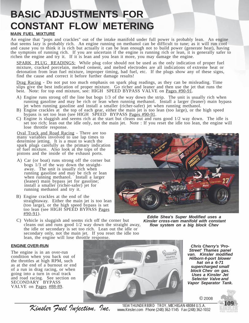
Kinsler Fuel Injection, Inc, 1834 THUNDERBIRD TROY, MICHIGAN 48084 U.S.A.www.Kinsler.com Phone (248) 362-1145 Fax (248) 362-1032
109
BASIC ADJUSTMENTS FORCONSTANT FLOW METERING
ENGINE OVER-RUNThe engine is in an over-runcondition when you back out ofthe throttles at high RPM, suchas at the end of a burnout or endof a run in drag racing, or whengoing into a turn in oval trackand road racing. See section onSECONDARY BYPASSVALVE on Pages #88-89.
Chris Cherry's 'Pro-Street' Thames panel
van. Kinsler modifiedHilborn 4-port blower
hat on a 6-71supercharged smallblock Chev on gas.Uses a Kinsler JetSelector Valve and
Vapor Separator Tank.
© 2008
MAIN FUEL MIXTUREAn engine that "pops and crackles" out of the intake manifold under full power is probably lean. An enginethat seems lazy is probably rich. An engine running on methanol can be difficult to tune; as it will run cooland cause you to think it is rich but actually it can be lean enough not to build power (generate heat), havingthe symptons of running rich. If you are uncertain if the engine is running rich or lean, it is generally safer torichen the engine and try it. If it is lean and you lean it more, you may damage the engine.
SPARK PLUG READINGS: While plug color should not be used as the only indication of proper fuelmixture, cracked porcelain, melted cement, and melted electrodes are all indications of extreme heat ordetonation from lean fuel mixture, improper timing, bad fuel, etc. If the plugs show any of these signs,find the cause and correct it before further damage results!
Drag Racing - Do not put too much emphasis on spark plug readings, as they can be misleading. Timeslips give the best indication of proper mixture. Go richer and leaner and then use the jet that runs thebest. Note: for top end mixture, see: HIGH SPEED BYPASS VALVE on Pages #90-91.
A) Engine runs strong off the line but bogs 1/3 of the way down the strip. The unit is usually rich whenrunning gasoline and may be rich or lean when running methanol. Install a larger (leaner) main bypassjet when running gasoline and install a smaller (richer-safer) jet when running methanol.
B) Engine crackles at the top of each gear, either the main jet is too lean (too large), or the high speedbypass is set too lean (see HIGH SPEED BYPASS Pages #90-91.
C) Engine is sluggish and seems rich at the start but cleans out and runs good 1/2 way down. The idle isset too rich; lean out the idle only, not the main jet. Note : If you reset the idle too lean, the engine willlose throttle response.
Eddie Shea's Super Modified uses a Kinsler cross-ram manifold with constant
flow system on a big block Chev
Oval Track and Road Racing - There are toomany variables involved to use lap times todetermine jetting. It is a must to watch thespark plugs carefully as the primary indicationof fuel mixture. Also look at the tops of thepistons and the inside of the exhaust ports.
A) Car (or boat) runs strong off the corner butbogs 1/3 of the way down the straight-away. The unit is usually rich whenrunning gasoline and may be rich or leanwhen running methanol. Install a larger(leaner) main bypass jet for gasoline;install a smaller (richer-safer) jet forrunning methanol and try it.
B) Engine crackles at the end of thestraightaway. Either the main jet is too lean(too large), or the high speed bypass is settoo lean (see HIGH SPEED BYPASS Pages#90-91).
C) Vehicle is sluggish and seems rich off the corner butcleans out and runs good 1/2 way down the straight away,the idle or secondary is set too rich. Lean out the idle orsecondary only, not the main jet. If you reset the idle toolean, the engine will lose throttle response.

Kinsler Fuel Injection, Inc, 1834 THUNDERBIRD TROY, MICHIGAN 48084 U.S.A.www.Kinsler.com Phone (248) 362-1145 Fax (248) 362-1032
110
Tank vent too small.Fuel level low in tank, or tank too small.Tank poorly designed; return fuel blasts bubbles down into outlet.Tank in bad location (hot, too low, or too far away).Poor quality fuel or old fuel.Hot fuel temperature or high vapor pressure gasoline (winter grade).
Inlet hose to pump: kinked, clogged, too small. Angled or restrictive fittings.Loose fitting or pinhole in hose; allows pump to suck air. Separating ortorn inner liner; allows flap of hose material inside to pop up when fuelflows through hose, may look OK unless carefully inspected. See FUELPUMPS on Page #98 for minimum hose size and inside diameter for theinlet hose and fittings.
Restrictive or clogged fuel filter or screen.Shut-off valve not fully open, too small, or vibrating closed.Debris under top fitting (above spool) in barrel valve.
Pump too small or wrong pump-to-engine drive ratio.Drive hex so worn that it slips, or slipping drive belt.Worn or damaged fuel pump; pump hex bottomed in drive.Faulty in-pump relief valve (early Hilborn pumps only).Pump shaft seal faulty causing pump to suck air.
Main bypass jet too large.Damaged or No jet sealing o-ring in main bypass or any valve that uses a jet.Dirty nozzles; check screens for dirt or lint.Nozzles too small.High speed bypass set too lean (if used) or not sealing properly.Barrel valve spool indexed incorrectly or fit too loose causing
secondary to bypass at wide open throttle.
Tank vent too small (see reference #1 at bottom of page).
Restrictive fittings (small inside diameter) in bypass hoses or in tank.Restrictive bypass lines (kinked or clogged).Main bypass return hose teed with other bypass hoses.
Main bypass jet too small.Stuck poppet in main bypass jet canMain or high speed bypass installed backward in hose.Teflon poppet , restrictive outside diameter.Nozzles too large.
Nozzles not matched properly or different size nozzles.Dirty nozzles; check screens for dirt or lint.Restrictive nozzle hose (plugged, kinked, or damaged).Barrel valve not adequate for fuel rate required.
TROUBLE SHOOTING CHARTCONSTANT FLOW SYSTEMFOR WIDE OPEN THROTTLE
REFERENCE#1- Primarily on gasoline burning engines. Gasoline generates considerable vapor pressure when it is contained in
a closed tank. The return fuel blasting back into the tank creates more volume of vapor than the volume ofgasoline used, so the pressure in the tank increases and causes the unit to go richer. Alcohol and nitro unitsgo lean if the vent is too small, as they can't draw the fuel out of the tank quick enough. See FUEL TANKCONSTRUCTION and LOCATION on Page #180 for proper vent sizes.
© 2008
ENGINERUNS LEAN
ENGINERUNS RICH
POORDISTRIBUTION
Fuel Tank
Plumbing
Fuel Pump
Metering
Plumbing
Fuel Tank
Fuel Pump
Metering

Kinsler Fuel Injection, Inc, 1834 THUNDERBIRD TROY, MICHIGAN 48084 U.S.A.www.Kinsler.com Phone (248) 362-1145 Fax (248) 362-1032
111
TROUBLE SHOOTING CHARTCONSTANT FLOW SYSTEM
Fuel level in tank below pump (see reference #2 at bottom of page).Main or secondary poppet stuck open, or spring missing.Main bypass installed backwards or in wrong hose - see reference #2.Loose or damaged pump inlet hose.Idle mixture set incorrectly.Worn pump; pump set for wrong rotation; broken drive.Fouled spark plugs or weak ignition.Camshaft improperly timed.
Main or secondary poppet stuck open, or spring missing.Restricted main bypass hose.Plugged or dirty nozzles, nozzle screens, or nozzle hose.Loose or damaged pump inlet hose.Vent in fuel tank too small - see reference #2.Throttle stops not adjusted properly - see reference #3.Throttle plates not synchronized or cross-link not adjusted - see reference #3.Twisted throttle shaft or worn throttle shaft bores - see reference #3.Throttle plates installed backwards or bent - see reference #3.Spring in main bypass too weak - see reference #4.Idle mixture too lean or air leak at manifold gasket - see reference #5.Fouled spark plugs or weak ignition.
Main bypass poppet stuck closed or spring too stiff.Main bypass installed backwards or restricted bypass hose - see reference #2.Vent in fuel tank too small - see reference #2.Idle mixture set too rich - see reference #5.Nozzle vents restricted or plugged (nozzles located below throttle plates).Barrel valve spool worn excessively.
Idle mixture set too lean or air leak at manifold gasket - see reference #5.Main or secondary poppet stuck open or spring missing.Improper barrel valve spool or linkage geometry.Ignition too far advanced.Bent or leaking intake valve.Camshaft not properly timed.Fouled spark plugs or weak ignition.
Throttle plates not synchronized or cross-link not adjusted - see reference #3.Twisted throttle shaft or worn throttle shaft bores - see reference #3.Throttle plates installed backwards or bent - see reference #3.Dirty or bent rod end bearing.Manifold not evenly tightened down.Manifold damaged, bushings loose, linkage geometry incorrect.Bolt securing one of the rod ends overtightened (deformed ball).
No shut-off valve or internally leaking shut-off valve.Fuel level in tank above nozzles without shut-off valve.Bad pump seal; leaks into engine (Not on belt drive pumps).Hose between shut-off valve and barrel valve picking up heat; fuel in hose boils, thus expanding into engine.
FOR STARTING, IDLE,AND PART THROTTLE
© 2008
WILL NOT START
WILL NOT IDLEOR POOR IDLEDISTRIBUTION
IDLES RICH
BACK FIRES WHENTHROTTLES OPEN,OR POOR RESPONSE
FUEL DRIPSCONTINUALLYINTO ENGINE WHENNOT RUNNING
STICKING THROTTLE
REFERENCE#2- See “Preferred Plumbing Schematic on Pg. #112#3- See “Uni-Syn” on Pg. #61. Note: Even through throttle synchronization only affects distribution at idle, it is very
important, since the difference in idling cylinder temperatures that it causes will heat some spark plugs more than others.The warmer plugs tend to overheat during the run and cause detonation, especially in fueler units. The overheatedplugs will at least give false readings even after a full throttle run.
#4- See “Bypass valves” on Pg. #95 #5- See “Basic Adjustments for Constant Flow Metering” on Pg. #106
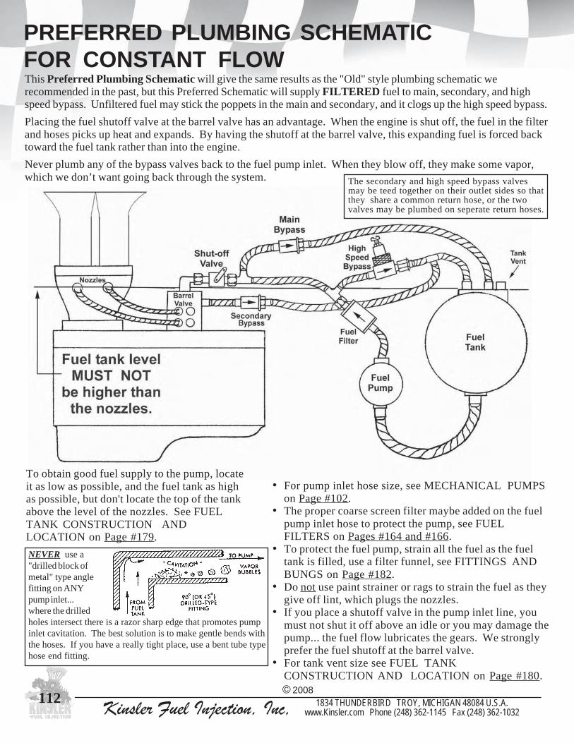
Kinsler Fuel Injection, Inc, 1834 THUNDERBIRD TROY, MICHIGAN 48084 U.S.A.www.Kinsler.com Phone (248) 362-1145 Fax (248) 362-1032
112
PREFERRED PLUMBING SCHEMATICFOR CONSTANT FLOWThis Preferred Plumbing Schematic will give the same results as the "Old" style plumbing schematic werecommended in the past, but this Preferred Schematic will supply FILTERED fuel to main, secondary, and highspeed bypass. Unfiltered fuel may stick the poppets in the main and secondary, and it clogs up the high speed bypass.
Placing the fuel shutoff valve at the barrel valve has an advantage. When the engine is shut off, the fuel in the filterand hoses picks up heat and expands. By having the shutoff at the barrel valve, this expanding fuel is forced backtoward the fuel tank rather than into the engine.
Never plumb any of the bypass valves back to the fuel pump inlet. When they blow off, they make some vapor,which we don’t want going back through the system.
To obtain good fuel supply to the pump, locateit as low as possible, and the fuel tank as highas possible, but don't locate the top of the tankabove the level of the nozzles. See FUELTANK CONSTRUCTION ANDLOCATION on Page #179.
© 2008
• For pump inlet hose size, see MECHANICAL PUMPSon Page #102.
• The proper coarse screen filter maybe added on the fuelpump inlet hose to protect the pump, see FUELFILTERS on Pages #164 and #166.
• To protect the fuel pump, strain all the fuel as the fueltank is filled, use a filter funnel, see FITTINGS ANDBUNGS on Page #182.
• Do not use paint strainer or rags to strain the fuel as theygive off lint, which plugs the nozzles.
• If you place a shutoff valve in the pump inlet line, youmust not shut it off above an idle or you may damage thepump... the fuel flow lubricates the gears. We stronglyprefer the fuel shutoff at the barrel valve.
• For tank vent size see FUEL TANKCONSTRUCTION AND LOCATION on Page #180.
The secondary and high speed bypass valvesmay be teed together on their outlet sides so thatthey share a common return hose, or the twovalves may be plumbed on seperate return hoses.
NEVER use a"drilled block ofmetal" type anglefitting on ANYpump inlet...where the drilledholes intersect there is a razor sharp edge that promotes pumpinlet cavitation. The best solution is to make gentle bends withthe hoses. If you have a really tight place, use a bent tube typehose end fitting.

Kinsler Fuel Injection, Inc, 1834 THUNDERBIRD TROY, MICHIGAN 48084 U.S.A.www.Kinsler.com Phone (248) 362-1145 Fax (248) 362-1032
113
“OLD” PLUMBING SCHEMATIC FORCONSTANT FLOWThis is the schematic recommended by most fuel injection manufacturers, and by us in the past.We now urge you to use the “Preferred Schematic” shown on the previous page, as it will supply filteredfuel to the main, secondary, and high speed bypass. Unfiltered fuel may stick the poppets in the main andsecondary, and it clogs the high speed bypass.
© 2008
Placing the fuel shutoff valve at the barrel valve has an advantage. When the engine is shut off, the fuel in the filterand hoses picks up heat and expands. By having the shutoff at the barrel valve, this expanding fuel is forced backtoward the fuel tank rather than into the engine.
Never plumb any of the bypass valves back to the fuel pump inlet.When they blow off, they make some vapor, which we don’t wantgoing back through the system.
NEVER use a"drilled block ofmetal" type anglefitting on ANYpump inlet...where the drilledholes intersect there is a razor sharp edge that promotes pumpinlet cavitation. The best solution is to make gentle bends withthe hoses. If you have a really tight place, use a bent tube typehose end fitting.
To obtain good fuel supply to the pump, locateit as low as possible, and the fuel tank as highas possible, but don't locate the top of the tankabove the level of the nozzles. See FUELTANK CONSTRUCTION ANDLOCATION on Page #179.
• For pump inlet hose size, see MECHANICAL PUMPSon Page #102.
• The proper coarse screen filter maybe added on the fuelpump inlet hose to protect the pump, see FUELFILTERS on Pages #164 and #166.
• To protect the fuel pump, strain all the fuel as the fueltank is filled, use a filter funnel, see FITTINGS ANDBUNGS on Page #182.
• Do not use paint strainer or rags to strain the fuel as theygive off lint, which plugs the nozzles.
• If you place a shutoff valve in the pump inlet line, youmust not shut it off above an idle or you may damage thepump... the fuel flow lubricates the gears. We stronglyprefer the fuel shutoff at the barrel valve.
• For tank vent size see FUEL TANKCONSTRUCTION AND LOCATION on Page #180.
The secondary and high speed bypass valvesmay be teed together on their outlet sides so thatthey share a common return hose, or the twovalves may be plumbed on seperate return hoses.

Kinsler Fuel Injection, Inc, 1834 THUNDERBIRD TROY, MICHIGAN 48084 U.S.A.www.Kinsler.com Phone (248) 362-1145 Fax (248) 362-1032
114
PLUMBING SCHEMATIC FOR ENDERLEBLOWER HAT AND BARREL VALVEASSEMBLY WITH PORT NOZZLESKINSLER'S CONVERSION FROM ENDERLE'S JET-IN-THE-BARREL-VALVE TO KINSLER EXTERNAL BYPASS SYSTEM.
Kinsler is pleased with the quality of Enderle's blower hats, but we prefer not to use their jets or nozzles for tworeasons: They are sharp edged and the jets have a screw driver slot. As mentioned in "A Note About Jets",square edged jets are easily damaged... the use of the screw driver in the slot further aggravates the problem.Changing to the Kinsler external bypass system and using the K-type jets eliminated the problem. Many of theracers also prefer the external bypass system for it's greater flexibility in tuning and ease of operation.
© 2008

Kinsler Fuel Injection, Inc, 1834 THUNDERBIRD TROY, MICHIGAN 48084 U.S.A.www.Kinsler.com Phone (248) 362-1145 Fax (248) 362-1032
115
KINSLER VAPOR SEPARATOR TANK (VST)SYSTEM
THE CAUSEThe main problem is caused by pump inlet cavitation, a form of "vapor lock". Because gasoline almost boils atroom temperature, if the temperature of the fuel is raised, or a vacuum is pulled on it, it will start to boil. This iswhat causes the pump delivery problem...as the pump tries to draw the fuel into it's inlet, it pulls a slightvacuum on the fuel. The higher the pump speed, the higher the vacuum. This vacuum, combined with hottemperatures found in most race cars, causes at least some of the fuel in the inlet hose to flash to vapor (boil).Thus the pump draws in a mixture of liquid and vapor and therefore delivers less fuel per revolution. Thiscauses an erratic lean condition and sometimes premature pump failure due to a lack of pump lubrication.
THE PROBLEMFor a constant flow fuel injection system to meter the fuel repeatably, the mechanical pump must deliver aprecise amount of fuel at any given RPM. In many installations, however, the pump delivers varying amounts offuel, sometimes very erratically, due to plumbing of the vehicle, or operation at high altitude and/or hotconditions.
Also know as a pressurized pump inlet system.
Hot weather; hot fuel in the fuel tank; vehicle parked on hot blackpavement on a sunny summer day (which heats up the whole car);exhaust pipes near fuel hoses, pump, tank, etc.; radiator heat comingback across fuel pump, hoses, tank, etc.; fuel pump not isolated fromengine block heat (use phenolic isolator see MECHANICAL FUELPUMPS on Page #104 and #176)
HEAT
VACUUM Pump inlet hose too long, such as in vehicles that have a fuel tank inthe rear; pump inlet hose too small in diameter; fittings in pump inlethose with too small of an inside diameter; angle drilled fittings, (seePg. #112); low mounted fuel tank; high mounted fuel pump
The Economizer Valve (Econ) is used to reduce the pump output pressure back closerto what it would have been if the pump were not pressurized at it’s inlet. The systemwould be quite rich at an idle and low speeds if this valve was not used. The poppet inthis valve has an orifice, sized to flow the proper amount of fuel for cranking andidling. Above idle, the poppet moves off it's seat and maintains a pressure drop ofabout 3 PSI across it to counterbalance the pressure being applied to the inlet side ofthe fuel pump. It should be installed after the filter to protect it from dirt.
© 2008
In our VST system, more fuel than the engine will consume is pumped from themain tank by an electric fuel pump to the VST. The excess fuel flows back to themain tank through the Backpressure Valve, which holds 2-6 PSI in the VST, thuspressurizing the mechanical pump inlet with about that same pressure. This helpsprevent the fuel from boiling at the inlet of the pump.
The VST is specially built to act as a low pressure reservoir and as a vaporseparator. The fuel coming from the electric fuel pump, main bypass, secondarybypass, and high speed bypass has vapor in it. The tank is SPECIALLY BAFFLEDto separate the vapor and feed it to the top center fitting on the tank, then back tothe main tank, where it can escape out of the main tank vent. The pressure in thetank is very dependant on the flow through the Backpressure Valve, so this flowcurve is an important part of the system’s calibrations. Since the electric fuel pumpprovides the flow through the valve, it is important to use only the specified modelelectric fuel pump; a pump that flows more or less would alter the calibration. Thepoppet in this valve is designed not to seal perfectly, so any residual pressure canbe bled back to the main tank when the system is shut off. It is best to install apressure gauge in the hose between the VST and the Backpressure Valve. If thesystem does not have about 3 PSI when the electric pump is switched on, theengine should not be started. Check to see that the electric pump is working andthe Backpressure Valve is functioning properly. Under racing conditions, apressure reading below 1 PSI could cause a lean condition. Any deviation fromthe required 2.5-4 PSI should be closely monitored.
THE CURE
Conditions that aggravate pump inlet cavitation :
4" diameter by 12" tall tank
Mounting clamp

Kinsler Fuel Injection, Inc, 1834 THUNDERBIRD TROY, MICHIGAN 48084 U.S.A.www.Kinsler.com Phone (248) 362-1145 Fax (248) 362-1032
116
PLUMBING SCHEMATIC
To protect the fuel pump, strain all the fuel as you fill the tank;use a filter funnel. See FITTINGS AND BUNGS Pg. #182.
Do not use a paint strainer or rags to strain the fuel as theygive off lint, which plugs the nozzles.
For pump inlet hose size, see MECHANICAL PUMPSPage #102.
A proper coarse screen filter may be added on themechanical fuel pump inlet hose to protect the pump,see FUEL FILTERS Pg. #163 and #166.
NEVER put a fuel shutoff valve in the fuel pump inlethose --- put it in the hose going from the pump to thebarrel valve. See SHUT-OFF VALVES Pg. #167 - #171
For tank vent size see FUEL TANK CONSTRUCTIONAND LOCATION Pg. #180.
To obtain good fuel supply conditions to the pump, locate theVST as high as possible, but don't locate the top of the tankabove the level of the nozzles unless you have a bubble tightshutoff just before the barrel valve that you use every time youshut off the engine. See FUEL TANK CONSTRUCTIONAND LOCATION Pg. #179.
Locate the mechanical fuel pump as low as possible to obtainbest fuel supply conditions.
© 2008
NEVER use a "drilled block of metal" type angle fitting on ANYpump inlet hose... where the drilled holes intersect there is a razorsharp edge that promotes pump inlet cavitation. The best solutionis to make gentle bends with the hoses. If you have a really tightplace, use a bent tube type hose end fitting.
KINSLER VAPOR SEPARATOR TANK (VST)SYSTEM
ECONOMIZERVALVE
- - - MUST BE THE LAST CONTROL VALVE BEFORE THE BARREL VALVE
- CONTINUED -
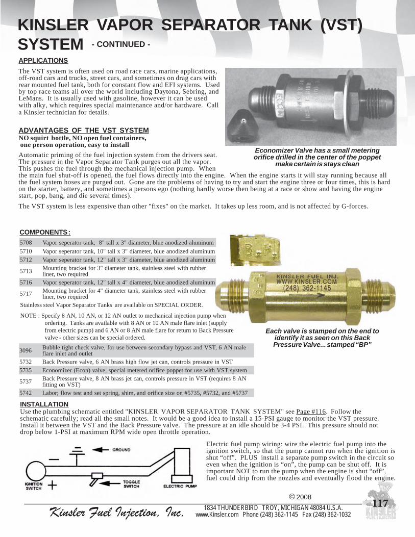
Kinsler Fuel Injection, Inc, 1834 THUNDERBIRD TROY, MICHIGAN 48084 U.S.A.www.Kinsler.com Phone (248) 362-1145 Fax (248) 362-1032
117
INSTALLATIONUse the plumbing schematic entitled "KINSLER VAPOR SEPARATOR TANK SYSTEM" see Page #116. Follow theschematic carefully; read all the small notes. It would be a good idea to install a 15-PSI gauge to monitor the VST pressure.Install it between the VST and the Back Pressure valve. The pressure at an idle should be 3-4 PSI. This pressure should notdrop below 1-PSI at maximum RPM wide open throttle operation.
COMPONENTS :
ADVANTAGES OF THE VST SYSTEMNO squirt bottle, NO open fuel containers, one person operation, easy to install
Automatic priming of the fuel injection system from the drivers seat.The pressure in the Vapor Separator Tank purges out all the vapor.This pushes the fuel through the mechanical injection pump. Whenthe main fuel shut-off is opened, the fuel flows directly into the engine. When the engine starts it will stay running because allthe fuel system hoses are purged out. Gone are the problems of having to try and start the engine three or four times, this is hardon the starter, battery, and sometimes a persons ego (nothing hardly worse then being at a race or show and having the enginestart, pop, bang, and die several times).
The VST system is less expensive than other "fixes" on the market. It takes up less room, and is not affected by G-forces.
Each valve is stamped on the end toidentify it as seen on this BackPressure Valve... stamped “BP”
Electric fuel pump wiring: wire the electric fuel pump into theignition switch, so that the pump cannot run when the ignition isshut “off”. PLUS install a separate pump switch in the circuit soeven when the ignition is “on”, the pump can be shut off. It isimportant NOT to run the pump when the engine is shut “off”,fuel could drip from the nozzles and eventually flood the engine.
APPLICATIONSThe VST system is often used on road race cars, marine applications,off-road cars and trucks, street cars, and sometimes on drag cars withrear mounted fuel tank, both for constant flow and EFI systems. Usedby top race teams all over the world including Daytona, Sebring, andLeMans. It is usually used with gasoline, however it can be usedwith alky, which requires special maintenance and/or hardware. Calla Kinsler technician for details.
© 2008
Economizer Valve has a small meteringorifice drilled in the center of the poppet
make certain is stays clean
NOTE : Specify 8 AN, 10 AN, or 12 AN outlet to mechanical injection pump whenordering. Tanks are available with 8 AN or 10 AN male flare inlet (supplyfrom electric pump) and 6 AN or 8 AN male flare for return to Back Pressurevalve - other sizes can be special ordered.
Stainless steel Vapor Separator Tanks are available on SPECIAL ORDER.
8075 munimuladezidonaeulb,retemaid"3xllat"8,knatrotarepesropaV
0175 munimuladezidonaeulb,retemaid"3xllat"01,knatrotarepesropaV2175 munimuladezidonaeulb,retemaid"3xllat"21,knatrotarepesropaV
3175 rebburhtiwleetssselniats,knatretemaid"3roftekcarbgnitnuoMderiuqerowt,renil
6175 munimuladezidonaeulb,retemaid"4xllat"21,knatrotarepesropaV
7175 rebburhtiwleetssselniats,knatretemaid"4roftekcarbgnitnuoMderiuqerowt,renil
6903 elamNA6,TSVdnassapybyradnocesneewtebesurof,evlavkcehcthgitelbbuBteltuodnatelnieralf
2375 TSVnierusserpslortnoc,nactejwolfhgihssarbNA6,evlaverusserPkcaB5375 metsysTSVhtiwesurofteppopecifiroderetemlaiceps,evlav)nocE(rezimonocE
7375 NA8seriuqer(TSVnierusserpslortnoc,nactejssarbNA8,evlaverusserPkcaB)TSVnognittif
2475 7375#dna,2375#,5375#noezisecifirodna,mihs,gnirpstesdnatsetwolf;robaL
KINSLER VAPOR SEPARATOR TANK (VST)SYSTEM - CONTINUED -

Kinsler Fuel Injection, Inc, 1834 THUNDERBIRD TROY, MICHIGAN 48084 U.S.A.www.Kinsler.com Phone (248) 362-1145 Fax (248) 362-1032
118
TO AVOID SPARK PLUG FOULING AND POTENTIAL CYLINDER FLOODING:MAIN JET should be about the same size as before the installation of the VST system.
Al Mullin’s Pro-Street 468 CID bigblock Chev El Camino. 6-71
supercharger on gas using Kinslerconstant flow system
Kinsler SS-12 Electric Fuel Shut-off valve mounted near the
barrel valve on the blower hat
Kinsler Vapor SeperatorTank and Jet Selector Valve
mounted in lower rightcorner of the photo
© 2008
BUBBLE TIGHT ONE-WAY CHECK VALVE
Installed to stop fuel flowing from the pressurized VST back through the secondarybypass valve, into the barrel valve, and out to the nozzles when the engine is notrunning. This could cause the engine to hydraulically lock up.
This valve is installed between the outlet of the secondary bypass valve and the vaporseparator tank. The 'arrow' on this valve must point toward the vapor separator tank.See VST Plumbing Schematic, Page #116.
6903 teltuodnatelnieralfelamNA6,evlavkcehcyaw-enothgitelbbuB
CAUTIONA) This system is designed to operate at 2-6 PSI. Never use the vapor separator tank in an application where it would be subject to pressures over 15 PSI or it might rupture and spill fuel.B) Never attempt to add another fitting to the tank, or modify it in any way; the internal baffling could be damaged.
START-UP
1) Turn ignition switch "on", turn electric fuel pump switch "on", ---- DO NOT CRANKENGINE.
2) Wait a few seconds to purge vapor from the VST and pressurize it.3) Open the fuel shut-off valve, wait a few seconds for fuel to flow to the nozzles.
This will prime the engine. Experience will help determine how long to leavethe shut-off open.
4) Close the fuel shut-off valve or the engine may become flooded.5) Crank engine, when it fires, open fuel shut-off valve.6) IF engine DOES NOT start immediately:
A) Engine may need more fuel for priming, repeat step #3.B) Make sure - VST has pressure, shut-off is opening and closing, barrel valve is set
correctly for idle.C) If the engine floods - leave shut-off closed, throttles closed, crank engine with
ignition "on".D) IF severe flooding occurs: remove the spark plugs, disable ignition, close fuel shut-off
valve, then crank the engine. Once excess fuel has been purged, reinstall spark plugs(new plugs maybe required) and go back to 1.
SHUT DOWN
1) Bring engine to idle.2) Turn electric pump switch
off so the VST pressurewill drop.
3) Close fuel shut-off valve.Allow engine to continuerunning to burn off anyexcess fuel. The enginemay pick up RPM whenthe shut-off is closed, as itleans out.
4) Turn off ignition switch.5) The shut-off MUST be left
in the closed positionuntil the engine is ready tobe restarted.
KINSLER VAPOR SEPARATOR TANK (VST)SYSTEM - CONTINUED -

Kinsler Fuel Injection, Inc, 1834 THUNDERBIRD TROY, MICHIGAN 48084 U.S.A.www.Kinsler.com Phone (248) 362-1145 Fax (248) 362-1032
119
TURBOCHARGED CONSTANT FLOWINJECTION SYSTEM
TYPICAL VALVES AND FUNCTIONSMain bypass : Set for nominal 2-3 PSI and has changeable metering jet. Controls fuel pressure for starting and low speed off-boostoperation. The jet in this valve controls fuel rates at part throttle and off boost conditions. (Also see Economizer valve)
Secondary bypass : this valve is typically set for 8-25 PSI blow off (depending on exactapplication). The function of this bypass is to control fuel pressure at part throttleoperation where high engine RPM is experienced. This valve is mechanically shut off atabout 50% of throttle opening. (See INDEXING A BARREL VALVE on Page #108)
Air valve : commonly called the "A" valve. This valve holds an orifice which reduces theamount of boost signal that is sensed at the boost sensor. The larger the jet in the air valve,the more boost the sensor will see, therefore making the injection unit go richer. This valveaids in controlling fuel under boost conditions ONLY !!!Boost sensor valve : this valve controls fuel enrichment on a boosted engine by restrictingthe fuel flow back to the fuel tank. A piloted valve suspended on a diaphragm slides intothe return port seat. When boost signal is applied to the dry side of the diaphragm, the airpressure pushes the valve toward the seat and restricting the return flow which richens theengine. When no boost signal exists on the diaphragm, the return flow pushes the valveand diaphragm away from the seat, opening sufficient area for fuel return.
Economizer valve : this valve is used to restrict the amount of fuel flow and pressure to the barrel valve andnozzles on injection systems with a single set of nozzles that are sized for high flow conditions. Nozzles thatare sized for high flow conditions (boosted engines), are too rich for part throttle operation. The systemwould be very difficult to tune as a small change in pressure will cause a significant flow change.Adjustment of economizer valve; remove shims from this valve to increase fuel flow at part throttle,especially as boost is just starting to come on.
#5 valve : (not shown in plumbing schematic) is used to bypass fuel directly into the fuel tank todecrease the return volume passing through the boost sensor valve. When the valve diverts fuel into thetank, the boost sensor enrichment rate will be reduced. Changing this valve's spring rate will mostlyeffect the point of opening while changing the restrictor jet will effect the tapering of enrichment fromthe boost sensor. The larger the bypass jet the slower the enrichment will be, (more gradual enrichment).This valve is similar to a high speed bypass on a normally aspirated engine.
The signal pressures in thischart are relative due to the
flow variations of the orifice inthe boost sensor valve body.
Unlike positive-displacement blowers (GMC roots blowers),the boost a turbocharged engine is not directly proportionalto engine speed. Since the boost level is not directly tied toRPM and throttle position, a conventional mechanical fuelinjection system, with a barrel valve and mechanical pump,cannot respond correctly to the engine’s fuel requirements.The system requires two stages of fuel delivery. One stagefuels the engine under the naturally aspirated conditionswhile the second stage takes over when the engine goes intoboost. The second stage is activated via the use of an airvalve and a boost sensor valve (See schematic below).
© 2008
"A" Valve Signal to Jet Sensor (PSI) .034" 18.50 .036" 20.00 .038" 21.50 .040" 22.75 .042" 23.50 .044" 24.25 .046" 25.50 .048" 25.75 .050" 26.25 .054" 27.25 .058" 27.75 .062" 28.25 .066" 28.75 .070" 29.00
Signal pressure at30 PSI boost withvarious KINSLER'A' -valve jets.
Boost sensor valve
Duane Schroeder's triple turbocharged alcoholJohn Deere ® super stock pulling tractor

Kinsler Fuel Injection, Inc, 1834 THUNDERBIRD TROY, MICHIGAN 48084 U.S.A.www.Kinsler.com Phone (248) 362-1145 Fax (248) 362-1032
120
ELECTRONIC FUEL INJECTION BASICS
GROUP FIREDThis injection system generally triggers a group of the injectorssimultaneously. The ignition system or crank trigger provides the signalto the electronic control unit (ECU) for speed input and thus injectortriggering. Since a V8 ignition fires four cylinders per revolution, thisgives four injections per revolution on a basic group fired system... eight injections per engine cycle. Most ECU's can beprogrammed to fire the injectors based on the number of ignition/trigger inputs received. Example: a typical V8 enginewill be programmed to pulse 4 or 8 injectors every fourth input pulse from the ECU trigger device.
The good thing about the group fired system is it's low cost. The problem is that while some injectors will be close toproperly timed, others will not. If an injector is triggered at the wrong crank angle, fuel may collect in areas of the intakeport or cling to the runner walls. When the intake valve opens, only a portion of the fuel injected will be in suspensionwith the air entering the cylinder, while the remainder may be running down the port wall as liquid. This can cause erraticmixture conditions to exist in that cylinder, especially during low speed engine operation, due to the small amount of airmovement in the intake runner.
Many engines have at least some liquid fuel coming past the intake valve at various conditions. One saving grace is thatthe pressure drop and turbulence across the intake valve causes much of the liquid fuel to become atomized at that point.
Since EFI injectors turn on and off, the interrupted flow causes pressure waves to bounce around in the fuel rails,especially at wide open throttle where the flows are the highest. In a group fired system you often trigger two or moreinjectors at a time in a given fuel rail. The simultaneous pulses can reinforce each other at some RPM to give unusuallyhigh pressure pulses, sometimes causing poor fuel distribution. It often helps to run a larger diameter fuel rail. Ourextruded aluminum fuel rails are .680 inch inside diameter as this smooths out the pulses quite well when compared tosmaller sizes. Running higher overall system pressure also helps. We often run about 72 PSI instead of the more common36 to 45. The amplitude of the pressure spikes will remain about the same, but will be relatively smaller based on thepercent change in injector flow. We also like the better atomization achieved with the higher pressure and it sometimesgives better power and economy. Be careful about running too high of fuel pressure, as some ECUs don't have enoughcurrent to lift the disc or pintle in the injector consistently off the seat against this added pressure, resulting in poor fueldistribution. Also be sure your fuel pump is capable of supplying the engine with the volume required at this higher fuelpressure.
SEQUENTIAL FIREDThese systems trigger each injector at a precise crank angle on every cylinder, usually near top dead center overlap (intakevalve opening). This improves idle quality, low speed engine smoothness, and fuel economy. Some systems can even beprogrammed for different injection phasing for each speed site in the fuel map.
Triggering a sequential system is more complicated than a group fired system, as it requires a separate triggering signal toreference the start of the injector firing sequence. This signal is typically generated once every two crankshaft revolutionson a 4 cycle engine and is most commonly referred to as the "CAM" or "SYNC" signal. The sequential system alsorequires a "Crank" signal, generated at a specific crankshaft angle on each cylinder. This signal is used to calculateengine RPM and crank angle position for injector firing and ignition triggering from the ECU. "Crank" and "CAM" signalrequirements will vary with each manufacturers ECU. Most manufacturers requireeither a sine wave signal, typically generated by a magnetic sensor, or a squarewave signal, typically generated by a Hall effect sensor.
Electronic fuel injection metering, when properly designed and programmed,is today's most accurate way to introduce fuel to an internal combustionengine. With it's many sensors and input signals it can be tuned to meet thedemands of an engine operating over an extremely broad range ofconditions.The most commonly sensed inputs are:
The magnetic pickup is a simple magnetic material core wrapped with fine wire.When a piece of steel is passed by it, a electric pulse is generated. This pickupmay not give as nice a signal as the Hall effect, but it can operate in a much hotterenvironment and it is more rugged.
The Hall effect square wave signal is generally very stable at all RPM andproduces a very clean sharp signal wave. A problem with the Hall effect is that ithas a solid state computer "chip" inside of it, so it cannot be surrounded by airthat is hotter than 300oF, or the chip may fail.
1) Engine RPM2) Throttle position and rate of opening/closing3) Barometric pressure and/or manifold absolute pressure (M.A.P.)4) Air temperature5) Water and/or oil temperature, and sometimes fuel temperature
There are two basic types of multi-port EFI : 1) Group Fired 2) Sequential Fired
Accel DFI Gen. VII system
© 2008We offer a complete line of both group and sequential fired systems, pricedfrom approximately $1,500.00 for the base grouped fired unit to $18,000.00for the most sophisticated sequential system for the professional racer.

Kinsler Fuel Injection, Inc, 1834 THUNDERBIRD TROY, MICHIGAN 48084 U.S.A.www.Kinsler.com Phone (248) 362-1145 Fax (248) 362-1032
121
ELECTRONIC FUEL INJECTION BASICS
SOME GOOD TIPS 1) Use premium quality race type suppression ignition wire. The type we use has what
looks like a tiny coil spring for a conductor. This "spring" design reduces themagnetic flux field surrounding the wire and therefore reduces the amount ofelectro-magnetic interference (E.M.I.).
2) You can never be too careful with the wiring effort. Through all the years, electricalwire failures have been a prime cause of cars not finishing races, even with just basicelectrical systems. Ty-wrap® the wires often so they don't vibrate and keep themaway from the distributor cap and spark plug wires. Use silicone sealer to strain-reliefthe wires.
3) The ECU must not be subjected to severe vibration or jarring. It is best to mount it onrubber vibration mounts, which we can supply. Some engines shake way too much forthe ECU, especially a four cylinder. It's always safest not to mount the ECU on the engine.
4) The ECU is made up of microprocessor computer circuits that operate on very tinyelectric inputs from the sensors on the engine. You can't be too careful with the wiring in the vehicle :
A) The chassis is not an acceptable ground for these systems! Using it as the ground for the ECU has caused manyproblems with all the brands and types of ECUs. The problem is that any vehicle has points along its electricalsystem with varying voltages, varying resistances, and current surges. By far the safest way to hook up the powersupply to any ECU is to run the positive and negative lead all the way from the terminals on the battery. Put arelay in the circuit, energized by the ignition switch so that the ECU will be automatically turned off when youshut off the vehicle. This wiring isolates the ECU from the current surges that pass through the ignition switch.
B) Alternators, electric fuel pumps, and other electric devices that seemed just fine before installing the ECU mayactually cause electric "noise" to be transmitted through the air or through the wires thus disturbing thefunctioning of the ECU. Loose or marginal connections in totally unrelated electrical items in the car can causeelectrical surges that may affect the ECU. Make all the connections as secure as you can.
5) The ECU DOES NOT LIKE HEAT !!! Since it is a computer circuit that is subject to failure from heat, and it isgenerating it’s own internal heat from it’s circuits, it must be mounted in as cool a spot as you can find. The drivercompartment is usually the best location. The better units need to be surrounded by air not exceeding 140oF whilesome units are limited to 110-120oF.
6) Nearly all sensors being used on racing EFI systems are from passenger car systems... they don't have the vibrationor temperature ratings that would be ideal for race vehicles. A few things to do :
A) Mount the air temperature sensor in the air intake duct and isolate if from any heat that could be conducted toit from the engine.
B) On engines that shake a lot ( just about all four cylinders), replace the sensors often that are mounted on theengine, especially the throttle position sensor... vibration seems to wear its rotating circuit wiper rapidly.
C) If the sensor shorts or goes open circuit, the output will be at it's minimum or maximum value... program thesepoints in the ECU with a "nominal" value so you can keep racing, or at least limp home.
D) When using a hall effect sensor for triggering the ECU, be sure to locate it in an area that will not exceed 300o
Fahrenheit, or it will fail.
E) Mount all temperature sensors in active areas. Examples: mount the air temperature sensor where air will passover the sensor tip; mount coolant sensor where there is good coolant flow so you don't 'read' a hot spot.
All of the systems are programmed via a serial link froman IBM compatible computer and allow the inputs from thesensors on the engine to be monitored on the screen. Somesystems use graphics for ease in programming. Programmingsoftware ranges from $300.00 thru $2,000.00 depending onthe number of controllable features.
The Basic Fueling in any EFI system is controlled byengine RPM and the amount of time each injector is keptopen. It is the "open" or "on" time that is varied by all theprogramming. This is called the "pulse width" and ismeasured in milliseconds. When the user wants to richen theengine, he places a larger value in the RPM and load sites toincrease the pulse width. The entire group of all the numbersis called the "table" or "map" for each of the ECU'sprogrammable functions.
Accel DFI Gen. VII ECU
© 2008
Most users are at least a bit intimidated by all the new things to know when first learning to program an EFIsystem, especially if not familiar with using a computer, but it all falls into place after a bit of practice.

Kinsler Fuel Injection, Inc, 1834 THUNDERBIRD TROY, MICHIGAN 48084 U.S.A.www.Kinsler.com Phone (248) 362-1145 Fax (248) 362-1032
122
TYPES OF ENGINE MANAGEMENT
© 2008
We carry several popular EFI management systems, and provide full programming and tuning for each of them.
Systems for pro racing, sportsman, and street.Basic systems start with group fired injection only.Advanced systems have sequential injection, sparkcurve mapping, wide band oxygen sensing, datalogging, etc.Our broad experience provides you with theselection guidance you need. If you have anexisting system and require calibration help,give us a call.We can deliver a complete ready to run EFIsystem with pump(s), filters, regulator(s),management system, manifold, fuel rails,injectors.
ErniePickler’sblowninjected69’Firebird

Kinsler Fuel Injection, Inc, 1834 THUNDERBIRD TROY, MICHIGAN 48084 U.S.A.www.Kinsler.com Phone (248) 362-1145 Fax (248) 362-1032
123
Protect your investment with the Ultimate in FiltrationKinsler ‘Monster Mesh’ series filters
Blue anodized housing for use withgasoline, oil, transmission, differential
Hard anodized - methanol compatable
Paper and stainless steel mesh
Monster Mesh inlet and outlet filters,Weldon pump, K-140 pressure reliefvalve - a bullet-proof combination
Paper-BRLfilterwith 10micron
disposablepaper
element
#8170
Element is o-ringsealed to endcap
For acomplete list
of MonsterMesh part
numbers anddescriptions,
see Pages#163-164
© 2008Quick release t-bolttype stainless steelmounting bracket
Available withinternal one-waycheck valve and
safety relief valve,call for details
Are youusing the
rightprotection?

Kinsler Fuel Injection, Inc, 1834 THUNDERBIRD TROY, MICHIGAN 48084 U.S.A.www.Kinsler.com Phone (248) 362-1145 Fax (248) 362-1032
124
ELECTRIC FUEL PUMPS
Selecting the proper electric fuel pump for gasoline on a naturally aspirated engineSelect a pump from the table that will give you the flow and pressure you need. Flow in lb/hr isabout 1/2 of the horsepower number of your engine (700 HP would need about 350 lb/hr).Oversizing the pump about 10% is safer. Oversizing the pump too much may cause a higherthan desireable current draw. Sometimes two smaller pumps are less expensive and draw lesscurrent than one larger pump.
WELDON BOSCHAEROMOTIVE
WALBRO AIRTEXMALLORY HOLLEY
The actual flow of your pump could be as much as 50% lowerthan the pump’s advertised flow, as the aftermarket industrydoes not have a standard for testing. Flow output may beadvertised with no backpressure on the pump, while it may seesubstantial backpressure in actual use. Incorrect informationcould cost you expensive engine parts and down time.
A) Electric pumps tested by Kinsler are first run-in on a schedule of varying pressure andvoltage, then flow tested to insure that you receive a good pump and accurate test info.
B) All flows are in pounds per hour (lbs/hr) of .72 specific gravity gasoline.Divide the flow by 6.0 to obtain approximate gallons per hour.
C) Tests are run with 13.2 volts at the pump terminals. This is on the low end of whatshould be available in any vehicle running an alternator, so the flows shown areconservative. To calculate the flows at slightly different voltages, (+ or - 4 volts),ratio the flow by the change in the voltage.
For Example: 15.2 volts
D) We offer flow testing of any new fuel pumps we sell.We also can flow test your existing fuel pump and supply you with the test results.
FILTRATIONWe offer many different fuel filters for the inletsof electric fuel pumps, see FUEL FILTERS onPages #162-166. Depending on the design ofthe electric pump, some are very susceptible tothe smallest amount of dirt. We suggest a 45micron filtration for Weldon vane style fuelpumps, while Bosch in-line fuel pumps require25 micron filtration.
Most ECU’s that offer electric fuel pump control require a relay to carry the amps needed to run thepump. The ECU’s delicate transistor circuit may only be capable of 500 milliamps (1/2 AMP).
© 2008
Wiring:You must use the correct wire gauge to assure good voltage to the pump. It is important tofuse the circuit for protection from excessive current (amp) draw or a possible short.
Steve Quinn's95' Camaro Z28NaturallyAspirated LT160' ET: 1.3201/8 mile ET: 6.2771/8 mile MPH: 108.31/4 mile ET: 9.9001/4 mile MPH: 135.16
AT KFI YOU GET THE FACTS, NOT SALES HYPE !!!
KINSLER SUPPLIES THE ANSWERS!
________ x flow at 13.2 volts = approx. flow at 15.2 volts13.2 volts
CAUTION: some ECU’s will ground the relay coil for activiation, while others will supplypower to the coil. Be sure you understand the system you are using before you connect thecircuit. See EFI CONNECTORS, RELAYS, AND ACCESSORIES ON Pages #152-153.
FUSE SELECTION CHARTPump Part # Recommended
5792, 10214, 10250, 10255,10279, 10284, 10287-O, 10287-G10208, 10209, 10210, 10270,10285, 10293, 10293C10211, 10265, 10286, 1028810292, 10295, 10296, 10297
10 AMP
15 AMP
20 AMP25 AMP
FLOW TESTING :Consists of recording flowdata and amperage draw.
3975 dnani-nurotrobaLtsetwolf weN
pmupleufcirtcele5975 dnani-nurotrobaL
tsetwolf 'remotsuc spmupleufcirtcele

Kinsler Fuel Injection, Inc, 1834 THUNDERBIRD TROY, MICHIGAN 48084 U.S.A.www.Kinsler.com Phone (248) 362-1145 Fax (248) 362-1032
125
ELECTRIC FUEL PUMPS
MOTOR RATED FOR35 AMPS MAX.
MOTOR RATED FOR30 AMPS MAX.
MOTOR RATED FOR20 AMPS MAX.
© 2008
#traPrelsniK 88201 16201 59201 56201 09201telnI elamefNA8 elamefNA21 elamefNA8 elamefNA01 elamefNA8teltuO elamefNA8 elamefNA01 elamefNA8 elamefNA01 elamefNA8
)sbl(thgieW 51.5 56.5 53.5 56.5 51.5retemaiD "020.3 "024.3 "079.2 "024.3 "020.3
htgneL "065.7 "053.7 "006.7 "053.7 "065.7)ISP(erusserP RH/BL SPMA RH/BL SPMA RH/BL SPMA RH/BL SPMA RH/BL SPMA
0 5301 3.8 0011 6.8 586 6.8 597 4.8 016 6.402 0001 6.9 099 2.01 066 4.9 417 3.01 585 3.505 539 4.21 527 3.51 516 8.01 755 8.41 525 8.607 758 7.41 535 4.91 585 9.11 624 0.81 014 2.8001 ISP501tafeileRlluF 045 0.41 ISP57tafeileRlluF021 005 6.51041 574 0.71061 054 5.81
#traPrelsniK 99201 89201 69201 26201 79201
telnI elamefNA61 elamefNA21 elamefNA21 elamefNA21 elamefNA21
teltuO elamefNA21 elamefNA01 elamefNA01 elamefNA21 elamefNA01
)sbl(thgieW 57.21 0.6 05.5 56.5 sbl54.5
retemaiD "038.5 "079.2 "004.3 "024.3 "020.3
htgneL "006.6 "001.8 "066.7 "053.7 "034.7
)ISP(erusserP v2.31SPMARH/BL
v0.61SPMARH/BL
v2.31SPMARH/BL
v0.61SPMARH/BL RH/BL SPMA RH/BL SPMA RH/BL SPMA
0 5762 3.52 0333 0.33 0251 9.7 5181 7.9 052,1 7.11 5221 2.21 051,1 6.902 0062 9.62 0033 9.83 0641 9.8 0571 2.01 090,1 0.31 5711 1.41 020,1 0.1105 0542 6.63 0013 3.24 0721 4.31 5751 2.41 030,1 0.61 579 6.91 569 3.3107 5732 9.34 0592 2.84 5411 1.71 0641 2.71 579 0.91 577 3.32 419 7.51001 0612 6.25 5082 1.35 559 5.22 5821 2.22 558 0.32 287 7.02021 dednemmoceRtoN dednemmoceRtoN ytuDtnettimretnI dednemmoceRtoN
SCALE: 1” = Approx. 4.25” Actual ADAPTER FITTINGS, SEE PAGES #182-188
Pump relaysand wiring
accessories,see Pages#152-153


Kinsler Fuel Injection, Inc, 1834 THUNDERBIRD TROY, MICHIGAN 48084 U.S.A.www.Kinsler.com Phone (248) 362-1145 Fax (248) 362-1032
127
ELECTRIC FUEL PUMPSWalbro pump installation
kits and accessories,see Page #128
#traPrelsniK 80201 90201 50201 30022 41201 21201telnI elppinelam"574. neercs elppinelam"574. elamef5.1xmm01 elppinelam"574. elppinelam"595.teltuO elamef5.1xmm21 elamef5.1xmm21 elamef5.1xmm21 elamef5.1xmm01 elppinelam"213. elamef5.1xmm21
)sbl(thgieW 51.2 50.2 01.2 0.1 04.1 51.2retemaiD "544.2 "025.2 "054.2 "096.1 "021.2 "054.2
htgneL "520.7 "004.5 "023.6 "003.6 "560.7 "577.6)ISP(erusserP RH/BL SPMA RH/BL SPMA RH/BL SPMA RH/BL SPMA RH/BL SPMA RH/BL SPMA
0 004 5.5 004 5.5 843 2.3 043 9.1 013 3.2 572 4.302 073 9.6 073 9.6 913 5.4 203 2.3 572 0.3 052 6.405 523 7.8 523 7.8 572 4.6 242 9.5 022 6.4 002 1.607 003 0.01 003 0.01 442 7.7 391 3.8 581 8.5 071 4.7001 062 7.11 062 7.11 191 9.9 301 7.21 99 5.7 57 4.9
021 002 0.31 002 0.31 051 3.11 dednemmoceRtoN dednemmoceRtoN dednemmoceRtoN
#traPrelsniK 37201 17201 27201 00201 47201 01201
telnI .llatsni51421#tik
telni11421#reniarts
telni31421#reniarts elamefNA8 tik.llatsni61421# elamef5.1xmm41
teltuO elppinelam"023. elppinelam"023. elppinelam"023. elamefNA6 elppinelam"023. elamef5.1xmm21)sbl(thgieW 8. 8. 8. 51.5 8. 51.2
retemaiD "545.1 "545.1 "545.1 "057.2 "545.1 "044.2htgneL "058.4 "539.4 "539.4 "005.8 "539.4 "585.6
)ISP(erusserP RH/BL SPMA RH/BL SPMA RH/BL SPMA RH/BL SPMA RH/BL SPMA RH/BL SPMA0 325 1.4 805 2.4 905 9.3 565 0.2 105 8.3 004 5.502 174 4.5 264 7.5 354 3.5 084 2.3 744 4.5 073 9.605 983 4.8 083 0.9 173 1.8 593 5.5 063 4.8 523 7.807 813 0.11 023 0.21 113 4.01 033 1.7 003 1.11 003 0.01001 311 6.61 841 8.81 621 5.41 042 5.9 011 8.61 062 7.11021 dedemmoceRtoN dedemmoceRtoN dedemmoceRtoN dedemmoceRtoN dedemmoceRtoN 002 0.31
Includes (2)mounting clamps
© 2008
SCALE: 1” = Approx. 4.25” Actual ADAPTER FITTINGS, SEE PAGES #125 AND #182-188
Pump relaysand wiring
accessories,see Pages#152-153

Kinsler Fuel Injection, Inc, 1834 THUNDERBIRD TROY, MICHIGAN 48084 U.S.A.www.Kinsler.com Phone (248) 362-1145 Fax (248) 362-1032
128
ELECTRIC FUEL PUMPINSTALLATION ACCESSORIES
#22002 pumpwith #22012 fittingsand #22011 crushwashers installed
#22002 pumpwith #22009 fittingsand #22011 crushwashers installed
#22008mount kit #22002 pump
with #22008 mount kit installed
#12412
#10271
#12411
For pump #1027111421 reniartstelni,retliF21421 ssenraheriW
Pump relays and wiringaccesories, see Pages
#152-153For pump #10272
#10272
#12413
#12414
31421 pilchtiwreniartstelni,retliF41421 ssenraheriW
#12415
#10273
For pump #10273
51421telnihtiwtiknoitallatsnIretpadadna,pilc,reniarts
civiCadnoHrof,esoh
For pump #10274
61421
telnihtiw,tiknoitallatsnI,retpadaesoh,spilc,reniarts
rof,slaesdna,ssenraheriwgnatsuMdroF79-5891tceles
#10274
#12416
For pumps #22002 & 2200380022 eveelsgnibutnoitalosi:sedulcni,tiktnuoM
spmalcdnableetsdetaoccitsalp)2(dna
90022 ,M0.1mm01xeralfelamNA6,gnittiF)11022#seriuqer(dezidonaeulb
01022 ,M0.1mm01xeralfelamNA8,gnittiF)11022#seriuqer(dezidonaeulb
11022 sdaerhtmm01rof,laesreshawhsurC
21022 stif(,M0.1mm01xbrabmm5.01,gnittiF)11022#seriuqer,esohkcol-hsup"8/3
For Bosch pumps
#8300
#10232
0038
esaelerkciuq,pmalcgnitnuoM"4/1owt,leetssselniats,tlob-t
tiftonseod(selohgnitnuom)41201#pmuphcsoB
23201
,epytelddas,tekcarbgnitnuoMtnuomnoihsuc,spmalcowthtiw
pmuphcsoBtiftonseod()41201#
#6193 #6192 #6184 #6182 #6183 #61811816 dezidonadrah,elam5.1mm21xeralfelamNA63816 dezidonadrah,elam5.1mm41xeralfelamNA62816 leets,elam5.1mm21xeralfelamNA84816 dezidonadrah,elam5.1mm41xeralfelamNA82916 leets,elam5.1mm81xeralfelamNA83916 leets,elam5.1mm81xeralfelamNA01
Metric adapter fittings *
* Washer o-ring required to seal fitting to Bosch pump
Washer o-rings
#6130#6131#61330316 sdaerhtmm21roF1316 sdaerhtmm41roF3316 sdaerhtmm81roF
© 2008

Kinsler Fuel Injection, Inc, 1834 THUNDERBIRD TROY, MICHIGAN 48084 U.S.A.www.Kinsler.com Phone (248) 362-1145 Fax (248) 362-1032
129
For Low Pressure or Carburetted applicationsELECTRIC FUEL PUMPS
© 2008
#traPrelsniK 55201#telnI elamefNA8teltuO elamefNA8
)sbl(thgieW 08.6retemaiD "030.3
htgneL "001.9)ISP(erusserP RH/BL SPMA
0 0661 0.65 5261 5.601 0421 2.7
#traPrelsniK 68201#telnI elamefNA8teltuO elamefNA8
)sbl(thgieW 51.5retemaiD "020.3
htgneL "065.7)ISP(erusserP RH/BL SPMA
0 0211 5.015 5701 9.0101 5501 9.0151 0001 0.1102 087 1.11
#traPrelsniK 0875#telnI elamefTPN"8/3teltuO elamefTPN"8/3
)sbl(thgieW 07.3retemaiD "584.2
htgneL "003.6)ISP(erusserP RH/BL SPMA
0 548 5.35 228 8.301 576 2.421 065 4.4
#traPrelsniK 48201#telnI elamefNA8teltuO elamefNA8
)sbl(thgieW 51.5retemaiD "020.3
htgneL "065.7)ISP(erusserP RH/BL SPMA
0 356 0.65 056 1.601 136 3.651 215 4.602 562 8.6
#traPrelsniK 2975#telnI elamefTPN"8/3teltuO elamefTPN"8/3
)sbl(thgieW 51.3retemaiD "001.2
htgneL "004.5)ISP(erusserP RH/BL SPMA
0 056 8.25 016 1.301 065 6.3
#traPrelsniK 97201#telnI elamefNA6teltuO elamefNA6
)sbl(thgieW 54.2retemaiD "005.2
htgneL "079.5)ISP(erusserP RH/BL SPMA
0 063 0.301 743 2.302 733 6.303 092 1.404 751 5.405 751 7.4
#traPrelsniK 38201#telnI elamefNA6teltuO elamefNA6
)sbl(thgieW 54.2retemaiD "005.2
htgneL "079.5)ISP(erusserP RH/BL SPMA
0 181 1.301 561 3.302 251 6.303 57 7.3
Pump relays andwiring accessories,see Pages #152-153
SCALE: 1” = Approx. 4.25” Actual
ADAPTER FITTINGS, SEE PAGES #182-188
#traPrelsniK 78201#telnI elamefNA6teltuO elamefNA6
)sbl(thgieW 0.3retemaiD "005.2
htgneL "004.5snoitacificepSs'rerutcafunaM
ruoHrePsnollaG13F002taebulraegW09htiw
erusserp.xamISP55.xamspma01:rotom
o
OILTRANSFER
PUMP

Kinsler Fuel Injection, Inc, 1834 THUNDERBIRD TROY, MICHIGAN 48084 U.S.A.www.Kinsler.com Phone (248) 362-1145 Fax (248) 362-1032
130
ELECTRIC FUEL PUMPS
© 2008
04321elbactoofxis,rellortnocsedulcni;tikwolF-A-laiD,hctiwsa,dneenotadellatsniretemoitnetopahtiw
retemoitnetopehtrofbonkadna,slanimretevif
73201 snoitacilppadegrahcobrut/degrahcrepusroftiK
83201 snoitacilppa)nwolbnu(detaripsayllamronroftiK
BOOST-A-PUMP ENHANCER SYSTEM
Raises voltage to electric fuel pump for increasedflow output.
Note: Requires additional amperage (40 amp max.)from electrical system on vehicle.
Kit consists of: enhancer box, wiring harness,remote mounted control knob with cable.
Unit can be activated either by a toggle switch,pressure switch, or vacuum switch. The voltageto the pump can be adjusted using the remotemounted control knob to obtain the requiredflow, see example below.
#10237
Example : Kinsler #10211 fuel pump with head pressure held at 40 PSI and the voltage supply held at 13.2 volts.
Example : Kinsler #10297 fuel pump with head pressure held at 70 PSI and the voltage supply held at 13.2 volts.
PMUP-A-TSOOBEGATNECREP
YLPPUSEGAREPMA
PMUPEGATLOV
PMUPEGAREPMA
UPTUOPMUP Trh/sbl
FFO 1.01 1.21 1.01 0140 7.61 2.51 8.21 51501 7.71 7.51 2.31 03502 9.91 6.61 7.31 05503 0.32 6.71 0.51 00604 4.62 7.81 1.61 52605 2.92 6.91 8.61 056
PMUP-A-TSOOBEGATNECREP
YLPPUSEGAREPMA
PMUPEGATLOV
PMUPEGAREPMA
TUPTUOPMUPrh/sbl
FFO 4.61 9.11 3.61 5280 2.32 2.51 7.71 011101 2.42 7.51 7.71 051102 4.62 7.61 3.81 022103 0.92 8.71 6.81 023104 1.92 9.81 6.71 504105 2.03 8.91 4.71 5441
SEE PUMPPAGES
#124 - 129
:FFO-"WOLF-A-LAID"
ISP rh/sbl EGAREPMA
0 084 7.705 524 5.0107 504 7.11001 563 6.31
LLUFTATES,NO-"WOLF-A-LAID" :
ISP rh/sbl EGAREPMA
0 073 7.305 523 7.607 503 3.8001 082 4.01
:FFO-"WOLF-A-LAID"
ISP rh/sbl EGAREPMA
0 586 9.705 516 1.0107 095 4.11001 045 4.31021 005 7.41
:LLUFTATES,NO-"WOLF-A-LAID"
ISP rh/sbl EGAREPMA
0 594 0.505 054 8.607 514 3.8001 093 5.01021 063 9.11
WELDON “DIAL-A-FLOW”The Weldon Dial-A-Flow voltage regulator, with pulse width modulationis a superb fuel pump controller. It allows the user to slow down theirfuel pump, reducing the amperage draw, quieting the pump, andreducing the potential heat build up in the fuel system, when thepump’s full fuel flow is not required. It is designed to regulate thespeed of a pump motor under changing flow rates while maintainingconstant pressure.
Example : Kinsler #10211 Bosch fuel pump Example : Kinsler #10295 Weldon fuel with voltage supply held at 13.2 volts. with voltage supply held at 13.2 volts.

Kinsler Fuel Injection, Inc, 1834 THUNDERBIRD TROY, MICHIGAN 48084 U.S.A.www.Kinsler.com Phone (248) 362-1145 Fax (248) 362-1032
131
MECHANICAL FUEL PUMPS FOR EFI
PUMP OUTPUTA mechanical pump's output is close to linear with the RPM at which it is driven.Rotate the pump shaft twice as fast and the flow will double. However, even agood pump is affected by the clearances of the gears and the pressure at the outlet.The flows at very low RPM and very high RPM will be below the linear graph ofthe pump's output due to internal leakage, caused by the side clearance requiredfor the gears. This clearance leakage back past the gears has the same effect as asmall bypass from the pump outlet back to the inlet.
Mechanical fuel pumps are ideal for Electronic Fuel Injection for several reasons:1. Flow output directly related to engine RPM - decreases demand on Pressure Relief valves throughout the rev range,
especially at idle2. No electric draw - decreases demand on electrical system3. Fuel compatibility - coated internal pump parts resistant to methanol corrosion; many electric pumps aren’t4. Fuel pressure - some mechanical pumps are capable of 300+ P.S.I.5. Weight
REQUIRED PUMP SIZEThe horsepower and the fuel being used will dictate the required pump size.
pmuPledoM
pmupmumixaMdeepstfahs
)MPR(
muminiMgntitiftelni
ezis052#-002# 000,7 NA8
003# 000,6 NA8004#
hguorht005#
000,6NA01
otNA21
055# 000,6 NA21007#-006# 000,5 NA21
009#hguorht
0031#000,5 NA61
We test and rebuild many types of pumps. To have your pump tested,send it in with all the fittings still in it. Include a day and evening phone
number with the area code.....so we can call if we need info.
ALL SIZES, FLOWS , AND RECOMMENDATIONS FORFUEL PUMPS ARE FOR GENERAL REFERENCE.CALL US FOR YOUR SPECIFIC APPLICATION !!!
© 2008
For more mechanical fuel pump info.,see Pg. #101-104, for Pump drives, see Pg. #174-176
Christian Kuhn’s 68’ Mustang powered by a 4.6 liter small blockFord with EFI
pounds per hour (lbs/hr) of .720 specific gravity test fluid at 60oF.
K-200
335
305
570
K-300
505
475
845
K-400
670
655
1150
K-500
835
815
1450
K-700
1170
1130
2000
K-1300
2160
2125
3670
KINSLER PUMP SIZESPUMPRPM PSI2000 02000 503500 50
FLOWS ARE TYPICAL OUTPUT -ACTUAL OUTPUT WILL VARY SLIGHTLY
K-450
770
760
1330

Kinsler Fuel Injection, Inc, 1834 THUNDERBIRD TROY, MICHIGAN 48084 U.S.A.www.Kinsler.com Phone (248) 362-1145 Fax (248) 362-1032
132
MECHANICAL FUEL PUMPS
KW 400 pump and parts
b) Pumps are available in sizes :KW/LW : 200, 300, 400, 450, 500 , 600, 700Large KW : 900, 1000, 1100, 1200, and 1300
c) Uses 3/8" male hex drive. Swivel base flange for ease of installation,allows indexing of inlet and outlet ports for clearance of inlet and outlethoses.
d) Kinsler offers a complete line of AN hard anodized aluminum fittings.These fittings are light, resistant to methanol corrosion, give smoothflow, and good sealing.
e) All parts are available to customer. Allows for "emergency" field service.
KW 200 - 700 FUEL PUMPSHousing configuration consists of3-inlet ports (1-8 AN and 2-6 ANfemale) and 3-outlet ports (1-8 ANfemale and 2-6 AN female). Pumpwithout fittings weighs approx.1.95 lbs
LW “Lite-Weight” FUEL PUMPSHousing configuration consists of 1-inletport (8 AN female) and 3-outlet ports (1-8 ANfemale and 2-6 AN female in cover). Pumpwithout fittings weighs approx. 1.45 lbs
© 2008
4092 noitatorraluger002-WK5092 noitatoresrever002-WK8092 noitatorraluger003-WK9092 noitatoresrever003-WK2192 noitatorraluger004-WK3192 noitatoresrever004-WK4592 noitatorraluger054-WK5592 noitatoresrever054-WK6192 noitatorraluger005-WK7192 noitatoresrever005-WK0892 noitatorraluger055-WK1892 noitatoresrever055-WK0292 noitatorraluger006-WK1292 noitatoresrever006-WK4292 noitatorraluger007-WK5292 noitatoresrever007-WK
NEW‘Lite-Weight’ fuel pump !
When every bitof weight counts !
4192 noitatorraluger004-WL5192 noitatoresrever004-WL6592 noitatorraluger054-WL7592 noitatoresrever054-WL8192 noitatorraluger005-WL9192 noitatoresrever005-WL2892 noitatorraluger055-WL3892 noitatoresrever055-WL
Service partsare available
for in-the-field repairs
LW ‘Lite-Weight’series pump
900 - 1300 series pumps have a larger housing,12 AN female inlet port and 8 AN female outlet port
2392 noitatorraluger009-WK
3392 noitatoresrever009-WK6392 noitatorraluger0001-WK7392 noitatoresrever0001-WK0492 noitatorraluger0011-WK1492 noitatoresrever0011-WK4492 noitatorraluger0021-WK5492 noitatoresrever0021-WK
7492
,0021-WK,0011-WK,0001-WK,009-WKnoedargpUraeg0031ezisotputpeccaotytilibapachtiwpmupdliub
009(recapslanoitiddadnarevoctnorf0031sesu,tesspmupezisrehtorofdesuerasrecapsezistnereffid,)ylno
8492 noitatorraluger0031-WK9492 noitatoresrever0031-WK
KINSLER FUEL PUMPSa) Side-by-side gear construction allows this pump to withstand higher fuel pressure loads
than other designs, with minimal flow losses. The gears and plates are coated withPolydyn TM dry film lubricant to reduce wear. The billet aluminum housingis hard anodized on the inside to reduce corrosion.
f) Interchangeable gears and spacers lets you quickly change the displacementsize of the fuel pump, bigger or smaller (within housing limits).
g) Pump can be driven either clockwise or counterclockwise without modification.Internal design allows either port to be inlet or outlet depending on rotation.Simply switch the inlet and outlet fittings.
0092wolfdnaninurotrobaL
leufWL/WKweNtsetrellamsroseires009,pmup
1092wolfdnaninurotrobaL
,pmupleufWKweNtsetregraldnaseires0001
PUMP FLOW TESTING SERVICE
6616 gnir-ohtiwgulptropNA6
6516 gnir-o+elamNA6xeralfelamNA64406 gnir-o+elamNA8xeralfelamNA63406 gnir-o+elamNA8xeralfelamNA83016 gnir-o+elamNA8xelamefNA6,gnihsubrecudeR7716 gnir-o+elamNA8xeralfelamNA018716 gnir-o+elamNA8xeralfelamNA219716 gnir-o+elamNA21xeralfelamNA210016 gnir-o+elamNA21xeralfelamNA61
P3M-3192 trop-3,noitatoresrever004-WKP4M-3192 trop-4,noitatoresrever004-WKP3M-5592 trop-3,noitatoresrever054-WKP4M-5592 trop-4,noitatoresrever054-WKP3M-7192 trop-3,noitatoresrever005-WKP4M-7192 trop-4,noitatoresrever005-WK
KINSLER MANIFOLD OUTLET FUEL PUMPS
FITTINGS-KINSLER HARD-ANODIZED ALUMINUM

Kinsler Fuel Injection, Inc, 1834 THUNDERBIRD TROY, MICHIGAN 48084 U.S.A.www.Kinsler.com Phone (248) 362-1145 Fax (248) 362-1032
133
KINSLER PRESSURE RELIEF VALVE
Model K-140 pressure relief valve has manyunique (patent pending) features
HIGH FLOW CAPACITY
ACCURATE PRESSURE CONTROL
FANTASTIC PRESSURE REPEATABILITY
METHANOL AND GASOLINE COMPATIBLE
COMPACT DESIGN
SERVICEABLE IN-THE-FIELD
Our unit has the highest flow capacity with the lowest pressure rise of any valveon the market. At 1000 lbs/hr (2.8 GPM) of bypass flow, it only has a 2.5 PSI pressurerise. This is less than 1/7th to 1/4 the drop of the most popular valves we havetested. For most applications the rise is under 1-PSI, since the total bypass flowfor most systems is 600 lbs/hr or less.
Extremely smooth operation. The closing flow curve is within 0.3 (3/10) PSI atany flow point on the opening curve. This is achieved by hardcoating, thenmicrolapping all of the moving parts. This means the pressure in the fuel railswill stay close to the set point on both rising and falling engine RPM.
Many valves can go into a "buzz" (hydraulic vibration); ours is more stableas it is the only valve on the market with an available damping option. Aunique spring arrangement is also available to further control buzz.
The diaphragm has a swiveling "live" center pintle that closes down on the seat forvery smooth operation. Both the pintle and the seat are lapped for bubble tight close-off.Valves that use a fixed pintle or a ball tend not to shut off smoothly, nor to seal completely.A nice design feature is a replaceable seat. Should the seat getdamaged or worn it can be removed and a new one installed.
Two 8 AN female inlets, with full flow-through capability to help balancefuel rail pressure fluctuations and a 3 AN pressure gauge port. We canadapt the valves inlets to most AN sizes.
Hard anodized aluminum housing components and a very compact designmakes this piece lighter and easier to install in the vehicle. Componentsare compatible with gasoline and methanol.
Seven different spring combinations are available for a total adjustable rangeof 17 - 230 PSI. There is also CUSTOM BUILDUP SERVICE available.
© 2008
#12104
K-140

Kinsler Fuel Injection, Inc, 1834 THUNDERBIRD TROY, MICHIGAN 48084 U.S.A.www.Kinsler.com Phone (248) 362-1145 Fax (248) 362-1032
134
EFI PRESSURE RELIEF VALVES
© 2008
#RELSNIK ISP RAB .JDAWERCS
.CAV.FER
GNISUOHLAIRETAM
THGIEW)SBL(
TELNISLIATED
TELTUOSLIATED
00701 44-63 0.3-5.2 seY oN leetSetidirIdloG 13.0 "61/5-1
elppiNelaM5.1mm21-1
elppiN"61/5dna
21701 471-56 0.21-5.4 seY seY leetSetidirIdloG 65.0
mm41-2elaM5.1
eralFdetrevnI
elaM5.1mm21-1elppiN"61/5dna
41701 78-44 0.6-0.3 seY seY leetSetidirIdloG 55.0
mm41-2elaM5.1
eralFdetrevnI
elaM5.1mm61-1elppiN"61/5dna
24701 471-85 0.21-0.4 seY oN leetSetidirIdloG 75.0
mm41-2elaM5.1
eralFdetrevnI
elaM5.1mm61-1elppiN"61/5dna
00121 73-71 5.2-2.1
seY seYmunimulA
draHdezidonA
24.0 NA8-2elameF
NA6-1eralFelaM
20121 15-62 5.3-8.1
40121 08-43 5.5-4.2
60121 601-94 3.7-4.3
80121 321-75 4.8-0.4
01121 251-27 4.01-0.5
61121 032-88 0.61-1.6
54701 78-53 0.6-5.2 seY seY munimulAdeR/kcalB 88.0 NA01-2
elameFNA6-1elameF
74701 *021-03 3.8-1.2 seY seY munimulAkcalB/dloG 01.1 NA01-2
elameF elameFNA6-1
51701 *021-03 3.8-1.2 seY seY munimulAkcalB/dloG 22.1 NA21-2
elameF elameFNA21-1
10701 63 5.2 oN seY kcalBleetSdetaoC 04.0
mm41-1elaM5.1
eralFdetrevnI
elaM5.1mm61-1elppiN"61/5dna
20701 44 0.3 oN seY kcalBleetSdetaoC 43.0 gnir-O-1 elameF5.1mm41
30701 44 0.3 oN seY kcalBleetSdetaoC 43.0 gnir-O-1 elppiN"61/5-1
01701 55 8.3 oN seY kcalBleetSdetaoC 83.0 gnir-O-1 elameF5.1mm41
11701 27 0.5 oN seY leetSetidirIdloG 44.0
mm41-1elaM5.1
eralFdetrevnI
elaM5.1mm61-1elppiN"61/5dna
Weldon
Aeromotive
#10745
#10715
12100 Series...Extremely Precise
Fuel Pressure Control> Light-weight
> MethanolCompatible
> Compact
>>>>> The Most AccurateValve on the Market
> Vacuum/BoostReference
> Adjustable#10747
Bosch
KINSLER K-140 PRESSURERELIEF VALVE
INSTALLATION KITS
69021,sgnittiftelnieralfelamNA6owT
,gulptropeguagNA3brabecnerefertsoob/muucav
89021,sgnittiftelnieralfelamNA8owT
,gulptropeguagNA3brabecnerefertsoob/muucav
#10700
#10702
#10710
* Optional springs available for 7-200 PSI
#12100

Kinsler Fuel Injection, Inc, 1834 THUNDERBIRD TROY, MICHIGAN 48084 U.S.A.www.Kinsler.com Phone (248) 362-1145 Fax (248) 362-1032
135
EFI PRESSURE RELIEF VALVESAND ACCESSORIES
© 2008
This assembly usestwo stock type lowcost relief valves forhigher flow capacity.
05701 telnielamefNA8,munimuladedurtxe,liargnitnuomfeilererusserplauD11701#dna,01701#,30701#,20701#,10701#sevlavstif,stropteltuo&
16701 liargnitnuomfeilererusserplaud05701#hsilopotrobaL3406 dezidonadrah,gnir-o+elamNA8xeralfelamNA8,gnittiF4406 dezidonadrah,gnir-o+elamNA8xeralfelamNA6,gnittiF7406 leetsdetalp,gnir-o&tun+elamNA8xgnir-o+elamNA8,daehkluB8406 leetsdetalp,gnir-o&tun+elamNA6xgnir-o+elamNA8,daehkluB
DUAL PRESSURE RELIEF VALVE ADAPTER
Dual pressure relief valve adaptershown with polished finish
SADDLE ADAPTER
15701NAotevlavfeilererusserptelnielytsgnir-ostpadaelddaS
stif,tropelamefNA6,dezidonaeulb,munimulatellib,sgnittif01701#dna,30701#,20701#sevlav
6516 dezidonadrah,gnir-o+elamNA6xeralfelamNA6,gnittiF
7516 ,.D.I"093.,gnir-o+elamNA6xeralfelamNA8,gnittiFleetsdetalp
8406 ,gnir-o&tun+elamNA6xgnir-o+elamNA8,daehkluBleetsdetalp
58021 dezidonakcalb,munimulatellib,tekcarbgnitnuoM68021 stnuomnoitalosinoitarbivrebburruoffoteS
#10901 Vacuumsignal block
ADJUSTABLE PRESSURE RELIEF VALVE TOWERConverts GM L-98 T.P.I. pressure reliefvalve for adjustable operation.
25701eulb,rewotevlavfeilererusserpelbatsujdA
,wercsrotsujdasedulcni,munimulatellibdezidonabattroppusgnirpsdna,gnittifelppinmuucav
QUICK RELEASE VACUUM/BOOSTREFERENCE KIT
71901)8(,gnittifteltuodebrabhtiw,ylbmessakcolbnoitcnujlangismuucaVkciuqthgiarts11901#)8(,sgnittiftelniesaelerkciuqeerged0921901#
gnibutnolynkcalbfo'01dna,sgnittifesaeler81901 "4/1x"8/1x"8/1,esaelerkciuq,gnittifeeT11901 gnir-o+elam23-01xtellocelamef"8/1,thgiarts,gnittifesaelerkciuQ21901 gnir-o+elam23-01xtellocelamef"8/1,eerged09,gnittifesaelerkciuQ
51901 dna11901#sgnittifstif,.D.O"521.x.D.I"070.,nolynkcalb,'01,gnibuT21901#
31901 daerhtepipelam"8/1xtellocelamef"4/1,thgiarts,gnittifesaelerkciuQ41901 daerhtepipelam"8/1xtellocelamef"4/1,eerged09,gnittifesaelerkciuQ
61901 dna31901#sgnittifstif,.D.O"052.x.D.I"051.,nolynkcalb,'01,gnibuT41901#
#10752
#10914#10913#10918
K-140 MOUNTING BRACKETBlack anodized billet aluminum, availablewith rubber vibration isolation mounts
VACUUM/BOOST REFERENCE KIT
00901dezidonaeulb,ylbmessakcolbnoitcnujlangismuucaV
telnidebrab"8/1-20901#)8(htiwmunimulatellibgnittifteltuodebrab"61/3enodnasgnittif
10901tellibdezidonaeulb,YLNOkcolblangismuucaV
"8/1)2(dnastropelamef23-01)8(htiw,munimulastropelamefTPN
20901 "8/1xteksaghtiwdaerhtelam23-01,gnittifdebraBbrab
40901 .pmet,gnittif20901#rof,enocilisoruolfkcalb,esoH'01,.D.I"8/1,F054ot08-egnar
50901 gnisluplangissecuder,langisPAMrof,repmadlangiS
o

Kinsler Fuel Injection, Inc, 1834 THUNDERBIRD TROY, MICHIGAN 48084 U.S.A.www.Kinsler.com Phone (248) 362-1145 Fax (248) 362-1032
136
PRESSURE RELIEF VALVE PLUMBINGSee EFI PLUMBING on Page #154 regarding the physicalplacement of the valve in relationship to the fuel rails. All hosesizes must have large enough inside diameter so that they willnot cause any restriction, which could cause the system's fuel pressure to vary with the change in flow.
VACUUM/BOOST REFERENCESome pressure relief valve models have a port (fitting or barb) to connect a manifold absolute pressure (M.A.P.) hose to the topside of the diaphragm in the valve. At idle or partial throttle the vacuum pulls up on the diaphragm, lowering the fuel pressure.Under boost, the fuel pressure will be raised. This feature broadens the usable range of the injectors. Ideally the valve shouldraise or lower the fuel pressure at a 1:1 ratio. See Fig. 2.
EFI PRESSURE RELIEF VALVESAND ACCESSORIES
ADJUSTABLE PRESSURESome pressure relief valves are available with an adjustmentscrew to allow the fuel pressure setting to be raised or lowered.Adjustment of the pressure relief valve allows the fuel pressureto be increased or decreased to change the injector’s flow (seeORIFICE THEORY on Pages #202-203), thus allowing the userto add more or less fuel without changing injectors or the fuelingprogram in the ECU.
To clear up a bit of confusion: a pressure regulator limits the pressure going into a system, such as a regulator feeding fuel to acarburetor... any vapor bubbles in the fuel are vented out through the float bowl. All EFI systems use a pressure reliefvalve to control the fuel pressure. Most bypass fuel after the fuel rails which purges the vapor out of the system. If apressure relief valve is used on the inlet of the fuel rails there would be no way to purge the vapor out of the rails. This isvery important, since after a hot soak any vapor trapped in the rails would flow out to one or two cylinders, causing thosecylinders to be lean at start up.
Fig. 2
Fig. 1
PRESSURE RELIEF VALVE BASICSFuel rail pressure is controlled on an EFI system by a pressurerelief valve which returns excess volume back to the tankthereby maintaining pressure at the injector's inlet.
If the pressure relief valve does not do it's job properly the systemfuel pressure may rise or fall which will cause the fuel flow to dothe same. Should the valve allow the fuel pressure to flutter, thenthe fuel delivery will flutter. These conditions could causedifficulty in starting the engine, inconsistency in the engine'sperformance, difficulty in programming, or engine damage.
Pressure relief valves used with EFI systems have a diaphragmassembly with a pintle or ball that sets on a seat. A spring(s)above the diaphragm assembly will force it to set on the seat at adesired pressure. Fuel pressure from the pump will exert force onthe diaphragm and lift the sealing device off the seat allowingfuel to pass through the valve. In order for the valve to openand allow fuel to flow, the spring must be compressed.Compressing the spring, causes a rise in pressure. When largervolumes of fuel must be bypassed, the spring will need to becompressed even further to allow the flow through the valve. The best designed valve will pass the desired amount ofvolume with very little pressure rise. See Fig. 1
It is desirable to maintain a constant pressure differential across the injectors for consistent fuel mapping (see ORIFICE THEORYon Pages #202-203). When the injector outlet is installed where itwould be subjected to vacuum (under the throttle plate) or boost(on the pressure side of blower/turbo), the flow of the injectorwill increase or decrease as the resulting outlet pressure changes.The vacuum and/or boost in a manifold runner is calledmanifold absolute pressure (M.A.P. see SENSORS FOR EFISYSTEMS on Page #146). Referencing the manifold absolutepressure to the pressure relief valve causes the fuel pressure inthe rail system to be adjusted by the change in the manifoldabsolute pressure. This reference will maintain a constantpressure differential across the injector and consistent flow.
© 2008
FILTRATION: It is very important the pressure relief valve has filtered fuel. The mechanical seat of the valve is very sensitive todirt. A proper fuel filter is vital to maintain the operational integrity of the EFI system components. We recommend the Kinsler fuelfilter assembly #8170, which has a 10-micron replaceable paper filter element #9031 - see FUEL FILTERS on Pages #162-166.

Kinsler Fuel Injection, Inc, 1834 THUNDERBIRD TROY, MICHIGAN 48084 U.S.A.www.Kinsler.com Phone (248) 362-1145 Fax (248) 362-1032
137
EFI INJECTORS
PINTLE TYPEControls fuel flow bymoving a pintle in andout of the fuel orifice.The pintle alsoatomizes the fuel bydispersing the fuel ina cone shaped pattern.These spray patternswill generally varyfrom 15 to 30 degreesof included angledependent upon the injector selected.Fuel atomization is very good withthese injectors.
THERE ARE THREE TYPES OF DESIGN FOR EFI INJECTORS - PINTLE, DISC, and BALL :
THE BASICS OF AN EFI INJECTORAn EFI injector is a electronically controlled solenoid that controls fuel flow through anorifice. When the solenoid is activated, the orifice is exposed allowing fuel to flow. EFIinjectors are available with various flow capacities. The injectors are electronically pulsed,typically measured in milliseconds (thousandths of a second), to control the amount of fueldelivered to the engine.
The percentage of time that the injector is pulsed is called the duty cycle. 100% duty cycleor Static Flow means the injector is open all the time. Static flows for injectors are specifiedat a certain pressure level. The test pressure rating may be in PSI, BAR, KPA, or KG/CM2.Manufactures rate their injectors at different pressures. For accurate comparison of flowrates, be sure you are comparing flows at the same pressure levels, (see Fuel Flow versusFuel Pressure - Page #138).
When properly sized for a specific application the injector will normally operate at 80-90%duty cycle. Injectors that are too large will not accurately deliver small amounts of fuel forgood idle quality. Injectors that are too small may cause severe engine damage because oflean mixtures at large throttle openings and/or high engine RPM.
DISC TYPEControls fuel flow bylifting a disc off of itsseat. The disc hasas many as six holesaround its circumference.When the injector isactivated,the disc israised and fuel flowsthrough the holes andexits out the orifice.The disc in this injectormay actually rotatewhile the injector isoperating. The spraypattern of this type ofinjector will generallyvary for 10 to 20 degrees. Thesenarrower spray patterns can aid intargeting the fuel. Fuel atomizationis typically not as fine as the pintletype injector.
BALL TYPEControls fuel flow byraising a ball off its seat.This allows fuel to flowthrough the seat orifice andthen out through a fixeddirector plate with severalholes. The director plateserves to direct the fuelspray pattern. This type ofinjector has a 10 to 15degree included anglespray pattern. The fuelatomization of this type ofinjector is similar to thedisc type injector. Disc andball type injectors bydesign are less susceptibleto clogging. We have notexperienced anyclogging problems pro-vided that the fuel isfiltered. (See Kinsler FuelFilters on Pages #162-166).
1 - Filter2 - Magnetic winding3 - Solenoid4 - O-ring5 - Needle valve pintle6 - Spray tip
1 - Filter 2 - Core 3 - Body 4 - Shim 5 - Valve seat 6 - Nozzle 7 - Calibration slide 8 - Spring 9 - Coil assembly10 - Spacer11 - Disc
SIEMENSDEKA © 2008
1 - Filter2 - Guide ring3 - Spacer4 - Core spring5 - Seat spring6 - Seat7 - Pole piece8 - Stop9 - Solenoid coil10 - Solenoid body11 - Core ring12 - Core13 - Spray tip housing14 - Director15 - Spray tip

Kinsler Fuel Injection, Inc, 1834 THUNDERBIRD TROY, MICHIGAN 48084 U.S.A.www.Kinsler.com Phone (248) 362-1145 Fax (248) 362-1032
138
EFI INJECTORSELECTRICAL DIFFERENCESThe solenoid inside an injector can be classified into one of two basic groups:low resistance or high resistance. The resistance of an injector coil can be measuredwith an ohm meter by attaching the meter leads to the two terminals on the injectors.
Low resistance injectorsAlso referred to as peak and hold, measure between 2 and 5 ohms resistance. Thedrive circuit for these injectors are called current sensing or current limiting. A peakcurrent is used to quickly open the injector, then a much lower hold current is used tomaintain the open condition while reducing overall current draw.
High resistance injectorsAlso referred to as saturation injectors, measure 12-16 ohms. The injector drivers forthese injectors are called saturation drivers. These drivers simply turn the supplyvoltage on and off to pulse the injector. High resistance injectors typically respondslower than low resistance injectors. High resistance injectors may sometimes becontrolled by a peak and hold driver. The drive circuit may not reach the peak currentvalue and therefore not switch to the hold current. This may cause some drivers tooverheat due to sustained high current. ECU manufacturers utilize various injectordrivers. You must consult Kinsler Fuel Injection or the manufacturer regarding specificdriver/injector compatibility.
FUEL FLOW versus FUEL PRESSUREInjector flow capacity varies with changes insupply pressure. Increasing fuel pressure tothe injector will result in additional flow anda potential improvement in atomization.When the pressure level is increased, the loadagainst the injector solenoid will alsoincrease. Some injectors solenoids will nothandle the increased load. Please consultyour Kinsler technical representative aboutspecific injector operation. The load againstthe fuel supply system will also increase andfuel pump output will decrease. Please besure that the fuel pump(s) will handle theincreased load. (See Electric Fuel Pumps onPages #124-130).
CALCULATION FOR INJECTOR SIZE SELECTIONMaximum Engine output (H.P.) times Brake Specific Fuel Consumption (B.S.F.C.) at Peak Power times 1.175 (Conversion factorfrom 85% duty cycle to static flow) divided by number of injectors equals Static Flow required per injector. If actual B.S.F.C.value is not available, use 0.5 for normally aspirated engines operating on gasoline. Use 1.1 - 1.2 B.S.F.C. for normally aspiratedmethanol burning engines.
Example : 1) Small block Chevrolet V8 on gasoline. [ 500 (h.p.) X 0.5 (B.S.F.C.) ] X 1.175 / 8 = 36.7 lbs/hr
2) Big block Chevrolet V8 on methanol. [ 1100 (h.p.) X 1.1 (B.S.F.C.) ] X 1.175 / 8 = 177.7 lbs/hr
Look for an injector that has flow close to flow rate at the operating pressure and the correct resistance for your electronics.
METHANOL WITH EFIMost EFI injectors are compatible with methanol based fuels. The problems are from the chemical affects of the methanol.Methanol attracts water which can cause rusting of internal components. When methanol comes into contact with aluminum itcorrodes the aluminum and when it drys it turns to a 'sand-like' residue which can easily clog up injectors, filters, pressure reliefvalve, and fuel pump. The only 100% way not to have a problem is to totally flush the entire fuel system after each use withcleaning solvent or gasoline. Methanol is extremely corrosive to aluminum components, fuel rails, fittings, etc. This aluminumoxidation also will put contamination in the fuel system, possibly causing problems. It is highly recommended that stainless steelfuel rail be used.
FLOWING AND GROUPINGEFI injectors are not perfect out of the box. We have measured as much as 12% variation in flow rates of the same part numberinjector. To obtain the best possible fuel distribution, it is advisable to have the injectors flow tested. Kinsler flows new or usedinjectors and can provide the test results.
We group similar flowing injectors to minimize the spread in distribution.
Injector measures 14.3 ohmon voltiohm meter
© 2008
If we know the flow of aninjector at some pressure,we can figure the flow at anew pressure :
Pressure rises as the square of theflow through an orifice, so to doublethe flow through an injector takesfour times the pressure :
EXAMPLE OF SYSTEM WITH INCREASING FUEL PRESSURE:alumroF ylppuS - egasUenignE = ssapyB
metsySerusserP
80201#-1pmuPleuFtadetset()stlov2.31
75001#-8ejnI rotc s
)wolfcitats(wolFssapyB
54 rh/sbl033 - rh/sbl0.651 = KO-rh/sbl47107 rh/sbl003 - rh/sbl0.691 = KO-rh/sbl401001 rh/sbl062 - rh/sbl7.482 = rh/sbl7.42- regnaD<

Kinsler Fuel Injection, Inc, 1834 THUNDERBIRD TROY, MICHIGAN 48084 U.S.A.www.Kinsler.com Phone (248) 362-1145 Fax (248) 362-1032
139
© 2008
EFI INJECTORS
Type: ballTop: o-ring Bottom: o-ringCenter to center on o-rings: 2.600"
Type: disc (D) or pintle (P)Top: o-ring Bottom: o-ringCenter to center on o-rings: 2.550"
Low Resistance
P ra #t ISP54rh/sbl
ISP07rh/sbl epyT
90101 2.02 8.52 P31101 6.02 6.62 P71101 2.23 8.04 P23101 8.23 3.14 P06101 7.04 1.94 P28001 9.65 6.07 D88101 7.75 0.37 P56101 0.56 1.18 P08001 8.37 7.29 D18001 8.48 9.501 D29001 0.851 0.791 P
High Resistance
#traP ISP54rh/sbl
ISP07rh/sbl epyT
52101 0.51 7.81 P91101 71 9. 3.22 P32101 1.62 5.23 P09001 2.62 2.33 P84101 7.52 3.33 P12101 1.13 8.83 P68101 7.23 6.04 D77101 2.23 1.04 P05101 5.23 1.14 P24101 8.34 7.45 D38001 7.55 5.96 P
STYLE 1
Manufacturers rate injectors at different pressures. Foraccurate flow comparison, be sure to compare flows at thesame pressure. To calculate the flow at different pressures
see "ORIFICE THEORY" on Pages #202-203.
High Resistance
Low Resistance
#traP ISP54rh/sbl
ISP07rh/sbl
76001 3.42 6.0386001 7.04 3.0596001 2.05 3.06
#traP ISP54rh/sbl
07 ISPrh/sbl
07001 2.37 rofllaCsliateD17001 5.49
Type: discTop: o-ring Bottom: o-ringCenter to center on o-rings: 2.500"
STYLE 2
High Resistance
#traP ISP54rh/sbl
ISP07rh/sbl
15001 5.41 5.9125001 7.13 2.0485001 6.83 0.8495001 1.44 0.55
Low Resistance
#traP ISP54rh/sbl
ISP07rh/sbl
75001 5.91 5.4206001 7.15 6.46
STYLE 3
STYLE 5
Type: pintleTop: hose Bottom: bung
Kinsler #10192; injector adapter forcaptive o-ring inlet detail.Kinsler #10087; modification of injectorfor #10192 adapter
Low Resistance
#traP ISP54rh/sbl
ISP07rh/sbl
50101 1.81 6.2270101 3.02 2.6200101 3.63 9.4420101 6.34 7.2530101 0.15 3.46
Low Resistance
Type: pintleTop: shankBottom: smooth open face end
Kinsler #10085; modification to topand bottom captive o-ring detail.
STYLE 6
#traP ISP54rh/sbl
ISP07rh/sbl
63101 5.83 6.6443101 7.84 4.0673101 0.35 0.46
STYLE 4
Very Low Resistance
#traP ISP54rh/sbl
ISP07rh/sbl
92101 8.36 0.9758.0:smhO
Type: discTop: o-ringBottom: smooth open face end
Kinsler #10086;modification to bottom captiveo-ring detail.
Low Resistance
Type: discTop: o-ring Bottom: o-ringCenter to center on o-rings: 2.550"
STYLE 7
#traP ISP54rh/sbl
ISP07rh/sbl
45101 7.63 8.5455101 7.63 8.54
‘EV6 long body’
#10154 has dual streamspray pattern designed
for 4-valve engines
High Resistance
Type: discTop: o-ringBottom: o-ringCenter to center on o-rings: 1.500"
STYLE 8
#traP ISP54rh/sbl
ISP07rh/sbl
16001 4.12 7.6226001 5.03 0.8336001 0.44 9.45
Type: discTop: o-ring Bottom: o-ringCenter to center on o-rings: 2.075"
High Resistance
STYLE 9
#traP ISP54rh/sbl
ISP07rh/sbl
57001 7.52 1.23
TO CONVERT cc/min to lbs/hrcc/min x 5.7 60 = lbs/hr
‘EV6 standard’
TO CONVERT lbs/hr to cc/minx 60 = cc/minlbs/hr
5.7

Kinsler Fuel Injection, Inc, 1834 THUNDERBIRD TROY, MICHIGAN 48084 U.S.A.www.Kinsler.com Phone (248) 362-1145 Fax (248) 362-1032
140
EFI INJECTORS :PARTS AND MODIFICATIONS
'DUMMY' INJECTOR
FLOW AND GROUPINGWe offerthis service onnew injectorsand customer'sinjectors.
EFI injectorsof the samerated sizedo notnecessarily havethe same flow rate.
FOR ULTIMATE RESULTS - THIS IS A MUST !!!
39101
'ymmud'munimulatellibrelsniK,mottobdnapotgnir-o,rotcejni
,ecnaraeppakcotsrofdezidonakcalbdnaliarleufgnikcolbroflaedi
esunitoneratahtstropdlofinam
#10193
EFI INJECTOR PARTS
09101 stif,tnemecalper.E.O,neercstelnIsrotcejniIFEdeefpothcsoB
19101 IFEdeefpottsomstif,neercstelnIsrotcejni
49101 ,rotcejnifoteltuo,epytMG,laesgnuB.D.O"045.x.D.I"053.
59101 elytshcsoB,pilcreniateR
69101 ,rotcejnihcsoB,laesgnuB.D.O"045.x.D.I"503.
79101 mottobropot,rotcejnihcsoBrof,gnir-O
09111
,relsniKrofedamyllaiceps,paceltniPegral,eltnipsdleihsngisedpitenoc
pacsniaterylerucesgnirgnikcoldedlomsrotcejnihcsoBlarevesstif,rotcejnino
INJECTOR ADAPTERS
29101
dnalanretnisah,munimulatellib,retpadAneebsahtahtrotcejninastif,gnir-olanretxe
.D.O"703.foknahstelnievahotdeifidom,)noitacifidomrotcejni78001#ees(
"013.,sgnir-oedulcnitonseodtnemerusaeM.D.O"525.x.D.I
89101 ,63101#,43101#stif,norleD,retpadatelnI.D.O"505.x.D.I"003.,73101#dna
99101 ,43101#,92101#stif,norleD,rehsawteltuO.D.O"725.x.D.I"013.,73101#dna,63101#
INDIVIDUAL INJECTOR FUEL CONNECTORS
69301 sselniats,eralfelamNA6,pucrotcejnielgniSevoorgpilcepythcsoBhtiw,leets
79301 sselniats,eralfelamNA8,pucrotcejnielgniSevoorgpilcepythcsoBhtiw,leets
© 2008
LABOR TO MODIFY EFI INJECTORS
BEFORE AFTER
BEFORE AFTER
58001 gnir-olaudot73101#,63101#,43101#srotcejniyfidoM
78001,50101#,30101#,20101#,00101#srotcejniyfidoM
aottelnienihcam,telnignir-ootnoisrevnocrof70101#retpada29101#relsniKseduclni,.D.O"803.htiwknahs
#10192
#10198
#10199
#10396
#10191
#10194#10196#10197
#10195#11190#10190
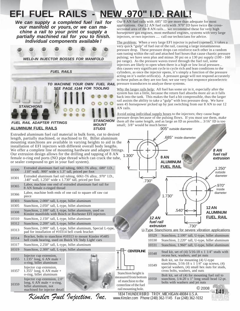
Kinsler Fuel Injection, Inc, 1834 THUNDERBIRD TROY, MICHIGAN 48084 U.S.A.www.Kinsler.com Phone (248) 362-1145 Fax (248) 362-1032
141
EFI FUEL RAILS - NEW .970" I.D. RAIL!
ALUMINUM FUEL RAILSExtruded aluminum fuel rail material in bulk form, cut to desiredlength, partially machined, or machined to fit. Billet aluminummounting stanchions are available in varying heights to aid in theinstallation of EFI injectors with different overall body lengths.We offer a complete line of mounting hardware and adapter fittings.Our extrusion design allows for the drilling and tapping of 8 ANfemale o-ring end ports (NO pipe thread which can crack the tube,or sealer compound to get in your fuel system).
© 2008
84301 htiwsduts"4/11x81-61/5)4(fotes,tikdutSstuntejdna,srehsaw,xehssecer
94301
epyt-U)4(gnitnuomroftes,tiktloB)4(,swercspac"4/11x81-61/5,snoihcnats,sdutsrofstunxehllams)4(,srehsawlaiceps
stundna,srehsaw,stlobssorc
05301otliarleufgnitnuomrof)4(fotes,tiktloB
.tp-21daehllamsgnol"1x02-4/1,noihcnatsstuntejdnasrehsawhtiwstlob
U-Type Stanchions are for severe vibration applications92301 munimulatellib,epyt-U,llat"001.2,noihcnatS03301 munimulatellib,epyt-U,llat"022.2,noihcnatS13301 munimulatellib,epyt-U,llat"069.1,noihcnatS
55301,noisnetxepucrotcejnI
+elamNA6,gnol"531.1munimulatellib,gnir-o
75301,noisnetxepucrotcejnI
+elamNA6,gnol"553.1munimulatellib,gnir-o
95301
"0.2,noisnetxepucrotcejnI,gnir-o+elamNA6,gnol
ton,munimulatellibliatedrotcejnirofdenihcam
.730"
.685" inside diameter
V
.905" outside diameter
V
VV
VV
1.300" 8 ANALUMINUMFUEL RAIL
.970"inside
diameter
1.250"outsidediameterV
V
VV
VV
.540"
.730"
1.730"
V
V
12 ANALUMINUMFUEL RAIL
We can supply a completed fuel rail forour manifold or yours, or we can ma-chine a rail to your print or supply a
partially machined rail for you to finish.Individual components available !
8 ANfuel railextrusion
Stanchion height ismeasured from bottom
of stanchion to thecenterline of the fuelrail mounting hole.
CENTERLINE
00301 ,.D.I"086.,yolla6T-1606,gnibutliarleufmunimuladedurtxEtoofrepdecirp,llat"3.1xediw"009.,llaw"011.
10301 ,.D.I"079.,yolla6T-1606,gnibutliarleufmunimuladedurtxEtoofrepdecirp,llat"037.1xediw"052.1,llaw"041.
56301 rofliarleufmunimuladedurtxefodneenoenihcam,robaLdaerhtdegnir-oelamefNA8
66301 tucwarffoerauqsotliarenofosdnehtobenihcam,robaLeceip
30301 munimulatellib,epyt-L,llat"000.2,noihcnatS50301 munimulatellib,epyt-L,llat"050.2,noihcnatS
80301 nodesu,munimulatellib,epyt-L,llat"001.2,noihcnatSsrotcejniIFEretsehcoRrohcsoBhtiwsdlofinamrelsniK
01301 munimulatellib,epyt-L,llat"051.2,noihcnatS21301 munimulatellib,epyt-L,llat"002.2,noihcnatS
31301 ,epyt-LlaicepS,munimulatellib,epyt-L,llat"000.2,noihcnatStekcarbknarclleb41301#fonoitallatsnirofdap
41301 5845#relsniKtnuomot31301#noihcnatsotstlob,tekcarBsrac'thgiLydnI'6VkciuBnodesu,gniraebknarclleb
71301 munimulatellib,epyt-L,llat"052.2,noihcnatS91301 munimulatellib,epyt-L,llat"003.2,noihcnatS
Our 8 AN fuel rails with .685" ID are more than adequate for mostapplications. Our 12 AN fuel rails with .970" ID have twice the cross-sectional area of the 8 AN rails... we recommend these for very highhorsepower gas engines, most methanol engines, systems with very largeinjectors, or two injectors .... call our technicians for advice.
The problem: When a very large EFI injector is pulsed (opened), it takes avery quick “gulp” of fuel out of the rail, causing a large instantaneouspressure drop. These pressure drops can reinforce each other in a randomram tuning within the rail and attached fuel hoses that cause chaotic pressurepulsing; we have seen plus and minus 30 psi on a 130 psi supply (100 - 160psi range). As the pressure waves travel through the fuel rail, someinjectors are likely to open when there is a high or low local pressure...this causes very significant cycle to cycle rich and lean conditions to thecylinders, as once the injector opens, it’s simply a function of the pressureacting on it’s outlet orifice(s). A pressure gauge will not respond accuratelyto these pulses as they are too fast; we use very fast responce piezoelectricpressure transducers to analyze these systems.
Why the larger rails help: All fuel has some air in it, especially after thesystem has run a little, because the return fuel absorbs more air as it fallsback into the tank. This makes the fuel a bit compressible, thus the largerrail assists the ability to take a “gulp” with less pressure drop. We haveseen 45 horsepower picked up by just switching from our 8 AN to our 12AN rails.
Avoid using individual supply hoses to the injectors; they cause hugepressure drops because of the pulsing flows. If you must use them, makethem all the same length, and as large an ID as possible... 3/16" ID is toosmall; 3/8" would be much better
FUEL RAIL ADAPTER FITTINGS
TO MACHINE YOUR OWN FUEL RAILSEE PAGE #144 FOR TOOLING
WELD-IN INJECTOR BOSSES FOR MANIFOLD
STANCHIONMOUNTSTUDS
FUEL RAILS
STANCHIONS
12 ANfuel railextrusion
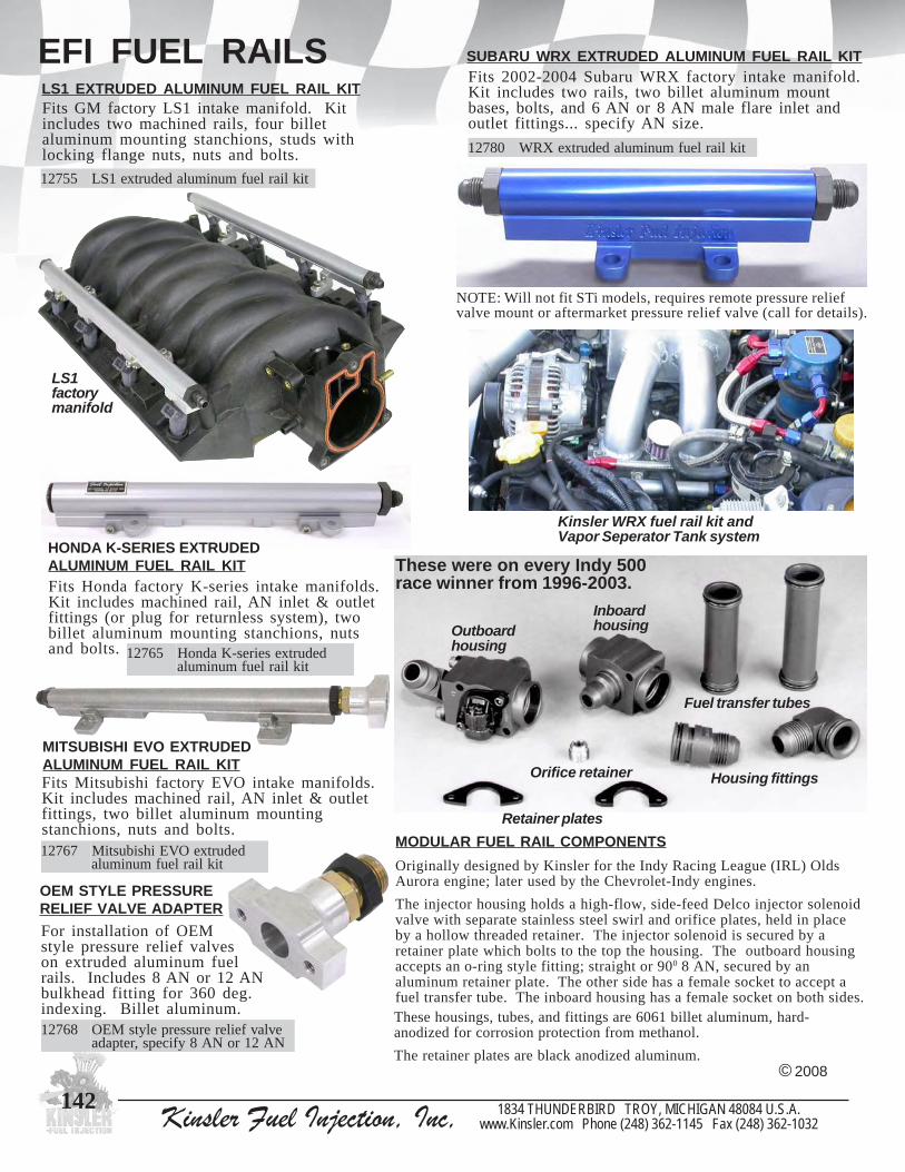
Kinsler Fuel Injection, Inc, 1834 THUNDERBIRD TROY, MICHIGAN 48084 U.S.A.www.Kinsler.com Phone (248) 362-1145 Fax (248) 362-1032
142
EFI FUEL RAILS
© 2008
LS1 EXTRUDED ALUMINUM FUEL RAIL KITFits GM factory LS1 intake manifold. Kitincludes two machined rails, four billetaluminum mounting stanchions, studs withlocking flange nuts, nuts and bolts.
55721 tikliarleufmunimuladedurtxe1SL
SUBARU WRX EXTRUDED ALUMINUM FUEL RAIL KITFits 2002-2004 Subaru WRX factory intake manifold.Kit includes two rails, two billet aluminum mountbases, bolts, and 6 AN or 8 AN male flare inlet andoutlet fittings... specify AN size.
08721 tikliarleufmunimuladedurtxeXRW
NOTE: Will not fit STi models, requires remote pressure reliefvalve mount or aftermarket pressure relief valve (call for details).
LS1factorymanifold
HONDA K-SERIES EXTRUDEDALUMINUM FUEL RAIL KITFits Honda factory K-series intake manifolds.Kit includes machined rail, AN inlet & outletfittings (or plug for returnless system), twobillet aluminum mounting stanchions, nutsand bolts. 56721 dedurtxeseires-KadnoH
tikliarleufmunimula
MITSUBISHI EVO EXTRUDEDALUMINUM FUEL RAIL KITFits Mitsubishi factory EVO intake manifolds.Kit includes machined rail, AN inlet & outletfittings, two billet aluminum mountingstanchions, nuts and bolts.
76721 dedurtxeOVEihsibustiMtikliarleufmunimula
MODULAR FUEL RAIL COMPONENTSOriginally designed by Kinsler for the Indy Racing League (IRL) OldsAurora engine; later used by the Chevrolet-Indy engines.
The injector housing holds a high-flow, side-feed Delco injector solenoidvalve with separate stainless steel swirl and orifice plates, held in placeby a hollow threaded retainer. The injector solenoid is secured by aretainer plate which bolts to the top the housing. The outboard housingaccepts an o-ring style fitting; straight or 900 8 AN, secured by analuminum retainer plate. The other side has a female socket to accept afuel transfer tube. The inboard housing has a female socket on both sides.These housings, tubes, and fittings are 6061 billet aluminum, hard-anodized for corrosion protection from methanol.
The retainer plates are black anodized aluminum.
Fuel transfer tubes
Orifice retainer
Outboardhousing
Inboardhousing
Housing fittings
Retainer plates
These were on every Indy 500race winner from 1996-2003.
Kinsler WRX fuel rail kit andVapor Seperator Tank system
OEM STYLE PRESSURERELIEF VALVE ADAPTERFor installation of OEMstyle pressure relief valveson extruded aluminum fuelrails. Includes 8 AN or 12 ANbulkhead fitting for 360 deg.indexing. Billet aluminum.
86721 evlavfeilererusserpelytsMEONA21roNA8yficeps,retpada
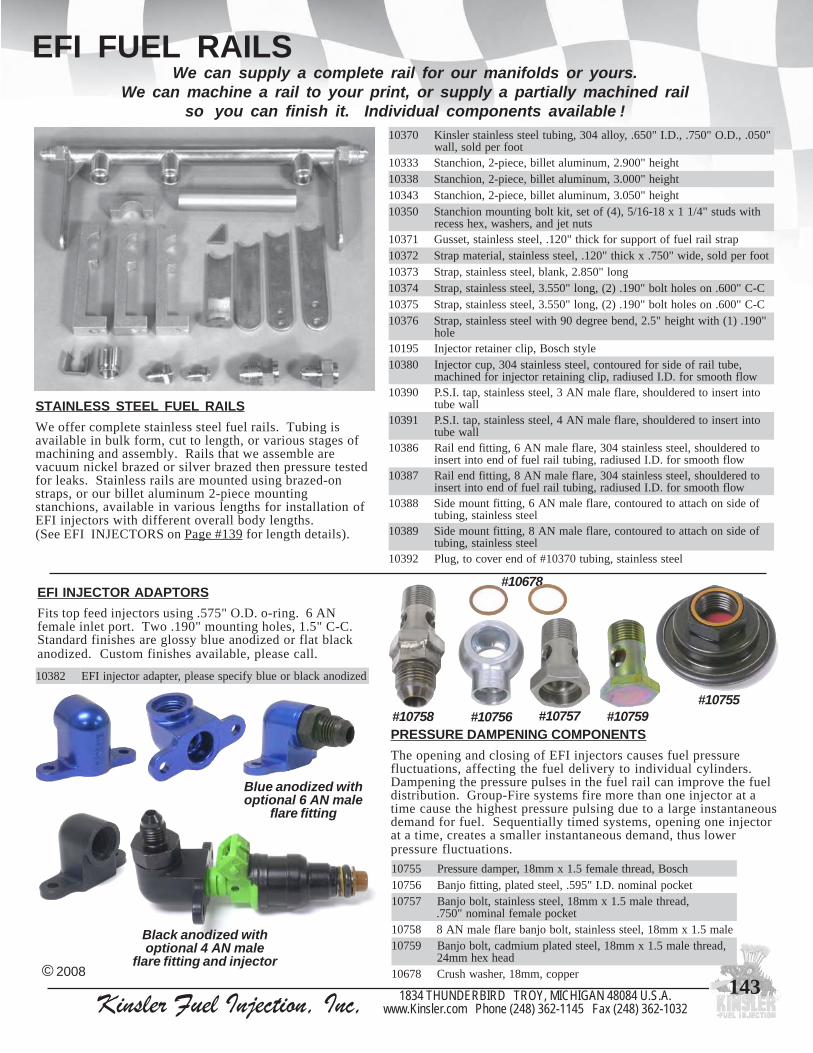
Kinsler Fuel Injection, Inc, 1834 THUNDERBIRD TROY, MICHIGAN 48084 U.S.A.www.Kinsler.com Phone (248) 362-1145 Fax (248) 362-1032
143
EFI FUEL RAILS
STAINLESS STEEL FUEL RAILSWe offer complete stainless steel fuel rails. Tubing isavailable in bulk form, cut to length, or various stages ofmachining and assembly. Rails that we assemble arevacuum nickel brazed or silver brazed then pressure testedfor leaks. Stainless rails are mounted using brazed-onstraps, or our billet aluminum 2-piece mountingstanchions, available in various lengths for installation ofEFI injectors with different overall body lengths.(See EFI INJECTORS on Page #139 for length details).
We can supply a complete rail for our manifolds or yours.We can machine a rail to your print, or supply a partially machined rail
so you can finish it. Individual components available !07301 "050.,.D.O"057.,.D.I"056.,yolla403,gnibutleetssselniatsrelsniK
toofrepdlos,llaw33301 thgieh"009.2,munimulatellib,eceip-2,noihcnatS83301 thgieh"000.3,munimulatellib,eceip-2,noihcnatS34301 thgieh"050.3,munimulatellib,eceip-2,noihcnatS05301 htiwsduts"4/11x81-61/5,)4(fotes,tiktlobgnitnuomnoihcnatS
stuntejdna,srehsaw,xehssecer17301 partsliarleuffotroppusrofkciht"021.,leetssselniats,tessuG27301 toofrepdlos,ediw"057.xkciht"021.,leetssselniats,lairetampartS37301 gnol"058.2,knalb,leetssselniats,partS47301 C-C"006.noselohtlob"091.)2(,gnol"055.3,leetssselniats,partS57301 C-C"006.noselohtlob"091.)2(,gnol"055.3,leetssselniats,partS67301 "091.)1(htiwthgieh"5.2,dnebeerged09htiwleetssselniats,partS
eloh59101 elytshcsoB,pilcreniaterrotcejnI08301 ,ebutliarfoedisrofderuotnoc,leetssselniats403,pucrotcejnI
wolfhtoomsrof.D.Idesuidar,pilcgniniaterrotcejnirofdenihcam09301 otnitresniotderedluohs,eralfelamNA3,leetssselniats,pat.I.S.P
llawebut19301 otnitresniotderedluohs,eralfelamNA4,leetssselniats,pat.I.S.P
llawebut68301 otderedluohs,leetssselniats403,eralfelamNA6,gnittifdneliaR
wolfhtoomsrof.D.Idesuidar,gnibutliarleuffodneotnitresni78301 otderedluohs,leetssselniats403,eralfelamNA8,gnittifdneliaR
wolfhtoomsrof.D.Idesuidar,gnibutliarleuffodneotnitresni88301 foedisnohcattaotderuotnoc,eralfelamNA6,gnittiftnuomediS
leetssselniats,gnibut98301 foedisnohcattaotderuotnoc,eralfelamNA8,gnittiftnuomediS
leetssselniats,gnibut29301 leetssselniats,gnibut07301#fodnerevocot,gulP
© 2008
PRESSURE DAMPENING COMPONENTSThe opening and closing of EFI injectors causes fuel pressurefluctuations, affecting the fuel delivery to individual cylinders.Dampening the pressure pulses in the fuel rail can improve the fueldistribution. Group-Fire systems fire more than one injector at atime cause the highest pressure pulsing due to a large instantaneousdemand for fuel. Sequentially timed systems, opening one injectorat a time, creates a smaller instantaneous demand, thus lowerpressure fluctuations.
55701 hcsoB,daerhtelamef5.1xmm81,repmaderusserP65701 tekcoplanimon.D.I"595.,leetsdetalp,gnittifojnaB75701 ,daerhtelam5.1xmm81,leetssselniats,tlobojnaB
tekcopelameflanimon"057.85701 elam5.1xmm81,leetssselniats,tlobojnaberalfelamNA895701 ,daerhtelam5.1xmm81,leetsdetalpmuimdac,tlobojnaB
daehxehmm4287601 reppoc,mm81,rehsawhsurC
EFI INJECTOR ADAPTORSFits top feed injectors using .575" O.D. o-ring. 6 ANfemale inlet port. Two .190" mounting holes, 1.5" C-C.Standard finishes are glossy blue anodized or flat blackanodized. Custom finishes available, please call.
Black anodized withoptional 4 AN male
flare fitting and injector
#10755
#10678
#10758 #10757#10756 #10759
28301 dezidonakcalbroeulbyficepsesaelp,retpadarotcejniIFE
Blue anodized withoptional 6 AN male
flare fitting

Kinsler Fuel Injection, Inc, 1834 THUNDERBIRD TROY, MICHIGAN 48084 U.S.A.www.Kinsler.com Phone (248) 362-1145 Fax (248) 362-1032
144
TOOLING TO MACHINE FUEL RAILSAND INJECTOR POCKET MACHINING
Machining tools (purchase or rental) so you can machineyour manifold and/or fuel rails. Fast and effective
way to cut the complete detail in one operation.EFI INJECTOR DETAIL
INJECTOR DETAIL IN ALUMINUM RAIL
#11001
Closeupof 8 AN+ o-ringthreaddetail
THREAD END OF ALUMINUM RAIL
50011 ,tekcopgnir-oNA8senihcam,rettucerobretnuoCebutliarleufmunimuladedurtxefoteltuo/telni
01011 dedurtxefoteltuo/telni,)daerht61-4/3(NA8,paTebutliarleufmunimula
30011 ,tekcopgnir-oNA21senihcam,rettucerobretnuoCebutliarleufmunimuladedurtxefoteltuo/telni
51011 foteltuo/telni,)daerht21-61/11(NA21,paTebutliarleufmunimuladedurtxe
© 2008
03011 ssob,teltuofopitnognir-oevitpachtiwrotcejniIFEroF.UECledoMleufhtiwYLNOdesuebot,ngisedhguorht-thgiartssiretemaidedisni
rotcejnielbatiusrehtorospilcgniniaterrotcejnievahtahtsliarnoitneter
13011 ,teltuofopitnognir-oevitpachtiwrotcejniIFEroF.CECledoMydobrotcejnipotsottaesgnir-onaevahlliwssobforetemaidedisni
dedurtxegnisunehwlootsihttceles,dlofinamrossobgnitcatnocmorfspilcreniaterrotcejnituohtiwsliarleufmunimula
23011 srotcejniroflaeselyts"gnub"gnisurotcejniIFEroF.BECledoMspilcreniaterliartuohtiwrohtiw
33011 fopitnognir-oevitpachtiwrotcejniIFEelyts'ociP'roF.PECledoMrotcejnipotsottaesgnir-onaevahlliwssobforetemaidedisni,teltuo
gnisunehwlootsihttceles,dlofinamrossobgnitcatnocmorfydobpilcreniaterrotcejnituohtiwsliarleufmunimuladedurtxe
54011 fopitnognir-oevitpachtiwrotcejniIFEelyts'6VE'roF.6VECledoMrotcejnipotsottaesgnir-onaevahlliwssobforetemaidedisni,teltuo
gnisunehwlootsihttceles,dlofinamrossobgnitcatnocmorfydobpilcreniaterrotcejnituohtiwsliarleufmunimuladedurtxe
10011 IFEelytsgnir-ofogninihcampets-enOleufmunimuladedurtxeotniliatedrotcejni
,snemeiS,retsehcoR,hcsoBtsomrof,liarsrotcejnideefpotosnednoppiNdna,sacuL
gnir-o.D.O"575.htiw64011 IFEelytsgnir-ofogninihcampets-enO
leufmunimuladedurtxeotniliatedrotcejnihtiwsrotcejniosneDdnanihieKtsomrof,liar
gnir-o.D.O"234.
6 AN DETAIL IN ALUMINUM FUEL RAILAllows a 6 AN male + o-ring fitting orKinsler #10355, #10357, or #10359 fuelcup extensions (see Page #141) to bescrewed into fuel rail.
60011 gnir-oNA6senihcam,rettucerobretnuoCsnoisnetxerotcejniroftekcop
11011 tekcopdaerht,)daerht81-61/9(NA6,paTgnittifNA6rofnoisnetxerotcejnirof
PRESSURE TAP IN ALUMINUM RAIL21011 )daerht02-61/7(,NA4,paT
31011,)daerht42-8/3(,NA3,paTnipatISProftekcopdaerht
ebutliarleufmunimuladedurtxe
RENTALRental of special machining tools:We send the tool(s) via UPS, PrepaidCredit Card or COD for the full purchaseprice. You may use the tool for 30 daysmaximum, at which time you may keep itor return it to us (in good shape); we willsubtract the rental fee and refund or creditthe difference. This only covers ourhandling costs and eventual resharpening;we are not really charging a rental fee.We appreciate your business and are gladto help you with your project.
05011 ,01011#:patenihcamenofolatneR41011#,31011#,21011#,11011#
15011 :rettucliatedlaicepsfolatneR,02011#,60011#,50011#,10011#,33011#,23011#,13011#,03011#
64011#,54011#
#11031model ‘CEC’cutting tool
Close up of#11031cutting tooldetail

Kinsler Fuel Injection, Inc, 1834 THUNDERBIRD TROY, MICHIGAN 48084 U.S.A.www.Kinsler.com Phone (248) 362-1145 Fax (248) 362-1032
145
SENSORS FOR EFI SYSTEMS
AIR TEMPERATURE SENSORAn air temperature sensor is a thermistor which monitors air temperature via a change inresistance. This sensor should be mounted where the incoming air will pass across thesensor tip. This sensor, when installed in the intake manifold, may be referred to as aM.A.T. (Manifold Air Temperature) sensor.
All sensors are not created equal! There are different types, styles, and quality. Similar modelsmay have different resistance values or response times. Most ECU's must use specific sensors.A few select ECUs offer the ability to be programmed for operation with various sensors.
COOLANT AND OIL TEMPERATURE SENSORA coolant or oil temperature sensor is a thermistor which monitors coolant or oiltemperature via a change in resistance. This sensor should be installed in the coolingsystem where the coolant will pass across the sensor tip. Thermostat housing areas onwater cooled engines usually provides a good location. Be sure to install the sensor onthe engine side of the thermostat, so it will sense the temperature as the engine is warmingup... since the ECU needs accurate readings to properly meter the fuel during warm up.
IDLE AIR CONTROL (I.A.C.) MOTORA computer controlled motor, of either step or screw design. The idle air motorbypasses air around the throttles to control engine idle RPM during warm-up orwhen the engine is under a load near idle, as when in gear with a torque converter.When the ECU senses that engine RPM is too low, the I.A.C. motor opens thebypass port allowing additional air flow to the engine.
#10652
#10650
#10653
#10651
KNOCK SENSORWorks like an electronic microphone, listening for sound (vibration)that represents spark knock or pre-ignition. The sensor produces anAC signal that increases with the intensity of detected knock. Thisallows the ECU to retard timing This sensor is NOT used on mostracing and high performance engines because the engines generallyproduce too much mechanical noise knock sensor control circuits canbe adjusted to ignore the engines mechanical sounds, however thisreduces it's ability to accurately detect knock
#10664 with #10660
© 2008
25601
yllaiceps,TPN"8/3,elytsMG,rosneserutarepmetriAhtiwelbitapmoc,htgneleborp"585.,relsniKybdettop
dna,cetoM,hcetlaH,orP-deepS/.T.S.A.F,IFD/leccAsmetsyscinortceleygolonhceTIFE
35601
htiw52.1xmm01,sacuL,rosneserutarepmetriAeborp"004.,relsniKybdettopyllaiceps,rehsawhsurc
IFEdna,cetoM,ketyZhtiwelbitapmoc,htgnelsmetsyscinortceleygolonhceT
05601,rehsawhsurchtiw5.1xmm21,hcsoB,rosneserutarepmettnalooC
ygolonhceTIFEdna,cetoM,ketyZhtiwelbitapmoc,htgneleborp"006.smetsyscinortcele
15601eborp"005.,TPN"8/3,elytsMG,rosneserutarepmetliorotnalooC
,hcetlaH,orP-deepS/.T.S.A.F,IFD/leccAhtiwelbitapmoc,htgnelsmetsyscinortceleygolonhceTIFEdna,cetoM
04601eborp"006.,daerht02-2/1,elytsMG,rosneserutarepmettnalooC
ecafruSdlofinaMrofdesuosla,IFD/leccAhtiwelbitapmoc,htgneltnuom14601#htiwgnisneserutarepmeT
14601 eulb,04601#rosneserutarepmeTecafruSdlofinaMrof,gnisuoHmunimulatellibdezidona
Special pottingconsists of injecting a
silicone speciallydesigned for electronicapplications around the
wire leads of thethermistor for
protection againstvibration
#10641with
#10640sensor
installed
06601 sesu,ngisedpets,daerht5.1xmm02,elytsMG,rotoM).C.A.I(lortnoCriAeldI70401#rotcennocnipruoferauqs
26601 36601#retlifriastpecca,telniTPN"8/3,ngisedwolfhgih,gnisuoh.C.A.IetomeR36601 N&K,gnsiuohwolfhgih.C.A.Ietomer26601#rofretlifriA
8915 eulb,retlif36601#fonoitcetorprofretlif-erP
46601
elamefNA8)1(dnastroptelnielamefNA8)2(,gnisuoh.C.A.IetomerdelaeSsiht,selohgnitnuomdedaerht02-4/1)2(htiwgnisuohezisxeh"2/11,tropteltuo
htiwdeppiuqesenignenoesurofdengisedyllaicepssawgnisuoh.C.A.Ietomerebtsumegassapriadellortnocehterehwsregrahcobrutrosrewolblagufirtnec
egakaeltsoobtneverpottelnielttorhtehttamaertsriaehtnidelaes
#10660 #10662
#10663 #5198

Kinsler Fuel Injection, Inc, 1834 THUNDERBIRD TROY, MICHIGAN 48084 U.S.A.www.Kinsler.com Phone (248) 362-1145 Fax (248) 362-1032
146
SENSORS FOR EFI SYSTEMSMANIFOLD ABSOLUTE PRESSURE (M.A.P.) SENSORMay be used either as a barometric sensor, (compensates for atmospheric pressurechange), or a Manifold Absolute Pressure sensor, depending on how the enginemanagement system is configured. This sensor may be remote mounted andconnected to the wiring harness or it may be mounted inside the ECU and mayrequire external plumbing. The ECU powers the MAP sensor via a fixed 5-voltsupply, and the sensor sends a variable 0-5 volt signal back proportional to theabsolute pressure. When used for manifold pressure/vacuum the unit is sensingrelative engine load. A high vacuum (low absolute pressure reading) indicates tothe ECU that the engine is experiencing less load, therefore requiring less fuel. Asthe absolute pressure reading increases, the ECU would increase the pulse time tothe injectors, therefore suppling more fuel.
VACUUM SIGNAL JUNCTION BLOCK AND COMPONENTS
Vacuum signal junction block for collecting vacuum/boost signal on individualthrottled runner manifolds. This junction block system is constructed withfittings and tubing to provide a good signal response while also minimizingexcess air bleed which causes idle RPM control problems. See Page #135 forvacuum/boost reference kits and components.
#10905 - Signal Damper with3/16" barbed fittings
Brandon Switzer’sNMRA
PRO 5.0 Mustang,Fastest N2O/EFI car
7.54 @ 189 MPH
Uses KinslerHigh-flow4-barrel
throttle bodyand
EFI systemcomponents
#10901 withbarbed fittings
installed
#10901 with quickrelease fittings
installed
© 2008
45601 ygolonhceTIFE,MG,raB1,rosnesPAM55601 MG,raB2,rosnesPAM65601 MG,raB3,rosnesPAM75601 .T.S.A.F,IFD/leccA,MG,raB1,rosnesPAM85601 .T.S.A.F,raB5,rosnesPAM
Note : 3/16” barbed fittings may be changed to 3AN male flare fittings.
SIGNAL DAMPER
The strong intake pulses on a tuned I.R. manifold along with ahigh performance or racing camshaft will create fluctuations inthe signal sensed by the MAP sensor. The Kinsler signal damperwill smooth out the signal pulsing. This is accomplished byflowing the signal across an orifice and into the accumulatedvolume within the damper.Note: transient signal amplitude may be slightly reduced.
50901 )sgnittifgnidulcniTON(gnol"052.4xretemaid"009.1,repmadlangiS

Kinsler Fuel Injection, Inc, 1834 THUNDERBIRD TROY, MICHIGAN 48084 U.S.A.www.Kinsler.com Phone (248) 362-1145 Fax (248) 362-1032
147
TPS rotation isdetermined
while looking atthe end of thethrottle shaft
CONNECTORASSEMBLY
30401 SPTMGtifot,kcaPrehtaeW,talf,nip3
clockwiserotation
counter-clockwiserotation
58601 ,elbatsujda,'D'ledom,elytsMG,SPTnoitatoresiwkcolc
68601 ,elbatsujda,'D'ledom,elytsMG,SPTnoitatoresiwkcolc-retnuoc
5907 SPTelytsMGrof,ssobretpadaSPTno-tloB0907 SPTelytsMGrof;godevirD
GM STYLESENSORS
THROTTLE POSITION SENSORS (TPS)AND ACCESORIES
© 2008
#10686
#7095#7090
#10685
GM style TPS, adapterboss and drive dog
installed on Kinsler fourbarrel throttle body
All Kinsler bolt-on TPS adapter bosses are .500" C-Cupper mount hole to throttle shaft and .587" C-C lowermount hole to throttle shaft. All of our manifold endsare drilled and tapped with these two bolt holes.
All Kinsler drivedogs are made
for a 3/8”diameter shaft
#7095with#7090
The TPS is a potentiometer actuated by a throttle shaft. TheECU supplies a constant 5 volts to the TPS which sends a 0-5volt signal back, proportional to throttle opening. The ECUuses this signal to find the proper fuel rate in it’s basic fuel maptable, and/or for accel/decel fueling.
1707 SPTelyts1SLrof,ssobretpadaSPTno-tloB2707 SPTelyts1SLrof,godevirD
#7071
#7072
#7071 with #7072
Exampleof LS1
style TPS
KinslerDragon Claw
withbolt-on TPSadapter and
TPSKinsler 4-barrel throttle body withbolt-on TPS adapter and TPS
#7097#10689
98601 ,elytsgnat/evoorgniwtSTC/MG,SPTnoitatoresiwkcolc-retnuoc
7907 SPT98601#rof,ssobretpadaSPTno-tloB7707 SPT98601#rof,godevirD
#7077#7097 with #7077

Kinsler Fuel Injection, Inc, 1834 THUNDERBIRD TROY, MICHIGAN 48084 U.S.A.www.Kinsler.com Phone (248) 362-1145 Fax (248) 362-1032
148
THROTTLE POSITION SENSORS (TPS)AND ACCESORIES
© 2008
09601 kinhcetovoN;SPT0807 SPTkinhcetovoNrof;ssobretpadaSPTno-tloB1807 SPTkinhcetovoNrof;godevirD
NOVOTECHNIK SENSORWill run CW and CCW
#10690#7080
#7081
#7091#7096
FORD STYLE SENSORS
48601 noitatoresiwkcolc-retnuoc,'F'ledom,elytsdroF;SPT6907 SPT48601#rof;ssobretpadaSPTno-tloB1907 SPT48601#rof;godevirD
#10684
#7093#7098
28601 noitatoresiwkcolc,'M'ledom,elytsdroF;SPT38601 noitatoresiwkcolc-retnuoc,'M'ledom,elytsdroF;SPT
8907 SPT38601#&28601#rof;ssobretpadaSPTno-tloB3907 SPT38601#&28601#rof;godevirD
#10682
#7080with#7081
#7098with#7093
#7096with#7091
- CONTINUED -
#7078 #70798707 SPTelytsevlav-3droFrof,ssobretpadaSPTno-tloB9707 SPTelytsevlav-3droFrof,godevirD
FORD 3-VALVE STYLE BOSS AND DRIVE
#7078 with #7079

Kinsler Fuel Injection, Inc, 1834 THUNDERBIRD TROY, MICHIGAN 48084 U.S.A.www.Kinsler.com Phone (248) 362-1145 Fax (248) 362-1032
149
THROTTLE POSITION SENSORSAND ACCESORIES
© 2008
#7087#7086
6807 llabdnatfahs,godevirdhtiw,.S.P.TelytsMGroF)yficeps(dezidonaeulbrodehsilop,sgniraeb
7807 munimuladehsilop,SPT6807#htiwesuroF
Remote TPS MountFor Delco/CTS lever style TPS only. Excellent foradapting TPS when a shaft end is not accessible, oryou want to drive the TPS at a different rate (byusing different length throttle arms). 1.925" tall,two #10 mount holes (1.570" C-C). Billet aluminumhousing with dual bearings for smooth operation.Weighs 0.3 lbs. Can be used to link T. P. S. to dataacquisition system for use with EFI.
Frank Yarasezski’s blown EFI Willy’s
Alf Stellan’s blown EFI GTOAl Maynard’s 1967 Camaro
- CONTINUED -
Bugcatcher
Birdcatcher

Kinsler Fuel Injection, Inc, 1834 THUNDERBIRD TROY, MICHIGAN 48084 U.S.A.www.Kinsler.com Phone (248) 362-1145 Fax (248) 362-1032
150
EXHAUST GAS OXYGEN (EGO)Installed in the exhaust system, this generates a low voltage signal (usually 0-5 volts) relative to theoxygen in the exhaust, which is proportional to the engine's instantaneous air-fuel ratio.This allows the ECU to adjust the fuel to maintain a proper air-fuel ratio.
HOW IT WORKS :The inside and outside of the ceramic body of the sensor is coated with a thin layer of zirconium/platinum which serve as electrodes. The inside surface is exposed to ambient air while the outsidesurface is exposed to exhaust gas. The difference in oxygen concentration between the exhaust gasand the ambient air results in a voltage differential between the two surfaces. This voltage serves as ameasure of oxygen in the exhaust. The ceramic body of the sensor becomes conductive for oxygenions starting at or above 572o Fahrenheit (300o Celsius). Sensor response time below this temperatureis measured in seconds, while response time at the ideal temperature of 1112o Fahrenheit (600o C) isless than 50 milliseconds (ms). Some sensors have heater circuits to aid in quickly raising the sensortemperature to operating levels. Most production sensors operate only in a narrow band close tostoichiometric (14.7:1 air-fuel ratio). These sensors are used for fueling corrections when the engineis at light load.
Some special sensors, like part #10672, operate through a wide band of air-fuel ratios. Wide bandsensors may respond much quicker, allowing fuel corrections to be safely performed on an engineoperating at wide open throttle. Most aftermarket ECU's that can use this type of sensor will readair-fuel ratios from 10:1 through 17:1. Very special units can monitor air-fuel ratios from 6:1 through60:1 either with a custom configured ECU or laboratory test equipment.
SENSORS FOR EFI SYSTEMS
AIR FUEL RATIO METER
#11065#11070
#10673
#10672
17601 htiwderiw,reteMoitaRleuF/riA56011/07011#nodesu,rosnesnegyxodetaeHssenrahreteMoitaRleuF/riAotniyltceridsgulptahtrotcennocralucricnip-3
27601 ,eriw-4,daerht5.1xmm81,MSLhcsoB,rosnesnegyxodnabediwdetaeH.S.T.Ddna,s'UCEygolonhceTIFEledom-etal,cetoM,hcetlaHhtiwelbitapmoc
sretemomanyd37601 "31,eriw-5,daerht5.1xmm81,USLhcsoB,ronsesnegyxodnabediwdetaeH
YLNOLEUFDEDAELNU,sdaeleriw53401 slaeselbacdna,snip,gnisuohhtiw,elam,37601#rof,ylbmessarotcennoC
57601 ,gulp,gnubrosnesnegyxO,ylbmessarehsawhsurcdna
leetssselniats40367601 elamef5.1xmm81,gnuB
403,rosnesnegyxorof,daerhtleetssselniats
77601 elam5.1xmm81,gulP403,xehelamef"61/5,daerht
leetssselniats87601 reppoc,mm81,rehsawhsurC
07011 xhtgnel"029.3,rotacidnioitarleuf/riaDEL03,retemlaH,YLNOreteMhtped"038.xhtdiw"079.1
56011 "4.2xhtgnel"520.4,rotacidnioitarleuf/riaDEL61,ZB,YLNOreteMhtped"0.1xhtdiw
17011 ni-dlew,rosnesnegyxo17601#,retem07011#sedulcni,tikoitaRleuFriAsnoitcurtsnidna,ssenrahgniriw,gnub
27011 )2(,srosnesnegyxo17601#)2(,retem07011#sedulcni,tikoitaRleuFriAsnoitcurtsnidna,ssenrahgniriwrosneslaud,sgnubni-dlew
37011 ni-dlew,rosnesnegyxo17601#,retem56011#sedulcni,tikoitaRleuFriAsnoitcurtsnidna,ssenrahgniriw,gnub
47011 rofrosnesnegyxodnabediwKTNsedulcni,leccA,tikoitaRleuFriA,ssenrahhtiweguagyalpsiddetanimulli"61/12,leufdedaelnurodedael
egnaroitarleuf/ria1:02ot1:0166011 rosnesnegyxoelgnis,retem07011#rof,ssenrahgniriW86011 srosnesnegyxolaud,retem07011#rof,ssenrahgniriW
#10435
#11074 Accel/DFI wide bandoxygen sensor kit with 2 1/16”illuminated display gauge andharness. NTK oxygen sensorfor leaded or unleaded fuel
with 10:1 to 20:1 air/fuel ratios
© 2008
#10676 Bung has pilot for positioning inthe exhaust tubing for welding

Kinsler Fuel Injection, Inc, 1834 THUNDERBIRD TROY, MICHIGAN 48084 U.S.A.www.Kinsler.com Phone (248) 362-1145 Fax (248) 362-1032
151
EFI SPEED AND SYNCHRONIZATIONSIGNAL GENERATORS
FORSTANDARD CHEVROLET
FORSMALLBLOCKFORD
HALL EFFECT SENSORSDetects the passing of a ferromagneticmaterial such as a gear tooth or bolt headnear the sensing tip. Sensing is accomplishedby the interruption of a magnetic field,providing non-contact speed sensingcapability down close to zero-speed. Unitshave stainless steel housing with 3/8-24thread. Maximum sink current: 25mA and10,000 Hz frequency response.
T-TYPE SPEED/SYNC DISTRIBUTORFits 10.2" tall deck Chev, billet aluminum Spacer required for standarddeck height. Blue anodized; custom anodizing available. Has Kinslerspeed/sync trigger wheel and dual Hall effect sensor #10630. Separatemounting plate for distributor cap allows the cap to be rotated for rotorphasing. Cap secured with Marine style hold-down clamps. We canbuild CUSTOM distributors for different makes of engines.
63601 vehCkceddradnatsrofrecapshtiwrotubirtsidcnys-deepsetelpmoC
KINSLER'S UNIVERSAL BELT DRIVESPEED/SYNC TRIGGER ASSEMBLY
51601 delaeslaudnotfahsretemaid"8/510601#leehwreggirtsesU.sgniraebtelliB.03601#rosnesllaHlauddnasbl4/12shgiew,ylbmessamunimula
13601 pullupK7.4htiwnoisrevrotelloC23601 tsumUCE(noisrevrotcellocnepO
)tucricpulluplanretnievah
KINSLER'S SPEED/SYNCTRIGGER WHEELS
00601 epyt-Trofcnys/deeps8VketyZrotubirtsid
10601 erob"8/5,cnys/deeps8Vepyt-K20601 cnys/deeps8VygolonhceTIFE
rotubirtsidepyt-Trof30601 21VLAICEPSygolonhceTIFE
erobtfahs036.,cnys/deeps
© 2008
DUAL HALL EFFECT SENSORDetects the air gap in the rotatingspeed/sync wheel to supply triggeringdata to the ECU for reference ofengine RPM and cam timing.
03601 sdaelhtiw,MG,rosneslauDrotcennocP-Wnip-4dna
ACCEL DUAL-SYNC DISTRIBUTORSOne distributor generates two signals:cam and crank for sequential fired fuelinjected engines. All popularapplications available. LED readoutallows you to synchronize cyl. #1 withthe hall effect pick-up in the distributorwithout expensive equipment. Large orsmall diameter cap with HEI type maletower design with screw-on wireretainer. Billet housing.
#10600Front Rear
TM
TM a division of Autotronic Controls Corporation
LOW PROFILEMSD BILLET ALUMINUM
EFI DISTRIBUTORSFOR CHEV V8 ENGINES
For magnetic triggered EFIsystems ONLY !!!
55601 tsuM!!!YLNOlangis.cnysnoitcejnIreggirtleehwylfrotfahsknarcesuthgiehkceddradnatsstiF.metsys #10655

Kinsler Fuel Injection, Inc, 1834 THUNDERBIRD TROY, MICHIGAN 48084 U.S.A.www.Kinsler.com Phone (248) 362-1145 Fax (248) 362-1032
152
CONNECTORSWeather Pack (W-P) assemblies include male tower,female shroud, mating terminal pins, and seals.
10401 ylbmessarotcennockcaPrehtaeWniP-1
20401 duorhs/rewot,ylbmessarotcennockcaPrehtaeWniP-2kcalbera
76401 eraduorhs/rewot,rotcennockcaPrehtaeWtalfniP-2sdaelreggirtIIV.neGleccAdna.T.S.A.Fstif,yerg
30401 ylbmessarotcennockcaPrehtaeWtalfniP-340401 ylbmessarotcennockcaPrehtaeWtalfniP-450401 ylbmessarotcennockcaPrehtaeWdnuorniP-560401 ylbmessarotcennockcaPrehtaeWtalfniP-6
70401 stif,ylbmessarotcennockcaPrehtaeWerauqsniP-406601#rotomlortnocriaeldiMG
83401 MG1TLstif,ylbmessarotcennockcaP-irteMtalfniP-4srotomlortnocriaeldi
93401 1TLstif,ylbmessarotcennockcaP-irteMdnuorniP-3srosnesnoitisopelttorhtMG
80401 ylbmessarotcennocrosneserutarepmettnaloocMG90401 yerg,ylbmessarotcennocrosneserutarepmetriaMG
01401 rosnesstif,eulb,ylbmessarotcennocrosnes.P.A.MMG45601#
11401 stif,egnaro,ylbmessarotcennocrosnes.P.A.MMGsrosnes.P.A.MraB3dna2tsom
21401 stif,neerg,ylbmessarotcennocrosnes.P.A.MMGIFD/leccA,75601#rosnes
31401 rosneskconkMGrof,ylbmessarewotelamniP-1
13401llehskcabdedlomdnasnipdetalpdlog,rotcennocelamefnip-3cepS-liM
lenaprofegnalf,ssenrahgniriwygolonhceT-IFEnodesuylnommoc,toobgnitnuomdaehklubro
23401 llehskcabdedlomdnasnipdetalpdlog,rotcennocelamnip-3cepS-liMssenrahgniriwygolonhceT-IFEnodesuylnommoc,toob
43401 ,ssenrahrotcejniorPdeepS/PFnodesusa,nip-01,ylbmessarotcennoCslaeselbacdnasnip,duorhs,rewotsedulcni
63401 ,IIV.neGleccAro.T.S.A.FrofrotcennocUCE,gnisuohrotcennocnip-03snoitangisednipY-LroK-Ayficeps,deriuqer.scpowt
73401 03fokcap,rotcennoc63401#rof,sniplanimreT57401 dedulcnisniplanimret,eludomSIDEdroFrof,ylbmessarotcennocnip-21
#10436
#10431 #10432
© 2008
41401 ,gnisuoh:sedulcni,epytesaelerkciuq,ylbmessarotcennocrotcejnItoobdna,slanimretelamef
02401 ,gnsiuoh:sedulcni,epytesaelerkciuq,ylbmessarotcennocrotcejnI)26401#(toobdna,slanimretelamef
12401 elamef,gnisuoh:sedulcni,epytno-hsup,ylbmessarotcennocrotcejnI)26401#(toobdna,slanimret
06401 nisrotcejni'5elytS'otnospans,ylbmessarotcennocrotcejnieerged09slanimretelamefdnagnisuoh:sedulcni,golatac
26401 srotcennoc12401#dna02401#stif,toobllehskcabrebbuR46401 elamef:sedulcni,epytMEOihpleD;ylbmessarotcennocrotcejnI
slaeselbacdnaslanimret96401 ,gnisuoh:sedulcni,ledometalhcsoB,ylbmessarotcennocrotcejnI
slaeselbacdnaslanimretelamef
EFI INJECTOR CONNECTORS
#10407#10408#10405 #10409
#10401 #10402 #10403 #10404 #10406
EFI CONNECTORS, RELAYS, ANDACCESSORIES
METRI-PACK CONNECTORS51401 ylbmessarotcennocdelaeshtiw,redlohesufkcaP-irteM43401 +IIVneGleccAro.T.S.A.Fstif,ylbmessarotcennocniP-01
dnaelam,duorhsdnarewot:sedulcni,ssenrahrotcejnislaeselbac,slanimretelamef
83401 lortnocriaeldi1TLledomMGstif,ylbmessarotcennocniP-4rotom
93401 rosnesnoitisopelttorht1TLledomMGstif,rotcennocniP-395401 noitingi+IIVneGleccAstif,ylbmessarotcennocniP-8
llehskcabhtiwduorhsdnarewot:sedulcni,ssenrahretpadaslaeselbac,slanimretelamefdnaelam,kcol
86401 slioc1SLledomMGstif,ylbmessarotcennocniP-437401 elbacnoitacinummoc.T.S.A.Fstif,ylbmessarotcennocniP-3
#10460#10421#10420#10414 #10464 #10469
#10439
#10438
#10468
#10434 #10459
#10415
#10473

Kinsler Fuel Injection, Inc, 1834 THUNDERBIRD TROY, MICHIGAN 48084 U.S.A.www.Kinsler.com Phone (248) 362-1145 Fax (248) 362-1032
153
32401 )worhTelbuoDeloPelgniS(etuor-ertnerruc,epytnigulp,pma03,yaleRtekcos72401#esu
42401 )TDPS(etuor-ertnerruc,epytnigulp,pma02,yaleR
52401 )TDPS(tcennoctnerruc,gnisuohlatem,epytnigulp,pma03,yaleRtekcos72401#esu
62401 etuor-ertnerruc,ylbmessarotcennockcaPrehtaeWhtiw,pma03,yaleR72401 erutaefgnikcol,52401#dna32401#syalerrof,ylbmessatekcoS82401 erutaefgnikcolno-dda,42401#yalerrof,ylbmessatekcoS
92401 yaler62401#rof,batgnitnuoM
RELAYS Preferred relay wiring diagram
EFI CONNECTORS, RELAYS, ANDACCESSORIES
WIRETemperature range of -760F to +3920F, 600 volts.
CURRENT REROUTE CURRENT CONNECT
© 2008
BALLAST RESISTOR03401 )8(gnisuroflortnoctnerruc,'RP2'ledomsacuL
UCEnosrotcejni)mho5.3-2(ecnadepmiwolevirddetimilrosrevirdnoitarutashtiwdeppiuqe
snipdnarotcennocgnitamhtiw,segats
#10430
24401 retemaidedisni"8/1,gnibutknirhstaeH34401 retemaidedisni"61/3,gnibutknirhstaeH44401 retemaidedisni"4/1,gnibutknirhstaeH54401 retemaidedisni"8/3,gnibutknirhstaeH64401 retemaidedisni"2/1,gnibutknirhstaeH74401 retemaidedisni"4/3,gnibutknirhstaeH84401 retemaidedisni"1,gnibutknirhstaeH94401 retemaidedisni"2/11,gnibutknirhstaeH
HEAT SHRINK TUBINGHeat Shrink Tubing is in 4-foot longsections and black. Select appropriatediameter tubing for wire gauge, cut tubingto length desired, slide over wire beforeterminating, position over connection, useradiant heat gun to shrink tubing tight towire. Do not use open flame to heat tubing.
EXPANDABLE SLEEVE ANDTY-RAP CABLE TIES
05401 ot"8/1,eveelselbadnapxE,retseylop,ezisegnar"61/7
htgneltoof0115401 ot"4/1,eveelselbadnapxE
,retseylop,ezisegnar"4/3htgneltoof01
25401 ot"2/1,eveelselbadnapxE,retseylop,ezisegnar"4/11
htgneltoof0135401 "8/53,seitelbacpaR-yT
,.aideldnub.xam"4/3,gnol.scp001,tneculsnart
45401 "2/15,seitelbacpaR-yTeldnub.xam"4/11,gnol.scp001,tneculsnart,.aid
04401 foedisnidaelGWA81eno,eriwdedleihStoofrepdlos,tekcajnolfetetihw,dleihsdediarb
14401 foedisnidaelGWA81owt,eriwdedleihStoofrepdlos,tekcajnolfetetihw,dleihsdediarb
#10441
#10440
#10425#10427#10423
#10428#10424
socket#10426 #10429
TOOLS AND ACCESSORIES
00401 ,eldnahwolley,srotcennockcaPrehtaeW,lootnoitcartxEebutelamef
56401 "240.,eldnahder,srotcennockcaP-orciM,lootnoitcartxEedalb"170.x
66401 ,eldnahneerg,srotcennockcaP-irteM,lootnoitcartxEedalbderepatleetsgnirps
71401 neerg,tnioPeulB,lootnoitcartxeniP
61401 oteriwspmirc,srotcennockcaPrehtaeW,lootgnipmirCslanimretGWA02-41,lanimret
03501 eroc,eveelsdnanipkcaPrehtaeWdelaeS,lootgnipmirCGWA02-41,noitalusnidna
13501 ,ylnoelamef,001kcaP-orciMdelaesnU,lootgnipmirCGWA22-41,noitalusnidnaeroc
23501 dnaeroc,082&051kcaP-irteMdelaeS,lootgnipmirCGWA02-41,noitalusni
81401 elttoblm7,rotacilppano-hsurb,recnahnEtcatnoCkeewT91401 stcatnoclacirtcelerof,esaergevititneverpnoisorroC#10419
#10418
#10466
#10400
#10530

Kinsler Fuel Injection, Inc, 1834 THUNDERBIRD TROY, MICHIGAN 48084 U.S.A.www.Kinsler.com Phone (248) 362-1145 Fax (248) 362-1032
154
EFI PLUMBING
FILTRATIONPleated 10-micron paper filter elements ( see FUEL FILTERSon Pages #162-166) in this system are very fine, so they doan excellent job of cleaning the fuel, but this means theyplug up quickly. Replace them after about every twentyhours of racing when operating on gasoline or every raceevent when using methanol. It is an excellent idea to useone of our large 45 micron filters to filter the fuel whenfilling the main tank. This will greatly extend the life of theelements in the system. Be extremely careful to keep waterout of the tank as it swells the paper elements shut.
SYSTEM PRESSUREWe prefer to operate our EFI systems at about 70 PSI rather than the typical 45 PSI, as we find slightly better power and economyand less sensitivity to pressure fluctuations. A 1 PSI fluctuation affects a 45 PSI system more than a 70 PSI system: see ORIFICETHEORY on Pages #202-203. Sometimes system cost prohibts running the higher pressures.
Fuel pressure reading should be taken as close as possible to the center of the fuel rail. This provides an average pressure reading.If the pressure gauge is installed before filters, tees, etc., the pressure gauge will read higher pressure than there really is in therails, due to the pressure drop across these components.
FUEL RAIL BASICSWe recommend that EFI injectors be plumbedusing fuel rails, rather than individual hoses.The instantaneous opening and closing of theinjectors causes large pressure pulses in thesystem. This pulsing can be dampened bycommon fuel plenums (rails), a high qualitypressure relief valve, and/or a speciallydesigned damper (see Page #143). Pressurespikes can cause poor fuel distribution and insevere cases lean conditions which can damagethe engine.
Two types of fuel rail material : 1) Aluminum - low cost and easy to machine. 2) Stainless steel - for use with alcohol and nitro.
See EFI FUEL RAILS on Pages #141-143 and TOOLING TO MACHINE FUEL RAILS AND INJECTOR MOUNTING on Page #144.
PLUMBING OF EFI SYSTEMWITH ELECTRIC FUEL PUMP ONLY
VACUUM/BOOST REFERENCEThe pressure relief valve should be referenced to vacuumand/or boost. This will help offset the manifold absolutepressure on the outlet of the injector to maintain aconstant injector flow rate (see EFI PRESSURE RELIEFVALVES AND ACCESSORIES on Pages #134-135, Fig.2).
TYPES OF FUEL RAIL PLUMBING PARALLEL :
Parallel plumbing is done by teeing the feed hose from the pump into both fuel rails, then connecting the two outlets tothe pressure relief valve, see Fig 1. This gives twice the flow capacity of series plumbing. It also reduces the fuelvelocity in the rail when compared to series plumbing. If the fuel velocity is too high it may cause flow disturbance inthe fuel rails. A parallel configuration is recommended to achieve the best cylinder to cylinder distribution.
SERIES :Series plumbing is done by feeding fuel into one rail, then out to the other rail, then to the pressure relief valve, seeFig. 2. This configuration has inherent fuel supply problems for the last cylinders in the series. This is most apparenton a Group Fire type of EFI system since the injectors are fired in groups of 4 or 8 (on a V8 engine) causing a highdemand in an instantaneous period of time. This plumbing method is NOT recommended on high horsepower engines.
© 2008
SERIES PLUMBINGFig. 2
PARALLEL PLUMBINGFig. 1

Kinsler Fuel Injection, Inc, 1834 THUNDERBIRD TROY, MICHIGAN 48084 U.S.A.www.Kinsler.com Phone (248) 362-1145 Fax (248) 362-1032
155
EFI PLUMBING
This system has two "flow loops" :A - The fuel from the main tank flows through the 45 micron filter into the transfer pump, which pushes
it into the VST If the engine isn't running, all of this fuel passes out through the top center fittingand back to the top of the main tank via the "backpressure" valve. This valve is set at about five PSI on EFI systems tokeep the VST pressurized, both to prevent boiling in the VST and cavitation of the main fuel pump, which wouldproduce vapor.
B - To start the engine, turn "on" the electric transfer pump. Leave the transfer pump "on" whenever the engine is running.After the fuel pressure in the VST comes up to about 5 PSI, turn "on" the electric starting pump. Fuel will flow to the 10micron filter, while the check valve on the outlet of the mechanical fuel pump prevents fuel from passing back throughthe clearances of the pump gears. All of the fuel is routed through the fuel rail, to purge out any vapor bubble thatformed in it and the hoses during the “hot soak” since the last time the engine was shut off.
Once the engine is running, the mechanical pump is adequate to run the engine. Turn “off” the electric start-up pump. Thecheck valve on it’s outlet prevents the high pressure fuel from back flowing through it.
2)
This schematic isFOR EFI ONLY,for constant flowsee Page #116.It is important to read thenotes on the constant flowplumbing schematic nomatter what type of fuelsystem is being used.NOTES :
WITH MECHANICAL FUEL PUMP AND VAPOR SEPARATOR TANK SYSTEM
© 2008
VAPOR SEPARATOR TANKS; PAGES #115-1181) Gasoline is a mixture of many types of hydrocarbons,some of which boil off at just above room temperature.It is common for some boiling to occur inside a warm fuel tank and fuel lines. The vapor bubblesproduced won't become liquid again when the main pump pressurizes the fuel... they will become smaller,but they will still be there. When these reach the injectors they cause an erratic lean condition.
The VST has a special baffle system to separate out the vapor coming into it from both the main tank andthe pressure relief valve. This vapor is collected in a chamber that is connected to the top center fittingon the tank, where it passes out to the main tank via the backpressure valve. This insures that the finalsupply pump(s) will receive vapor free fuel.
- CONTINUED -
MAINFUELTANK
INLET FUELFILTER
45 MICRON
ELECTRICTRANSFER
PUMP
BACKPRESSURE VALVE (NOMINAL 5 PSI)VENT
0 - 15 PSI GAUGE
VAPORSEPARATOR
TANK
MAINFUEL PUMP
USUALLYMECHANICAL
ONE WAYCHECKVALVES
ELECTRIC FUEL PUMP(STARTING)
FUELFILTER
10 MICRON
PRESSURERELIEFVALVE
FUEL RAILSAND
INJECTORS
See Page#154for FUELRAIL andPRESSURERELIEFVALVEPLUMBING.
The plumbing schematic would be simpler ifwe eliminated the Vapor Separator Tank(VST) by drawing out of the bottom of the maintank through the 45 micron filter directly to theinlet of the electric starting and mechanical fuelpumps, then plumb the pressure relief valve backto the top of the main tank. So why use the VST?
3) An excellent feature of the VST is that it allows you to use all the fuel from the main tank with no lean conditions. As the maintank runs low, the fuel will slosh away from the pickup, letting air go through the transfer pump and into the VST where it isseparated out. The 15 PSI gauge will drop close to zero under this condition, but you can still run for the pits at wide openthrottle. As soon as the main system pressure drops you must stop running at wide open throttle or engine damage will occur.
4) A mechanical pump is preferred to do the main system pressure work as it is more reliable than any electric pump and reducesthe overall system’s current draw. Current draw on an average electric pump can range from about 8-10 amps for a small blocknaturally aspirated V8 gasoline system, up to 60 amps for a large turbocharged system. When engine RPM increases, thedemand for fuel volume increases. When the engine RPM decreases, the fuel demand decreases. The mechanical pump outputincreases/decreases with RPM, thus following the engine requirement. An electric fuel pump provides a constant volume offuel, even if there are changes in engine RPM, throttle angle, and load. This volume is not needed at idle and light loadconditions, causing the pressure relief valve to work harder to maintain the proper fuel pressure (see PRESSURE RELIEFVALVES on Pages #133-136). On an EFI system, the mechanical pump isn’t used to sense engine speed, as it is on a constantflow system.Never use a "cross drilled block of metal" type angle fitting on any pump inlet hose...where the drills intersect there is a razor sharp edge that promotes pump inletcavitation. The best solution is to make gentle bends with the hoses, as in the aboveschematic. If there is a really tight place, use a bent tube type fitting.
5)
!!!!!Vapor
Separator TankMAXIMUM
PRESSUREIS 15 PSI

Kinsler Fuel Injection, Inc, 1834 THUNDERBIRD TROY, MICHIGAN 48084 U.S.A.www.Kinsler.com Phone (248) 362-1145 Fax (248) 362-1032
156
EFI PLUMBING
PLUMBING TWO PRESSURE RELIEF VALVESWe recommend installing two pressure relief valves on any system utilizing an electric pump(s) where the pump outputexceeds approximately 1000 lbs/hr. Using two pressure relief valves allows additional volume to be dumped off, to main-tain good pressure regulation. If only one pressure relief valve were installed, there would be excessive pressure rise in thesystem at low fuel demand conditions.
MECHANICAL INJECTION PUMP WITH ELECTRIC "STARTING" FUEL PUMP SYSTEM
This provides a large volume at high rail pressure for higher horsepower applications and alternate fuels, such as methanol,ethanol, and nitro combinations. It eliminates the high current draw associated with large or multiple electric pump installa-tions. A mechanical pump replaces electric pump #2 in the above schematic. The electric pump is used to start the engine.Once the engine is at sufficient RPM, the mechanical pump will supply all the fuel and the electric pump can be shut off.
Danny Boy Land Speed Streamliner owned by RichardThomason and Ed Tradup. Powered by a small blockChevrolet V8 with Kinsler 3-piece Dart/Buick manifold
equipped with F.A.S.T. EFI system
Danny Boy’s Records
C.I.D371 FIA Flying Mile 340.394 MPH371 FIA Flying K 547.250 KPH371 C/FS Flying Mile 332.921 MPH292 D/BGS Flying Mile 315.489 MPH256 E/BGS Flying Mile 290.007 MPH371 Bonneville Flying Mile 340.394 MPH
© 2008
- CONTINUED -
NOTE:Check out your electricalsystem to be sure it will
support the ampere drawof two pumps,
EFI management system,ignition, radio, cooling
fan(s), etc.
PLUMBING TWO ELECTRIC PUMPSShould the fuel demand require twopumps, it is best to plumb them usingthis schematic. Pump #1 will start andrun the engine under light load conditions.You can wire in a separate switch to activateeach pump -- But Don't Forget to Turn theSecond Pump ‘ON’ when operating at higherdemands. The check valve on the outlet of Pump#2 is so when Pump #1 is running and #2 isn't,fuel will not flow back through #2 and into thefuel tank.
BACKUP PUMP: If you are installing a second fuel pump as an auxiliary, you will need to install a check valve on theoutlet of both fuel pumps, so no matter which pump is ‘ON’ it will not backflow through the other.
PUMP INTERNAL CHECK VALVES : some pumps have an internal check valve/ball. We have experienced someinternal check valve "sticking" on systems operating in excess of 50 PSI. It may be necessary to remove the internal checkvalve and install an external valve that can handle the pressure loads without sticking. See CHECK VALVES on Page#189.
WITH TWO ELECTRIC FUEL PUMPSAND TWO PRESSURE RELIEF VALVES

Kinsler Fuel Injection, Inc, 1834 THUNDERBIRD TROY, MICHIGAN 48084 U.S.A.www.Kinsler.com Phone (248) 362-1145 Fax (248) 362-1032
157
EFI SYSTEMS
KINSLER CHEVROLET SMALL BLOCK V8Kinsler 3-piece intake manifold with extrudedaluminum fuel rails, F.A.S.T. XFI sequentialECU, sensors (air and water temp., TPS, MAP,and wide band O2). Kinsler #8312-045 pumpinlet filter with 45-micron stainless steel meshelement. Kinsler #8310-010 fuel filter with 10-micron replaceable paper element. Weldonelectric fuel pump. Kinsler #12104 adjustablepressure relief valve model K-140, and Boschinjectors.
NOTE : We offer individual runner intakemanifolds for most engine brands and models....call us.
KINSLER MODULAR THROTTLE BODIESModular throttle bodies configured for a Suzuki GSXR-1100 air cooled in-line 4-cylinder engine with fuel rail,AEM EMS sequential ECU, sensors (air and water temp.,TPS, MAP, and wide band O2). Kinsler #8309-025 pumpinlet filter with 25-micron stainless steel mesh element.Kinsler #8170 fuel filter with replaceable 10 micron paperelement, Walbro #22022 fuel pump, Kinsler #12104adjustable pressure relief valve model K-140, and Boschpintle style injectors.
NOTE : Our modular throttle bodies can be configured for anynumber of cylinders and different bore centers. Offered in manythrottle sizes and base details for boot or flange style mounting.These bodies allow great design flexibility. (See Page #48)
WE CAN SUPPLY A MANIFOLD WITH EFI OR MODIFY YOUR MANIFOLD FOREFI INJECTORS. DO-IT-YOURSELF COMPONENTS AND TOOLING AVAILABLE.
© 2008
KINSLER FOURBARREL THROTTLE BODYKinsler High-Flow series (4500 style) billetaluminum four barrel throttle body (2.0" throttlesize, 1600 CFM, with progressive throttle linkage)installed on a Kinsler modified Dart Big blockChev manifold, with Kinsler fuel rails. [Can alsobe installed on a tunnel-ram manifold with one ortwo throttle bodies]. Accel/DFI Gen. VIIsequential ECU, OEM style injector harness,sensors (air, water, and manifold surface temp.,TPS, MAP, and wide band O2). Kinsler #8312-045 pump inlet filter with 45-micron stainlesssteel mesh element. Kinsler #8170 fuel filter withreplaceable 10 micron paper element, #10211fuel pump, Weldon #10747 adjustable pressurerelief valve, and Lucas disc style injectors.
NOTE : We also offer Standardseries four barrel (4150 style)throttle bodies, see Page #43.

Kinsler Fuel Injection, Inc, 1834 THUNDERBIRD TROY, MICHIGAN 48084 U.S.A.www.Kinsler.com Phone (248) 362-1145 Fax (248) 362-1032
158
CONSTANT FLOW FUEL METERING - flow test and rebuild fuel pump - qualify and test barrel valve and spool for part
throttle distribution and fueling - custom grind barrel valve spool for customer's
application - correct linkage geometry - flowcheck nozzles for distribution and size - flowtest and calibrate complete injection system - flow and pressure check bypass valves for
pressure setting - install additional bypass valves for more precise
fuel system tuning - service and repair of bypass valves
ELECTRONIC FUEL INJECTION (EFI) - flow test electric fuel pump(s) - flow and check customer injectors for proper
distribution and flow capacity - backflush injectors and clean - flow and check fuel rail for distribution problems - run complete management system on flow bench
to check and evaluate fuel system maps - check wiring harness for proper function - check sensors for proper operation and resistance - flow and test pressure relief valve for desired
pressure setting and operation.LUCAS MECHANICAL TIMED METERING
- flowtest and rebuild electric and mechanical fuelpumps
- flow and check customer's nozzles for properspray pattern and operation pressure
- rebuild nozzles - flowtest and calibrate complete injection system - grind metering unit shuttles to improve fuel distribution - flow test and rebuild pressure relief valve - replace worn or damaged nozzle hoses - replate banjo bolts and hose ends - machine metering unit tower for clearance for
fuel cam - custom make fuel cam - install Kinsler solid roller lifter - replace banjo bolt o-rings and bung seals - complete rebuild of rotor and sleeve assembly
MANIFOLDS AND THROTTLE BODIES - replace worn linkage hardware - install new throttle plates - replace worn throttle shafts - install bronze throttle shaft bushings - remove and replace broken bolts - rebore throttle area - install bosses for nozzles or EFI injectors - install TPS boss with drive coupler - install vacuum reference system - machine manifold for cylinder head port profile
and blend runners - 'show-quality' polish manifold (aluminum only) - polish and anodize ramtubes (aluminum only) - machine throttle shaft(s) for increased air flow
-- FOR NEW OR USED CUSTOMERINJECTION SYSTEMS --
You don't have to own a Kinslerunit to get HELP from us!
Please call us rather than writing... we get a muchbetter exchange of information by phone.
© 2008
SERVICE AND MODIFICATIONOF OTHER BRANDS
We began as a company that serviced, repaired, and upgradedother brands of injection systems and components. As timepassed we started to manufacture more and more manifoldsand components, but we still service and sell all the otherbrands. This continues to give us a unique understanding ofthe different types of injection systems and their limitations, sothat we can do an excellent job of upgrading them.
I NEED HELP,WHERE SHOULD
I GO ?

Kinsler Fuel Injection, Inc, 1834 THUNDERBIRD TROY, MICHIGAN 48084 U.S.A.www.Kinsler.com Phone (248) 362-1145 Fax (248) 362-1032
159
CONVERSION OF CARBURETORMANIFOLDS INTO FUEL INJECTION
Converting a carburetor manifold for port fuel injection can beaccomplished several different ways. Manifold availability, desiredresults, and the cost effectiveness will help determine the approach tothe project.
Fuel injection is the combination of an air control device and a fuelcontrol system. These two controls need to be thought of as twoseparate things, joined together to perform a task:
Fuel Control - is done by constant flow metering, electronic enginemanagement (EFI), or Lucas mechanical metering. Any of these typesof fuel control can be combined with any type of air control, it is justa matter of which is best for the application.
Air Control - is achieved by some configuration of a throttle plate styleunit(s). It can be a Enderle Birdcatcher blower hat, one or two Kinsler4-barrel throttle bodies, a large single throttle plate unit, an oldcarburetor body, or any other suitable air control device.
Constant flow metering with Enderle Bugcatcherblower hat installed on tunnel ram manifold
WE CAN CONVERT YOUR EXISTINGMANIFOLD OR A NEW ONE INTO
A FUEL INJECTION UNIT.
INSTALLATION OF A BLOWER HATONTO A TUNNEL RAM MANIFOLDCertain tunnel ram manifolds (listed below), feature a top whichwill allow a blower hat with the 6-71 bolt pattern/opening to boltdirect onto the manifold. Most fabricated sheet aluminum tunnelrams are made to accept a bolt-on flat plate. We can machine anadapter plate to accept a blower hat. Some cast manifoldconversions require welding in between the two carburetor padsthen machining the top of the adapter to accept the blower hat.
© 2008
01961gibkcorbledEottahnrettaptlob17-6tnuomotretpadA
,5707#dlofinammarlennutmaR-rotciVtelorvehCkcolbstlobsedulcni
02961llamskcorbledEottahnrettaptlob17-6tnuomotretpadA
,0707#dlofinammarlennutmaR-rotciVtelorvehCkcolbstlobsedulcni
03961repuSdnaieWottahnrettaptlob17-6tnuomotretpadA
gibdroFro6995#kcolbgibtelorvehCrofmaR-iHorP9995#kcolb
23961 tsactraDottahnrettaptlob17-6tnuomotretpadAmarlennutmunimula
Two Kinsler billet High-Flow series4-barrel throttle bodies on sheet aluminum
tunnel ram manifold with constant flow
This was one of the forerunners.This dyno development setupconsisted of a Kinsler small blockChevrolet fuel injection manifoldwith steel runner extensions andplenum, with two Holley fourbarrel carburetors.
WHERE DID THOSETUNNEL RAM
MANIFOLDS STARTOUT IN THE
FIRST PLACE ?
The year... 1966. The data was very good; it went right out to one of themajor carburetor manifold manufacturers.

Kinsler Fuel Injection, Inc, 1834 THUNDERBIRD TROY, MICHIGAN 48084 U.S.A.www.Kinsler.com Phone (248) 362-1145 Fax (248) 362-1032
160
CONVERSION OF CARBURETORMANIFOLDS INTO FUEL INJECTION
INSTALLATION OF EFI INJECTORS BOSSES ONTO A MANIFOLDMost manifolds do not have runner walls thick enough for injector mounting. Aboss must be "welded" or "bolted on" and then machined for the injectors. Shouldyou wish to do this yourself, we offer all the components and even the tooling(see Page #144 - TOOLING TO MACHINE FUEL RAILS AND INJECTORMOUNTING).
EFI injectors and fuel rails installed on dual4-barrel manifold for big block Mopar
INSTALLATION OF CONSTANTFLOW FUEL INJECTION
Constant flow fuel metering -typically the nozzle has a 1/8" NPTthread. Most cast aluminummanifolds have runner walls thickenough that they can just be drilledand tapped for this size. However,most fabricated sheet aluminummanifold have runner walls too thinto be drilled and tapped. Providedthere is no epoxy in the runners, aboss can be welded into place, thendrilled and tapped. Mono valve throttle body with
constant flow fuel metering
VINTAGE HILBORN HEMI MANIFOLD CONVERTED FOR EFIConverts Hilborn 2 7/16" manifold (model: 426-C-8A) to electronic fuel injection.Billet aluminum plates bolt to existing ramtube 2-bolt pattern, accepts ourcombination billet aluminum EFI injector holder and ramtube adapter. The holderscan be installed with the injector towards the center of the engine or out by thevalve covers. Holders accept our extruded aluminum or stainless steel fuel rails.Allows the use of 2 3/8" inside diameteraluminum ramtubes which have anominal outside diameter of 2.490".
Throttle positionsensor is mountedon the previousbarrel valvemounting pad in the center ofthe manifold using#7086 remote TPSmount (see Page#149). The remoteTPS mount will be connected tothe throttle shaft using a hex link bar.
Kinsler High-Flow series 4-barrel throttlebody with constant fuel fuel metering
Ron Martin’s ‘65 Hemi Cornett withwith EFI conversion and F.A.S.Telectronics, seen in an issue of
Mopar Collector’s Guide© 2008

Kinsler Fuel Injection, Inc, 1834 THUNDERBIRD TROY, MICHIGAN 48084 U.S.A.www.Kinsler.com Phone (248) 362-1145 Fax (248) 362-1032
161
KINSLER INJECTOR/NOZZLE BOSSES
KINSLER UNIVERSAL BOSS INSERTSMost of Kinsler manifolds are tapped 13/16-16 to use these bossadapter inserts. To change the type of injector/nozzle, remove theboss insert and install another.
Closeupof #4806
Closeup ofuniversal
boss detailin KinslerMC-180throttlebody
© 2008
TOOLING FOR MACHINING FOR UNIVERSAL BOSS INSERTS02011 stresnirotcejnini-daerhtrofdlofinamnissobenihcam,rettuC41011 stresnissobni-daerhtrofpatelytsgnimottob,daerht61-61/31,paT
KINSLER BOLT-ON EFI INJECTOR BOSSESShown are two samples of bolt-on injector bosses. Usedwhere welding is not practical but a solid mountingsurface is required. Our bosses typically have injectorpocket machined into boss and fuel rail mountingstanchion bolt hole.
4084asaesurof81-61/5deppat,hguorhtyawehtlladellirdton,knalBsaesurofroTPN"8/1rofdeppatdnadellirdebnac,ssobgnitlob
stropmuucav
6084 rofdesuyllacipyt,stnevedishtiwmunimuladezidona,daerht02-2/1selzzonwolftnatsnocenilosag
8084 gnisuselzzonwolftnatsnocrofdesuyllacipyt,ssarb,daerht02-2/1lonahtem
2184 BECledom,srotcejniIFEepyt'laesgnub'MGdnahcsoBtsomroF
5184dnateltuonognir-oevitpacevahtahtsrotcejniIFEhcsoBtsomroFrofretemaidedisni"035.,CECledom,liarleufmunimuladedurtxe
gnir-orotcejni
6184sliarleufdnateltuonognir-oevitpacevahtahtsrotcejniIFEtsomroF
rofretemaidedisni"035.,UECledom,pilcgniniaterrotcejnihtiwgnir-orotcejni
7184teltuonognir-osahtahtrotcejniIFEstcudorPlaicepSretsehcoRroF
edisni"545.,EECledom,pilcgniniaterrotcejnihtiwliarleufdnagnir-orotcejnirofretemaid
8184teltuonognir-oevitpacevahtaht'RVAB-9117'rotcejniretsehcoRroF
retemaidedisni"565.,DECledom,liarleufmunimuladedurtxedna5184#nahtrewollahs"050.,gnir-orotdejnirof
9184,pilcgniniateratuohtiwdellatsnisrotcejniretsehcoRrosnemeiSroF
rof8184#nahtretemaidedisnirellams"510.sahssob,SECledomhsurcgnir-olanoitidda
0284 dnateltuonognir-oevitpacevahtahtsrotcejniIFEelyts'6VE'roF'6VEC'ledom,liarleufmunimuladedurtxe
1284 dnateltuonognir-oevitpacevahtahtsrotcejniIFE'ociP'roF'PEC'ledom,liarleufmunimuladedurtxe
2284 elzzonlacinahcemsacuLrofdesuyllacipyt,52.1xmm4152011 stresnissobrotcejniIFErelsniKroflootnoitallatsnI
#4843
WELD-IN / EPOXY-IN EFI INJECTOR BOSSESBosses are machined from billet 6061 aluminum.
2484 elyts'CEC'rofssobrotcejniIFEni-dlewlaudividnIhtgnelllarevo"065.1,rotcejniepytgnir-oevitpac
3484 elyts'CEC'rofssobrotcejniIFEni-dlewlaudividnIhtgnelllarevo"065.2,rotcejniepytgnir-oevitpac
#4842
#4822#4815#4812#4808#4806#4804
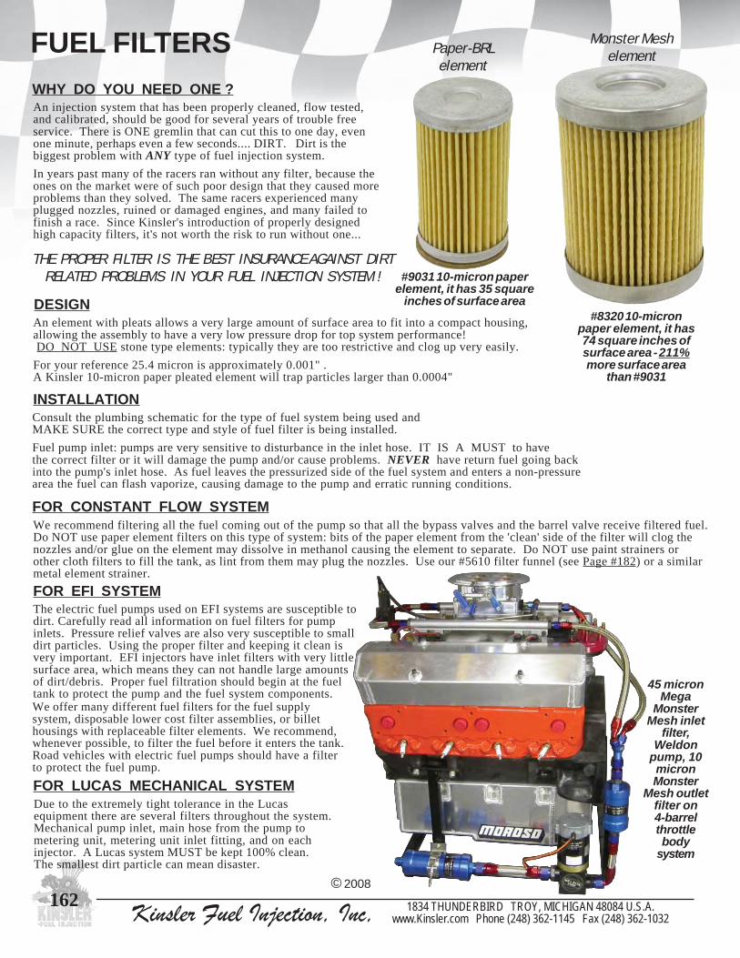
Kinsler Fuel Injection, Inc, 1834 THUNDERBIRD TROY, MICHIGAN 48084 U.S.A.www.Kinsler.com Phone (248) 362-1145 Fax (248) 362-1032
162
FUEL FILTERSWHY DO YOU NEED ONE ?An injection system that has been properly cleaned, flow tested,and calibrated, should be good for several years of trouble freeservice. There is ONE gremlin that can cut this to one day, evenone minute, perhaps even a few seconds.... DIRT. Dirt is thebiggest problem with ANY type of fuel injection system.
In years past many of the racers ran without any filter, because theones on the market were of such poor design that they caused moreproblems than they solved. The same racers experienced manyplugged nozzles, ruined or damaged engines, and many failed tofinish a race. Since Kinsler's introduction of properly designedhigh capacity filters, it's not worth the risk to run without one...
An element with pleats allows a very large amount of surface area to fit into a compact housing,allowing the assembly to have a very low pressure drop for top system performance! DO NOT USE stone type elements: typically they are too restrictive and clog up very easily.
For your reference 25.4 micron is approximately 0.001" .A Kinsler 10-micron paper pleated element will trap particles larger than 0.0004"
INSTALLATION
FOR CONSTANT FLOW SYSTEMWe recommend filtering all the fuel coming out of the pump so that all the bypass valves and the barrel valve receive filtered fuel.Do NOT use paper element filters on this type of system: bits of the paper element from the 'clean' side of the filter will clog thenozzles and/or glue on the element may dissolve in methanol causing the element to separate. Do NOT use paint strainers orother cloth filters to fill the tank, as lint from them may plug the nozzles. Use our #5610 filter funnel (see Page #182) or a similarmetal element strainer.
FOR EFI SYSTEMThe electric fuel pumps used on EFI systems are susceptible todirt. Carefully read all information on fuel filters for pumpinlets. Pressure relief valves are also very susceptible to smalldirt particles. Using the proper filter and keeping it clean isvery important. EFI injectors have inlet filters with very littlesurface area, which means they can not handle large amountsof dirt/debris. Proper fuel filtration should begin at the fueltank to protect the pump and the fuel system components.
Consult the plumbing schematic for the type of fuel system being used andMAKE SURE the correct type and style of fuel filter is being installed.
Fuel pump inlet: pumps are very sensitive to disturbance in the inlet hose. IT IS A MUST to havethe correct filter or it will damage the pump and/or cause problems. NEVER have return fuel going backinto the pump's inlet hose. As fuel leaves the pressurized side of the fuel system and enters a non-pressurearea the fuel can flash vaporize, causing damage to the pump and erratic running conditions.
DESIGN
THE PROPER FILTER IS THE BEST INSURANCE AGAINST DIRTRELATED PROBLEMS IN YOUR FUEL INJECTION SYSTEM !
© 2008
#9031 10-micron paperelement, it has 35 square
inches of surface area#8320 10-micron
paper element, it has74 square inches ofsurface area - 211%more surface area
than #9031
Paper-BRLelement
Monster Meshelement
Due to the extremely tight tolerance in the Lucasequipment there are several filters throughout the system.Mechanical pump inlet, main hose from the pump tometering unit, metering unit inlet fitting, and on eachinjector. A Lucas system MUST be kept 100% clean.The smallest dirt particle can mean disaster.
FOR LUCAS MECHANICAL SYSTEM
We offer many different fuel filters for the fuel supplysystem, disposable lower cost filter assemblies, or billethousings with replaceable filter elements. We recommend,whenever possible, to filter the fuel before it enters the tank.Road vehicles with electric fuel pumps should have a filterto protect the fuel pump.
45 micronMega
MonsterMesh inlet
filter,Weldon
pump, 10micronMonster
Mesh outletfilter on4-barrelthrottlebody
system

Kinsler Fuel Injection, Inc, 1834 THUNDERBIRD TROY, MICHIGAN 48084 U.S.A.www.Kinsler.com Phone (248) 362-1145 Fax (248) 362-1032
163
FUEL FILTERSMonster Mesh series filters
© 2008
Toyota, Honda, and Chevrolet
retliFemaN
gnisuoHhtgneL
.lcniton()sgnittif
gnisuoHretemaiD
aideMerauqSsehcnI
snorciMni
sselniatsnihsemleetsrepap
thgieWylbmessAretliF)secnuO(
sselniatshsemleetsrepap
leuFytilibitapmoC
gnisuoHhsiniF noitacilppA stroPelbaliavA
retliFdedleWresaL4918#
retliFdedleWresaL7918#
"001.3 "061.2 29 01 - 23.4 - enilosag leetssselniats teltuopmupIFE
brabelam"8/3
5.1xmm61elamef
rotcetorProtcejnI0718# "019.2 "009.1 54 01 - 29.5 - enilosag dezidonakcalb teltuopmupIFE *elamefNA8
LRB-onA6514# "019.2 "009.1 91 - 041 - 65.6 lonahtem dezidonadrah
)rolocyerg-evilo(pmuplacinahcem
teltuo *elamefNA8
LRB-mulA8414# "019.2 "009.1 91 - 041 - 65.6 enilosag dezidonader pmuplacinahcem
teltuo *elamefNA8
hseMretsnoMseireS0038 "530.4 "064.2
HSEM47
REPAP801
04,02,01 ,07,54,52812,001 21.9 88.01
enilosaglonahtemenahtemortin
dezidonaeulbdna
dezidonadrah
&telnipmupIFElacinahcem,teltuo
&telnipmuplio,teltuo
elamefNA8eralfelamNA8eralfelamNA01eralfelamNA21
retsnoMageMhseM
seireS0048"042.5 "064.2
HSEM111
REPAP261
04,02,01 ,07,54,52812,001 65.01 69.21
enilosaglonahtemenahtemortin
dezidonaeulbdna
dezidonadrah
&telnipmupIFElacinahcem,teltuo
&telnipmuplio,teltuo
elamefNA8eralfelamNA8eralfelamNA01eralfelamNA21
hseMretsnoMartlUseireS0058 "064.6 "064.2
HSEM841REPAP
612
04,02,01 ,07,54,52812,001 86.11 88.41
enilosaglonahtemenahtemortin
dezidonaeulbdna
dezidonadrah
&telnipmupIFElacinahcem,teltuo
&telnipmuplio,teltuo
elamefNA8eralfelamNA8eralfelamNA01eralfelamNA21
Quickrelease
t-bolt typestainless
steelmountingbracket
Elementis o-ringsealed
toendcap
Used for:
Used by:
- Injected or carburetted fuel systems- Engine oil- Rear end- Transmission
- Indy Racing League- Drag- Sprint
- Street- Off-road- Road race- Monster truck- Pull truck & tractors
- Midget

Kinsler Fuel Injection, Inc, 1834 THUNDERBIRD TROY, MICHIGAN 48084 U.S.A.www.Kinsler.com Phone (248) 362-1145 Fax (248) 362-1032
164
FUEL FILTERS
© 2008
xxx*---Specifiy 3-digits for micronExamples: 8308-010 specifies 10-micron Paper element 8556-218 specifies 218-micron Stainless Steel element
Monster Mesh Assembly8 AN female ports without fittings 4.77" overall
with 6 AN fittings 6.50" overall with 8 AN fittings 6.70" overall
8 AN male flare ends 6.02" overall10 AN male flare ends 6.89" overall12 AN male flare ends 7.25" overallSeries-micron End caps Anodized 8308-xxx* 8AN female Blue 8350-xxx 8AN female Hard 8309-xxx 8AN male flare Blue 8352-xxx 8AN male flare Hard 8310-xxx 10AN male flare Blue 8354-xxx 10AN male flare Hard 8312-xxx 12AN male flare Blue 8356-xxx 12AN male flare Hard
Mega Monster Mesh Assembly8 AN female ports without fittings 5.98" overall
with 6 AN fittings 7.71" overall with 8 AN fittings 7.91" overall
8 AN male flare ends 7.22" overall10 AN male flare ends 8.10" overall12 AN male flare ends 8.46" overallSeries-micron End caps Anodized 8408-xxx* 8AN female Blue 8450-xxx 8AN female Hard 8409-xxx 8AN male flare Blue 8452-xxx 8AN male flare Hard 8410-xxx 10AN male flare Blue 8454-xxx 10AN male flare Hard 8412-xxx 12AN male flare Blue 8456-xxx 12AN male flare Hard
Ultra Monster Mesh Assembly8 AN female ports without fittings 7.19" overall
with 6 AN fittings 8.92" overall with 8 AN fittings 9.12" overall
8 AN male flare ends 8.46" overall10 AN male flare ends 9.31" overall12 AN male flare ends 9.67" overallSeries-micron End caps Anodized 8508-xxx* 8AN female Blue 8550-xxx 8AN female Hard 8509-xxx 8AN male flare Blue 8552-xxx 8AN male flare Hard 8510-xxx 10AN male flare Blue 8554-xxx 10AN male flare Hard 8512-xxx 12AN male flare Blue 8556-xxx 12AN male flare Hard
0038 ,tlob-tesaelerkciuqhtiwdnableetssselniats,pmalcgnitnuoMselohgnitnuom"4/1owt
3038 dezidonaeulb,gnol"558.3,hseMretsnoM,gnisuoH4038 dezidonadrah,gnol"558.3,hseMretsnoM,gnisuoH3048 dezidonaeulb,gnol"560.5,hseMretsnoMageM,gnisuoH4048 dezidonadrah,gnol"560.5,hseMretsnoMageM,gnisuoH3058 dezidonaeulb,gnol"572.6,hseMretsnoMartlU,gnisuoH4058 dezidonadrah,gnol"572.6,hseMretsnoMartlU,gnisuoH4138 dezidonaeulb,telni,ssobgnir-oelamefNA8,pacdnE5138 dezidonaeulb,teltuo,ssobgnir-oelamefNA8,pacdnE6138 dezidonadrah,telni,ssobgnir-oelamefNA8,pacdnE7138 dezidonadrah,teltuo,ssobgnir-oelamefNA8,pacdnE4168 dezidonaeulb,telni,eralfelamNA8,pacdnE5168 dezidonaeulb,teltuo,eralfelamNA8,pacdnE6168 dezidonadrah,telni,eralfelamNA8,pacdnE7168 dezidonadrah,teltuo,eralfelamNA8,pacdnE
8168eetgnir-oelamefNA6htiw,teltuo,eralfelamNA8,pacdnEssobgnir-oelamefNA6lanretnidnaevlavfeilererusserprof
dezidonadrah,noitallatsnievlavkcehclanretnirof4148 dezidonaeulb,telni,eralfelamNA01,pacdnE5148 dezidonaeulb,teltuo,eralfelamNA01,pacdnE6148 dezidonadrah,telni,eralfelamNA01,pacdnE7148 dezidonadrah,teltuo,eralfelamNA01,pacdnE4158 dezidonaeulb,telni,eralfelamNA21,pacdnE5158 dezidonaeulb,teltuo,eralfelamNA21,pacdnE6158 dezidonadrah,telni,eralfelamNA21,pacdnE7158 dezidonadrah,teltuo,eralfelamNA21,pacdnE0068 sretlifseires'hseMretsnoM'llastif,gniniatertnemele,gnirpS1068 deriuqerowt,gnilaesgnisuohotpacdne,gnir-O2068 gnilaespacdneteltuoottnemele,gnir-O
MONSTER MESH SERIES PARTS
0238 repapnorcim010338 repapnorcim020438 repapnorcim045238 leetssselniatsnorcim525438 leetssselniatsnorcim540738 leetssselniatsnorcim070838 leetssselniatsnorcim0018838 leetssselniatsnorcim812
MONSTER MESH ELEMENTSPaper elements, pleated, 108 square inchesStainless steel mesh, pleated, 74 square inches
MEGA MONSTER MESH ELEMENTS
0248 repapnorcim010348 repapnorcim020448 repapnorcim045248 leetssselniatsnorcim525448 leetssselniatsnorcim540748 leetssselniatsnorcim070848 leetssselniatsnorcim0018848 leetssselniatsnorcim812
Paper elements, pleated, 162 square inchesStainless steel mesh, pleated, 111 square inches
ULTRA MONSTER MESH ELEMENTS
0258 repapnorcim010358 repapnorcim020458 repapnorcim045258 leetssselniatsnorcim525458 leetssselniatsnorcim540758 leetssselniatsnorcim070858 leetssselniatsnorcim0018858 leetssselniatsnorcim812
Paper elements, pleated, 216 square inchesStainless steel mesh, pleated, 148 square inches

Kinsler Fuel Injection, Inc, 1834 THUNDERBIRD TROY, MICHIGAN 48084 U.S.A.www.Kinsler.com Phone (248) 362-1145 Fax (248) 362-1032
165
FUEL FILTERS
Anodized aluminum housing, 8 AN female ports inlet and outlet, housing has threaded end caps that seal with o-rings.Dimensions at largest points: 1.9" diameter x 3.650" long (without fittings), weighs 0.4 lbs (without fittings).Filtration: one element, 1.250" diameter x 1.950" long, pleated, disposable paper element, 10-micron.
#8170 with #6043fittings installed
MECHANICAL PUMP OUTLET - METHANOL AND NITROHARD ANODIZED aluminum housing, 8 AN female ports inlet andoutlet, housing has threaded end caps that seal with o-rings. Elementsealed to end cap by o-ring. Dimensions at largest points: 1.9"diameter x 3.650" long (without fittings), weighs 0.4 lbs (withoutfittings).Filtration: one element, 1.1" diameter x 1.950" long, 22 square inches,pleated cleanable stainless steel element, 140-micron.
#4156 with #6044 fittingsand #4103 mounting clamp
#4105stainless
steelelement
6514dna,enilosag,lonahtem,etelpmoc,ylbmessaretliF
gnisuohdezidonadrah,tnemeleleetssselniats,enahtemortin'LRB-onA'ledom,spacdnedna
5014 norcim041,sehcnierauqs22,leetssselniats,tnemelE4014 ecalpnitnemelesniater,gnirpS2718 0718#dna,8414#,6514#rof,ydobotpacdne,gnir-O3718 tnemeleretlifotpacdne,gnir-O5314 dezidonadrah,pacdnE7314 liatedgnir-ohtiw,dezidonadrah,pacdnE
3014 leetssselniats,0718#dna,8414#,6514#rofpmalcgnitnuoMgnitnuomrofraednarenilnoihsucrebburhtiwdnab
EFI, CARBURETORS, AND LUCAS
0718 repapnorcim01,YLNOenilosag,etelpmoc,ylbmessaretliF'LRB-repaP'ledom,spacdnednagnisuohdezidonakcalb,tnemele
3209 ylraenidellatsni,sehcnierauqs22,repapnorcim01,tnemelE0718#nidellatsniebnac,0209#gnisuohretlif
1309 ecafruserom%06,sehcnierauqs53,repapnorcim01,tnemelE3209#nahtaera
4014 ecalpnitnemelesniater,gnirpS2718 6514#dna,8414#,0718#rof,gnir-O
3014 rebburhtiwdnableetssselniats,0718#rofpmalcgnitnuoMgnitnuomrofraednarenilnoihsuc
© 2008
MECHANICAL PUMP OUTLET - GASOLINE - HIGH FLOWAnodized aluminum housing, 8 AN female ports inlet and outlet, housing has threaded end caps that seal with o-rings.Element sealed to end cap by o-ring. Dimensions at largest points: 1.9" diameter x 3.650" long (without fittings),weighs 0.4 lbs (without fittings).Filtration: one element, 1.1" diameter x 1.950" long, 22 square inches,pleated cleanable stainless steel element, 140-micron.
#4148 with #6044fittings installed
8414leetssselniats,YLNOenilosag,etelpmoc,ylbmessaretliF
,spacdnedezidonakcalbhtiwgnisuohdezidonader,tnemele'LRB-mulA'ledom
5014 norcim041,sehcnierauqs22,leetssselniats,tnemelE4014 ecalpnitnemelesniater,gnirpS2718 0718#dna,8414#,6514#rof,ydobotpacdne,gnir-O3718 tnemeleretlifotpacdne,gnir-O4314 dezidonakcalb,pacdnE6314 liatedgnir-ohtiw,dezidonakcalb,pacdnE
3014 leetssselniats,0718#dna,8414#,6514#rofpmalcgnitnuoMgnitnuomrofraednarenilnoihsucrebburhtiwdnab
FUEL FLOW
Disassembled #8170 ‘Paper-BRL’
#9031element
Outlet end

Kinsler Fuel Injection, Inc, 1834 THUNDERBIRD TROY, MICHIGAN 48084 U.S.A.www.Kinsler.com Phone (248) 362-1145 Fax (248) 362-1032
166
FUEL FILTERS
MECHANICAL PUMP INLET PANCAKE STYLE - “E”-TYPEAnodized aluminum housing,12 AN female ports inlet andoutlet, housing held together withthree 7/16" hex bolts. Housinghas two 1/4-20 threaded holes formounting on pad at edge ofdiameter.Filtration: one 3.1" diameter,cleanable, stainless steel screen,element is available in two micronratings.
5094
tasnoisnemid,etelpmoc,ylbmessaretliFgnol"054.3xretemaid"023.4:tnioptsegral
tuohtiw(sbl55.1shgiew,)sgnittiftuohtiw()sgnittif
6094
,evlavffo-tuhshtiwylbmessaretliF:tnioptsegraltasnoisnemid,etelpmoctuohtiw(gnol"06.5xretemaid"023.4
)sgnittiftuohtiw(sbl52.2shgiew,)sgnittif
7094 ,esraoc,leetssselniats,hsem04,tnemelEderiuqereno
8094 eno,enif,leetssselniats,hsem04,tnemelEderiuqer
9094 6094#dna5094#rofgnir-O
Anodized aluminum housing, 12 AN female portsinlet and outlet, housing end secured to bodywith V-style stainless steel band clamp.Dimensions at largest points: 3.9" diameter x4.75" long (without fittings), weighs 2.3 lbs(without fittings). Housing has four 5/16-18threaded holes for mounting on outlet end plate.Holes located on 2.120” spacing with the outletboss in the center.Filtration: up to ten 2.75" diameter double sidedwafered, stainless steel, cleanable, disks on slitmandrel, available in two micron ratings.
MECHANICAL PUMP INLET - “H” TYPE0094 etelpmoc,norcim002,ylbmessaretliF6194 etelpmoc,norcim52,ylbmessaretliF
1094 002,hsem002x04,epytksid,tnemelE)01(seriuqerretlif,norcim
7194 retlif,norcim52,epytksid,tnemelE)01(seriuqer
4094 ,gnisuohretlif6194#dna0094#rof,gnir-Oderiuqereno
Al Marani’s 1968 Shelby Mustang with a 500 CID Ford BossHemi using a 6-71 GMC supercharger with a complete Kinsler
modified Accel/DFI electronic fuel injection
© 2008
FOR EFIIn-linedisposablefilter assembly.Stainless steel,laser welded,66 squareinches ofpleated10-micronpaper element.
4918 sbrabelam"8/3,retliF7918 stropgnir-o+elamef5.1xmm61,retliF
5816 ,gnir-ohtiw5.1mm61xeralfelamNA6,gnittiFmunimuladezidonaeulb
6816 ,gnir-ohtiw5.1mm61xeralfelamNA8,gnittiFmunimuladezidonaeulb
#6186 #6185
#8194
#8197
Small block ChevroletC5R manifold with wetnitrous system installed

Kinsler Fuel Injection, Inc, 1834 THUNDERBIRD TROY, MICHIGAN 48084 U.S.A.www.Kinsler.com Phone (248) 362-1145 Fax (248) 362-1032
167
SHUT-OFF VALVESUSAGESTypically used to shut off an engine with constant flow fuel metering. On this type of system it is not wise to shut off the ignitionto stop the engine. After killing the ignition system, the engine "winds down", and the mechanical fuel pump which is stillturning pumps fuel into the engine. A shut-off valve allows the operator to shut off the engine cleanly; prolonging enginecomponent life, ease in restarting, and reduces oil dilution. It also aids in obtaining reliable spark plug readings.
SHUT-OFF MOUNTING
TYPES OF SHUT-OFF VALVESMechanical valve - spool type and seal assisted ball.
Spool TypeAcceptable for internal sealing when in good condition. The spool rotatesinside a housing without the aid of any seals to prevent leakage around thespool. Typically smaller in size than the seal assisted ball type valve. Thefit of the spool to the housing is critical, a worn spool or housing will allowexcessive amount of leakage through the valve assembly. This may allowthe engine to continue to run, or fuel to leak past the valve when the engineis not running.
Ball Type - Seal AssistedExcellent for internal sealing. The ball rotates on a large sealing surfacestopping the flow of liquid on the inlet and outlet. A spring loaded sealon both sides of the ball prevents leakage around the ball. While this styleis more difficult and costly to manufacture it is the valve of choice due toit's positive shut off.
If the shut-off is mounted with a threaded fitting, do notscrew any other item to the valve.... under typical enginevibration the additional weight may tend to fatigue thefitting that mounts the valve and cause it to break.
When mounting a shut-off valve be sure that the valve itself and thelinkage\cable\etc. has plenty of room for operation.Always take into consideration the movement of parts under torquestress, or vibration, such as body panels, hood, suspension, etc.
On a constant flow injection it is always best to mount theshut-off valve at the inlet of the barrel valve (see "PreferredPlumbing Schematic" on Page #112), because:
A) If the shut-off is pulled at high engine speed, thefuel will be able to bypass back to the tank through themain bypass and the high speed bypass, thus avoidingexcessive fuel pump pressure. Since excess pressurecan ruin a fuel pump instantly, it is always best to pullthe shut-off at low RPM or install a relieving typeshut-off, (normally called a 3-way shut-off).
B) When the engine is shut off, the fuel in thehoses and filter absorbs heat and expands.Mounting the shut-off at the barrel valvewill force the expanding fuel back towardthe tank rather than into the engine.
DO NOT mount any two way shut-off valve directly on the pump outlet, since the fuel has no place to go
when the shut-off is pulled.... thiscould easily ruin the pump or rupture a hose.
!
© 2008
DO NOT USE a shut-off to stop fuel flow to a pump that isrotating. The fuel lubricates the pump, shutting off thefuel could cause damage to the pump. A shut-off can beused to allow the servicing of a pump inlet filter,removing a pump, or removal of a fuel tank.
DO NOT INSTALL a shut-off that will "dead head" thepump. Always be sure that an adequate flow path backto the tank is available.
KW pump with#6350 shut-off
Spool
Ball and components

Kinsler Fuel Injection, Inc, 1834 THUNDERBIRD TROY, MICHIGAN 48084 U.S.A.www.Kinsler.com Phone (248) 362-1145 Fax (248) 362-1032
168
SHUT-OFF VALVES
Pin removed,valve snaps closed
Pin installed, valve is open
SAFETY SERIES
Ideal for boats and motorcycles, if driver is thrown fromvehicle, cord attached to driver pulls pin, allowing springloaded valve to snap shut. Billet aluminum mounting bracketis blue anodized and features a stainless steel pull pin.
*** IMPORTANT*** DO NOT attach a cable or rod to valve arm when using it as a safety shut-off.
STANDARD SERIES
HFV SHUT-OFF VALVESHard anodized aluminum housing with 8 AN male flare and 8 ANfemale ends, will flow in either direction. Overall length is 2.6"without adapter fittings. Ball type valve with spring loaded end sealsand o-ring on actuation shaft. Arm rotates 360o on standard seriesvalve assembly and 90o on safety series valve. Standard series valvehas built-in detents every 90 degrees, this gives the valve a positiveon/off position and it can be actuated by cable, linkage, or by hand.A large selection of adapter fittings makes this a very adaptable andflexible valve. Arm has a 3/16" clearance hole and 1.250" center tocenter for a 900 travel of 1.768". Unit can be disassembled and newseals installed in the field.
#6036 HFV shut-off valve with#6043 8 AN adapter fitting installed
6306 YLNOlonahtemdnaenilosagrof,slaesenerpoen,'VFH'ledoM
8306 enahtemortindnalonahtemrof,slaesnolfet,'VFH'ledoM
7306 nipllupytefashtiw,6306#saemas,evlavffo-tuhsytefaSYLNOlonahtemdnaenilosagrof,tekcarbgnitnuomdna
9306 nipllupytefashtiw,8306#saemas,evlavffo-tuhsytefaSenahtemortindnalonahtemrof,tekcarbgnitnuomdna
ADAPTER FITTINGS -COMMONLY USED ON HFV SHUT-OFF VALVE
0406 leetsdetalp,leviwselamefNA8xeralfelamNA6
1406 munimula,leviwselamefNA8xleviwselamefNA6
2406 munimuladezidona-drah,gnir-o+elamNA8xleviwselamefNA8
3406 munimuladezidona-drah,gnir-o+elamNA8xeralfelamNA8
4406 munimuladezidonadrah,gnir-o+elamNA8xeralfelamNA6
7406 leetsdetalp,gnir-o&tun+daehklubelamNA8xgnir-o+elamNA8
8406 leetsdetalp,gnir-o&tun+daehklubelamNA6xgnir-o+elamNA8
© 2008
PARTS FOR HFV SHUT-OFF VALVES
5506 ,YLNOlonahtemdnaenilosagrof,7306#dna6306#roftiklaeSnipllormraenodna,laestfahseno,slaesdneowtsedulcni
6506 ,enahtemortindnalonahtemrof,9306#dna8306#roftiklaeSnipllormraenodna,laestfahseno,slaesdneowtsedulcni
1506 tfahsdnamrahtiw,evlav8306#dna6306#rof,ylbmessaetalppoT
2506 tfahsdnamrahtiw,evlav9306#dna7306#rof,ylbmessaetalppoT
3506 evlavffo-tuhs9306#,8306#,7306#,6306#rof,ylnollaB
9506 leufyficeps,evlavffo-tuhs9306#ot6306#nolaestfahsrof,gnir-O
MOUNTING BRACKETS FOR HFV SHUT-OFF VALVES
9406tellib,tnuomlenap,8306#dna6306#rof,tekcarB
owt,evlavffo-tuhsrofswercsgniniaterowt,munimuladezidonaeulb,srehsawhtiwswercsgnitnuom23-01
0506
tnuomottekcarb9406#htiwesurof,etalpgnitnuoMkcolbgib.cp-1relsniKnosevlavffo-tuhs'VFH'
kcalb,munimulatellib,dlofinamnoitcejnitelorvehC)lanoitpohsinifdehsilop(dezidona
#6050#6049

Kinsler Fuel Injection, Inc, 1834 THUNDERBIRD TROY, MICHIGAN 48084 U.S.A.www.Kinsler.com Phone (248) 362-1145 Fax (248) 362-1032
169
SHUT-OFF VALVESKINSLER 3-WAY SHUT-OFF VALVESHard-anodized aluminum body, precision ground and lapped stainless steel spool with internal detent pin, 1.430” C-C arm,housing has 8 AN female ports, rotates 90o closed to wide open. Side port can be used for bypass, this port will close off whenvalve is in "ON" position. Includes AN adapter fittings (other fittings are available).
OPERATIONInlet port "A" is always open to the distributioncavity in the center of the valve. When the handleis in the 'open' position, the inlet is open to theengine port "B". Port "C" is blocked off. When thehandle is in the closed position, the inlet is open tothe bypass back to the fuel tank, port "C", while theengine port "B" is blocked off.
We recommend mounting a shut-off at the barrel valve inletsee section on SHUT-OFF MOUNTING, Page #167).
However, if a customer desires to mount a shut-off valveon the fuel pump, this is the model to use!
© 2008
0536 elamNA6,elytsydobdevruc,evlavffo-tuhsyaw-3relsniKgnittiftelnidaehklubNA6,sgnittifssapybdnatelnieralf
4536 elamNA8,elytsydobdevruc,evlavffo-tuhsyaw-3relsniKgnittiftelnidaehklubNA8,sgnittifssapybdnatelnieralf
HIGH FLOW 3-WAYSHUT-OFF VALVES
Same as above 3-wayvalves but with largerports.
7806 NA01
8806 NA21
AB
C
OPEN CLOSED
PNEUMATIC 3-WAY SHUT-OFF VALVE KIT
Kits consists of: 3-way shut-off with AN fittings,pneumatic cylinder with mounting brackets, switch,connector fittings, and tubing. Customer isresponsible for air supply, 100-300 PSI operating.
9806 sgnittifNA6,evlavffo-tuhs0536#htiwtiketelpmoC
0906 sgnittifNA8,evlavffo-tuhs4536#htiwtiketelpmoC
1906 sgnittif,tekcarbgnitnuom,rednilyc,hctiwscitamuenPEVLAVFFO-TUHSON,gnibutdna
#6089

Kinsler Fuel Injection, Inc, 1834 THUNDERBIRD TROY, MICHIGAN 48084 U.S.A.www.Kinsler.com Phone (248) 362-1145 Fax (248) 362-1032
170
SHUT-OFF VALVES
DSR SHUT-OFF
Anodized aluminum, spool type (stainless steel),arm has stop pin to keep valve from over rotating,rotates 90o closed to wide open, 1.810" total travel.
8906 eralfelamNA6:teltuo,gnir-o&tunsulpelamNA6:telnIbl51.0:thgiew,"052.2:htgnelllarevO
9906 eralfelamNA6:teltuodnatelnIbl51.0:thgiew,"054.2:htgnelllarevO #6099#6098
SPRINT SHUT-OFF
Anodized aluminum, spool type (stainless steel), arm has stop pin to keepvalve from over rotating, rotates 90o closed to wide open, 2.121" totaltravel. Side port can be used for bypass valve, this port DOES NOTSHUT OFF. Includes arm and port plug.
4306edis,eralfelamNA6:teltuo,gnir-o&tunsulpelamNA6:telnIthgieh,"570.2:htgnelllarevO.gulptrophtiwelamefNA6:trop
bl51.0:thgiew,"577.:dellatsnigulphtiw
1306trophtiwelamefNA6:tropedis,eralfelamNA6:teltuodnatelnI
,"050.2:dellatsnigulphtiwthgieh,"570.2:htgnelllarevO.gulpbl02.0:thgiew
© 2008
#6034 #6031
FITTINGS - We offer a complete line of adapter fittings, see Pages #180-183.
SHUT-OFF WITH FILTER - PANCAKE STYLEAnodized aluminum housing, 12 AN female ports inlet and outlet, housing heldtogether with three 7/16" hex bolts. 900 travel, 2.882" total travel. Housing has two1/4-20 threaded holes for mounting on pad at edge of largest diameter. Mountingholes on 2.0" center to center. Filtration: one 3.1" diameter, cleanable, stainless steelscreen. Element available in two micron ratings (see below).
6094 snoisnemiD.etelpmocevlavffotuhshtiwylbmessaretliFtuohtiw(gnol"06.5xretemaid"023.4:stnioptsegraltaera
)sgnittiftuohtiw(bl52.2:thgiew,)sgnittif7094 deriuqereno,hsem-04,leetssselniats,tnemelE8094 deriuqereno,norcim-04,leetssselniats,tnemelE
2194 deriuqereno,gnisuohretlif6094#dna5094#rof,gnir-O
The arm is spring loaded and equipped with detents to secure the valve in the openposition. When rotated from the full open position the valve will snap closed.
#6095
12 AN AND 16 AN SHUT-OFF VALVE5906 lonahtemdnaenilosag,eralfelamNA21xdaehkluberalfelamNA21
otdesolcseerged09setatormra,ffo-tuhsepytllabdetsissalaeS.YLNO,"5.1:htdiw,"052.4:htgnelllarevo,hguorhtthgiarts.D.I"006.,nepoediw
bl55.0:thgiew,"055.2:thgieh3306 dnaenilosag,leetssselniats,eralfelamNA61xeralfelamNA61
seerged09setatormra,ffo-tuhsepytllabdetsissalaeS.YLNOlonahtemmorfderepatsipacdne,llabhguorht.D.I"586.,nepoediwotdesolc
,"5.1:htdiw,"004.3:htgnelllarevo,llabta"586.otpiteralfta"058.bl53.1:thgiew,"006.2:thgieh

Kinsler Fuel Injection, Inc, 1834 THUNDERBIRD TROY, MICHIGAN 48084 U.S.A.www.Kinsler.com Phone (248) 362-1145 Fax (248) 362-1032
171
SHUT-OFF VALVES
© 2008
SERVICE KITSConsists of : piston, spring, plunger, retainers, and seal.
B-8606 desolcyllamron21-SS2606#dna0606#rof,laeselirtinanuB
T-8606 desolcyllamron21-SS2606#dna0606#rof,laesnolfeTB-9606 nepoyllamron21-SS3606#/1606#rof,laesanuB
MODEL: SS-12Buna seals, stainless steel body.Weighs approx. 1.9 lbs and includes male/femaleWeather-Pack two pin sealed connector assembly.Seat orifice is 3/8” I.D.Two 10-32 threaded mounting holes located inbase. Has 1/4"NPT female inlet and outlet port.Maximum operating pressure: 150 PSI.Maximum fluid temperature: 2300F.
MODEL: SS-13 (Not Shown)Teflon seals, stainless steel body.Weighs approx. 1.3 lbs and includes male/femaleWeather-Pack two pin sealed connector assembly.Seat orifice is 1/4” I.D.Two 10-32 threaded mounting holes located inbase. Has 1/4"NPT female inlet and outlet port.Maximum operating pressure: 100 PSI.Maximum fluid temperature: 1800F.
Buna seals, brass body.Weighs approx. 1.3 lbs and includesmale/female Weather-Pack two pinsealed connector assembly.Seat orifice is 11/64” I.D.Has 1/4"NPT female ports.Maximum operating pressure: 11 PSI.Maximum fluid temperature: 1800F.
Recommend:For gasoline and methanol - buna sealsFor methanol / nitro - teflon sealsNote: teflon seals may not produce a dripless seal.
#6060 withtwo #61606 AN male
flare adapterfittings
Phil Sonner’s 55’ Chevywith a Kinsler EFI system
on a 454 big block
SOLENOID SHUT-OFF VALVE, 12-VOLT DCConsult us for proper use and application of this unit. A) Can be utilized for shut-off of complete gasoline system. B) Manual Lean-Out or enrichment system, can be activated by driver. C) Can be wired for vehicles with automatic transmission and a
transbrake or with a MSD two-step RPM control. D) Excellent for fuel system which requires two different main jet
selections, good launch and good mid-range.
0606 ,slaesanub,)deilppasirewopnehwsnepo(desolcyllamron,ylbmessaevlaV21-SS:ledom
1606 ,slaesanub,)deilppasirewopnehwsesolc(nepoyllamron,ylbmessaevlaV21-SS:ledom
2606 htiw,)deilppasirewopnehwsnepo(desolcyllamron,0606#ylbmessaevlaVgnittiftelnieralfelamNA6dnateltuonidellatsniredlohtejrotcirtser
3606 htiw,)deilppasirewopnehwsesolc(nepoyllamron,1606#ylbmessaevlaVgnittiftelnieralfelamNA6dnateltuonidellatsniredlohtejrotcirtser
4606 .31-SS:ledom,)deilppasirewopnehwsnepo(desolcyllamron,ylbmessaevlaVsgnittiferalfelamNA6sedulcni,ydobleetssselniats,slaesnolfeT
R-4606 .31-SS:ledom,)deilppasirewopnehwsnepo(desolcyllamron,ylbmessaevlaVdnatelnisgnittiferalfelamNA6sedulcni,ydobleetssselniats,slaesnolfeT
teltuonidellatsniredlohtejrotcirtser7606 ,.xamISP11,stropelamefTPN"4/1,CDtlov-21,evlavrotrevidwolfyaw-3
erutarepmetdiulf.xamF081 o

Kinsler Fuel Injection, Inc, 1834 THUNDERBIRD TROY, MICHIGAN 48084 U.S.A.www.Kinsler.com Phone (248) 362-1145 Fax (248) 362-1032
172
PUMP OUTPUTIn theory, a mechanical pump'soutput is linear to the RPM atwhich it is driven. Rotate thepump shaft twice as fast and theflow will double. However, evena good pump is affected by thephysical clearances of the gearsand the pressure load against theoutlet. Typically the flows atvery low RPM and very highRPM will be below the lineargraph of the pump's output dueto internal leakage, pumpingfriction losses, and clearance inthe components.
Running clearance is a must for thepump gears. This clearance causessome internal leakage back past thegears and has the same effect as abypass from the pump outlet backto the inlet.
MECHANICAL FUEL PUMP
TYPICAL APPLICATIONS VERSUS PUMP SIZEThese recommendations are based on the pump running at 1/2 crank speed.Variations will occure with RPM of engine and pump drive speed.
GENERAL SIZING AND SERVICEEngine displacement, volumetric efficiency, and the fuel being used will dictate the required pump displacement size. If youhave a doubt about the size of your pump, note the number stamped on it and give us a call. Several pumps are assembled usingthe same size housing, so the casting number located on the housing does not indicate the exact pump displacement. Most pumpsare identified by the serial number stamped on it.
Most pumps experience wear over a period of time. To maintain engine performance on a fuel system where the pump is losingflow output, the main jet has to be continually richened. If the main jet is not richened, the top end performance will drop off. Ifa problem is not found after thoroughtly checking other engine components (especially valve springs, cam lobes, and ignition),the pump should be sent in for testing.
We can test and rebuild many types of pumps. To have a pump tested, send it in with all of the fittings still in it.Include a day and evening time telephone number with the area code..... a technician will call if there is a problem.
ALL FLOWS , SIZES , AND RECOMMENDATIONS FOR FUEL PUMPS ARE FOR GENERALREFERENCE. CONSULT A KINSLER TECHNICIAN FOR YOUR SPECIFIC APPLICATION !!!
Flows in this chart are in pounds per hour (lbs/hr) of .720 specific gravity test fluid at 60oF.
KW-200
335
305
570
-00
380
295
570
KW-300
505
475
845
-0
685
590
1070
KW-400
670
655
1150
KW-500
835
815
1450
0-1/2
960
865
1515
-1
1190
1095
1950
KW-700
1170
1130
2000
KW-1300
2160
2125
3670
-2
2325
2140
3710
-4
2930
2765
4760
PUMP SIZEPUMPRPM PSI2000 02000 503500 50
FLOWS ARE AVERAGE OUTPUT - ACTUALOUTPUT MAY VARY SLIGHTLY
KW-450
770
760
1330
© 2008
WK nrobliH esUlacipyTA/N 432-LB )srednilycruofotenoyllacipyt(lohoclaro/dnaenilosagybdeleufsenignetnemecalpsidllamsyreV002 00- lohoclaro/dnaenilosagybdeleuf)yllacipyt(enignerednilycruoftnemecalpsidllamS003 A/N lohclaro/dnaenilosagybdeleuf)yllacipyt(enignerednilycruoftnemecalpsidegraL004 0- )8Vhcnicibuc004rednudnarednilyc-6yllacipyt(lohocladnaenilosaG054 A/N )8Vhcnicibuc004revo(lohoclA005 2/1- )8Vhcnicibuc034rednunwolbnuyllacipyt(lohocladnaenilosaG
007 1- llams;tnemecalpsidhcnicibuc007otpulohoclanwolbnu;enilosagnwolbdnanwolbnUortin%wolrotsoobwollohoclanwolbtnemecalpsid
0031 2- lohoclanwolbegareva;ortin%hgihnwolbnutnemecalpsidllamS
057BL 4- llams;lohoclanwolbtsoobhgihtnemecalpsidegral;ortin%hgihnwolbnutnemecalpsidegraLortinnwolbtsoobwoltnemecalpsid
0051BL 5- ortin%hgihtsoobhgihtnemecalpsidegral;lohoclanwolbtsoobhgihtnemecalpsidegralyreV

1731834 THUNDERBIRD TROY, MICHIGAN 48084 U.S.A.www.Kinsler.com Phone (248) 362-1145 Fax (248) 362-1032Kinsler Fuel Injection, Inc,
MECHANICAL PUMP INSTALLATION
IMPORTANT FUEL PUMP NOTES
To prevent pump inlet cavitation:A) Mount the pump as low as possible, this allows for
easier pump priming and better fuel supply conditions.B) Mount the tank as high and close to the pump as possible.
The far-forward tank location often used in early rear enginedragsters is NOT ideal; it would be better to locate the tank just in front of the engine, which will reduce the requiredinlet hose length.
C) Do not use a filter on the pump inlet. Strain the fuel as the tank is filled, to protect the pump from large pieces of dirt.If a filter is going to be used on the pump inlet, it must have a large surface area to prevent any restriction.
D) Keep the fuel in the tank cool... a good way is to wrap a wet towel (white, to reflect heat) around the tank and keep itwet. The evaporating water will keep the fuel cooler than the surrounding temperature.
E) Keep heat away from the fuel pump (exhaust pipes, hot airfrom the radiator, coolant system hoses, etc.). For oval trackand road racing, duct cool air over the pump.
F) Be sure that the tank is properly constructed and vented....See FUEL TANK on Pages #179-180.
G) Be sure that the pump inlet hose and fittings meet theminimum sizes in the table on Page #102.
Constant flow injection systems sense two engine conditions to meter the fuel. The first is engine speed, which is achieved byusing fuel pump speed... the faster the engine runs, the more fuel the pump delivers. The second is throttle angle, which isachieved by the barrel valve... as the throttles are opened, the linkage to the barrel valve rotates the spool toward full open fromthe partially closed off position that it had at an idle.
Because the fuel pump is an integral part of the metering system, it must be kept in good condition.The pump requires careful installation and maintenance to prevent premature deterioration and/or failure.
3) Index the pump so that an angled inlet fitting is NOT required(angled fittings on the pump outlet are permissible). It is OK todrill new holes in the pump flange or the mounting surface tore-index the pump. our model KW fuel pumps have a swivel flangefor easy indexing.
4) For front cover drives, check the hex drive spud (attached to thefront of the cam) for radial run-out: .015" maximum allowed. Onbelt drive units, mount the drive bracket in a vise, lathe, or verticalmill to check for radial run-out.
5) Check the radial alignment of the pump to the hex drive spud. Due tomanufacturing tolerances, many front covers do not locate the pump inexact alignment. If not, file the holes for the bolts that secure the coverto the engine to align the pump with the spud.
Two ways to check alignment :
A) Attach a dial indicator to the spud with the cover in place and checkthe run-out to the pump pilot hole in the cover.
B) Make an alignment tool: machine a 3/4" thick round piece with anOD the same as the ID of the front cover, and with a concentric ID.015" larger than the drive spud O.D. It should easily slip into thefront cover with the cover and spud in place on the engine.
6) Check hex engagement, male to female. It should be 3/8" minimum, butbe sure that the pump hex doesn't bottom out in the spud, as this willquickly ruin the pump. A minimum of .100" clearance is recommendedfrom the end of the male hex to the bottom of the female.
7) Any time the pump is removed, inspect the drive spud and replace it ifworn. Grease the pump hex when installing it.
8) Most belt drive kits mount the fuel pump at about the water pump height. It is ideal to modify the kit to mount the pump aslow as possible... we stock belts with various lengths, check available sizes (see Page #177) as you setup your pump drive.The pump should be setup to run one-half of engine speed. NOTE : Use the same above procedures to check the run out onthe belt drive spud.
© 2008
1) The pump must be primed before rotating the engine over, as thefuel lubricates the pump. If the pump is not going to be operatedfor an extended period of time, squirt some oil into it and turn itseveral revolutions.
2) The fuel pump moves a large volume of fuel. Any restriction inthe pump inlet hose may cause cavitation.

174 Kinsler Fuel Injection, Inc, 1834 THUNDERBIRD TROY, MICHIGAN 48084 U.S.A.www.Kinsler.com Phone (248) 362-1145 Fax (248) 362-1032
DRIVES FOR MECHANICAL PUMP
FRONT COVER FUEL PUMP DRIVE - KITS AND PARTS
KINSLER FRONT COVER FUEL PUMP DRIVE KITFOR USE WITH JESEL CAM DRIVEAvailable for small and big block Chevrolet, standard and raised cam (seebelow). Allows mechanical fuel pump or shorty ignition distributor (see Pg.219) to be run off the front of the cam. Clearance holes in mounting plate allowadjustment of cam timing without removing plate. Unit attachs to water outletports on block. Our spacers are hollow. Block off plates can be drilled andtapped for access to water. Kits are complete with all hardware and gaskets.Components are available separately.
© 20080825 tiketelpmoc,kceddradnats,telorvehCkcolbllamS
2825 tiketelpmoc,"193.+macdesiar,telorvehCkcolbllamS
3825 tiketelpmoc,kceddradnats,telorvehCkcolbgiB
5825 tiketelpmoc,"004.+macdesiar,telorvehCkcolbgiB
6825 xehelamef"8/3,daerhtdnahtfel,dupsevirD
#5204 #5203
#5200#5201
0025 smihsdna,gniraeb,dupshtiwrevocmunimula,8-VkcolbllamstelorvehC1025 smihsdna,gniraeb,dupshtiwrevocmunimula,8-VkcolbgibtelorvehC2025 smihsdna,gniraeb,dupshtiwrevocmunimula,8-Vkcolbllams982droF5025 munimulatsac,8-VkcolbllamstelorvehC,YLNOrevoctnorF6025 munimulatsac,8-VkcolbgibtelorvehC,YLNOrevoctnorF0125 tlob-3,evirdxehelamef"8/3,tfahsmac8-VtelorvehC,dupsevirD
1125 tlob-3,evirdxehelamef"8/3,tfahsmac8-VimeHrelsyrhC,dupsevirD
2125 1125#dna0125#sdupsevirdrof,tikmihS
3125 1125#dna0125#sdupsevirdrof,gniraebtsurhT4125 evirdxehelamef"8/3,8-Vkcolbllams982droF,dupsevirD3025 smihsdna,gniraeb,dups,revochtiwetelpmoc,8-VkcolbllamstelorvehC:nrobliH
4025 smihsdna,gniraeb,dups,revochtiwetelpmoc,8-VkcolbgibtelorvehC:nrobliH
6225 tlob-3,tfahsmac8-VtelorvehC,dupsevirdnrobliH7225 6225#roftikmihsnrobliH8225 6225#rofgniraeB
Small block ChevroletBig block Chevrolet
Install shims so that the cam end clearanceis .010" to .020". The smaller clearance is
preferred to minimize spark scatter.
SETUP
Drive spuds
Bearing
Shims

1751834 THUNDERBIRD TROY, MICHIGAN 48084 U.S.A.www.Kinsler.com Phone (248) 362-1145 Fax (248) 362-1032Kinsler Fuel Injection, Inc,
DRIVES FOR MECHANICAL PUMPBELT DRIVES ARE IDEAL FOR :
Freeing up space directly in front of engine, or to run stock water pumpKeeping fuel pump away from direct contact with hot engineMounting the pump low to allow proper gravity feed from the fuel tank
COMPONENTS
4625 ediw"61/3,erob"8/5,ediw"2/1,htoot-23,yelluPsediughtiwmunimula,yawyek
5625 ediw"61/3,erob"8/5,ediw"2/1,htoot-82,yelluPsediughtiwmunimula,yawyek
6625 ediw"61/3,erob"8/5,ediw"2/1,htoot-41,yelluPsediughtiwmunimula,yawyek
7725 ediw"61/3,erob"8/5,ediw"2/1,htoot-61,yelluPsediughtiwmunimula,yawyek
7625 htoot-61htiw,8VtelorvehCkcolbllams,buhknarCyellup
8625 htoot-61htiw,8VtelorvehCkcolbgib,buhknarCyellup
9625 htiw,8VtelorvehCkcolbllams,tiktekcarbevirDtekcarbdnayelluphtoot-23
0725 htiw,8VtelorvehCkcolbgib,tiktekcarbevirDtekcarbdnayelluphtoot-23
9725 yelluphtoot-23dna,gniraeb,tfahshtiwgnitsaC
1725 sevirdtleb3625#dna,2625#,1625#,0625#rof:tfahS
2725 deriuqereno,1725#tfahsrofgniraeB
3725 8VtelorvehCkcolbllamsrof,YLNOetalpgnitnuoM
4725 8VtelorvehCkcolbgibrof,YLNOetalpgnitnuoM
COMPLETE KIT CONSISTS OF:Drive unit, crank hub, pulleys,bracket,belt, and hardware.
0625 8-VtelorvehCkcolbllamS
1625 8-VtelorvehCkcolbgiB
2625 8-VimeH624relsyrhC
3625 elyts064/924:8-VkcolbgibdroF
#5241 H-Type kit installedon big block Chevrolet V8
BELT TYPE FUEL PUMP DRIVE: H-TYPE
#5261 Kit for small blockChevrolet V8
BELT TYPE FUEL PUMP DRIVES: E-TYPECOMPONENTS
5425 ediw"61/3,erob"8/5,ediw"2/1,htoot-23,yelluPsediughtiwdepahslleb,tesffo"8/5,munimula,yawyek
6425 edis"8/1,erob"4/11,ediw"2/1,htoot-61,yelluPedisenonoediughtiw,munimula,yawyek
7425 sedulcni,8VtelorvehCkcolbllams,retpadabuhknarCyelluphtoot-61
8425 sedulcni,8VtelorvehCkcolbgib,retpadabuhknarCyelluphtoot-61
9225 ,yelluprewolb17-6edisnistif,retpadabuhknarCyelluphtoot-61sedulcni
9425 htiw,8VtelorvehCkcolbllams,tiktekcarbevirDtekcarbdnayelluphtoot-23
0525 htiw,8VtelorvehCkcolbgib,tiktekcarbevirDtekcarbdnayelluphtoot-23
1525 3425#dna,2425#,1425#,0425#rof,tfahS
2525 deriuqerowt,1525#tfahsrof,gniraeB
3525 8VtelorvehCkcolbllamsrof,YLNOetalpgnitnuoM
4525 8VtelorvehCkcolbgibrofYLNOetalpgnitnuoM
5525 yelluphtoot-23dna,sgniraeb,tfahshtiwgnitsaC
COMPLETE KIT CONSISTS OF:Drive unit, crank hub, pulleys,bracket,belt, and hardware.
0425 8-VtelorvehCkcolbllamS
1425 8-VtelorvehCkcolbgiB
2425 8-VimeH624relsyrhC
3425 153/203/982:8-VkcolbllamsdroF
4425 8-VkcolbllamsrelsyrhC
#5260 E-Type kit installed onsmall block Chevrolet V8
#5240 H-type kit for small blockChevrolet V8
COMPLETE KITCONSISTS OF:Billet aluminum driveunit, crank hub,radius tooth pulleys,metric belt, bracketand hardware.
BELT TYPE FUEL PUMP DRIVE: W-TYPE
© 2008
D-4925 edisrevirDnodellatsnipmup,8VtelorvehCkcolbllamS
P-4925 edisregnessaPnodellatsnipmup,8VtelorvehCkcolbllamS
D-5925 edisrevirDnodellatsnipmup,8VtelorvehCkcolbgiB
P-5925 edisregnessaPnodellatsnipmup,8VtelorvehCkcolbgiB

176 Kinsler Fuel Injection, Inc, 1834 THUNDERBIRD TROY, MICHIGAN 48084 U.S.A.www.Kinsler.com Phone (248) 362-1145 Fax (248) 362-1032
DRIVES FOR MECHANICAL PUMP
KINSLER HEAVY-DUTYRIGHT ANGLE DISTRIBUTOR DRIVEFor Chevrolet small and big block, passenger (9.8" deck) and truck block(10.2" deck), engines. Can be adapted for many uses. Used on Lucasmechanical system to drive the ignition and fuel metering unit. Thehorizontal drive shaft has a 3/8 female hex; can drive a mechanical constantflow fuel pump or our “Shortie” distributor (see Pg #222). The top receiver ismachined for a tang drive or can be sealed off; we have Vertex magnetos to fitthis, or the hex drive. The gear driven drive assembly requires lubricationfrom the engine oil system. We offer a special filtered Z-20 lubrication nozzlefor this purpose. Optional mechanical tachometer drive.
OVERDRIVEBillet aluminumhousing with 3/8"male hex input and3/8" female hexoverdriven output.Unit is gear to gear,NO belt. The outputshaft turns the samedirection as theinput shaft.
#5275
3/8" COUPLER AND SHAFT
#5275 with two Hilbornfuel pumps installed, on belt
drive unit
© 2008
EXTENSIONS - FUEL PUMP5125 noisnetxe"4/12relsniKetelpmoC
6125 munimulatellib,"4/12relsniK,ylnognisuoH
7125 noisnetxe"4/12relsniKrofrelpuochtiwtfahS
0225 noisnetxe"2/14relsniKetelpmoC
1225 noisnetxe"2/14relsniK,YLNOgnisuoH
2225 noisnetxe"2/14relsniKrofrelpuochtiwtfahS
4225 noisnetxe"6dnaieWetelpmoC
5225 noisnetxe"6dnaieWrofrelpuochtiwtfahS
0325 noisnetxe"6nrobliHetelpmoC
1325 noisnetxe"6nrobliHrof,relpuochtiwtfahS
2325 deriuqerowt,delaes,0325#rof,ylnogniraeB
3325 leetsllordloc,elamefxeh"8/3,ylnorelpuoC
4325 hcnirepdlos,leetsllordloc,xeh"8/3,ylnolairetamtfahS
5325 -dedulcnisraegfotes-1,etelpmoc,ylbmessaevirdrevOevirdrevo%22ro,81,41,01fooitaryficeps
6325 tnemecalper/eraps,oitarevirdrevo%01,sraegrupS
7325 tnemecalper/eraps,oitarevirdrevo%41,sraegrupS
8325 tnemecalper/eraps,oitarevirdrevo%81,sraegrupS
9325 tnemecalper/eraps,oitarevirdrevo%22,sraegrupS
PHENOLIC INSULATORHelps isolate the fuel pump from heattransfer at it’s mounting surface.
Note: Always be certain thatthe pump hex shaft has sufficentengagement when adding thisinsulator.
6725 taehevirdsetalusni,kciht"041.pmupleuflacinahcemmorf
Spur gear #5235 overdriveassembly
DUAL PUMP DRIVEBillet aluminum housing with 3/8" male hex input and two3/8" female hex driven outputs. Gear to gear design does notrequire a belt. Output shafts turn the opposite rotation asinput, 1:1 ratio.
5725 etelpmoc,ylbmessaevirdpmuplauD
#5224#5220
#5215
#5230
Optionaltach. drive
V
#5276
DISCONTINUED

1771834 THUNDERBIRD TROY, MICHIGAN 48084 U.S.A.www.Kinsler.com Phone (248) 362-1145 Fax (248) 362-1032Kinsler Fuel Injection, Inc,
COG BELTS AND PULLEYS
© 2008
COG BELTS - L050 SERIES1/2" wide, 3/8 pitch
0235 ecnerefmucric"12;050L-012
1235 ecnerefmucric"2/122;050L-522
2235 ecnerefmucric"42;050L-042
3235 ecnerefmucric"2/152;050L-552
4235 ecnerefmucric"72;050L-072
5235 ecnerefmucric"2/182;050L-582
6235 ecnerefmucric"03;050L-003
7235 ecnerefmucric"4/123;050L-223
8235 ecnerefmucric"2/143;050L-543
9235 ecnerefmucric"4/363;050L-763
0335 ecnerefmucric"93;050L-093
1335 ecnerefmucric"24;050L-024
2335 ecnerefmucric"54;050L-054
COG BELTS - L075 SERIES3/4" wide, 3/8 pitch
0435 ecnerefmucric"12;570-012
1435 ecnerefmucric"2/122;570-522
2435 ecnerefmucric"42;570-042
3435 ecnerefmucric"2/152;570-552
4435 ecnerefmucric"72;570-072
5435 ecnerefmucric"2/182;570-582
6435 ecnerefmucric"03;570-003
7435 ecnerefmucric"4/123;570-223
8435 ecnerefmucric"2/143;570-543
9435 ecnerefmucric"4/363;570-763
COG BELTS - L100 SERIES1" wide, 3/8 pitch
0535 ecnerefmucric"12;001-012
1535 ecnerefmucric"2/122;001-522
2535 ecnerefmucric"42;001-042
3535 ecnerefmucric"2/152;001-552
4535 ecnerefmucric"72;001-072
5535 ecnerefmucric"2/182;001-582
6535 ecnerefmucric"03;001-003
7535 ecnerefmucric"4/123;001-223
8535 ecnerefmucric"2/143;001-543
9535 ecnerefmucric"4/363;001-763
LABOR -MACHINESHAFT BOREAND BROACH
7935 retemaidedisni"8/5otyelluperobnialp"2/1eroB
8935 erobyellup.D.I"8/5niyawyek"61/3hcaorB
9935 erobyellup.D.I"8/5niyawyek"4/1hcaorB
2935 otnoyellupyawyek"8/1erob"2/1stpada,gnihsuBtfahsyawyek"8/1retemaid"61/7a
COG BELTS - XL037 SERIES3/8" wide, 1/5 pitch
0035 ecnerefmucric"11;730LX-011
1035 ecnerefmucric"21;730LX-021
2035 ecnerefmucric"31;730LX-031
3035 ecnerefmucric"41;730LX-041
4035 ecnerefmucric"51;730LX-051
5035 ecnerefmucric"61;730LX-061
6035 ecnerefmucric"71;730LX-071
7035 ecnerefmucric"81;730LX-081
8035 ecnerefmucric"91;730LX-091
9035 ecnerefmucric"02;730LX-002
0135 ecnerefmucric"12;730LX-012
1135 ecnerefmucric"22;730LX-022
2135 ecnerefmucric"32;730LX-032
3135 ecnerefmucric"42;730LX-042
4135 ecnerefmucric"52;730LX-052
5135 ecnerefmucric"62;730LX-062
6135 ecnerefmucric"82;730LX-082
7135 ecnerefmucric"92;730LX-092
8135 ecnerefmucric"03;730LX-003
9135 ecnerefmucric"23;730LX-023
0635 ecnerefmucric"33;730LX-033
MACHINED SHAFT BOREAluminum with two belt guide flanges
5425 yawyek"61/3htiwerob"8/5,htoot23
6425 1YLNO,yawyek"8/1,erob"4/11,htoot61egnalf
4625 yawyek"61/3,erob"8/5,htoot23
5625 yawyek"61/3,erob"8/5,htoot82
7725 yawyek"61/3,erob"8/7,htoot61
6625 yawyek"61/3,erob"8/5,htoot41
2835foediskcab,yawyek"8/1,erob"2/1,htoot81
htrowsoC/sacuLtifottuodenihcamyellupevirdpmuplacinahcem
3835foediskcab,yawyek"8/1,erob"2/1,htoot02
htrowsoC/sacuLtifottuodenihcamyellupevirdpmuplacinahcem
4835foediskcab,yawyek"8/1,erob"2/1,htoot22
htrowsoC/sacuLtifottuodenihcamyellupevirdpmuplacinahcem
Steel WITH flanges0565 erobnialp"61/3,htoot21
3565 erobnialp"4/1,htoot41
6565 erobnialp"4/1,htoot61
9565 erobnialp"4/1,htoot81
0665 erobnialp"4/1,htoot02
3665 erobnialp"4/1,htoot22
5765 erobnialp"61/5,htoot03
COG PULLEYS L050 SERIES
COG PULLEYS XL037 SERIES
UN-MACHINED SHAFT BOREAluminum with two belt guideflanges
0735 erobnialp"2/1,htoot21
1735 erobnialp"2/1,htoot31
2735 erobnialp"2/1,htoot41
3735 erobnialp"2/1,htoot51
4735 erobnialp"2/1,htoot61
5735 erobnialp"2/1,htoot71
6735 erobnialp"2/1,htoot81
7735 erobnialp"2/1,htoot91
8735 erobnialp"2/1,htoot02
9735 erobnialp"2/1,htoot12
0835 erobnialp"2/1,htoot22
1835 erobnialp"2/1,htoot42
7835 erobnialp"2/1,htoot72
2665 erobnialp"4/1,htoot02
5665 erobnialp"4/1,htoot22
8665 erobnialp"4/1,htoot42
1765 erobnialp"4/1,htoot62
4765 erobnialp"4/1,htoot82
7765 erobnialp"8/3,htoot03
0965 erobnialp"61/5,htoot04
6965 erobnialp"61/5,htoot44
9965 erobnialp"8/3,htoot27
Aluminum WITHOUT flangesAluminum WITH flanges
1665 erobnialp"4/1,htoot024665 erobnialp"4/1,htoot227665 erobnialp"4/1,htoot420765 erobnialp"4/1,htoot623765 erobnialp"4/1,htoot826765 erobnialp"8/3,htoot035865 erobnialp"8/3,htoot63
7865 ,erobnialp"8/3,htoot63segnalfno-tlobLAICEPS
Belts are measured in circumference

178 Kinsler Fuel Injection, Inc, 1834 THUNDERBIRD TROY, MICHIGAN 48084 U.S.A.www.Kinsler.com Phone (248) 362-1145 Fax (248) 362-1032
PRIMER SYSTEMExcellent for Constant Flow Injection systems,Excellent for Constant Flow Injection systems,Excellent for Constant Flow Injection systems,Excellent for Constant Flow Injection systems,Excellent for Constant Flow Injection systems,
to assist in starting the engine.to assist in starting the engine.to assist in starting the engine.to assist in starting the engine.to assist in starting the engine.
Driver can prime engine from drivers seatDriver can prime engine from drivers seatDriver can prime engine from drivers seatDriver can prime engine from drivers seatDriver can prime engine from drivers seat.....Ideal for the racer who is traveling alone.Ideal for the racer who is traveling alone.Ideal for the racer who is traveling alone.Ideal for the racer who is traveling alone.Ideal for the racer who is traveling alone.
Safer - NO squirt bottle.
PREFERRED PLUMBING SCHEMATIC FOR PRIMING SYSTEM
PRIMER SYSTEM
Kits consist of necessary components to properly install the primer pump.Hose and hose ends are NOT supplied in kit, since plumbing is unique toeach installation, available separately, see Page #187.
This system reduces the cranking required by purging the air out of the fuelplumbing, especially on initial "fire up" for the day's racing. Great for mechanicalpump lubrication during initial cranking and starting. This system can beplumbed with gasoline from an auxiliary tank on those applications wheremethanol is used and hard starting is experienced, especially in cold weather.
#6065 Primer System
#6066 Primer System
KIT #6066 IS THE SAME AS #6065EXCEPT FOR FUEL PUMP (#10211)
WHICH HAS ‘AN’ MALE FLAREFITTINGS ON BOTH ENDS
Ambrose/Argenta/Huettman/Varsity Ford’s NHRA Competition Eliminator I/A record holders for E.T. (7.92 - 9/99) and M.P.H. (163.65 - 8/99)
using a Kinsler fuel system on 300 cubic inch 6-cylinder in-line Ford
© 2008
5606
reppalfNA61903#,pmupleufV21cirtcele30022#:fostsisnoClenapdnahctiwsyratnemom,gnittif-tleviws1516#,evlavkcehc01htiwredlohesuf,)edapselamef(slanimreteriw,gnisuohtnuom
eriwLXSepytGWA-81foteef02dna,esufpma
6606
reppalfNA61903#,pmupleufV21cirtcele01201#:fostsisnoClenapdnahctiwsyratnemom,gnittif-tleviws1516#,evlavkcehc01htiwredlohesuf,)edapselamef(slanimreteriw,gnisuohtnuom
eriwLXSepytGWA-81foteef02dna,esufpma

1791834 THUNDERBIRD TROY, MICHIGAN 48084 U.S.A.www.Kinsler.com Phone (248) 362-1145 Fax (248) 362-1032Kinsler Fuel Injection, Inc,
FUEL TANK CONSTRUCTION AND LOCATIONLOCATIONWhen mounting the fuel tank for a mechanical fuelinjection system, DO NOT locate the maximum fuellevel in the tank above the nozzles. This is to preventthe fuel from draining into the engine if the fuel shut-off valve is left open.... this is not a problem in anEFI system as the injectors shut off tight when theengine is not running.
SHUT-OFF VALVE
NEVER shut off the flow to the pump above idle speed; it may cause damage, since the fuel lubricates the pump. If ashut-off is installed to give access to a pump inlet filter, make sure the inside diameter of the shut-off valve and anyadapter fittings have the proper inside diameter. See Page #102 for minimum inlet hose sizes.
FUEL CELLS AND/OR BLADDERS
Due to the design of these types of fuel tanks, it may not bepossible to install any baffles. The best thing to do is to fillthe tank with a fuel compatible foam baffle material.
The return fuel shoots acrossthe tank, causing minimumfrothing. Deep constructionminimizes slosh due to carmovement; insures clear fuel atthe outlet. Outlet to the rear isbest; to the side is OK.
This design shoots the return fueldirectly down into the tank, but thefroth comes back to the surfacebefore reaching the outlet. It ispreferred to place the outlet towardthe rear of the car; can besideways.
CAUTION - The foam MUST be compatible with the fueland additives that may be used. If the foam breaks down, it willclog the fuel system. Even if the manufacturer states that thefoam is compatible, put a piece of it in a sample of the FUELBEING USED and TEST IT !!!
FILTER BETWEEN TANK AND PUMPWe strongly encourage CAUTION when using any filteron the inlet side of any pump. A filter can restrict theflow if the pump has to suck the fuel through the filter,the vacuum it has to pull to do it lowers the fuel’s boilingpoint and may cause inlet cavitation. It is always best tostrain the fuel when putting it into the tank and use aKinsler filter between the pump and the barrel valve. Ifyou want to use a filter before the pump, have a Kinslertechnician spec a proper Kinsler Monster Mesh filter.
Make a slit in the side of the tank. Slidea .050" to .125" thick plate into the slit soit extends 1" below and 1" to all sides ofthe fitting. Weld in place. The incomingforce of the fuel will be dissipated againstthe plate.
It is preferred to install this type oftank sideways in the vehicle. Thisdesign is poor since the return fuelshoots directly into the fuel, froths up,and the froth is easily sucked out theoutlet directly below. Early Moontanks were constructed like this.
© 2008
FIX FOR DESIGN #3; MAKES #2 BETTER
FUEL TANK CONSTRUCTION :DESIGN #2Rating: GOOD
DESIGN #3Rating: POOR
DESIGN #1Rating: EXCELLENT

180 Kinsler Fuel Injection, Inc, 1834 THUNDERBIRD TROY, MICHIGAN 48084 U.S.A.www.Kinsler.com Phone (248) 362-1145 Fax (248) 362-1032
FUEL TANKCONSTRUCTION AND LOCATION
OUTLET OF THE TANK
The outlet of the tank or cell should be at the lowest point on the tank/cell. It is best if the main feed hose to the fuel pump runsdown from the tank to the pump, NOT UP. Fuel pumps are not designed to draw fuel, they are meant to be gravity fed. Pumpswill pull fuel because of the fuel siphon due to displacement.
FITTING FOR OUTLET OF THE TANK
Bore the inside diameter (I.D.) of the tank outlet and pump inletfittings as large as possible without unduly weakening the fitting.Chamfer the fitting on the tank outlet as shown at the right.
Kinsler hard-anodized fittings are designed like this, see FITTINGSon Page #183.
NEVER use a "drilled block of metal" type angle fitting onANY pump inlet hose... where the drills intersect there is arazor sharp edge that promotes pump inlet cavitation. Thebest solution is to make gentle bends with the hoses.However, if there is a really tight place, use a bent tube typehose end fitting.
VENT SIZES
The tank MUST have a vent. Large amounts of fuel volume are being removed from the tank. This volume must be replaced or avacuum may be formed inside the tank, causing the fuel to be 'locked' inside. Scenario - a straw in a drinking glass: put a fingeron the end of the straw and lift it out of the liquid; the straw retains the liquid until the finger is removed and allows air in.
NOTICE : Fuel tank and cell manufacturers may NOT offer a tank that is properly configured for your application.
Too large of a vent will not hurt anything, too small may cause the pump to cavitate, resulting in an inconsistent fuel supply ordamaged engine parts. Remember when altering a vent by adding length (hose), installing a roll-over valve, or a filter, the ventmay require a larger inside diameter (see ORIFICE THEORY on Pages #202-203).
For pump sizes of -00 up to -1 3/8" (.375") inside diameter or biggerMINIMUM ALLOWABLE TANK VENT SIZES: For pump sizes of -2 up to -4 1/2" (.500") inside diameter or bigger.
For pump sizes of -5 or bigger 3/4" (.750") inside diameter or bigger.Please consult your rule book/sanctioning body for additional requirements.
NOTE: When running multiple pump systems multiply the area of the above vent sizes by the quantity of fuel pumps.
LIQUID BOILING VERSUS BAROMETER AND TEMPERATURE
This subject is very complex, we are only going to discuss it in very general terms.There are many chemistry books, scientific papers, and web sites that can helpfurther the understanding of this topic.
The boiling point of a liquid is affected by temperature and absolute pressure. Absolutepressure takes into consideration altitude. The temperature at which the vapor pressureof the liquid exceeds the pressure around the liquid is the boiling point. At temperaturesbelow the boiling point, evaporation takes place only from the surface of the liquid;during boiling, vapor forms within the body of the liquid. As the vapor bubbles risethrough the liquid, they cause the turbulence and the conditions that are associated withboiling. When the pressure against a liquid is increased, the boiling point goes up. Whenthe pressure on a liquid is reduced, the boiling point goes down.
The lowest boiling point is that of helium, -4520F (-268.90C). The highest is probably thatof tungsten, about 10,6500F (59000C).Water is generally 2120F at one standard atmosphere pressure (29.92" Hg).
© 2008See also KINSLER VAPOR SEPARATOR TANK SYSTEM /PRESSURIZED PUMP INLET SYSTEM on Pages #115-118.

1811834 THUNDERBIRD TROY, MICHIGAN 48084 U.S.A.www.Kinsler.com Phone (248) 362-1145 Fax (248) 362-1032Kinsler Fuel Injection, Inc,
ALUMINUM TANKS AND COMPONENTS
Our tanks are in stock and pressure tested for immediateshipment. Brushed spun aluminum, approx. .080" thickwall. All tanks have three bungs (3/8" female NPT)located near the top, one outlet (3/4" female NPT), onedrain ( 1/8" NPT), and screw on filler cap ( 2 1/4" ID). Custom built tanks are available. Individual components can be purchased.
KINSLER ALUMINUM TANKS
MOUNTING BRACKETSFOR ALUMINUM TANKS
CAPS WITH WELD-IN BUNGS
0185 demrof,ylnoknatretemaid"2/18rof,riaPdetniapyxopekcalb,ngisedpartsleets
6185 retemaid"2/18xgnol"5,nollag-1,flahknaT7185 retemaid"2/18xgnol"2/17,nollag-4/31,flahknaT8185 retemaid"2/18xgnol"01,nollag-2/12,flahknaT
0085 retemaid"2/18xgnol"01,latnoziroh,nollag-21085 retemaid"2/18xgnol"51,latnoziroh,nollag-2/132085 retemaid"2/18xgnol"02,latnoziroh,nollag-56085 retemaid"2/18xgnol"72,latnoziroh,nollag-6
BODY HALVES FOR ALUMINUM TANKOne solid piece, brushed spun aluminum, approx. .080" thick wall.
BUILDING YOUR OWN TANK...WE WILL BE GLAD TO SUPPLYANY COMBINATION OF PIECES !!!
Custom-madespunaluminumfuel tank
1385 .D.I"8/12,gnubdlewmunimuladnapaCpacno-wercshtiw
7385 1385#htiwdedulcnisaemas,ylnopaC
2385 ,.D.I"8/12,gnubdlewleetsdnapaCpackcol-tsiwt/tenoyab
© 2008
Releasecompoundrequiredwithaluminumscrew-oncap topreventgalling andseizing
#5816
#5817
#5818

182 Kinsler Fuel Injection, Inc, 1834 THUNDERBIRD TROY, MICHIGAN 48084 U.S.A.www.Kinsler.com Phone (248) 362-1145 Fax (248) 362-1032
Machined from 6061 aluminum.WELD-IN AN MALE FLARE BUNGS
Machined from 6061 aluminum.
WELD-IN FEMALE BUNGS -NATIONAL PIPE TAP (NPT) and AN
FITTINGS AND BUNGS
CLASSIC STYLE WITH HIGH TECHNOLOGY
Bill Duff's AC Cobra ( ERA replica ) powered bya Dale Hall built 567 cubic inch big block Ford withTFS Pro-Stock aluminum cylinder heads. Kinslerinjection manifold with special modifications madeper customer's request : relocate EFI injectors toinside of runners, with white PPG Deltron ® paint,and Kinsler billet aluminum radius inlet plates.
© 2008
5485 xeh"4/3,elamefTPN"8/1
6485 xeh"8/7,elamefTPN"4/1
7485 xeh"1,elamefTPN"8/3
8485 xeh"4/11,elamefTPN"2/1
9485 xeh"2/11,elamefTPN"4/3
0585 xeh"2/11,elamefTPN"1
1226 tekcopgnir-ohtiwelamefNA4
2226 tekcopgnir-ohtiwelamefNA6
3226 tekcopgnir-ohtiwelamefNA8
4226 tekcopgnir-ohtiwelamefNA01
5226 tekcopgnir-ohtiwelamefNA21
4616 tolipelam"23/71,thgiarts,eralfelamNA6
5616 tolipelam"23/71,.ged54,eralfelamNA6
2616 tolipelam"8/5,thgiarts,eralfelamNA8
3526 xeh"4/3,tolipelam"2/1,thgiarts,eralfelamNA6
4526 xeh"8/7,tolipelam"8/5,thgiarts,eralfelamNA8
5526 xeh"61/51,tolipelam"4/3,thgiarts,eralfelamNA01
6526 xeh"8/11,tolipelam"4/3,thgiarts,eralfelamNA21
FUNNEL - FILTER0165 htiwdedlomcitsalp,lennuF
sselniatselbasuer/elbanaelcralugnairt"9,tresniretlifleets
,pilhsols-itnahtiwgninepoteltuodeppetsowtdnaderepat
.D.I"050.2ot"054.1tifotkcenrellif
1265 elbasuer/elbanaelc,tresniretliF6.53,tnemeleleetssselniats
norcim06fosehcnierauqsaidemretlif
#6225#6224#6223#6222#6221
#5848 #5849#5847 #5850#5846#5845
#6164 #6165 #6162
#6253 #6254 #6255 #6256
Filter funnel in spunaluminum tank
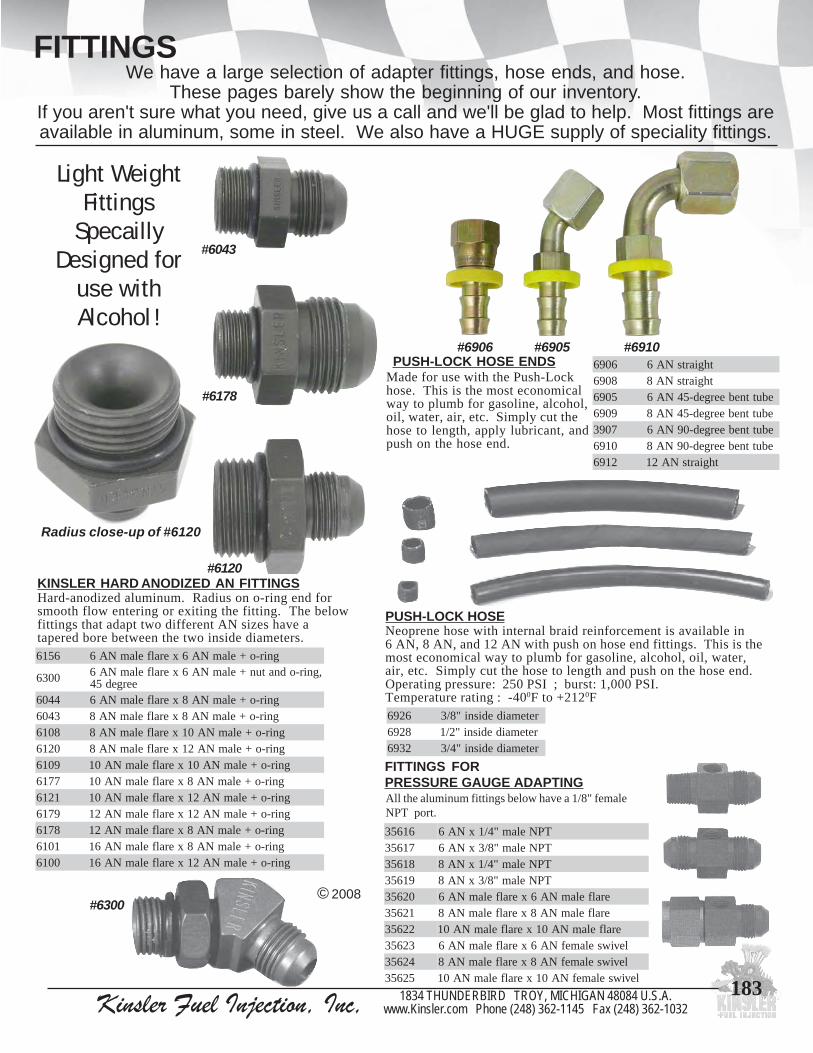
1831834 THUNDERBIRD TROY, MICHIGAN 48084 U.S.A.www.Kinsler.com Phone (248) 362-1145 Fax (248) 362-1032Kinsler Fuel Injection, Inc,
FITTINGS
FITTINGS FORPRESSURE GAUGE ADAPTING
PUSH-LOCK HOSENeoprene hose with internal braid reinforcement is available in6 AN, 8 AN, and 12 AN with push on hose end fittings. This is themost economical way to plumb for gasoline, alcohol, oil, water,air, etc. Simply cut the hose to length and push on the hose end.Operating pressure: 250 PSI ; burst: 1,000 PSI.Temperature rating : -400F to +2120F
KINSLER HARD ANODIZED AN FITTINGSHard-anodized aluminum. Radius on o-ring end forsmooth flow entering or exiting the fitting. The belowfittings that adapt two different AN sizes have atapered bore between the two inside diameters.
We have a large selection of adapter fittings, hose ends, and hose.These pages barely show the beginning of our inventory.
If you aren't sure what you need, give us a call and we'll be glad to help. Most fittings areavailable in aluminum, some in steel. We also have a HUGE supply of speciality fittings.
Light WeightFittings
SpecaillyDesigned for
use withAlcohol !
#6300© 2008
Radius close-up of #6120
6096 thgiartsNA68096 thgiartsNA85096 ebuttnebeerged-54NA69096 ebuttnebeerged-54NA87093 ebuttnebeerged-09NA60196 ebuttnebeerged-09NA82196 thgiartsNA21
Made for use with the Push-Lockhose. This is the most economicalway to plumb for gasoline, alcohol,oil, water, air, etc. Simply cut thehose to length, apply lubricant, andpush on the hose end.
PUSH-LOCK HOSE ENDS
#6043
#6178
#6120
#6906 #6905 #6910
6516 gnir-o+elamNA6xeralfelamNA6
0036 ,gnir-odnatun+elamNA6xeralfelamNA6eerged54
4406 gnir-o+elamNA8xeralfelamNA63406 gnir-o+elamNA8xeralfelamNA88016 gnir-o+elamNA01xeralfelamNA80216 gnir-o+elamNA21xeralfelamNA89016 gnir-o+elamNA01xeralfelamNA017716 gnir-o+elamNA8xeralfelamNA011216 gnir-o+elamNA21xeralfelamNA019716 gnir-o+elamNA21xeralfelamNA218716 gnir-o+elamNA8xeralfelamNA211016 gnir-o+elamNA8xeralfelamNA610016 gnir-o+elamNA21xeralfelamNA61
6296 retemaidedisni"8/38296 retemaidedisni"2/12396 retemaidedisni"4/3
61653 TPNelam"4/1xNA671653 TPNelam"8/3xNA681653 TPNelam"4/1xNA891653 TPNelam"8/3xNA802653 eralfelamNA6xeralfelamNA612653 eralfelamNA8xeralfelamNA822653 eralfelamNA01xeralfelamNA0132653 leviwselamefNA6xeralfelamNA642653 leviwselamefNA8xeralfelamNA852653 leviwselamefNA01xeralfelamNA01
All the aluminum fittings below have a 1/8" femaleNPT port.

184 Kinsler Fuel Injection, Inc, 1834 THUNDERBIRD TROY, MICHIGAN 48084 U.S.A.www.Kinsler.com Phone (248) 362-1145 Fax (248) 362-1032
FITTINGS
TEETEE TEE UNION
UNION-45 DEGREE UNION-90 DEGREE
UNION-45 DEGREE UNION-90 DEGREE
UNION - ADAPTER
PLUG - MALE FLARE
CAP - ANAluminum
NUT - ANAluminum
BULKHEAD-STRAIGHT BULKHEAD-45 DEGREEBULKHEAD TEE BULKHEAD TEE
Aluminum with maleflare on all ends,bulkhead on run
© 2008
Aluminum with maleflare on both ends
04353 NA3
14353 NA4
24353 NA6
34353 NA8
44353 NA01
54353 NA21
Aluminum with maleflare on both ends
05353 NA3
15353 NA4
25353 NA6
35353 NA8
45353 NA01
55353 NA21
Aluminum with maleflare on all ends,bulkhead on run
BULKHEAD-90 DEGREEAluminum with maleflare on both ends
06353 NA3
16353 NA4
26353 NA6
36353 NA8
46353 NA01
56353 NA21
61353 NA3
71353 NA4
81353 NA6
91353 NA8
02353 NA01
12353 NA21
61353 NA3
71353 NA4
81353 NA6
91353 NA8
02353 NA01
12353 NA21
98353 NA4ybNA309353 NA6ybNA319353 NA6ybNA449353 NA8ybNA669353 NA01ybNA679353 NA01ybNA899353 NA21ybNA600453 NA21ybNA810453 NA21ybNA0120453 NA61ybNA0130453 NA61ybNA21
Aluminumwith maleflare onboth ends
30653 NA340653 NA460653 NA6
2926 -draHNA6dezidonA
80653 NA801653 NA0121653 NA21
Aluminum
54553 NA364553 NA474553 NA684553 NA894553 NA0105553 NA21
Aluminum with maleflare by female swivel Aluminum with male
flare by female swivel70453 NA480453 NA690453 NA801453 NA0111453 NA21
51453 NA461453 NA671453 NA881453 NA0191453 NA21
Aluminum with maleflare by female swivel
Aluminum with maleflare by female swivel
15453 NA43116 NA65116 NA845453 NA0155453 NA21
14453 NA42116 NA64116 NA844453 NA0154453 NA21
35553 NA345553 NA465553 NA685553 NA806553 NA0126553 NA21
TEE - ANAluminum withfemale on all sides
06453 NA316453 NA426453 NA636453 NA846453 NA0156453 NA21
Aluminum with femaleswivel on run
Aluminum with femaleswivel on both ends
32453 NA40516 NA61406 NA8ybNA62406 NA872453 NA0182453 NA21
Aluminum with maleflare on all sides
13353 NA323353 NA433353 NA643353 NA853353 NA0163353 NA21
Aluminum with femaleswivel on side
90353 NA301353 NA4
1516 NA66116 NA831353 NA0141353 NA21
UNION - ANAluminum with maleflare on both ends
08353 NA318353 NA428353 NA638353 NA848353 NA0158353 NA21
00353 NA310353 NA4
2516 NA67116 NA840353 NA0150353 NA21

1851834 THUNDERBIRD TROY, MICHIGAN 48084 U.S.A.www.Kinsler.com Phone (248) 362-1145 Fax (248) 362-1032Kinsler Fuel Injection, Inc,
FITTINGS
FITTING - AN MALE FLARE X MALE NPTAluminum with male flare by male NPT
NA TPN THGIARTS EERGED-54 EERGED-093 8/1 56553 56653 567533 4/1 66553 66653 667534 8/1 76553 76653 767534 4/1 86553 86653 867536 8/1 96553 96653 967536 4/1 07553 07653 077536 8/3 17553 17653 177536 2/1 27553 27653 277538 4/1 37553 37653 377538 8/3 47553 47653 477538 2/1 57553 57653 577538 4/3 67553 67653 6775301 8/3 77553 77653 7775301 2/1 87553 87653 8775301 4/3 97553 97653 9775321 2/1 08553 08653 0875321 4/3 18553 18653 1875321 1 28553 28653 2875361 4/3 38553 38653 3875361 1 48553 48653 48753
© 2008
TEE - NPT ON RUNAluminum with two AN maleflares and NPT male on run
00553 TPN"8/1xNA310553 TPN"8/1xNA420553 TPN"4/1xNA630553 TPN"8/3xNA840553 TPN"2/1xNA0150553 TPN"4/3xNA21
TEE - NPT ON SIDEAluminum with two AN maleflares and NPT male on side
01553 TPN"8/1xNA311553 TPN"8/1xNA421553 TPN"4/1xNA631553 TPN"8/3xNA841553 TPN"2/1xNA0151553 TPN"4/3xNA21
REDUCER - NPTAluminum with femaleNPT by male NPTPLUG - MALE NPT
Recess hex53553 munimula"61/1
0616 leetssselniats"8/173553 munimula"8/183553 munimula"4/193553 munimula"8/304553 munimula"2/114553 munimula"4/324553 munimula"1
UNION - MALE NPTAluminum with maleNPT on both ends
87453 "8/197453 "4/108453 "8/318453 "2/128453 "4/338453 "1
UNION -FEMALE NPTAluminum withfemale NPT onboth ends
88453 "8/198453 "4/109453 "8/319453 "2/129453 "4/339453 "1
TEE - NPTAluminum withfemale NPT onall sides
07453 "8/117453 "4/127453 "8/337453 "2/147453 "4/357453 "1
Aluminum with swivelby male NPT
FITTING - AN X SWIVEL NPT MALE ADAPTER
NA TPN THGIARTS
ELAMEFLEVIWS
EERGED-09
ELAMERALF
EERGED-093 8/1 78553 71753 787534 8/1 88553 81753 887534 4/1 98553 91753 987536 8/1 09553 02753 097536 4/1 19553 12753 197536 8/3 29553 22753 297538 4/1 39553 32753 397538 8/3 49553 42753 497538 2/1 59553 52753 5975301 8/3 69553 62753 6975301 2/1 79553 72753 7975321 2/1 89553 82753 8975321 4/3 99553 92753 99753
02553 elam"4/1xelamef"8/112553 elam"8/3xelamef"8/122553 elam"8/3xelamef"4/132553 elam"2/1xelamef"8/142553 elam"2/1xelamef"4/152553 elam"2/1xelamef"8/362553 elam"4/3xelamef"4/172553 elam"4/3xelamef"8/382553 elam"4/3xelamef"2/192553 elam"1xelamef"8/303553 elam"1xelamef"2/113553 elam"1xelamef"4/3

186 Kinsler Fuel Injection, Inc, 1834 THUNDERBIRD TROY, MICHIGAN 48084 U.S.A.www.Kinsler.com Phone (248) 362-1145 Fax (248) 362-1032
FITTINGS
PORT PLUGS
© 2008
FITTING - AN MALE FLARE X METRICHard-anodized aluminum, compatible withalcohol.
1816 elam5.1mm21xeralfelamNA63816 elam5.1mm41xeralfelamNA62816 elam5.1mm21xeralfelamNA86816 elam5.1mm41xeralfelamNA8
AN ADAPTER BUSHING
2016 xtekcopgnir-ohtiwelamefNA3munimula,gnir-o+elamNA8
3016 xtekcopgnir-ohtiwelamefNA6munimula,gnir-o+elamNA8
9616 dezidona-drah,gnir-o+NA3munimula
6616 dezidona-drah,gnir-o+NA6munimula
8616 dezidona-drah,gnir-o+NA8munimula
7916 munimula,gnir-o+NA01
FITTING - AN MALE FLARE XINVERTED FLARE METRIC
9816 5.1mm21xeralfelamNA6leets,elamef
8816 5.1mm41xeralfelamNA6leetssselniats,leviwselamef
PLUG FOR1/2-20 NOZZLEBOSSIdeal for blockingoff nozzle boss ininjection manifoldif 'down' nozzles arebeing used.
0616 ,dezidonaeulb,munimmulAgnir-osedulcni
PLUG FOR 14MMNOZZLE BOSSIdeal for blockingoff nozzle boss ininjection manifoldwere Lucasmechanical nozzle
was located. Sealing spark plug holes forengine storage shipment. 14mm x 1.25.
1616 ,dezidonaeulb,munimmulAgnir-osedulcni
PLUG FOR GMIDLE AIR SPEEDMOTOR PORTIdeal for sealing the
Idle Air Control (I.A.C.)motor port in Kinsler
standard series four barrelthrottle body when I.A.C. is
not being used, 20mm x 1.5.
9616 dezidonaeulb,munimmulA
BULKHEADIdeal for mounting shut-off ontofuel pump, etc. Anywhere thattwo parts need to be closelymounted. Radius on both endsfor good flow. Steel fitting forstrength and aluminum nut,includes o-rings.
73353 NA6xgnir-o+elamNA6gnir-o+tunhtiwdaehklub
83353 NA8xgnir-o+elamNA6gnir-o+tunhtiwdaehklub
8406 NA6xgnir-o+elamNA8gnir-o+tunhtiwdaehklub
7406 NA8xgnir-o+elamNA8gnir-o+tunhtiwdaehklub
64353 NA8xgnir-o+elamNA01gnir-o+tunhtiwdaehklub
74353 NA01xgnir-o+elamNA01gnir-o+tunhtiwdaehklub
93353 NA8xgnir-o+elamNA21gnir-o+tunhtiwdaehklub
84353 NA01xgnir-o+elamNA21gnir-o+tunhtiwdaehklub
94353 NA21xgnir-o+elamNA21gnir-o+tunhtiwdaehklub
FITTING -AN MALEFLARE XMALEMETRIC +O-RING
5816xeralfelamNA6
eulb,elam5.1mm61munimuladezidona
6816xeralfelamNA8
eulb,elam5.1mm61munimuladezidona
FITTING - AN X BSP
1828"4/1xeralfelamNA6
emorhc,thgiarts,PSBleetsdetalp
2828"4/1xeralfelamNA6
eulb,thgiarts,PSBmunimuladezidona
7728 "8/3xeralfelamNA6leetsdetalp,thgiarts,PSB
9728 "4/1xeralfelamNA8leetsdetalp,thgiarts,PSB
0828"4/1xeralfelamNA8
eulb,thgiarts,PSBmunimuladezidona
Y FITTINGS
#6123
2216 6owtxeralfelamNA6sehcnarberalfelamNA
3216 6owtxeralfelamNA8sehcnarberalfelamNA
4216 8owtxeralfelamNA8sehcnarberalfelamNA
6216 8owtxeralfelamNA01sehcnarberalfelamNA
7216 01owtxeralfelamNA01sehcnarberalfelamNA
8216 01owtxeralfelamNA21sehcnarberalfelamNA
#6187 #6190 #6270MISC. FITTING
78165.1mm61xeralfelamNA6
dezidonadrah,gnol"4/11,elamefetitcoLseriuqer,munimula
0916 5.1mm21xeralfelamNA6leets,taeseralflanretni,elamef
0726 xelamefmm21,gnihsubrecudeRleets,elammm61

1871834 THUNDERBIRD TROY, MICHIGAN 48084 U.S.A.www.Kinsler.com Phone (248) 362-1145 Fax (248) 362-1032Kinsler Fuel Injection, Inc,
HOSE AND HOSE ENDS :STAINLESS STEEL BRAID
STRAIGHT
30O BENT TUBE
45O BENT TUBE
60O BENT TUBE
90O BENT TUBE
120O BENT TUBE
150O BENT TUBE
180O BENT TUBE
STAINLESS STEEL BRAIDED HOSEThis braided hose provides durability and heat resistance.The inner liner of chlorinated polyethylene (CPE)provides excellent fluid transfer with temperature rangefrom -40oF to +300oF.
DOUBLE SWIVEL HOSE ENDS ARE TRIPLESEALED AND ALLOW FULL ANGULAR
POSITIONING AFTER ASSEMBLY !
R of XRP, Inc.
40153 NA4
60153 NA6
80153 NA8
01153 NA01
21153 NA21
61153 NA61
02153 NA02
30O
45O
60O
90O
120O
© 2008
150O
63153 NA6
83153 NA8
04153 NA01
24153 NA21
34153 NA61
44153 NA02
64153 NA6
84153 NA8
05153 NA01
25153 NA21
65153 NA61
06153 NA02
66153 NA6
86153 NA8
07153 NA01
27153 NA21
67153 NA61
08153 NA02
SOLDPER
FOOT
69153 NA6
89153 NA8
00253 NA01
21253 NA21
61253 NA61
02253 NA02
62253 NA6
82253 NA8
03253 NA01
23253 NA21
63253 NA61
04253 NA02
64253 NA6
84253 NA8
05253 NA01
25253 NA21
65253 NA61
06253 NA02
66253 NA6
86253 NA8
07253 NA01
27253 NA21
67253 NA61
08253 NA02
*- When used with above hose ends. Thishose is not for power steering or hydraulicapplications. Due to the limitation of thehose end collar to retain the hose.
#traP eziS .D.IesoH gnitarepO.xaM*erusserP
40053 NA4 "23/7 0001
60053 NA6 "23/11 0001
80053 NA8 "61/7 0001
01053 NA01 "61/9 0001
21053 NA21 "61/11 0001
61053 NA61 "8/7 057
81053 NA02 "8/11 005
02053 NA82 "2/11 052
22053 NA23 "61/311 002
180O

188 Kinsler Fuel Injection, Inc, 1834 THUNDERBIRD TROY, MICHIGAN 48084 U.S.A.www.Kinsler.com Phone (248) 362-1145 Fax (248) 362-1032
FITTINGS SIZES
STAINLESS STEEL SAFETY WIRE
Available in a one pound spool with achoice of three wire diameter sizes. Thewire is coiled inside the can and pulls fromthe center to provide easy access.
SAFETY WIRESafety wire is commonly used to provide additional security so that a bolt or nut can'tback off. It has many other uses: holding something up, holding something out ofthe way, holding two things together, anywhere wire can be used.
HOW TO USE SAFETY WIRETo secure a nut or bolt so it doesn't come loose, drill a diagonal hole through a pointof the nut or bolt. Install wire through hole. Bring wire together, measure wire to anitem being used as an anchor point, wire must be cut longer than this distance, whentwisted length will shorten up. Anchor point must be in the OPPOSITE direct of therotation of the nut or bolt, otherwise the bolt/nut may rotate half to a full turn beforethe safety wire tightens up.
The anchor point for the other end of the safety wire must be further ahead, in direc-tion of tightening rotation, of the nut or bolt head. We recommend that the anchorpoint is located about 900 or more ahead of the item being secured.
© 2008
"AN" (Army-Navy) sizes were establishedby the Aerospace industry years ago. Thiswas done to standardize the industry. Any10 AN hose end will thread onto any 10 ANfitting. HOWEVER, this does not meanthat all the inside diameters (I.D.) havebeen standardized. Check the I.D. of anyhose and/or fittings that is going to beused. For example: a 6 AN teflon hose hasa much smaller I.D. than a common 6 ANstainless steel braided hose. This is true onhydraulic fittings, hose, and hose ends;they are designed to handle much higherpressures and have thicker side walls whichreduces the inside diameter. AN fittingsseal by the 37o flare or by using an o-ringor washer o-ring.
ANNational Pipe Thread: isbased on the insidediameter of the heavy wallpipe that plumbersoriginally used whichreceived the male thread.The tapered male andfemale thread makesmeasurement difficult.This taper creates aninterfere between the maleand female pieces creatingthe seal. A sealant/lubricant should beapplied before installationto assure sealing and futureremoval.
NPT METRICFittings are measured by the diameteracross the crowns of the male thread orthe valleys of the female thread and thesecond number is the distance betweenthe crowns of the threads or the valleys.Metric thread is straight. The fittingstypically seal with an o-ring or morecommonly with a washer o-ring.
ANNumber
3468
101216202432
ThreadSize
3/8 - 247/16 - 209/16 - 183/4 - 167/8 -14
1 1/16 - 121 5/16 - 121 5/8 - 121 7/8 - 122 1/2 - 12
NominalThread O.D.
.372"
.431"
.560"
.745"
.870"1.055"1.308"1.620"1.870"2.495"
PipeThread
Size1/16"1/8"1/4"3/8"1/2"3/4"
1 1/4"1 1/2"
2"
ThreadsperInch272718181414
11 1/211 1/211 1/2
BSP1/16”1/8"1/4"3/8"1/2”
Nomial O.D. x Threand/Inch.304” x 28.383” x 28.518” x 19.656” x 19.825” x 14
BSPBritish Standard Pipe is a straight thread.BSP uses a washer o-ring or a crush washerfor sealing. Lucas mechanical fuelinjection equipment generally requirethese fittings.
Metric10mm x 1.512mm x 1.514mm x 1.516mm x 1.518mm x 1.520mm x 1.5
Diameter x Thread/Inch.394" x .059".472" x .059".551" x .059".630" x .059".709" x .059".787" x .059"
6091 eriwretemaid"520.,loopseriwytefaS
7091 eriwretemaid"230.,loopseriwytefaS
8091 eriwretemaid"140.,loopseriwytefaS
9091 ytefasllirdot,erutxifllirDsrentsafxehnieloheriw
SAFETY WIRE DRILL FIXTURE
SAFETY WIRE PLIERSFast and easy way to twist safety wire. These pliersare actually three tools in one - pliers, wiretwisters, and cutters.
5091 sreilperiwytefaS

1891834 THUNDERBIRD TROY, MICHIGAN 48084 U.S.A.www.Kinsler.com Phone (248) 362-1145 Fax (248) 362-1032Kinsler Fuel Injection, Inc,
CHECK VALVES
Aircraft grade hinged-flap "toilet seat" checkvalve makes this a choice for roll-over valves,multiple tank fuel systems, or anti-back flowvalve. Hinged-flap has captive o-ring forexcellent seal when closed.
CHECK VALVES - FLAPPER
0903 teltuo&telnieralfelamNA4
1903 teltuo&telnieralfelamNA62903 teltuo&telnieralfelamNA87903 teltuo&telnieralfelamNA018903 teltuo&telnieralfelamNA21
3903 "4/3xtelnielamTPN"4/3teltuoelamefTPN
4903 teltuo&telnieralfelamNA615903 teltuo&telnieralfelamNA02
ONE WAY CHECK VALVEIdeal for pressure capturing equipment or low volumeone-way flow to a nozzle, primer system, etc.
8403ISP-1,ssarb,teltuodnatelnielamTPN"8/1
dnaenilosag,erusserpgninepolanimonhtgnelllarevo"3.1,ylnolonahtem
9403ISP-1,ssarb,teltuodnatelnielamTPN"4/1
dnaenilosag,erusserpgninepolanimonhtgnelllarevo"95.1,ylnolonahtem
#3048 #3049
© 2008
This 6 AN valve has ano-ringed poppet for positive
sealing. Flows 1000 lbs/hr with a2 PSI pressure drop for a very low
restriction. Valve has 0.5 PSI nominalopening pressure.
6903 teltuodnatelnieralfelamNA6,evlavkcehcyaw-enothgitelbbuB
BUBBLE TIGHTCHECK VALVE
2018 teltuoelamNA6htiwylbmessaevlaVstelnikcehceralfelamNA6owtdna
1018 teltuoelamNA8htiwylbmessaevlaVstelnikcehceralfelamNA8owtdna
0018 NA8sadesuebnac,YLNOydoBeetelamef
BOOST PRESSURE CAPTURING ASSEMBLYFor monitoring maximum manifold pressure (boost) withoutwatching the gauge. Assembly is setup with one-way check valve,glycerin filled pressure gauge,and push button pressure release.
1395 kcehc8403#sesu;ylbmessaeguagerusserptsooBeguagISP06-0ro03-0yficeps,TPN"8/1,evlav
2395 kcehc9403#sesu;ylbmessaeguagerusserptsooBeguagISP06-0ro03-0yficeps,TPN"4/1,evlav
#5931
#5932
3-WAY CHECK VALVEUnit allows for two separate inlets to feed one outlet.A check valve on each inlet allows either supply tobe utilized, while restricting back flow through thesupply not in use. Billet aluminum housing, blueanodized, 8 AN female ports, mounting ear withclearance hole for a 1/4" bolt. This type of valveassembly is run on many Lucas Mechanical injectionsystems (see Pages #205-213). Those systemsfeature an electric starting pump and a mechanicalengine driven pump. This assembly can also beinstalled when using two eletric pumps.
REPLACEMENT FLAPPERASSEMBLY
0413 NA4
1413 NA62413 NA83413 NA014413 NA21
Includes:flapper platewith seal,spring, andpin only, doesnot includefitting.
Checkinlet
fitting

190 Kinsler Fuel Injection, Inc, 1834 THUNDERBIRD TROY, MICHIGAN 48084 U.S.A.www.Kinsler.com Phone (248) 362-1145 Fax (248) 362-1032
AIR FILTRATION - FILTER FOAMExcellent for protecting racing and high performance engines from dirt in the air.This open cell polyurethane material is easily cleaned for reuse. Sold in bulk,allowing you to construct the most suitable filter for your application, while it isless expensive than other filter systems.
The finished element consists of three layers. The hardware meshgives structural strength. The metallic window screen issandwiched between the mesh and the foam to serve as a flamearrestor, TO PROTECT THE FOAM IN CASE OF A BACKFIRE!The filter foam sits on the outside of the screen.
Filter foam butt seams can be made by applying five minute epoxyto the edges, then holding them until the glue sets. Make the foamelement slightly smaller than the mesh support, so it will fit overwith a stretch fit.
FILTER SYSTEM CONSTRUCTION
Use a large area of foam to insure maximum airflow through the filter, while increasing its capacityto hold dirt without becoming restrictive.
We recommend the use of an air box type filter thatcovers all the ramtubes. When each ramtube takesit's "gulp" of air, it will have the entire area of foamto draw air through. The foam would have to beextremely dirty before any appreciablerestriction would occur.
The air box system does not require removing theramtube bells, like some individual air cleaners do.The bells should NOT be removed, as this causesappreciable power loss at high engine speeds.
ADVANTAGES OVER INDIVIDUAL AIR CLEANERS
Using an individual air cleaner on each ramtube,can seriously lower power output. This is becauseeach cylinder is drawing in air only about 30% ofthe time, and when it does, it takes a very fast"gulp". This instantaneous flow rate is very high,and individual air cleaners have a small area, sothey can be restrictive. A small amount of dirt cancause an even greater loss in air flow. #5021
0105 .tridenifyrevhtiwriaroF.hcnirepserop56,neerGkciht"2/1xgnol"01'4xediw"21:lloR
5105 .tridmuidemhtiwriaroF.hcnirepserop54,yerGkciht"2/1xgnol"8'6xediw"21:lloR
0205 tcetorpot,)BFVN(stuicsiBretliFtneVelzzoN)8(foteSIPP54,tridmorfselzzonwolftnatsnocnoecifiroriaeht
1205 HCAE,tiucsiBretliFtneVelzzoNlaudividnI
#5015
HardwareMesh1/4" openings
Metallicwindowscreen
Filter foam
© 2008
A filter that has adequatefiltering area when it isnew (clean) may not onceit traps a fair amount ofdirt. It is smart to make thefilter a minimum of 20%larger to compensate forthis... the bigger the better.
EXAMPLE :427 X 7500 25,500 = 126 Square Inches of
Filter Area minimum.
A 11 1/4" X 11 1/4" square is 126.5 square inches.A 9" X 13 1/4" is 121.5 square inches.A 12" X 12" is 144.0 square inches ( one square foot ).
Reference :
CID = Cubic Inch of Engine DisplacementRPM = RPM of engine at max. power A = Effective area in square inches of filter
SIZE FORMULA :Gives approximateminimum filter surfacearea needed.
CID X RPM 25,500
= A
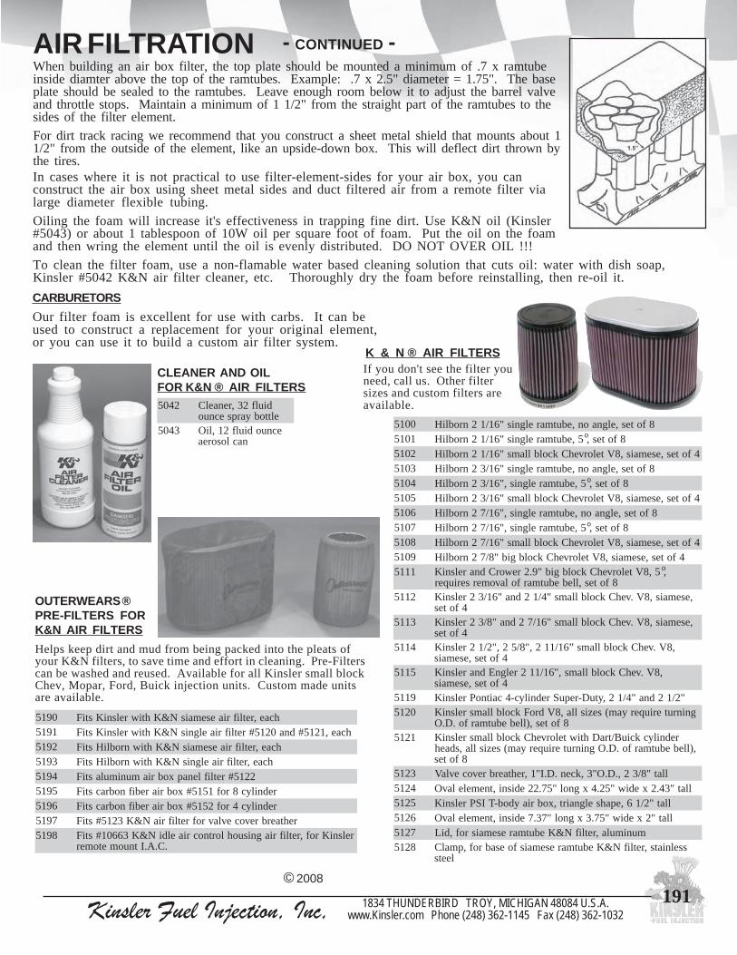
1911834 THUNDERBIRD TROY, MICHIGAN 48084 U.S.A.www.Kinsler.com Phone (248) 362-1145 Fax (248) 362-1032Kinsler Fuel Injection, Inc,
AIR FILTRATIONWhen building an air box filter, the top plate should be mounted a minimum of .7 x ramtubeinside diamter above the top of the ramtubes. Example: .7 x 2.5" diameter = 1.75". The baseplate should be sealed to the ramtubes. Leave enough room below it to adjust the barrel valveand throttle stops. Maintain a minimum of 1 1/2" from the straight part of the ramtubes to thesides of the filter element.
For dirt track racing we recommend that you construct a sheet metal shield that mounts about 11/2" from the outside of the element, like an upside-down box. This will deflect dirt thrown bythe tires.In cases where it is not practical to use filter-element-sides for your air box, you canconstruct the air box using sheet metal sides and duct filtered air from a remote filter vialarge diameter flexible tubing.
Oiling the foam will increase it's effectiveness in trapping fine dirt. Use K&N oil (Kinsler#5043) or about 1 tablespoon of 10W oil per square foot of foam. Put the oil on the foamand then wring the element until the oil is evenly distributed. DO NOT OVER OIL !!!
To clean the filter foam, use a non-flamable water based cleaning solution that cuts oil: water with dish soap,Kinsler #5042 K&N air filter cleaner, etc. Thoroughly dry the foam before reinstalling, then re-oil it.
CARBURETORSOur filter foam is excellent for use with carbs. It can beused to construct a replacement for your original element,or you can use it to build a custom air filter system.
CLEANER AND OILFOR K&N ® AIR FILTERS
2405 diulf23,renaelCelttobyarpsecnuo
3405 ecnuodiulf21,liOnaclosorea
OUTERWEARS ®PRE-FILTERS FORK&N AIR FILTERSHelps keep dirt and mud from being packed into the pleats ofyour K&N filters, to save time and effort in cleaning. Pre-Filterscan be washed and reused. Available for all Kinsler small blockChev, Mopar, Ford, Buick injection units. Custom made unitsare available.
0915 hcae,retlifriaesemaisN&KhtiwrelsniKstiF1915 hcae,1215#dna0215#retlifriaelgnisN&KhtiwrelsniKstiF2915 hcae,retlifriaesemaisN&KhtiwnrobliHstiF3915 hcae,retlifriaelgnisN&KhtiwnrobliHstiF4915 2215#retliflenapxobriamunimulastiF5915 rednilyc8rof1515#xobriarebifnobracstiF6915 rednilyc4rof2515#xobriarebifnobracstiF7915 rehtaerbrevocevlavrofretlifriaN&K3215#stiF8915 relsniKrof,retlifriagnisuohlortnocriaeldiN&K36601#stiF
.C.A.Itnuometomer
© 2008
o
0015 8fotes,elgnaon,ebutmarelgnis"61/12nrobliH1015 8fotes,5,ebutmarelgnis"61/12nrobliH2015 4fotes,esemais,8VtelorvehCkcolbllams"61/12nrobliH3015 8fotes,elgnaon,ebutmarelgnis"61/32nrobliH4015 8fotes,5,ebutmarelgnis,"61/32nrobliH5015 4fotes,esemais,8VtelorvehCkcolbllams"61/32nrobliH6015 8fotes,elgnaon,ebutmarelgnis,"61/72nrobliH7015 8fotes,5,ebutmarelgnis,"61/72nrobliH8015 4fotes,esemais,8VtelorvehCkcolbllams"61/72nrobliH9015 4fotes,esemais,8VtelorvehCkcolbgib"8/72nrobliH1115 ,5,8VtelorvehCkcolbgib"9.2reworCdnarelsniK
8fotes,llebebutmarfolavomerseriuqer2115 ,esemais,8V.vehCkcolbllams"4/12dna"61/32relsniK
4fotes3115 ,esemais,8V.vehCkcolbllams"61/72dna"8/32relsniK
4fotes4115 ,8V.vehCkcolbllams”61/112,"8/52,"2/12relsniK
4fotes,esemais5115 ,8V.vehCkcolbllams,"61/112relgnEdnarelsniK
4fotes,esemais9115 "2/12dna"4/12,ytuD-repuSrednilyc-4caitnoPrelsniK0215 gninruteriuqeryam(sezislla,8VdroFkcolbllamsrelsniK
8fotes,)llebebutmarfo.D.O1215 rednilyckciuB/traDhtiwtelorvehCkcolbllamsrelsniK
,)llebebutmarfo.D.Ogninruteriuqeryam(sezislla,sdaeh8fotes
3215 llat"8/32,.D.O"3,kcen.D.I"1,rehtaerbrevocevlaV4215 llat"34.2xediw"52.4xgnol"57.22edisni,tnemelelavO5215 llat"2/16,epahselgnairt,xobriaydob-TISPrelsniK6215 llat"2xediw"57.3xgnol"73.7edisni,tnemelelavO7215 munimula,retlifN&Kebutmaresemaisrof,diL8215 sselniats,retlifN&Kebutmaresemaisfoesabrof,pmalC
leets
o
o
o
- CONTINUED -
K & N ® AIR FILTERSIf you don't see the filter youneed, call us. Other filtersizes and custom filters areavailable.

192 Kinsler Fuel Injection, Inc, 1834 THUNDERBIRD TROY, MICHIGAN 48084 U.S.A.www.Kinsler.com Phone (248) 362-1145 Fax (248) 362-1032
AIR FILTRATION
CARBON-FIBER AIR BOXESComplete air box consists of carbon-fiber formed base with solidrubber panels for ramtubes (customer responsible to cut holes forthe ramtubes to go through). Upper part of box is molded withfiltering material on the top and sides. Standoffs with bolts toattach the upper part to the base are included.
1515 ,.sbl6.3shgiew,xobriaelyts8VetelpmoCgnol"91xediw"41xllat"7
2515 ,.sbl4.2shgiew,xobriarednilyc4enil-nietelpmoCgnol"91xediw"7xllat"7
3515 ,.sbl3.1shgiew,xobriarednilyc-laudetelpmoCgnol"9xediw"7xllat"7
© 2008
CUSTOM AIR FILTERSKinsler can custom fabricate an air filter system for your specificrequirements
Custom air filters madefor 460 big block Ford
street application
#5151
#5152
- CONTINUED -
BLOWER HAT AIR FILTERConsists of aluminum adapter toinlet of blower hat, K&N air filter,billet aluminum front plate, andinstallation hardware.
0415 ,rehctacguBelrednEroftiKediw"5.31,llat"5,peed"6
2415 ,rehctacdriBelrednEroftiKediw"71,llat"6,peed"11
K&N PANEL FILTER ELEMENTFor ‘do-it-yourself’ air box construction.
2215 gnol"61xediw"01,xobria8VroftnemecalperretlifriA4915 xobria8Vroftnemecalperretlif-erP
#5122
RAMTUBE BOOTIESReinforced sides with water repellant 25 micron nylon meshmedia. Can be made for any single ramtube or pairs ofsiamesed ramtubes,please call to discussyour project.
AIR BOX FOR KINSLER MOTORCYCLE UNITAvaialble with fiberglass or carbon fiber base,wire mesh screen dome with foam filter media,call for details

1931834 THUNDERBIRD TROY, MICHIGAN 48084 U.S.A.www.Kinsler.com Phone (248) 362-1145 Fax (248) 362-1032Kinsler Fuel Injection, Inc,
AIR DENSITY GAUGE
WHY YOU NEED TO MEASURE AIR DENSITYThe power output of an engine is directly related to the density of the air that it consumes.Air density is mainly affected by barometric pressure and air temperature.
Each time a piston goes down in your engine, it draws in the same volume of air, but the weight of that volumewill vary from day to day. If the atmospheric pressure increases (higher barometer), the air becomes compressedslightly... denser. If the temperature cools, the air shrinks slightly, which also makes it denser. The denser airmakes the same volume weigh more, so more power will be produced.
The challenge is to measure the density change so the correct adjustment to the fuel rate can be made to keep aproper air-fuel mixture... best power is obtained with just the right mixture... richer or leaner gives less power.For gasoline this ratio is about twelve pounds of air to one pound of fuel, or 12:1.
Since neither mechanical injection nor carbs automatically change the fuel rate when the air density changes, thefuel system needs to be re-jetted to keep the mixture correct.
If density increases but the fuel is not increased, the mixture will be lean. This will cause a power loss and coulddamage the engine. Adding fuel to get the proper mixture will give us a power increase.
Lower air density can hurt power output in two ways. Example : the car was running good; the air density was96% and the vehicle was jetted just right. Now the air density has dropped to 87%, a loss of 9%. See"UNDERSTANDING PERCENTAGE" on Page #194.
1) Since there is 9% less air to burn, there has to be a 9% loss of power... there is no way of correcting anythingto get that back. Of course, if the engine is supercharged or turbocharged, adjusting the overdrive orwastegate is a way to compensate.
2) Even though there was a loss of 9% of air density, the constant flow metering system doesn't sense it, so itputs in the same amount of fuel as it did before. This makes the mixture too rich, which costs about another5% of the power, making the total loss 14% (9% + 5%)!!! If the fuel system is leaned out to the proper air/fuel ratio, the 5% will be recovered, so there is only the 9% basic loss.
Everyone at the track will be affected the same way. It’s just a matter of who can properly adjust for it.HOW DOES THE AIR DENSITY GAUGE WORKThe gauge has a metal bellows with air sealed inside. Higher atmospheric pressurecompresses the bellows and moves the needle higher. Cooler temperature shrinksthe air in the bellows, which pulls the bellows together and also moves the needlehigher. Thus the gauge will give one needle reading to show the affect ofatmospheric pressure and temperature change on the air density.
6106 elacs%011ot%06,dnarbrelsniK,eguagytisnedriA7106 .eguagwenetarbilacdnayfilauqotrobaL yllacitirC
tnatropmi detarbilacsitekramehtnodnarbrehtoon...8106 rofeguagwenetarbilacLAICEPSdnayfilauqotrobaL
selibomwonsrof,YLNOESUREHTAEWDLOC9106 seod(eguags'remotsucetarbilac-erdnayfilauqotrobaL
)gnidliuberevisnetxeedulcniTON8206 rofeguags'remotsucetarbilac-erdnayfilauqotrobaL
)gnidliuberevisnetxeedulcniTONseod(REHTAEWDLOC9206 eguagytisnedria6106#rof,sneldnalezebtnemecalpeR
© 2008
WORKS EQUALLY WELL WITHFUEL INJECTION OR CARBSGIVES READINGS TO COMPENSATE FORCHANGES IN ALTITUDE AND WEATHER
It doesn't matter if two gauges don't read exactly the same, since the readingsare relative.... as long as you use the same gauge you should get good results.If you have a problem with your gauge we can test and possibly repair it.
The gauges we calibrate are done to read 100% at 59oF and29.92 inches of mercury pressure (by international agreement,these are the conditions for one standard atmosphere, STP).Some brands of gauges are calibrated differently, and somegauges get abused, so they will read differently than yours.Use only your gauge to take readings!
CALIBRATIONIS OPTIONAL
Internal workings of anair density gauge

194 Kinsler Fuel Injection, Inc, 1834 THUNDERBIRD TROY, MICHIGAN 48084 U.S.A.www.Kinsler.com Phone (248) 362-1145 Fax (248) 362-1032
AIR DENSITY GAUGECAUTIONAll weather broadcasts and weather maps give barometer readings corrected tosea level (zero altitude), so that high and low pressure weather fronts acrossthe country can be compared regardless of the altitude of the weather station.Example: Denver, Colorado reads 24.00" on their barometer, but they are5,000 feet above sea level, which causes a 5.02" lower pressure, so theybroadcast a 29.02" reading (24.00 + 5.02).
To do proper calculations you must use the actual reading of the locationyou are at. The best way to do this is to have your own air densitygauge. If you don’t have a gauge, you could obtain a barometerreading from a nearby airport (which will always be corrected toseal level), then corrrect it back to your altitude by subtracting1.0" for each thousand feetAIR DENSITY GAUGE READING PROCEDURE1) The gauge must be pulled up out of the foam of the
carrying case and placed in a shaded area. DoNOT hold the gauge in your hand, or place itinside the vehicle, or let sunlight fall directly onit, as all of these will artificially warm the gauge.Let the gauge sit for several minutes to stabilizebefore taking a reading.
2) Find the best jet for the day. Record the air densityand jet size.
3) The next race day, observe the readings of the air densitygauge. If it reads higher than before, go to a richer jet...this would be a smaller jet for a fuel injection unit, or a larger jetfor a carburetor.
4) After just a few days of racing you will have established a chart forthe jetting requirements versus the air density. Any time after that, merely observe the reading of
the air density gauge, refer to the chart, and select the jet for the prevailing conditions. You shouldalways try one richer and one leaner jet.
NOTE : Humidity has a very small affect... it can be neglected on an average day. If the humidityis very high (80-90%) go about 2% leaner, if it is very low (10-20%) go about 2% richer.
The vents on the sidesof the gauge must beexposed for a proper
reading. See 1) above.
ALTERNATE PROCEDURE
© 2008
UNDERSTANDING PERCENTAGEOne whole item of anything is 100% of it. 9% of an apple is 9/100 or .09 of it. Rather than saying9/100 or .09 of the apple, it is much easier to say 9%. To make any fraction into a %, move thedecimal point two places to the right, thus .09 becomes 9%.
X 100 = percent (%) change
X 100 = X 100 = -.085 X 100 = -8.5%
- CONTINUED -
This procedure will give the same results as the one above, but will take onlyone racing day to determine a baseline for making future jet changes:
1) and 2) Same as above.
3) The next race, observe the air density. Calculate the percent change in the air density.
Example On the first day, air density was observed to be 94% On the second day, air density was observed to be 86%
PERCENT: NEW A.D. - OLD A.D. 86 - 94 -8 CHANGE : OLD A.D. 94 94
Note that the sign is (-) because the air density has decreased; go to a leaner main jet. If the sign is (+) the airdensity has increased and go to a richer main jet. A high reading on the gauge means that there is an increasein density.
4) Go to the table on the next page and find your application. Go across in the table until coming to thepercent change that is closest to what has been calculated. Change the main jet by the amount shownin the column heading.
Example - Running an unblown gas engine, 427 cubic inches, -1 fuel pump. Under the "Unblown Gas" head-ing, use the "402-520" line, -1 pump. Go across to the percentage that is closest to the one calculated above:8.5%. The 9.0% figure is closest, so go .010" leaner (larger on fuel injection) on the main jet.
Example: 1/2 of something is .50 of it or 50% 1/8 of something is .125 or 12.5%

1951834 THUNDERBIRD TROY, MICHIGAN 48084 U.S.A.www.Kinsler.com Phone (248) 362-1145 Fax (248) 362-1032Kinsler Fuel Injection, Inc,
AIR DENSITY GAUGEPERCENT CHANGE IN FUEL DELIVERY
TO ENGINE VERSUS JET CHANGE
The systems operating pressure will affect the percent change of fuel flowwhen changing the main jet.This table is based on a typical system pressure of between 45 to 70 PSI.
© 2008
K-TYPE COMMERCIAL CUBIC PUMP SIZE JETS JETS
APPLICATION INCHES KINSLER / HILBORN .002" .004" .006" .008" .010" .005" .010"UNBLOWN GAS
BLOWN GAS
UNBLOWN ALKY
BLOWN ALKY
UNBLOWN NITRO
BLOWN NITRO
302-402402-520520+
302-520
70-200300-400400-500500+
300-500300-500
300-500300-500
300-500
400 -0 700 -1 700 -1
700 -1
300 -00 400 -0 700 -1 700 -1
700 -1 1300 -2
700 -1 1300 -2
LB750 -4
3.0 6.0 9.0 12.0 15.0 7.5 15.01.8 3.6 5.4 7.2 9.0 4.5 9.02.1 4.2 6.3 8.4 10.5 5.2 10.4
1.8 3.6 5.4 7.2 9.0 4.5 9.0
3.0 6.0 9.0 12.0 15.0 7.5 15.02.0 4.0 6.0 8.0 10.0 5.0 10.01.8 3.5 5.3 7.0 8.8 4.4 8.81.6 3.2 4.8 6.4 8.0 4.0 8.0
1.1 2.1 3.2 4.2 5.3 2.7 5.31.0 1.9 2.9 3.8 4.8 2.4 4.8
1.1 2.1 3.2 4.2 5.3 2.7 5.31.2 2.4 3.6 4.8 6.0 3.0 6.0
0.4 0.8 1.2 1.6 2.0 1.0 2.0
CASESNicely finished polished hardwood, piano type hinge, sturdy front latch, and foam liner.
0206 "0.3x"7.4x"7.4,YLNOeguagytisnedriadlohot,esaC1206 ,sgulpkraps04dnaeguagytisnedriadlohot,esaC
.partsgniyrracsah,"5.4x"6.5x"7.21
#6020 #6021 #6013
All-in-one digital weather station.Features: automatic air samplingand an internal fan control toprovide highly accurate results.Provides weather data andcalculated values to assist in E.T.prediction and tuning.
25011 noititepmoCriAecaRrezylanArehtaeW
Computech SystemsRace Air CompetitionWeather Analyzer
John Anderika of East Coast Auto Electric.Big block Chev using Kinsler constant flow
metering and mono-valve throttle body
3106 ,tikrezylanaleufdnaeguagytisnedriadlohot,esaCpartsgniyrracsah,"5.4x"3.6x"2.11
7206 esacrezlyanaleuf3106#nitnemecalper,tresnimaoF
- CONTINUED -

196 Kinsler Fuel Injection, Inc, 1834 THUNDERBIRD TROY, MICHIGAN 48084 U.S.A.www.Kinsler.com Phone (248) 362-1145 Fax (248) 362-1032
FUEL ANALYZER KIT FOR SPECIFIC GRAVITY
UNDERSTANDING SPECIFIC GRAVITY (sp gr)
© 2008
4106 :fostsisnoc,TIKREZYLANALEUFETELPMOC)...tnereffidowtroemasehtfoowt(sretemordyhowT
7006#,6006#,5006#,4006#,3006#:hcihwyficepsrednilycssalg0106#enO
retemomreht1106#enO,renilmaofhtiwesacgniyrracdoowdehsilop3106#enO
snoitcurtsnidna,slaivcitsalpowt5106 YTISNEDRIARELSNIKHTIWTIKREZYLANALEUFETELPMOC
dnaeguagytisnedriarelsniK6106#sulp,4106#saemaS:EGUAG)091#gpees(eguagfonoitarbilacdnanoitacifilauq7106#
3006 llarevo"21,)rgps(017.-046.,)enilosagnoitaiva(sagtsethgil,retemordyHsnoisividrgps5000.0taelacs"5,htgnel
4006 018.-007.,)lohocla(lonahtemthgiartsdnasagpmuptsom,retemordyHsnoisividrgps100.0taelacs"5,htgnelllarevo"21,)rgps(
5006 ,htgnelllarevo"21,)rgps(000.1-056.,enahtemortin%06-0,retemordyHsnoisividrgps500.0taelacs"4
6006 llarevo"21,)rgps(022.1-000.1,enahtemortin%001-06,retemordyHsnoisividrgps200.0taelacs"2/15,htgnel
7006 ,htgnelllarevo"21,)rgps(00.1-048.,enahtemortin%06-51,retemordyHsnoisividrgps100.0taelacs"5
0106 retemomrehtdnaretemordyhhtiwesurof,cc052,ssalg,rednilyC1106 "21,edargyrotarobal,Fseerged021otFseerged03-,retemomrehT
snoisividFeerged1taelacs"7,htgnelllarevo3106 tresnimaofhtiwdoowdehsilop,tikrezylanaleufrof,ylnoesaC7206 esacrezlyanaleuf3106#nitnemecalper,tresnimaoF
FOR FUEL INJECTION OR CARBS
LAB GRADE HYDROMETERS
FOR GAS, ALKY, NIITRO
#6011Thermometer
#6010Glass
Cylinder
#6006Hydrometer
WHY CHECK THE FUELEngines perform best in a narrow band of air-fuel ratios, determined by the weight of the airand fuel. Since all fuel injection systems and carburetors meter fuel by volume, a jet changemust be made if the sp gr of the fuel changes significantly. This change is to adjust thevolume to keep the weight of the fuel going to the engine the same. Example: if the sp gr ofthe fuel increases 4%, then the volume injected must be decreased 4% to keep the weightgoing to the engine the same.
Many race tracks and sanctioning bodies use our Fuel Analyzer Kit to spot-check thesp gr of the racers’ fuel, to see if it is consistent with the fuel that is legal at that track.
The sp gr of any substance is its weight compared to anequal volume of water. Since water is used as thereference, it was given a sp gr of 1.0 At 68 deg F(20 deg C) water weighs 8.330 pounds per gallon;62.32 pounds per cubic foot. Examples: 1. Gasoline with a sp gr of .740 is 74% of the density of water. 2. What is the weight of a gallon of gasoline with .740 sp gr at 68 deg F? .740 x 8.330 = 6.16 pounds 3. What is the weight of a gallon of methanol with .792 sp gr at 68 deg F? .792 x 8.330 = 6.60 poundsThe second and third example above are valid at about room temperature, butkeep in mind that as any substance is heated it expands, so the specific gravity of anyliquid decreases (weighs less per gallon) as its temperature increases. Because of this, sp grmust always be referenced to some standard temperature. Each of our hydrometer kits containsa temperature correction table so you can read the sp gr of your fuel at any temperature, thencorrect it to any standard temperature you want to use; we like 70 deg F. If you are measuringsp gr at about room temperature, using that reading will usually be close enough, but if it is tenor twenty degrees hotter or cooler, you might want to use the correction tables.
#6015 Complete kitplus air density
gauge. Has easyprocedure sheet

1971834 THUNDERBIRD TROY, MICHIGAN 48084 U.S.A.www.Kinsler.com Phone (248) 362-1145 Fax (248) 362-1032Kinsler Fuel Injection, Inc,
UNDERSTANDING FUELS
ETHANOLThe specific gravity of ethanol is .815 @ 68oF (200C). Ethanol, ethyl alcohol or grain alcohol (CH
3CH
2OH), is a liquid derived
from corn or other grain, other agricultural products or waste. Because ethanol is corrosive (due to oxidation), the samemodifications must be made to the fuel system as methanol to protect the fuel system components.
In the 1880s, Henry Ford built one of his first automobiles - the quadricycle - and fueled it with ethanol. Early Ford Model T'shad a carburetor adjustment that could allow the vehicle to run ethanol fuel that was produced by America's farmers. Ford's visionwas reportedly to "build a vehicle affordable to the working family and powered by a fuel that would boost the rural farmeconomy". However, in the past due to whatever reasons any alternative fuels other than gasoline were suppressed. Today, weare seeing the return of alternative fuel vehicles.
METHANOL (ALCOHOL)The specific gravity of pure methanol is .792 @ 68oF (200C). Methanol, methyl alcohol or wood alcohol(CH
3OH), is usually made from natural gas. It was first discovered in 1823 by condensing hot gases from
the burning of wood. It has been the fuel for Indianapolis 500 race cars since 1965. Methanol has theability to absorb water, even right out of the air. Keeping your fuel sealed will help prevent contamination.Adding water to alcohol will increase the specific gravity. High levels of water contamination will causethe alcohol to normally get cloudy. Loss of engine performance will typically occur before thecontamination reaches these high levels. Fuel should be checked with a hydrometer before using it, maybeeven before you leave your supplier, just to be sure to avoid any problems. Methanol is extremelycorrosive to aluminum and magnesium, great care should be taken to keep this reaction to a minimum. Thefuel system components should be of materials that do not react with methanol (stainless steel, brass, etc.)or should have a protective coating. Methanol crystallizes when it drys, this dried methanol does notreadily dissolve. The fuel system will need constant attention. When not in use, the fuel should be drainedout of the system. Flushing, or “pickling” with gasoline is a common practice.
GASOLINEThere is a big difference in specific gravity between various brands and grades of gasoline, often evenbetween two batches of the same brand. The typical range of premium automotive pump gasoline is .730to .760., aviation gasoline is .680 to .720, some unleaded racing gasolines are as heavy as .790. Manyblends of pump gas now contain as much as 10% ethanol. These blends generally fall into the heavierspecific gravity range. For Example : Unocal 76 ® unleaded racing gasoline .788 @ 590F (150C).
Unocal 76 ® leaded racing gasoline .728 @ 59oF (150C).
OCTANEOctane is a unit of measurement used to rate a fuels ability to resist detonation. Detonation (spark knock,ping) is the tendency of the fuel to explode violently in the engine rather than burning smoothly. If thefuel detonates, the pressure in the combustion chamber rises so fast and high that it is like beating on thetop of the piston with a hammer... this is a primary cause of piston, rod, and bearing failures. The higherthe octane rating the higher the resistance of the fuel to detonation. Racing gasoline is blended toprovide additional octane rating, not more energy. In fact, all grades of gasoline have about the sameamount of energy per pound. Increasing the octane, can get more power, since more compression or sparkadvance can be used. Note: too much octane can slow the burn rate of the fuel causing a loss in power.
NITROMETHANEThe specific gravity of pure nitromethane is 1.139 @ 60-70o F. Nicknamed 'nitro' is chemically CH
3NO
2. Pure alcohol (.792 @
68o F) is considerably different than nitromethane, it is easy to determine the percentage of nitromethane in alcohol by measuringthe specific gravity of the mixture. Adding nitro to alcohol will increase its specific gravity. A table can be set up to show thepercentage of nitromethane versus specific gravity (We supply this when a hydrometer or fuel analyzer kit is purchased).
The procedure is only slightly complicated by the fact that temperature affects the specific gravity, since any fluid expands as it iswarmed, and therefore has a lower specific gravity. For example, a 60% mixture of nitro and alcohol and heat it, we know that it isstill a 60% mixture, yet its specific gravity is lower.
Some brands of nitro hydrometer kits are sold without correction tables. Errors of 5% are common if no temperature correction isused. For best engine performance the nitro percent mixture should be kept within one or two percent of what the engine wastuned for.
HOW TO CHECK THE FUELSee detailed instructions on Pages #198-200 and supplied with fuel analyzer kit. Put enough of the liquidto be tested in the glass cylinder to allow the hydrometer to float. Hold the thermometer in the liquid sothe bulb is submerged but not touching any part of the glass cylinder. Carefully sight across the bottom ofthe meniscus and read the hydrometer. The hydrometer MUST be floating freely, not in contact with theglass cylinder or your fingers.
© 2008
NOTE: Mixing nitromethane creates a mild endothermic reaction, which absorbs heat from the mixture, thus cooling it(this is the opposite of most reactions, which give off heat). The maximum affect is with about a 50% mixture, whichcools approximately 15oF.

198 Kinsler Fuel Injection, Inc, 1834 THUNDERBIRD TROY, MICHIGAN 48084 U.S.A.www.Kinsler.com Phone (248) 362-1145 Fax (248) 362-1032
SPECIFIC GRAVITY1) Holding the glass cylinder almost horizontal, place the hydrometer and thermometer into it. Slowly bring the cylinder to an upright position while jiggling them gently to the bottom.
2) Fill the cylinder to within an inch of the top with a sample of the gasoline. This will cause the hydrometer to project out of the top for easy positioning with your fingers.
3) Place the cylinder in the shade. Wait a few minutes for the temperature to stabilize.
4) Carefully sight across the bottom of the meniscus and read the hydrometer. It must be floating freely when you read it; not in contact with the cylinder or your fingers.
5) Hold the thermometer up so that it’s bulb is about at the the middle of the hydrometer’s bulb. Read the temperature.
6) Note that you now have the observed specific gravity. To find the true specific gravity you must go to the correction chart, go down the column that has the heading temperature that is closest to the one you observed, until you come to the specific gravity you observed, then go across to the 600F column and read true specific gravity.
PROCEDURE FOR OBTAINING OBSERVED SPECIFIC GRAVITY
PROCEDURE FOR DETERMINING JET CHANGESFOR A CHANGE IN SPECIFIC GRAVITY
CAUTIONTo avoid
damage, alwayslower the
hydrometerslowly into the
liquid;dropping it
may make it hitthe bottom of
the glasscylinder.
Thermometer
Hydrometer
Meniscus
Eye
Since the specific gravity of a liquid decreases with a rise in it's temperature, specific gravitymust always be referenced to a particular temperature. The accepted standard is 600F.
However, since it is not convenient to have to measure the liquid at 600F in the field, a chart hasbeen made up to allow the specific gravity to be measured at any temperature, and then corrected to 600F.
Example : at 900F, the specific gravity of a gasoline sample is found to be .747. Go to the chart and go down the column labeled900F until you find .747 . Now read the true specific gravity in the 600F column as .760.
In the procedure below, any time we refer to specific gravity, we mean corrected specific gravity... the specific gravity at 600F.
Procedure - To go from one type or batch of gasoline to a new one : 1) Measure the specific gravity of the "old" fuel, and note the jet size that worked best. 2) Measure the specific gravity of the "new" fuel. 3) Calculate the percent difference between the old fuel and the new one: New fuel specific gravity - Old fuel specific gravity
Old fuel specific gravity
EXAMPLE : A new fuel is checked as .712, old fuel is .736 .712 - .736 -.024 .736 .736
4) To make jetting correction :a) For fuel injectors... Using the table below, go up or down on jet size to get the same total % change as determined in step #3 above. Since the example was "-", go to a richer (smaller) main jet. If it had been "+", go to a leaner (larger) main jet.
Percent change in fuel delivery to engine versus jet change for popular type fuel injection units, gasoline only :
Engine Displacement Pump Size K-type Jet .002" K-type jet .004" Commercial Jet .005" 302 - 402 cid -0 3.0 6.0 7.5 402 - 520 cid -1 1.8 3.6 4.5 All size blown -1 1.8 3.6 4.5
b) For carburetors... Calculate the area of the old main jets and increase or decrease them by the same percentage found in step #3 above. Going larger on carburetor jets is richer.
[ Old jet area = (old jet area X % from step #3) ] = new jet area
Sign (+ or -) is the opposite of the sign found for the % in step #3.
= = -.0326 = -3.26%
© 2008

1991834 THUNDERBIRD TROY, MICHIGAN 48084 U.S.A.www.Kinsler.com Phone (248) 362-1145 Fax (248) 362-1032Kinsler Fuel Injection, Inc,
SPECIFIC GRAVITY
Typically the grade of methanol used for racing is not pure in the true sense. Mostis really classified as anywhere from 96 to 97% pure. There is 100% puremethanol but it is far more costly.
If your base number is different than .792 for pure methanol then you will need toadjust all the numbers of the chart to compensate for the difference.
STRAIGHT METHANOL (ALKY) TO 50% NITRO 50% NITRO TO 100% NITRO
© 2008
The 0 in this chart refers to straight pure methanol (.792 sp. gr. @ 680F)and the numbers refer to the percentage of nitromethane in methanol.
devresbO.rG.pS F05 F06 F07 F08 F09 F001
877. --- --- --- --- 0 0587. --- --- --- 0 2 3297. --- 0 0 2 4 5997. 0 2 3 4 6 7608. 2 4 5 6 8 9318. 4 6 7 8 01 11028. 6 8 9 01 21 31728. 8 01 11 21 41 51438. 01 21 31 41 61 71148. 21 41 51 61 81 91748. 41 61 71 81 02 12458. 61 81 91 02 22 32168. 81 02 12 22 42 62868. 02 22 32 42 62 82578. 22 42 52 62 82 03288. 42 62 72 82 03 23988. 62 82 92 03 23 43698. 82 03 13 23 43 63309. 03 23 33 43 63 83019. 23 43 53 63 83 04719. 43 63 73 83 04 24429. 63 83 93 04 24 44139. 83 04 14 24 44 64839. 04 24 34 44 64 84549. 24 44 54 64 84 05259. 44 64 74 84 05 25959. 64 84 94 05 25 45
devresbO.rG.pS F05 F06 F07 F08 F09 F001
669. 84 05 15 25 45 65379. 05 25 35 45 65 85089. 25 45 55 65 85 06789. 45 65 75 85 06 26499. 65 85 95 16 26 46100.1 85 06 16 36 46 66800.1 06 26 36 56 66 86510.1 26 46 56 76 96 17220.1 46 66 76 96 17 37920.1 66 86 07 27 37 57630.1 86 07 27 47 57 77340.1 07 27 47 67 77 97940.1 27 47 67 87 97 18650.1 47 67 87 08 28 48360.1 67 87 08 28 48 68070.1 87 08 28 48 68 88770.1 08 28 48 68 88 09480.1 28 48 68 88 09 29090.1 48 68 68 88 09 29790.1 68 88 09 29 49 69401.1 88 09 29 49 69 89111.1 09 29 49 69 89 001811.1 29 49 69 89 001 ---421.1 49 69 89 001 --- ---131.1 69 89 001 --- --- ---831.1 89 001 --- --- --- ---541.1 001 --- --- --- --- ---
o o o o o o o o o o o o

200 Kinsler Fuel Injection, Inc, 1834 THUNDERBIRD TROY, MICHIGAN 48084 U.S.A.www.Kinsler.com Phone (248) 362-1145 Fax (248) 362-1032
SPECIFIC GRAVITYOBSERVED SPECIFIC GRAVITY VERSUS TRUE SPECIFIC GRAVITY AT 600F
FOR AUTOMOTIVE GASOLINE.This table corrects for both the change in volume of the glass hydrometer and the change in volume
(specific gravity) of the liquid when using Kinsler's soft glass hydrometer.
© 2008
oF05 F55 F06 F56 F07 F57 F08 F58 F09 F59 F001
477. 277. 077. 867. 667. 467. 167. 957. 757. 557. 357.
277. 077. 867. 667. 467. 267. 957. 757. 557. 357. 157.
077. 867. 667. 467. 267. 067. 757. 557. 357. 157. 947.
867. 667. 567. 267. 067. 857. 557. 357. 157. 947. 747.
667. 467. 267. 067. 857. 657. 357. 157. 947. 747. 547.
467. 267. 067. 857. 657. 457. 157. 947. 747. 547. 347.
267. 067. 857. 657. 457. 257. 947. 747. 547. 347. 147.
067. 857. 657. 457. 257. 057. 747. 547. 347. 147. 937.
857. 657. 457. 257. 057. 847. 547. 347. 147. 937. 737.
657. 457. 257. 057. 847. 647. 347. 147. 937. 737. 537.
457. 257. 057. 847. 647. 447. 147. 937. 737. 537. 337.
257. 057. 847. 647. 447. 247. 937. 737. 537. 337. 137.
057. 847. 647. 447. 247. 047. 737. 537. 337. 137. 927.
847. 647. 447. 247. 047. 837. 537. 337. 137. 927. 727.
647. 447. 247. 047. 837. 637. 337. 137. 927. 727. 527.
447. 247. 047. 837. 637. 437. 137. 927. 727. 527. 327.
247. 047. 837. 637. 437. 237. 927. 727. 527. 327. 127.
047. 837. 637. 437. 237. 037. 727. 527. 327. 127. 917.
837. 637. 437. 237. 037. 827. 527. 327. 127. 917. 717.
637. 437. 237. 037. 827. 627. 327. 127. 917. 717. 517.
437. 237. 037. 827. 627. 427. 127. 917. 717. 517. 317.
237. 037. 827. 627. 427. 227. 917. 717. 517. 317. 117.
037. 827. 627. 427. 227. 027. 717. 517. 317. 117. 907.
827. 627. 427. 227. 027. 817. 517. 317. 117. 907. 707.
627. 427. 227. 027. 817. 617. 317. 117. 907. 707. 507.
427. 227. 027. 817. 617. 417. 117. 907. 707. 507. 307.
227. 027. 817. 617. 417. 217. 907. 707. 507. 307. 107.
027. 817. 617. 417. 217. 017. 707. 507. 307. 107. 996.
817. 617. 417. 217. 017. 807. 507. 307. 107. 996. 796.
617. 417. 217. 017. 807. 607. 307. 107. 996. 796. 596.
417. 217. 017. 807. 607. 407. 107. 996. 796. 596. 396.
217. 017. 807. 607. 407. 207. 996. 796. 596. 396. 196.
017. 807. 607. 407. 207. 007. 796. 596. 396. 196. 986.
807. 607. 407. 207. 007. 896. 596. 396. 196. 986. 786.
607. 407. 207. 007. 896. 696. 396. 196. 986. 786. 586.
407. 207. 007. 896. 696. 496. 196. 986. 786. 586. 386.
207. 007. 896. 696. 496. 296. 986. 786. 586. 386. 186.
007. 896. 696. 496. 296. 096. 786. 586. 386. 186. 976.
896. 696. 496. 296. 096. 886. 586. 386. 186. 976. 776.
696. 496. 296. 096. 886. 686. 386. 186. 976. 776. 576.
496. 296. 096. 886. 686. 486. 186. 976. 776. 576. 376.
296. 096. 886. 686. 486. 286. 976. 776. 576. 376. 176.
096. 886. 686. 486. 286. 086. 776. 576. 376. 176. 966.
886. 686. 486. 286. 086. 876. 576. 376. 176. 966. 766.
686. 486. 286. 086. 876. 676. 376. 176. 966. 766. 566.
o o o o o o o o ooo

2011834 THUNDERBIRD TROY, MICHIGAN 48084 U.S.A.www.Kinsler.com Phone (248) 362-1145 Fax (248) 362-1032Kinsler Fuel Injection, Inc,
FUEL DATA
Example of use : A popularly accepted rule of thumb is that of the total heating value of gasoline, only about 1/3 goes downthe drive shaft as work, as about 1/3 goes out of the radiator as heat and about 1/3 goes out of the exhaustpipes as heat and blow-down pressure.
Lets look at a 331 cubic inch small 648 hp @ 7800 rpm with .46 BSFC (Brake Specific Fuel Consumption)block professional road race engine: 470 ft-lb @ 6750 rpm with .42 BSFC
Looking at our conversion chart, we know that one horsepower = 42.44 Btu
Torque From the conversion chart, hp = torque (ft-lb) x rpm = 470 x 6750 = 604 hp 5252 5252
604 hp x 42.44 Btu/min per hp = 25,634 Btu/min work done by the engine
From the conversion chart, BSFC = lb/hr fuel so lb/hr = BSFC x obs hp = .42 x 604 = 254 lb/hr observed hp
254 lb/hr = 4.233 lb/min gasoline 4.233 lb/min gas x 18,400 Btu/lb gas = 77,887 Btu/min heat value in the gasoline burned
Efficiency = 25,634 = 33% 77,887
Horsepower 648 hp x .46 BSFC = 298 lb/hr gas = 4.968 lb/min 4.968 lb/min x 18,400 Btu/lb = 91,411 Btu/min heat value648 hp x .4244 Btu/min per hp = 27,501 Btu/min work done by engine
Efficiency = 27,501 = 30% 91,411
NOTE It makes sense that the engine is less efficient at the horsepower peak than the torque peak,as the air pumping losses throughthe intake ports are higher at the horsepower peak.
Note : water is 8.3 pounds per gallon.
© 2008
Air/Fuel Ratio Latent heat of Mixture temp. Density Weight lb/gal Heating Value for complete evaporation drop due tosp. gr. at 60oF at 60oF Btu/lb - ** combustion Btu/lb - ** latent heat, oF - **
Gasoline .690 aviation 6.17 for 20,000 14.7 148 35.751 most pump .740 sp. gr.
[ avg of (6) major brands ].690 - .740 typical race
Methanol .792 with no 6.60 8,600 6.5 500 250water present(anhydrous)
Nitromethane 1.139 9.50 4,500 1.6 135 ? (100%)
** - These are approximate values, especially the latent heat and mixture temperature drop.
Earl Wooden’s Land Speed “1947 Crosley”,set several land speed records whenequipped with a Kinsler small block
Chevrolet, and now powered by a big blockG.M./D.R.C.E.2 engine at the World Finals
at Bonneville set the world record for aflying mile with a average of 292.288 M.P.H.
Jerry Helwig’s Land Speed 1940 Ford Coupepowered by Kinsler injected flat head Ford,
runs in XF/VGC on gasolineand XF/VFC with alcohol/nitromethance mixture

202 Kinsler Fuel Injection, Inc, 1834 THUNDERBIRD TROY, MICHIGAN 48084 U.S.A.www.Kinsler.com Phone (248) 362-1145 Fax (248) 362-1032
ORIFICE THEORY
The particle of fuel coming straightdown a bit off to the left or in at anangle at the right both find their wayinto the orifice.
This design is the least sensitive tomachine marks, but the blend of theradius to the main diameter is veryimportant. Not easily damaged, asnicks from handling tend to be on thetop surface.
The particle a bit off to the left hits thetop surface; may bounce off to the left,or into the orifice. The particle comingin from the right will go into the orifice.
This design is quite difficult to makeproperly as the sharp edge must be thesame on all the orifices, with no nicks.It is easily damaged by nicking theedge.
The particle a bit off to the left willnot enter the orifice. The particlecoming in from the right may notenter the orifice.
This design would never really beseen in a jet, but it is exactly like aramtube without a bell. The topedge is easily damaged.
© 2008
SQUARE CURVE
PSI
FLOWlb/HR
300
200
400
100
03020 40 50 60 70 80100
Knowing the flow of a jet or nozzle at some pressure,the flow at a new pressure can be calculated:
*
*
An orifice is “any hole that a fluid flows through”….both gasses and liquids. It can be any shape instead of round, with a totally roughinterior.
All fuel systems, carbs, constant flow injection, and EFI, use orifices for metering the liquid flow, so they should have very stable flowfor consistent metering. We achieve this by making them with a precise diameter and entrance radius that are very smooth, with a longlength vs the hole diameter. Even though we machine our nozzles and jets with extreme care, they don’t all flow just right because ofmicroscopic flaws. We flow virtually every piece we make at 30, 55, and 100 psi, note the errors in flow vs the master for thatdiameter, then use scrapers and polishing tools to bring the flow within 1% of the master. We work on the entrance and/or the exit.Even after this special effort, about one out of twelve pieces doesn’t conform to the master flow curve, so we discard it. We use brassbecause it is one of the better metals for achieving close tolerances and a smooth finish. While this extreme attention to detail costsmore, we don’t believe you can find this quality anywhere else.
The pressure increases as the square of the flow; see the graph below: to flow 200 lb/hr takes 20 psi; to flow 400 lb/hr takes 80 psi, soto get twice the flow takes four times the pressure. Why? If we want to flow twice as much through a fixed hole size, we will have topush twice as many fuel particles through it at twice the velocity, so we will have to do 2 x 2 or 4 times the work. We use the pressureto do this work.
If you want to flow more through an orifice, but keep the pressure the same, then you must use a larger orifice. The flow increases asthe area of the orifice increases. Since the area is Pi x diameter squared / 4, the area increases as the square of the diameter, so twice thediameter is four times the area. See the area and flow vs orifice size on the next page. (Pi is 3.1416).
We use these test pressures because 55 psi gives about 1.35 the flow as 30 psi, and 100 psi gives about 1.35 the flow as 55psi…. we like having the flow ratios about the same. See the very bottom of this page for the formula that we use to calculatethese ratios.
THREE ORIFICE EXAMPLES BELOWA sharp edge at the orifice entrance (middle example) causes the flow stream to converge, forming a vena contracta, which is a narrow-ing-in of the flow path of the particles. The diameter of the vena contracta becomes the effective flow diameter of the hole, thus theflow is reduced. At very low flows there is no vena contracta, while at very high flows there is a large vena contracta causing as muchas a 20% flow loss, so it varies with flow and is unstable. It is always ideal to use the “BEST” design, which we use in all of ourmetering pieces.
CHOKED FLOW Example: Injecting fuel into a supercharged manifold. If your nozzle pressure is 70 psi and your boost is 10 psi,you might expect the flow to be what the nozzle is rated to flow at 60 psi. It will actually flow at a 70 psi rate, because the downstreampressure has no affect on flow until its absolute value (gauge reading + 14.7 psi atmospheric pressure) is about ½ of the upstreamabsolute pressure. To find the downstream pressure that will just start to reduce the flow when there is 70 psi upstream: 70 + 14.7 =84.7 ½ x 84.7 = 42.3 absolute psi, – 14.7 = about 27.6 gauge psi. This is affected by fuel temperature, actual atmospheric pressure,and properties of the fuel.
FLOW THROUGH AN ORIFICEPressure rises as the square of the flow throughan orifice, so to double the flow through a jet ornozzle takes four times the pressure :

2031834 THUNDERBIRD TROY, MICHIGAN 48084 U.S.A.www.Kinsler.com Phone (248) 362-1145 Fax (248) 362-1032Kinsler Fuel Injection, Inc,
ORIFICE THEORYUNDERSTANDING AN ORIFICE - DIAMETER VERSUS AREAThe flow of an orifice CAN NOT be interpolated by the ratioof the diameter, an .080" diameter orifice does not flow twicethat of a .040" (see FLOW THROUGH AN ORIFICE on Page #199).
However flow can be interpolated by the ratio of thearea in square inches of an orifice.The diameter can be converted by the formula:
(radius x radius) x 3.14159 (Pi) = area
The area of .040" is .001257 in2 and .080" is .00527 in2
(see below quick reference chart).
This fomula can be used for Kinsler's electric enrichment or lean-out valve (see Pages #89 and #168 about this valve).Example for lean-out valve; If a .116" main jet is good for the basic mid-range and .124" is best when on transbrake,two-step, etc. You can calculate the K-jet for the lean-out by the following:
.012076 in2 (area of .124") - .010568 in2 (area of .116") = .001508 in2 (the difference in area of the two jets).Go to the chart and find area close to .001508 in2 which is approximately .044".This is the jet to install in the lean-out valve.
Dia. Area.113" .010029.114" .010207.115" .010387.116" .010568.117" .010751.118" .010936.119" .011122.120" .011310.121" .011499.122" .011690.123" .011882.124" .012076.125" .012272.126" .012469.127" .012668.128" .012868.129" .013070.130" .013273.131" .013478.132" .013685.133" .013893.134" .014103.135" .014314.136" .014527.137" .014741.138" .014957.139" .015175.140" .015394.141" .015615.142" .015837.143" .016061.144" .016277.145" .016513.146" .016742.147" .016972.148" .017203.149" .017437
Dia. Area.150" .017672.151" .017908.152" .018146.153" .018385.154" .018627.155" .018869.156" .019113.157" .019359.158" .019607.159" .019856.160" .020106.161" .020358.162" .020612.163" .020867.164" .021124.165" .021383.166" .021642.167" .021904.168" .022167.169" .022432.170" .022698.171" .022966.172" .023235.173" .023506.174" .023779.175" .024053.176" .024329.177" .024606.178" .024885.179" .025165.180" .025447.181" .025730.182" .026015.183" .026302.184" .026590.185" .026880.186" .027172
Dia. Area.077" .004657.078" .004778.079" .004902.080" .005027.081" .005153.082" .005281.083" .005411.084" .005542.085" .005675.086" .005809.087" .005945.088" .006082.089" .006221.090" .006362.091" .006504.092" .006648.093" .006793.094" .006940.095" .007088.096" .007238.097" .007390.098" .007543.099" .007698.100" .007854.101" .008012.102" .008171.103" .008332.104" .008495.105" .008659.106" .008825.107" .008992.108" .009161.109" .009331.110" .009503.111" .009677.112" .009852
Dia. Area.041" .001320.042" .001385.043" .001452.044" .001521.045" .001590.046" .001662.047" .001735.048" .001810.049" .001886.050" .001964.051" .002043.052" .002124.053" .002206.054" .002290.055" .002376.056" .002463.057" .002552.058" .002642.059" .002734.060" .002827.061" .002922.062" .003019.063" .003117.064" .003217.065" .003318.066" .003421.067" .003526.068" .003632.069" .003739.070" .003848.071" .003959.072" .004072.073" .004185.074" .004301.075" .004418.076" .004536
Dia. Area.005" .000020.006" .000028.007" .000038.008" .000050.009" .000064.010" .000079.011" .000095.012" .000113.013" .000133.014" .000154.015" .000177.016" .000201.017" .000227.018" .000254.019" .000284.020" .000314.021" .000346.022" .000380.023" .000415.024" .000452.025" .000491.026" .000531.027" .000573.028" .000616.029" .000661.030" .000707.031" .000755.032" .000804.033" .000855.034" .000908.035" .000962.036" .001018.037" .001075.038" .001134.039" .001195.040" .001257
= 3.999 ratio
So an .080" diameter orifice flows 3.999 times more than a .040" diameter orifice.
© 2008
.005027 in2 (.080" dia.)
.001257 in2 (.040" dia.)

204 Kinsler Fuel Injection, Inc, 1834 THUNDERBIRD TROY, MICHIGAN 48084 U.S.A.www.Kinsler.com Phone (248) 362-1145 Fax (248) 362-1032
IMPORTANT FACTS
One standard atmosphere (stp) is 59oF and 29.92" Hg (14.694 PSI) ; this is 100% air density.At stp, one pound of air = 13.07 ft3, or .07651 pound/ft3
Air density in lb/ft3 at other temperature and pressure = 1.327 x "Hg ( Note : oR = oF + 460) Temp. oR
Percent air density (like reading on air density gauge ) = 1734.7 x "Hg Temp. oR
Example : It is 82oF, barometer is 27.84"Hg Density = 1734.7 x 27.84 = 89% 82 + 460
Example : A 6-71 blown engine has an intake manifold pressure of 22 PSI at 258oFMany racers would figure : 22 + 14.7 = 250% air density at the intake ports.
14.7
Now lets see what it really is : 1734.7 x (22 + 14.7) x 2.037"Hg/PSI = 181% 258 + 460
Composition of air by weight : 75.8% nitrogen , 23.22% oxygen , 0.98% other gases.It takes .240 Btu/lb of air to change the temp. 1oF, while holding the pressure constant.It takes .172 Btu/lb of air to change the temp. 1oF, while holding the volume constant.
The air drag on a car goes up as the square of the car speed.The horsepower to push the car through the air goes up as the cube of the car speed.Example : Your car was going 80 MPH, now it is going 130 MPH... the
drag increases (130/80)2 = (1.625)2 = 2.6The horsepower increases (130/80)3 = (1.625)3 = 4.29 This is why it is easy to go 100 MPH, but very difficult to go 200 MPH; the car has four times the drag, and it takes eight times the power to push it through the air.
FORMULASArea in square inches of a circle : 3.14159 (pi) x (radius x radius) Area in square inches of a square : height x length
Convert inches to millimeters : inches x 25.4 = millimeters (mm) millimeters to inches : millimeters = inches 25.4
Engine size is measured by piston displacement: CID = bore x bore x stroke x number of cylinders X .7854
One standard horsepower is the work required to move 33,000 pounds a distance of 1-foot in one minute or:HP = ft-lbs per minute
33,000
Brake horsepower is measured on a dynamometer.If you know how much torque an engine is producing at a given RPM.
Volumetric Efficiency (VE) is the measure of an engine's ability to fill the cylinder with afresh intake charge. The volumetric efficiency is measured per engine cycle and willvary throughout the engines operating range. It is the ratio between what is actuallypumped into the engine and 100% of the actual cylinder volume.
Miles Per Hour: MPH = overall tire dynamic diameter x achieved engine RPM * differential ratio x achieved top gear ratio x 336
* - (1:1 No transmission or clutch slipage)
© 2008
PRESSURE VERSUS VELOCITY CHART .... for drag force on car bodies or pressure in air scoops.
Speed in MPH 40 60 80 100 120 140 160 180 200 250 300 400PSI .029 .064 .114 .178 .256 .348 .455 .577 .713 1.11 1.60 2.85
For other than stp conditions, multiply these values by the percent air density.Air drag on a car body = frontal area x value in chart x % density x drag coefficient (Cd).Cd is approximately: .65 - .75 for a tractor trailer truck, .60 - .70 for a convertible with top down, .55 - .70 for open wheel IndyRacing League car (this may appear like a high value, but it is due to down force from the front and rear wings for high MPHhandling), .38 - .45 for an average sedan, .33 for a C5 Corvette, .15 - .20 for a streamliner.
SOME AIR FACTS ... ALL ARE FOR DRY AIR ----- Related subject: see "AIR DENSITY" on Pages #190-192
HORSEPOWERThe invention of the steam enginemade it necessary to establish aunit of measurement that could beused to compare work done bycompeting engines. The unitchosen was related to the standardpower source of the time -"horsepower".
After some creative testing, it wasfound that the average horse worksat a rate of 33,000 ft-lb per minute.This is equivalent to lifting 1 ton(2,000 lb) a distance of 16.5 ft inone minute.
Horsepower is now the standard(in the Western Hemisphere) formeasuring the rate at which motorsand drives produce work. A 1-hpmotor, for example, can produce33,000 ft-lb of work in one minute.
Torque 'T' and horsepower 'HP' arerelated through speed 'S'.HP = T x S/C where 'C' is aconstant that depends on the unitsused for torque. If torque is givenin lb-ft, then the value of 'C' is5,252.
*- used with gracious permissionfrom PT Design, July 1999
Brake horsepower = torque x RPM5252
VE = Total Volume of intake chargeActual Cylinder Volume
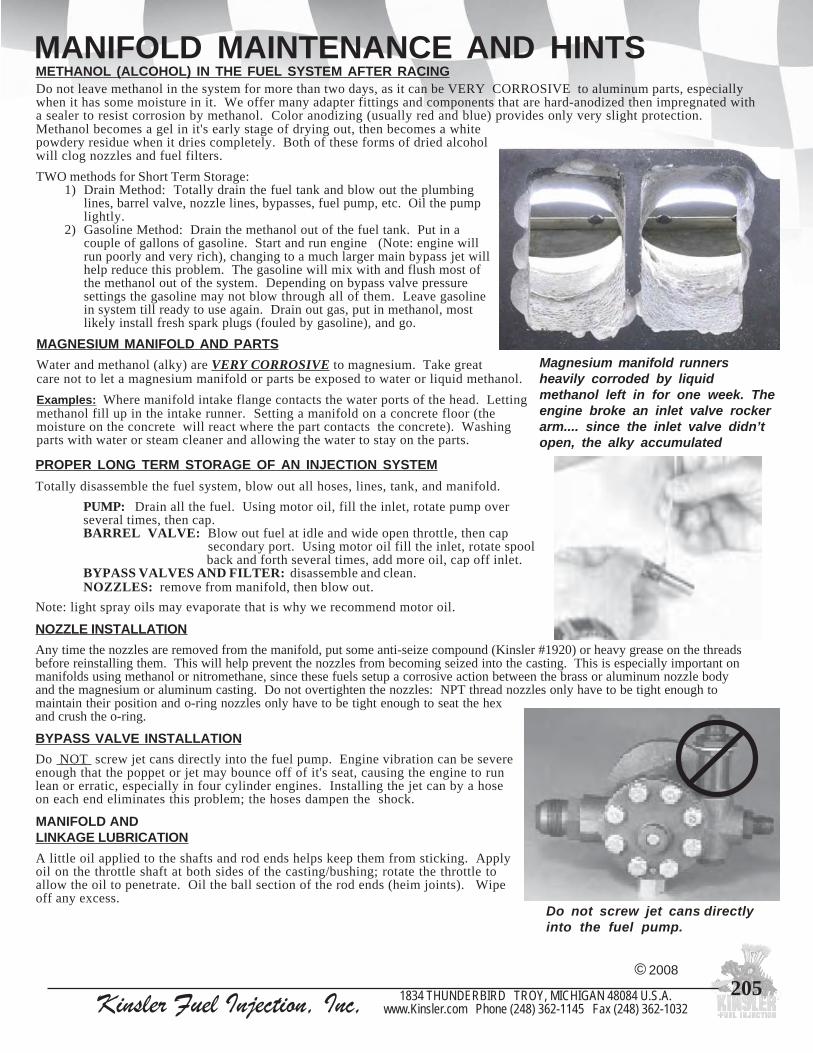
2051834 THUNDERBIRD TROY, MICHIGAN 48084 U.S.A.www.Kinsler.com Phone (248) 362-1145 Fax (248) 362-1032Kinsler Fuel Injection, Inc,
MANIFOLD MAINTENANCE AND HINTS
Methanol becomes a gel in it's early stage of drying out, then becomes a whitepowdery residue when it dries completely. Both of these forms of dried alcoholwill clog nozzles and fuel filters.
TWO methods for Short Term Storage: 1) Drain Method: Totally drain the fuel tank and blow out the plumbing
lines, barrel valve, nozzle lines, bypasses, fuel pump, etc. Oil the pumplightly.
2) Gasoline Method: Drain the methanol out of the fuel tank. Put in acouple of gallons of gasoline. Start and run engine (Note: engine willrun poorly and very rich), changing to a much larger main bypass jet willhelp reduce this problem. The gasoline will mix with and flush most ofthe methanol out of the system. Depending on bypass valve pressuresettings the gasoline may not blow through all of them. Leave gasolinein system till ready to use again. Drain out gas, put in methanol, mostlikely install fresh spark plugs (fouled by gasoline), and go.
MAGNESIUM MANIFOLD AND PARTSWater and methanol (alky) are VERY CORROSIVE to magnesium. Take greatcare not to let a magnesium manifold or parts be exposed to water or liquid methanol.
Examples: Where manifold intake flange contacts the water ports of the head. Lettingmethanol fill up in the intake runner. Setting a manifold on a concrete floor (themoisture on the concrete will react where the part contacts the concrete). Washingparts with water or steam cleaner and allowing the water to stay on the parts.
PROPER LONG TERM STORAGE OF AN INJECTION SYSTEMTotally disassemble the fuel system, blow out all hoses, lines, tank, and manifold.
PUMP: Drain all the fuel. Using motor oil, fill the inlet, rotate pump overseveral times, then cap.BARREL VALVE: Blow out fuel at idle and wide open throttle, then cap
secondary port. Using motor oil fill the inlet, rotate spool back and forth several times, add more oil, cap off inlet.
BYPASS VALVES AND FILTER: disassemble and clean.NOZZLES: remove from manifold, then blow out.
Note: light spray oils may evaporate that is why we recommend motor oil.
NOZZLE INSTALLATIONAny time the nozzles are removed from the manifold, put some anti-seize compound (Kinsler #1920) or heavy grease on the threadsbefore reinstalling them. This will help prevent the nozzles from becoming seized into the casting. This is especially important onmanifolds using methanol or nitromethane, since these fuels setup a corrosive action between the brass or aluminum nozzle bodyand the magnesium or aluminum casting. Do not overtighten the nozzles: NPT thread nozzles only have to be tight enough tomaintain their position and o-ring nozzles only have to be tight enough to seat the hexand crush the o-ring.
MANIFOLD ANDLINKAGE LUBRICATIONA little oil applied to the shafts and rod ends helps keep them from sticking. Applyoil on the throttle shaft at both sides of the casting/bushing; rotate the throttle toallow the oil to penetrate. Oil the ball section of the rod ends (heim joints). Wipeoff any excess.
BYPASS VALVE INSTALLATIONDo NOT screw jet cans directly into the fuel pump. Engine vibration can be severeenough that the poppet or jet may bounce off of it's seat, causing the engine to runlean or erratic, especially in four cylinder engines. Installing the jet can by a hoseon each end eliminates this problem; the hoses dampen the shock.
Magnesium manifold runnersheavily corroded by liquidmethanol left in for one week. Theengine broke an inlet valve rockerarm.... since the inlet valve didn’topen, the alky accumulated
© 2008
Do not leave methanol in the system for more than two days, as it can be VERY CORROSIVE to aluminum parts, especiallywhen it has some moisture in it. We offer many adapter fittings and components that are hard-anodized then impregnated witha sealer to resist corrosion by methanol. Color anodizing (usually red and blue) provides only very slight protection.
METHANOL (ALCOHOL) IN THE FUEL SYSTEM AFTER RACING
Do not screw jet cans directlyinto the fuel pump.

206 Kinsler Fuel Injection, Inc, 1834 THUNDERBIRD TROY, MICHIGAN 48084 U.S.A.www.Kinsler.com Phone (248) 362-1145 Fax (248) 362-1032
MANIFOLD DESIGN
NOTES
1) Six cylinder engines resonate stronger than eight cylinder engines as they have three pulses that are evenly spaced, compared to four that are unevenly spaced.
2) Tuning effects end where the intake becomes common, at E.
VARIABLE RESONANCE INDUCTION SYSTEM
Typical of some advanced design passenger carmanifolds in the 1990s.
THEORY
The length of the resonance tube F can bechanged by opening either valve C or D....only one would be used .... D giving a longerlength then C.
When a cylinder takes a gulp of air and the intakevalve closes, the inertia in the air column makes the airtry to keep flowing... it compresses down against thevalve, then springs back, setting up a resonant pulsing,which can enhance or hurt the intake pressure availableto the next cylinder gulping air.
Mazda obtained a positive effect through most of theRPM range by using the engine electronic control unit(ECU) to close a valve like C or D up to 3000 rpm,where it opens until 5200 RPM, where it closes again.
REFERENCE SAE Technical Paper #871977 Mazda six cylinder engine development
RUNNER FORMULA
How to calculate new length if you changethe runner diameter but want to keep theengine ram tuned at the same RPM.
Calculate "N" usingyour present lengths anddiameters. After youchange your diameters,work with the ramtubelength to obtain thesame value of "N".
Offshore Power Boatbig block Chev
withKinsler 1-piece
manifold.Lucas mechanical
metering andstaggered ramtubes.
© 2008
L1 L2 L3 = N D1
2 D22 D3
2+ +

2071834 THUNDERBIRD TROY, MICHIGAN 48084 U.S.A.www.Kinsler.com Phone (248) 362-1145 Fax (248) 362-1032Kinsler Fuel Injection, Inc,
LUCAS NOZZLE PLACEMENTNote - when the nozzles arelocated high in the ramtube, thatthe nozzle must be installed at a45o downward angle. This willkeep the fuel spray goinghorizontally across the port anddownward.
Advantage of low nozzle position is very goodthrottle response, which is very important onshort tight tracks; not so important on longwide open tracks.
This relative nozzle position shown here isgenerally a good compromise between goodpower and good throttle response.
This angle is necessary to keepfrom having excessive standoff ....the pulsating air column in theramtube moves upward and carriesfuel with it. The pulsation movesup and down as much as fourinches in the well tuned(ramtuned) racing engine.
If the nozzle is locatedlow enough wherestandoff is no problem,it should point straightinto the runner, as thiswill achieve the mostefficient spray pattern.
Advantage of high nozzle location, there ismore time for the fuel to evaporate before itgoes past the inlet valve, thus the charge iscooler and therefore more dense. This givesmore power.
A disadvantage of this position is that ittakes the fuel longer to get to the inletvalve during changes of fuel raterequirement; thus poorer throttle response.
© 2008

208 Kinsler Fuel Injection, Inc, 1834 THUNDERBIRD TROY, MICHIGAN 48084 U.S.A.www.Kinsler.com Phone (248) 362-1145 Fax (248) 362-1032
LUCAS METERINGLucas fuel metering equipment was used on all F-1 cars from the mid 50’s to mid 70’s, and most top sports cars,including all of the Can-Am cars of the 60’s and 70’s. Jim Kinsler started KFI in 1967... built the Lucas systems formost of the Can-Am cars, including the factory McLaren cars made famous by the always-winning Bruce McLarenand Denny Hulme. It is still very good for racing, as it has very precise fuel distribution at any RPM or throttleangle, and excellent vapor handling. Lucas only made metering pieces, not complete injection systems. To makea complete system you need a manifold, metering unit, pump, drive, fuel cam, filter, linkage, calibration, etc.
We were the North American distributor for Lucas in the 70’s and 80’s. We still have much new old stock and usedequipment for 4, 6, 8, and 12 cylinder engines.
We offer a premium line of modified Lucas equipment. The parts for every metering unit, pump, and nozzle arequalified, then assembled, and flowtested. The quality of these “Premium Race Grade” pieces is unsurpassed.
We service Lucas equipment for any application, including Ferrari, Maserati, Can-Am cars, F-1 cars, Triumph,offshore boats, etc. We rebuild worn and seized metering units, pumps, nozzles, etc. to new specs.
© 2008
A. Metering unit for four cylinder (Units are available for 4,6,8,12 cylinders).B. Mechanical fuel pump mounted on drive. Various pulley sizes and pitches are available.
Standard pump has .250” thick (center) pump segment. High flow option is .370” thick.C. Banjo bolt, carries fuel out to nozzle line. Standard finish on all Lucas pieces is cad plated.
Triple chrome satin plate optional; a must for marine use.D. Metering unit for eight cylinder engine.E. Electric fuel pump, high pressure (approx. 100 psi), used only to start Lucas system.F. Fittings made by Kinsler to adapt the BSP thread in the Lucas pieces to standard 6 AN (also 8 AN).G. Feeler gauges, special narrow made by Kinsler, for checking the metering unit shuttle stroke.H. Fuel cam follower by Kinsler for Lucas metering unit has precision ground solid-roller to eliminate the
friction of the standard flat lifter. Don’t use the ball bearing type; they crack!J. Banjo fittings, to fit unit like “D”. Triple chrome plated and stainless steel available.K. Pressure relief valve by Kinsler, diaphragm type, with 1/4”NPT ports, available with 6 AN fittings.
Smooth and reliable. Use this to replace the Lucas and Cosworth valves.L. 900 fitting, nozzle-line-to-nozzle. Available triple chrome plated.M. Bung seals, to seal the banjo bolt fitting nose to the metering unit sleeve.N. O-rings, special oversize by Kinsler for better leakproof seal of banjo fitting to housing.P. Bung seal installation tool.Q. Three-way check valve by Kinsler. 6 AN fittings on left and right are one-way check flaps
from mechanical and electric fuel pumps. 6 AN bottom fitting is outlet to fuel filter.R. Spanner wrench for removing diaphragm retainer plate securing nuts.S. Lucas nozzles, they only atomize the fuel. They have little to do with metering, which
is done by the metering unit. One size fits all. Available triple chrome plated.T. Filter (not shown), a must. Model: NPE, 10-micron, for inlet to Lucas metering unit, 6 AN fittings.U. Nozzle line (not shown), nylon, 1/4”OD, in black or translucent white.

2091834 THUNDERBIRD TROY, MICHIGAN 48084 U.S.A.www.Kinsler.com Phone (248) 362-1145 Fax (248) 362-1032Kinsler Fuel Injection, Inc,
LUCAS NOZZLES AND LINES
#9009 - Nozzleassembly blocks
900 nozzle line fitting, banjo fitting, banjobolt, KBB banjo bolt o-rings, bung seal,translucent and black Lucas nozzle line
LUCAS NOZZLESThe Lucas nozzles do an excellent job of atomizing, but no fuel meteringfunction. The metering unit controls the volume of the fuel being injected.All the nozzles should be set at the same opening pressure, usually 56 PSI.
© 2008
NOZZLE LINE ASSEMBLY..... read completely before beginning.1. Use Kinsler hardwood nozzle line gripping blocks (#9009) to hold
the tubing during installation, so that the outside will not bemarred. Use of the steel blocks that come in copper tube flaringkits will put rings around the outside of the tubing, creating a stresspoint, which may cause the tubing to fail.
2. Use only tubing from Kinsler for this application; available inblack and translucent. Other tubing may not have the strength,I.D., proper elasticity or the resistance to gasoline required.
3. Push an amount of tubing up through the block that is .200" longerthan the total length of the barb that you wish to install.
4. Clamp the block in a vise to grip the line.... a “C” clamp can beused in the field.
5. Put a drop of oil inside the end of the tubing, and a drop on the endof the fitting barb.
6. Start the end of the barb down into the tube by pushing and twistingit in by hand. If this is difficult, it can be made easier by driving atapered punch into the end of the tubing just enough to makestarting the barb easier. DO NOT “wallow” out the end of the tubewith a nail or such, as this will damage the inside of the tube.
7. Tap the fitting into the tube with a small hammer until the linecompletely covers the barb assembly. If the tube beneath thefitting tends to kink as you tap the fitting in, there is too much lineabove the block. Sometimes it is necessary to start with only asmall amount of line above the block, and then push more line upseveral times as you tap the fitting in.
8. Be careful that the tube does not slip down through the block asyou tap in the fitting. If the end of the barb assembly (down insidethe tubing) passes below the top of the block, it will damage thetubing.
9. Route the lines so that they have no sharp bends, since sharp bendstend to kink when the tubing gets hot. Keep the tubing away frommoving parts, such as throttle linkage. Tywrap the lines togetherto prevent them from vibrating when the engine is running...vibration can fatigue the lines.
We set each nozzle pressure, then thoroughly flow test it, then epoxy theadjuster shut. The nozzle body has a 14 x 1.25 mm thread. The thread at thetop for the fuel line fitting is 1/4 BSP.
+ =
Denny Hulme at speed inMcLaren MK 8A on backstraight at Elkhart Lake,Wisconsin
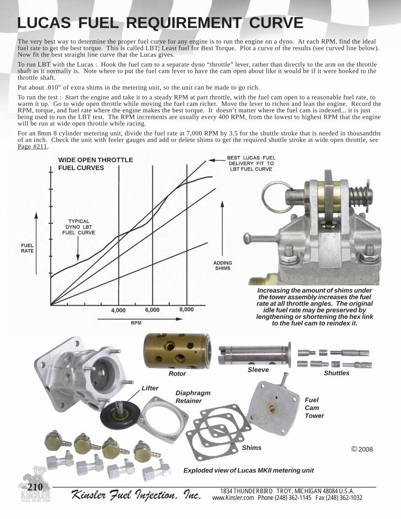
210 Kinsler Fuel Injection, Inc, 1834 THUNDERBIRD TROY, MICHIGAN 48084 U.S.A.www.Kinsler.com Phone (248) 362-1145 Fax (248) 362-1032
LUCAS FUEL REQUIREMENT CURVEThe very best way to determine the proper fuel curve for any engine is to run the engine on a dyno. At each RPM, find the idealfuel rate to get the best torque. This is called LBT; Least fuel for Best Torque. Plot a curve of the results (see curved line below).Now fit the best straight line curve that the Lucas gives.
To run LBT with the Lucas : Hook the fuel cam to a separate dyno “throttle” lever, rather than directly to the arm on the throttleshaft as it normally is. Note where to put the fuel cam lever to have the cam open about like it would be if it were hooked to thethrottle shaft.
Put about .010” of extra shims in the metering unit, so the unit can be made to go rich.
To run the test : Start the engine and take it to a steady RPM at part throttle, with the fuel cam open to a reasonable fuel rate, towarm it up. Go to wide open throttle while moving the fuel cam richer. Move the lever to richen and lean the engine. Record theRPM, torque, and fuel rate where the engine makes the best torque. It doesn’t matter where the fuel cam is indexed... it is justbeing used to run the LBT test. The RPM increments are usually every 400 RPM, from the lowest to highest RPM that the enginewill be run at wide open throttle while racing.
For an 8mm 8 cylinder metering unit, divide the fuel rate at 7,000 RPM by 3.5 for the shuttle stroke that is needed in thousandthsof an inch. Check the unit with feeler gauges and add or delete shims to get the required shuttle stroke at wide open throttle, seePage #211.
Exploded view of Lucas MKII metering unit
Increasing the amount of shims underthe tower assembly increases the fuelrate at all throttle angles. The original
idle fuel rate may be preserved bylengthening or shortening the hex link
to the fuel cam to reindex it.
© 2008
WIDE OPEN THROTTLEFUEL CURVES
Rotor Sleeve Shuttles
LifterDiaphragmRetainer
Shims
FuelCamTower

2111834 THUNDERBIRD TROY, MICHIGAN 48084 U.S.A.www.Kinsler.com Phone (248) 362-1145 Fax (248) 362-1032Kinsler Fuel Injection, Inc,
ADJUSTING THE METERING UNIT
TO MAKE SMALL MIXTURE CHANGESThe fuel cam on the top of the metering unit pivots on an eccentric marked “R” and “L” .
The idea of this design was that by pushing the shaft out against the spring and rotatingit so that the “R” moves toward the peg, the unit runs richer. One notch is supposed toequal .001” shim change.
GENERAL METERING UNIT SETTINGS
These are average settings for Amercian V8 2-valve gasoline engines using aLucas 8-cylinder metering unit with 8mm shuttles. If your engine is morepowerful than the average race engine, it will need more shuttle stroke (fuel rate).
AT WIDE OPEN THROTTLE (WOT)
© 2008
Eccentric pin, spring, cotter pin,spring rest washers, and fuel
cam bushings
Proper fuel timing gives best low RPM engine torque and throttle response;it has very little affect on high RPM horsepower.
For most engines, the best fuel timing is about 40 crankshaft degrees beforetop dead center, coming up to start the intake stroke. This timing usuallyworks well, but another setting may be better for a given application. Noharm will result from trying other timings.
If the engine builder specifies a certain timing, start with that, but you mighttry others......
TIMING THE METERING UNIT
To time the engine at 40 degrees before top dead center coming up tostart the intake stroke:
1. Rotate the crankshaft until it is 40 degrees before top dead center, comingup to start the intake stroke.
2. Remove the #1 nozzle line banjo bolt from the metering unit (be verycareful when reinstalling it as it cross threads easily).
3. With the right angle drive unit removed from the engine, rotate the drivegear on the bottom in the running direction until the ports in the rotor andthe bronze sleeve of the metering unit full line up.
4. When reinstalling the drive unit in the engine, try to mesh the drive gearto the cam so that it will keep this fuel timing. It is not critical to be exact.
NOTE -- DO NOT USE THIS .......
We have found that these pieces are often not indexed properlyas Lucas made them... it may cause an improper adjustment.Use only the shims to make any mixture adjustment unlessyou carefully check the functionality of this piece.
WIDE OPEN THROTTLESHUTTLE STROKE
.072"
.076"
.082"
.095"
.098"
.105"
.110"
.117"
.125"
.134"
CUBICINCHES LITERS 302 5.0 331 5.5 350 5.8 410 6.8 427 7.0 454 7.5 480 8.0 500 8.3 540 9.2 572 9.4
IDLESHUTTLE STROKE
.017"
.018"
.020"
.022"
.024"
.025"
.026"
.028"
.030"
.032"

212 Kinsler Fuel Injection, Inc, 1834 THUNDERBIRD TROY, MICHIGAN 48084 U.S.A.www.Kinsler.com Phone (248) 362-1145 Fax (248) 362-1032
ADJUSTING THE METERING UNIT
TURNBUCKLE VERSUS SHIM ANDECCENTRIC FUEL RATE CHANGES
If a wide open throttle fuel rate change is made by changing shims or using the eccentricpin, it will affect the idle fuel rate since the shuttle travel at the idle position will also bechanged by the same amount. Reset the idle fuel rate for best throttle response.
Changing the “idle” fuel rate by using the hex link to reindex the fuel cam does not affectthe wide open throttle (wot) fuel rate when using a KINSLER cam as it has no lift cutinto it from 65o to 90o past it’s nominal idle position. This is not only convenient, butproper, as a throttle plate does no throttling after about 65o of opening, so the engine is atwot air flow from that point on, and needs no additional fuel.
ANGLESThe throttle plates are cut at a 14o angle so they won’t stick in the throttle bore. Idle isabout 1o, or 15o total, so the throttle shaft only rotates about 75o to wide open throttle (90o)from an idle.
The fuel cam is connected to the throttle shaft with a parallel four bar linkage (see Page #62) so it also rotates about 75o to go fromidle to wot. Since it has no lift from 65o of travel to 90o, it can be reindexed to set idle fuel rate without affecting the wot fuel rateat all. It is rare to reindex the fuel cam more than 5o from the as shipped position to change the idle fuel rate significantly.
Some fuel cams have reference lines placed on them for checking the nominal, or “as shipped” cam position. The marks should bealigned as shown in Fig. 1 when the throttles are wide open on small block Chevrolets. On big block Chevrolet units, the throttlewould be closed.
TO MAKE LARGE MIXTURE CHANGESRemove the four nuts securing the top of the metering unit andremove it. Adding shims makes the unit richer (moves fuel camfarther from lifter). A .002” shim change will usually take care of alarge change in atmospheric conditions.
SETTING IDLE FUEL RATENote : The “idle” fuel rate should be set for best throttle response
as you quickly open the throttles; not for a smoothnonsmoking idle. The Lucas unit does not have an“accelerator pump shot”, so the idle must be rich tocompensate for this.
1. Start the engine and synchronize the throttle blades byusing a Uni-syn air flow meter.
2. To richen the idle fuel rate, adjust the hex link to the cam tomove it in the direction it moves as you open the throttles.
HOOKING UP THROTTLE LINKAGEOn units not having a rollerized fuel cam follower, the ideal place to attachthe throttle linkage is on the throttle shaft, close to the arm that activates thefuel cam. This will prevent putting the torque required to move the fuel camthrough the weakened section of the throttle shaft where it is milled toaccept the throttle blade.
On units that have a rollerized lifter (which takes very little force to move),it is acceptable to attach the throttle linkage to one of the spring-screw linksat the center of the manifold as long as the torque is pulling against thescrew in the spring-screw link, not against the rivit - spring.
Always attach the throttle return springs so that they pull at the same pointwhere the linkage is attached, so that they do not put torque through athrottle shaft. This will eliminate the possibility of putting the shaft under acyclic strain, which could eventually result in a fatigue failure.
The arrangement above puts torque through thethrottle shaft while the setup below does the samejob without putting any torque on the shaft.
CORRECT !!
Fig. 1
© 2008
NOT CORRECT !!

2131834 THUNDERBIRD TROY, MICHIGAN 48084 U.S.A.www.Kinsler.com Phone (248) 362-1145 Fax (248) 362-1032Kinsler Fuel Injection, Inc,
LUCAS MECHANICAL FUEL PUMPEach Lucas mechanical pump supplied by Kinsler will have a redflow test tag wired to it. This assures that the pump has been putthrough a run-in schedule of varying pump speeds and pressures forat least 1.2 hours. The pump is flow tested at the start and end ofthe run-in, and if there is more than a very small difference in flowbetween the start and end flow tests the pump is rejected asunsatisfactory.
DIRTIt can’t be stressed too much that cleanliness is of supremeimportance to any fuel system. It only takes one small grain ofdirt to start a scoring between the pump gears and the housing.
Making fuel lines: When you cut steel braided hose, smallfragments from the braid get inside... it must be flushed verythoroughly to get all of these out... some always lodge at the endof the barb of the hose fitting.
It is excellent to run a Kinsler 25 micron Monster stainless meshpump inlet filter, part #8309-025 (see Page #164). It is ideal toplace this in the fuel line immediately before the pump so it willcatch any dirt left inside the line during fabrication. It measuresjust 2.5" in diameter by 4" long and comes with 8 AN male flareends (can also be supplied with 6 AN male flare fittings).
LACK OF PUMP PRIMINGIt is important that the pump is primed with fuel before theengine is cranked over at all, since the fuel is the only lubricationfor the pump. It is smart to put a few drops of oil inside thepump each time you reinstall it on the engine, for initialstartup lubrication.
Turning on the high pressure electric starting pump doesn’tnecessarily push any fuel into the mechanical fuel pump. Thisis because there is a check valve at the outlet of each pump, toprevent fuel from going back through one pump when the otherone is pumping.
Lucas wide gear mechanical pump segmentmounted belt drive unit with AN adapter fittings
Disassembled Lucas mechanicalpump segment
LUCAS PUMP DRIVE SEALS
Kinsler design and manufacturedreplacment lip seals for Lucasmechanical and electric fuel pumpdrives. Special compound providesexcellent seal and resistance todetoration by the fuel.
Early Lucas electricfuel pump - filter
combination used onproduction Maseratiin the 60’s, and someracing Ferraris, such
as the P4. Called“The Black Bomb”
© 2008
6228 pmuplacinahcemsacuLlaestfahsevird
8228 pmupcirtcelesacuLlaestfahsevird
Later Lucas electric fuel pump withoutfilter. Used on production Triumph
fuel injected cars and as starter pumpon Can-Am cars in the 60’s and 70’s
PRESSUREThe pressure relief (PR) valve is set to maintain system pressure atabout 150 PSI on a Can-Am car with a 500 cubic inch engine, puttingout about 700 HP.... this requires about .117” shuttle stroke. Sincethe nozzles crack at 56 PSI, this leaves 94 PSI (150 - 56) to move thetwo shuttles inside the metering unit.
CAUSES OF PUMP FAILURE
#8228#8226

214 Kinsler Fuel Injection, Inc, 1834 THUNDERBIRD TROY, MICHIGAN 48084 U.S.A.www.Kinsler.com Phone (248) 362-1145 Fax (248) 362-1032
LUCAS NOTES
#9008 Spanner wrenchremoving #9244 spannernut to remove diaphragm
retainer plate
© 2008
2109 :fostsisnoc,tiKserapSsacuL)kcalbrotnaculsnartyficeps(enilelzzonsacuLfoteef-02
kcolbnoitacirbafenil9009#-1
)''510.,''800.,''400.,''300.,''200.:hcae1(rewottinugniretemrofsmihs-5
seguagreleefworranfotes5009#-1
sgnir-otlobojnabBBK5129#-61
slaesgnub6129#-8
lootnoitallatsnignub7009#-1
hcnerwrennaps8009#-1
pilcgnirpsdnarehsawtah,mgarhpaidsedulcni;tikmgarhpaidK-6329#-1
stnemeleretlifLRB1309#rostnemeleretlifEPN3209#-6
#9246 MK-II design
Top and bottom of#9290 Drive spud
A) The greatest enemy of any kind of fuel injection system is dirt.KEEP IT CLEAN. If disconnecting any lines, protect them from dirt.
B) There is a nylon filter in the adapter fitting on the inlet to the metering unit. Check thisoccasionally to be sure it is clean. Dirt may be removed from this and the nozzle inletscreens by using a Q-tip or similar cotton tipped swab.
C) An 8-cylinder metering unit that has 8mm diameter shuttles will flow 3.5 lbs/hr per .001”stroke at 7000 rpm.
D) Do not use any MK II metering units or nozzles that have not been flow tested.During certain dates of manufacture faulty pieces were assembled at the plant in England.
8093
dnagniwolfsedulcni,'CN'ledom,evlavfeilererusserprelsniKnehwyficepsesaelp(ISP051roISP521otgnitteserusserp
leetssselniatsdna,sgnittifretpadaeralfelamNA6,)gniredrostropeguagerusserpehtnidellatsnisgulptropTPN''8/1
9293 tunmajhtiwwercsretsujdA
8493 evlavCNrofmgarhpaiD
5995 .D.O"2/13otpusllebebutmartifot2006#rof,tiucsibretpadA
2006 esab"4/32,rezinorhcnyselttorhtnyS-inU
6106 eguagytisnedriarelsniK
7106 eguagytisnedria6106#etarbilacdnayfilauqotrobaL
2018 NA6,evlavkcehcyaw-3relsniK
#9235Lifter
#9236Diaphragm #9240
Diaphragmretainer clips
#9238Washer
#3948NC valvediaphragm
#3908Pressure relief valve,model: NC
Kinsler developed the K-140valve in 1995 for the IndyRacing League. While is isquite excellent, the model NCvalve is still totally adequate for theLucas system. The model NC valve is
the original one that Kinsler used on the Lucas systems from 1967 to 1995, so it is the correct piece for a vintage restoration.
#12106Pressurereliefvalve,model:K-140
1028 toofrep,tneculsnart,enilelzzonsacuL
2028 toofrep,kcalb,enilelzzonsacuL
3028 IIKM,eerged09,gnittifdneebutelzzoN
3828 PSB''4/1,gnir-orehsaW
4828 PSB''8/3,gnir-orehsaW
5009 IIKMdnaIKMsacuLhtiwesurofseguagreleefworraN
7009 lootnoitallatsnilaesgnuB
8009 stunreniatermgarhpaidgnivomerrofhcnerwrennapS
9009 skcolbnoitacirbafenilelzzondoowdrahfoteS
1129 IIKM,tlobojnaB
3129 IIKM,gnittifojnaB
5129 gnir-otlobojnabBBK
6129 laesgnuB
1329 IKM,dezirellordilosdnuorgnoisicerprelsniK,retfiL
5329 IIKM,dezirellordilosdnuorgnoisicerprelsniK,retfiL
6329 rewollofretfilrof,mgarhpaiD
8329 retfilotmgarhpaid6329#sniater,ssarb,rehsaW
0429 )deriuqer2(mgarhpaidnonwodrehsaw8329#skcol,pilC
4429 gniretem,etalpreniatermgarhpaidseruces,tunrennapSruofseriuqertinu
6429 ngisedIIKM,''200.,rewottinugniretem,mihS
8429 ngisedIIKM,''300.,rewottinugniretem,mihS
0529 ngisedIIKM,''400.,rewottinugniretem,mihS
2529 ngisedIIKM,''800.,rewottinugniretem,mihS
4529 ngisedIIKM,''510.,rewottinugniretem,mihS
0929 relsniKybedam,norleD,dupsevirdtinugnireteM

2151834 THUNDERBIRD TROY, MICHIGAN 48084 U.S.A.www.Kinsler.com Phone (248) 362-1145 Fax (248) 362-1032Kinsler Fuel Injection, Inc,
NOTES - PLUMBING MULTIPLE FUEL TANKSSEE PLUMBING SCHEMATIC ON PAGE #216 FORMULTIPLE FUEL SUPPLY TANKS ON A LUCAS SYSTEM.R E A D T H I S !!
This schematic greatly simplifies the plumbing and operation of the Lucas system when using multiple fuel tanks. It eliminatesthe need for multiple valves to select the desired fuel tank to run on. It also eliminates the need for selector valves running backto each tank.
Simply install one toggle switch on the instrument panel for each supply pump... these should all be wired through the ignitionswitch, (including the Lucas high pressure fuel pump) so no pump can be left running by mistake. Note: check amperage capac-ity of each switch. Select the tank that you want to use by using the corresponding fuel pump. This will deliver fuel through aone way check valve, then to the vapor separator tank. The check valves keep the fuel from backflowing into the other tank(s).
To switch to another tank: Leave the first pump running and flip on the switch for the nexttank. After allowing about twenty seconds for the new pump to purge out the trapped vapor,flip off the switch to the first pump.
A critical item for this system is the Kinsler Vapor Separator Tank (VST). It must beconstructed with a proper internal vapor separator chamber, or the tank will fill up withvapor. The Kinsler VST tanks have a proper chamber design:
Kinsler cross-ram big block Chevrolet manifoldon Greenwood IMSA Corvette usingLucas mechanical timed injection
Marsh Motorsports, New Zealand,road racing RX-8, Kinsler small block Chev
manifold with Lucas mechanical timed injection
When mounting any pump.....1. Mount it as low as possible, for good gravity feed from the tank. At
least keep it below the lowest fuel level the tank will have.2. Have no angled fittings in the inlet hose to the pump from the tank;
make any bends with a sweeping bend of the hose. If forced to use anangled fitting, it must be a bent tube type fitting... this gives the fuela reasonably smooth flow path, which will greatly reduce the tendencyof the pump to cavitate at its inlet.© 2008
8075 munimuladezidonaeulb,llat"8xretemaid"3,knatrotarepesropaV
0175 munimuladezidonaeulb,llat"01xretemaid"3,knatrotarepesropaV2175 munimuladezidonaeulb,llat"21xretemaid"3,knatrotarepesropaV
3175 rebburhtiwleetssselniats,knatretemaid"3roftekcarbgnitnuoMderiuqerowt,renil
6175 munimuladezidonaeulb,llat"21xretemaid"4,knatrotarepesropaV
7175 rebburhtiwleetssselniats,knatretemaid"4roftekcarbgnitnuoMderiuqerowt,renil
Stainless steel Vapor Separator Tanks are available on SPECIAL ORDER.
NOTE : Specify 8 AN, 10 AN, or 12 AN outlet to mechanical injection pumpwhen ordering. Tanks are available with 8 AN or 10 AN male flare inlet(supply from electric pump) and 6 AN or 8 AN male flare for return toBack Pressure valve - other sizes can be special ordered.
#5716#5717
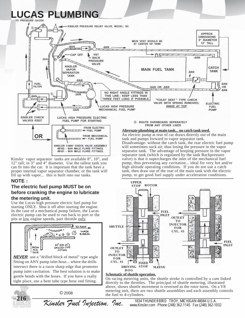
216 Kinsler Fuel Injection, Inc, 1834 THUNDERBIRD TROY, MICHIGAN 48084 U.S.A.www.Kinsler.com Phone (248) 362-1145 Fax (248) 362-1032
LUCAS PLUMBING
Use the Lucas high pressure electric fuel pump forstarting ONLY. Shut it off after starting the engine.In the case of a mechanical pump failure, the Lucaselectric pump can be used to run back to port or thepits at low engine speeds, part throttle only.
Kinsler vapor separator tanks are available 8”, 10”, and12” tall; in 3” and 4” diameter. Use the tallest tank youcan fit into the car. It is important that the tank have aproper internal vapor separator chamber, or the tank willfill up with vapor... this is built into our tanks.
NOTE :The electric fuel pump MUST be onbefore cranking the engine to lubricatethe metering unit.
Alternate plumbing at main tank... no catch tank used.An electric pump at rear of car draws directly out of the maintank and pumps forward to vapor separator tank.Disadvantage: without the catch tank, the rear electric fuel pumpwill sometimes suck air, thus losing the pressure in the vaporseparator tank. The advantage of keeping pressure in the vaporseparator tank (which is regulated by the tank Backpressurevalve) is that it supercharges the inlet of the mechanical fuelpump, thus preventing any cavitation... ideal for very hot and/orhigh altitude operating conditions. If you do not use a catchtank, then draw out of the rear of the main tank with the electricpump, to get good fuel supply under acceleration conditions.
© 2008
NEVER use a "drilled block of metal" type anglefitting on ANY pump inlet hose... where the drillsintersect there is a razor sharp edge that promotespump inlet cavitation. The best solution is to makegentle bends with the hoses. If you have a reallytight place, use a bent tube type hose end fitting.
SLEEVE
OUTLETTO
INJECTORFOR
CYL. #3
OUTLETTO
INJECTORFOR
CYL. #1
FUELINLET
SHUTTLE
UPPERSTOP ROTOR
FUELINLET
DRIVINGD O G
FIXEDSTOP
Schematic of shuttle operation.On racing metering units, the shuttle stroke is controlled by a cam linkeddirectly to the throttles. The principal of shuttle metering, illustratedabove, shows shuttle movement is reversed as the rotor turns. On a V8metering unit, there are two shuttle assemblies and each assembly controlsthe fuel to 4-cylinders.

2171834 THUNDERBIRD TROY, MICHIGAN 48084 U.S.A.www.Kinsler.com Phone (248) 362-1145 Fax (248) 362-1032Kinsler Fuel Injection, Inc,
CARBURETOR FUEL SUPPLY
The table gives the final regulated pressure for this system on asmall block Chev. If extremely fine pressure regulation is desired,two regulators can be installed in parallel, see table at right.Connect the two inlets together and connect the two outletstogether. This should not be needed except on larger gasolinebig block engines, or engines that run methanol. There are manyregulators; call us; we will recommend the best setup for you.
Nominal Holley ValveRegulated "H"Pressure Adjustment
2.0 .310"
3.0 .270"
4.0 .220"
5.0 .170"
6.0 .130"
7.0 .080"
8.0 .040"
9.0 -.010"
10.0 -.050"
Regulated PressureEngine One Two Holley HolleyRPM Regulator Regulators1000 8.0 8.02000 7.8 7.93000 7.7 7.95000 7.6 7.87000 7.3 7.78000 7.2 7.6
© 2008
Kinsler can supply a proper fuel supply system for a carburetor,using a mechanical or electric fuel pump (for information onELECTRIC FUEL PUMPS see Pages #124-130). Pump
drives, fuel filters, and bypass valves are also available.
MECHANICAL PUMP ELIMINATES THE NEED FOR A BATTERYAND CHARGING SYSTEM
ANY PRESSURE AND VOLUME YOU NEED
EXTREMELY DEPENDABLE !
Adjustable Pressure Regulators
0975 owtxtelnielamefTPN"8/3,rotalugererusserpyelloHsteltuoelamefTPN"8/3
0575 elamefNA01,ISP21-4,rotalugererusserpleuFangaMelamefTPN"8/1,steltuoelamefNA6owtxtelni
tropeguagerusserp1575 elamefNA01,ISP21-4,rotalugererusserpleuFangaM
erusserpelamefTPN"8/1,steltuoelamefNA6xtelnibrabecnerefermuucav/tsoobdnatropeguag
2575 elamefNA01,ISP21-4,rotalugererusserpleuFangaMelamefTPN"8/1,steltuoelamefNA8owtxtelni
tropeguagerusserp3575 elamefNA01,ISP21-4,rotalugererusserpleuFangaM
elamefTPN"8/1,steltuoelamefNA8owtxtelnibrabecenrefermuucav/tsoobdnatropeguagerusserp
4575 elamefNA01,ISP21-4,rotalugererusserpleuFangaMelamefTPN"8/1,steltuoelamefNA6ruofxtelni
tropeguagerusserp5575 elamefNA01,ISP21-4,rotalugererusserpleuFangaM
elamefTPN"8/1,steltuoelamefNA6ruofxtelnibrabecnerefermuucav/tsoobdnatropeguagerusserp
84701 elamefNA01owt,ISP03-0,rotalugererusserpnodleWerusserpelamefTPN"8/1,nruterelamefNA6xstelni
stropmuucav/tsoobdnaeguag
FOR GASOLINE
#5790 #5750 #5751
#5752 #5754 #10749
HOW IT WORKSMechanical injection pumps are positive displacement type, so thesystem must bypass the fuel that the carb doesn’t need back to thetank. The primary pressure relief valve does this, and also regulatesthe pressure at about 15 PSI* to the inlet of the regulator valve. It isnecessary to keep the inlet supply pressure to the carburetorregulator valve at least 1 PSI above the maximum desired regulatedpressure, but not more than 20 PSI total to prevent damage to theregulator.NOTE : the fuel filter is placed before the valves so that it will
protect both the relief and regulator valves.

218 Kinsler Fuel Injection, Inc, 1834 THUNDERBIRD TROY, MICHIGAN 48084 U.S.A.www.Kinsler.com Phone (248) 362-1145 Fax (248) 362-1032
CARBURETOR FUEL SUPPLYCall us to discussyour application; wewill recommend thebest setup for you.
The chart shows pump sizes versus maximumhorsepower output for carb supply systems,for pumps in good condition. The Chart uses0.5 Brake Specific Fuel Consumption (BSFC) for gasoline and 1.1 BSFC for methanol. The pumps are driven at 1/2 crankspeed, operate at a maximum of 50 PSI, and have 20% of the volume bypassed back to the fuel tank.
SELECTING THECORRECT PUMP
MECHANICAL PUMPSUPPLYING CARBURETORSYSTEM, WITH NITROUS OXIDEThe mechanical pump MUST becapable of supplying the requiredvolume at the RPM the nitrous isengaged. Just because the pump islarge enough to feed the engine at7000 RPM with nitrous, DOES NOTmean it is big enough to supply thevolume of fuel at 3500-4000 RPMwith nitrous. When engaging thenitrous at low RPM, a larger pumpwill be required to get the volumeneeded. DO NOT CONFUSEVOLUME WITH PRESSURE. Theremay be plenty of pressure before thenitrous is engaged, but when theenrichment solenoid opens and startsto flow volume the pressure willimmediately drop. Call us!
© 2008
FOR GASOLINEAND ALCOHOL
MAXIMUM MAXIMUM H.P. ON GASOLINE H.P. ON ALCOHOL
PUMP SIZE Engine RPM Engine RPM KW HILBORN 3500 7000 3500 7000 200 -00 420 840 190 380 400 -0 840 1680 380 760 500 -1/2 1120 2240 509 1018 700 -1 1760 3520 800 16001300 -2 3360 6720 1529 3054
We offer fittings and hose toproperly plumb these systems.
See Pages #182-186 for "FITTINGS" ;Page #187 for "HOSE AND HOSE ENDS"
- CONTINUED -
CARBURETOR VALVES
5875 NA6munimuladezidonadrah,evlavfeilererusserpyramirPnactej
6875 nactejNA6wolf-hgihssarb,evlavfeilererusserpyramirP7875 nactejNA8ssarb,evlavfeilererusserpyramirP
8875 7875#dna,6875#,5875#evobatesdnatsetwolfotrobaLnoitacilppacificepsrofevlav
#5787#5786#5785

2191834 THUNDERBIRD TROY, MICHIGAN 48084 U.S.A.www.Kinsler.com Phone (248) 362-1145 Fax (248) 362-1032Kinsler Fuel Injection, Inc,
U and L BENDS / CONNECTOR HOSE
IN STOCK FORIMMEDIATE SHIPMENT
BENDS ARE MANDRELL FORMED TO BE SMOOTH AND WRINKLE-FREE-- EXCELLENT FOR EXHAUST HEADERS, COLD AIR DUCTING,COOLANT PLUMBING, TURBOCHARGER DUCT WORK, ETC.
U-BENDS : ALUMINUM 3003-0 and 6061-0 alloy
L -BENDS : ALUMINUM3003-0 and 6061-0 alloy
OTHER SIZES ANDCENTERLINE RADIUSES
MAY BE AVAILABLE.PLEASE CALL !!!
#traP .D.O llaW .R.L.C lairetaM "W" geL5885 "4/31 "560. "3 0-3003 "8 "4
6885 "4/31 "560. "4 0-3003 "057.9 "4
7885 "4/31 "560. "5 0-3003 "057.11 "4
8885 "4/31 "560. "6 0-3003 "057.31 "4
4885 "2 "560. "4 0-3003 "01 "4
9885 "2 "560. "5 0-3003 "21 "4
1985 "2 "560. "6 0-3003 "088.31 "4
2985 "4/12 "560. "4 0-3003 "052.01 "4
5985 "4/12 "560. "4/15 0-3003 "005.21 "4
3985 "4/12 "560. "6 0-3003 "052.41 "4
4985 "2/12 "560. "4 0-3003 "005.01 "4
8985 "2/12 "560. "6 0-3003 "005.41 "4
7985 "3 "560. "2/14 0-1606 "21 "4
U-BENDS : STAINLESS STEELType 321 has excellent resistance to fatigueand cracking at elevated temperatures.
#traP .D.O llaW .R.L.C "W" geL9785 "2/11 "560. "560. "05.6 "4
0785 "2/11 "560. "530. "05.7 "4
1785 "2/11 "560. "560. "05.7 "4
2785 "4/31 "560. "560. "57.7 "4
3785 "4/31 "560. "560. "88.9 "4
4785 "4/31 "560. "560. "88.11 "4
5785 "2 "560. "560. "52.8 "4
6785 "2 "560. "560. "88.31 "4
7785 "8/12 "560. "560. "52.9 "4
8785 "8/12 "560. "560. 57.21 "4
To determine centerline radius:1) Imagine a circle that matches the centerline (the imaginary line running through the center of the
tube) of the radiused end of the bend.The center of that circle is the center point.2) Measure from the center point to any point in the arc of the imaginary circle. This measurement is the
centerline radius.
#traP .D.O llaW .R.L.C lairetaM sgeL2885 "3 "560. "3 403 "4
6985 "3 "560. "3 0-1606 "4
9985 "2/13 "560. "3 0-1606 "4
© 2008

220 Kinsler Fuel Injection, Inc, 1834 THUNDERBIRD TROY, MICHIGAN 48084 U.S.A.www.Kinsler.com Phone (248) 362-1145 Fax (248) 362-1032
.Metal Tubing: Standard length in stock is 36"We can cut special lengths
U and L BENDS / CONNECTOR HOSECONNECTOR HOSE - STRAIGHT .*** Hose sold ONLY in 18" and 36" sections ***
RickEssary’salcoholSuperStock
PullingTractor
Note on Connecting Tubing :Putting a bead around the end of both of the tubes isOK, but under boost conditions there is still a good
chance that the two pieces will blow apart causing notonly loss of boost but depending on where fuel is being
injected a fire hazard. The best thing to do is to weldan ear/flange on both pieces then either safety wirethem together, or even better, bolt them together.
CONNECTOR HOSE - 90-DEGREE ELBOWS4-ply reinforced silicone. Blue on the outside andred on the inside.
0881 sgel"2/181x"2/101,suidar"4x.D.I"21881 sgel"81x"2/18,suidar"4/12x.D.I"4/122881 sgel"01x"6,suidar"3x.D.I"2/123881 sgel"41x"8,suidar"2/13x.D.I"4/324881 sgel"21x"2/17,suidar"3x.D.I"3
18" LONG5381 .D.I"4/316381 .D.I"27381 .D.I"8/128381 .D.I"4/129381 .D.I"8/320481 .D.I"2/121481 .D.I"8/522481 .D.I"4/323481 .D.I"34481 .D.I"4/135481 .D.I"2/13
36" LONG1491 .D.I"4/312491 .D.I"24291 .D.I"8/123491 .D.I"4/124491 .D.I"8/325491 .D.I"2/126491 .D.I"8/527491 .D.I"4/328491 .D.I"39491 .D.I"4/130591 .D.I"2/13
© 2008
BAND CLAMPSStainless steel worm gear style, .560" wide band.
0781 "4/32ot"61/311morf.D.OesohfoegnaR1781 "3ot"61/12morf.D.OesohfoegnaR2781 "2/13ot"8/52morf.D.OesohfoegnaR3781 "4/33ot"61/312morf.D.OesohfoegnaR
3-ply glass fiber reinforcedsilicone, orange. Siliconeprovides mechanical, thermal,electrical and chemicalsuperiority over rubber or anyother elastomer. It is resistant to:wide range of temperature,hardening, cracking, moisture,steam, chemicals, solvents, fuels,oils. It is strong yet flexible, andgives long service life.
TUBE SECTIONSAluminum,type 6061,.065" thick wall
0685 .D.O"4/311685 .D.O"22685 .D.O"4/123685 .D.O"2/124685 .D.O"3
Stainless steel,type 321,.065" thick wall
6685 .D.O"4/317685 .D.O"28685 .D.O"8/12

2211834 THUNDERBIRD TROY, MICHIGAN 48084 U.S.A.www.Kinsler.com Phone (248) 362-1145 Fax (248) 362-1032Kinsler Fuel Injection, Inc,
O-RINGS / PLASTIC CAPS / JET NUTS
WASHER O-RINGS (stat-o-seals)Steel or aluminum washer with o-ring/sealattached around inside diameter.
CAPS PLUGSNote: O-rings and seals for Lucas Meteringequipment see Pages #208-209.
© 2008
O-RINGS
Kinsler stocks a wide range of sizes andcompounds. The following are commonlyused sizes and applications.
0103 dnarelsniK/ydobnactejNA6nrobliHdnarelsniKgulprognittifteltuoyradnocesevlavlerrabnrobliH
9003 'thgiL-artX'relsniKrofretemaidnodenihcamyllaicepSgnittifteltuoyradnocesevlavlerrab
3616 NA67316 NA88316 NA019316 NA21
11022 30022#,20022#spmupnodesu,mm010316 ,01201#,80201#teltuopmupleufhcsoBnodesu,mm21
21201#dna,11201#1316 01201#telnipmupleufhcsoBnodesu,mm412316 mm613316 11201#telnipmupleufhcsoBnodesu,mm813828 )tnempiuqegniretemsacuLnodesuylnommoc(PSB''4/14828 )tnempiuqegniretemsacuLnodesuylnommoc(PSB''8/3
1026 01foegakcap,NA3
3026 01foegakcap,NA4
5026 01foegakcap,NA6
7026 01foegakcap,NA8
9026 5foegakcap,NA01
1126 5foegakcap,NA21
2126 5foegakcap,NA61
0026 01foegakcap,NA3
4026 01foegakcap,NA6
6026 01foegakcap,NA8
8026 5foegakcap,NA01
0126 5foegakcap,NA21JET NUTSLight weight and compact. Only 40% of the weightof conventional elastic stop nuts.
1581 ,23-8 01foegakcap,tniop-6,detalpmuimdac
3581 ,23-01 01foegakcap,tniop-6,detalpmuimdac5581 ,82-4/1 01foegakcap,tniop-6,detalpmuimdac7581 ,82-4/1 01foegakcap,tniop21,detalpedixokcalb9581 ,42-61/5 01foegakcap,tniop-6,detalpmuimdac1681 ,42-8/3 01foegakcap,tniop-6,detalpmuimdac
4703 tej,sevlavssapybnactejwolfhgihNA6relsniKrofteSykla/sagrof,ydobdnagnilaes
6113 ykla/sag,nactejNA6nignilaesteJ7113 n-anub,YLNOykla/sag,tcennocsidkciuqrelsniKrofteS9113 .P.E,YLNOortin,tcennocsidkciuqrelsniKrofteS3143 retemaidegral,pacotydobniam,evlaVrotceleSteJrelsniK4143 ykla/sag,ydobniamottfahsrotor,evlaVrotceleSteJrelsniK
2718 deriuqerowt,6514#,8414#,0718#retlifleufrelsniK3718 6514#,8414#,0718#ydobretlifotgnilaestnemelE1068 owt,gnilaesydobotpacdne,sretlifseireshseMretsnoMrelsniK
deriuqer2068 gnilaespacdneottnemele,sretlifseireshseMretsnoMrelsniK4094 deriuqereno,0094#retlifleuF9094 deriuqereno,6094#dna5094#retlifleuF9506 leufyficeps,9306#&6306#evlavffo-tuhs,laestfahS
0416 netfoegakcap,n-anub,NA31416 netfoegakcap,n-anub,NA42416 netfoegakcap,n-anub,NA63416 netfoegakcap,n-anub,NA84416 netfoegakcap,n-anub,NA015416 netfoegakcap,n-anub,NA21
2253 ykla/sag,reworC/nrobliH/relsniK,tfahsloopsevlavlerraB4253 gulpesabevlavlerrabrelsniK5692 gnir-orevoctnorfpmupleufW-K8282 C,B,A051-GPledom,revoctnorfpmupleufnrobliH9282 571-GPledom,revoctnorfpmupleufnrobliH08161 ylka/sag,evlavlerrabepyterauqselrednEroftiK18161 ylno.ORTIN,evlavlerrabepyterauqselrednEroftiK28161 ykla/sag,evlavlerrabepyt.ortinwolf-hgihelrednEroftiK38161 ylno.ORTIN,evlavlerrabepyt.ortinwolf-hgihelrednEroftiK
5932 hcae,tresnielzzonni-wercselrednE/relsniK7932 hcae,elzzondaerht02-2/1nrobliH/relsniK9427 foegakcap,"2/12ot"61/32,dlofinamotretpadapotrelsniK
thgie8427 thgiefoegakcap,kcolbgib"9.2,dlofinamotretpadapotrelsniK79101 rotcejniIFEhcsoB
THROTTLE BORE PLUGS FOR KINSLER SMALLBLOCK CHEVROLET MANIFOLD
3126 8foegakcap,der,''4/12
4126 8foegakcap,der,''2/12
5126 8foegakcap,der,''8/52
6126 8foegakcap,wolley,"61/312
PLASTIC CAPSAND PLUGS
Ideal for protectingthrottle bores onmanifold, fittingflares and threads,and keeping a fuelsystem clean.Caps and plugshave ribs for easyfinger griping.Plugs have maleflare to help preventline or fittingleakage.
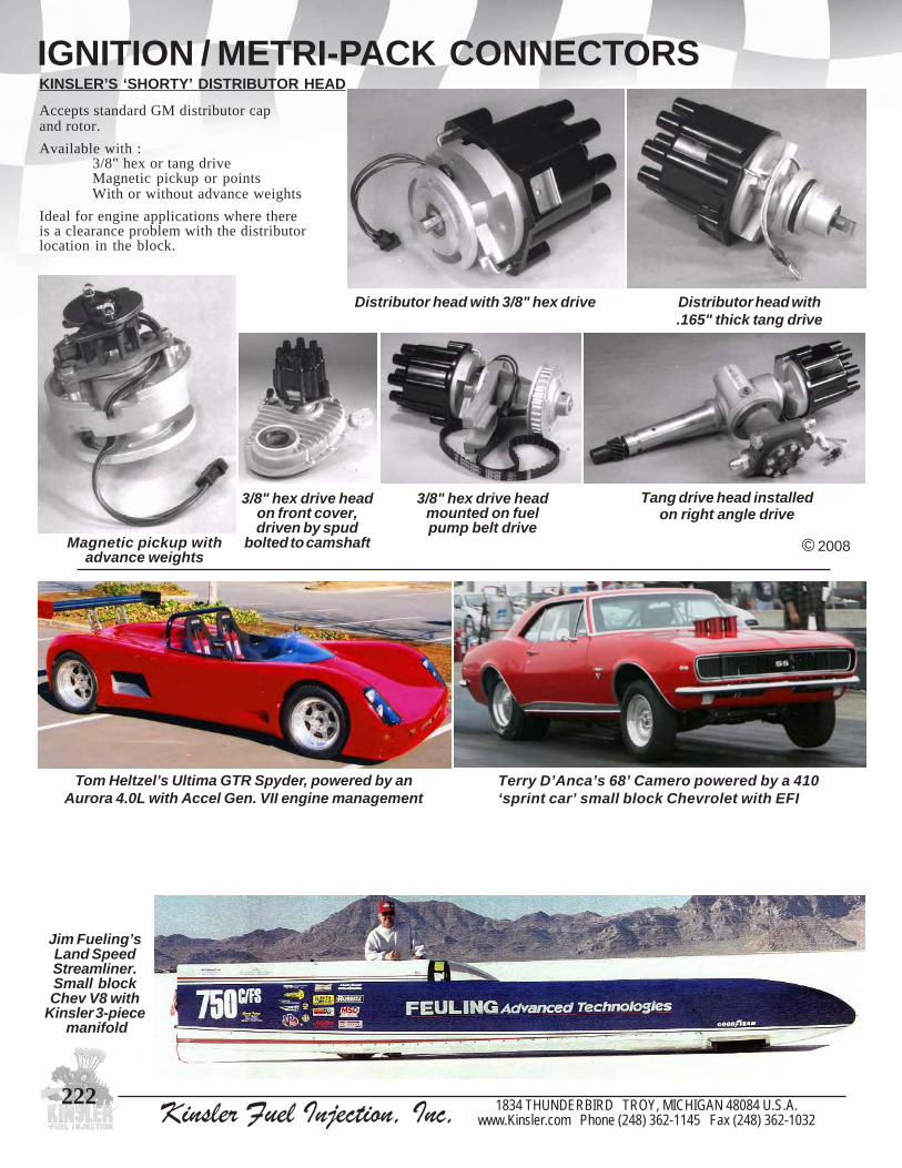
222 Kinsler Fuel Injection, Inc, 1834 THUNDERBIRD TROY, MICHIGAN 48084 U.S.A.www.Kinsler.com Phone (248) 362-1145 Fax (248) 362-1032
IGNITION / METRI-PACK CONNECTORSKINSLER’S ‘SHORTY’ DISTRIBUTOR HEAD
Accepts standard GM distributor capand rotor.
Available with :3/8" hex or tang driveMagnetic pickup or pointsWith or without advance weights
Ideal for engine applications where thereis a clearance problem with the distributorlocation in the block.
© 2008
Tang drive head installedon right angle drive
Magnetic pickup withadvance weights
Distributor head with 3/8" hex drive Distributor head with.165" thick tang drive
3/8" hex drive headmounted on fuelpump belt drive
3/8" hex drive headon front cover,driven by spud
bolted to camshaft
Jim Fueling’sLand SpeedStreamliner.Small blockChev V8 with
Kinsler 3-piece manifold
Terry D’Anca’s 68’ Camero powered by a 410‘sprint car’ small block Chevrolet with EFI
Tom Heltzel’s Ultima GTR Spyder, powered by anAurora 4.0L with Accel Gen. VII engine management

2231834 THUNDERBIRD TROY, MICHIGAN 48084 U.S.A.www.Kinsler.com Phone (248) 362-1145 Fax (248) 362-1032Kinsler Fuel Injection, Inc,
MISC.
KINSLER PRESSURE GAUGESStandard Kinsler series gauges feature an adjustable calibrationscrew. Pressure capturing equipment available, see Page #186.
#5912#5922
STANDARDGauge has 2" face,1/8"NPT male onback, steel case.
GLYCERIN FILLEDGauge has 2 1/2"face, 1/4" NPT maleon back andstainless steel case.Not adjustable.
ENGINE COOLANT SYSTEM CONNECTORS
Great for installing a thermostat or plumbing acoolant system to any injection or carburetor manifold.
EPOXY, COMMERCIAL GRADE
GLYCERIN FILLEDGauge has 1 1/2"face, 1/8" NPT maleon back andstainless steel case.Not adjustable.
0295 ISP51-01295 ISP03-02295 ISP06-03295 ISP001-04295 ISP061-05295 ISP002-0
3395 ISP51-04395 ISP03-05395 ISP06-06395 ISP001-0
0195 ISP03-01195 ISP06-02195 ISP001-04195 ISP061-03195 ISP002-0
0285 ,hsinif'tsacsa',munimulatsac,gnisuohtatsomrehtetomeR"3xllat"8/32,kcenretawdnatatsomrehtelytsMGsesu
owtdnastropTPN"2/1eerht,sbl4/11,gnol"2/14xediwdloserawdrah,mottobnosessobgnitnuom81-61/5
yletarepes4285 hsinif'dehsilop'htiwtub0285#saemaS1285 "2/1eno,llat"8/32,esoh"2/11rofretpadarellifeerged09
munimulatsac,stropTPN"4/1owtdnatropTPN2285 daptatsomrehtotstlob,pacrelliF3285 esohretemaidedisni"2/11rof,retpadarellifesoH
© 2008
EPOXY PUTTY
7191 dnuop-1,trapowt,yttuP
6191 ,htgnertshgih,edarglaicremmoc,evisehdatrapowTdeximnehwrolocnineerg,htgnertsraehsISP0003
Molds like clay, hardens solid in one hour, heat resistant upto 300 degrees F, cures chemically--doesn’t shrink, smoothsinto place with a wet fingertip, NO odor...cleans up with waterbefore hardening, adheres to damp surface, even cures underwater.
Can be sanded, drilled, machined, sawed and painted. Use onmetal, wood, brick, stone, concrete, plastic, glass, and tile.
We use this putty to repair corroded water passages in intakemanifolds.
#5820
#5821
#5822 #5823
ANTI SEIZE COMPOUNDPrevents thread galling orseizing. Ideal for nozzles andfittings with pipe threads, jet canassembly, fuel filter assembly,etc. We use this to assemblemany of our products that willrequire disassembly. Very fuelresistant and is easily applied tothreads. Thick paste-likesubstance stays where you put it.No messy clean-up!
0291 naclatemelbalaes-er,tnip1

224 Kinsler Fuel Injection, Inc, 1834 THUNDERBIRD TROY, MICHIGAN 48084 U.S.A.www.Kinsler.com Phone (248) 362-1145 Fax (248) 362-1032
KINSLER PATCH
8401 ,llat"8/33xediw"4/12derediorbe,roloc-4
APPAREL AND BOOKS
KINSLER POSTERYes, we have some early Kinslerposters left in stock. It has driver,two cars, boat, and motorcyclelogo on heavy paper. 20 5/8" x25" image size.
0501 ,retsoprevirdgnicarrelsniKebutgnippihssedulcni
KINSLER DECAL
Kinsler's 'Dragon' logo, 4-color.
3201 llat"4/34xediw"2/14
5201 llat"4/17xediw"7
Baseball cap, light browncorduroy with Kinsler's'Dragon' logo embroidered.Dark blue bill with strap typeadjustment, vented back halfwith vents in the top.
1401 pacllabesabrelsniK
KINSLER BASEBALL HATKinsler 'Dragon' shirts are white withlarge colorful fire breathing ‘Dragon’tearing out through the back.
KINSLER T-SHIRT
NOTE - ORDER T-SHIRTS ONE SIZE LARGER THAN YOU WEAR. THEY ARE 100% COTTON AND SHRINK ONE SIZE.
0601 ,egral,muidem,llams:trihs-Tegral-xdna
1601 egral-x2:trihs-T
2601 egral-x3:trihs-T
KINSLER RIPPER HAT
3401 tah'reppiR'relsniK
KINSLER SHOP APRON
7801 ,tekcopelbuod,eulbyvaNogol'nogarD'relsniKhtiw
8801 ,tekcopelbuod,kcalBogol'nogarD'relsniKhtiw
Tie one on!
Red and black withKinsler’s ‘Dragon’logo, claw, and ‘rip’embroidered.Adjustable velcroelastic strap. Makea statement withoutsaying a word!
Rightfront of
hat
Left rearof hat
Written by D.W. Fostle,217 pages, hardbound.Wonderfully illustrated using theRosenfeld Collection of woodpowerboat photos. Traces the boatsand the men that built and raced themfrom 1900 through 1955. Interestingstories on rum runners, the aircraftengine powered and super big raceboats. We all love this book!3.2 pounds of history.
5101 TAOBDEEPS
© 2008
KINSLER JACKETSBlack wool body with black lambskin leather sleeves. Kinsler's'Dragon' logo embroidered on back. Seven snap closure with twoexterior pockets on front and one interior pocket. A real hit withthe ladies! They are expensive to make so we are selling them atour cost. 4801 llams,tekcajrelsniK
5801 muidem,tekcajrelsniK
6801 egral,tekcajrelsniK
7801 egral-x,tekcajrelsniK

Kinsler Fuel Injection, Inc, 1834 THUNDERBIRD TROY, MICHIGAN 48084 U.S.A.www.Kinsler.com Phone (248) 362-1145 Fax (248) 362-1032
INDEX
© 2008
7070
181184224221
217-218132, 172
217
115-118
9-2328-32
3136, 39
41
97106, 109
76-77
78-8183-8488-89
9710710868
177
5050
159
504951
224
126-127139
134-135
195
72-733756
AAir box...................................................Air density gauge.....................................Air density - theory and calculation of...............Air facts and aerodynamics....................Air filters.........................................Alcohol - specific gravity test kit.................. properties.......................................Apparel - t-shirts, hats, jackets, posters...............................Arms, throttle.....................................BBarrel valve - models............................................. leakage setting................................ linkage installation.........................Bell crank linkage.....................................Belts and pulleys.....................................Blower hats - Enderle............................................ Hilborn............................................ mounting on tunnel ram.................Blown system - constant flow................................... EFI.................................................. PSI..................................................Books - Speedboat by Fostie........................Bosch - electric pumps......................... injectors (EFI)................................ pressure relief valves...............Boxes - hardwood, for air density gauge, spark plugs and fuel analyzer kit.............................Brief History of Fuel Injection........................Buick V6 manifold...................................Butterflies (throttle plates)......................CCables - shutoff and throttle.......................... clamps and brakets...........................Caps - fuel, oil, and water tank.................. fittings........................................... baseball.......................................... plastic............................................Carburetor - fuel supply system.................. mech. fuel pump..................... regulators.......................................Cavitation - prevention system for fuel pump inlet........................Chevrolet Manifolds : small block V8.............................. big block..................................... big block cross-ram........................... 4-cylinder in-line........................ V-4...................................................Constant flow metering - barrel valve...................................... basic adjustments.................... K-jets..........................................Constant flow metering - cont. nozzles........................................ main...........................................
192193
.194
.204190-191
.196201
22464-68
190-19282
14082, 123, 162-166
190182
128, 140, 143, 182-186
186187
128, 143, 186189
158158
76-7778
138, 140172124
24-26
333626
203204
196-198201, 204
43196
124-129
117137-140
120-121154-156
122
122
124126-127125-129
125129
126, 129126-128
130
224193-194, 204
19799
175 17468
208
Constant flow metering - cont. high speed................................... plumbing................................. troubleshooting charts......................................Conversion - your manifold to EFI...................... or constant flow..............................Crossram manifolds...................................DDecals.....................................................Density of air...........................Density of gasoline, alcohol, nitro..................................Distribution blocks....................................Drive - mechanical fuel pump, belt....................................... and front cover type....................... 90-degree linkage.............................. Lucas mechanical............................EEconomizer valve...................................EFI injectors....................................Electronic fuel metering - basics....................................... plumbing.................................. types...............................................Electronic Control Units (ECU) - Accel, F.A.S.T., Motec, AEM...................................Electric fuel pumps - flow testing..................................... Bosch....................................... Weldon..................................... Aeromotive..................................... Holley............................................. Mallory................................... Walbro..................................... controllers.......................................FFilters - air............................................ costant flow nozzle........................... EFI injectors................................... fuel............................Filter foam..............................................Filter funnel............................................Fittings - AN................... BSP................................................. hose ends......................................... metric.............................Flapper check valve................................Flow Testing - new manifold................................... your unit - any brand....................... K-type jets................................... constant flow nozzles........................ EFI injectors........................... mechanical pumps........................... electric pumps.................................Ford Manifolds - small block V8............................. big block............................................ 4-cylinder in-line............................... modular 4.6.......................................Formula - orifice area...................................... air density........................................ specific gravity......................... horsepower..............................Four barrel throttle bodies.........................Fuel analyzer kits....................................Fuel pump - electric....................................
90-94112-114
110-111
16015942
219-220
107
62-6364-65
6669
64-6871
74
76-77
22462, 69
174
202-20377
76-77
85-86
222
27133-134163-164
58142
137-140
150193223
61
224
71
92949393
72-73
223189193
201196
Fuel pump - cont. mechanical....................... installation tips...............................Fuel - some properties of gas, alky, nitro................................Fuel rails - aluminum................................. stainless steel................................... modular........................................... dampening....................................... machining....................................... conversion......................................Fuel tanks................................................Fuel tank caps.........................................GGauges - pressure, fuel................................... boost............................................... air density........................................Gasoline properties of................................... specific gravity test kit....................HHats - baseball.........................................Hex link bars (throttle linkage bars)........................High speed bypass - diaphragm......................................... K-140............................................... jet can............................................... electric lean-out/enrichment.............History of Fuel Injection......................IIgnition...................................................Indy Racing League (IRL) manifold........................................... pressure relief........................... oil filter.................................... ramtubes........................................... fuel rails..........................................Injectors - EFI.................................Instruments - air/fuel ratio.................................... air density gauge.............................. gauges - pressure.............................. Uni-syn, throttle synchronizer........................JJackets....................................................Jack shaft............................................Jesel........................................................Jet flow - theory and flow data................Jet holder - plastic jet case.........................Jet - main bypass for constant flow...............................Jet selector valve - for constant flow.........................KK-type jets...........................................LL-bends............................................Leakage - setting of barrel valve......................Linkage - setup and theory........................... spring-screw linkage..................... cable linkage arms/wheel.................... kits for S. B. Chevy........................... arms and stops............................. hex bars & rod ends...........................Lucas comparison to constant flow and EFI.......................
131-132, 172173
201
141-142143142143144160181181
1834 THUNDERBIRD TROY, MICHIGAN 48084 U.S.A.www.Kinsler.com Phone (248) 362-1145 Fax (248) 362-1032Kinsler Fuel Injection, Inc,
INDEX
© 2008
Lucas injectors (EFI)........................Lucas metering......................Lucas nozzles (mechanical)......................Lucas pumps - mechanical and electric............Lucas parts........................................MMagnesium - CAUTION manifolds.........................................Main bypass valves Quick Disconnect......................... Screw seal jet can............................... Jet Selector Valve..........................Manifolds: Features and options....................... Fuel metering......................... Chevrolet small blocks................... Chevrolet big blocks..................... Crossrams.............................. Ford small block........................... Ford big block.................................... Installation........................................ Mopar.......................................... Pontiac.............................................. 4-barrel throttle body......................... Motorcycle................................... Rochester fuel injection base plate.....Modification - and/or flow test of your unit.............Mopar small bock injection manifold.........Motorcycle fuel injection.....................NNitro-methane - specific gravity test kit..................... properties.................................Nozzles, constant flow...........................Nozzle flow data.........................................Nozzle vent filter biscuits..........................Nuts.........................................................OOrifice flow theory............................O-rings - fittings............................................. jet cans.................................. EFI injectors..................................... ramtubes............................................. filter..........................................PPatches.............................................Pills - (main bypass jets) for constant flow...........................Pintle cap for EFI injectors......................Plastic jet holder case - holds 26 jets.......................................Plenum logs................................................Plumbing - Carburetor supply system........... Hose and fittings....................... Plumbing schematic - Constant flow - preferred................. Original - “Old”................................ Range jet valve (for use with JSV)....... Enderle hat conversion..................... Vapor Separator Tank system... Turbocharged constant flow.............. EFI with mechanical pump............... EFI fuel rails.............................. EFI with electric pump..................... EFI with 2-electric pumps................ Primer system.................................. Lucas timed injection system............
137, 13972, 74, 207-216
209
208, 213208-215
205
83-8483
85-86
3-417-8, 72-74
9-2328-32
20, 31, 4224-26
3354
34-353843
44-4523
15835
44-45
196197, 201
78-817882
221
202-203
22183-84, 89, 92-
93, 95, 22114058
164-166
202-203
76-77140
7753
218-218182-187
11211387
114116, 155
119155
154-156154156178216
4847-48
125-129152-153
195-196195
195-196
219-22061
161
144107150188153
208, 209, 214
Theromstat..............................................Throttle arms, stops, cables, linkage.....Throttle bodies - 4-barrel...................................... 2-barrel...................................... mono.................................... Weber......................................... Motorcycle...........................Throttle plates (butterflies)........................Throttle shafts...........................................Throttle synchronization - Uni-syn...................................... linkage..................................Tools - fuel rail machining.................... leakage tester............................ air/fuel ratio............................. safety wire................................ wiring harness........................... Lucas......................TPS - sensors.............................. drive................................. remote mount...........................Tunnel ram - made into fuel injection early development....................Turbocharging - constant flow..................... EFI.............................................UU-bends............................................Uni-syn throttle synchronizer.....................Universal nozzle boss...............................VVacuum junction block..............................Vacuum damper.........................................Vapor Separator Tank (VST) system : constant flow.................... EFI........................................... Lucas................................Vent - fuel tank................................... nozzles, constant flow.................WWeber manifold - conversion.................................. throttle bodies.......................Weldon pumps..................................Wiring harness components..............Wood box - air density gauge................ spark plugs................................ fuel analyzer kit................XXtra-Light - manifold..................................... pumps.......................................
22364-68
4347
44-4748
44-455655
6164-71
147-148147-149
149
159
52, 11952
146146
115-118155
215-216
18079
18132
133-135134-135
134134224
1129.25
115-118
131-132, 172125-129
178
83-84
74
57-5858585959
21715313971
188
145145145
146150
147-148151151
82140224
168, 170169171168169
167-168
196197
199-200
8967
64-6514167
Pressure relief valve - EFI Kinsler............................... Bosch................................ Aeromotive.............................. Weldon.....................................Poster - Kinsler.........................................Port profiles - small block Chevrolet................. big block Chevrolet..................... small block Ford.........................Pressurized fuel pump inlet system.......................Pumps - mechanical............... electric.............................. primer.......................................QQuick change main bypass (quick disconnect)..................RRacing fuel injection comparsion.................Ramtubes - aluminum.............................. restrictors................................... carbon fiber................................. spacers........................................ radius plates................................Regulator - carburetor (see also pressure relief valves)..Relays.......................................................Rochester injectors (EFI)..........................Rod ends......................................................SSafety wire - wire, pliers, drilling fixture........Sensors, EFI : air temperature......................... coolant temperature.................. idle air control (IAC)................ manifold absolute pressure (MAP).............................. exhaust gas (O2)........................ throttle position (TPS)..... hall effect................................. signal generators.......................Screens - constant flow nozzles.................. EFI injectors.............................Shirts........................................................Shut-off valve - 2-way................................ 3-way........................................ electric...................................... safety........................................ pneumatic................................. mounting...........................Specific gravity - hydrometers.............................. understanding............................ charts................................Springs - jet cans....................................... throttle stop safety return...........Spring-screw universal - throttle shaft links.................Stanchions, for fuel rail mounting.............Stops - throttle...........................................TTanks - aluminum.................................. components....................... mounts...................................... bungs.........................................
181181-182
181182

4-CylinderTraditionalMonsterASCS Dragon Claw
SMALL BLOCK CHEVROLET and MOPAR
Dragon Claw
Dragon Claw Traditional Cross Ram Big Chief Pontiac Pro Stock
BIG BLOCK CHEVROLET
Small Block SVO Small Block Windsor Modular 4.6/5.4L
FORD
Big Block TFS and Hemi
‘Standard’Series
‘Dominator’ Series4-Barrel Throttle BodyEFI Tunnel Ram EFI Blower Hat Throttle Bodies
Super Cobra Jet