Keck Institute for Space Studies Postdoctoral Fellowship Final ...
124
Keck Institute for Space Studies Postdoctoral Fellowship Final Report BY Dr. Siddhartha Pathak October, 2012
-
Upload
khangminh22 -
Category
Documents
-
view
0 -
download
0
Transcript of Keck Institute for Space Studies Postdoctoral Fellowship Final ...

Keck Institute for Space Studies
Postdoctoral Fellowship Final Report
BY
Dr. Siddhartha Pathak October, 2012

Acknowledgements
I am grateful to the W. M. Keck Institute of Space Studies (KISS) Postdoctoral
Fellowship program for their support for the last two years (2010-2012) of my
postdoctoral research at California Institute of Technology (Caltech). I would like to
specially thank Prof Thomas A. Prince for allowing me the opportunity to be a part of
this select group of people with the KISS fellowship at Caltech, and to Ms Michelle A
Judd for the awesome support she provided during the years of my fellowship program. I
am honored to be a part of this great group of people in the KISS community and hope
that this is just the beginning of a long-lasting relationship.
Special thanks are due to Prof. Julia R Greer, my mentor at Caltech, who guided
me through the potential pitfalls as I embarked on my postdoctoral research. The work on
carbon nanotube (CNT) samples was the result of a very successful collaboration with
Prof. Chiara Daraio and Dr. Jordan R. Raney, whose expertise in the CNT synthesis
techniques was invaluable for my work.
I would like to acknowledge the help and support I received from the Greer group
members on my various projects, especially Dr. Shelby Hutchens, Dr. SeokWoo Lee, Ms.
Nisha Mohan, Ms. EeJane Lim and Ms. Elizabeth Decolvenaere on the CNT projects,
and Ms. Allison Kunz and Mr. Zachary H. Aitken on the grain boundary projects. Finally
thanks also to all of my other friends at Caltech for making my stay such a memorable
one.
ii

Summary
This report is composed of several papers and a book chapter that describe the key
results of my research on nanomechanical investigations of two different material
systems – grain boundaries in metals and mechanical behavior of vertically aligned
carbon nanotube (VACNT) brushes or arrays..
Grain boundaries – the interfaces between two grains, or crystallites, in a
polycrystalline material – play an important role in the mechanical response of
polycrystalline metals, and understanding their deformation behavior is key to their
successful use in various applications, including outer space. In this report I detail our
investigations on this topic using two different approaches. In Chapter 1, we explore the
mechanical behavior of grain boundaries in aluminum using micro and nano-pillars under
uniaxial compression, while in Chapter 2 the mechanical response of interfaces in Fe-
3%Si steel is explored using spherical indentation. In particular the paper discussed in
Chapter 2 entitled “Studying Grain Boundary Regions in Polycrystalline Materials Using
Spherical Nano-Indentation and Orientation Imaging Microscopy” deserves special
mention as a finalist nominee for the Journal of Materials Science Robert W. Cahn Best
Paper Prize for 2012 (the “Cahn Prize”).
Similarly VACNT forests are prime candidates for use in micro-electro-
mechanical systems (MEMS) as well as energy dissipative systems such as viscoelastic
rubbers and foams. VACNTs are complex, hierarchical structures of intertwined tubes
arrayed in a nominally vertical alignment due to their perpendicular growth from a stiff
substrate. They are a unique class of materials having many of the desirable thermal,
electrical, and mechanical properties of individual carbon nanotubes, while exhibiting
these properties through the collective interaction of thousands of tubes on a macroscopic
scale. In addition to their distinctive buckling behavior and their ability to recover from
large deformations, VACNTs have also been reported to demonstrate examples of
extreme mechanical performance – a unique viscoelastic response that spans a truly wide
temperature range from -196oC to 1000oC – something no other material has shown so
far. Such properties earmark them for applications in extreme environments, such as in
NASA’s planned future planetary missions to Titan, Europa and Venus. A proper
iii

understanding of the collective mechanical behavior of these structures, especially
instabilities leading to buckling and inhomogeneities which weaken mechanical
performance, is thus of great importance for their design and success in their current and
future applications.
Chapters 3 to 7 in this report detail my various projects on VACNTs. We start in
Chapter 3 – the chapter published in Encyclopedia of Nanotechnology (Springer) 2012,
which provide a broad overview of VACNTs in general. Chapters 4 and 5 explore the
response of VACNTs under uniaxial compression, while Chapters 6 and 7 look at their
deformation under flat punch indentation.
iv

Publications
1. Siddhartha Pathak�, Seok-Woo Lee, Julia R. Greer. Deformation of carbon
nanotube pillars at cryogenic temperatures: an in-situ study. In preparation
2. Siddhartha Pathak�, Nisha Mohan, Elizabeth Decolvenaere, Alan Needleman,
Mostafa Bedewy, Anastasios John Hart, Julia R. Greer. Effect of density
gradients on the deformation of carbon nanotube pillars: an in-situ study.
submitted
3. S Pathak, N Mohan, P PSS Abadi, S Graham, B A Cola, JR Greer. Compressive
Response of Vertically Aligned Carbon Nanotube Films via In-Situ Flat Punch
Indentations, Journal of Materials Research, 2012 – DOI: 10.1557/jmr.2012.366
4. S Pathak, J R Raney, C Daraio. Effect of morphology on the strain recovery of
vertically aligned carbon nanotube arrays: an in situ study. 2012 – submitted
5. S Pathak, Ee J. Lim, Parisa P.S.S. Abadi, S Graham, Baratunde A. Cola, Julia R.
Greer. Higher Recovery and Better Energy Dissipation at Faster Strain Rates in
Carbon Nanotube Bundles: an in-situ Study. ACS Nano, (2012); 6(3): 2189-97.
6. S Pathak, J Michler, K Wasmer and SR Kalidindi. Studying Grain Boundary
Regions in Polycrystalline Materials Using Spherical Nano-Indentation and
Orientation Imaging Microscopy, J. Materials Science Volume 47, Issue 2 (2012),
Page 815-823. Nominated as finalist for the Journal of Materials Science Robert
W. Cahn Best Paper Prize for 2012 (the “Cahn Prize”).
7. SB Hutchens, E Decolvenaere, S Pathak, JR Greer. Nanoshearing. Materials
Today, Volume 15, Issue 3, March 2012, Page 127
8. A. Kunz , S Pathak, J. R. Greer. Size effects in Al nanopillars: single crystalline
versus bicrystalline. Acta Materialia (2011) 59(11): p. 4416-4424.
Book Chapter
9. S Hutchens, S Pathak. Vertically Aligned Carbon Nanotubes, Collective
Mechanical Behavior. Encyclopedia of Nanotechnology (Springer) 2012, Part 22,
2809-2818, DOI: 10.1007/978-90-481-9751-4_387
v

Research Fellowships and Awards
2012 Director’s Postdoctoral Fellow, Los Alamos National Laboratory, Los
Alamos, NM
2011 ThinkSwiss Research Scholar – this scholarship provides funding for a
research stay in Switzerland (20 scholarships are awarded every year in this
nationwide program)
Work on carbon nanotubes (CNT) selected as the cover image for 2012 for
Materials Today through an international level competition.
First prize in the NanoArt 2011 International Online Competition
http://www.nanotech-now.com/columns/?article=550
Work featured as a slide show on Discovery Channel news Nov 2011
http://news.discovery.com/tech/scientists-artists-nanoart-exhibition-111109.html
CNT work featured in Advanced Materials & Processes magazine, Feb 2011
Invited Presentations
1) S Pathak (presenter), ZG Cambaz, Y Gogotsi, W Mook, J Michler. Viscoelasticity
and High Buckling Stress of Dense Carbon Nanotube Brushes. MS&T Annual
meeting, Columbus, Ohio, Oct 2011
2) S Pathak (presenter), SR Kalidindi. Studying the Mechanical Response of
Regions within Grains and Near Grain Boundaries using Spherical
Nanoindentation. TMS Annual meeting, San Diego, Feb-March 2011
Conference Presentations
3) S Pathak (presenter)�, Nisha Mohan, Elizabeth Decolvenaere, Alan Needleman,
Mostafa Bedewy, Anastasios John Hart, Julia R. Greer. Effect of density
gradients on the deformation of carbon nanotube pillars: an in-situ study. 2012
MRS Fall meeting, Boston, Nov-Dec 2012
4) S Pathak (presenter), N Mohan, Ee J. Lim , PPSS Abadi , S Graham, BA Cola, JR
Greer. "Insights into Energy Absorption Mechanisms in Hierarchical Carbon
Nanotube Forests." 2012 MRS Spring Meeting, San Francisco, 9-13 April USA.
vi

5) S Pathak (presenter), SR Kalidindi. Studying the Mechanical Response of
Regions within Grains and Near Grain Boundaries using Spherical
Nanoindentation. ICOTOM annual meeting, IIT Bombay, India, Dec 2011
6) S Pathak (presenter), ZG Cambaz, Y Gogotsi, W Mook, J Michler. Viscoelasticity
and High Buckling Stress of Dense Carbon Nanotube Brushes. TMS Annual
meeting, San Diego, Feb-March 2011
7) S Pathak (presenter), SR Kalidindi, R Raghavan, J Michler. Stress-strain response
from spherical nano-indentation and micro-pillar compression experiments: A
comparative study. TMS Annual meeting, San Diego, Feb-March 2011
8) S Pathak (presenter), JL Riesterer, SJ Vachhani, K Wasmer, J Michler, SR
Kalidindi. “On the Sequence of Events during Pop-ins in Spherical
Nanoindentation”; MRS Fall meeting, Boston, Nov-Dec 2010
Poster Presentations
9) S Pathak, N Mohan, Ee J. Lim , PPSS Abadi , S Graham, BA Cola, JR Greer.
"Insights into Energy Absorption Mechanisms in Hierarchical Carbon Nanotube
Forests." 2012 ICB Army-Industry Collaboration Conference and
Comprehensive Review, Santa Barbara, CA, USA
10) S Pathak, W Mook, ZG Cambaz, Y Gogotsi, J Michler. “In-situ SEM Micro-
compression of Dense Carbon Nanotube Brushes”; MRS Fall Meeting, Boston,
2010
Science Saturdays – Caltech Public Science lecture series
11) “Hyperspeed” – Discussion leader for Caltech outreach program (audience of
500), Feb 12, 2011
vii

Table of Contents:
Acknowledgements................................................................................................. ii
Summary ................................................................................................................ iii
Publications............................................................................................................. v
Book Chapter ...................................................................................................... v
Research Fellowships and Awards .................................................................... vi
Invited Presentations.......................................................................................... vi
Conference Presentations................................................................................... vi
Poster Presentations .......................................................................................... vii
Science Saturdays – Caltech Public Science lecture series .............................. vii
Table of Contents:................................................................................................ viii
Selected Publications ............................................................................................. ix
viii

ix
Selected Publications
CHAPTER 1: A Kunz , S Pathak, J R Greer. Size effects in Al nanopillars: single
crystalline versus bicrystalline. Acta Materialia (2011) 59(11): p. 4416-4424.
CHAPTER 2: S Pathak, J Michler, K Wasmer and SR Kalidindi. Studying Grain
Boundary Regions in Polycrystalline Materials Using Spherical Nano-Indentation and
Orientation Imaging Microscopy, J. Materials Science Volume 47, Issue 2 (2012), Page
815-823. Nominated as finalist for the Journal of Materials Science Robert W. Cahn
Best Paper Prize for 2012 (the “Cahn Prize”).
CHAPTER 3: S Hutchens, S Pathak. Vertically Aligned Carbon Nanotubes,
Collective Mechanical Behavior. Encyclopedia of Nanotechnology (Springer) 2012, Part
22, 2809-2818, DOI: 10.1007/978-90-481-9751-4_387
CHAPTER 4: S Pathak, Ee J. Lim, Parisa P.S.S. Abadi, S Graham, Baratunde A.
Cola, Julia R. Greer. Higher Recovery and Better Energy Dissipation at Faster Strain
Rates in Carbon Nanotube Bundles: an in-situ Study. ACS Nano, (2012); 6(3): 2189-97.
Supporting information for Chapter 4.
CHAPTER 5: Siddhartha Pathak, Nisha Mohan, Elizabeth Decolvenaere, Alan
Needleman, Mostafa Bedewy, Anastasios John Hart, Julia R. Greer. Effect of density
gradients on the deformation of carbon nanotube pillars: an in-situ study. 2012 – in
preparation.
Supporting information for Chapter 5.
CHAPTER 6: S Pathak, N Mohan, P PSS Abadi, S Graham, B A Cola, JR Greer.
Compressive Response of Vertically Aligned Carbon Nanotube Films via In-Situ Flat
Punch Indentations, Journal of Materials Research, 2012 – DOI: 10.1557/jmr.2012.366
CHAPTER 7: S Pathak, J R Raney, C Daraio. Effect of morphology on the strain
recovery of vertically aligned carbon nanotube arrays: an in situ study. 2012 – submitted

Available online at www.sciencedirect.com
www.elsevier.com/locate/actamat
Acta Materialia 59 (2011) 4416–4424
Size effects in Al nanopillars: Single crystalline vs. bicrystalline
Allison Kunz, Siddhartha Pathak, Julia R. Greer ⇑
Division of Engineering and Applied Sciences, California Institute of Technology, 1200 East California Boulevard, MC 309-81,
Pasadena, CA 91125-8100, USA
Received 31 January 2011; received in revised form 25 March 2011; accepted 25 March 2011Available online 22 April 2011
Abstract
The mechanical behavior of bicrystalline aluminum nano-pillars under uniaxial compression reveals size effects, a stochastic stress–strain signature, and strain hardening. Pillar diameters range from 400 nm to 2 lm and contain a single, non-sigma high angle grainboundary oriented parallel to the pillar axes. Our results indicate that these bicrystalline pillars are characterized by intermittent strainbursts and exhibit an identical size effect to their single crystalline counterparts. Further, we find that the presence of this particular grainboundary generally decreases the degree of work hardening relative to the single crystalline samples. These findings, along with trans-mission electron microscopy analysis, show that nano-pillar plasticity in the presence of a grain boundary is also characterized by dis-location avalanches, likely resulting from dislocation nucleation-controlled mechanisms, and that at these small length scales this grainboundary may serve as a dislocation sink rather than a dislocation source.� 2011 Acta Materialia Inc. Published by Elsevier Ltd. All rights reserved.
Keywords: Compression test; Nanoindentation; Electron backscatter diffraction; Interfaces; Aluminum
1. Introduction
The development of uniaxial micro-mechanical testinghas led to a renaissance of research in mechanical metal-lurgy. The original work by Uchic et al. [1] demonstratedthat cylindrical Ni pillars with micron scale diameters, fab-ricated using the focused ion beam (FIB) technique, exhib-ited an entirely new behavioral regime: discrete strain“bursts”, low hardening rates even for large strains, anda power law relationship between flow stress and pillardiameter [2]. A large number of subsequent nano- andmicro-pillar studies revealed similar stress–strain curvesand identical size effects for a number of fcc metals [3–8].Remarkably, the power-law size effect proved to be consis-tent for all fcc metals, generally of the form rf / Dn, whereD is the pillar diameter and n is of the order of �0.6. Whilethe origins of this size effect are a matter of intense debate,it is generally agreed that the higher stresses attained dur-
1359-6454/$36.00 � 2011 Acta Materialia Inc. Published by Elsevier Ltd. All
doi:10.1016/j.actamat.2011.03.065
⇑ Corresponding author.E-mail address: [email protected] (J.R. Greer).
ing mechanical deformation of small scale crystals are aresult of nucleation-governed plasticity. Mobile disloca-tions inside these pillars are attracted to the free surfacein response to the image forces, and new dislocations haveto be nucleated either in the bulk of the pillar or on its sur-face in order to accommodate further deformation. Deepin the sub-micron regime it has been shown that thestrained fcc pillars experience “hardening by dislocationstarvation”, whereby mobile dislocations exit the pillar atthe free surface at a faster rate than they multiply [3,9].A convincing example of this concept is the “mechanicalannealing” of nickel in an in situ transmission electronmicroscopy (TEM) compression study by Shan et al. [10].
Since 2005 nano-mechanical testing of pillars hasquickly evolved and expanded. New fabrication methodsand custom built in situ mechanical equipment allow uni-axial tension experiments in addition to compression tests[11–16]. As first shown by Kiener et al., samples withheads suitable for tension testing and correspondingnano-indenter “grippers” can be made using FIB technol-ogy [17,18]. Electroplating methods have also produced
rights reserved.

A. Kunz et al. / Acta Materialia 59 (2011) 4416–4424 4417
Cu pillars for both uniaxial tension and compression test-ing, with the additional capability of creating pillars withdiameters below 100 nm [19,20]. Beyond fcc, the effect ofsize on strength for a variety of crystal structures hasbeen investigated, including bcc [21–29] and hcp [30–32]. Computational techniques like molecular dynamics(MD) [33–35] and dislocation dynamics (DD) [36,37]have also been widely utilized to shed light on the under-lying defect mechanisms leading to this size-dependentstrengthening. For example, MD simulations of fcc andbcc nano-pillars by Weinberger et al. demonstrate dislo-cation starvation in the former and dislocation multipli-cation in the latter [38,39]. DD simulations generallyreveal the operation of truncated Frank–Read sources,or so-called “single-arm sources” [40]. The experimentaland computational findings on mostly micron sized fccpillars in compression up to 2008 can be found in a thor-ough review by Uchic et al. [41], while a recent review byGreer and de Hosson [42] offers a discussion on subse-quent size effects studies spanning other materials andsub-micron sizes.
While so far most groups have focused on studying sizeeffects in monolith systems such as single crystals, severalresearchers have looked at more complex microstructures,such as nano-crystalline [43], nano-twinned [44,45], nano-laminate [46,47], and alloyed materials [48,49], to name afew. For example, Jang et al. found a “smaller is weaker”
phenomenon in nanocrystalline Ni–W pillars with an aver-age grain size of 60 nm [50], while Mara et al. found thatthe presence of closely spaced Cu–Nb nano-laminates over-rides the size effect, with the strength being a function ofthe laminate spacing rather than the sample dimensions[46]. Several computational studies investigating deforma-tion of small scale interface-containing metallic systemshave also been published and were summarized in a recentreview by Zhu and Li [51]. In many cases the presence ofinternal boundaries has an effect on the size-dependentstrength. These results are especially relevant for industrialapplications, since most engineering materials are usuallypolycrystalline or multiphase rather than perfect singlecrystals. However, most reported literature on the mechan-ical properties of such materials reveals the aggregateeffects of many interfaces rather than the role of individualinterfaces. Therefore, the fundamental questions about theeffects of individual interfaces, for example the relativeinfluences of different types of interfaces (homogeneousvs. heterogeneous, coherent vs. incoherent, internal vs. freesurface, etc.) on dislocation motion and overall sampleplasticity, remain elusive.
This work compares the uniaxial compression results ofsingle crystalline and bicrystalline aluminum pillars withdiameters between �400 nm and 2 lm. The bicrystallinepillars contain a single grain boundary vertically orientedalong the pillar axis. We report the emergence of an iden-tical size effect regardless of the presence of a boundary,and discuss their deformation in the framework of nucle-ation-controlled plasticity.
2. Experiments
Commercially available high purity aluminum (5 N pur-ity, ESPI Metals) was annealed under vacuum at 350 �Covernight and then electropolished by Able Electropolish-ing Co. Grain orientation maps were obtained by auto-matic indexing of electron backscatter diffraction (EBSD)patterns using a Zeiss1550 VP field emission scanning elec-tron microscope equipped with an EBSD system fromOxford Instruments, as shown in Fig. 1a. Once a high anglegrain boundary of suitable length had been located, nano-pillar samples containing this boundary close to the centerof each sample were fabricated using a FEI Nova 200 scan-ning electron microscope with a focused ion beam (FIB)according to the procedure outlined in Greer et al. [2].All nano-pillars had height to width ratios between 3:1and 4:1, as well as less than 2� of vertical taper, with diam-eters ranging from roughly 400 to 2000 nm. Bicrystallinepillars contained the grain boundary oriented lengthwise,along the pillar or loading axis. A scanning electronmicroscopy (SEM) image of a representative bicrystallinepillar with overlaid EBSD pattern is shown in Fig. 1b. Sin-gle crystalline nanopillars were made using the same meth-odology in the two grains adjacent to the high angleboundary.
Uniaxial compression tests were conducted using aNanoindenter G200 (Agilent Technologies). Using thedynamic contact module (DCM) with a 7 lm diameter flatpunch we were able to simultaneously measure load, dis-placement, and harmonic contact stiffness during the tests.The tests were performed under displacement rate controlvia a feedback loop to attain a constant 0.001 s�1 strainrate until 15% strain. True stress and true strain, includingthe Sneddon correction, were calculated using the methodalso outlined in Greer et al. [2]. For each test the harmoniccontact stiffness data were compared with the theoreticalstiffness to ensure accurate effective pillar dimensions.SEM images of a bicrystalline pillar before and after uniax-ial compression are given in Fig. 1c and d, respectively.
In order to determine the oxygen content in the alumi-num sample and, hence, the extent of the native oxide layeron the sample surface, quantitative energy-dispersive X-rayspectroscopy (EDS) measurements (Oxford InstrumentsINCA 4.08) were performed using the same electron micro-scope as for the EBSD study. The results for the aluminumsample were compared with those for gold, tungsten, nio-bium, titanium and Fe–3% Si steel, all analyzed duringthe same session at 5 keV and a working distance of10 mm. The process was repeated on a second day for con-sistency. The wt.% (wt.% = apparent concentration/inten-sity correction) of the element was calculated from theEDS spectrum after correcting for inter-element effectsusing the XPP matrix correction scheme built-in in theINCA software. The at.% (at.% = wt.%/atomic weight)was calculated from the measured wt.% values for each ele-ment, with the sum of atomic weights of all elements in thesample being normalized to 100%.

Fig. 1. (a) Crystallographic orientation map of a polycrystalline aluminum sample. (Inset) The inverse pole figure. (b) EBSD image of a typical grainboundary in a pillar. SEM images of the pillars (c) before and (d) after compression to 15% strain.
4418 A. Kunz et al. / Acta Materialia 59 (2011) 4416–4424
Transmission electron microscopy (TEM) of a represen-tative post-compression bicrystalline nano-pillar was con-ducted using an FEI Tecnai F-20 microscope. To preparethe TEM sample a micron thick protective coating of tung-sten was deposited on the nanopillar using the Nova 200,and a segment containing the coated pillar on a couponof the underlying parent material was milled out. A micro-manipulator (Omniprobe) was used to lift out the segment,which was then glued to a copper TEM lamella with addi-tional tungsten deposition. FIB cleaning of cross-sectionsat very low currents of 10 pA and 30 kV was used to thinthe pillar-containing segment of aluminum down to lessthan 100 nm thick.
3. Results
Representative compressive stress–strain curves for sin-gle crystalline nano-pillars from each grain and for bicrys-talline aluminum nano-pillars are presented in Fig. 2. All of
the curves exhibit the discrete stochastic bursts that arecharacteristic of small scale fcc deformation. The orienta-tion information provided by EBSD was used to calculatethe anisotropic Young’s modulus E[hkl] and maximumSchmid factors for each orientation. To calculate the mod-ulus of the bicrystalline pillars we assumed an isostrainmodel with equal volume fractions for both grains. Sincealuminum is fairly isotropic (the theoretical values forE[126] and E[104] differ by only 2.7%), any uncertainty aboutthe exact volume fraction of each grain did not have asignificant effect on the bicrystalline data analysis. Theaverage slopes of the unloading curves matched theirrespective theoretical Young’s moduli E[hkl] to within 5%.Table 1 provides the Euler angles, Young’s moduli, bothcalculated and measured, and the Schmid factors for thefirst available slip system for each type of pillar.
The flow stresses at 7.5% strain for single crystalline andbicrystalline samples, resolved by their respective Schmidfactors, are plotted as a function of pillar diameter in

Fig. 2. Representative stress–strain curves for single crystalline pillars oriented with Z in the (a) [1 0 4] and (b) [1 2 6] directions, as well as (c) bicrystallinepillars created at the boundary between two grains.
Table 1Summary of the crystallographic data and size effects.
Pillar type Euler angle E[hkl](GPa) Schmid factor Slip systems Power law coefficient n R2
Calculated Measured
Single-crystalline �0.625 0.656[126]-oriented 19.2, 18.4, 28.1 65.72 68.63 0.4879 (1 �1 �1) [�1 0 �1] �0.629 0.788[104]-oriented 269.1, 15.5, 85.5 67.50 68.87 0.4803 (1 1 1) [0 1 �1], (�1 1 �1) [0 1 1] �0.578 0.689Bicrystalline 66.61 64.85 0.4841 �0.590 0.715
A. Kunz et al. / Acta Materialia 59 (2011) 4416–4424 4419
Fig. 3a and b. Note that the highly stochastic nature of thenano-pillar deformation, combined with possible uncer-tainty at initial loading between the pillar and the punch,make an unambiguous determination of the yield (elasticto plastic transition) very difficult. Calculating the flowstress at 7.5% strain, on the other hand, removes this ambi-guity, since this particular strain level is after full contact
has been established, but before the stochastic nature ofthe bursts obscures precise determination of flow stress.
The data for the single crystalline pillars (Fig. 3a) repro-duces the expected power law relationship between theresolved shear flow stress and pillar diameter with a slopeof �0.625, nearly identical to that observed for mostnon-pristine fcc metals [41]. Fig. 3b compares the single

Fig. 3. Size effect plots showing the power law relationship between pillardiameter and flow stress for (a) single crystalline and (b) single crystalline(condensed) vs. bicrystalline pillars. The error bars reflect the standarddeviation.
4420 A. Kunz et al. / Acta Materialia 59 (2011) 4416–4424
crystalline data shown in Fig. 3a, condensed into fewerpoints with error bars reflecting the standard deviationsfor clarity, with the bicrystalline results. Interestingly, wefind that the size effect exhibited by the bicrystalline sam-ples is nearly equivalent to the single crystalline ones: thepillars containing grain boundaries give a slope of�0.590, which is only a 5.6% difference from the singlecrystalline case. Another interesting observation that canbe made based on this data is that the bicrystalline pillarsand [104]-oriented single crystalline pillars show a signifi-cantly larger spread in flow stresses after 5% strain thanthe tightly distributed [126]-oriented single crystalline pil-lars. We ascribe this to the fact that the [104] direction isfavorably oriented for bi-slip, with two slip systems sharingthe highest Schmid factor values, while [126] is oriented forsingle slip only. Table 1 shows a summary of the primaryslip systems for each orientation, as well as their Schmidfactors and elastic moduli. The power law coefficients nand their R2 values are also included in Table 1.
We also investigate the amount of flow stress increasewith increasing strain for each pillar type. Since the defor-
mation of these nano-structures is characterized by inter-mittent strain bursts, the conventional definition of strainhardening is ill suited here. Instead, we define our harden-ing figure of merit as the angle calculated from the slope ofthe region between full flat punch–pillar contact and thebeginning of unloading on the stress–strain curves. Thisslope is normalized to the flow stress at 7.5% strain in orderto deconvolute any pillar size effect from the hardeningdata. We note, however, that these behavioral regimesare evident even without normalization of the hardeningslope with the flow stress. The point of full contact wasdetermined by the strain at which the measured harmoniccontact stiffness matched the theoretical stiffness calculatedfrom the effective pillar dimensions. A schematic outliningthis procedure on a representative stress–strain curve, aswell as the corresponding stiffness plot, are shown inFig. 4. Due to the uncertainty in the measurements imme-diately following a strain burst, when the indenter lagsbehind the pillar deformation, only peak values in the load-ing direction of each burst were used to represent theapplied stress. These hardening angles normalized to the7.5% flow stresses are plotted as a function of pillar diam-eter in Fig. 5. Only samples for which the hardening anglescould be reliably calculated, i.e. with enough burst peaks toobtain a reliable average slope, are included in the figure.Note also that the constraints imposed by the experimentalset-up are known to affect pillar hardening, as studied byDehm et al. [52], and thus only tests conducted using thesame set-up can be directly compared with each other. Ascan be seen from Fig. 5, the pillars containing grain bound-aries exhibit lower average angles compared with their sin-gle crystalline counterparts, forming two adjacentbehavioral regimes.
4. Discussion
Although the size effect here appears to remainunchanged despite the presence of this particular grainboundary, the stress–strain curves of single crystalline vs.bicrystalline samples exhibit distinct characteristics. First,we compare the data for single crystalline pillars fabricatedfrom the two adjacent grains with each other. Figs. 2a andb and 3a show that the [104]-oriented single crystalline pil-lars exhibit a shorter average burst size and less pro-nounced size effect. In order to understand themechanisms behind these different characteristics we returnto the EBSD analysis of the grain orientations. The inversepole figure in Fig. 1a indicates that the [126] orientationcorresponds to single slip, while the [104] orientation islikely to experience double slip. Previous work by Ngand Ngan [53] has shown the collapse of Schmid’s law dur-ing uniaxial compression of aluminum sub-micron pillars:this research found that as the volume of the pillardecreases the probability that a dislocation exists in the the-oretically favored slip orientation (maximum Schmid fac-tor) also decreases. Thus, in smaller pillars thedislocations residing in the slip planes less favored for slip

Fig. 4. Compression data analysis. Both the instrument contact stiffness measurements (CSM) and data adjusted with the Sneddon correction from Greeret al. [2], are plotted, along with the theoretical stiffness. The stress–strain curve from the same pillar is also given, with peak values following full contact inbold and their hardening angle indicated by the black dashed line.
Fig. 5. Plot of hardening angle vs. pillar diameter for the three sets ofpillars. The shaded area emphasizes the lower average hardening angle forbicrystalline pillars relative to single crystalline ones.
A. Kunz et al. / Acta Materialia 59 (2011) 4416–4424 4421
may possibly be the ones available for slip, thereby requir-ing higher resolved shear stresses for their activation. Mul-tiple slip provides a greater number of equivalent slipsystems, which increases hardening through shorteningthe dislocation mean free path, manifesting itself as ashorter average burst size. Deforming pillars with animperfect double slip orientation, meaning that some nom-inally double slip oriented pillars deform via symmetricalslip, others via single slip, would lead to a greater variabil-ity in yield stresses and hardening behavior. All of thesecharacteristics are consistent with our data for [104]-oriented samples. On the other hand, the [126]-oriented
samples show consistent hardening and a well-defined sizeeffect. The behavior of the bicrystalline samples resemblesmore closely that of the [126] pillars oriented for single slipthan the [104]-oriented samples oriented for double slip.This similarity is likely due to the slightly higher Schmidfactor for the [126] crystal orientation, which would there-fore be more likely to yield first. However, there is muchless hardening in the bicrystalline samples compared withsingle crystalline ones in both orientations.
The relatively large average burst sizes (Fig. 2c) and themuch lower hardening angles (Fig. 5) in the bicrystallinesamples may imply one of three scenarios. In the firsttwo cases either the dislocations travel unimpeded overappreciable distances causing little or no dislocation stor-age, or the dislocations pile up at obstacles (such as aboundary) and are collectively emitted in relatively largebursts. These two observations might suggest that this par-ticular grain boundary serves as a sink rather than a sourceof dislocations under applied uniaxial compressive loads.These results agree well with the classical work of Dollarand Gleiter [54], who showed that random high angleboundaries in an irradiated Au foil act as perfect disloca-tion sinks. Recent nanoindentation studies by Pathaket al. [55] and EBSD measurements by Sun et al. [56] havealso demonstrated the ability of high angle grain bound-aries to act as efficient dislocation sinks as a function ofapplied strain.
The third possibility is that the grain boundary itselfundergoes some kind of localized breakdown and compat-ibility loss. Such a scenario was discussed in the work of Ngand Ngan [57], in which the authors noted intense shear ofthe grain boundary during uniaxial compression of �6 lmdiameter bicrystalline aluminum micro-pillars. As dis-cussed later, TEM micrographs of our bicrystalline pillars

Fig. 6. (a) Dark field TEM image of the [126]-oriented half and (b) brightfield TEM image of the [104]-oriented half of the same bicrystalline pillarafter uniaxial compression to 15% strain. FIB damage, in the form ofdislocation loops, is evident in both sets of images.
Fig. 7. Stress–strain curves from representative single and bicrystallinepillars subjected to cyclic uniaxial compression testing, showing noBauschinger effect.
4422 A. Kunz et al. / Acta Materialia 59 (2011) 4416–4424
(Fig. 6) corroborate this possibility, as it is evident that theboundary itself was altered in the course of compression.Thus, when exposed to sufficiently high stresses, such asthose experienced by our nano-pillars, such grain boundaryrelief (or breakdown) mechanisms could also potentiallytrigger the significantly larger bursts in our bicrystalline pil-lars shown in Fig. 2c. Note that such large bursts were notobserved in the work of Ng and Ngan [57], probablybecause the micron sized pillars used in their study experi-enced roughly an order of magnitude lower stresses thanour nanoscale bicrystalline pillars. The exact nature andpossibility of the grain boundary breakdown mechanismstill remains to be explored in detail, and efforts addressingthis aspect are currently underway.
Interestingly, continuum-based crystalline plasticity sim-ulations accounting for the discrete behavior of the disloca-tion bursts have also noted a larger first burst duringcompression of bicrystalline, as well as single crystalline,Al pillars [58]. This is explained by simultaneous competi-tion by multiple slip systems for accommodation of theshear stress prior to the first burst. Additionally, one local-ized slip will only be accommodated if the neighboringregion, still free of defects, can also accommodate slippropagation. The presence of a boundary could potentiallyaccentuate this first burst, and efforts are currently under-way to conduct a statistical analysis comparing such burstdistributions between single and bicrystalline samples,which will be disseminated in a separate manuscript.
Of note is the exact opposite effect seen by Ng and Ngan[57], whose bicrystalline aluminum micro-pillars displayedlarger hardening angles compared with their single crystalcounterparts by a factor of nearly 2.5. However, the grainboundaries in their study had completely different grainboundary characteristics in terms of crystallographic orien-tations and boundary misorientations. Also, their bound-aries were not positioned lengthwise down the pillar,parallel to the loading axis, but instead at a large angleto the loading axis, with one end exiting the pillar throughthe cylinder wall. These differences indicate the importanceof understanding the grain boundary characteristics andorientation when analyzing such cases. Also, the size oftheir samples was nearly an order of magnitude larger thanours, allowing enough space to form an intertwined dislo-cation sub-structure.
To further understand microstructural evolution in thebicrystalline pillars we performed TEM analyses on a rep-resentative post-mortem sample, shown in Fig. 6, whichreveals no evidence of dislocations piling up at the grainboundary. Fig. 6a provides dark field images with

Table 2Quantitative EDS analysis results.
Gold Aluminum Tungsten Niobium Titanium Fe–3% Si steel
wt.% O K: 0 O K: 2.04 ± 0.34 O K: 1.38 ± 0.26 O K: 4.97 ± 0.43 O K: 0.83 ± 0.37 O K: 2.07 ± 0.29Au M: 100 Al K: 97.96 ± 0.34 W M: 98.62 ± 0.26 Nb L: 95.03 ± 0.43 Ti K: 99.17 ± 0.37 Si K: 2.7 ± 0.29
Fe L: 95.46 ± 0.41at.% O K: 0 O K: 3.42 O K: 13.93 O K: 23.17 O K: 2.45 O K: 6.69
Au M: 100 Al K: 96.58 W M: 86.07 Nb L: 76.83 Ti K: 97.55 Si K: 4.46Fe L: 88.85
A. Kunz et al. / Acta Materialia 59 (2011) 4416–4424 4423
g = 002 near the [1 1 0] zone axis for the [126]-oriented halfof the pillar; the sample tilt resulted in a brightness gradientacross the images. Dislocations are clearly visible, with thesmaller, looped dislocations probably being the result ofFIB damage and the longer dislocation segments probablyassociated with pillar deformation. The FIB damageappears to have an even distribution across the entire sur-face, a common effect observed by several groups [59–61],while the dislocations associated with deformation appearto be concentrated in the center of the half-pillar, asopposed to near the free surface or the grain boundary.Fig. 6b is a representative higher magnification bright fieldimage with g = 022 near the [1 0 0] zone axis for the [104]-oriented half of the same pillar, where again we see evi-dence of FIB damage, but not of dislocations associatedwith deformation. It is especially compelling that theregions next to the grain boundary in both grains are rela-tively defect free. This lack of evidence of dislocation pile-ups at the grain boundary and the presence of a so-called“denuded zone” [54], a region free of defect agglomeratesnear an interface, is consistent with our hypothesis that thisboundary serves as a dislocation sink. A distinct rotation ofthe grain boundary is also observed in the bright fieldimage (Fig. 6b), suggesting that the grain boundary itselfis deforming, although the mechanism remains to be fur-ther investigated.
The presence of a native oxide film on the sample sur-faces may be a concern in our experiments, as it may trapthe dislocations inside the pillar, generate dislocation pile-ups against the pillar–oxide interface, and require higherdeformation stresses. Previous work on single crystallinealuminum micro-pillars by Ng and Ngan [62] illustratedthat a nanocrystalline tungsten coating both increased theyield stresses and suppressed the discrete nature of thestress–strain curves. Simulations by Deshpande et al. [63]and thin film experiments by Nicola et al. [64] also showedthat surface passivation results in significantly more pro-nounced work hardening and a clear Bauschinger effect.Aluminum is known to generate a 5–10 nm oxide layeron its surface, and in order to test its effect on our pillarcompression experiments we ran intentional loading–unloading segments during the compression tests on bothsingle and bicrystalline nano-pillar samples, the results ofwhich are shown in Fig. 7. As seen from this plot, neitherstress–strain curve indicates strong hardening or a Bausch-inger effect, indicating that the native oxide layer does notserve as a passivation layer, and, therefore, probably does
not play a significant role in plastic deformation at thislength scale. Similarly, the EDS results shown in Table 2indicate that the weight percentage of oxygen in aluminum(�2 wt.%) is comparable with that of W, Nb, Ti and Fe–3% Si steel, metals whose size effects have been reportedby multiple groups [22,27,57]. Note that the EDS data islimited to only a weight estimation of the oxygen content;it does not provide any information on the mechanicalstrength of the oxide itself. Table 2 also indicates that,other than noble metals such as gold, all of the other metalstested have a layer of native oxide on their surface whichhas not been shown to affect their mechanical behavior atsubmicron length scales [21,22]. The low oxygen weightpercentages in Al, when combined with the lack of aBauschinger effect shown in Fig. 7, may indicate that thesurface aluminum oxide is unlikely to contribute greatlyto the mechanical strength of the aluminum nano-pillarsin compression experiments.
5. Conclusions
We have examined the effect of a vertical, non-sigma, highangle grain boundary on the mechanical properties anddeformation behavior of sub-micron Al pillars subjected touniaxial compression. We observe similar stress–strain sig-natures, containing numerous discrete displacement bursts,as well as an identical power law “smaller is stronger” sizeeffect in these bicrystalline samples as compared with theirsingle crystalline counterparts. We also observe lower hard-ening angles and larger burst extents in the bicrystalline pil-lars, implying little or no dislocation storage and suggestingthat this grain boundary may act as a dislocation sink. TEManalysis confirms this hypothesis, as the near boundaryregions appear to be defect free, with no evidence of disloca-tion pile-ups. Since similar work on larger sized bicrystallinealuminum pillars with a different type of grain boundaryexhibited the opposite effect: smaller burst sizes andincreased hardening, this study reveals that the characterof the boundary and sample size appear to play a significantrole in the deformation behavior. Efforts are currentlyunderway at comparing the effects of grain boundaries withvery different characters on deformation behavior.
Acknowledgements
S.P. gratefully acknowledges the support from the W.M.Keck Institute for Space Studies Postdoctoral Fellowship

4424 A. Kunz et al. / Acta Materialia 59 (2011) 4416–4424
program. J.R.G. gratefully acknowledges financial supportfrom an NSF Career award (DMR-0748267). The authorsalso thank Andrew T. Jennings and Carol Garland forTEM assistance and A. Fernandez, A. Jerusalem, and C.Weinberger for useful discussions.
References
[1] Uchic MD, Dimiduk DM, Florando JN, Nix WD. Science2004;305:986.
[2] Greer JR, Oliver WC, Nix WD. Acta Mater 2005;53:1821.[3] Greer JR, Nix WD. Phys Rev B 2006;73:245410.[4] Volkert CA, Lilleodden ET. Phil Mag 2006;86:5567.[5] Ng KS, Ngan AHW. Acta Mater 2008;56:1712.[6] Dimiduk DM, Uchic MD, Parthasarathy TA. Acta Mater
2005;53:4065.[7] Budiman A, Han S, Greer JR, Tamura N, Patel J, Nix WD. Acta
Mater 2007;56:602.[8] Kiener D, Motz C, Schoberl T, Jenko M, Dehm G. Adv Eng Mater
2006;8:1119.[9] Zheng H, Cao A, Weinberger CR, Huang JY, Du K, Wang J. Nat
Commun 2010;1:144.[10] Shan ZW, Mishra R, Syed SA, Warren OL, Minor AM. Nat Mater
2008:7.[11] Greer JR, Kim J-Y, Burek MJ. J Mater 2009;61:19.[12] Kiener D, Grosinger W, Dehm G. Scripta Mater 2009;60:148.[13] Dehm G. Prog Mater Sci 2009;54:664.[14] Legros M, Gianola DS, Motz C. MRS Bull 2010:35.[15] Richter G, Hillerich K, Gianola DS, Monig R, Kraft O, Volkert CA.
Nano Lett 2009;9:3048.[16] Zhang D, Breguet J-M, Clavel R, Phillippe L, Utke I, Michler J.
Nanotechnology 2009;20:365706.[17] Kiener D, Grosinger W, Dehm G, Pippan R. Acta Mater
2008;56:580.[18] Kim J-Y, Greer JR. Acta Mater 2009:57.[19] Jennings AT, Greer JR. Philos Mag A 2010;DOI:10.[20] Jennings AT, Burek MJ, Greer JR. Phys Rev Lett 2010:104.[21] Kim J-Y, Jang D, Greer JR. Scripta Mater 2009;61:300.[22] Kim J-Y, Jang D, Greer JR. Acta Mater 2010;58:2355.[23] Han SM, Bozorg-Grayeli T, Groves JR, Nix WD. Scripta Mater
2010;63:1153.[24] Bei H, Shim S, George EP, Miller MK, Herbert EG, Pharr GM.
Scripta Mater 2007;57:397.[25] Bei H, Shim S, Pharr GM, George EP. Acta Mater 2008;56:4762.[26] Schneider AS, Kaufmann D, Clark BG, Frick CP, Gruber PA, Monig
R, et al. Phys Rev Lett 2009:103.[27] Schneider AS, Clark BG, Frick CP, Gruber PA, Arzt E. Mater Sci
Eng A 2009;508:241.[28] Zaiser M, Schwerdtfeger J, Schneider AS, Frick CP, Clark BG,
Gruber PA, et al. Phil Mag 2008;88:3861.
[29] Lowry MB, Kiener D, LeBlanc MM, Chisholm C, Florando JN,Morris JWJ, et al. Acta Mater 2010;58:5160.
[30] Lilleodden E. Scripta Mater 2010;62:532.[31] Byer CM, Li B, Cao B, Ramesh KT. Scripta Mater 2010;62:536.[32] Yu Q, Shan Z-W, Li J, Huang X, Xiao L, Sun J, et al. Nature
2010;463:335.[33] Cao A, Wei Y, Ma E. Phys Rev B 2008;77:195429.[34] Deng C, Sansoz F. Acta Mater 2009;57:6090.[35] Jin Z-H, Gumbsch P, Albe K, Ma E, Lu K, Gleiter H, et al. Acta
Mater 2008;56:1126.[36] Senger J, Weygand D, Gumbsch P, Kraft O. Scripta Mater
2008;58:587.[37] Weygand D, Poignant M, Gumbsch P, Kraft O. Mater Sci Eng A
2008;483–484:188.[38] Weinberger C, Cai W. Proc Nat Acad Sci USA 2008;105:14304.[39] Greer JR, Weinberger C, Cai W. Mater Sci Eng A 2008;493:21.[40] Lee S, Nix W. Mater Sci Eng A 2010;527:1903.[41] Uchic MD, Shade PA, Dimiduk DM. Annu Rev Mater Res 2009:39.[42] Greer JR, de Hosson JTM. Prog Mater Sci 2011. doi:10.1016/
j.pmatsci.2011.01.005.[43] Rinaldi A, Peralta P, Friesen C, Sieradzki K. Acta Mater 2008;56:511.[44] Konstantin AA, Sansoz F. Nano Lett 2007;7:2056.[45] Deng C, Sansoz F. Appl Phys Lett 2009;95:091914.[46] Mara NA, Bhattacharyya D, Dickerson P, Hoagland RG, Misra A.
Appl Phys Lett 2008;92:231901.[47] Mara NA, Bhattacharyya D, Hirth JP, Dickerson P, Misra A. Appl
Phys Lett 2010:97.[48] San Juan JM, No ML, Schuh CA. Adv Mater 2008;20:272.[49] Clark BG, Gianola DS, Kraft O, Frick CP. Adv Eng Mater
2010;12:808.[50] Jang D, Greer JR. Scripta Mater 2011;64:77.[51] Zhu T, Li J. Prog Mater Sci 2010;55:710.[52] Kiener D, Motz C, Dehm G. Mater Sci Eng A 2009;505:79.[53] Ng KS, Ngan AHW. Scripta Mater 2008;59:796.[54] Dollar M, Gleiter H. Scr Metall 1985;19:481.[55] Pathak S, Michler J, Wasmer K, Kalidindi S. Submitted for
publication. 2011.[56] Sun S, Adams BL, Shet C, Saigal S, King W. Scripta Mater
1998;39:501.[57] Ng KS, Ngan AHW. Phil Mag 2009;89:3013.[58] Jerusalem A. Private communications.[59] Kiener D, Motz C, Rester M, Jenko M, Dehm G. Mater Sci Eng A
2006;459:262.[60] Shim S, Bei H, Miller MK, Pharr GM, George EP. Acta Mater
2009;57:503.[61] Kiener D, Motz C, Dehm G, Pippan R. Int J Mater Res
2009;100:1074.[62] Ng KS, Ngan AHW. Acta Mater 2009;57:4902.[63] Deshpande VS, Needleman A, Van der Giessen E. J Mech Phys Solids
2005;53:2661.[64] Nicola L, Xiang Y, Vlassak JJ, Van der Giessen E, Needleman A. J
Mech Phys Solids 2006:54 2089.

1 23
Journal of Materials ScienceFull Set - Includes `Journal of MaterialsScience Letters' ISSN 0022-2461Volume 47Number 2 J Mater Sci (2012) 47:815-823DOI 10.1007/s10853-011-5859-z
Studying grain boundary regions inpolycrystalline materials using sphericalnano-indentation and orientation imagingmicroscopy
Siddhartha Pathak, Johann Michler,Kilian Wasmer & Surya R. Kalidindi

1 23
Your article is protected by copyright and
all rights are held exclusively by Springer
Science+Business Media, LLC. This e-offprint
is for personal use only and shall not be self-
archived in electronic repositories. If you
wish to self-archive your work, please use the
accepted author’s version for posting to your
own website or your institution’s repository.
You may further deposit the accepted author’s
version on a funder’s repository at a funder’s
request, provided it is not made publicly
available until 12 months after publication.

Studying grain boundary regions in polycrystalline materialsusing spherical nano-indentation and orientation imagingmicroscopy
Siddhartha Pathak • Johann Michler •
Kilian Wasmer • Surya R. Kalidindi
Received: 24 June 2011 / Accepted: 6 August 2011 / Published online: 18 August 2011
� Springer Science+Business Media, LLC 2011
Abstract In this article, we report on the application of our
spherical nanoindentation data analysis protocols to study
the mechanical response of grain boundary regions in as-cast
and 30% deformed polycrystalline Fe–3%Si steel. In par-
ticular, we demonstrate that it is possible to investigate the
role of grain boundaries in the mechanical deformation of
polycrystalline samples by systematically studying the
changes in the indentation stress–strain curves as a function
of the distance from the grain boundary. Such datasets, when
combined with the local crystal lattice orientation informa-
tion obtained using orientation imaging microscopy, open
new avenues for characterizing the mechanical behavior of
grain boundaries based on their misorientation angle, dislo-
cation density content near the boundary, and their propen-
sity for dislocation source/sink behavior.
Introduction
Grain boundaries play an important role in the mechanical
response of polycrystalline metals. The well-known Hall–
Petch effect [1, 2] relates the increase in yield strength to a
decrease in the average grain size in the sample through a
power-law expression. Although the effect is clearly
established, its physical origins are a matter of debate in
literature [3, 4]. The physical explanations for the Hall–
Petch effect generally assume either dislocation pile-ups
[1, 2] or higher dislocation densities in the grain boundary
regions [5]. The dislocation pile-up model implicitly
assumes that the grain boundaries are not effective as
dislocation sinks. On the other hand, the models that
invoke higher dislocation densities in the grain boundary
regions (compared to the bulk of the grain) rely on grain
boundaries serving as effective sources of dislocations [6].
In this article, we outline a new methodology for studying
these effects across individual grain boundaries using
spherical nanoindentation stress–strain curves.
Mechanical studies involving grain boundaries have
traditionally been conducted on macroscopic specimens
containing multi-grained microstructures, and only recently
researchers have started to interrogate the mechanical
response of materials at the scale of individual grain
boundaries. Among the experimental techniques available
at these length scales, nanoindentation, with its high reso-
lution load and depth sensing capabilities, shows the
greatest promise due to its ease of experimentation and
versatility [7, 8]. In particular, using spherical indenters,
our recent work [9–11] has demonstrated the feasibility of
transforming the raw load–displacement data into mean-
ingful indentation stress–strain curves. These indentation
data analyses methods have captured successfully the local
loading and unloading elastic moduli, the local indentation
S. Pathak � J. Michler � K. Wasmer
EMPA, Swiss Federal Laboratory for Materials Science and
Technology, Feuerwerkerstrasse 39, 3602 Thun, Switzerland
S. Pathak (&) � S. R. Kalidindi
Department of Materials Science and Engineering,
Drexel University, Philadelphia, PA 19104, USA
e-mail: [email protected]; [email protected]
Present Address:S. Pathak
Materials Science, California Institute of Technology (Caltech),
1200 E. California Blvd., MC 309-81, Pasadena,
CA 91125-8100, USA
S. R. Kalidindi
Department of Mechanical Engineering and Mechanics,
Drexel University, Philadelphia, PA 19104, USA
123
J Mater Sci (2012) 47:815–823
DOI 10.1007/s10853-011-5859-z
Author's personal copy

yield strengths, and certain aspects of post-yield strain
hardening behavior in various polycrystalline metal sam-
ples. More specifically, the use of these indentation stress–
strain curves makes it possible to analyze the initial loading
segments of spherical indentation; before the indentation
itself imposes additional local plastic deformation and
alters the local microstructure and its properties. This has
enabled the measurement of the local indentation yield
strengths in individual grains of deformed polycrystalline
metallic samples, which in turn can be related to percent-
age increases in the local slip resistances from their fully
annealed conditions [12]. In this paper, we apply these
methods to indentations across grain boundaries showing
their potential in investigating the role of grain boundaries
in the mechanical response of polycrystalline samples.
Other than nanoindentation certain other techniques of
testing miniaturized samples, such as compression testing
of micro-pillars containing grain boundaries produced by
removing material around a selected region of interest
using a focused-ion beam (FIB), have also shown promise
in examining the mechanical behavior of grain boundaries
[13]. However, these techniques typically require tremen-
dous resources in terms of sample preparation, test condi-
tions and operator time, which make their large scale use
uneconomical.
Prior attempts to study the mechanical response of grain
boundary regions using indentation have been mostly
limited to measuring the hardness and modulus using sharp
(Vickers, Berkovich, cube corner) indenters. However,
most studies have found hardness to be a poor indicator for
measuring grain boundary strengthening effects [14, 15].
Only one study [16] has reported a significant change of
hardness close to grain boundary, but these results could
not be reproduced by others [17]. It is interesting to note
that the few studies which have reported a weak depen-
dence of hardness on the distance from the grain boundary
have all used very low maximum loads for their hardness
measurements [18–23]. This was studied systematically in
the work of Eliash et al. [24] who noted that the width of
their grain boundary-affected zone in molybdenum
decreased with increasing maximum indentation loads, and
for indentation loads exceeding 10 mN (using a Berkovich
indenter), the trend vanishes. These studies point to the
importance of calculating the contact stresses at or close to
yield in indentation experiments.
The focus of the above mentioned studies has been
primarily on measuring the resistance offered by grain
boundaries to dislocation transmission across them. In
these studies, the sharp indenters introduced substantial
amount of plastic deformation in the sample before the
dislocations were pushed to the grain boundaries and
impeded by them. Therefore, the plastic deformation
introduced by indentation in those experiments is likely to
influence strongly the mechanical property being mea-
sured. The approach taken in this study is fundamentally
different. The use of spherical indentation and our inden-
tation data analyses protocols allow us to estimate the local
indentation yield strength from the initial loading segment.
In this way, the characterized property (the initial inden-
tation yield point from the loading segment) corresponds to
the intact material at the indentation site, and can be used
to differentiate between inherent differences in the local
material structure at the indentation site. Using Orientation
Imaging Microscopy (OIM) [25, 26], which is based on
automated indexing of back-scattered electron diffraction
patterns, the structure information at the indentation site is
then correlated with the mechanical data obtained from
nanoindentation. In particular, in this study we demonstrate
the capability of our techniques to measure the differences
in indentation modulus and yield stresses across grain
boundaries both as a function of the grain boundary char-
acter (high versus low angle grain boundary measured
using OIM), and imposed cold work on the sample.
In addition, our investigations also revealed a new
method for characterizing the dislocation source/sink
behavior of grain boundaries by monitoring the (lack of)
pop-ins in the vicinity of some (but not all) grain bound-
aries. The pop-in or strain burst being referred to here is the
first pop-in in the sample under the indenter at lower loads
[27], and should not be confused with the grain boundary
induced pop-ins that occurs at much higher indentation
loads and depths (hundreds of nanometers) [15, 22, 28]. As
discussed in this article, the decrease in the propensity of
pop-ins in the near-grain boundary regions in annealed
samples could be used to quantify their potency as effective
dislocation sources.
Materials and methods
Polycrystalline as-cast samples of Fe–3%Si steel, sectioned
from the chill zone of a directionally solidified electrical
steel ingot, were used in this study. We selected these
particular samples since we have already established a
number of the experimental protocols and the orientation
dependence of indentation yield strength in annealed
crystals in this material [12, 27]. These samples exhibited
extremely large grains (of the order of few millimeters in
effective grain size). One sample was given a 30%
reduction in simple compression at room temperature to
produce a moderately deformed microstructure.
Surface preparation is known to influence the extraction
of indentation stress–strain curves from spherical nanoin-
dentation on metal samples, as discussed in detail in our
earlier report [27]. Following the procedure outlined in
[27], the samples (as-cast as well as 30% deformed) were
816 J Mater Sci (2012) 47:815–823
123
Author's personal copy

prepared for indentation using a Buehler grinding and
polishing machine. After grinding with SiC papers, 3 and
1 lm diamond suspensions were used for polishing the
samples in conjunction with several intermediate etches by
Nital (5% volume mixture of nitric acid in ethanol). The
samples were subsequently polished using 0.05 lm col-
loidal silica. Two approaches were followed for removing
the disturbed surface layer caused by mechanical polishing.
For one set of both the as-cast and 30% deformed samples,
the final step included vibratory polishing with 0.02 lm
colloidal silica on a Buehler vibratory polisher for several
(2–4) days. Another sample set was electropolished at
room temperature using a mixture of 95% acetic acid and
5% perchloric acid at a voltage of 60–90 V and a current of
0.5–1 A.
OIM scans on the samples (as-cast as well as deformed)
were already obtained in a previous study [12]. Based on the
OIM scans, three grains in the as-cast sample (labelled 1, 2,
and 3) and two grains in the 30% deformed sample (labelled 4
and 5) were chosen for this study. In particular, the boundaries
between Grains 1 and 2 (high mis-orientation angle in
annealed condition), 2 and 3 (low mis-orientation angle in
annealed condition), and 4 and 5 (high mis-orientation angle
in the deformed condition) were studied by nanoindentation.
The processing history of these samples (as described before)
is such that the boundaries of the large (millimetre–range)
grains studied here are expected to be nominally perpendic-
ular to the sample surface. This was also verified by cutting
*10 lm deep trenches across the boundaries using FIB
sections.
Nanoindentations were carried out using two different
nanoindenters—the MTS XP� system maintained and
operated by the Centralized Research Facilities in the
College of Engineering at Drexel University, Philadelphia,
USA, and the Agilent G200� system located at the Paul
Scherrer Institut (PSI), Villigen, Switzerland. Both systems
were equipped with the continuous stiffness measurement
(CSM) attachment. Three different spherical diamond tips
with radii of 1, 10, and 13.5 lm, respectively, were used in
this study. The different radii of the indenters allow us to
explore the influence of indentation length scales on the
measurements. The indentations were performed on a line
inclined at a shallow angle to the grain boundary, so as to
allow more indents close to the grain boundary. The large
grain sizes in our samples allowed us to perform between
three to five lines of indents, with each line containing 20
indents spaced 10 lm apart, across each grain boundary for
each indenter size. This resulted in at least 100 indents
across every grain boundary. The rather larger number
of indentations used in this study allows us to ensure
that the mechanical trends across the grain boundaries can
be clearly distinguished from the inherent experimental
scatter present in nanoindentation measurements. The
perpendicular distance from the center of the indent to the
grain boundary line was calculated as the distance of the
respective indent from the boundary. The indentation
contact radius at maximum load for the smaller 1 lm
indenter was around 400 nm for the samples studied here;
for the larger 10 and 13.5 lm indenters, the indentation
contact radius was around 1 lm. So the 10 lm spacing
between indents should be sufficient to prevent any inter-
ference between neighboring indents.
The measured load–displacement data in spherical
nanoindentation was converted into indentation stress–
strain curves to allow a better analysis of the local
mechanical response. The data analysis protocols are
detailed in Ref. [9] and can be briefly summarized as a two-
step procedure. The first step in the analysis process is an
accurate estimation of the point of effective initial contact
in the given data set, i.e., a clear identification of a zero-
point that makes the measurements in the initial elastic
loading segment consistent with the predictions of Hertz’s
theory [29–31]. As shown in Ref. [9], the zero point can be
conveniently determined using the following equation for
the initial elastic segment in a frictionless, spherical
indentation:
S ¼ 3P
2he
¼3 ~P� P�� �
2 ~he � h�� � ð1Þ
where ~P, ~he, and S are the measured load signal, the
measured displacement signal, and the continuous stiffness
measurement (CSM) signal in the initial elastic loading
segment from the machine, respectively, and P� and h�denote the values of the load and displacement values at
the point of effective initial contact. Rearrangement of
Eq. 1 reveals that a plot of ~P� 23
S~he against S will produce
a linear relationship whose slope is equal to � 23
h�and the
y-intercept is equal to P*. A linear regression analysis can
then be performed to identify the point of the effective
initial contact (P* and h*) very accurately.
In the second step, the values of indentation stress and
strain can be calculated by recasting Hertz theory for
frictionless, elastic, spherical indentation as
rind ¼ Eeffeind; rind ¼P
pa2; eind ¼
4
3phe
a� he
2:4a;
a ¼ S
2Eeff
;1
Eeff
¼ 1� m2s
Es
þ 1� m2i
Ei
;1
Reff
¼ 1
Ri
þ 1
Rs
;
ð2Þ
where rind and eind are the indentation stress and indenta-
tion strain, a is the radius of the contact boundary at the
indentation load P, he is the elastic indentation depth,
S (=dP/dhe) is the elastic stiffness described earlier, Reff
and Eeff are the effective radius and the effective stiffness
of the indenter and the specimen system, m and E are the
J Mater Sci (2012) 47:815–823 817
123
Author's personal copy

Poisson’s ratio and the Young’s modulus, and the sub-
scripts s and i refer to the specimen and the indenter,
respectively.
Results and discussion
Effects of surface preparation and indenter size
on pop-ins
Pop-ins or displacement bursts are a common feature in
indentation measurements on samples with low dislocation
densities. These are attributed to the fact that the indenta-
tion zone size in these experiments at the point of initiation
of plastic strain under the indenter is comparable or smaller
than the dislocation-network length scales in the sample
(e.g., spacing of dislocations, dislocation cell size). The
occurrence of the pop-ins can therefore be correlated to the
difficulty of activating a dislocation source in the primary
indentation zone. As expected, the propensity for pop-ins
decreases with an increase in the indentation zone size
(larger indenter radius), as well as with an increase in the
dislocation density of the sample (e.g., in a deformed
material) [27].
It is well-known that metal samples typically have a
5–10 nm-thick native oxide layer on their surfaces, and the
breakup of such an oxide film could also result in pop-in
events. However, no such pop-in events were found to
occur in the 30% deformed Fe–3%Si samples (shown later
in Fig. 4). Since the oxide layer thickness is expected to be
identical in both samples (as-cast and deformed), the pop-
ins seen in this study are not thought be due to the oxide
layer breakup. This issue has been discussed in significant
detail in our previous publication [27] as well.
Pop-ins, which appear as displacement bursts in a load
versus displacement plot, manifest as strain bursts in
indentation stress–strain curves. As seen in Fig. 1, an
indentation stress–strain plot with an initial pop-in often
exhibits a large discontinuity. This makes it difficult to
accurately estimate the indentation yield strength (Yind) from
such a plot. As-cast samples prepared using electropolishing
are highly susceptible to this problem, as shown in Fig. 1a. In
this study, we have vibro-polished one set of the as-cast
samples with the hope of avoiding the pop-ins without
significantly affecting the indentation yield strength. Rep-
resentative indentation load–displacement curves and
stress–strain curves obtained from the same grain in the
as-cast sample with an electro-polished surface and a vibro-
polished surface are compared to each other in Fig. 1a. The
excellent agreement between the back-extrapolated Yind
obtained on the electro-polished surface (with the pop-in)
and the Yind measured on the vibro-polished surface (without
0
5
10
15
20
0 50 100 1500
1
2
3
4
5
0 0.02 0.04 0.06
Lo
ad, m
N
Displacement, nm
Ind
enta
tio
n S
tres
s, G
Pa
Indentation Strain
13.5 µm indenter
As-Cast10 µm indenter
10 µm indenter
13.5 µm indenter
Eeff = 170 GPa
13.5 µm indenter, vibro-polished10 µm indenter, electropolished
Pop-in
Yind
0
1
2
3
4
5
6
0 0.05 0.10
5
10
15
20
0 50 100 150
Lo
ad, m
N
Ind
enta
tio
n S
tres
s, G
Pa
Indentation Strain
0 50 100 1500
1
2
13.5 µm indenter
1 µm indenter
1 µm indenter
1 µm indenter
13.5 µm indenter
Eeff = 174 GPaStress before pop-in
Stress after pop-in
Pop-in
Yind
(a)
(b)
10 µm indenter
10 µm indenter
Displacement, nm
As-Cast
As-CastAs-Cast
Fig. 1 a Effect of final surface
finish: vibro-polish versus
electro-polish. Indentations on
the as-cast Fe–3%Si steel’s
electro-polished surface almost
always result in a large pop-in.
Pop-ins are usually suppressed
on the vibro-polished surfaces
when using the large 13.5 lm
indenter. b Effect of indenter
size: indents with the small
1 lm indenter show consistent
pop-ins on the vibro-polished
surface. The good agreements
between the indentation stress–
strain curves from different
surface finishes and different
indenter radii provide additional
validation of the data analysis
protocols used. The ratio of the
stress before and after pop-in is
used as an indicator of the ease
of establishing a dislocation
source in the indentation zone
818 J Mater Sci (2012) 47:815–823
123
Author's personal copy

the pop-in) was confirmed in numerous measurements on the
sample. These measurements indicate that the vibro-pol-
ishing method introduces only a small number of disloca-
tions into the sample surface, which are enough to suppress
the pop-ins for the larger indenter sizes (10 and 13.5 lm
radii) but do not appear to influence the measured Yind on the
as-cast samples.
Figure 1b provides a comparison of the indentation
stress–strain curves obtained in the same grain using the 1
and 13.5 lm indenters, both on vibro-polished surfaces. It
is seen that the 1 lm indenter produces a large pop-in
confirming that the amount of dislocations introduced
during vibro-polishing is not large enough to suppress pop-
ins at the small (1 lm radius) indenter sizes. The good
agreement between the back-extrapolated Yind from the
indentation stress–strain curve with the pop-in and the Yind
from the indentation stress–strain curve without the pop-in,
despite the big difference in the indenter radii, is quite
reassuring. All of these observations indicate that it is
viable to extract a value of the Yind on the vibro-polished
surfaces of the as-cast samples.
Following the observations above, vibro-polishing was
chosen as the final sample surface preparation step for the
as-cast samples studied here. Vibro-polishing also reduces
the possibility of developing a significant groove at the
grain boundary that often results from electropolishing [19,
24]. Thus, for the present sample set, the smaller 1 lm
radius indenter is ideal for studying the pop-in behavior in
the grain boundary regions, while the larger 10 and
13.5 lm radii indenters, which seldom exhibit pop-ins, are
ideally suited for estimating the Yind values in the same
regions. The 30% deformed Fe–3%Si sample has a sig-
nificantly larger dislocation density and hence no pop-ins
are observed on this material irrespective of the indenter
radius size and/or surface finish technique used [27].
Grain boundaries as dislocation sources
In order to examine the potential role of grain boundaries as
dislocation sources, we examined the ratio of indentation
stresses before and after the pop-in as a function of the
distance from the grain boundary. As an example, the
indentation stresses before and after pop-in on the indenta-
tion stress–strain curve are identified in Fig. 1b. It is sug-
gested here that the ratio of these stresses can be used as a
measure of the difficulty of establishing a dislocation source
in the sample. In the limiting case where the pop-in disap-
pears completely, this ratio becomes one and suggests that
there was no difficulty in establishing a dislocation source.
As mentioned earlier, the pop-in behavior across grain
boundaries was studied using the smaller 1 lm radius
spherical indenter. In order to allow for more measure-
ments, the indentations were performed on a line inclined
at a shallow angle to the grain boundary as shown in Fig. 2.
This approach allowed us to get many more measurements
at varying distances from the grain boundary while
ensuring that the indentations were sufficiently spaced to
avoid any interference from each other.
Figure 2 shows two representative measurements on two
different grain boundaries with two substantially different
1
2
3
4
5
6
7
-80 -60 -40 -20 0 20 40 60-100
-50
0
50
100
150
200
250
Eeff , G
Pa
Str
ess
Rat
io b
efo
re/a
fter
po
p-i
n
Distance from boundary, µm
1 µm indenter
1 mm
12
As-cast
20 µmND# 1
# 2
1 mm
As-cast
2
3
20 µmND
# 3
# 2
1
2
3
4
5
6
7
-80 -60 -40 -20 0 20 40 60 800
50
100
150
200
250
Eeff , G
Pa
Distance from boundary, µm
1 µm indenter
Eeff
Eeff
Ratio
Ratio
Str
ess
Rat
io b
efo
re/a
fter
po
p-i
n
(a)
(b)
Fig. 2 Effective modulus (Eeff)
and ratio of stresses before and
after pop-ins across a a high
angle grain boundary between
Grains 1 and 2 and b a low
angle grain boundary between
Grains 2 and 3 in vibro-polished
as-cast Fe–3%Si steel. The OIM
maps show the location of a
representative row of indents
with respect to the
corresponding boundaries
J Mater Sci (2012) 47:815–823 819
123
Author's personal copy

lattice misorientation angles. The OIM scans in Fig. 2 are
color-coded to reflect the positions of the orientations in the
inverse pole figure map using the standard convention (i.e.,
grains colored red, green, and blue have (001), (101), and
(111) crystallographic planes parallel to the sample surface,
respectively). In the indentation stress-ratio plots shown in
Fig. 2, the grain boundary has been marked as a vertical
line with a finite thickness. The thickness of this line
reflects the region in which the primary indentation zone
size at Yind includes the grain boundary. In other words, any
indentation performed within the thickness of the vertical
line shown as the grain boundary is expected to apply
substantial stress on the grain boundary. The thickness of
the line representing the grain boundary is calculated as
3aYind, where aYind
is the contact radius at the indentation
yield stress (following Ref. [9]).
Figure 2 shows the variance of the ratio of the inden-
tation stress before and after pop-in with the distance from
the grain boundary for the two boundaries depicted in the
figure. It is seen that the grain boundary between Grains 1
and 2 is quite effective as a dislocation source (Fig. 2a),
because the pop-ins essentially disappear in the indenta-
tions conducted at the grain boundary (reflected by the
observation that the ratio of indentation stress before and
after the pop-in goes to one). Note also the higher effective
modulus (Eeff) for the near-(111) oriented Grain 2 as
compared to the near-(001) oriented Grain 1 in Fig. 2a,
denoting the high mismatch in stiffness between the two
grains. Figure 2b also indicates that the other (low angle)
grain boundary between Grains 2 and 3 is not as effective
in suppressing the pop-ins, because the indentation stress
ratio at the grain boundary has not changed significantly
from the bulk of the grains. It is therefore clear from Fig. 2
that different grain boundaries exhibit different levels of
potency in serving as dislocation sources in the deforma-
tion of polycrystalline materials, and the experimental
protocols suggested here are capable of quantifying their
effectiveness. Similar decrease and/or disappearance of the
nanoindentation pop-ins in the vicinity of some (but not all)
grain boundaries have been noted by other researchers as
well [14, 19, 21, 22, 24, 28]. Obviously, it is important to
repeat these measurements on a much larger number of
grain boundaries to quantify the misorientation dependence
of the grain boundary potency in serving as dislocation
sources.
Grain boundaries regions in as-cast samples
As noted earlier, pop-ins can be suppressed using a larger
indenter (see Figs. 1b, 3b). Therefore, we studied the
changes in indentation moduli and yield strengths in the
grain boundary regions in the as-cast samples using a larger
13.5 lm radius spherical indenter using the protocols
described earlier. The effective indentation modulus (Eeff)
and the indentation yield strength (Yind) extracted from
these measurements on the boundary between Grains 1 and
2 are plotted in Fig. 3a as a function of the distance from
the grain boundary. The grains are labeled as ‘soft’ and
‘hard’ in a relative sense based on their indentation yield
strengths. Note that the same grain boundary region in
Fig. 3a is marked as a much wider region compared to
Fig. 2 because of the larger indenter tip size in Fig. 3.
Figure 3b shows representative indentation stress–strain
curves in each grain for regions close to the grain boundary
(that is indents placed within the thickness of the vertical
line shown as the grain boundary in Fig. 3a), and far from
the grain boundary.
Figure 3a provides strong validation for our protocols.
The as-cast samples are not expected to have any excess
dislocation storage at the grain boundaries. Therefore, both
Eeff and Yind are fairly uniform in each grain and there is
almost a step transition at the grain boundary. As expected,
the indentation stress–strain curves in the regions adjacent
to the grain boundary on the side of the soft grain show a
composite effect with increases in both the indentation
0
0.5
1
1.5
2
2.5
3
0.5
1
1.5
2
2.5
-60 -40 -20 0 20 40 600
50
100
150
200
250E
eff , GP
a
Yin
d, G
Pa
Distance from boundary, µm
Grain 1(soft)
Grain 2(hard)
13.5 µm indenter
13.5 µm indenter
0.01
Indentation Strain
Yind
Yind
Eeff = 215 GPa
Eeff = 203 GPa
Eeff = 174 GPa
Grain 2
Grain 1
13.5 µm indenter
Grain 2 – close to GBGrain 2 – far from GBGrain 1 – close to GBGrain 1 – far from GB
Ind
enta
tio
n S
tres
s, G
Pa
Eeff
Yind
(a)
(b)
Fig. 3 a Measure of Eeff and Yind across the same high angle grain
boundary shown in Fig. 2a. b Representative indentation stress–strain
curves from the two grains showing the differences in mechanical
responses between near grain boundary regions versus grain interiors
820 J Mater Sci (2012) 47:815–823
123
Author's personal copy

modulus and the indentation yield strength reflecting con-
tributions from both grains (see Fig. 3b).
Grain boundaries regions in deformed samples
Next, we studied selected grain boundary regions in the
30% compressed samples using the same protocols. As
reported in our previous studies [12, 27], pop-ins do not
appear in deformed samples where it is relatively easy to
set up a dislocation source using the existing network of
forest dislocations in the sample. Therefore, we investi-
gated the grain boundary regions in the deformed samples
using both small and large indenters, as well as both vibro-
polished and electro-polished surfaces. A representative set
of results from this study are presented in Fig. 4. Figure 4b
shows representative indentation stress strain curves in
each grain for regions close to and far from the grain
boundary, while the summary of the Eeff and Yind values are
shown in Fig. 4c.
As in the as-cast sample, the values of Eeff were fairly
uniform in each grain of the 30% deformed sample as well
and show a step like transition at the grain boundary.
However, the variation of Yind indicated a substantial
transition zone on one side of the grain boundary. The
measurements are also remarkably consistent from all three
indenters used in the study, despite the large range in the
indenter tip radii. This level of consistency in the mea-
surements provides additional validation for the protocols
used in this study. No effects of the final surface polishing
step (vibro-polish versus electro-polish) were observed.
In order to better understand the measurements of Yind
shown in Fig. 4c, we have computed the percentage
increases in the yield strength from the as-cast condition as a
function of the distance from the grain boundary, as shown in
Fig. 4d. As demonstrated in our recent study [12], it is pos-
sible to experimentally map the orientation dependence of
the indentation yield strength for a given sample and to use
this map for normalizing the indentation yield strength. This
form of normalization accounts for the orientation depen-
dence of the indentation measurements, and thus the per-
centage increase in the Yind can be interpreted as the
percentage increase in the local slip resistance at the inden-
tation site. This in turn can be interpreted as an indicator of
the local dislocation density at the indentation site.
The Taylor factors in simple compression for Grains 4
and 5 were estimated using standard crystal plasticity
models [32] to be 2.01 and 3.15, respectively. This sug-
gests that Grain 5 should show more hardening as a result
of the 30% compression compared to Grain 4. The mea-
surements shown in Fig. 4d away from the grain boundary
are in complete accord with this expectation.
However, it is seen from Fig. 4d that the grain boundary
region on the side of Grain 5 accumulated much less dis-
location density in the immediate vicinity of the grain
boundary than far away from the boundary. Furthermore, it
is seen that the dislocation density very near the grain
boundary on the side of Grain 5 is also somewhat lower
20 µm ND# 4
# 5
30%
deformed
4 5
1
1.2
1.4
1.6
1.8
2
-60 -40 -20 0 20 40 60
0
50
100
150
200
0
10
20
30
40
50
Eeff , G
PaY
ind, G
Pa
Distance from boundary, µm
Grain 4(soft)
Grain 5(hard)
% c
han
ge
in Y
ind
Distance from boundary, µm
Grain 4 (soft)
Grain 5(hard)
13.5 µm indenter10 µm indenter1 µm indenter
Eeff
Yind
(a)
(b)
(c)
(d)
-60 -40 -20 0 20 40 600
1
2
3
4
0.02
Indentation Strain
Yind
Yind
Eeff = 210 GPa
Eeff = 190 GPa
Grain 5 Grain 4
1 µm indenterGrain 5 – close to GBGrain 5 – far from GBGrain 4 – close to GBGrain 4 – far from GB
Ind
enta
tio
n S
tres
s, G
Pa
Fig. 4 a OIM maps of the 30%
deformed Fe–3%Si steel sample
showing the location of the
indents with respect to the grain
boundary. b Representative
indentation stress–strain curves
from the two grains showing the
differences in mechanical
responses between near grain
boundary regions versus grain
interiors. c Measure of Eeff and
Yind across the grain boundary
between Grains 4 and 5.
d Estimate of the percentage
change in Yind from the
annealed condition following
Ref. [12]
J Mater Sci (2012) 47:815–823 821
123
Author's personal copy

than the dislocation density in the grain boundary region on
the side of Grain 4. These observations suggest that the
nature of the grain boundary or the grain boundary char-
acter on both sides of a grain boundary can be substantially
different from each other. In the example shown in Fig. 4,
it is seen that the grain boundary on the side of Grain 5 acts
as an efficient dislocation sink by absorbing the disloca-
tions from the grain boundary region on the side of Grain 5.
We note here again that these samples were sectioned
from a directionally solidified electrical steel ingot, and as
such the grain boundaries explored in this study are
expected be nominally vertical to the indentation surface.
This was also verified by *10 lm deep FIB cuts across the
boundaries. Thus, any possibility of an inclined geometry
of the boundaries below the surface is very remote. It is
also noteworthy that these observations are consistent with
previously reported observations in aluminum bicrystals
based on high resolution measurements of orientation
gradients on the sample surface [33–35].
Hardness across grain boundaries
It is emphasized here that insights obtained about the grain
boundary regions from Figs. 3 and 4 are largely made pos-
sible by the use of our spherical nanoindentation data anal-
yses protocols. In particular, computing the local indentation
yield stress from the initial loading segment allows us to
estimate the changes in the dislocation content at the
indentation site, before the additional plastic strain induced
by the indentation itself. This is in contrast to traditional
hardness measurements using nanoindentation, where the
contact stress at a specified load is typically measured after
the material has experienced significant plastic strain. As a
result, the conventional hardness measurements in the grain
boundary regions fail to reveal meaningful trends. This is
demonstrated in Fig. 5, where the variation of the local
hardness is plotted as a function of the distance from the
grain boundary. The hardness values in this case was esti-
mated as the contact stress at 14 mN of load using the
13.5 lm indenter for the same grain boundary regions that
are shown in Figs. 3 and 4. The hardness data shown in
Fig. 5 does not reveal any discernable or useful trends. This
observation was also reported by other researchers who have
used indentation hardness to measure the mechanical
response of grain boundaries [14, 15, 24]. The above dis-
cussion suggests that the initial indentation yield stress cal-
culated from the loading segments of spherical indentation is
a more reliable measure of the changes in the local dislo-
cation density in the sample, and can potentially provide
valuable new insights into the mechanical response of grain
boundary regions.
Effect of indenter size
As noted earlier, indenter size strongly influenced the
occurrence of pop-ins in the as-cast grains. In the experi-
ments on deformed grains where there were no pop-ins, it
was observed that the indenter size also strongly influenced
the strain hardening rates observed in the indentation
stress–strain curves. As an example, the indentation stress–
strain curves obtained in the deformed Grain 5 using two
different indenter sizes (1 and 10 lm radii) are shown in
Fig. 6a. Although there is excellent agreement in the values
of the indentation yield strength in the two indentation
stress–strain curves, the post yield behaviors are substan-
tially different.
In order to understand the differences in the post-yield
behaviors for the different indenter sizes, we present in
Fig. 6b the evolution of the contact radius corresponding to
the two indentation stress–strain curves in Fig. 6a. It is seen
that the contact radius for the smaller indenter is only about
100 nm at indentation yield. The indentation zone size can be
estimated to be of the order of 2–3 times the contact radius
[9]. In general dislocation cells sizes in most metals are
reported to be of the order of 1 lm. Therefore, the length
scale of the indentation zone for the small indenter may not
be adequate to set up the dislocation structures needed to
efficiently produce forest dislocations needed for strain
hardening. As the indentation strain increases, the contact
radius gradually increases and the strain hardening rate
0
0.5
1
1.5
2
2.5
3
3.5
4
-60 -40 -20 0 20 40 60 0
0.5
1
1.5
2
2.5
3
3.5
4
-60 -40 -20 0 20 40 60
Har
dn
ess
at 1
4mN
, GP
a
Distance from boundary, µm
Grain 1(soft)
Grain 2(hard)
As Cast
Fe-3%Si
Distance from boundary, µm
Har
dn
ess
at 1
4mN
, GP
a
13.5 µm indenter
30% deformed
Fe-3%Si 13.5 µm indenter
Grain 4(soft)
Grain 5(hard)
(a) (b)Fig. 5 Hardness profiles,
calculated as the contact stress
at 14 mN load for the 13.5 lm
indenter, across a Grains 1 and
2 for the as-cast Fe–3%Si
sample and b Grains 4 and 5 for
the 30% deformed Fe–3%Si
sample
822 J Mater Sci (2012) 47:815–823
123
Author's personal copy

appears to pick up. On the other hand, the contact radius
increases much faster for the larger indenter. This appears to
correspond well with the increased strain hardening rates
obtained with the larger indenter.
Conclusions
In summary, we have demonstrated a novel way of charac-
terizing the mechanical behavior of grain boundary regions
in polycrystalline materials using spherical nanoindentation.
This has been made possible by the combined use of OIM
and our data analysis procedures for spherical nanoinden-
tation which allow us to analyze the initial loading portion of
the indentation stress–strain response. In this study, our
analysis techniques have been able to characterize the
indentation yield strengths of near grain boundaries regions
in both as-cast and deformed samples, and estimate the
percentage increases in local slip resistances. Analysis of the
pop-in behavior across grain boundaries was also found to be
a useful indicator of the boundary’s potency as a dislocation
source. Use of these new protocols over a larger number of
different kinds of boundaries is expected to be very useful for
correlating the structures of the grain boundaries with their
mechanical response.
Acknowledgements Authors acknowledge funding from ARO
grant W911NF-10-1-0409, Dr. Dejan Stojakovic’s help in sample
preparation, and many insightful discussions with Prof. Roger Doh-
erty (Drexel University) in preparation of this manuscript. The
authors thank Dr. Manuel Pouchon for allowing the use of the Agilent
G200� nanoindentation system located at the Paul Scherrer Institut,
Villigen, Switzerland, while the MTS XP� System used in this study
is maintained and operated by the Centralized Research Facilities in
the College of Engineering at Drexel University.
References
1. Hall EO (1951) Proc Phys Soc 64:747
2. Petch NJ (1953) Iron Steel Inst J 174:25
3. Lasalmonie A, Strudel JL (1986) J Mater Sci 21:1837. doi:
10.1007/BF00547918
4. Meyers M, Chawla K (2007) In: Mechanical Behavior Of
Materials, Prentice-Hall, Upper Saddle River
5. Meyers MA, Ashworth E (1982) Philos Mag A 46:737
6. Li JCM (1963) Trans Metall Soc AIME 227:239
7. Bucaille JL, Stauss S, Felder E, Michler J (2003) Acta Mater 51:
1663
8. Stauss S, Schwaller P, Bucaille JL, Rabe R, Rohr L, Michler J,
Blank E (2003) Microelectron Eng 67–68:818
9. Kalidindi SR, Pathak S (2008) Acta Mater 56:3523
10. Pathak S, Kalidindi SR, Klemenz C, Orlovskaya N (2008) J Eur
Ceramic Soc 28:2213
11. Pathak S, Shaffer J, Kalidindi SR (2009) Scr Mater 60:439
12. Pathak S, Stojakovic D, Kalidindi SR (2009) Acta Mater 57:3020
13. Kunz A, Pathak S, Greer JR (2011) Acta Mater 59:4416
14. Ohmura T, Tsuzaki K, Fuxing Y (2005) Mater Trans 46:2026
15. Wang MG, Ngan AHW (2004) J Mater Res 19:2478
16. Lee CS, Han GW, Smallman RE, Feng D, Lai JKL (1999) Acta
Mater 47:1823
17. Wo PC, Ngan AHW (2004) J Mater Res 19:189
18. Soifer YM, Verdyan A, Kazakevich M, Rabkin E (2002) Scr
Mater 47:799
19. Ohmura T, Tsuzaki K (2008) J Phys D 41:074015
20. Goken M, Kempf M, Bordenet M, Vehoff H (1999) Surface
Interface Anal 27:302
21. Ohmura T, Tsuzaki K (2007) J Mater Sci 42:1728. doi:
10.1007/s10853-006-0885-y
22. Soer WA, Aifantis KE, De Hosson JTM (2005) Acta Mater
53:4665
23. Soer WA, De Hosson JTM (2005) Mater Lett 59:3192
24. Eliash T, Kazakevich M, Semenov VN, Rabkin E (2008) Acta
Mater 56:5640
25. Adams BL (1997) Ultramicroscopy 67:11
26. Adams BL, Wright SI, Kunze K (1993) Metall Trans A 24A:819
27. Pathak S, Stojakovic D, Doherty R, Kalidindi SR (2009) J Mater
Res 24:1142
28. Britton TB, Randman D, Wilkinson AJ (2009) J Mater Res
24:607
29. Hertz H (1896) Miscellaneous Papers. MacMillan and Co. Ltd.,
New York
30. Johnson KL (1987) Contact Mechanics: Cambridge University
Press, Cambridge
31. Sneddon IN (1965) Int J Eng Sci 3:47
32. Kalidindi SR, Bhattacharyya A, Doherty RD (2004) In: Pro-
ceedings of the Royal Society of London, Series A (Mathemati-
cal, Physical and Engineering Sciences) 460: 1935
33. Sun S, Adams BL, King WE (2000) Philos Mag A 80:9
34. Sun S, Adams BL, Shet C, Saigal S, King W (1998) Scr Mater
39:501
35. Zaefferer S, Kuo JC, Zhao Z, Winning M, Raabe D (2003) On the
influence of the grain boundary misorientation on the plastic
deformation of aluminum bicrystals. Acta Mater 51:4719
0
1
2
3
4
5
Ind
enta
tio
n S
tres
s, G
Pa
Indentation Strain
Eeff = 215 GPa
Grain 5
1 µm indenter
10 µm indenter
Yind
0
200
400
600
800
1000
0 0.02 0.04 0.06 0.08 0.1 0 0.02 0.04 0.06 0.08 0.1
Co
nta
ct r
adiu
s (a
), n
m
Indentation Strain
10 µm indenter 1 µm indenter
1 µm indenter
10 µm indenter
Grain 5
(a) (b)Fig. 6 Effect of indenter size
on the indentation stress–strain
curves from deformed samples.
a While the indentation stress–
strain curves obtained using two
different indenter radii show a
similar Yind value, the bigger
10 lm indenter shows larger
strain hardening than the
smaller 1 lm indenter.
b Changes in contact radius
a with indentation strain for the
two different indenter sizes
J Mater Sci (2012) 47:815–823 823
123
Author's personal copy

V
Vertically Aligned Carbon Nanotubes
▶Chemical Vapor Deposition (CVD)
Vertically Aligned Carbon Nanotubes,Collective Mechanical Behavior
Shelby B. Hutchens and Siddhartha Pathak
California Institute of Technology MC 309-81,
Pasadena, CA, USA
Synonyms
CNT arrays; CNT brushes; CNT bundles; CNT foams;
CNT forests; CNT mats; CNT turfs
Definition
Vertically aligned carbon nanotubes are complex,
hierarchical structures of intertwined tubes arrayed
in a nominally vertical alignment due to their
perpendicular growth from a stiff substrate. They
are a unique class of materials having many of
the desirable thermal, electrical, and mechanical
properties of individual carbon nanotubes, while
exhibiting these properties through the collective
interaction of thousands of tubes on a macroscopic
scale.
B. Bhushan (ed.), Encyclopedia of Nanotechnology, DOI 10.1007/# Springer Science+Business Media B.V. 2012
Introduction
While individual CNTs have been announced as the
strongest material known and have shown extremely
high strength and Young’s modulus in tensile tests
(▶Carbon Nanotubes), VACNTs are more likely to
find use in applications requiring large compliance and
deformability. Examples of these include microelec-
tromechanical systems (MEMS) and impact mitiga-
tion/energy absorption, where they are promising
candidates for their multifunctional nature, wide rang-
ing thermal stability, and relative ease of manufacture.
A proper understanding of the collective mechanical
behavior of these structures, especially instabilities
leading to buckling and inhomogeneities which
weaken mechanical performance, is thus of great
importance for their design and success in these and
other future applications.
Several features set VACNTs apart from other CNT
structures. First, the tubes that make up the material
grow perpendicularly to the support substrate, making
them nominally vertically aligned. An important char-
acteristic all VACNTs share is that the tubes them-
selves are long enough to become intertwined with
each other during the growth process, making the
structure into a kind of fibrous mat. This is in contrast
to arrays of vertically aligned CNTs that are short and/
or sparse enough that each CNT stands alone. Because
of the nominal alignment, VACNTs exhibit a marked
anisotropy in structure which is most apparent at mag-
nifications of 1,000 � (see Fig. 1, left). Magnifying
one hundred times more reveals their highly
interconnected, foam-like structure and the network
978-90-481-9751-4,

Vertically Aligned Carbon Nanotubes, Collective Mechan-ical Behavior, Fig. 1 A series of micrographs illustrating the
hierarchical nature of the VACNTs. The left and center images
are taken with a scanning electron microscope (SEM). The rightimage is a transmission electron micrograph (TEM)
V 2810 Vertically Aligned Carbon Nanotubes, Collective Mechanical Behavior
of CNTs begins to appear nearly isotropic. Magnifying
another hundred times, one obtains a view of the indi-
vidual CNTs themselves. As evidenced by the micro-
graphs in Fig. 1, in the as-grown state, certain segments
of the CNT forest may be pre-buckled/pre-bent, with
the resulting bending strain energy being balanced by
the favorable contact energy between the tubes [1].
The method by which these structures are synthe-
sized is the primary factor affecting their complex,
hierarchical morphology. This microstructure, in
turn, affects their mechanical behavior, in particular
the modulus, buckling strength, and recoverability.
Synthesis techniques for VACNTs can be divided
into two main categories: the Chemical Vapor Depo-
sition (CVD) synthesis method, and the Carbide-
Derived Carbon (CDC) synthesis method. In the
CVD process, the VACNT film is coated onto an
existing substrate. This is accomplished by depositing
a thin layer of catalyst (e.g., Fe) on the substrate
(typically Si or Quartz) and flowing a carbon source
(e.g., ethylene) over the substrate at atmospheric pres-
sure and temperatures typically around 750�C. In the
CDC method [2], on the other hand, carbon is formed
by selective extraction of the metal or metalloid atoms
in the carbide (e.g., silicon carbide) at high tempera-
tures (>1,600�C), transforming the carbide structure
into pure carbon. Since the CNT layer is formed by
inward growth, this usually retains the original shape
and volume of the precursor.
VACNTs grown by these different techniques
demonstrate very different structure and mechanical
properties. Even within materials grown via CVD,
control of the growth conditions, such as the atmo-
sphere, catalyst activity, and pressure, are known to
significantly affect the repeatability of the VACNT’s
morphology and hence the consistency of mechanical
properties [3]. Differences in the growth processes
used are revealed in the widely varying VACNT infor-
mation reported in literature, as seen in the large range
of properties in Table 1, not to mention variations in
tube diameter (from 2–3 [4] to 20–50 nm [5], to greater
than 100 nm [6]), number of walls in the CNT struc-
ture, and degree of tube alignment; properties which
are sometimes neither measured nor reported. Further,
the different stages of the CNT growth process can
result in a height-dependent inhomogeneity [7]. This
manifests as a gradient in both the density and the
alignment of the tubes within the same VACNT struc-
ture. As discussed later in this entry, such a structure
gradient may lead to a corresponding strength and
stiffness gradient along the VACNT height. As an
extreme example of the microstructure–property rela-
tionship, CDC-VACNTs are known to have a consid-
erably higher average density (roughly 10 times higher
than typical VACNTs), due to the conformal transfor-
mation of the carbide into carbon. This in turn leads to
significantly larger values for the elastic modulus and
yield stress in CDC-VACNTs [4] (see Table 1). These
promising characteristics, however, are unavailable for
applications requiring macroscopic films as currently
only VACNTs grown via CVD can reach macroscopic
heights (�mm). Growth of CDC-VACNTs remains
limited to only a few micrometers in height.
Another marked difference in material behavior is
the ability of some microstructures to recover from
large deformations, while others deform plastically.
Within those materials grown via CVD, several groups
have observed excellent recoverability [8–10] in their
VACNT samples, seeing less than 15% deformation
after thousands of cycles of strain to 85%. Other

Vertically Aligned Carbon Nanotubes, Collective Mechanical Behavior, Table 1 Summary of reported VACNT elastic
modulus values
Synthesis
technique Density Measurement method E (MPa) Yield/ buckling strength (MPa) Reference
CVD 87% porosity Uniaxial compression 50 12 Cao et al. [8]
97% porosity Uniaxial compression 818 14.1 Deck et al. [14]
NGd DMAe �50 NAf Mesarovic et al. [1]
NG Uniaxial compression <2 NA Suhr et al. [9]
1010 tubes/cm2a Uniaxial compression 0.22–0.25 NA Tong et al. [15]
NG Nanoindentation –
Berkovich
uniaxial compression
15 0.2–4.3 Zbib et al. [11]
NG Nanoindentation –
Berkovich
58 NA Zhang et al. [12]
NG Nanoindentation –
Berkovich
50 � 25b NA Qiu et al. [16]
0.018 g/cm3
0.114c g/cm3Uniaxial
compression
NG 0.12
5.5 cBradford et al. [13]
CDC 0.95 g/cm3 Nanoindentation –
spherical
18,000 90–590 Pathak et al. [4]
NG not given, DMA dynamic mechanical analysis, NA not applicableaDensity in tubes per unit area. Tubes were 20–30 nm in diameterbReported as reduced modulus. Indentation was performed with a diamond tip, so difference from sample modulus is smallcAfter post-growth CVD treatment
Vertically Aligned Carbon Nanotubes, Collective Mechanical Behavior 2811 V
V
groups, however, observe that the materials remain
plastically deformed [5, 11, 12]. Energy can be dissi-
pated in the former as they behave like viscoelastic
rubbers (discussed in a later section), whereas energy
can be absorbed in the latter. Both appear to deform via
the same structural mechanism (localized buckles)
intrinsic to the complex microstructure of these sys-
tems. It is still largely unclear what is responsible for
a VACNT material displaying plastic versus recover-
able behavior. Since individual CNTs are known to
recover from large bending angles, the plasticity must
be due to their collective interactions. Possible inter-
actions include entanglement, tube-to-tube adhesion
through attractive interactions (e.g., van der Waals),
or the fracture of the tubes themselves. However, frac-
ture is unlikely as experimental observations of quasi-
static mechanical loading have shown no evidence of
individual tube failure, most notably in Ref. [5]. Two
promising clues arise from recent work by Bradford
et al. [13]. They find that VACNTs can be converted
from irrecoverable to viscoelastic (recoverable) by
a second CVD treatment that increases tube diameter
and surface roughness, suggesting either may play
a role in determining recoverability.
Instrumented indentation, using a variety of tip
geometries such as flat punch, spherical, Berkovich,
and cube corner, has been the most common method
for studying mechanical properties of VACNTs [6].
Each geometry has its own strengths and weaknesses.
While maintaining parallel contact between the indenter
and the sample is a major concern for flat punch inden-
tation, it does allow for loading in a direction largely
normal to tube growth. Because of the marked anisot-
ropy of VACNTs, the sharper Berkovich or cube corner
geometries can cause the CNTs to bend away from the
indenter in shorter samples, which results in testing
a slightly different mode of behavior by applying more
load in the direction perpendicular to growth. In both
cases, modulus and hardness are measured from the
unloading portion of the test. On the other hand, spher-
ical indentation is advantageous in that it allows inden-
tation stress–strain curves to be extracted from the raw
load–displacement data, which enables resolution of the
evolution of the mechanical response in the VACNT
array: from initial elasticity, to the initiation of buckling,
to post-buckling behavior at finite strains [4]. Though
indentation is a relatively simple test to perform, ana-
lyses of the results, especially nonlinear elastic behavior
is difficult due to their highly localized stress fields. It is
also limited in total strain.
Another testing geometry, that of uniaxial compres-
sion, eliminates these localized, applied stress fields

25
20
15
10
5
00 20 40 60 80 100
Com
pres
sive
str
ess
(MP
a)
ε = 57%ε = 85%
V 2812 Vertically Aligned Carbon Nanotubes, Collective Mechanical Behavior
and reveals the existence of a localized deformation
mechanism in VACNTs. In these tests, the samples are
either large (�1 mm tall) bulk films and compressed
between two platens or they are microscale cylinders
and compressed using a flat punch indenter. These
tests, especially when performed in situ (load–
displacement data gathered simultaneously with
micrographs in a SEM) can offer valuable insights on
the morphological evolution in the VACNTs during
deformation [5] and are discussed in detail in the
next section.
Compressive strain (%)
Vertically Aligned Carbon Nanotubes, Collective Mechan-ical Behavior, Fig. 2 Nominal stress–strain response from
the uniaxial compression of a macroscale VACNT sample
illustrating the overall embodiment of foam-like elastic-
plateau-densification regimes [8] (Reprinted from [8] with
permission from AAAS (American Association for the
Advancement of Science))
Deformation Under Large Strain
The deformation of VACNTs is governed by their
hierarchical microstructure, collective intertube inter-
actions, and inherent property gradient. Taken as
a whole, their highly porous nature gives them an
overall foam-like response. The idealized stress–strain
response of traditional foams is characterized by three
distinct loading regimes: an initial elastic loading at
low strain, followed by a plateau in the stress during
which the supporting struts bend and buckle, and
finally a densification regime in which the space
between struts has been nearly eliminated and the
material begins to approach behavior intrinsic to the
struts themselves. For such a response, it is the inter-
mediate plateau regime that is responsible for the bulk
of energy absorption in the material, since the area
under this region of the stress–strain curve,
corresponding to the work done on the material, is
largest. This foam-like response of a bulk VACNT
film is apparent in the three distinctly differently
sloped regions of the stress–strain response shown in
Fig. 2. Locally, however, the response of VACNTs is
quite unlike that of traditional foams. In VACNTs, the
accommodation of strain during uniaxial compression
is accomplished entirely through the formation of folds
or buckles of small regions of the structure while the
remaining portion remains nearly undeformed. This
superposition of an overall foam-like response with
localized strain accommodation is the key characteris-
tic of VACNT deformation.
Experimental characterization of this buckle forma-
tion yields several interesting qualitative results.
In their early study, Cao et al. [8] compressed rela-
tively large structures (area: 0.5–2 cm2, height:
860 mm–1.2mm) and observed that the buckles formed
near the bottom of the structure (the end from which
the CNTs grow perpendicularly to the substrate) are
more deformed that those that formed near the top
(Fig. 3a). Motivated by this observation, they hypoth-
esized that the bottom buckles form first. A reversal of
the loading direction, by flipping the sample upside
down, resulted in the same deformed morphology,
with the tightest buckles forming at what was the end
of the sample attached to the growth substrate. These
observations point to the idea of an inherent, axial
property gradient being responsible for the sequential
nature of the buckling. Note that each individual
buckle is on the order of 12–25 mm in size (depending
on sample height) so that several tens of buckles form
during deformation. The sequential, localized buckling
phenomenon was later observed in much smaller
samples, by Zbib et al. [11] and Hutchens et al. [5]
(Fig. 3b, c) illustrating the universality of this response
in VACNTs. Buckles in these microscopic studies
were 12 and 7 mm in wavelength (measured from the
unbuckled conformation) for cylindrical samples with
diameters of 30–300 and 50 mm, respectively. The
bottom-first buckling mechanism was visually verified
by Hutchens et al. [5] through in situ experiments that
further revealed themechanism bywhich a single, local-
ized buckle evolves. As shown in their study, each
individual buckle does not form all at once, but rather
nucleates at one point and then propagates laterally

Vertically Aligned Carbon Nanotubes, Collective Mechan-ical Behavior, Fig. 3 Examples of local buckling in VACNTs.
(a) Close-up of the wavelike deformation observed after nominal
strains of 0.85 over 1,000 cycles from Cao et al. [8] (Reprinted
from [8] with permission fromAAAS). On the right, bottom-first
localized buckles observed after the uniaxial microcompression
of VACNT pillars by (b) Zbib et al. [11] (Copyright IOP
Publishing Ltd. Reproduced with permission), and (c) Hutchenset al. [5] (Copyright Wiley-VCH Verlag GmbH & Co. KGaA.
Reproduced with permission)
Vertically Aligned Carbon Nanotubes, Collective Mechanical Behavior 2813 V
V
across the cylindrical sample until completion [5].
In addition, each subsequent buckle begins only after
the previous buckle has completely formed, that is, the
crease has spread across the entire cylinder. Figure 4
illustrates the evolution and localization of deformation
for a uniaxially loaded VACNT cylinder. Cross corre-
lation of the in situ images with the accompanying
stress–strain data reveals that the localized buckle for-
mation and propagation correspond to undulations in the
nominal stress–strain curve. Specifically, softening
corresponds to the first appearance of the buckle and
the subsequent hardening coincides with the lateral
propagation of the buckle. This localized response over-
lays the aforementioned overall foam-like behavior seen
in these materials.
Notable differences between the classic foam-like
stress–strain behavior and the overall response of
VACNTs in uniaxial compression studies of VACNT
structures have also been observed in both macro-
scopic [8, 9, 15] and microscopic [5, 11] samples.
First, the plateau regime is highly sloped. In typical
foams, a sloped plateau indicates some homogeneous
variation in strut buckling stress due either to random
strut alignment, a distribution of strut sizes (aspect
ratio, diameter, etc.), or both. While both kinds of
inhomogeneities exist in VACNTs, the plateau regime
is too highly sloped to be explained by these small
fluctuations and the nonlocal nature of the buckling
points to another cause. In fact, the sloped plateau
regime actually points toward evidence of an axial
property gradient in VACNTs. As discussed previ-
ously, a gradient in tube density arises in VACNTs as
a result of the CVD growth process. This gradient can
be such that there is a lower tube density at the bottom
of the structure (i.e., the point at which the substrate
attaches) than the top. It follows that such a tube den-
sity gradient would result in a corresponding strength
and stiffness gradient. This property gradient is evident
in the stress–strain response from Fig. 4 in the progres-
sive increase in peak stress values for undulations in
the plateau region. Throughout this plateau, buckles
are known to form sequentially, bottom-to-top, and
therefore each subsequent buckle forms at a higher
(and more dense) location within the cylinder than
the previous buckle, requiring a larger stress in order
to form a new fold. Such property dependence has been
modeled by Hutchens et al. [5] in a viscoplastic finite
element framework which showed a direct correspon-
dence between the presence and extent of an applied
property gradient and the amount of hardening within
the plateau. Details of this and other efforts to capture
VACNT deformation mechanisms through modeling
are summarized in the next section.
Modeling of VACNT Deformation
Only a few preliminary models exist to describe the
mechanical deformation of VACNTs. Motivated by
both the morphology of the VACNTs (a series
of nominally vertical struts) as well as the observed
buckling behavior, many researchers utilize an
Euler buckling framework to mechanistically describe
their findings. In Euler buckling, an ideal column

0.18
0.17
0.16
0.15
6
543
21
0.30.280.26
0.4
0.1
Strain
Str
ess
[MP
a]
0.1 0.50.40.30.200
0.05
0.15
0.2
0.25
0.24
0.3
0.35
Vertically Aligned Carbon Nanotubes, Collective Mechan-ical Behavior, Fig. 4 In situ video micrographs and accompa-
nying nominal stress–strain data illustrating bottom-first
buckling and buckle initiation and propagation events [5]
(Copyright Wiley-VCH Verlag GmbH & Co. KGaA.
Reproduced with permission)
V 2814 Vertically Aligned Carbon Nanotubes, Collective Mechanical Behavior
(perfectly straight, homogeneous, and free from initial
stress) is determined to buckle when the applied load
reaches some critical value that causes the column to
be in a state of unstable equilibrium. Up to the point of
buckling, the column is assumed to be perfectly
elastic. Scaling calculations by Cao et al. [8] utilize
this critical stress to estimate the transition stress value
for departure from linear elastic behavior, that is, the
buckling stress, given a reasonable estimate of the
tube number density. Similarly, Mesarovic et al. [1]
include an additional intertube contact energy to
account for favorable van der Waals interactions
between tubes in their energetic treatment of
VACNTs. Another Euler-based model by Zbib et al.
[11], motivated by the formation of buckles they
observed, proposes piecewise buckling that assumes
the top of the pillar deforms via simple shear while the
bottom undergoes collapse. Using this framework,
they predict the buckling stress increases asymptoti-
cally with decreasing pillar height (for similar aspect
ratio pillars). Notably, however, none of these models
make predictions concerning the length-scale of the
buckles formed or their dependence on material
parameters such as density, stiffness, tube alignment,
or diameter.
Another subset of mechanical analyses utilizes an
alternating hardening-softening-hardening local con-
stitutive relation and are the only theories that attempt
to capture material response beyond the initial buck-
ling event. The hardening-softening-hardening behav-
ior is motivated by the anticipated behavior of the
individual CNT struts. Locally, the material is
expected to transition from elastic loading (hardening)
to buckling during which the load carrying capacity of
the tubes decreases (softening). Eventually, the mate-
rial densifies, corresponding to a return to hardening
behavior. The first of the analyses to use this general
behavior, a hierarchical bistable spring model, cap-
tures the quantitative stress–strain response of
VACNTs in compression [17]. The second, a finite
element, viscoplastic solid, captures the qualitative,
sequential, periodic buckle morphology [18]. The
bistable spring model consists of mesoscale elements
characterized by elastic-plateau-densification and,
most importantly, hysteresis in the unloading curve.
These mesoscale elements are the limiting case of
infinitely many bistable spring elements in series.
Briefly, a bistable spring consists of two thermody-
namically stable elastic loading sections (hardening)

Vertically Aligned Carbon Nanotubes, Collective Mechanical Behavior 2815 V
separated by an unstable, negative stiffness region(softening) of the stress–strain curve across which the
material snaps, similar to a phase transition. When
placed in series, these mesoscale elements closely cap-
ture the hysteretic unloading response seen by Cao
et al. [8]. Thus, this model can be utilized to charac-
terize the energy dissipation in VACNTs. In the finite
element model, Hutchens et al. [18] postulate
a positive–negative–positive sloped stress–strain
relation reminiscent of a bistable spring, but rather
than being elastic, it is used as a plastic hardening
function governing the local deformation of an ele-
ment post-elastic loading. These latter analyses find
that this constitutive relation is capable of producing
sequential, periodic buckles in an axisymmetric, circu-
lar cylindrical mesh with fixed boundary conditions at
the base (similar to VACNTs). In addition, an axial
gradient in the strength is not necessary to initiate the
bottom-first buckling seen in experiments; rather, the
fixed boundary conditions are sufficient for a uniform
property distribution. However, a reversal of buckle
initiation, top-to-bottom, can be achieved for
a sufficient inverse axial gradient (having lower
strength at the top of the pillar than the bottom). Both
of these analyses capture essential elements of
VACNT deformation, but do so for two very different
sets of experimental observations: recoverable defor-
mation and plastic deformation, respectively.
V
Viscoelasticity
In addition to their distinctive buckling behavior and
their ability to recover from large deformations,
VACNTs have also been reported to demonstrate
another case of extreme mechanical performance –
a unique viscoelastic response that spans a truly
wide temperature range from �196�C to 1,000�C –
something no other material has shown so far.
Viscoelastic materials exhibit both viscous and elastic
characteristics when subjected to load. Thus,
a viscoelastic material is able to both dissipate energy
through viscous behavior (as in honey), while storing
energy though elasticity (as in rubber band). The
stress–strain response of viscoelastic materials is typ-
ified by hysteresis in the loading-unloading cycle.
Viscoelastic behavior in a material is generally
characterized in terms of its loss (E00) or storage mod-
ulus (E0) (or by the ratio, known as tan d ¼ E00/E0, of
these two moduli). E00 relates to the amount of energy
dissipated while E0 represents the stored energy in the
material. The angle, d, is the phase lag between the
oscillatory load and displacement responses under
sinusoidal loading. In a typical experiment, the mate-
rial is loaded to a predetermined strain and themechan-
ical probe is oscillated across a range of frequencies.
By measuring the resultant load amplitude, displace-
ment amplitude, and the phase lag during the test, the
values of loss modulus, storage modulus, and tan d canbe determined. Similarly, viscoelasticity can also be
quantified by the memory or hysteresis effects during
load-unload cycles under deformation, where the
energy dissipated is given by the area of the hysteresis
loop. These viscoelastic effects have recently been
documented in the highly intertwined random net-
works of VACNTs. Viscoelasticity in CVD-VACNTs
has been demonstrated by Hutchens et al. [5], where
both storage and loss stiffnesses were studied in
a frequency range from 1 to 45 Hz at different strain
levels (Fig. 5a). Note that these stiffness values are
proportional to moduli given a known Poisson’s ratio,
which is lacking for VACNTs. The elastic response is
clearly frequency independent, indicating the
VACNT’s elastic deformation is likely due to the
same mechanism (likely tube bending) over the range
of timescales tested. As shown in Fig. 5a, more energy
is dissipated (higher values of loss stiffnesses) at larger
strain levels when a higher fraction of the VACNT
pillar has buckled. Interestingly, for the more dense
CDC-VACNTs the opposite seems to be true (Fig. 5b).
For the highly dense CDC-VACNTs, Pathak et al. [4]
have shown a significant drop in the tan d values of theCNTs after buckling, that is, when the material was
highly compacted. These observations indicate that
while an increase in density can significantly increase
the viscoelastic behavior of CNTs, there appears to be
a cutoff beyond which the contacting CNTs became
increasingly bundled resulting in a decrease in their
ability to dissipate energy.
A recent report by Xu et al. [10] also suggests
a rubber-like viscoelastic behavior in a random
network of long, interconnected, and tangled CNTs,
similar in many ways to VACNTs but significantly less
aligned, over a very wide temperature range –
from �196�C to 1,000 �C, with a possibility of
extending this behavior beyond 1,500 �C. While the
oxidizing nature of carbon may limit the application
of these materials to only vacuum or protective

600
Storage
Loss
ε = 0.01
ε = 0.01
ε = 0.39
ε = 0.39
ε = 0.85
ε = 0.85
500
400
300
200
Loss
Stif
fnes
s [N
/m]
100
0101100
1000
2000
3000
4000
5000
6000
Sto
rage
Stif
fnes
s [N
/m]
Frequency [Hz]
Frequency [Hz]
Tan
δ
cb
1005000
0.02
0.04
0.06
0.08
0.1
0.12
0.14
0.16
150
a
CNT − before buckling
CNT − after buckling
CNT/carbon walls
Vertically Aligned CarbonNanotubes, CollectiveMechanical Behavior,Fig. 5 Viscoelastic behavior
as seen in: (a) CVD-VACNTsshowing an increase in the loss
stiffness with increasing
strains [5] (Copyright
Wiley-VCH Verlag GmbH &
Co. KGaA. Reproduced with
permission) (b) CDC-VACNTs showing
a significantly decrease in
values of tan d after buckling
(Reproduced from [4] with
permission from Elsevier)
(c) Atomistic modeling image
of a possible entangled
arrangement of single, double,
and triple-walled CNTs
leading to their rubber-like
viscoelastic behavior
(Reprinted from [19] [8] with
permission from AAAS)
V 2816 Vertically Aligned Carbon Nanotubes, Collective Mechanical Behavior
(reducing) environments, CNTs are nevertheless the
only known solids to demonstrate such behavior at
extremely low or very high temperatures. The authors
attribute the reversible dissipation of energy in CNTs
over this remarkable range to the zipping and
unzipping of the CNTs upon contact (see Fig. 5c)
caused by the van der Waals interactions. In this
instance, “reversible” means that beyond a critical
strain the zipping/unzipping process was no longer
possible everywhere as more and more tubes become
permanently entangled at higher strain. This would
lead to a loss in their viscoelasticity, similar to the
observations in the highly dense CDC-VACNTs
(Fig. 5b).
The unique combination of superior mechanical
properties and the ability to dissipate energy during
deformation is expected to have significant impact in
damping applications utilizing VACNTs. These,
combined with the wide temperature range of its vis-
coelastic behavior, make VACNT-based materials
a promising choice for use in mechanical applications
under extreme temperatures or temperature gradients.
Possible environments range from the cold of interstel-
lar space to down-to-earth viscoelastic applications,
such as MEMS devices to high temperature vacuum
furnaces.
Applications
As described in detail in (▶Carbon-Nanotubes)
multiwall carbon nanotubes are well known for
a variety of exceptional properties. These include
a high tensile modulus, on the order of 1 TPa, high
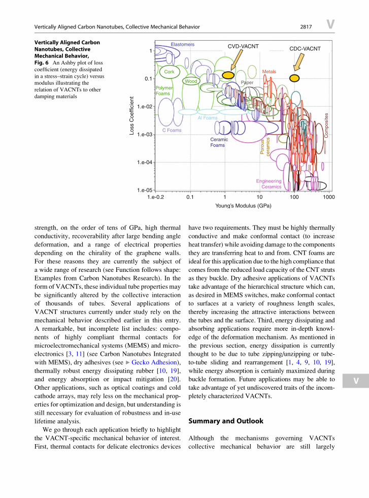
EngineeringCeramics
CeramicFoams
Al Foams
PolymerFoams
Wood Paper
MetalsCork
C Foams
Elastomers CVD-VACNT CDC-VACNT
Por
ous
cera
mic
s Com
posi
tes
100010010
Young’s Modulus (GPa)
0.11.e-0.21.e-05
1.e-04
1.e-03Loss
Coe
ffici
ent
1.e-02
0.1
1
1
Vertically Aligned CarbonNanotubes, CollectiveMechanical Behavior,Fig. 6 An Ashby plot of loss
coefficient (energy dissipated
in a stress–strain cycle) versus
modulus illustrating the
relation of VACNTs to other
damping materials
Vertically Aligned Carbon Nanotubes, Collective Mechanical Behavior 2817 V
V
strength, on the order of tens of GPa, high thermal
conductivity, recoverability after large bending angle
deformation, and a range of electrical properties
depending on the chirality of the graphene walls.
For these reasons they are currently the subject of
a wide range of research (see Function follows shape:
Examples from Carbon Nanotubes Research). In the
form of VACNTs, these individual tube properties may
be significantly altered by the collective interaction
of thousands of tubes. Several applications of
VACNT structures currently under study rely on the
mechanical behavior described earlier in this entry.
A remarkable, but incomplete list includes: compo-
nents of highly compliant thermal contacts for
microelectromechanical systems (MEMS) and micro-
electronics [3, 11] (see Carbon Nanotubes Integrated
with MEMS), dry adhesives (see ▶Gecko Adhesion),
thermally robust energy dissipating rubber [10, 19],
and energy absorption or impact mitigation [20].
Other applications, such as optical coatings and cold
cathode arrays, may rely less on the mechanical prop-
erties for optimization and design, but understanding is
still necessary for evaluation of robustness and in-use
lifetime analysis.
We go through each application briefly to highlight
the VACNT-specific mechanical behavior of interest.
First, thermal contacts for delicate electronics devices
have two requirements. They must be highly thermally
conductive and make conformal contact (to increase
heat transfer) while avoiding damage to the components
they are transferring heat to and from. CNT foams are
ideal for this application due to the high compliance that
comes from the reduced load capacity of the CNT struts
as they buckle. Dry adhesive applications of VACNTs
take advantage of the hierarchical structure which can,
as desired in MEMS switches, make conformal contact
to surfaces at a variety of roughness length scales,
thereby increasing the attractive interactions between
the tubes and the surface. Third, energy dissipating and
absorbing applications require more in-depth knowl-
edge of the deformation mechanism. As mentioned in
the previous section, energy dissipation is currently
thought to be due to tube zipping/unzipping or tube-
to-tube sliding and rearrangement [1, 4, 9, 10, 19],
while energy absorption is certainly maximized during
buckle formation. Future applications may be able to
take advantage of yet undiscovered traits of the incom-
pletely characterized VACNTs.
Summary and Outlook
Although the mechanisms governing VACNTs
collective mechanical behavior are still largely

V 2818 Vertically Aligned Carbon Nanotubes, Collective Mechanical Behavior
uncharacterized, the special properties of multiwall
carbon nanotubes combined with the complex interac-
tions that arise between them in the hierarchical
VACNT microstructure have generated significant
research interest. Their wide range of properties,
mechanical, electrical, and thermal, make them ideal
candidates as multifunctional materials, particularly
for applications in which soft materials (such as poly-
mers) have traditionally dominated. Notably,
VACNTs occupy a unique niche among engineering
materials as shown in the Ashby property chart in
Fig. 6 with the ability to span a wide range of proper-
ties given a tunable microstructure. The authors
believe that there are two major hurdles to rationally
designing VACNTs for any application: control of the
CNT growth process and understanding of the rela-
tionship between the microstructure and mechanical
response. These hurdles are interrelated through the
fact that the design space cannot be systematically
probed until the microstructure can be systematically
controlled. Mastery of these unknowns will not
only further VACNTs place as novel materials in the
current applications under study, but may reveal
previously undiscovered behaviors in microstructures
yet to be created or characterized.
Cross-References
▶Carbon-Nanotubes
▶Gecko Adhesion
References
1. Mesarovic, S.D., McCarter, C.M., Bahr, D.F.,
Radhakrishnan, H., Richards, R.F., Richards, C.D.,
McClain, D., Jiao, J.: Mechanical behavior of a carbon
nanotube turf. Scr. Mater. 56, 157–160 (2007)
2. Presser, V., Heon, M., Gogotsi, Y.: Carbide-derived
carbons – from porous networks to nanotubes and graphene.
Adv. Funct. Mater. 21, 810–833 (2011)
3. McCarter, C.M., Richards, R.F., Mesarovic, S.D.,
Richards, C.D., Bahr, D.F., McClain, D., Jiao, J.: Mechan-
ical compliance of photolithographically defined vertically
aligned carbon nanotube turf. J. Mater. Sci. 41, 7872–7878(2006)
4. Pathak, S., Cambaz, Z.G., Kalidindi, S.R., Swadener, J.G.,
Gogotsi, Y.: Viscoelasticity and high buckling stress of
dense carbon nanotube brushes. Carbon 47, 1969–1976
(2009)
5. Hutchens, S.B., Hall, L.J., Greer, J.R.: In situ mechanical
testing reveals periodic buckle nucleation and propagation
in carbon nanotube bundles. Adv. Funct. Mater. 20,2338–2346 (2010)
6. Qi, H.J., Teo, K.B.K., Lau, K.K.S., Boyce, M.C.,
Milne, W.I., Robertson, J., Gleason, K.K.: Determination
of mechanical properties of carbon nanotubes and
vertically aligned carbon nanotube forests using
nanoindentation. J. Mech. Phys. Solids 51, 2213–2237
(2003)
7. Bedewy, M., Meshot, E.R., Guo, H.C., Verploegen, E.A.,
Lu, W., Hart, A.J.: Collective mechanism for the
evolution and self-termination of vertically aligned carbon
nanotube growth. J. Phys. Chem. C 113, 20576–20582
(2009)
8. Cao, A.Y., Dickrell, P.L., Sawyer, W.G., Ghasemi-Nejhad,
M.N., Ajayan, P.M.: Super-compressible foamlike carbon
nanotube films. Science 310, 1307–1310 (2005)
9. Suhr, J., Victor, P., Sreekala, L.C.S., Zhang,X., Nalamasu,O.,
Ajayan, P.M.: Fatigue resistance of aligned carbon nanotube
arrays under cyclic compression. Nat. Nanotechnol. 2,417–421 (2007)
10. Xu, M., Futaba, D.N., Yamada, T., Yumura, M., Hata, K.:
Carbon nanotubes with temperature-invariant visco-
elasticity from-196� to 1000�C. Science 330, 1364–1368(2010)
11. Zbib, A.A., Mesarovic, S.D., Lilleodden, E.T., McClain, D.,
Jiao, J., Bahr, D.F.: The coordinated buckling of carbon
nanotube turfs under uniform compression. Nanotechnol-
ogy 19, 175704 (2008)
12. Zhang, Q., Lu, Y.C., Du, F., Dai, L., Baur, J., Foster, D.C.:
Viscoelastic creep of vertically aligned carbon nanotubes.
J. Phys. D: Appl. Phys. 43, 315401 (2010)
13. Bradford, P.D., Wang, X., Zhao, H., Zhu, Y.T.: Tuning the
compressive mechanical properties of carbon nanotube
foam. Carbon 49, 2834–2841 (2011)
14. Deck, C.P., Flowers, J., McKee, G.S.B., Vecchio, K.:
Mechanical behavior of ultralong multiwalled carbon
nanotube mats. J. Appl. Phys. 101:23512-23511-23519
(2007)
15. Tong, T., Zhao, Y., Delzeit, L., Kashani, A., Meyyappan, M.,
Majumdar, A.: Height independent compressive modulus
of vertically aligned carbon nanotube arrays. Nano Lett.
8, 511–515 (2008)
16. Qiu, A., Bahr, D.F., Zbib, A.A., Bellou, A.,
Mesarovic, S.D., McClain, D., Hudson, W., Jiao, J.,
Kiener, D., Cordill, M.J.: Local and non-local behavior
and coordinated buckling of CNT turfs. Carbon 49,1430–1438 (2011)
17. Fraternali, F., Blesgen, T., Amendola, A., Daraio, C.:
Multiscale mass-spring models of carbon nanotube foams.
J. Mech. Phys. Solids 59, 89–102 (2011)
18. Hutchens, S.B., Needleman, A., Greer, J.R.: Analysis of
uniaxial compression of vertically aligned carbon
nanotubes. J. Mech. Phys. Solids 59, 2227–2237 (2011)
19. Gogotsi, Y.: High-temperature rubber made from carbon
nanotubes. Science 330, 1332–1333 (2010)
20. Misra, A.A.G., Greer, J.R., Daraio, C.: Strain rate effects
in the mechanical response of polymer-anchored carbon
nanotube foams. Adv. Mater. 20, 1–5 (2008)

Visual Servoing for SEM 2819 V
Vibration Assisted Machining
▶Ultrasonic Machining
Viscosity
▶ Interfacial Investigation of Protein Films Using
Acoustic Waves
Visual Prosthesis
▶Artificial Retina: Focus on Clinical and Fabrication
Considerations
Visual Servoing for SEM
▶Robot-Based Automation on the Nanoscale
V


PATHAK ET AL . VOL. XXX ’ NO. XX ’ 000–000 ’ XXXX
www.acsnano.org
A
CXXXX American Chemical Society
Higher Recovery and Better EnergyDissipationatFasterStrainRates inCarbonNanotube Bundles: An in-Situ StudySiddhartha Pathak,†,* Ee J. Lim,† Parisa Pour Shahid Saeed Abadi,‡ Samuel Graham,‡,§ Baratunde A. Cola,‡,§
and Julia R. Greer†
†Materials Science, California Institute of Technology (Caltech), Pasadena, California, United States and ‡George W. Woodruff School of Mechanical Engineering,and §School of Materials Science and Engineering, Georgia Institute of Technology, Atlanta, Georgia, United States
Resilience, or a material's ability to re-cover back to its original dimensionsafter deformation, is a key criterion in
assessing lifetime reliability of material sys-tems. If a material exhibits time-dependentdeformation, that is, viscoelasticity, like ver-tically aligned carbon nanotube (VACNT)bundles,1,2 it is common for its stress�strainbehavior to exhibit a hysteresis loop uponcyclical loading, thus dissipating energy inevery cycle.3 Here we show that both recov-erability and energy dissipation in VACNTsare strongly dependent on strain-rate, at-taining their maxima by loading at fasterrates. Specifically, we find that when com-pressed at the faster strain rates of 4� 10�2/sec, the VACNT bundles recover virtuallyback to their original dimensions, while atthe slower deformation rates of 4 � 10�4/sec, they remain permanently deformed(<86% recovery), as evidenced by theirpost-mortem morphology containing local-ized buckles. The resilience of the VACNTsamples is further compromised when theyare loaded to beyond densification thresh-old strains of εg 0.65�0.7 for all strain rates.It has been shown previously that com-
pressive behavior of VACNT bundles isstrongly affected by variations in their com-plex hierarchical morphology, collective in-tertube interactions, and inherent propertygradients, which in turn are controlled bythe synthesis techniques.4 In part, this isevidenced by the wide range of mechanicalproperties reported for VACNTs, such asvariations inmodulus and buckling strengththat range anywhere from sub-MPa1,5 totens of MPa6�8 to GPa9,10 levels. Anothermarked difference among existing reports isthe ability (or lack thereof) of some VACNTmicrostructures to recover from large de-formations; with some exhibiting superiorcreep recovery,1�3,11 while others deform
permanently even at modest strains.8,12�14
The ability of VACNT bundles to dissipateenergy while maintaining their dimensionalstability with >80% recovery has suggestedtheir future use for energy storage applica-tions such as viscoelastic rubbers andfoams.2,15
In this work ∼30 μm � 30 μm (height �diameter) cylindrical pillars of VACNTs weregrown by atmospheric pressure chemical
* Address correspondence [email protected],[email protected].
Received for review October 24, 2011and accepted February 14, 2012.
Published online10.1021/nn300376j
ABSTRACT
We report mechanical behavior and strain rate dependence of recoverability and energy dissipation in
vertically aligned carbon nanotube (VACNT) bundles subjected to quasi-static uniaxial compression.We
observe three distinct regimes in their stress�strain curves for all explored strain rates from 4� 10�2
down to 4 � 10�4 /sec: (1) a short initial elastic section followed by (2) a sloped plateau with
characteristic wavy features corresponding to buckle formation and (3) densification characterized by
rapid stress increase. Load�unload cycles reveal a stiffer response and virtually 100% recoverability at
faster strain rates of 0.04/sec, while the response is more compliant at slower rates, characterized by
permanent localized buckling and significantly reduced recoverability.We propose that it is the kinetics
of attractive adhesive interactions between the individual carbon nanotubes within the VACNT matrix
that governsmorphology evolution and ensuing recoverability. In addition, we report a 6-fold increase
in elastic modulus and gradual decrease in recoverability (down to 50%) when VACNT bundles are
unloaded from postdensification stage as compared with predensification. Finally, we demonstrate
energy dissipation capability, as revealed by hysteresis in load�unload cycles. These findings, togetherwith high thermal and electrical conductivities, position VACNTs in the “unattained-as-of-to-date-
space” in the material property landscape.
KEYWORDS: vertically aligned carbon nanotubes . compression . mechanicalproperties . energy storage . recovery
ARTIC
LE

PATHAK ET AL . VOL. XXX ’ NO. XX ’ 000–000 ’ XXXX
www.acsnano.org
B
vapor deposition (APCVD) and tested both in air and inan in situ nanomechanical instrument inside of a scan-ningelectronmicroscope (SEM) under compressive cyclicloading (up to five load�unload cycles) at three differentdisplacement rates of 10, 100, and 1000 nm/s, whichcorrespond to strain rates of 0.0004, 0.004, and 0.04/sec,respectively (see Methods). The stress�strain res-ponses of VACNTs were measured using quasi-staticuniaxial compression experiments on these cylindricalspecimens1,3,12 as in this configuration the deformationoccurs under a relatively homogeneous stress field, whichis in contrast to quasi-static nanoindentation10,16,17 ordynamic impact testing methods18�20 where the pre-sence of strong strain gradients obscure stress�straincalculations. The in situ observations in SEM during theexperiments allow for simultaneous correlation betweenmorphological evolution in VACNTs and their stress�strain behavior.12,21
As shown in the representative stress�strain curveat 100 nm/sec in Figure 1, these pillars exhibit remark-able resilience (>90% recovery), with virtually no dis-cernible changes from their original morphology(compare Figures 1b and 1f) even after cycling torelatively high strains of 70�80%. Furthermore, theirload-unload trajectories are characterized by a con-siderable hysteresis loop, implying energy dissipationduring deformation.It has been proposed that some of the factors
leading to nearly full recovery and energy dissipationin VACNT bundles can be attributed to their hierarchi-cal microstructure1,2,12 (Figure 1b). At the lowest mag-nification (bottom SEM image Figure 1b) the VACNTpillar has a distinctivemuffin-like shape, with a bulboustop caused by the particular APCVD growth process(see Methods). APCVD VACNT pillars of such shortheights also tend to have a lower density (and hence,amore compliant structure) at the bottom closer to thesubstrate compared to taller APCVD forests.22 This isevident in the darker hue in the bottom ∼2 μm of thepillar in Figure 1b. Not surprisingly, upon compressionthe first buckling instability forms at this location(Figure 1c). Compared to other CNT structures, VACNTbundles are characterized by a significant number(∼millions) of CNTs arrayed in a nominally verticalalignment growing perpendicularly to the supportsubstrate, as seen at higher (micrometer level) magni-fications (Figure 1b, second image from bottom).However the long strands of individual CNTs intertwinein the course of their growth, which becomes apparentat higher magnifications (Figure 1b, third image frombottom). Upon careful examination, in their as-grownstates some tubes appear prebuckled and/or prebent,and the favorable contact energy between the tubes isthought to balance the bending strain energy of theirarrangement, resulting in a more stable low energyconfiguration.6 This is in contrast to arrays of VACNTsthat are short and/or sparse enough that each
individual CNT stands alone.23 At still higher magnifica-tions (nanometer length scales, see top TEM image inFigure 1b), individual, discrete CNTs dominate the me-chanical performance with details like CNT diameter,number of walls etc. governing their deformation.Despite their complex, hierarchical microstructure,
the general compressive behavior of VACNTs is akin tothat of typical open-cell foams,24 as evident fromFigure 1a. In the spirit of the overall open foam-likeresponse, the stress�strain curves of VACNTs arecharacterized by 3 distinct regimes: (1) initial linearelastic region, followed by (2) an oscillatory plateauregion, where each undulation is associated withlocalized buckling events, extending to the strains of∼65�70%, beyond which the stress steeply increasesdue to (3) densification. At the scale of its constituents,however, the response of VACNTs is quite differentfrom that of traditional foams. In VACNT bundles, thepostelastic compressive strain is accommodated en-tirely via the formation of lateral folds or bucklesusually close to the bottom of the bundle, while theremaining portion remains virtually unscathed.12 Thisis in contrast to traditional foams, where cell-edgebending and cell collapse are primarily responsiblefor the elastic�plastic foam response.24,25 In ourVACNT samples (Figure 1c), the formation of the firstbuckle at the bottom signals the transition from elasticto plateau regime. The postelastic plateau region in thestress�strain curve also shows marked differencesfrom that of an open cell foam response, as evidencedby its nonzero positive slope and wave-like shape,where each undulation can be traced to subsequentbuckling events (videos S1, S2 and S3 in the SupportingInformation). The positive slope of the plateau regionhas been attributed to the presence of a verticalproperty gradient in the VACNT pillars.3,12 The plateauregion continues to slope upward until ∼50% strain,where a pronounced kink forms approximately at themidheight of the pillar, leading to softening. This kinkformationmarks the end of the plateau, after which thestress�strain behavior shifts into the densificationregime characterized by a steep stress increase overa very small strain.The initial portion of the “elastic” regime (at very low
strains εe 0.05 shown in Figure 1a) is often affected byexperimental artifacts like the small initial misalign-ment between the indenter head and the micropillar,as well as top surface imperfections. Here, the defor-mation of the entire bulbous top of the VACNT pillars isfully contained within this elastic region, renderingquantitative analysis of this section of the stress�strainimpractical. Therefore, we focus our analysis on thepostelastic deformation only (see Methods).Figure 1a also shows the effect of load-unload
cycling on the mechanical behavior of VACNT micro-pillars compressed at 100 nm/s. It is evident that thefirst cycle is distinctly different from all subsequent
ARTIC
LE

PATHAK ET AL . VOL. XXX ’ NO. XX ’ 000–000 ’ XXXX
www.acsnano.org
C
loading cycles, which are self-consistent. For examplethe buckling stress as well as the plateau stress for thefirst loading are much higher than those in the lattercycles. It is also apparent that both the amount ofhysteresis, corresponding to the energy dissipatedevery cycle, and the recovered strain after unloadingdecrease with increasing cycle number.Under varying displacement rates (Figure 2), further
differences in the amount of recovery come to light. Asseen from the first unloading segment, recoverabilityappears to increase at higher strain rates when un-loaded from the same nominal maximum strain. This isalso evident from the post-mortem SEM images, whichclearly show permanent deformation and remnants ofbuckles in the samples compressed at the slowest10 nm/s displacement rate, while samples compressedat higher rates appear identical to their initial state, thatis, lacking any evidence of deformation. Note also thatthe plateau region in the samples deformed at theslowest rate shows more pronounced undulations,corresponding to more buckling events occurring atthis rate (compare Supporting Information videos S1,S2, and S3). All of this suggests a strong dependence
of deformation commencement on strain rate. Further,our demonstration of nearly full recovery and a lack ofmorphological damage in VACNTs deformed at thehighest tested strain rates may have significant impli-cations for its use as protective materials.Stiffness changes, measured as the elastic modulus
calculated from the initial unloading slope in the
Figure 1. (a) 5 load�unload cycles in compression of a VACNT micro-muffin by a flat punch diamond indenter at 100 nm/sshowing 3 distinct regimes; elastic, plateau, and densification. The first buckling instability, formed at the bottom of the pillarshown in (c), marks the start of the slopedplateau regionwhere buckles formprogressively. Densification typically starts afterthe large buckle at ε∼ 0.5 (d) and continues till εmax (e). Successive load�unload cycles to the same strain in (a) also reveal agradual drop in stress and recovery every cycle, suggesting progressive damage accumulation in thematerial.Micrographs in(b) reveal the hierarchical morphology of VACNTs, which consist of nominally vertical aligned CNTs at lowmagnification, anda complex intertwined network at higher magnification. Individual multiwalled CNTs are visible in the TEM image. SEMpictures are taken at a 86 deg tilt angle.
Figure 2. Tests at different displacement rates showingmore pronounced buckling signatures and lesser recoveryat the lower rates. SEM images in the figure are taken at a86� tilt angle.
ARTIC
LE

PATHAK ET AL . VOL. XXX ’ NO. XX ’ 000–000 ’ XXXX
www.acsnano.org
D
stress�strain curves, as a function of displacement rateand maximum strain, are shown in Figure 3. For aparticular displacement rate (for example 100 nm/s, or-ange diamonds in Figure 3a), themoduli obtained in sucha way change considerably depending on the maximumstrains attained before unloading. Thus while the moduliin the plateau regime start at a lowvalue (around120MPaat ε=0.1 for 100nm/s), they increase steadily to∼175MPaup to the strain of ε ∼ 0.5. This evolution in the modulusmirrors the trends shown in the shape of the stress�straincurve for the first load�unload cycle shown in Figures 1and 2. As seen from Figure 1a and 1d, the strain at ε ≈0.5 is associated with the formation of a large buckle inthemiddle of the pillar, and is followed by a decrease inthe slope of the stress�strain curve. Following a similartrend, the modulus also drops to 145 MPa at strainshigher than 0.5. Once the densification threshold strainis reached (εg 0.65�0.7), themodulus increases rapidlywith strain to values of up to 2�4 times than that in thepredensification regime.The variations in the modulus between the different
regimes are also revealed in Figure 3b, where theresults from the pre- and postdensification regimesare summarized separately. The considerably highermoduli in the densification regime, for example, in-creasing by more than a factor of 2 from 177( 11 MPato 385.1 ( 149 MPa in the first cycle for the fastest1000 nm/s displacement rate, are likely the effect of thesignificant increase in density due to compaction of thesample. In addition both pre- and postdensificationregimes in Figure 3b show an increasing trend in thestiffness with faster rates, a behavior considered typicalfor viscoelastic solids.26 Thus the fastest deformationrate of 1000 nm/s consistently results in the highermoduli in both regimes. Repeated cycling furtherexacerbates the localization of deformation into folds,leading to stiffness degradation (Figure 3b).The% recovery shows a similar correlation with both
the displacement rate and the maximum attainedstrains (Figure 4). Figure 4a shows recovery to bevirtually 100% when unloaded from elastic regime,>90% when unloaded from the plateau regime, andonly 50�80% when unloaded from strains in thedensification segment (ε g 0.65�0.7). The recovery inthe postdensification regime is seen to decrease gra-dually from >80% to ∼50% with increasing strainlevels. Similar to the modulus, samples deformed atthe slowest 10 nm/s rate are most permanently de-formed (i.e., least recovered, with 86.9 ( 2% recoveryfor the first cycle), while those compressed at thefastest (1000 nm/s) rate show a high 95.6 ( 3%recovery. While the recovery prior to densificationdecreases gradually with cycling, after densificationthe recovery drops sharply in the second cycle andthen stabilizes to a relatively lower value (Figure 4b).We find that the error bars in the data within thepostdensification regime (right image in Figure 4b) are
significantly larger than those before densification, likelya result of the % recovery being a strong function of theunloading strain in this regime. Also since the VACNTpillars compressed at the fastest rate of 1000 nm/s weresubjected to higher strains (Figure 4a), they recoveredless than the ones compressed at the slower 100 nm/srate in the postdensified regime (Figure 4b).Our viscoelastic analysis (see Figure S1 in the
Supporting Information) indicates that the time con-stant associated with the recovery of the VACNTs isvery short, on the order of ∼0.1 s (see also ref 12), andsignificantly below the deformation rates studied inour work. We also verified the same by loading theVACNTs in situ in SEMentor at various displacementrates (of 10, 100, and 1000 nm/s) and then quicklyunloading the indenter head, which confirmed thatVACNT recovery occurs very rapidly; at the framecapture rate of 30 frames/sec the entire recovery wascompleted within a single frame at unloading.Interestingly, relative recovery, defined as recovery
compared with the previous, as opposed to initial,cycle (Figure 4c), shows an identical trend for pre andpostdensified regimes. By the third cycle, data acrossall three rates shows ∼100% relative recovery. Thissuggests that in spite of the differences in their abso-lute values, the recovery in the VACNTs follows adeterministic (rather than stochastic) mechanism forall deformation rates.
Figure 3. (a) Changes in the unloading modulus as a func-tion of the maximum strains attained before unloadingshowing a response similar to the material's stress�strain behavior. (b) Modulus values (average ( standarddeviation) at different load�unload cycles as a functionof their displacement rates in the predensification(open symbols) and postdensification (filled symbols)regimes.
ARTIC
LE

PATHAK ET AL . VOL. XXX ’ NO. XX ’ 000–000 ’ XXXX
www.acsnano.org
E
While a robust mathematical description of the timedependence of VACNT recovery is beyond the scope ofthis work, the basic phenomenological process may beunderstood as follows. When compressed at the lowerdeformation rates, the individual CNT struts rearrangethemselves by twisting, bending, etc., in response tothe applied compressive load, thereby coming intoclose contact with one another. This type of individualstrut reconfiguration is not unreasonable in a high-entropy deformation process (i.e., many different con-figurations are available at each time step). Severalgroups have now shown that VACNTs deform similarlyto foams3,12,24 likely due to their open cell structurecreated by interwoven and intertwined tubes, whichact as supporting struts.3,12 In addition, CNTs areinherently “sticky,” experiencing an adhesive drivingforce due to van der Waals interactions.27 Therefore,in the course of compression at the slower rates, an
ever-increasing number of individual struts coalesce bycoming into close proximity of one another, therebyforming localized densified regions (i.e., buckles).Importantly, the adhesion process appears to be largelyirreversible; that is, the adhesion driving force over-rides the stored elastic energy upon unloading. Thisimplies that after unloading the buckles remain evenwhile undergoing elastic recovery. This all is in contrastto the deformation at higher rates, where the entirestructure recovers completely, with no evidence of thebuckles' presence upon unloading (see Figures 1, 2,and 5). We believe that this behavior stems from aninsufficient interaction time between individual tubesto come in contact with one another. This results ina significantly reduced contact intertubular area ascompared with the slowly deformed case, and henceleads to much lower adhesion. Compression at higherrates is likely a lower-entropy process since thereare fewer configurations available during each timestep, and therefore less intertubular contact occurs,leading to the lack of localized “zipped-up” densifiedbuckles.2,11,15,16
Thus, it stands to reason that if different VACNTmicropillars were allowed similar amounts of time for
Figure 4. (a) Percent recovery as a function of maximumstrain attained before unloading showing higher recoveryin the predensification regime (open symbols) while therecovery progressively decreases beyond densification(filled symbols). This is shown more clearly in panels (b)where recovery is higher at faster rates. (c) Similarity ofchanges in relative recovery values suggest that the processof mechanical damage accumulation is consistent amongdifferent rates. Note that tests in the postdensificationregime for the 1000 nm/s rate in (b) and (c) had only fourload�unload cycles.
Figure 5. (a) Schematic of test designs showing displace-ment�time plots for three different cases: a fast load-unloadtest at 1000 nm/s (black curve), a slow load-unload test at10 nm/s (blue), and a fast load-unload test at 1000 nm/swith a1500 s hold time at maximum displacement (green). Allsamples were loaded to a nominal maximum strain of ε ≈0.6. Inset micrographs show the postcompression images ofthe VACNTmicropillars taken at a 60 deg tilt angle after 5 suchload�unload cycles. (b) Percent recovery as a function of cyclenumber for tests with and without hold times. The trend linesfor the tests without hold time is reproduced from the data inFigure 4b of the manuscript.
ARTIC
LE

PATHAK ET AL . VOL. XXX ’ NO. XX ’ 000–000 ’ XXXX
www.acsnano.org
F
the reconfiguration to occur, they should exhibit simi-lar percent recovery for all loading rates. This is shownschematically in Figure 5a, where loading the sampleto ε ≈ 0.6 (predensification regime) at the fast rate of1000 nm/s and then holding it at the max load for∼1500 s (green curve) ensures that it spends anequivalent amount of time before unload as the sam-ple deformed at 10 nm/s test (blue curve). Figure 5bclearly shows that a hold time of∼130 s decreases therecovery for the 1000 nm/s displacement rate testsfrom 96 to 92% in the first cycle, while a longer holdtime of ∼1500 s brings it down even further to 86%.Note that these reduced percent recovery values aresimilar to those for the slower 100 and 10 nm/s rates,respectively (see also Figure 4b). Pillars subjected tothe additional hold times at maximum strain show asteeper decrease in their recovery in cycles after thesecond load�unload (Figure 5b), implying that thelonger time spent at a high strain is more detrimentalto recovery than a gradual increase in strain to amaximum value over the entire time period. The aboveresults suggest that it is the time spent by the VACNTsunder high strains, rather than the loading history, thatdetermines the permanence of their deformation.The postcompression images in Figure 5a also de-
monstrate a similar signature: while a VACNT micro-pillar deformed at 1000 nm/s with no hold is virtuallyindistinguishable from its original configuration (leftinset micrograph bordered in black), thosemicropillarsdeformed for longer periods of time have accordion-like morphologies, with vertically stacked folds alongtheir heights (insetmicrograph in themiddle and right,bordered in green and blue, respectively), for bothslow and fast loading rates.The combination of recoverability and viscoelasticity
in VACNTs results in their path-dependent load�unload behavior upon cycling, manifested as hyster-esis loops shown in Figure 1a. The fraction of energydissipated during the process can be calculated as theloss coefficientη (seeMethods), shown in Figure 6a as afunction of cycling. From this figure it is apparent thatthe loss coefficient is significantly higher for the firstload�unload cycle (η = 0.13�0.15) after which η dropssharply (to values of 0.07 and lower). Subsequent load-unload cycles cause the amount of energy dissipated todecrease steadily with increased cycling. η also appearsto be strain dependent, and is maximized at the fastest1000nm/sec rate, similar to the trends noted formodulusand recovery. No particular differences were noticedbetween the pre- and postdensification regimes in termsof the loss coefficient values. These results match wellwith the tan δmeasurements (see Figure S1 in Support-ing Information)The strain ratedependenceof the recovery andenergy
dissipation in the VACNTs appears to follow a strongcorrelationwith their increased stiffness at the faster rates.Higher stiffness at faster rates leads to a corresponding
increase in the buckling stress (Figures 1 and 2), whichincreases from 2.43 ( 0.16 MPa at 10 nm/s to2.55 ( 0.2 MPa at 100 nm/s to 2.69 ( 0.12 MPa at1000 nm/s (average ( standard deviation of 10 or moremeasurements). Usually, the buckling stress defines thebeginning of the plateau region, and since the plateauregion accounts for the largest fraction of the area underthe stress�strain curve, a higher buckling stress corre-sponds to greater energy absorption in the material andthe ability to sustain higher stresses during the extendeddeformability in this plateau region. Energy dissipation inVACNT bundles, on the other hand, is achieved uponunloading when the VACNTs transform back to theirnearly original alignment (unbuckle) by dissipating theexcess energy. Since energy dissipated is calculated as afunction of the area under the load�unload curve, thisvalue is inherently linked to the amount of recovery of theunloading curve. Hence the rate-dependent dampingbehavior of the VACNTs can also be explained by a similarline of reasoning as the VACNT recovery described earlier.
CONCLUSION
In summary, we demonstrate that VACNT cylindricalbundles grown by CVD technique exhibit unique defor-mation properties, namely resilience, deformability, andenergy dissipation, all of which increase at faster strain
Figure 6. (a) The loss coefficient values as a function ofload�unload cycles showing better energy dissipation athigher rates. (b) Ashby chart of loss coefficient (energydissipation) vs plateau stress (signifying the foam strength)multiplied by thermal conductivity of foammaterials show-ing the VACNT system as an ideal candidate for combiningthe advantages of bothmetallic andpolymeric foams. Usingelectrical conductivity instead of thermal also generates avery similar plot.
ARTIC
LE

PATHAK ET AL . VOL. XXX ’ NO. XX ’ 000–000 ’ XXXX
www.acsnano.org
G
rates. We hypothesize that it is the inability of individualCNTs in the VACNT matrix to reconfigure and come intocontact with one another, promoting adhesion andlocalized buckle formation, which governs recoverability.Specifically, we find that the deformation at slower strainrates results in the formation of localized, permanentbuckles along the pillar height, while faster strain ratesrender the individual struts' interaction times insufficientfor adhesion, leading to nearly full recovery. As such,these materials appear to combine the best aspects ofdifferent foam characteristics, such as their ability toswitch between various buckled morphologies whichmakes them capable of undergoing large strains of ca.
60�80% without generating damaging peak stresses(similar to metallic foams25), as well as their highresilience and close to 100% recovery upon load releaseleading to a higher energy dissipation (as in poly-meric foams24). This combination of desirable proper-ties suggests their potential use in protective applica-tions. Even more importantly, their multifunctionalnature, high electrical (comparable to copper) and ther-mal (similar to metals) conductivities,28,29 and relativeease of manufacture identifies VACNT bundles as acompletely new class of material systems entering the“white space” in the material property chart, as shown inFigure 6b.30
METHODSCNT Pillar Growth. Nominally ca. 30 μm � 30 μm (height �
diameter) size micropillars of VACNTs were grown using anatmospheric pressure chemical vapor deposition (APCVD)technique in a commercial (CVD) system (Black Magic Pro 400 ,Aixtron SE).22 Photolithography and a photoresist lift-off pro-cess were employed to pattern a trilayer catalyst of Ti (30 nm)/Al(10 nm)/Fe (3 nm) deposited by electron beam evaporation onSi substrates to seed the growth ofmicropillars. A gasmixture of160/100/7500 sccm of C2H2/H2/N2 was used to maintain thechamber pressure at 750 mbar during growth, which occurredat ∼750 �C. Multiwall CNTs, with an average diameter of 8.8 (2.1 nm (average ( standard deviation), were produced by thisprocess. The average mass density (CNT mass divided byvolume) was measured to be ∼80 mg/cm3. The muffin-likeshape of the VACNT micropillars is an artifact of this APCVDgrowth process that remains unexplained. High magnificationSEM shows that the bulb top is formed by the ends ofnanotubes, suggesting that the particular bulb top shapewas caused by lower CNT growth rates near the rim of thepillars. Transmission electron microscopy (TEM) images of theAPCVD-VACNTs were taken in a JEOL 4000EX machine.
Compression Tests. Vertically oriented cylindrical pillars withan aspect ratio (height/diameter≈ 30 μm/30 μm) were synthe-sized for cyclic compression tests. The compression experi-ments were performed using the XP module of Agilent'snanoindenter G200 with custom Testworks software controlmethods as described in ref 12. Compression tests were per-formed in air using a diamond flat punch of∼120 μm diameterat different displacement rates: 10, 100, and 1000 nm/s, whichcorrespond to strain rates of 0.0004, 0.004, and 0.04/sec,respectively. Typically five load�unload cycles were performedat each strain level. The maximum strains reached for the pillarswere varied from 10 to 80%. A minimum of 10 tests wereconducted at each compression rate.
As has been observed before by several research groups,6,12
CNTs frequently adhere to the diamond indenter tip, whichresults in slightly negative values of load during the final stagesof unloading in some cases (see Figure 1a). This effect is furtherintensified by the additional CNTs present in the protrudedbulbous head of the pillar. To mitigate this effect each cycle wasunloaded to only 10% of the max load in the previous cycle. Inaddition to maintaining a positive value of the load (and stress),this approach also helps to prevent loss of contact between theindenter tip and the pillar during loading and hence maintainthe cyclic nature of the tests.
In-Situ SEM Experiments. To capture the local deformationevents occurring during compression, in situ tests were alsoconducted inside our custom built mechanical deformationsystem, SEMentor,31 which is composed of a nanomechani-cal dynamic contact module (Agilent Corp.) inside a SEM(Quanta 200, FEI). Tests in the SEMentor were conducted with
a ∼60 μm � 80 μm conductive diamond flat punch in a similarmanner to the G200. The compression axis in the SEMentoris inclined by about 86� with respect to the electron beam,thus allowing continuous observation of the deformation mor-phology of the VACNTmicropillar during the loading/unloadingcycle, simultaneously with the acquisition of the load anddisplacement values. The SEM observations were recordedas a video file and later synchronized with the engineeringstress�strain curve to provide a one-to-one correlation be-tween each video frame and its corresponding position onthe stress�strain curve (see videos S1, S2, and S3 in theSupporting Information). Testing parameters in the SEMentorwere identical to that of the in-air G200 tests.
However, tests in the SEMentor differ from those in theG200in some key aspects, such as the SEMentor tests are conductedin a vacuumenvironment with an electron beam focused on thepillar, and the VACNT micropillars are in a horizontal configura-tion (gravity acting perpendicular to the compression axis)inside the SEMentor. For this study, results from the SEMentorwere used only for visualization purposes; all data analyseswere performed on tests conducted in the G200 nanoindentermachine.
Data Analysis. Engineering stress (σ) and strain (ε) werecalculated using the initial diameter (d0) and height (h0) of theVACNT micropillar, where h0 = [total height of the pillar] �[height of the bulbous top], along with the corrected load (pcorr)and displacement (ucorr) following the procedure in ref 12.Frictional forces between the VACNT pillar and the indenterhead were ignored.32,33
σ ¼ pcorrπd20=4
, ε ¼ ucorrh0
(1)
Note that eq 1 ignores the height of the bulbous top of the pillarwhen calculating engineering strain ε, thus assuming that thedeformation of the protruded pillar top has little or no effect inthe stress�strain response of the VACNT pillar. This assumptionis motivated by evidence from the video files S1, S2 and S3 inthe Supporting Information. As seen from these videos thedeformation of the entire bulbous top of the pillar is concen-trated entirely in the “elastic” portion of the loading response,while the rest of the pillar comes in full contact with the indenterhead at the beginning of the “plateau” regime (see Figure 1a).We also verified this effect by monitoring the continuousstiffness measurement (CSM) signal during the test, whichshowed that the point of full contact of the pillar with theindenter head;and hence the entire deformation of theprotruded head of the pillar;is within the initial “elastic”portion of the test. Additional validation of our approach isprovided by the fact that the modulus (E) values measured asthe slope of the initial 30% of the unloading stress�strain curvecalculated using eq 1 (see Figure 3 in the manuscript) matchclosely with the values calculated from the viscoelastic tests
ARTIC
LE

PATHAK ET AL . VOL. XXX ’ NO. XX ’ 000–000 ’ XXXX
www.acsnano.org
H
(Figure S1 in the Supporting Information). If h0 is taken to be thetotal height of the pillar (rather than being corrected for theadditional height of the bulb), the modulus values are over-estimated by around 25%.
The percentage recovery (R) values in the VACNTmicropillarsamples were measured as amount of strain recovered at theend of every cycle with respect to the maximum applied strain;that is, R = (εmax � εunload)/εmax, where εmax is the maximumstrain level at the end of loading and εunload is the strain afterunloading to 10% of the max load in the respective cycle.Similarly the percentage relative recovery values were mea-sured as the strain recovered in every cycle (i) compared to itsprevious one (i� 1); that is, Relative Recovery = Ri/Ri�1 = (εmax
i �εunloadi )/(εmax
i�1 � εunloadi�1 ) (Figure 4).
The loss coefficient, η (a dimensionless quantity), measuresthe degree to which a material dissipates energy and is cal-culated as30
η ¼ ΔUi
2πU1, U ¼
Zσmax
0σ dε, ΔU ¼
Iσ dε (2)
where U1 is the elastic energy stored in the material when it isloaded elastically to a stress σmax in the first cycle, and ΔUi is theenergy dissipated in the ith load�unload cycle (see Figure 6a). Wepoint out that in eq 2 ΔUi is normalized with respect to the area ofthefirst loading cycle (i.e., a constant value). Instead, normalizing thearea of the hysteresis loopwith respect to the area of the respectiveith cycle can also provide useful information about the dampingbehavior of the VACNTs, as shown in the Supporting InformationFigure S2.
A zero hold time at maximum load was used in all cases,except for the test shown in Figure 5. For the tests shown inFigure 5a three different test setups were used: the black curvedenotes a VACNT micropillar loaded at a fast rate of 1000 nm/sup to a strain of∼0.6 (i.e., in the predensification regime) and thenunloadedat the same rate, theblue curve shows the same for a slow10 nm/s loading�unloading rate, while the VACNT micropillarshown in the green curve was loaded at the fastest rate of1000 nm/s to a maximum strain of ε ≈ 0.6, held for 1500 s at thatmaximum strain level, and then unloaded again at 1000 nm/s. Inother words, both VACNTs micropillars shown in green (fast1000 nm/s loading rate) and blue (slow 10 nm/s loading rate) spentthe same amount of time under compression before unload:(loading time þ hold time)green,1000nm/s = (loading time)blue,10 nm/s.Five such load�unload cycles were carried out for each pillar. Inanother similar set of experiments the VACNT micropillars wereloaded at the fastest rate of 1000 nm/s, then held for 130 s at themaximum strain and subsequently unloaded, effectively bringingthe time-spent-before-unload to the same level as in the case of aslower 100 nm/s load-unload test with no hold.
Conflict of Interest: The authors declare no competingfinancial interest.
Acknowledgment. The authors acknowledge S. Hutchensfor helpful insights and guidance, N. Mohan for data analysis,financial support from the Georgia Institute of Technology Founda-tion through the Joseph Anderer Faculty Fellowship, and theInstitute for Collaborative Biotechnologies (ICB) for financial supportthrough Grant W911NF-09-0001 from the U.S. Army ResearchOffice. The content of the information does not necessarily reflectthe position or the policy of the Government, and no officialendorsement should be inferred. S.P. gratefully acknowledgessupport from theW.M. Keck Institute for Space Studies PostdoctoralFellowship program for this work. The authors acknowledge criticalsupport and infrastructure provided for this work by the KavliNanoscience Institute at Caltech.
Supporting Information Available: Three in situ videos of theVACNT micropillar compressions, synchronized with their re-spective engineering stress�strain curves; video files S1, S2, andS3 illustrate the VACNT micropillar deformations at 10, 100, and1000 nm/s which are shown at 100, 25, and 1 times their originalspeeds, respectively; viscoelastic characterization of the VACNTmicropillars (Figure S1) and the details of the loss coefficientmeasurement (Figure S2). This material is available free ofcharge via the Internet at http://pubs.acs.org.
REFERENCES AND NOTES1. Suhr, J.; Victor, P.; Sreekala, L. C. S.; Zhang, X.; Nalamasu, O.;
Ajayan, P. M. Fatigue Resistance of Aligned Carbon Nano-tube Arrays under Cyclic Compression. Nat. Nanotechnol.2007, 2, 417–421.
2. Xu, M.; Futaba, D. N.; Yamada, T.; Yumura, M.; Hata, K.Carbon Nanotubes with Temperature-Invariant Viscoelasticityfrom �196 degrees to 1000 degrees C. Science 2010, 330,1364–1368.
3. Cao, A. Y.; Dickrell, P. L.; Sawyer, W. G.; Ghasemi-Nejhad,M. N.; Ajayan, P. M. Super-Compressible Foamlike CarbonNanotube Films. Science 2005, 310, 1307–1310.
4. Kumar, M.; Ando, Y. Chemical Vapor Deposition of CarbonNanotubes: A Review on Growth Mechanism and MassProduction. J. Nanosci. Nanotechnol. 2010, 10, 3739–3758.
5. Tong, T.; Zhao, Y.; Delzeit, L.; Kashani, A.; Meyyappan, M.;Majumdar, A. Height Independent Compressive Modulusof Vertically Aligned Carbon Nanotube Arrays. Nano Lett.2008, 8, 511–515.
6. Mesarovic, S. D.; McCarter, C. M.; Bahr, D. F.; Radhakrishnan,H.; Richards, R. F.; Richards, C. D.; McClain, D.; Jiao, J.Mechanical Behavior of a Carbon Nanotube Turf. Scr.Mater. 2007, 56, 157–160.
7. Qiu, A.; Bahr, D. F.; Zbib, A. A.; Bellou, A.; Mesarovic, S. D.;McClain, D.; Hudson, W.; Jiao, J.; Kiener, D.; Cordill, M. J.Local andNon-local Behavior and Coordinated Buckling ofCNT Turfs. Carbon 2011, 49, 1430–1438.
8. Zhang, Q.; Lu, Y. C.; Du, F.; Dai, L.; Baur, J.; Foster, D. C.Viscoelastic Creep of Vertically Aligned Carbon Nano-tubes. J. Phys. D: Appl. Phys. 2010, 43, 315401.
9. Deck, C. P.; Flowers, J.; McKee, G. S. B.; Vecchio, K. Mechan-ical Behavior of Ultralong Multiwalled Carbon NanotubeMats. J. Appl. Phys. 2007, 101, 23512.
10. Pathak, S.; Cambaz, Z. G.; Kalidindi, S. R.; Swadener, J. G.;Gogotsi, Y. Viscoelasticity and High Buckling Stress of DenseCarbon Nanotube Brushes. Carbon 2009, 47, 1969–1976.
11. Xu, M.; Futaba, D. N.; Yumura, M.; Hata, K. Carbon Nano-tubes with Temperature-Invariant Creep and Creep-Recovery from�190 to 970 �C.Adv.Mater. 2011, 23, 3686–3691.
12. Hutchens, S. B.; Hall, L. J.; Greer, J. R. In Situ MechanicalTesting Reveals Periodic Buckle Nucleation and Propaga-tion in Carbon Nanotube Bundles. Adv. Funct. Mater. 2010,20, 2338–2346.
13. Zbib, A. A.; Mesarovic, S. D.; Lilleodden, E. T.; McClain, D.;Jiao, J.; Bahr, D. F. The Coordinated Buckling of CarbonNanotube Turfs under UniformCompression.Nanotechnol.2008, 19, 175704–1�7.
14. Cao, C.; Reiner, A.; Chung, C.; Chang, S.-H.; Kao, I.; Kukta,R. V.; Korach, C. S. Buckling Initiation and DisplacementDependence in Compression of Vertically Aligned CarbonNanotube Arrays. Carbon 2011, 49, 3190–3199.
15. Gogotsi, Y. High-Temperature Rubber Made from CarbonNanotubes. Science 2010, 330, 1332–1333.
16. Bradford, P. D.; Wang, X.; Zhao, H.; Zhu, Y. T. Tuning theCompressive Mechanical Properties of Carbon NanotubeFoam. Carbon 2011, 49, 2834–2841.
17. Maschmann, M. R.; Zhang, Q.; Wheeler, R.; Du, F.; Dai, L.;Baur, J. In Situ SEM Observation of Column-like and Foam-like CNT Array Nanoindentation. ACS Appl. Mater. Inter-faces 2011, 3, 648–653.
18. Daraio, C.; Nesterenko, V. F.; Jin, S.; Wang, W.; Rao, A. M.Impact Response by a Foamlike Forest of Coiled CarbonNanotubes. J. Appl. Phys. 2006, 100, 64309.
19. Misra, A.; Greer, J. R.; Daraio, C. Strain Rate Effects in theMechanical Response of Polymer-Anchored CarbonNanotube Foams. Adv. Mater. 2008, 20, 1–5.
20. Raney, J. R.; Fraternali, F.; Amendola, A.; Daraio, C. Model-ing and in Situ Identification of Material Parameters forLayered Structures Based on Carbon Nanotube Arrays.Compos. Struct. 2011, 93, 3013–3018.
21. Yaglioglu, O. Carbon Nanotube Based ElectromechanicalProbes. Ph.D. Thesis, Massachusetts Institute of Technol-ogy, Cambridge, MA, 2007.
ARTIC
LE

PATHAK ET AL . VOL. XXX ’ NO. XX ’ 000–000 ’ XXXX
www.acsnano.org
I
22. Abadi, P. P. S. S.; Hutchens, S.; Taphouse, J. H.; Greer, J. R.;Cola, B. A.; Graham, S. The Effect of Morphology onthe Micro-compression Response of Carbon NanotubeForests. Carbon 2011submitted for publication.
23. Waters, J. F.; Riester, L.; Jouzi, M.; Guduru, P. R.; Xu, J. M.Buckling Instabilities in Multiwalled Carbon Nanotubesunder Uniaxial Compression. Appl. Phys. Lett. 2004, 85,1787–1789.
24. Gibson, L. J.; Ashby, M. F., Cellular Solids: Structure andProperties; Cambridge University Press: UK, 1999.
25. Gibson, L. J. Mechanical Behavior of Metallic Foams.Annu. Rev. Mater. Sci. 2000, 30, 191–227.
26. Lakes, R. S., Viscoelastic Solids; CRC Press, Boca Raton, FL,1998.
27. Ruoff, R. S.; Tersoff, J.; Lorents, D. C.; Subramoney, S.; Chan,B. Radial Deformation of Carbon Nanotubes by van derWaals Forces. Nature 1993, 364, 514–516.
28. Baxendale, M. In The Physics and Applications of CarbonNanotubes; 12th International School on Condensed Mat-ter Physics: Contemporary Trends in Condensed MatterPhysics and Technology, 1�6 Sept. 2002, USA, KluwerAcademic Publishers: Norwell, MA, 2003; pp 657�659.
29. Hu, X. J.; Padilla, A. A.; Xu, J.; Fisher, T. S.; Goodson, K. E.3-OmegaMeasurements of Vertically Oriented Carbon Nano-tubes on Silicon. J. Heat Transfer 2006, 128, 1109–1113.
30. Ashby, M. F. Materials Selection in Mechanical Design, 3rded.; Butterworth-Heinemann: Oxford, UK, 2005.
31. Kim, J.-Y.; Greer, J. R. Tensile and Compressive Behavior ofGold and Molybdenum Single Crystals at the Nano-Scale.Acta Mater. 2009, 57, 5245–5253.
32. Tu, J. P.; Jiang, C. X.; Guo, S. Y.; Fu, M. F. Micro-frictionCharacteristics of Aligned Carbon Nanotube Film on anAnodic Aluminum Oxide Template. Mater. Lett. 2004, 58,1646–9.
33. Tu, J. P.; Zhu, L. P.; Hou, K.; Guo, S. Y. Synthesis andFrictional Properties of Array Film of Amorphous CarbonNanofibers on Anodic Aluminum Oxide. Carbon 2003, 41,1257–1263.
ARTIC
LE

ACS Nano
1
Supporting Online Material
Higher Recovery and Better Energy Dissipation at Faster Strain Rates in Carbon Nanotube Bundles: an in-situ Study.
Siddhartha Pathak 1∗
, Ee J. Lim 1
, Parisa Pour Shahid Saeed Abadi 2
, Samuel Graham 2,3
,
Baratunde A. Cola 2,3
, Julia R. Greer 1
1 Materials Science, California Institute of Technology (Caltech), Pasadena, CA, USA
2 George W. Woodruff School of Mechanical Engineering, Georgia Institute of
Technology, Atlanta, GA, USA. 3
School of Materials Science and Engineering, Georgia Institute of Technology, Atlanta,
GA, USA.
∗ Contact author: - Materials Science, California Institute of Technology (Caltech), 1200 E. California
Blvd., MC 309-81, Pasadena, CA 91125-8100, Phone: +1 (626) 395-8165, Fax: +1 (626) 395-8868, E-

ACS Nano
2
Viscoelastic Characterization In addition to their distinctive buckling behavior and their ability to recover from
large deformations, VACNTs have also been reported to demonstrate a unique
viscoelastic response, which was reported by a subset of the current authors for two
separate VACNT systems 1, 2
. The remarkable nature of the viscoelastic behavior of
VACNTs was further demonstrated in 3, where the material was found to exhibit this
behavior for a wide temperature range from -196oC to 1000
oC – something no other
material had shown previously. In the research conducted in our group viscoelastic
behavior including storage and loss moduli over a range of frequencies was reported by
Hutchens, et al 1. Below we describe the results of our additional viscoelastic experiments
performed on the described VACNT micro-pillars.
The viscoelastic properties of the VACNT film were measured using flat punch
indentation following the procedure outlined in Ref 1. In this method the indenter is
loaded into the sample at a constant displacement rate of 10 nm/s up to a specified strain,
where the indenter head is oscillated at ~8 nm amplitude across a range of frequencies
from 1 to 50 Hz. This cut-off frequency (50 Hz) is an instrument limitation as detailed in
Ref 1, 4
. The procedure was repeated at four different strains: ε = 0.18, 0.4, 0.62 and 0.84,
which ensured visco-elastic characterization of the samples in both their pre and post-
densification regimes.
Viscoelastic materials are commonly characterized by their storage (E ′ ) and loss
(E ′′ ) moduli, where the former represents the stored energy or the elastic response, and
the latter corresponds to the amount of energy dissipated or the viscous response, as well
as their ratio – δtan . Assuming linear viscoelastic behavior, these terms can be computed
following the calculations described in Refs 4-7
as follows:
AkE
s
21
2
νβπ −
′=′ , air
airu
F
u
Fk ϕϕ coscos
0
0
0
0 −=′ ,
AkE
s
21
2
νβπ −
′′=′′ , air
airu
F
u
Fk ϕϕ sinsin
0
0
0
0 −=′′ ,
E
E
′
′′=δtan (1)
Here k ′ and k ′′ are the storage and loss stiffnesses of the sample, obtained by finding the
real and complex parts, respectively, of the stiffness differences between oscillating the
indenter head on the sample at a fixed displacement and in air at the same raw
displacement, β is a constant (=1 for a flat punch indenter), 0F and 0u are the load and
displacement oscillation amplitudes respectively, and ϕ is the phase angle between the
load and displacement oscillations. The accuracy in the values of E ′ and E ′′ in Eq. (1)
can be affected by a couple of factors: uncertainties in the value of the Poisson ratio
(since the Poisson’s ratio can also be frequency dependent), and accuracy in the value of
the contact area, especially at lower indentation depth where full contact may not have
been established. On the other hand, calculation of δtan is independent of these
parameters, and thus is ideally suited as a measure of the viscoelasticity of the indented
material 2, 8
.

ACS Nano
3
The viscoelastic indentation response of the VACNT film, in terms of the
measured values of their storage modulus (E ′ ), loss modulus (E ′′ ) and δtan values, is
shown below (Figure S1). Similar to the % recovery results discussed in the main
manuscript, two distinct responses are seen in this figure depending on if the indenter is
oscillated at levels corresponding to the (i) pre-densification regime (open symbols in
Figure S1) or (ii) post-densification regime (filled symbols). While both E ′and E ′′ are
seen to increase by around 2-3 times after densification (Figures S1a and b), there is no
difference in the values of δtan between the pre- pand post-densification regimes
(Figure S1c). This indicates that both the values of E ′and E ′′ have increased in equal
proportions after densification.
The storage modulus values were found to be frequency independent over the
range of frequencies used in this work. On the other hand the loss modulus (and the
δtan ) values are strongly affected by the frequency, and they generally increase with
increasing frequency, although a couple of local minimas can be indentified at 30 and 50
Hz respectively. Unfortunately the cut-off frequency (50 Hz) of our instrument prevents
further study of this behavior at higher frequencies.
As shown in the figures of the main manuscript (Figures 1 and 2), the VACNT
microstructure starts getting densified at strain levels of ǫ ≥ 0.65-0.7. Thus the higher
values of E ′obtained in the post-densification regime indicate that the material is capable
of storing a higher amount of energy in this state, with the excess energy presumably
being stored in the buckled/densified regions. A correspondingly higher proportion of
energy is also dissipated in this regime, as indicated by a similar increase in the values of
E ′′ . However, the overall visco-elastic response of the VACNT material still remains
unaffected, as seen in Figure S1c. These results match well with the loss coefficient
measurements shown in Figure 6 (main manuscript), which also show similar values of
loss coefficient between the pre- and post densification regimes. An analogous response
was also noted by Xu et al. over a much wider temperature range of -196oC to 1000
oC
3.
In addition the unloading modulus values shown in Figure 3 (main manuscript) are also
are also found to match well with that of E ′ in Figure S1a.
Characterization of Material Damping Response The loss coefficient, η, (a dimensionless quantity) measures the degree to which a
material dissipates energy and is calculated in two different ways as shown below 9
12 U
Ui
πη
∆= , ∫=
max
dU
σ
εσ0
, ∫=∆ εσdU (2)
i
i
U
U
πη
2
∆= , ∫=
max
dU
σ
εσ0
, ∫=∆ εσdU (3)
where 1
U and i
U are the elastic energy stored in the material when it is loaded elastically
to a stress max
σ in the 1st and the i
th cycle respectively, and
iU∆ is the energy dissipated
in the ith load-unload cycle (see Fig. S2). The main difference between the above two
equations is that in Equation (2) the normalization is done with respect to the area of the
1st loading cycle, while in Equation (3) it is done w.r.t. the area of the i
th cycle

ACS Nano
4
respectively. In other words, the denominator in Equation (2) is a constant while that of
Equation (3) changes with every cycle. Each definition shows a different trend in the
values of η as shown in the figure below.
As seen from the figure below, use of Equation (2) results in sharp drop in the
values of η after the 1st cycle (Figure S2a), but there is no such drop when using Equation
(3). Note that the values of η for the 1st cycle are exactly the same in both figures (Figure
S2a and S2b). After the 1st cycle, both figures show a similar drop in the values of η for
increasing cycle number. In both cases, η also appears to be strain dependent, and is
maximized at the fastest 1000 nm/sec rate, similar to the trends noted for modulus and
recovery. As in the case of the tan δ values described earlier, no significant different
difference is seen between the pre- and post-densification regimes.
1. Hutchens, S. B.; Hall, L. J.; Greer, J. R., In situ Mechanical Testing Reveals
Periodic Buckle Nucleation and Propagation in Carbon Nanotube Bundles. Advanced
Functional Materials 2010, 20, 2338-2346.
2. Pathak, S.; Cambaz, Z. G.; Kalidindi, S. R.; Swadener, J. G.; Gogotsi, Y.,
Viscoelasticity and high buckling stress of dense carbon nanotube brushes. Carbon 2009,
47, 1969-1976.
3. Xu, M.; Futaba, D. N.; Yamada, T.; Yumura, M.; Hata, K., Carbon Nanotubes
with Temperature-Invariant Viscoelasticity from-196 degrees to 1000 degrees C. Science
2010, 330, 1364-1368.
4. Herbert, E. G.; Oliver, W. C.; Pharr, G. M., Nanoindentation and the dynamic
characterization of viscoelastic solids. Journal of Physics D: Applied Physics 2008, 41,
074021-1.
5. Herbert, E. G.; Oliver, W. C.; Lumsdaine, A.; Pharr, G. M., Measuring the
constitutive behavior of viscoelastic solids in the time and frequency domain using flat
punch nanoindentation. Journal of Materials Research 2009, 24, 626-37.
6. Wright, W. J.; Maloney, A. R.; Nix, W. D., An improved analysis for viscoelastic
damping in dynamic nanoindentation. International Journal of Surface Science and
Engineering 2007, 1, 274-92.
7. Wright, W. J.; Nix, W. D. In Storage and loss stiffnesses and moduli as
determined by dynamic nanoindentation, 506 Keystone Drive, Warrendale, PA 15086,
United States, Materials Research Society: 506 Keystone Drive, Warrendale, PA 15086,
United States, 2009; pp 863-871.
8. Pathak, S.; Gregory Swadener, J.; Kalidindi, S. R.; Courtland, H.-W.; Jepsen, K.
J.; Goldman, H. M., Measuring the dynamic mechanical response of hydrated mouse
bone by nanoindentation. Journal of the Mechanical Behavior of Biomedical Materials
2011, 4, 34-43.
9. Ashby, M. F., Materials Selection in Mechanical Design. Butterworth-
Heinemann; : 2005 (3 ed.).
1
0
0.02
0.04
0.06
0.08
0.1
0.12
0.14
0
10
20
30
40
50
600
100
200
300
400
500
Sto
rage
Mod
ulus
, M
Pa
Loss
Mod
ulus
, MP
aT
an d
elta
Frequency, Hz
Post-densification, ɛ
≥
0.65
Pre-densification, ɛ
≤
0.65
Post-densification, ɛ
≥
0.65
Pre-densification, ɛ
≤
0.65
0 10 20 30 40 50 60
10 nm/s
Post-densification, ɛ
≥
0.65 Pre-densification, ɛ
≤
0.65
Figure S1 (Supporting online material). The viscoelastic indentation response of the VACNT micro-pillars loaded at a rate of 10 nm/s, in terms of the measured values (average ±standard deviation) of their (a) storage modulus, (b) loss modulus and (c) tan δ
values, as a function of frequency.
(a)
(b)
(c)

2
Loss
coe
ffici
ent, η
Cycle number
Loss
coe
ffici
ent, η
Cycle number
Cycle number
Cycle number
1000 nm/s
100 nm/s
10 nm/s
1000 nm/s
100 nm/s
10 nm/s
Area
ΔUArea U
12 U
Ui
i
i
U
U
2
1 2 3 4 51 2 3 4 5
1 2 3 4 51 2 3 4 50
0.05
0.1
0.15
0
0.05
0.1
0.15
Area
ΔUArea U
Pre-densification, ɛ
≤
0.65 Post-densification, ɛ
≥
0.65
Pre-densification, ɛ
≤
0.65 Post-densification, ɛ
≥
0.65
1000 nm/s
100 nm/s
10 nm/s
(a)
(b)
Figure S2 (Supporting online material). (a) The loss coefficient
values calculated using Eq. (2) and (b) using Eq. (3) as a function of load-unload cycles showing better energy dissipation at higher rates.

Influence of density gradients on the stress-strain response of carbon nanotube micropillars Siddhartha Pathak 1, Nisha Mohan 1, Elizabeth Decolvenaere 1, Alan Needleman 2, Mostafa Bedewy 3, Anastasios John Hart 3, Julia R. Greer 1
1 Materials Science, California Institute of Technology (Caltech), Pasadena, CA, USA 2 Department of Materials Science and Engineering, College of Engineering and Center for Advanced Scientific Computing and Modeling (CASCaM), University of North Texas, Denton, TX, USA. 3 Mechanosynthesis Group, Department of Mechanical Engineering, University of Michigan, Ann Arbor, MI, USA.
Abstract The combined results of in-situ micro-mechanical experiments, image analysis,
and mechanics modeling revealed a linear correlation between the local number density of individual carbon nanotubes within vertically aligned carbon nanotubes (VACNT) forests, their microstructural deformation mechanism, and the hardening slope within their compressive stress-strain response. Both the stress-strain response and the commencement of localized buckling-like deformation were found to depend on the relative local density profile, which was quantified by edge-detection based image analysis. Those samples whose image analysis revealed a positive density gradient, i.e. where the density at the bottom of the forest was lower than that at the top, underwent a sequential bottom-to-top buckling and exhibited hardening in the stress-strain response. When the density gradient was insubstantial or slightly reversed, the bottom regions always buckled last and had a globally flat stress-strain response. These experimental findings were corroborated by the 2-dimensional, local material model based on a viscoplastic solid with plastic non-normality and with the effective stress – effective strain relation containing an initial peak, followed by softening and then hardening, originally reported by Hutchens, et al. 1,2 (Hutchens, S. B., Needleman, A. & Greer, J. R. Analysis of uniaxial compression of vertically aligned carbon nanotubes. Journal of the Mechanics and Physics of Solids 59, 2227-2237, 2011).
Keywords Vertically aligned carbon nanotubes, compression, mechanical properties, energy
storage, finite element simulation.
Contact author: - Materials Science, California Institute of Technology (Caltech), 1200 E. California Blvd., MC 309-81, Pasadena, CA 91125-8100, Phone: +1 (626) 395-8165, Fax: +1 (626) 395-8868, E-mail: [email protected], [email protected]
1

1. Motivation and Background Developing low-density materials for engineering applications requires knowing
the relationships between their structural component geometries and the physical and mechanical properties of constituent materials, like density and strength. These relationships may be challenging to obtain, especially for the complex hierarchical and largely disordered cellular structures like vertically aligned carbon nanotubes (VACNT) forests. These materials represent examples of spatial hierarchy because the individual nanotubes have diameters on the order of tens of nanometers; the individual openings or inter-tube distances may range from a few to hundreds of nanometers, the heights of the individual nanotubes may be as high as hundreds of microns to several millimeters, and their lateral extent of the forests can have macroscopic dimensions. The complexity associated with this structural design, as well as the unique properties driven by the nanometer dimensions and the attractive van der Waals interactions among the individual tubes, render quantifying their physical properties like density, characteristic mean-free path, and cell size, which are usually trivial to measure in conventional foams, particularly challenging.
Further, one of the grand pursuits in materials sciences is to develop a quantitative, predictive relationship between the characteristic microstructure of a particular material and its mechanical properties. Such relationships are powerful because they enable the derivation of structurally relevant quantities like strength, fatigue resistance, and fracture toughness based on what is known about the material. For example, in a typical metal the well-known Hall-Petch effect 3,4 relates the increase in yield strength, σ, to a decrease in the average grain size, d, through a power-law: σ ~ d1/2. In cellular materials 5, both the Young’s modulus (E) and strength scale with density: E, σ ~ ρ2. No analogous quantitative theory, which unambiguously predicts the mechanical response of carbon nanotube networks as a function of their local microstructural attributes like density, porosity, and/or tortuosity, exists. Establishing such a link will serve as the foundation for the development of reliability models, which will connect the characteristic intrinsic dimensions with the deformation evolution mechanisms and the macroscale mechanical properties. It is particularly important and relevant to establish such quantitative links between the VACNT microstructure and their mechanical properties because of their extensive use in technological applications, which range from micro-electro-mechanical systems (MEMS) to energy dissipative systems like viscoelastic rubbers and foams 6-11.
The details of the VACNT synthesis process, catalytic chemical vapor deposition, determines the diameter and quality of the individual CNTs, as well as the alignment and density of the forest. For example, using floating’ vs. ‘fixed’ catalysts 12 in chemical vapor deposition (CVD) syntheses 13 and growing carbon nanotubes via the carbide-derived carbon (CDC) 14 methods have been shown to result in vastly different VACNT morphologies. Such variations are evident both at the individual tube level (such as variations in tube diameter from 2-3 nm 15, to 20-50 nm 16, to greater than 100 nm 17, number of walls in the CNT structure etc.) and at the collective matrix levels (such as density variations from 0.018 18 to 0.95 gm/cm3 15). In part, this is evidenced by the wide range of mechanical properties reported for the VACNTs grown by different methods. For example, the modulus and the compressive buckling strengths of VACNTs have been
2

reported to range anywhere from sub-MPa 11,19 to tens of MPa 20-22 to GPa 15,23 levels ( Fig. S1a vs. S1b, c and d in Supplementary Information). An even more conspicuous example is that nominally identical VACNT samples have been found to substantially recover after large compressions 6,10,11,24,25 (Figs. S1a and b) or to deform permanently even at modest strains 16,22,26-28 (Figs. S1c and d).
Mechanical experiments like uniaxial compressions of VACNT samples with micrometer dimensions 6,12,16,25,29 and indentations into VACNT forests 15,30-32 have demonstrated the similarities in their mechanical deformation characteristics to those of typical open-cell foams 5. In the spirit of such a foam-like response, the compressive stress-strain curves for VACNTs have been described by having 3 distinct regimes: (1) an initial linear elastic loading, followed by (2) an oscillatory plateau, where each undulation in the data corresponded to a localized buckle formation in the material, and (3) a densification, manifested by a rapid stress increase. In contrast to cellular foams, which typically deform by bending and collapsing of the cell walls5,33, the post-elastic flow in VACNTs was accommodated entirely by the formation of localized folds or buckles of the entangled arrays, usually oriented orthogonally to the compression direction (Fig. S1) 6,12,19,26,27,30. Most VACNT structures, including patterned micro-pillars, have also been reported to follow a particular bottom-to-top buckling sequence under uniaxial compression, where the first buckle nucleated close to the substrate, and each subsequent lateral collapse event initiated only after the preceding one was completed, thus sequentially collapsing the entire structure 6,12,16,25. Another departure in the compressive behavior of VACNTs from that of typical open-cell foams is that the plateau region in their stress-strain curves has a positive global slope, which has been reported to range anywhere from 0.5 to 12 MPa 6,12,16,25. In open-cell foams, this plateau region is virtually horizontal 5. It has been speculated that the observed non-zero plateau slopes in VACNTs may be uniquely determined by a gradient in the material mechanical properties, like stiffness or yield strength, along the sample height 6,16. This reasoning is motivated in part by the numerous observations during compressions which show the localized folds within CNT structures always forming first at locations close to the growth substrate, which in studies of the CNT growth process has been shown to be the location of lowest CNT number density 34,35. The presence of fewer and wider separated individual tubes close to the growth substrate reduces the load-bearing capacity of the overall structure, which may drive the corresponding decrease in stiffness and yield stress at the base 6,26.
Recent models, which qualitatively captured the mechanics of VACNT deformation, have provided a physical foundation for the strengthening in the plateau region within the stress-strain VACNTs data 7,30. Using a constitutive hardening-softening-hardening model with plastic non-normality, Hutchens et al. 1,2,36 showed that a linear variation in the input yield-like property along the sample height was correlated with the output slope of the plateau region in the stress-strain curve. A constant property along the sample height was shown to result in a flat plateau, while introducing a straight gradient in the input property caused a corresponding linear increase in the slope of the stress plateau. What remains unknown is the relationship between this yield-like mechanical property and the physical attributes of the material, which drive it. This is due, in part, by the difficulty of quantifying local microstructural characteristics of the VACNTs, as well as by the lack of experimental data, which demonstrates a flat plateau in the compressive stress-strain response of VACNTs.
3

The challenges associated with measuring the local CNT density within a VACNT forest have hampered the ability to develop experimentally-informed quantitative models of their deformation. During the early growth stages of a VACNT forest, the van der Waals attraction between CNTs causes them to self-organize into the aligned morphology after a threshold density is acheived. 32,35 Owing to CNT-CNT interactions, the resulting hierarchical forest is a highly intertwined porous 3-dimensional network structure. These morphological complexities result in several challenges when using scanning electron microscopes (SEM) to visualize the microstructure of VACNT forests: (1) ample adjustments in the imaging conditions like the depth of field, contrast, and brightness are required as the beam is rastered along the sample; (2) the interaction volume between the incident electrons and the secondary electrons in the SEM is ambiguous, which obscures the interpretation of a 2-dimensional image onto a 3-dimensional structure; and (3) sample-to-sample variation is substantial. Other methods have attempted to quantify the local morphology within VACNTs, for example small angle X-ray scattering (SAXS) and mass attenuation have been used to non-destructively quantify the alignment, diameter, and density of the CNTs. 32,35,37 However, a limitation is the X-ray beam size, which in recent studies was no smaller than 10 microns, 34,37 limiting the ability to characterize micro-scale density gradients as opposed to trends through millimeter-scale CNT forests.
Theoretical studies have also provided useful insights into the factors that may influence the mechanical properties of VACNTs. Astrom et al. modified the semi-theoretical version of the Cox shear-lag model 38 to describe the deformation of CNT mats and fibers by taking into account the statistical number of bundle–bundle contacts 39. Their study suggested that the modulus of the CNT network was linearly related to the number of contact points. A similar result was obtained by Berhan and coworkers 40, who found that an increase in the waviness (tortuosity) of the nanotube ropes resulted in a significant reduction of their effective modulus 41. Attempts have been made to explore these effects experimentally using a variety of techniques such as image analysis 32,42,43 and making analogies to the artificial neural networks 44, but no conclusive data was reported.
In this work, we used an edge detection technique based on the Canny algorithm 45 to the SEM images of VACNTs to calculate the relative differences in their 2-dimensional areal density as a function of spatial coordinates. SEM images were obtained by systematically adjusting the imaging parameters when visualizing two sets of VACNT samples, which exhibited substantially distinct mechanical behavior. The combination of such image analyses and in-situ micro-compression experiments revealed a quantifiable correlation between the relative density profiles, the microstructural deformation mechanism, and the mechanical stress-strain data. We then applied a 2-dimensional local material model based on a viscoplastic solid with plastic non-normality and with the effective stress – effective strain relation containing an initial peak, followed by softening and then hardening,1 to quantify the mechanics of VACNT compressions. Reasoning that relative density was linearly related to the mechanical yield-like property at the same coordinates within the sample, we corroborated these experimental findings and revealed that the hardening slope of the plateau region in the stress-strain data was uniquely defined by the gradient in this property along the pillar height.
4

2. Materials and Methods
CNT Pillar Growth VACNTs were synthesized by catalytic chemical vapor deposition (CVD) in a
hot-walled reactor (Thermo-Fisher Mini-Mite, 22 mm inner diameter tube furnace with 12 in. heated length), from substrate-bound catalyst nanoparticles. Substrates were prepared by the physical vapor deposition of 1 nm of iron after 10nm of alumina on a thermally-oxidized (100) silicon wafer (0.5 mm thick). Micron-sized CNT pillars were prepared by photolithographic patterning of catalyst deposition (using SPR-220-3 photoresist). After lift-off of photoresist, millimeter-to-centimeter-sized silicon chips are loaded inside a quartz tube within the tube furnace. Before introducing the growth gas (ethylene) into the reactor, the multilayer thin film catalyst is heated in an atmosphere of hydrogen/helium to induce film dewetting into nanoscale particles. LabVIEW was used to interface and control all process variable, such as temperature and gas flow rates. After a five-minute helium (1000 sccm) purging step, hydrogen (400 sccm) and helium (100 sccm) are mixed and temperature is ramped up to 775 °C for 10 minutes and same temperature is maintained for another 10 minutes. Finally, ethylene (100 sccm) is introduced to the system for a maximum of 30 growth minutes. After growth, the tube is purged again with helium during cooling.
Ex-situ Compression Experiments Two sets of stand-alone patterned VACNT samples, grown on the same Si
substrate, were chosen for the compression tests (see Fig. 1). Both sample sets had the shape of micro-pillars, or columns, but differed in their cross-sectional geometry – one was a square with the sides of ~25 µm (hereafter referred to as “square pillars,” Fig. 1c), and the other was a circle with the diameter of ~28 µm (hereafter referred to as “circular pillars,” Fig. 1b). The heights of the square pillars were found to increase from 30 to 40.5 µm over the lateral distance of 2 mm on the Si substrate, and those of the circular pillars diminished from 42.6 to 38.7 µm over the same lateral extent. The compression experiments were performed in air, using the XP module of Agilent’s nanoindenter G200 with a custom fabricated, ~120 µm diameter, diamond flat punch indenter tip. Tests were performed at constant displacement rates of 10 nm/s, 100 nm/s and 1000 nm/s using the Testworks software control methods described in Ref 16. The maximum prescribed displacements ranged from 10% to 90% of the pillar heights, with multiple (up to 5) unload-reload cycles performed on the same pillar at discrete displacement intervals. During cyclical testing, the samples were unloaded to 10% of the maximum load in the previous cycle, and no constant-load holds were prescribed at the maximum loads before unloading. At least 5 tests were conducted at each compression rate.
In-situ Compression Experiments In-situ uniaxial compression tests were conducted to capture the local
microstructural evolution in the course of deformation. The in-situ testing was conducted in a custom built nanomechanical instrument, SEMentor, 46 which is comprised of a nano-mechanical dynamic contact module (Agilent Corp.) inside of a SEM (Quanta 200, FEI). The experimental methodology was nominally identical to the ex-situ experiments, with the exceptions of a vacuum environment and the flat punch dimensions of ~60 µm ×
5

80 µm in the SEMentor. The compression axis in the SEMentor is inclined by ~86o with respect to the vertically-oriented electron beam, which allows for the unobstructed view of the deforming gauge section, while simultaneously acquiring the mechanical load and displacement data. The continuously captured image scans were recorded as a video file during the test and were synchronized with the mechanical data during post-processing to correlate each video frame with its corresponding position on the stress-strain curve (see video S1 in the SI). The CNT micro-pillars in the SEMentor were compressed horizontally, i.e. with the gravity acting perpendicular to the compression axis, while those in the G200 were conducted vertically. Although the effects of these differences are expected to be minor, the SEMentor-generated results were limited to visualization purposes, and all the data analyses were performed on tests conducted ex-situ in air in G200.
Data Analysis Engineering stresses ( ) and strains ( ) were calculated using the initial
dimensions of the VACNT micro-pillar along with the corrected load ( ) and
displacement ( ) following the procedure in Ref corrp
corru 16. Frictional forces between the
VACNT pillar and the indenter head were not taken into account: 47-49
0A
pcorr , 0h
ucorr
20
(1)
where for the square pillars with the initial side width and 0 wA 0w 420dh
0A for
the circular pillars with the initial diameter . The initial height of the pillars was . 0d 0
The percentage recovery ( R ) was defined as the strain recovered at the end of every
cycle with respect to the total applied strain, max
unloadmaxR
, where max is the
maximum strain at the end of loading and unload is the strain after unloading to 10% of
the max load in the previous cycle. Strain recovered in every cycle (i) was also compared to that in the previous cycle (i-1), to compute the relative recovery:
111
iunload
unloadimax
iimax
i
i
relative R
RR
Image Analysis The relative change in VACNT density along the heights of the samples was
computed using an algorithmic image analysis technique centered on edge detection. During imaging, the samples were tilted to 30° with respect to the direction of the electron beam and imaged in a Zeiss 1550VP field emission SEM. The best imaging conditions were determined to be at 100 kX magnification, 10 kV accelerating voltage, at a working distance of 6 mm. These parameters captured a large enough representative area of the VACNT forest while maintaining an adequate resolution of the individual CNTs and bundles. To improve accuracy and to reduce variability in the interaction volume, the same SEM imaging conditions were maintained for each sample. 9-10 images at evenly spaced intervals were taken along the height of each pillar. The prescribed imaging contrast was set as constant along the entire height of every sample,
6

and only the brightness was adjusted to capture the full range of the intensity spectrum. To avoid any loss in resolution due to the 30° tilt of the samples, only the central 10% of each image was used for image analysis, as demonstrated in Fig. S2.
To estimate the number of CNTs in each image, the scans were first converted to grayscale, and the edges were identified and isolated using the Canny algorithm.45 This method has been shown to be more accurate than the pure thresholding-based methods 43 because it preserves the overlapping tubes as individual entities. The Canny algorithm is deterministic, i.e. it always produces the same result for the same image, and it is not sensitive to the image brightness or its gradient. In the Canny algorithm, the image is first blurred using a Gaussian filter to remove the noise, with the pixel radius of the filter chosen specifically to minimize the background noise while preserving the necessary detail. In this work, a radius of 3 pixels, which corresponds to 1.8nm in the SEM images, was taken as the lower bound for the width of the tubes that were in best focus, i.e. likely located in the front of the sample. The partial derivatives of the intensities were taken along the horizontal and vertical directions in the image, and were subsequently inserted into analytical expressions to produce sets of angles and magnitudes of these partial derivatives at each point. A total of six discrete angles were evaluated at each point to minimize both computational time and the rate of false negatives. The resulting magnitudes were further filtered by the non-maximum suppression method, 51 which leaves only the image of the local maxima in the intensity gradient. The resulting image was thresholded based on these magnitudes, using hysteresis to preserve the neighboring lower intensity magnitudes that may belong to longer lines. Finally a black-and-white image was generated with a pixel intensity of 1 at the detected “edges”, and 0 was assigned to all other locations. The resulting binary image was subsequently treated as a matrix and summed along the rows, producing a column vector of the number of edges.
Here, the number of tubes per unit width in each SEM image was calculated as half of the average of the column vectors. Although these values were found to be comparable across different samples captured with identical imaging conditions, the dependence of the Canny algorithm on the gradient means that the images had to be standardized for cross-comparison. This normalization required the images to be modified such that the mean became 0 and the standard deviation became 1. This was accomplished by defining the average relative tube number density, ζ, as
ζ
x
(2)
where µ represents the mean number density of tubes in a set of images from a single pillar, and σ is the standard deviation of the mean number density of tubes in the same set. In Eq. 3, x is the pixel count transformed into a number density of tubes, i.e.
)(2 hwnx , where n is the pixel count in the central 10% of the image, and h and w are the number of rows and columns in that region, respectively. The factor of 2 is to account for both edges of each tube. A minimum of three pillars was used to generate the data of ζ versus vertical coordinate for a particular category of pillar morphology. The efficacy of ζ serving as a reliable figure-of-merit was crosschecked by a manual tube-counting procedure. A series of additional SEM images of the same samples was taken at a higher magnification of 200 kX and analyzed via the method above using a pixel radius of 6. These same images were overlaid with five horizontal lines, and the crossings between these lines and tubes in the images were manually counted. Similar trends were
7

identified when using the Canny algorithm vs. the manual counting technique, suggesting that the Canny method may represent an accurate approach to determine the relative local tube number density variation within the same sample.
Model Formulation The mechanical behavior of the VACNT pillars with circular cross sections under
compressive loading was modeled using a dynamic, axisymmetric finite element code following the procedure described in Ref. 1. A compressible, isotropic elastic-viscoplastic constitutive relationship with plastic non-normality and a piecewise, linear hardening-softening-hardening type of flow strength function was used to model the material. This formulation has been reported to qualitatively capture some of the characteristics of the compression of VACNT micro-cylinders, such as the sequential formation of localized through-thickness folds oriented orthogonally to the compression direction and the oscillatory plateau region within the stress-strain curve, where each undulation corresponds to the formation and propagation of individual instabilities 36. The global slope of the stress plateau region, θ, was reported to correlate with the mechanical yield-like property gradient along the sample height. Calculations of the plastic and elastic stress tensors (p and q) were carried out with the fixed plastic non-normality parameters αp=0.2, βp=0.28, where p and q are defined as follows: =τ-βp(trτ)I and q=τ- αp(trτ)I, where E/σo=100 (ratio of Youngs’ Modulus to reference strength), ϒp=0.25 (plastic Poisson’s ratio), m=0.02 (rate hardening exponent), H/r=3 (height to radius of pillar), εo=5000 (the reference strain rate). h1=5.0, h2=-1.5, h3=1.5, ε1=0.005, ε2=0.1 (the hardening slopes and transition strains of the ‘g’ function) 36. The ‘g’ function is the flow stress function used to simulate a rate-dependent solid and is defined over the plastic strain (εp) as follows (see also eqn. 10 in Needleman et. al, 36):
g(εp )/σo = 1+ h1 (εp ) , εp < ε1;
= 1+ h1 (ε1) + h2(εp - ε1 ), ε1<εp< ε2 ; = 1+ h1 (ε1) + h2(ε2 - ε1 ) + h3(εp – ε2 ), εp> ε2.
For further details on the complete formulation of the model, see Needleman et al. 36 In the model used in Ref. 36, this gradient was represented by the so-called strength multiplier, SM, which is a multiplier giving the the spatial variations of E (Young’s modulus) and σₒ (reference strength) in the constitutive relation (see Fig. S3). In this work we further explored the effects of such a property gradient, focusing on 4 distinct cases: Case 1 – a flat SM function (SM is constant throughout the pillar height), Case 2 – a positive gradient in SM function (SM increases linearly with pillar height), Cas e3 – a negative gradient in SM function (SM decreases linearly towards the top of the sample), and Case 4 – a positive step function (SM has a sharp step-increase in the middle of the pillar height i.e. at z/H=0.5, where z and H are the variable and total heights of the pillar, respectively). The range of ΔSM (= |SMtop - SMbottom|) was restricted to be between 0 to 40 % because sequential buckling disappeared outside of this range 36.
The computational results were analyzed in terms of (1) the normalized stress vs. strain, (2) the corresponding displacement contours of the outer edge of the sample, and (3) the strain rate contour plots, all as functions of deformation strain. As described in
Ref46, the true stress t is calculated as 2t,H,RuRP
rt
, where P is the normal
compressive force computed from the quasi-static principle of virtual work, and ur is the
8

radial displacement of the cylinder as a function of its radius R, height H and the time step t.. This true stress is normalized by the reference yield stress 0 . The true strain was
computed by nt ln 1 , with εn representing the nominal strain (εn = ΔH/H), where
ΔH is the top displacement, normalized by the initial height. The figures of merit for
quantifying the output of the simulations were: (1) the transition strains (ɛ1 and ɛ2, Fig. 3d) and (2) the global hardening slope (θ) of the plateau region in the normalized stress-strain data. Cases 1, 2 and 3 required a single value of θ to define the entire plateau region, whereas in Case 4 (the SM step function), the plateau region had to be subdivided into two separate regions with the individual slopes of θ1 and θ2 (Fig. 3d). The evolution of the outer surface profiles was analyzed using the average amplitude ( a ) and wavelength (λ, Fig. 4a, right panel inset) of the resulting undulations at %40t for
each studied case. The strain rate contour plots (Fig. 4b), which are helpful for visualizing the sequential buckling process, are shown at the strains of %t 5 (
initiation of the buckle-like fold), t 10% and 15% (propagation) and %t 20
(densification) for the flat SM function (Case 1).
3. Results
Compression results Experiments were performed on two sets of VACNT micropillars with square and
circular cross sections, both grown by the same CVD process on the same substrate (Fig. 1), as described in the Methods section. The shape of the sample cross-sections did not appear to influence the deformation characteristics; rather it was their relative location on the substrate that likely played a key role in their resulting morphologies. The representative compressive mechanical response of each pillar type is shown in Fig. 1a. Stress-strain data for both pillar types exhibited 3 distinct regimes: (1) an initial linear elastic region, followed by (2) an oscillatory plateau region extending to the strains of ~75-80%, and (3) densification characterized by a steep stress increase upon further compression. While these features are commonly associated with the compressions of cellular solids such as open cell foams, 5 several important distinctions arise for the VACNTs. For example, the post-elastic stress plateau for both sets of pillars contained undulations, each of which corresponded to the consecutive buckling-like folding events (video S1 in the Supplementary Info). This is in contrast to traditional foams, where cell-edge bending and cell collapse mechanisms drive the stress plateau 5,52. Several features were distinct between the two pillar types. The circular pillars had a nearly flat plateau (slope ~ 0.02 MPa) up to a strain of 75% (Fig. 1a). The plateau in the square pillars’ data had two separate slopes: a relatively flat section up to 30% strain, followed by a steeper region, with the slope of 0.65 MPa to the unloading strain of 75% (Fig. 1b). The two pillar sets also differed in the amount of recovery after the first load-unload cycle: the circular pillars showed an almost 70% higher recovery than the square ones (R ≈ 42.6%).
In-situ uniaxial compressions tests were performed to identify whether any microstructural features and/or morphological attributes may have been associated with the distinctions in the mechanical response between the two sample types. These tests conveyed that the sequence in the formation of folds was consistently unique for each
9

sample type: for the square pillars the folds emanated from the bottom of the sample and propagated towards the top with increasing strain (Fig. 2a and video file S1); while the first instability in the circular pillars always formed somewhere at their mid-height (Fig. 2b, second panel from left),, and the buckle closest to the substrate was always the last one to form (Fig. 2b right-most panel). In the square pillars, the first buckling-like instability, which corresponded to the transition from the elastic segment to plateau in the stress-strain data, always formed at the bottom of the sample, immediately above the underlying Si substrate. After the initiation of the fold somewhere on the surface of the sample, the fold propagated laterally, spanning the entire pillar width. Consistent with the existing literature, the bottom-to-top buckling occurred in succession, with each subsequent buckle initiating only after the previous one, located below it, had completed 6,16. Unloading the sample from the maximum compression of ~70% strain left the top third of the pillar virtually unscathed (Fig. 2a, third panel from left), and the buckle closest to the top was always the last one to form (Fig. 2a, right-most panel). In contrast, the SEM images of the post-compression circular pillars from the maximum strain of 70% showed that it was the bottom third of the pillar that remained undeformed (Fig. 2b, third panel from left). The central position of this set of pillars on the Si substrate prevented unobstructed observation of compression during the in-situ tests.
4. Discussion 4.1 Deformation mechanism as a function of local density variation.
Existing literature reports a wide range of mechanical properties of VACNTs, mainly due to the variations in their growth methods. Figure S1 highlights some examples, where VACNTs synthesized by different techniques were found to differ in their strengths (compare Fig. S1a vs. S1b, c and d), recoverability (full recovery, Figs. S1a and b vs . permanent deformation Figs. S1c and d), and the slope of the stress plateau in their stress-strain data (11, 5 and 0.6 MPa for Figs. S1a, c and d, respectively). To avoid such synthesis-induced variations, all the tested samples in this work were physically located on the same Si substrate and were synthesized using the same CVD process during the same run. The differences in their mechanical response, therefore, must stem from the variations in the specific details of their microstructure 10,11,16. The hierarchy and complexity of the VACNT microstructure across multiple length scales are shown in Figs. 1c-e. At the lower magnifications of 4000X, the VACNT pillars appear either circular (Fig. 1b) or square (Fig. 1c). Increasing the magnification 10 times to 40,000X reveals the nominally vertical alignment of CNTs growing perpendicularly to the substrate within the overall VACNT network (Fig. 1d). A further five-fold increase in magnification to 200,000X reveals the isotropic CNT network with significant intertwining among the long, curved segments of the individual tubes that have a general vertical alignment 1,16,53. As-grown, some tube segments within the CNT forest are bent to large angles, having formed contacts with one another as a result of the attractive van der Waals forces during growth. At the highest magnifications, which allow for the nanometer resolution in the TEM image shown in Fig. 1f, each nanotube is clearly visible. The overall properties of such a hierarchically composed material are expected to be a combination of the mechanical attributes of its constituents at each relevant length scale; from the individual nanotubes, whose properties are a function of their geometries,
10

the number of walls, and chirality – to the micron-sized “cell” dimensions - to the macroscopic, monolithic-like forests.
The compression results revealed that the two CNT micro-pillar shapes, which were grown on the same Si substrate, produced different deformation characteristics and different mechanical properties under compression. Specifically, the square pillars deformed by forming sequential folds, which progressed from the bottom of the sample towards its top (Fig. 2a). Alternatively, the first such instability in the circular pillars always formed somewhere along their heights and the last one – near the substrate. These deformation characteristics were reflected in the stress-strain data of each pillar type: the square pillars had steep slopes within their stress plateaus while the plateau region in the stress-strain data of the circular samples was globally flat. It is unlikely that the key reason for these differences was the square vs. circular cross-sectional shapes of the pillars, and hence using the axisymmetric pillar code to simulate both cases was reasonable. The key distinction between these two pillar types is in the local density and its variation along the pillar height. We hypothesize that the substantial differences in the deformation and mechanical properties between the two pillar types studied in this work were caused by the local density variation over the height of each pillar type. 4.2 Quantification of local density via image analysis. Quantifying the absolute density while concurrently capturing the local fluctuations in such porous structures is challenging because the VACNTs do not have enough mass for the standard BET-type absorption techniques (see, for example 54-56, yet are too complicated for the typical image-based methods 57,58. To overcome these difficulties, we chose to evaluate relative changes in the local VACNT density as a function of height rather than to attempt to compute the absolute densities. We utilized the edge detection techniques using the Canny algorithm45 to systematically calculate the average relative number density, ζ, of tubes in each SEM image (see Materials and Methods). Image analysis revealed that the two types of samples exhibited mutually opposite trends with respect to the regions of highest relative density (Figure 2a,b). The square pillars had their highest ζ in the top 10 µm, and their density profiles resembled a step function, where ζ ≈ 1 for all locations above a pillar height of ~23 µm, and ζ ≤ 0 at all locales below. The maximum ζ in the circular pillars was located in the bottom ~10 µm, close to the substrate, and their relative density profiles were more or less random. Image analysis also revealed that the CNT number density dropped sharply in the midsection of all samples: at the height of ~ 23.7±3.5 µm in the 36 micron-tall the square pillars, and at ~16.3±1.5 µm in the 40 micron-tall circular ones.
Quantifying such relative density differences between the two sample sets is useful in understanding their deformation mechanism. For example, knowledge of the relative density profiles can be used to predict the location of the initial instability in a VACNT matrix. It is reasonable to expect the first folding event in compressed VACNTs originates close to the substrate because it is the region of the highest rigid constraint 26. The square pillars in this study corroborate this idea (Fig. 2a). In contrast, the incipient localization in the circular pillars occurs somewhere in the middle of the pillar height because these locales correspond to the lowest relative CNT density along the pillar height. . In this case, the lower density trumps the constraining effects of the substrate in driving the instability. The final instabilities in both sets of pillars occurred in the regions
11

with the highest relative CNT densities: near the top in the square samples and near the bottom in the circular ones. 4.3 Linking density and strength
Beyond helping to explain and forecast the deformation mechanism, quantifying the local variations in density along the pillar heights may also be useful in predicting their compressive strengths as a function of deformation. Some of the features associated with the inelastic deformation of VACNTs under compression, such as the sequential buckle formation and the elastic-plateau-densification regimes in the stress-strain response, have been qualitatively captured using a finite deformation model of Hutchens et al 1,36. This formulation uses a compressible elastic-viscoplastic constitutive relation with plastic non-normality and a linear hardening-softening-hardening flow strength function as described in the Materials and Methods section. The analyses in Ref. 1 also demonstrated the effect of an axial gradient in yield-like property over the height of the pillar on the stress-strain data and outer surface displacement.
To utilize this model in trying to link the microstructural detail like density to the mechanical stresses and strains, it is critical to first determine the relationship between the relative density and a mechanical property, which corresponds to the input function SM in the FE model. For example, the relationship between Young’s modulus, E, scales with the square of the relative density for many low density materials such as open-cell foams, E ~ ζ2. 5 This relationship may not hold for the VACNTs, whose complex hierarchical make-up, as well as the friction and the van der Waals attraction among the individual nanotubes, elicit a unique stress-strain response. It is reasonable to expect that the stiffness or modulus of VACNT forests would depend on the number of intertube junctions in the matrix, as well as by the number of load-bearing members and their individual mechanical properties. To determine the dependence of Young’s modulus on a morphology-governed figure of merit, Astrom et al. 39 applied a modified semi-theoretical version of the Cox shear-lag model 38 to CNT mats and fibers, while taking into account the statistical number of bundle–bundle contacts, which can be altered by chemical or irradiation-induced cross-linking. They confirmed that a critical issue in understanding elasticity of CNT networks is the lack of a quantifiable number of joints among crossing nanotubes. According to their model, the effective modulus of a single walled CNT mat is linearly related to the average number of bundle-bundle contacts per bundle. The number of fiber crossings also increased with the greater number of fibers,41 and hence with the density, although this effect was not necessarily linear. This suggests that, to a first approximation, that the stiffness of VACNTs may be linearly related to its density, E ~ ζ. Such a linear correlation was verified by Bradford et al 18 who used a post-growth CVD treatment on VACNT arrays to systematically vary their densities and then measured the compressive stresses as a function of compressive strain. The post-growth CVD treatment increased the individual CNT diameters through radial growth, which led to a higher global density, albeit the tube number density remained unchanged. A plot of the unloading elastic modulus as a function of density from the stress-strain data reported in 18 also shows a nearly linear dependence between the unloading modulus and density in VACNTs. Subsequent mechanical analysis is based on the assumption that the relationship between the stiffness and the relative density in VACNTs is linear. 4.4 Modeling stress vs. strain based on varying property gradients and constitutive relation
12

To uncover whether a quantifiable link between the relative density, a mechanical property gradient, and material strength could be established, we examined the output stress-strain data of the model with the input constitutive relation, which incorporated the same variation in the strength multiplier function, SM, as the variation in the relative CNT number density estimated from the image analysis. We assumed that the same spatial variation holds for Young’s modulus E and for the reference flow strength 0. The absolute coefficient for the assumed linear correlation between the trends in density and the mechanical property will affect the linearly varying SM cases (Cases 1-3) but is not critical for the cases where the variation has the form of a step function case (Case 4). The strength gradients over the height in terms of SM function for all four cases considered are shown in Fig. 3(a, c), and the normalized stress-strain data for Cases 1-3 is shown in Fig. 3(b, d). These plots revealed a direct linear relationship between the global hardening slope, , of the stress-strain plateau and the strength multiplier range ΔSM (ΔSM= |SMtop-SMbot|=20%, shown as inset in Fig. 3a. Comparing Cases 2 and 3 revealed that a gradient of the same magnitude in either a forward or a reverse direction in SM, corresponding to the cases where density would vary from the bottom to the top vs. visa versa, led to the same slope in the hardening behavior in the normalized stress-strain curve. Such a lack of sensitivity to the sign of the gradient is likely due to the identical fixed boundary conditions in the axial direction (but not necessarily in the radial direction) at both ends of the pillar in the model. When the gradients of opposite signs are prescribed, the deformation would commence in the direction of weaker-to-stronger part of the pillar, i.e. in the opposing directions. No distinction between their stress-strain output would be expected because in both cases the stress is governed by the strain rate wave overcoming the progressively harder regions, regardless of their position within the pillar. For Case 4, where SM is represented as a step function along the sample height, and which matches the experiment most closely, a single value of slope was insufficient to characterize the stress-strain data. Rather, it was better described by two distinct slopes, θ1 and θ2, which were found to correlate with the relatively porous (weaker) bottom part and the more densely populated (stiffer) top segment. The normalized stress-strain curve for Case 4 (Fig. 3d, black curve) closely matched that for Case 1 (constant property, no gradient) until ε1,. The second slope, θ2, between the strains of ε1 and ε2 was significantly higher than θ1 due to the abrupt shift to higher strengths in the middle of the pillar. In all cases, the slope(s) of the resulting stress-strain data qualitatively mimicked the shape of the input yield-like property gradient. It is reasonable, therefore, that a linear correlation between the two exists that can provide a quantifiable link between the measurable microstructural property, density, and the macroscopic mechanical response, stress as a function of strain. The hardening slope in Case 1, uniquely defined by a single value of θ, is lower compared to the two linearly varying cases (Case 2 and 3), which suggests a linear relation between the output slope θ and the input property variation, ΔSM.
Table 1 provides a matrix of the input and output parameters for each studied case. The additional output figures of merit were amplitude, a, and the wavelength, , of the outer surface displacement undulations, whose definitions are schematically shown in Figure 4(d). Table 1 demonstrates a close-to-50% drop in the amplitude of the oscillations in Case 3 (negative property gradient) compared to Case 1 (no gradient) - likely due to the substrate-like hindrance from the fixed radial displacement boundary
13

condition at the bottom. As the instability progresses from the top towards the bottom of the sample, radial displacements are restricted, which lowers the buckle amplitude. No considerable effects are observed in the buckle wavelength because the axial boundary conditions at the top and bottom are similar. The presence of a step-form barrier in strength in Case 4 reduces the effective length of pillar to half of its real length, allowing only the lower half to undergo sequential folding, while the upper half has a single instability. In this case, both the amplitude and the wavelength of the outer surface displacements are lower than in all other cases.
The experimental results unambiguously revealed a correlation between the density gradient over the height of pillar and the hardening slope of the plateau region of stress-strain response. Assuming a linear correlation between the local density and yield-like strength at the same location (see Section 4.3 in Discussion), the strength variations in the simulated Cases 1 and 4 represent reasonable approximations to the density distributions gleaned from the uninformed image analysis for the two sets of pillars. Both the experimental and the simulated stress vs. strain relationships reflect the attributes of these input variations. 4.5 Effects of strain rate wave
Looking deeper into the mechanism of localized fold formation, we evaluated the effects of strain rate within the individual folding events. The instability appears to occur in two consecutive phases: initiation and propagation. As discussed in the previous section, the initiation of instabilities is uniquely defined by and is sensitive to the direction of the density gradient: the first buckling-like instability always nucleated at the weakest point over the height. This holds true in both the experiment (Fig. 2) and the simulations (Fig. 3). Case 4 in the simulations differs from all others because the sequential buckling propagated only in the relatively lower strength regions, in the bottom half of the pillar. The stress hardening slope from the initial loading to ε1, θ1, for Case 4 (step function) was virtually equivalent to that for Case 1 (uniform property), θ, which implies that the strain rate wave had not yet reached the strength barrier at that point. Figure 4(a-d) shows the outer surface displacements for each studied case at 4 progressively higher applied strains, and Fig. 4(e) shows the strain rate contour plots within the buckling phases for the no-gradient case (Case 1). These computational results revealed that in Case 1 (no gradient) the first fold initiated at the bottom with a high strain rate wave, which caused instability (leftmost panel in Fig. 4(e)). This high strain rate wave then propagated laterally to the right while concurrently climbing towards the top (Fig. 4, 2nd and 3rd panels). At each strain, only the part of pillar below the strain rate wave, became unstable and buckled, which led to the sequential formation of folds as the wave propagated through the structure. By the time the wave reached the top of the pillar, the entire sample became unstable, which shifted the deformation into the densification phase, indicated by the high strain rate dispersed over the entire sample (rightmost panel of Fig. 4) and the steep increase in the normalized stress at strains higher than εt =20% (Fig. 3).
4. Conclusion This work presents the results of in-situ and ex-situ micro-mechanical experiments on stand-alone vertically aligned carbon nanotubes (VACNT) cylinders. Two distinct types of deformation mechanisms and ensuing mechanical data were uncovered for two sets of
14

pillars with different cross-sectional shapes: circular vs. square. All of these samples were physically grown on the same substrate and during the same synthesis instance. 2-dimensional edge detection algorithm applied to the systematically captured Scanning Electron Microscope (SEM) images along the height of each sample revealed distinct differences in the local density along the sample heights for each pillar type. We quantified the local density variations within each sample and postulate that these density profiles uniquely define both the deformation mechanism and the stress as a function of strain. Those samples whose image analysis revealed a positive density gradient, i.e. where the density at the bottom of the forest was lower than that at the top, underwent a sequential bottom-to-top buckling and exhibited hardening in the stress-strain response. When the density gradient was insubstantial or slightly reversed, the bottom regions always buckled last and had a globally flat stress-strain response. An axisymmetric finite element analysis using a size independent elastic-viscoplastic material model with plastic non-normality and with the effective stress - effective strain relation containing an initial peak, followed by abrupt softening and subsequent hardening, as described in Hutchens, et al.31 was employed to quantify the relationship between the input flow strength gradient along the pillar height and the output mechanical response. The results of these simulations closely match those generated by the experiments, and both the experiments and the modeling provide a quantifiable relationship between the local number density of individual carbon strands within vertically aligned carbon nanotubes (VACNT) forests, their microstructural deformation mechanism, and the hardening slope within their compressive stress-strain response.
1 Hutchens, S. B., Needleman, A. & Greer, J. R. Analysis of uniaxial compression of vertically aligned carbon nanotubes. Journal of the Mechanics and Physics of Solids 59, 2227-2237 (2011).
2 Hutchens, S. B., Needleman, A. & Greer, J. R. Erratum: Analysis of uniaxial compression of vertically aligned carbon nanotubes (Journal of the Mechanics and Physics of Solids (2011) 59 (2227-2237)). Journal of the Mechanics and Physics of Solids 60, 1753-1756, doi:10.1016/j.jmps.2012.06.002 (2012).
3 Hall, E. O. The deformation and ageing of mild steel III. Discussion of results. Proceedings of the Physical Society. Section B 64, 747-753, doi:04 002 (1951).
4 Petch, N. J. Cleavage strength of polycrystals. Iron and Steel Institute -- Journal 174, 25-28, doi:04 003 (1953).
5 Gibson, L. J. & Ashby, M. F. Cellular Solids: Structure and Properties. (Cambridge University Press, 1999).
6 Cao, A. Y., Dickrell, P. L., Sawyer, W. G., Ghasemi-Nejhad, M. N. & Ajayan, P. M. Super-Compressible Foamlike Carbon Nanotube Films. Science 310, 1307-1310, doi:10.1126/science.1118957 (2005).
7 Misra, A., Greer, J. R. & Daraio, C. Strain Rate Effects in the Mechanical Response of Polymer-Anchored Carbon Nanotube Foams. Advanced Materials 20, 1-5 (2008).
8 Cho, J., Richards, C., Bahr, D., Jiao, J. & Richards, R. Evaluation of contacts for a MEMS thermal switch. J. Micromech. Microeng. 18, doi:105012
15

10.1088/0960-1317/18/10/105012 (2008). 9 Cola, B. A., Xu, J. & Fisher, T. S. Contact mechanics and thermal conductance of
carbon nanotube array interfaces. International Journal of Heat and Mass Transfer 52, 3490-3503 (2009).
10 Xu, M., Futaba, D. N., Yamada, T., Yumura, M. & Hata, K. Carbon Nanotubes with Temperature-Invariant Viscoelasticity from-196 degrees to 1000 degrees C. Science 330, 1364-1368, doi:10.1126/science.1194865 (2010).
11 Suhr, J. et al. Fatigue Resistance of Aligned Carbon Nanotube Arrays under Cyclic Compression. Nature Nanotechnology 2, 417-421, doi:10.1038/nnano.2007.186 (2007).
12 Yaglioglu, O., Cao, A., Hart, A. J., Martens, R. & Slocum, A. H. Wide Range Control of Microstructure and Mechanical Properties of Carbon Nanotube Forests: A Comparison Between Fixed and Floating Catalyst CVD Techniques. Advanced Functional Materials, DOI: 10.1002/adfm.201200852, doi:10.1002/adfm.201200852 (2012).
13 Kumar, M. & Ando, Y. Chemical vapor deposition of carbon nanotubes: A review on growth mechanism and mass production. Journal of Nanoscience and Nanotechnology 10, 3739-3758, doi:10.1166/jnn.2010.2939 (2010).
14 Presser, V., Heon, M. & Gogotsi, Y. Carbide-derived carbons - from porous networks to nanotubes and graphene. Advanced Functional Materials 21, 810-833 (2011).
15 Pathak, S., Cambaz, Z. G., Kalidindi, S. R., Swadener, J. G. & Gogotsi, Y. Viscoelasticity and High Buckling Stress of Dense Carbon Nanotube Brushes. Carbon 47, 1969-1976, doi:10.1016/j.carbon.2009.03.042 (2009).
16 Hutchens, S. B., Hall, L. J. & Greer, J. R. In situ Mechanical Testing Reveals Periodic Buckle Nucleation and Propagation in Carbon Nanotube Bundles. Advanced Functional Materials 20, 2338-2346, doi:10.1002/adfm.201000305 (2010).
17 Qi, H. J. et al. Determination of mechanical properties of carbon nanotubes and vertically aligned carbon nanotube forests using nanoindentation. Journal of the Mechanics and Physics of Solids 51, 2213-2237, doi:02 007 (2003).
18 Bradford, P. D., Wang, X., Zhao, H. & Zhu, Y. T. Tuning the Compressive Mechanical Properties of Carbon Nanotube Foam. Carbon 49, 2834-2841 (2011).
19 Tong, T. et al. Height Independent Compressive Modulus of Vertically Aligned Carbon Nanotube Arrays. Nano Letters 8, 511-515, doi:10.1021/nl072709a (2008).
20 Mesarovic, S. D. et al. Mechanical Behavior of a Carbon Nanotube Turf. Scr. Mater. 56, 157-160, doi:10.1016/j.scriptamat.2006.09.021 (2007).
21 Qiu, A. et al. Local and Non-Local Behavior and Coordinated Buckling of CNT Turfs. Carbon 49, 1430-1438, doi:10.1016/j.carbon.2010.12.011 (2011).
22 Zhang, Q. et al. Viscoelastic Creep of Vertically Aligned Carbon Nanotubes. Journal of Physics D-Applied Physics 43, 315401-315401-315407, doi:315401
10.1088/0022-3727/43/31/315401 (2010). 23 Deck, C. P., Flowers, J., McKee, G. S. B. & Vecchio, K. Mechanical Behavior of
Ultralong Multiwalled Carbon Nanotube Mats. Journal of Applied Physics 101, 23512-23511-23519, doi:02 011 (2007).
16

24 Xu, M., Futaba, D. N., Yumura, M. & Hata, K. Carbon Nanotubes with Temperature-Invariant Creep and Creep-Recovery from −190 to 970 °C. Advanced Materials 23, 3686-3691, doi:10.1002/adma.201101412 (2011).
25 Pathak, S. et al. Higher Recovery and Better Energy Dissipation at Faster Strain Rates in Carbon Nanotube Bundles: An in-Situ Study. ACS Nano 6, 2189-2197, doi:10.1021/nn300376j (2012).
26 Zbib, A. A. et al. The Coordinated Buckling of Carbon Nanotube Turfs under Uniform Compression. Nanotechnology 19, 175704-175701-175707, doi:175704
10.1088/0957-4484/19/17/175704 (2008). 27 Cao, C. et al. Buckling Initiation and Displacement Dependence in Compression
of Vertically Aligned Carbon Nanotube Arrays. Carbon 49, 3190-3199, doi:10.1016/j.carbon.2011.03.043 (2011).
28 Yaglioglu, O. Carbon Nanotube Based Electromechanical Probes - PhD Thesis PhD thesis, Massachusetts Institute of Technology, (2007).
29 Raney, J. R., Misra, A. & Daraio, C. Tailoring the microstructure and mechanical properties of arrays of aligned multiwall carbon nanotubes by utilizing different hydrogen concentrations during synthesis. Carbon 49, 3631-3638 (2011).
30 Maschmann, M. R., Qiuhong, Z., Feng, D., Liming, D. & Baur, J. Length dependent foam-like mechanical response of axially indented vertically oriented carbon nanotube arrays. Carbon 49, 386-397, doi:10.1016/j.carbon.2010.09.034 (2011).
31 Pathak, S. et al. Compressive Response of Vertically Aligned Carbon Nanotube Films via In-Situ Flat Punch Indentations. Journal of Materials Research (2012 (submitted)).
32 McCarter, C. M. et al. Mechanical compliance of photolithographically defined vertically aligned carbon nanotube turf. Journal of Materials Science 41, 7872-7878, doi:10.1007/s10853-006-0870-5 (2006).
33 Maschmann, M. R. et al. Visualizing Strain Evolution and Coordinated Buckling within CNT Arrays by In Situ Digital Image Correlation. Advanced Functional Materials 22, 4686-4695, doi:10.1002/adfm.201200676 (2012).
34 Bedewy, M. et al. Collective mechanism for the evolution and self-termination of vertically aligned carbon nanotube growth. Journal of Physical Chemistry C 113, 20576-20582, doi:10.1021/jp904152v (2009).
35 Pour Shahid Saeed Abadi, P. et al. The Effect of Morphology on the Micro-Compression Response of Carbon Nanotube Forests. Nanoscale 4, 3373-3380, doi:10.1039/c2nr30474k (2012).
36 Needleman, A., Hutchens, S. B., Mohan, N. & Greer, J. R. Deformation of plastically compressible hardening-softening-hardening solids. Acta Mechanica Sinica 28, 1115-1124 (2012).
37 Wang, B. N., Bennett, R. D., Verploegen, E., Hart, A. J. & Cohen, R. E. Characterizing the Morphologies of Mechanically Manipulated Multiwall Carbon Nanotube Films by Small-Angle X-ray Scattering†. The Journal of Physical Chemistry C 111, 17933-17940, doi:10.1021/jp071798c (2007).
38 Cox, H. L. Elasticity and strength of paper and other fibrous materials. British Journal of Applied Physics 3, 72-79, doi:10.1088/0508-3443/3/3/302 (1952).
17

39 Astrom, J. A., Krasheninnikov, A. V. & Nordlund, K. Carbon nanotube mats and fibers with irradiation-improved mechanical characteristics: A theoretical model. Phys. Rev. Lett. 93, 215503-215501-215503-215504, doi:10.1103/PhysRevLett.93.215503 (2004).
40 Berhan, L. et al. Mechanical properties of nanotube sheets: Alterations in joint morphology and achievable moduli in manufacturable materials. Journal of Applied Physics 95, 4335-4345, doi:10.1063/1.1687995 (2004).
41 Berhan, L., Yi, Y. B. & Sastry, A. M. Effect of nanorope waviness on the effective moduli of nanotube sheets. Journal of Applied Physics 95, 5027-5034, doi:10.1063/1.1687989 (2004).
42 Malik, H., Stephenson, K. J., Bahr, D. F. & Field, D. P. Quantitative characterization of carbon nanotube turf topology by SEM analysis. Journal of Materials Science 46, 3119-3126, doi:10.1007/s10853-010-5192-y (2011).
43 Gao, Y. et al. Impact of nanotube density and alignment on the elastic modulus near the top and base surfaces of aligned multi-walled carbon nanotube films. Carbon 50, 3789-3798, doi:10.1016/j.carbon.2012.04.004 (2012).
44 Al-Khedher, M. A., Pezeshki, C., McHale, J. L. & Knorr, F. J. Quality classification via Raman identification and SEM analysis of carbon nanotube bundles using artificial neural networks. Nanotechnology 18, doi:10.1088/0957-4484/18/35/355703 (2007).
45 Canny, J. A computational approach to edge detection. IEEE Transactions on Pattern Analysis and Machine Intelligence PAMI-8, 679-698 (1986).
46 Kim, J.-Y. & Greer, J. R. Tensile and Compressive Behavior of Gold and Molybdenum Single Crystals at the Nano-Scale. Acta Materialia 57, 5245-5253 (2009).
47 Tu, J. P., Jiang, C. X., Guo, S. Y. & Fu, M. F. Micro-Friction Characteristics of Aligned Carbon Nanotube Film on an Anodic Aluminum Oxide Template. Materials Letters 58, 1646-1649 (2004).
48 Tu, J. P., Zhu, L. P., Hou, K. & Guo, S. Y. Synthesis and Frictional Properties of Array Film of Amorphous Carbon Nanofibers on Anodic Aluminum Oxide. Carbon 41, 1257-1263 (2003).
49 Bhushan, B., Xing, L., Jungen, A. & Hierold, C. Adhesion and friction of a multiwalled carbon nanotube sliding against single-walled carbon nanotube. Physical Review B (Condensed Matter and Materials Physics) 77, 165428-165421, doi:10.1103/PhysRevB.77.165428 (2008).
50 Ashby, M. F. Materials Selection in Mechanical Design. (Butterworth-Heinemann; , 2005 (3 ed.)).
51 Canny, J. F. Finding Edges and Lines in Images Master of Science thesis, Massachusetts Institute of Technology, (1983).
52 Gibson, L. J. Mechanical Behavior of Metallic Foams. Annual Review of Materials Science 30, 191-227 (2000).
53 Deshpande, V. S. & Fleck, N. A. Isotropic constitutive models for metallic foams. Journal of the Mechanics and Physics of Solids 48, 1253-1283, doi:10.1016/s0022-5096(99)00082-4 (2000).
54 Brunauer, S., Emmett, P. H. & Teller, E. Adsorption of gases in multimolecular layers. Journal of the American Chemical Society 60, 309-319 (1938).
18
19
55 Błachnio, M., Staszczuk, P. & Grodzicka, G. Adsorption and porosity properties of pure and modified carbon nanotube surfaces. J Therm Anal Calorim 94, 641-648, doi:10.1007/s10973-008-9371-x (2008).
56 Jagtoyen, M., Pardue, J., Rantell, T., Grulke, E. & Derbyshire, F. in Pac. Basin Conf., Adsorpt. Sci. Technol.,. (ed Duong D Do) 289-293 (World Scientific Publishing Co. Pte. Ltd., Singapore, Singapore).
57 Shaffer, M. S. P., Fan, X. & Windle, A. H. Dispersion and packing of carbon nanotubes. Carbon 36, 1603-1612, doi:10.1016/s0008-6223(98)00130-4 (1998).
58 Ghasemi-Mobarakeh, L., Semnani, D. & Morshed, M. A novel method for porosity measurement of various surface layers of nanofibers mat using image analysis for tissue engineering applications. Journal of Applied Polymer Science 106, 2536-2542, doi:10.1002/app.26949 (2007).

DensificationElastic
Plateau
5
9
Engineering Strain
Eng
inee
ring
Str
ess,
MP
a
Square pillars
Circular pillars
Figure 1. (a) Comparison of the stress-strain responses of two VACNT pillar systems grown on the same substrate; while the square pillars in (c) show a heavily sloped
plateau region, the same for the circular pillars shown in (b) is almost flat (as in open-cell foams). The square pillars also show a lower recovery than the circular pillars.
Micrographs in (d) and (e) reveal the hierarchical morphology of
VACNTs, which consist of nominally vertical aligned CNTs
at low magnification, and a complex intertwined network at higher mag. SEM pictures are taken at a 60 deg tilt angle.
Adhesion
0 0.2 0.4 0.6 0.8 1-0.1
0.1
0.3
0.5
0.7
0.9
1.1
1.3
0.5 mm
10 µm
(b) Circular pillar
(c) Square pillar
1 µm 500 nm
(a)
(d) (e)

5
5
5
5
5
Square pillars
70% strain 90% strain
70% strain
Circular pillars
(a)
(b)
First buckle
~5% strain
As grown
As grown
Figure 2. Relationship between the relative tube number density ζ
(Eq. XX) and the sequence of buckle-
formation for the (a) square and (b) circular pillars.
In (a) the square pillars have a higher relative density ζ
towards the top ~10 µm of the pillar, and buckles in this region of the pillar are the last to form. Buckling in these pillars follows a bottom-to-top sequence as shown by the SEM images. Thus the first buckle always forms at the bottom
(indicated by white arrows), but the top half of the pillar is still undamaged when the sample is unloaded from a strain of ε
~ 0.7. The buckles in the region with the highest ζ
values are the last to form.
On the other hand, in (b) the highest values of ζ
are at the
bottom ~10 µm of the circular pillars. Thus while the first buckle forms at the center of the circular pillars where the ζ
value is low (indicated by the black arrows), the buckles at the bottom are the last ones to form at high strain levels (ε
~ 0.9), i.e. in the densification regime. At lower strains (ε
~ 0.7) the bottom section of the circular pillars are still free of buckles.
The two left SEM images in (a) and (b) were taken at a 86 deg tilt angle and have the same magnification, while the two right SEM pictures (of similar magnification) were taken at a 60
deg tilt angle. All scale-bars are of 10 µm length.
-3 0 3-5
5
15
25
35
-3 0 3-5
5
15
25
35
45
~5% strain
First buckle
Last buckle
Hei
gh
t, µ
mH
eig
ht,
µm
Relative CNT number density, ζ
Relative CNT number density, ζ
90% strain
Last buckle
10 µm
5 µm
Flat punch indenter

0 0.05 0.1 0.15 0.2 0.250
0.2
0.4
0.6
0.8
1
εt
θ1
ɛ1 ɛ2
Strength Multiplier (SM)
Nor
mal
ized
Hei
ght (
z/H
)
1
bottom
top
2
3
1
bottom
top
4
Strength Multiplier (SM)
Nor
mal
ized
Hei
ght (
z/H
)
10
0.5
1
1.2
10
0.5
1
1.2
σt /σ
0
θ2
σeng,
MP
a
0 0.5 1-0.1
0.3
0.7
1.1 Square pillars
Circular pillars
0 0.05 0.1 0.15 0.2 0.250
0.2
0.4
0.6
0.8
1
σt /σ
0
εt
θ
Slo
pe,θ
% ∆SM
0.04
(a)
(c)
(b)
(d)
εeng
Fig 3. (a) Three variations of the SM function: Case 1: constant SM
function, Case 2 and 3: linearly increasing and decreasing SM functions respectively. (b) Corresponding normalized stress-strain curves showing a linear elastic region, buckling perturbations in the plateau region and densification at εt
~20%. Inset: Plot of the hardening slope of the plateau region (θ) vs. % ∆SM over the height of the pillar, showing a linear relationship. (c) Comparison of Case 1 vs. Case 4 (step variation of the SM function over the pillar height). (d) Corresponding normalized stress-strain curves for these two cases. Note that the plateau region in case 4 can be further subdivided by two distinct slopes, θ1
and θ2
. (d) Inset: Experimental uniaxial
stress-strain curves responses of the square vs. circular pillars showing the similarity in their responses as compared to the two cases in (c).

Ɛt
=0.1 Ɛt
=0.15 Ɛt
=0.2
Case 1:Flat gradient
ur
(R,z)/R ur
(R,z)/R ur
(R,z)/R ur
(R,z)/R
0.15 0.2
0.3
0.4
Buckle initiation
Buckle propagation
Densification
Ɛt
=0.05
Case 2:+ve
gradient Case 3:
-ve
gradientCase 4:
Step function
Nor
mal
ized
Hei
ght (
z/H
)N
orm
aliz
ed H
eigh
t (z/
H)
ur
(R,z)/Rur
(R,z)/R ur
(R,z)/R ur
(R,z)/R0 0.5 1 0 0.5 1 0 0.5 1 0 0.5 1
0
0.5
1
0 0.1 0.2 0 0.1 0.2 0 0.1 0.2 0 0.1 0.20
0.5
1
Buckle propagation
Ɛt
/Ɛmaxt
a
(a)
(b)Figure 4. (a) Evolution of the outer deformation profiles corresponding to the four different SM functions shown in Fig. 3. The profiles are shown for strains of 5, 10, 20, 30 and 40%. Case 1 also shows an extra profile at 15% strain. (b) Strain rate contour plots for Case 1 at four consecutive strains showing buckle initiation (Ɛt
= 0.05), propagation (Ɛt
= 0.1 and 0.15),
and densification with high strain rate distribution (Ɛt
=0.2). The contour of high strain rate, which originates at the bottom right corner of the pillar due to restrictive boundary conditions, propagates sideways and also climbs the pillar height simultaneously. Further buckles initiate sequentially in the section below this wave front.

Case # SlopeTransition
strain
Buckle amplitude
(Ur /R)
Buckle wavelength
(λ/R)
1 θ
= 0.037 Ɛ = 0.155 0.022 0.092
2 θ
= 0.862 Ɛ = 0.155 0.022 0.094
3 θ
= 0.853 Ɛ = 0.17 0.014 0.086
4θ1
= 0.025
θ2
= 3.6Ɛ1 = 0.089
Ɛ2 = 0.1260.013 0.043
Table 1: Comparison of the deformation characteristics measured for the four variations of the SM function

Supporting information for Chapter 5.

(b)
As-grown 1 cycle
Engineering Strain
En
gin
eeri
ng
Str
ess
(MP
a)
0 0.2 0.4 0.6 0.8
Densification
Plateau
Elastic
10 µm
As-grown 1 cycle
0
2
4
6
(c) (d)
(a)
Figure S1. VACNT behavior under compression for (a) 860 µm thick VACNT array Ref Cao, (b) 400 µm diameter CNT column Ref Onnik
(c) 30 µm ×
30 µm (diameter ×
height) VACNT micro-pillar Ref Pathak
and (d) 50 µm ×
60 µm (diameter ×
height) VACNT micro-pillar Ref Hutchens. All of these VACNT systems show 3 distinct regimes in their stress-strain response –
elastic, plateau and densification –
similar to open-cell foams. Unlike foams the plateau region in the VACNTs
generally has a strong positive slope. All VACNT systems also exhibit a bottom-first sequence of buckling.
However while both VACNT systems in (a) and (c) show remarkable recovery, even after multiple cycles, the VACNT systems in (b) and (d) does not exhibit any appreciable recovery.

Figure S2. (a) For image analysis 9-10 images at evenly spaced intervals were taken along the height of each pillar, as shown in. To compute CNT number density, each captured image (b) was converted to grayscale, and the edges were isolated using the Canny algorithm (c). A magnified version is shown in (d) and (e)
To avoid any loss in resolution due to the 30°
tilt of the samples, only the central 10% of each image was used for image analysis, as demonstrated by the red strips in (c) and (e).
10 µm0.5 µm
0.3 µm
(b) (c)
(d)
(a)
(e)

Figure S3. A three piecewise SM
function was used along the pillar height to generate an axial gradient in property, applied on E
and σ0
. The SM
function can be defined using the three slopes H1
, H2
and H3
, the two transition strains N1
and N2
and the difference in strength between the top and bottom of the pillar, ∆SM.
Str
engt
h M
ultip
lier(
SM
)
H1
H2
H3
N1 N2
bott
om
top
Normalized Height(z/H)
ΔSM

ARTICLES
Compressive response of vertically aligned carbon nanotube filmsgleaned from in situ flat-punch indentations
Siddhartha Pathaka) and Nisha MohanMaterials Science, California Institute of Technology (Caltech), Pasadena, California 91125
Parisa Pour Shahid Saeed AbadiGeorge W. Woodruff School of Mechanical Engineering, Georgia Institute of Technology, Atlanta, Georgia 30332
Samuel Graham and Baratunde A. ColaGeorge W. Woodruff School of Mechanical Engineering, Georgia Institute of Technology, Atlanta, Georgia 30332;and School of Materials Science and Engineering, Georgia Institute of Technology, Atlanta, Georgia 30332
Julia R. GreerMaterials Science, California Institute of Technology (Caltech), Pasadena, California 91125AU1
(Received 31 March 2012; accepted 28 September 2012)
We report the mechanical behavior of vertically aligned carbon nanotube films, grown on Sisubstrates using atmospheric pressure chemical vapor deposition, subjected to in situ largedisplacement (up to 70 lm) flat-punch indentations. We observed three distinct regimes in theirindentation stress–strain curves: (i) a short elastic regime, followed by (ii) a sudden instability,which resulted in a substantial rapid displacement burst manifested by an instantaneous verticalshearing of the material directly underneath the indenter tip by as much as 30 lm, and(iii) a positively sloped plateau for displacements between 10 and 70 lm. In situ nanomechanicalindentation experiments revealed that the shear strain was accommodated by an array of coiledcarbon nanotube “microrollers,” providing a low-friction path for the vertical displacementAU2 .Mechanical response and concurrent deformation morphologies are discussed in the foam-likedeformation framework with a particular emphasis on boundary conditions.
I. INTRODUCTION
Considerable efforts have been dedicated to explorethe deformation mechanisms of vertically aligned carbonnanotube (VACNT) forests, in part motivated by theirwide range of potential applications in areas such asenergy dissipation devices, electrical interconnects, ther-mal interface materials, microelectromechanical systems,and microelectronics.1–6 To date, instrumented indenta-tion has been a commonmethod for testing the mechanicalbehavior of VACNT films on substrates. However, due tothe limitations of the displacement actuators, most of theexisting studies are limited to shallow indentation depths(and strains), varying from a few hundred nanometers toseveral micrometers. Additionally, while VACNT forestfilms may have millimeter-sized lateral and verticaldimensions, they are composed of individual nanotubeswith diameters in the nanometer range, which drivestheir mechanical response to be distinct from monolithicmaterials. Hence, the accurate estimation of the contactarea between the VACNT film and the commonly usedparabolic7,8 and pyramidal7 indenter tip geometries,
necessary for indentation data analysis, poses a significantchallenge.In this work, we utilize flat-punch diamond indenter
tips, resulting in a constant contact area with the sample,to conduct large displacement indentations into VACNTfilms grown using atmospheric pressure chemical vapordeposition (APCVD). Using both on-edge in situ and in-bulk ex situ flat-punch indentations, we examine thecombined quantitative information (load–displacement)along with the concomitant morphological changes. Toexplore the effect of lateral boundary constraints, thesefindings are compared with our previous report9 on uni-axial compressions of the same APCVD-grown VACNTspatterned into cylindrical bundles.Mechanical response of VACNTs is a complex phe-
nomenon occurring across multiple length scales due toits hierarchical structure. The collective behavior of thesematerials is expected to rely heavily on the properties ofthe individual carbon nanotubes (CNTs), as well as onthe variations in the collective intertube interactions andinherent property gradients of the microstructure, whichin turn are dictated by their synthesis techniques.10–12
A wide range of mechanical behavior has been reported inVACNTs as a result of such variations in their micro-structure. These include modulus and buckling strengthsranging from sub-MPa13,14 to tens of MPa15–17 to GPa,8,18
1
234
567
891011
121314
151617
181920
21222324
252627
282930
31323334
353637
383940
414243
44454647
484950
51525354
555657
585960
a)Address all correspondence to this author.e-mail: [email protected], [email protected]
DOI: 10.1557/jmr.2012.366
J. Mater. Res., Vol. 27, No. 0, 2012 �Materials Research Society 2012 1

as well as a complete gamut of recoverability—from nearly100% recovery even after large deformations5,9,13,19,20 topermanent distortion even at modest strains.2,11,17,21,22
Such drastic differences in properties make it impracticalto compare VACNTs synthesized by nonidentical growthtechniques. In this work, we focus on VACNTs grown byAPCVD technique23 and describe their response underindentation, as compared with our previous work onuniaxial compressions of 30� 30 lm (diameter� height)cylindrical bundlesAU3 .9 These APCVD VACNTs bundlesexhibit three distinct regimes in their compressive stress–strain curves: (i) a short initial elastic section, followedby (ii) a sloped plateau with characteristic wavy featurescorresponding to localized buckle formation, and (iii) adensification characterized by a rapid stress increase—allof which liken their deformation to that of a typicalfoam.5,9,11 Unlike foams, however, the compressive strainin VACNTs is accommodated entirely via the formation oflocalized folds or buckles forming progressively alongtheir lengths.5,11,16,22,24,25 During compression of our par-ticular APCVD VACNT system, such localized bucklesfully recovered upon load release even from relativelylarge strains of 60–80% (i.e., the onset of densification)under fast displacement rates of 1000 nm/s. In addition,repeated cycling also revealed a distinctive hysteresisbehavior for the VACNT bundle in compression, suggest-ing energy dissipation in every cycle.9 However, sincethese properties were mainly documented for short heightAPCVD VACNTs under uniaxial compression, it is stilllargely unknown whether they demonstrate similar lucra-tive mechanical properties under different loading andboundary conditions.
In this work, we focus on the deformation response of142-lm-tall APCVD-grown VACNT films under largedisplacement flat-punch indentations and compare it withthat of uniaxial compressions of ;30 � 30 lm (height �diameter) cylindrical pillars patterned into the samestarting material. Thus, we directly compare the influenceof the boundary conditions posed by the presence orabsence of the external matrix. We use both an in situnanoindentation methodology to observe the on-edgedeformation in real time using a custom-built in situnanomechanical deformation instrument, SEMentor,26 aswell as more traditional ex situ indentation methods.Recent work by our group9,11,23 and others16,24 showedthe efficacy of conducting in situ compressions inside thescanning electron microscope (SEM), which allows foruninterrupted observation of the real-time evolution ofdeformation morphology while simultaneously recordingload versus displacement data. Unlike compressionexperiments, where the indenter tip applies an axial loadto an individual structure readily visible in SEM, in situindentation experiments have to be conducted on theedge of the sample, as opposed to in bulk, to facilitateuninhibited inspection of the material cross section.23
Although boundary conditions and constraints associatedwith such on-edge tests are different from those duringin-bulk indentations, they are instrumental in providinguseful information on morphological evolution in deform-ing VACNTs, not easily obtainable by other methods.
II. MATERIALS AND METHODS
A. CNT growth
VACNT films with thicknesses between 25 and 142 lmwere grown using APCVD technique in a commercial(CVD
AU4) system (Black Magic Pro 40; Aixtron SE AU5) as
described in detail in Ref. 23. A trilayer catalyst of Ti(30 nm)/Al (10 nm)/Fe (3 nm) was deposited by electronbeam evaporation on Si substrates to seed the growth ofthe VACNT films. A gas mixture of 160/100/7500 sccm ofC2H2/H2/N2 was used to maintain the chamber pressure at750 mbar during growth, which occurred at ;750 °C.Multiwall CNTs, with an average diameter of 8.86 2.1 nm(average 6 standard deviation) and average mass density(CNT mass divided by volume) of ;80 mg/cm3, wereproduced by this process.23
B. Ex situ indentation tests
Two different VACNT films with thicknesses of ;142and 25 lm were selected for large displacement cyclicindentation tests. The indentation experiments were per-formed using the XP module of Agilent’s nanoindenterG200 AU6with adjustable software control methods as de-scribed in Ref. 11. Tests were performed in air using acustom-made cylindrical diamond flat punch with;120 lmdiameter and ;80 lm height. For the 142-lm-thickVACNT sample, indentations were performed under a con-stant displacement control to varying indentation depths upto a maximum penetration depth of around 70 lm (re-stricted by the height limitations of the diamond flat punch).For the thinner samples, the maximum depth was limited to90% of the film thickness. Tests were conducted in theinterior of the samples (i.e., away from the sample edge) atthree different constant displacement rates: 10, 100, and1000 nm/s. Typically, five unload–reload cycles wereperformed at each displacement level. No hold time wasapplied at the maximum loads to maintain the cyclic natureof the tests. Minimum of 10 tests were conducted at eachdisplacement rate. The indents were spaced at least 500 lmapart to eliminate any possible proximity effects.
C. In situ SEM indentation experiments
To visualize the morphological changes in the VACNTsamples during indentation and correlate them with theconcurrent load–displacement data, in situ tests wereconducted in a custom-built mechanical deformation in-strument, SEMentor,26 composed of a nanomechanicaldynamic contact module (Agilent Corp.) inside a SEM
123
456
78910
111213
141516
17181920
212223
242526
272829
30313233
343536
373839
40414243
444546
474849
505152
53545556
575859
60
S. Pathak et al.: Compressive response of VACNT films gleaned from in situ flat-punch indentations
J. Mater. Res., Vol. 27, No. 0, 20122

(Quanta 200; FEIAU7 ). Tests in SEMentor were conductedwith a conductive diamond flat punch with a rectangularflat cross section of ;60 � 80 lm. The loading axis inSEMentor is inclined at ;86° with respect to the electronbeam, thus allowing continuous observation of the de-formation morphology of the VACNT film cross sectionduring the on-edge in situ experiments. Importantly, theouter constraints in on-edge indentations are different fromthose during in-bulk tests, and therefore, their stress–strain behavior is expected to be different, as well. SEMobservations were recorded as a video file at 30 frames/scapture rate and synchronized with the indentation data toprovide a real-time correlation between each video frameand the corresponding position on the load–displacementcurve (see video files S1 and S2, shown at 15 and 10 timestheir original speeds, respectively, in the supporting onlinematerial). SEMentor tests were conducted to a maximumpenetration depth of 30 lm (instrument limit). In addition,while, nominally, the experiments performed in bothG200 and SEMentor are identical, one notable differenceis that SEMentor tests are conducted in a vacuum envi-ronment, while those in G200 are conducted in air.Further, in SEMentor experiments, the samples are con-stantly exposed to the electron beam, and they are orientedhorizontally such that gravity is acting perpendicularly tothe compression axis. Due to these subtle differencesbetween the two instruments, the SEMentor-generatedresults were used only for visualization purposes in thisstudy, while all data analyses were performed on testsconducted in air in the G200 nanoindenter.
D. Data analysis
The applied load, P, and measured displacement, h,were corrected for machine compliance following theprocedure outlined in detail in Ref. 11. We assumednegligible friction between the indenter sidewalls andthe VACNT matrix—a reasonable approximation basedon previous reports.27,28 The initial loading portion ina typical flat-punch indentation experiment often suffersfrom misalignment issues between the indenter tip andthe sample surface requiring special care in reliable extrac-tion of useful properties. On the other hand, applying theHertzian contact model to the initial unloading segmentof the measured load–displacement curve permits a rea-sonable estimation of the Young’s modulus29,30:
Eeff ¼ffiffiffipp
2SffiffiffiAp ¼ S
2a;
1Eeff
¼ 1� m2sEs
þ 1� m2iEi
;
ð1Þ
where Eeff denotes the effective modulus of the combinedindenter–specimen system, S(5dP/dh) is the stiffnessmeasured from the slope of the initial 30% of theunloading load–displacement curve, v and E are the
Poisson’s ratio and the Young’s modulus, respectively,and the subscripts s and i refer to the specimen and theindenter, respectively. Following the common nanoinden-tation protocols, we chose the modulus of 1041 GPa andPoisson’s ratio of 0.07 for the diamond indenter tip. Sincethe APCVD-grown VACNT bundles have been shown toexhibit foam-like deformation with minimal lateral expan-sion under compressive load,9 we assume a vanishingPoisson’s ratio of v5 0 for the VACNTs as has also beensuggested previously.31 We note that this choice may bean approximation since the deformation in VACNTs ishighly localized. However, the error introduced is notexpected to be significant since the accuracy of Es dependsonly weakly on v [see Eq. (1)]; e.g., a change in v from0 to 0.3 causes only a 5.3% error in Es.
We also note that Eq. (1) treats the overall materialbehavior as that of an isotropic continuum medium,according to the inherent assumptions of the Hertz’stheory. VACNTs, on the other hand, demonstrate varyingdegrees of anisotropy at each level of its hierarchicalmicrostructure (see Fig. 1), rendering our calculations ofindentation moduli an approximation rather than an exactvalue. Nevertheless, isotropic continuum framework hasbeen previously utilized in developing the constitutiverelations in VACNTs11 and foams31 and appears to haveaccurately captured the qualitative features of outer defor-mation profile and the stress–strain curves. Despite thediscrete constituents and apparent vertical alignment at lowmagnification, the continuum foundation was motivated bythe nearly isotropic network of CNTs as revealed by imagesat or above magnifications of 240,000x [Fig. 1(c)] andabove.
We define the percentage recovery (R) as the displace-ment recovered at the end of each cycle with respect to themaximum displacement, i.e., R ¼ hmax�hunload
hmax, where hmax is
the maximum displacement at the end of loading andhunload is the displacement after unloading to 10% of themaximum load in each cycle.
The loss coefficient, g (a dimensionless quantity),measures the degree to which a material dissipates energyand is calculated as32:
g ¼ DUi
2pU1; U ¼
Zrmax
0
rinddeind �12
r2max
Es;
DU ¼I
rinddeind ; ð2Þ
where U1 is the elastic energy stored in the material whenit is loaded elastically to a stress rmax in the 1st cycle andDUi is the energy dissipated in the ith load–unload cycle[see Fig. 5(d)].
To compare the indentation response of VACNTs to itsstress–strain behavior under compression, we define the
123
456
78910
111213
141516
17181920
212223
242526
272829
30313233
343536
373839
40414243
444546
474849
505152
53545556
575859
60
S. Pathak et al.: Compressive response of VACNT films gleaned from in situ flat-punch indentations
J. Mater. Res., Vol. 27, No. 0, 2012 3

average indentation stress (rind) and strain (eind) under aflat-punch cylindrical indenter of contact diameter 2a andcontact area A as given below.33 In Eq. (3), the indentationresponse is assumed to free of any substrate effects:
rind ¼P
A¼ P
pa2; eind ¼
h
2a: ð3Þ
E. Viscoelastic characterization
The viscoelastic properties of the VACNT film weremeasured following the procedure outlined in Ref. 11. Inthis method, the indenter is loaded into the sample in air ata constant displacement rate of 100 nm/s up to a specifiedindentation depth where the indenter head is oscillated at;8 nm amplitude across a range of frequencies from 1 to50 Hz. The cutoff frequency of 50 Hz is dictated by theinstrumental limit, as detailed in Refs. 11 and 34. Theprocedure was repeated at seven different constant in-dentation depths: from 5 to 70 lm.
Viscoelastic materials are commonly characterized bytheir storage (E9) and loss (E0) moduli, where the formerrepresents the stored energy or the elastic response and thelatter corresponds to the amount of energy dissipated, orthe viscous response, as well as their ratio—tand. Assum-ing linear viscoelastic behavior, these terms can becomputed following the calculations described in Refs.34–37 as follows:
E9 ¼ k9
ffiffiffipp
2b1� m2sffiffiffi
Ap ; k9 ¼ F0
u0
�������� cosu� F0
u0
��������air
cosuair;
E0 ¼ k0
ffiffiffipp
2b1� m2sffiffiffi
Ap ; k0 ¼ F0
u0
�������� sinu� F0
u0
��������air
sinuair ;
tan d ¼ E0
E9: ð4Þ
Here, k9 and k0 are the storage and loss stiffnesses of thesample, obtained by finding the real and complex parts,respectively, of the stiffness differences between oscillat-ing the indenter head on the sample at a fixed displacementand in air at the same raw displacement, and b is a constant(51 for a flat-punch indenter). F0 and u0 are the load anddisplacement oscillation amplitudes, respectively, andu isthe phase angle between the load and displacementoscillations. We note that the accuracy in the values ofE9 and E0 in Eq. (4) can be affected by several factors:uncertainties in Poisson’s ratio, since it may be frequencydependent, and ambiguity in contact area, especially atshallower indentation depths, where full contact may nothave been established. On the other hand, calculation oftand is independent of the contact area and thus is ideallysuited as a measure of the viscoelasticity of the indentedmaterial.8,38
123
456
78910
111213
141516
17181920
212223
242526
272829
30313233
343536
373839
40414243
444546
474849
505152
53545556
575859
60
FIG. 1. SEM images reveal the hierarchical morphology of the(a) 141.5-lm-thick VACNT films (magnification 260x), which consistof (b) nominally vertical aligned CNTs visible at a lower magnificationof 30kx, and (c) a complex intertwined network seen at highermagnifications of 240kx. SEM pictures are taken at a 60° tilt angle.(c inset) Individual multiwalled CNTs of outer diameter 8.8 6 2.1 nm(average 6 standard deviation) are visible in the TEM image.
S. Pathak et al.: Compressive response of VACNT films gleaned from in situ flat-punch indentations
J. Mater. Res., Vol. 27, No. 0, 20124

III. RESULTS AND DISCUSSION
A. VACNT microstructure
Figure 1 shows the SEM and transmission electronmicroscopy (TEM) images at different magnifications ofa ;142-lm-thick VACNT film on a Si substrate grownusing the APCVD synthesis technique (see Sec. II). AllSEM images [Figs. 1(a)–1(c)] were taken at a 60° tilt tovisualize both top and edge surfaces of the sample. Thesefigures show the complex hierarchical nature of theVACNT microstructure with their distinct organizationaldetails across multiple length scales. Thus, while theVACNT appears as a continuous film at lower magnifica-tions of 260x [Fig. 1(a)], the nominally vertical alignmentof CNTs growing perpendicularly to the support substratein the VACNT bundle becomes visible at a highermagnification of 30,000x [Fig. 1(b)]. Increased magnifi-cation of 240,000x reveals significant intertwining in thelong curved lengths of individual CNTs, revealing theisotropic CNT network.11,12,31 As a result, in their as-grown states, certain segments of the CNT forest appear tobe prebuckled/prebent, and the favorable contact energybetween the tubes (van der Waals) is thought to balancethe bending strain energy of their arrangement, resulting ina stable low energy configuration.15 The diameters of theindividual multiwalled (3–6 walls) CNTs (8.8 6 2.1 nm)are visible at the nanometer length scale shown in the TEMimage in Fig. 1(c) inset. Such hierarchy in the VACNTmicrostructure governs its overall mechanical behavior,which is a result of not only the properties of individualCNTs but also of their complex mutual interactions anddistribution throughout the array.
Figure 1(a) shows the residual imprints of indentations(indicated by arrows): one ex situ, performed in theinterior of the sample away from the edges, and two insitu indentations, performed on a sample edge inside theSEMentor using a rectangular ;60 � 80 lm flat punch(see Sec. II). As can be seen clearly from this image, theindentations left a significant imprint on the surface of theVACNT film, suggesting marginal postmortem elasticrecovery. This is in contrast with the nearly full recover-ability exhibited by the same VACNTs patterned intomicrometer-sized bundles and compressed to the samenominal strain.9 This permanent shape change underneaththe indenter appears to have occurred along the verticaledges via a single shear offset (see also Fig. 3). Notably,although the two indents on the sample edge shown inFig. 1(a) are only 60 lm apart from one another, we see noevidence of any influence of the earlier (left) indent on thelatter (right). This observation suggests that the lateralextent of the plastic zone size in VACNTs under theindenter is much narrower as compared with the roundedcontinuum indentation stress field contours spanning theregions as far as one indenter diameter away from the flat-punch indenter tip in monolithic materials.39 This further
underlines the importance of understanding the hierar-chical nature of VACNT materials as their postindentmorphological signature is clearly of nonmonolithic nature,while its stress–strain response is akin to that of an open-cell foam.
B. In situ on-edge flat-punch indentations
To correlate the morphological changes underneaththe indenter with the details of the indentation load–displacement curve, a series of in situ indentations wereperformed in SEMentor using the procedures describedin Sec. II. Figure 2(a) shows two representative load–displacement curves, with the respective indentation stressvalues plotted on the secondary y axis. These correspondto two of the three indentations shown in Fig. 1: one on theedge and another in the sample interior. Both tests wereperformed at a nominal displacement rate of 100 nm/s.This plot indicates that while the curves are similar inshape, the on-edge regions deform at significantly lowerloads than in-bulk locations at equivalent indentationdepths. This result is not surprising due to the less restrictiveboundary conditions in the on-edge setup. In both cases, theload first increases steeply up to an instability manifested bya large displacement burst of ;20 lm, after which theindenter tip is unloaded [Fig. 2(a)]. Video frames from theindent-on-edge setup are provided in supporting onlinevideo (file S1), with several representative snapshots shownin Figs. 2(b)–2(d). As revealed by these images, the firstbuckle marked by double arrows in Fig. 2(c) forms close tothe substrate during the initial loading at the load of;6mN.This buckle is initially observed only in the region justunderneath the indenter tip—the lateral features outside ofthis region marked with single arrows appear after thedisplacement burst (see supporting online video S1). In-terestingly, the first buckle location was always ;9 lmabove the substrate. Other tests on VACNT samples of dif-ferent film thicknesses have also shown a similar responsewhere the first buckle invariably formed close to the bot-tom substrate.23 This indicates that the presence of a stiffsubstrate results in localized buckle formation under bothcompression5,9,11,16,22 and nanoindentation.
Upon further loading the buckle extends laterally[region marked with the single arrows in Fig. 2(c)] untilthe load of ;7.3 mN, where a sudden and extensivedisplacement burst of ;20 lm occurs. SEM imagesobtained immediately after this burst (video capture framerate was not fast enough to catch the details during theinstantaneous burst) reveal that a portion of VACNT filmsheared off nearly perfectly vertically along the edges ofthe indenter tip [Fig. 2(c)], and new buckle lines are visiblenext to the initial buckles.
Closer inspection of the sheared-off region conveysseveral noteworthy features. First, the deformation appearsto be highly localized, occurring only at the shear offset
123
456
78910
111213
141516
17181920
212223
242526
272829
30313233
343536
373839
40414243
444546
474849
505152
53545556
575859
60
S. Pathak et al.: Compressive response of VACNT films gleaned from in situ flat-punch indentations
J. Mater. Res., Vol. 27, No. 0, 2012 5

regions and the buckles formed at the bottom of the sample.The remaining portions of the VACNT film appear com-pletely unaffected [Fig. 2(d) top inset]. Second, the shearappears to have been carried by a series of tangledCNTs, or “microrollers,” seen in the magnified inset
images in Fig. 2(d), whereby originally vertical strandsof several entangled CNT collectively coiled themselvesinto helical structures. Three pairs of such coiled strandsof CNTs can be seen on either side of the sheared region.We find the length of the coiled CNTs in each microroller
123
456
78910
111213
141516
17181920
212223
242526
272829
30313233
343536
373839
40414243
444546
474849
505152
53545556
575859
60
FIG. 2. (a) Comparative indentation load (and stress)–displacement curves at 100 nm/s loading rate of in situ SEM indentation tests conducted on thesample edge versus in the interior of the sample using a 60� 80 lm rectangular flat-punch indenter. (b, c, and d) For the indent on edge, the indentationprocess was recorded as a video file from which individual picture frames were extracted corresponding to a particular event during the loading–unloading cycle (as indicated on the load–displacement graph). The double arrows in (c) mark the initiation of the first buckle at a load of around 6mN.The wide lateral buckles marked by single arrows are formed after the first buckle and increase in size with loading. (d) Upon unloading, these lateralbuckles disappear. (d inset top) The large displacement burst results in a vertical shear of the VACNT structure along the indenter edges. Note the cleanedge of the shear wall. (d bottom insets) The shear appears to have been carried by a series of CNT “microrollers,” which act as effective lubricantsprotecting the rest of the VACNT structure from further damage. All SEM images except the bottom two insets for (d) were taken at 86° tilt angle. Thebottom two insets for (d) were at 60° tilt angle.
S. Pathak et al.: Compressive response of VACNT films gleaned from in situ flat-punch indentations
J. Mater. Res., Vol. 27, No. 0, 20126

to be ;6 lm, and thus, the total displacement carried bythe rollers is ;18 lm. This distance is in reasonableagreement with the displacement burst extent of ;20 lmshown in Fig. 2(a). We hypothesize that these microrollersprovide a low-friction path during the shear process.
The shear event and the formation of the CNT micro-rollers [Figs. 2(c) and 2(d)] are unique characteristics seenonly in the intertwined VACNT systems. Neitherfoams,40,41 where the deformation is confined only toregions directly beneath the indenter, nor noninteractingVACNTs,42 where such shear would propagate withoutany microroller formation, show the unique features seenin Fig. 2. As shown before in Fig. 1, the hierarchical designof these materials results in considerable interlinkingbetween the individual struts. Thus, in spite of theirnominally vertical structure, the CNTs along the shearplane of the VACNT film can perform as highly efficientlubricants by collectively coiling themselves and therebycarrying the shear strain in response to axial loading. Theeffectiveness of this “lubrication process” is evidenced bythe very rapid nature of the burst and the resulting shearevent under the indenter. Comparing SEM images atmaximum load and after unload [Figs. 2(c) and 2(d)]shows that this shear event caused permanent damage tothe material structure, as unloading the indenter tip resultsin minimal recovery. Upon unloading, the CNT micro-rollers did not uncoil, and the only observed difference inthe morphology of the before and after deformationmaterial was that the buckle contours, which extendedlaterally beyond the sheared block, disappeared uponunloading.
C. Ex situ in-bulk large displacement indentations
To analyze the deformation beyond the initial largeburst, ex situ indentation tests were conducted in air inthe Agilent G200 nanoindenter (see Sec. II) to largerdepths of ;70 lm in the interior of the as-grown VACNTfilm away from the edges. This maximum indentationdepth was chosen based on the height of the cylindricalpunch (;80 lm) and to avoid the influence of the rigid Sisubstrate. Figure 3(a) shows a typical indentation load(stress)–displacement curve for a representative test con-ducted at the displacement rate of 10 nm/s up to a finaldisplacement of 70 lm on the 142-lm-thick VACNT film.Similar to the compression experiments on the sameVACNT system,9 three distinct regions are apparent: (i) ashort elastic regime, followed by a (ii) sudden instability,which results in a 40% load drop at;4.3-lm displacementwith the subsequent and (iii) sloped plateau region witha small positive slope starting at the displacement of;11 lm, where the load increases more gradually withdisplacement and contains several undulationsAU8 . We calcu-late rins at the point of instability to be ;1.6 MPa, a valuenearly 40% below the buckling stress of ;2.5 MPa
exhibited by this material system when patterned into30� 30 lm, height� diameter, bundles under compressionin the same instrument.9 Probable causes for this differencebetween the indentation and compression tests are detailedin the following sections.
Figure 3(a) also shows the effect of unload–reloadcycling and hysteresis8 demonstrating that the materialrecovers only slightly after the first cycle, while sub-sequent cycling results in a substantially higher relativerecovery. This renders the first cycle distinctly differentfrom all subsequent loading cycles, as has been widely
123
456
78910
111213
141516
17181920
212223
242526
272829
30313233
343536
373839
40414243
444546
474849
505152
53545556
575859
60
FIG. 3. (a) Five load–unload cycles during indentation on a 141.5-lm-thick VACNT film at 10 nm/s loading rate using a 120-lm-diameter flat-punch indenter showing three distinct regimes; elastic, drop in load ata critical instability stress rins, and plateau regime. (a inset) Successiveload–unload cycles to the same maximum displacement reveal a grad-ual drop in recovery in every cycle, suggesting progressive damageaccumulation in the material. The corresponding indentation stressvalues are shown along the secondary y axis. (b) Indentations at differentdisplacement rates showing a large displacement burst and morepronounced buckling signatures at the faster rates. The inset imagesshow the residual impressions of two different indentations conducted ata rate of 100 nm/s, one when the indenter is unloaded just after the burstversus when it is unloaded from a maximum displacement of ;65 lm.(color online)
S. Pathak et al.: Compressive response of VACNT films gleaned from in situ flat-punch indentations
J. Mater. Res., Vol. 27, No. 0, 2012 7

observed for CNT foams.4,5,9 The inset in Fig. 3(a) showsthe zoomed-in load–unload segments during cycling andindicates that both the amount of hysteresis, correspondingto the energy dissipated per cycle, and the recovereddisplacement after unloading diminish with each sub-sequent cycle. Although each cycle was specified to beunloaded to only 10% of the maximum load from theprevious cycle, in some cases, the applied loads weremeasured as slightly negative, likely due to the adhesionbetween the VACNT tips and the diamond indenter.12,15
Several indentation load (and stress)–displacementcurves for three different displacement rates are shownin Fig. 3(b). Although the general behavior across thedifferent rates is similar in appearance, several importantdistinctions can be made. For example, at the fasterloading rates of 100 and 1000 nm/s, there appears to bea rapid extensive displacement burst of ;20 lm or largerimmediately upon attaining rins, resulting in a temporaryloss of contact between the sample and the indenter tip.The burst size appears to increase with loading rate. This isin contrast to the gradual load removal, where contact ismaintained at all times, shown in the tests conducted at theslowest rate of 10 nm/s. Based on the in situ indentationtests described in Fig. 2, it appears that the burst may becaused by a rapid vertical shearing of the material directlyunderneath the indenter tip along the indenter edges.Indeed, when the test was stopped at the moment of theburst [top SEM image in Fig. 3(b) at 100 nm/s], weobserve the formation of a large imprint of depth;19 lmmirroring the shape of the indenter, with the residual depthequivalent to the displacement burst. Closer inspection ofthe imprints indicates that the material directly underneaththe indenter is mostly unperturbed, with all deformation—again—appearing to have been localized in the verticalshear region along the rim of contact between the sampleand the indenter tip.
Further loading beyond the first burst is characterizedby the reappearance of the sloped plateau. Such slopedplateau regions have been observed previously9,11 andwere attributed to an inherent property gradient in theVACNT microstructure along its height. Current authorsreported a similar gradient present in APCVD VACNTfilms where both—the CNT number and mass densities—were found to vary as a function of the film height.23
It is, therefore, reasonable to assume that a similar den-sity variation is present in the samples described here,resulting in the indenter punch encountering a denser,and hence stiffer, material in the deeper regions. Thisrequires the application of a higher stress to form eachsuccessive buckle, leading to an increasing global slopein the plateau region. While the slopes of the plateauregion appear to be similar among all three rates shown inFig. 3(b), samples deformed at the faster rates sustainhigher stresses, a behavior considered typical for visco-elastic solids.43
The plateau region is composed of several undulationsor kinks for all three loading rates. Such features havebeen observed previously during in situ compressionexperiments of 60-lm-tall VACNT bundles11 and in exsitu tests,5,11,16,22,24,25 as well as more recently by thepresent authors for in situ compressions of 30 � 30 lmheight � diameter VACNT micropillars made from thesame APCVD process.9 The in situ compression studiesof Hutchens et al.11 revealed that the formation of eachundulation corresponded to the formation of localizedfolds or buckles along the pillar height, with the faster ratesshowing drops of larger amplitude.9,11 While—unlike incompression experiments—direct observation of buckleformation is not possible during indentation in the interiorof the sample, it is reasonable to assume that a simi-lar deformation mechanism operates during flat-punchindentations. Thus, the series of load drops in the load–displacement curves likely correspond to the coordinatedsequential lateral collapse events somewhere below theindenter, with the force required to cause them being muchsmaller than that of the initial instability.
Unloading from a depth of ;65–70 lm results in verylittle recovery as shown by the residual imprint in thebottom SEM image of Fig. 3(b) inset. The imprint alsoshows the remnant of the first large burst, which is seen asa shear line at a depth of ;20 lm along the walls of thecrater. The vertical walls of the indent imprint indicate aclear shearing of the VACNTs along the rim of theindenter.
D. Effect of substrate on buckle formation
Figure 3 and video S1 indicate that the buckle formationin the VACNT film is strongly influenced by the con-straints imposed by the stiff substrate. In the taller;142-lm-thick sample shown in Figs. 1 and 2, the locationof the initial buckle is always close to the substrate, whilethe region underneath the indenter tip remains largelyunaffected. Further loading is thought to cause additionallocalized folds to continuously form along the VACNTfilm height, and the indenter starts probing the folded/collapsed densified region—an effect similar to thatobserved during compression experiments on theseVACNTs patterned into micrometer-sized bundles.9 Itstands to reason that such a response can be observedunder indentation by using a shorter sample. This is shownin Fig. 4(a) where the indentation response of a shorter25-lm-thick VACNT film is compared to a thicker;142-lm-thick film. Both tests shown in Fig. 4(a) wereconducted in the samples’ interior. It is evident that whilethe initial loading portions of both samples are similar, theshorter VACNT film has a significantly higher slope in itsplateau up to an indentation depth of;19 lm, suggestinga higher degree of stiffening in the shorter sample.Moreover, the plateau region of the shorter sample shows
123
456
78910
111213
141516
17181920
212223
242526
272829
30313233
343536
373839
40414243
444546
474849
505152
53545556
575859
60
S. Pathak et al.: Compressive response of VACNT films gleaned from in situ flat-punch indentations
J. Mater. Res., Vol. 27, No. 0, 20128
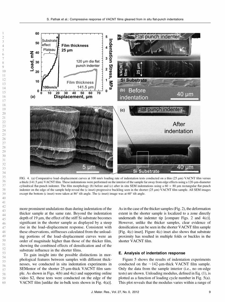
more prominent undulations than during indentation of thethicker sample at the same rate. Beyond the indentationdepth of 19 lm, the effect of the stiff Si substrate becomessignificant in the shorter sample as displayed by a steeprise in the load–displacement response. Consistent withthese observations, stiffnesses calculated from the unload-ing portions of the load–displacement curves were anorder of magnitude higher than those of the thicker film,showing the combined effects of densification and of thesubstrate influence in the shorter films.
To gain insight into the possible distinctions in mor-phological features between samples with different thick-nesses, we conducted in situ indentation experiments inSEMentor of the shorter 25-lm-thick VACNT film sam-ple. As shown in Figs. 4(b) and 4(c) and supporting onlinevideo S2, these tests were conducted on the edge of theVACNT film [unlike the in-bulk tests shown in Fig. 4(a)].
As in the case of the thicker samples (Fig. 2), the deformationextent in the shorter sample is localized to a zone directlyunderneath the indenter tip [compare Figs. 2 and 4(c)].However, unlike the thicker samples, clear evidence ofdensification can be seen in the shorter VACNT film sample[Fig. 4(c) inset]. Figure 4(c) inset also shows that substrateproximity has resulted in multiple folds or buckles in theshorter VACNT film.
E. Analysis of indentation response
Figure 5 shows the results of indentation experimentsconducted on the ;142-lm-thick VACNT film sample.Only the data from the sample interior (i.e., no on-edgetests) are shown. Unloading modulus, defined in Eq. (1), isplotted as a function of loading cycle number in Fig. 5(a).This plot reveals that the modulus varies within a range of
123
456
78910
111213
141516
17181920
212223
242526
272829
30313233
343536
373839
40414243
444546
474849
505152
53545556
575859
60
FIG. 4. (a) Comparative load–displacement curves at 100 nm/s loading rate of indentation tests conducted on a thin (25 lm) VACNT film versusa thick (141.5 lm) VACNT film. These indentations were performed on the interior of the sample far away from edge effects using a 120-lm-diametercylindrical flat-punch indenter. The film morphology (b) before and (c) after in situ SEM indentations using a 60 � 80 lm rectangular flat-punchindenter on the edge of the sample help reveal the (c inset) progressive buckling seen in the shorter (25 lm) VACNT film sample. All SEM imagesexcept the bottom (c inset) were taken at 86° tilt angle. The (c inset) image was at 60° tilt angle.
S. Pathak et al.: Compressive response of VACNT films gleaned from in situ flat-punch indentations
J. Mater. Res., Vol. 27, No. 0, 2012 9

120–175MPa as a function of displacement rate and load–unload cycle number. These moduli further demonstratea strong rate effect, with the fastest rate of 1000 nm/sconsistently resulting in the highest moduli for all load–unload cycles. Such a rate dependence of the materialstiffness is a known characteristic of viscoelastic solids.43
In contrast, repeated cycling appears to have only a mar-ginal effect on the sample modulus, although there is asmall increase from first to second cycle, remaining nearlyconstant during subsequent cycles for each displacementrate. We note that the above method of calculation ofunloading moduli inherently assumes indentation of anelastic half-space, usually representedwell by amonolithicmaterial.30,44 Therefore, they may not be suitable forVACNT indentation—particularly for the first load–unload cycle where a block of material separates fromthe outer matrix. In spite of these aspects, Fig. 5(a) helps tounderscore the higher degree densification of the VACNTfilm at faster rates. We also find that the higher modulusat faster rates leads to greater instability stress (Fig. 3),which increases from 1.49 6 0.2 MPa at 10 nm/s to1.546 0.2MPa at 100 nm/s to 1.756 0.3MPa at 1000 nm/s
(average 6 standard deviation over 10 or more measure-ments). Importantly, the indentation moduli shown inFig. 5(a) match well with those measured during com-pression of APCVD VACNT micropillar samples (160–180 MPa,9 see Table I AU9).
Figure 5(b) shows the trend in the % recovery asa function of maximum displacement before final unloadacross the three loading rates. Two distinct regions can beidentified in this figure: (i) a segment of higher recoverybetween 50–80% when the indentation tests are stoppedbefore the large initial displacement burst [open symbolsin Fig. 5(b)], while (ii) loading beyond the burst (filledsymbols) results in a very low (,10%) recovery. Thisindicates that the shear event, manifested by the largedisplacement burst in the indentation curve, results inpermanent damage of the VACNT structure and signifi-cantly compromises its recoverability. We note that thevirtually nonexistent material recovery from postdisplace-ment burst during indentation is in stark opposition to thealmost full (;100%) recovery seen in these materialsunder compression experiments9 (see Table I). We did notobserve any significant deformation rate effects on the %recovery.
The loss coefficient g (see Sec. II) is shown in Fig. 5(c)as a function of load–unload cycle number. The datacontain only those results for the tests loaded beyond thedisplacement burst. As a consequence of the marginalrecovery [Fig. 5(b)], the loss coefficient associated withnanoindentation into this material is also very low, on theorder of 0.003–0.006, a value nearly an order of magnitudelower than those for compression of the same material9
(Table I).The viscoelastic indentation response of the VACNT
film, in terms of the measured values of their storagemodulus (E9), loss modulus (E0), and tand values, isshown in Fig. 6. Similar to the % recovery results, twodistinct responses are seen in this figure depending onwhether the indenter is oscillated before the large initialdisplacement burst (open symbols in Fig. 6) or after (filledsymbols). Both E9 and E0 increase by a factor of ;3–4once the displacement burst has occurred [Figs. 6(a)and 6(b)], while tand decreases by 20–30% after the burst[Fig. 6(c)]. Before the burst, these parameters dependmorestrongly on the applied load during oscillations, asevidenced by the larger spread in the data.
We find the storage modulus to be frequency in-dependent over the range of frequencies probed. On theother hand, the loss modulus (and the tand) stronglyincreases with increasing frequency, although two localminimas exist at 30 and 50 Hz [Figs. 6(b) and 6(c)].Unfortunately, the cutoff frequency (50 Hz) of our in-strument prevents further study of this behavior at higherfrequencies.
As shown earlier (Figs. 2 and 3), the large displacementburst occurring in the initial loading stages results in
123
456
78910
111213
141516
17181920
212223
242526
272829
30313233
343536
373839
40414243
444546
474849
505152
53545556
575859
60
FIG. 5. (a) The unloading modulus (average 6 standard deviation) atthree different loading rates as a function of the load–unload cyclenumber. The lighter shade of the modulus values calculated from thefirst unload cycle reflects the uncertainty in their accuracy due to theapproximations inherent in their calculations. (b) % recovery as afunction of maximum displacement before unload. Unloading theindenter before the displacement burst (open symbols) shows signifi-cantly higher values of % recovery than after the burst (filled symbols).(c) The loss coefficient values as a function of load–unload cyclesshowing very poor energy dissipation under indentation. (color online)
S. Pathak et al.: Compressive response of VACNT films gleaned from in situ flat-punch indentations
J. Mater. Res., Vol. 27, No. 0, 201210

significant buckling. Thus, the higher E9 characteristic ofthe postburst structure indicates that the material is capableof storing a higher amount of energy in this state, with theexcess energy presumably being stored in the buckledregions. The corresponding increase in E0—related to thedissipated energy—is at a lower proportion, thus leadingto a less pronounced viscous response (lower values oftand) after the burst. The postburst decrease in tand islikely caused by the increased adhesion between theindividual nanotubes in the buckled regions when theyare brought into proximity of one another after buckling.A similar response has been observed in polymericmaterials like rubber,45 where an increase in cross-linkingleads to a decrease of the viscoelastic response. We notethat the trends reported in Fig. 6 are similar to thosereported previously for other VACNT microstructuresunder indentation.8 The storage modulus E9 shown inFig. 6(a) matches well with the unloading modulus shownin Fig. 5(a).
F. Comparing indentation and compression
Figure 7(a) displays a comparative analysis betweenindentations into the ;142-lm-thick APCVD VACNTfilms in this study and the compressions on 30 � 30 lm(diameter � height) APCVD VACNT micropillars fromour previous work.9 All tests were conducted at theloading rate of 1000 nm/s. The indentation stress (rind)and strain (eind) values were calculated using Eq. (3). Thefollowing observations can be made from this comparison:(i) instability stress in compression is ;1.5 times higherthan that in indentation, (ii) indentation is characterized bya significantly larger strain burst of (De 5 0.3) after theinstability as compared to compression (De 5 0.05). Thiscan be explained by the different deformation mechanismsassociated with the bursts. During indentation, a singleglobal shear event is responsible for such a burst, whileunder compression, a relatively small burst is sometimesobserved just after yielding, which has been attributedto a temporary loss in the pillar–indenter contact.9,11
(iii) After yield, the slope of the plateau region in com-pression is significantly higher (by a factor of almost 6)than during indentation. Thus, while the compressivestresses rise from ;2.8 MPa at yield to 4.8 MPa at thestrain of 0.6 (i.e., before the onset of densification), thestresses at equivalent strains in indentation are relativelyconstant, in the 2.0–2.1 MPa range. Finally, (iv) afterunloading (to 10% of maximum load), the material under
123
456
78910
111213
141516
17181920
212223
242526
272829
30313233
343536
373839
40414243
444546
474849
505152
53545556
575859
60
FIG. 6. The viscoelastic indentation response of the VACNT film ata loading rate of 100 nm/s, in terms of the measured values (average 6standard deviation) of their (a) storage modulus, (b) loss modulus, and(c) tand values, as a function of frequency. (color online)
FIG. 7. (a) Comparative stress–strain curves of VACNT in indentationand compression. (b) Table comparing the measured values fromindentation (this study) versus compression (Ref. 9).
S. Pathak et al.: Compressive response of VACNT films gleaned from in situ flat-punch indentations
J. Mater. Res., Vol. 27, No. 0, 2012 11

indentation shows negligible (,5%) recovery, while com-pression leads to an almost complete (.95%) recovery.
While determining the underlying physics of thedescribed observations requires rigorous multiscale mod-eling, some of these phenomena can be understood interms of the differences in boundary conditions betweenthe two loading configurations (indentation versus com-pression), in combination with the overall similarity ofthe VACNT deformation to that of open-cell foammaterials.46 The characteristics of flat-punch indentationsinto VACNT films closely resemble those reported formetallic40,47 and polymeric foams.41,46 In the spirit offoam-like deformation, the indentation zone for VACNTsis confined to the region directly beneath the indenter,while the surrounding regions are unaffected (see Fig. 2).The lack of lateral spread in the deformed region is typi-cal for foams, whereby it can be attributed to the non-existent Poisson’s ratio.2,40,46 This is diametricallyopposite to monolithic materials, where the plastic zoneunderneath the indenter tip is typically represented bya continuous hemispherical plastic zone.39 Another com-mon characteristic between indentation into conventionalfoams and VACNTs is the appearance of a so-called “tearline”40,41 along the corner of the flat-punch indenter wherethe shear force is largest. The depth of this shear line in afoam generally depends on its strength.40,41 Unlike foams,however, the constituents of the VACNT system—theindividual CNTs themselves—are nominally verticallyaligned with respect to the indenter tip [Fig. 1(b)], andthus, the vertical plane is expected to be the plane of lowestshear strength in the VACNT matrix. Once the criticalshear stress is attained during loading, the shear offproceeds catastrophically along this vertical plane throughthe thickness of the VACNT film down to the underlyingsubstrate. This results in highly localized deformationalong the shear plane, with no notable perturbation in otherregions. Subsequent loading initiates folding or bucklingof the material close to the substrate but not in the sheared-off block. In the extreme case of indenting a short VACNTfilm (Fig. 4), subsequent densification of the alreadyfolded/buckled CNTs commences.
On the contrary, under uniaxial compression, the shearstresses acting on the VACNT matrix are negligible.Instead, the applied compressive strain is accommodatedentirely via the formation of lateral folds or buckles alongthe length of the bundle, while the remaining portionremains virtually unscathed.9,11 Thus, the first instabilityshown in the compression stress–strain response in Fig. 7(a)is related to the onset of the first buckle formation in theVACNT matrix. Further loading beyond yield results inthe compression of the collapsed buckles. The resultingdensification of the matrix, in combination with a possibleproperty gradient in the VACNT structure,9,11 results inthe strong positive slope of the compression stress–straincurve in the plateau region.
A comparison of the instability stresses betweencompression (buckling, 2.69 6 0.1 MPa) and indentation(shear, 1.756 0.3 MPa) on the APCVD VACNT samplesindicates that the instability stress in indentation is 40%lower than that of compression [Fig. 7(b)]. Interestingly,this observation is opposite to that of traditional indenta-tion tests into monolithic materials, where yield in in-dentation typically requires 1–3 times higher stresses thanfor the uniaxial case for most solid29 and porous39 as wellas foam40,46,48 materials. The two distinct modes of de-formation in VACNTs—shear under indentation and buck-ling in compression—are likely responsible for this apparentreversal in their instability stress values, i.e., during in-dentation, the APCVD VACNT film reaches its criticalshear stress before it can buckle.
While our findings may be representative of the overallCNT film deformation, it is important to recognize thatboth the shear strength and the deformation behavior ofthe VACNT matrix are strongly affected by its micro-structural details such as tube and node density andtortuosity. These parameters govern the entanglement ofthe individual CNTs within the matrix, and hence, ourobservations are valid only for the particular APCVDVACNT film studied in this work. Further, even thestandard APCVD growth techniques for VACNTs arenotoriously difficult to control. For example, despite thegrowth recipe to create the 30-lm-tall VACNT pillarsstudied in Ref. 9 and the 142-lm-tall VACNT filmsinvestigated in this work being nominally identical (otherthan the growth time), it is reasonable to expect substantialdifferences in the VACNT density, alignment, and tortu-osity, and, especially, their respective variations along thesample heights. Both of these parameters have proved tobe very difficult to quantify experimentally. Similarly, thetwo VACNT film thicknesses shown in Fig. 4 may alsoshow a similar difference since they were grown indifferent batches. Our related work on VACNTs producedusing other CVD methods49 as well as that of others inthe field25 have yielded a wide range in instability stressesunder both indentation and compression, which are thoughtto be a consequence of the particular details (e.g., density,degree of entanglement, etc.) of the CNT structure andarrangement in their matrix.
We attribute the large difference in recoverability ofthe VACNT matrix in indentation (4.3% 6 0.3%) versuscompression (95.7%6 2.8 %) to the different deformationmodes and boundary conditions under these two loadingmodes. The almost complete recovery of the VACNTstructure under compression in Ref. 9 is related to theelastic unfolding of the buckles created during loading.This has been explained by the intertube interactions of theCNTs where the zipping and unzipping of CNTs in contacthave been proposed as the primary criteria for the superiorviscoelasticity and creep recovery of VACNTs.19,20,25,50
On the contrary, recovery in indentation is inhibited by the
123
456
78910
111213
141516
17181920
212223
242526
272829
30313233
343536
373839
40414243
444546
474849
505152
53545556
575859
60
S. Pathak et al.: Compressive response of VACNT films gleaned from in situ flat-punch indentations
J. Mater. Res., Vol. 27, No. 0, 201212

additional constraints of the surrounding VACNT material.Thus, even at lower strains (before the large shear burst),the recovery under indentation is still lower [50–80%,Fig. 5(b)] than that in compression. After the displace-ment burst, recovery of the VACNTs in indentation isfurther compromised by the permanent nature of thedamage caused by the shearing of a large block of thematerial from the matrix.
Similarly, the viscoelastic properties of the VACNTmatrix are also different in indentation (Fig. 6) versuscompression (Ref. 9). While the frequency dependenceof tand is similar in both cases, the values of tand inindentation (as measured after burst) were 20–30% lowerthan those in compression, suggesting a lower viscousresponse.
IV. CONCLUSIONS
In summary, we demonstrate that under large displace-ment indentations, APCVD-grown VACNT films deformby a single vertical catastrophic shear-off event alongthe rim of the indenter tip, manifested by an exten-sive ;20–40-lm-long displacement burst in the load–displacement curve. Similarly, to foam materials withnegligible Poisson’s ratios, the indentation in VACNTs isalso exclusively confined to regions directly beneath theindenter. Through in situ nanomechanical indentationexperiments, we show that the axial strain during thecatastrophic shearing event is accommodated by rolling ofseveral coiled-up CNT sections, or “microrollers.” Wehypothesize that such coiling provides a low-friction pathfor deformation, which may explain the lower stressesassociated with indentation. Loading beyond the initialshear event causes a 20–30% decrease in the material’sviscous response. We also find progressive buckling in theVACNT structure, with the buckles forming primarilynear the stiff underlying substrate. Comparison of in-dentation versus compression experiments indicates thatAPCVD-grown VACNT films reach their critical shearstress before buckling in indentation, which results in thecatastrophic shear formation in their microstructure. Asa result, these materials demonstrate negligible recoveryin indentation, as compared to their almost perfect re-coverability under compression.
ACKNOWLEDGMENTS
The authors acknowledge S. Hutchens and A. Needlemanfor helpful insights and guidance, E. Lim for data analysis,financial support from the Georgia Institute of TechnologyFoundation through the Joseph Anderer Faculty Fellow-ship, and the Institute for Collaborative Biotechnologies(ICB) for financial support through Grant No. W911NF-09-0001 from the U.S. Army Research Office. The contentof the information does not necessarily reflect the position
or the policy of the Government, and no official endorse-ment should be inferred. S.P. gratefully acknowledgessupport from the W.M. Keck Institute for Space StudiesPostdoctoral Fellowship program for this work. Wegratefully acknowledge critical support and infrastructureprovided for this work by the Kavli Nanoscience Instituteat Caltech.
REFERENCES
1. C.M. McCarter, R.F. Richards, S.D. Mesarovic, C.D. Richards,D.F. Bahr, D. McClain, and J. Jiao: Mechanical compliance ofphotolithographically defined vertically aligned carbon nanotubeturf. J. Mater. Sci. 41, 7872 (2006).
2. A.A. Zbib, S.D. Mesarovic, E.T. Lilleodden, D. McClain, J. Jiao,and D.F. Bahr: The coordinated buckling of carbon nanotube turfsunder uniform compression. Nanotechnology 19, 175704 (2008).
3. B.A. Cola, J. Xu, and T.S. Fisher: Contact mechanics and thermalconductance of carbon nanotube array interfaces. Int. J. Heat MassTransfer 52, 3490 (2009).
4. A. Misra, J.R. Greer, and C. Daraio: Strain rate effects in themechanical response of polymer-anchored carbon nanotube foams.Adv. Mater. 20, 1 (2008).
5. A.Y. Cao, P.L. Dickrell, W.G. Sawyer, M.N. Ghasemi-Nejhad, andP.M. Ajayan: Super-compressible foamlike carbon nanotube films.Science 310, 1307 (2005).
6. J. Cho, C. Richards, D. Bahr, J. Jiao, and R. Richards: Evaluation ofcontacts for a MEMS thermal switch. J. Micromech. Microeng. 18,(2008). AU10
7. J.F. Waters, P.R. Guduru, M. Jouzi, J.M. Xu, T. Hanlon, andS. Suresh: Shell buckling of individual multiwalled carbon nano-tubes using nanoindentation. Appl. Phys. Lett. 87, 103109 (2005).
8. S. Pathak, Z.G. Cambaz, S.R. Kalidindi, J.G. Swadener, andY. Gogotsi: Viscoelasticity and high buckling stress of densecarbon nanotube brushes. Carbon 47, 1969 (2009).
9. S. Pathak, E.J. Lim, P. Pour Shahid Saeed Abadi, S. Graham,B.A. Cola, and J.R. Greer: Higher recovery and better energydissipation at faster strain rates in carbon nanotube bundles: An insitu study. ACS Nano (2012) doi: 10.1021/nn300376j. AU11
10. M. Kumar and Y. Ando: Chemical vapor deposition of carbonnanotubes: A review on growth mechanism and mass production.J. Nanosci. Nanotechnol. 10, 3739 (2010).
11. S.B. Hutchens, L.J. Hall, and J.R. Greer: In situ mechanical testingreveals periodic buckle nucleation and propagation in carbonnanotube bundles. Adv. Funct. Mater. 20, 2338 (2010).
12. S.B. Hutchens, A. Needleman, and J.R. Greer: Analysis of uniaxialcompression of vertically aligned carbon nanotubes. J. Mech. Phys.Solids 59, 2227 (2011).
13. J. Suhr, P. Victor, L.C.S. Sreekala, X. Zhang, O. Nalamasu, andP.M. Ajayan: Fatigue resistance of aligned carbon nanotube arraysunder cyclic compression. Nat. Nanotechnol. 2, 417 (2007).
14. T. Tong, Y. Zhao, L. Delzeit, A. Kashani, M. Meyyappan, andA. Majumdar: Height independent compressive modulus of verti-cally aligned carbon nanotube arrays. Nano Lett. 8, 511 (2008).
15. S.D. Mesarovic, C.M. McCarter, D.F. Bahr, H. Radhakrishnan,R.F. Richards, C.D. Richards, D. McClain, and J. Jiao: Mechanicalbehavior of a carbon nanotube turf. Scr. Mater. 56, 157 (2007).
16. A. Qiu, D.F. Bahr, A.A. Zbib, A. Bellou, S.D. Mesarovic,D. McClain, W. Hudson, J. Jiao, D. Kiener, and M.J. Cordill:Local and non-local behavior and coordinated buckling of CNTturfs. Carbon 49, 1430 (2011).
17. Q. Zhang, Y.C. Lu, F. Du, L. Dai, J. Baur, and D.C. Foster:Viscoelastic creep of vertically aligned carbon nanotubes. J. Phys.D: Appl. Phys. 43, 315401 (2010).
123
456
78910
111213
141516
17181920
212223
242526
272829
30313233
343536
373839
40414243
444546
474849
505152
53545556
575859
60
S. Pathak et al.: Compressive response of VACNT films gleaned from in situ flat-punch indentations
J. Mater. Res., Vol. 27, No. 0, 2012 13

18. C.P. Deck, J. Flowers, G.S.B. McKee, and K. Vecchio: Mechanicalbehavior of ultralong multiwalled carbon nanotube mats. J. Appl.Phys. 101, 23512 (2007).
19. M. Xu, D.N. Futaba, T. Yamada, M. Yumura, and K. Hata: Carbonnanotubes with temperature-invariant viscoelasticity from-196degrees to 1000 degrees C. Science 330, 1364 (2010).
20. M. Xu, D.N. Futaba, M. Yumura, and K. Hata: Carbon nanotubeswith temperature-invariant creep and creep-recovery from �190 to970 °C. Adv. Mater. 23, 3686 (2011).
21. C. Cao, A. Reiner, C. Chung, S-H. Chang, I. Kao, R.V. Kukta, andC.S. Korach: Buckling initiation and displacement dependence incompression of vertically aligned carbon nanotube arrays. Carbon49, 3190 (2011).
22. M.R. Maschmann, Z. Qiuhong, D. Feng, D. Liming, and J. Baur:Length dependent foam-like mechanical response of axiallyindented vertically oriented carbon nanotube arrays. Carbon 49,386 (2011).
23. P. Pour Shahid Saeed Abadi, S. Hutchens, J.H. Taphouse,J.R. Greer, B.A. Cola, and S. Graham: The effect of morphologyon the micro-compression response of carbon nanotube forests.Nanoscale (2012).AU12
24. M.R. Maschmann, Q. Zhang, R. Wheeler, F. Du, L. Dai, andJ. Baur: In situ SEM observation of column-like and foam-like CNTarray nanoindentation. ACS Appl. Mater. Interfaces 3, 648 (2011).
25. P.D. Bradford, X. Wang, H. Zhao, and Y.T. Zhu: Tuning thecompressive mechanical properties of carbon nanotube foam.Carbon 49, 2834 (2011).
26. J-Y. Kim and J.R. Greer: Tensile and compressive behavior ofgold and molybdenum single crystals at the nano-scale. Acta Mater.57, 5245 (2009).
27. J.P. Tu, C.X. Jiang, S.Y. Guo, and M.F. Fu: Micro-frictioncharacteristics of aligned carbon nanotube film on an anodicaluminum oxide template. Mater. Lett. 58, 1646 (2004).
28. J.P. Tu, L.P. Zhu, K. Hou, and S.Y. Guo: Synthesis and frictionalproperties of array film of amorphous carbon nanofibers on anodicaluminum oxide. Carbon 41, 1257 (2003).
29. K.L. Johnson: Contact Mechanics (Cambridge University Press,Cambridge, 1987).
30. W.C. Oliver and G.M. Pharr: Improved technique for determininghardness and elastic modulus using load and displacement sensingindentation experiments. J. Mater. Res. 7, 1564 (1992).
31. V.S. Deshpande and N.A. Fleck: Isotropic constitutive models formetallic foams. J. Mech. Phys. Solids 48, 1253 (2000).
32. M.F. Ashby: Materials Selection in Mechanical Design, 3rd ed.(Butterworth-Heinemann, Oxford, 2005).
33. R. Hill: The Mathematical Theory of Plasticity (Oxford UniversityPress, Oxford, 1950).
34. E.G. Herbert, W.C. Oliver, and G.M. Pharr: Nanoindentation andthe dynamic characterization of viscoelastic solids. J. Phys.D: Appl. Phys. 41, 074021 (2008).
35. E.G. Herbert, W.C. Oliver, A. Lumsdaine, and G.M. Pharr:Measuring the constitutive behavior of viscoelastic solids in thetime and frequency domain using flat punch nanoindentation.J. Mater. Res. 24, 626 (2009).
36. W.J. Wright, A.R. Maloney, and W.D. Nix: An improved analysisfor viscoelastic damping in dynamic nanoindentation. Int. J. Surf.Sci. Eng. 1, 274 (2007).
37. W.J. Wright and W.D. Nix: Storage and loss stiffnesses and modulias determined by dynamic nanoindentation. J. Mater. Res. 24(3),863 (2009).
38. S. Pathak, J. Gregory Swadener, S.R. Kalidindi, H-W. Courtland,K.J. Jepsen, and H.M. Goldman: Measuring the dynamic mechan-ical response of hydrated mouse bone by nanoindentation. J. Mech.Behav. Biomed. Mater. 4, 34 (2011).
39. N.A. Fleck, H. Otoyo, and A. Needleman: Indentation of poroussolids. Int. J. Solids Struct. 29, 1613 (1992).
40. P. Sudheer Kumar, S. Ramchandra, and U. Ramamurty: Effect ofdisplacement-rate on the indentation behavior of an aluminumfoam. Mater. Sci. Eng., A 347, 330 (2003).
41. E.A. Flores-Johnson and Q.M. Li: Indentation into polymericfoams. Int. J. Solids Struct. 47, 1987 (2010).
42. A. Pantano, D.M. Parks, andM.C. Boyce:Mechanics of deformationof single- andmulti-wall carbon nanotubes. J. Mech. Phys. Solids 52,789 (2004).
43. R.S. Lakes: Viscoelastic Solids (CRC Press, Boca Raton, FL, 1998).44. M.F. Doerner andW.D. Nix: A method for interpreting the data from
depth-sensing indentation instruments. J. Mater. Res. 1, 601 (1986).45. I.M. Ward and J. Sweeney: An Introduction to the Mechanical
Properties of Solid Polymers, 2nd ed. (Wiley, West Sussex, UK,2004).
46. L.J. Gibson and M.F. Ashby: Cellular Solids: Structure andProperties (Cambridge, UK, 1999). AU13
47. E.W. Andrews, L.J. Gibson, and M.F. Ashby: The creep of cellularsolids. Acta Mater. 47, 2853 (1999).
48. E.W. Andrews, G. Gioux, P. Onck, and L.J. Gibson: Size effects inductile cellular solids. Part II: Experimental results. Int. J. Mech.Sci. 43, 701 (2001).
49. S. Pathak and J.R. Greer.50. Y. Gogotsi: High-temperature rubber made from carbon nanotubes.
Science 330, 1332 (2010).
123
456
78910
111213
141516
17181920
212223
242526
272829
30313233
343536
373839
40414243
444546
474849
505152
53545556
575859
60
Supplementary Material
Supplementary material can be viewed in this issue of the Journal of Materials Research by visitinghttp://journals.cambridge.org/jmr.
S. Pathak et al.: Compressive response of VACNT films gleaned from in situ flat-punch indentations
J. Mater. Res., Vol. 27, No. 0, 201214

Carbon
Effect of morphology on the strain recovery of vertically aligned carbon nanotube arrays: an in situ study. Siddhartha Pathak , Jordan R. Raney, Chiara Daraio
Division of Engineering and Applied Science, California Institute of Technology (Caltech), Pasadena, CA, USA
Abstract We report on the distinctly different mechanical responses of two vertically
aligned carbon nanotube (VACNT) films, subjected to large displacement (up to 70 µm) flat punch indentations. The VACNT films were synthesized using the same chemical vapor deposition (CVD) technique but for varying reaction times, which resulted in their different thicknesses (480 and 160 μm, respectively) and morphologies. In situ tests reveal that the shorter, more aligned VACNT film deforms via an instantaneous vertical shearing of the material directly underneath the indenter tip, which is manifested as a rapid displacement burst in the load-displacement response when tested at rates of 100 nm/s and above. The resultant buckles were of a more permanent nature leading to their low recoverability (22-40%). In contrast, we find the thicker, more tortuous VACNT film to show a higher (~80%) recovery and a more compliant response. These differences in the mechanical response of the VACNTs are discussed in the framework of foam-like deformation with a particular emphasis on their different morphological features, namely density and tortuosity.
Keywords Vertically aligned carbon nanotubes, indentation, mechanical properties, energy
storage, recovery
Contact author: - Materials Science, California Institute of Technology (Caltech), 1200 E. California Blvd., MC 309-81, Pasadena, CA 91125-8100, Phone: +1 (626) 395-8165, Fax: +1 (626) 395-8868, E-mail: [email protected], [email protected]
1

Carbon
1. Introduction Among the wide variety of macroscopic carbon nanotube (CNT) architectures,
vertically aligned carbon nanotube (VACNT) arrays have attracted special attention due to their possible applications ranging from micro-electro-mechanical systems (MEMS) to energy dissipative systems, such as viscoelastic rubbers and foams 1-6. VACNT arrays can be readily synthesized by different techniques 7, 8, and the choice of synthesis approach affects the morphology and the properties of the resulting arrays. A popular technique for production of large quantities of VACNTs is chemical vapor deposition (CVD) 7, 9. However, different CVD synthesis methods can lead to different resulting properties of the VACNTs. For example, the use of ‘floating’ 10, 11 vs. ‘fixed’ catalysts 12,
13 can lead to changes in both the structure of the individual CNTs, as well as differences in the complex hierarchical morphology of the VACNT arrays, their collective inter-tube interactions, and inherent property gradients 14. This variability is reflected in the range of mechanical properties reported for VACNTs, such as elastic modulus and buckling strength that range anywhere from sub-MPa 6, 15 to tens of MPa 16-18 to GPa 19, 20 levels.
Another marked difference among different VACNT arrays is the ability (or lack thereof) to recover from large deformations; with some exhibiting superior creep recovery 1, 5, 6, 21, 22, while others deform permanently even at modest strains 12, 18, 23-25. The recoverability of VACNTs is known to depend both on the experimental loading and boundary conditions as well as the VACNT morphology. For example, in recent work, Pathak et al. 22 found that under uniaxial compression the recoverability and energy dissipation of certain VACNTs is strain-rate dependent, with the values increasing at faster strain rates. For other VACNT types, however, the energy dissipation has been found to be rate independent 26. Flat-punch indentation experiments on VACNT films of larger thicknesses (grown by the same technique as in 22) have shown negligible – almost zero – recovery 27, 28. Various authors have suggested that the different boundary conditions present in indentation experiments result in significant shear stresses in the material. This often causes the VACNT films to deform by an instantaneous vertical shearing of the material directly underneath the indenter tip, and the permanent nature of the damage caused by shearing severely compromises the recoverability of the VACNTs 28, 29. The recoverability of VACNTs has also been shown to depend on the VACNT microstructure and morphology. In general, researchers growing CVD-VACNTs made using the ‘floating’ catalyst route have reported substantial (>90%) recovery in their samples 1, 11, 14, 30, while the recoverability of majority of VACNTs made using the ‘fixed’ catalyst technique 18, 23-25 has been poor (note: Ref 22 is a notable exception). In general, VACNTs made using the floating catalyst route have much thicker (>40 nm) diameter tubes, and a correspondingly higher density. This effect was studied systematically by Bradford et al. 31, who showed that VACNTs grown using a fixed catalyst technique and exhibiting low resilience changed to an almost complete recovery after a post growth CVD treatment. This was attributed to an increase in the individual CNT wall thickness, which also caused increased surface roughness of the CNTs, resulting in a decrease of the van der Waals interactions.
Other aspects of the VACNT microstructure are also known to influence their mechanical properties, such as their tortuosity (or waviness) and the number of inter-tube junctions in the matrix. A few studies have attempted to explore these effects
2
Carbon
experimentally 32-35, but no strong correlations were observed. Some key insights into these parameters can be gained from the theoretical studies involving random network of stiff fibers. For example, Astrom et al. 36 have applied their modified semi-theoretical version of the Cox shear-lag model 37 to CNT mats and fibers, while taking into account the statistical number of bundle–bundle contacts. Their study suggests a linear relationship between the number of contact points and the modulus of the CNT network. A similar result was also obtained by Berhan and coworkers 38, who also found that an increase in the waviness of the nanotube ropes results in a significant decrease in their effective modulus 39.
The lateral interaction of the nominally aligned CNTs is also an important parameter for determining the mechanical behavior of the VACNT array (such as compressive modulus 34), and it has been observed to vary with total array height, with taller arrays often showing more lateral entanglement 40. Arrays as short as 50 nm 41 and as long as several mm 19 have previously been examined. The mechanical responses of these extreme cases have been very different, with the short sample being made up of non-interacting parallel CNTs and the long sample consisting of highly entangled CNTs.
Such drastic changes in the VACNT properties make it impractical to compare the performance of VACNTs synthesized by non-identical growth techniques. In this work, we focus on VACNT films of two different heights of 160 and 480 µm respectively, which were grown by the same floating catalyst CVD technique 10, 11 and exhibit a highly entangled morphology. We perform large displacement instrumented indentation experiments to characterize the mechanical behavior of the two VACNT films. We utilize flat punch diamond indenter tip geometries for the indentation tests. Compared to other indenter tip geometries, the contact area for a flat punch indenter does not change with displacement. This is especially advantageous for the unique microstructural hierarchy of VACNT films, where the micrometer-to-millimeter sized film is composed of millions of individual nanotubes with diameters in the nanometer range. Such an arrangement not only renders the mechanical response of VACNTs to be distinct from monolithic materials, but also poses a challenge in the accurate estimation of the contact area between the VACNT film and the commonly used parabolic 20, 42 and pyramidal 42 indenter tip geometries. The constant contact area between the flat punch indenter and the VACNT sample is also of advantage in measuring the viscoelastic response of the VACNT assembly.
We utilize both an in situ nanoindentation methodology to observe the on-edge deformation in real time using a custom-built in situ nano-mechanical deformation instrument, SEMentor 43, as well as more traditional in-bulk ex situ indentation methods in this work. The in situ tests conducted inside the scanning electron microscope (SEM) have the advantage of allowing uninterrupted observation of the real-time evolution of deformation while simultaneously recording load vs. displacement data, thus providing a one-to-one correlation between the morphological changes and the mechanical response 23, 27, 44. However, in order to facilitate an uninhibited view of the material cross-section, in situ indentation experiments need to be conducted on the edge of the sample 27. While such a set-up causes the boundary conditions and constraints to differ from those during in-bulk indentations, they provide important information on morphological evolution during deformation of VACNTs, not easily obtainable by other methods.
3

Carbon
2. Materials and Methods
2.1 CNT Growth Aligned CNTs were synthesized on thermally oxidized Si wafers using vapor
phase (or “floating catalyst”) thermal CVD techniques that have been in wide use for more than a decade 10. Synthesis took place at atmospheric pressure in an inert Ar atmosphere at 827 °C. A precursor solution of ferrocene (which pyrolyzes to release atomic Fe to act as a catalyst for CNT growth) and toluene (which acts as a carbon source) was created at a concentration of 0.02 g ml-1 and injected at approximately 1 ml min-1 into the heating zone of the furnace in a flow of 800 sccm of Ar. The quartz furnace tube had a diameter of approximately 4 cm and the heating zone was about 20 cm long. VACNT samples of different heights were generated by varying the amount of precursor solution used (and hence the total reaction time). Two VACNT samples, of film thicknesses 480 and 160 μm and named samples A and B, respectively, were selected for further study. The longer sample corresponded to 10 ml of precursor solution and the shorter sample to 7 ml of precursor solution (about 10 and 7 minutes total reaction time, respectively). All other synthesis parameters between the samples were unchanged. Large portions of the samples (~ 10 mm2) were removed from the substrate with a razor blade, and their masses were obtained with a microbalance. Sample densities were obtained by dividing these measured values of mass by the respective volumes of the sample portions (with film thickness determined by scanning electron microscope (SEM) and areal dimensions directly obtained with calipers). Table 1 lists the major differences between samples A and B. The samples were studied using both SEM (FEI Nova 200 and 600, FEI Quanta 200) and transmission electron microscopy (TEM, FEI TF30UT) machines as shown in Fig. 1. Note the localized regions of lower density, visible as horizontal bands along the height of the VACNT structure in sample B in this figure.
Although both samples were synthesized under very similar conditions, we noted significant differences in their morphological features, and therefore in their mechanical behavior. These differences arise due to subtle effects related to the injection of our precursor solution. For example, modest increases in carbon concentration in the reactor can lead to increased entanglement of the individual CNTs 45. Similarly, because CNT diameter depends on injection rate of the precursor solution 46, fluctuations in this rate can lead to localized regions of lower density, visible as horizontal bands along the height of the final VACNT structure 47. We have observed in the past that these regions can result in strain localization during compression 47. Fluctuations in both of these quantities are especially likely at the beginning of our growth process due to variability that occurs during the sudden injection of a precursor solution. Because of the bottom-up growth process by which our VACNTs are synthesized 48, 49, these fluctuations at the beginning of the growth process are reflected in morphological differences near the top of the VACNT array (i.e., where the oldest growth is present). Note that under indentation the majority of the indentation stresses are also localized at the top portions of the VACNT array.
In order to test the repeatability of the samples, we synthesized a third set of VACNT samples with the lower reaction time of 7 min. While this sample set was similar in thickness (~170 µm) to sample B, it did not contain any bands of lower VACNT
4

Carbon
density as seen in sample B. The detailed results for this third sample set are not shown in this paper.
2.2 Ex situ indentations We tested the two different VACNT films with thicknesses of 480 and 160 μm
(samples A and B) under large displacement cyclic indentation tests. The indentation experiments were performed using the XP module of Agilent’s nanoindenter G200 with adjustable software control methods, as described in Ref 23. Tests were performed in air using a custom made cylindrical diamond flat punch with ~120 µm diameter and ~80 µm height. Indentations were performed under a constant displacement control varying indentation depths up to a maximum of around 70 µm (restricted by the height limitations of the diamond flat punch). Tests were conducted in the interior of the samples (in-bulk tests, i.e., away from the sample edge) at three different constant displacement rates: 10 nm/s, 100 nm/s and 1000 nm/s. Typically 5 load-unload cycles were performed at each displacement level. No hold time was applied at the maximum loads, and each cycle was unloaded to only 10% of the max load in the previous cycle, in order to maintain the cyclic nature of the tests. A minimum of 10 tests were conducted at each displacement rate. The indents were spaced at least 500 microns apart in order to eliminate any possible proximity effects.
2.3 In situ SEM indentations In situ tests were conducted in a custom-built indentation instrument 43, composed
of a nano-mechanical dynamic contact module (Agilent Corp.) inside a SEM (Quanta 200, FEI). Tests were conducted on the sample edge (‘on-edge’ 28 experiments, to facilitate viewing) with a conductive diamond flat punch with a rectangular flat cross-section of ~60 µm × 80 µm. The loading axis in the instrument is inclined at ~86o with respect to the electron beam, thus allowing continuous observation of the deformation morphology of the VACNT film cross-section during the on-edge in situ experiments. As described earlier, the outer constraints in on-edge indentations are different from those during in-bulk tests, and therefore the measured mechanical behavior is expected to be different. SEM observations were recorded as a video file at 30 frames per second and synchronized with the indentation data to provide a real-time correlation between each video frame and the corresponding position on the load-displacement curve. Three video files are provided as supporting online material – video file S1 shows the on-edge indentation on sample A conducted at a 100 nm/s displacement rate, files S2 (at 100 nm/s displacement rate) and S3 (at a slower 10 nm/s displacement rate) show the same for sample B. These three video files are shown at 30, 25, and 250 times their original speeds, respectively. These tests were conducted to a maximum penetration depth of 30 µm (instrument limit).
While both the ex situ and the in situ experiments are nominally identical, some differences exist. First, the in situ tests are conducted in a vacuum environment vs. the ex situ tests, which are conducted in air. Moreover, in the in situ case the samples are constantly exposed to the electron beam, and they are oriented horizontally such that gravity is acting perpendicular to the compression axis. Although the effect of these differences is expected to be minor, the in situ results are used here for visualization
5

Carbon
purposes only. All data analyses were performed on tests conducted in air in the ex situ nanoindenter.
2.4 Data Analysis The applied load, P , and measured displacement, , were corrected for machine
compliance following the procedure outlined in detail in Ref h
23. The unloading modulus was calculated from the initial unloading segment of the measured load-displacement curve using Hertzian contact mechanics 50, 51 and assuming negligible friction between the indenter sidewalls and the VACNT matrix 52-54 as:
,22 a
S
A
SEeff
i
i
s
s
eff EEE
22 111
(1)
where denotes the effective modulus of the combined indenter-specimen system; effE
)( dhdPS is the stiffness measured from the slope of the initial 30% of the unloading load-displacement curve; and E are the Poisson’s ratio and the Young’s modulus, respectively; and the subscripts s and i refer to the specimen and the indenter, respectively, with = 1041 GPa and iE i = 0.07. A vanishing Poisson’s ratio of 0 was
assumed for the VACNTs 55. Unfortunately, due to misalignment issues between the indenter tip and the sample surface Eq. (1) cannot be applied to the initial loading portion of the test. Eq. (1) is also limited by the inherent assumptions of Hertz’ theory, which assumes an isotropic, elastic, continuum material behavior. VACNTs, on the other hand, demonstrate varying degrees of anisotropy at each level of its hierarchical microstructure (see Fig. 1). Thus, our measurements of VACNT indentation moduli should instead be treated as their equivalent continuum isotropic values. We also point out that this isotropic continuum framework has been previously utilized in developing the constitutive relations in VACNTs 23 and foams 56, and appears to have accurately captured the qualitative features of their outer deformation profiles and the stress-strain responses. The continuum foundation is also motivated by the nearly isotropic network of CNTs as revealed by images at or above magnifications of 30,000X (Fig. 1c and e).
We define the percentage recovery (R) as the displacement recovered at the end of
each cycle with respect to the maximum displacement, i.e. max
max
h
hhR unload (2)
where is the maximum displacement at the end of loading and is the
displacement after unloading to 10% of the max load in each cycle. maxh unloadh
The loss coefficient, η, (a dimensionless quantity) measures the degree to which a material dissipates energy and is calculated as 57
12 U
U i
,
max
0
2max
2
1
s
indind EdU , indind dU (3)
where is the elastic energy stored in the material when it is loaded elastically to a
stress 1U
max in the 1st cycle, is the energy dissipated in the ith load-unload cycle, and
indicates the sample’s strain. iU
6
Carbon
2.5 Viscoelastic Characterization The viscoelastic properties of the VACNT films were measured following the
procedure outlined in Ref 23. In this method, the indenter is loaded into the sample in air at a constant displacement rate of 100 nm/s up to a specified indentation depth, at which point the indenter head is oscillated at ~8 nm amplitude across a range of frequencies from 1 to 50 Hz. The cut-off frequency of 50 Hz is dictated by the instrument limit, as detailed in Refs 23, 58. The procedure was repeated at six different constant indentation depths for sample A: 15, 26, 36, 47, 58 and 68 µm, respectively. In sample B, however, the viscoelastic properties could be measured for only the three deeper indentation depths of 47, 58 and 68 µm. As described in the next sections, there is a large ~30 µm displacement burst in sample B during loading, which masks the viscoelastic measurements at the lesser depths.
Viscoelastic materials are commonly characterized by their storage ( E ) and loss ( E ) moduli, as well as the ratio of the two – tan . E represents the stored energy or the elastic response, and E corresponds to the amount of energy dissipated, or the viscous response. Assuming linear viscoelastic behavior, these terms can be computed following the calculations described in Refs 58-61 as follows:
AkE s
21
2
, air
airu
F
u
Fk coscos
0
0
0
0 ,
AkE s
21
2
, airsin
airu
F
u
Fsin
0
0
0
0 k ,
E
E
tan . (4)
Here and are the storage and loss stiffnesses of the sample, obtained by finding the real and complex parts, respectively, of the stiffness differences between oscillating the indenter head on the sample at a fixed displacement and in air at the same raw displacement,
k k
is a constant (=1 for a flat punch indenter). and are the load and
displacement oscillation amplitudes, respectively, and 0F 0u
is the phase angle between the load and displacement oscillations. We note that the accuracy in the values of E and E in Eq. (4) can be affected by several factors: uncertainties in Poisson’s ratio, since it may be frequency dependent, and ambiguity in contact area, especially at shallower indentation depths, where full contact may not have been established. On the other hand, calculation of tan is independent of the contact area, and thus is ideally suited as a measure of the viscoelasticity of the indented material 20, 62.
3. Results and Discussion
3.1 VACNT morphology Figure 1 shows the SEM and TEM images at different magnifications of the two
VACNT samples A and B grown on Si substrates using the CVD synthesis technique with a floating catalyst (see Materials and Methods). The complex hierarchical nature of the VACNT microstructure, with distinct organizational details across multiple length scales, is shown in Figures 1a-c (sample A) and Figs. 1d-e (sample B). Thus, while
7

Carbon
VACNTs appear as continuous films at lower magnifications, the nominally vertical alignment of CNT bundles growing perpendicularly to the support substrate is apparent at a higher magnification of 500X and above (Figs. 1a and 1d). Still higher magnifications of 30,000X reveal significant intertwining in the long, curved lengths of individual CNTs along the VACNT height, and at this length scale the CNT network appears more isotropic 23, 56, 63 (Figs. 1c and 1e). A representative image, obtained via TEM, of the internal structure of an individual multiwall (typically 20-60 walls) CNT is shown in Fig. 1f. As a result of this complex hierarchical structure, the mechanical behavior of the VACNT matrix depends both on the properties of individual CNTs, as well as their mutual interactions and distribution throughout the array.
Figure 1 and Table 1 also highlight some of the important morphological differences between samples A and B. The cross-sectional view of Sample A in Fig. 1a indicates that the CNTs in the top 290 µm height of this sample are highly tortuous. The expanded views of this region in Figs. 1b and c show that the tortuous CNT bands have a uniform chord length (straight line distance between the ends of two neighboring tortuous regions) of around 7.5-8 µm throughout this height.
The CNTs seen in the shorter (~160 µm tall) sample B have negligible tortuosity and follow relatively straighter paths (Figs. 1d and e). Note that the bottom ~180 µm of sample A also does not show any major tortuosity. As described in the Materials and Methods section, both VACNT samples were synthesized using the same nominal CVD growth conditions, but for different reaction times. The top portions of the samples thus reflect the regions of oldest growth in each case (CVD is essentially a bottom-up growth process). Since tortuosity is present only in the taller sample, it would seem to indicate that the alignment of individual CNTs in VACNT arrays is related to the CVD growth time (and hence the VACNT height) 49. Such tortuous paths along a CNT are capable of storing more elastic energy than straight paths.
Sample B also shows the presence of two dark bands in its cross-section. The first of these bands is seen at a distance of ~32 µm from the top surface, while the second one is at ~50 µm (Fig. 1d). As described earlier, these bands develop due to fluctuations in the input rate of the precursor solution 47. The density of the CNTs in these banded regions is known to be lower than the average 64, and hence these regions are expected to have a softening effect on the overall microstructure 47.
A closer inspection of the top regions of samples A and B also indicate that the CNTs are of much larger diameter in sample A as compared to B (compare Figs. 1c vs. 1e). This effect has been described in detail in Ref 65 where the CNT wall thickness increases as a function of the growth time. The average and standard deviation values of the CNT diameters provided in Table 1 indicate that the tubes in the upper region of sample A (CNT diameter 68.1±10.6 nm) are twice as thick as that of sample B (diameter 31.1±7.5 nm). Also note that as an obvious consequence of the difference in their tube diameters, sample A has larger density than sample B (Table 1).
3.2 In situ on-edge flat punch indentations The different microstructures of the two VACNT samples A and B also result in
distinct mechanical responses under indentation. This can be seen in the in situ SEM indentations described in Fig. 2. Figure 2c compares the load-displacement responses of the two on-edge tests between samples A and B. The following points are immediately
8

Carbon
evident from this figure: (i) The slope of the initial loading segment of the load-displacement curve is significantly larger for sample B, indicating a much stiffer response for sample B than for sample A. (ii) In sample B the initial loading is followed by a sudden instability at a load level of 6.2 mN, manifested by a large displacement burst of length ~22 µm. No such burst is seen in sample A. (iii) Upon unloading, sample A shows almost full recovery, while sample B shows a much lower (~49%) recovery (compare Figs. 2a-b (sample A) vs. Fig 2d (sample B)).
The video files for these two on-edge indentation tests, which correlate the morphological changes happening in the samples under the indenter with their respective load-displacement responses, are provided as supporting online materials (video files S1 and S2), with several representative snapshots shown in Figs. 2a, b and d. For sample A (video file S1), the sequence of events occurring during the in situ indentations show that at the onset of indentation CNTs in the topmost ~14 µm of the VACNT film start to bend. As the indenter tip pushes forward, shear lines appear at the corners of the flat punch indenter. Further penetration of the indenter results in the formation of a buckling zone 60 µm directly below the indenter (see Fig. 2a inset). Note that the deformation of the VACNTs under indentation appears to be highly localized. Similar to foam deformation, the indentation zone for VACNTs is confined to the region directly beneath the indenter, while the surrounding regions are unaffected. This has generally been attributed to the non-existent Poisson’s ratio in structures such as open-cell foams and VACNTs 24, 56, 66, 67, and is very different from the hemispherical indentation plastic zone reported under monolithic materials 68. Unloading of the indenter tip reveals a remarkable resilience in the VACNTs in sample A, and hardly any after-effects of the indentation pressure can be seen on the surface of the VACNT film after full unload (compare Figs. 2a vs. 2b).
In contrast, the initial loading in sample B (video file S2) is followed by a small drop in indentation load (from 7.1 to 6.2 mN), after which a sudden and extensive displacement burst occurs. SEM images obtained immediately after this burst (SEM scanning rate was not fast enough to catch the details during the instantaneous burst) reveal that the top portion of the VACNT film has sheared off vertically below the edges of the indenter tip (Fig. 2d). The shear appears to be the result of a single buckle formed at a height of ~32 µm from the top of the VACNT film. The shear burst causes the indenter head to momentarily lose contact with the VACNT film, presumably since the VACNT film is collapsing at a faster rate than the prescribed motion of the indenter head (gravity cannot be responsible for the burst since gravity is acting perpendicular to the indentation axis). Interestingly, the 32 µm distance also corresponds to the location of the zone of dark bands seen in the cross-sections of these films (see Fig. 1d). As described earlier, these dark regions are known be zones of lower density in the VACNT matrix, and thus are predicted to be the first regions to buckle.
We find that the occurrence of the displacement burst in sample B depends strongly on the applied displacement rate. Indentation tests at slower displacement rates of 10 nm/s (video file S3) did not show any discrete behavior such as bursts, etc. Instead, we observe a gradual drop in the load from 6.2 to 3.2 mN after the onset of buckling. This would seem to indicate that at the lower displacement rates the individual CNT struts have enough time to realign themselves so as to avoid a catastrophic burst phenomenon 22. As in the case of the faster tests, the buckling zone for the slower tests
9

Carbon
also coincides with the zone of lower density VACNTs at ~32 µm from the top of the VACNT film. Further loading beyond the load drop at the slow displacement rate results in a flat plateau region where the displacement increases at a constant load. The SEM recordings of this stage indicate that the indenter is now pushing down on a rectangular region of width equal to the indenter tip and bounded at the bottom by the buckled zone (of height ~32 µm).
The buckles formed in sample B (for both the slow and fast indentation rates) are of a more permanent nature, and unloading of the indenter tip results in a much lower recovery for sample B than what was seen for sample A (Fig. 2d).
While the general pattern of deformation seen in the in situ videos (Fig. 2) is similar to those of typical open-cell foams, the shear events and the recoverability are unique characteristics seen only in intertwined VACNT systems. In VACNTs the plastic strain under the indenter is accommodated entirely by the formation of the lateral folds or buckles, which are highly localized. This is in contrast to traditional foams, where cell-edge bending and cell collapse are primarily responsible for the elastic-plastic foam response 67, 69. Similarly, a shear event in non-interacting VACNTs 70 would propagate through the entire thickness, thus severely limiting its recoverability. The two examples shown in Fig. 2 demonstrate how the different degrees of alignment and intertwinement between the individual CNTs affect the ability of the VACNT array to recover from large indentation strains.
3.3 Ex situ in-bulk large-displacement indentations In order to analyze the VACNT deformation beyond the displacement limit of the
in situ tests, ex situ indentation tests were conducted in air in the Agilent G200 nanoindenter to larger depths of ~70 µm in the interior of the as-grown VACNT film away from the edges (‘in-bulk’ tests, see Materials and Methods). This maximum indentation depth is limited by the height of the cylindrical indentation punch (~80 µm). Figure 3a shows a comparison of the indentation load (stress)-displacement responses of two representative in-bulk tests between samples A and B, conducted at a displacement rate of 10 nm/s. For both samples, three distinct regions are apparent from Fig. 3a: (i) a short elastic regime, followed by (ii) an instability with an accompanied load drop suggesting the onset of buckling, and (iii) a subsequent plateau region. The plateau region can be further subdivided into two separate sections: an initial relatively flat section (where the load is more-or-less constant with increasing displacement) followed by a positively sloped section, where the load increases more rapidly with displacement and contains several undulations. As expected, the in-bulk tests show significantly higher loads than those of the on-edge tests (compare Figs. 2c and 3a) due to the more restrictive boundary conditions in the in-bulk setup.
Figure 3a also shows the effect of unload-reload cycling and hysteresis 20 in the VANCTs. We show 5 load-unload cycles for each sample. As seen from this figure, the first cycle is distinctly different from all subsequent loading cycles 1, 2, 44. Subsequent cycling also results in a substantially higher relative recovery as compared to the first. In some cases during unloading we also measured the applied loads to be slightly negative, likely due to the adhesive interactions between the VACNTs and the diamond indenter tip 16, 63.
10

Carbon
A comparison of the load-displacement curves in Fig. 3a reveals some important differences between the indentation response of VACNT samples A and B. As in the case of the in situ on-edge tests, the in-bulk tests also show a much stiffer response for the VACNT sample B as compared to sample A. This is reflected in the higher slope of the initial loading segment, and in the higher resistance to buckling for sample B. In general the indentation loads (and stresses) are seen to be significantly higher for sample B than for sample A at equivalent indentation depths. We calculate the indentation stress at the point of instability ( ins ) to be ~0.9 MPa for sample B, which is twice as high as that for
sample A ( ins = 0.44±0.04 MPa). There is a steep drop in indentation load immediately
following the instability. The load drop is larger for sample B (from 10.4 mN to 6.7 mN) than for sample A (from 5.3 mN to 4.9 mN). As seen earlier from the in situ tests (video file S3) the load drop signifies the onset of buckling of the VACNTs under the indenter. Particularly in the case of sample B, the in situ tests revealed the buckling to originate at the zone of lower density (seen as a dark band in Fig. 1d) which is located at ~ 32 µm below the top surface.
Sample B also shows a pronounced flat plateau region of constant stress following the load drop. As in the in situ tests (see video file S3), this flat plateau is a likely result of the continuous buckling of the VACNTs under the indenter within a height of ~ 32 µm (i.e. up to the first VACNT band of low density). As expected, the flat plateau ends after around 30 µm of displacement, and is followed by a steep increase in the indentation load as the indenter experiences the denser VACNTs underneath.
Such sloped plateau regions have been observed previously in VACNTs 1, 11, 22, and an inherent property gradient in the VACNT microstructure along its height has been generally suggested as the cause. The particular constraints and boundary conditions under indentation loading, where the indenter continuously samples an increasing material volume, as well as a progressive densification of the VACNT matrix with increasing indentation depth, could also cause such a sloped region 20, 28. A combination of all of these effects is thought to be responsible for the features seen in Fig 3a, where the indenter encounters a denser, and hence stiffer, material in the deeper regions leading to an increasing global slope in the plateau region.
The later section of the plateau region for sample B also shows a large undulation or kink at around ~50 µm of indentation depth (Fig. 3a). This distance matches well with the location of the second band of lower density in sample B (see Fig. 1d). No such instabilities are observed in sample A.
Unloading from a depth of ~65-70 µm results in a much higher recovery for sample A than for sample B, as shown by the images of the residual imprints (Figs. 3b and 3c respectively). The imprint for the VACNT sample B (Fig. 3c) also shows the remnant of the zone of low VACNT density, which is seen as a shear line at a depth of ~ 32 µm along the walls of the crater. The vertical walls of the indent imprint above this depth indicate a clear shearing of the VACNTs in this height and thus possibly a lower degree of entanglement among the VACNTs for sample B. These images also help to show the highly localized nature of the VACNT deformation, where all of the deformation is limited to the vertical shear region along the rim of contact between the sample and the indenter tip.
We note that at loading rates faster than 10 nm/s the plateau region is obscured by a large displacement burst, particularly for VACNT sample B (a similar effect was noted
11

Carbon
earlier in the in situ tests as well in Fig. 2c). In these cases a rapid, extensive displacement burst of ~30 µm was noticed immediately after attaining ins at the faster
loading rates of 100 and 1000 nm/s. Unlike the gradual drop in load seen in Fig. 3a, such a burst indicates a temporary loss of contact between the sample and the indenter tip. Based on the in situ indentation tests described in Fig. 2, it appears that the burst may be caused by a rapid vertical shearing of the material directly underneath the indenter tip along the indenter edges up to a depth of ~32 µm (i.e. up to the location of the first low density zone). This was verified by stopping the test at the moment of the burst, which resulted in an imprint mirroring the shape of the indenter and of depth ~32 µm.
3.4 Analysis of indentation response Figure 4 shows a summary of the results from the in-bulk tests on VACNT
samples A and B (in situ on-edge tests are not included in this summary). The unloading modulus, defined in Eq. 1, is plotted as a function of the maximum displacement before unload in Fig. 4a. Results are shown for three different loading rates – 10, 100 and 1000 nm/s. For sample B, the results are also segregated by whether they are measured before (open symbols) or after (filled symbols) the first instability.
Figure 4a shows that in sample B, the changes in the unloading moduli clearly reflect the softening effects of the zones of lower density present along the height of the VACNT film. As shown in Fig. 1d, two such zones were visible in the cross-sectional view of VACNT sample B: at ~32 and ~50 µm below the top surface, respectively. The unloading moduli for sample B also show two sharp drops just before these displacement levels, as shown by the trend line for the 1000 nm/s tests. The first stiffness drop (ΔEs ≈ 170 MPa at around 20 µm displacement) is much larger than the second (ΔEs ≈ 35 MPa at around 41 µm displacement), suggesting that the lower density zone closer to the surface has a greater deleterious effect on the mechanical behavior of the sample. After the second drop the moduli are seen to be increasing again (from 129 to 190 MPa) with increasing displacement for sample B.
Sample B also shows an almost three-fold increase in unloading modulus values before the first burst (open symbols, from Es = 92 MPa to 346 MPa). We suspect this large increase to be partly an artifact of the misalignment between the sample surface and the flat punch indenter at the initial stages of loading.
The unloading moduli for sample A show order of magnitude lower values at similar displacement levels. The moduli in this sample range from ~ 7 MPa, at shallow displacement levels (~ 6 µm maximum displacement), to ~ 33 MPa, at the largest indentation depth of 66 µm. This steady increase in the unloading moduli for this sample (as well as the increase seen in sample B after the second instability) is a likely effect of the increase in density due to compaction of the VACNT matrix under the indenter. Both VACNT samples A and B also show slightly higher values of stiffness at the faster rates, consistent with the typical behavior for viscoelastic solids 71.
We note a particular limitation of our method in calculating the unloading moduli from Eq. (1) as reported in Fig. 4a: Eq. (1) inherently assumes indentation of an elastic half-space, as generally found in monolithic materials 51, 72. This may not be suitable for VACNTs, which are inherently hierarchical in their structure. Moreover, as shown in Fig. 2d for sample B, the VACNT foam can also fracture, further altering the boundary
12

Carbon
constraints. In spite of these aspects, Fig. 4a helps to underscore the large difference in stiffnesses between the two VACNT samples.
Such differences in unloading moduli between the two samples can be directly attributed to the differences in tortuosity or waviness in their structures. As shown earlier in Fig. 1, the VACNTs in sample B have a more vertically aligned structure than that of sample A. The longer growth time for sample A results in the distinctive tortuous nature, and the SEM images of this sample show a characteristic waviness with chord lengths of around 7.5-8 µm in their upper cross-section (Fig. 1b). Thus the VACNT network in sample A can be viewed as being already pre-buckled/pre-bent, where the favorable contact energy between the tubes (van der Waals) is balanced by the bending strain energy of their arrangement, resulting in a stable low energy configuration 16. This structure has a lower mechanical stiffness than the more aligned tubes of sample B. This justification is supported by prior theoretical studies on CNT networks, which have also reported the effective moduli of such networks to be strongly affected by the waviness of the CNT members 38, 39. These studies have shown that an increase in the tortuosity of the fibers (i.e., either a decrease in the chord length, or an increase in the amplitude) can cause a significant decrease in the modulus of the CNT network. The effect was also found to be magnified at lower densities 39. Our results from Fig. 4a and Table 1 suggest that both these factors – a stronger waviness in sample A and the lower density of sample B – are responsible for the large differences in the moduli of these two samples.
Figure 4b shows the trends in the % recovery (R, Eq. 2) and Fig. 4c the loss coefficient (η, Eq. 3) as a function of the load-unload cycle number across the three loading rates. The data for both these figures contain results only for the tests loaded beyond the first instability (or burst). The distinctly higher recovery for sample A (R ≈ 80% for the first cycle) as compared to sample B (R ≈ 22-40%) is evident in Fig. 4b. The loss coefficient η, or fractional energy dissipated during the load-unload cycling process (Fig. 4c), also shows a very similar trend, with sample A demonstrating 2-3 times higher values than sample B.
Interestingly, the two samples show opposite trends with respect to the indentation loading rate. Thus, while in sample A the tests conducted at the slowest 10 nm/s rate are the most permanently deformed (i.e. least recovered), the reverse is true for sample B where the fastest 1000 nm/s tests show the lowest values of R and η, especially in the first cycle (Figs. 4b and c). For VACNT networks showing high resilience, such as sample A, the reduced recovery at slower rates is explained by the greater time allowed for the individual CNTs to come in close contact with one another. These inter-tube interactions are inherently adhesive, due to van der Waals attractions 73. At the slower indentation rates these attractive forces supersede the elastic recovery process and thus decrease the reversibility of the VACNT structure under the imposed strain, resulting in lower values of R and η. Repeated cycling further acerbates the process, and the values are seen to drop even more with increasing cycle number. In contrast, at the faster rates there is insufficient interaction time between the CNTs in sample A, and hence much lower adhesion and higher recovery 22.
For sample B, the deformation is dominated by the zone of lower VACNT density present below the surface. Here, the individual CNT struts are also more vertically aligned than in sample A (Fig. 1), making the shear strength in the vertical plane of this sample much lower than that of sample A. Under the high shear forces generated during
13

Carbon
indentation, sample B experiences a catastrophic shearing-off process where the shear proceeds vertically through the VACNT thickness down to the zone of lower VACNT density. This effect is more drastic along the indenter edges where the indentation shear forces are the largest. In contrast, the slower indentation rates allow more time for the CNTs to reconfigure themselves, and thus help prevent the catastrophic nature of the burst. Hence, in sample B the recovery is higher at slower rates due to the lack of the sudden displacement burst during the loading cycle. The same effect is also seen at faster rates during repeated cycling in sample B (Fig. 4b); at 1000 nm/s the large displacement burst in the first cycle results in very low values of recovery (R = 22.6±2 %). The burst is absent in the subsequent cycles and the recovery improves to ~ 30% from the 2nd cycle onwards.
We note that the very high recovery (R ≈ 80%) of sample A is quite unique for VACNTs under large displacement indentation boundary conditions. Most VACNT systems exhibiting high recoverability have been tested under uniaxial compression, where shear stresses are negligible 1, 5, 6, 21, 22. However, when tested under indentation, some of these same systems have shown very poor recovery (R<10%) 27, 28, 74, 75, much lower than that of VACNT sample A in this study.
Some prior indentation studies have also noted the catastrophic shear process in the VACNT network. In these reports, the shear proceeds through the entire VACNT thickness, and leads to their virtually-nonexistent material recovery 27, 28. Instead, while sample B in our study suffers from the same shear phenomenon, the presence of the zone of low density in this sample helps to arrest the shear process to only the top section of the VACNT film. As a result, the recoverability of sample B (R ≈ 22-40%) still compares favorably to others reported in literature under indentation.
The viscoelastic indentation responses of the two VACNT films, in terms of the measured values of their storage modulus ( E ), loss modulus ( E ), and tan , are shown in Fig. 5. In this figure, both the storage and loss moduli for sample A are seen to increase as the indentation depth is increased from 15, 26, 36, 47, 58 to 68 µm. No such increase was noted for sample B. Note that the data for sample B contain values for only the three deeper depths of 47, 58 and 68 µm (see Materials and Methods, Section 2.5).
We find the storage moduli to be frequency independent over the range of frequencies probed for both samples, indicating that the VACNT’s elastic deformation is likely due to the same mechanism (probable tube bending) over the range of timescales tested. On the other hand, the loss moduli (and tan ) values for sample A show an almost step increase at 10 Hz; above 10 Hz a doubling in the values of these parameters can be seen in Figs. 5b and 5c. Unfortunately the cut-off frequency (50 Hz) of our instrument prevents further study of this behavior at higher frequencies. Similar to the trends of R and η, such frequency dependence can also be explained by the lower interaction time available at higher frequencies. The additional time available at the lower frequencies increases the adhesive interactions between the CNTs, causing a decrease in its ability to dissipate energy.
No such frequency dependence was noticed for the three deeper depths of 47, 58 and 68 µm in sample B. For both samples, the storage moduli E shown in Fig. 5 match well with the unloading modulus values described earlier in Fig. 4.
14

Carbon
3.5 Morphology and recoverability of VACNT systems The high recoverability in VACNTs and the lack of morphological damage after
deformation has significant implications for their use as protective materials and in energy dissipation devices. We have observed that an increased density and tortuosity correlates with a significantly higher resilience of the VACNT sample.
In order to understand the factors contributing to the recoverability of VACNTs, we first investigate the density gradient(s) present along the film height. The results from Figs. 1, 2 and 4 appear to indicate that the ability of VACNT sample B to recover under indentation can be strongly affected by the presence of a zone of lower VACNT density ~32 µm below the top surface. While such low density zones have an obvious softening effect on the mechanical properties of this sample, it is still unsure whether this in itself is the sole cause for its lower recoverability. In order to test this effect further, a third VACNT sample was synthesized with a similar reaction time of 7 min resulting in a similar film thickness (~179 µm) as sample B. Care was taken to keep the input rate of the precursor solution constant during synthesis of this third sample, and thus (unlike sample B) no lower density bands were present in this case. The recoverability of this sample (after buckling) was calculated to be R = 54%. Although this value is somewhat higher than that of sample B, it is still significantly lower than the R~80% seen for sample A. Hence, we can conclude that the presence of the low density bands is not the prime cause for the lower recovery of sample B.
We hypothesize that the lower recovery for VACNT sample B is caused by the more vertical alignment of the constituent CNTs in its matrix, as shown in Fig. 1 21, 76. Once such an aligned network is buckled, it results in significant lateral entanglement of the tubes in its matrix. The lateral interconnections between the adjacent CNTs inevitably lead to a strong bundling of the tubes. These interactions are inherently adhesive, due to van der Waals forces, and hence detrimental to the VACNT recovery. In sample A the more tortuous nature of the VACNTs helps to prevent such an increase in the side contacts between the tubes. The tubes in sample A also have twice the thickness of the CNTs in sample B (see Table 1), and hence the resultant increase in the bending stiffness of the tubes would also aid their elastic recovery process. This matches well with a number of observations in the literature, where reversible VACNT deformation was reported to be more common for thicker tubes (of ≥40 nm diameter) 1, 11, 30.
The above hypothesis is also supported by the results of the viscoelastic measurements of the two samples. In sample A (Fig. 5), we find the storage and loss moduli to increase with increasing indentation depth. Both of these increases can be explained by proportional increase in the number of inter-tube contacts happening at these depths. Theoretical studies have shown that the effective elastic modulus (represented by the storage modulus E ) of a stiff fiber network is directly proportional to the number of inter-tube contacts 36, 38, 39. Similarly the viscoelastic behavior of VACNTs is thought to be due to the zipping and unzipping of the CNTs upon contact 5,
20, and hence an increasing number of interconnections between the tubes should result in a greater viscoelastic response (and a resultant increase in the loss modulus E ). However, since these interactions are also inherently adhesive, it stands to reason that the recovery in this sample should follow the reverse trend, i.e., R should decrease with increasing depth. This can be seen in Fig. 5c (inset) where the recovery gradually decreases from a near complete recovery, R~100%, at the indentation depth of ~ 10 maxh
15
Carbon
µm to R~78% at ~ 65 µm, indicating the detrimental effects of increased VACNT
interconnections on their recovery. maxh
The large displacement burst seen in sample B also causes a sudden sharp increase in the CNT lateral connections. We theorize that the catastrophic nature of this shear-off process results in a strong bundling of the contacting CNTs. Thus any further increase in the indentation depth beyond the critical shear-off depth causes very little change in the VACNT viscoelastic properties (see data for sample B in Fig. 5). Beyond this critical indentation depth the bundled VACNTs in sample B also lose any frequency dependence in their behavior.
We note that while these results were found to be repeatable over different sample sets (including the third sample set described above), they are however valid only for the particular growth technique used in this work. The CVD technique for synthesizing VACNTs can be notoriously difficult to control. Changes in the synthesis routines – such as the use of a variable precursor input rate instead of a constant one – can substantially change the resultant VACNT density, alignment, and tortuosity, including their respective variations along the film heights, which affects their recovery 47. This is reflected in the wide range of recoverability values reported for CVD-VACNTs synthesized using the CVD method 1, 5, 6, 12, 18, 21-25. Experimentally quantifying these parameters continues to be a challenging task.
4. Conclusions In summary, we report a correlation between certain morphological features of
VACNT films, such as the tortuosity of the individual CNTs, and the recoverability of the systems after indentation. We find that the taller VACNT films synthesized for a longer growth time show a higher resilience under indentation. We hypothesize that the higher recovery in the taller films is caused by the increased tortuosity of the constituent CNTs in their network, as well as their higher densities. This combination enables the taller VACNT films to avoid a catastrophic shear failure under the indenter, hence enhancing their recoverability.
Supporting Online Material Three video recording of the SEM observations of indentations on the two
VACNT samples A and B, synchronized with their respective indentation load-displacement curves, are provided as supporting online material as described below: Video file S1: Sample A, 100 nm/s displacement rate, shown at 30 times its original speed Video file S2: Sample B, 100 nm/s displacement rate, shown at 25 times its original speed Video file S3: Sample B, at a slower 10 nm/s displacement rate, shown at 250 times its original speed
Acknowledgments We acknowledge Prof. Julia R. Greer for helpful discussions and for providing
access to testing facilities. SP gratefully acknowledges support from the W.M. Keck Institute for Space Studies Postdoctoral Fellowship program for this work. JRR
16

Carbon
acknowledges the Army Research Office and the Department of Defense for funding via a National Defense Science & Engineering Graduate fellowship during the course of this work. CD acknowledges support from the Institute for Collaborative Biotechnologies under contract W911NF-09-D-0001 with the Army Research Office. We acknowledge critical support and infrastructure provided for this work by the Kavli Nanoscience Institute at Caltech.
17

Carbon
[1] A. Y. Cao, P. L. Dickrell, W. G. Sawyer, M. N. Ghasemi-Nejhad, P. M. Ajayan, Science 2005, 310, 1307. [2] A. Misra, J. R. Greer, C. Daraio, Advanced Materials 2008, 20, 1. [3] J. Cho, C. Richards, D. Bahr, J. Jiao, R. Richards, J. Micromech. Microeng. 2008, 18. [4] B. A. Cola, J. Xu, T. S. Fisher, International Journal of Heat and Mass Transfer 2009, 52, 3490. [5] M. Xu, D. N. Futaba, T. Yamada, M. Yumura, K. Hata, Science 2010, 330, 1364. [6] J. Suhr, P. Victor, L. C. S. Sreekala, X. Zhang, O. Nalamasu, P. M. Ajayan, Nature Nanotechnology 2007, 2, 417. [7] M. Kumar, Y. Ando, Journal of Nanoscience and Nanotechnology 2010, 10, 3739. [8] V. Presser, M. Heon, Y. Gogotsi, Advanced Functional Materials 2011, 21, 810. [9] A.-C. Dupuis, Progress in Materials Science 2005, 50, 929. [10] R. Andrews, D. Jacques, A. M. Rao, F. Derbyshire, D. Qian, X. Fan, E. C. Dickey, J. Chen, Chemical Physics Letters 1999, 303, 467. [11] J. R. Raney, A. Misra, C. Daraio, Carbon 2011, 49, 3631. [12] O. Yaglioglu, in Dept. of Mechanical Engineering, Vol. PhD, Massachusetts Institute of Technology, 2007. [13] M. Bedewy, E. R. Meshot, H. Guo, E. A. Verploegen, W. Lu, A. J. Hart, Journal of Physical Chemistry C 2009, 113, 20576. [14] O. Yaglioglu, A. Cao, A. J. Hart, R. Martens, A. H. Slocum, Advanced Functional Materials 2012, DOI: 10.1002/adfm.201200852. [15] T. Tong, Y. Zhao, L. Delzeit, A. Kashani, M. Meyyappan, A. Majumdar, Nano Letters 2008, 8, 511. [16] S. D. Mesarovic, C. M. McCarter, D. F. Bahr, H. Radhakrishnan, R. F. Richards, C. D. Richards, D. McClain, J. Jiao, Scr. Mater. 2007, 56, 157. [17] A. Qiu, D. F. Bahr, A. A. Zbib, A. Bellou, S. D. Mesarovic, D. McClain, W. Hudson, J. Jiao, D. Kiener, M. J. Cordill, Carbon 2011, 49, 1430. [18] Q. Zhang, Y. C. Lu, F. Du, L. Dai, J. Baur, D. C. Foster, Journal of Physics D-Applied Physics 2010, 43, 315401. [19] C. P. Deck, J. Flowers, G. S. B. McKee, K. Vecchio, Journal of Applied Physics 2007, 101, 23512. [20] S. Pathak, Z. G. Cambaz, S. R. Kalidindi, J. G. Swadener, Y. Gogotsi, Carbon 2009, 47, 1969. [21] M. Xu, D. N. Futaba, M. Yumura, K. Hata, Advanced Materials 2011, 23, 3686. [22] S. Pathak, E. J. Lim, P. Pour Shahid Saeed Abadi, S. Graham, B. A. Cola, J. R. Greer, ACS Nano 2012, 6, 2189. [23] S. B. Hutchens, L. J. Hall, J. R. Greer, Advanced Functional Materials 2010, 20, 2338. [24] A. A. Zbib, S. D. Mesarovic, E. T. Lilleodden, D. McClain, J. Jiao, D. F. Bahr, Nanotechnology 2008, 19, 175704. [25] C. Cao, A. Reiner, C. Chung, S.-H. Chang, I. Kao, R. V. Kukta, C. S. Korach, Carbon 2011, 49, 3190. [26] J. R. Raney, F. Fraternali, C. Daraio, In preparation
18

Carbon
[27] P. Pour Shahid Saeed Abadi, S. Hutchens, J. H. Taphouse, J. R. Greer, B. A. Cola, S. Graham, Nanoscale 2012, 4, 3373. [28] S. Pathak, N. Mohan, P. Pour Shahid Saeed Abadi, S. Graham, B. A. Cola, J. R. Greer, Journal of Materials Research 2012 (submitted). [29] Y. C. Lu, J. Joseph, Q. Zhang, M. R. Maschmann, L. Dai, J. Baur, Experimental Mechanics 2012, in press. DOI 10.1007/s11340. [30] J. R. Raney, F. Fraternali, A. Amendola, C. Daraio, Composite Structures 2011, 93, 3013. [31] P. D. Bradford, X. Wang, H. Zhao, Y. T. Zhu, Carbon 2011, 49, 2834. [32] M. A. Al-Khedher, C. Pezeshki, J. L. McHale, F. J. Knorr, Nanotechnology 2007, 18. [33] H. Malik, K. J. Stephenson, D. F. Bahr, D. P. Field, Journal of Materials Science 2011, 46, 3119. [34] C. M. McCarter, R. F. Richards, S. D. Mesarovic, C. D. Richards, D. F. Bahr, D. McClain, J. Jiao, Journal of Materials Science 2006, 41, 7872. [35] Y. Gao, T. Kodama, Y. Won, S. Dogbe, L. Pan, K. E. Goodson, Carbon 2012, 50, 3789. [36] J. A. Astrom, A. V. Krasheninnikov, K. Nordlund, Phys. Rev. Lett. 2004, 93, 215503. [37] H. L. Cox, British Journal of Applied Physics 1952, 3, 72. [38] L. Berhan, Y. B. Yi, A. M. Sastry, E. Munoz, M. Selvidge, R. Baughman, Journal of Applied Physics 2004, 95, 4335. [39] L. Berhan, Y. B. Yi, A. M. Sastry, Journal of Applied Physics 2004, 95, 5027. [40] M. R. Maschmann, Q. Zhang, R. Wheeler, F. Du, L. Dai, J. Baur, ACS Applied Materials & Interfaces 2011, 3, 648. [41] J. F. Waters, L. Riester, M. Jouzi, P. R. Guduru, J. M. Xu, Applied Physics Letters 2004, 85, 1787. [42] J. F. Waters, P. R. Guduru, M. Jouzi, J. M. Xu, T. Hanlon, S. Suresh, Appl. Phys. Lett. 2005, 87, 103109. [43] J.-Y. Kim, J. R. Greer, Acta Materialia 2009, 57, 5245. [44] S. Pathak, E. J. Lim, P. Pour Shahid Saeed Abadi, S. Graham, B. A. Cola, J. R. Greer, ACS Nano 2012, DOI: 10.1021/nn300376j. [45] R. M. Malek Abbaslou, J. Soltan, A. K. Dalai, Applied Catalysis A: General 2010, 372, 147. [46] M. Maghrebi, A. A. Khodadadi, Y. Mortazavi, M. Rahimi, A. Sane, Z. Tsakadze, S. Mhaisalkar, Materials Chemistry and Physics 2010, 124, 1139. [47] J. R. Raney, R. Y. Wang, C. Daraio, Carbon 2012 (in review). [48] X. Li, A. Cao, Y. J. Jung, R. Vajtai, P. M. Ajayan, Nano Letters 2005, 5, 1997. [49] M. Pinault, V. Pichot, H. Khodja, P. Launois, C. Reynaud, M. Mayne-L'Hermite, Nano Letters 2005, 5, 2394. [50] K. L. Johnson, Contact Mechanics, Cambridge University Press, Cambridge, 1987. [51] W. C. Oliver, G. M. Pharr, Journal of Materials Research 1992, 7, 1564. [52] J. P. Tu, C. X. Jiang, S. Y. Guo, M. F. Fu, Materials Letters 2004, 58, 1646. [53] J. P. Tu, L. P. Zhu, K. Hou, S. Y. Guo, Carbon 2003, 41, 1257.
19

Carbon
20
[54] B. Bhushan, L. Xing, A. Jungen, C. Hierold, Physical Review B (Condensed Matter and Materials Physics) 2008, 77, 165428. [55] L. Lattanzi, J. R. Raney, L. De Nardo, A. Misra, C. Daraio, Journal of Applied Physics 2012, 111. [56] V. S. Deshpande, N. A. Fleck, Journal of the Mechanics and Physics of Solids 2000, 48, 1253. [57] M. F. Ashby, Materials Selection in Mechanical Design, Butterworth-Heinemann; , 2005 (3 ed.). [58] E. G. Herbert, W. C. Oliver, G. M. Pharr, Journal of Physics D: Applied Physics 2008, 41, 074021. [59] E. G. Herbert, W. C. Oliver, A. Lumsdaine, G. M. Pharr, Journal of Materials Research 2009, 24, 626. [60] W. J. Wright, A. R. Maloney, W. D. Nix, International Journal of Surface Science and Engineering 2007, 1, 274. [61] W. J. Wright, W. D. Nix, "Storage and loss stiffnesses and moduli as determined by dynamic nanoindentation", 506 Keystone Drive, Warrendale, PA 15086, United States, 2009. [62] S. Pathak, J. Gregory Swadener, S. R. Kalidindi, H.-W. Courtland, K. J. Jepsen, H. M. Goldman, Journal of the Mechanical Behavior of Biomedical Materials 2011, 4, 34. [63] S. B. Hutchens, A. Needleman, J. R. Greer, Journal of the Mechanics and Physics of Solids 2011, 59, 2227. [64] J. J. Jackson, A. A. Puretzky, K. L. More, C. M. Rouleau, G. Eres, D. B. Geohegan, ACS Nano 2010, 4, 7573. [65] X. Li, L. Ci, S. Kar, C. Soldano, S. J. Kilpatrick, P. M. Ajayan, Carbon 2007, 45, 847. [66] P. Sudheer Kumar, S. Ramchandra, U. Ramamurty, Materials Science and Engineering A 2003, 347, 330. [67] L. J. Gibson, M. F. Ashby, Cellular Solids: Structure and Properties 1999. [68] N. A. Fleck, H. Otoyo, A. Needleman, International Journal of Solids and Structures 1992, 29, 1613. [69] L. J. Gibson, Annual Review of Materials Science 2000, 30, 191. [70] A. Pantano, D. M. Parks, M. C. Boyce, Journal of the Mechanics and Physics of Solids 2004, 52, 789. [71] R. S. Lakes, Viscoelastic Solids, CRC Press, 1998. [72] M. F. Doerner, W. D. Nix, Journal of Materials Research 1986, 1, 601. [73] R. S. Ruoff, J. Tersoff, D. C. Lorents, S. Subramoney, B. Chan, Nature 1993, 364, 514. [74] M. R. Maschmann, Z. Qiuhong, D. Feng, D. Liming, J. Baur, Carbon 2011, 49, 386. [75] Y. C. Lu, J. Joseph, Q. Zhang, M. R. Maschmann, L. Dai, J. Baur, Experimental Mechanics 2012, in press. DOI 10.1007/s11340. [76] L. Ge, L. Ci, A. Goyal, R. Shi, L. Mahadevan, P. M. Ajayan, A. Dhinojwala, Nano Letters 2010, 10, 4509.

100 µm
480
µm
Si Substrate 25 µm2 µm
(a) (b) (c)
25 µm
160
µm
32 µ
m
2 µm
(d) (e)
5 nm
(f)Figure 1. SEM images reveal the hierarchical morphology of the (a) 480 µm thick VACNT films (Sample A), which consist of (b) horizontal layers of high tortuosity, and (c) a complex intertwined network of nominally vertical CNTs at higher mag. (d) On the other hand, a lower thickness VACNT film (Sample B, only top portion of the 160 µm film is shown) shows (e) a more aligned CNT structure at high mag. Note the dark bands starting at ~32 µm from the top in Sample B suggesting regions of lower density in (d), as well as the lower wall thickness of the CNTs in Sample B (compare (c) and (e)).
SEM pictures (a), (b), (c) and (e) are taken at a 60 deg tilt angle while (d) is at 86 deg tilt. (f) Individual multiwalled CNTs are visible in the TEM image.
Sample A
Sample BSample B
Sample ASample A
50 µ
m

0
1
2
3
4
5
6
7
8
0
0.2
0.4
0.6
0.8
1
1.2
1.4
Sample A at max load
Sample A after unload 25 µm25 µm
25 µm
Load
, mN
Displacement, µm
Indentation Stress, M
Pa
d Sample B after unload
Sample B
Sample A a 32 µ
m
0 10 20 30 40
100 nm/s
Burst
(c)
Figure 2. In-situ SEMentor
observations of on-edge indentations on (a) Sample A at maximum load, (b) Sample A after unload, and (d) Sample B after unload. Their corresponding locations on the load-unload cycles at 100 nm/s loading rate is shown in (c). All SEM images were taken at 86 deg tilt angle. These snapshots were captured from video files S1, S2 and S3.
10 µm
(a)
(d)
(b)
b

-2
0
2
4
6
8
10
12
14
-0.18
0.02
0.22
0.42
0.62
0.82
1.02
1.22
0 10 20 30 40 50 60 70
Lo
ad, m
N
Displacement, µm
Ind
entatio
n S
tress, MP
a
1st
2nd
34
5
50 µm
(c) Sample B(b) Sample A
Sample A
Sample B
10 nm/s
32 µ
m
50 µm
Figure 3. Indentations in the bulk of the sample, away from edge
effects. (a) Comparative indentation load (stress) –
displacement cycles (5 cycles each) for VACNT samples A and B. Loading at 10 nm/s loading rate shows 3 distinct regimes; elastic, a drop in load at a critical instability stress and plateau regime. Successive load-unload cycles to the same maximum displacement reveal a gradual drop in recovery in every cycle, suggesting progressive damage accumulation in the material. The corresponding indentation stress values are shown along the secondary y axis.
Residual imprints of flat punch indentation are shown for (b) Sample A and (c) Sample B.
(a)

Unl
oadi
ng M
odul
us, M
Pa
Displacement before unload, µm
1000 nm/s
100 nm/s
10 nm/s
0 25 50 750
50
100
150
200
250
300
350
400
Sample A
Sample B
After BurstBefore
burst
1 2 3 4 50
20
40
60
80
100
% r
ecov
ery,
(h m
ax-
h i)/
hm
ax
Sample A
Sample B
Cycle number
(a)
(b)
Figure 4. (a) Unloading modulus as a function of max displacement before unload for three different loading rates. For sample B the open symbols represent values before the first instability (burst) during indentation loading of this sample, while the filled symbols are for the values after the instability.
(b) % recovery and (c) loss coefficient –
both calculated at large indentation depths (i.e.
after the first instability) –
as a function of cycle number for samples A and B.
1 2 3 4 5Cycle number
Loss
coe
ffici
ent, η Sample A
Sample B
(c)
0
0.01
0.02
0.03
0.04
0.05
0.06
0.07
0.08

0
0.02
0.04
0.06
0.08
0.1
0.12
0.14
0
0.02
0.04
0.06
0.08
0.1
0.12
0.14
0
5
10
15
20
25
30
35
40
0
0.5
1
1.5
2
2.5
30
50
100
150
200
250
0
5
10
15
20
25
0 10 20 30 40 0 10 20 30 40
Sample A Sample BS
tora
ge M
odul
us,
MP
aLo
ss M
odul
us, M
Pa
Tan
del
ta
Frequency, Hz Frequency, Hz
15 µm26 µm
36 µm
47 µm
58 µm
h ≈
68 µm
Incr
easi
ng d
epth
Incr
easi
ng d
epth
Figure 5. Viscoelastic indentation response of the VACNT films at a loading rate of 100 nm/s, in terms of the measured values (average ±standard deviation) of their (a) storage modulus, (b) loss modulus and (c) tan δ
values, as a function of frequency. Note the difference in the y-axis scales between samples A and B for (a) and (b). (c inset) % recovery as a function of max displacement before unload for sample A at three different rates, 1000 nm/s (squares), 100 nm/s (diamond) and 10 nm/s (circles).
(a)
(b)
(c)
70
80
90
100
0 25 50 75Displacement, µm
% R

Sample A Sample B
Synthesis time 10 min 7 min
Height 480 µm 160 µm
Density 0.13 gm/cm3 0.06 gm/cm3
CNT dia 68.1±10.6 nm 31.1±7.5 nm
Table 1. Comparison between Samples A and B. The uncertainty in the density values is around 10%. The CNT diameters are average ±
standard deviation values from the top portions of the VACNT films.