
Katalog 824
36
· 1 · Topfmotoren 824 Encapsulated motors
-
Upload
khangminh22 -
Category
Documents
-
view
7 -
download
0
Transcript of Katalog 824

· 1 ·
Topfmotoren
824
Encapsulated motors

Katalog 824 / 02 / Ausgabe 2014
LieferbedingungenUnseren Lieferungen und Leistungen liegen unsere Verkaufs- und Lieferbedingungen sowie die allgemeinen Lieferbedingungen für Erzeugnisse und Leistungen der Elektroindustrie zugrunde.Änderungen der in der Liste angegebenen technischen Daten sowie Maße und Gewichte bleiben vorbehalten.Reklamationen können nur innerhalb 8 Tagen nach Empfang der Ware berücksichtigt werden.
PreiseUnsere Preise gelten ab Werk, ausschließlich Verpackung, zuzüglich der gesetzlich vorgeschriebenen Mehrwert-steuer.Verpackung wird nicht zurückgenommen.Preisänderungen bleiben vorbehalten. Der Berechnung werden jeweils die am Tage der Lieferung gültigen Preise zugrunde gelegt.
Kupferzuschläge / Copper surcharge
Kupferpreis lt. DEL-Notiz / Kupferzuschlag /Copper price Price increasee/100 kg %
231,– bis 281,– 1,20 %
282,– bis 332,– 2,50 %
333,– bis 383,– 3,50 %
384,– bis 435,– 4,50 %
436,– bis 486,– 5,50 %
487,– bis 537,– 6,50 %
538,– bis 588,– 7,50 %
589,– bis 639,– 8,50 %
640,– bis 690,– 9,50 %
Catalogue 824 / 02 / Edition 2014
Conditions of sale and deliveryOur supplies and services are subject to our own conditions of sale and delivery and the general conditions of supply and delivery for the products and services of the electrical industry.The technical data, dimensions and weights given in this catalogue are subject to change without notice.Any claims must be made within 8 days of the receipt of goods.
PricesThe prices quoted are ex-works, not including packing, plus value added tax at the current rate.Packing materials are non-returnable.The right is reserved to modify prices at any time. The prices charged are those ruling on the day of despatch.
EMOD MOTOREN GmbHElektromotorenfabrik
Hausanschrift / Address:36364 Bad Salzschlirf · Germany · Zur Kuppe 1 · Fon: + 49 66 48 51-0 · Fax: + 49 66 48 [email protected] · www.emod-motoren.de
Postfachadresse / Postbox:36361 Bad Salzschlirf · Germany · Postfach / Postbox 240

· 3 ·
Inhaltsverzeichnis / Katalog 824 / 02 / Ausgabe 2014Contents / Catalogue 824 / 02 / Edition 2014
Seite Page
Allgemeine technische Erläuterungen 4 –12 General technical information
Bremsmotoren • Allgemeine technische Informationen 13 Brake motors • General technical information
Leistungstabellen 14 – 25 Rated output
Maßtabellen 26 – 31 Dimension sheets
Bremsmotoren • Maßtabellen 32 – 33 Brake motors • Dimension sheets
Lieferbare Flansche 34 Flanges available

· 4 ·
Allgemeine technische ErläuterungenGeneral technical information
Technische Erläuterungen
Bei der TM-Motorenreihe handelt es sich um wasser-dichte Kurzschlussläufermotoren ohne Eigenlüfter in eintouriger Ausführung (Kühlung erfolgt durch Kon-vektion IC 410). Polumschaltbare Motoren sind auf Anfrage lieferbar. Topfmotoren sind dauerhaft ein-tauchbar bis zu einer max. Tauchtiefe von 1 m.
Die Bemessungsleistung gilt für Dauerbetrieb S1 bzw. Kurzzeitbetrieb S3 – 30 % und S3 –15 % entsprechend DIN EN 60 034-1. Für eine max. Kühlmitteltemperatur von 40 °C sowie eine Aufstellungshöhe bis 1000 m über NN. Bei abweichenden Bedingungen ist die zulässige Leistung anzufragen.
In der Normalausführung sind die Motoren in Wärme-klasse F ausgeführt. Die Isolierung der Motoren ist tropenfest.
Verstärkter Tropen- und Feuchtschutz ist gegen Mehrpreis lieferbar. Für erhöhte Kühlmitteltemperaturen oder Wärmebeanspruchung durch hohe Schalthäufig- keiten ist ein Isolationssystem der Wärmeklasse H (gegen Mehrpreis lieferbar).
Die Motoren entsprechen der Schutzart IP 67 nach DIN EN 60 034-5. Die Betriebsdaten gelten mit den Toleranzen nach DIN EN 60 034-1 für die angegebene Bemessungsspannung.
Technical data
TM-motors are specially designed, water-proofed, squirrel-cage, single-speed motors, without self ventila tion. (Type of cooling: Convection, IC 410). Pole chan-ging motors are available upon request. TM-motors are permanent immergable at a max. depth of 1 m.
The rated output is valid for continuous operation S1, short time operation S3 – 30 % and S3 – 15 %, to DIN EN 60 034-1. The ambient temperature should not exceed 40 °C and the altitude should not exceed 1000 m. For deviating conditions, the max. output has to be asked for.
In standard version the stator and rotor winding is of insulating class F. The insulating of the motors is tropic-proof.
Increased tropic- and moistureproof insulating is available at extra price. An insulation system of insulating class H is available for increased ambient temperature or ther-mal stress depending on a high number of operatings per hour. Version: Insolation class: F (H extra price).
Motors do have degree of protection IP 67 according to DIN EN 60 034-5. The rated data with the tolerance according to DIN EN 60 034-1 apply to the listed rated voltage.
· 5 ·
Allgemeine technische ErläuterungenGeneral technical information
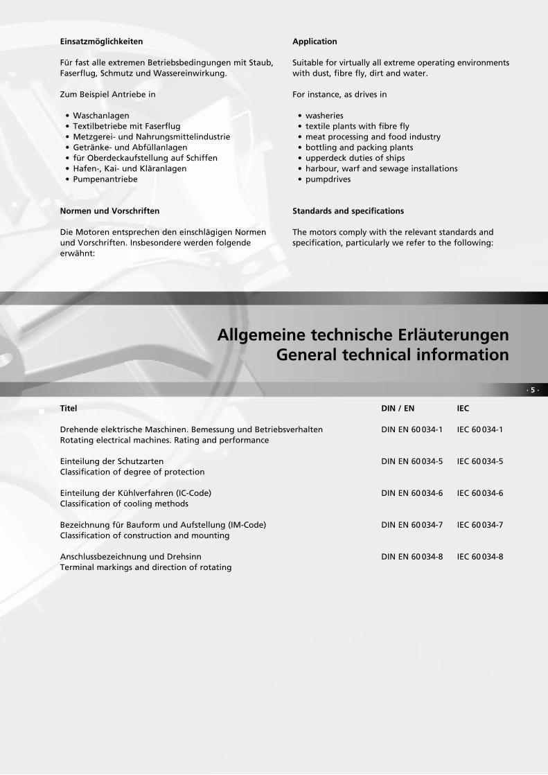
Einsatzmöglichkeiten
Für fast alle extremen Betriebsbedingungen mit Staub, Faserflug, Schmutz und Wassereinwirkung.
Zum Beispiel Antriebe in
• Waschanlagen• Textilbetriebe mit Faserflug• Metzgerei- und Nahrungsmittelindustrie• Getränke- und Abfüllanlagen• für Oberdeckaufstellung auf Schiffen• Hafen-, Kai- und Kläranlagen• Pumpenantriebe
Normen und Vorschriften
Die Motoren entsprechen den einschlägigen Normen und Vorschriften. Insbesondere werden folgende erwähnt:
Application
Suitable for virtually all extreme operating environments with dust, fibre fly, dirt and water.
For instance, as drives in
• washeries• textile plants with fibre fly• meat processing and food industry• bottling and packing plants• upperdeck duties of ships• harbour, warf and sewage installations• pumpdrives
Standards and specifications
The motors comply with the relevant standards and specification, particularly we refer to the following:
Titel DIN / EN IEC
Drehende elektrische Maschinen. Bemessung und Betriebsverhalten DIN EN 60 034-1 IEC 60 034-1Rotating electrical machines. Rating and performance
Einteilung der Schutzarten DIN EN 60 034-5 IEC 60 034-5Classification of degree of protection
Einteilung der Kühlverfahren (IC-Code) DIN EN 60 034-6 IEC 60 034-6Classification of cooling methods
Bezeichnung für Bauform und Aufstellung (IM-Code) DIN EN 60 034-7 IEC 60 034-7Classification of construction and mounting
Anschlussbezeichnung und Drehsinn DIN EN 60 034-8 IEC 60 034-8Terminal markings and direction of rotating

· 6 ·
Allgemeine technische ErläuterungenGeneral technical information
Mechanische Ausführung
Bauformen
Die Grundbauform der Motoren wird auf dem Leistungsschild nach DIN EN 60 034-7, Code 1, angegeben.
Motoren in den Grundbauformen B5 und B14 können auch in den folgenden anderen Einbaulagen betrieben werden:
IM B5 ⇒ IM V1 und IM V3IM B14 ⇒ IM V18 und IM V19
Flanschmotoren, Form A mit Durchgangsbohrungen
IM B5 (IM 3 001)Wellenende horizontalBefestigungsflansch Form AShaft horizontalFlange type A
IM V1 (IM 3 011)Wellenende nach untenBefestigungsflansch Form AShaft downwardFlange type A
Flanschmotoren, Form C mit Gewinde
IM B14 (IM 3 601)Wellenende horizontalBefestigungsflansch Form CShaft horizontalFlange type C
IM V18 (IM 3 611)Wellenende nach untenBefestigungsflansch Form CShaft downwardFlange type C
Flange motors, type A with through-holes
IM V3 (IM 3 031)Wellenende nach obenBefestigungsflansch Form AShaft upwardFlange type A
Flange motors, type C with threaded holes
IM V19 (IM 3 631)Wellenende nach obenBefestigungsflansch Form CShaft upwardFlange type C
Mechanical design
Types of construction
The basic type of mounting is marked on the name plate according to DIN EN 60 034-7 code 1.
Motors with the basic type of mounting are able to operate also at the following types of mounting:
IM B5 ⇒ IM V1 and IM V3IM B14 ⇒ IM V18 and IM V19
· 7 ·
Allgemeine technische ErläuterungenGeneral technical information
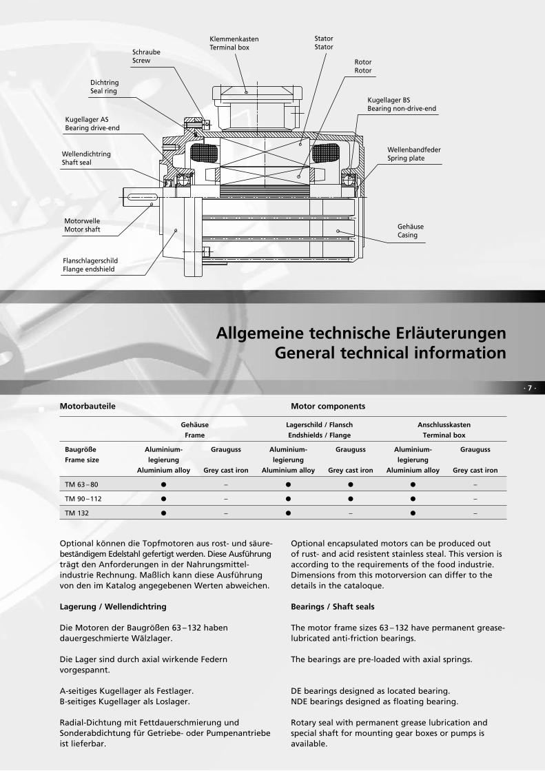
Optional können die Topfmotoren aus rost- und säure-beständigem Edelstahl gefertigt werden. Diese Ausführung trägt den Anforderungen in der Nahrungsmittel- industrie Rechnung. Maßlich kann diese Ausführung von den im Katalog angegebenen Werten abweichen.
Lagerung / Wellendichtring
Die Motoren der Baugrößen 63 –132 haben dauergeschmierte Wälzlager.
Die Lager sind durch axial wirkende Federn vorgespannt.
A-seitiges Kugellager als Festlager.B-seitiges Kugellager als Loslager.
Radial-Dichtung mit Fettdauerschmierung und Sonderabdichtung für Getriebe- oder Pumpenantriebe ist lieferbar.
Optional encapsulated motors can be produced out of rust- and acid resistent stainless steal. This version is according to the requirements of the food industrie. Dimensions from this motorversion can differ to the details in the cataloque.
Bearings / Shaft seals
The motor frame sizes 63 –132 have permanent grease-lubricated anti-friction bearings.
The bearings are pre-loaded with axial springs.
DE bearings designed as located bearing.NDE bearings designed as floating bearing.
Rotary seal with permanent grease lubrication and special shaft for mounting gear boxes or pumps is available.
Motorbauteile Motor components
Gehäuse Lagerschild / Flansch Anschlusskasten
Frame Endshields / Flange Terminal box
Baugröße Aluminium- Grauguss Aluminium- Grauguss Aluminium- Grauguss
Frame size legierung legierung legierung
Aluminium alloy Grey cast iron Aluminium alloy Grey cast iron Aluminium alloy Grey cast iron
TM 63 – 80 P – P P P –
TM 90 –112 P – P P P –
TM 132 P – P – P –

· 8 ·
Allgemeine technische ErläuterungenGeneral technical information
Lagerzuordnung / Bearing and frame size
TM 63 ≥ 2 6202 2RS 6202 2RS 15 30 7
TM 71 ≥ 2 6202 2RS 6202 2RS 15 30 7
TM 80 ≥ 2 6204 2RS 6204 2RS 20 35 7
TM 90 ≥ 2 6205 2RS 6205 2RS 25 40 7
TM 100 ≥ 2 6206 2RS 6206 2RS 30 47 7
TM 112 ≥ 2 6306 2RS 6306 2RS 30 47 7
TM 132 ≥ 2 6308 2RS C3 6307 2RS C3 40 60 10
Baug
röße
Fram
e si
ze
Polz
ahl
No.
of
pole
s
AS-
Lage
rD
E be
arin
g
BS-L
ager
ND
E be
arin
g
Wel
lend
icht
ring
(inne
n)
Wel
lend
icht
ring
(auß
en)
Shaf
t se
al (i
nter
nal d
ia)
Shaf
t se
al (e
xter
nal d
ia)
Brei
teW
idth
Wellenende
Die Wellenenden sind zylindrisch und die Abmessungen den Baugrößen und Leistungen entsprechend DIN 42 673-1 und DIN 42 677-1 zugeordnet.
Motorwellen aus rost-, säure- und hitzebeständigen Stählen sowie kundenspezifische Wellenabmessungen sind auf Anfrage lieferbar.
Serienmäßig werden die Wellenenden der Motoren der Baugrößen 90 –132 mit einem Zentriergewinde nach DIN 332-2, Form D, geliefert.
Shaft extension
Depending on the frame size and rated output the cylindrical shaft extensions are according to the standards DIN 42 673-1 and DIN 42 677-1.
Motor shafts of stainless, acid- and heat-resistant steel, or dimensions according to customers specification are available on request.
Motors of frame sizes 90 –132 are supplied with a tapped centre hole according to DIN 332-2, form D as a standard fitting.
Schmierstoffe / Lubricants
Betriebsbedingungen Wärmeklasse Wälzlagerfett / Einsatzbereich
Operating conditions Insulating class Bearing grease / Service range
Normal Baugrößen 63 –112, Lithiumseifenfett, –30°C bis +140°C
F Baugröße 132, Barium-Komplex, –20°C bis +140°C
Standard Frame sizes 63 –112, lithium-based grease, –30°C to +140°C
Frame size 132, barium complex, –20°C bis +140°C
Hohe Temperaturen, Hochtemperatur- und Langzeitschmierstoff,
extreme Betriebsbedingungen H
vollsynthetisches Grundöl, –20°C bis +180°C
High temperatures, High-temperature and long-term grease,
extreme operating conditions fully synthetic base oil, –20°C to +180°C
Tiefe Temperaturen F Tieftemperaturschmierstoff, Barium-Komplex, – 50°C bis +150°C
Low temperatures Low-temperature grease, barium complex, – 50°C to +150°C

· 9 ·
Allgemeine technische ErläuterungenGeneral technical information
Die Motoren werden mit eingelegter Passfeder nach DIN 6 885-1, Form A, geliefert.
Motorwellenwerkstoff: Standard 1.4021
Auswuchtung
Bei allen Motoren sind die Läufer mit eingelegter halber Passfeder dynamisch ausgewuchtet nach DIN ISO 8 821.
Antriebselemente wie Riemenscheiben, Kupplungen und Pumpenräder müssen ebenfalls mit eingelegter halber Passfeder dynamisch ausgewuchtet werden.
Es ist darauf zu achten, dass die Nabenlänge und die Länge der Passfedernut übereinstimmen, damit keine zusätzliche Restunwucht entsteht.
Auf besonderen Wunsch ist auch Vollkeilwuchtung möglich.
Die Art der Passfederwuchtung ist entsprechend der Norm auf der Stirnseite der Antriebswelle gekennzeichnet.
Klemmenkasten
Bei allen Baugrößen sind die Klemmenkästen um 90º drehbar.
Die Klemmenkastenlage bei Normalausführung ist auf die Antriebswelle gesehen rechts (0º) und die Kabeleinführung Richtung D.
Abweichende Klemmenkastenlage und Kabelein- führungslage bitte bei Bestellung angeben.
Konvektionsgekühlte Motoren führen ihre Verlust- leistung über die Oberfläche ab und haben eine relativ hohe Oberflächentemperatur.
Der Einbau soll so erfolgen, dass die Wärme an die Umgebung abgegeben werden kann, ohne dass ein Wärmestau oder Verbrennungsgefahr entstehen kann.
Es ist zu empfehlen, eine Anschlussleitung mit erhöhter Temperaturbeständigkeit einzusetzen.
Verbindungselemente
Schrauben und Sicherungselemente sind korrosionsgeschützt.
The kind of balancing is marked at the front of the shaft according to the standard.
Terminal box
For all frame sizes the terminal boxes are rotatable through 90º.
The terminal box alignment in standard version is to the right (0º) when looking at drive end. Standard cable inlet to direction D.
Please indicate deviations of terminal box alignment and cable inlet direction by order.
Motors coded by convention carry off the heat to the motor surface and have a high surface temperature.
The mounting will be, that the heat carries off to the ambient without heat concentration or the danger of burning.
We recommend the use of heat-resistant supply leads.
Fasteners
Screws and circlips with anti-corrosion finish.
The motors are supplied with an inserted featherkey according to DIN 6 885-1, form A.
Motorshaft: standard 1.4021
Balancing
The rotors of all motors are balanced dynamically with a half featherkey fitted according to DIN ISO 8 821.
Drive elements, such as belt pulleys, couplings or pump impeller wheels must also be dynamically balanced with a half featherkey fitted.
It is important to pay attention, that the length of the hub is the same as the length of the featherkey to avoid an additional residual unbalance.
The balancing with full featherkey is possible on request.

· 10 ·
Allgemeine technische ErläuterungenGeneral technical information
Die Klemmenkastenzuordnung gilt nur für Bemessungsspannungen ≥400 V bei eintourigen Drehstrommotoren.Die Lieferung der Motoren erfolgt ohne Kabelverschraubung.
Kabelanschluss
Option
Auf Wunsch sind die Motoren der Baugrößen TM 63 bis 132 ohne Klemmenkasten mit herausgeführtem Kabel lieferbar.Die Kabelausführung erfolgt über eine flache Klemmenflächenabschlussplatte (Maße auf Anfrage, Mehrpreis).Die feuchtigkeitsbeständige Anschlussleitung wird über wasserdichte Leitungseinführung mit der Motor-wicklung fest verschaltet. Die Steuerleitungen für Motorschutz können in die Anschlussleitungen inte-griert werden.Leitungslänge bei Standardausführung: 2 m
The relation of terminal boxes is only valid to single-speed three-phase motors at rated voltage ≥400 V. The cable glands are not included in the motor delivery.
Cable
Option
On request the motors with frame sizes TM 63 up to 132 are available without terminal box with drawn-out cable.The cable glands are mounted to a special flat terminal base cover (dimensions on request, extra price).
The moisture-resistant cable is connected to the motorwinding. Cable-inlet with water-proof cable cupling sleeves. Measuring lines for motor protection can be integrated in this cable.
Standard length of cable: 2 m
Motoranschluss / Motor connection
Leitungseinführung und Anschlussklemmen / Cable inlets and terminals
Baugröße Leitungseinführungsgewinde Anschlussgewinde Max. Strom je Klemmenbolzen
Frame size Cable inlet thread Terminal thread Max. current on terminal
TM 63 –100 1 x M20 x 1,5 6 x M4 16 A
TM 112 2 x M20 x 1,5 6 x M5 25 A
TM 132 2 x M25 x 1,5 6 x M6 63 A

· 11 ·
Allgemeine technische ErläuterungenGeneral technical information
Alle Motoren werden standardmäßig mit Normal- anstrich in Farbton RAL 7031 geliefert.
Andere Farbtöne und Anstriche auf Anfrage.
In standard the motors are delivered with the standard coating in colour RAL 7031.
Other colours or coatings on request.
Lage der Kondenswasserbohrungen
Standard ohne.
Auf Kundenwunsch je nach Aufstellung an der tiefsten Stelle verschlossen möglich.
Elektrische Ausführung
Bemessungsspannung und Frequenz
Die Drehstrommotoren werden für folgende Bemessungsspannungen geliefert:
3 AC, 50 Hz – 400 V, 500 V, 690 V3 AC, 60 Hz – 440 V, 460 V
Andere Bemessungsspannungen und Frequenzen sind gegen Mehrpreis lieferbar.Nach DIN EN 60 034-1 gilt für Motoren eine Spannungstoleranz von ± 5 %.
Alignment of the condensate drainage holes
Standard without drainage holes.
At the lowest point, depending on the installation, condensate holes are closed.
Electrical design
Voltage and frequency
The three-phase motors are available with the following rated voltages:
3AC, 50Hz – 400V, 500V, 690V3AC, 60Hz – 440V, 460V
Other rated voltages and frequencies are available at extra price.According to DIN EN 60 034-1 the voltage tolerance of the motors is ±5%.
Anstrich / Painting
Anstrich / Schichtdicke Eignung für Klimagruppe nach DIN IEC 721, Teil 2-1
Painting / Coat thickness Suitable for climate group to DIN IEC 721, part 2-1
Normalanstrich Grundierung / Primer : ≥ 20 µm Moderate
Standard coat Deckanstrich/ Top coat : ≥ 35 µm
Nitro-Combi-Decklack Innenraum und Freiluftaufstellung
Nitrocellulose combination finish For indoor and outdoor installation
Sonderanstrich SA1 Grundierung / Primer : ≥ 20 µm Worldwide
Special coat SA1 Zwischenanstrich / Sealer : ≥ 50 µm
Epoxid-Zwischenanstrich RAL 1002 Freiluftaufstellung, Einwirkung von Seewasseratmosphäre,
Epoxy resin sealer RAL 1002 Industriegasen und sauren Atmosphären
Deckanstrich/ Top coat : ≥ 40 µm For outdoor installation, for marine atmosphere,
2-Komponenten-Polyurethan-Anstrich industrial gases and acid atmospheres
Two-component polyurethane coat
Toleranzen nach DIN EN 60 034-1 / Tolerances according to DIN EN 60 034-1
Wirkungsgrad Leistungsfaktor Schlupf Anzugsstrom Anzugsmoment Kippmoment
Efficiency Power factor Slip Starting current Starting torque Breakdown torque
η cos ϕ s IA MA MK
P2 ≤ 50 kW: – 0,15 (1-η) – (1– cos ϕ) / 6
P2 > 50 kW: – 0,10 (1-η) min. 0,02; max. 0,07 ± 20% + 20% – 15% bis + 20% –10%

· 12 ·
Allgemeine technische ErläuterungenGeneral technical information
Motorschutz
Bei stromabhängigem Motorschutz muss der Schutz-schalter auf den am Leistungsschild angegebenen Nennstrom eingestellt werden.Bei Schalthäufigkeit, Kurzzeitbetrieb oder großen Temperaturschwankungen ist der Motorschutz nur mit direkter Temperaturüberwachung sicher wirksam.Hierzu bieten sich auf Wunsch folgende Möglichkeiten an:
• Temperaturschalter als ÖffnerBei Erreichen der Grenztemperatur öffnet dieser selbsttätig den Hilfsstromkreis und schaltet erst nach wesentlicher Temperaturänderung wieder ein. Schaltleistung: bei Wechselspannung 250 V 1,6 A.
• KaltleiterschutzDie eingebauten Kaltleiter werden in Verbindung mit einem Auslösegerät betrieben. Bei Erreichen der Grenztemperatur ändert der Kaltleiterfühler sprunghaft seinen Widerstand. In Verbindung mit dem Auslösegerät wird diese Wirkung zur Überwa-
Motor protection
For current-sensitive motor protection, the protective switch has to be set to the rated current given on the name plate.This motor protection is inadequate for high number of operations, short-time operation, or for fluctuations in coolant temperature. In these cases motors should be protected by direct temperature protection (extra price):
• Thermal protector switchWhen reaching the limiting temperature, the switch opens the control circuit. The NC switch closes the circuit when the temperature decreases essential. Contact rating: 1,6 amps for 250VAC.
• Thermistor protectionThe embedded temperature sensors are able to work only in conjunction with a tripping unit. When reaching the limiting temperature, the thermistor changes its resistance almost instantaneously. This action is utilized in conjunction with the tripping
unit to monitor motor temperature. The relay in- corporated in the device has a change-over contact, in which the contacts can be used for the control system.Advantages: The protection system is self-monitor- ing; low switching tolerance; quick reconnection of the drive.
In standard the connection of the temperature protection is with a terminal block inside the main terminal box.
Anti-condensation heaters
The windings of motors subjected to extreme temperature fluctuations or severe climatic conditions are endan- gered by the formation of condensation or moisture.Optional it is possible to use anti-condensation heaters inside the motor to heat up the winding after shut-down and prevent the formation of moisture inside the motor.The anti-condensation heaters must not be switched on while the motor is running.
chung der Motortemperatur ausgenutzt. Das im Gerät eingebaute Relais verfügt über einen Umschaltkontakt, dessen Öffner und Schließer für die Steuerung benutzt werden können. Vorteil: Schutzeinrichtung überwacht sich selbst; geringe Schalttoleranz; schnelles Wiedereinschalten des Antriebes.
Die Anschlüsse der Temperaturüberwachung sind standardmäßig auf eine Klemmenleiste im Haupt- klemmenkasten geführt.
Stillstandsheizung
Bei Motoren, die starken Temperaturschwankungen oder extremen klimatischen Verhältnissen ausgesetzt sind, ist die Motorwicklung durch Kondensatbildung oder Betauung gefährdet. Als Option kann eine einge-baute Stillstandsheizung die Motorwicklung nach dem Abschalten erwärmen und einen Feuchtigkeitsnieder-schlag im Motorinneren verhindern.Während des Betriebes darf die Stillstandsheizung nicht eingeschaltet werden.
Baugröße / Frame size Heizleistung / Heating capacity Anschlussspannung / Supply voltage
W V
TM 63 – 80 25 230 110
TM 90 –112 50 230 110
TM 132 100 230 110
· 13 ·
Allgemeine technische ErläuterungenGeneral technical information
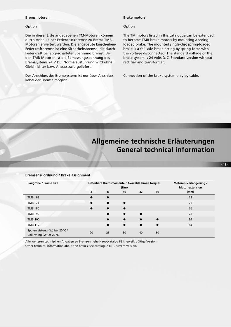
Bremsmotoren
Option
Die in dieser Liste angegebenen TM-Motoren können durch Anbau einer Federdruckbremse zu Brems-TMB-Motoren erweitert werden. Die angebaute Einscheiben-Federkraftbremse ist eine Sicherheitsbremse, die durch Federkraft bei abgeschalteter Spannung bremst. Bei den TMB-Motoren ist die Bemessungsspannung des Bremssystems 24 V DC. Normalausführung wird ohne Gleichrichter bzw. Anpasstrafo geliefert.
Der Anschluss des Bremssystems ist nur über Anschluss- kabel der Bremse möglich.
Brake motors
Option
The TM motors listed in this catalogue can be extended to become TMB brake motors by mounting a spring-loaded brake. The mounted single-disc spring-loaded brake is a fail-safe brake acting by spring force with the voltage disconnected. The standard voltage of the brake system is 24 volts D.C. Standard version without rectifier and transformer.
Connection of the brake system only by cable.
Bremsenzuordnung / Brake assignment
Baugröße / Frame size Lieferbare Bremsmomente / Available brake torques Motoren-Verlängerung /
(Nm) Motor extension
4 8 16 32 60 (mm)
TMB 63 P P 73
TMB 71 P P P 76
TMB 80 P P P 76
TMB 90 P P P 78
TMB 100 P P P P 84
TMB 112 P P P P 84
Spulenleistung (W) bei 20 °C /
Coil rating (W) at 20 °C 20 25 30 40 50
Alle weiteren technischen Angaben zu Bremsen siehe Hauptkatalog 821, jeweils gültige Version.
Other technical information about the brakes: see catalogue 821, current version.

Grö
ßer
e Le
istu
ng
en a
uf
An
frag
e /
Incr
ease
d o
utp
ut
on
req
ues
t
· 14 ·
Drehstrom- Topfmotoren
3000 min-1 50 Hz
Schutzart IP 67Betriebsart S1
Three-phase encapsulated motors
3000 min-1 50 Hz
Degree of protection IP 67Operating mode S1
Baug
röße
Fram
e si
ze
Bem
essu
ngsl
eist
ung
Rate
d ou
tput
Be
mes
sung
sdre
hzah
l
Rate
d sp
eed
Bem
essu
ngss
trom
bei
400
V
Rate
d cu
rren
t at
400
V
Leis
tung
sfak
tor
Pow
er f
acto
rW
irkun
gsgr
ad η
Effic
ienc
y η
Bem
essu
ngsm
omen
t
Gew
icht
W
eigh
t
Rate
d to
rque
Anz
ugsm
omen
t zu
Bem
essu
ngsm
omen
t
Star
ting
torq
ue t
o ra
ted
torq
ue
Anz
ugss
trom
zu
Bem
essu
ngss
trom
Star
ting
curr
ent
to r
ated
cur
rent
Kipp
mom
ent
zu B
emes
sung
smom
ent
Brea
kdow
n to
rque
to
rate
d to
rque
Träg
heits
mom
ent
J
Mom
ent
of in
ertia
J
kW min-1 A cos ϕ % Nm MA/MN IA/IN MK/MN kgm2 kg
TM 63 S / 2 0,06 2 790 0,21 0,73 57 0,21 3,3 5,3 3,6 0,00014 3,6
TM 63 L / 2 0,09 2 790 0,29 0,73 61 0,31 3,4 5,9 3,4 0,00019 4,3
TM 71 S / 2 0,12 2 870 0,38 0,74 62 0,40 3,7 6,4 4,2 0,00035 5,2
TM 71 L / 2 0,18 2 880 0,55 0,74 64 0,60 3,8 6,7 4,4 0,00046 6,0
TM 80 S / 2 0,22 2 880 0,60 0,74 72 0,73 4,4 7,2 4,5 0,00068 8,6
TM 80 L / 2 0,30 2 880 0,81 0,74 72 0,99 4,0 8,2 4,2 0,00090 10,3
TM 90 S / 2 0,37 2 890 0,85 0,82 77 1,22 3,5 9,2 4,2 0,00137 13,2
TM 90 L / 2 0,55 2 890 1,24 0,82 78 1,82 3,2 8,5 4,2 0,00183 15,5
TM 100 L / 2 0,75 2 930 1,87 0,75 77 2,45 4,2 10,0 4,4 0,00282 18,5
TM 112 M / 2 1,10 2 930 2,2 0,85 84 3,6 4,0 10,0 4,0 0,00556 28,5
TM 132 M k/2 1,50 2 930 3,5 0,77 80 4,9 3,5 9,6 3,7 0,0084 50
TM 132 M / 2 2,20 2 940 5,1 0,78 80 7,1 3,5 9,8 3,7 0,012 54

· 15 ·
Grö
ßer
e Le
istu
ng
en a
uf
An
frag
e /
Incr
ease
d o
utp
ut
on
req
ues
t
Drehstrom- Topfmotoren
3 000 min-1 50 Hz
Schutzart IP 67Betriebsart S3 – 30 %
Three-phase encapsulated motors
3 000 min-1 50 Hz
Degree of protection IP 67Operating mode S3 – 30%
Baug
röße
Fram
e si
ze
Bem
essu
ngsl
eist
ung
Rate
d ou
tput
Be
mes
sung
sdre
hzah
l
Rate
d sp
eed
Bem
essu
ngss
trom
bei
400
V
Rate
d cu
rren
t at
400
V
Leis
tung
sfak
tor
Pow
er f
acto
rW
irkun
gsgr
ad η
Effic
ienc
y η
Bem
essu
ngsm
omen
t
Gew
icht
W
eigh
t
Rate
d to
rque
Anz
ugsm
omen
t zu
Bem
essu
ngsm
omen
t
Star
ting
torq
ue t
o ra
ted
torq
ue
Anz
ugss
trom
zu
Bem
essu
ngss
trom
Star
ting
curr
ent
to r
ated
cur
rent
Kipp
mom
ent
zu B
emes
sung
smom
ent
Brea
kdow
n to
rque
to
rate
d to
rque
Träg
heits
mom
ent
J
Mom
ent
of in
ertia
J
kW min-1 A cos ϕ % Nm MA/MN IA/IN MK/MN kgm2 kg
TM 63 S / 2 0,15 2 740 0,46 0,74 63 0,52 2,6 4,8 2,8 0,00014 3,6
TM 63 L / 2 0,20 2 770 0,61 0,73 65 0,69 2,8 4,9 2,8 0,00019 4,3
TM 71 S / 2 0,30 2 775 0,78 0,84 66 1,03 2,1 4,5 2,4 0,00035 5,2
TM 71 L / 2 0,40 2 780 0,98 0,85 69 1,37 2,1 5,0 2,4 0,00046 6,0
TM 80 S / 2 0,55 2 810 1,36 0,78 75 1,87 2,9 5,4 2,9 0,00068 8,6
TM 80 L / 2 0,75 2 820 1,76 0,79 78 2,55 2,7 6,2 3,0 0,00090 10,3
TM 90 S / 2 1,10 2 840 2,45 0,85 77 3,7 2,0 6,0 2,6 0,00137 13,2
TM 90 L / 2 1,50 2 835 3,1 0,88 80 5,1 2 6,5 2,6 0,00183 15,5
TM 100 L / 2 2,00 2 850 4,45 0,82 79 6,7 2,5 5,5 2,5 0,00282 18,5
TM 112 M / 2 3,00 2 850 6,1 0,85 84 10,1 2 6,0 2,1 0,00556 28,5
TM 132 M k/2 4,00 2 930 8,2 0,84 84 13,0 3,5 9,6 3,7 0,0084 50
TM 132 M / 2 5,50 2 940 11,0 0,85 85 17,9 3,5 9,8 3,7 0,012 54

Grö
ßer
e Le
istu
ng
en a
uf
An
frag
e /
Incr
ease
d o
utp
ut
on
req
ues
t
· 16 ·
Drehstrom- Topfmotoren
3000 min-1 50 Hz
Schutzart IP 67Betriebsart S3–15%
Three-phase encapsulated motors
3000 min-1 50 Hz
Degree of protection IP 67Operating mode S3–15%
Baug
röße
Fram
e si
ze
Bem
essu
ngsl
eist
ung
Rate
d ou
tput
Be
mes
sung
sdre
hzah
l
Rate
d sp
eed
Bem
essu
ngss
trom
bei
400
V
Rate
d cu
rren
t at
400
V
Leis
tung
sfak
tor
Pow
er f
acto
rW
irkun
gsgr
ad η
Effic
ienc
y η
Bem
essu
ngsm
omen
t
Gew
icht
W
eigh
t
Rate
d to
rque
Anz
ugsm
omen
t zu
Bem
essu
ngsm
omen
t
Star
ting
torq
ue t
o ra
ted
torq
ue
Anz
ugss
trom
zu
Bem
essu
ngss
trom
Star
ting
curr
ent
to r
ated
cur
rent
Kipp
mom
ent
zu B
emes
sung
smom
ent
Brea
kdow
n to
rque
to
rate
d to
rque
Träg
heits
mom
ent
J
Mom
ent
of in
ertia
J
kW min-1 A cos ϕ % Nm MA/MN IA/IN MK/MN kgm2 kg
TM 63 S / 2 0,25 2 700 0,74 0,76 64 0,88 2,0 4,0 2,3 0,00014 3,6
TM 63 L / 2 0,37 2 700 1,07 0,77 65 1,31 2,0 3,8 2,0 0,00019 4,3
TM 71 S / 2 0,55 2 720 1,43 0,83 67 1,93 1,6 3,6 1,9 0,00035 5,2
TM 71 L / 2 0,75 2 770 1,91 0,80 71 2,60 2,0 4,4 2,2 0,00046 6,0
TM 80 S / 2 1,10 2 770 2,60 0,80 76 3,80 2,3 4,5 2,3 0,00068 8,6
TM 80 L / 2 1,50 2 790 3,45 0,82 77 5,1 2,3 5,5 2,6 0,00090 10,3
TM 90 S / 2 2,20 2 780 4,75 0,86 78 7,6 2,0 5,0 2,2 0,00137 13,2
TM 90 L / 2 3,00 2 820 6,2 0,85 82 10,2 2,0 5,6 2,4 0,00183 15,5
TM 100 L / 2 4,00 2 830 9,6 0,76 79 13,5 2,3 4,7 2,3 0,00282 18,5
TM 112 M / 2 6,00 2 860 12,1 0,84 85 20,0 2,1 6,5 2,2 0,00556 28,5
TM 132 M k/2 4,80 2 880 9,9 0,84 83 15,9 3,5 9,6 3,7 0,0084 50
TM 132 M / 2 6,60 2 870 13,2 0,85 85 22,0 3,5 9,8 3,7 0,012 54

· 17 ·
Grö
ßer
e Le
istu
ng
en a
uf
An
frag
e /
Incr
ease
d o
utp
ut
on
req
ues
t
Drehstrom- Topfmotoren
1500 min-1 50 Hz
Schutzart IP 67Betriebsart S1
Three-phase encapsulated motors
1500 min-1 50 Hz
Degree of protection IP 67Operating mode S1
Baug
röße
Fram
e si
ze
Bem
essu
ngsl
eist
ung
Rate
d ou
tput
Be
mes
sung
sdre
hzah
l
Rate
d sp
eed
Bem
essu
ngss
trom
bei
400
V
Rate
d cu
rren
t at
400
V
Leis
tung
sfak
tor
Pow
er f
acto
rW
irkun
gsgr
ad η
Effic
ienc
y η
Bem
essu
ngsm
omen
t
Gew
icht
W
eigh
t
Rate
d to
rque
Anz
ugsm
omen
t zu
Bem
essu
ngsm
omen
t
Star
ting
torq
ue t
o ra
ted
torq
ue
Anz
ugss
trom
zu
Bem
essu
ngss
trom
Star
ting
curr
ent
to r
ated
cur
rent
Kipp
mom
ent
zu B
emes
sung
smom
ent
Brea
kdow
n to
rque
to
rate
d to
rque
Träg
heits
mom
ent
J
Mom
ent
of in
ertia
J
kW min-1 A cos ϕ % Nm MA/MN IA/IN MK/MN kgm2 kg
TM 63 S / 4 0,09 1340 0,32 0,69 59 0,64 1,8 3,1 2,0 0,00021 3,6
TM 63 L / 4 0,12 1350 0,42 0,69 60 0,85 2,5 3,6 2,7 0,00028 4,3
TM 71 S / 4 0,15 1410 0,50 0,64 67 1,02 2,1 3,9 2,4 0,00056 5,2
TM 71 L / 4 0,18 1410 0,61 0,65 66 1,22 2,6 4,4 2,8 0,00073 6,0
TM 80 S / 4 0,25 1400 0,70 0,77 67 1,71 2,9 6,4 3,2 0,00128 8,6
TM 80 L / 4 0,30 1425 0,80 0,73 74 2,00 2,9 6,0 3,2 0,00165 10,3
TM 90 S / 4 0,37 1420 0,99 0,71 76 2,50 2,6 5,6 3,1 0,00235 13,2
TM 90 L / 4 0,55 1440 1,41 0,72 78 3,65 3,8 8,0 4,5 0,00313 15,5
TM 100 L / 4 0,75 1420 1,71 0,78 81 5,0 2,7 7,1 3,4 0,0045 18,5
TM 100 L / 4 a 1,0 1450 2,25 0,79 82 6,6 3,3 8,8 3,7 0,0060 22
TM 112 M / 4 1,5 1420 3,1 0,82 85 10,1 2,4 6,3 2,8 0,0119 31
TM 132 M / 4 1,8 1450 3,7 0,81 87 11,9 2,6 6,8 3,0 0,0233 54
TM 132 M / 4 a 2,7 1460 5,6 0,80 87,5 17,7 2,9 6,8 3,2 0,0354 59

Grö
ßer
e Le
istu
ng
en a
uf
An
frag
e /
Incr
ease
d o
utp
ut
on
req
ues
t
· 18 ·
Drehstrom- Topfmotoren
1500 min-1 50 Hz
Schutzart IP 67Betriebsart S3 – 30 %
Three-phase encapsulated motors
1500 min-1 50 Hz
Degree of protection IP 67Operating mode S3 – 30%
Baug
röße
Fram
e si
ze
Bem
essu
ngsl
eist
ung
Rate
d ou
tput
Be
mes
sung
sdre
hzah
l
Rate
d sp
eed
Bem
essu
ngss
trom
bei
400
V
Rate
d cu
rren
t at
400
V
Leis
tung
sfak
tor
Pow
er f
acto
rW
irkun
gsgr
ad η
Effic
ienc
y η
Bem
essu
ngsm
omen
t
Gew
icht
W
eigh
t
Rate
d to
rque
Anz
ugsm
omen
t zu
Bem
essu
ngsm
omen
t
Star
ting
torq
ue t
o ra
ted
torq
ue
Anz
ugss
trom
zu
Bem
essu
ngss
trom
Star
ting
curr
ent
to r
ated
cur
rent
Kipp
mom
ent
zu B
emes
sung
smom
ent
Brea
kdow
n to
rque
to
rate
d to
rque
Träg
heits
mom
ent
J
Mom
ent
of in
ertia
J
kW min-1 A cos ϕ % Nm MA/MN IA/IN MK/MN kgm2 kg
TM 63 S / 4 0,15 1300 0,50 0,70 62 1,10 1,8 3,0 1,8 0,00021 3,6
TM 63 L / 4 0,18 1350 0,60 0,70 62 1,27 2,1 3,2 2,3 0,00028 4,3
TM 71 S / 4 0,25 1390 0,78 0,68 68 1,72 2,0 4,1 2,3 0,00056 5,2
TM 71 L / 4 0,37 1390 1,04 0,72 71 2,55 2,2 4,5 2,4 0,00073 6,0
TM 80 S / 4 0,55 1380 1,49 0,74 72 3,80 2,1 4,8 2,3 0,00128 8,6
TM 80 L / 4 0,75 1390 1,90 0,74 74 5,2 2,2 4,8 2,4 0,00165 10,3
TM 90 S / 4 1,10 1400 2,8 0,76 76 7,5 2,2 5,2 2,7 0,00235 13,2
TM 90 L / 4 1,50 1410 3,5 0,80 79 10,2 2,4 5,6 2,8 0,00313 15,5
TM 100 L / 4 2,0 1420 5,0 0,75 77 13,5 2,4 5,6 2,9 0,0045 18,5
TM 100 L / 4 a 2,5 1420 5,9 0,78 78 16,8 2,8 7,3 3,3 0,0060 22
TM 112 M / 4 4,0 1420 8,3 0,82 85 27,0 2,4 6,3 2,8 0,0119 31
TM 132 M / 4 5,5 1450 11,4 0,81 86 36,0 2,8 6,6 3,0 0,0233 54
TM 132 M / 4 a 7,5 1460 15,4 0,81 87 49,0 2,6 6,8 3,0 0,0354 59

· 19 ·
Grö
ßer
e Le
istu
ng
en a
uf
An
frag
e /
Incr
ease
d o
utp
ut
on
req
ues
t
Drehstrom- Topfmotoren
1500 min-1 50 Hz
Schutzart IP 67Betriebsart S3 –15%
Three-phase encapsulated motors
1500 min-1 50 Hz
Degree of protection IP 67Operating mode S3 –15%
Baug
röße
Fram
e si
ze
Bem
essu
ngsl
eist
ung
Rate
d ou
tput
Be
mes
sung
sdre
hzah
l
Rate
d sp
eed
Bem
essu
ngss
trom
bei
400
V
Rate
d cu
rren
t at
400
V
Leis
tung
sfak
tor
Pow
er f
acto
rW
irkun
gsgr
ad η
Effic
ienc
y η
Bem
essu
ngsm
omen
t
Gew
icht
W
eigh
t
Rate
d to
rque
Anz
ugsm
omen
t zu
Bem
essu
ngsm
omen
t
Star
ting
torq
ue t
o ra
ted
torq
ue
Anz
ugss
trom
zu
Bem
essu
ngss
trom
Star
ting
curr
ent
to r
ated
cur
rent
Kipp
mom
ent
zu B
emes
sung
smom
ent
Brea
kdow
n to
rque
to
rate
d to
rque
Träg
heits
mom
ent
J
Mom
ent
of in
ertia
J
kW min-1 A cos ϕ % Nm MA/MN IA/IN MK/MN kgm2 kg
TM 63 S / 4 0,18 1320 0,65 0,70 57 1,30 1,6 2,7 1,8 0,00021 3,6
TM 63 L / 4 0,25 1340 0,95 0,68 56 1,78 2,0 2,8 2,2 0,00028 4,3
TM 71 S / 4 0,37 1370 1,09 0,73 67 2,60 1,8 3,9 2,0 0,00056 5,2
TM 71 L / 4 0,55 1370 1,62 0,73 67 3,85 2 3,9 2,2 0,00073 6,0
TM 80 S / 4 0,75 1360 2,15 0,72 70 5,3 2 4,8 2,2 0,00128 8,6
TM 80 L / 4 1,10 1350 3,30 0,70 69 7,8 1,4 3,5 2,0 0,00165 10,3
TM 90 S / 4 1,50 1380 3,7 0,81 72 10,4 1,9 4,5 2,2 0,00235 13,2
TM 90 L / 4 2,20 1380 5,2 0,81 75 15,2 2,1 4,8 2,4 0,00313 15,5
TM 100 L / 4 3,0 1390 7,2 0,77 78 20,5 1,8 4,0 2,0 0,0045 18,5
TM 100 L / 4 a 4,0 1400 9,1 0,80 79 27,5 2,0 5,3 2,3 0,0060 22
TM 112 M / 4 5,5 1410 11,4 0,82 85 37,5 2,1 5,7 2,5 0,0119 31
TM 132 M / 4 6,6 1420 13,5 0,81 87 44,5 2,6 6,8 3,0 0,0233 54
TM 132 M / 4 a 9,0 1430 18,6 0,80 87,5 60 2,9 6,8 3,2 0,0354 59

Grö
ßer
e Le
istu
ng
en a
uf
An
frag
e /
Incr
ease
d o
utp
ut
on
req
ues
t
· 20 ·
Drehstrom- Topfmotoren
1000 min-1 50 Hz
Schutzart IP 67Betriebsart S1
Three-phase encapsulated motors
1000 min-1 50 Hz
Degree of protection IP 67Operating mode S1
Baug
röße
Fram
e si
ze
Bem
essu
ngsl
eist
ung
Rate
d ou
tput
Be
mes
sung
sdre
hzah
l
Rate
d sp
eed
Bem
essu
ngss
trom
bei
400
V
Rate
d cu
rren
t at
400
V
Leis
tung
sfak
tor
Pow
er f
acto
rW
irkun
gsgr
ad η
Effic
ienc
y η
Bem
essu
ngsm
omen
t
Gew
icht
W
eigh
t
Rate
d to
rque
Anz
ugsm
omen
t zu
Bem
essu
ngsm
omen
t
Star
ting
torq
ue t
o ra
ted
torq
ue
Anz
ugss
trom
zu
Bem
essu
ngss
trom
Star
ting
curr
ent
to r
ated
cur
rent
Kipp
mom
ent
zu B
emes
sung
smom
ent
Brea
kdow
n to
rque
to
rate
d to
rque
Träg
heits
mom
ent
J
Mom
ent
of in
ertia
J
kW min-1 A cos ϕ % Nm MA/MN IA/IN MK/MN kgm2 kg
TM 63 S / 6 0,06 880 0,29 0,64 47 0,65 2,1 2,4 2,1 0,00031 3,6
TM 63 L / 6 0,09 890 0,38 0,68 50 0,97 2,1 2,4 2,1 0,00042 4,3
TM 71 S / 6 0,12 910 0,40 0,74 59 1,26 1,7 3,0 2,0 0,00091 5,2
TM 71 L / 6 0,15 925 0,50 0,74 59 1,55 2,3 4,0 2,6 0,0012 6,0
TM 80 S / 6 0,25 910 0,74 0,71 69 2,60 2,1 3,9 2,3 0,0022 9,5
TM 80 L / 6 0,30 920 0,84 0,75 69 3,10 2,2 4,0 2,3 0,0028 11,0
TM 90 S / 6 0,35 930 1,02 0,71 70 3,60 2,4 4,6 2,7 0,0037 13,2
TM 90 L / 6 0,50 940 1,39 0,70 74 5,1 2,6 4,7 2,7 0,005 15,5
TM 100 L / 6 0,70 950 1,82 0,72 77 7,0 2,4 5,4 2,9 0,010 22
TM 112 M / 6 1,0 960 2,55 0,69 82 9,9 3,0 6,4 3,2 0,018 33
TM 132 M / 6 1,5 960 3,65 0,74 80,0 14,9 2,8 6,8 3,2 0,031 52
TM 132 M / 6 a 2,2 960 5,7 0,75 74,0 22,0 3,0 6,5 3,1 0,038 58

· 21 ·
Grö
ßer
e Le
istu
ng
en a
uf
An
frag
e /
Incr
ease
d o
utp
ut
on
req
ues
t
Drehstrom- Topfmotoren
1000 min-1 50 Hz
Schutzart IP 67Betriebsart S3–30%
Three-phase encapsulated motors
1000 min-1 50 Hz
Degree of protection IP 67Operating mode S3–30%
Baug
röße
Fram
e si
ze
Bem
essu
ngsl
eist
ung
Rate
d ou
tput
Be
mes
sung
sdre
hzah
l
Rate
d sp
eed
Bem
essu
ngss
trom
bei
400
V
Rate
d cu
rren
t at
400
V
Leis
tung
sfak
tor
Pow
er f
acto
rW
irkun
gsgr
ad η
Effic
ienc
y η
Bem
essu
ngsm
omen
t
Gew
icht
W
eigh
t
Rate
d to
rque
Anz
ugsm
omen
t zu
Bem
essu
ngsm
omen
t
Star
ting
torq
ue t
o ra
ted
torq
ue
Anz
ugss
trom
zu
Bem
essu
ngss
trom
Star
ting
curr
ent
to r
ated
cur
rent
Kipp
mom
ent
zu B
emes
sung
smom
ent
Brea
kdow
n to
rque
to
rate
d to
rque
Träg
heits
mom
ent
J
Mom
ent
of in
ertia
J
kW min-1 A cos ϕ % Nm MA/MN IA/IN MK/MN kgm2 kg
TM 63 S / 6 0,09 880 0,39 0,71 47 0,98 1,9 2,0 2,2 0,00031 3,6
TM 63 L / 6 0,12 890 0,52 0,68 49 1,29 2,1 2,2 2,4 0,00042 4,3
TM 71 S / 6 0,18 910 0,60 0,73 59 1,89 1,6 3,0 1,9 0,00091 5,2
TM 71 L / 6 0,25 925 0,84 0,67 64 2,60 2,1 3,3 2,3 0,0012 6,0
TM 80 S / 6 0,37 920 1,21 0,67 66 3,85 2,2 3,7 2,2 0,0022 9,5
TM 80 L / 6 0,55 910 1,67 0,69 69 5,8 2,2 3,6 2,3 0,0028 11,0
TM 90 S / 6 0,75 915 2,2 0,70 70 7,8 2,1 3,8 2,2 0,0037 13,2
TM 90 L / 6 1,1 910 3,1 0,71 73 11,5 2,1 4,2 2,2 0,005 15,5
TM 100 L / 6 1,5 950 3,9 0,70 79 15,1 2,1 5,5 2,2 0,010 22
TM 112 M / 6 2,2 950 5,4 0,73 81 22,0 2,4 5,6 2,5 0,018 33
TM 132 M / 6 3,0 955 7,2 0,73 82,5 30,0 2,4 6,0 3,2 0,031 52
TM 132 M / 6 a 4,0 955 9,2 0,75 83,5 40,0 2,4 5,9 3,1 0,038 58

Grö
ßer
e Le
istu
ng
en a
uf
An
frag
e /
Incr
ease
d o
utp
ut
on
req
ues
t
· 22 ·
Drehstrom- Topfmotoren
1000 min-1 50 Hz
Schutzart IP 67Betriebsart S3–15%
Three-phase encapsulated motors
1000 min-1 50 Hz
Degree of protection IP 67Operating mode S3–15%
Baug
röße
Fram
e si
ze
Bem
essu
ngsl
eist
ung
Rate
d ou
tput
Be
mes
sung
sdre
hzah
l
Rate
d sp
eed
Bem
essu
ngss
trom
bei
400
V
Rate
d cu
rren
t at
400
V
Leis
tung
sfak
tor
Pow
er f
acto
rW
irkun
gsgr
ad η
Effic
ienc
y η
Bem
essu
ngsm
omen
t
Gew
icht
W
eigh
t
Rate
d to
rque
Anz
ugsm
omen
t zu
Bem
essu
ngsm
omen
t
Star
ting
torq
ue t
o ra
ted
torq
ue
Anz
ugss
trom
zu
Bem
essu
ngss
trom
Star
ting
curr
ent
to r
ated
cur
rent
Kipp
mom
ent
zu B
emes
sung
smom
ent
Brea
kdow
n to
rque
to
rate
d to
rque
Träg
heits
mom
ent
J
Mom
ent
of in
ertia
J
kW min-1 A cos ϕ % Nm MA/MN IA/IN MK/MN kgm2 kg
TM 63 S / 6 0,12 880 0,59 0,64 46 1,30 1,7 2,0 1,7 0,00031 3,6
TM 63 L / 6 0,18 890 0,84 0,66 47 1,93 1,6 1,9 1,6 0,00042 4,3
TM 71 S / 6 0,25 900 1,02 0,62 57 2,65 1,9 2,8 2,1 0,00091 5,2
TM 71 L / 6 0,37 900 1,41 0,63 60 3,95 1,9 2,9 2,2 0,0012 6,0
TM 80 S / 6 0,55 880 1,71 0,75 62 6,0 1,8 3,4 1,9 0,0022 9,5
TM 80 L / 6 0,75 890 2,3 0,69 68 8,0 2,0 3,5 2,1 0,0028 11,0
TM 90 S / 6 1,1 900 3,6 0,67 66 11,7 1,9 3,2 2,0 0,0037 13,2
TM 90 L / 6 1,5 900 4,75 0,67 68 15,9 2,0 3,6 2,1 0,005 15,5
TM 100 L / 6 2,2 920 6,3 0,69 73 23,0 1,9 4,4 2,2 0,010 22
TM 112 M / 6 3,0 930 7,3 0,76 78 31,0 2,4 5,6 2,5 0,018 33
TM 132 M / 6 3,6 950 9,0 0,74 78 36,0 2,4 6,0 2,6 0,031 52
TM 132 M / 6 a 4,8 950 12,0 0,74 78 48,5 2,4 5,9 2,6 0,038 58

· 23 ·
Grö
ßer
e Le
istu
ng
en a
uf
An
frag
e /
Incr
ease
d o
utp
ut
on
req
ues
t
Drehstrom- Topfmotoren
750 min-1 50 Hz
Schutzart IP 67Betriebsart S1
Three-phase encapsulated motors
750 min-1 50 Hz
Degree of protection IP 67Operating mode S1
Baug
röße
Fram
e si
ze
Bem
essu
ngsl
eist
ung
Rate
d ou
tput
Be
mes
sung
sdre
hzah
l
Rate
d sp
eed
Bem
essu
ngss
trom
bei
400
V
Rate
d cu
rren
t at
400
V
Leis
tung
sfak
tor
Pow
er f
acto
rW
irkun
gsgr
ad η
Effic
ienc
y η
Bem
essu
ngsm
omen
t
Gew
icht
W
eigh
t
Rate
d to
rque
Anz
ugsm
omen
t zu
Bem
essu
ngsm
omen
t
Star
ting
torq
ue t
o ra
ted
torq
ue
Anz
ugss
trom
zu
Bem
essu
ngss
trom
Star
ting
curr
ent
to r
ated
cur
rent
Kipp
mom
ent
zu B
emes
sung
smom
ent
Brea
kdow
n to
rque
to
rate
d to
rque
Träg
heits
mom
ent
J
Mom
ent
of in
ertia
J
kW min-1 A cos ϕ % Nm MA/MN IA/IN MK/MN kgm2 kg
TM 71 S / 8 0,05 670 0,33 0,48 46 0,71 2,1 2,7 2,2 0,00091 5,2
TM 71 L / 8 0,075 680 0,45 0,50 48 1,05 2,1 2,5 2,2 0,0012 6,0
TM 80 S / 8 0,10 680 0,46 0,57 55 1,40 2,4 3,3 2,5 0,0022 9,5
TM 80 L / 8 0,15 670 0,63 0,61 56 2,15 2,4 3,3 2,5 0,0028 11,0
TM 90 L / 8 0,25 670 0,90 0,62 65 3,55 2,5 3,7 2,4 0,005 15,5
TM 100 L / 8 0,35 690 1,02 0,74 67 4,85 1,9 4,1 2,1 0,0077 18,5
TM 100 L / 8 a 0,50 690 1,35 0,74 72 6,9 1,8 4,3 1,9 0,010 22
TM 112 M / 8 0,75 710 2,15 0,65 78 10,1 2,3 5,5 2,4 0,018 33
TM 132 M / 8 1,0 710 2,6 0,71 78 13,5 2,4 5,6 2,8 0,031 52
TM 132 M / 8 a 1,3 710 3,4 0,71 78 17,5 2,4 5,5 2,8 0,038 58

Grö
ßer
e Le
istu
ng
en a
uf
An
frag
e /
Incr
ease
d o
utp
ut
on
req
ues
t
· 24 ·
Drehstrom- Topfmotoren
750 min-1 50 Hz
Schutzart IP 67Betriebsart S3–30%
Three-phase encapsulated motors
750 min-1 50 Hz
Degree of protection IP 67Operating mode S3–30%
Baug
röße
Fram
e si
ze
Bem
essu
ngsl
eist
ung
Rate
d ou
tput
Be
mes
sung
sdre
hzah
l
Rate
d sp
eed
Bem
essu
ngss
trom
bei
400
V
Rate
d cu
rren
t at
400
V
Leis
tung
sfak
tor
Pow
er f
acto
rW
irkun
gsgr
ad η
Effic
ienc
y η
Bem
essu
ngsm
omen
t
Gew
icht
W
eigh
t
Rate
d to
rque
Anz
ugsm
omen
t zu
Bem
essu
ngsm
omen
t
Star
ting
torq
ue t
o ra
ted
torq
ue
Anz
ugss
trom
zu
Bem
essu
ngss
trom
Star
ting
curr
ent
to r
ated
cur
rent
Kipp
mom
ent
zu B
emes
sung
smom
ent
Brea
kdow
n to
rque
to
rate
d to
rque
Träg
heits
mom
ent
J
Mom
ent
of in
ertia
J
kW min-1 A cos ϕ % Nm MA/MN IA/IN MK/MN kgm2 kg
TM 71 S / 8 0,12 670 0,52 0,73 46 1,71 1,5 2,2 1,6 0,00091 5,2
TM 71 L / 8 0,18 675 0,73 0,68 52 2,55 1,6 2,4 1,7 0,0012 6,0
TM 80 S / 8 0,25 680 1,00 0,67 54 3,5 1,8 2,5 1,9 0,0022 9,5
TM 80 L / 8 0,37 680 1,44 0,63 59 5,2 1,9 2,6 2,0 0,0028 11,0
TM 90 L / 8 0,55 670 1,77 0,67 67 7,8 1,6 3,0 1,8 0,005 15,5
TM 100 L / 8 0,75 690 2,05 0,74 72 10,4 1,4 3,3 1,7 0,0077 18,5
TM 100 L / 8 a 1,1 690 3,0 0,71 74 15,2 1,5 3,3 1,8 0,010 22
TM 112 M / 8 1,5 710 4,75 0,60 76 20,0 2,2 4,4 2,5 0,018 33
TM 132 M / 8 2,2 710 5,3 0,74 81 29,5 2,4 5,1 3,0 0,031 52
TM 132 M / 8 a 3,0 710 7,1 0,74 82 40,5 2,4 5,6 3,0 0,038 58

· 25 ·
Grö
ßer
e Le
istu
ng
en a
uf
An
frag
e /
Incr
ease
d o
utp
ut
on
req
ues
t
Drehstrom- Topfmotoren
750 min-1 50 Hz
Schutzart IP 67Betriebsart S3–15%
Three-phase encapsulated motors
750 min-1 50 Hz
Degree of protection IP 67Operating mode S3–15%
Baug
röße
Fram
e si
ze
Bem
essu
ngsl
eist
ung
Rate
d ou
tput
Be
mes
sung
sdre
hzah
l
Rate
d sp
eed
Bem
essu
ngss
trom
bei
400
V
Rate
d cu
rren
t at
400
V
Leis
tung
sfak
tor
Pow
er f
acto
rW
irkun
gsgr
ad η
Effic
ienc
y η
Bem
essu
ngsm
omen
t
Gew
icht
W
eigh
t
Rate
d to
rque
Anz
ugsm
omen
t zu
Bem
essu
ngsm
omen
t
Star
ting
torq
ue t
o ra
ted
torq
ue
Anz
ugss
trom
zu
Bem
essu
ngss
trom
Star
ting
curr
ent
to r
ated
cur
rent
Kipp
mom
ent
zu B
emes
sung
smom
ent
Brea
kdow
n to
rque
to
rate
d to
rque
Träg
heits
mom
ent
J
Mom
ent
of in
ertia
J
kW min-1 A cos ϕ % Nm MA/MN IA/IN MK/MN kgm2 kg
TM 71 S / 8 0,18 650 0,84 0,62 50 2,65 1,5 2,1 1,6 0,00091 5,2
TM 71 L / 8 0,25 650 1,11 0,64 51 3,65 1,4 2,0 1,5 0,0012 6,0
TM 80 S / 8 0,37 670 1,42 0,65 58 5,3 2,2 3,5 2,3 0,0022 9,5
TM 80 L / 8 0,55 670 2,00 0,67 59 7,8 2,0 3,0 2,1 0,0028 11,0
TM 90 L / 8 0,75 650 2,5 0,68 64 11,0 1,7 3,0 1,8 0,005 15,5
TM 100 L / 8 1,1 670 3,55 0,66 68 15,7 1,5 3,4 1,8 0,0077 18,5
TM 100 L / 8 a 1,5 680 4,75 0,66 69 21,0 1,5 3,5 1,8 0,010 22
TM 112 M / 8 2,2 690 6,4 0,65 76 30,5 1,7 3,8 1,9 0,018 33
TM 132 M / 8 2,6 700 7,0 0,69 78 35,5 1,8 4,0 2,0 0,031 52
TM 132 M / 8 a 3,6 710 9,7 0,69 78 48,5 2,0 4,5 2,2 0,038 58

Drehstrom- Topfmotoren IP 67Maßblatt Nr. 824/09.001aBauform B5
Three-phase encapsulated motorsIP 67Dimension sheet No. 824/09.001aType of construction B5
· 26 ·
Passung d = ISA k6Passung b1 = ISA j6Passfeder u = DIN 6 885/1Innengewinde s4 = DIN 332, Form DR
Fit diameter d = ISA k6Fit diameter b1 = ISA j6Featherkey u = DIN 6 885/1Internal thread s4 = DIN 332, form DR
m
k
l
f1 c1
i2
∅ a
1
∅ b
1
s4
s1
∅ g
2
∅ g
y
n
u d
t
o
∅ e1
∅ s2
45
4 x 90
g1
Baugröße Polzahl Flanschmaße / Flange dimensions
Frame size No. of poles a1 b1 c1 e1 f1 y s2 g g1 g2 k
TM 63 ≥ 2 140 95 10 115 3 14 9 120 97 99 192
TM 71 ≥ 2 160 110 10 130 3,5 26,5 9 140 107 115 225
TM 80 ≥ 2 200 130 12 165 3,5 24 11 160 113 129 257
TM 132 ≥ 2 300 230 20 265 4 30 14 250 207 216 470
Baugröße Polzahl Welle / Shaft
Frame size No. of poles m n o s1 s4 d i2 l t u
TM 63 ≥ 2 40 90 90 M20 x 1,5 – 11 23 23 12,5 4
TM 71 ≥ 2 54 90 90 M20 x 1,5 – 14 30 30 16 5
TM 80 ≥ 2 52 90 90 M20 x 1,5 – 19 40 40 21,5 6
TM 132 ≥ 2 86 140 140 2 x M25 x 1,5 M12 38 80 80 41 10
Andere lieferbare Flansche siehe Maßblatt 824/01.004 / Other available flanges see dimension sheet 824/01.004

· 27 · Baugröße Polzahl Flanschmaße / Flange dimensions
Frame size No. of poles a1 b1 c1 e1 f1 y s2 g g1 g2 k
TM 90 ≥ 2 200 130 12 165 3,5 17 11 182 122 174 294
TM 100 ≥ 2 250 180 16 215 4 26 14 184 130 180 316
TM 112 ≥ 2 250 180 16 215 4 29,5 14 212 142 208 350
Baugröße Polzahl Welle / Shaft
Frame size No. of poles m n o s1 s4 d i2 l t u
Drehstrom- Topfmotoren IP 67Maßblatt Nr. 824/09.001bBauform B5
Three-phase encapsulated motorsIP 67Dimension sheet No. 824/09.001bType of construction B5
Passung d = ISA k6Passung b1 = ISA j6Passfeder u = DIN 6 885/1Innengewinde s4 = DIN 332, Form DR
Fit diameter d = ISA k6Fit diameter b1 = ISA j6Featherkey u = DIN 6 885/1Internal thread s4 = DIN 332, form DR
k
l
f1 c1
i2
∅ a
1
∅ b
1
s4
s1
∅ g
y
g2
m n o
∅ e1
∅ s2
45
4 x 90
g1
u
d
t
Andere lieferbare Flansche siehe Maßblatt 824/01.004 / Other available flanges see dimension sheet 824/01.004
TM 90 ≥ 2 52 90 90 M20 x 1,5 M8 24 50 50 27 8
TM 100 ≥ 2 46 90 90 M20 x 1,5 M10 28 60 60 31 8
TM 112 ≥ 2 65 90 90 M20 x 1,5 M10 28 60 60 31 8

Drehstrom- Topfmotoren IP 67Maßblatt Nr. 824/09.002aBauform B14
Three-phase encapsulated motorsIP 67Dimension sheet No. 824/09.002aType of construction B14
· 28 ·
Passung d = ISA k6Passung b1 = ISA j6Passfeder u = DIN 6 885/1Innengewinde s4 = DIN 332, Form DR
Fit diameter d = ISA k6Fit diameter b1 = ISA j6Featherkey u = DIN 6 885/1Internal thread s4 = DIN 332, form DR
o
k
l
s4
s1
∅ g
2
∅ g
n
∅ a
1
∅ b
1
i2
f1c1
m
g1∅ e1
45
s2
u
d
t
4 x 90
Baugröße Polzahl Flanschmaße / Flange dimensions
Frame size No. of poles a1 b1 c1 e1 f1 s2 g g1 g2 k m
TM 63 ≥ 2 90 60 8 75 2,5 M5 120 97 99 182 30
TM 71 ≥ 2 105 70 10 85 2,5 M6
140 107 115 205 34
120 80 10 100 3 M6 215 44
TM 80 ≥ 2 120 80 10 100 3 M6
160 113 129 237 32
140 95 12 115 3 M8 249 44
TM 132 ≥ 2 250 180 16 215 4 M12 250 207 216 435 51
Baugröße Polzahl Welle / Shaft
Frame size No. of poles n o s1 s4 d i2 l t u
TM 63 ≥ 2 90 90 M20 x 1,5 – 11 23 23 12,5 4
TM 71 ≥ 2
90 90 M20 x 1,5 – 14 30 30 16 5
TM 80 ≥ 2
90 90 M20 x 1,5 – 19 40 40 21,5 6
TM 132 ≥ 2 140 140 2 x M25 x 1,5 M12 38 80 80 41 10
Andere lieferbare Flansche siehe Maßblatt 824/01.004 / Other available flanges see dimension sheet 824/01.004

· 29 · Baugröße Polzahl Flanschmaße / Flange dimensions
Frame size No. of poles a1 b1 c1 e1 f1 s2 g g1 g2 k m
TM 90 ≥ 2 140 95 12 115 3 M8
182 122 174 282 40 160 110 12 130 3,5 M8
TM 100 ≥ 2 140 95 12 115 3 M8
184 130 180 316 46 160 110 12 130 3,5 M8
TM 112 ≥ 2 140 95 12 115 3 M8
212 142 208 338 53 160 110 12 130 3,5 M8
Baugröße Polzahl Welle / Shaft
Frame size No. of poles n o s1 s4 d i2 l t u
TM 90 ≥ 2
90 90 M20 x 1,5 M8 24 50 50 27 8
TM 100 ≥ 2
90 90 M20 x 1,5 M10 28 60 60 31 8
TM 112 ≥ 2
90 90 M20 x 1,5 M10 28 60 60 31 8
Drehstrom- Topfmotoren IP 67Maßblatt Nr. 824/09.002bBauform B14
Three-phase encapsulated motorsIP 67Dimension sheet No. 824/09.002bType of construction B14
Passung d = ISA k6Passung b1 = ISA j6Passfeder u = DIN 6 885/1Innengewinde s4 = DIN 332, Form DR
Fit diameter d = ISA k6Fit diameter b1 = ISA j6Featherkey u = DIN 6 885/1Internal thread s4 = DIN 332, form DR
k
l
s4
s1
∅ g
2
∅ g
n
∅ a
1
∅ b
1
i2
f1
c1
m
u d
t
45
s2
∅ e1
o
g1
4 x 90
Andere lieferbare Flansche siehe Maßblatt 824/01.004 / Other available flanges see dimension sheet 824/01.004

Drehstrom- Topfmotorenmit herausgeführtem Kabel IP 67Maßblatt Nr. 824/09.005
Three-phase encapsulated motorswith drawn-out cableIP 67Dimension sheet No. 824/09.005
· 30 · Baugröße Polzahl
Frame size No. of poles g1 n o
TM 63 ≥ 2 75 70 70
TM 71 ≥ 2 85 70 70
TM 80 ≥ 2 91 70 70
TM 90 ≥ 2 100 70 70
TM 100 ≥ 2 107 70 70
TM 112 ≥ 2 117 70 70
TM 132 ≥ 2 147 116 116
Die Abmaße sind nur gültig für die Bemessungsspannungen und Frequenzen wie auf Seite 11.
The dimensions are only available for voltages and frequencies like on page 11.
n o
g1

· 31 ·

Drehstrom- Topfmotoren IP 67 mit eingebauter Scheibenbremse (seewasserfest)Maßblatt Nr. 824/09.003Bauform B14
Three-phase encapsulated motorsIP 67 with mounted disc brake (seawater-resistant)Dimension sheet No. 824/09.003Type of construction B14
· 32 ·
l
s4
s1
∅ g
n
∅ a
1
∅ b
1
i2
f1
c1
m1
∅ g
2
k1
u
d
t
45
s2
∅ e1
o
g1
4 x 90
Baugröße Polzahl Bremse/Brake Flanschmaße / Flange dimensions
Frame size No. of poles (Nm) a1 b1 c1 e1 f1 s2 g g1 g2 k1
TMB 63 ≥ 2 4
90 60 8 75 2,5 M5 120 97 108 226
8 138 232 4 108 249TMB 71 ≥ 2 8 105 70 10 85 2,5 M6 140 107 138 255 16 160 266 4 108 259TMB 71 ≥ 2 8 120 80 10 100 3 M6 140 107 138 265 16 160 276 4 108 281TMB 80 ≥ 2 8 120 80 10 100 3 M6 160 113 138 287 16 160 298 4 108 293TMB 80 ≥ 2 8 140 95 12 115 3 M8 160 113 138 299 16 160 310 8 138 332TMB 90 ≥ 2 16 140 95 12 115 3 M8 182 122 160 343 32 190 349 8 138 332TMB 90 ≥ 2 16 160 110 12 130 3,5 M8 182 122 160 343 32 190 349 8 138 366
TMB 100 ≥ 2 16
140 95 12 115 3 M8 184 130 160 377
32 190 383 60 200 394 8 138 366
TMB 100 ≥ 2 16
160 110 12 130 3,5 M8 184 130 160 377
32 190 383 60 200 394 8 138 388
TMB 112 ≥ 2 16
140 95 12 115 3 M8 212 142 160 399
32 190 405 60 200 415 8 138 388
TMB 112 ≥ 2 16
160 110 12 130 3,5 M8 212 142 160 399
32 190 405 60 200 415 A
nd
ere
liefe
rbar
e Fl
ansc
he
sieh
e M
aßb
latt
824
/01.
004
/ Oth
er a
vaila
ble
fla
ng
es s
ee d
imen
sio
n s
hee
t 82
4/01
.004
· 33 ·
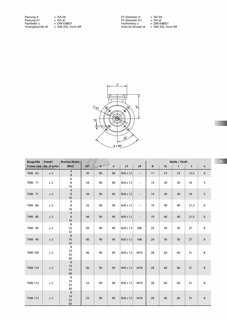
Passung d = ISA k6Passung b1 = ISA j6Passfeder u = DIN 6 885/1Innengewinde s4 = DIN 332, Form DR
Fit diameter d = ISA k6Fit diameter b1 = ISA j6Featherkey u = DIN 6 885/1Internal thread s4 = DIN 332, form DR
Baugröße Polzahl Bremse/Brake Welle / Shaft
Frame size No. of poles (Nm) m1 n o s1 s4 d i2 l t u
TMB 63 ≥ 2 4
30 90 90 M20 x 1,5 – 11 23 23 12,5 4 8 4TMB 71 ≥ 2 8 34 90 90 M20 x 1,5 – 14 30 30 16 5 16 4TMB 71 ≥ 2 8 44 90 90 M20 x 1,5 – 14 30 30 16 5 16 4TMB 80 ≥ 2 8 32 90 90 M20 x 1,5 – 19 40 40 21,5 6 16 4TMB 80 ≥ 2 8 44 90 90 M20 x 1,5 – 19 40 40 21,5 6 16 8TMB 90 ≥ 2 16 40 90 90 M20 x 1,5 M8 24 50 50 27 8 32 8TMB 90 ≥ 2 16 40 90 90 M20 x 1,5 M8 24 50 50 27 8 32 8
TMB 100 ≥ 2 16
46 90 90 M20 x 1,5 M10 28 60 60 31 8 32 60 8
TMB 110 ≥ 2 16
46 90 90 M20 x 1,5 M10 28 60 60 31 8 32 60 8
TMB 112 ≥ 2 16
53 90 90 M20 x 1,5 M10 28 60 60 31 8 32 60 8
TMB 112 ≥ 2 16
53 90 90 M20 x 1,5 M10 28 60 60 31 8 32 60
l
s4
s1
∅ g
n
∅ a
1
∅ b
1
i2
f1
c1
m1∅
g2
k1
u
d
t
45
s2
∅ e1
o
g1
4 x 90

Lieferbare FlanscheMaßblatt Nr. 824/09.004
Available flangesDimension sheet No. 824/09.004
· 34 ·
Baugröße Bauform Motorlänge
Frame size Type of Motor length
construction a1 b1 c1 e1 f1 s2 k m
TM 63 B14 90 60 8 75 2,5 M5 182 30
B14 120 80 12 100 3 M6 182 30
B14 140 95 10 115 3 M8 192 40
B5 140 95 10 115 3 9 192 40
TM 71 B14 105 70 12 85 2,5 M6 205 34
B14 120 80 12 100 3 M6 215 44
B5 120 80 12 100 3 7 225 54
B5 140 95 12 115 3 9 225 54
B5 160 110 12 130 3,5 9 225 54
TM 80 B14 120 80 12 100 3 M6 237 32
B5 120 80 12 100 3 7 257 52
B14 140 95 12 115 3 M8 249 44
B5 140 95 12 115 3 9 257 52
B5 160 110 12 130 3,5 9 257 52
B5 200 130 12 165 3,5 11 257 52
TM 90 B14 140 95 12 115 3 M8 282 40
B5 140 95 12 115 3 9 307 65
B14 160 110 12 130 3,5 M8 282 40
B5 160 110 12 130 3,5 9 307 65
B5 200 130 12 165 3,5 11 294 52
B5 250 180 12 215 4 14 282 52
TM 100 B14 140 95 12 115 3 M8 316 46
B14 160 110 12 130 3,5 M8 316 46
B5 200 130 12 165 3,5 11 328 58
B5 250 180 12 215 4 14 316 46
TM 112 B14 140 95 12 115 3 M8 338 53
B14 160 110 12 130 3,5 M8 338 53
B14 200 130 12 165 3,5 M10 350 65
B5 200 130 12 165 3,5 11 350 65
B5 250 180 12 215 4 14 350 65
TM 132 B14 250 180 12 215 4 M12 435 51
B5 300 230 20 265 4 14 470 86
Maße und Passungen nach DIN 42 677Passung b1 entspricht ISA j6
Dimensions and fits according to DIN 42 677Fit diameter b1 corresponds to ISA j6
f1
∅ a
1
∅ b
1
c145
90∅ e1
s2

Das EMOD-LieferprogrammDelivery program
Baureihe 820 Einphasenmotoren Schutzart IP 55 bis 2,5 kW
Baureihe 821 Drehstrommotoren IP 55 Basismotoren in Norm- und Sonderausführungen bis 1000 kW
Baureihe 821 IE Drehstrommotoren IP 55 IE2 + IE3 Motoren nach IEC 60034-30 bis 375 kW
Baureihe 822 Drehstrommotoren IP 23 in Norm- und Sonderausführungen bis 1200 kW
Baureihe 823 Außenläufermotoren Baureihe AS
Baureihe 824 Topfmotoren Schutzart IP 67 bis 6 kW
Baureihe 825 Tauchmotoren Schutzart IP 68 bis 1000 kW
Baureihe 826 Fahr- und Hebezeugmotoren bis 2/32-polig und regelbar
Baureihe 827 Positionierantriebe mit höchster Positioniergenauigkeit
Baureihe 828 Frequenzregelbare Drehstrommotoren für 1-, 2- und 4-Quadrantenbetrieb, Schutzart IP 55 und IP 23
Baureihe 829 Schiffsmotoren für Unter- und Oberdeckaufstellung, mit oder ohne Abnahme
Baureihe 831 Gleichstrommotoren Schutzart IP 44
Baureihe 832 Gleichstrommotoren Schutzart IP 23s
Baureihe 834 Reluktanzmotoren mit hohen Außertrittfallmomenten
Baureihe 835 Drehstrom-Servomotoren mit hohem Stillstandsmoment
Baureihe 836 Drehstrom-Schleifringläufermotoren Schutzart IP 54
Baureihe 837 Wassergekühlte Drehstrommotoren Leistungsbereich 0,75 bis 1000 kW
Baureihe 838 Flachmotoren Drehzahlen bis 24.000 U/min
Type 820 Single-phase motors degree of protection IP 55, up to 2.5kW
Type 821 Three-phase motors, IP 55 Basic-line in standard and special configurations up to 1000 kW
Type 821 IE Three-phase motors, IP 55 IE2 + IE3 Motors according to IEC 60034-30 up to 375 kW
Type 822 Three-phase motors, IP 23 in standard and special configurations, up to 1200kW
Type 823 External rotor motors type AS
Type 824 Encapsulated motors degree of protection IP 67, up to 6kW
Type 825 Submersible motors degree of protection IP 68, up to 1000 kW
Type 826 Crane and hoist drive motors with pole switching up to 2/32 poles and variable speed
Type 827 Positioning drives with extremely high positioning accuracy
Type 828 Variable speed polyphase motors 1, 2 and 4 quadrant operation, degrees of protection IP 55 and IP 23
Type 829 Marine motors for on-deck and below-deck applications, with and without certification
Type 831 DC motors degree of protection IP 44
Type 832 DC motors degree of protection IP 23s
Type 834 Reluctance motors for maintaining synchronisation at high torques
Type 835 AC servomotors with increased standstill torques
Type 836 Wound-rotor induction motors degree of protection IP 54
Type 837 Water-cooled three-phase motors rated outputs 0.75kW to 1000kW
Type 838 Flat motors rated speeds up to 24,000rpm

Motoren nach Maß
824
©cr
ear
t.d
e
EMOD MOTOREN GmbHElektromotorenfabrik36364 Bad SalzschlirfGermanyFon: + 49 66 48 51-0Fax: + 49 66 48 [email protected]