JP-3GB-A.S0004 タンデムフリーオペレーション
103
TTC 標準 TTC STANDARD JP-3GB-A.S0004 タンデムフリーオペレーション Tandem Free Operation 第 2 版 2001 年 5 月 14 日制定 社団法人 情報通信技術委員会 THE TELECOMMUNICATION TECHNOLOGY COMMITTEE
-
Upload
khangminh22 -
Category
Documents
-
view
0 -
download
0
Transcript of JP-3GB-A.S0004 タンデムフリーオペレーション
TTC標準 TTC STANDARD
JP-3GB-A.S0004
タンデムフリーオペレーション
Tandem Free Operation
第 2版
2001年 5月 14日制定
社団法人
情報通信技術委員会
THE TELECOMMUNICATION TECHNOLOGY COMMITTEE

本書は、(社)情報通信技術委員会が著作権を保有しています。
内容の一部又は全部を(社)情報通信技術委員会の許諾を得ることなく複製、転載、改変、
転用及びネットワーク上での送信、配布を行うことを禁止します。
- i - JP-3GB-A.S0004
JP-3GB-A.S0004
タンデムフリーオペレーション [Tandem Free Operation]
<参考> [Remarks]
1.英文記述の適用レベル [Application level of English description] 適用レベル [Application level]:E3
本標準の本文、付属資料および付録の文章および図に英文記述を含んでいる。
[English description is included in the text and figures of main body, annexes and appendices.]
2.国際勧告等の関連 [Relationship with international recommendations and standards] 本標準は、2001 年 1 月に 3GPP2 で承認された Technical Specification A.S0004-0.1 に準拠している。
[This standard is standardized based on the Technical Specification A.S0004-0.1 approved by 3GPP2 in Jan. 2001.]
3.上記国際勧告等に対する追加項目等 [Departures from international recommendations] 3.1 オプション選択項目 [Selection of optional items]
なし [None]
3.2 ナショナルマター項目 [Items of national matter]
なし [None]
3.3 原標準に対する変更項目 [Changes to original standard]
(2) 原標準が参照する標準のうち、TTC 標準・ARIB 標準に置き換える項目。
なし [None]
(2) 本標準で追加した項目。[Items added to the original standard]
なし [None]
(3) 本標準で削除した項目。ただし、本標準の理解を助けるために記述は残している。 [Items deleted from
the original standard]
なし [None]
(4) 本標準で修正した項目。[Items changed from the original standard]
なし [None]
3.4 原標準との章立て構成比較 [Difference in chapter ordering from the original standard.]
原標準との章立て構成の相違はない。
[There is no difference in chapter ordering from the original standard.]
4.改版の履歴 [Change history]
版数 [Revision] 制定日 [Date] 改版内容 [Contents]
第 1 版 [V.1] 2001 年 3 月 31 日 制定 [Newly standardized] 第 2 版 [V.2] 2001 年 5 月 14 日 改版 [Revised standardized]

JP-3GB-A.S0004 - ii -
5.工業所有権 [IPR] 本標準に関わる「工業所有権等の実施の権利に係る確認書」の提出状況は、TTCホームページでご覧に
なれます。
6.その他 [Others] なし [None]
3GPP2 A.S0004-0.1 Tandem Free Operation
i
3GPP2 A.S0004-0.1
Date: August, 2000
1
2
3
4
3GPP2 Tandem Free Operation Specification 5
Release A 6

Tandem Free Operation 3GPP2 A.S0004-0.1
ii
Contents 1
Foreword 2
1 Introduction.............................................................................................................................................. 1 3
2 References................................................................................................................................................ 1 4
3 Definitions and Abbreviations ................................................................................................................... 1 5 3.1 Definitions .........................................................................................................................................................1 6 3.2 Abbreviations.....................................................................................................................................................2 7
4 General Approach..................................................................................................................................... 3 8 4.1 Background........................................................................................................................................................3 9 4.2 Principle of Tandem Free Operation...................................................................................................................3 10
5 TFO Frame Structure ............................................................................................................................... 5 11 5.1 TFO Frame Structure for 16 kbps Sub-Multiplexing...........................................................................................5 12 5.1.1 Requirements/Assumptions for TFO Frame Structure Definitions .................................................................5 13 5.1.2 Coding of TFO Frames for 16 kbps Sub-Multiplexing...................................................................................5 14 5.1.3 TFO Frames for 16 kbps Sub-Multiplexing ...................................................................................................9 15
6 TFO Message Structure.......................................................................................................................... 22 16 6.1 Definition of the TFO_REQ Messages..............................................................................................................23 17 6.1.1 Definition of the TFO_Req_Extension_Block .............................................................................................24 18 6.1.2 Cyclic Redundancy Check...........................................................................................................................24 19 6.1.3 Definition of the Codec_List_Extension_Block ...........................................................................................24 20 6.2 Definition of the TFO_ACK Messages .............................................................................................................25 21 6.2.1 Definition of the TFO_Ack_Extension_Block .............................................................................................25 22 6.3 Definition of the TFO_TRANS Messages.........................................................................................................26 23 6.4 Definition of the TFO_NORMAL Message ......................................................................................................26 24 6.5 Definition of the TFO_FILL Message...............................................................................................................26 25 6.6 Definition of the TFO_DUP Message (TDMA only).........................................................................................26 26 6.7 Definition of the TFO_SYL Message (TDMA only) .........................................................................................27 27
7 Time Alignment of TFO Frames and TFO Messages............................................................................... 28 28 7.1 Time Alignment of TFO Messages...................................................................................................................28 29 7.2 Time Alignment of TFO Frames ......................................................................................................................28 30 7.3 Time Alignment of TFO Frames to Downlink TRAU Frames...........................................................................29 31
8 Processes for Tandem Free Operation ..................................................................................................... 31 32 8.1 Rx_TRAU Process ...........................................................................................................................................32 33 8.2 Tx_TRAU Process ...........................................................................................................................................32 34 8.2.1 Downlink Speech Transmission if TFO is ON ............................................................................................32 35 8.2.2 DTX handling for TIA/EIA-136 .................................................................................................................33 36 8.2.3 Synchronization and Bit Errors in Received TFO Frames ...........................................................................33 37 8.3 Tx_TFO Process ..............................................................................................................................................33 38 8.4 Rx_TFO Process ..............................................................................................................................................34 39 8.4.1 Search for and Monitoring of TFO Synchronization....................................................................................34 40 8.4.2 Errors in TFO Messages and TFO Frames ..................................................................................................35 41 8.5 TFO_Protocol Process ......................................................................................................................................36 42 8.5.1 Messages from Rx_TRAU or local MSC.....................................................................................................36 43 8.5.2 Messages to Tx_TRAU...............................................................................................................................36 44 8.5.3 Optional Messages to the local MSC (TDMA only) ....................................................................................37 45 8.5.4 Messages to and from Tx_TFO...................................................................................................................37 46 8.5.5 Messages from Rx_TFO .............................................................................................................................37 47 8.5.6 Messages from a higher level system (CDMA only) ....................................................................................37 48

3GPP2 A.S0004-0.1 Tandem Free Operation
iii
9 State Machine of the TFO_Protocol Process for CDMA.......................................................................... 39 1 9.1 Initialization ....................................................................................................................................................40 2 9.1.1 Not_Active State.........................................................................................................................................40 3 9.1.2 Wakeup State..............................................................................................................................................40 4 9.2 Establishment ..................................................................................................................................................40 5 9.2.1 First_Try State............................................................................................................................................40 6 9.2.2 Continuous_Retry State ..............................................................................................................................40 7 9.2.3 Periodic_Retry State ...................................................................................................................................41 8 9.2.4 Monitor State..............................................................................................................................................41 9 9.2.5 Mismatch State...........................................................................................................................................41 10 9.3 Contact State....................................................................................................................................................41 11 9.4 Konnect State...................................................................................................................................................41 12 9.5 Operation State ................................................................................................................................................41 13 9.6 Tandem............................................................................................................................................................42 14
10 Detailed Description of TFO_Protocol for CDMA .................................................................................. 43 15
11 State Machine of the TFO_Protocol Process for TDMA.......................................................................... 55 16 11.1 Initialization ....................................................................................................................................................56 17 11.1.1 Not_Active State.........................................................................................................................................56 18 11.1.2 Wakeup State..............................................................................................................................................56 19 11.2 Establishment ..................................................................................................................................................56 20 11.2.1 First_Try State............................................................................................................................................56 21 11.2.2 Continuous_Retry State ..............................................................................................................................57 22 11.2.3 Periodic_Retry State ...................................................................................................................................57 23 11.2.4 Monitor State..............................................................................................................................................57 24 11.2.5 Mismatch State...........................................................................................................................................57 25 11.3 Contact State....................................................................................................................................................57 26 11.4 Konnect State...................................................................................................................................................57 27 11.5 Operation State ................................................................................................................................................57 28 11.6 Local HO .........................................................................................................................................................58 29 11.6.1 Fast_Try State.............................................................................................................................................58 30 11.6.2 Fast_Contact State ......................................................................................................................................58 31 11.7 Distant HO, TFO Interruption ..........................................................................................................................58 32 11.7.1 Sync_Lost State ..........................................................................................................................................58 33 11.7.2 Re_Konnect State .......................................................................................................................................58 34 11.8 Failure State.....................................................................................................................................................58 35
12 Detailed Description of TFO_Protocol for TDMA .................................................................................. 59 36
13 Codec Mismatch Resolution and Codec Optimization.............................................................................. 70 37 13.1 CDMA TFO Operations...................................................................................................................................70 38 13.2 TDMA TFO Operations ...................................................................................................................................70 39
Annex A (Normative) Tandem Free Operation Capability Description and Requirements................................ 1 40 A.1 Introduction .......................................................................................................................................................1 41 A.2 Terminology ......................................................................................................................................................2 42 A.2.1 Acronyms .....................................................................................................................................................2 43 A.2.2 Definitions....................................................................................................................................................2 44 A.3 Scope .................................................................................................................................................................2 45 A.4 Tandem Free Operation Requirements ...............................................................................................................3 46 A.4.1 Mandatory Tandem Free Operation Requirements ........................................................................................3 47 A.4.2 Highly Desired Tandem Free Operation Requirements..................................................................................4 48
Annex B (Normative) Inband Signaling Protocol: Generic Structure............................................................... 1 49 B.1 Scope .................................................................................................................................................................1 50 B.2 Generic Structure of Inband Signaling Messages................................................................................................1 51
Tandem Free Operation 3GPP2 A.S0004-0.1
iv
B.2.1 Frequency and Order of Bit Transmission .....................................................................................................1 1 B.2.2 IS_Header.....................................................................................................................................................2 2 B.2.3 IS_Command_Block.....................................................................................................................................2 3 B.2.4 IS_Extension_Block(s) .................................................................................................................................3 4 B.3 Detailed Specification of IS Messages ................................................................................................................3 5 B.3.1 IS_REQ Message..........................................................................................................................................3 6 B.3.2 IS_ACK Message .........................................................................................................................................4 7 B.3.3 IS_IPE, IS_TRANS and IS_NORMAL Messages .........................................................................................4 8 B.3.4 IS_FILL Message..........................................................................................................................................5 9 B.3.5 IS_DUP Message..........................................................................................................................................6 10 B.3.6 IS_SYL Message ..........................................................................................................................................6 11 B.4 Keep_Open_Indication.......................................................................................................................................6 12 B.5 Rules for Sending of IS Messages.......................................................................................................................7 13 B.6 IS_System_Identification_Block.........................................................................................................................8 14
Annex C (Informative) In Path Equipment: Generic Rules and Guidelines ..................................................... 1 15 C.1 Scope .................................................................................................................................................................1 16 C.2 Types of In Path Equipment ...............................................................................................................................1 17 C.3 IS_Compliant IPEs.............................................................................................................................................2 18 C.3.1 Typical IPEs are IS_Passive..........................................................................................................................2 19 C.3.2 IS Message_Transparency.............................................................................................................................2 20 C.3.3 IPE State Representation...............................................................................................................................3 21 C.3.4 IPE in Sync_Not_Found ...............................................................................................................................4 22 C.3.5 IPE in Sync_Found .......................................................................................................................................5 23 C.3.6 IPE in Sync_Lost ..........................................................................................................................................5 24 C.3.7 IPE in Keep_Open_Sync...............................................................................................................................5 25 C.3.8 IPE in Keep_Open_Lost ...............................................................................................................................5 26 C.4 IPE Error Handling............................................................................................................................................6 27 C.5 IPE Transmission Delay.....................................................................................................................................6 28 C.5.1 IPE Transmission Delay in Normal_Mode....................................................................................................6 29 C.5.2 IPE Transmission Delay in Transparent_Mode .............................................................................................6 30 C.6 Compliance to IS Messages................................................................................................................................6 31 C.6.1 Compliance to IS_REQ and IS_ACK Messages ............................................................................................7 32 C.6.2 Compliance to IS_NORMAL Message..........................................................................................................7 33 C.6.3 Compliance to IS_TRANS_x Messages ........................................................................................................7 34 C.6.4 Compliance to IS_TRANS_x_u Messages.....................................................................................................7 35 C.6.5 Compliance to IS_FILL Message ..................................................................................................................8 36 C.6.6 Compliance to IS_DUP Messages .................................................................................................................8 37 C.6.7 Compliance to IS_SYL Messages..................................................................................................................8 38
Annex D History ........................................................................................................................................... 1 39 40
3GPP2 A.S0004-0.1 Tandem Free Operation
v
Foreword (this foreword is not part of American Nat ional Standard xxxx) 1
2 This standard is based on ETS GSM 08.62, Version 7.0.0, released Feb-1999. It is modified in order to adapt the Tandem 3 Free Operation to the North American Standards TIA/EIA-136 and TIA/EIA-95. 4 5 The present document introduces the Inband Signaling Protocol between Transcoder/Rate Adapter Units for speech traffic 6 channels for the Tandem Free Operation (TFO) of Speech Codecs within the digital cellular telecommunications system. 7 The contents of this document are subject to continuing work and may change following standard TIA/EIA procedures. 8
3GPP2 A.S0004.1 Tandem Free Operation
1
1 Introduction 1
This service description document details the Inband Signaling Protocol between Transcoder/Rate Adapter Units (TRAU) 2 for speech traffic channels for the Tandem Free Operation (TFO) of Speech Codecs, sometimes also termed "Vocoder 3 Bypass". It is applied to the North American standards TIA/EIA-136 and TIA/EIA-95. 4 5 Annex A is mandatory and defines the capability and requirements used in the development of this TFO standard. 6 7 Annex B is mandatory and describes the general Inband Signaling (IS) Principle. It is identical for all systems (e.g., 8 TIA/EIA-136, TIA/EIA-95, GSM) and only updated to include the System Identifications for TIA/EIA-136 and TIA/EIA-9 95. 10 11 Annex C is informative and gives the rules for In Path Equipment (IPE). It is identical for all systems (e.g., TIA/EIA-136, 12 TIA/EIA-95, GSM). 13 14
2 References 15
The following documents contain provisions which, through reference in this text, constitute provisions of the present 16 document. 17
• References are either specific (identified by date of publication, edition number, version number, etc.) or 18 non-specific. 19
• For a specific reference, subsequent revisions do not apply. 20 • For a non-specific reference, the latest version applies. 21 • A non-specific reference to an ETS shall also be taken to refer to later versions published as an EN with the same 22
number. 23 [1] TIA/EIA-136-410 " TDMA Cellular/PCS – Radio Interface Enhanced Full-Rate Voice Codec " 24
(ACELP) 25 [2] TIA/EIA-136-420 "VSELP" 26 [3] TIA/EIA-136-430 "US1" 27 [4] TIA/EIA-95-B “Mobile Station – Base Station Compatibility Standard for Dual Mode Spread 28
Spectrum Systems”, 1998 29 [5] TIA/EIA-96C “Speech Service Option Standard for Wideband Spread Spectrum Systems”, 1998 30 [6] TIA/EIA/IS-127-1 “Enhanced Variable Rate Codec, Speech Service Option 3 for Wideband Spread 31
Spectrum Digital Systems”, 1998 32 [7] TIA/EIA/IS-733-1 “High Rate Speech Service Option 17 for Wideband Spread Spectrum 33
Communication Systems”, 1999 34 [8] GSM 08.62: "Digital cellular telecommunication system (Phase 2+); Inband Tandem Free Operation 35
(TFO) of Speech Codecs; Version 7.0.0". 36 [9] ITU-T Recommendation I.130: "Method for the characterization of telecommunication services 37
supported by an ISDN and network capabilities of an ISDN". 38 39
3 Definitions and Abbreviations 40
3.1 Definitions 41
For the purposes of the present document, the following definitions apply. 42 TRAU Frame is used equivalent to "TRAU Speech Frame". TRAU Frames are transmitted between TRAU and TRX. 43 TFO Frame is used equivalent to "TFO TRAU Frame". TFO Frames are transmitted between TFO Partners (e.g. TRAUs). 44 TTL is used to denote the link between the TRAU and the TRX, independent of the system (TIA/EIA-136 or TIA/EIA-95). 45

Tandem Free Operation 3GPP2 A.S0004-0.1
2
Silence Descriptor (SID) is the replacement for the speech parameters in TFO frames containing the comfort noise 1 parameters, which are calculated by the MS encoder and used to generate comfort noise in the decoder during speech 2 pauses. 3 Error Concealment Indicator (ECI) is used to signal that a TFO frame does not contain valid speech parameters. 4 PSTN Interface is used to denominate the 64 kbps PCM link from/to the TRAU. Please note that PSTN Interface does not 5 necessarily mean a connection to a PSTN, but is a general description for a digital 64 kbps PCM line. 6
3.2 Abbreviations 7
For the purposes of the present document, the following abbreviations apply. 8 ACELP Algebraic Code Excited Linear Prediction (TIA/EIA - 136 - 410) 9 BFI Bad Frame Indicator 10 BS Base Station 11 BSC Base Station Controller 12 BTS Base Transceiver System 13 ECI Error Concealment Indicator 14 EVRC Enhanced Variable Rate Codec (TIA/EIA/IS-127-1) 15 EFRC Enhanced Full-Rate Codec 16 HO Hard Handoff in the case of TIA/EIA-95; Handover with TRAU change involved in the case of 17
TIA/EIA-136 18 IPE In Path Equipment 19 LPC Linear Predictive Codec 20 MS Mobile Station 21 MSC Mobile Switching Center 22 PCM Pulse Coded Modulation 23 PCM sample 8-bit value representing the A_Law or µ_Law coded sample of a speech or audio signal; 24
sometimes used to indicate the time interval between two PCM samples (125µs). 25 PCM_Silence either PCM_Alaw_Silence, or PCM_µLaw_Silence, dependent on application 26 Q8 Speech Codec Service Option 1 for TIA/EIA-95 at 8 kbps (TIA/EIA-96-C) 27 Q13 Speech Codec Service Option 17 for TIA/EIA-95 at 13.3 kbps (TIA/EIA/IS-733-1) 28 SID Silence Descriptor 29 TCME TFO Circuit Multiplication Equipment 30 TFO_ACK TFO Acknowledgement Message 31 T_Bits Time Alignment Bits 32 TFO Tandem Free Operation 33 TFO_FILL TFO Fill Message 34 TFO_TRANS TFO Transparent Mode Message 35 TFO_NORMAL TFO Normal Mode Message 36 TFO_DUP TFO (Half) Duplex Mode Message 37 TFO_REQ TFO Request Message 38 TFO_SYL TFO Sync Lost Message 39 TFO Tandem Free Operation 40 TRAU Transcoder and Rate Adapter Unit - this unit performs speech encoding and decoding on the 41
network side of the communications system according to the codec standard selected 42 TRX Radio transceiver station 43 TTL TRAU-TRX-Link 44 US1 US 1 Codec (TIA/EIA - 136 - 430) 45 VSELP Vector Sum Excited Linear Predictive Coding (TIA/EIA - 136 - 420) 46

3GPP2 A.S0004.1 Tandem Free Operation
3
4 General Approach 1
4.1 Background 2
In case of mobile-to-mobile calls (MS-MS calls) in mobile networks without TFO, the speech signal is encoded within the 3 first mobile station for transmission on the air interface, and decoded within the associated first TRAU. The PCM samples 4 are then transported within the fixed part of the network to the second TRAU using 64kbps traffic links. This second 5 TRAU encodes the speech signal a second time for the transmission on the second air interface, and the associated second 6 mobile station decodes it again. The two Codecs (Encoder-Decoder pair) of the connection are in "Tandem Operation". 7 8 Tandem Free Operation overcomes the disadvantage of degraded speech quality caused by the two consecutive 9 encoding/decoding processes required in Tandem Operation. 10 11 Tandem Free Operation requires a bi-directional "transparent" digital channel or path between the TRAUs. Devices 12 within these paths need to be transparent or to be switched off for the TFO Messages and the TFO Frames. To guarantee 13 this digital transparency with out-of-band signaling is not trivial. In particular, out-of-band signaling has insufficient 14 speed to fall back to normal operation in case of sudden interruption of the transparency of the links. 15 16 This TFO recommendation defines therefore an inband signaling protocol, which 17 • tests if: 18
− an MS-MS call is given; 19 − the paths between the TRAUs are digitally transparent; 20 − both TRAUs support TFO; 21 − the speech Codecs on both radio legs are identical. 22
• establishes the TFO connection by: 23 − commanding the paths to go transparent; 24 − bypassing the decoder/encoder functions within the TRAUs. 25
• provides a fast fall back procedure for sudden TFO interruption, and 26 • supports resolution of Codec mismatch situations (TDMA only). 27 28 29 Although Tandem Free Operation only requires changes to the TRAUs, network IPEs may also need to be modified to be 30 compliant with TFO. 31 32 In an optional mode, the TFO supports the resolution of codec mismatch situations (TDMA only); i.e., the situation where 33 the Speech-Codecs at both radio-legs are different. For this, additional communication channels between the TRAUs and 34 their corresponding MSCs are necessary and the MSCs have to take appropriate steps to change the Codec type(s). The 35 procedure on how to change a Codec is considered as manufacturer proprietary and not handled within this 36 recommendation. 37 38
4.2 Principle of Tandem Free Operation 39
The TRAU shall be controlled by the MSC when it is positioned remote from the MSC. In this case, the speech/data 40 information and TRAU control signals shall be transferred between the MSC and the TRAU in frames denoted "TRAU 41 Frames", not described further (manufacturer proprietary). 42 43 In Tandem Free Operation similar frames, denoted ”TFO Frames”, are transferred between the two TRAUs on the 44 PSTN-interface (decoded speech at 64 kbps) by inband signaling, i.e. inserting them into the PCM sample bit stream. 45 46 TFO frames have a fixed size (and length) of 320 bits (20 ms) and are carried by 16 kbps traffic channels mapped onto the 47 two least significant bits of the PCM samples. 48
Tandem Free Operation 3GPP2 A.S0004-0.1
4
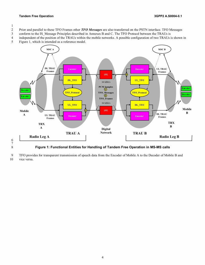
1 Prior and parallel to these TFO Frames other TFO Messages are also transferred on the PSTN interface. TFO Messages 2 conform to the IS_Message Principles described in Annexes B and C. The TFO Protocol between the TRAUs is 3 independent of the position of the TRAUs within the mobile networks. A possible configuration of two TRAUs is shown in 4 Figure 1, which is intended as a reference model. 5
IPE
IPE
PCM Samples
TFO_Messages
TFO_Frames
64 kBit/s
64 kBit/s
TFO_Protocol
DL_TFO
UL_TFO
Decoder
Encoder
TFO_Protocol
DL_TFO
UL_TFO
Decoder
Encoder
TRAU BTRAU A
UL TRAUFrames
DL TRAUFrames
DL TRAUFrames
UL TRAUFrames
TRXB
MobileB
TRXA
MobileA
Encoder
DecoderEncoder
Decoder
DigitalNetwork
MSC A MSC B
Radio Leg A Radio Leg B6
7 Figure 1: Functional Entities for Handling of Tandem Free Operation in MS-MS calls 8
TFO provides for transparent transmission of speech data from the Encoder of Mobile A to the Decoder of Mobile B and 9 vice versa. 10
3GPP2 A.S0004.1 Tandem Free Operation
5
5 TFO Frame Structure 1
5.1 TFO Frame Structure for 16 kbps Sub-Multiplexing 2
This section defines TFO frame structures for various communication systems. These definitions include structures for Q8 3 (IS-96-C), EVRC (TIA/EIA/IS-127-1), Q13 (TIA/EIA/IS-733-1) for CDMA system and EFRC (TIA/EIA-136-410), 4 VSELP (TIA/EIA-136-420), and US1 (TIA/EIA-136-430) for TDMA system. All TFO frame structures for TDMA are 5 defined to facilitate interoperability with the GSM TFO standard (GSM 08.62). 6 7
5.1.1 Requirements/Assumptions for TFO Frame Structure Definitions 8
This section lists a set of requirements and assumptions used to define the TFO frame structures for different systems and 9 speech codecs. Most of the requirements and assumptions are adopted from the GSM TFO standard (GSM 08.62) to 10 ensure CDMA, TDMA, and GSM TFO interoperability when compatible speech codecs are in use. 11 12 - The two base station entities in a tandem call are inter-connected by a 64 kbps link with an 8000 Hz sampling 13
frequency. 14 - TFO frame information is placed into the two least significant bits of each 8-bit octet (PCM sample) of the 64 kbps 15
link between the local and remote base station units. The remaining 6 bits of each octet are filled with the 16 corresponding decoded PCM bits. 17
- A TFO frame covers 160 8-bit octets and spans a period of 20 ms. 18 - The least significant bit (LSB) of every other 16th PCM octet is used for embedded TFO message bits. 19 - Eight bits are allocated for system identification. This 8-bit information is also used as a TFO frame identifier. 20 - Synchronization bits are defined in TFO frames to ensure TFO synchronization capability. These bits consist of 19 21
“1”s and eight “0”s in predefined TFO frame positions. This synchronization pattern is compatible to the GSM TFO 22 standard (GSM 08.62) 23
- Each set of traffic data in a TFO frame is marked with a 4-bit speech codec type field. It is used to confirm the codec 24 type in systems where codec change during TFO is allowed. 25
- Each set of traffic data within a TFO frame is protected by Cyclic Redundancy Checks (CRC) against data corruption 26 during transmission over the inter-base station link(s). 27
- One bit is reserved to denote the presence or absence of TFO embedded IS_Messages (see section 7.1.2.3). 28 - Time Alignment bits are allocated for potential phase adjustment after TFO establishment. 29 - All unused bit positions in a TFO frame structure are undefined and are not to be used for frame synchronization. 30
They are marked as “Reserved”. 31 32
5.1.2 Coding of TFO Frames for 16 kbps Sub-Multiplexing 33
This section presents general information applicable to some of the fields in a TFO frame structure. Section 7.1.3 details 34 the TFO frame structure definition information for each individual codec. 35 36
5.1.2.1 Coding of System Identification Bits (S1…S8) 37
The eight bits S1…S8 are used for System Identification. They identify the sending system of the TFO_Frames. 38 39
Table 1: System Identification Assignment 40 S1…S8 System 0000.0000 GSM (for information, see ETS GSM 08.62 and 08.60) 0000.0001 TDMA 0000.0010 CDMA All others (253) Reserved
Tandem Free Operation 3GPP2 A.S0004-0.1
6
1 Note: Coding of these identification bits is the same as coding of System Identification in TFO_REQ_Messages and 2 TFO_ACK_Messages. See Annex B and section 8. 3 4
5.1.2.2 Coding of Speech Codec Type (C1…C4) 5
A 4-bit field is used to identify the codec type in the TFO frame construction. TFO frames for different systems may have 6 the same codec type. This field, together with the 8-bit system identifier, uniquely identifies the system and codec types 7 characterizing the TFO frame sending party. 8 9
Table 2: Speech Codec Type Assignment 10 S1…S8 System C1...C4 0000.0000 GSM (for information, see ETS GSM 08.62) 0000.0001 TDMA 0000 (VSELP, TIA/EIA-136-420) 0001 (EFRC, TIA/EIA-136-410) 0010 (US1, TIA/TIA-136-430) All others (13) reserved 0000.0010 CDMA 0000 (Q8, IS-96-C) 0001 (EVRC, TIA/EIA/IS-127-1) 0010 (Q13, TIA/EIA/IS-733-1) All others (13) reserved
11 12
5.1.2.3 Embedded TFO Message Indicator Bit (C5) 13
This bit is clear (“0”) if the TFO frame has no embedded IS-message. It is set (“1”) to denote the presence of an 14 embedded IS-message in the TFO frame. 15 16
5.1.2.4 Packet Type Information for CDMA Variable Rate Codecs (D1...D9) 17
Variable bit rate speech packet decoding in CDMA requires information on the packet encoding rate and the packet status. 18 For Q8, EVRC, or Q13, the information is represented by a 3-bit field attached to each packet received from the BTS. 19 During CDMA TFO operation, proper handling of the encoded packet received by the local BSC from the remote TFO 20 partner requires successful transmission of the 3-bit packet type information for each encoded packet. The information is 21 used to determine if frame erasure recovery is necessary and to ensure proper processing by the local BSC and BTS for 22 downlink transmission to the local mobile user. 23 24 A 9-bit field, D1 to D9, is defined to provide error detection and correction capability for the 3-bit packet type information 25 transmission. Table 3 lists the 9-bit non-linear block codes. 26 27
Table 3: Block codes for CDMA variable rate codec packet type coding 28 Code index D1...D9
0 0,0000,0000 1 0,0001,1111 2 0,1111,1000 3 1,0110,0110 4 1,1101,0101 5 1,1010,1011 6 1,1000,1100 7 0,0111,0011
29
3GPP2 A.S0004.1 Tandem Free Operation
7
Table 4, 5 and 6 present a set of mappings of the Q8, EVRC, and Q13 packet type information to the code words. During 1 a TFO frame construction, each 3-bit packet type is mapped by the Tx_TFO to a 9-bit code, except for Q13 Rate 1 packets. 2 When a TFO frame is received by the Rx_TFO, the reverse mapping is performed to retrieve the packet type information. 3 Additional packet type information is indirectly provided by other rate specific bit fields such as CRC bits. Information in 4 these fields could be used in the packet type identification process. 5 6 When only the first six code words from Table 3 are used, double error correction capability is provided. For EVRC, a 7 blank frame and a Rate 1/8 frame with all bits set to “1” are easily identified and validated with the data content. They are 8 mapped to the last two code words, which have slightly less protection capability. Similarly, the blank frame packet type 9 for Q8 is also mapped to the 6th code word. 10 11
Table 4: Q8 packet type information to 9-bit code word mapping. For more information on Q8 packet 12 type information, see IS-96-C 13
Q8 packet type Code index D1 D2 … D9 Rate 1 0 0,0000,0000 Rate ½ 1 0,0001,1111 Rate ¼ 2 0,1111,1000 Rate 1/8 3 1,0110,0110 Blank 6 1,1000,1100 Rate 1 with bit errors 4 1,1101,0101 Insufficient frame quality (erasure) 5 1,1010,1011
14 15
Table 5: EVRC packet type information to 9-bit code word mapping. For more information on EVRC 16 packet type information, see TIA/EIA/IS-127-1 17
EVRC packet type Code index D1 D2 … D9 Rate 1 0 0,0000,0000 Rate ½ 1 0,0001,1111 Rate ¼ 2 0,1111,1000 Rate 1/8 3 1,0110,0110 Blank 6 1,1000,1100 Rate 1 with bit errors 4 1,1101,0101 Insufficient frame quality (erasure) 5 1,1010,1011 Rate 1/8 with all bits set to ‘1’ 7 0,0111,0011
18 19 Table 6: Q13 packet type information to 9-bit code word mapping. For more information on Q13 packet 20
type information, see TIA/EIA/IS-733-1 21 Q13 packet type Code index D1 … D9 Rate 1* 0 0,000 Blank 1 0,0001,1111 Rate ¼ 2 0,1111,1000 Rate 1/8 3 1,0110,0110 Rate ½ 4 1,1101,0101 Insufficient frame quality (erasure) 5 1,1010,1011
22 * Rate 1 uses only a 4-bit code (D1 … D4). 23
24
Tandem Free Operation 3GPP2 A.S0004-0.1
8
1
5.1.2.5 Coding of Time Alignment Bits (T1...T4) 2
Table 7: Coding of Time Alignment bits 3 T1...T4 Notes 1111 Bits positioned at the end of a TFO Frame. No other codes allowed.
4 5 If the timing of the frame is to be advanced by 250 µs, then these four bits (T1...T4) are not transferred in order to reduce 6 the length of the frame accordingly. If the timing is to be advanced by 125 µs, then T3 and T4 are not transferred. If the 7 timing of the frame is to be delayed by 125 µs (or a multiple of it), then another pair of T-Bits (1-bits) is transferred (or a 8 multiple of it), in order to increase the length of the frame accordingly. 9 Timing for the TIA/EIA/IS-733-1 can only be advanced by 125 µs, as only two T-Bits (T1, T2) are available. 10 11
5.1.2.6 Coding of Data Bits for VSELP, EFRC, US1, Q8 and EVRC (D-Bits) 12
Each set of traffic data in a TFO frame is partitioned at the subframe boundaries. Each partitioned sub-set is protected by 13 3 parity bits at the end of the sub-set. The order within a given subset is the same as presented in section 7.1.3. 14 15 These parity bits are added to the bits of the subset, according to a degenerate (shortened) cyclic code using the generator 16 polynomial: 17 18 g(D) = D3 + D + 1 19 20 The encoding of the cyclic code is performed in a systematic form which means that, in GF(2), the polynomial: 21 22 d(m)Dn + d(m+1)Dn-1 + ... + d(m + n-3)D3 + p(0)D2 + p(1)D + p(2) 23 24 where p(0), p(1), p(2) are the parity bits, when divided by g(D), yields a remainder equal to: 25 26 1 + D + D2 27 28 and where d(m) corresponds to a lower order D bit, e.g. D1, and d(m+n-3) corresponds to a higher order D bit, e.g. D29. 29 30 For every CRC, the transmission order is p(0) first followed by p(1) and p(2) successively. 31 32
5.1.2.7 Coding of Data Bits for Q13 (D-Bits) 33
34 Each set of traffic data in a Q13 TFO frame is protected by 7 parity bits at the end of the set. The order within a given set 35 is the same as presented in section 7.1.3. 36 37 The CRC generator polynomial g(X) is defined as 38 39 75421)( XXXXXXg +++++= 40 41 The input polynomial )(Xa consists of the N data bits to be protected, where )1(d is the lower order D bit, e.g. D10 and 42
)(Nd is the higher order D bit, e.g. D25. 43 44 021 )()1(...)2()1()( XNdXNdXdXdXa NN +−+++= −− 45
46

3GPP2 A.S0004.1 Tandem Free Operation
9
1 The parity polynomial )(Xb is the remainder of the division of the input polynomial and the generator polynomial, i.e. 2 3
)()()(
)()( 7
XgXbXq
XgXXa += 4
5 023456 )7()6()5()4()3()2()1()( XCXCXCXCXCXCXCXb ++++++= 6 7 The CRC bits are written into the TFO frame in ascending order, i.e. )1(C is first and )7(C is last. 8 9 The quotient polynomial )(Xq is discarded. 10 11
5.1.2.8 Rate Reduction Parameters for CDMA Variable Rate Codecs 12
The TFO frame structures for CDMA variable rate codecs Q8 and EVRC typically contain the local system downlink and 13 uplink rate reduction parameters. The TFO frame structure for CDMA variable rate codec Q13 contains only the local 14 system downlink rate reduction parameters. Upon receiving a remote downlink rate reduction parameter from the remote 15 TFO partner for CDMA variable rate coding, the local system may command the local mobile station to perform speech 16 encoding for local uplink transmission at the matching rate reduction mode. This measure avoids unnecessary rate 17 conversions by the remote TFO partner and thus avoids any possible artifacts associated with the rate conversion process 18 in the remote mobile. 19 20 Uplink rate reduction parameter is transmitted to the remote TFO partner for information only. 21 22
5.1.2.9 Dim-And-Burst with CDMA Variable Rate Codecs 23
The Dim-And-Burst feature of TIA/EIA-95 requires the TRAU to lower the coding rate upon request. During TFO, 24 however, the coding rate is not determined by the local TRAU itself, but by the remote mobile. For this situation, the 25 TRAU can send a message to the mobile station by reducing a rate 1 frame to a frame of a lower rate or by using Blank-26 and-Burst signaling. The design of a suitable algorithm is manufacturer dependent and not in the scope of this document. 27 28
5.1.3 TFO Frames for 16 kbps Sub-Multiplexing 29
This section presents TFO frame structures in detail for the speech codecs presented above. 30 31 Bit m of octet n, shall be transmitted in the Least Significant Bit of the 32 PCM sample k = n*4 + (m+1)/2 for m = (1, 3, 5, 7) (gray shaded columns) and n = (0...39). 33 Bit m of octet n shall be transmitted in the second Least Significant Bit of the 34 PCM sample k = n*4 + m/2 for m = (2, 4, 6, 8) (unshaded columns) and n = (0...39). 35 36 The underlined synchronization bits, as shown on the frame structure diagrams, can be used for embedded TFO messages. 37 38
5.1.3.1 TFO Frame Structure for TDMA VSELP (TIA/EIA-136-420) 39
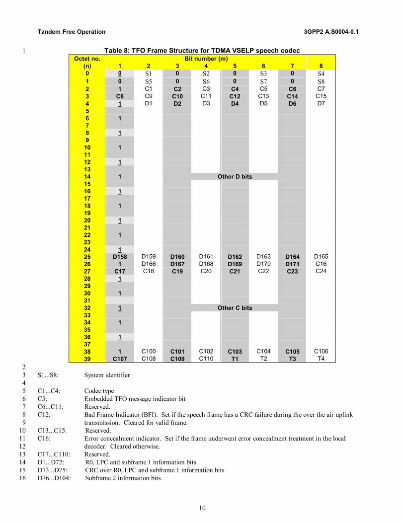
TFO frame structure for TDMA VSELP speech codec is as defined in Table 8. Each frame consists of 320 bits. For the 40 purpose of this description, the 320 bits of one TFO frame are arranged in 40 rows (0...39), with 8 bits (1...8: one octet) 41 each. 42
Tandem Free Operation 3GPP2 A.S0004-0.1
10
Table 8: TFO Frame Structure for TDMA VSELP speech codec 1 Octet no. Bit number (m)
(n) 1 2 3 4 5 6 7 8 0 0 S1 0 S2 0 S3 0 S4 1 0 S5 0 S6 0 S7 0 S8 2 1 C1 C2 C3 C4 C5 C6 C7 3 C8 C9 C10 C11 C12 C13 C14 C15 4 1 D1 D2 D3 D4 D5 D6 D7 5 6 1 7 8 1 9
10 1 11 12 1 13 14 1 Other D bits 15 16 1 17 18 1 19 20 1 21 22 1 23 24 1 25 D158 D159 D160 D161 D162 D163 D164 D165 26 1 D166 D167 D168 D169 D170 D171 C16 27 C17 C18 C19 C20 C21 C22 C23 C24 28 1 29 30 1 31 32 1 Other C bits 33 34 1 35 36 1 37 38 1 C100 C101 C102 C103 C104 C105 C106 39 C107 C108 C109 C110 T1 T2 T3 T4
2 S1...S8: System identifier 3 4 C1...C4: Codec type 5 C5: Embedded TFO message indicator bit 6 C6...C11: Reserved. 7 C12: Bad Frame Indicator (BFI). Set if the speech frame has a CRC failure during the over the air uplink 8
transmission. Cleared for valid frame. 9 C13...C15: Reserved. 10 C16: Error concealment indicator. Set if the frame underwent error concealment treatment in the local 11
decoder. Cleared otherwise. 12 C17...C110: Reserved. 13 D1...D72: R0, LPC and subframe 1 information bits 14 D73...D75: CRC over R0, LPC and subframe 1 information bits 15 D76...D104: Subframe 2 information bits 16
3GPP2 A.S0004.1 Tandem Free Operation
11
D105...D107: CRC over subframe 2 information bits 1 D108...D136: Subframe 3 information bits 2 D137...D139: CRC over subframe 3 information bits 3 D140...D168: Subframe 4 information bits 4 D169...D171: CRC over subframe 4 information bits 5 6 Notes: VSELP encoded parameters are transmitted in the order specified in TIA/EIA-136-420 with the most significant 7 bits transmitted first. 8 9
5.1.3.2 TFO Frame Structure for TDMA EFRC (TIA/EIA-136-410) 10
TFO frame structure for TDMA EFRC speech codec is as defined in Table 9. Each frame consists of 320 bits. For the 11 purpose of this description, the 320 bits of one TFO frame are arranged in 40 rows (0...39), with 8 bits (1...8: one octet) 12 each. 13

Tandem Free Operation 3GPP2 A.S0004-0.1
12
Table 9: TFO Frame Structure for TDMA EFRC speech codec 1 Octet no. Bit number (m)
(n) 1 2 3 4 5 6 7 8 0 0 S1 0 S2 0 S3 0 S4 1 0 S5 0 S6 0 S7 0 S8 2 1 C1 C2 C3 C4 C5 C6 C7 3 C8 C9 C10 C11 C12 C13 C14 C15 4 1 D1 D2 D3 D4 D5 D6 D7 5 6 1 7 8 1 9
10 1 11 12 1 13 14 1 Other D bits 15 16 1 17 18 1 19 20 1 21 22 1 23 24 1 D151 D152 D153 D154 D155 D156 D157 25 D158 D159 D160 C16 C17 C18 C19 C20 26 1 C21 C22 C23 C24 C25 C26 C27 27 28 1 29 30 1 31 Other C bits 32 1 33 34 1 35 36 1 37 38 1 C111 C112 C113 C114 C115 C116 C117 39 C118 C119 C120 C121 T1 T2 T3 T4
2 S1...S8: System identifier 3 4 C1...C4: Codec type 5 C5: Embedded TFO message indicator bit 6 C6...C11: Reserved. 7 C12: Bad Frame Indicator (BFI). Set if the speech frame has a CRC failure during the over the air uplink 8
transmission or if the frame is not a speech frame. Cleared for a valid speech frame. 9 C13: Comfort Noise Bad Frame Indicator (BFI_CN): Set if the comfort noise parameter frame has a CRC 10
failure during the over the air uplink transmission or if the frame is not a comfort noise parameter frame. 11 Cleared otherwise. 12
C14...C15: Reserved. 13 C16: Error concealment indicator. Set if the frame underwent error concealment treatment in the local 14
decoder. Cleared otherwise. 15
3GPP2 A.S0004.1 Tandem Free Operation
13
C17: DTX high/low state indicator. Set if DTX is applied on the frame in the local uplink transmission. 1 Cleared otherwise. 2
C18...C121: Reserved. 3 4 Speech TFO frame: 5 D1...D58: LPC and subframe 1 information bits s0 to s57 6 D59...D61: CRC over bits s0 to s57 7 D62...D90: Subframe 2 information bits s58 to s86 8 D91...D93: CRC over bits s58 to s86 9 D94...D125: Subframe 3 information bits s87 to s118 10 D126...D128: CRC over bits s87 to s118 11 D129...D157: Subframe 4 information bits s119 to s147 12 D158...D160: CRC over bits s119 to s147 13 14 Comfort noise parameter TFO frame: 15 D1...D38: LPC, excitation gain, and RESC parameter bits cn0 to cn37 16 D39...D41: CRC over bits D1 to D38 17 D42...D160: Reserved. 18 19 Blank TFO frame: 20 D1...D160: Reserved. 21 22 T1...T4: Time alignment bits 23 24 Notes: 25 • For speech parameter bit order information, see TIA/EIA-136-410. 26 • For information on comfort noise parameter bit order, see TIA/EIA-136-410. 27 • During DTX-low, local Tx_TFO sends comfort noise parameter TFO frames to the remote TFO partner. The remote 28
TFO partner is to convert these TFO frames into normal speech frame format for the remote mobile station. This 29 approach is taken by the GSM TFO standard and is adopted here to ensure interoperability with the GSM TFO 30 standard. 31
• During DTX-low and in the absence of comfort noise parameters, local Tx_TFO sends blank TFO frames to the 32 remote TFO partner. The remote TFO partner is to convert these blank TFO frames into normal speech frame format 33 for the remote mobile station. 34
• Speech, comfort noise parameter or blank TFO frames are marked by control bits C12, C13 and C17. 35 • Data bits in the blank TFO frames are reserved. 36 37
5.1.3.3 TFO Frame Structure for TDMA US1 (TIA/EIA-136-430) 38
TFO frame structure for TDMA US1 speech codec is as defined in Table 10. Each frame consists of 320 bits. For the 39 purpose of this description, the 320 bits of one TFO Frame are arranged in 40 rows (0...39), with 8 bits (1...8: one octet) 40 each. 41
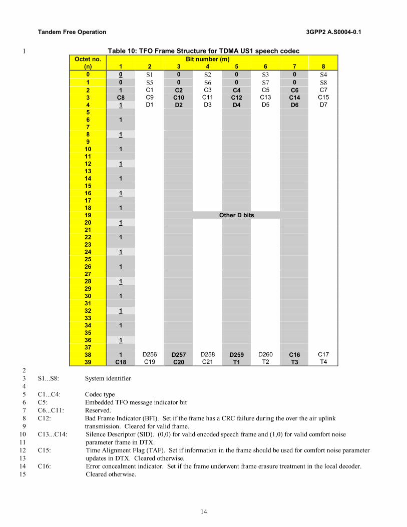
Tandem Free Operation 3GPP2 A.S0004-0.1
14
Table 10: TFO Frame Structure for TDMA US1 speech codec 1 Octet no. Bit number (m)
(n) 1 2 3 4 5 6 7 8 0 0 S1 0 S2 0 S3 0 S4 1 0 S5 0 S6 0 S7 0 S8 2 1 C1 C2 C3 C4 C5 C6 C7 3 C8 C9 C10 C11 C12 C13 C14 C15 4 1 D1 D2 D3 D4 D5 D6 D7 5 6 1 7 8 1 9
10 1 11 12 1 13 14 1 15 16 1 17 18 1 19 Other D bits 20 1 21 22 1 23 24 1 25 26 1 27 28 1 29 30 1 31 32 1 33 34 1 35 36 1 37 38 1 D256 D257 D258 D259 D260 C16 C17 39 C18 C19 C20 C21 T1 T2 T3 T4
2 S1...S8: System identifier 3 4 C1...C4: Codec type 5 C5: Embedded TFO message indicator bit 6 C6...C11: Reserved. 7 C12: Bad Frame Indicator (BFI). Set if the frame has a CRC failure during the over the air uplink 8
transmission. Cleared for valid frame. 9 C13...C14: Silence Descriptor (SID). (0,0) for valid encoded speech frame and (1,0) for valid comfort noise 10
parameter frame in DTX. 11 C15: Time Alignment Flag (TAF). Set if information in the frame should be used for comfort noise parameter 12
updates in DTX. Cleared otherwise. 13 C16: Error concealment indicator. Set if the frame underwent frame erasure treatment in the local decoder. 14
Cleared otherwise. 15

3GPP2 A.S0004.1 Tandem Free Operation
15
C17: DTX high/low state indicator. Set if DTX is applied on the frame in the local uplink transmission. 1 Cleared otherwise. 2
C18...C21: Reserved. 3 4 Speech TFO frame: 5 D1: Reserved (set to”1”). 6 D2...D39: LPC information bits s1 to s38 7 D40...D42: CRC over bits D1 to D22, D25 to D27 and D29 8 D43...D95: Subframe 1 information bits s39 to s91 9 D96...D98: CRC over bits D43 to D52, D91 and D92 10 D99...D148: Subframe 2 information bits s92 to s141 11 D149...D151: CRC over bits D99 to D103, D105, D144 and D145 12 D152...D204: Subframe 3 information bits s142 to s194 13 D205...D207: CRC over bits D152 to D161, D200 and D201 14 D208...D257: Subframe 4 information bits s195 to s244 15 D258...D260: CRC over bits D208 to D212, D214, D253 and D254 16 17 Comfort noise parameter TFO frame: 18 D1: Reserved (set to “1”) 19 D2…D39; LPC parameter bits s1 to s38 20 D40…D42: CRC over bits D2 to D39 21 D43…D62: Fixed codebook gain bits s87 to s91, s137 to s141, s190 to s194, and s240 to s244 22 D63…D65: CRC over bits D43 to D62 23 D66…D260: Reserved. 24 25 Blank TFO frame: 26 D1: Reserved (set to “1”) 27 D2...D260: Reserved. 28 29 T1...T4: Time alignment bits 30 31 Notes: 32 • This frame structure is compatible with the GSM Enhanced Full Rate frame structure. See GSM 08.60 Version 8.0. 33 • For information on US1 speech and comfort noise parameter bit order, see GSM 06.60 and GSM 06.62. 34 • During DTX-low, local Tx_TFO sends comfort noise parameter TFO frames to the remote TFO partner. The remote 35
TFO partner is to convert these TFO frames into normal speech frame format for the remote mobile station. This 36 approach is taken by the GSM TFO standard and is adopted here to ensure interoperability with the GSM TFO 37 standard. 38
• During DTX-low and in the absence of comfort noise parameters, local Tx_TFO sends blank TFO frames to the 39 remote TFO partner. The remote TFO partner is to convert these blank TFO frames into normal speech frame format 40 for the remote mobile station. 41
• Speech, comfort noise parameter or blank TFO frames are marked by control bits C12, C13, C14, C15 and C17. 42 • The data bits in a blank TFO frame are reserved. 43 44
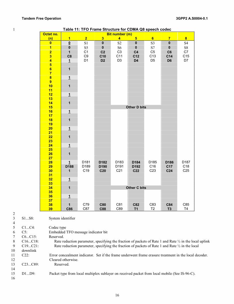
5.1.3.4 TFO Frame Structure for CDMA Q8 (IS-96-C) 45
TFO frame structure for CDMA Q8 speech codec is as defined in Table 11. Each frame consists of 320 bits. For the 46 purpose of this description, the 320 bits of one TFO Frame are arranged in 40 rows (0...39), with 8 bits (1...8: one octet) 47 each. 48
Tandem Free Operation 3GPP2 A.S0004-0.1
16
Table 11: TFO Frame Structure for CDMA Q8 speech codec 1 Octet no. Bit number (m)
(n) 1 2 3 4 5 6 7 8 0 0 S1 0 S2 0 S3 0 S4 1 0 S5 0 S6 0 S7 0 S8 2 1 C1 C2 C3 C4 C5 C6 C7 3 C8 C9 C10 C11 C12 C13 C14 C15 4 1 D1 D2 D3 D4 D5 D6 D7 5 6 1 7 8 1 9
10 1 11 12 1 13 14 1 15 Other D bits 16 1 17 18 1 19 20 1 21 22 1 23 24 1 25 26 1 27 28 1 D181 D182 D183 D184 D185 D186 D187 29 D188 D189 D190 D191 D192 C16 C17 C18 30 1 C19 C20 C21 C22 C23 C24 C25 31 32 1 33 34 1 Other C bits 35 36 1 37 38 1 C79 C80 C81 C82 C83 C84 C85 39 C86 C87 C88 C89 T1 T2 T3 T4
2 S1...S8: System identifier 3 4 C1...C4: Codec type 5 C5: Embedded TFO message indicator bit 6 C6...C15: Reserved. 7 C16...C18: Rate reduction parameter, specifying the fraction of packets of Rate 1 and Rate ½ in the local uplink 8 C19...C21: Rate reduction parameter, specifying the fraction of packets of Rate 1 and Rate ½ in the local 9 downlink 10 C22: Error concealment indicator. Set if the frame underwent frame erasure treatment in the local decoder. 11
Cleared otherwise. 12 C23...C89: Reserved. 13 14 D1...D9: Packet type from local multiplex sublayer on received packet from local mobile (See IS-96-C). 15 16
3GPP2 A.S0004.1 Tandem Free Operation
17
Rate 1 packet: 1 D10...D79: LPC and subframe 1 information bits s170 to s128, s126 to s120, s118 to s112, s110 to s104, s102 to s97 2 D80...D82: CRC over bits s170 to s128, s126 to s120, s118 to s112, s110 to s104, s102 to s97 3 D83...D114: Subframe 2 information bits s127, s119, s96, s94 to s88, s86 to s65 4 D115...D117: CRC over bits s127, s119, s96, s94 to s88, s86 to s65 5 D118...D151: Subframe 3 information bits s111, s103, s64 to s33 6 D152...D154: CRC over bits s111, s103, s64 to s33 7 D155...D189: Subframe 4 information bits s95, s87, s32 to s0 8 D190...D192: CRC over bits s95, s87, s32 to s0 9 10 Rate 1 packet with bit errors 11 D10..D192: See Rate 1 packet 12 13 Rate ½ packet: 14 D10...D59: LPC and subframe 1 information bits s79 to s30 15 D60...D62: CRC over bits s79 to s30 16 D63...D92: Subframe 2 information bits s29 to s0 17 D93...D95: CRC over bits s29 to s0 18 D96...D192: Reserved. 19 20 Rate ¼ packet: 21 D10...D49: Information bits s39 to s0 22 D50...D52: CRC over bits s39 to s0 23 D53...D192: Reserved. 24 25 Rate 1/8 packet: 26 D10...D25: Information bits s15 to s0 27 D26...D28: CRC over bits s15 to s0 28 D29...D192: Reserved. 29 30 Blank: 31 D1...D9: 9-bit packet type code (1,1000,1100, see Table 4) 32 D10…D18: 9-bit packet type code (1,1000,1100) 33 D19…D27: 9-bit packet type code (1,1000,1100) 34 D28…D192: Reserved. 35 36 Insufficient Frame Quality (Erasure): 37 D1...D9: 9-bit packet type code (1,1010,1011, see Table 4) 38 D10...D18: 9-bit packet type code (1,1010,1011) 39 D19...D27: 9-bit packet type code (1,1010,1011) 40 D28...D192: Reserved. 41 42 T1...T4: Time Alignment Bits 43 44 Note: 45 See IS-96-C for information on speech parameter bit order and the rate reduction parameter values. 46 47
5.1.3.5 TFO Frame Structure for CDMA EVRC (TIA/EIA/IS-127-1) 48
TFO frame structure for CDMA EVRC speech codec is as defined in Table 12. Each frame consists of 320 bits. For the 49 purpose of this description, the 320 bits of one TFO frame are arranged in 40 rows (0...39), with 8 bits (1...8: one octet) 50 each. 51

Tandem Free Operation 3GPP2 A.S0004-0.1
18
Table 12: TFO Frame Structure for CDMA EVRC speech codec 1 Octet no. Bit number (m)
(n) 1 2 3 4 5 6 7 8 0 0 S1 0 S2 0 S3 0 S4 1 0 S5 0 S6 0 S7 0 S8 2 1 C1 C2 C3 C4 C5 C6 C7 3 C8 C9 C10 C11 C12 C13 C14 C15 4 1 D1 D2 D3 D4 D5 D6 D7 5 6 1 7 8 1 9
10 1 11 12 1 13 14 1 15 Other D bits 16 1 17 18 1 19 20 1 21 22 1 23 24 1 25 26 1 27 28 1 D181 D182 D183 D184 D185 D186 D187 29 D188 D189 D190 D191 D192 C16 C17 C18 30 1 C19 C20 C21 C22 C23 C24 C25 31 32 1 33 34 1 Other C bits 35 36 1 37 38 1 C79 C80 C81 C82 C83 C84 C85 39 C86 C87 C88 C89 T1 T2 T3 T4
2 S1...S8: System identifier 3 4 C1...C4: Codec type 5 C5: Embedded TFO message indicator bit 6 C6...C15: Reserved. 7 C16...C18: Rate reduction parameter, specifying the fraction of packets of Rate 1 and Rate ½ in the local uplink 8 C19...C21: Rate reduction parameter, specifying the fraction of packets of Rate 1 and Rate ½ in the local downlink 9 C22: Error concealment indicator. Set if the frame underwent frame erasure treatment in the local decoder. 10
Cleared otherwise. 11 C23...C89: Reserved. 12 13 D1...D9: Packet type from local multiplex sublayer on received packet from local mobile. (See TIA/EIA/IS-127-1) 14 15 Rate 1 packet: 16
3GPP2 A.S0004.1 Tandem Free Operation
19
D10...D50: LPC and pitch delay information bits s1 to s41 1 D51...D53: CRC over bits s1 to s41 2 D54...D96: Subframe 1 codebook information bits s42 to s84 3 D97...D99: CRC over bits s42 to s84 4 D100...D142: Subframe 2 codebook information bits s85 to s127 5 D143...D145: CRC over bits s85 to s127 6 D146...D189: Subframe 3 codebook information bits s128 to s171. Bit s171 is reserved according to TIA/EIA/IS-127-7
1 and is set to “0”, to be consistent with Q13 specification. 8 D190...D192: CRC over bits s128 to s171 9 10 Rate 1 packet with bit errors: 11 D10..D192: See Rate 1 packet 12 13 Rate ½ packet: 14 D10...D38: LPC and pitch delay information bits s1 to s29 15 D39...D41: CRC over bits s1 to s29 16 D42...D58: Subframe 1 codebook information bits s30 to s46 17 D59...D61: CRC over bits s30 to s46 18 D62...D78: Subframe 2 codebook information bits s47 to s63 19 D79...D81: CRC over bits s47 to s63 20 D82...D98: Subframe 3 codebook information bits s64 to s80 21 D99...D101: CRC over bits s64 to s80 22 D102...D192: Reserved. 23 24 Rate 1/8 packet: 25 D10...D25: LPC and gain information bits s1 to s16 26 D26...D28: CRC over bits s1 to s16 27 D29...D192: Reserved. 28 29 Blank: 30 D1…D9: 9-bit packet type code (1,1000,1100, see Table 5) 31 D10...D18: 9-bit packet type code (1,1000,1100) 32 D19...D27: 9-bit packet type code (1,1000,1100) 33 D28...D192: Reserved. 34 35 Insufficient Frame Quality (Erasure): 36 D1…D9: 9-bit packet type code (1,1010,1011, see Table 5) 37 D10...D18: 9-bit packet type code (1,1010,1011) 38 D19...D27: 9-bit packet type code (1,1010,1011) 39 D28...192: Reserved. 40 41 Rate 1/8 with all bits set to ‘1’: 42 D1…D9: 9-bit packet type code (0,0111,0011, see Table 5) 43 D10...D25: all bits set to 1 44 D26...D192: Reserved. 45 46 T1...T4: Time Alignment Bits 47 48 49 Notes: 50 − See TIA/EIA/IS-127-1 for information on speech parameter bit order and rate reduction parameter values. 51 − Rate ¼ packets should be treated and sent as insufficient frame quality (erasure) packets (see TIA/EIA/IS-127-1). 52 53
Tandem Free Operation 3GPP2 A.S0004-0.1
20
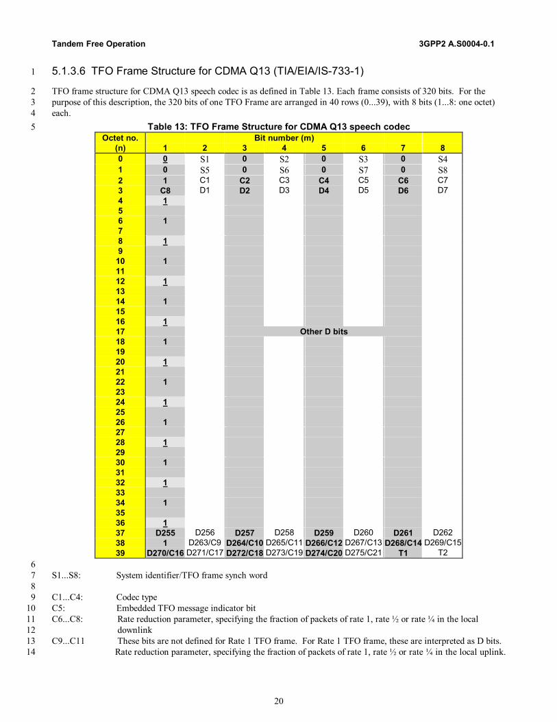
5.1.3.6 TFO Frame Structure for CDMA Q13 (TIA/EIA/IS-733-1) 1
TFO frame structure for CDMA Q13 speech codec is as defined in Table 13. Each frame consists of 320 bits. For the 2 purpose of this description, the 320 bits of one TFO Frame are arranged in 40 rows (0...39), with 8 bits (1...8: one octet) 3 each. 4
Table 13: TFO Frame Structure for CDMA Q13 speech codec 5 Octet no. Bit number (m)
(n) 1 2 3 4 5 6 7 8 0 0 S1 0 S2 0 S3 0 S4 1 0 S5 0 S6 0 S7 0 S8 2 1 C1 C2 C3 C4 C5 C6 C7 3 C8 D1 D2 D3 D4 D5 D6 D7 4 1 5 6 1 7 8 1 9
10 1 11 12 1 13 14 1 15 16 1 17 Other D bits 18 1 19 20 1 21 22 1 23 24 1 25 26 1 27 28 1 29 30 1 31 32 1 33 34 1 35 36 1 37 D255 D256 D257 D258 D259 D260 D261 D262 38 1 D263/C9 D264/C10 D265/C11 D266/C12 D267/C13 D268/C14 D269/C15 39 D270/C16 D271/C17 D272/C18 D273/C19 D274/C20 D275/C21 T1 T2
6 S1...S8: System identifier/TFO frame synch word 7 8 C1...C4: Codec type 9 C5: Embedded TFO message indicator bit 10 C6...C8: Rate reduction parameter, specifying the fraction of packets of rate 1, rate ½ or rate ¼ in the local 11
downlink 12 C9...C11 These bits are not defined for Rate 1 TFO frame. For Rate 1 TFO frame, these are interpreted as D bits. 13 Rate reduction parameter, specifying the fraction of packets of rate 1, rate ½ or rate ¼ in the local uplink. 14
3GPP2 A.S0004.1 Tandem Free Operation
21
C12...C21 These bits are not defined for Rate 1 TFO frame. For Rate 1 TFO frame, these are interpreted as D bits. 1 For all other packets, these bits are reserved. 2
3 Rate 1 packet: 4 D1...D4: 4-bit packet type code (0000, see Table 6). Packet type is from local multiplex sublayer on received 5
packet from local mobile. 6 D5...D268: Information bits s265 to s10, s7 to s0. 7 D269...D275: CRC over bits s265 to s0 except all 112 CINDEX bits and 2 reserved bits (see section 5.1.2.7). 8 9 Rate ½ packet: 10 D1...D9: 9-bit packet type code (1,1101,0101, see Table 6). 11 D10...D123: Information bits s123 to s0. 12 D124...D130: CRC over bits s123 to s0 except all 28 CINDEX bits. 13 D131...D262: Reserved. 14 15 Rate ¼ packet: 16 D1...D9: 9-bit packet type code (0,1111,1000, see Table 6). 17 D10...D61: Information bits s53 to s6, s3 to s0. 18 D62...D68: CRC over bits s53 to s6, s3 to s0. 19 D69...D262: Reserved. 20 21 Rate 1/8 packet: 22 D1...D9: 9-bit packet type code (1,0110,0110, see Table 6). 23 D10...D25: All information bits s19 to s4. 24 D26...D32: CRC over bits s19 to s4 except all 4 CBSEED bits. 25 D33...D262: Reserved. 26 27 Blank: 28 D1...D9: 9-bit packet type code (0,0001,1111, see Table 6) 29 D10...D18: 9-bit packet type code (0,0001,1111) 30 D19...D27: 9-bit packet type code (0,0001,1111) 31 D28...D262: Reserved. 32 33 Insufficient Frame Quality (Erasure): 34 D1...D9: 9-bit packet type code (1,1010,1011, see Table 6) 35 D10...D18: 9-bit packet type code (1,1010,1011) 36 D19...D27: 9-bit packet type code (1,1010,1011) 37 D28...D262: Reserved. 38 39 T1...T2: Time Alignment Bits 40 41 Notes: 42 • See TIA/EIA/IS-733-1 for information on speech parameter bit order. 43 • Error concealment on received frames corrupted by channel noise on the uplink is to be done in the far/remote 44
decoder. The option of it being handled by either the local or remote processor and indicated by the error 45 concealment indicator as in the case of Q8 and EVRC is not available for Q13. 46
• See TIA/EIA/IS-733-1 for rate reduction parameter values. 47 • See TIA/EIA/IS-733-1 for packet type information. 48 • CRC bits do not protect fixed codebook index bits. The fixed codebook index bits are replaced by random indices on 49
erasure (see TIA/EIA/IS-733-1). 50 • Q13 Rate 1, Rate ¼ and Rate 1/8 reserved bits are not transmitted. 51 52

Tandem Free Operation 3GPP2 A.S0004-0.1
22
6 TFO Message Structure 1
Several TFO Messages are defined, based on the general IS_Message principle, as defined in Annex B. 2 Definition for Sender side: 3 4 TFO_REQ (): Identifies the source of the message as a TFO capable device, using a defined speech Codec. 5 TFO_REQ contains the following parameters (): 6 • the specific Local_Signature of the sender; 7 • the Local_Used_Codec at sender side; 8 • the System_Identification. 9 10 TFO_REQ_L (): Is sent in case of Codec Mismatch or for sporadic updates of information. 11 TFO_REQ_L contains the following parameters (): 12 • the specific Local_Signature of the sender; 13 • the Local_Used_Codec at sender side; 14 • the System_Identification; 15 • the Local_Codec_List of alternative Codecs. 16 17 TFO_REQ_P (): 18 TFO_REQ_P contains the following parameters (): 19 • the specific Local_Signature of the Sender; 20 • the Preferred_Codec at sender side; 21 • the System_Identification; 22 • the Local_Codec_List of alternative Codecs. 23 24 TFO_ACK (): Is the response to a TFO_REQ Message. It contains the following parameters (): 25 • the Reflected_Signature, copied from the received TFO_REQ Message; 26 • the Local_Used_Codec at sender side; 27 • the System_Identification. 28 29 TFO_ACK_L (): Is the response to a TFO_REQ_L Message. 30 It contains the following parameters (): 31 • the Reflected_Signature, copied from the received TFO_REQ_L Message; 32 • the Local_Used_Codec at sender side; 33 • the System_Identification; 34 • the Local_Codec_List of alternative Codecs. 35 36 TFO_TRANS (): Commands possible IPEs to let the TFO Frames pass transparently within the 37 LSB (8 kbps) or the two LSBs (16 kbps). TFO_TRANS contains the following parameter (): 38 • the Local_Channel_Type (i.e. 8 kbps or 16 kbps). 39 40 TFO_NORMAL: Commands possible IPEs to revert to normal operation. 41 TFO_NORMAL has no parameters. 42 43 TFO_DUP: Informs the distant partner that TFO Frames are received, while still transmitting PCM samples. 44 TFO_DUP has no parameters. 45 46 TFO_SYL: Informs the distant partner (if still possible) that TFO Frames are no longer received. 47 TFO_SYL has no parameters. 48 49 TFO_FILL: Message without specific meaning, used to pre-synchronize IPEs or to bridge over gaps in TFO 50 protocols. TFO_FILL has no parameters. 51

3GPP2 A.S0004.1 Tandem Free Operation
23
1 Definition: A TFO Message is called ”regular”, if it is sent inserted into the PCM sample stream. A TFO Message is 2 called ”embedded”, if it is sent together with (embedded into) TFO Frames, see also section 9.2. The bit-stealing scheme 3 (see Annex B) is identical for regular and embedded TFO Messages. Due to the specific construction of the TFO Messages, 4 they replace some of the synchronization bits of the TFO Frames. TFO Frame synchronization is in case of embedded TFO 5 Messages therefore different, however, not endangered. Data and other control bits of the TFO Frames are not affected by 6 embedded TFO Messages. 7 8 Restrictions: 9 1. It is not allowed to send short and isolated TFO messages too close to the end of longer TFO messages. TFO 10
messages with the same length have no such restriction. For more information, see section C.2.2.3. 11 2. This release of the TFO standard does not support codec negotiation in the event of a codec mismatch in a CDMA 12
mobile-to-mobile call. TFO messages TFO_REQ_L, TFO_REQ_P and TFO_ACK_L are defined for TDMA TFO 13 operations only. When used for CDMA TFO operations, the Codec_List contains only the Local_Used_Codec. 14
3. This release of the TFO standard defines a simplified TFO state machine for CDMA TFO operations. TFO messages 15 TFO_DUP and TFO_SYL are defined for TDMA TFO operations only and are not defined for CDMA TFO 16 operations. 17
18
6.1 Definition of the TFO_REQ Messages 19
Symbolic Notation: TFO_REQ (System_Identification, Signature, Used_Codec) 20 TFO_REQ_L (System_Identification, Signature, Used_Codec, Codec_List) 21 TFO_REQ_P (System_Identification, Signature, Preferred_Codec, Codec_List) 22 23 The TFO_REQ Messages conform to the IS_REQ Message, defined in the Annex B, with IS_System_Identification set 24 accordingly, followed by the TFO_Req_Extension_Block and optionally by the Codec_List_Extension_Block. 25 TFO_REQ takes 140 ms for transmission, see Figure 2. TFO_REQ_L and TFO_REQ_P take 180 ms for transmission. 26
27
20 Bits
Header REQ System_Identification
10 Bits
TFO Req Extension 20 Bits 20 Bits
40 ms 40 ms20 Bits
Codec List Extension
40 ms40 ms 20 ms 28
Figure 2: Construction of the TFO_REQ Messages 29
Tandem Free Operation 3GPP2 A.S0004-0.1
24
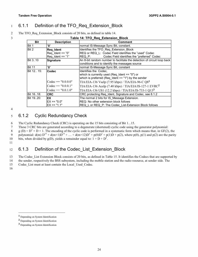
6.1.1 Definition of the TFO_Req_Extension_Block 1
The TFO_Req_Extension_Block consists of 20 bits, as defined in table 14. 2 Table 14: TFO_Req_Extension_Block 3
Bit Description Comment Bit 1 ”0” normal IS-Message Sync Bit, constant. Bit 2 Req_Ident Identifies the TFO_Req_Extension_Block Req_Ident == ”0” REQ or REQ_L: Codec Field identifies the ”used” Codec Req_Ident == ”1” REQ_P: Codec Field identifies the ”preferred” Codec Bit 3..10 Signature An 8-bit random number to facilitate the detection of circuit loop back
conditions and to identify the messages source Bit 11 ”0” normal IS-Message Sync Bit, constant Bit 12.. 15: Codec Identifies the Codec,
which is currently used (Req_Ident == "0") or which is preferred (Req_Ident == "1") by the sender
Codec == "0.0.0.0" TIA/EIA-136 Vselp (7.95 kbps) / TIA/EIA-96-C Q81 Codec == "0.0.0.1" TIA/EIA-136 Acelp (7.40 kbps) / TIA/EIA/IS-127-1 EVRC2 Codec == "0.0.1.0" TIA/EIA-136 US1 (12.2 kbps) / TIA/EIA/IS-733-1 Q133 Bit 16..18: CRC CRC protecting Req_Ident, Signature and Codec, see 8.1.2 Bit 19..20: EX The normal 2 bits for IS_Message Extension. EX == "0.0" REQ: No other extension block follows EX == "1.1" REQ_L or REQ_P: The Codec_List-Extension Block follows
4
6.1.2 Cyclic Redundancy Check 5
The Cyclic Redundancy Check (CRC) is operating on the 15 bits consisting of Bit 1...15. 6 These 3 CRC bits are generated according to a degenerate (shortened) cyclic code using the generator polynomial: 7 g (D) = D3 + D + 1. The encoding of the cyclic code is performed in a systematic form which means that, in GF(2), the 8 polynomial: d(m) D15 + d(m+1)D14 + … + d(m+12)D3 + p(0)D2 + p(1)D + p(2), where p(0), p(1) and p(2) are the parity 9 bits, when divided by g(D), yields a remainder equal to: 1 + D + D2. 10 11
6.1.3 Definition of the Codec_List_Extension_Block 12
The Codec_List Extension Block consists of 20 bits, as defined in Table 15. It identifies the Codecs that are supported by 13 the sender, respectively the BSS subsystem, including the mobile station and the radio resource, at sender side. The 14 Codec_List must at least contain the Local_Used_Codec. 15 16
1 Depending on System Identification 2 Depending on System Identification 3 Depending on System Identification
3GPP2 A.S0004.1 Tandem Free Operation
25
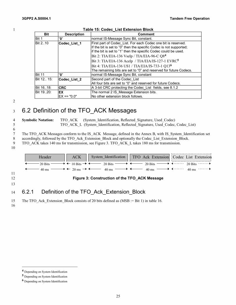
Table 15: Codec_List Extension Block 1 Bit Description Comment
Bit 1 ”0” normal IS-Message Sync Bit, constant. Bit 2..10 Codec_List_1 First part of Codec_List. For each Codec one bit is reserved.
If the bit is set to ”0” then the specific Codec is not supported; if the bit is set to ”1” then the specific Codec could be used. Bit 2: TIA/EIA-136 Vselp / TIA/EIA-96-C Q84 Bit 3: TIA/EIA-136 Acelp / TIA/EIA/IS-127-1 EVRC5 Bit 4: TIA/EIA-136 US1 / TIA/EIA/IS-733-1 Q136 The remaining bits are set to “0” and reserved for future Codecs.
Bit 11 ”0” normal IS-Message Sync Bit, constant Bit 12.. 15: Codec_List_2 Second part of the Codec_List
All four bits are set to “0” and reserved for future Codecs. Bit 16..18: CRC A 3-bit CRC protecting the Codec_List fields, see 8.1.2 Bit 19..20: EX The normal 2 IS_Message Extension bits. EX == "0.0" No other extension block follows.
2
6.2 Definition of the TFO_ACK Messages 3
Symbolic Notation: TFO_ACK (System_Identification, Reflected_Signature, Used_Codec) 4 TFO_ACK_L (System_Identification, Reflected_Signature, Used_Codec, Codec_List) 5 6 The TFO_ACK Messages conform to the IS_ACK Message, defined in the Annex B, with IS_System_Identification set 7 accordingly, followed by the TFO_Ack_Extension_Block and optionally the Codec_List_Extension_Block. 8 TFO_ACK takes 140 ms for transmission, see Figure 3. TFO_ACK_L takes 180 ms for transmission. 9 10
20 Bits
Header ACK System_Identification
10 Bits
TFO Ack Extension 20 Bits 20 Bits
40 ms 40 ms20 Bits
Codec List Extension
40 ms40 ms 20 ms 11
Figure 3: Construction of the TFO_ACK Message 12 13
6.2.1 Definition of the TFO_Ack_Extension_Block 14
The TFO_Ack_Extension_Block consists of 20 bits defined as (MSB := Bit 1) in table 16. 15 16
4 Depending on System Identification 5 Depending on System Identification 6 Depending on System Identification

Tandem Free Operation 3GPP2 A.S0004-0.1
26
Table 16: TFO_Ack_Extension_Block 1 Bit Description Comment
Bit 1 ”0” normal IS-Message Sync Bit, constant. Bit 2 Ack_Ident Identifies the TFO_Ack_Extension_Block Ack_Ident == ”0” ACK: Acknowledge to a received TFO_REQ Message Ack_Ident == ”1” reserved Bit 3..10 Signature An 8-bit number containing the received Signature, reflected back. Bit 11 ”0” normal IS-Message Sync Bit, constant Bit 12.. 15: Codec Identifies the Codec, which is currently used by the sender;
see TFO_Req_Extension block. Bit 16..18: CRC CRC protecting the Ack_Ident, Reply and Codec fields, see 8.1.2 Bit 19..20: EX The normal 2 bits for IS_Message Extension. EX == "0.0" ACK: No other extension block follows EX == "1.1" ACK_L: The Codec_List_Extension Block follows
2
6.3 Definition of the TFO_TRANS Messages 3
Symbolic Notation: TFO_TRANS (Channel_Type). 4 5 Two TFO_TRANS Messages are defined in conformity to the IS_TRANS Messages in Annex B. 6 For 16 kbps submultiplexing channels the ”TFO_TRANS (16k)” is used and is identical to ”IS_TRANS_2_u”. 7 TFO_TRANS takes 100 ms for transmission. 8 In most cases the respective TFO_TRANS Message shall be sent twice: once as a regular TFO Message, exactly before any 9 series of TFO Frames, and once embedded into the first TFO Frames, see section 12. 10 11
6.4 Definition of the TFO_NORMAL Message 12
Symbolic Notation: TFO_NORMAL. 13 14 The TFO_NORMAL Message is identical to the IS_NORMAL Message defined in the Annex B. 15 It shall be sent at least once whenever an established tandem free operation needs to be terminated in a controlled way. 16 TFO_NORMAL takes 100 ms for transmission. 17 18
6.5 Definition of the TFO_FILL Message 19
Symbolic Notation: TFO_FILL. 20 21 The TFO_FILL Message is identical to the IS_FILL Message, defined in the Annex B. 22 TFO_FILL may be used to pre-synchronize IPEs. Since IS_FILL is one of the shortest IS Messages, this is the fastest way 23 to synchronize IPEs, without IPEs swallowing other protocol elements. By default three TFO_Messages shall be sent at the 24 beginning; this number may be, however, configuration dependent. 25 One TFO_FILL takes 60 ms for transmission. 26 27
6.6 Definition of the TFO_DUP Message (TDMA only) 28
Symbolic Notation: TFO_DUP 29 30 The TFO_DUP Message is identical to the IS_DUP Message, defined in Annex B. 31 TFO_DUP informs the distant TFO Partner, that TFO Frames have been received unexpectedly, e.g. during Establishment. 32 This enables a fast re-establishment of TFO after a local HO. 33 TFO_DUP takes 60 ms for transmission. 34

3GPP2 A.S0004.1 Tandem Free Operation
27
1
6.7 Definition of the TFO_SYL Message (TDMA only) 2
Symbolic Notation: TFO_SYL 3 4 The TFO_SYL Message is identical to the IS_SYL Message, defined in Annex B. 5 TFO_SYL informs the distant TFO Partner that tandem free operation has existed, but suddenly no TFO Frames were 6 received anymore. This enables a fast re-establishment of TFO after a distant HO. 7 TFO_SYL takes 60 ms for transmission. 8
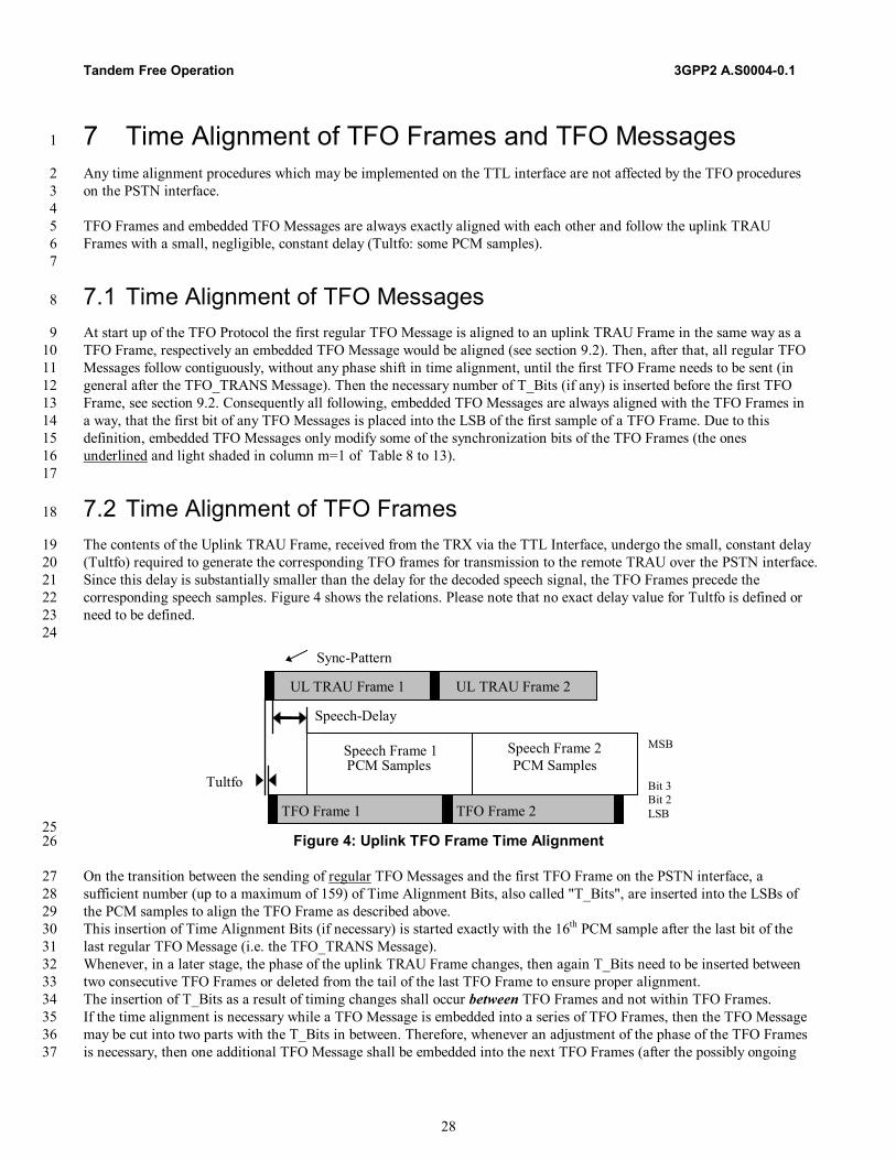
Tandem Free Operation 3GPP2 A.S0004-0.1
28
7 Time Alignment of TFO Frames and TFO Messages 1
Any time alignment procedures which may be implemented on the TTL interface are not affected by the TFO procedures 2 on the PSTN interface. 3 4 TFO Frames and embedded TFO Messages are always exactly aligned with each other and follow the uplink TRAU 5 Frames with a small, negligible, constant delay (Tultfo: some PCM samples). 6 7
7.1 Time Alignment of TFO Messages 8
At start up of the TFO Protocol the first regular TFO Message is aligned to an uplink TRAU Frame in the same way as a 9 TFO Frame, respectively an embedded TFO Message would be aligned (see section 9.2). Then, after that, all regular TFO 10 Messages follow contiguously, without any phase shift in time alignment, until the first TFO Frame needs to be sent (in 11 general after the TFO_TRANS Message). Then the necessary number of T_Bits (if any) is inserted before the first TFO 12 Frame, see section 9.2. Consequently all following, embedded TFO Messages are always aligned with the TFO Frames in 13 a way, that the first bit of any TFO Messages is placed into the LSB of the first sample of a TFO Frame. Due to this 14 definition, embedded TFO Messages only modify some of the synchronization bits of the TFO Frames (the ones 15 underlined and light shaded in column m=1 of Table 8 to 13). 16 17
7.2 Time Alignment of TFO Frames 18
The contents of the Uplink TRAU Frame, received from the TRX via the TTL Interface, undergo the small, constant delay 19 (Tultfo) required to generate the corresponding TFO frames for transmission to the remote TRAU over the PSTN interface. 20 Since this delay is substantially smaller than the delay for the decoded speech signal, the TFO Frames precede the 21 corresponding speech samples. Figure 4 shows the relations. Please note that no exact delay value for Tultfo is defined or 22 need to be defined. 23 24
UL TRAU Frame 1 UL TRAU Frame 2
TFO Frame 1 TFO Frame 2
Speech Frame 1PCM Samples
Speech Frame 2PCM Samples
Speech-Delay
MSB
Bit 3Bit 2LSB
Sync-Pattern
Tultfo
25 Figure 4: Uplink TFO Frame Time Alignment 26
On the transition between the sending of regular TFO Messages and the first TFO Frame on the PSTN interface, a 27 sufficient number (up to a maximum of 159) of Time Alignment Bits, also called "T_Bits", are inserted into the LSBs of 28 the PCM samples to align the TFO Frame as described above. 29 This insertion of Time Alignment Bits (if necessary) is started exactly with the 16th PCM sample after the last bit of the 30 last regular TFO Message (i.e. the TFO_TRANS Message). 31 Whenever, in a later stage, the phase of the uplink TRAU Frame changes, then again T_Bits need to be inserted between 32 two consecutive TFO Frames or deleted from the tail of the last TFO Frame to ensure proper alignment. 33 The insertion of T_Bits as a result of timing changes shall occur between TFO Frames and not within TFO Frames. 34 If the time alignment is necessary while a TFO Message is embedded into a series of TFO Frames, then the TFO Message 35 may be cut into two parts with the T_Bits in between. Therefore, whenever an adjustment of the phase of the TFO Frames 36 is necessary, then one additional TFO Message shall be embedded into the next TFO Frames (after the possibly ongoing 37
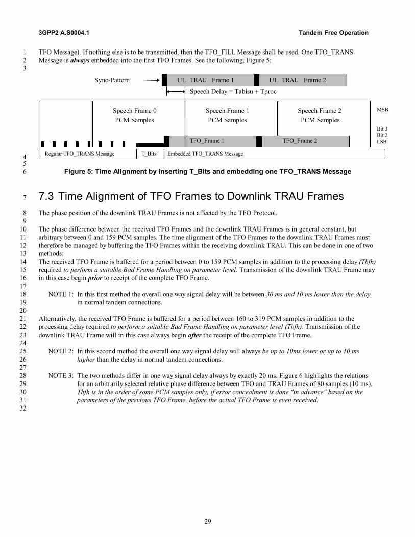
3GPP2 A.S0004.1 Tandem Free Operation
29
TFO Message). If nothing else is to be transmitted, then the TFO_FILL Message shall be used. One TFO_TRANS 1 Message is always embedded into the first TFO Frames. See the following, Figure 5: 2 3
Speech Frame 1PCM Samples
Speech Frame 2PCM Samples
Speech Delay = Tabisu + Tproc
MSB
Bit 3Bit 2LSBTFO_Frame 1 TFO_Frame 2
UL TRAU Frame 1 UL TRAU Frame 2Sync-Pattern
Regular TFO_TRANS Message T_Bits Embedded TFO_TRANS Message
Speech Frame 0PCM Samples
4 5
Figure 5: Time Alignment by inserting T_Bits and embedding one TFO_TRANS Message 6
7.3 Time Alignment of TFO Frames to Downlink TRAU Frames 7
The phase position of the downlink TRAU Frames is not affected by the TFO Protocol. 8 9 The phase difference between the received TFO Frames and the downlink TRAU Frames is in general constant, but 10 arbitrary between 0 and 159 PCM samples. The time alignment of the TFO Frames to the downlink TRAU Frames must 11 therefore be managed by buffering the TFO Frames within the receiving downlink TRAU. This can be done in one of two 12 methods: 13 The received TFO Frame is buffered for a period between 0 to 159 PCM samples in addition to the processing delay (Tbfh) 14 required to perform a suitable Bad Frame Handling on parameter level. Transmission of the downlink TRAU Frame may 15 in this case begin prior to receipt of the complete TFO Frame. 16 17
NOTE 1: In this first method the overall one way signal delay will be between 30 ms and 10 ms lower than the delay 18 in normal tandem connections. 19
20 Alternatively, the received TFO Frame is buffered for a period between 160 to 319 PCM samples in addition to the 21 processing delay required to perform a suitable Bad Frame Handling on parameter level (Tbfh). Transmission of the 22 downlink TRAU Frame will in this case always begin after the receipt of the complete TFO Frame. 23 24
NOTE 2: In this second method the overall one way signal delay will always be up to 10ms lower or up to 10 ms 25 higher than the delay in normal tandem connections. 26
27 NOTE 3: The two methods differ in one way signal delay always by exactly 20 ms. Figure 6 highlights the relations 28
for an arbitrarily selected relative phase difference between TFO and TRAU Frames of 80 samples (10 ms). 29 Tbfh is in the order of some PCM samples only, if error concealment is done "in advance" based on the 30 parameters of the previous TFO Frame, before the actual TFO Frame is even received. 31
32
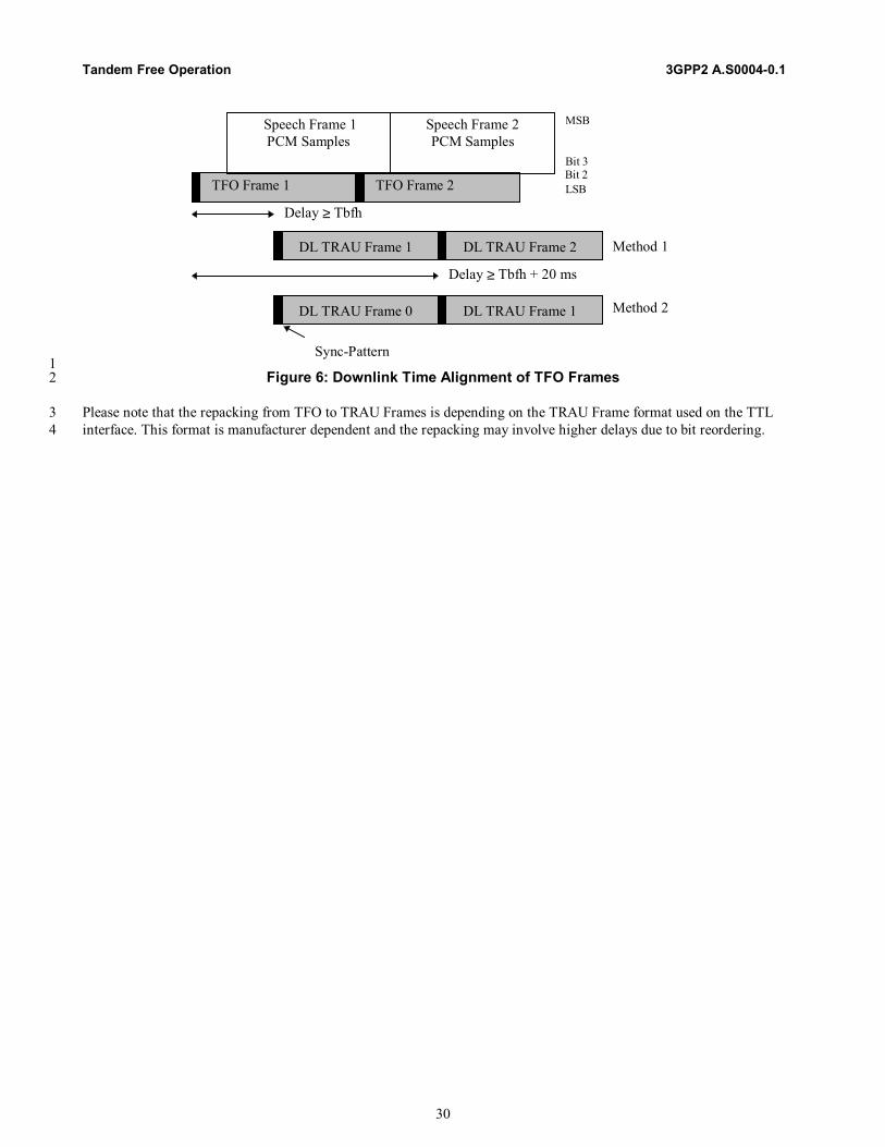
Tandem Free Operation 3GPP2 A.S0004-0.1
30
Delay ≥ Tbfh
TFO Frame 1 TFO Frame 2
Speech Frame 1PCM Samples
Speech Frame 2PCM Samples
MSB
Bit 3Bit 2LSB
DL TRAU Frame 1 DL TRAU Frame 2
Sync-Pattern
DL TRAU Frame 0 DL TRAU Frame 1
Method 1
Method 2
Delay ≥ Tbfh + 20 ms
1 Figure 6: Downlink Time Alignment of TFO Frames 2
Please note that the repacking from TFO to TRAU Frames is depending on the TRAU Frame format used on the TTL 3 interface. This format is manufacturer dependent and the repacking may involve higher delays due to bit reordering. 4
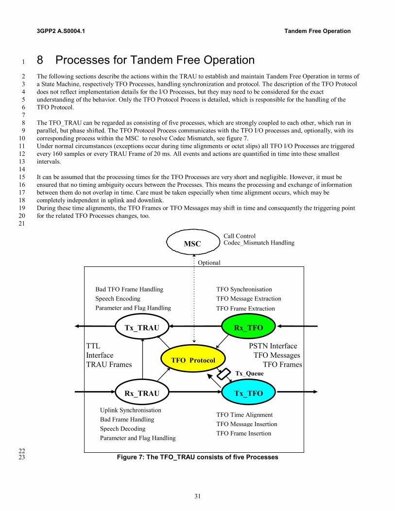
3GPP2 A.S0004.1 Tandem Free Operation
31
8 Processes for Tandem Free Operation 1
The following sections describe the actions within the TRAU to establish and maintain Tandem Free Operation in terms of 2 a State Machine, respectively TFO Processes, handling synchronization and protocol. The description of the TFO Protocol 3 does not reflect implementation details for the I/O Processes, but they may need to be considered for the exact 4 understanding of the behavior. Only the TFO Protocol Process is detailed, which is responsible for the handling of the 5 TFO Protocol. 6 7 The TFO_TRAU can be regarded as consisting of five processes, which are strongly coupled to each other, which run in 8 parallel, but phase shifted. The TFO Protocol Process communicates with the TFO I/O processes and, optionally, with its 9 corresponding process within the MSC to resolve Codec Mismatch, see figure 7. 10 Under normal circumstances (exceptions occur during time alignments or octet slips) all TFO I/O Processes are triggered 11 every 160 samples or every TRAU Frame of 20 ms. All events and actions are quantified in time into these smallest 12 intervals. 13 14 It can be assumed that the processing times for the TFO Processes are very short and negligible. However, it must be 15 ensured that no timing ambiguity occurs between the Processes. This means the processing and exchange of information 16 between them do not overlap in time. Care must be taken especially when time alignment occurs, which may be 17 completely independent in uplink and downlink. 18 During these time alignments, the TFO Frames or TFO Messages may shift in time and consequently the triggering point 19 for the related TFO Processes changes, too. 20 21
TFO_Protocol
Tx_TRAU
Rx_TRAU
Rx_TFO
Tx_TFO
TTLInterfaceTRAU Frames
PSTN Interface
TFO FramesTFO Messages
MSC
Uplink SynchronisationBad Frame HandlingSpeech DecodingParameter and Flag Handling
Tx_Queue
TFO SynchronisationTFO Message ExtractionTFO Frame Extraction
TFO Time AlignmentTFO Message InsertionTFO Frame Insertion
Bad TFO Frame HandlingSpeech EncodingParameter and Flag Handling
Call ControlCodec_Mismatch Handling
Optional
22 Figure 7: The TFO_TRAU consists of five Processes 23

Tandem Free Operation 3GPP2 A.S0004-0.1
32
8.1 Rx_TRAU Process 1
The Rx_TRAU Process receives Uplink TRAU Frames from the TTL Interface and synchronizes to them, i.e. checks 2 correct synchronization and contents. It performs all actions of a conventional Uplink TRAU, e.g. calls the Bad Frame 3 Handler and the Speech Decoder. 4 5 The resulting speech samples are handed to the Tx_TFO Process for output to the PSTN interface. In addition Rx_TRAU 6 passes the Uplink TRAU Frames directly and unaltered to Tx_TFO. 7
8.2 Tx_TRAU Process 8
The Tx_TRAU Process builds autonomously the relevant Downlink TRAU Frames and sends them in the correct phase 9 relation onto the TTL-Interface as required by the TRX. 10 Tx_TRAU has two major States: TFO == OFF (default at beginning) and TFO == ON, see Figure 8. 11 Toggling between these two States is commanded by TFO_Protocol with Accept_TFO, respectively Ignore_TFO. 12 13
TFO == OFF TFO ==ON
Timing and Encodinglike in a conventional
downlink TRAU
Error Concealment of receivedTFO Frames; buffering for
correct DL_Timing
Ignore_TFO
Accept_TFO
Initialize
14 Figure 8: States of the Tx_TRAU Process 15
During TFO == OFF, Tx_TRAU performs all actions of a conventional downlink TRAU, as described in the appropriate 16 standard (TIA/EIA-95, TIA/EIA-136). It samples one frame of speech samples in the correct phase position and calls the 17 Speech Encoder. The resulting speech parameters are then transmitted downlink on the TTL interface. 18 During TFO == ON, Tx_TRAU performs Bad Frame Handling (and Comfort Noise Parameter Handling on parameter 19 level in the case of TIA/EIA-136) on the received TFO Frames, if necessary. The resulting speech parameters and control 20 bits are buffered until they are passed as Downlink TRAU Frames in correct phase position to the TRX (see also section 21 9.3). 22 23 For TIA/EIA-136, there are two possible cases regarding DTX in a Mobile-to-Mobile communication, as reflected in 24 Table 17. 25 26
Table 17: DTX configurations in Mobile-To-Mobile communications 27 Case Local TRAU: Downlink Distant TRAU: Uplink 0 No-DTX No-DTX 1 No-DTX DTX
28
8.2.1 Downlink Speech Transmission if TFO is ON 29
During TFO == ON, the Rx_TFO Process receives TFO Frames from the PSTN Interface. It synchronizes to them, i.e. 30 checks correct synchronization and contents. It extracts the data bits and calls, if appropriate (e.g., if ECI == "1" or if the 31 TFO Frame is not valid, see section 10.4.2), a Bad Frame Handler to derive suitable parameters for Downlink TRAU 32 Frames. This Bad Frame Handler on the parameter level is manufacturer dependent and is not part of this 33 recommendation. 34 35

3GPP2 A.S0004.1 Tandem Free Operation
33
8.2.2 DTX handling for TIA/EIA-136 1
During TFO == ON, if distant Uplink DTX is active, (case 1 in Table 17), then the Rx_TFO Process receives TFO Frames 2 containing speech parameters (handled as in case 0, see above), as well as TFO Frames containing Comfort Noise 3 parameters or blank TFO Frames. Tx_TRAU then calls a Comfort Noise Generator to derive suitable "speech" parameters 4 for Downlink TRAU Frames. The Downlink TRAU Frames shall not contain Comfort Noise parameters, but parameters 5 that allow a direct decoding. Also, this Comfort Noise Generator on the parameter level is manufacturer dependent and is 6 not part of this recommendation. 7 8
8.2.3 Synchronization and Bit Errors in Received TFO Frames 9
If Rx_TFO detects an error in the received TFO Frame synchronization or control bits, or if a CRC error is detected, and 10 the error is detected prior to beginning the output of the same frame (as a Downlink TRAU Frame), then Tx_TRAU shall 11 either substitute parameters from the last good TFO Frame, or shall encode the received PCM samples for the duration of 12 this frame. 13 If Rx_TFO detects an error in the received TFO Frame synchronization or control bits, or if a CRC error is detected, and 14 the error is detected after beginning of the output of the same frame (as a Downlink TRAU Frame), then Tx_TRAU shall 15 deliberately corrupt the remaining, still unsent synchronization bits by setting them all to "0" and deliberately shall corrupt 16 the remaining CRC bits. The effect of the frame error will subsequently be masked by the Mobile station’s handling of bad 17 frames. 18 19
8.3 Tx_TFO Process 20
The Tx_TFO Process gets directly the unaltered Uplink TRAU Frames (containing the speech parameters and the control 21 bits) and the decoded speech PCM samples from Rx_TRAU. It further gets internal messages (commands) from 22 TFO_Protocol via the Tx_Queue. 23 Tx_TFO has two major States: TFO == OFF (default at beginning) and TFO == ON, see Figure 9. 24 Toggling between these two States is commanded by TFO_Protocol with Begin_TFO respectively Discontinue_TFO. 25 26
T F O == O F F T F O == O N
no T F O F ram es R egu lar T F O M essages
no T im e A lignm ent
T F O F ram esE m bedded T F O M essages
T im e A lignm ent
D iscon tinue_T F O
B egin_T F O
In itia lize
27 Figure 9: States of the Tx_TFO Process 28
During TFO == OFF, decoded speech PCM samples and regular TFO Messages (if any) are sent onto the PSTN interface. 29 Time Alignment takes place only once, just before the beginning of the first regular TFO Message. 30 During TFO == ON, TFO Frames and embedded TFO Messages (if any) are sent. Time Alignment takes place just before 31 the first TFO Frame and then whenever required in between two TFO Frames. 32 33 The Tx_TFO Process builds the relevant TFO Frames and sends them in the correct phase relation onto the PSTN 34 Interface. Time alignment of TFO Messages and TFO Frames are handled autonomously and independent of the 35 TFO_Protocol Process. Rx_TRAU informs Tx_TFO about any changes in the phase position of the Uplink TRAU Frame 36 and Tx_TFO inserts automatically the correct number of T_Bits before the next TFO Frame, and embeds autonomously 37 the next TFO_Message or a TFO_FILL Message, if necessary. 38 39
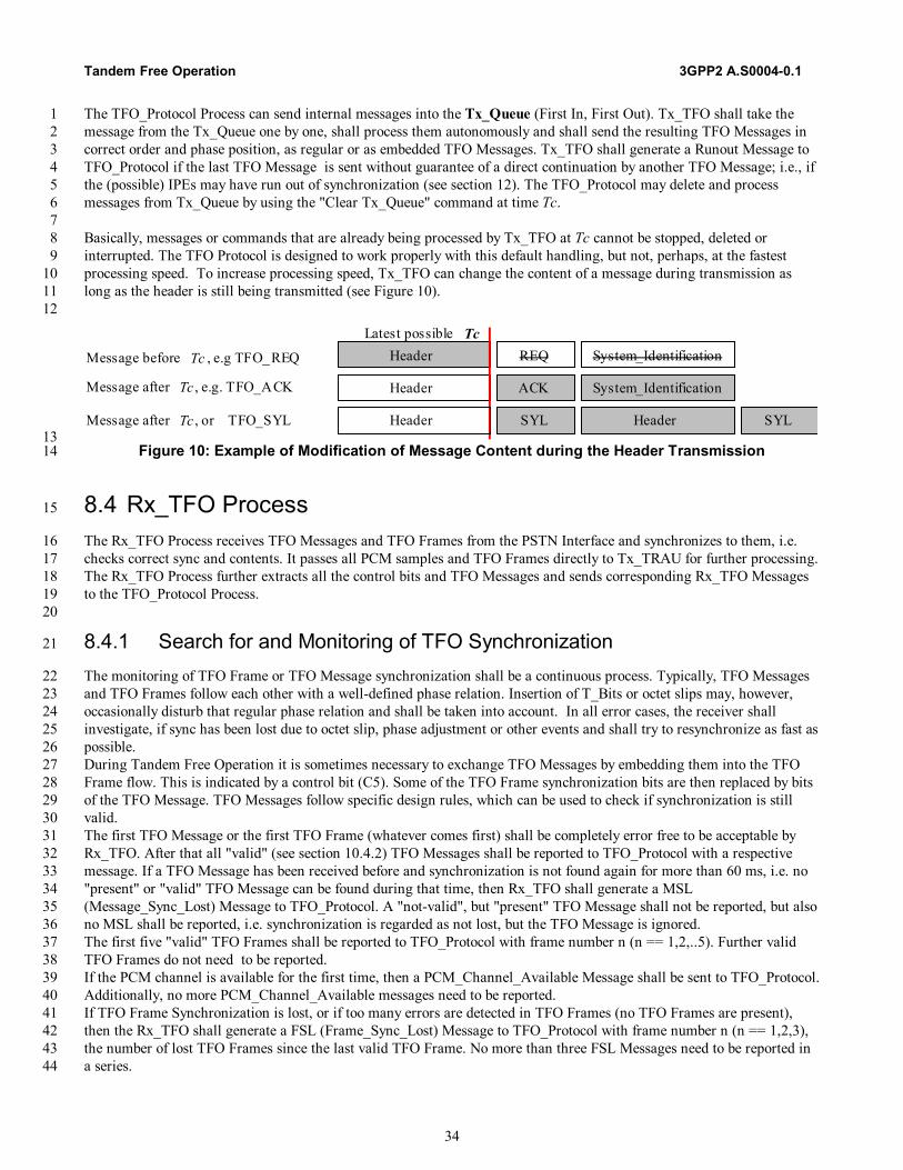
Tandem Free Operation 3GPP2 A.S0004-0.1
34
The TFO_Protocol Process can send internal messages into the Tx_Queue (First In, First Out). Tx_TFO shall take the 1 message from the Tx_Queue one by one, shall process them autonomously and shall send the resulting TFO Messages in 2 correct order and phase position, as regular or as embedded TFO Messages. Tx_TFO shall generate a Runout Message to 3 TFO_Protocol if the last TFO Message is sent without guarantee of a direct continuation by another TFO Message; i.e., if 4 the (possible) IPEs may have run out of synchronization (see section 12). The TFO_Protocol may delete and process 5 messages from Tx_Queue by using the "Clear Tx_Queue" command at time Tc. 6 7 Basically, messages or commands that are already being processed by Tx_TFO at Tc cannot be stopped, deleted or 8 interrupted. The TFO Protocol is designed to work properly with this default handling, but not, perhaps, at the fastest 9 processing speed. To increase processing speed, Tx_TFO can change the content of a message during transmission as 10 long as the header is still being transmitted (see Figure 10). 11 12
Header REQ System_Identification
Header ACK System_Identification
Latest possible TcMessage before Tc , e.g TFO_REQ
Message after Tc , e.g. TFO_ACK
Message after Tc , or TFO_SYL Header SYL Header SYL 13
Figure 10: Example of Modification of Message Content during the Header Transmission 14
8.4 Rx_TFO Process 15
The Rx_TFO Process receives TFO Messages and TFO Frames from the PSTN Interface and synchronizes to them, i.e. 16 checks correct sync and contents. It passes all PCM samples and TFO Frames directly to Tx_TRAU for further processing. 17 The Rx_TFO Process further extracts all the control bits and TFO Messages and sends corresponding Rx_TFO Messages 18 to the TFO_Protocol Process. 19 20
8.4.1 Search for and Monitoring of TFO Synchronization 21
The monitoring of TFO Frame or TFO Message synchronization shall be a continuous process. Typically, TFO Messages 22 and TFO Frames follow each other with a well-defined phase relation. Insertion of T_Bits or octet slips may, however, 23 occasionally disturb that regular phase relation and shall be taken into account. In all error cases, the receiver shall 24 investigate, if sync has been lost due to octet slip, phase adjustment or other events and shall try to resynchronize as fast as 25 possible. 26 During Tandem Free Operation it is sometimes necessary to exchange TFO Messages by embedding them into the TFO 27 Frame flow. This is indicated by a control bit (C5). Some of the TFO Frame synchronization bits are then replaced by bits 28 of the TFO Message. TFO Messages follow specific design rules, which can be used to check if synchronization is still 29 valid. 30 The first TFO Message or the first TFO Frame (whatever comes first) shall be completely error free to be acceptable by 31 Rx_TFO. After that all "valid" (see section 10.4.2) TFO Messages shall be reported to TFO_Protocol with a respective 32 message. If a TFO Message has been received before and synchronization is not found again for more than 60 ms, i.e. no 33 "present" or "valid" TFO Message can be found during that time, then Rx_TFO shall generate a MSL 34 (Message_Sync_Lost) Message to TFO_Protocol. A "not-valid", but "present" TFO Message shall not be reported, but also 35 no MSL shall be reported, i.e. synchronization is regarded as not lost, but the TFO Message is ignored. 36 The first five "valid" TFO Frames shall be reported to TFO_Protocol with frame number n (n == 1,2,..5). Further valid 37 TFO Frames do not need to be reported. 38 If the PCM channel is available for the first time, then a PCM_Channel_Available Message shall be sent to TFO_Protocol. 39 Additionally, no more PCM_Channel_Available messages need to be reported. 40 If TFO Frame Synchronization is lost, or if too many errors are detected in TFO Frames (no TFO Frames are present), 41 then the Rx_TFO shall generate a FSL (Frame_Sync_Lost) Message to TFO_Protocol with frame number n (n == 1,2,3), 42 the number of lost TFO Frames since the last valid TFO Frame. No more than three FSL Messages need to be reported in 43 a series. 44
3GPP2 A.S0004.1 Tandem Free Operation
35
1 NOTE: The MSL and FSL Messages shall not be mixed up with the TFO_SYL Message, by which the distant TFO 2
Partner reports lost synchronization. 3 4
TFO Messages with Extension_Blocks that can not be understood by the receiving TRAU, but which follow the design 5 rules for IS_Extension_Blocks, shall be ignored. This guarantees future expandability. 6 7
8.4.2 Errors in TFO Messages and TFO Frames 8
These definitions may serve as a guideline: 9 10 A TFO Message is called "error-free" if no error can be detected within the whole message. 11 12 A TFO Message is called "single-error" if no more than one bit position differs either in the IS_Header or the 13 IS_Command_Block or the System_Ident_Block or the IPE_Mode_Block or the Sync bits and no errors are detectable 14 within the CRC fields or the EX-fields. 15 16 A TFO Message may be regarded as "correctable" if the phase position is as in preceding TFO Messages and 17
- no more than 2 bit positions differ in the IS_Header; and 18 - no more than 1 error is detected within the IS_Command_Block; and 19 - no more than 3 errors are detected within the IPE_Mode_Block; and 20 - no more than 3 errors are detected within the System_Ident_Block; and 21 - no more than 1 error is detected within the Sync-Bit(s); and 22 - no more than 0 error is detected within the EX-field(s); and 23 - no more than 0 error is detected within the CRC-fields; and 24 - the total number of detected errors is not higher than 3. 25 - 26
TFO Messages which are error-free, single-error or correctable are also called "valid" TFO Messages. All other TFO 27 Messages are called "not-valid". 28 29 A TFO Message may be regarded as "present", if the phase position is as in preceding TFO Messages and 30
- no more than 4 bit positions differ in the IS_Header; and 31 - no more than 2 errors are detected within the IS_Command_Block; and 32 - no more than 3 errors are detected within the IPE_Mode_Block; and 33 - no more than 3 errors are detected within the System_Ident_Block; and 34 - no more than 2 errors are detected within the Sync-Bit(s); and 35 - no more than 1 error is detected within the EX-field(s); and 36 - no more than 1 error is detected within the CRC-fields; and 37 - the total number of detected errors is not higher than 5. 38
Messages which differ in more than "present" may not be recognized as TFO Messages at all ("not-present"). 39 40 Note that the insertion of T_Bits may change the phase position of the TFO Frames and of bits of an embedded TFO 41 Message. The TFO Message shall in that case be classified after the removal of the T_Bits. 42 43 An octet slip may also change the phase position of bits within a regular or embedded TFO Message. If an error-free or a 44 single-error TFO Message can be found after considering a hypothetical octet slip (±1 sample) then it may be regarded as 45 error-free or single-error and the new phase position shall be regarded as valid as long as no valid or present TFO 46 Message can be found at the old phase position. 47 48 A TFO Frame is called "error-free", if no error can be detected within the whole frame. 49 50 A TFO Frame is called "single-error", if no more than one bit position differs either in the synchronization bits or the 51 T_Bits and if no other errors can be detected. 52 53

Tandem Free Operation 3GPP2 A.S0004-0.1
36
TFO Frames, which are error-free, or single-error are also called "valid" TFO Frames. All other TFO Frames are called 1 "not-valid". 2 3 A TFO Frame may be regarded as "present", if 4
- no more than 4 bit positions differ in the synchronization bits 5 - no more than 2 errors are detected within the T_Bits; 6 - no more than 1 error is detected within the control bits; 7 - no more than 1 error is detected within the CRC block; and 8 - the total number of detected errors is not higher than 5. 9 10
Messages which differ in more than "present" may not be recognized as TFO Frames at all ("not-present" ). 11 12 Note that the insertion or deletion of T_Bits may change the phase position of the TFO Frames .The TFO Frame shall in 13 that case be classified after considering the T_Bits. 14 15 An octet slip may also change the phase position of bits within a TFO Frame. Typically a TFO Frame can not be corrected 16 after an octet slip, but the next TFO Frame shall be found again. 17 18 The parameters of a valid TFO Frame shall be regarded as "bad" if the corresponding bad frame indicator or frame loss 19 indicator is set to 1. 20 21
8.5 TFO_Protocol Process 22
The TFO_Protocol Process is typically invoked whenever a message is received, either from Rx_TRAU, Rx_TFO, 23 Tx_TFO or the local MSC. 24 25 Two events are due to modifications of the local MS-MSC configuration, 26
- a modification of the used speech Codec (New_Local_Codec); and 27 - a modification of the list of the alternative speech Codecs (New_Local_Codec_List). 28
29 The New_Local_Codec is extracted from the uplink TRAU Frames and reported by Rx_TRAU. 30 The New_Local_Codec_List is reported by the MSC in a manufacturer dependent way. 31 32 It may happen during an established TFO connection that the used Codec is identified as not optimal. Then the distant 33 partner (e.g. a TCME) may inform the TRAU by a TFO_REQ_P Message that another Codec would be preferred. 34 The TRAU has to inform the local MSC about the preferred Codec, but continues with TFO until an optional 35 In_Call_Modification is performed by the local MSC. 36 37
8.5.1 Messages from Rx_TRAU or local MSC 38
Rx == New_Speech_Call (Local_Used_Codec); Rx_TRAU is activated by BS. 39 Rx == New_Local_Codec (New_Local_Used_Codec); In Call Modification to other Codec Type. 40 Rx == Data_Call; In Call Modification to Data_Call. 41 Rx == Local_Codec_List; Manufacturer dependent, optional, from MSC. 42 Rx == TRAU_Idle; Manufacturer dependent, either from TRX or MSC. 43 44
8.5.2 Messages to Tx_TRAU 45
Tx_TRAU := Accept_TFO; if TFO Frames are correctly received, they shall be used. 46 Tx_TRAU := Ignore_TFO; TFO Frames, even if received correctly, shall be ignored. 47 48

3GPP2 A.S0004.1 Tandem Free Operation
37
8.5.3 Optional Messages to the local MSC (TDMA only) 1
The format of these messages is manufacturer specific. These messages, represented by MSC:-TFO(), can be used to 2 facilitate operations such as codec negotiation, codec mismatch, etc. 3 4
8.5.4 Messages to and from Tx_TFO 5
The symbol () indicates that these Messages contain parameters, see section 8. 6 Tx := TFO_REQ (); main TFO_REQ Message. 7 Tx := TFO_ACK (); main TFO_ACK Message, response only to TFO_REQ. 8 Tx := TFO_REQ_L (); used in Mismatch, Operation and Periodic_Retry to inform about alternative Codecs. 9 Tx := TFO_ACK_L (); response only to TFO_REQ_L. 10 (Tx := TFO_REQ_P ()); undefined for TRAU, defined only for TCME. 11 Tx := TFO_TRANS (); command IPEs to go transparent. 12 Tx := TFO_NORMAL; reset IPEs into their normal operation. 13 Tx := TFO_FILL; mainly to pre-synchronize IPEs. 14 Tx := TFO_DUP; "I receive TFO Frames in Establishment" (TDMA only). 15 Tx := TFO_SYL; "I lost TFO Frame synchronization" (TDMA only). 16 Tx := Begin_TFO; Insert TFO Frames from now on. 17 Tx := Discontinue_TFO; Discontinue inserting TFO Frames. 18 Clear Tx_Queue; Clears all remaining commands from Tx_Queue. 19 Rx == Runout; Reports that the continuous stream of outgoing TFO Messages may be interrupted. 20 21
8.5.5 Messages from Rx_TFO 22
The symbol () indicates that these Messages contain parameters, see section 8. 23 Rx == TFO_REQ () Request from potential distant TFO partner. 24 Rx == TFO_ACK () TFO acknowledge from distant TFO partner. 25 Rx == TFO_REQ_L () Local Codec and Codec list in the case of Codec mismatch. 26 Rx == TFO_ACK_L () Response to TFO_REQ_L Message. 27 Rx == TFO_REQ_P () Requests another, preferred Codec, plus Codec_List. 28 Rx == TFO_TRANS () May serve as alternative TFO_ACK in some cases! 29 Rx == TFO_NORMAL Command IPEs to normal operation. 30 Rx == TFO_FILL In general no specific meaning. 31 Rx == TFO_DUP Distant partner has changed (TDMA only). 32 Rx == TFO_SYL Distant partner doesn’t receive any more TFO messages (TDMA only). 33 Rx == TFO_Frame () TFO_Frame (Distant_Used_Codec; Number_of_Received_Frames). 34 Rx == Frame_Sync_Lost () Frame_Sync_Lost (Number_of_Lost_Frames). 35 Rx == Mess_Sync_Lost Message_Sync_Lost. 36 Rx == PCM_Channel_Available at the beginning of a period where a PCM channel on the PSTN interface is available. 37 38 The message "TFO_Frame ()" needs to be sent only at the first five occurrences, either after a not valid TFO Frame, or if 39 the Distant_Used_Codec changed. 40 The message "Frame_Sync_Lost ()" needs to be sent only at the first five occurrences of errors in TFO Frames or loss of 41 synchronization, after a correctly received TFO Frame. 42 The message "Mess_Sync_Lost" is sent when no following TFO Message is found after a valid TFO message. 43 44
8.5.6 Messages from a higher level system (CDMA only) 45
By default a TRAU will attempt TFO. A higher level system (e.g., MSC) can direct the TRAU to enter/exit Tandem Mode 46 using A1-Messages. 47 48
Transcoder Control Request message, with TFO mode set to: 49
Tandem Free Operation 3GPP2 A.S0004-0.1
38
Tandem Mode (Inhibit_TFO) This message is sent from higher level system to explicitly force the TRAU into 1 tandem mode. It is only sent after the PCM channel is available. If the state of the 2 PSTN interface can not be evaluated from a higher level system, and is received 3 prior to availability of the PCM channel, the message shall be queued until the 4 PCM channel is available. 5
TFO (Allow TFO) This message is sent from a higher level system to enable TFO negotiation in the 6 TRAU. 7
8 Transcoder Control Acknowledge message 9
This message is sent from the BS to the higher system level (e.g., MSC) to acknowledge whether TFO was 10 successfully enabled or disabled in response to the mode setting request. 11
12 Interoperability issues need to be addressed when the BS and the MSC do not support these messages. 13

3GPP2 A.S0004.1 Tandem Free Operation
39
9 State Machine of the TFO_Protocol Process for CDMA 1
The CDMA TFO_Protocol Process can be described by a State Machine, consisting of 11 States: six main States with 2 several sub-States, see figure 11: 3 4 Initialization (• Not_Active, • Wakeup). 5 Establishment (• First_Try, • Continuous_Retry, • Periodic_Retry, • Monitor, • Mismatch). 6 Contact (• Contact). 7 Konnect (• Konnect). 8 Operation (• Operation). 9 Tandem (• Tandem) 10 11 It is assumed that Events (Conditions checking, Actions and Transition to another State) are handled almost 12 instantaneously and in any case significantly shorter than the time required to complete the transmission of any one TFO 13 Message or TFO Frame. 14
First_Try C_Retry P_Retry Monitor
Contact
Mismatch
Konnect
Operation
Wakeup
Not_Active
Establishment
Initialisation
Tandem
15 16
Figure 11: CDMA TFO_Protocol State Machine with most important transitions 17

Tandem Free Operation 3GPP2 A.S0004-0.1
40
9.1 Initialization 1
9.1.1 Not_Active State 2
The state Not_Active is system and manufacturer dependent and cannot be described in detail here. The TRAU basically 3 performs no speech coding, but may monitor the link for certain patterns (e.g. Idle patterns). The TRAU may also be in 4 Data mode, which is also not described further, but is handled here as "Not_Active". 5 6
9.1.2 Wakeup State 7
The Wakeup State is entered when the TRAU is activated by the appropriate event (e.g. activation by a MSC message or 8 reception of TRAU Frames). The Wakeup state is characterized by the TRAU sending speech data at least in one direction. 9 10 TFO operation begins in the Wakeup State and transitions to the First_Try State when speech processing is performed in 11 both the uplink and downlink directions. 12 13
9.2 Establishment 14
The Establishment State encompasses several slightly different situations: 15 16 First_Try when the TRAU just has started; it sends TFO_REQ Messages continuously; 17 Continuous_Retry when Contact to a TFO Partner has existed but was interrupted recently; 18 Periodic_Retry when Contact to a TFO Partner had existed but was interrupted some time ago; 19 Monitor when no TFO partner could be found, but the TRAU continues to monitor the PSTN Interface; 20 Mismatch when a TFO partner with a different Codec has been identified. 21 22 Loopback is a specific situation that occurs when the call is still not through connected and the TRAU receives the same 23 outgoing messages. No specific State is allocated to describe this situation. Instead, loopback is handled in First_Try and 24 Continuous_Retry. 25 26 Common to all these situations is that the TRAU does not know, if there is a distant TFO partner and/or if the links are 27 digitally transparent. Typically, TFO_REQ Messages are sent and expected. 28 29
9.2.1 First_Try State 30
The TRAU sends and receives PCM samples on and from the PSTN interface. Regular TFO_REQ Messages are sent onto 31 the PSTN interface continuously for a certain maximum time. If a TFO Partner does not answer within this maximum 32 time period, Tx_TFO reports a Runout of TFO Messages, and TFO_Protocol enters automatically into the Monitor State. 33 34 If TFO_REQ Messages are received with the same Signature, then a circuit loop back is assumed, i.e. the call is still not 35 through connected. The TRAU selects a new Signature and continues sending TFO_REQ Messages, until a different 36 Signature is received. Since loop back delays may be substantial in some cases, the TRAU has to also remember and 37 compare the previously used Signature. Care has to be taken that the Signature selection contains a true random element 38 in order to minimize the probability of two different TRAUs coincidentally selecting identical signatures. 39 40
9.2.2 Continuous_Retry State 41
TFO Contact had existed, either by TFO Messages or by TFO Frames, but was interrupted and sync was lost. The TRAU 42 sends a maximum number of regular TFO_REQ Messages continuously to test if TFO could be re-established. If Tx_TFO 43 reports a Runout of TFO Messages, then the TFO_Protocol enters the Periodic_Retry State. 44 45

3GPP2 A.S0004.1 Tandem Free Operation
41
9.2.3 Periodic_Retry State 1
Entered from Continuous_Retry, TFO_Protocol periodically sends a single TFO_REQ_L to determine if TFO could be re-2 established. As soon as a TFO Message is received, TFO_Protocol leaves this State. 3
NOTE: Since no contiguous transmission of TFO Messages is ongoing, IPEs may not be synchronized. 4 5
9.2.4 Monitor State 6
The TRAU monitors the PSTN interface for TFO Messages or TFO Frames, but it does not send TFO Messages or TFO 7 Frames. As soon as a TFO Message from a distant partner (a TRAU or a TCME) has been received, the TRAU knows that 8 a TFO Partner exists and it knows that the transmission path from the partner is digitally transparent. 9 10 The TRAU may already now see whether TFO is possible, but it must ensure that all IPEs are synchronized. It therefore 11 transits into the Continuous_Retry State. In case of Codec Mismatch, it terminates the TFO Protocol by sending 12 TFO_REQ_L back, optionally informs its local MSC, and transits into Mismatch. 13
NOTE: Since no contiguous transmission of TFO Messages is ongoing, IPEs may not be synchronized. 14 15
9.2.5 Mismatch State 16
From a previous contact it is obvious that a distant TFO Partner exists, but the Codecs do not match. 17 The TRAU waits without sending TFO Messages or TFO Frames until either the distant TFO Partner changes to the 18 Local_Used_Codec or the Local_Used_Codec is changed resulting in a match with the Distant_Used_Codec 19
NOTE: Since no contiguous transmission of TFO Messages is ongoing, IPEs may not be synchronized. 20 21
9.3 Contact State 22
TFO_REQ messages have been received from a distant TFO Partner. The Codecs do match. The link from the distant 23 partner is digitally transparent. Now TFO_ACK needs to be sent to check the digital transparency of the link to the distant 24 partner. 25 26 As soon as a TFO_ACK or TFO_TRANS from a distant partner has been received, the TRAU knows that the links in both 27 directions are digitally transparent. The TRAU sends TFO_TRANS to bypass the IPEs and starts sending TFO Frames. It 28 transits into Konnect State. 29 30
9.4 Konnect State 31
The TRAU sends TFO Frames and possibly embedded TFO Messages as long as it receives correct TFO Messages. 32 The first received TFO Frame causes the transition into the final Operation State. 33 34 If no TFO Frames are received within a certain period, the TRAU transits to the Tandem State. 35 36
9.5 Operation State 37
This is the main state of TFO_Protocol. In this state, the TRAU sends and receives TFO frames and the TFO connection 38 is fully operational. 39 40
Tandem Free Operation 3GPP2 A.S0004-0.1
42
9.6 Tandem 1
This State is entered when either the distant partner shows an incorrect behavior or a TFO_Inhibit command from a 2 higher level system has been received to enter this State. The TRAU then sends pure PCM samples onto the PSTN 3 interface. It does not send TFO Frames or TFO Messages. 4

3GPP2 A.S0004.1 Tandem Free Operation
43
10 Detailed Description of TFO_Protocol for CDMA 1
The TFO_Protocol Process is always in one well-defined State. An Event triggers Actions and a Transition into another 2 State. The TFO Protocol is described in a table-wise manner, with syntax as defined in Table 18. 3 4
Table 18: Definition of the Syntax for the State Machine Description 5 Event:
Number:
<Received Message>
<running number>
… <Other Event>
<running number> Condition:
& [<Condition>] [<Condition>]
[<Condition>] [<Condition>]
Comment: State:
[<Comment>] [<Comment>]
<Actual State>: <Action Name>;[<Action Name>;] <Next State>; [<Comment>]
<Action Name>;[<Action name>;] <Next State>; [<Comment>]
… <Actual State>: <Action Name>;[<Action Name>;]
<Next State>; [<Comment>]
<Action Name>;[<Action Name>;] <Next State>; [<Comment>]
6 Several tables, table 21 to table 28, are necessary to describe the whole State Machine. If a table entry contains only a 7 dashed line, it is assumed that this combination can not occur. If, however, such a combination is encountered during 8 operation, it is treated as ‘don’t care’. 9 10 The Actions are described in Table 20, with syntax as defined in table 19. 11 12
Table 19: Definition of Syntax for Action Table 13 Name Action List Comment
<Action Name> <Action >;[ <Action >;] <Comment> … <Action Name> <Action >;[ <Action >;] <Comment>
14 Tx := TFO_REQ means, that TFO_Protocol places a command into Tx_Queue. Tx_TFO handles the details 15 autonomously and generates a TFO_REQ Message for transmission over the PSTN interface, when it comes to that 16 command. 17 18 Tx := 31*TFO_REQ means: put 31 TFO_REQ commands into Tx_Queue. Not necessarily all will really trigger 19 TFO_REQ Messages. In most cases Tx_Queue will be cleared earlier. Similar definitions hold for the other messages. 20 The Tx_Queue is a first_in_first_out command queue. It is filled by TFO_Protocol and read by Tx_TFO. 21 22 Clear Tx_Queue, means that all remaining commands are deleted from the Tx_Queue in that very moment (time Tc). 23 Note that due to the duration time to transmit a TFO_Message completely, the TFO_Protocol Process is often already 24 within another State while still TFO Messages commanded in earlier States are within the Tx_Queue or under 25 transmission. 26 27 MSC := TFO () means that a message is sent to the local MSC; similar 28 29 Tx_TRAU := … means a message to Tx_TRAU. 30 31
Tandem Free Operation 3GPP2 A.S0004-0.1
44
An Event TFO_REQ means that a TFO_REQ Message was correctly received on the PSTN interface. The Rx_TFO 1 Process has sent a message to TFO_Protocol, containing the new values for the respective variables. TFO_Protocol updates 2 its variables with the new values. Similar definitions hold for the other messages. 3 4 One Timer T := <Time_out> is necessary to describe time out situations. The notation T := DIS means that the Timer is 5 disabled. Positive values are decremented in a hidden background process in steps of 20 ms. When T gets to the value "0", 6 then the TFO_Protocol process is invoked. 7 8 Local_Used_Codec (short form: Luc) means the type of speech Codec used in the local TRAU and. 9 New Local_Used_Codec (Nluc) refers to the new codec received in "In_Call_Modifications". 10 11 Distant_Used_Codec (Duc) means the type of speech Codec used by the distant partner, as reported in TFO_REQ… or 12 TFO_ACK… 13 14 Distant_Preferred_Codec (DPC) means the type of speech Codec that the distant partner would prefer, as reported in 15 TFO_REQ_P. 16 17 Local_Codec_List (LCL) means the list of all Codecs that could alternatively be used; i.e., those supported by both the 18 local MS and the local MSC. It always contains at least the Local_Used_Codec. 19 It is reported in TFO_REQ_L, TFO_ACK_L or TFO_REQ_P. 20 21 Distant_Codec_List (DCL) means the list of all Codecs that could alternatively be used; i.e., those supported by the 22 distant MS and the distant MSC. It always contains at least the Distant_Used_Codec. 23 All these variables are initialized to UNKNOWN, which means that the contents of the variables are not defined. 24 25 Local_Signature (Lsig) means the 8-bit random number in TFO_REQ, which identifies the local TFO_REQ Messages. It 26 is also used in TFO_REQ_L. 27 28 Distant_Signature (Dsig) means the 8-bit random number as received in TFO_REQ, TFO_REQ_L and TFO_REQ_P, 29 in TFO_ACK and TFO_ACK_L 30 If received in TFO_REQ, TFO_REQ_L and TFO_REQ_P, then it should be different to the Local_Signature, otherwise 31 loop back must be assumed (exceptions exist). 32 If received in TFO_ACK or TFO_ACK_L, then it should be identical to the Local_Signature, otherwise the TFO_ACK is 33 not a response to an own TFO_REQ respectively TFO_REQ_L, but maybe was created during a HO situation. 34 35 Local Channel Type (LCh) and distant Channel Type (DCh) refer to the 8 or 16 kbps transparent channel used by the 36 local Tx_TFO respectively received by the distant TFO_TRANS. 37 38 Error protection and error handling: It is assumed that the defined error protection is strong enough for the error rates 39 encountered on typical PSTN interface links. The few occurring errors are in practically all cases detected and possibly 40 even corrected by Rx_TFO, before reported to TFO_Protocol. Therefore TFO_Protocol can rely on the correctness of the 41 received Events. The protocol is, however, "self-healing" and will handle the unlikely erroneously reported Events, too. 42 43 The Event "PCM_Channel_Available" is given in State Wakeup if valid PCM samples are received on the PSTN 44 interface. This event can be triggered by a message from a higher level system. 45 46 Timing: If two Events occur by coincidence at the same time, then they shall be processed in the order given by tables 21 47 to 28 (left to right) . TFO Messages always arrive some time before the embedding TFO Frame and, therefore, shall be 48 handled first. 49 50 Runout is the Event, when the last TFO Message has been taken from the Tx_Queue and the last 10 bits are going to be 51 sent by Tx_TFO to the PSTN interface. So there is still some time for TFO Protocol to react and place a further TFO 52 Message into Tx_Queue, which then shall be transmitted without gap to the messages before. 53 54

3GPP2 A.S0004.1 Tandem Free Operation
45
Table 20: Defined Actions 1 Name Actions Comments
C Clear Tx_Queue; T := DIS; Initialize Tx_Queue and disable the timer T1 T := 1s; Set Timeout to 1 second T2 T := 2s; Set Timeout to 2 seconds T5 T := 5s; Set Timeout to 5 seconds NoAc . No Action required S Lsig := New_Random_Number; Generate new Signature and set Old_Sig to unknown; Old_Sig := UNKNOWN; if no Loopback is assumed. SO Old_Sig := Lsig; Remember old Signature and generate a new Signature, Lsig := New_Random_Number; if Loopback is assumed. U Old_Sig := UNKNOWN; Reset Old_Sig before leaving FIT or COR F Tx := 3*TFO_FILL; "Hello IPEs! Please synchronize!" T Tx := TFO_TRANS (); "Hello IPEs! Please open a transparent channel!" N Tx := TFO_NORMAL; "Hello IPEs! Please return to normal operation!" REQ Tx := 35*TFO_REQ; “Hello Partner? Can You do TFO with me?” ACK Tx := 7*TFO_ACK; “Yes, I can do TFO with You!” L1 Tx := TFO_REQ_L; "Here is my Codec_List! Can you hear me?" L Tx := 6*TFO_REQ_L; "Here is my Codec_List, please acknowledge!" LA Tx := TFO_ACK_L; "Yes, I received Your Codec_List! Here is mine!" BT Tx := Begin_TFO; Begin Transmission of TFO Frames DT Tx := Discontinue_TFO; Discontinue Transmission of TFO Frames IT Tx_TRAU := Ignore_TFO; Tx_TRAU works as conventional downlink TRAU AT Tx_TRAU := Accept_TFO; Tx_TRAU bypasses TFO_Frames
2
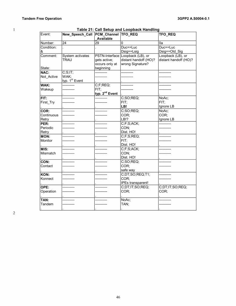
Tandem Free Operation 3GPP2 A.S0004-0.1
46
Table 21: Call Setup and Loopback Handling 1 Event: New_Speech_Call PCM_Channel
_Available TFO_REQ TFO_REQ
Number: 24 29 0 0a Condition: &
. . Duc==Luc Dsig==Lsig
Duc==Luc Dsig==Old_Sig
Comment: State:
System activates TRAU
PSTN-Interface gets active; occurs only at beginning
Loopback (LB), or distant handoff (HO)? wrong Signature?
Loopback (LB), or distant handoff (HO)?
NAC: C;S;IT; ---------- ---------- ---------- Not_Active WAK; ---------- ---------- ---------- . typ. 1st Event . . . WAK: ---------- C;F;REQ; ---------- ---------- Wakeup ---------- FIT; ---------- ---------- . . typ. 2nd Event . . FIT: ---------- ---------- C;SO;REQ; NoAc; First_Try ---------- ---------- FIT; FIT; . . . LB! Ignore LB COR: ---------- ---------- C;SO;REQ; NoAc; Continuous ---------- ---------- COR; COR; Retry . . LB!? Ignore LB PER: ---------- ---------- C;F;S;ACK; ---------- Periodic ---------- ---------- CON; ---------- Retry . . Dist. HO! . MON: ---------- ---------- C;F;S;REQ; ---------- Monitor ---------- ---------- FIT; ---------- . . . Dist. HO! . MIS: ---------- ---------- C;F;S;ACK; ---------- Mismatch ---------- ---------- CON; ---------- . . . Dist. HO! . CON: ---------- ---------- C;SO;REQ; ---------- Contact ---------- ---------- COR; ---------- . . . safe way . KON: ---------- ---------- C;DT;SO;REQ;T1; ---------- Konnect ---------- ---------- COR; ---------- . . . IPEs transparent! . OPE: ---------- ---------- C;DT;IT;SO;REQ; C;DT;IT;SO;REQ; Operation ---------- ---------- COR; COR; . . . . . TAN: ---------- ---------- NoAc; ---------- Tandem ---------- ---------- TAN; ---------- . . . . .
2
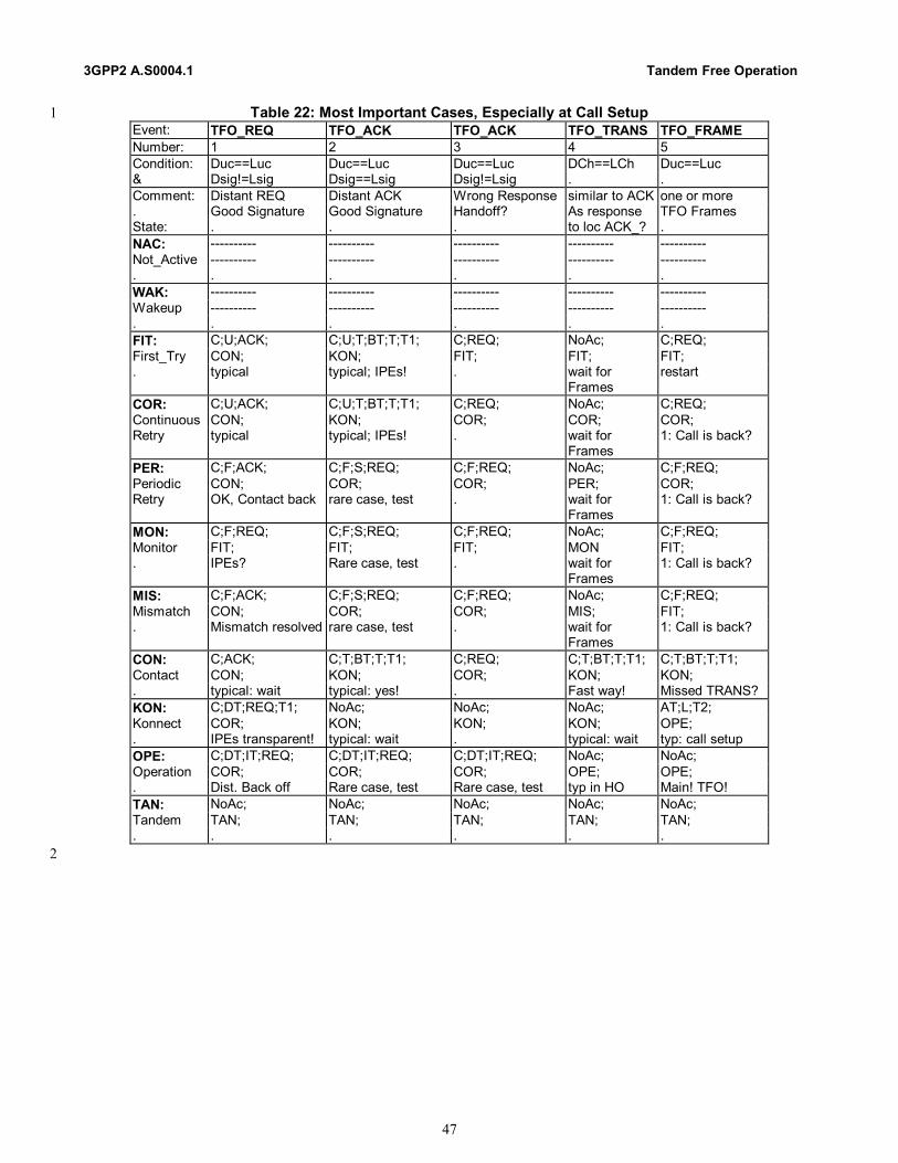
3GPP2 A.S0004.1 Tandem Free Operation
47
Table 22: Most Important Cases, Especially at Call Setup 1 Event: TFO_REQ TFO_ACK TFO_ACK TFO_TRANS TFO_FRAME Number: 1 2 3 4 5 Condition: Duc==Luc Duc==Luc Duc==Luc DCh==LCh Duc==Luc & Dsig!=Lsig Dsig==Lsig Dsig!=Lsig . . Comment: Distant REQ Distant ACK Wrong Response similar to ACK one or more . Good Signature Good Signature Handoff? As response TFO Frames State: . . . to loc ACK_? . NAC: ---------- ---------- ---------- ---------- ---------- Not_Active ---------- ---------- ---------- ---------- ---------- . . . . . . WAK: ---------- ---------- ---------- ---------- ---------- Wakeup ---------- ---------- ---------- ---------- ---------- . . . . . . FIT: C;U;ACK; C;U;T;BT;T;T1; C;REQ; NoAc; C;REQ; First_Try CON; KON; FIT; FIT; FIT; . typical typical; IPEs! . wait for
Frames restart
COR: C;U;ACK; C;U;T;BT;T;T1; C;REQ; NoAc; C;REQ; Continuous CON; KON; COR; COR; COR; Retry typical typical; IPEs! . wait for
Frames 1: Call is back?
PER: C;F;ACK; C;F;S;REQ; C;F;REQ; NoAc; C;F;REQ; Periodic CON; COR; COR; PER; COR; Retry OK, Contact back rare case, test . wait for
Frames 1: Call is back?
MON: C;F;REQ; C;F;S;REQ; C;F;REQ; NoAc; C;F;REQ; Monitor FIT; FIT; FIT; MON FIT; . IPEs? Rare case, test . wait for
Frames 1: Call is back?
MIS: C;F;ACK; C;F;S;REQ; C;F;REQ; NoAc; C;F;REQ; Mismatch CON; COR; COR; MIS; FIT; . Mismatch resolved rare case, test . wait for
Frames 1: Call is back?
CON: C;ACK; C;T;BT;T;T1; C;REQ; C;T;BT;T;T1; C;T;BT;T;T1; Contact CON; KON; COR; KON; KON; . typical: wait typical: yes! . Fast way! Missed TRANS? KON: C;DT;REQ;T1; NoAc; NoAc; NoAc; AT;L;T2; Konnect COR; KON; KON; KON; OPE; . IPEs transparent! typical: wait . typical: wait typ: call setup OPE: C;DT;IT;REQ; C;DT;IT;REQ; C;DT;IT;REQ; NoAc; NoAc; Operation COR; COR; COR; OPE; OPE; . Dist. Back off Rare case, test Rare case, test typ in HO Main! TFO! TAN: NoAc; NoAc; NoAc; NoAc; NoAc; Tandem TAN; TAN; TAN; TAN; TAN; . . . . . .
2

Tandem Free Operation 3GPP2 A.S0004-0.1
48
Table 23: In Call Modification and Handoff 1 Event: New_Local_Codec New_Local_Codec TFO_SYL TFO_DUP Number: 25 26 7 8 Condition: Duc==Nluc Duc!=Nluc . . & . . . . Comment: in Call Modif. in Call Modif. the dist. TRAU the dist. TRAU . Mismatch resolv. Mismatch occurs! lost sync recognized HOState: ( Luc!=Nluc ) ( Luc!=Nluc ) in OPE NAC: ---------- ---------- ---------- ---------- Not_Active ---------- ---------- ---------- ---------- . . . . . WAK: NoAc; NoAc; ---------- ---------- Wakeup WAK; WAK; ---------- ---------- . . . . . FIT: C;REQ; C;REQ; NoAc; NoAc; First_Try FIT; FIT; FIT; FIT; . restart restart HO? Ignore HO? Ignore COR: C;REQ; C;REQ; NoAc; NoAc; Continuous COR; COR; COR; COR; Retry . . ignore ignore PER: L1;T5; L1;T5; C;F;REQ; C;F;REQ; Periodic PER; PER; COR; COR; Retry . . rare case, test rare case, test MON: NoAc; NoAc; C;F;REQ; C;F;REQ; Monitor MON MON FIT; FIT; . . . rare case, test rare case, test MIS: C;F;REQ; L;T2; C;F;REQ; C;F;REQ; Mismatch COR; MIS; COR; COR; . Mismatch res. Direct info. rare case, test rare case, test CON: ---------- C;REQ; C;F;REQ; C;F;REQ; Contact ---------- COR; COR; COR; . . . rare case, test rare case, test KON: ---------- C;DT;REQ; C;DT;REQ; C;DT;REQ; Konnect ---------- COR; COR; COR; . . . . . OPE: ---------- C;DT;IT;REQ; C;DT;IT;REQ; C;DT;IT;REQ; Operation ---------- COR; COR; COR; . . . . . TAN: NoAc; NoAc; NoAc; NoAc; Tandem TAN; TAN; TAN; TAN; . . . . .
2

3GPP2 A.S0004.1 Tandem Free Operation
49
Table 24: Special Matching TFO Messages 1 Event: TFO_REQ_L TFO_REQ_L TFO_ACK_L TFO_ACK_L TFO_REQ_P TFO_REQ_P Number: 9 10 11 12 13 14 Condition: Duc==Luc Duc==Luc Duc==Luc Duc==Luc . . & Dsig==Lsig Dsig!=Lsig Dsig==Lsig Dsig!=Lsig Dsig==Lsig Dsig!=Lsig Comment: Only sent in
MIS/OPE/PER Only sent in MIS/OPE/PER
Only sent in MIS . sent by TCME only embedded
sent by TCME only embedded
State: HO? Loop? Codec_List HO? HO? NAC: ---------- ---------- ---------- ---------- ---------- ---------- Not_Active ---------- ---------- ---------- ---------- ---------- ---------- . . . . . . . WAK: ---------- ---------- ---------- ---------- ---------- ---------- Wakeup ---------- ---------- ---------- ---------- ---------- ---------- . . . . . . . FIT: NoAc; NoAc; NoAc; NoAc; ---------- ---------- First_Try FIT; FIT; FIT; FIT; ---------- ---------- . ignore ignore ignore ignore . . COR: NoAc; NoAc; NoAc; NoAc; ---------- ---------- Continuous COR; COR; COR; COR; ---------- ---------- Retry ignore ignore ignore ignore . . PER: C;F;S;REQ; C;F;REQ; C;F;S;REQ; C;F;REQ; ---------- ---------- Periodic COR; COR; COR; COR; ---------- ---------- Retry start again start again test test . . MON: C;F;S;REQ; C;F;REQ; C;F;S;REQ; C;F;REQ; ---------- ---------- Monitor FIT; FIT; FIT; FIT; ---------- ---------- . test test test test . . MIS: C;F;S;REQ; C;F;REQ; C;F;S;REQ; C;F;REQ; S;LA; LA; Mismatch COR; COR; COR; COR; MIS; MIS; . test test test test acknowledge acknowledge CON: C;S;REQ; C;REQ; C;S;REQ; C;REQ; ---------- ---------- Contact COR; COR; COR; COR; ---------- ---------- . safe way! safe way! safe way! safe way! . . KON: C;DT;S;REQ;T1 C;DT;REQ;T1; C;DT;S;REQ;T1; C;DT;REQ;T1; S;LA; LA; Konnect COR; COR; COR; COR; KON; KON; . safe way! safe way! safe way! safe way! acknowledge acknowledge OPE: S;L;T2; C;LA; C; S;L;T2; S;LA; LA; Operation OPE; OPE; OPE; OPE; OPE; OPE; . tx Codec_List Ack List, stop Ack ok, stop exchange list acknowledge acknowledge TAN: NoAc; NoAc; NoAc; NoAc; NoAc; NoAc; Tandem TAN; TAN; TAN; TAN; TAN; TAN; . . . . . . .
2

Tandem Free Operation 3GPP2 A.S0004-0.1
50
Table 25: TFO Messages with mismatching Codec Type 1 Event: TFO_REQ TFO_REQ TFO_ACK TFO_REQ_L TFO_REQ_L TFO_ACK_L Number: 15 16 17 18 19 20 Condition: Duc!=Luc Duc!=Luc Duc!=Luc Duc!=Luc Duc!=Luc Duc!=Luc & Dsig==Lsig Dsig!=Lsig Dsig==? Dsig==Lsig Dsig!=Lsig Dsig==? Comment: Mismatch Mismatch Mismatch Mismatch Mismatch Mismatch . Wrong Sig, HO? Good Sig w/wo HO Codec_List Codec_List Codec_List State: . . . Wrong Sig, HO? . . NAC: ---------- ---------- ---------- ---------- ---------- ---------- Not_Active ---------- ---------- ---------- ---------- ---------- ---------- . . . . . . . WAK: ---------- ---------- ---------- ---------- ---------- ---------- Wakeup ---------- ---------- ---------- ---------- ---------- ---------- . . . . . . . FIT: C;S;L;T2; C;U;L;T2; C;U;L;T2; C;S;LA; C;U;LA; C;U;LA; First_Try MIS; MIS; MIS; MIS; MIS; MIS; . rare typical: Setup HO? rare typ: Setup HO? COR: C;S;L;T2; C;U;L;T2; C;U;L;T2; C;S;LA; C;U;LA; C;U;LA; Continuous MIS; MIS; MIS; MIS; MIS; MIS; Retry . . . . . . PER: C;F;S;L;T2; C;F;L;T2; C;F;L;T2; C;F;S;LA; C;F;LA; C;F;LA; Periodic MIS; MIS; MIS; MIS; MIS; MIS; Retry . . . . . . MON: C;F;S;L;T2; C;F;L;T2; C;F;L;T2; C;F;S;LA; C;F;LA; C;F;LA; Monitor MIS; MIS; MIS; MIS; MIS; MIS; . . . . . . . MIS: C;S;L;T2; C;L;T2; C;L;T2; C;S;LA; C;LA; C;LA; Mismatch MIS; MIS; MIS; MIS; MIS; MIS; . . . . . term. Protoc. term. Protoc. CON: C;S;L;T2; C;L;T2; C;L;T2; C;S;LA; C;LA; C;LA; Contact MIS; MIS; MIS; MIS; MIS; MIS; . . . . . . . KON: C;DT;S;L;T2; C;DT;L;T2; C;DT;L;T2; C;DT;S;LA; C;DT;LA; C;DT;LA; Konnect MIS; MIS; MIS; MIS; MIS; MIS; . . . . . . . OPE: ---------- ---------- ---------- NoAc; NoAc; ---------- Operation ---------- ---------- ---------- OPE; OPE; ---------- . . . . Trans. Error? Trans. Error? . TAN: NoAc; NoAc; NoAc; NoAc; NoAc; NoAc; Tandem TAN; TAN; TAN; TAN; TAN; TAN; . . . . . . .
2

3GPP2 A.S0004.1 Tandem Free Operation
51
Table 26: Mismatching TFO_TRANS and TFO Frames 1 Event: TFO_TRANS TFO_FRAME TFO_FRAME Number: 21 22 23 Condition: DCh!=LCh Duc!=Luc Duc!=Luc & . n==1 n>1 Comment: Mismatch Mismatch Mismatch . of channel type for one for at least State: . TFO Frame two TFO Frames NAC: ---------- ---------- ---------- Not_Active ---------- ---------- ---------- . . . . WAK: ---------- ---------- ---------- Wakeup ---------- ---------- ---------- . . . . FIT: C;U;L;T2; NoAc; C;U;L;T2; First_Try MIS; FIT; MIS; . HO? HO? Be tolerant HO! Mismatch! COR: C;U;L;T2; NoAc; C;U;L;T2; Continuous MIS; COR; MIS; Retry . Call Forward? . PER: C;F;L;T2; NoAc; C;F;L;T2; Periodic MIS; PER; MIS; Retry . Call Forward? . MON: C;F;L;T2; NoAc; C;F;L;T2; Monitor MIS; MON MIS; . . Call Forward? . MIS: C;L;T2; NoAc; C;L;T2; Mismatch MIS; MIS; MIS; . . Call Forward? . CON: C;L;T2; NoAc; C;L;T2; Contact MIS; CON; MIS; . . . . KON: C;DT;L;T2; NoAc; C;DT;L;T2; Konnect MIS; KON; MIS; . . . . OPE: NoAc; NoAc; C;DT;L;T2;IT; Operation OPE; OPE; MIS; . ignore? Hard HO? Hard HO into
TFO TAN: NoAc; NoAc; NoAc; Tandem TAN; TAN; TAN; . . . .
2
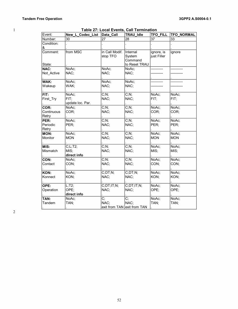
Tandem Free Operation 3GPP2 A.S0004-0.1
52
Table 27: Local Events, Call Termination 1 Event: New_L_Codec_List Data_Call TRAU_Idle TFO_FILL TFO_NORMAL Number: 30 27 28 37 33 Condition: . . . . . & . . . . . Comment: from MSC in Call Modif.
stop TFO Internal System Command
ignore, is just Filler
ignore
State: . to Reset TRAU NAC: NoAc; NoAc; NoAc; ---------- ---------- Not_Active NAC; NAC; NAC; ---------- ---------- . . . . . . WAK: NoAc; NoAc; NoAc; ---------- ---------- Wakeup WAK; NAC; NAC; ---------- ---------- . . . . . . FIT: NoAc; C;N; C;N; NoAc; NoAc; First_Try FIT; NAC; NAC; FIT; FIT; . update loc. Par. . . . . COR: NoAc; C;N; C;N; NoAc; NoAc; Continuous COR; NAC; NAC; COR; COR; Retry . . . . . PER: NoAc; C;N; C;N; NoAc; NoAc; Periodic PER; NAC; NAC; PER; PER; Retry . . . . . MON: NoAc; C;N; C;N; NoAc; NoAc; Monitor MON NAC; NAC; MON MON . . . . . . MIS: C;L;T2; C;N; C;N; NoAc; NoAc; Mismatch MIS; NAC; NAC; MIS; MIS; . direct info . . . . CON: NoAc; C;N; C;N; NoAc; NoAc; Contact CON; NAC; NAC; CON; CON; . . . . . . KON: NoAc; C;DT;N; C;DT;N; NoAc; NoAc; Konnect KON; NAC; NAC; KON; KON; . . . . . . OPE: L;T2; C;DT;IT;N; C;DT;IT;N; NoAc; NoAc; Operation OPE; NAC; NAC; OPE; OPE; . direct info . . . . TAN: NoAc; C; C; NoAc; NoAc; Tandem TAN; NAC; NAC; TAN; TAN; . . exit from TAN exit from TAN . .
2
3GPP2 A.S0004.1 Tandem Free Operation
53
Table 28: Special Events, Timeouts 1 Event: Runout T==0 Frame_Sync_Lost Frame_Sync_Lost Mes_Sync_Lost Number: 31 32 34 35 36 Condition: . . n<3 n>2 . & . . . . . Comment: IPEs may be-
come unsynch. Time-Out No Action Stop TFO Frames,
if 3 Frames missing.
State: . . . . . NAC: ---------- ---------- ---------- ---------- ---------- Not_Active ---------- ---------- ---------- ---------- ---------- . . . . . . WAK: ---------- ---------- ---------- ---------- ---------- Wakeup ---------- ---------- ---------- ---------- ---------- . . . . . . FIT: U;N; ---------- ---------- ---------- NoAc; First_Try MON ---------- ---------- ---------- FIT; . PSTN Call . . . . COR: U;L1;T5; C;N;REQ; ---------- ---------- NoAc; Continuous PER; COR; ---------- ---------- COR; Retry at end of COR reset IPEs . . . PER: NoAc; L1;T5; ---------- ---------- NoAc; Periodic PER; PER; ---------- ---------- PER; Retry . Periodic Test . . . MON: ---------- ---------- ---------- ---------- ---------- Monitor ---------- ---------- ---------- ---------- ---------- . . . . . . MIS: NoAc; N; NoAc; NoAc; NoAc; Mismatch MIS; MIS; MIS; MIS; MIS; . typ. Final state List not Ack_ed! . . . CON: REQ; ---------- ---------- ---------- C;REQ; Contact COR; ---------- ---------- ---------- COR; . can this occur? . . . . KON: NoAc; C;DT;N; ---------- ---------- C;DT;REQ;T1; Konnect KON; TAN; ---------- ---------- COR; . may happen Misbehavior! . . after Timeout: N OPE: NoAc; NoAc; C;DT;IT; F;REQ; NoAc; Operation OPE; OPE; OPE; COR; OPE; . typ. Final event List not Ack_ed! 1: Alarm, go on 2: Alarm, stop! Typ. Final event TAN: NoAc; ---------- ---------- ---------- NoAc; Tandem TAN; ---------- ---------- ---------- TAN; . typical . . . don’t trust!
2

Tandem Free Operation 3GPP2 A.S0004-0.1
54
Table 29: System Commands 1 Event: Inhibit_TFO Allow_TFO Number: 38 39 Condition: - - & . Comment: System command System command . Received Received State: . NAC: -------- -------- Not_Active -------- -------- . WAK: TAN; -------- Wakeup -------- . FIT: C;N; NoAc; First_Try TAN; FIT; . COR: C;N; NoAc; Continuous TAN; COR; Retry . PER: C;N; C;F;REQ; Periodic TAN; COR; Retry . MON: C;N; C;F;REQ; Monitor TAN; FIT; . . MIS: C;N; C;F;REQ; Mismatch TAN; COR; . . CON: C;N; NoAc; Contact TAN; CON; . . KON: C;DT;N; NoAc; Konnect TAN; KON; . . OPE: C;DT;IT;N; NoAc; Operation TAN; OPE; . TAN: NoAc; C; F; REQ; Tandem TAN; FIT; . .
2

3GPP2 A.S0004.1 Tandem Free Operation
55
11 State Machine of the TFO_Protocol Process for TDMA 1
The TDMA TFO_Protocol Process can be described by a State Machine, consisting of 15 States: five main States with 2 several sub-States; exception handling needs further States, see figure 12: 3 Initialization (• Not_Active,• Wakeup) 4 Establishment (• First_Try, • Continuous_Retry, • Periodic_Retry, • Monitor, • Mismatch) 5 Contact (• Contact) 6 Konnect (• Konnect) 7 Operation (• Operation) 8 Local HO (• Fast_Try, • Fast_Contact) 9 Distant HO (• Sync_Lost, • Re_Konnect) 10 Misbehavior (• Failure) 11 It is assumed that Events (Conditions checking, Actions and Transition to another State) are handled almost 12 instantaneously and in any case significantly shorter than the time required to complete the transmission of any one TFO 13 Message or TFO Frame. 14
Fast_Try
First_Try C_Retry P_Retry Monitor
Contact
Mismatch
Konnect
OperationSync_Lost
Failure
Wakeup
Not_Active
Fast_Con
Establishment
Initialisation
Re_Kon
LocalHandover
Distant Handover 15 16
Figure 12: TFO_Protocol State Machine with most important transitions 17
Tandem Free Operation 3GPP2 A.S0004-0.1
56
11.1 Initialization 1
11.1.1 Not_Active State 2
The state Not_Active is system and manufacturer dependent and cannot be described in detail here. The TRAU basically 3 performs no speech coding, but may monitor the link for certain patterns (e.g., idle patterns). The TRAU may also be in 4 Data mode, which is also not described further, but is handled here as "Not_Active". 5 6
11.1.2 Wakeup State 7
The Wakeup State is entered when the TRAU is activated by the appropriate event (e.g. activation by a MSC message or 8 reception of TRAU Frames). The Wakeup state is characterized by the TRAU sending speech data at least in one direction. 9 10 TFO operation begins in the Wakeup State and transitions to the First_Try State when speech processing is performed in 11 both the uplink and downlink directions. 12 13
11.2 Establishment 14
The Establishment State comprises several slightly different situations: 15 First_Try when the TRAU just has started; it sends TFO_REQ Messages continuously; 16 Continuous_Retry when Contact to a TFO Partner had existed but was interrupted recently; 17 Periodic_Retry when Contact to a TFO Partner had existed but was interrupted some time ago; 18 Monitor when no TFO partner could be found, but the TRAU continues to monitor the PSTN Interface; 19 Mismatch when a TFO partner with a different Codec has been identified. 20 Loopback is a specific situation, when the call is still not through connected and the TRAU receives the own sent signals. 21 No specific State is allocated to describe this situation. Instead, loopback is handled in First_Try and Continuous_Retry. 22 Common to all these situations is that the TRAU does not know, if there is a distant TFO partner and/or if the links are 23 digitally transparent. Typically, TFO_REQ Messages are sent and expected. 24 Due to HO cases it might, however, happen that a TRAU is initialized into an existing connection and therefore the other 25 TFO Partner may be in any State and all other TFO Messages may be received, too. 26 Especially important is, when TFO Frames are received, since then it can be assumed that an existing TFO Connection 27 was handed over to a newly initialized TRAU and the TFO should be continued - if possible uninterrupted - as soon as 28 possible. The TRAU may see from the TFO Frames the Distant_Used_Codec of a TFO Partner and that the receiving path 29 is digitally transparent, but it can not assume that the path to the other TFO Partner is also (already) transparent. 30 TFO_Protocol enters the exceptional State: Fast_Try, sending a specific, short TFO_DUP Message to test the other 31 direction. 32 33
11.2.1 First_Try State 34
The TRAU sends and receives PCM samples on and from the PSTN interface. Regular TFO_REQ Messages are sent onto 35 the PSTN interface continuously for a certain maximum time. If no answer is received from the TFO partner before the 36 end of this maximum time period, Tx_TFO reports a Runout of TFO Messages and TFO_Protocol enters automatically 37 into the Monitor State. 38 If TFO_REQ Messages are received with the same, own Signature, then a circuit loop back is assumed, i.e. the call is still 39 not through-connected. The TRAU selects a new Signature and continues sending TFO_REQ Messages, until a different 40 Signature is received. Since loop back delays may be substantial in some cases, the TRAU has to remember and compare 41 also the previously selected own Signature. Care has to be taken that the Signature selection contains a true random 42 element in order to minimize the probability of two different TRAUs coincidentally selecting identical signatures. 43 44
3GPP2 A.S0004.1 Tandem Free Operation
57
11.2.2 Continuous_Retry State 1
TFO Contact had existed, either by TFO Messages or by TFO Frames, but was interrupted and sync was lost. The TRAU 2 sends a maximum number of regular TFO_REQ Messages continuously to test if TFO could be re-established. If Tx_TFO 3 reports a Runout of TFO Messages, then the TFO_Protocol enters the Periodic_Retry State. 4 5
11.2.3 Periodic_Retry State 6
Entered from Continuous_Retry, TFO_Protocol periodically sends a single TFO_REQ_L to determine if TFO could be re-7 established. As soon as a TFO Message is received, TFO_Protocol leaves this State. 8
NOTE: Since no contiguous transmission of TFO Messages is ongoing, IPEs may not be synchronized. 9 10
11.2.4 Monitor State 11
The TRAU monitors the PSTN interface for TFO Messages or TFO Frames, but it does not send TFO Messages or TFO 12 Frames. As soon as a TFO Message from a distant partner (a TRAU or a TCME) has been received, the TRAU knows that 13 a TFO Partner exists and it knows that the transmission path from the partner is digitally transparent. 14 The TRAU may already now see, whether TFO is possible, but it must ensure that all IPEs are synchronized. It therefore 15 transits into the Continuous_Retry State. In case of Codec Mismatch, it terminates the TFO Protocol by sending 16 TFO_REQ_L back, informs its local MSC and transits into Mismatch. 17
NOTE: Since no contiguous transmission of TFO Messages is ongoing, IPEs may not be synchronized. 18 19
11.2.5 Mismatch State 20
From a previous contact it is obvious, that a distant TFO Partner exists, but the Codecs do not match. 21 The TRAU waits without sending TFO Messages or TFO Frames, if either the distant TFO Partner changes to the 22 Local_Used_Codec, or the local MSC solves the Codec mismatch situation by an intra cell HO to the Distant_Used_Codec. 23
NOTE: Since no contiguous transmission of TFO Messages is ongoing, IPEs may not be synchronized. 24 25
11.3 Contact State 26
TFO_REQ messages have been received from a distant TFO Partner. The Codecs do match. The link from the distant 27 partner is digitally transparent. Now TFO_ACK needs to be sent to check the digital transparency of the link to the distant 28 partner. 29 As soon as a TFO_ACK or TFO_TRANS from a distant partner has been received, the TRAU knows that the links in both 30 directions are digitally transparent. The TRAU sends TFO_TRANS to bypass the IPEs and starts sending TFO Frames. It 31 transits into Konnect State. 32 33
11.4 Konnect State 34
The TRAU sends TFO Frames and possibly embedded TFO Messages as long as it receives correct TFO Messages. 35 The first received TFO Frame causes the transition into the final Operation State. 36 If no TFO Frames are received within a certain period, the TRAU transits to the Failure State. 37 38
11.5 Operation State 39
This is the main state of the TFO Protocol. In this state, the TRAU sends and receives TFO frames and the TFO 40 connection is fully operational. 41 42
Tandem Free Operation 3GPP2 A.S0004-0.1
58
11.6 Local HO 1
11.6.1 Fast_Try State 2
When the TRAU in First_Try receives suddenly TFO Frames and the Codecs do match, then there is a high probability 3 that a local HO has initialized the TRAU into an existing TFO connection and a fast TFO establishment is likely. The 4 TFO_Protocol has still to check, whether the link to the distant TFO Partner is (already) transparent. This is done by the 5 specific TFO_DUP Message. 6 Since the HO must have been a local HO, i.e. close to the (new) TRAU, it can be assumed that the possibly existing IPEs 7 are still in transparent mode and TFO Messages therefore pass through directly. 8 9
11.6.2 Fast_Contact State 10
This State is entered from First_Try via Fast_Try, if TFO Frames and then TFO_SYL Messages are received. The TRAU 11 continues to send TFO_DUP Messages, until TFO Frames are received again. Then it immediately starts to send TFO 12 Frames, with a TFO_TRANS embedded into the first TFO Frames. The TRAU transits directly to Operation State. 13 14
11.7 Distant HO, TFO Interruption 15
11.7.1 Sync_Lost State 16
If the TRAU was in Operation State and suddenly the TFO Frame synchronization is lost then the TRAU enters the 17 Sync_Lost State for a short while, before it transits to Continuous_Retry. 18 If synchronization was lost due to a distant HO, then a fast TFO establishment might be possible and the TRAU enters 19 Operation State soon again. In Sync_Lost it expects TFO_DUP Message as confirmation of the distant HO. Then it 20 transits to Re_Konnect. 21 22
11.7.2 Re_Konnect State 23
This State is entered from Operation via Sync_Lost, if TFO_DUP Messages are received. The TRAU starts immediately to 24 send TFO Frames again, with a TFO_TRANS embedded into the first TFO Frames. The TRAU transits back to Operation 25 State, as soon as TFO Frames are received, again. 26 27
11.8 Failure State 28
This State is entered when the distant partner shows an incorrect behavior. The TRAU then sends pure PCM samples onto 29 the PSTN interface and waits for the failure to disappear. It does not send TFO Frames or TFO Messages. 30

3GPP2 A.S0004.1 Tandem Free Operation
59
12 Detailed Description of TFO_Protocol for TDMA 1
The TFO_Protocol Process is always in one well-defined State. An Event triggers Actions and a Transition into another 2 State. The TFO Protocol is described in a table-wise manner, with syntax as defined in Table 30. 3 4
Table 30: Definition of the Syntax for the State Machine Description 5 Event:
Number:
<Received Message>
<running number>
… <Other Event>
<running number> Condition:
& [<Condition>] [<Condition>]
[<Condition>] [<Condition>]
Comment: State:
[<Comment>] [<Comment>]
<Actual State>: <Action Name>;[<Action Name>;] <Next State>; [<Comment>]
<Action Name>;[<Action name>;] <Next State>; [<Comment>]
… <Actual State>: <Action Name>;[<Action Name>;]
<Next State>; [<Comment>]
<Action Name>;[<Action Name>;] <Next State>; [<Comment>]
6 Several tables, table 33 to table 40, are necessary to describe the whole State Machine. If a table entry contains only a 7 dashed line, it is assumed that this combination cannot occur. If, however, such a combination is encountered during 8 operation, it is treated as ‘don’t care’. 9 10 The Actions are described in table 32, with syntax as defined in table 31. 11 12
Table 31: Definition of Syntax for Action Table 13 Name Action List Comment
<Action Name> <Action >;[ <Action >;] <Comment> … <Action Name> <Action >;[ <Action >;] <Comment>
14 Tx := TFO_REQ means, that TFO_Protocol places a command into Tx_Queue. Tx_TFO handles the details 15 autonomously and generates a TFO_REQ Message for transmission over the PSTN interface, when it comes to that 16 command. 17 18 Tx := 31*TFO_REQ means: put 31 TFO_REQ commands into Tx_Queue. Not necessarily all will really trigger 19 TFO_REQ Messages. In most cases Tx_Queue will be cleared before. Similar definitions hold for the other messages. 20 The Tx_Queue is a first_in_first_out command queue. It is filled by TFO_Protocol and read by Tx_TFO. 21 22 Clear Tx_Queue, means that all remaining commands are deleted from the Tx_Queue in that very moment (time Tc). 23 Note that due to the duration time to transmit a TFO_Message completely, the TFO_Protocol Process is often already 24 within another State while still TFO Messages commanded in earlier States are within the Tx_Queue or under 25 transmission. 26 27 MSC := TFO () means that a message is sent to the local MSC; similar 28 29 Tx_TRAU := … means a message to Tx_TRAU. 30 31

Tandem Free Operation 3GPP2 A.S0004-0.1
60
An Event TFO_REQ means that a TFO_REQ Message was correctly received on the PSTN interface. The Rx_TFO 1 Process has sent a message to TFO_Protocol, containing the new values for the respective variables. TFO_Protocol updates 2 its variables with the new values. Similar definitions hold for the other messages. 3 4 One Timer T := <Time_out> is necessary to describe time out situations. The notation T := DIS means that the Timer is 5 disabled. Positive values are decremented in a hidden background process in steps of 20 ms. When T gets to the value "0", 6 then the TFO_Protocol process is invoked. 7 8 Local_Used_Codec (short form: Luc) means the type of speech Codec used in the local TRAU and. 9 New Local_Used_Codec (Nluc) refers to the new codec received in "In_Call_Modifications". 10 11 Distant_Used_Codec (Duc) means the type of speech Codec used by the distant partner, as reported in TFO_REQ… or 12 TFO_ACK… 13 14 Distant_Preferred_Codec (DPC) means the type of speech Codec that the distant partner would prefer, as reported in 15 TFO_REQ_P. 16 17 Local_Codec_List (LCL) means the list of all Codecs that could alternatively be used; i.e., those supported by both the 18 local MS and the local MSC. It always contains at least the Local_Used_Codec. 19 It is reported in TFO_REQ_L, TFO_ACK_L or TFO_REQ_P. 20 21 Distant_Codec_List (DCL) means the list of all Codecs that could alternatively be used; i.e., those supported by the 22 distant MS and the distant MSC. It always contains at least the Distant_Used_Codec. 23 All these variables are initialized to UNKNOWN, which means that the contents of the variables are not defined. 24 25 Local_Signature (Lsig) means the 8-bit random number in TFO_REQ, which identifies the local TFO_REQ Messages. It 26 is also used in TFO_REQ_L. 27 28 Distant_Signature (Dsig) means the 8-bit random number as received in TFO_REQ, TFO_REQ_L and TFO_REQ_P, 29 in TFO_ACK and TFO_ACK_L 30 If received in TFO_REQ, TFO_REQ_L and TFO_REQ_P, then it should be different to the Local_Signature, otherwise 31 loop back must be assumed (exceptions exist). 32 If received in TFO_ACK or TFO_ACK_L, then it should be identical to the Local_Signature, otherwise the TFO_ACK is 33 not a response to an own TFO_REQ respectively TFO_REQ_L, but maybe was created during a HO situation. 34 35 Local Channel Type (LCh) and distant Channel Type (DCh) refer to the 8 or 16 kbps transparent channel used by the 36 local Tx_TFO respectively received by the distant TFO_TRANS. 37 38 Error protection and error handling: It is assumed that the defined error protection is strong enough for the error rates 39 encountered on typical PSTN interface links. The few occurring errors are in practically all cases detected and possibly 40 even corrected by Rx_TFO, before reported to TFO_Protocol. Therefore TFO_Protocol can rely on the correctness of the 41 received Events. The protocol is, however, "self-healing" and will handle the unlikely erroneously reported Events, too. 42 43 The Event "PCM_Channel_Available" is given if in State Wakeup, if valid PCM samples are received on the PSTN 44 interface. This event can be triggered by a higher level system. 45 46 Fast HO handling: The defined protocol assumes that the new TRAU, to which the HO is performed, is already in State 47 Wakeup before the PSTN Interface is switched to that TRAU. Only then the TFO Frames can be received by that TRAU 48 and fast HO handling is possible. 49 50 Timing: If two Events occur by coincidence at the same time, then they shall be processed in the order given by the tables 51 32 to 39 (left to right) . TFO Messages arrive always some time before the embedding TFO Frame and shall be handled 52 therefore first. 53 54

3GPP2 A.S0004.1 Tandem Free Operation
61
Runout is the Event, when the last TFO Message has been taken from the Tx_Queue and the last 10 bits are going to be 1 sent by Tx_TFO to the PSTN interface. So there is still some time for the TFO Protocol to react and place a further TFO 2 Message into Tx_Queue, which then shall be transmitted without gap to the messages before. 3 4
Table 32: Defined Actions 5 Name Actions Comments
C Clear Tx_Queue; T := DIS; Initialize Tx_Queue and disable the timer T1 T := 1s; Set Timeout to 1 second T2 T := 2s; Set Timeout to 2 seconds T5 T := 5s; Set Timeout to 5 seconds NoAc . No Action required S Lsig := New_Random_Number; Generate new Signature and set Old_Sig to unknown; Old_Sig := UNKNOWN; if no Loopback is assumed. SO Old_Sig := Lsig; Remember old Signature and generate a new Signature, Lsig := New_Random_Number; if Loopback is assumed. U Old_Sig := UNKNOWN; Reset Old_Sig before leaving FIT or COR F Tx := 3*TFO_FILL; "Hello IPEs! Please synchronize!" T Tx := TFO_TRANS (); "Hello IPEs! Please open a transparent channel!" N Tx := TFO_NORMAL; "Hello IPEs! Please return to normal operation!" REQ Tx := 35*TFO_REQ; “Hello Partner? Can You do TFO with me?” ACK Tx := 7*TFO_ACK; “Yes, I can do TFO with You!” SYL1 Tx := TFO_SYL; "Hello Partner! I lost one or more TFO_Frames!" SYL Tx := 4*TFO_SYL; "Hello Partner! Serious interruption of TFO_Frames!" DUP Tx := 5*TFO_DUP; HO? “Hey, I see Your TFO Frames, Fine!” L1 Tx := TFO_REQ_L; "Here is my Codec_List! Can you hear me?" L Tx := 6*TFO_REQ_L; "Here is my Codec_List, please acknowledge!" LA Tx := TFO_ACK_L; "Yes, I received Your Codec_List! Here is mine!" BT Tx := Begin_TFO; Begin Transmission of TFO Frames DT Tx := Discontinue_TFO; Discontinue Transmission of TFO Frames IT Tx_TRAU := Ignore_TFO; Tx_TRAU works as conventional downlink TRAU AT Tx_TRAU := Accept_TFO; Tx_TRAU bypasses TFO_Frames B MSC := TFO (); "Hello MSC! Some news from the TFO_Scene!"
6
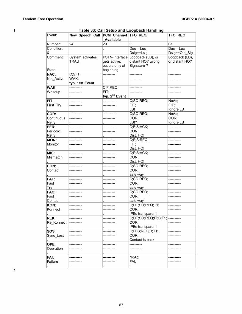
Tandem Free Operation 3GPP2 A.S0004-0.1
62
Table 33: Call Setup and Loopback Handling 1 Event: New_Speech_Call PCM_Channel
_Available TFO_REQ TFO_REQ
Number: 24 29 0 0a Condition: &
. . Duc==Luc Dsig==Lsig
Duc==Luc Dsig==Old_Sig
Comment: State:
System activates TRAU
PSTN-Interface gets active; occurs only at beginning
Loopback (LB), or distant HO? wrong Signature ?
Loopback (LB), or distant HO?
NAC: C;S;IT; ---------- ---------- ---------- Not_Active WAK; ---------- ---------- ---------- . typ. 1rst Event . . . WAK: ---------- C;F;REQ; ---------- ---------- Wakeup ---------- FIT; ---------- ---------- . . typ. 2nd Event . . FIT: ---------- ---------- C;SO;REQ; NoAc; First_Try ---------- ---------- FIT; FIT; . . . LB! Ignore LB COR: ---------- ---------- C;SO;REQ; NoAc; Continuous ---------- ---------- COR; COR; Retry . . LB!? Ignore LB PER: ---------- ---------- C;F;S;ACK; ---------- Periodic ---------- ---------- CON; ---------- Retry . . Dist. HO! . MON: ---------- ---------- C;F;S;REQ; ---------- Monitor ---------- ---------- FIT; ---------- . . . Dist. HO! . MIS: ---------- ---------- C;F;S;ACK; ---------- Mismatch ---------- ---------- CON; ---------- . . . Dist. HO! . CON: ---------- ---------- C;SO;REQ; ---------- Contact ---------- ---------- COR; ---------- . . . safe way . FAT: ---------- ---------- C;SO;REQ; ---------- Fast ---------- ---------- COR; ---------- Try . . safe way . FAC: ---------- ---------- C;SO;REQ; ---------- Fast ---------- ---------- COR; ---------- Contact . . safe way . KON: ---------- ---------- C;DT;SO;REQ;T1; ---------- Konnect ---------- ---------- COR; ---------- . . . IPEs transparent! . REK: ---------- ---------- C;DT;SO;REQ;IT;B;T1; ---------- Re_Konnect ---------- ---------- COR; ---------- . . . IPEs transparent! . SOS: ---------- ---------- C;IT;S;REQ;B;T1; ---------- Sync_Lost ---------- ---------- COR; ---------- . . . Contact is back . OPE: ---------- ---------- ---------- ---------- Operation ---------- ---------- ---------- ---------- . . . . . FAI: ---------- ---------- NoAc; ---------- Failure ---------- ---------- FAI; ---------- . . . . .
2

3GPP2 A.S0004.1 Tandem Free Operation
63
Table 34: Most Important Cases, Especially at Call Setup 1 Event: TFO_REQ TFO_ACK TFO_ACK TFO_TRANS TFO_FRAME Number: 1 2 3 4 5 Condition: Duc==Luc Duc==Luc Duc==Luc DCh==LCh Duc==Luc & Dsig!=Lsig Dsig==Lsig Dsig!=Lsig . n<3 Comment: Distant REQ Distant ACK Wrong Response similar to ACK one or two . Good Signature Good Signature HO? As response TFO Frames State: . . . to loc ACK_? . NAC: ---------- ---------- ---------- ---------- ---------- Not_Active ---------- ---------- ---------- ---------- ---------- . . . . . . WAK: ---------- ---------- ---------- ---------- ---------- Wakeup ---------- ---------- ---------- ---------- ---------- . . . . . . FIT: C;U;ACK; C;U;T;BT;T;T1; C;REQ; NoAc; C;U;DUP; First_Try CON; KON; FIT; FIT; FAT; . typical typical; IPEs! . wait for Frames 1: HO COR: C;U;ACK; C;U;T;BT;T;T1; C;REQ; NoAc; C;U;DUP; Continuous CON; KON; COR; COR; FAT; Retry typical typical; IPEs! . wait for Frames 1: Call is back? PER: C;F;ACK; C;F;S;REQ; C;F;REQ; NoAc; C;DUP; Periodic CON; COR; COR; PER; FAT; Retry OK, Contact back rare case, test . wait for Frames 1: Call is back? MON: C;F;REQ; C;F;S;REQ; C;F;REQ; NoAc; C;DUP; Monitor FIT; FIT; FIT; MON FAT; . IPEs? Rare case, test . wait for Frames 1: Call is back? MIS: C;F;ACK; C;F;S;REQ; C;F;REQ; NoAc; C;DUP; Mismatch CON; COR; COR; MIS; FAT; . Mismatch resolved rare case, test . wait for Frames 1: Call is back? CON: C;ACK; C;T;BT;T;T1; C;REQ; C;T;BT;T;T1; C;T;BT;T;T1; Contact CON; KON; COR; KON; KON; . typical: wait typical: yes! . Fast way! Missed TRANS? FAT: C;REQ; C;REQ; C;REQ; NoAc; NoAc; Fast COR; COR; COR; FAC; FAT; Try safe way safe way safe way wait for Frames 2: typ. Loc. HO FAC: C;REQ; C;REQ; C;REQ; NoAc; C;BT;T;L;T2;AT;
B; Fast COR; COR; COR; FAC; OPE; Contact safe way safe way safe way wait for Frames 5: typ. Loc. HO KON: C;DT;REQ;T1; NoAc; NoAc; NoAc; AT;L;T2;B; Konnect COR; KON; KON; KON; OPE; . IPEs transparent! Typical: wait . typical: wait typ: call setup REK: C;DT;REQ;IT;B;T1
; C;DT;REQ;IT;B;T1; C;DT;REQ;IT;B;T
1 NoAc; AT;L;T2;B;
Re_Konnect COR; COR; COR; REK; OPE; . IPEs transparent! . . wait for Frames 5: typ. Dis. HO SOS: C;IT;REQ;B;T1; C;IT;REQ;B;T1; C;IT;REQ;B;T1; NoAc; C;BT;T;L;T2;B; Sync_Lost COR; COR; COR; SOS; OPE; . Contact is back Contact is back Contact is back wait for Frames short Interrupt? OPE: ---------- ---------- ---------- NoAc; NoAc; Operation ---------- ---------- ---------- OPE; OPE; . . . . typ in HO Main! TFO! FAI: NoAc; NoAc; NoAc; NoAc; NoAc; Failure FAI; FAI; FAI; FAI; FAI; . . . . . .
2

Tandem Free Operation 3GPP2 A.S0004-0.1
64
Table 35: In Call Modification and HO 1 Event: New_Local_Codec New_Local_Codec TFO_FRAME TFO_SYL TFO_DUP Number: 25 26 6 7 8 Condition: Duc==Nluc Duc!=Nluc Duc==Luc . . & . . n>2 . . Comment: in Call Modif. In Call Modif. Three or more the dist. TRAU the dist. TRAU . Mismatch resolv. Mismatch occurs! TFO Frames lost sync recognized HO State: ( Luc!=Nluc ) ( Luc!=Nluc ) . in OPE NAC: ---------- ---------- ---------- ---------- ---------- Not_Active ---------- ---------- ---------- ---------- ---------- . . . . . . WAK: NoAc; NoAc; ---------- ---------- ---------- Wakeup WAK; WAK; ---------- ---------- ---------- . . . . . . FIT: C;REQ; C;REQ; ---------- NoAc; NoAc; First_Try FIT; FIT; ---------- FIT; FIT; . restart restart . HO? Ignore HO? Ignore COR: C;REQ; C;REQ; ---------- NoAc; NoAc; Continuous COR; COR; ---------- COR; COR; Retry . . . ignore ignore PER: L1;T5; L1;T5; ---------- C;F;REQ; C;F;REQ; Periodic PER; PER; ---------- COR; COR; Retry . . . rare case, test rare case, test MON: NoAc; NoAc; ---------- C;F;REQ; C;F;REQ; Monitor MON MON ---------- FIT; FIT; . . . . rare case, test rare case, test MIS: C;F;REQ; L;T2;B; ---------- C;F;REQ; C;F;REQ; Mismatch COR; MIS; ---------- COR; COR; . Mismatch res. Direct info. . rare case, test rare case, test CON: ---------- C;L;T2;B; ---------- C;F;REQ; C;F;REQ; Contact ---------- MIS; ---------- COR; COR; . . . . rare case, test rare case, test FAT: ---------- C;L;T2;B; NoAc; NoAc; C;F;REQ; Fast ---------- MIS; FAC; FAC; COR; Try . . . 3: typ. Loc. HO rare case, test FAC: ---------- C;L;T2;B; C;BT;T;L;T2;AT;B; NoAc; C;F;REQ; Fast ---------- MIS; OPE; FAC; COR; Contact . . . 4: typ. Loc. HO rare case, test KON: ---------- C;DT;L;T2;B; ---------- NoAc; NoAc; Konnect ---------- MIS; ---------- KON; KON; . . . . wait, short int? other TRAU? REK: ---------- C;DT;IT;L;T2;B; ---------- C;DT;SYL; NoAc; Re_Konnect ---------- MIS; ---------- SOS; REK; . . . . IPEs not transp? 4: typ. Dist. HO SOS: ---------- C;IT;L;T2;B; ---------- NoAc; C;BT;T;T1; Sync_Lost ---------- MIS; ---------- SOS; REK; . . . . short Inter? 3: typ. Dis. HO OPE: ---------- C;DT;IT;L;T2;B; NoAc; NoAc; NoAc; Operation ---------- MIS; OPE; OPE; OPE; . . . Main! TFO! Short interrupt? Typical FAI: ---------- NoAc; NoAc; NoAc; NoAc; Failure ---------- FAI; FAI; FAI; FAI; . . . . . .
2

3GPP2 A.S0004.1 Tandem Free Operation
65
Table 36: Special Matching TFO Messages 1 Event: TFO_REQ_L TFO_REQ_L TFO_ACK_L TFO_ACK_L TFO_REQ_P TFO_REQ_P Number: 9 10 11 12 13 14 Condition: Duc==Luc Duc==Luc Duc==Luc Duc==Luc . . & Dsig==Lsig Dsig!=Lsig Dsig==Lsig Dsig!=Lsig Dsig==Lsig Dsig!=Lsig Comment: Only sent in
MIS/OPE/PER Only sent in MIS/OPE/PER
Only sent in MIS . sent by TCME only embedded
sent by TCME only embedded
State: HO? Loop? Codec_List HO? HO? NAC: ---------- ---------- ---------- ---------- ---------- ---------- Not_Active ---------- ---------- ---------- ---------- ---------- ---------- . . . . . . . WAK: ---------- ---------- ---------- ---------- ---------- ---------- Wakeup ---------- ---------- ---------- ---------- ---------- ---------- . . . . . . . FIT: NoAc; NoAc; NoAc; NoAc; ---------- ---------- First_Try FIT; FIT; FIT; FIT; ---------- ---------- . ignore ignore ignore ignore . . COR: NoAc; NoAc; NoAc; NoAc; ---------- ---------- Continuous COR; COR; COR; COR; ---------- ---------- Retry ignore ignore ignore ignore . . PER: C;F;S;REQ; C;F;REQ; C;F;S;REQ; C;F;REQ; ---------- ---------- Periodic COR; COR; COR; COR; ---------- ---------- Retry start again start again test test . . MON: C;F;S;REQ; C;F;REQ; C;F;S;REQ; C;F;REQ; ---------- ---------- Monitor FIT; FIT; FIT; FIT; ---------- ---------- . test test test test . . MIS: C;F;S;REQ; C;F;REQ; C;F;S;REQ; C;F;REQ; S;LA;B; LA;B; Mismatch COR; COR; COR; COR; MIS; MIS; . test test test test acknowledge acknowledge CON: C;S;REQ; C;REQ; C;S;REQ; C;REQ; ---------- ---------- Contact COR; COR; COR; COR; ---------- ---------- . safe way! Safe way! Safe way! Safe way! . . FAT: C;S;REQ; C;REQ; C;S;REQ; C;REQ; S;LA;B; LA;B; Fast COR; COR; COR; COR; FAT; FAT; Try safe way! Safe way! Safe way! Safe way! Acknowledge acknowledge FAC: C;S;REQ; C;REQ; C;S;REQ; C;REQ; S;LA;B; LA;B; Fast COR; COR; COR; COR; FAC; FAC; Contact safe way! Safe way! Safe way! Safe way! Acknowledge acknowledge KON: C;DT;S;REQ;T1 C;DT;REQ;T1; C;DT;S;REQ;T1; C;DT;REQ;T1; S;LA;B; LA;B; Konnect COR; COR; COR; COR; KON; KON; . safe way! Safe way! Safe way! Safe way! Acknowledge acknowledge REK: C;DT;S;REQ;T1 C;DT;REQ;T1; C;DT;S;REQ;T1 C;DT;REQ;T1; ---------- ---------- Re_Konnect COR; COR; COR; COR; ---------- ---------- . safe way! Safe way! Safe way! Safe way! . . SOS: C;IT;S;REQ;B;T1 C;IT;REQ;B;T1 C;IT;S;REQ;B;T1 C;IT;REQ;B;T
1 S;LA;B; LA;B;
Sync_Lost COR; COR; COR; COR; SOS; SOS; . safe way! Safe way! Safe way! Safe way! Acknowledge acknowledge OPE: S;L;T2;B; C;LA;B; C;B; S;L;T2;B; S;LA;B; LA;B; Operation OPE; OPE; OPE; OPE; OPE; OPE; . tx Codec_List Ack List, stop Ack ok, stop exchange list acknowledge acknowledge FAI: NoAc; NoAc; NoAc; NoAc; NoAc; NoAc; Failure FAI; FAI; FAI; FAI; FAI; FAI; . . . . . . .
2
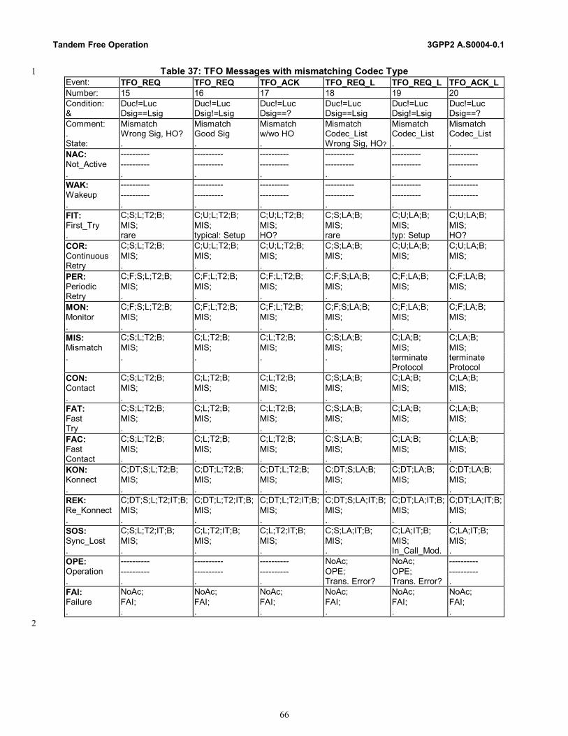
Tandem Free Operation 3GPP2 A.S0004-0.1
66
Table 37: TFO Messages with mismatching Codec Type 1 Event: TFO_REQ TFO_REQ TFO_ACK TFO_REQ_L TFO_REQ_L TFO_ACK_L Number: 15 16 17 18 19 20 Condition: Duc!=Luc Duc!=Luc Duc!=Luc Duc!=Luc Duc!=Luc Duc!=Luc & Dsig==Lsig Dsig!=Lsig Dsig==? Dsig==Lsig Dsig!=Lsig Dsig==? Comment: Mismatch Mismatch Mismatch Mismatch Mismatch Mismatch . Wrong Sig, HO? Good Sig w/wo HO Codec_List Codec_List Codec_List State: . . . Wrong Sig, HO? . . NAC: ---------- ---------- ---------- ---------- ---------- ---------- Not_Active ---------- ---------- ---------- ---------- ---------- ---------- . . . . . . . WAK: ---------- ---------- ---------- ---------- ---------- ---------- Wakeup ---------- ---------- ---------- ---------- ---------- ---------- . . . . . . . FIT: C;S;L;T2;B; C;U;L;T2;B; C;U;L;T2;B; C;S;LA;B; C;U;LA;B; C;U;LA;B; First_Try MIS; MIS; MIS; MIS; MIS; MIS; . rare typical: Setup HO? rare typ: Setup HO? COR: C;S;L;T2;B; C;U;L;T2;B; C;U;L;T2;B; C;S;LA;B; C;U;LA;B; C;U;LA;B; Continuous MIS; MIS; MIS; MIS; MIS; MIS; Retry . . . . . . PER: C;F;S;L;T2;B; C;F;L;T2;B; C;F;L;T2;B; C;F;S;LA;B; C;F;LA;B; C;F;LA;B; Periodic MIS; MIS; MIS; MIS; MIS; MIS; Retry . . . . . . MON: C;F;S;L;T2;B; C;F;L;T2;B; C;F;L;T2;B; C;F;S;LA;B; C;F;LA;B; C;F;LA;B; Monitor MIS; MIS; MIS; MIS; MIS; MIS; . . . . . . . MIS: C;S;L;T2;B; C;L;T2;B; C;L;T2;B; C;S;LA;B; C;LA;B; C;LA;B; Mismatch MIS; MIS; MIS; MIS; MIS; MIS; . . . . . terminate
Protocol terminate Protocol
CON: C;S;L;T2;B; C;L;T2;B; C;L;T2;B; C;S;LA;B; C;LA;B; C;LA;B; Contact MIS; MIS; MIS; MIS; MIS; MIS; . . . . . . . FAT: C;S;L;T2;B; C;L;T2;B; C;L;T2;B; C;S;LA;B; C;LA;B; C;LA;B; Fast MIS; MIS; MIS; MIS; MIS; MIS; Try . . . . . . FAC: C;S;L;T2;B; C;L;T2;B; C;L;T2;B; C;S;LA;B; C;LA;B; C;LA;B; Fast MIS; MIS; MIS; MIS; MIS; MIS; Contact . . . . . . KON: C;DT;S;L;T2;B; C;DT;L;T2;B; C;DT;L;T2;B; C;DT;S;LA;B; C;DT;LA;B; C;DT;LA;B; Konnect MIS; MIS; MIS; MIS; MIS; MIS; . . . . . . . REK: C;DT;S;L;T2;IT;B; C;DT;L;T2;IT;B; C;DT;L;T2;IT;B; C;DT;S;LA;IT;B; C;DT;LA;IT;B; C;DT;LA;IT;B; Re_Konnect MIS; MIS; MIS; MIS; MIS; MIS; . . . . . . . SOS: C;S;L;T2;IT;B; C;L;T2;IT;B; C;L;T2;IT;B; C;S;LA;IT;B; C;LA;IT;B; C;LA;IT;B; Sync_Lost MIS; MIS; MIS; MIS; MIS; MIS; . . . . . In_Call_Mod. . OPE: ---------- ---------- ---------- NoAc; NoAc; ---------- Operation ---------- ---------- ---------- OPE; OPE; ---------- . . . . Trans. Error? Trans. Error? . FAI: NoAc; NoAc; NoAc; NoAc; NoAc; NoAc; Failure FAI; FAI; FAI; FAI; FAI; FAI; . . . . . . .
2
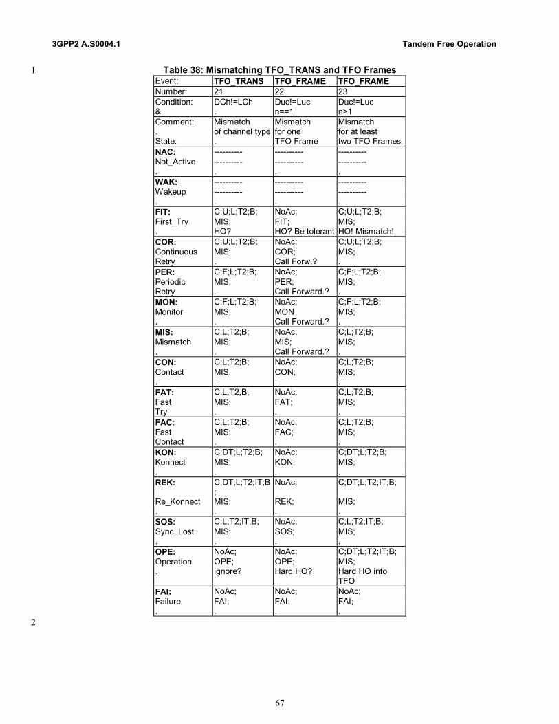
3GPP2 A.S0004.1 Tandem Free Operation
67
Table 38: Mismatching TFO_TRANS and TFO Frames 1 Event: TFO_TRANS TFO_FRAME TFO_FRAME Number: 21 22 23 Condition: DCh!=LCh Duc!=Luc Duc!=Luc & . n==1 n>1 Comment: Mismatch Mismatch Mismatch . of channel type for one for at least State: . TFO Frame two TFO Frames NAC: ---------- ---------- ---------- Not_Active ---------- ---------- ---------- . . . . WAK: ---------- ---------- ---------- Wakeup ---------- ---------- ---------- . . . . FIT: C;U;L;T2;B; NoAc; C;U;L;T2;B; First_Try MIS; FIT; MIS; . HO? HO? Be tolerant HO! Mismatch! COR: C;U;L;T2;B; NoAc; C;U;L;T2;B; Continuous MIS; COR; MIS; Retry . Call Forw.? . PER: C;F;L;T2;B; NoAc; C;F;L;T2;B; Periodic MIS; PER; MIS; Retry . Call Forward.? . MON: C;F;L;T2;B; NoAc; C;F;L;T2;B; Monitor MIS; MON MIS; . . Call Forward.? . MIS: C;L;T2;B; NoAc; C;L;T2;B; Mismatch MIS; MIS; MIS; . . Call Forward.? . CON: C;L;T2;B; NoAc; C;L;T2;B; Contact MIS; CON; MIS; . . . . FAT: C;L;T2;B; NoAc; C;L;T2;B; Fast MIS; FAT; MIS; Try . . . FAC: C;L;T2;B; NoAc; C;L;T2;B; Fast MIS; FAC; MIS; Contact . . . KON: C;DT;L;T2;B; NoAc; C;DT;L;T2;B; Konnect MIS; KON; MIS; . . . . REK: C;DT;L;T2;IT;B
; NoAc; C;DT;L;T2;IT;B;
Re_Konnect MIS; REK; MIS; . . . . SOS: C;L;T2;IT;B; NoAc; C;L;T2;IT;B; Sync_Lost MIS; SOS; MIS; . . . . OPE: NoAc; NoAc; C;DT;L;T2;IT;B; Operation OPE; OPE; MIS; . ignore? Hard HO? Hard HO into
TFO FAI: NoAc; NoAc; NoAc; Failure FAI; FAI; FAI; . . . .
2
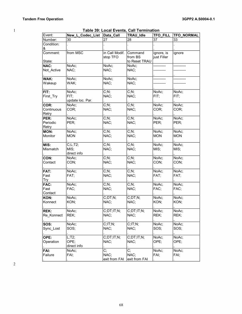
Tandem Free Operation 3GPP2 A.S0004-0.1
68
Table 39: Local Events, Call Termination 1 Event: New_L_Codec_List Data_Call TRAU_Idle TFO_FILL TFO_NORMAL Number: 30 27 28 37 33 Condition: . . . . . & . . . . . Comment: from MSC in Call Modif.
stop TFO Command from BS
ignore, is just Filler
ignore
State: . to Reset TRAU NAC: NoAc; NoAc; NoAc; ---------- ---------- Not_Active NAC; NAC; NAC; ---------- ---------- . . . . . . WAK: NoAc; NoAc; NoAc; ---------- ---------- Wakeup WAK; NAC; NAC; ---------- ---------- . . . . . . FIT: NoAc; C;N; C;N; NoAc; NoAc; First_Try FIT; NAC; NAC; FIT; FIT; . update loc. Par. . . . . COR: NoAc; C;N; C;N; NoAc; NoAc; Continuous COR; NAC; NAC; COR; COR; Retry . . . . . PER: NoAc; C;N; C;N; NoAc; NoAc; Periodic PER; NAC; NAC; PER; PER; Retry . . . . . MON: NoAc; C;N; C;N; NoAc; NoAc; Monitor MON NAC; NAC; MON MON . . . . . . MIS: C;L;T2; C;N; C;N; NoAc; NoAc; Mismatch MIS; NAC; NAC; MIS; MIS; . direct info . . . . CON: NoAc; C;N; C;N; NoAc; NoAc; Contact CON; NAC; NAC; CON; CON; . . . . . . FAT: NoAc; C;N; C;N; NoAc; NoAc; Fast FAT; NAC; NAC; FAT; FAT; Try . . . . . FAC: NoAc; C;N; C;N; NoAc; NoAc; Fast FAC; NAC; NAC; FAC; FAC; Contact . . . . . KON: NoAc; C;DT;N; C;DT;N; NoAc; NoAc; Konnect KON; NAC; NAC; KON; KON; . . . . . . REK: NoAc; C;DT;IT;N; C;DT;IT;N; NoAc; NoAc; Re_Konnect REK; NAC; NAC; REK; REK; . . . . . . SOS: NoAc; C;IT;N; C;IT;N; NoAc; NoAc; Sync_Lost SOS; NAC; NAC; SOS; SOS; . . . . . . OPE: L;T2; C;DT;IT;N; C;DT;IT;N; NoAc; NoAc; Operation OPE; NAC; NAC; OPE; OPE; . direct info . . . . FAI: NoAc; C; C; NoAc; NoAc; Failure FAI; NAC; NAC; FAI; FAI; . . exit from FAI exit from FAI . .
2

3GPP2 A.S0004.1 Tandem Free Operation
69
Table 40: Special Events, Timeouts 1 Event: Runout T==0 Frame_Sync_Lost Frame_Sync_Lost Mes_Sync_Lost Number: 31 32 34 35 36 Condition: . . n<3 n>2 . & . . . . . Comment: IPEs may be-
come unsynch. Time-Out start to send SYL
already Stop TFO Frames, if 3 Frames missing
.
State: . . . . . NAC: ---------- ---------- ---------- ---------- ---------- Not_Active ---------- ---------- ---------- ---------- ---------- . . . . . . WAK: ---------- ---------- ---------- ---------- ---------- Wakeup ---------- ---------- ---------- ---------- ---------- . . . . . . FIT: U;N; ---------- ---------- ---------- NoAc; First_Try MON ---------- ---------- ---------- FIT; . PSTN Call . . . . COR: U;L1;T5; C;N;REQ; ---------- ---------- NoAc; Continuous PER; COR; ---------- ---------- COR; Retry at end of COR Reset IPEs . . . PER: NoAc; L1;T5; ---------- ---------- NoAc; Periodic PER; PER; ---------- ---------- PER; Retry . Periodic Test . . . MON: ---------- ---------- ---------- ---------- ---------- Monitor ---------- ---------- ---------- ---------- ---------- . . . . . . MIS: NoAc; N;B; NoAc; NoAc; NoAc; Mismatch MIS; MIS; MIS; MIS; MIS; . typ. Final state List not Ack_ed! . . . CON: REQ; ---------- ---------- ---------- C;REQ; Contact COR; ---------- ---------- ---------- COR; . can this occur? . . . . FAT: REQ; ---------- NoAc; NoAc; C;REQ; Fast COR; ---------- FAT; FAT; COR; Try fast HO failed . typical in HO typical in HO fast HO failed FAC: REQ; ---------- NoAc; NoAc; C;REQ; Fast COR; ---------- FAC; FAC; COR; Contact fast HO failed . typical in HO typical in HO fast HO failed KON: NoAc; C;DT;N; ---------- ---------- C;DT;REQ;T1; Konnect KON; FAI; ---------- ---------- COR; . may happen Misbehavior! . . after Timeout: N REK: NoAc; C;DT;N;IT;B; ---------- ---------- C;DT;REQ;IT;B;T1; Re_Konnect REK; FAI; ---------- ---------- COR; . may happen Misbehavior! . . after Timeout: N SOS: REQ;IT;B;T1; ---------- ---------- NoAc; C;REQ;IT;B;T1; Sync_Lost COR; ---------- ---------- SOS; COR; . after Timeout: N . . wait for Runout after Timeout: N OPE: NoAc; B; SYL1; C;DT;SYL; NoAc; Operation OPE; OPE; OPE; SOS; OPE; . typ. Final event List not Ack_ed! 1: Alarm, go on 2: Alarm, stop! Typ. Final event FAI: NoAc; ---------- ---------- ---------- NoAc; Failure FAI; ---------- ---------- ---------- FAI; . typical . . . don’t trust!
2

Tandem Free Operation 3GPP2 A.S0004-0.1
70
13 Codec Mismatch Resolution and Codec Optimization 1
13.1 CDMA TFO Operations 2
Codec mismatch resolution and codec optimization are not defined for CDMA TFO operations in this release of the TFO 3 standard. The Local_Code_List in TFO messages TFO_REQ_L, TFO_ACK_L, and TFO_REQ_P contains only the 4 Local_Used_Codec 5 6
13.2 TDMA TFO Operations 7
It is not mandatory to support the resolution of Codec Mismatch or Codec Optimization. When these features are not 8 supported, the Local_Codec_List shall include only the Local_Used_Codec. However, in the optional case, if a MSC 9 sends a Local_Codec_List that includes more than the Local_Used_Codec, then it is mandatory for that MSC to support 10 the resolution of Codec Mismatch or the Codec Optimization, considering the reported Codec_Types. 11 12 The determination of the Local_Codec_List (i.e., the list of all Codecs supported by the local radio leg, consisting of the 13 local MS, the local MSC and the local radio resources) and the communication of the TRAU with the local MSC, is a 14 MSC specific matter and is outside the scope of this specification. However, only Codec_Types that are real alternatives, 15 considering all resources, shall be reported within the Local_Codec_List. The Local_Codec_List shall be updated and 16 resent as soon as these local resource conditions have changed, if the MSC wants to have these new conditions considered 17 within the Codec Mismatch Resolution or Codec Optimization. 18 19 If the Codec Mismatch Resolution and Codec Optimization options are supported by the local MSC, whenever a new 20 Distant_Codec_List or a new Local_Codec_List becomes available, the MSC shall attempt to resolve the Codec_Mismatch 21 or optimize the Codec_Type as soon as possible. This is accomplished by following the rules outlined in table 41 and 22 performing a subsequent intra cell HO to the new Local_Used_Codec. 23 24
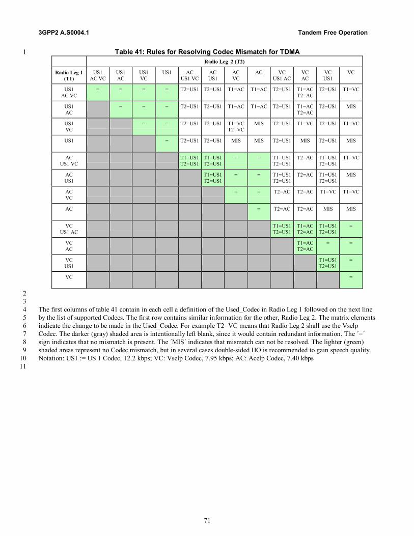
3GPP2 A.S0004.1 Tandem Free Operation
71
Table 41: Rules for Resolving Codec Mismatch for TDMA 1 Radio Leg 2 (T2)
Radio Leg 1 (T1)
US1 AC VC
US1 AC
US1 VC
US1
AC US1 VC
AC US1
AC VC
AC
VC US1 AC
VC AC
VC US1
VC
US1 AC VC
= = = = T2=US1 T2=US1 T1=AC T1=AC T2=US1 T1=AC T2=AC
T2=US1 T1=VC
US1 AC
= = = T2=US1 T2=US1 T1=AC T1=AC T2=US1 T1=ACT2=AC
T2=US1 MIS
US1 VC
= = T2=US1 T2=US1 T1=VC T2=VC
MIS T2=US1 T1=VC T2=US1 T1=VC
US1 = T2=US1 T2=US1
MIS MIS T2=US1 MIS T2=US1 MIS
AC US1 VC
T1=US1 T2=US1
T1=US1T2=US1
= = T1=US1 T2=US1
T2=AC T1=US1 T2=US1
T1=VC
AC US1
T1=US1T2=US1
= = T1=US1 T2=US1
T2=AC T1=US1 T2=US1
MIS
AC VC
= = T2=AC T2=AC T1=VC T1=VC
AC = T2=AC
T2=AC MIS MIS
VC US1 AC
T1=US1 T2=US1
T1=ACT2=AC
T1=US1 T2=US1
=
VC AC
T1=ACT2=AC
= =
VC US1
T1=US1 T2=US1
=
VC
=
2 3 The first columns of table 41 contain in each cell a definition of the Used_Codec in Radio Leg 1 followed on the next line 4 by the list of supported Codecs. The first row contains similar information for the other, Radio Leg 2. The matrix elements 5 indicate the change to be made in the Used_Codec. For example T2=VC means that Radio Leg 2 shall use the Vselp 6 Codec. The darker (gray) shaded area is intentionally left blank, since it would contain redundant information. The ´=´ 7 sign indicates that no mismatch is present. The ´MIS´ indicates that mismatch can not be resolved. The lighter (green) 8 shaded areas represent no Codec mismatch, but in several cases double-sided HO is recommended to gain speech quality. 9 Notation: US1 := US 1 Codec, 12.2 kbps; VC: Vselp Codec, 7.95 kbps; AC: Acelp Codec, 7.40 kbps 10 11

SP-4683 Tandem Free Operation
A-1
Annex A (Normative) 1
Tandem Free Operation Capability Description and 2
Requirements 3
A.1 Introduction 4
It is expected that the need for Tandem Free Operation will be driven by the increasing market penetration of digital 5 technologies, which will result in an increase in the percentage of calls that are mobile-to-mobile calls. In addition, given 6 that the effects of tandem vocoding are greater for lower bit rate vocoders, the need for this feature becomes greater as the 7 use of low bit rate vocoders increases. 8 9 The Tandem Free Operation (TFO) feature, also known as Vocoder Bypass (VB), improves the end-to-end voice quality 10 observed in mobile-to-mobile voice calls in wireless networks. 11 12
Station A
De-
Encoder
CoderEn-
Coder
Mobile MobileStation B
SDU B
DecodedSpeech
SDU A
Decoder
13 14
Figure A,.1: Logical Diagram of the Speech Path for Digital Calls 15 from Mobile A to Mobile B 16
17 18

Tandem Free Operation 3GPP2 A.S0004-0.1
A-2
Currently, there are four vocoders concatenated together on the call connection for a mobile-to-mobile call. See Figure A.1. 1 For example, the vocoder in mobile station A encodes the voice and sends it to SDU A. The vocoder in SDU A decodes the 2 voice and sends it across the network to the vocoder in SDU B. The vocoder in SDU B encodes the voice and sends the 3 encoded voice to the mobile station B where it is then decoded again. Each vocoder degrades the voice quality by 4 introducing speech quantization errors that are inherent in any speech encoding and decoding process. Also each 5 vocoding process introduces additional throughput delay. 6 7 The “Tandem Free Operation” feature will enhance current operation by bypassing the vocoding process at the SDUs for 8 mobile to mobile calls. The encoded voice received from the BTS is not decoded at the SDU. Instead the encoded voice is 9 transmitted transparently through the network. The encoded speech is routed to the appropriate SDU where it is converted 10 back to the appropriate signaling format for routing to the BTS. 11 12
A.2 Terminology 13
A.2.1 Acronyms 14
15 BS Base Station 16 BTS Base Transceiver System 17 CDMA Code Division Multiple Access 18 DS0 Digital Signal Level 0 19 DTMF Dual Tone Multi-Frequency 20 GSM Global System for Mobile Communication 21 MS Mobile Station 22 MSC Mobile Switching Center 23 PSTN Public Switched Telephone Network 24 SDU Selection/Distribution Unit 25 TDMA Time Division Multiple Access 26 TFO Tandem Free Operations 27 VoIP Voice over IP 28 29
A.2.2 Definitions 30
2G 2nd generation wireless systems. 31 32 3G 3rd generation wireless systems. 33
34 Decoder reconstruction of a speech signal from a compressed format according to an appropriate algorithm. 35 36 Encoder compression of a speech signal into a new format for bandwidth efficiency according to an appropriate 37
algorithm. 38 39 Mobile a standalone unit communicating with the BTS over an air interface in a digital wireless communication 40
system. In this document it is interpreted as a mobile station or a fixed wireless terminal. 41 42 SDU a unit for housing the encoder and the decoder required for digital wireless transmission. 43
A.3 Scope 44
This document identifies the mandatory requirements and highly desirable requirements for TFO, which are used as a 45 basis for development of a TFO standard. 46
SP-4683 Tandem Free Operation
A-3
A.4 Tandem Free Operation Requirements 1
A.4.1 Mandatory Tandem Free Operation Requirements 2
The TFO Feature shall: 3 4 1. Be established and maintained on successful communication between local and remote vocoders. The two bypass 5
capable vocoders must be linked directly with a digital connection with no analog and digital processes such as digital 6 loss pad or conference bridge between them. 7 8
2. Be transparent to both the mobile and land users and it should not have any operational impact on a regular mobile to 9 land call. 10 11
3. Support cdma2000 to cdma2000 mobile to mobile voice calls. 12 13
4. Not prevent voice calls between any 2G or 3G systems regardless if TFO is implemented. 14 15
5. Support TFO between two mobile stations that are on the same MSC. 16 17
6. Support TFO between two mobile stations that are on different MSCs within the same operator's network. This 18 includes calls which transit other networks but terminate on MSCs within the same operator's network. 19 20
7. Support inter-MSC within two different operator’s networks using a single technology, subject to other restrictions. 21 This includes calls, which transit other networks but terminate on MSCs within the different operator's networks. 22 23
8. Provide a solution that shall include the ability to inactivate echo cancellers while this feature is enabled, and activate 24 echo cancellers while this feature is disabled. This feature shall not be enabled if echo canceller control is not possible. 25 26
9. Neither impact nor be impacted by soft handoff (i.e., TFO and soft handoff function independently). 27 28
10. Support TFO both before and after hard handoff when the vocoder type is the same. Support disabling of TFO after 29 hard handoff when the vocoder types are different. 30 31
11. Support establishment of bypass mode following interruptions, such as supplementary service (e.g., 3-Way calling, 32 etc.) and hard handoff. 33 34
12. Not preclude inband or out-of-band transmission of DTMF. This feature may be temporarily disabled to support 35 transmission of DTMF. This requirement shall not add new DTMF generation requirements. 36 37
13. Not be restricted to mobile to mobile calls as long as conditions for TFO exist. For instance, either endpoint of a call 38 may be a fixed wireless terminal. 39 40
14. Provide a solution that is not required to be supported across an international gateway, for example, T1 to E1, A-law 41 to mu-law. 42 43
15. Provide a solution that shall be capable of functioning in a system that makes use of existing SS7 (ISUP) without 44 impact to signaling and TIA/EIA-41 on the Network-Network interface. 45 46
16. Be backwards compatible to a 2G system, i.e., the solution shall function in 2G systems updated with this feature. 47 48
17. Avoid impacts to SS7 (ISUP) signaling. 49 50 18. Provide a solution that shall result in perceived voice quality equal to or better than that of the same call without the 51
use of TFO. 52
Tandem Free Operation 3GPP2 A.S0004-0.1
A-4
1 19. Provide a solution that shall have minimal impact on supplementary services, e.g., Call Forwarding, Call Waiting, 3-2
Way Calling. However, supplementary services shall take precedence over TFO. 3 4
20. Allow Lawfully Authorized Electronic Surveillance without degradation of voice quality perceived by the mobile users. 5 6
21. Not cause further degradation to perceived voice quality during bad frames compared to the same call without the use 7 of TFO. 8 9
22. Not result in degradation to the perceived voice quality in the presence of link impairments (e.g., jitter, insertion of 10 gain or loss padding) between the two speech processing units compared to the same call without use of TFO. This 11 feature may be disabled under persistent link impairment conditions. 12 13
23. Support a system that automatically attempts to use TFO when all necessary conditions are met, and the network 14 operator enables the feature. Specifically, the call must be a mobile to mobile voice call or fixed wireless call using the 15 same vocoder type (algorithm) and no supplementary services prevent the use of TFO. 16 17
24. Avoid negative audible impacts on the perceived voice quality during transition to and from bypass mode, e.g., during 18 call setup, during handoff, or at the start and stop of supplementary service activities. 19 20
25. Be able to be established within 2 seconds of stable call setup, i.e., a trunk has been established between the two SDUs 21 that contains no echo cancellers or other disruptions 22 23
26. Allow TFO mode to be established for the active call during the use of Call Waiting when the criteria for bypass mode 24 are met. That is, when the mobile station is connected to a second call as a result of call waiting or call transfer 25 operations and the bypass mode criteria are met, then bypass mode shall be established. 26 27
27. Be capable of allowing the network operator to prevent the establishment of TFO, even if the conditions exist for 28 bypass mode. 29 30
28. Support the ability of the network at either end of the call to reject establishment of TFO mode. 31 32
29. Provide support for the use of TFO calls between any 2G and 3G systems when compatible TFO implementations 33 exist in those systems. 34 35
30. Support the following network configurations (assuming that other necessary conditions for TFO are met): 36 - Intra-operator, intra-MSC and inter-MSC: direct trunks between MSCs –OR– call delivery via PSTN. 37 – Inter-operator: direct trunks between MSCs –or– call delivery via PSTN. 38 39
31. Not be required to work when the span types or companding (A-law / µ-law) are not in agreement. 40 41
32. Support transmission across 64 kbps clear channels. 42 43
33. Allow for TFO operation following cellular network call forwarding to another mobile. (e.g. call forwarding no 44 answer) 45 46
34. Require encoding and decoding processes internal to the speech handlers be reactivated on the completion of a mobile 47 to mobile connection, or on the interruption of a clear digital channel between two TFO capable speech applications 48 such as by a digital loss, handoff, conference bridge, etc. 49
50
A.4.2 Highly Desired Tandem Free Operation Requirements 51
The TFO Feature may: 52 53

SP-4683 Tandem Free Operation
A-5
1. Provide support of calls other than cdma2000 to cdma2000 mobile to mobile calls, such as cdma2000 to GSM, TDMA, 1 or Voice over IP (VoIP). 2 3
2. Minimize impacts to 2G systems to support TFO. (Example: networks using echo cancellers, gain/loss pad, or voice 4 compression.) 5 6
3. Provide a solution that shall allow interoperability with the ETSI-GSM TFO standard (aka Vocoder Bypass). 7 8
4. Provide a solution that shall allow compatibility with the voice over IP (VoIP) standards. 9 10
5. Provide for negotiation towards the use of a common vocoder for the duration of the call in order to establish TFO. 11 12
6. Permit, as part of the setup negotiation process, either end of the system to transcode directly from one vocoder to 13 another. When transcoding is employed, the system using it could identify to the other end the type of transcoding in 14 use, thus possibly avoiding the use of two transcoders. 15 16
7. Minimize the impact on standards and functions other than those related to speech processing. 17 18
8. Support an ATM based interface to permit direct MSC to MSC and BSC to BSC transmission of vocoder frames, 19 thereby reducing the bandwidth requirements between serving systems. 20 21
9. Provide benefits by reducing delay, possibly by allowing a network to transcode directly between vocoders Such 22 transcoding could eliminate the need to convert to PCM first. 23 24
10. Define a means to allow a CDMA system to communicate between the TFO process and the MSC. 25 26
11. Support the transmission of DTMF tones without reverting to tandem mode. 27 28
29 30
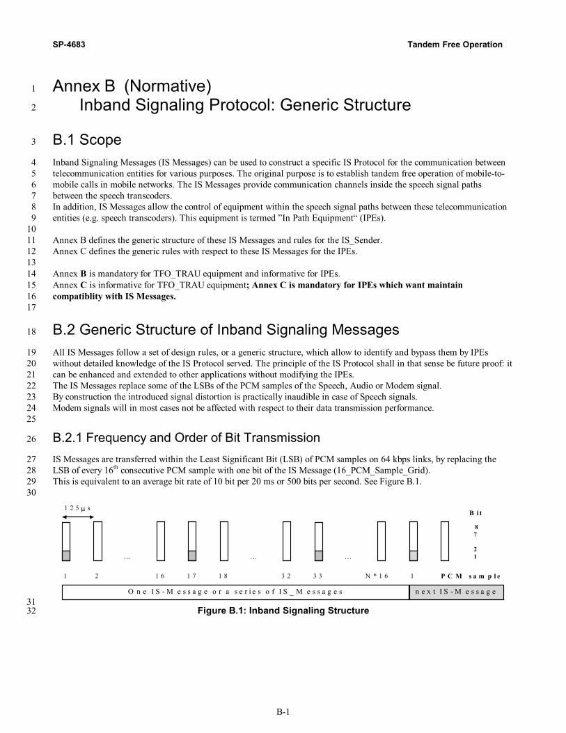
SP-4683 Tandem Free Operation
B-1
Annex B (Normative) 1
Inband Signaling Protocol: Generic Structure 2
B.1 Scope 3
Inband Signaling Messages (IS Messages) can be used to construct a specific IS Protocol for the communication between 4 telecommunication entities for various purposes. The original purpose is to establish tandem free operation of mobile-to-5 mobile calls in mobile networks. The IS Messages provide communication channels inside the speech signal paths 6 between the speech transcoders. 7 In addition, IS Messages allow the control of equipment within the speech signal paths between these telecommunication 8 entities (e.g. speech transcoders). This equipment is termed ”In Path Equipment“ (IPEs). 9 10 Annex B defines the generic structure of these IS Messages and rules for the IS_Sender. 11 Annex C defines the generic rules with respect to these IS Messages for the IPEs. 12 13 Annex B is mandatory for TFO_TRAU equipment and informative for IPEs. 14 Annex C is informative for TFO_TRAU equipment; Annex C is mandatory for IPEs which want maintain 15 compatiblity with IS Messages. 16 17
B.2 Generic Structure of Inband Signaling Messages 18
All IS Messages follow a set of design rules, or a generic structure, which allow to identify and bypass them by IPEs 19 without detailed knowledge of the IS Protocol served. The principle of the IS Protocol shall in that sense be future proof: it 20 can be enhanced and extended to other applications without modifying the IPEs. 21 The IS Messages replace some of the LSBs of the PCM samples of the Speech, Audio or Modem signal. 22 By construction the introduced signal distortion is practically inaudible in case of Speech signals. 23 Modem signals will in most cases not be affected with respect to their data transmission performance. 24 25
B.2.1 Frequency and Order of Bit Transmission 26
IS Messages are transferred within the Least Significant Bit (LSB) of PCM samples on 64 kbps links, by replacing the 27 LSB of every 16th consecutive PCM sample with one bit of the IS Message (16_PCM_Sample_Grid). 28 This is equivalent to an average bit rate of 10 bit per 20 ms or 500 bits per second. See Figure B.1. 29 30
1 2
…
N * 1 6 1
…
3 2 3 3
…
1 6 1 7 1 8
O n e I S - M e s s a g e o r a s e r i e s o f I S _ M e s s a g e s n e x t I S - M e s s a g e
P C M s a m p l e
1 2 5 µ s
87
21
B i t
31 Figure B.1: Inband Signaling Structure 32
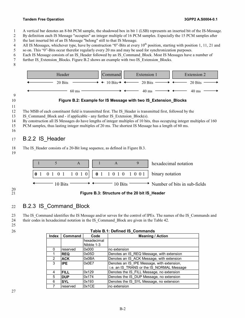
Tandem Free Operation 3GPP2 A.S0004-0.1
B-2
A vertical bar denotes an 8-bit PCM sample, the shadowed box in bit 1 (LSB) represents an inserted bit of the IS-Message. 1 By definition each IS Message "occupies" an integer multiple of 16 PCM samples. Especially the 15 PCM samples after 2 the last inserted bit of an IS Message "belong" still to that IS Message. 3 All IS Messages, whichever type, have by construction “0”-Bits at every 10th position, starting with position 1, 11, 21 and 4 so on. This “0”-Bits occur therefor regularly every 20 ms and may be used for synchronization purposes. 5 Each IS Message consists of an IS_Header followed by an IS_Command_Block. Most IS Messages have a number of 6 further IS_Extension_Blocks. Figure B.2 shows an example with two IS_Extension_Blocks. 7 8
20 Bits
Header Command Extension 1
10 Bits
Extension 2
20 Bits 20 Bits
60 ms 40 ms 40 ms 9
Figure B.2: Example for IS Message with two IS_Extension_Blocks 10 11
The MSB of each constituent field is transmitted first. The IS_Header is transmitted first, followed by the 12 IS_Command_Block and - if applicable - any further IS_Extension_Block(s). 13 By construction all IS Messages do have lengths of integer multiples of 10 bits, thus occupying integer multiples of 160 14 PCM samples, thus lasting integer multiples of 20 ms. The shortest IS Message has a length of 60 ms. 15 16
B.2.2 IS_Header 17
The IS_Header consists of a 20-Bit long sequence, as defined in Figure B.3. 18 19
0 1 0 1 0 1 1 0 1 0 0 1 1 0 1 0 1 0 0 1
hexadecimal notation
binary notation
Number of bits in sub-fields10 Bits
1 5 A 1 A 9
10 Bits 20
Figure B.3: Structure of the 20 bit IS_Header 21
B.2.3 IS_Command_Block 22
The IS_Command identifies the IS Message and/or serves for the control of IPEs. The names of the IS_Commands and 23 their codes in hexadecimal notation in the IS_Command_Block are given in the Table 42. 24 25
Table B.1: Defined IS_Commands 26 Index Command Code Meaning / Action
hexadecimal Nibble 1-3
0 reserved 0x000 no extension 1 REQ 0x05D Denotes an IS_REQ Message, with extension 2 ACK 0x0BA Denotes an IS_ACK Message, with extension 3 IPE 0x0E7 Denotes an IS_IPE Message, with extension,
i.e. an IS_TRANS or the IS_NORMAL Message 4 FILL 0x129 Denotes the IS_FILL Message, no extension 5 DUP 0x174 Denotes the IS_DUP Message, no extension 6 SYL 0x193 Denotes the IS_SYL Message, no extension 7 reserved 0x1CE no extension
27
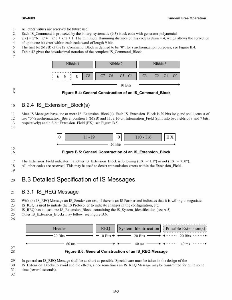
SP-4683 Tandem Free Operation
B-3
All other values are reserved for future use. 1 Each IS_Command is protected by the binary, systematic (9,3) block code with generator polynomial 2 g(x) = x^6 + x^4 + x^3 + x^2 + 1. The minimum Hamming distance of this code is dmin = 4, which allows the correction 3 of up to one bit error within each code word of length 9 bits. 4 The first bit (MSB) of the IS_Command_Block is defined to be "0", for synchronization purposes, see Figure B.4. 5 Table 42 gives the hexadecimal notation of the complete IS_Command_Block. 6 7
10 Bits
C3 C2 C1 C0 C7 C6 C5 C4C80
Nibble 2 Nibble 3 Nibble 1
0 0
8 Figure B.4: General Construction of an IS_Command_Block 9
B.2.4 IS_Extension_Block(s) 10
Most IS Messages have one or more IS_Extension_Block(s). Each IS_Extension_Block is 20 bits long and shall consist of 11 two "0"-Synchronization_Bits at position 1 (MSB) and 11, a 16-bit Information_Field (split into two fields of 9 and 7 bits, 12 respectively) and a 2-bit Extension_Field (EX); see Figure B.5. 13 14
0 I1 - I9 0 E X I10 - I1620 Bits
15 Figure B.5: General Construction of an IS_Extension_Block 16
The Extension_Field indicates if another IS_Extension_Block is following (EX :="1.1") or not (EX := "0.0"). 17 All other codes are reserved. This may be used to detect transmission errors within the Extension_Field. 18 19
B.3 Detailed Specification of IS Messages 20
B.3.1 IS_REQ Message 21
With the IS_REQ Message an IS_Sender can test, if there is an IS Partner and indicates that it is willing to negotiate. 22 IS_REQ is used to initiate the IS Protocol or to indicate changes in the configuration, etc. 23 IS_REQ has at least one IS_Extension_Block, containing the IS_System_Identification (see A.5). 24 Other IS_Extension_Blocks may follow; see Figure B.6. 25 26
20 Bits
Header REQ System_Identification10 Bits
Possible Extension(s) 20 Bits 20 Bits
60 ms 40 ms 40 ms 27
Figure B.6: General Construction of an IS_REQ Message 28
In general an IS_REQ Message shall be as short as possible. Special care must be taken in the design of the 29 IS_Extension_Blocks to avoid audible effects, since sometimes an IS_REQ Message may be transmitted for quite some 30 time (several seconds). 31 32

Tandem Free Operation 3GPP2 A.S0004-0.1
B-4
B.3.2 IS_ACK Message 1
With the IS_ACK Message an IS Partner typically answers an IS_REQ Message or an IS_ACK Message. It can also be 2 used to submit further information to the other IS Partner. IS_REQ and IS_ACK are the main message types between IS 3 Partners. 4 The IS_ACK has at least an IS_Extension_Block containing the IS_System_Identification (see A.5). Other 5 IS_Extension_Blocks may follow; see Figure B.7. 6 7
20 Bits
Header ACK System_Identification10 Bits
Possible Extension(s) 20 Bits 20 Bits
60 ms 40 ms 40 ms 8
Figure B.7: General Construction of an IS_ACK Message 9
No specific design constraints with respect to audibility exist, since IS_ACK is typically not sent very often. 10 11
B.3.3 IS_IPE, IS_TRANS and IS_NORMAL Messages 12
The IPE command denotes IS_IPE Messages. An IPE shall always look for this type of message and follow the instruction. 13 An IS_Sender shall use this IS_IPE Message to command all IPEs into a specific mode of "Bit Transparency". 14 This Message has one IS_Extension_Block, indicating the requested IPE_Mode. See Figure B.8. 15 16
20 Bits
Header IPE IPE_Mode10 Bits 20 Bits
60 ms 40 ms 17
Figure B.8: General Construction of an IS_IPE Message 18
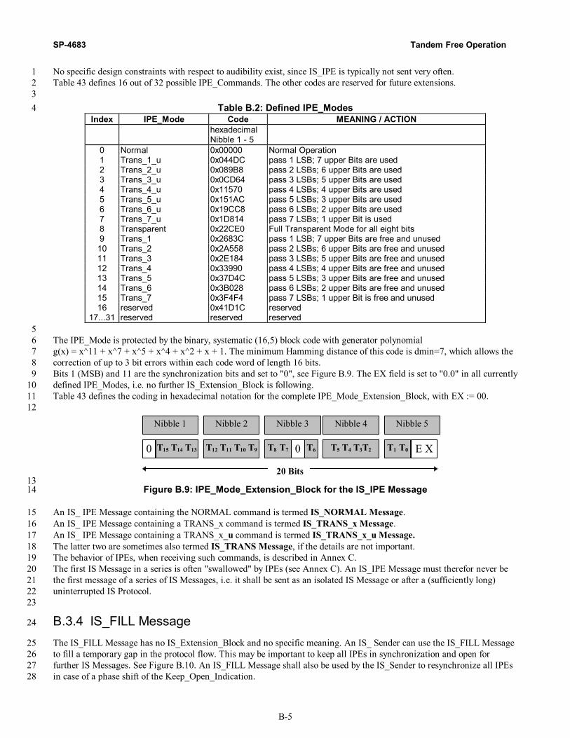
SP-4683 Tandem Free Operation
B-5
No specific design constraints with respect to audibility exist, since IS_IPE is typically not sent very often. 1 Table 43 defines 16 out of 32 possible IPE_Commands. The other codes are reserved for future extensions. 2 3
Table B.2: Defined IPE_Modes 4 Index IPE_Mode Code MEANING / ACTION
hexadecimal Nibble 1 - 5
0 Normal 0x00000 Normal Operation 1 Trans_1_u 0x044DC pass 1 LSB; 7 upper Bits are used 2 Trans_2_u 0x089B8 pass 2 LSBs; 6 upper Bits are used 3 Trans_3_u 0x0CD64 pass 3 LSBs; 5 upper Bits are used 4 Trans_4_u 0x11570 pass 4 LSBs; 4 upper Bits are used 5 Trans_5_u 0x151AC pass 5 LSBs; 3 upper Bits are used 6 Trans_6_u 0x19CC8 pass 6 LSBs; 2 upper Bits are used 7 Trans_7_u 0x1D814 pass 7 LSBs; 1 upper Bit is used 8 Transparent 0x22CE0 Full Transparent Mode for all eight bits 9 Trans_1 0x2683C pass 1 LSB; 7 upper Bits are free and unused 10 Trans_2 0x2A558 pass 2 LSBs; 6 upper Bits are free and unused 11 Trans_3 0x2E184 pass 3 LSBs; 5 upper Bits are free and unused 12 Trans_4 0x33990 pass 4 LSBs; 4 upper Bits are free and unused 13 Trans_5 0x37D4C pass 5 LSBs; 3 upper Bits are free and unused 14 Trans_6 0x3B028 pass 6 LSBs; 2 upper Bits are free and unused 15 Trans_7 0x3F4F4 pass 7 LSBs; 1 upper Bit is free and unused 16 reserved 0x41D1C reserved
17...31 reserved reserved reserved 5 The IPE_Mode is protected by the binary, systematic (16,5) block code with generator polynomial 6 g(x) = x^11 + x^7 + x^5 + x^4 + x^2 + x + 1. The minimum Hamming distance of this code is dmin=7, which allows the 7 correction of up to 3 bit errors within each code word of length 16 bits. 8 Bits 1 (MSB) and 11 are the synchronization bits and set to "0", see Figure B.9. The EX field is set to "0.0" in all currently 9 defined IPE_Modes, i.e. no further IS_Extension_Block is following. 10 Table 43 defines the coding in hexadecimal notation for the complete IPE_Mode_Extension_Block, with EX := 00. 11 12
20 Bits
T12 T11 T10 T9 T5 T4 T3T2T60T8 T7T15 T14 T130 E XT1 T0
Nibble 2Nibble 1 Nibble 3 Nibble 4 Nibble 5
13 Figure B.9: IPE_Mode_Extension_Block for the IS_IPE Message 14
An IS_ IPE Message containing the NORMAL command is termed IS_NORMAL Message. 15 An IS_ IPE Message containing a TRANS_x command is termed IS_TRANS_x Message. 16 An IS_ IPE Message containing a TRANS_x_u command is termed IS_TRANS_x_u Message. 17 The latter two are sometimes also termed IS_TRANS Message, if the details are not important. 18 The behavior of IPEs, when receiving such commands, is described in Annex C. 19 The first IS Message in a series is often "swallowed" by IPEs (see Annex C). An IS_IPE Message must therefor never be 20 the first message of a series of IS Messages, i.e. it shall be sent as an isolated IS Message or after a (sufficiently long) 21 uninterrupted IS Protocol. 22 23
B.3.4 IS_FILL Message 24
The IS_FILL Message has no IS_Extension_Block and no specific meaning. An IS_ Sender can use the IS_FILL Message 25 to fill a temporary gap in the protocol flow. This may be important to keep all IPEs in synchronization and open for 26 further IS Messages. See Figure B.10. An IS_FILL Message shall also be used by the IS_Sender to resynchronize all IPEs 27 in case of a phase shift of the Keep_Open_Indication. 28

Tandem Free Operation 3GPP2 A.S0004-0.1
B-6
1
20 Bits
Header FILL10 Bits
60 ms 2
Figure B.10: Construction of the IS_FILL Message 3
IS_FILL is designed in a way that multiple repetitions cause minimal audible effects. 4 5
B.3.5 IS_DUP Message 6
The IS_DUP Message may be used between IS Partners to indicate a half-duplex mode. It may be especially important in 7 HO situations. The IS_DUP Message has no IS_Extension_Block, see Figure B.11. 8 9
20 Bits
Header DUP10 Bits
60 ms 10
Figure B.11: Construction of the IS_DUP Message 11
B.3.6 IS_SYL Message 12
The IS_SYL Message may be used between IS Partners to indicate the loss of synchronization. It may be especially 13 important in HO situations. The IS_SYL Message has no IS_Extension_Block, see Figure B.12. 14 15
20 Bits
Header SYL10 Bits
60 ms 16
Figure B.12: Construction of the IS_SYL Message 17
B.4 Keep_Open_Indication 18
In Transparent_Mode, i.e. after properly receiving an IS_TRANS Message, all IPEs shall monitor the bypassing bit stream 19 for the Keep_Open_Indication (definition see below). If this Keep_Open_Indication is not seen for some time, then the 20 IPEs shall fall automatically back into normal operation, i.e. the mode of operation before the IS_TRANS Message. 21 This automatic fall back shall have the same effect as the IS_NORMAL Message would have. 22 By definition, the Keep_Open_Indication is a continuous bit stream of one "0"-Bit in the LSB of every 160th PCM sample, 23 i.e. every 20 ms. At least one "1"-Bit must be present within the LSBs of the other 159 PCM samples. See Figure B.3. 24 25

SP-4683 Tandem Free Operation
B-7
0
1 2
…
1 5 9 1
0…
n n + 1
…
1 6 1 7 1 8
O n e P e r i o d o f t h e K e e p _ O p e n _ I n d i c a t i o n N e x t P e r i o d
P C M s a m p l e
1 2 5 µ s
87
21
B i t2 0 m s
1
1 Figure B.13: Keep_Open_Indication 2
The "0"-Bit stream of the Keep_Open_Indication shall always be present as long as the IPEs need to be in 3 Transparent_Mode. 4 The Keep_Open_Indication shall be in phase with the preceding IS Messages; i.e., the first bit of the 5 Keep_Open_Indication shall be in the position of the first bit of the (hypothetical) next IS Message. In fact, the IS 6 Messages themselves contain this Keep_Open_Indication by definition. 7 In case of a known phase shift of the Keep_Open_Indication, the IS_Sender has to send at least one IS Message, which 8 defines the new phase position of the Keep_Open_Indication. If no other IS Message is to be sent, then the IS_FILL 9 Message shall be used. If an IS Message longer than 160 ms is scheduled for transmission, then an IS_FILL Message 10 should be inserted before, to guarantee fast resynchronization of the IPEs. 11 12
B.5 Rules for Sending of IS Messages 13
IS Messages replace some bits of the PCM samples and therefor cause a minimal signal distortion. Therefore IS Messages 14 shall be used with care and not longer than necessary. The IS Protocol is kept to a minimum to avoid unnecessary 15 complexity. One basic assumption is that only one IS Protocol is active at a time between two IS Partners. 16 Only specific telecommunication entities shall be allowed to initiate IS Protocols. They are called IS_Active or active IS 17 Partners. In principle these shall only be terminal devices or their "representatives" within the network. Examples are 18 ISDN-Terminals, Speech-Servers, and TRAUs (in mobile networks as representatives of the MSs). 19 Other telecommunication entities shall only react on IS Protocols. They are called IS_Passive. Most IPEs are of this type. 20 They bypass the IS Messages, they obey the IS_IPE Messages, but they never initiate IS Messages. 21 Other telecommunication entities are IS_Passive by default. But if they receive IS Protocols that they can understand, then 22 they may become IS_Active and start to initiate IS Protocols. They thus become active IS Partners and shall take care that 23 only one IS Protocol is active on both of their sides. They are called IS_Responsive. Examples are TCMEs. 24 Active IS Partners shall send either continuous sequences of IS Messages without interruption of the 25 16_PCM_Sample_Grid or 26
- isolated IS Messages with same message lengths; or 27 - isolated IS Messages with sufficient distance between them, if shorter IS Messages follow longer IS Messages. 28
The latter case is important, because shorter isolated IS Messages travel faster through IPEs than longer ones, see annex B. 29 As said above, after initialization of an IS Message sequence, no interruption of the 16_PCM_Sample_Grid shall occur 30 within the sequence. Adjustments of the phase position of the Keep_Open_Indication shall be done only after the 31 IS_TRANS Message by inserting the necessary number n (with 0 < n < 160) of "1" Bits (termed "T_Bits") into the LSBs 32 of the PCM samples that have to be skipped. The first PCM sample for this insertion of T_Bits is the one where the next 33 regular IS Message or next regular Keep_Open_Indication would begin. At the new phase position the next IS Message or 34 the IS_FILL Message shall be sent, to allow IPEs to resynchronize fast. See Figure B.14. 35 36

Tandem Free Operation 3GPP2 A.S0004-0.1
B-8
0
1 2
…
N 1
0
3 4
…
9 5 9 9 6 0
1
1
I S _ T R A N S M e s s a g e e . g . I S _ F I L L
P C M s a m p l e
1 2 5 µ s
87
21
B i t
2
1 1 1 1
P h a s e S h i f t b y i n s e r t i n g n T _ B i t s
N o r m a l M o d e T r a n s p a r e n t M o d e 1 Figure B.14: Phase Shift of the 16_PCM_Sample_Grid by inserting T_Bits 2
Similarly, the adjustment of the phase between two Keep_Open_Indications shall be done by inserting the necessary 3 number of T_Bits and by sending an IS Message - preferably, but not necessarily - the IS_FILL. 4 Finally a "negative" phase adjustment between two Keep_Open_Indications shall be allowed by shortening the cycle by a 5 maximum of 2 PCM samples and sending an IS Message (see above) at the new phase position. 6 7
B.6 IS_System_Identification_Block 8
The IS_System_Identification_Block is a mandatory IS_Extension_Block for the IS_ACK and IS_REQ messages with the 9 16-bit Information_Field containing the IS_System_Identification. It identifies the system within which the message is 10 generated. Table 44 shows the defined IS_System_Identification codes. 11 12
Table B.3: Defined IS_System_Identification Codes 13 System Code (in hex)
GSM: 0x53948 either 0x53948, if EX == "0.0" or 0x5394B, if EX == "1.1"
TIA/EIA-136: 0x53414 either 0x53414 if EX == "0.0" or 0x53417 if EX == "1.1"
TIA/EIA-95: 0x528AC either 0x528AC if EX == "0.0" or 0x528AF if EX == "1.1"
all other (253) code points reserved
14 The only defined codes so far are GSM_Identification, TIA/EIA_95_Identification and TIA/EIA_136_Identification, see 15 also Figure B.15. 16 17
20 Bits
1 0 1 0 1 E X 0 0 1 1 0 1 0 0 0 0 10 0
18 Figure B.15: IS_System_Identification for TIA/EIA-136 19
All other codes are reserved. Additional IS_System_Identification Codes for other systems shall be defined in a way that 20 the audibility is minimal and the hamming distances to the already defined codes is maximal. 21 The IS_System_Identification is protected by the binary, systematic (16,8) block code with generator polynomial g(x) = 22 x^8 + x^7 + x^6 + x^4 + x^2 + x + 1. The minimum Hamming distance of this code is dmin=5, which allows the 23 correction of up to 2 bit errors within each code word of length 16 bits. 24 Code word 0x0000 = 0000.0000.0000.0000 is per definition used for GSM. 25 Code word 0x01D3 = 0000.0001.1101.0111 is per definition used for TIA/EIA-136. 26 Code word 0x0279 = 0000.0010.0111.1001 is per definition used for TIA/EIA-95. 27 The first, upper eight bits represent the systematic part (underlined), the following eight bits the redundant part of the 28 Code words. 29
SP-4683 Tandem Free Operation
B-9
1 Please note that the systematic part is also used within the TFO Frames of GSM, TIA/EIA-136 and TIA/EIA-95 systems 2 for System_Identification (S1...S8), see main part of the document, section 5. 3 4 The resulting 16 bits are placed into the IS_System_Extension_Block as shown in Figure B.15 and then the whole 20 bit 5 word is additionally EXORed with the fixed code word 0x53948 to minimize audible effects. 6 7

3GPP2 A.S0004-0.1 Tandem Free Operation
C-1
Annex C (Informative) 1
In Path Equipment: Generic Rules and Guidelines 2
C.1 Scope 3
Inband Signaling Messages (IS Messages) can be used to construct a specific IS Protocol for the communication between 4 telecommunication entities for various purposes. The original purpose is to establish tandem free operation of mobile-to-5 mobile calls in mobile networks. The IS Messages provide communication channels inside the speech signal paths 6 between the speech transcoders. 7 In addition, IS Messages allow the control of equipment within the speech signal paths between these telecommunication 8 entities (e.g., speech transcoders). This equipment is termed ”In Path Equipment“ (IPEs). 9 Annex B defines the generic structure of these IS Messages and rules for the IS_Sender. 10 Annex C defines the generic rules with respect to these IS Messages for the IPEs. 11 Annex B is mandatory for TFO_TRAU equipment and informative for IPEs. 12 Annex C is informative for TFO_TRAU equipment; Annex C is mandatory for IPEs which want to maintain compatiblity 13 with IS Messages. 14 15
C.2 Types of In Path Equipment 16
The term "In Path Equipment" (IPE) is used for any telecommunication equipment within the (64 kbps) transmission path 17 for the speech signal between two entities, which want to communicate via IS Messages, i.e. the IS Partners. 18 In modern telecommunication networks most of these IPEs are digitally transparent for the complete 64 kbps data stream 19 all the time after call establishment until call release. These IPEs are optimal and need no consideration here. 20 Some IPEs are most of the time digitally transparent, but disturb the link every now and then. Examples are: 21
• switches, which interrupt the link during HO; 22 • switches, which insert a kind of conference bridge for a short while during HO; 23 • links, which do octet deletions or insertions (octet slips); 24 • DTMF generators, which insert DTMF tones sometimes for a short while; 25 and more. 26
Other IPEs are digitally transparent in one direction, but not in the other. Examples are: 27 • DTMF generators (again), which insert the DTMF tones only in one direction; 28 • Network Echo Cancellers (NEC), which let the signal pass unaltered towards the PSTN, but cancel the echo; 29 and more. 30
Other IPEs are semi-transparent, i.e. let most or some of the bits pass, but not all. Examples are: 31 • A/µ_Law converters; 32 • µ/A_Law converters; 33 • the tandem connection of A/µ_Law and µ/A_Law converters, or vice versa; 34 • links, which insert inband signaling by bit stealing (T1 links); 35 and more. 36
Other IPEs are not transparent at all to the digital bit stream, although the speech signal pass more or less unaltered. 37 Examples: 38
• level shifters, which adjust the signal levels, e.g. between national networks; 39 • DCMEs (Digital Circuit Multiplication Equipment), which compress the bit stream by encoding/decoding the 40
speech signal for cost efficient transmission; 41 and more. 42
For some tine, many of these IPEs will not be compliant with the IS Message principle described above. The IS Messages 43 will not always pass these non-compliant IPEs in either one or both directions. Care must be taken to identify situations 44 where IPEs are part-time-transparent or semi-transparent, when applying IS Messages. Other IPEs - at some point in time 45 in the future - will be compliant to the IS Message principle. The rules they have to fulfil are described below. 46

Tandem Free Operation 3GPP2 A.S0004-0.1
C-2
C.3 IS_Compliant IPEs 1
C.3.1 Typical IPEs are IS_Passive 2
General: An IPE shall never actively initiate the exchange of IS Messages. The active initiation is only done by terminals 3 or their "representatives". This avoids uncontrolled and unnecessary fluctuation of IS Messages within the network. 4 Most IPEs shall never actively respond to IS Messages by sending other IS Messages. They are called IS_Passive. 5 They need not and do not understand the IS Protocol, but let it just pass unaltered and obey the relevant IS_IPE Messages. 6 Some IPEs may, however, respond on received IS Messages, modify these and/or respond with own IS Messages, if they 7 understand the IS Protocol and can take or bring advantage to the overall system performance or system quality. These 8 IPEs are called IS_Responsive. Examples are TFO-specific Digital Circuit Multiplication Equipment (TCMEs), which 9 reduce transmission costs without degrading the speech quality. These IPEs may be able to step into the IS Protocol, 10 interpret and respond to it and modify the speech signal in a system compliant way. Thus they become IS_Active Partners 11 themselves. 12
C.3.2 IS Message_Transparency 13
When commanded into a Transparent Mode, the IPEs are fully transparent at least for the LSBs specified in all PCM 14 samples. Therefore the following rules are needed only and only do apply for the IPEs, when in Normal_Mode: 15 IPEs shall let the IS Messages bypass, respectively re-insert them, from their input to their respective output. 16 They shall not alter them, nor do any kind of error correction. Exceptions are the IS_Responsive IPEs. 17
C.3.2.1 First IS Message 18
During its Normal_Mode an IS_Compliant IPE shall always monitor the incoming PCM data stream for the occurrence 19 of the IS_Header sequence. If the IS_Header is detected after a period without IS Messages, the IPE shall store the 20 following IS_Command and IS_Extension_Block(s). During reception of this first IS Message, the normal operation of the 21 IPE is maintained with the consequence that the first IS Message may not appear at the output of the IPE. 22
C.3.2.2 IS Messages within a Sequence 23
All further IS Messages which follow directly after the first detected IS Message in the same phase position shall be passed 24 unaltered to the output of the IPE with exactly that delay the IPE would later introduce when commanded into 25 Transparent_Mode by one of the IS_TRANS commands, see Figure C.1. 26
Delayfor
speech
Header1 C1 Extension1 Extension2 Header2 C2 Header3 C3
Header2 C2 Header3 C3
(nearly) no Delay for 2nd and 3rd IS_Messages !
Input
Output
27 Figure C.1: Transparency and Delay for first and following IS Messages 28
The upper row symbolizes the speech signal at the input of the IPE, with the PCM samples drawn vertically and the IS 29 Messages inserted into the LSBs. The lower row symbolizes the speech signal at the output of the IPE. The vertical lines 30 denote the boundaries of the IS Message elements. 31 Figure C.1 shows an example where the first IS Message is detected, but not passed through. The distortion caused by the 32 first IS Message is still "somehow" there (indicated by the empty dashed boxes in the LSB), but the message is destroyed. 33 The second and third IS Messages are passed through unaltered. Note, however, that the delay of the speech signal is (in 34

3GPP2 A.S0004-0.1 Tandem Free Operation
C-3
this example) substantially higher than the delay of the IS Messages. They travel faster than the speech signal through this 1 IPE. 2
C.3.2.3 Isolated IS Message 3
In cases where the first detected IS Message is not immediately followed by further IS Messages, the IPE shall insert this 4 first IS Message (which the IPE has stored) into its output PCM bit stream, with exactly the delay and phase position a 5 second IS Message would have. See Figure C.2, which shows an example where an isolated IS Message is travelling 6 through an IPE. 7
Delayfor
speech
Header1 C1 Extension1 Extension2
Delay for this isolated IS_Message !
Header1 C1 Extension1 Extension2
Header2
Same phase position as IS_Message 2 would have
Input
Output
8 Figure C.2: Transparency and Delay for an isolated IS Message 9
Note that the delay of an isolated IS Message is depending on its own length! Longer IS Messages will have more delay, 10 shorter less. It could - in principle - happen that a second, shorter isolated IS Message would "bypass" the first longer IS 11 Message - with the consequence that the first one would be destroyed. This is especially important when there are several 12 IPEs in the path, since the delay effects accumulate. Therefore it is not allowed to send shorter isolated IS Messages too 13 close after longer IS Messages. IS Messages with the same length have no such restriction. 14 In summary: the first IS Message in a series of IS Messages is "swallowed" by an IPE, while all the following IS 15 Messages pass unaltered and with minimal delay. If an IS Message occurs isolated, then it is not swallowed, but delayed 16 by exactly its own length. The latter mechanism ensures that isolated IS Messages can pass through an unlimited number 17 of IPEs. 18
C.3.2.4 Check if IS Message is following 19
The checking, whether another IS Message is following or not, is done "on the fly"; i.e., bit by bit. This is possible due to 20 the fact that all messages begin with exactly the same IS_Header. The decision, whether an IS Message is an isolated 21 message or the first message in a series, can be done latest after the last bit of the (next) IS_Header. See Figure C.2. 22 Consequently: after detection of the first IS Message, the IS_Header is in any case inserted at the output in the correct 23 position, regardless, whether a second message follows or not. 24 25
C.3.3 IPE State Representation 26
Concerning the IS Protocol, an IPE can be described with five major States in two main Modes, where the States describe 27 the IPE with respect to the IS Protocol and the Modes describe the IPE with respect to the operation on PCM data. Figure 28 C.3 shows a graphical representation of the State diagram of an IPE. 29 30

Tandem Free Operation 3GPP2 A.S0004-0.1
C-4
Sync_Not_Found
Normal_Mode
IS_NORMAL
IS_TRANS
Sync_FoundSync_Lost
Keep_Open_SyncKeep_Open_Lost Transparent_Mode
1 Figure C.3: Principle of a State Diagram of an IPE 2
Some Definitions: 3 An IS Message shall be recognized as "error-free", if no error can be detected, neither within the IS_Header, nor in the 4 IS_Command nor in any IS_Extension_Block. 5 An IS Message shall be recognized as "single-error", if no more than one bit position differs in the IS_Header or the 6 IS_Command_Block or the IPE_Mode_Block or one EX-field or one Sync bit. 7 An IS Message shall be recognized as "correctable", if the phase position is as in preceding IS Messages and: 8
- no more than 2 bit position differs in the IS_Header; and 9 - no more than 1 error is detected within the IS_Command_Block; and 10 - no more than 3 errors are detected within the IPE_Mode_Block; and 11 - no more than 0 error is detected within the EX-field(s); and 12 - no more than 1 error is detected within the Sync-Bit(s); and 13 - the total number of detected errors is not higher than 3. 14
IS Messages, which are error-free, single-error or correctable are also called "valid" IS Messages. 15 An IS Message shall be recognized as "present", if the phase position is as in preceding IS Messages and: 16
- no more than 4 bit position differs in the IS_Header; and 17 - no more than 2 errors are detected within the IS_Command_Block; and 18 - no more than 3 errors are detected within the IPE_Mode_Block; and 19 - no more than 1 error is detected within the EX-field(s); and 20 - no more than 2 errors are detected within the Sync-Bit(s); and 21 - the total number of detected errors is not higher than 4. 22
Sequences, which differ in more than "present" are not recognized as IS Messages at all ("not_present"). 23 Note that the insertion of T_Bits may change the phase position of an IS Message. The IS Message shall in that case be 24 classified after the removal of the T_Bits. 25 An octet slip may also change the phase position of an IS Message. If an error-free or a single-error IS Message can be 26 found after considering a hypothetical octet slip (±1 sample), then it may be regarded as error-free or single-error and the 27 new phase position shall be regarded as valid, if no valid or present IS Message can be found at the old phase position. 28
C.3.4 IPE in Sync_Not_Found 29
After start-up or after a long interruption of the IS Protocol an IPE is in Normal_Mode, performing its normal operation. 30 IS Messages have not been found and consequently no bypassing of IS Messages is performed. 31 The algorithm for initial synchronization shall be able to detect each single IS Message, especially the first or an isolated 32 one. An IPE shall always, during Normal_Mode and during Transparent_Mode, search for the IS_Header and 33 consequently for complete IS Messages. When found, it can be assumed that with high probability the following IS 34 Messages and the Keep_Open _Indication will stay within the found "grid" or "phase" of every 16th PCM sample, the 35 16_PCM_Sample_Grid. 36 An IPE transits from Sync_Not_Found into Sync_Found, if and only if an error-free IS Message is detected. Then the IPE 37 lets the following IS Messages bypass, as described above. 38 If the first IS Message is an error-free IS_TRANS Message, then the IPE transits directly into the Transparent_Mode. 39
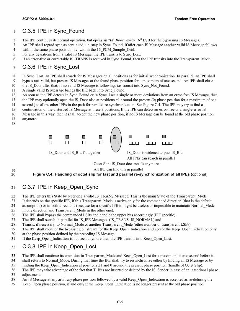
3GPP2 A.S0004-0.1 Tandem Free Operation
C-5
C.3.5 IPE in Sync_Found 1
The IPE continues its normal operation, but opens an "IS_Door" every 16th LSB for the bypassing IS Messages. 2 An IPE shall regard sync as continued, i.e. stay in Sync_Found, if after each IS Message another valid IS Message follows 3 within the same phase position, i.e. within the 16_PCM_Sample_Grid. 4 For any deviations from a valid IS Message, the IPE transits to Sync_Lost. 5 If an error-free or correctable IS_TRANS is received in Sync_Found, then the IPE transits into the Transparent_Mode. 6
C.3.6 IPE in Sync_Lost 7
In Sync_Lost, an IPE shall search for IS Messages on all positions as for initial synchronization. In parallel, an IPE shall 8 bypass not_valid, but present IS Messages at the found phase position for a maximum of one second. An IPE shall close 9 the IS_Door after that, if no valid IS Message is following, i.e. transit into Sync_Not_Found. 10 A single valid IS Message brings the IPE back into Sync_Found. 11 As soon as the IPE detects in Sync_Found or in Sync_Lost a single or more deviations from an error-free IS Message, then 12 the IPE may optionally open the IS_Door also at positions ±1 around the present (0) phase position for a maximum of one 13 second ] to allow other IPEs in the path for parallel re-synchronization. See Figure C.4. The IPE may try to find a 14 continuation of the disturbed IS Message at these 3 positions. If the IPE can detect an error-free or a single-error IS 15 Message in this way, then it shall accept the new phase position, if no IS Message can be found at the old phase position 16 anymore. 17 18
IS_Door and IS_Bits fit together
Octet Slip: IS_Door does not fit anymore
IS_Door is widened to pass IS_Bits
All IPE can find this in parallel
All IPEs can search in parallel
19 Figure C.4: Handling of octet slip for fast and parallel re-synchronization of all IPEs (optional) 20
C.3.7 IPE in Keep_Open_Sync 21
The IPE enters this State by receiving a valid IS_TRANS Message. This is the main State of the Transparent_Mode. 22 It depends on the specific IPE, if this Transparent_Mode is active only for the commanded direction (that is the default 23 assumption) or in both directions (because for a specific IPE it might be useless or impossible to maintain Normal_Mode 24 in one direction and Transparent_Mode in the other one). 25 The IPE shall bypass the commanded LSBs and handle the upper bits accordingly (IPE specific). 26 The IPE shall search in parallel for IS_IPE Messages (IS_TRANS, IS_NORMAL) and 27 Transit, if necessary, to Normal_Mode or another Transparent_Mode (other number of transparent LSBs) 28 The IPE shall monitor the bypassing bit stream for the Keep_Open_Indication and accept the Keep_Open_Indication only 29 at the phase position defined by the preceding IS Message. 30 If the Keep_Open_Indication is not seen anymore then the IPE transits into Keep_Open_Lost. 31
C.3.8 IPE in Keep_Open_Lost 32
The IPE shall continue its operation in Transparent_Mode and Keep_Open_Lost for a maximum of one second before it 33 shall return to Normal_Mode. During that time the IPE shall try to resynchronize either by finding an IS Message or by 34 finding the Keep_Open_Indication at positions ±1 and 0 around the present phase position (handle of Octet Slip). 35 The IPE may take advantage of the fact that T_Bits are inserted or deleted by the IS_Sender in case of an intentional phase 36 adjustment. 37 An IS Message at any arbitrary phase position followed by a valid Keep_Open_Indication is accepted as re-defining the 38 Keep_Open phase position, if and only if the Keep_Open_Indication is no longer present at the old phase position. 39

Tandem Free Operation 3GPP2 A.S0004-0.1
C-6
A Keep_Open_Indication at a phase position ±1 PCM sample interval around the old phase position is accepted as re-1 defining the Keep_Open phase position, if and only if the Keep_Open_Indication is no longer present at the old phase 2 position. 3 The Keep_Open_Indication is valid, as long as at least 40 "0"-Bits are seen at the correct positions within a sliding 4 window of length of one second. At least one "1"-Bit must be seen in between each pair of the expected "0"-Bits. 5 6
C.4 IPE Error Handling 7
The first IS_Message shall only be accepted, if there is no detectable error. 8 For all following IS_Messages it shall apply: 9
- errors in IS Messages shall be passed unaltered through the IPEs. This shall hold for all IS Messages. 10 - only error-free or correctable IS_IPE Message shall be applied by the IPE to its own operation. Other IS_IPE 11
Messages shall be ignored, but bypassed. 12 13
C.5 IPE Transmission Delay 14
The transmission delay introduced by an IPE for the speech, audio or modem signal is in general different in 15 Normal_Mode and Transparent_Mode. Some IPEs may have several different Normal_Modes with possibly different 16 signal delays. IS Messages are transmitted within the regular 16_PCM_Sample_Grid. It is important that this regularity is 17 not disturbed. Therefor care must be taken at the transition between these modes. 18 The transmission delay of a specific IPE is in general lower for IS Messages than for speech, audio or modem signals. 19
C.5.1 IPE Transmission Delay in Normal_Mode 20
The delay for IS Messages in Normal_Mode shall be identical to the delay in that Transparent_Mode, that follows after the 21 first IS_TRANS Message. If different Transparent_Modes with different delays could follow, then the shortest delay of all 22 possible Transparent Modes shall be selected for IS Messages in Normal_Mode. 23 If an IPE in Normal_Mode has to change its transmission delay, then this shall not affect the delay of the IS Messages. 24
C.5.2 IPE Transmission Delay in Transparent_Mode 25
In the majority of all cases the IPE will keep the transmission delay for the IS Messages in Normal_Mode also in 26 Transparent_Mode for the transmission of the commanded transparent LSBs. IPEs which do not understand the IS 27 Protocol shall never modify the transparent bits, so they are also not allowed to change delay. 28 Some IPEs, which understand a specific IS Protocol, may have even different Transparent_Modes and also here the 29 transmission delays may differ. Examples are TCMEs. 30 If an IPE has to change its transmission delay at the transition from Normal_Mode to Transparent_Mode, then the IPE 31 shall readjust the phase of the Keep_Open_Indication after transition into the Transparent_Mode with higher delay by 32 inserting the relevant number of T_Bits after the first IS_TRANS Message and before the next IS Message. If no other IS 33 Message is following, then the IS_FILL shall be inserted, obeying all other relevant rules of the specific IS Protocol (e.g. 34 EMBED bit C5 in TFO Frames). 35 If an IPE has to change from one Transparent_Mode to another one with a different transmission delay, then the IPE shall 36 readjust the phase of the Keep_Open_Indication after transition into the new Transparent_Mode by inserting the relevant 37 number of T_Bits. If no other IS Message is following, then the IS_FILL shall be inserted at the new phase position to 38 mark the new grid position of the 16_PCM_Sample_Grid and to allow other IPEs to resynchronize, obeying all other 39 relevant rules of the specific IS Protocol (e.g. EMBED bit C5 in TFO Frames). 40 41
C.6 Compliance to IS Messages 42
An IS_Compliant IPE shall be capable of interpreting and obeying the IS_IPE Messages. 43 It depends on the intelligence and task of an IPE, how many and which of the other IS Messages it needs to understand. 44
3GPP2 A.S0004-0.1 Tandem Free Operation
C-7
The IPEs shall synchronize to all IS Messages, especially to find or re-find the Keep_Open_Indication. All IPEs shall 1 resynchronize, if they see an IS Message in a new phase position, and if the synchronization can not be found in the old 2 phase position anymore. 3 4
C.6.1 Compliance to IS_REQ and IS_ACK Messages 5
Most IPEs need not and do not understand these messages. They just synchronize to them and let them pass unaltered. 6 Only IS_Responsive IPEs may take advantage. This is system specific and IPE specific. 7
C.6.2 Compliance to IS_NORMAL Message 8
The IPE shall act in response to the receipt of an IS_NORMAL Message such that: 9 The IPE shall synchronize to it. The message shall appear unchanged at the output of the IPE. 10 The IPE shall resume its Normal_Mode of operation for all data received subsequent to the IS_NORMAL Message, 11 until a different command is received. 12 It depends on the type and operation of the specific IPE, whether the Normal_Mode is resumed in both directions, or only 13 in the direction in which the IS_NORMAL Message flows. It must be assumed that in general only this one direction is 14 affected. 15
C.6.3 Compliance to IS_TRANS_x Messages 16
The IPE shall act in response to the receipt of an IS_TRANS_x Message (x in the range 1 to 8) such that: 17 The IPE shall synchronize to it. The IS_TRANS_x Message shall appear unchanged at the output of the IPE. 18 The IPE shall be transparent in all x LSBs of all PCM samples received subsequent to the IS_TRANS Message. 19 The transparency shall persist as long as the Keep_Open_Indication persists, or until a different command is received. 20 The (8-x) upper bits of the PCM samples are not of interest and may be modified arbitrarily by the IPE. 21 It depends on the type and operation of the specific IPE, whether the Transparent_Mode is resumed in both directions, or 22 only in the direction in which the IS_TRANS Message flows. It must be assumed that in general only this one direction is 23 affected. 24
C.6.4 Compliance to IS_TRANS_x_u Messages 25
The IPE shall act in response to the receipt of an IS_TRANS_x_u Message (x in the range 1 to 7) such that: 26 The IPE shall synchronize to it. The messages shall appear unchanged at the output of the IPE. 27 The IPE shall be transparent in all x LSBs of all PCM samples received subsequent to the IS_TRANS Message. 28 The transparency shall persist as long as the Keep_Open_Indication persists, or until a different command is received. 29 The (8-x) upper bits of the PCM samples are important and in general shall not be modified by the IPE, but shall be 30 bypassed transparently in exactly the same manner and delay as the x LSBs. It is important that this transparency for the 31 upper bits is provided by IPEs that do not understand the specific IS Protocol (e.g., do not understand the 32 IS_System_Identification or the protocol of the transmitted parameters). 33 Only IPEs which exactly understand the specific IS Protocol shall take advantage of the opportunities given with the 34 IS_TRANS_x_u Messages. An example is the TCME, which transmits internally only the coded speech parameters and 35 re-generates the upper x bits at its output (termed here as "first solution"). The resulting delay in the upper 8-x bits shall 36 be identical to the delay in the x LSBs. 37 If this transparency of the upper (8-x) bits or their re-generation can not be established, then the upper bits shall contain a 38 constant pattern, giving the least output energy (PCM_Silence). This "second solution" may cause temporary interruptions 39 of the speech signal in some transition cases (e.g. HO in some tandem free mobile-to-mobile calls). Therefore the first 40 solution is the preferred one. 41 IPEs, which implements the second solution shall switch to the full transparent 64 kbps channel as soon as they loose 42 synchronization with the protocol of the transmitted parameters (e.g. the "TFO Frames" in mobile Systems). The full 43 transparency shall be executed for both directions. The near side shall be fully transparent in less than 60 ms and the other 44 side the one way delay of that IPE later. 45 It depends on the type and operation of the specific IPE, whether the Transparent_Mode is resumed in both directions, or 46 only in the direction in which the IS_TRANS Message flows. It must be assumed that in general only this one direction is 47 affected. 48
Tandem Free Operation 3GPP2 A.S0004-0.1
C-8
1
C.6.5 Compliance to IS_FILL Message 2
The IS_FILL Message has no specific meaning, but may serve for two purposes. 3 First of all, it can be used to close the gap in an IS Protocol to keep all IPEs synchronized. Otherwise - in case of an 4 interruption - the n IPEs in the path would swallow the next n IS Messages again. 5 Second, an IS_FILL Message can be used to resynchronize all IPEs to a new grid position, if necessary. 6
C.6.6 Compliance to IS_DUP Messages 7
The IS_DUP Message is sent by an IS Partner to the distant IS Partner to inform about a specific Half_Duplex reception. 8 Most IPEs need not and do not understand this message. They just synchronize to it and let it pass unaltered. 9 Only IS_Responsive IPEs may take advantage. This is system specific and IPE specific. 10
C.6.7 Compliance to IS_SYL Messages 11
The IS_SYL Message is sent by an IS Partner to the distant IS Partner to inform about a specific Sync_Lost Situation. 12 Most IPEs need not and do not understand this message. They just synchronize to it and let it pass unaltered. 13 Only IS_Responsive IPEs may take advantage. This is system specific and IPE specific. 14
3GPP2 A.S0004-0.1 Tandem Free Operation
D-1
Annex D History 1
Document history
2