
JNIT JAGANNATH GUPTA INSTITUTE OF ENGINEERING ...
71
This question paper contains ( 1 ) no. of printed page. Note: Attempt any four questions out of five questions. 1 What is scan conversion? Explain raster scan system with the help of block diagram. Ans: Scan Conversion is the process of finding the screen pixels that intersect a polygon. For this, we find it convenient to move to a copy of image space that is scaled to closely correspond to the pixels in our display screen. Scan conversion is a processing technique for changing the vertical / horizontal scan frequency of signal for different purposes and applications. In a raster- scan system, the electron beam is swept across the screen, one row at a time from top to bottom. As the electron beam moves across each row, the beam intensity is turned on and off to create a pattern of illuminated spots. Picture definition is stored in memory area called the refresh buffer or frame buffer. This memory area holds the set of intensity values for all the screen points. Stored intensity values are then retrieved from the refresh buffer and painted on the screen one row at a time as shown below. Each screen point is referred to as a pixel( picture element). 5 JNIT JAGANNATH GUPTA INSTITUTE OF ENGINEERING & TECHNOLOGY JAIPUR I-Mid Term Examination Session 2018 B.Tech III Year VI Semester Branch: CS Subject: CGMT Time: 2:00PM to 3:30PM Subject Code: 6CS4A Date: 15/02/2018 Max. Marks: 20
-
Upload
khangminh22 -
Category
Documents
-
view
2 -
download
0
Transcript of JNIT JAGANNATH GUPTA INSTITUTE OF ENGINEERING ...

This question paper contains ( 1 ) no. of printed page.
Note: Attempt any four questions out of five questions.
1 What is scan conversion? Explain raster scan system with the help of block
diagram.
Ans: Scan Conversion is the process of finding the screen pixels that intersect a
polygon. For this, we find it convenient to move to a copy of image space that is
scaled to closely correspond to the pixels in our display screen. Scan
conversion is a processing technique for changing the vertical / horizontal scan
frequency of signal for different purposes and applications.
In a raster- scan system, the electron beam is swept across the screen, one row at a
time from top to bottom. As the electron beam moves across each row, the beam
intensity is turned on and off to create a pattern of illuminated spots. Picture
definition is stored in memory area called the refresh buffer or frame buffer. This
memory area holds the set of intensity values for all the screen points. Stored
intensity values are then retrieved from the refresh buffer and painted on the
screen one row at a time as shown below. Each screen point is referred to as a
pixel( picture element).
5
JNITJAGANNATH GUPTA INSTITUTE OF ENGINEERING & TECHNOLOGY
JAIPURI-Mid Term Examination Session 2018
B.Tech III Year VI Semester
Branch: CS Subject: CGMTTime: 2:00PM to 3:30PM Subject Code: 6CS4ADate: 15/02/2018 Max. Marks: 20

Refreshing on raster-scan displays is carried out at the rate of 60 to 80 frames per
second. Refresh rates are described in units of cycles per second, or Hertz (Hz),
where a cycle corresponds to one frame. At the end of each scan line, the electron
beam returns to the left side of the screen to begin displaying the next scan line.
The return to the left of the screen, after refreshing each scan line, is called the
horizontal retrace of the electron beam. And at the end of each frame the electron
beam returns to the top left corner of the screen to begin the next frame.
2 Explain the basic principle to draw a circle using mid-point circle algorithm.
The algorithm used to draw circles is very similar to the Midpoint Line algorithm.
8 way-symmetry - for a circle centered at (0,0) and given that point (x,y) is on the
circle, the following points are also on the circle:
So it is only necessary to compute the pixels for 1/8 of the circle and then simply
illuminate the appropriate pixels in the other 7/8.
given a circle centered at (0,0) with radius R:
r2 = x2 + y2
f(x,y) = x2 + y2 - r2
For any point (xi,yi) we can plug xi,yi into the above equation and
f(xi,yi) = 0 -> (xi,yi) is on the circle
f(xi,yi) > 0 -> (xi,yi) is outside the circle
5
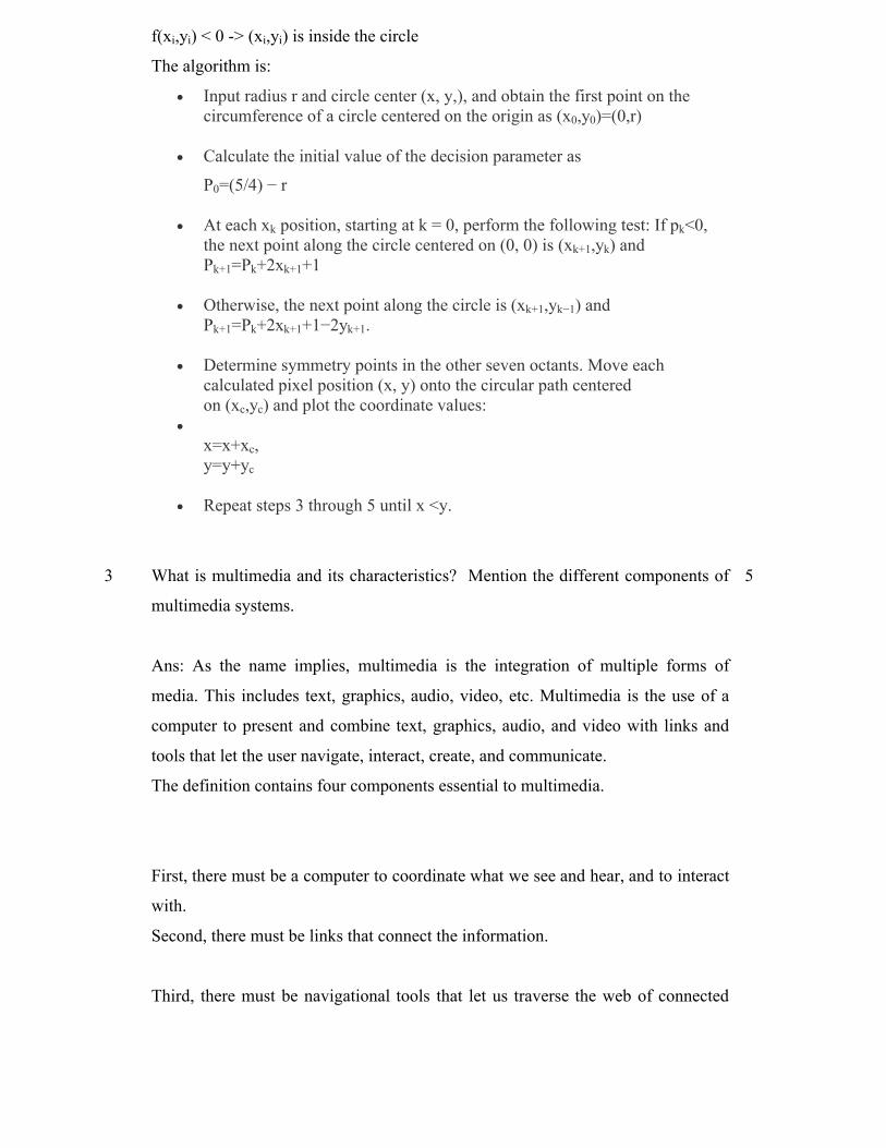
f(xi,yi) < 0 -> (xi,yi) is inside the circle
The algorithm is:
Input radius r and circle center (x, y,), and obtain the first point on the circumference of a circle centered on the origin as (x0,y0)=(0,r)
Calculate the initial value of the decision parameter as
P0=(5/4) − r
At each xk position, starting at k = 0, perform the following test: If pk<0, the next point along the circle centered on (0, 0) is (xk+1,yk) andPk+1=Pk+2xk+1+1
Otherwise, the next point along the circle is (xk+1,yk−1) andPk+1=Pk+2xk+1+1−2yk+1.
Determine symmetry points in the other seven octants. Move each calculated pixel position (x, y) onto the circular path centered on (xc,yc) and plot the coordinate values:
x=x+xc,y=y+yc
Repeat steps 3 through 5 until x <y.
3 What is multimedia and its characteristics? Mention the different components of
multimedia systems.
Ans: As the name implies, multimedia is the integration of multiple forms of
media. This includes text, graphics, audio, video, etc. Multimedia is the use of a
computer to present and combine text, graphics, audio, and video with links and
tools that let the user navigate, interact, create, and communicate.
The definition contains four components essential to multimedia.
First, there must be a computer to coordinate what we see and hear, and to interact
with.
Second, there must be links that connect the information.
Third, there must be navigational tools that let us traverse the web of connected
5

information.
Finally, because multimedia is not a spectator sport, there must be ways for us to
gather, process, and communicate our own information and ideas. If one of these
components is missing, we do not have multimedia.
For example, if we have no computer to provide interactivity, we have mixed
media, not multimedia. If there are no links to provide a sense of structure and
dimension, we have a bookshelf, not multimedia. If there are no navigational tools
to let us decide the course of action, we have a movie, not multimedia. If we
cannot create and contribute our own ideas, we have a television, not multimedia
.
Multimedia screens consist of several design elements, including text, pictures,
icons, triggers, and buttons. The relationships among these elements on the screen
are called layout. When we create a multimedia screen, we should plan its layout
so our content gets presented with good balance. Lets think of dividing the screen
into regions, of which some will be pictorial, with others consisting of blocks of
text. We must also think about how the user will interact with our screen, and
include the appropriate navigational buttons and hypertext links.
4 Explain the DDA line drawing algorithm.
Ans: Digital Differential Analyzer is a scan conversion line algorithm based on
calculating either dy or dx. We sample the line at unit intervals in one coordinate
& determine corresponding integer values nearest to the line path for the other
coordinate.
The algorithm accepts as input the two endpoint pixel positions. Horizontal &
vertical differences between the endpoint positions are assigned to parameters dx
& dy. The difference with the greater magnitude determines the increment of the
parameter steps. Starting with the pixel position (xa , ya), we determine the offset
needed at each step to generate the next pixel position along the line path. We loop
5

through this process.
The sreps are diven below:
Step 1: Get the input of two end points (X0,Y0) and(X1,Y1).
Step 2: Find the difference between two end points.
dx = X1 - X0
dy = Y1 - Y0
Step 3 : Based on the calculated difference in step2, we need to identify the
number of steps to put pixel. If dx > dy, then we need more steps in x coordinate;
otherwise in y coordinate.
if (abs(dx) > abs(dy))
Steps = absolute(dx);
else
Steps = absolute(dy);
Step 4 :Calculate the increment in x coordinate and y coordinate.
Xincrement = dx / (float) steps;
Yincrement = dy / (float) steps;
Step 5 : Draw the pixel by successfully incrementing x and y coordinates
accordingly and complete the drawing of the line.
for(int v=0; v < Steps; v++)
{
x = x + Xincrement;
y = y + Yincrement;
putpixel(Round(x), Round(y));
}

5 Write short note on
(a) Animation techniques.
Ans: Here are the major animation techniques used today.
2D Animation Techniques:
Classic, hand drawn animation - Disney's Lion King.
Cut outs - Monty Python
Rotoscope - Waking Life
Flip book - Keith Haring has made some famous ones.
Computer Assisted Animation (2D):
This term refers to all types of animation that use a computer somewhere in the
process.
Mostly we use it to describe the tools that have come to replace pencil, paper and
film, for example:
Flash animations:
Many TV series are now done in Flash, Coloring and layering hand drawn
animation using a computer.Drawing directly into an animation software with a
Pen Tablet
3D Animation Techniques:
3D animation- Pixar's Up, Toy Story.
Stereoscopic 3D - Coraline, Avatar.
CGI cut out - South Park
Motion Capture (an aid tool for 3D animators) Final Fantasy, Avatar, Gollum in
Lord of the Rings.
Morphing .
(b) Frame buffer:
5
Ans: A frame buffer is a large, contiguous piece of computer memory. At a
minimum there is one memory bit for each pixel. The picture is built up in the
frame buffer one bit at a time. The portion of memory reserved for holding the
complete bit-mapped image that is sent to the monitor. Typically the frame buffer
is stored in the memory chips on the video adapter. In some instances, however,
the video chipset is integrated into the motherboard design, and the frame buffer is

stored in general main memory. Its used to hold the frame of data that is
continuously being sent to the screen. The buffer is the size of the maximum
image that can be displayed and may be a separate memory bank on the graphics
card (display adapter) or a reserved part of regular memory. Sophisticated graphics
systems are built with several memory planes, each holding one or more bits of the
pixel.
Frame Buffer
This question paper contains ( 1 ) no. of printed page.
Note: Attempt any four questions out of five questions.
QUESTIONS WITH SOLUTION
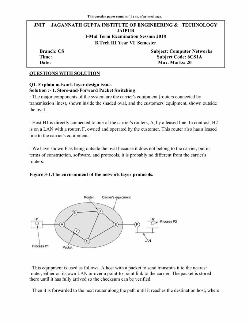
Q1. Explain network layer design issue.Solution :- 1. Store-and-Forward Packet Switching· The major components of the system are the carrier's equipment (routers connected by transmission lines), shown inside the shaded oval, and the customers' equipment, shown outside the oval.
· Host H1 is directly connected to one of the carrier's routers, A, by a leased line. In contrast, H2 is on a LAN with a router, F, owned and operated by the customer. This router also has a leased line to the carrier's equipment.
· We have shown F as being outside the oval because it does not belong to the carrier, but in terms of construction, software, and protocols, it is probably no different from the carrier's routers.
Figure 3-1.The environment of the network layer protocols.
· This equipment is used as follows. A host with a packet to send transmits it to the nearest router, either on its own LAN or over a point-to-point link to the carrier. The packet is stored there until it has fully arrived so the checksum can be verified.
· Then it is forwarded to the next router along the path until it reaches the destination host, where
JNIT JAGANNATH GUPTA INSTITUTE OF ENGINEERING & TECHNOLOGY JAIPUR
I-Mid Term Examination Session 2018B.Tech III Year VI Semester
Branch: CS Subject: Computer Networks Time: Subject Code: 6CS1A Date: Max. Marks: 20

it is delivered. This mechanism is store-and-forward packet switching.
2. Services Provided to the Transport Layer
· The network layer provides services to the transport layer at the network layer/transport layer interface. An important question is what kind of services the network layer provides to the transport layer.
· The network layer services have been designed with the following goals in mind.
1. The services should be independent of the router technology.
2. The transport layer should be shielded from the number, type, and topology of the routers present.
3. The network addresses made available to the transport layer should use a uniform numbering plan, even across LANs and WANs.
Given these goals, the designers of the network layer have a lot of freedom in writing detailed specifications of the services to be offered to the transport layer. This freedom often degenerates into a raging battle between two warring factions.
The other camp argues that the subnet should provide a reliable, connection-oriented service. They claim that 100 years of successful experience with the worldwide telephone system is an excellent guide. In this view, quality of service is the dominant factor, and without connections in the subnet, quality of service is very difficult to achieve, especially for real-time traffic such as voice and video.
These two camps are best exemplified by the Internet and ATM. The Internet offers connectionless network-layer service; ATM networks offer connection-oriented network-layer service. However, it is interesting to note that as quality-of-service guarantees are becoming more and more important, the Internet is evolving.
3. Implementation of Connectionless Service
Two different organizations are possible, depending on the type of service offered. If connectionless service is offered, packets are injected into the subnet individually and routed independently of each other. No advance setup is needed.
In this context, the packets are frequently called datagrams (in analogy with telegrams) and the subnet is called a datagram subnet. If connection-oriented service is used, a path from the source router to the destination router must be established before any data packets can be sent.
This connection is called a VC (virtual circuit), in analogy with the physical circuits set up by the telephone system, and the subnet is called a virtual-circuit subnet. In this section we will examine datagram subnets; in the next one we will examine virtual-circuit subnets.
Let us now see how a datagram subnet works. Suppose that the process P1 in Fig. 3-2 has a long message for P2. It hands the message to the transport layer with instructions to deliver it to
process P2 on host H2.
The transport layer code runs on H1, typically within the operating system. It prepends a transport header to the front of the message and hands the result to the network layer, probably just another procedure within the operating system.
Q2 Explain:(1) Distance vector routing algorithm
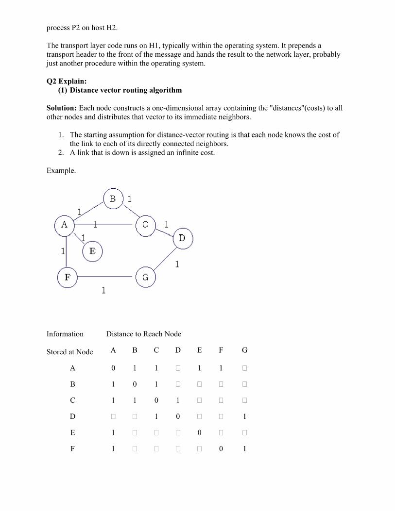
Solution: Each node constructs a one-dimensional array containing the "distances"(costs) to all other nodes and distributes that vector to its immediate neighbors.
1. The starting assumption for distance-vector routing is that each node knows the cost of the link to each of its directly connected neighbors.
2. A link that is down is assigned an infinite cost.
Example.
Information
Stored at Node
Distance to Reach Node
A B C D E F G
A 0 1 1 � 1 1 �
B 1 0 1 � � � �
C 1 1 0 1 � � �
D � � 1 0 � � 1
E 1 � � � 0 � �
F 1 � � � � 0 1

G � � � 1 � 1 0
Table 1. Initial distances stored at each node(global view).
We can represent each node's knowledge about the distances to all other nodes as a table like the one given in Table 1.
Note that each node only knows the information in one row of the table.
1. Every node sends a message to its directly connected neighbors containing its personal list of distance. ( for example, A sends its information to its neighbors B,C,E, and F. )
2. If any of the recipients of the information from A find that A is advertising a path shorter than the one they currently know about, they update their list to give the new path length and note that they should send packets for that destination through A. ( node B learns from A that node E can be reached at a cost of 1; B also knows it can reach A at a cost of 1, so it adds these to get the cost of reaching E by means of A. B records that it can reach E at a cost of 2 by going through A.)
3. After every node has exchanged a few updates with its directly connected neighbors, all nodes will know the least-cost path to all the other nodes.
4. In addition to updating their list of distances when they receive updates, the nodes need to keep track of which node told them about the path that they used to calculate the cost, so that they can create their forwarding table. ( for example, B knows that it was A who said " I can reach E in one hop" and so B puts an entry in its table that says " To reach E, use the link to A.)
Information
Stored at Node
Distance to Reach Node
A B C D E F G
A 0 1 1 2 1 1 2
B 1 0 1 2 2 2 3
C 1 1 0 1 2 2 2
D 2 2 1 0 3 2 1
E 1 2 2 3 0 2 3
F 1 2 2 2 2 0 1
G 2 3 2 1 3 1 0
Table 2. final distances stored at each node ( global view).

In practice, each node's forwarding table consists of a set of triples of the form:
( Destination, Cost, NextHop).
For example, Table 3 shows the complete routing table maintained at node B for the network in figure1.
Destination Cost NextHop
A 1 A
C 1 C
D 2 C
E 2 A
F 2 A
G 3 A
Table 3. Routing table maintained at node B.
(2) Link state routing
Solution: Every node knows how to reach its directly connected neighbors, and if we make sure that the totality of this knowledge is disseminated to every node, then every node will have enough knowledge of the network to determine correct routes to any destination.
Reliable Flooding is the process of making sure that all the nodes participating in the routing protocol get a copy of the link-state information from all the other nodes. As the term " flooding" suggests, the basic idea is for a node to send its link-state information out on all of its directly connected links, with each node that receives this information forwarding it out on all of its link. This process continues until the information has reached all the nodes in the network.
Link State Packet(LSP) contains the following information:
The ID of the node that created the LSP;
A list of directly connected neighbors of that node, with the cost of the link to each one;
A sequence number;
A time to live(TTL) for this packet.
Flooding works in the following way. When a node X receives a copy of an LSP that originated at some other node Y, it checks to see if it has already stored a copy of an LSP from Y. If not, it

stores the LSP. If it already has a copy, it compares the sequence numbers; if the new LSP has a larger sequence number, it is assumed to be the more recent, and that LSP is stored, replacing the old one. The new LSP is then forwarded on to all neighbors of X except the neighbor from which the LSP was just received.
Each switch computes its routing table directly from the LSPs it has collected using a realization of Dijkstra's algorithm.
Dijkstra's Algorithm
Dijkstra's Algorithm solves the single source shortest path problem in O((E + V)logV) time, which can be improved to O(E + VlogV) when using a Fibonacci heap. This note requires that you understand basic graph theory terminology and concepts.
Single Source Shortest Path (sssp)
The sssp is to find the shortest distance from the source vertex to all other vertices in the graph. We can store this in a simple array.
Psuedo-code
1. Set the distance to the source to 0 and the distance to the remaining vertices to infinity.2. Set the current vertex to the source.3. Flag the current vertex as visited.4. For all vertices adjacent to the current vertex, set the distance from the source to
the adjacent vertex equal to the minimum of its present distance and the sum of the weight of the edge from the current vertex to the adjacent vertex and the distance from the source to the current vertex.
5. From the set of unvisited vertices, arbitrarily set one as the new current vertex, provided that there exists an edge to it such that it is the minimum of all edges from a vertex in the set of visited vertices to a vertex in the set of unvisited vertices. To reiterate: The new current vertex must be unvisited and have a minimum weight edges from a visited vertexto it. This can be done trivially by looping through all visited vertices and all adjacent unvisited vertices to those visited vertices, keeping the vertex with the minimum weight edge connecting it.
6. Repeat steps 3-5 until all vertices are flagged as visited.
Implementation
#include <iostream>#include <algorithm>using namespace std;const int INF = 1<<29;int N, M, adj[1002][1002], dist[1002]; bool flag[1002];void dijkstra(int s){ fill(dist, dist+1002, INF); dist[s] = 0; for(int i=1; i<=N; i++){

int d=INF, u=0; for(int j=1; j<=N; j++) if(!flag[j] && dist[j]< d){ d=dist[j]; u=j; } flag[u] = 1; for(int j=1; j<=N; j++) if(!flag[j]) dist[j]=min(dist[j], dist[u]+adj[u][j]); }}int main(){ cin >> N >> M; fill_n(&adj[0][0], 1002*1002, INF); for(int i=0, u, v, w; i<M; i++){ cin >> u >> v >> w; adj[u][v] = adj[v][u] = min(adj[u][v], w); } dijkstra(1); for(int i=1; i<=N; i++) if(flag[i]) cout << dist[i] << endl; else cout << -1 << endl;
}
Diagram
Q3. Explain IPV4 and IPV6.Solution : IPv4 (Internet Protocol
used to to identify devices on a network through an addressing system. The Internet Protocol is designed for use in interconnected systems of packet
if(!flag[j] && dist[j]< d){
t[j], dist[u]+adj[u][j]);
fill_n(&adj[0][0], 1002*1002, INF);for(int i=0, u, v, w; i<M; i++){
adj[u][v] = adj[v][u] = min(adj[u][v], w);
if(flag[i]) cout << dist[i] << endl;
rotocol Version 4) is the fourth revision of the Internet Protocol (IP) identify devices on a network through an addressing system. The Internet Protocol is
designed for use in interconnected systems of packet-switched computer communication
) is the fourth revision of the Internet Protocol (IP) identify devices on a network through an addressing system. The Internet Protocol is
switched computer communication

IPv4 is the most widely deployed Internet protocol used to connect devices to the Internet. IPv4 uses a 32-bit address scheme allowing for a total of 2^32 addresses (just over 4 billion addresses). With the growth of the Internet it is expected that the number of unused IPv4 addresses will eventually run out because every device -- including computers, smartphones and game consoles -- that connects to the Internet requires an address.
IPv6 (Internet Protocol Version 6) is also called IPng (Internet Protocol next generation) and it is the newest version of the Internet Protocol (IP) reviewed in the IETF standards committees to replace the current version of IPv4 (Internet Protocol Version 4).
IPv6 is the successor to Internet Protocol Version 4 (IPv4). It was designed as an evolutionary upgrade to the Internet Protocol and will, in fact, coexist with the older IPv4 for some time. IPv6 is designed to allow the Internet to grow steadily, both in terms of the number of hosts connected and the total amount of data traffic transmitted.
IPv6 is often referred to as the "next generation" Internet standard and has been under development now since the mid-1990s. IPv6 was born out of concern that the demand for IP addresses would exceed the available supply.
The Benefits of IPv6While increasing the pool of addresses is one of the most often-talked about benefit of IPv6, there are other important technological changes in IPv6 that will improve the IP protocol:
No more NAT (Network Address Translation) Auto-configuration No more private address collisions Better multicast routing Simpler header format Simplified, more efficient routing True quality of service (QoS), also called "flow labeling" Built-in authentication and privacy support Flexible options and extensions Easier administration (say good-bye to DHCP)
The Difference Between IPv4 and IPv6 AddressesAn IP address is binary numbers but can be stored as text for human readers. For example, a 32-bit numeric address (IPv4) is written in decimal as four numbers separated by periods. Each number can be zero to 255. For example, 1.160.10.240 could be an IP address.IPv6 addresses are 128-bit IP address written in hexadecimal and separated by colons. An example IPv6 address could be written like this: 3ffe:1900:4545:3:200:f8ff:fe21:67cf.
Q4. Explain ARP and IGMP protocols.
Solution: The Internet Group Management Protocol (IGMP) is a communications protocol used by hosts and adjacent routers on IPv4 networks to establish multicast group memberships. IGMP is an integral part of IP multicast.

IGMP can be used for one-to-many networking applications such as onlinevideo and gaming, and allows more efficient use of resources when supporting these types of applications.
IGMP is used on IPv4 networks. Multicast management by Multicast Listener Discoveryencapsulation.
Architecture
A network designed to deliver a multicast service using IGMP might use this basic architecture:
IGMP operates between the client router. Switches featuring IGMP snoopingtransactions. Protocol Independent Multicastmulticast routers, to direct multicast traffic from the multicast server to many multicast clients.
IGMP operates on the network layerlike ICMP.[1]
The IGMP protocol is implemented on membership to a group through its local router while a router listens for these requests and periodically sends out subscription queries. A single router per subnet is elected to perform this querying function. Some multilayer switchesIGMP snooping features to work in the absence of an IP multicast capability in the larger network.
IGMP is vulnerable to some attacks, and firewalls commonly allow the user to disable it if not needed.
Versions
There are three versions of IGMP, as definedthe Internet Engineering Task Forcedefined by RFC 2236 and IGMPv3 was initially defined byby RFC 4604 which defines both IGMPv3 and MLDv2. IGMPv2 improves over IGMPv1 by adding the ability for a host to signal desire to leave a multicast gIGMPv2 mainly by supporting source
many networking applications such as online streaming , and allows more efficient use of resources when supporting these types of
networks. Multicast management on IPv6 networks is handled (MLD) which is a part of ICMPv6 in contrast to IGMP's bare IP
A network designed to deliver a multicast service using IGMP might use this basic architecture:
IGMP operates between the client computer and a local multicast IGMP snooping derive useful information by observing these IGMP
Protocol Independent Multicast (PIM) is then used between the local and remote ulticast traffic from the multicast server to many multicast clients.
network layer, just the same as other network management protocols
The IGMP protocol is implemented on a particular host and within a router. A host requests membership to a group through its local router while a router listens for these requests and
t subscription queries. A single router per subnet is elected to perform this multilayer switches include an IGMP querier capability to allow their
IGMP snooping features to work in the absence of an IP multicast capability in the larger
IGMP is vulnerable to some attacks, and firewalls commonly allow the user to disable it if not
There are three versions of IGMP, as defined by Request for Comments (RFC) documents of rnet Engineering Task Force (IETF). IGMPv1 is defined by RFC 1112, IGMPv2 is
and IGMPv3 was initially defined by RFC 3376 and has been updated which defines both IGMPv3 and MLDv2. IGMPv2 improves over IGMPv1 by
adding the ability for a host to signal desire to leave a multicast group. IGMPv3 improves over source-specific multicast and Membership Report aggregation.
streaming , and allows more efficient use of resources when supporting these types of
networks is handled in contrast to IGMP's bare IP
A network designed to deliver a multicast service using IGMP might use this basic architecture:
observing these IGMP (PIM) is then used between the local and remote
ulticast traffic from the multicast server to many multicast clients.
, just the same as other network management protocols
. A host requests membership to a group through its local router while a router listens for these requests and
t subscription queries. A single router per subnet is elected to perform this include an IGMP querier capability to allow their
IGMP snooping features to work in the absence of an IP multicast capability in the larger
IGMP is vulnerable to some attacks, and firewalls commonly allow the user to disable it if not
(RFC) documents of , IGMPv2 is
and has been updated which defines both IGMPv3 and MLDv2. IGMPv2 improves over IGMPv1 by
roup. IGMPv3 improves over and Membership Report aggregation.

These versions are backwards compatible. A router supporting IGMPv3 can support clients running IGMPv1, IGMPv2 and IGMPv3.
IGMPv1 uses a query-response model. Queries are sent to 224.0.0.1. Membership reports are sent to the group's multicast address.
IGMPv2 accelerates the process of leaving a group and adjusts other timeouts. Leave-group messages are sent to 224.0.0.2. A group-specific query is introduced. Group-specific queries are sent to the group's multicast address. A means for routers to select an IGMP querier for the network is introduced.
IGMPv3 introduces source-specific multicast capability. Membership reports are sent to 224.0.0.22
Packet structure
IGMP messages are carried in bare IP packets with IP protocol number 2. There is no transport layer used with IGMP messaging, similar to the Internet Control Message Protocol.
There are several types of IGMP messages: Membership Queries (general and group-specific), Membership Reports, and Leave Group messages.
Membership Queries are sent by multicast routers to determine which multicast addresses are of interest to systems attached to its network. Routers periodically send General Queries to refresh the group membership state for all systems on its network. Group-Specific Queries are used for determining the reception state for a particular multicast address. Group-and-Source-Specific Queries allow the router to determine if any systems desire reception of messages sent to a multicast group from a source address specified in a list of unicast addresses.
IGMPv2 messages[edit]
IGMPv2 packet structure[9]
+Bits 0–
78–15 16–31
0 Type Max Resp Time Checksum
32 Group Address
Where:
Type
Indicates the message type as follows: Membership Query (0x11), Membership Report (IGMPv1: 0x12, IGMPv2: 0x16, IGMPv3: 0x22), Leave Group (0x17)
Max Resp Time
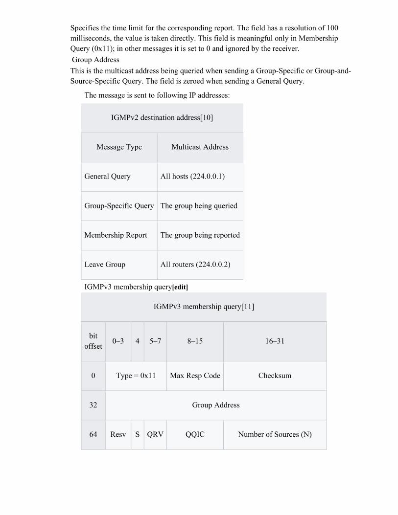
Specifies the time limit for the corresponding report. The field has a resolution of 100 milliseconds, the value is taken directly. This field is meaningful only in Membership Query (0x11); in other messages it is set to 0 and ignored by the receiver.
Group Address
This is the multicast address being queried when sending a Group-Specific or Group-and-Source-Specific Query. The field is zeroed when sending a General Query.
The message is sent to following IP addresses:
IGMPv2 destination address[10]
Message Type Multicast Address
General Query All hosts (224.0.0.1)
Group-Specific Query The group being queried
Membership Report The group being reported
Leave Group All routers (224.0.0.2)
IGMPv3 membership query[edit]
IGMPv3 membership query[11]
bit offset
0–3 4 5–7 8–15 16–31
0 Type = 0x11 Max Resp Code Checksum
32 Group Address
64 Resv S QRV QQIC Number of Sources (N)

96 Source Address [1]
128 Source Address [2]
. . .
Source Address [N]
Where:Max Resp Code
This field specifies the maximum time (in 1/10 second) allowed before sending a responding report. If the number is below 128, the value is used directly. If the value is 128 or more, it is interpreted as an exponent and mantissa.
Checksum
This is the 16-bit one's complement of the one's complement sum of the entire IGMP message.
Group Address
This is the multicast address being queried when sending a Group-Specific or Group-and-Source-Specific Query. The field is zeroed when sending a General Query.
Resv
This field is reserved. It should be zeroed when sent and ignored when received.
S (Suppress Router-side Processing) Flag
When this flag is set, it indicates to receiving routers that they are to suppress the normal timer updates.
QRV (Querier's Robustness Variable)
If this is non-zero, it contains the Robustness Variable value used by the sender of the Query. Routers should update their Robustness Variable to match the most recently received Query unless the value is zero.
QQIC (Querier's Query Interval Code)
This code is used to specify the Query Interval value (in seconds) used by the querier. If the number is below 128, the value is used directly. If the value is 128 or more, it is interpreted as an exponent and mantissa.
Number of Sources (N)
This field specifies the number of source addresses present in the Query. For General and Group-Specific Queries, this value is zero. For Group-and-Source-Specific Queries, this value is non-zero, but limited by the network's MTU.
Source Address [i]

The Source Address [i] fields are a vector of n IP unicast addresses, where n is the value in the Number of Sources (N) field.
The address resolution protocol (arp) is a protocol used by the Internet Protocol (IP) [RFC826], specifically IPv4, to map IP network addresses to the hardware addresses used by a data link protocol. The protocol operates below the network layer as a part of the interface between the OSI network and OSI link layer. It is used when IPv4 is used over Ethernet.
The term address resolution refers to the process of finding an address of a computer in a network. The address is "resolved" using a protocol in which a piece of information is sent by a client process executing on the local computer to a server process executing on a remote computer. The information received by the server allows the server to uniquely identify the network system for which the address was required and therefore to provide the required address. The address resolution procedure is completed when the client receives a response from the server containing the required address.
An Ethernet network uses two hardware addresses which identify the source and destination of each frame sent by the Ethernet. The destination address (all 1's) may also identify a broadcast packet (to be sent to all connected computers). The hardware address is also known as the Medium Access Control (MAC) address, in reference to the standards which define Ethernet. Each computer network interface card is allocated a globally unique 6 byte link address when the factory manufactures the card (stored in a PROM). This is the normal link source address used by an interface. A computer sends all packets which it creates with its own hardware source link address, and receives all packets which match the same hardware address in the destination field or one (or more) pre-selected broadcast/multicast addresses.
The Ethernet address is a link layer address and is dependent on the interface card which is used. IP operates at the network layer and is not concerned with the link addresses of individual nodes which are to be used.The address resolution protocol (arp) is therefore used to translate between the two types of address. The arp client and server processes operate on all computers using IP over Ethernet. The processes are normally implemented as part of the software driver that drives the network interface card.
There are four types of arp messages that may be sent by the arp protocol. These are identified by four values in the "operation" field of an arp message. The types of message are:
1. ARP request2. ARP reply3. RARP request4. RARP reply
The format of an arp message is shown below:
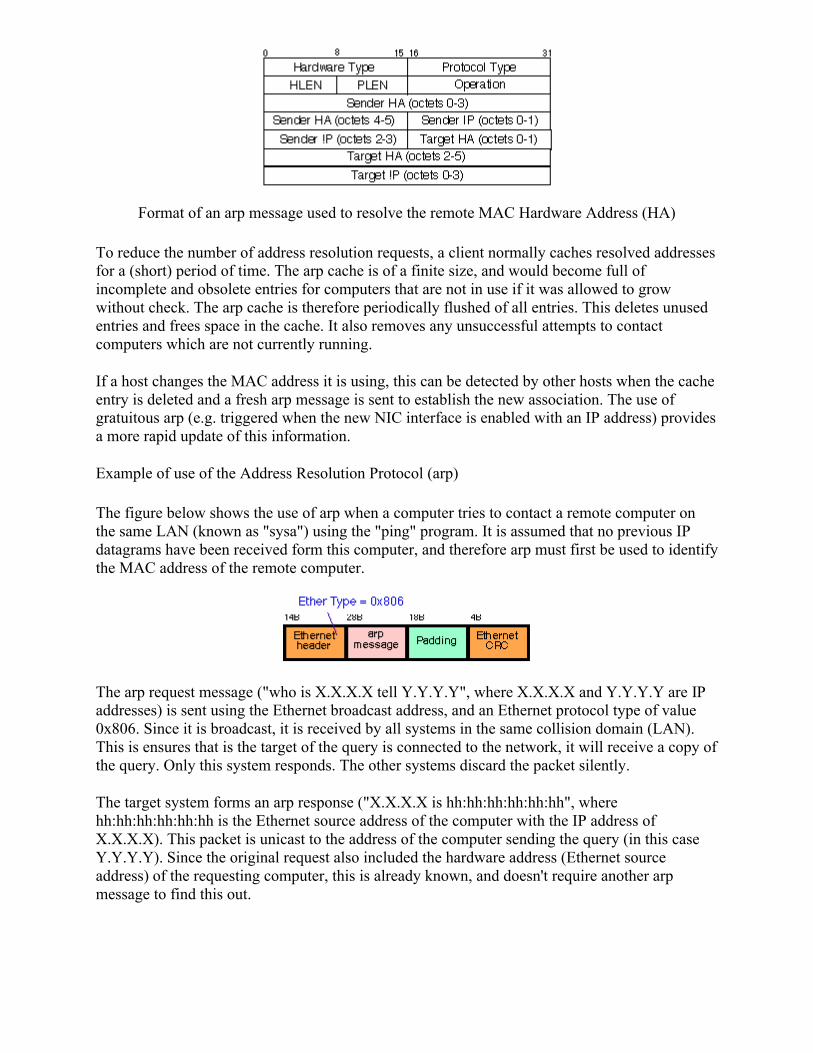
Format of an arp message used to resolve the remote MAC Hardware Address (HA)
To reduce the number of address resolution requests, a client normally caches resolved addresses for a (short) period of time. The arp cache is of a finite size, and would become full of incomplete and obsolete entries for computers that are not in use if it was allowed to grow without check. The arp cache is therefore periodically flushed of all entries. This deletes unused entries and frees space in the cache. It also removes any unsuccessful attempts to contact computers which are not currently running.
If a host changes the MAC address it is using, this can be detected by other hosts when the cache entry is deleted and a fresh arp message is sent to establish the new association. The use of gratuitous arp (e.g. triggered when the new NIC interface is enabled with an IP address) provides a more rapid update of this information.
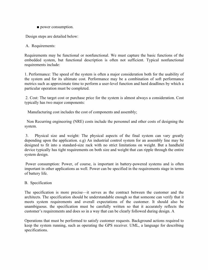
Example of use of the Address Resolution Protocol (arp)
The figure below shows the use of arp when a computer tries to contact a remote computer on the same LAN (known as "sysa") using the "ping" program. It is assumed that no previous IP datagrams have been received form this computer, and therefore arp must first be used to identify the MAC address of the remote computer.
The arp request message ("who is X.X.X.X tell Y.Y.Y.Y", where X.X.X.X and Y.Y.Y.Y are IP addresses) is sent using the Ethernet broadcast address, and an Ethernet protocol type of value 0x806. Since it is broadcast, it is received by all systems in the same collision domain (LAN). This is ensures that is the target of the query is connected to the network, it will receive a copy of the query. Only this system responds. The other systems discard the packet silently.
The target system forms an arp response ("X.X.X.X is hh:hh:hh:hh:hh:hh", where hh:hh:hh:hh:hh:hh is the Ethernet source address of the computer with the IP address of X.X.X.X). This packet is unicast to the address of the computer sending the query (in this case Y.Y.Y.Y). Since the original request also included the hardware address (Ethernet source address) of the requesting computer, this is already known, and doesn't require another arp message to find this out.

Gratuitous ARP
Gratuitous ARP is used when a node (end system) has selected an IP address and then wishes to defend its chosen address on the local area network (i.e. to check no other node is using the same IP address). It can also be used to force a common view of the node's IP address (e.g. after the IP address has changed).
Use of this is common when an interface is first configured, as the node attempts to clear out any stale caches that might be present on other hosts. The node simply sends an arp request for itself.
Proxy ARP
Proxy ARP is the name given when a node responds to an arp request on behalf of another node. This is commonly used to redirect traffic sent to one IP address to another system.
Proxy ARP can also be used to subvert traffic away from the intended recipient. By responding instead of the intended recipient, a node can pretend to be a different node in a network, and therefore force traffic directed to the node to be redirected to itself. The node can then view the traffic (e.g. before forwarding this to the originally intended node) or could modify the traffic. Improper use of Proxy ARP is therefore a significant security vulnerability and some networks therefore implement systems to detect this. Gratuitous ARP can also help defend the correct IP to MAC bindings.

Q5 Write short note on congestion control.
Solution:A state occurring in network layer when the message traffic is so heavy that it slows down network response time.Effects of Congestion As delay increases, performance decreases. If delay increases, retransmission occurs, making situation worse.
Congestion control algorithms Leaky Bucket Algorithm
Let us consider an example to understandImagine a bucket with a small hole in the bottom, No matter at what rate water enters the bucket, the outflow is at constant rate, When the bucket is full with water additional water entering spills over the sides and is lost.Similarly, each network interface contains a leaky bucket and the following steps are involved in leaky bucket algorithm:1. When host wants to send packet, packet is thrown into the bucket.2. The bucket leaks at a constant rate, meaning the network interface transmits packets at a
constant rate.3. Busty traffic is converted to a uniform traffic by the leaky bucket.4. In practice the bucket is a finite queue that outputs at a finite rate. Token bucket Algorithm
Need of token bucket Algorithm:-The leaky bucket algorithm enforces output pattern at the average rate, no matter how bursty the traffic is. So in order to deal with the busty traffic we need a flexible algorithm so that the data is not lost. One such algorithm is token bucket algorithm.Steps of this algorithm can be described as follows:1. In regular intervals tokens are thrown into the bucket. ƒ2. The bucket has a maximum capacity. ƒ3. If there is a ready packet, a token is removed from the bucket, and the packet is send.4. If there is no token in the bucket, the packet cannot be send.

This question paper contains () no. of printed page.
Note: Attempt any four questions out of five questions.
PAPER SOLUTION: By: Pawan Kishore Jhajharia
Q.1 X= <A, B, C, B, D, A, B > , Y= <B, D, C, A, B, A >
If Z is an LCS of X and Y, then find Z using Dynamic Programming .(also write algo)
JNITJAGANNATH GUPTA INSTITUTE OF ENGINEERING & TECHNOLOGY
JAIPURI-Mid Term Examination Session 2017-2018
B.Tech III -Year VI- Semester
Branch: CS Subject:D.A.A Time: 2.00-3.30 PM Subject Code: 6CS2ADate: 14 Feb 18 Max. Marks: 20

Solution:-


Q2.(a) What is the divide and conquer Method? Sort the following sequence using Merge Sort
method:- 5, 2, 4, 7, 1, 3, 2, 6
Solution:- Divide and Conquer:
In algorithm design, the idea is to take a problem on a large input, break the input
In to smaller pieces, solve the problem on each of the small pieces, and then combine the
piecewise solutions into a global solution. But once you have broken the problem into pieces,

how do you solve these pieces? The answer is to apply divide-and-conquer to them, thus further
breaking them down.The process ends when you are left with such tiny pieces remaining (e.g.
one or two items) that it is trivial to solve them.
Summarizing, the main elements to a divide-and-conquer solution are
(i) Divide (the problem into a small number of pieces),
(ii) Conquer (solve each piece, by applying divide-and-conquer recursively to it), and
(iii) Combine (the pieces together into a global solution).
There are a huge number computational problems that can be solved efficiently using divide-
and-conquer. In fact the technique is so powerful, that when someone first suggests a problem to
me,the first question I usually ask (after what is the brute-force solution) is “does there exist a
divide-and-
conquer solution for this problem?”Divide-and-conquer algorithms are typically recursive, since
the conquer part involves invoking the same technique on a smaller sub problem. Analyzing the
running times of recursive programs is rather tricky, but we will show that there is an elegant
mathematical concept, called a recurrence, which is useful for analyzing the sort of recursive
programs that naturally arise in divide-and-conquer solutions.For the next couple of lectures we
will discuss some examples of divide-and-conquer algorithms, andhow to analyze them using
recurrences.
Merge Sort:
The first example of a divide-and-conquer algorithm which we will consider is perhaps the best
known. This is a simple and very efficient algorithm for sorting a list of numbers, called
Merge Sort.


(b) Design an O(n) time algorithm that ,given a real number X and a sorted array S of n numbers
determines whether or not there exist two elements in S whose sum is exactly x.
Solution:-asArrayTwoCandidates (A[], ar_size, sum)
1) Sort the array in non-decreasing order.
2) Initialize two index variables to find the candidate
elements in the sorted array.
(a) Initialize first to the leftmost index: l = 0
(b) Initialize second the rightmost index: r = ar_size-1
3) Loop while l < r.
(a) If (A[l] + A[r] == sum) then return 1
(b) Else if( A[l] + A[r] < sum ) then l++
(c) Else r--
4) No candidates in whole array - return 0
Q.3 Write short note :-( any two)
(i) Job sequencing problemSolution:- Job Sequencing Problem (Greedy Algorithm)
Given an array of jobs where every job has a deadline and associated profit if the job is finished before the deadline. It is also given that every job takes single unit of time, so the minimum possible deadline for any job is 1. How to maximize total profit if only one job can be scheduled at a time.
Examples:Input: Four Jobs with following deadlines and profits JobID Deadline Profit a 4 20 b 1 10 c 1 40 d 1 30Output: Following is maximum profit sequence of jobs c, a
Input: Five Jobs with following deadlines and profits JobID Deadline Profit a 2 100 b 1 19 c 2 27 d 1 25 e 3 15Output: Following is maximum profit sequence of jobs

c, a, e
(ii) Optimal merge patternSolution:-Merge a set of sorted files of different length into a single sorted file. We need to find an optimal solution, where the resultant file will be generated in minimum time.If the number of sorted files are given, there are many ways to merge them into a single sorted file. This merge can be performed pair wise. Hence, this type of merging is called as 2-way merge patterns.As, different pairings require different amounts of time, in this strategy we want to determine an optimal way of merging many files together. At each step, two shortest sequences are merged.To merge a p-record file and a q-record file requires possibly p + q record moves, the obvious choice being, merge the two smallest files together at each step.Two-way merge patterns can be represented by binary merge trees. Let us consider a set of n sorted files {f1, f2, f3, …, fn}. Initially, each element of this is considered as a single node binary tree. To find this optimal solution, the following algorithm is used.
Algorithm: TREE (n) for i := 1 to n – 1 do declare new node node.leftchild := least (list) node.rightchild := least (list) node.weight) := ((node.leftchild).weight) + ((node.rightchild).weight) insert (list, node); return least (list); At the end of this algorithm, the weight of the root node represents the optimal cost.ExampleLet us consider the given files, f1, f2, f3, f4 and f5 with 20, 30, 10, 5 and 30 number of elements respectively.If merge operations are performed according to the provided sequence, thenM1 = merge f1 and f2 => 20 + 30 = 50M2 = merge M1 and f3 => 50 + 10 = 60M3 = merge M2 and f4 => 60 + 5 = 65M4 = merge M3 and f5 => 65 + 30 = 95Hence, the total number of operations is50 + 60 + 65 + 95 = 270Now, the question arises is there any better solution?Sorting the numbers according to their size in an ascending order, we get the following sequence −f4, f3, f1, f2, f5
Hence, merge operations can be performed on this sequenceM1 = merge f4 and f3 => 5 + 10 = 15M2 = merge M1 and f1 => 15 + 20 = 35M3 = merge M2 and f2 => 35 + 30 = 65M4 = merge M3 and f5 => 65 + 30 = 95Therefore, the total number of operations is15 + 35 + 65 + 95 = 210Obviously, this is better than the previous one.In this context, we are now going to solve the problem using this algorithm.

Initial Set
Step-1
Step-2
Step-3
Step-4
Hence, the solution takes 15 + 35 + 60 + 95 = 205 number of comparisons.
(iii) Matrix chain multiplicationSolution:-efficiently multiply a chain of N matrices, i.e. calculate in the fastest way M = M1M2M3 … MN.
Each matrix Mk has dimension pk-1 x pk. The dimensions are stored in array

P = < p0 p1 … pN>.
Math behind this problem: matrices can be multiplied only two by two, and their order in the chain must be preserved (partially because number of columns of the first matrix must equal the number of rows of the second matrix). In other words, if A and B are matrices, AB ≠ BA. Number of scalar multiplications in AaxbBbxc equals to a*b*c.
For example, M1M2M3 can be calculated as (M1M2)M3 or M1(M2M3). The order of multiplication, i.e. the placement of parenthesis, will determine the number of scalar multiplications.
Example: M = M1M2M3, P = <10 100 5 50>.
If we calculate M = (M1M2)M3, then the number of scalar multiplications is:10*100*5 to multiply K=M1M2. Dimension of K is 10x5.+ 10*5*50 to multiply M=KM3. Dimension of M is 10x50.Total: 7,500 scalar multiplications.
If we calculate M = M1(M2M3), then the number of scalar multiplications is:100*5*50 to multiply L=M2M3. Dimension of L is 100x50.+ 10*100*50 to multiply M=M1L. Dimension of M is 10x50.Total: 75,000 scalar multiplications.
Therefore, the problem boils down to: given a product chain of N matrices, fully parenthesize the chain in order to minimize the number of scalar multiplications.
A solution: brute force method using dynamic programming, i.e. write and implement a dynamic programming formula to solve the problemMATRIX-CHAIN-ORDER(P) {
n = length(P) – 1for i = 1, n
m[i,i] = 0for L = 2, n
for i = 1, n – L + 1j = i + L – 1m [i, j] = ∞for k = i, j-1
q = m[i, k] + m[k+1, j] + pi-1pkpj
if q < m[i,j]m[i,j] = qs[i,j] = k
return m and s}
(iv) Minimum Spanning Tree

Solution:-A spanning tree is a subset of Graph G, which has all the vertices covered with minimum possible number of edges. Hence, a spanning tree does not have cycles and it cannot be disconnected..By this definition, we can draw a conclusion that every connected and undirected Graph G has at least one spanning tree. A disconnected graph does not have any spanning tree, as it cannot be spanned to all its vertices.
We found three spanning trees off one complete graph. A complete undirected graph can have maximum nn-2 number of spanning trees, where n is the number of nodes. In the above addressed example, 33−2 = 3 spanning trees are possible.
Minimum Spanning-Tree AlgorithmWe shall learn about two most important spanning tree algorithms here −
Kruskal's Algorithm Prim's Algorithm
Both are greedy algorithms.
Q.4 Consider n=3, (w1,w2, w3 ) = (2 , 3, 3 )
(p1, p2, p3) = (1, 2, 4) and M=6 find optimal solution for following knapsack problem using
dynamic programming

Solution:-


OR
(a)Describe the various types of asymptotic notations with example?
Solution:- Asymptotic Notations:We have discussed Asymptotic Analysis, and Worst, Average and Best Cases of Algorithms. The main idea of asymptotic analysis is to have a measure of efficiency of algorithms that doesn’t depend on machine specific constants, and doesn’t require algorithms to be implemented and time taken by programs to be compared. Asymptotic notations are mathematical tools to represent time complexity of algorithms for asymptotic analysis. The following 3 asymptotic notations are mostly used to represent time complexity of algorithms.
1) Θ Notation: The theta notation bounds a functions from above and below, so it defines exact asymptotic behavior.A simple way to get Theta notation of an expression is to drop low order terms and ignore leading constants. For example, consider the following expression.3n3 + 6n2 + 6000 = Θ(n3)Dropping lower order terms is always fine because there will always be a n0 after which Θ(n3) has higher values than Θn2) irrespective of the constants involved.For a given function g(n), we denote Θ(g(n)) is following set of functions.
Θ(g(n)) = {f(n): there exist positive constants c1, c2 and n0 such that 0 <= c1*g(n) <= f(n) <= c2*g(n) for all n >= n0}The above definition means, if f(n) is theta of g(n), then the value f(n) is always between c1*g(n) and c2*g(n) for large values of n (n >= n0). The definition of theta also requires that f(n) must be non-negative for values of n greater than n0.
2) Big O Notation: The Big O notation defines an upper bound of an algorithm, it bounds a function only from above. For example, consider the case of Insertion Sort. It takes linear time in best case and quadratic time in worst case. We can safely say that the time complexity of Insertion sort is O(n^2). Note that O(n^2) also covers linear time.If we use Θ notation to represent time complexity of Insertion sort, we have to use two statements for best and worst cases:1. The worst case time complexity of Insertion Sort is Θ(n^2).2. The best case time complexity of Insertion Sort is Θ(n).
The Big O notation is useful when we only have upper bound on time complexity of an algorithm. Many times we easily find an upper bound by simply looking at the algorithm.
O(g(n)) = { f(n): there exist positive constants c and n0 such that 0 <= f(n) <= cg(n) for all n >= n0}3) Ω Notation: Just as Big O notation provides an asymptotic upper bound on a function, Ω notation provides an asymptotic lower bound.

Ω Notation< can be useful when we have lower bound on time complexity of an algorithm. As discussed in the previous post, the best case performance of an algorithm is generally not useful, the Omega notation is the least used notation among all three.
For a given function g(n), we denote by Ω(g(n)) the set of functions.
Ω (g(n)) = {f(n): there exist positive constants c and n0 such that 0 <= cg(n) <= f(n) for all n >= n0}.Let us consider the same Insertion sort example here. The time complexity of Insertion Sort can be written as Ω(n), but it is not a very useful information about insertion sort, as we are generally interested in worst case and sometimes in average case.
Exercise:Which of the following statements is/are valid?1. Time Complexity of QuickSort is Θ(n^2)2. Time Complexity of QuickSort is O(n^2)3. For any two functions f(n) and g(n), we have f(n) = Θ(g(n)) if and only if f(n) = O(g(n)) and f(n) = Ω(g(n)).4. Time complexity of all computer algorithms can be written as Ω(1)
(b)Solve the following recurrence relation and find their complexities using master method
(i) T(n) = 3T(n/4) + log2n
(ii) T(n) = 4T(n/2) + n2
Solution:- (i) Cannot Solve by using Master Method
(ii)
Q.5 consider the five items along with their respective values and weights.
I= {I1, I2, I3 , I4 , I5} W= {5, 10, 20, 30, 40} V= {30, 20, 100, 90, 16}
Knapsack has Capacity W=60. Find the optimal solution of the problem using concept of fractional Knapsack.
Solution:-


Embedded system
1. What is embedded system? Explain embedded system design process.
ANS: An embedded system can be thought of as a computer hardware system having software embedded in it. An embedded system can be an independent system or it can be a part of a large system. An embedded system is a microcontroller or microprocessor based system which is designed to perform a specific task. For example, a fire alarm is an embedded system; it will sense only smoke.
An embedded system has three components −
It has hardware. It has application software. It has Real Time Operating system (RTOS) that supervises the application software and
provide mechanism to let the processor run a process as per scheduling by following a plan to control the latencies. RTOS defines the way the system works. It sets the rules during the execution of application program. A small scale embedded system may not have RTOS.
So we can define an embedded system as a Microcontroller based, software driven, reliable, real-time control system.
THE EMBEDDED SYSTEM DESIGN PROCESS
Overview of the embedded system design process aimed at two objectives. First,it will give us an introduction to the various steps in embedded system design before we delve into them in more detail. Second, it will allow us to consider the design methodology itself.
Top–down Design—we will begin with the most abstract description of the system and conclude with concrete details. The alternative is a bottom–up view in which we start with components to build a system. Bottom–up design steps are shown in the figure as dashed-line arrows. We need bottom–up design because we do not have perfect insight into how later stages of the design process will turn out. During the design process we have to consider the major goals of the design such as
■ manufacturing cost;
■ performance (both overall speed and deadlines); and
JNIT JAGANNATH GUPTA INSTITUTE OF ENGINEERING & TECHNOLOGY JAIPUR
I-Mid Term Examination Session 2018B.Tech III Year VI Semester
Branch: Computer Science Subject: Embedded system Time: Subject Code: 6CS5 Date: Max. Marks: 20
■ power consumption.
Design steps are detailed below:
A. Requirements:
Requirements may be functional or nonfunctional. We must capture the basic functions of the embedded system, but functional description is often not sufficient. Typical nonfunctional requirements include:
1. Performance: The speed of the system is often a major consideration both for the usability ofthe system and for its ultimate cost. Performance may be a combination of soft performance metrics such as approximate time to perform a user-level function and hard deadlines by which a particular operation must be completed.
2. Cost: The target cost or purchase price for the system is almost always a consideration. Costtypically has two major components:
Manufacturing cost includes the cost of components and assembly;
Non Recurring engineering (NRE) costs include the personnel and other costs of designing the system.
3. Physical size and weight: The physical aspects of the final system can vary greatly depending upon the application. e.g) An industrial control system for an assembly line may be designed to fit into a standard-size rack with no strict limitations on weight. But a handheld device typically has tight requirements on both size and weight that can ripple through the entire system design.
Power consumption: Power, of course, is important in battery-powered systems and is oftenimportant in other applications as well. Power can be specified in the requirements stage in terms of battery life.
B. Specification
The specification is more precise—it serves as the contract between the customer and the architects. The specification should be understandable enough so that someone can verify that it meets system requirements and overall expectations of the customer. It should also be unambiguous. the specification must be carefully written so that it accurately reflects the customer’s requirements and does so in a way that can be clearly followed during design. A
Operations that must be performed to satisfy customer requests. Background actions required to keep the system running, such as operating the GPS receiver. UML, a language for describing specifications.

C. Architecture Design
The specification does not say how the system does things, only what the system does. Describing how the system implements those functions is the purpose of the architecture. Figure
Many implementation details should we refine that system block diagram into two block diagrams: one for hardware and another for software. These two more refined block diagrams are shown in Figure 1.4.The hardware block diagram clearly shows that we have one central CPU surrounded by memory and I/O devices. In particular, we have chosen to use two memories: a frame buffer for the pixels to be displayed and a separate program/data memory for general use by the CPU .
D. Designing Hardware and Software Components
The component design effort builds those components in conformance to the architecture and specification. The components will in general include both hardware—FPGAs, boards, and so on—and software modules. Some of the components will be ready-made. In the moving map, the GPS receiver is a good example of a specialized component that will nonetheless be a predesigned, standard component. We can also make use of standard software modules. One good example is the topographic database.
E. System Integration
The components built are put together and see how the system works. If we debug only a few modules at a time, we are more likely to uncover the simple bugs and able to easily recognize them. Only by fixing the simple bugs early will we be able to uncover the more complex or obscure bugs.
2. Explain PLDs in detail.ANS: A programmable logic device (PLD) is an electronic component used to build reconfigurable digital circuits. Unlike a logic gate, which has a fixed function, a PLD has an undefined function at the time of manufacture. Before the PLD can be used in a circuit it must be programmed, that is, reconfigured. PLD has three types:
PROM: Programmable read-only memory, a memory chip on which data can be written only once. Once a program has been written onto a PROM, it remains there forever. Unlike RAM, PROMs retain their contents when the computer is turned off.
The difference between a PROM and a ROM (read-only memory) is that a PROM is manufactured as blank memory, whereas a ROM is programmed during the manufacturing process. To write data onto a PROM chip, you need a special device called a PROM programmer or PROM burner. The process of programming a PROM is sometimes called burning the PROM.

An EPROM (erasable programmable read-only memory) is a special type of PROM that can be erased by exposing it to ultraviolet light. Once it is erased, it can be reprogrammed. An EEPROM is similar to a PROM, but requires only electricity to be erased.
Programmable Array Logic (PAL) is a family of programmable logic device semiconductors used to implement logic functions in digital circuits introduced by Monolithic Memories, Inc. (MMI) in March 1978.[1] MMI obtained a registered trademark on the term PAL for use in "Programmable Semiconductor Logic Circuits". The trademark is currently held by Lattice Semiconductor.[2]
PAL devices consisted of a small PROM (programmable read-only memory) core and additional output logic used to implement particular desired logic functions with few components.
Using specialized machines, PAL devices were "field-programmable". PALs were available in several variants:
"One-time programmable" (OTP) devices could not be updated and reused after initial programming (MMI also offered a similar family called HAL, or "hard array logic", which were like PAL devices except that they were mask-programmed at the factory.).
UV erasable versions (e.g.: PALCxxxxx e.g.: PALC22V10) had a quartz window over the chip die and could be erased for re-use with an ultraviolet light source just like an EPROM.
Later versions (PALCExxx e.g.: PALCE22V10) were flash erasable devices.
A programmable logic array (PLA) is a kind of programmable logic device used to implement combinational logic circuits. The PLA has a set of programmable AND gate planes, which link to a set of programmable OR gate planes, which can then be conditionally complemented to produce an output. It has 2^N AND Gates for N input variables and for M outputs from PLA, there should be M OR Gates, each with programmable inputs from all of the AND gates. This layout allows for a large number of logic functions to be synthesized in the sum of products canonical forms.
PLAs differ from Programmable Array Logic devices (PALs and GALs) in that both the AND and OR gate planes are programmable. PALs and GALs are available only in small sizes, equivalent to a few hundred logic gates. For bigger logic circuits, complex PLDs or CPLDs can be used. These contain the equivalent of several PALs linked by programmable interconnections, all in one integrated circuit. CPLDs can replace thousands, or even hundreds of thousands, of logic gates.
Some CPLDs are programmed using a PAL programmer, but this method becomes inconvenient for devices with hundreds of pins. A second method of programming is to solder the device to its printed circuit board, then feed it with a serial data stream from a personal computer. The CPLD contains a circuit that decodes the data stream and configures the CPLD to perform its specified logic function
FPGA: FPGAs use a grid of logic gates, and once stored, the data doesn't change, similar to that of an ordinary gate array. The term "field-programmable" means the device is programmed by the customer, not the manufacturer. FPGAs are usually programmed after being soldered down to the circuit board, in a manner similar to that of larger CPLDs. In most larger FPGAs, the configuration is volatile and must be re-loaded into the device whenever power is applied or different functionality is required. Configuration is typically stored in a configuration PROM or EEPROM. EEPROM versions may be in-system programmable (typically via JTAG).
The difference between FPGAs and CPLDs is that FPGAs are internally based on Look-up tables (LUTs) whereas CPLDs form the logic functions with sea-of-gates (e.g. sum of products). CPLDs are meant for simpler designs while FPGAs are meant for more complex designs. In general, CPLDs are a good choice for wide combinational logic applications, whereas FPGAs are more suitable for large state machines (i.e. microprocessors).
3. What is DMA? Explain DMA controller and Transfer in detail.
ANS: Direct memory access (DMA) is a feature of computer systems that allows certain hardware subsystems to access main system memory (Random-access memory), independent of the central processing unit (CPU).
Without DMA, when the CPU is using programmed input/output, it is typically fully occupied for the entire duration of the read or write operation, and is thus unavailable to perform other work. With DMA, the CPU first initiates the transfer, then it does other operations while the transfer is in progress, and it finally receives an interrupt from the DMA controller when the operation is done. This feature is useful at any time that the CPU cannot keep up with the rate of data transfer, or when the CPU needs to perform work while waiting for a relatively slow I/O data transfer. Many hardware systems use DMA, including disk drive controllers, graphics cards, network cards and sound cards. DMA is also used for intra-chip data transfer in multi-core processors. Computers that have DMA channels can transfer data to and from devices with much less CPU overhead than computers without DMA channels. Similarly, a processing element inside a multi-core processor can transfer data to and from its local memory without occupying its processor time, allowing computation and data transfer to proceed in parallel.
DMA channels are used to communicate data between the peripheral device and the system memory. All four system resources rely on certain lines on a bus. Some lines on the bus are used for IRQs, some for addresses (the I/O addresses and the memory address) and some for DMA channels.
A DMA channel enables a device to transfer data without exposing the CPU to a work overload. Without the DMA channels, the CPU copies every piece of data using a peripheral bus from the I/O device. Using a peripheral bus occupies the CPU during the read/write process and does not allow other work to be performed until the operation is completed.
The data transfer technique in which peripherals manage the memory buses for direct interaction with main memory without involving the CPU is called direct memory access

(DMA). Using DMA technique large amounts of data can be transferred between memory and the peripheral without severely impacting CPU performance.
During the DMA transfer, the CPU is idle and has no control of the memory buses. A DMA controller takes over the buses to manage the transfer directly between the I/O device(s) and main memory.
The DMA request CPU to handle control of buses to the DMA using bus request (BR) signal. The CPU grants the control of buses to DMA using bus grant (BG) signal after placing the address bus, data bus and read and write lines into high impedance state (which behave like open circuit).CPU initializes the DMA by sending following information through the data bus.
1. Starting address of memory block for read or write operation.2. The word count which is the no. of words in the memory block.3. Control to specify the mode of transfer such as read or write.4. A control to start the DMA transfer.
The DMA takes control over the buses directly interacts with memory and I/O units and transfers the data without CPU intervention. When the transfer completes, DMA disables the BR line. Thus CPU disable BG line, takes control over the buses and return to its normal operation.

Basic DMA operation•The direct memory access (DMA) I/O technique provides di-rect access to the memory while the microprocessor is tempo-rarily disabled. •A DMA controller temporarily borrows the address bus, data bus, and control bus from the microprocessor and transfers the data bytes directly between an I/O port and a series of memory locations. •The DMA transfer is also used to do high-speed memory-to-memory transfers. •Two control signals are used to request and acknowledge a DMA transfer in the microprocessor-based system. •The HOLD signal is a bus request signal which asks the microprocessor to release control of the buses after the current bus cycle. •The HLDA signal is a bus grant signal which indicates that the microprocessor has indeed released control of its buses by placing the buses at their high-impedance states. •The HOLD input has a higher priority than the INTR or NMI interrupt inputs.
4.. What is interrupt? Explain Shared data problem.
ANS: An interrupt is a signal to the processor emitted by hardware or software indicating an event that needs immediate attention. Whenever an interrupt occurs, the controller completes the execution of the current instruction and starts the execution of an Interrupt Service Routine (ISR) or Interrupt Handler. ISR tells the processor or controller what to do when the interrupt occurs. The interrupts can be either hardware interrupts or software interrupts. Shared data problem can arise in a system when another higher priority task finishes an operation and modifies the data or a variable before the completion of previous task operations. Disabling interrupt mechanism, using. semaphores and using reentrant. functions are some solutions.
Assume that several ISRs or tasks share a variable. If there is a variable currently running under a task and there is an interrupt and some other task will be taking the control of that variable. Since the variable is already used by other task, so there comes a shared data problem.The bugs encountered in the above process can be eliminated by means of following techniques

use of volatile modifier – this declaration warns the compiler that certain variables can modify because the ISR does not consider the fact that the variable is also shared with a calling function
reentrant function – part of a function that needs its complete execution before it can be interrupted. This part is called the critical section.
put a shared variable in a circular queue – a function that requires the value of this variable always delete it from the queue front and another function which inserts the value of this variable,a lways does so at the queue back.
Disabling the interrupts before a critical section starts executing and enable the interrupts on its completion. In this method, the high priority task or ISRs will be waiting because of the disabling of the interrupts
Semaphores- Elimination of Shared Data Problems with Semaphores
The use of semaphores does not eliminate the shared data problem completely.
So there are some problems when using semaphores
Sharing of two semaphores leads to deadlocks Suppose that the locked semaphore is not released? There should be some timeout
interval in which after the timeout the Watch Dog Timer will reset the processor thereby the error is handled by a function
A semaphore is not taken as another task uses a shared variable A wrong semaphore is taken by a task There may be priority inversion problem
Deadlocks
Suppose if there are two semaphores S1 and S2, and there are two tasks T1 and T2. The locking will be in the following cycle
T1-> S1 -> S2-> T1
T2 -> S2 -> S1 -> T2
The above two scenarios, both the Tasks T1 and T2 needs to take the semaphores S1 and S2. Both the tasks wont release the semaphores until it completes the execution
Task T1 locks S1 and waiting for S2 which is been locked by T2. similarly, the task T2 also waits for s1 which is being locked by T1. This problem is called as Deadlock
5.. Explain survey of software architecture in detail.

ANS: Software architecture, according to ANSI/IEEE Standard 1471-2000, is defined as the “fundamental organization of a system, embodied in its components, their relationships to each other and the environment, and the principles governing its design and evolution.” Embedded software, as we’ve said, must interact with
the environment through sensors and actuators, and often has hard, real-time constraints. The organization of the software, or its architecture , must reflect these realities. Usually, the criticalaspect of an embedded control system is its speed of response which is a function of (among other things) the processor speed and the number and complexity of the tasks to be accomplished, as well as the software architecture. Clearly, embedded systems with not much to do, and plenty of time in which to do it, can employ a simple software organization (a vending machine, for example, or the power seat in your car). Systems that must respond rapidly to many different events with hard real-time deadlines generally require a more complex softwarearchitecture (the avionics systems in an aircraft, engine and transmission control, traction control and antilock brakes in your car). Most often, the various tasks managed by an embedded system have different priorities : Some things have to be done immediately (fire the spark plug precisely20◦before the piston reaches top-dead-center in the cylinder), while other tasks may have less severe time constraints (read and store the ambient temperature for use in a calculation to be done later).
1. Round robin2. Round robin with interrupts3. Function queue scheduling4. Real time operating systems (RTOS)
1. Round RobinThe simplest possible software architecture is called “round robin.” Round robin architecture has no interrupts; the software organization consists of one main loop wherein the processor simply polls each attached device in turn, and provides service if any is required. After all devices have been serviced, start over from the top. Graphically, round robin looks like Figure 1. Round robin pseudocode looks something like this:
void main(void) {while(TRUE) {if (device_A requires service)service device_Aif (device_B requires service)service device_Bif (device_C requires service)service device_C... and so on until all devices have been serviced, then start over again}
2. Round Robin with InterruptsRound robin is simple, but that’s pretty much its only advantage. One step up on the performance scale is round robin with interrupts. Here, urgent tasks get handled in an interrupt service routine, possibly with a flag set for follow-up processing in the main loop. If nothing urgent happens

emergency stop button pushed, or intruder detected), then the processor continues to operate round robin, managing more mundane tasks
in order around the loop. Possible pseudocode:
BOOL flag_A = FALSE; /* Flag for device_A follow-up processing *//* Interrupt Service Routine for high priority device_A */ISR_A(void) {... handle urgent requirements for device_A in the ISR,then set flag for follow-up processing in the main loop ...flag_A = TRUE;}void main(void) {while(TRUE) {if (flag_A)flag_A = FALSE... do follow-up processing with data from device_Aif (device_B requires service)service device_Bif (device_C requires service)service device_C... and so on until all high and low priority devices have been serviced}}
Function Queue SchedulingFunction queue scheduling provides a method of assigning priorities to interrupts. In this architecture, interrupt service routines accomplish urgent processing from interrupting devices, but then put a pointer to a handler function on a queue for follow-up processing. The main loop simply checks the function queue, and if it’s not empty, calls the first function on the queue. Priorities are assigned by the order of the function in the queue – there’s no reason that functions have to be placed in the queue in the order in which the interrupt occurred. They may just as easily be placed in the queue in priority order: high priority functions at the top of the queue, and low priority functions at the bottom. The worst case timing for the highest priority function is the execution time of the longest function in the queue (think of the case of the processor just starting to execute the longest function right before an interrupt places a high priority task at the front of the queue). The worst case timing for the lowest priority task is infinite: it may never get executed if higher priority code is always being inserted at the front of the queue.
Real-time Operating System (RTOS): A real-time operating system is complicated, potentially expensive, and takes up precious memory in our almost always cost and memory constrained embedded system. Why use one? There are two main reasons: flexibility and response time. The elemental component of a real-time operating system is a task, and it’s straightforward to add new tasks or delete obsolete ones because there is no main loop: The RTOS schedules when each task is to run based on its priority. The scheduling of tasks by the RTOS is referred to as multi-tasking. In a preemptive

multi-tasking system, the RTOS can suspend a low priority task at any time to execute a higher priority one, consequently, the worst case response time for a high priority task is almost zero (in a non-preemptive multi-tasking system, the low priority task finishes executing before the high priority task starts). In the simplest RTOS, a task can be in one of three states:
Running: The task code is being executed by the processor. Only one task may be running at any time.Ready: All necessary data are available and the task is prepared to run when the processor is available. Many tasks may be ready at any time, and will run in priority order.
Blocked: A task may be blocked waiting for data or for an event to occur. A task, if it is not preempted, will block after running to completion. Many tasks may be blocked at one time.
JaganNath Gupta Institute of Engineering and Technology
Subject: HCI, 6th
Semester, CS Branch
1st Midterm Paper Solution
Q.1 Explain interaction design process using suitable steps and diagrams?
The objective of this chapter is to learn all the aspects of design and development of interactive
systems, which are now an important part of our lives. The design and usability of these
systems leaves an effect on the quality of people’s relationship to technology. Web applications,
games, embedded devices, etc., are all a part of this system, which has become an integral part
of our lives. Let us now discuss on some major components of this system.
Concept of Usability Engineering
Usability Engineering is a method in the progress of software and systems, which includes user
contribution from the inception of the process and assures the effectiveness of the product
through the use of a usability requirement and metrics.
It thus refers to the Usability Function features of the entire process of abstracting,
implementing & testing hardware and software products. Requirements gathering stage to
installation, marketing and testing of products, all fall in this process.
Goals of Usability Engineering
Effective to use − Functional
Efficient to use − Efficient
Error free in use − Safe
Easy to use − Friendly
Enjoyable in use − Delightful Experience
Usability
Usability has three components − effectiveness, efficiency and satisfaction, using which, users
accomplish their goals in particular environments. Let us look in brief about these components.
Effectiveness − The completeness with which users achieve their goals.
Efficiency − The competence used in using the resources to effectively achieve the goals.
Satisfaction − The ease of the work system to its users.
Usability Study
The methodical study on the interaction between people, products, and environment based on
experimental assessment. Example: Psychology, Behavioral Science, etc.
Usability Testing
The scientific evaluation of the stated usability parameters as per the user’s requirements,
competences, prospects, safety and satisfaction is known as usability testing.
Acceptance Testing
Acceptance testing also known as User Acceptance Testing (UAT), is a testing procedure that is
performed by the users as a final checkpoint before signing off from a vendor. Let us take an
example of the handheld barcode scanner.
Let us assume that a supermarket has bought barcode scanners from a vendor. The supermarket
gathers a team of counter employees and make them test the device in a mock store setting. By
this procedure, the users would determine if the product is acceptable for their needs. It is
required that the user acceptance testing "pass" before they receive the final product from the
vendor.
Software Tools
A software tool is a programmatic software used to create, maintain, or otherwise support other
programs and applications. Some of the commonly used software tools in HCI are as follows −
Specification Methods − The methods used to specify the GUI. Even though these are
lengthy and ambiguous methods, they are easy to understand.
Grammars − Written Instructions or Expressions that a program would understand.
They provide confirmations for completeness and correctness.
Transition Diagram − Set of nodes and links that can be displayed in text, link
frequency, state diagram, etc. They are difficult in evaluating usability, visibility,
modularity and synchronization.
Statecharts − Chart methods developed for simultaneous user activities and external
actions. They provide link-specification with interface building tools.
Interface Building Tools − Design methods that help in designing command languages,
data-entry structures, and widgets.
Interface Mockup Tools − Tools to develop a quick sketch of GUI. E.g., Microsoft
Visio, Visual Studio .Net, etc.
Software Engineering Tools − Extensive programming tools to provide user interface
management system.
Evaluation Tools − Tools to evaluate the correctness and completeness of programs.

Interactive System Design
The uni-directional movement of the waterfall model of Software Engineering shows that every
phase depends on the preceding phase and not vice-versa. However, this model is not suitable
for the interactive system design.
The interactive system design shows that every phase depends on each other to serve the
purpose of designing and product creation. It is a continuous process as there is so much to
know and users keep changing all the time. An interactive system designer should recognize
this diversity.
Q.2 What do you mean by input/output channels? Explain different types of channels with
example.
Answer: Input Output channels A person’s interaction with the outside world occurs through
information being received and sent: input and output. In an interaction with a computer the user
receives information that is output by the computer, and responds by providing input to the computer –
the user’s output become the computer’s input and vice versa. Consequently the use of the terms input
and output may lead to confusion so we shall blur the distinction somewhat and concentrate on the
channels involved. This blurring is appropriate since, although a particular channel may have a primary

role as input or output in the interaction, it is more than likely that it is also used in the other role. For
example, sight may be used primarily in receiving information from the computer, but it can also be
used to provide information to the computer, for example by fixating on a particular screen point when
using an eye gaze system. Input in human is mainly though the senses and output through the motor
control of the effectors. There are five major senses:
• Sight
• Hearing
• Touch
• Taste
• Smell of these first three are the most important to HCI. Taste and smell do not currently play a
significant role in HCI, and it is not clear whether they could be exploited at all in general computer
systems, although they could have a role to play in more specialized systems or in augmented reality
systems. However, vision hearing and touch are central. Similarly there are a number of effectors:
• Limbs
• Fingers
• Eyes
• Head
• Vocal system
In the interaction with computer, the fingers play the primary role, through typing or mouse control,
with some use of voice, and eye, head and body position. Imagine using a personal computer with a
mouse and a keyboard. The application you are using has a graphical interface, with menus, icons and
windows. In your interaction with this system you receive information primarily by sight, from what
appears on the screen. However, you may also receive information by ear: for example, the computer
may ‘beep’ at you if you make a mistake or to draw attention to something, or there may be a voice
commentary in a multimedia presentation. Touch plays a part too in that you will feel the keys moving
(also hearing the ‘click’) or the orientation of the mouse, which provides vital feedback about what you
have done. You yourself send information to the computer using your hands either by hitting keys or
moving the mouse.
Vision Human vision is a highly complex activity with range of physical and perceptual limitations, yet it
is the primary source of information for the average person. We can roughly divide visual perception
into two stages:
• The physical reception of the stimulus from outside world, and

• The processing and interpretation of that stimulus.
On the one hand the physical properties of the eye and the visual system mean that there are
certain things that cannot be seen by the human; on the other interpretative capabilities of visual
processing allow images to be constructed from incomplete information. We need to understand
both stages as both influence what can and can not be perceived visually by a human being,
which is turn directly affect the way that we design computer system. We will begin by looking
at the eye as a physical receptor, and then go onto consider the processing involved in basic
vision. The human eye Vision begins with light. The eye is a mechanism for receiving light and
transforming it into electrical energy. Light is reflected from objects in the world and their image
is focused upside down on the back of the eye. The receptors in the eye transform it into
electrical signals, which are passed to brain. The eye has a number of important components as
you can see in the figure. Let us take a deeper look. The cornea and lens at the front of eye focus
the light into a sharp image on the back of the eye, the retina. The retina is light sensitive and
contains two types of photoreceptor: rods and cones.
Q.3 Explain different types of text entry devices?
One enduring trait of computing systems is the presence of the human operator. At the human-
computer interface, the nature of computing has witnessed dramatic transformations--from
feeding punched cards into a reader to manipulating 3D virtual objects with an input glove. The
technology at our finger tips today transcends by orders of magnitude that in the behemoth
calculators of the 1940s. Yet technology must co-exist with the human interface of the day. Not
surprisingly, themes on keeping pace with advances in technology in the human-computer
interface and, hopefully, getting ahead, underlie many chapters in this book. The present chapter
is no exception. Input devices and interaction techniques are the human operator's baton. They
set, constrain, and elicit a spectrum of actions and responses, and in a large way inject a
personality on the entire human-machine system. In this chapter, we will present and explore the
major issues in "input", focusing on devices, their properties and parameters, and the possibilities
for exploiting devices in advanced human-computer interfaces.
To place input devices in perspective, we illustrate a classical human factors interpretation of the
human-machine interface (e.g., Chapanis, 1965, p. 20). Figure 1 simplifies the human and
machine to three components each. The internal states of each interact in a closed-loop system
through controls and displays (the machine interface) and motor-sensory behavior (the human
interface). The terms "input" and "output" are, by convention, with respect to the machine; so
input devices are inputs to the machine controlled or manipulated by human "outputs".
Traditionally human outputs are our limbs--the hands, arms, legs, feet, or head--but speech and

eye motions can also act as human output. Some other human output channels are breath and
electrical body signals (important for disabled users).
Figure 1. The human-machine interface; Input devices are the controls humans
manipulate to change the machine state.
Keyboards
With the availability of disk storage systems, punch cards went out of fashion and keyboards
took their place - and keep it to this day. The basic advantage of keyboards over punch cards is,
that they allow direct interaction with the computer system without intermediate steps by directly
notifying the computer as soon as a key is pressed. Furthermore, traditional keyboards are still
the fastest known devices for text input and so are not likely to lose their dominant status in the
near future. Nowadays keyboards come in different styles and forms ("ergonomic", asymmetric
shaped keys, with multimedia-keys, foldable, illuminated, ...) but most commonly still share the
layout of traditional typewriters (namely the "QUERTY"- or in Germany the "QUERTZ"-layout,
named after the first row of keys); though different, perhaps more usable, layouts for the key-
arrangement on keyboards were invented (-> figure 2), but couldn't stand against the existing
standard. Differences to this old design can mostly be found in the addition of extra keys, for
example arrow keys or keys, which are supposed to control programs like media players or
internet browsers. A special class of these devices build the keyboards, which are integrated in
necessarily small computers, like mobile phones or PDAs: Due to the limited space there are
much less keys available. To provide the user nevertheless with the functionality of a full-size
keyboard, these devices need to assign each key with more functionality - which makes the
process of entering data harder and slower. Even on gadgets, which provide no space at all for an
appropriate keyboard (e.g. PDAs or TabletPCs), the keyboard-design is used to enter text:
Instead of physical keys, the keyboard is displayed on the touchable screen of the device ("on-
screen keyboard"). Although most users have no trouble finding the keys due to the well-known
layout, ease of use and typing-speed are still poor in comparison to a physical keyboard, mostly
because of the missing tactile feedback and the smallness of the buttons.
Stylus

This matter is especially of significance with the small displays of PDAs, where the keys become
so tiny, that even small fingers couldn't operate them. Also the usage of a stylus (-> figure 3)
with the on-screen keyboard doesn't really improve this situation very much. But used in a
different technology, the stylus can be used as a quite powerful text input device: In combination
with a character-recognition software such as "graffiti" by PalmOne enables the user to write on
the screen in a way similar to natural handwriting. Though the user still needs to learn to write
the characters in a (for the computer-software) understandable way (or even nearly a new
alphabet), after this training period most users are able to enter text in a quite reliable and fast
way. Additionally this way of text input doesn't need any valuable space on the graphical user
interface as an on-screen keyboard does.
Glove
An even more mobile way of entering text is the usage of special data-gloves (-> figure 4). These
devices are used with one or both hands to enter text either by measuring accelerations/rotations
of the forearm and flexations of the fingers (gesture recognition) or in a more traditional way by
working as a keyboard, whose buttons are attached to the glove - or combinations of these.
Gloves, which are able to recognize gestures could proof especially for disabled people, who
depend on communication through sign language, as extremely valuable; actually built
prototypes and commercial products, however, suffered from a very little set of gestures the
systems could understand and were quite expensive, but achieved good input-speeds. Gloves
with attached buttons are much cheaper to build and need no extra computations, but are
restricted to a small number of keys; therefore the simple mapping "one key (plus Shift/Control)
-> one character" of ordinary keyboards can not be used. Instead a technique called "chording"
seems suitable: A character is typed by simultaneously pressing multiple buttons like musicians
playing a chord on a trumpet. In this way, it is possible to type all standard letters plus some
control inputs (e.g. <space> or <return>) with just one button at each finger of one glove by just
pressing the fingertips on any surface; with two gloves of this kind there are far more possible
input-combinations than a common keyboard provides - and a user is able to remember.
Alternatively additional shifting-keys reachable for the thumb can enlarge the amount of typable
characters.
Q.4 Write short notes on: (any two)
A. WIMP
B. Display devices
C. Effects of Emotion
Answer (A) WIMP stands for Windows, Icons, Menus and Pointing device and the interface
was created in the late 1960's by Douglas Englebart and the Human Augmentation Project. Since
then, it has been updated and revised by many people at many companies throughout the years
until Microsoft proposed the Windows interface in 1985. WIMP interfaces and direct
manipulation interfaces are separate entities. In direct manipulation, a special tool is used to
directly interact with an object within a computer program, i.e. CAD software using a digitizer
pad. Metaphors are often used in WIMP interfaces, such as the act of deleting a file using the

"recycle bin" or the use of buttons in media software that resemble those on a CD or DVD
player. Some benefits to the use of WIMP interfaces are ease of use and familiarity.
Answer (B) Several interactive devices are used for the human computer interaction. Some of
them are known tools and some are recently developed or are a concept to be developed in the
future. In this chapter, we will discuss on some new and old interactive devices.
Touch Screen
The touch screen concept was prophesized decades ago, however the platform was acquired
recently. Today there are many devices that use touch screen. After vigilant selection of these
devices, developers customize their touch screen experiences.
The cheapest and relatively easy way of manufacturing touch screens are the ones using
electrodes and a voltage association. Other than the hardware differences, software alone can
bring major differences from one touch device to another, even when the same hardware is
used.
Along with the innovative designs and new hardware and software, touch screens are likely to
grow in a big way in the future. A further development can be made by making a sync between
the touch and other devices.
In HCI, touch screen can be considered as a new interactive device.
Gesture Recognition
Gesture recognition is a subject in language technology that has the objective of understanding
human movement via mathematical procedures. Hand gesture recognition is currently the field
of focus. This technology is future based.
This new technology magnitudes an advanced association between human and computer where
no mechanical devices are used. This new interactive device might terminate the old devices
like keyboards and is also heavy on new devices like touch screens.
Speech Recognition
The technology of transcribing spoken phrases into written text is Speech Recognition. Such
technologies can be used in advanced control of many devices such as switching on and off the
electrical appliances. Only certain commands are required to be recognized for a complete
transcription. However, this cannot be beneficial for big vocabularies.
This HCI device help the user in hands free movement and keep the instruction based
technology up to date with the users.
Keyboard
A keyboard can be considered as a primitive device known to all of us today. Keyboard uses an
organization of keys/buttons that serves as a mechanical device for a computer. Each key in a
keyboard corresponds to a single written symbol or character.

This is the most effective and ancient interactive device between man and machine that has
given ideas to develop many more interactive devices as well as has made advancements in
itself such as soft screen keyboards for computers and mobile phones.
Response Time
Response time is the time taken by a device to respond to a request. The request can be anything
from a database query to loading a web page. The response time is the sum of the service time
and wait time. Transmission time becomes a part of the response time when the response has to
travel over a network.
In modern HCI devices, there are several applications installed and most of them function
simultaneously or as per the user’s usage. This makes a busier response time. All of that
increase in the response time is caused by increase in the wait time. The wait time is due to the
running of the requests and the queue of requests following it.
So, it is significant that the response time of a device is faster for which advanced processors are
used in modern devices.
Answer (C) Emotions and Affect in Human Factors and Human–Computer Interaction is a
complete guide for conducting affect-related research and design projects in H/F and HCI
domains. Introducing necessary concepts, methods, approaches, and applications, the book
highlights how critical emotions and affect are to everyday life and interaction with cognitive
artifacts.
The text covers the basis of neural mechanisms of affective phenomena, as well as
representative approaches to Affective Computing, Kansei Engineering, Hedonomics, and
Emotional Design. The methodologies section includes affect induction techniques,
measurement techniques, detection and recognition techniques, and regulation models and
strategies. The application chapters discuss various H/F and HCI domains: product design,
human–robot interaction, behavioral health and game design, and transportation. Engineers and
designers can learn and apply psychological theories and mechanisms to account for their
affect-related research and can develop their own domain-specific theory. The approach
outlined in this handbook works to close the existing gap between the traditional affect research
and the emerging field of affective design and affective computing.
Emotion-sensitive Human-Computer Interaction (HCI) is a hot topic. HCI is the study, planning
and design of the interaction between users and computer systems. Indeed today a lot of
research is moving towards this direction. To attract users, more and more developers add the
emotional side to their applications. To simplify the HCI, systems must be more natural,
efficacious, persuasive and trustworthy. And to do that, system must be able to sense and
response appropriately to the user’s emotional states.
Emotions are an important factor of life and they play an essential role to understand user’s
behavior with computer interaction. In addition, the emotional intelligence plays a major role to

measure aspects of success in life. Recent researches in human-computer interaction don’t focus
only on the cognitive approach, but on the emotions part too. Both approaches are very
important; indeed take into account that emotions of the user solve some important aspects of
the design in HCI systems. Additionally the human-machine interaction could be better if the
machine can adapt its behavior according to users; and this system is seen more natural,
efficacious, persuasive, and trustworthy by users. The following question is asked”Which is the
connection between emotions and design?” and the respond is that”Our feelings strongly
influence our perceptions and often frame how we think or how we refer to our experiences at a
later date”, emotion is the differentiator in our experience. In our society, positive and negative
emotions influence the consumption of product and to understand the decisional process, it
could be crucial to measure the emotional expression. Emotions are an important part in our
life, it’s why affective computing was developed. As say in”affective computing is to develop
computer-based system that recognize and express emotions in the same way humans do”. In
human-computer interaction, the nonverbal communication plays an important role, in that we
can identify the difficulties that users stumble upon, by measuring the emotions in facial
expressions. Therefore in we talk about a number of studies that have investigated people’s
reactions and responses to computers that have been designed to be more human-like. And
several studies have reported a positive impact of computers that were designed to flatter and
praise users when they did something right. With this system, users have a better opinion of
themselves. By cons, we have to be careful because sometimes, the same expression of an
emotion can have a different signification in different countries and cultures. A smile in Europe
is the sign of happiness, pleasure or irony. But for japanese people, it could simply imply their
agreement with the applied punishment or could be the sign of indignation associated with the
person applying the punishment. These ethnic differences should make us aware of different
results with the use of the same affective system in different countries
Q.5 Write short notes on: (any two)
A. Scenarios
Answer: Short stories about people and activities using technology in context. A
representation of the designer understands of activities so that it can be discussed and verified
By other designers
By the people undertaking the activities
Why use it?
Forces consideration of practicalities - helps reflection on the context by describing
‘actual’ situations of use
More or less detailed depending on the stage of the design, but it is important to capture
the variation that is possible in people, goals, contexts, technologies and the details of
activities, so a range of scenarios are needed
Encourages fluidity in design: concrete (specific & detailed) but rough (therefore readily
adaptable)
Can be developed to describe many possible views/levels
Can be used as a generalised design object for use in other situations
Used to describe ‘work’ activities – can involve users in their construction; doesn’t get
bogged down in key presses
Provides an easily understandable bridge between researchers, designers, users and
developers
Conditions Required
Use everyday language
Include details about people and interaction
Relevant information about the user
Details of interaction sequence and presentation
Often give names to the participants in a scenario to make the interaction seem more real
A concrete example of the system being used, not a generalised account of all the
possible functions and alternative results
B. Standards
Answer : Usability as a quality objective These standards relate to usability as a high level
quality objective, and usability is defined in this way in ISO 9241-11: Usability: the extent to
which a product can be used by specified users to achieve specified goals with effectiveness,
efficiency and satisfaction in a specified context of use. Standards of this type can be used to
support the following activities: • specification of overall quality and usability requirements and
evaluation against these requirements (ISO 9241-11 and ISO/IEC 14598-1) • incorporation of
usability into a quality system (ISO 9241-11) • incorporation of usability into the design process
(ISO/IEC 13407)
C. Iteration and prototyping
Answer: The iterative design process may be applied throughout the new product
development process. However, changes are easiest and less expensive to implement in the

earliest stages of development. The first step in the iterative design process is to develop
a prototype. The prototype should be evaluated by a focus group or a group not associated with
the product in order to deliver non-biased opinions. Information from the focus group should be
synthesized and incorporated into the next iteration of the design. The process should be repeated
until user issues have been reduced to an acceptable level.
Iterative design is commonly used in the development of human computer interfaces. This allows
designers to identify any usability issues that may arise in the user interface before it is put into
wide use. Even the best usability experts cannot design perfect user interfaces in a single attempt,
so a usability engineering lifecycle should be built around the concept of iteration.[1]
The typical steps of iterative design in user interfaces are as follows:
1. Complete an initial interface design
2. Present the design to several test users
3. Note any problems had by the test user
4. Refine interface to account for/fix the problems
5. Repeat steps 2-4 until user interface problems are resolved
Iterative design in user interfaces can be implemented in many ways. One common method of
using iterative design in computer software is software testing. While this includes testing the
product for functionality outside of the user interface, important feedback on the interface can be
gained from subject testing early versions of a program. This allows software companies to
release a better quality product to the public, and prevents the need of product modification
following its release.
Iterative design in online (website) interfaces is a more continuous process, as website
modification, after it has been released to the user, is far more viable than in software design.
Often websites use their users as test subjects for interface design, making modifications based
on recommendations from visitors to their sites.
One approach to iterative design is to use the highest level of abstraction for developing an early
generation product. The principle here is that rapid development may not produce efficient code,
but obtaining feedback is more important that technology optimization. Examples of this
approach include use of non-functional code, object databases, or low code platforms - these
allow quick testing of designs before issues of optimization are addressed.
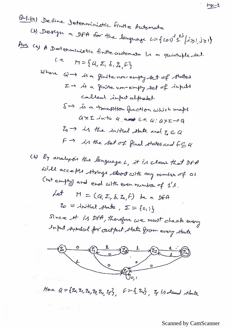
Scanned by CamScanner

Scanned by CamScanner

Scanned by CamScanner

Scanned by CamScanner

Scanned by CamScanner

Scanned by CamScanner

Scanned by CamScanner

Scanned by CamScanner