IS THERE A FOURTH DIMENSION? - World Radio History
52
IS THERE A FOURTH DIMENSION? HOW BRIDGES ARE BUILT WATER RAISING, THE NEW TELEVISION, FILES AND FILING,PHOTO CELLS AT WORK, OLD WATERLOO BRIDGE, HISTORIC LOCOS., AUTOMATIC SIGNALS FOR MODEL RAILWAYS, PRIVATE HOUSE ELECTRIC LIGHT PLANTS, MAKING CLOCK CHIMES, PICTURES BY WIRE, NEW WIRELESS APPARATUS. ETC. www.americanradiohistory.com
-
Upload
khangminh22 -
Category
Documents
-
view
3 -
download
0
Transcript of IS THERE A FOURTH DIMENSION? - World Radio History

IS THERE A FOURTH DIMENSION?
HOW BRIDGESARE BUILT
WATER RAISING, THE NEW TELEVISION, FILES AND FILING,PHOTO CELLS AT WORK,OLD WATERLOO BRIDGE, HISTORIC LOCOS., AUTOMATIC SIGNALS FOR MODELRAILWAYS, PRIVATE HOUSE ELECTRIC LIGHT PLANTS, MAKING CLOCK
CHIMES, PICTURES BY WIRE, NEW WIRELESS APPARATUS. ETC.www.americanradiohistory.com

OPEN LETTER TO PARENTSDear Sir or Madam,
When your children first arrived they brought with them a wonderful lot of sunshine.Later you became proud of the intelligence they displayed, but still later, you became anxious
as to what would become of them in the future. Perhaps you were anxious when you visualised themas grown men and women.
Even with plenty of money it is not always easy to select the right career, and a parent is some-times inclined to ask advice of some relative, and in ninety-nine cases out of a hundred that relativeknows nothing at all about the possibilities of employment.
Why not let me relieve you of some of your anxieties ? In fact, why not let me be their Father 1We do not profess to act as an employment agency, but the nature of our business compels us to
keep an eye upon the class of men and women that are wanted and who wants them.There are some people who manufacture an article and put it on the market to sell. We do not do
that, we work in exactly the opposite direction. We find out what employers want and we train ourstudents to fill those jobs. We have to be experts in the matter of employment, progress and prosperity.
If you have any anxieties at all as to what your sons or daughters should be, write to me, or betterstill, let them write to me personally-Fatherly Advice Department, and tell me their likes and dislikes,and I will give sound practical advice as to the possibilities of a vocation and how to succeed in it.
Yours sincerely,Note address carefully :F.A. Dept. 76, The Bennett College Ltd., Sheffield
If-6 ,/ ' 40
..............
...,- CAN YOU LET ME BE YOUR FATHER STUDY IN YOUR
..) CHANGE MYr k. EXPRESSION ? Unless you are We do not pro - AT SPARE
glre&..--...... in touch withall branches ofindustry, youcannot see thepossibilities of
fess to act as
an employment
agency, but we
certainly are in
HOME TIME
oror.4114414%.
IF SO, YOU MAYi BE THE ARTIST
employment,but with our
s a position to giveCAN HAVE A COLLEGE TRAINING IN
THAT COMMERCE gigantic or- fatherly adviceALMOST ANY CAREER FOR
IS WAITING FOR. g anisation weare in touchwith ery
on all careers and
t h e possibilityA FEW SHILLINGS MONTHLY.
MATRICULATIONJust try it for yourself,trace or draw the out -
0944.4.. line and then put in
.... 44 cf< the features.
There are hundreds of openings in connectionwith Humorous Papers, AdvertisementDrawing, Posters, Calendars, Catalogues,
sphereve ofactivity, andwe know thatin many tradesand prof e s -sions there aremore vacancies
of employment
therein.
c-\lt-..
o
There --are many ways of commencing acareer, but Matriculation is the jumping-
off board for all the best ones.
CIVIL SERVICESuitable
413To-
Textile Designs, Book Illustrations, etc. than there are MGS \ to both sexes. . Ages i5i to 24.
60% of Commercial Art Work is done by trained men to \ We G.P.O. ENG. DEPT." Free Lance Artists " who do their work fill them. % C? teach byat home and sell it to the highest bidders. Post in all parts of CUSTOMS AND EXCISE; INSP. OFMany Commercial Artists draw " retaining 'k G the world specialiseNO TAXES, Etc.fees"from various sources, others prefer and EXPERIENCE REQUIREDto work full-time employment or partner- 0 in all Examinations. OPEN EXAMS.ship arrangement. We teach you not only ct Mathematics We prepare candidates for allhow to draw what is wanted, but how to Accountancy Matriculationmake buyers want what you draw. Many Examinations Metallurgy INSTITUTEof our students who originally took up Advertising and Sales Mining, all subjectsCommercial Art as a hobby have since Management Mining, Electrical EXAMS.turned it into a full-time paying professionwith studio and staff of assistant artists ;
A_ .1)11.ile.dFie
Mechanics.Exam.
PArmy Certificates
EngineeringMotor EngineeringMotor Trade
TECHNICAL, INSURANCE,COMMERCIAL, GENERAL, POLICE,there is no limit to the possibilities. Let Auctioneers and Estate Agents Municipal and County Etc., Etc.us send full particulars for a FREE TRIAL Aviation Engineering Engineers
and de tails of our course for your inspection.You will be under no obligation whatever.
Banking
Book-keeping,BoilerAccountancyPattern
Naval ArchitectureMaking
Police, Special CourseENGINEERS '.*BRANCHESThere are examinations which are open
Art Dept. 76. -& Modern Business MethodsB.Sc. (Eng.)B.Sc. (Estate Management)
Preceptors, College ofPumps and Pumping
Machinery
and suitable to you, others which are not.Get our advice before deciding.
YOUNG MEN Building, Architectureand Clerk of Works
Radio ReceptionRoad -Making & Maintenance The Commercial Side of
Young men physically fit and whose Civill tnrVinceeering SalesmanshipSanitation THE MOTOR
careers are not definitely fixed should All Commercial Subjects Secretarial Exams.join the Police Force. We have Special Commercial Art Shipbuilding TRADECourses for Entrance and Promotion. Concrete and Structural
EngineeringShorthand (Pitman's)Structural Engineering offers exceptional opportunities for
1/- per week brings success. Draughtsmanship. All Surveying young men of good education.Full particulars free. branches Teachers of Handicrafts
Address: Police Dept. 76. E nsguizeeg gi, Allexaminationsbranches, Telephony and TelegraphyTransport Inst. Exams. EVERY DEPARTMENT IS A
T 0 STUDENTS General EducationG.P.O. Engineering Bent.Heating and Ventilating
Weights and MeasuresInspe:tor
Wireless Telegraphy andCOMPLETE COLLEGE.
EVERY STUDENT IS A CLASSLIVING ABROAD Industrial Chemistry
InsuranceTelephony
Works Managers TO HIMSELF.or on the high seas, a good supply of lessons IF YOU DO NOT SEE YOUR OWN REQUIRE -is given, so that they may be done in theirorder, and despatched to us for examination and
MENTS ABOVE, WRITE TO US ON ANY SUBJECT. DO NOT DELAYCHARGE),
of Success.
correction. They are then sent back with morework, and in this way a continuous stream of workis always in transit from the Student to us andfrom us to the Student.
IT COSTS NOTH.NG TO ENQUIRE.
Also ask for cur New Book (FREE OFTHE HUM AN MACHINE, Secrets
There may be chances for you to -day forwhich you may be too late to -morrow.
Every day counts in a man's career.
A'ORErTEFR/2/1S.E. SS Dept. 76, ,THE BENNETT COLLEGE LTD., SHEFFIELDAll applications respecting Advertising In this Publication should be addressed to the ADVERTISEMENT MANAGER, GEORGE NEWNES Ltd.,
23-11 Southampton Street, Strand, London, W,C.2. Telephone: Temple Bar 7760.
lLwww.americanradiohistory.com
September, 1934 PRACTICAL MECHANICS 541
VOL. 1. Nn. 12SE PTEMBER
1934
Edited by EJ.CAMMSUBSCRIPTION RATES :
Inland and Abroad, 7s. 6d. per annumCanada - - 7s. per annum
Editorial and Advertisement Offices : " PracticalMechanics," George Newnes Ltd., Southampton
Street, Strand, W.C.2.Registered at the G.P.O. for transmission by
Canadian Magazine Post.
Notes, News and ViewsA New Volume commences Next Month
THIS issue completes Volume I. ofPRACTICAL MECHANICS, and an announce-
ment regarding binding cases and index willappear next month. The first milestone ispassed, and I am glad to learn from theshoals of enthusiastic letters I regularlyreceive from readers all over the world thatthe first stage of our journey has been sopleasant. During that journey we havemade pleasant excursions, even though onlyin print, into the stratosphere, into thefields of aviation, television, radio, mecha-nics, below the sea with divers, and we havedallied to study rays, to make models, toexamine novelties, and to read about thelatest scientific endeavours. The secondstage of our journey will be even moreinteresting than the last. Make quite surethat you miss none of the sideshows, byordering PRACTICAL MECHANICS to bedelivered regularly to your home.
Our New Companion Journal " PracticalTelevision "
THEgrowing interest in television-the
missing link to complete home radioentertainment-is indicated by the volumeof correspondence we regularly receive fromreaders on this intriguing and fascinatingnew science. Our readers, therefore, will beinterested to learn that Messrs. Geo.Newnes Ltd. (Publishers of PRACTICALMECHANICS) have just published No. 1 ofour companion journal, Practical Television,which is obtainable from all newsagents for6d. The first issue contains instructions forBuilding a Simple Disc Visor, How to MakeSynchronising Gear, Television SimplyExplained, Telenews and Televiews, Build-ing up the Picture, The Cathode Ray Oscillo-graph, Scanning Systems, Will my SetOperate a Television Receiver ? ReceivingSound and Vision, Teletips, and manyother important articles on this new subject.Purchase a copy to-day-unless the issueis already sold out !
A Mammoth Oil Engine -driven AlternatorAHUGE generator recently put intooperation at the Copenhagen Electricity
works is driven by a two-stroke double-acting oil engine having eight cylinders.The cylinders, which have a bore of 33 in.and. a stroke of no less than 5 ft. 11 in.,develop 20,400 b.h.p. The engine isstarted by compressed air, which is suppliedby a separate compressed air plant. Thelength of the engine is 66 ft., the height40 ft., and the breadth over 27 ft. Its totalweight is approximately 1,200 tons.
The 50 -cycle alternator is designed for acontinuous output of 19,000 K.V.A., thestator being wound for 6,600 volts. Togive an indication of the immense size ofthis machine, the total height of the alter-nator, measured from the engine room floor,is 18 ft., and it projects 16 ft. 6 in. below thefloor. Its total weight is 187 tons.Germany's New Airship
ACCORDING to a recent report, the newZeppelin " L.Z.129," which is nearing
THE MONTH'S SCIENCESIFTINGS
According to a recent report, a telescopewhich is claimed to be the largest in theBritish Empire is to be installed at thenew Dunlop Observatory in Toronto. Thetelescope has a 74 -in, reflector and in allweighs about 50 tons.
A new world long-distance glidingrecord of 233 miles was recently establishedby Heini Dittmar. He started from thesummit of the Rhoen Mountains andlanded at Likkau, in Czecho-Slovakia. Theflight took six hours twenty-five minutes.
An oil well has been drilled to the recorddepth of 11,377 ft. in the San JoaquinValley, California.
All kinds of articles from toys to electriccables will be manufactured in a rubberfactory which is now being constructed atTrivandrum, Southern India.
One of the four propellers for the newCunarder has just been shipped fromLondon. Each of the propellers weighsabout 35 tons.
The latest addition to the Japanese Navyis a midget submarine, only 29 ft. long,and which can be hoisted on board a largewarship. The boat is electrically driven,current being supplied by accumulators.She is armed with a single torpedo tube anda machine gun, and is manned by a crewof four.
completion in Germany, will be slightlylonger than the American airship " Macon,which is at present the largest airship in theworld. She will have a gas capacity of over7,000,000 cub. ft., and will be propelled byengines of 4,400 h.p. Accommodation willbe provided for fifty passengers, a crew ofthirty-five, and 10 tons of freight.
New Streamlined LocomotiveWHAT is claimed to be the most powerful
express passenger locomotive in GreatBritain was recently completed at the
Doncaster works of the London and NorthEastern Railway. The new locomotive is ofthe 2-8-2 Mikado type, its eight coupleddriving wheels being 6 ft. 2 in. in diameter.A large boiler, working at a pressure of220 lb. per square inch, supplies threecylinders fitted with poppet valves. Twochimneys are fitted on this huge locomotive,and, as no steam dome is visible, thestreamline effect of the boiler is unbroken.The engine is named " Cock o' the North."
India's New Dam
THE Mettur Canvery dam, said to be oneof the largest in the world, has just
been completed. It is situated about 230miles from Madras, and has taken ten yearsto build. Three million tons of concretehave been used in constructing the dam,which is a mile long, and impounds an arti-ficial lake containing 94,000 million cubicfeet of water. The stone crushers used forcrushing the granite for the concrete aggre-gate, which are the largest machines of thiskind ever built in this country, were con-structed by Messrs. Hadfield Ltd., ofSheffield. These huge " jaw -breakers,"which break up the crude stone into 6 -in.lumps at the rate of 200 tons of stone anhour, weigh about 100 tons each, and wereused to feed the smaller jaw crushers.
Britain's Latest Flying BoatTHE second largest flying boat ever put into
service has been designed by the Black-burn Aeroplane Co. Accommodation willbe provided for fifty passengers, and it willbe fitted with six engines of about 650 h.p.The machine will be a high -wing monoplane,four of the engines will be housed in theleading edge of the wing, and the other twoin the trailing edge. Designed for speed andgreat range, it is intended for trans -oceanmail and passenger services.
Coloured X -RaysAN Armenian scientist, Mr. LutheruSimjiam, has perfected an apparatuswhich enables variations of the density ofthe body structure to be seen, not in theusual X-ray grey tones, but in contrastingcolours. The apparatus embodies the X-ray fluoroscope and the photo -electric cellused in television. The operator can inten-sify any of the colours as desired, thuspermitting particular organs to be shown upin sharper relief. The apparatus makes useof X-rays of weaker intensity than is cus-tomary, and the patient may therefore besafely subjected to longer periods ofobservation.
www.americanradiohistory.com
542 PRACTICAL MECHANICS September, 1934
HOW BRIDGES AREThe positions, foundations, design, construction and erection of great bridges of various types are
and of exceptional interest, but they have taxed the brains of our best engineers
By R. V. BOUGHTON,
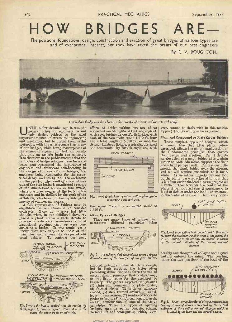
Twickenham Bridge over the Thames, a fine example of a reinforced concrete arch bridge.
UNTIL a few decades ago it was thegeneral policy for engineers to notonly design bridges in the most
important matters of structural engineeringand mechanics, but to design them archi-tecturally, with the consequence that manyof our bridges, while being masterpieces ofthe science of engineering, lack the beautythat only an artistic brain can conceive.It is therefore in the public interest that thepromoters of bridge schemes have for someyears past recognised the importance ofengineers and architects collaborating inthe design of many of our bridges, theengineers being responsible for the struc-tural design and safety, and the architectsfor the beauty. The result of this combina-tion of the best brains is manifested by someof the illustrations shown in this article,where one may wonder at the feats of theengineers and be thrilled by the work of thearchitects, who have put beauty into greatmasses of engineering works.
A full appreciation of bridges may beengendered in our minds if we considercontrasts. Many of us gave but littlethought when, in our childhood days, weplaced a plank across a little stream tOprovide a safe (and sometimes a mosthazardous) crossing, that we were con-structing a bridge. It was crude, yet abridge that was subject to most of theprinciples that govern the design of ourgreat bridges. To contrast our early
PLANK BENDSR Li TTLr AS St/OWNDOTTED
Fig. 3.-As the load is applied near the bearing theplank begins to bend or deflect. When it is in the
centre the plank bends considerably.
efforts at bridge -making but few of usconnected our thoughts of that single plankwith such bridges as our Forth Bridge, witheach of the two main spans 1,710 ft. longand a total length of 5,330 ft., or with theSydney Harbour Bridge, Australia, designedand constructed by British engineers, with
Fig. 1.-A simple form of bridge with a plain girdersupporting a parapet wall.
the largest1,650 ft.
Many Types of BridgesThere are many types of bridges that
necessitate different principles being
" arch " span in the world of
ORDI1713R- PLANK
Fig. 2.-An ordinary deal plank placed across a streamillustrates some of the principles of our great bridges.
adopted, not only in their structural design,but in their erection, the latter oftenpresenting difficulties that force the use ofcertain design principles that prohibit any,or but little, scope for the architect tobeautify. The general types of bridges are :(1) plain and compound or plate girder,(2) framed girder, (3) brick or masonryarched, (4) steel framed arched, (5) canti-lever, (6) suspension, (7) reinforced concretegirder or beam, (8) reinforced concrete arch,and (9) combination of some of the aboveprinciples. There are types of openingbridges, such as swing, bascule, rolling,vertical lift and transporter, which, how-
ever, cannot be dealt with in this article.Types (1) to (9) will now be explained.
Plain and Compound or Plate Girder BridgesThese simplest types of bridges, which
are much like that little plank beforedescribed, allows the simple explanation ofthe fundamental principles that governtheir design and erection. Fig. 1 depictsan elevation of a small bridge with a plaingirder on each side which supports the floorand a light parapet wall. Fig. 2 is our littlefriend, the plank bridge over the stream,and we will confine our minds to it for awhile. As we rather gingerly put one footon the plank, we were relieved to note thatit felt firm under the load ; as we progresseda little further towards the centre of theplank it was noticed that it commenced tobend or deflect under the load ; as we stoodin the centre of the span it bent very consi.
BERMLOAD CONC£117RfTL.:
CENTRE
ecru)NomErl TDiticRf7P1
Fig. 4.-A beam with a load concentrated in the centreproduces the maximum bending stress at the centre, thestresses reducing as the bearings are neared, as shownby the vertical ordinates of the bending moment
diagram
derably and thoughts of collapse and a goodwetting entered the mind. The bendingunder the two positions of the load of the
BERNLORD UNIFORMLYDISTRIBUTED,
411111111111110"5E1101114 MOMENTDIRGRIVI
Fig. 5.-Loads evenly distributed along abeam producebending stresses of values represented by the verticalordinates of the bending moment diagram which is
bounded by the beam and the parabolic curve.
www.americanradiohistory.com

September, 1934 PRACTICAL MECHANICS 543
BUILTsubjects not only of importancefor many generations.
A.I.Struct.E.
body are diagrammatically shown by Fig. 3,and this presents one of the chief principlesof structural mechanics, i.e., bendingmoments, or what may be termed the valueof the forces which induce bending. Bythe fact that the plank bends most when theload is in the centre proves that the greateststresses are induced, and the greatest strainsare produced, in the centre of the span. Itmust be understood that a stress is a forcethat produces a strain. As the load becomesfurther away from the centre and nearer oneof the supports, the strain on the plank isreduced. It should be manifest that toresist these stresses in a beam there shouldbe a force in the beam itself that will safelyresist them. This force is known as themoment of resistance, and to provideequilibrium it should at least equal thebending moment. The value of the stress,or the bending moment, in any part of abeam that is subject to various loadings is
"MUM- Of -5FROM END TO
!l=a INCREASESCENTRE OI' WAVER ,
The Sydney Harbour Bridge with a span of ,650 ft., the largest arched bridge in the world.
shown by Fig. 5, the curve being parabolic.Before another interesting matter is ex-plained, it is necessary to state that shearing
stresses haveto be seri-ously con-sidered byengineers.Verticalshearing isthe action ofone part ofa materialtending t oslide or shearoff the partimmediately
adjoining it, as is shown by Fig. 7. Themaximum shearing stress occurs near thesupports of a beam, and for the purposesof this articlemay be saidto be nil atthe centre ofthe span.
Now wewill explainwhy engin-eers, for thesake ofeconomy, en-deavour tomake girderbridges ashigh as
PLR 7"E GIRDER.Fig. 6.-A steel plate girder. Note the disposition of the steel in
the top and bottom flanges to combat the stresses.
easily calculated either mathematically orby what is known as a stress diagram. IfFigs. 4 and 5 are studied they will verysimply explain the reason why a compoundor plate girder, as shown by Fig. 6, hasmuch more steel in the form of plates atthe top and bottom at and near the centre.Fig. 4 depicts a concentrated load in thecentre of the beam, such as a person in thecentre of a plank, and the bending momentsat various parts of the beam are equal to thevalue represented by the lengths of thevertical lines or ordinates. The maximumbending moment occurs at the centre andis represented by the line marked M. It isimportant to understand that a uniformlydistributed load produces stresses the valueof which are represented by the ordinates
possible, and to do this wewill show two small plankbridges, again to bridge ourlittle stream, and each ofthese bridges will have ex-actly the same amount ofmaterial, yet the scientificarrangement of one willprovide a bridge that istimes as strong as theother ! Fig. 8 shows theweaker arrangement withthe 9 x 2 -in. planks laidflat as girders, and whichwill bend or deflect veryconsiderably when peoplewalk over it. Fig. 9 showsthe planks laid on edge,providing a much greaterstrength.
Fig. 10 depicts a com-pound girder bridge that
Fig.'10.-A large plate girder carrying a railway over the Sutton By -pan. carries a railway oftr a
11
street, and the supports are brick abut-ments. The girders Lwould be placed inposition by hoisting or by rolling into posi-tion with the aid of temporary supportsfrom the street.Framed Girder Bridges
This type of bridge is used for great spansover valleys or rivers for roads or railways,or both. Fig. 11 shows one of manyarrangements of the various members, anda study of the principles of the stresses inthem, their construction and erection, isnot only of great interest, but makes themore complicated types of bridges moreeasily understood. Referring again toFig. 9, it may be stated that the tendencyfor the 9 x 2 -in, plank to bend causes thefibres in the top to be compressed and thoseat the bottom to be in tension. Exactly the.
PLfltila LAID FLFIT.. BF? titSye -
Ill 8
Fig. 8.-The simple plank bridge over a stream with the planks laid flat. which is construc-tionally weak.
same occurs in connection with the top andbottom members of the framed girder, asFig. 11. The top and bottom booms are incompression and tension respectively. Thelaws of mechanics of structures show thatthe greater the distance apart of thesebooms, the less are the stresses induced inthem, and consequently less metal isrequired in them to resist such stresses,and this is why engineers make the heightof this type of bridge as high as possible,subject to certain limitations regulated byconditions which are a little too complicatedto explain in this article.
Fig. 12 indicates the approximate varyingamounts of the stresses in the variousmembers by means of thicknesses of thelines, the thicker the line the greater thestress. The solid lines are compression anddotted lines tension members. There is,theoretically, no stress in the centre member shown by the long dotted line. Fig. 13is a photographic reproduction of a framed
www.americanradiohistory.com

544 PRACTICAL MECHANICS September, 1934
Brick or Masonry Arched Bridges
-
struction which may be better understood
-
sure on its neighbour, and the stressesare eventually transmitted to the abut -
of the arch, the stronger is the arch, pro-
BOONS (...NCREASES FROM ENO CEN7RE
\ /I
/ /11
//, 0
0a /I
lay a la le m as se um sr Li - - -
This particular type of bridge must notThese are a very common form of bridge be confounded with suspension bridges,
and are used for small and great spans, which mayeither single or in series as viaducts. Old appear to be T/E5Waterloo Bridge is one example of an arched similar, but aremasonry bridge, and an interesting article constructed onon it appears elsewhere in this issue. totally differ -There is a rather considerable difference ant principles.in the principles of arch and beam con The principle of
cantileverageby giving a very simple example. A will be dealtbrick arch over an ordinary window with later.opening is in effect a very small bridge. Most of themIt will be illustrated next month. The use ordinaryseparate wedge-shaped units or voussoirs steel girders or rolled steel' joists extend -are kept in position owing to the fact ing or cantilevering over brick piers andthat each of them exerts a lateral Ares the ends of each cantilever supporting a
simple beam member. As will be gatheredby the description of the erection of
menu or piers. The sharper the curvature bridges, it will be readily understood thatthe fundamental principle of this type of
fi/VOU NT OF STEEL IN TOP 11/10 BOTTOM low the gradualbridge is to al -
TD building out ofeach canti-levered framedpart until eachmeet at thecentre, wherethey are con-nected togetherby the sus-pended span.
Fig. 12.-An outline of a steel framed girder, showing the compressional members in Great care hassolid lines and the tensile members dotted. Note the varying amount of steel required to be exercised
in the various members. by the design-ers to ensure
RMOUNT OF .57 -4 -EL TIES ario ..57ieU73-DE.GR5E5 FROM END 70 CENTRE Of GIRDER
vided the depth of the rings are the same.For instance, any arch which is muchflatter than another might require tworings to carry the same load as a deep archwould do with one ring.
Steel Framed Arch BridgesIn this type of bridge (to be dealt with
next month) the main stresses being takenby the arched construction from which issuspended members which support thelevel road or railway. One of the bestexamples is the Newcastle -on -Tyne Bridge,which has the largest steel arch in GreatBritain, constructed in 1925-28 to carrythe Great North Road across the Tyne.The length is 1,254 ft. Sydney HarbourBridge, Australia, was built on this prin-
BERM T( fY DS 70...571t-f3R HERE,
Fig. 7.-This shows how beam wodd shear.
that no collapse shall occur during theerection or building out of the cantileveredparts, and that such parts are well heldback orbalancedby theproject-ing armsreachingshore-wardsand an-choreddown.An in-stance ofseriousdisasteris theQuebecBridgecrossingthe St.Law -r en c eRiver.Thisbridgehad athan n e 1span of1,800 ft.
PLANKS F7 XED Oty 4/YD
)1SWTDC-ti
r-4
15
9
Fig. 9.-Exactly the same quantity of timber is used in this little bridge as that shown by Fig. 8, but theplanks are laid on end. With 2 -in. X 9 -in. planks this bridge is four and a half times stronger than if planks
were laid flat.
girder bridge. The methods of erection ofthis type of bridge, as well as others, willbe dealt with under a following heading.
ciple, and has the largest arch span in theworld of 1,650 ft.
Cantilever Bridges
Twice during its construction it failed,which necessitated changes in the originaldesign. The Forth Bridge is a fineexample of a cantilever bridge, the twomain spans being each 1,710 ft.
Suspension Bridges
A good English example is the well-known Chelsea Bridge, over the Thames,The general principle is that steel wireropes or steel links, or series of them, passover high towers, forming an exceptionallypowerful loop or loops between the towers,such ropes or links being anchoreddown on the land side of the towers.The platform for the roadway is sus-pended from the ropes or linked loopsby vertical wire ropes or rods. Thistype of bridge can be used for verylarge spans.
TOP BOON1
.5narrs. so77-0/1 50011Fig. 11.-An outline of a steel framed girder.
Reinforced Concrete Girder or BeamBridges
This method of construction is com-paratively modern, and is extensively usednowadays, especially for bridges of moderatespan As it is of a mass constructioncomposed of concrete cast in situ with steelrods incorporated with it, it does not lenditself to such engineering feats as framedsteelwork does in allowing erection overgreat spaces by gradually cantilevering out.Briefly, the principle of reinforced concreteis that concrete is exceptionally strong incompression and very weak in tension,whereas steel, although very strong incompression, is also very strong in tension.Therefore, steel introduced into those partsof a concrete beam which are subject totensile stresses makes up for the lack oftensile strength in the concrete. Thescientific disposition of mass concrete anda little steel results in a method of construc-tion which is exceptionally strong, the steelis protected by the concrete and the wholehas a long life and requires but little repairsand practically no decorations.
Fig. 13.-The large steel framed girders used for the temporary Waterloo Bridge over theThames. The bottom booms are hidden by the parapet to the footways.
www.americanradiohistory.com
September, 1934 PRACTICAL MECHANICS 545
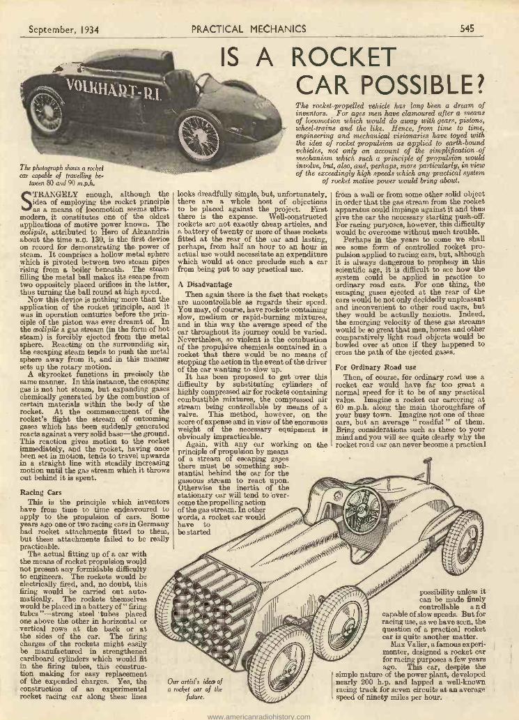
The photograph shows a rocketcar capable of travelling be-
tween 80 and 90 m.p.h.
STRANGELY enough, although theidea of employing the rocket principleas a means of locomotion seems ultra-
modern, it constitutes one of the oldestapplications of motive power known. Theceolipile, attributed to Hero of Alexandriaabout the time B.O. 130, is the first deviceon record for demonstrating the power ofsteam. It comprises a hollow metal spherewhich is pivoted between two steam pipesrising from a boiler beneath. The steamfilling the metal ball makes its escape fromtwo oppositely placed orifices in the latter,thus turning the ball round at high speed.
Now this device is nothing more than theapplication of the rocket principle, and itwas in operation centuries before the prin-ciple of the piston was ever dreamt of. Inthe ceolipile a gas stream (in the form of hotsteam) is forcibly ejected from the metalsphere. Reacting on the surrounding air,the escaping steam tends to push the metalsphere away from it, and in this mannersets up the rotary motion.
A skyrocket functions in precisely thesame manner. In this instance, the escapinggas is not hot steam, but expanding gaseschemically generated by the combustion ofcertain materials within the body of therocket. At the commencement of therocket's flight the stream of outcominggases which has been suddenly generatedreacts against a very solid base-the ground.This reaction gives motion to the rocketimmediately, and the rocket, having oncebeen set in motion, tends to travel upwardsin a straight line with steadily increasingmotion until the gas stream which it throwsout behind it is spent.
Racing CarsThis is the principle which inventors
have from time to time endeavoured toapply to the propulsion of cars. Someyears ago one or two racing cars in Germanyhad rocket attachments fitted to them,but these attachments failed to be reallypracticable.
The actual fitting up of a car withthe means of rocket propulsion wouldnot present any formidable difficultyto engineers. The rockets would beelectrically fired, and, no doubt, thisfiring would be carried out auto-matically. The rockets themselveswould be placed in a battery of " firingtubes "-strong steel tubes placedone above the other in horizontal orvertical rows at the back or atthe sides of the car. The firingcharges of the rockets might easilybe manufactured in strengthenedcardboard cylinders which would fitin the firing tubes, this construc-tion making for easy replacementof the expended charges. Yes, theconstruction of an experimentalrocket racing car along these lines
IS A ROCKETCAR POSSIBLE?The rocket -propelled vehicle has long been a dream ofinventors. For ages men have clamoured after a meansof locomotion which would do away with gears, pistons,wheel -trains and the like. Hence, from time to time,engineering and mechanical visionaries have toyed withthe idea of rocket propulsion as applied to earth -boundvehicles, not only on account of the simplification ofmechanism which such a principle of propulsion wouldinvolve, but, also, and, perhaps, more particularly, in viewof the exceedingly high speeds which any practical system
of rocket motive power would bring about.
looks dreadfully simple, but, unfortunately,there are a whole host of objectionsto be placed against the project. Firstthere is the expense. Well -constructedrockets are not exactly cheap articles, anda battery of twenty or more of these rocketsfitted at the rear of the car and lasting,perhaps, from half an hour to an hour inactual use would necessitate an expenditurewhich would at once preclude such a carfrom being put to any practical use.
A DisadvantageThen again there is the fact that rockets
are uncontrollable as regards their speed.You may, of course, have rockets containingslow, medium or rapid -burning mixtures,and in this way the average speed of thecar throughout its journey could be varied.Nevertheless, so violent is the combustionof the propulsive chemicals contained in arocket that there would be no means ofstopping the action in the event of the driverof the car wanting to slow up.
It has been proposed to get over thisdifficulty by substituting cylinders ofhighly compressed air for rockets containingcombustible mixtures, the compressed airstream being controllable by means of avalve. This method, however, on thescore of expense and in view of the enormousweight of the necessary equipment isobviously impracticable.
Again, with any car working on theprinciple of propulsion by meansof a stream of escaping gatesthere must be something sub-stantial behind the car for thegaseous stream to react upon.Otherwise the inertia of thestationary car will tend to over-come the propelling actionof the gas stream. In otherwords, a rocket car wouldhave tobe started
Our artist's idea ofa rocket car of the
future.
from a wall or from some other solid objectin order that the gas stream from the rocketapparatus could impinge against it and thusgive the car the necessary starting push -off.For racing purposes, however, this difficultywould be overcome without much trouble.
Perhaps in the years to come we shallsee some form of controlled rocket pro-pulsion applied to racing cars, but, althoughit is always dangerous to prophesy in thisscientific age, it is difficult to see how thesystem could be applied in practice toordinary road cars. For one thing, theescaping gases ejected at the rear of thecars would be not only decidedly unpleasantand inconvenient to other road users, butthey would be actually noxious. Indeed,the emerging velocity of these gas streamswould be so great that men, horses and othercomparatively light road objects would bebowled over at once if they happened tocross the path of the ejected gases.
For Ordinary Road useThen, of course, for ordinary road use a
rocket car would have far too great anormal speed for it to be of any practicalvalue. Imagine a rocket car careering at60 m.p.h. along the main thoroughfare ofyour busy town. Imagine not one of thesecars, but an average roadful " of them.Bring considerations such as these to yourmind and you will see quite clearly why therocket road car can never become a practical
possibility unless itcan be made finelycontrollable a n d
capable of slow speeds. But forracing use, as we have seen, thequestion of a practical rocketcar is quite another matter.
Max Valier, a famous experi-menter, designed a rocket carfor racing purposes a few yearsago. This car, despite the
simple nature of the power plant, developednearly 200 h.p. and lapped a well-knownracing track for seven circuits at an averagespeed of ninety miles per hour.
www.americanradiohistory.com
546
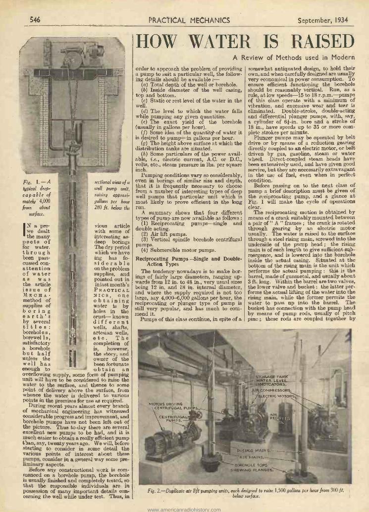
Fig. 1. -Atypical deep -capable ofmately 4,000from about
surface.
sectional view of awell pump unit,raising approxi-gallons per hour280 ft. below the
Iwe dealtN a pre- vious article
with some ofthe many interesting as-
pects of deep boringsfor water. The dry periodthrough r which we havebeen pass- ing has fo-cussed con F siderableattention on the problemof water supplies, andas was pointed out inthe article in last month'sissue of PRACTICALMECH A - NICE, onemethod of obtainingsupplies of water is byboring holes in theearth's crust- knownby several differenttitles: wells, shafts,borehol e s , artesian wells,borewel I s, I etc. Thesatisfactory completion ofa borehole is, however,
the story, andunless the owner of thewell has been fortunate
but half
enough to obtain anoverflowing supply, some form of pumpingunit will have to be considered to raise thewater to the surface, and thence to somepoint of delivery above the surface, fromwhence the water is delivered to variouspoints in the premises for use as required.
During recent years almost every branchof mechanical engineering has witnessedconsiderable progress and improvement, andborehole pumps have not been left out ofthe picture. Thus to -day there are severalexcellent new pumps to be had, and it ismuch easier to obtain a really efficient pumpt'aan, say, twenty years ago. We will, beforestarting to consider in some detail thevarious points of interest about thesepumps, consider in a general way some pre-liminary aspects.
Before any constructional work is com-menced on a borehole pump, the boreholeis usually finished and completely tested, sothat the responsible individuals are inpossession of many important details con-cerning the well while under test. Thus, in
PRACTICAL MECHANICS September, 1934
HOW *WATER IS RAISEDA Review of Methods used in Modern
order to approach the problem of providinga pump to suit a particular well, the follow-ing details should be available :-
(a) Total depth of the well or borehole.(b) Inside diameter of the well casing,
top and bottom.(c) Static or rest level of the water in the
well.(d) The level to which the water falls
while pumping any given quantities.(e) The exact yield of the borehole
(usually in gallons per hour).(f) Some idea of the quantity of water it
is desired to pump-in gallons per hour.(g) The height above surface at which the
distribution tanks are situated.(h) Some particulars of the power avail-
able, i.e., electric current, A.C. or D.C.,volts, etc., steam pressure in lbs. per squareinch.
Pumping conditions vary so considerably,even in borings of similar size and depth,that it is frequently necessary to choosefrom a number of interesting types of deepwell pumps that particular unit which ismost likely to prove efficient in the longrun.
A summary shows that four differenttypes of pump are now available as follows :
(1) Reciprocating pumps-single anddouble acting.
(2) Air lift pumps.(3) Vertical spindle borehole centrifugal
pumps.(4) Submersible motor pumps.
Reciprocating Pumps-Single and Double -Action Types
The tendency nowadays is to make bor-ings of fairly large diameters, ranging up-wards from 12 in. to 48 in., very usual sizesbeing 12 in. and 18 in. internal diameter,and where the supply required is not toolarge, say 4,000-6,000 gallons per hour, thereciprocating or plunger type of pump isstill very popular, and has much to com-mend it.
Pumps of this class continue, in spite of a
MOTORS DRIVINGCENTRIFUGAL Pt)
CENTRIFUGALPUMPS. -
somewhat antiquated design, to hold theirown, and when carefully designed are usuallyvery economical in power consumption. Toensure efficient functioping the boreholeshould be reasonably vertical. Run, as arule, at low speeds -15 to 18 r.p.m.-pumpsof this class operate with a minimum ofvibration, and excessive wear and tear iseliminated. Double -stroke, double-actingand differential plunger pumps, with, say,a cylinder of 6f -in. bore and a stroke of18 in., have speeds up to 35 or more com-plete strokes per minute.
Plunger pumps may be operated by beltdrive or by means of a reduction gearingdirectly coupled to an electric motor, or beltdriven by gas, gasoline, steam or waterwheel. Direct -coupled steam heads havebeen extensively used, and have given goodservice, but they are necessarily extravagantin the use of fuel, even when in perfectcondition.
Before passing on to the next class ofpump a brief description must be given ofthe reciprocating pump, and a glance atFig. 1 will make the cycle of operationsclear.
The reciprocating motion is obtained bymeans of a crank suitably mounted betweena pair of " A " frames ; the crank is rotatedthrough gearing by an electric motorusually. The water is raised to the surfacethrough a steel rising main, screwed into theunderside of the pump head ; the risingmain is of such length to give sufficient sub-mergence, and is lowered into the boreholeinside the actual casing. Situated at thebottom of the rising main is the unit whichperforms the actual pumping : this is thebarrel, made of gunmetal, and usually about3 ft. long. Within the barrel are two valves,the lower valve and bucket : the latter per-forms the actual lifting of the water into therising main, while the former permits thewater to pass up into the barrel. Thebucket has connection with the pump headby means of pump rods, usually of pitchpine ; these rods are coupled together by
STORAGE TANKTER L EWA-
TCATOR S.
AIR COMPRESSORSLECTRIC MOTORS.,
RISING MAINS
R HAI N S.
"-.6.7"--- DOR E HOL E TOPS
SHOWING FLANGES.
Fig. 2.-Duplicate air lift pumping units, each designed to raise 1,500 gallons per hour from 300 ft.below surface.
www.americanradiohistory.com
September, 1934 PRACTICAL MECHANICS 547
FROM DEEP WELLSPumping Plants at present on the
means, of wrought -iron couplings, and thecomplete set of rods is moved up and downinside the main by the rotation of the crank-shaft, thereby causing the bucket to moveup and down in the barrel. The action isvery simple : on the down stroke the waterin the barrel is forced up through the valvein the bucket ; on the up stroke the waternow above the bucket is lifted into therising main, thus causing a vacuum in thebarrel into which the water flows frombeneath the lower valve. On the nextdown stroke the water is again forced intothe main, and thus the actual lifting goeson, the rising main thus performing thedouble function of a main for the water anda guide for the pump rods. A suction -tubeis fitted to the lower end of the barrel and adifferential plunger is fitted at the deliveryoutlet to equalise the flow of water in thedelivery. The water can be raised to anyreasonable height above the surface, andsuch pumps are capable of raising anyquantity from 100 to 6,000 gallons per hourfrom depths varying from 50 to 500 ft.below the surface.
Frequently deep well pumps are requiredto be super -silent in operation, particularlywhen used to supply water to blocks ofoffices ; in such cases the mechanical func-tioning is obtained by means of the wormreduction gearing, and Fig. 2 shows a headgear of this type operating in a Londonbuilding.
Air Lift Pumping PlantsWe come now to a form of deep well pump
which is fairly well known and in use inquite a number of the very well-knownLondon buildings. Raising water by com-pressed air has the great advantage in thatall the moving machinery is situated inaccessible positions on the surface, so that inthe event of mechanical trouble it is a veryeasy matter as a rule to make necessaryadjustments, and very many air lift plantsare in operation at the moment which havenot been overhauled for years and are stillgiving excellent service.
Figs. 2 and 3 show two views of a typicalair lift plant ; in Fig. 2 the surface gear isplainly seen, while in Fig. 3 a well equippedwith such a plant is shown in section.
The essential units are (a) an air com-pressor ; (b) a driving unit-usually anelectrical motor direct -coupled to the com-pressor ; (c) an air receiver ; (d) an electricstarter. Water is raised to the surface bymeans of compressed air, which, passingfrom the compressor through the receiver,is stabilised and passes down the smallertube. When it reaches the bottom of theair main the air mixes with the water andaerates it, causing the water in the boreholeto flow up the rising main on account of itsdecreased density.
Duplicate MachinerySometimes it is a sound plan to instal
duplicate machinery-the duplicate to actas a standby set. Sometimes the standbyset is installed in, and operates, a separateborehole ; while not infrequently, where thediameter of the borehole will permit it, adouble set of pipes -may be fitted, so thatthe surface machinery may be arranged tooperate either set. The limit of practicalutility to which water can be raised isgoverned by the working water level, to-gether with the height to which it is desiredto raise the water above the surface.
Market
Should thel-e be a considerable drop inthe working water level it is perhaps betterto discharge into a small tank at surfacelevel and pump from there into the elevatedstorage tanks by using a small surface cen-trifugal pump. The air lift system is notadopted for pumping horizontally for a greatdistance ; for this reason the horizontal dis-charge should be kept as short as possible.
While it is conceded that the air lift typeof plant is not perhaps so economical andefficient as other methods of pumping, undercertain conditions such pumps have turnedout to be extremely satisfactory. With thistype of pumping unit the water is generallyraised to the surface and delivered into sur-
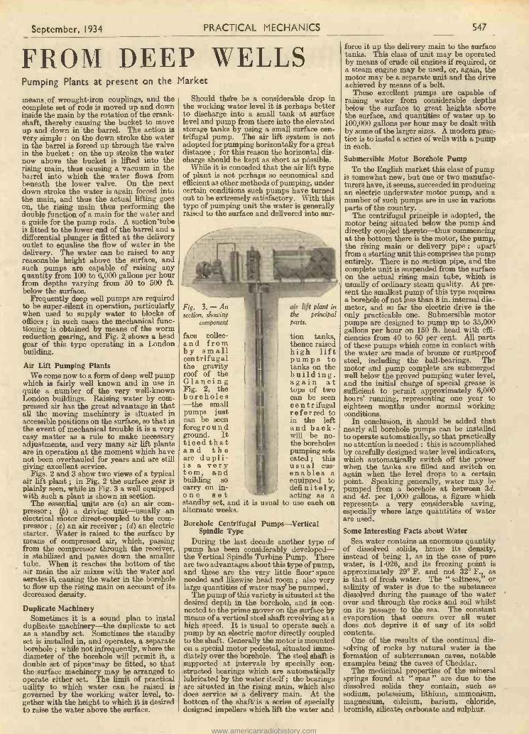
Fig. 3. - Ansection, showing
component
face collec-and fromby smallcentrifugalthe gravityroof of theGlancingFig. 2, theboreholes-the smallpumps justcan be seenforegroundground. Itticed thatand theare dupli-is a verytorn, andbuilding socarry on in -one setstandby set, and it isalternate weeks.
Borehole CentrifugalSpindle Type
During the last decade another type ofpump has been considerably developed-the Vertical Spindle Turbine Pump. Thereare two advantages about this type of pump,and these are the very little floor- spaceneeded and likewise head room ; also verylarge quantities of water may be pumped.
The pump of this variety is situated at thedesired depth in the borehole, and is con-nected to the prime mover on the surface bymeans of a vertical steel shaft revolving at ahigh speed. It is usual to operate such apump by an electric motor directly coupledto the shaft. Generally the motor is mountedon a special motor pedestal, situated imme-diately over the borehole. The steel shaft issupported at intervals by specially con-structed bearings which are automaticallylubricated by the water itself ; the bearingsare situated in the rising main, which alsodoes service as a delivery main. At thebottom of the shaft' is a series of speciallydesigned impellers which lift the water and
air lift plant inthe principalparts.
tion tanks,thence raisedhigh liftpumps totanks on thebuild ing.again attops of twocan be seenc e n t r ifugalreferred toin the leftand back -will be no -the boreholespumping setscated ; thisusual cus-enables aequipped todefinitely,acting as a
usual to use each on
Pumps-Vertical
force it up the delivery main to the surfacetanks. This class of unit may be operatedby means of crude oil engines if required, ora steam engine may be used, or, again, themotor may be a separate unit and the driveachieved by means of a belt.
These excellent pumps are capable ofraising water from considerable depthsbelow the surface to great heights abovethe surface, and quantities of water up to100,000 gallons per hour may be dealt withby some of the larger sizes. A modern prac-tice is to instal a series of wells with a pumpin each.
Submersible Motor Borehole PumpTo the English market this class of pump
is somewhat new, but one or two manufac-turers have, it seems, succeeded in producingan electric underwater motor pump, and anumber of such pumps are in use in variousparts of the country.
The centrifugal principle is adopted, themotor being situated below the pump anddirectly coupled thereto-thus commencingat the bottom there is the motor, the pump,the rising main or delivery pipe : apartfrom a starting unit this comprises the pumpentirely. There is no suction pipe, and thecomplete unit is suspended from the surfaceon the actual rising main tube, which isusually of ordinary steam quality. At pre-sent the smallest pump of this type requiresa borehole of not less than 8 in. internal dia-meter, and so far the electric drive is theonly practicable one. Submersible motorpumps are designed to pump up to 35,000gallons per hour on 150 ft. head with effi-ciencies from 40 to 60 per cent. All partsof these pumps which come in contact withthe water are made of bronze or rustproofsteel, including the ball -bearings. Themotor and pump complete are submergedwell below the proved pumping water level,and the initial charge of special grease issufficient to permit approximately 6,000hours' running, representing one year toeighteen months under normal workingconditions.
In conclusion, it should be added thatnearly all borehole pumps can be installedto operate automatically, so that practicallyno attention is needed : this is accomplishedby carefully designed water level indicators,which automatically switch off the powerwhen the tanks are filled and switch onagain when the level drops to a certainpoint. Speaking generally, water may bepumped from a borehole at between 3d.and 4d. per 1,000 gallons, a figure whichrepresents a very considerable saving,especially where large quantities of waterare used.
Some Interesting Facts about WaterSea water contains an enormous quantity
of dissolved solids, hence its density,instead of being 1, as in the case of purewater, is 1.026, and its freezing point isapproximately 29° F. and not 32° F., asis that of fresh water. The " saltness," orsalinity of water is due to the substancesdissolved during the passage of the waterover and through the rocks and soil whilston its passage to the sea. The constantevaporation that occurs over all waterdoes not deprive it of any of its solidcontents.
One of the results of the continual dis-solving of rocks by natural water is theformation of subterranean caves, notableexamples being the caves of Cheddar.
The medicinal properties of the mineralsprings found at " spas " are due to thedissolved solids they contain, such assodium, potassium, lithium, ammonium,magnesium, calcium, barium, chloride,bromide, silicate, carbonate and sulphur.
www.americanradiohistory.com
548 PRACTICAL MECHANICS September, 1934
IS THERE A FOURTH
Fig. 4.-Human beings see everything in two dimen-sional tern length and breadth.
pERIODICALLY this question cropsup, and now that the cult of science -fiction is gaining more adherents every
day, authors are giving greater attention totales of pseudo -scientific wonder such asnarratives of time -travel, interplanetaryadventure, and projections of earthlypeoples into a fourth or even " fifth 'dimension.
In the first place we must clearly under-stand that there is absolutely no scientificproof that such a dimension does not exist,and the root of the whole matter lies in thefact that we ourselves are three-dimensional creatures, living ina three-dimensional world, andable to appreciate only the factswhich are apparent to our three-dimensional brains. There isno reason whatever why thereshould not exist in the samespace as the objects we see andfeel other objects, or otheraspects of the same objects,of which we are mentally andphysically incapable of having any know-ledge.
This is a very difficult matter to explainwithout delving into abstruse questions ofrelativity, but perhaps the following willserve as an illustration.
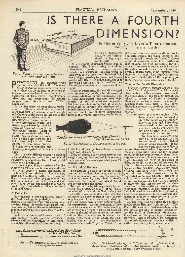
Let us imagine, first, a creature after thestyle of an eel or worm, but so long and thinthat it is simply a living exposition ofEuclid's definition relative to a line, namely,length but neither breadth nor thickness.Such a creature, when facing one of hisfellows, would see him solely as a dot orpoint, and by his one-dimensional naturewould regard the whole world as a universeof dots or points.A Flatlander
Now imagine a two-dimensional being-the best analogy is probably that of ashadow ; so imagine your own shadow as asentient being. It would have length andalso breadth, but no thickness whatsoever ;in fact, it might be very aptly termed a flat-lander.
Such a creature would know a world oflines only, or, in other words, they them-selves would see everything as one-dimen-sional (the dimension of lines and length)
The Human Being only knows a Three-dimensionalWorld ; Is there a Fourth ?
though themselvesactually two - dimen-sional, having lengthand breadth.
Now we come to normal beings such ashumans. The human being is a three-dimensional creature, having length,breadth and thickness ; but the world asseen by us is two-dimensional in actual fact,everything appearing in planes and lengthand breadth (the three-dimensional effect ofour sight being in a sense an artificial onedue to the stereoscopic arrangement of oureyes).
Now, to summarise, if a one-dimensionalcreature sees only points, a two-dimensionalcreature only lines (or one-dimensional) anda three-dimensional creature sees onlyplanes (or two dimensions), ingeniousthinkers plausibly argue that it is quitereasonable to surmise the existence of afourth dimension or state of being to whichwe are visible to all three dimensions,though this fourth dimension would be as
- -
Taro Dimensional CreatareSees Everthing InOne Dimeynsional Terms
Fig. 2.-The Flatlander would know a universe of lines only.
not enter into his cosmos at all, and so hecan only wriggle the whole length of theenormous roll to reach the " moon." Givena third dimension he would find it within aninch of him. So with ourselves ; the dis-tance to our moon is enormous as far as ourthree-dimensional senses can tell us, butgiven a fourth there is no knowing whatshort cut we might find ourselves precipi-tated into. Naturally all this is pure hypo-thesis, but it gives one furiously to think.Time as the Fourth Dimension
There is, however, another aspect of theterm " fourth dimension," which is veryoften confused with the above. We refer tothe application of the term to time in therelativity theory of Professor Einstein.Here the phrase has a definite meaning, for Einstein states that time is the fourthdimension necessary to the three dimensionalposition of space to specifically define suchposition.
In other words, it is no use saying " JohnJones was at the second windowup of the house at the corner ofRussell Square and TottenhamCourt Road " unless we add thetime at which he was there, forthe flow of time is as essentialin space as is position itself.
To show how deceptive timemay be, let us imagine that weare on one of the very distantstars watching the earth. If thestar were ten light years distant
we would see events which happened in 1923because it has taken that time for the lightimpulses of these events to travel there. Nowsuppose we were able to leave that star andtravel towards the earth at the speed oflight, we would, at the end of one year, beable to observe events which were takingplace in 1925, not 1924, because two yearsof earth time have passed during only oneyear of ours. This illustration can beelaborated quite scientifically until one isable to visualise time and events actuallyproceeding backwards, but this is sufficientto illustrate the importance of the timedimension in the relativity theory, and toshow that Einstein's specific reference to afourth dimension has a definite application,whereas the generalised term previously dis-cussed is usually a reference to a hypo-thetical dimension in space itself.
Readers who wish to pursue this subjectshould study Hinton's work entitled " TheFourth Dimension." The theses advanced inthis article are not, of course, originatedby the staff of PRACTICAL Mxcasvics.They have been the playthings of scientistsfor years. But if we admit the possibilityof a fourth dimension, why not a fifth, asixth, a seventh-in fact, any number ?
A
invisible and incomprehensible to us as weare to the Flatlander.
This, of course, allows great play to theimagination, and has resulted hi many veryingenious and extremely plausible plots forexciting tales.An Interesting Example
To postulate a case : the moon is somequarter of a million miles away, and to ourthree-dimensional minds and bodies moreor less inaccessible, but, given a fourthdimension, there is no reason why it shouldnot be just round the corner.
To " prove " this, let us go back to ourfriend, the Flatlander again. If we had ahuge roll of paper and unrolled it along theroad until it was half undone, then doubledthe other half over the first so that the twolong lengths of paper were separated by1 in., we would have a very suitable trackfor experiment,. At the beginning of thepaper let us imagine our Flatlander startingoff to reach his " moon," which we place asa disc at the end of the paper on the sameside as the little creature is started on.Actually the moon is 1 in. above the Flat-lander, but as he is a two-dimensionalcreature the words " up " or " down " do
One Dimensional Creature Sees EverythingIn 7erms Of Points 6
C
Fig. 1.-This creature would regard the whole world as auniverse of dots and points.
Fig. 3.-The Flatlander's journey. A. B. C., the paper path. D, flatlander starts.E, the " moon" (flatlander's god). F., third dimensional distance. G. C. C. is
the only feasible distance to a two-dimensional creature.
www.americanradiohistory.com
September, 1934 PRACTICAL MECHANICS 549
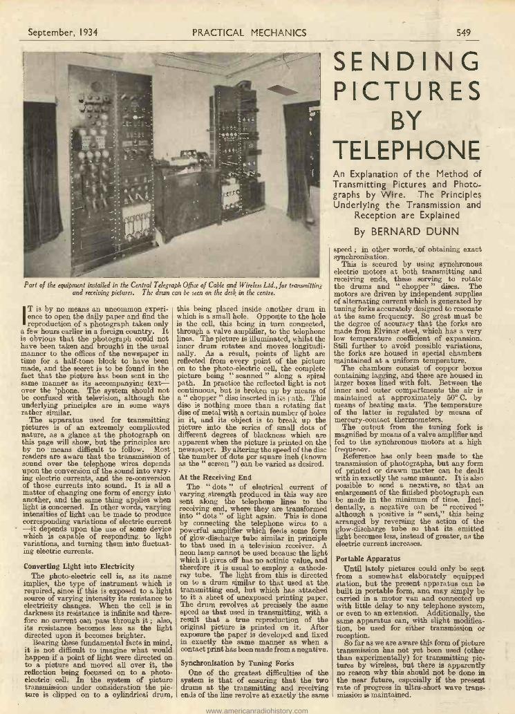
Part of the equipment installed in the Central Telegraph Office of Cable and Wireless Ltd., for transmittingand receiving pictures. The drum can be seen on the desk in the centre.
IT is by no means an uncommon experi-ence to open the daily paper and find thereproduction of a photograph taken only
a few hours earlier in a foreign country. Itis obvious that the photograph could nothave been taken and brought in the usualmanner to the offices of the newspaper intime for a half -tone block to have beenmade, and the secret is to be found in thefact that the picture has been sent in thesame manner as its accompanying text-over the 'phone. The system should notbe confused with television, although theunderlying principles are in some waysrather similar.
The apparatus used for transmittingpictures is of an extremely complicatednature, as a glance at the photograph onthis page will show, but the principles areby no means difficult to follow. Mostreaders are aware that the transmission ofsound over the telephone wires dependsupon the conversion of the sound into vary-ing electric currents, and the re -conversionof those currents into sound. It is all amatter of changing one form of energy intoanother, and the same thing applies whenlight is concerned. In other words, varyingintensities of light can be made to producecorresponding variations of electric current-it depends upon the use of some devicewhich is capable of responding to lightvariations, and turning them into fluctuat-ing electric currents.
Converting Light into ElectricityThe photo -electric cell is, as its name
implies, the type of instrument which isrequired, since if this is exposed to a lightsource of varying intensity its resistance toelectricity changes. When the cell is indarkness its resistance is infinite and there-fore no current can pass through it ; also,its resistance becomes less as the lightdirected upon it becomes brighter.
Bearing these fundamental facts in mind,it is not difficult to imagine what wouldhappen if a point of light were directed onto a picture and moved all over it, thereflection being focussed on to a photo-electric cell. In the system of picturetransmission under consideration the pic-ture is clipped on to a cylindrical drum,
this being placed inside another drum inwhich is a small hole. Opposite to the holeis the cell, this being in turn connected,through a valve amplifier, to the telephonelines. The picture is illuminated, whilst theinner drum rotates and moves longitudi-nally. As a result, points of light arereflected from every point of the pictureon to the photo -electric cell, the completepicture being " scanned " along a spiralpath. In practice the reflected light is notcontinuous, but is broken up by means ofa " chopper " disc inserted in its ; ath. Thisdisc is nothing more than a rotating flatdisc of metal with a certain number of holesin it, and its object is to break up thepicture into the series of small dots ofdifferent degrees of blackness which areapparent when the picture is printed on thenewspaper. By altering the speed of the discthe number of dots per square inch (knownas the " screen ") can be varied as desired.
At the Receiving EndThe " dots " of electrical current of
varying strength produced in this way aresent along the telephone lines to thereceiving end, where they are transformedinto " dots " of light again. This is doneby connecting the telephone wires to apowerful amplifier which feeds some formof glow -discharge tube similar in principleto that used in a television receiver. Aneon lamp cannot be used because the lightwhich it gives off has no actinic value, andtherefore it is usual to employ a cathode-ray tube. The light from this is directedon to a drum similar to that used at thetransmitting end, but which has attachedto it a sheet of unexposed printing paper.The drum revolves at precisely the samespeed as that used in transmitting, with aresult that a true reproduction of theoriginal picture is printed on it. Afterexposure the paper is developed and fixedin exactly the same manner as when acontact print has been made from a negative.
Synchronisation by Tuning ForksOne of the greatest difficulties of the
system is that of ensuring that the twodrums at the transmitting and receivingends of the line revolve at exactly the same
SENDINGPICTURES
BYTELEPHONEAn Explanation of the Method ofTransmitting Pictures and Photo-graphs by Wire. The PrinciplesUnderlying the Transmission and
Reception are Explained
By BERNARD DUNN
speed ; in other words, of obtaining exactsynchronisation.
This is secured by using synchronouselectric motors at both transmitting andreceiving ends, these serving to rotatethe drums and " chopper " discs. Themotors are driven by independent suppliesof alternating current which is generated bytuning forks accurately designed to resonateat the same frequency. So great must bethe degree of accuracy that the forks aremade from Elvinar steel, which has a verylow temperature coefficient of expansion.Still further to avoid possible variations,the forks are housed in special chambersmaintained at a uniform temperature.
The chambers consist of copper boxescontaining lagging, and these are housed inlarger boxes lined with felt. Between theinner and outer compartments the air ismaintained at approximately 50° C. bymeans of heating mats. The temperatureof the latter is regulated by means ofmercury -contact thermometers.
The output from the tuning fork ismagnified by means of a valve amplifier andfed to the synchronous motors at a highfrequency.
Reference has only been made to thetransmission of photographs, but any formof printed or drawn matter can be dealtwith in exactly the same manner. It is alsopossible to send a negative, so that anenlargement of the finished photograph canbe made in the minimum of time. Inci-dentally, a negative can be " received "although a positive is " sent," this beingarranged by reversing the action of theglow -discharge tube so that its emittedlight becomes less, instead of greater, as theelectric current increases.
Portable ApparatusUntil lately pictures could only be sent
from a somewhat elaborately equippedstation, but the present apparatus can bebuilt in portable form, ann may simply becarried in a motor van and connected upwith little delay to any telephone system,or even to an extension. Additionally, thesame apparatus can, with slight modifica-tion, be used for either transmission orreception.
So far as we are aware this form of picturetransmission has not yet been used (otherthan experimentally) for transmitting pic-tures by wireless, but there is apparentlyno reason why this should not be done inthe near future, especially if the presentrate of progress in ultra -short wave trans-mission is maintained.
www.americanradiohistory.com
550 PRACTICAL MECHANICS September, 1934
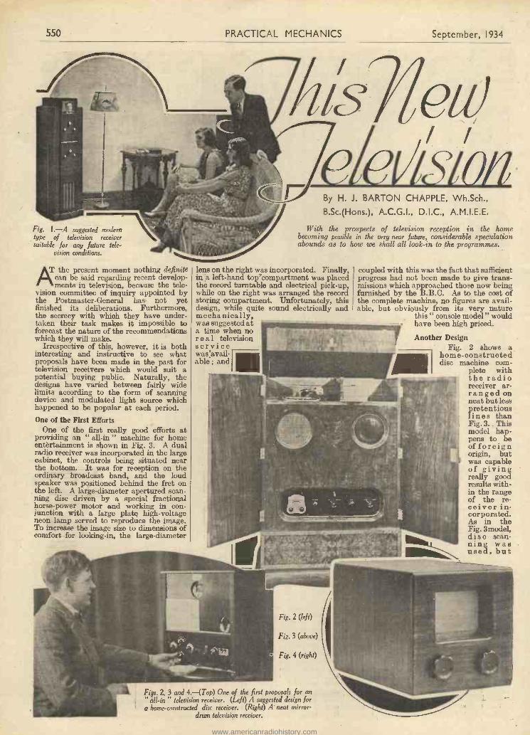
Fig. 1.-A suggested modemtype of television receiversuitable for any future tele-
vision conditions.
AT the present moment nothing definitecan be said regarding recent develop-ments in television, because the tele-
vision committee of inquiry appointed bythe Postmaster -General has not yetfinished its deliberations. Furthermore,the secrecy with which they have under-taken their task makes it impossible toforecast the nature of the recommendationswhich they will make.
Irrespective of this, however, it is bothinteresting and instructive to see whatproposals have been made in the past fortelevision receivers which would suit apotential buying public. Naturally, thedesigns have varied between fairly widelimits according to the form of scanningdevice and modulated light source whichhappened to be popular at each period.One of the First Efforts
One of the first really good efforts atproviding an " all -in " machine for homeentertainment is shown in Fig. 3. A dualradio receiver was incorporated in the largecabinet, the controls being situated nearthe bottom. It was for reception on theordinary broadcast band, and the loudspeaker was positioned behind the fret onthe left. A large -diameter apertured scan-ning disc driven by a special fractionalhorse -power motor and working in con-junction with a large plate high -voltageneon lamp served to reproduce the image.To increase the image size to dimensions ofcomfort for looking -in, the large -diameter
I
Ysldeieval0/1By H. J. BARTON CHAPPLE, Wh.Sch.,
B.Sc.(Hons.), A.C.G.I., D.I.C., A.M.I.E.E.
With the prospects of television receptionin the homebecoming possible in the very near future, considerable speculationabounds as to how we shall all look -in to the programmes.
lens on the right was incorporated. Finally,in a left-hand top'compartment was placedthe record turntable and electrical pick-up,while on the right was arranged the recordstoring compartment. Unfortunately, thisdesign, while quite sound electrically andmechanically,was suggested ata time when noreal televisionservicewas:avail-able ; and
Fig. 2 (left)
Fig. 3 (above)
Fig. 4 (right)
Figs. 2, 3 and 4.-(Top) One of the first proposals for an" all -in television receiver. (Left) A suggested design fora home -constructed disc receiver. (Right) A neat mirror -
drum television receiver.
coupled with this was the fact that sufficientprogress had not been made to give trans-missions which approached those now beingfurnished by the B.B.C. As to the cost ofthe complete machine, no figures are avail-able, but obviously from its very nature
this " console model " wouldhave been high priced.
Another DesignFig. 2 shows a
home -constructeddisc machine com-
plete withthe radioreceiver ar-ranged onneat but lesspretentiouslines thanFig. 3. Thismodel hap-pens to beof foreignorigin, butwas capableof givingreally goodresults with-in the rangeof the re-ceiver in-corporated.As in theFig. 3model,disc scan-ning wasused, but
www.americanradiohistory.com

September, 1934 PRACTICAL MECHANICS 551
the scanning member was of rather smalldiameter. In addition, arrangements hadbeen made to take advantage of both theBritish and Continental television trans-missions. The former uses vertical scan-ning, so that the images were watchedthrough the magnifying lens on the right.For the horizontally scanned Continentaltransmissions the centre top lens wasemployed. A simple, neat, completereceiver of this character has many pointsin its favour, not the least of which is therelatively low cost of assembly and ease ofcontrol. When mirror -drum scanning isused, so that the image is built up by backprojection on to a translucent frosted glassscreen, the designs for a complete receivercan take on an entirely different character.
Fig. 5.-An experimental mirror -drum televisionmodel for home use.
When the television receiver only isrequired, the radio set employed for thereception of the actual broadcast signalsfunctioning as a distinct unit, the equip-ment can be accommodated in quite asmall compass. For low definition tele-vision, Fig. 4 shows a proposed Germandesign, which is solid in character, with onlytwo controls to handle once the machine hasbeen set up. Fig. 5 shows another designwhich used a mirror -drum scanner, and thiswas a Baird experimental " Televisor "used for demonstration purposes, andincluded the low -frequency amplifier insidethe cabinet. The image was seen on theright-hand rectangular screen, while theamplifier controls were mounted on the left-hand panel, leaving the framing and phasingknobs in the centre. It must be admittedthat a receiver of this character looks par-ticularly neat, and would make a good tablemodel for use in conjunction with a separateH.F. amplifier and detector unit.
A Table ModelFig. 6 is a table model which would grace
any drawing -room, and shows a singularabsence of stray leads, while the controlsare reduced to bare essentials. Therelatively large translucent screen at thetop is for portraying the television images( mirror -drum or similar scanning arrange-ments have been catered for here), and ahome screen of this size would amply meet
the requirements of alarge section of a radioand television mindedpublic. Immediatelybelow the screen is theradio receiver, an all -mains model, the tuningcontrol and indicatingaperture being posi-tioned in the centre.The other two controlscan serve a variety ofpurposes-combinedframing and phasingadjustment, image in-tensity regulation, vol-ume control, etc.
Undoubtedly the
Fig. 8.-Hew soon will it be before the television images received in thehouse will be projected on to the small cinema screen of this size ?
present trend isto reduce workingcontrols to thebarest minimum,it being assumedthat all otheressential adjust-ments can be un-dertaken at thetime the equip -
Fig. 6.-A high -quality television re-ceiver design of very pleasing character.
ment is installed. Once theseinitial settings have been made,then the user is only called uponto manipulate two or threeknobs to suit his own personaltastes.
Reverting to Fig. 6, the largerectangular wooden cabinet basewould house all the mains elimi-nator equipment together withthe low -frequency amplifier.Questions of cost for a designof this nature cannot be con-sidered, for they would dependnaturally on the extent of theplans of production. One objec-tion that might be raised is theabsence of any provision foraccommodating the sound side
of the complete television programme.Each television transmission to be completeis of a dual character, and unless the loudspeaker reproducing the music, song orspeech is in close proximity to the imagescreen, the illusion of a " talking picture "is lost.
Needs of the FutureOne suggestion for meeting the needs of
the latter class appears in Fig. 7. Here is alarge console model shown partly dis-mantled and built with an eye to any
possible high definition televisionservice demanding the use of acathode ray tube. Within the past
twelve months the earlier de-spised cathode ray tube hasreturned to marked favour forthe purpose of reproducing
televisionimages.Intenseactivity isbeing die -played bythose man-ufac turers
Fig. 7.-Another
design, incor-porating a dualradio receiver with
a cathode ray tube for building up the television images.
www.americanradiohistory.com
552 PRACTICAL MECHANICS September, 1934
having facilities for producing these tubes,and undoubtedly the result of this work willmanifest itself in the marketing of tubeswhich possess none of the inherent dis-advantages of their early prototypes.Limitation of image area size on the tube'sfluorescent screen end seems to be one ofthe prime objections put forward bymechanical scanning protagonists, andresearch is being directed towards a com-plete solution of this point. Absolutesilence in operation is an outstandingadvantage, together with the comparativeease of change to accommodate the receivingapparatus to any alterations which mighttake place in the number of scanning lines,image area, shape, and so on.
Returning to Fig. 7, the tube's fluorescentend is shown as the white disc encompassedby a black circle immediately below thecontrols at the top of the intermediatevertical panel support. The radio receiver,time bases and amplifiers are housed insections with their appropriate connections,while the loud speaker is covered by a figuredfret near the bottom of the panel. To add tothe scope of usefulness of a set of this charac-ter, a gramophone turntable, together withan electrical pick-up, is incorporated in a topcompartment immediately beneath the lid.
Meeting Special ConditionsOf course, a scheme of this character is
capable of numerous modifications, and inFig. 1 is shown a further suggested designwhich could meet the conditions of " thisnew television " when any form of long andregular service of transmissions becomesavailable to the general public on a whollyacceptable basis. A dual sound and visionreceiver is indicated here, the actualcabinet design being one which will tonewith the average modem room furnish-ings.
The image screen is located near thecabinet top, being a comfortable eye levelwhen viewed from a few feet distant. Eithera cathode ray tube or one of the suggestedmechanical forms of scanning would besuitable here, the cabinet depth beinggoverned by the methods used for imageintegration. Below this could be groupedthe actual radio and television receiveressential controls, symmetrically disposedon the slightly projecting upright woodenpanel. A little lower could be placed thesound radio receiver controls with the loudspeaker underneath. Ample accommoda-tion would be available for low -frequencyamplifiers, H.T. and L.T. supplies, togetherwith the auxiliaries essential to a scheme
of this nature. Undoubtedly we shall seemodels of similar character to this on themarket, and it must be agreed that anyattempt made to provide home entertain-ment in this form is sure to meet with theapprobation of the buying public, even ifthe price rules high when compared withthe radio receiver alone now doing servicein the home.
Of course, there are still many who lookforward to the day when the received tele-vision images will be projected on to ahome screen comparable in size with thatillustrated in Fig. 8. Here we see the whitescreen of normal home talkie dimensions,and many of the television schemes nowbeing investigated show promise of givingbrilliant high definition pictures suitablefor this purpose. At present, however, theapparatus required is costly, and needs theservices of a skilled operator. This stage inthe process of evolution towards themass-produced commercial product isinevitable, however, and a measure ofpatience, leavened with a little helpfulcriticism, will do much to stimulate thepioneer efforts now being directed togive " this new television ' the status itdeserves in the home life of every house-hold.
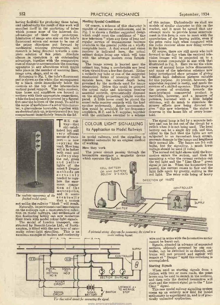
THE rail-way-thatold - estab-
lished but stillvery efficientmeans of trans-port - is nowcopying theroad. How longwill it be beforeboth road andrailway obeythe red, greenand yellowlights of therobot Drasticmethods arecertainlyneeded to regu-late the enor-mous conges-tion of themetropolis,and it seemseventuallythat a system
not unlike the railway " block " will result.Naturally, improvements and innovations
on the railways cast a representative reflec-tion on model railways, and enthusiasts ofthis fascinating hobby can now modernisetheir track with model colour -light signals.
The model of London transport, con-structed by Bassett-Lowke Ltd., of North-ampton, is fitted with the new type of auto-matic colour -light signalling. This is anexcellent. example of realism and modernity
The realistic appearance of thefinished model signal.
A4 3 1 2
COLOUR LIGHT SIGNALLINGIts Application to Model Railways
in model railways, and the signalling isrendered automatic by an original methodof working.How they work
The power circuit passing through thelocomotive energises a magnetic devicewhich operates the lights.
CELL BATTERYOR ANY BATTERYBELOW 3' 5 VOLTS
The signal lamp is fed by a separate bat-tery and can be cut out of the circuit by aswitch when it is not being used. The localbattery can be a single dry cell, and this,added to the fact that the lights are notsubjected to an inconstant track circuit,prevents damage to the lamps and lengthenstheir normal life. The lamps are 3.5 voltbulbs, but for signalling, a much lowervoltage should be used (2 volts).
The normal red light shows until the loco-motive enters the section, and then byenergising a relay the current switches outthe red light and the " Line Clear " greensignal is cut in. When the locomotive haspassed, the current ceases to flow and thelight falls again by gravity, cutting in thered light. The relay coils being of heavy
DIRECTION OF TRAM
A pictorial wiring diagram for connecting the signal to amodel railway layout.
SUPPLY
ICONTROLLERS00 00 \
9SIGNAL SIGNAL
SEeTION NO33NO 4 e T
N *.,SECTION SWITCHES
CIRCUIT
1111LISTANCE A H
BATTERYSIGNAL I SWITCH STOP
TO AVERAGE
CIRCUIT
SIGNAL
rir thec7etical circuit fm connecting the signal.
CONTROLLER
SUPPLY
wire and in series with the locomotive motorcannot be burnt out.
Signals, situated in advance of separatedsections, although governed by one con-troller, can be switched in as desired, andtrains will not proceed and signals willremain at " Danger " until this switching isaccomplished.
Starting SignalsWhen used as starting signals from a
station with two or more roads, the pointlevers can be used to switch in the sections,and then only the desired locomotive willstart and the correct signal go to the " LineClear " signal.
This new model railway signalling systemopens up an entirely new field for modelenthusiasts to experiment in, and is of prac-tically unlimited application.
www.americanradiohistory.com
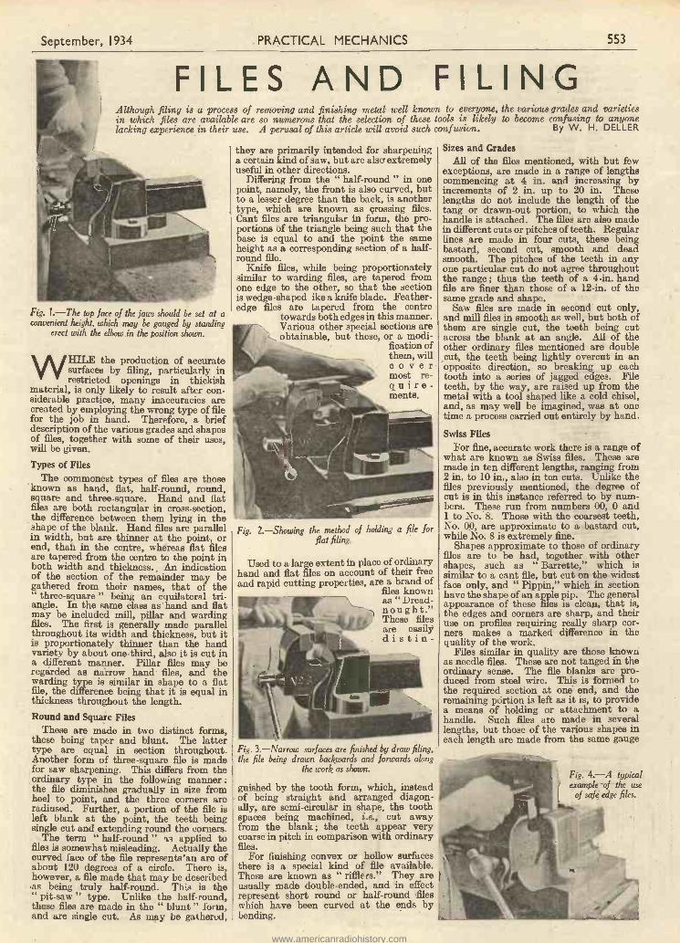
September, 1934 PRACTICAL MECHANICS 553
FILES AND FILINGAlthough filing is a process of removing and finishing metal well known to everyone, the various grades and varietiesin which files are available are so numerous that the selection of these tools is likely to become confusing to anyonelacking experience in their use. A perusal of this article will avoid such confusion. By W. H. DELLER
Fig. 1.-The top face of the jaws should be set at aconvenient height, which may be gauged by standing
erect with the elbow in the position shown.
RILE the production of accuratesurfaces by filing, particularly inrestricted openings in thickish
material, is only likely to result after con-siderable practice, many inaccuracies arecreated by employing the wrong type of filefor the job in hand. Therefore, a briefdescription of the various grades and shapesof files, together with some of their uses,will be given.
Types of FilesThe commonest types of files are those
known as hand, flat, half -round, round,square and three -square. Hand and flatfiles are both rectangular in cross-section,the difference between them lying in theshape of the blank. Hand files are parallelin width, but are thinner at the point, orend, than in the centre, whereas flat filesare tapered from the centre to the point inboth width and thickness. An indicationof the section of the remainder may begathered from their names, that of the
three -square " being an equilateral tri-angle. In the same class as hand and flatmay be included mill, pillar and wardingfiles. The first is generally made parallelthroughout its width and thickness, but itis proportionately thinner than the handvariety by about one-third, also it is cut ina different manner. Pillar files may beregarded as narrow hand files, and thewarding type is similar in shape to a flatfile, the difference being that it is equal inthickness throughout the length.Round and Square Files
These are made in two distinct forms,these being taper and blunt. The lattertype are equal in section throughout.Another form of three -square file is madefor saw sharpening. This differs from theordinary type in the following manner :the file diminishes gradually in size fromheel to point, and the three corners areradiused. Further, a portion of the file isleft blank at the point, the teeth beingsingle cut and extending round the corners.
The term " half -round " TR applied tofiles is somewhat misleading. Actually thecurved face of the file represents'an arc ofabout 120 degrees of a circle. There is,however, a file made that may be describedas being truly half -round. This is the" pit -saw " type. Unlike the half -round,these files are made in the " blunt " form,and are single cut. As may be gathered,
they are primarily intended for sharpeninga certain kind of saw, but are also extremelyuseful in other directions.
Differing from the " half -round " in onepoint, namely, the front is also curved, butto a lesser degree than the back, is anothertype, which are known as crossing files.Cant files are triangular in form, the pro-portions of the triangle being such that thebase is equal to and the point the sameheight as a corresponding section of a half -round file.
Knife files, while being proportionatelysimilar to warding files, are tapered fromone edge to the other, so that the sectionis wedge-shaped ike a knife blade. Feather-edge files are tapered from the centre
towards both edges in this manner.Various other special sections areobtainable, but these, or a modi-
fication ofthem, willCO vet'most re-quire-ments.
Fig. 2.-Showing the method of holding a file forflat filing.
Used to a large extent in place of ordinaryhand and flat files on account of their freeand rapid cutting properties, are a brand of
files knownas " Dread-
, nought."These filesare easilydistin-
Fig. 3.-Narroto surfaces are finished by draw filing,the file being drawn backwards and forwards along
the work as shown.
guished by the tooth form, which, insteadof being straight and arranged diagon-ally, are semi -circular in shape, the toothspaces being machined, i.e., cut awayfrom the blank ; the teeth appear verycoarse in pitch in comparison with ordinaryfiles.
For finishing convex or hollow surfacesthere is a special kind of file available.These are known as " rifflers." They areusually made double -ended, and in effectrepresent short round or half -round fileswhich have been curved at the ends bybending.
Sizes and GradesAll of the files mentioned, with but few
exceptions, are made in a range of lengthscommencing at 4 in. and increasing byincrements of 2 in. up to 20 in. Theselengths do not include the length of thetang or drawn-out portion, to which thehandle is attached. The files are also madein different cuts or pitches of teeth. Regularlines are made in four cuts, these beingbastard, second cut, smooth and deadsmooth. The pitches of the teeth in anyone particular cut do not agree throughoutthe range ; thus the teeth of a 4 -in. handfile are finer than those of a 12 -in. of thesame grade and shape.
Saw files are made in second cut only,and mill files in smooth as well, but both ofthem are single cut, the teeth being cutacross the blank at an angle. All of theother ordinary files mentioned are doublecut, the teeth being lightly overcut in anopposite direction, so breaking up eachtooth into a series of jagged edges. Fileteeth, by the way, are raised up from themetal with a tool shaped like a cold chisel,and, as may well be imagined, was at onetime a process carried out entirely by hand.
Swiss FilesFor fine, accurate work there is a range of
what are known as Swiss files. These aremade in ten different lengths, ranging from2 in. to 10 in., also in ten cuts. Unlike thefiles previously mentioned, the degree ofcut is in this instance referred to by num-bers. These run from numbers 00, 0 and1 to No. 8. Those with the coarsest teeth,No. 00, are approximate to a bastard cut,while No. 8 is extremely fine.
Shapes approximate to those of ordinaryfiles are to be had, together with othershapes, such as " Barrette," which issimilar to a cant file, but cut on the widestface only, and " Pippin," which in sectionhave the shape of an apple pip. The generalappearance of these files is clean, that is,the edges and corners are sharp, and theiruse on profiles requiring really sharp cor-ners makes a marked difference in thequality of the work.
Files similar in quality are those knownas needle files. These are not fanged in theordinary sense. The file blanks are pro-duced from steel wire. This is formed tothe required section at one end, and theremaining portion is left as it is, to providea means of holding or attachment to ahandle. Such files are made in severallengths, but those of the various shapes ineach length are made from the same gauge
Fig. 4.-A typicalexample of the use
of safe edge files.
www.americanradiohistory.com
554 PRACTICAL MECHANICS September, 1934
material. Consequently they may con-veniently be held in a handle fitted with achuck or set screw.
Safe EdgesHand files are as standard, made with one
safe edge, that is, one of the narrow sideshas no teeth cut on it. The object of thisis that when filing against a shoulder, thesafe edge of the file is kept adjacent to it,thus preventing " cutting in " on that side.Square files are also made in this manner,having one or more safe edges, but not asstandard.
Where a particular shape of file is notreadily obtainable, ordinary files may bemodified in various ways in order to makethem suitable for the purpose. This ischiefly done by grinding extra safe edges orreducing the width to permit working innarrow spaces where a smaller file would betoo flimsy.
For filing large surfaces the end of a fileis sometimes cranked to permit the handleto clear the surface of the work. To do thisit is necessary to heat the file, and in sodoing care must be taken to prevent theheat travelling up and drawing the temperfrom the cutting portion. Round and half-
round files are sometimes heated and bentat the ends to serve as riffiers. This meansrehardening, which, if carefully carried out,is satisfactory, but seldom will a file sotreated stand up to prolonged use.Handles
The question of handles is an important
one, particularly when heavy filing has tobe done. Thus bastard files of reasonablesize should be fitted with handles of such adiameter and shape as to afford a comfort-able grip, free from any suggestion ofcramping. Common file handles of wood,and suitably ferruled, are quite satisfactory,although there are various types of specialhandles which offer certain advantages,and are mostly of a non -splitting character.
There is also a special holder made whichenables an ordinary hand file to be used onlarge surfaces without the necessity ofcranking the end. Whatever type of handleis used, care must be taken to see that it isa rigid fit when in position. This is mostnecessary if accurate work is to be produced.
FilingThe first point to receive consideration
should be the vice. This should be of sucha size that it will hold the largest work likelyto be handled. It is an important pointthat the top face of the jaws are set at aconvenient height. This may be judged bystanding erect with the elbow in theposition shown in Fig. 1, the vice beingpacked up to the correct height.
For small work a small vice may withgreat convenience be used in conjunctionwith a larger one. The small vice is mountedon a piece of plate to the bottom of which isattached a piece of hexagonal steel bar 3 or4 in. in length. This shank may then beheld in various positions in the larger vice.The method of holding a file for flat filingis seen in Fig. 2. Normally the handle is
gripped in the right hand with the thumbupwards, and the point of the file being heldbetween the ball of the thumb and thefingers of the left hand. If the surface is arough one, or there is much metal to remove,a bastard cut or Dreadnought file is used.
The filing is carried out in a diagonaldirection, and the pressure which is appliedon the forward stroke is reduced on thereturn stroke. After a time the direction offiling is reversed, this having the effect oftaking off the series of ridges left by the filewhen travelling in the opposite direction.The filing is continued in alternate directionsuntil the work is close to the required size.Care must be taken to see that the file iskept moving in a horizontal plane. At firstthere is, however, a general tendency toraise the right hand on the return strokeand the left hand on the forward one. Theeffect of this is to produce a surface any-thing but flat, and is a condition to becorrected by practice. Carry on the filingwith a second cut file to remove the marksleft by the previous one, and finish with afine file. Fine files are liable to pick uppieces of metal in the teeth, with the resultthat the surface of the work is deeplyscratched. This clogging can be obviatedby cleaning the file and filling the teeth withchalk. Narrow surfaces are finished bythaw -filing. The file is held and drawnbackwards and forwards along the work, asseen in Fig. 3, a " straight-line " finishresulting.
A typical example of the use of safe edgefiles is shown in Fig. 4.
ANYTHING that is made, regardlessof how it is made, has to be measured,weighed or counted, and the tally
must be accurate. Otherwise, how couldcosts be estimated and profits ascertained ?
But to count by hand each piece pro-duced would, of course, be impossible.Even to tally one hour's output of theaverage factory of to -day would be a tre-mendous task. Some other method ofchecking is necessary.
Count and measure can be computed byweight, likewiseweight can bedetermined bycount or measure,but the process isindirect, inaccu-rate, slow andconsequentlycostly.
While somefactories are still
This hand tally registers at using the abovemethods,
theevery pressure of the thumb majority oflever. modern plants
have adopted the mechanical method ofcounting each piece as it is produced fromthe machine itself. Such a tally is madepossible with the aid of a small countingmachine which faithfully and ceaselessly,if desired, works twenty-four hours a dayand without pay.
A Common Application
Probably the most common of counterapplications is on the stamping press ordrop hammer; Here the counter recordseach stroke of the press from which pro-duction is easily computed. If desired, abell can be attached which will ring whena certain total is reached, warning theoperator.
Other common applications are onprinting presses, turret lathes, automaticscrew machines, bottle -filling machines, con-veying machines, buttonhole machines,
ABOUT COUNTINGDEVICES
folders, wire -cutters and straighteners,marine indicators and cancelling machines.
A recent development is a predeterminedcounter which can be set to any desired
total, themachine putinto opera-tion andwhen the pre-determinednumber ofpieces havebeen pro-duced t h emachine isautomati-()allystopped. Byturning asmall resetknob, thecounter isready for asecond countof the samepredeter-mined num-ber of pieces,when the
machine is again automatically stopped, andso on, until the total quantity has beenreached. The operator does not have tokeep mental notes on the amount of piecesproduced, and therefore can give his atten-tion to other machines. A gong or signallight can also be attached to the counter,which calls the operator's attention to themachine that has stopped.
An electrically -operated counter.
The Hub OdometerAnother well-known Veeder-Root product
is the Hub Odometer, a device which seals
on to the left front hub of a pleasure car,motor truck or 'bus and accurately recordsthe mileage of travel to the tenth of a mile.The Veeder-Root bicycle cyclometer, too,has for years been the choice of cyclists allover the world. More than ten million havebeen sold. Then there is the mileagerecorder for freight and passenger elevators.They register even to the inch of travel.They soon reveal the efficiency or ineffi-ciency of the operator.
Counting machines are now used exten-sively to record production in the office.A small instrument attached to a type-writer will indicate the number of key-strokes typed. Many typists are nowbeing paid by the keystroke. Severalother office machines, too, can beequipped with counters-operators earnmore and fewer machines turn out morework.
The hand tally, a counter of 1,001 pur-poses, is made to comfortably fit the hand,either right or left, and is manually operatedby pressing a small thumb lever. It iseasily carried in the pocket, and will recordanything where a count is desired. A smallspeed counter, operated by a clutch, willindicate the number of revolutions of anyrevolving part over a given period of time.Another counter is being used to count thecorpuscles in the blood, still another willcount drops of water, and there is a smallcounter that will register each time one'sfinger is pointed at it. Then there is thetraffic counter, which records the numberof vehicles passing certain points.
A speed counter for recording the revs. per minute ofengines, motors, etc,
www.americanradiohistory.com
September, 1934 PRACTICAL MECHANICS 555
A sectional view of the Kohler automatic 1,500 -watt plant, illustrated below. Thedynamo is driven by a four -cylinder water-cooled petrol engine working at a speed of1,000 r.p.m. Special features of this plant are mechanical throttling, automatic con-
troller for current supply, and forced lubrication.
PEOPLE residing in country districtswhere the facilities of the town and cityare not available can now enjoy all the
advantages of electricity for lighting, heat-ing and cooking purposes. To -day thereare several makes of compact, self-containedplants that run on petrol or paraffin, andwhich require very little attention once theyare installed.
There are various types of these plantsavailable suitable for any householdrequirements, and these are of three mainclasses, viz.: (1) automatic ; (2) semi-automatic ; and (3) hand -controlled. Ineach class are examples of four-stroke andtwo-stroke engines using petrol or paraffinas fuel. The dynamo is either belt -drivenor direct -coupled to the engine.
An automatic plant is very compact andingenious, and dispenses with storagebatteries, except for a car -type startingbattery which is charged automatically.When the first lamp or appliance is turnedon, the starting battery uses the dynamoas a motor, and rapidly cranks and startsthe engine. The engine then drives thedynamo, which supplies current direct tothe point at which it is to be used. Whenthe last lamp, or appliance, is switched off,an automatic control device stops theengine.
A semi -automatic plant is used in con-junction with a storage battery, and isdesigned to run without any attention fromthe beginning to the end of the batterycharging. At other times a little attentioncan be given as occasion requires. Thedynamo with this type of plant is a self-regulating one, and the switch gear isdesigned to shut down the engine when thebatteries are fully charged. The engine isstarted by pressing a switch on top of thedynamo or on the switchboard.
In the hand -controlled type of plant therunning of the engine, and also the output,are under the direct control of the personwhose duty it is to look after the plant.The actual time taken up in attending to
SELF-CONTAINEDELECTRIC LIGHT-
ING PLANTSAn article describing the ingenious units forgenerating electricity in houses, or other buildings,in remote country districts where no public supply
is available.
such a light-ing set isvery littlemore thanthat neces-sary for asemi - auto-matic plant.One of thesecompactplants, in-stalled in asuitableouthouse,transformsit into aminiaturegeneratingstation cap-able ofsupplying
the house with electric light and current foroperating various domestic electric appli-ances.
Some Representative PlantsAmong the automatic electric lighting
plants that require no storage batteries, a
A small4 to 5 kw. electric light plant by the National!Gas and Oil Engine Co. Ltd. The engine, of 8iLb.h.p., works on heavy oil, and rims at 800 to 1,000
r.p.m.
good example is the " Kohler," two modelsof which, the 800 -watt and 1,500 -watt, areparticularly suitable for small countryhouses. The smaller plant will supplycurrent for an installation of twenty-sevenlamps, each of 30 watts, and when all thepower is not required for lighting it can beused for operating domestic appliances.The larger model is designed to meet therequirements of the average country house,and supplies current for fifty 30 -watt lamps,or the equivalent in larger or smaller lamps.The generator of the smaller model is drivenby a two -cylinder air-cooled four-cyclepetrol engine of about 1i h.p. The
By A. J. BUDDgovernor is of the magnetic throttling typewhich automatically proportions the fuelconsumption to the number of lamps inuse. By means of a patent automaticcontroller the plant is started when the firstlamp or appliance (of 20 watts or more) isswitched on, and stopped when the demandfor current ceases. The dynamo is of thefour -pole compound -wound type.
In the semi -automatic class, a veryefficient and economical lighting set is the" A.L." plant made by Allen-LiversidgeLtd. It is rated at 11 kilowatts, thedynamo being direct -coupled to a four-cycleparaffin engine. The plant is so arrangedthat the engine can be started by simplypressing a switch on top of the dynamo,thus doing away with the trouble of hardcranking. When started, the set will runfor hours without any attention, andsupplies current for twenty to fifty 30 -wattlamps, according to the capacity of thestorage battery installed. When all thepower is not required for lighting, it can beused for operating a vacuum cleaner, ironor fan.
A popular lighting set for the countryresidence, hotel or garage is the Crossley,manufactured by the well-known firm ofCrossley Brothers Ltd. This lighting set
The Kohler automatic 1,500 -watt electric lightplant. The generator delivers current at 110 or 220volts D.C., suitable for an installation of 60 lamps,each of 25 watts, or the equivalent in larger or
smaller lamps.
www.americanradiohistory.com
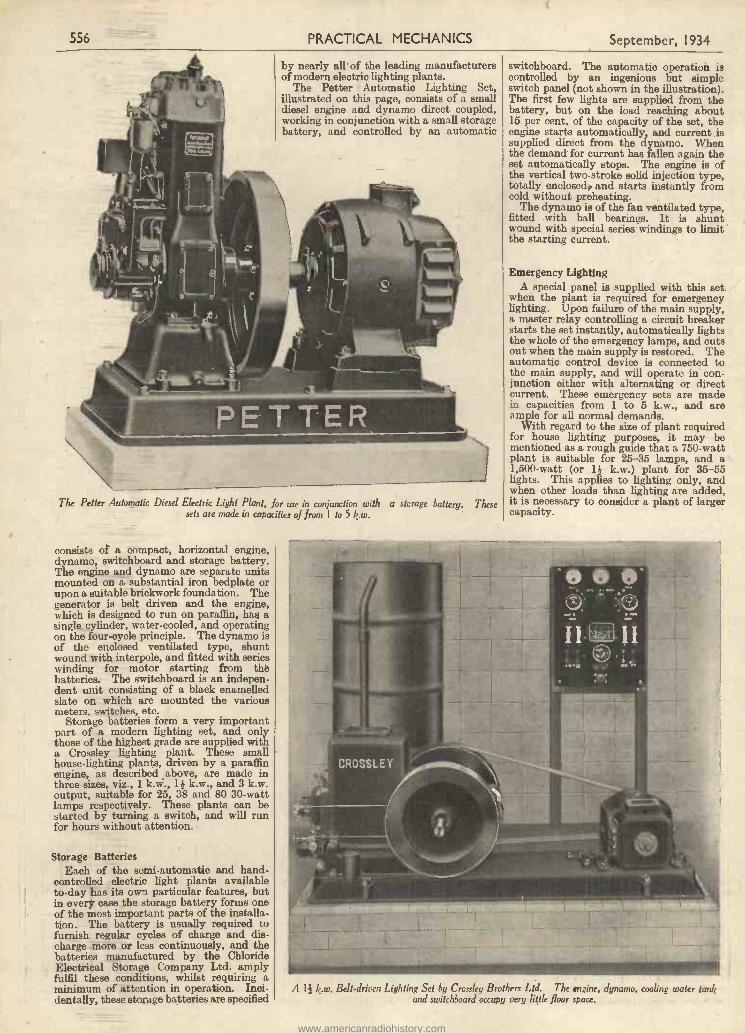
556 PRACTICAL MECHANICS September, 1934
by nearly all of the leading manufacturersof modern electric lighting plants.
The Petter Automatic Lighting Set,illustrated on this page, consists of a smalldiesel engine and dynamo direct coupled,working in conjunction with a small storagebattery, and controlled by an automatic
The Petter Automatic Diesel Electric Light Plant, for use in conjunction with a storage battery. Thesesets are made in capacities of from I to 5 k.w.
consists of a compact, horizontal engine,dynamo, switchboard and storage battery.The engine and dynamo are separate unitsmounted on a substantial iron bedplate orupon a suitable brickwork foundation. Thegenerator is belt driven and the engine,which is designed to run on paraffin, has asingle cylinder, water-cooled, and operatingon the four-cycle principle. The dynamo isof the enclosed ventilated type, shuntwound with interpole, and fitted with serieswinding for motor starting from thebatteries. The switchboard is an indepen-dent unit consisting of a black enamelledslate on which are mounted the variousmeters, switches, etc.
Storage batteries form a very importantpart of a modern lighting set, and onlythose of the highest grade are supplied witha Crossley lighting plant. These smallhouse -lighting plants, driven by a paraffinengine, as described above, are made inthree sizes, viz., 1 k.vi;. 11 k.w.,and 3 k.w.output, suitable for 25, 38 and 80 30 -wattlamps respectively. These plants can bestarted by turning a switch, and will runfor hours without attention.
Storage BatteriesEach of the semi -automatic and hand -
controlled electric light plants availableto -day has its own particular features, butin every case the storage battery forms oneof the most important parts of the installa-tion. The battery is usually required tofurnish regular cycles of charge and dis-charge more or less continuously, and thebatteries manufactured by the ChlorideElectrical Storage Company Ltd. amplyfulfil these conditions, whilst requiring aminimum of attention in operation. Inci-dentally, these storage batteries are specified
switchboard. The automatic operation iscontrolled by an ingenious but simpleswitch panel (not shown in the illustration).The first few lights are supplied from thebattery, but on the load reaching about15 per cent. of the capacity of the set, theengine starts automatically, and current issupplied direct from the dynamo. Whenthe demand for current has fallen again theset automatically stops. The engine is ofthe vertical two-stroke solid injection type,totally enclosedo and starts instantly fromcold without preheating.
The dynamo is of the fan ventilated type,fitted with ball bearings. It is shuntwound with special series windings to limitthe starting current.
Emergency LightingA special panel is supplied with this set.
when the plant is required for emergencylighting. Upon failure of the main supply,a master relay controlling a circuit breakerstarts the set instantly, automatically lightsthe whole of the emergency lamps, and cutsout when the main supply is restored. Theautomatic control device is connected tothe main supply, and will operate in con-junction either with alternating or directcurrent. These emergency sets are madein capacities from 1 to 5 k.w., and areample for all normal demands.
With regard to the size of plant requiredfor house lighting purposes, it may bementioned as a rough guide that a 750 -wattplant is suitable for 25-35 lamps, and a1,500 -watt (or 11 k.w.) plant for 35-55lights. This applies to lighting only, andwhen other loads than lighting are added,it is necessary to consider a plant of largercapacity.
A 14 k.w. Belt -driven Lighting Set by Crossley Brothers Ltd. The engine, dynamo, cooling water tankand switchboard occupy very little floor space.
www.americanradiohistory.com
September, 1934 PRACTICAL MECHANICS 557
ELECTRIC CLOCK CHIMESInteresting Details Concerning the Construction of Mechanism for Operating Chimes from an Electrical
Isl. QUARTER
I s f d:
34 MS
-0-
34' QUARTER
f s d: d
4tk QUARTER (HOUR)
f I s d: f 5 I f: I f 5 d: d s I
Clock System
By W. J. DELANEY
2"QUARTER (HALF HOUR)
f I s d: f s I f:
I f: I
J
.1
seal
-G-C
Fig. 1.-The popular Westminster Chimes.
WE recently described a Master andSlave clock system (see PRACTICALMECHANICS, March, 1934), and
many readers have written to ask how thissystem could be modified to include someform of chiming mechanism. This is notquite such a simple matter as would at firstappear, owing to the fact that it is almostessential to call in the aid of clockwork inorder to govern the strikers. The reasonfor this is that the only alternative is amotor which would turn the necessarygoverning roller, and apart from the powerrequired for the motor the necessity forself-starting arises. The master clockoperates through the power of a 3 -volt drycell, and it is almost impossible to find asatisfactory self-starting motor which wouldoperate from this voltage, and this meansthat a separate supply would be requiredfor the motor with the added complicationof some separate switching to be operatedat the chiming periods. Before dealingwith the construction of suitable mechanismthe principles will first be described.The Chimes
There are in use in England severalmusical sequences known as chimes, someof which are only popular in the particulardistrict in which they are heard, whilstothers are of almost universal popularity.The Westminster (or Big Ben) chimes areundoubtedly the most popular and pro-bably the simplest to construct from theamateur clockmaker's point of view. Resi-dents of Portsmouth probably prefer to callthis particular combination the Pompeychimes. there is also the Cambridgecombination, and others which are lessknown. The Westminster consists of fortynotes in all, divided up into ten separatepeals or combinations, each of four notes.If the majority of people were asked tohum these chimes they would be found tooffer different versions of the quarter, halfand three-quarter intervals. They do noteach commence in the same sequence, butare varied, and to any musical ear it isobvious after hearing each peal just what
AD -
O
.1
Fig. 2.-Method of constructing a support for chimerods.
part of the hour is being rung, as there is amusical arrangement in the peal whichgives each chime a completeness, somewhatafter the manner of an ordinary sentence inEnglish. Thus, when the first quarter ischimed it expresses finality with onlyfour notes, and if the musical arrangementof the chimes in Fig. 1 is carefully studiedit will be seen how the peals vary. It willbe obvious that only four separate notes arerequired, and in most striking mechanismsthese four notes are struck together to formthe hour -striking note. In more elaboratemechanism a separate note is employed, aswith the actual Big Ben system. Thisarrangement will necessitate a separatecontact and other complications which maynot be considered worth while.
Rods or TubesFor the actual notes metal rods or tubes
are usual ; the rod enables a more compactarrangement to be constructed, but the tubegives a much more pleasing tone and enablesdeeper notes to be obtained. Brass will befound quite suitable, and if rod is to beemployed it must be clamped at one end, asatisfactory arrangement being depicted inFig. 2, where a piece of ordinary broom -handle is cut down the centre after fourholes are drilled transversely to accommo-date the rod. Tone will be improved if thinleather is placed between the wood and therod, and the notes may be adjusted bysliding the rods through after tighteningthe nuts to hold the rod moderately firmly.A pencil or any piece of wood will enablethe rods to be struck whilst adjusting thenotes. For tubes a hole should be drilledslightly below one end and pieces of gut(a violin or banjo string will be foundadmirable) looped through, as shown inFig. 3. It will be seen that in addition astrip of wood should be arranged a shortdistance below the suspension point, and asmall block of wood should extend betweenthe rods and be joined to a similar strip onthe other side of the rods. Felt glued to
Fig. 3.-How to suspend chime tubes to prevent undue movement without impairing the tone.
www.americanradiohistory.com
558 PRACTICAL MECHANICS September, 1934
the surfaces of these wooden pieces willprevent undue movement of the tubes, andwill prevent movement due to vibrationwithout impairing the tone when the tubesare struck.
The Operating HammersThe cleanest tone will be obtained from
leather -tipped hammers, and one of theeasiest methods of constructing these whichI have found is to take a piece of brass rodfin. in diameter. This is cut into fin.lengths and one end of each length is boredout to fin. diameter by k -in. deep, andinto this is forced a piece cut from a leatherlathe belt (round section). This is ham-mered lightly into the recess in the brasshammer and furnishes a most useful striker.A transverse hole to accommodate a pieceof 20 -gauge piano wire, and a tapped holeto take a locking screw enables the hammerto be fitted to the striker and to be adjustedto provide the correct blow. Details of this
LOCKING SCREW
HOLE TOACCOMMODATE20 GAUGE PIANO
WIRE
Fig. 4. -The simplest method of constructing a chimehammer.
are given in Fig. 4. When mounting thehammer the wire should be bent so that inthe position of rest the surface of the leatheris slightly clear of the rod or tube, and whenlifted the weight will be sufficient to enablethe hammer to give the requisite blow tothe rod or tube, and then jump clear.This adjustment may easily be made afterassembly.
Direct or Remote ControlWe now arrive at the point where we
HAMMERS ORCONTACTS
have to decideupon the methodof operating thechimes. The ad-vantage of theelectric clock isthat the mastermay be stowedaway in a cellaror attic and slavesoperated at anydesired position.In a similarmanner thechimes may beplaced in anydesired positionand operated fromany slave. Topreserve a neatappearance t hechiming rods maybe mounted in asmall cabinet withelectrom agnetsfor striking, andthese may be con-trolled by thestriking mechan-ism arranged insome other posi-tion. Alter-natively, the strik-ing mechanismmay consist ofordinary clock-work gears withthe hammersraised and re-leased by pins ona drum, and thisgearing may beset free by electri-cal means at adistance. Fig. 5illustrates the twomethods dia-grammatically,
and it will be seen that the second methodoffers the simplest solution and is by agreat deal the cheaper. One magnet onlywill be required, and this will release therotating drum carrying the pins which raisethe hammers.
For both methods it is necessary to markout the drum or cylinder which carries eitherpins to lift the hammers or pins to make thecontacts to operate the magnets to lift the
HALFHOUR
THREEGUARTE
HOUR
z0I -
Fig. 6. -To mark out thechime -operating drum a stripshould be marked off in thismanner and then wrapped
round the drum.
hammers. In general a large diameterdrum will be needed, as this not onlyfacilitates the insertion of the operatingcontacts but reduces errors in setting out.For this it is necessary to mark out thesurface of the cylinder in the ten separatepeals mentioned in the first section. Aspace must separate each peal, that betweensuccessive quarters being slightly greaterthan between the individual sections ofeach peal. A specimen marking -out stripis shown in Fig. 6, from which it will beseen that forty pins have to be insertedto agree with the notes in Fig. 1. Thestrip should be of the same size as thecircumference of the drum which is used,
HAMMER _SOFT IRONARMATURE
CONTACT MAKINGMECHANISM _ (CLOCKWORK
OPERATED)CHIMINGROD
HAMMER PIVOT.1,m,...INNma
TO SLAVECLOCK CONTACTS
HAMMER OPERATINGCHIMING ROD DRIVEN BY
ROD CLOCKWORK
Fig. 5. -Two methods of arranging the chimingmechanism.
and it should then be wrapped round thedrum and holes drilled at the points whichare marked, or, alternatively, nails may bedriven into the wood. For the directoperation of the hammers 1 -in. wire nailswill be suitable, but for operating the con-tacts gramophone needles will be foundmore suitable on account of their shortnessand ridigity.
Sufficient has been written to enable theamateur clockmaker to build a completeelectric chiming mechanism, and it is notproposed to give constructional details thismonth as it is possible that each constructorwill desire to assemble the apparatus to suithis individual requirements. A word ofadvice may be given before closing, andthat is, use at least an eight -day clockmechanism for the striking gear, or thecontinued rewinding of this part of the clocksystem will detract from the advantages ofthe electrically operated time -pieces.
AtomicNumber. Element.
AtomicWeight.
First Period12
Second Period3456789
10Third Period
1112131415161718
Fourth Period19202122232426
HydrogenHelium .
Lithium .BerylliumBoron .
Carbon .Nitrogen.Oxygen .
FLUORINENeon .
Sodium . .MagnesiumAluminium .Silicon . .
PHOSPHORUSSulphur . .
Chlorine . .
Argon . .
PotassiumCalcium .ScandiumTitaniumVanadiumChromium Manganese
1.0084.00
6.949.01
10.8212.0014.0116.0019.0020.2
23.0024.3227428.331.0432.0635.4639.88
39.1040.0745.148.151.052.054.93
TABLE OF ELEMENTSArranged according to the Periodic Law (first discovered by Mendeleef.)
AtomicNumber.
Fourth Period2627282930313233343536
Fifth Period373839404142434445
Element.AtomicWeight.
AtomicNumber. Element.
Fifth PeriodIron . . 55.84 46 PalladiumCobalt . . 58.97 47 SilverNickel . . 58.68 48 CadmiumCopper . . 63.57 49 Indium .
Zinc . . 65.37 50 TinGallium . . 69.9 51 AntimonyGermanium . 72.5 52 TelluriumArsenic . . 74.96 53 Iodine .Selenium 79.2 54 Xenon ,
Bromine . 79.92 Sixth PeriodKrypton. . 82.92 55 Osmium .
56 Barium .
Rubidium . 85.45 57 LanthanumStrontium . 87.63 58 Canium .
Yttrium . . 88.7 59 PraseodymiumZirconium . 90.6 60 NeodymiumNiobium. . 93.5 61Molybdenum . 96.0 62 Samarium
Ruthenium . 101.7634 64
EuropiumCadolinium
Rhodium . 102.9 65 Terbium
AtomicNumber. Element.
AtomicWeight.
Sixth Period411,' 674 68
695. 70g 71
72
DysprosiumHolmiumErbium .ThuliumYTTerbiumLuteciumHafnium.
162.5163.5167.7168517351750178.0
AtomicWeight.
106.7 73 Tantalum 181.5107.88 74 Tungsten 184.0112.40 75114.8 76 Osmium . 190.9118.7 77 Iridium . 193.1120.2 78 Platinum 195.2127.5 79 Gold 197.2126.92 80 Mercury . 200.6130.2 81 Thallium 204.4
82 Lead 207.20132.81 83 Bismuth 209.00137.37 84 Polonium 210.0139.0 85140.25 86 ' Niton . 222.0140.9 Seventh Period144.3 87
88 Radium . . 226.0150.4 89 Actinium 226152.0 90 THorium 232.12157.3 91 Protoactinium 230159.2 92 Uranium. . 238.9
www.americanradiohistory.com
September, 1934 PRACTICAL MECHANICS 559
FILM
PHOTO CELLS AT WORK
ROTATING SHUTTER'T450 WITH MIRROR
SURFACE
LENS
PHOTO CELL
-
WIRES TO VALVEAMPLIFIER
Fig. 1.-The auto -exposure tine camera.
THE modern photo cell, capable of beingmodulated at enormous frequencieswith a high degree of accuracy and
employing alkali metals, such as calcium,is a direct scientific relation of the radiovalve, whose cathodes, coated with alkaliearths, give off electrons under the actionof heat instead oflight.
There are twomain types of self -generating photocell. Those whichrequire, like theradio valve, ananode to collect theelectrons given off,and those of thecopper type, whichwill generate quitehigh currents of thenature of 20 m.a.without any kindof polarising battery. This latter typeis more sluggish in action compared withthe vacuum caesium type of cell usedfor television. All that is required tooperate the photo cell is a shadow-thenew magic wand of science and commerce.
One of the most ingenious of its appli-cations is the auto -exposure camera, which,without human adjustment, makes thecorrect exposure, whatever the degree oflight presentance, and however that lightvaries. This new device is of special valuein news -reel and cinema work, and is shownin Fig. 1.How the Auto -exposure Camera works
The simplest theoretical arrangement of
SLIT. B.MIRROR
4
4
I SLIT.A.,
LIGHT
MERCURYBELT L.T.
Fig. 4.-The arrangement of the photo -cell thermometer,
MIRROR
PHOTO CELL
PHOTO CELL
The -photo -electric cell in its modem form is an actual current generator, andmust not be confused with the older form of selenium cell, which operated onlyat a variable resistance under the action of light controlling the current from
an external battery.
this camera is the use of a plate of opticalglass at 45° to the plate, which reflects someof the light from the lens on to a photo-electric cell (see Fig. 2). This cell controlsthe anode current of a valve by applyinga varying grid bias on to the grid of thevalve.
The amount of grid bias will depend onthe amount of light falling on to the cell.In the anode circuit of the valve is asolenoid magnet operating a ratchet devicewhich rotates the iris diaphragm of thecamera, thus varying the " stop " and,therefore, the exposure continuously and
LENS
SOLENOID WORKNG RACKAND PINION ON IRIS DIAPHRAGMOF LENS
DIAPHRAGM121.
L.T.PLATE OPTICAL GLASS AT 450
Fig. 2.-How an automatic exposure camera is arranged.
IRIS
entirely automatically as the light fromthe lens varies.
In the cinema camera the reflector isincorporated with the rotating shutter, thusdoing away with the sheet glass, and givingthe necessary signal to the photo -electriccell between " frames " of the film.Photo -cell Exposure Meters
The new photo -cell exposure meters area further example of the way in which thephoto cell is coming to the aid of the photo-grapher. These little devices give a directreading of the correct exposure on a meterattached directly to the photo cell, whichis usually of the direct -output copper -oxide type capable, without a polarising
battery of anykind, of givingcurrents as highas 15 to 20 m.a.(see Fig. 3). As ameasuring device
er the photo cell hasa paramountquality whichmakes it invalu-
I able for sensitivemeasurements,
--L- since it can makeon use of a weightless
beam of light.Fig. 4 shows
the general ar-rangement. Theheight of slits" A " and"B"can be set in anyposition up the
NO VALUE RELAY
LOW VALUERELAY
IIGRID BIAS
column of the thermometer. Reference toFig. 4 shows that the photo cell receiveslight from two directions-firstly throughthe lower slit and also vid the mirrors andtop slit.
When the mercury has covered the lowerslit, cutting off the light through thatparticular slit on to the photo cell, theoutput of the photo cell, which, it shouldbe noted, still receives light vid the mirrorsand the top slit, will be nevertheless reduced,and, if necessary, a relay can be adjusted tooperate at this point.
As the temperature goes up and themercury rises, it will eventually close thetop slit, and the output of the photo cellwill cease altogether. A further relay canbe made to operate at this point a warningsignal, or, if necessary, control thermostaticgear.
The Photo -gas Flow MeterAn example of the use of a ray of light
to indicate the action of something which ismechanically inaccessible is the methodemployed to measure or indicate the rateof flow of a gas in a pipe (see Fig. 5). Thegas revolves a fan bearing slots whichintercept the ray of light from a lamp
passing throu ghthe slots on to aphoto cell. Thespeed of rotationaffects the amount
POINTER
PHOTO CELL
WIRES FROM PHOTOCELL TO METER COIL
ROTATING SCALE RING WITH PLATESPEEDS ON IT
Fig. 3.-Details of the photo -cell exposure meter.
of light falling on the photo cell, but therevolving vane, not being mechanicallyconnected to the measuring device, is freeto revolve in the gas flow, and is subject
'HoTo GAS FLOW METER
PHOTO CELL
GLASSWINDOW
Fig. 5.-Thephoto -cellgas -flow
meter.
ROTATING VANES
GLASS WINDOW
www.americanradiohistory.com
560 PRACTICAL MECHANICS September, 1934
r "RELAY
Fig. 8.-A photo -cell CONTACTS
working entirely off A.0 mains.
only to the friction of the pivot, on whichit revolves, which is very small.
The Photo Cell as an Automatic TesterOne of the cleverest applications of the
photo cell in the radio industry is the useof the cell to detect movements of a wheat -stone bridge galvo for the automaticacceptance or rejection of mass-producedresistances. Fig. 7 shows the arrangementof the bridge and galvo, and Fig. 6 thearrangement of the photo cells. Onlyresistances having a valve between certainlimits are accepted. The units are fed on a
SHADOW ARM
GALVO I LOW UMIT SLOT
SCREEN
SPRING' CLIPSCONTACTOR CONVEYOR BELT
PRODUCTIONSTANDARD
BATTERY
Fig. 6.-The arrangement of the photo cells for the automatic tester.
conveyor, which passes them between con-tactor clips, which are in turn connected tothe wheatstone bridge.
If the galvo needle swings too far to theright or left, a ray of light impinging on ahigh -limit or low -limit photo cell is inter-rupted. Whichever photo cell is affectedoperates a rejector ram, which throws theresistor into a high or low position, as thecase may be. Photo cells incapable ofoptical fatigue have been in operation dayand night continuously for five and sixyears with perfect reliability, and with the
E=ItINiSLOT=
UGHT
GALVO SHADOWBAR
1361016001M.a..M.VOIBMS1
HIGH LIMIT\PHOTO CELL
SCREEN
==1SLOT
LOW LIMITPHOTO CELL
Fig. 7.-The arrangement of the wheatstone bridgeand galvo.
aid of their cousin, the radio valve, cancontrol far heavier things than galvoneedles or columns of mercury.
The huge high-speed printing plants ofdaily newspapers are started and stopped,as it were, by a mere wink, by photo cellswatching the miles of paper tearing alonginto the press for the slightest sign of a splitor a break. If the paper does break, thealarm gongs go, and the vast machines slow
up and stop as soonas a second photo cell" sees " the broken endof the reel of paper ar-rive at a point wherethe menders are stand-ing by to join it upagain.
The fact that photo-cells are themselvesrectifying devices,makes it possible forexceedingly r o bustself-contained units tobe built which operateentirely off alternat-ing current, and whichcan be installed inexposed places, suchas steel rolling mills,where they performthe double functionsof watchman and
sheer operators. Fig. 8 shows a typicalA.C. photo -cell circuit for A.C. mains.
Photo Cells in Steel MillsThe white hot steel rails which shoot out
of the rolling mills and streak across thefloor of the sheds at the speed of an expresstrain take some getting used to. Theslightest touch is disfigurement or disabilityfor life. But in the modern mill photo cellsare relentlessly watching the danger areas.If any careless operator steps across one,the photo watchman links up electricallywith another cell, which has already " seen "the rail enter the rollers from the other side,and lets fly the alarm gongs, and if necessarystops the rollers after a interval of time bymeans of an ingenious " pause " circuit,which makes use of the discharge periodof a condenser through a given resistance,Only one of these circuits can be dealt within these present notes, but the applicationof them, specially in photo traffic control,will be dealt with on another occasion.Fig. 9 shows a photo -cell " pause " circuit.
How the " Pause " Circuit worksWhile the contacts of relay " A," which
is opened by the photo cell, are closed, the
WI RES TO PHOTO CELLAM PLIFIER
I RELAY.
RE AY. A.
TO ALARMGONG CIRCUIT
MAINS
Fig. 9.-How the photo cell can be made to pause.
grid of the valve is kept negative with regardto the filament, thus stopping the flow oranode current through relay " B." When,however, the photo -cell amplifier opens thecontacts of relay " A," this negativepotential is removed from the condenses,which starts slowly to discharge throughthe resistance R3. As this occurs, thenegative bias on the grid of the valve ifgradually reduced, and the anode currentthrough the relay " B " slowly rises untilthe relay " B " is actuated and its contactsare closed, making the alarm gong or rollercontrol gear circuit.
How it is DonePick up the empty tumbler and hold it
over and partly inside the mouth of thebag. With the other hand pick up bunchesof confetti and drop them into the tumbler.The bag should be so placed on the tablethat the empty compartment is towardsyou, and the tumbler, held in the righthand, poised just over the empty compart-ment. The left hand lifts the confetti fromthe side nearest the audience and its move-ment is from front to back. When thevisible tumbler is nearly full, and as seem-ingly the last handful of confetti is to beplaced into it, it is allowed to drop into thepadded compartment masked by theapproaching left hand, which, on its lastjourney, brings, not loose confetti, but theprepared tumbler, which, kept well coveredby the hand holding it, is carried forwardinto the right hand to take the place of theone just released, the hinged portion of thepartition yielding under slight pressure to
THE MAGIC EGGThe solution to the trickdescribed on page 532 of
last month's issue.
make way for it. A final pinch of confettiis piled above the fake in the glass and thencasually shaken back into the bag, as thoughto level off the surface. The combinedmovements are very deceptive, and to allappearance the glass is filled with looseconfetti. The bag, having served its pur-pose, is placed aside to leave the table clearfor the glass so that the latter is the objectof attention and that the former may beforgotten. The glass is covered with thehandkerchief, the egg is taken in the lefthand and the fan in the right. As the eggis fanned the shell is crushed and the mass
of confetti kneaded by the fingers. Thisloosens it to facilitate its scattering and alsobreaks up the shell which mingles and fallswith it.
In lifting the handkerchief from theglass, the thread is seized through the fabricand withdrawn with it, leaving the egg inthe glass. In conclusion, the egg is brokeninto the tumbler to prove its genuineness.
Details'af the sheIrshowiny how it is cut.
www.americanradiohistory.com
September, 1934 PRACTICAL MECHANICS 561
DO NOT FAIL TO VISIT THE
MODEL ENGINEEREXHIBITIONROYAL HORTICULTURAL HALLVINCENT SQUARE, WESTMINSTER, S.W.I
SEPTEMBER 6th to 15th (" sanbTIN° imn.)
Admission 1s. 3d. (tax included)
A Wonder Show of ModelEngines, Ships, SpeedBoats, Aeroplanes andElectrical and ScientificNovelties.
Lathes, Tools and Work-shop Equipment of allkinds.
MUSIC.
Designs, Castings andMaterials for ModelMaking.
Steam and Electric ModelRailways running daily.
Demonstrations of Wire-less and Light -RayControl.
REFRESHMENTS.
The Most Popular ScientificShow of the Year
DO NOT MISS IT !
ECONOMIC ELECTRIC CO.LONDON ROAD, TWICKENHAM
"The Speedwell " Dry Battery Motor. Thelightest and most efficient motor yet produced.Will run from a flash -lamp battery for 4 hours.Height 21 in. Price 9/- Post 4d.
MAINS TRANSFORM ER giving choice of 3output voltages, 3t, 5 or 8i volts, at 3 amp.,
complete with flex and adaptor Price 14/6. Post 9d.Electric Soldering Iron, 45 watt. 4d.
Those little bits for your41'11=311! Workshop which you havethe greatest difficulty in obtaining, such as metal sheet,rod, tube, ebonite, ditto screws, instrument and resistancewires, battery chemicals, insulating materials, etc., allthese and all you can want will be found in our List, senton receipt of 2d.
25xPENCIL POCKET MICROSCOPEThe best and most wonderfulPocket Microscope evermade
3,9 POST FREE
DE LUXE MODEL 40K POSTto 60x MAGNIFICATION 17,6 FREE
- In case complete -Everything Optical. Lists of Telescopes, Microscopes, Binoculars, on request
BROADHURST, CLARKSON & CO.Note Address : TELESCOPE HOUSE63 FARRINGDON ROAD, LONDON, E.C.1
For a few shillingsdown you can startMAKING MOVIES
Why miss this fascinatinghobby when such easy termsbring it within the reach ofeverybody ? The summer sun-shine is ideal for making goodmovie pictures. We have afine range of Cine Camerasfrom 14/9 down. After payingthe first of 9 equal monthlypayments, you can start usingyours at once. Write for ourspecial free Catalogues.
PATH ESCOPE "B " MOTOCAME RA (IIIu /2 )
A very popular and excellent model. Its price is low and it is easy to use.Has strong clockwork motor drive and high grade F/3'5 anast. lens.
This is but one of the many fine instruments we sell.
YOURS FOR 14/9 :IgntillympoaryemIns,":rr 6 GNS. Cash
Generous allowance on your used camera in part exchange.
CITY SALE & EXCHANGE(1929) LTD.
59 CHEAPSIDE, LONDON, E.C.2
By Thunder .711 Here areTEN THOUSAND WAYS
of AlakiwAlomey!
,41
)
"What a blessingt1 filled in that Coupon!"11 111 MCI MI NMI Mil =Mil MEE 11
FILL IN (and Post) this COUPON NOWITo The Scientific & Commercial Publishing Co. (Dept. P.M.),
9 to 14 Artillery Row, London, S.W.I.IPlease send FREE Descriptive Particulars of your Book of10,000 MONEY -MAKING FORMULAS, PROCESSESAND TRADE SECRETS (complete in one large volume).It is understood that this coupon places me under no obligationwhatsoever and that I do not wish a Traveller to call.
I Name
IIIII
IAddress
I I
I II
I If this coupon is sent, without any other written matter, and placedIn unsealed envelope, halfpenny scamp only is required.
Please use BLOCK CAPITALS. P.M.875nom' im
www.americanradiohistory.com
562 PRACTICAL MECHANICS September, 1934
WHEN BUYINGA HORSE YOULOOK AT ITSTEETH '"/
WHEN BUYINGA RECEIVER®LOOK AT ITSVALVEHOLDERS
When they're "Clix " it's a
sure sign that the designersinclude quality componentsthroughout. That's a guar-antee of good performance.
CLIX SPECIFIED FOR
"P.M." TABLEGRAMBuild with " Clix " com-ponents as used by leading
manufacturers.Get our Neu, 1935 Folder
Stand 218 OLYMPIA
LECTRO LINX. LTD.,79A ROCHESTER ROW LONDON 5.W.1
WIRELESS.TELEVISION
Television is the coming At the WIRELESSboom in wireless-it will COLLEGE studentsbring even greater pros- receive training in all theperity to the industry and latest developments in allcreate many more opportunities for a branches of the Wireless profession.career. Men who foresaw the broadcast- Marine, Aircraft, Manufacturing, Design-ing boom made good-be trained and ing, Experimenting, Sales and Service, etc.prepared for this television boom which College on sea front. Write for freemust follow as surely as night follows day. prpsgertus.
STUDENTS ACCEPTED AS BOARDERS. TRAININGFEE CAN BE PAID AFTER APPOINTMENT SECURED
The WIRELESS COLLEGEc orvvyANLEBSAY
Voltmeters, Ammeters,Milliammeters, and Combined
Instruments, 2/6 to 60/ -
The " Bi-Mag " Dynamo, 14 -
TRADE Circle° MARK
TWO THINGS YOU SHOULDNOT MISS
Our 1935 Catalogue. 105 pages.Covering thousands of lines toonumerous to mention in detail.Beautifully illustrated and indexed.3d. post free.
And our Stand (No. 16) at theModel Engineer Exhibition, Sept.6th -15th, 1934.For the first and foremost Catalogue inthe Experimental, Model, Educational andElectrical World. Send now to (Dept. P).
GRAFTON ELECTRIC CO.54 Grafton St., Tottenham Court
Road, London, W.1
ANIEN Specified for "PracticalMechanics Tablegram "
FerrocartMade underlicence fromthe patentee,
Hans Vogt. * Write to -day for Radio List No. 12, telling youall about Ferrocart.
To get the splendid results offered by this finereceiver be sure to insist on Ferrocart-thecoils specified by the designers. Their unfailingaccuracy and splendid construction have madethem the choice of experts and amateurs alikethroughout the length and breadth of the country.Set of coils GI, G2 and G3, with mains switch-39/- complete.
COLVERNCOLVERN LTD ROM FORD, ESSEX,
WIRELESS FOR THE MAN -IN -THE -MOON
by COULOMBUS and DECIBEL2/6 net
by post 2/10
"If you want a really gorgeous 'text -book' on Wireless doread WIRELESS FOR THE MAN -IN -THE -MOON," writesthe Manchester Evening News reviewer. And referring tothis book and its authors, the Midland Daily Telegraph says,"They succeed in imparting a real knowledge about Wireless.It is both good fun and sound theory."This book should be in the hands of all who are interested inwireless and wish to acquire a complete knowledge of "howit works."
THE OUTLINE OF WIRELESSby RALPH STRANGER
8/6 netThe author has an easy and informative style coupled with athorough knowledge of his subject and the rare faculty ofpresenting scientific facts in simple language. The result isa book which covers the theory and practice of WirelessReception from A to Z and makes everything plain, even tothe most " non -technical " reader. Fourth Edition, revisedand up to date. 816 pages, profusely illustrated. A completework of reference which should occupy a prominent place inevery wireless enthusiast's library.
At all Booksellers or by post fromGEO. NEWNES LTD., 8-1 1 Southampton St., Strand,
London, W.C.2
Illlllillllllllllllllllllllllll111llllllllliliii
Geo. Nerimes Ltd.
www.americanradiohistory.com
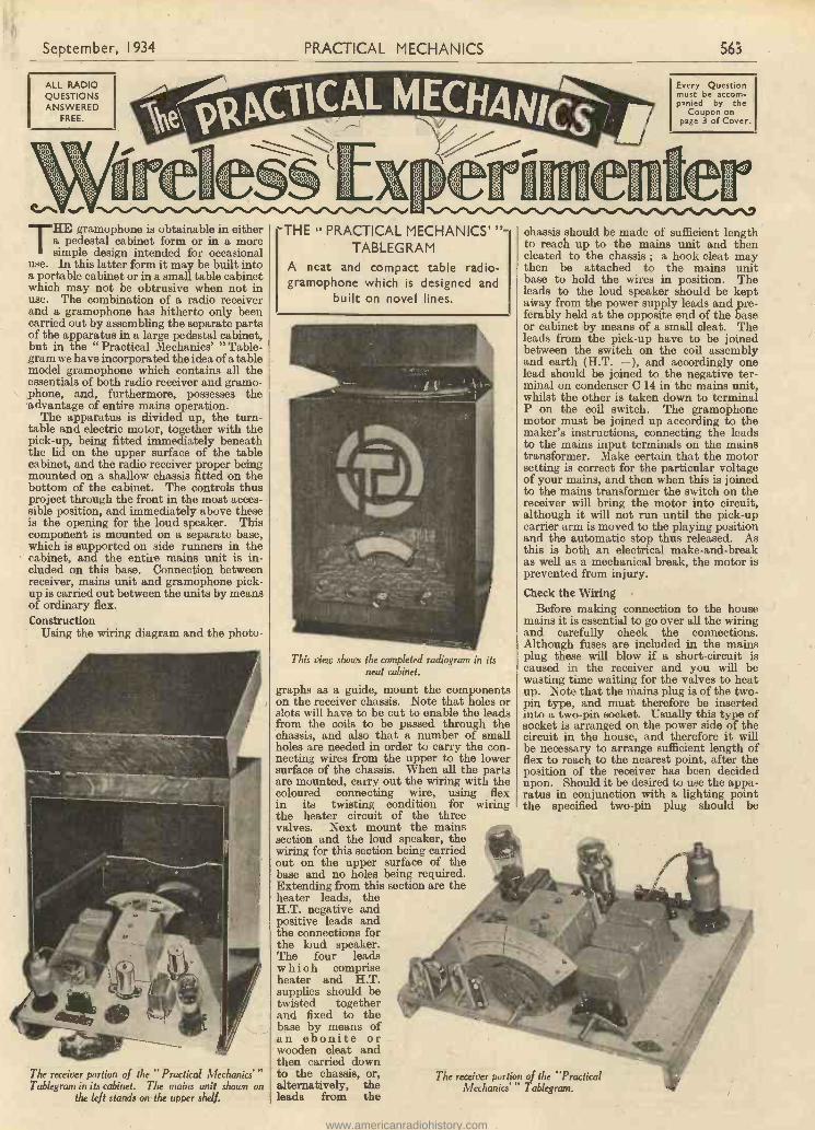
September, 1934 PRACTICAL MECHANICS 563
ALL RADIOQUESTIONSANSWERED
FREE.
ei.". ''Nkoe1ioirWij,iaoor"%/Nid"%S'Swe"i.sr.%.^.or\dr\ii/NeSo".d
THE gramophone is obtainable in eithera pedestal cabinet form or in a moresimple design intended for occasional
use. In this latter form it may be built intoa portable cabinet or in a small table cabinetwhich may not be obtrusive when not inuse. The combination of a radio receiverand a gramophone has hitherto only beencarried out by assembling the separate partsof the apparatus in a large pedestal cabinet,but in the " Practical Mechanics' " Table -gram we have incorporated the idea of a tablemodel gramophone which contains all theessentials of both radio receiver and gramo-phone, and, furthermore, possesses theadvantage of entire mains operation.
The apparatus is divided up, the turn-table and electric motor, together with thepick-up, being fitted immediately beneaththe lid on the upper surface of the tablecabinet, and the radio receiver proper beingmounted on a shallow chassis fitted on thebottom of the cabinet. The controls thusproject through the front in the most acces-sible position, and immediately above theseis the opening for the loud speaker. Thiscomponent is mounted on a separate base,which is supported on side runners in thecabinet, and the entire mains unit is in-cluded on this base. Connection betweenreceiver, mains unit and gramophone pick-up is carried out between the units by meansof ordinary flex.Construction
Using the wiring diagram and the photo -
The receiver portion of the "Practical MechanicsTablegram in its cabinet. The mains unit shown on
the left stands on the upper shelf.
-THE " PRACTICAL MECHANICS' "-TABLEG RAM
A neat and compact table radio-gramophone which is designed and
built on novel lines.
This view shows the completed radiogram in itsneat cabinet.
graphs as a guide, mount the componentson the receiver chassis. Note that holes orslots will have to be cut to enable the leadsfrom the coils to be passed through thechassis, and also that a number of smallholes are needed in order to carry the con-necting wires from the upper to the lowersurface of the chassis. When all the partsare mounted, carry out the wiring with thecoloured connecting wire, using flexin its twisting condition for wiringthe heater circuit of the threevalves. Next mount the mainssection and the loud speaker, thewiring for this section being carriedout on the upper surface of thebase and no holes being required.Extending from this section are theheater leads, theH.T. negative andpositive leads andthe connections forthe loud speaker.The four leadswhich compriseheater and H.T.supplies should betwisted togetherand fixed to thebase by means ofan ebonite orwooden cleat andthen carried downto the chassis, or,alternatively, theleads from the
Every Questionmust be accom-panied by the
Coupon onpage 3 of Cover.
chassis should be made of sufficient lengthto reach up to the mains unit and thencleated to the chassis ; a hook cleat maythen be attached to the mains unitbase to hold the wires in position. Theleads to the loud speaker should be keptaway from the power supply leads and pre-ferably held at the opposite end of the baseor cabinet by means of a small cleat. Theleads from the pick-up have to be joinedbetween the switch on the coil assemblyand earth (H.T. - ), and accordingly onelead should be joined to the negative ter-minal on condenser C 14 in the mains unit,whilst the other is taken down to terminalP on the coil switch. The gramophonemotor must be joined up according to themaker's instructions, connecting the leadsto the mains input terminals on the mainstransformer. Make certain that the motorsetting is correct for the particular voltageof your mains, and then when this is joinedto the mains transformer the switch on thereceiver will bring the motor into circuit,although it will not run until the pick-upcarrier arm is moved to the playing positionand the automatic stop thus released. Asthis is both an electrical make -and -breakas well as a mechanical break, the motor isprevented from injury.
Check the WiringBefore making connection to the house
mains it is essential to go over all the wiringand carefully check the connections.Although fuses are included in the mainsplug these will blow if a short-circuit iscaused in the receiver and you will bewasting time waiting for the valves to heatup. N ote that the mains plug is of the two -pin type, and must therefore be insertedinto a two -pin socket. Usually this type ofsocket is arranged on the power side of thecircuit in the house, and therefore it willbe necessary to arrange sufficient length offlex to reach to the nearest point, after theposition of the receiver has been decidedupon. Should it be desired to use the appa-ratus in conjunction with a lighting pointthe specified two -pin plug should be
The receiver portion of the "PracticalMechanics"' Tablegram.
www.americanradiohistory.com

564 PRACTICAL MECHANICS September, 1934
VOLUME CONTROL
REACTION
23'; I 2 Yz"
Dimensioned diagram of the controls of theradiogram.
retained and one of the lamp -socketadaptors should be obtained and pluggedinto the lamp -socket so as to accommodatethe two -pin plug. When checking thewiring it is a good plan to use a meter and abattery, thus making perfectly certain thatjoints are soundly constructed as well asshort-circuits avoided. When finally certainthat everything is in order the receiver maybe tested out, but for this purpose it ispreferable to ignore the pick-up connections,and to place the receiver and the mainsunit side by side on a table so that allconnections are easily got at for testingpurposes.
OperationOperation of this instrument is simplicity
itself. The control knob on the coils has fourpositions-when turned in an anti -clockwisedirection as far as it will go the receiver isswitched off and is dead. As it is rotated ina clockwise direction it will fall into definitepositions, the first being the medium wave-band, the second the long -wave .band andthe third switches out the tuning circuitsand connects the grid of the detector valve
LIST OF COMPONENTSOne set Ferrocart Coils, 01, G2 and G3, with Mains
Switch, Colvern.One Midget Three Gang Condenser, .0005 mfd. with
Drive, Polar.One -00015 mfd. Differential Reaction Condenser,
Polar.Two S.H.F. Screened H.F. Chokes, Ward and
Goldstone.Two 5 -pin and one 7 -pin Chassis Type Valveholders,
Clix.One Toco L.F. Transformer, Multitone.One 5,000 -ohm Volume Control, Burne Jones.One W.31 Mains Transformer, Heayberd.One H.T. 8 -metal Rectifier, Westinghouse.Three 4 mfd. Fixed Condensers (350 -volt test),
T.M.C.One 0001 mfd. Tubular Condenser, T.M.C.One .0002 PI /fOne .0005Two 1 mfd. Type 25 Fixed Condensers,' T.M.C.One .1One 2One .5One 30,000 ohm. Fixed 'Resistance, Ferranti.One 15,000One 20,000 Three 500One 300Two 5,000 One 1-megohm Grid 'Leak, Feiranti.One Mains Smoothing Choke (Type 751), Heayberd.One M.C.22 M.C. Speaker, Amplion.One Tablegram Cabinet, Peto-Scott.One Metaplex Chassis, 14' x 10' with 1rrunners,
Peto-Scott.One Bulgin Mains Connecting Plug with .5 amp
Fuses, Bulgin.One AC/VP Valve, one AC/HL Valve, and one
AC/Y Valve, Hivac.One 50 mfd. (Type 501) and one 50 mfd. (Type 521)
Electrolytic Condenser, T.C.C.One Belling -Lee A. and E. Strip.Flex, Connecting Wire, Screws, etc.One Garrard Electric Gramophone MotorOne Pick-up, Belling -Lee.Two Component Brackets (21 in.), B.R.G.
TUNING
_I_ 31;
WAVECHANGEN -OFF AND.
GRAMO SWITCH
to the pick-up circuit. A small letter willbe found embossed on the control knob toindicate these positions, so that no difficultyshould arise. When the coil switch hasbeen adjusted to the desired position, themain tuning control should be turned sothat the pointer is in the position indicatingthe nearest station, and if any doubtarises concerning its exact wavelengththe programmes published in the dailypaper or the Radio Times should be con-sulted. Provided that the station is not toofar away, it should be possible to hear somesort of signal at this setting, and the extremeleft-hand control should then be adjusted toreduce the strength of the signal to almostinaudibility. Now carefully adjust the
(Continued on page 566.)
01 MFD
I5
I MFD
CONNECTIONSON
UNDERSIDEOF COIL UNIT
16
ro MAINS TRANS4"..081: HEATER TERMS 4V5A
E
8
SLOTSCUT IN
BASEBOARD
500 OHMS.,
1,25
I MEG.
C5
I MFD
H. T. +
p -H
R5
5,000OHMS
Rg
000OHMS
10
3
MB
ro
V3
14
500 OHMS
C13
50 MFDELECTROLYTIC
COND
C12
2 MFD
15
.00 CII
0.5 MFD
TO PICK-UP
COILUNIT
O
TO MAINS TRANSINPUT TERMS.
///// / / I\ \ \
E A, 42 4300 0 . 0 0
141\ag.'.%= TO MAINS PLUG
TRIMMER
USED
.00015 MFD 12DIFFERENTIALREACTION COND
CT
TRIMMER
iii
TRIMMER
01 LL-LI 3 GANGTUNING
H FCHOKE CONDENSER
M.B
15
O
5,000 OHMVOLUME CONTROL
R3
CHORE
NOTE- POINTS MARKEDC ARE CONNECTIONSTO METALLISEDBASEBOARD.
LFTRANSFORMER
N. V
TO TERMINALON SIDE OF Vs"
14
Wiring diagram of the" Practical Mechanics' " Tablegram.
www.americanradiohistory.com

September, 1934 PRACTICAL MECHANICS 565
The Pilot KitSERVICE was/ounded in 1919.
P.M. TABLEGRAM TELEVISION RECEIVER KIT PILOT AUTHOR KITEXACT TO SPECIFICATION
P.M. TABLEGRAM
PETO-SCOTTHAS IT FIRST
Originators of Kits of parts in 1919,we supply all your Radio Needs
CASH, C.O.D. or EASIWAY. Our Customersare invited to take advantage of our FREETechnical Service or call for Demonstration atour Showrooms, 77 City Road, London, E.C.1,or 62 High Holborn, London, W.C.1.
1935 ADAPTAGRAMCONVERT YOUR PRESENT SETTO A MAGNIFICENT RADIOGRAM
Hand French Polished byleading experts of Lon-don's piano trade. Alljoints mortised and ten-oned. Ready to take yourset, speaker, power equip-ment and your own gram°fittings. With ready -fitted motor board. Plainfront or vignetted to takeany panel up to 18 ins. by18 ins., or specially drilledto your own dimensionedsketch at slight extracost.
Overall Dimensions981 ins. high by 22Cins. by 17* ins. deep.
MODEL ccA." Cash or C.O.D., 63/-. Carriageand Packing 24 extra England or
Wales. Yours for 8/3 and 11 monthly payments of5/9. Baffie-board 3/6 extra.
WALNUT, OAK or MAHOGANY to choice.
MODEL " B " Bet itnot
Standard 1935 Adaptagramwith Double spring Motor. 12 -in. Plush -covered Turntable,Automatic Stop, B.R.G. ToneArm with Pickup, and VolumeControl Complete-AutomaticNeedle Cup that delivers newneedles one at a time to yourfinger tips. Cash or SC.O.D., or 12 monthly Npayments of 12/ -
Loudspeaker CompartmentBaffle -board fitted if required,
3/6 extra.
MODEL " C " Ei;octircStandard 1935 AdaptagramCabinet-Collaro or GarrardInduction Electric Motor withTone Arm, Pickup and VolumeControl -12 -in. Plush -coveredTurntable-Automatic Stop-Automatic Needle Cup thatdelivers needles one at a timeto your finger tips. A.C. GMains only. Cash or NC.O.D., or 12 monthly Spayments of 13/9. D.O.Model Prices on application.Loudspeaker CompartmentBaffle -board fitted if required,
3/6 extra.
pay -scot& rP4g;f1rdrair4111V,E7;FULL-SIZE CONE-NOT A MIDGETPower or Pentode. Cash or C.O.D.Complete with input 19/6Transformer. Send Carr. Paid.2/6 with order.Balance in 5 monthlypayments of 4/-.Class B Model. Cashor C.O.D. Carr. Paid.51.2.6 or 2/6 down
and 9 monthly payments of 4/-.
KIT "A" 23,1134V,Kit of First
Specified Parts, less Valves andCabinet. Cash or C.O.D., carriagepaid, 510.17.6.
KIT I B." As for Kit"A," but including setof Specified Valves.Cash or C.O.D. (carriagepaid). 512.16.0.Or 12 monthly pay-ments of 23/6.
Yours for
201 -Balance in 11
monthly payments of 20/ -
KIT "C." As for Kit" A," but including setof Specified Valves andPeto-Scott TablegramCabinet. Cash orC.O.D. (carriage paid).515.13.6. Or 12 monthlypayments of 28/9.
Tf Amplion Speaker is required with above Kits, add21.19.6 to Cash or C.O.D. Price, or add 3/6 to depositand to each monthly payment. '
If Garrard Electric Motor is required with aboveKits, add 22.10.0 to Cash or C.O.D. Price, or add4/6 to each monthly payment.
If Belling -Lee Pick-up is required with above Kits,add 21.10.0 to Cash or C.O.D. Price, or add 2/9 todeposit and to each monthly payment,
PETO-SCOTTWALNUT
TABLEGRAMCABINETAnother exclusive anddelightful cabinet byPETO - SCOTT. Thebeautiful walnut finishand handsomecontrasting macassarveneer set the seal ofperfection in cabinetdesign on this latestPeto-Scottproduction.
Cash or C.O.D. (carriage paid).H.P. 7/6 Deposit and 11 monthly payments of 5/ -Loudspeaker Baffle Baseboard Assembly ifrequired 3/6 extra. State size of hole required 57'6when ordering.
PILOT Class "B" 4KIT "A"CASH OR C.O.D. £3 : 16 : 6Carriage Paid. Or 12 Monthly Payments of 7/-
K I T 66 A." Comprising Author's Kitof first specified parts, less valves and cabinet.
KIT " B." As for Kit" A," but including setof 6 specified valves,only Cash or C.O.D.(carriage paid). 25.7.6.Or 12 monthly pay-ments of 9/9.
KIT "C." As for Kit" A," but including setof specified valves andcabinet. Cash or C.O.D.(carriage paid). 26.0.0.Or 12 monthly pay-ments of 11/-.
If Pete -Scott Bargain Class II" Speaker required withKit, add 17/6 to cash or C.O.D. prices, or 1/7 todeposit and each monthly payment.
See the PILOTon the carton. It'sa real guarantee.
PETO-SCOTT-751. DISC
TELEVISION ASSEMBLED IN 30 MINUTES
NO SPECIALTOOLS
REQUIRED
Your for
I 5/ -and 11 monthly
' payments of 6/3.Cash or C.O.D.
- -Carriage Paid, 75/-.
PETO-SCOTT, Pioneers in Television since 1927, after consi-derable research, have produced this "up-to-the-minute"
Dice Tiblevision Receiver Kit, of which Efficiency and Econ-omy are the key notes. Designed to work from almost any3 -valve battery or mains set, the Peto-Scott 75/- Disc Tele-vision Receiver is supplied in Kit form, and comprises Pets -Scott Universal Television Motor and Stand ; controllingresistances ; laminated and ready assembled chassis; Strobo-scopic 16 -in. scanning disc; Lens and Lensholder ; NeonLamp and Holder, together with sundry small parts. It isabsolutely complete down to the last screw and piece of wire.Full-size Blueprint with assembly, wiring and operatinginstructions included with every kit.
"Saft44PILOT CLASS B
1935 SPEAKER -AMPLIFIER KITGIVES YOUR PRESENT BATTERY SET A
NEW LEASE OF LIFEObtain seven times the volumewith mains quality from yourexisting battery set by convert-ing it to Class B amplification.This amazing Unit comprisesB.V.A. Class B Valve, 1935 Pete,Scott Permanent -Magnet MovingCoil Speaker. B.R.G. DriverTransformer and seven-piff ValveHolder. Pato-Scott Baffle andBaseboard Assembly, all Wires,Screws and plug-in Valve Adap-tor. With full-size Diagramsand Assembly Instructions.Complete with Speaker. Cash or C.O.D.Carriage Paid. Or send only 5/-.Balance in 9 monthly payments of 5/ -
SUITABLE FOR ANY BATTERY SET-
IMPORTANT
45, -
Miscellaneous Components, Parts, Kits, Finished Receiversor Accessories for Cash or C.O.D, or H.P. on our own Systemof Easy Payments. Send us a list of your wants. We willquote you by return. C.O.D. orders value over 10/. sentcarriage and poet charges paid (GREAT BRITAIN ONLY).OVERSEAS CUSTOMERS CAN SEND TO US WITH CONFI-DENCE. We carry a special export staff and cave alldelay. We pay half carriage packed free. Send fullvalue plus sufficient for half carriage. Any surplus re-funded immediately. Hire Purebase Terms are NOTavailable to Irish or Overseas customers.
- - - - - - - - - - - - -I PETO-SCOTT CO. LTD., 77 City Rend, London, E.C.1
Telephone : Clerkenwell 9406/7.11I West End Showrooms: 62 High Holborn. London, W.C.I.
Telephone: Holborn 3248.I Dear Sirs,I(a) Please send me..116 I enclose Cash/DepositNAME
I ADDRESS
- - Pr.M. 9/341
rf3a/y.Oti Past -i4 QUiCka-CASH:.C.O.D.-EASIWAY
www.americanradiohistory.com
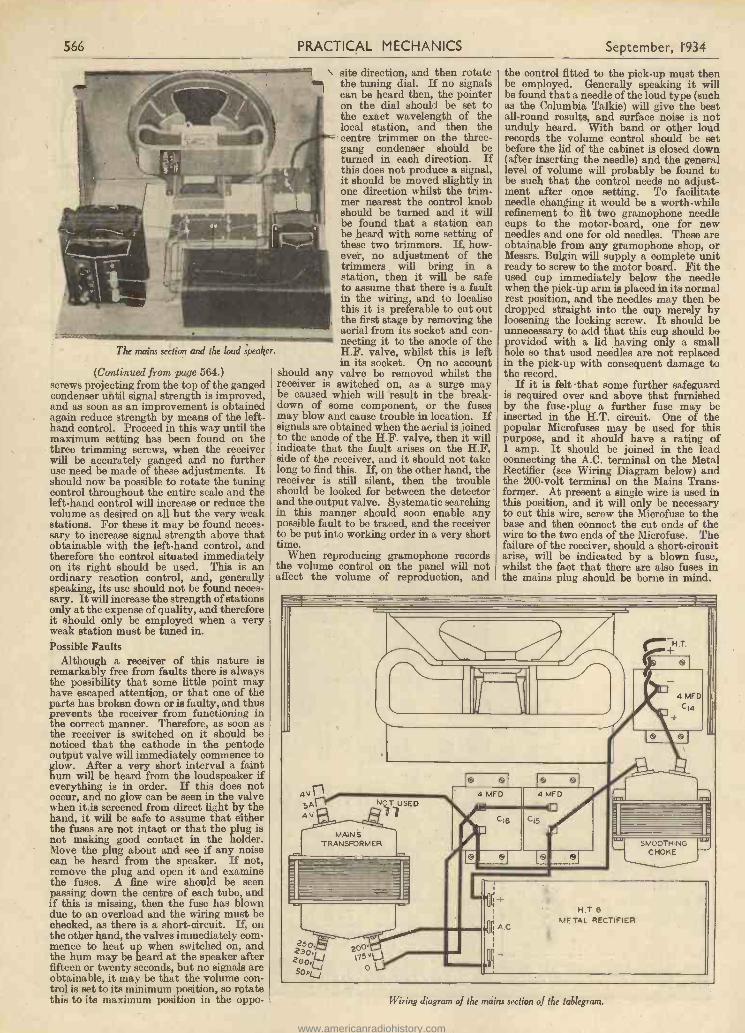
566 PRACTICAL MECHANICS September, 1934
The mains section and the loud speaker.
(Continued from page 564.)screws projecting from the top of the gangedcondenser until signal strength is improved,and as soon as an improvement is obtainedagain reduce strength by means of the left-hand control. Proceed in this way until themaximum setting has been found on thethree trimming screws, when the receiverwill be accurately ganged and no furtheruse need be made of these adjustments. Itshould now be possible to rotate the tuningcontrol throughout the entire scale and theleft-hand control will increase or reduce thevolume as desired on all but the very weakstations. For these it may be found neces-sary to increase signal strength above thatobtainable with the left-hand control, andtherefore the control situated immediatelyon its right should be used. This is anordinary reaction control, and, generallyspeaking, Its use should not be found neces-sary. It will increase the strength of stationsonly at the expense of quality, and thereforeit should only be employed when a veryweak station must be tuned in.Possible Faults
Although a receiver of this nature isremarkably free from faults there is alwaysthe possibility that some little point mayhave escaped attention, or that one of theparts has broken down or is faulty, and thusprevents the receiver from functioning inthe correct manner. Therefore, as soon asthe receiver is switched on it should benoticed that the cathode in the pentodeoutput valve will immediately commence toglow. After a very short interval a fainthum will be heard from the loudspeaker ifeverything is in order. If this does notoccur, and no glow can be seen in the valvewhen it is screened from direct light by thehand, it will be safe to assume that eitherthe fuses are not intact or that the plug isnot making good contact in the holder.Move the plug about and see if any noisecan be heard from the speaker. If not,remove the plug and open it and examinethe fuses. A fine wire should be seenpassing down the centre of each tube, andif this is missing, then the fuse has blowndue to an overload and the wiring must bechecked, as there is a short-circuit. If, onthe other hand, the valves immediately com-mence to heat up when switched on, andthe hum may be heard at the speaker afterfifteen or twenty seconds, but no signals areobtainable, it may be that the volume con-trol is set to its minimum position, so rotatethis to its maximum position in the oppo-
230v6200.6
site direction, and then rotatethe tuning dial. If no signalscan be heard then, the pointeron the dial should be set tothe exact wavelength of thelocal station, and then thecentre trimmer on the three -gang condenser should beturned in each direction. Ifthis does not produce a signal,it should be moved slightly inone direction whilst the trim-mer nearest the control knobshould be turned and it willbe found that a station canbe heard with some setting ofthese two trimmers. If, how-ever, no adjustment of thetrimmers will bring in astation, then it will be safeto assume that there is a faultin the wiring, and to localisethis it is preferable to cut outthe first stage by removing theaerial from its socket and con-necting it to the anode of theH.F. valve, whilst this is leftin its socket. On no account
should any valve be removed whilst thereceiver is switched on, as a surge maybe caused which will result in the break-down of some component, or the fusesmay blow and cause trouble in location. Ifsignals are obtained when the aerial is joinedto the anode of the H.F. valve, then it willindicate that the fault arises on the H.F.side of the receiver, and it should not takelong to find this. If, on the other hand, thereceiver is still silent, then the troubleshould be looked for between the detectorand the output valve. Systematic searchingin this manner should soon enable anypossible fault to be traced, and the receiverto be put into working order in a very shorttime.
When reproducing gramophone recordsthe volume control on the panel will notaffect the volume of reproduction, and
the control fitted to the pick-up must thenbe employed. Generally speaking it willbe found that a needle of the loud type (suchas the Columbia Talkie) will give the bestall-round results, and surface noise is notunduly heard. With band or other loudrecords the volume control should be setbefore the lid of the cabinet is closed down(after inserting the needle) and the generallevel of volume will probably be found tobe such that the control needs no adjust-ment after once setting. To facilitateneedle changing it would be a worth -whilerefinement to fit two gramophone needlecups to the motor -board, one for newneedles and one for old needles. These areobtainable from any gramophone shop, orMessrs. Bulgin will supply a complete unitready to screw to the motor board. Fit theused cup immediately below the needlewhen the pick-up arm is placed in its normalrest position, and the needles may then bedropped straight into the cup merely byloosening the locking screw. It should beunnecessary to add that this cup should beprovided with a lid having only a smallhole so that used needles are not replacedin the pick-up with consequent damage tothe record.
If it is felt that some further safeguardis required over and above that furnishedby the fuse -plug a further fuse may beinserted in the H.T. circuit. One of thepopular Microfuses may be used for thispurpose, and it should have a rating of1 amp. It should be joined in the leadconnecting the A.C. terminal on the MetalRectifier (see Wiring Diagram below) andthe 200 -volt terminal on the Mains Trans-former. At present a single wire is used inthis position, and it will only be necessaryto cut this wire, screw the Microfuse to thebase and then connect the cut ends of thewire to the two ends of the Microfuse. Thefailure of the receiver, should a short-circuitarise, will be indicated by a blown fuse,whilst the fact that there are also fuses inthe mains plug should be borne in mind.
4,,nSA4V
MANSTRANSFORMER
2so zoo"175'Ve/50eL 0j
4 MFD 4 MED
CIS C'5
4 MFD
C'4
SMOOTHINGCHOKE
H.T 6
METAL REcTivlEr
Wiring diagram of the mains section of the tablegram.
www.americanradiohistory.com

September, 1934 PRACTICAL MECHANICS 567
AMPLION " LION" SPEAKERS ARETHE ONLY SPEAKERS THAT CANBE CORRECTLY MATCHED TOEVERY CLASS OF OUTPUT VALVE
Ratios are provided for every output valve withoptimum load impedance from 2,000 to 40,000 ohms.
The New Sealed Magnetic Gap ensures that quality
reproduction is consistently maintained at thepinnacle of perfection.
Amplion
specified
for the" TABLE GRAM "
The exceptional matching facilities of Lion"speakers render them suitable for use withany receiver.
UNIVERSAL TRANSFORMER I to 20AND 2,000 to 40,000 OHMSPROVISION FOR VOLUME OR TONECONTROL AND USE OF ADDITIONALSPEAKER
AMPLION LION "PERMANENT MAGNETMOVING COIL SPEAKER
Amplion Lion Super " 10 in. Cone 55/
SPEAKERS - RECEIVERS -
47/6(7 in. Cone)
RADIOGRAMS(Descriptive Literature sent on request.)
AMPLION (1932) LTD.82-84 Rosoman Street, Rosebery Avenue, London, E.C.I
Adjustable. No. 1096Without Volume Control.
No. 1177
"GOLTONE"COMPONENTS
AGAIN SELECTEDli
.4111111EMMENIMIIIMIIIIIIMMI
This timefor the
"P.M.TABLEGRAM"" GOLTONE" SCREENED
HF. CHOKESType S.H.F, Specified exclusively.Highly efficient, robust mechanicalconstruction. Inductance 250.000
mice. approx.Price 4/. each
"GOLTONE" 3 -COILAND SWITCH CHASSISWith IRON CORED COILS', in.eluding G.I.C.5 and G.I.C.6 Band-pass units, and G.I.C.2 withreaction. Q. M.B. Switch included.Complete chassis as described
R/0.I.0.23 S13/6
See Catalogue and Pamphlet forfull particulars.
"Gallons" components are obtain-able from all first-class RadioStores-refuse substitutes-if any
difficulty write direct
Wrd GoldtatonPENDLE TON
FR EEON REQUEST .1LARGE 1934/35 60 -pagenew edition RADIOCatalogue just released]
SPECIFIED BYTHE DESIGNER
ModelD
The quality of the Belling -Lee range of pick-ups shouldbe compared with more expensive models, when it willbe found to give a better performance for a lower price.Model A.Model D.
each 27/6
each 30/ -Model C. As D, but with Volume Control.
No. 1117 . . each 35/ -
The " CLIP -ON "PICK-UP
Gives Radiogram resultsfrom any gramophone with-out affecting portability.Clips on and off in aninstant. Adjustable tone -arm and head, volumecontrol, etc.No. 1103 . . . each 35/Write for book, post free, 2ci
BELLING & LEE LTDCAMBRIDGE ARTERIAL ROAD, ENFIELD, MIDD X
www.americanradiohistory.com

568 PRACTICAL MECHANICS September, 1934
OLD WATERLOO BRIDGEInteresting facts about its construction and some reasons for its decay.
THE failure by subsidence into the bedof the Thames of part of this famousbridge, the many arguments and dis-
cussions - often heated - in the Press,Council Chambers and Parliament, regard-ing the merits and demerits of the bridge,and its demolition and replacement by anew and modern bridge, causes us to reflectupon the traffic conditions that existednearly a century and a quarter ago, and thescientific knowledge and materials in usethen, and the conditions and knowledge ofour modern times.Mud, Clay and Timber Foundations
But few motorists who used WaterlooBridge, and spectators who admired itsnine spans of 120 ft. each, constructed withheavy granite arches and about 20 -ft. thickabutments, gave much thought to anythingelse except what could be perceived abovewater level, and the conveniences of transit.The lay mind seldom gave much thoughtas to what existed below water level, andthe ravages that were occurring in thefoundations due to time, and the use ofconstructive methods and materials about120 years ago that do not conform topresent-day principles, which are con-sidered to ensure a much longer life than120 years for a bridge.
An outstanding feature of WaterlooBridge is that the many thousands of tonsof dead load of masonry, and the superloads of modern day traffic, with its con-siderable vibration, have foundations con-sisting of heavy timber platforms placed atabout the level of the river bed, such plat-forms being supported by timber pilesdriven into the London clay under the riverbed. The illustration will give a good ideaof the method of construction.An Interesting Point
Although certain timbers, when keptconstantly wet, resist decay for a veryconsiderable time, it is difficult, especiallyin the face of present-day knowledge, tofail to be surprised that the natural decay
of the timber due to time, insects andworms that attack wood, and the rottingagents that must exist in mud and clay,has not caused an earlier failure of thebridge. These conditions must raise in theminds of many thinkers the vital questionas to whether the designers of the bridge,John Rennie and his son, Sir John Rennie,used the best principles in their time. (It isunlikely that Rennie designed the bridge. Itis more probable that Rennie's capable pre-decessor in office-Dodson-designed thebridge, and that Rennie succeeded in gettingDodson removed from office, filching the creditreally due to Dodson. The design of the archesis, however, open to severe criticism.-En.) Alittle thought and research brings to lightsome interesting facts which tempt one toconclude that materials and principles ofbridge construction in use in about 1815were different to those used nowadays.Prior to 1824, when Portland cement wasfirst introduced, lime concrete was used,which was considerably weaker than themodern Portland cement concrete. Rein-forced concrete, that is, concrete which isstrong in compression and weak in tension,having combined with it steel to resisttensile stresses, is a comparatively recentprinciple of construction.Reducing the Total Dead Weight
In summing up all the conditions, wefeel that the methods and materials usedin 1815 were in conformity with theprinciples that were then existent. Itappears that it would have been possibleto have reduced the total dead weight ofthe bridge, and still maintained an amplemargin of safety, by reducing the size ofthe 20 -ft. thick piers or abutments, andproviding a greater area at the base of them,which would have had the effect of spread-ing the load over a greater area of river bed,and possibly eliminating the necessity ofthe timber platforms, and to allow the loadsto be carried on the piles and clay only.
We favour the view held by some authori-ties that the timber foundations have
BFILISTIZRDED PARAPET
rotted, and also feel that due respect mustbe given to the opinions of other expertswho think that the weight of the bridge wastoo great for the foundations, and also thatcurrents have swept away some of thegravel which appears to exist in additionto the clay under the foundations. It mustbe stated that there appears to be evidencethat the woodwork is still quite sound, buttoo much reliance should not be given tothis evidence, owing to the difficulties ofcarrying out tests before the bridge has beendemolished.
At the present time no one can tell withcertainty what is the cause, but when theold bridge is demolished it is certain thatour great modern engineers will find thecause and take precautions to prevent thenew bridge failing.
Old Rivers beneath the ThamesIt is exceptionally interesting to be able
to state that it is possible that the cause ofthe subsidence of Waterloo Bridge may bepartly attributed to the action of a smallriver, the Fleet, which existed a very longtime ago, and which, according to oneauthority, wended its way along a course(different to that which it does now) whichwent under the present positions of theThames and the centre of Waterloo Bridge,and entered into one of the old courses ofthe Thames which was by the Elephant andCastle. A well-known geologist, Mr. F. H.Mackintosh, who was consulted regardinga problem which arose in connection withthe foundations of Unilever House, Black -friars Bridge, discovered, after boringoperations, the old channel of the RiverFleet, its course being directed towards thecentre of Waterloo Bridge The geologistadvances the theory that the old channel ofthe Fleet caused disturbances in the geolo-gical formation of the ground under Water-loo Bridge, and that in consequence thereare certain pockets of gravel and re-deposited clay that may have affected thefoundations of the bridge.
Kmotttavaut 1)2)3AZIAMIA 1,11M matxtta MIlt101,i1 lat d,Alt
1f111!I'1Ji FTII 11
'1 11j
IIRIVER LONDON 11
1111111111 TIMBER BED. CLAYI 1 PLF1TFOM
II II 11 I OR GRILRLFIGE.
TIMBER 11
II1 11 11 11
1'I11 PILES. 11
II A part section of one of the arch es of Waterloo Bridge, showing the construction and Ny.10foundation below the River Thames.
RIVER THAMES.
W.FITER. - -= -- - - -II
II (11111fill«al,(1(0111111(1111(ifuitgligirtii,ilritill.rer"ii I.1111717111 Irrirr 0111111Tirr I Irrn iirrrforrniirrrrwm-r fro rz4N"qlkzk.sir,ws,
)10i) »is. !I !,.(,) II II 1 1: II111111111i1I II I1 11 1: 11
it 11 11 11 V1 11 11 11 IiI 11 11 11 II 11
I II 11 II 11 II
(Ir
www.americanradiohistory.com

September, 1934 PRACTICAL MECHANICS 569
Fig. 14.-Pearson'sBristol and Exetertank engine,I853-4.
HISTORIC LOCOMOTIVES
_I-iimmm ..0in.-(-'\\;T:,77-."\-r 4iiiii -,,),iiirlii
-MI
,1111,1111111111,,,
PART VBy E. W. TWINING
5' 6SCALE OP Peett
6' 75' 6 14'
9, a; 4
THE next class of locomotive which Ithink should be recorded as havingoutstanding characteristics is a batch
of eight. numbered 39 to 46, designed byMr. Pearson, the locomotive engineer of theBristol and Exeter Railway, for workingthe express passenger trains between thetwo terminal points of his line. The railwaywas broad gauge and formed a continuationwestward of the Great Western main line.These engines achieved world fame forthemselves by putting up the high authen-ticated speed of 81 miles per hour, whichwas not exceeded until after the close of thenineteenth century.
They were of unusual design and ofextraordin- a r y con-struction. The wheelarrange- ment wasof 4-2--4 type, aswill be seen in the draw-i n g (Fig. 14), that isto say, there weretwo four- wheelbogies, oneend, whichplay, beingtheir cen-tres on balland socketjoints. Thedrivingwheels werethe largest
at eitherhad no sidepivoted at
ever successfully run and the largest madein Great Britain, with the exception of thetwo or three early freak engines of theG.W.R. in 1837. They were 9 ft. in diameterand had no flanges.
These Uristol and Exeter engines had notenders. hey were thus double -enders andcarried their water in two tanks, one in thenormal position behind the firebox and theother slung beneath the boiler in front ofthe driving axle and partly underneath andpartly between the motion. They were con-structed by Bothwell & Co., of Bolton,Lancashire, and were delivered in 1853 and1854. Their weight loaded was 42 tons andthe valves were operated by Gooch valvegear. There appears to be no record of theheating surface or of the firegrate area, butthe first could not have been greater than1,100 sq. ft., and the latter not more than20 sq. ft. Although the boiler was small, itsupplied steam to a pair of cylindersmeasuring 16i x 24 in. It speaks well forthe efficiency of these engines when it isstated that the fuel consumption was only211 lb. of coke per mile.
Turning to the construction, which I
5'9
referred to as having been extraordinary,the frames were extremely light, measuringonly 8 in. deep and terminating at the fire-box, to which they were riveted. As will beseen in the drawing, there was an outsideframe with axle boxes at the driving wheel,and the weight of the engine carried by thedriving axle was transmitted through rubbersprings from the top of the boiler ; thus thelight inside frames took up only the workingstresses of the machinery. The leadingbogie had its pivot pin attached to thecylinders, whilst the rear bogie was pivotedto the underside of the main tank. It willbe seen, therefore, that the firebox had totake up all road inequality stresses, and theboiler barrel, through the front tube plate,took those occurring in front of the drivingaxle. Obviously, through the firebox alsowas transmitted the draw -bar of the train.
Perhaps even more extraordinary thanthe construction is the fact that these loco-motives ran consistently well for fifteen
years, that isto say, until1868, whenthey werescrapped andnew engines ofsimilar typewere built,having con -tinuous frames
- 2.1190. 991. 5 9%' 7'S' 4:SirSCALE OF FEET
*? 4 4 1 4. 4, '5, 4 7, 8, 9,
Fig. 15.-Gooch'i broad gauge engine "Ivanhoe," 1855.
www.americanradiohistory.com
570 PRACTICAL MECHANICS September, 1934
"HIGH SPOTS" from theBASSETT-LOWKE Model Works
Spick and span, fresh from the heart of the Midlands, waiting toimprove some lucky boy's layout-to give it that little something"extra "-SCALE FINISH-that every one of us wants.A really handsome new 0-6-0 Tank fitted with all -British motormechanism, outside cylinders, etc., and finished in black with redlines. Clockwork L2 2s. Od. Electric, D.C., 6-8 volts, or A.C., 20volts, L2 5s. Od." ASHFIELD," the modern Northampton -made station, to theLondon Passenger Transport Board design. Finished in light creamwith blue facings. LI 5 0. Island Platform I9s. 6d.New range of Gauge "0 " Upper Quadrant Signals, from 7s. 6d.Three new continental type locomotives in Gauge "0."
German State Railways 4-6-2 type - E6 10s. Od.American 4-6-4 type (New York Central) - E7 is. Od.French Mountain 4-8--2 type - - - E8 8s. Od.
Send for free leaflets of our new productions or, better still, write for ModelRailway Catalogue, A.12, price 6d. post free. New Boiler and Castings Catalogue,8.12, Model Ships and Fittings, S. 2, 6d. each.
BASSETT-LOWKE LTDLONDON: NORTHAMPTON MANCHESTER:112 High Holborn, 28 Corporation St.
W.C.I
The "CORONA" Electric DrillIS INDISPENSABLE TO ALL MECHANICS
Efficient, a model of accuracyand workmanship, and trouble -free qualities are the featuresof this drill. Its equipmentcomprises a powerful A.G. orD.C. Motor, voltages 100/ 120,200/ 230, 230/ 250, with
PRICE Armature Shaft In groundalloy steel. Hobbed gears inmetal housing. Hoffman ballthrust. Keyless chuck, }-in.capacity. Aluminium die cast
Please state voltage. handle. Current consumption175 watts, using In. drill on
mild steel. 8 ft. Cab tyre flex with earth wire. Weight 5 lbs.These drills are British Made and are designed for drilling up to In. diameterand are guaranteed under these conditions for six months and are now inconstant use in many factories. Send for illustrated leaflet to :-
CORONA ENGINEERING CO., Leighton Place, Kentish Town, N.111.5Tele. : GULLIVER 3739
£2. 15.0Carriage Paid.
TheSTAN LE
11,:. TRA1, ..a,/
VEST-POCKETMICROSCOPEThree magnificationsof 40, 50 and 60instantlyavailable.
17'sPost Free.
Soft Leather CaseI/6 extra.
Descriptive Leaflet P.255 uponapplication.
W. F. STANLEY & CO. LTD.The Largest Makers in the World of Surveying
and Drawing Office Equipment.
286 HIGH HOLBORN, LONDON, W.C.I
WHICH OF THESE IS YOUR PET SUBJECT ?CIVIL ENGINEERING GROUP.
Specifications. Structural Design.Road Engineering. Structural Engineering.Hydraulics. Reinforced Concrete.Municipal Engineering. Sanitary Engineering.General Civil Engineering. Geology.
SURVEYING GROUPValuations. Surveying and Levelling.Heating and Ventilating. Building Construction.Clerk of Works.
COMMERCIAL ENGINEERING GROUPSalesmanship. Commercial Engineering.Advertising. Cost Accounts.Languages.
One of theseA.M.I.C.E.A.M.I.Struct.E.Sanitary Inspectors.A.M.I.H. & V.E.A.M. I. Mech.E.A.M.I.P.E.
MECHANICAL ENGINEERING GROUPWorks Management. Heat Engines.Press Tool Work. Workshop Practice.Maintenance Engineering. Fitting and Erecting.Metallurgy. Inspection.Sheet Metal Work. Ironfounding.Welding. Pattern Making.Diesel Engines. Draughtsmanship.Refrigeration.
WIRELESS GROUPGeneral Wireless. Talking -PictureAdvanced Wireless. Engineering.Television. Radio Servicing.
examinations would multiplyA.M.1.W.T.A.Rad.A.M. I. M. T.A.F.R.Ae.S.B.Sc. Degree.
G.P.O. Supt. of Traffic.Patent Office Examiner.Handicrafts Instructor.Inspector of Factories.Aircraft Apprentices.
your earninInst. Mun. & Cy. E.M.R.San.l.F.S.I.A.R.I.B.A.L.I.O.B.F.A.I.
AUTOMOBILE ENGINEERING GROUPGarage Management. Claims Assessing.Electrical Equipment. High-speed Diesels.
ELECTRICAL ENGINEERING GROUPTraction. Mains Engineering.Electrical Supply. Telegraphy.Electrical Meters. Telephony.Electrical Design. Alternating Currents.Installations. Neon Lighting.Electrical Engineering. Power House Design.
AERONAUTICAL ENGINEERING GROUPAerial Navigation. Aero Engines.Aeroplane Design.
g power ! WHICH ONE?City & Guilds.A.M. I.Fire.E.A.M. I.E.E.A.M.I.A.E.A.M.I.Ae.E.
London Matriculation.G.P.O. Prob. Inspector.Air Navigators
Certificate.Ground Engineers'
Certificate.
May we send you full particulars of our unique tutorial organisation ? Whatever your requirementswhether you desire a complete course of instruction, or tuition in some specialised subject, our Organisationis so planned that it will dovetail into your needs exactly.
As an indication of the strength of the B.I.E.T. Tutorial Organisation it should be clearly notedthat we alone guarantee to return full fees to any student who does not pass his chosenExamination successfully. In short, " If you do not pass, you do not pay."
Send to -day for a free copy of " ENGINEERING OPPORTUNITIES." This valuable 256 -page Guideshows clearly and definitely the way in which you may carve out a successful career in your chosen branchof Engineering, irrespective of your age, education or experience. Among a host of other things, it givesdetails of all the above -mentioned Courses and shows the easiest way to prepare (in the privacy of your ownhome) for any of the recognised Examinations we have listed.
"ENGINEERING OPPORTUNITIES" should most certainly be in your hands. Send for yourcopy at once-free of cost or obligation.
BRITISH INSTITUTE of ENGINEERING TECHNOLOGY410 SHAKESPEARE HOUSE, 29-31 OXFORD STREET, LONDON, W.1
www.americanradiohistory.com
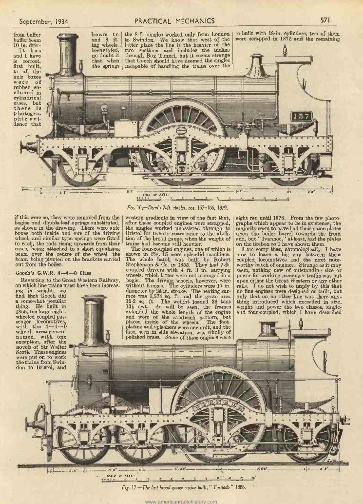
September, 1934 PRACTICAL MECHANICS 571
from bufferbuffer beam10 in. driv-It hasand I haveis correct,first built,to all theaxle boxeswere ofrubber en-closed incylindricalcases, butthere isp hotogr a-phic evi-dence that
beam toand 8 ft.ing wheels.been stated,no doubt itthat whenthe springs
- -.11111MMASIN
0 0 0 0 0 0 0 0
r--- 3' 8'
the 8 -ft. singles worked only from Londonto Swindon. We know that west of thelatter place the line is the heavier of thetwo sections and includes the inclinethrough Box Tunnel, but it seems strangethat Gooch should have deemed the singlesincapable of handling the trains over the
I
-7r,l111111,006.-
re -built with 18 -in. cylinders, two of themwere scrapped in 1872 and the remaining
a
1 5 7
if this were so, they were removed from thebogies and double -leaf springs substituted,as shown in the drawing. There were axleboxes both inside and out of the drivingwheel, and similar type springs were fittedto each, the rods rising upwards from theircases, being attached to a short equalisingbeam over the centre of the wheel, thebeam being pivoted on the brackets carriedout from the boiler.
Gooch's G.W.R. 4-4-0 ClassReverting to the Great Western Railway,
on which line trains must have_been increas-ing in weight, wefind that Gooch dida somewhat peculiarthing. He built in1855, ten large eight -wheeled coupled pas-senger locomotives,with the 4-4-0wheel arrangementnamed, with oneexception, after thenovels of Sir WalterScott. These engineswere put on to workthe trains from Swin-don to Bristol, and
2 a
SCALE OF peer:9' 2'
Fig. 16.-Dean's 7 -ft. singles, nos. 157-166, 1879.
western gradients in view of the fact that,after these coupled engines were scrapped,the singles worked unassisted through toBristol for twenty years prior to the aboli-tion of the broad gauge, when the weight oftrains had become still heavier.
The four -coupled engines, one of which isshown in Fig. 15 were splendid machines.The whole batch was built by RobertStephenson & Co. in 1855. They had 7 -ft.coupled drivers with 4 ft. 3 in. carryingwheels, which latter were not arranged in abogie. The driving wheels, however, werewithout flanges. The cylinders were 17 in.diameter by 24 in. stroke. The heating sur-face was 1,574 sq. ft. and the grate area19.2 sq. ft. The weight loaded 36 tons13i cwt. As will be seen, the framesextended the whole length of the engineand were of the sandwich pattern, butplaced inside of the wheels. The foot -plating and splashers were one unit, and theface, seen in side elevation, was wholly ofpolished brass. Some of these engines were
a'u' --mace or FEET.
6' 6'
eight ran until 1876. From the few photo-graphs which appear to be in existence, themajority seem to have had their name platesupon the boiler barrel towards the frontenfi, but " Ivanhoe," at least, had the plateson the firebox as I have shown them.
I am sorry that, chronologically, I havenow to leave a big gap between thesecoupled locomotives and the next note-worthy batch of engines. Strange as it mayseem, nothing new of outstanding size orpower for working passenger traffic was putupon either the Great Western or any otherrails. I do not wish to imply by this thatno fine engines were designed or built, butonly that on no other line was there any-thing introduced which exceeded in size,weight and power the two classes, single -and four -coupled, which I have described
Fig. 17.-The last broad -gauge engine built," Tornado" 1
www.americanradiohistory.com

J
572 PRACTICAL MECHANICS September, 1934
in which Gooch reached his ultimatum.Many fine examples of locomotive engineer-ing could be mentioned ; for instance, therewere Johnson's four -coupled bogies on theMidland, Patrick Sterling's 8 -ft. bogiesingles on the Great Northern, Stroudley's0-4-2 class on the Brighton line, andDrummond's 4-4-0 on the North British,to give only a few, and although my nextdrawing shows a class which was perhapsno larger than the general British practiceof the time, it was certainly well up to theaverage, and so I am adhering to the GreatWestern Railway.
Dean's 157-166 ClassIn 1864 Daniel Gooch ceased his work at
Swindon as locomotive engineer, and wassucceeded by Joseph Armstrong, who re-mained in the position until 1877, whenWilliam Dean was appointed. Two yearsafter taking up his duties, that is to say in1879, Dean designed what has beendescribed as the handsomest class of enginewhich ever ran upon the Great Westernmetals. These, ten in all, numbered 157 to166, were built for the standard 4 ft. 84 in.gauge, and succeeded somewhat similarengines which had been designed by Goochand built by Sharp, Steward & Co. in 1862.The whole ten were constructed by theGreat Western themselves at Swindon.They were of the 2-2-2 type, with 7 -ft.diameter drivers and 4 -ft. leading and trail-ing wheels. The cylinders were 18 in. dia-meter by 24 -in. stroke, and these were sup-plied with steam from a boiler having1,214.27 sq. ft. of heating surface, the gratearea being 19'3 sq. ft. Their weight loadedwas 36 tons 3 cwt. As will be seen from thedrawing (Fig. 16), the frames were of thesandwich pattern, and the open splasherswere polished brass of particularly neatdesign. Only one of them bore a name,No. 162, " Cobham," but it is only rightto say I have heard or read somewhere thatNo. 158 was named " Worcester " for a
very short time, the plate being removedafter about two months' running.
So useful were these engines found to bethat they stood re-boilering twice. Thefirst boiler renewals were of the same type,but with a dome encased in brass. Theheating surface was increased to 1,328.2sq. ft. and the grate area to 21 sq. ft. Thesecond batch of new boilers were placed inthe frames by the late Mr. Churchwardfrom time to time during the early years ofthe present century. These were of theBelpaire pattern, all domeless and withsafety valves on the boiler barrel exceptNo. 160, which had a very large -dome andthe safety valve was over the firebox. Thelast of them to go to the scrap heap wasNo. 165, which ceased work early in 1915.It was the last locomotive of the 2-2-2type to run in this country.
These engines worked chiefly betweenPaddington and Wolverhampton, and oneof the duties assigned to them on theopening of the London to Birminghamdirect route was the running of the non-stopexpress trains, which for the period wereparticularly heavy.
The Last Broad -Gauge EngineBy 1855 the full complement of single
express engines necessary to deal withGreat Western broad -gauge passengertraffic had been built, and after that dateno new engines were added to the stockuntil 1880, but during the years 1876-80most of them were either re-boilered orscrapped and renewed. In both the re-newals and in the re-boilered engines theheating surface, strangely enough, wasreduced to 1,793.4 sq. ft. In 1880 oneentirely new engine was added, bringingthe total number up to thirty. By 1888some new boilers were again required, andthis time Mr. Dean increased the heatingsurface to a figure never before known inBritish locomotive history. Three of theolder engines were scrapped and new ones
took their place, whilst three others werere-boilered, all with 2,084.7 sq. ft. of area,with a corresponding increase of grate areato 24 sq. ft. These figures remained unap-proached until well into the present century.
Of the three new engines, the very lastto be built in 1888 was the " Tornado,"which left the Swindon works in July ofthe year mentioned. I give a drawing ofthis in Fig. 17. The cylinders were of thesame size as those introduced by Gooch,namely, 18 x 24 in. The boiler diameterwas 4 ft. 10 in. inside, the working pressure140 lb. per square inch and the weight41 tons 14 cwt. Only four years after theconstruction of these magnificent machinesthe broad gauge was abolished, and they,with their sisters and all the rest of theother broad -gauge engines, were collectedtogether on specially laid temporary sidingsat Swindon to await their breaking up.
The reader may find it of interest to com-pare the outline of the " Tornado," shownin Fig. 17, with that of the " Lord of theIsles " in Fig. 13. Here he will see that thelatest of the class was very much modern-ised, having a cab and a vacuum trainpipe carried through with hose for couplingup at the front. The boiler was fed byinjectors, the check valves being on thefirebox back plate. The inside frames werecarried right through to the rear bufferbeam instead of terminating at the frontcorners of the firebox. All Great Westernengines, as well as, I believe, most on otherlines, after the introduction of the vacuumbrake system on the trains, were fitted withsteam brakes, as shown in Figs. 16 and 17,probably because the steam cylinder occu-pied very much less space than would thevacuum. The driver's valve was arrangedto operate both systems simultaneously.
I believe I am correct in stating that thethree 1888 broad -gauge singles were the lastlocomotives built in England fitted withGooch's radial valve gear.
(To be continued.)
IN all the developments which are takingplace in aviation, none is more importantthan the increases which continue to be
recorded in the volume of letters consignedby air.
During a recent period of three months,for which figures have just become available,there was a growth of nearly 50 per cent. inair -mail dispatches from this country todestinations in Africa, India, and the East.And the air -mail from London to theContinent, during the same period, showeda very substantial increase, also.
At the present time, air -mail leavingLondon each Saturday for India and theEast is carrying approximately 50,000etters a week ; while the total outward -bound by Wednesday's service to Africaexceeds 30,000 a week, and is increasingsteadily.The Time Saved
Accelerations on our services now enablesthem to show still greater time -savings oversurface transport. Take a few examplesfrom these quickened schedules. ToBaghdad the air -mail now saves from, threeto four days, as compared with ordinarydispatch. To Khartoum the saving issix to nine days. To Cape Town it is eightdays. To Delhi it has become nine days.To Calcutta and Johannesburg it is tendays, and to Singapore fourteen days.
Big banking institutions are now expe-diting more and more of their correspond-ence by earmarking it for air -mail. It is thesame, too, with many business houses whichhave to keep in regular touch with similarorganisations along their Empire routes.In some cases the bulk of the letter -mail
GROWTH IN THE VOLUME OFAIR -BORNE MAILS
between certain firms is now scheduled forair dispatch. Another point emerging, justrecently, is that an increasing amount ofprivate correspondence is being transmittedby air along the Empire routes. Homenews is so much fresher when it comes in afew days by air ; while the homelandappears so muchcloser when youcan send a budgetof overseas tidingsby air, and get areply from Eng-land, in the timetaken in the passageof a letter in onedirection only bysurface transport.
A Steady GrowthStatistics have
just been preparedshowing how air-mail loads havebeen growing fromyear to year. In1924-25, which wasthe first year ofImperial Airways,their machinescarried 100,000letters. A yearlater this totalhad increased to
200,000, by 1926-27 it was 400,000. Inthe following year it had jumped toapproximately 3,000,000. Another twelvemonths saw an increase of roughly anothermillion, and by 1929-30 the total had goneup to 5,500,000. For the two followingyears the increase was at the rate ofapproximately 1,000,000 letters a year.In 1932-33 the total stood at more than8,000,000. And nowadays they are carry-ing letters by air at the rate of roughly12,000,000 a year.
An interesting photograph showing the inside of Prof. Piccard's gondola, in whichhe explored the stratosphere.
www.americanradiohistory.com
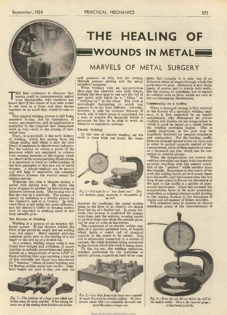
September, 1934 PRACTICAL MECHANICS 573
THE first craftsmen to discover thatmetals could be homogeneously unitedwere blacksmiths, who centuries ago
found that if two pieces of iron were raisedto red heat in a forge and then beatentogether on an anvil they would become asone.
This original welding process is still beingpractised to -day, but its limitations, ofcourse, are numerous, and its application isrestricted to the roughest and commonestwork in iron-such as the joining of cart-wheel rims.
There, in a nutshell, is the early historyof welding, which has sprung from thevillage smithy and which is now the bestfriend of engineers in almost every industry.For the layman to obtain a grasp of theprocesses which are employed to achievesuch seeming miracles as the repairs whichare shown in the accompanying illustrations,it is necessary to have an understanding ofthe first principles of this new art of metalsurgery. A simple analogy can be quotedand will help to emphasise the essentialdifferences between the various means foruniting metals.
Everyone has seen a chemist sealing aparcel with sealing wax. He sticks onepiece of paper to another by introducing anadhesive between them. The sealing wax islike the ham in a sandwich. The joining ofmetals by soldering is a similar process tothe chemist's, and so is brazing. In bothcases there is not unity but mere adhesion,and the tinman's solder or brazing speltermay be regarded as nothing more or lessthan metallic glue.The Process of Welding
Welding is a process of an entirely dif-ferent nature. If the chemist welded thefolds of his parcel he would not use sealingwax, but paper ! Metal surgery providescomplete unity akin to the healing of a cutfinger or the sett ng of a broken leg.
As a science, welding began when it wasfound that oxygen and acetylene, if mixedtogether in suitable proportions and ignited,burned at a temperature of some 2,000° C.Soon a welding blow -pipe emitting a tiny jetof this intensely hot flame was introducedfor " burning " pieces of metal together andfor flowing molten metal into cracks. Iden-tical flames are used to -day, not only for
Fig. I.-The bedplate of a large crane which wasbroken when the earth subsided. When salving thecrane one of the winding drum brackets was broken.
THE HEALING OFWOUNDS IN METAL
MARVELS OF METAL SURGERYsuch purposes as this, but for cuttingthrough armour plating and for manyindustrial purposes.
When working with an oxy-acetyleneblow -pipe the operator uses both hands,holding the blow -pipe in one and the rod ofnew metal with which he is " filling " or" building -up " in the other. The work isexceedingly fascinating to watch andappears to be far from difficult. Actually,however, it calls for extreme delicacy oftouch, and it takes years of experience fora man to acquire the dexterity which isnecessary for him to be able to work onintricate or expensive castings.
Electric WeldingIn the case of electric welding, ail the
work is done with one hand, the flame
Fig.3.-Not a job for a " ham fisted man." Thisis a thickness gauge, measuring in thousandths of
an inch.
required for rendering the metal moltenbeing in the form of an electric arc struckfrom the tip of a fusible rod. In many dis-tricts this process is employed for joiningtram lines, and the welders, wearing masksto protect their eyes from the intense glare,can be seen at work in the streets.
The equipment of an electric welder con-sists of a heavily -insulated form of handlewhich holds a metal rod of identicalanalysis to the metal to be united. Thisrod is electrically connected to a source ofcurrent, the other terminal being connectedto the part on which the work is being done.
To the lay eye, the welding operation,whether performed by the acetylene orelectric process, appears in itself to be com-
Fig. 2.-Less than forty-eight hours were requiredto repair this crack by scientific yielding. An inex-pensive repair that was completely successful and
saved the owners a large sum.
plete, but actually it is only one of anelaborate series of stages through which theparts have to pass. Reference is now beingmade, of course, not to simple butt welds,like the joining of tramlines, but to repairsto castings such as those which are seen inthe accompanying illustrations.
Commencing on a CastingWhen a damaged casting is first received
at the factory of a specialist welding engi-neer, it is first inspected by an expertmetallurgist, who determines its preciseanalysis and decides on the temperature towhich it must be raised as a whole beforethe welding operation begins. This isvitally important, as the part may behopelessly distorted by unequal expansionand contraction. For the heating, mufflefurnaces of many special types are used, andin order to permit accurate control of thetemperatures, some of them contain as manyas a thousand gas jets, which can be con-trolled in ordered groups.
When the temperatures are correct thewelding operation can begin with one expertoperator watching over the general condi-tion of the " patient " while another healsthe wounds. Sometimes in the course of thework the casting has to go back many timesinto the muffle, and the instant that the lastdrop of new metal is flowed on, the return ofthe part to the muffle is a matter of para-mount importance. From this moment thetemperatures have to be most accuratelycontrolled, or internal stresses would developin the casting, leading to the formation ofcracks and all manner of future troubles.
The operators have to possess an almostintuitional grasp of the characteristics of
Fig. 4.-Even this job did not defeat the skill ofthe modern welder. Here is the repaired gauge ;
it functioned perfectly.
www.americanradiohistory.com
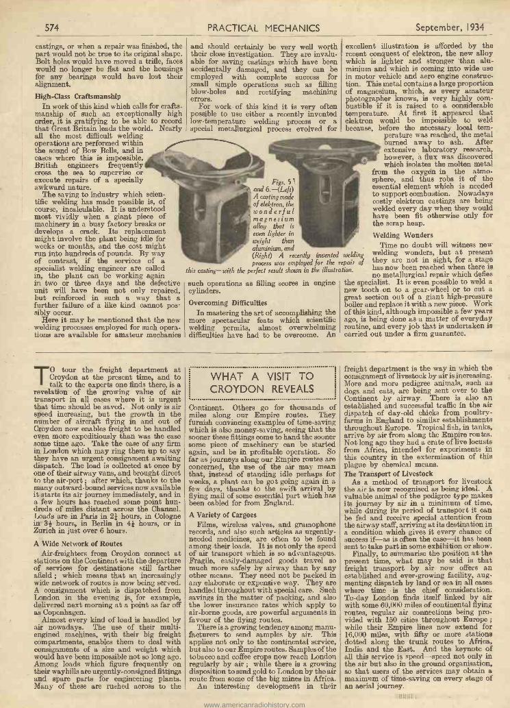
574 PRACTICAL MECHANICS September, 1934
castings, or when a repair was finished, thepart would not be true to its original shape.Bolt holes would have moved a trifle, faceswould no longer be flat and the housingsfor any bearings would have lost theiralignment.
High -Class CraftsmanshipIn work of this kind which calls for crafts-
manship of such an exceptionally highorder, it is gratifying to be able to recordthat Great Britain leads the world. Nearlyall the most difficult weldingoperations are performed withinthe sound of Bow Bells, and incases where this is impossible,British engineers frequentlycross the sea to supervise orexecute repairs of a speciallyawkward nature.
The saving to industry which scien-tific welding has made possible is, ofcourse, incalculable. It is understoodmost vividly when a giant piece ofmachinery in a busy factory breaks ordevelops a crack. Its replacementmight involve the plant being idle forweeks or months, and the cost mightrun into hundreds of pounds. By wayof contrast, if the services of aspecialist welding engineer are calledin, the plant can be working againin two or three days and the defectiveunit will have been not only repaired,but reinforced in such a way that afurther failure of a like kind cannot pos-sibly occur.
Here it may be mentioned that the newwelding processes employed for such opera-tions are available for amateur mechanics
and should certainly be very well worththeir close investigation. They are invalu-able for saving castings which have beenaccidentally damaged, and they can beemployed with complete success forsmall simple operations such as fillingblow -holes and rectifying machiningerrors.
For work of this kind it is very oftenpossible to use either a recently inventedlow -temperature welding process or aspecial metallurgical process evolved for
Figs. 51and 6.-(Left)A casting madeof elektron, thewonderfulmagnesiumalloy that iseven lighter inweight thanaluminium, and(Right) A recently invented weldingprocess was employed for the repair of
this casting-with the perfect result shown in the illustration.
such operations as filling scores in enginecylinders.
Overcoming DifficultiesIn mastering the art of accomplishing the
more spectacular feats which scientificwelding permits, almost overwhelmingdifficulties have had to be overcome. An
excellent illustration is afforded by therecent conquest of elektron, the new alloywhich is lighter and stronger 'than alu-minium and which is coming into wide usein motor vehicle and aero engine construc-tion. This metal contains a large proportionof magnesium, which, as every amateurphotographer knows, is very highly com-bustible if it is raised to a considerabletemperature. At first it appeared thatelektron would be impoisible to weldbecause, before the necessary local tem-
perature was reached, the metalburned away to ash. Afterextensive laboratory research,however, a flux was discoveredwhich isolates the molten metal
from the oxygen in the atmo-sphere, and thus robs it of theessential element which is neededto support combustion. Nowadayscostly elektron castings are beingwelded every day when they wouldhave been fit otherwise only forthe scrap heap.Welding Wonders
Time no doubt will witness newwelding wonders, but at presentthey are not in sight, for a stagehas now been reached when there isno metallurgical repair which defies
the specialist. It is even possible to weld anew tooth on to a gear -wheel or to cut agreat section out of a giant high-pressureboiler and replace it with a new piece. Workof this kind, although impossible a few yearsago, is being done as a matter of everydayroutine, and every job that is undertaken iscarried out under a firm guarantee.
TO tour the freight department atCroydon at the present time, and totalk to the experts one finds there, is a
revelation of the growing value of airtransport in all cases where it is urgentthat time should be saved. Not only is airspeed increasing, but the growth in thenumber of aircraft flying in and out ofCroydon now enables freight to be handledeven more expeditiously than was the casesome time ago. Take the case of any firmin London which may ring them tip to saythey have an urgent consignment awaitingdispatch. The load is collected at once byone of their airway vans, and brought directto the air -port ; after which, thanks to themany outward -bound services now availableit starts its air journey immediately, and ina few hours has reached some point hun-dreds of miles distant across the Channel.Loads are in Paris in 2k hours, in Colognein 3i hours, in Berlin in 4k hours, or inZurich in just over 6 hours.
A Wide Network of RoutesAir -freighters from Croydon connect at
stations on the Continent with the departureof services for destinations still fartherafield ; which means that an increasinglywide network of routes is now being served.A consignment which is dispatched fromLondon in the evening is, for example,delivered next morning at a point as far offas Copenhagen.
Almost every kind of load is handled byair nowadays. The use of their multi-engined machines, with their big freightcompartments, enables them to deal withconsignments of a size and weight whichwould have been impossible not so long ago.Among loads which figure frequently ontheir waybills are urgently -consigned fittingsand spare parts for engineering plants.Many of these are rushed across to the
WHAT A VISIT TOCROYDON REVEALS
Continent. Others go for thousands ofmiles along our Empire routes. Theyfurnish convincing examples of time -savingwhich is also money -saving, seeing that thesooner these fittings come to hand the soonersome piece of machinery can be startedagain, and be in profitable operation. Sofar as journeys along our Empire routes areconcerned, the use of the air may meanthat, instead of standing idle perhaps forweeks, a plant can be got going again in afew days, thanks to the swift arrival byflying mail of some essential part which hasbeen cabled for from England.A Variety of Cargoes
Films, wireless valves, and gramophonerecords, and also such articles as urgently -needed medicines, are often to be foundamong their loads. It is not only the speedof air transport which is so advantageous.Fragile, easily -damaged goods travel somuch more safely by airway than by anyother means. They need not be packed inany elaborate or expensive way. They arehandled throughout with special care. Suchsavings in the matter of packing, and alsothe lower insurance rates which apply toair -borne goods, are powerful arguments infavour of the flying routes.
There is a growing tendency among manu-facturers to send samples by air. Thisapplies not only to the continental service,but also to our Empire routes. Samples of thetobacco and coffee crops now reach Londonregularly by air ; while there is a growingdisposition to send gold to London by the airroute from some of the big mines in Africa.
An interesting development in their
freight department is the way in which theconsignment of livestock by air is increasing.More and more pedigree animals, such asdogs and cats, are being sent over to theContinent by airway. There is also anestablished and successful traffic in the airdispatch of day -old chicks from poultry -farms in England to similar establishmentsthroughout Europe. Tropical fish, in tanks,arrive by air from along the Empire routes.Not long ago they had a crate of live locustsfrom Africa, intended for experiments inthis country in the extermination of thisplague by chemical means.The Transport of Livestock
As a method of transport for livestockthe air is now recognised as being ideal. Avaluable animal of the pedigree type makesits journey by air in a minimum of time,while during its period of transport it canbe fed and receive special attention fromthe airway staff, arriving at its destination ina condition which gives it every chance ofsuccess if-as is often the case-it has beensent to take part in some exhibition or show.
Finally, to summarise the position at thepresent time, what may be said is thatfreight transport by air now offers anestablished and ever-growing facility, aug-menting dispatch by land or sea in all caseswhere time is the chief consideration.To -day London finds itself linked by airwith some 60,000 miles of continental flyingroutes, regular air connections being pro-vided with 150 cities throughout Europe ;while their Empire lines now extend for16,000 miles, with fifty or more stationsdotted along the trunk routes to Africa,India and the East. And the keynote ofall this service is speed-speed not only inthe air but also in the ground organisation,so that users of the services may obtain amaximum of time -saving on every stage ofan aerial journey.
www.americanradiohistory.com

September, 1934 PRACTICAL MECHANICS 575
The " GRAYSON " 3 -IN. BACK -GEAREDSCREW -CUTTING LATHE
£4:5:0DELIVERY FROM STOCK
SPECIFICATION :Length between Centres, 121 in. ; Max. Swing -over Saddle, 31 in. ;Max. Swing -over Gap, 71 in. ; Dia. of Mandril, 1 in. Whit. ; Man-dril and Tailstock bored I in. clearance ; Centres, No. i Morse ;Dia. of Face Plate, 61 in. ; Dia. of Catch Plate, 21 in. ; Lead Screw ;Square Thread, 1 in. by 8 T.P.I. ; 3 -Speed Cone Pulley, 21 in. -3 in. -3/ in. ; Width of Belt, 1 in.
ACCESSORIES :3 Jaw Chuck Fitted, 34/-. Foot Wheel, 58 lb., 35/-.I in. Drill Chuck, 213. Belting, 5d. ft.
Send for our Catalogues FREE
E. GRAY & SON LTD.18-20 CLERKENWELL ROAD, LONDON, E.C.1Established 1822. Telephone: Clerkenwell 015512
THE 1\1 EW ADANA AUHIGHOMATI-SPEED
C
PRINTING MACHINE
FREE ;litahc hei.enrye
100 PAGE BOOK
" 85 WAYS OFMAKING MONEY
WITH APRINTINGMACHINE "
In order to celebrate thesuccess of the Adana PrintingMachine and to provide theutmost assistance to all pur-chasers, it has been decided topresent FREE OF CHARGE acopy of a 2/6 Book, " 85 Waysof Making Money," by the well-known expert, Mr. C. A. H.Aspinall. With this book, con-taining over a hundred pagesand fully illustrated, the ownerof the small ADANA printingoutfit has the key to "TheRoad of Success."
CASH OREASY TERMS
A Real Automatic Machine in every detailAccurate Metal Diecastings (having a
tensile strength of over 20 Tons) fromcostly moulds have made it possible tomarket this fine piece of machinery atthis remarkably low price. Nothing hasbeen spared to produce a smooth -running,high-class, fast Printing Machine. The
result is wonderful. No words can explainwhat fine adjustments can easily be made toproduce a perfect print, and which, once set,is permanently maintained throughout thejob, as the impression is entirely mechanical.
1,000 COPIES PER HOURA thousand copies per hour are easily obtain.able. Any size of paper, card, or made-upcartons, etc., can be printed. It is thereforepossible to do an unlimited number of jobsthat are in everyday use. The inkingmechanism is all that can be desired. Standardprinter's type and blocks of all descriptionscan be used as well as line, colour, registerand half -tone work. Adjustable lay gauge isprovided to do away with the necessity ofgauge pins.
MONEY - MAKING POSSIBILITIESWITH THIS MACHINE ARE
GREATER THAN EVERWrite at once for full IllustratedParticulars and Samples of Work
D. A. ADANA(Dept. P.M.7) 17/18 CHURCH STREET
TWICKENHAMLondon Dept.:
I Ludgate House, Fleet Street, E.0 4,Manchester : 60 Oldham Street,
FOR THE STUDENT WHO WILL HAVE
Here is a complete laboratory for thestudent, containing 34 different Chemicals,Bunsen Burner, Rubber Tubing, Tripod andGauze, Flask, Test -Tubes, Glass Tubing,Filters, Test -Tube Brush, Asbestos Paperand Millboard, Trays, Scoop, Test -TubeHolder, Corks and a splendid book fullof instructions and experiments.
10/6 eachOther splendid outfits, each completewith Bunsen Burner, a good supplyof chemicals and apparatus, and abook of experiments and instruc-tions, at 2/6, 3/6, 5/-, 7,'6, 15/-,21/-, 35/-, 63/- and 105/- each.
THE BEST
KAY TELEPHONESA pair of marvellous House Telephones-full-sized, one-piece
instruments, each 82- in. long-easy to instal-automatic calling-perfect reception-works off ordinary pocket -lamp batteries ! Each set
complete with two instruments, 30 feet of twin wire, and full instructions.25/. set
Also other wonderful Telephone Sets at 10/6, 15/6 and 21/- set,
Here is a complete electrical workshop,containing a wonderful Electric InductionCoil, a Triple -coil Electric Motor, 2 BulbHolders, 2 Fancy Shades, 2 Bulbs, Turn -screw, Battery Tester, Switch, 3 Coilscf Wire, Battery Clips, Insulated Staples,and a splendid book full of instructionsand experiments.
10/6 eachOther complete outfits at 2/-, 3/6,5/6, 7/6, 12/6, I5/-, 21/, 30/- and
50/- each, the larger ones includ-ing Dynamotors, Tapper Sets,Telephones, in addition to Electric
Bells, Induction Coils, Motorsand Lighting Equipment, etc.
Obtainable from all leading Stores, Toyshops, and Sports Shops. If you have any difficulty, please send direct to the manufacturers :
KAY (Sports and Games) LTD., Dept. P.M., PEMBROKE WORKS, LONDON, N.I0Send for FREE Illustrated Catalogue
www.americanradiohistory.com

576 PRACTICAL MECHANICS September, 1934
IT is assumed that most model makersrequire a good climb followed by a" flatten out " at the top of the climb,
with no tendency to stall ; a period ofcruising under reduced power, and finally,the most difficult of all, a good flat glide toa happy landing. Many models can beseen performing quite excellently until thepower ceases, when they become erratic ina fore and aft direction, finishing up theirflight in a series of zooms and dives. Thistrouble, of course, is due to the modelhaving been designed and set so that all iswell when under power. As soon as thepower ceases a new set of conditions and
MODEL AEROPLANEWith a few notes on
These notes on the all-important question of automatic stability of thesubject, but rather, the aim is to discuss the question purely from aproblem will be able to apply the principles given below when
more head resistance, but it allows of anumber of reliable flights at high speed on afast model instead of the very occasionallucky one at a slightly higher speed.
MAIN PLANE AT FIN AREA AT REAR BALANCES DIHEDRALCORRECT POSITIVE SIDE AREA AT FRONTJN SIDESLIPANGLE OF INCIDENCE. (SEE LATERAL STABILITY.)
THRUSTLINE.
TAILPLANE
C.G. POSITION BELOW THRUST LINE POSITION
Fig. 1.-A high -wing layout.
pressures appear to confound these arrange-ments. It is essential, therefore, to giveconsideration to all the requirements whendesigning the model, so that, except for thealteration in speed of the model, there willbe no other variations occurring, whetherthe power is on or off. The model musttherefore be designed so that it is anexcellent glider with no power on. Thepower must then be applied so that themodel will travel faster under power, whichwill create a greater lift on the mainplaneonly, thus making the machine climb. Asthe power dies the speed will drop and themodel therefore get into its gliding angle.Throughout this performance the tailplaneshould not be unduly affected by thepropeller's slipstream, and should only comeinto violent corrective action when themodel is getting into a dangerous stallingattitude with nose too high.
Fore and aft stability is dealt with firstin a general sense, followed by threeexamples of layouts for a high -wing mono-plane, a low -wing monoplane, and a biplane,giving a few tips on a useful method oflaying the fuselage out on paper, followedby notes on construction.
Lateral stability will then be 'dealt within broad terms.
Fore and Mt StabilityIt may be said that to obtain stability on
a really fast model aeroplane is more diffi-cult than in the case of a lighter loaded andslower model. Thus a racing model aero-plane is a tricky sort of problem, but auseful tip, if you desire speed, is to have areally large tailplane. It may offer a little
LARGER ANGLE OFINCIDENCE.
THRULINE.
So many people produce racing modelswith the most delightful little tailplanes,as in full-sized practice, but I have yet tosee one of these models perform consistently.
They talk about having a large leverageat the high speeds they require. But inpractice this does not often work. One hasto remember there are intermediate speeds
THRUSTLINE
gone wrong on certain points on lightermodels, and yet got away with it.
Light and Heavy ModelsLet me repeat that a fairly lightly loaded
model is easier to make stable than aheavily loaded and fast model, and if themodel does meet with any obstruction it isless likely to suffer damage, as its speed isless, and there is less weight to stop in ahurry.
It is obviously impossible in one shortarticle to go into too much detail, so I willgive a simple method of laying out a fuse-lage design that may appeal to the noviceif not to the expert, and discuss the pointsof fore and aft stability.
Assuming that a simple type of rect-angular fuselage has been decided upon, firstobtain a roll of white kitchen paper and aroll of waterproof grease paper. Now laythe white paper on a board long enoughand wide enough to take the full-sizeddrawing of the fuselage. Keep the paperin position on the board by drawing -pins.
Having decided before this the length andgeneral shape of the fuselage, draw a centreline lengthwise.
This line will bethe all-important
C.G. POSITION BELOW THRUST LINE.
Fig. 2.-A low -wing layout.
during acceleration and deceleration to bereckoned with, and without a pilot'scorrecting hand. The large tailplane of thecorrect type, set in the correct position,will look after these problems. In themodel aeroplane world, even amongst theold hands, there is a great divergence ofopinion on many things to do with stability,and often fierce arguments result.
It will be found that the petrol model isthe most hard to get automatically stable,chiefly owing to its weight.
To. correct the momentum of a heavymodel sufficiently rapidly to avert troublerequires more careful attention to thestability problem.
This type of model, of which I have builtseven, has shown me, in my own opinion,where I and certain others have sometimes
C.G.PCSMON BELOW THRUST LINE.
LOWER WING AT CONSIDERABLEPOSITIVE STAGGER.
.°WA°18.11LESSER ANGLE OF INCIDENCE.
Fig. 3.-A:biplane layout yielding good stability.
TAILPLANE
TAILPLANE
thrust line that we are going to base all ourdesign around-whether the model be High -wing, Low -wing or Biplane, Tractor orPusher.
The propeller spindle in the case of therubber -driven model, or the crankshaft of thepetrol model, must be a prolongation of theforward end of this line, whilst the tailplaneleading edge and trailing edge should cutthe line (see Fig. 1).
Whether the power is on or off, thereshould be no violent difference in effect onthe tailplane set in this manner. Butshould the tailplane be tilted up at the rear,or locate it below the thrust line, i.e., giveit a negative angle of incidence to the thrustline, when the power is on a considerableforce from the propeller slipstream willstrike the top surface and tend to push thetailplane down. As the power dies awaywhen the rubber fades or the petrol motoris switched off in the air, this thrust willalso cease, and the tail will naturally riseand so get the model into a dive.
Now take the reverse position, i.e., withthe tail at a positive angle to this thrust line.The propeller slipstream strikes the under -surface when in flight and forces the tail up.The mainplane has therefore to be locatedfurther forward of the centre of gravityposition in order to prevent a dive.
The model then flies nicely after thisadjustment, but as soon as the power is cutoff the force under the tail ceases and the
www.americanradiohistory.com
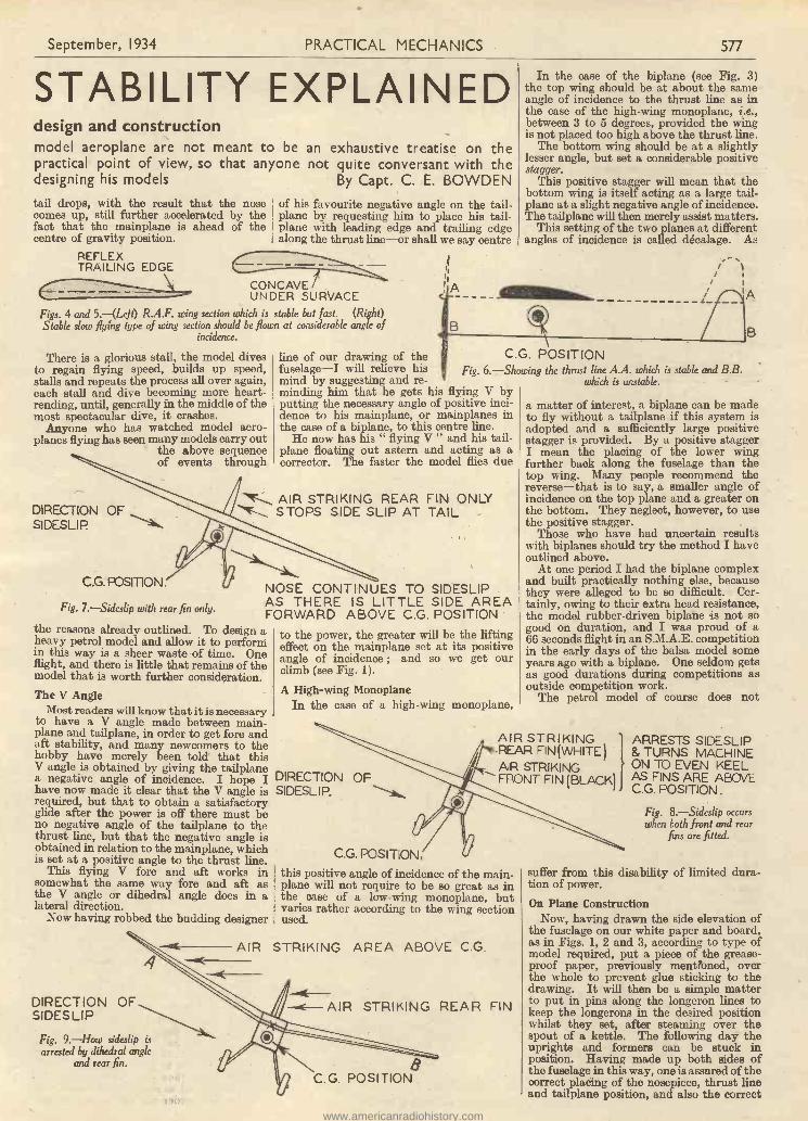
September, 1934 PRACTICAL MECHANICS 577
STABILITY EXPLAINEDdesign and constructionmodel aeroplane are not meant to be an exhaustive treatise on thepractical point of view, so that anyone not quite conversant with thedesigning his models By Capt. C. E. BOWDENtail drops, with the result that the nosecomes up, still further accelerated by thefact that the mainplane is ahead of thecentre of gravity position.
REFLEXTRAILING EDGE
of his favourite negative angle on the tail-plane by requesting him to place his tail-plane with leading edge and trailing edgealong the thrust line-or shall we say centre
CONCAVEUNDER SUIRVACE
Figs. 4 and 5.-(LeJi) R.A.F. wing section which is stable but fast. (Right)Stable slow flying type of wing section should be flown at considerable angle of
incidence.
There is a glorious stall, the model divesto regain flying speed, builds up speed,stalls and repeats the process all over again,each stall and dive becoming more heart-rending, until, generally in the middle of themost spectacular dive, it crashes.
Anyone who has watched model aero-planes flying has seen many models carry out
the above sequenceof events through
IA
In the case of the biplane (see Fig. 3)the top wing should be at about the sameangle of incidence to the thrust line as inthe case of the high -wing monoplane, i.e.,between 3 to 5 degrees, provided the wingis not placed too high above the thrust line.
The bottom wing should be at a slightlylesser angle, but set a considerable positivestagger.
This positive stagger will mean that thebottom wing is itself acting as a large tail-plane at a slight negative angle of incidence.The tailplane will then merely assist matters.
This setting of the two planes at differentangles of incidence is called decalage. As
line of our drawing of the C.G. POSITIONfuselage-I will relieve his Fig. 6.-Showing the thrust line A.A. which is stable and B.B.mind by suggesting and re- which is unstable.minding him that he gets his flying V byputting the necessary angle of positive inci-dence to his mainplane, or mainplanes inthe case of a biplane, to this centre line.
He now has his " flying V " and his tail-plane floating out astern and acting as acorrector. The faster the model flies due
AIR STRIKING REAR FIN ONLYDIRECTION OF "'T.,. STOPS SIDE SLIP AT TAILSIDESLIP.
C.G. POSITION.
Fig. 7.-Sideslip with rear fin only.
NOSE CONTINUES TO SIDESLIPAS THERE IS LITTLE SIDE AREAFORWARD ABOVE C.G. POSITION
the reasons already outlined. To design aheavy petrol model and allow it to performin this way is a sheer waste of time. Oneflight, and there is little that remains of themodel that is worth further consideration.The V Angle
Most readers will know that it is necessaryto have a V angle made between main -
plane and tailplane, in order to get fore andaft stability, and many newcomers to thehobby have merely been told that thisV angle is obtained by giving the tailplanea negative angle of incidence. I hope Ihave now made it clear that the V angle isrequired, but that to obtain a satisfactoryglide after the power is off there must beno negative angle of the tailplane to thethrust line, but that the negative angle isobtained in relation to the mainplane, whichis set at a positive angle to the thrust line.
This flying V fore and aft works insomewhat the same way fore and aft asthe V angle or dihedral angle does in alateral direction.
Now having robbed the budding designer
4
DIRECTION OFSIDESLIP
Fig. 9.-How sideslip isarrested by dihedral angle
and rear fin.
AIR
to the power, the greater will be the liftingeffect on the mainplane set at its positiveangle of incidence ; and so we get ourclimb (see Fig. 1).
A High -wing MonoplaneIn the case of a high -wing monoplane,
DIRECTION OFSIDESLIP.
C.G. POSITION.
B
a matter of interest, a biplane can be madeto fly without a tailplane if this system isadopted and a sufficiently large positivestagger is provided. By a positive staggerI mean the placing of the lower wingfurther back along the fuselage than thetop wing. Many people recommend thereverse-that is to say, a smaller angle ofincidence on the top plane and a greater onthe bottom. They neglect, however, to usethe positive stagger.
Those who have had uncertain resultswith biplanes should try the method I haveoutlined above.
At one period I had the biplane complexand built practically nothing else, becausethey were alleged to be so difficult. Cer-tainly, owing to their extra head resistance,the model rubber -driven biplane is not sogood on duration, and I was proud of a66 seconds flight in an S.M.A.E. competitionin the early days of the balsa model someyears ago with a biplane. One seldom getsas good durations during competitions asoutside competition work.
The petrol model of course does not
AIR STRIKINGREAR FIN (WHITE )AIR STRIKINGFRONT FIN (BLACK)
this positive angle of incidence of the main-
plane will not require to be so great as inthe case of a low -wing monoplane, butvaries rather according to the wing sectionused.
STRIKING AREA ABOVE C.G.
-0E-AIR STRIKING REAR FIN
8C.G. POSITION
ARRESTS SIDESLIP& TURNS MACHINEON TO EVEN KEELAS FINS ARE ABOVEC.G. POSITION.
Fig. 8.-Sideslip occurswhen both front and rear
fins are fitted.
suffer from this disability of limited dura-tion of power.
On Plane ConstructionNow, having drawn the side elevation of
the fuselage on our white paper and board,as in Figs. 1, 2 and 3, according to type ofmodel required, put a piece of the grease-proof paper, previously mentioned, overthe whole to prevent glue sticking to thedrawing. It will then be a simple matterto put in pins along the longeron lines tokeep the longerons in the desired positionwhilst they set, after steaming over thespout of a kettle. The following day theuprights and formers can be stuck inposition. Having made up both sides ofthe fuselage in this way, one is assured of thecorrect placing of the nosepiece, thrust lineand tailplane position, and also the correct
www.americanradiohistory.com
578 PRACTICAL MECHANICS
angle of incidences where the wings meetthe fuselage on top or bottom, or both.The fore and aft stability should thereforebe assured. The mainplanes should beset so that the centre of gravity positionof the model is located at about one-thirdof the chord of the mainplane from theleading edge.
The model should, when completed, glidewell with these settings, but if under powerit climbs rather too steeply, then a certainamount of down thrust should be given bytilting the engine shaft slightly downwards.Do not alter the tailplane. It now remainsto consider the areas of surfaces and typesof wing and tailplane sections to be used.
With regard to areas, this is a questionwhich depends upon the speed requiredfrom the model. But it should be remem-bered that it is desirable to keep the leadingedge of the tailplane at least one and a halftimes the chord at the root of the mainplane,from the trailing edge of the mainplane.Furthermore, a really large tailplane makesfor stability, the only disadvantage of alarge tailplane being the added head resist-ance offered. Therefore a happy mean hasto be struck ; but it is advisable to err onthe large size, particularly in the case ofthe petrol model, which, owing to its weight,is slower to react torighting efforts. FORWARD
The MainpianeSection
With regard to themainplane section, itis important to usea stable type in itself,even if the designer'sintention is a fastmodel. To put thematter very broadly,the R.A.F. 34 Sec-tion, or modificationsof it, with its reflextrailing edge, is astable but ratherfast section (see Fig.4). If a slower sec-tion is desired thatis also stable, theold-fashioned con -
SIDE AR
cave undersurfaced wing section, but ratherthick in front and thin behind, is excellent.
'The centre of pressure does not movemuch in this type of wing section. Thesection has to be flown at a considerableangle of incidence, however, and for certaintypes of model offers a lot of head resistance(see Fig. 5).
This matter of head resistance does notmatter in the case of a petrol model. Infact it is an advantage, as it all helpstowards the valuable property of slowflying and landing speeds.
A compromise can be made between thetwo sections for a high performance durationrubber model. However, I am chiefly con-cerned here in the matter of stability, andwill therefore not labour the question ofdrag too much.
For really good stability fore and aft, itis certain that a good stable -wing section,where the centre of pressure does not altermuch at different angles of attack, is agreat advantage.
The TailplaneHaving tried out all kinds of tailplane, I
definitely favour, for most purposes, whatis known as the " lifting " tailplane, butset, as I have already explained, in a posi-tion so that it does not really lift, morethan float out behind, until the model getsits nose well into a stalling attitude. Thecambered surface of the " lifting " tail-plane then obtains lift by finding itself
flying at a greater positive angle of incidence.This lift then brings up the tailplane and
thus restores the model to an even keeland reduces the unduly large positive angleof incidence on the mainplane that has nowarrived at the " burbling point " where theair flow is breaking down.
I usually use a thinnish cambered sectionwith concave undersurface for the tail-plane. This combination, when doublesurfaced, does not produce undue headresistance, and has the merit of acting as acorrective quickly.
-Before we leave the practical side of foreand aft stability to tackle lateral stability,it is worth examining the effect of thrust -line position in relation to the centre ofgravity.
It has been found that the higher theline of thrust is located in relation to thecentre of gravity, the greater the longitu-dinal stability of the model.
This can easily be worked out theoreti-cally, but space forbids here. Nevertheless,it is an important point to remember whendesigning a model, and particularly so inthe case of a low -wing model.
Fig. 6 shows, firstly, the thrust linemarked A.A. higher than the centre ofgravity, which is stable. In the second
EA ABOVE C.G.REAR SIDE A
Fig. I0.-How the for-ward side area is ob.
C.G. POSITION. tamed by dihedral angle.
case, the thrust line marked B.B. is belowthe centre of gravity and is not stable, andwhen the machine noses upwards the thrusttends to aggravate matters towards a stall.
It will be noticed that in Figs. 1, 2 and3 the centre of gravity position is shown inall cases below the thrust line.Lateral Stability
This is, strangely enough, somewhat inter-connected with longitudinal stability. Forone must remember that when an aeroplanebanks at over an angle of 45 degrees thecontrols become reversed ; that is to say,the elevator becomes the rudder and therudder becomes the elevator.
This is easily understood if a model isheld in the hand on a bank of over 45degrees. The rudder will now be seen tobe nearly horizontal instead of vertical, andit is in practically the same position as theelevator was when the machine was on aneven keel. It will be obvious that to pushthe rudder up in this position will depressthe tail of the machine, whereas to pushthe rudder down will force the tail up andthe nose down. In the case of a turn tothe left with a bank of over 45 degrees itwill also be clear that the elevator must bepulled up so that it forces the nose of themachine to the left and tail away. Theturn really becomes a sideways loop ifcontinued for a complete turn.
This little matter of reversal of controlsoften defeats the young pilot at the begin-ning of his flying training. But once onehas been through the mill on full-sizedmachines many curious effects that takeplace with models when in a steep bank willbe clear.
REA_ ABOVE C.G.
September, 1934
However, it is advisable to design amodel so that it will quickly come out of avertical bank should it inadvertently getthere. I do not recommend the use of thismethod on the " Kanga," which was de-scribed on page 506 of last month's issue.
To ensure that a model recovers from asideslip after excessive bank it is necessaryto design the model with the correct sideareas, both fore and aft above the centre ofgravity.
Reference to Fig. 7 should make it clearthat when a model without any side areaforward gets into a bank it will sideslipinwards and downwards. The air willstrike the fin at the rear, which will tendto push the tail upwards, whilst the nosewill continue to sideslip inwards, thusgetting the machine into a spin.
Now look at Fig. 8. In this case themodel has a fin, both at the rear and at thefrimt, above the centre of gravity.
As the model sideslips inwards the airstrikes both rear and front fin, which areso proportioned as to balance each other.As these fins are above the centre of gravity,the model is arrested in its sideslip and atthe same time pushed over on to an evenkeel.
The model shown in Fig. 9 has insteadof a front fin a" dihedral angle,"which offers a sidearea forward over thecentre of gravity inlieu of a front fin.
It will be observedthat the wing A offersa considerable for-ward side area to theair when the modelis sideslipping in-wards. This sidearea is above thecentre of gravity, and
so pushes the machine on to an evenkeel. The rear fin does the same thing forthe tail end of the machine. In the caseof the low -wing model aeroplane thisdihedral angle must be greater in order toobtain a side area showing above the centreof gravity.
Fig. 10 should explain how the forwardaide area is obtained by a dihedral angle.
When arranging for correct side areasfore and aft to balance each other, theside areas of the fuselage must, of course,be taken into account.
To prove this theory, let any reader notconversant with it construct a paper gliderwith no dihedral, but with a rear fin only.The glider will easily spin and have nolateral stability. Now either add a frontfin to balance the rear fin or sufficientdihedral on the mainplane to get the sameeffect, and he will notice how the modelat once becomes stable laterally and refusesto spin.
A FINE HANDBOOK ON
Model Aircraft"Model Aeroplanesand Airships " by
F. J. Camm96 pages. 120 Illustrations.
Obtainable from all newsagents Prite 1/ -or from Messrs. George Newnes Ltd.,8-11 Southampton St., Strand, W.C.2,
for 1/2 post free.
www.americanradiohistory.com

September, 1934 PRACTICAL MECHANICS* 579
LIQUEFYING GASESFor the amateur chemical experimenter there is hardly a field of work of more absorbinginterest than that represented by the liquefaction of gases. Using merely common-senseprecautions, quite a number of gases may be liquefied with the simplest of apparatus and bythe easiest of means. What is more, the gases so liquefied can be preserved as specimens
quite indefinitely.
Fig. 1.-Apparatus for the liquefaction of sulphurdioxide.
LL gases, as the reader no doubt willbe well aware, can be liquefied by theapplication of cold and pressure.
Every gas has what is known as a " criticaltemperature," above which no amount ofpressure will cause it to liquefy. The criticaltemperatures of the gases enumerated inthis article, however, are all well above thenormal everyday temperatures of a room.Hence the existence of these critical tem-peratures will not bother the experimenterin his gaseous liquefactions.
One of the easiest gases to liquefy issulphur dioxide, SO2, a gas formed in largeq uwAti Lies when sulphur burns in air oroxygen. Sulphur dioxide is a colourless gaswhich possesses the smell of burning sulphur.The gas is not inflammable, and, owing toits sulphurous character it is sometimesused as a fumigant and disinfectant. Sul-phur dioxide is also generated when hot con-centrated sulphuric acid is allowed to act onmetallic copper. This is the manner inwhich the gas is best prepared for liquefac-tion purposes.
Sulphur DioxideObtain a length-about 18 in. or 2 ft.-
of stout -walled glass tubing of about k -in.bore and seal up one end of this tubing in abunsen or spirit -lamp flame. Cut up severalinched of thin bare copper wire into smallpieces and slide these down to the bottomof the tube. Now pour concentrated sul-phuric acid down the tube so that thecopper therein is covered, and take a tuft ofcotton wool hooked on a piece of wire, andpass this down the side of the tube so thatit may absorb and wipe away the sulphuricacid from the sides of the tube. Then, bymeans of a " batswing " gas flame, maketwo acute bends in the tube, taking care notto allow the sulphuric acid to flow along thetube.
The tube will now have two limbs, asshown in the photograph, Fig. 1. Keepingthe tube in an upright position, hold theempty limb in a gas flame until the glasssoftens. Then carefully draw down thelower end of the empty limb so that itforms a narrow neck. Finally, seal up theopen lower end of the empty limb, and theapparatus for liquefying sulphur dioxidewill now be ready for use.
Clamp the tube firmly by some means,
and, if possible, place around the emptylimb of the tube a vessel containing meltingice or some other freezing mixture. If theseare unobtainable, however, cold water willsuffice, although the gas is much more easilyliquefied and sealed off if this collecting limbof the tube is immersed in ice. Place avessel of warm water around the tube limbwhich contains the copper and concentratedsulphuric acid. Almost immediately thechemical action will commence. If the sul-phuric acid in the tube limb tends to frothup, remove the vessel of water for a time.If, on the other hand, the chemical actionproceeds too slowly, increase the heat of thewater until it reaches boiling point.
Sealing the TubeWithin a few minutes the pressure of the
sulphur dioxide generated within the tubewill cause it to liquefy and to collect as aclear, limpid, highly -refracting liquid in thereceiving limb of the tube. This should nowbe cooled as strongly as possible and finallysealed off at the narrow drawn-out neck.Take care to make a good seal in a gasflame, rounding the seal off neatly so thatthere will be no danger of it breaking offafterwards. Your specimen of liquid sulphurdioxide will now be a permanent one-solong as the tube remains unbroken. At 0°Centigrade, sulphur dioxide liquefies at apressure of 1.5 atmospheres ; at ordinarytemperatures the gas liquefies at about 4atmospheres pressure. This latter, there-fore, is the internal pressure within thespecimen tube of liquid sulphur dioxideafter it has been finally sealed off andallowed to return to normal temperatures.
The above experiment is quite a safe onebecause ordinary glass tubing is capable ofstanding pressures considerably above thislimit. To be absolutely safe, however, it is
WIDE NECKEDBOTTLE OR JARTIGHTLY
CORKED.
EGGCUPHALF FULL
OF SILVER -CHLORIDE
4m LAYER OFCOMMERCIAL
LIQUIDAMMONIA
Fig. 2.-Illustrating the preparation of the silverchloride -ammonia absorption used for the generation of
wnmonia gas in the sealed liquefaction tube.
always best to interpose a piece of wiregauze between the gas -liquefying apparatusand yourself during the experiment, just incase the tube should burst. This precautionshould be taken in all gas liquefying experi-ments of this description.
Liquefied ChlorineChlorine is another gas which can be
liquefied by the home experimenter,although, in this instance, the pressurerequired is higher. The apparatus neces-
LIQUIFIEDAMMONIA GAS
Fig. 3.-Showing bentglass tube in which theliquefaction of ,am-monia gas can be
effected.
LOOSE PLUGOF WIRE OR
GAUZE.
AMMON IA -SATURATED
SILVER -CHLORIDEPREPARED ASSHOWN IN FIG 2
sary is exactlysimilar to that re-quired for theliquefaction ofsulphur dioxide. In thegas -generating limb i splaced either a mixtureof manganese dioxide and strong hydro-chloric acid or a mixture of potassiumdichromate and strong hydrochloric acid.On the application of heat to the liquid hithe tube, chlorine gas is evolved and in duecourse it will liquefy in the receiving limbof the tube. In this instance, however, thereceiving limb must be surrounded by afreezing mixture of ice and salt, and it mustbe retained therein until the limb has beenfinally sealed off.
Chlorine is a yellow -green gas with acharacteristic choking smell. It was,indeed, the first of the stiffocating gasesused in the Great War in April, 1915. Pre-pared in small quantities, of course, it isharmless. At 0° Centigrade, chlorine takesa pressure of 6 atmospheres to liquefy it,this pressure being correspondingly in-creased at normal temperatures. Hence,care should be taken to effect its liquefac-tion only in stout -walled glass tubing. Thesealing off of the specimen of liquid chlorinemust be effected while the limb of the tubecontaining it is immersed in an ice and saltfreezing mixture.
Liquid AmmoniaWhat is usually known as " liquid
ammonia " is, of course, merely a solutionof ammonia gas in water. Ammonia gas,however, can be liquefied by the applicationof pressure in quite a simple manner. Place
www.americanradiohistory.com

580 PRACTICAL MECHANICS September, 1934
in one limb of a stout glass tube, shapedsimilarly to the ones described above, amixture of sal -ammoniac (ammoniumchloride), ammonium sulphate, or anyother ammonium salt and slaked lime. Heatthis mixture in the tube very gently, havingthe other limb of the tube immersed in icecold' water:- --The ammonia gas generatedwill condense to a liquid in the cold limb ofthe tube, whereupon it can be sealed off inthe usual manner.
Another way of liquefying ammonia is tomake up a small quantity of a strong solu-tion of silver nitrate and add to it an equalamount of a similarly strong solution ofcommon salt. A white mass of silver chloridewill be formed immediately. This should befiltered off carefully, washed with coldwater and dried.Silver Chloride
Silver chloride has the remarkable pro-perty of absorbing comparatively largevolumes of ammonia gas, forming the com-pound, AgC13N112. Fill an egg cup halffull with dry silver chloride and stand it onthe bottom of a large stoppered or corkedbottle or jar containing at the bottom about+-in. depth of ordinary commercial " liquidammonia." Allow the silver chloride toremain in contact with the ammonia fumesfor about a week, stirring it every day so asto expose a fresh surface. After the lapseof this time it will have absorbed a good dealof the ammonia gas.
Now pack the ammonia -saturated silverchloride so prepared into one limb of astout glass tube fashioned roughly into theshape of a " U." Place the empty limb ofthe " U "-tube in cold water and the limbcontaining the silver chloride in warmwater. The heat will drive off the ammoniafrom the silver chloride, and, under theinfluence of the pressure generated withinthe tube, it will condense to a liquid in the
Fig. 4.-Apparatus forthe preparation andliquefaction of nitrosyl
chloride gas.
and allowed to cool down, the silver salt willagain absorb the ammonia, thus causing theliquefied gas to disappear from the otherlimb of the tube. This backwards and for-wards passage of the ammonia from thestate of absorption in the silver chloride tothe state of liquefaction in the opposite limbof the tube can be thus carried out an inde-finite number of times. It is best to place asmall plug of fine wire gauze in the tubejust above the silver chloride in order toavoid the possibility of loose particles ofthe material getting into the opposite limbof the tube.
Liquefied ammonia is colourless, mobileand highly refracting. At a temperature of0° Centigrade it liquefies at a pressure ofapproximately 4 atmospheres. At normaltemperatures its liquefaction pressure is justunder 7 atmospheres.
There are a number of other gases whichare easily liquefiable in glass tubes on linessimilar to the above. Cyanogen, preparedby heating mercury cyanide, is one of these.Another is carbonyl chloride or phosgene.Such gases, however, ought never to beexperimented with under home conditions,for they are excessively poisonous.
An Interesting GasSulphuretted hydrogen, H2S, is an in-
teresting gas to liquefy. It is best generatedfor this purpose by heating antimony trisulphide with strong hydrochloric acid.Care should be taken, however, to usestrong glass tube for the liquefaction of thegas, and to immerse the receiving limb ofthe tube in a strong freezing mixture. Alsono attempt should be made to seal off thelimb of the tube in which the liquefied gas
MIXTURE 3 PARTSSTRONG HYDRO-CHLORIC ACID ANDI PART STRONG NITRIC
ACID
PAN OFWARMWATER.,
NOT HOT)
WIDE NECKED BOTTLESTANDING IN COLD WATER,TOCONDENSE ANY ACID VAPOUR,WHICH MAY DISTIL OVER.
U TUBE IN WHICHNITROSYL CHLORIDE CONDENSESTO A LIQUID THE TUBE IS IMMERSEDIN MELTING ICE
opposite limb of the tube. As soon as the collects. At normal temperatures the gaslimb of the tube containing the silver remains liquid under a pressure of 16 at -chloride is withdrawn from the warm water mospheres. A good glass tube will stand
this pressure, but under these conditions itwill not permit of a seal being made to it.
It may be men-tioned that thered gas generatedby the action ofnitric acidon copperwill condenseto an orangeliquid when astream of itmixed withair is passedthrough a" U "-tubeimmerse d
Fig. 5.-A tubecontaining lique-
fied chlorine.
inice water. The nitr c acid and copper gener-ate nitric oxide, NO, a colourless gas which,when mixed with air or oxygen, is convertedinto nitrogen peroxide, NO2 (or N504),which condenses to an orange liquid. Thisliquid boils just above normal temperatures.Hence, perhaps, it just escapes being cor-rectly termed a " liquefied gas," such a termbeing applied more exclusively to con-densed gases which boil below normaltemperatures.
Nitrosyl ChlorideFinally, there is rutrosyl chloride, NOC1,
an orange -yellow gas which is best preparedby gently warming a mixture of strongnitric and hydrochloric acids. Passedthrough a " U ''-tube immersed in a mixtureof ice and salt, this gas will condense to anorange liquid. It may then be quicklypoured into a dry thick-walled glass tube,the upper end of which can subsequently besealed off. Nitrosyl chloride, at ordinarypressures, boils at - 8° C.
In preserving samples of liquefied gases instout glass tubes it is best, as a precaution,to make a tightly -fitting " cage " of copperwire to surround the tube on the same prin-ciple as the wire wrappings are applied tosome soda water syphons. This will preventany flying pieces of glass in the rare event ofthe tube bursting owing to its inwardpressure.
WILL MY SET WORK A TELEVISOR ?
SEE
"PRACTICAL TELEVISION"
No. I OUT TO -DAY PRICE 6d.FROM ALL NEWSAGENTS.
Covers every branch of television.
ORDER YOUR COPY NOW
THE advantages of keeping in touch withcivilisation while surveying uncharted
land and sea in the Polar regions are tooobvious to need description. Equally obviousis the fact that when the medium of com-munication is wireless, the equipmentmust be of the most reliable and sturdytypeIt.
says much, therefore, for the confid-ence placed in the productions of theG.E.C. that one of the Company's radioreceivers has been selected by those
THE BRITISH GRAHAMLAND EXPEDITION
responsible for the organisation of theBritish Graham Land Expedition, which isshortly embarking, with the support of theBritish Government and the Royal Geo-graphical Society, on a cruise coveringapproximately 1,500 miles of unsurveyed
coast line at the back of the Weddell Seain the Antarctic. A G.E.C. superhetero-dyne battery receiver will be the sole meansby which the Expedition will be able tokeep abreast of world progress during thetwo and a half years it is engaged in itsmomentous task. The Expedition istaking with it an aeroplane, which willbe piloted by the leader of the partyof fourteen men, Mr. J. Rymill, a mem-ber of the Watkins Arctic Air RouteExpedition.
www.americanradiohistory.com

September, 1934 PRACTICAL MECHANICS 581
A NOVEL BENCH GRINDER
THE bench grinder illustrated in Fig. 1will be found a very useful addition tothe mechanic's tool -room, and as it
consists almost entirely of cycle parts, thecost of construction is very low. The wholeassembly is built round the bottom bracketof a bicycle frame, the two tubes whichnormally run to the axle of the back wheelforming the front pillars of the grinder, withthe tube to the saddle arranged as a backsupport.
The whole of the ball -bearing assembly isretained, the crank spindle being threadedat each end for attachment of the emerywheel and the driving pulley. By means ofthe adjustable ball races, the wheel can berun at high speed without rocking and witha very minimum of friction.
The local cycle dealer will no doubt beable to supply the demand for the partsrequired. If the complete frame can bepurchased, so much the better.
The tubes forming the front supports arecut off 6 in. from the bottom bracket andthe saddle tube left 10 in. long. The front
Fig. I.-The finished bench grinder.
down tube of the frame is not required. Itcan be cut off short to the bracket and acork fitted to form an inspection cover anda means for oiling.
Now remove the cranks and then thecotters which retain the cups of the ballraces. Place a shallow tray under thebracket when unscrewing the cups to catchthe balls as they fall out. Clean the spindleand have it turned and threaded. The wheelturns in an anti -clockwise direction whenviewed from the right side in Fig. 1, so thatboth spindle ends must have right-handthreads to prevent unturning the nuts.
Great care must be taken to. avoidsplitting the tubes when flattening andbending the ends to form the feet. Makeeach end in turn red hot and squeeze itsteadily in a vice. Repeat the heating asthe tube cools. A flat of about 14 in. longis required. After bending, which shouldalso be done hot, the edges are filed off andfixing holes drilled. The back pillar mayrequire a double bend, so that all feet willrest flat on the bench.
The driving pulley can be made from hardwood to suit individual requirements. Tworings of -in. brass, each of 3 in. diameter,are clamped on either side of the emerywheel, which is of 8 -in. diameter and in.thick. An adjustable rest can be madevery simply by bolting an iron support, suit-ably bent, across the two front pillars andclamping it with a smaller plate at the back.
The idea could be adapted equally wellfor a small circular saw, polishing head, orother use where low -power drive is required.
A MASSIVEFOUNDATION
VATHE SCIENTIFIC
I/ALT/IE
BRITISH
Hivac use only the highest qualityglass obtainable, because soft"glass will not stand up to and re-tain the " hard " vacuum essentialto high efficiency and consistentcharacteristics.
MADE The Broad " pinch " allows greaterspacing of lead -out wires, therebyreducing inter -electrode effects.
HIVAC SPECIFIED FOR THE
"P.M."TABLEG RAMACJHL - - - - 9/6AC/VP - - - - 13/6AC/Y - - - - 15/6
Obtainable from all Curry'sbranches & high-class dealers
BATTERYTYPESFROM
MAINSTYPESFROM
319
916HIVAC 1935 VALVE GUIDE& COMPARATIVE TABLE" E " FREE ON REQUEST
STAND 21 OLYMPIA
ESSENTIALTO STRENGTH
BRITISH MADE byHigh Vacuum Valve Co. Ltd., 113-117 Farringdon Road, London, E.C.I
SILVER -SOLDERING & BRAZING
B1.001T-Stir-BLOWING BLOWPIPEWORKS FROM ANYOAS TUBE -AT HOME -IN THE GARAGE -Om WORKSHO
tit EN !NEMOMETAL WORKERS PLUMBERSTOOL MAICERSCOPPERSMITHS GARAGE MEN RADIO WORKERS.
AS SUPPUM rt7 M.M.GOO--RAILWAY cm,-
i.f.A0live CAR AIVRS (A0tis-wwCt Se)CORAORATION3 -TECHNICAL wartrunoms-,
SEND FOR ONE NOW!NO BELLOWS REQUIRED
This wonderful Blowpipe operates on the ordinary HouseGas by small flexible tube, anyone can Silver -Solder or Brazewith it. Thousands satisfied. Prices including Blowpipe,Silver -Solder, Brazing Wire and instructions:Send for Free Lie. 12,6, 7/6, 6/. post free.L B. BOARDMAN, 2 Badly Pl., London, W.I. Mayfair 1192.
ELECTRADIX HomeBroadcasting Microphones
The "P.M." TABLE RADIO MIKEImproved pedestal model, bakelitecase, containing high -ratio 15/_transformer.Write for special mike instructionleaflet "A." We make 25 types ofmicrophone for all purposes.CROONERS.-Lapel Mike3 for dancebands. America, mule', 12/11.
" P.IYI." Typo15/ -
For 1,000 other Bargains, send rid. stamp for NewIllustrated Sale List " P.M." State your requirements.
ELECTRADIX RADIOS218 Upper Thames St., E.C.4. '/'hone: Contra! 4611.
MORSE KEYS.We have the biggest range of Wire-less Keys in the country. 52 models,from 4/13 to 30/-. Ask for specialillustrated Key List " P.M.," invalu-able to transmitters and testers.
MilM62111111L10111.
www.americanradiohistory.com
582 PRACTICAL MECHANICS
CH0SE
N
HeayberdMains Compo-
nenta have been chosenonce more. " PracticalMechanics" Technicians re-quired a Transformer andChoke for their latest set-the " Tablegram "-and they
decided to rely once again on the products of MAINSSPECIALISTS-HEAYBRRD. When building this set,be sure you follow the advice of the designers.
Model W.3I Transformer - Price 29/-Model 751 Smoothing Choke 12/6
Fill in the coupon below, enclose Scl. in stamps and postN u W for copy of NEW 1931 RADIO HAN DBOuK describ-ing the wide range of mains apparatus manufactured by us.
Mr
P.M.
F. C. HEAYBERO & CO.
10 FINSBURY STREET
LONDON, E.C.2
YOUROLD WATCHTAKEN IN PARTEXCHANGE
GUARANTEED 7 YEARSAGAINST BREAKAGES
Made by the suppliers to IMPERIALAIRWAYS & AIR MINISTRY CON-TRACTORS.The Ideal watch for bard wear, it can bewarn without fear of damage whilst atwork, or when camping or swimming!Impervious to any climate. Floating non-magnetic jewelled movement, shock, vibra-tion, dust and sand proof.Each watch time tested under water.Chromium patent gland case, 24 hr. dial,leather strap. Cash price 59/8, chromiumadjustable bracelet 5/- extra, luminous dial2/6 extra.
Ar, THE ORIGINAL
()rap a neSPECIALLY BUILT FOR USEUNDER ALL CONDITIONS
Bend your order to -day, or write for latEliCatalogue of 75 models from 25/,
G. & M: LANE & CO: Ltd:,Dept. P.M.1, 24-28 Ludgate Hill, London, E.C.4.
Club Reports for inclusion in this feature should notexceed 250 words in length, and should be received notlater than the 12th of each month for inclusion in thesubsequent month's issue.
THE MALDEN SOCIETY OF MODEL ANDEXPERIMENTAL ENGINEERS
THE above Society would like to get into touch withreaders residing in Malden and district who are
interested in Wireless and Model Speedboats ; of coursewe should also like to meet readers who are intereitedin any other branch of mechanics. We have a largeand well-equipped workshop, including a 3f -in. lathe,and various other tools.
The Society has decided upon a system of specialsubscriptions ; all members are allowed to have a keyto the club, so that they can use it at any time otherthan club nights. We should particularly like to getinto touch with readers who are interested in petrol -driven model aeroplanes. One of our members isstarting on a one -quarter full-size model of a 8 h.p.Ford car, which will be complete in all detail, whileanother is converting his lawn -mower to motor drive.If any interested readers will get into touch with me,I shall be pleased to give them full particulars ofsubscriptions, etc.
THE NORTHERN HEIGHTS MODELFLYING CLUB
THE Northern Heights Model Flying Club's GalaDay was held on the Fairey Aviation Company's
Great West Road Aerodrome.Twenty-five clubs from as far afield as Leamington,
Birmingham, Brighton, Reading, etc., sent strongcontingents to uphold the prestige of their clubs, anda most wonderful display of model planes of manytypes and variety of sizes was to be seen. About 350to 400 models were present, and ranged from a 4 -in.span miniature fighting plane, complete with machine-guns, engine and correctly coloured squadron markingsto a very fine 15 c.c. petrol-engined specimen of a DeHaviland " Puss Moth." There were duration planesweighing but a few ounces, medium -weight planes,typifying many kinds of full-sized aeroplanes, andgiant 9, 10 and 12 ft. span rubber driven modelsweighing up to 12 lb., in fact every conceivable idea ofa flying machine.
The most important contest of the day, the Inter -Club Team Contest, started at 1.30 p.m.
The teams consisted of one Lightweight Model, oneHeavyweight Model, and one Flying Scale Model,which was required to represent some well-known full-size machine, and to be built to a 1 -in. scale andcorrectly coloured and marked. This competitionbroke entirely new ground in this country with regardto the flying scale models, and unfortunately the windwas a little too fresh for the type, which, of necessity,is of somewhat delicate construction, and a deal ofdamage was done to them.
The competition resulted in a win for the BlackheathModel Aero Club with 320 points, and they thereforehold the Northern Heights Challenge Cup presented byMr. C. R. Fairey, M.B.E. F.R.Ae.S., for one year,and receive £3 from the dela Fund. The Model Air-eraft Club were second with 305 points, and theyreceived £1 10a. The Leytonstone and District ModelAero Club were third with 285 points, and theyreceived 15s.
THE BRITISH INTERPLANETARY SOCIETYREPORT FOR JUNE
MEETINGS are held monthly in summer on thefirst Friday of each month. The last meeting
was thus held on Friday last, July 6th.Several new members were elected, including Mr.
J. F. Darwin, of Southport, and Mr. Prugh, of America.It was proposed and carried that a system of corre-
spondence should be inaugurated between the moredistant members of the Society, the correspondence tobe about interplanetary travel in particular, and otherscientific matters generally. This would be set inmotion by an announcement in the next issue of theJournal if space is available. Members interestedshould write to the Secretary, stating particularinterests, age, etc.
Discussion ensued about the future form of theJournal of the Society. It was decided to continue theJournal in its present form until the end of the year.Meanwhile investigations would be made with a viewto improving the present arrangement.
The question of a subscription rate for non-memberswas discussed at the request of several non-members.It was referred to Mr. Sinus, who would give a reporton the matter. There may be certain difficulties inputting this into operation.
It was decided, also, to keep members personallyinformed of the proceedings at meetings, as many areunable to attend. Copies of future lectures may els,be obtained after their delivery for a small nominalcharge to cover costs.
Further particulars can be obtained by writing toLeslie J. Johneons Ron, Secretary, dd ADD Lane,Liverpool, 18,
September, 1934
The perfectuniformity ofmovement ina well -train-ed chorus isnot as easy toachieve as it looks. Itcalls for experience, endless prac-tice and endless patience. So it is withT.M.C.-HYDRA condensers. Patient and care-ful checking is carried out at every stage intheir manufacture. Stringent tests are appliedto ensure uniform accuracy within the nar-rowest of limits. And so you know that everyT.M.C.-HYDRA condenser you buy is abso-lutely reliable.
T.M.C.BRITISH -MADE
HYDRACONDENSERSThe special method of sealing T.M.C.-HYDRA condensersdefinitely prevents the penetration of moisture andpreserves the high electrical properties of the condensers.T.M.C.-HYDRA condensers of all types are sold byyour radio dealer, but if you have any difficulty inobtaining supplies, write to the Sole Distribi.tors :
T.M.C.-HARWELL (SALES) LTDBritannia House, 233 Shaftesbury Avenue
London, W.L.2. (A few doors from New Oxford St.)Telephone: Temple Bar 0055 (3 lines)
Made .b TELEPHONE MANUFACTURING Co,Ltd
WHEN REPLYING TOADVERTISERS PLEASE
MENTIONPRACTICAL MECHANICS
27 /6!! I-Brand New B.T.H.-R.K. SPEAKERS,by. field, suitable for P.A. work, etc.
E2, 7:6 ! !-B.T.H. SPEAKERS, as above, for too -250v. A.C., complete with field rectifier.
MAGNAVOX D.C.I52 (gin. cone), 22/6; Magnavox554 (61ill. cone), 16/3; all with hum -bucking coils,power or pentode transformers and 2,5oo or 6,5oo-ohm
fields; Magnavox P.M.254, 18/,
Attention to all orders within 24 hours; carriage paid;cash with order or c.o.d.
WARD,and floor. 4S ParrIngdon Street, London ACA.
rrit/Mrtret Belk,* woj.
www.americanradiohistory.com
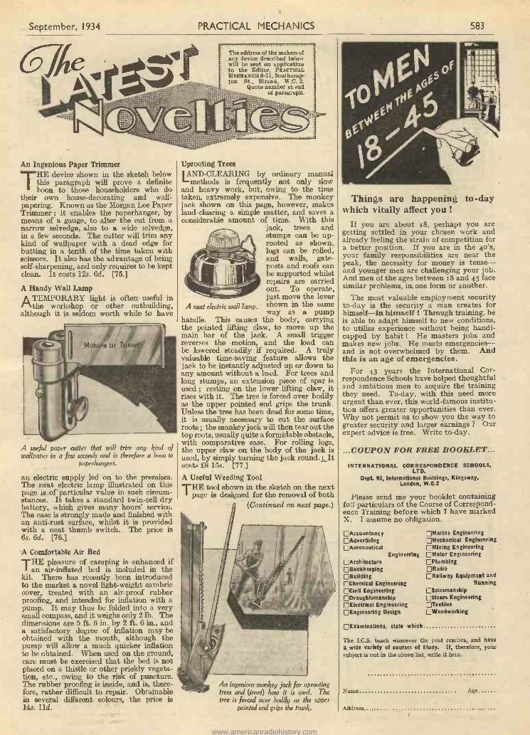
September, 1934 PRACTICAL MECHANICS 583
An Ingenious Paper TrimmerTHE device shown in the sketch below
this paragraph will prove a definiteboon to those householders who do
their own house -decorating and waif -papering. Known as the Morgan Lee PaperTrimmer ; it enables the paperhanger, bymeans of a gauge, to alter the cut from anarrow selvedge, also to a wide selvedge,in a few seconds. The cutter will trim anykind of wallpaper with a dead edge forbutting in a tenth of the time taken withscissors. It also has the advantage of beingself -sharpening, and only requires to be keptclean. It costs 128. 6d. [75.]
A Handy Wall Lamp
ATEMPORARYlight is often' useful in
the workshop or other outbuilding,although it is seldom worth while to have
A useful paper cutter that will trim any kind ofwallpaper in a few seconds and is therefore a boon to
paperhangers.
an electric supply led on to the premises.The neat electric lamp illustrated on thispage is of particular value in such circum-stances. It takes a standard twin -cell drybattery, which gives many hours' service.The case is strongly made and finished withan anti -rust surface, whilst it is providedwith a neat thumb switch. The price is6s. 6d. [76.]
.A Comfortable Air Bed
THEpleasure of camping is enhanced if
an air -inflated bed is included in thekit. There has recently been introducedto the market a novel light -weight cambriccover, treated with an air -proof rubberproofing, and intended for inflation with apump. It may thus be folded into a verysmall compass, and it weighs only 2 lb. Thedimensions are 5 ft. 6 in. by 2 ft. 6 in., anda satisfactory degree of inflation may beobtained with the mouth, although thepump will allow a much quicker inflationto be obtained. When used on the ground,care must be exercised that the bed is notplaced on a thistle or other prickly vegeta-tion, etc., owing to the risk of puncture.The rubber proofing is inside, and is, there-fore, rather difficult to repair. Obtainablein several different colours, the price is14s. 11d.
Uprooting Trees
LAND -CLEARING by ordinary manualmethods is frequently not only slow
and heavy work, but, owing to the timetaken, extremely expensive. The monkeyjack shown on this page, however, makesland -clearing a simple matter, and saves aconsiderable amount of time. With this
jack, trees andstumps can be up-rooted as shown,logs can be rolled,and walls, gate-posts and roofs canbe supported whilstrepairs are carriedout. To operate,just move the levershown in the same
The address of the makers ofany device described belowwill be sent on applicationto the Editor, PRACTICALMECHANICS 8-11, Southamp-ton St., Strand, W.C. 2.
Quote number at endof paragraph.
4o*
* 7 e' er
A neat electric wall lamp. way as a pumphandle. This causes the body, carryingthe pointed lifting claw, to move up themain bar of the jack. A small triggerreverses the motion, and the load canbe lowered steadily if required. A trulyvaluable time -saving feature allows thejack to be instantly adjusted up or down toany amount without a load. For trees andlong stumps, an extension piece of spar isused ; resting on the lower lifting claw, itrises with it. The tree is forced over bodilyas the upper pointed end grips the trunk.Unless the tree has been dead for some time,it is usually necessary to cut the surfaceroots ; the monkey jack will then tear out thetop roots, usually quite a formidable obstacle,with comparative ease. For rolling logs,the upper claw on the body of the jack isused, by simply turning the jack round. _Litcosts £8 158. [77.]
A Useful Weeding ToolTHE tool shown in the sketch on the next
page is designed for the removal of both(Continued on next page.)
' An ingenious monkey jack for uprootingtrees and (inset) how it is used. Thetree is forced over bodily as the upper
pointed end grips the trunk.
Things are happening to -daywhich vitally affect you!
If you are about 18, perhaps you aregetting settled in your chosen work andalready feeling the strain of competition fora better position. If you are in the 4.0's,your family responsibilities are near thepeak, the necessity for money is tense-and younger men are challenging your job.And men of the ages between 18 and 45 facesimilar problems, in. one form or another.
The most valuable employment securityto -day is the security a man creates forhimself-in himself ! Through training, heis able to adapt himself to new conditions,to utilise experience without being handi-capped by habit ! He masters jobs andmakes new jobs. He meets emergencies-and is not overwhelmed by them. Andthis is an age of emergencies.
For 43 years the International Cor-respondence Schools have helped thoughtfuland ambitious men to acquire thd trainingthey need. To -day, with this need moreurgent than ever, this world-famous institu-tion offers greater opportunities than ever.Why not permit us to show you the way togreater security and larger earnings ? Ourexpert advice is free. Write to -day.
...COUPON FOR FREE BOOKLET...
INTERNATIONAL CORRESPONDENCE SCHOOLS,LTD.
Dept. 95, International Buildings, Kingsway,London, W.C.2
Please send me your booklet containingfull particulars of the Course of Correspond-ence Training before which I have markedX. I assume no obligation.
EAccountancyEAdvertisingEAeronautical
EngineeringE ArchitectureE BookkeepingEBuildingEChemical Engineering['Civil EngineeringEDraughtsmanshipEElectrical EngineeringD Engineering Design
EMarine EngineeringEhlechanical Engineering[Alining Engineering[Motor EngineeringEPlumbingERadioORailway Equipment and
RunningESalesmanshipESteam EngineeringETextiles:Woodworking
D Examinations, state which
The I.C.S. teach wherever the post reaches, and havea wide variety of courses of Study. If, therefore, yoursubject is not is the above list, write it here.
Name Age
Address
www.americanradiohistory.com
584 PRACTICAL MECHANICS September, I934
FIT A "WILCO" LIGHTING SETON YOUR CYCLE
17/6Completepost free.
The headlamp gives a powerfulbeam of light, and a batteryprovides illumination when the
cycle is stationary.
The special Chromium -plated Dynamo D grit-,dust,- and damp-proof; an
automatic voltage regu-lator prevente lampsfrom burning out athigh speeds, and amplecurrent is generatedeven at a walking -pace.Guaranteed is nwnths.
Other models from 16/9 to 23/-. Obtainablefrom your local dealer or, in ease of difficulty,direct from us. Complete electrical cata-logue 4d. post free.
L. WILKINSON, 8 CITY ROAD, LONDON, E.C.1
AMATEUR CINE SERVICEhave all the newest apparatusand a fine selection of usedcameras and projectors atbargain prices. For astonish-ing allowances and reallyeasy payments just send us
a postcard.
We don't play at service, it'sour business.
52B WIDMORE ROAD, BROMLEY, KENTPhone: RAV 1926
Eng DEEPSIGElidEcontaining the widestchoice of engineeringcourses in the worldStudy at home with The T.I.G.B. for awell -paid post. Become an A.M.I e.E.,A. M. I. Mech.E.. A.M.I E. E. , etc. Traininguntil Successful Is guaranteed.WRITE NOW for Free Guidestating branch, post or quali-fication that interests you, toTHE TECHNOLOGICAL INSTI-TUTE OF GREAT BRITAIN,123 Temple Bar House,London. E. CA. (Founded 1917,19,000 Successes.)
To SUCCESS
11111SIMMS
THIS
BOXSUPER
WITH CS YOURSFILM5'- ABSOLUTELYInstruc-
CAMERA
Lions forIndoorphoto-
graphs &exposures,
etc.To popularise our 100 per cent.Sheffield 'Double Life" 3 -holetype double-edged razor blades we are giving absolutelyFREE with every order for 55 blades for 1/- post andpacking 6d., this Camera with good lens, brilliant view-finder, simple time and instantaneous shutter, leather-ette finish. Daylight loading. Also films and fullinstructions to take photos indoors and outdoors, cloudyweather and time exposure& Money back if blades arenot equal to any 4d. blade obtainable. Send 1/6 onlyfor blades and FREE Camera and Photographic Outfit.Additional Anna lid. extra. No more to pay.AIRCRAFT PRODUCTS LTD. (Dept. P.F.C.1),
99 Mow Oxford Strut, London, W.C.1(Opposite Mew' @antral ',trustee.)
long and short -rooted weeds. The long semi-circular jaws embrace the whole root, thebarbs on the inner faces preventing the toolfrom slipping and thus failing to remove thewhole of the weed. Hold the weeder (oneknob in each hand) in an upright positionover the weed, with the jaws slightly apart,usually about in. With the tool in thisposition, press downward through the earthto a sufficient depth to embrace the rootand, holding the handles together, pull the
The speed with which weeds can bepermanently removed with this weeder is
amazing.
weeder upwards. The root will come outclean and whole in the jaws, leaving only asmall hole, with no possibility of the weedgrowing again. It costs 33. 11d. [78.]
A Garden Shears AttachmentGARDENERS will no doubt welcome the
little device which can be attached toa pair of ordinary shears, as shown in thesketch. The hooks of this device preventtwigs and branches slipping out of thecutting edge, and so make the gadgetindispensable for cutting evergreen hedges.It costs ls. 9d. [79.]
This device, when fitted to a pair of shears, preventstwigs and branches from slipping out of the cutting
edge while cutting evergreens, etc.
A Non -shock Saddle PillarF you are a keen cyclist and spend yourweekends touring the countryside, you
often find it rough going when cycling alongcountry lanes, and sometimes receive asevere shaking, through the inability ofthe saddle to absorb the shocks. If youwish to enjoy your cycling to the utmost,you should fit your bicycle with a non -shock saddle pillar which is now on themarket. This sprung pillar is well made,and is guaranteed to absorb all shocks inthe saddle, no matter how rough the roadmay be. It is obtainable in two types, thestraight non -shock pillar costs 58. 6d. andthe bracket non -shock pillar 6s. 6d. Motor-cycles can be fitted with this pillar byspecial arrangement with the manufacturer.[so.]
Health, StaminaI positively GUARANTEE to giveyou Robust Health, DoubledStrength and 10-25" more musclein 30 days or return your moneyin full. The famous STEBBING4 -in -1 Course consists of fourgreat mu rats in one, yet costs only5/- post free. It has been proved(1) The moat effective HEALTHand ENERGY System ever de-vised; (2) It quickly builds NOR-MAL WEIGHT and VIRILEMANHOOD; (3) It develops aStrong Will, rigid SELF-CON-TROL; and (4) It includes anamazing SUCCESS and PER.SONAR MAGNETISM Course.
Complete Course, 5/ -No extras, no appliances to
Pupil S. Davey (London) purchase.Further details sent privately, under plain, sealed rover.LIONEL STEBBING, STEBBING INSTITUTE,
Dept. C.P., 28 Dean Road, London, N.W.2.
RUPTURE ANDELASTIC TRUSSESAPPLIANCES
BestElasticWebbingsfor Repairs
SingleDouble
Any style.No extra
charge forlarge pads.
- 10/6- 14/6
The new ..Campolastic " Air Pads, unpundurable.Customers daily write "For quality and eft iency yourappliances cannot be equalled."All receipts hove printedGuarantee:-" Money refunded if unsatisfied."
FREE TRUSSES for National Beath insuredpersons. Send for illus.
Price List and measurement form POST PItEE.C. A. MACBETH (P.M.)124 St. John's Hill, Claloham Junction,London, S.W.11. Phone: Bat. 4247.
QUALITY
IN CHEMISTRYEQUIPMENT
MEANS SUCCESSFUL.EXPERIMENTS
SAMPLE PARCEL containing: 1 Flask, flatbottom, 150 ccs.; 1 Beaker, spouted, 100 cos.;3 Test Tubes, 4 in. X in. 1 Thistle Funnel, 20cms. . 3 ft. Glass Tubing; 1 Rubber Cork, 2holes; 4 inches Rubber Connection n in PostTubing; Glass Stirring Rod. L/ U Free
BECK (Merin Stoktleir StrenetititWrite for FREE PRICE LIST.
WHY BE THIN ?BUILD UP YOUR BODY AGAINST ILLNESSAND DISEASE. DON'T HIDE YOUR BONES
UNDER AN OVERCOAT!Thousands have put on weight and muscular tissue with
the aid of
V I TA E PO N (THL111,1 ")A customer writes :-" After my illness I gained 15 lb. in
weight, and my nerves improved tremendously as the result ofn six weeks' course of Vitaepon."
Vitaepon is not a drug-simply take two tabletswith the morning and evening meal.
Obtainable only from :-WESTGOTT & CO. (Dept. P.),
37 Albemarle Street, Piccadilly, London, W.I.For Week's Trial Supply send P.O. for 3/- or 15/- forfull six weeks' course. Abroad by registered post, 3/6
and 16/-, post free. Sent in plain covers.A new book, entitled "Thinness:Its Cause and Cure"
sent free with every six weeks' course.
7/6 A.C. Battery Charger 7/6Kit "A," i-amp. Charger: Mains Transformer 4/6,Tantalum 1/6, other parts 1/3. Complete, 7/6 post free.Kit "13" as "A," but charging at I amp., 10/6 post free.Kit "C" with Westinghouse Rectifier, h amp., 12/6, post 6d.Model " D " complete in metal Case, charges 2, 4 or 6 voltcells at I amp., ready to plug-in, 17/6 post free.Model "E," a Real charger, As "D" but charging at2 amps., 21/-.ALL ABOVE SUITABLE FOR 100-250 VOLT A.C. MAINS.
Please slate Mains Voltages when ordering.FROST RADIO CO., 21 Red Lion St., E.C.1
Send to FOYLES IFOR BOOKS !
ft
New and second-hand books on every subject.Over two million volumes in stock. Catalogues
ee on mentioning your interests.119.125 Charing Cross Road, London, W,C.2
Telephone-Gerrard 566o (seven lines).
www.americanradiohistory.com
September, 1934 PRACTICAL MECHANICS 585
A Review of the Laces. Devices for The AmateurMechanic. The address of the Makers of the Items men-tioned can be had on application to the Editor. Please
quote the number at the end of the paragraph.
The Howkins Spot FacerTHE tool shown in the sketch below is
for producing a circular facing where ahole is already drilled any size fromA in. to in. It is fitted with a self-adjusting taper pilot which automaticallyslides in and out of the cutter end of thetool ; the taper adjusting itself to the hole.The pilot is steadied by the flat part workingin the slot in the cutter and also by itscylindrical body sliding in the centre hole.Pressure on the pilot is maintained by thespring which can be adjusted by the screwplug. The spot -facer is supplied in threesizes, in., ig in., and in., allwith pilot for holes varying fromA in. to g in. The price ofeach is 68. 6d. [78.]
A Saw Table and Spindle
THEsaw table shown on this page
will prove a very useful tool for themetal worker. Fitted with a 5 -in. square, ithas two fences with a I -in. stem, a cast-ironfoot, and a 7 -in. saw arbour which takes3 -in. wood saws fin. bore between the twocollars, or a 2* -in. fine tooth metal saw witha 10 mm. bore between the first collar andthe spindle body. The I -in. stem as sup-plied, is long enough for a 5 -in. centre lathe,and one may have to reduce its length tosuit a smaller lathe if the end of the lathedoes not clear the bed. It is an advantageto have a short extra stem in order to bringthe table top below the lathe centres whenrequired. When the foot is fixed to a lathe
A spot facer for producing acircular facing where a hole
\\V is already drilled.
cross -slide it will be reversed with its bossoverhanging downwards. This same sawtable can be used with polishing heads bymounting the foot on a wooden block. Thetable weighs 3] lb., and costs £1. Extra3 -in. wood saws, coarse, medium or fine,can be obtained for 3s. each, and metal saws,fine tooth hollow ground, for 18. 6d. each.The 7 -in. saw spindle alone costs 58., andextra table stems 18. 3d. each. [79.]
A Combination FileTHE sketch at the foot of the second
column shows a very handy combinationtool, adjustable for a variety of purposes.It is designed for the purpose of rasping,filing and scraping wood and metals, and,by attaching suitable materials, may alsobe used for sand -papering, polishing, etc.The tool consists of three parts held together
by nuts and screws, which can be readilyloosened to make any required adjustment.The first part is a reversible steel rasp andfile with different cuts on opposite faces andedges so as to be suitable for a variety ofwork. The second, a steel scraper whichcan be moved out either sideways or end-ways, so that any one of the four edges canbe used for scraping and smoothly preparingthe surface of wood, metal and othermaterials. This scraper, when projectingsideways, can also be used as a guide whenit is desired to rub down small sections ofmaterial against the edges of the file ;accurate right -angles may thus be main-tained or produced by keeping one surfacepressed against the side. The third part isa wooden handle conveniently shaped sothat the tool may be readily used with onehand forpreparing large surfaces, or held inthe hand whilst small pieces are rubbedagainst it by the other.
When it is desired to use the toolfor sandpapering or polishing, the
A saw table andspindle- which can
also- be -used with polishing heads by mountingthe foot on a wooden block.
nuts should be loosened sufficiently to permitof the edges of the emery, glass or sandpaper,or of the polishing cloth, being insertedbetween the scraper and the file along bothsides. The nuts should then be tightened,whilst the paper or cloth is held stretchedacross the surface of the file. If the edgesof the scraper blade are not used enough tobecome worn, the blade will serve also as astraight -edge for surface testing. Shouldthe edges of the blade require sharpeningfor scraping purposes, this may be effectedby drawing it a few times across anothersteel edge, or even across one end of thefile if the tool is first dismantled. It costs88.6d. [80.]
An Improved Bull -Nose Rabbet PlaneTHE improved bull -nose rabbet plane
shown overleaf is ideal for fine workwhere extreme accuracy is required. Animproved adjustable mouth has beenembodied in this plane by fitting two steeldistance pieces in between the detachable
A handy combination tool that can beused for the purpose of rasping, filing and
scraping wood and metal.
THE GREATVALUE OF
MAXALDI NGTO MANKINDMr. Buckie'sphotograph isguaranteedunretouchedand thetestimonialunsolicitedunder forfeitof £50 to thispaper.
" Dear Sir, 22/6;34.I enrolled for
Strength Course' inMarch, 1931, and havecontinued with same, as
time permitted,up to date. I
enclose threeunretouchedphotos ofMaxaldingposes.Having been
abroad since ensrolling, am takingthis opportunity of
thanking you for wonderful results derivedfrom constant practice of Maxalding. I haveconstantly recommended your course andshall not hesitate in future, when opportunityarises. My photo is ample proof of the greatvalue of Maxalding to mankind. You are atliberty to use my photo as you think fit.
Yours sincerely,(Signed) C. S. Buckie."
MAXALDING IS FULLY DESCRIBEDin a 20,000 -words illustrated treatise. It ispublished at 11- nett, but one copy will be sentfree to any applicant, from any part of the world,who sends name, address, age and occupation,together with postage for 3 ozs. sealed cover.
No Cost or Obligation involved.
MAHALDING (Dept. 834) 14 CURSITOR ST.LONDON, E.C.4
PATENTS,TRADE MARKSAND DESIGNS
'ADVICE HANDBOOK"AND CONSULTATIONS
FREE!KINGS PATENT AGENCY LTD.Direotor: B. T. King, c.Lmit , Reg. Pat. Agent G.B..
U.S.A. & Can.146a Queen Victoria St., LONDON, E.C.4and 57 Chancery Lane (near Patent Ottice), W.C.2.
49 Years' TELEitRA NIS : Gaotootc, LONDON.References. HONE: CITY 6161.
PRACTICAL HINTS ON PATENTINGand the development of inventions.
Sent free on application.THE IMPERIAL PATENT SERVICEFirst Avenue House, High Holborn, W.G.1.
Principal: M. E. J. GHEURY DE BRAY, F.P.S.Preliminary Tele {phone: Holborn 919r.Consultation Free. grams: Imperatrix, London.
PATENTS, DESIGNSAND TRADE MARKSA VALUABLE GUIDE ON INTERNATIONAL
PROTECTION OF INVENTIONS.100 Pages - Post Free, 6d.
The TECHNICAL ADVERTISING AGENCY253(D) Gray's Inn Road, London, W.C.1
FROST & CO.70 Old Compton St., London, W.I
Engineers, Tool and Model Makers.Models of all descriptions.
Inventors, Scale and Advertising.Patterns, Castings, or Finished Parts, Small
Stampings and Press Tools.Experimental and Repetition Work.
www.americanradiohistory.com
586 PRACTICAL MECHANICS September, 1934
Get thisNew Edition
TELEVISIONFOR THEAMATEURCONSTRUCTOR
By EL J. BARTON CHAPPLE, B.Sc.
ALL keen radio constructors andhome mechanics should have the
revised, Second Edition of thispractical handbook. It shows youexactly how to make a home-madetelevision receiver, incorporating allthe very latest ideas. The clearinstructions and many excellentdiagrams give you all the help youcould possibly need and they evenshow you how to make your ownmaterials and apparatus. Orderyour copy to -day.
SECOND EDITION. 12/8 net.
"II YOU want to build uour own televisionset, here is sour chance."-DAILYHERALD.
" Will keep the constructor alwags on theright lines." -M ECC ANO MAGAZINE.
PITMANPARKER ST., KINGSWAY, W.C.2
Your Height increasedTALL int cl k4. da ramazinn
Stebbins System soonbrings 3-5 inches
increase and new energy. The first original and theone GENUINE guaranteed Height Increase System.Complete Course, 5/.., or Booklet, Testimony andGuarantee sent free, privately, under plain sealed cover.STEBBING SYSTEM, Dept. M.P., 28 Dean Road,London, N.W. 2.
M ICROFU GOLD FILM FUSES20 Stock Ratings. Type F.2,suitable for Battery sets, 150M/A blows at 300 M/A Resistance78 ohms. Voltage 260 Volts D.C.
Type F.2, suitable for Mains sets, 500 M/A FUSES 6d.blows at tamp resistance 1S ohms. 260 Volts HOLDERS 6d.D.C. Now available, 2 mA. 6/., 1 mA. 4/6.MICROFUSES LTD., 36, Clerkenwell Rd.London, E.C.1. 'Phone: CLE 4049.
GOOD IDEAS-are often rejected because of uncon-vincing drawings!Let us prepare attractive illustrationswhich will convey your idea quickly andclearly to Manufacturers, Editors,Agents, etc.We specialise in Patent Office and Techni-
cal drawings of all descriptions.Write or 'phone us at
HIGH HOLBORN HOUSE,HIGH HOLBORN, W.C.1.
Hoc. 8698
REPLIES TO QUERIES& ENQUIRIES
If a postal reply Is desired, a stamped addressed envelope must be enclosed. Every query and drawing which Issent must bear the name and address of the sender and be accompanied by the coupon appearing on page Ili. ofCover. Send your queries to the Editor, PRACTICAL MECHANICS, Geo. Newnes Ltd., 8-1 I Southampton
Street, Strand, London, W.C.2.
Conversion of Dynamos to A.C." N the June issue of ' Practical
Mechanics' you gave an article dealingwith the conversion of dynamos to A.C.
motors. I wrote you regarding one, a D.C.motor, I wished to convert, and I thank youfor your prompt reply. I did as you sug-gested and re -wound the field coils with 1 lb.8 oz. of wire, 26 D.C.C., and it ran straightoff with a little adjustment of brush position.It was an old D.C. 25 h.p. 12 -slot armature24 -bar corn. 2 -pole motor. Now its speedis 4,500 r.p.m., but there is no power behindit, as I can pull it right up by pressure onthe shaft. (1) Can this be overcome in anyway ? (2) Would re -winding the armaturedo any good ? (3) What wire and turnsshould I have to use ? (4) Can you suggestanything ? Your last letter was of greatvalue to me, and I trust you will be able tohelp me further, as I wish now, having gotso far, to make a useful tool of the motor.It will run half an hour and not get warm(at 4,500 r.p.m.)." (E. W., Northampton.)
In answer to your questions, the difficultycan be overcome by re -winding the machinewith No. 18 D.C.C. wire, this will give youabout eight times the present power output.We quoted the No. 26 wire before to be onthe safe side, since we did not know thematerial of the machine and could notestimate the heating. After the re -wind,start the machine with the resistance inseries; this will not be necessary whenusing the machine for short periods. Re-winding the armature will only improve theperformance of the machine slightly.A Transformer Query
" Will you kindly tell me if it would bepractical to use a suitably wound trans-former, on the spark coil principle, using amotor -driven mercury interruptor to supplyH.T. to a radio receiving set from a 32 -voltD.C. source. Would the resulting currenthave to be rectified ?
" If it is practical, will you please giveme details of the core size, winding andgauge of wire, etc., and if a rectifier isnecessary will you kindly describe a suitableone, valve or otherwise ? I wish to obtain anoutput of 50 to 60 m.a. at 200 volts, aftersmoothing, etc." (C. R., South Africa.)
There are sets on the market which workfrom a 6 -volt battery and give the outputyou require, but they cost a little over 30s.We have seen these in operation andconsider them more efficient than theaverage that the homeworker could make.
If you wish to make the apparatus, thefollowing details should be sufficient.
Transformer of " Stalloy " stampingsforming a box core, inside measurementsbeing 3 x 3 in., and cross-section / x I in.,primary 300 turns of No. 22 D.C.C. wire,secondary 1,250 turns of No. 28 D.C.C. wire.Rectify the output with a Cossor 506 B.U.valve. The output should be fairly smooth,giving about 200 volts 60 m.a.Obtaining Water Power
" In the June issue of ' PracticalMechanics ' there was an interesting articleabout small water -power installations.Unfortunately, with the type of wheel youdescribed it is necessary to have a fairlylarge water pressure. There is a streamabout 12 ft. wide passing through our land,and I have made several attempts to harness
it, but unsuccessfully. The depth of thestream is about 1 ft., and it travels at about12 ft. a minute, but it reaches a muchgreater velocity in winter. I am notallowed to make a waterfall higher thanabout 18 in., as there is danger of causingfloods in winter. I would be much obligedif you would let me know what you wouldconsider the best way to tackle the jobagain, and how to construct the water-wheel. I have a motor -car dynamo and itgenerates current at a fairly low speed."(M. D., Cork.)
We regret to say that we do not think itpossible to arrange an electric installationdriven by water power from the stream youdescribe. The difficulty is that there is notenough fall of water, 18 in. being altogetherinadequate. A water -power installation isusually only possible when the stream flowsdown a steep hillside.
A Pond Fountain" I wish to fix a fountain in a goldfish
pond. Will you kindly supply me withsome information with regard to the water ?
" The tank is fixed in the top of a shed,and the difference in the levels of the tankand pond is 10 ft. Will this give me a 5 -ft.spray. If not, how else could a 5 -ft. risebe achieved with the tank in its presentposition, and what would the tank heighthave to be to give a 5 -ft. rise.
" Water return to the tank will be effectedby means of an electrically driven pump."(L. D., Newport.)
The arrangement suggested for your waterfountain should be quite satisfactory, pro-viding that the jet is not too big for the sizeof pipe. You can try jets of different sizesuntil the best result is obtained.
Infra -Red Photography" Having read your very interesting book
since the first edition, I would like thefollowing information :
" (1) Is it possible to use a camera witha 7.7 anstig. lens in focussing mount forinfra -red ray work ?
" (2) What is the price of infra -red rayplates size 34 x 21 ?
" (3) What is the price of an infra -redfilter to fit a 1 -in. diameter lens ?
" (4) What sort of developer has to beused with ray sensitive plates ? " (J. C.,Newcastle -on -Tyne.)
(1) Your camera should give quite satis-factory results with infra -red photography.
(2) and (3) Any good photographic dealerwill give you the price of plates and filtersfor infra -red work, or you can write to themanufacturers for full information. Addressis : Ilford Ltd. (Photographic Manufac-turers), Ilford, London, E.
(4) Use the developer formula given onthe plate box, or on the little card inside thebox.
OUR NEW MONTHLYPRACTICAL TELEVISION
6d. EVERY MONTHPublished by
GEO. NEWNES LTD.,8-1 I Southampton St., Strand, W.C.2
www.americanradiohistory.com
September, 1934 PRACTICAL MECHANICS 587
Improved Cinematograph Picture Produc-tion
" HAVE thought out an idea wherebyit is possible to take and project stereo-scopic cinematograph pictures, and
would like you to give advice as to itsvalidity, novelty and value." (R. P.,Northumberland.)
The suggested arrangement for takingand projecting cinematograph pictures is,so far as is known from personal knowledge,novel and would form fit subject -matter forprotection by Letters Patent, provided itachieves a more useful result than knownmethods. The inventor is, however, firstadvised to carry out certain experiments toprove the correctness of the theory onwhich the invention is based, and afterbeing satisfied on this score to make asearch amongst the prior Patent Specifica-tions dealing with the subject to ascertainthe novelty of the invention.
It is, however, a mistake to think thatthe proposed arrangement will give stereo-scopic projection. It is probably true thatthe projected picture would be more bril-liant, due to the double number of picturestaken and projected per second, but whethera more life -like projection would result isdoubtful and could only be proven byexperiment. In order to produce a stereo-scopic picture, it would be necessary tohave some arrangement whereby each eyeof an observer is alternately masked insynchronism with the projected pictures.The mere alternate projection of two pic-tures taken stereoscopically will notproduce a stereoscopic effect on the be-holder. The " faithful " rendering ofcolour would most certainly not be achievedby the invention ; it would probably bepossible to obtain a result comparable withthe now discarded system known as" kinemacolor." A further objection to theproposal is the duplication of taking andprojecting apparatus and the double costentailed in dealing with twice the amountof film ordinarily required.Trade Marks
(1) What is the total cost of registering aTrade Mark or design or word ? I have thepamphlet from the Patent Office, but I amnot quite clear as to the cost. It would appearto be Ll on application and £2 on acceptance,making £3 in all, but then how does oneknow whether an objection will be raised,as if this is done it would appear thatanother £3 is payable, and is the moneyreturned to me if the objector wins ?
" (2) Would the word ' Nuglo ' forapplication to furniture polishing cream beaccepted, or is there a prior registration ofthis word ?
" (3) I have noticed on some labels thewords ' Copyright Design.' What is thedifference between this and a Trade Markand how does one copyright a design, andwhat is the cost ? " (C. J. B., Moreton -in -Marsh.)
The Stamp Duty payable on filing anApplication to register a Trade Mark in one
SUGGESTED BY OUR READERS
class is £1. The Mark may consist of adevice or a word. After the Application forregistration is filed, the Trade Marks Officemakes a search to ascertain if the same, or asimilar Mark, has been previously registeredor applied for in respect of the same or asimilar class of goods. If the search doesnot disclose any such Mark and the pro-posed Mark is otherwise considered suit-able for registration, the Application isallowed to proceed. It then becomesnecessary, in the case of a device mark ora word mark printed in some particularway or type, to file a printing block foradvertising the Mark in the Official TradeMarks Journal. This block is not returned,and if it exceeds 2 in. in width or depth afee is payable for advertising. After beingduly advertised for one month to allow foropposition to registration, the certificate ofregistration is issued on payment of a feeof £2. The Mark is then registered forfourteen years, renewable for like periodsof fourteen years. If opposition to registra-tion be raised by an interested party, andthe opposition is successful after beingcontested, costs may be awarded by theRegistrar to the successful party. In nocase is any fee returnable by the Office.Provided the word NUGLO has not pre-viously been registered in respect of" Polishing cream for furniture " it mightbe accepted for registration, but objectionmay be taken on the ground that it issimply the mis-spelling of two descriptivewords NEW and GLOW. It is not pos-sible to ascertain whether this word haspreviously been registered without firstmaking a search, for which a fee is payable.
To register a design the procedure isquite different from that for registration of aTrade Mark, and the fee payable depends onthe class of goods for which the design isrequired to be registered.
Automatic Record Repeater" I have constructed a simple device
which can be instantly attached to ordetached from any gramophone recordwhen laid on the turn -table, and whichrenders the action of the tone -arm auto-matic, inasmuch as one tune can be playedtwice or more without attention. Thiswould be particularly useful for dancepurposes.
" The device could be manufactured at alow cost and sold to the public for a fewshillings only.
" Will you be kind enough to advisewhether or no such would be of any com-mercial value ? Should you wish I couldsubmit drawings at a later date." (G. N.,Surrey.)
The broad idea of fitting a device to agramophone whereby a record can berepeatedly played is not thought to benovel. There have been many devicesproposed and many Patented for accom-plishing the object in view. It may be thatthe applicant's device is either less expen-sive to produce, or is otherwise more usefulthan those hitherto proposed, in which caseit should have a certain commercial valuewhich, however, will depend on the way itis marketed.
" We're Fluxite and Solder-the reliable pair ;Famous for Soldering-known everywhere !The toy that was 'old '-will live to be ' older 'Thanks to the aid-of Fluxite and Solder "
See that Fluxite and Solder are always by you-inthe house - garage - workshop - anywhere where
simple, speedy soldering is needed.
ALL MECHANICS WILL HAVE
MITEIT SIMPLIFIES ALL SOLDERING
All Ironmongers sell Fluxite in tins; 4d., 8d., 1/4and 2/8. Ask to see the FLUXITE POCKETSOLDERING SET-complete with full instruc-tions - 7/8, Ask also for our leaflet onHARDENING STEEL with Fluxite.
FLUXITE Ltd. (Dept. P.M.),Dragon Works, Bermondsey Street, S.E.I
FOR ALL REPAIRS!
INFERIORITYCOMPLEX
eradicatedAn Inferiority Complex is a disturbance in the Subconscious
Mind which manifests itself in self-consciousness and lack ofconfidence-in nervous mannerisms, worry and timidity, lackof enterprise, in weakness of will sod Indecision. Its originlies in experiences and influences during your personality -development which may be entirely forgotten, but their effectsremain in the form of a "disturbance centre" in Subconscious-ness which sends out powerful negative impulses.
Toss cannot control these impulses-to fight them by directeffort increases their strength-but you can remove themaltogether and build up in their place a new personality withpowerful positive impulses, generating forces within yourselfwhich will help instead of binder, which will carry you forwardtowards a happier, healthier, fuller, more successful life.
This you can now do-yourself-simply endinexpensively, by your own efforts, in the privacyof your own home. Send coupon or write to -dayfor Free Book.
You have only one life to live in this wonderful world. Letthe past go I Begin life again with the glorious promise ofhappy expression of the power that lies within your personalityself -reconstructed into one strong harmonious unity.
Millions pass through life in tragic ignorance of theirunused capacity for achievement. Do not be misled by thebelief that you have a certain Axed kind of temperament.Cease to resign yourself to patient endurance of circumstances.Shape your own fortunes, bring out your latent abilities, increaseyour personal value, measured both in money and influence.
THE BRITISH INSTITUTE OFPRACTICAL PSYCHOLOGY LTD.--I (E.A.2), LUDGATE HILL, LOUDON, E.C.4-
Please send me FREE BOOK "I CAN .AND I WILL."
Name(BLOCH LETTERS)
Address
E.A.2.
www.americanradiohistory.com
588 PRACTICAL MECHANICS September, 1934
The 'WErd7 SERVICE AIR RIFLE, Mk. If.WRITE FOR
No Licence required to purchase.
DESCRIPTIVEFOLDER Rooks, Rabbits. Rats,
Sparrows and similar verminCan be destroyed by this extremely
accurate and powerful Air Rifle.Ideal for Target Practice.
Calibre 22 or 177 With Leafsight and Peepsight.WESLEY & SCOTT, IA 106 Weaman St., BI RM I NG HAM 4
tlj
It
BE TALLER!!RESULTS SPEAK POE THEMSELVESPupil, age 191, gains 5 ins. in 6 wks.
21, 5 ins. in 5 mho.20, 31 ins. in 16 dye.90, 2 ins. in 4 wks.40, 11 ins in 6
Inreased my own height to oP 3Is ROSS SYSTEMTestimonials/ram allover the world NEVER PAILSPee:I,22 2s. complete. Convincing Testimony 21d.
stamp. Mailed privately.L. MALCOLM ROSS, Height Specialist*Scarborough, England. (P.O. Box 15.1
BANDGUIDE
Giving hints on the Bugle,Drum and Flute, alsoParade Formations, useof Parade Cane, Staff,etc., free and post paid.
Makers:
POTTER'S36138, West Street,
Charing Cross Road,
LONDON,W.C.a
13/11 ARDEN CHARGING UNITS 13/11Get an ARDEN CHARGING UNIT and
charge your own Accumulator.Incorporating Westinghouse Metal Rectifier and robusttransformer to B. E.S.A. specification, tested 2,000v. betweenwindings. Complete In crackle finish ventilated metal case,ready for immediate use. Suitable for 000-250v. A.C. mains.26v. at I amp., 18/11, post free. 2-6v. at 1 amp., 15/0, postfree. List free. Money returned within 7 days if dissatisfied.The Arden Agency, Wollaston, Wellingborough, 5
NERVOUSNESSEvery sufferer from " nerves" should read my interest-ing book describing an inexpensive treatment forWeak Nerves, Depression, Morbid Fears, Insomnia,Self -Consciousness, Blushing and similar nervous dis-
orders; sent privately free of charge.
HENRY J. RIVERS (Dept. K.D.3),40 Lamb's Conduit Street, London, W.C.1
NERVOUSNESSAre you anxious to overcome Nervousness, Blushing, Self -Consciousness 4 Do you wish to acquire charm and magneticpower, and be popular with both sexes? Would you like todevelop a bold, fearless, dominant personality and a keen, super -alert brain that will win you success in life? My secret systemwill bring you strong nerves and a strange new personalmagnetism in a few weeks. Your money back if not delightedwith results in 30 days. Complete Course, 5/, Detailsfree, privately. LIONEL STEBBING TREATMENT,
Dept. M.P., 28 Dean Road, London, N.W.2.
LEARN TO MAKS PICTUREFRAMES. Picture Framing, Tray -
making, Craft Work, etc.Wonderful Wholesale Bargains inMouldings, Beadings, Frets, Plys,Jacobean Legs, Table Tops, Cornerand Tray Mouldings, Fine Art
Pictures, Transfers, Silhouettes.Fully Illustrated Guide, post free, 3d.
WATKINS PROVIDER fi rots.
10,000 MOTORS (Spring and Electric) forRADIOGRAMS or GRAMOPHONES in stock.Thousands of components: Tone Arms Sound .--boxem, Pick-ups, all types Horns, Pedestal -portable Cabinets, fittings, hinges,
-4-2
..
14 ' ----"tlidatays, springs for all motors.gears, repairs, accessories. Portable I .-ClisNk....'7- liti,KR....--------.Gramos. from 12/6. Violins, stringsfor all instruments. Big trade dis-count. Radio goods to order. List ' -alVfree. 04 -page Catalogue-how to T.'. -make them -2d. Est. 30 yrs. AThe Regent Fittings 0o., D 289,
120 Old Street, London, E.C.1.
HOME -O -CRAFT NON -FLYING KITSSpan, 6 in. to 8 In. 8.6.B., Puss Moth, Fox Moth,Dragon, H.Fury, Siskin, V.Jockey, Southampton,Vildebeest, F.L.R.M. Contents, Plan, Printed
Balsa, Wheels, Glue.Price: 1 Kit, 1141 3 Site, 2/4. Post Free. Price List, 14
MODEL AIRCRAFT SUPPLIES LTD.,171 NEW KENT ROAD, LONDON, 8.E.1
nose and the plane body, which gives fourvarying openings for fine or coarse work.The faces and sides of the plane are accur-ately machined and ground, and it can beused as a chisel plane by removing the nose.It has screw adjustment for regulating thedepth of cut, and is fitted with tungstensteel cutters. The plane is 4 in. long, has
An improved bull -nose rabbet plane.
11 -in. cutter and weighs If lb. It costs108. 6d. [81.]Petrol Blow LampTHERE are many occasions on which -
a convenient type of blow lamp isextremely useful to the owner -driver andhome mechanic. A device of this naturecan be used for hard soldering or even fordoing small brazing jobs, especially if it isable to provide a reasonable amount of heat.The " Bladon " petrol blow lamp which isnow on the market is of a particularly neatand handy type and, being operated entirelyfrom petrol, it has a very special appeal tothe motorist, who always has an ampleamount of fuel ready to hand. The lampunder review is provided with a heat -resist-ing handle, and has a small clip which maybe used for holding a stick of solder orspelter while the work is in progress.Although in every way a real, workmanlikepiece of apparatus, this lamp retails at only58.6d. [82.]Double -Action Foot Bellows and BlowpipeThe home mechanic will no doubt be
I interested in the above type of gas bellowsand blowpipe which are now on the marketat a very reasonable price. They give asteady and perfectly controlled blast, with asufficient volume for all the ordinary benchpurposes of jewellers, dentists, opticians,etc. An important feature of these bellowsand blowpipe is that they oan be used withgreat comfort while seated ; and the flamecan be directed to any point, leaving thehand of the operator free to manipulatehis work. The bellows, rubber balloon,with net and tubing complete, withoutblowpipe, cost 178., extra rubber pipe andnets 4s. 6d. each, and the blowpipe completewith stand costs 128. 6d. each. [83.]A Micrometer for the Workbench
THEmicrometer shown below will be
found to be well within the reach ofthe handyman's pocket. Obtainable in twosizes, it is sold complete with ratchet head,this head enabling a large number ofmeasurements to be made with equal
A cheap and efficientmicrometer.
precision by different people, owing to thefact that only a certain definite pressure canbe exerted on the measuring surfaces. Theprice of each is -0 in. to 1 in. 21e., and 1 in.to 2 in. 308. [84.]
UNIVERSAL HIGH VOLTAGE MAINS VALVES(Made in Vienna)
are the only Universal Valves that can be wired inParallel. There's no wider, finer or more up-to-daterange available. They work equally as well on eitherD.C. or A.C. supply without alteration, off the FullMains Voltage and they do Not require Trans-formers, Barretters or Breakdown Residences.
Because of their remarkable efficiency they havebeen specified and are fully recommended by" Wireless Press."KITS SUPPLIED FOR ALL TYPES OF RECEIVERS-RADIOGRAMS-AMPLIFIERS.
It is simple to convert Battery or any mains setto Universal AC/DC with Ostar-Ganz valves. Fulldetails and circuits and technical assistance free.EUGEN FORBAT, 213-29 Southampton St., W.C.2
District Agents wanted. Tele : Temple Bar 8608
MODEL AIRCRAFT MATERIALSSEND lid. STAMP KITS, BLUE PRINTS,
for lists of BALSA WOOD, etc.'CONDOR' KITS EVERYTHING FOR THEAND MATERIALS AERO MODELLISTNORTHERN MODEL AIRCRAFT CO.,
I la HIGH ST., MANCHESTER, 4(Hours: Mon.-Fri. 9.30-6.30. Sat. 9.30-2.0)
"IDEAL -LATHES " 3in.s.C.LATHESfrom 14.
31, in. S.C.B.G. from E7/18/6. LISTS, Stamp please.J. WILLIMOTT & SON, Neville's Factory, Chilwell, Notts.
DON'T BE BULLIEDLearn to fear no man. TheBEST self-defence ever in-vented, namely, JUJITSU.Easy to learn. Send 2 pennystamps for SPLENDID ILLUS-TRATED LESSONS. PhotoARTICLE, Testimonials andparticulars, of P.O. 1/- forP i RST PART of my course.'You will be more thandelighted.Dept. P., Blenteim House, Bedfont Lanareltham,bliddlesex.
Helpful Books for the Practical Man
NEWNES
HOME MECHANICSSERIES
Price 1/- net eachBy post 1/2 each
SIMPLE ELECTRICAL APPARATUSInteresting and useful apparatus, easily con-structed, with which the student is enabled totest for himself the theory and practice ofElectricity as laid down in the text -books.
THE HOME WOODWORKERThe various examples of woodwork described inthis Handbook have been designed by practicalcraftsmen. They are modern in style, and theirconstruction is well within the powers of the averagehome -worker who follows the instructions given.
MOTOR -CAR OVERHAUL AND UPKEEPMany, by undertaking their own repairs, canafford to run a Car, and it is the purpose of thishandbook to show how the Owner -Driver maycarry out most of the adjustments and repairswhich every Car sooner or later needs.
85 SIMPLE WORKING MODELSAll the models described in this book can beconstructed from the simplest materials and withvery modest equipment. None requires lathe -work. 147 illustrations.
THERE ARE 10 BOOKS IN THIS SERIES.
SEND POST CARD FOR LIST.
From all Booksellers, Newsagents, etc., or by postIs. 2d. each from the Publishers :-
GEORGE NEWNES LTD.8-11 Southampton St., Strand, London, W.C.2
www.americanradiohistory.com
UNIQUE SLIDE RULESBRITISH MADE
Ton -inch log -log rule in polished mahogany. ScalesA, B, C and D. Log -log Reciprocal. Celluloid faced.Flexible back. Aluminium -framed free view, unbreak-able cursor. Size of rule, 114" X 14".
Price 5/- each.
Five -inch log -log ruts. Specification as above. Sizeor x 14".
Price 3/6 each.
Ten -inch Universal rule, with Sine and Tangent scalesin addition to those of the log -log types. This rulehas screw adjustment for fit of slide. The most com-plete rule. Size, 114" x le.
Price 6/- each.All types are accurate, and each rule is supplied withcase and full instructions for use, including Conver-sion able for money calculations. Postage 3d. extrafor each rule, but postage is paid when three or morerules are ordered together.FREE GIFT of a set of 12" Draughtsmen's Scales witheach 10" rule bought during current month.Manufactured and sold byTHE TECHNICAL SUPPLY CO. (P),
NORFOLK HOUSE,CARDEN AVENUE,
Phone BRIGHTON,PRESTON 3927. SUSSEX.
CLASSIFIEDADVERTISEMENTS
Private or trade announcements can be inserted inthis column at the price of THREEPENCE per wordPREPAID.All communications should be addressed toTHE ADVERTISEMENT MANAGER,
PRACTICAL MECHANICS,8/1z SOUTHAMPTON ST., STRAND,
LONDON, W.C.2.
CINEMATOGRAPH FILMS.-Standard size from6d. 100 feet. Machines, Accessories. Sample Films,1/- and 2/6 post free. Catalogues free.-" Filmerles,"57 Lancaster Road, Leytonstone, E.11.
COMMERCIAL TRANSFERS for all decorativeor stock purposes. Signwriting, Graining, etc. Illus-trated booklet 14d.-PM. Axon, Jersey, England.A. MATHISEN, CHARTERED PATENT AGENT,Patents, Designs & Trade Marks, First Avenue House,High Holborn, London, W.C. 1. Holborn 8950.
MICROSCOPIC OBJECTS, prepared unmounted.Assorted packet, 2/-.-LENG, 183 Manchester Drive,Leigh -on -Sea.
MAKE LEAD TOYS! Easy, profitable, with" SUCCESS " Moulds. List Free.-LEE'S, BEN-TINCK ROAD, NOTTINGHAM.
SUPER A.G. MOTORS. 4, 4 and 1 h.p. 35/ -to 70/-.-A. Musham, 397 Killinghall Road, Bradford.
TOY CASTING MOULDS for Lead Soldiers,Animals, Novelties. No experience necessary. Illus-trated catalogue, stamp.-J. Toymoulds, 7 JamaicaRow, Birmingham.
FOR SMALL TURNED PARTS up to half inchdiameter made on automatic, also small press work,send to F.E.X. Co., 42 Blenheim Road, UpperHolloway, N.19. Good work, quick deliveries andkeen prices. Also plating work, barrel and still.
WANTED in condition as new and open to trialbefore purchase. 1 200 -230 -volt constant speed D.C.motor; 2" shafting and 3 bearings; 1-6" diameterCarborundum Wheel; 1-6" diameter Buffing Wheel;1 Wet Grindstone, 2" diameter, 100 r.p.m.; 1 bracketdrill; 1 Lathe, 4" height (gap bed) 3 ft. distancebetween head and tail stock, 3 -jaw chuck and morsetaper; 1 circular wood saw, 12" diameter.-Capt.G. N. C. Treeby, Elphinstone House, Sungei Siput,Perak, F.M.S.
FIFTY TESTED Wireless Circuits." By F. J.Camm (Editor of ' Practical Wireless "). This hand-book contains every modern circuit, complete withinstructions for assembling, component values, andnotes on operation. On sale at Booksellers, 2/6, orby post 2/9 from George Newnes Ltd., 8-11Southampton Street, Strand, London, W.C.2.
FREE ADVICE BUREAUCOUPON
This coupon is available until September 29th,: 1934, and must be attached to all letters con-
taining queries.: PRACTICAL MECHANICS, SEPT., 1934M1444.1444.5.*.4444401,'1 - 4" s
P.M. Gift Stamp No. 12
Trt,
Catalogues and .1_1Publications Received
OUR FREE CATALOGUE SERVICETo save readers trouble, we undertake to send on cata-
logues of any of our advertisers. Merely state on a post-card the number (or numbers) appearing at the end of theparagraphs below and address it to " Catalogue,"PrAenCia MECHANICS, Geo. Newnes Ltd., 8/11 South-ampton Street, Strand, London, W.C.2. Where advertisersmake a charge, or require postage, tkia should be sentwith applications for catalogues. No other correspondencewhatsoever should be enclosed.A Splendid Kay CompetitionKAY (Sports & Games) Ltd., of Pembroke Works,
London, N.10, are running a grand competition thisyear. There are 185 prizes, and there is no entrancefee. The prizes are made up as follows : 10 first prizes,each a 21s. Kay chemistry or electrical outfit; 25second prizes, each a 10s. 6d. Kay chemistry or electricaloutfit ; 50 third prizes, each a 5s. Kay chemistry orelectrical outfit ; and 100 smaller Kay chemistry orelectrical outfits as consolation prizes. All you haveto do is to write, in not more than twenty-five wordsthe reason " why Kay chemistry and electrical outfitsare best." Entries must be made on a postcard, whichmust bear a penny stamp, and competitors must alsoclearly state their full name and address, and also thename and address of their local Kay dealer. Thecompleted card must be sent to Kay (Sports & Games)Ltd., Competition Dept., Pembroke Works, London,N.10, and must reach there not later than twelve o'clocknoon on December 31st, 1934. The results will beannounced in the March, 1935, issue of PRACTICALMECHANICS. Write at once for their latest catalogue,which contains full details of this splendid competition,which will be sent free of charge upon application. [59.]Special Optical BargainsMESSRS. BROADHURST CLARKSON &Co., 63
Farringdon Road, London, E.C.1, the well-knownoptical manufacturers, have recently introduced anumber of novelties and bargains which should appealto all readers. They are listed in a well -Illustrated 15 -page catalogue, and consist of pocket magnifyingglasses and microscopes, binoculars, slide rules, thermo-meters, telescopes, etc., etc. Of special note is a fine3 -in. astronomical telescope which is listed at a reason-able price. It is mounted on a stand, and is an idealinstrument for long-distance use. Write at once forthis catalogue, which will be sent post free uponapplication. [60.]Sundry Laboratory EquipmentLESLIE DIXON & Co., Electradix House, 218 Upper
Thames Street, London, E.C.4, a name well known inthe wireless tradd, have recently published a listcontaining a number of bargains in high-gradeapparatus for reg6arch and standardising work. Mostof the apparat is in a new condition, and has onlybeen used once twice ; but all are in first-class order,and are offered t 'purchasers at low prices for cash only.Such an opport ity occurs seldom, and prospective
ii"purchasers are ised that there are no duplicates,
1
and orders cannokte repeated. Write at once for theabove list, which 'WI be sent free of charge uponapplication. [61.] 4.,,,." Goltone " Radio' ComponentsMANY useful components and radio accessories for
the set constructor are shown in the new season'slist issued by Ward & Goldstone Ltd., Pendleton,Manchester. This 60 -page booklet contains a finerange of H.F. chokes, including some heavy duty typessuitable for A.C. or D.C. sets. Iron -cored tuning coils,H.F. coupling units, screened dual range coils, a switchunit chassis, condensers in bakelite or metal cases,compression type condensers, and switches of differenttypes are also listed. Among the other materials givenin this comprehensive list are instrument wire in allgauges, rubber and flex covered wires, voltmeters andammeters, the " Goltone " screened down lead, accu-mulators charging boards, and a range of bakelitemoulded adaptors and lamp holders. Every set con-structor is advised to write for a free copy of thisvaluable list. [62.]Hivac Valves1E High Vacuum Valve Co. Ltd., 113 Farringdon
Road, E.C.1, the well-known firm of valve manu-facturers, offer to the public a fine range of first -qualityvalves at reasonable prices. In addition to existingtypes, they have recently introduced new A.C. mainsvalves for the first time, and these include H.F. pen-todes, a general purpose triode, and a 84 -watt outputpentode. Write at once for their valve list, which willbe sent free of charge upon application. [63.]A Model Engineer ExhibitionPlif, EADERS interested in models and scientific"novelties should not fall to pay a visit to the ModelEngineer Exhibition, which is organised by MessrsPercival & Marshall & Co., from September 6th to the15th. This year they have a wonder show of modelengines, ships, speed boats, aeroplanes, electric andscientific novelties, lathes, tools and workshop equip-ment of all kinds, castings and materials for modelmaking, steam and electric model railways runningdaily, and demonstrations of wireless and light raycontrol. The price of admission is ls. 3d., and theExhibition will be opened daily from 11 a.m. to9.30 p.m. The Exhibition is held at the RoyalHorticultural Hall, Vincent Sq., Westminster, S.W.1.
FREE SERVICE
FOR READERS
DEADERS requiring infor--1-t mation concerning goods orservices advertised inPRACTICAL MECHANICSshould give names of Advertisersfrom whom particulars aredesired. Any number of namesmay be included and we willobtain for you catalogues, lists,and any other information youmay be wanting. THERE ISNO CHARGE FOR THISSERVICE.
Readers desiring particulars from anumber of Advertisers will, by thismethod, save time and postage. Half-penny stamp only is required if yourenvelope is left unsealed. If any Adver-tiser stipulates that stamps or postalorders are necessary before samples orcatalogues are sent, please enclose thenecessary amount with your instruc-tions. You are cordially invited tomake full use of this Service.
Post this to
ADVERT. SERVICE DEPT.,
PRACTICAL MECHANICS,
8-11 SOUTHAMPTON STREET
STRAND, W.C.2
Please obtain and send to meparticulars from the Advertisersin your September issue whosenames I give on list attached.
Advertiser J Page No. I Information Required.
Attach sheet of paper, with par-ticulars, and your name andaddress (written in BLOCKletters), with date, to thisannouncement.
All applications respecting Advertising in this Publication should be addressed to the ADVERTISEMENT MANAGER, GEORGE NEWNES Ltd.,8.11 Southampton Street, Strand, London, W,0.2. Telephone: Temple Bar 7780.
Iwww.americanradiohistory.com

f
BUY YOUR COPYOF NO. i TO -DAY
On sale at all Newsagents andBookstalls, or by post nd.from George Newnes Ltd.,8-II Southampton Street,Strand, London, W.C.2.
NOIlitFOR
IREVISIO
THE time cannot be far distant when we look -in as well as listen -in . .
BRING YOUR KNOWLEDGE OF TELEVISION RIGHT UP TODATE BY STUDYING THE PAGES OF THIS NEW MAGAZINE.
Read all about the various systems, how your set may be .adapted toreceive television, how to make a receiver at small cost, how picturesare transmitted, the latest television news, and many other aspects ofthis most modern and intriguing of sciences.
"PRACTICAL TELEVISION" WILL TELL YOU ALLABOUT THE NEW HOBBY IN EVERYDAY LANGUAGE,PRACTICAL DIAGRAMS AND PHOTOGRAPHS.
PRACTLEVI
ICALSION
Gso. Newts.: La.
Published by GEORGE NEWNES LIMITED, 8-11 Southampton Street, Strand, London, W.C.2, and Printed in Great Britain by THa WUITesIIARS PRgSS LTD..Loudon and Tonbridge. Bole Agents for Australia and New Zealand-Gordon & Gotch Ltd. Sole Agents for South Afries,--Central News Agency LW.
1kiwww.americanradiohistory.com