Intelligent and systematic residential ventilation - Systemair
188
Intelligent and systematic residential ventilation Ventilation units, duct systems, diffusers and accessories Residential ventilation
-
Upload
khangminh22 -
Category
Documents
-
view
1 -
download
0
Transcript of Intelligent and systematic residential ventilation - Systemair

Intelligent and systematic residential ventilation Ventilation units, duct systems, diffusers and accessories
Residential ventilation

2 systemair

systemair 3
A great feeling all-round: to be able to enjoy clean fresh air at any time in your own home – while saving valuable energy every day!
Allow your customers to experience this extra quality of life: with intelligent residential venti-lation systems from Systemair. Using the latest technology, reassuringly safe, reliable, powerful and energy efficient. What's more, you will be ideally prepared for trouble-free and safe installation.
Right from the start, this allows you too to experience just what your customers value so much about Systemair: a great feeling all-round.

4 systemair
Why residential ventilation? | Page 6
Why residential ventilation from Systemair? | Page 8
Systems with heat recovery | Page 11 A guide for your construction project | Page 12 System presentation for single-family house | Page 14
Units with heat recovery for single-family house | Page 16 SAVE control the intelligent controller | Page 18
Accessoires for devices with heat-recovery | Page 48 Schematic diagram of units with heat recovery | Page 62
Central vacuum cleaner | Page 66
Duct systems | Page 70 System presentation | Page 72
Air distribution products | Page 98
Genius air heating system | Page 114 Systems with heat recovery for apartment blocks | Page 130
Centralised systems with heat recovery for apartment blocks | Page 132 Decentralised systems with heat recovery for apartment blocks | Page 136
Systems without heat recovery | Page 138 Systems presentation for single-family houses | Page 140 Systems presentation for apartment houses | Page 142 FAQ / Information for planners | Page 164 Assistance in planning a residential ventilation system | Page 165 EnEV - the German Energy Conservation Regulation | Page 166 EU Ecodesign Directive | Page 168 VDI Guideline 3805 | Page 170 Fire protection and smoke extraction dampers | Page 171 Comparison of rotary and counter flow heat exchangers | Page 172 Air filters for ventilation and air conditioning | Page 174 Application and installation examples | Page 178
Systemair worldwide | Page 182
Notes | Page 184
Index | Page 186
Contents
systemair 5
Catalogue navigation made easy: the symbols will take you to the desired product area. Follow the double arrows to the next relevant configuration step and find the right components. Get started on the next page.
A high-performance, technologically mature ventilation unit is the core of every advanced residential ventilation system. But function, sustainability and therefore continued user satisfaction are always a product of the overall system.
It is the optimum interaction of the ventilation unit, the right accessories (e.g. intelligent control), the duct system and the diffuser components which, at the end of the day, achieves the decisive advantage in efficiency and performance. At Systemair, and in this catalogue, you will find all the components you need – with the best quality, thoroughly tested and perfectly attuned to each other. Systematic excellence!
Everything that efficient residential ventilation needs.
1 2 3 4
Unitswith heat recovery
Accessoriesfor units with heat recovery
Duct systems Diffusers

6 systemair
Contemporary living – with intelligent ventilation!The desire to save energy and the high-performance insulation needed to achieve this have made our houses and apartments increasingly airtight. Time for new solutions!
A natural exchange of air is almost impossible with modern windows, walls, façades and doors. On the one hand, this is a good thing – from an energy-saving perspective. On the other hand, it’s not so good in terms of air quality and quality-of-life of the inhabitants. Poorly-ventilated rooms have a higher risk of developing mould and palpably stale air is a real hindrance to well-being.
A potential solution: ventilation via the windows, carefully planned and implemented. However, in practice this usually proves to be difficult
to do and also counter-productive in terms of energy savings. The significantly more comfortable, more sustainable and therefore more modern option is controlled residential ventilation, generally with heat recovery.
The basic principle: stale air is extracted and fresh air is brought in from outside. The fresh air is cleaned by filters and preheated via heat exchangers (which take heat from the extracted air). The exchange of air occurs continuously; the need to open all the windows
wide at frequent intervals becomes a thing of the past. The result: a consistently perfect indoor climate – at the desired temperature!
That’s the theory. There are a few differences in practice. Firstly, attention must be paid to the quality and function of the components used. And, just as important to you as a planner or installer: getting comprehensive expert advice and support. Before, during and after installation of the system.

systemair 7
It is always good to have a partner at your side who doesn’t think only in terms of individual products, but who is able to take a broader view. Someone who doesn’t just deliver technical components, but a functioning system. This is the pledge we live by. As our name suggests.
Window ventilation Air extraction Heat recovery
kWh/year
10000
8000
6000
4000
2000
0
100 %83 %
42 %
168 m2 living area 10 kWh = 1 litre heating oil or 1 m3 natural gas
Quality-of-life: Up – Heating costs: Down
Source: Hessian Ministry of Economics, Transport, Urban and Regional Development

8 systemair
Systematic satisfaction: Residential ventilation with SystemairWith Systemair, planners, installers – and of course users – can all profit from our more than 40 years of experience in ventilation engineering.
The result: thoroughly tested, technically mature systems and components which have been ideally attuned to each other by our experts. Powerful and energy-efficient, with well-thought-out details which make all the difference when they interact with each other. Such as the integrated humidity sensor, which perfectly adjusts the fan and rotor speed to the needs of the inhabitants. Or the selectable filter quality which enables adaptation to local conditions. And that’s just two examples.
Since we don’t only want to make life more pleasant for those using our products, but also to make life easier for all the professionals on-site, we have taken care to keep our technology manageable, i.e. easy to install. For trou-ble-free installation according to plan.
Whether for a single dwelling or an apartment block, with heat recovery or without: in our product portfolio you are certain to find the optimum solution which not only
completely fulfils the building requirements but also the demands of your customer. And that’s for sure.
But advanced technology isn’t everything. It is just the central feature of an attractive overall package – consisting of personal consultation, (on request) active, CAD-based, support during the planning phase, as well as quote generation right through to commissioning. Our excellent Logistics team ensures that everything arrives on time and in perfect condition – as a complete or partial delivery, depending on your needs.
This special package is rounded off by prompt and obliging service. Trust invested in the right place – that’s Systemair.
Create ventilation concepts easily and in accordance with DIN 1946-6.
Airplan suggests the appropriate overall product solution.
Airplan is your plan: Find the most suitable ventilation concept in just a few minutes! Our free software tool Airplan will help you configure your ventilation systems. Find out more at www.systemair.de

systemair 9
SAVE control is literally “smart” and is able to learn. The system optimises the indoor air and saves energy at the same time. And that’s not all it’s capable of. The SAVE control mobile app provides more detailed control. Also available: Smart Home integration. SAVE control monitors and regulates the indoor air quality.
Nobody home? Then select the “Away” mode when you leave home. Press “Refresh” when you come back and wish to freshen up the air quickly. Having guests around? The “Crowded” intensive ventilation function is handy
when there are more people than usual in your home. The “Fireplace” setting makes it easier to light an open fire and a smoky room is avoided. SAVE control offers a func-tion for households with a central vacuum cleaner system, measures humidity and, with the appropriate accessories, also measures CO2 and odours. It gives a clear signal if the condition of the indoor air ought to be improved. You’ll be on the safe side with SAVE control!
Breathe easy with a clear conscienceSAVE control monitors and regulates the indoor air quality. SAVE control is our new, highly intelligent control system which is child’s play to operate. A gentle tap of the unique touch display is sufficient for precise control. Just like using a smartphone. All residential venti-lation units (SAVE) are equipped with the SAVE control feature.
Every day, we consume 4 kg food and drink, and inhale around 12,000 litres (15 kg) of air. Around 90 % of this is indoor air. Despite this, the quality requirements for food and drink are much higher than those for the air which we breathe.
SAVE controlAll you need to know at a glance: the display's homepage gives you information about air quantity, temperature, air quality and shows active functions. Whether on the wall or as an app for your smartphone, SAVE control is simple to install and easy to operate.

10 systemair
Did you know, that by insulating the building shell – and particularly by replacing windows and doors – the natural exchange of air is often reduced by up to 40 times? This means the risk of mould formation, dust mites and stale air in general also increases considerably. The right solution: a ventilation system with heat recovery.

Systemair residential ventilation with heat recovery
It's smart to use fresh room air to save energy at the same time – via
heat recovery. Systemair equipment also offers decisive advantages
over pure extraction systems and is available with either rotary or counter flow heat exchangers.
In a rotary heat exchanger, heat from the extract air is used to warm
the incoming cool supply air, and to transfer some of the moisture
content to the supply air. This enables your customers to achieve up to
85 % heat recovery efficiency. Only a counter flow heat exchanger can
offer more, with up to 90 %.
Considering the many advantages of both systems, your customers'
decision shouldn't be whether to use heat recovery or not, but just:
which type to use.
12 systemair
Page 14
or
Page 140
Single-family houseSystems without heat recovery
Single-family houseSystems with heat recovery
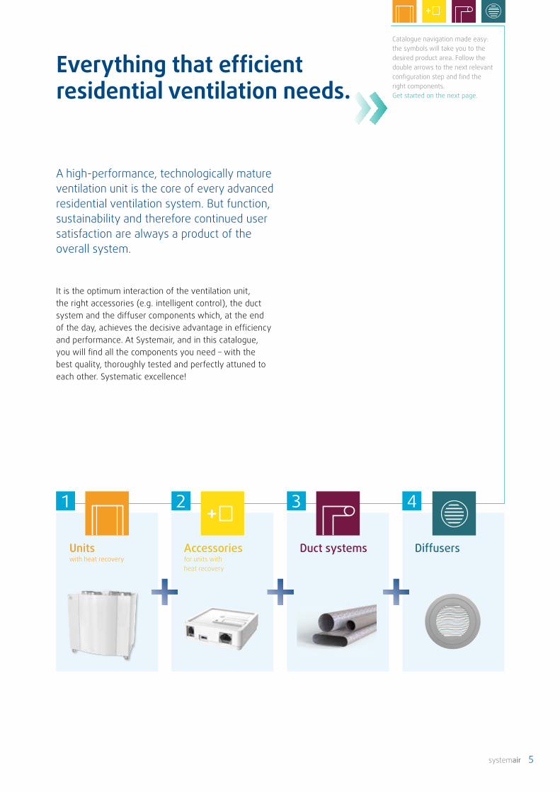
Save energy, enjoy optimum indoor air, improve thermal comfort and be equipped for the future? The solution for all these demands: heat recovery systems from Systemair. Ventilation systems with heat recovery offer a high degree of living comfort thanks to preheated, temperature-controlled, clean air.
In addition, there are huge energy savings to be made: ventilation heat losses are low, thanks to a high level of heat recovery.
The only decision still to make is whether to use a counter flow or a rotary heat exchanger.
Are controlled ventilation, an optimum indoor climate and heat recovery still not enough? This energy-efficient central building services unit combines heating, cooling, hot water and ventilation. Find out more from page Page 114
Genius is simply brilliant
Are you looking for an alternative with low maintenance costs and low power consumption? Even without heat recovery, the system has an advantage over conventional window ventilation. Just the controlled adjustability significantly reduces ventilation heat loss.
The right solution for every requirement. What would you like to do?
systemair 13
or
Page 142
Page 136
Page 132
Apartment blockSystems without heat recovery
Apartment blockSystems with heat recovery
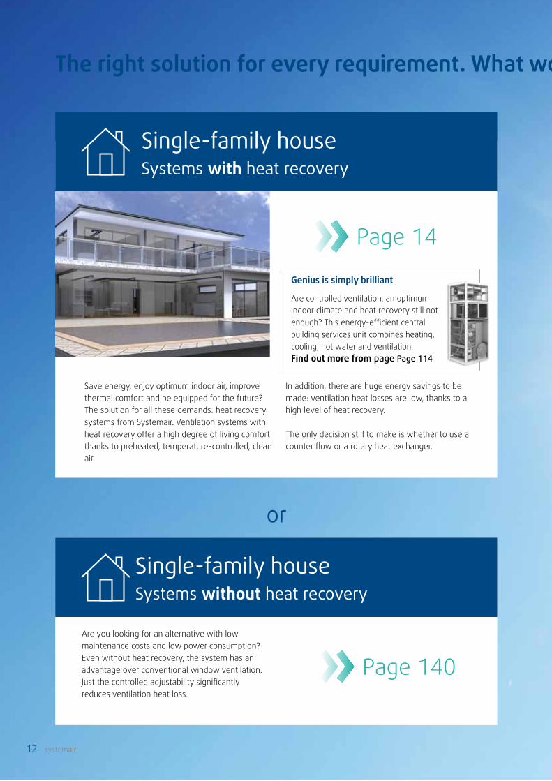
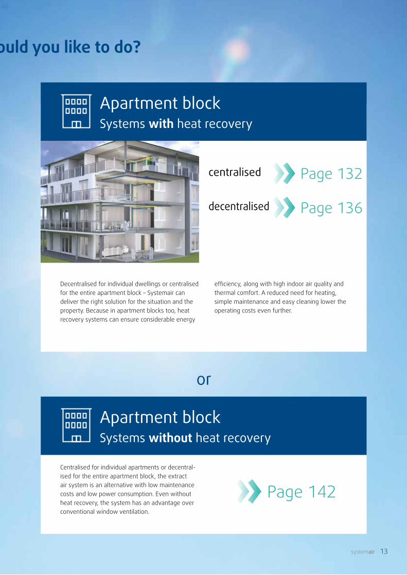
Decentralised for individual dwellings or centralised for the entire apartment block – Systemair can deliver the right solution for the situation and the property. Because in apartment blocks too, heat recovery systems can ensure considerable energy
Centralised for individual apartments or decentral-ised for the entire apartment block, the extract air system is an alternative with low maintenance costs and low power consumption. Even without heat recovery, the system has an advantage over conventional window ventilation.
efficiency, along with high indoor air quality and thermal comfort. A reduced need for heating, simple maintenance and easy cleaning lower the operating costs even further.
centralised
decentralised
The right solution for every requirement. What would you like to do?
14 systemair
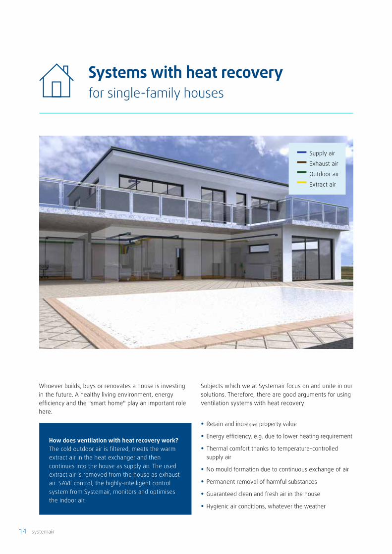
Systems with heat recoveryfor single-family houses
Supply air
Exhaust air
Outdoor air
Extract air
Whoever builds, buys or renovates a house is investing in the future. A healthy living environment, energy efficiency and the "smart home" play an important role here.
How does ventilation with heat recovery work? The cold outdoor air is filtered, meets the warm extract air in the heat exchanger and then continues into the house as supply air. The used extract air is removed from the house as exhaust air. SAVE control, the highly-intelligent control system from Systemair, monitors and optimises the indoor air.
Subjects which we at Systemair focus on and unite in our solutions. Therefore, there are good arguments for using ventilation systems with heat recovery:
• Retain and increase property value
• Energy efficiency, e.g. due to lower heating requirement
• Thermal comfort thanks to temperature-controlled supply air
• No mould formation due to continuous exchange of air
• Permanent removal of harmful substances
• Guaranteed clean and fresh air in the house
• Hygienic air conditions, whatever the weather

systemair 15
1 2 3 4
Living area Type of installation
Heat exchanger Explanation Page 17
Max. air volume at 120 pa
Dimensions (B x H x D)
Product
to 100 m2 Wall Rotary 220 m3/h 596 x 762 x 465 mm SAVE VTR 150/K Page 38
to 100 m2 Ceiling Rotary 250 m3/h 596 x 672 x 368 mm SAVE VTR 150/B Page 36
to 120 m2 Ceiling Rotary 160 m3/h 1108 x 570 x 300 mm SAVE VSR 150/B Page 28
to 180 m2 Wall Counter flow 260 m3/h 660 x 824 x 594 mm SAVE VTC 200 Page 20
to 180 m2 Wall Rotary 270 m3/h 598 x 850 x 490 mm SAVE VTR 250/B Page 40
to 240 m2 Wall Rotary 340 m3/h 762 x 842 x 492 mm SAVE VTR 300/B Page 42
to 240 m2Ceiling, Floor
Rotary 340 m3/h 1150 x 395 x 505 mm SAVE VSR 300 Page 30
to 300 m2 Wall Counter flow 410 m3/h 762 x 839 x 615 mm SAVE VTC 300 Page 22
bis 400 m2 Wall Counter flow 420 m3/h 880 x 845 x 615 mm SAVE VTC 500 Page 22
to 400 m2Ceiling, Floor
Rotary 600 m3/h 1150 x 645 x 595 mm SAVE VSR 500 Page 32
to 400 m2 Wall Rotary 600 m3/h 920 x 845 x 584 mm SAVE VTR 500 Page 44
to 700 m2 Floor Rotary 960 m3/h 1170 x 1213 x 860 mm SAVE VTR 700 Page 46
to 600 m2 Floor Counter flow 880 m3/h 1170 x 1213 x 860 mm SAVE VTC 700 Page 26
Unitswith heat recovery
Accessoriesfor units with heat recovery
Duct systems Diffusers
4 components for the right solution
Which unit best fits your requirements?

16 systemair
Units with heat recoveryfor single-family houses
SAVE control
Touch-Display
An ideal combination: residential ventilation units from Systemair combine excellent comfort and a high level of heat recovery with a filtered air supply and considerable energy savings.

systemair 17
Units with heat recoveryfor single-family houses
A detailed explanation of the heat exchangers can be found on Page 172.
The right choice made easy
Ventilation systems with heat recovery offer users a high degree of living comfort thanks to temperature-controlled and clean air. Here, important criteria are cleanliness, heating and humidity. Systemair has an eye on the future too: the potential for energy-saving exceeds even future requirements.
Considering the many advantages, your customers' decision shouldn't be whether to use heat recovery or not, but just which type of heat recovery to use.
• Thermal comfort
• Lower heating requirement
• Lower ventilation heat losses
• Preheating of the supply air
• Considerable energy-saving potential
A perfect exchange and a perfect indoor climate – the most important advantages of units with heat recovery
Heat recovery units are ideal for use in houses, small offices and similar spaces – with an optimum exchange programme: the ventilation unit guides air extracted from the kitchen and bathroom to the outside. Fresh outdoor air is drawn into the unit via the pipe system. The heat from the extract air is transferred to the supply air via a heat exchanger, which is then supplied back to the living and sleeping quarters.
A counter flow heat exchanger is for transferring heat.
The filtered supply air and the used extract air are completely separated from each other. Therefore, moisture is not tran-smitted and must be removed. A counter flow heat exchanger
can make best use of its high efficiency – up to 90 per cent – if the outside temperature does not fall (or falls only briefly) below its specific frost point (-3 °C at 90% efficiency). Then, frost protection is unnecessary and, due to the mild climate (not colder than around -3 °C), the indoor climate does not become too dry, even without the transfer of moisture. Additional frost protection is required at temperatures of less than -3 °C . This can be implemented using a brine- geothermal heat exchanger or an electric preheater.
High-efficiency residential ventilation with rotary heat exchangers
High-efficiency residential ventilation with counter flow heat exchangers
A rotary heat exchanger en-sures both heat and moisture recovery. The constant turning of the rotor enables heat to be transferred continuously. In winter, the heat from the extract air is transferred to the cold filtered outdoor air. In
summer, the reverse effect is used: the warm outdoor air is cooled by the colder extract air and the heat stays outside. A rotor can achieve sensible efficiencies of more than 85 per cent, and performs most strongly in climates down to around -20 °C. Here it is able to generate max-imum heat recovery without any frost protection at all. Thanks to moisture recovery, the rotary heat exchanger also ensures perfect room humidity and an optimum indoor climate at any time of year – not too humid and not too dry.

18 systemair
Ventilation on demand
5 fan levels are provided for the manual ventilation function. "On demand" means either time-dependent or sensor-actuated volumetric flow, humidity and temperature control. With sensor-actuated ventilation, a control range is defined for the flow rate, instead of switching the fan levels. The operating point moves continuously within this range, depending on current requirements. This enables the system to adjust itself to the optimum operating point, depending on energy-savings and indoor air quality.
To do this, all our units are equipped with a humidity sensor in the extract air as standard. This enables moisture levels to be controlled automatically right from the start. Humidity control means either increasing
the air volume over a short period to remove indoor air moisture and/or to reduce the rotor speed in order to transfer less moisture as needed (useful for small dwellings and new properties). Of course, other sensors which can be used to automatically control operation are also available as accessories, e.g. CO2, moisture and presence sensors – installed either centrally, in zones or in rooms. Connection to a building control system or a smart home solution enables operation to be controlled externally using other building parameters as well.
SAVE control – the intelligent controller with touch display and smartphone-feel

systemair 19
• On-demand control for more comfort and less energy consumption.1
SAVE control offersmany possibilities
• Intuitive operation via touch display or smartphone (app).2
Smart home – simple connection to the building control system.4
• Predefined user modes make controlling the indoor air quality easier.3
• Controlled heat and moisture recovery thanks to speed-controlled rotor.5
• Summer mode: cold recovery and free cooling (night-time cooling).6Season-recognition for automatic heating/cooling support (extra energy-saving).
7
More comfort, less energy consumption
Numerous user functions enable the operating mode of a Systemair ventilation system to adapt to changing situations in the home. According to predefined situations, these default settings – easily activated on a touch display or smartphone – vary the system function via the total volumetric flow range of the fans, the specific options for temperature adjustment (heat recovery, heating and cooling) and the parameter "time".
Additional energy savings are possible in summer, thanks to a freely-programmable night-time cooling function. More intensive ventilation in the cooler night-time hours enables the heat collecting in the building on hot days to be removed to the outside. Those who already have active cooling installed can even use our heat recovery technology for cooling in the summer, in a similar way to heating in winter. The warm outside air is simply cooled before it enters the rooms – using the extract air from the air-conditioned building. This significantly reduces the power consumption for cooling.
SAVE control makes monitoring the indoor air quality in your home easy. Operation is just like on a smart-phone. All SAVE units are delivered with the SAVE touch-controller. With the accessories for internet access, the unit can connect to our SAVE control mobile app.
SAVE control
SAVE control mobile app
Users can change the ventilation system operating mode remotely via an app, or use the app just to check if the temperature, humidity, CO2 content etc. are all OK. Faults can be spotted straight away, and the manufacturer can be given direct access to the control system so that the service department can remedy the fault without delay.
It is also possible to install software updates directly via the cloud. This means you can easily access new functions and gadgets to keep your system up to date at all times. There are various options for connecting to the cloud or the BEMS: Modbus, the cable network or Wi-Fi.

20 systemair
SAVE VTC 200
Technical dataItem no. 88281 (left version)
88280 (right version)Energy efficiency class Standard unit A
with accessories A+Installation Vertical designMaterial Galvanized steel, whiteVoltage / frequency V / 50Hz 230Power consumption per fan at operating point
W 22190 m³/h bei 50 pa
SFP kW/m³/s 0,287Input power, fan motor W 2 x 68Recommended fuse A 10Filter class Supply air
Exhaust air
G4 / Coarse 65% (*F7 / ePM1 55%) G4 / Coarse 65%
Weight kg 47
* available as accessorySFP = Specific Fan Power (kW/m3/s), refers to the entire unit
• Up to 92% heat recovery efficiency
• Designed for living areas up to 180 m²
• Automatic summer mode, cold recovery and free night-time cooling
• External connection box for simple connection of external sensors
• Separate adjustment of the supply airflow and the extract airflow
• Water heating and cooling elements available as accessories
• Startup wizard
• Integrated humidity sensor in extract air
Features of the SAVE VTC 200 – characteristics and advantages at a glance
Residential ventilation unit with high-efficiency counter flow heat exchanger and intelligent SAVE control. It has an integrated extract air / exhaust air bypass, as well as low noise and energy-saving RadiCal fans with demand-driven speed control. The housing is made of galvanised sheet steel (painted white), with an interior of expanded polypropylene (EPP). A preheater and reheater are available as as accessories.
The humidity sensor (installed as standard) controls the flow rates of the energy-saving fans. The residential ventilation unit also has an automatic defrost control function. This is achieved by reducing the speed of the supply air fan. A preheater is required for continuous operation at low outside temperatures.
The SAVE VTC 200 can be controlled and set externally via an app. The standard Modbus interface enables smart integration with the building control system. A comprehensive range of accessories is available for the compact residential ventilation unit.
Mid-frequency range, HzLwA dB(A) Tot 63 125 250 500 1k 2k 4k 8kSupply air 59 70 63 61 57 54 50 41 34Extract air 51 67 55 55 49 43 34 22 23Surroundings 45 45 46 43 43 41 36 25 21
The table shows the sound power level LwA, which is not to be con-fused with the sound pressure level LpA (based on the above-specified operating point at 50 Pa).

systemair 21
0 60 120 180 240 300 3600
100
200
300
400
500
6000 0.03 0.06 0.09
[m³/s]
Q [m³/h]
Ps [P
a]
Supply air Exhaust air Outdoor air Extract air
A B C D E F G H J K L M N660 750 230 594 824 145 110 145 405 1300 1205 675 645
Dimensions in mm
A *
C ** C ** F
D
G G
G
K
N
*
A *
C ** C ** F
D
G G
G
K
N
*
0 60 120 180 240 300 3600
100
200
300
400
500
6000 0.03 0.06 0.09
[m³/s]
Q [m³/h]
Ps [P
a]
SFP(2.5)
SFP(2)
SFP(1.5)SFP(1.2)
A *
C ** C ** F **
D
G G
G
K
N
A *
C ** C ** F **
D
G G
G
K
N
Supply air Extract air
Left version
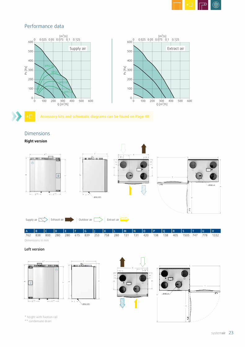
Performance data
DimensionsRight version
* height with fixation rail** condensate drain
Accessory kits and schematic diagrams can be found on Page 48
22 systemair
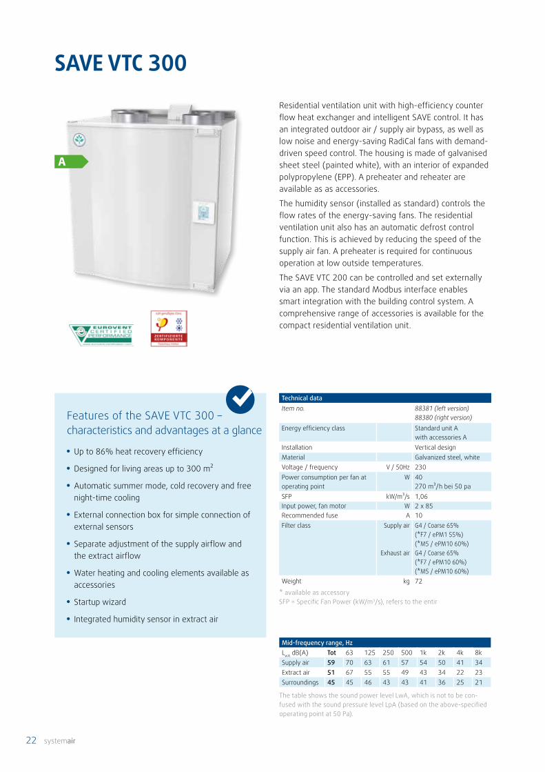
SAVE VTC 300
Technical dataItem no. 88381 (left version)
88380 (right version)Energy efficiency class Standard unit A
with accessories AInstallation Vertical designMaterial Galvanized steel, whiteVoltage / frequency V / 50Hz 230Power consumption per fan at operating point
W 40270 m³/h bei 50 pa
SFP kW/m³/s 1,06Input power, fan motor W 2 x 85 Recommended fuse A 10Filter class Supply air
Exhaust air
G4 / Coarse 65% (*F7 / ePM1 55%) (*M5 / ePM10 60%) G4 / Coarse 65%(*F7 / ePM10 60%)(*M5 / ePM10 60%)
Weight kg 72
* available as accessorySFP = Specific Fan Power (kW/m3/s), refers to the entir
Residential ventilation unit with high-efficiency counter flow heat exchanger and intelligent SAVE control. It has an integrated outdoor air / supply air bypass, as well as low noise and energy-saving RadiCal fans with demand-driven speed control. The housing is made of galvanised sheet steel (painted white), with an interior of expanded polypropylene (EPP). A preheater and reheater are available as as accessories.
The humidity sensor (installed as standard) controls the flow rates of the energy-saving fans. The residential ventilation unit also has an automatic defrost control function. This is achieved by reducing the speed of the supply air fan. A preheater is required for continuous operation at low outside temperatures.
The SAVE VTC 200 can be controlled and set externally via an app. The standard Modbus interface enables smart integration with the building control system. A comprehensive range of accessories is available for the compact residential ventilation unit.
Mid-frequency range, HzLwA dB(A) Tot 63 125 250 500 1k 2k 4k 8kSupply air 59 70 63 61 57 54 50 41 34Extract air 51 67 55 55 49 43 34 22 23Surroundings 45 45 46 43 43 41 36 25 21
The table shows the sound power level LwA, which is not to be con-fused with the sound pressure level LpA (based on the above-specified operating point at 50 Pa).
• Up to 86% heat recovery efficiency
• Designed for living areas up to 300 m²
• Automatic summer mode, cold recovery and free night-time cooling
• External connection box for simple connection of external sensors
• Separate adjustment of the supply airflow and the extract airflow
• Water heating and cooling elements available as accessories
• Startup wizard
• Integrated humidity sensor in extract air
Features of the SAVE VTC 300 – characteristics and advantages at a glance
systemair 23
Supply air Exhaust air Outdoor air Extract air
A B C D E F G J K L M N O P Q R S T U V762 838 800 280 280 615 839 253 758 280 131 131 420 138 138 405 1505 747 778 1332
Dimensions in mm
A *
D ** E **
F
J
KLM N
T
S
*
A *
D ** E **
F
J
KLM N
T
S
*
0 100 200 300 400 500 600Q [m³/h]
0 0.025 0.05 0.075 0.1 0.125 [m³/s]
0
100
200
300
400
500
600
Ps [P
a]
0 100 200 300 400 500 6000
100
200
300
400
500
6000 0.025 0.05 0.075 0.1 0.125
[m³/s]
Q [m³/h]
Ps [P
a]
SFP(2.5)
SFP(2)
SFP(1.5)
SFP(1.2)
A *
D ** E **
F
J
KL
MN
T
S
A *
D ** E **
F
J
KL
MN
T
S
Supply air Extract air
Performance data
Left version
DimensionsRight version
Accessory kits and schematic diagrams can be found on Page 48
* height with fixation rail** condensate drain

24 systemair
• Up to 84% heat recovery efficiency
• Designed for living areas up to 400 m²
• The CAV-kit allows volume flow constant opera-tion without accessories
• Automatic summer mode, cold recovery and free night-time cooling
• External connection box for simple connection of external sensors
• Separate adjustment of the supply airflow and the extract airflow
• Heating coil (into device mountable) available as accessories
• Water heating and cooling elements available as accessories
• Startup wizard
• Integrated humidity sensor in extract air
SAVE VTC 500 is a top connected high efficiency aluminum counter flow unit designed for installation on the wall in laundry rooms, storerooms etc. in a home with a ventilated area of up to approx. 400 m². VTC 500 is white painted, double skinned, fully insulated and comes with control panel with complete control functionality. CAV kit is the new accessory that consists of a double-point pressure transmitter, which is mounted directly on the Main Board. Pressure tapping and tubes are available inside the unit from the factory. The unit automatically regulate the recovery of heating / cooling by the built in damper and has automatic defrosting function. The option for connecting one or more external control panels is available as well as access over internet with the internet access module (IAM) or Modbus via RS-485. The new touch display makes it easy to install and use all unit functions.
SAVE VTC 500
Technical dataItem no. 92717 (left version)
92716 (right version)Energy efficiency class Standard unit A
with accessories AInstallation Vertical designMaterial Galvanized steel, whiteVoltage / frequency V / 50Hz 230Power consumption per fan at operating point
W 73420 m³/h bei 50 pa
SFP kW/m³/s 0,344Input power, fan motor W 2 x 170 Recommended fuse A 10Filter class Supply air
Exhaust air
F7 / ePM1 60%(*F8 / ePM1 70%) M5 / ePM10 50%
Weight kg 82
* available as accessorySFP = Specific Fan Power (kW/m3/s), refers to the entir
Mid-frequency range, HzLwA dB(A) Tot 63 125 250 500 1k 2k 4k 8kSupply air 62 72 71 67 66 63 57 49 38Extract air 51 67 63 51 52 47 39 28 22Surroundings 40 49 50 48 41 35 31 24 21
The table shows the sound power level LwA, which is not to be con-fused with the sound pressure level LpA (based on the above-specified operating point at 50 Pa).
Features of the SAVE VTC 500 – characteristics and advantages at a glance

systemair 25
A B C D** E** F G* H J** K L M N O P Q R S T U V W880 849 800 182 199 615 845 878 373 347 316 130 120 277 450 302 1319 201 1799 718 233 233
Dimensions in mm
A
B C G* H
J**E**D**
F
Ø16 (1/2")
Ø200 x4
K L
M
O
M
P
Q
R
T
U S
W
V
N
A
B C G* H
J**E**D**
F
Ø16 (1/2")
Ø200 x4
K L
M
O
M
P
Q
R
T
U S
W
V
N
0 100 200 300 400 500 600 700 8000
200
400
600
800
1000
1200
1400
1600
Ps [P
a]
[m³/s]
Q [m³/h]
0,05 0,1 0,15 0,200
SFP(0.8)SFP(1.2)
SFP(1.5)
SFP(2)
[m³/s]0,05 0,1 0,15 0,200
0
200
400
600
800
1000
1200
1400
1600
Ps [P
a]
0 100 200 300 400 500 600 700 800Q [m³/h]
A
B C G* H
J**
Ø200 x4
E**
L K
D**
F
N M
M M
O P
R
Q
S T
V
U
Ø16 (1/2")
A
B C G* H
J**
Ø200 x4
E**
L K
D**
F
N M
M M
O P
R
Q
S T
V
U
Ø16 (1/2")
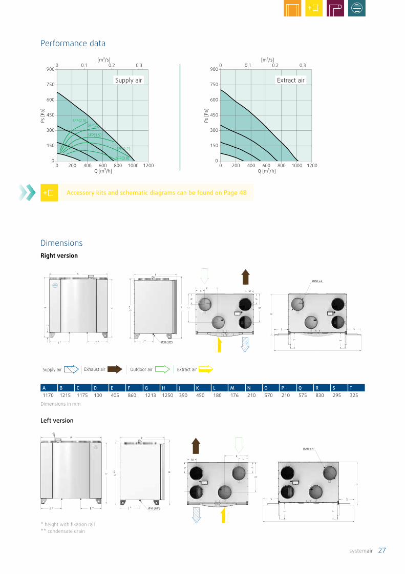
A B C D** E** F G* H J** K L M N O P Q R S T U V880 849 800 182 199 615 845 878 255 347 316 130 120 304 361 1799 1318 202 718 233 750
Dimensions in mm
Performance data
Supply air Extract air
Accessory kits and schematic diagrams can be found on Page 48
Left version
DimensionsRight version
* height with fixation rail** condensate drain
* height with fixation rail** condensate drain
Supply air Exhaust air Outdoor air Extract air

26 systemair
SAVE VTC 700
Technical dataItem no. 88781 (left version)
88780 (right version)Energy efficiency class Standard unit A
with accessories A+Installation Vertical designMaterial Galvanized steel, whiteVoltage / frequency V / 50Hz 230Power consumption per fan at operating point
W 66630 m³/h bei 50 pa
SFP kW/m³/s 0,75Input power, fan motor W 2 x 170Recommended fuse A 10Filter class Supply air
Exhaust air
M5 / ePM10 60% (*F7 / ePM1 55%)M5 / ePM10 60%(*F7 / ePM10 60%)
Weight kg 160
* available as accessoriesSFP = Specific Fan Power (kW/m3/s), refers to the entire unit
Residential ventilation unit with high-efficiency counter flow heat exchanger and intelligent SAVE control. It has an integrated outdoor air / supply air bypass, as well as low noise and energy-saving RadiCal fans with demand-driven speed control. The housing is made of galvanised sheet steel (painted white), with an interior of expanded polypropylene (EPP). A preheater and reheater are available as as accessories.
The humidity sensor (installed as standard) controls the flow rates of the energy-saving fans. The residential ventilation unit also has an automatic defrost control function. This is achieved by reducing the speed of the supply air fan. A preheater is required for continuous operation at low outside temperatures.
The SAVE VTC 700 can be controlled and set externally via an app. The standard Modbus interface enables smart integration with the building control system. A comprehensive range of accessories is available for the compact residential ventilation unit.
Mid-frequency range, HzLwA dB(A) Tot 63 125 250 500 1k 2k 4k 8kSupply air 59 70 63 61 57 54 50 41 34Extract air 51 67 55 55 49 43 34 22 23Surroundings 45 45 46 43 43 41 36 25 21
The table shows the sound power level LwA, which is not to be con-fused with the sound pressure level LpA (based on the above-specified operating point at 50 Pa).
• Up to 83% heat recovery efficiency
• Designed for living areas up to 600 m²
• Automatic summer mode, cold recovery and free night-time cooling
• External connection box for simple connection of external sensors
• Separate adjustment of the supply airflow and the extract airflow
• Water heating and cooling elements available as accessories
• Startup wizard
• Integrated humidity sensor in extract air
Features of the SAVE VTC 700 – characteristics and advantages at a glance
systemair 27
Supply air Exhaust air Outdoor air Extract air
A B C D E F G H J K L M N O P Q R S T1170 1215 1175 100 405 860 1213 1250 390 450 180 176 210 570 210 575 830 295 325
Dimensions in mm
A
E *
F
J *E *
KL M
S S
A
E *
F
J *E *
KL M
S S
0 200 400 600 800 1000 12000
150
300
450
600
750
9000 0.1 0.2 0.3
[m³/s]
Q [m³/h]
Ps [P
a]
0 200 400 600 800 1000 12000
150
300
450
600
750
9000 0.1 0.2 0.3
[m³/s]
Q [m³/h]
Ps [P
a]
SFP(2.5)SFP(2)
SFP(1.5)
SFP(1.2)
SFP(0.8)
A
E *
F
J *E *
KLM
S S
A
E *
F
J *E *
KLM
S S
Supply air Extract air
Performance data
Left version
DimensionsRight version
* height with fixation rail** condensate drain
Accessory kits and schematic diagrams can be found on Page 48
28 systemair
SAVE VSR 150/B
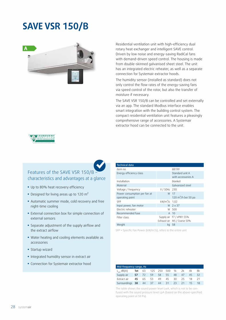
Technical dataItem no. 88199Energy efficiency class Standard unit A
with accessories AInstallation blanketMaterial Galvanized steelVoltage / frequency V / 50Hz 230Power consumption per fan at operating point
W 17120 m³/h bei 50 pa
SFP kW/m³/s 1,02Input power, fan motor W 2 x 37Electric reheater W 500Recommended fuse A 10Filter class Supply air
Exhaust airF7 / ePM1 55%M5 / Coarse 50%
Weight kg 58
SFP = Specific Fan Power (kW/m3/s), refers to the entire unit
Residential ventilation unit with high-efficiency dual rotary heat exchanger and intelligent SAVE control. Driven by low noise and energy-saving RadiCal fans with demand-driven speed control. The housing is made from double-skinned galvanised sheet steel. The unit has an integrated electric reheater, as well as a separate connection for Systemair extractor hoods.
The humidity sensor (installed as standard) does not only control the flow rates of the energy-saving fans via speed control of the rotor, but also the transfer of moisture if necessary.
The SAVE VSR 150/B can be controlled and set externally via an app. The standard Modbus interface enables smart integration with the building control system. The compact residential ventilation unit features a pleasingly comprehensive range of accessories. A Systemair extractor hood can be connected to the unit.
Mid-frequency range, HzLwA dB(A) Tot 63 125 250 500 1k 2k 4k 8kSupply air 57 72 59 58 55 48 47 45 32Extract air 45 65 53 49 45 30 25 18 21Surroundings 38 44 37 44 31 23 21 15 18
The table shows the sound power level LwA, which is not to be con-fused with the sound pressure level LpA (based on the above-specified operating point at 50 Pa).
• Up to 80% heat recovery efficiency
• Designed for living areas up to 120 m²
• Automatic summer mode, cold recovery and free night-time cooling
• External connection box for simple connection of external sensors
• Separate adjustment of the supply airflow and the extract airflow
• Water heating and cooling elements available as accessories
• Startup wizard
• Integrated humidity sensor in extract air
• Connection for Systemair extractor hood
Features of the SAVE VSR 150/B – characteristics and advantages at a glance

systemair 29
0 0.02 0.04 0.06 [m³/s]
0
100
200
300
400
500
600
Ps [P
a]
0 50 100 150 200 250 300Q [m³/h]
0 0.02 0.04 0.06 [m³/s]
0
100
200
300
400
500
600
Ps [P
a]
0 50 100 150 200 250 300Q [m³/h]
SFP(2.5)
SFP(2)
SFP(1.5)
SFP(1.2)
Supply air Extract air
Performance data
Dimensions
Accessory kits and schematic diagrams can be found on Page 48
A B C D E F G H J K L M N O P Q R S303 570 430 101 127 586 416 199 469 325 140 146 599 881 1150 1215 26 329
Dimensions in mm.*) connection for extractor hood
A
B
C
D
E
F
G
H
J
KL
M
EN
O
P
Q
RS
A
B
C
D
E
F
G
H
J
KL
M
E
N
O
P
Q
RS
Supply air Exhaust air Outdoor air Extract air

30 systemair
SAVE VSR 300
Technical dataItem no. 88350Energy efficiency class Standard unit A
with accessories AInstallation Vertical design, blanketMaterial Galvanized steelVoltage / frequency V / 50Hz 230Power consumption per fan at operating point
W 37260 m³/h bei 50 pa
SFP kW/m³/s 1,03Input power, fan motor W 2 x 83 Electric reheater W 1670Recommended fuse A 10
Filter class
Supply air
Exhaust air
F7 / ePM10 80% **(*F7 / ePM1 60%)G3 / Coarse 60% **(*F7 / ePM10 50%)
Weight kg 65
* available as accessories** Filterset PHI available as accessoriesSFP = Specific Fan Power (kW/m3/s), refers to the entire unit
Residential ventilation unit with high-efficiency rotary heat exchanger and intelligent SAVE control. Driven by low noise and energy-saving RadiCal fans with demand-driven speed control. The housing is made from double-skinned galvanised sheet steel. The unit has an integrated electric reheater.
The humidity sensor (installed as standard) does not only control the flow rates of the energy-saving EC fans via speed control of the rotor, but also the transfer of moisture if necessary.
The SAVE VSR 300 can be controlled and set externally via an app. The standard Modbus interface enables smart integration with the building control system. A comprehensive range of accessories is available for the compact residential ventilation unit.
Mid-frequency range, HzLwA dB(A) Tot 63 125 250 500 1k 2k 4k 8kSupply air 62 69 66 66 58 55 54 47 41Extract air 53 62 54 59 51 39 35 26 23Surroundings 42 44 48 48 39 33 29 21 26
The table shows the sound power level LwA, which is not to be con-fused with the sound pressure level LpA (based on the above-specified operating point at 50 Pa).
• Up to 85% heat recovery efficiency
• Designed for living areas up to 240 m²
• Automatic summer mode, cold recovery and free night-time cooling
• External connection box for simple connection of external sensors
• Separate adjustment of the supply airflow and the extract airflow
• Water heating and cooling elements available as accessories
• Startup wizard
• Integrated humidity sensor in extract air
Features of the SAVE VSR 300 – characteristics and advantages at a glance

systemair 31
Supply air Exhaust air Outdoor air Extract air
A B C D E F G H J K L M N O P Q R230 188 112 303 1150 1040 595 575 368 160 178 137 231 505 460 1122 410
Dimensions in mm*Condensate drain
A
D J *
K
N *
Q
A
D J *
K
N *
Q
0 0.025 0.05 0.075 0.1 0.125 [m³/s]
0
150
300
450
600
750
900
Ps [P
a]
0 100 200 300 400 500 600Q [m³/h]
0 0.025 0.05 0.075 0.1 0.125 [m³/s]
0
150
300
450
600
750
900
Ps [P
a]
0 100 200 300 400 500 600Q [m³/h]
SFP(2.5)
SFP(2)
SFP(1.5)
SFP(1.2)
Supply air Extract air
Performance data
Dimensions
Accessory kits and schematic diagrams can be found on Page 48
32 systemair
SAVE VSR 500
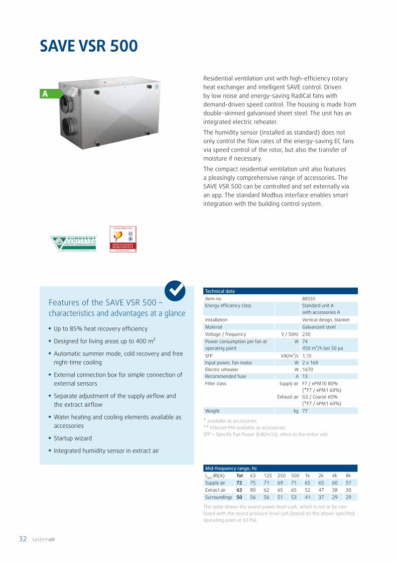
Technical dataItem no. 88550Energy efficiency class Standard unit A
with accessories AInstallation Vertical design, blanketMaterial Galvanized steelVoltage / frequency V / 50Hz 230Power consumption per fan at operating point
W 74450 m³/h bei 50 pa
SFP kW/m³/s 1,15Input power, fan motor W 2 x 169Electric reheater W 1670Recommended fuse A 13Filter class Supply air
Exhaust air
F7 / ePM10 80% (*F7 / ePM1 60%)G3 / Coarse 60%(*F7 / ePM1 60%)
Weight kg 77
* available as accessories** Filterset PHI available as accessoriesSFP = Specific Fan Power (kW/m3/s), refers to the entire unit
Residential ventilation unit with high-efficiency rotary heat exchanger and intelligent SAVE control. Driven by low noise and energy-saving RadiCal fans with demand-driven speed control. The housing is made from double-skinned galvanised sheet steel. The unit has an integrated electric reheater.
The humidity sensor (installed as standard) does not only control the flow rates of the energy-saving EC fans via speed control of the rotor, but also the transfer of moisture if necessary.
The compact residential ventilation unit also features a pleasingly comprehensive range of accessories. The SAVE VSR 500 can be controlled and set externally via an app. The standard Modbus interface enables smart integration with the building control system.
Mid-frequency range, HzLwA dB(A) Tot 63 125 250 500 1k 2k 4k 8kSupply air 72 75 71 69 71 65 65 60 57Extract air 63 80 62 65 65 52 47 38 30Surroundings 50 56 56 51 53 41 37 29 29
The table shows the sound power level LwA, which is not to be con-fused with the sound pressure level LpA (based on the above-specified operating point at 50 Pa).
• Up to 85% heat recovery efficiency
• Designed for living areas up to 400 m²
• Automatic summer mode, cold recovery and free night-time cooling
• External connection box for simple connection of external sensors
• Separate adjustment of the supply airflow and the extract airflow
• Water heating and cooling elements available as accessories
• Startup wizard
• Integrated humidity sensor in extract air
Features of the SAVE VSR 500 – characteristics and advantages at a glance
systemair 33
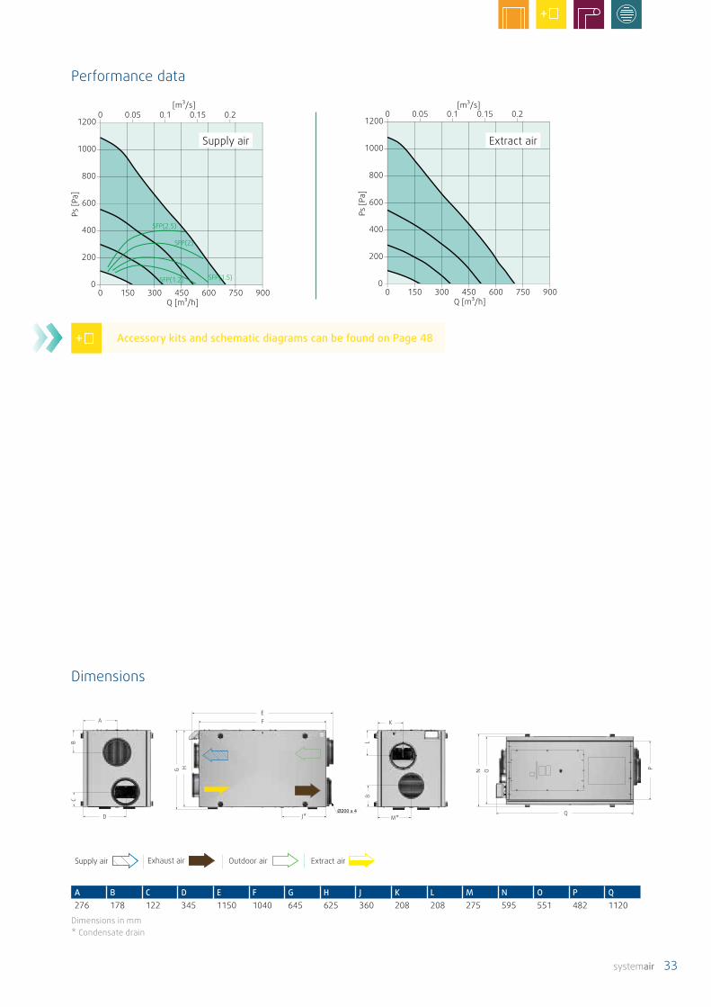
Supply air Exhaust air Outdoor air Extract air
A B C D E F G H J K L M N O P Q276 178 122 345 1150 1040 645 625 360 208 208 275 595 551 482 1120
Dimensions in mm* Condensate drain
A
D
EF K
A
D
EF K
0 0.05 0.1 0.15 0.2 [m³/s]
0
200
400
600
800
1000
1200
Ps [P
a]
0 150 300 450 600 750 900Q [m³/h]
0 0.05 0.1 0.15 0.2 [m³/s]
0
200
400
600
800
1000
1200
Ps [P
a]
0 150 300 450 600 750 900Q [m³/h]
SFP(2.5)
SFP(2)
SFP(1.5)SFP(1.2)
Supply air Extract air
Performance data
Dimensions
Accessory kits and schematic diagrams can be found on Page 48

34 systemair
SAVE VTR 100/B
Technical dataItem no. 98080Energy efficiency class Standard unit A
with accessories A
Installation Vertical design, blanketMaterial Galvanized steelVoltage / frequency V / 50Hz 230Power consumption per fan at operating point
W 1380 m³/h bei 50 pa
SFP kW/m³/s 1,15Input power, fan motor W 2 x 35Electric reheater W 250Recommended fuse A 10Filter class Supply air M5 / ePM10 50%
(*F7 / ePM1 60%) Exhaust air M5 / ePM10 50%
(*M5 / Coarse 70%)Weight kg 39
* available as accessoriesSFP = Specific Fan Power (kW/m3/s), refers to the entire unit
Mid-frequency range, HzLwA dB(A) Tot 63 125 250 500 1k 2k 4k 8kSupply air 59 77 65 62 55 54 46 40 24Extract air 54 73 62 57 52 40 23 17 20Surroundings 37 54 38 40 37 28 17 12 12
The table shows the sound power level LwA, which is not to be confused with the sound pressure level LpA (based on the above-specified oper-ating point at 50 Pa).
• Up to 84% heat recovery efficiency
• Designed for living areas up to 80 m²
• Automatic summer mode, cold recovery and free night-time cooling
• External connection box for simple connection of external sensors
• Installation in kitchen cupboard possible
• Unit can be adapted for both right and left versions
• Startup wizard
• Integrated humidity sensor in extract air
• Connection for the Systemair extractor hood
Features of the SAVE VTR 100/B – characteristics and advantages at a glance
Residential ventilation unit with high-efficiency rotary heat exchanger and intelligent SAVE control. Driven by low noise and energy-saving RadiCal fans with demand-driven speed control. The housing is made from double-skinned galvanised sheet steel. The unit has an integrated electric reheater, as well as a separate connection for Systemair extractor hoods.
The humidity sensor (installed as standard) does not only control the flow rates of the energy-saving EC fans via speed control of the rotor, but also the transfer of moisture if necessary.
The compact residential ventilation unit also features a pleasingly comprehensive range of accessories. The SAVE VTR 100/B can be controlled and set externally via an app. The standard Modbus interface enables smart integration with the building control system.

systemair 35
0 50 100 150 200 2500
100
200
300
400
500
6000 0.02 0.04 0.06
[m³/s]
Q [m³/h]
Ps [P
a]
SFP(0.8) SFP(1.2)
SFP(1.5)
SFP(2)
SFP(2.5)
0 50 100 150 200 2500
100
200
300
400
500
6000 0.02 0.04 0.06
[m³/s]
Q [m³/h]
Ps [P
a]
SFP(0.8) SFP(1.2)
SFP(1.5)
SFP(2)
SFP(2.5)
Supply air Exhaust air Outdoor air Extract air
Supply air Extract air
Performance data
Dimensions
Accessory kits and schematic diagrams can be found on Page 48
A D
F GH
JM M
A B C D E F G H J K L M N561 600 646 322 679 478 338 227 88 102 220 283 161
Dimensions in mm. The unit can be converted from supply air right (Standard unit) to supply air left.
A D
F GH
JM M
A D
F GH
JM M
A D
F GH
JM M

36 systemair
SAVE VTR 150/B
Technical dataEnergy efficiency class Standard unit B
with accessories AInstallation Vertical designVoltage / frequency V / 50Hz 230Power consumption per fan at operating point
W 22125 m³/h bei 50 pa
SFP kW/m³/s 1,26 1,32Input power, fan motor W 2 x 83Recommended fuse A 10
Filter classSupply air
Exhaust air
M5 / ePM10 60% (*F7 / ePM1 55%) M5 /ePM10 60%
Weight kg 46
* available as accessoriesSFP = Specific Fan Power (kW/m3/s), refers to the entire unit
Unit versions left right500 Watt 96157 961561000 Watt 96155 96154
• Up to 80% heat recovery efficiency
• Designed for living areas up to 100 m²
• Automatic summer mode, cold recovery and free night-time cooling
• External connection box for simple connection of external sensors
• Separate adjustment of the supply airflow and the extract airflow
• Water heating and cooling elements available as accessories
• Startup wizard
• Integrated humidity sensor in extract air
• Connection for the Systemair extractor hood
Features of the SAVE VTR 150/B – characteristics and advantages at a glance
Mid-frequency range, Hz (SAVE VTR 150/B R)LwA dB(A) Tot 63 125 250 500 1k 2k 4k 8kSupply air 61 68 70 66 59 53 50 41 31Extract air 52 63 62 58 50 35 25 16 19Surroundings 38 44 44 42 38 24 22 13 15
Mid-frequency range, Hz (SAVE VTR 150/B L)LwA dB(A) Tot 63 125 250 500 1k 2k 4k 8kSupply air 61 72 67 65 59 54 52 42 34Extract air 53 70 63 58 48 37 28 17 20Surroundings 38 49 43 43 34 25 24 16 19
The table shows the sound power level LwA, which is not to be con-fused with the sound pressure level LpA (based on the above-specified operating point at 50 Pa).
Residential ventilation unit with high-efficiency rotary heat exchanger and intelligent SAVE control. Driven by low noise and energy-saving RadiCal fans with demand-driven speed control. The housing is made from double-skinned galvanised sheet steel. The unit has an integrated electric reheater, as well as a separate connection for Systemair extractor hoods.
The humidity sensor (installed as standard) does not only control the flow rates of the energy-saving EC fans via speed control of the rotor, but also the transfer of moisture if necessary.
The compact residential ventilation unit also features a pleasingly comprehensive range of accessories. The SAVE VTR 150/B can be controlled and set externally via an app. The standard Modbus interface enables smart integration with the building control system.
systemair 37
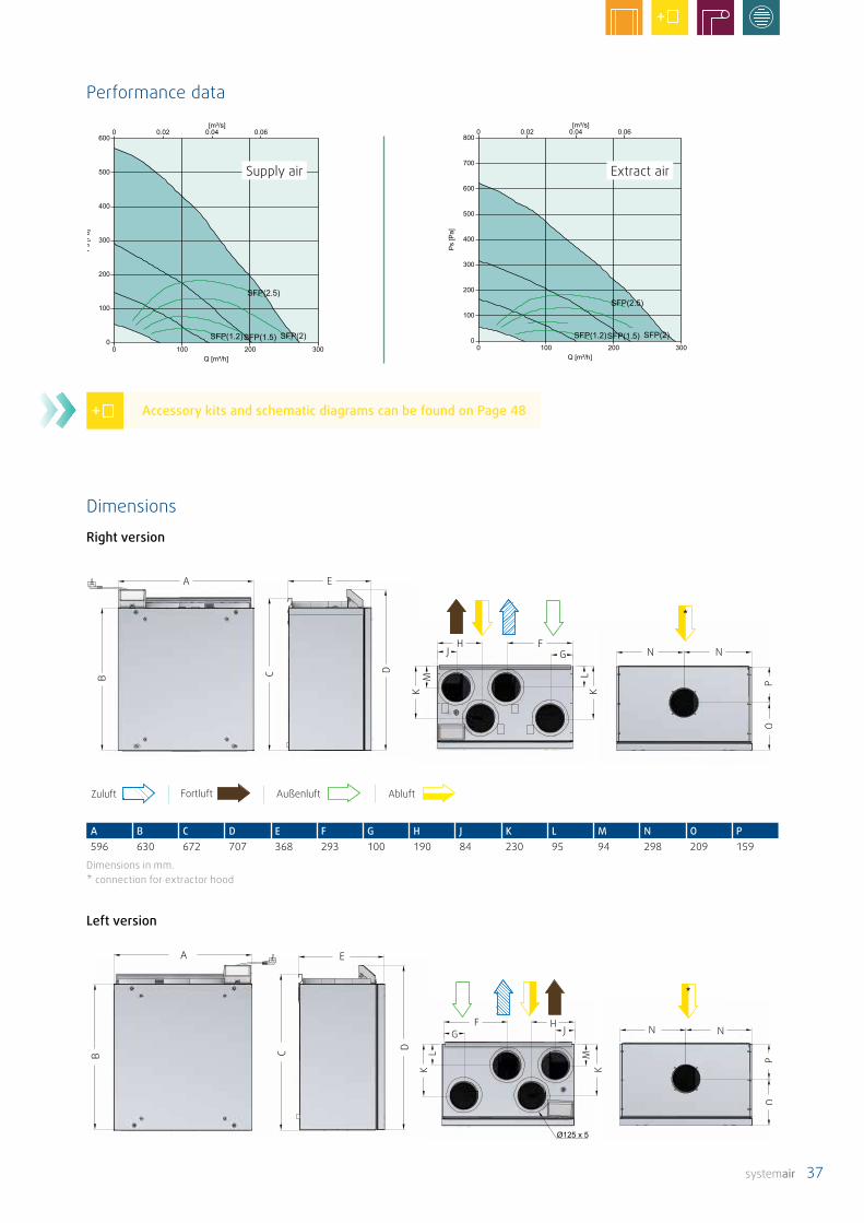
0 100 200 3000
100
200
300
400
500
6000 0.02 0.04 0.06
[m³/s]
Q [m³/h]
Ps [P
a]
SFP(1.2)SFP(1.5) SFP(2)
SFP(2.5)
0 100 200 3000
100
200
300
400
500
600
700
8000 0.02 0.04 0.06
[m³/s]
Q [m³/h]
Ps [P
a]
SFP(1.2)SFP(1.5) SFP(2)
SFP(2.5)
Supply air Extract air
Performance data
Dimensions
Accessory kits and schematic diagrams can be found on Page 48
Zuluft Fortluft Außenluft Abluft
A B C D E F G H J K L M N O P596 630 672 707 368 293 100 190 84 230 95 94 298 209 159
Dimensions in mm.* connection for extractor hood
Right version
A
GJH
N NF
A
GJH
N NF
G JH N N
F
A
G JH N N
F
A
Left version

38 systemair
SAVE VTR 150/K
Unit versions, Front left right500 Watt, white 88157 881561000 Watt, white 88155 88154500 Watt, Stainless steel 88148 881491000 Watt, Stainless steel 88159 88158
Technical dataEnergy efficiency class Standard unit B
with accessories AInstallation Vertical designVoltage / frequency V / 50Hz 230 230Power consumption per fan at operating point
W 23 24125 m³/h bei 50 pa
SFP kW/m³/s 1,26 1,32Input power, fan motor W 2 x 86 2 x 86Electric reheater W 500 / 1000 500 / 1000Recommended fuse A 10 10Filter class Supply air
Exhaust air
M5 / ePM10 60% (*F7 / ePM1 55%) M5 / ePM10 60%
Weight kg 61 61
* available as accessoriesSFP = Specific Fan Power (kW/m3/s), refers to the entire unit
Residential ventilation unit with high-efficiency rotary heat exchanger, intelligent SAVE control and an integrated extractor hood for installation in the kitchen above the oven. Driven by low noise and energy-saving RadiCal fans with demand-driven speed control. The housing is made from double-skinned galvanised sheet steel (stainless steel or painted white). The unit has an integrated electric reheater.
The humidity sensor (installed as standard) does not only control the flow rates of the energy-saving EC fans via speed control of the rotor, but also the transfer of moisture if necessary.
The compact residential ventilation unit also features a pleasingly comprehensive range of accessories. The SAVE VTR 150/K can be controlled and set externally via an app. The standard Modbus interface enables smart integration with the building control system.
• Up to 80% heat recovery efficiency
• Designed for living areas up to 100 m²
• Automatic summer mode, cold recovery and free night-time cooling
• External connection box for simple connection of external sensors
• Separate adjustment of the supply airflow and the extract airflow
• Water heating and cooling elements available as accessories
• Startup wizard
• Integrated humidity sensor in extract air
• Integrated extractor hood
Features of the SAVE VTR 150/K – characteristics and advantages at a glance
Mid-frequency range, Hz (SAVE VTR 150/K R)LwA dB(A) Tot 63 125 250 500 1k 2k 4k 8kSupply air 61 68 70 66 59 53 50 41 31Extract air 52 63 62 58 50 35 25 16 19Surroundings 38 44 44 42 38 24 22 13 15
Mid-frequency range, Hz (SAVE VTR 150/K L)LwA dB(A) Tot 63 125 250 500 1k 2k 4k 8kSupply air 61 72 67 65 59 54 52 42 34Extract air 53 70 63 58 48 37 28 17 20Surroundings 38 49 43 43 34 25 24 16 19
The tables show the sound power level LwA, which is not to be confused with the sound pressure level LpA (based on the above-specified operating point at 50 Pa).

systemair 39
Supply air Exhaust air Outdoor air Extract air
A B C D E F G H J K L M N O P596 720 745 12 465 762 135 800 84 191 293 99 99 234 110
Dimensions in mm
EA E
G **
JK L
M
EA E
G **
JK L
M
0 50 100 150 200 250 3000
150
300
450
600
750
9000 0.03 0.06
[m³/s]
Q [m³/h]
Ps [P
a]
0 50 100 150 200 250 3000
150
300
450
600
750
9000 0.03 0.06
[m³/s]
Q [m³/h]
Ps [P
a]
SFP(2.5)
SFP(2)SFP(1.5)
SFP(1.2)
A E
G **
JKL
M
A E
G **
JKL
M
Supply air Extract air
Performance data
Left version
DimensionsRight version
* curved access panel** access panel
Accessory kits and schematic diagrams can be found on Page 48

40 systemair
SAVE VTR 250/B
Unit versions left right500 Watt 88253 882521000 Watt 88251 88250
Technical dataEnergy efficiency class Standard unit A
with accessories AInstallation Vertical designVoltage / frequency V / 50Hz 230Power consumption per fan at operating point
W 36215 m³/h bei 50 pa
SFP kW/m³/s 1,1Input power, fan motor W 2 x 83Electric reheater W 500 / 1000Recommended fuse A 10Filter class Supply air
Exhaust airF7 / ePM1 55% G3 / Coarse 50%(*M5 / ePM10 50%)
Weight kg 56
* available as accessoriesSFP = Specific Fan Power (kW/m3/s), refers to the entire unit
Residential ventilation unit with high-efficiency rotary heat exchanger and intelligent SAVE control. Driven by low noise and energy-saving RadiCal fans with demand-driven speed control. The housing is made of double-skinned galvanised sheet steel (painted white). The unit has an integrated electric reheater, as well as a separate connection for Systemair extractor hoods.
The humidity sensor (installed as standard) does not only control the flow rates of the energy-saving EC fans via speed control of the rotor, but also the transfer of moisture if necessary.
The compact residential ventilation unit also features a pleasingly comprehensive range of accessories. The SAVE VTR 250/B can be controlled and set externally via an app. The standard Modbus interface enables smart integration with the building control system.
Mid-frequency range, HzLwA dB(A) Tot 63 125 250 500 1k 2k 4k 8kSupply air 62 72 68 58 62 55 50 41 29Extract air 56 66 59 63 48 40 33 22 21Surroundings 40 49 47 40 38 34 28 21 8
The table shows the sound power level LwA, which is not to be con-fused with the sound pressure level LpA (based on the above-specified operating point at 50 Pa).
• Up to 80% heat recovery efficiency
• Designed for living areas up to 220 m²
• Automatic summer mode, cold recovery and free night-time cooling
• External connection box for simple connection of external sensors
• Separate adjustment of the supply airflow and the extract airflow
• Water heating and cooling elements available as accessories
• Startup wizard
• Integrated humidity sensor in extract air
• Connection for the Systemair extractor hood
Features of the SAVE VTR 250/B – characteristics and advantages at a glance
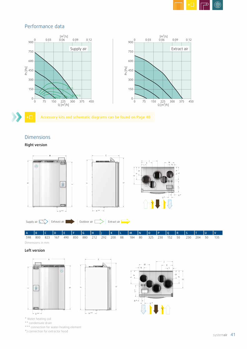
systemair 41
Supply air Exhaust air Outdoor air Extract air
A B C D E F G H J K L M N O P Q R S T U V598 800 823 167 490 850 880 212 292 200 88 184 80 325 230 152 50 230 204 50 135
Dimensions in mm
AA
D **
E
H **
JK
LM
N W
X
AA
D **
E
H **
JK
LM
N W
X
0 75 150 225 300 375 4500
150
300
450
600
750
9000 0.03 0.06 0.09 0.12
[m³/s]
Q [m³/h]
Ps [P
a]
0 75 150 225 300 375 4500
150
300
450
600
750
9000 0.03 0.06 0.09 0.12
[m³/s]
Q [m³/h]
Ps [P
a]
SFP(2)
SFP(1.5)SFP(1.2)SFP(1)
A
D **
E
H **
J
KL
MN W
X
A
D **
E
H **
J
KL
MN W
X
Supply air Extract air
Performance data
Left version
DimensionsRight version
* Water heating coil** condensate drain*** connection for water-heating element*) connection for extractor hood
Accessory kits and schematic diagrams can be found on Page 48

42 systemair
SAVE VTR 300/B
Technical dataItem no. 88301 (left version)
88300 (right version)Energy efficiency class Standard unit A
with accessories AInstallation Vertical designMaterial Galvanized steel, whiteVoltage / frequency V / 50Hz 230Power consumption per fan at operating point
W 37260 m³/h bei 50 pa
SFP kW/m³/s 1,02Input power, fan motor W 2 x 88Electric reheater W 1670Recommended fuse A 10Filter class ** Supply air
Exhaust air
F7 / ePM10 80%(*G3 / Coarse 60%)(*F7 / ePM1 60%)G3 / Coarse 60%(*F7 / ePM1 60%)
Weight kg 70
* available as accessories** PHI Filterset available as accessories SFP = Specific Fan Power (kW/m3/s), refers to the entire unit
• Up to 85% heat recovery efficiency
• Designed for living areas up to 240 m²
• Automatic summer mode, cold recovery and free night-time cooling
• External connection box for simple connection of external sensors
• Separate adjustment of the supply airflow and the extract airflow
• Water heating and cooling elements available as accessories
• Startup wizard
• Integrated humidity sensor in extract air
• Connection for the Systemair extractor hood
Features of the SAVE VTR 300/B – characteristics and advantages at a glance
Residential ventilation unit with high-efficiency rotary heat exchanger and intelligent SAVE control. Driven by low noise and energy-saving RadiCal fans with demand-driven speed control. The housing is made of double-skinned galvanised sheet steel (painted white). The unit has an integrated electric reheater, as well as a separate connection for Systemair extractor hoods.
The humidity sensor (installed as standard) does not only control the flow rates of the energy-saving EC fans via speed control of the rotor, but also the transfer of moisture if necessary.
The compact residential ventilation unit also features a pleasingly comprehensive range of accessories. The SAVE VTR 300/B can be controlled and set externally via an app. The standard Modbus interface enables smart integration with the building control system.
Mid-frequency range, HzLwA dB(A) Tot 63 125 250 500 1k 2k 4k 8kSupply air 63 66 65 65 59 54 56 48 41Extract air 55 71 63 61 45 42 41 27 23Surroundings 44 51 50 50 38 32 32 27 20
The table shows the sound power level LwA, which is not to be con-fused with the sound pressure level LpA (based on the above-specified operating point at 50 Pa).

systemair 43
Supply air Exhaust air Outdoor air Extract air
A
G
H **
JK
L
T *U *
W
A
G
H **
JK
L
T *U *
W
0 100 200 300 400 500 6000
150
300
450
600
750
9000 0.03 0.06 0.09 0.12
[m³/s]
Q [m³/h]
Ps [P
a]
0 100 200 300 400 500 6000
150
300
450
600
750
9000 0.03 0.06 0.09 0.12
[m³/s]
Q [m³/h]
Ps [P
a]
SFP(2.5)
SFP(2)
SFP(1.5)SFP(1.2)
A
G
H **
JK
L
T *U *
W
A
G
H **
JK
L
T *U *
W
A B C D E F G H J K L M N O P Q R S T U V W X Y Z762 823 802 234 492 842 878 210 354 255 104 258 97 291 211 136 201 306 78 50 107 1504 745 1207 779
Dimensions in mm
Supply air Extract air
Performance data
Left version
DimensionsRight version
* water-heating element ** condensate drain *** height with fixation rail *) connection for extractor hood
Accessory kits and schematic diagrams can be found on Page 48

44 systemair
SAVE VTR 500
Technical dataItem no. 88501 (left version)
88500 (right version)Energy efficiency class Standard unit A
with accessories AInstallation Vertical designMaterial Galvanized steel, whiteVoltage / frequency V / 50Hz 230Power consumption per fan at operating point
W 70400 m³/h bei 50 pa
SFP kW/m³/s 1,2Input power, fan motor W 2 x 170Electric reheater W 1670Recommended fuse A 13Filter class Supply air
Exhaust air
F7 / ePM10 80% (*G3 / Coarse 60%)G3 / Coarse 60%
Weight kg 85
SFP = Specific Fan Power (kW/m3/s), refers to the entire unit
Residential ventilation unit with high-efficiency rotary heat exchanger and intelligent SAVE control. Driven by low noise and energy-saving RadiCal fans with demand-driven speed control. The housing is made of double-skinned galvanised sheet steel (painted white). The unit has an integrated electric reheater.
The humidity sensor (installed as standard) does not only control the flow rates of the energy-saving EC fans via speed control of the rotor, but also the transfer of moisture if necessary.
The compact residential ventilation unit also features a pleasingly comprehensive range of accessories. The SAVE VTR 500 can be controlled and set externally via an app. The standard Modbus interface enables smart integration with the building control system.
Mid-frequency range, HzLwA dB(A) Tot 63 125 250 500 1k 2k 4k 8kSupply air 68 70 69 68 69 58 59 53 49Extract air 60 75 68 64 59 49 47 37 29Surroundings 47 50 53 49 49 35 34 31 27
The table shows the sound power level LwA, which is not to be con-fused with the sound pressure level LpA (based on the above-specified operating point at 50 Pa).
• Up to 85% heat recovery efficiency
• Designed for living areas up to 400 m²
• Automatic summer mode, cold recovery and free night-time cooling
• External connection box – simple connection of external sensors
• Separate adjustment of the supply airflow and the extract airflow
• Water heating and cooling elements available as accessories
• Startup wizard
• Integrated humidity sensor in extract air
Features of the SAVE VTR 500 – characteristics and advantages at a glance
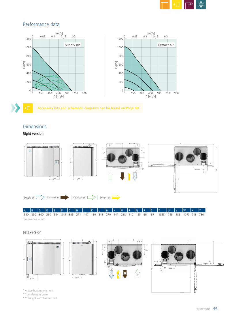
systemair 45
Supply air Exhaust air Outdoor air Extract air
A
D **
E
H **
JK
OP
R*S*
U
T
V
A
D **
E
H **
JK
OP
R*S*
U
T
V
0 150 300 450 600 750 9000
200
400
600
800
1000
12000 0.05 0.1 0.15 0.2
[m³/s]
Q [m³/h]
Ps [P
a]
0 150 300 450 600 750 9000
200
400
600
800
1000
12000 0.05 0.1 0.15 0.2
[m³/s]
Q [m³/h]
Ps [P
a]
SFP(2.5)
SFP(2)
SFP(1.5)SFP(1.2)
A B C D E F G H J K L M N O P Q R S T U V W X Y920 850 800 290 584 845 885 271 442 130 318 270 141 288 110 135 60 87 1855 748 185 1290 218 780
Dimensions in mm
A
D **
E
H **
U
T
V
R*S*
JK
OP
A
D **
E
H **
U
T
V
R*S*
JK
OP
Supply air Extract air
Performance data
Left version
DimensionsRight version
* water-heating element** condensate drain*** height with fixation rail
Accessory kits and schematic diagrams can be found on Page 48

46 systemair
SAVE VTR 700
Technical dataItem No. 88701 (left version)
88700 (right version)Energy efficiency class Standard unit A
with accessories* A+Installation Vertical designMaterial Steel, whiteVoltage / frequency V / 50Hz 230Power consumption per fan at operating point
W 71670 m³/h bei 50 pa
SFP kW/m³/s 0,72Input power, fan motor W 2 x 168Recommended fuse A 13Filter class M5 / ePM10 60%
(* F7 / ePM1 / 55%)M5 / ePM10 60%
Weight kg 188
* available as accessoriesSFP = Specific Fan Power (kW/m3/s), refers to the entire unit
• Up to 83% heat recovery efficiency
• Designed for living areas up to 600 m²
• Automatic summer mode, cold recovery and free night-time cooling
• External connection box for simple connection of external sensors
• Separate adjustment of the supply airflow and the extract airflow
• Water heating and cooling elements available as accessories
• Startup wizard
• Integrated humidity sensor in extract air
Features of the SAVE VTR 700 – characteristics and advantages at a glance
Residential ventilation unit with high-efficiency rotary heat exchanger and intelligent SAVE control. Driven by low noise and energy-saving RadiCal fans with demand-driven speed control. The housing is made of double-skinned galvanised sheet steel (painted white).
The humidity sensor (installed as standard) does not only control the flow rates of the energy-saving EC fans via speed control of the rotor, but also the transfer of moisture if necessary.
The compact residential ventilation unit also features a pleasingly comprehensive range of accessories. The SAVE VTR 700 can be controlled and set externally via an app. The standard Modbus interface enables smart integration with the building control system.
Mid-frequency range, HzLwA dB(A) Tot 63 125 250 500 1k 2k 4k 8kSupply air 63 76 67 67 61 55 54 48 34Extract air 56 68 70 62 47 48 38 31 23Surroundings 40 54 48 46 34 27 23 20 6
The table shows the sound power level LwA, which is not to be con-fused with the sound pressure level LpA (based on the above-specified operating point at 50 Pa).
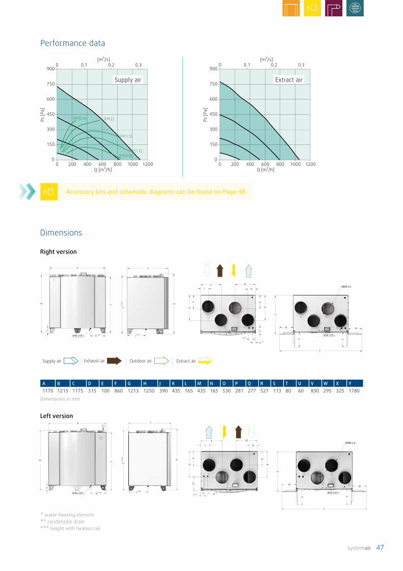
systemair 47
A F
KL
M
N
T *
U *
W W
Y
A F
KL
M
N
T *
U *
W W
Y
Supply air Exhaust air Outdoor air Extract air
0 200 400 600 800 1000 12000
150
300
450
600
750
9000 0.1 0.2 0.3
[m³/s]
Q [m³/h]
Ps [P
a]
0 200 400 600 800 1000 12000
150
300
450
600
750
9000 0.1 0.2 0.3
[m³/s]
Q [m³/h]
Ps [P
a]
SFP(2.6) SFP(2)
SFP(1.5)
SFP(1.2)SFP(0.8)
A F
KL
M
N
T * U *
W W
Y
A F
KL
M
N
T * U *
W W
Y
A B C D E F G H J K L M N O P Q R S T U V W X Y1170 1215 1175 315 100 860 1213 1250 390 435 165 435 165 530 281 277 527 113 80 60 830 295 325 1780
Dimensions in mm
Supply air Extract air
Performance data
Left version
Dimensions
Right version
* water-heating element** condensate drain*** height with fixation rail
Accessory kits and schematic diagrams can be found on Page 48
48 systemair
Residential ventilation units from Systemair are supplied with all the components needed to ensure efficient operation and good indoor air quality. However, there are still options for adapting functions and operation to particular needs and requirements.
Accessories & schematic diagrams

systemair 49
The right accessories for your needs
Product accessories
SAVE VTC 200 Page 50
SAVE VTC 300 Page 50
SAVE VTC 500 Page 50
SAVE VTC 700 Page 50
SAVE VSR 150/B Page 54
SAVE VSR 300 Page 54
SAVE VSR 500 Page 54
SAVE VTR 100/B Page 56
SAVE VTR 150/B Page 56
SAVE VTR 150/K Page 58
SAVE VTR 250/B Page 58
SAVE VTR 300/B Page 60
SAVE VTR 500 Page 60
SAVE VTR 700 Page 60
• Extending the functionality of the units • More flexible operation thanks to demand-
driven ventilation• Simpler or more modern operation (app)• Additional air heating beyond heating via heat
recovery• Spare parts
Our accessories help adapt the standard units to the special needs and wishes of our customers
Our philosophy is for the standard units to be able to satisfy most of our customers, and that these are delivered with all the necessary components. Those with particular wishes or needs can fulfil them using our accessories.

50 systemair
SAVE VTC 200 SAVE VTC 300
Description Name Item No.
Name Item No.
Basi
c ac
cess
orie
s,co
ntro
l
SAVE touch (HMI) control unit, black SAVE touch HMI, black SAVE touch HMI, black138078 138078
SAVE touch (HMI) control unit, white SAVE touch HMI, white SAVE touch HMI, white138077 138077
SAVE touch wall mounting frame SAVE touch Wall Mounted Kit SAVE touch Wall Mounted Kit140736 140736
SAVE touch IAM Internet access module SAVE touch IAM Modul SAVE touch IAM Modul211243 211243
VK connection cable VK-15 VK-15306594 306594
CE/CD coupling for connecting multiple control panels
CE/CD CE/CD37367 37367
Basi
c
Flexible pipe silencer, 50 mm insulation, 1.0 m long
SCD 125 SCD 160 84331 84332
Spring return control damper, incl. 230V motor with spring return actuator
Tune-R-125-3-M4 Tune-R-160-3-M4311968 311969
Relay box for shut-off valve 230V with or without spring return
RMK RMK153549 153549
Relay box for shut-off valve 24VAC with or without spring return, incl. Trafo
RMK-T RMK-T153548 153548
Filter cassette G3 insulated, Prefilter
FGR-I 125 FGR-I 16037064 37065
Combi-grille, sheet steel Outdoor and exhaust air, black
CVVX 125 CVVX 16026421 25394
Combi-grille, sheet steel Outdoor and exhaust air, white
CVVX 125 CVVX 16026422 25396
On-d
eman
d co
ntro
l
CO2 sensor, wall-mounted * 0-10 V, 0…2000ppm
CO2-Sensor CO2-Sensor14904 14904
CO2 sensor, duct-mounted * L = 100 mm, 0-10 V, 0…2000ppm
CO2-Sensor CO2-Sensor14906 14906
Combi-sensor, wall-mounted * CO2 + humidity + temp.
CO2 RH CO2 RH211522 211522
CO2 transmitter, wall-mounted * digital 0/1, 0…2000ppm
CO2RT-R-D CO2RT-R-D6993 6993
CO2 transmitter, duct-mounted* digital 0/1, 0…2000ppm
CO2DT-R CO2DT-R 14352 14352
Humidistat, wall-mounted * digital 0/1, 30-100% r.F.
HU HU30213 30213
Duct temperature sensor G-K3/NTC10-01 G-K3/NTC10-01211524 211524
Room temperature sensor TG-R5/NTC10-01 TG-R5/NTC10-01211525 211525
Surface temperature sensor TG-A1/NTC10-01 TG-A1/NTC10-01211523 211523
VAV
/ CA
V VAV/CAV-Set SAVE touch PDT12S25 PDT12S25140777 140777
Iris diaphragm **(only for CAV control)
SPI-125 C SPI-160 C6751 6753
* Energy efficiency class - standard unit with accessories** 2 pcs. required for CAV control (constant volume control).
Accessories SAVE VTC

systemair 51
SAVE VTC 200 SAVE VTC 300
Description Name Item No.
Name Item No.
Wat
er-r
ehea
ting
elem
ents
in
stal
led
in v
entil
atio
n du
ct
Hot-water heating element duct-mounted
VBC 125-2 VBC 160-25457 5458
Surface temperature sensor TG-A1/NTC10-01 TG-A1/NTC10-01211523 211523
Duct temperature sensor G-K3/NTC10-01 G-K3/NTC10-01211524 211524
Actuator for mixing valve 24 V
RVAZ4 24A RVAZ4 24A9862 9862
3-way valve ZTR 15-0,4 ZTR 15-0,69670 6573
Actuator power supply transformer 230 V - 24 V
PSS48 PSS48211945 211945
Wat
er-c
oolin
g el
emen
ts
inst
alle
d in
ven
tilat
ion
duct Cold water cooler
duct-mountedCWK 125-3-2,5 CWK 160-3-2,530021 30022
Duct temperature sensor G-K3/NTC10-01 G-K3/NTC10-01211524 211524
Actuator for mixing valve 24 V
RVAZ4 24A RVAZ4 24A9862 9862
3-way valve ZTR 15-0,4 ZTR 15-0,69670 6573
Actuator power supply transformer 230 V - 24 V
PSS48 PSS48211945 211945
Elec
tric
rehe
ater
in
stal
led
in v
entil
a-tio
n un
it
Unit version right - Electric reheaterVTC 300 R- 138107
Unit version left - Electric reheaterVTC 300 L- 139312
Elec
tric
pre
heat
er,
inst
alle
d in
ven
tila-
tion
duct
Electric preheater CB 125-1,2 CB 160-2,15290 5292
CB connection set SAVE control CB connection SAVE control CB connection142852 142852
Filte
rs
Supply air filter F7 PF VTC 200 ePM1 55% PF VTC 300 ePM1 55%208671 207041- BF VTC 300 ePM1 65% - 207042
Supply air filter M5 - PF VTC 300 ePM10 60% - 207040
Supply airfilter G4 PF VTC 200 Coarse 65% S/E PF VTC 300 Coarse 65% S/E208670 207039
Exhaust airfilter M5 - -- -
Exhaust airfilter G4 PF VTC 200 Coarse 65% S/E PF VTC 300 Coarse 65% S/E208670 207039
*** Requires separate power supply

52 systemair
SAVE VTC 500 SAVE VTC 700
Description Name Item No.
Name Item No.
Basi
c ac
cess
orie
s,co
ntro
l
SAVE touch (HMI) control unit, black SAVE touch HMI, black SAVE touch HMI, black138078 138078
SAVE touch (HMI) control unit, black SAVE touch HMI, white SAVE touch HMI, white138077 138077
SAVE touch wall mounting frame SAVE touch Wall Mounted Kit SAVE touch Wall Mounted Kit140736 140736
SAVE touch IAM Internet access module SAVE touch IAM Modul SAVE touch IAM Modul211243 211243
VK connection cable VK-15 VK-15306594 306594
CE/CD coupling for connecting multiple control panels
CE/CD CE/CD37367 37367
CAV kit für SAVE Touch CAV kit -161100 -
Basi
c
Flexible pipe silencer, 50 mm insulation, 1.0 m long
SCD 250 SCD 25084333 87545
Spring return control damper, incl. 230V motor with spring return actuator
TUNE-R-200-3-M4 TUNE-R-250-3-M4311970 311971
Relay box for shut-off valve 230V with or without spring return
SAVE Relaisbox 230VAC SAVE Relaisbox 230VAC153549 153549
RRelay box for shut-off valve 24VAC with or without spring return, incl. Trafo
RMK-T RMK-T153548 153548
Filter cassette G3 insulated, Prefilter
FGR-I 200 FGR-I 25037066 37316
Combi-grille, sheet steel Outdoor and exhaust air, black
CVVX 200 CVVX 25025395 8498
Combi-grille, sheet steel Outdoor and exhaust air, white
CVVX 200 CVVX 25025357 146260
On-d
eman
d co
ntro
l
CO2 sensor, wall-mounted * 0-10 V, 0…2000ppm
CO2-Sensor CO2-Sensor14904 14904
CO2 sensor, duct-mounted * L = 100 mm, 0-10 V, 0…2000ppm
CO2-Sensor CO2-Sensor14906 14906
Combi-sensor, wall-mounted * CO2 + humidity + temp.
CO2 RH CO2 RH211522 211522
CO2 transmitter, wall-mounted * digital 0/1, 0…2000ppm
CO2RT-R-D CO2RT-R-D6993 6993
CO2 transmitter, duct-mounted* digital 0/1, 0…2000ppm
CO2DT-R CO2DT-R 14352 14352
Humidistat, wall-mounted * digital 0/1, 30-100% r.F.
HU HU30213 30213
Duct temperature sensor G-K3/NTC10-01 G-K3/NTC10-01211524 211524
Room temperature sensor TG-R5/NTC10-01 TG-R5/NTC10-01211525 211525
Surface temperature sensor TG-A1/NTC10-01 TG-A1/NTC10-01211523 211523
VAV
/ CA
V VAV/CAV-Set SAVE touch PDT12S25 PDT12S25140777 140777
Iris diaphragm **(only for CAV control)
SPI-200 C SPI-250 C6754 6755
* Energy efficiency class - standard unit with accessories** 2 pcs. required for CAV control (constant volume control).
Accessories SAVE VTC
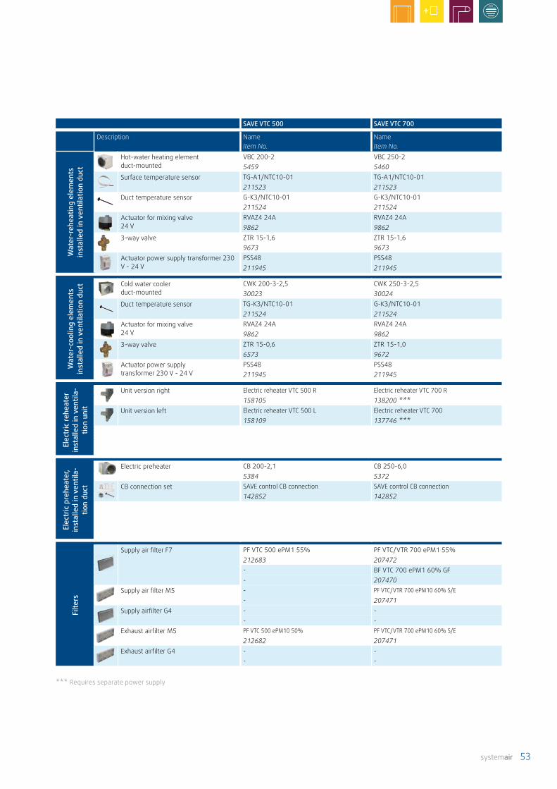
systemair 53
SAVE VTC 500 SAVE VTC 700
Description Name Item No.
Name Item No.
Wat
er-r
ehea
ting
elem
ents
in
stal
led
in v
entil
atio
n du
ct
Hot-water heating element duct-mounted
VBC 200-2 VBC 250-25459 5460
Surface temperature sensor TG-A1/NTC10-01 TG-A1/NTC10-01211523 211523
Duct temperature sensor G-K3/NTC10-01 G-K3/NTC10-01211524 211524
Actuator for mixing valve 24 V
RVAZ4 24A RVAZ4 24A9862 9862
3-way valve ZTR 15-1,6 ZTR 15-1,69673 9673
Actuator power supply transformer 230 V - 24 V
PSS48 PSS48211945 211945
Wat
er-c
oolin
g el
emen
ts
inst
alle
d in
ven
tilat
ion
duct Cold water cooler
duct-mountedCWK 200-3-2,5 CWK 250-3-2,530023 30024
Duct temperature sensor TG-K3/NTC10-01 G-K3/NTC10-01211524 211524
Actuator for mixing valve 24 V
RVAZ4 24A RVAZ4 24A9862 9862
3-way valve ZTR 15-0,6 ZTR 15-1,06573 9672
Actuator power supply transformer 230 V - 24 V
PSS48 PSS48211945 211945
Elec
tric
rehe
ater
in
stal
led
in v
entil
a-tio
n un
it
Unit version right Electric reheater VTC 500 R Electric reheater VTC 700 R158105 138200 ***
Unit version left Electric reheater VTC 500 L Electric reheater VTC 700158109 137746 ***
Elec
tric
pre
heat
er,
inst
alle
d in
ven
tila-
tion
duct
Electric preheater CB 200-2,1 CB 250-6,05384 5372
CB connection set SAVE control CB connection SAVE control CB connection142852 142852
Filte
rs
Supply air filter F7 PF VTC 500 ePM1 55% PF VTC/VTR 700 ePM1 55%212683 207472- BF VTC 700 ePM1 60% GF- 207470
Supply air filter M5 - PF VTC/VTR 700 ePM10 60% S/E
- 207471Supply airfilter G4 - -
- -Exhaust airfilter M5 PF VTC 500 ePM10 50% PF VTC/VTR 700 ePM10 60% S/E
212682 207471Exhaust airfilter G4 - -
- -
*** Requires separate power supply

54 systemair
SAVE VSR 150/B SAVE VSR 300 SAVE VSR 500
Description Name Item no.
Name Item no.
Name Item no.
Basi
c ac
cess
orie
s,Co
ntro
l
SAVE touch (HMI) control unit, black SAVE touch HMI, black SAVE touch HMI, black SAVE touch HMI, black138078 138078 138078
SAVE touch (HMI) control unit, black SAVE touch HMI, white SAVE touch HMI, white SAVE touch HMI, white138077 138077 138077
SAVE touch wall mounting frame SAVE touch Wall Mounted Kit SAVE touch Wall Mounted Kit SAVE touch Wall Mounted Kit140736 140736 140736
SAVE control IAM Internet access module
SAVE touch IAM Modul SAVE touch IAM Modul SAVE touch IAM Modul211243 211243 211243
VK connection cable VK-15 VK-15 VK-15306594 306594 306594
CE/CD coupling for connecting multiple control panels
CE/CD CE/CD CE/CD37367 37367 37367
Basi
c
Flexible pipe silencer, 50 mm insulation, 1.0 m long
SCD 125 SCD 160 SCD 20084331 84332 2560
Spring return control damper, incl. 230V motor with spring return actuator
Tune-R-125-3-M4 Tune-R-160-3-M4 TUNE-R-200-3-M4311968 311969 311970
Relay box for shut-off valve 230V with or without spring return
RMK RMK RMK153549 153549 153549
Relay box for shut-off valve 24VDC, with or without spring return, incl. Trafo
RMK-T RMK-T RMK-T153548 153548 153548
Filter cassette G3 insulated, Prefilter
FGR-I 125 FGR-I 160 FGR-I 20037064 37065 37066
Combi-grille, sheet steel Outdoor and exhaust air, black
CVVX 125, black CVVX 160, black CVVX 200, black26421 25394 25395
Combi-grille, sheet steel Outdoor and exhaust air, white
CVVX 125, white CVVX 160, white CVVX 200, white26422 25396 25397
Telescopic suspension Telescopic suspension VSR 150/B - -37251 - -
Ceiling mounting kit Wall mounting kit VSR 150/B Ceiling mounting kit VSR 300 Ceiling mounting kit VSR 500115599 131610 131620
Wall mounting kit Wanll mounting kit vertical - -165599 - -Wanll mounting kit horizontal - -162999 - -
On-d
eman
d co
ntro
l
CO2 sensor, wall-mounted * 0-10 V, 0…2000ppm
CO2-Sensor CO2-Sensor CO2-Sensor14904 14904 14904
CO2 sensor, duct-mounted * L = 100 mm, 0-10 V, 0…2000ppm
CO2-Sensor CO2-Sensor CO2-Sensor14906 14906 14906
Combi-sensor, wall-mounted * CO2 + humidity + temp.
CO2 RH CO2 RH CO2 RH211522 211522 211522
CO2 transmitter, wall-mounted * digital 0/1, 0…2000ppm
CO2RT-R-D CO2RT-R-D CO2RT-R-D6993 6993 6993
CO2 transmitter, duct-mounted* digital 0/1, 0…2000ppm
CO2DT-R CO2DT-R CO2DT-R 14352 14352 14352
Humidistat, wall-mounted * digital 0/1, 30-100% r.F.
HU HU HU30213 30213 30213
Duct temperature sensor G-K3/NTC10-01 G-K3/NTC10-01 G-K3/NTC10-01211524 211524 211524
Room temperature sensor TG-R5/NTC10-01 TG-R5/NTC10-01 TG-R5/NTC10-01211525 211525 211525
Surface temperature sensor TG-A1/NTC10-01 TG-A1/NTC10-01 TG-A1/NTC10-01211523 211523 211523
Accessories SAVE VSR
* Energy efficiency class - standard unit with accessories** 2 pcs. required for CAV control (constant volume control).
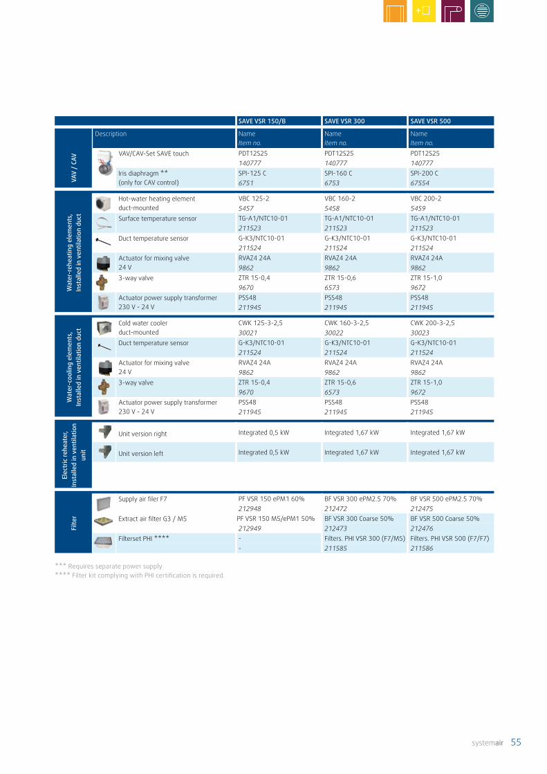
systemair 55
SAVE VSR 150/B SAVE VSR 300 SAVE VSR 500
Description Name Item no.
Name Item no.
Name Item no.
VAV
/ CA
V VAV/CAV-Set SAVE touch PDT12S25 PDT12S25 PDT12S25140777 140777 140777
Iris diaphragm **(only for CAV control)
SPI-125 C SPI-160 C SPI-200 C6751 6753 67554
Wat
er-r
ehea
ting
elem
ents
, In
stal
led
in v
entil
atio
n du
ct
Hot-water heating element duct-mounted
VBC 125-2 VBC 160-2 VBC 200-25457 5458 5459
Surface temperature sensor TG-A1/NTC10-01 TG-A1/NTC10-01 TG-A1/NTC10-01211523 211523 211523
Duct temperature sensor G-K3/NTC10-01 G-K3/NTC10-01 G-K3/NTC10-01211524 211524 211524
Actuator for mixing valve 24 V
RVAZ4 24A RVAZ4 24A RVAZ4 24A9862 9862 9862
3-way valve ZTR 15-0,4 ZTR 15-0,6 ZTR 15-1,09670 6573 9672
Actuator power supply transformer 230 V - 24 V
PSS48 PSS48 PSS48211945 211945 211945
Wat
er-c
oolin
g el
emen
ts,
Inst
alle
d in
ven
tilat
ion
duct
Cold water cooler duct-mounted
CWK 125-3-2,5 CWK 160-3-2,5 CWK 200-3-2,530021 30022 30023
Duct temperature sensor G-K3/NTC10-01 G-K3/NTC10-01 G-K3/NTC10-01211524 211524 211524
Actuator for mixing valve 24 V
RVAZ4 24A RVAZ4 24A RVAZ4 24A9862 9862 9862
3-way valve ZTR 15-0,4 ZTR 15-0,6 ZTR 15-1,09670 6573 9672
Actuator power supply transformer 230 V - 24 V
PSS48 PSS48 PSS48211945 211945 211945
Elec
tric
rehe
ater
, In
stal
led
in v
entil
atio
n un
it
Unit version right Integrated 0,5 kW Integrated 1,67 kW Integrated 1,67 kW
Unit version left Integrated 0,5 kW Integrated 1,67 kW Integrated 1,67 kW
Filte
r
Supply air filer F7 PF VSR 150 ePM1 60% BF VSR 300 ePM2.5 70% BF VSR 500 ePM2.5 70%212948 212472 212475
Extract air filter G3 / M5 PF VSR 150 M5/ePM1 50% BF VSR 300 Coarse 50% BF VSR 500 Coarse 50%212949 212473 212476
Filterset PHI **** - Filters. PHI VSR 300 (F7/M5) Filters. PHI VSR 500 (F7/F7)- 211585 211586
*** Requires separate power supply**** Filter kit complying with PHI certification is required.
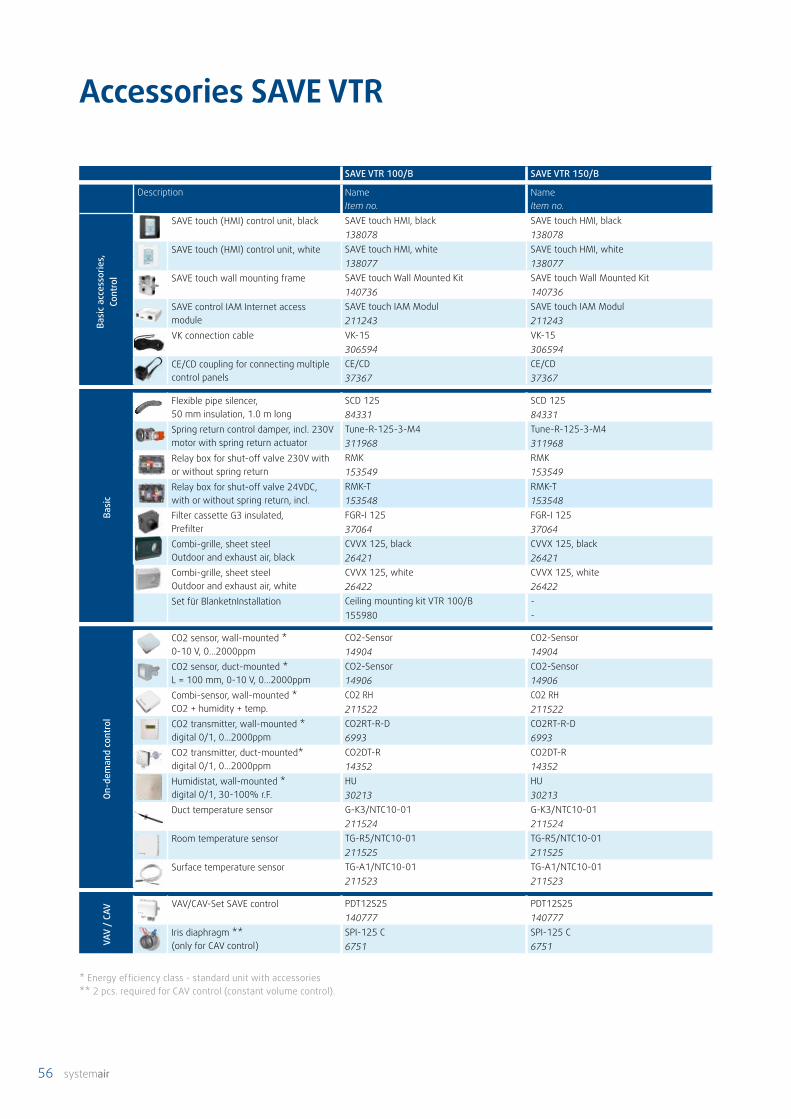
56 systemair
SAVE VTR 100/B SAVE VTR 150/B
Description Name Item no.
Name Item no.
Basi
c ac
cess
orie
s,Co
ntro
l
SAVE touch (HMI) control unit, black SAVE touch HMI, black SAVE touch HMI, black138078 138078
SAVE touch (HMI) control unit, white SAVE touch HMI, white SAVE touch HMI, white138077 138077
SAVE touch wall mounting frame SAVE touch Wall Mounted Kit SAVE touch Wall Mounted Kit140736 140736
SAVE control IAM Internet access module
SAVE touch IAM Modul SAVE touch IAM Modul211243 211243
VK connection cable VK-15 VK-15306594 306594
CE/CD coupling for connecting multiple control panels
CE/CD CE/CD37367 37367
Basi
c
Flexible pipe silencer, 50 mm insulation, 1.0 m long
SCD 125 SCD 12584331 84331
Spring return control damper, incl. 230V motor with spring return actuator
Tune-R-125-3-M4 Tune-R-125-3-M4311968 311968
Relay box for shut-off valve 230V with or without spring return
RMK RMK153549 153549
Relay box for shut-off valve 24VDC, with or without spring return, incl.
RMK-T RMK-T153548 153548
Filter cassette G3 insulated, Prefilter
FGR-I 125 FGR-I 12537064 37064
Combi-grille, sheet steel Outdoor and exhaust air, black
CVVX 125, black CVVX 125, black26421 26421
Combi-grille, sheet steel Outdoor and exhaust air, white
CVVX 125, white CVVX 125, white26422 26422
Set für BlanketnInstallation Ceiling mounting kit VTR 100/B -155980 -
On-d
eman
d co
ntro
l
CO2 sensor, wall-mounted * 0-10 V, 0…2000ppm
CO2-Sensor CO2-Sensor14904 14904
CO2 sensor, duct-mounted * L = 100 mm, 0-10 V, 0…2000ppm
CO2-Sensor CO2-Sensor14906 14906
Combi-sensor, wall-mounted * CO2 + humidity + temp.
CO2 RH CO2 RH211522 211522
CO2 transmitter, wall-mounted * digital 0/1, 0…2000ppm
CO2RT-R-D CO2RT-R-D6993 6993
CO2 transmitter, duct-mounted* digital 0/1, 0…2000ppm
CO2DT-R CO2DT-R 14352 14352
Humidistat, wall-mounted * digital 0/1, 30-100% r.F.
HU HU30213 30213
Duct temperature sensor G-K3/NTC10-01 G-K3/NTC10-01211524 211524
Room temperature sensor TG-R5/NTC10-01 TG-R5/NTC10-01211525 211525
Surface temperature sensor TG-A1/NTC10-01 TG-A1/NTC10-01211523 211523
VAV
/ CA
V VAV/CAV-Set SAVE control PDT12S25 PDT12S25140777 140777
Iris diaphragm **(only for CAV control)
SPI-125 C SPI-125 C6751 6751
Accessories SAVE VTR
* Energy efficiency class - standard unit with accessories** 2 pcs. required for CAV control (constant volume control).

systemair 57
SAVE VTR 100/B SAVE VTR 150/B
Description Name Item no.
Name Item no.
Wat
er-r
ehea
ting
elem
ents
In
stal
led
in v
entil
atio
n du
ct
Hot-water heating element duct-mounted
VBC 125-2 VBC 125-25457 5457
Surface temperature sensor TG-A1/NTC10-01 TG-A1/NTC10-01211523 211523
Duct temperature sensor G-K3/NTC10-01 G-K3/NTC10-01211524 211524
Actuator for mixing valve 24 V
RVAZ4 24A RVAZ4 24A9862 9862
3-way valve ZTR 15-0,4 ZTR 15-0,49670 9670
Actuator power supply transformer 230 V - 24 V
PSS48 PSS48211945 211945
Wat
er-c
oolin
g el
emen
ts
Inst
alle
d in
ven
tilat
ion
duct Cold water cooler
duct-mountedCWK 125-3-2,5 CWK 125-3-2,530021 30021
Duct temperature sensor G-K3/NTC10-01 G-K3/NTC10-01211524 211524
Actuator for mixing valve 24 V
RVAZ4 24A RVAZ4 24A9862 9862
3-way valve ZTR 15-0,4 ZTR 15-0,49670 9670
Actuator power supply transformer 230 V - 24 V
PSS48 PSS48211945 211945
Elec
tric
rehe
ater
In
stal
led
in v
entil
a-tio
n un
it
Electric reheater 500 W Integrated 0,5 or 1,0 kW154100
Filte
r
Supply air filter F7 PF VTR 100 ePM1 60% PF VTR 150 ePM1 55%212147 211122BF VTR 100 ePM1 60% -212145 -
Supply air filter M5 PF VTR 100 ePM10 50% S/E PF VTR 150 ePM10 60%212148 211121BF VTR 100 Coarse 70% S/E BF VTR 150 ePM10 50%212146 210253
Exhaust airfilter M5 PF VTR 100 ePM10 50% S/E PF VTR 150 ePM10 60%212148 211120BF VTR 100 Coarse 70% S/E BF VTR 150 ePM10 50%212146 210254

58 systemair
Accessories SAVE VTR
SAVE VTR 150/K SAVE VTR 250/B
Description Name Item no.
Name Item no.
Basi
c ac
cess
orie
s,Co
ntro
l
SAVE touch (HMI) control unit, black SAVE touch HMI, black SAVE touch HMI, black138078 138078
SAVE touch (HMI) control unit, white SAVE touch HMI, white SAVE touch HMI, white138077 138077
SAVE touch wall mounting frame SAVE touch Wall Mounted Kit SAVE touch Wall Mounted Kit140736 140736
SAVE control IAM Internet access module
SAVE touch IAM Modul SAVE touch IAM Modul211243 211243
VK connection cable VK-15 VK-15306594 306594
CE/CD coupling for connecting multiple control panels
CE/CD CE/CD37367 37367
Basi
c
Flexible pipe silencer, 50 mm insulation, 1.0 m long
SCD 125 SCD 12584331 84331
Spring return control damper, incl. 230V motor with spring return actuator
Tune-R-125-3-M4 Tune-R-125-3-M4311968 311968
Relay box for shut-off valve 230V with or without spring return
RMK RMK153549 153549
Relay box for shut-off valve 24VDC, with or without spring return, incl.
RMK-T RMK-T153548 153548
Filter cassette G3 insulated, Prefilter
FGR-I 125 FGR-I 12537064 37064
Combi-grille, sheet steel Outdoor and exhaust air, black
CVVX 125, black CVVX 125, black26421 26421
Combi-grille, sheet steel Outdoor and exhaust air, white
CVVX 125, white CVVX 125, white26422 26422
On-d
eman
d co
ntro
l
CO2 sensor, wall-mounted * 0-10 V, 0…2000ppm
CO2-Sensor CO2-Sensor14904 14904
CO2 sensor, duct-mounted * L = 100 mm, 0-10 V, 0…2000ppm
CO2-Sensor CO2-Sensor14906 14906
Combi-sensor, wall-mounted * CO2 + humidity + temp.
CO2 RH CO2 RH211522 211522
CO2 transmitter, wall-mounted * digital 0/1, 0…2000ppm
CO2RT-R-D CO2RT-R-D6993 6993
CO2 transmitter, duct-mounted* digital 0/1, 0…2000ppm
CO2DT-R CO2DT-R 14352 14352
Humidistat, wall-mounted * digital 0/1, 30-100% r.F.
HU HU30213 30213
Duct temperature sensor G-K3/NTC10-01 G-K3/NTC10-01211524 211524
Room temperature sensor TG-R5/NTC10-01 TG-R5/NTC10-01211525 211525
Surface temperature sensor TG-A1/NTC10-01 TG-A1/NTC10-01211523 211523
VAV
/ CA
V VAV/CAV-Set SAVE control PDT12S25 PDT12S25140777 140777
Iris diaphragm **(only for CAV control)
SPI-125 C SPI-125 C6751 6751
* Energy efficiency class - standard unit with accessories** 2 pcs. required for CAV control (constant volume control).
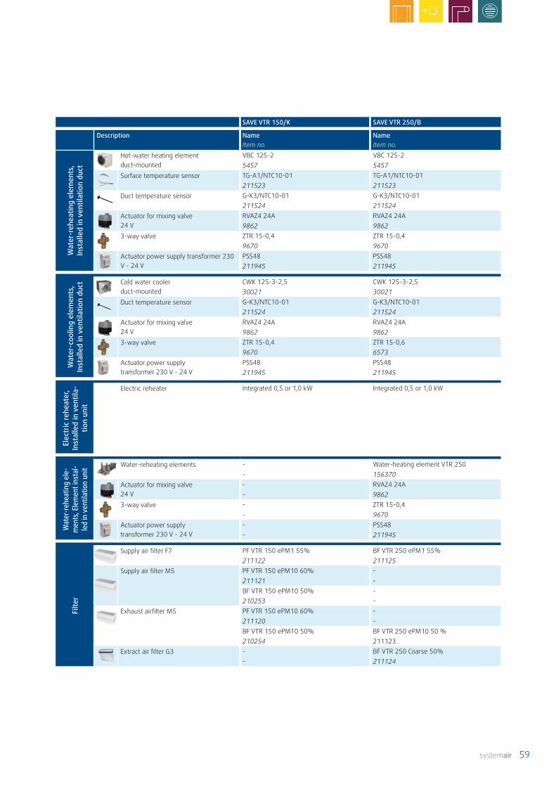
systemair 59
SAVE VTR 150/K SAVE VTR 250/B
Description Name Item no.
Name Item no.
Wat
er-r
ehea
ting
elem
ents
, In
stal
led
in v
entil
atio
n du
ct
Hot-water heating element duct-mounted
VBC 125-2 VBC 125-25457 5457
Surface temperature sensor TG-A1/NTC10-01 TG-A1/NTC10-01211523 211523
Duct temperature sensor G-K3/NTC10-01 G-K3/NTC10-01211524 211524
Actuator for mixing valve 24 V
RVAZ4 24A RVAZ4 24A9862 9862
3-way valve ZTR 15-0,4 ZTR 15-0,49670 9670
Actuator power supply transformer 230 V - 24 V
PSS48 PSS48211945 211945
Wat
er-c
oolin
g el
emen
ts,
Inst
alle
d in
ven
tilat
ion
duct Cold water cooler
duct-mountedCWK 125-3-2,5 CWK 125-3-2,530021 30021
Duct temperature sensor G-K3/NTC10-01 G-K3/NTC10-01211524 211524
Actuator for mixing valve 24 V
RVAZ4 24A RVAZ4 24A9862 9862
3-way valve ZTR 15-0,4 ZTR 15-0,69670 6573
Actuator power supply transformer 230 V - 24 V
PSS48 PSS48211945 211945
Elec
tric
rehe
ater
, In
stal
led
in v
entil
a-tio
n un
it
Electric reheater Integrated 0,5 or 1,0 kW Integrated 0,5 or 1,0 kW
Wat
er-re
heat
ing
ele-
men
ts, E
lem
ent i
nsta
l-le
d in
ven
tilat
ion
unit
Water-reheating elements - Water-heating element VTR 250- 156370
Actuator for mixing valve 24 V
- RVAZ4 24A- 9862
3-way valve - ZTR 15-0,4- 9670
Actuator power supply transformer 230 V - 24 V
- PSS48- 211945
Filte
r
Supply air filter F7 PF VTR 150 ePM1 55% BF VTR 250 ePM1 55%211122 211125
Supply air filter M5 PF VTR 150 ePM10 60% -211121 -BF VTR 150 ePM10 50% -210253 -
Exhaust airfilter M5 PF VTR 150 ePM10 60% -211120 -BF VTR 150 ePM10 50% BF VTR 250 ePM10 50 %210254 211123
Extract air filter G3 - BF VTR 250 Coarse 50%- 211124

60 systemair
SAVE VTR 300/B SAVE VTR 500 SAVE VTR 700
Description Name Item no.
Name Item no.
Name Item no.
Basi
c ac
cess
orie
s,Co
ntro
l
SAVE touch (HMI) control unit, black SAVE touch HMI, black SAVE touch HMI, black SAVE touch HMI, black138078 138078 138078
SAVE touch (HMI) control unit, white SAVE touch HMI, white SAVE touch HMI, white SAVE touch HMI, white138077 138077 138077
SAVE touch wall mounting frame SAVE touch Wall Mounted Kit SAVE touch Wall Mounted Kit SAVE touch Wall Mounted Kit140736 140736 140736
SAVE control IAM internet communication module
SAVE touch IAM Modul SAVE touch IAM Modul SAVE touch IAM Modul211243 211243 211243
VK connection cable VK-15 VK-15 VK-15306594 306594 306594
CE/CD coupling for connecting multiple control panels
CE/CD CE/CD CE/CD37367 37367 37367
Basi
c
Flexible pipe silencer, 50 mm insulation, 1.0 m long
SCD 160 SCD 200 SCD 25084332 84333 87545
Spring return control damper, incl. 230V motor with spring return actuator
Tune-R-160-3-M4 TUNE-R-200-3-M4 TUNE-R-250-3-M4311969 311970 311971
Relay box for shut-off valve 230V with or without spring return
RMK RMK RMK153549 153549 153549
Relay box for shut-off valve 24VDC, with or without spring return, incl.
RMK-T RMK-T RMK-T153548 153548 153548
Filter cassette G3 insulated, Prefilter
FGR-I 160 FGR-I 200 FGR-I 25037065 37066 37316
Combi-grille, sheet steel Outdoor and exhaust air, black
CVVX 160, black CVVX 200, black CVVX 250, black25394 25395 8498
Combi-grille, sheet steel Outdoor and exhaust air, white
CVVX 160, white CVVX 200, white CVVX 250, white25396 25397 146260
On-d
eman
d co
ntro
l
CO2 sensor, wall-mounted * 0-10 V, 0…2000ppm
CO2-Sensor CO2-Sensor CO2-Sensor14904 14904 14904
CO2 sensor, duct-mounted * L = 100 mm, 0-10 V, 0…2000ppm
CO2-Sensor CO2-Sensor CO2-Sensor14906 14906 14906
Combi-sensor, wall-mounted * CO2 + humidity + temp.
CO2 RH CO2 RH CO2 RH211522 211522 211522
CO2 transmitter, wall-mounted * digital 0/1, 0…2000ppm
CO2RT-R-D CO2RT-R-D CO2RT-R-D6993 6993 6993
CO2 transmitter, duct-mounted* digital 0/1, 0…2000ppm
CO2DT-R CO2DT-R CO2DT-R 14352 14352 14352
Humidistat, wall-mounted * digital 0/1, 30-100% r.F.
HU HU HU30213 30213 30213
Duct temperature sensor G-K3/NTC10-01 G-K3/NTC10-01 G-K3/NTC10-01211524 211524 211524
Room temperature sensor TG-R5/NTC10-01 TG-R5/NTC10-01 TG-R5/NTC10-01211525 211525 211525
Surface temperature sensor TG-A1/NTC10-01 TG-A1/NTC10-01 TG-A1/NTC10-01211523 211523 211523
VAV
/ CA
V VAV/CAV-Set SAVE touch PDT12S25 PDT12S25 PDT12S25140777 140777 140777
Iris diaphragm **(only for CAV control)
SPI-160 C SPI-200 C SPI-250 C6753 6754 6755
Accessories SAVE VTR
* Energy efficiency class - standard unit with accessories** 2 pcs. required for CAV control (constant volume control).

systemair 61
SAVE VTR 300/B SAVE VTR 500 SAVE VTR 700
Description Name Item no.
Name Item no.
Name Item no.
Wat
er-r
ehea
ting
elem
ents
In
stal
led
in v
entil
atio
n du
ct
Hot-water heating element duct-mounted
VBC 160-2 VBC 200-2 VBC 250-25458 5459 5460
Surface temperature sensor TG-A1/NTC10-01 TG-A1/NTC10-01 TG-A1/NTC10-01211523 211523 211523
Duct temperature sensor G-K3/NTC10-01 G-K3/NTC10-01 G-K3/NTC10-01211524 211524 211524
Actuator for mixing valve 24 V
RVAZ4 24A RVAZ4 24A RVAZ4 24A9862 9862 9862
3-way valve ZTR 15-0,6 ZTR 15-1,0 ZTR 15-1,66573 9672 9673
Actuator power supply transformer 230 V - 24 V
PSS48 PSS48 PSS48211945 211945 211945
Wat
er-c
oolin
g el
emen
ts
Inst
alle
d in
ven
tilat
ion
duct
Cold water cooler duct-mounted
CWK 160-3-2,5 CWK 200-3-2,5 CWK 250-3-2,530022 30023 30024
Duct temperature sensor G-K3/NTC10-01 G-K3/NTC10-01 G-K3/NTC10-01211524 211524 211524
Actuator for mixing valve 24 V
RVAZ4 24A RVAZ4 24A RVAZ4 24A9862 9862 9862
3-way valve ZTR 15-0,6 ZTR 15-1,0 ZTR 15-1,66573 9672 96723
Actuator power supply transformer 230 V - 24 V
PSS48 PSS48 PSS48211945 211945 211945
Wat
er-r
ehea
ting
elem
ents
In
stal
led
in v
entil
atio
n un
it Water-reheating elements Water-heating element VTR 300 Water-heating element VTR 500 Wasserheizreg. VTR 700141700 141701 141101 r. Ausf. / 138101 l. Ausf.
Actuator for mixing valve 24 V
RVAZ4 24A RVAZ4 24A RVAZ4 24A9862 9862 9862
3-way valve ZTR 15-0,6 ZTR 15-1,0 ZTR 15-1,66573 9672 9673
Actuator power supply transformer 230 V - 24 V
PSS48 PSS48 PSS48211945 211945 211945
Elec
tric
pre
heat
er,
Inst
alle
d in
ven
tilat
ion
duct
Unit version right Integrated 0,5 kW Integrated 1,67 kW Electric reheater VTR 700141100
Unit version left Integrated 0,5 kW Integrated 1,67 kW Electric reheater VTR 700138100
Filte
rs
Supply air filter F7 BF VTR 300 ePM10 80% BF VTR 500 ePM10 80% PF VTC/VTR 700 ePM1 55%208268 208283 207472
Supply air filter M5 - - PF VTC/VTR 700 ePM10 60% S/E- - 207471
Supply air filter G3 BF VTR 300 Coarse 60% BF VTR 500 Coarse 60% -208269 208285 -
Extract air filter G3 BF VTR 300 Coarse 60% BF VTR 500 Coarse 60% -208270 208284 -
Extract air filter M5 - - PF VTC/VTR 700 ePM10 60% S/E- - 207471
PHI filter kit*** Filterset PHI VTR 300 (F7/F7) - -211587 - -
*** Filter kit complying with PHI certification is required.

62 systemair
Schematic diagram
Filter Outdoor / extract air filterVR Rotary heat exchangerEAF Exhaust air fanRHS / EAT Humidity and extract air temperature sensorSAF Supply air fan ELH Electric reheaterSAT Supply air temperature sensorOHT Overheating sensorEMT Safety-temperature limiterOAT Outdoor air temperature sensorBP Bypass for extractor
RH/T
Exha
ust a
irO
utdo
or a
ir Extract airSupply air
FilterOAT
ELH OHT EMT SATBP
SAF
EAF
RHS/EATFilter
SAVE VSR 150/B
Filter Outdoor / extract air filterVR Rotary heat exchangerEAF Exhaust air fanRHS / EAT Humidity and extract air temperature sensorSAF Supply air fanELH Electric reheater OHT Overheating sensor EMT Safety-temperature limiter OAT Outdoor air temperature sensorSAT Supply air temperature sensor
RH/T
Extr
act a
ir
Filter
OATELHOHTEMTSAT Filter
RHS/EAT
EAF
SAF
Exhaust airO
utdoor airSupp
ly a
ir
SAVE VSR 500
Filter Outdoor / extract air filterVR Rotary heat exchangerEAF Exhaust air fanRHS / EAT Humidity and extract air temperature sensorSAF Supply air fan ELH Electric reheaterSAT Supply air temperature sensorOHT Overheating sensorEMT Safety-temperature limiterOAT Outdoor air temperature sensor
RHS / EATFilter
EMTSAT ELH
VR
OHT OAT
Extr
act a
ir
EAF
Filter
SAF
RH/T
Exhaust airO
utdoor airSupp
ly a
ir
SAVE VSR 300
Filter Outdoor / extract air filterVR Rotary heat exchangerEAF Exhaust air fanRHS / EAT Humidity and extract air temperature sensorSAF Supply air fanOAT Outdoor air temperature sensorSAT Supply air temperature sensorBP Bypass for integrated extractor hood
SAVE VTR 100/B
Extract air
SAT
OAT
Filter Filter
RHS/EAT
Exhaust air Outdoor airSupply air
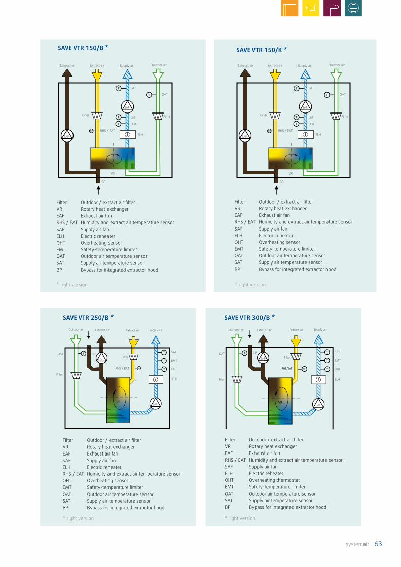
systemair 63
Filter Outdoor / extract air filterVR Rotary heat exchangerEAF Exhaust air fanRHS / EAT Humidity and extract air temperature sensorSAF Supply air fanELH Electric reheaterOHT Overheating sensorEMT Safety-temperature limiterOAT Outdoor air temperature sensorSAT Supply air temperature sensorBP Bypass for integrated extractor hood
VR
BP
EAF
Filter Filter
OAT
SAT
EMT
OHT
RHS / EAT
SAF
ELHRH/T
Extract airExhaust air Outdoor airSupply air
SAVE VTR 150/K *
* right version
Filter Outdoor / extract air filterVR Rotary heat exchangerEAF Exhaust air fanSAF Supply air fanELH Electric reheaterRHS / EAT Humidity and extract air temperature sensorOHT Overheating sensorEMT Safety-temperature limiterOAT Outdoor air temperature sensorSAT Supply air temperature sensorBP Bypass for integrated extractor hood
VR
BP
Filter
OATFilter
SAT
OHT
EMTEAF
SAF
ELH
RHS / EAT RH/T
Extract airExhaust airOutdoor air Supply air
SAVE VTR 250/B *
Filter Outdoor / extract air filterVR Rotary heat exchangerEAF Exhaust air fanRHS / EAT Humidity and extract air temperature sensorSAF Supply air fanELH Electric reheaterOHT Overheating thermostatEMT Safety-temperature limiter OAT Outdoor air temperature sensorSAT Supply air temperature sensorBP Bypass for integrated extractor hood
RH/TRHS/EAT
Filter
OAT
ELH
OHT
EMT
SAT
Filter
SAF
EAF
BP
Extract airExhaust airOutdoor air Supply air
SAVE VTR 300/B *
SAVE VTR 150/B *
VR
BP
EAF
Filter Filter
OAT
SAT
EMT
OHT
RHS / EAT
SAF
ELHRH/T
Extract airExhaust air Outdoor airSupply air
Filter Outdoor / extract air filterVR Rotary heat exchangerEAF Exhaust air fanRHS / EAT Humidity and extract air temperature sensorSAF Supply air fanELH Electric reheaterOHT Overheating sensorEMT Safety-temperature limiterOAT Outdoor air temperature sensorSAT Supply air temperature sensorBP Bypass for integrated extractor hood
* right version
* right version * right version

64 systemair
Filter Outdoor / extract air filterHE Counter flow heat exchangerEAF Exhaust air fanRHS / EAT Humidity and extract air temperature sensorSAF Supply air fan SAT Supply air temperature sensorOAT Outdoor air temperature sensorDB Outdoor air / Supply air bypass
EATOAT
Filter FilterRHS/EAT
DB
HE
SAT
EAFSAFRH/T
Extract air Exhaust airOutdoor air Supply air
SAVE VTC 300 *
Filter Outdoor / extract air filterHE Counter flow heat exchangerEAF Exhaust air fanRHS / EAT Humidity and extract air temperature sensorSAF Supply air fan SAT Supply air temperature sensorOAT Outdoor air temperature sensorDB Outdoor air / Supply air bypass
EATOAT
FilterDB
SAT
Filter
EAF SAF
RHS / EAT RH/T
Extract airExhaust air Outdoor air Supply air
SAVE VTC 200 *
Filter Outdoor / extract air filterVR Rotary heat exchangerEAF Exhaust air fanRHS / EAT Humidity and extract air temperature sensorSAF Supply air fanELH Electric reheaterSAT Supply air temperature sensorOAT Outdoor air temperature sensorEMT Safety-temperature limiter OHT Overheating sensor
RH/T
Filter
OAT
ELH
OHT
EMT
SAT
RHS/EAT
Filter
SAF
EAF
Extract airExhaust airOutdoor air Supply air
SAVE VTR 500 * SAVE VTR 700
Filter Outdoor / extract air filterVR Rotary heat exchangerEAF Exhaust air fanRHS / EAT Humidity and extract air temperature sensorSAF Supply air fanSAT Supply air temperature sensorOAT Outdoor air temperature sensor
RH/T
SAFVR
Filter
OAT SAT
RHS/EAT
FilterEAF
Extract airExhaust airOutdoor air Supply air
* right version
* right version * right version
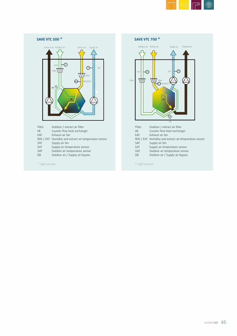
systemair 65
* right version
Filter Outdoor / extract air filterHE Counter flow heat exchangerEAF Exhaust air fanRHS / EAT Humidity and extract air temperature sensorSAF Supply air fan SAT Supply air temperature sensorOAT Outdoor air temperature sensorDB Outdoor air / Supply air bypass
RH/T
OAT SAT
EAFSAFFilter FilterRHS/EAT
DB
Extract air Exhaust airOutdoor air Supply air
SAVE VTC 700 *
* right version
* right version
Filter Outdoor / extract air filterHE Counter flow heat exchangerEAF Exhaust air fanRHS / EAT Humidity and extract air temperature sensorSAF Supply air fan SAT Supply air temperature sensorOAT Outdoor air temperature sensorDB Outdoor air / Supply air bypass
SAVE VTC 500 *
* right version
RH/T
Exhaust air Outdoor air Extract air Supply air
Filter
EAF SAF
Filter
RHS/EAT
OATSAT
HE

66 systemair
Premium 2 Base attachm., 10 mArticel no. 26430
Basic configuration
This consists of the central vacuum cleaner, a pipe kit (selection of three sizes) and the Premium 2 hose kit with a 2-level on/off switch on the handle.The Premium 2 hose kit is a complete package with 10 m
Villavent® central vacuum cleaner system
The Villavent® V20/V30 central vacuum cleaner is a pow-erful and low noise device. The central unit is connected with the suction sockets via a low voltage control line and is activated by this control line. The dust container is locat-ed in the lower section of the unit. The dust is collected in a filter bag. To optimise the dust collection, our vacuum cleaners are equipped with safety filters and filter barriers.
The exhaust air of the vacuum cleaner is preferably discharged outside, so that fine particulate matter is not blown back into the building. The resulting underpressure must be compensated for by air leakage in the building or by outdoor air openings.
So that airtight buildings do not have to do without a cen-tral vacuum cleaner, the vacuum cleaner can be equipped with a HEPA filter. An exhaust air line then becomes unnec-essary. The HEPA filter filters fine particulate matter from the air and needs to be replaced regularly. If a SAVE ventilation unit is installed in the building, the two units can communicate with each other via a control line. The ventilation system reduces the extract air volume during vacuum cleaning to automatically maintain a bal-ance in the building.
• No need to lug around heavy vacuum-cleaning equipment
• High suction power and low noise
• Simple and flexible installation
• Simple to operate and maintain
• One connection socket on each storey
• Robust plastic housing
Features of the central vacuum cleaner system – characteristics and advantages at a glance
Preassembled pipe kit for installation.
flexible hose, 1 m telescopic pipe, standard floor nozzle, parquet nozzle, 3 in 1 combi-brush and wall holder. The central vacuum cleaner is switched on or off via the switch on the handle. Other accessories are available.
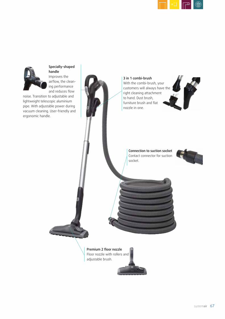
systemair 67
Specially-shaped handleImproves the airflow, the clean-ing performance and reduces flow
noise. Transition to adjustable and lightweight telescopic aluminium pipe. With adjustable power during vacuum cleaning. User-friendly and ergonomic handle.
3 in 1 combi-brushWith the combi-brush, your customers will always have the right cleaning attachment to hand. Dust brush, furniture brush and flat nozzle in one.
Premium 2 floor nozzleFloor nozzle with rollers and adjustable brush.
Connection to suction socketContact connector for suction socket.

68 systemair
V30 Articel no. 12548Rated power (max.) 1650 WMotor cooling AmbientVoltage 230 V (50 Hz)Control circuit 24 VSuction power 620 WCurrent 6.5 AFuse (slow blow) 10 ASuction (max.) 2880 mmWsAirflow 57 l/sSound pressure level LpA (1 m) 67 dB(A)Vacuum unit container 31 lVacuum cleaner bag 23 l, single useWeight approx. 7.9 kgMax. pipe length* approx. 30 mPipe diameter Ø 50.8 mm (2”)Cable length ~2.5 m cable (with plug)
Contents pipe kit 1 socket 2 sockets 3 socketsItem No. 3734 3735 3736Angle 90° for connection to suction socket 1 pc. 2 pcs. 3 pcs. Pipe bend 90° (one rotatable pipe bend in each kit) 3 pcs. 7 pcs. 10 pcs. Pipe bend 45° for connection to pipe system 2 pcs. 4 pcs. 6 pcs. Y-piece 45° for connection to pipe system 1 pc. 1 pc. 1 pc. Y-piece 90° for connection to pipe system - - 1 pc. Pipe socket 4 pcs. 6 pcs. 8 pcs. Pipe bracket 3 pcs. 5 pcs. 6 pcs. Socket (wall-mounted component) 1 pc. 1 pc. 1 pc. Mounting frame for vacuum sockets (building shell) 1 pc. 2 pcs. 3 pcs. Cover plate for vacuum sockets (building protection) 1 pc. 2 pcs. 3 pcs. Low voltage cable 24 V 10 m 17 m 30 mMounting material (packaging) 1 1 1Glue (bottle) 100 ml 100 ml 100 mlPipe, length 1.15 m 6 pcs. 10 pcs. 14 pcs. Assembly instructions 1 pc. 1 pc. 1 pc.
* Pipe length between the unit and the furthest socket, including the exhaust air hose. The exhaust air hose should not exceed a length of 10 m. The max. pipe length was determined using a hose kit with a length of 10 m.
Technical data
Dimensions

systemair 69
Description Name Item No.
Suction socket with mounting frame and protective cover. White plastic.
SDO8485
Sweep inlet valve with LED lighting. White plastic. ZSS SSD79230
Exhaust silencer ZS SD3744
Exhaust air wall-grille ZS ASG3745
HEPA filter HEPA filter V20 /V3012549
Parquet nozzle with rollers and brush for hard floors. Premium 2 parquet nozzle30156
Floor nozzle with rollers and adjustable brushes.Premium 2 floor nozzle30660
Turbo nozzle with rotating brush for carpets.Premium 2 turbo nozzle39605
Combi-brush with integrated dust brush, furniture brush and flat nozzle.
Premium 2 3-in-1 combi-brush30748
Adapter round to ovalPremium 2 adapter30779
Basket for accessoriesBasket313881
Ashcan Ashcan12320
Filter bag Filter bag12552
Accessories

70
Flexible and individual: the type of ventilation, the structural situation on-site, materials, design and much more – duct systems from Systemair adapt to require-ments.
Duct systems

71
Duct systems Dimensions Volumetric flow per line
Description
Plastic duct SystemairTube F DN 50, 80 DN 63, 80DN 75, 89DN 90, 110
15 m3/h20 m3/h 30 m3/h 45 m3/h
flexible and airtight without additional sealing, quick to install thanks to simple "click" system Page 74
SystemairISO+ (supplementary)
DN 160DN 200
the ideal combination of thermal and acoustic insulation, used as connection between ventilation unit and exterior wall (outdoor and exhaust air), and in unheated areas
Page 81
Metal duct Flat duct 136 mm x 59 mm215 mm x 59 mm
80 m3/h140 m3/h
oval, made from galvanised sheet steel or stainless steel, fixation and sealing using cold-shrink tape
Page 83
Folded spiral seam duct with zoom pipe
DN 100 DN 125 DN 160 DN 200DN 250
85 m3/h130 m3/h220 m3/h340 m3/h530 m3/h
round, with rubber lip seals, pipe length ad-justable without cutting which saves time during installation Page 88
Flow-related and acoustic considerations must be ana-lysed before selecting a duct system. Furthermore, the routing of the ducts must be agreed withthe other trades and adapted to the situation on the construction site early on. The next step: as soon as the volumes which need to be transported by the ventilation system are known, the ducts can be designed – calculat-ing the quantity of air required according to DIN 1946-6. A maximum speed of 3 m/s is recommended in the main duct. This avoids high pressure losses and unnecessary noise.
But how can ventilation concepts be generated without a great deal of work? The answer: with Airplan from Syste-mair. Create ventilation concepts easily and in accordance with DIN 1946-6. Airplan comes up with suggestions for appropriate overall product solutions.
• Safe and economical air distribution in the building
• Configuration (selection and design) depending on individual specifications
• Galvanised sheet steel, stainless steel or plastic
• Round or oval design
• Extremely robust and dimensionally stable
• Easy to clean
• Also available as a pipe kit
Flexible duct systems – characteristics and advantages at a glance
Circumstances alter, prerequisites do not remain the same, sudden changes represent new challenges – it's good that systems from Systemair can handle every situation. This applies to round and oval metal ducts, as well as our plastic pipe systems Systemair Tube F and ISO+. Hygiene is also an important consideration: the inside surfaces of the ducts are smooth, making them conducive to airflow and easy to clean.
Which is the best type of duct for your plans?

72
Supply air
Exhaust air
Outdoor air
Extract air
Choosing the right duct: so the air can flowWorking in harmony like a perfectly coordinated organism – ventilation systems from Sys-temair can be configured individually for each house and therefore for every requirement. Because every organism is unique in its own way. The ventilation ducts work like veins, distributing and transporting. Of central importance: correct installation and appropriate use, enabling the air to circulate without problems.
Duct for every situation: Tube F Able to handle any challenge. Tube F are suitable for every installation and mounting scenario – quickly and easily thanks to their "click" system. For installation in floors, filigree slab ceilings, prefabricated ceilings or sus-pended ceilings, for new builds and renovation projects, for residential and commercial buildings. Always stable and safe to tread on. Tube F adapts flexibly to on-site circumstances during installation.
Extremely robust: metal duct and pipesFlat ducts and folded spiral seam ducts always retain their shape – thanks to galvanised sheet steel. This ensures enormous robustness, especially when being installed in floor screed. Tough and durable, suitable for high tem-peratures, space-saving in installation on or below raw concrete ceilings.
Airplan is your plan: Find the right ventilation concept in just a few min-utes! It's easy with Airplan, the free software tool:
• Volume calculation according to DIN 1946-6• Calculation of unit dimensions• Specification and compilation of the duct system,
including silencers and diffusers
Find out more at www.systemair.de
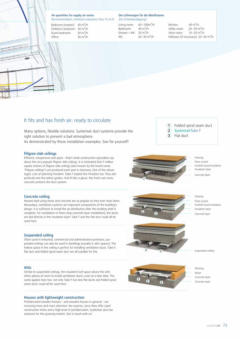
73
Suspended ceiling
Bedroom (master): 40 m³/hChildren’s bedroom: 30 m³/hGuest bedroom: 30 m³/hOffice: 30 m³/h
Living room: 60 – 100m³/h Bathroom: 40 m³/hShower + WC: 30 m³/hWC: 20 – 30 m³/h
Kitchen: 40 m³/hUtility room: 20 – 30 m³/hStore room: 10 – 20 m³/hHallways (if necessary): 20 – 40 m³/h
Die Luftmengen für die Ablufträume (für Schnellauslegung)
Air quantities for supply air roomsRecommendation: minimum volumetric flow 15 m3/h
It fits and has fresh air: ready to circulate
Many options, flexible solutions. Systemair duct systems provide the right solution to prevent a bad atmosphere. As demonstrated by these installation examples. See for yourself!
Filigree slab ceilings Efficient, inexpensive and quick – that's what construction specialists say about the very popular filigree slab ceilings. It is estimated that 4 million square metres of filigree slab ceilings (also known by the brand name "Filigran ceilings") are produced each year in Germany. One of the advan-tages: Lots of planning freedom. Tube F exploit this freedom too. They slot perfectly into the lattice girders. And fit like a glove: the fresh cast insitu concrete protects the duct system.
Concrete ceiling Houses built using stone and concrete are as popular as they ever have been. Nowadays, ventilation systems are important components of the building's design. It is sufficient to install the air distribution after the building shell is complete. For installation in floors (top concrete layer installation), the ducts are laid directly in the insulation layer. Tube F and the flat duct could all be used here.
Suspended ceiling Often used in industrial, commercial and administrative premises, sus-pended ceilings can also be used in dwellings (usually in attic spaces). The hollow space in the ceiling is perfect for installing ventilation ducts. Tube F, flat duct and folded spiral seam duct are all suitable for this.
Attic Similar to suspended ceilings, the insulated roof space above the attic offers plenty of room to install ventilation ducts, even at a later date. The same applies here too: not only Tube F but also flat ducts and folded spiral seam ducts could all be used here.
Houses with lightweight constructionPrefabricated wooden houses – and wooden houses in general – are receiving more and more attention. No surprise, since they offer rapid construction times and a high level of prefabrication. Systemair also has solutions for this growing market. Get in touch with us!
123
SystemairTube FFolded spiral seam duct
Flat duct
Flooring
Floor screedFootfall sound insulation
Insulation layer
Concrete layer
Flooring
Beam
Concrete layer
Concrete layer
Flooring
Floor screedFootfall sound insulationInsulation layer
Concrete layer
23
132
2
42 3 32

74
(Pa/
m)
(m³/h)
0
5
10
15
20
25DN50 [mm]
DN63 [mm]
DN75 [mm]
DN90 [mm]
0 5 10 15 20 25 30 35 40 45 50
SystemairTube F
DN 50 DN 63 DN 75 DN 90Flow rate in m³/h approx.:
2 m/s 2,5 m/s 3 m/s 2m/s 2,5 m/s 3 m/s 2m/s 2,5 m/s 3 m/s 2m/s 2,5 m/s 3 m/s
1 pipe10 m³/h 12,5 m³/h 15 m³/h 15 m³/h 20 m³/h 25 m³/h 22 m³/h 28 m³/h 34 m³/h 34 m³/h 42 m³/h 51 m³/h
2 pipes20 m³/h 25 m³/h 30 m³/h 30 m³/h 40 m³/h 50 m³/h 44 m³/h 56 m³/h 68 m³/h 68 m³/h 84 m³/h 102 m³/h
3 pipes30 m³/h 37,5 m³/h 45 m³/h 45 m³/h 60 m³/h 75 m³/h - - - - - -
Pipe
leng
th (m
)
2 m/s 2,5 m/s 3 m/s 2 m/s 2,5 m/s 3 m/s 2 m/s 2,5 m/s 3 m/s 2 m/s 2,5 m/s 3 m/s2 7,6 10,0 12,6 4,0 5,6 8,4 2,6 4,0 6,0 2,6 4,0 5,44 15,2 20,0 25,2 8,0 11,2 16,8 5,2 8,0 12,0 5,2 8,0 10,86 22,8 30,0 37,8 12,0 16,8 25,2 7,8 12,0 18,0 7,8 12,0 16,28 30,4 40,0 50,4 16,0 22,4 33,6 10,4 16,0 24,0 10,4 16,0 21,610 38,0 50,0 63,0 20,0 28,0 42,0 13,0 20,0 30,0 13,0 20,0 27,012 45,6 60,0 - 24,0 33,6 50,4 15,6 24,0 36,0 15,6 24,0 32,414 53,2 - - 28,0 39,2 58,8 18,2 28,0 42,0 18,2 28,0 37,816 60,8 - - 32,0 44,8 - 20,8 32,0 48,0 20,8 32,0 43,218 - - - 36,0 50,4 - 23,4 36,0 54,0 23,4 36,0 48,6
Pressure loss
Pressure loss
Economical, safe, hygienic and easy: Systemair Tube F is absolutely airtight – nothing gets out and nothing gets in. Thanks to the small pipe diameter and the 'click' system, the Tube F system can be laid quickly, compactly and flex-ibly. Good for the environment and good for the user: The pipe is manufactured from physiologically and toxicologi-cally safe plastic with no recycled materials. This ensures that the pipe is not only odour-neutral, but halogen and emission free.
Tightness class D according to DIN EN 12237 (highest tightness class of the standard).
• Material: PE without recycled material
• Operating temperature: -20 °C to +60 °C
• Ring stiffness: 8 kN/m²
• Fire protection class: DIN EN 13501-1
Features of SystemairTube F – characteristics and advantages at a glance
Air pipe Outside ⌀ [mm]
Inside ⌀ [mm]
Max. internalcorrugation [mm]
Bending radius [m]
DN 50 51 41 0.4 0.15DN 63 64 54 0.5 0.15DN 75 76 64 0.6 0.15DN 90 91 78 0.7 0.15

75
Tube F FR Tube F RV
Tube F BSTube F RS
Tube F VC-C
Duct cutter RS for Tube F DUCT.
Plastic pipe connection for connecting Tube F pipes. Incl. 2 sealing rings.
Flexible plastic duct in 50m coil.
Galvanised sheet steel angle bracket. For bending Tube F pipes. Supplied with cable ties.
Diverter from Tube F connections to ceiling valve. Supplied with end covers. Plastic.
Tube F BS Item no. DN A90° 79869 DN 63 / 75 /90 153
DN 63 DN 75 DN 90
Tube F VC-C 3x63/125/230 2x75/125/230 1x90/125/230 2x90/125/230Item no. 146606 146607 146608 146609A 223 189 106 226B 3x DN63 2x DN75 1x DN90 2x DN90C 229 271 278 278D 94 94 121 121
*can be cut to length as required
Tube F DUCT Item no. DN50 159965 DN 5063 159966 DN 6375 159967 DN 7590 159968 DN 90
Tube F CON Item no. DN ⌀ d mm ⌀ D mm50 146602 DN 50 52 5963 146603 DN 63 65 7275 146604 DN 75 77 8490 146605 DN 90 92 100
Tube F RS Artikel-Nr. DN50/63 198964 DN 50/6375/90 198965 DN 75/90

76
Tube F VC-W-P
Diverter from Tube F connections to wall valve.Internal wall dimension min. 80 mm. Socket length 13 mm. Not suitable for installation in the floor.
Extension socket for plastic diverter. Can be cut to length as required.
Tube F extension socket
DN 63 DN 75
Tube F VC-W-P 3x63/125/13 2x75/125/13Item no. 146610 146611A 189 223B DN63 DN75Connections 3x DN 63 + 1x DN 125 2x DN 75 + 1x DN 125
Tube F EXT Item no. Socket length230 146612 248
248
131
129
Tube F VC-W-M
Transition from Tube F connections to wall valve.Internal wall dimension min. 70mm.
Artikel 162391
Artikel 162391
Tube F VC-W-M Item no. DN Valve connection2x63/125-90 162391 DN 63 DN 1253x63/125-90 238100 DN 63 DN 125
Artikel 238100
Artikel 238100

77
28
130 70
DN125
DN63
29570
255
48
Artikel 162392
Transition from Tube F connections to wall valve
Tube F US-W-M Item no. DN Valve connection3x63/125-Z 162392 DN 63 DN 125
Tube F TRANS
Asymmetric adapters for transition from DN 125 to plastic Tube F connections. Rubber seals and end covers includ-ed.
Plastic horizontal distributor for Tube F pipe systems. For distributing supply air or extract air. Protective and end covers included.
Tube F DH
Tube F DH 12x63/DN125 12x63/DN160 8x75/DN160Item no. 146617 146619 146620A 380 380 446B 223 223 189C 3xDN63 3xDN63 2xDN75D 1xDN125 DN160 DN160
80
45
D
A
A
CB
Tube F TRANS Item no. ConnectionsDN 125/3x63 146614 3x DN 63 + 1x DN 125DN 125/2x75 146615 2x DN 75 + 1x DN 125DN 125/1x90 146616 1x DN 90 + 1x DN 125
DN 63 DN 75 DN 9012xDN 63/160 8xDN 75/16012x63/DN125

78
Tube F DHD 18x63/DN160 12x75/DN160 6x90/DN160Item no. 146627 146628 146629A 708 794 800B 223 189 104C 380 466 478D 430 430 430Connections 18x DN 63 + 1x DN160 12x DN 75+ 1x DN 160 6x DN 90 + 1x DN 160
DN 160
Tube F DH 9xDN63 / Syst. 151Item no. 146630Connections 9 x DN 63 + 1x DN 151
430
803x
DN63
223
380
413
207
50
DN 63
155
44
80
A
Tube F DV
Vertical distributor made of sheet steel. Galvanised and powder-coated.
Tube F DV Item no. DN A (mm) B (mm)15xDN63/160 199086 DN63/160 563 20018xDN63/160 199087 DN63/160 674 20010xDN75/160 199088 DN75/160 563 24412xDN75/160 199089 DN75/160 674 2445xDN90/160 199091 DN90/160 563 2506xDN90/160 199090 DN90/160 674 250
Item no. 199086 to 199091 Item no. 162389 to 162390
Tube F DV Item no. DN A (mm) B (mm)15xDN63/125 162389 DN63/125 400 13015xDN63/160 162390 DN63/160 400 130
Tube F DH

79
Grey plastic. For connecting the rising mains to the distrib-utor, with turn-click system. Also fits for connection to the ISO+ grille or GEO. The socket is supplied with a protective cover.
Tube F socket
Tube F socket Item no. ⌀DSocket 125 146633 125Socket 160 146634 160Socket 180 146635 180
⌀125 ⌀160 ⌀180
Grey plastic. For airtight closing of distributor openings, with turn-click system.
Tube F End cover
Tube F End cover Item no. DNDN 200 146632 200
Tube F RED
Plastic transition piece for adapting DN 63 to DN 50,for installation in Tube F diverters and distributors.
Tube F RED Item no.63-50 mm 146613
Tube F Mounting frame DN125/129
Tube F Mounting frame Item no. DN HeightDN125 162369 125 / 129 65 mm

80
Connections Code*
3x Ø 63 mm 6*
2x Ø 75 mm 7*
1x Ø 90 mm 9*
2x Ø 90 mm 2*
Sealing cover D*
Coupling piece K*
Oval connection, syst. 151 W*
Socket Ø 125 mm 2
Socket Ø 160 mm 6
Socket Ø 180 mm 8
Sealing cover Ø 200 mm D
Adapter, asymmetrical / Ø 125 mm H*
Adapter, 90° / Ø 125 mm V*
* not available singly!
Order reference example
Small distributor Tube F HV4: D 7W6D . D2Large distributor Tube F HV6: B 66D79K . 6DDD + V
Part 1: Installation: Floor B Ceiling D
Part 2: Side connections: 3x Ø 63 mm = 6 2x Ø 75 mm = 7 1x Ø 90 mm = 9 2x Ø 90 mm = 2 Cover = D Coupling = K Oval connection = W
Part 3: Upper/lower connections: Ø 125 = 2 Ø 160 = 6 Ø 180 = 8 Cover Ø 200 = D
Part 4: Supply line from the side: Vertical = V Horizontal = H
Max. air volume⌀ 63 = 20 m³/h⌀ 75 = 30 m³/h⌀ 90 = 45 m³/hDistributor = 360 m³/h
Order referenceThe variable distributor connections can be laid as desired. Some things must be selected very carefully when putting together the order reference. This is comprised of four parts and the codes in the table shown on the right.
Part 1 Floor installation or ceiling installation – especially important for connections 2x DN 75 (Code 7),1x DN90 (Code 9) and 2x DN 90 (Code 2). These nominal connection diameters extend beyond the distributor height. Therefore offset connection is possible. For ceiling installation - offset downwards and for floor installation - offset upwards. → Select B or D
Part 2 Then the desired side connections are specified (possible codes: 6, 7, 9, 2, D, K, W according to table on the right) for the sides (No.1-4 or 1-6 according to figure above). The sequence on the distributor is numbered as shown in the figure above. The installation situation of the distributor must be considered when deciding upon locations. Then a point is placed in the order number.
Part 3 Then the position and nominal size of the supply line to the distributor and the sealing cover(s) must be specified. (Possible codes: 2, 6, 8, D) Small distributors each have one connection point on the upper and lower sides: (A and B). The large distributors each have 2 connection points on the upper and lower sides (A, B and C, D acc. above figure). The sockets and sealing covers (possible codes: 2, 6, 8, D) can be exchanged without problems.
Part 4 If, in addition, the distributor is to have an adapter on one of the side connections, the type of adapter must be stated (Code H or V). This is located in the order number after the "+". Therefore the coupling piece (Code K) is absolutely essential for Part 2. Otherwise, the order number will end already before the "+".
Small distributor Large distributor
Tube F variable distributor
1
2 3
4B
A
1 6
5
23 4
C
B
A
D

81
5
4
3
2
1
00 50 100 150 200 250 300 350
Pa/
m
m³/h
DN160 DN200
SystemairISO+
Pressure loss
• Sound-absorbing and thermally insulated
• The two nominal diameters DN 125 / 180 plus associated transition pieces make the system easy to work with.
• Easier to install: the robust PE external sheath gives the pipe stability. Thanks to its integrated insulation, additional work to insulate the pipe is unnecessary.
• Fully recyclable
Features of SystemairISO+ – characteristics and advantages at a glance
Robust, noise absorbing pipe, preferably for use in unheated areas. Excellent acoustic properties thanks to the combination of a hard, ribbed external sheath with enclosed air chambers and foam insulation on the interior. Sagging of the pipe is considerably reduced thanks to the robust PE external sheath. Quicker to install due to the small number of fixation points. Fully insulated, making installation easier since additional work to insulate the pipe is unnecessary.
ISO+ pipe
ISO+ pipe Item No. Outer ⌀ Inner ⌀ LengthDN 160-125 314887 160 125 2 mDN 200-180 314888 200 170 2 m
Robust, noise absorbing pipe, preferably for use in un-heated areas. High-density polyethylene (HDPE) external sheath; polyolefin inner sheath with closed cell structure. Thermal conductivity: 0.040 W/mK at 40 °CFire protection class: external sheath B2, inner pipe B1

82
ISO+ C ISO+ SK
ISO+ B90 ISO+ B45
ISO+ C Item No. Outer ⌀ Outer 1-⌀160-160 314881 160 (167) 163200-200 314882 200 (206) 202
Flexible EPDM rubber connection sleeve.
ISO+ R, asymmetrical
ISO+ R Item No. Outer ⌀ Outer 1-⌀ Outer 2-⌀160-125A 314884 160 (163) 167 125 (121)
Asymmetrical transition to Spiro. Material: EPDM rubber
ISO+ R, symmetrical
ISO+ R Item No. Outer ⌀ Outer 1-⌀ Outer 2-⌀160-125 314883 160 (160) 167 125 (121)200-180 314886 200 (202) 206 180 (176)200-160 314885 200 (202) 206 150/160 (146)
Symmetrical transition to Spiro. Material: EPDM rubber
ISO+ SK Item No. for Spiro pipe60-165 312510 160S60-215 312511 200
Hose clamp for fixing the rubber sleeve to the Spiro pipe.
ISO+ bend 90° Item No. Outer ⌀ Inner ⌀B90/160-125 314879 160 125 incl. one
connectorB90/200-180 314880 200 170
ISO+ bend 45° Item No. Outer ⌀ Inner ⌀B45/160-125 314877 160 125 incl. one
connectorB45/200-180 314878 200 170
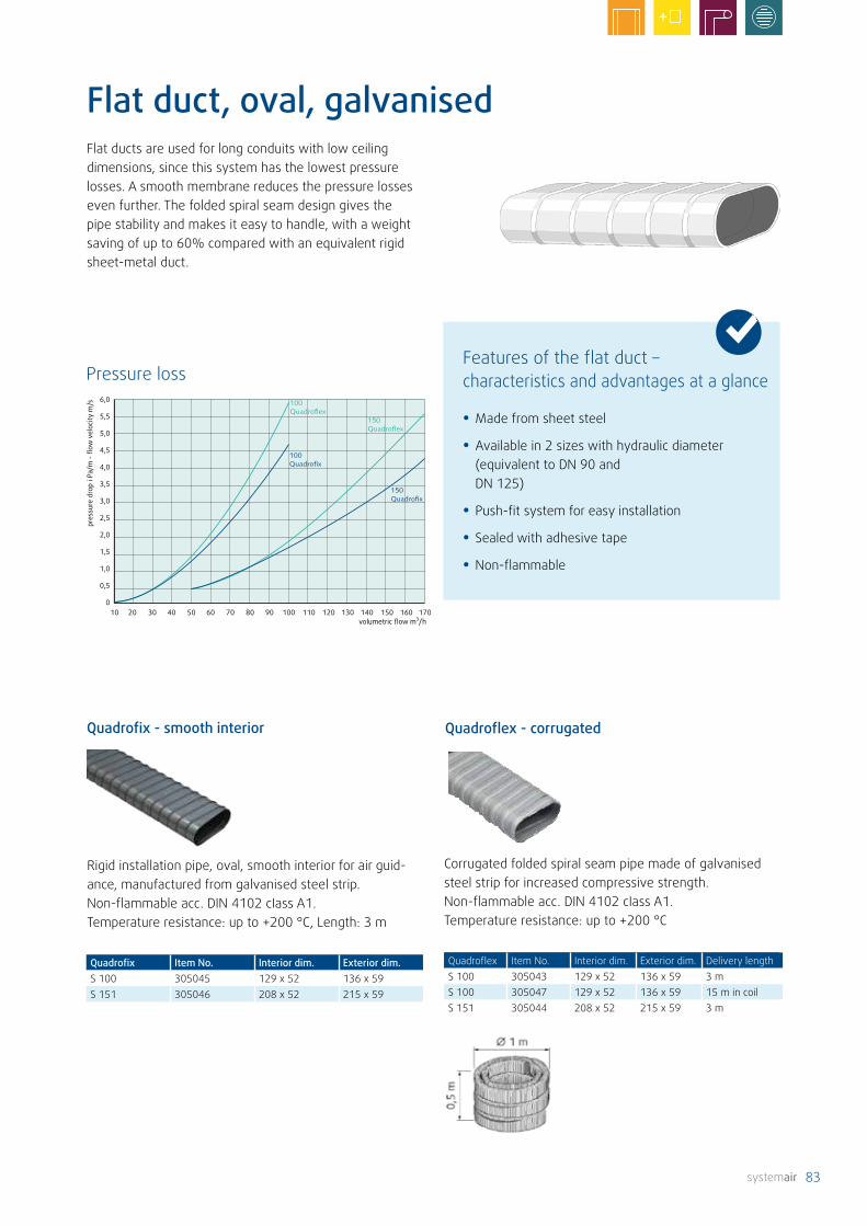
83
Quadroflex Artikel-Nr. Innenmaß Außenmaß LieferlängeS 100 305043 129 x 52 136 x 59 3 mS 100 305047 129 x 52 136 x 59 15 m im BundS 151 305044 208 x 52 215 x 59 3 m
volumetric flow m³/h
pres
sure
dro
p i P
a/m
- fl
ow v
eloc
ity m
/s 6,0
5,5
5,0
4,5
4,0
3,5
3,0
2,5
2,0
1,5
1,0
0,5
010 20 30 40 50 60 70 80 90 100 110 120 130 140 150 160 170
Rigid installation pipe, oval, smooth interior for air guid-ance, manufactured from galvanised steel strip. Non-flammable acc. DIN 4102 cIass A1. Temperature resistance: up to +200 °C, Length: 3 m
Quadrofix Item No. Interior dim. Exterior dim.S 100 305045 129 x 52 136 x 59S 151 305046 208 x 52 215 x 59
Quadrofix - smooth interior
Corrugated folded spiral seam pipe made of galvanised steel strip for increased compressive strength. Non-flammable acc. DIN 4102 cIass A1. Temperature resistance: up to +200 °C
Quadroflex - corrugated
Quadroflex Item No. Interior dim. Exterior dim. Delivery lengthS 100 305043 129 x 52 136 x 59 3 mS 100 305047 129 x 52 136 x 59 15 m in coilS 151 305044 208 x 52 215 x 59 3 m
Flat duct, oval, galvanisedFlat ducts are used for long conduits with low ceiling dimensions, since this system has the lowest pressure losses. A smooth membrane reduces the pressure losses even further. The folded spiral seam design gives the pipe stability and makes it easy to handle, with a weight saving of up to 60% compared with an equivalent rigid sheet-metal duct.
Pressure loss
• Made from sheet steel
• Available in 2 sizes with hydraulic diameter (equivalent to DN 90 and DN 125)
• Push-fit system for easy installation
• Sealed with adhesive tape
• Non-flammable
Features of the flat duct – characteristics and advantages at a glance
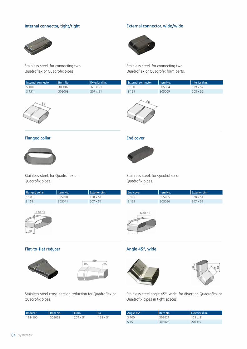
84
Stainless steel angle 45°, wide, for diverting Quadroflex or Quadrofix pipes in tight spaces.
Angle 45°, wide
Angle 45° Item No. Exterior dim.S 100 305027 128 x 51S 151 305028 207 x 51
Stainless steel, for Quadroflex or Quadrofix pipes.
Flanged collar Item No. Exterior dim.S 100 305010 128 x 51S 151 305011 207 x 51
Flanged collar
Stainless steel, for connecting two Quadroflex or Quadrofix pipes.
Internal connector, tight/tight
Internal connector Item No. Exterior dim.S 100 305007 128 x 51S 151 305008 207 x 51
Stainless steel, for connecting two Quadroflex or Quadrofix form parts.
External connector, wide/wide
External connector Item No. Interior dim.S 100 305064 129 x 52S 151 305009 208 x 52
End cover Item No. Exterior dim.S 100 305055 128 x 51S 151 305056 207 x 51
Stainless steel, for Quadroflex or Quadrofix pipes.
End cover
Reducer Item No. From To151-100 305022 207 x 51 128 x 51
Stainless steel cross-section reduction for Quadroflex or Quadrofix pipes.
Flat-to-flat reducer

85
Stainless steel angle 45°, flat, for diverting Quadroflex or Quadrofix pipes in tight spaces.
Angle 45°, flat
Angle 45° Item No. Exterior dim.S 100 305029 128 x 51S 151 305030 207 x 51
Angle 90° Item No. Exterior dim.S 100 305033 128 x 51S 151 305034 207 x 51
Stainless steel angle 90° in three segments, flat, for diverting Quadroflex or Quadrofix pipes.
Angle 90°, flat
Angle 90° Item No. Exterior dim.S 100 305031 128 x 51S 151 305032 207 x 51
Angle 90°, wide
Stainless steel angle 90° in three segments, wide, for diverting Quadroflex or Quadrofix pipes.
Transition Item No. from toS 100 305018 ø99 128x51S 151 315246 ø124 207x51S 151 305019 ø149 207x51
Symmetrical stainless steel transition piece for adapting oval pipe ends to round cross sections.
Transition round to flat

86
Angle diverter 90° for connecting disc valves. Suitable for wall installation. Material: stainless steel
Angle diverter
Angle diverter Item No. H100/DN 100 303052 185.5100/DN 125 303053 210.5
Branch piece, outlet S 151
Branch piece Item No.DN 150/151 305017DN 200/151 303177
Branch piece 90° with one connection socket for Quadrof-lex or Quadrofix pipe system 151. Material: stainless steel
Stainless steel branch piece 90° with three connection sockets for Quadroflex or Quadrofix pipes. Outlet on wide side.
Branch piece Item No. Duct Outlet L151-100 305016 207 x 51 128 x 51 220151-151 305048 207 x 51 207 x 51 240
External dimensions
Branch piece 90°, wide
Stainless steel branch piece 90° with three connection sockets for Quadroflex or Quadrofix pipes. Outlet on flat side.
Branch piece Item No. Duct Outlet L100-100 305013 128 x 51 128 x 51 300100-151 305014 128 x 51 207 x 51 360151-100 305015 207 x 51 128 x 51 300151-151 305040 207 x 51 207 x 51 360
External dimensions
Branch piece 90°, flat
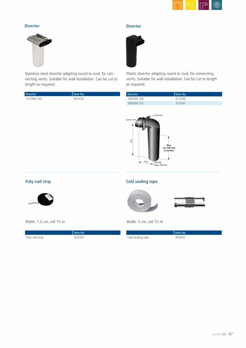
87
Poly-nail strip Cold sealing tape
Width: 1.5 cm, roll 15 m Width: 5 cm, roll 15 m
Plastic diverter adapting round to oval, for connecting vents. Suitable for wall installation. Can be cut to length as required.
Diverter Item No.100/DN 100 311240100/DN 125 311241
Diverter
Stainless steel diverter adapting round to oval, for con-necting vents. Suitable for wall installation. Can be cut to length as required.
Diverter
Diverter Item No.151/DN 150 305426
Item No.Poly-nail strip 302361
Item No.Cold sealing tape 305001
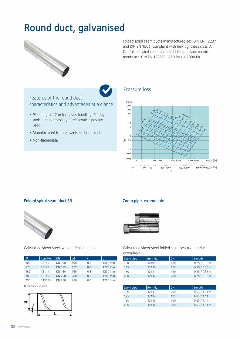
88
0.02
0.05
0.1
0.5
1
5
10
50
100
200
[l/s]
[Pa/m]
∆pt
5 10 50 100 500 1000 5000 10000 50000
q[m3/h]10 50 100 500 1000 5000 10000 50000 100000
2
34
5
10
15
20
ød [mm]
v [m
/s]
6380
100
125
160
200
250
315
400
500
630
800
1000
1250
Round duct, galvanisedFolded spiral seam ducts manufactured acc. DIN EN 12237 and DIN EN 1506, compliant with leak tightness class D.Our folded spiral seam ducts fulfil the pressure require-ments acc. DIN EN 12237: - 750 Pa / + 2000 Pa.
• Pipe length 1.2 m for easier handling. Cutting tools are unnecessary if telescopic pipes are used.
• Manufactured from galvanised sheet steel
• Non-flammable
Features of the round duct – characteristics and advantages at a glance
SR Item No. DN ød t L100 12142 DN 100 100 0.6 1200 mm125 12143 DN 125 125 0.6 1200 mm160 12144 DN 160 160 0.6 1200 mm200 12145 DN 200 200 0.6 1200 mm250 313563 DN 250 250 0.6 1200 mm
Dimensions in mm.
Folded spiral seam duct SR
Galvanised sheet steel, with stiffening beads.
Zoom pipe Item No. DN Length100 12109 100 0.25 / 0.36 m125 12110 125 0.25 / 0.36 m160 12111 160 0.25 / 0.36 m200 12112 200 0.25 / 0.36 m
Zoom pipe, extendable
Galvanised sheet steel folded spiral seam zoom duct, extendable.
Pressure loss
Zoom pipe Item No. DN Length100 12113 100 0.63 / 1.14 m125 12114 125 0.63 / 1.14 m160 12115 160 0.63 / 1.14 m200 12116 200 0.63 / 1.14 m

89
UIS
ød
L
L1
B
H
DC
ød1
L
L
rm
rm = 1,0xd1
ød1
L
Lrm
UIS Item No.DN 100 12121DN 125 12122DN 160 12123DN 200 12124
DC Item No. ød L L1 H BDN 125 12178 125 610 315 63 210DN 160 12179 160 647 315 80 300
Galvanised sheet steel duct cross with socket on both ends.
Compressed alu-flex pipe, socket on both ends.Length 230 mm, extendable length 1 m.
B 90° Item No. ød1 LDN 100 12085 100 100DN 125 12086 125 125DN 160 12087 160 160DN 180 309618 180 200DN 200 12088 200 242DN 250 313565 250 242
Bend 90°
Galvanised sheet steel, with rubber lip seal on both ends.
B 45° Item No. ød1 LDN 100 12089 100 41DN 125 12090 125 52DN 160 12091 160 66DN 200 12092 200 83DN 250 313564 250 120
Bend 45°
Galvanised sheet steel, with rubber lip seal on both ends.

90
R R
⌀d2
⌀d1
L
T Item No. ød1 ød3 H LDN 100 12069 100 125 95 215DN 125 12067 125 100 75 180DN 125 12073 125 160 75 200DN 160 12065 160 100 92 180DN 160 12064 160 125 92 180DN 160 305485 160 150 100 260DN 200 12074 200 100 112 200DN 200 12075 200 125 112 250DN 200 12072 200 160 112 250DN 250 37257 200 250 165 385DN 250 37258 250 160 150 256DN 250 37259 250 200 150 306
T-piece
T Item No. ød1 ød3 H LDN 100 12068 100 100 60 180DN 125 12070 125 125 75 200DN 160 12063 160 160 92 250DN 200 12071 200 200 112 305
Galvanised sheet steel T-piece, with rubber lip seal on the connections.
T-piece with reduced outlet / duct cross-section.
R Item No. ød1 ød2 LDN 125/100 79806 125 100 27DN 150/100 79807 150 100 41DN 200/150 79808 200 150 37DN 250/150 79809 250 150 62DN 315/250 79812 315 250 50
Galvanised sheet steel reducer, with rubber lip seal on both ends.
R Item No. ød1 ød2 LDN 100/80 12080 100 80 61DN 125/100 12081 125 100 64DN 160/100 12079 160 100 83DN 160/125 12078 160 125 71DN 160/150 6233 160 150 59DN 180/125 309621 180 125 85DN 180/160 309816 180 160 66DN 200/125 12082 200 125 90DN 200/160 12077 200 160 73DN 200/180 309817 200 180 63
Galvanised sheet steel reducer, one end with socket and one end with rubber lip seal.
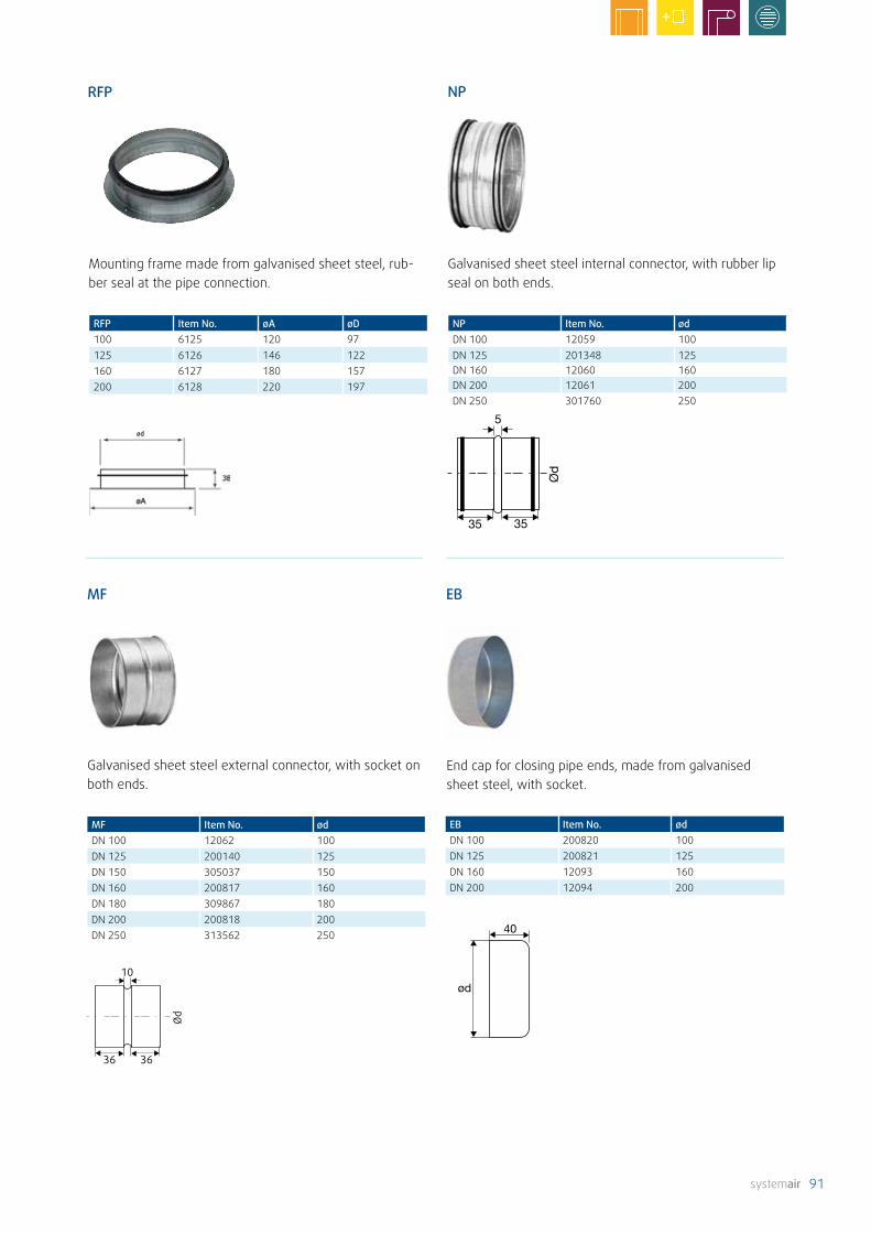
91
RFP
35 35
5
NP
ød
36 36
10
MF
ød
40
EB
RFP Item No. øA øD100 6125 120 97125 6126 146 122160 6127 180 157200 6128 220 197
Mounting frame made from galvanised sheet steel, rub-ber seal at the pipe connection.
NP Item No. ødDN 100 12059 100DN 125 201348 125DN 160 12060 160DN 200 12061 200DN 250 301760 250
Galvanised sheet steel internal connector, with rubber lip seal on both ends.
MF Item No. ødDN 100 12062 100DN 125 200140 125DN 150 305037 150DN 160 200817 160DN 180 309867 180DN 200 200818 200DN 250 313562 250
Galvanised sheet steel external connector, with socket on both ends.
EB Item No. ødDN 100 200820 100DN 125 200821 125DN 160 12093 160DN 200 12094 200
End cap for closing pipe ends, made from galvanised sheet steel, with socket.

92
DIS
Filter
FGR-I
Insulation hose used for insulating outdoor and exhaust air pipes, as well as to avoid formation of condensation in air ducts in unheated areas.
DIS Item No. InsulationDN 100 84789 25 mmDN 125 85034 25 mmDN 160 87546 25 mmDN 200 87547 25 mmDN 250 87620 25 mm
DN 100 87548 50 mmDN 125 87549 50 mmDN 160 87562 50 mmDN 200 87563 50 mmDN 250 87621 50 mm
The insulated FGR-I filter cassette is equipped with a standard G3 fleece filter mat. The housing and the connec-tion sockets are made from galvanised sheet steel with 13 mm insulation. The cover can be closed with snap fasten-ers. The connection sockets have a rubber lip seal. Spare PFR-type filters are available as accessories. The insulated filter cassettes are used, for example, as supply air filters for industrial and factory halls, as pre-filters for ventilation systems or as extract air filters for tumble dryers. The rec-ommended final pressure loss is 170 Pa.
FGR-I Item No. Fleece filter mat* Filter class125 37064 PFR 100-160 G3160 37065 PFR 100-160 G3200 37066 PFR 200-250 G3250 37316 PFR 200-250 G3
*included
FGR-I** ø A B C D E*125 125 156 190 241 213.5 190160 160 156 190 241 213.5 190200 200 156 215 320 308.5 280250 247 156 206 320 305 280
*space requirement for filter change**insulated
Pressure loss
Item No.PE insulation hose 305630
PE soft-foam insulation hose with 4 mm insulation for DN 160 or System 151. Length 10 m.
PE insulation hose
Polypropylene adhesive tape
Width: 5 cm, roll 10 m, material: polypropylene.
Self-tapping screws Item No.100 pieces/kit 312227500 pieces/kit 312228
Galvanised, self tapping.
Self-tapping screws

93

94
LF SCD
Silencers
Flexible connection silencer with a perforated aluminium flex pipe on the inside and a plastic cover on the outside. Mineral wool noise insulation with a thickness of 25 mm. One end has a connection sleeve, the other end has a valve connection fitting including a membrane for con-nection to the moisture barrier. Length: 800 mm
LF Item No. Connection Insertion losses in dB Octave centre frequency in Hz
Socket 125 250 500 1k 2k 4k 8k tot100 12436 ⌀100 8 14 22 30 25 10 8 15125 12533 ⌀125 6 12 22 28 25 11 9 14
SCD Item No. Insulation D (mm) L (m) Mid-frequency range, Hz63 125 250 500 1000 2000 4000 8000 Tot (dB)
100 2555 25 mm 100 1 15.9 22.9 31.1 38.6 36.4 40.6 50.1 35.9 39125 2556 25 mm 125 1 11.7 18.9 32.4 29.9 28.8 34.5 40.9 24.5 32160 2558 25 mm 160 1 19.3 25.4 30.5 27.1 23.8 32.2 27.8 17.3 28200 2560 25 mm 200 1 10.7 12.1 28.7 22.8 22.8 30.6 19.4 11.9 26250 2561 25 mm 250 1 12.9 18.7 24.3 19.5 19.9 27.7 12.9 10.2 22100 84330 50 mm 100 1 4.3 8.5 15.5 28.2 50.8 51 57.8 38.5 30125 84331 50 mm 125 1 17.7 26.3 35.4 29.2 33.3 45.4 40.5 26.5 35160 84332 50 mm 160 1 16.5 24.1 30.6 27.5 29.6 41.7 28.7 18.1 32200 84333 50 mm 200 1 6.5 6.3 21.1 27.1 30.5 35.8 19.4 12.3 29250 87545 50 mm 250 1 12,9 18,7 24,3 19,5 19,9 27,7 12,9 10,2 22
Acoustic insulation (dB)
Flexible pipe silencer with standardised connections (socket-nipple). Noise insulation values are shown in the following table. The internal pipe consists of a closed, non-woven internal hose (washable) and a 25 or 50 mm thick acoustic and thermal insulation layer. To ensure effective noise insulation, the silencer should be installed either directly ahead of or directly after the fan or a bend. Thanks to its flexibility, it can also be used as a bend.
Technical dataInternal pipe Non-woven mattingInsulation 25 or 50 mm mineral wool/fleeceExternal sheath Glass-fibre-reinforced aluminium laminate Connection Socket on one side, nipple on the otherConnection material Galvanised sheet steelFire resistance class Bs1 (EN13501-1)Temperature range °C -30 to +140Working pressure Pa max. 2000Airspeed m/s max. 10Length m 1.0 (without socket or nipple)

95
360
System 100
60
500 58,5
IRS
d
s
Flexible aluminium flat duct silencer for noise reduction. Absorption material: mineral-fibre-freeNon-flammable acc. DIN 4102 cIass A2. Temperature resistant from -60 °C to +60 °C.
System Item No. Length Interior dim. Exterior dim. Connection100 305012 500 129 x 52 202 x 117 128 x 51
Flat duct silencer
Rigid, mineral-fibre-free silencer for use with the Quadro System 100. Non-flammable acc. DIN 4102 cIass B1. Temperature resistant up to +60 °C.
System Item No. Length Connection Insertion losses in dB Octave centre frequency in Hz
125 250 500 1k 2k 4k 8k
100 305036 500 128 x 51 9.2 10.2 20.4 21.1 15.2 9.4 4.8
Flat duct silencer
IRS Item No. d s Insertion losses in dB Octave centre frequency in Hz
125 250 500 1k 2k 4k 8k totDN 100 305049 102 50 14 12 8 7 7 11 18 8DN 125 305050 127 50 14 9 5 8 6 11 16 7DN 160 305051 162 50 14 9 8 7 7 14 17 8DN 200 305193 202 50 12 4 4 8 8 13 14 6
Internal pipe silencer, made from fire and mould-resistant foam, complying with the requirements of emissions class M1 (melamine resin). Can be used with full valve function, for acoustic insulation and pressure regulation.
Insertion losses in dB Octave centre frequency in Hz125 250 500 1k 2k 4k 8k tot8 10 18 46 50 44 38 19

96
E
øD
A
B
C
CVVX
ABS
⌀dr
90°
45°
L
AB 90°
20070
45°270
Dd
IGC-LI
r = ød
Combi-grille for separate guidance of outdoor and exhaust air. Manufactured from coated sheet steel Black: RAL 9005 White: RAL 9016
CVVX Item No.Black
Item No.White
A B C øD E
125 26421 26422 418 291 185 125 130160 25394 25396 470 362 215 160 130200 25395 25397 550 402 255 200 130250 8498 - 680 550 350 250 136
Outdoor and exhaust air grilles
Intake/discharge bend made from mirror-bright stainless steel, suitable for outdoor and exhaust air, angled with integrated protective grille.
ABS Item No. Connection150 305035 ø150200 313673 ø200
Galvanised sheet steel intake/discharge bend, suitable for outdoor and exhaust air, with integrated angled socket and protective grille.
AB Item No. ød L kg150 305041 150 250 2.9200 313674 200 300 4.7
Intake grille for installation indoors and outdoors. The grille is made of aluminium. The bird protection mesh behind the slats is made from rust-proof stainless steel.
IGC-LI Item No. ød øDIGC-LI 100 37357 100 131IGC-LI 125 37358 125 151IGC-LI 160 37359 160 188IGC-LI 200 37360 200 230IGC-LI 250 37361 250 278IGC-LI 315 37362 315 350
ød = connection diameterøD = external diameter

97
VK-SR
SDLAH-V2A
Outdoor/exhaust air grille for steel spiro-pipes, pow-der-coated. The pipe connection fits directly into pipes of diameters 160, 200 and 250 mm. Colour: Black
VK-SR Item No. A B C D E øF G160 312507 326 306 280 149 137 160 33°200 312508 326 306 280 149 137 200 33°
ISO+ external grille
ISO+ grille Item No. A B C D E* øF G125 312506 252 262 239 130 - 125 35°180 304635 252 262 239 130 41 180 35°
*E= on request
Intake/discharge grille made from powder-coated steel. The pipe connection fits directly into pipes of diameter 125 mm (ISO+ DN 160) or 180 mm (ISO+ DN 200)Colour: Black
Roof hood for outdoor and exhaust air. Roof pitch 6° to 60°. Other roof pitches available upon request. Available as a kit, including universal roof flash-ing, roof hood top element and base, in the colours red or black.
SDL Item No. Colour ød ød1 D L1 A B C D125 313335 Red 138 123 250 177 145 320 380 204160 313336 Red 178 158 268 212 180 360 420 260200 313337 Red 198 218 288 252 230 410 470 310
125 313338 Black 138 123 250 177 145 320 380 204160 313339 Black 178 158 268 212 180 360 420 260200 313340 Black 198 218 288 252 230 410 470 310
Stainless steel intake hood. Consisting of a slatted hood (supplied), a 1000 mm long pipe, two static brackets and an adapter for a DN 200 pipe connection. The intake should be situated at least 100 cm above the ground. The air intake hood is removable so that the filter inside can be cleaned or replaced.
AH-V2A Item No.Air intake, stainless steel; DN 200 305052Filter for air intake, G4, VPE = 2 pcs. 305053
Other diameters on request.

98
Systemair's diffusers are particularly quiet and work extremely effectively. This means air is transported without draughts, and a pleasant and comfortable indoor climate is guaranteed.
Diffusers
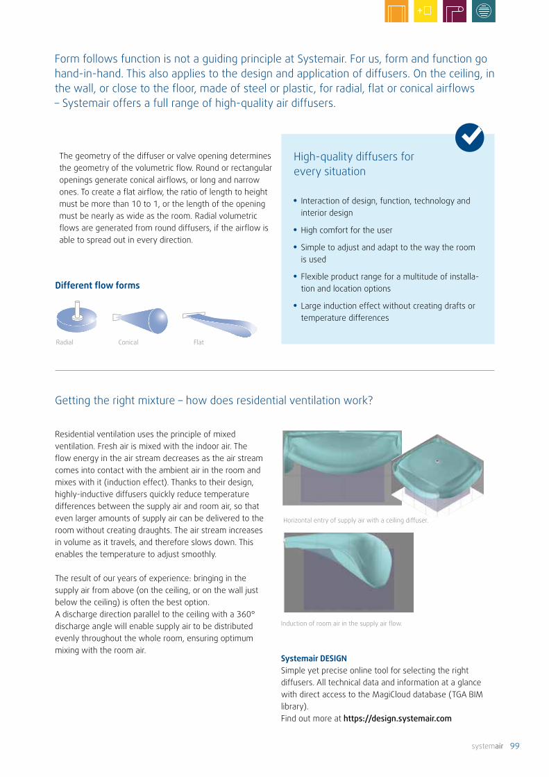
99
Radial Conical Flat
The geometry of the diffuser or valve opening determines the geometry of the volumetric flow. Round or rectangular openings generate conical airflows, or long and narrow ones. To create a flat airflow, the ratio of length to height must be more than 10 to 1, or the length of the opening must be nearly as wide as the room. Radial volumetric flows are generated from round diffusers, if the airflow is able to spread out in every direction.
Residential ventilation uses the principle of mixed ventilation. Fresh air is mixed with the indoor air. The flow energy in the air stream decreases as the air stream comes into contact with the ambient air in the room and mixes with it (induction effect). Thanks to their design, highly-inductive diffusers quickly reduce temperature differences between the supply air and room air, so that even larger amounts of supply air can be delivered to the room without creating draughts. The air stream increases in volume as it travels, and therefore slows down. This enables the temperature to adjust smoothly.
The result of our years of experience: bringing in the supply air from above (on the ceiling, or on the wall just below the ceiling) is often the best option. A discharge direction parallel to the ceiling with a 360° discharge angle will enable supply air to be distributed evenly throughout the whole room, ensuring optimum mixing with the room air.
Getting the right mixture – how does residential ventilation work?
• Interaction of design, function, technology and interior design
• High comfort for the user
• Simple to adjust and adapt to the way the room is used
• Flexible product range for a multitude of installa-tion and location options
• Large induction effect without creating drafts or temperature differences
High-quality diffusers for every situation
Different flow forms
Induction of room air in the supply air flow.
Form follows function is not a guiding principle at Systemair. For us, form and function go hand-in-hand. This also applies to the design and application of diffusers. On the ceiling, in the wall, or close to the floor, made of steel or plastic, for radial, flat or conical airflows – Systemair offers a full range of high-quality air diffusers.
Horizontal entry of supply air with a ceiling diffuser.
Systemair DESIGN Simple yet precise online tool for selecting the right diffusers. All technical data and information at a glance with direct access to the MagiCloud database (TGA BIM library). Find out more at https://design.systemair.com
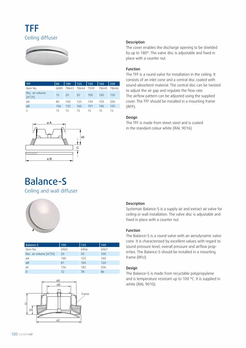
100
frame
TFFCeiling diffuser
Balance-S 100 125 160Item No. 6965 6966 6967Rec. air volume [m³/h] 20 50 100øA 100 125 160øB 81 104 120øC 156 182 206D 72 78 86
DescriptionThe cover enables the discharge opening to be shielded by up to 180°. The valve disc is adjustable and fixed in place with a counter nut.
FunctionThe TFF is a round valve for installation in the ceiling. It consists of an inlet cone and a central disc coated with sound-absorbent material. The central disc can be twisted to adjust the air gap and regulate the flow rate. The airflow pattern can be adjusted using the supplied cover. The TFF should be installed in a mounting frame (RFP).
DesignThe TFF is made from sheet steel and is coated in the standard colour white (RAL 9016).
TFF 80 100 125 150 160 200Item No. 6089 78643 78644 7509 78645 78646Rec. air volume [m³/h]
15 20 50 100 100 150
øA 80 100 125 149 159 200øB 106 135 160 191 196 195C 15 15 15 15 15 15
DescriptionSystemair Balance-S is a supply air and extract air valve for ceiling or wall installation. The valve disc is adjustable and fixed in place with a counter nut.
FunctionThe Balance-S is a round valve with an aerodynamic valve cone. It is characterised by excellent values with regard to sound pressure level, overall pressure and airflow prop-erties. The Balance-S should be installed in a mounting frame (RFU).
DesignThe Balance-S is made from recyclable polypropylene and is temperature resistant up to 100 °C. It is supplied in white (RAL 9010).
Balance-SCeiling and wall diffuser

101
frame
DescriptionBalance-E is a round extract air disc valve for ceiling or wall installation with an aerodynamic valve cone. The valve disc is fixed in place with a counter nut.
FunctionIt is characterised by excellent values with regard to sound pressure level, overall pressure and airflow properties. The Balance-E should be installed in a mounting frame (RFP).
DesignThe Balance-E is made from recyclable polypropylene and is temperature resistant up to 100 °C. The valve is supplied in white (RAL 9010).
DescriptionSystemair extract air valve EFF. Extract air disc valve for ceiling or wall installation. The valve disc is adjustable and fixed in place with a counter nut.
FunctionThe EFF is a extract air valve which can be used for all types of buildings. The EFF should be installed in a mount-ing frame (RFP).
DesignThe EFF is made from sheet steel and is coated in white (RAL9010).
Balance-E Item No. Rec. air volume [m³/h]
øA øB øC D
100 6961 20 100 70 142 61125 6962 50 125 87 160 61160 6963 100 160 118 195 57200 6964 150 200 167 240 64
EFF Item No. Rec. air volume [m³/h]
øA øB C
80 6145 15 80 106 15100 78619 20 100 135 15125 78638 50 125 160 15150 7490 100 149 191 15160 78639 100 159 196 15200 78642 150 200 238 18
Balance-ECeiling and wall diffuser
EFFCeiling and wall diffuser
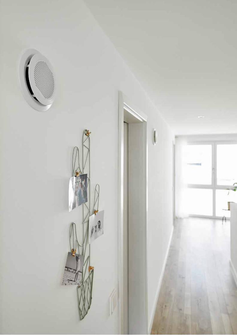
102

103
Wall installation Ceiling installation
Supply air
Grille open, disc closed Grille closed, disc in position 1 without shielding
Grille closed, disc in position 2 possible with or without shielding
Extract air
Grille open, disc in position 2 without shielding
Grille closed, disc in position 1 without shielding
Grille closed, disc in position 2 without shielding
Hmin. Hmax.
ØD2
ØD1
Borea settings
Deflectors can be used to partially close the disc opening in order to shield certain areas. The deflectors can be removed for use with extract air or for four-sided discharge.
DescriptionThe adjustable Borea valve can be used for supply air and extract air. The valve can be installed both in the ceiling and in the wall.
FunctionWhen used with supply air, sections of the outlet can be closed for focused air guidance.
DesignBorea is manufactured completely out of white polystyrene. It consists of a base unit, a closing disc and an adjustable front grille. This enables different throw patterns and trajectories to be set easily. It can be inserted directly in a DN125 pipe or a DN125 flanged collar.
Type Air volumeQv[m³/h]
Supply air Extract air
Grille open, disc closed, wall installation
without deflector with deflector Grille open, disc open
Grille closed, disc openGrille closed, disc open, ceiling installation
Position 1 Position 2 Position 2 Position 2 Position 1 Position 2
dp (Pa)Lw (dB(A))
dp (Pa)Lw (dB(A))
dp (Pa)Lw (dB(A))
dp (Pa)Lw (dB(A))
dp (Pa)Lw (dB(A))
dp (Pa)Lw (dB(A))
dp (Pa)Lw (dB(A))
Borea125
45 9 < 20 18 26 7 < 20 13 22 3 < 20 20 23 7 < 2060 17 < 20 30 31 13 21 20 27 5 < 20 37 33 13 2175 25 24 40 35 18 24 31 32 8 < 20 57 41 20 2590 36 31 56 39 25 28 43 36 11 20 80 46 27 29120 62 43 - - 40 36 70 43 19 28 - - 48 36150 - - - - 62 41 - - 28 34 - - 74 43
Dimensions
Item No. ØD1 ØD2 Hmin. Hmax.Borea 125 68872 119 165 12 24
Filter G4 DN125 137290
BoreaCeiling and wall diffuser
Deflectors

104
BOR-RBOR-S
*
DescriptionThe BOR supply air valve (wall installation) was especially developed for draught-free, low noise application in residential ventilation. It can also be used for ventilation applications in offices, conference rooms and hotel rooms. The special diffuser design prevents the airflow from falling into the inhabited area before the fresh air has reached a pleasant temperature and speed. The maximum ΔT is 10 K. BOR-R can also be used in VAV systems. The diffusers are equipped with a setting mechanism and differential pressure measurement points.
FunctionThe diffuser has an adjustable cover for setting the flow rate. This can be accessed from the outside and may save awkward disassembly of the diffuser. The cover can be fixed in 9 positions. All measurements were taken using these fixed positions. The test nipple must be closed after setting the desired flow rate using the measuring points. The performance data can be read from the graphs below.
DesignThe body of the BOR unit is made from galvanised sheet steel with a perforated, convex front plate. The front plate is coated in RAL 9010 as standard.
BOR-S/-R Item No.100* 26078125* 26079100 26076125 26077
*Filter BOR-S, VPE 10 pcs., Item No. 314449
Dimensions
BOR-S DN 100 100125 125
BOR-R DN100 100125 125
BOR-S / -RWall diffuser

105
Performance graphs
Throw distance

106
In larger rooms, several floor diffusers must be arranged.In smaller rooms a floor outlet is sufficient.
DescriptionPLUTO floor diffuser with perforated stainless steel front. Suitable for ventilating dwellings, hotel rooms or smaller offices. For ease of cleaning, the floor diffuser can be removed completely.
FunctionThe PLUTO floor diffuser has been specially developed for draught-free and low noise delivery of supply air into living and sleeping quarters. The floor diffuser is inserted in the FLEX+ or OVAL+ diverter.
DesignThe floor diffuser is made from galvanised steel, with a slightly convex, perforated, brushed stainless steel front plate and high-quality rubber seals.
AccessoriesIRS 125 for regulating air volume.
Dimensions
Item No.PLUTO 73377
PLUTOFloor diffuser

107
1
2
5
34
200
150
100
50
040 60 80 100 120 140 160 Pa
120
6045
3015
Δpt
m³/
h
1 Replaceable louvre grille2 Casing ring3 Support disc with sleeve and rubber ring4 Control unit5 Electrical connections
Acoustic propertiesLW dB(A)
70 Pa 100 Pa 130 Pa 160 PaAE 15/30 24 27 30 33AE 30/60 25 31 34 36AE 45/120 27 33 34 37
FunctionThe AE is an electrically-adjustable extract air valve for two flow rates (basic and demand-driven ventilation).It is ideal for ventilation of kitchens, bathrooms and toilets, and for central ventilation systems in residential buildings. The basic flow rate is increased to the demand-driven flow rate via a switch (switch provided on-site by the client). After 30 minutes, it switches back to the level "basic ventilation". The degree of protection is IP X1.
DesignMade from plastic in RAL 9010. Exchangeable front grille in different colours. Size DN 125. High-quality design with an aerodynamic form and low acoustic values.
InstallationFor direct installation in the wall, incl. mounting ring. An angle guide is needed if installed in the ceiling, which must be provided on-site by the client.
SettingsSystem setting / system calibration is not necessary for constant-pressure systems.
MaintenanceThe covering and optimum height of the intake ring avoid dirty edges. Simple to clean without risking changes to the air volumes.
• Two flow rates for basic and demand-driven ventilation, e.g. via switch (supplied by client)
• System setting / system calibration not necessary for constant-pressure systems
• Appealing design
• High-quality design with an aerodynamic form and low acoustic values
• Covering and optimum height of the intake ring avoid dirty edges
• Simple to clean without risking changes to the air volumes
AE Item No.15/30 3141230/60 3141345/120 31414
Filter G4 DN125 137290
AESelf-regulating extract air valve
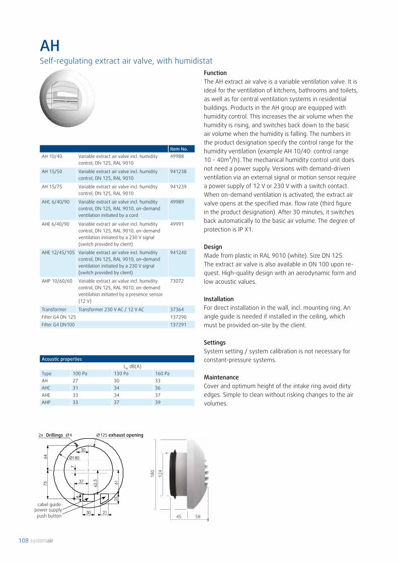
108
:
45 58
180
124
Item No.AH 10/40 Variable extract air valve incl. humidity
control, DN 125, RAL 901049988
AH 15/50 Variable extract air valve incl. humiditycontrol, DN 125, RAL 9010
941238
AH 15/75 Variable extract air valve incl. humiditycontrol, DN 125, RAL 9010
941239
AHC 6/40/90 Variable extract air valve incl. humidity control, DN 125, RAL 9010, on-demand ventilation initiated by a cord
49989
AHE 6/40/90 Variable extract air valve incl. humidity control, DN 125, RAL 9010, on-demandventilation initiated by a 230 V signal (switch provided by client)
49991
AHE 12/45/105 Variable extract air valve incl. humidity control, DN 125, RAL 9010, on-demandventilation initiated by a 230 V signal (switch provided by client)
941240
AHP 10/60/60 Variable extract air valve incl. humidity control, DN 125, RAL 9010, on-demand ventilation initiated by a presence sensor (12 V)
73072
Transformer Transformer 230 V AC / 12 V AC 37364Filter G4 DN 125 137290Filter G4 DN100 137291
FunctionThe AH extract air valve is a variable ventilation valve. It is ideal for the ventilation of kitchens, bathrooms and toilets,as well as for central ventilation systems in residential buildings. Products in the AH group are equipped with humidity control. This increases the air volume when the humidity is rising, and switches back down to the basic air volume when the humidity is falling. The numbers in the product designation specify the control range for the humidity ventilation (example AH 10/40: control range 10 - 40m³/h). The mechanical humidity control unit does not need a power supply. Versions with demand-driven ventilation via an external signal or motion sensor require a power supply of 12 V or 230 V with a switch contact. When on-demand ventilation is activated, the extract air valve opens at the specified max. flow rate (third figure in the product designation). After 30 minutes, it switches back automatically to the basic air volume. The degree of protection is IP X1.
DesignMade from plastic in RAL 9010 (white). Size DN 125. The extract air valve is also available in DN 100 upon re-quest. High-quality design with an aerodynamic form and low acoustic values.
InstallationFor direct installation in the wall, incl. mounting ring. An angle guide is needed if installed in the ceiling, which must be provided on-site by the client.
SettingsSystem setting / system calibration is not necessary for constant-pressure systems.
MaintenanceCover and optimum height of the intake ring avoid dirty edges. Simple to clean without risking changes to the air volumes.
AHSelf-regulating extract air valve, with humidistat
Acoustic propertiesLW dB(A)
Type 100 Pa 130 Pa 160 PaAH 27 30 33AHC 31 34 36AHE 33 34 37AHP 33 37 39
Drillings exhaust opening
cabel guidepower supplypush button

109

110
[ Hz ]
80
70
60
50
40
30
20
50 80 125
315
500
800
1250
2000
3150
5000
200
Referenz
[ dB
]
FAV
180
500*
Ø124
60 50
� 1
50
storm protection
80
*shortenabel on wall thickness
FAV
The FAV wall valve will impress you with its elegant design and outstanding sound-insulating properties. The function and air distribution offered by the newly- designed supply air valve is excellently suited to normal and high-level sound insulation requirements. All components needed for installation are supplied in a complete kit.
Applications / installation optionsFor installation in external walls as a fresh air supply valve – into single-family houses, office buildings and multilevel apartment blocks. The wall valve is particularly suitable for living rooms and bedrooms.
How it worksAn air extraction system removes stale air from the extract air rooms, such as the kitchen, bathroom, storage rooms and WC. The FAV filters the outdoor air and and distributes it proportionately between the living room, bedrooms and leisure rooms. Optimum efficiency can be achieved if the unit is installed in the upper wall region, next to a window, 2.0 to 2.2 m above a radiator. The storm protection limits the air supply to 30 m³/h, thus avoiding draughts.
Supply air valve
Acoustically-insulated wall spacer with storm protection
Outdoor air valve
Item No. ⌀ bore Max. flow rate with G3 standard filter
Acoustic value Dn,w* for wall thickness
Rw, R** Version / colour***
312214 124 mm 10 Pa 30 m³/h 400 mm / 48 dB500 mm / 51 dB
18 dB20 dB
White plasticInside: squareOutside: round
*Rated element standardised sound level difference Dn,w acc. DIN EN ISO 140-10 **Acoustic insulation value acc. DIN 4109 ***colour white: similar to RAL 9010
Dimensions in mm.
FAVSelf-regulating supply air valve, acoustically insulated

111
⌀D
�14
0
⌀A ⌀C
B150
The VTK regulates the flow rate depending on the tem-perature. This is achieved using a thermostat-bulb, which changes the valve opening depending on the outdoor temperature. As temperatures fall, the size of the opening is reduced, throttling the flow rate. The optional spacers can be used to ensure a minimum flow rate.The VTK comprises an external cowl, a course filter and the self-regulating extract air valve.
VTK 80 100 160Item No. 5657 5658 5659⌀A 80 95 157B 40 40 47⌀C 147 147 207⌀D 85 104 163
FAV outdoor grille FAV weather protection for outdoor grilles
FAV filter cartridge F7FAV fleece filter mat, G2
Item No. Colour312217 White, RAL 9010
Item No. Colour312216 White, RAL 9010
Item No.314279 Fleece filter mat, G2
Item No.312215 L = 94 mm, DN 80
VTKSelf-regulating extract air valve

112
spacers
volu
me
flow
m3 /
h
∆PT [Pa]
RDR Item No.80/15-50 (m³/h) 37293100/15-50 (m³/h) 37294100/50-100 (m³/h) 37295125/15-50 (m³/h) 37296125/50-100 (m³/h) 37297125/100-180 (m³/h) 37292150/50-100 (m³/h) 37309150/100-180 (m³/h) 37298
Volumetric flow LW dB(A)
(m³/h) 50Pa 100Pa 150Pa 200Pa
15 25 29 32 3530 26 31 35 3845 27 33 36 3960 32 37 39 4275 32 37 40 4290 32 38 41 44120 30 34 39 42150 33 37 41 45180 34 40 44 47210 34 40 42 44240 35 41 44 47270 37 43 45 49300 33 37 42 45
Test report: CETIAT 2315002 for volumetric flow RD Ø80 to RD Ø125 mm.
DescriptionRDR is a constant volumetric flow regulator which is in-stalled in round pipes to achieve a constant flow rate.
FunctionThe air is forced to flow through a predetermined space. Here the integrated flap can change its position, depend-ing on the specified airflow. The flap is attached by a calibrated spring, so it is not possible to make subsequent adjustments to the flow rate. No additional energy is required.
DesignThe RDR is made from plastic (fire resistance class M1). The regulator is grey and can be used for temperatures up to 60 °C.
InstallationThe volumetric flow regulator is installed directly in horizontal or vertical pipe systems. Airtight installation is ensured by a lip seal. The arrow on the housing shows the air direction. For supply air applications, the distance from duct branches or outlets must be at least 3x the pipe diameter.
RDRConstant volumetric flow regulator

113
SPI Item No. Ød C ØD80 7621 79 110 125100 6750 99 54 163125 6751 124 63 210150 6752 149 54 230160 6753 159 60 230200 6754 199 62 285250 6755 249 62 333300 6756 299 65 405315 6757 314 63 406400 6758 399 70 560500 7625 499 60 644630 7626 629 60 811800 6881 798 70 1015
DescriptionSPI is an iris diaphragm for measuring and adjusting airflow. It has the following properties: low noise lev-el, centrally-formed volumetric flow and test points for precise measurements. The iris diaphragm can be opened completely. This means that a service flap for cleaning is not necessary. Available in sizes 80 to 800 mm. Can be used up to a temperature of 70 °C.
DesignThe iris diaphragm is manufactured from galvanised sheet steel and has airtight rubber seals at the pipe connections. The unit is suitable for extract air applications.
InstallationThe SPI must be installed with defined minimum dis-tances from other duct components, to keep deviations in the flow rate as low as possible. No special distances are specified for reduction/increase of the pipe diameter to the next size. The SPI enables volumetric flow to be determined accurately at all locations – even those close to curved flow paths, e.g. T-pieces, bends and upstream of air outlets.
Minimum distancesAhead of bend - 1 x ØDAfter bend - 1 x ØDAhead of T-piece - 3 x ØDAfter T-piece - 1 x ØDBefore diffuser - 3 x ØD
SPIIris diaphragm

114 systemair
Genius air heating system
Ventilation, heating, cooling and hot water production – Geni-us is the compact central building services unit which can do everything.

systemair 115
Genius by name, genius by nature
Modern buildings need contemporary building servic-es. Genius from Systemair is the intelligent combined solution for energy-efficient single-family houses: heating, ventilation, cooling, heat recovery and hot water production.
Our controllable residential ventilation with integrat-ed heat recovery ensures a balanced indoor climate throughout the entire year. Ventilation is enhanced by a steplessly-controlled air-air-water heat pump, al-ways taking care that you have the right climate and temperature: providing pure air heating in winter and in summer – thanks to a reversible mode – cooling too.
Genius is a tour de force. The perfect description for a relatively small system which packs a surprising amount of power and per-formance.
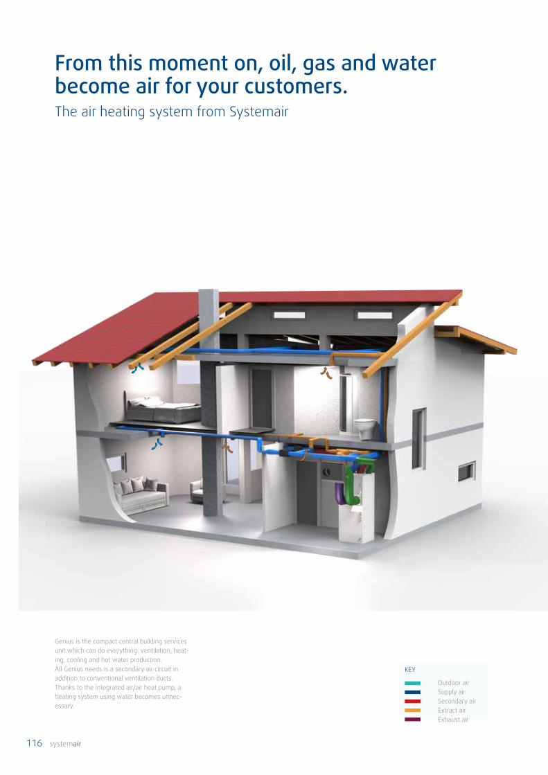
116 systemair
Genius is the compact central building services unit which can do everything: ventilation, heat-ing, cooling and hot water production. All Genius needs is a secondary air circuit in addition to conventional ventilation ducts. Thanks to the integrated air/air heat pump, a heating system using water becomes unnec-essary.
From this moment on, oil, gas and waterbecome air for your customers.The air heating system from Systemair
KEY
Outdoor air Supply air Secondary air Extract air Exhaust air
systemair 117
Nowadays, whoever erects a new building or renovates an old one in Germany must fulfil the requirements of the German Energy Conservation Regulation (EnEV). The result is often highly insulated, airtight building envelopes which require mechanical residential ventilation – for a healthy indoor climate and as little energy loss as possible. At the same time, thanks to today's improved standards for insulation, the heating energy required is less. For this reason, conventional heating systems are generally over-dimensioned for energy-efficient houses. This is why we developed Genius. A central building services unit which, with its integrated air-air heat pump is able to ventilate efficiently with heat recovery, and is also able to use the air for heating or cooling the rooms. But that's not all: thanks to an integrated air-water heat pump, even hot water production is included. That is to say, your custom-ers only need a single system. This saves a great deal of time in the planning phase, reduces investment costs and, what's more, needs less space. Convincing arguments for demanding customers. And promising prospects for you.
The idea of using air as a heat transfer medium and transporting it from room to room through ducts has been around a long time. However, until now it was com-mon for unpleasant smells and impurities to be transport-ed too. Thanks to Systemair's secondary air system, your customers will only experience pure air quality, because the extract air system remains completely untouched. This ensures that the transmission of odours or substanc-es is excluded. High-performance pollen and dust filters also clean the supply air.The result: the very best air quality and a pleasant indoor climate for your customers.
A bad atmosphere is a thing of the past with Genius
How does the air heating system work?
At the heart of the system is the Genius combi-unit. It continually supplies the living and sleeping quarters with fresh, clean air, and transports the extract air to the exterior, via the kitchen, bathroom and WC. A rotary heat exchanger removes the heat from the extract air and, if necessary, uses it to preheat the cool supply air. It also ensures that the air is not too dry. In summer, the princi-ple functions in reverse, so that the extract air cools the supply air and excessive indoor air humidity is removed.
Heating and cooling modes
The heating load is covered by an increase in the flow rate. Here a fan draws air from the living area via a separate duct system (secondary air). A steplessly-controlled air-air heat pump heats this depending on the requirements and conveys it to the living and sleeping quarters. In summer, the heat pump works in reverse so that the dwelling is cooled.
Hot water production
All Genius functions can be used individually or in parallel. This applies to hot water production as well. A 150 litre tank is integrated for storing the drinking water A heating rod is installed inside to ensure the system functions per-fectly, even if the outside temperatures are extremely low.

118 systemair
40
60
80
100
20
0air-water heat pumpas combination device
Genius gas calorific value
costs in percent
investment cost Operating costs per yearSystem comparison passive house 180 m² living space
!
One for all. All with air. Genius – the modern central building services unit
Genius from Systemair is the intelligent solution for energy-efficient single-family houses*. The compact unit combines controlled residential ventilation including heat recovery (up to 85%) with heating / cooling and hot wa-ter production. In combination with a photovoltaic system, it is even possible to realise a virtually self-sufficient and CO2 neutral system. And best of all: with Genius, you save much time in the planning phase, because Systemair will take on all the project engineering work for you.
Advantageous. For your customers and for you.
All the Genius functions are possible independently or in parallel – just as you need them. This means optimum utilisation of the required energy and conservation of resources. Additional electric heating is only necessary in exceptional situations, since Genius is equipped with modern and powerful heat pump technology. This makes
pleasant room temperatures possible, even on very cold days. If your customer still wants to have a wood-burning stove, or a tiled stove, there is nothing to stop them: the secondary air distributes the heat from the stove through-out the entire house. In summer, the steplessly-controlled heat pump works in reverse, actively cooling the ambient air. This way, your customer can enjoy an ideal indoor climate and the highest level of comfort throughout the whole year with just one system.
By the way: Genius can easily be operated via the inter-net. This means you and your customers have unlimited access, even from outside. Clever, don't you think?
Modern buildings require a ventilation system. So ex-penditure for this is unavoidable. However, with Genius you save by not having to install a separate distribu-tion system for the heating, which also results in lower maintenance costs. Furthermore, Genius is an absolute pioneer with regard to efficiency, making the operating costs comparable to or cheaper than for other systems.
Good for the environment and the budget
* KfW 40+ and KfW 40 max. 200m² living area · KfW 55 approx. 150m² living area, depending on the heating load

systemair 119
Outside air
Exhaust air
·
·
·
·
·
·
Hot water module
Rotary heat exchangerwith moisture recovery
The house is heated/cooled via the ventilation system's supply air ducts
Ventilation module
Heat pump module
With steplessly-controlled compressor for pre-cise adjustment
Reversible air-air/air-water heat pump for heat-ing/cooling/hot water
incl. control cabinet and150 l hot water tank
Hot water production parallel to heating and cooling oper-ation
Supply airExtract air
Secondary airOutdoor air

120 systemair
!
Increased comfort, decreased space requirement
Good to know
The individual Genius components for ventila-tion, the heat pump and hot water are installed in compact modules, which can simply be pushed into the housing or placed on top. This makes instal-lation and maintenance easier.
KEY
Genius Hot water tank Boiler Ventilation unit Underfloor heating
Conventional system Genius air heating system
Ventilation module – WRG
Heat pump module – WP
Hot water module – WW
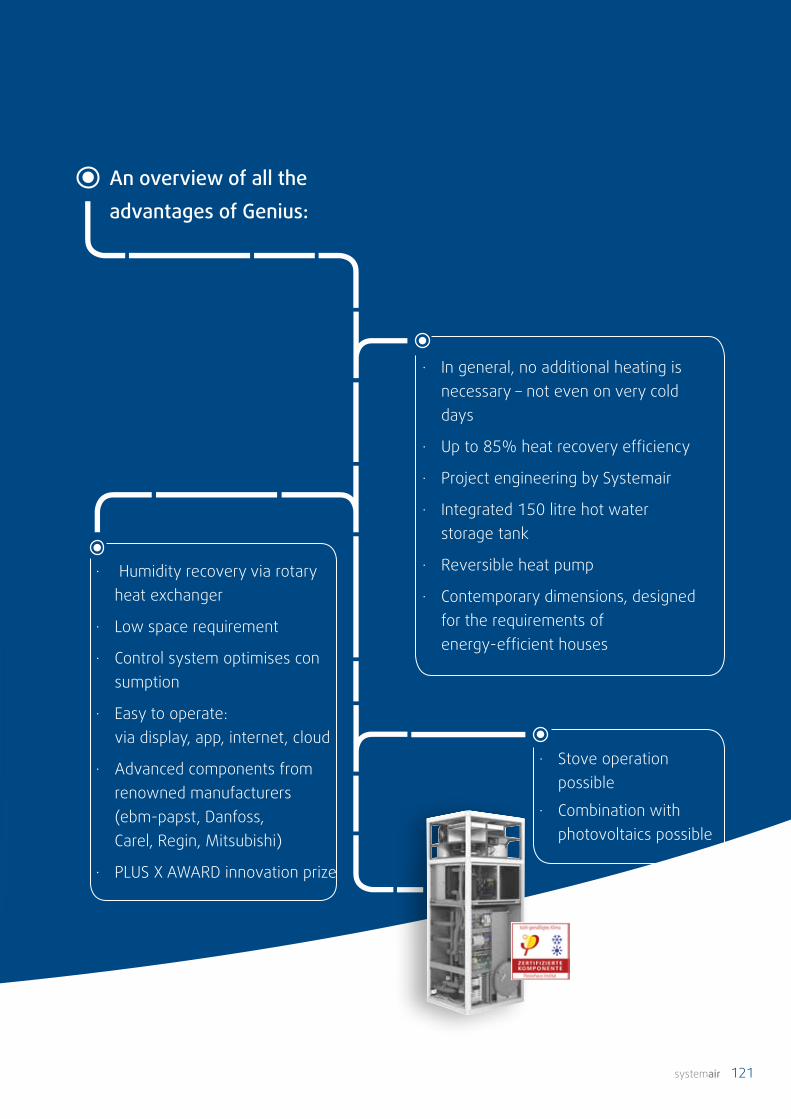
systemair 121
· Humidity recovery via rotary heat exchanger
· Low space requirement
· Control system optimises con sumption
· Easy to operate: via display, app, internet, cloud
· Advanced components from renowned manufacturers (ebm-papst, Danfoss, Carel, Regin, Mitsubishi)
· PLUS X AWARD innovation prize
An overview of all theadvantages of Genius:
· In general, no additional heating is necessary – not even on very cold days
· Up to 85% heat recovery efficiency
· Project engineering by Systemair
· Integrated 150 litre hot water storage tank
· Reversible heat pump
· Contemporary dimensions, designed for the requirements of energy-efficient houses
· Stove operation possible
· Combination with photovoltaics possible

122 systemair
Comfortable in all areas. Modules, control, functions
The functions in detail:
4 ventilation stages acc. DIN 1946/6: • Ventilation for moisture protection • Reduced ventilation • Nominal ventilation • Intensive ventilation • Additional option to switch off
Temperature control in winter: • Setpoint adjustment based on outside temperature • Temperature control of individual rooms • Fixed value • Setpoint = average setpoint temperatures for the room • Setpoint = Reference room setpoint
Temperature control in summer: • Setpoint adjustment based on outside temperature • Fixed value • Cooling can be deactivated
Stove operation
Legionella control program
Fast charging hot water
Emergency mode hot water
Emergency mode heating
Adjustment of maximum supply air temperature based on outdoor temperature, alternatively manually
Modern technology requires contemporary, convenient operation. We have designed Genius so that you and your customers can easily control the system with a PC and even using the internet: via the service level as a special-ist or via the user level as an end user. This enables you and your customers to have permanent access, even from outside, and an optimum overview of all functions and parameters. It is just as easy to control individual rooms via a display as it is to control the system via a control panel on the unit itself. The Systemair App allows you to operate the system using your smartphone.
Minimum supply air temperature
Time programs: • Ventilation/heating/cooling • Hot water: automatic, individual • Decrease mode: setpoint temperature, ventilation stage • Holiday mode
Filter monitoring
Passive night-time cooling, individually adjustable
Chart function: recording of conditions/parameters
Electric reheating elements (PTCs): • Temperature control of individual rooms • Emergency operation • Start delay • Can be switched off
Window contact function: as soon as a window is opened, e.g. in the bedroom, the heating for this room is interrupted (accessory shut-off valve required)
systemair 123

124 systemair
Thoroughly thought through. Genius in operation
Ventilation mode
The extract air is extracted via the kitchen, bathroom and WC. On its way outside, it flows through the rotary heat exchanger. At the same time, fresh air is drawn in from the outside and is also passed through the rotary heat exchanger. With each rotation of the heat exchanger, both supply air and extract air flow through the cells. In this way, heat from the extract air is transferred to the supply air. In summer, the principle functions in reverse, so that the cooler extract air cools down the warmer supply air.
As well as heat, the rotary heat exchanger also recovers humidity. This means that the atmospheric humidity is generally always within a comfortable range.
Heating mode
The heating load is covered by an increase in the flow rate. This requires a separate duct system. A fan, which is controlled in parallel to the heat pump, removes second-ary air from the living area. This is warmed by the heat pump and fed back into the living and sleeping quarters as supply air. The extract air system remains completely untouched, ensuring that contamination of the supply air is impossible. The heat pump only uses the residual ener-gy in the exhaust air, after heat recovery, as an additional heat source.
Living area
FS (ETS)
(EHS)
SF
EF RF
Heat
pum
p
Out
side
Heat
reco
very
uni
t
Secondary air
SS
Bath-room
WC Kit-chen
Living room
Sleeping area
R3
PTC RS
R6
PTC RS
R2
PTC RS
R5
PTC RS
R1
PTC RS
R1
PTC RS
Storage charging pump
B3
Living area
FS (ETS)
(EHS)
SF
EF RF
Heat
pum
p
Out
side
Heat
reco
very
uni
t
Secondary air
SS
WC Kit-chen
Living room
Sleeping area
R3
PTC RS
R6
PTC RS
R2
PTC RS
R5
PTC RS
R1
PTC RS
R1
PTC RS
Condenser
Storage charging pump
B3
Evap
orat
or
Bath-room

systemair 125
Cooling mode
The cooling mode works in the same way as the heating mode, except that the heat pump works in reverse. This means that the evaporator becomes the condenser and the condenser becomes the evaporator. The heat pump extracts heat from the dwelling, which is then dis-charged to the outside.
KEY
SF Supply air fanEF Extract air fan RF Secondary air fan FS Outdoor air sensor ETS Extract air sensor
SS Supply air sensorEHS Exhaust air sensor PTC Electric reheaterRS Room controller
Outdoor air Supply air Secondary air Extract air Exhaust air
Hot water production without heating or cooling demand
The ventilation functions as described in "Ventilation mode". If there is a demand for hot water, the compres-sor and the storage charging pump start. The residual energy of the extract air is used as in the heating mode. A plate heat exchanger is used: the hot gas of the refrig-eration circuit flows through the primary side and hot water flows through the secondary side.
Hot water production in parallel with heating
Hot gas flows continuously through the plate heat exchanger for hot water production. The heat transfer for hot water production takes place only via the charge pump. If heating is operating at the same time, the secondary air fan follows the heating demand. Now hot water production has priority, but the residual heat is used for heating.
Hot water production in parallel with cooling functions according to the same principle.
Living area
FS (ETS)
(EHS)
SF
EF RF
Heat
pum
p
Out
side
Heat
reco
very
uni
t
Secondary air
SS
WC Kit-chen
Living room
Sleeping area
R3
PTC RS
R6
PTC RS
R2
PTC RS
R5
PTC RS
R1
PTC RS
R1
PTC RS
Condenser
Storage charging pump
B3
Evap
orat
or
Bath-room
Living area
FS (ETS)
(EHS)
SF
EF RF
Heat
pum
p
Out
side
Heat
reco
very
uni
t
Secondary air
SS
WC Kit-chen
Living room
Sleeping area
R3
PTC RS
R6
PTC RS
R2
PTC RS
R5
PTC RS
R1
PTC RS
R1
PTC RS
Storage charging pump
B3
Evap
orat
or
Bath-room
Living area
FS (ETS)
(EHS)
SF
EF RF
Heat
pum
p
Out
side
Heat
reco
very
uni
t
Secondary air
SS
WC Kit-chen
Living room
Sleeping area
R3
PTC RS
R6
PTC RS
R2
PTC RS
R5
PTC RS
R1
PTC RS
R1
PTC RS
Storage charging pump
B3
Evap
orat
or
Condenser
Bath-room

126 systemair
Central building services unitItem No. Description
Genius combi unit 84349 All building services in a single unit.Functions: heating, ventilation, cooling, heat recovery and hot water production
Genius insulating base 315188 Noise decoupling for the unit, 90 x 90 mm, 4 pcs. requiredArgus-RS-CDO 2994 Room controller DN 125, connection via RS485 (Modbus or EXOline)Genius module PTC 312784 PTC electric reheaterCBM 160-2,1 5482 Electric reheater DN 160, only in conjunction with TG-K 360CBM 200-3,0 7593 Electric reheater DN 200, only in conjunction with TG-K 360TG-K 360 4846 Temperature sensor, in conjunction with CBM 160, 200Tune-R-125-3-M4 311968 Motorised shut-off valve, in conjunction with window contact.Filter F7, supply air 306380 Supply air filter for Genius central building services unit, filter class F7Filter G4, extract air 306346 Extract air filter for Genius central building services unit, filter class G4Filter G4, secondary air 306374 Secondary air filter for Genius central building services unit, filter class G4
Electrical dataVoltage V 230Frequency Hz 50Max. compressor power consumption W 1800Max. fan power consumption Ventilation module
W je 80
Max. fan power consumption Heat pump module
W 170
Storage charging pump power consumption W 6–28
VentilationAir volume (normal mode) m3/h 190Max. air volume heating/cooling (incl. secondary air)
m3/h 600
Heat recovery efficiency % bis 85Outdoor air filter grade F7Extract air filter grade G4Secondary air filter grade G4
Dimensions / weightsWidth mm 865Height mm 2070Depth mm 750Ventilation module weight kg 75Heat pump module weight kg 60Basic module/hot water unit weight kg 170Total weight when empty kg 305Total weight when full kg 460
Other informationRefrigerant R410ARefrigerant fill quantity kg 1,1Tank volume l 150Expansion tank l 6Hot water safety valve bar 6
ConnectionsCold water 1" AGHot water 1" AGCirculation 1" AGCondensate mm DN 40Safety valve 3/4" Outdoor air ventilation mm DN 160Outdoor air heat pump mm DN 250Extract air mm DN 160Supply air mm DN 200Secondary air mm DN 200Exhaust air ventilation/heat pump mm DN 250
Performance dataHeating capacity kW max. 6 *Cooling capacity kW max. 4 *Power PTC element W je 600 (100m³/h)Heating rod output, hot water kW 3
VentilationReference volumetric flow m3/h 195 195Temperature outdoor air °C 7 7Temperature extract air °C 20 20Temperature supply air °C 17,4 16,1
Spec. elec. power consumptionW/
(m3/h)0,38 0,38
Supply air side temperature ratio
% 79,6 78,5
Supply air sidehumidity ratio
% 50
HeatingTemperature outdoor air °C 7 2 -7Temperature extract air °C 20 20 20Heat pump performance % 40 50 50Volumetric flow secondary air % 80 100 100Heating capacity entire unit W 4400 4030 4030Heating capacity heat pump W 3630 3000 2640COP unit 3,58 2,98 3,26COP heat pump 3,02 2,22 2,13
Exceptional in every disciplineThe technical data
* these are maximum values. The application limits must be adhered to. The manufacturer must be consulted if the heating load is greater than 5 kW.

systemair 127
V1
V2V3
qVminqVref
qVd
0
50
100
150
200
250
300
350
0 50 100 150 200 250 300 350 400
Volumetric flow [m3/h]
qv2qv1
!
82
2
75
0
865
865
62
07
2
822
750
Certified:The Genius air handling unit is passive-house certified. It is suitable for all low-energy houses and passiv houses, as well as for other houses and apartments, in which energy should be saved.
Distinct design, concentrated powerDespite its many functions, Genius doesn't take up much space. What's more, the appealing design of the unit means it doesn't need to be hidden away in a special service room.
Volumetric flow/pressure diagram
Quality:Systemair is certified according to ISO 9001, ISO 14001 and ATEX. Our testing and de-velopment laboratories are among the most modern facilities in Europe; measurements are performed according to international standards such as AMCA and ISO.
Save energy, reduce operating costs!Our "Green Ventilation" label identifies all products which are particularly energy-effi-cient. All products with a "Green Ventilation" label unite economy with energy efficiency.
Prize-winning:Genius was awarded the Plus X Award in the categories Innovation, High Quality, Function-ality and Ecology.
Products you can rely on

128 systemair
"For years now we have been planning high-quality, airtight houses. They are excellently insulated with the best components and very low energy consump-tion. But due to the lack of alternatives for building services, until now we have always had to use expensive components which were mostly over-di-mensioned for the specific requirements, or which were, to a certain extent, unnecessary. The Genius combi-unit is exactly the alternative that we needed."
Sven Haustein, haalplatz architekten, Schwäbisch Hall, Germany

systemair 129
What is the difference between secondary air and recir-culating air? Recirculating air is extract air which is treated and then fed back (as a component of the supply air) to at least one room from which it was not originally taken. This means it is possible for odours and substances to be transmitted.In contrast, secondary air is removed from a supply air zone, fed through a separate duct system and, after treatment, is fed back into the same room. Therefore, it is impossible for it to mix with the extract air. This also applies to the Genius system. The only difference is that the secondary air is fed back into the entire supply system after treatment, instead of just one room.
For what buildings is Genius appropriate?The application limits are:KfW 40+ and KfW 40: max. 200 m2 living areaKfW 55: approx. 150m² living areadepending on the heating load.
What other basic requirements must be met?
· The supply air duct system must be insulated and de signed for the higher flow rates· A separate duct system is needed for the secondary air· Additional electric convectors or underfloor heating is recommended in bathrooms
Is the drinking water tank sufficient to supply a one-fam-ily household without additional electrical energy? With Genius, the hot water is produced on demand and is possible during all operating states, i.e. also during heat-ing and cooling. The drinking water tank holds 150 litres. Thanks to parallel operation and the heat pump perfor-mance, this is sufficient for a one-family household, even
with a high level of consumption. The additional electrical heating rod is only for the following functions: Legionella control program, fast charge, emergency operation and assistance when the outside temperature is extremely low.
Can Genius be operated in combination with a fireplace?
Yes, as long as the fireplace is installed independently of the indoor air. This is because when an indoor air-depend-ent fireplace is operated in parallel to a ventilation sys-tem, if an underpressure forms, it must be impossible for exhaust gases from the fireplace to enter the room. Here, safety measures are required which could result in the system being switched off. Since Genius also provides the entire heating function, any shutdown must be prevented. The heat from an indoor air-independent stove operated in parallel can be simply and evenly distributed through-out the whole house via the Genius secondary air duct system.
How can the temperature be regulated in individual rooms?With an air heating system, you can control the tempera-ture of individual rooms using the PTC reheating elements. Here the heat pump only supplies the temperature de-manded by the room controller configured as the "refer-ence" room (this is generally the bedroom). The temper-ature increase in the other rooms occurs on an individual basis, using the electric reheaters.
Often asked. Happily answered.Our customers' FAQs

130 systemair
Systems with heat recoveryfor apartment block
Important things should not be left to chance! Our airtight construction methods make ventilation an important consid-eration regarding protecting the building and the health of the inhabitants. There are various options for mechanical ventila-tion in apartment blocks which save energy, permit a pleasant living environment and, at the same time, ensure the value of the property is retained. Two systems with heat recovery are presented on the following pages.

systemair 131
Systems with heat recoveryfor apartment block
In an apartment block, a whole range of habits, inclinations, characters and needs always have to be accommodated. This is also demonstrated by the way people treat their living space. Many people do a lot right all by themselves, but others may need help – or to be relieved of responsibility altogether – e.g. for ventilation. Having said that, ventilation using windows can almost no longer be recommended. Our outdoor air today is not always what you would wish to have in your home. Ventilation systems offer the right conditions for high-quality filtering of the outdoor air.
Stuffy, stale air has always needed to be removed and replaced with fresh air. In the past this happened all by itself, but nowadays we need to make an effort to achieve good indoor air quality. Not everyone does this or is even conscious of the fact. The final result is often a "mouldy" apartment.
To prevent this from happening, and help investors and owners sleep easily, you can rely on ventilation systems - preferably from Systemair. Equipment from Systemair unites energy efficiency, easy installation and operation with all-round service from a single partner.
Intelligent control always ensures sufficient ventilation to prevent the worst.
• Low energy consumption
• Highest possible energy-saving thanks to heat recovery and
• On-demand ventilation as required
• Building protection program provides peace of mind
• Support and service
• Humidity control
• Comprehensive quality from a one-stop shop
Optimum use of energy, comfort and safety thanks to the use of supply and extract air systems with heat recovery
The right choice made easy
All residents in an apartment block give the heat from "their" extract air to the common supply air. It may well be that one or two residents believe they are being short-changed and giving more than others. However, maintenance costs for ventilation are lower because only one large unit is required. On the other hand, fire protection measures must be taken and fire dampers maintained.
Apartment block with a decentralised system
Apartment block with a centralised system
In this type of system, each dwelling has its own ventilation system with heat recovery. The advantage here is that fire compartments do not have to be breached, so savings can be made on fire dampers. No valuable living space is taken up by rising pipes which have to pass through every apartment. However, an external grille must be integrated in the façade for every dwelling. Residents profit from a 100% independently-operated system with regard to air volume, temperature and heat recovery.

132 systemair
Whoever creates living space in the form of an apartment block not only wishes to offer users a pleasant home, but to protect their property from damage – while complying with energy-saving regulations. A residential ventilation system with heat recovery is the best investment for this.
Systems with heat recovery centralised for apartment blocks
How does ventilation with heat recovery work? The cold outdoor air is filtered, meets the warm extract air in the heat exchanger and then continues into the apartment as supply air. The used extract air is removed from the house as exhaust air. SAVE control, the highly-intelligent control system from Systemair, monitors and optimises the indoor air.
• Retain and increase property value, energy efficiency, e.g. due to lower heating requirement
• Thermal comfort thanks to temperature-controlled supply air
• No mould formation due to continuous exchange of air
• Permanent removal of harmful substances
• Guaranteed clean and fresh air in the house
• Hygienic air conditions, whatever the weather
Supply air
Exhaust air
Outdoor air
Extract air

systemair 133
1 2 3 4
Unitswith heat recovery
Accessoriesfor units with heat recovery
Duct systems Diffusers
Which apartment station best fits your needs?
Air volume Application Type of installation Product
60 - 650 m³/h17 - 180 l/s
Per apartmentCeiling or wall installation
OPTIMA-RES Page 134
You will find units for centralised systems in our ventilation equipment catalogue or on our homepage at www.systemair.de
A central ventilation system in an apartment block has the ventilation unit installed either in the roof or the basement. Central ducts transport the supply air and extract air through the storeys to the individual apartments. In the apartments themselves, an apartment station provides individual air volume regulation according to requirements. A smaller duct system transports the supply air and extract air from the station to individual valves in the various rooms, similar to a single-family house.
4 components for the right solution

134 systemair
MZ3-Touch
OPTIMA-RES is part of a centralised ventilation system. It enables supply air and extract air quantities to be set individually for each apartment. The volumetric flow regulator is operated via the user-friendly wired remote control, MZ3-Touch, which is available as an accessory.
OPTIMA-RES is a compact unit with integrated volumetric flow regulators (1x supply air and 1x extract air) and integrated silencers. The residential ventilation box is integrated in a complete system with external control. For greater convenience, the air volumes can be adjusted individually for each apartment using the MZ3-Touch controller.
Design
The housing of the OPTIMA-RES is made from galvanised sheet steel. The OPTIMA-RES includes:
• One supply air and one extract air volumetric flow reg-ulator (OPTIMA-R)
• Electrical connections and control, pre-wired• Pre-installed silencer
Optima-RES-DE can be fitted on the wall or the ceiling. The connections have a rubber seal, enabling direct fitting to a folded spiral seam duct. The baseplate of the system box has mounting lugs, making installation with screws significantly easier.
The VAV controller has integrated sleeves, ensuring that it is easy to maintain. The system box has cable entry points for power supply, actual value signal, setpoint signal and manual overload signal.
These cables must be connected on-site by the installing technician. The relevant terminals can be viewed on the circuit diagram.
Operating temperature range: -20 ° C ... +70 ° C in duct, -20 ° C ... +50 ° C for actuator. Dry indoor climate.
Power supply (whole system): AC 230V / 50HzProtection class (closed box): IP40
• Efficient silencer
• Connection sockets with rubber lip seal
• Simple maintenance thanks to access cover
• Control valve Leak tightness class 4 acc. EN 1751
• ILH hygiene certificate VDI 6022
• High measurement and control precision of 5%
Characteristics and advantages at a glance
Volumetric flow regulator OPTIMA-RESFor decentralised air volume control
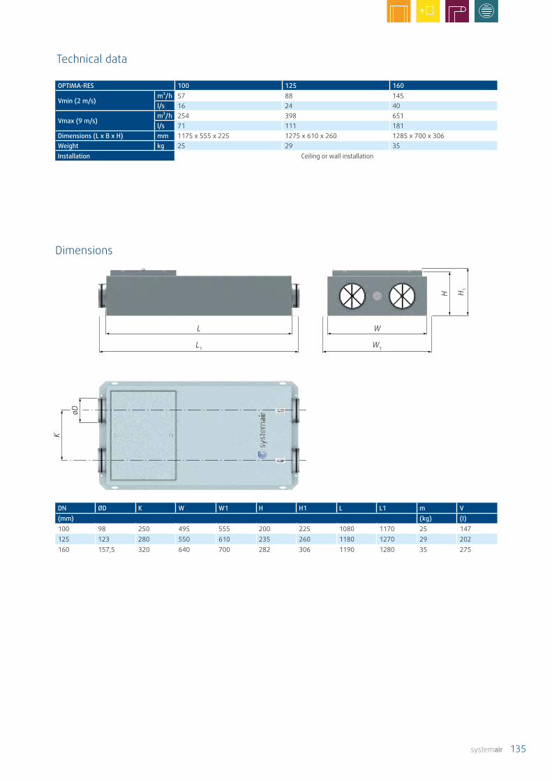
systemair 135
L
L1
W
W1
H 1
H
øD
K
DN ØD K W W1 H H1 L L1 m V(mm) (kg) (I)100 98 250 495 555 200 225 1080 1170 25 147125 123 280 550 610 235 260 1180 1270 29 202160 157,5 320 640 700 282 306 1190 1280 35 275
Technical data
OPTIMA-RES 100 125 160
Vmin (2 m/s)m³/h 57 88 145l/s 16 24 40
Vmax (9 m/s)m³/h 254 398 651l/s 71 111 181
Dimensions (L x B x H) mm 1175 x 555 x 225 1275 x 610 x 260 1285 x 700 x 306Weight kg 25 29 35Installation Ceiling or wall installation
Dimensions
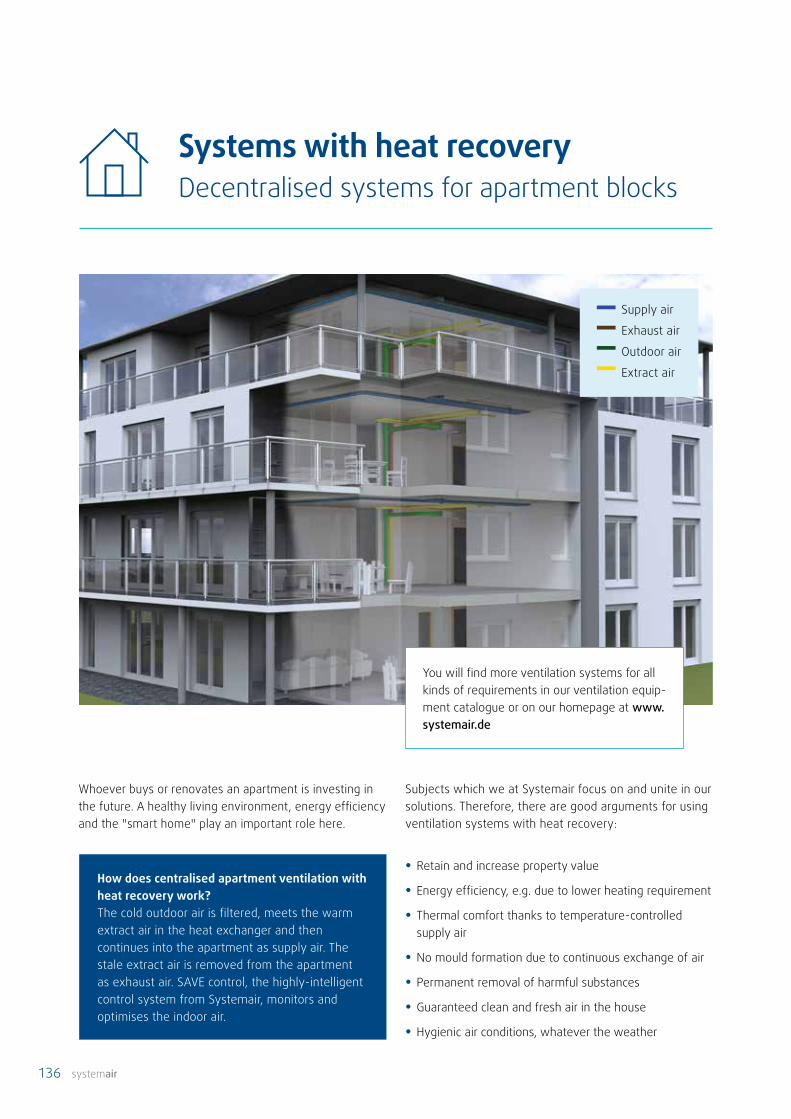
136 systemair
Systems with heat recoveryDecentralised systems for apartment blocks
Whoever buys or renovates an apartment is investing in the future. A healthy living environment, energy efficiency and the "smart home" play an important role here.
How does centralised apartment ventilation with heat recovery work? The cold outdoor air is filtered, meets the warm extract air in the heat exchanger and then continues into the apartment as supply air. The stale extract air is removed from the apartment as exhaust air. SAVE control, the highly-intelligent control system from Systemair, monitors and optimises the indoor air.
Subjects which we at Systemair focus on and unite in our solutions. Therefore, there are good arguments for using ventilation systems with heat recovery:
• Retain and increase property value
• Energy efficiency, e.g. due to lower heating requirement
• Thermal comfort thanks to temperature-controlled supply air
• No mould formation due to continuous exchange of air
• Permanent removal of harmful substances
• Guaranteed clean and fresh air in the house
• Hygienic air conditions, whatever the weather
You will find more ventilation systems for all kinds of requirements in our ventilation equip-ment catalogue or on our homepage at www.systemair.de
Supply air
Exhaust air
Outdoor air
Extract air
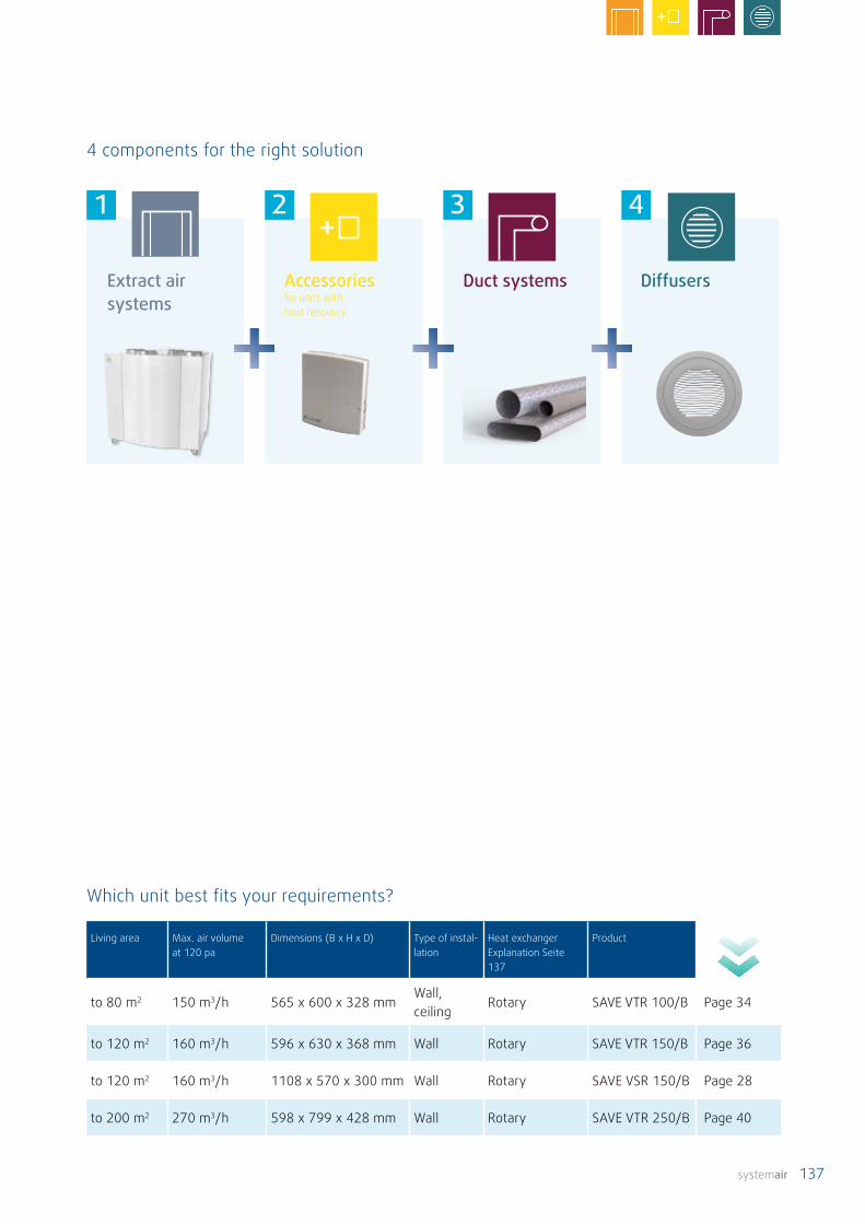
systemair 137
1 2 3 4
Extract air systems
Accessoriesfor units with heat recovery
Duct systems Diffusers
4 components for the right solution
Which unit best fits your requirements?
Living area Max. air volume at 120 pa
Dimensions (B x H x D) Type of instal-lation
Heat exchanger Explanation Seite 137
Product
to 80 m2 150 m3/h 565 x 600 x 328 mmWall, ceiling
Rotary SAVE VTR 100/B Page 34
to 120 m2 160 m3/h 596 x 630 x 368 mm Wall Rotary SAVE VTR 150/B Page 36
to 120 m2 160 m3/h 1108 x 570 x 300 mm Wall Rotary SAVE VSR 150/B Page 28
to 200 m2 270 m3/h 598 x 799 x 428 mm Wall Rotary SAVE VTR 250/B Page 40

138 systemair
Systems without heat recovery
There's only one place for smelly, moist and stale indoor air – outside! Otherwise you risk the build-up of mould and harmful substances. Extract air systems from Systemair make sure the air is clean.
systemair 139
A fan removes stale, moist, impure air from the extract air rooms (such as the kitchen, bathroom and WC) via a network of ducts. The air is then guided outside via the roof or an external wall. Depending on the flow rate and application, the extract air fans can be installed in the building or on the roof. Outdoor air flows in through special openings (valves with filters in the external walls) into the living room and sleeping quarters, ensuring the whole dwelling has continuous ventilation. What's more, thanks to the adjustability of the system, the ventilation heat losses are reduced when compared with conventional ventilation via the windows.
• Low-noise ventilation
• Targeted airflows in the apartment
• Air filtering thanks to filters in the supply air fixtures
• Lower energy consumption thanks to EC fans
• Simple installation and low maintenance costs
A perfect exchange and a perfect indoor climate – the most important advantages of units without heat recovery
In modern, energy-efficient houses, airing via the windows is not enough. Who knows when it's time to air the room? Certainly not when the air indoors is already stale. It's much better to rely on extract air systems from Systemair. 24 hours a day, 365 days a year, these conveniently transport the desired air volume, either continuously or depending on parameters such as humidity or CO2 levels. The result – considerably less heat lost compared with conventional ventilation via the windows. And a constant supply of fresh air.
Extract air system in a single-family house or an apartment
The right choice made easyExtract air systems in apartment blocks
The extract air fan transports moisture and odours out of the kitchen, bathroom and WC. Supply air components are integrated in the exterior walls of living and sleeping quarters to ensure sufficient exchange of air. The outdoor/supply air flows into the dwelling to compensate an underpressure. Because there is no heat recovery, it is not possible to preheat the supply air.
Systems in apartment blocks are managed based on demand (controlled). A central fan on the roof or in the attic controls the exchange of air for the whole building. Air extraction components in the apartments remove the moist air. This extract air system can be controlled on demand by using extract air components which monitor parameters such as humidity or presence. This system can be used for ventilating bathrooms and toilets without an external window in apartments and in similar inhabited areas, in accordance with DIN 18017 – 3. As a matter of principle, special attention must be paid to fire protection in apartment blocks.
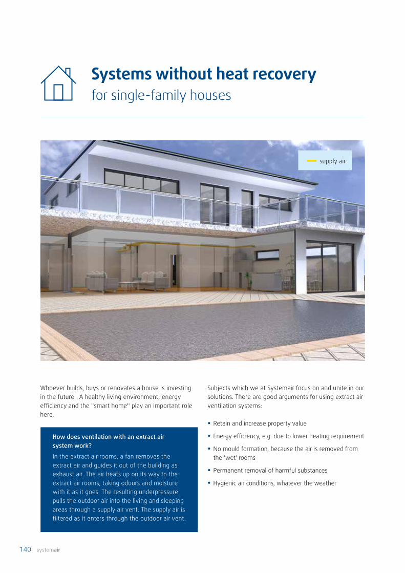
140 systemair
supply air
Systems without heat recoveryfor single-family houses
Whoever builds, buys or renovates a house is investing in the future. A healthy living environment, energy efficiency and the "smart home" play an important role here.
Subjects which we at Systemair focus on and unite in our solutions. There are good arguments for using extract air ventilation systems:
• Retain and increase property value
• Energy efficiency, e.g. due to lower heating requirement
• No mould formation, because the air is removed from the 'wet' rooms
• Permanent removal of harmful substances
• Hygienic air conditions, whatever the weather
How does ventilation with an extract air system work?
In the extract air rooms, a fan removes the extract air and guides it out of the building as exhaust air. The air heats up on its way to the extract air rooms, taking odours and moisture with it as it goes. The resulting underpressure pulls the outdoor air into the living and sleeping areas through a supply air vent. The supply air is filtered as it enters through the outdoor air vent.
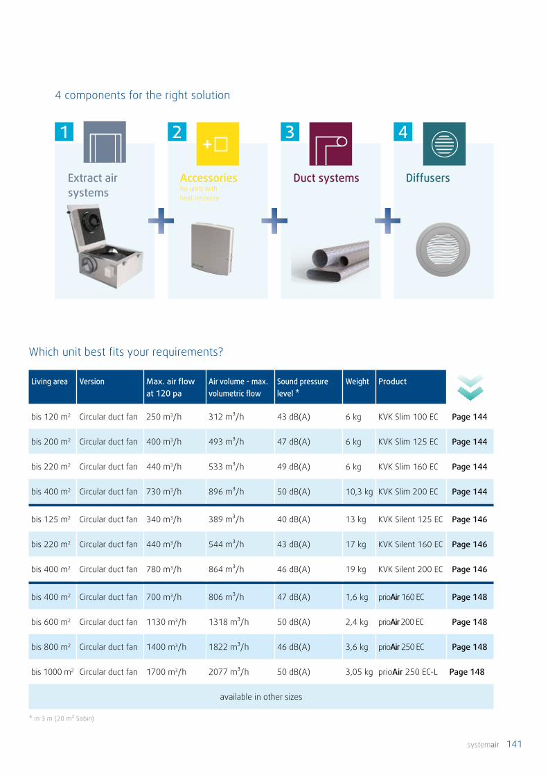
systemair 141
Which unit best fits your requirements?
Living area Version Max. air flow at 120 pa
Air volume - max. volumetric flow
Sound pressure level *
Weight Product
bis 120 m2 Circular duct fan 250 m3/h 312 m³/h 43 dB(A) 6 kg KVK Slim 100 EC Page 144
bis 200 m2 Circular duct fan 400 m3/h 493 m³/h 47 dB(A) 6 kg KVK Slim 125 EC Page 144
bis 220 m2 Circular duct fan 440 m3/h 533 m³/h 49 dB(A) 6 kg KVK Slim 160 EC Page 144
bis 400 m2 Circular duct fan 730 m3/h 896 m³/h 50 dB(A) 10,3 kg KVK Slim 200 EC Page 144
bis 125 m2 Circular duct fan 340 m3/h 389 m³/h 40 dB(A) 13 kg KVK Silent 125 EC Page 146
bis 220 m2 Circular duct fan 440 m3/h 544 m³/h 43 dB(A) 17 kg KVK Silent 160 EC Page 146
bis 400 m2 Circular duct fan 780 m3/h 864 m³/h 46 dB(A) 19 kg KVK Silent 200 EC Page 146
bis 400 m2 Circular duct fan 700 m3/h 806 m³/h 47 dB(A) 1,6 kg prioAir 160 EC Page 148
bis 600 m2 Circular duct fan 1130 m3/h 1318 m³/h 50 dB(A) 2,4 kg prioAir 200 EC Page 148
bis 800 m2 Circular duct fan 1400 m3/h 1822 m³/h 46 dB(A) 3,6 kg prioAir 250 EC Page 148
bis 1000 m2 Circular duct fan 1700 m3/h 2077 m³/h 50 dB(A) 3,05 kg prioAir 250 EC-L Page 148
available in other sizes
* in 3 m (20 m² Sabin)
1 2 3 4
Extract air systems
Accessoriesfor units with heat recovery
Duct systems Diffusers
4 components for the right solution

142 systemair
supply air
Systemair fans come in all shapes and sizes. Fans with constant pressure control are generally used in apartment blocks. No matter what the weather conditions, we have a solution for every application. You can round off your system using our wide range of accessories.
Systems without heat recoveryfor apartment blocks
You will find more fans for all kinds of require-ments in our fan catalogue or on our home-page at www.systemair.de

systemair 143
1 2 3 4
Which unit best fits your requirements?
Version Max. air flow at 120 pa
Electr. input power Weight Product
Roof fan 835 m3/h 123 W 6 kg DVC 190-P Page 158
Roof fan 1044 m3/h 159 W 6 kg DVC 225-P Page 158
Roof fan 2059 m3/h 153 W 14 kg DVC 315-P Page 158
Roof fan 4136 m3/h 521 W 25 kg DVC 355-P Page 158
Roof fan 4892 m3/h 539 W 25 kg DVC 400-P Page 158
Roof fan 6782 m3/h 996 W 40 kg DVC 450-P Page 158
Roof fan 6390 m3/h 774 W 38 kg DVC 450-PK Page 158
Duct fan 2333 m3/h 157 W 28 kg MUB-CAV/VAV 025 315EC Page 154
Duct fan 4100 m3/h 526 W 31 kg MUB-CAV/VAV 025 355EC Page 154
Duct fan 4705 m3/h 537 W 50 kg MUB-CAV/VAV 042 400EC Page 154
Duct fan 7420 m3/h 991 W 54 kg MUB-CAV/VAV 042 450EC Page 154
Duct fan 6898 m3/h 768 W 53 kg MUB-CAV/VAV 042 450EC-K Page 154
Duct fan 932 m3/h 155 W 15 kg MUB 016 200EC Page 152
Duct fan 2333 m3/h 157 W 27 kg MUB 025 315EC Page 152
Duct fan 4100 m3/h 526 W 30 kg MUB 025 355EC Page 152
Duct fan 4705 m3/h 537 W 49 kg MUB 042 400EC Page 152
Duct fan 7420 m3/h 991 W 54 kg MUB 042 450EC Page 152
Duct fan 6898 m3/h 768 W 53 kg MUB 042 450EC-K Page 152
Extract air systems
Accessoriesfor units with heat recovery
Duct systems Diffusers
4 components for the right solution
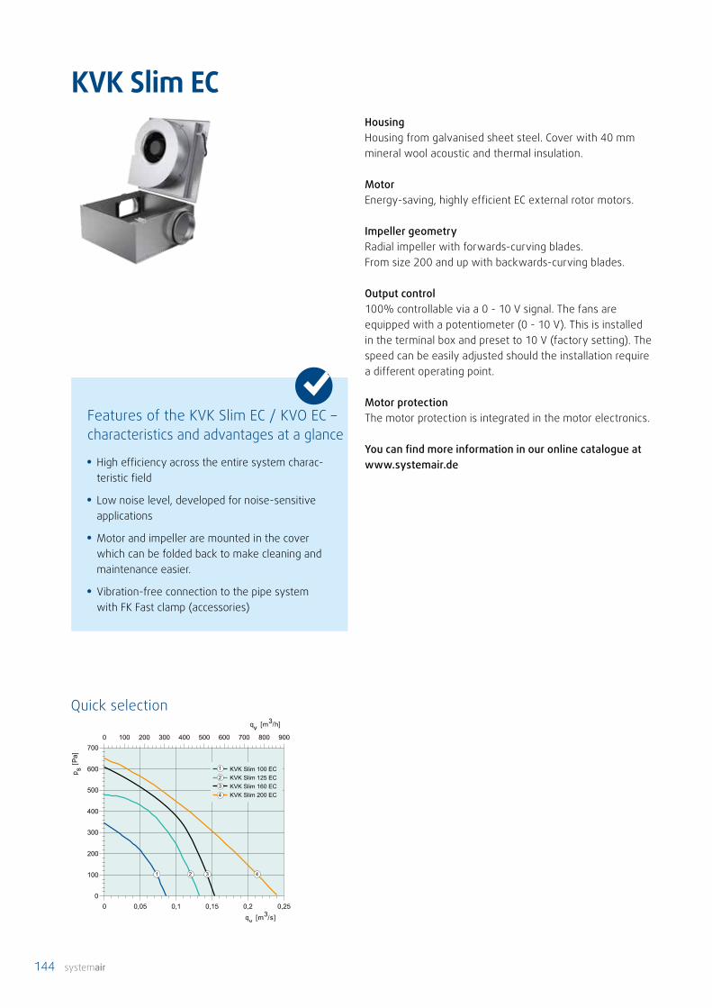
144 systemair
KVK Slim EC
KVK Slim 100 ECKVK Slim 125 ECKVK Slim 160 ECKVK Slim 200 EC
1
23
4
1 2 3 4
HousingHousing from galvanised sheet steel. Cover with 40 mm mineral wool acoustic and thermal insulation.
MotorEnergy-saving, highly efficient EC external rotor motors.
Impeller geometryRadial impeller with forwards-curving blades. From size 200 and up with backwards-curving blades.
Output control100% controllable via a 0 - 10 V signal. The fans are equipped with a potentiometer (0 - 10 V). This is installed in the terminal box and preset to 10 V (factory setting). The speed can be easily adjusted should the installation require a different operating point.
Motor protectionThe motor protection is integrated in the motor electronics.
You can find more information in our online catalogue at www.systemair.de• High efficiency across the entire system charac-
teristic field
• Low noise level, developed for noise-sensitive applications
• Motor and impeller are mounted in the cover which can be folded back to make cleaning and maintenance easier.
• Vibration-free connection to the pipe system with FK Fast clamp (accessories)
Features of the KVK Slim EC / KVO EC – characteristics and advantages at a glance
Quick selection
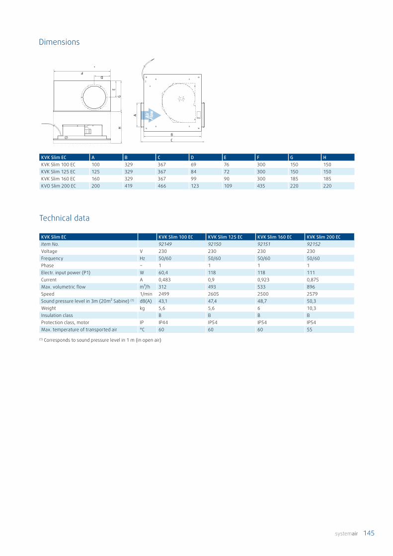
systemair 145
KVK Slim EC A B C D E F G HKVK Slim 100 EC 100 329 367 69 76 300 150 150KVK Slim 125 EC 125 329 367 84 72 300 150 150KVK Slim 160 EC 160 329 367 99 90 300 185 185KVO Slim 200 EC 200 419 466 123 109 435 220 220
A
FD
EGH
BC
KVK Slim EC KVK Slim 100 EC KVK Slim 125 EC KVK Slim 160 EC KVK Slim 200 ECItem No. 92149 92150 92151 92152Voltage V 230 230 230 230Frequency Hz 50/60 50/60 50/60 50/60Phase ~ 1 1 1 1Electr. input power (P1) W 60,4 118 118 111Current A 0,483 0,9 0,923 0,875Max. volumetric flow m³/h 312 493 533 896Speed 1/min 2499 2605 2500 2579Sound pressure level in 3m (20m² Sabine) (1) dB(A) 43,1 47,4 48,7 50,3Weight kg 5,6 5,6 6 10,3Insulation class B B B BProtection class, motor IP IP44 IP54 IP54 IP54Max. temperature of transported air °C 60 60 60 55
A
FD
EG
HB C
Dimensions
Technical data
(1) Corresponds to sound pressure level in 1 m (in open air)

146 systemair
KVK Silent EC
KVK Silent 125 ECKVK Silent 160 ECKVK Silent 200 EC
1
2
3
1 2 3
Features of the KVK Silent EC – characteristics and advantages at a glance
Quick selection
HousingHousing from galvanised sheet steel. 50 mm mineral wool acoustic and thermal insulation.
MotorEnergy-saving, highly efficient EC external rotor motors.
Impeller geometryRadial impeller with backwards-curving blades.
Output control100% controllable via a 0 - 10 V signal. The fans are equipped with a potentiometer (0 - 10 V). This is installed in the cover and preset to 10 V (factory setting). The speed can be easily adjusted should the installation require a different operating point.
Motor protectionThe motor protection is integrated in the motor electronics.
You can find more information in our online catalogue at www.systemair.de
• High efficiency across the entire system charac-teristic field
• For noise-sensitive applications
• Motor and impeller are mounted in the cover which can be folded back to make cleaning and maintenance easier.
• Plug connection interrupts the power supply when the cover is opened: no on/off switch is required for maintenance
• Vibration-free connection to the pipe system with FK Fast clamp (accessories)
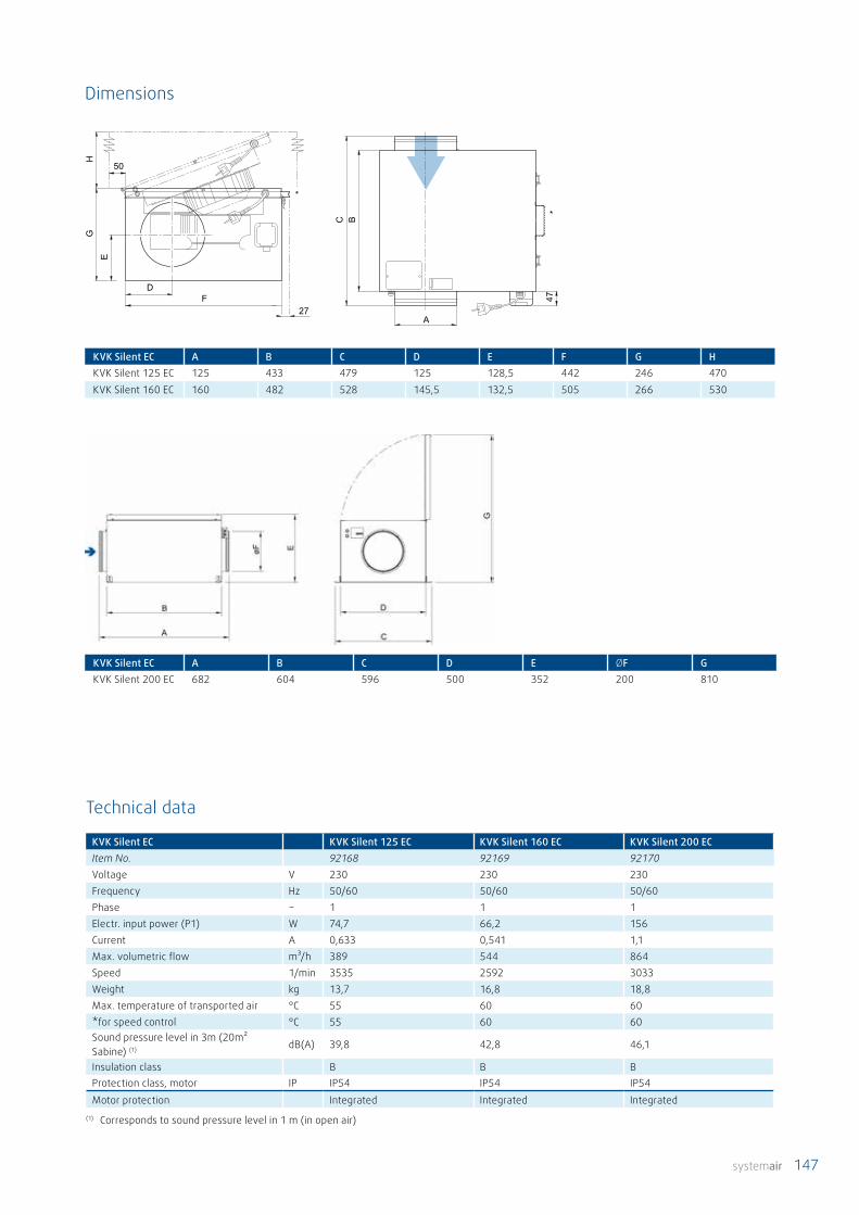
systemair 147
KVK Silent EC A B C D E F G HKVK Silent 125 EC 125 433 479 125 128,5 442 246 470KVK Silent 160 EC 160 482 528 145,5 132,5 505 266 530
D
EG
H
50
F27
C B
47
A
*
*
KVK Silent EC KVK Silent 125 EC KVK Silent 160 EC KVK Silent 200 ECItem No. 92168 92169 92170Voltage V 230 230 230Frequency Hz 50/60 50/60 50/60Phase ~ 1 1 1Electr. input power (P1) W 74,7 66,2 156Current A 0,633 0,541 1,1Max. volumetric flow m³/h 389 544 864Speed 1/min 3535 2592 3033Weight kg 13,7 16,8 18,8Max. temperature of transported air °C 55 60 60*for speed control °C 55 60 60Sound pressure level in 3m (20m² Sabine) (1) dB(A) 39,8 42,8 46,1
Insulation class B B BProtection class, motor IP IP54 IP54 IP54
Motor protection Integrated Integrated Integrated
KVK Silent EC A B C D E ØF GKVK Silent 200 EC 682 604 596 500 352 200 810
Dimensions
Technical data
(1) Corresponds to sound pressure level in 1 m (in open air)

148 systemair
prioAir EC
0 0.1 0.2 0.3 0.4 0.5 0.6 0.7 0.80
100
200
300
400
500
6000 200 400 600 800 1000 1200 1400
Q [m³/s]
Ps [P
a]
Q [m³/h]
432
1
prio 160 EC
prio 200 EC
prio 250 EC
1
2
3
prio 250 EC-L4
Quick selection
HousingAirtight, linear housing made from composite material (PP TD20). Leakage rate compliant with Leak tightness class C, according to EN 12237:2003. With 25 mm long duct connections compliant with EN1506:1997.
MotorEnergy-saving, highly efficient EC external rotor motors.
Impeller geometryThanks to our in-house-developed, flow-optimised, free running plastic axial impeller and special guide vanes, the prioAir is the fan with the best SFP values in its class.
Output control100 % controllable via a 0-10 V signal.
Motor protectionThe motor protection is integrated in the motor electronics.
You can find more information in our online catalogue at www.systemair.de
• Low SFP values and very high efficiency
• Powerful EC motor with integrated motor elec-tronics
• Integrated potentiometer for speed control
• Compact design, therefore low space require-ment
• Low noise
• Can be installed in any mounting position
Features of the prioAir EC – characteristics and advantages at a glance

systemair 149
prioAir EC A ØB C ØD E160 220 159 211 187 25200 245 199 249 227 25250 300 249 303 284,4 30
250-L 300 249 303 284,4 30
A
ØD
C
ØB
ØB
EE
prioAir EC prio 160 EC prio 200 EC prio 250 EC prio 250 EC-LItem No. 78185 78186 78187 78188Voltage V 230 230 230 230Frequency Hz 50/60 50/60 50/60 50/60Phase ~ 1 1 1 1Electr. input power (P1) W 77,1 117 126 171Current A 0,659 0,921 0,901 1,17Max. volumetric flow m³/h 806 1318 1822 2077Speed 1/min 4304 3463 2336 2649Weight kg 1,6 2,4 2,9 3,05Max. temperature of transported air °C 55 55 55 55Sound pressure level in 3m (20m² Sabine) (1) dB(A) 47 50 45,7 50
Insulation class B B B BProtection class, motor IP 44 44 44 44
Motor protection integrated integrated integrated integrated
Dimensions
Technical data
(1) Corresponds to sound pressure level in 1 m (in open air)
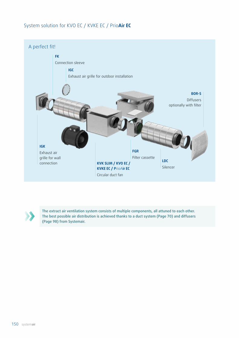
150 systemair
KVK SLIM / KVO EC / KVKE EC / PrioAir EC
Circular duct fan
IGC
Exhaust air grille for outdoor installation
IGK
Exhaust air grille for wall connection
FK
Connection sleeve
LDC
Silencer
BOR-S
Diffusersoptionally with filter
FGR
Filter cassette
System solution for KVO EC / KVKE EC / PrioAir EC
A perfect fit!
The extract air ventilation system consists of multiple components, all attuned to each other. The best possible air distribution is achieved thanks to a duct system (Page 70) and diffusers (Page 98) from Systemair.
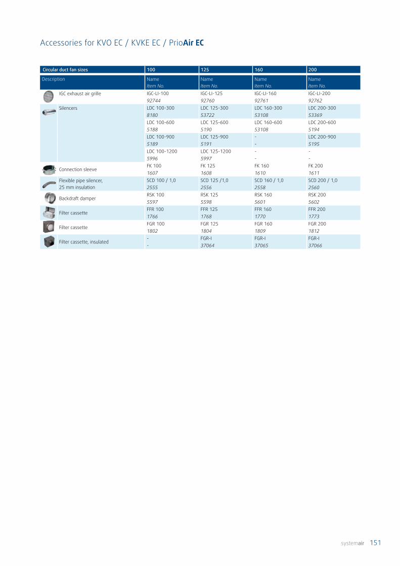
systemair 151
Circular duct fan sizes 100 125 160 200
Description Name Item No.
Name Item No.
Name Item No.
Name Item No.
IGC exhaust air grille IGC-LI-100 IGC-LI-125 IGC-LI-160 IGC-LI-20092744 92760 92761 92762
Silencers LDC 100-300 LDC 125-300 LDC 160-300 LDC 200-3008180 53722 53108 53369LDC 100-600 LDC 125-600 LDC 160-600 LDC 200-6005188 5190 53108 5194LDC 100-900 LDC 125-900 - LDC 200-9005189 5191 - 5195LDC 100-1200 LDC 125-1200 - -5996 5997 - -
Connection sleeveFK 100 FK 125 FK 160 FK 2001607 1608 1610 1611
Flexible pipe silencer, 25 mm insulation
SCD 100 / 1,0 SCD 125 /1,0 SCD 160 / 1,0 SCD 200 / 1,02555 2556 2558 2560
Backdraft damperRSK 100 RSK 125 RSK 160 RSK 2005597 5598 5601 5602
Filter cassetteFFR 100 FFR 125 FFR 160 FFR 2001766 1768 1770 1773
Filter cassetteFGR 100 FGR 125 FGR 160 FGR 2001802 1804 1809 1812
Filter cassette, insulated- FGR-I FGR-I FGR-I- 37064 37065 37066
Accessories for KVO EC / KVKE EC / PrioAir EC
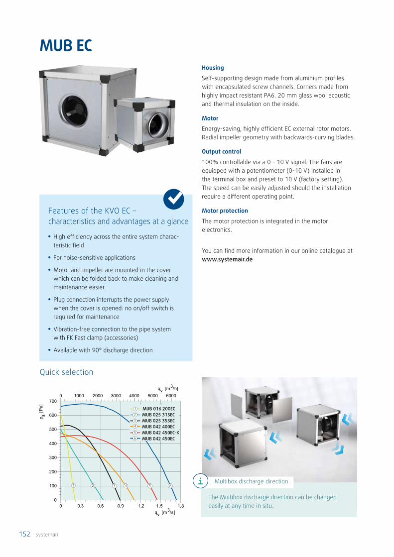
152 systemair
MUB EC
2 3 541
MUB 042 400ECMUB 025 355ECMUB 025 315EC2
34
MUB 042 450EC-KMUB 042 450EC
56
MUB 016 200EC1
6
Housing
Self-supporting design made from aluminium profiles with encapsulated screw channels. Corners made from highly impact resistant PA6. 20 mm glass wool acoustic and thermal insulation on the inside.
Motor
Energy-saving, highly efficient EC external rotor motors. Radial impeller geometry with backwards-curving blades.
Output control
100% controllable via a 0 - 10 V signal. The fans are equipped with a potentiometer (0-10 V) installed in the terminal box and preset to 10 V (factory setting). The speed can be easily adjusted should the installation require a different operating point.
Motor protection
The motor protection is integrated in the motor electronics.
You can find more information in our online catalogue at www.systemair.de
• High efficiency across the entire system charac-teristic field
• For noise-sensitive applications
• Motor and impeller are mounted in the cover which can be folded back to make cleaning and maintenance easier.
• Plug connection interrupts the power supply when the cover is opened: no on/off switch is required for maintenance
• Vibration-free connection to the pipe system with FK Fast clamp (accessories)
• Available with 90° discharge direction
Quick selection
Features of the KVO EC – characteristics and advantages at a glance
The Multibox discharge direction can be changed easily at any time in situ.
Multibox discharge direction
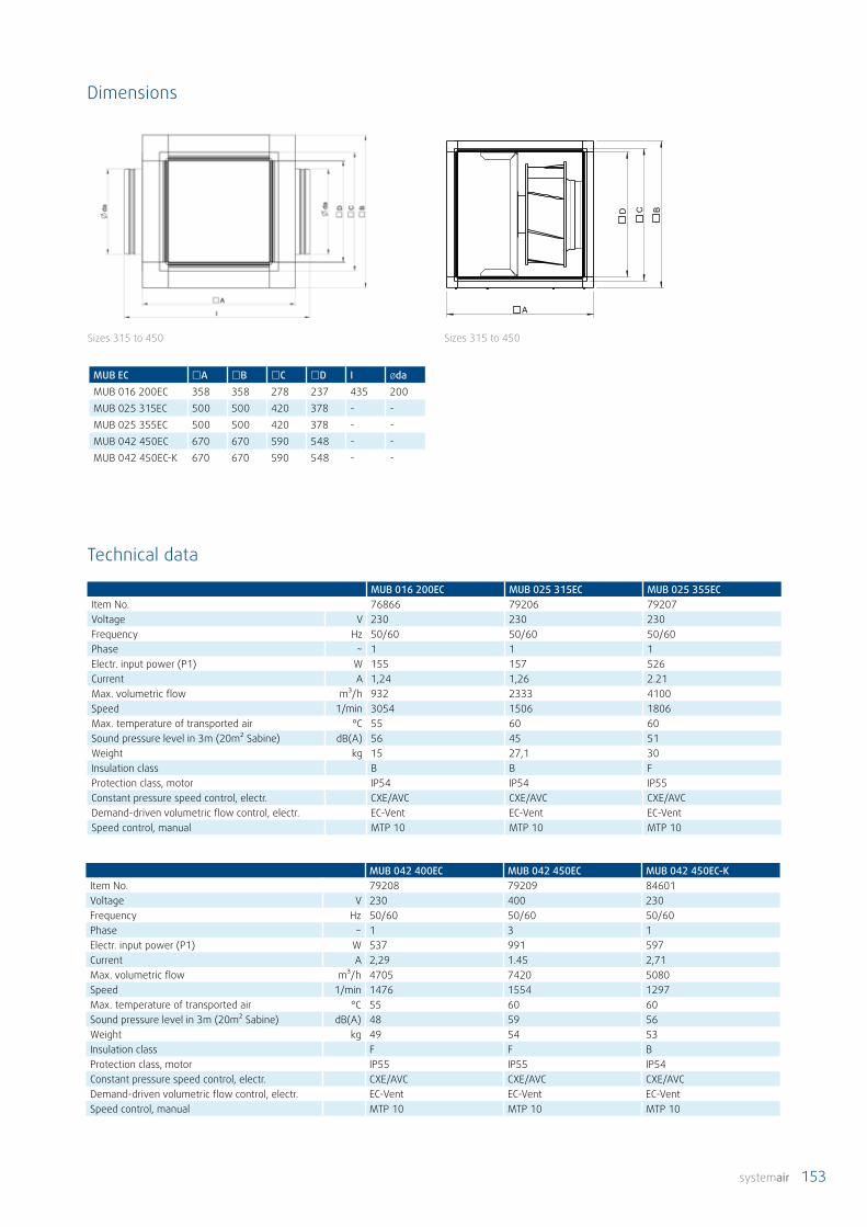
systemair 153
MUB 016 200EC MUB 025 315EC MUB 025 355ECItem No. 76866 79206 79207Voltage V 230 230 230Frequency Hz 50/60 50/60 50/60Phase ~ 1 1 1Electr. input power (P1) W 155 157 526Current A 1,24 1,26 2.21Max. volumetric flow m³/h 932 2333 4100Speed 1/min 3054 1506 1806Max. temperature of transported air °C 55 60 60Sound pressure level in 3m (20m² Sabine) dB(A) 56 45 51Weight kg 15 27,1 30Insulation class B B FProtection class, motor IP54 IP54 IP55Constant pressure speed control, electr. CXE/AVC CXE/AVC CXE/AVCDemand-driven volumetric flow control, electr. EC-Vent EC-Vent EC-VentSpeed control, manual MTP 10 MTP 10 MTP 10
C B
A
D
MUB EC £A £B £C £D I ødaMUB 016 200EC 358 358 278 237 435 200MUB 025 315EC 500 500 420 378 - -MUB 025 355EC 500 500 420 378 - -MUB 042 450EC 670 670 590 548 - -MUB 042 450EC-K 670 670 590 548 - -
MUB 042 400EC MUB 042 450EC MUB 042 450EC-KItem No. 79208 79209 84601Voltage V 230 400 230Frequency Hz 50/60 50/60 50/60Phase ~ 1 3 1Electr. input power (P1) W 537 991 597Current A 2,29 1.45 2,71Max. volumetric flow m³/h 4705 7420 5080Speed 1/min 1476 1554 1297Max. temperature of transported air °C 55 60 60Sound pressure level in 3m (20m² Sabine) dB(A) 48 59 56Weight kg 49 54 53Insulation class F F BProtection class, motor IP55 IP55 IP54Constant pressure speed control, electr. CXE/AVC CXE/AVC CXE/AVCDemand-driven volumetric flow control, electr. EC-Vent EC-Vent EC-VentSpeed control, manual MTP 10 MTP 10 MTP 10
Technical data
Dimensions
Sizes 315 to 450Sizes 315 to 450

154 systemair
MUB CAV/VAV
0 0,3 0,6 0,9 1,2 1,5 1,8
MUB-CAV/VAV 042 400ECMUB-CAV/VAV 025 355ECMUB-CAV/VAV 025 315EC1
2
3
MUB-CAV/VAV 042 450EC4
MUB-CAV/VAV 042 450EC-K5
1 2 3 45
HousingSelf-supporting design made from aluminium profiles with encapsulated screw channels. Corners made from highly impact resistant PA6. 20 mm glass wool acoustic and thermal insulation on the inside.
MotorEnergy-saving, highly efficient EC external rotor motors.Radial impeller geometry with backwards-curving blades.
Output controlThe MUB-CAV/VAV Multibox is equipped with a sensor control module and a measuring cable for volumetric flow control. The system is completely prewired. Depending on which mode is set, the unit can be used as a sensor module or a control module.
Motor protectionThe motor protection is integrated in the motor electron-ics.
You can find more information in our online catalogue at www.systemair.de
Quick selection
• High efficiency across the entire system charac-teristic field
• For noise-sensitive applications
• Motor and impeller are mounted in the cover which can be folded back to make cleaning and maintenance easier.
• Plug connection interrupts the power supply when the cover is opened: no on/off switch is required for maintenance
• Vibration-free connection to the pipe system with FK Fast clamp (accessories)
• Available with 90° discharge direction
Features of the KVO EC – characteristics and advantages at a glance
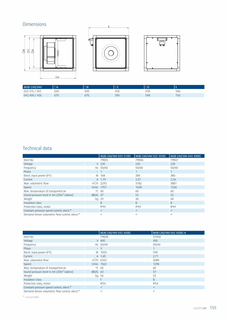
systemair 155
MUB CAV/VAV 025 315EC MUB CAV/VAV 025 355EC MUB CAV/VAV 042 400ECItem No. 79835 79836 79837Voltage V 230 230 230Frequency Hz 50/60 50/60 50/60Phase ~ 1 1 1Electr. input power (P1) W 168 389 380Current A 1,19 2,37 2,26Max. volumetric flow m³/h 2293 3182 3881Speed 1/min 1701 1638 1336Max. temperature of transported air °C 60 60 60Sound pressure level in 3m (20m² Sabine) dB(A) 47 53 52Weight kg 29 30 46Insulation class B B BProtection class, motor IP44 IP44 IP44Constant pressure speed control, electr.*
Demand-driven volumetric flow control, electr.*
DCB
A
E
MUB-CAV/VAV £A £B £C £D E025 315 / 355 500 500 420 378 586042 400 / 450 670 670 590 548 756
MUB CAV/VAV 042 450EC MUB CAV/VAV 042 450EC-KItem No. 79838 37458Voltage V 400 400Frequency Hz 50/60 50/60Phase ~ 3 1Electr. input power (P1) W 1059 599Current A 1,45 2,71Max. volumetric flow m³/h 6332 5080Speed 1/min 1562 1298Max. temperature of transported air °C 60 60Sound pressure level in 3m (20m² Sabine) dB(A) 63 57Weight kg 56 53Insulation class F BProtection class, motor IP54 IP54Constant pressure speed control, electr.*
Demand-driven volumetric flow control, electr.*
* convertable
Technical data
Dimensions

156 systemair
Indoor installation
Outdoor installation
FGV
Flexible connection socket
WSG
Weather protection grid
UGS
Transition socket
CCM
Intake socket
SD MUB vibration damper
MUB / MUB EC
Duct fan Multibox
TUNE-AHU
Shutter damper
CCM / CCMI
Discharge socket
WSG
Weather protection grid
UGS
Transition socket
WSDWeather-protection roof
MUB / MUB EC
Duct fan Multibox
CCM / CCMI
Discharge socket
System solution for multiboxes
The extract air ventilation system consists of multiple components, all attuned to each other. The best possible air distribution is achieved thanks to a duct system (Page 70) and diffusers (Page 98) from Systemair.

systemair 157
MUB EC / -CAV/VAV 025 315 025 355 042 450
Description Name Item No.
Name Item No.
Name Item No.
Basi
c
Weather protection grid WSG MUB 025 WSG MUB 025 WSG MUB 04231484 31484 31485
Weather protection grid, rotated
WSG 025 MUB/T WSG 025 MUB/T WSG 042 MUB/T36070 36070 36071
Weather-protection roof WSD-MUB 025 WSD-MUB 042 WSD-MUB 04231480 31481 31481
Indoor installation
Outdoor installation
MUB EC / -CAV/VAV 025 315 025 355 042 400
Description Name Item No.
Name Item No.
Name Item No.
Basi
c
Intake socket CCM 315 CCM 355 CCM 400312562 312718 311780
Discharge socket CCM 315 CCM 355 CCM 400312535 312719 311682
Discharge socket , insulated CCMI 315 CCMI 355 CCMI 315313843 313844 313845
Vibration dampers kit SD MUB SD MUB SD MUB37324 37324 37324
Shutter damper TUNE-AHU 025 TUNE-AHU 025 TUNE-AHU 79800 79800 79881
Transition socket UGS 025/315 UGS 025/355 UGS 042/40031290 4356 31290
Weather protection grid WSG MUB 025 WSG MUB 025 WSG MUB 04231484 31484 31485
Weather protection grid, rotated
WSG 025 MUB/T WSG 025 MUB/T WSG 042 MUB/T36070 36070 36071
Flexible connection FGV 025 FGV 025 FGV 0424196 4196 4605
Accessories MUB EC / MUB CAV/VAV

158 systemair
DVC / DVCI-S | DVC / DVCI-P
DVC/DVCI 450
DVC/DVCI 500
DVC/DVCI 560
DVC/DVCI 6304
3
2
1
4321
DVC/DVCI 225DVC/DVCI 315DVC/DVCI 355
DVC/DVCI 400DVC/DVCI 450 PK/SK
2
3
4
5
6
65431
DVC/DVCI 1901
2
HousingHousing made from salt water resistant aluminium. Base frame made from galvanised sheet steel. DVCI with 50 mm mineral wool acoustic and thermal insulation.
MotorEnergy-saving, highly efficient EC external rotor motors.
Impeller geometryRadial impeller with backwards-curving blades.
Output control100% controllable. DVC(I)-S fans are equipped with a potentiometer (0 - 10 V) mounted in the terminal box. DVC(I)-P with integrated pressure regulator unit for constant pressure control. DVC(I)-POC with integrated pressure regulator and temperature sensor for external temperature compensation. The programming for constant pressure control can be executed with and without external temperature compensation.
Motor protectionThe motor protection is integrated in the motor electronics.
You can find more information in our online catalogue at www.systemair.de
• High efficiency across the entire system charac-teristic field
• P version: integrated pressure regulator unit for simple implementation of constant pressure control
• S version: stepless control via 0 - 10 V signal, thanks to integrated potentiometer
• For noise-sensitive applications
Features – characteristics and advantages at a glance
Quick selection

systemair 159
DVC/DVCI 315-POCDVC/DVCI 355-POCDVCI 400-POCDVC/DVCI 450K-POC
1
2
3
4
1 2 3 4
DVC / DVCI-S £A £B C £E £F H øK øI190-225 370/497 295/442 170/211 335 245 6xM6 285 10(4x)315 560/690 470/583 330/369 435 330 6xM6 285 10(4x)355-400 720/874 618/648 390/439 595 450 6xM8 438 12(4x)450 900/968 730/730 465/479 665 535 6xM8 438 12(4x)
DVC / DVCI-P £A £B C D £E £F H øK øI190-225 370/497 320/442 175/211 - 335 245 6XM6 285 10(4x)315 560/690 470/583 330/369 392,5 435 330 6xM6 285 10(4x) 355-400 720/874 618/648 390/439 454 595 450 6xM8 438 12(4x) 450 900/970 730/730 465/479 516 665 535 6xM8 438 12(4x)
H
M20x1,5
I
K
F
E
CD
BA
Dimensions
Quick selection

160 systemair
DVC 190-S DVC 190-P DVC 225-S DVC 225-P DVC 315-S DVC 315-P DVC 355-SItem No. 79245 79349 79246 79236 79247 79237 79248Voltage V 230 230 230 230 230 230 230Frequency Hz 50/60 50/60 50/60 50/60 50/60 50/60 50/60Phase ~ 1 1 1 1 1 1 1Electr. input power (P1) W 123 123 159 159 153 153 521Current A 0,969 0,969 1,27 1,27 1,24 1,24 2,18Max. volumetric flow m³/h 835 835 1044 1044 2059 2059 4136Speed 1/min 3661 3661 3120 3120 1532 1532 1800Max. temperature of transported air °C 60 60 55 55 60 60 60Sound pressure level in 4m dB(A) 56 56 56 56 45 45 59Sound pressure level in 10m dB(A) 50 49 49 49 37 37 51Weight kg 5,2 6 5 6 12 14 22,6Insulation class B B B B B B FProtection class, motor IP 54 54 54 54 54 54 55
DVC 355-P DVC 400-S DVC 400-P DVC 450-SK DVC 450-S DVC 450-P DVC 450-PKItem No. 79238 79249 79239 79260 79259 79240 79241Voltage V 230 230 230 230 230 230 230Frequency Hz 50/60 50/60 50/60 50/60 50/60 50/60 50/60Phase ~ 1 1 1 1 3 3 1Electr. input power (P1) W 521 539 539 774 996 996 774Current A 2,18 2,27 2,27 3,22 1,47 1,47 3,22Max. volumetric flow m³/h 4136 4892 4892 6390 6782 6782 6390Speed 1/min 1800 1503 1503 1416 1555 1555 1416Max. temperature of transported air °C 60 55 55 60 60 60 60Sound pressure level in 4m dB(A) 59 47 47 51 54 54 51Sound pressure level in 10m dB(A) 51 39 39 43 46 46 43Weight kg 24,5 23 23 37 38 40 38Insulation class F F F F F F FProtection class, motor IP 55 55 55 55 55 55 55
Technical data
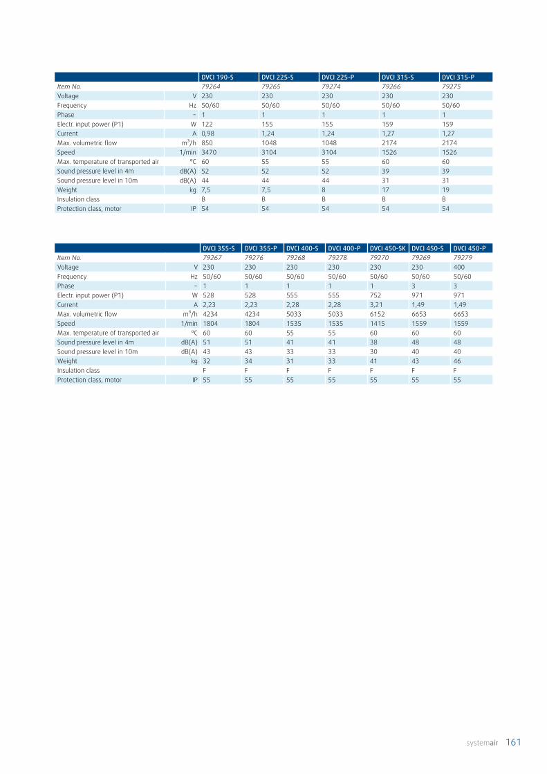
systemair 161
DVCI 190-S DVCI 225-S DVCI 225-P DVCI 315-S DVCI 315-PItem No. 79264 79265 79274 79266 79275Voltage V 230 230 230 230 230Frequency Hz 50/60 50/60 50/60 50/60 50/60Phase ~ 1 1 1 1 1Electr. input power (P1) W 122 155 155 159 159Current A 0,98 1,24 1,24 1,27 1,27Max. volumetric flow m³/h 850 1048 1048 2174 2174Speed 1/min 3470 3104 3104 1526 1526Max. temperature of transported air °C 60 55 55 60 60Sound pressure level in 4m dB(A) 52 52 52 39 39Sound pressure level in 10m dB(A) 44 44 44 31 31Weight kg 7,5 7,5 8 17 19Insulation class B B B B BProtection class, motor IP 54 54 54 54 54
DVCI 355-S DVCI 355-P DVCI 400-S DVCI 400-P DVCI 450-SK DVCI 450-S DVCI 450-PItem No. 79267 79276 79268 79278 79270 79269 79279Voltage V 230 230 230 230 230 230 400Frequency Hz 50/60 50/60 50/60 50/60 50/60 50/60 50/60Phase ~ 1 1 1 1 1 3 3Electr. input power (P1) W 528 528 555 555 752 971 971Current A 2,23 2,23 2,28 2,28 3,21 1,49 1,49Max. volumetric flow m³/h 4234 4234 5033 5033 6152 6653 6653Speed 1/min 1804 1804 1535 1535 1415 1559 1559Max. temperature of transported air °C 60 60 55 55 60 60 60Sound pressure level in 4m dB(A) 51 51 41 41 38 48 48Sound pressure level in 10m dB(A) 43 43 33 33 30 40 40Weight kg 32 34 31 33 41 43 46Insulation class F F F F F F FProtection class, motor IP 55 55 55 55 55 55 55

162 systemair
System solution for roof fans
DVC / DVCI sileoRoof fan
VKMMotor-actuated flap valve
ASSFlexible socket
FDSFlat roof base
ASFIntake flange
The extract air ventilation system consists of multiple components, all attuned to each other. The best possible air distribution is achieved thanks to a duct system (Page 70) and diffusers (Page 98) from Systemair.

systemair 163
Roof fan sizes 190 225 315 355 400 450
Description Name Item No.
Name Item No.
Name Item No.
Name Item No.
Name Item No.
Name Item No.
Basi
c
Maintenance switches REV-3POL/03 REV-3POL/03 REV-3POL/03 REV-3POL/03 REV-3POL/03 REV-3POL/0333978 33978 33978 33978 33978 33978
Adapter frame TDA DV 190/225 TDA DV 190/225 TDA DV 315 TDA DV 355/400 TDA DV 355/400 TDA DV 450/500309416 309416 309230 301393 301393 301394
Self-actuating flap valve VKS 190/225 VKS 190/225 VKS 190/225 VKS 310/311 VKS 355-500 VKS 355-5009539 9539 9539 9543 9544 9544
Flap valve,motor-actuated
- - VKM 310/311 VKM 355-500 VKM 355-500 VKM 355-500- - 9555 9556 9556 9556
Flexible socket ASS 190/225 ASS 190/225 ASS 310/311 ASS 355-500 ASS 355-500 ASS 355-5009573 9573 9575 9576 9576 9576
Intake flange ASF 190/225 ASS 190/225 ASS 310/311 ASS 355-500 ASS 355-500 ASS 355-5009567 9573 9575 9576 9576 9576
Base silencer SSD 190/225 SSD 190/225 SSD 315M/L SSD 355/400 SSD 355/400 SSD 450/5009560 9560 30086 9562 9562 9563
Flat roof baseFDS 190/225 FDS 190/225 FDS 310/311 FDS 355/400 FDS 355/400 FDS 450/5009548 9548 9549 9550 9550 9551
Inclined roof baseSDS 190/225 SDS 310/311 SDS 355/400 SDS 355/400 SDS 355/400 SDS 450-5003783 3784 3785 3785 3785 3786
Accessories DVC / DVCI | DVCI-S / DVCI-P

164 systemair
You will find more information about standards, guidelines and frequently asked questions in this section.
FAQ / Information for planners

systemair 165
Assistance in planning a residential ventilation systemTo help you find the right duct system and the right size, here we give you a few simple design rules for determining the overall air volumes needed in an apartment or a single-family house.
The air volumes for the supply air rooms are specified depending on the planned occupancy, whereby the air volumes should not fall below a minimum volumetric flow of 15 m³/h.
Locating valves
For acoustic reasons, valves should never be installed in the corners of rooms, but instead be at least 1 m away from the wall.
Wherever possible, you should always plan to install supply air valves in the ceiling, or in the wall just below the ceiling. This gives the most effective and comfortable distribution of air in the room. When selecting valves, please consider whether the valve geometry is suitable for the ceiling or the wall.
For acoustic reasons, a supply or extract air valve should be specified with a maximum of 40 m³/h. This is unless the valve is explicitly intended for higher flow rates. The air speed in the ducts should be max. 3 m/s. The following tables show the max. volumetric flows for an air speed of 3 m/s for our various duct systems.
You can use these to roughly work out the size and number of ducts and valves you need.
Extract air valves should also be installed in the ceiling, or close to the ceiling, so that it is always possible to remove the warmest and most humid air from the room. Here, too, the best location is the centre of the room.
If you adhere to these requirements, you will have a system with an external pressure loss of around 60 - 80 Pa. Using the overall air volume and the external pressure loss, you can configure the appropriate unit on our homepage. It is even simpler if you use the specified operating point for our units here in the catalogue: air volume at 50 Pa.
Bedroom (master): 40 m³/hChildren's bedroom: 30 m³/hGuest bedroom: 30 m³/hOffice: 30 m³/hLiving room: 60 – 100m³/h
Bathroom: 40 m³/hShower + WC: 30 m³/hWC: 20 – 30 m³/hKitchen: 40 m³/h
Utility room: 20 – 30 m³/hStore room: 10 – 20 m³/hHallways (if necessary): 20 – 40 m³/h
Air volumes for extract air rooms (as specification)
Air quantities for supply air roomsMinimum volumetric flow 15 m3/h
DN100 85 m³/hDN125 130 m³/hDN160 220 m³/hDN200 340 m³/hDN250 530 m³/h
Folded spiral seam ductAir speed 3 m/s
DN50 15 m³/hDN63 20 m³/hDN75 30 m³/hDN90 45 m³/hØ250 530 m³/h
SystemairTube FAir speed 2.5 m/s
System 100 80 m³/hSystem 151 140 m³/h
Flat ductAir speed 3 m/s

166 systemair
EnEV The German Energy Conservation Regulation
EnEV
All energy-related aspects of buildings are regulated in the German Energy Conservation Regulation (EnEV – Energieeinsparverordnung). This not does not just apply to new builds, but also to the renovation of older buildings. The reference building in the EnEV specifies the values for all structural elements (e.g. walls, roof or windows) and for the building services (e.g. hot water production, heating or ventilation systems) which you must fulfil. If there is a deviation in one part of the reference building, you will need to balance this out using other components.
Airtightness and minimum exchange of air are mentioned in section 6(1) and (2) of the EnEV. (1) "Structures to be built must be designed so that the heat-transferring envelope, including the joints, is sealed in line with good engineering practice, making it permanently airtight." All this means is that your customer's house must be sealed so that almost no air flows into it due to infiltration (air movement due to air leakage in the house). However, (2) contradicts (1) by saying: (2) "Structures to be built must be designed so that the minimum exchange of air required for health and heating is ensured." So on the one hand, you need to seal your customer's house, but on the other hand, you must also provide the minimum exchange of air needed for health. This minimum exchange of air is described and calculated in DIN 1946 Section 6.
DIN 1946 Section 6
DIN 1946 Section 6, Ventilation of residential accommodation, provides binding regulations to ensure the necessary ventilation for residential accommodation. A ventilation concept must be created for each building project – whether new build or renovation – to provide evidence and appropriate specifications for the minimum exchange of air needed to protect the building and ensure a hygienic indoor environment. The ventilation concept is used to calculate and decide whether free ventilation is acceptable, or whether a fan-supported system is necessary.
The ventilation concept
DIN 1946-6 now requires the creation of a ventilation concept for new buildings and renovation work. A ventilation concept is required for renovation work if, in a single-family house or an apartment block, more than 1/3 of the existing windows are replaced or if, in a
single-family house, more than 1/3 of the roof surface is newly-sealed. This means: The planner or contractor must specify how the exchange of air needed for hygiene and building protection can be implemented. Any specialist who plans, implements or maintains ventilation systems, or who is involved in planning and modernising buildings can generate the ventilation concept. The most important question when coming up with a ventilation concept is how to ensure ventilation for moisture protection. Factors incorporated in the calculation are the standard of insulation, the type and the location of the building. The former indicates the degree of leakage in the building shell. The living area indicates the expected loading. The location of the house is important in order to estimate the wind load. A fan-supported ventilation system with heat recovery is then designed for nominal ventilation.
Ventilation measures
If the supply of air through leaks in the building is not sufficient to ensure ventilation for moisture protection, the planner must provide ventilation measures. This can be achieved with additional ventilation via shafts or valves installed in the outer building envelope (outside wall vents), in conjunction with extract air systems. Alternatively, fan-supported residential ventilation systems with heat recovery or building service systems such as Genius can be used. At this level, planning active ventilation via the windows by the inhabitants is not permitted. Ventilation for moisture protection must work independently of the user! The planner must also specify how the required exchange of air is to be achieved for the following ventilation levels. For cross ventilation and shaft ventilation systems, the planner will need to include active window ventilation as soon as ventilation is reduced. The planner must explicitly inform the users about this. If necessary, for fan-supported ventilation, the planner can incorporate active opening of the windows for intensive ventilation. For increased requirements regarding energy efficiency, noise protection and indoor air quality, fan-supported ventilation is always required.

systemair 167
Ventilation levels
Ventilation for moisture protection
Ventilation to ensure protection of the building against moisture: depending on the level of thermal insulation of the building, under normal conditions of use, with partially reduced moisture loading (e.g. partial absence of the user, no drying of washing). According to the standard, this level must be ensured continuously and independently of the user.
Reduced ventilation
Additionally-required ventilation to ensure minimum standards of hygiene (presence of harmful substances) and protection of the building, with partial absence of the user. As far as is possible, this level must be ensured independently of the user.
Nominal ventilation
Describes the necessary ventilation for ensuring compliance with hygienic and health requirements, as well as protecting the building during normal use of the dwelling. Here, the user can be involved to a certain extent with active window ventilation.
Intensive ventilation
Helps deal with peak loading (e.g. due to cooking, washing). Here to the user can be involved to a certain extent with active window ventilation.
Special case: windowless rooms
Rooms without windows represent a special case in a dwelling. The ventilation of these rooms must be still be planned and implemented according to the requirements of the current DIN 18017-3 issued in September 2009. According to DIN 1946-6, ventilation measures for windowless rooms may be sufficient to supply the whole dwelling with fresh air. This must also be checked on a case-by-case basis and gives rise to a number of questions. For example, to what extent is a bathroom ventilation system – which can be switched off – sufficient ventilation for protecting the entire dwelling from moisture, if it only runs for brief periods during the day.

168 systemair
SEC or SEV-Klasse SEC or SEV in kWh/am²A+ (highest efficiency) SEV < -42A -42 ≤ SEV -34B -34 ≤ SEV -26C -26 ≤ SEV -23D -23 ≤ SEV -20E (lowest efficiency) -20 ≤ SEV -10F (not valid) -10 ≤ SEV -0G (not valid) 0 ≤ SEV
SEC value or SEV value and energy class allocation
EU Ecodesign DirectiveReduce harm to the environment through product design
The energy label should permit the end user to compare products easily, enabling them to select energy-efficient products. In contrast to other electrical equipment, the energy classes on the labels of residential ventilation equipment are determined by a calculated parameter, the specific energy consumption (SEC). This value should display the energy-saving potential of the equipment used in kilowatt hours per m² per year.
The EU sets minimum energy efficiency requirements for the appropriate products via the "Directive 2009/125/EC establishing a framework for the setting of ecodesign requirements for energy-related products" – or Ecodesign Directive or ErP Directive for short.
Fans EU 327/2011 (B2B, no label)
• Since 2013, minimum requirements apply for fans above 125 Watts regarding energy efficiency
• From January 1, 2015, these requirements have become significantly more stringent
Central ventilation and air conditioning units EU 1253/2014 (B2B, no label)
• Since January 1, 2016, minimum requirements apply regarding • fan power consumption and • heat recovery efficiency
Residential ventilation equipment EU 1253/2014 and 1254/2014 (B2C, label)
• Minimum requirements from January 1, 2016: The units must save at least as much primary energy (electricity and heat) as they use (elec-tricity)
• Minimum requirements from January 1, 2018: The units must save significantly more primary energy than they use – the ventilation heat requirement of the residential building is approximately halved
• Energy efficiency label from A+ to G (see Table)
Air conditioners EU 206/2012 (B2C, label)
• Since January 1, 2013, units with a cooling per-formance up to 12 kW are classified in energy efficiency classes from A+++ to D
• Units in cooling mode must fulfil at least the requirements of energy efficiency class A
New requirements for ventilation and air-conditioning
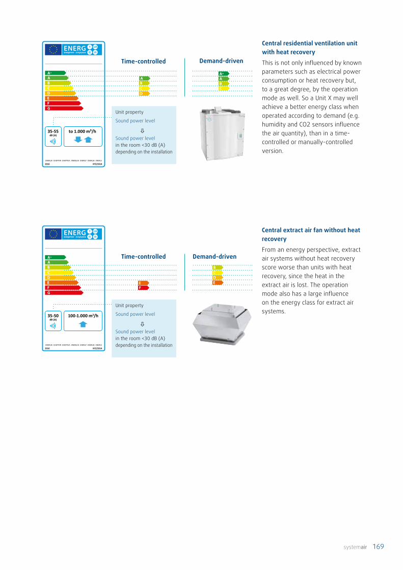
systemair 169
2016 XYZ/2014
35-55 dB (A)
ENERGIA · ЕНЕРГИЯ · ΕΝΕΡΓΕΙΑ · ENERGIJA · ENERGY · ENERGIE ENERGI
A++
A+
to 1.000 m³/h
+
2016 XYZ/2014
35-50 dB (A)
ENERGIA · ЕНЕРГИЯ · ΕΝΕΡΓΕΙΑ · ENERGIJA · ENERGY · ENERGIE ENERGI
A++
A+
100-1.000 m3/h
Time-controlled Demand-driven
Central residential ventilation unit with heat recovery
This is not only influenced by known parameters such as electrical power consumption or heat recovery but, to a great degree, by the operation mode as well. So a Unit X may well achieve a better energy class when operated according to demand (e.g. humidity and CO2 sensors influence the air quantity), than in a time-controlled or manually-controlled version.
Central extract air fan without heat recovery
From an energy perspective, extract air systems without heat recovery score worse than units with heat recovery, since the heat in the extract air is lost. The operation mode also has a large influence on the energy class for extract air systems.
Time-controlled Demand-driven
Unit property
Sound power level
Sound power level in the room <30 dB (A) depending on the installation
Unit property
Sound power level
Sound power level in the room <30 dB (A) depending on the installation

170 systemair
The VDI Guideline ensures that different CAD and calculation programs can import product data from different manufacturers without additional interfaces.
Systemair will support you in your ventilation project from the planning phase right through to implementation – now also with data acc. VDI 3805 for Systemair residential ventilation and compact air handling units.
VDI Guideline 3805
In building services engineering, systems are increasingly planned and con-figured with the assistance of IT systems. This requires the product data to be available in a machine-readable format.
The VDI Guideline 3805 "Product data exchange in building services" aims to create standardised dataset descriptions which permit the creation of uniform (from an IT perspective) product descriptions for each product group, with the following content:
• All the technical data required for designing the product
• The geometry associated with the relevant product (in the form of distur-bance spaces, connections and form blocks for complex representation).
• The item numbers, DATANORM numbers and StLB numbers assigned to the product.
This ensures that different CAD and calculation programs can import product data from different manufacturers without additional interfaces. One can compare the format with, for example, the JPEG format, which can be read by all image processing programs. VDI 3805 covers products and components in heating, ventilation and sanitary systems. The format is manufacturer-neutral and can therefore be imported into all common CAD programs.
You can find more detailed information about the VDI Guideline 3805, including links to downloads, at www.systemair.de
The item numbers, DATANORM numbers and StLB numbers assigned to the product.
The geometry associated with the relevant product (in the form of disturbance spaces, connections and form blocks for complex representation)
All the technical data required for designing the product

systemair 171
Fire protection and smoke extraction dampers from Systemair offer increased safety for people and animals, prevent the spread of fire and smoke, and provide focused smoke extraction for the protection of buildings. In and on solid walls and ceilings, in lightweight walls, fire-resistant walls and on wall exteriors – the variety of installation options offers you maximum certainty during planning.
We care about safetyFire protection and smoke extraction dampers
Systemair DESIGN Simple yet precise online tool for selecting the right fire protection and smoke extraction dampers, diffusers and volumetric flow regulators. All technical data and information at a glance with direct access to the MagiCloud database (TGA BIM library). Find out more at https://design.systemair.com
• Tested according to DIN EN 15650 and DIN EN 12101/8
• With CE marking
• Fire resistance class to EI120S
• Fire dampers can also be supplied in EX versions
• Wide range of accessories
Characteristics and advantages at a glance
We offer you round and square fire dampers and in-pipe fire dampers, in all kinds of sizes. Our products are characterised by high quality, reasonable prices and rapid delivery times. The fire dampers comply with EN 15650, are tested according to EN 1366-2 and are classified according to EN 13501-3, as well as being CE-inspected.
You can find more information on our homepage at www.systemair.de

172 systemair
Aluminium and plastic counter flow heat exchangers transfer heat (sensible heat) and are able to achieve efficiencies of over 90 per cent.
Heat transferIn plate heat exchangers, the air flows through a series of parallel plates. Here supply air and extract air always
flow alternately on opposite sides. The heat energy is transferred through the plate from the warm air current to the cold air current.
Without moisture transferIf conventional aluminium or plastic plate heat exchangers are used, the resulting condensate must be removed from the unit via a waste water pipe. The siphon must always be filled with water to prevent air from being sucked through the duct system.
As well as heat (sensible heat), rotary heat exchangers are also able to transmit moisture (latent heat). For use in single-family houses or dwellings with sensible efficiencies of up to more than 85 per cent.
Heat transferThe lamellar structure of the rotor (similar to corrugated paper) and the continuous rotary motion between the warm and cold air currents result in the rotor heating up in the extract air. In winter this heat is transferred to the cold supply air. This effect can be used in reverse in summer, because heat from the outdoor air is transferred to the cooler extract air. This enables a cooling effect to be achieved in summer, or also it can be used to recover cooling energy in air-conditioned buildings.
Moisture transmission via a condensation rotorThe heat exchange matrix is made from pure aluminium which transfers moisture precisely at the moment when condensation forms on the extract air side and is then reabsorbed by the outdoor air. For large temperature differences, the degree of recovered moisture can rise above 60 per cent. With our rotors, moisture is primarily transferred when it is needed, i.e. in winter. This enables problems with overly-dry air to be reduced or even avoided altogether. The moisture transfer can be controlled by adjusting the rotor speed.
Entrained rotation – internal leakageThe rotor rotation can result in small amounts of extract air entering the supply air (entrained rotation). A combination of air leakage in the housing and the rotor speed, in conjunction with the pressure differential of the unit (caused by filters, for example), can result in a certain amount of extract air being transferred to the supply air. In general, our equipment has an internal leakage rate of less than 5 per cent. This even falls to below 3 per cent for equipment certified for use in passive houses. This means that nowadays, units with a rotor are certainly comparable with plate heat exchangers, at least concerning internal leakage.
Frost protectionThanks to the transfer of moisture, it is not necessary to drain away condensation in residential buildings. This means the ventilation unit does not need to be connected to a waste water pipe. Also, down to around -20 °C, the rotor does not freeze while transferring condensation, making frost protection for the heat exchanger unnecessary. Therefore, the entire capability of the heat exchanger can be exploited when outside temperatures are low. The colder the better.
Rotary heat exchanger
The right choice made easyComparison of rotary and counter flow heat exchangers
Counter flow heat exchanger

systemair 173
AirtightnessSupply air and extract air are completely separate from each other so, in theory, there is no portion of extract air in the supply air. In practice however, there can be internal leakages due to a combination of manufacturing tolerances of approx. 0.8 per cent for plate heat exchangers (manufacturer's specifications) and leakages in the housing, depending on the pressure difference in the unit. Here too, the limit for internal leakage is 5 per cent and 3 per cent for a passive house.
Frost protectionThe higher the efficiency of the heat exchanger, the more condensate can form when temperature differences are large. The efficiency also affects the temperature below which the heat exchanger must be protected from frost, i.e. when the condensate starts to freeze. For high-performance counter flow heat exchangers with efficiencies of around 90 per cent, this may already be the case for outside temperatures below -3 °C. The lower the efficiency, the lower the freezing point. This also means the energy expenditure for frost protection varies correspondingly. For reliable frost protection, and to prevent too much heat being extracted from the heat exchanger, the outdoor air can either be preheated, or guided past the heat exchanger via a bypass and then over a heater. Another option is often used: the supply air fan is throttled, creating an imbalance between the supply air and the extract air. However this no longer works for modern, airtight houses. Frost protection can be achieved without using
too much energy by investing in a brine-geothermal heat exchanger. No matter how it is done, frost protection costs money and energy!
Special types of plate heat exchangers, such as the membrane counter flow heat exchanger, can also transfer moisture as well as heat. However the sensible heat transmission efficiency is reduced to around 75 per cent, i.e. below that of the rotors.
With moisture transferMembrane exchangers can transfer moisture and do not need to be connected to a waste water pipe. Depending on the humidity difference, moisture can also be transferred from the outdoor air to the extract air in summer. However, membranes are subject to wear; the pores start to close up and eventually the heat exchanger must be replaced. This means that the original moisture transfer performance reduces continually over time.
Frost protectionAt around -8 °C, the frost point of membrane heat exchangers is somewhat lower than that of aluminium or plastic heat exchangers. Just like for aluminium or plastic heat exchangers, energy must be added to protect the heat exchanger from freezing when outside temperatures are low.
Every type of heat exchanger has advantages and disadvantages, which are more or less significant depending on the requirements. A plate heat exchanger can make the best use of its high efficiency if the outside temperature does not fall (or falls only briefly) below its specific frost point. Then frost protection is unnecessary and, due to the mild climate (not colder than around -3°C), the indoor climate does not become too dry, even without moisture transfer. A membrane heat exchanger plays to its strengths wherever as much moisture as possible is to be transferred continuously. Aluminium or plastic heat exchangers are often replaced by membrane heat exchangers after around two years, once the moisture from construction has gone. However, the moisture transfer cannot be controlled here and the membrane gradually closes. A rotor performs most strongly in climates down to around -20 °C. Here the rotor is able to generate maximum heat recovery without any frost protection at all, as well as transferring moisture as needed. Nowadays internal leakages are no longer a problem, since they are comparable with other heat exchangers. Within a dwelling a slight transfer of odour is unimportant, since the proportion transferred via the ventilation system is considerably smaller than, for example, via doors, clothes or the body of air able to move between rooms. With the open plan (living-eating area) designs common today, this is no longer of any significance.
Conclusion

174 systemair
Air filters for ventilation and air conditioningChange of the filter classes EN 779 -> ISO 16890
Air filters are important components in ventilation and air conditioning systems for ensuring good indoor air quality and a hygienic system.
On July 1, 2018, the inspection standards and certification of air filters switched from EN 779 to ISO 16890.
In contrast to EN 779, the new ISO 16890 evaluates the effectiveness of air filters regarding the different fine particulate fractions PM1, PM2.5, PM10 and Coarse (fine particulate matter up to 1μm, up to 2.5 μm, up to 10 μm and coarse particles). These PM (Particulate Matter) values are also used analogously in the evaluation of outdoor air quality.
The filter classes ISO ePM1, ISO ePM2.5, ISO ePM10 and Coarse with ISO coarse therefore replace the previous filter classes G1 to F9. Compared with EN 779:2012, operators and planners of ventilation and
air-conditioning systems will now find it much easier to select appropriate filters using the new inspection standard and its classification system. The new testing and classification process will determine the separation behaviour of all particles with sizes between 0.3 and 10 µm occurring in the outdoor air, instead of – as previously – just particles of 0.4 µm. This means the standard is now more closely aligned with real application conditions. The filtration performance of fine particle filters is then determined without a previous dust feed. This eliminates the problematic dependency of the filter efficiency on a synthetic test dust, and is a significantly more reliable parameter than the efficiency specification according to EN779.

systemair 175
Total
upper airways(Nasen-/Rachenraum)
Bronchial tubes
Bronchioles
Alveoli (pulmonary alveoli)
10080604020
80604020
80604020
604020
604020
0,01 0,1 1 10
Particle diameter [μm]
Depo
sitio
n of
the
num
ber o
f par
ticle
s [%
]
1vµm = 0,001 mm
human har≈ 70 µm
PM10≤ 10 µm
PM2,5≤ 2,5 µm
PM1≤ 1 µm
The new classification system is much more user-friendly when selecting filters to achieve a desired air quality. There are four filter classes specifying the filter's required filtration performance as a percentage in the relevant spectrum. The class ISO ePM1 60% has a filtration performance (e) for particles of ≤ 1 µm of at least 60%. Filters with a filtration performance of less than 50% at PM10 are assigned the category ISO coarse.
A large number of guidelines, standards and regulations refer to the EN 779 filter classification, and these will only be replaced successively in the coming years. Therefore comparability is often an issue when air filters with the newer classification are used. A simple conversion from the old classes to the new is not possible due to the difference in the evaluation method. A correct transposition into the relevant user standard for the filter must take place in the future.
The human body absorbs numerous particles and dust when breathing in air. In particular, the majority of these particles are made up of small fractions of particulate matter which can get into the blood and organs via the alveoli. Filters complying with ISO 16890 reduce the amount of particles in the range from >0.3 µm by up to >90%.
Class Efficiency range Example particle / fine particulateISO ePM1 ePM1, min >= 50% Viruses, bacteria, nano-particles,
soot (from fossil fuels), sea salt, oil mist
ISO ePM2.5 ePM2.5, min >= 50%
Bacteria, fungi and mould spores, pollen, toner particles
ISO ePM10 ePM10 >= 50% Pollen, stone dust, agricultural dusts
ISO Coarse ePM10 <50% Sand, fluff, airborne seeds, hair etc.
EN 779:2018 PM 1 ePM 2.5 ePM 10M5 5% - 35% 10% - 45% 40% - 70%M6 10% - 40% 20% - 50% 60% - 80%F7 40% - 65% 65% - 75% 80% - 90%F8 65% - 90% 75% - 95% 90% - >95%F9 80% - 90% 85% - 95% 90% - >95%
Help with comparing filter classes

176 systemair
Nowadays it is easy to purchase cheaper filters on the internet. These imitations might fit into your unit, but may otherwise have almost nothing in common with the original part. Often the end customer cannot see any difference in the product, only in the price. But the price is based on things which the cheap filter simply cannot provide.
Original replacement filters or or cheaper counterfeit products?
So there are good reasons why you should buy original replacement filters:
1.) The filter used by the equipment manufacturer must be approved with regard to fire protection and hygiene. To receive accreditation, the filter must comply with the building material class B2 and pass a flammability test acc. DIN 4102-1. Furthermore, all substances and materials used in the filter (filter fleece, frames, sealants, adhesives) must be demonstrably free from substances hazardous to health.
2.) The filters in our equipment are designed for the relevant unit with respect to pressure loss (air volume). Here the filter area must be adapted to the material used. The correct pressure loss over the filter in both flow directions is important for the internal leakage of the unit (pressure differences in the unit) and the air volume ratio (balance between the supply air and extract air). The unit characteristics and the fan activation for air volume control have been determined in extensive laboratory tests and are the basis for catalogues, design tools and the software for controlling the units. Other filters with other properties change the behaviour and the air volumes of the unit definitively. Finding a counterfeit product with the
same properties would be like winning the lottery.
3.) Due to differences in materials or a smaller filter surface, incorrect filters can lead to higher pressure losses. In addition to 2.), a higher pressure loss also means the unit will consume more electricity. This is because the effort needed for the fan to transport the air is increased.
4.) Equipment manufacturers must provide evidence and documentation for the filter classes. They are inspected by market surveillance authorities and must therefore also check their suppliers to ensure reliable and consistent quality.
5.) Fine filters must be sealed to the housing, so that no unfiltered air can flow past the filter. The higher the filter class, the better the seal needs to be. The original part has the appropriate seal for the unit!
Replacement filter for our our devices You can find an overview of all filters for our devices in our Me-dia Center or on our homepage at www.systemair.de.

systemair 177

178 systemair
Ceiling installation of ventilation unit and TUBE F ducts
Drawings one to four show the connection of TUBE F distributors to ceiling or floor-mounted units for horizontal installation.
Application and installation examples
Figure 1 consisting of: VSR150 + SCD + adapter + distributor Figure 2 consisting of: VSR300 + SCD + T-piece + 2 adapters + 2 distributors
Figure 3 consisting of: VSR300 upright + SCD + T-piece + 2 adapters + 2 distributors
Figure 4 consisting of: VSR300 upright + SCD 90° + T-piece + 2 distributors

systemair 179
Connection of a duct system vertically to a wall unit
Vertical connection for installing TUBE F pipes in the building storeys: either under, in, or above the ceiling.
TUBE F manifold connection under the ceiling to the ventilation unit with transition piece from DN125 directly to the manifold.
Figure 5 consisting of: VTR300 + SCD + spiral + 2 distributors
Figure 7 consisting of: VTR300 + SCD + T-piece + 2 distributors
Figure 6 consisting of: VTR300 + SCD 90° + adapter + distributor
Folded spiral seam duct connection to ventilation unit with air volume split between two distributors.
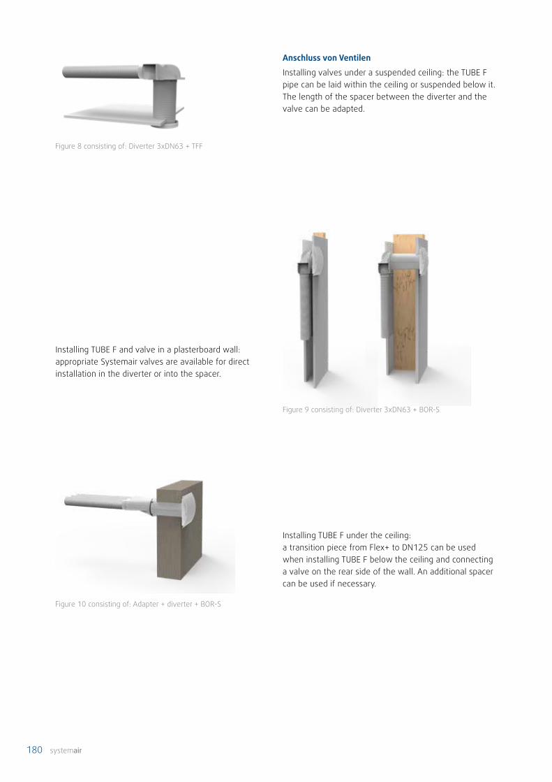
180 systemair
Anschluss von Ventilen
Installing valves under a suspended ceiling: the TUBE F pipe can be laid within the ceiling or suspended below it. The length of the spacer between the diverter and the valve can be adapted.
Figure 10 consisting of: Adapter + diverter + BOR-S
Figure 9 consisting of: Diverter 3xDN63 + BOR-S
Figure 8 consisting of: Diverter 3xDN63 + TFF
Installing TUBE F and valve in a plasterboard wall: appropriate Systemair valves are available for direct installation in the diverter or into the spacer.
Installing TUBE F under the ceiling:a transition piece from Flex+ to DN125 can be used when installing TUBE F below the ceiling and connecting a valve on the rear side of the wall. An additional spacer can be used if necessary.

systemair 181
Figure 9 consisting of: Diverter 3xDN63 + BOR-S

182 systemair
Systemair around the globe
3 Distribution Centers
50 Countries with Sals Subsidiaries

systemair 183
Systemair around the globe
Always close to you!
27 Production Facilities

184 systemair
Notes

systemair 185

186 systemair
IndexAAB 90° ............................................. 96ABS .................................................. 96Adapter ........................................... 69AE ................................................... 107AH .................................................. 108AH-V2A ........................................... 97Angle 45° ....................................... 84Angle 45°, flat ............................... 85Angle 45°, wide ............................ 84Angle 90° ....................................... 85Angle 90°, flat ............................... 85Angle 90°, wide ............................ 85Angle diverter ................................ 86Ashcan ............................................ 69
BBalance-E ...................................... 101Balance-S ...................................... 100Basket ............................................. 69Bend 45° ........................................ 89Bend 90° ........................................ 89BFVSR .............................................. 55BFVTR .............................................. 57Borea ............................................. 103BOR-S / -R .................................... 104Branch piece 90° ........................... 86Branch piece 90°, flat ................... 86Branch piece 90°, wide ................ 86Branch piece, outlet S 151 .......... 86
CCB ..................................................... 51CE/CD.......................... 50, 54, 56, 58CO2DT-R ..................... 50, 54, 56, 58CO2 RH ....................... 50, 54, 56, 58CO2RT-R-D ........................ 54, 56, 58CO2-Sensor................ 50, 54, 56, 58Cold sealing tape ........................... 87Combi-brush ................................... 69Combi-grille .................................... 69CVVX ..................... 50, 54, 56, 58, 96CWK ................................... 51, 55, 57
DDC ..................................................... 89DIS .................................................... 92Diverter ........................................... 87DVC ................................................ 158DVCI ............................................... 158DVCI-P ........................................... 158DVCI-S ............................................ 158
EEB ..................................................... 91EFF ................................................. 101End cover ........................................ 84External connector ........................ 84External connector, wide/wide ... 84
FFAV ................................................. 110FGR-I ..................... 50, 54, 56, 58, 92Filter bag ......................................... 69Flanged collar ................................. 84Flat duct silencer ........................... 95Flat-to-flat reducer ........................ 84Floor nozzle .................................... 69Folded spiral seam duct SR ......... 88
GGenius .................................. 115, 126G-K3/NTC ................... 50, 54, 56, 58
HHEPA filter ....................................... 69HU ............................... 50, 54, 56, 58
IIGC-LI ............................................... 96Internal connector ......................... 84Internal connector, tight/tight ..... 84IRS .................................................... 95ISO+ B45 ......................................... 82ISO+ B90 ......................................... 82ISO+ C .............................................. 82ISO+ external grille ........................ 97ISO+ pipe ........................................ 81ISO+ R .............................................. 82ISO+ R, asymmetrical ................... 82ISO+ R, symmetrical ..................... 82ISO+ SK ............................................ 82ISO+ T-piece ................................... 81
KKVK Silent EC ................................ 146KVK Slim EC .................................. 144
LLF ...................................................... 94
MMF .................................................... 91MUB CAV/VAV .............................. 154MUB EC ......................................... 152
NNP .................................................... 91
OOPTIMA-RES ................................. 134
PPE insulation hose ......................... 92PFVSR .............................................. 55PLUTO ............................................ 106Poly-nail strip ................................. 87Polypropylene adhesive tape ..... 92prioAir EC ...................................... 148PSS48 ....................................... 55, 57
QQuadrofix - smooth interior ......... 83Quadroflex - corrugated .............. 83
RR ....................................................... 90RDR ................................................ 112RFP ................................................... 91
SSAVECair IAM ................................. 52SAVE VSR 150/B ............................ 28SAVE VSR 300 ................................ 30SAVE VSR 500 ................................ 32SAVE VTC 200 ................................ 20SAVE VTC 300 ......................... 22, 24SAVE VTC 500 ................................ 24SAVE VTC 700 ................................ 26SAVE VTR 100/B ............................ 34SAVE VTR 150/B ............................ 36SAVE VTR 150/K ............................ 38SAVE VTR 250/B ............................ 40SAVE VTR 300/B ............................ 42SAVE VTR 500 ................................ 44SAVE VTR 700 ................................ 46SCD................................................... 94SDL ................................................... 97Self-tapping screws ...................... 92SPI .................................................. 113
TT-piece ............................................ 90Transition round to flat ................. 85TUBE F ............................................. 74TUBE F BS ....................................... 75TUBE F DH ................................ 77, 78TUBE F DV ....................................... 78

systemair 187
TUBE F End cover .......................... 79TUBE F extension socket .............. 76TUBE F FR........................................ 75TUBE F RED ..................................... 79TUBE F RS ....................................... 75TUBE F RV ....................................... 75TUBE F socket ................................ 79TUBE F TRANS ................................ 77TUBE F VC-C .................................... 75TUBE F VC-W-M ............................. 76TUBE F VC-W-P ............................... 76
UUIS .................................................... 89
VV30 .................................................. 68VKR-SR ............................................ 97VTK ................................................. 111
WWandmontageset .......................... 54

www.systemair.com
Syst
emai
r Gm
bH ·
Sept
embe
r 202
0