
Integrating P2P with Next Generation Networks
35
Integrating P2P with Next Generation Networks Athanasios Christakidis 2 , Jens Fiedler 1 , Nikolaos Efthymiopoulos 2 , Konstantinos Koutsopoulos 4 , Evangelos Markakis 5 , Stephen Garvey 3 ,Spyros Denazis 2 , Spyridwn Tombros 2 , Shane Dempsey 3 , Evangelos Pallis 5 , Odysseas Koufopavlou 2 1 Fraunhofer Fokus, Berlin, Germany 2 Electrical and Computer Engineering,University of Patras, Greece 3 Waterford Institute of Technology, Waterford, Ireland 4 Blue Chip Technologies S.A., Athens, Greece 5 Centre for Technological Research of Crete
-
Upload
independent -
Category
Documents
-
view
1 -
download
0
Transcript of Integrating P2P with Next Generation Networks

Integrating P2P with Next GenerationNetworks
Athanasios Christakidis2, Jens Fiedler1, Nikolaos Efthymiopoulos2,Konstantinos Koutsopoulos4, Evangelos Markakis5, Stephen Garvey3,Spyros Denazis2,
Spyridwn Tombros2, Shane Dempsey3, Evangelos Pallis5, Odysseas Koufopavlou2
1Fraunhofer Fokus, Berlin, Germany2Electrical and Computer Engineering,University of Patras, Greece
3Waterford Institute of Technology, Waterford, Ireland4Blue Chip Technologies S.A., Athens, Greece
5Centre for Technological Research of Crete


Contents
1 Integrating P2P with Next Generation Networks 51.1 Introduction . . . . . . . . . . . . . . . . . . . . . . . . . . 51.2 Use Cases as motivation . . . . . . . . . . . . . . . . . . . 81.3 VITAL++ architecture: An Overview . . . . . . . . . . . . . 9
1.3.1 P2P-Authentication Sub-Architecture . . . . . . . . 111.3.2 Content Security SA . . . . . . . . . . . . . . . . . 131.3.3 Content diffusion P2P overlay (CDO) SA . . . . . . 171.3.4 Content Index SA . . . . . . . . . . . . . . . . . . . 181.3.5 VITAL++ client architecture: An Overview . . . . . 19
1.4 VITAL++ P2P functionality for live streaming . . . . . . . . 231.5 Use Case (SoftMix) . . . . . . . . . . . . . . . . . . . . . . 241.6 VITAL++ Test bed Deployment . . . . . . . . . . . . . . . 26
1.6.1 Test bed configuration . . . . . . . . . . . . . . . . 291.6.2 The IPTV injection scenario . . . . . . . . . . . . . 301.6.3 VITAL++ test-bed deployment over an interactive DVB-
T infrastructure . . . . . . . . . . . . . . . . . . . . 321.7 Conclusions . . . . . . . . . . . . . . . . . . . . . . . . . . 331.8 Acknowledgements . . . . . . . . . . . . . . . . . . . . . . 34
Bibliography 35
3


1Integrating P2P with Next Generation Networks
This chapter describes the major components and their interactions of a novelarchitecture called VITAL++ that combines the best features of the two seem-ingly disparate worlds, Peer-to-Peer (P2P) and NGN in particular IMS, whichare then used to support multimedia applications and content distributionservices. To this end, P2P is enhanced with advanced authentication, DRMmechanisms while NGN benefits from the enhanced scalability, reliabilityand efficient distribution of service and content by exploiting P2P self - or-ganization properties. We describe novel P2P algorithms for optimizing net-work resources in order to efficiently distribute content among various userswithout resorting to laborious management operations required in NGN.
1.1 Introduction
The widespread adoption of the Internet technology in daily life as a ma-jor communication medium has led to the emergence of a plethora of e-applications some of which have already become more popular than the con-ventional telephony. Assisted by the wider roll-out of broadband communi-cations technologies, Internet and its use has elevated digital communica-tions to higher levels and made audiovisual communications, such as con-tent distribution, digital TV, video on demand affordable for everyone andmainstream among the Internet applications of today. Among them computerbased applications like the TVtube, Skype and Music City, offer rich-contentto users, in real time with acceptable quality, making use of sophisticatedpeer-to-peer (P2P) technology algorithms for content tracking, download-ing, synthesis and playback. These emerging types of applications, rich inuser-created content, enabled by P2P technology, with high demandsfor network resources are rapidly changing the landscape of network op-erations and requirements creating new challenges in network and servicemanagement, configuration, deployment, protocols etc. P2P is primarily an
5

6 1 Integrating P2P with Next Generation Networks
end-users’ technology that fosters self-deployment and self-organizationwhile it achieves optimized resource utilization for the deployed applica-tions and services. In other words P2P technology has succeeded where QoSmechanisms have failed being deployed and operating at large scales.
On the other hand, latest trends in telecommunication networks have ledto the emergence of the first version of converged IP communication plat-forms known as Next Generation Networks (NGN). AN initial instance ofNGN is the IP Multimedia Sub-system (IMS). IMS networks constitute fully-fledged IP networks offering, in contrast to Internet communications, quality-controllable fixed, mobile and wireless links. With IMS, users is said to beable of making ubiquitous use of operator services using 3G UMTS, WiFiand PC-based terminals. IMS is a control plane technology that primar-ily addresses issues of heterogeneity of access technologies, addressingschemes, AAA, security and mobility management from an operator’sperspective.
In so far, these two seemingly competing technologies, NGN and P2Phave been deployed independent of each other thus failing to mutually exploittheir strengths towards creating a new and more powerful paradigm.
When comparing IMS and P2P [2], we compare two inherently differentworlds. IMS as a technology for controlling media flows, administering sub-scribers and controlling access to services, both operator-services and third-party. IMS is a highly centralized architecture, which business goals such asmanageability, security and charging. P2P technologies on the other side havebeen designed to be scalable, adaptable, and failure resilient, mainly for thedistribution of media (files, streams). Figure 1.1 illustrates the complementaryfeatures of both technologies, which are discussed in the following.
As already mentioned, scalability is one of the biggest features of P2Pnetworks, while scaling up an IMS core network can only be done by meansof laborious configuration operations that increase the management overhead.P2P networks usually have no single point of failure as they are self-healing,while e.g. the HSS is a single point of failure for an IMS network. In a P2Pnetwork, users are often the only content providers, while this concept isnot supported in the IMS, which clearly distinguishes between consumersand service providers. Under normal circumstances, a P2P network is notvulnerable to DDoS attacks, because an attacked node will behave as a singlefailure, which is subject to self-healing in the rest of the network. IMS ismore vulnerable, as e.g. an I-CSCF may be flooded and put out of servicefor all users. Access to a P2P network can be considered easy, as there is noaccess control in open P2P networks. Nevertheless, password- controlled P2P

1.1 Introduction 7
Figure 1.1 IMS vs. P2P comparative overview
solutions exist, but none of them are standardized. Access to an IMS and itsservices is quite complex, as cryptographic mechanisms need to be deployedfor even the simplest access. Additionally, each user must be provisioned andits profile, which is stored in the HSS, must be maintained.
But in the direct comparison, IMS does not only have disadvantages againstP2P technologies. The complexity of access results in a much better securitysituation among IMS users due to the AAA management in the IMS corenetwork for all users. Due to the fact that IMS is located in an operatornetwork, it can also access network topology information in a standardizedway from a Network Attachment Sub-System (NASS)1. This informationmust be estimated or measured in a pure P2P overlay and therefore the in-corporation of information from a NASS will result in a better and moreefficient overlay if presented to an overlay construction algorithm. IMS is astandardized architecture with standardized network protocols and functions,which makes development for an open market possible, while P2P overlaysare usually dictated by the associated piece of software. For the same reasonas for topology awareness, IMS components can influence the data paths be-tween users and service nodes in terms of bandwidth (resource reservation),which is completely unthinkable for any pure user driven P2P network, asuser nodes cannot influence routers in any of the involved networks. P2P
1 ETSI, TISPAN Release 1 Architecture, Dec 2005

8 1 Integrating P2P with Next Generation Networks
systems usually need to provide remarkable efforts, up to dictating the archi-tecture of the overlay, in order to make clients communicate with each otherwhich are behind a NAT. In the IMS, the P-CSCF has the task to deal withNATed2 users (proxy, holds pinhole open, all communication goes throughthe P-CSCF). Last but not least, the probably biggest advantage of IMS is theeasy way to deploy new services, which is very expensive in a P2P system, asa P2P system is usually designed directly on the use case (e.g. file sharing).
This chapter describes the VITAL++ architecture [4] which is the result ofcombining and experimenting with the best features of the two worlds,namely, IMS-like control plane functionality and P2P technology. Thishas given rise into a combined communication paradigm that brings benefitto both users and operators and makes multimedia applications readily andsecurely available.
1.2 Use Cases as motivation
The combination of P2P with NGN/IMS technologies opens numerous pos-sibilities, a few of which will be described in this section. These are based onuse cases implemented in the Vital++ IST project3
The first use case is Remote Services Access (Geo-Blocking).Due to li-censing policies AV Content on the internet is often geo-blocked, i.e. onlyavailable in certain areas. This, however, excludes users who have paid theirbroadcast licence fees but happen to be temporarily outside the geographicarea where they live and pay their fees.
With IMS technology, viewers can be enabled to consume content theyhave a right to access wherever they are. A suitable area of application wouldbe the streaming AV (IPTV) offers by national public broadcasters, whichcould then be made available for all rightful viewers anywhere throughoutEurope. As these public broadcasters by law and regulation often cannot payfor distribution outside their business area, the use of P2P technology may bevery useful to reduce costs for content distribution.
The second use case is Content Distribution in Rural Areas. In someremote rural areas, served by satellite connections or radio access, the useof P2P technologies can improve the way operators serve multimedia on-demand content. In a rural area where a number of users are connected to
2 IETF, RFC 2663 - IP Network Address Translation (NAT) Terminology and Considera-tions, Aug 1999, web: http://tools.ietf.org/html/rfc2663
3 ICT-Vital++ Project website, web: http://www.ict-vitalpp.upatras.gr

1.3 VITAL++ architecture: An Overview 9
a broadband network using a number of satellite accesses the same con-tent may be forwarded at different times at several satellite accesses using ahigh amount of bandwidth. This scenario can be improved if subscribers areconnected to a local area network (wired, WiFi, etc.) and share one satelliteaccess.
The network operator can improve the use of the expensive and scarcebandwidth satellite access using a P2P approach. This approach can be auser P2P, where a user serves contents to other users or even an operatorP2P, where every on-demand content requested by a user to the network isstored at a local element belonging to the operator. In both cases, when asecond remote user asks for the same content, it is distributed from the localbroadband network, instead of using the satellite access time and again.
Another use case is Science Video Blog. The architecture and function-ality of VITAL++ enables the creation of a video pool for science commu-nication. Individual institutions could connect with others - whether inside aclosed group like Fraunhofer Gesellschaft or between free, individual organi-zations sharing interest in a certain topic - and share information on the latestdevelopments and findings.
Such an application would not require much of an elaborate GUI de-sign but rather should be based on decent metadata handling to ensure thatinterested community users will find what they are interesting in.
The fourth use case is Personalized Radio and Video Service. As a demon-strator for the usage potential of combining P2P and IMS technology, theVITAL++ consortium developed a demonstrator application which empowersa personalized radio experience way beyond broadcast radio programmes.This service, SoftMix, will be described further down below.
1.3 VITAL++ architecture: An Overview
The VITAL++ architecture has been derived from several major design crite-ria, which are:
1. Minimal modification of standardized functions.2. Easy to deploy into existing IMS networks.3. A high-degree of extensibility.4. Security for media and user data.5. Optimal overlays with intelligent path management.
From these design aspects, it has been decided to position IMS sided func-tionalities of the VITAL++ architecture in an application server; while the

10 1 Integrating P2P with Next Generation Networks
Clie
nt-
Fun
ctio
ns
IMS/N
GN
-Fun
ction
s
NetworkClient(s) IMS
Message & Media Exchange
P2P-Authentication
Content Indexing
Content Security
Overlay Management
Interaction
Figure 1.2 VITAL++ abstract view of the overall architecture
client sided functionalities are located directly in the client so that no addi-tional nodes become necessary. Figure 1.2 illustrates an overview over thearchitecture and its functional blocks, which are explained in the remainingsections of this work.
In order to address the VITAL++ challenges, a number of Sub-Architectures(SA’s) that interact with each other have been defined, each one respon-sible to address specific design criteria. These are the P2P Authenticationsub-architecture (P2PA), the Content Index sub-architecture (CI), the Con-tent Diffusion Overlay sub-architecture (CDO) and the Content Security sub-architecture (CS). Each sub-architecture spans across the client, the networkand the IMS with its components. Sub-architectures may interact with eachother in an arbitrary way, especially in the client, while on the NGN side thereneed to be well defined interfaces. Thus the media exchange is not entitled assub-architecture, but it interacts with these and itself in the same as well as inremote clients.
Peer-to-peer Authentication (P2PA) SA is responsible for enabling clients(peers) to authenticate messages, which they receive in order to ensure thatclients know who has really created the message. This is a basic requirementin order to enable secure P2P messaging. Based on this, additional featurescan be introduced, like a secure DHT or authentic media streaming, etc.

1.3 VITAL++ architecture: An Overview 11
The content index (CI) SA has three major objectives. Firstly it allowsthe publishing of a content item from users and content providers, enablesqueries for items that our system maintains and distributes, acts as a trackerand provides the initial insertion of a peer to the overlay that distributes theitems that it requests.
Content Diffusion Overlay (CDO) SA is a graph that participating peersdynamically form and maintain by selecting each one of them a small subsetof peers that act as its neighbors. The purpose of the CDO is the distributionof the content, which users exchange with their neighbors in real time inthe form of data (content) blocks. This graph determines the network pathsthat the system uses in order to distribute the content according to the userrequests. The system creates and maintains one CDO for each media objectthat it distributes.
The Content Security (CS) sub-architecture has been designed to en-able content providers to control the distribution of their content using aDigital Rights Management technology. Vital++’s DRM system took its re-quirements from network operators and a content provider participating inthe Vital++ IST project. In this context it answers real-world business issuesrequired for commercial exploitation of the Vital++ platform such as chargingand billing. More specifically, the requirements range from Identity-basedconditional access to streaming content (providing a better alternative to Geo-Blocking), encryption of file-based and streamed content where appropriate,flexible rights expression, integration with micro-charging accounting, re-spect for privacy and consumer rights and an innovative explicit support forfair-use assertions such as backup/critique/education.
1.3.1 P2P-Authentication Sub-Architecture
The purpose of the P2P-Authentication Sub-Architecture (P2PA-SA) is toenable clients (peers) to verify the authenticity of messages which have beensent by other clients directly to them, without passing through any operatorcontrolled entity. This envisages the security of services, which are based onpure P2P message exchange, like sharing of contacts or media, etc.
The P2P-Authentication sub-architecture works with certificates, whichdescribe an entity and its properties. In the VITAL++ scope, three types ofcertificates are distinguished. The root certificate that is self-signed and pre-installed in every client and P2P-authentication server module. The servercertificate that is signed by the Root-CA, is pre-installed in every P2P- Au-thentication server module, describes the identity of the server domain and its

12 1 Integrating P2P with Next Generation Networks
Root-Cert.
Public Key
Signature
Root-ID
Private Key
Server-Cert.
Public Key
Signature
Server-ID
Private Key
Client1-Cert.
Public Key
Signature
Client1-ID
Private Key
use
d t
o s
ign
use
d t
o s
ign
Text Message
Signature over Text
Client 1
Client1-Cert.
Public Key
Signature
Client1-ID
Text Message
Signature over Text
use
d t
o s
ign
use
d t
o s
ign
Server-Cert.
Public Key
Signature
Server-ID
Root-Cert.
Public Key
Signature
Root-IDused toverify
P2P Message Transfer over SIP
used toverify Client 2
Pre-Installed
Pre-Installed
Acquired
Acquired
Generated
Transmitted
used toverify
Figure 1.3 Relation between Certificates and Messages
public key and is acquired by each client during registration. The third is theclient certificate that is signed by a p2p authentication server on request anddescribes the identity of the client and its public key.
Finally, each client is equipped with these three certificates, which al-low it to perform all authenticity transactions and checks as explained in thefollowing paragraphs.
The relation between the certificates and their use in order to enable au-thentic message exchange is depicted in Figure 1.3. In every transaction thereis either a certificate or signature being transported between the entities. Bothare encoded as XML documents and attached as a MIME multipart messageto the corresponding SIP message.
Initial certificate provision: The P2P Authentication module in the VI-TAL++ AS will process the registration hint from the S-CSCF and supplythe newly registered user with its server certificate, signed by the commonRoot-CA, as illustrated in figure 1.3.
Client certificate authorization:The client hereby generates its personalprivate-public key-pair and creates an unsigned certificate with its identityand public key. This is then being sent to the VITAL++-AS, which checks theidentity and other fields of the certificate before he signs it with his privateserver key. The signed certificate is then being sent back to the client, whichstores it as its own personal certificate. After performing this transaction, the

1.3 VITAL++ architecture: An Overview 13
SIP REGISTERServerCert.SIP MESSAGE
Verify Server Cert. with Root Cert. 200 OK
200 OK
ServerCert.
Client
VITAL++ AS
S-CSCFSIP REGISTER
200 OK
Figure 1.4 Initial server certificate acquisition.
client owns a valid certificate verifiable by every instance, which also knowsthe server certificate.
The client hereby generates its personal private-public key-pair and cre-ates an unsigned certificate with its identity and public key. This is then beingsent to the VITAL++-AS, which checks the identity and other fields of thecertificate before he signs it with his private server key. The signed certificateis then being sent back to the client, which stores it as its own personal cer-tificate. After performing this transaction, the client owns a valid certificateverifiable by every instance, which also knows the server certificate.
Client-to-client Message authentication: The sender creates a text mes-sage, which he signs with his private key, which corresponds to its own clientcertificate. He then sends the text message along with its own client certificateand the message signature to the receiver. This one can then first check theauthenticity of the client certificate using its server certificate, followed bychecking the message signature with the public key from the client certificateand inform the user accordingly.
1.3.2 Content Security SA
The Content Security Sub-Architecture (CS-SA) is implemented as a SIP In-stant Messaging based service. The CPS is integrated within the IMS networkas shown in Figure 1.5.

14 1 Integrating P2P with Next Generation Networks
Figure 1.5 CPS integration within the IMS.
The User Equipment (UE) here represents a Vital++ node. The nodeaccesses the functions of the Content Protection Function, the logic of theContent Security Sub-Architecture) using the IMS ISc interface. The IScis a SIP protocol connection that is used when the S-CSCF loads a triggerpoint corresponding to the message that has been presented to it. In ourcase the message is matched based on a known ”service indentifier” e.g.content-protection@vital-domain and the Vital++ SIP header that is addedto all Vital++ messages.
Licensing Content: The process of licensing a piece of content followsa Request/Response model and uses the SIP Instant Messaging conversationmechanism defined by the 3GPP. By re-using an existing mechanism we relyon the standard IMS authentication and message security mechanisms.
The Content Protection Function (CPF) is deployed within a standardIMS application server corresponding to the Java Community Process’s JSR2894 specification. The CPF may additionally use the HSS to verify a sub-scriber’s credentials using the Sh interface (profile information).
The content licensing process is orchestrated using a ”Licensing Con-ductor”, implemented to the design specified by the Open Media Commons5
group. In realizing this implementation, the Java Business Process Manage-
4 JSR SIP Servlet v1.1, http://jcp.org/en/jsr/detail?id=2895 Open Media Commons, http://www.openmediacommons.org

1.3 VITAL++ architecture: An Overview 15
ment (JBPM) open source workflow management engine was chosen to de-scribe the licensing process. AS denotes an Application Server hosting thespecified node in the CP-SA.
Identity Management: Similar to the P2P-SA, the CPF uses Public KeyInfrastructure (PKI) to mutually authenticate content provider and contentconsumer. The CPF acts as a trusted intermediary meaning that the con-tent consumer and provider do not have to interact directly in the licensingprocess. This is necessary as the content is super-distributed among peersin the overlay. Mutual authentication means that the content consumer canbe confident the licensed content is being licensed from the correct providerand hasn’t been tampered with. The content provider similarly benefits fromIMS Authentication and PKI being used to identify the consumer. A Certifi-cate Authority (CA) is used to associate public-private key pairs with IMSidentities.
Business Rules: The Drools Expert6 rules engine is used to process busi-ness logic encoded in text-based rules. The content provider registers licens-ing rules with the Content Security Sub-Architecture. These rules can beparameterized and hence associated with individual users, user groups, con-tent types, network context (e.g. user location) and billing scenarios (e.g.pre-pay, post-pay). For example: the following is true if the subscriber hasa prepay account and their account balance is sufficient to afford the contentitem.
Subscriber(Account type == ”prepay”) &&Subscriber(account balance)> Content(cost estimate)
Figure 1.6 shows how request handling, rules processing and accounting areintegrated within a single workflow following the Service-Oriented principleof ”loose coupling” 7.
Integration with Accounting:The Accounting subsystem consists of el-ements including:
- A Charging Gateway Function (CGF) - An IMS charging gateway forstoring usage data. The CFG exposes a diameter interface to switchingand application server nodes.
- ” An Accounting and Billing Function (ABF) - A flexible and highlyscalable accounting system based on spreadsheet worksheets. The ABF
6 Drools Expert - Jboss Community, http://www.jboss.org/drools/drools-expert.html7 Kaye D. ”Loosely Coupled - The missing pieces of the web”, RDS Press, 2003

16 1 Integrating P2P with Next Generation Networks
Figure 1.6 Licensing Workflow.
has a web service interface. It receives usage data in the IP Detail Record(IPDR) XML format and responds with an XML rating document. Therating document may be transformed into a customer bill for service andnetwork usage.
- A Charging Control Function (CCF) - A rules-based charging decisionfunction that evaluates whether a service can be provided to a particularuser based on their charging profile and that of the service. E.g. Theservice may require ”post-pay” and the user account may be ”pre-pay”only. The CCF is implemented using JBPM workflows.
The ABF within the Accounting system associates a charging worksheetwith a service or content provider and the service or content being provided.The worksheet describes additional logic for special tariffs to incentivisegood behavior on the overlay e.g. relaying content. We have adopted theextensible XML-based IPDR (Internet Protocol Detail Record) Network DataManagement-Usage (NDM-U)8 scheme for charging data.
8 ipdr.org. Network Data Management Usage (NDM-U) for IP-based Services, version3.1.1 edition, October 2002.

1.3 VITAL++ architecture: An Overview 17
1.3.3 Content diffusion P2P overlay (CDO) SA
The objective that we fulfill through the architecture of the CDO is the cre-ation and the maintenance of a scalable system, in terms of participatingpeers, through the distribution of this its management and organization pro-cess to them. Additionally we focus on adapting the graph to dynamic peerarrivals and departures and continuously reorganize it according to them. Spe-cial attention has been given to the adaptation of CDO to the dynamic networkconditions and exploitation of network locality in the selection of neighborsfrom each peer. Finally innovative algorithms have been designed and run inCDO that deploy a P2P overlay graph structure that ensures the maximumof the utilization of upload bandwidth contributed by highly heterogeneousparticipating peers while a newly-designed p2p block scheduler exploits theproperties of the P2P overlay in order to uniformly distribute the sum of theupload bandwidth resources to every participating peer.
The P2P overlay graph structure (Figure 1.7- left) consists of two in-teracting sub graphs. In the first graph we insert only peers (class 1 peers)that their upload bandwidth exceeds the bit rate of the service rate that oursystem has to sustain while in the second we insert the rest (class 2 peers).These two graphs are constructed in such a way that all nodes have an equalnumber of connections. The interconnection between two graphs is done withconnections that class 1 peers create in order to provide peers of class 2 withadditional upload bandwidth resources. The number of these connections isproportional to the surplus of upload bandwidth of class 1 peers. This surplusis also assigned uniformly in peers of class 2.
In both graphs all the peers periodically execute a Distributed Optimiza-tion and Maintenance Algorithm (DOMA) that reorganizes the ”neighbor-hoods” of CDO in order to keep the structure of the graph optimal for contentdelivery even during peer arrivals and departures. It also ensures high levelsof bandwidth utilization. The algorithm makes use of an ”energy function”that captures the impact of specific parameters e.g. network latency, betweenany two nodes in the overlay. DOMA is executed between two neighborsthat we note as initiators and their direct neighbors that we called satellites.Its purpose is to minimize the overall sum of the energy functions betweeninitiators and satellites under the constraints on the number of neighbors thatthe aforementioned graph structure implies. In Figure 1.7 (right) the lengthof the arrows expresses the value of the energy function. The one initiator inthe left figure has surplus bandwidth twice as much as the other. We observethat the execution of DOMA minimizes the sum of energy functions while

18 1 Integrating P2P with Next Generation Networks
CLASS 1 GRAPH
INTERCONNECTIONS
CLASS 2 GRAPH
CLASS 1
PEERS
CLASS 2
PEERS
INITIATORS INITIATORS
SATELLITES SATELLITES
Figure 1.7 Left- The graph structure of the CDO, Right - Execution of DOMA.
it reassigns the number of neighbors according to their upload bandwidthresources.
Every change in the underlying network, in the resources of a peer, peerarrivals and departures or execution of DOMA in neighboring nodes triggersnew changes in CDO while it always converges to the desired graph structureand to a minimized sum of energies[1].
1.3.4 Content Index SA
In IMS networks, context indexing is used for distinguishing calls with re-spect to requested content type. Quite often in commercial P2P services con-tent indexing is used not only for accelerating the content searching pro-cess, but as a tool for content publication, together with content descriptioninformation.
In the scope of the VITAL++ network, content indexing is defined as aSub-Architecture (CI-SA) implemented as part of the SIP Instant Messagingstandard9 and offering the following services:
- Content Publication: The content publication service can be used byIMS users interested in offering content. The service works by declar-
9 Campbell B. [et al.], RFC 3428 - Session Initiation Protocol (SIP) Extension for InstantMessaging, IETF, Dec 2002.

1.3 VITAL++ architecture: An Overview 19
ing content availability to the network that may be fed to the usersthrough the CI-SA. Context searching and download is possible fromthird-parties by executing network search on the basis of content de-scription information publicized along with the content.
- Content Searching: Content searching is the basic service offered ,whereby users looking for particular content are browsing other users’publicized content on the basis of certain criteria. These criteria aresubmitted to the CI-SA and the result is fed to the requesting users asa list of descriptions of available content items. The list also containsmatching criteria which are used as filters against relevance of the resultfor presentation to the user.
- Overlay Bootstrapping-Maintenance: Contrary to the regular sessionsetup process of IMS, whereby connection parameters are negotiatedduring bearer set-up, the Vital++ client has to join P2P overlays wellbefore this process takes place, in order to be able to acquire contentindexing information. For this purpose, once the user has selected aspecific content item to be retrieved and reproduced locally, this has tobe communicated to the CI-SA. In this case the CI-SA interacts withthe Overlay Management SA (OM-SA) in order to either create a newoverlay or to update an existing one. In any case the outcome of the OM-SA, which is a list of peers per overlay member, is sent either to a newlyadded member of an overlay or to an existing member for which the listof its peers has been updated.
1.3.5 VITAL++ client architecture: An Overview
The terms ”Client” and ”Peer” are used equivalently in this document as theyrefer to the same thing. The VITAL++ client is a hybrid client. This means itis an IMS client and a P2P client at the same time. The IMS functionalitiesare used to mainly interact with an IMS core or system for exchanging controlinformation, while the P2P part is used to exchange content with other peers.
The components of the client are directly derived from the necessity tointeract with other clients and the IMS core in order to fulfill the envisagedfeatures. Figure 1.8 illustrates the functional blocks inside the client. Theseare the content manager, which is responsible for publishing and discoveringcontent as well as triggering DRM operations via the client DRM moduleif a license needs to be obtained. The authentication module obtains andmanages certificates of VITAL++ entities (clients, application servers, root-

20 1 Integrating P2P with Next Generation Networks
VITAL++ Client
OverlayManagement
QoSManagement
Content Manager
Authentication
Client DRM
localcontent
P2P MediaExchange
P2P MessageExchange
TCPUDP
+IP
SIP
RTP
GUI
MediaPlayer
Figure 1.8 Client functional blocks.
certificate). It interacts mainly with the P2P message exchange in order tosign and verify messages. The latter has the purpose to exchange P2P mes-sages with other peers for generic purposes (i.e. playlist exchange, etc.). Theoverlay management module obtains overlay changes from the applicationserver and re-organizes its neighborhood accordingly, also to respect to QoSrequirements, issued by the QoS management module, which can also realizeQoS enforcement via NGN mechanisms. Also standard IMS client function-ality is realized (not depicted) for initial IMS registration and IMS sessionmanagement.
The platform side of the architecture consists of four application serverentities, which can be co-located in the same box (as depicted), or distributedover several machines. The communication with the client occurs mainlythrough the IMS core and its call/session control functions (P/I/S-CSCF).Each of the functional blocks in the application server refers to a relatedsub-architecture.
Figure 1.9 depicts the platform components and their relation with otherIMS objects. The functional blocks are the
- P2P-Authentication module, which stores client certificates for use byother modules, serves the client with initial credentials and signs theclient’s certificates on request.

1.3 VITAL++ architecture: An Overview 21
P2PAuthentication
ContentSecurity
Content Index
VITAL++ AS
OverlayManagement
P-CSCF
S-CSCF
HSS
I-CSCF
Client
Figure 1.9 Platform components.
- Content Index module, which stores content descriptions and metadataand provides search functions to the clients.
- Overlay Management module, which constructs and maintains optimizedoverlays according to the client’s connectivity.
- Content Security module, which provides and maintains DRM licensesfor published content.
P2P communication concept integration in the frame of the server/clientnetwork architecture of IMS is realized by mapping P2P mechanisms forcontent management on the components of the core IMS network. Under thisconcept, overlay communication is enabled using IMS signaling for decen-tralized operations implementation for peers removal and addition.
Once the desired content has been found, realization of media stream-ing is done using a RTP protocol version that deviates from the traditionalclient/server communication model concerning its capacity for tiny contentretrieval from many different sources. This enhanced RTP version is tolerantto frequent handovers for content between peers.
Session initiation and negotiation, which in IMS is handled by SIP Invitedialogs, has been replaced by P2P mechanisms, while media streaming ishandled by the transport layer of the IMS. In this context, the VITAL++ clienthas been implemented following the architecture depicted in Figure 1.10.

22 1 Integrating P2P with Next Generation Networks
P2P Engine
P2P Logic
SIP Engine
SIP Dialogs
Registration
Subscription
Publication
Invite (In/Out)
IM (In/Out)
Transport
Adapter
Overlay Management
Transport Management
Rx/Tx
DHT
Co
ntr
ol i
nte
rfa
ce
User Interface
Control
Content Searching
Content Publication
Media Management
Media Presentation Media Capturing
Communication Abstraction
Se
rvic
es
Pro
vis
ion
ing
an
d
Pro
toco
l In
teg
rati
on
La
ye
r
User Interaction Layer
Integration Logic
Media Transport Interface
Transport Adapter
Content Provisioning Interface
Java Libraries and
Services
Figure 1.10 VITAL++ Client architecture.
The user interaction layer is the part of the client that interacts with theuser. It provides all media playback and capturing capabilities as well asmeans for aiding the discovery and publication of content. This layer operatesin a transport and communication agnostic manner. It produces and consumesboth control information and media content. Control data are generated andprocessed by GUI elements that allow the use navigate in the acquired infor-mation. The control information that is produced identifies either criteria forcontent searching/publishing or content selection for acquisition through theunderlying layers procedures. Media management contains all the requiredmechanisms for media representation or capturing by use of the available me-dia libraries. Control on the media components is restricted to configurationregarding media playback or capturing leaving transport layer dependenciesto be handled by the underlying layers according to UA configuration.
The services provisioning and protocol integration layer contains one SIPengine and one P2P engine. The SIP engine is built as a library that allowsfor the establishment of a number of SIP dialogs. The dialog objects can beconfigured to provide the content that is exchanged in their lifetime so that itcan be processed in other application modules for the provision of a specificservice.
The P2P engine provides a configuration interface through which all thecontrol information can be applied for the proper initialization and mainte-
1.4 VITAL++ P2P functionality for live streaming 23
nance of the engine. Additionally the P2P engine provides a content exchangeinterface through which media content can be transmitted to the network orretrieved and forwarded to the media handling modules.
1.4 VITAL++ P2P functionality for live streaming
We have used VITAL++ architecture (client and network sides) to deliver livestreaming as it has strong requirements in terms of bandwidth that it needs,introduces high amounts of traffic in the underlying network and strict timeconstraints in the distribution of content as peers consume it in real time.
The multimedia stream generated by individual users and/ or contentproviders is divided into blocks and distributed by the deployed overlay.A P2P Block Exchange Scheduling Algorithm (P2P-BESA) - also part ofthe VITAL++ client -ensures the distribution of each block to every userthat requests the specific multimedia stream with low latency. This latencyis known as setup time and it is defined as the time interval between thegeneration of each block from the stream producer until its delivery to everyparticipating peer. An efficientP2P-BESA has to maximize the delivery rateof the multimedia stream with respect to the participating peers uploadingcapabilities while ensuring the reliable delivery of the stream in the presenceof dynamic conditions such as batch peer arrivals and departures, dynamicnetwork latencies and path bit-rates.
Neighbors in the CDO periodically exchange the set of blocks they have.Each receiver exploits this information and proactively requests blocks fromits neighbors in the CDO in order to: a) avoid the duplicate block transmis-sions from two peers, b) eliminate starvation of blocks and c) guarantee thediffusion of newly produced blocks and/or rare blocks in a neighborhood.
In contrast, each sender every time that is ready to transmit a new blockexamines the set of blocks that its neighbors have and using as criteria themost deprived neighbors (miss the largest number of blocks) and neighborswith high capabilities of upload bandwidth selects one of them and transmitsto it a block.
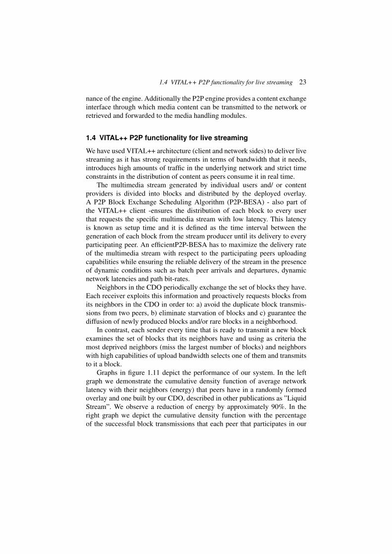
Graphs in figure 1.11 depict the performance of our system. In the leftgraph we demonstrate the cumulative density function of average networklatency with their neighbors (energy) that peers have in a randomly formedoverlay and one built by our CDO, described in other publications as ”LiquidStream”. We observe a reduction of energy by approximately 90%. In theright graph we depict the cumulative density function with the percentageof the successful block transmissions that each peer that participates in our

24 1 Integrating P2P with Next Generation Networks
Figure 1.11 Left:CDF of the average network latency, Right: CDF of the successful blockreceptions.
system has. We mention here that the video steaming rate is 95% of the aver-age upload bandwidth of the participating peers and the latency between thegeneration of a video block and its distribution in every peer in the system is 4seconds. Through these graphs we observe the optimal and stable delivery ofa video (right graph) while simultaneously our system minimizes the trafficthat it introduces in the underlying network (left graph).
1.5 Use Case (SoftMix)
The SoftMix service, developed by content provider Rundfunk Berlin Bran-denburg (RBB) over the course of VITAL++, serves as main demonstratorfor the full functionality of the VITAL++ individual components and overallarchitecture.
Independent of the technological setting, its basic aim is to enable usersto experience a truly personalized radio, which serves exactly the kind ofcontent that they like. This service is meant to be a prototype of a radio oftomorrow, combining the traditional experience of the radio with the possibil-ities of the Internet: while traditional radio runs in the background and doesnot require any kind of interaction with the ”output device/user interface”(i.e. the radio), the Internet offers a variety of opportunities to interact with

1.5 Use Case (SoftMix) 25
the content through the service, including browsing, skipping, downloading,etc. SoftMix aims to enable the user to listen to the radio and personalize thisexperience according to his/her preferences. In this case ”user” is the mostsuitable term as the service enables active use and influence, way beyondpassive listening. As long as the user is happy with the programme, however,s/he will not have to interact at all. The radio will just keep playing withoutfurther intervention.
The SoftMix service is intended for use on different IP-networked de-vices, stationary or mobile. Depending on their peer-to-peer capabilities, band-width, screen displays and other potentially limiting factors some such de-vices may not offer all of the service features. However, it is clearly intendedthat all of them offer the basic capabilities of receiving multimedia contentaccording to their preferences and to further influence their profiles.
The SoftMix service will be offered via a dedicated RBB website whereinterested users can download the client and choose a start profile. Users willhave to register for the service, saving some basic information as a first steptowards their personal radio style. As RBB’s six radio channels are alreadytargeting certain interest groups they will be a good starting point. There-fore, the first step towards a user profile is to choose the one RBB radiochannel profile that most suits their interest and taste. From the moment thatthey selected one they can start receiving their radio programme and willreceive more general recommendations soon according to their first reactions(like/dislike) to the programmes they received. The respective procedures willbe described and explained in the following chapters.
The player will display the current media file on a screen, plus the basicinformation (channel, series, title/short description) - most other informationwill be available for searching and profiling but not visible in the player view.This player offers a reduced palette of buttons for maximum usability:
* PLAY/PAUSE.* BOOKMARK: (this file), so you can listen to it later.* SUBSCRIBE: (to this series); it will be added to your profile and any
new episode added to your playlist with every new update.* RECOMMEND: will show a bar with icons of friends that are online
and can be selected to receive a recommendation. This file will thenappear in their playlists.
* LIKE: this file and/or its related series will be uprated in your profile.* DISLIKE: this file/series will be downrated in your profile.* SKIP: Skipping a content item will also influence the profile.

26 1 Integrating P2P with Next Generation Networks
There will not be any active search facility. Content search will happen inthe background, being triggered by the user’s profile in combination with aneditorial frame which ensures that the order of files is not arbitrary but keepslistening to SoftMix a high quality radio experience.
To organize content search only according to user preferences would gen-erate a random radio programme which would most certainly not have thequality of traditional radio programmes. In order to avoid arbitrary playliststhe concept of Programme Frames was introduced. Over long periods radioexperts have developed concepts to organize radio programmes so that theyentertain and inform people in different ways at different times of the day;the famous morning radio shows are a prominent example for this.
SoftMix now also offers such Programme Frames in order to organize theradio programme in the way that generic frames define what type of contentshould follow the current item. This would avoid that three recipe podcastsor weather forecasts would be played in a row.
The Recommendation Engine which matches the user profile with theavailable content will now do this according to the currently relevant frameand thus filter the search request and at the same time organize the order ofthe playlist.
Using Broadcast Mode, users can ”publish” simple media files or com-plete playlists as their own little radio show. Other users can tune in to theirshow and listen to this prepared playlist rather than to their own playlist asrecommended by the SoftMix application based on their profile.
For devices with slow connectivity or small disk space the VITAL++architecture employs a transcoding service converts media files between dif-ferent content formats, e.g. codecs and bandwidth, depending on the require-ments of the end user device.
IMS features are used, among others, for registering users, especially toenable decent influence and control on users who want to publish their ownfiles or put together their own radio shows from own and public files bycreating and publishing a playlist in ”broadcast mode”.
1.6 VITAL++ Test bed Deployment
In order to test/evaluate the proposed VITAL++ paradigm a number of hetero-geneous telecommunication platforms were interconnected into a commonexperimental playground, as depicted in Figure 1.12. This unified testbed en-vironment includes the IMS-enabled telecommunication infrastructures fromFOKUS (Fraunhofer Institut), Telekomm Austria (TA), Telefonica I+D (TID),

1.6 VITAL++ Test bed Deployment 27
Figure 1.12 VITAL++ testbed.
University of Patras (UoP), and Voiceglobe, as well as an interactive DVB-Tplatform (at CTRC premises) acting as a Media Provider (Broadcaster) andData injector in the services that we offer. More specifically, here we describea scenario where, live streaming TV content (IPTV) is fed from an active-userlocated within the DVB-T broadcasting footprint (potential Broadcaster) ontothe p2p engine, via a VPN connection. The received IPTV stream is processedby the P2P engine and distributed over the entire VITAL++ infrastructure viaa number of specially configured VPN tunnels, established with OpenVPNsoftware10, enabling both IMS and P2P connectivity. This was achieved bymeans of VPN tunnels (see Figure 1.13).
Towards these, a VPN server was installed in Telefonica I+D’s premisesand VPN clients in the remaining testbeds, in order to establish a VPN tunnelbetween Telefonica I+D and each partner’s testbed. A DNS server was alsoinstalled to resolve the domain names of each IMS core, therefore enablingthe placement of calls between users registered at different IMS cores. Oncebasic IP and IMS connectivity was achieved, it was the turn of adapting thecores to VITAL++ needs, deploying the elements and entities required by thearchitecture.
First, the PCs hosting the IMS clients would also host the VITAL++clients, both Monster’s and BlueChip Technology’s. It was decided that VI-
10 http://openvpn.net/

28 1 Integrating P2P with Next Generation Networks
Figure 1.13 VITAL++ testbed connectivity.
TAL++’s users were going to be created only at Franunhofer’s IMS Core,which would be considered as the home network for those users. While test-ing from another testbed, those users would act as roaming users accessingto their home network from a visited network, via the local P-CSCF. TheSub Architectures defined in the project would be distributed among thetestbed, not centralized, and would be located at the following testbeds. Con-tent Indexing (CI-SA) and Overlay Management (OM-SA) at University ofPatras’s. P2P Authentication (P2PA-SA) at Fraunhofer’s and Content Secu-rity (CS-SA) at Waterford Institute of Technology (WIT). In this case, twoVPN tunnels were required, one for the CS itself and other for the CertificateAuthority, CA, the CS relies on). Those SA are considered as IMS Applica-tion Servers (SA), and are registered as such in Fraunhofer IMS core, in orderto route IMS traffic among them and the clients.
However, besides adapting the testbeds, VITAL++ requires a number ofexternal elements to carry out its functionalities properly. They are listedbriefly here:
- In the case of Voiceglobe, a commercial provider of SIP telephony, adirect connection to the testbeds’ network can not be established sinceits subscribers are assigned real IP addresses. In order to circumventthis obstacle, a VITAL++ Proxy has been implemented, that would ap-pear to VITAL++ system as an standard VITAL++ Client and will en-

1.6 VITAL++ Test bed Deployment 29
Figure 1.14 VITAL++ Configuration.
able Voiceglobe clients to download the contents made available byVITAL++.
- A database containing the data and metadata of the contents distributedby VITAL++ is located at Rundfunk Berlin Brandenburg’s (RBB) premises.This database will not be connected directly to the network compris-ing the VPN tunnels or visible by the VITAL++ Clients, but indirectlyaccessed via University of Patras’s testbed.
- In order to provide the content format that best fits the terminal ca-pabilities (i.e. bandwidth, spatial resolution) a transcoding utility hasbeen made available at Telefonica I+D’s premises, which will automat-ically convert any uploaded contents into a set of predefined formats,served by respective overlays, enabling VITAL++ clients to join themost appropriate for their needs.
- In the case of the IPTV injection scenario, the Centre for TechnologicalResearch of Crete (CTRC) has inject a live streaming TV content ontothe UoP test-bed from an active-user (potential Broadcaster) locatedwithin the regenerative DVB-T platform at CTRC premises, via a VPNconnection. This stream is processed by the P2P engine and distributedover the entire VITAL++ infrastructure.
1.6.1 Test bed configuration
From a logical standpoint, the relationships and interfaces among the dif-ferent entities involved in VITAL++ are depicted in figure 1.14. VITAL++

30 1 Integrating P2P with Next Generation Networks
client registration will be carried out using the Fraunhofer’s IMS core withinFokus’s tesbed or via VPN connections from the partners in the case of roam-ing users from other testbeds (”visited networks” in IMS terminology). In thecase of VoiceGlobe subscribers, the use of VITAL++ Proxy is mandatory.Once registered the VITAL++ Clients will be able to interact with the VI-TAL++ SA by sending and receiving IMS messages, in order to carry out thefollowing tasks:
* To upload a content into Rundfunk Berlin Brandenburg’s systems andcreate as many overlays as required for transcoding purposes plus asuperpeer to serve them, in case the original uploader leaves the overlay.
* To search for contents, according to user’s preferences stored in a per-sonal profile, in order to retrieve a list of recommendations.
* To play that list of recommendations, joining the overlays serving eachobject. Notice that the play will be sequential and the user will be giventhe option of skipping tracks (though not of direct selection).
* To compose a playlist with contents already available in the system orstored in its HD and publish it.
* To join the playlists of the users in broadcast mode, who will identifiedas such in the user interface.
* To join the overlays offering Live TV and audio broadcast.
1.6.2 The IPTV injection scenario
In order to provide to the VITAL++ test-bed a live video event stemming froma real operational DVB-T platform in the Heraklion city [3] the followingmodules were configured:
* To upload a content into Rundfunk Berlin Brandenburg’s systems andcreate as many overlays as required for transcoding purposes plus asuperpeer to serve them, in case the original uploader leaves the overlay.
* An interactive DVB-T platform in regenerative configuration, where thecommon DVB-T downlink stream is transmitted in channel 40 of theUHF band (i.e. 622-630MHz), utilizing 8K operation mode with 16QAMmodulation scheme, 7/8 code rate, 1/32 guard interval and the multi-protocol encapsulation mechanism (MPE) for the distribution of the IPdatagrams. These transmission parameters provide a total available down-link capacity of about 20.5Mb/s, according to the DVB-T standard, partof which (12.5Mb/s) was allocated among three digital TV programs

1.6 VITAL++ Test bed Deployment 31
(MPEG-2 live and non-live TV broadcasts), while the rest bandwidthwas dedicated to IP services (i.e. 8Mb/s).
* A Cell Main Node (namely CMN1 in figure 1.15) located in an urbanarea of Heraclion City, providing triple play services to the end-users.The communication between this CMN and the DVB-T platform is viaa one-way point-to-point link IEEE 802.11g (uplink), while downlinkdata are received by the CMN over the DVB-T broadcasting stream. Thecommunication between the end-users and this CMN (access network)is over IEEE 802.11g full-duplex links.
* One rural-based CMN (namely CMN2) located 10 kilometers away fromthe DVB-T platform. This CMN serves a number of end-users exploit-ing ADSL technology (downlink 8048/uplink 1024) in the access net-work, while communicating with the regenerative DVB-T over commonPSTN/ISDN lines in the uplink, and over the broadcasting stream in thedownlink.
* A number of end-users located inside the access network of the cell mainnodes. The Users located inside the Broadcast area are potentially usersof the whole VITAL++ test-bed via the UoP test-bed.
* A VPN client that has two network interfaces, a) one real IP interface(fxp0:192.92.9.xx), and b) one interconnected with the DVB-T network(rl0= 10.0.67.xx). It has to be noted that the VPN client is an openBSDrouter that routes all traffic stemming from the DVB-T Network to theUoP testbed via a IPSec tunnel (enc0=192.168.184.xx).
In order to inject the stream inside the UOP testbed the following method wasfollowed:
1. An end user using a digital TV tuner in order to capture the transmittedlive video stream and forward it to the CMN.
2. A CMN capable of Transcoding the stream stemming from the end userand forwarding it to the central broadcasting point in RTP format.
3. A central broadcasting point where the transcoded stream was encapsu-lated and broadcasted in the UHF channel enabling the end users to becapable of viewing the RTP based transcoded DVB-STREAM.
4. A CORE module located in the central broadcasting point forwardingthe transcoded video stream to the IPSec tunnel connecting CTRC withUoP.
5. At the UoP site the transcoded live video stream is received by the VI-TAL++ p2p client enabling all the VITAL++ end users interconnectedwith the UoP test-bed to access the live video service stemming from the

32 1 Integrating P2P with Next Generation Networks
VPN Client
10.8.1.22
VITAL Client
192.168.184.x
VITAL Client
192.168.184.x
UoP’s Testbed
ims.ece.upatras.gr
IMS Core
192.168.184.149
OM-SA + CI-SA/AS
192.168.184.x
Broadcast
area
Heraklion
City
CMN1
access
network
IPSec VPN Server/Router
Fxp0=193.92.9.52
rl0=
VITAL Client nth
192.168.0.x
UHF CHANNEL 21
VITAL Client 1st
192.168.0.x
CTRC
Premises
CMN2
access
network
VITAL Client nth
172.16.0.x
VITAL Client 1st
172.16.0.x
CMN1
CMN2
Reverse P
ath
Reverse Path
Figure 1.15 The IPTV injection scenario architecture.
end user located in the broadcasting area of the DVB-T infrastructure inHeraklion City.
1.6.3 VITAL++ test-bed deployment over an interactive DVB-Tinfrastructure
By deploying the VITAL++ Paradigm to an interactive DVB-T infrastructure,we enhance the scalability as well as the performance of the entire network,by exploiting P2P technology. On the other hand, the deployment of the IPMultimedia subsystems (IMS) tries to address issues of heterogeneity in theaccess technologies, AAA, security, and mobility management.
In order to enable the end users of the DVB-T interactive to become endusers of the VITAL++ test-bed the following modules will be configured: ADVB-T platform, where the common DVB-T stream is transmitted in chan-nel 40 of the UHF band (i.e. 622-630MHz), utilizing 8K operation modewith 16QAM modulation scheme, 7/8 code rate, 1/32 guard interval and themulti-protocol encapsulation mechanism (MPE) for the distribution of the IPdatagram’s.
The DVB/IP core network (see figure 1.16) utilizes the I-CSCF, S-CSCFand HSS (based on Fokus OpenSource IMS Core software). The core net-work will be able to receive the users/nodes IP traffic and IMS signalinginformation over the uplinks (via the appropriate Proxy Call Session Control

1.7 Conclusions 33
DVB-T CMN
IMS ENABLED
WLAN (802.11g)
Access Network WLAN (802.11b)
Access Network
xDSL Access
Network
MULTIMEDIA SERVER
VITAL++ End-user
Using the Hybrid P2P/IMS CLIENT
VITAL++ End-user
Using the Hybrid P2P/IMS CLIENT
Re
ve
rse
pa
th
ch
an
ne
l
Re
ve
rse
pa
th
ch
an
ne
l
Re
ve
rse
pa
th
ch
an
ne
l
Ac
ce
ss
ne
two
rk
P-CSCF
Fo
rwa
rd
ch
an
ne
l
Fo
rwa
rd
ch
an
ne
l
Fo
rwa
rd
ch
an
ne
l
P-CSCF P-CSCF
DVB-T CMN
IMS ENABLED
DVB-T CMN
IMS ENABLED
S-CSCF
HSS
I-CSCF
VITAL++
End-user
Using the
Hybrid P2P/
IMS CLIENT
DV
B-T
Co
re
ne
two
rk
Figure 1.16 Proposed configuration of VITAL++ paradigm in an Interactive DVB-T infras-tructure.
Function (P-CSCF)). The visited domains that are allowed to roam will bealso defined in the IMS Core.
The CMN will gather all IP traffic stemming from its users, while theProxy Call Session Control Function (P-CSCF) operating as the first contactpoint of the IMS domain, will create the necessary signaling for the provi-sion of secure data transmission, authorization of the media and compressionsupport of the SIP signaling, where required. The end user will utilize theVITAL++ HYBRID IMS/P2P Client.
A VPN client that has two network interfaces, One real IP interface andone interconnected with the DVB-T network. It has to be noted that theVPN client will routes all traffic stemming from the DVB-T Network to theVITAL++ test-bed via a IPSec tunnel.
1.7 Conclusions
In this work we analyzed how IMS, with it’s centralized management andfeatures for AAA and charging can exploit a P2P networking paradigm tooffer content distribution services that are scalable, adaptable, secure, reli-able while simultaneously offer new functionalities to the users. Through thedevelopment of the Vital++ platform we learned that P2P authentication isa promising solution for scalable and secure content distribution services.

34 1 Integrating P2P with Next Generation Networks
Content security and accounting may be successfully combined with P2Poverlays in order to meet business requirements. A centralized content index-ing reveals P2P capabilities and doesn’t hurt system scalability. Finally theoptimization and the dynamic adaptation of the content distribution overlayis a critical factor for the successful operation of P2P content distributionservices.
1.8 Acknowledgements
This work is funded from the European project VITAL++ with ContractNumber: INFSO-ICT-224287.

Bibliography
[1] N. Efthymiopoulos A. Christakidis S. Denazis and O. Koufopavlou. Liquidstream - net-work dependant dynamic p2p live streaming. Springer Peer-to- Peer Networking andApplications (Accepted to be published), 2010.
[2] J. Fiedler T. Magedanz and J. Mueller. Extending an IMS client with peer-to-peer contentdelivery. In Proceedings of the Second International Conference on MOBILe WirelessMiddleWARE, Operating Systems, Applications - ICST MOBILWARE, 1978.
[3] E. Markakis E. Pallis and H. Skianis. Exploiting peer-to-peer technology for network andresource management in interactive broadcasting environments. In Proceedings of IEEEGlobecom, 2010.
[4] VITAL++. http://www.ict-vitalpp.upatras.gr/.
35