Instruction Manual - Columbus McKinnon
58
Instruction Manual September 2012 Part Number: 146-17040 © Copyright 2012 Magnetek
-
Upload
khangminh22 -
Category
Documents
-
view
5 -
download
0
Transcript of Instruction Manual - Columbus McKinnon

Instruction Manual
September 2012Part Number: 146-17040
© Copyright 2012 Magnetek

IMPULSE®•R Instruction ManualSeptember 2012 2
Table of Contents
Preface and Safety . . . . . . . . . . . . . . . . . . . . . . . . . . . . . . . . . . . . . . . . . . . . . . . . . . . . . . . . . . . . 3
Product Safety Information. . . . . . . . . . . . . . . . . . . . . . . . . . . . . . . . . . . . . . . . . . . . . . . . . . 3
Product Warranty Information. . . . . . . . . . . . . . . . . . . . . . . . . . . . . . . . . . . . . . . . . . . . . . . . 3
Conditions of Acceptability . . . . . . . . . . . . . . . . . . . . . . . . . . . . . . . . . . . . . . . . . . . . . . . . . . 4
Supplemental Safety Instructions. . . . . . . . . . . . . . . . . . . . . . . . . . . . . . . . . . . . . . . . . . . . . 5
Notes for Safe Operation . . . . . . . . . . . . . . . . . . . . . . . . . . . . . . . . . . . . . . . . . . . . . . . . . . . 6
Receiving . . . . . . . . . . . . . . . . . . . . . . . . . . . . . . . . . . . . . . . . . . . . . . . . . . . . . . . . . . . . . . . . . . 10
Section Safety . . . . . . . . . . . . . . . . . . . . . . . . . . . . . . . . . . . . . . . . . . . . . . . . . . . . . . . . . . 10
Inspection Checkpoints . . . . . . . . . . . . . . . . . . . . . . . . . . . . . . . . . . . . . . . . . . . . . . . . . . . 10
Installation . . . . . . . . . . . . . . . . . . . . . . . . . . . . . . . . . . . . . . . . . . . . . . . . . . . . . . . . . . . . . . . . . 12
Section Safety . . . . . . . . . . . . . . . . . . . . . . . . . . . . . . . . . . . . . . . . . . . . . . . . . . . . . . . . . . 12
Checking Installation Site . . . . . . . . . . . . . . . . . . . . . . . . . . . . . . . . . . . . . . . . . . . . . . . . . . 12
Clearances . . . . . . . . . . . . . . . . . . . . . . . . . . . . . . . . . . . . . . . . . . . . . . . . . . . . . . . . . . . . . 14
Dimensions. . . . . . . . . . . . . . . . . . . . . . . . . . . . . . . . . . . . . . . . . . . . . . . . . . . . . . . . . . . . . 15
Removing and Replacing the Front Cover . . . . . . . . . . . . . . . . . . . . . . . . . . . . . . . . . . . . . 17
Removing and Replacing the LCD Monitor/Digital Operator . . . . . . . . . . . . . . . . . . . . . . . 17
Wiring . . . . . . . . . . . . . . . . . . . . . . . . . . . . . . . . . . . . . . . . . . . . . . . . . . . . . . . . . . . . . . . . . . . . . 19
Section Safety . . . . . . . . . . . . . . . . . . . . . . . . . . . . . . . . . . . . . . . . . . . . . . . . . . . . . . . . . . 19
Connection Diagram. . . . . . . . . . . . . . . . . . . . . . . . . . . . . . . . . . . . . . . . . . . . . . . . . . . . . . 20
Selecting Peripheral Devices . . . . . . . . . . . . . . . . . . . . . . . . . . . . . . . . . . . . . . . . . . . . . . . 21
Wiring Main Circuit Terminals. . . . . . . . . . . . . . . . . . . . . . . . . . . . . . . . . . . . . . . . . . . . . . . 25
External Terminals . . . . . . . . . . . . . . . . . . . . . . . . . . . . . . . . . . . . . . . . . . . . . . . . . . . . . . . 29
Operation . . . . . . . . . . . . . . . . . . . . . . . . . . . . . . . . . . . . . . . . . . . . . . . . . . . . . . . . . . . . . . . . . . 31
Section Safety . . . . . . . . . . . . . . . . . . . . . . . . . . . . . . . . . . . . . . . . . . . . . . . . . . . . . . . . . . 31
Checks Prior to Main Power Application . . . . . . . . . . . . . . . . . . . . . . . . . . . . . . . . . . . . . . 31
Setting the Power Supply Voltage Jumper . . . . . . . . . . . . . . . . . . . . . . . . . . . . . . . . . . . . . 31
Using the Digital Operator . . . . . . . . . . . . . . . . . . . . . . . . . . . . . . . . . . . . . . . . . . . . . . . . . 32
Digital Operator Modes. . . . . . . . . . . . . . . . . . . . . . . . . . . . . . . . . . . . . . . . . . . . . . . . . . . . 34
Power On/Off Sequence. . . . . . . . . . . . . . . . . . . . . . . . . . . . . . . . . . . . . . . . . . . . . . . . . . . 38
Run Command Selection . . . . . . . . . . . . . . . . . . . . . . . . . . . . . . . . . . . . . . . . . . . . . . . . . . 38
Maintenance and Inspection . . . . . . . . . . . . . . . . . . . . . . . . . . . . . . . . . . . . . . . . . . . . . . . . . . . 40
Section Safety . . . . . . . . . . . . . . . . . . . . . . . . . . . . . . . . . . . . . . . . . . . . . . . . . . . . . . . . . . 40
Periodic Inspection and Maintenance . . . . . . . . . . . . . . . . . . . . . . . . . . . . . . . . . . . . . . . . 40
Troubleshooting . . . . . . . . . . . . . . . . . . . . . . . . . . . . . . . . . . . . . . . . . . . . . . . . . . . . . . . . . . . . . 43
Fault Detection . . . . . . . . . . . . . . . . . . . . . . . . . . . . . . . . . . . . . . . . . . . . . . . . . . . . . . . . . . 43
Minor Fault Detection . . . . . . . . . . . . . . . . . . . . . . . . . . . . . . . . . . . . . . . . . . . . . . . . . . . . . 45
Operation Errors. . . . . . . . . . . . . . . . . . . . . . . . . . . . . . . . . . . . . . . . . . . . . . . . . . . . . . . . . 46
Specifications. . . . . . . . . . . . . . . . . . . . . . . . . . . . . . . . . . . . . . . . . . . . . . . . . . . . . . . . . . . . . . . 47
Appendix. . . . . . . . . . . . . . . . . . . . . . . . . . . . . . . . . . . . . . . . . . . . . . . . . . . . . . . . . . . . . . . . . . . 51

IMPULSE®•R Instruction ManualSeptember 2012
3
Preface and Safety
©2012 MAGNETEK
All rights reserved. This notice applies to all copyrighted materials included with this product, including, but not limited to, this manual and software embodied within the product. This manual is intended for the sole use of the persons to whom it was provided. Any unauthorized distribution of the manual or dispersal of its contents is strictly forbidden. This manual may not be reproduced in whole or in part by any means whatsoever without the expressed written permission from Magnetek.
IMPULSE®•R is a power regenerative unit which has both braking and regenerative functions. This instruction manual describes installation, maintenance and inspection, troubleshooting, and specifications
of the IMPULSE®•R. Read this instruction manual thoroughly before operation.
Product Safety Information
Magnetek, Inc. (Magnetek) offers a broad range of radio remote control products, control products and adjustable frequency drives, and industrial braking systems for material handling applications. This manual has been prepared by Magnetek to provide information and recommendations for the installation, use, operation and service of Magnetek’s material handling products and systems (Magnetek Products). Anyone who uses, operates, maintains, services, installs or owns Magnetek Products should know, understand, and follow the instructions and safety recommendations in this manual for Magnetek Products.
The recommendations in this manual do not take precedence over any of the following requirements relating to cranes, hoists, lifting devices or other equipment which use or include Magnetek Products:
• Instructions, manuals, and safety warnings of the manufacturers of the equipment where the Magnetek Products are used,
• Plant safety rules and procedures of the employers and the owners of the facilities where the Magnetek Products are being used,
• Regulations issued by the Occupational Health and Safety Administration (OSHA),
• Applicable local, state, or federal codes, ordinances, standards and requirements, or
• Safety standards and practices for the industries in which Magnetek Products are used.
This manual does not include or address the specific instructions and safety warnings of these manufacturers or any of the other requirements listed above. It is the responsibility of the owners, users, and operators of the Magnetek Products to know, understand, and follow all of these requirements. It is the responsibility of the employer to make its employees aware of all of the above listed requirements and to make certain that all operators are properly trained. No one should use Magnetek Products prior to becoming familiar with and being trained in these requirements and the instructions and safety recommendations for this manual.
Product Warranty Information
Magnetek, hereafter referred to as Company, assumes no responsibility for improper programming of a drive by untrained personnel. A drive should only be programmed by a trained technician who has read and understands the contents of this manual. Improper programming of a drive can lead to unexpected, undesirable, or unsafe operation or performance of the drive. This may result in damage to equipment or personal injury. Company shall not be liable for economic loss, property damage, or other consequential damages or physical injury sustained by the purchaser or by any third party as a result of such programming. Company neither assumes nor authorizes any other person to assume for Company any other liability in connection with the sale or use of this product. For information on Magnetek’s product warranties by product type, please visit www.magnetekmh.com.

IMPULSE®•R Instruction ManualSeptember 2012 4
Conditions of Acceptability
NEC, CEC and UL Compliance
In order to comply with the NEC, CEC and UL, the following conditions of use must be strictly adhered to:
Surge Protector Installation
An MOV must be installed on the input of the IMPULSE®•R.
Current Suppression Reactor Installation
The Current Suppression Reactor must be installed as shown in Figure 9.
Terminal Blocks
The Power Terminal Blocks of the IMPULSE®•R are for factory wiring use only.
Installation Environment
Install the IMPULSE®•R in a protective enclosure suitable to its environment if it was not purchased as an enclosed kit.
CSA Standards Compliance
The IMPULSE®•R is CSA certified as following.
Products
CLASS 3211 06INDUSTRIAL CONTROL EQUIPMENTMotor Controllers Miscellaneous
CLASS 2411 02ELEVATOR EQUIPMENTEnclosed Elevator and Escalator Electrical Equipment
Applicable Requirements
CAN/CSA C22.2 No.0.4-04Bonding of Electrical Equipment
CAN/CSA C22.2 No.14-05Industrial Control Equipment
CSA B44.1-04/ASME A17.5-2004Elevator and Escalator Electrical Equipment
Figure 1: CSA B44.1-04/ASME A17.5-2004 Mark

IMPULSE®•R Instruction ManualSeptember 2012
5
Supplemental Safety Instructions
Read and understand this manual before installing, operating, or servicing this product. Install the product according to this manual and local codes.
The following conventions indicate safety messages, and may be used in this manual to emphasize important and critical information. Failure to heed these messages could cause fatal injury or damage products and related equipment and systems.
DANGER
DANGER indicates an imminently hazardous situation which, if not avoided, will result in death or serious injury. This signal word is to be limited to the most extreme situations.
WARNING
WARNING indicates a potentially hazardous situation which, if not avoided, could result in death or serious injury.
CAUTION
CAUTION indicates a potentially hazardous situation which, if not avoided, could result in minor or moderate injury. It may also be used to alert against unsafe practices.
NOTICE
NOTICE indicates an equipment damage message.
NOTE: A NOTE statement is used to notify installation, operation, programming, or maintenance information that is important, but not hazard-related.

IMPULSE®•R Instruction ManualSeptember 2012 6
Notes for Safe Operation
Receiving
Installation
CAUTION
Do not install or operate any power regenerative unit which is damaged or has missing parts.Failure to observe this caution may result in personal injury or equipment damage (refer to page 10).
CAUTION
Lift the cabinet by the base. When moving the unit, never lift by the front cover or the front panel.Otherwise, the main unit may be dropped, causing damage to the unit (refer to page 12).
Mount the power regenerative unit on nonflammable material (i.e. metal).Failure to observe this caution can result in a fire (refer to page 12).
When mounting units in an enclosure, install a fan or other cooling device to keep the intake air temperature below 45°C.Overheating may cause a fire or damage to the unit (refer to page 12).
In order to comply to UL regulations, the MOV and current suppression reactor must be
installed on the input of the IMPULSE®•R.Refer to the installation diagram (refer to page 12).

IMPULSE®•R Instruction ManualSeptember 2012
7
Wiring
WARNING
Only commence wiring after verifying that the power supply is turned OFF.Failure to observe this warning can result in an electric shock or a fire (refer to page 19).
Wiring should be performed only by qualified personnel.Failure to observe this warning can result in an electric shock or a fire (refer to page 19).
Make sure to ground the ground terminal before connecting the other terminals.Failure to observe this warning can result in an electric shock or a fire (refer to page 19).
Install adequate branch short circuit protection according to applicable codes.Failure to comply could result in damage to the drive.
The device is suitable for circuits capable of delivering up to 100 kA RMS Symmetrical Amperes, 240 VAC maximum (230 V Class), 480 VAC maximum (460 V Class), or equivalent to the SCCR rating of the VFD to which it is connected - whichever value is less.
IMPULSE®•R devices shall be connected to a VFD which incorporates Solid State Short Circuit Protection Circuitry and was found to comply with the High Fault Current Short Circuit Test.
CAUTION
Verify that the power regenerative unit rated voltage coincides with the AC power supply voltage.Failure to observe this caution can result in personal injury or a fire (refer to page 19).
Do not perform a withstand voltage test of the power regenerative unit.It may cause semiconductor elements to be damaged (refer to page 19).
Connect the power coordinating reactor and the power suppressing reactor as described in this instruction manual.Improper connection may cause a fire (refer to page 19).
Verify that the rated voltage of the power regenerative unit coincides with the rated voltage of the power regenerative unit to be connected.Failure to observe this caution can result in a fire (refer to page 19).
Tighten terminal screws.Failure to observe this caution can result in a fire (refer to page 19).

IMPULSE®•R Instruction ManualSeptember 2012 8
Operation
WARNING
Only turn ON the input power supply after replacing the front cover or the terminal cover. Do not remove the cover while power is on.Failure to observe this warning can result in an electric shock (refer to page 31).
Never operate the digital operator or other switches when your hand is wet.Failure to observe this warning can result in an electric shock (refer to page 31).
Never touch the terminals while power is on, even if the power regenerative unit stops.Failure to observe this warning can result in an electric shock (refer to page 31).
CAUTION
Never touch the heatsink or input reactors since their temperature may be very high.Failure to observe this caution can result in harmful burns to the body (refer to page 31).
All the parameters of the power regenerative unit have been preset at the factory. Do not change the settings unnecessarily.The power regenerative unit may be damaged (refer to page 31).

IMPULSE®•R Instruction ManualSeptember 2012
9
Maintenance and Inspection
WARNING
Never touch high-voltage terminals in the power regenerative unit.Failure to observe this warning can result in an electric shock (refer to page 40).
Perform maintenance or inspection only after verifying that the CHARGE LED goes OFF, after the main circuit power supply is turned OFF.The capacitors are still charged and can be dangerous (refer to page 40).
Only authorized personnel should be permitted to perform maintenance, inspections, or parts replacement.[Remove all metal objects (watches, bracelets, etc.) before operation.] Use tools which are insulated against electric shock.
Failure to observe this warning can result in an electric shock. (Refer to page 40)
Never modify the product.Failure to observe this warning can result in an electric shock or personal injury and will invalidate the guarantee (refer to page 40).
CAUTION
The power regenerative unit employs semi-conductor elements. Do not touch the CMOS elements.They are easily damaged by static electricity (refer to page 40).
Do not connect or disconnect wires or connectors while power is applied to the circuit.Failure to observe this caution can result in personal injury (refer to page 40).
IMPULSE®•R Instruction ManualSeptember 2012 10
Receiving
Section Safety
Inspection Checkpoints
Receiving CheckpointsTable 1: Checkpoints
If any of the above checkpoints are not satisfactory, contact your Magnetek representative.
CAUTION
Do not install or operate any power regenerative unit which is damaged or has missing parts.Failure to observe this caution may result in personal injury or equipment damage.
Checkpoints Description
Does the power regenerative unit model number correspond with the purchase order?
Check the model number on the nameplate on the side of the IMPULSE®•R.
Are any parts damaged? Visually check the exterior and verify that there was no damage during transport.
Is hardware properly seated and securely tightened?
Remove the front cover of the power regenerative unit.Check all visible hardware with appropriate tools.

IMPULSE®•R Instruction ManualSeptember 2012
11
Model Designation
Figure 2: Model Designation
Productive Structure
• Open Chassis Type (IEC IP00)Protected so that parts of the human body cannot reach electrically charged parts from the front when the power regenerative unit is mounted in a control panel.
• Enclosed Wall-mounted Type (IEC IP20, NEMA 1)The power regenerative unit is structured so that the power regenerative unit is shielded from the exterior, and can thus be mounted to the interior wall of a standard building (not necessarily enclosed in a control panel). The protective structure conforms to the standards of NEMA 1 in the USA.

IMPULSE®•R Instruction ManualSeptember 2012 12
Installation
Section Safety
Checking Installation Site
Installation Site
Install the power regenerative unit under the following conditions.
Table 2: Acceptable Installation Conditions
CAUTION
Lift the cabinet by the base. When moving the unit, never lift by the front cover or the front panel.Otherwise, the main unit may be dropped causing damage to the unit.
Mount the power regenerative unit on nonflammable material (i.e. metal).Failure to observe this caution can result in a fire.
When mounting units in an enclosure, install a fan or other cooling device to keep the intake air temperature below 45°C.Overheating may cause a fire or damage to the unit.
Type Ambient Operating Temperature Humidity
Enclosed wall-mounted –10 to +40°C 90% RH or less (no condensation)
Open chassis –10 to +45°C 90% RH or less (no condensation)
NOTICE
Do not install the power regenerative unit to an area greater than pollution degree 2 (UL standard).

IMPULSE®•R Instruction ManualSeptember 2012
13
To ensure proper performance and long operating life, follow the recommendations below when
choosing a location for installing the IMPULSE®•R. Make sure the power regenerative unit is protected from the following conditions:
• Extreme cold and heat. Use only within ambient temperature range: -10°C to +40°C
• Rain, moisture. (For enclosed wall-mounted type)
• Oil sprays, splashes
• Salt spray.
• Direct sunlight. (Avoid using outdoors.)
• Corrosive gases or liquids.
• Dust or metallic particles in the air. (For enclosed wall-mounted type)
• Physical shock, vibration.
• Magnetic noise. (Example: welding machines, power devices, etc.)
• High humidity.
• Radioactive materials.
• Combustibles: thinners, solvents, etc.
Controlling the Ambient Temperature
To enhance the reliability of operation, the power regenerative unit should be installed in an environment free from extreme temperature increases. If the power regenerative unit is installed in an enclosed environment, such as a box, use a cooling fan or air conditioner to maintain the internal air temperature below 45°C.
Protecting the Power Regenerative Unit from Foreign Matter
Place a cover over the power regenerative unit during installation to shield it from metal power produced by drilling.
Always remove the cover from the power regenerative unit after completing installation. Otherwise, ventilation will be reduced, causing the power regenerative unit to overheat.

IMPULSE®•R Instruction ManualSeptember 2012 14
Clearances
Install the unit vertically and allow sufficient clearances for effective cooling as shown in Figure 3.
Figure 3: Clearances
NOTE: The clearances required at top/bottom and both sides are common in open chassis type (IP00) and enclosed wall-mounted type (NEMA 1).When installing the models of 230 V (130 A) or 460 V (65 A or greater) equipped with eyebolts, extra spacing will be required on either side. For detailed dimensions, contact your Magnetek representative.Ensure sufficient space for the sections at the upper and lower parts marked with * in order to permit the flow of intake/exhaust air to/from the unit.

IMPULSE®•R Instruction ManualSeptember 2012
15
Dimensions
Figure 4: Dimensions of the IMPULSE®•R
Figure 5: Dimensions of the IMPULSE®•R

IMPULSE®•R Instruction ManualSeptember 2012 16
Table 3: IMPULSE®•R Dimensions in (mm) and Approx. Weight lb (kg)
VoltageModel
NumberFigure
Dimensionsin (mm)
Mounting Dimensionin (mm)
Approx. Weightlb (kg)
Mounting Hole d
Enclosure Type
W H D W1 H1 H2
230 V Class
2015
4
5.51(140)
11.02(280)
7.09(180)
4.96(126)
10.47(266)
0.28(7.0)
9.9(4.5)
M5
IP20
2022
2028
20427.87(200)
11.81(300)
8.07(205)
7.32(186)
11.22(285)
0.32(8.0)
12.1(5.5)
M6
205413.2(6)
2068
9.84(250)
14.96(380) 8.86
(225)9.29(236)
14.37(365)
0.30(7.5)
22(10)2080
210415.75(400)
1.08(27.5)
24.3(11)
2130 512.80(325)
17.72(450)
11.22(285)
10.83(275)
17.13(435)
0.30(7.5)
50.7(23)
IP00
460 V Class
4007
4
5.51(140)
11.02(280)
7.09(180)
4.96(126)
10.47(266)
0.28(7.0)
7.7(3.5)
M5
IP20
4011 8.8(4)4014
4021 7.87(200)
11.81(300)
8.07(205)
7.32(186)
11.22(285)
0.32(8.0)
13.2(6)
M6
4027
40349.84(250)
14.96(380)
8.86(225)
9.29(236)
14.37(365)
0.30(7.5)
23.1(10.5)
4040
4052
460 V Class
4065
512.80(325)
17.72(450)
11.22(285)
10.83(275) 17.13
(435)
0.30(7.5)
55.1(25)
M6 IP00
407711.22(285)
10.83(275)
57.3(26)
409625.0(635)
11.22(285)
10.83(275) 24.02
(610)
75(34)
412411.22(285)
10.83(275)
79.4(36)

IMPULSE®•R Instruction ManualSeptember 2012
17
Removing and Replacing the Front Cover
To remove the front cover, first move the LCD monitor/digital operator in the direction shown by arrow 1. Then squeeze the cover in the direction shown by arrows 2 on both sides and lift in the direction shown by arrow 3.
Figure 6: Removing and Replacing the Front Cover
NOTE: Do not replace the front cover with the LCD monitor/digital operator connected. The LCD monitor/digital operator will not be connected to the power regenerative unit. Replace the front cover first and then install the LCD monitor/digital operator on the cover. Refer to Removing and Replacing the LCD Monitor/Digital Operator section for replacing the LCD monitor/digital operator.
Removing and Replacing the LCD Monitor/Digital Operator
Remove and replace the LCD monitor/digital operator as follows.
Removing the LCD Monitor/Digital Operator
Push the LCD monitor/digital operator lever in the direction shown by arrow 1 and lift the LCD monitor/digital operator in the direction shown by arrow 2 to remove the LCD monitor/digital operator from the front cover.
Figure 7: Removing the LCD Monitor/Digital Operator

IMPULSE®•R Instruction ManualSeptember 2012 18
Replacing the LCD Monitor/Digital Operator
Engage the LCD monitor/digital operator on claws A in the direction shown by arrow 1 and then on claws B in the direction shown by arrow 2 to lock the LCD monitor/digital operator.
Figure 8: Replacing the LCD Monitor/Digital Operator
NOTE: Never fit the LCD monitor/digital operator in any other direction or by any other method. The LCD monitor/digital operator will not be connected to the inverter.

IMPULSE®•R Instruction ManualSeptember 2012
19
Wiring
Section Safety
WARNING
Only commence wiring after verifying that the power supply is turned OFF.Failure to observe this warning can result in an electric shock or a fire.
Wiring should be performed only by qualified personnel.Failure to observe this warning can result in an electric shock or a fire.
Make sure to ground the ground terminal before connecting the other terminals.Failure to observe this warning can result in an electric shock or a fire.
Install adequate branch short circuit protection according to applicable codes.Failure to comply could result in damage to the drive.
The device is suitable for circuits capable of delivering up to 100 kA RMS Symmetrical Amperes, 240 VAC maximum (230 V Class), 480 VAC maximum (460 V Class) or equivalent to the SCCR rating of the VFD to which it is connected - whichever value is less.
R5 Series of Power Regenerative devices shall be connected to a VFD which incorporates Solid State Short Circuit Protection Circuitry and was found to comply with the High Fault Current Short Circuit Test.
CAUTION
Verify that the power regenerative unit rated voltage coincides with the AC power supply voltage.Failure to observe this caution can result in personal injury or a fire.
Do not perform a withstand voltage test of the power regenerative unit.It may cause semi-conductor elements to be damaged.
Connect the power coordinating reactor and the power suppressing reactor as described in this instruction manual.Improper connection may cause a fire.
Verify that the rated voltage of the power regenerative unit coincides with the rated voltage of the power regenerative unit to be connected.Failure to observe this caution can result in a fire.
Tighten terminal screws.Failure to observe this caution can result in a fire.

IMPULSE®•R Instruction ManualSeptember 2012 20
Connection Diagram
Connection Diagram with Drive
Figure 9 shows a diagram of a typical connection of the IMPULSE®•R with a Magnetek drive.
Figure 9: Connection Diagram (when connecting an IMPULSE®•R and a Magnetek drive)
<1> Connect the Magnetek AC Drive power supply terminals R/L1, S/L2, and T/L3 to the secondary
side of the power coordinating reactor. Connect the IMPULSE®•R AC power supply terminals R/L1, S/L2, and T/L3 to the secondary side of the power suppressing reactor.
<2> Connect terminals r/ 1, s/ 2 of IMPULSE®•R, and terminals r1/ 11, 1/ 21, and t1/ 31 of the unit to the primary side of the power coordinating reactor.
<3> Make sure to use the specified reactor, fuse, and fuse holder.
<4> The sequence input terminal of IMPULSE®•R is the same as terminal S1. Typically, the only needed input connection would be a jumper between SC and S2 to use AutoRun mode.
<5> The wiring distance between the power coordinating reactor, and IMPULSE®•R and a Magnetek AC Drive should be 10 m or less.

IMPULSE®•R Instruction ManualSeptember 2012
21
<6> DC bus wiring [(+) 1 - (+), ] between the Drive and the power regenerative unit should be 5 m or less.
<7> Remove the wiring of terminals r/l 1 and s/l 2 since they were connected at the factory.
<8> If installing a circuit breaker or a magnetic contactor on the unit output (DC) side to shut down the power supply in an emergency, observe the following precautions:
• Be sure to confirm that the charge lamps on the unit and the Inverter are not lit, and then turn on the circuit breaker or contactor. If the circuit breaker or contactor is turned on while power is supplied to the unit and the Inverter, an overcurrent may occur and damage the circuit breaker or contactor.
• Be sure to confirm that the circuit breaker or contactor is turned on before the power is turned on
for the IMPULSE®•R.
Selecting Devices
Selecting Standard Duty or Heavy Duty IMPULSE®•R Application
The IMPULSE®•R overload rating has the capability of 150% braking torque for 30 seconds and 200% peak braking torque. The overload capability is based on the standard duty rating. The unit overload rating can be applied to heavy duty applications. Typically, the heavy duty rating is used when not operating or driving through a gear box. The following is a description of the standard duty and heavy duty ratings.
Standard Duty
Standard duty applications require intermittent full energy dissipation. The continuous rating is 80% or less braking torque and 100% braking torque for 60 seconds with a duty cycle of 25% (60 seconds maximum on-time of every 240 seconds). The overload rating is 150% braking torque for 30 seconds. Please note the peak torque should be less than 200%.
The IMPULSE®•R requires selecting Power Coordination and Current Suppression reactors according to specifications in Table 6.
Heavy Duty
Heavy duty applications require continuous energy dissipation (100% braking torque).
The overload rating is 125% for 60 seconds with a duty cycle of 25%. Braking torque of 187.5% is available for 30 seconds. Please note the peak torque should be less than 250%.
The IMPULSE®•R requires selecting Power Coordination and Current Suppression reactors according to specifications in Table 6.

IMPULSE®•R Instruction ManualSeptember 2012 22
Table 4: 230 V Class Input Fuse
Table 5: 460 V Class Input Fuse
IMPULSE®•R Input fuse Fuse holder
Model Number
Motor Rated Current (Aac)
Rated input current (Aac)
25%ED
Magnetek Part
Number
Amount per unit
Magnetek Part
Number
Amount per unit
2015 15.2 10 146-17022 3 146-17035 1
2022 22 15 146-17023 3 146-17035 1
2028 28 20 146-17023 3 146-17035 1
2042 42 30 146-17024 3 146-17036 3
2054 54 40 146-17025 3 146-17037 3
2068 68 50 146-17025 3 146-17037 3
2080 80 60 146-17026 3 146-17037 3
2104 104 80 146-17027 3 146-17037 3
2130 130 100 146-17027 3 146-17037 3
IMPULSE®•R Input fuse Fuse holder
Model Number
Motor Rated Current (Aac)
Rated input current (Aac)
25%ED
Magnetek Part
Number
Amount per unit
Magnetek Part
Number
Amount per unit
4007 7.6 5 146-17028 3 146-17038 1
4011 11 7.5 146-17029 3 146-17038 1
4014 14 10 146-17029 3 146-17038 1
4021 21 15 146-17030 3 146-17038 1
4027 27 20 146-17030 3 146-17038 1
4034 34 25 146-17031 3 146-17036 3
4040 40 30 146-17031 3 146-17036 3
4052 52 40 146-17032 3 146-17044 3
4065 65 50 146-17032 3 146-17044 3
4077 77 60 146-17033 3 146-17044 3
4096 96 75 146-17034 3 146-17044 3
4124 124 100 146-17034 3 146-17044 3

IMPULSE®•R Instruction ManualSeptember 2012
23
Power Coordination and Current Suppression Reactors
Both Power Coordination and Current Suppression Reactors are 3-phase input reactors that
correspond to each IMPULSE®•R model and are necessary when operating the unit. Use a single
Power Coordination and a single Current Suppression reactor for each IMPULSE®•R application.
Recommended IMPULSE®•R Power Coordination and Suppression Reactor Specifications
Table 6 shows Magnetek’s recommended specifications for Power Coordination and Current
Suppression reactors for each IMPULSE®•R model.
Table 6: Recommended IMPULSE®•R Power Coordination and Suppression Reactor Specifications
IMPULSE®•R Power Coordination Reactor* Current Suppression Reactor*
Drive Model Number Model Number Rated Current Model Number Rated Current
230 V Class
2015 REA230-5 18 REA230-3 12
2022 REA230-7.5 25 REA230-7.5 25
2028 REA230-10 35 REA230-7.5 25
2042 REA230-15 45 REA230-10 35
2054 REA230-20 55 REA230-20 55
2068 REA230-25 80 REA230-25 80
2080 REA230-25 80 REA230-25 80
2104 REA230-40 100 REA230-40 100
2130 REA230-50 130 REA230-50 130
460 V Class
4007 REA460-5 8 REA460-3R 8
4011 REA460-7.5 12 REA460-5 8
4014 REA460-10 18 REA460-7.5 12
4021 REA460-15 25 REA460-10 18
4027 REA460-20 35 REA230-7.5 25
4034 REA460-20 35 REA230-10 35
4040 REA460-30R 45 REA460-30R 45
4052 REA460-40 55 REA460-40 55
4065 REA460-50 80 REA460-50 80
4077 REA460-50 80 REA230-25 80
4096 REA460-75 100 REA230-40 100
4124 REA460-100 130 REA230-50 130
* Reactor models shown are for standard duty. For heavy duty models, consult your Magnetek representative.

IMPULSE®•R Instruction ManualSeptember 2012 24
Wiring Precautions
The external interconnection wiring must be performed with following procedures. After completing
IMPULSE®•R interconnections, be sure to check that the connections are correct. Never use control circuit buzzer check.
Precautions on Control Circuit Wiring
• Separate control circuit wires from main circuit wires and other power cables to prevent erroneous operation caused by noise interference.
• Separate the wiring of control circuit terminals from other control terminals or main circuit wirings.
• Wiring distance should be less than 50 m.
• Insert the wire into the lower part of the terminal block and connect it tightly with a screwdriver. Wire sheath strip length must be 7 mm.
Figure 10: Control Circuit Terminal Wiring
Use twisted shielded or twisted-pair shielded wire for the control circuit line and connect the shielded sheath to inverter terminal E (see Figure 11).
Figure 11: Shielded Wire Termination

IMPULSE®•R Instruction ManualSeptember 2012
25
Ground Wiring
• Do not share the ground wire with other devices, such as welding machines or power tools. Separate the grounding cables from the wirings for power tools.
• Always use a ground wire that complies with technical standards on electrical equipment and minimize the length of the ground wire. Leakage current flows through the power regenerative unit. Therefore, if the distance between the ground electrode and the ground terminal is too long, potential on the ground terminal of the power regenerative unit will become unstable.
• When using more than one power regenerative unit, be careful not to loop the ground wire.
Figure 12: Ground Wiring
Wiring Main Circuit Terminals
Required Wire Size
Select wires to be used for wiring from Table 7 and Table 8.
Table 7: 230 V Class Wire Size
CircuitModel
NumberTerminal Symbol
Terminal Screw
Wire Size <1>Wire Type
mm2 AWG
Main
2015
R/L1, S/L2, T/L3, (+), (+), ,
M4 2 to 5.5 14 to 10
Power cable: 600 V vinyl sheathed
wire or equivalent
r1/ 11, 1/ 21, t1/ 31
2022
R/L1, S/L2, T/L3, (+), (+), ,
M4
3.5 to 5.5 12 to 10
r1/ 11, 1/ 21, t1/ 31 2 to 5.5 14 to 10
3.5 to 5.5 12 to 10
<1> Wire size is determined by 75°C temperature-rated copper wire.

IMPULSE®•R Instruction ManualSeptember 2012 26
NOTE: Cable size is selected assuming external wiring of single 3-core cables at an ambient temperature of 30°C.
NOTE: For model number 2054, use closed-loop connectors that are recommended by JST (JST 14-5).
Main
2028
R/L1, S/L2, T/L3, (+), (+), ,
M4
5.5 10
Power cable: 600 V vinyl sheathed
wire or equivalent
r1/ 11, 1/ 21, t1/ 31 2 to 5.5 14 to 10
3.5 to 5.5 12 to 10
2042
R/L1, S/L2, T/L3, (+), (+), ,
M5
8 8
r1/ 11, 1/ 21, t1/ 31 2 to 5.5 14 to 10
5.5 to 8 10 to 8
2054
R/L1, S/L2, T/L3, (+), (+), ,
M5
8 8
r1/ 11, 1/ 21, t1/ 31 2 to 5.5 14 to 10
5.5 to 8 10 to 8
2068
R/L1, S/L2, T/L3, (+), (+), , M8 22 4
r1/ 11, 1/ 21, t1/ 31 M4 2 to 5.5 14 to 10
M6 8 8
2080
R/L1, S/L2, T/L3, (+), (+), , M8 22 4
r1/ 11, 1/ 21, t1/ 31 M4 2 to 5.5 14 to 10
M6 8 8
2104
R/L1, S/L2, T/L3, (+), (+), , M8 30 to 38 3 to 2
r1/ 11, 1/ 21, t1/ 31 M4 2 to 5.5 14 to 10
M6 14 6
2130
R/L1, S/L2, T/L3, (+), (+), , M8 50 to 60 1 to 1/0
r1/ 11, 1/ 21, t1/ 31 M4 2 to 5.5 14 to 10
M6 14 6
ControlCommon to all models
S1, S2, S3, S4, SS, SP, SC, M1, M2, M3, M4, MA, MB, MC, AM, AC
--
twisted wire0.5 to 1.25
single0.5 to 1.25
twisted wire20 to 16single
20 to 16
Shielded twisted-pair
wires
E (G) M3.5 0.5 to 2 20 to 14
CircuitModel
NumberTerminal Symbol
Terminal Screw
Wire Size <1>Wire Type
mm2 AWG
<1> Wire size is determined by 75°C temperature-rated copper wire.

IMPULSE®•R Instruction ManualSeptember 2012
27
Table 8: 460 V Class Wire Size
CircuitModel
NumberTerminal Symbol
Terminal Screw
Wire Size <1>Wire Type
mm2 AWG
Main
4007
R/L1, S/L2, T/L3, (+), (+),
(+), , M4 2 to 5.5 14 to 10
Power cable: 600 V vinyl sheathed
wire or equivalent
r1/ 11, 1/ 21, t1/ 31
4011
R/L1, S/L2, T/L3, (+), (+),
(+), , M4 2 to 5.5 14 to 10r1/ 11, 1/ 21, t1/ 31
4014
R/L1, S/L2, T/L3, (+), (+), ,
M4 2 to 5.5 14 to 10r1/ 11, 1/ 21, t1/ 31
4021
R/L1, S/L2, T/L3, (+), (+), ,
M5
3.5 to 5.5 10
r1/ 11, 1/ 21, t1/ 312 to 5.5 14 to 10
4027
R/L1, S/L2, T/L3, (+), (+), ,
M5
5.5 10
r1/ 11, 1/ 21, t1/ 31 2 to 5.5 14 to 10
8 8
4034
R/L1, S/L2, T/L3, (+), (+), , M6 8 to 14 8 to 6
r1/ 11, 1/ 21, t1/ 31 M4 2 to 5.5 14 to 10
M6 8 8
4040
R/L1, S/L2, T/L3, (+), (+), , M6 8 to 14 8 to 6
r1/ 11, 1/ 21, t1/ 31 M4 2 to 5.5 14 to 10
M6 8 8
4052
R/L1, S/L2, T/L3, (+), (+), , M6 14 6
r1/ 11, 1/ 21, t1/ 31 M4 2 to 5.5 14 to 10
M6 8 8
4065
R/L1, S/L2, T/L3, (+), (+), , M6 14 to 22 6 to 4
r1/ 11, 1/ 21, t1/ 31 M4 2 to 5.5 14 to 10
M6 8 8
<1> Wire size is determined by 75°C temperature-rated copper wire.

IMPULSE®•R Instruction ManualSeptember 2012 28
NOTE: Cable size is selected assuming external wiring of single 3-core cables at an ambient temperature of 30°C
NOTE: For model number 4021 and 4027, use closed-loop connectors that are recommended by JST (JST 3.5 - R5).
Closed-Loop Connectors Size
Magnetek recommends using closed-loop crimp terminals.
UL/cUL approval requires the use of closed-loop crimp terminals when wiring the main circuit terminals.
Use only the tools recommended by the terminal manufacturer for crimping.
Table 9: Closed Loop Connectors Sizes (JIS C 2805) (For 230 V/460 V classes)
Main
4077
R/L1, S/L2, T/L3, (+), (+), , M8 22 to 38 4 to 2
Power cable: 600 V vinyl sheathed
wire or equivalent
r1/ 11, 1/ 21, t1/ 31 M4 2 to 5.5 14 to 10
M6 8 8
4096
R/L1, S/L2, T/L3, (+), (+), , M8 38 to 60 2 to 1/0
r1/ 11, 1/ 21, t1/ 31 M4 2 to 5.5 14 to 10
M6 14 6
4124
R/L1, S/L2, T/L3, (+), (+), , M8 50 to 60 1 to 1/0
r1/ 11, 1/ 21, t1/ 31 M4 2 to 5.5 14 to 10
M6 14 6
Control
Common to all models
S1, S2, S3, S4, SS, SP, SC, M1, M2, M3, M4, MA, MB, MC, AM, AC
--
twisted wire0.5 to 1.25
single0.5 to 1.25
twisted wire20 to 16single
20 to 16
Shielded twisted-pair
wires
E (G) M3.5 0.5 to 2 20 to 14
Wire SizeTerminal Screw
Tightening Torque (N•m)
Closed Loop Connectorsmm2 AWG
0.5 20M3.5M4
0.8 to 1.01.2 to 1.4
R1.25-3.5R1.25-4
0.75 18
1.25 16
2 14M4 1.2 to 1.4 R2-4
M5 2.1 to 2.5 R2-5
3.5 12M4 1.2 to 1.4 3.5-4
M5 2.1 to 2.5 3.5-R5
5.5 10M4 1.2 to 1.4 R5.5-4
M5 2.1 to 2.5 R5.5-5
CircuitModel
NumberTerminal Symbol
Terminal Screw
Wire Size <1>Wire Type
mm2 AWG
<1> Wire size is determined by 75°C temperature-rated copper wire.

IMPULSE®•R Instruction ManualSeptember 2012
29
NOTE: Determine the wire size for the main circuit so that line voltage drop is within 2% of the rated voltage. Line voltage drop is calculated as follows:(If there is a possibility of excessive voltage drop, use a larger wire suitable to the required length.)
Line voltage drop (V) = √3 x wire resistance (Ω/km) x wire length (m) x current (A) x 10-3
External Terminals
Main Circuit Terminal Functions
Table 10: Main Circuit Terminal Functions
8 8M5 2.1 to 2.5 R8-5
M6 3.6 to 5.1 R8-6
14 6 M6 3.6 to 5.1 R14-6
22 4 M8 8.2 to 10.2 R22-8
30/38 3/2 M8 8.2 to 10.2 R38-8
30/38 3/2
M10 18 to 23
R38-10
50/60 1/1/0 R60-10
80 3/0 R80-10
100 4/0 R100-10
100 4/0
M12 31.5 to 39.5
R100-12
150 300 R150-12
200 400 R200-13
Wire SizeTerminal Screw
Tightening Torque (N•m)
Closed Loop Connectorsmm2 AWG
Terminal Symbol Description
R/L1S/L2T/L3 Power Regenerative Unit
Main Circuit Input
Main circuit AC power supply terminal for the power regenerative unit.
(+), Connect to the Drive’s DC power supply voltage input terminals.
• Two terminals are provided for both (+) and .
r1/ 11, 1/ 21,
t1/ 31
Power Supply Voltage Detection
Detects the phase sequence and the voltage level.• Connect to the power side of the power coordinating reactor.
Power Input for FAN and MC
Supplies power for the cooling fan and inrush prevention MC of the power regenerative unit.

IMPULSE®•R Instruction ManualSeptember 2012 30
Control Circuit Terminal Functions
Table 11: Control Circuit Terminal Functions
Type No. <1> Signal Input Function Function Signal Level
Sequence Input
S1 MANUAL RUNRun when CLOSED, stops when
OPEN
24 VDC 8 mA Photocoupler isolation
S2 AUTO RUNAuto run (regenerative operation)
when CLOSED
S3EXTERNAL
FAULT INPUTExternal fault
when CLOSED Multi-function Contact Inputs
(H1-01 to H1-02)S4FAULT RESET
INPUTFault reset when
CLOSED
SCSequence Common
SSPhotocoupler
internal common
SPSequence +24 V
Power Supply
Photocoupler Output
M1 - M2 CONV READY
Closed when power
regenerative unit is READY
H2-01 to H2-0248 VDC 80 mA or less
M3 - M4 RUN CLOSE during run
Relay OutputMA - MCMB - MC
FAULT Output
Outputs when a fault is detected.Terminal MA-MC:Closed during fault detectionTerminal MB-MC:Open during fault detection
Outputs when a fault is detected.Terminal MA-MC:Closed during fault detectionTerminal MB-MC:Open during fault detection
250 VAC 1 A or less30 VDC 1 A or less
Analog OutputAM Input Current
5 V: 100% of rated input current
Multi-function Analog Output (H1-04)
- 10 V to + 10 VDC 2 mA or less)AC Analog Ground
<1> Indicates the terminal number of the control card.

IMPULSE®•R Instruction ManualSeptember 2012
31
Operation
Section Safety
Checks Prior to Main Power Application
Check the following before turning ON the power supply:
• Check that the power supply is of the correct voltage.230 V class: 200 to 230 VAC, 50/60 Hz460 V class: 380 to 460 VAC, 50/60 Hz
• Make sure that the power regenerative unit and the Drive are connected correctly.
• Make sure that the phase sequence of the main circuit terminals (R/L1, S/L2, T/L3) and the power supply voltage detection terminals (r1/ 11, 1/ 21, t1/ 31) are correct.
• Make sure that the power regenerative unit and the control device are wired correctly.
• Set the run command of the power regenerative unit and the drive to OFF.
Setting the Power Supply Voltage JumperNOTE: 460 V CLASS REGENERATIVE UNITS OF 65 A OR HIGHER
Set the power supply voltage jumper for 460 V class power regenerative unit of 65 A or higher. Insert the jumper into the voltage connector nearest to the actual power supply voltage.
Incorrect connector setting may negatively impact the performance of the power regenerative unit.
The jumper is factory-set to 460 V when shipped. If the power supply voltage is not 460 V, use the following procedure to change the setting.
WARNING
Only turn ON the input power supply after replacing the front cover or the terminal cover. Do not remove the cover while power is on.Failure to observe this warning can result in an electric shock.
Never operate the digital operator or other switches when your hand is wet.Failure to observe this warning can result in an electric shock.
Never touch the terminals while current is flowing, even if the power regenerative unit stops.Failure to observe this warning can result in an electric shock.
CAUTION
Never touch the heatsink or input reactors since their temperature may be very high.Failure to observe this caution can result in harmful burns to the body.
All the constants of the power regenerative unit have been preset at the factory. Do not change the settings unnecessarily.The power regenerative unit may be damaged.

IMPULSE®•R Instruction ManualSeptember 2012 32
1. Turn OFF the power supply switch and wait for at least five minutes before removing the front panel and setting the jumper.
2. Remove the front cover.
3. Insert the jumper at the position for the voltage supplied to the power regenerative unit (see Figure 13.
4. Replace the front cover.
Figure 13: Setting the Power Supply Voltage (For 460 V Class Power Regenerative Unit between 65 A and 248 A)
Using the Digital Operator
This section describes the component names and functions of the Digital Operator. The component names and functions are shown in Figure 14 and the key functions are described in Table 12.
Figure 14: Digital Operator Component Names and Functions

IMPULSE®•R Instruction ManualSeptember 2012
33
Table 12: Key Function
NOTE: Except diagrams, keys are referred to using the key names listed in the above table.
Key Name Function
LOCAL/REMOTE KeySwitches between operation (LOCAL) via the Digital Operator and control circuit terminal (REMOTE) operation.This key can be enabled or disabled by setting O2-01.
MENU Key Displays menus.
ESC Key Returns to the status before the DATA/ENTER Key was pressed.
JOG Key Not used.
FWD/REV Key Not used.
RESET KeySet the number of digits for parameter settings.Also acts as the reset Key when a fault has occurred.
Increment KeySelects menu items, groups, functions, and parameter names, and increments set values.
Decrement KeySelects menu items, groups, functions, and parameter names, and decrements set values.
DATA/ENTER KeyEnters menu items, functions, parameters, and set values after they are set.
RUN Key Starts the IMPULSE®•R operation when the unit is in operation with the Digital Operator.
STOP KeyStops IMPULSE®•R operation.This Key can be enabled or disabled by setting O2-02 when operating from the control circuit terminal.

IMPULSE®•R Instruction ManualSeptember 2012 34
Digital Operator Modes
This section describes the unit’s monitor modes, switching between modes, and accessing/setting user parameters.
Modes
The IMPULSE®•R’s user parameters and monitoring functions have been organized in groups called modes that make it easier to read and set user parameters.
The unit is equipped with four modes, as shown in Table 13.
Table 13: Modes
Navigating Digital Operator Modes
Once the power regenerative unit has been put into operation mode by pressing the Menu Key, the Increment and Decrement Keys can be pressed to switch to other modes. Press the DATA/ENTER Key to read/set the user parameters in each mode.
Press the ESC Key to return to the mode display from the user parameter display.
Press the DATA/ENTER Key twice to write a parameter and then press the ESC Key to return to the mode display. This is the most Basic operation, so please remember it.
Mode Primary Function(s)
Operation modeThe power regenerative unit can be run in this mode.Use this mode when monitoring values such as frequency references or output current, displaying fault information, or displaying the fault history.
Initialize mode
Use this mode when selecting the language displayed on the Digital Operator, selecting the access level for reading/setting user parameters, selecting the control mode, or initializing the user parameters.Factory setting: English (A1-00=0)
Programming mode
Use this mode when reading/setting the user constants required for operation.The program mode functions are subdivided into the following groups:
• Application: Operation mode selection
• Tuning: No Auto-Tuning
• Option: No Option Card support
• Terminal: Settings for sequential I/O and analog I/O
• Protection: Settings for the motor and power regenerative unit protection function
• Operator: Selects the Digital Operator’s display and Key function
Modified constants modeUse this mode to read/set user parameters that have been changed from their factory set values.

IMPULSE®•R Instruction ManualSeptember 2012
35
Figure 15: Mode Transitions
NOTE: When running the power regenerative unit after using the digital operator, press the MENU Key to enter the operation mode and then press the DATA/ENTER Key from the operation mode display to bring up the monitor display. Run commands can’t be received from any other display (monitor display in the operation mode appears when the power is turned ON).
Parameter Setting Example
The group level will be displayed when the DATA/ENTER Key is pressed at the programming mode display.

IMPULSE®•R Instruction ManualSeptember 2012 36
Figure 16: Parameter Setting Example
The parameter setting has been completed (operation mode has changed from the external terminals to the operator).
Operation Mode
Operation mode is the mode in which the power regenerative unit can be operated.
Many user parameters can’t be changed when the power regenerative unit is operating.
Viewing monitor displays, fault information, and fault history are possible in operation mode.
NOTE: When running the power regenerative unit after using digital operator, press the MENU Key to enter the operation mode and then press the DATA/ENTER Key from the operation mode display to bring up the monitor display. Run commands can’t be received from any other display (monitor display in the operation mode appears when the power is turned ON).

IMPULSE®•R Instruction ManualSeptember 2012
37
Operations in Operation Mode
Key operations in operation mode are shown in Figure 17.
Figure 17: Operations in Operation Mode

IMPULSE®•R Instruction ManualSeptember 2012 38
Power On/Off Sequence
Refer to Figure 18 when building a power ON/OFF sequence for the IMPULSE®•R.
Figure 18: Power Supply ON/OFF Sequence
Check the following when using the power regenerative unit.
• Run commands of the drive and the power regenerative unit should be turned ON after confirming that the drive and the power regenerative unit are READY.
• Run commands of the drive and the power regenerative unit should be turned ON at the same time.
• Never turn the run command of the power regenerative unit OFF while the drive output during run is ON.
• Run output of the power regenerative unit turns OFF one second after the run command is turned OFF.
• Turn the power OFF after the run output of the power regenerative unit is OFF.
Run Command Selection
This section explains the two run command modes of the power regenerative unit. Select the mode according to the application.
Auto Run
Auto run is the mode in which the power regenerative unit detects any increase/decrease of the bus voltage and performs an auto run/stop if the terminal S2-SC is “closed.”
When the DC voltage is less than the voltage set at the auto run/stop level, the IMPULSE®•R will stop after the preset time value in parameter C8-20 is passed (default: 1 sec).

IMPULSE®•R Instruction ManualSeptember 2012
39
Figure 19: Time chart of the Auto Run Mode
Manual Run
Manual run is the mode in which the IMPULSE®•R starts running when the terminal S1-SC is “closed,” and stops one second after S1-SC is “open.”
Figure 20: Time chart of the Manual Run mode
Build a sequence so that the run commands of the power regenerative unit and the inverter are turned ON at the same time.

IMPULSE®•R Instruction ManualSeptember 2012 40
Maintenance and Inspection
Section Safety
Periodic Inspection and Maintenance
The maintenance period of the power regenerative unit is as follows.
Maintenance period: Within 18 months of shipping from the factory or within 12 months of being delivered to the final user, whichever comes first.
Daily Inspection
Check the following items with the system in operation:
• There should be no abnormal heat generation.
• The ambient temperature should not be too high.
• The cooling fan on the power regenerative unit should be operating normally.
WARNING
Never touch high-voltage terminals in the power regenerative unit.Failure to observe this warning can result in an electric shock.
Perform maintenance or inspection only after verifying that the CHARGE LED goes OFF, after the main circuit power supply is turned OFF.The capacitors are still charged and can be dangerous.
Only authorized personnel should be permitted to perform maintenance, inspections or parts replacement.[Remove all metal objects (watches, bracelets, etc.) before operation.] (Use tools which are insulated against electric shock.) Failure to observe this warning can result in an electric shock.
Never modify the product.Failure to observe this warning can result in an electric shock or personal injury and will invalidate the guarantee.
CAUTION
The power regenerative unit employs semi-conductor elements. Do not touch the CMOS elements.They are easily damaged by static electricity.
Do not connect or disconnect wires or connectors while power is applied to the circuit.Failure to observe this caution can result in personal injury.

IMPULSE®•R Instruction ManualSeptember 2012
41
Periodic Inspection
Check the following items during periodic maintenance.
Always turn OFF the power supply before beginning inspection. Confirm that the LED indicators on the front cover have all turned OFF, and then wait at least five minutes have elapsed before beginning the inspection. Be sure not to touch terminals right after the power has been turned OFF. Doing so can result in an electric shock.
Table 14: Periodic Inspections
Item Inspection Corrective Procedure
External terminals, mounting bolts, connectors, etc.
Are all screws and bolts tight? Tighten loose screws and bolts firmly.
Are connectors tight? Reconnect the loose connectors.
Heatsink Are the fins dirty?
Clean off any dirt and dust with an air gun using
dry air at a pressure of 39.2x10⁴ to 58.8x10⁴ Pa
(4 to 6 kg•cm2).
PCBsIs there any conductive dirt or oil mist
on the PCBs?
Clean off any dirt and dust with an air gun using
dry air at a pressure of 39.2x10⁴ to 58.8x10⁴ Pa
(4 to 6 kg•cm2). Replace the boards if they cannot be made clean.
Cooling fanIs there any abnormal noise or
vibration or has the total operating time exceeded 20,000 hours? <1>
Replace the cooling fan.
Power elementsIs there any conductive dirt or oil mist
on the elements?
Clean off any dirt and dust with an air gun using
dry air at a pressure of 39.2x10⁴ to 58.8x10⁴ Pa
(4 to 6 kg•cm2).
Smoothing capacitorAre there any irregularities, such as
discoloration or odor?Replace the capacitor or power regenerative unit.
<1> Unit power must be ON to perform this check.

IMPULSE®•R Instruction ManualSeptember 2012 42
Periodic Maintenance of Parts
The power regenerative unit is configured of many parts, and these parts must be operating properly in order to make full use of its functionality.
Among the electronic components, there are some that require maintenance depending on their usage conditions. In order to keep the power regenerative unit operating normally over a long period of time, it is necessary to perform period inspections and replace parts according to their service life.
When replacing parts, be careful not to drop any, such as screws, inside the unit. Failure to observe this caution may result in a short-circuit and a fire.
Periodic inspection standards vary depending the installation environment and usage conditions of the power regenerative unit. The power regenerative unit’s maintenance periods are noted below. Keep them as reference.
Table 15: Part Replacement Guidelines
NOTE: Usage conditions are as follows: • Ambient temperature: Yearly average of 30°C • Load factor: 80% max. • Operating rate: 12 hours max. per day.
Part Standard Replacement Period Replacement Method
Smoothing capacitor 5 yearsReplace with new part (determine need by inspection).
Breaker relays -- Determine need by inspection.
Fuses 10 years Replace with new part.
Aluminum capacitors on PCBs
5 yearsReplace with new board (determine need by inspection).

IMPULSE®•R Instruction ManualSeptember 2012
43
Troubleshooting
Fault Detection
When the power regenerative unit detects a fault, the fault code is displayed on the Digital Operator and the fault contact output operates.
When a fault has occurred, refer to the following table to identify and correct the cause of the fault.
Use one of the following methods to reset the fault after restarting the power regenerative unit.
• Turn ON the fault reset signal.
• Press the RESET Key on the Digital Operator.
• Turn the main circuit power supply OFF and then ON again.
Table 16: Fault Displays and Processing
Fault Display Meaning Probable Causes Corrective Actions
PUFIGBT, Fuse Failure
Fuse BlownThe fuse in the main circuit is blown.The main transistor has damaged.
The output transistor has failed because of a short-circuit or overcurrent.
Replace the power regenerative unit after correcting the cause.
UV1Dc Bus Undervolt
Main Circuit UndervoltageThe main circuit DC voltage is below the undervoltage detection level (L2-05).230 V class: Approx. 190 VDC460 V class: Approx. 380 VDC
• An open-phase occurred with the input power supply.
• A momentary power loss occurred.
• The wiring terminals for the input power supply are loose.
Reset the fault after correcting its cause.
UV2CTR PS Undervolt
Control Power FaultThe control power supply voltage dropped.
--
• Try turning the power supply off and on.
• Replace the power regenerative unit if the fault continues to occur.
UV3MC Answerback
Inrush Prevention Circuit FaultA fault occurred in the inrush prevention circuit.
--
• Try turning the power supply off and on.
• Replace the power regenerative unit if the fault continues to occur.
AUvAc Undervoltage
AC Power UndervoltageAC power undervoltage occurred during running.230 V class: Approx. 150 VAC or less460 V class: Approx. 300 VAC or less
• An open-phase occurred with the input power supply.
• A momentary power loss occurred.
• The wiring terminals for the input power supply are loose.
Reset the fault after correcting its cause.
FdVePower F Fault
Power Supply Frequency FaultAC power supply frequency has exceeded the setting value (F1-10).
• The power supply fluctuations occurred during running.
• Power loss occurred during running.
Reset the fault after correcting its cause.

IMPULSE®•R Instruction ManualSeptember 2012 44
SrCPower Supply Flt.
Power Supply FaultThe phase of the input power supply has changed after turning ON the control power supply.
• An open-phase occurred with the input power supply.
• A momentary power loss occurred.
• The wiring terminals for the input power supply are loose.
Reset the fault after correcting its cause.
OCOver Current
OvercurrentThe output current of the power regenerative unit exceeded the overcurrent detection level. (200% of rated current)
• A short-circuit occurred at the power regenerative output.
• Power supply drop
• Faulty wiring
Reset the fault after correcting its cause.
SCShort Circuit
IGBT Short-circuitThe IGBT gate signal was short-circuited.
A short-circuit of the PWM signal occurred.
Replace the control card.
OVDc Bus Overvolt
Main Circuit OvervoltageThe main circuit DC voltage exceeded the overvoltage detection level.230 V class: Approx. 400 VDC460 V class: Approx. 800 VDC
The deceleration time is too short and the regenerative energy from the motor is too large.
• Increase the deceleration time.
• Check the capacity of the power regenerative unit.
• (Increase the capacity.)
The power supply voltage is too high.
Decrease the voltage so it is within specifications.
OHHeatsink Overtmp
Heatsink OverheatingThe temperature of the power regenerative unit’s cooling fins exceeded the setting in L8-02.(Stopping method can be changed by L8-03.)
The ambient temperature is too high.
Install a cooling unit.
There is a heat source nearby.
Remove the heat source.
The cooling fan of the power regenerative unit has stopped.
Replace the cooling fan. (Contact your Magnetek representative.)
OH1Heatsink Max temp
Heatsink OverheatingThe temperature of the power regenerative unit’s cooling fins exceeded 105°C. (Stopping method: Coast to stop)
The ambient temperature is too high.
Install a cooling unit.
There is a heat source nearby.
Remove the heat source.
The cooling fan of the power regenerative unit has stopped.
Replace the cooling fan. (Contact your Magnetek representative.)
OLInput Over Loaded
Power Regenerative Unit Input OverloadPower regenerative unit input exceeded the overload capacity.
The load is too heavy. Check the size of the load.
EF3External Fault 3
External fault(terminal S3-SC)
An external fault was input from a multi-function input.
• Reset external fault inputs to the multi-function inputs.
• Remove the cause of the external fault.
EF4External Fault 4
External fault(terminal S4-SC)
OPROper Disconnect
Operator Connection FaultThe Operator was disconnected during operation started by a run command from the Operator.
--Check the Operator connection.
Fault Display Meaning Probable Causes Corrective Actions

IMPULSE®•R Instruction ManualSeptember 2012
45
Minor Fault DetectionTable 17: Minor Fault Detection
ERREEPROM R/W Err
EEPROM Write Error --
A verification error occurred when writing EEPROM.Try turning the power supply off and on again.Try setting the constants again.
CPF00COM-ERR (OP&CONV)
Control Circuit Error 1(Operator Communications Error)
• Communications with the digital operator were not established within 5 seconds after the power was turned on.
• MPU peripheral element check fault.
• Disconnect the digital operator and then connect it again.
• Check the wiring of the control circuit power supply.
• Replace the control card.
CPF01COM-ERR (OP&CONV)
Control Circuit Error 2(Operator Communications Error)
• After communications were established, there was a transmission error with the digital operator for more than 2 seconds.
• MPU peripheral element check fault
• Disconnect the digital operator and then connect it again.
• Check the wiring of the control circuit power supply.
• Replace the control card.
CPF02BB Circuit Err
Baseblock Circuit Error
The control circuit is damaged.
Replace the control card.CPF03EEPROM Err
EEPROM Error
CPF04Internal A/D Err
CPU Internal A/D Converter Error
Fault Display Meaning Probable Causes Corrective Actions
Minor Fault Display Meaning Probable Causes Corrective Actions
UVDc Bus Undervolt
Main Circuit UndervoltageThe main circuit DC voltage was below the undervoltage detection level (L2-05).230 V class: Approx. 190 VDC or less460 V class: Approx. 380 VDC or less
See causes for AUv, FdVe, SrC, and UV3 faults.
--
OVDc Bus Overvolt
Main Circuit OvervoltageThe main circuit DC voltage exceeded the overvoltage detection level.230 V class: Approx. 400 VDC460 V class: Approx. 800 VDC
The regenerative energy from the motor is too large.
Check the capacity of the power regenerative unit. (Increase the capacity.)
The power supply voltage is too high.
Decrease the voltage so it is within specifications.
OHHeatsink Overtmp
Heatsink OverheatingThe temperature of the power regenerative unit’s cooling fins exceeded the setting in L8-02.(Stopping method can be changed by L8-03.)
The ambient temperature is too high.
Install a cooling unit.
There is a heat source nearby.
Remove the heat source.
The cooling fan of the power regenerative unit has stopped.
Replace the cooling fan. (Contact your Magnetek representative.)

IMPULSE®•R Instruction ManualSeptember 2012 46
Operation Errors
After the parameters have been set, an operation error will occur if there is an invalid setting or a contradiction between two parameter settings.
It won’t be possible to start the power regenerative unit until the parameters have been set correctly (the minor fault output and fault contact output will not operate, either).
When an operation error has occurred, refer to the following table to identify and correct the cause of the errors.
Table 18: Operation Error Displays and Incorrect Settings
OLInput Over Loaded
Power Regenerative Unit Input OverloadPower regenerative unit input exceeded the overload capacity.
The load is too heavy. Check the size of the load.
EF3External Fault 3
External fault (terminal S3-SC)
An external fault was input from a multi-function input.
• Reset external fault inputs to the multi-function inputs.
• Remove the cause of the external fault.
EF4External Fault 4
External fault (terminal S4-SC)
Minor Fault Display Meaning Probable Causes Corrective Actions
Display Meaning Incorrect settings
OPE01kVA Selection
Incorrect Power Regenerative Unit Capacity Setting
The power regenerative unit capacity setting does not match the Unit. (Contact your Magnetek representative.)
OPE02Limit
Parameter Setting Range ErrorThe parameter setting is outside of the valid setting range.
OPE03Terminal
Multi-function Input Selection ErrorThe same setting has been selected for two or more multi-function inputs (H1-01, H1-02)
IMPULSE®•R Instruction ManualSeptember 2012
47
Specifications
Table 19: 230 V Class Specifications
NOTE: Consult the factory if connecting more than one inverter to one power regenerative unit.<1> Standard duty applications require intermittent full energy dissipation. The continuous rating is 80% or less braking torque and 100% braking torque for 60 seconds with a duty cycle of 25% (60 seconds maximum on-time of every 240 seconds). The overload rating is 150% braking torque for 30 seconds. Please note the peak torque should be less than 200%.<2> Heavy duty applications require continuous energy dissipation (100% braking torque). The overload rating is 125% for 60 seconds with a duty cycle of 25%. Braking torque of 187.5% is available for 30 seconds. Please note the peak torque should be less than 250%.
Model Number 2015 2022 2028 2042 2054 2068 2080 2104 2130
Rating
Rated Capacity
Standard Duty <1>
Motor Rated Current 15.2 22 28 42 54 68 80 104 130
HP (kW)5
(3.7)7.5
(5.5)10
(7.5)15
(11)20
(15)25
(18.5)30
(22)40
(30)50
(37)
Rated Current on Input Side (100%, 60s)
10 15 20 30 40 50 60 80 100
Heavy Duty <2>
Motor Rated Current 9.6 15.2 22 28 42 54 68 80 104
HP (kW)3
(2.2)5
(3.7)7.5
(5.5)10
(7.5)15
(11)20
(15)25
(18.5)30
(22)40
(30)
Rated Current on Input Side (100% Cont.)
8 12 16 24 32 40 48 64 80
Rated DC Current A 13 19 26 37 51 64 77 102 126
Regenerative TorqueHeavy Duty: 100% cont., 125% for 60 s (25% ED), 187.5% for 30 s, max. torque < 250%Standard Duty: 80% cont., 100% for 60s (25% ED), 150% for 30s, max. torque < 200%

IMPULSE®•R Instruction ManualSeptember 2012
48
Table 20: 230 V Class Specifications (cont)
NOTE: <1> Do not use this unit with single-phase power. Use three-phase power.<2> Imbalance rate between phases can be calculated using the following formula (conforming to IEC1800-3): Imbalance rate between phases [%] = Three-phase average voltage divided by (Max. voltage - Min. voltage) x 67. Use a power regenerative unit with larger output capacity if the imbalance rate between phases exceeds 2%
Input Power Supply
Voltage Frequency 200 to 220 VAC 50 Hz, 200 to 230 VAC 60 Hz
Allowable Voltage Fluctuation + 10 to - 15% (Imbalance rate between phases: within 2%) <2>
Allowable Frequency Fluctuation ± 3 Hz (3 phase rotation)
Control Characteristics
Control Method 120° current conduction
Input Power Factor 0.9 or more (Rated current)
Overload CapacityStandard Duty: 150% for 30 secondsHeavy Duty: 187.5% for 30 seconds
Programmable Input/Output Two Digital Inputs, Two Digital Outputs, One Analog Output.
Operation Input External Terminals
Status Output
Fault 1C contact output
PHC Output Photocoupler output: 1 point can be selected (ready)
Analog Output Analog output: 1 point can be selected (current monitor)
Protective Function
Instantaneous OvercurrentStandard Duty: Stops at approx. 200% of the current on power side
Heavy Duty: Stops at approx. 250% of the current on power side
Blown Fuse Motor stops by blown fuse.
OverloadStandard Duty: Stops after 30 seconds at 150% of rated current.Heavy Duty: Stops after 30 seconds at 187.5% of rated current.
Undervoltage (DC Voltage) Stops at approx. 190 VDC or less.
Undervoltage (Power Side Voltage) Stops at approx. 150 VAC or less.
Overload Stops at approx. 400 VDC or more.
Fin Overheat Protected by thermistor
Power Supply Open Phase <1> Stops at power supply open phase detection.
Power Frequency Error Stops by fluctuation more than ± 3 Hz of rated input frequency.
Power Charge Indication Indicated until main output voltage is approx. 50 V or less.
Environmental Conditions
Location Indoor (Protected from corrosive gases and dust)
Ambient Temperature- 10°C to + 40°C (Enclosed wall-mounted type)
- 10°C to + 45°C (Open chassis type)
Humidity 90% RH or less (non-condensing)
Vibration 9.8 m/s2 (1G) less than 20 Hz, up to 1.96 m/s2 (0.2G) at 20 to 50 Hz
IMPULSE®•R Instruction ManualSeptember 2012
49
Table 21: 460 V Class Specifications
NOTE: Consult the factory if connecting more than one inverter to one power regenerative unit.<1> Standard duty applications require intermittent full energy dissipation. The continuous rating is 80% or less braking torque and 100% braking torque for 60 seconds with a duty cycle of 25% (60 seconds maximum on-time of every 240 seconds). The overload rating is 150% braking torque for 30 seconds. Please note the peak torque should be less than 200%.<2> Heavy duty applications require continuous energy dissipation (100% braking torque). The overload rating is 125% for 60 seconds with a duty cycle of 25%. Braking torque of 187.5% is available for 30 seconds. Please note the peak torque should be less than 250%.
Model Number 4007 4011 4014 4021 4027 4034 4040 4052 4065 4077 4096 4124
Rating
Rated Capacity
Standard Duty <1>
Motor Rated Current 7.6 11 14 21 27 34 40 52 65 77 96 124
HP (kW)5
(3.7)7.5
(5.5)10
(7.5)15
(11)20
(15)25
(18.5)30
(22)40
(30)50
(37)60
(45)75
(55)100(75)
Rated Current on Input Side (100%, 60s)
5 7.5 10 15 20 25 30 40 50 60 75 100
Heavy Duty <2>
Motor Rated Current 4.8 7.6 11 14 21 27 34 40 52 65 77 96
HP (kW)3
(2.2)5
(3.7)7.5
(5.5)10
(7.5)15
(11)20
(15)25
(18.5)30
(22)40
(30)50
(37)60
(45)75
(55)
Rated Current on Input Side (100% Cont.)
4 6 8 12 16 20 24 32 40 48 60 80
Rated DC Current A 6 9 13 19 26 32 37 51 64 77 96 128
Regenerative TorqueHeavy Duty: 100% cont., 125% for 60 s (25% ED), 187.5% for 30 s, max. torque < 250%Standard Duty: 80% cont., 100% for 60s (25% ED), 150% for 30s, max. torque < 200%

IMPULSE®•R Instruction ManualSeptember 2012
50
Table 22: 460 V Class Specifications (cont)
NOTE: <1> Do not use this unit with single-phase power. Use three-phase power.<2> Imbalance rate between phases can be calculated using the following formula (Conforming to IEC1800-3). Imbalance rate between phases [%] = Three-phase average voltage divided by (Max. voltage - Min. voltage) x 67. Use a power regenerative unit with larger output capacity if the imbalance rate between phases exceeds 2%
Input Power Supply
Voltage Frequency 380 to 460 VAC 50/60 Hz
Allowable Voltage Fluctuation + 10 to - 15% (Imbalance rate between phases: within 2%) <2>
Allowable Frequency Fluctuation ± 3 Hz (3 phase rotation)
Control Characteristics
Control Method 120° current conduction
Input Power Factor 0.9 or more (Rated current)
Overload CapacityStandard Duty: 150% for 30 secondsHeavy Duty: 187.5% for 30 seconds
Operation Input External terminals
Status Output
Fault 1C contact output
PHC Output Photocoupler output
Analog Output Analog output: 1 point can be selected (current monitor)
Protective Function
Instantaneous OvercurrentStandard Duty: Stops at approx. 200% of the current on power side
Heavy Duty: Stops at approx. 250% of the current on power side
Blown Fuse Motor stops by blown fuse.
OverloadStandard Duty: Stops after 30 seconds at 150% of rated current.Heavy Duty: Stops after 30 seconds at 187.5% of rated current.
Undervoltage (DC Voltage) Stops at approx. 380 VDC or less.
Undervoltage (Power Side Voltage) Stops at approx. 300 VAC or less.
Overload Stops at approx. 800 VDC or less.
Fin Overheat Protected by thermistor
Power Supply Open Phase <1> Stops at power supply open phase detection.
Power Frequency Error Stops by fluctuation more than ± 3 Hz of rated input frequency.
Power Charge Indication Indicated until main output voltage is approx. 50 V or less.
Environmental Conditions
Location Indoor (Protected from corrosive gases and dust)
Ambient Temperature - 10°C to + 40°C (Closed wall–mounted); - 10°C to + 45°C (Open chassis type)
Humidity 90% RH or less (non–condensing)
Vibration 9.8 m/s2 (1G) less than 20 Hz, up to 1.96 m/s2 (0.2G) at 20 to 50 Hz
IMPULSE®•R Instruction ManualSeptember 2012
51
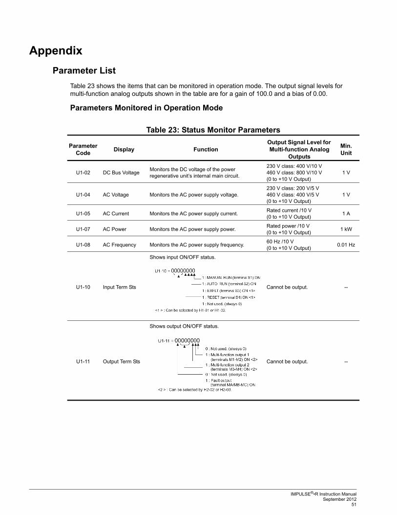
Appendix
Parameter List
Table 23 shows the items that can be monitored in operation mode. The output signal levels for multi-function analog outputs shown in the table are for a gain of 100.0 and a bias of 0.00.
Parameters Monitored in Operation Mode
Table 23: Status Monitor Parameters
Parameter Code
Display FunctionOutput Signal Level for Multi-function Analog
Outputs
Min. Unit
U1-02 DC Bus VoltageMonitors the DC voltage of the power regenerative unit’s internal main circuit.
230 V class: 400 V/10 V460 V class: 800 V/10 V(0 to +10 V Output)
1 V
U1-04 AC Voltage Monitors the AC power supply voltage.230 V class: 200 V/5 V460 V class: 400 V/5 V(0 to +10 V Output)
1 V
U1-05 AC Current Monitors the AC power supply current.Rated current /10 V(0 to +10 V Output)
1 A
U1-07 AC Power Monitors the AC power supply power.Rated power /10 V(0 to +10 V Output)
1 kW
U1-08 AC Frequency Monitors the AC power supply frequency.60 Hz /10 V(0 to +10 V Output)
0.01 Hz
U1-10 Input Term Sts
Shows input ON/OFF status.
Cannot be output. --
U1-11 Output Term Sts
Shows output ON/OFF status.
Cannot be output. --

IMPULSE®•R Instruction ManualSeptember 2012 52
Table 24: Fault Trace Parameters
U1-12 Int Ct1 Sts 1
Power regenerative unit operating status.
Cannot be output. --
U1-13 Elapsed TimeMonitors the power regenerative unit’s elapsed operating time. Can be set with parameter O2-07 or O2-08.
Cannot be output. --
U1-14 FLASH ID (Manufacturer’s ID number) Cannot be output. --
U1-21 V DeviationMonitors the deviation between the AC power supply voltage and the main circuit DC voltage.
230 V class: 400 V/10 V460 V class: 800 V/10 V
1 V
U1-28 CPU ID (Manufacturer’s ID number) Cannot be output. --
Parameter Code
Display FunctionOutput Signal Level for Multi-function Analog
Outputs
Min. Unit
U2-01 Current Fault Information on current fault. Cannot be output. --
U2-02 Last Fault Information on the last fault. Cannot be output. --
U2-04 DC Bus VoltageMain circuit DC voltage value when the “last fault” occurred.
Cannot be output. 1 V
U2-06 AC VoltageAC power supply voltage value when the “last fault” occurred.
Cannot be output. 1 V
U2-07 AC CurrentCurrent value at AC power side when the “last fault” occurred.
Cannot be output. 1 A
U2-08 AC PowerPower at AC power side when the “last fault” occurred.
Cannot be output. 1 kW
U2-10 AC FrequencyFrequency at AC power side when the “last fault” occurred.
Cannot be output. 0.01 Hz
U2-11 Input Term StsInput terminal status when the “last fault” occurred. (Same format as U1-10.)
Cannot be output. --
U2-12 Output Term StsOutput terminal status when the “last fault” occurred. (Same format as U1-11.)
Cannot be output. --
U2-13 Regen Unit StsOperating status when the “last fault” occurred. (Same format as U1-12.)
Cannot be output. --
U2-14 Elapsed TimeElapsed operating or power-on time when the “last fault” occurred.
Cannot be output. 1 H
U2-20 V Deviation Voltage deviation when the “last fault” occurred. Cannot be output. 1 V
Parameter Code
Display FunctionOutput Signal Level for Multi-function Analog
Outputs
Min. Unit

IMPULSE®•R Instruction ManualSeptember 2012
53
Table 25: Fault History Parameters
Table 26: Parameter List
Parameter Code
Display FunctionOutput Signal Level for Multi-function Analog
Outputs
Min. Unit
U3-01 Last Fault Information on the last fault. Cannot be output. --
U3-02 Fault Message 2 Information on the 2nd to last fault. Cannot be output. --
U3-03 Fault Message 3 Information on the 3rd to last fault. Cannot be output. --
U3-04 Fault Message 4 Information on the 4th to last fault. Cannot be output. --
U3-05 Elapsed Time 1Elapsed running or power-on time when the last fault occurred.
Cannot be output. 1 H
U3-06 Elapsed Time 2Elapsed running or power-on time when the 2nd to last fault occurred.
Cannot be output. 1 H
U3-07 Elapsed Time 3Elapsed running or power-on time when the 3rd to last fault occurred.
Cannot be output. 1 H
U3-08 Elapsed Time 4Elapsed running or power-on time when the 4th to last fault occurred.
Cannot be output. 1 H
Parameter Code
Display Function RangeInitial Value
Access Level
A1-00 Select Language Language selection for the Digital Operator.This parameter is not reset to the factory setting by A1-03.
0, 1 0 A
0 English
1 Japanese
A1-01 Access Level Selects which parameters are accessible via the Digital Operator.
0 to 9999 4 A
0 Operation Only
1 Advanced Level
A1-03 Init Parameters Used to return all parameters to their factory or user default settings. (Initializes and then returns A1-03 to zero.)2220: 2-Wire Initialization
0000 to 9999
0000 A
A1-04 Enter Password When the value set into A1-04 does NOT match the value set into A1-05, parameters A1-01 through A1-03 cannot be changed. All other parameters asdetermined by A1-01 can be changed. Parameter A1-05 can be accessed by pressing the MENU key while holding the RESET key.
0000 to 9999
0 A
B1-02 Run Source Selects the run command input source.
0 Operator- RUN and STOP keys on Digital Operator.
1 Terminals - Contact closure on terminals S1 or S2.
B1-06 Cntl Input Scans Sets the scan rate of terminals S1 to S4. 0, 1 1 A
0 500 ms - 2 scans (for quick response)
1 5 ms - 2 scans (for noisy environments)
C8-17 Autorun Iout See Figure 19 10 to 100%
50 A
C8-18 V Bias of Run For 460 V class power regenerative units, double the initial setting and setting range.
0.0 to 50.0 V
2.0 A
C8-19 V Width of Stop For 460 V class power regenerative units, double the initial setting and setting range.
0.5 to 50.0 V
3.0 A

IMPULSE®•R Instruction ManualSeptember 2012 54
C8-20 Minimum Run Time -- 0.0 to 600.0 sec
1.0 A
F1-10 FDEV DetectLevel Configures the frequency deviation fault (DEV) detection. DEV fault will occur if the frequency deviation is greater than the F1-10 setting for a time longer than F1-11. F1-10 is set as a percentage of the maximum output frequency (E1-04). Frequency deviation is the difference between actual input supply frequency and the frequency reference command.
1.0 to 10.0 Hz
3.0 A
F1-11 FDEV Detect Time Configures the frequency deviation fault (DEV) detection. DEV fault will occur if the frequency deviation is greater than the F1-10 setting for a time longer than F1-11. F1-10 is set as a percentage of the maximum output frequency (E1-04). Frequency deviation is the difference between actual input supply frequency and the frequency reference command.
0.0 to 255.0 sec
70.0 A
H1-01 Terminal S3 Sel Selects the function of terminal S3.24: External fault, Normally Open, Always Detected, Coast To Stop.Refer to Table 27.
0 to 2F 24 A
H1-02 Terminal S4 Sel Selects the function of terminal S4.14: Fault resetClosed = Resets the Drive after the fault and the run command have been removed.Refer to Table 27.
0 to 2F 14 A
H2-02 Terminal M1 Sel Selects the function of terminals M1 to M2.6: Drive readyClosed - When the Drive is powered up, not in a fault state and in the DRIVE mode.Refer to Table 28.
0 to 20 6 A
H2-03 Terminal M3 Sel Selects the function of terminals M2 - M4.0: During Run 1Closed - When a run command is input or the Drive is outputting voltage.Refer to Table 28.
0 to 20 0 A
H4-01 Terminal AM Sel Selects which monitor will be output on terminals AM and AC. Refer to Table 29.
0 to 21 5 A
0 Not Used
2 DC bus voltage (U1-02)
4 AC power supply voltage (U1-04)
5 Current at power side (U1-05)
7 Power at power side (U1-07)
8 AC power supply frequency (U1-08)
21 Voltage deviation (U1-21)
H4-02 Terminal AM Gain Sets terminal AM output level when selected monitor is at 100%.
0.00 to 2.50
0.50 A
H4-03 Terminal AM Bias Selects the signal level of terminal AM. 0, 1 1 A
0 0 to 10 VDC
1 -10 to +10 VDC
Parameter Code
Display Function RangeInitial Value
Access Level

IMPULSE®•R Instruction ManualSeptember 2012
55
L2-01 PwrL Selection Enables and disables the momentary power loss function.
0 to 2 0 A
0 Disabled - Unit trips on (UV1) fault when power is lost.
1 Power Loss Ride Thru Time - Unit will restart if power returns within the time set in L2-02.*
2 CPU Power Active - Unit will restart if power returns prior to control power supply shut down.*
* In order for a restart to occur, the run command must be maintained throughout the ride thru period.
L2-02 PwrL Ridethru t Sets the power loss ride-thru time. This value is dependent on the capacity of the Unit. Only effective when L2-01 = 1.
0.0 to 2.0 2.0 A
L2-05 PUV Det Level Sets the Unit’s DC Bus undervoltage trip level. If this is set lower than the factory setting, additional AC input reactance or DC bus reactance may be necessary. Consult the factory before changing this parameter setting.
150 to 210 V
190 A
L5-01 Num of Restarts Sets the counter for the number of times the Unit will perform an automatic restart. Auto restart will check to see if the fault has cleared every 5 ms. When no fault is present, the Unit will attempt an auto restart. If the Unit faults after an auto restart attempt, the counter is incremented. When the Unit operates without fault for 10 minutes, the counter will reset to the value set in L5-01.
0 to 10 0 A
L5-02 Restart Sel Determines if the fault contact activates during an automatic restart attempt.
0, 1 0 A
0 No Fault Relay - fault contact will not activate during an automatic restart attempt.
1 Fault Relay Active - fault contact will activate during an automatic restart attempt.
L8-02 OH Pre-Alarm Lvl When the cooling fin temperature exceeds the value set in this parameter, an overheat alarm (OH) will occur.
50 to 110 deg
95 A
L8-03 OH Pre-Alarm Sel Selects the Unit operation upon an OH pre-alarm detection.
1, 3 3 A
0 Coast to Stop
1 Alarm Only
L8-07 Ph Loss In Sel Selects the detection of output current open-phase. When applied motor capacity is too small for Unit capacity, output phase loss may be detected inadvertently. In this case, set to 0.
0, 1 0 A
0 Disabled
1 Enabled
O1-01 User Monitor Sel Selects which monitor will be displayed in the operation menu upon power-up when O1-02 = 4.
4 to 8 8 A
4 Power supply voltage (U1-04)
7 Power at power side (U1-07)
8 Power supply frequency (U1-08)
Parameter Code
Display Function RangeInitial Value
Access Level

IMPULSE®•R Instruction ManualSeptember 2012 56
Table 27: Multi-function Input Functions
O1-02 Power-On Monitor Selects which monitor will be displayed upon power-up.
2 to 4 2 A
2 DC Bus Voltage (U1-02)
3 Output Current at the power side (U1-05)
4 Monitor set in O1-01
O2-01 Local/Remote Key Determines if the Digital Operator Local/Remote key is functional.
0, 1 1 A
0 Disabled
1 Enabled
O2-02 Oper Stop Key Determines if the STOP key on the Digital Operator will stop the Unit when the Unit is operating from external terminals.
0, 1 0 A
0 Enabled during run command from the digital operator
1 Enabled
O2-04 Regen Unit Model Sets the kVA of the Unit. Enter the number based on the Unit model number. Use the last four digits of the model number.This parameter only needs to be set when installing a new control board. Do not change for any other reason.
00 to FF * A
O2-06 Oper Detection Determines if the Unit will stop when the Digital Operator is removed when in LOCAL mode or B1-02 = 0.
0, 1 0 A
0 Disabled - the Unit will not stop when the Digital Operator is removed.
1 Enabled - The Unit will fault (OPR) and coast to stop when the Digital Operator is removed.
O2-07 Elapsed Time Set Sets the initial value of the elapsed operation timer U1-13.
0 to 65535H
-- A
O2-08 Elapsed Time Run Sets how time is accumulated for the elapsed operation timer U1-13.
0, 1 0 A
0 Power-On Time - Time accumulates when the Unit is powered.
1 Running Time - time accumulates only when the Unit is running.
Setting Value Function (H1-01, 02) Remarks
8External baseblock (NO contact)
[Ext BaseBlk N.O.]--
9External baseblock (NC contact)
[Ext BaseBlk N.C.]--
FNot used
[Term Not Used]--
14Fault reset
[Fault Reset]--
Parameter Code
Display Function RangeInitial Value
Access Level

IMPULSE®•R Instruction ManualSeptember 2012
57
Table 28: Multi-function Output Functions
Table 29: Multi-function Analog Output Functions
24-2FExternal fault
[External Fault]
24: External Fault, Normally Open, Always Detected, Coast To Stop25: External Fault, Normally Closed, Always Detected, Coast To Stop26: External Fault, Normally Open, During Run, Coast To Stop27: External Fault, Normally Closed, During Run, Coast To Stop28: External Fault, Normally Open, Always Detected, Fast Stop29: External Fault, Normally Closed, Always Detected, Fast Stop2A: External Fault, Normally Open, During Run, Fast Stop2B: External Fault, Normally Closed, During Run, Fast Stop2C: External Fault, Normally Open, Always Detected, Alarm Only2D: External Fault, Normally Closed, Always Detected, Alarm Only2E: External Fault, Normally Open, During Run, Alarm Only2F: External Fault, Normally Closed, During Run, Alarm Only
Setting Value Function (H2-02, 03) Remarks
0During run
[During RUN 1]Closed = When a run command is input or the Unit is outputting voltage.
6Regenerative unit ready
[Regen Unit Ready]Closed = When the Unit is powered up, not in a fault state, and in the DRIVE mode.
7During DC bus undervoltage (UV)
detection[DC Bus Undervolt]
Closed = When the DC bus voltage falls below the UV trip level set in L2-05.
8During baseblock
[BaseBlk 1]Closed = When the Unit is not outputting voltage.
ADuring MCON
[Mc On]Closed = When the pre-charge contactor contact is energized.
EFault
[Fault]Closed = When the Unit experiences a major fault.
FNot used
[Not Used]--
10Alarm
[Minor Fault]Closed = When the Unit experiences an alarm.
11Fault reset command active
[Reset Cmd Active]Closed = When the Unit receives a reset command from a digital input terminal or serial communication.
1ERestart enabled
[Restart Enabled]Closed = When the Unit is performing an automatic restart attempt. Automatic restart is configured by parameter L5-01.
1FOverload (OL1) pre-alarm
[Overload (OL1)]Closed = When OL1 is 80% of its trip point or greater.
20Overheat pre-alarm
[OH Prealarm]Closed = When the Unit’s heatsink temperature exceeds the setting of parameter L8-02.
Setting Value
Function (H4-01) Output signal level Remarks
0Not used
[Not Used]-- --
2DC bus voltage
[DC Bus Voltage]230 V class: 400 V/10 V460 V class: 800 V/10 V
100% = 400 / 800 VDC depending on the Unit voltage rating.
4Power supply voltage
[AC Voltage]
230 V class: 200 V/5 V460 V class: 400 V/5 V(0 to +10 V output)
100% = 400 / 800 VDC depending on the Unit voltage rating.
Setting Value Function (H1-01, 02) Remarks

IMPULSE®•R Instruction ManualSeptember 2012 58
5Current at power side
[AC Current]Rated current /10 V 100% = Unit current at the power side.
7Power at power side
[AC Power]Rated power /10 V 100% = Unit power at the power side.
8Power supply frequency
[AC Frequency]60 Hz/10 V 100% = Unit power supply frequency.
21Voltage deviation input
[V Deviation]230 V class: 400 V/10 V460 V class: 800 V/10 V
100% = 400 / 800 VDC depending on the Unit voltage rating.
Setting Value
Function (H4-01) Output signal level Remarks