HVI Leitung (vorkonfektioniert) - DEHN
80
www.dehn.de www.dehn.de Publication No. 1841 / Update 09.17 Mat-No. 3003899 © Copyright 2017 DEHN + SÖHNE DE Blitzschutz/Erdung Montageanleitung HVI ® Leitung HVI ® Leitung (vorkonfektioniert) / HVI ® long-Leitung
-
Upload
khangminh22 -
Category
Documents
-
view
0 -
download
0
Transcript of HVI Leitung (vorkonfektioniert) - DEHN
www.dehn.dewww.dehn.de
Publication No. 1841 / Update 09.17 Mat-No. 3003899 © Copyright 2017 DEHN + SÖHNE
DE
Blitzschutz/Erdung
MontageanleitungHVI®LeitungHVI®Leitung (vorkonfektioniert) / HVI®long-Leitung
2
INHALTSVERZEICHNIS
1. Sicherheitshinweise .................................................................................................... 4
2. SpezifikationderHVI®Leitung ..................................................................................... 6
2.1 Anwendung/AufbauderHVI®Leitung ........................................................................ 6
2.2 TechnischeDaten ......................................................................................................... 7
2.3 ChemischeEigenschaften ............................................................................................ 7
3. VerfügbareVarianten ................................................................................................... 8
3.1 HVI®Leitung(vorkonfektioniert)/HVI®long-Leitung ................................................... 8
3.2 HVI®LeitungzurAnbindunganBlitzspannungbehafteteAnlagenteile ..................... 10
3.3 Anschlusselemente HVI®long-LeitungimStützrohrundamStützrohr...................... 12
3.4 Anschlusselemente HVI®long-Leitung(Einzelteile) ................................................... 13
3.5 Zubehör für die HVI®long-Leitung ............................................................................. 15
4. Konfektionierung/VorkonfektionierungderHVI®Leitung ....................................... 16
4.1 MontagevonKopfstückbzw.Anschlusselement ....................................................... 16
4.2 Umschrumpfen ........................................................................................................... 17
4.3 AbsetzendesgrauenMantelsfürdieVerlegungimStützrohr .................................. 18
4.4 StützrohremitFangspitze/Fangstange .................................................................... 19
5. Montage .................................................................................................................... 20
5.1 MontagederHVI®long-LeitungimStützrohr ............................................................ 20
5.2 MaßnahmenzurVerringerungdesTrennungsabstandes"s" (außengeführtenHVI®Leitungen) ............................................................................. 22
5.3 Endverschluss ............................................................................................................ 25
5.3.1 Bereich des Endverschlusses am Stützrohr am Beispiel einer Antennenanwendung ....................25
5.3.2 Variabler Endverschluss bei der Anwendung mit der HVI®Leitung ..........................................28
5.3.3 Endverschluss an einer Gebäudestruktur ..................................................................................32
6. Anwendung HVI®Leitungmit"GetrennterRingleitung" ........................................... 33
3
7. HVI®LeitungimStützrohr(Länge3,2m)errichtetimDreibeinstativ ........................ 34
8. Leitungsverlegung ..................................................................................................... 36
8.1 ZusätzlicherAnschlussdesäußerenKabelmantelszumZweckedes Potentialausgleiches .................................................................................................. 36
8.2 Windbeanspruchung/Windlast ................................................................................. 37
9. ChecklistefürHVI®Installation ................................................................................. 39
4
1. Sicherheitshinweise
 Die Montage der HVI®Leitungen ist grundsätzlich nur im Rahmen der in dieser Montageanleitung genannten Vorgaben und Bedingungen zulässig.
 Die Montagearbeiten zur Verlegung der HVI®Leitungen dürfen nur durch ein qualifiziertes, geschul-tes Fachpersonal (Blitzschutz-Fachkraft) durchgeführt werden. Wir empfehlen eine spezielle Schulung zu den HVI®Produktenbei DEHN+SÖHNE (zu finden unter http://www.dehn.de/de/dehnacademy) durchzuführen.
 Bei erkennbaren bzw. herannahenden Gewittertätigkeiten sind die Montagearbeiten aus Sicher-heitsgründen zu unterbrechen.
Die erhältlichen Komponenten des HVI®Systemes sind als Gesamtsystem abgeprüft wor-den. Eine Mischung mit Bauteilen oder jeglicher Komponenten anderer Hersteller ist nicht zulässig.
 Vor der Montage sind die HVI®Leitungen auf ordnungsgemäßen Zustand zu kontrollieren. Soll-te eine Beschädigung oder ein sonstiger Mangel festgestellt werden, dürfen die HVI®Leitungen nicht montiert werden. Der schwarze Mantel der HVI®Leitung darf grundsätzlich keine Druck- und Schnittverletzungen aufweisen.
 Bei der Montage der HVI®Leitungen müssen bei entsprechenden Anwendungen die Sicherheitsvor-kehrungen gegen Brand- und Explosionsgefahren berücksichtigt werden.
 Soll die HVI®Leitung auf weich gedeckten Dächern (z.B. Reet, Stroh) eingesetzt werden, sind für die-se feuergefährdeten Betriebsstätten besondere Montagebedingungen einzuhalten. Die besonderen Montagebedingungen sind für die HVI-Leitung im EB-Hauptkatalog Blitzschutz/Erdung (HVI-Blitz-schutz an Weichdächern) enthalten.
 Wird das Stützrohr durch ein Dach eingeführt, ist eine fachgerechte Abdichtung und bei einem Warmdach zusätzlich eine fachgerechte Dämmung zu realisieren.
 Die HVI®Leitung ist geeignet für Außenverlegung und kann nach dem Endverschluss, z.B. auf Dä-chern, in Wänden, unter Putz, im Beton oder Fassaden/Fassadenkonstruktionen verlegt werden. Die Leitung ist jedoch nicht für dauernde Was se reinwirkung geeignet. Nur die HVI®Leitung mit dem zusätzlichen grauenMantel kann im Erdreich verlegt werden, um z.B. die Ableitung am Gebäude an den Ringerder über eine Länge von max. 2m anzuschließen. Die HVI®Leitung kann nicht zum örtlichen Verlagern von Potentialtrichtern im Erdreich (Gefährdung durch Schrittspannung) verwen-det werden.
IEC 60417-6182:Installation, electrotechnical expertise
IEC 60417-6183:Installation, mechanical expertise
5
 Bei Verschmutzung der HVI®Leitung kann diese durch einen mit dem Spezialreiniger (Art.-Nr. 297 199), getränkten Lappen gereinigt werden. Aus gefahrgutrechtlichen Gründen ist ein Versand dieses Spe-zialreinigers nur in Deutschland und Österreich möglich. Alternativ ist ISOPROPYLALCOHOL 99,1 bis 99,9 % (CSA-Nr. 67-63.0) zu verwenden!
 Durch den speziellen Aufbau des Außenmantels der HVI®Leitung ist ein Anstrich im Endverschluss-bereich unzulässig.
 Die HVI®Leitung mit grauem Mantel kann unter Beachtung nachfolgender Bedingungen im weite-ren Leitungsverlauf farblich angepaßt werden. Die Lacke und Farben müssen PVC-verträglich sein. Die Farben und Lacke können wasserlöslich, aber auch lösemittelhaltig sein.Anmerkung: Die Lösungsmittel in Farben und Lacken verdunsten bei einem kurzzeitigen dünnen Auftrag schnell und führen nicht zu einer Beschädigung des Kunststoffes.
 Für die Anwendung in explosionsgefährdeten Betriebsstätten sind besondere Montagebedingungen zu beachten (siehe Mon ta gean lei tung Publication No. 1501).
 Die HVI®Leitung ist ein Bauteil zur Einhaltung des Trennungsabstandes. Konstruktionsbedingt be-sitzt diese keine magnetische Schirmwirkung. Induktionswirkungen in sekundären Leitungen/Schlei-fen sind zu beachten. Gegebenenfalls sind Maßnahmen zum Überspannungsschutz vorzusehen.
 Bitte wenden Sie sich bei anwendungstechnischen Fragen an das für Sie zuständige Vertriebsteam oder den Außendienst-Mitarbeiter in Ihrer Region.
 Ergänzende Hinweise über das Bauteileprogramm des HVI®Leitungs-Systems können aus unserer Druckschrift DS Nr. 0151, unserem Katalog Blitzschutz/Erdung oder www.dehn.de - Produktdaten entnommen werden.

6
2. SpezifikationderHVI®Leitung
2.1 Anwendung/AufbauderHVI®Leitung
Diese Montageanleitung beschreibt speziell die Anwendung der HVI®Leitung im Stützrohr bzw. außen am Stützrohr. Im Einzelnen wird auf die Verarbeitung / Konfektionierung der HVI®Leitung für die In-nenverlegung im Stützrohr und außen am Stützrohr (bis zu 4 Leitungen) eingegangen.
Die HVI®Leitung ist eine hochspannungsfeste, isolierte Ableitung mit einem spannungsgesteuerten Außenmantel (siehe Bild 1).
Typisch ist die Anwendung als isolierte Ableitung im Blitzschutz zur Beherrschung des Trennungsabstan-des nach DIN EN 62305-3 (VDE 0185-305-3). Zuerst ist die Berechnung des Trennungsabstandes“s”, wie in der Norm DIN EN 62305-3 (VDE 0185-305-3) Blitzschutz Teil 3, Abschnitt 6.3 erläutert, mit dem Ma te ri al faktor km = 1 für Luft oder km = 0,5 für festen Baustoff durchzuführen. Es muss geprüft werden, ob dieser errechnete Trennungsabstand mit dem äquivalenten Trennungsabstand der HVI®Leitung (siehe technische Daten, Tabelle 1, Seite 7) realisiert werden kann:
errechneterTrennungsabstand≤äquivalenterTrennungsabstand.
Ist dies nicht der Fall, dann sind die im Kapitel 5.3 auf Seite 25 beschriebenen Maßnahmen notwendig.Die Länge für die Berechnung des Trennungsabstandes“s” muss vom Kopfstück bis zur nächsten Ebene des Blitzschutz-Potentialausgleiches, z.B. Erdungsanlage, gemessen werden.Bei einer Ableitung kc =1 können somit je nach Schutzklasse des Blitschutzsystems (LPS) folgende ma-ximale Leitungslängen realisiert werden:LPS II max. 12,5 mLPS III/IV max. 18,75 m
Bild1 Aufbau der HVI®Leitung
Cu-Leiter mehr-/eindrähtig19 mm²
Halbleitender Außenmantel
Isolationsschicht

7
2.2 TechnischeDaten
Außenmantel schwarz, RAL 9011 grau, RAL 7035
ÄquivalenterTrennungsabstand derHVI®Leitung
Luft ≤ 75 cm
festen Baustoff ≤ 150 m
Außendurchmesser 20 mm 23 mm
minimaler Biegeradius 200 mm 230 mm
Dauertemperaturbereich (bei fester Verlegung) -30° bis +70°C
Umgebungstemperatur und Leitungstemperaturbei Verlegung und Verarbeitung
-5° bis +40°C
max. Zugbelastung 950 N
Innenleiter Kupfer mehr-/eindrähtig 19 mm²
Tabelle1 Technische Daten HVI®Leitung
2.3 ChemischeEigenschaften
schwarz, RAL 9011 grau, RAL 7035
Brandverhalten (selbstverlöschend) Nein Ja
Witterungsbeständig (UV-stabilisiert) Ja
Brandlast 3,6 kWh/m 4,3 kWh/m
Tabelle2 Chemische Eigenschaften HVI®Leitung
8
3. VerfügbareVarianten
3.1 HVI®Leitung(vorkonfektioniert)/HVI®long-Leitung
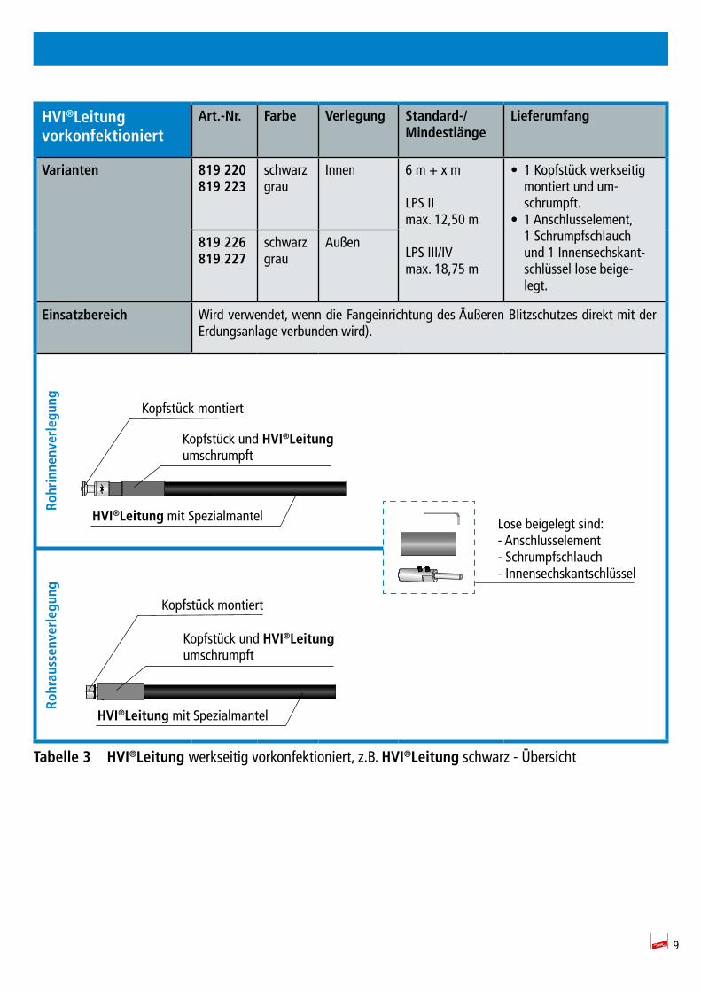
Generell ist bei den vorkonfektionierten HVI®Leitungen werksseitig ein Leitungsende, wie in Tabelle 3 auf Seite 9 und Tabelle 4 auf Seite 10 dargestellt, mit entsprechender Anschlusstechnik vor-konfektioniert. Damit ist das Kopfstück fest montiert und bereits umschrumpft. Das zweite Leitungsen-de kann im Bedarfsfall noch gekürzt werden, um das lose mitgelieferte Anschlusselment entsprechend des Aufbaues der Anlage genau zu positionieren.
Bei Bestellung der HVI®Leitung ist die Leitungs-/Mindestlänge zu beachten / anzugeben. Diese An-gabe ist bindend und folglich kann auf Grund der auftragsbezogenen Fertigung (Konfektionierung der Leitungslänge) die Leitung nicht zurückgenommen werden. Die vorkonfektionierte HVI®Leitung ist in einer Standard-/Mindestlänge von 6 m verfügbar und kann mit 0,5 m Schritten erhöht werden. Die Standardmindestlänge von 6 m ist für den Einsatz in Kombination mit dem 3,2 m langen Stützrohr ausgelegt.
Es wird lose beiliegend ein Anschlusselement, ein Schrumpfschlauch und ein Innensechskantschlüssel mitgeliefert (siehe auch Tabelle 3), welche grundsätzlich für die einmalige Montage ausgelegt sind.
Das Ablängen / Kürzen der HVI®Leitungen sollte mit speziellem Werkzeug (HVI®cutter und HVI®strip 20) und das spätere Anbringen des Anschlusselementes bzw. Schrumpfschlauches, un-ter Berücksichtigung der beschriebenen Anschlusstechnik, durchgeführt werden (siehe hierzu Kapitel 4 ab Seite 16).
9
HVI®Leitung vorkonfektioniert
Art.-Nr. Farbe Verlegung Standard-/Mindestlänge
Lieferumfang
Varianten 819 220819 223
schwarzgrau
Innen 6 m + x m LPS II max. 12,50 m
LPS III/IV max. 18,75 m
• 1 Kopfstück werkseitig montiert und um-schrumpft.
• 1 Anschlusselement, 1 Schrumpfschlauch und 1 Innensechskant-schlüssel lose beige-legt.
819 226819 227
schwarzgrau
Außen
Einsatzbereich Wird verwendet, wenn die Fangeinrichtung des Äußeren Blitzschutzes direkt mit der Erdungsanlage verbunden wird).
Tabelle3 HVI®Leitung werkseitig vorkonfektioniert, z.B. HVI®Leitung schwarz - Übersicht
HVI®Leitung mit Spezialmantel
Kopfstück montiert
Lose beigelegt sind:- Anschlusselement- Schrumpfschlauch- Innensechskantschlüssel
Kopfstück und HVI®Leitung umschrumpft
Rohrinnenverlegung
Rohraussenverlegung
HVI®Leitung mit Spezialmantel
Kopfstück montiert
Kopfstück und HVI®Leitung umschrumpft
10
3.2 HVI®LeitungzurAnbindunganBlitzspannungbehafteteAnlagenteile
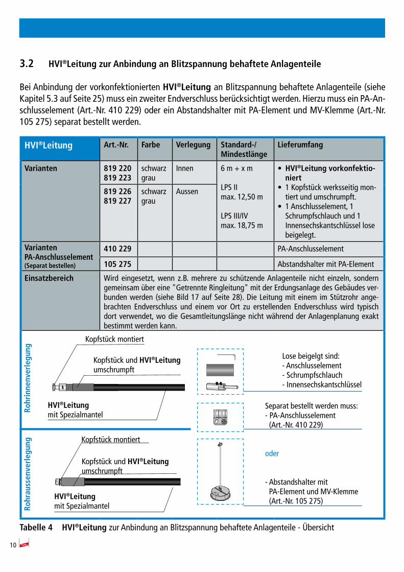
Bei Anbindung der vorkonfektionierten HVI®Leitung an Blitzspannung behaftete Anlagenteile (siehe Kapitel 5.3 auf Seite 25) muss ein zweiter Endverschluss berücksichtigt werden. Hierzu muss ein PA-An-schlusselement (Art.-Nr. 410 229) oder ein Abstandshalter mit PA-Element und MV-Klemme (Art.-Nr. 105 275) separat bestellt werden.
HVI®Leitung Art.-Nr. Farbe Verlegung Standard-/Mindestlänge
Lieferumfang
Varianten 819 220819 223
schwarzgrau
Innen 6 m + x m
LPS II max. 12,50 m
LPS III/IV max. 18,75 m
• HVI®Leitungvorkonfektio-niert
• 1 Kopfstück werksseitig mon-tiert und umschrumpft.
• 1 Anschlusselement, 1 Schrumpfschlauch und 1 Innensechskantschlüssel lose beigelegt.
819 226819 227
schwarzgrau
Aussen
VariantenPA-Anschlusselement(Separatbestellen)
410 229 PA-Anschlusselement
105 275 Abstandshalter mit PA-Element
Einsatzbereich Wird eingesetzt, wenn z.B. mehrere zu schützende Anlagenteile nicht einzeln, sondern gemeinsam über eine "Getrennte Ringleitung" mit der Erdungsanlage des Gebäudes ver-bunden werden (siehe Bild 17 auf Seite 28). Die Leitung mit einem im Stützrohr ange-brachten Endverschluss und einem vor Ort zu erstellenden Endverschluss wird typisch dort verwendet, wo die Gesamtleitungslänge nicht während der Anlagenplanung exakt bestimmt werden kann.
Tabelle4 HVI®Leitung zur Anbindung an Blitzspannung behaftete Anlagenteile - Übersicht
Rohrinnenverlegung
Rohraussenverlegung
HVI®Leitungmit Spezialmantel
Kopfstück montiert
Lose beigelgt sind:- Anschlusselement- Schrumpfschlauch- Innensechskantschlüssel
Separat bestellt werden muss:- PA-Anschlusselement (Art.-Nr. 410 229)
oder
- Abstandshalter mit PA-Element und MV-Klemme (Art.-Nr. 105 275)
Kopfstück und HVI®Leitung umschrumpft
Kopfstück und HVI®Leitung umschrumpft
Kopfstück montiert
HVI®Leitungmit Spezialmantel
11
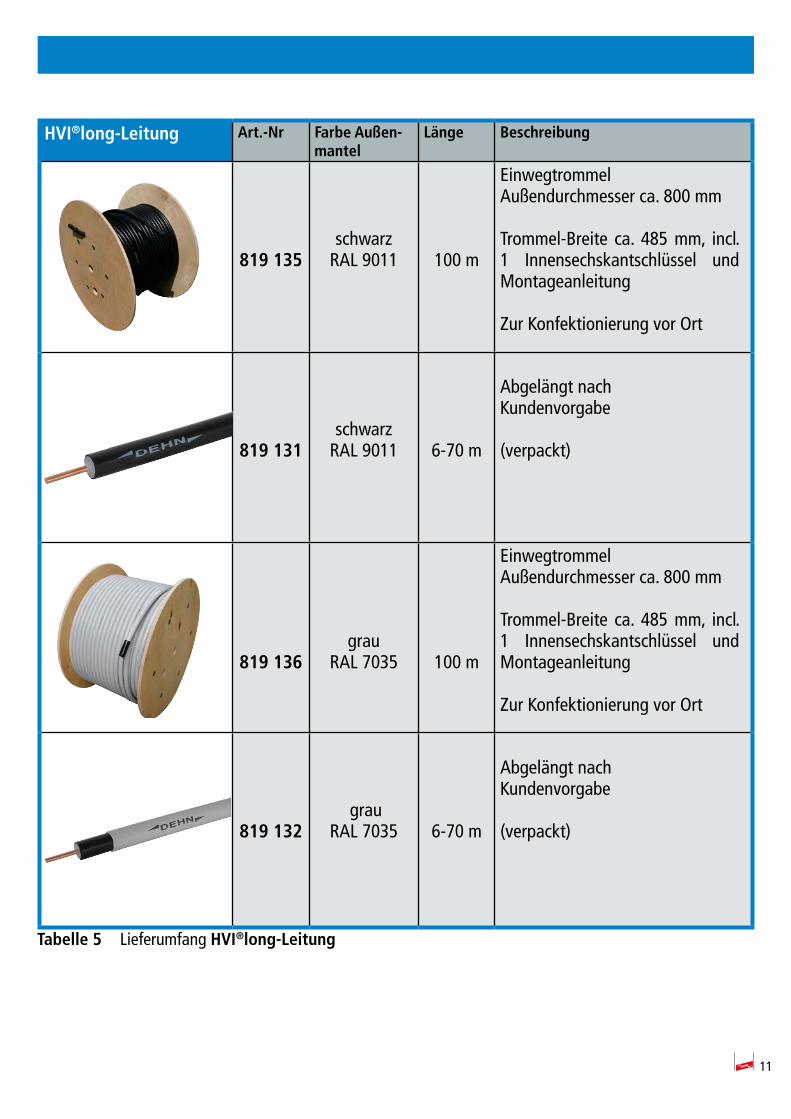
HVI®long-Leitung Art.-Nr FarbeAußen-mantel
Länge Beschreibung
819 135
schwarzRAL 9011 100 m
EinwegtrommelAußendurchmesser ca. 800 mm
Trommel-Breite ca. 485 mm, incl. 1 Innensechskantschlüssel und Montageanleitung
Zur Konfektionierung vor Ort
819 131schwarz
RAL 9011 6-70 m
Abgelängt nachKundenvorgabe
(verpackt)
819 136grau
RAL 7035 100 m
EinwegtrommelAußendurchmesser ca. 800 mm
Trommel-Breite ca. 485 mm, incl. 1 Innensechskantschlüssel und Montageanleitung
Zur Konfektionierung vor Ort
819 132 grau
RAL 7035 6-70 m
Abgelängt nachKundenvorgabe
(verpackt)
Tabelle5 Lieferumfang HVI®long-Leitung
12
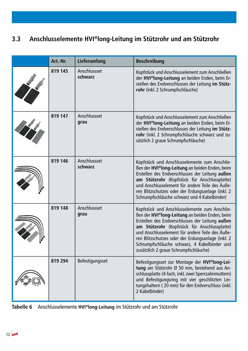
3.3 Anschlusselemente HVI®long-LeitungimStützrohrundamStützrohr
Art.-Nr. Lieferumfang Beschreibung
819 145 Anschlusssetschwarz
Kopfstück und Anschlusselement zum Anschließen der HVI®long-Leitung an beiden Enden, beim Er-stellen des Endverschlusses der Leitung im Stütz-rohr (inkl. 2 Schrumpfschläuche)
819 147 Anschlusssetgrau
Kopfstück und Anschlusselement zum Anschließen der HVI®long-Leitung an beiden Enden, beim Er-stellen des Endverschlusses der Leitung im Stütz-rohr (inkl. 2 Schrumpfschläuche schwarz und zu-sätzlich 2 graue Schrumpfschläuche)
819 146 Anschlusssetschwarz
Kopfstück und Anschlusselemente zum Anschlie-ßen der HVI®long-Leitung an beiden Enden, beim Erstellen des Endverschlusses der Leitung außenam Stützrohr (Kopfstück für Anschlussplatte) und Anschlusselement für andere Teile des Äuße-ren Blitzschutzes oder der Erdungsanlage (inkl. 2 Schrumpfschläuche schwarz und 4 Kabelbinder)
819 148 Anschlusssetgrau
Kopfstück und Anschlusselemente zum Anschlie-ßen der HVI®long-Leitung an beiden Enden, beim Erstellen des Endverschlusses der Leitung außenam Stützrohr (Kopfstück für Anschlussplatte) und Anschlusselement für andere Teile des Äuße-ren Blitzschutzes oder der Erdungsanlage (inkl. 2 Schrumpfschläuche schwarz, 4 Kabelbinder und zusätzlich 2 graue Schrumpfschläuche)
819 294 Befestigungsset Befestigungsset zur Montage der HVI®long-Lei-tung am Stützrohr Ø 50 mm, bestehend aus An-schlussplatte (4-fach, inkl. zwei Sperrzahnmuttern) und Befestigungsring mit vier geschlitzten Lei-tungshaltern ( 20 mm) für den Endverschluss (inkl. 2 Kabelbinder)
Tabelle6 Anschlusselemente HVI®long-Leitungim Stützrohr und am Stützrohr
13
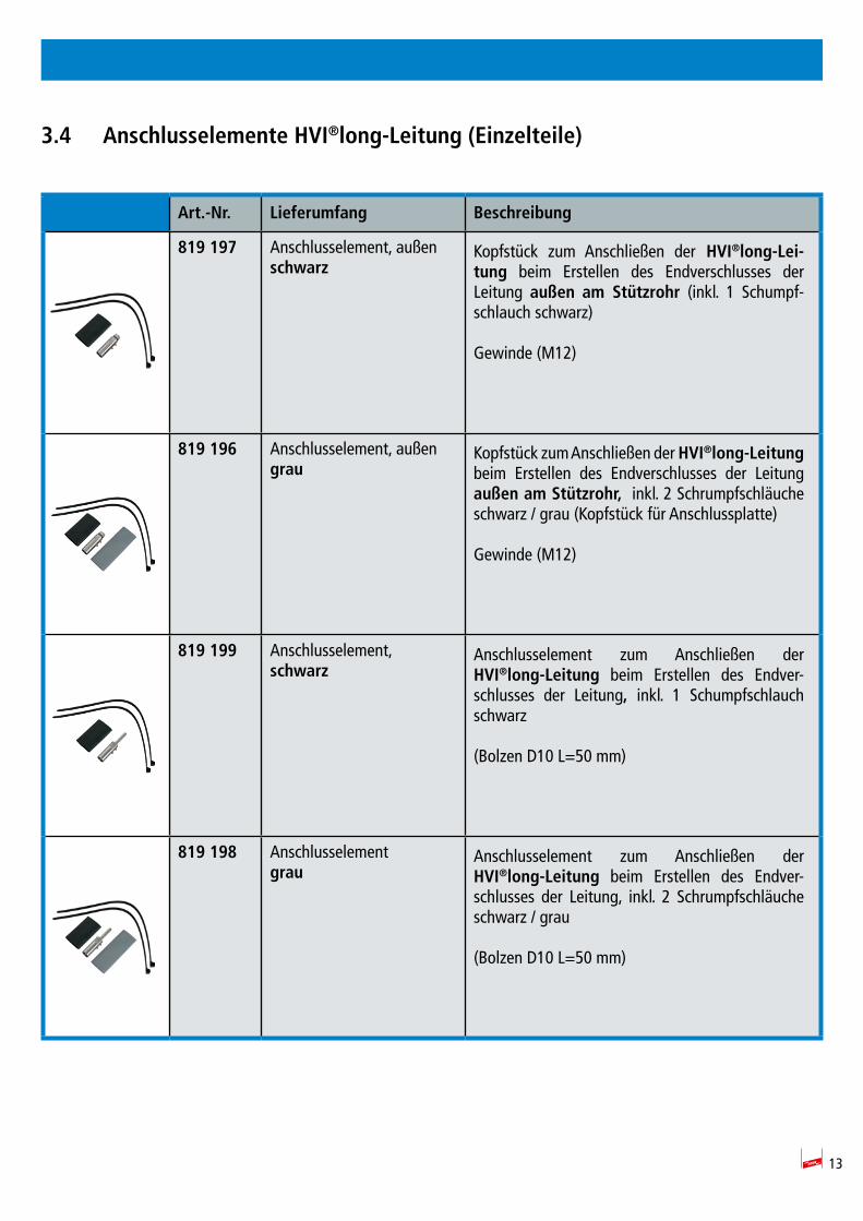
3.4 Anschlusselemente HVI®long-Leitung(Einzelteile)
Art.-Nr. Lieferumfang Beschreibung
819 197 Anschlusselement, außenschwarz
Kopfstück zum Anschließen der HVI®long-Lei-tung beim Erstellen des Endverschlusses der Leitung außen am Stützrohr (inkl. 1 Schumpf-schlauch schwarz)
Gewinde (M12)
819 196 Anschlusselement, außengrau
Kopfstück zum Anschließen der HVI®long-Leitung beim Erstellen des Endverschlusses der Leitung außenamStützrohr, inkl. 2 Schrumpfschläuche schwarz / grau (Kopfstück für Anschlussplatte)
Gewinde (M12)
819 199 Anschlusselement,schwarz
Anschlusselement zum Anschließen der HVI®long-Leitung beim Erstellen des Endver-schlusses der Leitung, inkl. 1 Schumpfschlauch schwarz
(Bolzen D10 L=50 mm)
819 198 Anschlusselementgrau
Anschlusselement zum Anschließen der HVI®long-Leitung beim Erstellen des Endver-schlusses der Leitung, inkl. 2 Schrumpfschläuche schwarz / grau
(Bolzen D10 L=50 mm)
14
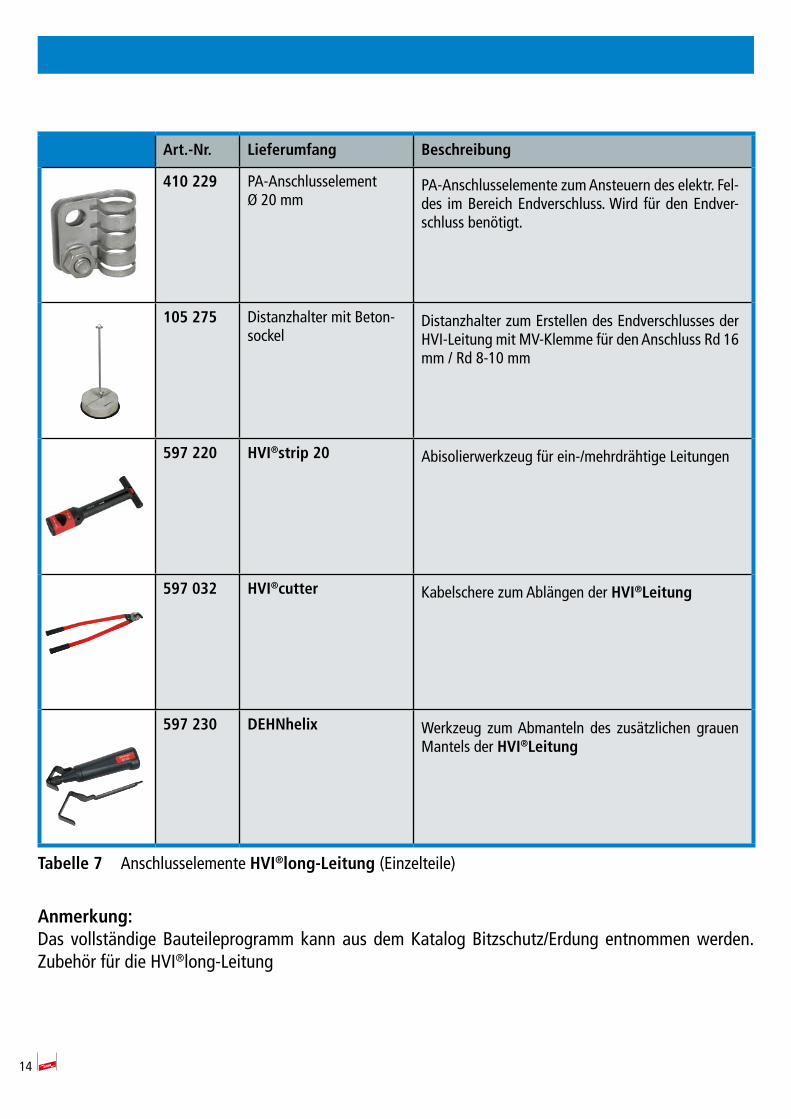
Art.-Nr. Lieferumfang Beschreibung
410 229 PA-Anschlusselement Ø 20 mm
PA-Anschlusselemente zum Ansteuern des elektr. Fel-des im Bereich Endverschluss. Wird für den Endver-schluss benötigt.
105 275 Distanzhalter mit Beton-sockel
Distanzhalter zum Erstellen des Endverschlusses der HVI-Leitung mit MV-Klemme für den Anschluss Rd 16 mm / Rd 8-10 mm
597 220 HVI®strip 20 Abisolierwerkzeug für ein-/mehrdrähtige Leitungen
597 032 HVI®cutter Kabelschere zum Ablängen der HVI®Leitung
597 230 DEHNhelix Werkzeug zum Abmanteln des zusätzlichen grauen Mantels der HVI®Leitung
Tabelle7 Anschlusselemente HVI®long-Leitung(Einzelteile)
Anmerkung:Das vollständige Bauteileprogramm kann aus dem Katalog Bitzschutz/Erdung entnommen werden.Zubehör für die HVI®long-Leitung
15
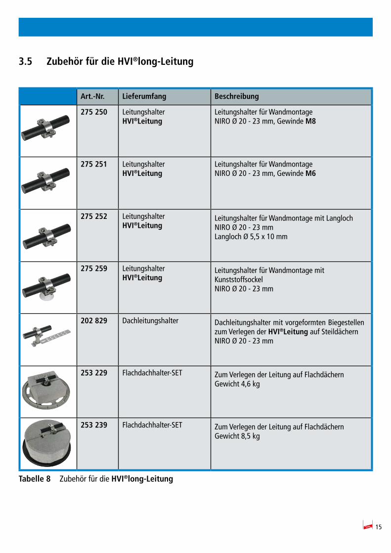
3.5 Zubehör für die HVI®long-Leitung
Art.-Nr. Lieferumfang Beschreibung
275 250 LeitungshalterHVI®Leitung
Leitungshalter für Wandmontage NIRO Ø 20 - 23 mm, Gewinde M8
275 251 LeitungshalterHVI®Leitung
Leitungshalter für Wandmontage NIRO Ø 20 - 23 mm, Gewinde M6
275 252 LeitungshalterHVI®Leitung
Leitungshalter für Wandmontage mit Langloch NIRO Ø 20 - 23 mmLangloch Ø 5,5 x 10 mm
275 259 LeitungshalterHVI®Leitung
Leitungshalter für Wandmontage mit KunststoffsockelNIRO Ø 20 - 23 mm
202 829 Dachleitungshalter Dachleitungshalter mit vorgeformten Biegestellen zum Verlegen der HVI®Leitung auf SteildächernNIRO Ø 20 - 23 mm
253 229 Flachdachhalter-SET Zum Verlegen der Leitung auf FlachdächernGewicht 4,6 kg
253 239 Flachdachhalter-SET Zum Verlegen der Leitung auf FlachdächernGewicht 8,5 kg
Tabelle8 Zubehör für die HVI®long-Leitung
16
4. Konfektionierung/VorkonfektionierungderHVI®Leitung
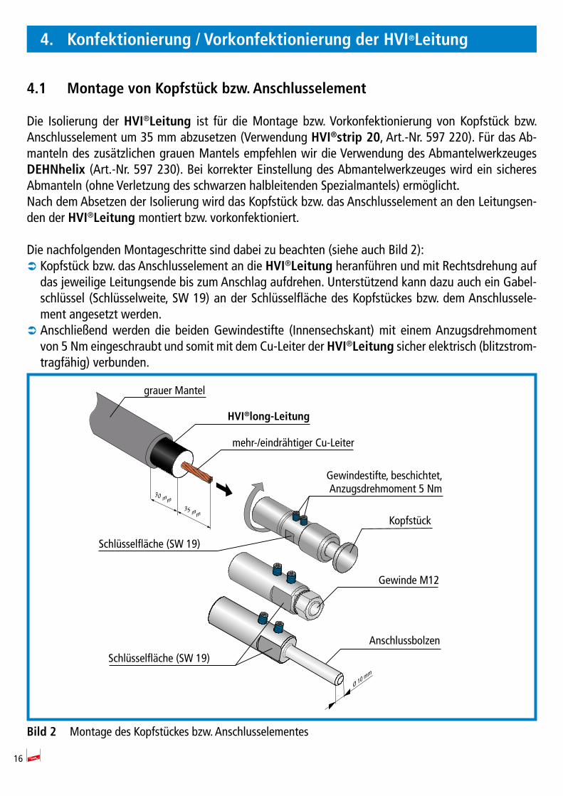
4.1 MontagevonKopfstückbzw.Anschlusselement
Die Isolierung der HVI®Leitung ist für die Montage bzw. Vorkonfektionierung von Kopfstück bzw. Anschlusselement um 35 mm abzusetzen (Verwendung HVI®strip 20, Art.-Nr. 597 220). Für das Ab-manteln des zusätzlichen grauen Mantels empfehlen wir die Verwendung des Abmantelwerkzeuges DEHNhelix (Art.-Nr. 597 230). Bei korrekter Einstellung des Abmantelwerkzeuges wird ein sicheres Abmanteln (ohne Verletzung des schwarzen halbleitenden Spezialmantels) ermöglicht.Nach dem Absetzen der Isolierung wird das Kopfstück bzw. das Anschlusselement an den Leitungsen-den der HVI®Leitung montiert bzw. vorkonfektioniert.
Die nachfolgenden Montageschritte sind dabei zu beachten (siehe auch Bild 2): Â Kopfstück bzw. das Anschlusselement an die HVI®Leitung heranführen und mit Rechtsdrehung auf das jeweilige Leitungsende bis zum Anschlag aufdrehen. Unterstützend kann dazu auch ein Gabel-schlüssel (Schlüsselweite, SW 19) an der Schlüsselfläche des Kopfstückes bzw. dem Anschlussele-ment angesetzt werden.
 Anschließend werden die beiden Gewindestifte (Innensechskant) mit einem Anzugsdrehmoment von 5 Nm eingeschraubt und somit mit dem Cu-Leiter der HVI®Leitung sicher elektrisch (blitzstrom-tragfähig) verbunden.
Bild2 Montage des Kopfstückes bzw. Anschlusselementes
Gewinde M12
Ø 10 mm
35 mm
30 mm
grauer Mantel
HVI®long-Leitung
Gewindestifte, beschichtet,Anzugsdrehmoment 5 Nm
Kopfstück
Schlüsselfläche (SW 19)
Schlüsselfläche (SW 19)
Anschlussbolzen
mehr-/eindrähtiger Cu-Leiter
17
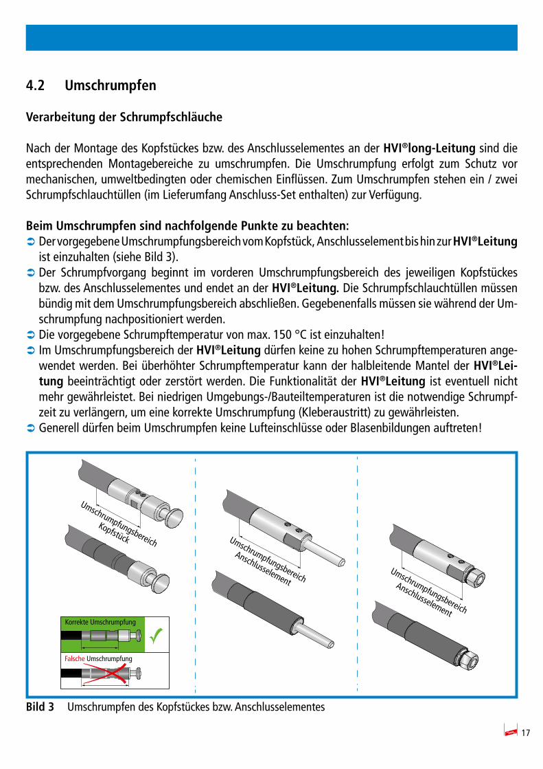
4.2 Umschrumpfen
VerarbeitungderSchrumpfschläuche
Nach der Montage des Kopfstückes bzw. des Anschlusselementes an der HVI®long-Leitung sind die entsprechenden Montagebereiche zu umschrumpfen. Die Umschrumpfung erfolgt zum Schutz vor mechanischen, umweltbedingten oder chemischen Einflüssen. Zum Umschrumpfen stehen ein / zwei Schrumpfschlauchtüllen (im Lieferumfang Anschluss-Set enthalten) zur Verfügung.
BeimUmschrumpfensindnachfolgendePunktezubeachten: Â Der vorgegebene Umschrumpfungsbereich vom Kopfstück, Anschlusselement bis hin zur HVI®Leitung ist einzuhalten (siehe Bild 3).
 Der Schrumpfvorgang beginnt im vorderen Umschrumpfungsbereich des jeweiligen Kopfstückes bzw. des Anschlusselementes und endet an der HVI®Leitung. Die Schrumpfschlauchtüllen müssen bündig mit dem Umschrumpfungsbereich abschließen. Gegebenenfalls müssen sie während der Um-schrumpfung nachpositioniert werden.
 Die vorgegebene Schrumpftemperatur von max. 150 °C ist einzuhalten!  Im Umschrumpfungsbereich der HVI®Leitung dürfen keine zu hohen Schrumpftemperaturen ange-wendet werden. Bei überhöhter Schrumpftemperatur kann der halbleitende Mantel der HVI®Lei-tung beeinträchtigt oder zerstört werden. Die Funktionalität der HVI®Leitung ist eventuell nicht mehr gewährleistet. Bei niedrigen Umgebungs-/Bauteiltemperaturen ist die notwendige Schrumpf-zeit zu verlängern, um eine korrekte Umschrumpfung (Kleberaustritt) zu gewährleisten.
 Generell dürfen beim Umschrumpfen keine Lufteinschlüsse oder Blasenbildungen auftreten!
Bild3 Umschrumpfen des Kopfstückes bzw. Anschlusselementes
Umschrumpfungsbereich
Anschlusselement
Umschrumpfungsbereich
Anschlusselement
Umschrumpfungsbereich
Kopfstück
Korrekte Umschrumpfung
Falsche Umschrumpfung
18
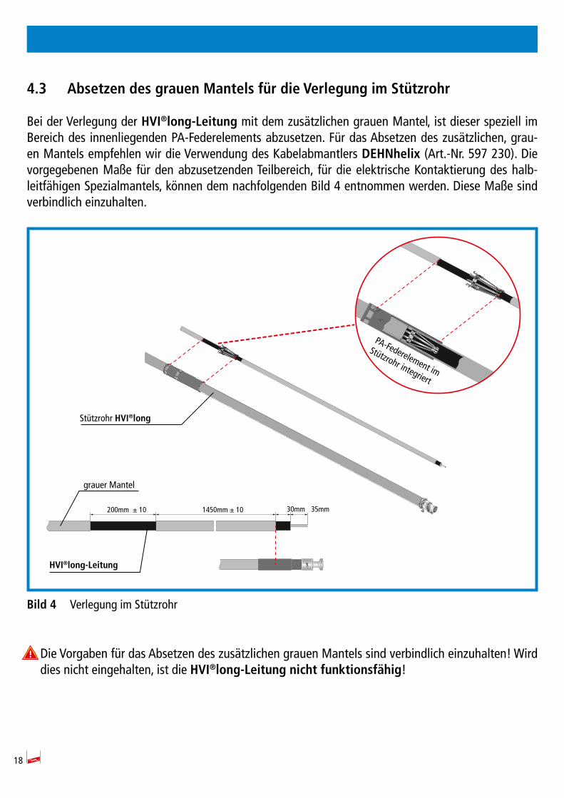
4.3 AbsetzendesgrauenMantelsfürdieVerlegungimStützrohr
Bei der Verlegung der HVI®long-Leitung mit dem zusätzlichen grauen Mantel, ist dieser speziell im Bereich des innenliegenden PA-Federelements abzusetzen. Für das Absetzen des zusätzlichen, grau-en Mantels empfehlen wir die Verwendung des Kabelabmantlers DEHNhelix (Art.-Nr. 597 230). Die vorgegebenen Maße für den abzusetzenden Teilbereich, für die elektrische Kontaktierung des halb-leitfähigen Spezialmantels, können dem nachfolgenden Bild 4 entnommen werden. Diese Maße sind verbindlich einzuhalten.
Bild4 Verlegung im Stützrohr
Die Vorgaben für das Absetzen des zusätzlichen grauen Mantels sind verbindlich einzuhalten! Wird dies nicht eingehalten, ist die HVI®long-Leitungnichtfunktionsfähig!
HVI®long-Leitung
grauer Mantel
30mm 35mm1450mm ± 10200mm ± 10
PA-Federelement im
Stützrohr integriert
Stützrohr HVI®long
19
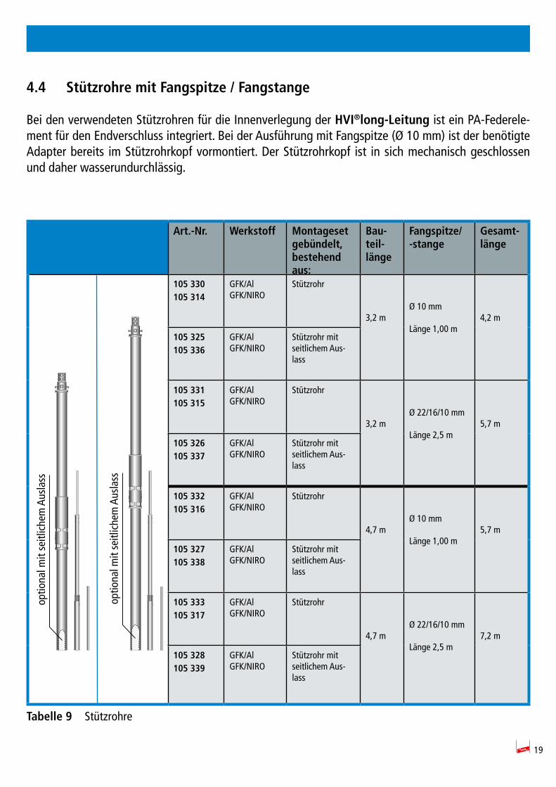
4.4 StützrohremitFangspitze/Fangstange
Bei den verwendeten Stützrohren für die Innenverlegung der HVI®long-Leitung ist ein PA-Federele-ment für den Endverschluss integriert. Bei der Ausführung mit Fangspitze (Ø 10 mm) ist der benötigte Adapter bereits im Stützrohrkopf vormontiert. Der Stützrohrkopf ist in sich mechanisch geschlossen und daher wasserundurchlässig.
Art.-Nr. Werkstoff Montagesetgebündelt,bestehend aus:
Bau-teil-länge
Fangspitze/-stange
Gesamt-länge
105 330105 314
GFK/AlGFK/NIRO
Stützrohr
3,2 mØ 10 mm
Länge 1,00 m4,2 m
105 325105 336
GFK/AlGFK/NIRO
Stützrohr mit seitlichem Aus-lass
105 331105 315
GFK/AlGFK/NIRO
Stützrohr
3,2 mØ 22/16/10 mm
Länge 2,5 m5,7 m
105 326105 337
GFK/AlGFK/NIRO
Stützrohr mit seitlichem Aus-lass
105 332105 316
GFK/AlGFK/NIRO
Stützrohr
4,7 mØ 10 mm
Länge 1,00 m5,7 m
105 327105 338
GFK/AlGFK/NIRO
Stützrohr mit seitlichem Aus-lass
105 333105 317
GFK/AlGFK/NIRO
Stützrohr
4,7 mØ 22/16/10 mm
Länge 2,5 m7,2 m
105 328105 339
GFK/AlGFK/NIRO
Stützrohr mit seitlichem Aus-lass
Tabelle9 Stützrohre
optio
nal m
it se
itlic
hem
Aus
lass
optio
nal m
it se
itlic
hem
Aus
lass
20
5. Montage
5.1 MontagederHVI®long-LeitungimStützrohr
Vor der Montage des Stützrohres ist die konfektionierte HVI®long-Leitung mit montiertem Kopfstück voran in das Stützrohr einzuführen und zu befestigen (siehe hierzu auch Bild 5, Seite 21).
DienachfolgendenMontageschrittesindhierbeizubeachten:
 Zuerst die Arretierungsschraube Kopfstück M8 x 25 mm am Stützrohrkopf aufschrauben.
 Nun wird die HVI®long-Leitung von unten in das Stützrohr eingeführt, dabei muss der Druckwider-stand der innenliegenden PA-Federkontaktierung überwunden werden. Ein mehrfaches Rein- und Rausschieben der Leitung in das Stützrohr ist möglich. Zur Kontaktierung des Kopfstückes muss die HVI®long-Leitung bis zum oberen Anschlag des Stützrohres eingeschoben und gehalten werden.
 Danach wird die Arretierungsschraube M8 x 25 mm wieder fest verschraubt und damit das Kopfstück im Stützrohr fixiert und elektrisch (blitzstromtragfähig) verbunden. Dabei ist ein Anzugsdrehmoment der Arretierungsschraube von 15 Nm zu beachten. Auf einen korrekten Abstand (ca. 7 mm) des Schraubenkopfes zum Stützrohr nach dem Festziehen ist zu achten. Die Kleberbeschichtung der Schraube wird erst nach ca. 5 Minuten fest, so dass in diesem Zeitraum die Schraube korrekt positio-niert und angezogen werden kann. Nach dem vollständigen Aushärten der Kleberbeschichtung muß beim wieder Entfernen der Schraube diese durch eine Neue ersetzt werden.
 Die ordnungsgemäße mechanische Befestigung der HVI®long-Leitung im Stützrohr ist zu über-prüfen! (siehe Bild 5). Die korrekte Montage kann mit einem leichten Zug am Austritt der Leitung überprüft werden.
 Je nach Aufbau der Anlage muss entweder vor bzw. nach der Montage des Stützrohres die entspre-chende Fangspitze oder Fangstange montiert werden.
 Die Fangspitze bzw. Fangstange wird von oben in den Stützrohrkopf eingeführt und mittels der beiden Arretierungsschrauben M8x16 mm bzw. M8x10 mm festgeschraubt, dabei ist ebenfalls das Anzugsdrehmoment von 15 Nm zu beachten.

21
Bild5 Montage des Kopfstückes im Stützrohr
optio
nal m
it se
itlic
hem
Aus
lass
Lieferzustand Montagezustand KorrekteMontage
ca. 13 mm ca. 0 mm
ca.7 mm
FalscheMontage
ArretierungsschraubeKopfstück, M8 x 25 mm,Anzugsdrehmoment 15 Nm
ArretierungsschraubenAnzugsdrehmoment 15 Nm-Fangspitze 2x M8x16 mm-Fangstange 2x M8x10 mm
ArretierungsschraubeKopfstück(M8 x 25 mm,Anzugsdrehmoment 15 Nm)
FangstangeØ 22/16/10 mm
Fangspitze Ø 10 mm
Stützrohr HVI®long
Stützrohrkopf
wasserundurchlässig
HVI®long-Leitung
22
5.2 MaßnahmenzurVerringerungdesTrennungsabstandes"s" (außengeführtenHVI®Leitun-gen)
Die Stromaufteilung auf mehrere Ableitungen, z.B. durch parallele Verlegung von HVI®Leitungen, kann den not wen digen Tren nungs abstand "s" verringern. Da bei der parallelen Verlegung von Leitungen magnetische Wech selwirkungen auftre-ten können, muss beachtet werden, dass ein Min-destabstand ab dem Bereich des End ver schlus ses/Stützrohres der parallelen HVI®Leitungen einge-halten wird. Empfohlen wird ein Abstand von > 200 mm im weiteren Leitungsverlauf nach dem Endverschluss.
Weiterhin ist zu beachten, dass der Anschluss der HVI®Leitungen an entfernt liegenden Punkten, z.B. einer "Getrennten Ringleitung" oder Erdungs-anlage erfolgen muss. Durch Einhaltung dieser Maßnahmen wird eine annähernd gleichmäßige Stromaufteilung er zielt.
Am Stützrohr können außen bis zu vier HVI®Leitungen mit dem Befestigungsset (Art.-Nr. 819 294) angebracht werden. Die not-wendigen Montageschritte zum Anbringen der außen geführten z.B. HVI®long-Leitung sind nachfolgend dargestellt:
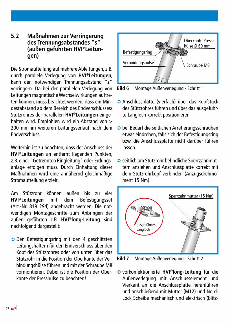
 Den Befestigungsring mit den 4 geschlitzten Leitungshaltern für den Endverschluss über den Kopf des Stützrohres oder von unten über das Stützrohr in die Position der Oberkante der Ver-bindungshülse führen und mit der Schraube M8 vormontieren. Dabei ist die Position der Ober-kante der Presshülse zu beachten!
Bild6 Montage Außenverlegung - Schritt 1
 Anschlussplatte (vierfach) über das Kopfstück des Stützrohres führen und über das ausgeführ-te Langloch korrekt positionieren
 bei Bedarf die seitlichen Arretierungsschrauben etwas eindrehen, falls sich der Befestigungsring bzw. die Anschlussplatte nicht darüber führen lassen.
 seitlich am Stützrohr befindliche Sperrzahnmut-tern anziehen und Anschlussplatte korrekt mit dem Stützrohrkopf verbinden (Anzugsdrehmo-ment 15 Nm)
Bild7 Montage Außenverlegung - Schritt 2
 vorkonfektionierte HVI®long-Leitung für die Außenverlegung mit Anschlusselement und Vierkant an die Anschlussplatte heranführen und anschließend mit Mutter (M12) und Nord-Lock Scheibe mechanisch und elektrisch (blitz-
Befestigungsring
Verbindungshülse Schraube M8
Oberkante Press-hülse Ø 60 mm
ausgeführtesLangloch
Sperrzahnmutter (15 Nm)

23
stromtragfähig) verbinden. Hierbei ist auf die korrekte Position des Vierkantloches zu achten und ein Anzugsdrehmoment von 25 Nm aufzu-bringen.
Bild8 Montage Außenverlegung - Schritt 3
 HVI®long-Leitung am Stützrohr verlegen und mit den geschlitzten Überlegern des Befesti-gungsringes korrekt verbinden. Auf eine gerad-linige Leitungsführung am Stützrohr achten. Gegebenenfalls Position des Befestigungsrings nachjustieren. Den Befestigungsring mit der Schraube M8 (Anzugsdrehmoment 15 Nm) fest fixieren. Bei der Verwendung der HVI®Leitung long oder vorkonfektioniert, mit dem zusätz-lichen grauen Mantel, ist im Bereich der ge-schlitzten Überleger der äußere, graue Mantel abzusetzen, damit der schwarze Mantel kon-taktiert werden kann. Der schwarze Mantel darf nicht eingeschnitten werden.
Bild9 Montage Außenverlegung - Schritt 4
 Die im Montagematerial mitgelieferten Kabelbinder können im Bereich der Mitte des Stützrohres zur Befestigung der Leitung am Stützrohr montiert werden.
 Zuletzt wird die Fangspitze / Fangstange mon-tiert.
Bild10 Montage Außenverlegung - Komplett
Mutter (M12) undNord-Lock Scheibe(25 Nm)
Anschlussplatte
HVI®long-Leitung
Vierkant-loch
geschlitzter Überleger

24
 eine Verbindungsleitung zwischen den Stützrohren wie im Bild 11 dargestellt, ähnlich einer Ringlei-tung, begünstigt den Stromaufteilungskoeffizienten kc. Dadurch kann der notwendige Trennungsab-stand "s" verringert bzw. eingehalten werden. Für diese Anschlüsse (Rohraußenverlegung) werden die Anschlusselemente z.B. Art.-Nr. 819 197 oder 819 196 verwendet.
Bild11 Verbindungsleitung zwischen den Stützrohren
Verbindungsleitung Verbindungsleitung
25
5.3 Endverschluss
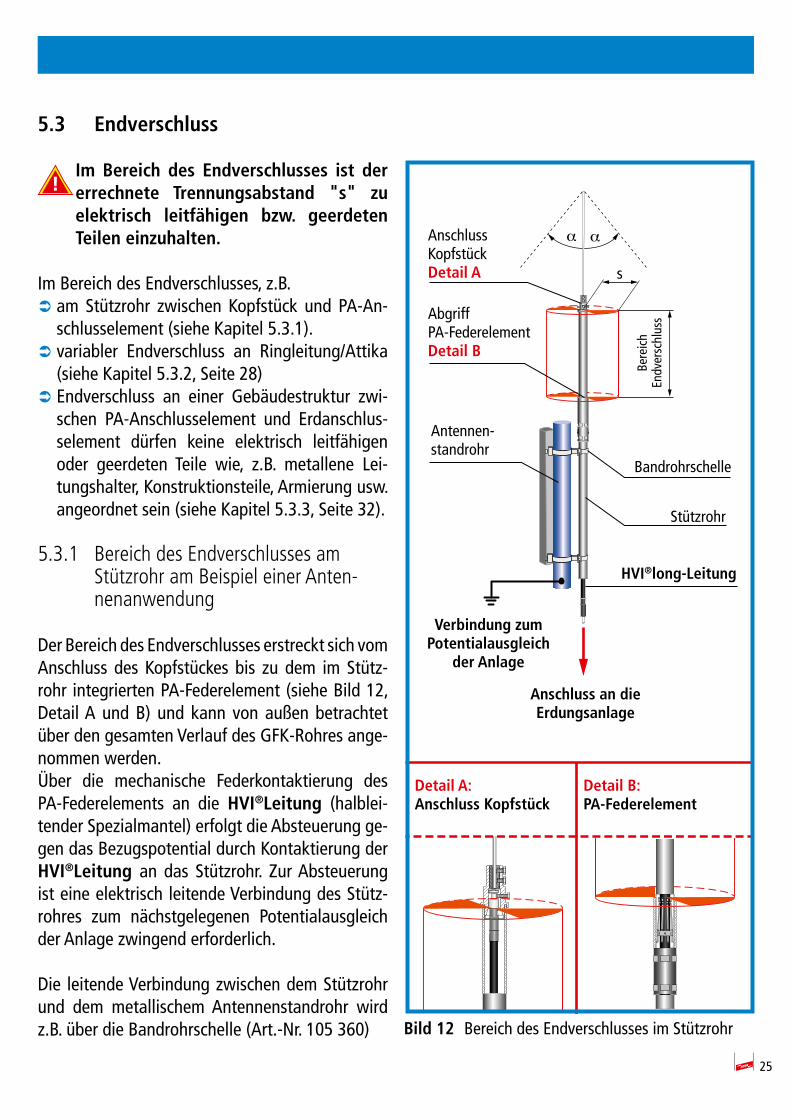
Im Bereich des Endverschlusses ist dererrechnete Trennungsabstand "s" zuelektrisch leitfähigen bzw. geerdetenTeileneinzuhalten.
Im Bereich des End verschlusses, z.B. Â am Stützrohr zwischen Kopfstück und PA-An-schlusselement (siehe Kapitel 5.3.1).
 variabler Endverschluss an Ringleitung/Attika (siehe Kapitel 5.3.2, Seite 28)
 Endverschluss an einer Gebäudestruktur zwi-schen PA-Anschlusselement und Erdanschlus-selement dürfen keine elek trisch leitfähigen oder geerdeten Teile wie, z.B. metallene Lei-tungs halter, Kon struk tionsteile, Ar mierung usw. angeordnet sein (siehe Kapitel 5.3.3, Seite 32).
5.3.1 Bereich des Endverschlusses am Stützrohr am Beispiel einer Anten-nenanwendung
Der Bereich des Endverschlusses erstreckt sich vom Anschluss des Kopfstückes bis zu dem im Stütz-rohr integrierten PA-Federelement (siehe Bild 12, Detail A und B) und kann von außen betrachtet über den gesamten Verlauf des GFK-Rohres ange-nommen werden.Über die mechanische Federkontaktierung des PA-Federelements an die HVI®Leitung (halblei-tender Spezialmantel) erfolgt die Absteuerung ge-gen das Bezugspotential durch Kontaktierung der HVI®Leitung an das Stützrohr. Zur Absteuerung ist eine elektrisch leitende Verbindung des Stütz-rohres zum nächstgelegenen Potentialausgleich der Anlage zwingend erforderlich.
Die leitende Verbindung zwischen dem Stützrohr und dem metallischem Antennenstandrohr wird z.B. über die Bandrohrschelle (Art.-Nr. 105 360) Bild12 Bereich des Endverschlusses im Stützrohr
Bere
ich
Endv
ersc
hlus
s
DetailA:AnschlussKopfstück
DetailB:PA-Federelement
AnschlussKopfstückDetailA s
α α
AbgriffPA-FederelementDetailB
Antennen-standrohr
Bandrohrschelle
Stützrohr
HVI®long-Leitung
Verbindung zum Potentialausgleich
derAnlage
AnschlussandieErdungsanlage
26
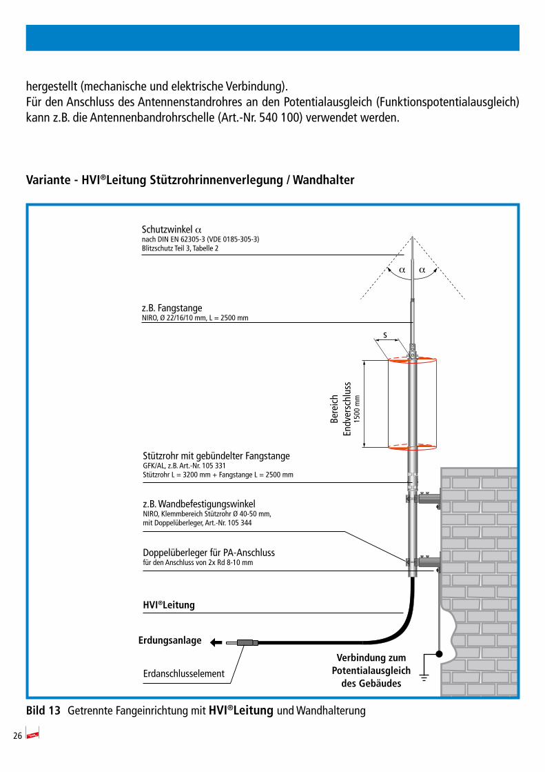
hergestellt (mechanische und elektrische Verbindung).Für den Anschluss des Antennenstandrohres an den Potentialausgleich (Funktionspotentialausgleich) kann z.B. die Antennenbandrohrschelle (Art.-Nr. 540 100) verwendet werden.
Variante-HVI®LeitungStützrohrinnenverlegung/Wandhalter
Bild13 Getrennte Fangeinrichtung mit HVI®Leitung und Wandhalterung
Schutzwinkel αnach DIN EN 62305-3 (VDE 0185-305-3)Blitzschutz Teil 3, Tabelle 2
z.B. FangstangeNIRO, Ø 22/16/10 mm, L = 2500 mm
z.B. WandbefestigungswinkelNIRO, Klemmbereich Stützrohr Ø 40-50 mm,mit Doppelüberleger, Art.-Nr. 105 344
Doppelüberleger für PA-Anschlussfür den Anschluss von 2x Rd 8-10 mm
Erdanschlusselement
HVI®Leitung
Verbindung zumPotentialausgleichdesGebäudes
Erdungsanlage
α α
Bere
ich
Endv
ersc
hlus
s15
00 m
m
s
Stützrohr mit gebündelter FangstangeGFK/AL, z.B. Art.-Nr. 105 331Stützrohr L = 3200 mm + Fangstange L = 2500 mm
27
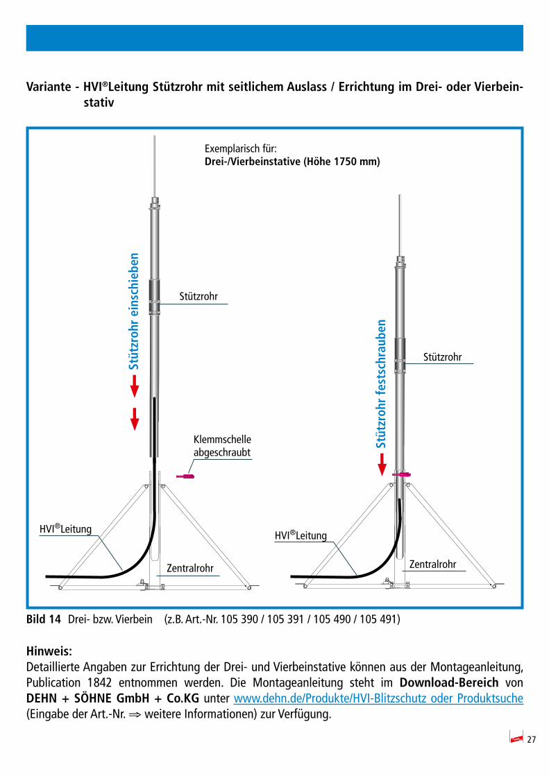
Variante-HVI®LeitungStützrohrmitseitlichemAuslass/ErrichtungimDrei-oderVierbein-stativ
Bild14 Drei- bzw. Vierbein (z.B. Art.-Nr. 105 390 / 105 391 / 105 490 / 105 491)
Hinweis:Detaillierte Angaben zur Errichtung der Drei- und Vierbeinstative können aus der Montageanleitung, Publication 1842 entnommen werden. Die Montageanleitung steht im Download-Bereich von DEHN+SÖHNEGmbH+Co.KG unter www.dehn.de/Produkte/HVI-Blitzschutz oder Produktsuche (Eingabe der Art.-Nr. ⇒ weitere Informationen) zur Verfügung.
Exemplarisch für:Drei-/Vierbeinstative(Höhe1750mm)
Stützrohreinschieben
Stützrohrfestschrauben
Stützrohr
Stützrohr
Klemmschelleabgeschraubt
HVI®LeitungHVI®Leitung
ZentralrohrZentralrohr
28
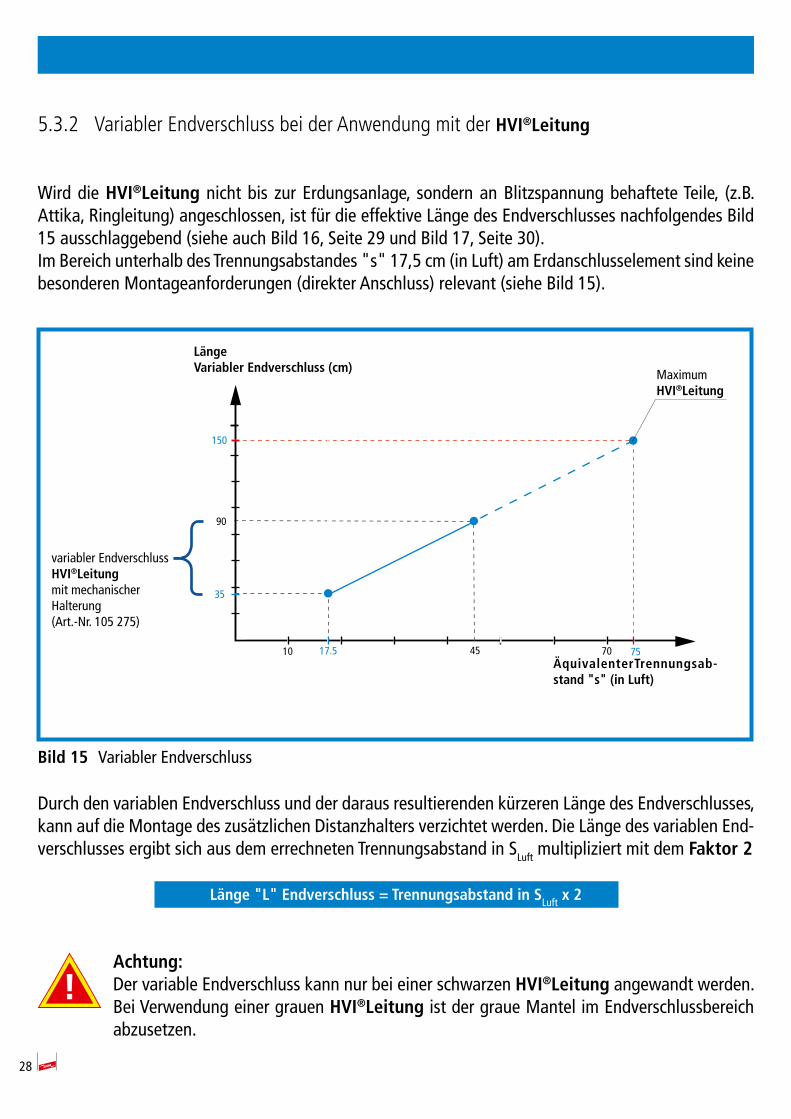
5.3.2 Variabler Endverschluss bei der Anwendung mit der HVI®Leitung
Wird die HVI®Leitung nicht bis zur Erdungsanlage, sondern an Blitzspannung behaftete Teile, (z.B. Attika, Ringleitung) angeschlossen, ist für die effektive Länge des Endverschlusses nachfolgendes Bild 15 ausschlaggebend (siehe auch Bild 16, Seite 29 und Bild 17, Seite 30).Im Bereich unterhalb des Trennungsabstandes "s" 17,5 cm (in Luft) am Erdanschlusselement sind keine besonderen Montageanforderungen (direkter Anschluss) relevant (siehe Bild 15).
Bild15 Variabler Endverschluss
Durch den variablen Endverschluss und der daraus resultierenden kürzeren Länge des Endverschlusses, kann auf die Montage des zusätzlichen Distanzhalters verzichtet werden. Die Länge des variablen End-verschlusses ergibt sich aus dem errechneten Trennungsabstand in SLuft multipliziert mit dem Faktor2
Länge"L"Endverschluss=TrennungsabstandinSLuft x 2
Achtung:Der variable Endverschluss kann nur bei einer schwarzen HVI®Leitung angewandt werden. Bei Verwendung einer grauen HVI®Leitung ist der graue Mantel im Endverschlussbereich abzusetzen.
35
90
704517.5 75
150
10
Maximum HVI®Leitung
variabler Endverschluss HVI®Leitungmit mechanischer Halterung (Art.-Nr. 105 275)
LängeVariablerEndverschluss(cm)
ÄquivalenterTrennungsab-stand"s"(inLuft)
29
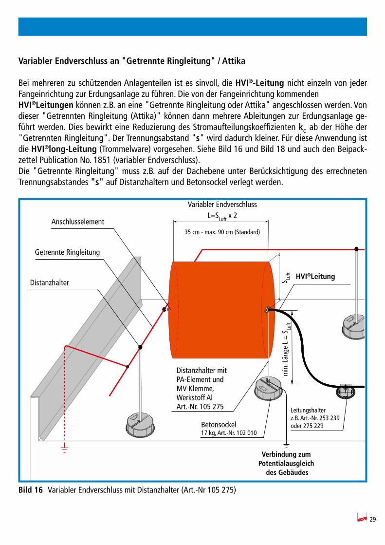
VariablerEndverschlussan"GetrennteRingleitung"/Attika
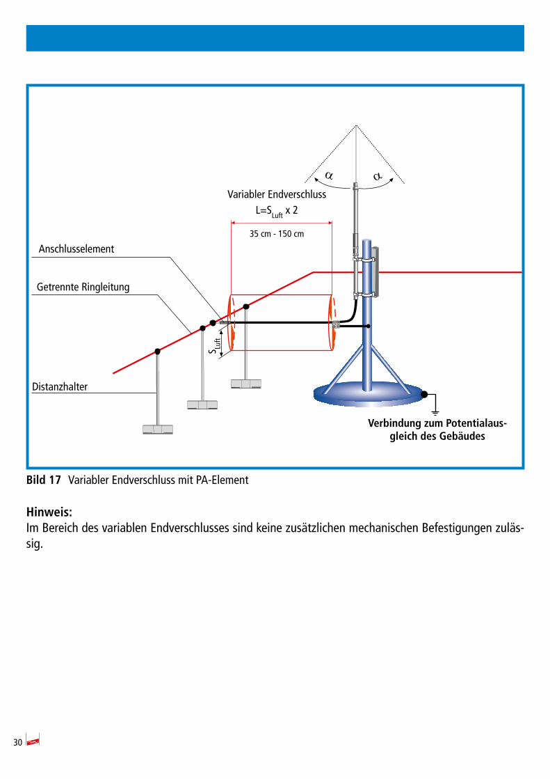
Bei mehreren zu schützenden Anlagenteilen ist es sinvoll, die HVI®-Leitungnicht einzeln von jeder Fangeinrichtung zur Erdungsanlage zu führen. Die von der Fangeinrichtung kommenden HVI®Leitungen können z.B. an eine "Getrennte Ringleitung oder Attika" angeschlossen werden. Von dieser "Getrennten Ringleitung (Attika)" können dann mehrere Ableitungen zur Erdungsanlage ge-führt werden. Dies bewirkt eine Reduzierung des Stromaufteilungskoeffizienten kC ab der Höhe der "Getrennten Ringleitung". Der Trennungsabstand "s" wird dadurch kleiner. Für diese Anwendung ist die HVI®long-Leitung (Trommelware) vorgesehen. Siehe Bild 16 und Bild 18 und auch den Beipack-zettel Publication No. 1851 (variabler Endverschluss).Die "Getrennte Ringleitung" muss z.B. auf der Dachebene unter Berücksichtigung des errechneten Trennungsabstandes "s" auf Distanzhaltern und Betonsockel verlegt werden.
Bild16 Variabler Endverschluss mit Distanzhalter (Art.-Nr 105 275)
Distanzhalter mit PA-Element und MV-Klemme,Werkstoff AlArt.-Nr. 105 275
min
. Län
ge L
= S
Luft
Variabler EndverschlussL=SLuft x 2
35 cm - max. 90 cm (Standard)
S Luft HVI®Leitung
Verbindung zumPotentialausgleichdesGebäudes
Getrennte Ringleitung
Distanzhalter
Leitungshalterz.B. Art.-Nr. 253 239oder 275 229
Anschlusselement
Betonsockel17 kg, Art.-Nr. 102 010
30
Bild17 Variabler Endverschluss mit PA-Element
Hinweis:Im Bereich des variablen Endverschlusses sind keine zusätzlichen mechanischen Befestigungen zuläs-sig.
α αVariabler Endverschluss
L=SLuft x 2
35 cm - 150 cm
VerbindungzumPotentialaus-gleichdesGebäudes
Getrennte Ringleitung
Anschlusselement
Distanzhalter
S Luft
31
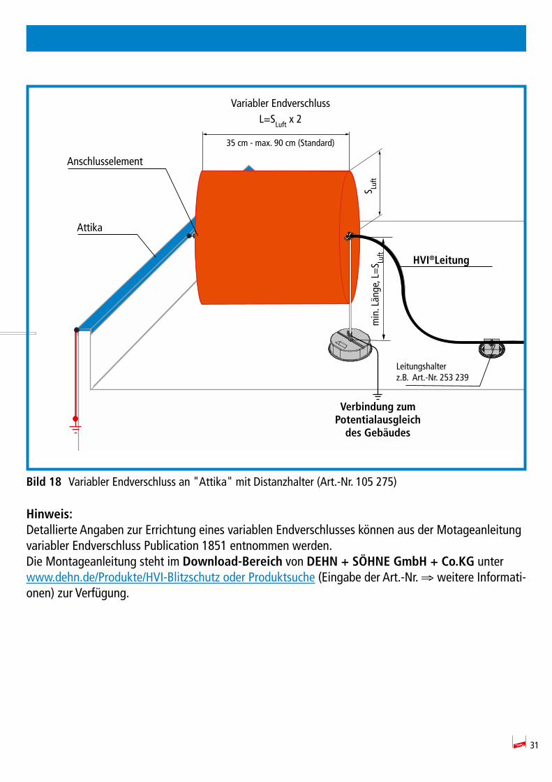
Bild18 Variabler Endverschluss an "Attika" mit Distanzhalter (Art.-Nr. 105 275)
Hinweis:Detallierte Angaben zur Errichtung eines variablen Endverschlusses können aus der Motageanleitungvariabler Endverschluss Publication 1851 entnommen werden. Die Montageanleitung steht im Download-Bereich von DEHN+SÖHNEGmbH+Co.KG unter www.dehn.de/Produkte/HVI-Blitzschutz oder Produktsuche (Eingabe der Art.-Nr. ⇒ weitere Informati-onen) zur Verfügung.
min
. Län
ge, L
=S Lu
ft
Variabler EndverschlussL=SLuft x 2
35 cm - max. 90 cm (Standard)
HVI®Leitung
Verbindung zumPotentialausgleichdesGebäudes
Attika
Anschlusselement
S Luft
Leitungshalterz.B. Art.-Nr. 253 239
32
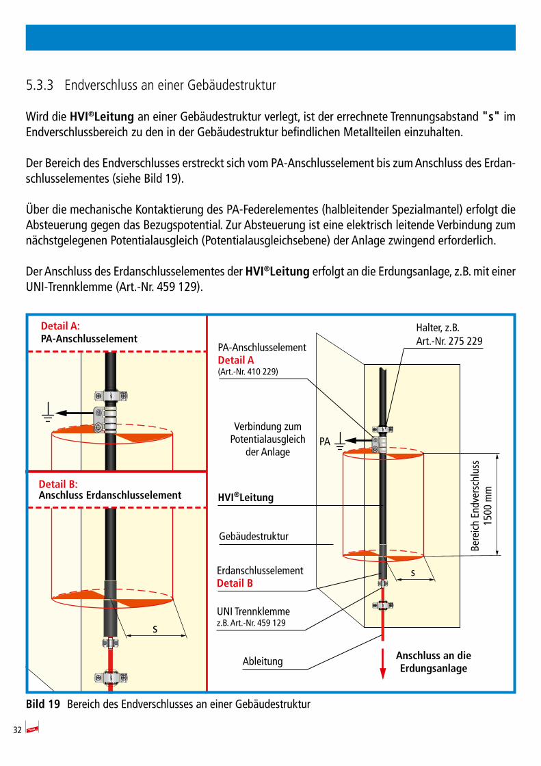
5.3.3 Endverschluss an einer Gebäudestruktur
Wird die HVI®Leitung an einer Gebäudestruktur verlegt, ist der errechnete Trennungsabstand "s"im Endverschlussbereich zu den in der Gebäudestruktur befindlichen Metallteilen einzuhalten.
Der Bereich des Endverschlusses erstreckt sich vom PA-Anschlusselement bis zum Anschluss des Erdan-schlusselementes (siehe Bild 19).
Über die mechanische Kontaktierung des PA-Federelementes (halbleitender Spezialmantel) erfolgt die Absteuerung gegen das Bezugspotential. Zur Absteuerung ist eine elektrisch leitende Verbindung zum nächstgelegenen Potentialausgleich (Potentialausgleichsebene) der Anlage zwingend erforderlich.
Der Anschluss des Erdanschlusselementes der HVI®Leitung erfolgt an die Erdungsanlage, z.B. mit einer UNI-Trennklemme (Art.-Nr. 459 129).
Bild19 Bereich des Endverschlusses an einer Gebäudestruktur
Ableitung
Bere
ich
Endv
ersc
hlus
s15
00 m
m
s
PA
PA-AnschlusselementDetailA(Art.-Nr. 410 229)
ErdanschlusselementDetailB
HVI®Leitung
AnschlussandieErdungsanlage
Verbindung zum Potentialausgleich
der Anlage
DetailA:PA-Anschlusselement
DetailB:AnschlussErdanschlusselement
Halter, z.B.Art.-Nr. 275 229
UNI Trennklemmez.B. Art.-Nr. 459 129
Gebäudestruktur
s

33
6. Anwendung HVI®Leitungmit"GetrennterRingleitung"
Bei mehreren zu schützenden Anlagenteilen ist es sinnvoll, die HVI®Leitung nicht einzeln von jeder Fangeinrichtung zur Erdungsanlage zu führen. Die von der Fangeinrichtung kommenden HVI®Lei-tungen können z.B. an eine "Getrennte Ringleitung" angeschlos sen werden. Von dieser "Getrenn-ten Ringleitung" können dann mehrere Ableitungen zur Erdungsanlage geführt werden. Dies bewirkt eine Reduzierung des Stromaufteilungskoeffizienten kc ab der Höhe der "Getrennten Ringleitung". Der Trennungsabstand "s" wird dadurch kleiner.
Die "Getrennte Ringleitung" muss z.B. auf der Dachebene unter Berücksichtigung des er rech neten Trennungsabstandes "s" auf Distanzhaltern (z.B. Art.-Nr. 106 175) und Betonsockel (Art.-Nr. 102 010) für die Aufnahme des Distanzhalters, verlegt werden.
34
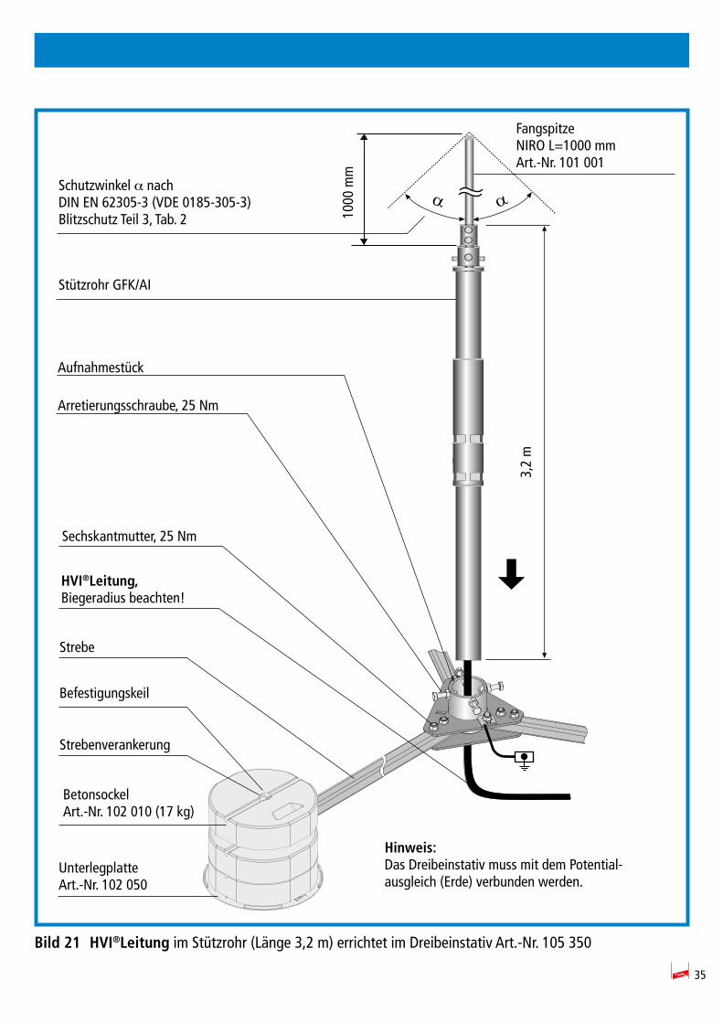
7. HVI®LeitungimStützrohr(Länge3,2m)errichtetimDreibeinstativ
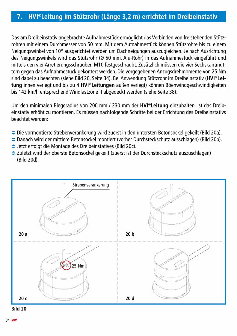
Das am Dreibeinstativ angebrachte Aufnahmestück ermöglicht das Verbinden von frei ste hen den Stütz-rohren mit einem Durchmesser von 50 mm. Mit dem Aufnahmestück können Stützrohre bis zu einem Neigungswinkel von 10° ausgerichtet werden um Dachneigungen auszugleichen. Je nach Ausrichtung des Neigungswinkels wird das Stützrohr (Ø 50 mm, Alu-Rohr) in das Aufnahmestück eingeführt und mittels den vier Ar re tie rungs schrauben M10 fest ge schraubt. Zusätzlich müssen die vier Sechskantmut-tern gegen das Aufnahmestück gekontert werden. Die vorgegebenen Anzugsdrehmomente von 25 Nm sind dabei zu beachten (siehe Bild 20, Seite 34). Bei Anwendung Stützrohr im Dreibeinstativ (HVI®Lei-tung innen verlegt und bis zu 4 HVI®Leitungen außen verlegt) können Böenwindgeschwindigkeiten bis 142 km/h entsprechend Windlastzone II abgedeckt werden (siehe Seite 38).
Um den minimalen Biegeradius von 200 mm / 230 mm der HVI®Leitung einzuhalten, ist das Dreib-einstativ erhöht zu montieren. Es müssen nachfolgende Schritte bei der Errichtung des Dreibeinstativs beachtet werden:
 Die vormontierte Strebenverankerung wird zuerst in den untersten Betonsockel gekeilt (Bild 20a).  Danach wird der mittlere Betonsockel montiert (vorher Durchsteckschutz ausschlagen) (Bild 20b).  Jetzt erfolgt die Montage des Dreibeinstatives (Bild 20c).  Zuletzt wird der oberste Betonsockel gekeilt (zuerst ist der Durchsteckschutz auszuschlagen) (Bild 20d).
Bild20
20 a 20 b
20 c 20 d
25 Nm
Strebenverankerung
35
Bild21 HVI®Leitung im Stützrohr (Länge 3,2 m) errichtet im Dreibeinstativ Art.-Nr. 105 350
ααSchutzwinkel α nachDIN EN 62305-3 (VDE 0185-305-3)Blitzschutz Teil 3, Tab. 2
Fangspitze NIRO L=1000 mmArt.-Nr. 101 001
Stützrohr GFK/AI
1000
mm
Aufnahmestück
Arretierungsschraube, 25 Nm
Sechskantmutter, 25 Nm
HVI®Leitung,Biegeradius beachten!
Befestigungskeil
Strebenverankerung
BetonsockelArt.-Nr. 102 010 (17 kg)
Strebe
UnterlegplatteArt.-Nr. 102 050
Hinweis:Das Dreibeinstativ muss mit dem Potential-ausgleich (Erde) verbunden werden.
3,2
m
36
8. Leitungsverlegung
Die HVI®Leitung muss in ihrem gesamten Leitungsverlauf im Schutzbereich einer Fangeinrichtung des Äußeren Blitzschutzes verlegt werden. Sie darf im gesamten Leitungsverlauf nicht mit Blitzspannung behafteten Teilen der Fangeinrichtung, Ableitung oder Gebäudekonstruktionsteilen in Verbindung kom-men.
Von dieser Festlegung kann abgewichen werden, wenn der Trennungsabstand "s" am Kreu zungs punkt der HVI®Leitung mit dem Blitzspannung behafteten Teil (Fangeinrichtung, Attika oder Ableitung) ≤ 0,35 m (in Luft) oder ≤ 0,7 m (im festen Baustoff) ist. In diesem Fall ist eine Verbindung zwischen dem Mantel der HVI®Leitung und dem Blitzspannung behafteten Teil zulässig (rückwärtige Spannungsfes-tigkeit).
Die HVI®Leitung muss bei der Verlegung nach dem Bereich Endverschluss in Abständen von ≤ 1m befestigt werden.
Die Befestigungsschrauben der metallenen Leitungshalter sind mit max. 5 Nm anzuziehen, die Befesti-gungsschrauben der Kunststoff-Leitungshalter mit max. 2 Nm.
Wird die HVI®Leitung in der baulichen Anlage verlegt, sind bauseits festgelegte Schutzmaßnahmen z.B. Brandschottungen zu beachten.
8.1 ZusätzlicherAnschlussdesäußerenKabelmantelszumZweckedes Potentialausgleiches
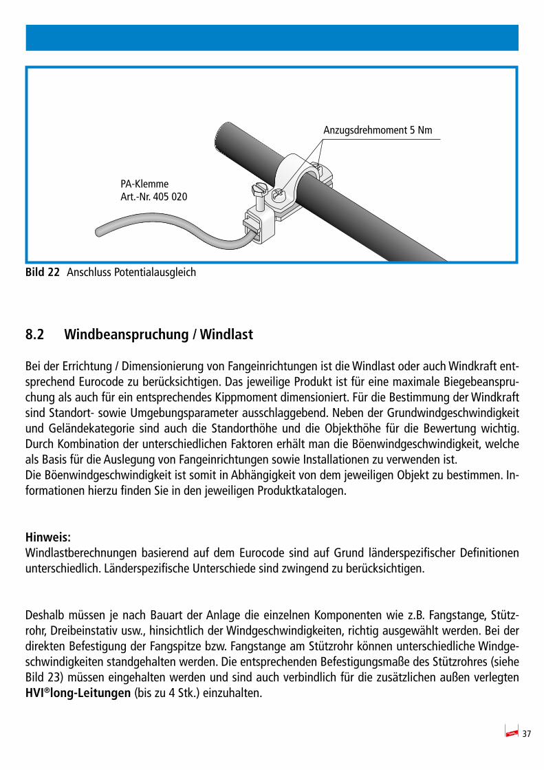
Es wird empfohlen bei Kreuzungen oder parallelen Führungen zu geerdeten metallenen Installationen wie z.B. Attikas, Kabelpritschen oder Rohrleitungen, den schwarzen Mantel der HVI®Leitung mit dem Potentialausgleich zu verbinden. Dies ist eine ergänzende Maßnahme des Po ten ti al aus gleichs.
Anschlüsse können durch die PA-Klemme, Art.-Nr. 405 020, ausgeführt werden. Dieser PA-Anschluss muss nicht blitzstromtragfähig sein. Der Leiterquerschnitt muss ≥4 mm2 Cu oder leitwertgleich sein.
Bei Verwendung der HVI®Leitung mit grauem Mantel ist dieser abzusetzen, damit der da runterliegende halbleitende schwarze Mantel kontaktiert werden kann. Der schwarze Mantel darf nicht eingeschnitten werden.
37
Bild22 Anschluss Potentialausgleich
8.2 Windbeanspruchung/Windlast
Bei der Errichtung / Dimensionierung von Fangeinrichtungen ist die Windlast oder auch Windkraft ent-sprechend Eurocode zu berücksichtigen. Das jeweilige Produkt ist für eine maximale Biegebeanspru-chung als auch für ein entsprechendes Kippmoment dimensioniert. Für die Bestimmung der Windkraft sind Standort- sowie Umgebungsparameter ausschlaggebend. Neben der Grundwindgeschwindigkeit und Geländekategorie sind auch die Standorthöhe und die Objekthöhe für die Bewertung wichtig. Durch Kombination der unterschiedlichen Faktoren erhält man die Böenwindgeschwindigkeit, welche als Basis für die Auslegung von Fangeinrichtungen sowie Installationen zu verwenden ist. Die Böenwindgeschwindigkeit ist somit in Abhängigkeit von dem jeweiligen Objekt zu bestimmen. In-formationen hierzu finden Sie in den jeweiligen Produktkatalogen.
Hinweis:Windlastberechnungen basierend auf dem Eurocode sind auf Grund länderspezifischer Definitionen unterschiedlich. Länderspezifische Unterschiede sind zwingend zu berücksichtigen.
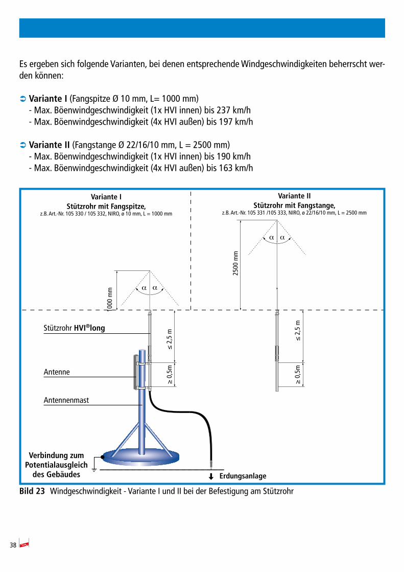
Deshalb müssen je nach Bauart der Anlage die einzelnen Komponenten wie z.B. Fangstange, Stütz-rohr, Dreibeinstativ usw., hinsichtlich der Windgeschwindigkeiten, richtig ausgewählt werden. Bei der direkten Befestigung der Fangspitze bzw. Fangstange am Stützrohr können unterschiedliche Windge-schwindigkeiten standgehalten werden. Die entsprechenden Befestigungsmaße des Stützrohres (siehe Bild 23) müssen eingehalten werden und sind auch verbindlich für die zusätzlichen außen verlegten HVI®long-Leitungen(bis zu 4 Stk.) einzuhalten.
Anzugsdrehmoment 5 Nm
PA-KlemmeArt.-Nr. 405 020
38
Es ergeben sich folgende Varianten, bei denen entsprechende Windgeschwindigkeiten beherrscht wer-den können:
 VarianteI (Fangspitze Ø 10 mm, L= 1000 mm) - Max. Böenwindgeschwindigkeit (1x HVI innen) bis 237 km/h- Max. Böenwindgeschwindigkeit (4x HVI außen) bis 197 km/h
 VarianteII (Fangstange Ø 22/16/10 mm, L = 2500 mm) - Max. Böenwindgeschwindigkeit (1x HVI innen) bis 190 km/h- Max. Böenwindgeschwindigkeit (4x HVI außen) bis 163 km/h
Bild23 Windgeschwindigkeit - Variante I und II bei der Befestigung am Stützrohr
Antennenmast
Antenne
Stützrohr HVI®long
1000
mm
≤ 2
,5 m
≥ 0
,5m
2500
mm
α
α
α
α
Verbindung zum PotentialausgleichdesGebäudes Erdungsanlage
VarianteIStützrohrmitFangspitze,
z.B. Art.-Nr. 105 330 / 105 332, NIRO, ø 10 mm, L = 1000 mm
VarianteIIStützrohrmitFangstange,
z.B. Art.-Nr. 105 331 /105 333, NIRO, ø 22/16/10 mm, L = 2500 mm
≤ 2
,5 m
≥ 0
,5m
39
9. ChecklistefürHVI®Installation
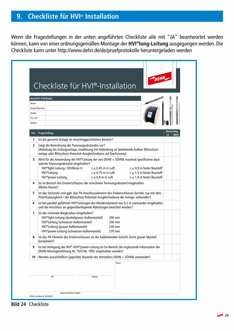
Wenn die Fragestellungen in der unten angeführten Checkliste alle mit "JA" beantwortet werden können, kann von einer ordnungsgemäßen Montage der HVI®long-Leitung ausgegangen werden. Die Checkliste kann unter http://www.dehn.de/de/pruefprotokolle heruntergeladen werden
Bild24 Checkliste
Checkliste für HVI®-InstallationAnschrift Prüfobjekt:
Name:
Ansprechpartner:
Straße:
PLZ, Ort:
Telefon:
Pos. FragestellungBewertungJA NEIN
1 Ist die gesamte Anlage im einschlaggeschützten Bereich?
2 Liegt die Berechnung des Trennungsabstandes vor?(Ableitung bis Erdungsanlage, Insellösung mit Anbindung an bestehende Äußere Blitzschutz-anlage oder Blitzschutz-Potential-Ausgleichsebene auf Dachniveau)
3 Wird für die Anwendung der HVI®Leitung der von DEHN + SÖHNE maximal spezifizierte äqui-valente Trennungsabstand eingehalten? HVI®light-Leitung / DEHNcon H s ≤ 0,45 m in Luft s ≤ 0,9 m fester Baustoff HVI®Leitung s ≤ 0,75 m in Luft s ≤ 1,5 m fester Baustoff HVI®power-Leitung s ≤ 0,9 m in Luft s ≤ 1,8 m fester Baustoff
4 Ist im Bereich des Endverschlusses der errechnete Trennungsabstand eingehalten (fiktive Reuse)
5 Ist das Stützrohr und ggfs. das PA-Anschlusselement des Endverschlusses korrekt, nur mit dem Potentialausgleich / der Blitzschutz-Potential-Ausgleichsebene der Anlage, verbunden?
6 Ist bei parallel geführten HVI®Leitungen der Mindestabstand von 0,2 m zueinander einge halten und der Anschluss an gegenüberliegende Ableitungen beachtet worden?
7 Ist der minimale Biegeradius eingehalten? HVI®light-Leitung (dunkelgrauer Außenmantel) 200 mm HVI®Leitung (schwarzer Außenmantel) 200 mm HVI®Leitung (grauer Außenmantel) 230 mm HVI®power-Leitung (schwarzer Außenmantel) 270 mm
8 Ist das PA-Element des Endverschlusses an der halbleitenden Schicht (nicht grauer Mantel) kontaktiert
9 Ist bei Verlegung der HVI®-/HVI®power-Leitung im Ex-Bereich die ergänzende Information der DEHN-Montageanleitung Nr. 1501/Nr. 1892 eingehalten worden
10 Wurden ausschließlich (geprüfte) Bauteile des Herstellers DEHN + SÖHNE verwendet?
DEHN-Formblatt-Nr. 2848/0815
Firma
Ort Datum
Unterschrift des Prüfers

Überspannungsschutz DEHN + SÖHNE Hans-Dehn-Str. 1 Tel. +49 9181 906-0Blitzschutz/Erdung GmbH + Co.KG. Postfach 1640 www.dehn.deArbeitsschutz 92306 Neumarkt DEHN schützt.® Germany
www.dehn.deGB
Lightning protection/earthing
Installation instructionsHVI®ConductorHVI®Conductor (pre-assembled) / HVI®long Conductor
Publication No. 1841 / Update 09.17 Mat-No. 3003899 © Copyright 2017 DEHN + SÖHNE
2
CONTENTS
1. Safety instructions ....................................................................................................... 4
2. SpecificationofHVI®Conductors ................................................................................. 6
2.1 Application / design of HVI®Conductors ..................................................................... 6
2.2 Technical data .............................................................................................................. 7
2.3 Chemical properties ..................................................................................................... 7
3. Available versions ........................................................................................................ 8
3.1 HVI®Conductor (pre-assembled) / HVI®long Conductor ............................................... 8
3.2 HVI®Conductor for connection to parts of an installation carrying lightning voltage ....................................................................................................................... 10
3.3 Connection elements for installing HVI®long Conductors installed inside the supporting tube ......................................................................................................... 12
3.4 Connections elements for HVI®long Conductors (single parts) ................................. 13
3.5 Accessories for HVI®long Conductors ....................................................................... 15
4. Assembly/pre-assembly of HVI®Conductors ............................................................. 16
4.1 Mounting the head piece/connection element .......................................................... 16
4.2 Wrapping a heat shrinkable sleeve around the head piece/connection element ..... 17
4.3 Removing the grey sheath for installing HVI®long Conductors in the supporting tube .................................................................................................... 18
4.4 Supporting tubes with air-termination tip/rod .......................................................... 19
5. Installation ................................................................................................................. 20
5.1 Installing HVI®long Conductors in the supporting tube ............................................ 20
5.2 Measures to reduce the separation distance "s" (HVI®Conductors installed outside the supporting tube) .......................................... 22
5.3 Sealing end ................................................................................................................ 25
5.3.1 Sealing and rang at the supporting tube based on the example of an antenna ..........................25
5.3.2 Variable sealing end in case of HVI®Conductors ...............................................................28
5.3.3 Sealing end on a building’s structure ........................................................................................32

3
6. Connection of HVI®Conductors to an isolated ring conductor ................................ 33
7. Installation of HVI®Conductors integrated in the supporting tube (3.2 m long) in a tripod .............................................................................................. 34
8. Conductor installation ............................................................................................... 36
8.1 Additional connection of the external cable sheath for equipotential bonding ....... 36
8.2 Wind load ................................................................................................................... 37
9. Checklist for installing HVI®Conductors .................................................................... 39
4
1. Safety instructions
 HVI®Conductors may only be installed under the conditions shown and referred to in these instal-lation instructions.
 Only qualified and trained personnel (lightning protection specialists) may install HVI®Conductors. We recommend to visit a special training course on HVI®products held by DEHN + SÖHNE.
 For safety reasons, installation work must be stopped as soon as a thunderstorm approaches/is noticed.
The components of the HVI®system have been tested as a complete system. Mixing com-ponents of the HVI®system with components from other manufacturers is not permitted.
 Prior to installation, HVI®Conductors must be examined for good order and condition. If damage or any other defect is found, the HVI®Conductor must not be installed. The black sheath of HVI® Conductor must not be damaged by compressive deformation or cuts.
 When using HVI®Conductors in potentially explosive atmospheres, fire and explosion protection measures must be taken.
 If HVI®Conductors are installed on thatched roofs (e.g. reed, straw), special installation conditions must be observed for these flammable locations. These special installation conditions for HVI®Con-ductors are described in our Lightning Protection/Earthing main catalogue (HVI Lightning Protecti-on for Thatched Roofs).
 If the supporting tube is led through a roof, the roof must be properly sealed. Warm roofs must be properly sealed and insulated.
 HVI®Conductors are suitable for outdoor use and can be installed downstream of the sealing end e.g. on roofs, in walls, under plaster, in concrete or on facades/facade constructions. Only HVI® Con-ductors with an additional grey sheath may be installed in the soil, e.g. to connect the down con-ductor installed on the building to the ring earth electrode over a length of max. 2 m. HVI®Conduc-tors must not be used to locally increase the potential gradient area in the soil (risk of step voltage).
 Soiled HVI®Conductors can be cleaned with a cloth soaked with a special cleaning agent (Part No. 297 199). To be able to comply with dangerous goods regulations, this product is only transported within Germany and Austria. ISOPROPYL ALCOHOL (99.1 to 99.9 %) (CSA No. 67-63.0) can be used as an alternative!
IEC 60417-6182:Installation, electrotechnical expertise
IEC 60417-6183:Installation, mechanical expertise
5
 HVI®Conductors must not be painted in the sealing end range due to the special design of their outer sheath.
 HVI®Conductors with grey sheath may be coated if the following conditions are fulfilled: Lacquers and paints must be PVC-compatible, may be water-soluble and may contain solvents.
Note:Solvents in paints and lacquers quickly evaporate if a thin coat is applied and do not damage pla-stics.
 When using HVI®Conductors in hazardous locations, special installation conditions must be obser-ved (see installation instructions No. 1501).
 The function of HVI®Conductors is to maintain the separation distance. Due to their design, they do not have a magnetic shielding effect. Induction effects in secondary conductors/loops must be observed. If required, surge protection measures must be taken.
 For application-specific questions, please contact the relevant sales team or the DEHN representati-ve in your country.
 Further information on the component portfolio of the HVI®Conductor system can be found in our brochure No. 151, our Lightning Protection/Earthing catalogue or at www.dehn-international.com (product data).
6
2. SpecificationofHVI®Conductors
2.1 Application / design of HVI®Conductors
These installation instructions specifically describe the use of HVI®Conductors inside/outside the sup-porting tube and illustrate how HVI®Conductors installed inside and outside the supporting tube (up to four conductors) are processed/assembled.
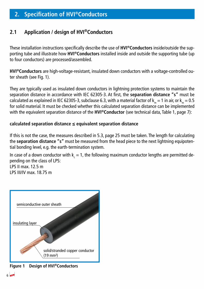
HVI®Conductors are high-voltage-resistant, insulated down conductors with a voltage-controlled ou-ter sheath (see Fig. 1).
They are typically used as insulated down conductors in lightning protection systems to maintain the separation distance in accordance with IEC 62305-3. At first, the separation distance “s” must be calculated as explained in IEC 62305-3, subclause 6.3, with a material factor of km = 1 in air, or km = 0.5 for solid material. It must be checked whether this calculated separation distance can be implemented with the equivalent separation distance of the HVI®Conductor (see technical data, Table 1, page 7):
calculatedseparationdistance≤equivalentseparationdistance
If this is not the case, the measures described in 5.3, page 25 must be taken. The length for calculating the separation distance “s” must be measured from the head piece to the next lightning equipoten-tial bonding level, e.g. the earth-termination system.
In case of a down conductor with kc = 1, the following maximum conductor lengths are permitted de-pending on the class of LPS:LPS II max. 12.5 mLPS III/IV max. 18.75 m
Figure 1 Design of HVI®Conductors
solid/stranded copper conductor (19 mm )
semiconductive outer sheath
insulating layer
7
2.2 Technical data
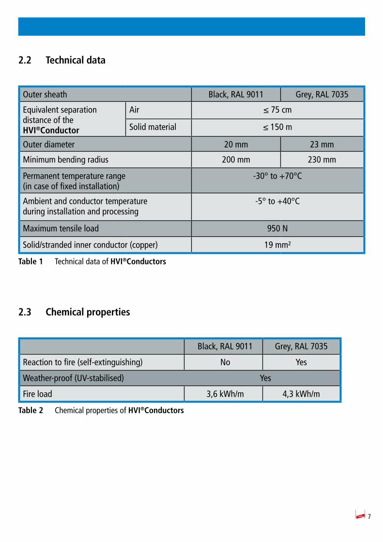
Outer sheath Black, RAL 9011 Grey, RAL 7035
Equivalent separation distance of theHVI®Conductor
Air ≤ 75 cm
Solid material ≤ 150 m
Outer diameter 20 mm 23 mm
Minimum bending radius 200 mm 230 mm
Permanent temperature range (in case of fixed installation)
-30° to +70°C
Ambient and conductor temperature during installation and processing
-5° to +40°C
Maximum tensile load 950 N
Solid/stranded inner conductor (copper) 19 mm
Table 1 Technical data of HVI®Conductors
2.3 Chemical properties
Black, RAL 9011 Grey, RAL 7035
Reaction to fire (self-extinguishing) No Yes
Weather-proof (UV-stabilised) Yes
Fire load 3,6 kWh/m 4,3 kWh/m
Table 2 Chemical properties of HVI®Conductors
8
3. Available versions
3.1 HVI®Conductor (pre-assembled) / HVI®long Conductor
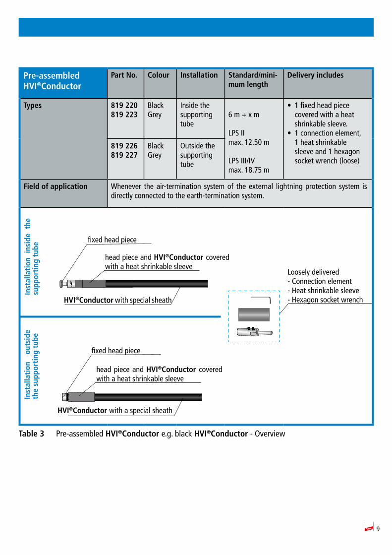
In general, one conductor end of the pre-assembled HVI®Conductors is fitted with the relevant connec-tion element as shown in Table 3, page 9 and Table 4, page 10. Thus, the head piece is fixed and a heat shrinkable sleeve is wrapped around it. If required, the second conductor end can be shortened to exactly match the loose connection element to the installation.
When ordering HVI®Conductors, the conductor/minimum length must be observed/indicated. This in-formation is binding. Conductors cannot be returned since they are tailored to customer needs (pre-as-sembled conductor lengths). Pre-assembled HVI®Conductors are available with a standard/minimum length of 6 m and can be customised in 0.5 m steps. The standard/minimum length of 6 m must be used in combination with a 3.2 m long supporting tube.
A loose connection element, heat shrinkable sleeve and hexagon socket wrench are included in deli-very (for one-time installation) (see also Table 3).
Special tools (HVI®cutter and HVI®strip 20) should be used to cut HVI®Conductors to length/shorten HVI®Conductors and the connection element/heat shrinkable sleeve should be attached considering the relevant connection method (see 4., from page 16).
9
Pre-assembledHVI®Conductor
Part No. Colour Installation Standard/mini-mum length
Delivery includes
Types 819 220819 223
BlackGrey
Inside the supporting tube
6 m + x m LPS II max. 12.50 m
LPS III/IV max. 18.75 m
• 1 fixed head piece covered with a heat shrinkable sleeve.
• 1 connection element, 1 heat shrinkable sleeve and 1 hexagon socket wrench (loose)
819 226819 227
BlackGrey
Outside the supporting tube
Field of application Whenever the air-termination system of the external lightning protection system is directly connected to the earth-termination system.
Table 3 Pre-assembled HVI®Conductor e.g. black HVI®Conductor - Overview
HVI®Conductor with special sheath
fixed head piece
Loosely delivered- Connection element- Heat shrinkable sleeve- Hexagon socket wrench
head piece and HVI®Conductor covered with a heat shrinkable sleeve
Inst
alla
tion
ins
ide
the
supp
orti
ng t
ube
Inst
alla
tion
ou
tsid
e th
e su
ppor
ting
tub
e
HVI®Conductor with a special sheath
fixed head piece
head piece and HVI®Conductor covered with a heat shrinkable sleeve

10
3.2 HVI®Conductor for connection to parts of an installation carrying lightning voltage
A second sealing end is required to connect the pre-assembled HVI®Conductor to parts of an installa-tion carrying lightning voltage (see 5.3, page 25). To this end, an EB connection element (Part No. 410 229) or a spacer with EB element and MV clamp (Part No. 105 275) must be ordered separately:
HVI®Conductor Part No. Colour Installation Standard/mi-nimum length
Delivery includes
Types 819 220819 223
BlackGrey
Inside the supporting tube
6 m + x m
LPS II max. 12.50 m
LPS III/IV max. 18.75 m
• Pre-assembled HVI®Con-ductor
• 1 fixed head piece cover-ed with a heat shrinkable sleeve
• 1 connection element, 1 heat shrinkable sleeve and 1 hexagon socket wrench (loose)
819 226819 227
BlackGrey
Outside the supporting tube
Types of EB connec-tion element(ordered separately)
410 229 EB connection element
105 275 Spacer with EB element
Field of application This conductor is used for connecting e.g. several parts of an installation requiring protection jointly to the earth-termination system of the building via an isolated ring conductor (see Fig. 17, page 28). Conductors with a sealing end mounted in the supporting tube and a sealing end to be adjusted on site are typically used whenever the total conductor length cannot be exactly determined at the design stage of the installation.
Table 4 HVI®Conductor connected to parts of an installation carrying lightning voltage - Overview
Inst
alla
tion
insi
de
the
supp
orti
ng t
ube
Inst
alla
tion
out
side
th
e su
ppor
ting
tub
e
HVI®Conductorwith special sheath
fixed head piece
Loosely delivered:- Connection element- Heat shrinkable sleeve- Hexagon socket wrench
To be ordered separately:- EB connection element (Part No. 410 229)
or
- Spacer with EB element and MV clamp (Part No. 105 275)
head piece and HVI®Conductor covered with a heat shrinkable sleeve
head piece and HVI®Conductor covered with a heat shrinkable sleeve
fixed head piece
HVI®Conductorwith special sheath
11
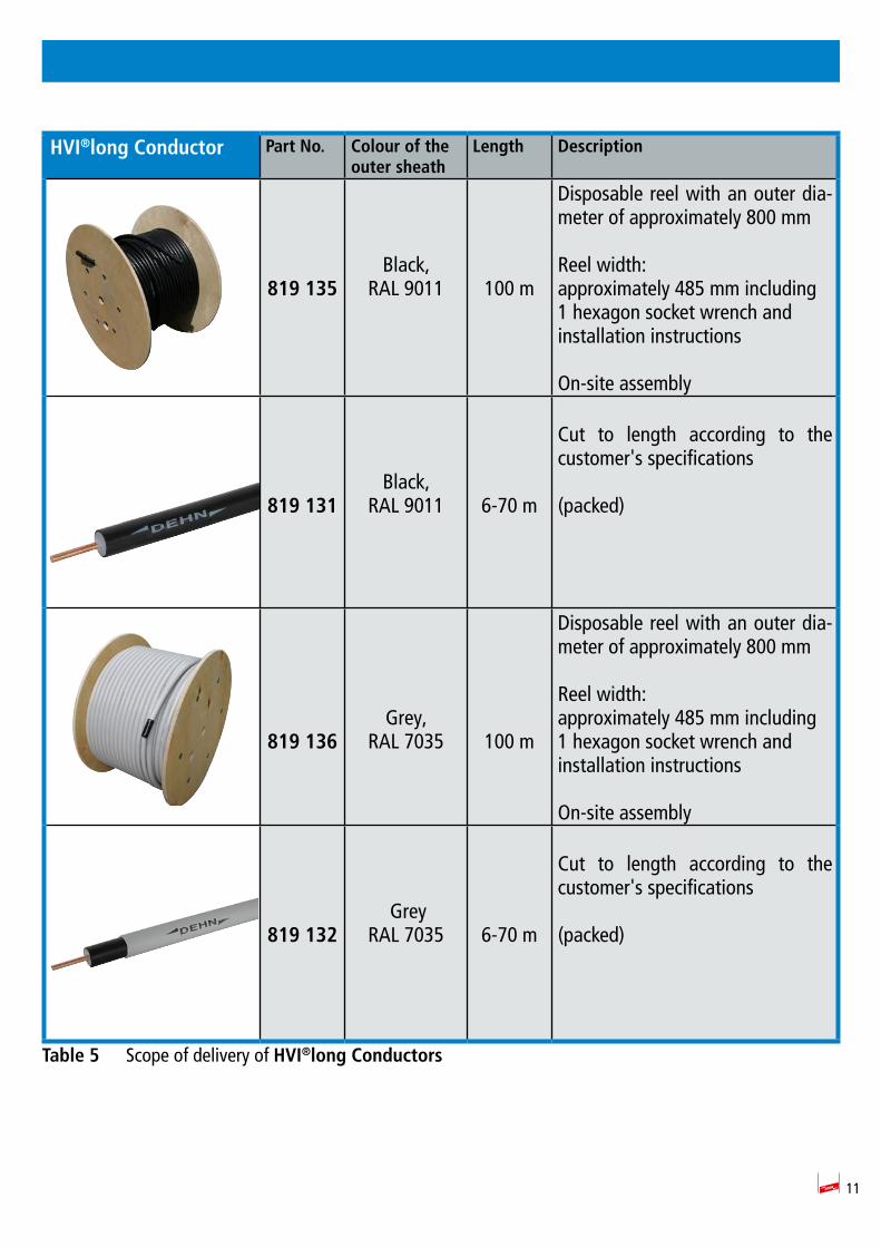
HVI®long Conductor Part No. Colour of the outer sheath
Length Description
819 135
Black,RAL 9011 100 m
Disposable reel with an outer dia-meter of approximately 800 mm
Reel width: approximately 485 mm including 1 hexagon socket wrench and installation instructions
On-site assembly
819 131Black,
RAL 9011 6-70 m
Cut to length according to the customer s specifications
(packed)
819 136Grey,
RAL 7035 100 m
Disposable reel with an outer dia-meter of approximately 800 mm
Reel width:approximately 485 mm including 1 hexagon socket wrench and installation instructions
On-site assembly
819 132 Grey
RAL 7035 6-70 m
Cut to length according to the customer s specifications
(packed)
Table 5 Scope of delivery of HVI®long Conductors

12
3.3 Connection elements for installing HVI®long Conductors installed inside the supporting tube
Part No. Delivery includes Description
819 145 Connection set(black)
Head piece and connection element to be connec-ted to both ends of the HVI®long Conductor when mounting the sealing end of the conductor inside the supporting tube (two heat shrinkable sleeves included)
819 147 Connection set(grey)
Head piece and connection element to be connec-ted to both ends of the HVI®long Conductor when mounting the sealing end of the conductor inside the supporting tube (two black and two grey heat shrinkable sleeves included)
819 146 Connection set(black)
Head piece and connection element to be connec-ted to both ends of the HVI®long Conductor when mounting the sealing end of the conductor outside the supporting tube (head piece for connecting plate) and connection element for other parts of the external lightning protection system or earth-termi-nation system (two black heat shrinkable sleeves and four cable ties included)
819 148 Connection set(grey)
Head piece and connection element to be connec-ted to both ends of the HVI®long Conductor when mounting the sealing end of the conductor outside the supporting tube (head piece for connecting plate) and connection element for other parts of the external lightning protection system or earth-termi-nation system (two black and two grey heat shrin-kable sleeves and four cable ties included)
819 294 Fixing set Fixing set for mounting the HVI®long Conductor on the supporting tube (Ø 50 mm) consisting of a connecting plate (for four conductors, two self-lo-cking nut with serrated bearing included) and a fixing ring with four slotted conductor holders (20 mm) for the sealing end (two cable ties included)
Table 6 HVI®long Conductor
13
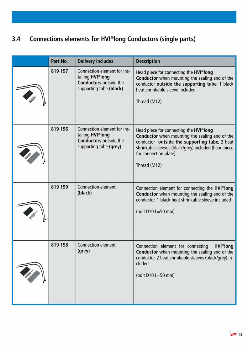
3.4 Connections elements for HVI®long Conductors (single parts)
Part No. Delivery includes Description
819 197 Connection element for ins-talling HVI®long Conductors outside the supporting tube (black)
Head piece for connecting the HVI®long Conductor when mounting the sealing end of the conductor outside the supporting tube, 1 black heat shrinkable sleeve included
Thread (M12)
819 196 Connection element for ins-talling HVI®long Conductors outside the supporting tube (grey)
Head piece for connecting the HVI®long Conductor when mounting the sealing end of the conductor outside the supporting tube, 2 heat shrinkable sleeves (black/grey) included (head piece for connection plate)
Thread (M12)
819 199 Connection element (black)
Connection element for connecting the HVI®long Conductor when mounting the sealing end of the conductor, 1 black heat shrinkable sleeve included
(bolt D10 L=50 mm)
819 198 Connection element(grey)
Connection element for connecting HVI®long Conductor when mounting the sealing end of the conductor, 2 heat shrinkable sleeves (black/grey) in-cluded
(bolt D10 L=50 mm)

14
Part No. Delivery includes Description
410 229 EB connection element (Ø 20 mm)
EB connection element for controlling the electrical field in the sealing end range. Required for the sealing end.
105 275 Spacer with concrete base
Spacer for mounting the sealing end of the HVI Con-ductor by means of an MV clamp for Rd 16 mm/Rd 8-10 mm
597 220 HVI®strip 20 Stripping tool for solid/stranded conductors
597 032 HVI®cutter Cable pliers for cutting HVI®Conductors to length
597 230 DEHNhelix Tool for stripping the additional grey sheath of the HVI®Conductor
Table 7 Connections elements for HVI®long Conductors (single parts)
Note:The complete component portfolio is listed in our Lightning Protection/Earthing catalogue.
15
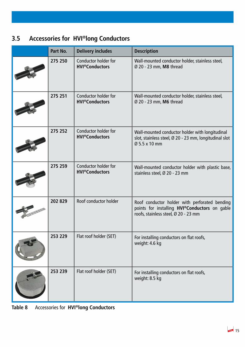
3.5 Accessories for HVI®long Conductors
Part No. Delivery includes Description
275 250 Conductor holder forHVI®Conductors
Wall-mounted conductor holder, stainless steel, Ø 20 - 23 mm, M8 thread
275 251 Conductor holder forHVI®Conductors
Wall-mounted conductor holder, stainless steel, Ø 20 - 23 mm, M6 thread
275 252 Conductor holder forHVI®Conductors
Wall-mounted conductor holder with longitudinal slot, stainless steel, Ø 20 - 23 mm, longitudinal slot Ø 5.5 x 10 mm
275 259 Conductor holder forHVI®Conductors
Wall-mounted conductor holder with plastic base, stainless steel, Ø 20 - 23 mm
202 829 Roof conductor holder Roof conductor holder with perforated bending points for installing HVI®Conductors on gable roofs, stainless steel, Ø 20 - 23 mm
253 229 Flat roof holder (SET) For installing conductors on flat roofs, weight: 4.6 kg
253 239 Flat roof holder (SET) For installing conductors on flat roofs, weight: 8.5 kg
Table 8 Accessories for HVI®long Conductors
16
4. Assembly/pre-assembly of HVI®Conductors
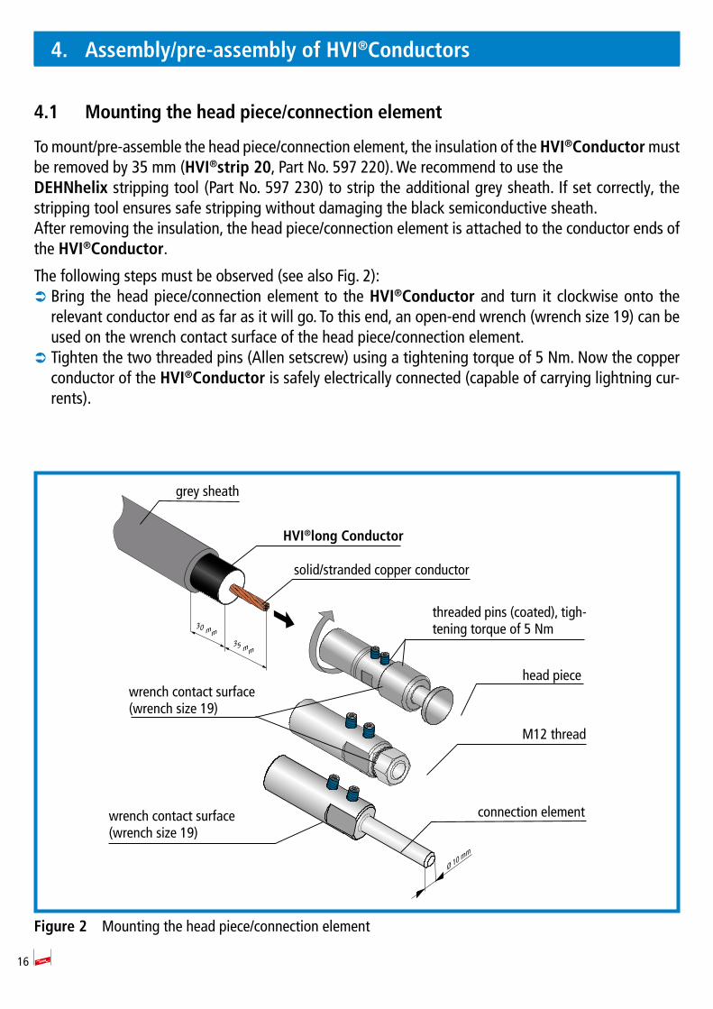
4.1 Mounting the head piece/connection element
To mount/pre-assemble the head piece/connection element, the insulation of the HVI®Conductor must be removed by 35 mm (HVI®strip 20, Part No. 597 220). We recommend to use the DEHNhelix stripping tool (Part No. 597 230) to strip the additional grey sheath. If set correctly, the stripping tool ensures safe stripping without damaging the black semiconductive sheath.After removing the insulation, the head piece/connection element is attached to the conductor ends of the HVI®Conductor.
The following steps must be observed (see also Fig. 2): Â Bring the head piece/connection element to the HVI®Conductor and turn it clockwise onto the relevant conductor end as far as it will go. To this end, an open-end wrench (wrench size 19) can be used on the wrench contact surface of the head piece/connection element.
 Tighten the two threaded pins (Allen setscrew) using a tightening torque of 5 Nm. Now the copper conductor of the HVI®Conductor is safely electrically connected (capable of carrying lightning cur-rents).
Figure 2 Mounting the head piece/connection element
Ø 10 mm
35 mm
30 mm
M12 thread
grey sheath
HVI®long Conductor
threaded pins (coated), tigh-tening torque of 5 Nm
head piecewrench contact surface(wrench size 19)
wrench contact surface(wrench size 19)
connection element
solid/stranded copper conductor
17
4.2 Wrapping a heat shrinkable sleeve around the head piece/connection element
Applying heat shrinkable sleeves
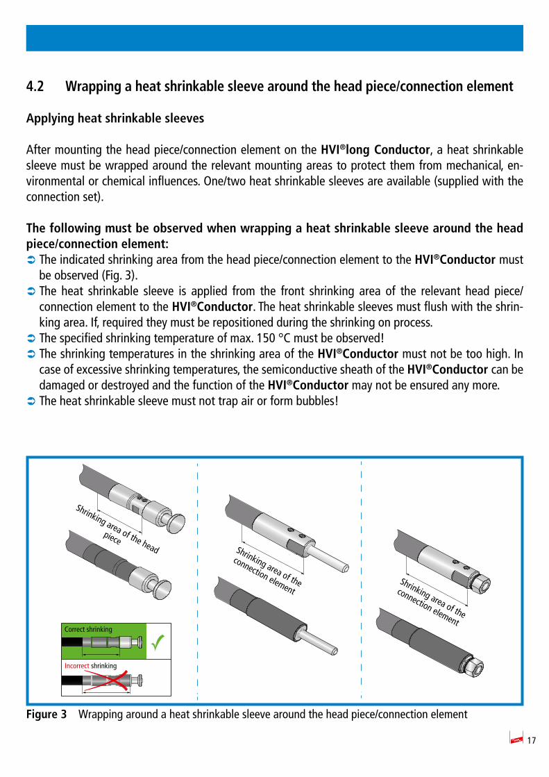
After mounting the head piece/connection element on the HVI®long Conductor, a heat shrinkable sleeve must be wrapped around the relevant mounting areas to protect them from mechanical, en-vironmental or chemical influences. One/two heat shrinkable sleeves are available (supplied with the connection set).
The following must be observed when wrapping a heat shrinkable sleeve around the head piece/connection element:
 The indicated shrinking area from the head piece/connection element to the HVI®Conductor must be observed (Fig. 3).
 The heat shrinkable sleeve is applied from the front shrinking area of the relevant head piece/connection element to the HVI®Conductor. The heat shrinkable sleeves must flush with the shrin-king area. If, required they must be repositioned during the shrinking on process.
 The specified shrinking temperature of max. 150 °C must be observed!  The shrinking temperatures in the shrinking area of the HVI®Conductor must not be too high. In case of excessive shrinking temperatures, the semiconductive sheath of the HVI®Conductor can be damaged or destroyed and the function of the HVI®Conductor may not be ensured any more.
 The heat shrinkable sleeve must not trap air or form bubbles!
Figure 3 Wrapping around a heat shrinkable sleeve around the head piece/connection element
Shrinking area of the
connection element
Shrinking area of the
connection element
Shrinking area of the head
piece
Correct shrinking
Incorrect shrinking
18
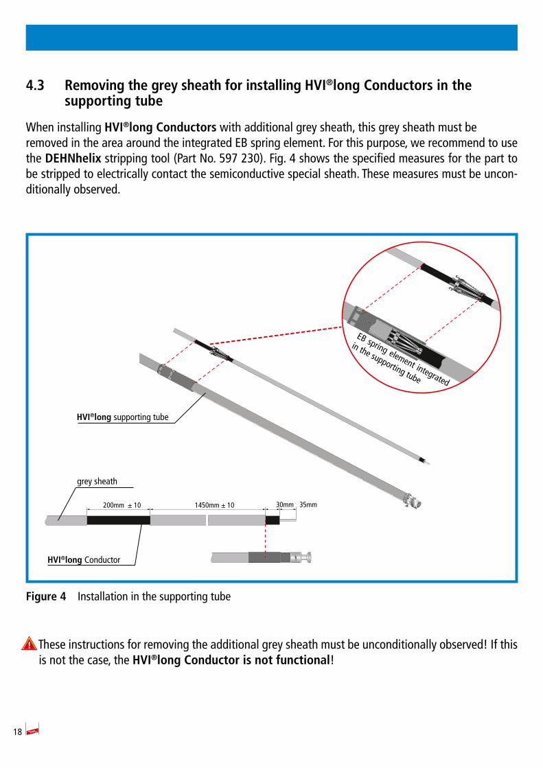
4.3 Removing the grey sheath for installing HVI®long Conductors in the supporting tube
When installing HVI®long Conductors with additional grey sheath, this grey sheath must be removed in the area around the integrated EB spring element. For this purpose, we recommend to use the DEHNhelix stripping tool (Part No. 597 230). Fig. 4 shows the specified measures for the part to be stripped to electrically contact the semiconductive special sheath. These measures must be uncon-ditionally observed.
Figure 4 Installation in the supporting tube
These instructions for removing the additional grey sheath must be unconditionally observed! If this is not the case, the HVI®long Conductor is not functional!
EB spring element integrated
in the supporting tube
HVI®long Conductor
HVI®long supporting tube
grey sheath
30mm 35mm1450mm ± 10200mm ± 10
19
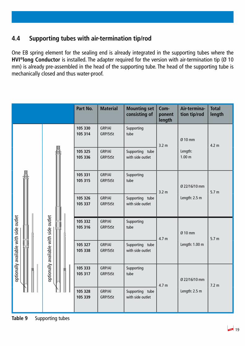
4.4 Supporting tubes with air-termination tip/rod
One EB spring element for the sealing end is already integrated in the supporting tubes where the HVI®long Conductor is installed. The adapter required for the version with air-termination tip (Ø 10 mm) is already pre-assembled in the head of the supporting tube. The head of the supporting tube is mechanically closed and thus water-proof.
Part No. Material Mounting setconsisting of
Com-ponent length
Air-termina-tion tip/rod
Total length
105 330105 314
GRP/AlGRP/StSt
Supportingtube
3.2 mØ 10 mm
Length:1.00 m
4.2 m
105 325105 336
GRP/AlGRP/StSt
Supporting tube with side outlet
105 331105 315
GRP/AlGRP/StSt
Supportingtube
3.2 mØ 22/16/10 mm
Length: 2.5 m5.7 m
105 326105 337
GRP/AlGRP/StSt
Supporting tube with side outlet
105 332105 316
GRP/AlGRP/StSt
Supportingtube
4.7 mØ 10 mm
Length: 1.00 m5.7 m
105 327105 338
GRP/AlGRP/StSt
Supporting tube with side outlet
105 333105 317
GRP/AlGRP/StSt
Supportingtube
4.7 mØ 22/16/10 mm
Length: 2.5 m7.2 m
105 328105 339
GRP/AlGRP/StSt
Supporting tube with side outlet
Table 9 Supporting tubes
optio
nally
ava
ilabl
e w
ith s
ide
outle
t
optio
nally
ava
ilabl
e w
ith s
ide
outle
t
20
5. Installation
5.1 Installing HVI®long Conductors in the supporting tube
Before installing the supporting tube, insert the fixed head piece of the pre-assembled HVI®long Con-ductor into the supporting tube and fix it (see also Fig. 5, page 21).
The following steps must be observed
 Unscrew the locking screw of the head piece (M8 x 25 mm) at the head of the supporting tube.
 Insert the HVI®long Conductor from below into the supporting tube. To this end, the compressive strength of the integrated EB spring element must be overcome. The conductor can be inserted and removed several times. To contact the head piece, insert the HVI®long Conductor into the suppor-ting tube as far as it will go and hold it there.
 The locking screw (M8 x 25 mm) is firmly tightened again using a tightening torque of 15 Nm. Thus, the head piece is fixed in the supporting tube and is electrically connected (capable of carrying light-ning currents). Make sure that there is a sufficient distance (about 7 mm) between the screw head and the supporting tube after tightening the locking screw. The adhesive coating of the screw only hardens after about 5 minutes so that the screw can be correctly positioned and tightened during this period. After the adhesive coating has hardened, the screw must be replaced by a new one if the screw is removed.
 Check whether the HVI®long Conductor is properly fixed in the supporting tube (see Fig. 5). Proper installation can be verified by slightly pulling the conductor at the point where the conductor leaves the supporting tube.
 Depending on the construction of the installation, the relevant air-termination tip/air-termination rod must be installed before or after the supporting tube has been installed.
 Insert the air-termination tip/air-termination rod from above into the head of the supporting tube and tighten the two locking screws (M8 x 16 mm/M8 x 10 mm) using a tightening torque of 15 Nm.
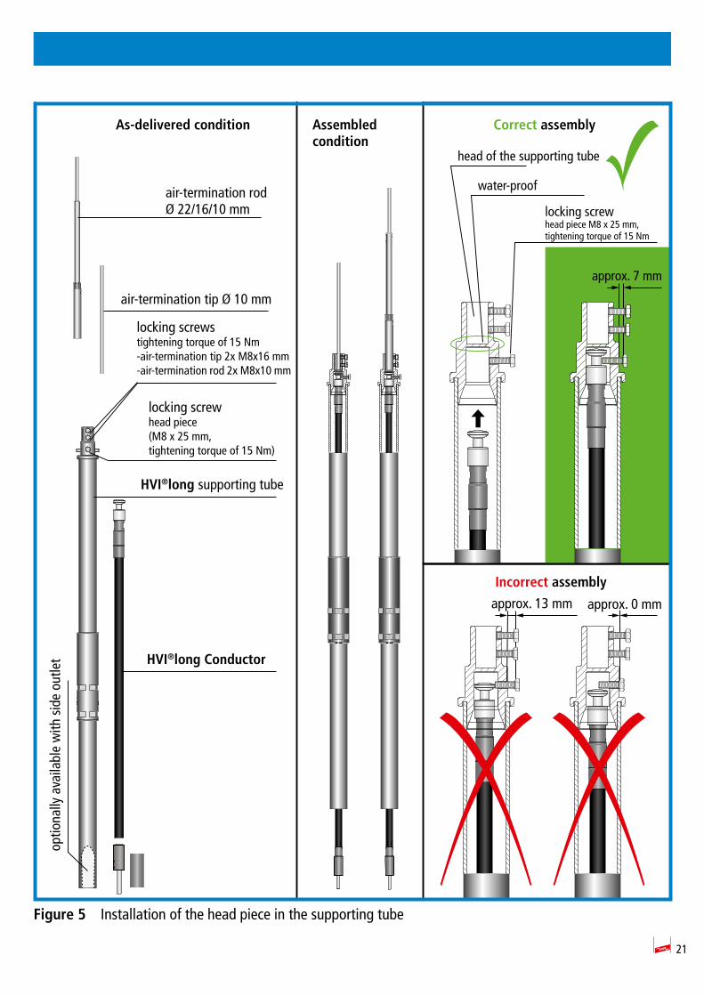
21
Figure 5 Installation of the head piece in the supporting tube
optio
nally
ava
ilabl
e w
ith s
ide
outle
t
As-delivered condition Assembled condition
Correct assembly
approx. 13 mm approx. 0 mm
approx. 7 mm
Incorrect assembly
locking screwhead piece M8 x 25 mm,tightening torque of 15 Nm
locking screwstightening torque of 15 Nm-air-termination tip 2x M8x16 mm-air-termination rod 2x M8x10 mm
locking screwhead piece(M8 x 25 mm,tightening torque of 15 Nm)
air-termination rodØ 22/16/10 mm
air-termination tip Ø 10 mm
HVI®long supporting tube
head of the supporting tube
water-proof
HVI®long Conductor
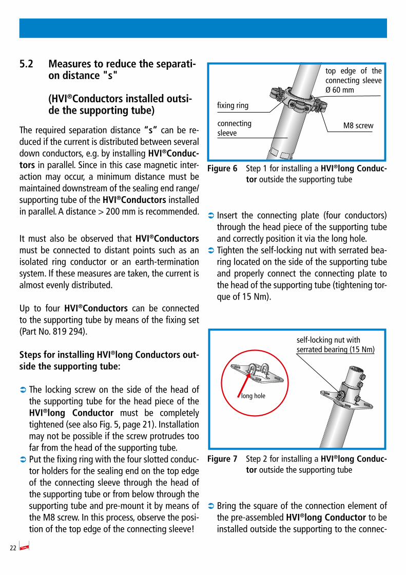
22
5.2 Measures to reduce the separati-on distance "s"
(HVI®Conductors installed outsi-de the supporting tube)
The required separation distance “s” can be re-duced if the current is distributed between several down conductors, e.g. by installing HVI®Conduc-tors in parallel. Since in this case magnetic inter-action may occur, a minimum distance must be maintained downstream of the sealing end range/supporting tube of the HVI®Conductors installed in parallel. A distance 200 mm is recommended.
It must also be observed that HVI®Conductors must be connected to distant points such as an isolated ring conductor or an earth-termination system. If these measures are taken, the current is almost evenly distributed.
Up to four HVI®Conductors can be connected to the supporting tube by means of the fixing set (Part No. 819 294).
Steps for installing HVI®long Conductors out-side the supporting tube:
 The locking screw on the side of the head of the supporting tube for the head piece of the HVI®long Conductor must be completely tightened (see also Fig. 5, page 21). Installation may not be possible if the screw protrudes too far from the head of the supporting tube.
 Put the fixing ring with the four slotted conduc-tor holders for the sealing end on the top edge of the connecting sleeve through the head of the supporting tube or from below through the supporting tube and pre-mount it by means of the M8 screw. In this process, observe the posi-tion of the top edge of the connecting sleeve!
Figure 6 Step 1 for installing a HVI®long Conduc-tor outside the supporting tube
 Insert the connecting plate (four conductors) through the head piece of the supporting tube and correctly position it via the long hole.
 Tighten the self-locking nut with serrated bea-ring located on the side of the supporting tube and properly connect the connecting plate to the head of the supporting tube (tightening tor-que of 15 Nm).
Figure 7 Step 2 for installing a HVI®long Conduc-tor outside the supporting tube
 Bring the square of the connection element of the pre-assembled HVI®long Conductor to be installed outside the supporting to the connec-
fixing ring
connectingsleeve
M8 screw
top edge of the connecting sleeve Ø 60 mm
long hole
self-locking nut with serrated bearing (15 Nm)
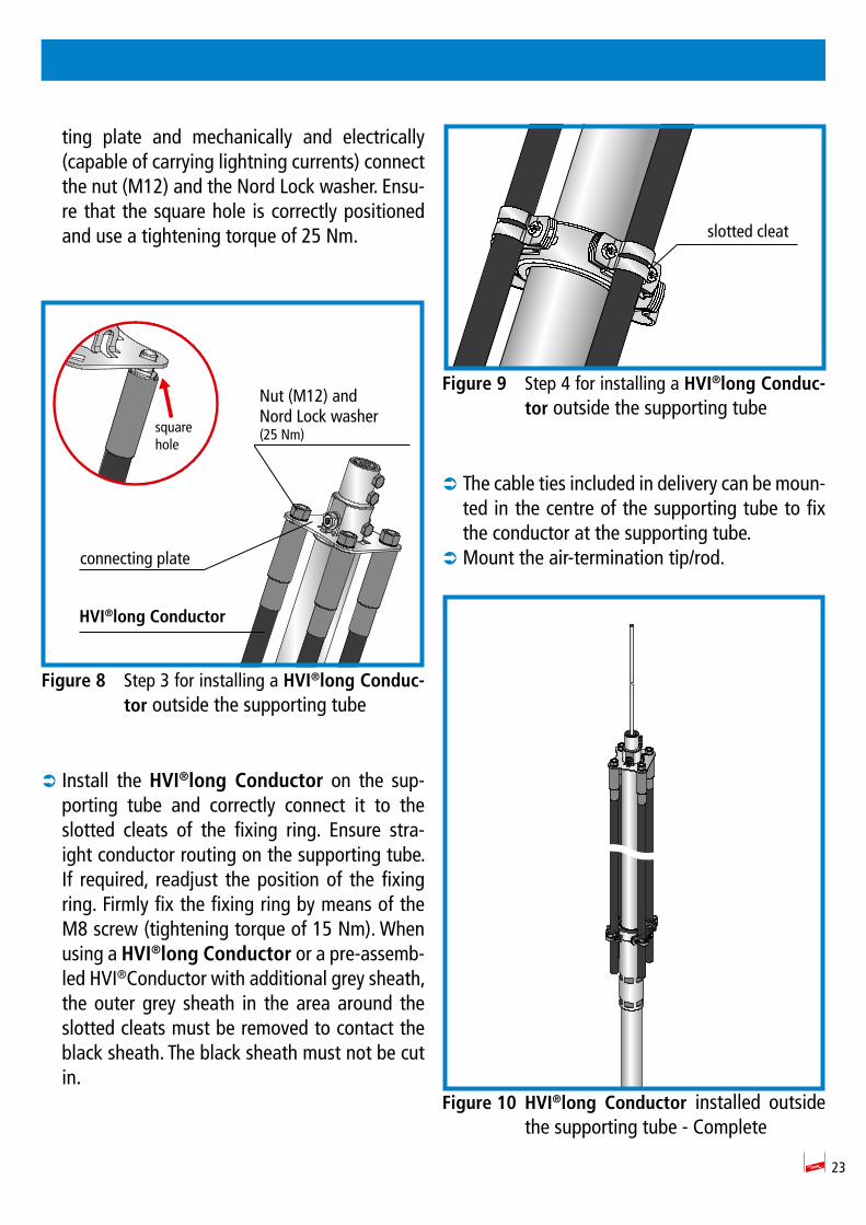
23
ting plate and mechanically and electrically (capable of carrying lightning currents) connect the nut (M12) and the Nord Lock washer. Ensu-re that the square hole is correctly positioned and use a tightening torque of 25 Nm.
Figure 8 Step 3 for installing a HVI®long Conduc-tor outside the supporting tube
 Install the HVI®long Conductor on the sup-porting tube and correctly connect it to the slotted cleats of the fixing ring. Ensure stra-ight conductor routing on the supporting tube. If required, readjust the position of the fixing ring. Firmly fix the fixing ring by means of the M8 screw (tightening torque of 15 Nm). When using a HVI®long Conductor or a pre-assemb-led HVI®Conductor with additional grey sheath, the outer grey sheath in the area around the slotted cleats must be removed to contact the black sheath. The black sheath must not be cut in.
Figure 9 Step 4 for installing a HVI®long Conduc-tor outside the supporting tube
 The cable ties included in delivery can be moun-ted in the centre of the supporting tube to fix the conductor at the supporting tube.
 Mount the air-termination tip/rod.
Figure 10 HVI®long Conductor installed outside the supporting tube - Complete
Nut (M12) andNord Lock washer(25 Nm)
connecting plate
HVI®long Conductor
squarehole
slotted cleat
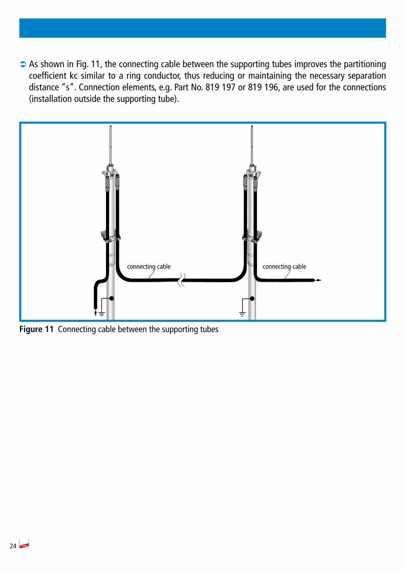
24
 As shown in Fig. 11, the connecting cable between the supporting tubes improves the partitioning coefficient kc similar to a ring conductor, thus reducing or maintaining the necessary separation distance s . Connection elements, e.g. Part No. 819 197 or 819 196, are used for the connections (installation outside the supporting tube).
Figure 11 Connecting cable between the supporting tubes
connecting cable connecting cable
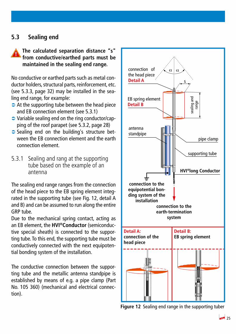
25
5.3 Sealing end
The calculated separation distance “s" from conductive/earthed parts must be maintained in the sealing end range.
No conductive or earthed parts such as metal con-ductor holders, structural parts, reinforcement, etc. (see 5.3.3, page 32) may be installed in the sea-ling end range, for example:
 At the supporting tube between the head piece and EB connection element (see 5.3.1)
 Variable sealing end on the ring conductor/cap-ping of the roof parapet (see 5.3.2, page 28)
 Sealing end on the building s structure bet-ween the EB connection element and the earth connection element.
5.3.1 Sealing and rang at the supporting tube based on the example of an antenna
The sealing end range ranges from the connection of the head piece to the EB spring element integ-rated in the supporting tube (see Fig. 12, detail A and B) and can be assumed to run along the entire GRP tube.Due to the mechanical spring contact, acting as an EB element, the HVI®Conductor (semiconduc-tive special sheath) is connected to the suppor-ting tube. To this end, the supporting tube must be conductively connected with the next equipoten-tial bonding system of the installation.
The conductive connection between the suppor-ting tube and the metallic antenna standpipe is established by means of e.g. a pipe clamp (Part No. 105 360) (mechanical and electrical connec-tion).
Figure 12 Sealing end range in the supporting tuber
seal
ing
and
rang
e
Detail A:connection of the head piece
Detail B:EB spring element
connection of the head pieceDetail A s
α α
EB spring elementDetail B
antenna standpipe
pipe clamp
supporting tube
HVI®long Conductor
connection to the equipotential bon-ding system of the
installationconnection to the earth-termination
system

26
An antenna pipe clamp (Part No. 540 100), for example, can be used to connect the antenna standpipe to the equipotential bonding system (functional equipotential bonding).
HVI®Conductorinstalledinsideinthesupportingtube/wallfi ingbracket
Figure 13 Isolated air-termination system with HVI®Conductor and wall fixing bracket
protective angle αacc. to IEC 62305 Part 3, Table 2
e.g. air termination rodStSt, Ø 22/16/10 mm, L = 2500 mm
e.g. wall fixing bracketStSt, clamping range supporting tube Ø 40-50 mm, with double cleat, Part No.105 344
double cleat for connecting2x Rd 8 to 10 mm to the equipotential bonding system
earth connection element
HVI®Conductor
connection to the equipotential bonding system of the building
earth-termination system
α α
Seal
ing
and
rang
e 15
00 m
m
s
supporting tube with air-termination rodGRP/AL, e.g. Part No. 105 331supporting tube L = 3200 mm + air-termination rod L = 2500 mm
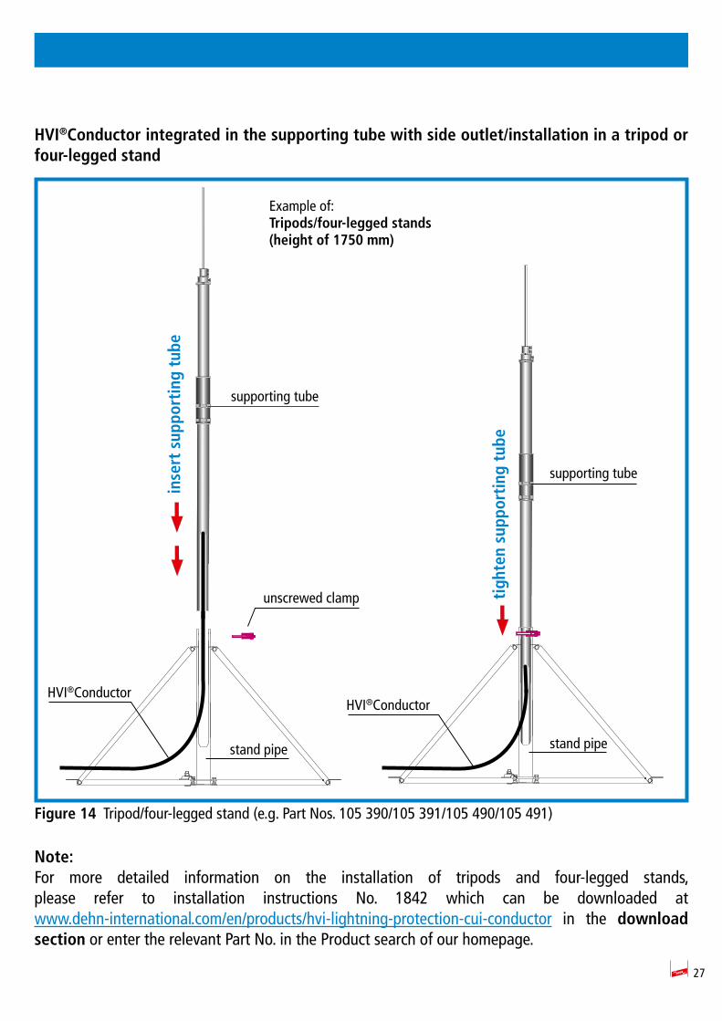
27
HVI®Conductor integrated in the supporting tube with side outlet/installation in a tripod or four-legged stand
Figure 14 Tripod/four-legged stand (e.g. Part Nos. 105 390/105 391/105 490/105 491)
Note:For more detailed information on the installation of tripods and four-legged stands, please refer to installation instructions No. 1842 which can be downloaded at www.dehn-international.com/en/products/hvi-lightning-protection-cui-conductor in the download section or enter the relevant Part No. in the Product search of our homepage.
Example of: Tripods/four-legged stands (height of 1750 mm)
inse
rt s
uppo
rtin
g tu
be
tigh
ten
supp
orti
ng t
ube
supporting tube
supporting tube
unscrewed clamp
HVI®ConductorHVI®Conductor
stand pipestand pipe
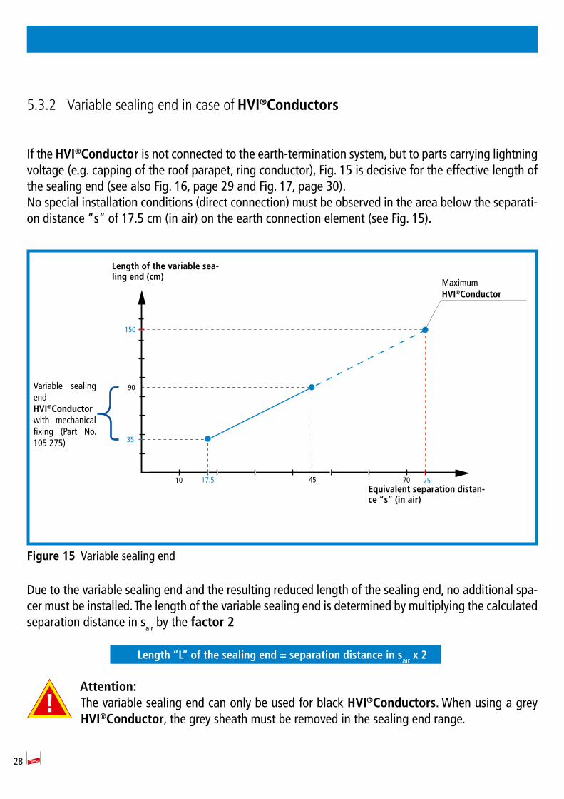
28
5.3.2 Variable sealing end in case of HVI®Conductors
If the HVI®Conductor is not connected to the earth-termination system, but to parts carrying lightning voltage (e.g. capping of the roof parapet, ring conductor), Fig. 15 is decisive for the effective length of the sealing end (see also Fig. 16, page 29 and Fig. 17, page 30).No special installation conditions (direct connection) must be observed in the area below the separati-on distance s of 17.5 cm (in air) on the earth connection element (see Fig. 15).
Figure 15 Variable sealing end
Due to the variable sealing end and the resulting reduced length of the sealing end, no additional spa-cer must be installed. The length of the variable sealing end is determined by multiplying the calculated separation distance in sair by the factor 2
Length “L” of the sealing end = separation distance in sair x 2
Attention:The variable sealing end can only be used for black HVI®Conductors. When using a grey HVI®Conductor, the grey sheath must be removed in the sealing end range.
35
90
704517.5 75
150
10
Maximum HVI®Conductor
Variable sealing endHVI®Conductorwith mechanical fixing (Part No. 105 275)
Length of the variable sea-ling end (cm)
Equivalent separation distan-ce “s” (in air)
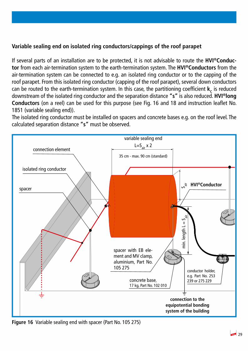
29
Variable sealing end on isolated ring conductors/cappings of the roof parapet
If several parts of an installation are to be protected, it is not advisable to route the HVI®Conduc-tor from each air-termination system to the earth-termination system. The HVI®Conductors from the air-termination system can be connected to e.g. an isolated ring conductor or to the capping of the roof parapet. From this isolated ring conductor (capping of the roof parapet), several down conductors can be routed to the earth-termination system. In this case, the partitioning coefficient kC is reduced downstream of the isolated ring conductor and the separation distance “s” is also reduced. HVI®long Conductors (on a reel) can be used for this purpose (see Fig. 16 and 18 and instruction leaflet No. 1851 (variable sealing end)).The isolated ring conductor must be installed on spacers and concrete bases e.g. on the roof level. The calculated separation distance “s” must be observed.
Figure 16 Variable sealing end with spacer (Part No. 105 275)
spacer with EB ele-ment and MV clamp, aluminium, Part No. 105 275
min
. len
gth
L =
Sai
r
variable sealing endL=Sair x 2
35 cm - max. 90 cm (standard)
S air HVI®Conductor
connection to the equipotential bonding system of the building
isolated ring conductor
spacer
conductor holder, e.g. Part No. 253 239 or 275 229
connection element
concrete base, 17 kg, Part No. 102 010
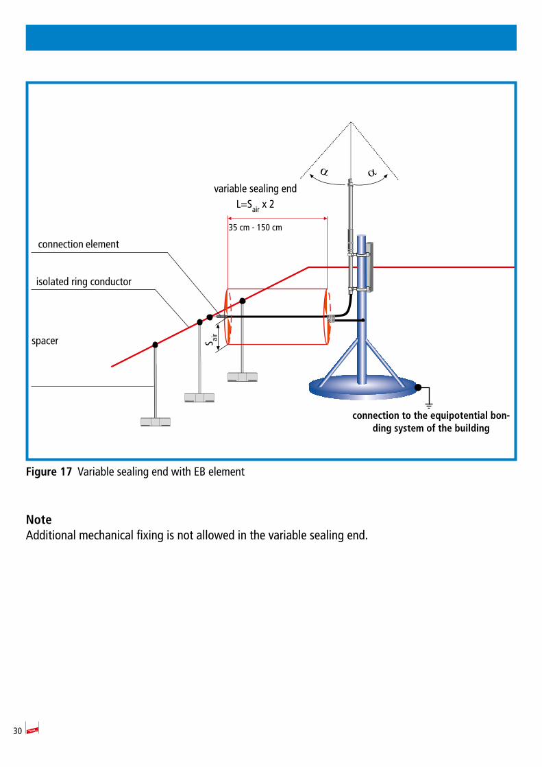
30
Figure 17 Variable sealing end with EB element
NoteAdditional mechanical fixing is not allowed in the variable sealing end.
α αvariable sealing end
L=Sair x 2
35 cm - 150 cm
connection to the equipotential bon-ding system of the building
isolated ring conductor
connection element
spacer S air
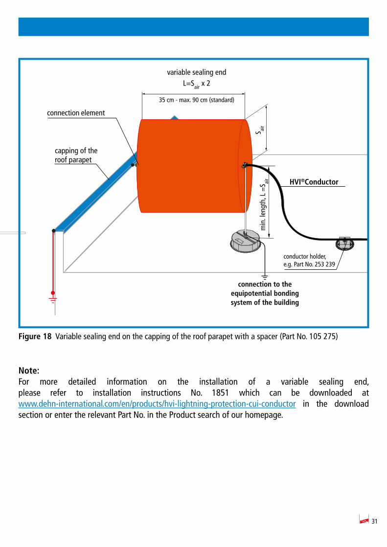
31
Figure 18 Variable sealing end on the capping of the roof parapet with a spacer (Part No. 105 275)
Note:For more detailed information on the installation of a variable sealing end, please refer to installation instructions No. 1851 which can be downloaded at www.dehn-international.com/en/products/hvi-lightning-protection-cui-conductor in the download section or enter the relevant Part No. in the Product search of our homepage.
min
. len
gth,
L =
S air
variable sealing endL=Sair x 2
35 cm - max. 90 cm (standard)
HVI®Conductor
connection to the equipotential bonding system of the building
capping of the roof parapet
connection element
S air
conductor holder, e.g. Part No. 253 239
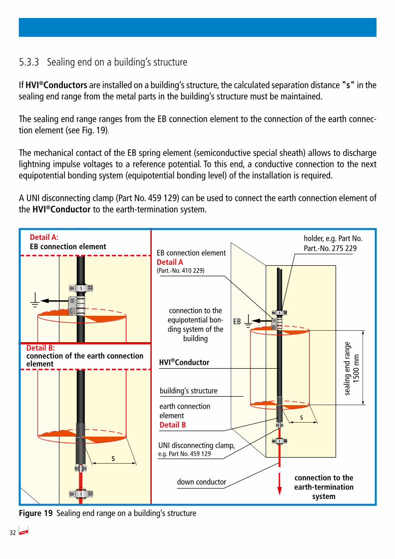
32
5.3.3 Sealing end on a building’s structure
If HVI®Conductors are installed on a building s structure, the calculated separation distance "s" in the sealing end range from the metal parts in the building s structure must be maintained.
The sealing end range ranges from the EB connection element to the connection of the earth connec-tion element (see Fig. 19).
The mechanical contact of the EB spring element (semiconductive special sheath) allows to discharge lightning impulse voltages to a reference potential. To this end, a conductive connection to the next equipotential bonding system (equipotential bonding level) of the installation is required.
A UNI disconnecting clamp (Part No. 459 129) can be used to connect the earth connection element of the HVI®Conductor to the earth-termination system.
Figure 19 Sealing end range on a building s structure
down conductor
seal
ing
end
rang
e15
00 m
m
s
EB
EB connection elementDetail A (Part.-No. 410 229)
earth connection elementDetail B
HVI®Conductor
connection to the earth-termination
system
connection to the equipotential bon-ding system of the
building
Detail A:EB connection element
Detail B:connection of the earth connection element
holder, e.g. Part No.Part.-No. 275 229
UNI disconnecting clamp, e.g. Part No. 459 129
building s structure
s
33
6. Connection of HVI®Conductors to an isolated ring conductor
If several parts of an installation are to be protected, it is not advisable to route the HVI®Conduc-tor from each air-termination system to the earth-termination system. The HVI®Conductors from the air-termination system can be connected to e.g. an isolated ring conductor. From this isolated ring conductor, several down conductors can be routed to the earth-termination system. In this case, the partitioning coefficient kc is reduced downstream of the isolated ring conductor and the separation distance "s" is also reduced.
The isolated ring conductor must be installed on spacers (e.g. Part No. 106 175) and concrete bases (Part No. 102 010). The calculated separation distance "s" must be observed.
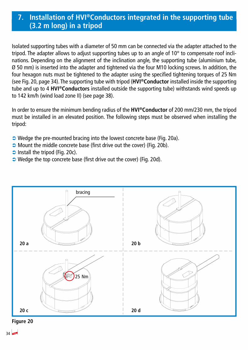
34
7. Installation of HVI®Conductors integrated in the supporting tube (3.2 m long) in a tripod
Isolated supporting tubes with a diameter of 50 mm can be connected via the adapter attached to the tripod. The adapter allows to adjust supporting tubes up to an angle of 10° to compensate roof incli-nations. Depending on the alignment of the inclination angle, the supporting tube (aluminium tube, Ø 50 mm) is inserted into the adapter and tightened via the four M10 locking screws. In addition, the four hexagon nuts must be tightened to the adapter using the specified tightening torques of 25 Nm (see Fig. 20, page 34). The supporting tube with tripod (HVI®Conductor installed inside the supporting tube and up to 4 HVI®Conductors installed outside the supporting tube) withstands wind speeds up to 142 km/h (wind load zone II) (see page 38).
In order to ensure the minimum bending radius of the HVI®Conductor of 200 mm/230 mm, the tripod must be installed in an elevated position. The following steps must be observed when installing the tripod:
 Wedge the pre-mounted bracing into the lowest concrete base (Fig. 20a).  Mount the middle concrete base (first drive out the cover) (Fig. 20b).  Install the tripod (Fig. 20c).  Wedge the top concrete base (first drive out the cover) (Fig. 20d).
Figure 20
20 a 20 b
20 c 20 d
25 Nm
bracing
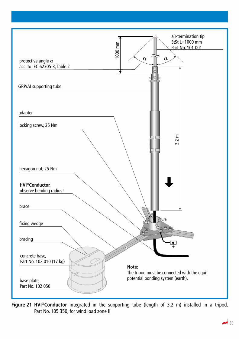
35
Figure 21 HVI®Conductor integrated in the supporting tube (length of 3.2 m) installed in a tripod, Part No. 105 350, for wind load zone II
ααprotective angle α acc. to IEC 62305-3, Table 2
air-termination tip StSt L=1000 mmPart No. 101 001
GRP/AI supporting tube
1000
mm
adapter
locking screw, 25 Nm
hexagon nut, 25 Nm
HVI®Conductor,observe bending radius!
fixing wedge
bracing
concrete base,Part No. 102 010 (17 kg)
brace
base plate, Part No. 102 050
Note:The tripod must be connected with the equi-potential bonding system (earth).
3.2
m

36
8. Conductor installation
The entire HVI®Conductor must be installed in the protected zone of the air-termination system of the external lightning protection system and must not be connected to parts of the air-termination system, down conductor or structural parts carrying lightning voltage.
An exception can be made if the separation distance s at the crossover of the HVI®Conductor and the part carrying lightning voltage (air-termination system, capping of the roof parapet, down conduc-tor) is ≤ 0.35 m (air) or ≤ 0.7 m (solid material). In this case, the sheath of the HVI®Conductor can be connected to the part carrying lightning voltage.
Downstream of the sealing end range, the HVI®Conductor must be fixed at intervals of ≤ 1 m.
The fixing screws of metal conductor holders must be tightened with max. 5 Nm, the fixing screws of plastic conductor holders with max. 2 Nm.
If a HVI®Conductor is installed in the structure, existing protection measures, e.g. fire barriers, must be observed.
8.1 Additional connection of the external cable sheath for equipotential bon-ding
In case of crossovers or parallel conductor routing towards earthed metal installations such as cap-pings of the roof parapet, cable racks or pipelines, it is advisable to connect the black sheath of the HVI®Conductor to the equipotential bonding system. This is a complementary equipotential bonding measure.
Connections can be made with EB clamps, Part No. 405 020. This EB connection does not have to be capable of carrying lightning currents. Conductor cross-sections ≥ 4 mm2 (copper) or conductor cross-sections with the same conductivity must be used.
When using HVI®Conductors with grey sheath, the grey sheath must be removed to contact the black semiconductive sheath underneath it. The black sheath must not be cut in.
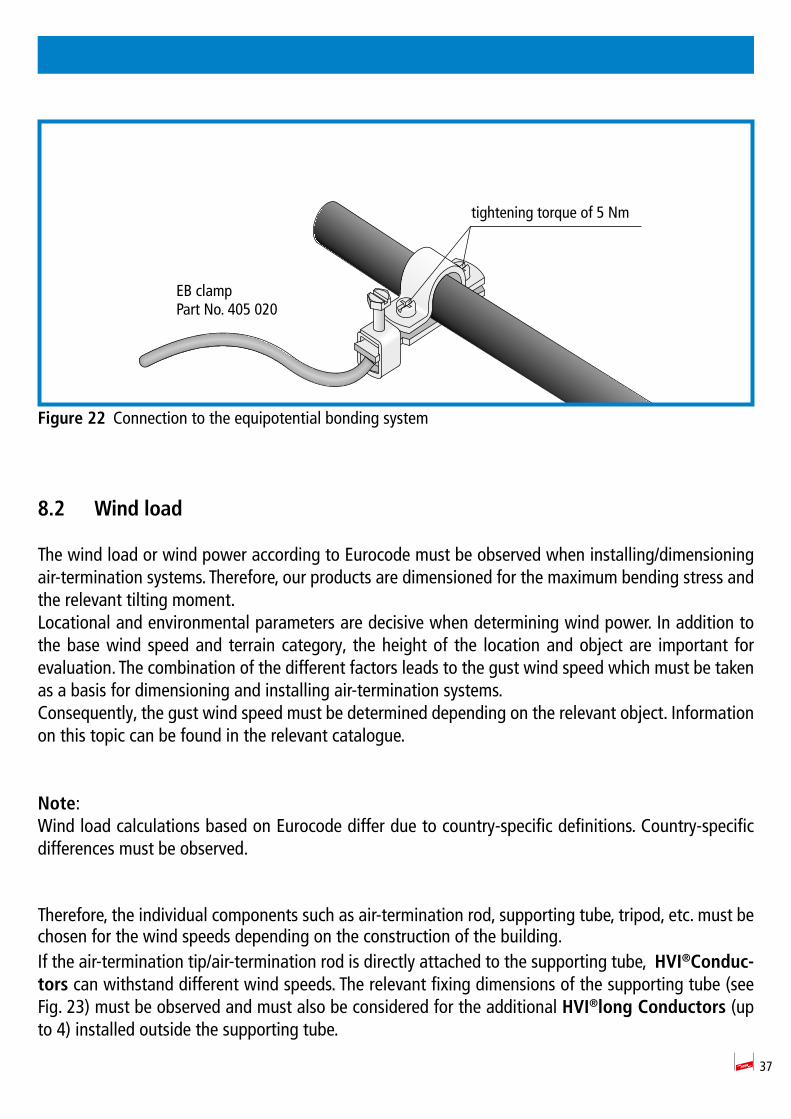
37
Figure 22 Connection to the equipotential bonding system
8.2 Wind load
The wind load or wind power according to Eurocode must be observed when installing/dimensioning air-termination systems. Therefore, our products are dimensioned for the maximum bending stress and the relevant tilting moment. Locational and environmental parameters are decisive when determining wind power. In addition to the base wind speed and terrain category, the height of the location and object are important for evaluation. The combination of the different factors leads to the gust wind speed which must be taken as a basis for dimensioning and installing air-termination systems.Consequently, the gust wind speed must be determined depending on the relevant object. Information on this topic can be found in the relevant catalogue.
Note:Wind load calculations based on Eurocode differ due to country-specific definitions. Country-specific differences must be observed.
Therefore, the individual components such as air-termination rod, supporting tube, tripod, etc. must be chosen for the wind speeds depending on the construction of the building.If the air-termination tip/air-termination rod is directly attached to the supporting tube, HVI®Conduc-tors can withstand different wind speeds. The relevant fixing dimensions of the supporting tube (see Fig. 23) must be observed and must also be considered for the additional HVI®long Conductors (up to 4) installed outside the supporting tube.
tightening torque of 5 Nm
EB clampPart No. 405 020
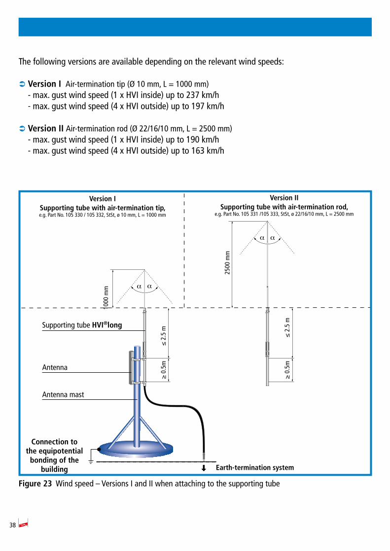
38
The following versions are available depending on the relevant wind speeds:
 Version I Air-termination tip (Ø 10 mm, L = 1000 mm) - max. gust wind speed (1 x HVI inside) up to 237 km/h- max. gust wind speed (4 x HVI outside) up to 197 km/h
 Version II Air-termination rod (Ø 22/16/10 mm, L = 2500 mm) - max. gust wind speed (1 x HVI inside) up to 190 km/h- max. gust wind speed (4 x HVI outside) up to 163 km/h
Figure 23 Wind speed Versions I and II when attaching to the supporting tube
Antenna mast
Antenna
Supporting tube HVI®long
1000
mm
≤ 2
.5 m
≥ 0
.5m
2500
mm
α
α
α
α
Connection to the equipotential
bonding of the building Earth-termination system
Version ISupporting tube with air-termination tip,e.g. Part No. 105 330 / 105 332, StSt, ø 10 mm, L = 1000 mm
Version IISupporting tube with air-termination rod,
e.g. Part No. 105 331 /105 333, StSt, ø 22/16/10 mm, L = 2500 mm
≤ 2
.5 m
≥ 0
.5m
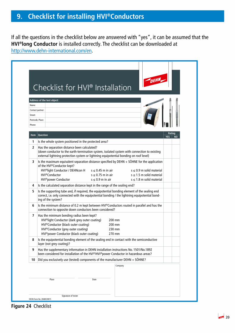
39
9. Checklist for installing HVI®Conductors
If all the questions in the checklist below are answered with yes , it can be assumed that the HVI®long Conductor is installed correctly. The checklist can be downloaded at http://www.dehn-international.com/en.
Figure 24 Checklist
Checklist for HVI® InstallationAddress of the test object:
Name:
Contact partner:
Street:
Postcode, Place:
Phone:
Item QuestionRating
YES NO
1 Is the whole system positioned in the protected area?
2 Has the separation distance been calculated?(down conductor to the earth-termination system, isolated system with connection to existing external lightning protection system or lightning equipotential bonding on roof level)
3 Is the maximum equivalent separation distance specified by DEHN + SÖHNE for the application of the HVI®Conductor kept? HVI®light Conductor / DEHNcon H s ≤ 0.45 m in air s ≤ 0.9 m solid material HVI®Conductor s ≤ 0.75 m in air s ≤ 1.5 m solid material HVI®power Conductor s ≤ 0.9 m in air s ≤ 1.8 m solid material
4 Is the calculated separation distance kept in the range of the sealing end?
5 Is the supporting tube and, if required, the equipotential bonding element of the sealing end correct, i.e. only connected with the equipotential bonding / the lightning equipotential bond-ing of the system?
6 Is the minimum distance of 0.2 m kept between HVI®Conductors routed in parallel and has the connection to opposite down conductors been considered?
7 Has the minimum bending radius been kept? HVI®light Conductor (dark grey outer coating) 200 mm HVI®Conductor (black outer coating) 200 mm HVI®Conductor (grey outer coating) 230 mm HVI®power Conductor (black outer coating) 270 mm
8 Is the equipotential bonding element of the sealing end in contact with the semiconductive layer (not grey coating)?
9 Has the supplementary information in DEHN installation instructions No. 1501/No.1892been considered for installation of the HVI®/HVI®power Conductor in hazardous areas?
10 Did you exclusively use (tested) components of the manufacturer DEHN + SÖHNE
DEHN Form No. 2848/E/0815
Company
Place Date
Signature of tester

Surge Protection DEHN + SÖHNE Hans-Dehn-Str. 1 Tel. +49 9181 906-0Lightning Protection GmbH + Co.KG. Postfach 1640 www.dehn-international.comSafety Equipment 92306 Neumarkt DEHN protects. Germany