How to use a Multimeter as a voltmeter, ammeter or resistance ...
8
How to use a Multimeter as a voltmeter, ammeter or resistance & continuity tester, plus Simple Circuits, Resistors, Ohm’s Law, Power Equation • How to use a multimeter • Why doesn’t it work? • Which to buy A multimeter is simply a meter with many electrical functions. It can measure voltage, current, resistance... Analogue voltmeters & ammeters (i.e. those with a needle display) can make for easier teaching of the fundamentals of current and voltage due to their simplicity but replacing blown shunts in ammeters is tricky and if not done right will result in uncalibrated meters rendering the readings they give as meaningless. In tertiary education and industry, digital multimeters are the norm. They are increasingly being used in secondary education. They essentially work the same way as ‘stand alone’ analogue ammeters & voltmeters. We can shy away from them because we feel overwhelmed by the vast array of numbers and symbols and inputs on their face. However, for the most part we only use them to measure DC voltage and current. Basic electrical circuit understanding The simplest electrical circuit contains: • a source of energy - eg battery or power supply. This voltage pushes the current through the circuit (sketch below). • a component which consumes that energy (eg a resistor or a light globe) provides a resistance to the current flow. • leads to connect components, to form a closed circuit for the electrical current to flow through. • and usually a switch to turn the current flow on and off. Electrical circuits can be compared to water through pipes (consider the images above): Voltage (in Volts), current (in Amps) and resistance (in Ohms, Ω) are the 3 main features we are interested in. • The Water Corporation provides the water pressure by using water towers and pumps. This pressure equates to voltage, it is the pushing force in the circuit. • The water moving through the pipes is the current flow. • The piping is equivalent to the connecting wires. • The narrower the piping, the more resistance there is to current flow. Appliances also resist the current flow. Series and parallel circuits fundamentals - refer to the circuit above (again the water analogy might help): In a series circuit • The current flow is the same in all parts of the circuit. • The supply voltage is equivalent to the addition of the voltage drop (ie the water pressure drop) across each individual component (whether it be a light globe, resistor, etc). In a parallel circuit • The total current flow is the addition of the current flow in each individual leg of the circuit. • Since both legs are connected directly to the supply voltage, each component has the same voltage across them
-
Upload
khangminh22 -
Category
Documents
-
view
0 -
download
0
Transcript of How to use a Multimeter as a voltmeter, ammeter or resistance ...

How to use a Multimeter as a voltmeter, ammeter or resistance & continuity tester, plus Simple Circuits, Resistors, Ohm’s Law, Power Equation
• How to use a multimeter • Why doesn’t it work? • Which to buy
A multimeter is simply a meter with many electrical functions. It can measure voltage, current, resistance... Analogue voltmeters & ammeters (i.e. those with a needle display) can make for easier teaching of the fundamentals of current and voltage due to their simplicity but replacing blown shunts in ammeters is tricky and if not done right will result in uncalibrated meters rendering the readings they give as meaningless.
In tertiary education and industry, digital multimeters are the norm. They are increasingly being used in secondary education. They essentially work the same way as ‘stand alone’ analogue ammeters & voltmeters.
We can shy away from them because we feel overwhelmed by the vast array of numbers and symbols and inputs on their face. However, for the most part we only use them to measure DC voltage and current.
Basic electrical circuit understanding
The simplest electrical circuit contains: • a source of energy - eg battery or power supply. This voltage pushes the current through the circuit (sketch below). • a component which consumes that energy (eg a resistor or a light globe) provides a resistance to the current flow. • leads to connect components, to form a closed circuit for the electrical current to flow through. • and usually a switch to turn the current flow on and off.
Electrical circuits can be compared to water through pipes (consider the images above): Voltage (in Volts), current (in Amps) and resistance (in Ohms, Ω) are the 3 main features we are interested in.
• The Water Corporation provides the water pressure by using water towers and pumps. This pressure equates to voltage, it is the pushing force in the circuit.
• The water moving through the pipes is the current flow.
• The piping is equivalent to the connecting wires.
• The narrower the piping, the more resistance there is to current flow. Appliances also resist the current flow. Series and parallel circuits fundamentals - refer to the circuit above (again the water analogy might help): In a series circuit
• The current flow is the same in all parts of the circuit. • The supply voltage is equivalent to the addition of the voltage drop (ie the water pressure drop) across each
individual component (whether it be a light globe, resistor, etc). In a parallel circuit
• The total current flow is the addition of the current flow in each individual leg of the circuit. • Since both legs are connected directly to the supply voltage, each component has the same voltage across them
Measuring voltage and current with a multimeter
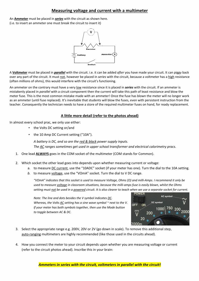
An Ammeter must be placed in series with the circuit as shown here. (i.e. to insert an ammeter one must break the circuit to insert it)
A Voltmeter must be placed in parallel with the circuit. i.e. it can be added after you have made your circuit. It can piggy back over any part of the circuit. It must not, however be placed in series with the circuit, because a voltmeter has a high resistance (often millions of ohms), this would interfere with the circuit’s functioning.
An ammeter on the contrary must have a very low resistance since it is placed in series with the circuit. If an ammeter is mistakenly placed in parallel with a circuit component then the current will take this path of least resistance and blow the meter fuse. This is the most common mistake made with an ammeter! Once the fuse has blown the meter will no longer work as an ammeter (until fuse replaced). It’s inevitable that students will blow the fuses, even with persistent instruction from the teacher. Consequently the technician needs to have a store of the required multimeter fuses on hand, for ready replacement.
A little more detail (refer to the photos ahead)
In almost every school prac, we only use either: • the Volts DC setting or/and
• the 10 Amp DC Current setting (“10A”).
A battery is DC, and so are the red & black power supply inputs. The AC ranges sometimes get used in upper school transformer and electrical calorimetry pracs.
1. One lead ALWAYS goes in the COM socket of the multimeter (COM stands for Common).
2. Which socket the other lead goes into depends upon whether measuring current or voltage: a. to measure DC current, use the “10ADC” socket (if your meter has one). Turn the dial to the 10A setting. b. to measure voltage, use the “VΩmA” socket. Turn the dial to V DC range.
“VΩmA” indicates that this socket is used to measure Voltage, Ohms (Ω) and milli-Amps. I recommend it only be used to measure voltage in classroom situations, because the milli-amps fuse is easily blown, whilst the Ohms setting must not be used in a powered circuit. It is also clearer to teach when we use a separate socket for current.
Note: The line and dots besides the V symbol indicates DC. Whereas, the Volts AC setting has a sine wave symbol ~ next to the V. If your meter has both symbols together, then use the Mode button to toggle between AC & DC.
3. Select the appropriate range e.g. 200V, 20V or 2V (go down in scale). To remove this additional step, auto-ranging multimeters are highly recommended (like those used in the circuits ahead).
4. How you connect the meter to your circuit depends upon whether you are measuring voltage or current (refer to the circuit photos ahead). Inscribe this in your brain:
Ammeters in series with the circuit, voltmeters in parallel with the circuit!

Auto-ranging multimeter (for reference in the circuits ahead)
A simple circuit - a globe connected to a battery

Measuring CURRENT in a circuit (note how I have ‘broken’ the previous circuit to insert the meter)
Measuring VOLTAGE in a circuit

Measuring both current and voltage in a circuit at the same time
Applying Ohm’s Law
The resistance of the globe (at this voltage):
R = V/I = 1.346V/0.232A = 5.8 Ohms
(more on Ohm’s Law later)
Why isn’t the Multimeter working as I expect? • Has the multimeter’s fuse blown? A blown fuse is nearly always the main cause of a problem in class.
However a blown fuse only affects current measurement, so you can still measure voltage.
• If measuring voltage, do I have the voltmeter in parallel with the circuit?
• If measuring current, do I have the ammeter in series with the circuit?
• Is one lead plugged into the “COM” socket?
• Is the other lead plugged into the “V” socket for voltage measurements?
• Is the other lead plugged into the 10A socket for current measurements (or the mA socket if appropriate)?
• Are you on an AC range instead of DC (check the dial, or perhaps you have a Mode button). AC or DC is usually shown in the display. AC is only used on occasions in upper school.
• Has the “Hold” the display, button been inadvertently pressed?
• If you don’t have an auto-ranging multimeter, are you on too low a range?
Multimeters are usually fairly robust against damage, but here’s a few tips to protect them: • It is best to have fused multimeters. Fuses protect the multimeter. Most multimeters are fused, but not all.
• Confirm the leads are in the correct sockets (refer above).
If you don’t have a “10A” socket, then you will have to use the “VΩmA” socket to measure current, but this is unfortunate since the mA fuse will blow more frequently. It is also clearer to teach, if separate sockets are used for current and voltage.
• Always switch off the power to the circuit before adjusting any settings on the multimeter.
• Confirm you are on an appropriate range before you connect to a circuit (work your way down through the ranges). It is obviously preferable to purchase auto-ranging models.
• If the meter has a separate on/off switch, then place the dial on a voltage setting when not in use. If left on a current range there is the accidental chance the fuse will be inadvertently blown in next use.
• There is a capacity to measure resistance directly with a multimeter (that’s the Ω range). This is useful for a technician to check if the fuse has blown in a meter (but not within its own meter). It is best that students are not alerted to this feature because one must NOT try to measure resistance (i.e. Ω) in a powered circuit!
Test for blown multimeter fuses after each class
It is inevitable fuses in multimeters will get blown in class, so it is necessary to test for blown fuses after use. A blown fuse means the multimeter can not be used to measure current; and since ammeters go in series with the circuit, then if the fuse is blown the circuit will not work. The meter can still be used as a voltmeter because there is no need for a fuse in a voltmeter. How to test for blown fuses
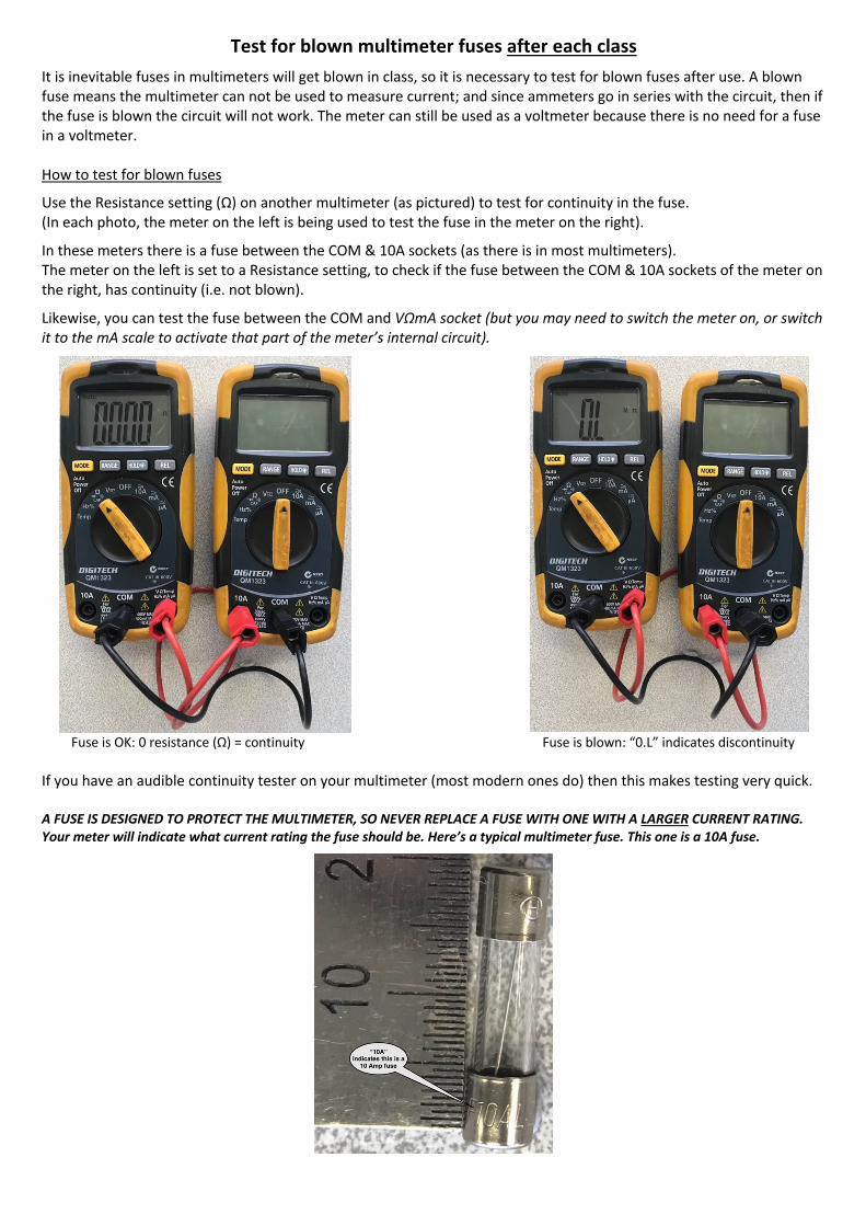
Use the Resistance setting (Ω) on another multimeter (as pictured) to test for continuity in the fuse. (In each photo, the meter on the left is being used to test the fuse in the meter on the right).
In these meters there is a fuse between the COM & 10A sockets (as there is in most multimeters). The meter on the left is set to a Resistance setting, to check if the fuse between the COM & 10A sockets of the meter on the right, has continuity (i.e. not blown).
Likewise, you can test the fuse between the COM and VΩmA socket (but you may need to switch the meter on, or switch it to the mA scale to activate that part of the meter’s internal circuit).
Fuse is OK: 0 resistance (Ω) = continuity Fuse is blown: “0.L” indicates discontinuity If you have an audible continuity tester on your multimeter (most modern ones do) then this makes testing very quick. A FUSE IS DESIGNED TO PROTECT THE MULTIMETER, SO NEVER REPLACE A FUSE WITH ONE WITH A LARGER CURRENT RATING. Your meter will indicate what current rating the fuse should be. Here’s a typical multimeter fuse. This one is a 10A fuse.
Resistors - what are they and which to use?
A resistor simply resists the flow of current. They are used to control the current.
The voltage (in volts) provides the push to the current (in amps),
but it will encounter some resistance (in ohms).
If you don’t want to do the maths, I recommend buying these four resistors for your classes. They are all you will need:
10, 15, 22 & 47 ohm. Each must be 10 Watt, to prevent overheating
Available here: https://www.altronics.com.au/p/r0423-10r-10w-wire-wound-resistor/ 25c ea/pkt of 10, on account Altronics
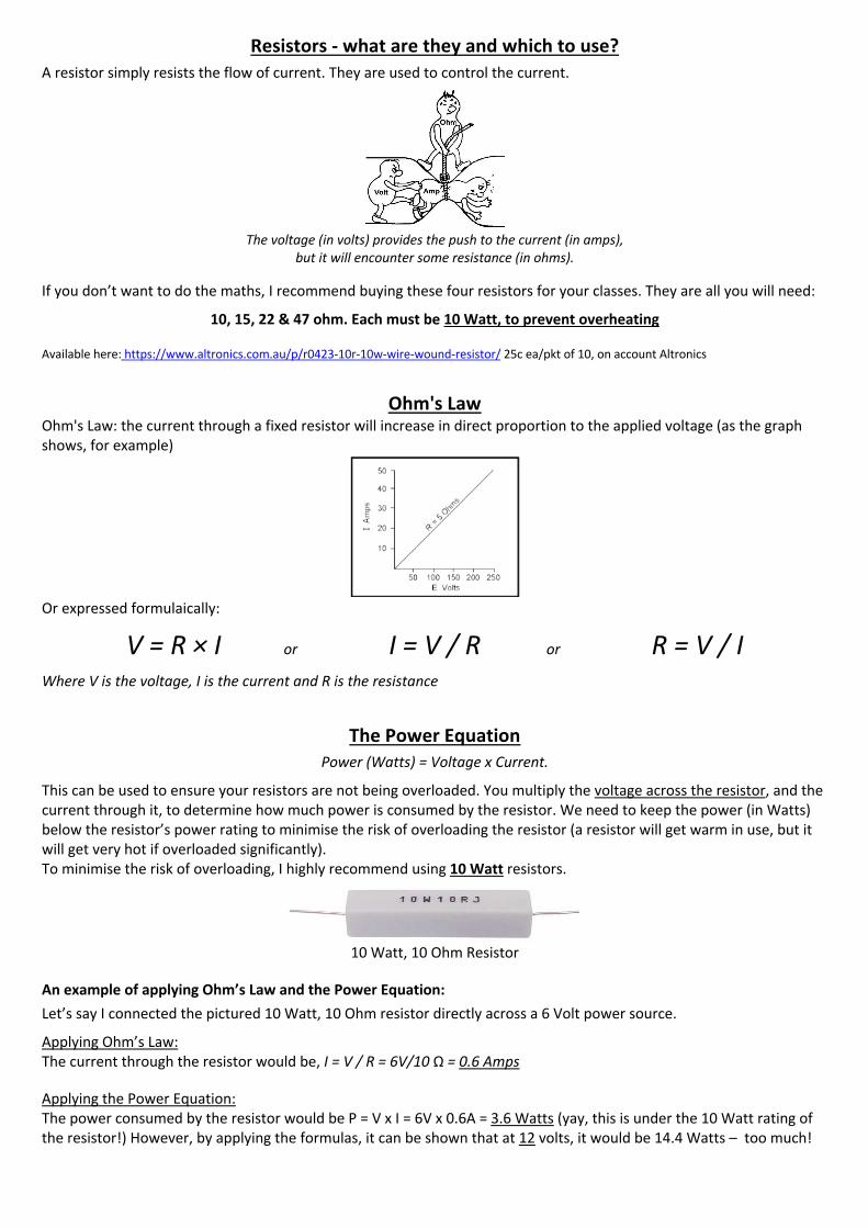
Ohm's Law Ohm's Law: the current through a fixed resistor will increase in direct proportion to the applied voltage (as the graph shows, for example)
Or expressed formulaically:
V = R × I or I = V / R or R = V / I Where V is the voltage, I is the current and R is the resistance
The Power Equation Power (Watts) = Voltage x Current.
This can be used to ensure your resistors are not being overloaded. You multiply the voltage across the resistor, and the current through it, to determine how much power is consumed by the resistor. We need to keep the power (in Watts) below the resistor’s power rating to minimise the risk of overloading the resistor (a resistor will get warm in use, but it will get very hot if overloaded significantly). To minimise the risk of overloading, I highly recommend using 10 Watt resistors.
10 Watt, 10 Ohm Resistor
An example of applying Ohm’s Law and the Power Equation: Let’s say I connected the pictured 10 Watt, 10 Ohm resistor directly across a 6 Volt power source.
Applying Ohm’s Law: The current through the resistor would be, I = V / R = 6V/10 Ω = 0.6 Amps
Applying the Power Equation: The power consumed by the resistor would be P = V x I = 6V x 0.6A = 3.6 Watts (yay, this is under the 10 Watt rating of the resistor!) However, by applying the formulas, it can be shown that at 12 volts, it would be 14.4 Watts – too much!
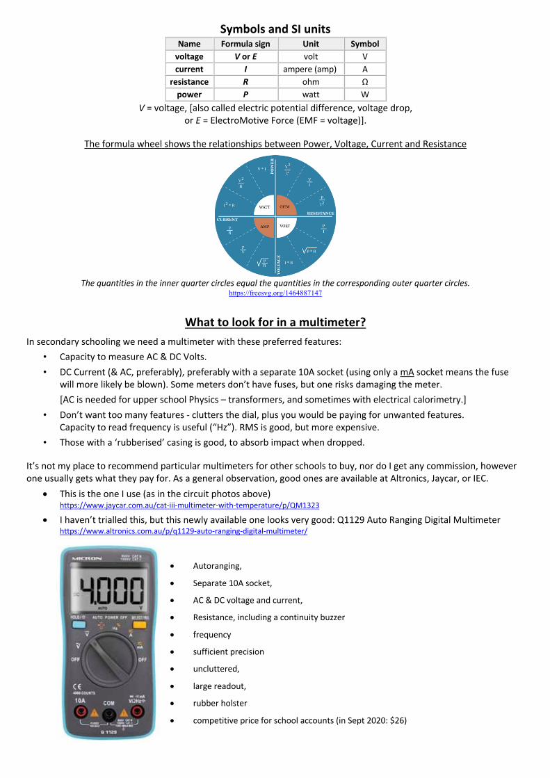
Symbols and SI units Name Formula sign Unit Symbol
voltage V or E volt V current I ampere (amp) A
resistance R ohm Ω power P watt W
V = voltage, [also called electric potential difference, voltage drop, or E = ElectroMotive Force (EMF = voltage)].
The formula wheel shows the relationships between Power, Voltage, Current and Resistance
The quantities in the inner quarter circles equal the quantities in the corresponding outer quarter circles.
https://freesvg.org/1464887147
What to look for in a multimeter? In secondary schooling we need a multimeter with these preferred features:
• Capacity to measure AC & DC Volts. • DC Current (& AC, preferably), preferably with a separate 10A socket (using only a mA socket means the fuse
will more likely be blown). Some meters don’t have fuses, but one risks damaging the meter. [AC is needed for upper school Physics – transformers, and sometimes with electrical calorimetry.]
• Don’t want too many features - clutters the dial, plus you would be paying for unwanted features. Capacity to read frequency is useful (“Hz”). RMS is good, but more expensive.
• Those with a ‘rubberised’ casing is good, to absorb impact when dropped.
It’s not my place to recommend particular multimeters for other schools to buy, nor do I get any commission, however one usually gets what they pay for. As a general observation, good ones are available at Altronics, Jaycar, or IEC.
• This is the one I use (as in the circuit photos above) https://www.jaycar.com.au/cat-iii-multimeter-with-temperature/p/QM1323
• I haven’t trialled this, but this newly available one looks very good: Q1129 Auto Ranging Digital Multimeter https://www.altronics.com.au/p/q1129-auto-ranging-digital-multimeter/
• Autoranging,
• Separate 10A socket,
• AC & DC voltage and current,
• Resistance, including a continuity buzzer
• frequency
• sufficient precision
• uncluttered,
• large readout,
• rubber holster
• competitive price for school accounts (in Sept 2020: $26)