How to Cheat in 3ds Max 2015
328
-
Upload
khangminh22 -
Category
Documents
-
view
1 -
download
0
Transcript of How to Cheat in 3ds Max 2015


cheatIN
3ds Max 2015
HOW TO

This page intentionally left blank

cheatIN
3ds Max 2015
HOW TO
Get spectacular results fast
Michael McCarthy

How to Cheat in 3ds MaxFirst published 2015by Focal Press70 Blanchard Road, Suite 402, Burlington, MA 01803and by Focal Press2 Park Square, Milton Park, Abingdon, Oxon OX14 4RN
Focal Press is an imprint of the Taylor & Francis Group, an informa business
© 2015 Taylor & Francis
The right of Michael McCarthy to be identified as the author of this work has been asserted by him in accordance with sections 77 and 78 of the Copyright, Designs and Patents Act 1988.
All rights reserved. No part of this book may be reprinted or reproduced or utilised in any form or by any electronic, mechanical, or other means, now known or hereafter invented, including photocopy-ing and recording, or in any information storage or retrieval system, without permission in writing from the publishers.
NoticesKnowledge and best practice in this field are constantly changing. As new research and experience broaden our understanding, changes in research methods, professional practices, or medical treat-ment may become necessary.
Practitioners and researchers must always rely on their own experience and knowledge in evaluating and using any information, methods, compounds, or experiments described herein. In using such information or methods they should be mindful of their own safety and the safety of others, includ-ing parties for whom they have a professional responsibility.
Product or corporate names may be trademarks or registered trademarks, and are used only for identification and explanation without intent to infringe.
Library of Congress Cataloging-in-Publication DataMcCarthy, Michael, 1977-How to cheat in 3ds Max 2015 : how to get spectacular results fast / Michael McCarthy.pages cmIncludes bibliographical references.1. 3ds max (Computer file) 2. Computer animation--Computer programs. I. Title. TR897.72.A14M33 2014006.6’96--dc232014021958
ISBN: 9781138022294 (pbk)ISBN: 9781315777115 (ebk)
Typeset in Amasis, Myriad, FlexysansBy Michele Bousquet
Publisher’s NoteThis book has been prepared from camera-ready copy provided by the author
Additional materials are available on the companion website at www.focalpress.com/cw/McCarthy

How to Cheat in 3ds Max
v
Contents
1 Customization and UI . . . 3
Exploring your scene . . . . . . . . . . . . . . . . 4
Enhanced menu . . . . . . . . . . . . . . . . . . . . 6
X marks the spot . . . . . . . . . . . . . . . . . . . . 8
Make the new old again . . . . . . . . . . . .10
Hotbox quad . . . . . . . . . . . . . . . . . . . . . . .12
Custom workspace . . . . . . . . . . . . . . . . .14
2 Basics . . . . . . . . . . . . . . . . . 17
A selection of selections . . . . . . . . . . . .18
Making a Scene . . . . . . . . . . . . . . . . . . . .20
Zoom, pan, display . . . . . . . . . . . . . . . . .22
Organizing objects . . . . . . . . . . . . . . . . .24
Transforms and coordinates . . . . . . . .26
Organizing objects: a matter of choice . . . . . . . . . . . . . . . . . .28
Roger’s top 10 reasons why you can’t select your object . . . . . . . .30
3 Modeling . . . . . . . . . . . . . . 33
Modeling tools . . . . . . . . . . . . . . . . . . . . .34
Reference images . . . . . . . . . . . . . . . . . .36
Spline to low poly . . . . . . . . . . . . . . . . . .38
Virtual studio . . . . . . . . . . . . . . . . . . . . . .40
Speed modeling . . . . . . . . . . . . . . . . . . .42
Modeling with maps in mind . . . . . . .44
Object placement . . . . . . . . . . . . . . . . . .46
Curvy curtain . . . . . . . . . . . . . . . . . . . . . .48
Shell game . . . . . . . . . . . . . . . . . . . . . . . . .50
BYO weapon . . . . . . . . . . . . . . . . . . . . . . .52
Quad chamfer. . . . . . . . . . . . . . . . . . . . . .54
How to make a mess with modeling . . . . . . . . . . . . . . . . . . . . .56
Secrets of the spline . . . . . . . . . . . . . . . .58
Modeling for the masses . . . . . . . . . . .60
4 Character Modeling . . . . 63
Character references . . . . . . . . . . . . . . .64
Character modeling process . . . . . . . .66
Chop shop . . . . . . . . . . . . . . . . . . . . . . . . .68
Nip and tuck . . . . . . . . . . . . . . . . . . . . . . .70
Polygon building . . . . . . . . . . . . . . . . . . .72
Subdivision . . . . . . . . . . . . . . . . . . . . . . . .74
Poly modeling in practice . . . . . . . . . .76
Making animatable models . . . . . . . . .78
5 Materials . . . . . . . . . . . . . . 81
Material Editor basics. . . . . . . . . . . . . . .82
Mapping coordinates . . . . . . . . . . . . . .84
Preparing textures . . . . . . . . . . . . . . . . .86
People, trees, and cars . . . . . . . . . . . . . .88
Multiple maps . . . . . . . . . . . . . . . . . . . . .90
Procedurally speaking . . . . . . . . . . . . . .92
Gradual mix . . . . . . . . . . . . . . . . . . . . . . . .94
Unwrapping the mapping . . . . . . . . . .96
Normal mapping . . . . . . . . . . . . . . . . . . .98
Concavity . . . . . . . . . . . . . . . . . . . . . . . . .100
Faking subsurface scattering . . . . . .102
Mapping a character . . . . . . . . . . . . . .104
Basic mental ray materials . . . . . . . . .108
Custom mental ray materials . . . . . .110

How to Cheat in 3ds Max
vi
6 Lighting & Shadows . . . 111
1-2-3 Lighting . . . . . . . . . . . . . . . . . . . . .112
Troubleshooting shadows . . . . . . . . .114
Exterior lighting . . . . . . . . . . . . . . . . . . .116
Bright sunshiny day . . . . . . . . . . . . . . .118
Mental ray lighting . . . . . . . . . . . . . . . .120
Good lighting made better . . . . . . . .122
Daylight savings time . . . . . . . . . . . . .124
Saving time with shadows . . . . . . . . .126
Where’s the shadow? . . . . . . . . . . . . . .128
Shadow and wireframe presentation . . . . . . . . . . . . . . . . . . . . . .130
7 Reflections . . . . . . . . . . . 133
Reflecting on reflections . . . . . . . . . .134
Bling . . . . . . . . . . . . . . . . . . . . . . . . . . . . . .136
Reflections in the dark . . . . . . . . . . . .138
Where’s my reflection? . . . . . . . . . . . .140
8 Glass . . . . . . . . . . . . . . . . . 143
Exterior daytime windows . . . . . . . . .144
Interior daytime windows . . . . . . . . .146
Nighttime and dusk . . . . . . . . . . . . . . .148
Pint glass . . . . . . . . . . . . . . . . . . . . . . . . .150
Fun with physics . . . . . . . . . . . . . . . . . .152
9 Animation . . . . . . . . . . . . 155
Animation 101 . . . . . . . . . . . . . . . . . . . .156
Pose to pose . . . . . . . . . . . . . . . . . . . . . .158
Spinning your gears . . . . . . . . . . . . . . .160
Animated pivot point . . . . . . . . . . . . .162
Following a path . . . . . . . . . . . . . . . . . .164
Look a-here . . . . . . . . . . . . . . . . . . . . . . .166
Hold it now . . . . . . . . . . . . . . . . . . . . . . .168
Jumping beans . . . . . . . . . . . . . . . . . . .170
Linktopia . . . . . . . . . . . . . . . . . . . . . . . . .172
Linking to multiple objects . . . . . . . .174
Chains . . . . . . . . . . . . . . . . . . . . . . . . . . . .176
Scripting animation . . . . . . . . . . . . . . .178
Super-duper tools . . . . . . . . . . . . . . . . .180
10 Character Animation . . 183
Character animation workflow . . . . .184
CAT 101 . . . . . . . . . . . . . . . . . . . . . . . . . . .186
Biped 101 . . . . . . . . . . . . . . . . . . . . . . . . .188
Skeleton fitting . . . . . . . . . . . . . . . . . . .190
Skinning . . . . . . . . . . . . . . . . . . . . . . . . . .192
Walking in your footsteps . . . . . . . . .194
Snack strong . . . . . . . . . . . . . . . . . . . . . .196
The alternative skeleton . . . . . . . . . . .198
Biped foot control . . . . . . . . . . . . . . . . .200
CAT gizmos . . . . . . . . . . . . . . . . . . . . . . .202
CAT vs. Biped . . . . . . . . . . . . . . . . . . . . .204

How to Cheat in 3ds Max
vii
11 MAXScript . . . . . . . . . . . . 207
A world of MAXScripts . . . . . . . . . . . .208
Voronoi stone wall . . . . . . . . . . . . . . . .210
Gizmo control . . . . . . . . . . . . . . . . . . . . .212
CAT gizmos for custom rigs . . . . . . . .214
Getting a little tense . . . . . . . . . . . . . .216
Visual pivot placer . . . . . . . . . . . . . . . . .218
PF spliner . . . . . . . . . . . . . . . . . . . . . . . . .220
FX puck . . . . . . . . . . . . . . . . . . . . . . . . . . .222
12 Rendering . . . . . . . . . . . . 225
Rendering basics . . . . . . . . . . . . . . . . . .226
Render passes with state sets . . . . . .228
Managing your scene . . . . . . . . . . . . .230
Mental ray rendering . . . . . . . . . . . . . .232
Don’t trust your eyes . . . . . . . . . . . . . .234
Auto render elements (Photoshop) . . . . . . . . . . . . . . . . . . . . . .236
Auto render elements (After Effects) . . . . . . . . . . . . . . . . . . . . .238
What is mental ray, anyway? . . . . . . .240
Perspective matching . . . . . . . . . . . . .242
Nitrous viewport . . . . . . . . . . . . . . . . . .244
Quicksilver rendering . . . . . . . . . . . . .246
Tipping the attenuation scales . . . . .248
13 Plugins . . . . . . . . . . . . . . . 251
V-Ray . . . . . . . . . . . . . . . . . . . . . . . . . . . . .252
Phoenix FD . . . . . . . . . . . . . . . . . . . . . . .254
Joy of liquids . . . . . . . . . . . . . . . . . . . . . .256
Ornatrix . . . . . . . . . . . . . . . . . . . . . . . . . . .258
Zookeeper . . . . . . . . . . . . . . . . . . . . . . . .260
Node based snacking . . . . . . . . . . . . .262
14 Parameter Wiring . . . . . 265
Wiring 101 . . . . . . . . . . . . . . . . . . . . . . . .266
Follow me . . . . . . . . . . . . . . . . . . . . . . . .268
Telling time . . . . . . . . . . . . . . . . . . . . . . .270
Spinning wheels . . . . . . . . . . . . . . . . . .272
Feeling exposed . . . . . . . . . . . . . . . . . .274
To code or not to code . . . . . . . . . . . .276
15 Special Effects . . . . . . . . 279
Logo polishing . . . . . . . . . . . . . . . . . . . .280
MassFX destruction . . . . . . . . . . . . . . .282
Breaking into the industry . . . . . . . . .284
Raindrops . . . . . . . . . . . . . . . . . . . . . . . . .286
Morphing . . . . . . . . . . . . . . . . . . . . . . . . .288
One click to After Effects . . . . . . . . . .290
Cracks in a surface . . . . . . . . . . . . . . . .292
What’s in the box? . . . . . . . . . . . . . . . . .294
Particle flow basics . . . . . . . . . . . . . . . .296
Swirly particles . . . . . . . . . . . . . . . . . . . .298
mParticles . . . . . . . . . . . . . . . . . . . . . . . .300
Data flow operators . . . . . . . . . . . . . . .302
Appendix . . . . . . . . . . . . . . . .305
Index . . . . . . . . . . . . . . . . . . . .311

How to Cheat in 3ds Max
viii
I am very excited to be bringing you this revision of the How to Cheat in 3ds Max series. I was thrilled when Focal approached me with the opportunity to update and continue this book series because I feel that it provides an intelligent and interesting perspective on how 3ds Max can be utilized to achieve the fastest and best results.
In this revision I have gathered some amazing artists to add their insights to the book in the form of interludes. Some artists like Allan Mckay chose to give some industry advice to all the 3D artists out there and some Like John Martini created scripts and explained how they could be used to increase productivity and get the most out of 3ds Max.
In my production work I am continually running into tips, tricks, and interesting ways to do things in 3ds Max and I love to share these with the CG community. New topics I have created for this book may be more on the intermediate side and do require a certain basic knowledge of 3ds Max and 3D in general. That being said, many of the basic topics in the beginning of the book will help even new users get their footing.
In this new edition, I explore production proven practices that will save you time, allowing for a more polished end result.
Michael McCarthy
Foreword from the author

How to Cheat in 3ds Max
ix
The truth about cheatingThe word “cheat” has an interesting history. Its original meaning described the
passing of an inheritance to someone other than one’s heirs. This definition has
come up through the ages to mean getting something dishonestly, or getting things
by trickery or good luck. This book is an example of the original definition whereby
I will impart the knowledge I have gathered through the years unto you, the reader.
In this book, you’ll learn shortcuts to use 3ds Max to its full potential without
having to learn it all from scratch, and thus make your own good luck as an artist.
There are some very thick and intimidating books out there that cover every
possible tool in 3ds Max but this is not one of them. If you want to get the job done
in the least possible time, then this is the book for you.
The “cheats” in this book were all gleaned from real-world jobs and projects,
where the client wanted something done in three days, not three months or
even three weeks. I learned most of this through trial and error, and eventually
developed my own bag of tricks. With this book, I’ve opened the bag and spilled
out the contents.
Workthroughs and examplesEach workthrough in this book is designed as a double page spread. This allows
you to prop the book up next to your monitor as you work with the files on the
web. Many of the examples pertain to real-world companies, and show techniques
used for a recent job.
At the end of most chapter is an Interlude with a discussion of a relevant topic.
Think of it as advice from the shopworn.
How to cheat, and why

How to Cheat in 3ds Max
x
What’s on the website?On the book’s companion website are starter scenes and maps for many of the
cheats in this book.
www .focalpress .com/cw/mccarthy
Feel free to try out the techniques on the included files, or use your own scenes
instead. I’ve also included final scenes and animation so you can see the end result.
The names of files that pertain to the cheat appear under the download icon on the
right page of the spread.
When you load a scene file for the first time, you’ll get a message telling you
that 3ds Max can’t find the maps. Just browse to the maps folder for that chapter
and add the path, and all the maps for that chapter should load without further
messages.
There are images and scenes in the book that couldn’t be included on the
website due to copyright constraints. In most cases, you can visit the website of the
company that provided the imagery and see plenty of their work there.

How to Cheat in 3ds Max
xi
A big thanks to Allan Mckay, Zap Andersson, Vincent LaCour, and John
Martini for providing insightful interludes from a professional artists prospective. An
extra special thanks to Michele Bousquet for all her help with the book and through
the years. She has always been an amazing help and inspiration to me.
I want to thank a few of my star students from The New England Institute of
Art for contributing their wonderful models to the book.
John Anderson: Goblin, Mill Building, Old Stone Barn, Hyena Man, Deer Skull,
Lily, and Pilot.
https://www.linkedin.com/in/johnanderson3d
Tetyana Rykova: Fluffy the cat character.
http://tetyanarykova.com
Ralph Sutter: Gunslinger and Quadruped character.
http://ralphsutter3d.com
I’d also like to thank John Anderson again for his keen technical editing and the
folks at Focal Press for giving me the opportunity to update this book and make
these tips available to 3ds Max users once again.
Finally I want to thank my beautiful and caring wife Candice and my boy
Declan. You two are truly the lights of my life.
Michael McCarthy
Acknowledgments

How to Cheat in 3ds Max
xii

How to Cheat in 3ds Max
xiii
I’d be surprised if anyone read this book by starting at the beginning and going
through to the end. This is the kind of book you should be able to just dip into and
extract the information you need.
Still, I’d like to make a couple of recommendations. The Customization and
Basics chapters deal with the fundamentals of using 3ds Max, so if you’re new to
the program, you should start there. In general, you can’t do anything else until
you do a bit of modeling, so I recommend that you look through the Modeling
chapter before tackling some of the more advanced topics like Character
Animation and Parameter Wiring.
Although the book is designed for users of 3ds Max 2014, most topics apply
to 3ds Max 2013 and many apply to earlier versions as well. The MAX files on
the website are in 3ds Max 2014 format, but all the bitmaps will work with any
version.
The techniques in each chapter build up as you progress through the
workthroughs. Frequently I’ll use a technique that’s been discussed in more detail
earlier in the same chapter, so it might be worth going through the pages in each
chapter in order, even if you don’t do every cheat or read every chapter in the
book. If a cheat mentions a topic you’re not familiar with, check the Index or the
3ds Max help for more information.
The download icon, when it appears on a tutorial page, indicates that file(s)
listed below the icon are available on the website. These files are the same ones
used to create the images for that topic. You can use these files immediately to try
out the cheat, or use your own instead.
How to use this book

How to Cheat in 3ds Max
22
n Customizing your user interface (UI) can make your workflow a lot faster.

How to Cheat in 3ds Max
3
1Customization and UI3DS MAX HAS EVOLVED over the years to include a variety of features
for customizing the user interface, all with the goal of improving your
workflow and making it faster and easier for you to create great scenes.
In this chapter, I’ll tell you about some of the most popular timesavers.

Customization and UI1
44
WHEN YOU FIRST LAUNCH 3ds Max 2015 you will notice a new Scene Explorer view docked
to the left of the screen. This refreshed Scene Explorer allows for a workflow more like the Outliner in Maya, and it also introduces a new way to work with layers.
If you click Layer Manager you will get this new Scene Explorer and can manage your layers with it. The ability to nest layers and link on the fly can really help in organizing your scene.
3 To work with layers, click the Layer Mode button at the bottom of the Scene Explorer. You can now manage your
layers and objects. Hide a layer by clicking the lightbulb icon, and drag objects from layer to layer with drag and drop.
1By default, the Scene Explorer is set in Hierarchy mode to display all the objects in your scene and allow you to
quickly select, hide, or parent them. To select an object, just click on it in Scene Explorer. To hide it, click the lightbulb icon.
Exploring your scene

How to Cheat in 3ds Max
55
2 If you need to parent an object, you can drag and drop one object onto another and the dragged object will be linked to
the other object as its parent. To unlink an object from the chain, right-click the object and choose Unlink.
HOT TIPYou can add additional columns to the Scene Explorer to suit your workflow. To add a Freeze column, for example, go to the Customize menu, choose Configure Columns, and add Freeze.
4 To nest layers, drag and drop a layer on top of another layer. For example, a layer group named Set could contain layers for
Cameras and Lights. This gives you an easy way to hide or select the entire set or just the lights or cameras.

Customization and UI1
66
Enhanced menu
3DS MAX 2014 SHIPS with a brand new menu system that can improve your workflow. This new feature is tucked away under the Workspaces dropdown.
The new Enhanced Menu is faster to navigate and has flexible functionality like docking, tear-offs, and different ways to view menu options. Sub-menus can be expanded or minimized by default.
The new functionality of Enhanced Menus is great for adding your own custom menu with all the tools you use most often, and minimizing the ones that you rarely use. You can even set menu sections to show as Icons, text, or text and icons to maximize your workspace and improve item recognition in menus.
3 If you find yourself going to the same menus over and over, tear them off to put them close at hand instead
of at the top of the screen. You can also dock different menus together to build your own quick tool palette.
2 The new layout groups the tools in a more task-based way. For example, the Lighting/Cameras menu has tools like
Exposure Control and the Light Lister as well as options to create lights and cameras.

How to Cheat in 3ds Max
77
4 In the Menus tab of the Customize User Interface dialog, you can build your own custom menu and add it to the the main Menu bar of 3ds Max. This will give you quick access to your favorite tools and the ability to dock this new menu with
others like Rendering or Animation in the UI.
1To enable the Enhanced Menu, choose Enhanced Menus from the Workspaces dropdown. This will switch to a Workspace that has the new Enhanced Menu and new layout.

Customization and UI1
88
ASIDE EFFECT of the new Enhanced Menus is a great
feature called the 3ds Max Search Bar. This new tool allows you to quickly search through commands and execute them in the viewport under your mouse.
In addition, 3ds Max 2014 has a new method of cycling the viewports akin to the Windows workflow of cycling through applications with Alt-Tab.
4 You can also run commands like Align, Array, and Light Lister. Tap the X key and start typing Array with your sphere selected. The Array dialog will pop up once you press Enter.
2 You can choose the first option by pressing Enter or picking one of the additional options with a mouse click.
Once you press Enter you will be prompted to create a Sphere object in the viewport and brought to the Create panel in the 3ds Max UI.
1As you hover the cursor over any viewport, tap the X key
to bring up the new Search Bar feature in 2014. Here you can type in actionable commands. Try typing in Sphere and three options will pop up: Sphere, Sphere Gizmo, and GeoSphere.
X marks the spot

How to Cheat in 3ds Max
99
HOT TIPYou can set up a variety of 3ds Max actions like Play, or setting your coordinate system to Local, using the X key actions.
3 With the Sphere selected hit the X key again and type Taper. Select the Taper modifier to apply it to your sphere. The Modify panel will be activated so you can adjust the Taper parameters.
5 Another quick workflow improvement from 3ds Max 2014 is the addition of viewport cycling when you’re in a maximized view. Previously you would need to use a hotkey or minimize and then maximize your view again to cycle viewports. Now
you can use Windows + Shift to bring up a viewport switching interface. Hit the Shift key to cycle through and choose your view.

Customization and UI1
1010
3 Go to Customize User Interface and under the Menu Tab click Reset. This will reset your menus to the original default layout
but still use the enhanced menu.
WE OLD-TIME USERS of 3ds Max already have significant muscle memory with regard
to the order and layout of our menus. If you’re one of us, you might prefer the way menus were set up in previous versions of 3ds Max instead of the new task-based order.
However, it would be nice to have the benefits of the new features while taking advantage of the speed and flexibility of the Enhanced Menus.
Here is a quick way to get the best of both worlds and set your Enhanced Menus back to the older menu layout.
1Switch to the Enhanced Menu Workspace layout to enable the new Enhanced Menu.
Make the new old again

How to Cheat in 3ds Max
1111
4 Customize the menu items to have certain ones open by default, display icons, or text only.
2 Create a new Workspace called Enhanced Menu
Original in Manage Workspaces.

Customization and UI1
1212
Hotbox quad
3 If you want your menu options to fill the quad rather than having to use a sub-menu, right-click and choose Flatten Sub-
Menu.
1Go to the Customize menu and choose Customize User Interface. In the Quads tab add a new quad menu named Hotbox. Set the
shortcut key to Space, and check the Show All Quads option.
WHEN WORKING back and forth between 3ds
Max and Maya, I find myself missing Maya’s Hotbox feature. This is a heads-up display that gives you access to all the application menus right under your mouse when you hit the spacebar.
In 3ds Max you can emulate this Maya feature by adding a custom quad menu. You can add pre-defined 3ds Max menus to a custom quad menu so that when you right-click, you get a set of menus. Then you can assign the spacebar hotkey to bring up that quad menu.
Even if you’ve never used Maya, this method of putting your frequently-used tools at your fingertips can speed up your workflow dramatically.

How to Cheat in 3ds Max
1313
HOT TIPYou can make custom menus in the Menus tab of the Custom User Interface dialog to remove tools that you never use, and add in other tools and scripts that you use all the time.
With this and other UI modifications it may be necessary to close and relaunch 3ds max.
4 Now you can save your new Hotbox quad menu and quickly access your tools directly under your mouse with the tap of the
spacebar.
2 Drag menus from the left hand Menu section to the Quad section marked in yellow on the right. You can even add back in
the File menu if you prefer to use it instead of the newer Jewel icon.

Customization and UI1
1414
3 Customize your menu by having only modeling tools present. In Customize User Interface under the Menu tab remove all of the menu items from the Main Menu Bar. Now add back menu items only for modeling tasks like Parametric Deformers, Spline
objects, and Poly tools. You can even tear off dockable, floating menus that will persist and load with the workspace.
1From the Workspace dropdown at the top of the screen, choose Manage Workspaces. Choose Save as New Workspace. Name the new workspace
Modeling and check the Ribbon and Hotkeys options in Active Workspace Properties.
Custom workspace
BY DEFAULT, 3ds Max exposes all the tools necessary for modeling, texturing, lighting, rigging, animation, and other
tasks. However, you don’t always need or want all these tools displayed.. Workspaces allow you to create a custom interface for each different task.
For example, if you work primarily with modeling, you don’t need particle simulation or rigging tools to be displayed. Instead, you’ll want the Graphite Modeling Tools handy at all times. You might also want to use a Viewport Tab Preset to customize your viewport layout for modeling.
Here, I’ll walk through the steps of setting up a modeling workspace. You can use these concepts to set up a custom workspace for any 3ds Max workflow.

How to Cheat in 3ds Max
1515
4 Viewport Tab Presets allow you to quickly set up views especially for the task at hand. For modeling, a good layout is a three-view tab with a large Perspective view with Clay shading, and two smaller views displaying Consistent Colors with Edge
Faces on. After setting up such a viewport display, you can right-click the Viewport Tab and save it as a preset.
2 You don’t need the Track Bar or other animation tools for modeling, but you do want Graphite Modeling Tools available all the time. Customize your panels by docking the Graphite Modeling Tools to the right, and by turning off the Track Bar UI from
Customize>Show UI.
HOT TIPYou may want to create your own new menus instead of using the 3ds Max default ones. This can avoid confusion and editing the 3ds Max default menus by mistake. By doing this you can also remove commands you rarely use in those menus.

How to Cheat in 3ds Max
16
n Using 3ds Max is an adventure that begins with a few important steps.

How to Cheat in 3ds Max
17
2BasicsTHE TECHNIQUES DESCRIBED in this book assume a basic grasp of 3ds
Max. But with so many options to choose from, it’s easy to get lost in
all the tools, buttons, and menus.
Not all features are created equal. This chapter goes over the
fundamentals of 3ds Max with an eye toward the most important tools
and how you can use them to create beautiful scenes as quickly as
possible.

Basics2
18
THE ABILITY TO SELECT objects at will is an important skill for working quickly with 3ds Max. Just about every
operation you perform will start with the selection of one or more objects or sub-objects.
Conversely, there’s nothing more frustrating than knowing exactly what you need to select, but not knowing how to select it or get at it.
Every possible type of selection can be done with the tools at hand. It’s just a matter of knowing them so you can mix and match when needed.
4 To select multiple objects, hold down Ctrl while clicking. To unselect an object, hold down Alt while clicking.
Note that this workflow differs from earlier versions of 3ds Max, where holding down Ctrl while clicking an already selected object used to unselect it.
8 The Scene Explorer (Tools menu > Scene Explorer) is similar to the Select by Name dialog, but you can leave
it open as a floater while you work. You can also open multiple Scene Explorers showing different sets of objects.
A selection of selections
1When you rest the cursor over an object’s wireframe for a moment, the object’s name appears as a tooltip.
This is one reason why it’s important to name your objects intelligently.
7 To select multiple objects or select by name, click the Select by Name button on the toolbar or press the H
shortcut key. On this dialog, you can display specific sets of objects such as just geometry or lights.

How to Cheat in 3ds Max
19
HOT TIPPressing the Spacebar locks or unlocks the current selection. If you think you might have accidentally locked the selection by pressing the space bar inadvertently, look for the lock icon on the status bar to see if it’s turned on. Just press the Spacebar to turn it off again.
9 When the object is at a sub-object level, you can only select sub-objects that correspond to that level for that
object. To select other objects, you will need to return to the base level of the object by exiting the sub-object level.
5 You can also select multiple objects by drawing a bounding region around them. Start by clicking in a
blank area of the viewport, and then drag in any direction. The shape of the region is determined by the Selection Region currently chosen on the toolbar.
6 The Window/Crossing toggle on the toolbar determines how the bounding region works. When Window
is turned on, only objects that are completely within the bounding region are selected. When Crossing is on, all objects touched by the bounding area are selected.
3 If objects are on top of one another in the view you’re working with, you can hold the cursor still and click
multiple times to cycle through the objects. Watch for the object name to appear on the panel.
2 Click an object’s wireframe to select it. In a wireframe view, you will need to click an actual line. The axis tripod
appears, the object wireframe changes color, and the object name appears on the panel at the right of the screen.
10 The Selection Filter can limit your selections to specific object types such as lights and cameras. Be
sure to reset the selection to All or Geometry to select objects again.

Basics2
20
4 Gather up or create your textures and reference images. See the Modeling chapter to find out how to create
reference images and textures from photographs and the Materials and Mapping chapter for creating tileable textures.
Making a Scene
1Before you load 3ds Max, gather up a few pictures with lighting, materials, and composition that approximate
your vision of the final rendering. You won’t be copying these images, but having them handy for reference will be invaluable as you create the scene.
7 If animation is part of your scene, get a rough animation in place before working with lights and rendering. Test
renderings and previews will give you a quick approximation of the final result. See the Animation chapter.
THERE IS A MYTH that you should spend most of your time modeling, and then cram all the lighting, texturing,
and animation into whatever time remains in the schedule. This so-called wisdom stems from the early 1990s when computer graphics were new, modeling was a rare skill, and any rendering at all was impressive.
Nowadays, clients expect decent materials, lighting, and animation, if not outright realism. To achieve this goal, the best approach is to take time at the front end to gather reference materials such as photos, drawings, videos, and textures. Each hour spent on preparation can reduce scene creation time by five or even ten times, in addition to providing a strong direction for modeling, materials, and lighting. In addition to this you should always plan your scene around your camera shots, models, textures and lighting setups. Having a proper storyboard before you start is important to this process.

How to Cheat in 3ds Max
21
2 Sketch out the scene with all major elements. This step can be as elaborate as a color storyboard or as simple
as a quick line drawing on a slip of paper. Even if you’re using a detailed architectural plan, consider items that aren’t noted such as trees, cars, and people.
3 In 3ds Max, block out the scene with primitives as placeholders for the final objects. This will enable you
to place a camera and see which objects need to be the most detailed. You can also place a few representative lights to get an idea of how they’ll work with the scene.
8 Place lights in the scene to simulate “real” lighting, such as near an indoor lamp or in the sky to simulate the
sun. Shadows are a key element in adding dimension. See the Lighting and Shadows chapters for more details.
9 Test renderings show you how the scene is shaping up. Compare your rendering with sample photos and pick
out details that will improve realism. See the Reflections and Rendering chapters for tips on increasing realism.
5 Now you can start modeling. Use the reference images and textures liberally to guide the process. The best tool
for modeling is the Editable Poly. See the Modeling chapter for tips on speedy modeling using your maps.
6 Materials and mapping are next. Avoid spending a lot of time tweaking colors and reflections as materials will
change appearance when lighting is added or changed. See the Materials and Mapping chapter for tips on quick mapping.
HOT TIPPhotographs edited in Photoshop can often provide all the reference material you need.
BrickBldgsEnd.max

Basics2
22
OVER THE COURSE of your work with 3ds Max, you will need to zoom, pan, and rotate the scene many times to get the job done. You’ll also need to switch your viewport displays between wireframe and shaded to see what’s going on with the model. Learning
how to use the tools available will save you a great deal of time in the long run. A mouse with a middle wheel can speed up your work in 3ds Max by many times, allowing
you to zoom, pan, and rotate the scene quickly and easily. This inexpensive investment will speed up your viewport navigation by many times.
3 The zoom controls are at the lower right of the screen. The
Zoom Extents buttons are useful for getting objects back into view. The Maximize Viewport Toggle switches between smaller views larger views.
5 If you have a middle mouse wheel, hold down Alt and the
wheel at the same time, and drag to rotate the view.
Zoom, pan, display
2 To change a view to a different angle, use a hotkey (F for Front, T for Top, L for Left). To change to a perspective view, press the P key. You can also click the
viewport label or press the V hotkey to choose from a menu.
6 You can also use the View Cube to rotate the viewport or change to a different view. Click a view on the cube itself, or click a rotation arrow to rotate the view
by 90 degrees. Drag any part of the cube display to change the view to a custom view. Ctrl+Alt+V toggles the View Cube on and off.
[+] [Orthographic] [Smooth + Highlights] [+] [Orthographic] [Smooth + Highlights]
[+] [Orthographic] [Smooth + Highlights][+] [Orthographic] [Smooth + Highlights]

How to Cheat in 3ds Max
23
8 To quickly isolate one or more objects in viewports, select the objects and click the Isolation Toggle
button on the status bar. You can also choose Tools > Isolate Selection, or press Alt+Q.
4 If your mouse has a middle wheel, you can zoom in and out
by rolling the wheel, or pan by pressing the wheel and dragging. This method of viewport navigation means you don’t have to keep clicking different viewport navigation buttons to move around your scene.
7 If you prefer a different viewport arrangement, click the arrow button on the tab bar to the left of the viewports, or use Views > Viewport Configuration >
Layout tab.
1Use F3 to toggle wireframe and shaded displays in any viewport, and F4 to toggle edge display when in shaded or Realistic mode.
HOT TIPPressing Ctrl + Zoom Extents All zooms all viewports except the Perspective view. This is useful for keeping a Perspective view exactly as it is for rendering while zooming the remaining viewports.
If you like the view in a viewport and want to keep it to return to later, you can use Viewports menu > Save Active [current view]. Use Restore Active [current view] to get it back.
Lily.max

Basics2
24
EVEN A TRUE ARTISTE needs to get organized once in a while. Object names, layers, and selection sets are all part of
keeping your scene tidy so your work will be as fast as possible.
Keeping the scene organized is especially important when you need to pass it on to someone else. On the receiving end, there’s nothing worse than getting a scene full of Box01 and Box02 with no layers or selection sets in sight.
Be kind to your fellow artists (and to yourself !) and take a few moments to get your scene in order. You’ll be glad you did.
5 Organizing your objects into layers can also help keep things under control. In 3ds Max, layers refer to sets of objects, not physical layers. In other words,
layer order has no effect on the appearance of a rendering. In the Layer dialog, you can also hide, freeze, and select objects. To open the Layer Manager, click the Layer Manager button on the toolbar or choose Tools > Manage Layers.
1The Object Properties dialog is “command central” for your
objects. Choose Edit > Object Properties, or right-click and choose Object Properties from the quad menu.
2 Naming your objects intelligently is the first step toward good scene
management. The quickest way to do this is to type in the name on the Modify panel.
Organizing objects
Ruby01Diamond01
Ruby03
Ruby02
Diamond03
Diamond02

How to Cheat in 3ds Max
25
7 Be sure to name your materials, too. If you have a
lot of complex materials, consider naming your maps as well. You’ll be glad you did.
8 Use Group > Group to group objects into one single selectable entity. While this
is a common practice for architectural scenes, grouping makes animation difficult to control, so I don’t recommend it.
6 A Selection Set is a name given to a selection of
objects, providing quick selection of object sets from a dropdown menu on the toolbar.
4 You can temporarily hide objects to unclutter your viewports, or freeze them
to make them impossible to select by accident. Right-click the screen and choose a Hide or Freeze tool from the quad menu.
3 If you have numerous similar objects that need to be renamed, you can use Tools > Rename Objects to automate the process.
Enter the number of digits (letters) to remove, and enter a new prefix to replace the letters removed. Here, a selection of toruses (Torus01, Torus02, etc.) is renamed while keeping the numbering intact.

Basics2
26
THE MOVE, ROTATE, AND SCALE buttons on the toolbar are called transforms. The Select and Move
transform is your primary tool for lining up objects in a scene.
Coordinate systems work hand-in-hand with transforms. A coordinate system determines what 3ds Max considers to be the X, Y, and Z directions at any given moment. While you can choose a variety of coordinate systems from the dropdown menu on the toolbar, the ones you’ll use most often are View, World, and Local.
4 A different coordinate system can be assigned to each transform. When you want to change the coordinate system, be sure to choose the transform first. If you want a single coordinate system to apply to all transforms, choose Customize >
Preferences, click the General tab, and turn on Constant in the Ref. Coord. System group.
6 The Pick coordinate system uses a specific object’s pivot point as the center for transforms on all objects in the scene. After you pick the object to use as the center, choose the Use Transform Coordinate Center button from the flyout. This type of
coordinate system is most useful for rotating one object around another.
1The default coordinate system for orthographic viewports (straight-on views) is the View coordinate system. In the
Top, Front, and Left views, X always points to the right and Y always points up in whichever viewport is active at the moment.
Transforms and coordinatesFront
Front Front
PerspectivePerspective

How to Cheat in 3ds Max
27
8 The Transform Toolbox (Edit menu > Transform Toolbox)
gives you instant access to all the transform tools, plus some great options for controlling the way transforms work in viewports.
7 To transform an object by a specific amount, you can enter a value on the status bar, or right-click the
transform button to bring up a type-in entry dialog.
5 The pivot center button next to the coordinate system dropdown menu determines whether the object will be transformed around itself (Use Pivot Point Center), the center of the selection (Use Selection Center), or some other object
(Use Transform Coordinate Center).
HOT TIPAvoid using the scale transform on an object whenever possible. Instead, adjust the object’s parameters if it’s a primitive. For an Editable Poly or Editable Mesh, scale the object at the Vertex or Polygon sub-object level. Changing an object’s dimensions with parameters or sub-object scaling has no negative effects on the object.
The F12 hotkey brings up the Transform Type-In dialog for the currently selected transform.
3 The Local coordinate system is aligned with the selected object’s pivot point. Each object you create is
automatically assigned its own XYZ pivot point. If the object has been rotated, the Local coordinate system allows you to easily move the object in the direction in which it’s rotated.
2 The default coordinate system for the Perspective view is called World. Here, Z always points in the up direction.
The coordinate system is still listed as View on the toolbar because having the World system in the Perspective view is part of the View coordinate system’s definition.
Perspective Left
Perspective Perspective

Basics2
28
WITH A CHOICE OF SO MANY TOOLS in 3ds Max for organizing objects, you have many
options for managing your scene. Layers, for example, are not necessarily better or worse than
selection sets. It’s a matter of what works best for your purposes.
A selection set is simply a selection of objects that you give a name to. It’s the easiest one
to use: select, enter a name on the toolbar, done. In the early days of 3ds Max, before layers
were introduced, this was the primary tool artists used to organize objects.
Grouping has been available for just as long. This type of tool is common in 2D graphics
and layout programs such as Illustrator and InDesign. While it works very well in 2D for just
about anything, grouping has specific, limited uses in 3D.
For objects that won’t be animated, grouping is fine. Architectural artists, for example,
find it useful to group together all the furniture so they can move it around easily. This works
because the furniture isn’t going to be animated to fly around the scene (or so one would
presume). The camera might be animated, but that won’t have any effect on grouped objects
just sitting there.
If the object is going to be animated, grouping becomes something that we in the 3D
industry call A Bad Idea. If you animate the group to make it fly around, the animation keys
are on the group itself as an object. If you later ungroup the objects, you will lose the animation
keys. And if you open the group and animate individual objects within the group, and then
ungroup the object, you get what we in the industry call A Big Mess. So for static objects,
group away. For animated objects, use Dummy objects to keep it all together (covered in the
Animation chapter).
Layers are the most used and adopted method of organizing your scene in 3ds Max.
Architectural designers love layers because they’re a mainstay of AutoCAD, a technical design
program used by most of the known universe, and many architectural artists got their start with
AutoCAD. If you can get in the habit of it, I recommend organizing your objects into layers
once you start to build your scene up past a few basic objects.
I N T E R L U D E
Organizing objects: a matter of choice

How to Cheat in 3ds Max
29
Containers were added to 3ds Max a few versions back for the purpose
of sharing specific parts of a model across multiple users, as with a game
development team sharing parts of a game environment. You can save parts
of your scene into their own scene files, then assemble them into one master
scene using XRefs or Containers. Containers haven’t caught on outside this
usage, though.
If you model something made up of several separate objects, such as a
chair made up of numerous bits of metal and wood, you can use the Attach
tool (available with Editable Poly and Editable Mesh objects) to put them all
together into one object. Each object will retain its own material and become
an Element sub-object, which makes it easy to select the piece and move it
around or assign it a different material.
In short, no one method for scene organization does it all. Try them out
and use what works best for a particular set of objects, a specific scene, or you
personally.

Basics2
30
1The current selection is locked, preventing you from making a new selection. You can tell if this is the problem by checking the Selection Lock Toggle on the status bar to see if the button is turned on. Click
the button to turn it off, or press the space bar.
6 The Window/Crossing toggle on the toolbar is set to Window, and you are making a Crossing selection. Click the button to toggle to Crossing.
5 You are still at the sub-object level for one object. At a sub-object level, you can select only sub-objects of that object. Return to the base level of the object by turning off the sub-object level.
4 A creation button, such as Box or Sphere on the Create panel, is still clicked, and a selection tool (such as Select Object) is not currently selected. Right-click a couple of times to turn off the creation
tool, or click a selection tool.
3 The object is frozen. Right-click anywhere in the viewport and choose Unfreeze All, or use the unfreeze options on the Display panel.
2 You are attempting to select an object in a wireframe view by clicking in its volume area rather than on the wireframe. Click the wireframe, or change to a shaded viewport and click the volume.
P L A Y T I M E
Roger’s top 10 reasons why you can’t select your object
MY GOOD FRIEND Roger Cusson is, like me, a longtime instructor on 3ds Max.
One day we got to talking about the challenges of teaching such a large and
complex program, and we agreed that the biggest barrier new students have is
confusion about selecting objects.
Roger proposed that since we go over these pitfalls in every class, he should
publish a list of Roger’s Top 10 Reasons Why You Can’t Select Your Object. The
list never actually got published until the first edition of this book. Here is the
list, printed for the first time in the first edition of this book and back by popular
demand, including a cutout reminder list that you can tape to your laptop or
monitor for easy reference.

How to Cheat in 3ds Max
31
7 You are clicking the back side of a one-sided object such as a Plane. Rotate the view and click the other side.
8 You are currently using a tool that ‘s expecting a selection for that specific tool. For example, if you click Select and Link then click Select by Name, you will pick an object to link to rather than simply
selecting an object. Click Select Object to turn off the other tool and enable selection.
9 The Selection Filter is limiting your selection. Set the Selection Filter to All.
10 You are trying to use Shift or Alt instead of Ctrl to add to the selection. Use Ctrl to add to the selection, and Alt to remove from the selection.
Roger’s Top 10 Reasons Why You Can’t Select Your Object
1 Unlock the selection (space bar, or turn off Selection Lock Toggle).
2 Click the wireframe, not the volume.
3 Unfreeze the object (right-click for quad menu, choose Unfreeze All).
4 Turn off the creation tool you’re currently using, or click Select Object.
5 Get out of sub-object mode.
6 Make sure Window/Crossing is set to the mode you want.
7 One-sided object? Click the other side.
8 Turn off the tool that’s expecting a selection, or click Select Object.
9 Reset the Selection Filter to All or Geometry.
10 Use Ctrl to add to the selection, not Shift.

32
How to Cheat in 3ds Max
n A few words here about the subject matter of the chapter. Images have shadows underneath.nModeling quickly and intelligently requires good reference images and a little ingenuity.
32

How to Cheat in 3ds Max
3ModelingMODELS ARE the main building blocks of scenes. When creating a
model, it’s important to model just enough detail to make a good
rendering. It’s easy to get bogged down in small details that take
a long time to model and won’t even be noticeable in the final
rendering.
Mapping, the process of putting textures on a model, is akin to
modeling. In this chapter you’ll learn simple mapping techniques that
can reduce modeling time to minutes instead of hours.
33

Modeling3
34
1Primitive objects are the starting point for most of your objects. Between Standard and Extended Primitives, there are more than 20 primitives to choose from. The box is the
most commmonly used base object for both simple and complex models.
3 In some cases, a spline (curved or straight line) is the most straightforward way to create an object. The Sweep and Lathe modifiers, among others, will turn a spline into
a 3D object.
KNOWING the primary modeling tools in 3ds Max will make your work go
much faster. Make sure you can find all these tools in the user interface, and take it from there.
Modeling tools
PHO
TO O
F BU
ILD
ING
: FJP

How to Cheat in 3ds Max
35
2 A primitive can be turned into an Editable Mesh or Editable Poly for direct access to vertices and polygons. You can access the tools at the Vertex or Polygon sub-object level by expanding the base object and
choosing a sub-object level, or you can click directly on a tool from the Graphite ModelingTools toolbar.
4 To clone an object, hold down Shift as you move the object. A Copy is independent of the original. An Instance maintains a connection between the two so any changes to one clone changes the
other. References are a combination of the two, which is useful under specific circumstances.

Modeling3
36
4 Use horizontal guides on the model’s front view to line up the side view. You’ll need to use the Distort and Warp tools liberally to remove
any inconsistencies in perspective and symmetry. Utilize obvious symmetrical landmarks such as the corners of the eyes, mouth and nostrils to achieve accurate horizontal guides.
1Take photographs or make drawings of the object you want to model. With mostly symmetrical references such
as this model’s face, a front and side view are sufficient.. Take photos at as much of a straight-on view as you can get. You can also take a back and top picture if you like.
Reference images
THE IMPORTANCE of using reference images for modeling cannot be overstated. An hour spent creating
or cleaning up useful reference images can easily save you a dozen hours of modeling and tweaking.
The best tool for cleaning up reference images is Photoshop. By learning the Transform tools, you’ll open up a whole new world of useful images that can even double as textures.
I‘ve found the following tools most useful for image cleanup:nQuick Selectionn TransformnDistortnWarpnGuides

How to Cheat in 3ds Max
37
HOT TIPOutdoor photographs taken on an overcast day have fewer shadows and more even lighting than those taken in bright sunlight.
5 Save the image and use it as a guide for your model’s proportions in 3ds Max.
The details on how to do this are covered in this chapter.
6 With a few modeled details and the
reference image as a texture map, you have an instantly believable asset for your scene.
3 In this case, the model’s front and side view are different sizes and slightly crooked. Resize the images to similar
scales and straighten out the image using the Rotate, Distort, and Warp tools as necessary. Remove any perspective artifacts from the image.
2 Use guides to help you rotate the items straight. Using a contrasting background color, erase the photo
background with the Quick Selection and Eraser tools. Resist the temptation to waste a lot of time delicately erasing pixels at the edges. The edges don’t have to be perfectly clean to use the images for reference in 3ds Max.
Pilot_Front.jpgPilot_Side.jpgPilot_Oblique.jpgPilotEnd.max

Modeling3
38
1Create a spline profile of a wheel and tire in the front view. You create the right side and then Mirror it in sub-object Spline mode.
3 Adjust the Lathe Segments down to 10 to reduce the number of polygons generated around the Lathe. Now select the Line in the modifiers stack and
in the Interpolation rollout, set the Steps to 1. That will bring down the number of polygons generated along the spline.
WHEN ARTISTS model with splines they tend
to output a final fairly high poly or smooth looking result. Starting with a spline to create a low poly mesh for further editing or details is a very effective workflow.
Spline modeling through operations like a Lathe, Extrude, or Surface is a fast way to rough out a basic shape of an object. Once you have that basic form you can adjust the number of steps the spline has in order to create a low poly mesh output instead of high poly final result.
Spline to low poly

How to Cheat in 3ds Max
39
2 Add a Lathe modifier and adjust the Axis Direction to X. Also in sub-object Axis mode, position the Axis to the center of
the wheel’s hub.
4 Now you can add more detail with poly modeling techniques. Add an Edit Poly modifier on top of your Lathe and in sub-object Polygon mode select
every other polygon radiating out from the center hub. Bevel these in a few times to create the mags. Add a Turbosmoth Modifier to smooth out the entire wheel.
HOT TIPUsing multiple Edit Poly Modifiers can allow you to layer your modeling edits. Toggle them on or off to add or remove modeling details.
WheelStart.maxWheelFinal.max

Modeling3
40
Virtual studio
A VIRTUAL STUDIO is a scene setup that provides the
three-dimensional reference required to model a specific object. It’s one of the prime tools used by expert modelers to get the job done quickly. I recomend this method over basic viewport backgrounds.
6 Make a box and position it in the Front viewport to align with
the image. Press Alt+X to make the box see-through, and match its size roughly to the outer bounds of the front reference image.
7 Press F4 to turn on the Edged Faces display, and increase the
number of box segments to allow enough detail for the object. Convert the object to an Editable Poly by right-clicking the modifier stack and choosing Convert to Editable Poly.
8 Now you can directly access the box’s vertices (points) and edges (lines
between points) to shape the object. At the object’s Vertex sub-object level, move and scale vertices to shape the object to fit the image. Be sure to select vertices using a bounding area so you get the ones in the back as well.
2 Create a perfectly square image that contains both maps. This
will save your being concerned with the image aspect ratio when you use it in 3ds Max.
1Get two views of the object you want to model. In Photoshop,
paint out the backgrounds and remove any obvious perspective from the images as described in the Reference Images cheat.

How to Cheat in 3ds Max
41
HOT TIPTo speed up the modeling process, model one side of the object and use the Symmetry modifier to mirror it to the other side.
9 In the Left viewport, move vertices to match the side image. 10 With the help of the virtual
studio, finish shaping the object as necessary. If necessary, add more edges with the Cut tool, or with the Connect tool as described in the Speed Modeling cheat.
5 Clone and rotate the plane by holding down Shift while
rotating it by 90 degrees. The resulting arrangement, called a virtual studio, provides a framework for creating a 3D model.
4 Create a plane in the Front viewport with square dimensions
and one segment along each side. Apply the material to the plane, and turn on Show Map in Viewport. Press F3 to toggle the viewport to a shaded view. Because the map is square, you don’t have to be concerned about its aspect ratio.
3 In 3ds Max, create a material with the reference image as a Diffuse
map. Set the Self-Illumination value to 100 to make the image show clearly in viewports regardless of the lighting.
11With the use of a TurboSmooth modifier, the result is a
correctly proportioned object that looks great when rendered, especially if you use the reference images as a basis for its textures.
Skull_Top&Side.jpgSkull_Side.jpgSkull_Front.jpgSkull_Top.jpgSkull.max

Modeling3
42
WHEN YOU NEED TO POPULATE a scene with buildings, you can do it with a long, arduous process. Or, if
you like, you can do it the quick and easy way. Which would you prefer?
The Preserve UVs feature of the Editable Poly object makes it possible to visually shape the building right to the map without leaving the Front viewport.
7 Access the Vertex sub-object level. In the Edit Geometry rollout, turn on Preserve UVs. This will keep the map in
place while you move vertices. Move each row of vertices to line up with its corresponding horizontal.
4 Count the number of horizontal segments you‘ll need to extrude windows and other details. Here, I counted one
for the top and bottom of each window.
8 Using the windows as a guide, count how many vertical segments will be needed. Select the horizontal edges
and use Connect again to add the segments.
1Get photographs of a building, and make sure you have at least one with a nearly straight-on perspective. In
Photoshop, correct the perspective distortion and clean it up. Grab some parts of the photo to use as textures.
Speed modeling

How to Cheat in 3ds Max
43
HOT TIPTo force vertices to move along existing edges, turn on the Edge option in the Constraints section of the Edit Geometry rollout.
5 Access the Edge sub-object level and select the vertical edges at the sides of the building. You’ll need to make
sure Window/Crossing is set to Crossing, and then draw a bounding area across the box horizontally.
9 With Preserve UVs on, move the new columns of vertices to line up with windows. Note the adjustment
of vertices around windows and the curved part of the building.
6 Click Connect Settings and choose the appropriate number of segments. The horizontal segments appear
on the box. If you can’t see them, press F4 to turn on Edged Faces in the viewport.
3 Adjust the box size with parameters only, with the Show End Result On/Off Toggle turned on. If you use scaling
rather than parameters, the map won’t stay still while you change the box size. Collapse the modifier stack and convert the box to an Editable Poly.
2 In 3ds Max, create a box and map the building image onto it. Assign a UVW Map modifier and use Align to
View, Fit, and Bitmap Fit to map the image with the correct aspect ratio. The box won’t have the right aspect ratio, but you need to get the image right before you can fix this.
10 If the texture wobbles as you move vertices, fix it by reapplying the UVW Map modifier. At the Polygon
sub-object level, select the window polygons and extrude them inward. Work on the building in your 3D viewports to give it the same shape as your reference images.
StoneBarn_FrontStoneBarn_Roof.jpgStoneBarn_Stone.jpgStoneBarnEnd.max

Modeling3
44
7 Modeling right over the mapping, rather than modeling and applying the mapping later, makes the process
much simpler.
4 Make a material with the dormer front map and put it on the cylinder. Apply a UV Map modifier and select
Planar aligned to the cylinder cap. Without collapsing the modifier stack and with Show End Result toggle on, adjust the size of the cylinder so the map looks right. Adjust the box without any regard for whether the box is the right size.
1 In Photoshop, cut out the dormers and paste them to their own layer. On the facade, carefully paint out the
dormers by guessing what the building looks like in that area. This step was already done in the Speed Modeling cheat.
Modeling with maps in mind
SHADOW CASTING DETAILS make an important addition to your building. A sign hanging off the facade, a balcony,
flags, and other doodads multiply the 3D illusion.
The most convincing items use maps you’ve created from a photo. However, these items are often odd-shaped, and it can be tough to get the object and map to match. By using the Preserve UVs feature, you can use a map placed right on the object as a guide and get the modeling done right-quick.
For the building in the previous cheat, the original image shows an ornate dormer. Adding the dormer to the scene as a 3D object adds depth to the rendering without a lot of work.

How to Cheat in 3ds Max
45
HOT TIPWhen creating maps from photos, fill in the background with a main color from the map. That way, if the map “bleeds” a little off the sides of the object in 3ds Max, the effect won’t be so noticeable.
3 In 3ds Max, create a primitive object a bit larger than the final object. In this case, I have chosen a cylinder to
approximate the curve of the dormer roof. Create the cylinder in the front viewport.
2 Separate the dormer picture into the front and top views, and save each one as a map.
5 Turn on Slice in the Cylinder parameters rollout and adjust the To and From until the edges align to the
dormer. Make a judgement on the number of segments you’ll need to model the object. Here we want sufficient segments for the supports and top detail. Collapse the cylinder to an Editable Poly.
6 Go to the Vertex sub-object level, turn on Preserve UVs in the Edit Geometry rollout, and move vertices around
to fit the map. You might need to delete polygons or use Extrude or Weld to make the right object shape.
9 Add a shadow-casting light, and you have an interesting detail that gives a lot of depth with minimal effort.8 For the dormer roof, select the top polygons and apply a
planar UVW Map modifier and collapse the stack. Apply a material with the balcony top map to the polygons, and to this area, apply a shingle texture created from the barn image.
BarnStart.maxBarnEnd.maxBarn_Front.jpgBarn_Roof.jpgBarn_Stone.jpgBarn_Dormer.jpgBarn_Tower.jpg

Modeling3
4646
4 Using the Placement tool, select the Post It object and place it on the Cup. The Placement tool can duplicate
objects and place them at the same time too. Shift+Click while dragging the Post It object to place copies of it in a few other places on the desk.
1In this scene we have an art desk with objects ready to be placed on it. It’s important that the objects be set up with
proper pivot points so they can be easily placed. A little time adjusting the pivots and up axis beforehand will be well spent.
T HE OBJECT PLACEMENT TOOL is a fast way to point and click objects into
position in 3ds Max. This tool allows you to drag an object onto the surface of any other object in the scene using the object’s pivot point. This tool can be very useful when doing set dressing and placing many objects into a scene quickly. It can also allow for a more natural placement of objects.
Object placement

How to Cheat in 3ds Max
4747
2 Choose the Placement Tool in the toolbar. Click on the Paint object in the scene to select it, and drag it to the
TableTop object. Use the same technique to place the Glue object. Notice that the pivot for the glue is on its side and the paint is on the bottom.
HOT TIPThe Visual Pivot Placer in the Maxscript chapter can help to quickly set pivot points on objects that you plan to place with the Placement tool.
3 Place the rest of the objects except the Post It. Placing the Pencils may be a little tricky so frame up the view
so you can pick the bottom of the cup and orient the pencil placement.
6 Notice at the bottom of the Placement Settings Dialog there are some options for axes. This can be helpful for
positioning objects as well as rotation. Choose the Y+ option and rotate some of the push pins so they are not all 100% straight in the art board.
5 Let’s add a little variation to prevent the placement from looking too staged. Right-click the Placement tool to
bring up the Placement Settings. Click the Rotate button, and click and drag different objects on the desk to give them some rotational variation.
PlacementStart.maxPlacementEnd.max

Modeling3
48
5 In the Front viewport, select the curve at the top of the curtain. On the Modify panel, in
the General rollout, click Attach. Click each curve in descending order.
Curvy curtain
6 On the Modify panel, in the Create Surfaces rollout, click ULoft. Click the top curve, then
click each curve in succession to create the curtain surface. Right-click to complete creation of the loft.
7 The ULoft might be inside-out. Choose the Surface sub-object, and click the Surface
itself to select it. In the Surface Common rollout, toggle the Flip Normals checkbox to make sure the curtain is facing the right way.
THE NURBS MODELING method uses curves to define a surface, as opposed to polygons. While NURBS caused a sensation when they were first
included in 3ds Max back in the 90s, nowadays they’re mainly used for specialty modeling of softly curved surfaces. Here, NURBS make an easy, convincing curtain out of a handful of curves.
When making a surface with draping folds, it’s important to draw each curve separately. While you could copy a single curve and scale each copy, the final model would have a stiff, computer-generated appearance. When you draw each curve separately, the inevitable differences between each one will result in subtle variations over the length of the curtain, making it look more realistic.
REN
DER
ING
: NEO
SCA
PE

How to Cheat in 3ds Max
49
1 On the Create panel, choose Shapes, and pick NURBS Curve from the dropdown menu. Click Point Curve, and create a wavy curve in the Top viewport to set the shape
for the top of the curtain. Right-click to end the curve.
2 Create more NURBS Point Curves in the Top viewport to set the shapes at different vertical levels along the curtain’s length. Make sure each curve has the same
number of points and the same pattern of peaks and valleys. You can scale a curve after creating it, or edit points on the Modify panel at the Point sub-object level.
3 In the Front viewport, move each curve to correspond
to its vertical position along the length of the curtain.
8 To remove the curvy effect at the curtain’s middle, increase
the tension on that curve. At the Surface sub-object level, select the surface itself, then select the curve from the list in the ULoft Surface rollout. Increase Tension parameter to 20 or 50. Do the same with the last curve to firm up the curtain at the bottom.
HOT TIPNURBS stands for Non-Uniform Relational B-Splines. If you’re curious about what this means, you can look it up on the Internet. But many artists enjoy long, profitable careers without ever understanding the exact technical details of the NURBS name.
4 In the Top viewport, move the curves so they are on top of one another.
9 You can move or scale any of
the curves to change the shape of the curtain. At the Curve sub-object level, select any curve and change it to create different types of curtains.
CurtainStart.maxCurtainFinal.max

Modeling3
5050
Shell is a very useful modifier that adds thickness to set of polygons. It has the additional ability to select the faces it
creates along the extrusion or at either end. We can leverage that to make adjustments to those selections in the modifier stack.
In this setup we will grab those selections and and use the Delete Mesh Modifier. Then we can apply Shell to those new faces to get some interesting procedural geometry.
4 Apply the Delete Mesh Modifier again and apply Shell again with only an Outer Amount of 3.0. This should
give us an interesting double Ngon outline mesh.5 Check Override Edge Mat ID and enter a value of 2.0.
This will allow us to apply a different material for the edge faces. Assign a Multi/Sub-Object Material with two materials that have different Diffuse colors.
1Create an Ngon in the Top view and apply the Shell Modifier to it. Set the Outer Amount to 3.0 . This will
basically extrude the mesh.
Shell game

How to Cheat in 3ds Max
5151
HOT TIPTry the Bevel profile option in Shell to get a detailed beveled edge on your geometry.
6 To get a nice beveled look, apply a Chamfer Modifier and choose All Edges from the Select dropdown. Set the
Amount to about 0.3.
3 Next apply another Shell Modifier, which will add depth to the new set of faces. Add an Inner Amount of 3.0 and
check Select Edges. 2 In the Parameters rollout for Shell, check Select Inner
Faces and Select Outer Faces. This will select the top and bottom faces. Apply a Delete Mesh modifier to delete them.
7 Building something procedurally like this allows for a lot of flexibility. At any point we can go back down to the
base Ngon on the modifier stack and change the shape to get different results.
ShellGame.maxShellGameEnd.max

Modeling3
52
1Create a plane the same size as the reference image, with sufficient detail to model the major shapes of the object. Use Alt+X to make the plane see-through so you can see the reference.
3 At the polygon sub-object level, delete all the polygons that do not form parts of the object.
THE GAME STARTS in an hour, and you want to bring a custom
weapon. What’s a modeler to do?
This speed-modeling technique starts with a plane rather than a box, cutting in half the number of vertices you need to deal with in the first phase of modeling. The Shell modifier makes it 3D. After that, all you need is a bit of shaping and a texture, and you’re good to go.
BYO weapon
2 Convert the plane to an Editable Poly. Move the plane’s vertices to fit the major parts of the object. As necessary, use Connect to create more edges, weld vertices together, and create new edges between
vertices.
PHO
TO: P
LAN
ET E
CLIP
SE L
TD
How to Cheat in 3ds Max
53
4 Apply the Shell modifier to the object to give it some thickness. Collapse the object and convert it to an Editable Poly, and shape the object a bit more
where needed.
5 Pull out a few edges and scale down some of the polygons, and you have the basic weapon shape. Apply TurboSmooth, and set the Crease value at the Editable Poly’s Edge sub-object level to 1.0 for edges that need to keep their shape. With the reference image as the texture map, you have
a weapon that isn’t perfect in every detail, but is good enough to get you in the game.
HOT TIPWhen an object has open areas such as the trigger area on the gun, starting with a box would require you to bridge edges after cutting holes. Using a Plane with the Shell modifier eliminates this modeling step.
Gun.maxGunMap.jpg

Modeling3
5454
4 Choose Selected Edges from the dropdown, and then in the Editable Poly object below Chamfer, select only
the edges you want to chamfer. You will get a smooth chamfer along only the edges you selected.
3 In some cases, chamfering all the object’s edges is not ideal. In these cases, you can use the Selection Options
dropdown to choose a Sub-Object level.
W ITH 3DS MAX 2015, a long-awaited feature has finally been
added: the ability to do quad-based chamfers both on entire objects and a Sub-Object level. Applying a Chamfer modifier to an object can now create chamfered edges that retain the quad topology of the mesh.
1Select an object with hard edges and apply the Chamfer modifier. The default settings produce quads, but you can
choose the legacy method too.
Quad chamfer

How to Cheat in 3ds Max
5555
5 Like the Shell modifier, the Chamfer modifier has a Material
ID option. Check Set Chamfer Material and set the Material ID value to 2. Now you can apply a Multi/Sub-Object Material and have the second material appear on the chamfers.
HOT TIPThe Chamfer tool within Editable Poly has also been updated to allow for quad output, so you can also do this operation locally.
2 Apply a Turbosmooth modifier on the top of the stack, and adjust the Chamfer Amount to produce the desired edge hardness.
QuadChamferStart.max

Modeling3
56
WHEN YOU SET OUT to model an object, your primary concern is to give the model the right overall shape to represent the object. But right behind that concern is the necessity to create a clean model that will be easy to edit, and that will work in a
variety of rendering and animation situations.Consider a toy car model as an example. To create the body of the car, the most obvious
approach is to draw a couple of splines to represent the shape, attach them together, and use the Extrude or Bevel modifier to create a 3D object.
While this is all fine and good for getting the basic shape of the car body, consider what happens afterward. The model is not quite smooth enough, so you apply the TurboSmooth modifier, and that’s when you experience the disaster. The model collapses into itself and makes a mess. Even if you don’t apply TurboSmooth, just try applying a Bend modifier to it to experience a completely different kind of mess.
What went wrong? When you use Extrude or Bevel on a spline, you’re taking a gamble with the face structure. To see what I mean, select the object and turn off the Edges Only option in the Display panel. The edges on such an object go every which way, creating long, thin, triangular faces that the TurboSmooth modifier doesn’t like.
A better approach is to start with a Plane, convert it to an Editable Poly, and shape the car’s profile by deleting polygons and moving vertices around. Then apply a Shell modifier to give it some thickness, or use Extrude or Bevel at the Polygon level to shape the object. You might need to use the Flip option on some of the polygons to get the object to look right, but it’s well worth the trouble. When you apply TurboSmooth to it, the result is beautiful to behold.
I N T E R L U D E
How to make a mess with modeling

How to Cheat in 3ds Max
57
TurboSmooth works well with three-sided and four-sided polygons of a fairly regular shape and size, but not so well with any other kind. Modifiers like Bend and Taper work best with these types, too.
In general, you can use splines all you like with the Sweep and Lathe modifiers, and as Loft paths. Using the Extrude and Bevel modifiers with splines works fine with a boxy object that isn’t going to be smoothed. But if you plan to use TurboSmooth with an object, use the Plane modeling method instead.

Modeling3
58
SPLINES MIGHT SEEM LIKE a lesser cousin of polygons, but in practice they
have many uses. Some types of modeling, such as vehicle and aircraft design,
require these smooth curves to define the shape of the object.
Splines have a long history. Back in the shipbuilding days of yore, naval
architects created their hull designs by bending a strip of wood over and around a
series of weights, creating a smooth curve. The piece of wood was called a spline.
In computer graphics, this idea was borrowed to create what is now called the
spline.
Some modelers avoid splines, saying they take too long to adjust. But if you
learn to draw them right the first time (or at least close to right), you’ll have the
freedom to use splines for the jobs that call for them.
I won’t lie and say that drawing splines is intuitive. When I first started using
splines, I cursed them more often than anyone. But then I figured out a few key
things about them, and now I can draw them nearly perfectly the first time, every
time.
The factors that determine the shape of the spline are the placement of the
vertices and the curves going in and out of them. You can get a large curve out of
just two well-placed vertices. The fewer you use, the easier it will be to adjust the
curves.
Start by drawing as few vertices as possible and see what you can get out of
that. When drawing a spline, a single click makes a corner vertex, where the spline
will go straight in and out of the vertex. To get a little curve on it, drag the vertex
while placing it.
The two key points to get into your head are:
You do not have to drag all the way to the next vertex before releasing the
mouse button. Once the curve looks good for all the vertices drawn so far, release
the mouse and move it to the next spot.
You don’t even have to drag in the direction of the next vertex. Learn to ignore
the line between the last vertex and the current cursor position, as this does not
determine the shape of the line. After you drag to make the curve shape, you can
release and move the cursor and place the next vertex anywhere you want.
After you’ve drawn your nearly perfect spline, you can move vertices around
P L A Y T I M E
Secrets of the spline

How to Cheat in 3ds Max
59
and adjust their handles (if they’re the Bezier type). To change a vertex type, right-
click the vertex and choose the new type from the quad menu. If you make a big
mess of things, change all the vertex types to Smooth and take it from there.
It takes practice to get good at drawing splines, but really no more than an hour
or two. That’s all it takes to unravel the secrets of the spline. Just imagine how good
you’ll feel when you can create them quickly with no muss or fuss.
Candles.jpg
HOT TIPIf you can’t move the vertex handles after you’ve created the spline, press the minus key (-) to shrink the transform so you can get at the handles.

Modeling3
60
I N T E R L U D E
Modeling for the masses
WHEN I WORKED AT TurboSquid I used to see all kinds of 3D models. TurboSquid.com is the world’s largest marketplace for 3D artists to sell their work, and every month thousands of models are uploaded in every category
from Accordions to Zombies.A few years ago they noticed a shift in customers’ demands. When TurboSquid was
started in 2000, customers were happy to get any old 3D model no matter what the topology looked like. Then sometime after 2005, the buyers started to get pickier. The complaints came in roundabout ways like, “I merged all these models together in a scene and some of them were way too small,” or “I tried to rig this model but it got all crumpled when I animated it.”
It became obvious after a while that TurboSquid needed to put out some kind of standard for their seller artists to follow. But first they needed to nail down what customers were actually asking for, which was a trick in itself. After interviewing and surveying customers in every industry about their workflows, habits, needs, and difficulties, TurboSquid released the CheckMate Pro standard in August 2011. Since then, hundreds of our artists have taken the standard to heart and produced CheckMate-certified 3D models.
Because the standard is designed for professional artists to use in any production workflow, it works for pretty much any client. The standard is published at the TurboSquid website and is free for you to use in your own work. They also have a lot of “best practices” videos on YouTube, and MAXScripts you can run to check your model and see if it meets the standard.M
OD
EL: W
ATCH
MO
VEM
ENT
BY M
ILO
S JA
KU
BEC
, CO
URT
ESY
OF
TURB
OSQ
UID

How to Cheat in 3ds Max
61
Here are the main points of the CheckMate Pro standard, some of which you’ll recognize as good practices mentioned elsewhere in this book.
nModel to real-world scale. Set and use units within 3ds Max, whether it’s inches, centimeters, or
meters.
nModel with quads (four-sided polygons). Use triangles when you have to, but never use polygons with
more than four sides.
nClean up your models, removing isolated vertices and coincident faces, and fixing flipped normals. In
3ds Max, XView can check for these types of problems.
nMap your models carefully, using unwrapping and other techniques to avoid stretching and other
obvious artifacts.
While many of these rules might seem like common sense, you might not have realized how universal they are. Clients working in games, films, TV, and architectural visualization all have similar needs.
I invite you to use the CheckMate Pro standard for your own work. If you follow these rules from the start, they’re not hard to incorporate into your 3D models.
Michele BousquetEditor-in-Chief, CG Freelancer Magazine

How to Cheat in 3ds Max
62
n Low-poly characters that animate well can be a challenge to create, but the results, and the skills you’ll develop along the way, are well worth it.

How to Cheat in 3ds Max
63
4Character Modeling
MODELING CHARACTERS is one of the most appealing uses for 3ds Max. We’ve all seen great animation and stills featuring characters seemingly sculpted from nothing into living, breathing people.
Your main tool for character modeling is persistence. Character modeling takes skills that you might not have coming into the field of computer graphics, but you can develop these skills with practice.
When learning these techniques, a rule of thumb is that your first character will take a week to create and will look absolutely terrible; the second will take half the time and look twice as good; and successive attempts will continue to take exponentially less time and look even better. If you keep at it using the techniques described in this chapter, you’ll eventually get where you want to be.

Character Modeling4
64
BEFORE YOU START modeling, you’ll need good reference images to work with. At the very least, you’ll need one
image for the front of the model, and another for the side. The images don’t have to be highly detailed, but they do need to provide enough information to create the basic shape of the model. If you don’t have the skills to photograph or draw the images, get an artistic friend or colleague to help.
For highly detailed areas, such as the face or an intricate piece of jewelry or clothing, you can create a separate set of images and use them after you’ve completed the bulk of the model. Even with good reference images, after modeling the character you’ll need to complete the finishing touches by visually checking the model itself against your vision of what it should be.
Starting with useful reference material is key to creating appealing characters. Time spent up front to make or get these images will pay off many times over in the time you’ll save while modeling.
Character references

How to Cheat in 3ds Max
65
HOT TIPFor a body side reference image, it can be helpful to erase the arms to make it easier to see the shape of the body from the side.
3 Map the reference images onto two perpendicular planes in 3ds Max, leaving enough room to create the model where the two images intersect.
2 Using Photoshop, resize the front and side images so the character is the same height in both images, and major areas of the body or face line up. It can be
helpful to put both reference images into the same image and use guides to line up the images.
1Reference images can be drawings or photos, or combinations of the two. Making the outlines of the
character’s body clear is more important than color. The front reference image should show the character standing straight with its arms away from its sides, and its legs slightly apart. Facial reference should show a neutral facial expression, or at least the same expression in both pictures. SethFront.jpg
SethSide.jpgOgreFront.jpgOgreSide.jpgCatFront.jpgCatSide.jpg

Character Modeling4
66
4 Add more detail and shape to the torso using Cut, Connect, Chamfer, and other cutting and refinishing tools described in the topic Chop Shop. You’ll also need to clean up the edge flow with the tools in the Nip and Tuck topic.
1After you’ve set up your reference images, start with a box. Convert it to an Editable Poly so you can access the
Polygon and Vertex tools.
Character modeling process
TO MODEL ANY CHARACTER, you’ll use the same general process in 3ds Max. As with sculpting, you’ll start with
a simple object like a box or cylinder, and mold and shape the character using a variety of tools.
This is a basic overview of the process; the tools themselves are described in more detail in subsequent topics.

How to Cheat in 3ds Max
67
5 Form polygons on the body where the arms and legs will come out. Extrude the limbs, then form the hands
and feet.
3 Smooth out the shading to see the torso’s shape more accurately. See the Polygon Building topic for
details.2 At the Vertex sub-object level, move vertices around to
give the torso its general shape to match the front and side reference images.
6 Here, I’ve modeled the head using the original reference images. Alternatively, you could use a separate set of
detailed reference images to build out the head as a separate object and Attach and Weld it to the body later.
Goblin_Front.jpgGoblin_Side.jpgGoblinEnd.max
HOT TIPIf you’ve never created a character before, sculpting it in clay first can be very helpful to the process.

Character Modeling4
68
CUTTING AND RESTRUCTURING your model’s polygons is an inevitable part of character modeling. Although
Editable Poly and Editable Mesh have numerous sub-object tools, you’ll find that you use the same few over and over again. Here you’ll find a guide to the most popular and useful tools.
Most of these tools can be found on the Graphite toolbar, where you can easily choose them rather than hunting for them on the command panel.
7 Every once in a while during your chopping session, you should use Weld to clean up coincident vertices. Extra
vertices are a common cause of pinching.
1To create more polygons, use the Cut tool at the Edge sub-object level to cut new edges.
4 You can draw a new edge in a specific place with the Create tool at the Edge sub-object level.
Chop shop

How to Cheat in 3ds Max
69
HOT TIPWhen cutting a new edge between two existing vertices, use Create to draw the edge rather than Cut. Using Create will avoid duplicate vertices that need to be welded later on.
9 Before extruding limbs, use Make Planar at the Polygon sub-object level on the polygons you plan to extrude.
This will give you a flat area to extrude cleanly.8 When you move vertices around, use the Edge
constraint to keep them moving along the model’s surface and not out in space.
2 You can also use the Connect tool to create new edge loops around a specific area. 3 The Chamfer tool creates two edges from one. This tool
often requires cleanup afterward with Target Weld.
6 The Collapse tool at the Vertex sub-object level, similar to Target Weld, automatically welds all selected vertices
into one.5 Target Weld at the Vertex sub-object level welds one
vertex to another. This is helpful for cleaning up areas with too many small polygons, which can cause pinching.

Character Modeling4
70
2 An edge loop is a series of consecutive edges forming a closed loop on the model. Edge loops make for
smoother subdivision, and allow the model to deform more cleanly during animation.
3 Whenever possible, form edge loops around major body areas. Use cutting and welding as much as necessary to
make the loops flow.
IN YOUR QUEST for a well-built model with three-sided and four-sided polygons, you will do a lot of plastic surgery on your
model. Even if the shape of the model is right, you’ll need to clean up edges to make them flow. A model with flowing edges doesn’t pucker when you apply TurboSmooth, and will deform smoothly when animated.
Before checking for problem areas, be sure to smooth the model using the technique described in the Polygon Building topic.
Nip and Tuck

How to Cheat in 3ds Max
71
HOT TIPIf your model puckers at any given spot, you might need to weld vertices. Cutting edges sometimes creates new, extra vertices on top of existing ones, leading to puckering. Sometimes, the puckering is visible only when you render, or when you apply TurboSmooth.
4 Use the Symmetry
modifier to allow you to model just one side of the model and have it mirror to the other side. After you use the Symmetry modifier for the last time, collapse the stack and some asymmetrical details.
1Clean up any edges that end abruptly by cutting or creating new edges.

Character Modeling4
72
SOMETIMES YOU’LL make such a mess of things that you have
to delete polygons and make new ones from scratch. Although you won’t need this skill often, when you do need it, you’ll really need it. If you know you can create polygons at will, you won’t be afraid to cut and chop in your quest for the perfect construction.
Polygon building
3 Instead of drawing polygons from scratch, you can select the open hole at the Border sub-object level of an
Editable Poly, and use the Cap tool to close it up. You’ll need to create new edges through the cap to make three-sided and four-sided polygons.
2 When drawing polygons from scratch, take care to click actual vertices on the model. Otherwise, the vertices will
end up out in space.

How to Cheat in 3ds Max
73
1To delete polygons, simply select them at the Polygon sub-object
level and press Delete. To draw a new polygon, click Create at the Polygon sub-object level, then click three or four vertices to outline the polygon, and click once more at the starting vertex to finish. Be sure to click vertices in sequential order and in a counter-clockwise direction. Going counter-clockwise will make the polygon’s normals face the correct direction. If you use a clockwise direction, you’ll have to flip the polygon’s normals after creating it.
4 Newly created polygons won’t appear smooth as they won’t be in the same smoothing group as surrounding polygons. While looking at the Polygon Smoothing Groups rollout at the Polygon sub-object level, select one of the polygons near
the new polygons and note which smoothing groups the polygon belongs to. Then select the new polygons, and assign them to that smoothing group.

Character Modeling4
74
THE TURBOSMOOTH and MeshSmooth modifiers subdivide
a model into more polygons, smoothing out the model in the process. MeshSmooth has more parameters, but TurboSmooth uses less memory and updates faster. For this reason, TurboSmooth has become the subdivision modifier of choice for 3ds Max modelers.
3 With the TurboSmooth modifier, a value of 1 or 2 for Iterations is usually plenty. To keep viewports updating quickly, you can set the Render Iters parameter to
1 or 2 and leave the Iterations parameter at 0, which will make the model render with the Render Iters value but not show it in viewports.
1When modeling, try to keep all polygons three or four-sided. Such a model animates better, and also works well with the TurboSmooth modifier.
Subdivision

How to Cheat in 3ds Max
75
HOT TIP
The Subdivide modifier, while originally designed for radiosity renderings, can also be used to create more detail in areas with larger polygons. Adjust the Size parameter to limit the effect to the largest polygons.
4 If you want to apply a subdivision modifier like TurboSmooth to a skinned model, always apply it above the
Skin modifier on the stack.
2 To make edges keep their shape when TurboSmooth is applied, increase the Crease parameter at the Edge sub-object level to 1.0.

Character Modeling4
76
BOX MODELING a low poly character is one of my favorite things to do. If you have good reference and follow it, your
experience will be much better. If you’re new to box modeling or just want to play around, a cartoony character like this anthropomorphic cat from one of my star students Tetyana Rykova is great to work with. This little guy was modeled for an entry in an 11-Second Club competition animation.
Poly modeling in practice
3 In the side view, move vertices around to line up polygons for the arm holes, one on each side of the body. You might need to use Connect at the Edge sub-object level to cut more edges. Select the armhole polygons, and Bevel or Extrude to get
the basic arm shape. Then move vertices to shape the arms.

How to Cheat in 3ds Max
77
1 Create or obtain front and side views of the character (called a model sheet in the 3D biz), and use it to create
a virtual studio in 3ds Max. Create a box with 1-4 segments along the height, width, and depth.
4 At the end of each arm, use Connect to cut extra edges for fingers. Bevel polygons with the By Polygon option
turned on to create separate fingers.
2 Make the box see-through, and collapse it to an Editable Poly. At the Vertex sub-object level, shape the box to
match the character’s torso. Move vertices at the corners of the box to make it rounder.
CatFront.jpgCatSide.jpg
6Apply the TurboSmooth modifier for some instant gratification. If TurboSmooth makes the model too squishy, select some of the edges and add addtional edge loops in those areas. This will hold the edges in place even when TurboSmooth is applied.
Continue working with the model, using the same tools to extrude and shape any additional character elements.
5 In the same way you did the arms, extrude the legs and feet and shape them at the Vertex sub-object level. Then
use Bevel to create the head, and shape it the same way.

Character Modeling4
78
NOT ALL CHARACTER MODELS ARE created equal. A model that looks great in a still
rendering is not necessarily going to animate well. This is why, when you’re modeling a character,
you need to pay attention to how you construct it in addition to how it looks when rendered.
Characters that animate well have these attributes in common:
The model consists of three-sided and four-sided polygons only. These types of polygons are
necessary for smooth edge flow, but that’s not all. Many game engines work only with three-sided
or four-sided polys, and the TurboSmooth modifier itself behaves correctly only with these types
of polygons.
Polygons are evenly sized and spaced. Long, thin triangles are bad news in a character model.
Remember that when a character’s arm or leg bends, the polygons themselves don’t bend. You
need enough evenly-spaced detail to make smooth bends at the character’s joints.
I N T E R L U D E
Making animatable models

How to Cheat in 3ds Max
79
Edges follow natural bend and crease lines. When you sit, there’s a natural V-shaped crease
where your thighs meet your hips. When you bend your elbow, there’s a natural crease where the
wide part of your lower arm meets the upper arm. Make edges on your character to follow these
natural creases.
Both visible and hidden edges f low smoothly. The Editable Poly is the form of choice for many
character modelers because of its toolset, as compared with Editable Mesh. The catch is that a
four-sided poly has a hidden edge that, if turned in the wrong direction, can wreck the smooth
flow of faces.
Subdivision is used intelligently. If the model has three-sided and four-sided polygons and uses
creasing where needed, you can create it with a low number of polygons, skin the model with
ease with the Skin modifier, then put the TurboSmooth modifier above the Skin modifier on the
stack. The result will be a model that animates easily and accurately, updates quickly on screen,
and renders beautifully.

How to Cheat in 3ds Max
80

How to Cheat in 3ds Max
81
5MaterialsHAVING GOOD TEXTURES is half the battle in making realistic materials.
The other half is knowing how to create materials with the textures,
and how to get them onto objects with the right orientation and size.
While a map is 2D and provides color information only, a material has
a 3D aspect to it. Shininess, bumpiness, and transparency are all set
within the material. You define a material with one or more maps, and
then assign the material to a 3D object.
In this chapter, you’ll learn how to create materials and apply
mapping to suit your scene.

Materials5
82
THE MATERIAL EDITOR is the heart of all materials and mapping. Here is where you specify the maps that will
be applied to the object. This topic is a quick guide to the Material Editor tools you’ll use the most often.
As of version 2011, 3ds Max has two different material editors: the compact Material Editor (the only version before 2011) and the Slate Material Editor. This topic covers the Slate version, which gives you a graphical representation of the material.
Material Editor basics
4 To assign a bitmap as the material color, scroll down the Material/Map browser display to find the Maps listing.
Drag a bitmap node into the Active View, and choose a bitmap with the Select Bitmap Image File dialog.
7 To make the material shinier, scroll down the Parameter Editor to locate the Specular Highlights parameters.
Adjust the Specular Level and Glossiness parameters to change the material’s shininess. The shininess changes in both the viewport and renderings.
6 To show the map on the object in viewports, select the Bitmap node and click the Show Shaded Material in
Viewport button on the toolbar. The color on the Bitmap node changes to a two-color display to indicate the map is being shown in the viewports.
3 To assign the material to an object in the scene, first select the object, then right-click the Material header
and choose Assign Material to Selection from the pop-up menu.

How to Cheat in 3ds Max
83
2 To change the material color, double-click the Material node header to make the material parameters appear in
the Parameter Editor. Click the Diffuse color, and change the color in the Color Selector.
1Open the Slate Material Editor by pressing the M key or clicking the Material Editor button on the toolbar. To start
a new material, locate the Standard material in the Material/Map Browser under Materials > Standard. Drag the Standard material type to the right side of the Active View to create a Material node and start a new Standard material.
8 To make the material bumpy, create a Noise map node and attach it to the Bump node of the material. Another
Controller Bezier Float node appears. To make sure you know which one goes with which map, expand the Additional Params and Maps rollouts on the Material node.
5 Connect the new bitmap node to the Diffuse Color slot on the Material node. To see the Controller Bezier Float node right-click, choose Show Additional Parameters, and select Show All. This value represents the Diffuse color amount. A value of
1.0 means the bitmap will be used for the full color.
HOT TIPTo switch between the Slate and Compact Material Editors, use the Modes menu on either one.
9 Double-click the Noise map node to see its parameters in the Parameter Editor. Click Show Shaded Material in
Viewport to see the Noise map on the object, and increase the Tiling parameters. You’ll need to render the viewport to see the Diffuse and Bump maps working together.

Materials5
84
MAPPING IS A METHOD of specifying the orientation and size of maps on an object. For mapping, 3ds Max uses a
special coordinate system that works with both flat and curved sections of objects. When you apply a material to an object, the object’s own mapping coordinates determine the textures’ orientation and size.
Every primitive, and just about every other kind of object you can create in 3ds Max, has mapping coordinates assigned to it by default. You can change the default coordinates by applying a UVW Map modifier to the object, where you’ll have a selection of mapping types to choose from. In practice, you’ll use just two or three of them for the majority of your work.
Mapping coordinates
1Every primitive in 3ds Max, and most other objects, have default mapping coordinates applied. As you’d
imagine, the default mapping coordinates correspond to the general shape of the primitive.
4 Box, Spherical, and Shrink-Wrap
have specialty uses for certain types of objects. You will rarely use the other types available with the UVW Map modifier.

How to Cheat in 3ds Max
85
HOT TIP3ds Max uses UVW as the letters for its coordinate system to avoid confusion with the XYZ coordinate system used to designate 3D space.
2 To change the mapping coordinates, apply a UVW Map modifier. The default setting for this modifier,
Planar, projects the map onto the surface. This is the mapping type you’ll use most often.
3 Cylindrical mapping looks good on curved surfaces, but warps at the edges of flat surfaces.
This is the mapping type you’ll use occasionally, mostly for round surfaces.
5 On a lofted object, you can use the Apply Mapping option to apply custom mapping coordinates that
follow the loft path. For objects that follow a spline but aren’t created with lofting, you can use the Unwrap UVW modifier’s Spline Mapping feature.
6 When mapping coordinates from the UVW Map modifier don’t give you exactly what you need,
you can use the Unwrap UVW modifier to fine-tune the mapping. See the Unwrapping the Mapping topic for details on this feature.

Materials5
86
2 If the map doesn’t match the object exactly, the background
color will “bleed” onto the object. Use Photoshop’s Smudge tool to push the edges of the image and make it larger.
1A straight-on photograph of an object makes an excellent basis for
a texture map. In Photoshop, remove perspective with the Warp and Distort tools and clean up the image.
GOOD TEXTURE MAPS are the key to believability in your renderings. Realistic textures can bring a crude
model to life, but it doesn’t work the other way around. If your textures aren’t up to par, your rendering will suffer accordingly.
Rather than paint your own textures, start with photographs as a base and do a bit of cleanup in Photoshop.
Preparing textures
6 Tiny shadows in crevices can be hard to produce with lighting and
shadows alone. Build these shadows into the texture itself for a more realistic rendering.
5 If you need a Bump map, make a grayscale version of your texture
map and increase the contrast so you have a range from black to white.

How to Cheat in 3ds Max
87
7 To create interesting shadows without having to model the
objects, create a Projector map from a photo. See the Shadows chapter to find out how to use this type of map.
8 For quick people, cars, and trees, start with a photo and paint out the background to a transparent layer. Put the texture on a plane facing the
camera. Create an Opacity map with solid areas as white and transparent areas as black, or use an alpha channel to hide the background. This technique is described in detail in the People, Trees, and Cars topic.
4 To make a map tileable, cut it into four equal quadrants and swap each one with its diagonal counterpart. Clean up the visible edges in the middle, and the result is a tileable map. This technique
is particularly good for landscape elements that need to be tiled over a large area, like grass, rocks, and sand. Use a texture like this with the Gradual Mix cheat to make a natural-looking landscape.
3 You can also create textures right in 3ds Max by rendering an
orthographic viewport. This is a great way to make animated textures for television and monitor screens.
HOT TIPTo create textures from photographs, you can use the same techniques as those used on reference images in the Modeling chapter.

Materials5
88
7 The same can be done with trees. The base of the tree will give away the fact that it’s on a plane unless you
hide it behind something, such as a mailbox.
EXTRA SCENE ELEMENTS like people, trees, and cars are time-consuming to create as models.
You can save a lot of time by creating these extra elements as textures and mapping each one onto a plane. For a more three-dimensional look, you can also model a simple low-polygon object, and let the textures do most of the work.
People, trees, and cars
3 In 3ds Max, create a material with the PSD
file as the Diffuse map. In the PSD Input Options dialog, choose the Individual Layer option and select the single layer. This ensures that the background area will be transparent. In the Bitmap Parameters rollout, make sure Alpha Source is set to None.
6 Place a shadow-casting light in the scene with Ray Traced Shadows. This will render shadows cast by
transparent objects correctly, while a Shadow Map won’t.
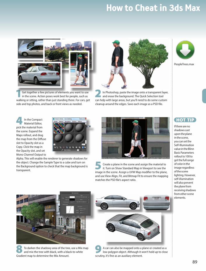
How to Cheat in 3ds Max
89
1Get together a few pictures of elements you want to use in the scene. Action poses work best for people, such as
walking or sitting, rather than just standing there. For cars, get side and top photos, and back or front views as needed.
4 In the Compact Material Editor,
pick the material from the scene. Expand the Maps rollout, and drag the map from the Diffuse slot to Opacity slot as a Copy. Click the map in the Opacity slot, and set Mono Channel Output to Alpha. This will enable the renderer to generate shadows for the object. Change the Sample Type to a cube and turn on the Background option to check that the map background is transparent.
2 In Photoshop, paste the image onto a transparent layer, and erase the background. The Quick Selection tool
can help with large areas, but you’ll need to do some custom cleanup around the edges. Save each image as a PSD file.
8 To darken the shadowy area of the tree, use a Mix map and mix the tree with black, with a black-to-white
Gradient map to determine the Mix Amount.
5 Create a plane in the scene and assign the material to it. Turn on Show Standard Map in Viewport to see the
image in the scene. Assign a UVW Map modifier to the plane, and use View Align, Fit, and Bitmap Fit to ensure the mapping matches the PSD file’s aspect ratio.
HOT TIPIf there are no shadows cast upon the plane in the scene, you can set the Self-Illumination value in the Blinn Basic Parameters rollout to 100 to get the full range of color in the image regardless of the scene lighting. However, self-illumination will also prevent the plane from receiving shadows from other scene elements.
9 A car can also be mapped onto a plane or created as a low-polygon object. Although it won’t hold up to close
scrutiny, it’s fine as an auxiliary element.
PeopleTrees.max

Materials5
90
1In the Compact Material Editor, select a material slot, click the Diffuse color for a new material, and change the color
to the general color of the object. Assign the material to the object. Drag the material to another slot to make a copy, and give it a different name. In this second material, assign the texture map you want to use on just one part of the object.
7 Access the main level of the UVW Mapping modifier, and right-click it. Choose Collapse All to collapse the modifier
stack. This embeds the mapping in the selected polygons.
4 Choose the Bitmap Fit option on the UVW Mapping modifier, and pick the texture map. This will resize the
gizmo to the same aspect ratio as the bitmap.
YOU WILL OFTEN NEED to map several different textures onto one object. There are many ways to do this,
but the one shown here is the quickest.The key is to assign each material to an
appropriate selection of polygons. The result is an automatic Multi/Sub-Object material with exactly the right materials in the right places.
This technique uses the Compact Material Editor, where it’s easier to copy materials than in the Slate Material Editor.
Multiple maps

How to Cheat in 3ds Max
91
2 At the Polygon sub-object level, select the polygons to which you want to apply the texture map. Assign the
material to the object while still at the Polygon sub-object level. This assigns the material to the selected polygons only. Press F2 to toggle selection display so the selection is outlined in red, rather than displaying the face as solid red. This way you can see the texture you’ve applied.
3 With the polygons still selected, apply a UVW Map modifier to the object. Use the View Align and Fit
options to line up the gizmo with the approximate size and orientation.
8 Select another set of polygons and repeat the process: Assign a material, apply a UVW Map modifier, adjust the
gizmo, collapse the stack. Repeat this as many times as needed to map the entire object.
9 After assigning multiple materials, click an empty sample slot in the Material Editor and use the eyedropper to pick
the material from the object. The material is a Multi/Sub-Object material with all sub-materials assigned appropriately.
5 If the texture needs to be moved or scaled, access the Gizmo sub-object level of the UVW Mapping modifier,
and move or scale the gizmo.6 If the map is a decal (meaning it’s not meant to be
tiled), turn off the Tile checkbox for both U and V in the bitmap’s Coordinates rollout in the Material Editor.
HOT TIPTo see the bitmap on the object after assigning the material, turn on the Show Shaded Material in Viewport option on the Material Editor toolbar.
MailStart.maxMailFinish.maxUSPS_Logo.psdUSMail.jpg

Materials5
92
1The Noise map makes a random pattern of black and white blobs. This type of map makes a great Bump map to give an object a bit of texture. Change the Source to Explicit Map
Channel, increase the Tile values, and turn on Show Standard Map in Viewport to see how the map lies on the object.
3 The Gradient Ramp map makes a gradient from a series of colors. The Radial type creates concentric circles, and the Solid Interpolation setting makes great cartoon-style eyeballs.
PROCEDURAL maps use algorithms (a series of equations) to generate an
individual color pattern. You change the pattern not by painting pixels, but by adjusting parameters.
Although 3ds Max comes with many procedural maps, I use the Noise map and Gradient Ramp map more than all the others combined. With the examples here, it’s easy to see why.
Procedurally speaking

How to Cheat in 3ds Max
93
2 The Noise map, like many maps, can be nested. In other words, the black or white channels in a Noise map can lead to another Noise map, or any map for that matter. Here, a Noise map is used as a background. The Size parameter is turned
down low and the Noise Threshold: Low value is increased to reduce the amount of white. This produces a field of white stars on a black background. Then the black channel holds another Noise map made up of larger blobs of dark blue and purple, creating a rich background for a space scene.
4 You can also use a Gradient Ramp to generate rings of varying colors. Here, the Gradient Ramp map in the Diffuse channel is coupled with a Noise map in the Opacity channel to create the semi-transparent rings around a planet.
HOT TIPIf a Noise pattern is still too large with a small Size setting, increase the Tiling values in the map’s Coordinates rollout. Procedural maps don’t always appear accurately in viewports, so be sure to render the scene to see what the map really looks like.

Materials5
94
3 In the Material Editor, create a Standard material with a Mix map in the Diffuse map slot, and assign it to the terrain. Select a Color 1 map for the black areas
and a Color 2 map for the white areas. As you assign each map, display it in the viewport with the Show Shaded Material in Viewport option so you can adjust tiling appropriately.
1Create a terrain object with any method and apply a VertexPaint modifier to it. In the VertexPaint dialog, turn on Vertex Color Display - Unshaded. By default, all
vertex colors are white. You’ll use the VertexPaint tool to paint some of the vertices black.
A LARGE LANDSCAPE might call for gradual changes from one kind of ground cover to
another. Examples are grass and dirt on a forest floor and rocks and snow on a mountaintop.
There are a number of ways you could create the texture map for such a landscape, such as mixing two maps using a Noise map to vary it across the surface. But with that type of setup, it’s hard to control where each map appears on the terrain.
Instead, you can use vertex painting to put different maps on specific areas. This technique gives you fine control over the final look of the landscape while retaining natural-looking variations from one map to another.
Gradual mix

How to Cheat in 3ds Max
95
HOT TIPTo see the ground cover bitmap on the object without the vertex colors, turn on the Disable vertex color display option in the VertexPaint dialog.
4 For the Mix Amount map, choose a Vertex Color map. This will use the vertex colors to determine the amount by which the two maps are mixed. Since you
can see only one map at a time in viewports, you’ll need to render the image to see the result. You can also paint some of the black vertices back to white to change the effect.
2 Make sure the color swatch in the Paintbox is black. Click the Paint tool and move the cursor over the object to see the disk-shaped Paintbrush tool. Drag
the cursor over the object to paint areas black. Here, I’ve painted the peaks black and left the valleys white.
TerrainStart.maxTerrainMix.max

Materials5
96
1Planar mapping works fine for the top of the mountain, but you’ll get stripes on the sides due to the map pixels going straight down. To visualize the problem clearly, you can apply a Checker map to the
object and see where the checkers stretch.
MAPPING A STEEP surface like a mountain presents
specific difficulties that can be solved only with the Unwrap UVW modifier.
This powerful tool can be used in a variety of situations. Here it’s used to clean up mapping artifacts on a vertical surface.
Learning to visualize how the Edit UVWs dialog relates to the object takes some practice, but it’s well worth the time spent. Once you know how to unwrap your UVs, you’ll be able to map any object with ease regardless of its size or shape.
Unwrapping the mapping
4 For extreme vertical areas, you can also reduce the striping further by scaling selected vertices so they use more of the map. Turn on Soft Selection in the lower row of tools below the edit window,
and move and scale vertices. Vertices selected in the viewport are automatically selected in the Edit UVWs dialog, and vice versa.

How to Cheat in 3ds Max
97
HOT TIPYou can display a bitmap in the Edit UVWs dialog to help you visualize how the map will fall on the object. If a material with a Diffuse bitmap has been assigned to the object, you can pick the bitmap from the dropdown list at the top of the Edit UVWs dialog. You can also choose Pick Texture and pick a new one to display in the window.
2 Apply an Unwrap UVW modifier and click Edit, and you’ll see why. The vertices in the vertical areas are all
bunched up around the center of the mapping coordinates. You’ll use the Relax tool to fix this.
3 Select all the points and choose Tools menu > Relax. Choose the Relax by Centers option with the Keep
Boundary Points Fixed option turned on, and click Apply several times until the distribution evens out.
5 If the bitmap is displayed on the object in the viewport, you’ll see it change interactively as you move vertices around in the Edit UVWs dialog. The result is a mountaintop with an evenly distributed texture and no obvious stripes due to
mapping.
MountStart.maxMountUVW.max

Materials5
98
8 In the Baked Material rollout, choose Output Into Source and Keep Source Materials. This will cause the Render to
Texture operation to automatically assign the new maps to the low-res object’s material in their appropriate slots.
NORMAL MAPPING is a type of bump mapping that produces realistic, detailed bumps. Normal mapping is particularly useful for replacing a high-resolution object with a low-resolution version for medium shots and animation.
While bump mapping uses a grayscale image and distorts normals at render time, normal mapping uses a range of colors to indicate normals pointing in all directions, and replaces the normals entirely at render time.
Drawing a normal map from scratch is a complicated business, so 3ds Max provides tools to create them for you. The Render to Texture tool projects the faces of a high-resolution object onto a low-resolution version to produce the normal map.
Normal mapping works best on curved surfaces, where none of the hi-res object’s faces are at right angles to one another. With the right kind of hi-res object, you can instantly get a fabulous-looking low-res object without the overhead of hi-res polygons.
Normal mapping
5 In the Render to Texture dialog, in the Mapping Coordinates group, choose Use Automatic Unwrap for
the Object setting. Having the Render to Texture operation unwrap the mapping for you usually yields better results than using the existing mapping.
6 In the Output rollout, click Add and choose NormalsMap, and click Add Elements to add it to the
output queue. Make sure the Target Map Slot is set to Bump. Set the map size to 2048x2048, and turn on Output into Normal Bump.
7 As long as we’re rendering a normal bump map, we may as well grab the hi-res object’s texture too. Click the Add
button again, and choose DiffuseMap. Set the Target Map Slot to Diffuse Color, and set the map size to 2048x2048.

How to Cheat in 3ds Max
99
2 Move the low-res object in such a way that the normals of the high-res object will project onto its surface. Here,
I’ve reduced the radius of the low-res ball so it fits inside the hi-res one.
3 Select the low-res object. Choose Render
to Texture from the Rendering menu, or press the shortcut key 0 (zero). The Render to Texture dialog appears.
9 Click Render on the Render to Texture dialog. The unwrapped texture shows in the Rendered Frame
Window, and the new maps are assigned to the appropriate slots in the low-res object’s material. An Automatically Flatten UVs modifier is added to the low-res object’s stack.
HOT TIPA normal is an imaginary vector (arrow) pointing out from a face or polygon. 3ds Max uses normals to determine how to shade surfaces at render time. For example, if a face’s normal is pointing right at a light source, that face will render brighter than faces with normals pointing in other directions.
1Create two objects, one with a high resolution and all the contours modeled, and the other a low-resolution
version of the same object. Both objects must have mapping coordinates. Apply a material to the low-res object.
10 Move the low-res object away from the hi-res one, and render any viewport. The low-res object’s
material has been updated with the new maps, and it appears with the same colors and contours as the hi-res object.
SoccerBall.max
4 In the Projection Mapping group, click
Pick, and pick the hi-res object. This adds the Projection modifier to the low-res object, and puts a cage around the hi-res object. This cage sets the direction of the face projection from the hi-res to the low-res object.

Materials5
100
4 You will need to fine-tune some of the parameters in the Tension modifiers Convexity/Concavity rollout to
get a more clamped result. Set the Concave Scale to 10.0 and the Concave Exp to 0.1. This should push the red out more and make it more defined.
1Apply the Tension modifier to a creature with a good amount of
geometry folds and detail. Uncheck Do Compression and Do Expansion from the Tension Parameters rollout and be sure Do Convex is checked under Convexity/Concavity. Also uncheck Relative to Ref. Pos. This will turn off the tension calculations. We don’t need them now, and it will also ignore any reference pose for the concavity.
IN THE MAXSCRIPT chapter we looked at a plugin called Tension. This plugin can be used to make some pretty interesting
shaders. Along with its ability to display tension with vertex colors, it can also display concavity. Using this tool, we can create a fast dirt shader for a creature.
Concavity

How to Cheat in 3ds Max
101
6 Set the Self Illumination back and tune your maps so that you have an interesting dirt map on the character.
3 To use this vertex information in our material we will need to use a Vertex Color map as a mask. Create a
Standard material that has 100% Self Illumination so it will be easy to see the blend. Add a Mix map to the Diffuse color slot and pipe in a Vertex Color map to the Mix Amount map. Set your mix colors to green and red and the Vertex Color Sub Channel to Green.
2 Click Toggle Vert Colors on the Operations rollout to see the character displayed with a green color for the
convex areas of the mesh and red for concave.
5 Now we can add a noise map or other grime map to the concave areas. Add a noise map for now and adjust its
size to fit the character. Also change the green color to one more fitting the character.
ConcavityStart.maxConcavityEnd.max

Materials5
102
SUBSURFACE SCATTERING is a CG effect that simulates the way light affects thin, convex surfaces such as skin. In life, areas such as the ears begin to glow red as the light gets in and scatters around. Areas that are
deep in in a contour don’t get as much light and so they don’t have that glowing effect. When you can simulate this effect, you can have much more real-looking skin.
While there are tools in 3ds Max for making light affect surfaces in this way, these tools usually cause render times to go through the roof.
So how do we get a subsurface scattering effect without the long render times? In the previous topic, we used the Tension plugin to make a dirt map for your character based on the concavity in the mesh. We can use that same information to get a convincing subsurface scattering effect without the long render times.
Faking subsurface scattering
3 Pipe a Falloff map to the red color slot and set the two Falloff colors
to red and black. Now set the Falloff type to Shadow/Light. This will give the Self Illumination a black color if it’s in shadow and the red color when in light.

How to Cheat in 3ds Max
103
2 The red colors generated by this setup are too bright. Set the red to be a very deep red, and tweak it so it
looks like bit of a glow under the skin but not too much. The deeper the red, the less of an effect you will get. Take note that we are getting this effect in the shadows, too. This is because the effect is driven by the vertex colors and not the light at all.
1Start with the setup from the last topic and create a Mix map for the Self Illumination map. Use the same
Vertex Color map as the Mix Amount and set the colors to red and black. In the root of the Standard material set the Color checkbox for Self Illumination so it uses the map’s color instead of just the value. Turn off the Diffuse map so you can easily see what you’re doing in preview renders.
Fake3SStart.maxFake3SEnd.max
4 Turn your Diffuse map back on and play around with the
colors to get a good balance. We are using basic colors and simple shaders here, but ideally you would have unwrapped Diffuse, Dirt, and Self Illumination maps. Also remember that this is a faking technique. It looks cool in many instances and is much faster to work with than real subsurface scattering, but for high-end skin shading it’s recommended that you use MR Fastskin or V-Ray.

Materials5
104
7 Once you have all or a significant portion of the object mapped you can apply a material and render a UVW
template to paint in Photoshop. From the Tools menu in the Edit UVW window, choose Render UVW Template to render a template.
Mapping a character
1Apply the Unwrap UVW modifier, and click Edit. The mesh displayed in the Edit UVWs dialog represents the object
flattened out.
6 Create selections and seams, and Quick Peel other parts of the body. Flat parts of a character like the bottom of the
boot can be planar mapped instead of using Peel.
MAPPING A CHARACTER requires a few special techniques. The use of the Unwrap UVW modifier makes it
possible to put all the textures into one image, making a game-ready character that uses as little memory as possible.
Wrapping your head around the Unwrap UVW modifier takes a little practice, but it will open up a new world of texturing to you.

How to Cheat in 3ds Max
105
2 Select all the
polys and move them out of the mapping space to keep a clear workspace for newly mapped geometry.
4 With the polygons
still selected, click on the Point to Point Seam tool and create a seam along an edge of the model where the seam will be least visible, as in the inner leg in this example.
3 Select a body part
to start mapping. In this case we’ll start with the leg. Select the polygons that make up the leg, making sure you get all the ones around the back.
8 In Photoshop paint over the template image to get the texture detail you want on the polygon islands laid out.
Once you are pleased with the image bring it back into 3ds max and apply it .
5 Click Quick Peel and
the leg will be unwrapped in the UVW Editor.
HOT TIPTo make the map easier to see and work with in the Edit UVWs dialog, choose Options > Preferences, turn off Tile Bitmap, and use View > Show Grid to turn off the grid display.

Materials5
106
MENTAL RAY comes with a number of preset materials that work “as is” in your
scene. Materials that are difficult to create with the Standard type take just minutes when you use the Arch & Design material’s presets.
Mental ray materials are available only when mental ray is selected as the renderer. These materials are designated in the Material/Map Browser by a yellow sphere icon.
Note that if you switch back to the default renderer after you assign mental ray materials, you will need to reassign non-mental ray materials to make the scene render properly.
Basic mental ray materials
1In the Render Setup dialog > Common tab, change the renderer to NVidia mental ray. Open the Slate Material Editor, where the
mental ray materials will now be available. Drag an Arch & Design material into the Active View.
3 Experiment with more templates, and note how they change the Diffuse, Reflectivity, and Transparency settings. Also, look for the
Bump and Displacement settings in the Special Purpose Maps rollout. Many templates automatically assign textures to these parameters.

How to Cheat in 3ds Max
107
HOT TIPTo keep the rendering time to a reasonable length while getting the benefits of mental ray, turn on Enable Final Gather in the Global Illumination tab of the Render Setup dialog, and set the Preset to Draft.
2 On Double-click the material node to see the material parameters. To get started, choose a template from the Select a Template dropdown and assign the material to an object in the scene. Choosing a template sets the material parameters
to appropriate values, but the preset name doesn’t stay with the material. Try a new template, change the Diffuse color swatch, apply it to an object, and render. Set the output resolution low to keep the rendering time reasonable.
4 Where mental ray really shines is with hard-to-get-right materials like glass. Here, I’ve applied the Glass
(Physical) template to the pint glass. At any time, you can change the parameters on any rollout to change the object’s color or appearance.
5 The Water, Reflective Surface template gives you instantly believable water. With just a quick change of
the Diffuse color, you can make it match your scene. In the next topic, Custom Mental Ray Materials, you’ll learn how to use your own maps with these templates.

Materials5
108
WHILE PRESET MATERIALS can get you through some of your projects, to really make use of mental ray you’ll need to use your own bitmaps
and textures. To create a 3D version of this 17th-century ornamental carving, I used mental ray to make all those nooks and crannies really pop.
Custom mental ray materials
1Before you start using mental ray, create Standard materials for the
object as usual.
5 Replace the Reflection Color map with the same map as the Diffuse map. In the case of Masonry, this will put soft
reflections on the object. Replace the Bump map with your original material’s bump map. For my model, the bumpiness was a bit high for the leaves, so I reduced the Bump value from 1.0 to 0.6.
4 Remove the default map assigned to the Arch & Design material by selecting and deleting it. Connect the
Diffuse Color map from the original material to the Diffuse Color map for the Arch & Design material. Render the scene to see how the material is coming along. Here I’ve assigned the material to the leaves only.
PHO
TO: W
ARR
EN A
PEL

How to Cheat in 3ds Max
109
3 In the same Material Editor view, create a new Arch & Design material. This type of material is available
only after you have set the renderer to mental ray, and has a number of presets that make it easy to get a particular look for your materials. Click the Templates dropdown menu and choose a template. For my carving, I chose Masonry. Choosing a template changes the material parameters and assigns default maps automatically. You will make your custom material by replacing the default maps.
HOT TIPIf a bump map creates too hard a line between black and white areas in the rendering, increase the Blur value on the bitmap’s Coordinates rollout.
2 Get the maps and materials to the point
where the rendering looks pretty good with the default renderer, then assign mental ray as the current renderer (Render Setup dialog > Assign Renderer rollout). In the Global Illumination tab, turn on Enable Final Gather and choose the Draft preset. Render the scene to see if it looks any different. Shown here are renderings with the default renderer (top) and mental ray renderer (bottom). Aside from slight differences in the shadows that are generated, you won’t see much of a change until you assign mental ray materials.
6 Use the same method to create mental ray materials for all other parts of the model. Use an appropriate preset
as a base for each material, and replace the maps with your Standard material maps as necessary. Assign each material to a Polygon sub-object selection to automatically create a Multi/Sub-Object material made up of mental ray materials. Here, I’ve used the Vertex Paint method to make a messy wall with the Gradual Mix technique.
7 You can also use the bump map as a Displacement map. This causes the bumps to look as though they are
physically modeled, so they show in profile in the rendering. Note the difference in the the circular center of this model, where the ridges stand out and prevent it from looking perfectly round. I also made it look like an old relic by mixing a bit of the Speckle map with the original bump map and by applying a Noise modifier to the model itself.
Carving.maxCarvingMR.max

How to Cheat in 3ds Max
110
nWorking with lighting and shadows is a skill you’ll need to bring realism to your renderings.

How to Cheat in 3ds Max
111
6Lighting & ShadowsLIGHTING AND SHADOWS ADD REALISM to a rendering, but their
purpose goes beyond making a scene believable. Shadows anchor
stationary objects to the ground and give flying objects their height.
They also give important visual cues about scale and location, object
solidity, and time of day.
Once you determine the types of shadows you want to have in
your scene, you can choose from a variety of methods to create them.
Unfortunately, the best-looking shadows usually take the longest to
render. In this chapter, you’ll also learn some time-saving methods for
realistic shadows.

Lighting & Shadows6
112
1-2-3 Lighting
FOR GENERAL LIGHTING, a three-point or four-point system with Standard lights
provides general illumination without washing out your scene. 3ds Max lights default to the Photometric type, so you’ll need to pick Standard from the dropdown menu before getting started.
A light’s intensity is set by its Multiplier value in the Intensity/Color/Attenuation rollout. You can also change it in the Light Lister dialog, available from the Tools menu.
Use the top view of this classic lighting setup (shown at left) and angled view (shown on the right) to guide you in placing lights.
4
32
1

How to Cheat in 3ds Max
113
HOT TIPA light always shines through objects in the scene unless its Shadow checkbox is turned on.
4 If needed, you can also add an Omni light at the back of the scene to
light the top of the object. This light, called a kicker or rim light, helps separate key elements from other background objects.
3 A dim Omni light placed under the ground and slightly forward
simulates light bouncing off the ground.
2 The fill light fills in the other side of the scene and lightens up
shadows. This Omni light has a lower intensity than the key light.
1The key light provides the shadow and the bulk of the illumination.
Make this light a directional or spot light, and give it the highest intensity of all lights in the scene.
Mailbox.maxMailboxLit.max

Lighting & Shadows6
114
1If visible rectangular chunks appear in a Shadow Map shadow, you need more samples. Increase the Sample
Range for the shadow to smooth them out.
SO YOUR SHADOWS ARE appearing, but they’re misbehaving. If you don’t know why they’re being naughty, you
can waste hours trying to make them obey. Check out these common shadow problems and their solutions.
Troubleshooting shadows
2Sometimes a shadow becomes disconnected from the object that casts it. This effect is most noticeable with
thin objects. Reduce the Bias setting for the shadow type to bring the shadow closer to the object.

How to Cheat in 3ds Max
115
4 Spot and Omni lights cast non-parallel shadows (top). Compare
with Direct lights, which cast parallel shadows like those from the sun (bottom). Non-parallel shadows make an outdoor scene look small, like a miniature indoor version. The difference is subtle, but the human eye detects it.
HOT TIPA Shadow Map shadow works by projecting a square map in the direction of the light in the Size you specify. The larger the Size, the more shadow detail is calculated.
5 You can also preview shadows in the Nitrous viewport. With the
view shading set to Realistic, right and make sure Illuminate with Scene Lights and Shadows are checked.

Lighting & Shadows6
116
Exterior lighting
LIGHTING FOR AN outdoor scene requires a direct shadow-casting
light to simulate the sun, a medium-strength fill light to lighten the shadows, and a dim underground light to simulate bounced light.
This lighting setup works equally well with the default renderer and with mental ray.

How to Cheat in 3ds Max
117
HOT TIPWhile Ray Traced Shadows cast sharp shadows, Shadow Map shadows cast soft shadows like those you see on an overcast day.
If you’re feeling adventurous and want to try out the mental ray renderer, use a mr Daylight System as the only light and see what kind of results you get.
3 A dim underground light provides the effect of light bouncing off the ground to illuminate overhangs and eaves.
2 An Omni light opposite the main light fills in the shadows and
simulates ambient light.1A strong direct light provides sunlight and
shadow for the scene. Ray traced shadows simulate the sharp shadows of daylight.
Exterior.maxExteriorLit.max

Lighting & Shadows6
118
Bright sunshiny day
SUNLIGHT THROUGH a window makes a pretty presentation for a room. A glow around the windows simulates the real-life effect of light spilling in through the window and washing the outdoor view to white.
This topic shows how to set up this type of lighting for the default renderer. See the Mental Ray Lighting cheat for details on how to adjust it for mental ray.

How to Cheat in 3ds Max
119
1Use a strong Direct light to make sunlight come through the window. Turn on Shadows and set the shadow type
to Ray Traced Shadows. Turn off the Casts Shadows property for the window panes to allow the light to come through the windows and shine onto the floor.
HOT TIPShadow Map shadows from an Omni light get softer when you move the light farther away from the object receiving the shadow (wall or floor).
2 Two or three Omni lights placed in the central part of the room simulate sunlight bouncing off the walls and floor
to illuminate areas that aren’t in the direct path of the sunlight. Turn on Shadows and set the shadow type to Shadow Map. A small Size and a large Sample Range create soft shadows on the walls and floor.
3 A glow around the windows adds to
the impression of strong sunlight. Change the window pane material’s Material ID Channel to a number other than 0, then set up a Glow with Render > Effects > Lens Effects. In the Glow Element rollout, go to the Options tab and set the Material ID value to the same number as the Material ID channel. Adjust the Intensity and Size parameters on the Parameters tab to make a soft glow around the windows in the rendering.
InteriorDay.max

Lighting & Shadows6
120
THE KEY TO GOOD LIGHTING with mental ray is to start with lighting that works well with the
default renderer. Then you can switch to the mental ray renderer and adjust your lighting before moving on to adjusting materials. This usually means turning lights off or reducing their intensities rather than adding more lights to the scene.
To change the render to the mental ray renderer, choose Rendering menu > Render Setup > Common Tab > Assign renderer rollout and pick NVIDIA mental ray renderer. Then make sure Enable Final Gather is on in the Global Illumination Tab, and that the Preset is set to Draft. You can also increase Diffuse Bounces to 1 or 2 to brighten up dark areas.
Mental ray lighting
3increase the Sample Range in the mental ray Shadow Map rollout for both lights, which will spread out each
shadow over a wider area. Here, I’ve increased the Sample Range to 0.2 for both lights. The result is a spray of dark dots on the walls, but we can fix that.
2For an interior with windows, you’ll always need to change all Shadow Map shadows to the mental ray
Shadow Map type to keep soft shadows in the mental ray rendering. Usually, the default settings for this shadow type will give you harsh and blocky shadows, and even strange artifacts such as those on the tapestry on the far wall.

How to Cheat in 3ds Max
121
1With an exterior scene, the change to mental ray lighting takes just a couple of minutes. You might need to decrease the lights’ Multiplier values to get the right intensity or turn them off altogether. Here, I’ve turned off the underground light and
reduced the Multiplier for both the sun and fill lights.
HOT TIPTurn on mr photographic Exposure Control when rendering with mental ray. Use the tiny Render Preview window, then change the EV Value until the little thumbnail lighting looks good. Finish it off by using Image Control to finetune the Shadow/Midrange and Highlights.
4To smooth out the spotty shadows, increase the Samples value for each light to a high number such as 100 or 200.
This will take color samples from more pixels in each shadow, effectively smoothing them out. It’s a lot easier to make these adjustments at the very start, before you adjust Multiplier levels.
5Before making further adjustments to lights, change your materials to mental ray materials, as described in the
Custom Mental Ray Materials topic in the Materials chapter.
ExteriorMR.maxRoomMR.max

Lighting & Shadows6
122
2 Changing the color swatch in the Intensity/Color/Attenuation rollout changes the light’s color. For
outdoor scenes, use pale yellow for sunlight and pale blue for moonlight.
LIGHTING EFFECTS can add that extra something to a scene. The techniques shown here are good choices if you need
to punch up the scene or give it a bit of interest. However, these techniques are not a substitute for good basic lighting.
As with all good things in 3D, enhancements can take longer to render but can set your image apart from the crowd.
Good lighting made better

How to Cheat in 3ds Max
123
1A negative Multiplier value decreases the lighting where the light shines, creating a dark spot. Use this technique when you want to reduce light in a small area. You can also scale the light itself on one axis to shape the light to the area you want to
affect. Here, a spot light has been scaled on one axis to make its hotspot and falloff areas tall and thin.
4A volume light is suitable for strong sunlight
through a window mingling with dust or smoke. To create this effect, choose Rendering > Environment, click Add, pick Volume Light, and pick the light. For the light itself, turn on the two Use checkboxes for the light in the Intensity/Color/Attenuation rollout and adjust the Near and Far values to prevent the volume light from overpowering the scene. You can also change the Density and Max Light % values in the Environment rollout to change the “thickness” of the effect.
3 Attenuation causes a light to lessen or decay farther from the light source. Turn on this feature for an individual light with the Use checkbox in the Far Attenuation group. To control the degree of decay, turn on Show and adjust the Start and
End values. The image at left has no attenuation, while the image at right has attenuation enabled for the two Omni lights that simulate bounced light. The effect takes longer to render but can add a touch of realism to your lighting.
RoomNeg.maxRoomAtten.maxSpaceFlare.maxRoomVolume.max

Lighting & Shadows6
124
IN RESPONSE TO user requests, Autodesk has introduced several lighting systems into the last few releases of 3ds Max.
The advantage is more choices for you. The disadvantage is that older systems are never retired, and the plethora of choices can be confusing.
This guide takes you on a tour of the Daylight lighting system and its uses. The Daylight lighting system, designed for use with mental ray, sets a light to use as a virtual sun and an environment or background for a virtual sky, which not only renders in viewports but affects the coloration of the scene.
The Daylight system features a compass rose and date/time/location settings for real-life light settings, but you can also adjust the light angle manually. The Daylight system is the only place where you can enable the mr sun light, which works like Skylight but is optimized for mental ray. While the mr sun can save time in some situations, standard lighting is still just as useful as it always has been.
It’s best to the use the Daylight system with scenes that are created to real-world scale. You can use it with all scenes, but you might need to make heavy use of Multiplier parameters to get the right lighting.
Daylight savings time
1To create a Daylight system, choose Create > Systems > Daylight and drag in any viewport. Drag once to create
the compass rose, and then again to set the height of the light. To adjust the light’s distance from the scene, choose Date, Time and Location, and change the Orbital Scale value. You can switch to other types of lights and skies on the Modify panel.
4 If you need a photographic background with the Daylight system, you’re best off using the map itself
as the background in the Environment and Effects dialog rather than mr physical sky. Select the Daylight, and in the Modify panel, set the Skylight option to Skylight rather than mr sky. This uses settings in the Skylight Parameters rollout to illuminate the scene, even if you don’t have a Skylight in the scene.
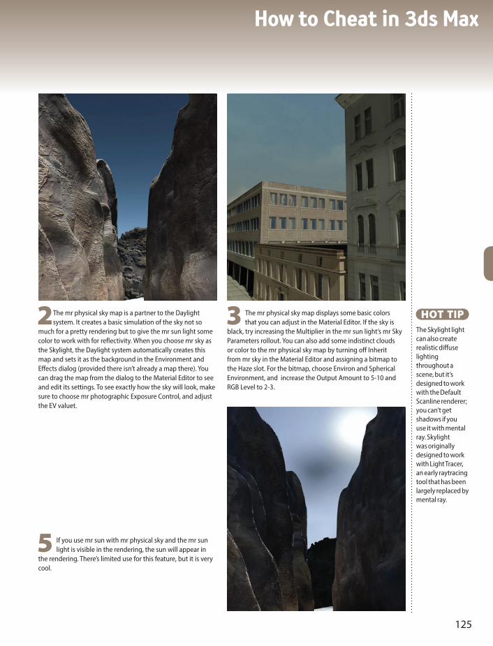
How to Cheat in 3ds Max
125
5 If you use mr sun with mr physical sky and the mr sun light is visible in the rendering, the sun will appear in
the rendering. There’s limited use for this feature, but it is very cool.
HOT TIPThe Skylight light can also create realistic diffuse lighting throughout a scene, but it’s designed to work with the Default Scanline renderer; you can’t get shadows if you use it with mental ray. Skylight was originally designed to work with Light Tracer, an early raytracing tool that has been largely replaced by mental ray.
2The mr physical sky map is a partner to the Daylight system. It creates a basic simulation of the sky not so
much for a pretty rendering but to give the mr sun light some color to work with for reflectivity. When you choose mr sky as the Skylight, the Daylight system automatically creates this map and sets it as the background in the Environment and Effects dialog (provided there isn’t already a map there). You can drag the map from the dialog to the Material Editor to see and edit its settings. To see exactly how the sky will look, make sure to choose mr photographic Exposure Control, and adjust the EV valuet.
3 The mr physical sky map displays some basic colors that you can adjust in the Material Editor. If the sky is
black, try increasing the Multiplier in the mr sun light’s mr Sky Parameters rollout. You can also add some indistinct clouds or color to the mr physical sky map by turning off Inherit from mr sky in the Material Editor and assigning a bitmap to the Haze slot. For the bitmap, choose Environ and Spherical Environment, and increase the Output Amount to 5-10 and RGB Level to 2-3.

Lighting & Shadows6
126
Saving time with shadows
THERE ARE MANY cases when rendering slows to a crawl. At
these times the first thing I look at is whether there are shadows in the scene, and ray traced shadows in particular. Ray traced shadows can be particularly slow if the circumstances are right. Usually this involves a strange scene scale or the lights being way too far away from the camera. The Scanline renderer is the worst offender, but mental ray can still slow down with improperly placed and tuned lights.
3 Whenever setting a shadow to Raytraced I always set the Max Quadtree Depth to 10 in the Ray Traced Shadow Params rollout.
This is a parameter that controls quality but it’s very rare if ever that you would notice any quality decrease with it set to the maximum value of 10. However, it will speed up renders significantly. Render again and the render time should be under 1 second.
1A quick render of this scene has it rendering rather slowly for what it is at 26 seconds on my laptop. You can see that the light is a Spotlight and positioned fairly far away from the camera and objects it is
supposed to light.

How to Cheat in 3ds Max
127
HOT TIPIf you’re doing outdoor lighting or sharp direct shadows a Direct Light can be a better choice than a Spotlight in many cases. The falloff of the Spotlight is contributing to the slowdowns we are seeing in this example.
4 If we switch over to mental ray and turn off Final Gather under the Global
Illumination tab, this scene should render in about 6 seconds. The modifications we did for Scanline will not matter as much for mental ray as it is much better equipped for ray tracing. Mental ray in many cases can be overkill and, in this case, with a little tuning, Scanline is 5 seconds faster. This means if our entire animation takes 1 hour to render with Scanline, it could take 6 hours with mental ray.
2 The first thing to do here is move the light on its Local Coordinate to be much closer to the camera. We don’t need it to be that far away and that is wreaking havoc with the Raytraced Shadow
generation. Once at a reasonable distance the render looks the same and renders in about 4 seconds.
ShadowSpeed.max

Lighting & Shadows6
128
Where’s the shadow?
1Make sure the Shadows option is turned on for the light, and that each object’s Cast Shadows and Receive
Shadows properties are turned on (Edit > Object Properties).
SHADOWS HAVE A HABIT of disappearing from time to time. Described here are the top five reasons
your shadows aren’t appearing in your scene.
4 Light that you expect to show through an opening, such as light through a window, might be blocked by an object. Turn off the object’s Cast Shadows attribute to let the light shine through.

How to Cheat in 3ds Max
129
HOT TIPIf you’re having trouble determining what the problem is with your shadows, turn off all the lights, and then turn them on one by one and render the scene. The Light Lister dialog is an excellent tool for this trouble-shooting technique.
5 If the light angle is too low in relation to the surface receiving the shadow, the shadow might stretch out or might not even appear at all. Move the light up to increase the angle to the ground.
3 If the object receiving the shadow is completely self-illuminated, no shadow will appear. Turn down the
material’s Self-Illumination value in the Material Editor.2 If the other lights are too bright, shadows can be
washed out. The shadow-casting light should be the brightest, and the total of all Multipliers should be below 3.0.

Lighting & Shadows6
130
YOU’VE PROBABLY SEEN images of models presented with a nice shadow
beneath them or even a wireframe representation. These types of images have
become a staple on the Internet for modelers showcasing their work in portfolios,
stock 3D model marketplaces, and online profiles. The techniques for producing
these images aren’t complicated but require a bit more thought than a simple
rendering or screen capture.
For a model with a shadow beneath it, place a plane at the floor level (usually
just touching the bottom of the model) and point a shadow-casting light at the
model. Then create a Matte/Shadow material and apply it to the object. When you
render, only the shadow cast by the object will appear on the plane, and the rest of
the plane will be invisible.
Presenting a wireframe requires a little more ingenuity. You could just turn
on the Backface Cull option on the Display panel and capture the screen, but in
general this gives you a pretty ugly capture. On the creature model shown, for
example, there’s a lot of crisscrossing of edges on the head and shoulders. This
happens with just about any model that has any complexity to it.
Instead, create a copy of the model right on top of itself with Edit > Clone.
Create two materials, one a Matte/Shadow material with the Receive Shadows
option turned off and the other a black self-illuminated material.
Assign the Matte/Shadow material to the original and the black material to the
copy. Select the copy and apply the Lattice modifier to it. This creates geometry
along each edge. Choose the Struts Only From Edges option and reduce the Radius
to a value that looks good. For the dog, I set the Radius to 0.5.
The Lattice technique is the most reliable, but it has a limitation: the wireframe
will be narrower farther from the camera. For most models this isn’t a problem, but
if you prefer to have a uniform wire width, you can use the Push modifier instead.
I N T E R L U D E
Shadow and wireframe presentation

How to Cheat in 3ds Max
131
Select the copy, and instead of applying the Lattice modifier, apply a Push
modifier. Set the Push Value to a small number such as 0.2. This will push the
model’s faces out along their normals. Then, for the black material, turn on the
Wire option. In the Extended Parameters rollout, set the wire’s Size and turn on the
Pixels option. The rendered image will have a uniform wire size everywhere in the
rendering, regardless of the edges’ distances from the camera.
In both cases, the key is the original object inside the copy with its Matte/
Shadow material. This material hides the edges at the back of the model and does
a far better job than a screen capture with the Backface Cull option.
n Creature model rendered with Matte/Shadow plane below it (above), followed by straight screen capture with Backface Cull (upper right), and Push copy (lower right). You can also just choose Hidden Line as a viewport shading mode and do a viewport capture by clicking the plus button in the viewport menu, then pick Create Preview > Capture Still Image.
How to Cheat in 3ds Max
132
n Nothing says “shiny” like reflective surfaces in your scene. To get as much bling as you can with the least rendering time, use the techniques in this chapter.
How to Cheat in 3ds Max
132
How to Cheat in 3ds MaxHow to Cheat in 3ds Max
7ReflectionsIN LIFE, REFLECTIONS APPEAR on shiny objects. A bit of shine and
reflection well placed in a scene adds realism that you can’t get any
other way.
While nature produces reflections with ease, recreating them in 3ds
Max takes some know-how. There just isn’t enough rendering time in
this world to render every reflection that nature makes, so you need
to pick where and how your reflections will appear. Knowing your
options and the end result you’re looking for are essential to fast work
and pretty results.
133

Reflections7
134134
Reflecting on reflections
REFLECTIONS ADD a needed degree of realism to a scene. However, there’s no magic Reflection button in 3ds Max; you need to set reflection types separately for
each material used in the scene.In general, the more accurate you want the reflections to
be, the longer the effect will take to render. If an object is close to the camera or is the focal point of the scene, you’ll need accurate reflections. For incidental objects, simpler and faster-rendering solutions will do.
Here, reflection techniques are presented roughly in order of fast/decent to slow/accurate.
3 Using a Reflect/Refract map in the Reflection channel causes curved objects to reflect the environment,
which means you need to have surrounding geometry and/or an environment map to reflect. The Reflection percentage determines how strongly the surrounding geometry is reflected. Here, the objects reflect each other as well as the environment.

How to Cheat in 3ds Max
135135
8 One two three four five six seven eight nine ten eleven twelve thirteen fourteen fifteen sixteen seventeen
eighteen nineteen twenty One two three four five six seven eight nine ten One two three four five six seven eight nine tenOne two three four five six seven eight nine ten
9 One two three four five six seven eight nine ten eleven twelve thirteen fourteen fifteen sixteen seventeen
eighteen nineteen twenty One two three four five six seven eight nine ten One two three four five six seven eight nine tenOne two three four five six seven eight nine ten
HOT TIPOne great advantage of using a reflection bitmap is the ability to blur it easily. Raytrace options usually take quite a long time to render a blurred reflection.
5 Of course, you get the best results with mental ray materials, which automatically reflect the geometry and
environment map if the Reflectivity setting is above 0.0. The reflectivity works for both curved and flat surfaces. However, the added render time is worth it only if the reflective objects are the focal point of the scene. Otherwise, you can use the faster, simpler solutions described in earlier steps.
2 By default, the Reflection percentage is set to 100 (represented as 1.0 in the Controller Bezier Float node),
which causes the reflection to overpower the material. Reduce the percentage in the Maps rollout to 10 or 20 (or the Controller Bezier Float value to 0.1 or 0.2) and increase the Specular Level and Glossiness settings to make reflections more realistic.
1The quickest and easiest reflective material for curved surfaces is a Standard material with a Bitmap map in
the Reflection channel. This type of map puts a bitmap on an imaginary sphere around the scene and reflects the pixels off the object based on the camera angle. Here, I’ve used Chromic.jpg, a map that comes with 3ds Max and my favorite all-purpose bitmap for reflection.
4 More accurate results can be achieved with a Raytrace map on both curved and flat surfaces, but it takes
much longer to render. This map was an older solution to the problem of reflections, which is why it’s used in so many scenes from previous versions of 3ds Max. Raytrace maps can usually be replaced with Reflect/Refract and Flat Mirror maps without noticeable loss of scene quality.
ShaderBallRef.max

Reflections7
136136
Bling
SUCH A BRILLIANT SHINE is easy to produce with the help of the Raytrace material and a black-and-white background map. This type of material renders fast and produces great results without the overhead of mental ray.
A few simple steps is all it takes. The resulting jewels will sparkle and shine regardless of the lighting setup you use.
3 To make the bling sing, a black-and-white background is essential. Open the Environment and Effects dialog with Rendering menu > Environment, and click the Environment Map box to choose a bitmap. Here I’ve used Chromic.jpg
from the standard Maps/Reflection folder. Drag the map from the Environment and Effects dialog to the Slate Material Editor as an Instance so you can edit its parameters. In the bitmap’s Coordinates rollout, choose the Environ option and the Spherical Environment type to wrap the image around the scene. For this scene, I also cropped the bitmap to use mostly white areas.
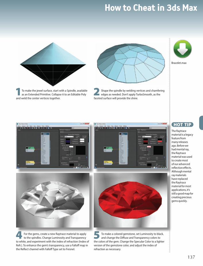
How to Cheat in 3ds Max
137137
HOT TIPThe Raytrace material is a legacy feature from many releases ago. Before we had mental ray, the Raytrace material was used to create most of our advanced reflection effects. Although mental ray materials have replaced the Raytrace material for most applications, it’s still a good map for creating precious gems quickly.
1To make the jewel surface, start with a Spindle, available as an Extended Primitive. Collapse it to an Editable Poly
and weld the center vertices together.2 Shape the spindle by welding vertices and chamfering
edges as needed. Don’t apply TurboSmooth, as the faceted surface will provide the shine.
4 For the gems, create a new Raytrace material to apply to the spindles. Change Luminosity and Transparency
to white, and experiment with the index of refraction (Index of Refr.). To enhance the gem’s transparency, use a Falloff map in the Reflect channel with Falloff Type set to Fresnel.
5 To make a colored gemstone, set Luminosity to black, and change the Diffuse and Transparency colors to
the colors of the gem. Change the Specular Color to a lighter version of the gemstone color, and adjust the index of refraction as necessary.
Bracelet.max

Reflections7
138138
5 Drag the Gradient Ramp map into the Environment slot of the scene so the object will have something
interesting to reflect. The coordinates of the map should be set to Screen or Cylindrical Environment.
4 A Gradient Ramp map can be a used to create a flexible and interesting environment for a scene like this. Create
a Gradient Ramp map with a few interesting colors to reflect and that matches the color tone of your scene.
1With a logo in a scene that has no lights and no environment, all you get is black. Creating or turning on a
key light will start to show the form of the object.
Reflections in the dark
WWHEN WORKING WITH reflections on 3D
logos there are a few things to remember. First, It’s important to have a good three-point lighting setup. Next, the logo needs to have a good amount of detail and bevels to catch the light. Finally, if the logo is highly reflective it needs a good environment to reflect.
When creating logo or motion graphics scenes, problems with reflections crop up because there is no environment or no decent default lighting setup. An environment and lighting setup needs to be created to make your logos look spectacular. After all, if you put a shiny object in a dark room with nothing in it, all you will get is a black, uninteresting object.

How to Cheat in 3ds Max
139139
2 Adding a back light or rim light in will catch some of the bevels from the back and start to break the logo’s form
away from the background. A back light is also a great light to add a bit of accent color.
3 Finally, a few fill or bounced lights can add more details to the sides of the object as well as fill out the body
more. However, there is still no environment in the scene which is bringing the coolness factor of the logo way down.
6 By setting your Gradient Ramp map to Cylindrical Environment in the Coordinates rollout you can usually get more interesting reflections than with it set to Screen. If you do this however, you may not get the desired look out of the
background. To have the best of both worlds, make a copy of the Gradient Ramp map and set it to Cylindrical Environment. Place that copy into the Environment Map slot of your Arch & Design material. This will give you an interesting Screen background in the render while using a Cylindrical mapping for the logo’s reflections.
LogoReflStart.maxLogoReflEnd.max

Reflections7
140
SO YOU’VE SET UP A STANDARD MATERIAL for a reflective surface using a
Reflect/Refract map or Bitmap map in the Reflection slot. You apply the material,
render the camera view, and...nothing. No reflection on the surface. What went
wrong?
The problem is most likely with the angles between the objects. To understand
how this works, we’ll do a quick lesson in optics, the science of light.
In life, light bounces off an object and into your eyes or a camera. Light
bouncing off the object means you can see it; no light bouncing off the object
means you can’t.
When a mirror or other reflective surface is present, light bounces off the
object, then the mirror, and then into your eyes. That’s how you see the reflection in
the mirror. The light always bounces in a straight line, and bounces off the reflective
surface at exactly the same angle at which it hits it.
In order to see a reflection in a mirror, your eyes have to be at the same angle
to the mirror as the object you’re looking at. When you stand straight in front of
a mirror, the light just bounces straight out and back again into your eyes. If you
stand to one side of the mirror, you’ll see objects on the other side.
When you’re seeing a reflection, distance from the mirror is not a factor in
whether the object is reflected; only the angle of reflection is important. If this is
confusing, get out a hand mirror and experiment with it. Hold it to the side and see
what reflects in the mirror, and compare your eyes’ angle to the reflected angle.
And so it is in 3D. In order for the camera to “see” the reflection, the object
being reflected on the surface must be at the same angle to the surface as the
camera. If it isn’t, you won’t see a reflection.
Highlights work the same way. A highlight is created by light reflecting off a
surface and right into your eyes. Getting highlights on an object is a matter of
placing the light in such a way that it bounces off a part of the object and right into
the camera lens.
I N T E R L U D E
Where’s my reflection?

How to Cheat in 3ds Max
141
The Place Highlight tool, available from the Align flyout on the toolbar,
works very well for both highlight and reflection placement. For a highlight,
activate the camera view, select the light, choose Place Highlight, and drag
the cursor over the shiny object. The light will move around to place the
highlight at the cursor position. Release the cursor where you want the
highlight to appear, and the light is placed in such a way that a highlight will
be produced when you render.
To place an object to reflect on a surface, select the object that will be
reflected, activate the camera view, and choose Place Highlight. Drag the
cursor over the reflective surface and release the mouse when you reach
the spot where you want the reflection to appear.
If you still don’t get a reflection, then something else is wrong. Be sure
to use the Reflect/Refract map on curved surfaces only, and the Flat Mirror
map on flat surfaces only. You can also try working with a simplified version
of the scene. Get the reflections to appear in the less complex scene then
build it up gradually to the complex version.
n Angle A must equal angle B for the camera to see the watch reflected on the surface.
A B

142
n A few words here about the subject matter of the chapter. Images have shadows underneath.
How to Cheat in 3ds Max
142
nWhat makes glass look like glass? Reflections, transparency, shininess, and refraction all play a part.

8GlassGLASS CAN SEEM TO BE awfully complicated. Plain old transparency
with a bit of shine doesn’t do the trick. You search in vain for the
Instant Glass button, but somehow the developers of 3ds Max left it
out of the user interface.
The key is to use reference images to find the look you want, and
then consider which maps and parameters will create a material that
simulates that look.
How to Cheat in 3ds Max
143

Glass8
144144
REN
DER
ING
S: N
EOSC
APE
, IN
C.
Exterior daytime windows
2 You can use a photo as a basis for a texture and map it onto the windows. This will give you a realistic look, but only if the light is coming from the same angle as in the photo. For a still image, this is a viable
option. With an animated camera, the lack of a changing reflection will become obvious as soon as the camera moves.
G LASS WINDOWS ON A SUNNY DAY make a pretty architectural rendering. Using photos for reference, you can create a realistic rendition of
windows seen from the outside, as with this rendering from Neoscape, Inc.

How to Cheat in 3ds Max
145145
ExtWindows.max
3 To reflect the sky and also show shadows from the scene’s light source, apply a Matte/Shadow material to the windowpanes. Be sure to turn on Receive Shadows and Additive Reflection for the material. If
using mental ray, use the Matte/Shadow/Reflection (mi) material. Here, a large plane creates the panes for all the windows at once, and mullions are modeled separately to sit above the plane.
1From photos, you can see that exterior windows in daylight aren’t really transparent. Depending on the lighting, you might be able to see partway into the building, or you only see a reflection of the
environment.

Glass8
146146
Interior daytime windows
T HE APPEARANCE OF WINDOWS can make or break an interior rendering. Nicely done windows indicate a space with air and light. The appearance of the exterior environment
through the windows coupled with the play of light on the floor will do most of the work for you.
REN
DER
ING
S: N
EOSC
APE
, IN
C.

How to Cheat in 3ds Max
147147
1Being able to see the environment outside indicates
less direct light or a lower exposure for your virtual photograph. Here, there’s no distinct light shape on the floor, but rather a blown-out highlight, indicating indirect light. This effect is created with a spot light that shines only on the floors and nearby walls, with a large difference between its Hotspot and Falloff angles. A hint of reflection in the windowpanes is appropriate for this type of setup.
2 A higher exposure for your virtual photo almost
completely whites out the environment in the windows. A sharp light shape on the floor indicates direct light coming through the window. Create this effect by whiting out the background and making the windows nearly opaque.

Glass8
148148
Nighttime and dusk
W INDOWS AT NIGHTTIME are perhaps the easiest to do. For exterior scenes, they’re just clear panes showing the scene lit within. For interiors, the scene outside is dark,
perhaps showing a brightly lit cityscape but not much else.For exterior scenes at dusk, the appearance of windows varies according to the direction of
the sun and also whether anyone has bothered to turn on the lights. The reference images shown above help show the various ways windows can look at these different times of day.
REN
DER
ING
S: N
EOSC
APE
, IN
C.

How to Cheat in 3ds Max
149149
1In late afternoon or at dusk, windows are dark if the lights aren’t on and bright if they
are. The direction of the sun is also a factor.HOT TIP
For nighttime exteriors, you’ll need to put something inside the building for the viewer to see through the window. Often, a few items mapped onto planes will do the trick.
2 Nighttime windows are brightly lit from inside, and the interior is visible.
3 Interior windows at night are dark, not allowing much of an exterior view. In the picture at right, a bit of the cityscape is visible.

Glass8
150150
Pint glass
G LASS IS SHINY and transparent, so to make curved glass, all you have to do
is turn up the shine and lower the opacity on the material, right?
Not exactly. Curved glass is refractive, meaning light bends as it passes through it. Refraction is one of the properties that distinguishes glass from plastic and other materials.
To make convincing glass, you actually don’t mess with the opacity at all. Instead, you get refraction to do all the work for you. This means you have to have some sort of interesting environment to refract. A basic lathed studio setup , detailed scene, or environment map will help. You can use the same technique to create drinking glasses, vases, and any kind of curved glass object.
1Let’s take a look at a few reference photos. The cut-glass vase refracts light aplenty, creating an irregular pattern of
black and white reflections. In fact, there’s so much refraction you can hardly see through it at all. Even a simple drinking glass refracts light.
4 To save rendering time, you can get decent glass with a Standard material. if your glass is not the center of
attention, this might be enough. Start by setting up a streaky map as the Reflection map and giving the material high Specular Level and Glossiness values to make it shiny.

How to Cheat in 3ds Max
151151
HOT TIPIn 3ds Max, the appearance of a glass material changes in different kinds of light. Set up your lighting first before spending a lot of time getting the glass to look right.
2 To make convincing glass, model both the inside and outside of the object using a lathed spline. Set the
segments high enough to have a smooth result. 3 If you have plenty of time for rendering, you can use
a mental ray material. Change the renderer to mental ray, choose the Arch & Design material, and choose the Glass (Physical) template. This material works right out of the box but takes longer to render than a Standard material.
5 To get refractions, add a Raytrace map as the Refraction map. Lower the Reflection map percent to
10 or 20. Because the Refraction map creates the illusion of transparency, you won’t need to adjust Opacity at all.
6 Change the Index of Refraction in the Extended Parameters rollout to get different effects. Here, I’ve set
the Index of Refraction to 2.5 and Reflection map percent to just 10.
ScanlineGlass.maxMRGlass.max

Glass8
152
I N T E R L U D E
Fun with physics
BEHOLD THE HUMBLE drinking glass. You’ve seen a glass like this a hundred times, so you
know what it should look like, right? Unfortunately, so does everyone else. This means you
can’t get away with a cheesy rendering of a transparent tube. A little physics is required to get a
realistic rendering.
To study the properties of curved glass, I placed a pencil into an ordinary drinking glass. As
light passes through the glass, it bends, bounces around a bit, and eventually makes it into your
eyes (or in this case, the camera lens). The picture at the far left shows the actual photograph,
where the pencil inside the glass appears bent.
Modeling the glass, pencil, and tabletop in 3ds Max was a pretty simple exercise. I used Bevel
on each of the polygons in the middle portion of the glass to simulate the indentations in the glass
I photographed, and I made a custom texture to simulate the spots on the glass.
Next up was the material for the glass. In life, some transparent media, such as glass and
water, bend light to some degree. In physics, this degree is expressed as a number called the
Index of Refraction. Clear air, which doesn’t bend light at all, has an Index of Refraction of 1.0.
Numbers greater and lesser than 1.0 indicate bending of light. The farther you get from 1.0, the
more the light bends. Numbers less than 1.0, such as 0.8 and 0.9, bend the light one way, while

How to Cheat in 3ds Max
153
HOT TIPThe 3ds Max file contains numerous lights, many of which illuminate just one or two objects. This makes it easier to control the highlights and brightness of individual objects in the rendering so that the reference photo could be matched as closely as possible. In addition, Exposure Control was used on the image with Render > Environment > Exposure Control rollout.
DrinkingGlass.max
n The first image shows a photo of a pencil in a glass. The rest of the images are renderings, with an IOR of 0.8, 0.9, 1.1, and 1.2 respectively, and then a last rendering with an IOR that varies over the surface of the glass. The variable IOR was created with a pair of Gradient Ramp maps in the IOR channel of an Arch & Design (mi) material. When a map is used to set the IOR, white represents 1.0, and darker colors descend to lower IOR values.
numbers such as 1.1 and 1.2 bend it in the other direction.
For many materials, 3ds Max provides a parameter to set the Index of Refraction for
transparent/refractive objects. You can find the Index of Refraction parameter in the Extended
Parameters rollout for Standard materials and the IOR parameter in the Main Material
Parameters rollout for Arch & Design (mi) materials.
There are numerous websites where you can find the real-life IOR for everyday items
like glass, plastic, water, and gemstones. However, getting a realistic rendering isn’t as simple
as setting the IOR to the specified number. The IOR for glass clocks in at about 1.5, but the
outside of a drinking glass might have a different IOR than the inside, and the glass might have
imperfections. In other words, the physics-based IOR is just a guide. If the rendering looks good,
the IOR is right; if it doesn’t, it isn’t.
Physics tells us that the IOR for all known substances is above 1.0. But the second and last
renderings shown above, both of which use IORs under 1.0, are actually truer to the reference
photo than those with IORs above 1.0.
So when you need to simulate refraction, go with what your eyes tell you, not with what the
physics book says. A realistic rendering is always more “correct” than a technically accurate one.

154154
How to Cheat in 3ds Max
n Learning a few animation tricks of the trade will make it possible for you to animate scenes quickly and effectively.

155
How to Cheat in 3ds Max
9AnimationANIMATION IS WHERE the real fun comes in with 3ds Max. You can fly
through or around your model or make objects whiz by. You can even
animate materials and modifiers.
In this chapter, you’ll learn how to utilize 3ds Max’s powerful
animation toolset to animate your scene in a minimum of time.
Dummy objects, non-rendering objects used to control other objects,
are particularly useful in setting up animation.

Animation9
156156
Animation 101
1A keyframe is a major point that the animation passes through. You don’t animate every frame in 3ds Max; you
just place the object at key points along the way, and 3ds Max figures out what to do in between.
4 While the time line shows you the keyframes for the currently selected object, you can see a full
representation of all keys in Graph Editors > Track View - Dope Sheet. In Dope Sheet mode, Track View shows a track for each axis of each transform.
KEYFRAME ANIMATION is the easiest type to do with 3ds Max. Use this primer to learn the basic tools and start
animating your scene right away.
5 Curve Editor mode shows how the frames between keys are interpolated. To open this window, you can use the
Mode menu on an open Dope Sheet or choose Graph Editors > Track View - Curve Editor. In Curve Editor mode, you can also move keys around to change timing, either in Track View or on the time line. Learning to use Track View and the time line effectively means you can create the animation you envision.

How to Cheat in 3ds Max
157157
6 On the time line, right-click the key to see which parameters are animated at that frame. You can change
the key value or frame number in the dialog that appears.
2 To create keyframes, turn on Auto Key at the bottom of the screen. Pull the time slider to go to a frame later
than 0, and move or rotate the object. This sets a key at that frame and also at frame 0 if a key is not already present.
3 Move to other frames and transform the object again to set more keyframes. You can instantly see the results of
your keyframing by pressing Play Animation at the lower right of the screen. Press the same button to stop playback.
8 You can set the total number of frames
and the speed of the animation by clicking Time Configuration at the lower right of the screen.
7 You can also animate any numeric parameter or color in 3ds Max by changing it with Auto Key turned on. Doing
so creates a keyframe on the time line and in Track View.
HOT TIPTo determine rough timing for your animation, play it in your head while counting the seconds. This might sound silly, but it works. You can also use a stopwatch.

Animation9
158158
4 With Autokey on move forward in the timeline a few frames and create a keyframe for the spider rearing back
getting ready to jump. Then move forward in time a few more frames and create a keyframe for the spider lunging forward and finally leaping off the ground.
1Create a Selection Set or Selection Filter for your character or object controls that are important to animate.
Using a pose-to-pose approach to rough out your first animation pass is a great way to lay down all the important
poses and timing for your animation. I start out with pose to pose for 90% of my animations.
A pose-to-pose setup can also be called the blocking phase of animation. Many studios block out most of their shots quickly first then move into fine detail.
In 3ds Max you can employ a few tools to streamline your pose-to-pose workflow. When setting keyframes, 3ds Max will use a smooth interpolation by default. In the case of pose to pose animation we want to use Step interpolation to focus on timing and key poses.
Pose to pose
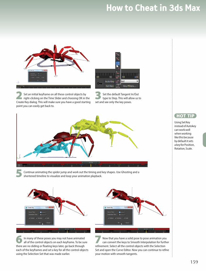
How to Cheat in 3ds Max
159159
HOT TIPUsing Set Key instead of Autokey can work well when working like this because by default it sets a key for Position, Rotation, Scale.
7 Now that you have a solid pose to pose animation you can convert the keys to Smooth Interpolation for further
refinement. Select all the control objects with the Selection Set and open the Curve Editor. Now you can continue to refine your motion with smooth tangents.
5 Continue animating the spider jump and work out the timing and key shapes. Use Ghosting and a shortened timeline to visualize and loop your animation playback.
6 In many of these poses you may not have animated all of the control objects on each keyframe. To be sure
there are no sliding or floating keys later, go back through each of the keyframes and set a key for all the control objects using the Selection Set that was made earlier.
3 Set the default Tangent In/Out type to Step. This will allow us to
set and see only the key poses.2 Set an initial keyframe on all these control objects by
right-clicking on the Time Slider and choosing OK in the Create Key dialog. This will make sure you have a good starting point you can easily get back to.

Animation9
160160
Spinning your gears
5 Scale the selected vertices outward to form the gear teeth. Create the additional gears in the same way,
selecting every other set of two vertices to form the teeth.
1Draw a diagram to figure out how many teeth each gear will have. Numbers that divide evenly into 360 are easiest
to work with. My gears will have 12 and 15 teeth.
4 On the NGon, select two adjacent vertices, skip two vertices, select the next two, skip the next two,
continuing in this fashion all the way around the NGon.
WHEELS, GEARS, and other spinning objects often need to rotate over the length of the entire animation.
With a few keyframes and a bit of math, you can get your wheels and gears in motion.
8 Turn on Auto Key. On a frame later than 0, such as frame 10, rotate each gear by the number of degrees equal
to one tooth, which is 360 (the number of degrees in a circle) divided by the number of teeth. After rotation, the teeth will be aligned again. Scrub the animation to test it.
9 To make the gears turn infinitely, select one of the gears and open the Curve Editor. Select the Rotation track
with the curve, and then on the Edit menu choose Controller > Out-of-Range Types. Click the right button under Relative Repeat, and close the dialog.

How to Cheat in 3ds Max
161161
2 In 3ds Max, create an NGon shape for the first gear with four times as many sides as the number of teeth.
Collapse the shape to an Editable Spline.
6 The additional gears should be proportional in size. For example, since the second gear has 20% more teeth (15
as opposed to 12), it should be 20% larger.
HOT TIPTo rotate by exactly a specified number of degrees, type the value into the entry area at the bottom of the screen. If you’re not sure which axis is correct, try each one. If you pick the wrong one, type in 0 to reset the rotation on that axis, and try again.
7 Prepare for animation by rotating and moving one of the gears so its teeth fit with the other gear.
11Repeat the process for each gear, and play the animation to test it. Extrude the gears and shape
them, and add additional elements as necessary to complete your scene.
Gears.max
10 When you play the animation, you’ll see a slight hesitation on each turn. Open the Curve Editor,
select the points at each end of the animation curve, and click Set Tangents to Linear. When you play the animation again, the gear will turn smoothly.
3 Select all vertices and right-click them to change them all to the Corner type. This will make it easier to form
the teeth.

Animation9
162162
Animated pivot point
1With your object selected, go to the Motion panel and select the
Transform track from the controller list. Click Assign Controller and choose CATHDPivotTrans from the list.
With this controller you have the standard Position, Rotation, and Scale transform tracks as well as a new Pivot: Bezier Position track. There is a new Sub-Object option in the Motion panel where you will edit the animatable pivot.
PIVOT POINTS are critical to animation and especially rotational animation in 3ds Max. Once you start working a lot with pivot points, you will want to animate them.
The ability to animate a pivot point is a bit of a hidden gem in 3ds Max, a side effect of the animated pivot feature that came with the CAT rigging system introduced in 3ds Max 2011. A number of controllers were introduced with CAT and the CATHDPivotTrans is one of them. It allows us to have an animated pivot point on any 3ds Max object including custom rigs.

How to Cheat in 3ds Max
163163
HOT TIPUse hold keyframes to set your pivot point animation to change over one frame. You might have to set a few more keys, but you will not have to change your key interpolation type.
3 With Auto Key on, rotate the object so it rotates forward to its next edge. Make sure you are not in Sub-Object
mode for this part.
4 Hop back into Sub-Object mode and move the pivot point to the leading edge of your object so it will rotate
from that edge next. Switch your interpolation type to Step.5 Get out of Sub-Object mode and set the interpolation
back to Smooth. Now rotate the object forward again and it will rotate over the leading edge.
2 With your object selected, click the Sub-Object button in the Motion panel. Now you can move the pivot point to
its starting place, such as the corner of your object. When you step back out of Sub-Object mode, the new pivot point is used instead of the default 3ds Max pivot.
AnimPivotStart.maxAnimPivotEnd.max

Animation9
164164
Following a path
1Create a camera in the scene at around the same spot you want it to be when the animation starts. Create a shape for the camera to follow,
and move the shape so it starts roughly at the same spot where the camera currently sits. Here, I’ve created an Arc shape.
3 Scrub the time slider to see the animation. In the Motion panel, you can see that the % Along Path parameter in the Path Parameters rollout has
been animated from 0 to 100 over the course of the total number of frames in your animation. If you want the object to start at the other end, you can turn on Auto Key and change the % Along Path parameter to start at 100 and end at 0.
INSTEAD OF MANUALLY setting keyframes to animate an object, you can use a constraint. A constraint automatically
animates an object according to specific parameters.
In this example, you’ll use a Path Constraint to make an object follow a path shape over a series of frames. This technique is particularly useful for making a camera follow a path to create a fly-around or fly-through of your scene.

How to Cheat in 3ds Max
165165
2 Select the camera and choose Animation > Constraints > Path Constraint. A dotted line appears, waiting for you to select a path. Click
the shape to complete the assignment of the constraint. The camera jumps to the start of the path.
4 To change the path, you can convert the shape to an Editable Spline and move the vertices. The constrained object will move along the path in its
new shape.
HOT TIPIf moving the vertices causes the path to take a strange shape, change all vertices to the Smooth type on the right-click quad menu.
HyenaManTT.max
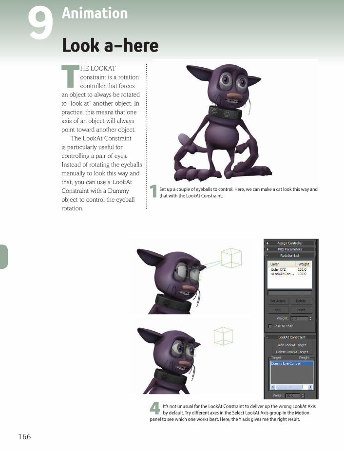
Animation9
166166
Look a-here
THE LOOKAT constraint is a rotation controller that forces
an object to always be rotated to “look at” another object. In practice, this means that one axis of an object will always point toward another object.
The LookAt Constraint is particularly useful for controlling a pair of eyes. Instead of rotating the eyeballs manually to look this way and that, you can use a LookAt Constraint with a Dummy object to control the eyeball rotation.
4 It’s not unusual for the LookAt Constraint to deliver up the wrong LookAt Axis by default. Try different axes in the Select LookAt Axis group in the Motion
panel to see which one works best. Here, the Y axis gives me the right result.
1Set up a couple of eyeballs to control. Here, we can make a cat look this way and that with the LookAt Constraint.

How to Cheat in 3ds Max
167167
5 Repeat the process for the other eye. When you move the Dummy object around, the cat’s eyeballs will automatically orient themselves to look at it.
HOT TIPIts a good idea to link your eyeball assembly to a Point helper or Dummy object first and then use these for the LookAt Constraint. Having the extra level of hierarchy will give you flexibility in your rig down the road.
2 Create a Dummy object for the eyes to look at with Create panel > Helpers
> Dummy.3 Select one of the eyeballs and choose Animation menu > Constraints >
LookAt Constraint. Move the cursor to pick the object that you want the selected object to look at.

Animation9
168168
HOLD KEYFRAMES are an important part of animation.
When an object stops or needs to hold in one spot for a moment, you need a set of hold keyframes at either end of the time range where your object is holding its position. If you don’t set proper hold keyframes, the object will likely float and wave around when it should be holding. You will not get the hard-hitting stops that are needed for convincing motion.
In 3ds Max there are a few quick ways to set up hold keyframes. 1Set the first key of the hold, then Shift+Drag the key to a later frame to copy it
and allow for a good hold in animation between those two keys.
Hold it now

How to Cheat in 3ds Max
169169
HOT TIPConsider where you want your animation to start, and always set a keyframe there. This will prevent a lot of issues with floating animation and misbehaving keyframes.
2 Another way to create a key at a particular frame is to go to that
frame on the time slider and right-click on the time slider itself. This will bring up the Create Key dialog which allows you to set a key for the selected object at the current frame using the current transform values. You can choose all three transforms or just one, such as Rotation in this case.
3 If you would like to insert a set of hold keys in an animation that is
already set (like this gear rotating 360 degrees over 100 frames), you can use the little known option of right-clicking while dragging on the time slider. In this case you would create a key at frame 35 as we did in step 2, then while still at frame 35, right-click on the time slider and drag to frame 50. The Create Key Dialog will pop up, allowing you to create a key at frame 50 with the key info from frame 35. This will produce a hold in rotation between frames 35 and 50.
GearsHold.max

Animation9
170170
Jumping beans
1Select the object that you want to make jump around randomly. Choose Animation menu > Position Controllers
> Noise. Scrub the time slider to see the object jump around.
THE NOISE CONTROLLER animates an object randomly. This type of controller is useful for giving life to an
object, making it sway or vibrate in a subtle way that will register as real to your audience. You can assign a Noise Controller to animate the position, rotation, or scale of an object, and adjust each one separately for that transform.
The animation produced by the Noise Controller appears to be random, but is actually calculated to appear that way. At the heart of the calculation is a Seed number that produces a motion graph. By using the same Seed for two Noise Controllers, you can produce exactly the same “random” effect today that you did yesterday. On the other hand, using a different Seed for two different objects gives you the same flavor of motion without an exact match in speed and direction.
Making the Seed values different is important; making them wildly different is not. Two consecutive Seed numbers produce completely different motion, so making the Seed 0 for one object and 1 for another will give you as much variation as using 57 and 2398 for the two values. 3 Reduce the Frequency to make the object move slower.
You will see the Characteristic Graph change to reflect the new frequency. Turn on the >0 checkbox for the Z Strength parameter to keep the object from moving below the surface it’s sitting on. Adjust any other parameters as you like, and scrub the time slider to test the effect.
5 The Noise Controller takes over the definition of the
object’s position so you can’t move it manually in the viewport. If you want to move the object to another location, select the Position XYZ layer in the Position List rollout, then click the Set Active button to give control back to the default transform controller. Now you can move the object in the usual way.

How to Cheat in 3ds Max
171171
4 Repeat the process of assigning a Noise Controller to animate each object’s position. Change the Seed
parameter to change the graph pattern while retaining the same overall parameters. You can also assign a Noise Controller to an object’s position with Animation menu > Rotation Controllers > Noise.
2 On the Motion panel, expand the hierarchy in the Assign Controller rollout to see the Transform > Position >
Noise Position entry. Highlight Noise Position, and right-click to choose Properties from the menu.
6 Add some motion blur by changing the object
properties. Select all objects, right-click to choose Object Properties from the quad menu, and turn on the Image type of motion blur. After rendering a test, adjust the Multiplier value to give you the right amount of blur in the rendering.
HOT TIPClose the Noise Controller dialog before selecting another object. If you don’t close the dialog and select another object, the dialog will still show the earlier object’s parameters and not those of the currently selected object, making it too easy to accidentally change the earlier object and not the current one.
JumpingBeans.max

Animation9
172172
Linktopia
LINKING OBJECTS TOGETHER with Select and Link can help you
control your animation without having to animate each object individually. Linking works with a parent-child relationship, where you link the child to the parent and the child does what the parent does thereafter.
Dummy objects can assist greatly with linked animation. A Dummy object is a non-rendering Helper object that works as an intermediary between linked objects, allowing you to pass only movement and not rotation, or vice versa.
The advantage of linking to Dummy objects is that you can easily change the animation without losing your animation keys. Just link different objects to the Dummy objects to get a completely new animation.
5 Now you can
rotate the center Dummy object to rotate the outside objects without rotating the center object.
6 To prevent the outside objects from rotating, select an outside
Dummy and go to the Hierarchy panel. On the Link Info tab, under Inherit, turn off the Rotate checkboxes for X, Y, and Z. Repeat for each outside Dummy object.
ICO
NS
CREA
TED
WIT
H P
HO
TOS
BY W
ARR
EN A
PEL

How to Cheat in 3ds Max
173173
1Use Select and Link to
link all the outside objects to the one in the center, and rotate the center object. All the outside objects rotate around the center object and turn as they do so. If this is what you want, then you’re done.
7 Now you can make
the outer objects orbit the inner one without rotating.
4 Link all outside
Dummy objects to the center Dummy. You can do this by selecting all the Dummy objects and linking them to the center Dummy at the same time.
2 More likely, you’ll
want the outside objects to keep their original upright orientations as they rotate, and you won’t necessarily want the center object to rotate. You can achieve this effect with Dummy objects.
3 Use Create panel
> Helpers > Dummy to create a Dummy around the center object and around each outside object. Link each outside object to its Dummy.
8 To complete the controls, create another Dummy object around
the center object, and link both the object and the first center Dummy to it. This will allow you to move or rotate both the center object and the entire assembly.
HOT TIPWhen linking, take care to drag the cursor to an area of the screen that contains only the parent to avoid linking to the wrong object. Click Select Objects to end the linking process and avoid linking additional objects by accident. You can also link by name by pressing the H key to select the parent object.

Animation9
174174
Linking to multiple objects
LINKING IS A USEFUL TOOL for many types of scenes, but it limits an object to having one parent throughout the entire animation. For times when you want an object
to follow one parent for a while and then another, use the Link Constraint.
In this example, the object follows two different parents, but in practice you could make an object follow numerous different parents over the course of the animation.
2 Animate the object changing position at the transition point. In this case, the nail jumps to the magnet when the magnet gets close.

How to Cheat in 3ds Max
175175
1Select the object to be animated or the Dummy object that the object is linked to. Choose Animation menu > Transform Controllers > Link Constraint, and then
click a stationary object in the scene. This will keep the selected object still until you want it to follow another object.
3 At the frame where the nail comes into contact with the magnet, go to the Motion panel and click Add Link, and pick the magnet. 4 Play the animation. The nail sits
still until the magnet gets close, then jumps to the magnet and sticks to it as the magnet leaves the frame.
MagnetStart.maxMagnetFinish.max

Animation9
176176
Chains
3DS MAX INCLUDES a Bones system, a series of non-rendering objects that are already linked together. While Bones were primarily intended to create a
skeletal system for a character, they are useful for animating a series of solid objects that need to stay together but move separately.
A series of linked objects is called a chain. Like a metal chain, each link can rotate on its own, but only as long as it stays connected to its adjacent chain members.
Any linked chain can be controlled by an IK solver. IK stands for inverse kinematics, a technical term meaning an individual link in the chain can be affected by links on either side of it. This is the opposite of forward kinematics, where a link can be affected by one end of the chain only.
Here, we’ll use a short chain of five objects to illustrate the concept. In practice, you can use Bones and IK chains on as long a chain as you like.
On a historical note, the implementation of inverse kinematics in mainstream 3D software in the 1990s was a breakthrough that made all kinds of animation possible. A character animator, for example, could finally animate a leg by working with either the hip or the foot. Inverse kinematics is one of the reasons 3D animation has taken off so much in the past decade.

How to Cheat in 3ds Max
177177
1Create the chain as a series of objects laid out straight. While it isn’t strictly necessary to have the objects lined up, it will make your work much easier if they are.
4 Now you’ll apply an IK solver, a gizmo that allows you to use IK with your object. Select the first bone you created, choose Animation menu > IK Solvers > HI Solver, and click the nub at the end of the bone chain. This creates a new object, an IK
Chain helper, between the nub and its previous bone.
HOT TIPIf the bones appear too skinny in your viewport, you can make them fatter by increasing the Width and Height values in the Bone Parameters rollout on the Modify panel. To change the parameters of multiple bones at once, go to Animation menu > Bone Tools and press Bone Edit Mode. Then you can change the parameters for several bones at the same time.
2 Choose Create panel > Systems > Bones to create a series of bones through the objects. Click at each joint in the chain to create a bone for that joint. Creating the bones at a slight angle to one another will determine the bend angle after you
apply the IK solver. When you get to the end, right-click to create a nub at the end. Don’t delete the nub.
3 Move the bones so they go through the objects, with each bone end coinciding with a “joint.” In this case, the joints lie between the jewels. Use Select and Link on the toolbar to link each jewel to its bone. When you’re done, click the Select
Objects button or right-click the screen to close the linking process and avoid accidental linking when doing the next steps.
5 You can move the IK Chain helper to change the shape of the chain, and can even animate it. To make this
easier, you might want to place a Dummy object at each end of the chain, and link the first bone to one Dummy and the IK Chain object to the other. The object might flip onto its side when you do this, but you can simply rotate it back into place. If you want to change the angle of rotation of the chain, you can select the IK Chain object, and on the Motion panel, change the Swivel Angle parameter.
JewelLinks.max

Animation9
178
I N T E R L U D E
Scripting animationThere are many approaches to automating repetitive animation, but I’ve found scripting to give the most
flexibility and freedom. Scripting in 3ds Max is a skill that can greatly enhance your workflow and productivity
with just a few simple lines of text, and it’s well worth your time to learn just the basics.
Trying to script all the actual motions and mechanics is too time consuming, so I’ve developed more of
a hybrid approach. I’ll often hand animate parts, pieces or sections of the shot I’m working on, and then use
scripting to offset the keyframes or add randomization. Let’s look at how we can use some simple scripting to
offset keys across several objects to create the effect of many objects moving in an overlapping sequence.
For this example we’ll start with a pre-made scene, ScriptingAnimationStart.max. It’s a simple scene with
some flowers in a bed. We’re going to animate them growing, then use scripting to add some variation to the
timing. It would be extremely tedious to do this by hand but with one line of script we can do it in just seconds.
First, let’s add some animation to offset. Let’s have our
flowers animate up from nothing and have a spinning kind
of action. For actions where objects are appearing, I like to
animate the sequence backwards then reverse it when it’s done
so I never have to worry about the objects being invisible in the
first frame. We’ll keep the animation simple for this example,
but the same technique will work on any custom animation you
apply to your objects transforms (position, rotation, scale).
Select all the flowers, turn on Autokey and move to frame 4, and scale them up to115%. Move to frame 15
and scale them down until they are not visible and rotate your flowers by -180 degrees in the Y axis.
Right-click in your timeline and go to Configure and turn on Show Selection range. Select all your keys. You
should see a black bar underneath them with a white cap at each end. If you hover your cursor over the the
white cap from the start you should see your cursor change to a single arrow next to a square. Click and drag to
pull the start out past the end key until the readout at the bottom reads Scaling: -100%. Your animation should
play forward now, with the flowers starting out invisible, then scaling up.
Next we’ll script the offset. Go to the Maxscript menu and choose New Script. In this case we’re going to
use a For Loop and take advantage of the default variable “selection” which tells 3ds Max you want to affect the
currently selected objects in your scene. To start the initial loop type in the following:
for i in 1 to selection.count do()

How to Cheat in 3ds Max
179
This first part of the script will cause it to
take action on each selected object. Next we’ll
add the action. In between the parentheses
type in the following:
movekeys selection[i][3] i
The movekeys command shifts keyframes by a given
amount, selection[i] is an individual object within our selection
and the [3] is designating that we want to affect the transforms
of that object. It’s just a shorthand for the .transform.controller
property of the object. The i at the end represents the number of frames we want to move the keys. Each object in
our selection is assigned a number as it is selected, and the way we’ve written our script it will offset the keys the
same number of frames as the number of the object. So our first flower will have its animation happen one frame
later, and our last 100 frames later. Here’s what the final looks like:
for i in 1 to selection.count do(movekeys selection[i][3] i)
You can test it out by choosing Tools >Evaluate All in your script window. If the script gives you an error,
check it against the code here and look for a typo. You might need to extend the length of your timeline to see the
full animation.
Now for the fun part. With our script working, we can now make different selections and run the script on them
until we have a nice randomized animation. You can use the layers that are already set up in this scene to freeze
the site so only the flowers are selectable. I like to switch my selection type from Rectangular to Spray Paint and
select objects in an interesting pattern. A spiral
pattern or a back and forth row by row always
looks cool, but you should experiment with as
many different options as possible.
If you want to slow down the overlap between
objects, you can also add a multiplier to the i. Try
replacing i with i*2 or i*3 and see what effect it
has on your animation’s timing.
You can use this technique to add random or
controlled variation to any animation.
Vincent LaCour
Digital Artist
Neoscape
ScriptAnimStart.maxScriptAnimFinal.max

Animation9
180
I N T E R L U D E
Super-duper tools
AS FASHIONS CHANGE, so do trends in 3D graphics tools. There are a number of features that
came into fashion, had their heyday, and then faded into obscurity. Not entirely though, because
they retain their positions on the menu release after release.
Old tools are never retired, because to remove them from the system would cause older files
to cease working. Every production company that’s been around for a few years has a library of
these old files, and they are some of Autodesk’s best customers.
This can confuse a new user. You want to become better at using 3ds Max, so you start
perusing all the available tools. You read about them in the Help, and scratch your head. You
try in vain to find someone who knows how it works. The problem is that those of us who lived
through the tool’s heyday discarded it from our personal toolset long ago, and we can’t remember
much about it except that it was replaced by something else.
The following tools are not worth learning about, except for historical purposes. I’m not
saying you should never learn them, but if you’re trying to get up to speed quickly on useful tools,
you should skip over these features.
Video Post. Back in the old days, this tool was great for compositing scenes. With the
widespread use of Photoshop, After Effects and Premiere, it’s pretty antiquated. Still, you’ll run
into the occasional old file that uses it. Use the newer Composite tool instead.
HD Solver. HD stands for history-dependent, meaning every time you update something it
has to run through the entire animation to figure out what it’s doing. This type of solver is good
for mechanical animation that requires IK, but not for other applications. Use the HI Solver
instead.
Spline IK Solver. This tool uses a spline to control a chain of objects. When it was first
released, everyone got very excited about it. Then we discovered that if you curl the spline a
certain way (as you’re very likely to do in any animation of substance), the spline flips around
erratically. Every 3D package with a similar tool has the same problem; it’s rooted in the way IK
works, and isn’t likely to be solved anytime soon.

How to Cheat in 3ds Max
181
Scatter. Replaced by particle
systems where you can pick the
emitter.
Scene States. Have been used
to setup render passes and for
scene management. These always
tended to be buggy and you never
knew what had been saved in a state. Scene States
is now a much better and more robust tool for doing both scene management and render passes.
Boolean. Replaced by ProBoolean.
NURBS. An alternative to polygon modeling, NURBS makes smoothly curved surfaces from
splines. NURBS is useful for making curtains and tablecloths, and that’s about it. Some industries
use it almost exclusively, but if you’re not in one of them (and you’ll know if you are), learning
NURBS is not the best use of your time.
Lens Effects. These are effects like Glow, Star and Streak right inside 3ds Max. While it is cool
to have them directly in 3ds Max they are fairly limiting. In many cases you’re better off doing
some compositing in Composite or After Effects.
Physique modifier. Before the Skin modifier, it was all we had. Physique hasn’t been updated
in several releases, and the Skin modifier is now light years beyond it. If you need to update an
old scene that uses Physique, your first order of business should be to replace Physique with Skin.
I’m sure that some people still use these tools, in fact I expect to get angry letters from the
three people who are still using Video Post. I’m not questioning anyone’s right to use them. I’m
just recommending that you learn the most useful tools first.
So then, you might ask, what tools should you learn? Why, the ones in this book, of course.

182182
How to Cheat in 3ds Max
n 3ds Max has some of the best character animation tools available for PC-based software. A little bit of work can go a long way toward bringing your models to life.

183
How to Cheat in 3ds Max
10Character AnimationANIMATION OF CHARACTERS is one of the primary uses for 3ds Max in
the fields of games and broadcast. While this primer won’t teach you
everything you need to know to be a character animator, it can get
you started with the main tools: CAT and Biped.
CAT is short for Character Animation Tools. CAT is a complete and
easy-to-use animation system for creatures of all shapes and sizes.
Biped, an animation system designed for two-legged characters, is
an older and less robust tool, but is still used by many animators.

Character Animation10
184184
Character animation workflow
1Start with a character model created with the usual modeling tools. Create a CAT or Biped skeleton and pose
it to fit inside the character model.
4 Once the skinning is complete, animate the skeleton performing the final animation.
SO YOU’VE HEARD about CAT and Biped and what they can do. How do you get started? The overview here will
give you the basic workflow, and then you can use the topics that follow to kick-start your own project.

How to Cheat in 3ds Max
185185
2 Create a short test animation for the skeleton, moving it through the poses it’s likely to make over the course of
your animation.3 Use the Skin modifier to associate the skeleton with the
character model, and adjust the influence of each bone over the vertices around it.
5 Hide the skeleton and check the animation. Adjust skinning as necessary, and render the final animation.

Character Animation10
186186
CAT 101
5 Turn on Auto Key, go to a frame later than 0, and start animating
the skeleton. You can move or rotate just about any bone in the skeleton.
4 Before you start
animating, click the Setup/Animation Mode Toggle button in the Layer Manager rollout to change it to Animation mode (green). This tells CAT that you’re done posing the skeleton and you’re ready to start animating.
THE CAT ANIMATION system was introduced in 3ds Max 2011. It provides a number of features including a wider
variety of default skeletons and easy-to-use motion controls.

How to Cheat in 3ds Max
187187
7 To create a walk cycle, add a CATMotion Layer. This creates
a default walk cycle that you can customize as you like.
8 To remove a layer’s influence on a body part, select the part and
lower the Local Weight value for that layer.
6 To move an entire foot, select the helper object underneath the
foot and move the helper to move the whole foot.
3 Select any part of the CAT rig, and go to Motion panel. In the Layer
Manager rollout, click and hold the Add Layer button to display layer types, and choose Abs to add an Absolute Animation Layer.
1To create a CAT skeleton, use Create panel > Helpers > CAT Objects >
CATParent. Choose a template in the CATRig Load Save rollout, then drag in a viewport to create the skeleton.
2 Fit the skeleton to the mesh, and skin the mesh. See the Skeleton
Fitting topic for details on how to do this.

Character Animation10
188188
Biped 101
4 To animate the entire Biped, move or rotate the COM (center of mass) object. You can select this object
easily by clicking one of the first three selection buttons in the Selection Track rollout. The COM works a little differently from other 3ds Max objects, where it has a separate track for horizontal movement, vertical movement, and rotation.
BIPED BODY PARTS work a little differently from regular 3ds Max objects. While you can animate as usual with
Auto Key, several additional tools are available on the Motion panel that are specific to Biped tools.
To create a Biped, click Create panel > Systems > Biped, and drag anywhere in the scene.
3 Now you can turn on Auto Key, move to a frame other than 0, and start moving and rotating Biped parts. Don’t
animate the pose at frame 0. If you want the Biped to start off in a different pose, animate its parts into the pose on a later frame, such as 10. When you render, you can simply render from that frame forward.

How to Cheat in 3ds Max
189189
1One of the easiest ways to get an animation going with the Biped is to create footsteps for it. See the Walking in your Footsteps
topic for details.
5 To move the entire animation, use Move All Mode in the Biped rollout. This causes a disk to appear around the COM, indicating
that you can move or rotate the Biped to shift the entire animation. An Offset dialog appears where you can type in numerical values rather than manually moving or rotating the Biped. Be sure to turn off Move All Mode when you’re finished with this tool.
HOT TIPIn Track View, tracks for Biped parts are different from regular 3ds Max objects. There is one track for each entire leg/foot and one track for each arm/hand.
The COM object is named Bip01 by default. It’s the root of the entire linked Biped hierarchy.
2 To prepare the Biped for a non-footstep-based animation (called Free Form in Biped parlance),
you’ll need to put a key at frame 0 for all Biped parts. Select all Biped parts, go to the Motion panel, and click the Set Key button in the Key Info dialog. You will also need to click each of the three COM selection buttons (the first three buttons in the Track Selection rollout) and click Set Key for each one.
6 To reuse a pose, copy and paste postures in the Copy/Paste rollout. First you will need to click
the Create Collection button, and then select the Biped parts you want to copy and click Copy Posture. Then you can go to another frame, and with Auto Key turned on, paste the posture to the selected parts.

Character Animation10
190190
Skeleton fitting
1Your character model should be posed with its arms out at its sides and palms facing down, and with its
feet a shoulder’s width apart. It can also help to bend the arms and legs slightly.
5 Rotate and scale the skeleton’s legs to fit the character’s legs. If a CAT skeleton’s legs don’t go
down the center of the character’s legs, you can move the thighs to make them line up. For a Biped, you’ll need to scale the Pelvis object horizontally until the legs fit. Be sure to match up the knees and ankles in all views, and rotate the legs slightly to match the bent legs.
THE FIRST STEP in associating a skeleton with a character is posing the skeleton to fit the character. A
skeleton that fits the character well will animate the character well. Conversely, it’s nearly impossible to get a decent animation from a poorly fitted skeleton.
When you fit a Biped, you turn on Figure Mode in the Motion panel to indicate that you’re posing the Biped and not animating it. With a CAT skeleton, you make sure the Setup/Animation Mode Toggle button is set to Setup (red) in the Motion panel. In general, you want the skeleton to fit inside the character model with its bones sized to about 1/2 to 3/4 the volume of the model.
While working with a specific part of the skeleton, it’s important to put on blinders and work with just that part to get it posed correctly before moving on to the next. The skeleton will look very strange until the very end, when it all comes together in a perfect pose.

How to Cheat in 3ds Max
191191
4 Line up the skeleton with the character body, especially the
hips. For a CAT skeleton, move the parent object and then the pelvis. For a Biped, go to the Motion panel and turn on Figure Mode, then move the COM (center of mass object) to the center of the character’s hips.
2 Position the character on the ground plane grid. If you’ve
applied a TurboSmooth modifier to the body, remove it. Make all the body parts see-through, and freeze them.
3 Create a CAT or Biped skeleton about the same height as the
model. Set the skeleton parameters as necessary to match the type of character.
8 Fingers usually take the longest to pose. Scale the palm to fit the
character, and move and rotate each base finger link to get it going in the right direction before scaling the finger links. The hand is easiest to pose in an angled view while simultaneously checking your work in an orthographic view. After you’ve done one hand, copy and paste the pose to the other side of the body.
6 Scale all the spine links to get the shoulders into
the right place, then rotate the arms to fit the model. Be sure to check the Top view to ensure the skeleton’s arms are inside the character’s arms. Scale the skeleton’s neck and head to fit the model.
HOT TIPFor the best results with skeletal fitting and animation, the character body model should be all one piece. While it’s possible to use CAT or Biped with a multipiece model, the seams might be exposed when you animate the model. However, it’s usually okay to leave the head and hair as separate objects.
7 Scale and adjust the feet and toes, making sure
the skeleton’s ankles fall at the model’s ankles. If the character is wearing shoes or boots, the skeleton’s feet should fill out the entire shoe area. Scale a single toe link to represent the entire toe of the shoe.

Character Animation10
192192
Skinning1Hide the character
model, and take the skeleton out of pose mode (for Biped, turn off Figure Mode; for CAT, add an Abs Layer and set the Setup/Animation Mode Toggle to Animation mode). With the skeleton, create a simple animation to test the skinning, such as bending the arms and legs. You should also create a Selection Set for the skeleton to make the skinning process easier.
7 Another area that’s fairly easy to clean up initially is the torso. Select 2-3 rows of vertices and the nearest spine
bone, and set Abs. Effect to 1.0. You can also scrub to a later frame to find and select vertices that aren’t behaving correctly. Here, the vertices that make up the third button need to be affected by the second spine bone. At frame 10, they’re easy to select and adjust.
SKINNING IS THE PROCESS of associating a character model with a skeleton. When you apply the Skin
modifier to a model, it uses the bones you specify to determine how the model will deform when the skeleton is animated.
Skinning works by associating each bone with specific vertices on the model. If a vertex is affected by more than one bone, then the bone’s influence on that vertex is determined by a weight value. All the weights for a vertex add up to 1.0, and a weight of 1.0 means the bone has complete influence over the vertex. Weights are set with the Abs. Effect parameter and the Weight Table.
4 Hide the skeleton.
Pull the time slider to see if the character model deforms correctly. Chances are, it won’t. The easiest areas to fix are the legs and arms. Let’s use the left calf as an example.

How to Cheat in 3ds Max
193193
2 Put the skeleton back into its pose
mode (turn on Figure Mode for Biped, or set Setup/Animation Mode Toggle to Setup mode for CAT). Unhide just the character body. Remove any TurboSmooth or MeshSmooth modifier from the character, and collapse any modifiers still on the stack.
3 Apply the Skin
modifier to the head and body model. Click the Add button next to Bones in the Parameters rollout, and choose all the skeleton parts.
8 Once you’ve done a general cleanup, some areas, such as underarms and hips, will need additional work. Select
a few vertices and open the Weight Table. Choose Selected Vertices at the bottom left of the dialog, and from the Options menu, choose Show Affected Bones. In the table, drag a weight value left or right to change the weight values. The vertex changes position as you change the values.
9 Work on the vertex weights until the entire body looks
good in the test animation. Unhide the skeleton and the other body parts. Put the skeleton in pose mode again, and link any facial parts such as eyes, hair, and teeth to the skeleton head. Go into animation mode, remove the test animation keys from the skeleton, and your skinned model is ready for animation.
5 Select the body model. In the
Parameters rollout, click Edit Envelopes. In the Select group, turn on the Vertices option. Select all vertices that should be affected by the left calf bone only. In the Parameters rollout, choose the right calf bone. In the Weight Properties group, change Abs. Effect to 1.0.
6 Scrub the time slider to a later frame, and check the right calf. Select individual vertices, and for each one,
adjust the Abs. Effect parameter for the left calf and left thigh bones until the leg looks good. If you like, you can apply a TurboSmooth modifier above the Skin modifier to see how it’s coming along.
HOT TIPWith straight skinning, as we’ve done here, elbows and knees don’t retain their bony appearance when bent to extremes, giving you “spaghetti” or “noodle” arms and legs. To fix this problem, use the Skin Morph modifier to set custom volumes at extreme poses.
Gunslinger.max

Character Animation10
194194
Walking in your footsteps
ONE OF THE BIPED’S key features is its footstep tool, which lays down footstep icons for the Biped to step
through. This unique feature uses a complex set of calculations to set keys for the entire Biped skeleton, including the spine and arms.
In order to use footsteps to animate the Biped, you must not have set any keys for Biped parts. If you animate one or more of the Biped body parts manually, the Footstep Mode button will be disabled, making it impossible to use footsteps. If this happens, you can delete the keys to make Footstep Mode become available.
1Select any part of the Biped. On the Motion panel, turn on Footstep Mode in the Biped rollout.
4 Click Create Keys for Inactive Footsteps in the Footstep Operations rollout to create the keys. Play the animation
to see the Biped move through the footsteps. If more frames are needed to create your animation, the length of the animation is extended automatically.

How to Cheat in 3ds Max
195195
HOT TIPIf moving, rotating, scaling, or bending footsteps causes the Biped’s legs to behave strangely (unexpected stomping, kicking, etc.), you can reset the body keys. Select the footsteps and click Deactivate Footsteps in the Footstep Operations rollout to remove the keys, then click Create Keys for Inactive Footsteps to reset them. While this will fix the leg animation, it will also remove any upper body animation, so copy the upper body animation to a track first and paste it back on afterward if necessary.
2 In the Footstep Creation rollout, choose a gait: Walk, Run, or Jump. The gait determines the overall
footstep pattern that will be created. 3 Click Create Multiple Footsteps. In the dialog that appears,
set the Number of Footsteps and other parameters as desired. Click OK to create the footstep icons in the scene. If you play the the animation, you won’t see any action as the keys haven’t been created yet.
5 You can move and rotate the footsteps themselves, and the Biped’s feet will follow them automatically.
You can also use the Bend and Scale parameters in the Footstep Operations rollout to change selected footsteps.
6 To change footstep timing, open Track View – Dope Sheet while still in Footstep Mode, and expand the Bip01 Footsteps
track. Each colored box corresponds to a footstep. Drag one end of a footstep key to change its length, or select and drag an entire key to move the entire footstep in time.

Character Animation10
196196
4 Now we we need the SkinPoint and MorphDeform to share the same transform. To do this, select them both,
and in the Dope Sheet replace the Position XYZ controller with a Position List on each. This will help us in a later step. Next, Copy the first Position XYZ in the list from MorphDeform and Paste it to SkinPoint as an Instance.
1Apply a Skin Modifier to the SkinPlane and choose SkinPoint as a Bone. Set the Relative option in Envelope
Properties and set the Radius of both sides of the envelope falloff to 100.0. Now when we move the SkinPoint it will deform the mesh.
WITH THE ANNOUNCEMENT of the end of life for Autodesk Softimage, users of the software
started thinking about how they might do certain tasks in other applications like Maya or 3ds Max. This sparked a string of videos on rigging, particularly on how to get a controller that follows morphing and skin deformations but is able to deform on top of that.
This rigging setup is called the Dorito Approach or Dorito Effect due to the triangular controls that were first used. This setup is very handy for facial rigging and control. Let’s take a look at one way we can snack strong with the Dorito Approach in 3ds Max.
The scene provided has a few objects needed for this setup. The SkinPoint Helper will be the bone for SkinPlane and the MorphAttach Helper will get attached to the MorphPlane with an Attachment Constraint. Both the BulgeTarget and the SkinPlane will be loaded into a Morpher Modifier on MorphPlane. Finally. we’ll need to do a little work on the helpers so they transform correctly.
Snack strong

How to Cheat in 3ds Max
197197
HOT TIPCheck out the Plugins chapter for a more visual way to set up and manage an effect like this.
5 Copy the Rotation and Scale controllers from MorphDeform and Paste them as instances to SkinPoint
as well. Now when we move, rotate or scale MorphDeform, SkinPoint will transform too, giving us the deformation we need. Set the BulgeTarget to 50 and move, rotate, or scale MorphDeform. The mesh should update.
6 One thing you will notice is that MorphDeform is getting a double transform for its position. Add a
Position XYZ controller to its Available slot in the Position List and set its Weight to -100. Then check Blend Weights. This should blend it back into position. This approach is a cheat; for a production rig, it’s better to set zeroed frozen tracks.
3 Next we will want MorphAttach to follow along with the mesh if the BuldgeTarget is used. Attach the
MorphAttach Helper to the MorphPlane with an Attachment Constraint and set its position to the center of the mesh using Set Position in the Motion Panel. You can also uncheck Align to Surface as we don’t need the point helper to rotate with the surface. Then Link MorphDeform to MorphAttach. The MorphAttach and MophDeform should now follow the surface if BulgeTarget is used.
2 Apply a Morpher Modifier to the MorphPlane and add the BulgeTarget as well as the Skin Plane. Set the Skin
Plane to 100.0 and check Automatically Reload Targets. This will make it so whenever the SkinPlane is deformed it will also deform our MorphPlane. Hide the SkinPlane and move the SkinPoint to see the MorphPlane deformation.
DoritoStart.max

Character Animation10
198198
The alternative skeleton
SKELETONS COME in all shapes and sizes. The CAT system comes
with a variety of default skeletons such as a centipede and an alien. And while the Biped system is intended for two-legged creatures, you can use it to animate just about anything, including a quadruped.
1You can turn Biped into a quadruped by bending its spine links over during the posing stage.

How to Cheat in 3ds Max
199199
2 CAT is flexible enough to create multi-legged and armed creatures as well as bipedal ones. When creating a quadruped CAT, a custom rig is your best bet.

Character Animation10
200200
Biped foot control
BIPED HAS its own method of doing IK/FK blending using Plant and Free keyframes. These keyframe types when
set on a foot or hand will set the Biped’s IK blend mode to IK or FK. Many animators like to have some sort of control object and just have the Biped’s legs in IK mode most of the time.
Creating a controller object for the Biped’s feet is easy. Biped already has the option to control its feet and hands with an external object. Usually this is used for animation scenarios where you need to stick the biped’s feet or hands to an animated object.
1Create a control object around the Biped’s foot that you will use to animate with. A spline object is usually a good
choice.
3 In order for the Biped foot to follow the control object we need to make a keyframe on the foot and set the key
to use IK and follow the object. Create a keyframe and set the IK blend to 1.0 and select the Object option.

How to Cheat in 3ds Max
201201
HOT TIPIf you’re working with spline controllers like this you can also link the Biped COM object to a controller for easier selection and control.
2 With the Biped’s foot selected go to the Key Info rollout in the Motion Panel. Here under the IK section you will find Select IK Object. Pick your
spline control object in the scene.
4 Now you can set up control objects for both feet and interact with your Biped more like a standard IK setup, setting keys on the control object for
animation.

Character Animation10
202202
4 One cool thing about these gizmos is that you can add your own custom shapes or objects to the list easily.
You will find a Gizmos.max file in the folder plugcfg_ln\CAT\Gizmos off your root 3ds Max folder. This is the file that our CAT Gizmos are created from. Open the Gizmos.max scene.
1If you right-click on a CAT limb bone, the bottom left quad will show some CAT specific tools like Extra Bones,
Extra Controllers, and Gizmos.CAT COMES WITH a set of tools to help control its rigs. Some of these additional tools can
be found in the CAT context sensitive quad menu. One of these tools is the CAT Gizmo. CAT Gizmos create fast controllers for your CAT bones. This can make your rig a little more customized without you having to do any heavy scripting or controller work.
CAT gizmos

How to Cheat in 3ds Max
203203
HOT TIPTo use these CAT Gizmos with your other custom bone rigs, take a look at the CAT Gizmos for Custom Rigs topic in the MAXScript chapter.
5 When creating new gizmos pay attention to the pivot point position and orientation so your gizmo aligns
the way you want on the rig. If you’re creating a more custom object you may want to add an Xform modifier so you can adjust the size without affecting object level scale.
6 Save the Gizmos.max file and go back to the CAT rig. As the Gizmos.max file is likely on your C: drive you will
need to make sure you have proper permissions to save over it. Be sure to make a backup copy of the original file just in case. Now you can add your own custom Gizmos to the CAT rig.
3 Adding other gizmos to parts of the rig will give you quick set of control objects for the CAT rig.2 Choosing Add Gizmo brings up a dialog where the type
of gizmo can be chosen. Choose a gizmo type and it will be added to the CAT rig. Most of these gizmos are parametric 3ds Max objects so you can adjust their size and properties like Render Enabled in Viewport.

Character Animation10
204
I N T E R L U D E
CAT vs. BipedIN THE BEGINNING, 3ds Max had no built-in character animation systems. From
1990 to 1995, character animators using 3ds Max had to fend for themselves with
Bones, morphing, and fairly primitive IK systems. While a few brave souls managed
to get some good work done, the process took a long time and required an
extensive knowledge of skeletal animation, not to mention 3ds Max itself.
Then, in 1996, a breakthrough. Unreal Pictures, an independent software
developer, released the Character Studio plugin for 3ds Max with its signature
Biped skeleton. Although the first release was nowhere near as sophisticated as it
is now, it did include those magic footsteps. Character animation suddenly became
available to anyone willing to purchase the plugin, and subsequent versions went
from strength to strength. Character Studio, now known as Biped, was eventually
included with 3ds Max when version 7.0 was released in 2004.
The same year, Character Animation Technologies introduced the Character
Animation Toolkit (CAT) as a 3ds Max plugin. CAT, with its superior toolset,
was quickly adopted by production studios that specialize in advanced character
animation.
Now that CAT is included with 3ds Max, you can expect that most new
character animation projects will use CAT rather than Biped. However, there’s still
a long legacy of Biped animation out there, and chances are you’ll have to deal with
a Biped sooner or later.
The Skin modifier continues to be the tool of choice for skinning, but the
original version of Biped included a modifier called Physique to perform this task.
In its day, Physique was quite the slick tool, and it remains available in 3ds Max
so old files that reference it will still open and function. However, Physique hasn’t
been updated in several versions, and the Skin modifier has long since surpassed
it in ease of use, functionality, and reliability. From time to time I run into someone

How to Cheat in 3ds Max
205
who genuinely prefers Physique, but the vast majority of artists use the Skin
modifier instead.
The same is likely to be true for Biped for many years to come. Artists who are
very comfortable with Biped, and who find it meets their needs, will continue to
use it for a long while.
If you’re just now learning character animation, I advise you to go with CAT to
keep your skills current, at least until the next big breakthrough comes along.

206206
How to Cheat in 3ds Max
nMAXScripts can speed up your workflow by performing complex or repetitive tasks.

207
How to Cheat in 3ds Max
11MAXScriptMAXSCRIPT IS 3ds Max’s scripting language, which is very powerful
and pretty simple to use. With MAXScript you can automate tasks,
create new tools, and extend 3ds Max’s functionality greatly.
There are also a large amount of free and commercial scripts out
there in the community if you are not a scripter yourself.
At Scriptspot.com, you can search and download a huge amount of
useful scripts. In this chapter we will look at a few scripts that I find
useful in many of the projects I work on.
Website for scripts: http://www.scriptspot.com

MAXScript11
208
I N T E R L U D E
A world of MAXScriptsIT’S HARD TO IMAGINE the world of 3ds Max without the ScriptSpot website. A vast
community of MAXScripters contribute to and utilize this website on a daily basis.
What’s even more amazing is that they do it all for free! That’s right, just about all the
MAXScripts listed at ScriptSpot can be downloaded free of charge. This might seem too good to
be true, but MAXScripters seem to enjoy sharing and exchanging the scripts they’ve written for
themselves. There’s even free training on the site for learning how to write MAXScripts.
Before you get into a downloading frenzy, you need to know that MAXScripts come in a few
different forms. The ScriptSpot website has a great article that explains how the different types
work as well as how to install them:
http://www.scriptspot.com/3ds-max/tutorials/script-installation-in-3ds-max
Here is a brief summary of the file types and how to install and run them. There are a few
different types of MAXScripts that you will run into when you download scripts from Scriptspot
or other places. The most common file types are .MS and .MCR, and you will also sometimes
encounter .MSE and .MZP files.
n The .MS file is the original type of maxscript and should be run by using the Run Script
command under the MAXScript menu.
n The .MCR is a newer style of maxscript called a Macroscript. Macroscripts are run by loading
them as you do with .MS files, but then you must assign them as an action in the Customize UI
dialog. You can assign them to a toolbar or quad menu, or as a standard menu item.
nAn MSE file is an encrypted maxscript. These files are encrypted for security to protect the
author’s code. Usually, these are commercial scripts (meaning, they cost money).
n Finally, the .MZP extension is a Zip format that allows you to more easily install the script.
With these files you can install them by dragging them into the 3ds Max viewport or by using the
Run Script command.
An important note on MAXScripts is that they aren’t the same as plugins. While some plugins

How to Cheat in 3ds Max
209
started out as MAXScripts, plugins generally come with an .EXE file for installation, and you can’t
see the code. With a MAXScript file in .MS or .MCR file, the code is stored as plain text. You can
look inside and see how it was written, and even customize it for your own needs.
Use any text editor such as Notepad to edit MAXScript files. You can also download the free
Notepad++ program, which numbers the lines of code for easier editing.
Never done any programming? Afraid to try? To get familiar with MAXScript commands, open
the MAXScript Listener from the MAXScript menu, choose Macrorecorder > Enable, and watch
the commands pop up as you execute them in the user interface. This is a great way to learn the
MAXScript equivalents of 3ds Max tools you use every day.

MAXScript11
210210
3 Set the Nb Parts and Iterations
so you get the desired amount of pieces. Watch the Break button at the bottom which will tell you how many pieces you will ultimately get. Don’t go too crazy or 3ds Max might take a long time to respond after you click Break.
5 Select all the pieces of the
wall and add a Push modifier to them. The Push modifier will make up for the volume lost when we apply TurboSmooth in the next step.
4 Break your object into pieces by clicking Break in. Once it’s done you will have an object fractured into many
chunks.
Voronoi stone wall
Fracture Voronoi is a script that fractures objects based on a
fractal voronoi type pattern. This pattern emulates how objects like stone might crack or break apart with age. This script is very useful when doing destruction sequences or creating rubble of some kind.
At Scriptspot.com, search for: Fracture Voronoi

How to Cheat in 3ds Max
211211
1Create the shape of an object you want to destroy or break into pieces. 2 Run the Fracture Voronoi script and pick the object with
the Pick button at the top of the dialog.
6 Add Turbosmooth and adjust the Push and Turbosmooth modifiers so your wall looks like a
freeform stone wall.7 Lastly you can add a Noise or Bend modifier to all the
objects to vary the shape of the wall, and remove a few of the rocks to make it look like an old stone wall.
HOT TIPIn the Special Effects chapter. we look at how to use this tool to destroy objects.
FractWallStart.maxFractWallEnd.max

MAXScript11
212212
Gizmo control
4 The Slice gizmo will jump to the position and orientation of the helper object but now you can control the gizmo with that control object. Select the point helper and align it so you have a nice-looking cutaway. A Shell modifier can be added with an Inner Amount to
give your object thickness.
1Select one or a number of objects and apply a Slice modifier. Choose Remove Top from the Slice Parameters
and adjust the slice gizmo so its at the desired angle to give a good cross section of your object.
GIZMO CONTROL is a nice little script that allows for control of a modifier or object gizmo via a control object like a
point helper. Here, we’ll look at how to use this script to create a helper that controls a Slice modifier’s gizmo.
Gizmo Control is a MacroScript, so you will need to set it up ahead of time to run from a toolbar or quad menu. The action is under the MB Tools Category in Customize UI. You can also drag it to the 3ds Max Extras toolbar if you prefer.
At Scriptspot.com, search for: gizmoControl

How to Cheat in 3ds Max
213213
HOT TIPThe Gizmo Control script can make an object work similar to the way the Linked Xform modifier works. Another common use would be to use it to animate a UVW gizmo.
5 Animate the control object to create an animated cross section of your object that reveals the details inside.
Now you can add an animation controller to the control object such as a Path Constraint for complex cutaway animations.
6 For the look of a technical illustration, you can apply different materials to the inside, outside, and edges with
a Multi/Sub-Object material by setting the Shell Overrides to create a different material ID for each part.
3 A dialog will pop up asking which modifier’s gizmo you want to control. Choose Slice and click Ok. Click Pick
control object and pick your point helper. To associate the two together, click Link gizmo to node transform.
2 Create a Helper object such as a Point helper to control the slice gizmo, and run the Gizmo Control script from
the toolbar or quad menu. Click Pick modifier object and choose the object with the Slice modifier on it.
GizmoStart.maxGizmoEnd.max

MAXScript11
214214
CAT gizmos for custom rigs
IN THE Character Animation chapter we looked at creating gizmos for a CAT rig. Wouldn’t it be cool if we could use those
gizmos for any 3ds Max rig or object? With a couple of edits to the scripts that are used in 3ds Max, we can.
There are two scripts that control the the CAT gizmos:n CATRiggingRCM.ms in the 3ds Max\
stdplugs\stdscripts\CATScripts foldernMacro_CAT.mcr in the 3ds Max\
MacroScripts folderYou can use any text editor to edit these
files. Before saving the changes, be sure to store a backup copy of the original files.
2 Open the Macro_CAT.mcr script and go to line 258. Comment out the “on isVisible do” section by adding a /* to the
beginning of line 258 and a */ at the end of line 261. This will allow the Add Gizmo option in the quad to always be present so these gizmos can be added to any object. Save the script.

How to Cheat in 3ds Max
215215
1 Open the CATRiggingRCM.ms script in the text editor of your choice, and locate line 58. Replace lines 58 through 60 with the code shown in the second image above. This new code allows you to set a gizmo for other objects as well as CAT objects.
It aligns the gizmo to the correct axis of a bone object, like the original code does for a CAT object. Save the script with the same filename in the same folder.
HOT TIPThis can be a very useful trick, but be sure you know what you’re doing before you use something like this in production.
3 Create a quick bone setup in 3ds Max, and right-click
on it and add your gizmos. Now that you’ve updated these scripts, these gizmos will be available to you for any object in 3ds Max from now on.

MAXScript11
216216
Getting a little tense
THE TENSION MODIFIER is more of a plugin than a script. But unlike the plugins in the plugin chapter, this one is
free for educational and non-commercial use. As with scripts, there are a great deal of free
or inexpensive plugins that can help produce better results or get the job done faster.
Grant Adam’s Tension Modifier: http://www.rpmanager.com/plugins/TensionMod.htm
4 Scrub the timeline to see the character deform. The vertex colors change to show the tension and compression or squash and stretch of the mesh. This is useful for tuning your skinning or blending in textures in these areas.
1The Tension modifier allows you to visualize areas of a mesh that have tension or compression. This can be useful for animation and skinning. With a deforming
character selected add the Tension modifier to it.

How to Cheat in 3ds Max
217217
3 In the Operations rollout click Toggle Vert Colors. You character will turn
black, but this is normal.2 Uncheck Do Convex (B or RG) for
now. We will use this in another lesson in materials.
5 Adjust the Blur value as well as the Comp. Scale and Expan. Scale to get a smoother result, or push up either the tension or compression.
TensionStart.maxTensionEnd.max

MAXScript11
218
I N T E R L U D E
Visual pivot placerTHE PROCESS OF
ADJUSTING an object’s pivot
is a common and repetitive
task when working in 3D
applications. Sometimes you
want the pivot along an edge
or the bottom, and there’s
no quick way to do this with
default 3ds Max tools.
To solve this problem, I
wrote a MAXScript tool that
allows you to quickly adjust
the pivot of any number of
selected objects.
Run the MAXScript
visualPivotPlacer_v02.ms.
A dialog will appear in 3ds
Max with the title Pivot Placer.
Once open, select the objects
you want to adjust. Then click
the Run Pivot Placer button.
The 27 white dots
represent the options for pivot
location. The locations are all
based on the bounding box
and centers. So for the last step
of this tool just click whichever
white dot as the new location
of the selected object’s pivots.

How to Cheat in 3ds Max
219
This tool also works on
multiple selected objects. As an
example, if you select four soda
cans with pivots at the bottom
of each can, you can quickly
adjust their pivots to be centered
around the entire selection.
John Martini
Digital Artist
www.JokerMartini.com
sodaCan.maxvisualPivotPlacer_v02.ms

MAXScript11
220220
PF spliner
3 Another nice function is the
Animate Splines Growth option. Click Delete Old Splines and check the Animated Growth option. Generate Splines again.
1Select some particles with interesting
movement to them like the ones created in the swirly particles topic in the Effects chapter. Run the PF SPliner script and your particles will already be active in the particle source section.
PF SPLINER is a great little script that generates splines from particles. This can produce some interesting motion
graphics effects as well as effects for creating trails behind objects. There are options for making the paths animate as well as attaching them all together into one object.
A special thanks goes out to John Rand for updating the script for 3ds Max 2014 for me and the rest of the community.
At Scriptspot.com, search for: PF Spliner

How to Cheat in 3ds Max
221221
2 Click Generate Splines and the
script will run through the timeline twice. Once to track the particles and once to build the splines. In the end you will have a bunch of cool swirly splines.
4 The splines are now animated over time,
creating a captivating flow or trail from the particles.
HOT TIPBe careful of large particle counts when using this script. It can generate a lot of data and cause 3ds Max to become unresponsive for some time.
PFSplinerStart.maxPFSplinerEnd.max

MAXScript11
222
I N T E R L U D E
FX puckFOR 3DS MAX ARTISTS using particle systems, a common need is for particles to come from
several locations in the scene to enhance the quality of a shot.
One way to accomplish this is to make several duplicates of a particle system. To avoid
having to do this, I wrote a MAXScript script called FX Puck. This script causes a single particle
system to generate particles from multiple locations in the scene.
To get started with FX Puck, choose Maxscript menu > Run Script
and run the file fxPuck_v01.ms. The FX Puck dialog appears. The first
option determines the size of the circular mesh that gets created. The
second option automatically places the created FX Puck Object on a
specific layer. Once the desired options are set, click Create FX Puck.
Next, create a basic particle
system with Create panel >
Particle Systems > PF Source.
A few things need to be
set up in the particle system
to make it work with FX Puck.
Replace the Position Icon
operator with a Position Object
operator, making sure to add
the FX Puck to the Emitter
Objects list. Inside the Position
Object operator settings,
enable Animated Shape and
choose Selected Faces as the
Location type. Lastly, enable
Delete Particles under the If
Location Is Valid section.
Next you’ll adjust the Speed
By Surface operator. For this
operator you need to add the
FX Puck object to the Surface
Geometry list. To further vary

How to Cheat in 3ds Max
223
the direction of the particles, increase the Divergence value to around 40.
Select the FX Puck object and begin adding FX Times to its list. These times will control the
frame at which particles will be generated on the surface of that particular FX Puck object. To
add a time to the list,
just click the Append
button and it will add
the current time in the
timeline. You can also
add a specific number
to the list by typing it
into the Edit Text Field
followed by hitting
Append.
One of the best features of this tool is the ability to generate multiple sets of particles at
different times, and at different locations. You can create multiple FX Pucks and add those
objects to the same Position
Object and Speed By Surface
operators, along with unique
FX Times to control the
creation of particles.
John Martini
Digital Artist
www.JokerMartini.com
FX_Pucks.maxfxPuck_v01.ms

224224
How to Cheat in 3ds Max
n Understanding render settings can help you improve your workflow.

225
How to Cheat in 3ds Max
12RenderingRENDERING IS THE EASIEST task in 3ds Max, in most cases just a matter
of a few clicks. In this chapter, we’ll look at ways to enhance your
rendering experience while keeping the process fast and easy.

Rendering12
226226
Rendering basics
1To prepare for rendering, your first stop is the Time Output group in the Render Setup dialog.
To render an animated sequence, choose Active Time Segment or enter a range of frames next to Range.
THE RENDER SETUP DIALOG is your main resource for rendering settings. Choose Rendering menu > Render Setup to open the
dialog.While this dialog contains numerous parameters,
there are a few that are crucial to creating the type of rendering you want.
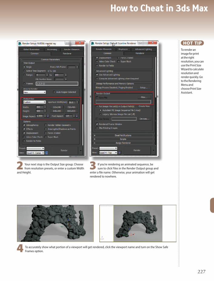
How to Cheat in 3ds Max
227227
HOT TIPTo render an image for print at the right resolution, you can use the Print Size Wizard to calculate resolution and render quickly. Go to the Rendering Menu and choose Print Size Assistant.
4 To accurately show what portion of a viewport will get rendered, click the viewport name and turn on the Show Safe Frames option.
3 If you’re rendering an animated sequence, be sure to click Files in the Render Output group and
enter a file name. Otherwise, your animation will get rendered to nowhere.
2 Your next stop is the Output Size group. Choose from resolution presets, or enter a custom Width
and Height.

Rendering12
228228
STATE SETS can be used to create complex render passes for your scene so you can more effectively composite and update your renders in post-production.
Render passes can isolate objects via mattes or IDs. You can also create separate ink line or Ambient Occlusion passes. Previously you would need to save many different versions of your scene to do this which can become cumbersome.
State Sets work like a layered system to your base 3ds Max scene. Every State you add can change something in that base scene like materials, lights, renderers, and modifiers.
2 Create a new State and name it Logo_Grey. Click Record and hide
everything in the scene but the Logo object. Open the Material Editor and assign a new grey material to the logo. This pass can be rendered with the logo itself with a flat grey material that could be useful in composite.
Render passes with state sets

How to Cheat in 3ds Max
229229
1Launch State Sets and click Record on State 01.
Hide the Logo and Background objects and click the Record button again to stop recording. Press the arrow button to toggle on or off the effect of that State. Turning on the state now hides these two objects so you can render only the midground tiles. Rename the state to Mid_Tiles by slowly double-clicking on its name.
3 State Sets can switch to different renderers
for different passes. To create a fast AO pass create a new State named AO and click Record. Switch the renderer to QuickSilver and assign all the objects in the scene a white 100% self-illuminated material. Set the QuickSilver AO radius to 30.
PassesStart.maxPassesEnd.max
HOT TIPState Sets have the ability to use different renderers in each State. This feature can work well if you need to render memory-heavy geometry like fluids or hair in another renderer.

Rendering12
230230
STATE SETS is a great tool for scene management and setup. Besides
controlling display properties of objects, states can control viewport properties and materials. By setting up a few states you can optimize your work environment for animating, rigging, or skinning a character among other things.
3 Create one more state and click Record. In this State apply a simple
grey material to the character so it’s fast to update without the textures. Unhide the Biped layer and select all objects on the Biped layer. Set those objects to Display as Box. Name the state Animate.
1Launch State Sets and start recording State 01. Hide the Controllers layer and unhide the environment layer. Stop
the recording by clicking Record again, and rename the state to Display.
Managing your scene

How to Cheat in 3ds Max
231231
4 If you want to go back into any state and record some new option you can at any time. Create a new viewport tab with two views, and set them to Front and Perspective. Set
your view preferences for each view to Consistent Colors for the Front with no AO or Shadows, and Realistic for the Perspective view. Go back to the main View Tab and click record on the Display State. Switch Viewport Tabs to the newly created one and stop recording. Now that State will switch to this layout for you as well.
2 Create a new state and click Record. Hide the Character Mesh layer and unhide Biped. Set the view to be Shaded instead of Realistic so it will be faster for
animation. Select all the objects on the Biped Layer and set them to renderable. This way if you see the biped’s movement in a rendering. Stop recording, then name the state Rig.
Gunslinger.max
HOT TIPIf setting up another Realistic View is too taxing on your system and video card in step 4, try setting the Perspective view to Shaded.

Rendering12
232232
Mental ray rendering
3 To get the most from mental ray, change your materials to mental
ray materials. See the Materials and Mapping chapter for specifics on how to do this.
THE DEFAULT RENDERER for 3ds Max is called the Default Scanline Renderer. You will find many uses for the mental ray renderer, which creates images with a higher degree of realism than the Default Scanline renderer.
This topic gives you a quick guide to using mental ray. More information is available in the Materials chapter and the Lighting chapter.
2 Under the Global Illumination tab, in the Final Gathering rollout, make sure Enable Final Gather
is checked, and the FG Precision Presets are set to Draft.

How to Cheat in 3ds Max
233233
1To change the renderer to the mental ray renderer, click the pick button in the Assign Renderer rollout of the
Render Setup dialog, and choose NVIDIA mental ray Renderer from the dialog that appears.
HOT TIPWhen you switch to the mental ray renderer, its a good idea to use the mrphotographic Exposure Control
4 Mental ray renders one rectangular chunk (called a bucket) of the image at a time. The first pass is for advanced lighting calculations, and the second is for the final rendering.

Rendering12
234234
“Your eyes can deceive you. Don’t trust them.”
It’s good advice. Let me be Obi-Wan Kenobi to your Luke Skywalker and explain why this is the case.
It might come in handy when you’re hurtling down a trench to blow up a Death Star some day.
For years I’ve been a proponent of “doing things right”. For a given lighting scenario, there is a given
“correct” way a certain real world object would appear when photographed. How light works is largely
known - why not simply simulate that, and compute that? Why “cheat”?
Well, this book is about cheating. The usual mentality when it comes to the “cheating” workflow is “I’ll
tweak it until it looks right”. There is, however, a fundamental flaw with that mode of thinking; there are
some things you are actually physiologically incapable of judging based on your eyes alone.
I’ll let that sink in. It’s not just tricky, hard, or even plain difficult - you lack the sensory apparatus
capable of making that judgment. Or to be more specific, the psycho-optical subsystem in your brain
works in such a way that you are incapable of assessing the situation objectively.
For example, it turns out absolute brightness is something we are incapable of judging objectively,
because we do not see brightness. We see differences in brightness (technically, the derivatives), and we
actually extrapolate the perceived brightness by re-integrating those derivatives....poorly.
Behold this image of diamond shapes. Which tiles are brightest? The top row, or the bottom row? The
answer is that all the tiles are completely identical. There is a vertical gradient within each tile, but they are
exactly the same.
It turns out the brain tries to understand
what it sees in terms of light and shading,
but it also tries to “undo” that light and
shading before presenting the image to our
conscious selves, which is what makes this so
hard. Gradients get interpreted as shading or
shadowing, and the brain tries to reconstruct
a model based on this, with such shading and
shadowing “removed”.
Let’s look an image with a checkerboard.
Which square is brighter, A or B? A child can
I N T E R L U D E
Don’t trust your eyes

How to Cheat in 3ds Max
235235
see square A is brighter, right? Wrong. They are exactly the
same brightness. If you don’t believe me, hide the other
squares with your fingers and compare just those two.
Our brains are constantly renormalizing, trying to take
what we are currently watching or listening to and averaging
it out. If you think the sky in your rendering isn’t blue
enough, and you make it bluer, your brain takes the new blue
and renormalizes to to the old blue, and ten minutes later
you don’t think the sky is blue enough again.
So what’s the remedy? Reference, reference, reference. Compare with a real object, and work from
there, or start with a physically correct rendering as a baseline, and only add small touches of “art
direction” on top of this. Be gentle!
Watch things in context. To avoid the renormalization effect, watch your shot along with other shots.
Watch your frame with other frames. Watch things in motion, not as stills. The renormalization effect
can make you over-tweak a single frame in such a way that it looks unnatural in motion.
Don’t make everything visible. You think everything is visible because your eyes want to “undo
lighting” and constantly renormalize to what you are looking at. But in real photography, things are
blown out to white or lost in the blackness of shadows all the time. If you look at your frame and you
can see everything, something is fundamentally wrong with your image. It is, by definition, not realistic.
Make subtle things subtle. For example, one often sees over-obvious over-bright dust and smoke
effects because to perceive the dust in a single frame, it had to be turned up to 11. Try turning it down
to 3. You can’t even see it in a single frame, but in motion, its subtle effect can be seen.
Know your eyes’ limits. Learn more about what you can and cannot see, and compensate for that
intellectually. It’s hard, it may even be impossible in some cases, but it is ten times better than living
under the false assumption that your eyes can accurately assess the world around them. They can’t!
And now for one last challenge. Which dot is brightest? Of course they are all the same white, but
the glow around the rightmost one makes you want to reach for your sunglasses.
Zap Andersson
Rendering Architect
Autodesk Inc.
twitter.com/MasterZap

Rendering12
236236
4 In Photoshop open the file State Sets created. You will see that each layer is ordered and composited
correctly together to make the final image. Add an Exposure Adjustment layer with the Gamma set to 2.2 in order to get the same look that 3ds Max’s frame buffer displays.
SETTING UP and compositing Render Elements can be tricky. They need to be in the proper order and have their blend
modes set correctly. State Sets can set this up for you automatically if you’re outputting to Adobe After Effects or Photoshop. All Render Elements will be ordered and set with the proper blend modes so you can get a jump on compositing.
1First launch the State Sets manager and rename State01 to AutoRE. Next click the Set Path button in the Render
Output section at the bottom. The default path will render all the files to the renderoutput folder inside a folder named AutoRE, as well as name all the files with the prefix AutoRE.
Auto render elements (Photoshop)

How to Cheat in 3ds Max
237237
5 Utility render elements like Object ID are hidden by default so they don’t interfere with the composite, but
you can still use them to make edits. Select the green color of the Object ID layer using the Magic Wand tool and apply a Hue/Saturation Adjustment layer just above the Diffuse Output layer. Set it to Colorize and change the object’s color to a deep blue.
6 Play with creating other color corrections and adjusting the opacity of the layers. The reflections are a little
harsh so you might try to blur them slightly. Having the render elements in the right place to start can give you a good jumping off point to tweak your work further.
HOT TIPWhen working in Photoshop with multiple layers blending together its a good idea to set the Color Settings to Blend RGB Colors Using Gamma 1.0.
3 From the Compositor menu choose Create PSD and click the Browse button to pick a place to save the .PSD file.
Once you have picked where to save the file click the Render button in that dialog to save it out.
2 Enter the AutoRE State by clicking the Arrow button next to it and do a Quick Render. Render Elements are
already active in this scene so this will render the footage as well as the elements. Next go to the Compositor menu and choose Compositor View (RE). This will launch the compositor view and allow you to see all those elements wired together and ready for output to Photoshop or After Effects.
AutoREStart.max

Rendering12
238238
Auto render elements (After Effects)
STATE SETS can send your footage with Render Elements over to Adobe After Effects too. This could be a still frame
as we have here or an entire sequence of frames from an animation. Pick up from where we left off in the previous topic but instead of outputting to Photoshop, let’s go over to After Effects.
4 Expand the Autodesk Link folder and double click on the Autodesk Link Composition. In the timeline you will see the AutoRE composition and if you double-click on that all the footage inside will be layered and blended together. If you
had many States with different render passes that all had Render Elements each would be brought in as a Pre-Composition. This drastically reduces the clutter and time needed to set up complex compositions.
1Back in 3ds Max have a look at the Composite View. You will see that all the nodes first feed into a Composite
node named AutoRE, then flow into the main Composite Output node. Having this structure allows States with Render Elements like this to be Pre-Composed in After Effects.

How to Cheat in 3ds Max
239239
HOT TIPJust like in Photoshop you can use the Object ID pass to make selections and adjust different objects in the composition.
5 Like in Photoshop it’s important to set the color blending properly for gamma 1.0 footage. In the File menu choose Project Settings and in the dialog check Blend Colors using 1.0 Gamma. Now your scene should be blended together correctly.
2 Bring up the Compositor Link tab by going to the Compositor menu and choosing Compositor Link. The
tab will open at the bottom of the State Sets window. Uncheck every option but Footage as we will only be bringing footage over at this time. Click on Create Link and save the .SOF file.
3 Launch After Effects and from the File menu choose Open Compositor Link (Autodesk). From the Compositor
Link dialog in After Effects click on Create Link and pick the .SOF file you created. This will build your composite and bring in your footage. Note: If you don’t have the State Sets Media Sync software installed in After Effects you will want to download the latest State Sets Media Sync installer from Autodesk’s website.

Rendering12
240240
IN REAL LIFE, light bounces all around all the time. The light bouncing off any
surface, such as your desk, and then into your eyes (so you can see it) might have
bounced thousands of times before it got to you. Each time it bounces, it loses
some of its energy (brightness).
To understand the effect this bounced light has on what you see in everyday
life, take a look under your desk. You can clearly make out the carpet or floor
below even though no light reaches this area directly. Light from a window or from
overhead has bounced several times off the floor and the underside of the desk to
illuminate this area enough for you to see it.
The mental ray renderer calculates an approximation of this bounced light. It
isn’t feasible for your humble computer system to calculate light rays bouncing as
many times as they do in real life, so mental ray cheats a bit and uses just a handful
of bounces. The reasoning is that by the time light has bounced a few times it’s lost
most of its brightness anyway, so you only need so many bounces to get a decent
result.
Mental ray renders by bouncing light around the scene a specific number of
times. Compare with the Default Scanline Renderer, which does no such thing. The
default renderer sends light rays out one time from each light source, and that’s it.
In addition to lighting areas that don’t receive direct light, bounced light also
picks up a bit of color from each object it touches. For example, a brightly colored
object near a plain wall will leave a subtle spray of color on the wall. This effect,
called radiosity, makes the difference between a so-so rendering and a magnificent
one. Viewers, without knowing anything about radiosity, will intuitively find a
scene with this effect warmer and more inviting, not to mention more realistic. The
mental ray renderer, when used with mental ray materials, produces this effect. To
enhance the radiosity effect, increase the number of Diffuse Bounces in the Final
Gather rollout to 1 or 2.
I N T E R L U D E
What is mental ray, anyway?

How to Cheat in 3ds Max
241241
Mental ray includes two methods for bouncing light around a scene: Global
Illumination (GI) and Final Gather. While the rays used for GI are narrower and give
a more accurate result, Final Gather sends out big clumpy rays to light an entire
blob of the rendering in one shot. Originally, Final Gather was intended to be used
in addition to GI to lighten up dark corners and other areas that somehow didn’t
get their share of GI rays. But then artists discovered that you could get pretty good
results with Final Gather alone, and that it was much faster to use than GI. The use
of Final Gather alone has now become popular as a rendering workflow.
When using Final Gather, start with the Draft setting and make changes only
as necessary. The Max Trace Depth value (Render Setup dialog > Renderer >
Rendering Algorithms rollout > Reflections/Refractions group) determines how
many bounces occur. By default this value is 5, and a rendering often looks pretty
close to real with just 5 bounces. You can increase realism by increasing this value,
but you’ll also increase rendering time.
All this light-bouncing is done with an intense series of calculations on virtual
rays rather than real rays. Thus the name mental ray.

Rendering12
242242
Here we’ll take a look at integrating a CG element into a photograph.
Open up your render settings and change the size of your output to match the size of the image you’ll
be using. In my case it’s a larger image so after I’ve set both dimensions I’ll lock the aspect ratio and lower
the size so that I can test render quickly. Hop into a perspective view and hit Shift+F to enable safe frame.
Hit Alt+B to get your viewport background dialog and choose your image. I chose to drop a plane and
a teapot into my scene at this point so I had something to align to my image. You can use whatever model
I N T E R L U D E
Perspective matching
you like but you will need some sort of ground plane that can
catch shadows.
Go to the Utilities tab in the Command Panel. Choose
Perspective Match. Click the Show Vanishing Lines button. This
brings up several helpers we can use to get our view aligned
to the perspective of the photograph. One at a time align these
helpers on each end to the perspective lines of the image,
making sure you stay consistent with the axis that you use for
each color. I started by aligning both green axes to the lines
moving away from the camera. Next I aligned the red helpers
to horizontal lines running across the view. Finally I found two
vertical lines that I could use to align the blue helpers. The
longer you’re able to make these lines the more precision you’ll
be able to get. If you’re having trouble seeing parts of your
image, you can use the 2D pan zoom mode
under the [+] menu in your viewport. This
will allow you to zoom and pan your view
without changing the camera angle. Once
you’re happy with your perspective lines
you can use the horizontal, vertical and
distance spinners to match up your scene
elements to the camera in space and get
your scale right. I used a plane set to 12ft
to match the rough size of the road in my
image. Hit Ctrl+C to create a camera from
your view so you don’t lose the angle.

How to Cheat in 3ds Max
243243
Jump to a Top view and in your Command Panel go to Create > Systems > Daylight. Create
the system, and allow it to turn on Exposure Control if it prompts you. Align the compass north
to the orientation you took your picture at. I used Google maps to figure out which direction my
photo was oriented. Select the sun and go to the Motion Panel. Input the Day, Time and Location
your photo was taken at. If you don’t have this information, you can switch to manual mode and
adjust the sun angle based on the shadows in your shot. Usually I work in manual, but because
I took the picture and had all the information handy I chose to use that to make sure it was
accurate.
Open your Environment dialog by hitting the 8 key and add your picture as a bitmap into the
environment. Drag the map to your Material Editor as an instance and make sure the mapping
type is set to screen. I set my exposure to mr Photographic and chose the physically based,
outdoor daylight preset from the dropdown. You’ll also need to change your physical scale to a
Unitless System since our background isn’t an HDR. I upped the value there to 150000 but it will
vary depending on the image you use.
In your Material Editor, create a new Matte/Shadow Reflection material from the mental ray
materials. This will be the material for your ground plane. We want it to pick up the shadows cast
by your object, but just use the color from your background image. Plug your environment image
into the Camera Mapped Background slot. At this point I found my shadows were too light, so I
adjusted the Ambient Shadow Intensity to darken them down a bit. I ended up going with a value
of 0.001. I also added a slight green tint to
the color because I felt the shadows were
too red compared to the backplate.
If you need your ground plane to be
reflective, turn on the receive reflections
checkbox and adjust the settings to match
your image. The lower the glossiness
value, the blurrier your reflections will be.
Vincent LaCour
Digital Artist
Neoscape
PerspMatchFinal.max

Rendering12
244244
THE LATEST releases of 3ds Max have implemented a much
more realistic viewport rendering system called Nitrous.
Nitrous is on by default, but there are a few options to consider for getting the best realistic viewport results or fastest interactive performance. Nitrous also includes a few new viewport shading modes that can be useful for specific workflows.
3 There are some interesting overlay effects that can be useful for pre-visualization. Try Ink Lines or Colored Pencil to give your scene the look of a
sketch, and avoid questions from clients about texturing and lighting when you’re not at that stage yet. These effects make it clear that what’s being shown is for preview only.
Nitrous viewport

How to Cheat in 3ds Max
245245
1Realistic mode is great for tuning lighting and getting good previews of your model. However, it
can slow down scenes that are very large or have huge textures to deal with.
2 When modeling with reference planes in the background and using the see-through property on your model, it’s good
to turn off the Ambient Occlusion option as it makes a mess and continually updates. You can also just use the Shaded option.
4 The clay shader is useful for modeling in 3ds Max. It’s similar to shaders in other sculpting applications that can help you visualize your model’s topology in a better way.
HOT TIPTurn off adaptive degradation if your navigation gets slow on simple scenes. It’s supposed to make it easier to navigate heavy scenes but sometimes it can do the opposite for basic ones.

Rendering12
246246
TO RENDER the results you see in the viewport, the Quicksilver renderer has been introduced. With Quicksilver you
can produce a higher quality preview render for pre-vizualization and in some cases final output.
3 Use it for a super fast AO (ambient occlusion) pass. Quicksilver does screen space AO that is really fast. If this is good enough for your production, render
an AO pass out of Quicksilver.
1Change the renderer to Quicksilver so you can output the Nitrous results. There are options to let the renderer increase the quality for a certain number of
iterations.
Quicksilver rendering

How to Cheat in 3ds Max
247247
4 Quicksilver also has a few render elements it can output. In many cases it can be the quickest way to get Zdepth or Material IDs.
2 The option of time per frame is great. I will set this pretty often when I know how much time
I have and need a good preview animation in 20 minutes. Just set the time per frame and you will get the best quality possible for that amount of time.
HOT TIPFor the AO pass add a white100% Self Illuminated material to all your objects in the scene.

Rendering12
248248
WHILE ADVANCED rendering engines such as mental ray and V-Ray are certainly the most
appropriate and accurate when it comes to photorealistic interior lighting and rendering, at
certain times you might find yourself in need of a quicker and easier Scanline solution.
For this interlude I will focus on an interior scene that is lit almost entirely from exterior
light sources; specifically the sun (direct illumination) and the sky and bounce lights (indirect
illumination). One of the most difficult lighting effects to achieve without the help of global
illumination or Final Gather is the correct mix of direct and indirect sources and mimicking how
light would bounce around a room. For instance, it is deceiving how much variation in light color
and intensity there is within a single interior space.
Play close attention to the corners of any interior space and, in particular, the quality of light
as compared to the other parts of the room. The corners are often darker than the center of the
I N T E R L U D E
Tipping the attenuation scales

How to Cheat in 3ds Max
249249
room, setting them back in the overall visual mix. To achieve this look without the use of an advanced rendering
engine, you can take advantage of an underutilized light function within 3ds Max: scaling the attenuation settings
of a particular light source.
Attenuation refers to the distance a given light’s rays are able to travel through 3D space in your scene. If
attenuation is not used, the rays will travel forever. If you choose to use this function, your light’s rays will attenuate
or diminish over the specified distance. When using an Omni light, this distance is represented by a wireframe
sphere that will grow away from the light’s center as you increase the attenuation.
What you might not realize is that this spherical representation of the light’s attenuation can be scaled to better
match a particular space. To put this into practical use, I’ve created a simple interior scene and placed an Omni
light in the center of the room. Without any attenuation, the room looks quite flat and unrealistic.
To achieve more photorealistic results, check both the Use and Show radio buttons in the Intensity/Color/
Attenuation rollout and do a quick non-uniform scale on the Omni light. Also, it is important to turn off both the
Diffuse and Specular light and check the Ambient Only radio button in the Advanced Effects options of the Omni
light.
Jason Donati
Department Chair, Media Arts
The New England Institute of Art
ScaleLightStart.maxScaleLightEnd.max

250250
How to Cheat in 3ds Max
n Plugins improve your workflow and results for complex CG tasks like fur and fire.

251
How to Cheat in 3ds Max
13PluginsONE OF 3DS MAX’s strongest suits is its active third-party plugin
development community. In some cases these tools become the basis for a
3ds Max pipeline. Because of this I wanted to highlight some of the plugins
I could not do without in 3ds Max. Some of these tools I have helped to
design, and some are crucial to my workflow.
It’s important to know what tools are out there and what developers
produce good tools that can help you get your job done. Like scripts, each
plugin has a website for downloads and updates.
When a new version of 3ds Max is released, plugins usually have to be
recompiled for that version, which is why there’s a specific version of a
plugin for each version of 3ds Max. www.maxplugins.de is one of the best
resources around for 3ds Max plugins, partly because the owner of the site,
David Baker, takes his own valuable time to recompile many plugins for the
latest versions of 3ds Max. Depending on the scope of the 3ds Max update,
adjusting and recompiling a plugin can take a while, causing a delay in your
favorite plugins becoming compatible with the latest release.

Plugins13
252252
V-Ray
CHAOS GROUP’s V-Ray Renderer is the raytrace renderer of choice for 3ds Max. It has all the bells and whistles of an advanced rendering system including Global Illumination,
Caustics, Advanced Materials, as well as the ability to handle huge amounts of geometry and output a comprehensive set of render passes.
One feature I find useful for really tuning renders in post is the LightSelect Render Element. LightSelect is a V-Ray Render Element that allows you to select each light in the scene and output its contribution as a render element. If you have a scene with many light sources as well as global illumination, you can render using LightSelect and then tune your renders to a great degree in post.
3 In Photoshop arrange your render elements in your preferred order, and set their blend modes to Add. This
combines them together, adding each light contribution to the overall look.
2 Save your files out as .exr or a format that supports 32 bit pixel depth. This way you will be able to adjust the
Exposure effectively in the post application.

How to Cheat in 3ds Max
253253
4 Adjust the Exposure and Hue/Saturation of each layer to
achieve the look you’re after. You can brighten and darken lights, and set the tone of each by adjusting its color.
5 Having this much flexibility real-time in a post application is
very nice because you can really tweak the final render without long 3ds Max render times on every edit.
1After you render with all your lights selected in render elements you will get many light outputs in the V-Ray VFB.

Plugins13
254254
2 Setting up multiple grids to ignite at different times can make your
simulation more dynamic and can even save time. Using the Burning options, some sources are set to emit only fuel that is ignited by one of the other simulators.
PHOENIX FD is Chaos Group’s fluid dynamics simulator. With it you
can create realistic smoke, flames, explosions and liquid effects. Fluid simulations are a fairly technical area but if you want to achieve realism its the way to go.
A couple of reasons I use Phoenix for my fluids work are that it does liquids right inside of 3ds Max as well as smoke and fire, and it has great integration with V-Ray since it’s from the same developer.
Phoenix FD

How to Cheat in 3ds Max
255255
3 The GPU preview can give you a good idea of what
your final render will look like without costly full frame renders
1When using a grid-based fluid system like Phoenix FD it’s
important to tune your grid and cell size to get the best detail and speed. I find using multiple grids can be helpful for this as well as using the adaptive grid option. Here an adaptive grid is set up on the windmill blade so it does not have have a large grid that would encompass the entire blade rotation.

Plugins13
256256
3 Set your Conservation Method to Smooth and increase the Steps Per Frame. This will improve realism by allowing the liquid to smoothly cover the object
without being too clumpy.
LIQUIDS CAN BE a tricky thing to do in 3D convincingly. Usually this involves an external application and caching
a mesh and importing it into the scene. This can be cumbersome, and simulating in another application does not allow for the flexibility of on-the-fly updates or scene based dependencies.
Phoenix FD allows for liquid simulation right in 3ds Max, and produces very high quality splashes, foam, and viscous liquids like chocolate.
1Start out your simulation by setting the Liquid option in the Simulator to calculate liquids
instead of smoke or fire fluids.
Joy of liquids

How to Cheat in 3ds Max
257257
HOT TIPWhen simulating liquids, set your simulation grid size fairly low in order to catch fine details.
4 Phoenix FD can render using a Mesh for renderers other than V-Ray, but if you’re using V-Ray the ISO Surface is a great option. This will generate a finely
detailed mesh at render time.
2 Try to strike a balance between the smoothness of the liquid and the viscosity. Give your liquid a good deal of Viscosity to produce those nice curls as it pours
onto the surface of your object.

Plugins13
258258
2 In the Surface Comb modifier Sub-Object
mode you can set Sinks to control the direction of the comb. These are drag and drop pointers that influence the hair. A few quick clicks should get you a nice base to work with.
ORNATRIX IS a hair solution for 3ds Max for grooming, animation, and rendering. Its styling tools are very intuitive and it uses a modifier stack based system. The
modifier system lets you apply an individual curl or brushed style per modifier. This leverages one of the core strengths of 3ds Max and allows you to come up with flexible solutions for your production.
Ornatrix has its own raytrace renderer that is capable of very fast, soft, and fluffy hair. It also has very tight integration with V-Ray, allowing for renderings of large amounts of hair using V-Ray’s hair shader with global illumination, reflections, and other V-Ray rendering features.
Ornatrix

How to Cheat in 3ds Max
259259
3 Adding a Mesh from the Strands and Render
modifier that are enabled only in the viewport can give you great viewport rendering quality. With the latest Nitrous viewport a really nice preview can be achieved for Ornatrix hair right in the viewport.
1When setting up a furry character with Ornatrix the Surface Comb modifier is a quick way to get a base groom.

Plugins13
2602602 Creating a new tab for object management and using the top filters can give you quick access to only
lights or helpers in a tab.
ZOOKEEPER IS a scene management tool for 3ds Max that allows for a fully node based workflow as well as advanced outliner tools like object management and
nested layers. On a daily basis I use it for quick selection of objects and managing layers more effectively than the 3ds Max layer manager. For more complex scenes Zookeeper is great for managing materials and scene objects in a node based environment.
Zookeeper

How to Cheat in 3ds Max
261261
1With Zookeeper docked in the 3ds mMx UI you can quickly select
objects and layers as well as drag and drop between the two. Selected objects have their layer highlighted so you can know which layer they are on.
3 Having full node-based control over not only materials but all
objects, controllers, modifiers and everything in 3ds Max is good to have for complex scenes or setups. You can directly wire controllers, expressions, and materials together and easily see their relationships.

Plugins13
262262
3 When it’s time to instance the Transform Controller from one object to another, drag out the controller from one object and pipe it into the other’s input.
UNDER THE SNACK STRONG topic in the Character Animation
chapter, we looked at setting up a rig with the Dorito Approach. In such a rig we have objects on top of one another and linked together with various dependencies, which can be tricky to set up and visualize.
The Zookeeper plugin allows for full schematic viewing and editing of all nodes in 3ds Max, which can make complicated tasks like the Dorito Approach easier to deal with and visualize.
Most of this setup doesn’t require a lot of viewport interaction. Because the objects are small or hidden and right on top of one another, it can be cumbersome to try and pick them from viewports and work with them that way.
1Rather than select rig objects from viewports, bring up an Object and Schematic preset layout for Zookeeper to visualize the scene more easily.
Node-based snacking
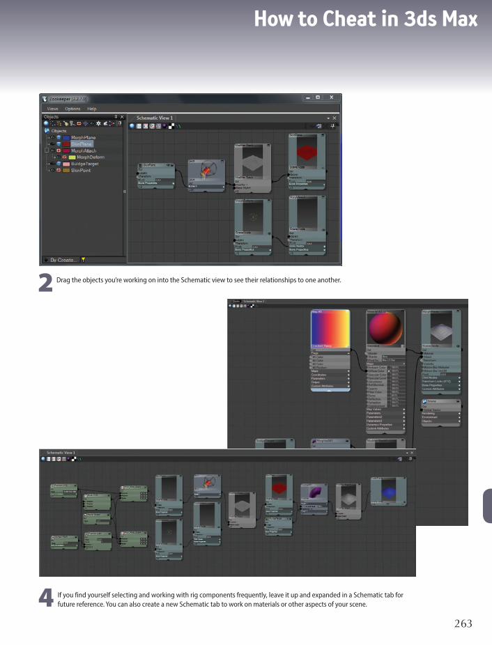
How to Cheat in 3ds Max
263263
2 Drag the objects you’re working on into the Schematic view to see their relationships to one another.
4 If you find yourself selecting and working with rig components frequently, leave it up and expanded in a Schematic tab for future reference. You can also create a new Schematic tab to work on materials or other aspects of your scene.

264264
How to Cheat in 3ds Max
n Automate your animation with parameter wiring, and animate multiple objects by changing just one parameter.

265
How to Cheat in 3ds Max
14Parameter WiringTO SIMPLIFY the animation process, you can set up custom parameters
that pertain to just the values you want to animate, and put all the
new parameters in one central location. Then you can wire (connect)
these custom parameters to real parameters to create a useful
interface for your animation needs.
While programming experience and math skills are helpful for
doing parameter wiring, they’re not essential to take advantage of this
powerful tool.

Parameter Wiring14
266266
Wiring 101
TO ILLUSTRATE THE concepts of parameter wiring, I’ve used a simple animation of a bead on
a wire. In this example, you’ll create a custom manipulator right on the screen, and then use it to control the bead’s animation.
4 Next, we’ll wire the manipulator’s Value parameter to the Percent parameter for the bead. Right-click the slider and
choose Wire Parameters. From the pop-up menu that appears, choose Object (Slider) > Value. Click the bead, and from the pop-up menu, choose Transform > Position > Path Constraint > Percent.
3 Now we’ll create a custom manipulator to control the bead. On the Create panel, choose
Helpers > Manipulators, and click Slider. Enter a name for the manipulator in the Label field, and click in the Front view to create the slider. Set Maximum to 1.0, and adjust the X Position and Y Position so you can see the slider on the screen.

How to Cheat in 3ds Max
267267
HOT TIPThe reason we made the slider Value go from 0 to 1, rather than 0 to 100, is that 3ds Max internally stores the Percent parameter for the Path Constraint as a number between 0 and 1.
2 Pull the time slider to see the animation. The bead goes around the path but doesn’t turn
with it. In the Motion panel, turn on Follow, and try different Axis settings until the bead goes around the wire correctly.
5 The Parameter Wiring dialog appears. Click the right arrow, and then click Connect to
connect the two parameters together, with the slider controlling the bead’s Percent parameter. Minimize the dialog.
6 On the toolbar, click Select and Manipulate. Pull the slider handle to make the bead
go around the wire. To animate the bead moving around a wire, simply turn on Auto Key and animate the slider value.
1Load the file BeadStart.max, and select the bead. Choose Animation menu > Constraints
> Path Constraint, and click the wire to put the bead on the path.
BeadStart.maxBeadFinish.max

Parameter Wiring14
268268
Follow me
ONE BEAD is very nice, but what about multiple beads? We can’t wire them all directly to the manipulator value or
they’ll all end up on top of one another. What we want is for each successive bead to follow the first, but with an offset so they’ll follow in order.
1Load the file BeadsSeq.max. The first bead is wired to the manipulator, and is currently at the 0 position on the
path. Select each of the other beads, and note their % Along Path values on the Motion panel. Each bead’s percent differs from the previous one’s by -4.0. This will translate to -0.04 with parameter wiring.
4 Click Manipulator Mode on the main toolbar, then when you pull the slider handle, the second bead
follows the first, always keeping a distance equivalent to 4% of the path length.
5 Wire the third bead to the second, and the fourth to the third, each time with an offset of -0.04. When you pull
the manipulator handle, all the beads will follow along.

How to Cheat in 3ds Max
269269
HOT TIPA manipulator is a special kind of helper that creates an in-viewport parameter control. Like every manipulator, you’ll need to click Select and Manipulate on the toolbar before using it.
2 Select the first bead. Right-click it to choose Wire Parameters, and choose Transform > Position > Path
Constraint > Percent. Click the second bead, and choose the same sequence of parameters.
3 In the Parameter Wiring dialog, the first bead appears on the left, and the second bead on the right. In the entry
area at the bottom right of the dialog, change the entry to Percent – 0.04. Click the right arrow and Connect to make the connection.
6 This type of setup works with any kind of path, even an open one. Here, I’ve converted the circle to an Editable Spline and used Break to break one of the vertices. Then I was able to fashion the spline into a necklace shape. When the first bead is
at 0, the other beads will jump to the end of the path, as 3ds Max interprets a negative Percent value as 100 minus the value. For example, -4% is interpreted as 96%. To avoid this problem, you can adjust the slider’s Minimum value to 0.12 to force the first bead to start far enough down the path to accommodate all the beads.
BeadsSeq.maxBeadsFollow.max

Parameter Wiring14
270270
Telling time
1Load the file TimeStart.max, and select the Dummy object at the top of the watch.
This is the object that will hold our new custom parameters.
6 Since the watch face has 360 degrees and
12 hours, each hour is 30 degrees along the watch face. At the lower right of the Parameter Wiring dialog, type in – Hours * 30 (with the minus sign for the negative rotation), and click the right arrow and Connect.
YOU COULD SET THE TIME manually, but why bother when you can use wiring? Setting up wiring for rotation requires a
smidgen of math and the use of a special function to convert the numbers to angular degrees that 3ds Max can interpret.
4 Rotate the hour hand Dummy with the Local coordinate
system, and you can see that it rotates on the negative Z axis. You will use this axis when wiring it to the Hours parameter.
5 Select the Watch vcontrol Dummy, and
wire its Object (Dummy) > Custom Attributes > Hours parameter to the hour hand Dummy’s Transform > Rotation > Keyframe XYZ > Z Rotation parameter.

How to Cheat in 3ds Max
271271
7 When you adjust the Hours spinner, the hour hand goes wild. This happens because
internally, 3ds Max expresses degrees as radians, an angular measure equal to about 57 degrees. You’ll need to convert the degrees to radians with the degtorad function in the Parameter Wiring dialog. At the lower right of the dialog, change the entry to – degtorad(Hours * 30) and click Update. Adjust the Hours spinner to see the hour hand move smoothly from hour to hour.
8 Wire the Minutes value in the same way. Freeze the minute hand Dummy at the 12 mark on the watch face, check for the correct
rotation axis, and use – degtorad(Minutes * 6) to wire the Minutes parameter to the minute hand Dummy’s rotation parameter. Now you can animate the Hours and Minutes parameters as you like to set the time on the watch.
TimeStart.maxTimeFinish.max
2 Choose Animation menu > Parameter Editor. Create a new parameter of the Float type
called Hours, with a Range from 1 to 12. After you click Add, the parameter appears on the Modify panel. Create a second parameter called Minutes with a Range from 1 to 60.
3 We’ll wire the hour hand first. But before we do that, we need to tell 3ds Max where the 0 position is. Select the hour hand Dummy
and rotate the hour hand to point to the 12. Then use ALT-right-click to display the animation quad menu, and choose Freeze Rotation. This resets the current rotation to 0 internally, so any rotation coming from wiring will start from that point as the 0 point.

Parameter Wiring14
272272
REMEMBER WHEN YOU dozed off in geometry class, wondering when you
would ever use the stuff you were learning? That day has arrived.
In your animation travels, sooner or later you’ll need to make something spin.
Of course you can keyframe the rotation, but that can be tricky. If you rotate
an object three full times, for example, 3ds Max will sometimes think the object
just has to go the shortest distance between the start and end rotation, which
is essentially zero. So keyframing rotations of more than 360 degrees can be
troublesome.
Instead, look at wiring as an option. For example, suppose you need to animate
a toy car moving along a road. You know how far the car is going to travel, so you
can easily figure out the number of wheel rotations.
If you know a bit of geometry, that is. Let’s revisit that musty old classroom and
grab a useful equation or two.
A circle has 360 degrees, and a wheel turns 360 degrees to make one turn. So
far, so good.
Every circular object has a radius, the distance from the center to the edge of
the circle. If you know the radius you can figure out all kinds of things, like how
much road a wheel covers when it turns one time.
Suppose you put a chalk mark on your car’s tire, then roll it forward just far
enough so the chalk mark goes around once and comes right back to where it
started. You have just traveled a distance equal to the outside edge of your tire.
The measurement of this outside edge is called the circumference. To measure
the circumference of a wheel, you can get out your tape measure and wrap it
around the wheel. Or you can do it the easy way: measure the radius and make a
calculation.
The circumference of any circle is the same as 2 times the radius times pi, a
magic number equal to 3.14 something and a bit. Pi is sometimes represented as
the Greek symbol π. You don’t even have to know exactly what pi is to do your
calculations. 3ds Max knows what it is, and that’s all that matters.
I N T E R L U D E
Spinning wheels

How to Cheat in 3ds Max
273273
Say the car travels 300 units on the Y axis, and the radius of the wheel is 23.
To figure out how many times the wheel turns, you need to divide the distance
traveled (300) by the circumference of the wheel (2 x 23 x pi).
So that gives us the number of full turns. To get the number of degrees it has
turned at any given time, just multiply the whole thing by 360, stick a degtorad in
front of it, and you have wheels-a-turning. If you want to see this equation in action,
I’ve included a toy car file with all four wheels wired in this way.
Granted, this technique isn’t for the faint of heart. But if you like the idea of
automated animation, parameter wiring can’t be beat. If that’s the case, dust off that
old geometry book and revisit those equations. All of them still work.
ToyCar.max

Parameter Wiring14
274274
EXPOSE TRANSFORM is a tool that riggers use to get info from objects or controllers in their rig
in order to set values on other objects in respect to that. Being able to get to this data allows you to drive other objects with that information. The Expose Transform helper can also be used to create some interesting motion graphics like effects by driving object properties based on their distance from another object in the scene.
6 If you move the POS_CTRL object the Tile will rotate based on its distance from the control object.
3 Select the Expose Transform helper and pick POS_Object
as the Expose Node. Uncheck Parent under that and pick POS_CTRL as the Local Reference Node. This will set the Expose Transform helper to expose the distance from these two objects.
Feeling exposed

How to Cheat in 3ds Max
275275
1To get started we have a few objects. First the mesh object (Tile) which will be our flipping tile in the scene.
Second, a point helper (POS_Object) for the position of the Tile. Third is a Circle (POS_CTRL) that will be moved around the scene controlling the flipping. And lastly, the Expose Transform (ExTrans) helps to expose the distance between POS_CTRL and POS_Object.
7 Select all objects but POS_CTRL and go to Array. Set up a 2D array with 10 copies in each. Offset in X and Y in
the first set and only in Y in the second. Make sure you choose Copy as Type of object.
4 Right-click on Tile and select Wire Parameters. Choose Transform/Rotation/Rotation X then pick EXTrans and
wire Object/Distance.5 In the Wire Dialog click the arrow pointing to the left to
connect in that direction and then in the bottom left field add a /100 after Distance to slow the rotation a bit. Make sure you choose Connect or Update in the bottom center of the dialog.
2 So all these pieces move together, link ExTrans to Tile, and then link Tile to POS_Object. Now to move the
assembly you can just move the POS_Object.
8 As you move the POS_CTRL circle around the tiles will flip and create a progressing rotational animation.
TileExposeTStart.maxTileExposeTEnd.max

Parameter Wiring14
276276
I HAVE WORKED in the 3D industry for 20 years and for most of that time I
have been a technical director and coder doing a variety of jobs: building tools,
animating, rigging, modeling, and everything in between for companies such as
Walt Disney, 2K, Red Rover, Lockheed Martin Areospace and many more. I am
also a professor and currently work at the largest college in Canada teaching 3D.
In that time I have been asked many questions but there’s one that must
come up at least once a month: “What do I need to do to become an excellent
technical director?” This is always a very hard question to answer as there are
many things that need to be learned. First and foremost is we all need to be
artists and understand what is needed by artists. We also need to have the desire
to solve problems as that is what much of the job of technical artist or director
entails.
But, the one main thing that is always needed by anyone in the 3D business
is a work ethic and the ability to be able to finish what one has started. This, of
course, sounds very similar to what all of our parents kept telling us for years
and what most of us ignored until we either spent a life failing at what we
wanted to do or succeeding at doing what we set our minds to.
As a technical director I’m usually asked to solve problems for which there
is little or no guidance. The ability to solve problems is a very difficult skill to
teach someone. It is about having the desire to not accept failure in producing a
desired result, and finding creative ways to solve the issues that are slowing or
stopping production.
I N T E R L U D E
To code or not to code

How to Cheat in 3ds Max
277277
I’m also often asked if a technical director needs to learn to program.
The answer to this is “Yes”. There are some companies that have positions
for “riggers” who only rig characters using available software tools, and these
positions are not required to know how to code. However, these are very low
level positions; if you want to be efficient at rigging it is best to know at least
the built-in language of the software you are working with. The ability to solve
problems that don’t have built-in solutions will make you a far better technical
director and worth more to the companies that hire you.
Learning math, programming languages and best practices is the easy part;
learning to rig complex characters just takes time. It is the desire and work ethic
to not give up trying to understand the tools and methods that is the hard part.
Paul Neale
PEN Productions
http://penproductions.ca

278278
How to Cheat in 3ds Max
n Special effects are usually created with a combination of tools.

279
How to Cheat in 3ds Max
15Special EffectsON ANY GIVEN DAY at the movie theater, you can enjoy a variety
of special effects from rain, snow, and smoke to entire forests and
landscapes.
While big-budget film effects might not be in your schedule, there
are a few effects you can add to your scenes with a minimum of work.

Special Effects15
280280
3 Adding a bit of glow or glare to the highlights is easy. In the Render Settings Dialog under the Renderer tab, check the Output option under Camera
Shaders. This will apply the Glare camera shader to the scene. Wherever there are hot highlights or reflections in the scene a glare effect will be produced.
1It’s common in logo animations and motion graphics to set objects up on an infinite plane. To cast shadows on that plane and see through to the
background environment, apply a Matte/Shadow/Reflection material to the plane.
Logo polishing
IN THE REFLECTIONS chapter we worked with a logo for a motion graphics spot. Here we will add
some nice shadows and a glow to polish it up.

How to Cheat in 3ds Max
281281
4 The Glare shader can be dragged into the material editor to tune its Spread, Quality and other settings. You can even set the Streaks option to get some more interesting results.
2 Set the Camera Mapped Background map to use the gradient map that is currently in the Environment background slot. The scene will now render with the object’s shadow over the backdrop. This is also a good
way to get reflections over the environment if needed.
LogoPolishStart.maxLogoPolishEnd.max

Special Effects15
282282
MassFX destruction
MASSFX WAS INTRODUCED as the de facto simulation engine in 3ds Max 2012. MassFX replaced Reactor as a
simulation engine. While it does not cover all the areas that Reactor did, it is a pretty fast rigid body simulator.
Here we will set up a simple destruction sequence making use of the Fracture Voronoi script from the MAXScript chapter.
1Run the Fracture Voronoi script and select the Pillar object to fracture.
5 On the MassFX Toolbar, click Reset simulation (back button). Then
with all the pillar objects selected click the MassFX Tools button and go to the Multi-Object Editor tab. Here set Start in Sleep Mode for all the objects. This means they will hold their position until something collides with them.

How to Cheat in 3ds Max
283283
HOT TIPFracture Voronoi can set up material IDs for the inside of the fractured objects. This way the insides of the destroyed pillar can look slightly different with a Multi/Sub-Object material applied.
8 Bake out the animation and, by using the Bake All option in the
MassFX Tools dialog, render out the animation.
7 Simulate the scene and the pillar will stand until the sphere object
crashes into it, causing the pillar to crumble to the ground.
6 Select the sphere in the scene and set it to be a Kinematic Rigid
Body. This will allow the object to keep its animation and collide with other objects in the scene.
2 In the Fracture Voronoi dialog set your Nb Parts to 11 and Iterations
to 3. Parts will create 11 large chunks and Iterations will then subdivide those further. Set the option for Vo.Cells Centers, which will set the pivot of each object to the center of the cell.
3 Break the pillar object and with all the pieces selected bring up the
MassFX toolbar. Here you can set all the pieces to Dynamic Rigid Bodies.
4 Simulate by pressing the Play button in the MassFX toolbar and
the pillar will crumble to the ground. We want the pillar to stay standing until an object hits it, so we will set the Start in Sleep Mode property for all the pillar objects.
PillarStart.maxPillarEnd.max

Special Effects15
284284
I N T E R L U D E
Breaking into the industryPROBABLY THE MOST CRITICAL thing to anybody’s career that is also the most
neglected is actually their career. Artists often focus so much on tutorials, on what buttons
to push, and what tricks are available in each software package that they don’t actually
look at how to attract work and how to build a name for themselves.
Having an online presence is crucial as it will allow the world to know that you are
out there, and will also tell them of your abilities. Setting up Vimeo and Youtube accounts
and posting your work to each and on Facebook should become second nature. When
you wrap on a project, take a few hours to put together a breakdown video of your work,
show some wireframes and render passes and the finished result. This is fun eye candy
for people to see, and also great material for your reel. Putting it on your Vimeo page for
others to see will help you get your name out there as well as make people familiar with
who you actually are! The more people become familiar with your work from your site,
videos, and forums, the more people are going to think of you when a certain shot or
sequence comes up they need to hire for.
Who are you? If you can learn to skillfully summarize yourself in one sentence that
will be your sound bite to introduce yourself to anybody that you meet or email. It should
become second nature and it should pack the most punch. “Hi I’m Allan, I’m a Technical
Director at ILM working on a massive effects sequence on The Last Airbender! I just
wrapped on Transformers 3 a Michael Bay film before coming here!” Keeping it fairly
short but making every word count, you want to quickly summarize who you are and
where you’ve been and what you can do. Now you won’t be Allan, that guy from the
dinner party, but Allan that vfx sup from Ubisoft and Activision that worked on all that
great project!
You need it to be clear from the minute you meet someone how they should categorize
you in their mind. This is entirely within your control. The same way that if you send a
reel and resume into a studio for a job, it is good to define your biggest strength in 3D
clearly in your application, as well as a secondary strength. Human Resources personnel,
when reviewing reels, typically aren’t going to identify what your strengths are, and can
usually can only make the call of whether you are good or not, and therefore which bin

How to Cheat in 3ds Max
285285
your application will go into for future review later on. That being said, if you can state
clearly you are a lighting artist, for instance, then as soon as your reel goes onto their desk
there’s a good possibility it can go directly to a project supervisor for consideration for their
project, if they are in fact needing a good lighting artist. I know this, because I hire and
review artists’ work all the time for feature film projects.
And this is why it’s important to be on all of the social media and connection sites,
most importantly LinkedIn. Recruiters typically will look for artists on LinkedIn more than
any other site because they can find more about an artist and find them in more ways
through this site than any other place on the planet. Job boards are great, and I will get
to those. But your LinkedIn profile should be flawless. It should have an abundance of
information and be completely up to date. It should also have a nice big picture of your big
beautiful smile which spells out “I am very approachable, and I’m not insane!” People will
identify with your photo instantly, as that’s what is embedded in our DNA to do. You have a
decent profile photo handy from when you were using it on your forum posts, right?
The other important thing to do once you have some feature films under your belt is
get a page on IMDB (Internet Movie Database). Having a page on IMDB.com will make
you more legit, and these days it’s pretty much the standard currency for employers,
as well as governments when dealing with visas, to evaluate your level of experience.
So it is important to keep this up to date. You can also get IMDB Pro which allows you
to customize your profile further. This is actually key, because you can put all of your
information, photos and other contact information up there, which again will make you
easily contactable and more professional.
There are many key steps to promoting your career and yourself, but the key thing here
is that you need to see yourself as a business. If nobody knows about your business, how
are you going to get work? Promoting yourself is not a dirty word; it’s a necessity. Without
making yourself known to every studio, recruiter and client out there, how are they going
to hire you, over the hundreds of other artists who are making themselves heard?
Allan McKay
VFX Supervisor
http://www.allanmckay.com

Special Effects15
286286
Raindrops
5 Create a material for the raindrops to make them look like water. No need to go overboard--a simple material with a Reflection
map, lowered Opacity, and high shininess will do the job. Render a few frames late in the animation to see how the raindrops look with the material.
6 Copy the first
raindrop to create two more raindrops. These will be your drips. Alter one of them to look like a long, dripping raindrop when viewed in the Top viewport. Select the round drip, and use the Morpher modifier to morph it into the long drip over 120-150 frames.
NATURAL PHENOMENA can be intimidating, especially water. All that
transparency and refraction! But in reality, falling rain looks like a blur. Water droplets, when viewed en masse, are just reflective blobs.
To create an animation of raindrops falling on a window pane, you need rain outside the window, droplets fallling on a window pane, and a few drips for good measure.
Dreary lighting, a dark exterior, a reflective window pane, and dappled shadows on the window frame add to the gloom.

How to Cheat in 3ds Max
287287
2 Create a Spray particle system to spray particles outside the window. Turn on Object Motion Blur for the Spray in
the Object Properties dialog. Adjust the particle Speed until the raindrops look like a fast blur in the rendering.
3 Create a raindrop object to spread over the window pane. A sphere will do, but you’ll catch more highlights
with a flattened sphere. At the Vertex sub-object level, rotate the sphere so its flat end points down in the Front viewport. This will ensure the drops are oriented correctly when used with the PCloud particle system.
HOT TIPIf you don’t like the distribution of raindrops, you can get a new arrangement by clicking New under Uniqueness. This grabs a new Seed value for random calculations, redistributing the particles in a new configuration.
1Set up the scene for rainy day lighting. Here, I’ve set up a dim direct light coming in through the window, and
medium lighting in the room itself. A second direct light makes dappled shadows on the window frame.
7 Create a second PCloud system for the drips, with the round drip as the instanced particle. The number of
particles should be about 5% of the total number of raindrops. Under Animation Offset Keying, choose Birth to cause the drips to morph as soon as they appear.
4 Create a plane over both window panes. Create a PCloud particle system, and choose the plane as
the emitter. In the Particle Type rollout, choose Instanced Geometry, and pick the raindrop as the reference. Hide the plane, and set particle size and quantity values to get a nice spread of raindrops over the course of the animation.
8 Create a copy of the raindrop material, and add a Raytrace map in the Refraction slot for the drips.
Because the drips are larger, you can detect the refraction in the rendering. There aren’t a lot of drips, so the Raytrace map shouldn’t cause a significant increase in render time..
RainStart.maxRainFinish.max

Special Effects15
288288
I N T E R L U D E
MorphingMORPHING CAN BE A useful tool for special effects. It turns one object into another over a
series of frames. Morphing is accomplished by assigning the Morpher modifier to an object and
picking target objects.
Morphing works by taking the vertices of one object and moving them to the locations of the
other object’s vertices. Under the hood, 3ds Max numbers the vertices of every object. When
you morph one object to another, vertex #1 of the original object travels to the position of vertex
#1 of the target object, vertex #2 in the original object travels to vertex #2 position of the target
object, etc. The distance and direction in which the vertices travel are relative to the object’s pivot
point.
Morph targets have to have the same number of vertices as the original object, or the
Morpher modifier won’t let you use them. The best way to create morph targets is to make a
copy of the original object and alter the copies to make targets. Then each target will have the
same vertex configuration, with its pivot point in the same relative position to the final object.
Even with carefully-made morph targets, things can go awry. Suppose you modify a morph
target in such a way that the pivot point isn’t really in the right spot. You can just move the pivot
point, right? Wrong. Morphing uses the original pivot point location, no matter where you move
the visible pivot point after the fact.
n Raindrop drips from Raindrops topic: round drop, long drip, and partial morph from round to long. The morph grows upward at the top due to the pivot point alignment. Moving the long drip downward at the vertex sub-object level would put the pivot point at the right spot for a correct morph.

How to Cheat in 3ds Max
289289
The only solution is to move the entire
object at the sub-object level to orient it to the
original pivot point. This can get tricky, since
the original pivot point is essentially invisible.
The best approach is to align a helper with the
pivot so you can see it when moving the object
at the sub-object level.
Once you’ve created morph targets,
there’s no going back to the original object
and collapsing vertices or adding edges. Such
operations will cause a mismatch between the
number of vertices in the original object and
the morph targets. And you can’t correct the
problem by adding a vertex here and there.
Doing so causes a change to the object’s
vertex numbering pattern. Remember that
vertex #236 on the original object will travel
to the location of vertex #236 on the target
object. Adding vertices on one object changes
its vertex configuration relative to other
objects. This means that when you morph,
you’ll end up with a big mess, with the object
turning inside out and most likely looking like a
wadded-up tissue along the way.
The most common uses for morphing are
lip synch and facial animation. Create a series
of morph targets representing vocal sounds
and facial expressions, morph between them
in time with the sound track, and you’ve got
yourself a live, talking character. Just be sure
to have the original object in perfect condition,
with the exact number of polygons needed and
all the vertices welded appropriately. Then you
won’t have the need to add or remove vertices
after you’ve created the morph targets.
nMorph targets for facial expressions. For a full set of lip synch and facial expression targets, each major vowel and consonant sound is represented, as well as common facial expressions like blinking, smiling, and frowning.

Special Effects15
290290
3 Select all the objects, and click Export Select to Compositor Link on the State Sets toolbar. When the dialog pops up, name and save your .SOF file.
1Right-click on the main toolbar and choose State Sets to bring up the State Sets toolbar.MANY NEW STATE SETS
improvements were introduced with 3ds Max 2015. Users had been
asking for an easy way to send cameras, lights, and null objects over to Adobe After Effects without a lot of setup. Now there is a quick button on the State Sets toolbar to do just that.
One click to After Effects

How to Cheat in 3ds Max
291291
HOT TIPMake sure you have the After Effects Media Sync plugins installed to get this interoperability. The latest installer for the plugin is available on the Autodesk site (Autodesk.com).
2 Create a simple setup with a camera, a light, and a couple of planes for sending over to Adobe After Effects.
4 In After Effects, open the Compositor Link dialog from the File menu. Click Create Link and pick the .SOF file you just saved. The light, camera, and planes will come over into After
Effects along with any camera or object animation.
OneClicktoAE.max

Special Effects15
292292
Cracks in a surface
ANIMATED CRACKS appearing in a landmass make a
powerful visual statement. The ProBoolean tool with an animated loft makes quick work of it and allows you to determine where the crack appears and how fast it grows.
4 Go to the last frame of the animation, turn on Auto Key,
and move the two middle points on the graph to arrange it as shown in the picture. Take care not to make the points pass by each other, as this could confuse 3ds Max and make it do unexpected things.
3 Next you’ll animate the loft scale to make the loft grow along the
path. Go to the Modify panel, and on the Deformations rollout, click Scale. In the Scale Deformation window, click Insert Corner Point, and add two points on the line. Click Move Control Point and arrange the graph as shown in the diagram. Use the value entries at the bottom of the window to enter the value 0 for the two rightmost points.

How to Cheat in 3ds Max
293293
HOT TIPTo make the crack automatically have a material different from the surface, assign different material IDs to the surface and the loft before performing the boolean operation. You can do this quickly by applying a Material modifier with a different ID number to each object.
5 Test the animation by scrubbing the time slider. The loft should grow over time.
2 Create a tall, thin ellipse and loft it along the line. The resulting loft will be used to cut the crack. Make sure
the Creation Method is set to Instance, and turn off Banking in the Skin Parameters rollout. Set Shape Steps to 2 or 3 and Path Steps to 0 for faster computation. If it looks like the cut won’t be the right width or depth, change the ellipse parameters.
1Create a terrain with some thickness, and draw the line in the shape of the crack. Use Snaps Toggle with the Face
option turned on. Create a line in the Top viewport starting outside the terrain, then zigzag it across the terrain to form the crack. Place three or four vertices between each twist and turn so the line stays on the surface the whole time. Be sure to turn off Snaps Toggle when you’re done.
6 Select the terrain, and use the ProBoolean compound object to subtract the loft object. Hide the loft and
scrub the animation. If you want to change the crack’s path anywhere along the way, just move the vertices of the original line used to make the loft.
CrackStart.maxCrackFinish.max

Special Effects15
294294
I N T E R L U D E
What’s in the box?Particle Flow was introduced in 3ds Max 6 quite some time ago. Its a very powerful system
and throughout the years the original developer, Orbaz, has continued to improve and add
functionality with plugin releases. Each of these extensions to PFlow was called a Box and there
has been a release for Box #1, Box #2, and Box #3. At this point all of these additional Boxes
have been integrated in the main 3ds Max package.
Box #1 was integrated early on and introduced some important speed improvements as
well as cool operators like Lock Bond. Box #2 and Box #3 have just been integrated in 3ds Max
2014.
Box #2’s main focus is dynamics and allowing particles to collide with each other in a
dynamic way. It uses the MassFX technology and has been dubbed MParticles in 3ds Max. Most
of the operators associated with MParticles will have an mP in their names.
Box #3 allows you to create your own operators using math nodes and other conditions.
It’s a very powerful set of tools accessed from the Data Operator, and it has its own Data View to
create operators in.
See, not as scary as you thought.

How to Cheat in 3ds Max
295295

Special Effects15
296296
4 To link Events or pass particles from one to another you will need a Test action. Dragging an Age Test into the
original Event will allow you to define an age at which particles go into the next Event.
5 Adjust actions in the Parameters Panel. Select the second Display action you created and set the Type to
Diamonds. Select the Age Test and set the Test Value to 5. Now at frame 5 you can see the particles are passed to the second event.
1Drag out a PF Source in the Perspective view and press play. PFlow gives you a default set of particles so you have
moving particles right from the start, and you can start playing with settings.
PARTICLE FLOW, also known as PFlow, is the core, node-based particle system in 3ds Max. There is still room for the
simple legacy particle systems for quick and dirty things but I recommend using PFlow for most of your particle needs.
Most of the work in PFlow is done in the Particle View. Particle flow has all the base particle attributes you’re used to, but presents them in a more modular way. Parameters like Birth, Speed, Rotation, and Display are all present in PFlow.
Particle flow basics

How to Cheat in 3ds Max
297297
6 Any action you add into the new event you created will only affect particles over 5 frames old. Drag a Speed action into that event and set the Speed to 0. The particles will now stop after 5 frames and hang in space.
3 Pflow actions or operators are at the bottom in the Depot. You can drag actions like Speed, Age Test, or
Display into an existing event or into the Event Display directly to create a new event.
2 Open up the Particle View and you will see a few sections. The Event Display is where most of the action
happens. Pflow is event based and particles get passed from event to event through some sort of condition or test.

Special Effects15
298298
Swirly particles
4 To get the swirling effect more clearly and slow our particles down some add a Drag force to the system. Set
the Damping to be 25% in X,Y, and Z. Set the Time off to be the end of the frame range too.
3 Add the Wind force to the Pflow event by dragging a Force action into the event and then adding the Wind.
The wind should now blow the particles away and give them some turbulence as they go.
MANY BROADCAST, film, and game effects shots have
these swirly particles with fluid movement. This type of movement can be generated by a turbulent field with some sort of drag that reduces the particles’ speed over time or distance. Let’s look at setting up a simple swirly particle animation.

How to Cheat in 3ds Max
299299
5 Increase the particle count and tune the wind turbulence and
drag damping to get interesting swirling particle effects.
2 Create a Wind force and set its Strength to 0.2, Turbulence to 1.5 and Scale to 0.01. This will blow the
particles slightly and with a little turbidity.1Start with a Pflow source that emits about 10,000
particles over 300 frames. Set the particle speed to 0 as we will be creating the particle movement with wind.
HOT TIPThe Scale in Wind is a bit backwards from how you might expect it to work. A small value like 0.01 produces a large wavy turbulent field and a larger value like 1.0 produces a tight pattern that will make your particles jitter around.
SwirlyStart.maxSwirlyEnd.max

Special Effects15
300300
MPARTICLES ALLOW YOU to have particle meshes collide with one another, and let you add joints
to particles and skin particles in a cloth-like fashion.
4 Set the Birth Grid to Non-Uniform Grid and reduce the Grid height % to get more coins stacked up. Press play
to watch them drop into place and collide with the ground.
1Create a Pflow system and in the Particle View remove all the events and drag in an mParticles Flow. This will set
up a preset flow with all the basics needed for an mParticles simulation. You should see an mP Shape action as well as an mP World. The mP world is the MassFX simulation engine integrated into particle flow to do shape collisions.
mParticles

How to Cheat in 3ds Max
301301
HOT TIPPlay with the Restitution value in mP Shape to get the desired bounce out of your simulation.
5 The coins collide a bit unnaturally because their mP Shape is set to box. Set the mP Shape Collide As field
to Convex Hull to better approximate the actual shape of the coins and press play again. Now they collide better.
6 To collide with a scene object, use an mP Collision Test below mP World. In order to pick the scene object to
collide with, add the Pflow Collision Shape (WSM) modifier to it. Make sure you press the Activate button in the modifier so it will participate in the simulation.
3 Create a Chamfer Cylinder that is about the size of a coin and replace the standard Shape action with a Shape
Instance. Pick the cylinder as the instanced shape. Adjust the Scale of the shape so they don’t overlap. If the objects are interpenetrating the collisions will fail and they will go flying off into space.
2 Play back the animation and you should see a grid of boxes that drop to the ground and collide with each of
the ground plane as well as each other.
mParticlesEnd.max

Special Effects15
302302
DATA FLOW OPERATORS (or PFlow Box #3) allow you to dig deep into particles and create your own
operators that normally would not be a part of PFlow. It’s a bit technical by nature, but here is a simple example of the types of things you can do with it.
6 In the Output Standard action choose Script and select
Vector from the dropdown list and close the Edit Data Flow view. This may disconnect your Position Vector. Be sure to reconnect it. Now the particles will emit and after a short time find their target particle on the other system.
4 Add a Data Operator to the second event above Find Target
and Edit Data Flow. In the Data Flow window add a Select Object, Input Proxy, and Output Standard and wire them together. In Select Object set the Type to Pflow System and choose the first Pflow system by clicking on the none button and picking that system. This will be the system we grab our info from.
1Start out with a particle system that places a few hundred particles on the surface of an object using the Position
Object action. We will create a second particle system that emits particles, then finds the particles in the first system and moves to their positions.
Data flow operators

How to Cheat in 3ds Max
303303
7 Right now the particles find the target and just keep flying
around after that. To have them stay once they find the particle we can use the Lock Bond action. Add Lock Bond to the third and final event and pick the Torus as the Lock On Object. Set the Lock To Surface and Snap To Surface options. Now the particles will find their target and stick to the surface afterward.
5 Right-click on the Input Proxy and choose Show
Data. If you scrub the timeline this will show you the position data for all the particles in the Pflow System that was picked. By feeding that info into the Output Standard action as a Script Vector, Find Target will be able to access that data.
2 Drag out a Standard Flow to the Event Display to create another system and set the Birth of amount of the
second system so that you have the same amount of particles emitting as the first system. Set the Speed to be 100 and Random 3D for Direction.
3 In the second event add
a Find Target Test and send those particles to a new event with a new Display action. In Find Target set it to Control by Time with a Time of 120 and Variation of 60. This will cause the particles to find their targets over 120 frames with a little variation. In the Target section set Point to Script Vector. We don’t have a script vector yet for it to find, but that is what we will build with the Data Operator.
DataFlowStart.maxDataFlowEnd.max

304304
How to Cheat in 3ds Max

305
How to Cheat in 3ds Max
AppendixHERE IN THE BACK, I’ve included some goodies to aid
you on your journey to becoming a better and faster
artist with 3ds Max.
These challenges will give you practice in the
techniques described in this book.
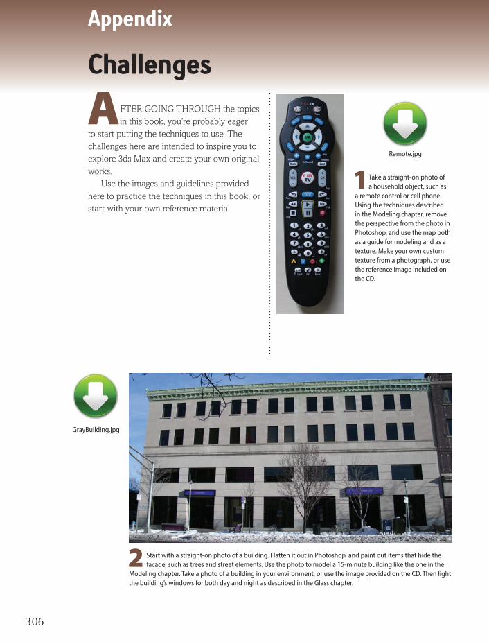
Appendix
306306
Challenges
2 Start with a straight-on photo of a building. Flatten it out in Photoshop, and paint out items that hide the facade, such as trees and street elements. Use the photo to model a 15-minute building like the one in the
Modeling chapter. Take a photo of a building in your environment, or use the image provided on the CD. Then light the building’s windows for both day and night as described in the Glass chapter.
GrayBuilding.jpg
1Take a straight-on photo of a household object, such as
a remote control or cell phone. Using the techniques described in the Modeling chapter, remove the perspective from the photo in Photoshop, and use the map both as a guide for modeling and as a texture. Make your own custom texture from a photograph, or use the reference image included on the CD.
Remote.jpg
A FTER GOING THROUGH the topics in this book, you’re probably eager
to start putting the techniques to use. The challenges here are intended to inspire you to explore 3ds Max and create your own original works.
Use the images and guidelines provided here to practice the techniques in this book, or start with your own reference material.

How to Cheat in 3ds Max
307307
3 To get a handle on the techniques of making curved glass, try your hand at making this well-used pitcher. Feel free to use the
spots texture from the Glass chapter.
Spots3.jpg
4 Reference material is important for animation, too. Videotape a friend walking, getting as close to a
straight side view as you can. Then animate the Biped walking the same way. The crazier your friend walks, the more fun you’ll have.

Appendix
308308
Challenges
OgreFront.jpgOgreSide.jpg
REFERENCE IMAGES AND MODEL: JAMES MALLARD

How to Cheat in 3ds Max
309309
SethFront.jpgSethSide.jpg
5 What’s more fun than modeling characters? Nothing, I say. That’s why
I’ve included these reference images so you can make your own. These models were created by Michele Bousquet’s students in her Low Polygon Character Modeling class at CGSociety.org. They have graciously allowed their reference images to be included with the book so you can enjoy the same pleasure. Use the techniques described in the Character Modeling chapter to create the body and head, then rig and animate with the Character Animation chapter.
REFERENCE IMAGES: NICOLAS ZARZA AND PABLO MORENO MODEL: NICOLAS ZARZA

Index
310

How to Cheat in 3ds Max
311
AAfter Effects 236–237, 238–239, 290–291alpha channel, PSD file 88animation
Auto Key 157Curve Editor 160–161Dummy objects 172–173facial 289IK solver 176Link Constraint 174–175loft 292–293LookAt Constraint 166–167Noise Controller 170–171Path Constraint 164–165pivot point 162–163pose-to-pose 158random effect 170–171scene workflow 20trackbar 157Track View 156
Arch & Design material 106–107, 108–109Attach
Editable Mesh/Poly 29–30attenuation. See lightingAuto Key 157
BBackface Cull 130balcony 44–45Bevel 56–57Bias 114Biped
copy and paste postures 189Figure Mode 191fitting skeleton 190footsteps 194–195IK/FK 200move without animating 189skinning 184–185
Bones 176–177Boolean 181
IndexCCap 72CAT animation system 186–187
fitting skeleton 190Gizmos 202, 214–215history 204–205pivot point controller 162skinning 190
CATHDPivotTrans 162CheckMate Pro standard 60–61circumference calculation 272–273clone object 35coincident faces 61collapse modifier stack 90COM, selecting 188Connect 41–42, 43, 77controller
CATHDPivotTrans 162coordinate systems 26–27copy object 35Curve Editor 156, 160–161
set tangents 161custom menu 6–7Cut 41–42cycling viewports 8
DDaylight system 124–125decal map 91degtorad 271dirt shader 100Dope Sheet 156Dorito approach 196–197, 262Dummy objects 28, 166–167, 172–177
in parameter wiring 270–271
Eedge loops 70Edge sub-object 43Editable Poly
Attach 29–30Convert to 40Preserve UVs 42–43

Index
312
Edit UVWs dialog 96–97Enhanced Menus 10–11Expose Transform helper 274–275Exposure Control 6Extrude 56–57
Fface structure 56–57facial animation 289Fastskin 103Flat Mirror map 141flipped faces 61fluid dynamics simulation 254–255Fracture Voronoi script 210–211, 282–283Free keys (Biped) 200freeze 25, 30
Ggemstones 136–137glass
pint 150–151refraction 152–153windows 144–149
glow 118–119Gradient Ramp map 92–93Group 28
Hhair 258–259HD Solver 180helper
Expose Transform 274–275hide 25hold keyframes 168–169
IIK Chain 177IK/FK blending 200IK solver 176–177index of refraction 152–153Instance 35inverse kinematics 200isolated vertices 61
Kkeyframing 156–157
rotation 160–161Step interpolation 158–159
LLathe modifier 34, 57Lattice modifier 130Layer Manager 4–5, 24layers 28lighting
attenuation 248–249, 234–235, 123, 240–241
bounced 240–241colors 122intensity 112, 120mr sun 125negative Multiplier 123scene workflow 21Skylight 125Spot vs. Direct 115sun 116–117three-point 112–113volume light 123
Light Lister 6Light Lister dialog 112, 129Link Constraint 174–175linking 172–173, 174–175lip synch 289Local coordinate system 27lock selection 19, 30loft 292–293logo treatment 138–139, 280–281LookAt Constraint 166–167
Mmanipulator 266–267mapping
building 42–47scene workflow 21

How to Cheat in 3ds Max
313
mapsdecal 91Flat Mirror 141Gradient Ramp 92–93mr physical sky 125Noise 92–93Normal 98–99Raytrace 135, 287Reflect/Refract 134, 141tileable 87Vertex Color 95
materialsMatte/Shadow 130, 145Mental Ray 135Raytrace 136–137scene workflow 21
Matte/Shadow material 130, 145Maximize Viewport Toggle 22MAXScripts
CAT gizmos 214–215for getting a job 276–277Fracture Voronoi 210–211Gizmo Control 212–213PF Spliner 220Tension modifier 216–217
Maya 12–13Mental Ray 232–233, 240–241
Arch & Design material 106–107, 108–109radiosity 240–241
Mental Ray material 135middle mouse wheel 23–24
modifiersLathe 34, 39, 57Lattice 130MeshSmooth 74Morpher 196–197, 286, 288–289Physique 181Projection 99Push 131Shell 53, 56Skin 181, 192–193, 196Sweep 34, 57Symmetry 41Tension 216–217TurboSmooth 41, 74, 56–57Unwrap UVW 85, 96–97, 104–105UVW Map 43, 84–85VertexPaint 94–95
Morpher modifier 196–197, 286, 288–289motion blur
rain 287–288mr physical sky map 125mr sun light 125Multi/Sub-Object material 90–91
NNGon 160–161Nitrous viewport 244–245Noise Controller 170–171Noise map 92–93normal
definition 99mapping 98–99
NURBS 48–49, 181

Index
314
PParameter Editor 271parameter wiring 272–273
dialog 267particle systems 294–303
duplicating 222–223PCloud 287Spray 287
Path constraint 164–165, 266–269PCloud 287PFlow
about 294–295Box 3 302–303
PF Spliner script 220Phoenix FD 256Photoshop
cleaning up reference images 36–37render elements 236–237, 252
Physique modifier 181pi 272–273pivot point 27, 162–163
for morphing 288–289placing with MAXScript 218–219
Place Highlight tool 141Plant keys 200plugins
Phoenix FD 256–257Tension 100Zookeeper 262–263
polygon structure , 72–73, 56Polygon sub-object 43pose-to-pose animation 158–159Preserve UVs 42–47primitives 34–35
scene workflow 21ProBoolean 181, 292–293Projection modifier 99promotion 284PSD file
alpha channel 88Push modifier 131
Qquadruped 198quad topology 61, 78Quicksilver renderer 246–247
Rradiosity 240–241random animation 170–171Raytrace map 135, 287Raytrace material 136–137reference images 20, 20–21, 64–65
use in virtual studio 40–41reflection
troubleshooting 140–141Reflect/Refract map 134, 141refraction 152–153Rename Objects 25renderer
mental ray 232–235Quicksilver 246–247V-Ray 252–253
Render Scene dialog 226–227Render to Texture 98–99rigid body simulation 282–283
Sscale transform 27Scatter 181Scene Explorer 4–5scene workflow 20–21scripting 178–179ScriptSpot.com
about 208–209scripts 210–213, 220–221
Search Bar 8–9Select by Name 18, 31Selection Filter 31selections 18–19, 30–31
lock 19, 30multiple objects 18–19sub-object 19, 30unlock 19
Selection Set 25, 28

How to Cheat in 3ds Max
315
shadowsBias 114ray traced vs. shadow map 88, 117Shadow Map Size 115troubleshooting 128–131
Shell modifier 53, 56Show Standard Map in Viewport 91skeleton
fitting 190quadruped 198
skinmaterial 102–103
Skin modifier 181, 196skinning 184–185
procedure 192–193Weight Table 193
Skylight light 125social media 284–285Spline IK Solver 180spline modeling 38–39splines 34
how to draw 58–59splines to particles 220–221Spray 287standards for 3D modeling 60state sets 228–229, 230–231, 290–291subdivision 74–75, 79sub-object
Edge 43Polygon 43selection 19, 21Vertex 40, 42
subsurface scattering 102–103Sweep modifier 34, 57Symmetry modifier 41
Ttechnical director job 276–277Tension plugin 100–101three-point lighting 112–113tileable map 87Time Configuration 157trackbar 157Track View 156TurboSmooth modifier 41, 74–75
not working well 56–57TurboSquid 60
UUnwrap UVW modifier 85, 96–97, 104–105UVW Map modifier 43, 84–85
fitting options 90–91
VVertex Color map 95vertex painting 94–95Vertex sub-object 40, 42Video Post 180viewports
cycling 8Nitrous 244–245
virtual studio 77volume light 123
Wwater droplets 286–287Window/Crossing toggle 19, 21windows 144–149wiring. See parameter wiringWorkspace 6–7, 10, 14, 260–261World coordinate system 27
ZZookeeper 262–263Zoom controls 22