Heatpipes
Transcript of Heatpipes

International Journal of Emerging trends in Engineering and Development ISSN 2249-6149
Issue1, Vol. 2
RS Publication Page 25
Design, fabrication and performance
evaluation of axially grooved wick assisted
heat pipe Rudra Naik
1, Venugopal Varadarajan
2,G Pundarika
3
1,2,3 Department of Mechanical Engineering,
BM S College of Engineering, Bangalore, India.560019.
Abstract
The work reported here involves the fabrication and testing of an axial grooved heat pipe of
outer diameter 8mm, inner diameter 4mm and a length of 150mm.The objective of this work is
to design, fabricate and test a heat pipe with an axial grooved wick for horizontal and gravity
assisted orientations. The experimental setup consists of a heat pipe with wick, mica heater,
J-type thermocouples, temperature indicator, data acquisition system, dimmer stat, moisture
trap, pressure gauge and a vacuum pump. Orientation of heat pipe plays a vital role in
certain applications like satellites and laptops where the performances of such heat pipes
have to be studied and analyzed. In the present analysis three different working fluids i.e.
methanol, acetone and distilled water are used. The maximum heat transfer coefficient of the
grooved heat pipe for methanol, acetone and distilled water were found to be 3550 W/m2 o
C
for horizontal orientation, 1700 W/m2o
C for vertical orientation and 2400 W/m2o
C for vertical
orientation respectively. In earlier studies parameters such as type of working fluids used, fill
charge ratios and vacuum pressures have been investigated for wickless heat pipes. The effect
of orientation for both vertical and horizontal is not available in the open literature since the
wickless heat pipes do not perform well at acute angles. However it is observed that there is
considerable variation in the performance of horizontal and vertical orientation in the case of
methanol. This implies that there is a working fluid specificity that affects heat pipe
performance in the context of orientation. This analysis would help the researchers and
industry professionals in choosing appropriate working fluids for specific orientation.
KEYWORDS- Heat transfer, Grooved heat pipe, Working fluids, Capillary limit
Nomenclature
A =Cross-section area (m2 )
d =Diameter of heat pipe, diameter of wick
wire (m)

International Journal of Emerging trends in Engineering and Development ISSN 2249-6149
Issue1, Vol. 2
RS Publication Page 26
D =Internal pipe diameter (m)
h =Heat transfer coefficient(W/m2 0C)
k =Thermal conductivity(W/m 0C)
K=Wick permeability (m2)
L =Length (m)
M =Merit number (W/m2)
P=Pressure (N/m2)
ΔpL/Δx= Sum of inertial and viscous
pressure drop
Δpv/Δx = Sum of inertial and viscous
pressure drop
ρ=Density of vapour in (kg/m3)
λ= Latent heat of the fluid in (KJ/Kg)
(ΔP)= Maximum capillary pressure
difference in (N/m2)
ΔP= Pressure gradient. (N/m2)
q =Limit
Q= Heat transport in(KW/m2)
r =Radius (m)
R= Thermal resistance (0C/W) , Gas
constant (J/kg K)
T =Temperature (0C)
V =Volume of liquid (m3)
α =Angle of inclination to the horizontal
(radians)
γ =Ratio of specific heats
η =Efficiency
μ= Dynamic viscosity in (N-s/m2)
ρ= Density (kg/m3
)
σ =Surface Tension (N/m)
Subscripts
+ =Normal hydrostatic pressure drop
a =Adiabatic
b= Boiling
c= Condenser, Capillary
cmax=Maximum capillary pressure
difference generated within capillary
wicking structure between wet and dry
points.
conv =Convection
eff =Effective
ent =Entrainment
ent= Entrainment
evaporator =Evaporator
G =Gravitational
h =hydraulic
i =Inner
l =Liquid
ll =Axial hydrostatic pressure drop
n=nucleation site
o =Outerw
p=Pipe
Ph=phase transition
s = Sonic
v= Vapor, Viscous
v=vapour space
w = wall
International Journal of Emerging trends in Engineering and Development ISSN 2249-6149
Issue1, Vol. 2
RS Publication Page 27
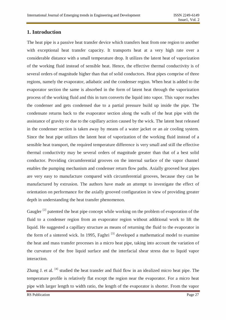
1. Introduction
The heat pipe is a passive heat transfer device which transfers heat from one region to another
with exceptional heat transfer capacity. It transports heat at a very high rate over a
considerable distance with a small temperature drop. It utilizes the latent heat of vaporization
of the working fluid instead of sensible heat. Hence, the effective thermal conductivity is of
several orders of magnitude higher than that of solid conductors. Heat pipes comprise of three
regions, namely the evaporator, adiabatic and the condenser region. When heat is added to the
evaporator section the same is absorbed in the form of latent heat through the vaporization
process of the working fluid and this in turn converts the liquid into vapor. This vapor reaches
the condenser and gets condensed due to a partial pressure build up inside the pipe. The
condensate returns back to the evaporator section along the walls of the heat pipe with the
assistance of gravity or due to the capillary action caused by the wick. The latent heat released
in the condenser section is taken away by means of a water jacket or an air cooling system.
Since the heat pipe utilizes the latent heat of vaporization of the working fluid instead of a
sensible heat transport, the required temperature difference is very small and still the effective
thermal conductivity may be several orders of magnitude greater than that of a best solid
conductor. Providing circumferential grooves on the internal surface of the vapor channel
enables the pumping mechanism and condenser return flow paths. Axially grooved heat pipes
are very easy to manufacture compared with circumferential grooves, because they can be
manufactured by extrusion. The authors have made an attempt to investigate the effect of
orientation on performance for the axially grooved configuration in view of providing greater
depth in understanding the heat transfer phenomenon.
Gaugler [2]
patented the heat pipe concept while working on the problem of evaporation of the
fluid to a condenser region from an evaporator region without additional work to lift the
liquid. He suggested a capillary structure as means of returning the fluid to the evaporator in
the form of a sintered wick. In 1995, Faghri [3]
developed a mathematical model to examine
the heat and mass transfer processes in a micro heat pipe, taking into account the variation of
the curvature of the free liquid surface and the interfacial shear stress due to liquid vapor
interaction.
Zhang J. et al. [4]
studied the heat transfer and fluid flow in an idealized micro heat pipe. The
temperature profile is relatively flat except the region near the evaporator. For a micro heat
pipe with larger length to width ratio, the length of the evaporator is shorter. From the vapor

International Journal of Emerging trends in Engineering and Development ISSN 2249-6149
Issue1, Vol. 2
RS Publication Page 28
pressure distribution, it was observed that the pressure varies linearly and is not strongly
affected by the length to width ratio. On evaluating, the effective thermal conductivity of a
micro heat pipe increases with increase in the evaporation area as well as length or width of
the micro heat pipe. It was also reported that a fluid with larger latent heat would produce
larger effective thermal conductivity.
Robert Richter et al [5]
developed thermodynamic aspects of heat pipe operation. In this article
the general operation and performance of heat pipes is approached from a fundamental
thermodynamic considerations. Scott et al. [6]
developed the effect of working fluid inventory
on the performance of revolving helically grooved heat pipes. Recent experiments have
shown that the capillary limit of a helically grooved heat pipe (HGHP) was increased
significantly when the transverse body force field was increased. This was due to the
geometry of a helical groove wick structure.
Khrustalev et al. [7]
developed a mathematical model for a low temperature axially grooved
heat pipe with emphasis on capillary and boiling limitations. The design of heat pipe is a very
complex process involving different physical variables such as the shape, size, weight and
volume, thermo physical properties such as working fluid, wicking structure and container
material. The thermal loads, transport length, evaporator and condenser length, operating
temperature ranges, fluid inventories and temperature environments also play a major role in
the design of the heat pipes. The present study intends to design, fabricate and test for key
performance parameters of an axially grooved wick assisted heat pipe for two different
orientations.
2 Design Considerations
The maximum heat transport capability of the heat pipe is governed by several limiting factors
which must be addressed while designing the heat pipe. There are five primary heat transport
limitations which include: viscous limit, sonic limit and capillary pumping limit, entrainment or
flooding limit and boiling limit [3]
. Each heat transport limitation is summarized as follows:

International Journal of Emerging trends in Engineering and Development ISSN 2249-6149
Issue1, Vol. 2
RS Publication Page 29
2.1 Capillary Limit
The capillary limit is set by the pumping capacity of the wick structure. It is a strong function of
the operating orientation and the type of wick structure. The two most important properties of a
wick are the pore radius and the permeability. The pore radius determines the pumping pressure
the wick can develop. The permeability determines the frictional losses of the fluid as it flows
through the wick. There are several types of wick structures available including: grooved, screen,
cables/fibres, and sintered powder metal.
Grooved wicks have a large pore radius and a high permeability, as a result the pressure losses
are low but the pumping head is also low. Grooved wicks can transfer high heat loads in a
horizontal or gravity aided position, but cannot transfer large loads against gravity. The powder
metal wicks on the opposite end of the list have small pore radii and relatively low permeability.
Powder metal wicks are limited by pressure drops in the horizontal position but can transfer large
loads against gravity. It is recommended that the liquid fill should be at least 50% of the volume
of the evaporator [8]
.
The volume of liquid is given by:
Vl .001d le+ la+ lc 1
The fundamental drive mechanism that governs the operation of these devices emerges from the
difference in the capillary pressure across the liquid vapour interfaces in the evaporator and
condenser regions. Vaporization from the evaporator section of a heat pipe causes the meniscus
to recede into the wick and condensation in the condenser causes flooding. The point at which
the meniscus has minimum radius of curvature is referred to as the “dry” point and this usually
occurs in the evaporator at a point farthest from the condenser region. The “wet” point occurs at
that point where the vapour pressure and liquid pressure are approximately equal or where the
radius of curvature is at maximum. For a heat pipe to function properly, the net capillary pressure
difference between wet and dry points must be greater than the summation of all the pressure
losses occurring throughout the liquid and vapour flow paths. This relationship is referred to as
the capillary limitation [10]
which can be expressed as:
ΔPc m ≥ leff ∂pv
∂x dx +
∂Pl
∂xdx + ΔPh,e + ΔPh,c + ΔPll + ΔP+ (2)

International Journal of Emerging trends in Engineering and Development ISSN 2249-6149
Issue1, Vol. 2
RS Publication Page 30
2.2 Sonic Velocity Limit
qs = 0.474λAv (ρvPv )0.5 (3)
The sonic limit heat capacity sq is always higher than the desired capacity in order to ensure that
sonic velocities will not be encountered during the heat pipe operation.
2.3 Entrainment Limit
qent = Avhfg σρg
2rhs
1/2 (4)
If entq is greater than the desired heat transport, the design operation is not hindered by
entrainment.
2.4 Boiling Limit
qb
= 2πLeff Keff Tv
λρvln
ri
rv
2σ
rn
− Δpcm (5)
Not operating within the boiling limit could result in nucleate boiling phenomenon which could
potentially cause the vapour bubbles to block the return of the working fluid back to the
evaporator.
2.5 Design Calculations
For calculations the [8,9]
volume of the fluid should always be greater than 0.6 ml. The total
evaporator volume is approximately one-third the volume of the heat pipe. The cross sectional
details are shown in figure 1.
Fig. 1 The cross sectional view of Grooved heat pipe

International Journal of Emerging trends in Engineering and Development ISSN 2249-6149
Issue1, Vol. 2
RS Publication Page 31
Vevap orator = πD2L/ 3 (6)
The heat pipe design parameters in the present experimental investigation are well within the
operational limitations of a conventional heat pipe. Provision is made for an allowance of 30%
for losses during filling and degasification of the working fluid. The total evaporator volume is
taken as 3.267ml and fill ratio of 60%.
3. Fabrication
A copper tube is selected with the OD of 8 mm, ID of 4 mm, and length of 150 mm. Boring
process is carried out. The grooving is done axially on the inner periphery of the pipe using wire
cutting process. A brass wire of 0.2mm square cross section is used for creating the grooves of
the required dimensions. This procedure is carried out with a CNC machine. Six Copper annular
fins were then copper brazed onto the pipe in the condenser region to ensure proper cooling of
the vapors. The fins were arranged at an angle of 60o
to the pipe around the condenser region of
the pipe. This ensures effective heat dissipation. The dimensions of the fins are: 50x15x1(mm3).
4. Description of the Experimental setup and the Experimental Procedure
A
B
CD
E
F
G
H
I
J
K
A Data recorderB Auto transformerC ThermocouplesD Grooved heat pipesE Cooling FanF ClinometerG Moisture trapH SS flex houseI Pressure gaugeJ Vaccum pumpK Pirani gauge
Fig. 2: The experimental test rig
The experimental setup as shown in figure 2 consists of a grooved wick assisted heat pipe, Data
acquisition system, vacuum pump, digital Pirani gauge and a power supply unit. The important
factors to be considered in the selection of heat pipe material are compatibility with working

International Journal of Emerging trends in Engineering and Development ISSN 2249-6149
Issue1, Vol. 2
RS Publication Page 32
fluid and external environment, thermal conductivity, fabrication process complexity, wet ability,
strength to weight ratio and porosity. Of the possible candidates like aluminium, copper, bronze
and stainless steel, copper is selected because of its advantages like high thermal conductivity
and better corrosion resistance. Thermocouples are used to measure the temperature variation
along the pipe length and are connected to the data acquisition system which stores and analyzes
the values. Nine thermocouples of J-type are connected along the length of the heat pipe with a
spacing of 12.5 mm between the junctions. J-type (Iron-Constantan, 1 mm diameter)
thermocouples used have a temperature range of (−40 to +750) °C and sensitivity of ~52 μV/°C,
suitable for the temperature range encountered and the sensitivity requirements. Three
thermocouples each are used for evaporator, adiabatic and condenser region respectively. A 15-
channel digital data acquisition system that can record experimental data on the computer is
used. This is essential in a project of this nature where several experiments were carried out, each
requiring over 100 temperature readings.
The DAQ records the simultaneous temperatures of the 9 thermocouples. It uses 15 Pro Scan
channel temperature scanners with a range of 0-200ºC, 230V. Additionally an RS 485 interface
facility and RS 232 to RS 435 conversion option is available. A block heater is used with a
power rating of 65W and resistance of 800Ω. In order to avoid the loss of heat, insulation is
provided surrounding the clamp. The evaporator and adiabatic section is insulated using glass
wool. A fan is installed at the condenser fins to achieve forced convection cooling. The vacuum
pump is used to maintain the required pressure within the heat pipe. An autotransformer and a
multi meter are provided to control and measure the electrical power input to the heater
respectively. The evaporator end of the pipe is sealed and the condenser end is connected to the
control valve to vary the charge volume. Working fluid is metered and charged through the fluid
inlet valve and sealed under required vacuum level. Another opening at the condenser end is
provided radially to connect the vacuum pump. An ED6 Hindvac vacuum pump with Nominal
Pumping rate of 6m3/hr and ultimate partial Pressure (on McLeod Gauge) of 5x10
-4mbar is used.
The Pump rotating speed at no load conditions is 1340-1440 rpm. Oil Capacity is 2 x 10⁻³
m3.
The vacuum level is measured by a digital Pirani gauge (Hindhivac Pirani Model HPS-2), which
has a pressure range of 0.001-1000mbars. The ball valve is made of Brass with a temperature
Range of (10 - 65)
0C. Ball Material type is stainless steel and Sealing Material is Poly-Tetra-
Fluro-Ethylene. When the vacuum pump is operated, there are chances that the working fluid
may get sucked into the pump. This may damage the working parts of the pump. Hence a
moisture trap is used with different levels of entry and exit points to prevent this from happening.

International Journal of Emerging trends in Engineering and Development ISSN 2249-6149
Issue1, Vol. 2
RS Publication Page 33
A tangential flow of the liquid is setup in the apparatus so that the heavy particles of the fluid are
trapped in the apparatus. It consists of a hollow cubical box of 300mm dimension. Flexible
tubing is provided between the vacuum pump, moisture trap and heat pipe. The connection
between the vacuum pump and the moisture trap is a stainless steel tube of diameter 37.5mm.
The connection between the moisture trap and the heat pipe is made using a Polyurethane tube.
Various plots are drawn to study the performance of the wick and to optimise the heat transfer
characteristics. The steady state temperature, overall heat transfer co-efficient, the thermal
resistances are calculated and the graphs are plotted. The performances of these parameters are
now compared to the working of a heat pipe without a wick.
5 Results and Discussions
The experiments were conducted at a constant working pressure of 500 mbar choosing three
different working fluids and for two different orientations and operating limits as detailed above.
The heat pipe without a working fluid represents heat transfer in a regular metallic conductor
termed as Dry run in the experiment. Its performance is considered as the base for the
evaluation of heat pipe (i.e. with working fluid in it).
Figure 3 represents variation of temperature difference between evaporator and condenser with
respect to heat input for (0 0) orientation.
International Journal of Emerging trends in Engineering and Development ISSN 2249-6149
Issue1, Vol. 2
RS Publication Page 34
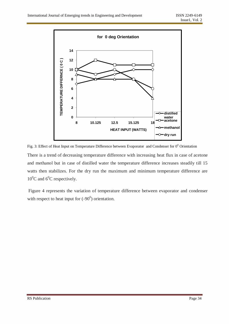
Fig. 3: Effect of Heat Input on Temperature Difference between Evaporator and Condenser for 00 Orientation
There is a trend of decreasing temperature difference with increasing heat flux in case of acetone
and methanol but in case of distilled water the temperature difference increases steadily till 15
watts then stabilizes. For the dry run the maximum and minimum temperature difference are
100C and 6
0C respectively.
Figure 4 represents the variation of temperature difference between evaporator and condenser
with respect to heat input for (-900) orientation.
0
2
4
6
8
10
12
14
8 10.125 12.5 15.125 18
TE
MP
ER
AT
UR
E D
IFF
ER
NC
E (
0 C
)
HEAT INPUT (WATTS)
for 0 deg Orientation
distilled water acetone
methanol
dry run

International Journal of Emerging trends in Engineering and Development ISSN 2249-6149
Issue1, Vol. 2
RS Publication Page 35
Fig. 4: Effect of Heat Input on Temperature Difference between Evaporator and Condenser for -90 0 Orientation
The volatility of changes in temperature difference is not so pronounced in any of the working
fluids especially in the case of methanol it is irresponsive to the increasing heat flux in gravity-
assisted orientation. As modelled by faghri et al [3]
the expression for temperature difference.
Tw, o − Tv, e =1
2πRoLe
dQ
dz
Le
0
1
hhe
dz (7)
Between pipe Inner Wall and evaporator section is given by equation 16. Similar expression
exists for temperature difference between Condenser section and pipe inner wall. The difference
between Wall-Evaporator and Condenser-Wall heat transfer coefficients remains constant in case
of methanol. Hence the heat transfer is actually near isothermal. For the dry run the maximum
and minimum temperature difference are 120C and 10
0C.
In figure 5 representing enthalpy variation with heat flux for 0 0 orientation, it is observed that
there is positive rate of increase of enthalpy however the slope is maximum in cases of methanol
and minimum in case of acetone.
0
2
4
6
8
10
12
14
16
18
8 10.125 12.5 15.125 18
TE
MP
ER
AT
UR
E D
IFF
ER
NC
E (
0C
)
HEAT INPUT (W)
for -90 deg Orientation
distilled water acetone
methanol

International Journal of Emerging trends in Engineering and Development ISSN 2249-6149
Issue1, Vol. 2
RS Publication Page 36
Fig. 5: Effect of Heat Input on Total Enthalpy for 00 Orientation
There is evidence in all the working fluids at both orientations that the temperatures at evaporator
and condenser slightly increase in the beginning as there is some sensible heat addition after
which there is a drop that is characteristic of the onset of evaporation and condensation processes
after which there is more or less isothermal operation. For the dry run the slope becomes steeper
after 12.5 watts and highest recorded enthalpy is 2400 W/m2 0
C.As seen in figure 6 representing
enthalpy variation with heat flux for -90 0 orientation the slope of increase is maximum in case of
distilled water and minimum in case methanol.
Fig. 6: Effect of Heat Input on Total Enthalpy for -90 0 Orientation
0
500
1000
1500
2000
2500
3000
3500
4000
8 10.125 12.5 15.125 18
EN
TH
AL
PY
h
HEAT INPUT (W)
for 0 deg Orientation
distilled water
acetone
methanol
0
500
1000
1500
2000
2500
3000
8 10.125 12.5 15.125 18
EN
TH
AL
PY
h
HEAT INPUT (W)
for -90 deg Orientation
distilled water acetone
methanol

International Journal of Emerging trends in Engineering and Development ISSN 2249-6149
Issue1, Vol. 2
RS Publication Page 37
For dry run the slope is not as steep as in case of the horizontal orientation and achieves a
maximum enthalpy of 1050 W/m2 0
C.
In figure 7, representing the variation of thermal resistance with respect to heat flux for 0 0
orientation, the slope of decrease of thermal resistance is maximum in case of methanol and
minimum in case of distilled water.
Fig. 7: Effect of Heat Input on Thermal resistance for 00 Orientation
For dry run the thermal resistance curve is steeply declining and reaches a minimum of
0.350C/W. In gravity assisted orientation as seen in figure 8, methanol has maximum slope and
acetone forms the other end of the spectrum with minimum slope.
Fig. 8: Effect of Heat Input on Thermal resistance for -90 0 Orientation
0
0.2
0.4
0.6
0.8
1
1.2
1.4
8 10.125 12.5 15.125 18
TH
ER
MA
L R
ES
IST
AN
CE
HEAT INPUT (W)
for 0 deg Orientation
distilled water acetone
methanol
0
0.5
1
1.5
2
2.5
8 10.125 12.5 15.125 18
TH
ER
MA
L R
ES
IST
AN
CE
HEAT INPUT (W)
for -90 deg Orientation
distilled water acetone
methanol

International Journal of Emerging trends in Engineering and Development ISSN 2249-6149
Issue1, Vol. 2
RS Publication Page 38
This is seen owing to a wide difference in the thermo physical properties of the two working
fluids. For the dry run the maximum and minimum thermal resistances are 1.2 0C/W and 0.75
0C/W respectively.
6 Conclusions
The experiments have been conducted using three different working fluids as detailed above
in Section 5. The following conclusions were drawn.
1. The maximum heat transfer coefficient found in the horizontal orientation at 3550
W/m2 o
C at 60% fill ratio and 500 mbar pressure, 1700 W/m2 o
C at 60% fill ratio and 500
mbar vacuum pressure for vertical orientation respectively for methanol and acetone. Finally,
the maximum heat transfer coefficient of the grooved heat pipe for distilled water is found in
the vertical orientation at 2400 W/m2 o
C at 60% fill ratio and 500 mbar vacuum pressure.
These findings clearly indicate that the role of gravity is working fluid selective in influencing
performance.
2. Merit number determines the maximum possible heat transfer for a given heat pipe.
However, merit number alone cannot be the decisive parameter in rating the working fluid as it is
quite evident from the results that the merit number is high in case of distilled water compared to
acetone and methanol though methanol is seen to be the most effective working fluid. This
indicates the strong influence of geometry on the performance of heat pipe.
3. There is a significant increase in thermal resistance for the gravity assisted orientation
when compared with the horizontal position. The influence would only get compounded as the
heat input is increased to higher wattages and hence needs to be further investigated for high heat
flux conditions.
References
[1] Eastman, G.Y. The Heat Pipe. Scientific American, 1968, 218 (5), pp 38-46.
[2] Gaugler, R.S. Heat Transfer Device. US Patent, 2350348, Appl. 21st December, 1942,
Published 6 June, 1944.
[3] Faghri, Heat Pipe Science and Technology, Taylor and Francis, Washington, D.C., 1995.
[4] Zhang, J. and H. Wong "Evaporation, condensation, and flow in an idealized micro heat
pipe," Proceedings of ASME IMECE 2002 , paper No. 39196, (2002).

International Journal of Emerging trends in Engineering and Development ISSN 2249-6149
Issue1, Vol. 2
RS Publication Page 39
[5] Richter, Robert; Gottschlich, Joseph M. Thermodynamic aspects of heat pipe operation.
Journal of Thermo physics and Heat Transfer (ISSN 0887-8722), vol. 8, no. 2, p. 334-340
[6] Scott K. Thomas; R. M. Castle; Kirk L. Yerkes; The Effect of Working Fluid Inventory
on the Performance of Revolving Helically Grooved Heat Pipes, J. Heat Transfer --
February 2001 -- Volume 123, Issue 1, 120
[7] D. Khrustalev and A. Faghri ; Thermal Characteristics of Conventional and Flat Miniature
Axially Grooved Heat Pipes. J. Heat Transfer -- November 1995 -- Volume 117, Issue
4, 1048
[8] Sreenivasa, T.N, Sridhara, S. N and Pundarika.G, “Working Fluid Inventory in Miniature
Heat Pipe”, International Conference on Mechanical Engineering, BUET, Dhaka,
Bangladesh (Dec 28-30, 2005)..
[9] George P. Peterson An introduction to heat pipes: modeling, testing, and applications Wiley
series in Thermal Management of Microelectronic and Electronic systems.1994. John Wiley
& Sons.

