HALCON/HDevelop - MVTec Software GmbH
949
HALCON Version 6.0.4 MVTec Software GmbH HALCON/HDevelop Reference Manual
-
Upload
khangminh22 -
Category
Documents
-
view
0 -
download
0
Transcript of HALCON/HDevelop - MVTec Software GmbH

HALCON Version 6.0.4
MVTec Software GmbH
HALCON/HDevelop
Reference Manual

This manual describes the operators of the image analysis system HALCON, version 6.0.4, in HDevelop syntax.It was generated on July 21, 2003.
All rights reserved. No part of this publication may be reproduced, stored in a retrieval system, or transmitted, inany form or by any means, electronic, mechanical, photocopying, recording, or otherwise, without prior writtenpermission of the publisher.
Copyright c© 1997-2003 by MVTec Software GmbH, M¨unchen, Germany MVTec Software GmbH
More information about HALCON can be found at: http://www.mvtec.com

Contents
1 Classification 1clearsampset . . . . . . . . . . . . . . . . . . . . . . . . . . . . . . . . . . . . . . . . . . . . 1closeall classbox . . . . . . . . . . . . . . . . . . . . . . . . . . . . . . . . . . . . . . . . . . 1closeclassbox . . . . . . . . . . . . . . . . . . . . . . . . . . . . . . . . . . . . . . . . . . . 2createclassbox . . . . . . . . . . . . . . . . . . . . . . . . . . . . . . . . . . . . . . . . . . . 2descriptclassbox . . . . . . . . . . . . . . . . . . . . . . . . . . . . . . . . . . . . . . . . . . 2enquireclassbox . . . . . . . . . . . . . . . . . . . . . . . . . . . . . . . . . . . . . . . . . . 3enquirerejectclassbox . . . . . . . . . . . . . . . . . . . . . . . . . . . . . . . . . . . . . . . 4get classbox param. . . . . . . . . . . . . . . . . . . . . . . . . . . . . . . . . . . . . . . . . 4learnclassbox . . . . . . . . . . . . . . . . . . . . . . . . . . . . . . . . . . . . . . . . . . . 5learnsampsetbox . . . . . . . . . . . . . . . . . . . . . . . . . . . . . . . . . . . . . . . . . . 6readclassbox . . . . . . . . . . . . . . . . . . . . . . . . . . . . . . . . . . . . . . . . . . . . 7readsampset. . . . . . . . . . . . . . . . . . . . . . . . . . . . . . . . . . . . . . . . . . . . . 7set classbox param . . . . . . . . . . . . . . . . . . . . . . . . . . . . . . . . . . . . . . . . . 8test sampsetbox . . . . . . . . . . . . . . . . . . . . . . . . . . . . . . . . . . . . . . . . . . . 9write classbox . . . . . . . . . . . . . . . . . . . . . . . . . . . . . . . . . . . . . . . . . . . 9
2 Control 11assign . . . . . . . . . . . . . . . . . . . . . . . . . . . . . . . . . . . . . . . . . . . . . . . . 11break . . . . . . . . . . . . . . . . . . . . . . . . . . . . . . . . . . . . . . . . . . . . . . . . . 12comment. . . . . . . . . . . . . . . . . . . . . . . . . . . . . . . . . . . . . . . . . . . . . . . 12exit . . . . . . . . . . . . . . . . . . . . . . . . . . . . . . . . . . . . . . . . . . . . . . . . . . 13for . . . . . . . . . . . . . . . . . . . . . . . . . . . . . . . . . . . . . . . . . . . . . . . . . . 13if . . . . . . . . . . . . . . . . . . . . . . . . . . . . . . . . . . . . . . . . . . . . . . . . . . . 15ifelse . . . . . . . . . . . . . . . . . . . . . . . . . . . . . . . . . . . . . . . . . . . . . . . . . 15insert . . . . . . . . . . . . . . . . . . . . . . . . . . . . . . . . . . . . . . . . . . . . . . . . . 16stop . . . . . . . . . . . . . . . . . . . . . . . . . . . . . . . . . . . . . . . . . . . . . . . . . 17while . . . . . . . . . . . . . . . . . . . . . . . . . . . . . . . . . . . . . . . . . . . . . . . . . 17
3 Develop 19dev clearobj . . . . . . . . . . . . . . . . . . . . . . . . . . . . . . . . . . . . . . . . . . . . 19dev clearwindow . . . . . . . . . . . . . . . . . . . . . . . . . . . . . . . . . . . . . . . . . . 19dev closeinspectctrl . . . . . . . . . . . . . . . . . . . . . . . . . . . . . . . . . . . . . . . . 20dev closewindow . . . . . . . . . . . . . . . . . . . . . . . . . . . . . . . . . . . . . . . . . . 20dev display . . . . . . . . . . . . . . . . . . . . . . . . . . . . . . . . . . . . . . . . . . . . . 21dev error var . . . . . . . . . . . . . . . . . . . . . . . . . . . . . . . . . . . . . . . . . . . . . 22dev inspectctrl . . . . . . . . . . . . . . . . . . . . . . . . . . . . . . . . . . . . . . . . . . . 23dev mappar . . . . . . . . . . . . . . . . . . . . . . . . . . . . . . . . . . . . . . . . . . . . . 23dev mapprog . . . . . . . . . . . . . . . . . . . . . . . . . . . . . . . . . . . . . . . . . . . . 24dev mapvar . . . . . . . . . . . . . . . . . . . . . . . . . . . . . . . . . . . . . . . . . . . . . 24dev openwindow . . . . . . . . . . . . . . . . . . . . . . . . . . . . . . . . . . . . . . . . . . 24dev set check . . . . . . . . . . . . . . . . . . . . . . . . . . . . . . . . . . . . . . . . . . . . 27dev set color . . . . . . . . . . . . . . . . . . . . . . . . . . . . . . . . . . . . . . . . . . . . . 27dev set colored . . . . . . . . . . . . . . . . . . . . . . . . . . . . . . . . . . . . . . . . . . . 28dev setdraw . . . . . . . . . . . . . . . . . . . . . . . . . . . . . . . . . . . . . . . . . . . . . 29dev set line width . . . . . . . . . . . . . . . . . . . . . . . . . . . . . . . . . . . . . . . . . . 30dev set lut . . . . . . . . . . . . . . . . . . . . . . . . . . . . . . . . . . . . . . . . . . . . . . 30

dev setpaint . . . . . . . . . . . . . . . . . . . . . . . . . . . . . . . . . . . . . . . . . . . . . 31dev setpart . . . . . . . . . . . . . . . . . . . . . . . . . . . . . . . . . . . . . . . . . . . . . 32dev set shape . . . . . . . . . . . . . . . . . . . . . . . . . . . . . . . . . . . . . . . . . . . . 33dev setwindow . . . . . . . . . . . . . . . . . . . . . . . . . . . . . . . . . . . . . . . . . . . 34dev setwindow extents . . . . . . . . . . . . . . . . . . . . . . . . . . . . . . . . . . . . . . . 34dev unmappar . . . . . . . . . . . . . . . . . . . . . . . . . . . . . . . . . . . . . . . . . . . 36dev unmapprog . . . . . . . . . . . . . . . . . . . . . . . . . . . . . . . . . . . . . . . . . . . 36dev unmapvar . . . . . . . . . . . . . . . . . . . . . . . . . . . . . . . . . . . . . . . . . . . . 36dev updatepc . . . . . . . . . . . . . . . . . . . . . . . . . . . . . . . . . . . . . . . . . . . . 37dev updatetime . . . . . . . . . . . . . . . . . . . . . . . . . . . . . . . . . . . . . . . . . . . 37dev updatevar . . . . . . . . . . . . . . . . . . . . . . . . . . . . . . . . . . . . . . . . . . . . 38dev updatewindow . . . . . . . . . . . . . . . . . . . . . . . . . . . . . . . . . . . . . . . . . 38
4 File 414.1 Images. . . . . . . . . . . . . . . . . . . . . . . . . . . . . . . . . . . . . . . . . . . . . . . . 41
readimage . . . . . . . . . . . . . . . . . . . . . . . . . . . . . . . . . . . . . . . . . . . . . . 41readsequence. . . . . . . . . . . . . . . . . . . . . . . . . . . . . . . . . . . . . . . . . . . . 42write image . . . . . . . . . . . . . . . . . . . . . . . . . . . . . . . . . . . . . . . . . . . . . 44
4.2 Misc . . . . . . . . . . . . . . . . . . . . . . . . . . . . . . . . . . . . . . . . . . . . . . . . . 45file exists . . . . . . . . . . . . . . . . . . . . . . . . . . . . . . . . . . . . . . . . . . . . . . 45readworld file . . . . . . . . . . . . . . . . . . . . . . . . . . . . . . . . . . . . . . . . . . . . 46
4.3 Region . . . . . . . . . . . . . . . . . . . . . . . . . . . . . . . . . . . . . . . . . . . . . . . . 46readregion. . . . . . . . . . . . . . . . . . . . . . . . . . . . . . . . . . . . . . . . . . . . . . 46write region . . . . . . . . . . . . . . . . . . . . . . . . . . . . . . . . . . . . . . . . . . . . . 47
4.4 Text . . . . . . . . . . . . . . . . . . . . . . . . . . . . . . . . . . . . . . . . . . . . . . . . . 48closeall files . . . . . . . . . . . . . . . . . . . . . . . . . . . . . . . . . . . . . . . . . . . . 48closefile . . . . . . . . . . . . . . . . . . . . . . . . . . . . . . . . . . . . . . . . . . . . . . . 48fnew line . . . . . . . . . . . . . . . . . . . . . . . . . . . . . . . . . . . . . . . . . . . . . . . 48freadchar . . . . . . . . . . . . . . . . . . . . . . . . . . . . . . . . . . . . . . . . . . . . . . 49freadstring . . . . . . . . . . . . . . . . . . . . . . . . . . . . . . . . . . . . . . . . . . . . . 50fwrite string . . . . . . . . . . . . . . . . . . . . . . . . . . . . . . . . . . . . . . . . . . . . . 50openfile . . . . . . . . . . . . . . . . . . . . . . . . . . . . . . . . . . . . . . . . . . . . . . . 51
4.5 Tuple. . . . . . . . . . . . . . . . . . . . . . . . . . . . . . . . . . . . . . . . . . . . . . . . . 52readtuple . . . . . . . . . . . . . . . . . . . . . . . . . . . . . . . . . . . . . . . . . . . . . . 52write tuple . . . . . . . . . . . . . . . . . . . . . . . . . . . . . . . . . . . . . . . . . . . . . . 52
4.6 XLD . . . . . . . . . . . . . . . . . . . . . . . . . . . . . . . . . . . . . . . . . . . . . . . . . 53readcontourxld arc info . . . . . . . . . . . . . . . . . . . . . . . . . . . . . . . . . . . . . . 53readpolygonxld arc info . . . . . . . . . . . . . . . . . . . . . . . . . . . . . . . . . . . . . . 54write contourxld arc info . . . . . . . . . . . . . . . . . . . . . . . . . . . . . . . . . . . . . 54write polygonxld arc info . . . . . . . . . . . . . . . . . . . . . . . . . . . . . . . . . . . . . 55
5 Filter 575.1 Affine-Transformations. . . . . . . . . . . . . . . . . . . . . . . . . . . . . . . . . . . . . . . 57
affine transimage . . . . . . . . . . . . . . . . . . . . . . . . . . . . . . . . . . . . . . . . . . 57mirror image. . . . . . . . . . . . . . . . . . . . . . . . . . . . . . . . . . . . . . . . . . . . . 59polar transimage . . . . . . . . . . . . . . . . . . . . . . . . . . . . . . . . . . . . . . . . . . 59rotateimage . . . . . . . . . . . . . . . . . . . . . . . . . . . . . . . . . . . . . . . . . . . . . 60zoomimagefactor . . . . . . . . . . . . . . . . . . . . . . . . . . . . . . . . . . . . . . . . . 61zoomimagesize . . . . . . . . . . . . . . . . . . . . . . . . . . . . . . . . . . . . . . . . . . 62
5.2 Arithmetic . . . . . . . . . . . . . . . . . . . . . . . . . . . . . . . . . . . . . . . . . . . . . . 63absimage . . . . . . . . . . . . . . . . . . . . . . . . . . . . . . . . . . . . . . . . . . . . . . 63add image . . . . . . . . . . . . . . . . . . . . . . . . . . . . . . . . . . . . . . . . . . . . . . 64div image . . . . . . . . . . . . . . . . . . . . . . . . . . . . . . . . . . . . . . . . . . . . . . 65invert image . . . . . . . . . . . . . . . . . . . . . . . . . . . . . . . . . . . . . . . . . . . . . 66max image . . . . . . . . . . . . . . . . . . . . . . . . . . . . . . . . . . . . . . . . . . . . . . 66min image . . . . . . . . . . . . . . . . . . . . . . . . . . . . . . . . . . . . . . . . . . . . . . 67mult image . . . . . . . . . . . . . . . . . . . . . . . . . . . . . . . . . . . . . . . . . . . . . 68scaleimage . . . . . . . . . . . . . . . . . . . . . . . . . . . . . . . . . . . . . . . . . . . . . 69

sub image . . . . . . . . . . . . . . . . . . . . . . . . . . . . . . . . . . . . . . . . . . . . . . 70
5.3 Bit . . . . . . . . . . . . . . . . . . . . . . . . . . . . . . . . . . . . . . . . . . . . . . . . . . 71bit and . . . . . . . . . . . . . . . . . . . . . . . . . . . . . . . . . . . . . . . . . . . . . . . . 71bit lshift . . . . . . . . . . . . . . . . . . . . . . . . . . . . . . . . . . . . . . . . . . . . . . . 72bit mask . . . . . . . . . . . . . . . . . . . . . . . . . . . . . . . . . . . . . . . . . . . . . . . 73bit not . . . . . . . . . . . . . . . . . . . . . . . . . . . . . . . . . . . . . . . . . . . . . . . . 73bit or . . . . . . . . . . . . . . . . . . . . . . . . . . . . . . . . . . . . . . . . . . . . . . . . . 74bit rshift . . . . . . . . . . . . . . . . . . . . . . . . . . . . . . . . . . . . . . . . . . . . . . . 75bit slice . . . . . . . . . . . . . . . . . . . . . . . . . . . . . . . . . . . . . . . . . . . . . . . 75bit xor . . . . . . . . . . . . . . . . . . . . . . . . . . . . . . . . . . . . . . . . . . . . . . . . 76
5.4 Color . . . . . . . . . . . . . . . . . . . . . . . . . . . . . . . . . . . . . . . . . . . . . . . . . 77rgb1 to gray . . . . . . . . . . . . . . . . . . . . . . . . . . . . . . . . . . . . . . . . . . . . . 77rgb3 to gray . . . . . . . . . . . . . . . . . . . . . . . . . . . . . . . . . . . . . . . . . . . . . 78transfrom rgb . . . . . . . . . . . . . . . . . . . . . . . . . . . . . . . . . . . . . . . . . . . . 78transto rgb . . . . . . . . . . . . . . . . . . . . . . . . . . . . . . . . . . . . . . . . . . . . . 82
5.5 Edges. . . . . . . . . . . . . . . . . . . . . . . . . . . . . . . . . . . . . . . . . . . . . . . . . 85closeedges . . . . . . . . . . . . . . . . . . . . . . . . . . . . . . . . . . . . . . . . . . . . . 85closeedgeslength . . . . . . . . . . . . . . . . . . . . . . . . . . . . . . . . . . . . . . . . . . 86derivategauss . . . . . . . . . . . . . . . . . . . . . . . . . . . . . . . . . . . . . . . . . . . . 87diff of gauss. . . . . . . . . . . . . . . . . . . . . . . . . . . . . . . . . . . . . . . . . . . . . 90edgesimage . . . . . . . . . . . . . . . . . . . . . . . . . . . . . . . . . . . . . . . . . . . . . 91edgessubpix . . . . . . . . . . . . . . . . . . . . . . . . . . . . . . . . . . . . . . . . . . . . 94frei amp . . . . . . . . . . . . . . . . . . . . . . . . . . . . . . . . . . . . . . . . . . . . . . . 96frei dir . . . . . . . . . . . . . . . . . . . . . . . . . . . . . . . . . . . . . . . . . . . . . . . . 97highpassimage . . . . . . . . . . . . . . . . . . . . . . . . . . . . . . . . . . . . . . . . . . . 98info edges . . . . . . . . . . . . . . . . . . . . . . . . . . . . . . . . . . . . . . . . . . . . . . 99kirsch amp . . . . . . . . . . . . . . . . . . . . . . . . . . . . . . . . . . . . . . . . . . . . . . 100kirsch dir . . . . . . . . . . . . . . . . . . . . . . . . . . . . . . . . . . . . . . . . . . . . . . 101laplace . . . . . . . . . . . . . . . . . . . . . . . . . . . . . . . . . . . . . . . . . . . . . . . . 102laplaceof gauss . . . . . . . . . . . . . . . . . . . . . . . . . . . . . . . . . . . . . . . . . . . 104prewitt amp . . . . . . . . . . . . . . . . . . . . . . . . . . . . . . . . . . . . . . . . . . . . . 105prewitt dir . . . . . . . . . . . . . . . . . . . . . . . . . . . . . . . . . . . . . . . . . . . . . . 105roberts . . . . . . . . . . . . . . . . . . . . . . . . . . . . . . . . . . . . . . . . . . . . . . . . 107robinsonamp . . . . . . . . . . . . . . . . . . . . . . . . . . . . . . . . . . . . . . . . . . . . 107robinsondir . . . . . . . . . . . . . . . . . . . . . . . . . . . . . . . . . . . . . . . . . . . . . 108sobelamp . . . . . . . . . . . . . . . . . . . . . . . . . . . . . . . . . . . . . . . . . . . . . . 109sobeldir . . . . . . . . . . . . . . . . . . . . . . . . . . . . . . . . . . . . . . . . . . . . . . . 111
5.6 Enhancement. . . . . . . . . . . . . . . . . . . . . . . . . . . . . . . . . . . . . . . . . . . . . 112emphasize. . . . . . . . . . . . . . . . . . . . . . . . . . . . . . . . . . . . . . . . . . . . . . 112equhisto image . . . . . . . . . . . . . . . . . . . . . . . . . . . . . . . . . . . . . . . . . . . 114illuminate . . . . . . . . . . . . . . . . . . . . . . . . . . . . . . . . . . . . . . . . . . . . . . 114scaleimagemax . . . . . . . . . . . . . . . . . . . . . . . . . . . . . . . . . . . . . . . . . . 116
5.7 FFT . . . . . . . . . . . . . . . . . . . . . . . . . . . . . . . . . . . . . . . . . . . . . . . . . 116convol fft . . . . . . . . . . . . . . . . . . . . . . . . . . . . . . . . . . . . . . . . . . . . . . 116convol gabor. . . . . . . . . . . . . . . . . . . . . . . . . . . . . . . . . . . . . . . . . . . . . 117energygabor. . . . . . . . . . . . . . . . . . . . . . . . . . . . . . . . . . . . . . . . . . . . . 118fft generic . . . . . . . . . . . . . . . . . . . . . . . . . . . . . . . . . . . . . . . . . . . . . . 119fft image . . . . . . . . . . . . . . . . . . . . . . . . . . . . . . . . . . . . . . . . . . . . . . . 120fft imageinv . . . . . . . . . . . . . . . . . . . . . . . . . . . . . . . . . . . . . . . . . . . . . 121genbandfilter . . . . . . . . . . . . . . . . . . . . . . . . . . . . . . . . . . . . . . . . . . . . 122genbandpass . . . . . . . . . . . . . . . . . . . . . . . . . . . . . . . . . . . . . . . . . . . . 123genfilter mask . . . . . . . . . . . . . . . . . . . . . . . . . . . . . . . . . . . . . . . . . . . 124gengabor . . . . . . . . . . . . . . . . . . . . . . . . . . . . . . . . . . . . . . . . . . . . . . 125genhighpass. . . . . . . . . . . . . . . . . . . . . . . . . . . . . . . . . . . . . . . . . . . . . 126gen lowpass . . . . . . . . . . . . . . . . . . . . . . . . . . . . . . . . . . . . . . . . . . . . . 127gensin bandpass . . . . . . . . . . . . . . . . . . . . . . . . . . . . . . . . . . . . . . . . . . 128genstd bandpass . . . . . . . . . . . . . . . . . . . . . . . . . . . . . . . . . . . . . . . . . . 128phasedeg . . . . . . . . . . . . . . . . . . . . . . . . . . . . . . . . . . . . . . . . . . . . . . 129

phaserad . . . . . . . . . . . . . . . . . . . . . . . . . . . . . . . . . . . . . . . . . . . . . . 130powerbyte . . . . . . . . . . . . . . . . . . . . . . . . . . . . . . . . . . . . . . . . . . . . . . 131power ln . . . . . . . . . . . . . . . . . . . . . . . . . . . . . . . . . . . . . . . . . . . . . . . 132powerreal . . . . . . . . . . . . . . . . . . . . . . . . . . . . . . . . . . . . . . . . . . . . . . 132
5.8 Lines . . . . . . . . . . . . . . . . . . . . . . . . . . . . . . . . . . . . . . . . . . . . . . . . . 133bandpassimage . . . . . . . . . . . . . . . . . . . . . . . . . . . . . . . . . . . . . . . . . . . 133lines facet . . . . . . . . . . . . . . . . . . . . . . . . . . . . . . . . . . . . . . . . . . . . . . 134lines gauss. . . . . . . . . . . . . . . . . . . . . . . . . . . . . . . . . . . . . . . . . . . . . . 136
5.9 Match . . . . . . . . . . . . . . . . . . . . . . . . . . . . . . . . . . . . . . . . . . . . . . . . 138adapttemplate. . . . . . . . . . . . . . . . . . . . . . . . . . . . . . . . . . . . . . . . . . . . 138bestmatch . . . . . . . . . . . . . . . . . . . . . . . . . . . . . . . . . . . . . . . . . . . . . . 139bestmatchmg . . . . . . . . . . . . . . . . . . . . . . . . . . . . . . . . . . . . . . . . . . . . 140bestmatchpre mg . . . . . . . . . . . . . . . . . . . . . . . . . . . . . . . . . . . . . . . . . 141bestmatchrot . . . . . . . . . . . . . . . . . . . . . . . . . . . . . . . . . . . . . . . . . . . . 142bestmatchrot mg . . . . . . . . . . . . . . . . . . . . . . . . . . . . . . . . . . . . . . . . . . 143clear template . . . . . . . . . . . . . . . . . . . . . . . . . . . . . . . . . . . . . . . . . . . . 145cornerresponse . . . . . . . . . . . . . . . . . . . . . . . . . . . . . . . . . . . . . . . . . . . 145createtemplate . . . . . . . . . . . . . . . . . . . . . . . . . . . . . . . . . . . . . . . . . . . 146createtemplaterot . . . . . . . . . . . . . . . . . . . . . . . . . . . . . . . . . . . . . . . . . 148exhaustivematch . . . . . . . . . . . . . . . . . . . . . . . . . . . . . . . . . . . . . . . . . . 149exhaustivematchmg . . . . . . . . . . . . . . . . . . . . . . . . . . . . . . . . . . . . . . . . 150fast match . . . . . . . . . . . . . . . . . . . . . . . . . . . . . . . . . . . . . . . . . . . . . . 152fast matchmg . . . . . . . . . . . . . . . . . . . . . . . . . . . . . . . . . . . . . . . . . . . . 153fill dvf . . . . . . . . . . . . . . . . . . . . . . . . . . . . . . . . . . . . . . . . . . . . . . . . 154gengausspyramid . . . . . . . . . . . . . . . . . . . . . . . . . . . . . . . . . . . . . . . . . 154monotony . . . . . . . . . . . . . . . . . . . . . . . . . . . . . . . . . . . . . . . . . . . . . . 155optical flow match . . . . . . . . . . . . . . . . . . . . . . . . . . . . . . . . . . . . . . . . . 156readtemplate . . . . . . . . . . . . . . . . . . . . . . . . . . . . . . . . . . . . . . . . . . . . 158setoffset template. . . . . . . . . . . . . . . . . . . . . . . . . . . . . . . . . . . . . . . . . . 158set referencetemplate. . . . . . . . . . . . . . . . . . . . . . . . . . . . . . . . . . . . . . . . 159write template . . . . . . . . . . . . . . . . . . . . . . . . . . . . . . . . . . . . . . . . . . . . 159
5.10 Misc . . . . . . . . . . . . . . . . . . . . . . . . . . . . . . . . . . . . . . . . . . . . . . . . . 160convol image . . . . . . . . . . . . . . . . . . . . . . . . . . . . . . . . . . . . . . . . . . . . 160expanddomaingray . . . . . . . . . . . . . . . . . . . . . . . . . . . . . . . . . . . . . . . . . 161gray inside . . . . . . . . . . . . . . . . . . . . . . . . . . . . . . . . . . . . . . . . . . . . . . 162gray skeleton . . . . . . . . . . . . . . . . . . . . . . . . . . . . . . . . . . . . . . . . . . . . 163lut trans . . . . . . . . . . . . . . . . . . . . . . . . . . . . . . . . . . . . . . . . . . . . . . . 163principal comp . . . . . . . . . . . . . . . . . . . . . . . . . . . . . . . . . . . . . . . . . . . 164symmetry . . . . . . . . . . . . . . . . . . . . . . . . . . . . . . . . . . . . . . . . . . . . . . 164topographicsketch . . . . . . . . . . . . . . . . . . . . . . . . . . . . . . . . . . . . . . . . . 165
5.11 Noise. . . . . . . . . . . . . . . . . . . . . . . . . . . . . . . . . . . . . . . . . . . . . . . . . 166addnoisedistribution . . . . . . . . . . . . . . . . . . . . . . . . . . . . . . . . . . . . . . . . 166addnoisewhite . . . . . . . . . . . . . . . . . . . . . . . . . . . . . . . . . . . . . . . . . . . 167gaussdistribution . . . . . . . . . . . . . . . . . . . . . . . . . . . . . . . . . . . . . . . . . . 168noisedistributionmean . . . . . . . . . . . . . . . . . . . . . . . . . . . . . . . . . . . . . . . 169sp distribution . . . . . . . . . . . . . . . . . . . . . . . . . . . . . . . . . . . . . . . . . . . . 169
5.12 Smoothing. . . . . . . . . . . . . . . . . . . . . . . . . . . . . . . . . . . . . . . . . . . . . . 170anisotropediff . . . . . . . . . . . . . . . . . . . . . . . . . . . . . . . . . . . . . . . . . . . . 170eliminatemin max . . . . . . . . . . . . . . . . . . . . . . . . . . . . . . . . . . . . . . . . . 172eliminatesp . . . . . . . . . . . . . . . . . . . . . . . . . . . . . . . . . . . . . . . . . . . . . 173fill interlace . . . . . . . . . . . . . . . . . . . . . . . . . . . . . . . . . . . . . . . . . . . . . 174gaussimage . . . . . . . . . . . . . . . . . . . . . . . . . . . . . . . . . . . . . . . . . . . . . 175info smooth . . . . . . . . . . . . . . . . . . . . . . . . . . . . . . . . . . . . . . . . . . . . . 176meanimage . . . . . . . . . . . . . . . . . . . . . . . . . . . . . . . . . . . . . . . . . . . . . 177meann . . . . . . . . . . . . . . . . . . . . . . . . . . . . . . . . . . . . . . . . . . . . . . . . 178meansp . . . . . . . . . . . . . . . . . . . . . . . . . . . . . . . . . . . . . . . . . . . . . . . 179medianimage . . . . . . . . . . . . . . . . . . . . . . . . . . . . . . . . . . . . . . . . . . . . 180medianseparate. . . . . . . . . . . . . . . . . . . . . . . . . . . . . . . . . . . . . . . . . . . 181

medianweighted . . . . . . . . . . . . . . . . . . . . . . . . . . . . . . . . . . . . . . . . . . 182midrangeimage . . . . . . . . . . . . . . . . . . . . . . . . . . . . . . . . . . . . . . . . . . . 183rank image. . . . . . . . . . . . . . . . . . . . . . . . . . . . . . . . . . . . . . . . . . . . . . 184sigmaimage . . . . . . . . . . . . . . . . . . . . . . . . . . . . . . . . . . . . . . . . . . . . . 186smoothimage . . . . . . . . . . . . . . . . . . . . . . . . . . . . . . . . . . . . . . . . . . . . 187trimmedmean . . . . . . . . . . . . . . . . . . . . . . . . . . . . . . . . . . . . . . . . . . . . 188
5.13 Texture. . . . . . . . . . . . . . . . . . . . . . . . . . . . . . . . . . . . . . . . . . . . . . . . 189deviationimage . . . . . . . . . . . . . . . . . . . . . . . . . . . . . . . . . . . . . . . . . . . 189entropyimage . . . . . . . . . . . . . . . . . . . . . . . . . . . . . . . . . . . . . . . . . . . . 190texturelaws . . . . . . . . . . . . . . . . . . . . . . . . . . . . . . . . . . . . . . . . . . . . . 191
5.14 Wiener-Filter. . . . . . . . . . . . . . . . . . . . . . . . . . . . . . . . . . . . . . . . . . . . . 193genpsf defocus . . . . . . . . . . . . . . . . . . . . . . . . . . . . . . . . . . . . . . . . . . . 193genpsf motion . . . . . . . . . . . . . . . . . . . . . . . . . . . . . . . . . . . . . . . . . . . 194simulatedefocus. . . . . . . . . . . . . . . . . . . . . . . . . . . . . . . . . . . . . . . . . . . 196simulatemotion . . . . . . . . . . . . . . . . . . . . . . . . . . . . . . . . . . . . . . . . . . . 196wienerfilter . . . . . . . . . . . . . . . . . . . . . . . . . . . . . . . . . . . . . . . . . . . . . 198wienerfilter ni . . . . . . . . . . . . . . . . . . . . . . . . . . . . . . . . . . . . . . . . . . . 199
6 Graphics 2036.1 Drawing . . . . . . . . . . . . . . . . . . . . . . . . . . . . . . . . . . . . . . . . . . . . . . . 203
dragregion1 . . . . . . . . . . . . . . . . . . . . . . . . . . . . . . . . . . . . . . . . . . . . . 203dragregion2 . . . . . . . . . . . . . . . . . . . . . . . . . . . . . . . . . . . . . . . . . . . . . 204dragregion3 . . . . . . . . . . . . . . . . . . . . . . . . . . . . . . . . . . . . . . . . . . . . . 205draw circle . . . . . . . . . . . . . . . . . . . . . . . . . . . . . . . . . . . . . . . . . . . . . . 206draw circle mod . . . . . . . . . . . . . . . . . . . . . . . . . . . . . . . . . . . . . . . . . . . 206draw ellipse . . . . . . . . . . . . . . . . . . . . . . . . . . . . . . . . . . . . . . . . . . . . . 207draw ellipsemod . . . . . . . . . . . . . . . . . . . . . . . . . . . . . . . . . . . . . . . . . . 208draw line . . . . . . . . . . . . . . . . . . . . . . . . . . . . . . . . . . . . . . . . . . . . . . . 210draw line mod . . . . . . . . . . . . . . . . . . . . . . . . . . . . . . . . . . . . . . . . . . . . 210draw point . . . . . . . . . . . . . . . . . . . . . . . . . . . . . . . . . . . . . . . . . . . . . . 212draw point mod . . . . . . . . . . . . . . . . . . . . . . . . . . . . . . . . . . . . . . . . . . . 212draw polygon . . . . . . . . . . . . . . . . . . . . . . . . . . . . . . . . . . . . . . . . . . . . 213draw rectangle1 . . . . . . . . . . . . . . . . . . . . . . . . . . . . . . . . . . . . . . . . . . . 214draw rectangle1mod . . . . . . . . . . . . . . . . . . . . . . . . . . . . . . . . . . . . . . . . 215draw rectangle2 . . . . . . . . . . . . . . . . . . . . . . . . . . . . . . . . . . . . . . . . . . . 216draw rectangle2mod . . . . . . . . . . . . . . . . . . . . . . . . . . . . . . . . . . . . . . . . 217draw region . . . . . . . . . . . . . . . . . . . . . . . . . . . . . . . . . . . . . . . . . . . . . 218
6.2 Gnuplot . . . . . . . . . . . . . . . . . . . . . . . . . . . . . . . . . . . . . . . . . . . . . . . 219gnuplotclose . . . . . . . . . . . . . . . . . . . . . . . . . . . . . . . . . . . . . . . . . . . . 219gnuplotopenfile . . . . . . . . . . . . . . . . . . . . . . . . . . . . . . . . . . . . . . . . . . 219gnuplotopenpipe . . . . . . . . . . . . . . . . . . . . . . . . . . . . . . . . . . . . . . . . . . 220gnuplotplot ctrl . . . . . . . . . . . . . . . . . . . . . . . . . . . . . . . . . . . . . . . . . . . 221gnuplotplot funct 1d . . . . . . . . . . . . . . . . . . . . . . . . . . . . . . . . . . . . . . . . 221gnuplotplot image . . . . . . . . . . . . . . . . . . . . . . . . . . . . . . . . . . . . . . . . . 222
6.3 LUT . . . . . . . . . . . . . . . . . . . . . . . . . . . . . . . . . . . . . . . . . . . . . . . . . 223disp lut . . . . . . . . . . . . . . . . . . . . . . . . . . . . . . . . . . . . . . . . . . . . . . . . 223draw lut . . . . . . . . . . . . . . . . . . . . . . . . . . . . . . . . . . . . . . . . . . . . . . . 224get fixed lut . . . . . . . . . . . . . . . . . . . . . . . . . . . . . . . . . . . . . . . . . . . . . 225get lut . . . . . . . . . . . . . . . . . . . . . . . . . . . . . . . . . . . . . . . . . . . . . . . . 225get lut style . . . . . . . . . . . . . . . . . . . . . . . . . . . . . . . . . . . . . . . . . . . . . 225query lut . . . . . . . . . . . . . . . . . . . . . . . . . . . . . . . . . . . . . . . . . . . . . . . 226set fixed lut . . . . . . . . . . . . . . . . . . . . . . . . . . . . . . . . . . . . . . . . . . . . . 226set lut . . . . . . . . . . . . . . . . . . . . . . . . . . . . . . . . . . . . . . . . . . . . . . . . 227set lut style . . . . . . . . . . . . . . . . . . . . . . . . . . . . . . . . . . . . . . . . . . . . . 229write lut . . . . . . . . . . . . . . . . . . . . . . . . . . . . . . . . . . . . . . . . . . . . . . . 230
6.4 Mouse . . . . . . . . . . . . . . . . . . . . . . . . . . . . . . . . . . . . . . . . . . . . . . . . 231get mbutton . . . . . . . . . . . . . . . . . . . . . . . . . . . . . . . . . . . . . . . . . . . . . 231get mposition . . . . . . . . . . . . . . . . . . . . . . . . . . . . . . . . . . . . . . . . . . . . 232
get mshape . . . . . . . . . . . . . . . . . . . . . . . . . . . . . . . . . . . . . . . . . . . . . 233querymshape . . . . . . . . . . . . . . . . . . . . . . . . . . . . . . . . . . . . . . . . . . . . 233setmshape. . . . . . . . . . . . . . . . . . . . . . . . . . . . . . . . . . . . . . . . . . . . . . 234
6.5 Output . . . . . . . . . . . . . . . . . . . . . . . . . . . . . . . . . . . . . . . . . . . . . . . . 234disp arc . . . . . . . . . . . . . . . . . . . . . . . . . . . . . . . . . . . . . . . . . . . . . . . 234disp arrow . . . . . . . . . . . . . . . . . . . . . . . . . . . . . . . . . . . . . . . . . . . . . . 235disp channel . . . . . . . . . . . . . . . . . . . . . . . . . . . . . . . . . . . . . . . . . . . . . 237disp circle . . . . . . . . . . . . . . . . . . . . . . . . . . . . . . . . . . . . . . . . . . . . . . 237disp color . . . . . . . . . . . . . . . . . . . . . . . . . . . . . . . . . . . . . . . . . . . . . . 239disp distribution . . . . . . . . . . . . . . . . . . . . . . . . . . . . . . . . . . . . . . . . . . . 239disp ellipse . . . . . . . . . . . . . . . . . . . . . . . . . . . . . . . . . . . . . . . . . . . . . 240disp image . . . . . . . . . . . . . . . . . . . . . . . . . . . . . . . . . . . . . . . . . . . . . . 242disp line . . . . . . . . . . . . . . . . . . . . . . . . . . . . . . . . . . . . . . . . . . . . . . . 243disp obj . . . . . . . . . . . . . . . . . . . . . . . . . . . . . . . . . . . . . . . . . . . . . . . 244disp polygon . . . . . . . . . . . . . . . . . . . . . . . . . . . . . . . . . . . . . . . . . . . . . 245disp rectangle1 . . . . . . . . . . . . . . . . . . . . . . . . . . . . . . . . . . . . . . . . . . . 246disp rectangle2 . . . . . . . . . . . . . . . . . . . . . . . . . . . . . . . . . . . . . . . . . . . 247disp region . . . . . . . . . . . . . . . . . . . . . . . . . . . . . . . . . . . . . . . . . . . . . . 248disp xld . . . . . . . . . . . . . . . . . . . . . . . . . . . . . . . . . . . . . . . . . . . . . . . 249
6.6 Parameters. . . . . . . . . . . . . . . . . . . . . . . . . . . . . . . . . . . . . . . . . . . . . . 250get comprise. . . . . . . . . . . . . . . . . . . . . . . . . . . . . . . . . . . . . . . . . . . . . 250get draw . . . . . . . . . . . . . . . . . . . . . . . . . . . . . . . . . . . . . . . . . . . . . . . 250get fix . . . . . . . . . . . . . . . . . . . . . . . . . . . . . . . . . . . . . . . . . . . . . . . . 251get hsi . . . . . . . . . . . . . . . . . . . . . . . . . . . . . . . . . . . . . . . . . . . . . . . . 251get icon . . . . . . . . . . . . . . . . . . . . . . . . . . . . . . . . . . . . . . . . . . . . . . . 252get insert . . . . . . . . . . . . . . . . . . . . . . . . . . . . . . . . . . . . . . . . . . . . . . . 252get line approx . . . . . . . . . . . . . . . . . . . . . . . . . . . . . . . . . . . . . . . . . . . 253get line style . . . . . . . . . . . . . . . . . . . . . . . . . . . . . . . . . . . . . . . . . . . . . 253get line width . . . . . . . . . . . . . . . . . . . . . . . . . . . . . . . . . . . . . . . . . . . . 254get paint . . . . . . . . . . . . . . . . . . . . . . . . . . . . . . . . . . . . . . . . . . . . . . . 254get part . . . . . . . . . . . . . . . . . . . . . . . . . . . . . . . . . . . . . . . . . . . . . . . 255get part style . . . . . . . . . . . . . . . . . . . . . . . . . . . . . . . . . . . . . . . . . . . . 255get pixel . . . . . . . . . . . . . . . . . . . . . . . . . . . . . . . . . . . . . . . . . . . . . . . 256get rgb . . . . . . . . . . . . . . . . . . . . . . . . . . . . . . . . . . . . . . . . . . . . . . . . 257get shape. . . . . . . . . . . . . . . . . . . . . . . . . . . . . . . . . . . . . . . . . . . . . . . 257queryall colors . . . . . . . . . . . . . . . . . . . . . . . . . . . . . . . . . . . . . . . . . . . 258querycolor . . . . . . . . . . . . . . . . . . . . . . . . . . . . . . . . . . . . . . . . . . . . . 258querycolored . . . . . . . . . . . . . . . . . . . . . . . . . . . . . . . . . . . . . . . . . . . . 259querygray . . . . . . . . . . . . . . . . . . . . . . . . . . . . . . . . . . . . . . . . . . . . . . 260query insert . . . . . . . . . . . . . . . . . . . . . . . . . . . . . . . . . . . . . . . . . . . . . 260query line width . . . . . . . . . . . . . . . . . . . . . . . . . . . . . . . . . . . . . . . . . . . 261querypaint . . . . . . . . . . . . . . . . . . . . . . . . . . . . . . . . . . . . . . . . . . . . . 261queryshape . . . . . . . . . . . . . . . . . . . . . . . . . . . . . . . . . . . . . . . . . . . . . 261set color . . . . . . . . . . . . . . . . . . . . . . . . . . . . . . . . . . . . . . . . . . . . . . . 262set colored . . . . . . . . . . . . . . . . . . . . . . . . . . . . . . . . . . . . . . . . . . . . . . 263set comprise . . . . . . . . . . . . . . . . . . . . . . . . . . . . . . . . . . . . . . . . . . . . . 263setdraw . . . . . . . . . . . . . . . . . . . . . . . . . . . . . . . . . . . . . . . . . . . . . . . 264set fix . . . . . . . . . . . . . . . . . . . . . . . . . . . . . . . . . . . . . . . . . . . . . . . . 265setgray . . . . . . . . . . . . . . . . . . . . . . . . . . . . . . . . . . . . . . . . . . . . . . . 266sethsi . . . . . . . . . . . . . . . . . . . . . . . . . . . . . . . . . . . . . . . . . . . . . . . . 267set icon . . . . . . . . . . . . . . . . . . . . . . . . . . . . . . . . . . . . . . . . . . . . . . . 268set insert . . . . . . . . . . . . . . . . . . . . . . . . . . . . . . . . . . . . . . . . . . . . . . . 268set line approx. . . . . . . . . . . . . . . . . . . . . . . . . . . . . . . . . . . . . . . . . . . . 269set line style . . . . . . . . . . . . . . . . . . . . . . . . . . . . . . . . . . . . . . . . . . . . . 270set line width . . . . . . . . . . . . . . . . . . . . . . . . . . . . . . . . . . . . . . . . . . . . 271setpaint . . . . . . . . . . . . . . . . . . . . . . . . . . . . . . . . . . . . . . . . . . . . . . . 271setpart . . . . . . . . . . . . . . . . . . . . . . . . . . . . . . . . . . . . . . . . . . . . . . . . 275setpart style . . . . . . . . . . . . . . . . . . . . . . . . . . . . . . . . . . . . . . . . . . . . . 276setpixel . . . . . . . . . . . . . . . . . . . . . . . . . . . . . . . . . . . . . . . . . . . . . . . 277

set rgb . . . . . . . . . . . . . . . . . . . . . . . . . . . . . . . . . . . . . . . . . . . . . . . . 277set shape. . . . . . . . . . . . . . . . . . . . . . . . . . . . . . . . . . . . . . . . . . . . . . . 278
6.7 Text . . . . . . . . . . . . . . . . . . . . . . . . . . . . . . . . . . . . . . . . . . . . . . . . . 279get font . . . . . . . . . . . . . . . . . . . . . . . . . . . . . . . . . . . . . . . . . . . . . . . 279get string extents . . . . . . . . . . . . . . . . . . . . . . . . . . . . . . . . . . . . . . . . . . 280get tposition . . . . . . . . . . . . . . . . . . . . . . . . . . . . . . . . . . . . . . . . . . . . . 281get tshape . . . . . . . . . . . . . . . . . . . . . . . . . . . . . . . . . . . . . . . . . . . . . . 281new line . . . . . . . . . . . . . . . . . . . . . . . . . . . . . . . . . . . . . . . . . . . . . . . 282query font . . . . . . . . . . . . . . . . . . . . . . . . . . . . . . . . . . . . . . . . . . . . . . 282query tshape. . . . . . . . . . . . . . . . . . . . . . . . . . . . . . . . . . . . . . . . . . . . . 283readchar . . . . . . . . . . . . . . . . . . . . . . . . . . . . . . . . . . . . . . . . . . . . . . . 283readstring . . . . . . . . . . . . . . . . . . . . . . . . . . . . . . . . . . . . . . . . . . . . . . 284set font . . . . . . . . . . . . . . . . . . . . . . . . . . . . . . . . . . . . . . . . . . . . . . . . 285set tposition . . . . . . . . . . . . . . . . . . . . . . . . . . . . . . . . . . . . . . . . . . . . . 286set tshape . . . . . . . . . . . . . . . . . . . . . . . . . . . . . . . . . . . . . . . . . . . . . . 287write string . . . . . . . . . . . . . . . . . . . . . . . . . . . . . . . . . . . . . . . . . . . . . 287
6.8 Window . . . . . . . . . . . . . . . . . . . . . . . . . . . . . . . . . . . . . . . . . . . . . . . 288clear rectangle. . . . . . . . . . . . . . . . . . . . . . . . . . . . . . . . . . . . . . . . . . . . 288clearwindow . . . . . . . . . . . . . . . . . . . . . . . . . . . . . . . . . . . . . . . . . . . . 289closewindow . . . . . . . . . . . . . . . . . . . . . . . . . . . . . . . . . . . . . . . . . . . . 290copy rectangle. . . . . . . . . . . . . . . . . . . . . . . . . . . . . . . . . . . . . . . . . . . . 290dumpwindow . . . . . . . . . . . . . . . . . . . . . . . . . . . . . . . . . . . . . . . . . . . . 292get window extents . . . . . . . . . . . . . . . . . . . . . . . . . . . . . . . . . . . . . . . . . 293get window pointer3 . . . . . . . . . . . . . . . . . . . . . . . . . . . . . . . . . . . . . . . . 294get window type . . . . . . . . . . . . . . . . . . . . . . . . . . . . . . . . . . . . . . . . . . . 295moverectangle . . . . . . . . . . . . . . . . . . . . . . . . . . . . . . . . . . . . . . . . . . . 295new externwindow . . . . . . . . . . . . . . . . . . . . . . . . . . . . . . . . . . . . . . . . . 297opentextwindow . . . . . . . . . . . . . . . . . . . . . . . . . . . . . . . . . . . . . . . . . . 299openwindow . . . . . . . . . . . . . . . . . . . . . . . . . . . . . . . . . . . . . . . . . . . . 303querywindow type . . . . . . . . . . . . . . . . . . . . . . . . . . . . . . . . . . . . . . . . . 306setwindow attr . . . . . . . . . . . . . . . . . . . . . . . . . . . . . . . . . . . . . . . . . . . 306setwindow dc . . . . . . . . . . . . . . . . . . . . . . . . . . . . . . . . . . . . . . . . . . . . 307setwindow extents . . . . . . . . . . . . . . . . . . . . . . . . . . . . . . . . . . . . . . . . . 308setwindow type . . . . . . . . . . . . . . . . . . . . . . . . . . . . . . . . . . . . . . . . . . . 309slide image . . . . . . . . . . . . . . . . . . . . . . . . . . . . . . . . . . . . . . . . . . . . . 310
7 Image 3117.1 Access. . . . . . . . . . . . . . . . . . . . . . . . . . . . . . . . . . . . . . . . . . . . . . . . 311
get grayval . . . . . . . . . . . . . . . . . . . . . . . . . . . . . . . . . . . . . . . . . . . . . . 311get imagepointer1 . . . . . . . . . . . . . . . . . . . . . . . . . . . . . . . . . . . . . . . . . 312get imagepointer1rect . . . . . . . . . . . . . . . . . . . . . . . . . . . . . . . . . . . . . . . 313get imagepointer3 . . . . . . . . . . . . . . . . . . . . . . . . . . . . . . . . . . . . . . . . . 314get imagetime . . . . . . . . . . . . . . . . . . . . . . . . . . . . . . . . . . . . . . . . . . . 315
7.2 Channel . . . . . . . . . . . . . . . . . . . . . . . . . . . . . . . . . . . . . . . . . . . . . . . 315accesschannel. . . . . . . . . . . . . . . . . . . . . . . . . . . . . . . . . . . . . . . . . . . . 315appendchannel . . . . . . . . . . . . . . . . . . . . . . . . . . . . . . . . . . . . . . . . . . . 316channelsto image . . . . . . . . . . . . . . . . . . . . . . . . . . . . . . . . . . . . . . . . . . 317compose2 . . . . . . . . . . . . . . . . . . . . . . . . . . . . . . . . . . . . . . . . . . . . . . 317compose3 . . . . . . . . . . . . . . . . . . . . . . . . . . . . . . . . . . . . . . . . . . . . . . 317compose4 . . . . . . . . . . . . . . . . . . . . . . . . . . . . . . . . . . . . . . . . . . . . . . 318compose5 . . . . . . . . . . . . . . . . . . . . . . . . . . . . . . . . . . . . . . . . . . . . . . 318compose6 . . . . . . . . . . . . . . . . . . . . . . . . . . . . . . . . . . . . . . . . . . . . . . 319compose7 . . . . . . . . . . . . . . . . . . . . . . . . . . . . . . . . . . . . . . . . . . . . . . 320countchannels. . . . . . . . . . . . . . . . . . . . . . . . . . . . . . . . . . . . . . . . . . . . 320decompose2. . . . . . . . . . . . . . . . . . . . . . . . . . . . . . . . . . . . . . . . . . . . . 321decompose3. . . . . . . . . . . . . . . . . . . . . . . . . . . . . . . . . . . . . . . . . . . . . 321decompose4. . . . . . . . . . . . . . . . . . . . . . . . . . . . . . . . . . . . . . . . . . . . . 322decompose5. . . . . . . . . . . . . . . . . . . . . . . . . . . . . . . . . . . . . . . . . . . . . 323

decompose6. . . . . . . . . . . . . . . . . . . . . . . . . . . . . . . . . . . . . . . . . . . . . 323decompose7. . . . . . . . . . . . . . . . . . . . . . . . . . . . . . . . . . . . . . . . . . . . . 324imageto channels. . . . . . . . . . . . . . . . . . . . . . . . . . . . . . . . . . . . . . . . . . 325
7.3 Creation . . . . . . . . . . . . . . . . . . . . . . . . . . . . . . . . . . . . . . . . . . . . . . . 325copy image . . . . . . . . . . . . . . . . . . . . . . . . . . . . . . . . . . . . . . . . . . . . . 325gen image1 . . . . . . . . . . . . . . . . . . . . . . . . . . . . . . . . . . . . . . . . . . . . . 326gen image1extern. . . . . . . . . . . . . . . . . . . . . . . . . . . . . . . . . . . . . . . . . . 327gen image1rect . . . . . . . . . . . . . . . . . . . . . . . . . . . . . . . . . . . . . . . . . . . 328gen image3 . . . . . . . . . . . . . . . . . . . . . . . . . . . . . . . . . . . . . . . . . . . . . 330gen imageconst . . . . . . . . . . . . . . . . . . . . . . . . . . . . . . . . . . . . . . . . . . . 331gen imagegray ramp . . . . . . . . . . . . . . . . . . . . . . . . . . . . . . . . . . . . . . . . 332gen imageproto . . . . . . . . . . . . . . . . . . . . . . . . . . . . . . . . . . . . . . . . . . . 334gen imagesurfacesecondorder . . . . . . . . . . . . . . . . . . . . . . . . . . . . . . . . . . 334region to bin . . . . . . . . . . . . . . . . . . . . . . . . . . . . . . . . . . . . . . . . . . . . . 336region to label . . . . . . . . . . . . . . . . . . . . . . . . . . . . . . . . . . . . . . . . . . . . 337region to mean . . . . . . . . . . . . . . . . . . . . . . . . . . . . . . . . . . . . . . . . . . . 338
7.4 Domain . . . . . . . . . . . . . . . . . . . . . . . . . . . . . . . . . . . . . . . . . . . . . . . 339addchannels. . . . . . . . . . . . . . . . . . . . . . . . . . . . . . . . . . . . . . . . . . . . . 339changedomain . . . . . . . . . . . . . . . . . . . . . . . . . . . . . . . . . . . . . . . . . . . 340full domain . . . . . . . . . . . . . . . . . . . . . . . . . . . . . . . . . . . . . . . . . . . . . 340get domain. . . . . . . . . . . . . . . . . . . . . . . . . . . . . . . . . . . . . . . . . . . . . . 341rectangle1domain . . . . . . . . . . . . . . . . . . . . . . . . . . . . . . . . . . . . . . . . . . 341reducedomain . . . . . . . . . . . . . . . . . . . . . . . . . . . . . . . . . . . . . . . . . . . . 342
7.5 Features. . . . . . . . . . . . . . . . . . . . . . . . . . . . . . . . . . . . . . . . . . . . . . . 342areacentergray . . . . . . . . . . . . . . . . . . . . . . . . . . . . . . . . . . . . . . . . . . . 342cooc featureimage . . . . . . . . . . . . . . . . . . . . . . . . . . . . . . . . . . . . . . . . . 343cooc featurematrix . . . . . . . . . . . . . . . . . . . . . . . . . . . . . . . . . . . . . . . . . 344elliptic axis gray . . . . . . . . . . . . . . . . . . . . . . . . . . . . . . . . . . . . . . . . . . 345entropygray . . . . . . . . . . . . . . . . . . . . . . . . . . . . . . . . . . . . . . . . . . . . . 346fit surfacefirst order . . . . . . . . . . . . . . . . . . . . . . . . . . . . . . . . . . . . . . . . 347fit surfacesecondorder . . . . . . . . . . . . . . . . . . . . . . . . . . . . . . . . . . . . . . . 348fuzzy entropy . . . . . . . . . . . . . . . . . . . . . . . . . . . . . . . . . . . . . . . . . . . . 349fuzzy perimeter . . . . . . . . . . . . . . . . . . . . . . . . . . . . . . . . . . . . . . . . . . . 350gencoocmatrix . . . . . . . . . . . . . . . . . . . . . . . . . . . . . . . . . . . . . . . . . . . 351gray histo . . . . . . . . . . . . . . . . . . . . . . . . . . . . . . . . . . . . . . . . . . . . . . 352gray projections . . . . . . . . . . . . . . . . . . . . . . . . . . . . . . . . . . . . . . . . . . . 353histo 2dim . . . . . . . . . . . . . . . . . . . . . . . . . . . . . . . . . . . . . . . . . . . . . . 354intensity . . . . . . . . . . . . . . . . . . . . . . . . . . . . . . . . . . . . . . . . . . . . . . . 355min max gray . . . . . . . . . . . . . . . . . . . . . . . . . . . . . . . . . . . . . . . . . . . . 356momentsgray plane. . . . . . . . . . . . . . . . . . . . . . . . . . . . . . . . . . . . . . . . . 357planedeviation . . . . . . . . . . . . . . . . . . . . . . . . . . . . . . . . . . . . . . . . . . . 358selectgray . . . . . . . . . . . . . . . . . . . . . . . . . . . . . . . . . . . . . . . . . . . . . . 359shapehisto all . . . . . . . . . . . . . . . . . . . . . . . . . . . . . . . . . . . . . . . . . . . . 360shapehisto point . . . . . . . . . . . . . . . . . . . . . . . . . . . . . . . . . . . . . . . . . . 362
7.6 Format . . . . . . . . . . . . . . . . . . . . . . . . . . . . . . . . . . . . . . . . . . . . . . . . 363changeformat . . . . . . . . . . . . . . . . . . . . . . . . . . . . . . . . . . . . . . . . . . . . 363crop domain . . . . . . . . . . . . . . . . . . . . . . . . . . . . . . . . . . . . . . . . . . . . . 363crop domainrel . . . . . . . . . . . . . . . . . . . . . . . . . . . . . . . . . . . . . . . . . . . 364crop part . . . . . . . . . . . . . . . . . . . . . . . . . . . . . . . . . . . . . . . . . . . . . . . 364crop rectangle1 . . . . . . . . . . . . . . . . . . . . . . . . . . . . . . . . . . . . . . . . . . . 365tile channels. . . . . . . . . . . . . . . . . . . . . . . . . . . . . . . . . . . . . . . . . . . . . 366tile images. . . . . . . . . . . . . . . . . . . . . . . . . . . . . . . . . . . . . . . . . . . . . . 367tile imagesoffset . . . . . . . . . . . . . . . . . . . . . . . . . . . . . . . . . . . . . . . . . . 368
7.7 Framegrabber. . . . . . . . . . . . . . . . . . . . . . . . . . . . . . . . . . . . . . . . . . . . 370closeall framegrabbers. . . . . . . . . . . . . . . . . . . . . . . . . . . . . . . . . . . . . . . 370closeframegrabber . . . . . . . . . . . . . . . . . . . . . . . . . . . . . . . . . . . . . . . . . 370get framegrabberlut . . . . . . . . . . . . . . . . . . . . . . . . . . . . . . . . . . . . . . . . 371get framegrabberparam. . . . . . . . . . . . . . . . . . . . . . . . . . . . . . . . . . . . . . . 371

grab image. . . . . . . . . . . . . . . . . . . . . . . . . . . . . . . . . . . . . . . . . . . . . . 372grab imageasync . . . . . . . . . . . . . . . . . . . . . . . . . . . . . . . . . . . . . . . . . . 373grab imagestart . . . . . . . . . . . . . . . . . . . . . . . . . . . . . . . . . . . . . . . . . . . 374grabregion . . . . . . . . . . . . . . . . . . . . . . . . . . . . . . . . . . . . . . . . . . . . . 375grabregionasync . . . . . . . . . . . . . . . . . . . . . . . . . . . . . . . . . . . . . . . . . . 375info framegrabber. . . . . . . . . . . . . . . . . . . . . . . . . . . . . . . . . . . . . . . . . . 376openframegrabber . . . . . . . . . . . . . . . . . . . . . . . . . . . . . . . . . . . . . . . . . 377set framegrabberlut . . . . . . . . . . . . . . . . . . . . . . . . . . . . . . . . . . . . . . . . . 380set framegrabberparam . . . . . . . . . . . . . . . . . . . . . . . . . . . . . . . . . . . . . . . 380
7.8 Manipulation. . . . . . . . . . . . . . . . . . . . . . . . . . . . . . . . . . . . . . . . . . . . . 381paint gray . . . . . . . . . . . . . . . . . . . . . . . . . . . . . . . . . . . . . . . . . . . . . . 381paint region . . . . . . . . . . . . . . . . . . . . . . . . . . . . . . . . . . . . . . . . . . . . . 382setgrayval . . . . . . . . . . . . . . . . . . . . . . . . . . . . . . . . . . . . . . . . . . . . . . 383
7.9 Type-Conversion. . . . . . . . . . . . . . . . . . . . . . . . . . . . . . . . . . . . . . . . . . . 384complexto real . . . . . . . . . . . . . . . . . . . . . . . . . . . . . . . . . . . . . . . . . . . 384convertimagetype . . . . . . . . . . . . . . . . . . . . . . . . . . . . . . . . . . . . . . . . . 384dvf to int1 . . . . . . . . . . . . . . . . . . . . . . . . . . . . . . . . . . . . . . . . . . . . . . 385int1 to dvf . . . . . . . . . . . . . . . . . . . . . . . . . . . . . . . . . . . . . . . . . . . . . . 385real to complex . . . . . . . . . . . . . . . . . . . . . . . . . . . . . . . . . . . . . . . . . . . 386
8 Lines 3878.1 Access. . . . . . . . . . . . . . . . . . . . . . . . . . . . . . . . . . . . . . . . . . . . . . . . 387
approxchain . . . . . . . . . . . . . . . . . . . . . . . . . . . . . . . . . . . . . . . . . . . . . 387approxchainsimple . . . . . . . . . . . . . . . . . . . . . . . . . . . . . . . . . . . . . . . . . 390
8.2 Features. . . . . . . . . . . . . . . . . . . . . . . . . . . . . . . . . . . . . . . . . . . . . . . 392line orientation . . . . . . . . . . . . . . . . . . . . . . . . . . . . . . . . . . . . . . . . . . . 392line position . . . . . . . . . . . . . . . . . . . . . . . . . . . . . . . . . . . . . . . . . . . . . 392partition lines . . . . . . . . . . . . . . . . . . . . . . . . . . . . . . . . . . . . . . . . . . . . 393selectlines . . . . . . . . . . . . . . . . . . . . . . . . . . . . . . . . . . . . . . . . . . . . . . 395selectlines longest . . . . . . . . . . . . . . . . . . . . . . . . . . . . . . . . . . . . . . . . . 396
9 Morphology 3999.1 Gray-Values. . . . . . . . . . . . . . . . . . . . . . . . . . . . . . . . . . . . . . . . . . . . . 399
dual rank . . . . . . . . . . . . . . . . . . . . . . . . . . . . . . . . . . . . . . . . . . . . . . 399gendisc se . . . . . . . . . . . . . . . . . . . . . . . . . . . . . . . . . . . . . . . . . . . . . . 400gray bothat . . . . . . . . . . . . . . . . . . . . . . . . . . . . . . . . . . . . . . . . . . . . . 401gray closing . . . . . . . . . . . . . . . . . . . . . . . . . . . . . . . . . . . . . . . . . . . . . 402gray dilation . . . . . . . . . . . . . . . . . . . . . . . . . . . . . . . . . . . . . . . . . . . . . 403gray dilation rect . . . . . . . . . . . . . . . . . . . . . . . . . . . . . . . . . . . . . . . . . . 403gray erosion . . . . . . . . . . . . . . . . . . . . . . . . . . . . . . . . . . . . . . . . . . . . . 404gray erosionrect . . . . . . . . . . . . . . . . . . . . . . . . . . . . . . . . . . . . . . . . . . 405gray opening. . . . . . . . . . . . . . . . . . . . . . . . . . . . . . . . . . . . . . . . . . . . . 405gray rangerect . . . . . . . . . . . . . . . . . . . . . . . . . . . . . . . . . . . . . . . . . . . 406gray tophat . . . . . . . . . . . . . . . . . . . . . . . . . . . . . . . . . . . . . . . . . . . . . 407readgray se . . . . . . . . . . . . . . . . . . . . . . . . . . . . . . . . . . . . . . . . . . . . . 408
9.2 Region . . . . . . . . . . . . . . . . . . . . . . . . . . . . . . . . . . . . . . . . . . . . . . . . 408bottomhat . . . . . . . . . . . . . . . . . . . . . . . . . . . . . . . . . . . . . . . . . . . . . . 408boundary. . . . . . . . . . . . . . . . . . . . . . . . . . . . . . . . . . . . . . . . . . . . . . . 409closing . . . . . . . . . . . . . . . . . . . . . . . . . . . . . . . . . . . . . . . . . . . . . . . . 410closingcircle . . . . . . . . . . . . . . . . . . . . . . . . . . . . . . . . . . . . . . . . . . . . 412closinggolay . . . . . . . . . . . . . . . . . . . . . . . . . . . . . . . . . . . . . . . . . . . . 413closing rectangle1. . . . . . . . . . . . . . . . . . . . . . . . . . . . . . . . . . . . . . . . . . 414dilation1 . . . . . . . . . . . . . . . . . . . . . . . . . . . . . . . . . . . . . . . . . . . . . . . 415dilation2 . . . . . . . . . . . . . . . . . . . . . . . . . . . . . . . . . . . . . . . . . . . . . . . 416dilation circle . . . . . . . . . . . . . . . . . . . . . . . . . . . . . . . . . . . . . . . . . . . . 418dilation golay . . . . . . . . . . . . . . . . . . . . . . . . . . . . . . . . . . . . . . . . . . . . 419dilation rectangle1. . . . . . . . . . . . . . . . . . . . . . . . . . . . . . . . . . . . . . . . . . 420dilation seq . . . . . . . . . . . . . . . . . . . . . . . . . . . . . . . . . . . . . . . . . . . . . 422

erosion1 . . . . . . . . . . . . . . . . . . . . . . . . . . . . . . . . . . . . . . . . . . . . . . . 423erosion2 . . . . . . . . . . . . . . . . . . . . . . . . . . . . . . . . . . . . . . . . . . . . . . . 424erosioncircle . . . . . . . . . . . . . . . . . . . . . . . . . . . . . . . . . . . . . . . . . . . . 426erosiongolay . . . . . . . . . . . . . . . . . . . . . . . . . . . . . . . . . . . . . . . . . . . . 427erosionrectangle1. . . . . . . . . . . . . . . . . . . . . . . . . . . . . . . . . . . . . . . . . . 428erosionseq . . . . . . . . . . . . . . . . . . . . . . . . . . . . . . . . . . . . . . . . . . . . . 429fitting . . . . . . . . . . . . . . . . . . . . . . . . . . . . . . . . . . . . . . . . . . . . . . . . 430genstructelements . . . . . . . . . . . . . . . . . . . . . . . . . . . . . . . . . . . . . . . . . 431golay elements . . . . . . . . . . . . . . . . . . . . . . . . . . . . . . . . . . . . . . . . . . . 432hit or miss . . . . . . . . . . . . . . . . . . . . . . . . . . . . . . . . . . . . . . . . . . . . . . 435hit or missgolay . . . . . . . . . . . . . . . . . . . . . . . . . . . . . . . . . . . . . . . . . . 436hit or missseq . . . . . . . . . . . . . . . . . . . . . . . . . . . . . . . . . . . . . . . . . . . 437minkowski add1 . . . . . . . . . . . . . . . . . . . . . . . . . . . . . . . . . . . . . . . . . . . 438minkowski add2 . . . . . . . . . . . . . . . . . . . . . . . . . . . . . . . . . . . . . . . . . . . 440minkowski sub1 . . . . . . . . . . . . . . . . . . . . . . . . . . . . . . . . . . . . . . . . . . . 441minkowski sub2 . . . . . . . . . . . . . . . . . . . . . . . . . . . . . . . . . . . . . . . . . . . 442morphhat . . . . . . . . . . . . . . . . . . . . . . . . . . . . . . . . . . . . . . . . . . . . . . 443morphskeleton . . . . . . . . . . . . . . . . . . . . . . . . . . . . . . . . . . . . . . . . . . . 445morphskiz . . . . . . . . . . . . . . . . . . . . . . . . . . . . . . . . . . . . . . . . . . . . . . 445opening . . . . . . . . . . . . . . . . . . . . . . . . . . . . . . . . . . . . . . . . . . . . . . . 446openingcircle . . . . . . . . . . . . . . . . . . . . . . . . . . . . . . . . . . . . . . . . . . . . 448openinggolay . . . . . . . . . . . . . . . . . . . . . . . . . . . . . . . . . . . . . . . . . . . . 449openingrectangle1 . . . . . . . . . . . . . . . . . . . . . . . . . . . . . . . . . . . . . . . . . 450openingseg . . . . . . . . . . . . . . . . . . . . . . . . . . . . . . . . . . . . . . . . . . . . . 451pruning. . . . . . . . . . . . . . . . . . . . . . . . . . . . . . . . . . . . . . . . . . . . . . . . 452thickening . . . . . . . . . . . . . . . . . . . . . . . . . . . . . . . . . . . . . . . . . . . . . . 453thickeninggolay . . . . . . . . . . . . . . . . . . . . . . . . . . . . . . . . . . . . . . . . . . . 454thickeningseq . . . . . . . . . . . . . . . . . . . . . . . . . . . . . . . . . . . . . . . . . . . . 455thinning . . . . . . . . . . . . . . . . . . . . . . . . . . . . . . . . . . . . . . . . . . . . . . . 456thinning golay . . . . . . . . . . . . . . . . . . . . . . . . . . . . . . . . . . . . . . . . . . . . 457thinning seq . . . . . . . . . . . . . . . . . . . . . . . . . . . . . . . . . . . . . . . . . . . . . 458top hat . . . . . . . . . . . . . . . . . . . . . . . . . . . . . . . . . . . . . . . . . . . . . . . . 460
10 Object 46110.1 Information . . . . . . . . . . . . . . . . . . . . . . . . . . . . . . . . . . . . . . . . . . . . . 461
countobj . . . . . . . . . . . . . . . . . . . . . . . . . . . . . . . . . . . . . . . . . . . . . . 461get channelinfo . . . . . . . . . . . . . . . . . . . . . . . . . . . . . . . . . . . . . . . . . . . 461get obj class . . . . . . . . . . . . . . . . . . . . . . . . . . . . . . . . . . . . . . . . . . . . . 462test equalobj . . . . . . . . . . . . . . . . . . . . . . . . . . . . . . . . . . . . . . . . . . . . 463test equalregion . . . . . . . . . . . . . . . . . . . . . . . . . . . . . . . . . . . . . . . . . . . 463test obj def . . . . . . . . . . . . . . . . . . . . . . . . . . . . . . . . . . . . . . . . . . . . . 464
10.2 Manipulation. . . . . . . . . . . . . . . . . . . . . . . . . . . . . . . . . . . . . . . . . . . . . 465clearobj . . . . . . . . . . . . . . . . . . . . . . . . . . . . . . . . . . . . . . . . . . . . . . . 465concatobj . . . . . . . . . . . . . . . . . . . . . . . . . . . . . . . . . . . . . . . . . . . . . . 466copy obj . . . . . . . . . . . . . . . . . . . . . . . . . . . . . . . . . . . . . . . . . . . . . . . 466genemptyobj . . . . . . . . . . . . . . . . . . . . . . . . . . . . . . . . . . . . . . . . . . . . 467integerto obj . . . . . . . . . . . . . . . . . . . . . . . . . . . . . . . . . . . . . . . . . . . . 468obj to integer . . . . . . . . . . . . . . . . . . . . . . . . . . . . . . . . . . . . . . . . . . . . 468selectobj . . . . . . . . . . . . . . . . . . . . . . . . . . . . . . . . . . . . . . . . . . . . . . 469
11 Regions 47111.1 Access. . . . . . . . . . . . . . . . . . . . . . . . . . . . . . . . . . . . . . . . . . . . . . . . 471
get regionchain . . . . . . . . . . . . . . . . . . . . . . . . . . . . . . . . . . . . . . . . . . . 471get regioncontour . . . . . . . . . . . . . . . . . . . . . . . . . . . . . . . . . . . . . . . . . . 472get regionconvex . . . . . . . . . . . . . . . . . . . . . . . . . . . . . . . . . . . . . . . . . . 472get regionpoints . . . . . . . . . . . . . . . . . . . . . . . . . . . . . . . . . . . . . . . . . . 473get regionpolygon . . . . . . . . . . . . . . . . . . . . . . . . . . . . . . . . . . . . . . . . . 474get regionruns . . . . . . . . . . . . . . . . . . . . . . . . . . . . . . . . . . . . . . . . . . . 474
11.2 Affine-Transformations. . . . . . . . . . . . . . . . . . . . . . . . . . . . . . . . . . . . . . . 475

affine transregion . . . . . . . . . . . . . . . . . . . . . . . . . . . . . . . . . . . . . . . . . . 475mirror region . . . . . . . . . . . . . . . . . . . . . . . . . . . . . . . . . . . . . . . . . . . . 476moveregion . . . . . . . . . . . . . . . . . . . . . . . . . . . . . . . . . . . . . . . . . . . . . 477transposeregion . . . . . . . . . . . . . . . . . . . . . . . . . . . . . . . . . . . . . . . . . . . 478zoomregion . . . . . . . . . . . . . . . . . . . . . . . . . . . . . . . . . . . . . . . . . . . . . 479
11.3 Creation . . . . . . . . . . . . . . . . . . . . . . . . . . . . . . . . . . . . . . . . . . . . . . . 480gencheckerregion . . . . . . . . . . . . . . . . . . . . . . . . . . . . . . . . . . . . . . . . . 480gencircle . . . . . . . . . . . . . . . . . . . . . . . . . . . . . . . . . . . . . . . . . . . . . . 481genellipse . . . . . . . . . . . . . . . . . . . . . . . . . . . . . . . . . . . . . . . . . . . . . . 482genemptyregion . . . . . . . . . . . . . . . . . . . . . . . . . . . . . . . . . . . . . . . . . . 484gengrid region . . . . . . . . . . . . . . . . . . . . . . . . . . . . . . . . . . . . . . . . . . . 484genrandomregion . . . . . . . . . . . . . . . . . . . . . . . . . . . . . . . . . . . . . . . . . 486genrandomregions . . . . . . . . . . . . . . . . . . . . . . . . . . . . . . . . . . . . . . . . . 487genrectangle1. . . . . . . . . . . . . . . . . . . . . . . . . . . . . . . . . . . . . . . . . . . . 488genrectangle2. . . . . . . . . . . . . . . . . . . . . . . . . . . . . . . . . . . . . . . . . . . . 490genregionhisto . . . . . . . . . . . . . . . . . . . . . . . . . . . . . . . . . . . . . . . . . . . 491genregionhline . . . . . . . . . . . . . . . . . . . . . . . . . . . . . . . . . . . . . . . . . . . 492genregion line . . . . . . . . . . . . . . . . . . . . . . . . . . . . . . . . . . . . . . . . . . . 492genregionpoints . . . . . . . . . . . . . . . . . . . . . . . . . . . . . . . . . . . . . . . . . . 493genregionpolygon . . . . . . . . . . . . . . . . . . . . . . . . . . . . . . . . . . . . . . . . . 494genregionpolygonfilled . . . . . . . . . . . . . . . . . . . . . . . . . . . . . . . . . . . . . . 495genregionruns . . . . . . . . . . . . . . . . . . . . . . . . . . . . . . . . . . . . . . . . . . . 496label to region . . . . . . . . . . . . . . . . . . . . . . . . . . . . . . . . . . . . . . . . . . . . 497
11.4 Features. . . . . . . . . . . . . . . . . . . . . . . . . . . . . . . . . . . . . . . . . . . . . . . 498areacenter . . . . . . . . . . . . . . . . . . . . . . . . . . . . . . . . . . . . . . . . . . . . . . 498circularity . . . . . . . . . . . . . . . . . . . . . . . . . . . . . . . . . . . . . . . . . . . . . . 499compactness. . . . . . . . . . . . . . . . . . . . . . . . . . . . . . . . . . . . . . . . . . . . . 500connectandholes . . . . . . . . . . . . . . . . . . . . . . . . . . . . . . . . . . . . . . . . . . 501contlength . . . . . . . . . . . . . . . . . . . . . . . . . . . . . . . . . . . . . . . . . . . . . . 502convexity. . . . . . . . . . . . . . . . . . . . . . . . . . . . . . . . . . . . . . . . . . . . . . . 503diameterregion . . . . . . . . . . . . . . . . . . . . . . . . . . . . . . . . . . . . . . . . . . . 504eccentricity . . . . . . . . . . . . . . . . . . . . . . . . . . . . . . . . . . . . . . . . . . . . . 505elliptic axis . . . . . . . . . . . . . . . . . . . . . . . . . . . . . . . . . . . . . . . . . . . . . 505eulernumber . . . . . . . . . . . . . . . . . . . . . . . . . . . . . . . . . . . . . . . . . . . . 507find neighbors. . . . . . . . . . . . . . . . . . . . . . . . . . . . . . . . . . . . . . . . . . . . 507get region index . . . . . . . . . . . . . . . . . . . . . . . . . . . . . . . . . . . . . . . . . . . 508get region thickness. . . . . . . . . . . . . . . . . . . . . . . . . . . . . . . . . . . . . . . . . 509hammingdistance. . . . . . . . . . . . . . . . . . . . . . . . . . . . . . . . . . . . . . . . . . 510hammingdistancenorm . . . . . . . . . . . . . . . . . . . . . . . . . . . . . . . . . . . . . . 511inner circle . . . . . . . . . . . . . . . . . . . . . . . . . . . . . . . . . . . . . . . . . . . . . 512momentsregion2nd . . . . . . . . . . . . . . . . . . . . . . . . . . . . . . . . . . . . . . . . 513momentsregion2nd invar . . . . . . . . . . . . . . . . . . . . . . . . . . . . . . . . . . . . . 514momentsregion2nd rel invar . . . . . . . . . . . . . . . . . . . . . . . . . . . . . . . . . . . 514momentsregion3rd . . . . . . . . . . . . . . . . . . . . . . . . . . . . . . . . . . . . . . . . . 515momentsregion3rd invar . . . . . . . . . . . . . . . . . . . . . . . . . . . . . . . . . . . . . . 516momentsregioncentral . . . . . . . . . . . . . . . . . . . . . . . . . . . . . . . . . . . . . . . 517momentsregioncentralinvar . . . . . . . . . . . . . . . . . . . . . . . . . . . . . . . . . . . . 518orientationregion . . . . . . . . . . . . . . . . . . . . . . . . . . . . . . . . . . . . . . . . . . 519roundness . . . . . . . . . . . . . . . . . . . . . . . . . . . . . . . . . . . . . . . . . . . . . . 519runlengthdistribution . . . . . . . . . . . . . . . . . . . . . . . . . . . . . . . . . . . . . . . . 521runlengthfeatures . . . . . . . . . . . . . . . . . . . . . . . . . . . . . . . . . . . . . . . . . . 521selectregionpoint . . . . . . . . . . . . . . . . . . . . . . . . . . . . . . . . . . . . . . . . . . 522selectregionspatial . . . . . . . . . . . . . . . . . . . . . . . . . . . . . . . . . . . . . . . . . 523selectshape . . . . . . . . . . . . . . . . . . . . . . . . . . . . . . . . . . . . . . . . . . . . . 524selectshapeproto . . . . . . . . . . . . . . . . . . . . . . . . . . . . . . . . . . . . . . . . . . 527selectshapestd . . . . . . . . . . . . . . . . . . . . . . . . . . . . . . . . . . . . . . . . . . . 529smallestcircle . . . . . . . . . . . . . . . . . . . . . . . . . . . . . . . . . . . . . . . . . . . . 530smallestrectangle1 . . . . . . . . . . . . . . . . . . . . . . . . . . . . . . . . . . . . . . . . . 531smallestrectangle2 . . . . . . . . . . . . . . . . . . . . . . . . . . . . . . . . . . . . . . . . . 531

spatialrelation . . . . . . . . . . . . . . . . . . . . . . . . . . . . . . . . . . . . . . . . . . . . 533test regionpoint . . . . . . . . . . . . . . . . . . . . . . . . . . . . . . . . . . . . . . . . . . . 534
11.5 Sets. . . . . . . . . . . . . . . . . . . . . . . . . . . . . . . . . . . . . . . . . . . . . . . . . . 535complement . . . . . . . . . . . . . . . . . . . . . . . . . . . . . . . . . . . . . . . . . . . . . 535difference . . . . . . . . . . . . . . . . . . . . . . . . . . . . . . . . . . . . . . . . . . . . . . 535intersection . . . . . . . . . . . . . . . . . . . . . . . . . . . . . . . . . . . . . . . . . . . . . 536union1 . . . . . . . . . . . . . . . . . . . . . . . . . . . . . . . . . . . . . . . . . . . . . . . . 537union2 . . . . . . . . . . . . . . . . . . . . . . . . . . . . . . . . . . . . . . . . . . . . . . . . 538
11.6 Transformation. . . . . . . . . . . . . . . . . . . . . . . . . . . . . . . . . . . . . . . . . . . . 538backgroundseg . . . . . . . . . . . . . . . . . . . . . . . . . . . . . . . . . . . . . . . . . . . 538clip region . . . . . . . . . . . . . . . . . . . . . . . . . . . . . . . . . . . . . . . . . . . . . . 539clip regionrel . . . . . . . . . . . . . . . . . . . . . . . . . . . . . . . . . . . . . . . . . . . . 540connection. . . . . . . . . . . . . . . . . . . . . . . . . . . . . . . . . . . . . . . . . . . . . . 541distancetransform. . . . . . . . . . . . . . . . . . . . . . . . . . . . . . . . . . . . . . . . . . 542eliminateruns . . . . . . . . . . . . . . . . . . . . . . . . . . . . . . . . . . . . . . . . . . . . 544expandregion . . . . . . . . . . . . . . . . . . . . . . . . . . . . . . . . . . . . . . . . . . . . 545fill up . . . . . . . . . . . . . . . . . . . . . . . . . . . . . . . . . . . . . . . . . . . . . . . . 546fill up shape . . . . . . . . . . . . . . . . . . . . . . . . . . . . . . . . . . . . . . . . . . . . . 546hammingchangeregion. . . . . . . . . . . . . . . . . . . . . . . . . . . . . . . . . . . . . . . 547interjacent . . . . . . . . . . . . . . . . . . . . . . . . . . . . . . . . . . . . . . . . . . . . . . 548junctionsskeleton . . . . . . . . . . . . . . . . . . . . . . . . . . . . . . . . . . . . . . . . . . 550mergeregionsline scan. . . . . . . . . . . . . . . . . . . . . . . . . . . . . . . . . . . . . . . 550partition dynamic . . . . . . . . . . . . . . . . . . . . . . . . . . . . . . . . . . . . . . . . . . 551partition rectangle. . . . . . . . . . . . . . . . . . . . . . . . . . . . . . . . . . . . . . . . . . 552rank region . . . . . . . . . . . . . . . . . . . . . . . . . . . . . . . . . . . . . . . . . . . . . 553removenoiseregion. . . . . . . . . . . . . . . . . . . . . . . . . . . . . . . . . . . . . . . . . 554shapetrans. . . . . . . . . . . . . . . . . . . . . . . . . . . . . . . . . . . . . . . . . . . . . . 555skeleton . . . . . . . . . . . . . . . . . . . . . . . . . . . . . . . . . . . . . . . . . . . . . . . 556sort region . . . . . . . . . . . . . . . . . . . . . . . . . . . . . . . . . . . . . . . . . . . . . . 556split skeletonlines . . . . . . . . . . . . . . . . . . . . . . . . . . . . . . . . . . . . . . . . . 557split skeletonregion . . . . . . . . . . . . . . . . . . . . . . . . . . . . . . . . . . . . . . . . . 558
12 Segmentation 561auto threshold . . . . . . . . . . . . . . . . . . . . . . . . . . . . . . . . . . . . . . . . . . . . 561bin threshold . . . . . . . . . . . . . . . . . . . . . . . . . . . . . . . . . . . . . . . . . . . . 562char threshold . . . . . . . . . . . . . . . . . . . . . . . . . . . . . . . . . . . . . . . . . . . . 563checkdifference. . . . . . . . . . . . . . . . . . . . . . . . . . . . . . . . . . . . . . . . . . . 565class2dim sup. . . . . . . . . . . . . . . . . . . . . . . . . . . . . . . . . . . . . . . . . . . . 566class2dim unsup . . . . . . . . . . . . . . . . . . . . . . . . . . . . . . . . . . . . . . . . . . 568classndim box . . . . . . . . . . . . . . . . . . . . . . . . . . . . . . . . . . . . . . . . . . . 570classndim norm . . . . . . . . . . . . . . . . . . . . . . . . . . . . . . . . . . . . . . . . . . . 571detectedgesegments . . . . . . . . . . . . . . . . . . . . . . . . . . . . . . . . . . . . . . . . 573dual threshold . . . . . . . . . . . . . . . . . . . . . . . . . . . . . . . . . . . . . . . . . . . . 574dyn threshold . . . . . . . . . . . . . . . . . . . . . . . . . . . . . . . . . . . . . . . . . . . . 576expandgray . . . . . . . . . . . . . . . . . . . . . . . . . . . . . . . . . . . . . . . . . . . . . 577expandgray ref . . . . . . . . . . . . . . . . . . . . . . . . . . . . . . . . . . . . . . . . . . . 579expandline . . . . . . . . . . . . . . . . . . . . . . . . . . . . . . . . . . . . . . . . . . . . . 581fast threshold . . . . . . . . . . . . . . . . . . . . . . . . . . . . . . . . . . . . . . . . . . . . 582histo to thresh . . . . . . . . . . . . . . . . . . . . . . . . . . . . . . . . . . . . . . . . . . . . 583hysteresisthreshold . . . . . . . . . . . . . . . . . . . . . . . . . . . . . . . . . . . . . . . . . 585learnndim box . . . . . . . . . . . . . . . . . . . . . . . . . . . . . . . . . . . . . . . . . . . 586learnndim norm . . . . . . . . . . . . . . . . . . . . . . . . . . . . . . . . . . . . . . . . . . 587local max . . . . . . . . . . . . . . . . . . . . . . . . . . . . . . . . . . . . . . . . . . . . . . 588nonmaxsuppressionamp . . . . . . . . . . . . . . . . . . . . . . . . . . . . . . . . . . . . . . 589nonmaxsuppressiondir . . . . . . . . . . . . . . . . . . . . . . . . . . . . . . . . . . . . . . . 590plateaus . . . . . . . . . . . . . . . . . . . . . . . . . . . . . . . . . . . . . . . . . . . . . . . 591plateauscenter. . . . . . . . . . . . . . . . . . . . . . . . . . . . . . . . . . . . . . . . . . . . 592pouring. . . . . . . . . . . . . . . . . . . . . . . . . . . . . . . . . . . . . . . . . . . . . . . . 593regiongrowing . . . . . . . . . . . . . . . . . . . . . . . . . . . . . . . . . . . . . . . . . . . . 594

regiongrowingmean . . . . . . . . . . . . . . . . . . . . . . . . . . . . . . . . . . . . . . . . 596regiongrowingn . . . . . . . . . . . . . . . . . . . . . . . . . . . . . . . . . . . . . . . . . . . 597threshold. . . . . . . . . . . . . . . . . . . . . . . . . . . . . . . . . . . . . . . . . . . . . . . 601thresholdsubpix . . . . . . . . . . . . . . . . . . . . . . . . . . . . . . . . . . . . . . . . . . 602watersheds. . . . . . . . . . . . . . . . . . . . . . . . . . . . . . . . . . . . . . . . . . . . . . 603zerocrossing . . . . . . . . . . . . . . . . . . . . . . . . . . . . . . . . . . . . . . . . . . . . 604zerocrossingsub pix . . . . . . . . . . . . . . . . . . . . . . . . . . . . . . . . . . . . . . . . 605
13 System 60713.1 Database. . . . . . . . . . . . . . . . . . . . . . . . . . . . . . . . . . . . . . . . . . . . . . . 607
countrelation . . . . . . . . . . . . . . . . . . . . . . . . . . . . . . . . . . . . . . . . . . . . 607get modules . . . . . . . . . . . . . . . . . . . . . . . . . . . . . . . . . . . . . . . . . . . . . 608resetobj db . . . . . . . . . . . . . . . . . . . . . . . . . . . . . . . . . . . . . . . . . . . . . 609
13.2 Error-Handling. . . . . . . . . . . . . . . . . . . . . . . . . . . . . . . . . . . . . . . . . . . . 610get check . . . . . . . . . . . . . . . . . . . . . . . . . . . . . . . . . . . . . . . . . . . . . . 610get error text . . . . . . . . . . . . . . . . . . . . . . . . . . . . . . . . . . . . . . . . . . . . 610get spy . . . . . . . . . . . . . . . . . . . . . . . . . . . . . . . . . . . . . . . . . . . . . . . . 611queryspy . . . . . . . . . . . . . . . . . . . . . . . . . . . . . . . . . . . . . . . . . . . . . . 612set check. . . . . . . . . . . . . . . . . . . . . . . . . . . . . . . . . . . . . . . . . . . . . . . 612set spy . . . . . . . . . . . . . . . . . . . . . . . . . . . . . . . . . . . . . . . . . . . . . . . . 613
13.3 Information . . . . . . . . . . . . . . . . . . . . . . . . . . . . . . . . . . . . . . . . . . . . . 615disp info . . . . . . . . . . . . . . . . . . . . . . . . . . . . . . . . . . . . . . . . . . . . . . . 615get chapterinfo . . . . . . . . . . . . . . . . . . . . . . . . . . . . . . . . . . . . . . . . . . . 616get keywords . . . . . . . . . . . . . . . . . . . . . . . . . . . . . . . . . . . . . . . . . . . . 617get operatorinfo . . . . . . . . . . . . . . . . . . . . . . . . . . . . . . . . . . . . . . . . . . 617get operatorname . . . . . . . . . . . . . . . . . . . . . . . . . . . . . . . . . . . . . . . . . . 618get paraminfo . . . . . . . . . . . . . . . . . . . . . . . . . . . . . . . . . . . . . . . . . . . . 619get paramnames . . . . . . . . . . . . . . . . . . . . . . . . . . . . . . . . . . . . . . . . . . 621get paramnum . . . . . . . . . . . . . . . . . . . . . . . . . . . . . . . . . . . . . . . . . . . 621get paramtypes . . . . . . . . . . . . . . . . . . . . . . . . . . . . . . . . . . . . . . . . . . . 622queryoperatorinfo . . . . . . . . . . . . . . . . . . . . . . . . . . . . . . . . . . . . . . . . . 623queryparaminfo . . . . . . . . . . . . . . . . . . . . . . . . . . . . . . . . . . . . . . . . . . 623searchoperator . . . . . . . . . . . . . . . . . . . . . . . . . . . . . . . . . . . . . . . . . . . 624
13.4 Operating-System. . . . . . . . . . . . . . . . . . . . . . . . . . . . . . . . . . . . . . . . . . 624countseconds . . . . . . . . . . . . . . . . . . . . . . . . . . . . . . . . . . . . . . . . . . . . 624systemcall . . . . . . . . . . . . . . . . . . . . . . . . . . . . . . . . . . . . . . . . . . . . . . 625wait seconds. . . . . . . . . . . . . . . . . . . . . . . . . . . . . . . . . . . . . . . . . . . . . 625
13.5 Parallelization. . . . . . . . . . . . . . . . . . . . . . . . . . . . . . . . . . . . . . . . . . . . 626checkpar hw potential . . . . . . . . . . . . . . . . . . . . . . . . . . . . . . . . . . . . . . . 626load par knowledge . . . . . . . . . . . . . . . . . . . . . . . . . . . . . . . . . . . . . . . . . 627storepar knowledge. . . . . . . . . . . . . . . . . . . . . . . . . . . . . . . . . . . . . . . . . 628
13.6 Parameters. . . . . . . . . . . . . . . . . . . . . . . . . . . . . . . . . . . . . . . . . . . . . . 628get system . . . . . . . . . . . . . . . . . . . . . . . . . . . . . . . . . . . . . . . . . . . . . . 628set system . . . . . . . . . . . . . . . . . . . . . . . . . . . . . . . . . . . . . . . . . . . . . . 631
13.7 Serial. . . . . . . . . . . . . . . . . . . . . . . . . . . . . . . . . . . . . . . . . . . . . . . . . 636clearserial . . . . . . . . . . . . . . . . . . . . . . . . . . . . . . . . . . . . . . . . . . . . . . 636closeall serials . . . . . . . . . . . . . . . . . . . . . . . . . . . . . . . . . . . . . . . . . . . 636closeserial . . . . . . . . . . . . . . . . . . . . . . . . . . . . . . . . . . . . . . . . . . . . . . 637get serial param . . . . . . . . . . . . . . . . . . . . . . . . . . . . . . . . . . . . . . . . . . . 637openserial . . . . . . . . . . . . . . . . . . . . . . . . . . . . . . . . . . . . . . . . . . . . . . 638readserial . . . . . . . . . . . . . . . . . . . . . . . . . . . . . . . . . . . . . . . . . . . . . . 638set serial param . . . . . . . . . . . . . . . . . . . . . . . . . . . . . . . . . . . . . . . . . . . 639write serial . . . . . . . . . . . . . . . . . . . . . . . . . . . . . . . . . . . . . . . . . . . . . . 640
13.8 Sockets. . . . . . . . . . . . . . . . . . . . . . . . . . . . . . . . . . . . . . . . . . . . . . . . 641closesocket . . . . . . . . . . . . . . . . . . . . . . . . . . . . . . . . . . . . . . . . . . . . . 641get next socketdatatype . . . . . . . . . . . . . . . . . . . . . . . . . . . . . . . . . . . . . . 641opensocketaccept . . . . . . . . . . . . . . . . . . . . . . . . . . . . . . . . . . . . . . . . . 642opensocketconnect. . . . . . . . . . . . . . . . . . . . . . . . . . . . . . . . . . . . . . . . . 643

receiveimage . . . . . . . . . . . . . . . . . . . . . . . . . . . . . . . . . . . . . . . . . . . . 644receiveregion . . . . . . . . . . . . . . . . . . . . . . . . . . . . . . . . . . . . . . . . . . . . 644receivetuple . . . . . . . . . . . . . . . . . . . . . . . . . . . . . . . . . . . . . . . . . . . . . 645receivexld . . . . . . . . . . . . . . . . . . . . . . . . . . . . . . . . . . . . . . . . . . . . . . 645sendimage . . . . . . . . . . . . . . . . . . . . . . . . . . . . . . . . . . . . . . . . . . . . . 645sendregion . . . . . . . . . . . . . . . . . . . . . . . . . . . . . . . . . . . . . . . . . . . . . 646sendtuple . . . . . . . . . . . . . . . . . . . . . . . . . . . . . . . . . . . . . . . . . . . . . . 646sendxld . . . . . . . . . . . . . . . . . . . . . . . . . . . . . . . . . . . . . . . . . . . . . . . 647socketacceptconnect . . . . . . . . . . . . . . . . . . . . . . . . . . . . . . . . . . . . . . . . 648
14 Tools 64914.1 Affine-Transformations. . . . . . . . . . . . . . . . . . . . . . . . . . . . . . . . . . . . . . . 649
affine transpoint 2d . . . . . . . . . . . . . . . . . . . . . . . . . . . . . . . . . . . . . . . . . 649affine transpoint 3d . . . . . . . . . . . . . . . . . . . . . . . . . . . . . . . . . . . . . . . . . 650dvf to hom mat2d . . . . . . . . . . . . . . . . . . . . . . . . . . . . . . . . . . . . . . . . . . 651hom mat2dcompose . . . . . . . . . . . . . . . . . . . . . . . . . . . . . . . . . . . . . . . . 651hom mat2didentity . . . . . . . . . . . . . . . . . . . . . . . . . . . . . . . . . . . . . . . . . 652hom mat2dinvert . . . . . . . . . . . . . . . . . . . . . . . . . . . . . . . . . . . . . . . . . . 652hom mat2drotate . . . . . . . . . . . . . . . . . . . . . . . . . . . . . . . . . . . . . . . . . . 653hom mat2dscale . . . . . . . . . . . . . . . . . . . . . . . . . . . . . . . . . . . . . . . . . . 654hom mat2dslant . . . . . . . . . . . . . . . . . . . . . . . . . . . . . . . . . . . . . . . . . . 655hom mat2dto affine par . . . . . . . . . . . . . . . . . . . . . . . . . . . . . . . . . . . . . . 656hom mat2dtranslate . . . . . . . . . . . . . . . . . . . . . . . . . . . . . . . . . . . . . . . . 656hom mat3dcompose . . . . . . . . . . . . . . . . . . . . . . . . . . . . . . . . . . . . . . . . 657hom mat3didentity . . . . . . . . . . . . . . . . . . . . . . . . . . . . . . . . . . . . . . . . . 659hom mat3dinvert . . . . . . . . . . . . . . . . . . . . . . . . . . . . . . . . . . . . . . . . . . 659hom mat3drotate . . . . . . . . . . . . . . . . . . . . . . . . . . . . . . . . . . . . . . . . . . 660hom mat3dscale . . . . . . . . . . . . . . . . . . . . . . . . . . . . . . . . . . . . . . . . . . 662hom mat3dtranslate . . . . . . . . . . . . . . . . . . . . . . . . . . . . . . . . . . . . . . . . 663vectorangleto rigid . . . . . . . . . . . . . . . . . . . . . . . . . . . . . . . . . . . . . . . . 665vector to hom mat2d . . . . . . . . . . . . . . . . . . . . . . . . . . . . . . . . . . . . . . . . 666vector to rigid . . . . . . . . . . . . . . . . . . . . . . . . . . . . . . . . . . . . . . . . . . . . 666vector to similarity . . . . . . . . . . . . . . . . . . . . . . . . . . . . . . . . . . . . . . . . . 667
14.2 Background-Estimator. . . . . . . . . . . . . . . . . . . . . . . . . . . . . . . . . . . . . . . . 668closeall bg esti . . . . . . . . . . . . . . . . . . . . . . . . . . . . . . . . . . . . . . . . . . . 668closebg esti . . . . . . . . . . . . . . . . . . . . . . . . . . . . . . . . . . . . . . . . . . . . . 668createbg esti . . . . . . . . . . . . . . . . . . . . . . . . . . . . . . . . . . . . . . . . . . . . 669get bg esti params. . . . . . . . . . . . . . . . . . . . . . . . . . . . . . . . . . . . . . . . . . 671give bg esti . . . . . . . . . . . . . . . . . . . . . . . . . . . . . . . . . . . . . . . . . . . . . 673run bg esti . . . . . . . . . . . . . . . . . . . . . . . . . . . . . . . . . . . . . . . . . . . . . . 674setbg esti params. . . . . . . . . . . . . . . . . . . . . . . . . . . . . . . . . . . . . . . . . . 675updatebg esti . . . . . . . . . . . . . . . . . . . . . . . . . . . . . . . . . . . . . . . . . . . . 677
14.3 Barcode . . . . . . . . . . . . . . . . . . . . . . . . . . . . . . . . . . . . . . . . . . . . . . . 678decode1d bar code . . . . . . . . . . . . . . . . . . . . . . . . . . . . . . . . . . . . . . . . . 678decode2d bar code . . . . . . . . . . . . . . . . . . . . . . . . . . . . . . . . . . . . . . . . . 679discrete1d bar code. . . . . . . . . . . . . . . . . . . . . . . . . . . . . . . . . . . . . . . . . 680find 1d bar code. . . . . . . . . . . . . . . . . . . . . . . . . . . . . . . . . . . . . . . . . . . 681find 1d bar coderegion . . . . . . . . . . . . . . . . . . . . . . . . . . . . . . . . . . . . . . . 684find 2d bar code. . . . . . . . . . . . . . . . . . . . . . . . . . . . . . . . . . . . . . . . . . . 686gen1d bar codedescr . . . . . . . . . . . . . . . . . . . . . . . . . . . . . . . . . . . . . . . 689gen1d bar codedescrgen . . . . . . . . . . . . . . . . . . . . . . . . . . . . . . . . . . . . . 690gen2d bar codedescr . . . . . . . . . . . . . . . . . . . . . . . . . . . . . . . . . . . . . . . 691get 1d bar code . . . . . . . . . . . . . . . . . . . . . . . . . . . . . . . . . . . . . . . . . . . 693get 2d bar code . . . . . . . . . . . . . . . . . . . . . . . . . . . . . . . . . . . . . . . . . . . 694get 2d bar codepos . . . . . . . . . . . . . . . . . . . . . . . . . . . . . . . . . . . . . . . . . 698
14.4 Calibration. . . . . . . . . . . . . . . . . . . . . . . . . . . . . . . . . . . . . . . . . . . . . . 700caltabpoints . . . . . . . . . . . . . . . . . . . . . . . . . . . . . . . . . . . . . . . . . . . . . 700cameracalibration . . . . . . . . . . . . . . . . . . . . . . . . . . . . . . . . . . . . . . . . . . 701

changeradial distortioncampar . . . . . . . . . . . . . . . . . . . . . . . . . . . . . . . . . . 706changeradial distortioncontoursxld . . . . . . . . . . . . . . . . . . . . . . . . . . . . . . . 707changeradial distortion image . . . . . . . . . . . . . . . . . . . . . . . . . . . . . . . . . . . 707contourto world planexld . . . . . . . . . . . . . . . . . . . . . . . . . . . . . . . . . . . . . 708convertposetype . . . . . . . . . . . . . . . . . . . . . . . . . . . . . . . . . . . . . . . . . . 709createcaltab . . . . . . . . . . . . . . . . . . . . . . . . . . . . . . . . . . . . . . . . . . . . . 710createpose. . . . . . . . . . . . . . . . . . . . . . . . . . . . . . . . . . . . . . . . . . . . . . 712disp caltab . . . . . . . . . . . . . . . . . . . . . . . . . . . . . . . . . . . . . . . . . . . . . . 718find caltab . . . . . . . . . . . . . . . . . . . . . . . . . . . . . . . . . . . . . . . . . . . . . . 720find marksandpose. . . . . . . . . . . . . . . . . . . . . . . . . . . . . . . . . . . . . . . . . 721get line of sight . . . . . . . . . . . . . . . . . . . . . . . . . . . . . . . . . . . . . . . . . . . 723get posetype . . . . . . . . . . . . . . . . . . . . . . . . . . . . . . . . . . . . . . . . . . . . 724handeyecalibration. . . . . . . . . . . . . . . . . . . . . . . . . . . . . . . . . . . . . . . . . 725hom mat3dto pose . . . . . . . . . . . . . . . . . . . . . . . . . . . . . . . . . . . . . . . . . 731imagepoints to world plane . . . . . . . . . . . . . . . . . . . . . . . . . . . . . . . . . . . . 732poseto hom mat3d . . . . . . . . . . . . . . . . . . . . . . . . . . . . . . . . . . . . . . . . . 733project3d point . . . . . . . . . . . . . . . . . . . . . . . . . . . . . . . . . . . . . . . . . . . 734readcampar . . . . . . . . . . . . . . . . . . . . . . . . . . . . . . . . . . . . . . . . . . . . 736readpose . . . . . . . . . . . . . . . . . . . . . . . . . . . . . . . . . . . . . . . . . . . . . . 737setorigin pose. . . . . . . . . . . . . . . . . . . . . . . . . . . . . . . . . . . . . . . . . . . . 738sim caltab . . . . . . . . . . . . . . . . . . . . . . . . . . . . . . . . . . . . . . . . . . . . . . 739write cam par . . . . . . . . . . . . . . . . . . . . . . . . . . . . . . . . . . . . . . . . . . . . 741write pose . . . . . . . . . . . . . . . . . . . . . . . . . . . . . . . . . . . . . . . . . . . . . . 742
14.5 Fourier-Descriptor. . . . . . . . . . . . . . . . . . . . . . . . . . . . . . . . . . . . . . . . . . 744absinvar fourier coeff . . . . . . . . . . . . . . . . . . . . . . . . . . . . . . . . . . . . . . . 744fourier 1dim . . . . . . . . . . . . . . . . . . . . . . . . . . . . . . . . . . . . . . . . . . . . . 745fourier 1dim inv . . . . . . . . . . . . . . . . . . . . . . . . . . . . . . . . . . . . . . . . . . . 746invar fourier coeff . . . . . . . . . . . . . . . . . . . . . . . . . . . . . . . . . . . . . . . . . . 746matchfourier coeff . . . . . . . . . . . . . . . . . . . . . . . . . . . . . . . . . . . . . . . . . 747movecontourorig . . . . . . . . . . . . . . . . . . . . . . . . . . . . . . . . . . . . . . . . . . 748prepcontourfourier . . . . . . . . . . . . . . . . . . . . . . . . . . . . . . . . . . . . . . . . . 749
14.6 Function . . . . . . . . . . . . . . . . . . . . . . . . . . . . . . . . . . . . . . . . . . . . . . . 750absfunct 1d . . . . . . . . . . . . . . . . . . . . . . . . . . . . . . . . . . . . . . . . . . . . . 750createfunct 1d array . . . . . . . . . . . . . . . . . . . . . . . . . . . . . . . . . . . . . . . . 750createfunct 1d pairs . . . . . . . . . . . . . . . . . . . . . . . . . . . . . . . . . . . . . . . . 751distancefunct 1d . . . . . . . . . . . . . . . . . . . . . . . . . . . . . . . . . . . . . . . . . . 751funct 1d to pairs . . . . . . . . . . . . . . . . . . . . . . . . . . . . . . . . . . . . . . . . . . . 752get pair funct 1d . . . . . . . . . . . . . . . . . . . . . . . . . . . . . . . . . . . . . . . . . . 752integratefunct 1d . . . . . . . . . . . . . . . . . . . . . . . . . . . . . . . . . . . . . . . . . . 753matchfunct 1d trans . . . . . . . . . . . . . . . . . . . . . . . . . . . . . . . . . . . . . . . . 753negatefunct 1d . . . . . . . . . . . . . . . . . . . . . . . . . . . . . . . . . . . . . . . . . . . 754num points funct 1d . . . . . . . . . . . . . . . . . . . . . . . . . . . . . . . . . . . . . . . . 755readfunct 1d . . . . . . . . . . . . . . . . . . . . . . . . . . . . . . . . . . . . . . . . . . . . 755samplefunct 1d . . . . . . . . . . . . . . . . . . . . . . . . . . . . . . . . . . . . . . . . . . . 755scaley funct 1d . . . . . . . . . . . . . . . . . . . . . . . . . . . . . . . . . . . . . . . . . . . 756smoothfunct 1d gauss . . . . . . . . . . . . . . . . . . . . . . . . . . . . . . . . . . . . . . . 756smoothfunct 1d mean . . . . . . . . . . . . . . . . . . . . . . . . . . . . . . . . . . . . . . . 757transformfunct 1d . . . . . . . . . . . . . . . . . . . . . . . . . . . . . . . . . . . . . . . . . 758write funct 1d . . . . . . . . . . . . . . . . . . . . . . . . . . . . . . . . . . . . . . . . . . . . 758x rangefunct 1d . . . . . . . . . . . . . . . . . . . . . . . . . . . . . . . . . . . . . . . . . . 759y rangefunct 1d . . . . . . . . . . . . . . . . . . . . . . . . . . . . . . . . . . . . . . . . . . 759
14.7 Geometry . . . . . . . . . . . . . . . . . . . . . . . . . . . . . . . . . . . . . . . . . . . . . . 760anglell . . . . . . . . . . . . . . . . . . . . . . . . . . . . . . . . . . . . . . . . . . . . . . . . 760anglelx . . . . . . . . . . . . . . . . . . . . . . . . . . . . . . . . . . . . . . . . . . . . . . . 761distancelr . . . . . . . . . . . . . . . . . . . . . . . . . . . . . . . . . . . . . . . . . . . . . . 761distancepl . . . . . . . . . . . . . . . . . . . . . . . . . . . . . . . . . . . . . . . . . . . . . . 763distancepp . . . . . . . . . . . . . . . . . . . . . . . . . . . . . . . . . . . . . . . . . . . . . 764distancepr . . . . . . . . . . . . . . . . . . . . . . . . . . . . . . . . . . . . . . . . . . . . . . 765
distanceps . . . . . . . . . . . . . . . . . . . . . . . . . . . . . . . . . . . . . . . . . . . . . . 766distancerr min . . . . . . . . . . . . . . . . . . . . . . . . . . . . . . . . . . . . . . . . . . . 767distancerr min dil . . . . . . . . . . . . . . . . . . . . . . . . . . . . . . . . . . . . . . . . . 768distancesl . . . . . . . . . . . . . . . . . . . . . . . . . . . . . . . . . . . . . . . . . . . . . . 768distancesr . . . . . . . . . . . . . . . . . . . . . . . . . . . . . . . . . . . . . . . . . . . . . . 769distancess . . . . . . . . . . . . . . . . . . . . . . . . . . . . . . . . . . . . . . . . . . . . . . 771get pointsellipse . . . . . . . . . . . . . . . . . . . . . . . . . . . . . . . . . . . . . . . . . . 772intersectionll . . . . . . . . . . . . . . . . . . . . . . . . . . . . . . . . . . . . . . . . . . . . 773projectionpl . . . . . . . . . . . . . . . . . . . . . . . . . . . . . . . . . . . . . . . . . . . . . 774
14.8 Hough . . . . . . . . . . . . . . . . . . . . . . . . . . . . . . . . . . . . . . . . . . . . . . . . 775houghcircle trans . . . . . . . . . . . . . . . . . . . . . . . . . . . . . . . . . . . . . . . . . . 775houghcircles . . . . . . . . . . . . . . . . . . . . . . . . . . . . . . . . . . . . . . . . . . . . 775houghline trans . . . . . . . . . . . . . . . . . . . . . . . . . . . . . . . . . . . . . . . . . . . 776houghlines . . . . . . . . . . . . . . . . . . . . . . . . . . . . . . . . . . . . . . . . . . . . . 777selectmatchinglines . . . . . . . . . . . . . . . . . . . . . . . . . . . . . . . . . . . . . . . . 778
14.9 Kalman-Filter . . . . . . . . . . . . . . . . . . . . . . . . . . . . . . . . . . . . . . . . . . . . 779filter kalman . . . . . . . . . . . . . . . . . . . . . . . . . . . . . . . . . . . . . . . . . . . . . 779readkalman . . . . . . . . . . . . . . . . . . . . . . . . . . . . . . . . . . . . . . . . . . . . . 783sensorkalman . . . . . . . . . . . . . . . . . . . . . . . . . . . . . . . . . . . . . . . . . . . . 785updatekalman . . . . . . . . . . . . . . . . . . . . . . . . . . . . . . . . . . . . . . . . . . . . 786
14.10 Matching. . . . . . . . . . . . . . . . . . . . . . . . . . . . . . . . . . . . . . . . . . . . . . . 788clearshapemodel . . . . . . . . . . . . . . . . . . . . . . . . . . . . . . . . . . . . . . . . . . 788createshapemodel . . . . . . . . . . . . . . . . . . . . . . . . . . . . . . . . . . . . . . . . . 789find shapemodel . . . . . . . . . . . . . . . . . . . . . . . . . . . . . . . . . . . . . . . . . . 791inspectshapemodel . . . . . . . . . . . . . . . . . . . . . . . . . . . . . . . . . . . . . . . . . 793readshapemodel . . . . . . . . . . . . . . . . . . . . . . . . . . . . . . . . . . . . . . . . . . 794write shapemodel . . . . . . . . . . . . . . . . . . . . . . . . . . . . . . . . . . . . . . . . . . 794
14.11 Measure. . . . . . . . . . . . . . . . . . . . . . . . . . . . . . . . . . . . . . . . . . . . . . . 795closemeasure . . . . . . . . . . . . . . . . . . . . . . . . . . . . . . . . . . . . . . . . . . . . 795genmeasurearc . . . . . . . . . . . . . . . . . . . . . . . . . . . . . . . . . . . . . . . . . . . 795genmeasurerectangle2. . . . . . . . . . . . . . . . . . . . . . . . . . . . . . . . . . . . . . . 797measurepairs . . . . . . . . . . . . . . . . . . . . . . . . . . . . . . . . . . . . . . . . . . . . 799measurepos . . . . . . . . . . . . . . . . . . . . . . . . . . . . . . . . . . . . . . . . . . . . . 801measureprojection . . . . . . . . . . . . . . . . . . . . . . . . . . . . . . . . . . . . . . . . . 802measurethresh . . . . . . . . . . . . . . . . . . . . . . . . . . . . . . . . . . . . . . . . . . . 803
14.12 OCR . . . . . . . . . . . . . . . . . . . . . . . . . . . . . . . . . . . . . . . . . . . . . . . . . 804appendocr trainf . . . . . . . . . . . . . . . . . . . . . . . . . . . . . . . . . . . . . . . . . . 804closeall ocrs . . . . . . . . . . . . . . . . . . . . . . . . . . . . . . . . . . . . . . . . . . . . 805closeocr . . . . . . . . . . . . . . . . . . . . . . . . . . . . . . . . . . . . . . . . . . . . . . . 806concatocr trainf . . . . . . . . . . . . . . . . . . . . . . . . . . . . . . . . . . . . . . . . . . . 806createocr classbox . . . . . . . . . . . . . . . . . . . . . . . . . . . . . . . . . . . . . . . . . 807do ocr multi . . . . . . . . . . . . . . . . . . . . . . . . . . . . . . . . . . . . . . . . . . . . . 809do ocr single . . . . . . . . . . . . . . . . . . . . . . . . . . . . . . . . . . . . . . . . . . . . 809info ocr classbox . . . . . . . . . . . . . . . . . . . . . . . . . . . . . . . . . . . . . . . . . . 810ocr changechar . . . . . . . . . . . . . . . . . . . . . . . . . . . . . . . . . . . . . . . . . . . 811ocr get features . . . . . . . . . . . . . . . . . . . . . . . . . . . . . . . . . . . . . . . . . . . 811readocr . . . . . . . . . . . . . . . . . . . . . . . . . . . . . . . . . . . . . . . . . . . . . . . 812readocr trainf . . . . . . . . . . . . . . . . . . . . . . . . . . . . . . . . . . . . . . . . . . . . 812readocr trainf names . . . . . . . . . . . . . . . . . . . . . . . . . . . . . . . . . . . . . . . . 813readocr trainf select . . . . . . . . . . . . . . . . . . . . . . . . . . . . . . . . . . . . . . . . 814testdocr classbox . . . . . . . . . . . . . . . . . . . . . . . . . . . . . . . . . . . . . . . . . 814traind ocr classbox . . . . . . . . . . . . . . . . . . . . . . . . . . . . . . . . . . . . . . . . . 815trainf ocr classbox . . . . . . . . . . . . . . . . . . . . . . . . . . . . . . . . . . . . . . . . . 815write ocr . . . . . . . . . . . . . . . . . . . . . . . . . . . . . . . . . . . . . . . . . . . . . . . 816write ocr trainf . . . . . . . . . . . . . . . . . . . . . . . . . . . . . . . . . . . . . . . . . . . 817write ocr trainf image . . . . . . . . . . . . . . . . . . . . . . . . . . . . . . . . . . . . . . . . 817
14.13 OCV . . . . . . . . . . . . . . . . . . . . . . . . . . . . . . . . . . . . . . . . . . . . . . . . . 818closeall ocvs . . . . . . . . . . . . . . . . . . . . . . . . . . . . . . . . . . . . . . . . . . . . 818
closeocv . . . . . . . . . . . . . . . . . . . . . . . . . . . . . . . . . . . . . . . . . . . . . . . 818createocv proj . . . . . . . . . . . . . . . . . . . . . . . . . . . . . . . . . . . . . . . . . . . 819do ocv simple . . . . . . . . . . . . . . . . . . . . . . . . . . . . . . . . . . . . . . . . . . . . 820readocv . . . . . . . . . . . . . . . . . . . . . . . . . . . . . . . . . . . . . . . . . . . . . . . 821traind ocv proj . . . . . . . . . . . . . . . . . . . . . . . . . . . . . . . . . . . . . . . . . . . 822write ocv . . . . . . . . . . . . . . . . . . . . . . . . . . . . . . . . . . . . . . . . . . . . . . . 823
14.14 Shape-from . . . . . . . . . . . . . . . . . . . . . . . . . . . . . . . . . . . . . . . . . . . . . 823depthfrom focus . . . . . . . . . . . . . . . . . . . . . . . . . . . . . . . . . . . . . . . . . . 823estimateal am . . . . . . . . . . . . . . . . . . . . . . . . . . . . . . . . . . . . . . . . . . . . 824estimatesl al lr . . . . . . . . . . . . . . . . . . . . . . . . . . . . . . . . . . . . . . . . . . . 825estimatesl al zc . . . . . . . . . . . . . . . . . . . . . . . . . . . . . . . . . . . . . . . . . . . 825estimatetilt lr . . . . . . . . . . . . . . . . . . . . . . . . . . . . . . . . . . . . . . . . . . . . 826estimatetilt zc . . . . . . . . . . . . . . . . . . . . . . . . . . . . . . . . . . . . . . . . . . . . 826phot stereo. . . . . . . . . . . . . . . . . . . . . . . . . . . . . . . . . . . . . . . . . . . . . . 827selectgrayvaluesfrom channels . . . . . . . . . . . . . . . . . . . . . . . . . . . . . . . . . . 827sfs mod lr . . . . . . . . . . . . . . . . . . . . . . . . . . . . . . . . . . . . . . . . . . . . . . 828sfs orig lr . . . . . . . . . . . . . . . . . . . . . . . . . . . . . . . . . . . . . . . . . . . . . . 829sfs pentland . . . . . . . . . . . . . . . . . . . . . . . . . . . . . . . . . . . . . . . . . . . . . 830shadeheightfield . . . . . . . . . . . . . . . . . . . . . . . . . . . . . . . . . . . . . . . . . . 832
15 Tuple 83515.1 Arithmetic . . . . . . . . . . . . . . . . . . . . . . . . . . . . . . . . . . . . . . . . . . . . . . 835
tuple abs . . . . . . . . . . . . . . . . . . . . . . . . . . . . . . . . . . . . . . . . . . . . . . . 835tuple acos . . . . . . . . . . . . . . . . . . . . . . . . . . . . . . . . . . . . . . . . . . . . . . 835tuple add . . . . . . . . . . . . . . . . . . . . . . . . . . . . . . . . . . . . . . . . . . . . . . . 836tuple asin . . . . . . . . . . . . . . . . . . . . . . . . . . . . . . . . . . . . . . . . . . . . . . 836tuple atan . . . . . . . . . . . . . . . . . . . . . . . . . . . . . . . . . . . . . . . . . . . . . . 837tuple atan2. . . . . . . . . . . . . . . . . . . . . . . . . . . . . . . . . . . . . . . . . . . . . . 837tuple ceil . . . . . . . . . . . . . . . . . . . . . . . . . . . . . . . . . . . . . . . . . . . . . . . 837tuple cos . . . . . . . . . . . . . . . . . . . . . . . . . . . . . . . . . . . . . . . . . . . . . . . 838tuple cosh . . . . . . . . . . . . . . . . . . . . . . . . . . . . . . . . . . . . . . . . . . . . . . 838tuple div . . . . . . . . . . . . . . . . . . . . . . . . . . . . . . . . . . . . . . . . . . . . . . . 839tuple exp . . . . . . . . . . . . . . . . . . . . . . . . . . . . . . . . . . . . . . . . . . . . . . . 839tuple fabs . . . . . . . . . . . . . . . . . . . . . . . . . . . . . . . . . . . . . . . . . . . . . . 839tuple floor . . . . . . . . . . . . . . . . . . . . . . . . . . . . . . . . . . . . . . . . . . . . . . 840tuple fmod . . . . . . . . . . . . . . . . . . . . . . . . . . . . . . . . . . . . . . . . . . . . . . 840tuple ldexp . . . . . . . . . . . . . . . . . . . . . . . . . . . . . . . . . . . . . . . . . . . . . . 841tuple log . . . . . . . . . . . . . . . . . . . . . . . . . . . . . . . . . . . . . . . . . . . . . . . 841tuple log10 . . . . . . . . . . . . . . . . . . . . . . . . . . . . . . . . . . . . . . . . . . . . . 841tuple mult . . . . . . . . . . . . . . . . . . . . . . . . . . . . . . . . . . . . . . . . . . . . . . 842tuple neg . . . . . . . . . . . . . . . . . . . . . . . . . . . . . . . . . . . . . . . . . . . . . . . 842tuple pow . . . . . . . . . . . . . . . . . . . . . . . . . . . . . . . . . . . . . . . . . . . . . . 843tuple rad . . . . . . . . . . . . . . . . . . . . . . . . . . . . . . . . . . . . . . . . . . . . . . . 843tuple sin . . . . . . . . . . . . . . . . . . . . . . . . . . . . . . . . . . . . . . . . . . . . . . . 843tuple sinh . . . . . . . . . . . . . . . . . . . . . . . . . . . . . . . . . . . . . . . . . . . . . . 844tuple sqrt . . . . . . . . . . . . . . . . . . . . . . . . . . . . . . . . . . . . . . . . . . . . . . 844tuple sub . . . . . . . . . . . . . . . . . . . . . . . . . . . . . . . . . . . . . . . . . . . . . . . 845tuple tan . . . . . . . . . . . . . . . . . . . . . . . . . . . . . . . . . . . . . . . . . . . . . . . 845tuple tanh . . . . . . . . . . . . . . . . . . . . . . . . . . . . . . . . . . . . . . . . . . . . . . 845
15.2 Bit-Operations. . . . . . . . . . . . . . . . . . . . . . . . . . . . . . . . . . . . . . . . . . . . 846tuple band . . . . . . . . . . . . . . . . . . . . . . . . . . . . . . . . . . . . . . . . . . . . . . 846tuple bnot . . . . . . . . . . . . . . . . . . . . . . . . . . . . . . . . . . . . . . . . . . . . . . 846tuple bor . . . . . . . . . . . . . . . . . . . . . . . . . . . . . . . . . . . . . . . . . . . . . . . 847tuple bxor . . . . . . . . . . . . . . . . . . . . . . . . . . . . . . . . . . . . . . . . . . . . . . 847tuple lsh . . . . . . . . . . . . . . . . . . . . . . . . . . . . . . . . . . . . . . . . . . . . . . . 848tuple rsh . . . . . . . . . . . . . . . . . . . . . . . . . . . . . . . . . . . . . . . . . . . . . . . 848
15.3 Comparison. . . . . . . . . . . . . . . . . . . . . . . . . . . . . . . . . . . . . . . . . . . . . 849tuple equal . . . . . . . . . . . . . . . . . . . . . . . . . . . . . . . . . . . . . . . . . . . . . . 849
tuple greater . . . . . . . . . . . . . . . . . . . . . . . . . . . . . . . . . . . . . . . . . . . . . 849tuple greaterequal . . . . . . . . . . . . . . . . . . . . . . . . . . . . . . . . . . . . . . . . . 849tuple less. . . . . . . . . . . . . . . . . . . . . . . . . . . . . . . . . . . . . . . . . . . . . . . 850tuple lessequal . . . . . . . . . . . . . . . . . . . . . . . . . . . . . . . . . . . . . . . . . . . 850tuple not equal . . . . . . . . . . . . . . . . . . . . . . . . . . . . . . . . . . . . . . . . . . . 851
15.4 Conversion. . . . . . . . . . . . . . . . . . . . . . . . . . . . . . . . . . . . . . . . . . . . . . 851tuple chr . . . . . . . . . . . . . . . . . . . . . . . . . . . . . . . . . . . . . . . . . . . . . . . 851tuple chrt . . . . . . . . . . . . . . . . . . . . . . . . . . . . . . . . . . . . . . . . . . . . . . 852tuple deg . . . . . . . . . . . . . . . . . . . . . . . . . . . . . . . . . . . . . . . . . . . . . . . 852tuple is number . . . . . . . . . . . . . . . . . . . . . . . . . . . . . . . . . . . . . . . . . . . 853tuple number . . . . . . . . . . . . . . . . . . . . . . . . . . . . . . . . . . . . . . . . . . . . 853tuple ord . . . . . . . . . . . . . . . . . . . . . . . . . . . . . . . . . . . . . . . . . . . . . . . 854tuple ords . . . . . . . . . . . . . . . . . . . . . . . . . . . . . . . . . . . . . . . . . . . . . . 854tuple real . . . . . . . . . . . . . . . . . . . . . . . . . . . . . . . . . . . . . . . . . . . . . . 854tuple round . . . . . . . . . . . . . . . . . . . . . . . . . . . . . . . . . . . . . . . . . . . . . 855tuple string . . . . . . . . . . . . . . . . . . . . . . . . . . . . . . . . . . . . . . . . . . . . . 855
15.5 Creation . . . . . . . . . . . . . . . . . . . . . . . . . . . . . . . . . . . . . . . . . . . . . . . 857tuple concat . . . . . . . . . . . . . . . . . . . . . . . . . . . . . . . . . . . . . . . . . . . . . 857tuple genconst . . . . . . . . . . . . . . . . . . . . . . . . . . . . . . . . . . . . . . . . . . . 857
15.6 Element-Order. . . . . . . . . . . . . . . . . . . . . . . . . . . . . . . . . . . . . . . . . . . . 857tuple inverse . . . . . . . . . . . . . . . . . . . . . . . . . . . . . . . . . . . . . . . . . . . . . 857tuple sort . . . . . . . . . . . . . . . . . . . . . . . . . . . . . . . . . . . . . . . . . . . . . . 858tuple sort index . . . . . . . . . . . . . . . . . . . . . . . . . . . . . . . . . . . . . . . . . . . 858
15.7 Features. . . . . . . . . . . . . . . . . . . . . . . . . . . . . . . . . . . . . . . . . . . . . . . 859tuple deviation. . . . . . . . . . . . . . . . . . . . . . . . . . . . . . . . . . . . . . . . . . . . 859tuple length . . . . . . . . . . . . . . . . . . . . . . . . . . . . . . . . . . . . . . . . . . . . . 859tuple max . . . . . . . . . . . . . . . . . . . . . . . . . . . . . . . . . . . . . . . . . . . . . . 859tuple mean. . . . . . . . . . . . . . . . . . . . . . . . . . . . . . . . . . . . . . . . . . . . . . 860tuple min . . . . . . . . . . . . . . . . . . . . . . . . . . . . . . . . . . . . . . . . . . . . . . 860tuple sum . . . . . . . . . . . . . . . . . . . . . . . . . . . . . . . . . . . . . . . . . . . . . . 861
15.8 Logical-Operations. . . . . . . . . . . . . . . . . . . . . . . . . . . . . . . . . . . . . . . . . 861tuple and . . . . . . . . . . . . . . . . . . . . . . . . . . . . . . . . . . . . . . . . . . . . . . . 861tuple not . . . . . . . . . . . . . . . . . . . . . . . . . . . . . . . . . . . . . . . . . . . . . . . 861tuple or . . . . . . . . . . . . . . . . . . . . . . . . . . . . . . . . . . . . . . . . . . . . . . . 862tuple xor . . . . . . . . . . . . . . . . . . . . . . . . . . . . . . . . . . . . . . . . . . . . . . . 862
15.9 Selection. . . . . . . . . . . . . . . . . . . . . . . . . . . . . . . . . . . . . . . . . . . . . . . 863tuple first n . . . . . . . . . . . . . . . . . . . . . . . . . . . . . . . . . . . . . . . . . . . . . 863tuple last n . . . . . . . . . . . . . . . . . . . . . . . . . . . . . . . . . . . . . . . . . . . . . . 863tuple select . . . . . . . . . . . . . . . . . . . . . . . . . . . . . . . . . . . . . . . . . . . . . 864tuple selectrange . . . . . . . . . . . . . . . . . . . . . . . . . . . . . . . . . . . . . . . . . . 864tuple str bit select . . . . . . . . . . . . . . . . . . . . . . . . . . . . . . . . . . . . . . . . . . 865
15.10 String-Operators. . . . . . . . . . . . . . . . . . . . . . . . . . . . . . . . . . . . . . . . . . . 865tuple environment. . . . . . . . . . . . . . . . . . . . . . . . . . . . . . . . . . . . . . . . . . 865tuple split . . . . . . . . . . . . . . . . . . . . . . . . . . . . . . . . . . . . . . . . . . . . . . 866tuple str first n . . . . . . . . . . . . . . . . . . . . . . . . . . . . . . . . . . . . . . . . . . . 866tuple str last n . . . . . . . . . . . . . . . . . . . . . . . . . . . . . . . . . . . . . . . . . . . . 867tuple strchr . . . . . . . . . . . . . . . . . . . . . . . . . . . . . . . . . . . . . . . . . . . . . 867tuple strlen . . . . . . . . . . . . . . . . . . . . . . . . . . . . . . . . . . . . . . . . . . . . . . 868tuple strrchr . . . . . . . . . . . . . . . . . . . . . . . . . . . . . . . . . . . . . . . . . . . . . 868tuple strrstr . . . . . . . . . . . . . . . . . . . . . . . . . . . . . . . . . . . . . . . . . . . . . 869tuple strstr . . . . . . . . . . . . . . . . . . . . . . . . . . . . . . . . . . . . . . . . . . . . . . 869
16 XLD 87116.1 Access. . . . . . . . . . . . . . . . . . . . . . . . . . . . . . . . . . . . . . . . . . . . . . . . 871
get contourxld . . . . . . . . . . . . . . . . . . . . . . . . . . . . . . . . . . . . . . . . . . . 871get lines xld . . . . . . . . . . . . . . . . . . . . . . . . . . . . . . . . . . . . . . . . . . . . . 871get parallelsxld . . . . . . . . . . . . . . . . . . . . . . . . . . . . . . . . . . . . . . . . . . . 872get polygonxld . . . . . . . . . . . . . . . . . . . . . . . . . . . . . . . . . . . . . . . . . . . 873

16.2 Creation . . . . . . . . . . . . . . . . . . . . . . . . . . . . . . . . . . . . . . . . . . . . . . . 873gencontourpolygonxld . . . . . . . . . . . . . . . . . . . . . . . . . . . . . . . . . . . . . . 873gencontourregionxld . . . . . . . . . . . . . . . . . . . . . . . . . . . . . . . . . . . . . . . 874gencontoursskeletonxld . . . . . . . . . . . . . . . . . . . . . . . . . . . . . . . . . . . . . . 875genellipsecontourxld . . . . . . . . . . . . . . . . . . . . . . . . . . . . . . . . . . . . . . . 876genparallelsxld . . . . . . . . . . . . . . . . . . . . . . . . . . . . . . . . . . . . . . . . . . . 877genpolygonsxld . . . . . . . . . . . . . . . . . . . . . . . . . . . . . . . . . . . . . . . . . . 878mod parallelsxld . . . . . . . . . . . . . . . . . . . . . . . . . . . . . . . . . . . . . . . . . . 879
16.3 Features. . . . . . . . . . . . . . . . . . . . . . . . . . . . . . . . . . . . . . . . . . . . . . . 880areacenterxld . . . . . . . . . . . . . . . . . . . . . . . . . . . . . . . . . . . . . . . . . . . 880contourpoint num xld . . . . . . . . . . . . . . . . . . . . . . . . . . . . . . . . . . . . . . . 881dist ellipse contourxld . . . . . . . . . . . . . . . . . . . . . . . . . . . . . . . . . . . . . . . 882fit circle contourxld . . . . . . . . . . . . . . . . . . . . . . . . . . . . . . . . . . . . . . . . 883fit ellipse contourxld . . . . . . . . . . . . . . . . . . . . . . . . . . . . . . . . . . . . . . . . 885fit line contourxld . . . . . . . . . . . . . . . . . . . . . . . . . . . . . . . . . . . . . . . . . 887get contouranglexld . . . . . . . . . . . . . . . . . . . . . . . . . . . . . . . . . . . . . . . . 889get contourattrib xld . . . . . . . . . . . . . . . . . . . . . . . . . . . . . . . . . . . . . . . . 890get contourglobal attrib xld . . . . . . . . . . . . . . . . . . . . . . . . . . . . . . . . . . . . 890get regressparamsxld . . . . . . . . . . . . . . . . . . . . . . . . . . . . . . . . . . . . . . . 891info parallelsxld . . . . . . . . . . . . . . . . . . . . . . . . . . . . . . . . . . . . . . . . . . 892lengthxld . . . . . . . . . . . . . . . . . . . . . . . . . . . . . . . . . . . . . . . . . . . . . . 893local max contoursxld . . . . . . . . . . . . . . . . . . . . . . . . . . . . . . . . . . . . . . . 893max parallelsxld . . . . . . . . . . . . . . . . . . . . . . . . . . . . . . . . . . . . . . . . . . 894momentsany xld . . . . . . . . . . . . . . . . . . . . . . . . . . . . . . . . . . . . . . . . . . 895momentsxld . . . . . . . . . . . . . . . . . . . . . . . . . . . . . . . . . . . . . . . . . . . . . 896querycontourattribsxld . . . . . . . . . . . . . . . . . . . . . . . . . . . . . . . . . . . . . . 897querycontourglobal attribsxld . . . . . . . . . . . . . . . . . . . . . . . . . . . . . . . . . . 897selectcontoursxld . . . . . . . . . . . . . . . . . . . . . . . . . . . . . . . . . . . . . . . . . 898
16.4 Transformation. . . . . . . . . . . . . . . . . . . . . . . . . . . . . . . . . . . . . . . . . . . . 899addnoisewhite contourxld . . . . . . . . . . . . . . . . . . . . . . . . . . . . . . . . . . . . 899affine transcontourxld . . . . . . . . . . . . . . . . . . . . . . . . . . . . . . . . . . . . . . . 900affine transpolygonxld . . . . . . . . . . . . . . . . . . . . . . . . . . . . . . . . . . . . . . . 900clip contoursxld . . . . . . . . . . . . . . . . . . . . . . . . . . . . . . . . . . . . . . . . . . 901combineroadsxld . . . . . . . . . . . . . . . . . . . . . . . . . . . . . . . . . . . . . . . . . 902genparallelcontourxld . . . . . . . . . . . . . . . . . . . . . . . . . . . . . . . . . . . . . . 903mergecont line scanxld . . . . . . . . . . . . . . . . . . . . . . . . . . . . . . . . . . . . . . 904regresscontoursxld . . . . . . . . . . . . . . . . . . . . . . . . . . . . . . . . . . . . . . . . . 905segmentcontoursxld . . . . . . . . . . . . . . . . . . . . . . . . . . . . . . . . . . . . . . . . 906smoothcontoursxld . . . . . . . . . . . . . . . . . . . . . . . . . . . . . . . . . . . . . . . . 907split contoursxld . . . . . . . . . . . . . . . . . . . . . . . . . . . . . . . . . . . . . . . . . . 908union straightcontourshisto xld . . . . . . . . . . . . . . . . . . . . . . . . . . . . . . . . . . 909union straightcontoursxld . . . . . . . . . . . . . . . . . . . . . . . . . . . . . . . . . . . . . 910
Index 913


Chapter 1
Classification
clear sampset ( : : SampKey : )
Free memory of a data set.
clear sampset frees the memory which was used for training data set having read byread sampset . Thismemory is only reusable in combination withread sampset .
Parameter
. SampKey (input control) . . . . . . . . . . . . . . . . . . . . . . . . . . . . . . . . . . . . . . . . . . . . . . . . . . . . . . . . featureset ; integerNumber of the data set.
Resultclear sampset returns 2 (HMSG TRUE). An exception handling is raised if the keySampKeydoes not exist.
Parallelization Informationclear sampset is local and processedcompletely exclusivelywithout parallelization.
Possible Predecessor Functionscreate class box , enquire class box , learn class box , write class box
See Alsotest sampset box , learn sampset box , read sampset
ModuleTools
close all class box ( : : : )
Destroy all classificators.
close all class box deletes all classificators and frees the used memory space. All the trained data will belost.
AttentionSince all classificators are closed byclose all class box all handles become invalid.
ResultIf it is possible to close the classificators the operatorclose all class box returns the value 2(H MSG TRUE). Otherwise an exception handling is raised.
Parallelization Informationclose all class box is local and processedcompletely exclusivelywithout parallelization.
Alternativesclose class box
ModuleTools
1

2 CHAPTER 1. CLASSIFICATION
close class box ( : : ClassifHandle : )
Destroy the classificator.
close class box deletes the classificator and frees the used memory space. All the trained data will be lost.For saving this trained data you should usewrite class box before.
Parameter
. ClassifHandle (input control) . . . . . . . . . . . . . . . . . . . . . . . . . . . . . . . . . . . . . . . . . . . . . . . . . classbox ; integerClassificator’s handle number.
Resultclose class box returns 2 (HMSG TRUE).
Parallelization Informationclose class box is local and processedcompletely exclusivelywithout parallelization.
Possible Predecessor Functionscreate class box , enquire class box , learn class box , write class box
See Alsocreate class box , enquire class box , learn class box
ModuleTools
create class box ( : : : ClassifHandle )
Create a new classificator.
create class box creates a new adaptive classificator. All procedures which are explained in chapter classi-fication refer to such a initialized classificator (of type 2). Seelearn class box for more details about thefunctionality of the classificator.
Parameter
. ClassifHandle (outputcontrol) . . . . . . . . . . . . . . . . . . . . . . . . . . . . . . . . . . . . . . . . . . . . . . . .classbox ; integerClassificator’s handle number.
Resultcreate class box returns 2 (HMSG TRUE) if the parameter is correct. An exception handling is raised if aclassificator with this name already exists or there is not enough memory.
Parallelization Informationcreate class box is local and processedcompletely exclusivelywithout parallelization.
Possible Successor Functionslearn class box , enquire class box , write class box , close class box ,clear sampset
See Alsolearn class box , enquire class box , close class box
ModuleTools
descript class box ( : : ClassifHandle, Dimensions : )
Description of the classificator.
A classificator uses a set of hyper cuboids for every class. With these hyper cuboids it is attempted to get the arrayattributes inside the class.descript class box returns for every class the expansion of every appropriatecuboid from dimension 1 up toDimensions (to ’standardoutput’).
HALCON/HDevelop Reference Manual, 2003-7-21

3
Parameter
. ClassifHandle (input control) . . . . . . . . . . . . . . . . . . . . . . . . . . . . . . . . . . . . . . . . . . . . . . . . . classbox ; integerClassificator’s handle number.
. Dimensions (input control) . . . . . . . . . . . . . . . . . . . . . . . . . . . . . . . . . . . . . . . . . . . . . . . . . . . . . . . integer; integerHighest dimension for output.Default Value : 3
Resultdescript class box returns 2 (HMSG TRUE).
Parallelization Informationdescript class box is local and processedcompletely exclusivelywithout parallelization.
Possible Predecessor Functionscreate class box , learn class box , set class box param
Possible Successor Functionsenquire class box , learn class box , write class box , close class box
See Alsocreate class box , enquire class box , learn class box , read class box ,write class box
ModuleTools
enquire class box ( : : ClassifHandle, FeatureList : Class )
Classify a tuple of attributes.
FeatureList is a tuple of any floating point- or integer numbers (attributes) which has to be assigned to a classwith assistance of a previous trained (learn class box ) classificator. It is possible to specify attributes asunknown by indicating the symbol ’∗’ instead of a number. If you specify n values, then all following values, i.e.the attributes n+1 until ’max’, are automatically supposed to be undefined.
See learn class box for more details about the functionality of the classificator.
You may call the procedureslearn class box and enquire class box alternately, so that it is possibleto classify already in the phase of learning. This means you could see when a satisfying behavior had been reached.
Parameter
. ClassifHandle (input control) . . . . . . . . . . . . . . . . . . . . . . . . . . . . . . . . . . . . . . . . . . . . . . . . . classbox ; integerClassificator’s handle number.
. FeatureList (input control) . . . . . . . . . . . . . . . . . . . . . . . . . . . . . . . . . . . . . . . real-array; real/ integer / stringArray of attributes which has to be classified.Default Value : 1.0
. Class (outputcontrol) . . . . . . . . . . . . . . . . . . . . . . . . . . . . . . . . . . . . . . . . . . . . . . . . . . . . . . . . . . . . . integer; integerNumber of the class to which the array of attributes had been assigned.
Resultenquire class box returns 2 (HMSG TRUE).
Parallelization Informationenquire class box is local and processedcompletely exclusivelywithout parallelization.
Possible Predecessor Functionscreate class box , learn class box , set class box param
Possible Successor Functionslearn class box , write class box , close class box
Alternativesenquire reject class box
See Alsotest sampset box , learn class box , learn sampset box
ModuleTools
HALCON 6.0.4

4 CHAPTER 1. CLASSIFICATION
enquire reject class box ( : : ClassifHandle, FeatureList : Class )
Classify a tuple of attributes with rejection class.
FeatureList is a tuple of any floating point- or integer numbers (attributes) which has to be assigned to a classwith assistance of a previous trained (learn class box ) classificator. It is possible to specify attributes asunknown by indicating the symbol ’∗’ instead of a number. If you specify n values, then all following values, i.e.the attributes n+1 until ’max’, are automatically supposed to be undefined.
If the array of attributes cannot be assigned to a class, i.e. the array does not reside inside of one of the hyperboxes, then in contrary toenquire class box not the next class is going to be returned, but the rejection class-1 as a result is going to be passed.
See learn class box for more details about the functionality of the classificator.
You may call the procedureslearn class box and enquire class box alternately, so that it is possibleto classify already in the phase of learning. By this means you could see when a satisfying behavior had beenreached.
Parameter
. ClassifHandle (input control) . . . . . . . . . . . . . . . . . . . . . . . . . . . . . . . . . . . . . . . . . . . . . . . . . classbox ; integerClassificator’s handle number.
. FeatureList (input control) . . . . . . . . . . . . . . . . . . . . . . . . . . . . . . . . . . . . . . . real-array; real/ integer / stringArray of attributes which has to be classfied.Default Value : 1.0
. Class (outputcontrol) . . . . . . . . . . . . . . . . . . . . . . . . . . . . . . . . . . . . . . . . . . . . . . . . . . . . . . . . . . . . . integer; integerNumber of the class, to which the array of attributes had been assigned or -1 for the rejection class.
Resultenquire reject class box returns 2 (HMSG TRUE).
Parallelization Informationenquire reject class box is local and processedcompletely exclusivelywithout parallelization.
Possible Predecessor Functionscreate class box , learn class box , set class box param
Possible Successor Functionslearn class box , write class box , close class box
Alternativesenquire class box
See Alsotest sampset box , learn class box , learn sampset box
ModuleTools
get class box param ( : : ClassifHandle, Flag : Value )
Get information about the current parameter.
get class box param gets the parameter of the classificator. The meaning of the parameter is explained inset class box param .
Default values:’min samplesfor split’ = 80,’split error’ = 0.1,’prop constant’ = 0.25
HALCON/HDevelop Reference Manual, 2003-7-21

5
Parameter
. ClassifHandle (input control) . . . . . . . . . . . . . . . . . . . . . . . . . . . . . . . . . . . . . . . . . . . . . . . . . classbox ; integerClassificator’s handle number.
. Flag (input control) . . . . . . . . . . . . . . . . . . . . . . . . . . . . . . . . . . . . . . . . . . . . . . . . . . . . . . . . . . . . . . . . . .string; stringName of the system parameter.Default Value : ’split error’Value List : Flag ∈ {’split error’, ’prop constant’, ’usedmemory’, ’min samplesfor split’}
. Value (outputcontrol) . . . . . . . . . . . . . . . . . . . . . . . . . . . . . . . . . . . . . . . . . . . . . . . . . . . . . . . number; real/ integerValue of the system parameter.
Resultget class box param returns 2 (HMSG TRUE). An exception handling is raised ifFlag has been set withwrong values.
Parallelization Informationget class box param is local and processedcompletely exclusivelywithout parallelization.
Possible Predecessor Functionscreate class box , enquire class box , learn class box , write class box
Possible Successor Functionsset class box param , learn class box , enquire class box , write class box ,close class box , clear sampset
See Alsocreate class box , set class box param
ModuleTools
learn class box ( : : ClassifHandle, Features, Class : )
Train the classificator.
Features is a tuple of any floating point numbers or integers (attributes) which has to be assigned to the classClass . This class is specified by an integer. You may use procedureenquire class box later to find themost probable class for any array (=tupel). The algorithm tries to describe the set of arrays of one class by hypercuboids in the feature space. On demand you may even create several cuboids per class. Hence it is possible tolearn disjunct concepts, too. I.e such concepts which split in several ”‘cluster”’ of points in the feature space. Thedata structure is hidden to the user and only accessible with such procedures which are described in this chapter.
It is possible to specify attributes as unknown by indicating the symbol ’∗’ instead of a number. If you specify nvalues, then all following values, i.e. the attributes n+1 until ’max’, are automatically supposed to be undefined.
You may call the procedureslearn class box and enquire class box alternately, so that it is possibleto classify already in the phase of learning. By this means you could see when a satisfying behavior had beenreached.
The classificator is going to be bigger using further training. This means, that it is not advisable to continue trainingafter reaching a satisfactory behavior.
Parameter
. ClassifHandle (input control) . . . . . . . . . . . . . . . . . . . . . . . . . . . . . . . . . . . . . . . . . . . . . . . . . classbox ; integerClassificator’s handle number.
. Features (input control) . . . . . . . . . . . . . . . . . . . . . . . . . . . . . . . . . . . . . . . . number-array; real/ integer / stringArray of attributes to learn.Default Value : ’[1.0,1.5,2.0]’
. Class (input control) . . . . . . . . . . . . . . . . . . . . . . . . . . . . . . . . . . . . . . . . . . . . . . . . . . . . . . . . . . . . . . integer; integerClass to which the array has to be assigned.Default Value : 1
Resultlearn class box returns 2 (HMSG TRUE) for a normal case. An exception handling is raised if there are
HALCON 6.0.4

6 CHAPTER 1. CLASSIFICATION
memory allocation problems. The number of classes is constrained. If this limit is passed, an exception handlingis raised, too.
Parallelization Informationlearn class box is local and processedcompletely exclusivelywithout parallelization.
Possible Predecessor Functionscreate class box , enquire class box
Possible Successor Functionstest sampset box , learn class box , enquire class box , write class box ,close class box , clear sampset
See Alsotest sampset box , close class box , create class box , enquire class box ,learn sampset box
ModuleTools
learn sampset box ( : : ClassifHandle, SampKey, Outfile, NSamples,StopError, ErrorN : )
Train the classificator with one data set.
learn sampset box trains the classificator with data for the keySampKey (see read sampset ). Thetraining sequence is terminated at least afterNSamples examples. IfNSamples is bigger than the number ofexamples inSampKey, then a cyclic start at the beginning occurs. If the error underpasses the valueStopError ,then the training sequence is prematurely terminated.StopError is calculated with N / ErrorN. Whereby Nsignificates the number of examples which were wrong classified during the lastErrorN training examples.Typically ErrorN is the number of examples inSampKeyandNSamples is a multiple of it. If you want a dataset with 100 examples to run 5 times at most and if you want it to terminate with an error lower than 5%, then thecorresponding values areNSamples = 500,ErrorN = 100 andStopError = 0.05. A protocol of the trainingactivity is going to be written in fileOutfile .
Parameter
. ClassifHandle (input control) . . . . . . . . . . . . . . . . . . . . . . . . . . . . . . . . . . . . . . . . . . . . . . . . . classbox ; integerClassificator’s handle number.
. SampKey (input control) . . . . . . . . . . . . . . . . . . . . . . . . . . . . . . . . . . . . . . . . . . . . . . . . . . . . . . . . featureset ; integerNumber of the data set to train.
. Outfile (input control) . . . . . . . . . . . . . . . . . . . . . . . . . . . . . . . . . . . . . . . . . . . . . . . . . . . . . . . . . . . filename; stringName of the protocol file.Default Value : ’training prot’
. NSamples (input control) . . . . . . . . . . . . . . . . . . . . . . . . . . . . . . . . . . . . . . . . . . . . . . . . . . . . . . . . . . integer; integerNumber of arrays of attributes to learn.Default Value : 500
. StopError (input control) . . . . . . . . . . . . . . . . . . . . . . . . . . . . . . . . . . . . . . . . . . . . . . . . . . . . . . . . . . . . . . real; realClassification error for termination.Default Value : 0.05
. ErrorN (input control) . . . . . . . . . . . . . . . . . . . . . . . . . . . . . . . . . . . . . . . . . . . . . . . . . . . . . . . . . . . . . integer; integerError during the assignment.Default Value : 100
Resultlearn sampset box returns 2 (HMSG TRUE). An exception handling is raised if keySampKey does notexist or there are problems while opening the file.
Parallelization Informationlearn sampset box is local and processedcompletely exclusivelywithout parallelization.
Possible Predecessor Functionscreate class box
HALCON/HDevelop Reference Manual, 2003-7-21

7
Possible Successor Functionstest sampset box , enquire class box , write class box , close class box ,clear sampset
See Alsotest sampset box , enquire class box , learn class box , read sampset
ModuleTools
read class box ( : : ClassifHandle, FileName : )
Read the classificator from a file.
read class box reads the saved classificator from the fileFileName (see write class box ). The valuesof the current classificator are overwritten.
AttentionAll values of the classificator are going to be overwritten.
Parameter
. ClassifHandle (input control) . . . . . . . . . . . . . . . . . . . . . . . . . . . . . . . . . . . . . . . . . . . . . . . . . classbox ; integerClassificator’s handle number.
. FileName (input control) . . . . . . . . . . . . . . . . . . . . . . . . . . . . . . . . . . . . . . . . . . . . . . . . . . . . . . . . . filename; stringFilename of the classificators.Default Value : ’klassifikator1’
Resultread class box returns 2 (HMSG TRUE). An exception handling is raised if it was not possible to open fileFileName or the file has the wrong format.
Parallelization Informationread class box is local and processedcompletely exclusivelywithout parallelization.
Possible Predecessor Functionscreate class box
Possible Successor Functionstest sampset box , enquire class box , write class box , close class box ,clear sampset
See Alsocreate class box , write class box
ModuleTools
read sampset ( : : FileName : SampKey )
Read a training data set from a file.
The training examples are accessible with the keySampKey by calling proceduresclear sampset andlearn sampset box . You may edit the file using an editor. Every row contains an array of attributes withcorresponding class. An example for a format might be:
(1.0, 25.3, *, 17 | 3)
This row specifies an array of attributes which belong to class 3. In this array the third attribute is unknown.Attributes upwards 5 are supposed to be unknown, too. You may insert comments like /* .. */ in any place.
Parameter
. FileName (input control) . . . . . . . . . . . . . . . . . . . . . . . . . . . . . . . . . . . . . . . . . . . . . . . . . . . . . . . . . filename; stringFilename of the data set to train.Default Value : ’sampset1’
HALCON 6.0.4

8 CHAPTER 1. CLASSIFICATION
. SampKey (outputcontrol) . . . . . . . . . . . . . . . . . . . . . . . . . . . . . . . . . . . . . . . . . . . . . . . . . . . . . . . featureset ; integerIdentification of the data set to train.
Resultread sampset returns 2 (HMSG TRUE). An exception handling is raised if it is not possible to open the fileor it contains syntax errors or there is not enough memory.
Parallelization Informationread sampset is local and processedcompletely exclusivelywithout parallelization.
Possible Predecessor Functionscreate class box
Possible Successor Functionstest sampset box , enquire class box , write class box , close class box ,clear sampset
See Alsotest sampset box , clear sampset , learn sampset box
ModuleTools
set class box param ( : : ClassifHandle, Flag, Value : )
Set system parameters for classification.
set class box param modifies parameter which manipulate the training sequence while callinglearn class box . Only parameters of the classificator are modified, all other classificators remain unmodified.’min samplesfor split’ is the number of examples at least which have to train in one cuboid of this classificator,before the cuboid is allowed to divide itself. ’spliterror’ indicates the critical error. By its exceeding the cuboiddivides itself, if there are more than ’minsamplesfor split’ examples to train. ’propconstant’ manipulates theextension of the cuboids. It is proportional to the average distance of the training examples in this cuboid to thecenter of the cuboid. More detailed:
extension× prop = average distance of the expectation value.
This relation is valid in every dimension. Hence inside a cuboid the dimensions of the feature space are supposedto be independent.
The parameters are set with problem independent default values, which must not modified without any rea-son. Parameters are only important during a learning sequence. They do not influence on the behavior ofenquire class box .Default setting:’min samplesfor split’ = 80,’split error’ = 0.1,’prop constant’ = 0.25
Parameter
. ClassifHandle (input control) . . . . . . . . . . . . . . . . . . . . . . . . . . . . . . . . . . . . . . . . . . . . . . . . . classbox ; integerClassificator’s handle number.
. Flag (input control) . . . . . . . . . . . . . . . . . . . . . . . . . . . . . . . . . . . . . . . . . . . . . . . . . . . . . . . . . . . . . . . . . .string; stringName of the wanted parameter.Default Value : ’split error’Value Suggestions :Flag ∈ {’min samplesfor split’, ’split error’, ’prop constant’}
. Value (input control) . . . . . . . . . . . . . . . . . . . . . . . . . . . . . . . . . . . . . . . . . . . . . . . . . . . . . . . . number; real/ integerValue of the parameter.Default Value : 0.1
Resultread sampset returns 2 (HMSG TRUE).
Parallelization Informationset class box param is local and processedcompletely exclusivelywithout parallelization.
HALCON/HDevelop Reference Manual, 2003-7-21

9
Possible Predecessor Functionscreate class box , enquire class box
Possible Successor Functionslearn class box , test sampset box , write class box , close class box , clear sampset
See Alsoenquire class box , get class box param , learn class box
ModuleTools
test sampset box ( : : ClassifHandle, SampKey : Error )
Classify a set of arrays.
In contrast to learn sampset box there is not a learning here. Typically you usetest sampset box toclassify independent test data.Error gives you information about the applicability of the learned training set onnew examples.
Parameter
. ClassifHandle (input control) . . . . . . . . . . . . . . . . . . . . . . . . . . . . . . . . . . . . . . . . . . . . . . . . . classbox ; integerClassificator’s handle number.
. SampKey (input control) . . . . . . . . . . . . . . . . . . . . . . . . . . . . . . . . . . . . . . . . . . . . . . . . . . . . . . . . featureset ; integerKey of the test data.
. Error (outputcontrol) . . . . . . . . . . . . . . . . . . . . . . . . . . . . . . . . . . . . . . . . . . . . . . . . . . . . . . . . . . . . . . . . . . . real; realError during the assignment.
Resulttest sampset box returns 2 (HMSG TRUE). An exception handling is raised, if if keySampKey does notexist or problems occur while opening the file.
Parallelization Informationtest sampset box is local and processedcompletely exclusivelywithout parallelization.
Possible Predecessor Functionscreate class box , learn class box , set class box param
Possible Successor Functionsenquire class box , learn class box , write class box , close class box ,clear sampset
See Alsoenquire class box , learn class box , learn sampset box , read sampset
ModuleTools
write class box ( : : ClassifHandle, FileName : )
Save the classificator in a file.
write class box saves the classificator in a file. You may read the data by callingread class box .
AttentionIf a file with this name exists, it is overwritten without a warning. The file can not be edited.
Parameter
. ClassifHandle (input control) . . . . . . . . . . . . . . . . . . . . . . . . . . . . . . . . . . . . . . . . . . . . . . . . . classbox ; integerClassificator’s handle number.
. FileName (input control) . . . . . . . . . . . . . . . . . . . . . . . . . . . . . . . . . . . . . . . . . . . . . . . . . . . . . . . . . filename; stringName of the file which contains the written data.Default Value : ’klassifikator1’
HALCON 6.0.4

10 CHAPTER 1. CLASSIFICATION
Resultwrite class box returns 2 (HMSG TRUE). An exception handling is raised if it was not possible to open fileFileName .
Parallelization Informationwrite class box is local and processedcompletely exclusivelywithout parallelization.
Possible Predecessor Functionscreate class box , enquire class box , learn class box , test sampset box ,write class box
Possible Successor Functionsclose class box , clear sampset
See Alsocreate class box , read class box
ModuleTools
HALCON/HDevelop Reference Manual, 2003-7-21
Chapter 2
Control
assign ( : : Input : Result )
Assign a new value to a control variable.
assign assigns a new value to a variable. In HDevelop an assignment is treated like an operator. To use anassignment you have to select the operatorassign(Input,Result) . This operator has the following seman-tics: It evaluatesInput (right side of assignment) and stores it inResult (left side of assignment). However, inthe program text the assignment is represented by the usual syntax of the assignment operator: ’:= ’. The followingexample outlines the difference between an assignment in C syntax and its transformed version in HDevelop:
The assignment in C syntax
u = sin(x) + cos(y);
is defined in HDevelop using the assignment operator as
assign(sin(x) + cos(y), u)
which is displayed in the program window as:
u := sin(x) + cos(y)
Parameter
. Input (input control) . . . . . . . . . . . . . . . . . . . . . . . . . . . . . . . . . . . . . . . . . . . . . . real(-array); real/ integer / stringNew value.Default Value : 1
. Result (outputcontrol) . . . . . . . . . . . . . . . . . . . . . . . . . . . . . . . . . . . . . . . . . . . real(-array); real/ integer / stringVariable that has to be changed.
Example
Tuple1 := [1,0,3,4,5,6,7,8,9]Val := sin(1.2) + cos(1.2)Tuple1[1] := 2Tuple2 := []for i := 0 to 10 by 1
Tuple2[i] := iendfor
Resultassign returns 2 (HMSG TRUE) if the evaluation of the expression yields no error.
Parallelization Informationassign is reentrant, local, and processedwithoutparallelization.
11
12 CHAPTER 2. CONTROL
Alternativesinsert
ModuleBasic operators
break ( : : : )
Terminate loop execution.
break terminates the smallest enclosingfor or while loop. Program execution is continued at the nextprogram line after the end of the loop or at the next line after thebreak statement in case no enclosing loopexists.
Example
read_image (Image, ’monkey’)threshold (Image, Region, 160, 180)connection (Region, Regions)Number := |Regions|AllRegionsValid := 1* check if for all regions area <=30for i := 1 to Number by 1
ObjectSelected := Regions[i]area_center (ObjectSelected, Area, Row, Column)if (Area > 30)
AllRegionsValid := 0break ()
endifendfor
Resultbreak always returns 2 (HMSG TRUE)
Parallelization Informationbreak is reentrant, local, and processedwithoutparallelization.
See Alsofor , while
ModuleBasic operators
comment ( : : Comment : )
Add a comment of one line to the program.
comment allows to add a comment of one line to the program. As parameter value, i.e. as comment, all charactersare allowed. This operator has no effect on the program execution.
Parameter
. Comment (input control) . . . . . . . . . . . . . . . . . . . . . . . . . . . . . . . . . . . . . . . . . . . . . . . . . . . . . . . . . . . . . string; stringArbitrary sequence of characters.
Example
* This is a program width comments* ’this is a string as comment’* here are numbers: 4711, 0.815stop ()
HALCON/HDevelop Reference Manual, 2003-7-21

13
Resultcomment always returns 2 (HMSG TRUE).
Parallelization Informationcomment is reentrant, local, and processedwithoutparallelization.
ModuleBasic operators
exit ( : : : )
Terminate HDevelop.
exit terminates HDevelop. The operator is aquivalent to the menuFile . Quit . Internally and for exportedC++ code the C-function callexit(0) is used.
Example
read_image (Image, ’fabrik’)intensity (Image, Image, Mean, Deviation)open_file (’intensity.txt’, ’output’, FileHandle)fwrite_string (FileHandle, Mean + ’ ’ + Deviation)close_file (FileHandle)exit ()
Resultexit returns 0 (o.k.) to the calling environment of HDevelop = operating system.
Parallelization Informationexit is reentrant, local, and processedwithoutparallelization.
See Alsostop
ModuleBasic operators
for ( : : Start, End, Step : Variable )
Execute the body for a fixed number.
The for loop is controlled by a start and termination value and an incrementation value that determines thenumber of loop steps. These values may also be expressions which are evaluated immediately before the loop isentered. The expressions may be of typeinteger or of typereal . If all input values are of typeintegerthe loop variable will also be of typeinteger . In all other cases the loop variable will be of typereal . If thestart value is less or equal to the termination value, the loop index is assigned with the starting value and the bodyof the loop is entered. If the increment is less than zero the loop is entered if the start value is larger or equal tothe end value. Each time the body is executed, the loop index is incremented by the incrementation value. If theloop index is equal to the termination value, the body of the loop is performed for the last time. If the loop indexis larger than the termination value the body will not be excecuted any longer. For negative increment values theloop is terminated if the loop index is less than the termination value.
Please note that it is not necessary, that the loop index has to be equal to the termination value before terminating theloop. The loop index is set to the termination value when the loop is being left. Please note, that the expressionsfor start and termination value are evaluated only once when entering the loop. A modification of a variablethat appears within these expressions has no influence on the termination of the loop. The same applies to themodifications of the loop index. It also has no influence on the termination. The loop value is assigned to thecorrect value each time thefor operator is executed.
If the for loop is left too early (e.g. if you pressStop and set thePC) and the loop is entered again, theexpressions will be evaluated, as if the loop were entered for the first time.
HALCON 6.0.4

14 CHAPTER 2. CONTROL
AttentionFor exported C++ please note the different semantics of the for loop.
Parameter
. Start (input control) . . . . . . . . . . . . . . . . . . . . . . . . . . . . . . . . . . . . . . . . . . . . . . . . . . . . . . . . number; integer/ realStart value for the loop variable.Default Value : 1
. End (input control) . . . . . . . . . . . . . . . . . . . . . . . . . . . . . . . . . . . . . . . . . . . . . . . . . . . . . . . . . . . number; integer/ realEnd value for the loop variable.Default Value : 5
. Step (input control) . . . . . . . . . . . . . . . . . . . . . . . . . . . . . . . . . . . . . . . . . . . . . . . . . . . . . . . . . number; integer/ realIncrement value for the loop variable.Default Value : 1
. Variable (outputcontrol) . . . . . . . . . . . . . . . . . . . . . . . . . . . . . . . . . . . . . . . . . . . . . . . . . . . number; integer/ realLoop variable.
Example
dev_update_window (’off’)dev_close_window ()dev_open_window (0, 0, 728, 512, ’black’, WindowID)read_image (Bond, ’die3’)dev_display (Bond)stop ()threshold (Bond, Bright, 100, 255)shape_trans (Bright, Die, ’rectangle2’)dev_set_color (’green’)dev_set_line_width (3)dev_set_draw (’margin’)dev_display (Die)stop ()reduce_domain (Bond, Die, DieGrey)threshold (DieGrey, Wires, 0, 50)fill_up_shape (Wires, WiresFilled, ’area’, 1, 100)dev_display (Bond)dev_set_draw (’fill’)dev_set_color (’red’)dev_display (WiresFilled)stop ()opening_circle (WiresFilled, Balls, 15.5)dev_set_color (’green’)dev_display (Balls)stop ()connection (Balls, SingleBalls)select_shape (SingleBalls, IntermediateBalls, ’circularity’, ’and’, 0.85, 1.0)sort_region (IntermediateBalls, FinalBalls, ’first_point’, ’true’, ’column’)dev_display (Bond)dev_set_colored (12)dev_display (FinalBalls)stop ()smallest_circle (FinalBalls, Row, Column, Radius)NumBalls := |Radius|Diameter := 2*RadiusmeanDiameter := sum(Diameter)/NumBallsmimDiameter := min(Diameter)dev_display (Bond)disp_circle (WindowID, Row, Column, Radius)dev_set_color (’white’)set_font (WindowID, ’system26’)
HALCON/HDevelop Reference Manual, 2003-7-21
15
for i := 1 to NumBalls by 1if (fmod(i,2)=1)
set_tposition (WindowID, Row[i-1]-1.5*Radius[i-1], Column[i-1]-60)else
set_tposition (WindowID, Row[i-1]+2.5*Radius[i-1], Column[i-1]-60)endifwrite_string (WindowID, ’Diam: ’+Diameter[i-1])
endfordev_set_color (’green’)dev_update_window (’on’)
Resultfor returns 2 (HMSG TRUE) if the evaluation of the expression yields no error.endfor (as operator) alwaysreturns 2 (HMSG TRUE)
Parallelization Informationfor is reentrant, local, and processedwithoutparallelization.
Alternativeswhile
See Alsoif , ifelse
ModuleBasic operators
if ( : : Condition : )
Conditional statement.
if is a conditional statement. The condition contains a boolean expression. If the condition is true, the body isexecuted. Otherwise the execution is continued at the first expression or operator call that follows the correspondingendif .
Parameter
. Condition (input control) . . . . . . . . . . . . . . . . . . . . . . . . . . . . . . . . . . . . . . . . . . . . . . . . . . . . . . . . . integer; integerCondition for the if statement.Default Value : 1
Resultif returns 2 (HMSG TRUE) if the evaluation of the expression yields no error.endif (as operators) alwaysreturns 2 (HMSG TRUE)
Parallelization Informationif is reentrant, local, and processedwithoutparallelization.
Alternativesifelse
See Alsofor , while
ModuleBasic operators
ifelse ( : : Condition : )
Condition with alternative.
ifelse is a condition with an alternative. If the condition is true (i.e. not 0), all expressions and calls betweenthe head and operatorendif are performed. If the condition is false (i.e. 0) the part betweenelse andendifis executed. Note that the operator is calledifelse and it is displayed asif in the program text area.
HALCON 6.0.4

16 CHAPTER 2. CONTROL
Parameter
. Condition (input control) . . . . . . . . . . . . . . . . . . . . . . . . . . . . . . . . . . . . . . . . . . . . . . . . . . . . . . . . . integer; integerCondition for the if statement.Default Value : 1
Resultifelse returns 2 (HMSG TRUE) if the evaluation of the expression yields no error.else andendif (asoperators) always return 2 (HMSG TRUE)
Parallelization Informationifelse is reentrant, local, and processedwithoutparallelization.
Alternativesif
See Alsofor , while
ModuleBasic operators
insert ( : : Input, Value, Index : Result )
Assignment of a value into a tuple.
insert assigns a single value into an tuple. If the first input parameter and the first output parameter are identical,the call:
insert (Areas, Area, Radius-1, Areas)
is not presented in the program text as an operator call, but in the more intuitive form as:
Areas[Radius-1] := Area
.
Parameter
. Input (input control) . . . . . . . . . . . . . . . . . . . . . . . . . . . . . . . . . . . . . . . . . . . . . . real(-array); real/ integer / stringTuple, where the new value has to be inserted.Default Value : ’[]’
. Value (input control) . . . . . . . . . . . . . . . . . . . . . . . . . . . . . . . . . . . . . . . . . . . . . . . . . . . . . real; real/ integer / stringValue that has to be inserted.Default Value : 1Typical Range of Values :0≤ Value ≤ 1000000
. Index (input control) . . . . . . . . . . . . . . . . . . . . . . . . . . . . . . . . . . . . . . . . . . . . . . . . . . . . . . . . . . . . . . integer; integerIndex position for new value.Default Value : 0Value Suggestions :Index ∈ {0, 1, 2, 3, 4, 5, 6}Minimal Value Step : 1
. Result (outputcontrol) . . . . . . . . . . . . . . . . . . . . . . . . . . . . . . . . . . . . . . . . . . . real(-array); real/ integer / stringResult tuple with inserted values.
Resultinsert returns 2 (HMSG TRUE) if the evaluation of the expression yields no error.
Parallelization Informationinsert is reentrant, local, and processedwithoutparallelization.
Alternativesassign
ModuleBasic operators
HALCON/HDevelop Reference Manual, 2003-7-21

17
stop ( : : : )
Stop program execution.
stop stops the program execution of HDevelop. ThePC is then placed at the program line behindstop . Theoperator is equivalent the presing thestop button in the menu bar.
Attentionstop is not available in C++.
Example
read_image (Image, ’fabrik’)regiongrowing (Image, Regions, 3, 3, 6, 100)Number := |Regions|dev_update_window (’off’)for i := 1 to Number by 1
RegionSelected := Regions[i]dev_clear_window ()dev_display (RegionSelected)stop ()
endfor
Resultstop always returns 2 (HMSG TRUE)
Parallelization Informationstop is reentrant, local, and processedwithoutparallelization.
See Alsoexit
ModuleBasic operators
while ( : : Condition : )
Continue to execute the body as long as the condition is true.
while executes the body as long as the condition is true. Thewhile loop has a boolean expression as theconditional part. As long as it istrue (i.e. not equal 0), the body of the loop is performed. In order to enter theloop, the condition has to be true in the first place.
Parameter
. Condition (input control) . . . . . . . . . . . . . . . . . . . . . . . . . . . . . . . . . . . . . . . . . . . . . . . . . . . . . . . . . integer; integerCondition for loop.
Example
dev_update_window (’off’)dev_close_window ()dev_open_window (0, 0, 512, 512, ’black’, WindowID)read_image (Image, ’particle’)dev_display (Image)stop ()threshold (Image, Large, 110, 255)dilation_circle (Large, LargeDilation, 7.5)dev_display (Image)dev_set_draw (’margin’)dev_set_line_width (3)dev_set_color (’green’)
HALCON 6.0.4
18 CHAPTER 2. CONTROL
dev_display (LargeDilation)dev_set_draw (’fill’)stop ()complement (LargeDilation, NotLarge)reduce_domain (Image, NotLarge, ParticlesRed)mean_image (ParticlesRed, Mean, 31, 31)dyn_threshold (ParticlesRed, Mean, SmallRaw, 3, ’light’)opening_circle (SmallRaw, Small, 2.5)connection (Small, SmallConnection)dev_display (Image)dev_set_colored (12)dev_display (SmallConnection)stop ()dev_set_color (’green’)dev_display (Image)dev_display (SmallConnection)Button := 1while (Button = 1)
dev_set_color (’green’)get_mbutton (WindowID, Row, Column, Button)dev_display (Image)dev_display (SmallConnection)dev_set_color (’red’)select_region_point (SmallConnection, SmallSingle, Row, Column)dev_display (SmallSingle)NumSingle := |SmallSingle|if (NumSingle=1)
intensity (SmallSingle, Image, MeanGray, DeviationGray)area_center (SmallSingle, Area, Row, Column)dev_set_color (’yellow’)set_tposition (WindowID, Row, Column)write_string (WindowID, ’Area=’+Area+’, Int=’+MeanGray)
endifendwhiledev_set_line_width (1)dev_update_window (’on’)
Resultwhile returns 2 (HMSG TRUE) if the evaluation of the expression yields no error.endwhile (as operator)always returns 2 (HMSG TRUE)
Parallelization Informationwhile is reentrant, local, and processedwithoutparallelization.
Alternativesfor
See Alsoif , ifelse
ModuleBasic operators
HALCON/HDevelop Reference Manual, 2003-7-21

Chapter 3
Develop
dev clear obj ( Objects : : : )
Delete an iconic object from the HALCON database.
dev clear obj deletes iconic objects, which are no longer needed, from the HALCON database. It should benoted thatdev clear obj cannot be exported to C++ due to the automatic memory management in C++.
AttentionNever useclear obj to clear objects in HDevelop. The operatordev clear obj has to be used instead.
Parameter
. Objects (input object) . . . . . . . . . . . . . . . . . . . . . . . . . . . . . . . . . . . . . . . . . . . . . . . . . . . . . object(-array); HobjectObjects to be deleted.
Resultdev clear obj returns 2 (HMSG TRUE) if the variable is instantiated. If necessary, an exception is raised.
Parallelization Informationdev clear obj is local and processedcompletely exclusivelywithout parallelization.
See Alsoclear obj , test obj def , dev set check , reset obj db
ModuleBasic operators
dev clear window ( : : : )
Clear the active graphics window.
dev clear window clears the graphics window content and the history of the active window. Parameters as-signed to this window (e.g. withdev set color , dev set draw , etc.) remain unmodified. The operator isequivalent to pressing theClear button of the active graphics window. A graphics window can be activated bycalling dev set window .
AttentionIf dev clear window should be used for exported Code (C++), please note the description ofclear windowdue to the different semantics in C++.
Example
read_image (Image, ’fabrik’)regiongrowing (Image, Regions, 3, 3, 6, 100)Number := |Regions|dev_update_window (’off’)for i := 1 to Number by 1
19

20 CHAPTER 3. DEVELOP
RegionSelected := Regions[i]dev_clear_window ()dev_display (RegionSelected)* stop ()
endfor
Resultdev clear window always returns 2 (HMSG TRUE).
Parallelization Informationdev clear window is local and processedcompletely exclusivelywithout parallelization.
Possible Predecessor Functionsdev set window , dev open window , dev display
Possible Successor Functionsdev display
See Alsoclear window
ModuleSystem
dev close inspect ctrl ( : : Variable : )
Close an inspect window of a control variable.
dev close inspect ctrl is the opposite operator todev inspect ctrl , and closes the inspect windowcorresponding toVariable . The window can also be closed by pressing theClose -button of the dialog.
AttentionThis operator is not supported for exported C++ code.
Parameter
. Variable (input control) . . . . . . . . . . . . . . . . . . . . . . . . . . . . . . . . . . . . . . . . . . real(-array); real/ integer / stringName of the variable which inspect window has to be closed.
Example
Var := 1dev_inspect_ctrl (Var)Var := [1,2,3,9,5,6,7,8]Var[3] := 4stopdev_close_inspect_ctrl (Var)
ResultIf an inspect window associated withVariable is open dev close inspect ctrl returns 2(H MSG TRUE).
Parallelization Informationdev close inspect ctrl is local and processedcompletely exclusivelywithout parallelization.
Possible Predecessor Functionsdev inspect ctrl
ModuleBasic operators
dev close window ( : : : )
Close the active graphics window.
HALCON/HDevelop Reference Manual, 2003-7-21

21
dev close window closes the active graphics window which has been opened bydev open window or byHDevelop (default window). The operator is equivalent to pressing theClose button of the active window. Agraphics window can be activated by callingdev set window .
AttentionIf dev close window should be used for exported Code (C++), please note the description ofclose windowdue to the different semantics in C++.
Example
* close all windowsfor i := 1 to 10 by 1
dev_close_window ()endforread_image (For5, ’for5’)get_image_pointer1 (For5, Pointer, Type, Width, Height)dev_open_window (0, 0, Width, Height, ’black’, WindowHandle)dev_display (For5)
Resultdev close window always returns 2 (HMSG TRUE).
Parallelization Informationdev close window is local and processedcompletely exclusivelywithout parallelization.
Possible Predecessor Functionsdev set window , dev open window
Possible Successor Functionsdev open window
See Alsoclose window
ModuleSystem
dev display ( Object : : : )
Displays image objects in the current graphics window.
dev display displays an image object (image, region, or XLD) in the active graphics window. This is equivalentto a double click on an icon variable inside the variable window.
AttentionIf dev display should be used for exported Code (C++), please note the description ofdisp obj due to thedifferent semantics in C++.
Parameter
. Object (input object) . . . . . . . . . . . . . . . . . . . . . . . . . . . . . . . . . . . . . . . . . . . . . . . . . . . . . . object(-array); HobjectImage objects to be displayed.
Example
read_image (Image, ’fabrik’)regiongrowing (Image, Regions, 3, 3, 6, 100)dev_clear_window ()dev_display (Image)dev_set_colored (12)dev_set_draw (’margin’)dev_display (Regions)
Resultdev display always returns 2 (HMSG TRUE)
HALCON 6.0.4

22 CHAPTER 3. DEVELOP
Parallelization Informationdev display is local and processedcompletely exclusivelywithout parallelization.
Alternativesdisp obj , disp image , disp region , disp xld
See Alsodev set color , dev set colored , dev set draw , dev set line width
ModuleSystem
dev error var ( : : ErrorVar, Mode : )
Define or undefine an error variable.
dev error var defines an error variable, i.e. a variable which contains the status of the last call of an operator.ErrorVar will be H MSG TRUE (2) if no error had occured. The parameterModespecifies if the error variableshould be used (1) or not (0). If an error variable is active it will be updated each an operator excetion is finished.Thus a value is only valid until the next call of an operator. The value can be saved by assigning it to anothervariable (see example) or by callingdev error var(ErrorVar,0) .
AttentionIf dev error var should be used for exported Code (C++), please note the different handling of return valuesin C++.
Parameter
. ErrorVar (input control) . . . . . . . . . . . . . . . . . . . . . . . . . . . . . . . . . . . . . . . . . . . . . . . . . . . integer(-array); integerName of the variable which shall contain the error status.
. Mode (input control) . . . . . . . . . . . . . . . . . . . . . . . . . . . . . . . . . . . . . . . . . . . . . . . . . . . . . . . . . . . . . . . integer; integerSwitch the error variable on or off.Default Value : 1Value List : Mode∈ {0, 1}
Example
dev_close_window ()dev_open_window (0, 0, 512, 512, ’black’, WindowHandle)dev_error_var (Error, 1)dev_set_check (’˜give_error’)FileName := ’wrong_name’read_image (Image, FileName)ReadError := Errorif (ReadError # H_MSG_TRUE)
write_string (WindowHandle, ’wrong file name: ’+FileName)endif
Resultdev error var always returns 2 (HMSG TRUE)
Parallelization Informationdev error var is local and processedcompletely exclusivelywithout parallelization.
Possible Predecessor Functionsdev set check
Possible Successor Functionsdev set check , if , ifelse , assign
See Alsoset check
ModuleBasic operators
HALCON/HDevelop Reference Manual, 2003-7-21

23
dev inspect ctrl ( : : Variable : )
Open a window to inspect a control variable.
dev inspect ctrl opens a dialog to check the contents of a control variable. This dialog has a scrolled list withall the values of the variable. In the case of an frame grabber handle a specific dialog is opened which displaysthe most important frame grabber parameters and can be used to switch the frame grabber only interactively.The contents of the dilaog will be updated whenever the value(s) of variable changes. The update mode caninfluenced by the operatordev update var . The dialog can be closed by pressing theClose -button or bycalling dev close inspect ctrl .
AttentionThis operator is not supported for exported C++ code.
Parameter
. Variable (input control) . . . . . . . . . . . . . . . . . . . . . . . . . . . . . . . . . . . . . . . integer(-array); integer/ real / stringName of the variable to be checked.
Example
read_image (Image, ’fabrik’)regiongrowing (Image, Regions, 3, 3, 6, 100)area_center (Regions, Area, Row, Column)dev_inspect_ctrl (Area)
Resultdev inspect ctrl always returns 2 (HMSG TRUE)
Parallelization Informationdev inspect ctrl is local and processedcompletely exclusivelywithout parallelization.
See Alsodev update var
ModuleBasic operators
dev map par ( : : : )
Open the dialog to specify the display parameters.
dev map par opens the dialog which can also be accessed from the menuVisualization . SetParameters... . The dialog is used to configure the modes to display data like images, regions, or polygons.
AttentionThis operator is not supported for exported C++ code.
Example
read_image (Image, ’fabrik’)threshold (Image, Region, 128, 255)dev_map_par ()
Resultdev map par always returns 2 (HMSG TRUE)
Parallelization Informationdev map par is local and processedcompletely exclusivelywithout parallelization.
Possible Successor Functionsdev unmap par
ModuleBasic operators
HALCON 6.0.4

24 CHAPTER 3. DEVELOP
dev map prog ( : : : )
Make the main window of HDevelop visible.
dev map prog is used to map the main window of HDevelop after it has been unmapped bydev unmap prog .
AttentionThis operator is not supported for exported C++ code.
Depending on the operating system or the window manager the execution ofdev map prog will result only in avisible icon of the window. In this case it has to be opened by the user with mouse interaction.
Resultdev map prog always returns 2 (HMSG TRUE)
Parallelization Informationdev map prog is local and processedcompletely exclusivelywithout parallelization.
Possible Predecessor Functionsdev unmap prog
Possible Successor Functionsdev unmap prog
See Alsodev map par , dev map var
ModuleBasic operators
dev map var ( : : : )
Map the variable window on the screen.
dev map var maps the variable window on the screen (i.e. makes it visible) that has been unmapped usingdev unmap var .
AttentionThis operator is not supported for exported C++ code.
Resultdev map var always returns 2 (HMSG TRUE)
Parallelization Informationdev map var is local and processedcompletely exclusivelywithout parallelization.
Possible Predecessor Functionsdev unmap var
Possible Successor Functionsdev unmap var
See Alsodev map par , dev map prog
ModuleBasic operators
dev open window ( : : Row, Column, Width, Height,Background : WindowHandle )
Open a graphics window.
dev open window opens a new graphics window, which can be used to perform output of gray value data,regions, and graphics as well as to perform textual output. This new window automatically becomes active, whichmeans that all output (dev display and automatical display of operator results) is redirected to this window.This is shown by the green dot in theActive button.
HALCON/HDevelop Reference Manual, 2003-7-21

25
In the case of the standard display operators (likedisp image , disp region , disp line , etc.) instead ofdev display the logical window numberWindowHandle has to be used.
The background of the created window is set to the color specified inBackground .
Pressing theClear button clears the graphics window contents and the history of the window. This can also beachived by using the operatordev clear window . You close a graphics window using theClose button ofthe window frame or by callingdev close window .
The the origin of the graphics window is the upper left corner with the coordinates (0,0). The x values (column)increase from left to right, the y values increase from top to bottom. Normally, the coordinate system of the graphicswindow corresponds to the the most recently displayed image, which is automatically zoomed so that every pixelof the image is visible. The coordinate system can be changed interactively using the menuVisualization .Set Parameters . Zoomor with the operatordev set part . Every time an image with a different sizeis displayed, the coordinate system will be adapted automatically.
Each window has a history which contains all
• objects and
• display parameters
which have been displayed or changed since the most recent clear action or display of a full image. This historyis used for redrawing the contents of the window. Other output like text or general graphics likedisp line ordisp circle or iconic data that is displayed using HALCON operators likedisp image or disp regionarenot part of the history, and arenot redrawn. Only the object classes image, region, and XLD that are displayedwith the HDevelop operatordev display or by double clicking on an icon are part of the history.
You may change the size of the graphics window interactively by “gripping” the window border with the mouse.Then you can resize the window by dragging the mouse pointer. After this size modification the window contentis redisplayed. Now you see the same part of the window with changed zoom.
If the mouse cursor is inside the window its look-up-table is reactivated. This is necessary if other programs usetheir own look-up table. Thus if there is a “strange” graphics window presentation, you may load the properlook-up table by placing the mouse inside the window.
Opening a window causes the assignment of a default font. It is used in connection with procedures likewrite string and you may overwrite it by performingset font after calling dev open window .On the other hand you have the possibility to specify a default font by callingset system(’default font’,<Fontname>) before opening a window (and all following windows; see alsoquery font ).
If you want to specify display parameters for a window you may select the menu itemVisualization in themenu bar. Here you can set the appropriate parameters by clicking the desired item. Parameters which you have setin this way are used forall windows (in contrast to standard windows opened withopen window ). The effectsof the new parameters will be applied direcly to thelast object of the window history and alter its parameters only.
AttentionNever useclose window to close an HDevelop graphics window. The operatordev close window has tobe used instead.
If dev open window should be used for exported Code (C++), please note the description ofopen windowdue to the different semantics in C++.
Parameter
. Row(input control) . . . . . . . . . . . . . . . . . . . . . . . . . . . . . . . . . . . . . . . . . . . . . . . . . . . . . . . rectangle.origin.y; integerRow index of upper left corner.Default Value : 0Typical Range of Values :0≤ RowMinimal Value Step : 1Recommended Value Step :1Restriction : Row≥ 0
HALCON 6.0.4
26 CHAPTER 3. DEVELOP
. Column (input control) . . . . . . . . . . . . . . . . . . . . . . . . . . . . . . . . . . . . . . . . . . . . . . . . . . . rectangle.origin.x; integerColumn index of upper left corner.Default Value : 0Typical Range of Values :0≤ ColumnMinimal Value Step : 1Recommended Value Step :1Restriction : Column ≥ 0
. Width (input control) . . . . . . . . . . . . . . . . . . . . . . . . . . . . . . . . . . . . . . . . . . . . . . . . . . . . rectangle.extent.x; integerWidth of the window.Default Value : 256Typical Range of Values :0≤ WidthMinimal Value Step : 1Recommended Value Step :1Restriction : (Width > 0) ∨ (Width = -1 )
. Height (input control) . . . . . . . . . . . . . . . . . . . . . . . . . . . . . . . . . . . . . . . . . . . . . . . . . . . rectangle.extent.y; integerHeight of the window.Default Value : 256Typical Range of Values :0≤ HeightMinimal Value Step : 1Recommended Value Step :1Restriction : (Height > 0) ∨ (Height = -1 )
. Background (input control) . . . . . . . . . . . . . . . . . . . . . . . . . . . . . . . . . . . . . . . . . . . . . . . . integer; integer/ stringColor of the background of the new window.Default Value : ”black”
. WindowHandle (outputcontrol) . . . . . . . . . . . . . . . . . . . . . . . . . . . . . . . . . . . . . . . . . . . . . . . . . . window; integerWindow identifier.
Example
dev_close_window ()read_image (For5, ’for5’)get_image_pointer1 (For5, Pointer, Type, Width, Height)dev_open_window (0, 0, Width, Height, ’black’, WindowHandle)dev_display (For5)dev_set_lut (’rainbow’)dev_display (For5)stop ()dev_set_lut (’default’)dev_display (For5)stop ()dev_set_part (100, 100, 300, 300)dev_display (For5)
ResultIf the values of the specified parameters are correctdev open window returns 2 (HMSG TRUE). If necessaryan exception handling is raised.
Parallelization Informationdev open window is local and processedcompletely exclusivelywithout parallelization.
Possible Successor Functionsdev display , dev set lut , dev set color , dev set draw , dev set part
Alternativesopen window
See Alsoquery color
ModuleSystem
HALCON/HDevelop Reference Manual, 2003-7-21
27
dev set check ( : : Mode : )
Specify the error handling.
dev set check specifies how HDevelop should react if an error occures. IfMode has the value’give error’ –which is the system default – HDevelop stops the program execution if an exception occures and displays an errormessage. If you use’˜give error’ the exception will be ignored and the program continues.dev set check isintended to be used in connection withdev error var , which allows to check for the result state of an operator.
AttentionIf dev set check should be used for exported Code (C++), please note the description ofset check due tothe different semantics in C++.
Parameter
. Mode (input control) . . . . . . . . . . . . . . . . . . . . . . . . . . . . . . . . . . . . . . . . . . . . . . . . . . . . . . . . . . . . . . . . . .string; stringMode of error handling.Default Value : ’give error’
Example
dev_close_window ()dev_open_window (0, 0, 512, 512, ’black’, WindowHandle)dev_error_var (Error, 1)dev_set_check (’˜give_error’)FileName := ’wrong_name’read_image (Image, FileName)dev_set_check (’give_error’)ReadError := Errorif (ReadError # H_MSG_TRUE)
write_string (WindowHandle, ’wrong file name: ’+FileName)endif* Now the program will stop with an exceptionread_image (Image, FileName)
Resultdev set check always returns 2 (HMSG TRUE)
Parallelization Informationdev set check is local and processedcompletely exclusivelywithout parallelization.
Possible Successor Functionsdev error var
See Alsoset check
ModuleSystem
dev set color ( : : ColorName : )
Set output color.
dev set color defines the color for region and line oriented output in the graphics windows. The availablecolors can be queried with the operatorquery color . The “colors” ’black’ and ’white’ are available for allscreens. If colors are used that are not displayable on the screen, HALCON can choose a similar, displayable colorof the output. For this,set check(’˜color’) must be called.
The defined color is used untildev set color or dev set colored is called.
Colors are defined for all graphics windows in contrast to the operatorset color .
AttentionIf dev set color should be used for exported Code (C++), please note the description ofset color due tothe different semantics in C++.
HALCON 6.0.4

28 CHAPTER 3. DEVELOP
Parameter
. ColorName (input control) . . . . . . . . . . . . . . . . . . . . . . . . . . . . . . . . . . . . . . . . . . . . . . . . . . . . string(-array); stringOutput color names.Default Value : ’white’Value Suggestions :ColorName ∈ {’white’, ’black’, ’gray’, ’red’, ’green’, ’blue’}
Example
read_image(Image,’mreut’)dev_set_draw(’fill’)dev_set_color(’red’)threshold(Image,Region,180,255)dev_set_color(’green’)threshold(Image,Region,0,179)
Resultdev set color always returns 2 (HMSG TRUE)
Parallelization Informationdev set color is local and processedcompletely exclusivelywithout parallelization.
Possible Predecessor Functionsdev open window , query color , query all colors
Possible Successor Functionsdev display
Alternativesdev set colored
See Alsodev set draw , dev set line width , set color
ModuleSystem
dev set colored ( : : NumColors : )
Set multiple output colors.
dev set colored allows the user to display a tuple of regions in different colors.NumColors defines thenumber of colors that are used. Valid values forNumColors can be queried withquery colored .
AttentionIf dev set colored should be used for exported Code (C++), please note the description ofset coloreddue to the different semantics in C++.
Parameter
. NumColors (input control) . . . . . . . . . . . . . . . . . . . . . . . . . . . . . . . . . . . . . . . . . . . . . . . . . . . . . . . . . integer; integerNumber of output colors.Default Value : 6Value List : NumColors ∈ {3, 6, 12}
Example
read_image(Image,’monkey’)threshold(Image,Region,128,255)dev_set_colored(6)connection(Region,Regions)
Resultdev set colored always returns 2 (HMSG TRUE)
HALCON/HDevelop Reference Manual, 2003-7-21
29
Parallelization Informationdev set colored is local and processedcompletely exclusivelywithout parallelization.
Possible Predecessor Functionsdev open window
Possible Successor Functionsdev display
Alternativesdev set color
See Alsodev set draw , dev set line width , set colored
ModuleSystem
dev set draw ( : : DrawMode : )
Define the region fill mode.
dev set draw defines the region fill mode. IfDrawMode is set to ’fill’, output regions are filled, if setto ’margin’, only contours are displayed. It is used by region output likedev display , disp region ,disp circle , disp rectangle1 , disp rectangle2 , disp arrow , etc. If the mode is ’margin’, thecontour can be affected bydev set line width , set line approx and set line style .
AttentionIf dev set draw should be used for exported Code (C++), please note the description ofset draw due to thedifferent semantics in C++.
Parameter
. DrawMode (input control) . . . . . . . . . . . . . . . . . . . . . . . . . . . . . . . . . . . . . . . . . . . . . . . . . . . . . . . . . . . . string; stringFill mode for region output.Default Value : ’fill’Value List : DrawMode ∈ {’fill’, ’margin’ }
Example
read_image(Image,’monkey’)threshold(Image,Region,128,255)dev_clear_windowdev_set_color(’red’)dev_set_draw(’fill’)dev_display(Region)dev_set_color(’white’)dev_set_draw(’margin’)dev_display(Region)
Resultdev set draw always returns 2 (HMSG TRUE)
Parallelization Informationdev set draw is local and processedcompletely exclusivelywithout parallelization.
Possible Successor Functionsdev set line width , dev display
See Alsoset draw
ModuleSystem
HALCON 6.0.4
30 CHAPTER 3. DEVELOP
dev set line width ( : : LineWidth : )
Define the line width for region contour output.
dev set line width defines the line width (in pixel) in which a region contour or lines are displayed (e.g.with dev display , disp region , disp line , disp polygon , etc.).
AttentionIf dev set line width should be used for exported Code (C++), please note the description ofset line width due to the different semantics in C++.
Parameter
. LineWidth (input control) . . . . . . . . . . . . . . . . . . . . . . . . . . . . . . . . . . . . . . . . . . . . . . . . . . . . . . . . . integer; integerLine width for region output in contour mode.Default Value : 1Restriction : LineWidth ≥ 1
Example
read_image(Image,’monkey’)threshold(Image,Region,128,255)dev_set_draw(’margin’)dev_set_line_width(5)dev_clear_windowdev_display(Region)
Resultdev set line width always returns 2 (HMSG TRUE)
Parallelization Informationdev set line width is local and processedcompletely exclusivelywithout parallelization.
Possible Successor Functionsdev display
See Alsoset line width , query line width
ModuleSystem
dev set lut ( : : LutName : )
Set “look-up-table” (lut).
dev set lut sets look-up-table of the the output window. A look-up-table defines the transformation of a “grayvalue” within an image into a gray value or color on the screen. It describes the screen gray value/color as acombination of red, green and blue for any image gray value (0..255) (so it is a ’table’ to ’look up’ the screen grayvalue/color for each image gray value: look-up-table). Transformation into screen-colors is performed in real-timeat every time the screen is displayed new (typically this happens about 60 - 70 times per second). So it is possibleto change the look-up-table to get a new look of images or regions. Please remind that not all machines supportchanging the look-up-table (e.g. monochrome resp. truecolor).
For common monitors only one look-up-table can be loaded per screen. Whereasdev set lut can be activatedseparately for each window. There is the following solution for this problem: It will always be activated the look-up-table that is assigned to the “active window” (a window is set into the state “active” by placing the mouse insidethe window).
look-up-tables can also be used with truecolor displays. In this case the look-up-table will be simulated in software.This means, that the look-up-table will be used each time an image is displayed.
query lut lists the names of all look-up-tables.
HALCON/HDevelop Reference Manual, 2003-7-21
31
AttentionIf dev set lut should be used for exported Code (C++), please note the description ofset lut due to thedifferent semantics in C++.
Parameter
. LutName (input control) . . . . . . . . . . . . . . . . . . . . . . . . . . . . . . . . . . . . . . . . . . . . . . . . . . . . . . . . . . . . . string; stringName of look-up-table, values of look-up-table (RGB) or file name.Default Value : ’default’Value Suggestions :LutName ∈ {’default’, ’linear’, ’inverse’, ’sqr’, ’inv sqr’, ’cube’, ’inv cube’, ’sqrt’,’inv sqrt’, ’cubic root’, ’inv cubic root’, ’color1’, ’color2’, ’color3’, ’color4’, ’three’, ’six’, ’twelfe’,’twenty four’, ’rainbow’, ’temperature’, ’cyclicgray’, ’cyclic temperature’, ’hsi’, ’change1’, ’change2’,’change3’}
Example
read_image(Image,’mreut’)dev_set_lut(’inverse’)* For true color only:dev_display(Image)
Resultdev set lut always returns 2 (HMSG TRUE)
Parallelization Informationdev set lut is local and processedcompletely exclusivelywithout parallelization.
Possible Successor Functionsdev display
See Alsoset lut
ModuleSystem
dev set paint ( : : Mode : )
Define the grayvalue output mode.
dev set paint defines the output mode for grayvalue display in the graphics window. The mode is used bydev display .
This page describes the different modes, that can be used for grayvalue output. It should be noted, that the mode’default’ is the most suitable.
A different way to display grayvalues is the histogram (mode: ’histogram’). This mode has three additionalparameter values: Row (second value) and column (third value). They denote row and column of the histogramcenter for positioning on the screen. The scale factor (fourth value) determines the histogram size: a scale factorof 1 distinguishes 256 grayvalues, 2 distinguishes 128 grevalues, and so on. The four values are passed as a tuple,e.g. [’histogram’, 256,256,1]. If only the first value is passed (’histogram’), the other values are set to defaults orthe last values, respectively. For histogram computation seegray histo .
The modes ’line’ and ’column’ allow to display gray values along lines or columns, respecively. The position(line- and columnindex) is passed with the second paramter value. The third parameter value is the scale factor inpercent (100 means 1 pixel per grayvalue, 50 means one pixel per two grayvalues).
Gray images can also be interpreted as 3d data, depending on the grayvalue. To view these 3d plots, select themodes ’contourline’, ’3D-plot’ or ’3D-plothidden’.
Paramters for modes that need more than one parameter can be passed the following ways:
• Only the name of the mode is passed: the defaults or the last values are used, respectively. Example:dev set paint(’contourline’)
• All values are passed: all output characteristics can be set. Example:dev set paint([’contourline’,10,1])
HALCON 6.0.4
32 CHAPTER 3. DEVELOP
• Only the first n values are passed: only the passed values are changed. Example:dev set paint([’contourline’,10])
AttentionIf dev set paint should be used for exported Code (C++), please note the description ofset paint due tothe different semantics in C++.
Parameter
. Mode (input control) . . . . . . . . . . . . . . . . . . . . . . . . . . . . . . . . . . . . . . . . . . . . . . . . . . . . string-array; string/ integerGrevalue output name. Additional parameters possible.Default Value : ’default’Value List : Mode∈ {’default’, ’histogram’, ’line’, ’column’, ’contourline’, ’3D-plot’, ’3D-plot hidden’,’3D-plot point’}
Example
read_image(Image,’fabrik’)dev_set_paint(’3D-plot’)dev_display(Image)
Parallelization Informationdev set paint is local and processedcompletely exclusivelywithout parallelization.
Possible Predecessor Functionsdev open window
Possible Successor Functionsdev set color , dev display
See Alsoset paint
ModuleSystem
dev set part ( : : Row1, Column1, Row2, Column2 : )
Modify the displayed image part.
dev set part modifies the image part that is displayed in the graphics window. (Row1,Column1 ) denotes theupper left corner and (Row2,Column2 ) the lower right corner of the image part to display.
If Row1is larger thanRow2the zooming will be reset. That means that the last displayed image will be completetlyvisible. Please note that this is not possible with the operatorset part outside HDevelop.
AttentionIf dev set part should be used for exported Code (C++), please note the description ofset part due to thedifferent semantics in C++.
Parameter
. Row1(input control) . . . . . . . . . . . . . . . . . . . . . . . . . . . . . . . . . . . . . . . . . . . . . . . . . . . . . . rectangle.origin.y; integerRow of the upper left corner of the chosen image part.Default Value : 0
. Column1 (input control) . . . . . . . . . . . . . . . . . . . . . . . . . . . . . . . . . . . . . . . . . . . . . . . . . rectangle.origin.x; integerColumn of the upper left corner of the chosen image part.Default Value : 0
. Row2(input control) . . . . . . . . . . . . . . . . . . . . . . . . . . . . . . . . . . . . . . . . . . . . . . . . . . . . . rectangle.corner.y; integerRow of the lower right corner of the chosen image part.Default Value : 128
. Column2 (input control) . . . . . . . . . . . . . . . . . . . . . . . . . . . . . . . . . . . . . . . . . . . . . . . . . rectangle.corner.x; integerColumn of the lower right corner of the chosen image part.Default Value : 128
HALCON/HDevelop Reference Manual, 2003-7-21
33
Example
read_image (Image, ’fabrik’)for i := 1 to 240 by 10
dev_set_part (i, i, 511-i, 511-i)dev_display (Image)
endfordev_set_part (1, 1, -1, -1)dev_display (Image)
Resultdev set part always returns 2 (HMSG TRUE)
Parallelization Informationdev set part is local and processedcompletely exclusivelywithout parallelization.
Possible Successor Functionsdev display
See Alsoset part
ModuleSystem
dev set shape ( : : Shape : )
Define the region output shape.
dev set shape defines the shape for region output. The output shape is used bydev display for regions.The available shapes can be queried withquery shape .
Available modes:
’original’: The shape is displayed unchanged. Nevertheless modifications via parameters likedev set line width can take place. This is also true for all other modes.
’outer circle’: Each region is displayed by the smallest surrounding circle. (Seesmallest circle .)
’inner circle’: Each region is displayed by the largest included circle. (Seeinner circle .)
’ellipse’: Each region is displayed by an ellipse with the same moments and orientation (Seeelliptic axis .)
’rectangle1’: Each region is displayed by the smallest surrounding rectangle parallel to the coordinate axes. (Seesmallest rectangle1 .)
’rectangle2’: Each region is displayed by the smallest surrounding rectangle. (Seesmallest rectangle2 .)
’convex’: Each region is displayed by its convex hull (Seeshape trans .)
’icon’ Each region is displayed by the icon set withset icon in the center of gravity.
AttentionIf dev set shape should be used for exported Code (C++), please note the description ofset shape due tothe different semantics in C++.
Parameter
. Shape (input control) . . . . . . . . . . . . . . . . . . . . . . . . . . . . . . . . . . . . . . . . . . . . . . . . . . . . . . . . . . . . . . . . string; stringRegion output mode.Default Value : ’original’Value List : Shape ∈ {’original’, ’convex’, ’outer circle’, ’inner circle’, ’rectangle1’, ’rectangle2’, ’ellipse’,’icon’}
HALCON 6.0.4

34 CHAPTER 3. DEVELOP
Example
read_image(Image,’monkey’)threshold(Image,Region,128,255)connection(Region,Regions)dev_set_shape(’rectangle1’)dev_set_draw(’margin’)dev_display(Regions)
Parallelization Informationdev set shape is local and processedcompletely exclusivelywithout parallelization.
Possible Successor Functionsdev display , dev set color
See Alsoset shape , dev set line width
ModuleSystem
dev set window ( : : WindowID : )
Activate a graphics window.
dev set window activates a graphics window. This is equivalent to pressing theActive button of the graphicswindow.
AttentionIf dev set window should be used for exported Code (C++), please note the different handling of windows inC++.
dev set window is not supported for C++.
Parameter
. WindowID (input control) . . . . . . . . . . . . . . . . . . . . . . . . . . . . . . . . . . . . . . . . . . . . . . . . . . . . . . . . . window; integerWindow id.
Example
dev_open_window (1, 1, 200, 200, ’black’, WindowID1)dev_open_window (1, 220, 200, 200, ’black’, WindowID2)read_image(Image,’monkey’)dev_set_window(WindowID1)dev_display(Image)dev_set_window(WindowID2)dev_display(Image)
Parallelization Informationdev set window is local and processedcompletely exclusivelywithout parallelization.
Possible Predecessor Functionsdev open window
Possible Successor Functionsdev display
ModuleBasic operators
dev set window extents ( : : Row, Column, Width, Height : )
Change position and size of a graphics window.
HALCON/HDevelop Reference Manual, 2003-7-21

35
dev set window extents changes the position and/or the size of the currently active graphics window.
The parametersRowandColumn specify the new position (upper left corner) of the window. If one of both valuesis negative, the position will remain unchanged. The parametersWidth andHeight specify the new size of thewindow. This is the size of the inner part that actually displayes the data. If one of the two values is negative, thesize will remain unchanged.
AttentionNever use set window extents to change the size and position of an HDevelop graphics window. Theoperatordev set window extents has to be used instead.
Parameter
. Row(input control) . . . . . . . . . . . . . . . . . . . . . . . . . . . . . . . . . . . . . . . . . . . . . . . . . . . . . . . rectangle.origin.y; integerRow index of upper left corner.Default Value : 0Typical Range of Values :0≤ RowMinimal Value Step : 1Recommended Value Step :1Restriction : (Row≥ 0) ∨ (Row= -1 )
. Column (input control) . . . . . . . . . . . . . . . . . . . . . . . . . . . . . . . . . . . . . . . . . . . . . . . . . . . rectangle.origin.x; integerColumn index of upper left corner.Default Value : 0Typical Range of Values :0≤ ColumnMinimal Value Step : 1Recommended Value Step :1Restriction : (Column ≥ 0) ∨ (Column = -1 )
. Width (input control) . . . . . . . . . . . . . . . . . . . . . . . . . . . . . . . . . . . . . . . . . . . . . . . . . . . . rectangle.extent.x; integerWidth of the window.Default Value : 256Typical Range of Values :0≤ WidthMinimal Value Step : 1Recommended Value Step :1Restriction : (Width > 0) ∨ (Width = -1 )
. Height (input control) . . . . . . . . . . . . . . . . . . . . . . . . . . . . . . . . . . . . . . . . . . . . . . . . . . . rectangle.extent.y; integerHeight of the window.Default Value : 256Typical Range of Values :0≤ HeightMinimal Value Step : 1Recommended Value Step :1Restriction : (Height > 0) ∨ (Height = -1 )
Example
dev_close_window ()read_image (For5, ’for5’)get_image_pointer1 (For5, Pointer, Type, Width, Height)dev_open_window (0, 0, Width, Height, ’black’, WindowHandle)dev_display (For5)stop ()dev_set_window_extents (-1,-1,Width/2,Height/2)dev_display (For5)stop ()dev_set_window_extents (200,200,-1,-1)
ResultIf the values of the specified parameters are correctdev set window extents returns 2 (HMSG TRUE). Ifnecessary an exception handling is raised.
Parallelization Informationdev set window extents is local and processedcompletely exclusivelywithout parallelization.
Possible Successor Functionsdev display , dev set lut , dev set color , dev set draw , dev set part
HALCON 6.0.4

36 CHAPTER 3. DEVELOP
See Alsoset window extents
ModuleSystem
dev unmap par ( : : : )
Hide the window for the graphic parameters.
dev unmap par hides the window for the graphic parameters so that it is no longer visible. It can be mappedagain using the operatordev map par .
AttentionThis operator is not supported for exported C++ code.
Resultdev unmap par always returns 2 (HMSG TRUE)
Parallelization Informationdev unmap par is local and processedcompletely exclusivelywithout parallelization.
Possible Successor Functionsdev map prog
See Alsodev map par , dev map prog , dev map var
ModuleBasic operators
dev unmap prog ( : : : )
Hide the main window.
dev unmap prog hides the main window so that it is no longer visible. It can be mapped again using the operatordev map prog .
AttentionThis operator is not supported for exported C++ code.
Resultdev unmap prog always returns 2 (HMSG TRUE)
Parallelization Informationdev unmap prog is local and processedcompletely exclusivelywithout parallelization.
Possible Successor Functionsdev map prog , stop
See Alsodev map par , dev map prog , dev map var
ModuleBasic operators
dev unmap var ( : : : )
Hide the variable window.
dev unmap var hides the variable window so that it is no longer visible. It can be mapped again using theoperatordev map var .
HALCON/HDevelop Reference Manual, 2003-7-21

37
AttentionThis operator is not supported for exported C++ code.
Resultdev unmap var always returns 2 (HMSG TRUE)
Parallelization Informationdev unmap var is reentrant, local, and processedwithoutparallelization.
Possible Successor Functionsdev map var
See Alsodev map par , dev map prog
ModuleBasic operators
dev update pc ( : : DisplayMode : )
Specify the behaviour of the PC during program execution.
dev update pc specifies the behaviour of the PC during program execution. In the mode ’on’ (default) the PCis always displayed in front of the current operator. In addition the program text is scrolled – if necessary – so thatthe current operator is visible. In the mode ’off’ the PC is not visible during program execution and the programtext will not be scrolled automatically.
This option can also be controled by the dialog
File . Options . Update PC .
AttentionThis operator is not supported for exported C++ code.
Parameter
. DisplayMode (input control) . . . . . . . . . . . . . . . . . . . . . . . . . . . . . . . . . . . . . . . . . . . . . . . . . . . . . . . . string; stringMode for runtime behaviour.Default Value : ’off’Value List : DisplayMode ∈ {’on’, ’off’ }
Resultdev update pc always returns 2 (HMSG TRUE)
Parallelization Informationdev update pc is reentrant, local, and processedwithoutparallelization.
See Alsodev update time , dev update window , dev update var
ModuleBasic operators
dev update time ( : : DisplayMode : )
Switch time measurement for operators on or off.
dev update time controls if the execution time of an operator has to be measured.
This option can also be controled by the dialog
File . Options . Show Processing Time .
AttentionThis operator is not supported for exported C++ code.
HALCON 6.0.4

38 CHAPTER 3. DEVELOP
Parameter
. DisplayMode (input control) . . . . . . . . . . . . . . . . . . . . . . . . . . . . . . . . . . . . . . . . . . . . . . . . . . . . . . . . string; stringMode for graphic output.Default Value : ’off’Value List : DisplayMode ∈ {’on’, ’off’ }
Resultdev update time always returns 2 (HMSG TRUE)
Parallelization Informationdev update time is reentrant, local, and processedwithoutparallelization.
See Alsodev update pc , dev update window , dev update var
ModuleBasic operators
dev update var ( : : DisplayMode : )
Specify the behaviour of the variable window during program execution.
dev update var specifies the behaviour of the variable window during program execution. Using the mode’on’ (default) the contents of the variable window (iconic and control variables) is updated each time a variableis modified by the program. In the mode ’off’ the variables are updated only when the execution is finished.Please not that update in this contents only means the graphical representation of the internal values in the variablewindow.
This option can also be controled by the dialog
File . Options . Update Variables .
AttentionThis operator is not supported for exported C++ code.
Parameter
. DisplayMode (input control) . . . . . . . . . . . . . . . . . . . . . . . . . . . . . . . . . . . . . . . . . . . . . . . . . . . . . . . . string; stringMode for graphic output.Default Value : ’off’Value List : DisplayMode ∈ {’on’, ’off’ }
Resultdev update var always returns 2 (HMSG TRUE)
Parallelization Informationdev update var is reentrant, local, and processedwithoutparallelization.
See Alsodev update pc , dev update window , dev update time
ModuleBasic operators
dev update window ( : : DisplayMode : )
Specify the output behaviour during program execution.
dev update window specifies the output behaviour during program execution. By default every object (image,region, or XLD) is displayed in the active graphics window. This can be changed by using the value ’off’ forDisplayMode . In this case objects are only displayed in single step mode. Here one would use the operatordev display to output objects.
This option can also be controled by the dialog
File . Options . Update Window .
HALCON/HDevelop Reference Manual, 2003-7-21

39
AttentionThis operator is not supported for exported C++ code.
Parameter
. DisplayMode (input control) . . . . . . . . . . . . . . . . . . . . . . . . . . . . . . . . . . . . . . . . . . . . . . . . . . . . . . . . string; stringMode for graphic output.Default Value : ’off’Value List : DisplayMode ∈ {’on’, ’off’ }
Resultdev update window always returns 2 (HMSG TRUE)
Parallelization Informationdev update window is reentrant, local, and processedwithoutparallelization.
Possible Successor Functionsdev display
See Alsodev update pc , dev update var , dev update time
ModuleBasic operators
HALCON 6.0.4

40 CHAPTER 3. DEVELOP
HALCON/HDevelop Reference Manual, 2003-7-21
Chapter 4
File
4.1 Images
read image ( : Image : FileName : )
Read an image with different file formats.
The operatorread image reads the indicated image files from the background storage and generates the image.One or more files can be indicated. The region of the generated image object (= all pixels of the matrix) is maximalchosen.
All images files written by the operatorwrite image (format ’ima’) have the extension’.ima’ . A descriptionfile can be available for every image in HALCON format (same file name with extension’.exp’). The type of thepixel data (byte, int4, real) can also be taken from the description file. If this information is not available the typebyte is used as presetting.
Besides the HALCON format TIFF, GIF, BMP, JPEG, PNG, PCX, SUN-Raster, PGM, PPM, PBM and XWDfiles can also be read. The gray values of PBM images are set at the values 0 and 255. The file formats areeither recognized by the extension (if indicated) or because of the internal structure of the files. If the extension isindicated the image can be found faster. In case of PGM, PPM and PBM the corresponding extension (e.g.’pgm’ )or the general value’pnm’ can be used. In case of TIFF’tiff’ and’tif’ are accepted. In case of colored images animage with three color channels (matrices) is created, the red channel being stored in the first, the blue channel inthe second and the green channel in the third component (channel number).
Image files are searched in the current directory (determined by the environment variable) and in the image direc-tory of HALCON . The image directory of HALCON is preset at’.’ and ’/usr/local/halcon/images’in a UNIXenvironment and can be set via the operatorset system . More than one image directory can be indicated. Thisis done by separating the individual directories by a colon.
Furthermore the search path can be set via the environment variable HALCONIMAGES (same structure as’im-agedir’ ). Example:
setenv HALCONIMAGES "/usr/images:/usr/local/halcon/images"\\*
HALCON also searches images in the subdirectory”‘images”’ (Images for the program examples). The environ-ment variable HALCONROOT is used for the HALCON directory.
AttentionIf CMYK or YCCK JPEG files are read, HALCON assumes that these files follow the Adobe Photoshop conventionthat the CMYK channels are stored inverted, i.e., 0 represents 100% ink coverage, rather than 0% ink as one wouldexpect. The images are converted to RGB images using this convention. If the JPEG file does not follow thisconvention, but stores the CMYK channels in the usual fashion,invert image must be called after reading theimage.
If PNG images that contain an alpha channel are read, the alpha channel is returned as the second or fourth channelof the output image, unless the alpha channel contains exactly two different gray values, in which case a one or
41
42 CHAPTER 4. FILE
three channel image with a reduced domain is returned, in which the points in the domain correspond to the pointswith the higher gray value in the alpha channel.
Parameter
. Image (outputobject) . . . . . . . . . . . . . . . . . . . . . . . . . . . . . . . . . . . . . . . . . . . . . image; Hobject: byte / int4 / real
. FileName (input control) . . . . . . . . . . . . . . . . . . . . . . . . . . . . . . . . . . . . . . . . . . . . . . . . . . filename(-array); stringDefault Value : ’fabrik’Value Suggestions :FileName ∈ {’monkey’, ’fabrik’, ’mreut’}
Example
/* Reading an image: */read_image(Image,’monkey’).
/* Reading 3 images into an image object: */read_image(Bildobjekt,[’house_red’,’house_green’,’house_blue’]).
/* Setting of search path for images on ’/mnt/images’ and ’/home/images’:*/
set_system(’image_dir’,’/mnt/images:/home/images’).
ResultIf the parameters are correct the operatorread image returns the value 2 (HMSG TRUE). If the indicated filescannot be foundread image returns the value 5 (HMSG FAIL). Otherwise an exception handling is raised.
Parallelization Informationread image is processed undermutual exclusionagainst itself and without parallelization.
Possible Successor Functionsdisp image , threshold , regiongrowing , count channels , decompose3 ,class ndim norm , gauss image , fill interlace , zoom image size , zoom image factor ,crop part , write image , rgb1 to gray
Alternativesread sequence
See Alsoset system , write image
ModuleImage / region / XLD management
read sequence ( : Image : HeaderSize, SourceWidth, SourceHeight,StartRow, StartColumn, DestWidth, DestHeight, PixelType, BitOrder,ByteOrder, Pad, Index, FileName : )
Read images.
The operatorread sequence reads unformatted image data, from a file and returns a “suitable” image. Theimage data must be filled consecutively pixel by pixel and line by line.
Any file headers (with the lengthHeaderSize bytes) are skipped. The parametersSourceWidth andSourceHeight indicate the size of the filled image.DestWidth andDestHeight indicate the size of theimage. In the simplest case these parameters are the same. However, areas can also be read. The upper left cornerof the required image area can be determined viaStartRow andStartColumn .
The pixel types’bit’ , ’byte’ , ’short’ (16 bits, unsigned),’signed short’ (16 bits, signed),’long’ (32 bits, signed),’swapped long’ (32 bits, with swapped segments), and’real’ (32 bit floating point numbers) are supported. Fur-thermore, the operatorread sequence enables the extraction of components of a RBG image, if a triple ofthree bytes (in the sequence “red”, “green”, “blue”) was filed in the image file. For the red component the pixeltype ’r byte’ must be chosen, and correspondingly for the green and blue components’g byte’ or ’b byte’, re-spectively.
HALCON/HDevelop Reference Manual, 2003-7-21

4.1. IMAGES 43
’MSBFirst’ (most significant bit first) or the inversion thereof (’LSBFirst’ ) can be chosen for the bit order(BitOrder ). The byte orders (ByteOrder ) ’MSBFirst’ (most significant byte first) or’LSBFirst’ , respec-tively, are processed analogously. Finally an alignment (Pad) can be set at the end of the line:’byte’ , ’short’ or’long’ . If a whole image sequence is stored in the file a single image (beginning at Index 1) can be chosen via theparameterIndex .
Image files are searched in the current directory (determined by the environment variable) and in the image direc-tory of HALCON . The image directory of HALCON is preset at’.’ and ’/usr/local/halcon/images’in a UNIXenvironment and can be set via the operatorset system . More than one image directory can be indicated. Thisis done by separating the individual directories by a colon.
Furthermore the search path can be set via the environment variable HALCONIMAGES (same structure as’im-agedir’ ). Example:
setenv HALCONIMAGES "/usr/images:/usr/local/halcon/images"\\*
HALCON also searches images in the subdirectory”‘images”’ (Images for the program examples). The environ-ment variable HALCONROOT is used for the HALCON directory.
AttentionIf files of pixel type’real’ are read and the byte order is chosen incorrectly (i.e., differently from the byte order inwhich the data is stored in the file) program error and even crashes because of floating point exceptions may result.
Parameter
. Image (outputobject) . . . . . . . . . . . . . . . . . . . . . . . . . . . . . . . . . . . . . . . . . . . . . . . . . . . . . . . . . . . . . . image; HobjectImage read.
. HeaderSize (input control) . . . . . . . . . . . . . . . . . . . . . . . . . . . . . . . . . . . . . . . . . . . . . . . . . . . . . . . integer; integerNumber of bytes for file header.Default Value : 0Typical Range of Values :0≤ HeaderSize
. SourceWidth (input control) . . . . . . . . . . . . . . . . . . . . . . . . . . . . . . . . . . . . . . . . . . . . . . . . . . . . . extent.x; integerNumber of image columns of the filed image.Default Value : 512Typical Range of Values :1≤ SourceWidth
. SourceHeight (input control) . . . . . . . . . . . . . . . . . . . . . . . . . . . . . . . . . . . . . . . . . . . . . . . . . . . extent.y; integerNumber of image lines of the filed image.Default Value : 512Typical Range of Values :1≤ SourceHeight
. StartRow (input control) . . . . . . . . . . . . . . . . . . . . . . . . . . . . . . . . . . . . . . . . . . . . . . . . . . . . . . . . . . point.y; integerStarting point of image area (line).Default Value : 0Typical Range of Values :0≤ StartRowRestriction : StartRow < SourceHeight
. StartColumn (input control) . . . . . . . . . . . . . . . . . . . . . . . . . . . . . . . . . . . . . . . . . . . . . . . . . . . . . . point.x; integerStarting point of image area (column).Default Value : 0Typical Range of Values :0≤ StartColumnRestriction : StartColumn < SourceWidth
. DestWidth (input control) . . . . . . . . . . . . . . . . . . . . . . . . . . . . . . . . . . . . . . . . . . . . . . . . . . . . . . . .extent.x; integerNumber of image columns of output image.Default Value : 512Typical Range of Values :1≤ DestWidthRestriction : DestWidth ≤ SourceWidth
. DestHeight (input control) . . . . . . . . . . . . . . . . . . . . . . . . . . . . . . . . . . . . . . . . . . . . . . . . . . . . . . extent.y; integerNumber of image lines of output image.Default Value : 512Typical Range of Values :1≤ DestHeightRestriction : DestHeight ≤ SourceHeight
HALCON 6.0.4

44 CHAPTER 4. FILE
. PixelType (input control) . . . . . . . . . . . . . . . . . . . . . . . . . . . . . . . . . . . . . . . . . . . . . . . . . . . . . . . . . . . string; stringType of pixel values.Default Value : ’byte’Value List : PixelType ∈ {’bit’, ’byte’, ’r byte’, ’g byte’, ’b byte’, ’short’, ’signedshort’, ’long’,’swappedlong’}
. BitOrder (input control) . . . . . . . . . . . . . . . . . . . . . . . . . . . . . . . . . . . . . . . . . . . . . . . . . . . . . . . . . . . . string; stringSequence of bits within one byte.Default Value : ’MSBFirst’Value List : BitOrder ∈ {’MSBFirst’, ’LSBFirst’}
. ByteOrder (input control) . . . . . . . . . . . . . . . . . . . . . . . . . . . . . . . . . . . . . . . . . . . . . . . . . . . . . . . . . . . string; stringSequence of bytes within one ’short’ unit.Default Value : ’MSBFirst’Value List : ByteOrder ∈ {’MSBFirst’, ’LSBFirst’}
. Pad (input control) . . . . . . . . . . . . . . . . . . . . . . . . . . . . . . . . . . . . . . . . . . . . . . . . . . . . . . . . . . . . . . . . . . . string; stringData units within one image line (alignment).Default Value : ’byte’Value List : Pad ∈ {’byte’, ’short’, ’long’}
. Index (input control) . . . . . . . . . . . . . . . . . . . . . . . . . . . . . . . . . . . . . . . . . . . . . . . . . . . . . . . . . . . . . . integer; integerNumber of images in the file.Default Value : 1Typical Range of Values :1≤ Index (lin)
. FileName (input control) . . . . . . . . . . . . . . . . . . . . . . . . . . . . . . . . . . . . . . . . . . . . . . . . . . . . . . . . . filename; stringName of input file.
ResultIf the parameter values are correct the operatorread sequence returns the value 2 (HMSG TRUE). If the filecannot be opened 5 (HMSG FAIL) is returned. Otherwise an exception handling is raised.
Parallelization Informationread sequence is processed undermutual exclusionagainst itself and without parallelization.
Possible Successor Functionsdisp image , count channels , decompose3 , write image , rgb1 to gray
Alternativesread image
See Alsoread image
ModuleImage / region / XLD management
write image ( Image : : Format, FillColor, FileName : )
Write images in graphic formats.
The operatorwrite image returns the indicated image (Image ) in different image formats in files. Pixelsoutside the region receive the color defined byFillColor . For gray value images a value between 0 (black)and 255 (white) must be passed, with RGB color images the RGB values can be passed directly as a hexadecimalvalue: e.g., 0xffff00 for a yellow background (red=255, green=255, blue=0).
The following formats are currently supported:
’tiff’ TIFF format, 3-channel-images (RGB): 3 samples per pixel; other images (grayvalue images): 1 sample perpixel, 8 bits per sample, uncompressed,72 dpi; file extension: *.tiff
’bmp’ Windows-BMP format, 3-channel-images (RGB): 3 bytes per pixel; other images (gray value image): 1byte per pixel; file extension: *.bmp
’jpeg’ JPEG format, with lost of information; together with the format string the quality value determining thecompression rate can be provided: e.g., ’jpeg 30’. Attention: images stored for being processed later shouldnot be compressed with the jpeg format according to the lost of information.
HALCON/HDevelop Reference Manual, 2003-7-21

4.2. MISC 45
’png’ PNG format (lossless compression); together with the format string, a compresion level between 0 and 9 canbe specified, where 0 corresponds to no compression and 9 to the best possible compression. Alternatively,the compression can be selected with the following strings: ’best’, ’fastest’, and ’none’. Hence, examples forcorrect parameters are ’png’, ’png 7’, and ’png none’. Images of type byte can be stored in PNG files. If animage with a reduced domain is written, the region is stored as the alpha channel, where the points within thedomain are stored as the maximum gray value of the image type and the points outside the domain are storedas the gray value 0. If an image with a full domain is written, no alpha channel is stored.
’ima’ The data is written binary line by line (without header or carriage return). The size of the image and thepixel type are stored in the description file ”’FileName .exp”’. byte, int4 andreal images can be written.The file extension is: ’.ima’
Parameter
. Image (input object) . . . . . . . . . . . . . . . . . . . . . . . . . . . . . . . . . . . . . . . . . . . . . . . . . . . . . . . . image(-array); HobjectOutput image(s).
. Format (input control) . . . . . . . . . . . . . . . . . . . . . . . . . . . . . . . . . . . . . . . . . . . . . . . . . . . . . . . . . . . . . . . string; stringGraphic format.Default Value : ’tiff’Value List : Format ∈ {’tiff’, ’bmp’, ’jpeg’, ’ima’, ”jpeg 100”, ”jpeg 80”, ”jpeg 60”, ”jpeg 40”, ”jpeg 20”,”png”, ”png best”, ”png fastest”, ”png none”}
. FillColor (input control) . . . . . . . . . . . . . . . . . . . . . . . . . . . . . . . . . . . . . . . . . . . . . . . . . . . . . . . . . integer; integerFill gray value for pixels not belonging to the image region.Default Value : 0Value Suggestions :FillColor ∈ {-1, 0, 255, ’0xff0000’, ’0xff00’}
. FileName (input control) . . . . . . . . . . . . . . . . . . . . . . . . . . . . . . . . . . . . . . . . . . . . . . . . . . filename(-array); stringName of graphic file.
ResultIf the parameter values are correct the operatorwrite image returns the value 2 (HMSG TRUE). Otherwisean exception handling is raised. If the file cannot be openedwrite image returns 5 (HMSG FAIL).
Parallelization Informationwrite image is processed undermutual exclusionagainst itself and without parallelization.
Possible Predecessor Functionsopen window , read image
ModuleImage / region / XLD management
4.2 Misc
file exists ( : : FileName : )
Check whether file exists.
The operator file exists checks whether the indicated file already exists. If this is the case, the operatorfile exists returns TRUE, otherwise FALSE.
Parameter
. FileName (input control) . . . . . . . . . . . . . . . . . . . . . . . . . . . . . . . . . . . . . . . . . . . . . . . . . . . . . . . . . filename; stringName of file to be checked.Default Value : ’/bin/cc’
ResultThe operatorfile exists returns the value 2 (HMSG TRUE) (file exists) or 3 (HMSG FALSE) (file doesnot exist).
Parallelization Informationfile exists is reentrantand processedwithoutparallelization.
Possible Successor Functionsopen file
HALCON 6.0.4

46 CHAPTER 4. FILE
Alternativesopen file
ModuleBasic operators
read world file ( : : FileName : WorldTransformation )
Read the geo coding from an ARC/INFO world file.
read world file reads a geocoding from an ARC/INFO world file with the file nameFileName and returnsit as a homogeneous 2D transformation matrix inWorldTransformation . To find the fileFileName , alldirectories contained in the HALCON system variable’image dir’ (usually this is the content of the environmentvariable HALCONIMAGES) are searched (seeread image ). This transformation matrix can be used to trans-form XLD contours to the world coordinate system before writing them withwrite contour xld arc info .If the matrixWorldTransformation is inverted by callinghom mat2d invert , the resulting matrix canbe used to transform contours that have been read withread contour xld arc info to the image coordinatesystem.
Parameter
. FileName (input control) . . . . . . . . . . . . . . . . . . . . . . . . . . . . . . . . . . . . . . . . . . . . . . . . . . . . . . . . . filename; stringName of the ARC/INFO world file.
. WorldTransformation (outputcontrol) . . . . . . . . . . . . . . . . . . . . . . . . . . . . . . . . . . . . . . affine2d-array; realTransformation matrix from image to world coordinates.Parameter Number : 6
ResultIf the parameters are correct and the world file could be read, the operatorread world file returns the value2 (H MSG TRUE). Otherwise an exception is raised.
Parallelization Informationread world file is reentrantand processedwithoutparallelization.
Possible Successor Functionshom mat2d invert , affine trans contour xld , affine trans polygon xld
See Alsowrite contour xld arc info , read contour xld arc info , write polygon xld arc info ,read polygon xld arc info
ModuleSub-pixel operators
4.3 Region
read region ( : Region : FileName : )
Read binary images or HALCON regions.
The operatorread region reads regions from a binary file. The data is stored in packed form.
Tiff: Binary Tiff images with extension’tiff’ or ’tif’ . The result is alwaysone region. The color black is used asforeground.
BMP: Binary Windows bitmap images with extension’bmp’ . The result is alwaysone region. The color black isused as foreground.
HALCON regions: File format of HALCON for regions. Several images can be stored (in one file) or readsimultaneously via the operatorswrite region and read region . All region files have the extension’.reg’, which is not indicated when reading or writing the file.
HALCON/HDevelop Reference Manual, 2003-7-21

4.3. REGION 47
A search path (’image dir’ ) can be defined analogous to the operatorread image .
Parameter
. Region (outputobject) . . . . . . . . . . . . . . . . . . . . . . . . . . . . . . . . . . . . . . . . . . . . . . . . . . . . . region(-array); Hobject
. FileName (input control) . . . . . . . . . . . . . . . . . . . . . . . . . . . . . . . . . . . . . . . . . . . . . . . . . . . . . . . . . filename; stringExample
/* Reading of regions and giving them gray values. */read_image(Img,’bild_test5’)read_region(Regs,’reg_test5’)reduce_domain(Img,Regs,Res)
ResultIf the parameter values are correct the operatorread region returns the value 2 (HMSG TRUE). If the filecannot be opened 5 (HMSG FAIL) is returned. Otherwise an exception handling is raised.
Parallelization Informationread region is reentrantand processedwithoutparallelization.
Possible Predecessor Functionsread image
Possible Successor Functionsreduce domain , disp region
See Alsowrite region , read image
ModuleImage / region / XLD management
write region ( Region : : FileName : )
Write regions on file.
The operatorwrite region writes the regions of the input images (in runlength coding) to a binary file. Thedata is stored in packed form. The output data can be read via the operatorread region . The file name is<FileName >.reg. The extension is not indicated.
Parameter
. Region (input object) . . . . . . . . . . . . . . . . . . . . . . . . . . . . . . . . . . . . . . . . . . . . . . . . . . . . . . region(-array); HobjectRegion of the images which are returned.
. FileName (input control) . . . . . . . . . . . . . . . . . . . . . . . . . . . . . . . . . . . . . . . . . . . . . . . . . . . . . . . . . filename; stringName of region file without extension.Default Value : ’/tmp/region’
Example
regiongrowing(Img,Segmente,3,3,5,10)write_region(Segmente,’result1’).
ResultIf the parameter values are correct the operatorwrite region returns the value 2 (HMSG TRUE). If the filecannot be opened 5 (HMSG FAIL) is returned. Otherwise an exception handling is raised.
Parallelization Informationwrite region is reentrantand processedwithoutparallelization.
Possible Predecessor Functionsopen window , read image , read region , threshold , regiongrowing
See Alsoread region
ModuleImage / region / XLD management
HALCON 6.0.4
48 CHAPTER 4. FILE
4.4 Text
close all files ( : : : )
Close all open files.
close all files closes all open files.
AttentionSince all files are closed byclose all files all handles become invalid.
ResultIf it is possible to close the files the operatorclose all files returns the value 2 (HMSG TRUE). Otherwisean exception handling is raised.
Parallelization Informationclose all files is local and processedcompletely exclusivelywithout parallelization.
Alternativesclose file
ModuleBasic operators
close file ( : : FileHandle : )
Closing a text file.
The operatorclose file closes a file which was opened via the operatoropen file .
Parameter
. FileHandle (input control) . . . . . . . . . . . . . . . . . . . . . . . . . . . . . . . . . . . . . . . . . . . . . . . . . . . . . . . . . . .file; integerFile handle.
Example
open_file(’/tmp/data.txt’,’input’,FileHandle)// ....close_file(FileHandle).
ResultIf the file handle is correctclose file returns the value 2 (HMSG TRUE). Otherwise an exception handlingis raised.
Parallelization Informationclose file is local and processedcompletely exclusivelywithout parallelization.
Possible Predecessor Functionsopen file
See Alsoopen file
ModuleBasic operators
fnew line ( : : FileHandle : )
Create a line feed.
The operatorfnew line puts out a line feed into the output file. At the same time the output buffer is cleaned.
HALCON/HDevelop Reference Manual, 2003-7-21

4.4. TEXT 49
Parameter
. FileHandle (input control) . . . . . . . . . . . . . . . . . . . . . . . . . . . . . . . . . . . . . . . . . . . . . . . . . . . . . . . . . . .file; integerFile handle.
Example
fwrite_string(FileHandle,’Good Morning’)fnew_line(FileHandle)
ResultIf an output file is open and it can be written to the file the operatorfnew line returns the value 2(H MSG TRUE). Otherwise an exception handling is raised.
Parallelization Informationfnew line is reentrantand processedwithoutparallelization.
Possible Predecessor Functionsfwrite string
See Alsofwrite string
ModuleBasic operators
fread char ( : : FileHandle : Char )
Read a character from a text file.
The operatorfread char reads a character from the current input file.fread char returns the charactersequence’eof’ . At the end of a line the value’nl’ is returned.
Parameter
. FileHandle (input control) . . . . . . . . . . . . . . . . . . . . . . . . . . . . . . . . . . . . . . . . . . . . . . . . . . . . . . . . . . .file; integerFile handle.
. Char (outputcontrol) . . . . . . . . . . . . . . . . . . . . . . . . . . . . . . . . . . . . . . . . . . . . . . . . . . . . . . . . . . . . . . . . string; stringRead character or control string (’nl’,’eof’).
Example
repeat >fread_char(FileHandle:Char)(if(Char = ’nl’) > fnew_line(FileHandle)) |(if(Char != ’nl’) > fwrite_string(FileHandle,Char))
until(Char = ’eof’).
ResultIf an input file is open the operator freadchar returns 2 (HMSG TRUE). Otherwise an exception handling israised.
Parallelization Informationfread char is reentrantand processedwithoutparallelization.
Possible Predecessor Functionsopen file
Possible Successor Functionsclose file
Alternativesfread string , read string
See Alsoopen file , close file , fread string
HALCON 6.0.4
50 CHAPTER 4. FILE
ModuleBasic operators
fread string ( : : FileHandle : OutString, IsEOF )
Read strings from a text file.
The operatorfread string reads a string from the current input file. A string begins with the first representablecharacter: letters, numbers, additional characters (except blanks). A string ends when a blank or a line skip isreached. Several successive line skips are ignored. If the end of the file is reachedIsEOF return the value1,otherwise0.
Parameter
. FileHandle (input control) . . . . . . . . . . . . . . . . . . . . . . . . . . . . . . . . . . . . . . . . . . . . . . . . . . . . . . . . . . .file; integerFile handle.
. OutString (outputcontrol) . . . . . . . . . . . . . . . . . . . . . . . . . . . . . . . . . . . . . . . . . . . . . . . . . . . . . . . . . .string; stringRead character sequence.
. IsEOF (outputcontrol) . . . . . . . . . . . . . . . . . . . . . . . . . . . . . . . . . . . . . . . . . . . . . . . . . . . . . . . . . . . . . integer; integerReached end of file.
Example
fwrite_string(FileHandle,’Please enter text and return: ..’)fread_string(FileHandle,String,IsEOF) >fwrite_string(FileHandle,[’here it is again: ’,String])fnew_line(FileHandle).
ResultIf a file is open and a suitable string is readfread string returns the value 2 (HMSG TRUE). Otherwise anexception handling is raised.
Parallelization Informationfread string is reentrantand processedwithoutparallelization.
Possible Predecessor Functionsopen file
Possible Successor Functionsclose file
Alternativesfread char , read string
See Alsoopen file , close file , fread char
ModuleBasic operators
fwrite string ( : : FileHandle, String : )
Write values in a text file.
The operator fwrite string puts out a string or numbers on the output file. The operatoropen fileopens a file. The callset system(::’flush file’, <boolean-value>:) determines whether theoutput characters are put out directly on the output medium. If the value’flush file’ is set to’false’ the characters(especially in case of screen output) show up only after the operatorfnew line is called.
Strings as well as whole numbers and floating point numbers can be used as arguments. If more than one valueserves as input the values are put out consecutively without blanks.
HALCON/HDevelop Reference Manual, 2003-7-21

4.4. TEXT 51
Parameter
. FileHandle (input control) . . . . . . . . . . . . . . . . . . . . . . . . . . . . . . . . . . . . . . . . . . . . . . . . . . . . . . . . . . .file; integerFile handle.
. String (input control) . . . . . . . . . . . . . . . . . . . . . . . . . . . . . . . . . . . . . . . . . . . string(-array); string/ integer / realValues to be put out on the text file.Default Value : ’hallo’
Example
fwrite_string(FileHandle,[’text with numbers:’,5,’ and ’,1.0])./* results in the following output: *//* ’text with numbers:5 and 1.00000’ */
ResultIf the writing procedure was carried out successfully the operatorfwrite string returns the value 2(H MSG TRUE). Otherwise an exception handling is raised.
Parallelization Informationfwrite string is reentrantand processedwithoutparallelization.
Possible Predecessor Functionsopen file
Possible Successor Functionsclose file
Alternativeswrite string
See Alsoopen file , close file , set system
ModuleBasic operators
open file ( : : FileName, FileType : FileHandle )
Open text file.
The operatoropen file opens a file.FileType determines whether this file is an input (’input’ ) or outputfile (’output’ or ’append’). open file creates files which can be accessed either by reading (’input’ ) or bywriting (’output’ or ’append’) are created. For terminal input and output the file names’standard’ (’input’ and’output’ ) and’error’ (only ’output’ ) are reserved.
Parameter
. FileName (input control) . . . . . . . . . . . . . . . . . . . . . . . . . . . . . . . . . . . . . . . . . . . . . . . . . . . . . . . . . filename; stringName of file to be opened.Default Value : ’standard’Value Suggestions :FileName ∈ {’standard’, ’error’, ”/tmp/dat.dat”}
. FileType (input control) . . . . . . . . . . . . . . . . . . . . . . . . . . . . . . . . . . . . . . . . . . . . . . . . . . . . . . . . . . . . string; stringType of file.Default Value : ’output’Value List : FileType ∈ {’input’, ’output’, ’append’}
. FileHandle (outputcontrol) . . . . . . . . . . . . . . . . . . . . . . . . . . . . . . . . . . . . . . . . . . . . . . . . . . . . . . . . . file; integerFile handle.
Example
/* Creating of an outputfile with the name ’/tmp/log.txt’ and writing *//* of one string: */
open_file(’/tmp/log.txt’,’output’,FileHandle)
HALCON 6.0.4

52 CHAPTER 4. FILE
fwrite_string(FileHandle,’these are the first and last lines’)fnew_line(FileHandle)close_file(FileHandle).
ResultIf the parameters are correct the operatoropen file returns the value 2 (HMSG TRUE). Otherwise an excep-tion handling is raised.
Parallelization Informationopen file is local and processedcompletely exclusivelywithout parallelization.
Possible Successor Functionsfwrite string , fread char , fread string , close file
See Alsoclose file , fwrite string , fread char , fread string
ModuleBasic operators
4.5 Tuple
read tuple ( : : FileName : Tuple )
Read a tuple from a file.
The operator read tuple reads the contents ofFileName and converts it intoTuple . The file has to begenerated bywrite tuple .
Parameter
. FileName (input control) . . . . . . . . . . . . . . . . . . . . . . . . . . . . . . . . . . . . . . . . . . . . . . . . . . . . . . . . . filename; stringName of the file to be read.
. Tuple (outputcontrol) . . . . . . . . . . . . . . . . . . . . . . . . . . . . . . . . . . . . . . . . . number(-array); real/ integer / stringTuple with any kind of data.
ResultIf the parameters are correct the operatorread tuple returns the value 2 (HMSG TRUE). If the file could notbe openedread tuple returns 5 (HMSG FAIL). Otherwise an exception handling is raised.
Parallelization Informationread tuple is reentrantand processedwithoutparallelization.
Alternativesfwrite string
See Alsowrite tuple , gnuplot plot ctrl , write image , write region , open file
ModuleOperators not requiring licensing
write tuple ( : : Tuple, FileName : )
Write a tuple to a file.
The operatorwrite tuple writes the contents ofTuple to a file. The data is written in an ASCII format.Therefore, the file can be exchanged between different architectures. There is no specific extension for this kind offile.
HALCON/HDevelop Reference Manual, 2003-7-21

4.6. XLD 53
Parameter
. Tuple (input control) . . . . . . . . . . . . . . . . . . . . . . . . . . . . . . . . . . . . . . . . . . number(-array); real/ integer / stringTuple with any kind of data.
. FileName (input control) . . . . . . . . . . . . . . . . . . . . . . . . . . . . . . . . . . . . . . . . . . . . . . . . . . . . . . . . . filename; stringName of the file to be written.
ResultIf the parameters are correct the operatorwrite tuple returns the value 2 (HMSG TRUE). If the file couldnot be openedwrite tuple returns 5 (HMSG FAIL). Otherwise an exception handling is raised.
Parallelization Informationwrite tuple is reentrantand processedwithoutparallelization.
Alternativesfwrite string
See Alsoread tuple , write image , write region , open file
ModuleOperators not requiring licensing
4.6 XLD
read contour xld arc info ( : Contours : FileName : )
Read XLD contours to a file in ARC/INFO generate format.
read contour xld arc info reads the lines stored in ARC/INFO generate format in the fileFileName , andreturns them as XLD contours inContours . To find the fileFileName , all directories contained in the HAL-CON system variable’image dir’ (usually this is the content of the environment variable HALCONIMAGES)are searched (seeread image ). The returned contours are in world coordinates. They can be transformed tothe image coordinate system with the operatoraffine trans contour xld . The necessary transformationmatrix can be generated by usingread world file to read the transformation matrix from image to worldcoordinates, and inverting this matrix by callinghom mat2d invert .
Parameter
. Contours (outputobject) . . . . . . . . . . . . . . . . . . . . . . . . . . . . . . . . . . . . . . . . . . . . . . . . xldcont(-array); HobjectRead XLD contours.
. FileName (input control) . . . . . . . . . . . . . . . . . . . . . . . . . . . . . . . . . . . . . . . . . . . . . . . . . . . . . . . . . filename; stringName of the ARC/INFO file.
Example
/* Read the transformation and invert it */read_world_file (’image.tfw’, WorldTransformation)hom_mat2d_invert (WorldTransformation, ImageTransformation)/* Read the image */read_image (Image, ’image.tif’)/* Read the line data */read_contour_xld_arc_info (LinesWorld, ’lines.gen’)/* Transform the line data to image coordinates */affine_trans_contour_xld (LinesWorld, Lines, ImageTransformation)
ResultIf the parameters are correct and the file could be read, the operatorread contour xld arc info returns thevalue 2 (HMSG TRUE). Otherwise an exception is raised.
Parallelization Informationread contour xld arc info is reentrantand processedwithoutparallelization.
Possible Successor Functionshom mat2d invert , affine trans contour xld
HALCON 6.0.4

54 CHAPTER 4. FILE
See Alsoread world file , write contour xld arc info , read polygon xld arc info
ModuleSub-pixel operators
read polygon xld arc info ( : Polygons : FileName : )
Read XLD polygons from a file in ARC/INFO generate format.
read polygon xld arc info reads the lines stored in ARC/INFO generate format in the fileFileName , andreturns them as XLD polygons inPolygons . To find the fileFileName , all directories contained in the HAL-CON system variable’image dir’ (usually this is the content of the environment variable HALCONIMAGES)are searched (seeread image ). The returned polygons are in world coordinates. They can be transformed tothe image coordinate system with the operatoraffine trans polygon xld . The necessary transformationmatrix can be generated by usingread world file to read the transformation matrix from image to worldcoordinates, and inverting this matrix by callinghom mat2d invert .
Parameter
. Polygons (outputobject) . . . . . . . . . . . . . . . . . . . . . . . . . . . . . . . . . . . . . . . . . . . . . . . . xldpoly(-array) ; HobjectRead XLD polygons.
. FileName (input control) . . . . . . . . . . . . . . . . . . . . . . . . . . . . . . . . . . . . . . . . . . . . . . . . . . . . . . . . . filename; stringName of the ARC/INFO file.
Example
/* Read the transformation and invert it */read_world_file (’image.tfw’, WorldTransformation)hom_mat2d_invert (WorldTransformation, ImageTransformation)/* Read the image */read_image (Image, ’image.tif’)/* Read the line data */read_polygon_xld_arc_info (LinesWorld, ’lines.gen’)/* Transform the line data to image coordinates */affine_trans_polygon_xld (LinesWorld, Lines, ImageTransformation)
ResultIf the parameters are correct and the file could be read, the operatorread polygon xld arc info returns thevalue 2 (HMSG TRUE). Otherwise an exception is raised.
Parallelization Informationread polygon xld arc info is reentrantand processedwithoutparallelization.
Possible Successor Functionshom mat2d invert , affine trans polygon xld
See Alsoread world file , write polygon xld arc info , read contour xld arc info
ModuleSub-pixel operators
write contour xld arc info ( Contours : : FileName : )
Write XLD contours to a file in ARC/INFO generate format.
write contour xld arc info writes the XLD contoursContours to an ARC/INFO generate format filewith nameFileName . If no absolute path is given inFileName , the output file is created in the current di-rectory of the HALCON process. The contours must have been transformed to the world coordinate system with
HALCON/HDevelop Reference Manual, 2003-7-21

4.6. XLD 55
affine trans contour xld beforehand. The necessary transformation can be read from an ARC/INFOworld file with read world file .
Parameter
. Contours (input object) . . . . . . . . . . . . . . . . . . . . . . . . . . . . . . . . . . . . . . . . . . . . . . . . . .xldcont(-array); HobjectXLD contours to be written.
. FileName (input control) . . . . . . . . . . . . . . . . . . . . . . . . . . . . . . . . . . . . . . . . . . . . . . . . . . . . . . . . . filename; stringName of the ARC/INFO file.
Example
/* Read transformation and image */read_world_file (’image.tfw’, WorldTransformation)read_image (Image, ’image.tif’)/* Segment image */.../* Write result */affine_trans_contour_xld (Contours, ContoursWorld, WorldTransformation)write_contour_xld_arc_info (ContoursWorld, ’result.gen’)
ResultIf the parameters are correct and the file could be written, the operatorwrite contour xld arc info returnsthe value 2 (HMSG TRUE). Otherwise an exception is raised.
Parallelization Informationwrite contour xld arc info is reentrantand processedwithoutparallelization.
Possible Predecessor Functionsaffine trans contour xld
See Alsoread world file , read contour xld arc info , write polygon xld arc info
ModuleSub-pixel operators
write polygon xld arc info ( Polygons : : FileName : )
Write XLD polygons to a file in ARC/INFO generate format.
write polygon xld arc info writes the XLD polygonsPolygons to an ARC/INFO generate format filewith nameFileName . If no absolute path is given inFileName , the output file is created in the current di-rectory of the HALCON process. The polygons must have been transformed to the world coordinate system withaffine trans polygon xld beforehand. The necessary transformation can be read from an ARC/INFOworld file with read world file .
AttentionThe XLD contours that are possibly referenced byPolygons are not stored in the ARC/INFO file, since thisis not possible with the ARC/INFO generate file format. Therefore, when the polygons are read again usingread polygon xld arc info , this information is lost, and no references to contours are generated for thepolygons. Hence, operators that access the contours associated with a polygon, e.g.,split contours xldwill not work correctly.
Parameter
. Polygons (input object) . . . . . . . . . . . . . . . . . . . . . . . . . . . . . . . . . . . . . . . . . . . . . . . . . xldpoly(-array) ; HobjectXLD polygons to be written.
. FileName (input control) . . . . . . . . . . . . . . . . . . . . . . . . . . . . . . . . . . . . . . . . . . . . . . . . . . . . . . . . . filename; stringName of the ARC/INFO file.
Example
HALCON 6.0.4

56 CHAPTER 4. FILE
/* Read transformation and image */read_world_file (’image.tfw’, WorldTransformation)read_image (Image, ’image.tif’)/* Segment image */.../* Write result */affine_trans_polygon_xld (Polygons, PolygonsWorld, WorldTransformation)write_polygon_xld_arc_info (PolygonsWorld, ’result.gen’)
ResultIf the parameters are correct and the file could be written, the operatorwrite polygon xld arc info returnsthe value 2 (HMSG TRUE). Otherwise an exception is raised.
Parallelization Informationwrite polygon xld arc info is reentrantand processedwithoutparallelization.
Possible Predecessor Functionsaffine trans polygon xld
See Alsoread world file , read polygon xld arc info , write contour xld arc info
ModuleSub-pixel operators
HALCON/HDevelop Reference Manual, 2003-7-21
Chapter 5
Filter
5.1 Affine-Transformations
affine trans image ( Image : ImageAffinTrans : HomMat2D,Interpolation, AdaptImageSize : )
Apply an arbitrary affine transformation to an image.
affine trans image applies an arbitrary affine transformation, i.e., scaling, rotation, translation, and skewing,to an image. The affine map is described by the transformation matrix given inHomMat2D, which is built up byusing hom mat2d identity , hom mat2d scale , hom mat2d rotate , and hom mat2d translate .The components of the homogeneous transformation matrix are interpreted as follows: therow coordinate of theimage corresponds to thex coordinate of the matrix, while thecolumncoordinate of the image corresponds to they coordinate of the matrix. This is necessary to obtain a right-handed coordinate system, which is assumed for thehomogeneous transformation matrices, also for the image. In particular, by doing so rotations are performed in thecorrect direction. Note that the (x,y) order of the matrices quite naturally corresponds to the usual (row,column)order for coordinates in the image.
The region of the input image is ignored, i.e., assumed to be the full rectangle of the image. The region of theresulting image is set to the transformed rectangle of the input image. If necessary, the resulting image is filledwith zero (black) outside of the region of the original image.
Generally, transformed points will lie between pixel coordinates. Therefore, an appropriate interpolation schemehas to be used. The interpolation can also be used to avoid aliasing effects for scaled images. The quality andspeed of the interpolation can be set by the parameterInterpolation :
none No interpolation: The gray value is determined from the nearest pixel’s gray value (possibly low quality,very fast).
constant Use equally wighted interpolation between adjacent pixels (medium quality and run time).
weighted Use Gaussian interpolation between adjacent pixels (best quality, slow).
In addition, the system parameter’int zooming’ (see set system ) affects the accuracy of the transformation.If ’int zooming’ is set to’true’ , the transformation for byte and int2 images is carried out internally using fixedpoint arithmetic, leading to much shorter execution times. However, the accuracy of the transformed gray valuesis smaller in this case. For byte images, the differences to the more accurate calculation (using’int zooming’ =’false’) is typically less than two gray levels. Correspondingly, for int2 images, the gray value differences are lessthan 1/128 times the dynamic gray value range of the image, i.e., they can be as large as 512 gray levels if theentire dynamic range of 16 bit is used. For real images, the parameter’int zooming’ does not affect the accuracy,since the internal calculations are always done using floating point arithmetic.
The size of the target image can be controlled by the parameterAdaptImageSize : With value’true’ the sizewill be adapted so that no clipping occurs at the right or lower edge. With value’false’ the target image has thesame size as the input image. Note that, independent ofAdaptImageSize , the image is always clipped at theleft and upper edge, i.e., all image parts that have negative coordinates after the transformation are clipped.
AttentionThe region of the input image is ignored.
57

58 CHAPTER 5. FILTER
The components of the homogeneous transformation matrix are interpreted as follows: therow coordinate of theimage corresponds to thex coordinate of the matrix, while thecolumncoordinate of the image corresponds to they coordinate of the matrix. This is necessary to obtain a right-handed coordinate system, which is assumed for thehomogeneous transformation matrices, also for the image. In particular, by doing so roatations are performed inthe correct direction. Note that the (x,y) order of the matrices quite naturally corresponds to the usual (row,column)order for coordinates in the image.
Parameter
. Image (input object) . . . . . . . . . . . . . . . . . . . . . . . . . . . . . . . (multichannel-)image(-array); Hobject: byte / realInput image.
. ImageAffinTrans (outputobject) . . . . . . . . . . . . . . . . (multichannel-)image(-array); Hobject: byte / realTransformed image.
. HomMat2D(input control) . . . . . . . . . . . . . . . . . . . . . . . . . . . . . . . . . . . . . . . . . . . . . . . . . . . . . . affine2d-array; realInput transformation matrix.Parameter Number : 6
. Interpolation (input control) . . . . . . . . . . . . . . . . . . . . . . . . . . . . . . . . . . . . . . . . . . . . . . . . . . . . . string; stringType of interpolation.Default Value : ’constant’Value List : Interpolation ∈ {’none’, ’constant’, ’weighted’}
. AdaptImageSize (input control) . . . . . . . . . . . . . . . . . . . . . . . . . . . . . . . . . . . . . . . . . . . . . . . . . . . . string; stringAdaption of size of result image.Default Value : ’false’Value List : AdaptImageSize ∈ {’true’, ’false’}
Example
/* Reduction of an image (512 x 512 Pixels) by 50%, rotation *//* by 180 degrees and translation to the upper-left corner: */
hom_mat2d_identity(Matrix1)hom_mat2d_scale(Matrix1,0.5,0.5,256.0,256.0,Matrix2)hom_mat2d_rotate(Matrix2,3.14,256.0,256.0,Matrix3)hom_mat2d_translate(Matrix3,-128.0,-128.0,Matrix4,)affine_trans_image(Image,TransImage,Matrix4,1).
/* Enlarging the part of an image in the interactively *//* chosen rectangular window sector: */
draw_rectangle2(WindowHandle,L,C,Phi,L1,L2)hom_mat2d_identity(Matrix1)get_system(width,Width)get_system(height,Height)hom_mat2d_translate(Matrix1,Height/2.0-L,Width/2.0-C,Matrix2)hom_mat2d_rotate(Matrix2,3.14-Phi,Height/2.0,Width/2.0,Matrix3)hom_mat2d_scale(Matrix3,Height/(2.0*L2),Width/(2.0*L1),
Height/2.0,Width/2.0,Matrix4)affine_trans_image(Image,Matrix4,TransImage,1).
Resultaffine trans image returns 2 (HMSG TRUE) if all parameter values are correct. If the input is empty thebehaviour can be set viaset system(::’no object result’,<Result>:) . If necessary, an exceptionhandling is raised.
Parallelization Informationaffine trans image is reentrantand automaticallyparallelized(on tuple level, channel level).
Possible Predecessor Functionshom mat2d identity , hom mat2d translate , hom mat2d rotate , hom mat2d scale
Alternativeszoom image size , zoom image factor , mirror image , rotate image ,affine trans region
HALCON/HDevelop Reference Manual, 2003-7-21
5.1. AFFINE-TRANSFORMATIONS 59
See Alsoset part style
ModuleImage filters
mirror image ( Image : ImageMirror : Mode : )
Mirror an image.
mirror image reflects an imageImage about one of three possible axes. IfMode is set to ’row’, it is reflectedabout the horizontal axis, ifMode is set to ’column’, about the vertical axis, and ifMode is set to ’main’, aboutthe main diagonalx = y.
Parameter
. Image (input object) . . . . . . . . . . . . . . . . . . . . . . . . . . . . . . (multichannel-)image(-array); Hobject: byte / int2Input image.
. ImageMirror (outputobject) . . . . . . . . . . . . . . . . . . . . . (multichannel-)image(-array); Hobject: byte / int2Reflected image.
. Mode (input control) . . . . . . . . . . . . . . . . . . . . . . . . . . . . . . . . . . . . . . . . . . . . . . . . . . . . . . . . . . . . . . . . . .string; stringAxis of reflection.Default Value : ’row’Value List : Mode∈ {’row’, ’column’, ’main’ }
Example
read_image(Image,’affe’)disp_image(Image,WindowHandle)mirror_image(Image,MirImage,’row’).disp_image(MirImage,WindowHandle)
Parallelization Informationmirror image is reentrantand automaticallyparallelized(on tuple level, channel level).
Alternativeshom mat2d rotate , affine trans image , rotate image
See Alsorotate image , hom mat2d rotate
ModuleImage filters
polar trans image ( ImageXY : ImagePolar : Row, Column, Width,Height : )
Transform an image to polar coordinates
polar trans image transforms an image in cartesian coordinates to an image in polar coordinates. The sizeof the resulting image is selected withWidth andHeight . Width determines the angular resolution, whileHeight determines the resolution of the radius.RowandColumn determine the center of the polar coordinatesystem in the original imageImageXY. This point is mapped to the upper row ofImagePolar .
A point (x’,y’) in the result image corresponds to the point (x,y) in the original image in the following manner:
x = y′ cos(2π(x′/resultwidth)) + Columny = y′ sin(2π(x′/resultwidth)) + Row .
HALCON 6.0.4
60 CHAPTER 5. FILTER
Parameter
. ImageXY (input object) . . . . . . . . . . . . . . . . . . . . . . . . . . . . (multichannel-)image(-array); Hobject: byte / int2Input image in cartesian coordinates.
. ImagePolar (outputobject) . . . . . . . . . . . . . . . . . . . . . . (multichannel-)image(-array); Hobject: byte / int2Result image in polar coordinates.
. Row(input control) . . . . . . . . . . . . . . . . . . . . . . . . . . . . . . . . . . . . . . . . . . . . . . . . . . . . . . . . . . . . . . . . .point.y; integerRow coordinate of the center of the coordinate system.Default Value : 100Value Suggestions :Row∈ {0, 10, 100, 200}Typical Range of Values :0≤ Row≤ 512Minimal Value Step : 1Recommended Value Step :1
. Column (input control) . . . . . . . . . . . . . . . . . . . . . . . . . . . . . . . . . . . . . . . . . . . . . . . . . . . . . . . . . . . . point.x; integerColumn coordinate of the center of the coordinate system.Default Value : 100Value Suggestions :Column ∈ {0, 10, 100, 200}Typical Range of Values :0≤ Column ≤ 512Minimal Value Step : 1Recommended Value Step :1
. Width (input control) . . . . . . . . . . . . . . . . . . . . . . . . . . . . . . . . . . . . . . . . . . . . . . . . . . . . . . . . . . . . . extent.x; integerWidth of the result image.Default Value : 314Value Suggestions :Width ∈ {100, 200, 157, 314, 512}Typical Range of Values :2≤ Width ≤ 512Minimal Value Step : 1Recommended Value Step :10
. Height (input control) . . . . . . . . . . . . . . . . . . . . . . . . . . . . . . . . . . . . . . . . . . . . . . . . . . . . . . . . . . . .extent.y; integerHeight of the result image.Default Value : 200Value Suggestions :Height ∈ {100, 128, 256, 512}Typical Range of Values :2≤ Height ≤ 512Minimal Value Step : 1Recommended Value Step :10
Example
read_image(Image,’affe’)disp_image(Image,WindowHandle)polar_trans_image(Image,PolarImage,100,100,314,200).disp_image(PolarImage,WindowHandle)
Parallelization Informationpolar trans image is reentrantand automaticallyparallelized(on tuple level, channel level).
Alternativesaffine trans image
ModuleImage filters
rotate image ( Image : ImageRotate : Phi, Interpolation : )
Rotate an image about its center.
rotate image rotates the imageImage counterclockwise byPhi degrees about its center. This operator ismuch faster ifPhi is a multiple of 90 degrees than the general operatoraffine trans image . For rotationsby 90, 180, and 270 degrees, the region is rotated accordingly. For all other rotations the region is set to themaximum region, i.e., to the extent of the resulting image. The effect of the parameterInterpolation is the
HALCON/HDevelop Reference Manual, 2003-7-21

5.1. AFFINE-TRANSFORMATIONS 61
same as inaffine trans image . It is ignored for rotations by 90, 180, and 270 degrees. The size of theresulting image is the same as that of the input image, with the exception of rotations by 90 and 270 degrees,where the width and height will be exchanged.
AttentionThe anglePhi is given in degrees, not in radians.
Parameter
. Image (input object) . . . . . . . . . . . . . . . . . . . . . . . . . . . . . . (multichannel-)image(-array); Hobject: byte / int2Input image.
. ImageRotate (outputobject) . . . . . . . . . . . . . . . . . . . . . (multichannel-)image(-array); Hobject: byte / int2Rotated image.
. Phi (input control) . . . . . . . . . . . . . . . . . . . . . . . . . . . . . . . . . . . . . . . . . . . . . . . . . . . . . . . . . angle.deg; real/ integerRotation angle.Default Value : 90Value Suggestions :Phi ∈ {90, 180, 270}Typical Range of Values :0≤ Phi ≤ 360Minimal Value Step : 0.001Recommended Value Step :0.2
. Interpolation (input control) . . . . . . . . . . . . . . . . . . . . . . . . . . . . . . . . . . . . . . . . . . . . . . . . . . . . . string; stringType of interpolation.Default Value : ’constant’Value List : Interpolation ∈ {’none’, ’constant’, ’weighted’}
Example
read_image(Image,’affe’)disp_image(Image,WindowHandle)rotate_image(ImageRotImage,270).disp_image(RotImage,WindowHandle)
Parallelization Informationrotate image is reentrantand automaticallyparallelized(on tuple level, channel level).
Alternativeshom mat2d rotate , affine trans image
See Alsomirror image
ModuleImage filters
zoom image factor ( Image : ImageZoomed : ScaleWidth, ScaleHeight,Interpolation : )
Zoom an image by a given factor.
zoom image factor scales the imageImage by a factor of ScaleWidth in width and a factorScaleHeight in height. The parameterInterpolation determines the type of interpolation used (seeaffine trans image ).
Parameter
. Image (input object) . . . . . . . . . . . . . . . . . . . . . . . . . (multichannel-)image(-array); Hobject: byte / int2 / realInput image.
. ImageZoomed (outputobject) . . . . . . . . . . . . . . . . (multichannel-)image(-array); Hobject: byte / int2 / realScaled image.
HALCON 6.0.4

62 CHAPTER 5. FILTER
. ScaleWidth (input control) . . . . . . . . . . . . . . . . . . . . . . . . . . . . . . . . . . . . . . . . . . . . . . . . . . . . . . . . . extent.x; realScale factor for the width of the image.Default Value : 0.5Value Suggestions :ScaleWidth ∈ {0.25, 0.5, 1.5, 2.0}Typical Range of Values :0.001≤ ScaleWidth ≤ 10.0Minimal Value Step : 0.001Recommended Value Step :0.1
. ScaleHeight (input control) . . . . . . . . . . . . . . . . . . . . . . . . . . . . . . . . . . . . . . . . . . . . . . . . . . . . . . . . extent.y; realScale factor for the height of the image.Default Value : 0.5Value Suggestions :ScaleHeight ∈ {0.25, 0.5, 1.5, 2.0}Typical Range of Values :0.001≤ ScaleHeight ≤ 10.0Minimal Value Step : 0.001Recommended Value Step :0.1
. Interpolation (input control) . . . . . . . . . . . . . . . . . . . . . . . . . . . . . . . . . . . . . . . . . . . . . . . . . . . . . string; stringType of interpolation.Default Value : ’constant’Value List : Interpolation ∈ {’none’, ’constant’, ’weighted’}
Example
read_image(Image,’affe’)disp_image(Image,WindowHandle)zoom_image_factor(Image,ZooImage,0,0.5,0.5).disp_image(ZooImage,WindowHandle)
Parallelization Informationzoom image factor is reentrantand automaticallyparallelized(on tuple level, channel level).
Alternativeszoom image factor , affine trans image , hom mat2d scale
See Alsohom mat2d scale , affine trans image
ModuleImage filters
zoom image size ( Image : ImageZoom : Width, Height, Interpolation : )
Zoom an image to a given size.
zoom image size scales the imageImage to the size given byWidth and Height . The parameterInterpolation determines the type of interpolation used (seeaffine trans image ).
Parameter
. Image (input object) . . . . . . . . . . . . . . . . . . . . . . . . . (multichannel-)image(-array); Hobject: byte / int2 / realInput image.
. ImageZoom (outputobject) . . . . . . . . . . . . . . . . . . . (multichannel-)image(-array); Hobject: byte / int2 / realScaled image.
. Width (input control) . . . . . . . . . . . . . . . . . . . . . . . . . . . . . . . . . . . . . . . . . . . . . . . . . . . . . . . . . . . . . extent.x; integerWidth of the resulting image.Default Value : 512Value Suggestions :Width ∈ {128, 256, 512}Typical Range of Values :2≤ Width ≤ 512Minimal Value Step : 1Recommended Value Step :10
HALCON/HDevelop Reference Manual, 2003-7-21

5.2. ARITHMETIC 63
. Height (input control) . . . . . . . . . . . . . . . . . . . . . . . . . . . . . . . . . . . . . . . . . . . . . . . . . . . . . . . . . . . .extent.y; integerHeight of the resulting image.Default Value : 512Value Suggestions :Height ∈ {128, 256, 512}Typical Range of Values :2≤ Height ≤ 512Minimal Value Step : 1Recommended Value Step :10
. Interpolation (input control) . . . . . . . . . . . . . . . . . . . . . . . . . . . . . . . . . . . . . . . . . . . . . . . . . . . . . string; stringType of interpolation.Default Value : ’constant’Value List : Interpolation ∈ {’none’, ’constant’, ’weighted’}
Example
read_image(Image,’affe’)disp_image(Image,WindowHandle)zoom_image_size(Image,ZooImage,0,200,200).disp_image(ZooImage,WindowHandle)
Parallelization Informationzoom image size is reentrantand automaticallyparallelized(on tuple level, channel level).
Alternativeszoom image factor , affine trans image , hom mat2d scale
See Alsohom mat2d scale , affine trans image
ModuleImage filters
5.2 Arithmetic
abs image ( Image : ImageAbs : : )
Calculate the absolute value (modulus) of an image.
The operator abs image calculates the absolute gray values of images of any type and stores the result inImageAbs . The power spectrum of complex images is calculated as a ’real’ image. The operatorabs imagegenerates a logical copy of unsigned images.
Parameter
. Image (input object) . . . . . . . . . . . . . . . . . . . . . . . . . . . . . . . . . . . . (multichannel-)image(-array); Hobject: anyImage(s) for which the absolute gray values are to be calculated.
. ImageAbs (outputobject) . . . . . . . . . . . . . . . . . . . . . . . . . . . . . . . (multichannel-)image(-array); Hobject: anyResult image(s).
Example
laws_int2(Image,&Texture,0,5);abs_image(Texture,Abs);
ResultThe operatorabs image returns the value 2 (HMSG TRUE). The behavior in case of empty input (no inputimages available) is set via the operatorset system(::’no object result’,<Result>:)
Parallelization Informationabs image is reentrantand automaticallyparallelized(on tuple level, channel level, domain level).
See Alsoconvert image type , power byte
ModuleImage filters
HALCON 6.0.4

64 CHAPTER 5. FILTER
add image ( Image1, Image2 : ImageResult : Mult, Add : )
Add two images.
The operatoradd image adds two images. The gray values (g1, g2) of the input images (Image1 andImage2 )are transformed as follows:
g′ := (g1 + g2) ∗ Mult + Add
If an overflow or an underflow occurs the values are clipped. This is not the case with int2 images ifMult is equalto 1 andAdd is equal to 0. To reduce the runtime the underflow and overflow check is skipped. The resultingimage is stored inImageResult .It is possible to add byte images with int2 and int4 images. In this case the result will be of type int2 or int4respectively.Several images can be processed in one call. In this case both input parameters contain the same number of imageswhich are then processed in pairs. An output image is generated for every pair.Please note that the runtime of the operator varies with different control parameters. For frequently used combina-tions special optimizations were used.
Parameter
. Image1 (input object) . . . . . . (multichannel-)image(-array); Hobject: byte / int1 / int2 / int4 / real / direc-tion / cyclic / complex
Image(s) 1.. Image2 (input object) . . . . . . (multichannel-)image(-array); Hobject: byte / int1 / int2 / int4 / real / direc-
tion / cyclic / complexImage(s) 2.
. ImageResult (outputobject) . . . . . . (multichannel-)image(-array); Hobject : byte / int1 / int2 / int4 /real / direction / cyclic / complex
Result image(s) by the addition.. Mult (input control) . . . . . . . . . . . . . . . . . . . . . . . . . . . . . . . . . . . . . . . . . . . . . . . . . . . . . . . . . number; real/ integer
Factor for gray value adaption.Default Value : 0.5Value Suggestions :Mult ∈ {0.2, 0.4, 0.6, 0.8, 1.0, 1.5, 2.0, 3.0, 5.0}Typical Range of Values :-255.0≤ Mult ≤ 255.0Minimal Value Step : 0.001Recommended Value Step :0.1
. Add (input control) . . . . . . . . . . . . . . . . . . . . . . . . . . . . . . . . . . . . . . . . . . . . . . . . . . . . . . . . . . . number; real/ integerValue for gray value range adaption.Default Value : 0Value Suggestions :Add ∈ {0, 64, 128, 255, 512}Typical Range of Values :-512.0≤ Add ≤ 512.0Minimal Value Step : 0.01Recommended Value Step :1.0
Example
read_image(Image0,"fabrik")disp_image(Image0,WindowHandle)read_image(Image1,"Affe")disp_image(Image1,WindowHandle)add_image(Image0,Image1,Result,2.0,10.0)disp_image(Result,WindowHandle)
ResultThe operator add image returns the value 2 (HMSG TRUE) if the parameters are correct. Thebehavior in case of empty input (no input images available) is set via the operatorset system(::’no object result’,<Result>:) If necessary an exception handling is raised.
Parallelization Informationadd image is reentrantand automaticallyparallelized(on tuple level, channel level, domain level).
HALCON/HDevelop Reference Manual, 2003-7-21

5.2. ARITHMETIC 65
Alternativessub image , mult image
See Alsosub image , mult image
ModuleImage filters
div image ( Image1, Image2 : ImageResult : Mult, Add : )
Divide two images.
The operator div image divides two images. The gray values (g1, g2) of the input images (Image1 ) aretransformed as follows:
g′ := g1/g2 ∗ Mult + Add
If an overflow or an underflow occurs the values are clipped.Several images can be processed in one call. In this case both input parameters contain the same number of imageswhich are then processed in pairs. An output image is generated for every pair.
Parameter
. Image1 (input object) . . . . (multichannel-)image(-array); Hobject: byte / int1 / int2 / int4 / real / complexImage(s) 1.
. Image2 (input object) . . . . (multichannel-)image(-array); Hobject: byte / int1 / int2 / int4 / real / complexImage(s) 2.
. ImageResult (outputobject) . . . . . . (multichannel-)image(-array); Hobject : byte / int1 / int2 / int4 /real / complex
Result image(s) by the division.
. Mult (input control) . . . . . . . . . . . . . . . . . . . . . . . . . . . . . . . . . . . . . . . . . . . . . . . . . . . . . . . . . number; real/ integerFactor for gray range adaption.Default Value : 255Value Suggestions :Mult ∈ {0.1, 0.2, 0.5, 1.0, 2.0, 3.0, 10, 100, 500, 1000}Typical Range of Values :-1000≤ Mult ≤ 1000Minimal Value Step : 0.001Recommended Value Step :1
. Add (input control) . . . . . . . . . . . . . . . . . . . . . . . . . . . . . . . . . . . . . . . . . . . . . . . . . . . . . . . . . . . number; real/ integerValue for gray range adaption.Default Value : 0Value Suggestions :Add ∈ {0.0, 128.0, 256.0, 1025}Typical Range of Values :-1000≤ Add ≤ 1000Minimal Value Step : 0.01Recommended Value Step :1.0
Example
read_image(Image0,"fabrik")disp_image(Image0,WindowHandle)read_image(Image1,"Affe")disp_image(Image1,WindowHandle)div_image(Image0,Image1,Result,2.0,10.0)disp_image(Result,WindowHandle)
ResultThe operator div image returns the value 2 (HMSG TRUE) if the parameters are correct. Thebehavior in case of empty input (no input images available) is set via the operatorset system(::’no object result’,<Result>:) If necessary an exception handling is raised.
HALCON 6.0.4

66 CHAPTER 5. FILTER
Parallelization Informationdiv image is reentrantand automaticallyparallelized(on tuple level, channel level, domain level).
Alternativesadd image , sub image , mult image
See Alsoadd image , sub image , mult image
ModuleImage filters
invert image ( Image : ImageInvert : : )
Invert an image.
The operatorinvert image inverts the gray values of an image. For images of the ’byte’ and ’cyclic’ type theresult is calculated as:
g′ = 255 − g
Images of the ’direction’ type are transformed by
g′ = (g + 90) modulo180
In the case of signed types the values are negated. The resulting image has the same pixel type as the input image.Several images can be processed in one call. An output image is generated for every input image.
Parameter
. Image (input object) . . . . . . (multichannel-)image(-array); Hobject: byte / int1 / int2 / int4 / real / cyclic /direction
Input image(s).. ImageInvert (outputobject) . . . . . . (multichannel-)image(-array); Hobject : byte / int1 / int2 / int4 /
real / cyclic / directionImage(s) with inverted gray values.
Example
read_image(Orig,"fabrik")invert_image(Orig,Invert)disp_image(Invert,WindowHandle).
Parallelization Informationinvert image is reentrantand automaticallyparallelized(on tuple level, channel level, domain level).
Possible Successor Functionswatersheds
Alternativesscale image
See Alsoscale image , add image , sub image
ModuleImage filters
max image ( Image1, Image2 : ImageMax : : )
Calculate the maximum of two images pixel by pixel.
HALCON/HDevelop Reference Manual, 2003-7-21

5.2. ARITHMETIC 67
max image calculates the maximum of the imagesImage1 andImage2 (pixel by pixel). The result is stored inthe imageImageMax . The resulting image has the same pixel type as the input image. If several (pairs of) imagesare processed in one call, every i-th image fromImage1 is compared to the i-th image fromImage2 . Thus thenumber of images in both input parameters must be the same. An output image is generated for every input pair.
AttentionThe two input images must be of the same type and size.
Parameter
. Image1 (input object) . . . . . . (multichannel-)image(-array); Hobject: byte / int1 / int2 / int4 / real / direc-tion / cyclic
Image(s) 1.
. Image2 (input object) . . . . . . (multichannel-)image(-array); Hobject: byte / int1 / int2 / int4 / real / direc-tion / cyclic
Image(s) 2.
. ImageMax (outputobject) . . . . . . (multichannel-)image(-array); Hobject: byte / int1 / int2 / int4 / real /direction / cyclic
Result image(s) by the maximization.
Example
read_image(Bild1,"affe")read_image(Bild2,"fabrik")max_image(Bild1,Bild2,Max)disp_image(Max,WindowHandle)
ResultIf the parameter values are correct the operatormax image returns the value 2 (HMSG TRUE). Thebehavior in case of empty input (no input images available) is set via the operatorset system(::’no object result’,<Result>:) . If necessary an exception handling is raised.
Parallelization Informationmax image is reentrantand automaticallyparallelized(on tuple level, channel level, domain level).
Alternativesmax image
See Alsomin image
ModuleImage filters
min image ( Image1, Image2 : ImageMin : : )
Calculate the minimum of two images pixel by pixel.
The operatormin image determines the minimum (pixel by pixel) of the imagesImage1 andImage2 . Theresult is stored in the imageImageMin . The resulting image has the same pixel type as the input image. If several(pairs of) images are processed in one call, every i-th image fromImage1 is compared to the i-th image fromImage2 . Thus the number of images in both input parameters must be the same. An output image is generatedfor every input pair.
Parameter
. Image1 (input object) . . . . . . (multichannel-)image(-array); Hobject: byte / int1 / int2 / int4 / real / direc-tion / cyclic
Image(s) 1.
. Image2 (input object) . . . . . . (multichannel-)image(-array); Hobject: byte / int1 / int2 / int4 / real / direc-tion / cyclic
Image(s) 2.
HALCON 6.0.4

68 CHAPTER 5. FILTER
. ImageMin (outputobject) . . . . . . (multichannel-)image(-array); Hobject: byte / int1 / int2 / int4 / real /direction / cyclic
Result image(s) by the minimization.
ResultIf the parameter values are correct the operatormin image returns the value 2 (HMSG TRUE). Thebehavior in case of empty input (no input images available) is set via the operatorset system(::’no object result’,<Result>:) If necessary an exception handling is raised.
Parallelization Informationmin image is reentrantand automaticallyparallelized(on tuple level, channel level, domain level).
Alternativesgray erosion
See Alsomax image , min image
ModuleImage filters
mult image ( Image1, Image2 : ImageResult : Mult, Add : )
Multiply two images.
mult image multiplies two images. The gray values (g1, g2) of the input images (Image1 ) are transformed asfollows:
g′ := g1 ∗ g2 ∗ Mult + Add
If an overflow or an underflow occurs the values are clipped.Several images can be processed in one call. In this case both input parameters contain the same number of imageswhich are then processed in pairs. An output image is generated for every pair.
Parameter
. Image1 (input object) . . . . . . (multichannel-)image(-array); Hobject: byte / int1 / int2 / int4 / real / direc-tion / cyclic / complex
Image(s) 1.
. Image2 (input object) . . . . . . (multichannel-)image(-array); Hobject: byte / int1 / int2 / int4 / real / direc-tion / cyclic / complex
Image(s) 2.
. ImageResult (outputobject) . . . . . . (multichannel-)image(-array); Hobject : byte / int1 / int2 / int4 /real / direction / cyclic / complex
Result image(s) by the product.
. Mult (input control) . . . . . . . . . . . . . . . . . . . . . . . . . . . . . . . . . . . . . . . . . . . . . . . . . . . . . . . . . number; real/ integerFactor for gray range adaption.Default Value : 0.005Value Suggestions :Mult ∈ {0.001, 0.01, 0.5, 1.0, 2.0, 3.0, 5.0, 10.0}Typical Range of Values :-255.0≤ Mult ≤ 255.0Minimal Value Step : 0.001Recommended Value Step :0.1
. Add (input control) . . . . . . . . . . . . . . . . . . . . . . . . . . . . . . . . . . . . . . . . . . . . . . . . . . . . . . . . . . . number; real/ integerValue for gray range adaption.Default Value : 0Value Suggestions :Add ∈ {0.0, 128.0, 256.0}Typical Range of Values :-512.0≤ Add ≤ 512.0Minimal Value Step : 0.01Recommended Value Step :1.0
HALCON/HDevelop Reference Manual, 2003-7-21

5.2. ARITHMETIC 69
Example
read_image(Image0,"fabrik")disp_image(Image0,WindowHandle)read_image(Image1,"Affe")disp_image(Image1,WindowHandle)mult_image(Image0,Image1,Result,2.0,10.0)disp_image(Result,WindowHandle)
ResultThe operator mult image returns the value 2 (HMSG TRUE) if the parameters are correct. Thebehavior in case of empty input (no input images available) is set via the operatorset system(::’no object result’,<Result>:) If necessary an exception handling is raised.
Parallelization Informationmult image is reentrantand automaticallyparallelized(on tuple level, channel level, domain level).
Alternativesadd image , sub image , div image
See Alsoadd image , sub image , div image
ModuleImage filters
scale image ( Image : ImageScaled : Mult, Add : )
Scale the gray values of an image.
The operatorscale image scales the input images (Image ) by the following transformation:
g′ := g ∗ Mult + Add
If an overflow or an underflow occurs the values are clipped.
This operator can be applied, e.g., to map the gray values of an image, i.e., the interval [GMin,GMax], to themaximum range [0:255]. For this, the parameters are chosen as follows:
Mult =255
GMax− GMinAdd = −Mult ∗ GMin
The values for GMin and GMax can be determined, e.g., with the operatormin max gray .
Parameter
. Image (input object) . . . . . . (multichannel-)image(-array); Hobject: byte / int1 / int2 / int4 / real / direc-tion / cyclic / complex
Image(s) whose gray values are to be scaled.
. ImageScaled (outputobject) . . . . . . (multichannel-)image(-array); Hobject : byte / int1 / int2 / int4 /real / direction / cyclic / complex
Result image(s) by the scale.
. Mult (input control) . . . . . . . . . . . . . . . . . . . . . . . . . . . . . . . . . . . . . . . . . . . . . . . . . . . . . . . . . number; real/ integerScale factor.Default Value : 0.01Value Suggestions :Mult ∈ {0.001, 0.003, 0.005, 0.008, 0.01, 0.02, 0.03, 0.05, 0.08, 0.1, 0.5, 1.0}Typical Range of Values :-255.0≤ Mult ≤ 255.0Minimal Value Step : 0.001Recommended Value Step :0.1
HALCON 6.0.4

70 CHAPTER 5. FILTER
. Add (input control) . . . . . . . . . . . . . . . . . . . . . . . . . . . . . . . . . . . . . . . . . . . . . . . . . . . . . . . . . . . number; real/ integerOffset.Default Value : 0Value Suggestions :Add ∈ {0, 10, 50, 100, 200, 500}Typical Range of Values :-512.0≤ Add ≤ 512.0Minimal Value Step : 0.01Recommended Value Step :1.0
Example
/* Complement of the gray values: */scale_image(Bild,Invert,-1.0,255.0,).
ResultThe operator scale image returns the value 2 (HMSG TRUE) if the parameters are correct. Thebehavior in case of empty input (no input images available) is set via the operatorset system(::’no object result’,<Result>:) Otherwise an exception treatment is carried out.
Parallelization Informationscale image is reentrantand automaticallyparallelized(on tuple level, channel level, domain level).
Possible Predecessor Functionsmin max gray
Alternativesmult image , add image , sub image
See Alsomin max gray
ModuleImage filters
sub image ( ImageMinuend, ImageSubtrahend : ImageSub : Mult, Add : )
Subtract two images.
The operatorsub image subtracts two images. The gray values (g1, g2) of the input images (ImageMinuendandImageSubtrahend ) are transformed as follows:
g′ := (g1 − g2) ∗ Mult + Add
If an overflow or an underflow occurs the values are clipped.Several images can be processed in one call. In this case both input parameters contain the same number of imageswhich are then processed in pairs. An output image is generated for every pair.
Parameter
. ImageMinuend (input object) . . . . . . (multichannel-)image(-array); Hobject : byte / int1 / int2 / int4 /real / direction / cyclic / complex
Minuend(s).
. ImageSubtrahend (input object) . . . . . . (multichannel-)image(-array); Hobject: byte / int1 / int2 / int4/ real / direction / cyclic / com-plex
Subtrahend(s).
. ImageSub (outputobject) . . . . . . (multichannel-)image(-array); Hobject: byte / int1 / int2 / int4 / real /direction / cyclic / complex
Result image(s) by the subtraction.
HALCON/HDevelop Reference Manual, 2003-7-21

5.3. BIT 71
. Mult (input control) . . . . . . . . . . . . . . . . . . . . . . . . . . . . . . . . . . . . . . . . . . . . . . . . . . . . . . . . . number; real/ integerCorrection factor.Default Value : 1.0Value Suggestions :Mult ∈ {0.0, 1.0, 2.0, 3.0, 4.0}Typical Range of Values :-255.0≤ Mult ≤ 255.0Minimal Value Step : 0.001Recommended Value Step :0.1
. Add (input control) . . . . . . . . . . . . . . . . . . . . . . . . . . . . . . . . . . . . . . . . . . . . . . . . . . . . . . . . . . . number; real/ integerCorrection value.Default Value : 128.0Value Suggestions :Add ∈ {0.0, 128.0, 256.0}Typical Range of Values :-512.0≤ Add ≤ 512.0Minimal Value Step : 0.01Recommended Value Step :1.0
Example
read_image(Image0,"fabrik")disp_image(Image0,WindowHandle)read_image(Image1,"Affe")disp_image(Image1,WindowHandle)sub_image(Image0,Image1,Result,2.0,10.0)disp_image(Result,WindowHandle)
ResultThe operator sub image returns the value 2 (HMSG TRUE) if the parameters are correct. Thebehavior in case of empty input (no input images available) is set via the operatorset system(::’no object result’,<Result>:) If necessary an exception handling is raised.
Parallelization Informationsub image is reentrantand automaticallyparallelized(on tuple level, channel level, domain level).
Possible Successor Functionsdual threshold
Alternativesmult image , add image , sub image
See Alsoadd image , mult image , dyn threshold , check difference
ModuleImage filters
5.3 Bit
bit and ( Image1, Image2 : ImageAnd : : )
Bit-by-bit AND of all pixels of the input images.
The operatorbit and calculates the “and” of all pixels of the input images bit by bit. The semantics of the “and”operation corresponds to that of C for the respective types (signed char, unsigned char, short, int/long). The imagesmust have the same size and pixel type. The pixels within the definition range of the image in the first parameterare processed.Several images can be processed in one call. In this case both input parameters contain the same number of imageswhich are then processed in pairs. An output image is generated for every pair.
Parameter
. Image1 (input object) . . . . . . . . . . . . . . . . . . (multichannel-)image(-array); Hobject: byte / int1 / int2 / int4Input image(s) 1.
. Image2 (input object) . . . . . . . . . . . . . . . . . . (multichannel-)image(-array); Hobject: byte / int1 / int2 / int4Input image(s) 2.
HALCON 6.0.4

72 CHAPTER 5. FILTER
. ImageAnd (outputobject) . . . . . . . . . . . . . . . (multichannel-)image(-array); Hobject: byte / int1 / int2 / int4Result image(s) by AND-operation.
Example
read_image(Image0,’affe’)disp_image(Image0,WindowHandle)read_image(Image1,’fabrik’)disp_image(Image1,WindowHandle)bit_and(Image0,Image1,ImageBitA)disp_image(ImageBitA,WindowHandle).
ResultIf the images are correct (type and number) the operatorbit and returns the value 2 (HMSG TRUE).The behavior in case of empty input (no input images available) is set via the operatorset system(::’no object result’,<Result>:) If necessary an exception handling is raised.
Parallelization Informationbit and is reentrantand automaticallyparallelized(on tuple level, channel level, domain level).
Alternativesbit mask, add image , max image
See Alsobit mask, add image , max image
ModuleImage filters
bit lshift ( Image : ImageLShift : Shift : )
Left shift of all pixels of the image.
The operatorbit lshift calculates a “left shift” of all pixels of the input image bit by bit. The semantics of the“left shift” operation corresponds to that of C (“<<“) for the respective types (signed char, unsigned char, short,int/long). If an overflow occurs the result is limited to the maximum value of the respective pixel type. Only thepixels within the definition range of the image are processed.
Several images can be processed in one call. An output image is generated for every input image.
Parameter
. Image (input object) . . . . . . . . . . . . . . . . . . . . . . . . . . . . . . . . . . . . . . . . . . (multichannel-)image(-array); HobjectInput image(s).
. ImageLShift (outputobject) . . . . . . . . . . . (multichannel-)image(-array); Hobject: byte / int1 / int2 / int4Result image(s) by shift operation.
. Shift (input control) . . . . . . . . . . . . . . . . . . . . . . . . . . . . . . . . . . . . . . . . . . . . . . . . . . . . . . . . . . . . . . integer; integerShift value.Default Value : 3Value Suggestions :Shift ∈ {1, 2, 3, 4, 5, 6, 7, 8, 9, 10, 11, 12, 13, 14, 15, 16, 20, 24, 30, 31}Typical Range of Values :0≤ Shift ≤ 31Minimal Value Step : 1Recommended Value Step :1Restriction : (Shift ≥ 1) ∧ (Shift ≤ 31)
Example
read_image(&ByteImage,"fabrik");convert_image_type(ByteImage,&Int2Image,"int2");bit_lshift(Int2Image,&FullInt2Image,8);
ResultIf the images are correct (type) and ifShift has a valid value the operatorbit lshift returns the value
HALCON/HDevelop Reference Manual, 2003-7-21

5.3. BIT 73
2 (H MSG TRUE). The behavior in case of empty input (no input images available) is set via the operatorset system(::’no object result’,<Result>:) If necessary an exception handling is raised.
Parallelization Informationbit lshift is reentrantand automaticallyparallelized(on tuple level, channel level, domain level).
Alternativesscale image
See Alsobit rshift
ModuleImage filters
bit mask ( Image : ImageMask : BitMask : )
Logical “AND” of each pixel using a bit mask.
The operatorbit mask carries out an “and” operation of each pixel with a fixed mask. The semantics of the“and” operation corresponds to that of C for the respective types (signed char, unsigned char, short, int/long). Onlythe pixels within the definition range of the image are processed.Several images can be processed in one call. An output image is generated for every input image.
Parameter
. Image (input object) . . . . . . . . . . . . . . . . . . . . (multichannel-)image(-array); Hobject: byte / int1 / int2 / int4Input image(s).
. ImageMask (outputobject) . . . . . . . . . . . . . (multichannel-)image(-array); Hobject: byte / int1 / int2 / int4Result image(s) by combination with mask.
. BitMask (input control) . . . . . . . . . . . . . . . . . . . . . . . . . . . . . . . . . . . . . . . . . . . . . . . . . . . . . . . . . . . integer; integerBit fieldDefault Value : 128Value List : BitMask ∈ {1, 2, 4, 8, 16, 32, 64, 128, 256, 512, 1024, 2048, 4096}Value Suggestions :BitMask ∈ {1, 2, 4, 8, 16, 32, 64, 128, 256, 512, 1024, 2048, 4096}
ResultIf the images are correct (type) the operatorbit mask returns the value 2 (HMSG TRUE). Thebehavior in case of empty input (no input images available) is set via the operatorset system(::’no object result’,<Result>:) If necessary an exception handling is raised.
Parallelization Informationbit mask is reentrantand automaticallyparallelized(on tuple level, channel level, domain level).
Possible Successor Functionsthreshold , bit or
Alternativesbit slice
See Alsobit and , bit lshift
ModuleImage filters
bit not ( Image : ImageNot : : )
Complement all bits of the pixels.
The operatorbit not calculates the “complement” of all pixels of the input image bit by bit. The semantics ofthe “complement” operation corresponds to that of C (“∼”) for the respective types (signed char, unsigned char,short, int/long). Only the pixels within the definition range of the image are processed.Several images can be processed in one call. An output image is generated for every input image.
HALCON 6.0.4

74 CHAPTER 5. FILTER
Parameter
. Image (input object) . . . . . . . . . . . . . . . . . . . . (multichannel-)image(-array); Hobject: byte / int1 / int2 / int4Input image(s).
. ImageNot (outputobject) . . . . . . . . . . . . . . . (multichannel-)image(-array); Hobject: byte / int1 / int2 / int4Result image(s) by complement operation.
Example
read_image(Image0,’affe’)disp_image(Image0,WindowHandle)bit_not(Image0,ImageBitN)disp_image(ImageBitN,WindowHandle).
ResultIf the images are correct (type) the operatorbit not returns the value 2 (HMSG TRUE). The be-havior in case of empty input (no input images available) is set via the operatorset system(::’no object result’,<Result>:) If necessary an exception handling is raised.
Parallelization Informationbit not is reentrantand automaticallyparallelized(on tuple level, channel level, domain level).
Alternativesbit or , bit and , add image
See Alsobit slice , bit mask
ModuleImage filters
bit or ( Image1, Image2 : ImageOr : : )
Bit-by-bit OR of all pixels of the input images.
The operator bit or calculates the “or” of all pixels of the input images bit by bit. The semantics of the“or”operation corresponds to that of C for the respective types (signed char, unsigned char, short, int/long). Theimages must have the same size and pixel type. The pixels within the definition range of the image in the firstparameter are processed.Several images can be processed in one call. In this case both input parameters contain the same number of imageswhich are then processed in pairs. An output image is generated for every pair.
Parameter
. Image1 (input object) . . . . . . . . . . . . . . . . . . (multichannel-)image(-array); Hobject: byte / int1 / int2 / int4Input image(s) 1.
. Image2 (input object) . . . . . . . . . . . . . . . . . . (multichannel-)image(-array); Hobject: byte / int1 / int2 / int4Input image(s) 2.
. ImageOr (outputobject) . . . . . . . . . . . . . . . . (multichannel-)image(-array); Hobject: byte / int1 / int2 / int4Result image(s) by OR-operation.
Example
read_image(Image0,’affe’)disp_image(Image0,WindowHandle)read_image(Image1,’fabrik’)disp_image(Image1,WindowHandle)bit_or(Image0,Image1,ImageBitO)disp_image(ImageBitO,WindowHandle).
ResultIf the images are correct (type and number) the operatorbit or returns the value 2 (HMSG TRUE).
HALCON/HDevelop Reference Manual, 2003-7-21

5.3. BIT 75
The behavior in case of empty input (no input images available) is set via the operatorset system(::’no object result’,<Result>:) If necessary an exception handling is raised.
Parallelization Informationbit or is reentrantand automaticallyparallelized(on tuple level, channel level, domain level).
Alternativesbit and , add image
See Alsobit xor , bit and
ModuleImage filters
bit rshift ( Image : ImageRShift : Shift : )
Right shift of all pixels of the image.
The operatorbit rshift calculates a “right shift” of all pixels of the input image bit by bit. The semanticsof the “right shift” operation corresponds to that of C (“>>”) for the respective types (signed char, unsigned char,short, int/long). Only the pixels within the definition range of the image are processed.
Several images can be processed in one call. An output image is generated for every input image.
Parameter
. Image (input object) . . . . . . . . . . . . . . . . . . . . (multichannel-)image(-array); Hobject: byte / int1 / int2 / int4Input image(s).
. ImageRShift (outputobject) . . . . . . . . . . . (multichannel-)image(-array); Hobject: byte / int1 / int2 / int4Result image(s) by shift operation.
. Shift (input control) . . . . . . . . . . . . . . . . . . . . . . . . . . . . . . . . . . . . . . . . . . . . . . . . . . . . . . . . . . . . . . integer; integershift valueDefault Value : 3Value Suggestions :Shift ∈ {0, 1, 2, 3, 4, 5, 6, 7, 8, 9, 10, 11, 12, 13, 14, 15, 16, 20, 24, 30, 31}Typical Range of Values :0≤ Shift ≤ 31Minimal Value Step : 1Recommended Value Step :1Restriction : (Shift ≥ 1) ∧ (Shift ≤ 31)
Example
bit_rshift(Int2Image,&ReducedInt2Image,8);convert_image_type(ReducedInt2Image,&ByteImage,"byte");
ResultIf the images are correct (type) andShift has a valid value the operatorbit rshift returns the value2 (H MSG TRUE). The behavior in case of empty input (no input images available) is set via the operatorset system(::’no object result’,<Result>:) If necessary an exception handling is raised.
Parallelization Informationbit rshift is reentrantand automaticallyparallelized(on tuple level, channel level, domain level).
Alternativesscale image
See Alsobit lshift
ModuleImage filters
bit slice ( Image : ImageSlice : Bit : )
Extract a bit from the pixels.
HALCON 6.0.4
76 CHAPTER 5. FILTER
The operatorbit slice extracts a bit level from the input image. The semantics of the “and” operation corre-sponds to that of C for the respective types (signed char, unsigned char, short, int/long). Only the pixels within thedefinition range of the image are processed.Several images can be processed in one call. An output image is generated for every input image.
Parameter
. Image (input object) . . . . . . . . . . . . . . . . . . . . (multichannel-)image(-array); Hobject: byte / int1 / int2 / int4Input image(s).
. ImageSlice (outputobject) . . . . . . . . . . . . (multichannel-)image(-array); Hobject: byte / int1 / int2 / int4Result image(s) by extraction.
. Bit (input control) . . . . . . . . . . . . . . . . . . . . . . . . . . . . . . . . . . . . . . . . . . . . . . . . . . . . . . . . . . . . . . . . . integer; integerBit to be selected.Default Value : 8Value Suggestions :Bit ∈ {1, 2, 3, 4, 5, 6, 7, 8, 9, 10, 11, 12, 13, 14, 15, 16, 20, 24, 30, 32}Typical Range of Values :1≤ Bit ≤ 32Minimal Value Step : 1Recommended Value Step :1Restriction : (Bit ≥ 1) ∧ (Bit ≤ 32)
Example
read_image(&ByteImage,"fabrik");for (bit=1; bit<=8; i++){
bit_slice(ByteImage,&Slice,bit);threshold(Slice,&Region,0,255);disp_region(Region,WindowHandle);clear(bit_slice); clear(Slice); clear(Region);
}
ResultIf the images are correct (type) andBit has a valid value, the operatorbit slice returns the value 2(H MSG TRUE). The behavior in case of empty input (no input images available) is set via the operatorset system(::’no object result’,<Result>:) If necessary an exception handling is raised.
Parallelization Informationbit slice is reentrantand automaticallyparallelized(on tuple level, channel level, domain level).
Possible Successor Functionsthreshold , bit or
Alternativesbit mask
See Alsobit and , bit lshift
ModuleImage filters
bit xor ( Image1, Image2 : ImageXor : : )
Bit-by-bit XOR of all pixels of the input images.
The operatorbit xor calculates the “xor” of all pixels of the input images bit by bit. The semantics of the “xor”operation corresponds to that of C for the respective types (signed char, unsigned char, short, int/long). The imagesmust have the same size and pixel type. The pixels within the definition range of the image in the first parameterare processed.Several images can be processed in one call. In this case both input parameters contain the same number of imageswhich are then processed in pairs. An output image is generated for every pair.
HALCON/HDevelop Reference Manual, 2003-7-21

5.4. COLOR 77
Parameter
. Image1 (input object) . . . . . . . . . . . . . . . . . . (multichannel-)image(-array); Hobject: byte / int1 / int2 / int4Input image(s) 1.
. Image2 (input object) . . . . . . . . . . . . . . . . . . (multichannel-)image(-array); Hobject: byte / int1 / int2 / int4Input image(s) 2.
. ImageXor (outputobject) . . . . . . . . . . . . . . . (multichannel-)image(-array); Hobject: byte / int1 / int2 / int4Result image(s) by XOR-operation.
Example
read_image(Image0,’affe’)disp_image(Image0,WindowHandle)read_image(Image1,’fabrik’)disp_image(Image1,WindowHandle)bit_xor(Image0,Image1,ImageBitX)disp_image(ImageBitX,WindowHandle).
ResultIf the parameter values are correct the operatorbit xor returns the value 2 (HMSG TRUE). The behav-ior in case of empty input (no input images available) can be determined by the operatorset system(::’no object result’,<Result>:) If necessary an exception handling is raised.
Parallelization Informationbit xor is reentrantand automaticallyparallelized(on tuple level, channel level, domain level).
Alternativesbit or , bit and , add image
See Alsobit or , bit and
ModuleImage filters
5.4 Color
rgb1 to gray ( RGBImage : GrayImage : : )
Transform an RGB image into a gray scale image.
rgb1 to gray transforms an RGB image into a gray scale image. The three channels of the RGB image arepassed as the first three channels of the input image. The image is transformed according to the following formula:
k = 0.299r+ 0.587g + 0.144b .
Parameter
. RGBImage(input object) . . . . . . . . . . . . . . . . . . . . . . . . . . . . . . . . . . . . . . . . image(-array); Hobject: byte / int2Three-channel RBG image.
. GrayImage (outputobject) . . . . . . . . . . . . . . . . . . . . . . . . . . . . . . . . . . . . . . image(-array); Hobject: byte / int2Gray scale image.
Example
/* Tranformation from rgb to gray */read_image(Image,’patras’)disp_color(Image,WindowHandle)rgb1_to_gray(Image,GrayImage)disp_image(GrayImage,WindowHandle).
HALCON 6.0.4

78 CHAPTER 5. FILTER
Parallelization Informationrgb1 to gray is reentrantand automaticallyparallelized(on tuple level, domain level).
Possible Predecessor Functionscompose3
Alternativestrans from rgb , rgb3 to gray
ModuleImage filters
rgb3 to gray ( ImageRed, ImageGreen, ImageBlue : ImageGray : : )
Transform an RGB image to a gray scale image.
rgb3 to gray transforms an RGB image into a gray scale image. The three channels of the RGB image arepassed as three separate images. The image is transformed according to the following formula:
k = 0.299r+ 0.587g + 0.144b .
Parameter
. ImageRed (input object) . . . . . . . . . . . . . . . . . . . . . . . . . . . . . . . . . . . . . . . . image(-array); Hobject: byte / int2Input image (red channel).
. ImageGreen (input object) . . . . . . . . . . . . . . . . . . . . . . . . . . . . . . . . . . . . . . image(-array); Hobject: byte / int2Input image (green channel).
. ImageBlue (input object) . . . . . . . . . . . . . . . . . . . . . . . . . . . . . . . . . . . . . . . image(-array); Hobject: byte / int2Input image (blue channel).
. ImageGray (outputobject) . . . . . . . . . . . . . . . . . . . . . . . . . . . . . . . . . . . . . . image(-array); Hobject: byte / int2Gray scale image.
Example
/* Tranformation from rgb to gray */read_image(Image,’patras’)disp_color(Image,WindowHandle)decompose3(Image,Rimage,Gimage,Bimage)rgb3_to_gray(Rimage,Gimage,Bimage,GrayImage)disp_image(GrayImage,WindowHandle).
Parallelization Informationrgb3 to gray is reentrantand automaticallyparallelized(on tuple level, domain level).
Possible Predecessor Functionsdecompose3
Alternativesrgb1 to gray , trans from rgb
ModuleImage filters
trans from rgb ( ImageRed, ImageGreen, ImageBlue : ImageResult1,ImageResult2, ImageResult3 : ColorSpace : )
Transform an image from the RGB color space to an arbitrary color space.
trans from rgb transforms an image from the RGB color space to an arbitrary color space (ColorSpace ).The three channels of the image are passed as three separate images on input and output.
The following transformations are supported:
HALCON/HDevelop Reference Manual, 2003-7-21

5.4. COLOR 79
’yiq’ Y
IQ
=
0.299 0.587 0.144
0.595 −0.276 −0.3330.209 −0.522 0.287
R
GB
’argyb’ A
RgY b
=
0.30 0.59 0.11
0.50 −0.50 0.000.25 0.25 −0.50
R
GB
’ciexyz’ X
YZ
=
0.476 0.299 0.175
0.262 0.656 0.0820.020 0.161 0.909
R
GB
’hls’ min = min(R,G,B)max = max(R,G,B)L = (min + max) / 2if (max == min)
H = 0S = 0
elseif (L > 0.5)
S = (max - min) / (2 - max - min)else
S = (max - min) / (max + min)fiif (R == max)
H = ((G - B) / (max - min)) * 60elif (G == max)
H = (2 + (B - R) / (max - min)) * 60elif (B == max)
H = (4 + (R - G) / (max - min)) * 60fi
fi’hsi’
M1M2I1
=
2√6
−1√6
−1√6
0 1√2
−1√2
1√3
1√3
1√3
R
GB
H
SI
=
arctan M2
M1√M12 +M22
I1√3
’hsv’ min = min(R,G,B)max = max(R,G,B)V = maxif (max == min)
S = 0H = 0
elseS = (max - min) / maxif (R == max)
H = ((G - B) / (max - min)) * 60elif (G == max)
H = (2 + (B - R) / (max - min)) * 60elif (B == max)
HALCON 6.0.4

80 CHAPTER 5. FILTER
H = (4 + (R - G) / (max - min)) * 60fi
fi
’ihs’ min = min(R,G,B)max = max(R,G,B)I = (R + G + B) / 3if (I == 0)
H = 0S = 1
elseS = 1 - min / Iif (S == 0)
H = 0else
A = (R + R - G - B) / 2B = (R - G) * (R - G) + (R - B) * (G - B)C = sqrt(B)if (C == 0)
H = 0else
H = acos(A / C)fiif (B > G)
H = 2 * pi - Hfi
fifi
’isfeuklid’ min = min(R,G,B)max = max(R,G,B)I = sqrt(R * R + G * G + B * B) / sqrt(3)if (I == 0)
S = 0F = 0
elseS = acos(max(1, (R + G + B) / (I * 3))) / (pi / 2)if (R == min)
F = acos(max(1, B / sqrt(G * G + B * B)))/ (pi * 3 / 2) + 1 / 3
elif (G == min)F = acos(max(1, R / sqrt(B * B + R * R)))
/ (pi * 3 / 2) + 2 / 3else
F = acos(max(1, G / sqrt(R * R + G * G)))/ (pi * 3 / 2)
fifi
’isfdiff’ if (R >= B && B >= G)I = RS = R - GF = (R - B) / 6
elif (R >= G && G >= B)I = RS = R - BF = (2 - (R - G)) / 6
elif (G >= R && R >= B)I = GS = G - BF = (2 + (G - R)) / 6
HALCON/HDevelop Reference Manual, 2003-7-21

5.4. COLOR 81
elif (G >= B && B >= R)I = GS = G - RF = (4 - (G - B)) / 6
elif (B >= G && G >= R)I = BS = B - RF = (4 + (B - G)) / 6
elseI = BS = B - GF = (6 + (B - R)) / 6
fi’cielab’
XYZ
=
0.476 0.299 0.175
0.262 0.656 0.0820.020 0.161 0.909
R
GB
L = 116 ∗ Y 13 − 16
a = 500 ∗ (X
0.95
13
− Y13 )
b = 200 ∗ (Y13 − Z
1.09
13
)
’i1i2i3’ I1
I2I3
=
0.333 0.333 0.333
1.0 0.0 −1.0−0.5 1.0 −0.5
R
GB
’ciexyz2’ X
YZ
=
0.620 0.170 0.180
0.310 0.590 0.1100.000 0.066 1.020
R
GB
’ciexyz3’ X
YZ
=
0.618 0.177 0.205
0.299 0.587 0.1140.000 0.056 0.944
R
GB
If one of the following conditions is fulfilled, certain scalings are performed accordingly to the image type:
• Considering byte images, the domain of color space values is generally mapped to the full domain of[0..255].The origin of signed values is shifted to 128.
• Hue values are represented by angles of[0..2π] and are coded for the particular image types differently:
– byte-images map the angle domain on[0..255].– int4-images are coded in angle minutes[0..21600].– real-images are coded in radians[0..2π] .
• int4-images map a domain of[0..1] of transformed values on[0..10000].
HALCON 6.0.4

82 CHAPTER 5. FILTER
Parameter
. ImageRed (input object) . . . . . . . . . . . . . . . image(-array); Hobject: byte / int1 / int2 / int4 / real / complexInput image (red channel).
. ImageGreen (input object) . . . . . . . . . . . . image(-array); Hobject: byte / int1 / int2 / int4 / real / complexInput image (green channel).
. ImageBlue (input object) . . . . . . . . . . . . . . image(-array); Hobject: byte / int1 / int2 / int4 / real / complexInput image (blue channel).
. ImageResult1 (outputobject) . . . . . . . . . image(-array); Hobject: byte / int1 / int2 / int4 / real / complexColor-transformed output image (channel 1).
. ImageResult2 (outputobject) . . . . . . . . . image(-array); Hobject: byte / int1 / int2 / int4 / real / complexColor-transformed output image (channel 1).
. ImageResult3 (outputobject) . . . . . . . . . image(-array); Hobject: byte / int1 / int2 / int4 / real / complexColor-transformed output image (channel 1).
. ColorSpace (input control) . . . . . . . . . . . . . . . . . . . . . . . . . . . . . . . . . . . . . . . . . . . . . . . . . . . . . . . . . string; stringColor space of the output image.Default Value : ’hsv’Value List : ColorSpace ∈ {’cielab’, ’hsv’, ’hsi’, ’yiq’, ’argyb’, ’ciexyz’, ’ciexyz2’, ’ciexyz3’, ’hls’, ’ihs’,’isfeuklid’, ’isfdiff’, ’i1i2i3’ }
Example
/* Tranformation from rgb to hsv and conversely */read_image(Image,’patras’)disp_color(Image,WindowHandle)decompose3(Image,Rimage,Gimage,Bimage)trans_from_rgb(Rimage,Gimage,Bimage,Image1,Image2,Image3,’hsv’)trans_to_rgb(Image1,Image2,Image3,ImageRed,ImageGreen,ImageBlue,’hsv’)compose3(ImageRed,ImageGreen,ImageBlue,Multichannel)disp_color(Multichannel,WindowHandle).
Resulttrans from rgb returns 2 (HMSG TRUE) if all parameters are correct. If the input is empty the behaviourcan be set viaset system(::’no object result’,<Result>:) . If necessary, an exception handlingis raised.
Parallelization Informationtrans from rgb is reentrantand automaticallyparallelized(on tuple level, domain level).
Possible Predecessor Functionsdecompose3
Possible Successor Functionscompose3
Alternativesrgb1 to gray , rgb3 to gray
See Alsotrans to rgb
ModuleImage filters
trans to rgb ( ImageInput1, ImageInput2, ImageInput3 : ImageRed,ImageGreen, ImageBlue : ColorSpace : )
Transform an image from an arbitrary color space to the RGB color space.
trans to rgb transforms an image from an arbitrary color space (ColorSpace ) to the RGB color space. Thethree channels of the image are passed as three separate images on input and output.
The following transformations are supported:
HALCON/HDevelop Reference Manual, 2003-7-21

5.4. COLOR 83
’yiq’ R
GB
=
0.999 0.962 0.615
0.949 −0.220 −0.7320.999 −1.101 1.706
Y
IQ
’argyb’ R
GB
=
1.00 1.29 0.22
1.00 −0.71 0.221.00 0.29 −1.78
A
RgY b
’ciexyz’ R
GB
=
2.750 −1.149 −0.426
−1.118 2.026 0.0330.138 −0.333 1.104
X
YZ
’hls’ Hi = integer(H * 6)Hf = fraction(H * 6)if (L <= 0.5)
max = L * (S + 1)else
max = L + S - (L * S)fimin = 2 * L - maxif (S == 0)
R = LG = LB = L
elseif (Hi == 0)
R = maxG = min + Hf * (max - min)B = min
elif (Hi == 1)R = min + (1 - Hf) * (max - min)G = maxB = min
elif (Hi == 2)R = minG = maxB = min + Hf * (max - min)
elif (Hi == 3)R = minG = min + (1 - Hf) * (max - min)B = max
elif (Hi == 4)R = min + Hf * (max - min)G = minB = max
elif (Hi == 5)R = maxG = minB = min + (1 - Hf) * (max - min)
fifi
’hsi’
M1 = S ∗ sinH
M2 = S ∗ cosH
HALCON 6.0.4

84 CHAPTER 5. FILTER
I1 =I√3
RGB
=
2√6
0 1√3−1√
61√2
1√3−1√
6−1√
21√3
M1
M2I1
’hsv’ if (S == 0)if (H == 0)
R = VG = VB = V
elseR = 0G = 0B = 0
fielse
Hi = integer(H)Hf = fraction(H)if (Hi == 0)
R = VG = V * (1 - (S * (1 - Hf)))B = V * (1 - S)
elif (Hi == 1)R = V * (1 - (S * Hf))G = VB = V * (1 - S)
elif (Hi == 2)R = V * (1 - S)G = VB = V * (1 - (S * (1 - Hf)))
elif (Hi == 3)R = V * (1 - S)G = V * (1 - (S * Hf))B = V
elif (Hi == 4)R = V * (1 - (S * (1 - Hf)))G = V * (1 - S)B = V
elif (Hi == 5)R = VG = V * (1 - S)B = V * (1 - (S * Hf))
fifi
If one of the following conditions is fulfilled, certain scalings are expected accordingly to the image type:
• Considering byte images, the domain of color space values is generally expected to be spread to the fulldomain of[0..255]. The origin of signed values must be shifted to 128.
• Hue values are represented by angles of[0..2π] and are coded for the particular image types differently:
– byte-images map the angle domain on[0..255].– int4-images are coded in angle minutes[0..21600].– real-images are coded in radians[0..2π] .
• For int4-images a domain of[0..1] of transformed values must be spread to[0..10000].
HALCON/HDevelop Reference Manual, 2003-7-21

5.5. EDGES 85
Parameter
. ImageInput1 (input object) . . . . . . . . . . . . . . . . . . . . . . . . . . . . . . . image(-array); Hobject: byte / int4 / realInput image (channel 1).
. ImageInput2 (input object) . . . . . . . . . . . . . . . . . . . . . . . . . . . . . . . image(-array); Hobject: byte / int4 / realInput image (channel 2).
. ImageInput3 (input object) . . . . . . . . . . . . . . . . . . . . . . . . . . . . . . . image(-array); Hobject: byte / int4 / realInput image (channel 3).
. ImageRed (outputobject) . . . . . . . . . . . . . . . . . . . . . . . . . . . . . . . . . . image(-array); Hobject: byte / int4 / realRed channel.
. ImageGreen (outputobject) . . . . . . . . . . . . . . . . . . . . . . . . . . . . . . . image(-array); Hobject: byte / int4 / realGreen channel.
. ImageBlue (outputobject) . . . . . . . . . . . . . . . . . . . . . . . . . . . . . . . . . image(-array); Hobject: byte / int4 / realBlue channel.
. ColorSpace (input control) . . . . . . . . . . . . . . . . . . . . . . . . . . . . . . . . . . . . . . . . . . . . . . . . . . . . . . . . . string; stringColor space of the input image.Default Value : ’hsv’Value List : ColorSpace ∈ {’hsi’, ’yiq’, ’argyb’, ’ciexyz’, ’hls’, ’hsv’ }
Example
/* Tranformation from rgb to hsv and conversely */read_image(Image,’patras’)disp_color(Image,WindowHandle)decompose3(Image,Rimage,Gimage,Bimage)trans_from_rgb(Rimage,Gimage,Bimage,Image1,Image2,Image3,’hsv’)trans_to_rgb(Image1,Image2,Image3,ImageRed,ImageGreen,ImageBlue,’hsv’)compose3(ImageRed,ImageGreen,ImageBlue,Multichannel)disp_color(Multichannel,WindowHandle).
Resulttrans to rgb returns 2 (HMSG TRUE) if all parameters are correct. If the input is empty the behaviour canbe set via set system(::’no object result’,<Result>:) . If necessary, an exception handling israised.
Parallelization Informationtrans to rgb is reentrantand automaticallyparallelized(on tuple level, domain level).
Possible Predecessor Functionsdecompose3
Possible Successor Functionscompose3 , disp color
See Alsodecompose3
ModuleImage filters
5.5 Edges
close edges ( Edges, EdgeImage : RegionResult : MinAmplitude : )
Close edge gaps using the edge amplitude image.
close edges closes gaps in the output of an edge detector, and thus tries to produce complete object contours.This is done by examining the neighbors of each edge point to determine the point with maximum amplitude (i.e.,maximum gradient), and adding the point to the edge if its amplitude is larger than the minimum amplitude passedin MinAmplitude . This operator expects as input the edges (Edges ) and amplitude image (EdgeImage )returned by typical edge operators, such asedges image or sobel amp. close edges does not take into
HALCON 6.0.4

86 CHAPTER 5. FILTER
account the edge directions that may be returned by an edge operator. Thus, in areas where the gradient is almostconstant the edges may become rather “wiggly.”
Parameter
. Edges (input object) . . . . . . . . . . . . . . . . . . . . . . . . . . . . . . . . . . . . . . . . . . . . . . . . . . . . . . . region(-array); HobjectRegion containing one pixel thick edges.
. EdgeImage (input object) . . . . . . . . . . . . . . . . . . . . . . . . . . . . . . . . . . . . . . . . . . . . . . . . . . . image; Hobject: byteEdge amplitude (gradient) image.
. RegionResult (outputobject) . . . . . . . . . . . . . . . . . . . . . . . . . . . . . . . . . . . . . . . . . . . . . region(-array); HobjectRegion containing closed edges.
. MinAmplitude (input control) . . . . . . . . . . . . . . . . . . . . . . . . . . . . . . . . . . . . . . . . . . . . . . . . . . . . integer; integerMinimum edge amplitude.Default Value : 16Value Suggestions :MinAmplitude ∈ {5, 8, 10, 12, 16, 20, 25, 30, 40, 50}Typical Range of Values :1≤ MinAmplitude ≤ 255Minimal Value Step : 1Recommended Value Step :1Restriction : MinAmplitude ≥ 0
Example
sobel_amp(Image,&EdgeAmp,"sum_abs",5);threshold(EdgeAmp,&EdgeRegion,40.0,255.0);skeleton(EdgeRegion,&ThinEdge);close_edges(ThinEdge,EdgeAmp,&CloseEdges,15);skeleton(CloseEdges,&ThinCloseEdges);
Resultclose edges returns 2 (HMSG TRUE) if all parameters are correct. If the input is empty the behaviour can beset via set system(’no object result’,<Result>) . If necessary, an exception handling is raised.
Parallelization Informationclose edges is reentrantand automaticallyparallelized(on tuple level).
Possible Predecessor Functionsedges image , sobel amp, threshold , skeleton
Possible Successor Functionsskeleton
Alternativesclose edges length , dilation1 , closing
See Alsogray skeleton
ModuleImage filters
close edges length ( Edges, Gradient : ClosedEdges : MinAmplitude,MaxGapLength : )
Close edge gaps using the edge amplitude image.
close edges length closes gaps in the output of an edge detector, and thus tries to produce complete objectcontours. This operator expects as input the edges (Edges ) and amplitude image (Gradient ) returned by typicaledge operators, such asedges image or sobel amp.
Contours are closed in two steps: First, one pixel wide gaps in the input contours are closed, and isolated points areeliminated. After this, open contours are extended by up toMaxGapLength points by adding edge points untileither the contour is closed or no more significant edge points can be found. A gradient is regarded as significant ifit is larger thanMinAmplitude . The neighboring points examined as possible new edge points are the point inthe direction of the contour and its two adjacent points in an 8-neighborhood. For each of these points, the sum of
HALCON/HDevelop Reference Manual, 2003-7-21
5.5. EDGES 87
its gradient and the maximum gradient of that points three possible neighbors is calculated (look aheadof length1). The point with the maximum sum is then chosen as the new edge point.
Parameter
. Edges (input object) . . . . . . . . . . . . . . . . . . . . . . . . . . . . . . . . . . . . . . . . . . . . . . . . . . . . . . . region(-array); HobjectRegion containing one pixel thick edges.
. Gradient (input object) . . . . . . . . . . . . . . . . . . . . . . . . . . . . . . . . . . . . . . . . . . . . . . . . . . . . . image; Hobject: byteEdge amplitude (gradient) image.
. ClosedEdges (outputobject) . . . . . . . . . . . . . . . . . . . . . . . . . . . . . . . . . . . . . . . . . . . . . . region(-array); HobjectRegion containing closed edges.
. MinAmplitude (input control) . . . . . . . . . . . . . . . . . . . . . . . . . . . . . . . . . . . . . . . . . . . . . . . . . . . . integer; integerMinimum edge amplitude.Default Value : 16Value Suggestions :MinAmplitude ∈ {5, 8, 10, 12, 16, 20, 25, 30, 40, 50}Typical Range of Values :1≤ MinAmplitude ≤ 255Minimal Value Step : 1Recommended Value Step :1Restriction : MinAmplitude ≥ 0
. MaxGapLength (input control) . . . . . . . . . . . . . . . . . . . . . . . . . . . . . . . . . . . . . . . . . . . . . . . . . . . . integer; integerMaximal number of points by which edges are extended.Default Value : 3Value Suggestions :MaxGapLength ∈ {1, 2, 3, 4, 5, 6, 7, 8, 9, 10, 12, 15, 20, 30, 40, 50, 70, 100}Typical Range of Values :1≤ MaxGapLength ≤ 127Minimal Value Step : 1Recommended Value Step :1Restriction : (MaxGapLength > 0) ∧ (MaxGapLength ≤ 127 )
Example
sobel_amp(Image,&EdgeAmp,"sum_abs",5);threshold(EdgeAmp,&EdgeRegion,40.0,255.0);skeleton(EdgeRegion,&ThinEdge);close_edges_length(ThinEdge,EdgeAmp,&CloseEdges,15,3);
Resultclose edges length returns 2 (HMSG TRUE) if all parameters are correct. If the input is empty the be-haviour can be set viaset system(’no object result’,<Result>) . If necessary, an exception han-dling is raised.
Parallelization Informationclose edges length is reentrantand automaticallyparallelized(on tuple level).
Possible Predecessor Functionsedges image , sobel amp, threshold , skeleton
Alternativesclose edges , dilation1 , closing
BibliographyM. Üsbeck: “Untersuchungen zur echtzeitf¨ahigen Segmentierung”; Studienarbeit, Bayerisches Forschungszentrumfür Wissensbasierte Systeme (FORWISS), Erlangen, 1993.
ModuleImage filters
derivate gauss ( Image : DerivGauss : Sigma, Component : )
Convolve an image with derivatives of the Gaussian.
derivate gauss convolves an image with the derivatives of a Gaussian and calculates various features derivedthereof. Possible values forComponent are:
HALCON 6.0.4
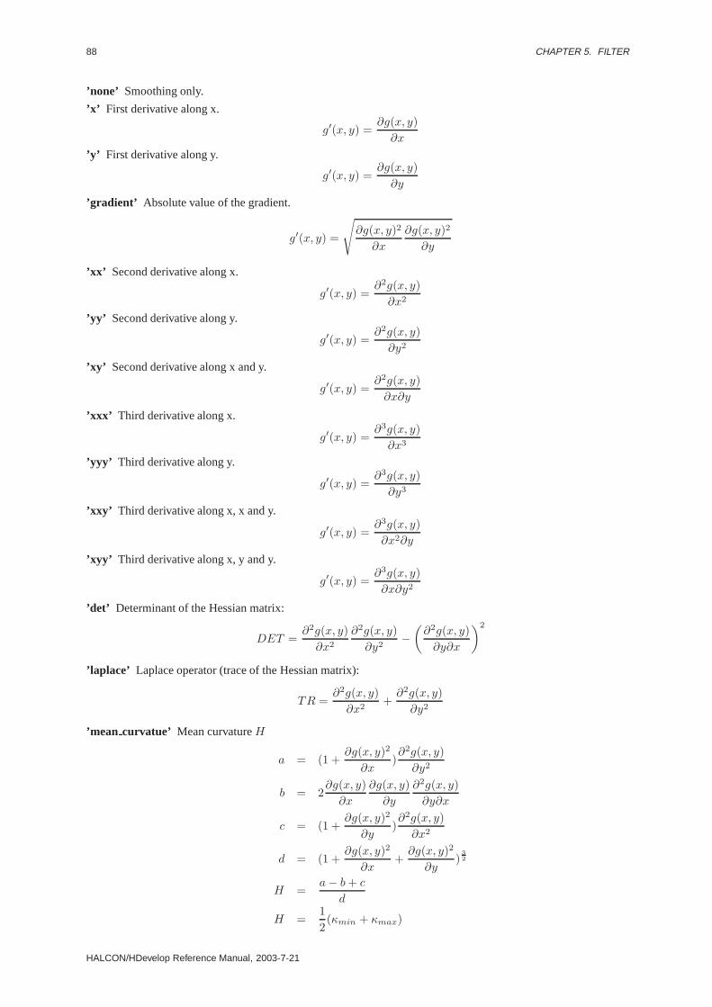
88 CHAPTER 5. FILTER
’none’ Smoothing only.
’x’ First derivative along x.
g′(x, y) =∂g(x, y)∂x
’y’ First derivative along y.
g′(x, y) =∂g(x, y)∂y
’gradient’ Absolute value of the gradient.
g′(x, y) =
ög(x, y)2
∂x
∂g(x, y)2
∂y
’xx’ Second derivative along x.
g′(x, y) =∂2g(x, y)∂x2
’yy’ Second derivative along y.
g′(x, y) =∂2g(x, y)∂y2
’xy’ Second derivative along x and y.
g′(x, y) =∂2g(x, y)∂x∂y
’xxx’ Third derivative along x.
g′(x, y) =∂3g(x, y)∂x3
’yyy’ Third derivative along y.
g′(x, y) =∂3g(x, y)∂y3
’xxy’ Third derivative along x, x and y.
g′(x, y) =∂3g(x, y)∂x2∂y
’xyy’ Third derivative along x, y and y.
g′(x, y) =∂3g(x, y)∂x∂y2
’det’ Determinant of the Hessian matrix:
DET =∂2g(x, y)∂x2
∂2g(x, y)∂y2
−(∂2g(x, y)∂y∂x
)2
’laplace’ Laplace operator (trace of the Hessian matrix):
TR =∂2g(x, y)∂x2
+∂2g(x, y)∂y2
’mean curvatue’ Mean curvatureH
a = (1 +∂g(x, y)2
∂x)∂2g(x, y)∂y2
b = 2∂g(x, y)∂x
∂g(x, y)∂y
∂2g(x, y)∂y∂x
c = (1 +∂g(x, y)2
∂y)∂2g(x, y)∂x2
d = (1 +∂g(x, y)2
∂x+∂g(x, y)2
∂y)
32
H =a− b+ c
d
H =12(κmin + κmax)
HALCON/HDevelop Reference Manual, 2003-7-21

5.5. EDGES 89
’gausscurvatue’ Gaussian curvatureK
K =DET
(1 + ∂g(x,y)2
∂x + ∂g(x,y)2
∂y )2
’eigenvalue1’ First eigenvalue
a =∂2g(x,y)
∂x2 + ∂2g(x,y)∂y2
2
λ1 = a+
√a2 − (
∂2g(x, y)∂x2
∂2g(x, y)∂y2
− ∂2g(x, y)2
∂y∂x)
’eigenvalue2’ Second eigenvalue
a =∂2g(x,y)
∂x2 + ∂2g(x,y)∂y2
2
λ2 = a−
√a2 − (
∂2g(x, y)∂x2
∂2g(x, y)∂y2
− ∂2g(x, y)2
∂y∂x)
’main1 curvature’ First principal curvature
κmax = H +√H2 −K
’main2 curvature’ Second principal curvature
κmin = H −√H2 −K
’kitchen rosenfeld’ Second derivative perpendicular to the gradient
k =∂2g(x,y)
∂x2∂g(x,y)2
∂y + ∂2g(x,y)∂y2
∂g(x,y)2
∂x − 2∂2g(x,y)∂y∂x
∂g(x,y)2
∂x∂g(x,y)2
∂y
∂g(x,y)2
∂x + ∂g(x,y)2
∂y
’2nd ddg’ Second derivative along the gradient
k =∂2g(x,y)
∂x2∂g(x,y)2
∂x + 2∂g(x,y)∂x
∂g(x,y)∂y
∂2g(x,y)∂y∂x + ∂2g(x,y)
∂y2∂g(x,y)2
∂y
∂g(x,y)2
∂x + ∂g(x,y)2
∂y
’de saint venant’ Second derivative along and perpendicular to the gradient
k =∂g(x,y)
∂x∂g(x,y)
∂y (∂2g(x,y)∂x2 − ∂2g(x,y)
∂y2 ) − (∂g(x,y)2
∂x − ∂g(x,y)2
∂y )∂2g(x,y)∂x∂y
∂g(x,y)2
∂x + ∂g(x,y)2
∂y
Parameter
. Image (input object) . . . . . . . . . . . . . . . (multichannel-)image(-array); Hobject: byte / int1 / int2 / int4 / realInput image.
. DerivGauss (outputobject) . . . . . . . . . . . . . . . . . . . . . . . . . . . . (multichannel-)image(-array); Hobject: realFiltered result image.
. Sigma (input control) . . . . . . . . . . . . . . . . . . . . . . . . . . . . . . . . . . . . . . . . . . . . . . . . . . . . . . . . . . . . . . . . . . . . real; realSigma of the Gaussian.Default Value : 1.0Value Suggestions :Sigma ∈ {0.7, 1.0, 1.5, 2.0, 3.0, 4.0, 5.0}Typical Range of Values :0.2≤ Sigma ≤ 50.0Minimal Value Step : 0.01Recommended Value Step :0.1Restriction : Sigma > 0.0
. Component (input control) . . . . . . . . . . . . . . . . . . . . . . . . . . . . . . . . . . . . . . . . . . . . . . . . . . . . . . . . . . . string; stringDerivative or feature to be calculated.Default Value : ’x’Value List : Component ∈ {’none’, ’x’, ’y’, ’gradient’, ’xx’, ’yy’, ’xy’, ’xxx’, ’yyy’, ’xxy’, ’xyy’, ’det’,’meancurvature’, ’gausscurvature’, ’eigenvalue1’, ’eigenvalue2’, ’main1curvature’, ’main2curvature’,’kitchen rosenfeld’, ’zunigaharalick’, ”2nd ddg”, ’de saint venant’, ’area’, ’laplace’, ’gradientdir’,’eigenvecdir’}
HALCON 6.0.4

90 CHAPTER 5. FILTER
Example
read_image(&Image,"mreut");derivate_gauss(Image,&Gauss,3.0,"x");zero_crossing(Gauss,&ZeroCrossings);
Parallelization Informationderivate gauss is reentrantand automaticallyparallelized(on tuple level, channel level, domain level).
Possible Successor Functionszero crossing , dual threshold
Alternativeslaplace , laplace of gauss , gauss image , smooth image
See Alsozero crossing , dual threshold
BibliographyK. Voss H. Süse; “Praktische Bildverarbeitung” Hanser Verlag; M¨unchen, Wien; 1991; Seite 88.
ModuleImage filters
diff of gauss ( Image : DiffOfGauss : Sigma, SigFactor : )
Approximate the LoG operator (Laplace of Gaussian).
diff of gauss approximates the Laplace-of-Gauss operator by a difference of Gaussians. The standard devia-tions of these Gaussians can be calculated, according to Marr, from the ParameterSigma of the LoG and the ratioof the two standard deviations (SigFactor ) as:
sigma1 =Sigma√
−2log ( 1
SigF actor )
SigFactor 2−1
sigma2 =sigma1
SigFactor
DiffOfGauss = (Image ∗ gauss(sigma1))− (Image ∗ gauss(sigma2))
For aSigFactor = 1.6, according to Marr, an approximation to the Mexican-Hat-Operator results. The resultingimage is stored inDiffOfGauss .
Parameter
. Image (input object) . . . . . . . . . . . . . . . . . . . . . . . . . . . . . . . . . . . . (multichannel-)image(-array); Hobject: byteInput image
. DiffOfGauss (outputobject) . . . . . . . . . . . . . . . . . . . . . . . . . . . (multichannel-)image(-array); Hobject: int2LoG image.
. Sigma (input control) . . . . . . . . . . . . . . . . . . . . . . . . . . . . . . . . . . . . . . . . . . . . . . . . . . . . . . . . . . . . . . . . . . . . real; realSmoothing parameter of the Laplace operator to approximate.Default Value : 3.0Value Suggestions :Sigma ∈ {2.0, 3.0, 4.0, 5.0}Typical Range of Values :0.2≤ Sigma ≤ 50.0Minimal Value Step : 0.01Recommended Value Step :0.1Restriction : Sigma > 0.0
. SigFactor (input control) . . . . . . . . . . . . . . . . . . . . . . . . . . . . . . . . . . . . . . . . . . . . . . . . . . . . . . . . . . . . . . real; realRatio of the standard deviations used (Marr recommends 1.6).Default Value : 1.6Typical Range of Values :0.1≤ SigFactor ≤ 10.0Minimal Value Step : 0.01Recommended Value Step :0.1Restriction : SigFactor > 0.0
HALCON/HDevelop Reference Manual, 2003-7-21

5.5. EDGES 91
Example
read_image(Image,’fabrik’)diff_of_gauss(Image,Laplace,2.0,1.6)zero_crossing(Laplace,ZeroCrossings).
ComplexityThe execution time depends linearly on the number of pixels and the size of sigma.
Resultdiff of gauss returns 2 (HMSG TRUE) if all parameters are correct. If the input is empty the behaviour canbe set viaset system(’no object result’,<Result>) . If necessary, an exception handling is raised.
Parallelization Informationdiff of gauss is reentrantand automaticallyparallelized(on tuple level, channel level, domain level).
Possible Successor Functionszero crossing , dual threshold
Alternativeslaplace , derivate gauss
BibliographyD. Marr: “Vision (A computational investigation into human representation and processing of visual information)”;New York, W.H. Freeman and Company; 1982.
ModuleImage filters
edges image ( Image : ImaAmp, ImaDir : Filter, Alpha, NMS, Low,High : )
Extract edges using Deriche, Lanser, Shen, or Canny filters.
edges image detects step edges using recursively implemented filters (according to Deriche, Lanser and Shen)or the conventionally implemented “derivative of Gaussian” filter (using filter masks) proposed by Canny. Thus,the following edge operators are available:
’deriche1’, ’lanser1’, ’deriche1int4’, ’deriche2’, ’lanser2’, ’lanser2int4’, ’shen’, ’mshen’, and ’canny’ (parameterFilter ).
The edge amplitudes (gradient magnitude) and directions are returned inImaAmp and ImaDir , respectively.The edge operators ’deriche1’ bzw. ’deriche2’ are also available for int4-images, and return the signed filterresponse instead of its absolute value. This behavior can be obtained for byte-images as well by selecting ’de-riche1 int4’ bzw. ’deriche2int4’ as filter. This can be used to calculate the second derivative of an image byapplying edges image (with parameter ’lanser2’) to the signed first derivative. Edge directions are stored in2-degree steps, i.e., an edge direction ofx degrees with respect to the horizontal axis is stored asx/2 in the edgedirection image. Furthermore, the direction of the change of intensity is taken into account. Let[Ex, Ey] denotethe image gradient. Then the following edge directions are returned asr/2:
intensity increase Ex/Ey
edge directionrfrom bottom to top 0/+ 0from lower right to upper left +/− ]0, 90[from right to left +/0 90from upper right to lower left +/+ ]90, 180[from top to bottom 0/+ 180from upper left to lower right −/+ ]180, 270[from left to right +/0 270from lower left to upper right −/− ]270, 360[
Points with edge amplitude 0 are assigned the edge direction 255 (undefined direction).
HALCON 6.0.4
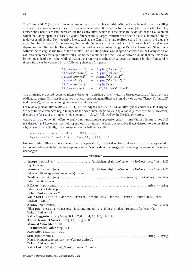
92 CHAPTER 5. FILTER
The “filter width” (i.e., the amount of smoothing) can be chosen arbitrarily, and can be estimated by callinginfo edges for concrete values of the parameterAlpha . It decreases for increasingAlpha for the Deriche,Lanser and Shen filters and increases for the Canny filter, where it is the standard deviation of the Gaussian onwhich the Canny operator is based. “Wide” filters exhibit a larger invariance to noise, but also a decreased abilityto detect small details. Non-recursive filters, such as the Canny filter, are realized using filter masks, and thus theexecution time increases for increasing filter width. In contrast, the execution time for recursive filters does notdepend on the filter width. Thus, arbitrary filter widths are possible using the Deriche, Lanser and Shen filterswithout increasing the run time of the operator. The resulting advantage in speed compared to the Canny operatornaturally increases for larger filter widths. As border treatment, the recursive operators assume that the images tobe zero outside of the image, while the Canny operator repeats the gray value at the image’s border. Comparablefilter widths can be obtained by the following choices ofAlpha :
Alpha (′lanser1′) = Alpha (′deriche1′)Alpha (′deriche2′) = Alpha (′deriche1′)/2Alpha (′lanser2′) = Alpha (′deriche2′)Alpha (′shen′) = Alpha (′deriche1′)/2Alpha (′mshen′) = Alpha (′shen′)Alpha (′canny′) = 1.77/Alpha (′deriche1′)
The originally proposed recursive filters (’deriche1’, ’deriche2’, ’shen’) return a biased estimate of the amplitudeof diagonal edges. This bias is removed in the corresponding modified version of the operators (’lanser1’, ’lanser2’und ’mshen’), while maintaining the same execution speed.
For relatively small filter widths (11× 11), i.e., for Alpha (’lanser2’ = 0.5), all filters yield similar results. Only for“wider” filters differences begin to appear: the Shen filters begin to yield qualitatively inferior results. However,they are the fastest of the implemented operators — closely followed by the Deriche operators.
edges image optionally offers to apply a non-maximum-suppression (NMS= ’nms’/’inms’/’hvnms’; ’none’ ifnot desired) and hysteresis threshold operation (Low,High ; at least one negative if not desired) to the resultingedge image. Conceptually, this corresponds to the following calls:
nonmax suppression dir(...,NMS,...)hysteresis threshold(...,Low,High,999,...)
However, this calling sequence would return appropriately modified regions, whereasedges image markssuppressed edge points by 0 in the amplitude and 255 in the direction image, while leaving the region of the imageunchanged.
Parameter
. Image (input object) . . . . . . . . . . . . . . . . . . . . . . . . . (multichannel-)image(-array); Hobject: byte / int4 / int2Input image.
. ImaAmp (outputobject) . . . . . . . . . . . . . . . . . . . . . . . (multichannel-)image(-array); Hobject: byte / int4 / int2Edge amplitude (gradient magnitude) image.
. ImaDir (outputobject) . . . . . . . . . . . . . . . . . . . . . . . . . . . . . . . . . . . . . . . . . . . image(-array); Hobject: directionEdge direction image.
. Filter (input control) . . . . . . . . . . . . . . . . . . . . . . . . . . . . . . . . . . . . . . . . . . . . . . . . . . . . . . . . . . . . . . . string; stringEdge operator to be applied.Default Value : ’lanser2’Value List : Filter ∈ {’deriche1’, ’lanser1’, ’deriche1int4’, ’deriche2’, ’lanser2’, ’lanser2int4’, ’shen’,’mshen’, ’canny’}
. Alpha (input control) . . . . . . . . . . . . . . . . . . . . . . . . . . . . . . . . . . . . . . . . . . . . . . . . . . . . . . . . . . . . . . . . . . . . real; realFilter parameter: small values result in strong smoothing, and thus less detail (opposite for ’canny’).Default Value : 0.5Value Suggestions :Alpha ∈ {0.1, 0.2, 0.3, 0.4, 0.5, 0.7, 0.9, 1.1}Typical Range of Values :0.2≤ Alpha ≤ 50.0Minimal Value Step : 0.01Recommended Value Step :0.1Restriction : Alpha > 0.0
. NMS(input control) . . . . . . . . . . . . . . . . . . . . . . . . . . . . . . . . . . . . . . . . . . . . . . . . . . . . . . . . . . . . . . . . . . . string; stringNon-maximum suppression (’none’, if not desired).Default Value : ’nms’Value List : NMS∈ {’nms’, ’inms’, ’hvnms’, ’none’}
HALCON/HDevelop Reference Manual, 2003-7-21
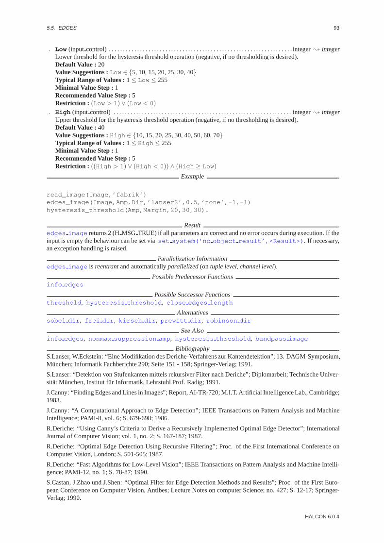
5.5. EDGES 93
. Low (input control) . . . . . . . . . . . . . . . . . . . . . . . . . . . . . . . . . . . . . . . . . . . . . . . . . . . . . . . . . . . . . . . . . integer; integerLower threshold for the hysteresis threshold operation (negative, if no thresholding is desired).Default Value : 20Value Suggestions :Low ∈ {5, 10, 15, 20, 25, 30, 40}Typical Range of Values :1≤ Low ≤ 255Minimal Value Step : 1Recommended Value Step :5Restriction : (Low > 1) ∨ (Low < 0)
. High (input control) . . . . . . . . . . . . . . . . . . . . . . . . . . . . . . . . . . . . . . . . . . . . . . . . . . . . . . . . . . . . . . . integer; integerUpper threshold for the hysteresis threshold operation (negative, if no thresholding is desired).Default Value : 40Value Suggestions :High ∈ {10, 15, 20, 25, 30, 40, 50, 60, 70}Typical Range of Values :1≤ High ≤ 255Minimal Value Step : 1Recommended Value Step :5Restriction : ((High > 1) ∨ (High < 0)) ∧ (High ≥ Low)
Example
read_image(Image,’fabrik’)edges_image(Image,Amp,Dir,’lanser2’,0.5,’none’,-1,-1)hysteresis_threshold(Amp,Margin,20,30,30).
Resultedges image returns 2 (HMSG TRUE) if all parameters are correct and no error occurs during execution. If theinput is empty the behaviour can be set viaset system(’no object result’,<Result>) . If necessary,an exception handling is raised.
Parallelization Informationedges image is reentrantand automaticallyparallelized(on tuple level, channel level).
Possible Predecessor Functionsinfo edges
Possible Successor Functionsthreshold , hysteresis threshold , close edges length
Alternativessobel dir , frei dir , kirsch dir , prewitt dir , robinson dir
See Alsoinfo edges , nonmax suppression amp, hysteresis threshold , bandpass image
BibliographyS.Lanser, W.Eckstein: “Eine Modifikation des Deriche-Verfahrens zur Kantendetektion”; 13. DAGM-Symposium,München; Informatik Fachberichte 290; Seite 151 - 158; Springer-Verlag; 1991.
S.Lanser: “Detektion von Stufenkanten mittels rekursiver Filter nach Deriche”; Diplomarbeit; Technische Univer-sität München, Institut f¨ur Informatik, Lehrstuhl Prof. Radig; 1991.
J.Canny: “Finding Edges and Lines in Images”; Report, AI-TR-720; M.I.T. Artificial Intelligence Lab., Cambridge;1983.
J.Canny: “A Computational Approach to Edge Detection”; IEEE Transactions on Pattern Analysis and MachineIntelligence; PAMI-8, vol. 6; S. 679-698; 1986.
R.Deriche: “Using Canny’s Criteria to Derive a Recursively Implemented Optimal Edge Detector”; InternationalJournal of Computer Vision; vol. 1, no. 2; S. 167-187; 1987.
R.Deriche: “Optimal Edge Detection Using Recursive Filtering”; Proc. of the First International Conference onComputer Vision, London; S. 501-505; 1987.
R.Deriche: “Fast Algorithms for Low-Level Vision”; IEEE Transactions on Pattern Analysis and Machine Intelli-gence; PAMI-12, no. 1; S. 78-87; 1990.
S.Castan, J.Zhao und J.Shen: “Optimal Filter for Edge Detection Methods and Results”; Proc. of the First Euro-pean Conference on Computer Vision, Antibes; Lecture Notes on computer Science; no. 427; S. 12-17; Springer-Verlag; 1990.
HALCON 6.0.4
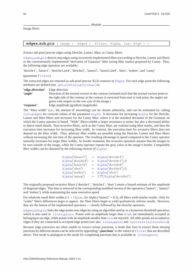
94 CHAPTER 5. FILTER
ModuleImage filters
edges sub pix ( Image : Edges : Filter, Alpha, Low, High : )
Extract sub-pixel precise edges using Deriche, Lanser, Shen, or Canny filters.
edges sub pix detects step edges using recursively implemented filters (according to Deriche, Lanser and Shen)or the conventionally implemented “derivative of Gaussian” filter (using filter masks) proposed by Canny. Thus,the following edge operators are available:
’deriche1’, ’lanser1’, ’deriche1int4’, ’deriche2’, ’lanser2’, ’lanser2int4’, ’shen’, ’mshen’, and ’canny’
(parameterFilter ).
The extracted edges are returned as sub-pixel precise XLD contours inEdges . For each edge point the followingattributes are defined (seeget contour attrib xld ):
’edge direction’ Edge direction’angle’ Direction of the normal vectors to the contour (oriented such that the normal vectors point to
the right side of the contour as the contour is traversed from start to end point; the angles aregiven with respect to the row axis of the image.)
’response’ Edge amplitude (gradient magnitude)
The “filter width” (i.e., the amount of smoothing) can be chosen arbitrarily, and can be estimated by callinginfo edges for concrete values of the parameterAlpha . It decreases for increasingAlpha for the Deriche,Lanser and Shen filters and increases for the Canny filter, where it is the standard deviation of the Gaussian onwhich the Canny operator is based. “Wide” filters exhibit a larger invariance to noise, but also a decreased abilityto detect small details. Non-recursive filters, such as the Canny filter, are realized using filter masks, and thus theexecution time increases for increasing filter width. In contrast, the execution time for recursive filters does notdepend on the filter width. Thus, arbitrary filter widths are possible using the Deriche, Lanser and Shen filterswithout increasing the run time of the operator. The resulting advantage in speed compared to the Canny operatornaturally increases for larger filter widths. As border treatment, the recursive operators assume that the images tobe zero outside of the image, while the Canny operator repeats the gray value at the image’s border. Comparablefilter widths can be obtained by the following choices ofAlpha :
Alpha (′lanser1′) = Alpha (′deriche1′)Alpha (′deriche2′) = Alpha (′deriche1′)/2Alpha (′lanser2′) = Alpha (′deriche2′)Alpha (′shen′) = Alpha (′deriche1′)/2Alpha (′mshen′) = Alpha (′shen′)Alpha (′canny′) = 1.77/Alpha (′deriche1′)
The originally proposed recursive filters (’deriche1’, ’deriche2’, ’shen’) return a biased estimate of the amplitudeof diagonal edges. This bias is removed in the corresponding modified version of the operators (’lanser1’, ’lanser2’und ’mshen’), while maintaining the same execution speed.
For relatively small filter widths (11× 11), i.e., for Alpha (’lanser2’ = 0.5), all filters yield similar results. Only for“wider” filters differences begin to appear: the Shen filters begin to yield qualitatively inferior results. However,they are the fastest of the implemented operators — closely followed by the Deriche operators.
edges sub pix links the edge points into edges by using an algorithm similar to a hysteresis threshold operation,which is also used inlines gauss . Points with an amplitude larger thanHigh are immediately accepted asbelonging to an edge, while points with an amplitude smaller thanLow are rejected. All other points are accepted asedges if they are connected to accepted edge points (see alsolines gauss and hysteresis threshold ).
Because edge extractors are often unable to extract certain junctions, a mode that tries to extract these missingjunctions by different means can be selected by appending’ junctions’ to the values ofFilter that are describedabove. This mode is analogous to the mode for completing junctions that is available inlines gauss .
HALCON/HDevelop Reference Manual, 2003-7-21
5.5. EDGES 95
Parameter
. Image (input object) . . . . . . . . . . . . . . . . . . . . . . . . . . . . . . . . . . . . . . . . . . . . . . . . . . . . . . . . . image; Hobject: byteInput image.
. Edges (outputobject) . . . . . . . . . . . . . . . . . . . . . . . . . . . . . . . . . . . . . . . . . . . . . . . . . . . . . . xldcont-array; HobjectExtracted edges.
. Filter (input control) . . . . . . . . . . . . . . . . . . . . . . . . . . . . . . . . . . . . . . . . . . . . . . . . . . . . . . . . . . . . . . . string; stringEdge operator to be applied.Default Value : ’lanser2’Value List : Filter ∈ {’deriche1’, ’lanser1’, ’deriche2’, ’lanser2’, ’shen’, ’mshen’, ’canny’, ’sobel’,’deriche1junctions’, ’lanser1junctions’, ’deriche2junctions’, ’lanser2junctions’, ’shenjunctions’,’mshenjunctions’, ’cannyjunctions’, ’sobeljunctions’}
. Alpha (input control) . . . . . . . . . . . . . . . . . . . . . . . . . . . . . . . . . . . . . . . . . . . . . . . . . . . . . . . . . . . . . . . . . . . . real; realFilter parameter: small values result in strong smoothing, and thus less detail (opposite for ’canny’).Default Value : 0.5Value Suggestions :Alpha ∈ {0.1, 0.2, 0.3, 0.4, 0.5, 0.7, 0.9, 1.1}Typical Range of Values :0.2≤ Alpha ≤ 50.0Minimal Value Step : 0.01Recommended Value Step :0.1Restriction : Alpha > 0.0
. Low (input control) . . . . . . . . . . . . . . . . . . . . . . . . . . . . . . . . . . . . . . . . . . . . . . . . . . . . . . . . . . . . . . . . . integer; integerLower threshold for the hysteresis threshold operation.Default Value : 20Value Suggestions :Low ∈ {5, 10, 15, 20, 25, 30, 40}Typical Range of Values :1≤ Low ≤ 255Minimal Value Step : 1Recommended Value Step :5Restriction : Low > 0
. High (input control) . . . . . . . . . . . . . . . . . . . . . . . . . . . . . . . . . . . . . . . . . . . . . . . . . . . . . . . . . . . . . . . integer; integerUpper threshold for the hysteresis threshold operation.Default Value : 40Value Suggestions :High ∈ {10, 15, 20, 25, 30, 40, 50, 60, 70}Typical Range of Values :1≤ High ≤ 255Minimal Value Step : 1Recommended Value Step :5Restriction : (High > 0) ∧ (High ≥ Low)
Example
read_image(Image,’fabrik’)edges_sub_pix(Image,Edges,’lanser2’,0.5,20,40).
ComplexityLet A be the number of pixels in the domain ofImage . Then the runtime complexity isO(A ∗ Sigma) for theCanny filter andO(A) for the recursive Lanser, Deriche, and Shen filters.
LetS = Width∗Heightbe the number of pixels ofImage . Then edges sub pix requires at least60 ∗ S bytesof temporary memory during execution.
Resultedges sub pix returns 2 (HMSG TRUE) if all parameters are correct and no error occurs during execution.If the input is empty the behaviour can be set viaset system(’no object result’,<Result>) . Ifnecessary, an exception handling is raised.
Parallelization Informationedges sub pix is reentrantand automaticallyparallelized(on tuple level).
Alternativessobel dir , frei dir , kirsch dir , prewitt dir , robinson dir , edges image
See Alsoinfo edges , hysteresis threshold , bandpass image , lines gauss , lines facet
HALCON 6.0.4

96 CHAPTER 5. FILTER
BibliographyS.Lanser, W.Eckstein: “Eine Modifikation des Deriche-Verfahrens zur Kantendetektion”; 13. DAGM-Symposium,München; Informatik Fachberichte 290; Seite 151 - 158; Springer-Verlag; 1991.
S.Lanser: “Detektion von Stufenkanten mittels rekursiver Filter nach Deriche”; Diplomarbeit; Technische Univer-sität München, Institut f¨ur Informatik, Lehrstuhl Prof. Radig; 1991.
J.Canny: “Finding Edges and Lines in Images”; Report, AI-TR-720; M.I.T. Artificial Intelligence Lab., Cambridge;1983.
J.Canny: “A Computational Approach to Edge Detection”; IEEE Transactions on Pattern Analysis and MachineIntelligence; PAMI-8, vol. 6; S. 679-698; 1986.
R.Deriche: “Using Canny’s Criteria to Derive a Recursively Implemented Optimal Edge Detector”; InternationalJournal of Computer Vision; vol. 1, no. 2; S. 167-187; 1987.
R.Deriche: “Optimal Edge Detection Using Recursive Filtering”; Proc. of the First International Conference onComputer Vision, London; S. 501-505; 1987.
R.Deriche: “Fast Algorithms for Low-Level Vision”; IEEE Transactions on Pattern Analysis and Machine Intelli-gence; PAMI-12, no. 1; S. 78-87; 1990.
S.Castan, J.Zhao und J.Shen: “Optimal Filter for Edge Detection Methods and Results”; Proc. of the First Euro-pean Conference on Computer Vision, Antibes; Lecture Notes on computer Science; no. 427; S. 12-17; Springer-Verlag; 1990.
ModuleSub-pixel operators
frei amp ( Image : ImageEdgeAmp : : )
Detect edges (amplitude) using the Frei-Chen operator.
frei amp calculates an approximation of the first derivative of the image data and is used as an edge detector.The filter is based on the following filter masks:
A =1 1 10 0 0
−1 −1 −1
B =1 0 −11 0 −11 0 −1
The result image contains the maximum response of the masksA andB.
Parameter
. Image (input object) . . . . . . . . . . . . . . . . . . . . . . . . . . . . . . (multichannel-)image(-array); Hobject: byte / int2Input image.
. ImageEdgeAmp (outputobject) . . . . . . . . . . . . . . . . . . . . (multichannel-)image(-array); Hobject: byte / int2Edge amplitude (gradient magnitude) image.
Example
read_image(Image,’fabrik’)frei_amp(Image,Frei_amp)threshold(Frei_amp,Edges,128,255).
Resultfrei amp always returns 2 (HMSG TRUE). If the input is empty the behaviour can be set viaset system(’no object result’,<Result>) . If necessary, an exception handling is raised.
Parallelization Informationfrei amp is reentrantand automaticallyparallelized(on tuple level, channel level, domain level).
HALCON/HDevelop Reference Manual, 2003-7-21

5.5. EDGES 97
Possible Predecessor Functionsgauss image , sigma image , median image , smooth image
Alternativessobel amp, kirsch amp, prewitt amp, robinson amp, roberts
See Alsobandpass image , laplace of gauss
ModuleImage filters
frei dir ( Image : ImageEdgeAmp, ImageEdgeDir : : )
Detect edges (amplitude and direction) using the Frei-Chen operator.
frei dir calculates an approximation of the first derivative of the image data and is used as an edge detector.The filter is based on the following filter masks:
A =1
√2 1
0 0 0−1 −
√2 −1
B =1 0 −1√2 0 −
√2
1 0 −1
The result image contains the maximum response of the masksA andB. The edge directions are returned inImageEdgeDir , and are stored in 2-degree steps, i.e., an edge direction ofx degrees with respect to the horizontalaxis is stored asx/2 in the edge direction image. Furthermore, the direction of the change of intensity is taken intoaccount. Let[Ex, Ey] denote the image gradient. Then the following edge directions are returned asr/2:
intensity increase Ex/Ey
edge directionrfrom bottom to top 0/+ 0from lower right to upper left +/− ]0, 90[from right to left +/0 90from upper right to lower left +/+ ]90, 180[from top to bottom 0/+ 180from upper left to lower right −/+ ]180, 270[from left to right +/0 270from lower left to upper right −/− ]270, 360[
Points with edge amplitude 0 are assigned the edge direction 255 (undefined direction).
Parameter
. Image (input object) . . . . . . . . . . . . . . . . . . . . . . . . . . . . . . (multichannel-)image(-array); Hobject: byte / int2Input image.
. ImageEdgeAmp (outputobject) . . . . . . . . . . . . . . . . . . . . (multichannel-)image(-array); Hobject: byte / int2Edge amplitude (gradient magnitude) image.
. ImageEdgeDir (outputobject) . . . . . . . . . . . . . . . . . . . . . (multichannel-)image(-array); Hobject: directionEdge direction image.
Example
read_image(Image,’fabrik’)frei_dir(Image,Frei_dirA,Frei_dirD)threshold(Frei_dirA,Res,128,255).
HALCON 6.0.4
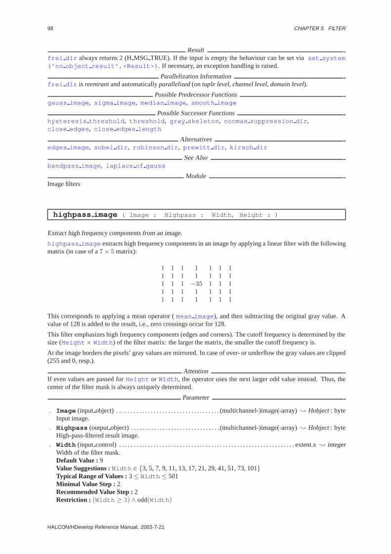
98 CHAPTER 5. FILTER
Resultfrei dir always returns 2 (HMSG TRUE). If the input is empty the behaviour can be set viaset system(’no object result’,<Result>) . If necessary, an exception handling is raised.
Parallelization Informationfrei dir is reentrantand automaticallyparallelized(on tuple level, channel level, domain level).
Possible Predecessor Functionsgauss image , sigma image , median image , smooth image
Possible Successor Functionshysteresis threshold , threshold , gray skeleton , nonmax suppression dir ,close edges , close edges length
Alternativesedges image , sobel dir , robinson dir , prewitt dir , kirsch dir
See Alsobandpass image , laplace of gauss
ModuleImage filters
highpass image ( Image : Highpass : Width, Height : )
Extract high frequency components from an image.
highpass image extracts high frequency components in an image by applying a linear filter with the followingmatrix (in case of a7 × 5 matrix):
1 1 1 1 1 1 11 1 1 1 1 1 11 1 1 −35 1 1 11 1 1 1 1 1 11 1 1 1 1 1 1
This corresponds to applying a mean operator (mean image ), and then subtracting the original gray value. Avalue of 128 is added to the result, i.e., zero crossings occur for 128.
This filter emphasizes high frequency components (edges and corners). The cutoff frequency is determined by thesize (Height × Width ) of the filter matrix: the larger the matrix, the smaller the cutoff frequency is.
At the image borders the pixels’ gray values are mirrored. In case of over- or underflow the gray values are clipped(255 and 0, resp.).
AttentionIf even values are passed forHeight or Width , the operator uses the next larger odd value instead. Thus, thecenter of the filter mask is always uniquely determined.
Parameter
. Image (input object) . . . . . . . . . . . . . . . . . . . . . . . . . . . . . . . . . . . . (multichannel-)image(-array); Hobject: byteInput image.
. Highpass (outputobject) . . . . . . . . . . . . . . . . . . . . . . . . . . . . . . . (multichannel-)image(-array); Hobject: byteHigh-pass-filtered result image.
. Width (input control) . . . . . . . . . . . . . . . . . . . . . . . . . . . . . . . . . . . . . . . . . . . . . . . . . . . . . . . . . . . . . extent.x; integerWidth of the filter mask.Default Value : 9Value Suggestions :Width ∈ {3, 5, 7, 9, 11, 13, 17, 21, 29, 41, 51, 73, 101}Typical Range of Values :3≤ Width ≤ 501Minimal Value Step : 2Recommended Value Step :2Restriction : (Width ≥ 3) ∧ odd(Width )
HALCON/HDevelop Reference Manual, 2003-7-21

5.5. EDGES 99
. Height (input control) . . . . . . . . . . . . . . . . . . . . . . . . . . . . . . . . . . . . . . . . . . . . . . . . . . . . . . . . . . . .extent.y; integerHeight of the filter mask.Default Value : 9Value Suggestions :Height ∈ {3, 5, 7, 9, 11, 13, 17, 21, 29, 41, 51, 73, 101}Typical Range of Values :3≤ Height ≤ 501Minimal Value Step : 2Recommended Value Step :2Restriction : (Height ≥ 3) ∧ odd(Height )
Example
highpass_image(Image,&Highpass,7,5);threshold(Highpass,&Region,60.0,255.0);skeleton(Region,&Skeleton);
Resulthighpass image returns 2 (HMSG TRUE) if all parameters are correct. If the input is empty the behaviourcan be set viaset system(’no object result’,<Result>) . If necessary, an exception handling israised.
Parallelization Informationhighpass image is reentrantand automaticallyparallelized(on tuple level, channel level, domain level).
Possible Successor Functionsthreshold , skeleton
Alternativesmean image , sub image , convol image , bandpass image
See Alsodyn threshold
ModuleImage filters
info edges ( : : Filter, Mode, Alpha : Size, Coeffs )
Estimate the width of a filter inedges image .
info edges returns an estimate of the width of any of the filters used inedges image . To do so, the corre-sponding continuous impulse responses of the filters are sampled until the first filter coefficient is smaller than fivepercent of the largest coefficient.Alpha is the filter parameter (seeedges image ). Seven edge operators aresupported (parameterFilter ):
’deriche1’, ’lanser1’, ’deriche2’, ’lanser2’, ’shen’, ’mshen’ und ’canny’.
The parameterMode(’edge’/’smooth’) is used to determine whether the corresponding edge or smoothing operatoris to be sampled. The Canny operator (which uses the Gaussian for smoothing) is implemented using conventionalfilter masks, while all other filters are implemented recursively. Therefore, for the Canny filter the coefficients ofthe one-dimensional impulse responsesf(n) with n ≥ 0 are returned inCoeffs in addition to the filter width.
Parameter
. Filter (input control) . . . . . . . . . . . . . . . . . . . . . . . . . . . . . . . . . . . . . . . . . . . . . . . . . . . . . . . . . . . . . . . string; stringName of the edge operator.Default Value : ’lanser2’Value List : Filter ∈ {’deriche1’, ’lanser1’, ’deriche2’, ’lanser2’, ’shen’, ’mshen’, ’canny’}
. Mode (input control) . . . . . . . . . . . . . . . . . . . . . . . . . . . . . . . . . . . . . . . . . . . . . . . . . . . . . . . . . . . . . . . . . .string; string1D edge filter (’edge’) or 1D smoothing filter (’smooth’).Default Value : ’edge’Value List : Mode∈ {’edge’, ’smooth’}
HALCON 6.0.4
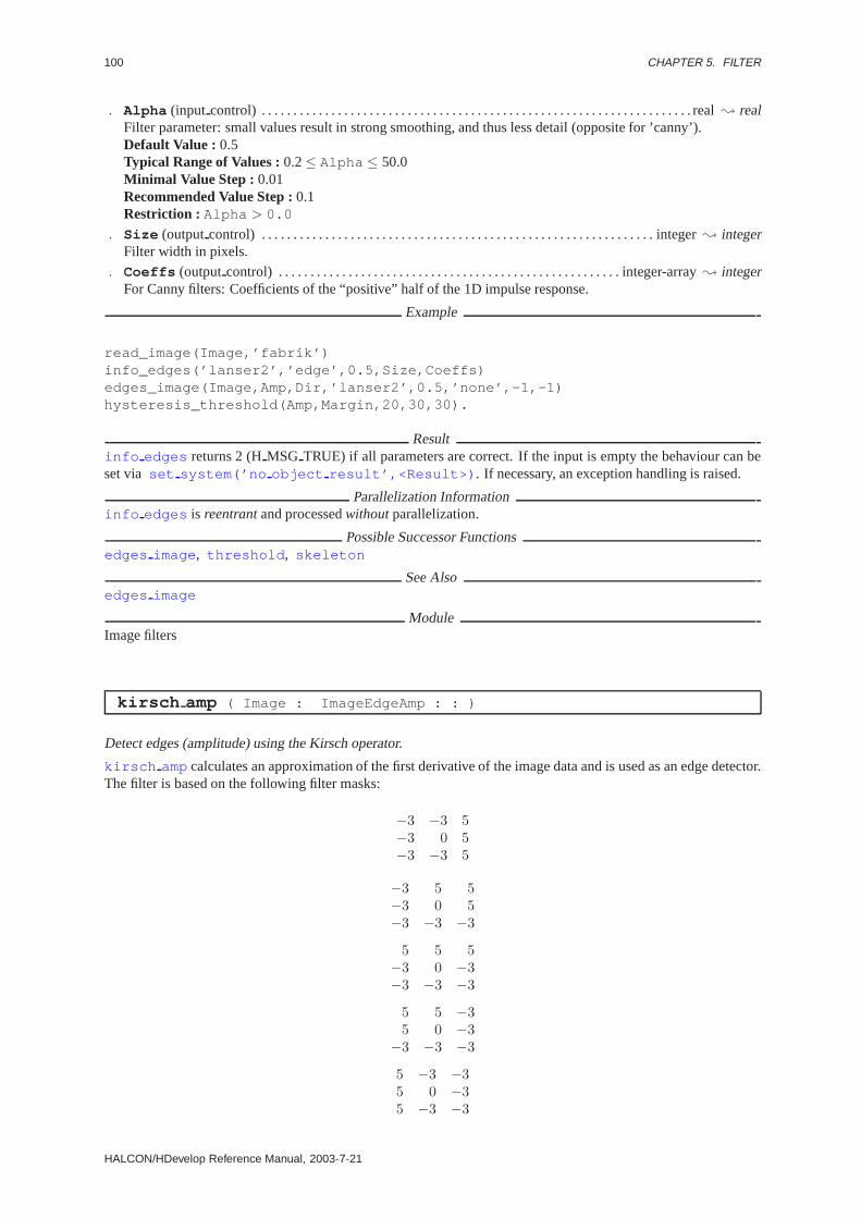
100 CHAPTER 5. FILTER
. Alpha (input control) . . . . . . . . . . . . . . . . . . . . . . . . . . . . . . . . . . . . . . . . . . . . . . . . . . . . . . . . . . . . . . . . . . . . real; realFilter parameter: small values result in strong smoothing, and thus less detail (opposite for ’canny’).Default Value : 0.5Typical Range of Values :0.2≤ Alpha ≤ 50.0Minimal Value Step : 0.01Recommended Value Step :0.1Restriction : Alpha > 0.0
. Size (outputcontrol) . . . . . . . . . . . . . . . . . . . . . . . . . . . . . . . . . . . . . . . . . . . . . . . . . . . . . . . . . . . . . . integer; integerFilter width in pixels.
. Coeffs (outputcontrol) . . . . . . . . . . . . . . . . . . . . . . . . . . . . . . . . . . . . . . . . . . . . . . . . . . . . . . integer-array; integerFor Canny filters: Coefficients of the “positive” half of the 1D impulse response.
Example
read_image(Image,’fabrik’)info_edges(’lanser2’,’edge’,0.5,Size,Coeffs)edges_image(Image,Amp,Dir,’lanser2’,0.5,’none’,-1,-1)hysteresis_threshold(Amp,Margin,20,30,30).
Resultinfo edges returns 2 (HMSG TRUE) if all parameters are correct. If the input is empty the behaviour can beset via set system(’no object result’,<Result>) . If necessary, an exception handling is raised.
Parallelization Informationinfo edges is reentrantand processedwithoutparallelization.
Possible Successor Functionsedges image , threshold , skeleton
See Alsoedges image
ModuleImage filters
kirsch amp ( Image : ImageEdgeAmp : : )
Detect edges (amplitude) using the Kirsch operator.
kirsch ampcalculates an approximation of the first derivative of the image data and is used as an edge detector.The filter is based on the following filter masks:
−3 −3 5−3 0 5−3 −3 5
−3 5 5−3 0 5−3 −3 −3
5 5 5−3 0 −3−3 −3 −3
5 5 −35 0 −3
−3 −3 −3
5 −3 −35 0 −35 −3 −3
HALCON/HDevelop Reference Manual, 2003-7-21

5.5. EDGES 101
−3 −3 −35 0 −35 5 −3
−3 −3 −3−3 0 −3
5 5 5
−3 −3 −3−3 0 5−3 5 5
The result image contains the maximum response of all masks.
Parameter
. Image (input object) . . . . . . . . . . . . . . . . . . . . . . . . . . . . . . (multichannel-)image(-array); Hobject: byte / int2Input image.
. ImageEdgeAmp (outputobject) . . . . . . . . . . . . . . . . . . . . . . . . . . . . . . . . . . image(-array); Hobject: byte / int2Edge amplitude (gradient magnitude) image.
Example
read_image(Image,’fabrik’)kirsch_amp(Image,Kirsch_amp)threshold(Kirsch_amp,Edges,128,255).
Resultkirsch ampalways returns 2 (HMSG TRUE). If the input is empty the behaviour can be set viaset system(’no object result’,<Result>) . If necessary, an exception handling is raised.
Parallelization Informationkirsch amp is reentrantand automaticallyparallelized(on tuple level, channel level, domain level).
Possible Predecessor Functionsgauss image , sigma image , median image , smooth image
Alternativessobel amp, frei amp, prewitt amp, robinson amp, roberts
See Alsobandpass image , laplace of gauss
ModuleImage filters
kirsch dir ( Image : ImageEdgeAmp, ImageEdgeDir : : )
Detect edges (amplitude and direction) using the Kirsch operator.
kirsch dir calculates an approximation of the first derivative of the image data and is used as an edge detector.The filter is based on the following filter masks:
−3 −3 5−3 0 5−3 −3 5
−3 5 5−3 0 5−3 −3 −3
5 5 5−3 0 −3−3 −3 −3
HALCON 6.0.4
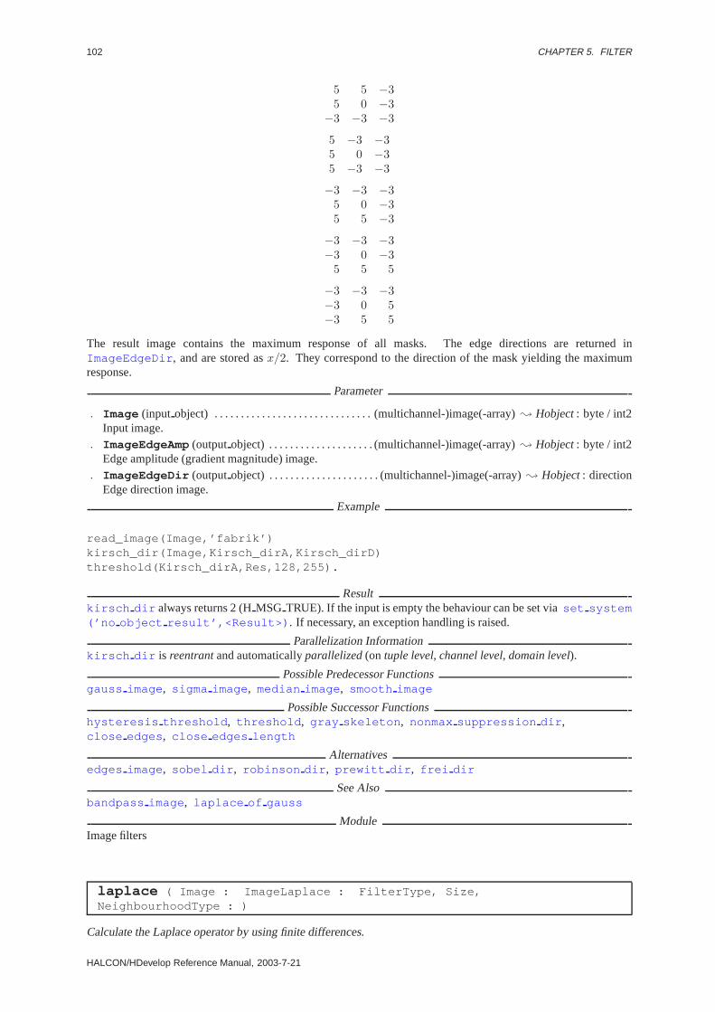
102 CHAPTER 5. FILTER
5 5 −35 0 −3
−3 −3 −3
5 −3 −35 0 −35 −3 −3
−3 −3 −35 0 −35 5 −3
−3 −3 −3−3 0 −3
5 5 5
−3 −3 −3−3 0 5−3 5 5
The result image contains the maximum response of all masks. The edge directions are returned inImageEdgeDir , and are stored asx/2. They correspond to the direction of the mask yielding the maximumresponse.
Parameter
. Image (input object) . . . . . . . . . . . . . . . . . . . . . . . . . . . . . . (multichannel-)image(-array); Hobject: byte / int2Input image.
. ImageEdgeAmp (outputobject) . . . . . . . . . . . . . . . . . . . . (multichannel-)image(-array); Hobject: byte / int2Edge amplitude (gradient magnitude) image.
. ImageEdgeDir (outputobject) . . . . . . . . . . . . . . . . . . . . . (multichannel-)image(-array); Hobject: directionEdge direction image.
Example
read_image(Image,’fabrik’)kirsch_dir(Image,Kirsch_dirA,Kirsch_dirD)threshold(Kirsch_dirA,Res,128,255).
Resultkirsch dir always returns 2 (HMSG TRUE). If the input is empty the behaviour can be set viaset system(’no object result’,<Result>) . If necessary, an exception handling is raised.
Parallelization Informationkirsch dir is reentrantand automaticallyparallelized(on tuple level, channel level, domain level).
Possible Predecessor Functionsgauss image , sigma image , median image , smooth image
Possible Successor Functionshysteresis threshold , threshold , gray skeleton , nonmax suppression dir ,close edges , close edges length
Alternativesedges image , sobel dir , robinson dir , prewitt dir , frei dir
See Alsobandpass image , laplace of gauss
ModuleImage filters
laplace ( Image : ImageLaplace : FilterType, Size,NeighbourhoodType : )
Calculate the Laplace operator by using finite differences.
HALCON/HDevelop Reference Manual, 2003-7-21

5.5. EDGES 103
laplace filters the input imagesImage using a Laplace operator. Depending on the parameterNeighbourhoodType the following simple approximations of the Laplace operator are used:
’n 4’
11 −4 1
1
’n 8’
1 1 11 −8 11 1 1
’n 8 isotrop’
10 22 1022 −128 2210 22 10
The filter ’n 8’ corresponds to the filter mask used inhighpass image(O:R:3,3:) . For a Laplace operatorwith size3 × 3, the corresponding filter is applied directly, while for larger filter sizes (Size = 5,7,9 and 11) theinput image is first smoothed using a Gaussian filter of the selected size. Therefore,
laplace(O:R:int4,S,N:)
for Size > is equivalent to
gauss image(O:G:S:) .laplace(G:R:int4,3,N:).
laplace either returns the absolute value of the Laplace filtered image (FilterType ’abs’) in a byte-image orthe signed result (FilterType ’int4’) in an int4-image.
Attentionlaplace is only implemented for byte-images.
Parameter
. Image (input object) . . . . . . . . . . . . . . . . . . . . . . . . . . . . . . . . . . . . (multichannel-)image(-array); Hobject: byteInput image.
. ImageLaplace (outputobject) . . . . . . . . . . . . . . . . . . . . (multichannel-)image(-array); Hobject: byte / int4Laplace-filtered result images.
. FilterType (input control) . . . . . . . . . . . . . . . . . . . . . . . . . . . . . . . . . . . . . . . . . . . . . . . . . . . . . . . . . string; stringCalculate the absolute value of the filter to a byte-image or the signed result to an int4-image.Default Value : ’int4’Value List : FilterType ∈ {’abs’, ’int4’}
. Size (input control) . . . . . . . . . . . . . . . . . . . . . . . . . . . . . . . . . . . . . . . . . . . . . . . . . . . . . . . . . . . . . . . integer; integerSize of filter mask.Default Value : 3Value List : Size ∈ {3, 5, 7, 9, 11}
. NeighbourhoodType (input control) . . . . . . . . . . . . . . . . . . . . . . . . . . . . . . . . . . . . . . . . . . . . . . . . string; stringNeighborhood used in the Laplace operatorDefault Value : ’n 8 isotrop’Value List : NeighbourhoodType ∈ {’n 4’, ’n 8’, ’n 8 isotrop’}
Example
read_image(&Image,"mreut");laplace(Image,&Laplace,"int4",3,"n_8_isotrop");zero_crossing(Laplace,&ZeroCrossings);
HALCON 6.0.4

104 CHAPTER 5. FILTER
Resultlaplace returns 2 (HMSG TRUE) if all parameters are correct. If the input is empty the behaviour can be setvia set system(’no object result’,<Result>) . If necessary, an exception handling is raised.
Parallelization Informationlaplace is reentrantand automaticallyparallelized(on tuple level, channel level, domain level).
Possible Successor Functionszero crossing , dual threshold
Alternativesdiff of gauss , laplace of gauss
See Alsohighpass image , edges image
ModuleImage filters
laplace of gauss ( Image : ImageLaplace : Sigma : )
LoG-Operator (Laplace of Gaussian).
laplace of gauss calculates the Laplace-of-Gaussian operator, i.e., the Laplace operator on a Gaussiansmoothed image, for arbitrary smoothing parametersSigma . The Laplace operator is given by:
∆g(x, y) =∂2g(x, y)∂x2
+∂2g(x, y)∂y2
The derivatives inlaplace of gauss are calculated by appropriate derivatives of the Gaussian, resulting inthe following formula for the convolution mask:
∆Gσ(x, y) =
12πσ4
(x2 + y2
2σ2− 1
)[exp
(−x
2 + y2
2σ2
)]
Parameter
. Image (input object) . . . . . . . . . . . . . . . (multichannel-)image(-array); Hobject: byte / int1 / int2 / int4 / realInput image.
. ImageLaplace (outputobject) . . . . . . . . . . . . . . . . . . . . . . . . . (multichannel-)image(-array); Hobject: int2Laplace filtered image.
. Sigma (input control) . . . . . . . . . . . . . . . . . . . . . . . . . . . . . . . . . . . . . . . . . . . . . . . . . . . . . . . . number; real/ integerSmoothing parameter of the Gaussian.Default Value : 2.0Value Suggestions :Sigma ∈ {0.5, 1.0, 1.5, 2.0, 2.5, 3.0, 4.0, 5.0, 7.0}Typical Range of Values :0.7≤ Sigma ≤ 5.0Minimal Value Step : 0.01Recommended Value Step :0.1Restriction : (Sigma > 0.7 ) ∧ (Sigma ≤ 25.0 )
Example
read_image(&Image,"mreut");laplace_of_gauss(Image,&Laplace,2.0);zero_crossing(Laplace,&ZeroCrossings);
Parallelization Informationlaplace of gauss is reentrantand automaticallyparallelized(on tuple level, channel level, domain level).
Possible Successor Functionszero crossing , dual threshold
HALCON/HDevelop Reference Manual, 2003-7-21

5.5. EDGES 105
Alternativeslaplace , diff of gauss , derivate gauss
See Alsoderivate gauss
ModuleImage filters
prewitt amp ( Image : ImageEdgeAmp : : )
Detect edges (amplitude) using the Prewitt operator.
prewitt ampcalculates an approximation of the first derivative of the image data and is used as an edge detector.The filter is based on the following filter masks:
A =1 1 10 0 0
−1 −1 −1
B =1 0 −11 0 −11 0 −1
The result image contains the maximum response of the masksA andB.
Parameter
. Image (input object) . . . . . . . . . . . . . . . . . . . . . . . . . . . . . . (multichannel-)image(-array); Hobject: byte / int2Input image.
. ImageEdgeAmp (outputobject) . . . . . . . . . . . . . . . . . . . . (multichannel-)image(-array); Hobject: byte / int2Edge amplitude (gradient magnitude) image.
Example
read_image(Image,’fabrik’)prewitt_amp(Image,Prewitt)threshold(Prewitt,Edges,128,255).
Resultprewitt ampalways returns 2 (HMSG TRUE). If the input is empty the behaviour can be set viaset system(’no object result’,<Result>) . If necessary, an exception handling is raised.
Parallelization Informationprewitt amp is reentrantand automaticallyparallelized(on tuple level, channel level, domain level).
Possible Predecessor Functionsgauss image , sigma image , median image , smooth image
Possible Successor Functionsthreshold , gray skeleton , nonmax suppression amp, close edges , close edges length
Alternativessobel amp, kirsch amp, frei amp, robinson amp, roberts
See Alsobandpass image , laplace of gauss
ModuleImage filters
prewitt dir ( Image : ImageEdgeAmp, ImageEdgeDir : : )
Detect edges (amplitude and direction) using the Prewitt operator.
HALCON 6.0.4

106 CHAPTER 5. FILTER
prewitt dir calculates an approximation of the first derivative of the image data and is used as an edge detector.The filter is based on the following filter masks:
A =1 1 10 0 0
−1 −1 −1
B =1 0 −11 0 −11 0 −1
The result image contains the maximum response of the masksA andB. The edge directions are returned inImageEdgeDir , and are stored in 2-degree steps, i.e., an edge direction ofx degrees with respect to the horizontalaxis is stored asx/2 in the edge direction image. Furthermore, the direction of the change of intensity is taken intoaccount. Let[Ex, Ey] denote the image gradient. Then the following edge directions are returned asr/2:
intensity increase Ex/Ey
edge directionrfrom bottom to top 0/+ 0from lower right to upper left +/− ]0, 90[from right to left +/0 90from upper right to lower left +/+ ]90, 180[from top to bottom 0/+ 180from upper left to lower right −/+ ]180, 270[from left to right +/0 270from lower left to upper right −/− ]270, 360[
Points with edge amplitude 0 are assigned the edge direction 255 (undefined direction).
Parameter
. Image (input object) . . . . . . . . . . . . . . . . . . . . . . . . . . . . . . (multichannel-)image(-array); Hobject: byte / int2Input image.
. ImageEdgeAmp (outputobject) . . . . . . . . . . . . . . . . . . . . (multichannel-)image(-array); Hobject: byte / int2Edge amplitude (gradient magnitude) image.
. ImageEdgeDir (outputobject) . . . . . . . . . . . . . . . . . . . . . (multichannel-)image(-array); Hobject: directionEdge direction image.
Example
read_image(Image,’fabrik’)prewitt_dir(Image,PrewittA,PrewittD)threshold(PrewittA,Edges,128,255).
Resultprewitt dir always returns 2 (HMSG TRUE). If the input is empty the behaviour can be set viaset system(’no object result’,<Result>) . If necessary, an exception handling is raised.
Parallelization Informationprewitt dir is reentrantand automaticallyparallelized(on tuple level, channel level, domain level).
Possible Predecessor Functionsgauss image , sigma image , median image , smooth image
Possible Successor Functionshysteresis threshold , threshold , gray skeleton , nonmax suppression dir ,close edges , close edges length
Alternativesedges image , sobel dir , robinson dir , frei dir , kirsch dir
See Alsobandpass image , laplace of gauss
ModuleImage filters
HALCON/HDevelop Reference Manual, 2003-7-21

5.5. EDGES 107
roberts ( Image : ImageRoberts : FilterType : )
Detect edges using the Roberts filter.
roberts calculates the first derivative of an image and is used as an edge operator. If the following mask describesa part of the image,
A BC D
the different filter types are defined as follows:
’robertsmax’ max(|A −D|, |B − C|)’gradientmax’ max(|A +B − (C +D)|, |A+ C − (B +D)|)’gradientsum’ |A+B − (C +D)| + |A+ C − (B +D)|
If an overflow occurs the result is clipped. The result of the operator is stored at the pixel with the coordinates of“D”.
Parameter
. Image (input object) . . . . . . . . . . . . . . . . . . . . . . . . . . . . . . (multichannel-)image(-array); Hobject: byte / int2Input image.
. ImageRoberts (outputobject) . . . . . . . . . . . . . . . . . . . . (multichannel-)image(-array); Hobject: byte / int2Roberts-filtered result images.
. FilterType (input control) . . . . . . . . . . . . . . . . . . . . . . . . . . . . . . . . . . . . . . . . . . . . . . . . . . . . . . . . . string; stringFilter type.Default Value : ’gradientsum’Value List : FilterType ∈ {’robertsmax’, ’gradientmax’, ’gradientsum’}
Example
read_image(Image,’fabrik’)roberts(Image,Roberts,’roberts_max’)threshold(Roberts,Margin,128,255).
Resultroberts returns 2 (HMSG TRUE) if all parameters are correct. If the input is empty the behaviour can be setvia set system(’no object result’,<Result>) . If necessary, an exception handling is raised.
Parallelization Informationroberts is reentrantand automaticallyparallelized(on tuple level, channel level, domain level).
Possible Predecessor Functionsgauss image
Possible Successor Functionsthreshold , skeleton
Alternativesedges image , sobel amp, frei amp, kirsch amp, prewitt amp
See Alsolaplace , highpass image , bandpass image
ModuleImage filters
robinson amp ( Image : ImageEdgeAmp : : )
Detect edges (amplitude) using the Robinson operator.
HALCON 6.0.4
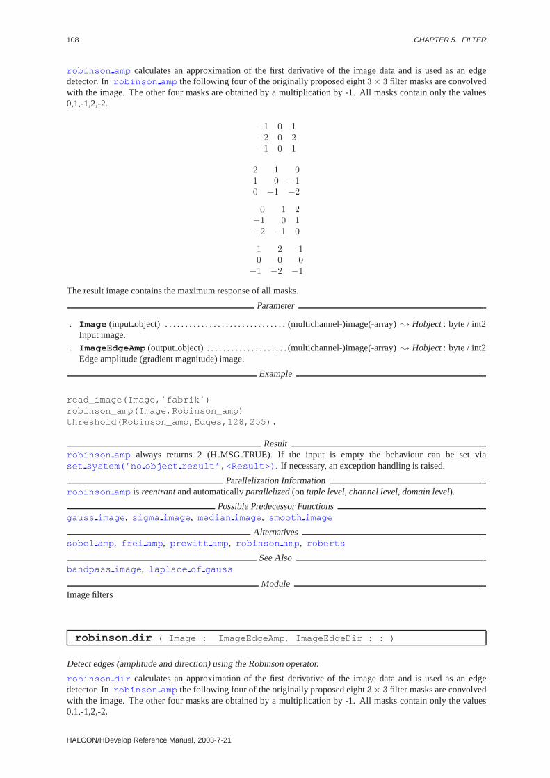
108 CHAPTER 5. FILTER
robinson amp calculates an approximation of the first derivative of the image data and is used as an edgedetector. Inrobinson amp the following four of the originally proposed eight3 × 3 filter masks are convolvedwith the image. The other four masks are obtained by a multiplication by -1. All masks contain only the values0,1,-1,2,-2.
−1 0 1−2 0 2−1 0 1
2 1 01 0 −10 −1 −2
0 1 2−1 0 1−2 −1 0
1 2 10 0 0
−1 −2 −1
The result image contains the maximum response of all masks.
Parameter
. Image (input object) . . . . . . . . . . . . . . . . . . . . . . . . . . . . . . (multichannel-)image(-array); Hobject: byte / int2Input image.
. ImageEdgeAmp (outputobject) . . . . . . . . . . . . . . . . . . . . (multichannel-)image(-array); Hobject: byte / int2Edge amplitude (gradient magnitude) image.
Example
read_image(Image,’fabrik’)robinson_amp(Image,Robinson_amp)threshold(Robinson_amp,Edges,128,255).
Resultrobinson amp always returns 2 (HMSG TRUE). If the input is empty the behaviour can be set viaset system(’no object result’,<Result>) . If necessary, an exception handling is raised.
Parallelization Informationrobinson amp is reentrantand automaticallyparallelized(on tuple level, channel level, domain level).
Possible Predecessor Functionsgauss image , sigma image , median image , smooth image
Alternativessobel amp, frei amp, prewitt amp, robinson amp, roberts
See Alsobandpass image , laplace of gauss
ModuleImage filters
robinson dir ( Image : ImageEdgeAmp, ImageEdgeDir : : )
Detect edges (amplitude and direction) using the Robinson operator.
robinson dir calculates an approximation of the first derivative of the image data and is used as an edgedetector. Inrobinson amp the following four of the originally proposed eight3 × 3 filter masks are convolvedwith the image. The other four masks are obtained by a multiplication by -1. All masks contain only the values0,1,-1,2,-2.
HALCON/HDevelop Reference Manual, 2003-7-21

5.5. EDGES 109
−1 0 1−2 0 2−1 0 1
2 1 01 0 −10 −1 −2
0 1 2−1 0 1−2 −1 0
1 2 10 0 0
−1 −2 −1
The result image contains the maximum response of all masks. The edge directions are returned inImageEdgeDir , and are stored asx/2. They correspond to the direction of the mask yielding the maximumresponse.
Parameter
. Image (input object) . . . . . . . . . . . . . . . . . . . . . . . . . . . . . . (multichannel-)image(-array); Hobject: byte / int2Eingabebild.
. ImageEdgeAmp (outputobject) . . . . . . . . . . . . . . . . . . . . (multichannel-)image(-array); Hobject: byte / int2Edge amplitude (gradient magnitude) image.
. ImageEdgeDir (outputobject) . . . . . . . . . . . . . . . . . . . . . (multichannel-)image(-array); Hobject: directionEdge direction image.
Example
read_image(Image,’fabrik’)robinson_dir(Image,Robinson_dirA,Robinson_dirD)threshold(Robinson_dirA,Res,128,255).
Resultrobinson dir always returns 2 (HMSG TRUE). If the input is empty the behaviour can be set viaset system(’no object result’,<Result>) . If necessary, an exception handling is raised.
Parallelization Informationrobinson dir is reentrantand automaticallyparallelized(on tuple level, channel level, domain level).
Possible Predecessor Functionsgauss image , sigma image , median image , smooth image
Possible Successor Functionshysteresis threshold , threshold , gray skeleton , nonmax suppression dir ,close edges , close edges length
Alternativesedges image , sobel dir , kirsch dir , prewitt dir , frei dir
See Alsobandpass image , laplace of gauss
ModuleImage filters
sobel amp ( Image : EdgeAmplitude : FilterType, Size : )
Detect edges (amplitude) using the Sobel operator.
HALCON 6.0.4

110 CHAPTER 5. FILTER
sobel amp calculates first derivative of an image and is used as an edge detector. The filter is based on thefollowing filter masks:
A =1 2 10 0 0
−1 −2 −1
B =1 0 −12 0 −21 0 −1
These masks are used differently, according to the selected filter type. (In the following,a undb denote the resultsof convolving an image withA undB for one particular pixel.)
’sum sqrt’√a2 + b2
’sum abs’ (|a| + |b|)/2’thin sumabs’ (thin(|a|) + thin(|b|))/2’thin max abs’ max(thin(|a|), thin(|b|))’x’ b’y’ a
Here,thin(x) is equal tox for a vertical maximum (mask A) and a horizontal maximum (mask B), respectively,and 0 otherwise. Thus, for ’thinsumabs’ and ’thinmax abs’ the gradient image is thinned. In the case of byte-images for’x’ and’y’ an int1-image is returned as result. For a Sobel operator with size3 × 3, the correspondingfilters A andB are applied directly, while for larger filter sizes (Size = 5,7,9 and 11) the input image is firstsmoothed using a Gaussian filter of sizeSize -2. Therefore,
sobel amp(I:E,Dir:FilterTyp,S:)
for Size > 3 is equivalent to
gauss image(I:G:S-2) .sobel amp(G:E:FilterType,3:).
Parameter
. Image (input object) . . . . . . . . . . . . . . . . . . . . . . . . . . . . . . (multichannel-)image(-array); Hobject: byte / int2Input image.
. EdgeAmplitude (outputobject) . . . . . . . . . . . . . . . . . . . (multichannel-)image(-array); Hobject: int1 / int2Edge amplitude (gradient magnitude) image.
. FilterType (input control) . . . . . . . . . . . . . . . . . . . . . . . . . . . . . . . . . . . . . . . . . . . . . . . . . . . . . . . . . string; stringFilter type.Default Value : ’sum abs’Value List : FilterType ∈ {’sum abs’, ’thin sumabs’, ’thin max abs’, ’sumsqrt’, ’x’, ’y’ }
. Size (input control) . . . . . . . . . . . . . . . . . . . . . . . . . . . . . . . . . . . . . . . . . . . . . . . . . . . . . . . . . . . . . . . integer; integerSize of filter mask.Default Value : 3Value List : Size ∈ {3, 5, 7, 9, 11, 13}
Example
read_image(Image,’fabrik’)sobel_amp(Image,Amp,’sum_abs’,3)threshold(Amp,Edg,128,255).
Resultsobel ampreturns 2 (HMSG TRUE) if all parameters are correct. If the input is empty the behaviour can be setvia set system(’no object result’,<Result>) . If necessary, an exception handling is raised.
Parallelization Informationsobel amp is reentrantand automaticallyparallelized(on tuple level, channel level, domain level).
HALCON/HDevelop Reference Manual, 2003-7-21
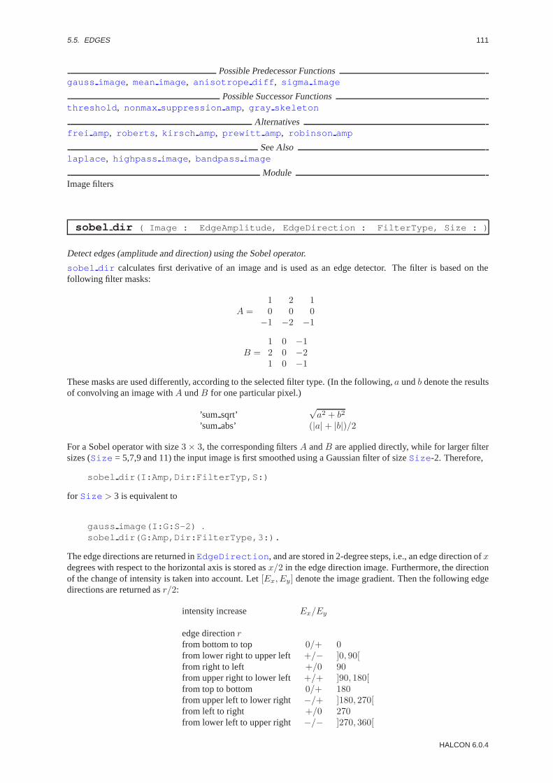
5.5. EDGES 111
Possible Predecessor Functionsgauss image , mean image , anisotrope diff , sigma image
Possible Successor Functionsthreshold , nonmax suppression amp, gray skeleton
Alternativesfrei amp, roberts , kirsch amp, prewitt amp, robinson amp
See Alsolaplace , highpass image , bandpass image
ModuleImage filters
sobel dir ( Image : EdgeAmplitude, EdgeDirection : FilterType, Size : )
Detect edges (amplitude and direction) using the Sobel operator.
sobel dir calculates first derivative of an image and is used as an edge detector. The filter is based on thefollowing filter masks:
A =1 2 10 0 0
−1 −2 −1
B =1 0 −12 0 −21 0 −1
These masks are used differently, according to the selected filter type. (In the following,a undb denote the resultsof convolving an image withA undB for one particular pixel.)
’sum sqrt’√a2 + b2
’sum abs’ (|a| + |b|)/2
For a Sobel operator with size3 × 3, the corresponding filtersA andB are applied directly, while for larger filtersizes (Size = 5,7,9 and 11) the input image is first smoothed using a Gaussian filter of sizeSize -2. Therefore,
sobel dir(I:Amp,Dir:FilterTyp,S:)
for Size > 3 is equivalent to
gauss image(I:G:S-2) .sobel dir(G:Amp,Dir:FilterType,3:).
The edge directions are returned inEdgeDirection , and are stored in 2-degree steps, i.e., an edge direction ofxdegrees with respect to the horizontal axis is stored asx/2 in the edge direction image. Furthermore, the directionof the change of intensity is taken into account. Let[Ex, Ey] denote the image gradient. Then the following edgedirections are returned asr/2:
intensity increase Ex/Ey
edge directionrfrom bottom to top 0/+ 0from lower right to upper left +/− ]0, 90[from right to left +/0 90from upper right to lower left +/+ ]90, 180[from top to bottom 0/+ 180from upper left to lower right −/+ ]180, 270[from left to right +/0 270from lower left to upper right −/− ]270, 360[
HALCON 6.0.4

112 CHAPTER 5. FILTER
Points with edge amplitude 0 are assigned the edge direction 255 (undefined direction).
Parameter
. Image (input object) . . . . . . . . . . . . . . . . . . . . . . . . . . . . . . (multichannel-)image(-array); Hobject: byte / int2Input image.
. EdgeAmplitude (outputobject) . . . . . . . . . . . . . . . . . . (multichannel-)image(-array); Hobject: byte / int2Edge amplitude (gradient magnitude) image.
. EdgeDirection (outputobject) . . . . . . . . . . . . . . . . . . . . (multichannel-)image(-array); Hobject: directionEdge direction image.
. FilterType (input control) . . . . . . . . . . . . . . . . . . . . . . . . . . . . . . . . . . . . . . . . . . . . . . . . . . . . . . . . . string; stringFilter type.Default Value : ’sum abs’Value List : FilterType ∈ {’sum abs’, ’sumsqrt’}
. Size (input control) . . . . . . . . . . . . . . . . . . . . . . . . . . . . . . . . . . . . . . . . . . . . . . . . . . . . . . . . . . . . . . . integer; integerSize of filter mask.Default Value : 3Value List : Size ∈ {3, 5, 7, 9, 11, 13}
Example
read_image(Image,’fabrik’)sobel_dir(Image,Amp,Dir,’sum_abs’,3)threshold(Amp,Edg,128,255).
Resultsobel dir returns 2 (HMSG TRUE) if all parameters are correct. If the input is empty the behaviour can be setvia set system(’no object result’,<Result>) . If necessary, an exception handling is raised.
Parallelization Informationsobel dir is reentrantand automaticallyparallelized(on tuple level, channel level).
Possible Predecessor Functionsgauss image , mean image , anisotrope diff , sigma image
Possible Successor Functionsnonmax suppression dir , hysteresis threshold , threshold
Alternativesedges image , frei dir , kirsch dir , prewitt dir , robinson dir
See Alsoroberts , laplace , highpass image , bandpass image
ModuleImage filters
5.6 Enhancement
emphasize ( Image : ImageEmphasize : MaskWidth, MaskHeight, Factor : )
Enhance contrast of the image.
The operatoremphasize emphasizes high frequency areas of the image (edges and corners). The resultingimages appears sharper.
First the procedure carries out a filtering with the low pass (mean image ). The resulting gray values (res) arecalculated from the obtained gray values (mean) and the original gray values (orig) as follows:
res := round((orig −mean) ∗ Factor ) + orig
Factor serves as measurement of the increase in contrast. The division frequency is determined via the size ofthe filter matrix: The larger the matrix, the lower the disivion frequency.
HALCON/HDevelop Reference Manual, 2003-7-21

5.6. ENHANCEMENT 113
As an edge treatment the gray values are mirrored at the edges of the image. Overflow and/or underflow of grayvalues is clipped.
Parameter
. Image (input object) . . . . . . . . . . . . . . . . . . . . . . . . . . . . . . (multichannel-)image(-array); Hobject: byte / int2Image to be enhanced.
. ImageEmphasize (outputobject) . . . . . . . . . . . . . . . . . (multichannel-)image(-array); Hobject: byte / int2contrast enhanced image.
. MaskWidth (input control) . . . . . . . . . . . . . . . . . . . . . . . . . . . . . . . . . . . . . . . . . . . . . . . . . . . . . . . .extent.x; integerWidth of low pass mask.Default Value : 7Value Suggestions :MaskWidth ∈ {3, 5, 7, 9, 11, 15, 21, 25, 31, 39}Typical Range of Values :3≤ MaskWidth ≤ 201Minimal Value Step : 2Recommended Value Step :2
. MaskHeight (input control) . . . . . . . . . . . . . . . . . . . . . . . . . . . . . . . . . . . . . . . . . . . . . . . . . . . . . . extent.y; integerHeight of the low pass mask.Default Value : 7Value Suggestions :MaskHeight ∈ {3, 5, 7, 9, 11, 15, 21, 25, 31, 39}Typical Range of Values :3≤ MaskHeight ≤ 201Minimal Value Step : 2Recommended Value Step :2
. Factor (input control) . . . . . . . . . . . . . . . . . . . . . . . . . . . . . . . . . . . . . . . . . . . . . . . . . . . . . . . . . . . . . . . . . . real; realIntensity of contrast emphasis.Default Value : 1.0Value Suggestions :Factor ∈ {0.3, 0.5, 0.7, 1.0, 1.4, 1.8, 2.0}Typical Range of Values :0.0≤ Factor ≤ 20.0 (sqrt)Minimal Value Step : 0.01Recommended Value Step :0.2Restriction : (0 < Factor ) ∧ (Factor < 20)
Example
read_image(Image,’meer_rot’)disp_image(Image,WindowHandle)draw_region(Region,WindowHandle)reduce_domain(Image,Region,Mask)emphasize(Mask,Sharp,7,7,2.0)disp_image(Sharp,WindowHandle).
ResultIf the parameter values are correct the operatoremphasize returns the value 2 (HMSG TRUE) Thebehavior in case of empty input (no input images available) is set via the operatorset system(::’no object result’,<Result>:) . If necessary an exception handling is raised.
Parallelization Informationemphasize is reentrantand automaticallyparallelized(on tuple level, channel level, domain level).
Possible Successor Functionsdisp image
Alternativesmean image , sub image , laplace , add image
See Alsomean image , highpass image
ModuleImage filters
HALCON 6.0.4

114 CHAPTER 5. FILTER
equ histo image ( Image : ImageEquHisto : : )
Histogram linearisation of images
The operatorequ histo image enhances the contrast. The starting point is the histogram of the input images.The following simple gray value transformationf(g) is carried out:
f(g) = 255∑
x=0...g
h(x)
h(x) describes the relative frequency of the occurrence of the gray valuex. This transformation linearises thecumulative histogram. Maxima in the original histogram are ”‘spreaded”’ and thus the contrast in image regionswith these frequently occuring gray values is increased. Supposedly homogenous regions receive more easilyvisible structures. On the other hand, of course, the noise in the image increases correspondlingly. Minima in theoriginal histogram are dually ”‘compressed”’. The transformed histogram contains gaps, but the remaining grayvalues used occur approximately at the same frequency (”‘histogram equalization”’).
AttentionThe operatorequ histo image primarily serves for optical processing of images for a human viewer. Forexample, the (local) contrast spreading can lead to a detection of fictitious edges.
Parameter
. Image (input object) . . . . . . . . . . . . . . . . . . . . . . . . . . . . . . . . . . . . (multichannel-)image(-array); Hobject: byteImage to be enhanced.
. ImageEquHisto (outputobject) . . . . . . . . . . . . . . . . . . . . . . . . (multichannel-)image(-array); Hobject: byteImage with linearized gray values.
Parallelization Informationequ histo image is reentrantand automaticallyparallelized(on tuple level, channel level).
Possible Successor Functionsdisp image
Alternativesscale image , scale image max, illuminate
See Alsoscale image
BibliographyR.C. Gonzales, P. Wintz: ”‘Digital Image Processing”’; Second edition; Addison Wesley; 1987.
ModuleImage filters
illuminate ( Image : ImageIlluminate : MaskWidth, MaskHeight,Factor : )
Illuminate image.
The operatorilluminate enhances contrast. Very dark parts of the image are ”‘illuminated”’ more strongly,very light ones are ”‘darkened”’. Iforig is the original gray value andmean is the corresponding gray value ofthe low pass filtered image detected via the operatorsmean image and filter sizeMaskHeight x MaskWidth .For byte-images val equals 127, for int2-images val equals the median value. The resulting gray value isnew:
new := round((val −mean) ∗ Factor + orig)
The low pass should have rather large dimensions (30 x 30 to 200 x 200). Reasonable parameter combinationsmight be:
MaskHeight MaskWidth Factor40 40 0.55100 100 0.7150 150 0.8
HALCON/HDevelop Reference Manual, 2003-7-21

5.6. ENHANCEMENT 115
i.e. the larger the low pass mask is chosen, the largerFactor should be as well.
The following ”‘spotlight effect”’ should be noted: If, for example, a dark object is in front of a light wall the objectas well as the wall, which is already light in the immediate proximity of the object contours, are lightened by theoperator illuminate . This corresponds roughly to the effect that is produced when the object is illuminatedby a strong spotlight. The same applies to light objects in front of a darker background. In this case, however, thefictitious ”‘spotlight”’ darkens objects.
Parameter
. Image (input object) . . . . . . . . . . . . . . . . . . . . . . . . . . . . . . (multichannel-)image(-array); Hobject: byte / int2Image to be enhanced.
. ImageIlluminate (outputobject) . . . . . . . . . . . . . . . . (multichannel-)image(-array); Hobject: byte / int2”‘Illuminated”’ image.
. MaskWidth (input control) . . . . . . . . . . . . . . . . . . . . . . . . . . . . . . . . . . . . . . . . . . . . . . . . . . . . . . . .extent.x; integerWidth of low pass mask.Default Value : 101Value Suggestions :MaskWidth ∈ {31, 41, 51, 71, 101, 121, 151, 201}Typical Range of Values :3≤ MaskWidth ≤ 299Minimal Value Step : 2Recommended Value Step :10
. MaskHeight (input control) . . . . . . . . . . . . . . . . . . . . . . . . . . . . . . . . . . . . . . . . . . . . . . . . . . . . . . extent.y; integerHeight of low pass mask.Default Value : 101Value Suggestions :MaskHeight ∈ {31, 41, 51, 71, 101, 121, 151, 201}Typical Range of Values :3≤ MaskHeight ≤ 299Minimal Value Step : 2Recommended Value Step :10
. Factor (input control) . . . . . . . . . . . . . . . . . . . . . . . . . . . . . . . . . . . . . . . . . . . . . . . . . . . . . . . . . . . . . . . . . . real; realScales the ”‘correction gray value”’ added to the original gray values.Default Value : 0.7Value Suggestions :Factor ∈ {0.3, 0.5, 0.7, 1.0, 1.5, 2.0, 3.0, 5.0}Typical Range of Values :0.0≤ Factor ≤ 5.0Minimal Value Step : 0.01Recommended Value Step :0.2Restriction : (0 < Factor ) ∧ (Factor < 5)
Example
read_image(Image,’fabrik’)disp_image(Image,WindowHandle)illuminate(Image,Better,40,40,0.55)disp_image(Better,WindowHandle).
ResultIf the parameter values are correct the operatorilluminate returns the value 2 (HMSG TRUE)The behavior in case of empty input (no input images available) is set via the operatorset system(::’no object result’,<Result>:) . If necessary an exception handling is raised.
Parallelization Informationilluminate is reentrantand automaticallyparallelized(on tuple level, channel level, domain level).
Possible Successor Functionsdisp image
Alternativesscale image max, equ histo image , mean image , sub image
See Alsoemphasize , gray histo
ModuleImage filters
HALCON 6.0.4

116 CHAPTER 5. FILTER
scale image max ( Image : ImageScaleMax : : )
Maximum gray value spreading in the value range0 bis255.
The operatorscale image max calculates the minimum and maximum and scales the image to the maximumvalue range of a byte image. This way the dynamics (value range) is fully exploited. The number of different grayscales does not change, but in general the visual impression is enhanced. The gray values of images of thereal,int2 andint4 type are scaled to the range0 to 255and returned asbyte images.
AttentionThe output always is an image of the typebyte.
Parameter
. Image (input object) . . . . . . . . . . . . . . . . . . . . (multichannel-)image(-array); Hobject: byte / int2 / int4 / realImage to be scaled.
. ImageScaleMax (outputobject) . . . . . . . . . . . . . . . . . . . . . . . . . . . . . . . . . . . . . . image(-array); Hobject: bytecontrast enhanced image.
Parallelization Informationscale image max is reentrantand automaticallyparallelized(on tuple level, channel level).
Possible Successor Functionsdisp image
Alternativesequ histo image , scale image , illuminate , convert image type
See Alsomin max gray , gray histo
ModuleImage filters
5.7 FFT
convol fft ( ImageFFT, ImageFilter : ImageConvol : : )
Convolve an image with a byte-mask in the frequency domain.
convol fft convolves two (Fourier-transformed) images in the frequency domain, i.e., the pixels of the compleximageImageFFT are multiplied by the corresponding pixels of the filterImageFilter . This image is a byte-image in which 0 corresponds to complete suppression of a frequency, and 255 corresponds to no suppression. Theresult image is of type’complex’.
AttentionThe filtering is always done on the entire image, i.e., the region of the image is ignored.
Parameter
. ImageFFT (input object) . . . . . . . . . . . . . . . . . . . . . . . . . . . . . . . . . . . . . . . . . . image(-array); Hobject: complexComplex input image.
. ImageFilter (input object) . . . . . . . . . . . . . . . . . . . . . . . . . . . . . . . . . . . . . . . . . . . . . . . . . image; Hobject: byteFilter in frequency domain.
. ImageConvol (outputobject) . . . . . . . . . . . . . . . . . . . . . . . . . . . . . . . . . . . . . image(-array); Hobject: complexResult of applying the filter.
Example
my_highpass(Hobject Image, Hobject *Result, int frequency, int size){
Hobject FFT, Highpass, FFTConvol;fft_image(Image,&FFT);gen_highpass(&Highpass,frequency,size);convol_fft(FFT,Highpass,&FFTConvol);
HALCON/HDevelop Reference Manual, 2003-7-21

5.7. FFT 117
clear_obj(Highpass); clear_obj(FFT);fft_image_inv(FFTConvol,Result);clear_obj(FFTConvol);
}
Resultconvol fft returns 2 (HMSG TRUE) if all parameters are correct. If the input is empty the behaviour canbe set via set system(::’no object result’,<Result>:) . If necessary, an exception handling israised.
Parallelization Informationconvol fft is reentrantand automaticallyparallelized(on tuple level).
Possible Predecessor Functionsfft image , fft generic , gen highpass , gen lowpass , gen bandpass , gen bandfilter
Possible Successor Functionspower byte , power real , power ln , fft image inv , fft generic
Alternativesconvol gabor
See Alsogen gabor , gen highpass , gen lowpass , gen bandpass , convol gabor , fft image inv
ModuleImage filters
convol gabor ( ImageFFT, GaborFilter : ImageResultGabor,ImageResultHilbert : : )
Convolve an image with a Gabor filter in the frequency domain.
convol gabor convolves a Fourier-transformed image with a Gabor filterGaborFilter (see gen gabor )and its Hilbert transform in the frequency domain. The result image is of type’complex’.
AttentionThe filtering is always done on the entire image, i.e., the region of the image is ignored.
Parameter
. ImageFFT (input object) . . . . . . . . . . . . . . . . . . . . . . . . . . . . . . . . . . . . . . . . . . image(-array); Hobject: complexInput image.
. GaborFilter (input object) . . . . . . . . . . . . . . . . . . . . . . . . . . . . . . . . . . . . .multichannel-image; Hobject: realGabor/Hilbert-Filter.
. ImageResultGabor (outputobject) . . . . . . . . . . . . . . . . . . . . . . . . . . . . . . image(-array); Hobject: complexResult of the Gabor filter.
. ImageResultHilbert (outputobject) . . . . . . . . . . . . . . . . . . . . . . . . . . . image(-array); Hobject: complexResult of the Hilbert filter.
Example
fft_image(Image,&FFT);gen_gabor(&Filter,1.4,0.4,1.0,1.5,512);convol_gabor(FFT,Filter,&Gabor,&Hilbert);fft_image_inv(Gabor,&GaborInv);fft_image_inv(Hilbert,&HilbertInv);energy_gabor(GaborInv,HilbertInv,&Energy);
Resultconvol gabor returns 2 (HMSG TRUE) if all images are of correct type. If the input is empty the behaviourcan be set viaset system(::’no object result’,<Result>:) . If necessary, an exception handlingis raised.
HALCON 6.0.4

118 CHAPTER 5. FILTER
Parallelization Informationconvol gabor is reentrantand automaticallyparallelized(on tuple level).
Possible Predecessor Functionsfft image , fft generic , gen gabor
Possible Successor Functionspower byte , power real , power ln , fft image inv , fft generic
Alternativesconvol fft
See Alsoconvol image
ModuleImage filters
energy gabor ( ImageGabor, ImageHilbert : Energy : : )
Calculate the energy of a two-channel image.
energy gabor calculates the local contrast (Energy ) of the two input images. The energy of the resultingimage is then defined as
Energy = channel12 + channel22 .
Often the calculation of the energy is preceded by the convolution of an image with a Gabor filter and the Hilberttransform of the Gabor filter (seeconvol gabor ). In this case, the first channel of the image passed toenergy gabor is the Gabor-filtered image, transformed back into the spatial domain (seefft image inv ),and the second channel the result of the convolution with the Hilbert transform, also transformed back into thespatial domain. The local energy is a measure for the local contrast of structures (e.g., edges and lines) in theimage.
Parameter
. ImageGabor (input object) . . . . . . . . . . . . . . . . . . . . . . . . . . . . . . . . . . . . . . image(-array); Hobject: byte / real1st channel of input image (usually: Gabor image).
. ImageHilbert (input object) . . . . . . . . . . . . . . . . . . . . . . . . . . . . . . . . . . . image(-array); Hobject: byte / real2nd channel of input image (usually: Hilbert image).
. Energy (outputobject) . . . . . . . . . . . . . . . . . . . . . . . . . . . . . . . . . . . . . . . . . . . . . . . . image(-array); Hobject: realImage containing the local energy.
Example
fft_image(Image,&FFT);gen_gabor(&Filter,1.4,0.4,1.0,1.5,512);convol_gabor(FFT,Filter,&Gabor,&Hilbert);fft_image_inv(Gabor,&GaborInv);fft_image_inv(Hilbert,&HilbertInv);energy_gabor(GaborInv,HilbertInv,&Energy);
Resultenergy gabor returns 2 (HMSG TRUE) if all parameters are correct. If the input is empty the behaviour canbe set via set system(::’no object result’,<Result>:) . If necessary, an exception handling israised.
Parallelization Informationenergy gabor is reentrantand automaticallyparallelized(on tuple level, domain level).
Possible Predecessor Functionsgen gabor , convol gabor , fft image inv
ModuleImage filters
HALCON/HDevelop Reference Manual, 2003-7-21

5.7. FFT 119
fft generic ( Image : ImageFFT : Direction, Exponent, Norm, Mode : )
Compute the fast Fourier transform of an image.
fft generic computes the fast Fourier transform of the input imageImage . Because several definitions of theforward and reverse transforms exist in the literature, this operator allows the user to select the most convenientdefinition.
The general definition of a Fourier transform is as follows:
F (m,n) =M−1∑k=0
N−1∑l=0
es2πi(km/M+ln/N)f(k, l)
Opinions vary on whether the signs in the exponent should be set to1 or −1 for the forward transform, i.e. thefor going to the frequency domain. There is also disagreement on the magnitude of the normalizing factorc. Thisis sometimes set to1 for the forward transform, sometimes toMN , and sometimes (in case of the unitary FFT) to√MN . Especially in image processing applications the DC term is shifted to the center of the image.
fft generic allows to select these choices individually. The parameterDirection allows to select the logicaldirection of the FFT. (This parameter is not unnecessary; it is needed to discern how to shift the image if theDC term should rest in the center of the image.) Possible values are’to freq’ and ’from freq’ . The parameterExponent is used to determine the sign of the exponent. It can be set to1 or −1. The normalizing factor can beset withNorm, and can take on the values’none’, ’sqrt’ and’n’ . The parameterMode determines the location ofthe DC term of the FFT. It can be set to’dc center’ or ’dc edge’.
In any case, the user must ensure the consistent use of the parameters. This means that the normalizing factorsused for the forward and bacward transform must yieldMN when multiplied, the exponents must be of oppositesign, andMode must be equal for both transforms.
A consistent combination is, for example(’to freq’,-1,’n’,’dc edge’) for the forward transform and(’from freq’,1,’none’,’dc edge’) for the reverse transform. In this case, the FFT can be interpreted as inter-polation with trigonometric basis functions. Another useful combination is(’to freq’,1,’sqrt’,’dc center’) and(’from freq’,-1,’sqrt’,’dc center’).
Parameter
. Image (input object) . . . . . . . . . . . . . . . . . . . . . . . . . . . . . . . . . . . . . . . . . . . . . . . . . . . image(-array); Hobject: anyInput image.
. ImageFFT (outputobject) . . . . . . . . . . . . . . . . . . . . . . . . . . . . . . . . . . . . . . . . . image(-array); Hobject: complexFourier-transformed image.
. Direction (input control) . . . . . . . . . . . . . . . . . . . . . . . . . . . . . . . . . . . . . . . . . . . . . . . . . . . . . . . . . . . string; stringCalculate forward or reverse transform.Default Value : ’to freq’Value List : Direction ∈ {’to freq’, ’from freq’}
. Exponent (input control) . . . . . . . . . . . . . . . . . . . . . . . . . . . . . . . . . . . . . . . . . . . . . . . . . . . . . . . . . . integer; integerSign of the exponent.Default Value : 1Value List : Exponent ∈ {-1, 1}
. Norm (input control) . . . . . . . . . . . . . . . . . . . . . . . . . . . . . . . . . . . . . . . . . . . . . . . . . . . . . . . . . . . . . . . . . .string; stringNormalizing factor of the transform.Default Value : ’sqrt’Value List : Norm ∈ {’none’, ’sqrt’, ’n’}
. Mode (input control) . . . . . . . . . . . . . . . . . . . . . . . . . . . . . . . . . . . . . . . . . . . . . . . . . . . . . . . . . . . . . . . . . .string; stringLocation of the DC term in the frequency domain.Default Value : ’dc center’Value List : Mode∈ {’dc center’, ’dcedge’}
Example
/* simulation of fft */my_fft(Hobject In, Hobject *Out){
HALCON 6.0.4

120 CHAPTER 5. FILTER
fft_generic(In,Out,’to_freq’,1,’sqrt’,’dc_center’);}
/* simulation of fft_image_inv */my_fft_image_inv(Hobject In, Hobject *Out){
Hobject Tmp;fft_generic(In,&Tmp,’from_freq’,1,’sqrt’,’dc_center’);convert_image_type(Tmp,Out,"byte");clear_obj(Tmp);
}
Resultfft generic returns 2 (HMSG TRUE) if the input image is of correct type, its width and height are apower of 2, and all parameters are correct. If the input is empty the behaviour can be set viaset system(::’no object result’,<Result>:) . If necessary, an exception handling is raised.
Parallelization Informationfft generic is reentrantand automaticallyparallelized(on tuple level).
Possible Successor Functionsconvol fft , convol gabor , convert image type , power byte , power real , power ln ,phase deg , phase rad , energy gabor
Alternativesfft image , fft image inv
ModuleImage filters
fft image ( Image : ImageFFT : : )
Compute the fast Fourier transform of an image.
fft image calculates the Fourier transform of the input image (Image ), i.e., it transforms the image into thefrequency domain. The algorithm used is the fast Fourier transform. This corresponds to the call
fft generic(Image,ImageFFT,’to freq’,1,’n’,’dc center’:)
The result image is of type’complex’.
AttentionThe filtering is always done on the entire image, i.e., the region of the image is ignored. The images must bequadratic and the width and height must be a power of 2.
Parameter
. Image (input object) . . . . . . . . . . . . . . . . . . . . . . . . . . . . . . . . . . . . . . . . . . . . . image(-array); Hobject: byte / realInput image.
. ImageFFT (outputobject) . . . . . . . . . . . . . . . . . . . . . . . . . . . . . . . . . . . . . . . . . image(-array); Hobject: complexFourier-transformed image.
Example
fft_image(Image,&FFT);gen_gabor(&Filter,1.4,0.4,1.0,1.5,512);convol_gabor(FFT,Filter,&Gabor,&Hilbert);fft_image_inv(Gabor,&GaborInv);fft_image_inv(Hilbert,&HilbertInv);energy_gabor(GaborInv,HilbertInv,&Energy);
Resultfft image returns 2 (HMSG TRUE) if the input image is of correct type and its width and height are a power of
HALCON/HDevelop Reference Manual, 2003-7-21

5.7. FFT 121
2. If the input is empty the behaviour can be set viaset system(::’no object result’,<Result>:) .If necessary, an exception handling is raised.
Parallelization Informationfft image is reentrantand automaticallyparallelized(on tuple level).
Possible Successor Functionsconvol fft , convol gabor , convert image type , power byte , power real , power ln ,phase deg , phase rad
Alternativesfft generic
See Alsofft image inv
ModuleImage filters
fft image inv ( Image : ImageFFTInv : : )
Compute the inverse fast Fourier transform of an image.
fft image inv calculates the inverse Fourier transform of the input image (Image ), i.e., it transforms theimage back into the spatial domain. This corresponds to the call
fft generic(Image,ImageFFT,’from freq’,-1,’sqrt’,’dc center’)convert image type(ImageFFT,ImageFFTInv,’byte’)
The result image is of type’byte’ .
AttentionThe filtering is always done on the entire image, i.e., the region of the image is ignored. The images must bequadratic and the width and height must be a power of 2.
Parameter
. Image (input object) . . . . . . . . . . . . . . . . . . . . . . . . . . . . . . . . . . . . . . . . . . . . . . image(-array); Hobject: complexInput image.
. ImageFFTInv (outputobject) . . . . . . . . . . . . . . . . . . . . . . . . . . . . . . . . . . . . . . . . . image(-array); Hobject: byteInverse-Fourier-transformed image.
Example
fft_image(Image,&FFT);gen_gabor(&Filter,1.4,0.4,1.0,1.5,512);convol_gabor(FFT,Filter,&Gabor,&Hilbert);fft_image_inv(Gabor,&GaborInv);fft_image_inv(Hilbert,&HilbertInv);energy_gabor(GaborInv,HilbertInv,&Energy);
Resultfft image inv returns 2 (HMSG TRUE) if the input image is of correct type and its width andheight are a power of 2. If the input is empty the behaviour can be set viaset system(::’no object result’,<Result>:) . If necessary, an exception handling is raised.
Parallelization Informationfft image inv is reentrantand automaticallyparallelized(on tuple level).
Possible Predecessor Functionsconvol fft , convol gabor , fft image
Possible Successor Functionsconvert image type , energy gabor
Alternativesfft generic
HALCON 6.0.4
122 CHAPTER 5. FILTER
See Alsofft image , fft generic , energy gabor
ModuleImage filters
gen bandfilter ( : ImageFilter : MinFrequency, MaxFrequency, Size : )
Generate an ideal band filter.
gen bandfilter generates an ideal band filter in the frequency domain. The DC term is assumed to lie in thecenter of the image. The parametersMinFrequency andMaxFrequency determine the cutoff frequencies ofthe filter (in pixels). The resulting image contains an annulus with the value 0, and the value 255 outside of thisannulus.
Parameter
. ImageFilter (outputobject) . . . . . . . . . . . . . . . . . . . . . . . . . . . . . . . . . . . . . . . . . . . . . . . . image; Hobject: byteBand filter in the frequency domain.
. MinFrequency (input control) . . . . . . . . . . . . . . . . . . . . . . . . . . . . . . . . . . . . . . . . . . . . . . . . . . . . . . . . . . real; realMinimum frequency.Default Value : 20Value Suggestions :MinFrequency ∈ {10, 20, 30, 40, 50, 60, 70, 100}Typical Range of Values :1≤ MinFrequencyMinimal Value Step : 1Recommended Value Step :1Restriction : MinFrequency > 0
. MaxFrequency (input control) . . . . . . . . . . . . . . . . . . . . . . . . . . . . . . . . . . . . . . . . . . . . . . . . . . . . . . . . . . real; realMaximum frequency.Default Value : 40Value Suggestions :MaxFrequency ∈ {10, 20, 30, 40, 50, 60, 70, 100}Typical Range of Values :1≤ MaxFrequencyMinimal Value Step : 1Recommended Value Step :1Restriction : MaxFrequency > 0
. Size (input control) . . . . . . . . . . . . . . . . . . . . . . . . . . . . . . . . . . . . . . . . . . . . . . . . . . . . . . . . . . . . . . . integer; integerSize (dimension) of the image (filter).Default Value : 512Value List : Size ∈ {8, 16, 32, 64, 128, 256, 512, 1024, 2048, 4096, 8192}
Example
my_lowpass(Hobject Image, Hobject *Result){
Hobject FFT, Bandpass, FFTConvol;fft_image(Image,&FFT);gen_bandfilter(&Bandpass,20,40,512);convol_fft(FFT,Bandpass,&FFTConvol);clear_obj(Bandpass); clear_obj(FFT);fft_image_inv(FFTConvol,Result);clear_obj(FFTConvol);
}
Resultgen bandfilter returns 2 (HMSG TRUE) if all parameters are correct. If necessary, an exception handlingis raised.
Parallelization Informationgen bandfilter is reentrantand processedwithoutparallelization.
Possible Successor Functionsconvol fft
HALCON/HDevelop Reference Manual, 2003-7-21

5.7. FFT 123
Alternativesgen circle , paint region
See Alsogen highpass , gen lowpass , gen bandpass
ModuleImage filters
gen bandpass ( : ImageBandpass : MinFrequency, MaxFrequency, Size : )
Generate an ideal bandpass filter.
gen bandpass generates an ideal bandpass filter in the frequency domain. The DC term is assumed to lie in thecenter of the image. The parametersMinFrequency andMaxFrequency determine the cutoff frequencies ofthe filter (in pixels). The resulting image contains an annulus with the value 255, and the value 0 outside of thisannulus.
Parameter
. ImageBandpass (outputobject) . . . . . . . . . . . . . . . . . . . . . . . . . . . . . . . . . . . . . . . . . . . . . image; Hobject: byteBandpass filter in the frequency domain.
. MinFrequency (input control) . . . . . . . . . . . . . . . . . . . . . . . . . . . . . . . . . . . . . . . . . . . . . . . . . . . . . . . . . . real; realMinimum frequency.Default Value : 20Value Suggestions :MinFrequency ∈ {10, 20, 30, 40, 50, 60, 70, 100}Typical Range of Values :1≤ MinFrequency ≤ 200Minimal Value Step : 1Recommended Value Step :1Restriction : MinFrequency > 0
. MaxFrequency (input control) . . . . . . . . . . . . . . . . . . . . . . . . . . . . . . . . . . . . . . . . . . . . . . . . . . . . . . . . . . real; realMaximum frequency.Default Value : 40Value Suggestions :MaxFrequency ∈ {10, 20, 30, 40, 50, 60, 70, 100}Typical Range of Values :1≤ MaxFrequency ≤ 200Minimal Value Step : 1Recommended Value Step :1Restriction : MaxFrequency > 0
. Size (input control) . . . . . . . . . . . . . . . . . . . . . . . . . . . . . . . . . . . . . . . . . . . . . . . . . . . . . . . . . . . . . . . integer; integerSize (dimension) of the image (filter).Default Value : 512Value List : Size ∈ {8, 16, 32, 64, 128, 256, 512, 1024, 2048, 4096, 8192}
Example
my_lowpass(Hobject Image, Hobject *Result){
Hobject FFT, Bandpass, FFTConvol;fft(Image,&FFT);gen_bandpass(&Bandpass,20,40,512);convol_fft(FFT,Bandpass,&FFTConvol);clear_obj(Bandpass); clear_obj(FFT);fft_image_inv(FFTConvol,Result);clear_obj(FFTConvol);
}
Resultgen bandpass returns 2 (HMSG TRUE) if all parameters are correct. If necessary, an exception handling israised.
Parallelization Informationgen bandpass is reentrantand processedwithoutparallelization.
HALCON 6.0.4
124 CHAPTER 5. FILTER
Possible Successor Functionsconvol fft
Alternativesgen circle , paint region
See Alsogen highpass , gen lowpass , gen bandfilter
ModuleImage filters
gen filter mask ( : ImageFilter : FilterMask, Scale, Size : )
Store a filter mask in the spatial domain as a real-image.
gen filter mask stores a filter mask in the spatial domain as a real-image. The center of the filter mask liesin the center of the resulting image. The parameterScale determines by which amount the values of the filtermask are multiplied (this results in larger values of the Fourier transform of the filter). The corresponding filtermatrix, which is given inFilterMask can be generated either from a file or a tuple. The format of the filtermatrix is described with the operatorconvol image . Example filter masks can be found in the directory “filter”in the HALCON home directory. This operator is useful for visualizing the frequency response of filter masks (byapplying a Fourier transform to the result image of this operator).
Parameter
. ImageFilter (outputobject) . . . . . . . . . . . . . . . . . . . . . . . . . . . . . . . . . . . . . . . . . image(-array); Hobject: realFilter in the spatial domain.
. FilterMask (input control) . . . . . . . . . . . . . . . . . . . . . . . . . . . . . . . . . . . . . . . . . . string(-array); string/ integerFilter mask as file name or tuple.Default Value : ’sobel’Value Suggestions :FilterMask ∈ {’laplace4’, ’laplace8’, ’lowpass3 3’}
. Scale (input control) . . . . . . . . . . . . . . . . . . . . . . . . . . . . . . . . . . . . . . . . . . . . . . . . . . . . . . . . . . . . . . . . . . . . real; realScaling factor.Default Value : 1.0Value Suggestions :Scale ∈ {0.3, 0.5, 0.75, 1.0, 1.25, 1.5, 2.0}Typical Range of Values :0.001≤ Scale ≤ 10.0Minimal Value Step : 0.001Recommended Value Step :0.1Restriction : Scale > 0.0
. Size (input control) . . . . . . . . . . . . . . . . . . . . . . . . . . . . . . . . . . . . . . . . . . . . . . . . . . . . . . . . . . . . . . . integer; integerSize (dimension) of the image (filter).Default Value : 512Value List : Size ∈ {8, 16, 32, 64, 128, 256, 512, 1024, 2048, 4096, 8192}
Example
gen_filter_mask(&Filter,"lowpass_3_3",1.0,512);fft_image(Filter,&FilterFFT);set_paint(WindowHandle,"3D-plot_hidden");disp_image(FilterFFT,WindowHandle);
Parallelization Informationgen filter mask is reentrantand processedwithoutparallelization.
Possible Successor Functionsfft image , fft generic
See Alsoconvol image
ModuleImage filters
HALCON/HDevelop Reference Manual, 2003-7-21

5.7. FFT 125
gen gabor ( : ImageFilter : Angle, Frequency, Bandwidth, Orientation,Size : )
Generate a Gabor filter.
gen gabor generates a Gabor filter with a user-definable bandpass frequency range and sign for the Hilberttransformation. This is done by calculating a symmetrical filter in the frequency domain, which can be adapted bythe parametersAngle , Frequency , Bandwidth undOrientation such that a certain frequency band anda certain direction range in the spatial domain is filtered out in the frequency domain.
The parametersFrequency (central frequency = distance from the DC term) andOrientation (direction)determine the center of the filter. Larger values ofFrequency result in higher frequencies being passed. A valueof 0 for Orientation generates a horizontally oriented “crescent” (the bulge of the crescent points upward).Higher values ofOrientation result in the counterclockwise rotation of the crescent.
The parametersAngle andBandwidth are used to determine the range of frequencies and angles being passedby the filter. The largerAngle is, the smaller the range of angles passed by the filter gets (because the “cres-cent” gets narrower). The largerBandwidth is, the smaller the frequency band being passed gets (because the“crescent” gets thinner).
The resulting image is a two-channel real-image, containing the Gabor filter in the first channel and the corre-sponding Hilbert filter in the second channel.
Parameter
. ImageFilter (outputobject) . . . . . . . . . . . . . . . . . . . . . . . . . . . . multichannel-image(-array); Hobject: realGabor and Hilbert filter.
. Angle (input control) . . . . . . . . . . . . . . . . . . . . . . . . . . . . . . . . . . . . . . . . . . . . . . . . . . . . . . . . . . . . . . . . . . . . real; realAngle range, inversely proportional to the range of orientations.Default Value : 1.4Value Suggestions :Angle ∈ {1.0, 1.2, 1.4, 1.6, 2.0, 2.5, 3.0, 5.0, 6.0, 10.0, 20.0, 30.0, 50.0, 70.0, 100.0}Typical Range of Values :1.0≤ Angle ≤ 500.0Minimal Value Step : 0.001Recommended Value Step :0.1
. Frequency (input control) . . . . . . . . . . . . . . . . . . . . . . . . . . . . . . . . . . . . . . . . . . . . . . . . . . . . . . . . . . . . . . real; realDistance of the center of the filter to the DC term.Default Value : 0.4Value Suggestions :Frequency ∈ {0.0, 0.05, 0.1, 0.15, 0.2, 0.25, 0.3, 0.35, 0.4, 0.45, 0.50, 0.55, 0.60, 0.65,0.699}Typical Range of Values :0.0≤ Frequency ≤ 0.7Minimal Value Step : 0.00001Recommended Value Step :0.005
. Bandwidth (input control) . . . . . . . . . . . . . . . . . . . . . . . . . . . . . . . . . . . . . . . . . . . . . . . . . . . . . . . . . . . . . . real; realBandwith range, inversely proportional to the range of frequencies being passed.Default Value : 1.0Value Suggestions :Bandwidth ∈ {0.1, 0.3, 0.7, 1.0, 1.5, 2.0, 3.0, 5.0, 7.0, 10.0, 15.0, 20.0, 30.0, 50.0}Typical Range of Values :0.05≤ Bandwidth ≤ 100.0Minimal Value Step : 0.001Recommended Value Step :0.1
. Orientation (input control) . . . . . . . . . . . . . . . . . . . . . . . . . . . . . . . . . . . . . . . . . . . . . . . . . . . . . . . . . . . . real; realAngle of the principal orientation being passed.Default Value : 1.5Value Suggestions :Orientation ∈ {0.0, 0.2, 0.4, 0.6, 0.8, 1.0, 1.2, 1.4, 1.6, 1.8, 2.0, 2.2, 2.4, 2.6, 2.8,3.0, 3.14}Typical Range of Values :0.0≤ Orientation ≤ 3.1416Minimal Value Step : 0.0001Recommended Value Step :0.05
. Size (input control) . . . . . . . . . . . . . . . . . . . . . . . . . . . . . . . . . . . . . . . . . . . . . . . . . . . . . . . . . . . . . . . integer; integerSize (dimension) of the image (filter).Default Value : 512Value List : Size ∈ {8, 16, 32, 64, 128, 256, 512, 1024, 2048, 4096, 8192}
HALCON 6.0.4

126 CHAPTER 5. FILTER
Example
fft_image(Image,&FFT);gen_gabor(&Filter,1.4,0.4,1.0,1.5,512);convol_gabor(FFT,Filter,&Gabor,&Hilbert);fft_image_inv(Gabor,&GaborInv);fft_image_inv(Hilbert,&HilbertInv);energy_gabor(GaborInv,HilbertInv,&Energy);
Resultgen gabor returns 2 (HMSG TRUE) if all parameters are correct. If necessary, an exception handling is raised.
Parallelization Informationgen gabor is reentrantand processedwithoutparallelization.
Possible Predecessor Functionsfft image , fft generic
Possible Successor Functionsconvol gabor
Alternativesgen bandpass , gen bandfilter , gen highpass , gen lowpass
See Alsofft image inv , energy gabor
ModuleImage filters
gen highpass ( : ImageHighpass : Frequency, Size : )
Generate an ideal highpass filter.
gen highpass generates an ideal highpass filter in the frequency domain. The DC term is assumed to lie inthe center of the image. The parameterFrequency determines the cutoff frequency of the filter (in pixels). Theresulting image contains a circle of radiusFrequency with the value 0, and the value 255 outside of this circle.
Parameter
. ImageHighpass (outputobject) . . . . . . . . . . . . . . . . . . . . . . . . . . . . . . . . . . . . . . . . . . . . . image; Hobject: byteHighpass filter in the frequency domain.
. Frequency (input control) . . . . . . . . . . . . . . . . . . . . . . . . . . . . . . . . . . . . . . . . . . . . . . . . . . . . . . . . . . . . . . real; realCutoff frequency.Default Value : 20Value Suggestions :Frequency ∈ {10, 20, 30, 40, 50, 60, 70, 100}Typical Range of Values :1≤ Frequency ≤ 200Minimal Value Step : 1Recommended Value Step :1Restriction : Frequency > 0
. Size (input control) . . . . . . . . . . . . . . . . . . . . . . . . . . . . . . . . . . . . . . . . . . . . . . . . . . . . . . . . . . . . . . . integer; integerSize (dimension) of the image (filter).Default Value : 512Value List : Size ∈ {16, 32, 64, 128, 256, 512, 1024, 2048, 4096, 8192}
Example
my_highpass(Hobject Image, Hobject *Result, int frequency, int size){
Hobject FFT, Highpass, FFTConvol;fft_image(Image,&FFT);gen_highpass(&Highpass,frequency,size);convol_fft(FFT,Highpass,&FFTConvol);
HALCON/HDevelop Reference Manual, 2003-7-21

5.7. FFT 127
clear_obj(Highpass); clear_obj(FFT);fft_image_inv(FFTConvol,Result);clear_obj(FFTConvol);
}
Resultgen highpass returns 2 (HMSG TRUE) if all parameters are correct. If necessary, an exception handling israised.
Parallelization Informationgen highpass is reentrantand processedwithoutparallelization.
Possible Successor Functionsconvol fft
Alternativesgen circle , paint region
See Alsoconvol fft , gen lowpass , gen bandpass , gen bandfilter
ModuleImage filters
gen lowpass ( : ImageLowpass : Frequency, Size : )
Generate an ideal lowpass filter.
gen lowpass generates an ideal lowpass filter in the frequency domain. The DC term is assumed to lie in thecenter of the image. The parameterFrequency determines the cutoff frequency of the filter (in pixels). Theresulting image contains a circle of radiusFrequency with the value 255, and the value 0 outside of this circle.
Parameter
. ImageLowpass (outputobject) . . . . . . . . . . . . . . . . . . . . . . . . . . . . . . . . . . . . . . . . . . . . . . image; Hobject: byteHighpass filter in the frequency domain.
. Frequency (input control) . . . . . . . . . . . . . . . . . . . . . . . . . . . . . . . . . . . . . . . . . . . . . . . . . . . . . . . . . . . . . . real; realCutoff frequency.Default Value : 20Value Suggestions :Frequency ∈ {10, 20, 30, 40, 50, 60, 70, 100}Typical Range of Values :1≤ Frequency ≤ 200Minimal Value Step : 1Recommended Value Step :1
. Size (input control) . . . . . . . . . . . . . . . . . . . . . . . . . . . . . . . . . . . . . . . . . . . . . . . . . . . . . . . . . . . . . . . integer; integerSize (dimension) of the image (filter).Default Value : 512Value List : Size ∈ {16, 32, 64, 128, 256, 512, 1024, 2048, 4096, 8192}
Example
my_lowpass(Hobject Image, Hobject *Result, int frequency, int size){
Hobject FFT, Lowpass, FFTConvol;fft(Image,&FFT);gen_lowpass(&Lowpass,frequency,size);convol_fft(FFT,Lowpass,&FFTConvol);clear_obj(Lowpass); clear_obj(FFT);fft_image_inv(FFTConvol,Result);clear_obj(FFTConvol);
}
Resultgen lowpass returns 2 (HMSG TRUE) if all parameters are correct. If necessary, an exception handling israised.
HALCON 6.0.4
128 CHAPTER 5. FILTER
Parallelization Informationgen lowpass is reentrantand processedwithoutparallelization.
Possible Successor Functionsconvol fft
Alternativesgen circle , paint region
See Alsogen highpass , gen bandpass , gen bandfilter
ModuleImage filters
gen sin bandpass ( : ImageFilter : Frequency, Size : )
Generate a bandpass filter with sinusoidal shape.
gen sin bandpass generates a rotationally invariant bandpass filter with the response being a sinusoidal func-tion in the frequency domain. The maximum of the sine (255) is determined byFrequency (distance from theDC term in pixels). The filter is always zero for the DC term, rises with the sine function up toFrequency , anddrops for higher frequencies accordingly. The range of the sine used is from0 to π. All other points are set to zero.
Parameter
. ImageFilter (outputobject) . . . . . . . . . . . . . . . . . . . . . . . . . . . . . . . . . . . . . . . . . image(-array); Hobject: byteBandpass filter as image in the frequency domain.
. Frequency (input control) . . . . . . . . . . . . . . . . . . . . . . . . . . . . . . . . . . . . . . . . . . . . . . . . . . . . . . . . . . . . . . real; realDistance of the filter’s maximum from the DC term.Default Value : 20Value Suggestions :Frequency ∈ {0.0, 5, 10, 15, 20, 25, 30, 35, 40, 45, 50, 55, 60, 65, 80, 100, 150, 200}Typical Range of Values :0.0≤ Frequency ≤ 1000Minimal Value Step : 1Recommended Value Step :2
. Size (input control) . . . . . . . . . . . . . . . . . . . . . . . . . . . . . . . . . . . . . . . . . . . . . . . . . . . . . . . . . . . . . . . integer; integerSize (dimension) of the image (filter).Default Value : 512Value List : Size ∈ {8, 16, 32, 64, 128, 256, 512, 1024, 2048, 4096, 8192}
Resultgen sin bandpass returns 2 (HMSG TRUE) if all parameters are correct. If necessary, an exception handlingis raised.
Parallelization Informationgen sin bandpass is reentrantand processedwithoutparallelization.
Possible Predecessor Functionsfft image , fft generic
Possible Successor Functionsconvol fft
Alternativesgen std bandpass , gen bandpass , gen bandfilter , gen highpass , gen lowpass
See Alsofft image inv
ModuleImage filters
gen std bandpass ( : ImageFilter : Frequency, Sigma, Size, Mode : )
Generate a bandpass filter with Gaussian or sinusoidal shape.
HALCON/HDevelop Reference Manual, 2003-7-21
5.7. FFT 129
gen std bandpass generates a rotationally invariant bandpass filter with the response being determined bythe parametersFrequency andSigma : Frequency determines the location of the maximum response withrespect to the DC term, whileSigma determines the width of the frequency band that passes the filter. ForMode= ’gauss’, a Gaussian response is generated withSigma being the standard deviation. ForMode = ’sin’ , a sinefunction is generated with the maximum atFrequency and the extentSigma .
Parameter
. ImageFilter (outputobject) . . . . . . . . . . . . . . . . . . . . . . . . . . . . . . . . . . . . . . . . . image(-array); Hobject: byteBandpass filter as image in the frequency domain.
. Frequency (input control) . . . . . . . . . . . . . . . . . . . . . . . . . . . . . . . . . . . . . . . . . . . . . . . . . . . . . . . . . . . . . . real; realDistance of the filter’s maximum from the DC term.Default Value : 20Value Suggestions :Frequency ∈ {0.0, 5, 10, 15, 20, 25, 30, 35, 40, 45, 50, 55, 60, 65, 80, 100, 150, 200}Typical Range of Values :0.0≤ Frequency ≤ 1000Minimal Value Step : 1Recommended Value Step :2
. Sigma (input control) . . . . . . . . . . . . . . . . . . . . . . . . . . . . . . . . . . . . . . . . . . . . . . . . . . . . . . . . . . . . . . . . . . . . real; realBandwidth of the filter (standard deviation).Default Value : 1.0Value Suggestions :Sigma ∈ {0.1, 0.3, 0.7, 1.0, 1.5, 2.0, 3.0, 5.0, 7.0, 10.0, 15.0, 20.0, 30.0, 50.0}Typical Range of Values :0.05≤ Sigma ≤ 100.0Minimal Value Step : 0.001Recommended Value Step :0.1
. Size (input control) . . . . . . . . . . . . . . . . . . . . . . . . . . . . . . . . . . . . . . . . . . . . . . . . . . . . . . . . . . . . . . . integer; integerSize (dimension) of the image (filter).Default Value : 512Value List : Size ∈ {8, 16, 32, 64, 128, 256, 512, 1024, 2048, 4096, 8192}
. Mode (input control) . . . . . . . . . . . . . . . . . . . . . . . . . . . . . . . . . . . . . . . . . . . . . . . . . . . . . . . . . . . . . . . . . .string; stringFilter type.Default Value : ’sin’Value List : Mode∈ {’sin’, ’gauss’}
Resultgen std bandpass returns 2 (HMSG TRUE) if all parameters are correct. If necessary, an exception handlingis raised.
Parallelization Informationgen std bandpass is reentrantand processedwithoutparallelization.
Possible Predecessor Functionsfft image , fft generic
Possible Successor Functionsconvol fft
Alternativesgen sin bandpass , gen bandpass , gen bandfilter , gen highpass , gen lowpass
See Alsofft image inv
ModuleImage filters
phase deg ( ImageComplex : ImagePhase : : )
Return the phase of a complex image in degrees.
phase deg computes the phase of a complex image in degrees. The following formula is used:
phase =180tan−1(imaginarypart/realpart)
π.
HALCON 6.0.4

130 CHAPTER 5. FILTER
Parameter
. ImageComplex (input object) . . . . . . . . . . . . . . . . . . . . . . . . . . . . . . . . . . . . image(-array); Hobject: complexInput image in frequency domain.
. ImagePhase (outputobject) . . . . . . . . . . . . . . . . . . . . . . . . . . . . . . . . . . . . . . image(-array); Hobject: directionPhase of the image in degrees.
Example
read_image(&Image,"affe");disp_image(Image,WindowHandle);fft_image(Image,&FFT);phase_deg(FFT,&Phase);disp_image(Phase,WindowHandle);
Resultphase deg returns 2 (HMSG TRUE) if the image is of correct type. If the input is empty the behaviour canbe set via set system(::’no object result’,<Result>:) . If necessary, an exception handling israised.
Parallelization Informationphase deg is reentrantand automaticallyparallelized(on tuple level, domain level).
Possible Predecessor Functionsfft image , fft generic
Possible Successor Functionsdisp image
Alternativesphase rad
See Alsofft image inv
ModuleImage filters
phase rad ( ImageComplex : ImagePhase : : )
Return the phase of a complex image in radians.
phase rad computes the phase of a complex image in radians. The following formula is used:
phase = tan−1(imaginarypart/realpart) .
Parameter
. ImageComplex (input object) . . . . . . . . . . . . . . . . . . . . . . . . . . . . . . . . . . . . image(-array); Hobject: complexInput image in frequency domain.
. ImagePhase (outputobject) . . . . . . . . . . . . . . . . . . . . . . . . . . . . . . . . . . . . . . . . . . image(-array); Hobject: realPhase of the image in radians.
Example
read_image(&Image,"affe");disp_image(Image,WindowHandle);fft_image(Image,&FFT);phase_rad(FFT,&Phase);disp_image(Phase,WindowHandle);
HALCON/HDevelop Reference Manual, 2003-7-21
5.7. FFT 131
Resultphase rad returns 2 (HMSG TRUE) if the image is of correct type. If the input is empty the behaviour canbe set via set system(::’no object result’,<Result>:) . If necessary, an exception handling israised.
Parallelization Informationphase rad is reentrantand automaticallyparallelized(on tuple level, domain level).
Possible Predecessor Functionsfft image , fft generic
Possible Successor Functionsdisp image
Alternativesphase deg
See Alsofft image inv
ModuleImage filters
power byte ( Image : PowerByte : : )
Return the power spectrum of a complex image.
power byte computes the power spectrum from the real and imaginary parts of a Fourier-transformed image(see fft image ), i.e., the modulus of the frequencies. The result image is of type’byte’ . The following formulais used:
√realpart2 + imaginarypart2 .
Parameter
. Image (input object) . . . . . . . . . . . . . . . . . . . . . . . . . . . . . . . . . . . . . . . . . . . . . . image(-array); Hobject: complexInput image in frequency domain.
. PowerByte (outputobject) . . . . . . . . . . . . . . . . . . . . . . . . . . . . . . . . . . . . . . . . . . . image(-array); Hobject: bytePower spectrum of the input image.
Example
read_image(&Image,"affe");disp_image(Image,WindowHandle);fft_image(Image,&FFT);power_byte(FFT,&Power);disp_image(Power,WindowHandle);
Resultpower byte returns 2 (HMSG TRUE) if the image is of correct type. If the input is empty the behaviour canbe set via set system(::’no object result’,<Result>:) . If necessary, an exception handling israised.
Parallelization Informationpower byte is reentrantand automaticallyparallelized(on tuple level, domain level).
Possible Predecessor Functionsfft image , fft generic , convol fft , convol gabor
Possible Successor Functionsdisp image
Alternativesabs image , convert image type , power real , power ln
HALCON 6.0.4
132 CHAPTER 5. FILTER
See Alsofft image
ModuleImage filters
power ln ( Image : ImageResult : : )
Return the power spectrum of a complex image.
power ln computes the power spectrum from the real and imaginary parts of a Fourier-transformed image (seefft image ), i.e., the modulus of the frequencies. Additionally, the natural logarithm is applied to the result. Theresult image is of type’real’ . The following formula is used:
ln(√
realpart2 + imaginarypart2).
Parameter
. Image (input object) . . . . . . . . . . . . . . . . . . . . . . . . . . . . . . . . . . . . . . . . . . . . . . image(-array); Hobject: complexInput image in frequency domain.
. ImageResult (outputobject) . . . . . . . . . . . . . . . . . . . . . . . . . . . . . . . . . . . . . . . . . image(-array); Hobject: realPower spectrum of the input image.
Example
read_image(&Image,"monkey");disp_image(Image,WindowHandle);fft_image(Image,&FFT);power_ln(FFT,&Power);disp_image(Power,WindowHandle);
Resultpower ln returns 2 (HMSG TRUE) if the image is of correct type. If the input is empty the behaviour can be setvia set system(::’no object result’,<Result>:) . If necessary, an exception handling is raised.
Parallelization Informationpower ln is reentrantand automaticallyparallelized(on tuple level, domain level).
Possible Predecessor Functionsfft image , fft generic , convol fft , convol gabor
Possible Successor Functionsdisp image , convert image type , scale image
Alternativesabs image , convert image type , power real , power byte
See Alsofft image , fft generic
ModuleImage filters
power real ( Image : ImageResult : : )
Return the power spectrum of a complex image.
power real computes the power spectrum from the real and imaginary parts of a Fourier-transformed image(see fft image ), i.e., the modulus of the frequencies. The result image is of type’real’ . The following formulais used:
HALCON/HDevelop Reference Manual, 2003-7-21

5.8. LINES 133
√realpart2 + imaginarypart2 .
Parameter
. Image (input object) . . . . . . . . . . . . . . . . . . . . . . . . . . . . . . . . . . . . . . . . . . . . . . image(-array); Hobject: complexInput image in frequency domain.
. ImageResult (outputobject) . . . . . . . . . . . . . . . . . . . . . . . . . . . . . . . . . . . . . . . . . image(-array); Hobject: realPower spectrum of the input image.
Example
read_image(&Image,"affe");disp_image(Image,WindowHandle);fft_image(Image,&FFT);power_real(FFT,&Power);disp_image(Power,WindowHandle);
Resultpower real returns 2 (HMSG TRUE) if the image is of correct type. If the input is empty the behaviour canbe set via set system(::’no object result’,<Result>:) . If necessary, an exception handling israised.
Parallelization Informationpower real is reentrantand automaticallyparallelized(on tuple level, domain level).
Possible Predecessor Functionsfft image , fft generic , convol fft , convol gabor
Possible Successor Functionsdisp image , convert image type , scale image
Alternativesabs image , convert image type , power byte , power ln
See Alsofft image
ModuleImage filters
5.8 Lines
bandpass image ( Image : ImageBandpass : FilterType : )
Edge extraction using bandpass filters.
bandpass image serves as an edge filter. It applies a linear filter with the following convolution mask toImage :
FilterType : ’lines’In contrast to the edge operatorsobel amp this filter detects lines instead of edges, i.e., two closely adjacentedges.
0 −2 −2 −2 0−2 0 3 0 −2−2 3 12 3 −2−2 0 3 0 −2
0 −2 −2 −2 0
At the border of the image the gray values are mirrored. Over- and underflows of gray values are clipped to theinterval [0,255]. The resulting images are returned inImageBandpass .
HALCON 6.0.4

134 CHAPTER 5. FILTER
Parameter
. Image (input object) . . . . . . . . . . . . . . . . . . . . . . . . . . . . . . . . . . . . (multichannel-)image(-array); Hobject: byteInput images.
. ImageBandpass (outputobject) . . . . . . . . . . . . . . . . . . . . . . . . (multichannel-)image(-array); Hobject: byteBandpass-filtered images.
. FilterType (input control) . . . . . . . . . . . . . . . . . . . . . . . . . . . . . . . . . . . . . . . . . . . . . . . . . . . . . . . . . string; stringFilter type: currently only ’lines’ is supported.Default Value : ’lines’Value List : FilterType ∈ {’lines’}
Example
bandpass_image(Image,&LineImage,"lines");threshold(LineImage,&Lines,60.0,255.0);skeleton(Lines,&ThinLines);
Resultbandpass image returns 2 (HMSG TRUE) if all parameters are correct. If the input is empty the behaviourcan be set viaset system(::’no object result’,<Result>:) . If necessary, an exception handlingis raised.
Parallelization Informationbandpass image is reentrantand automaticallyparallelized(on tuple level, channel level, domain level).
Possible Successor Functionsthreshold , skeleton
Alternativesconvol image , topographic sketch , texture laws
See Alsohighpass image , gray skeleton
ModuleImage filters
lines facet ( Image : Lines : MaskSize, Low, High, LightDark : )
Detection of lines using the facet model.
The operator lines facet can be used to extract lines (curvilinear structures) from the imageImage . Theextracted lines are returned inLines as sub-pixel precise XLD-contours. The parameterLightDark determines,whether bright or dark lines are extracted.
The extraction is done by using the facet model, i.e., a least squares fit, to determine the parameters of a quadraticpolynomial in x and y for each point of the image. The parameterMaskSize determines the size of the windowused for the least squares fit. Larger values ofMaskSize lead to a larger smoothing of the image, but canlead to worse localization of the line. The parameters of the polynomial are used to calculate the line directionfor each pixel. Pixels which exhibit a local maximum in the second directional derivative perpendicular to theline direction are marked as line points. The line points found in this manner are then linked to contours. Thisis done by immediately accepting line points that have a second derivative larger thanHigh . Points that havea second derivative smaller thanLow are rejected. All other line points are accepted if they are connected toaccepted points by a connected path. This is similar to a hysteresis threshold operation with infinite path length(see hysteresis threshold ). However, this function is not used internally since it does not allow theextraction of sub-pixel precise contours.
The gist of how to select the thresholds in the description oflines gauss also holds for this operator. A valueof Sigma = 1.5 there roughly corresponds to aMaskSize of 5 here.
The extracted lines are returned in a topologically sound data structure inLines . This means that lines arecorrectly split at junction points.
lines facet defines the following attributes for each line point:
HALCON/HDevelop Reference Manual, 2003-7-21

5.8. LINES 135
’angle’ The angle of the direction perpendicular to the line’response’ The magnitude of the second derivative
These attributes can be queried via the operatorget contour attrib xld .
AttentionThe smaller the filter sizeMaskSize is chosen, the more short, fragmented lines will be extracted. This can leadto considerably longer execution times.
Parameter
. Image (input object) . . . . . . . . . . . . . . . . . . . . . . singlechannel-image; Hobject: byte / int1 / int2 / int4 / realInput image.
. Lines (outputobject) . . . . . . . . . . . . . . . . . . . . . . . . . . . . . . . . . . . . . . . . . . . . . . . . . . . . . . xldcont-array; HobjectExtracted lines.
. MaskSize (input control) . . . . . . . . . . . . . . . . . . . . . . . . . . . . . . . . . . . . . . . . . . . . . . . . . . . . . . . . . . integer; integerSize of the facet model mask.Default Value : 5Value List : MaskSize ∈ {3, 5, 7, 9, 11}
. Low (input control) . . . . . . . . . . . . . . . . . . . . . . . . . . . . . . . . . . . . . . . . . . . . . . . . . . . . . . . . . . . number; real/ integerLower threshold for the hysteresis threshold operation.Default Value : 3Value Suggestions :Low ∈ {0, 0.5, 1, 2, 3, 4, 5, 8, 10}Typical Range of Values :0≤ Low ≤ 20Recommended Value Step :0.5Restriction : Low ≥ 0
. High (input control) . . . . . . . . . . . . . . . . . . . . . . . . . . . . . . . . . . . . . . . . . . . . . . . . . . . . . . . . . number; real/ integerUpper threshold for the hysteresis threshold operation.Default Value : 8Value Suggestions :High ∈ {0, 0.5, 1, 2, 3, 4, 5, 8, 10, 12, 15, 18, 20, 25}Typical Range of Values :0≤ High ≤ 35Recommended Value Step :0.5Restriction : (High ≥ 0) ∧ (High ≥ Low)
. LightDark (input control) . . . . . . . . . . . . . . . . . . . . . . . . . . . . . . . . . . . . . . . . . . . . . . . . . . . . . . . . . . . string; stringExtract bright or dark lines.Default Value : ’light’Value List : LightDark ∈ {’dark’, ’light’ }
Example
/* Detection of lines in an aerial image */read_image(Image,’mreut4_3’)lines_facet(Image,Lines,5,3,8,’light’)disp_xld(Lines,WindowHandle).
ComplexityLetA be the number of pixels in the domain ofImage . Then the runtime complexity isO(A ∗ MaskSize).
LetS = Width∗Heightbe the number of pixels ofImage . Then lines facet requires at least55 ∗S bytes oftemporary memory during execution.
Resultlines facet returns 2 (HMSG TRUE) if all parameters are correct and no error occurs during execution. Ifthe input is empty the behaviour can be set viaset system(::’no object result’,<Result>:) . Ifnecessary, an exception handling is raised.
Parallelization Informationlines facet is reentrantand processedwithoutparallelization.
Possible Successor Functionsgen polygons xld
Alternativeslines gauss
HALCON 6.0.4
136 CHAPTER 5. FILTER
See Alsobandpass image , dyn threshold , topographic sketch
BibliographyA. Busch: ”‘Fast Recognition of Lines in Digital Images Without User-Supplied Parameters”’. In H. Ebner, C.Heipke, K.Eder, eds., ”‘Spatial Information from Digital Photogrammetry and Computer Vision”’, InternationalArchives of Photogrammetry and Remote Sensing, Vol. 30, Part 3/1, pp. 91-97, 1994.
ModuleSub-pixel operators
lines gauss ( Image : Lines : Sigma, Low, High, LightDark,ExtractWidth, CorrectPositions, CompleteJunctions : )
Detect lines and their width.
The operator lines gauss can be used to extract lines (curvilinear structures) from the imageImage . Theextracted lines are returned inLines as sub-pixel precise XLD-contours. The parameterLightDark deter-mines, whether bright or dark lines are extracted. IfExtractWidth is set to’true’ the line width is extractedfor each line point. IfCorrectPositions is set to’true’ , lines gauss compensates the effect of asym-metrical lines (lines having different contrast on each side of the line), and corrects the position and width ofthe line. This parameter is only meaningful ifExtractWidth =’true’ . Because the line extractor is unable toextract certain junctions because of differential geometric reasons, it tries to extract these by different means ifCompleteJunctions is set to’true’ .
The extraction is done by using partial derivatives of a Gaussian smoothing kernel to determine the parametersof a quadratic polynomial in x and y for each point of the image. The parameterSigma determines the amountof smoothing to be performed. Larger values ofSigma lead to a larger smoothing of the image, but can leadto worse localization of the line. Generally, the localization will be much better than that of lines returned bylines facet with comparable parameters. The parameters of the polynomial are used to calculate the linedirection for each pixel. Pixels which exhibit a local maximum in the second directional derivative perpendicularto the line direction are marked as line points. The line points found in this manner are then linked to contours.This is done by immediately accepting line points that have a second derivative larger thanHigh . Points thathave a second derivative smaller thanLow are rejected. All other line points are accepted if they are connected toaccepted points by a connected path. This is similar to a hysteresis threshold operation with infinite path length (seehysteresis threshold ). However, this function is not used internally since it does not allow the extractionof sub-pixel precise contours.
For the choice of the thresholdsHigh andLow one has to keep in mind that the second directional derivativedepends on the amplitude and width of the line as well as the choice ofSigma . The value of the second derivativedepends linearly on the amplitude, i.e., the larger the amplitude, the larger the response. For the width of theline there is an approximately inverse exponential dependence: The wider the line is, the smaller the responsegets. This holds analogously for the dependence onSigma : The largerSigma is chosen, the smaller the secondderivative will be. This means that for larger smoothing correspondingly smaller values forHigh andLow haveto be chosen. Two examples help to illustrate this: If 5 pixel wide lines with an amplitude larger than 100 are to beextracted from an image with a smoothing ofSigma = 1.5,High should be chosen larger than 14. If, on the otherhand, 10 pixel wide lines with an amplitude larger than 100 and aSigma = 3 are to be detected,High should bechosen larger than 3.5. For the choice ofLow values between 0.25High and 0.5High are appropriate.
The extracted lines are returned in a topologically sound data structure inLines . This means that lines arecorrectly split at junction points.
lines gauss defines the following attributes for each line point ifExtractWidth was set to’false’:
’angle’ The angle of the direction perpendicular to the line’response’ The magnitude of the second derivative
If ExtractWidth was set to’true’ andCorrectPositions to ’false’, the following attributes are definedin addition to the above ones:’width left’ The line width to the left of the line’width right’ The line width to the right of the line
Finally, if CorrectPositions was set to’true’ , additionally the following attributes are defined:
HALCON/HDevelop Reference Manual, 2003-7-21

5.8. LINES 137
’asymmetry’ The asymmetry of the line point’contrast’ The contrast of the line point
Here, the asymmetry is positive if the asymmetric part, i.e., the part with the weaker gradient, is on the right side ofthe line, while it is negative if the asymmetric part is on the left side of the line. All these attributes can be queriedvia the operatorget contour attrib xld .
AttentionIn general, but in particular if the line width is to be extracted,Sigma ≥ w/
√3 should be selected, wherew is
the width (half the diameter) of the lines in the image. As the lowest allowable valueSigma ≥ w/2.5 mustbeselected. If, for example, lines with a width of 4 pixels (diameter 8 pixels) are to be extracted,Sigma ≥ 2.3should be selected.
Parameter
. Image (input object) . . . . . . . . . . . . . . . . . . . . . . singlechannel-image; Hobject: byte / int1 / int2 / int4 / realInput image.
. Lines (outputobject) . . . . . . . . . . . . . . . . . . . . . . . . . . . . . . . . . . . . . . . . . . . . . . . . . . . . . . xldcont-array; HobjectExtracted lines.
. Sigma (input control) . . . . . . . . . . . . . . . . . . . . . . . . . . . . . . . . . . . . . . . . . . . . . . . . . . . . . . . . number; real/ integerAmount of Gaussian smoothing to be applied.Default Value : 1.5Value Suggestions :Sigma ∈ {1, 1.2, 1.5, 1.8, 2, 2.5, 3, 4, 5}Typical Range of Values :0.7≤ Sigma ≤ 20Recommended Value Step :0.1
. Low (input control) . . . . . . . . . . . . . . . . . . . . . . . . . . . . . . . . . . . . . . . . . . . . . . . . . . . . . . . . . . . number; real/ integerLower threshold for the hysteresis threshold operation.Default Value : 3Value Suggestions :Low ∈ {0, 0.5, 1, 2, 3, 4, 5, 8, 10}Typical Range of Values :0≤ Low ≤ 20Recommended Value Step :0.5Restriction : Low ≥ 0
. High (input control) . . . . . . . . . . . . . . . . . . . . . . . . . . . . . . . . . . . . . . . . . . . . . . . . . . . . . . . . . number; real/ integerUpper threshold for the hysteresis threshold operation.Default Value : 8Value Suggestions :High ∈ {0, 0.5, 1, 2, 3, 4, 5, 8, 10, 12, 15, 18, 20, 25}Typical Range of Values :0≤ High ≤ 35Recommended Value Step :0.5Restriction : (High ≥ 0) ∧ (High ≥ Low)
. LightDark (input control) . . . . . . . . . . . . . . . . . . . . . . . . . . . . . . . . . . . . . . . . . . . . . . . . . . . . . . . . . . . string; stringExtract bright or dark lines.Default Value : ’light’Value List : LightDark ∈ {’dark’, ’light’ }
. ExtractWidth (input control) . . . . . . . . . . . . . . . . . . . . . . . . . . . . . . . . . . . . . . . . . . . . . . . . . . . . . . . string; stringShould the line width be extracted?Default Value : ’true’Value List : ExtractWidth ∈ {’true’, ’false’}
. CorrectPositions (input control) . . . . . . . . . . . . . . . . . . . . . . . . . . . . . . . . . . . . . . . . . . . . . . . . . string; stringShould the line position and width be corrected?Default Value : ’true’Value List : CorrectPositions ∈ {’true’, ’false’}
. CompleteJunctions (input control) . . . . . . . . . . . . . . . . . . . . . . . . . . . . . . . . . . . . . . . . . . . . . . . . string; stringShould junctions be added where they cannot be extracted?Default Value : ’true’Value List : CompleteJunctions ∈ {’true’, ’false’}
Example
/* Detection of lines in an aerial image */read_image(Image,’mreut4_3’)lines_gauss(Image,Lines,1.5,3,8,’light’,’true’,’true’,’true’)disp_xld(Lines,WindowHandle).
HALCON 6.0.4
138 CHAPTER 5. FILTER
ComplexityLetA be the number of pixels in the domain ofImage . Then the runtime complexity isO(A ∗ Sigma).
LetS = Width∗Heightbe the number of pixels ofImage . Then lines gauss requires at least55 ∗S bytes oftemporary memory during execution.
Resultlines gauss returns 2 (HMSG TRUE) if all parameters are correct and no error occurs during execution. Ifthe input is empty the behaviour can be set viaset system(::’no object result’,<Result>:) . Ifnecessary, an exception handling is raised.
Parallelization Informationlines gauss is reentrantand processedwithoutparallelization.
Possible Successor Functionsgen polygons xld
Alternativeslines facet
See Alsobandpass image , dyn threshold , topographic sketch
BibliographyC. Steger: “Extracting Curvilinear Structures: A Differential Geometric Approach”. In B. Buxton, R. Cipolla, eds.,“Fourth European Conference on Computer Vision”, Lecture Notes in Computer Science, Volume 1064, SpringerVerlag, pp. 630-641, 1996.
C. Steger: “Extraction of Curved Lines from Images”. In “13th International Conference on Pattern Recognition”,Volume II, pp. 251-255, 1996.
C. Steger: “An Unbiased Detector of Curvilinear Structures”. Technical Report FGBV-96-03, ForschungsgruppeBildverstehen (FG BV), Informatik IX, Technische Universit”at M”unchen, July 1996.
ModuleSub-pixel operators
5.9 Match
adapt template ( Image : : TemplateID : )
Adapting a template to the size of an image.
The operatoradapt template serves to adapt a template which has been created bycreate template tothe size of an image. The operatoradapt template can be called before the template is used with images ofanother size, or if the image used to create the template had another size. If it is not called explicitly it will becalled internally each time another image size is used. The contents of the image is hereby irrelevant; only thewidth of Image will be considered.
Parameter
. Image (input object) . . . . . . . . . . . . . . . . . . . . . . . . . . . . . . . . . . . . . . . . . . . . . . . . . . image(-array); Hobject: byteImage which determines the size of the later matching.
. TemplateID (input control) . . . . . . . . . . . . . . . . . . . . . . . . . . . . . . . . . . . . . . . . . . . . . . . . . . . . . . template; integerTemplate number.
ResultIf the parameter values are correct, the operatoradapt template returns the value 2 (HMSG TRUE). Ifnecessary, an exception handling is raised.
Parallelization Informationadapt template is processed undermutual exclusionagainst itself and without parallelization.
Possible Predecessor Functionscreate template , create template rot , read template
Possible Successor Functionsset reference template , best match , fast match , fast match mg,
HALCON/HDevelop Reference Manual, 2003-7-21
5.9. MATCH 139
set offset template , best match mg, best match pre mg, best match rot ,best match rot mg
ModuleTemplate matching
best match ( Image : : TemplateID, MaxError, SubPixel : Row, Column,Error )
Searching the best matching of a template and an image.
The operator best match performs a matching of the template ofTemplateID and Image . Hereby thetemplate will be moved over the points ofImage so that the template will lie always insideImage . best matchworks similar to fast match , with the exception, that each time a better match is found the value ofMaxErroris internally updated to a lower value to reduce runtime.
With regard to the parameterSubPixel , the position will be indicated by subpixel accuracy. The matchingcriterion (“displaced frame difference”) is defined as follows:
error[row, col] =
∑u,v |Image [row − u, col − v] − TemplateID [u, v]|
area(TemplateID)
The runtime of the operator depends on the size of the domain ofImage . Therefore it is important to restrict thedomain as far as possible, i.e. to apply the operator only in a very confined “region of interest”. The parameterMaxError determines the maximal error which the searched position is allowed to have at most. The lower thisvalue is, the faster the operator runs.
RowandColumn return the position of the best match, wherebyError indicates the average difference of thegrayvalues. If no position with an error belowMaxError was found the position(0, 0) and a matching result of255 for Error are returned. In this caseMaxError has to be set larger.
The maximum error of the position (without noise) is0.1 pixel. The average error is0.03 pixel.
Parameter
. Image (input object) . . . . . . . . . . . . . . . . . . . . . . . . . . . . . . . . . . . . . . . . . . . . . . . . . . image(-array); Hobject: byteInput image inside of which the pattern has to be found.
. TemplateID (input control) . . . . . . . . . . . . . . . . . . . . . . . . . . . . . . . . . . . . . . . . . . . . . . . . . . . . . . template; integerTemplate number.
. MaxError (input control) . . . . . . . . . . . . . . . . . . . . . . . . . . . . . . . . . . . . . . . . . . . . . . . . . . . . . . . . . . . . . . . . real; realMaximum average difference of the grayvalues.Default Value : 20Value Suggestions :MaxError ∈ {0, 1, 2, 3, 4, 5, 6, 7, 9, 11, 15, 17, 20, 30, 40, 50, 0, 70}Typical Range of Values :0≤ MaxError ≤ 255Minimal Value Step : 1Recommended Value Step :3
. SubPixel (input control) . . . . . . . . . . . . . . . . . . . . . . . . . . . . . . . . . . . . . . . . . . . . . . . . . . . . . . . . . . . . string; stringSubpixel accuracy in case of’true’ .Default Value : ’false’Value List : SubPixel ∈ {’true’, ’false’}
. Row(outputcontrol) . . . . . . . . . . . . . . . . . . . . . . . . . . . . . . . . . . . . . . . . . . . . . . . . . . . . . . . . . . . point.y(-array); realRow position of the best match.
. Column (outputcontrol) . . . . . . . . . . . . . . . . . . . . . . . . . . . . . . . . . . . . . . . . . . . . . . . . . . . . . . . point.x(-array); realColumn position of the best match.
. Error (outputcontrol) . . . . . . . . . . . . . . . . . . . . . . . . . . . . . . . . . . . . . . . . . . . . . . . . . . . . . . . . . . . . real(-array); realAverage divergence of the grayvalues of the best match.
ResultIf the parameter values are correct, the operatorbest match returns the value 2 (HMSG TRUE).If the input is empty (no input images are available) the behaviour can be set viaset system(’no object result’,<Result>) . If necessary, an exception handling is raised.
HALCON 6.0.4

140 CHAPTER 5. FILTER
Parallelization Informationbest match is reentrantand automaticallyparallelized(on tuple level).
Possible Predecessor Functionscreate template , read template , set offset template , set reference template ,adapt template , draw region , draw rectangle1 , reduce domain
Alternativesfast match , fast match mg, best match mg, best match pre mg, best match rot ,best match rot mg, exhaustive match , exhaustive match mg
ModuleTemplate matching
best match mg ( Image : : TemplateID, MaxError, SubPixel, NumLevels,WhichLevels : Row, Column, Error )
Searching the best grayvalue matches in a pyramid.
best match mgapplies gray value matching using an image pyramid.best match mgworks analogously tobest match , but it is faster due to the use of a pyramid. Input is an image with an optionally reduced domain.The paramterMaxError specifies the maximum error for template matching. Using smaller values results in areduced runtime but it is possible that the pattern might be missed. The value ofMaxError has to set largercompared withbest match , because the error is at higher levels of the pyramid often increased.
SubPixel specifies if the result is calculated with sub pixel accuracy or not. A value of1 for SubPixel resultsin an operator similar tobest match , i.e. only the original gray values are used. For values larger than1, thealgorithm starts at the lowest resultion and searches for a position with the lowest matching error. At the next higherresolution this position is refined. This is continued up to the maximum resolution (WhichLevels = ’all’ ). As analternative Method the modeWhichLevels with value’original’ can be used. In this case not only the positionwith the lowest error but all points belowMaxError are analysed further on in the next higher resolution. Thismethod is slower but it is more stable and the possibilty to miss the correct position is very low. In this case it isoften possible to start with a lower resolution (higher level in Pyramid, i.e. larger value forNumLevels ) whichleads to a reduced runtime. Besides the values’all’ and’original’ for WhichLevels you can specify the pyramidlevel explicitly where to switch between a “match all” and the ”best match”. Here0 corresponds to’original’ andNumLevels - 1 is equivalent to’all’ . A value in between is in most cases a good compromise between speedand a stable detection. A larger value forWhichLevels results in a reduced runtime, a smaller value results in amore stable detection. The value ofNumLevels has to equal or smaller than the value used to create the template.
The position of the found matching position is returned inRowandColumn . The corresponding error is givenin Error . If no point belowMaxError is found a value of255 for Error and0 for Row andColumn isreturned. If the desired object is missed (no object found or wrong position) you have to setMaxError higher orWhichLevels lower. Check also if the illumination has changed (seeset offset template ).
The maximum error of the position (without noise) is0.1 pixel. The average error is0.03 pixel.
Parameter
. Image (input object) . . . . . . . . . . . . . . . . . . . . . . . . . . . . . . . . . . . . . . . . . . . . . . . . . . image(-array); Hobject: byteInput image inside of which the pattern has to be found.
. TemplateID (input control) . . . . . . . . . . . . . . . . . . . . . . . . . . . . . . . . . . . . . . . . . . . . . . . . . . . . . . template; integerTemplate number.
. MaxError (input control) . . . . . . . . . . . . . . . . . . . . . . . . . . . . . . . . . . . . . . . . . . . . . . . . . . . . . . . . . . . . . . . . real; realMaximal average difference of the grayvalues.Default Value : 30Value Suggestions :MaxError ∈ {0, 1, 2, 3, 4, 5, 6, 7, 9, 11, 15, 17, 20, 30, 40, 50, 60, 70}Typical Range of Values :0≤ MaxError ≤ 255Minimal Value Step : 1Recommended Value Step :3
. SubPixel (input control) . . . . . . . . . . . . . . . . . . . . . . . . . . . . . . . . . . . . . . . . . . . . . . . . . . . . . . . . . . . . string; stringExactness in subpixels in case of’true’ .Default Value : ’false’Value List : SubPixel ∈ {’true’, ’false’}
HALCON/HDevelop Reference Manual, 2003-7-21
5.9. MATCH 141
. NumLevels (input control) . . . . . . . . . . . . . . . . . . . . . . . . . . . . . . . . . . . . . . . . . . . . . . . . . . . . . . . . . integer; integerNumber of the used resolution levels.Default Value : 4Value List : NumLevels ∈ {1, 2, 3, 4, 5, 6}
. WhichLevels (input control) . . . . . . . . . . . . . . . . . . . . . . . . . . . . . . . . . . . . . . . . . . . . . . . integer; integer/ stringResolution level up to which the method “best match” is used.Default Value : 2Value Suggestions :WhichLevels ∈ {’all’, ’original’, 0, 1, 2, 3, 4, 5, 6}
. Row(outputcontrol) . . . . . . . . . . . . . . . . . . . . . . . . . . . . . . . . . . . . . . . . . . . . . . . . . . . . . . . . . . . . . . . . . . point.y; realRow position of the best match.
. Column (outputcontrol) . . . . . . . . . . . . . . . . . . . . . . . . . . . . . . . . . . . . . . . . . . . . . . . . . . . . . . . . . . . . . . point.x; realColumn position of the best match.
. Error (outputcontrol) . . . . . . . . . . . . . . . . . . . . . . . . . . . . . . . . . . . . . . . . . . . . . . . . . . . . . . . . . . . . . . . . . . . real; realAverage divergence of the grayvalues in the best match.
ResultIf the parameter values are correct, the operatorbest match mg returns the value 2 (HMSG TRUE).If the input is empty (no input images are available) the behaviour can be set viaset system(’no object result’,<Result>) . If necessary, an exception handling is raised.
Parallelization Informationbest match mgis reentrantand automaticallyparallelized(on tuple level).
Possible Predecessor Functionscreate template , read template , adapt template , draw region , draw rectangle1 ,reduce domain , set reference template , set offset template
Alternativesfast match , fast match mg, best match , best match pre mg, best match rot ,best match rot mg, exhaustive match , exhaustive match mg
ModuleTemplate matching
best match pre mg ( ImagePyramid : : TemplateID, MaxError, SubPixel,NumLevels, WhichLevels : Row, Column, Error )
Searching the best grayvalue matches in a pre generated pyramid.
best match pre mg applies gray value matching using an image pyramid.best match pre mg worksanalogously tobest match mg, but it makes use of pre calculated pyramid which has to be generated beforehandusing gen gauss pyramid . This reduces runtime if more than one match has to be done or the pyramid has beused otherwise. The pyramid has to be generated using the zooming factor0.5and the mode’constant’.
Parameter
. ImagePyramid (input object) . . . . . . . . . . . . . . . . . . . . . . . . . . . . . . . . . . . . . . . . . . image-array; Hobject: byteImage pyramid inside of which the pattern has to be found.
. TemplateID (input control) . . . . . . . . . . . . . . . . . . . . . . . . . . . . . . . . . . . . . . . . . . . . . . . . . . . . . . template; integerTemplate number.
. MaxError (input control) . . . . . . . . . . . . . . . . . . . . . . . . . . . . . . . . . . . . . . . . . . . . . . . . . . . . . . . . . . . . . . . . real; realMaximal average difference of the grayvalues.Default Value : 30Value Suggestions :MaxError ∈ {0, 1, 2, 3, 4, 5, 6, 7, 9, 11, 15, 17, 20, 30, 40, 50, 60, 70}Typical Range of Values :0≤ MaxError ≤ 255Minimal Value Step : 1Recommended Value Step :3
. SubPixel (input control) . . . . . . . . . . . . . . . . . . . . . . . . . . . . . . . . . . . . . . . . . . . . . . . . . . . . . . . . . . . . string; stringExactness in subpixels in case of’true’ .Default Value : ’false’Value List : SubPixel ∈ {’true’, ’false’}
HALCON 6.0.4

142 CHAPTER 5. FILTER
. NumLevels (input control) . . . . . . . . . . . . . . . . . . . . . . . . . . . . . . . . . . . . . . . . . . . . . . . . . . . . . . . . . integer; integerNumber of the used resolution levels.Default Value : 3Value List : NumLevels ∈ {1, 2, 3, 4, 5, 6}
. WhichLevels (input control) . . . . . . . . . . . . . . . . . . . . . . . . . . . . . . . . . . . . . . . . . . . . . . . integer; integer/ stringResolution level up to which the method “best match” is used.Default Value : ’original’Value Suggestions :WhichLevels ∈ {’all’, ’original’, 0, 1, 2, 3, 4, 5, 6}
. Row(outputcontrol) . . . . . . . . . . . . . . . . . . . . . . . . . . . . . . . . . . . . . . . . . . . . . . . . . . . . . . . . . . . . . . . . . . point.y; realRow position of the best match.
. Column (outputcontrol) . . . . . . . . . . . . . . . . . . . . . . . . . . . . . . . . . . . . . . . . . . . . . . . . . . . . . . . . . . . . . . point.x; realColumn position of the best match.
. Error (outputcontrol) . . . . . . . . . . . . . . . . . . . . . . . . . . . . . . . . . . . . . . . . . . . . . . . . . . . . . . . . . . . . . . . . . . . real; realAverage divergence of the grayvalues in the best match.
ResultIf the parameter values are correct, the operatorbest match pre mg returns the value 2 (HMSG TRUE).If the input is empty (no input images are available) the behaviour can be set viaset system(’no object result’,<Result>) . If necessary, an exception handling is raised.
Parallelization Informationbest match pre mgis reentrantand automaticallyparallelized(on tuple level).
Possible Predecessor Functionsgen gauss pyramid , create template , read template , adapt template , draw region ,draw rectangle1 , reduce domain , set reference template
Alternativesfast match , fast match mg, exhaustive match , exhaustive match mg
ModuleTemplate matching
best match rot ( Image : : TemplateID, AngleStart, AngleExtend,MaxError, SubPixel : Row, Column, Angle, Error )
Searching the best matching of a template and an image with rotation.
The operatorbest match rot performs a matching of the template ofTemplateID andImage . It workssimilar to best match with the extension that the pattern can be rotated. The parametersAngleStart andAngleExtend define the maximum rotation of the pattern:AngleStart specifies the maximum counter clock-wise rotation andAngleExtend the maximum clockwise rotation relative to this angle. Both values have tosmaller or equal to the values used for the creation of the pattern (seecreate template rot ). In additionto best match best match rot returns the rotion angle of the pattern inAngle (radiant). The accuracy ofthis angle depends on the parameter AngleStep ofcreate template rot . In the case ofSubPixel = ’true’the position and the angle are calculated with “sub pixel” accuracy.
Parameter
. Image (input object) . . . . . . . . . . . . . . . . . . . . . . . . . . . . . . . . . . . . . . . . . . . . . . . . . . image(-array); Hobject: byteInput image inside of which the pattern has to be found.
. TemplateID (input control) . . . . . . . . . . . . . . . . . . . . . . . . . . . . . . . . . . . . . . . . . . . . . . . . . . . . . . template; integerTemplate number.
. AngleStart (input control) . . . . . . . . . . . . . . . . . . . . . . . . . . . . . . . . . . . . . . . . . . . . . . . . . . . . . . . . angle.rad; realSmallest Rotation auf the pattern.Default Value : -0.39Value Suggestions :AngleStart ∈ {-3.14, -1.57, -0.79, -0.39, -0.20, 0.0}
. AngleExtend (input control) . . . . . . . . . . . . . . . . . . . . . . . . . . . . . . . . . . . . . . . . . . . . . . . . . . . . . . .angle.rad; realMaximum positive Extention ofAngleStart .Default Value : 0.79Value Suggestions :AngleExtend ∈ {6.28, 3.14, 1.57, 0.79, 0.39}Restriction : AngleExtend > 0
HALCON/HDevelop Reference Manual, 2003-7-21

5.9. MATCH 143
. MaxError (input control) . . . . . . . . . . . . . . . . . . . . . . . . . . . . . . . . . . . . . . . . . . . . . . . . . . . . . . . . . . . . . . . . real; realMaximum average difference of the grayvalues.Default Value : 30Value Suggestions :MaxError ∈ {0, 1, 2, 3, 4, 5, 6, 7, 9, 11, 15, 17, 20, 30, 40, 50, 60, 70}Typical Range of Values :0≤ MaxError ≤ 255Minimal Value Step : 1Recommended Value Step :3
. SubPixel (input control) . . . . . . . . . . . . . . . . . . . . . . . . . . . . . . . . . . . . . . . . . . . . . . . . . . . . . . . . . . . . string; stringSubpixel accuracy in case of’true’ .Default Value : ’false’Value List : SubPixel ∈ {’true’, ’false’}
. Row(outputcontrol) . . . . . . . . . . . . . . . . . . . . . . . . . . . . . . . . . . . . . . . . . . . . . . . . . . . . . . . . . . . point.y(-array); realRow position of the best match.
. Column (outputcontrol) . . . . . . . . . . . . . . . . . . . . . . . . . . . . . . . . . . . . . . . . . . . . . . . . . . . . . . . point.x(-array); realColumn position of the best match.
. Angle (outputcontrol) . . . . . . . . . . . . . . . . . . . . . . . . . . . . . . . . . . . . . . . . . . . . . . . . . . . . . . .angle.rad(-array); realRotation angle of pattern.
. Error (outputcontrol) . . . . . . . . . . . . . . . . . . . . . . . . . . . . . . . . . . . . . . . . . . . . . . . . . . . . . . . . . . . . real(-array); realAverage divergence of the grayvalues of the best match.
ResultIf the parameter values are correct, the operatorbest match rot returns the value 2 (HMSG TRUE).If the input is empty (no input images are available) the behaviour can be set viaset system(’no object result’,<Result>) . If necessary, an exception handling is raised.
Parallelization Informationbest match rot is reentrantand automaticallyparallelized(on tuple level).
Possible Predecessor Functionscreate template rot , read template , set offset template , set reference template ,adapt template , draw region , draw rectangle1 , reduce domain
Alternativesbest match rot mg
See Alsobest match , best match mg
ModuleTemplate matching
best match rot mg ( Image : : TemplateID, AngleStart, AngleExtend,MaxError, SubPixel, NumLevels : Row, Column, Angle, Error )
Searching the best matching of a template and a pyramid with rotation.
The operatorbest match rot mgperforms a matching of the template ofTemplateID andImage . It workssimilar to best match mgwith the extension that the pattern can be rotated analogously tobest match rot .The parametersAngleStart andAngleExtend define the maximum rotation of the pattern:AngleStartspecifies the maximum counter clockwise rotation andAngleExtend the maximum clockwise rotation rela-tive to this angle. Both values have to smaller or equal to the values used for the creation of the pattern (seecreate template rot ). In addition to best match mg best match rot mgreturns the rotion angle ofthe pattern inAngle (radiant).
The value ofMaxError has to set larger compared withbest match rot , because the error is at higher levelsof the pyramid often increased.
In the case ofSubPixel = ’true’ the position and the angle are calculated with “sub pixel” accuracy.
The value ofNumLevels has to equal or smaller than the value used to create the template.
HALCON 6.0.4

144 CHAPTER 5. FILTER
Parameter
. Image (input object) . . . . . . . . . . . . . . . . . . . . . . . . . . . . . . . . . . . . . . . . . . . . . . . . . . image(-array); Hobject: byteInput image inside of which the pattern has to be found.
. TemplateID (input control) . . . . . . . . . . . . . . . . . . . . . . . . . . . . . . . . . . . . . . . . . . . . . . . . . . . . . . template; integerTemplate number.
. AngleStart (input control) . . . . . . . . . . . . . . . . . . . . . . . . . . . . . . . . . . . . . . . . . . . . . . . . . . . . . . . . angle.rad; realSmallest Rotation auf the pattern.Default Value : -0.39Value Suggestions :AngleStart ∈ {-3.14, -1.57, -0.79, -0.39, -0.20, 0.0}
. AngleExtend (input control) . . . . . . . . . . . . . . . . . . . . . . . . . . . . . . . . . . . . . . . . . . . . . . . . . . . . . . .angle.rad; realMaximum positive Extention ofAngleStart .Default Value : 0.79Value Suggestions :AngleExtend ∈ {6.28, 3.14, 1.57, 0.79, 0.39}Restriction : AngleExtend > 0
. MaxError (input control) . . . . . . . . . . . . . . . . . . . . . . . . . . . . . . . . . . . . . . . . . . . . . . . . . . . . . . . . . . . . . . . . real; realMaximum average difference of the grayvalues.Default Value : 40Value Suggestions :MaxError ∈ {0, 1, 2, 3, 4, 5, 6, 7, 9, 11, 15, 17, 20, 30, 40, 50, 60, 70}Typical Range of Values :0≤ MaxError ≤ 255Minimal Value Step : 1Recommended Value Step :1
. SubPixel (input control) . . . . . . . . . . . . . . . . . . . . . . . . . . . . . . . . . . . . . . . . . . . . . . . . . . . . . . . . . . . . string; stringSubpixel accuracy in case of’true’ .Default Value : ’false’Value List : SubPixel ∈ {’true’, ’false’}
. NumLevels (input control) . . . . . . . . . . . . . . . . . . . . . . . . . . . . . . . . . . . . . . . . . . . . . . . . . . . . . . . . . integer; integerNumber of the used resolution levels.Default Value : 3Value List : NumLevels ∈ {1, 2, 3, 4, 5, 6}
. Row(outputcontrol) . . . . . . . . . . . . . . . . . . . . . . . . . . . . . . . . . . . . . . . . . . . . . . . . . . . . . . . . . . . point.y(-array); realRow position of the best match.
. Column (outputcontrol) . . . . . . . . . . . . . . . . . . . . . . . . . . . . . . . . . . . . . . . . . . . . . . . . . . . . . . . point.x(-array); realColumn position of the best match.
. Angle (outputcontrol) . . . . . . . . . . . . . . . . . . . . . . . . . . . . . . . . . . . . . . . . . . . . . . . . . . . . . . .angle.rad(-array); realRotation angle of pattern.
. Error (outputcontrol) . . . . . . . . . . . . . . . . . . . . . . . . . . . . . . . . . . . . . . . . . . . . . . . . . . . . . . . . . . . . real(-array); realAverage divergence of the grayvalues of the best match.
ResultIf the parameter values are correct, the operatorbest match rot mg returns the value 2 (HMSG TRUE).If the input is empty (no input images are available) the behaviour can be set viaset system(’no object result’,<Result>) . If necessary, an exception handling is raised.
Parallelization Informationbest match rot mgis reentrantand automaticallyparallelized(on tuple level).
Possible Predecessor Functionscreate template rot , set reference template , set offset template , adapt template ,draw region , draw rectangle1 , reduce domain
Alternativesbest match rot , best match mg
See Alsofast match
ModuleTemplate matching
HALCON/HDevelop Reference Manual, 2003-7-21

5.9. MATCH 145
clear template ( : : TemplateID : )
Deallocation of the memory of a template.
The operator clear template deallocates the memory of a template which has been created bycreate template or create template rot . After execution of the operatorclear template thetemplate can no longer be used. The value ofTemplateID is not valid. However, the number can be used againby further calls ofcreate template or create template rot .
Parameter
. TemplateID (input control) . . . . . . . . . . . . . . . . . . . . . . . . . . . . . . . . . . . . . . . . . . . . . . . . . . . . . . template; integerTemplate number.
ResultIf the number of the template is valid, the operatorclear template returns the value 2 (HMSG TRUE). Ifnecessary an exception handling will be raised.
Parallelization Informationclear template is local and processedcompletely exclusivelywithout parallelization.
Possible Predecessor Functionscreate template , create template rot , read template , write template
ModuleTemplate matching
corner response ( Image : ImageCorner : Size, Weight : )
Searching corners in images.
The operatorcorner response extracts gray value corners in an image. The formula for the calculation of theresponse is:
R(x, y) = A(x, y) · B(x, y) − C2(x, y) −Weight · (A(x, y) +B(x, y))2
A(x, y) = W (u, v) ∗ (∇xI(x, y))2
B(x, y) = W (u, v) ∗ (∇yI(x, y))2
C(c, y) = W (u, v) ∗ (∇xI(x, y)∇yI(x, y))
whereI is the input image andR the output image of the filter. The operatorgauss image is used for smoothing(W ), the operatorsobel amp is used for calculating the derivative (∇).
The corner response function is invariant with regard to rotation. In order to achieve a suitable dependency of thefunctionR(x, y) on the local gradient, the parameterWeight must be set to 0.04. With this, only gray valuecorners will return positive values forR(x, y), while straight edges will receive negative values. The output imagetype is identical to the input image type. Therefore, the negative output values are set to 0 if byte images areused as input images. If this is not desired, the input image should be converted into a real or int2 image withconvert image type .
Parameter
. Image (input object) . . . . . . . . . . . . . . . . . . . . . . . . . (multichannel-)image(-array); Hobject: byte / int2 / realInput image.
. ImageCorner (outputobject) . . . . . . . . . . . . . . . . . multichannel-image(-array); Hobject: byte / int2 / realResult of the filtering.Parameter Number : ImageCorner = Image
. Size (input control) . . . . . . . . . . . . . . . . . . . . . . . . . . . . . . . . . . . . . . . . . . . . . . . . . . . . . . . . . . . . . . . integer; integerDesired filtersize of the graymask.Default Value : 3Value List : Size ∈ {3, 5, 7, 9, 11}
HALCON 6.0.4
146 CHAPTER 5. FILTER
. Weight (input control) . . . . . . . . . . . . . . . . . . . . . . . . . . . . . . . . . . . . . . . . . . . . . . . . . . . . . . . . . . . . . . . . . . real; realWeighting.Default Value : 0.04Typical Range of Values :0.0≤ Weight ≤ 0.3Minimal Value Step : 0.001Recommended Value Step :0.01
Example
read_image(&Fabrik,"fabrik");corner_response(Fabrik,&CornerResponse,3,0.04);local_max(CornerResponse,&LocalMax);disp_image(Fabrik,WindowHandle);set_color(WindowHandle,"red");disp_region(LocalMax,WindowHandle);
Parallelization Informationcorner response is reentrantand automaticallyparallelized(on tuple level, channel level, domain level).
Possible Successor Functionslocal max, threshold
See Alsogauss image , sobel amp, convert image type
BibliographyC.G. Harris, M.J. Stephens, “A combined corner and edge detector”’; Proc. of the 4th Alvey Vision Conference;August 1988; pp. 147-152.
H. Breit, “Bestimmung der Kameraeigenbewegung und Gewinnung von Tiefendaten aus monokularen Bildfol-gen”; Diplomarbeit am Lehrstuhl f”ur Nachrichtentechnik der TU M”unchen; 30. September 1990.
ModuleImage filters
create template ( Template : : FirstError, NumLevel, Optimize,GrayValues : TemplateID )
Preparing a pattern for template matching.
The operatorcreate template preprocesses a pattern (Template ), which is passed as an image, for thetemplate matching. After the transformation, a number (TemplateID ) is assigned to the template for being usedin the further process. The shape and the size ofTemplate can be chosen arbitrarily. You have to be aware, thatthe matching is only applied to that part of an image whereTemplate fits completely into the image.
The template has be chosen such that it contains no pixels of the (changing) background. Here you can makeuse of the artitrary shape of a template which is not restricted to a rectangle. To create a template you can usesegmentation operators likethreshold . In the case of sub pixel accurate matchingTemplate has in additionto be one pixel smaller than the pattern (i.e. one pixel border to the changing background). This can be done e.g.by applying the operatorerosion circle .
The parameterNumLevel specifies the number of pyramid levels (NumLevel = 1 means only original grayvalues) which can be used for matching. The number of levels used later for matching will be below or equal thisvalue. If the pattern becomes to small due to zooming, the maximum number of pyramid levels is automaticallyreduced (without error message).
The parameterGrayValues defines, wheter the original gray values (’original’ , ’normalized) or the edge am-plitude (’gradient’ , ’sobel’) is used. With’original’ the sum of the differences is used as feature which is verystable and fast if there is no change in illumination.’normalized is used if the illumination changes. The methodis a bit slower and not quite as stable. If there is no change in illumination the mode’original’ should be used.The edge amplitude is another method to be invariant to changes in illumination. The disadvantage is the increasedexecution time and the higher sensitivity to changes in the shape of the pattern. The mode’gradient’ is slighyfaster but more sensitive to noise.
HALCON/HDevelop Reference Manual, 2003-7-21

5.9. MATCH 147
The maximum error for matching has typically to be chosen higher when using the edge amplitude. The modechosen byGrayValues leads automatically to calling the appropriate filter during matching — if necessary.
As an alternative to the gradient approach the operatorset offset template can be used, if the change inillumination is known.
The parameterOptimize specifies if the pattern has to optimized for runtime. This optimization results in alonger time to create the template but reduces the time for matching. In addition the optimization leads to a morestable matching, i.e., the possibilty to miss good matches is reduced. The optimization process selects the moststable and significant gray values to be tested first during the matching process. Using this technique a wrongmatch can be eliminated very early.
The reference position for the template is its center of gravity. I.e. if you apply the template to the orig-inal image the center of gravity is returned. This default reference can be adapted using the operatorset reference template .
In sub pixel mode a special position correction is calculated which is added after each matching: The template isapplied to the original image and the difference between the found position and the center of gravity is used as acorrection vector. This is important for patterns in a textured context or for asymetric pattern. For most templatesthis correction vector is near null.
If the pattern is no longer used, it has to be freed by the operatorclear template in order to deallocate thememory.
Before the use of the template, which is stored independently of the image size, it can be adapted explicitly to thesize of a definite image size by usingadapt template .
Parameter
. Template (input object) . . . . . . . . . . . . . . . . . . . . . . . . . . . . . . . . . . . . . . . . . . . . . . . . . . . . . image; Hobject: byteInput image whose domain will be processed for the pattern matching.
. FirstError (input control) . . . . . . . . . . . . . . . . . . . . . . . . . . . . . . . . . . . . . . . . . . . . . . . . . . . . . . . integer; integerNot jet in use.Default Value : 255Value List : FirstError ∈ {255}
. NumLevel (input control) . . . . . . . . . . . . . . . . . . . . . . . . . . . . . . . . . . . . . . . . . . . . . . . . . . . . . . . . . . integer; integerMaximal number of pyramid levels.Default Value : 4Value List : NumLevel ∈ {1, 2, 3, 4, 5, 6, 7, 8, 9, 10}
. Optimize (input control) . . . . . . . . . . . . . . . . . . . . . . . . . . . . . . . . . . . . . . . . . . . . . . . . . . . . . . . . . . . . string; stringKind of optimizing.Default Value : ’sort’Value List : Optimize ∈ {’none’, ’sort’}
. GrayValues (input control) . . . . . . . . . . . . . . . . . . . . . . . . . . . . . . . . . . . . . . . . . . . . . . . . . . . . . . . . . string; stringKind of grayvalues.Default Value : ’original’Value List : GrayValues ∈ {’original’, ’normalized’, ’gradient’, ’sobel’}
. TemplateID (outputcontrol) . . . . . . . . . . . . . . . . . . . . . . . . . . . . . . . . . . . . . . . . . . . . . . . . . . . . template; integerTemplate number.
ResultIf the parameters are valid, the operatorcreate template returns the value 2 (HMSG TRUE). If necessaryan exception handling will be raised.
Parallelization Informationcreate template is local and processedcompletely exclusivelywithout parallelization.
Possible Predecessor Functionsdraw region , reduce domain , threshold
Possible Successor Functionsadapt template , set reference template , clear template , write template ,set offset template , best match , best match mg, fast match , fast match mg
Alternativescreate template rot , read template
ModuleTemplate matching
HALCON 6.0.4

148 CHAPTER 5. FILTER
create template rot ( Template : : NumLevel, AngleStart, AngleExtend,AngleStep, Optimize, GrayValues : TemplateID )
Preparing a pattern for template matching with rotation.
The operatorcreate template rot preprocesses a pattern, which is passed as an image, for the templatematching. An extension tocreate template the matching can applied to rotated patterns. The parametersAngleStart and AngleExtend define the maximum rotation of the pattern:AngleStart specifies themaximum counter clockwise rotation andAngleExtend the maximum clockwise rotation relative to this angle.ThereforeAngleExtend has to be smaller than2π. With the parameterAngleStep the maximum angleresolution (on the highest resolution level) can be specified.
You have to be aware, that all possible rotations are calculated beforehand to reduce runtime during matching. Thisleads to a higher execution time forcreate template rot and high memory requirements for the template.The amount of memory depends on the parametersAngleExtend andAngleStep . The number of pyramidlevels can be neglected. IfA is the number of pixels ofTemplate , the memoryM needed for the template inbyte is about:
M =A ∗ 12 ∗ AngleExtend
AngleStep
After the transformation, a number (TemplateID ) is assigned to the template for being used in the furtherprocess.
A description of the other parameters can be found at the operatorcreate template .
AttentionYou have to be aware, that depending on the resolution a large number of pre calculated patterns have to be createdwhich might result in a large amount of memory needed.
Parameter
. Template (input object) . . . . . . . . . . . . . . . . . . . . . . . . . . . . . . . . . . . . . . . . . . . . . . . . . . . . . image; Hobject: byteInput image whose domain will be processed for the pattern matching.
. NumLevel (input control) . . . . . . . . . . . . . . . . . . . . . . . . . . . . . . . . . . . . . . . . . . . . . . . . . . . . . . . . . . integer; integerMaximal number of pyramid levels.Default Value : 4Value List : NumLevel ∈ {1, 2, 3, 4, 5, 6, 7, 8, 9, 10}
. AngleStart (input control) . . . . . . . . . . . . . . . . . . . . . . . . . . . . . . . . . . . . . . . . . . . . . . . . . . . . . . . . angle.rad; realSmallest Rotation of the pattern.Default Value : -0.39Value Suggestions :AngleStart ∈ {-3.14, -1.57, -0.79, -0.39, -0.20, 0.0}
. AngleExtend (input control) . . . . . . . . . . . . . . . . . . . . . . . . . . . . . . . . . . . . . . . . . . . . . . . . . . . . . . .angle.rad; realMaximum positive Extention ofAngleStart .Default Value : 0.79Value Suggestions :AngleExtend ∈ {6.28, 3.14, 1.57, 0.79, 0.39}Restriction : AngleExtend > 0
. AngleStep (input control) . . . . . . . . . . . . . . . . . . . . . . . . . . . . . . . . . . . . . . . . . . . . . . . . . . . . . . . . . angle.rad; realStep rate (angle precition) of matching.Default Value : 0.0982Value Suggestions :AngleStep ∈ {0.3927, 0.1963, 0.0982, 0.0491, 0.0245}Restriction : AngleStep > 0
. Optimize (input control) . . . . . . . . . . . . . . . . . . . . . . . . . . . . . . . . . . . . . . . . . . . . . . . . . . . . . . . . . . . . string; stringKind of optimizing.Default Value : ’sort’Value List : Optimize ∈ {’none’, ’sort’}
. GrayValues (input control) . . . . . . . . . . . . . . . . . . . . . . . . . . . . . . . . . . . . . . . . . . . . . . . . . . . . . . . . . string; stringKind of grayvalues.Default Value : ’original’Value List : GrayValues ∈ {’original’, ’normalized’, ’gradient’, ’sobel’}
. TemplateID (outputcontrol) . . . . . . . . . . . . . . . . . . . . . . . . . . . . . . . . . . . . . . . . . . . . . . . . . . . . template; integerTemplate number.
HALCON/HDevelop Reference Manual, 2003-7-21
5.9. MATCH 149
ResultIf the parameters are valid, the operatorcreate template rot returns the value 2 (HMSG TRUE). If nec-essary an exception handling will be raised.
Parallelization Informationcreate template rot is local and processedcompletely exclusivelywithout parallelization.
Possible Predecessor Functionsdraw region , reduce domain , threshold
Possible Successor Functionsbest match rot , best match rot mg, adapt template , set reference template ,clear template , set offset template , write template
Alternativescreate template
ModuleTemplate matching
exhaustive match ( Image, RegionOfInterest,ImageTemplate : ImageMatch : Mode : )
Matching of a template and an image.
The operator exhaustive match matchesImageTemplate and Image within the region of interestRegionOfInterest . Hereby theImageTemplate will be moved over all points ofImage which lie withinthe RegionOfInterest . With regard to the parameterMode, a matching criterion will be calculated. Theresult values will be stored inImageMatch .
The following matching criteria (Mode) are available:
’norm correlation’
ImageMatch [i][j] = 255 ·∑
u,v (Image [i− u][j − v] · ImageTemplate [l − u][c− v])√∑u,v (Image [i− u][j − v]2) ·
∑u,v (ImageTemplate [l − u][c− v]2)
wherebyX [i][j] indicates the grayvalue in theith column andjth row of the imageX . (l, c) is the centre ofthe region ofImageTemplate . u andv are chosen so that all points of the template will be reached,i, jrun accross theRegionOfInterest . At the image frame only those parts ofImageTemplate will beconsidered which lie inside the image (i.e.u andv will be restricted correspondingly). Range of values: 0 -255 (best fit).
’dfd’ Calculating the average “displaced frame difference”:
ImageMatch [i][j] =
∑u,v |Image [i− u][j − v] − ImageTemplate [l − u][c− v]|
AREA(ImageTemplate)
The terms are the same as in ’normcorrelation’. AREA ( X ) means the area of the region X. Range of value0 (best fit) - 255.
To calculate the normalized correlation as well as the “displaced frame difference” is (with regard to thearea of ImageTemplate ) very time consuming. Therefore it is important to restrict the input region(RegionOfInterest if possible, i.e. to apply the filter only in a very confined “region of interest”.
As far as quality is concerned, both modes return comparable results, whereby the mode ’dfd’ is faster by a factorof about 3.5.
Parameter
. Image (input object) . . . . . . . . . . . . . . . . . . . . . . . . . . . . . . . . . . . . . . . . . . . . . . . . . . . . . . . . . image; Hobject: byteInput image.
. RegionOfInterest (input object) . . . . . . . . . . . . . . . . . . . . . . . . . . . . . . . . . . . . . . . . . . . . . . . region; HobjectArea to be searched in the input image.
HALCON 6.0.4

150 CHAPTER 5. FILTER
. ImageTemplate (input object) . . . . . . . . . . . . . . . . . . . . . . . . . . . . . . . . . . . . . . . . . . . . . . image; Hobject: byteThis area will be “matched” byImage within theRegionOfInterest .
. ImageMatch (outputobject) . . . . . . . . . . . . . . . . . . . . . . . . . . . . . . . . . . . . . . . . . . . . . . . . . . . . . . . image; HobjectResult image: values of the matching criterion.
. Mode (input control) . . . . . . . . . . . . . . . . . . . . . . . . . . . . . . . . . . . . . . . . . . . . . . . . . . . . . . . . . . . . . . . . . .string; stringDesired matching criterion.Default Value : ’dfd’Value List : Mode∈ {’norm correlation’, ’dfd’}
Example
read_image(Image,’monkey’)disp_image(Image,WindowHandle)draw_rectangle2(WindowHandle,Row,Column,Phi,Length1,Length2)gen_rectangle2(Rectangle,Row,Column,Phi,Length1,Length2)reduce_domain(Image,Rectangle,Template)exhaustive_match(Image,Image,Template,ImageMatch,’dfd’)invert_image(ImageMatch,ImageInvert)local_max(Image,Maxima)union1(Maxima,AllMaxima)add_channels(AllMaxima,ImageInvert,FitMaxima)threshold(FitMaxima,BestFit,230.0,255.0)disp_region(BestFit,WindowHandle).
ResultIf the parameter values are correct, the operatorexhaustive match returns the value 2 (HMSG TRUE).If the input is empty (no input images are available) the behaviour can be set viaset system(’no object result’,<Result>) . If necessary, an exception handling is raised.
Parallelization Informationexhaustive match is reentrantand automaticallyparallelized(on tuple level).
Possible Predecessor Functionsdraw region , draw rectangle1
Possible Successor Functionslocal max, threshold
Alternativesexhaustive match mg
ModuleImage filters
exhaustive match mg ( Image, ImageTemplate : ImageMatch : Mode,Level, Threshold : )
Matching a template and an image in a resolution pyramid.
The operatorexhaustive match mgis an additional option for the operatorexhaustive match perform-ing a matching of the imageImage and the templateImageTemplate . HerebyImageTemplate will bemoved over all points of the region ofImage , a matching criterion will be calculated with regard to the parameterMode and the result values will be stored inImageMatch .
Of images having been filtered this way, normally only those areas with good matching results are of interest. Thesize of the area to be searched, i.e. the region of the input imageImage , determines decisively the runtime ofthe matching filter. Therefore it is recommendable to use at firstexhaustive match mgwith reduced imageresolution in order to determine a “region of interest” in which good matching results can be expected; then in thisrestricted area only the real matching (see alsoexhaustive match ) will be executed with normal resolution.
Hereby the Gauss-pyramids ofImage andImageTemplate will be composed (in particular the correspondingregions will be transformed as well). Then on each level of the resolution pyramids - starting with the startlevelLevel - the matching inside the current “region of interest” will be executed. Whereby the “region of interest” on
HALCON/HDevelop Reference Manual, 2003-7-21

5.9. MATCH 151
the startlevel is equivalent to the region of the input imageImage . After the filtering, a new “region of interest” isdetermined with the help of a threshold operation and will be transformed on the next resolution level:
threshold (..0,Threshold..), ifMode = ’dfd’threshold (..Threshold,255..), ifMode = ’crosscorrelation’
The final matching in the determined “region of interest” will then be calculated with the highest resolution (Level0). The output imageImageMatch includes the corresponding filter result and the final “region of interest”, whichis determined on the result image with the help of a threshold operation.
The operatorexhaustive match mg therefore is not simply a filter, but can also be considered as a memberof the class of region transformations.
Parameter
. Image (input object) . . . . . . . . . . . . . . . . . . . . . . . . . . . . . . . . . . . . . . . . . . . . . . . . . . image(-array); Hobject: byteInput image.
. ImageTemplate (input object) . . . . . . . . . . . . . . . . . . . . . . . . . . . . . . . . . . . . . . . . . . . . . . image; Hobject: byteThe domain of this image will be matched withImage .
. ImageMatch (outputobject) . . . . . . . . . . . . . . . . . . . . . . . . . . . . . . . . . . . . . . . . . . image(-array); Hobject: byteResult image and result region: values of the matching criterion within the determined “region of interest”.Parameter Number : ImageMatch = Image
. Mode (input control) . . . . . . . . . . . . . . . . . . . . . . . . . . . . . . . . . . . . . . . . . . . . . . . . . . . . . . . . . . . . . . . . . .string; stringDesired matching criterion.Default Value : ’dfd’Value List : Mode∈ {’crosscorrelation’, ’dfd’}
. Level (input control) . . . . . . . . . . . . . . . . . . . . . . . . . . . . . . . . . . . . . . . . . . . . . . . . . . . . . . . . . . . . . . integer; integerStartlevel in the resolution pyramid (highest resolution: Level 0).Default Value : 1Value List : Level ∈ {0, 1, 2, 3, 4, 5, 6, 7, 8}Restriction : (Level < ld(width(Image ))) ∧ (Level < ld(height(Image )))
. Threshold (input control) . . . . . . . . . . . . . . . . . . . . . . . . . . . . . . . . . . . . . . . . . . . . . . . . . . . . . . . . . integer; integerThreshold to determine the “region of interest”.Default Value : 30Value Suggestions :Threshold ∈ {5, 10, 15, 20, 25, 30, 35, 40, 45, 50, 55, 60, 65, 70, 75, 80, 85, 90, 95,100, 105, 110, 115, 120, 125, 130, 135, 140, 145, 150, 155, 160, 165, 170, 175, 180, 185, 190, 195, 200, 205,210, 215, 220, 225, 230, 235, 240, 245, 250}Typical Range of Values :0≤ Threshold ≤ 255Minimal Value Step : 1Recommended Value Step :5
Example
read_image(&Image,"monkey");disp_image(Image,WindowHandle);draw_rectangle2(WindowHandle,&Row,&Column,&Phi,&Length1,&Length2);gen_rectangle2(&Rectangle,Row,Column,Phi,Length1,Length2);reduce_domain(Image,Rectangle,&Template);exhaustive_match_mg(Image,Template,&ImageMatch,’dfd’1,30);invert_image(ImageMatch,&ImageInvert);local_max(ImageInvert,&BestFit);disp_region(BestFit,WindowHandle);
ResultIf the parameter values are correct, the operatorexhaustive match mgreturns the value 2 (HMSG TRUE).If the input is empty (no input images are available) the behaviour can be set viaset system(’no object result’,<Result>) . If necessary, an exception handling is raised.
Parallelization Informationexhaustive match mgis reentrantand automaticallyparallelized(on tuple level).
Possible Predecessor Functionsdraw region , draw rectangle1
HALCON 6.0.4

152 CHAPTER 5. FILTER
Possible Successor Functionsthreshold , local max
Alternativesexhaustive match
See Alsogen gauss pyramid
ModuleImage filters
fast match ( Image : Matches : TemplateID, MaxError : )
Searching all good matches of a template and an image.
The operator fast match performs a matching of the template ofTemplateID and Image . Hereby thetemplate will be moved over the points ofImage so that the template always lies completely inside ofImage .The matching criterion (“displaced frame difference”) is defined as follows:
error[row, col] =
∑u,v |Image [row − u, col − v] − TemplateID [u, v]|
area(TemplateID)
The difference betweenfast match and exhaustive match is that the matching for one position is stoppedif the error is to high. This leads to a reduced runtime but one might miss correct matches. The runtime of theoperator depends mainly on the size of the domain ofImage . Therefore it is important to restrict the domain asfar as possible, i.e. to apply the operator only in a very confined “region of interest”. The parameterMaxErrordetermines the maximal error which the searched position is allowed to show. The lower this value is, the fasterthe operator runs.
All points which show a matching error smaller thanMaxError will be returned in the output regionMatches .This region can be used for further processing. For example by using a connection andbest match to find allthe matching objects. If no point has a match error belowMaxError the empty region (i.e no points) is returned.
Parameter
. Image (input object) . . . . . . . . . . . . . . . . . . . . . . . . . . . . . . . . . . . . . . . . . . . . . . . . . . image(-array); Hobject: byteInput image inside of which the pattern has to be found.
. Matches (outputobject) . . . . . . . . . . . . . . . . . . . . . . . . . . . . . . . . . . . . . . . . . . . . . . . . . . . . region(-array); HobjectAll points whose error lies below a certain threshold.
. TemplateID (input control) . . . . . . . . . . . . . . . . . . . . . . . . . . . . . . . . . . . . . . . . . . . . . . . . . . . . . . template; integerTemplate number.
. MaxError (input control) . . . . . . . . . . . . . . . . . . . . . . . . . . . . . . . . . . . . . . . . . . . . . . . . . . . . . . . . . . . . . . . . real; realMaximal average difference of the grayvalues.Default Value : 20Value Suggestions :MaxError ∈ {0, 1, 2, 3, 4, 5, 6, 7, 9, 11, 15, 17, 20, 30}Typical Range of Values :0≤ MaxError ≤ 255Minimal Value Step : 1Recommended Value Step :1
ResultIf the parameter values are correct, the operatorfast match returns the value 2 (HMSG TRUE).If the input is empty (no input images are available) the behaviour can be set viaset system(’no object result’,<Result>) . If necessary, an exception handling is raised.
Parallelization Informationfast match is reentrantand automaticallyparallelized(on tuple level).
Possible Predecessor Functionscreate template , read template , adapt template , draw region , draw rectangle1 ,reduce domain
Possible Successor Functionsconnection , best match
HALCON/HDevelop Reference Manual, 2003-7-21

5.9. MATCH 153
Alternativesbest match , best match mg, fast match mg, exhaustive match , exhaustive match mg
ModuleTemplate matching
fast match mg ( Image : Matches : TemplateID, MaxError, NumLevel : )
Searching all good grayvalue matches in a pyramid.
The operator fast match mg like the operator fast match performs a matching of the template ofTemplateID andImage . In contrast to fast match , however, the search for good matches starts in scaleddown images (pyramid). The number of levels of the pyramid will be determined byNumLevel . Hereby the value1 indicates that no pyramid will be used. In this case the operatorfast match mg is equivalent to the operatorfast match . The value 2 triggers the search in the image with half the framesize. The search for all those pointsshowing an error small enough in the scaled down image (error smaller thanMaxError ) will be refined at thecorresponding positions in the original image (Image ).
The runtime of matching dependends on the parameterMaxError : the larger the value the longer is the processingtime, because more points of the pattern have to be tested. IfMaxError is to low the pattern will not be found.The value has therefore to be optimized for every application.
NumLevel indicates the number of levels of the pyramid, including the original image. Optionally a second valuecan be given. This value specifies the number (0..n) of the lowest level which is used the the matching. The regionfound up to this level will then be zoomed to the size of the original level. This can used to increase the runtime inthe case that the accuracy does not have to be so high.
Parameter
. Image (input object) . . . . . . . . . . . . . . . . . . . . . . . . . . . . . . . . . . . . . . . . . . . . . . . . . . image(-array); Hobject: byteInput image inside of which the pattern has to be found.
. Matches (outputobject) . . . . . . . . . . . . . . . . . . . . . . . . . . . . . . . . . . . . . . . . . . . . . . . . . . . . region(-array); HobjectAll points which have an error below a certain threshold.
. TemplateID (input control) . . . . . . . . . . . . . . . . . . . . . . . . . . . . . . . . . . . . . . . . . . . . . . . . . . . . . . template; integerTemplate number.
. MaxError (input control) . . . . . . . . . . . . . . . . . . . . . . . . . . . . . . . . . . . . . . . . . . . . . . . . . . . . . . . . . . . . . . . . real; realMaximal average difference of the grayvalues.Default Value : 30Value Suggestions :MaxError ∈ {0, 1, 2, 3, 4, 5, 6, 7, 9, 11, 15, 17, 20, 30, 40, 50, 60, 70}Typical Range of Values :0≤ MaxError ≤ 255Minimal Value Step : 1Recommended Value Step :3
. NumLevel (input control) . . . . . . . . . . . . . . . . . . . . . . . . . . . . . . . . . . . . . . . . . . . . . . . . . . . integer(-array); integerNumber of levels in the pyramid.Default Value : 3Value List : NumLevel ∈ {1, 2, 3, 4, 5, 6, 7, 8}
ResultIf the parameter values are correct, the operatorfast match mg returns the value 2 (HMSG TRUE).If the input is empty (no input images are available) the behaviour can be set viaset system(’no object result’,<Result>) . If necessary, an exception handling is raised.
Parallelization Informationfast match mgis reentrantand automaticallyparallelized(on tuple level).
Possible Predecessor Functionscreate template , read template , adapt template , draw region , draw rectangle1 ,reduce domain
Alternativesbest match , best match mg, fast match , exhaustive match , exhaustive match mg
ModuleTemplate matching
HALCON 6.0.4

154 CHAPTER 5. FILTER
fill dvf ( Image : ImageExpanded : Width, Height, Iterations : )
Expansion of a displacement vector field onto undefined areas.
The operatorfill dvf calculates a value for each undefined point in a displacement vector field by averagingits neighbors. The dimension of the neighborhod will be determined by the parametersWidth andHeight . Asthe gaps may be larger than the masks, the filter may be used iteratively (Iterations ). Correctly defined valuesin the input image will not be modified.
Parameter
. Image (input object) . . . . . . . . . . . . . . . . . . . . . . . . . . . . . . . . . . . . . . . . . . . . . . . . . . . image(-array); Hobject: dvfInput image.
. ImageExpanded (outputobject) . . . . . . . . . . . . . . . . . . . . . . . . . . . . . . . . . . . . . . . image(-array); Hobject: dvfResult of adding the points which are missing.
. Width (input control) . . . . . . . . . . . . . . . . . . . . . . . . . . . . . . . . . . . . . . . . . . . . . . . . . . . . . . . . . . . . . extent.x; integerWidth of the filtermask.Default Value : 5Value Suggestions :Width ∈ {3, 5, 7, 9, 11, 15}Typical Range of Values :3≤ Width ≤ 201Minimal Value Step : 2Recommended Value Step :2
. Height (input control) . . . . . . . . . . . . . . . . . . . . . . . . . . . . . . . . . . . . . . . . . . . . . . . . . . . . . . . . . . . .extent.y; integerHeight of the filtermask.Default Value : 5Value Suggestions :Height ∈ {3, 5, 7, 9, 11, 13, 15}Typical Range of Values :3≤ Height ≤ 201Minimal Value Step : 2Recommended Value Step :2
. Iterations (input control) . . . . . . . . . . . . . . . . . . . . . . . . . . . . . . . . . . . . . . . . . . . . . . . . . . . . . . . integer; integerNumber of iterations.Default Value : 3Value Suggestions :Iterations ∈ {1, 2, 3, 4, 5, 6, 7, 8, 9, 10, 11, 12, 13, 14, 15}Typical Range of Values :1≤ Iterations ≤ 100Minimal Value Step : 1Recommended Value Step :1
Parallelization Informationfill dvf is reentrantand automaticallyparallelized(on tuple level, domain level).
Possible Predecessor Functionsoptical flow match
ModuleImage filters
gen gauss pyramid ( Image : ImagePyramid : Mode, Scale : )
Calculating a Gauss pyramid.
The operatorgen gauss pyramid calculates a pyramid of scaled down images. The scale by which the nextimage will be reduced is determined by the parameterScale . For instance, a value of 0.5 forScale will shortenthe edge length ofImage by 50%. This is exactly equivalent to the “normal” pyramid.
The parameterMode determines the way of averaging. For a more detailed description concerning this parametersee alsoaffine trans image . In the case thatScale is equal 0.5 there are the additional modes’min’ and’max’ available. In this case the minimum or the maximum of the four neighboring pixels is selected.
Please note that each level will be returned as an individual image, i.e. as one iconic objekt, with one matrix and itsown domain. If a multichannel image is needed as a result, the operatorimage to channels has to be used.A single level or more than one level can be selected by usingselect obj respectivelycopy obj .
HALCON/HDevelop Reference Manual, 2003-7-21
5.9. MATCH 155
Parameter
. Image (input object) . . . . . . . . . . . . . . . . . . . . . . . . . . . . . . . . . . . . . . . . . . . . . . . . . . . . image; Hobject: byte / realInput image.
. ImagePyramid (outputobject) . . . . . . . . . . . . . . . . . . . . . . . . . . . . . . . . . . . . image-array; Hobject: byte / realOutput images.Parameter Number : ImagePyramid > Image
. Mode (input control) . . . . . . . . . . . . . . . . . . . . . . . . . . . . . . . . . . . . . . . . . . . . . . . . . . . . . . . . . . . . . . . . . .string; stringKind of filtermask.Default Value : ’weighted’Value List : Mode∈ {’none’, ’constant’, ’weighted’, ’min’, ’max’}
. Scale (input control) . . . . . . . . . . . . . . . . . . . . . . . . . . . . . . . . . . . . . . . . . . . . . . . . . . . . . . . . . . . . . . . . . . . . real; realFactor for scaling down.Default Value : 0.5Value Suggestions :Scale ∈ {0.2, 0.3, 0.4, 0.5, 0.6}Typical Range of Values :0.1≤ Scale ≤ 0.9Minimal Value Step : 0.01Recommended Value Step :0.1Restriction : (0.1 < Scale ) ∧ (Scale < 0.9 )
Example
gen_gauss_pyramid(Image,Pyramid,"weighted",0.5);count_obj(Pyramid,&num);for (i=1; i<=num; i++){
select_obj(Pyramid,&Single,i);disp_image(Single,WindowHandle);clear(Single);
}
Parallelization Informationgen gauss pyramid is reentrantand automaticallyparallelized(on tuple level).
Possible Successor Functionsimage to channels , count obj , select obj , copy obj
Alternativeszoom image size , zoom image factor
See Alsoaffine trans image
ModuleImage filters
monotony ( Image : ImageMonotony : : )
Calculating the monotony operation.
The operatormonotony calculates the monotony operator. Thereby the points which are strictly smaller than thecurrent grayvalue will be counted in the 8 neighborhood. This number will be entered into the output imaged.
If there is a strict maximum, the value 8 is returned; in case of a minimum or a plateau, the value 0 will be returned.A ridge or a slope will return the corresponding intermediate values.
The monotony operator is often used to prepare matching operations as it is invariant with regard to lightnessmodifications.
HALCON 6.0.4

156 CHAPTER 5. FILTER
Parameter
. Image (input object) . . . . . . . . . . . . . . . . . . . . . . . . . . . . . . (multichannel-)image(-array); Hobject: byte / int2Input image.
. ImageMonotony (outputobject) . . . . . . . . . . . . . . . . . . (multichannel-)image(-array); Hobject: byte / int2Result of the monotony operator.Parameter Number : ImageMonotony = Image
Example
/* searching the strict maximums */gauss_image(Image,&Gauss,5);monotony(Gauss,&Monotony);threshold(Monotony,Maxima,8.0,8.0);
Parallelization Informationmonotony is reentrantand automaticallyparallelized(on tuple level, channel level, domain level).
Possible Predecessor Functionsgauss image , median image , mean image , smooth image , invert image
Possible Successor Functionsthreshold , exhaustive match , disp image
Alternativeslocal max, topographic sketch , corner response
ModuleImage filters
optical flow match ( Image1, Image2 : VectorField : Mode, Threshold,Step, SizeWindow, SizeSearch, Weights : )
Calculating the Displacement vector field by correlation methods.
The operatoroptical flow match determines a displacement vector field (DVF) with the help of correlationmethods. Simple- and multichannel Images may be used. A window of the sizeSizeWindow will be movedinside a mask of the sizeSizeSearch over a second image and there the grayvalues will be compared with theones from the first image. The correlation showing the slightest error will determine the vector. In case of twovectors having the same weighting, the shorter vector will be prefered. After having processed one image point, thenext image point at a distance ofStep will be selected. It is therefore not guaranteed to get a dense displacementvector field.
The parameterThreshold specifies the maximal divergence of previously estimated correlations and the bestestimation of a displacement vector.
The method used by the operator is determined by the parameterMode. The follwing values forMode can beselected:
’dfd’ Calculation of displaced frame difference.
’dfd norm’ Calculation of displaced frame difference normalized by the mean value of the matching windows.
If the image has more than one channel the parameterWeights indicates the weighting of the individual channels.For each channel one weight factor must be passed.
For the parametersSizeWindow , SizeSearch andStep optionally two values can be passed: The first valueindicates hereby the width (respectively the row), the second value the height (respectively the column).
Parameter
. Image1 (input object) . . . . . . . . . . . . . . . . . . . . . . . . . . . . . . . . . . . . . . . . . . . . . . . . . image(-array); Hobject: byteFirst input image (optionally with more than one channel).
. Image2 (input object) . . . . . . . . . . . . . . . . . . . . . . . . . . . . . . . . . . . . . . . . . . . . . . . . . image(-array); Hobject: byteSecond input image (optionally with more than one channel).Parameter Number : Image2 = Image1
HALCON/HDevelop Reference Manual, 2003-7-21

5.9. MATCH 157
. VectorField (outputobject) . . . . . . . . . . . . . . . . . . . . . . . . . . . . . . . . . . . . . . . . . image(-array); Hobject: dvfDisplacement vector field to be calculated.Parameter Number : VectorField = Image1
. Mode (input control) . . . . . . . . . . . . . . . . . . . . . . . . . . . . . . . . . . . . . . . . . . . . . . . . . . . . . . . . . . . . . . . . . .string; stringKind of correlation.Default Value : ’dfd’Value List : Mode∈ {’dfd’, ’dfd norm’}
. Threshold (input control) . . . . . . . . . . . . . . . . . . . . . . . . . . . . . . . . . . . . . . . . . . . . . . . . . . . . . . . . . integer; integerMaximal divergence of the previously estimated correlations and the best estimate of a displacement vector.Default Value : 10Value Suggestions :Threshold ∈ {1, 2, 3, 4, 5, 7, 10, 12, 15, 17, 20}Typical Range of Values :1≤ Threshold ≤ 300Minimal Value Step : 1Recommended Value Step :5
. Step (input control) . . . . . . . . . . . . . . . . . . . . . . . . . . . . . . . . . . . . . . . . . . . . . . . . . . . . . . . . integer(-array); integerStep width.Default Value : 10Value Suggestions :Step ∈ {1, 2, 3, 5, 7, 10, 15, 20, 30, 50}Typical Range of Values :1≤ Step ≤ 300Minimal Value Step : 1Recommended Value Step :5
. SizeWindow (input control) . . . . . . . . . . . . . . . . . . . . . . . . . . . . . . . . . . . . . . . . . . . . . . . . integer(-array); integerSize of the correlation window.Default Value : 11Value Suggestions :SizeWindow ∈ {3, 5, 7, 9, 11, 15, 20, 30}Typical Range of Values :1≤ SizeWindow ≤ 30Minimal Value Step : 1Recommended Value Step :2
. SizeSearch (input control) . . . . . . . . . . . . . . . . . . . . . . . . . . . . . . . . . . . . . . . . . . . . . . . . integer(-array); integerSize of the area to be searched.Default Value : 20Value Suggestions :SizeSearch ∈ {3, 5, 7, 10, 20, 30, 40, 50, 60}Typical Range of Values :1≤ SizeSearch ≤ 60Minimal Value Step : 1Recommended Value Step :2
. Weights (input control) . . . . . . . . . . . . . . . . . . . . . . . . . . . . . . . . . . . . . . . . . . . . . . . . . . . . integer(-array); integerWeighting of the channels.Default Value : 1Value Suggestions :Weights ∈ {1, 3, 5, 7, 10}Typical Range of Values :1≤ Weights ≤ 10Minimal Value Step : 1Recommended Value Step :1
Example
read_image(B1,’image1’)mean_image(B1,L1,16,16)read_image(B2,’image2’)mean(B2,L2,16,16)optical_flow_match(L1,L2,VVF,’dfd’,10,10,11,20,1)disp_image(B1,WindowHandle)set_color(WindowHandle,’red’)disp_image(VVF,WindowHandle).
Parallelization Informationoptical flow match is reentrantand automaticallyparallelized(on tuple level).
Possible Predecessor Functionsmean image , gauss image , smooth image
HALCON 6.0.4
158 CHAPTER 5. FILTER
Possible Successor Functionsfill dvf
See Alsodvf to int1 , dvf to hom mat2d
ModuleImage filters
read template ( : : FileName : TemplateID )
Reading a template from file.
The operator read template reads a matching template from file which has been written withwrite template .
Parameter
. FileName (input control) . . . . . . . . . . . . . . . . . . . . . . . . . . . . . . . . . . . . . . . . . . . . . . . . . . . . . . . . . filename; stringfile name.
. TemplateID (outputcontrol) . . . . . . . . . . . . . . . . . . . . . . . . . . . . . . . . . . . . . . . . . . . . . . . . . . . . template; integerTemplate number.
ResultIf the file name is valid, the operatorread template returns the value 2 (HMSG TRUE). If necessary anexception handling will be raised.
Parallelization Informationread template is local and processedcompletely exclusivelywithout parallelization.
Possible Successor Functionsadapt template , set reference template , set offset template , best match ,fast match , best match rot
ModuleTemplate matching
set offset template ( : : TemplateID, GrayOffset : )
Gray value offset for template.
set offset template adds a gray value offset to the template to eliminate gray value changes in the im-age. The parameterGrayOffset specifies a difference relative to the gray values of the pattern when it wascreated with create template (not relative to the last call ofset offset template ). The values ofGrayOffset has to be chosen according to the gray values of the image: A brighter image results in a posi-tive value, a darker image results in a negative value.set offset template has to be called each time thegray values of the image changes. The gray values can be meassured in a reference area usingintensity ormin max gray
Parameter
. TemplateID (input control) . . . . . . . . . . . . . . . . . . . . . . . . . . . . . . . . . . . . . . . . . . . . . . . . . . . . . . template; integerTemplate number.
. GrayOffset (input control) . . . . . . . . . . . . . . . . . . . . . . . . . . . . . . . . . . . . . . . . . . . . . . . . . . . . . . number; integerOffset of gray values.Default Value : 0Value Suggestions :GrayOffset ∈ {-10, -5, -2, -1, 0, 1, 2, 5, 10}Typical Range of Values :-255≤ GrayOffset ≤ 255Minimal Value Step : 1Recommended Value Step :1
ResultIf the parameter values are correct, the operatorset offset template returns the value 2 (HMSG TRUE).If necessary, an exception handling is raised.
HALCON/HDevelop Reference Manual, 2003-7-21

5.9. MATCH 159
Parallelization Informationset offset template is processed undermutual exclusionagainst itself and without parallelization.
Possible Predecessor Functionscreate template , adapt template , read template
Possible Successor Functionsbest match , best match mg, best match rot , fast match , fast match mg
ModuleTemplate matching
set reference template ( : : TemplateID, Row, Column : )
Define reference position for a matching template.
set reference template allows to define a new reference position for a template. As default after call-ing create template or create template rot the center of gravity of the template is used. Usingset reference template the reference position can be redefined. In the case of the center of gravity asreference the vector(0, 0) is returned after matching for a null translation of the pattern relative to the image.
Parameter
. TemplateID (input control) . . . . . . . . . . . . . . . . . . . . . . . . . . . . . . . . . . . . . . . . . . . . . . . . . . . . . . template; integerTemplate number.
. Row(input control) . . . . . . . . . . . . . . . . . . . . . . . . . . . . . . . . . . . . . . . . . . . . . . . . . . . . . . . . . . . . . . . . . . . point.y; realReference position of template (row).
. Column (input control) . . . . . . . . . . . . . . . . . . . . . . . . . . . . . . . . . . . . . . . . . . . . . . . . . . . . . . . . . . . . . . . point.x; realReference position of template (column).
ResultIf the parameter values are correct, the operatorset reference template returns the value 2(H MSG TRUE). If necessary, an exception handling is raised.
Parallelization Informationset reference template is processed undermutual exclusionagainst itself and without parallelization.
Possible Predecessor Functionscreate template , create template rot , read template , adapt template
Possible Successor Functionsbest match , best match mg, best match rot , fast match , fast match mg
ModuleTemplate matching
write template ( : : TemplateID, FileName : )
Writing a template to file.
The operator write template writes a matching template to file which can be read again withread template .
Parameter
. TemplateID (input control) . . . . . . . . . . . . . . . . . . . . . . . . . . . . . . . . . . . . . . . . . . . . . . . . . . . . . . template; integerTemplate number.
. FileName (input control) . . . . . . . . . . . . . . . . . . . . . . . . . . . . . . . . . . . . . . . . . . . . . . . . . . . . . . . . . filename; stringfile name.
ResultIf the file name is valid (permission to write), the operatorwrite template returns the value 2(H MSG TRUE). If necessary an exception handling will be raised.
HALCON 6.0.4

160 CHAPTER 5. FILTER
Parallelization Informationwrite template is reentrantand processedwithoutparallelization.
Possible Predecessor Functionscreate template , create template rot
ModuleTemplate matching
5.10 Misc
convol image ( Image : ImageResult : FilterMask, Margin : )
Convolve an image with an arbitrary filter mask.
convol image convolves the input imageImage with an arbitrary linear filter. The corresponding filter mask,which is given inFilterMask can be generated either from a file or a tuple. Several options for the treatment atthe image’s borders can be chosen (Margin ):
0 . . . 255 Gray values are assumed constant outside of the image (with the given gray value).
-1 The border’s gray values are continued.
-2 The border’s gray values are continued cyclically.
-3 The gray values are mirrored along the image borders.
All image points are convolved with the filter mask. If an overflow or underflow occurs, the resulting gray value isclipped (to 0 or 255, respectively). If a filename is given inFilterMask the filter mask is read from a text filewith the following structure:
〈Mask size〉〈Inverse weight of the mask〉〈Matrix〉
The first line contains the size of the filter mask, given as two numbers separated by white space (e.g., 3 3 for3× 3). Here, the first number defines the height of the filter mask, while the second number defines its width. Thenext line contains the inverse weight of the mask, i.e., the number by which the convolution of a particular imagepoint is divided. The remaining lines contain the filter mask as integer numbers (separated by white space), oneline of the mask per line in the file. The file must have the extension “.fil”. This extension must not be passed tothe operator. If the filter mask is to be computed from a tuple, the tuple given inFilterMask must also satisfythe structure described above. However, in this case the line feed is omitted.
Parameter
. Image (input object) . . . . . . . . . . . . . . . . . . . . . . . . . . . . . . . . . . . . (multichannel-)image(-array); Hobject: byteImage to be convolved.
. ImageResult (outputobject) . . . . . . . . . . . . . . . . . . . . . . . . . . . . multichannel-image(-array); Hobject: byteConvolved result image.
. FilterMask (input control) . . . . . . . . . . . . . . . . . . . . . . . . . . . . . . . . . . . . . . . . . . string(-array); string/ integerFilter mask as file name or tuple.Default Value : ’sobel’Value Suggestions :FilterMask ∈ {’sobel’, ’laplace4’, ’lowpas3 3’}
. Margin (input control) . . . . . . . . . . . . . . . . . . . . . . . . . . . . . . . . . . . . . . . . . . . . . . . . . . . . . . . . . . . . . integer; integerBorder treatment: 0...255 (constant), -1 (continue border’s gray value), -2 (continue cyclically), -3 (mirrorgray values).Default Value : -3Typical Range of Values :-3≤ Margin ≤ 255
Parallelization Informationconvol image is reentrantand automaticallyparallelized(on tuple level, channel level).
ModuleImage filters
HALCON/HDevelop Reference Manual, 2003-7-21
5.10. MISC 161
expand domain gray ( InputImage : ExpandedImage : ExpansionRange : )
Expand the domain of an image and set the gray values in the expanded domain.
expand domain gray expands the border gray values of the domain outwards. The width of the expansionis set by the parameterExpansionRange . All filters in HALCON use gray values of the pixels outside thedomain depending on the filter width. This may lead to undesirable side effects especially in the border regionof the domain. For example, if the foreground (domain) and the background of the image differ strongly inbrightness, the result of a filter operation may lead to undesired darkening or brightening at the border of thedomain. In order to avoid this drawback, the domain is expanded byexpand domain gray in a preliminarystage, copying the gray values of the border pixels to the outside of the domain. In addition, the domain itself isalso expanded to reflect the newly set pixels. Therefore, in many cases it is reasonable to reduce the domain again( reduce domain or change domain ) after using expand domain gray and call the filter operationafterwards.ExpansionRange should be set to the half of the filter width.
Parameter
. InputImage (input object) . . . . . . . . . . . . . . . . . . . . . . . . . . . . . . . . . . . . . . image(-array); Hobject: byte / int2Input image with domain to be expanded.
. ExpandedImage (outputobject) . . . . . . . . . . . . . . . . . . . . . . . . . . . . . . . . . image(-array); Hobject: byte / int2Output image with new gray values in the expanded domain.
. ExpansionRange (input control) . . . . . . . . . . . . . . . . . . . . . . . . . . . . . . . . . . . . . . . . . . . . . . . . . . integer; integerRadius of the gray value expansion, measured in pixels.Default Value : 2Value Suggestions :ExpansionRange ∈ {1, 2, 3, 4, 5, 6, 7, 8, 9, 10, 12, 14, 16}Restriction : ExpansionRange ≥ 1
Example
read_image(Fabrik, ’fabrik.tif’);gen_rectangle2(Rectangle_Label,243,320,-1.55,62,28);reduce_domain(Fabrik, Rectangle_Label, Fabrik_Label);/* Character extraction without gray value expansion: */mean_image(Fabrik_Label,Label_Mean_normal,31,31);dyn_threshold(Fabrik_Label,Label_Mean_normal,Characters_normal,10,’dark’);dev_display(Fabrik);dev_display(Characters_normal);/* The characters in the border region are not extracted ! */stop();/* Character extraction with gray value expansion: */expand_domain_gray(Fabrik_Label, Label_expanded,15);reduce_domain(Label_expanded,Rectangle_Label, Label_expanded_reduced);mean_image(Label_expanded_reduced,Label_Mean_expanded,31,31);dyn_threshold(Fabrik_Label,Label_Mean_expanded,Characters_expanded,10,’dark’);dev_display(Fabrik);dev_display(Characters_expanded);/* Now, even in the border region the characters are recognized */
ComplexityLetL the perimeter of the domain. Then the runtime complexity is approximatelyO(L) ∗ ExpansionRange .
Resultexpand domain gray returns 2 (HMSG TRUE) if all parameters are correct. If necessary, an exception han-dling is raised.
Parallelization Informationexpand domain gray is reentrantand automaticallyparallelized(on tuple level).
Possible Predecessor Functionsreduce domain
Possible Successor Functionsreduce domain , mean image , dyn threshold
HALCON 6.0.4
162 CHAPTER 5. FILTER
See Alsoreduce domain , mean image
ModuleImage filters
gray inside ( Image : ImageDist : : )
Calculate the lowest possible gray value on an arbitrary path to the image border for each point in the image.
gray inside determines the “cheapest” path to the image border for each point in the image, i.e., the path onwhich the lowest gray values have to be overcome. The resulting image contains the difference of the gray valueof the particular point and the maximum gray value on the path. Bright areas in the result image therefore signifythat these areas (which are typically dark in the original image) are surrounded by bright areas. Dark areas in theresult image signify that there are only small gray value differences between them and the image border (whichdoesn’t mean that they are surrounded by dark areas; a small “gap” of dark values suffices). The value 0 (black) inthe result image signnifies that only darker or equally bright pixels exist on the path to the image border.
The operator is implemented by first segmenting into basins and watersheds the image using thewatershedsoperator. If the image is regarded as a gray value mountain range, basins are the places where water accumulatesand the mountain ridges are the watersheds. Then, the watersheds are distributed to adjacent basins, thus leavingonly basins. The border of the domain (region) of the original image is now searched for the lowest gray value,and the region in which it resides is given its result values. If the lowest gray value resides on the image border,all result values can be calculated immediately using the gray value differences to the darkest point. If the smallesfound gray value lies in the interior of a basin, the lowest possible gray value has to be determined from the alreadyprocessed adjacent basins in order to compute the new values. An 8-neighborhood is used to determine adjacency.The found region is subtracted from the regions yet to process, and the whole process is repeated. Thus, the imageis “stripped” form the outside.
Analogously towatersheds , it is advisable to apply a smoothing operation before callingwatersheds , e.g.,gauss image , in order to reduce the amount of regions that result from the watershed algorithm, and thus tospeed up the processing time.
Parameter
. Image (input object) . . . . . . . . . . . . . . . . . . . . . . . . . . . . . . . . . . . . (multichannel-)image(-array); Hobject: byteImage being processed.
. ImageDist (outputobject) . . . . . . . . . . . . . . . . . . . . . . . . . . . . . . (multichannel-)image(-array); Hobject: int2Result image.
Example
read_image(Bild,’coin’)gauss_image (Bild,G_Bild,11)open_window (0,0,512,512,0,’visible’,’’,WindowHandle)gray_inside(G_Bild,Ausgabebild)disp_image (Ausgabebild,WindowHandle).
Resultgray inside always returns 2 (HMSG TRUE).
Parallelization Informationgray inside is reentrantand automaticallyparallelized(on tuple level, channel level).
Possible Predecessor Functionsgauss image , smooth image , mean image , median image
Possible Successor Functionsselect shape , area center , count obj
See Alsowatersheds
ModuleImage filters
HALCON/HDevelop Reference Manual, 2003-7-21

5.10. MISC 163
gray skeleton ( Image : GraySkeleton : : )
Thinning of gray value images.
gray skeleton applies a gray value thinning operation to the input imageImage . Figuratively, the grayvalue “mountain range” is reduced to its ridge lines by setting the gray value of “hillsides” to the gray value atthe corresponding valley bottom. The resulting ridge lines are at most two pixels wide. This operator is espe-cially useful for thinning edge images, and is thus an alternative tononmax suppression amp. In contrastto nonmax suppression amp, gray skeleton preserves contours, but is much slower. In contrast toskeleton , this operator changes the gray values of an image while leaving its region unchanged.
Parameter
. Image (input object) . . . . . . . . . . . . . . . . . . . . . . . . . . . . . . . . . . . . (multichannel-)image(-array); Hobject: byteImage to be thinned.
. GraySkeleton (outputobject) . . . . . . . . . . . . . . . . . . . . . . . . . (multichannel-)image(-array); Hobject: byteThinned image.
Example
/* Seeking leafs of a beech tree in an aerial picture: */read_image(Image,’wald1’)gray_skeleton(Image,Skelett)mean_image(Skelett,MeanSkelett,7,7)dyn_threshold(Skelett,MeanSkelett,Leafs,3,’light’).
Resultgray skeleton returns 2 (HMSG TRUE) if all parameters are correct. If the input is empty the behaviour canbe set viaset system(’no object result’,<Result>) . If necessary, an exception is raised.
Parallelization Informationgray skeleton is reentrantand automaticallyparallelized(on tuple level, channel level).
Possible Successor Functionsmean image
Alternativesnonmax suppression amp, nonmax suppression dir , local max
See Alsoskeleton , gray dilation rect
ModuleImage filters
lut trans ( Image : ImageResult : Lut : )
Transform an image with a gray-value look-up-table
lut trans transforms an imageImage by using a gray value look-up-tableLut . This table acts as a transfor-mation function. In the case of byte-images,Lut has to be a tuple of length 256. In the case of int2-images,Luthas to be a tuple of length 256 ¡= length ¡= 65536. If the length of theLut is ¡= 32768, the transformation isapplied to the positive gray values only, i.e., the first element of theLut specifies the new gray value for the grayvalue 0. If theLut is longer than 32768, exactly 65536 must be passed. In this case, the positive and negative grayvalues are transformed. In this case, the first element indicates the new gray value for the gray value -32768 of theinput image, while the last element of the tuple indicates the new gray value for the gray value 32767. In all cases,the gray values of values outside the range ofLut are set to 0.
Parameter
. Image (input object) . . . . . . . . . . . . . . . . . . . . . . . . . . . . . . (multichannel-)image(-array); Hobject: byte / int2Image whose gray values are to be transformed.
. ImageResult (outputobject) . . . . . . . . . . . . . . . . . . . . . (multichannel-)image(-array); Hobject: byte / int2Transformed image.
HALCON 6.0.4
164 CHAPTER 5. FILTER
. Lut (input control) . . . . . . . . . . . . . . . . . . . . . . . . . . . . . . . . . . . . . . . . . . . . . . . . . . . . . . . . . . . integer-array; integerTable containing the transformation.
Example
/* To get the inverse of an image: */read_image(Image,’wald1’)def_tab(Tab,0)lut_trans(Image,Invers,Tab,1,1)
def_tab(Tab,I) :- I=255Tab = 0
def_tab([Tk|Ts],I) :-Tk is 255 - IIw is I -1def_tab(Ts,Iw)
ResultThe operatorlut trans returns the value 2 (HMSG TRUE) if the parameters are correct. Otherwise an excep-tion is raised.
Parallelization Informationlut trans is reentrantand automaticallyparallelized(on tuple level, channel level, domain level).
ModuleImage filters
principal comp ( MultichannelImage : PCAImage : : InfoPerComp )
Compute the principal components of multi-channel images.
principal comp does a principal components analysis of multi-channel images. This is useful for imagesobtained, e.g., with the thematic mapper of the Landsat satellite. Because the spectral bands are highly correlated itis desirable to transform them to uncorrelated images. This can be used to save storage, since the bands containinglittle information can be discarded, and with respect to a later classification step.
The operatorprincipal comp takes a (multi-channel) imageMultichannelImage and transforms it to theoutput imagePCAImage, which contains the same number of channels, using the principal components analysis.The parameterInfoPerComp contains the relative information content of each output channel.
Parameter
. MultichannelImage (input object) . . . . . . . multichannel-image; Hobject: byte / int1 / int2 / int4 / realMulti-channel input image.
. PCAImage (outputobject) . . . . . . . . . . . . . . . . . . . . . . . . . . . . . . . . . . . . . . . multichannel-image; Hobject: realMulti-channel ouput image.
. InfoPerComp (outputcontrol) . . . . . . . . . . . . . . . . . . . . . . . . . . . . . . . . . . . . . . . . . . . . . . . . . . . . . real-array; realInformation content of each output channel.
ResultThe operatorprincipal comp returns the value 2 (HMSG TRUE) if the parameters are correct. Otherwisean exception is raised.
Parallelization Informationprincipal comp is reentrantand processedwithoutparallelization.
ModuleImage filters
symmetry ( Image : ImageSymmetry : MaskSize, Direction, Exponent : )
Symmentry of gray values along a row.
HALCON/HDevelop Reference Manual, 2003-7-21

5.10. MISC 165
symmetry calculates the symmetry along a line. For each pixel the gray values of both sides of the line arecompared: The absolut value of the differences of gray values with same distance to the pixel is computed. Eachof these differences is weighted by the exponent (after division by 255) and the summed up.
sym := 255 − 255MaskSize
MaskSize∑i=1
(|g(i) − g(−i)|
255
)Exponent
Pixels with a high symmetry have large gray values.
AttentionCurrently only horizontal search lines are implemented
Parameter
. Image (input object) . . . . . . . . . . . . . . . . . . . . . . . . . . . . . . . . . . . . (multichannel-)image(-array); Hobject: byteInput image.
. ImageSymmetry (outputobject) . . . . . . . . . . . . . . . . . . . . . . . . (multichannel-)image(-array); Hobject: byteSymmetry image.
. MaskSize (input control) . . . . . . . . . . . . . . . . . . . . . . . . . . . . . . . . . . . . . . . . . . . . . . . . . . . . . . . . . number; integerExtension of search area.Default Value : 40Value Suggestions :MaskSize ∈ {3, 5, 7, 10, 15, 20, 25, 30, 40, 50, 60, 70, 80, 100, 120, 140, 180}Typical Range of Values :3≤ MaskSize ≤ 1000Minimal Value Step : 1Recommended Value Step :2
. Direction (input control) . . . . . . . . . . . . . . . . . . . . . . . . . . . . . . . . . . . . . . . . . . . . . . . . . . . . . . . . . . . number; realAngle of test direction.Default Value : 0.0Value Suggestions :Direction ∈ {0.0}Typical Range of Values :0.0≤ Direction ≤ 0.0
. Exponent (input control) . . . . . . . . . . . . . . . . . . . . . . . . . . . . . . . . . . . . . . . . . . . . . . . . . . . . . . . . . . . . number; realExponent for weighting.Default Value : 0.5Value Suggestions :Exponent ∈ {0.1, 0.2, 0.3, 0.4, 0.5, 0.7, 0.8, 0.9, 1.0}Typical Range of Values :0.05≤ Exponent ≤ 1.0Minimal Value Step : 0.01Recommended Value Step :0.1Restriction : (0 < Exponent ) ∧ (Exponent ≤ 1)
Example
read_image(Image,’monkey’)symmetry(Image,ImageSymmetry,70,0.0,0.5)threshold(ImageSymmetry,SymmPoints,170,255)
ResultIf the parameter values are correct the operatorsymmetry returns the value 2 (HMSG TRUE) Thebehavior in case of empty input (no input images available) is set via the operatorset system(::’no object result’,<Result>:) . If necessary an exception handling is raised.
Parallelization Informationsymmetry is reentrantand automaticallyparallelized(on tuple level, channel level, domain level).
Possible Successor Functionsthreshold
ModuleImage filters
topographic sketch ( Image : Sketch : : )
Compute the topographic primal sketch of an image.
HALCON 6.0.4

166 CHAPTER 5. FILTER
topographic sketch computes the topographic primal sketch of the input imageImage . This is done byapproximating the image locally by a bicubic polynomial (“facet model”). It serves to calculate the first andsecond partial derivatives of the image, and thus to classify the image into 11 classes. These classes are coded inthe output imageSketch as numbers from 1 to 11. The classes are as follows:
Peak 1Pit 2Ridge 3Ravine 4Saddle 5Flat 6Hillside Slope 7Hillside Convex 8Hillside Concave 9Hillside Saddle 10Hillside Inflection 11
In order to obtain the separate classes as regions, a threshold operation has to be applied to the result image withthe appropriate thresholds.
Parameter
. Image (input object) . . . . . . . . . . . . . . . . . . . . . . . . . . . . . . . . . . . . (multichannel-)image(-array); Hobject: byteImage for which the topographic primal sketch is to be computed.
. Sketch (outputobject) . . . . . . . . . . . . . . . . . . . . . . . . . . . . . . . . . (multichannel-)image(-array); Hobject: byteLabel image containing the 11 classes.
Example
/* To extract the Ridges from a Image */read_image(Image,’sinus’)topographic_sketch(Image,Sketch)threshold(Sketch,Ridges,3,3).
ComplexityLet n be the number of pixels in the image. ThenO(n) operations are performed.
Resulttopographic sketch returns 2 (HMSG TRUE) if all parameters are correct. If the input is empty the be-haviour can be set viaset system(’no object result’,<Result>) . If necessary, an exception israised.
Parallelization Informationtopographic sketch is reentrantand automaticallyparallelized(on tuple level, channel level).
Possible Successor Functionsthreshold
BibliographyR. Haralick, L. Shapiro: “Computer and Robot Vision, Volume I”; Reading, Massachusetts, Addison-Wesley;1992; Kapitel 8.13.
ModuleImage filters
5.11 Noise
add noise distribution ( Image : ImageNoise : Distribution : )
Add noise to an image.
add noise distribution adds noise distributed according toDistribution to the imageImage . Re-sulting gray values are clipped to the range [0,255].
HALCON/HDevelop Reference Manual, 2003-7-21

5.11. NOISE 167
Parameter
. Image (input object) . . . . . . . . . . . . . . . . . . . . . . . . . . . . . . (multichannel-)image(-array); Hobject: byte / int2Input image.
. ImageNoise (outputobject) . . . . . . . . . . . . . . . . . . . . . . (multichannel-)image(-array); Hobject: byte / int2Noisy image.Parameter Number : ImageNoise = Image
. Distribution (input control) . . . . . . . . . . . . . . . . . . . . . . . . . . . . . . . . . . . . . . . distribution.values-array; realNoise distribution.Parameter Number : 513
Example
read_image(Image,’meer_rot’)disp_image(Image,WindowHandle)sp_distribution(30,30,Dist)add_noise_distribution(Image,ImageNoise,Dist)disp_image(ImageNoise,WindowHandle).
Resultadd noise distribution returns 2 (HMSG TRUE) if all parameters are correct. If the input is emptythe behaviour can be set viaset system(’no object result’,<Result>) . If necessary, an exceptionhandling is raised.
Parallelization Informationadd noise distribution is reentrantand automaticallyparallelized(on tuple level, channel level, domainlevel).
Possible Predecessor Functionsgauss distribution , sp distribution , noise distribution mean
Alternativesadd noise white
See Alsosp distribution , gauss distribution , noise distribution mean, add noise white
ModuleImage filters
add noise white ( Image : ImageNoise : Amp : )
Add noise to an image.
add noise white adds noise to the imageImage . The noise is white noise, equally distributed in the interval[-Amp,Amp], and is generated by using the C function “drand48” with an initial time dependent seed. Resultinggray values are clipped to the range [0,255].
Parameter
. Image (input object) . . . . . . . . . . . . . . . . . . . . . . . . . . . . . . (multichannel-)image(-array); Hobject: byte / int2Input image.
. ImageNoise (outputobject) . . . . . . . . . . . . . . . . . . . . . . (multichannel-)image(-array); Hobject: byte / int2Noisy image.Parameter Number : ImageNoise = Image
. Amp(input control) . . . . . . . . . . . . . . . . . . . . . . . . . . . . . . . . . . . . . . . . . . . . . . . . . . . . . . . . . . . . . . . . . . . . . . real; realMaximum noise amplitude.Default Value : 60.0Value Suggestions :Amp∈ {1.0, 2.0, 5.0, 10.0, 20.0, 40.0, 60.0, 90.0}Typical Range of Values :1.0≤ Amp≤ 1000.0Minimal Value Step : 1.0Recommended Value Step :10.0Restriction : Amp> 0
HALCON 6.0.4
168 CHAPTER 5. FILTER
Example
read_image(Image,’fabrik’)disp_image(Image,WindowHandle)add_noise_white(Image,ImageNoise,90)disp_image(ImageNoise,WindowHandle).
Resultadd noise white returns 2 (HMSG TRUE) if all parameters are correct. If the input is empty the behaviourcan be set viaset system(’no object result’,<Result>) . If necessary, an exception handling israised.
Parallelization Informationadd noise white is reentrantand automaticallyparallelized(on tuple level, channel level, domain level).
Alternativesadd noise distribution
See Alsoadd noise distribution , noise distribution mean, gauss distribution ,sp distribution
ModuleImage filters
gauss distribution ( : : Sigma : Distribution )
Generate a Gaussian noise distribution.
gauss distribution generates a Gaussian noise distribution. The parameterSigma determinesthe noise’s standard deviation. Usually, the resultDistribution is used as input for the operatoradd noise distribution .
Parameter
. Sigma (input control) . . . . . . . . . . . . . . . . . . . . . . . . . . . . . . . . . . . . . . . . . . . . . . . . . . . . . . . . . . . . . . . . . . . . real; realStandard deviation of the Gaussian noise distribution.Default Value : 2.0Value Suggestions :Sigma ∈ {1.5, 2.0, 3.0, 5.0, 10.0}Typical Range of Values :0.0≤ Sigma ≤ 100.0Minimal Value Step : 0.1Recommended Value Step :1.0
. Distribution (outputcontrol) . . . . . . . . . . . . . . . . . . . . . . . . . . . . . . . . . . . . . . distribution.values-array; realResulting Gaussian noise distribution.Parameter Number : 513
Example
read_image(Image,’fabrik’)disp_image(Image,WindowHandle)gauss_distribution(30,Dist)add_noise_distribution(Image,ImageNoise,Dist)disp_image(ImageNoise,WindowHandle).
Parallelization Informationgauss distribution is reentrantand processedwithoutparallelization.
Possible Successor Functionsadd noise distribution
Alternativessp distribution , noise distribution mean
HALCON/HDevelop Reference Manual, 2003-7-21

5.11. NOISE 169
See Alsosp distribution , add noise white , noise distribution mean
ModuleImage filters
noise distribution mean ( ConstRegion,Image : : FilterSize : Distribution )
Determine the noise distribution of an image.
noise distribution meancalculates the noise distribution in a region of the imageImage . The parameterConstRegion determines a region of the image with approximately constant gray values. Ideally, the changesin gray values should only be caused by noise in this region. From this region the noise distribution is determinedby using themean image operator to smooth the image, and to use the gray value differences in this area as anestimate for the noise distribution, which is returned inDistribution .
AttentionIt is important to ensure that the regionConstRegion is not too close to a large gradient in the image, becausethe gradient values are then used for calculating the mean. This means the the distance ofConstRegion mustbe at least as large as the filter sizeFilterSize used for calculating the mean.
Parameter
. ConstRegion (input object) . . . . . . . . . . . . . . . . . . . . . . . . . . . . . . . . . . . . . . . . . . . . . . . region(-array); HobjectRegion from which the noise distribution is to be estimated.
. Image (input object) . . . . . . . . . . . . . . . . . . . . . . . . . . . . . . . . . . . . . . . . . . . . . . . . . . . . . . . . . image; Hobject: byteCorresponding image.
. FilterSize (input control) . . . . . . . . . . . . . . . . . . . . . . . . . . . . . . . . . . . . . . . . . . . . . . . . . . . . . . . integer; integerSize of the mean filter.Default Value : 21Value Suggestions :FilterSize ∈ {5, 11, 15, 21, 31, 51, 101}Typical Range of Values :3≤ FilterSize ≤ 501 (lin)Minimal Value Step : 2Recommended Value Step :2
. Distribution (outputcontrol) . . . . . . . . . . . . . . . . . . . . . . . . . . . . . . . . . . . . . . distribution.values-array; realNoise distribution of all input regions.
Parallelization Informationnoise distribution mean is reentrantand processedwithoutparallelization.
Possible Predecessor Functionsdraw region , gen circle , gen ellipse , gen rectangle1 , gen rectangle2 , threshold ,erosion circle , gauss image , smooth image , sub image
Possible Successor Functionsadd noise distribution , disp distribution
See Alsomean image , gauss distribution
ModuleImage filters
sp distribution ( : : PercentSalt, PercentPepper : Distribution )
Generate a salt-and-pepper noise distribution.
sp distribution generates a noise distribution with the values 0 and 255. The parametersPercentSaltandPercentPepper determine the percentage of white and black noise pixels, respectively. The sum of theseparameters must be smaller than 100. Usually, the resultDistribution is used as input for the operatoradd noise distribution .
HALCON 6.0.4

170 CHAPTER 5. FILTER
Parameter
. PercentSalt (input control) . . . . . . . . . . . . . . . . . . . . . . . . . . . . . . . . . . . . . . . . . . . . . . . . number; real/ integerPercentage of salt (white noise pixels).Default Value : 5.0Value Suggestions :PercentSalt ∈ {1.0, 2.0, 5.0, 7.0, 10.0, 15.0, 20.0, 30.0}Typical Range of Values :0.0≤ PercentSalt ≤ 100.0Minimal Value Step : 0.1Recommended Value Step :1.0Restriction : (0.0 ≤ PercentSalt ) ∧ (PercentSalt ≤ 100.0 )
. PercentPepper (input control) . . . . . . . . . . . . . . . . . . . . . . . . . . . . . . . . . . . . . . . . . . . . . number; real/ integerPercentage of pepper (black noise pixels).Default Value : 5.0Value Suggestions :PercentPepper ∈ {1.0, 2.0, 5.0, 7.0, 10.0, 15.0, 20.0, 30.0}Typical Range of Values :0.0≤ PercentPepper ≤ 100.0Minimal Value Step : 0.1Recommended Value Step :1.0Restriction : (0.0 ≤ PercentPepper ) ∧ (PercentPepper ≤ 100.0 )
. Distribution (outputcontrol) . . . . . . . . . . . . . . . . . . . . . . . . . . . . . . . . . . . . . . distribution.values-array; realResulting noise distribution.Parameter Number : 513
Example
read_image(Image,’fabrik’)disp_image(Image,WindowHandle)sp_distribution(30,30,Dist)add_noise_distribution(Image,ImageNoise,Dist)disp_image(ImageNoise,WindowHandle)
Parallelization Informationsp distribution is reentrantand processedwithoutparallelization.
Possible Successor Functionsadd noise distribution
Alternativesgauss distribution , noise distribution mean
See Alsogauss distribution , noise distribution mean, add noise white
ModuleImage filters
5.12 Smoothing
anisotrope diff ( Image : ImageAniso : Percent, Mode, Iteration,neighborhoodType : )
Smooth an image by edge-preserving anisotropic diffusion.
The operatoranisotrope diff carries out an iterative, anisotropic smoothing process on the mathematicalbasis of physical diffusion. In analogy to the physical diffusion process describing the concentration balancebetween molecules dependent on the density gradient, the diffusion filter carries out a smoothing of the grayvalues dependent on the local gray value gradients.
For iterative calculation of the gray value of a pixel the gray value differences in relation to the four or eightneighbors, respectively, are used. These gray value differences, however, are evaluated differently, i.e., a non-linear diffusion process is carried out.
The evaluation is carried out by using a diffusion function (two different functions were implemented, namelyMode= 1 and/or 2), which — depending on the gradient — ensures that within homogenous regions the smoothing
HALCON/HDevelop Reference Manual, 2003-7-21
5.12. SMOOTHING 171
is stronger than over the margins of regions so that the edges remain sharp. The diffusion function is adjusted tothe noise ratio of the image by a histogram analysis in the gradient image (according to Canny). A high value forPercent increases the smoothing effect but blurs the edges a little more (values from 80 - 90 percent are typical).
The parameterIteration determines the number of iterations (typically 3–7).
Parameter
. Image (input object) . . . . . . . . . . . . . . . . . . . . . . . . . . . . . . . . . . . . (multichannel-)image(-array); Hobject: byteImage to be smoothed.
. ImageAniso (outputobject) . . . . . . . . . . . . . . . . . . . . . . . . . . . . (multichannel-)image(-array); Hobject: byteSmoothed image.
. Percent (input control) . . . . . . . . . . . . . . . . . . . . . . . . . . . . . . . . . . . . . . . . . . . . . . . . . . . . . . . . . . . integer; integerFor histogram analysis; higher values increase the smoothing effect, typically: 80-90.Default Value : 80Value Suggestions :Percent ∈ {65, 70, 75, 80, 85, 90}Typical Range of Values :50≤ Percent ≤ 100Minimal Value Step : 1Recommended Value Step :5
. Mode (input control) . . . . . . . . . . . . . . . . . . . . . . . . . . . . . . . . . . . . . . . . . . . . . . . . . . . . . . . . . . . . . . . integer; integerSelection of diffusion function.Default Value : 1Value List : Mode∈ {1, 2}
. Iteration (input control) . . . . . . . . . . . . . . . . . . . . . . . . . . . . . . . . . . . . . . . . . . . . . . . . . . . . . . . . . integer; integerNumber of iterations, typical values: 3-7.Default Value : 5Value Suggestions :Iteration ∈ {1, 2, 3, 4, 5, 6, 7, 8, 9, 10}Typical Range of Values :1≤ Iteration ≤ 30Minimal Value Step : 1Recommended Value Step :1
. neighborhoodType (input control) . . . . . . . . . . . . . . . . . . . . . . . . . . . . . . . . . . . . . . . . . . . . . . . integer; integerReqired neighborhood type.Default Value : 8Value List : neighborhoodType ∈ {4, 8}
Example
read_image(Image,’fabrik’)anisotrope_diff(Image,Aniso,80,1,5,8)sub_image(Image,Aniso,Sub,2.0,127)disp_image(Sub,WindowHandle).
ComplexityFor each pixel:O(Iterations ∗ 18).
ResultIf the parameter values are correct the operatoranisotrope diff returns the value 2 (HMSG TRUE).The behavior in case of empty input (no input images available) is set via the operatorset system(’no object result’,<Result>) . If necessary an exception handling is raised.
Parallelization Informationanisotrope diff is reentrantand automaticallyparallelized(on tuple level, channel level, domain level).
Possible Predecessor Functionsread image , grab image
Possible Successor Functionsregiongrowing , threshold , sub image , dyn threshold , auto threshold
Alternativessigma image , rank image
See Alsosmooth image , gauss image , sigma image , rank image , eliminate min max
HALCON 6.0.4

172 CHAPTER 5. FILTER
BibliographyP. Perona, J. Malik: “Scale-space and edge detection using anisotropic diffusion”, IEEE transaction on patternanalysis and machine intelligence, Vol. 12, No. 7, July 1990.
ModuleImage filters
eliminate min max ( Image : filteredImage : MaskWidth, MaskHeight,Gap, Mode : )
Smooth an image in the spatial domain to suppress noise.
eliminate min max smooths an image by replacing gray values with neighboring mean values, or local min-ima/maxima. In order to prevent edges and lines from being smoothed, only those gray values that represent localminima or maxima are replaced (if there is a line or edge within an image there will be at least one neighboringpixel with a comparable gray value).Gap controls the strictness of replacment: Only gray values that exceed allother values within their local neighborhood more thanGap and all values that fall below their neighboring morethanGap are replaced:E(x, y) represents aN ×M sized rectangular neighborhood of an pixel at position(x, y),containing all pixels within the neighborhood except the pixel itself;
• if grayvalue(x, y) ≥ Gap+maximum(E(x, y)) then replacement;
• else ifgrayvalue(x, y) + Gap≤ minimum(E(x, y)) then replacement;
• else adoptgrayvalue(x, y) without change;
Mode specifies how to perform the new value in case of a replacement.
Mode = 1 → replace a local maximum with next minor local maximum and replace a local minimum withnext bigger local minimum
Mode = 2 → replace with mean value of all pixels within the local neighborhood (including the replacedpixel)
Mode = 3 → replace with median value of all pixels within the local neighborhood (including the replacedpixel (this is default and used ifMode has got any other value than 1 or 2)
MaskWidth andMaskHeight specifiy the width and height of the rectangular neighborhood. Border treatment:Pixels outside the image border are not considered (e.g.: With a local3 × 3-mask the neighborhood of a pixel at(0, 0) reduces to the pixels at(1, 0), (0, 1) and(1, 1)).
Attentioneliminate min max only can work on byte images (HALCON image type BYTEIMAGE). If MaskWidthor MaskHeight is an even number, it is replaced by the next higher odd number (this allows the unique extractionof the center of the filter mask). Width/height of the mask may not exceed the image width/height.
Parameter
. Image (input object) . . . . . . . . . . . . . . . . . . . . . . . . . . . . . . . . . . . . . . . . . . . (multichannel-)image; Hobject: byteImage to smooth.
. filteredImage (outputobject) . . . . . . . . . . . . . . . . . . . . . . . . . . . . . . . (multichannel-)image; Hobject: byteSmoothed image.
. MaskWidth (input control) . . . . . . . . . . . . . . . . . . . . . . . . . . . . . . . . . . . . . . . . . . . . . . . . . . . . . . . .extent.x; integerWidth of filter mask.Default Value : 3Value Suggestions :MaskWidth ∈ {3, 5, 7, 9}Typical Range of Values :3≤ MaskWidth ≤ width(Image)Minimal Value Step : 2Recommended Value Step :2Restriction : odd(MaskWidth )
HALCON/HDevelop Reference Manual, 2003-7-21
5.12. SMOOTHING 173
. MaskHeight (input control) . . . . . . . . . . . . . . . . . . . . . . . . . . . . . . . . . . . . . . . . . . . . . . . . . . . . . . extent.y; integerHeight of filter mask.Default Value : 3Value Suggestions :MaskHeight ∈ {3, 5, 7, 9}Typical Range of Values :3≤ MaskHeight ≤ width(Image)Minimal Value Step : 2Recommended Value Step :2Restriction : odd(MaskWidth )
. Gap (input control) . . . . . . . . . . . . . . . . . . . . . . . . . . . . . . . . . . . . . . . . . . . . . . . . . . . . . . . . . . . . . . . . . . . number; realGap between local maximum/minimum and all other gray values of the neighborhood.Default Value : 1.0Value Suggestions :Gap∈ {1.0, 2.0, 5.0, 10.0}
. Mode (input control) . . . . . . . . . . . . . . . . . . . . . . . . . . . . . . . . . . . . . . . . . . . . . . . . . . . . . . . . . . . . . . . integer; integerReplacement rule (1 = next minimum/maximum, 2 = average, 3 =median).Default Value : 3Value List : Mode∈ {1, 2, 3}
Resulteliminate min max returns 2 (HMSG TRUE) if all parameters are correct. If the input is emptyeliminate min max returns with an error message.
Parallelization Informationeliminate min max is reentrantand automaticallyparallelized(on tuple level, channel level, domain level).
Possible Successor Functionswiener filter , wiener filter ni
See Alsomean sp , mean image , median image , median weighted , gauss image , smooth image
BibliographyM. Imme:“A Noise Peak Elimination Filter”; S. 204-211 in CVGIP Graphical Models and Image Processing, Vol.53, No. 2, March 1991
M. L”uckenhaus:“Grundlagen des Wiener-Filters und seine Anwendung in der Bildanalyse”; Diplomarbeit; Tech-nische Universit”at M”unchen, Institut f”ur Informatik; Lehrstuhl Prof. Radig; 1995.
ModuleImage filters
eliminate sp ( Image : ImageFillSP : MaskWidth, MaskHeight, MinThresh,MaxThresh : )
Replace values outside of thresholds with average value.
The operatoreliminate sp replaces all gray values outside the indicated gray value intervals (MinThreshto MaxThresh ) with the neighboring mean values. Only those neighboring pixels which also fall within the grayvalue interval are used for averaging. If no such pixel is present in the vicinity the original gray value is used. Thegray values in the input image falling within the gray value interval are also adopted without change.
AttentionIf even values instead of odd values are given forMaskHeight or MaskWidth , the routine uses the next largerodd values instead (this way the center of the filter mask is always explicitly determined).
Parameter
. Image (input object) . . . . . . . . . . . . . . . . . . . . . . . . . . . . . . . . . . . . (multichannel-)image(-array); Hobject: byteInput image.
. ImageFillSP (outputobject) . . . . . . . . . . . . . . . . . . . . . . . . . . (multichannel-)image(-array); Hobject: byteSmoothed image.
HALCON 6.0.4

174 CHAPTER 5. FILTER
. MaskWidth (input control) . . . . . . . . . . . . . . . . . . . . . . . . . . . . . . . . . . . . . . . . . . . . . . . . . . . . . . . .extent.x; integerWidth of filter mask.Default Value : 3Value Suggestions :MaskWidth ∈ {3, 5, 7, 9, 11}Typical Range of Values :3≤ MaskWidth ≤ 512 (lin)Minimal Value Step : 2Recommended Value Step :2Restriction : odd(MaskWidth )
. MaskHeight (input control) . . . . . . . . . . . . . . . . . . . . . . . . . . . . . . . . . . . . . . . . . . . . . . . . . . . . . . extent.y; integerHeight of filter mask.Default Value : 3Value Suggestions :MaskHeight ∈ {3, 5, 7, 9, 11}Typical Range of Values :3≤ MaskHeight ≤ 512 (lin)Minimal Value Step : 2Recommended Value Step :2Restriction : odd(MaskHeight )
. MinThresh (input control) . . . . . . . . . . . . . . . . . . . . . . . . . . . . . . . . . . . . . . . . . . . . . . . . . . . . . . . . . integer; integerMinimum gray value.Default Value : 1Value Suggestions :MinThresh ∈ {1, 5, 7, 9, 11, 15, 23, 31, 43, 61, 101}Typical Range of Values :0≤ MinThresh ≤ 254 (lin)Minimal Value Step : 1Recommended Value Step :1
. MaxThresh (input control) . . . . . . . . . . . . . . . . . . . . . . . . . . . . . . . . . . . . . . . . . . . . . . . . . . . . . . . . . integer; integerMaximum gray value.Default Value : 254Value Suggestions :MaxThresh ∈ {5, 7, 9, 11, 15, 23, 31, 43, 61, 101, 200, 230, 250, 254}Typical Range of Values :1≤ MaxThresh ≤ 255 (lin)Minimal Value Step : 1Recommended Value Step :1Restriction : MinThresh ≤ MaxThresh
Example
read_image(Image,’meer_rot’)disp_image(Image,WindowHandle)eliminate_sp(Image,ImageMeansp,3,3,101,201)disp_image(ImageMeansp,WindowHandle).
Parallelization Informationeliminate sp is reentrantand automaticallyparallelized(on tuple level, channel level, domain level).
Possible Successor Functionsdisp image
Alternativesmean sp , mean image , median image , eliminate min max
See Alsogauss image , smooth image , anisotrope diff , sigma image , eliminate min max
ModuleImage filters
fill interlace ( ImageCamera : ImageFilled : Mode : )
Interpolate 2 video half images.
The operatorfill interlace calculates an interpolated full image or removes odd/even lines from a videoimage composed of two half images. If an image is recorded with a video camera it consists of two half images
HALCON/HDevelop Reference Manual, 2003-7-21

5.12. SMOOTHING 175
recorded at different times but stored in one image in the digital form. This can lead to several errors in furtherprocessing. In order to reduce these errors the video image is modified. Every second line is re-calculated orremoved. The parameterMode determines whether this must be done for even (’even’, ’rmeven’) or odd (’odd’,’rmodd’) line numbers. If you choose ’even’ or ’odd’ the gray values in the generated lines are calculated as meanvalues from the direct neighbors above or below the current pixel, respectively. If you choose ’rmeven’ or ’rmodd’the even or odd lines numbers are removed (in that case the resulting image is only half as high as the input image).The value ’switch’ forMode cause the odd and even lines to be exchanged.
Parameter
. ImageCamera (input object) . . . . . . . . . . . . . . . . . . . . . . . . . . . . (multichannel-)image(-array); Hobject: byteGray image consisting of two half images.
. ImageFilled (outputobject) . . . . . . . . . . . . . . . . . . . . . . . . . . (multichannel-)image(-array); Hobject: byteFull image with interpolated/removed lines.
. Mode (input control) . . . . . . . . . . . . . . . . . . . . . . . . . . . . . . . . . . . . . . . . . . . . . . . . . . . . . . . . . . . . . . . . . .string; stringInstruction whether even or odd lines should be replaced/removed.Default Value : ’odd’Value List : Mode∈ {’odd’, ’even’, ’rmodd’, ’rmeven’, ’switch’}
Example
read_image(Image,’video_bild’)fill_interlace(Image,New,’odd’)sobel_amp(New,Sobel,’sum_abs’,3).
ComplexityFor each pixel:O(2).
ResultIf the parameter values are correct the operatorfill interlace returns the value 2 (HMSG TRUE).The behavior in case of empty input (no input images available) is set via the operatorset system(’no object result’,<Result>) . If necessary an exception handling is raised.
Parallelization Informationfill interlace is reentrantand automaticallyparallelized(on tuple level, channel level, domain level).
Possible Predecessor Functionsread image , grab image
Possible Successor Functionssobel amp, edges image , regiongrowing , diff of gauss , threshold , dyn threshold ,auto threshold , mean image , gauss image , anisotrope diff , sigma image ,median image
See Alsomedian image , gauss image , crop part
ModuleImage filters
gauss image ( Image : ImageGauss : Size : )
Smooth using discrete gauss functions.
The operatorgauss image smoothes images using the discrete Gaussian. The smoothing effect increases withincreasing filter size. The following filter sizes (Size ) are supported (the sigma value of the gauss function isindicated in brackets):
3 (0.81)5 (0.93)7 (1.50)9 (2.00)11 (2.45)
HALCON 6.0.4
176 CHAPTER 5. FILTER
For margin control the gray values of the images are reflected at the image borders.
Parameter
. Image (input object) . . . . . . . . . . . . . . . . . . . . . . . . . (multichannel-)image(-array); Hobject: byte / int4 / int2Image to be smoothed.
. ImageGauss (outputobject) . . . . . . . . . . . . . . . . . (multichannel-)image(-array); Hobject: byte / int4 / int4Filtered image.
. Size (input control) . . . . . . . . . . . . . . . . . . . . . . . . . . . . . . . . . . . . . . . . . . . . . . . . . . . . . . . . . . . . . . . integer; integerRequired filter size.Default Value : 5Value List : Size ∈ {3, 5, 7, 9, 11}
Example
gauss_image(Input,Gauss,7)regiongrowing(Gauss,Segments,7,7,5,100).
ComplexityFor each pixel:O(Size ∗ 2).
ResultIf the parameter values are correct the operatorgauss image returns the value 2 (HMSG TRUE).The behavior in case of empty input (no input images available) is set via the operatorset system(’no object result’,<Result>) . If necessary an exception handling is raised.
Parallelization Informationgauss image is reentrantand automaticallyparallelized(on tuple level, channel level, domain level).
Possible Predecessor Functionsread image , grab image
Possible Successor Functionsregiongrowing , threshold , sub image , dyn threshold , auto threshold
Alternativessmooth image , derivate gauss
See Alsomean image , anisotrope diff , sigma image , gen lowpass
ModuleImage filters
info smooth ( : : Filter, Alpha : Size, Coeffs )
Information on smoothing filtersmooth image .
The operator info smooth returns an estimation of the width of the smoothing filters used in routinesmooth image . For this purpose the underlying continuous impulse answers ofFilter are scanned until afilter coefficient is smaller than five percent of the maximum coefficient (at the origin).Alpha is the filter param-eter (seesmooth image ). Currently four filters are supported (parameterFilter ):
’deriche1’, ’deriche2’, ’shen’ und ’gauss’.
The gauss filter was conventionally implemented with filter masks (the other three are recursive filters). In the caseof the gauss filter the filter coefficients (of the one-dimensional impulse answerf(n) with n ≥ 0) are returned inCoeffs in addition to the filter size.
Parameter
. Filter (input control) . . . . . . . . . . . . . . . . . . . . . . . . . . . . . . . . . . . . . . . . . . . . . . . . . . . . . . . . . . . . . . . string; stringName of required filter.Default Value : ’deriche2’Value List : Filter ∈ {’deriche1’, ’deriche2’, ’shen’, ’gauss’}
HALCON/HDevelop Reference Manual, 2003-7-21

5.12. SMOOTHING 177
. Alpha (input control) . . . . . . . . . . . . . . . . . . . . . . . . . . . . . . . . . . . . . . . . . . . . . . . . . . . . . . . . . . . . . . . . . . . . real; realFilter parameter: small values effect strong smoothing (reversed in case of ’gauss’).Default Value : 0.5Value Suggestions :Alpha ∈ {0.5, 1.0, 1.5, 2.0, 2.5, 3.0, 4.0, 5.0, 7.0, 10.0}Typical Range of Values :0.01≤ Alpha ≤ 50.0Minimal Value Step : 0.01Recommended Value Step :0.1Restriction : Alpha > 0.0
. Size (outputcontrol) . . . . . . . . . . . . . . . . . . . . . . . . . . . . . . . . . . . . . . . . . . . . . . . . . . . . . . . . . . . . . . integer; integerWidth of filter is approx. size x size pixels.
. Coeffs (outputcontrol) . . . . . . . . . . . . . . . . . . . . . . . . . . . . . . . . . . . . . . . . . . . . . . . . . . . . . . integer-array; integerIn case of gauss filter: coeffients of the “positive” half of the 1D impulse answer.
Example
info_smooth(’deriche2’,0.5,Size,Coeffs)smooth_image(Input,Smooth,’deriche2’,7).
ResultIf the parameter values are correct the operatorinfo smooth returns the value 2 (HMSG TRUE). Otherwisean exception handling is raised.
Parallelization Informationinfo smooth is reentrantand processedwithoutparallelization.
Possible Predecessor Functionsread image
Possible Successor Functionssmooth image
See Alsosmooth image
ModuleImage filters
mean image ( Image : ImageMean : MaskWidth, MaskHeight : )
Smooth by averaging.
The operatormean image carries out a linear smoothing with the gray values of all input images (Image ). Thefilter matrix consists of ones (evaluated equally) and has the sizeMaskHeight ×MaskWidth . The result of theconvolution is divided byMaskHeight × MaskWidth . For margin control the gray values are reflected at theimage edges.
AttentionIf even values instead of odd values are given forMaskHeight or MaskWidth , the routine uses the next largerodd values instead (this way the center of the filter mask is always explicitly determined).
Parameter
. Image (input object) . . . . . . . . . . . . . . . (multichannel-)image(-array); Hobject: byte / int2 / int4 / real / dvfImage to be smoothed.
. ImageMean (outputobject) . . . . . . . . . (multichannel-)image(-array); Hobject: byte / int2 / int4 / real / dvfSmoothed image.
. MaskWidth (input control) . . . . . . . . . . . . . . . . . . . . . . . . . . . . . . . . . . . . . . . . . . . . . . . . . . . . . . . .extent.x; integerWidth of filter mask.Default Value : 9Value Suggestions :MaskWidth ∈ {3, 5, 7, 9, 11, 15, 23, 31, 43, 61, 101}Typical Range of Values :3≤ MaskWidth ≤ 501Minimal Value Step : 2Recommended Value Step :2Restriction : odd(MaskWidth )
HALCON 6.0.4

178 CHAPTER 5. FILTER
. MaskHeight (input control) . . . . . . . . . . . . . . . . . . . . . . . . . . . . . . . . . . . . . . . . . . . . . . . . . . . . . . extent.y; integerHeight of filter mask.Default Value : 9Value Suggestions :MaskHeight ∈ {3, 5, 7, 9, 11, 15, 23, 31, 43, 61, 101}Typical Range of Values :3≤ MaskHeight ≤ 501Minimal Value Step : 2Recommended Value Step :2Restriction : odd(MaskHeight )
Example
read_image(Image,’fabrik’)mean_image(Image,Mean,3,3)disp_image(Mean,WindowHandle).
ComplexityFor each pixel: O(15).
ResultIf the parameter values are correct the operatormean image returns the value 2 (HMSG TRUE).The behavior in case of empty input (no input images available) is set via the operatorset system(’no object result’,<Result>) . If necessary an exception handling is raised.
Parallelization Informationmean image is reentrantand automaticallyparallelized(on tuple level, channel level, domain level).
Possible Successor Functionsdyn threshold , regiongrowing
Alternativesgauss image , smooth image
See Alsoanisotrope diff , sigma image , convol image , gen lowpass
ModuleImage filters
mean n ( Image : ImageMean : : )
Average gray values over several channels.
The operatormean n generates the pixel-by-pixel mean value of all channels . For each coordinate point the sumof all gray values at this coordinate is calculated. The result is the mean of the gray values (sum divided by thenumber of channels). The output image has one channel.
Parameter
. Image (input object) . . . . . . . . . . . . . . . . . . . . . . . . . . . . . . . . multichannel-image(-array); Hobject: byte / realMultichannel gray image.
. ImageMean (outputobject) . . . . . . . . . . . . . . . . . . . . . . . . . singlechannel-image(-array); Hobject: byte / realResult of averaging.
Example
compose3(Channel1,Channel2,Channel3,&MultiChannel);mean_n(MultiChannel,&Mean);
Parallelization Informationmean n is reentrantand automaticallyparallelized(on tuple level, domain level).
Possible Predecessor Functionscompose2 , compose3 , compose4 , add channels
Possible Successor Functionsdisp image
HALCON/HDevelop Reference Manual, 2003-7-21
5.12. SMOOTHING 179
See Alsocount channels
ModuleImage filters
mean sp ( Image : ImageSPMean : MaskWidth, MaskHeight, MinThresh,MaxThresh : )
Suppress salt and pepper noise.
The operatormean sp carries out a smoothing by averaging the values. Only the gray values within the intervalfrom MinThresh to MaxThresh are averaged. Gray values which are too light or too dark are ignored duringsummation. If no gray value lies within the default interval during summation the original gray value is adopted.If the thresholds are set at0 or 255, respectively, the operatormean sp behaves likemean image except forthe running time.
The operatormean sp is used to suppress extreme gray values (salt and pepper noise = white and black dots).
AttentionIf even values instead of odd values are given forMaskHeight or MaskWidth , the routine uses the next largerodd values instead (this way the center of the filter mask is always explicitly determined).
Parameter
. Image (input object) . . . . . . . . . . . . . . . . . . . . . . . . . . . . . . . . . . . . (multichannel-)image(-array); Hobject: byteInput image.
. ImageSPMean (outputobject) . . . . . . . . . . . . . . . . . . . . . . . . . . (multichannel-)image(-array); Hobject: byteSmoothed image.
. MaskWidth (input control) . . . . . . . . . . . . . . . . . . . . . . . . . . . . . . . . . . . . . . . . . . . . . . . . . . . . . . . .extent.x; integerWidth of filter mask.Default Value : 3Value Suggestions :MaskWidth ∈ {3, 5, 7, 9, 11}Typical Range of Values :3≤ MaskWidth ≤ 512 (lin)Minimal Value Step : 2Recommended Value Step :2Restriction : odd(MaskWidth )
. MaskHeight (input control) . . . . . . . . . . . . . . . . . . . . . . . . . . . . . . . . . . . . . . . . . . . . . . . . . . . . . . extent.y; integerHeight of filter mask.Default Value : 3Value Suggestions :MaskHeight ∈ {3, 5, 7, 9, 11}Typical Range of Values :3≤ MaskHeight ≤ 512 (lin)Minimal Value Step : 2Recommended Value Step :2Restriction : odd(MaskHeight )
. MinThresh (input control) . . . . . . . . . . . . . . . . . . . . . . . . . . . . . . . . . . . . . . . . . . . . . . . . . . . . . . . . . integer; integerMinimum gray value.Default Value : 1Value Suggestions :MinThresh ∈ {1, 5, 7, 9, 11, 15, 23, 31, 43, 61, 101}Typical Range of Values :0≤ MinThresh ≤ 255 (lin)Minimal Value Step : 1Recommended Value Step :1
. MaxThresh (input control) . . . . . . . . . . . . . . . . . . . . . . . . . . . . . . . . . . . . . . . . . . . . . . . . . . . . . . . . . integer; integerMaximum gray value.Default Value : 254Value Suggestions :MaxThresh ∈ {5, 7, 9, 11, 15, 23, 31, 43, 61, 101, 200, 230, 250, 254}Typical Range of Values :0≤ MaxThresh ≤ 255 (lin)Minimal Value Step : 1Recommended Value Step :1Restriction : MinThresh ≤ MaxThresh
HALCON 6.0.4
180 CHAPTER 5. FILTER
Example
read_image(Image,’meer_rot’)disp_image(Image,WindowHandle)mean_sp(Image,ImageMeansp,3,3,101,201)disp_image(ImageMeansp,WindowHandle).
Parallelization Informationmean sp is reentrantand automaticallyparallelized(on tuple level, channel level, domain level).
Possible Successor Functionsdisp image
Alternativesmean image , median image , median separate , eliminate min max
See Alsoanisotrope diff , sigma image , gauss image , smooth image , eliminate min max
ModuleImage filters
median image ( Image : ImageMedian : MaskType, Radius, Margin : )
Median filtering with different rank masks.
The operatormedian image carries out a non-linear smoothing of the gray values of all input images (Image ).The shift mask (MaskType ) is transmitted in the form of an object (more precisely: its region). Several margincontrols can be chosen for filtering (Margin ):
0...255 Pixels outside of the image edges are assumuedconstant (with the indicated gray value).
-1 Continuation of edge pixels.-2 Cyclic continuation of image edges.-3 Reflection of pixels at the image edges.
The indicated mask (= region of the mask image) is put over the image to be filtered in such a way that the centerof the mask touches all pixels of the objects once. For each of these pixels all neighboring pixels covered by themask are sorted in an ascending sequence according to their gray values. Thus, each of these sorted gray valuesequences contains exactly as many gray values as the mask has pixels. From these sequences the median isselected and entered as resulting gray value at the corresponding output image.
Parameter
. Image (input object) . . . . . . . . . . . . . . . . . . . . . . . . . . . . . . . . . . . . (multichannel-)image(-array); Hobject: byteImage to be filtered.
. ImageMedian (outputobject) . . . . . . . . . . . . . . . . . . . . . . . . . . (multichannel-)image(-array); Hobject: byteMedian filtered image.
. MaskType (input control) . . . . . . . . . . . . . . . . . . . . . . . . . . . . . . . . . . . . . . . . . . . . . . . . . . . . . . . . . . . . string; stringType of median mask.Default Value : ’circle’Value List : MaskType ∈ {’circle’, ’rectangle’}
. Radius (input control) . . . . . . . . . . . . . . . . . . . . . . . . . . . . . . . . . . . . . . . . . . . . . . . . . . . . . . . . . . . . . integer; integerRadius of median mask.Default Value : 1Value Suggestions :Radius ∈ {1, 2, 3, 4, 5, 6, 7, 8, 9, 11, 15, 19, 25, 31, 39, 47, 59}Typical Range of Values :1≤ Radius ≤ 101Minimal Value Step : 1Recommended Value Step :2
HALCON/HDevelop Reference Manual, 2003-7-21

5.12. SMOOTHING 181
. Margin (input control) . . . . . . . . . . . . . . . . . . . . . . . . . . . . . . . . . . . . . . . . . . . . . . . . . . . . . . . . . . . . . integer; integerMargin control: 0...255 (constant), -1 (edge pixels continued), -2 (cyclic continuation), -3 (reflection).Default Value : -3Typical Range of Values :-3≤ Margin ≤ 255
Example
read_image(Image,’fabrik’)median_image(Image,Median,’circle’,3,-1)disp_image(MedianWeighted,WindowHandle).
ComplexityFor each pixel: O(
√area(MaskType ) ∗ 5).
ResultIf the parameter values are correct the operatormedian image returns the value 2 (HMSG TRUE).The behavior in case of empty input (no input images available) is set via the operatorset system(’no object result’,<Result>) . If necessary an exception handling is raised.
Parallelization Informationmedian image is reentrantand automaticallyparallelized(on tuple level, channel level, domain level).
Possible Predecessor Functionsread image
Possible Successor Functionsthreshold , dyn threshold , regiongrowing
Alternativesrank image
See Alsogen circle , gen rectangle1 , gray erosion rect , gray dilation rect
BibliographyR. Haralick, L. Shapiro; “Computer and Robot Vision”; Addison-Wesley, 1992, Seite 318-319
ModuleImage filters
median separate ( Image : ImageSMedian : MaskWidth, MaskHeight,Margin : )
Separated median filtering with rectangle masks.
The operatormedian separate carries out a variation of the median filtering: First two auxiliary images arecreated. The first one originates from a median filtering with a horizontal mask with a height of one pixel and thewidth MaskWidth followed by filtering with a mask with the heightMaskHeight . The second auxiliary imageis created by filtering with the same masks, but with a reversed sequence of the operation: first the vertical, thenthe horizontal mask. The output image results from averaging the two auxiliary images pixel by pixel.
The operator median separate is clearly faster than the normal operatormedian image because bothmasks are one pixel wide, facilitating a very effecient processing. The runtime is practicallyindependent of thesize of the mask. For example, the operatormedian separate can be well used after texture filters, wherelarge masks are needed.
The filter can also be used several times in a row in order to enhance the smoothing.
Parameter
. Image (input object) . . . . . . . . . . . . . . . . . . . . . . . . . . . . . . . . . . . . (multichannel-)image(-array); Hobject: byteImage to be filtered.
. ImageSMedian (outputobject) . . . . . . . . . . . . . . . . . . . . . . . . . (multichannel-)image(-array); Hobject: byteMedian filtered image.
HALCON 6.0.4

182 CHAPTER 5. FILTER
. MaskWidth (input control) . . . . . . . . . . . . . . . . . . . . . . . . . . . . . . . . . . . . . . . . . . . . . . . . . . . . . . . .extent.x; integerWidth of rank mask.Default Value : 25Value Suggestions :MaskWidth ∈ {1, 3, 5, 7, 9, 11, 13, 15, 17, 19, 21, 27, 43, 51, 67, 91, 121, 151}Typical Range of Values :1≤ MaskWidth ≤ 401Minimal Value Step : 2Recommended Value Step :2
. MaskHeight (input control) . . . . . . . . . . . . . . . . . . . . . . . . . . . . . . . . . . . . . . . . . . . . . . . . . . . . . . extent.y; integerHeight of rank mask.Default Value : 25Value Suggestions :MaskHeight ∈ {1, 3, 5, 7, 9, 11, 13, 15, 17, 19, 21, 27, 43, 51, 67, 91, 121, 151}Typical Range of Values :1≤ MaskHeight ≤ 401Minimal Value Step : 2Recommended Value Step :2
. Margin (input control) . . . . . . . . . . . . . . . . . . . . . . . . . . . . . . . . . . . . . . . . . . . . . . . . . . . . . . . . . . . . . integer; integerMargin control: 0...255 (constant), -1 (edge pixels continued), -2 (cyclic continuation), -3 (reflection).Default Value : -3Typical Range of Values :-3≤ Margin ≤ 255Minimal Value Step : 1Recommended Value Step :1
Example
read_image(Image,’fabrik’)median_separate(Image,MedianSeparate,5,5,3)disp_image(MedianSeparate,WindowHandle).
ComplexityFor each pixel: O(40).
Parallelization Informationmedian separate is reentrantand automaticallyparallelized(on tuple level, channel level).
Possible Predecessor Functionstexture laws , sobel amp, deviation image
Possible Successor Functionslearn ndim norm , learn ndim box , median separate , regiongrowing , auto threshold
Alternativesmedian image
See Alsorank image
BibliographyR. Haralick, L. Shapiro; “Computer and Robot Vision”; Addison-Wesley, 1992, Seite 319
ModuleImage filters
median weighted ( Image : ImageWMedian : MaskType, MaskSize : )
Weighted median filtering with different rank masks.
The operator median weighted calculates the median of the gray values within a local environment. Incontrast to median image , which uses all gray values within the environment exactly once, the operatormedian weighted weights all gray values several times depending on their position. A gray value is receivedinto the field to be sorted several times according to its weighting. The following masks are available:
’gauss’ (MaskSize = 3)1 2 12 4 21 2 1
HALCON/HDevelop Reference Manual, 2003-7-21

5.12. SMOOTHING 183
’inner’ (MaskSize = 3)1 1 11 3 11 1 1
The operatormedian weighted means that, contrary tomedian image , gray value corners remain.
Parameter
. Image (input object) . . . . . . . . . . . . . . . . . . . . . . . . . . . . . . (multichannel-)image(-array); Hobject: byte / int2Image to be filtered.
. ImageWMedian (outputobject) . . . . . . . . . . . . . . . . . . . . (multichannel-)image(-array); Hobject: byte / int2Median filtered image.
. MaskType (input control) . . . . . . . . . . . . . . . . . . . . . . . . . . . . . . . . . . . . . . . . . . . . . . . . . . . . . . . . . . . . string; stringType of median mask.Default Value : ’inner’Value List : MaskType ∈ {’inner’, ’gauss’}
. MaskSize (input control) . . . . . . . . . . . . . . . . . . . . . . . . . . . . . . . . . . . . . . . . . . . . . . . . . . . . . . . . . . integer; integermask size.Default Value : 3Value List : MaskSize ∈ {3}
Example
read_image(Image,’fabrik’)median_weighted(Image,MedianWeighted,’gauss’,3)disp_image(MedianWeighted,WindowHandle).
ComplexityFor each pixel: O(log(area(MaskType ))area(MaskType )).
Parallelization Informationmedian weighted is reentrantand automaticallyparallelized(on tuple level, channel level, domain level).
Possible Predecessor Functionsread image
Possible Successor Functionsthreshold , dyn threshold , regiongrowing
Alternativesmedian image , trimmed mean, sigma image
BibliographyR. Haralick, L. Shapiro; “Computer and Robot Vision”; Addison-Wesley, 1992, Seite 319
ModuleImage filters
midrange image ( Image, Mask : ImageMidrange : Margin : )
Calculate the average of maximum and minimum inside any mask.
The operatormidrange image forms the average of maximum and minimum inside the indicated mask in thewhole image. Several margin controls (Margin) can be chosen for filtering:
0...255 Pixels outside of the image edges are assumuedconstant (with the indicated gray value).
-1 Continuation of edge pixels.-2 Cyclic continuation of image edges.-3 Reflection of pixels at the image edges.
HALCON 6.0.4
184 CHAPTER 5. FILTER
The indicated mask (= region of the mask image) is put over the image to be filtered in such a way that the centerof the mask touches all pixels once.
Parameter
. Image (input object) . . . . . . . . . . . . . . . . . . . . . . . . . . . . . . . . . . . . (multichannel-)image(-array); Hobject: byteImage to be filtered.
. Mask (input object) . . . . . . . . . . . . . . . . . . . . . . . . . . . . . . . . . . . . . . . . . . . . . . . . . . . . . . . . . . region; Hobject: byteRegion serving as filter mask.
. ImageMidrange (outputobject) . . . . . . . . . . . . . . . . . . . . . . . . . . . . . . . multichannel-image(-array); HobjectFiltered output image.
. Margin (input control) . . . . . . . . . . . . . . . . . . . . . . . . . . . . . . . . . . . . . . . . . . . . . . . . . . . . . . . . . . . . . integer; integerMargin control: 0...255 (constant), -1 (edge pixels continued), -2 (cyclic continuation), -3 (reflection).Default Value : -3Typical Range of Values :-3≤ Margin ≤ 255
Example
read_image(Image,’fabrik’)draw_region(Region,WindowHandle)midrange_image(Image,Region,Midrange,-3)disp_image(Midrange,WindowHandle).
ComplexityFor each pixel: O(
√area(Mask) ∗ 5).
ResultIf the parameter values are correct the operatormidrange image returns the value 2 (HMSG TRUE).The behavior in case of empty input (no input images available) is set via the operatorset system(’no object result’,<Result>) . If necessary an exception handling is raised.
Parallelization Informationmidrange image is reentrantand automaticallyparallelized(on tuple level, channel level).
Possible Predecessor Functionsread image , draw region , gen circle , gen rectangle1
Possible Successor Functionsthreshold , dyn threshold , regiongrowing
Alternativessigma image
See Alsogen circle , gen rectangle1 , gray erosion rect , gray dilation rect , gray range rect
BibliographyR. Haralick, L. Shapiro; “Computer and Robot Vision”; Addison-Wesley, 1992, Seite 319
ModuleImage filters
rank image ( Image, Mask : ImageRank : Rank, Margin : )
Smooth an image with an arbitrary rank mask.
The operatorrank image carries out a non-linear smoothing of the gray values of all input images (Image ).The filter mask (Mask) is transmitted as a region. In contrast to many other filters you can choose an arbitraryshape, e.g., by using operators likegen circle or draw region . The position of the mask region has noinfluence on the result; the center of gravity of the region is used as the reference point of the filter mask.
The specified mask is moved over the image to be filtered in such a way that the reference point of the mask touchesall pixels once. At each position a histogram is calculated from the gray values of all pixels covered by the mask.By specifyingRank = 1 the lowest (= darkest) gray value appearing in the histogram is selected and entered asresulting gray value in the output imageImageRank ; if Rank corresponds to the number of pixels of the filter
HALCON/HDevelop Reference Manual, 2003-7-21

5.12. SMOOTHING 185
mask, i.e., its area, the brightest gray value is selected. This behavior is idential to the erosion/dilation operators ingray morphology (gray erosion , gray dilation ). If you use a rank that is equal to half of the pixels ofthe filter mask you get the same behavior as for the the median filter (median image ).
You can use rank image to eliminate noise, to eliminate structures with a given orientation (usegen rectangle2 to create the mask region), or as an advanced gray morphologic operator that is more ro-bust against noise. In this case you will not use 1 or the mask area as rank values, but a slightly higher or lowervalue, respectively.
Several margin controls can be chosen for filtering (Margin ):
0...255 Pixels outside of the image edges are assumuedto be constant (with the indicated gray value).
-1 Continuation of edge pixels.-2 Cyclic continuation of image edges.-3 Reflection of pixels at the image edges.
Parameter
. Image (input object) . . . . . . . . . . . . . . . . . . . . . . . . . . . . . . . . . . . . . multichannel-image(-array); Hobject: byteImage to be filtered.
. Mask (input object) . . . . . . . . . . . . . . . . . . . . . . . . . . . . . . . . . . . . . . . . . . . . . . . . . . . . . . . . . . region; Hobject: byteRegion serving as filter mask.
. ImageRank (outputobject) . . . . . . . . . . . . . . . . . . . . . . . . . . . . . . . . . . . . multichannel-image(-array); HobjectFiltered image.
. Rank (input control) . . . . . . . . . . . . . . . . . . . . . . . . . . . . . . . . . . . . . . . . . . . . . . . . . . . . . . . . . . . . . . . integer; integerRank of the output gray value in the sorted sequence of input gray values inside the filter mask. Typical value(median): area(mask) / 2.Default Value : 5Value Suggestions :Rank ∈ {1, 3, 5, 7, 9, 11, 13, 15, 17, 19, 21, 23, 25, 27, 29, 31}Typical Range of Values :1≤ Rank ≤ 512Minimal Value Step : 1Recommended Value Step :2
. Margin (input control) . . . . . . . . . . . . . . . . . . . . . . . . . . . . . . . . . . . . . . . . . . . . . . . . . . . . . . . . . . . . . integer; integerMargin control: 0...255 (constant), -1 (edge pixels continued), -2 (cyclic continuation), -3 (reflection).Default Value : -3Typical Range of Values :-3≤ Margin ≤ 255
Example
read_image(Image,’fabrik’)draw_region(Region,WindowHandle)rank_image(Image,Region,ImageRank,5,-3)disp_image(ImageRank,WindowHandle).
ComplexityFor each pixel: O(
√area(Mask) ∗ 5).
ResultIf the parameter values are correct the operatorrank image returns the value 2 (HMSG TRUE).The behavior in case of empty input (no input images available) is set via the operatorset system(’no object result’,<Result>) . If necessary an exception handling is raised.
Parallelization Informationrank image is reentrantand automaticallyparallelized(on tuple level, channel level).
Possible Predecessor Functionsread image , draw region , gen circle , gen rectangle1
Possible Successor Functionsthreshold , dyn threshold , regiongrowing
Alternativessigma image
HALCON 6.0.4

186 CHAPTER 5. FILTER
See Alsogen circle , gen rectangle1 , gray erosion rect , gray dilation rect
BibliographyR. Haralick, L. Shapiro; “Computer and Robot Vision”; Addison-Wesley, 1992, Seite 318-320
ModuleImage filters
sigma image ( Image : ImageSigma : MaskHeight, MaskWidth, Sigma : )
Non-linear smoothing with the sigma filter.
The operatorsigma image carries out a non-linear smoothing of the gray values of all input images (Image ).All pixels are checked in a rectangular window (MaskHeight × MaskWidth ). All pixels of the window whichdiffer from the current pixel by less thanSigma are used for calculating the new pixel, which is the average of thechosen pixels. If all differences are larger thanSigma the gray value is adapted unchanged.
AttentionThe filter is implemented for images of the ’byte’ type only. If even values instead of odd values are given forMaskHeight or MaskWidth , the routine uses the next larger odd values instead (this way the center of the filtermask is always explicitly determined).
Parameter
. Image (input object) . . . . . . . . . . . . . . . (multichannel-)image(-array); Hobject: byte / int1 / int2 / int4 / realImage to be smoothed.
. ImageSigma (outputobject) . . . . . . . (multichannel-)image(-array); Hobject: byte / int1 / int2 / int4 / realSmoothed image.
. MaskHeight (input control) . . . . . . . . . . . . . . . . . . . . . . . . . . . . . . . . . . . . . . . . . . . . . . . . . . . . . . extent.y; integerHeight of the mask (number of lines).Default Value : 5Value Suggestions :MaskHeight ∈ {3, 5, 7, 9, 11, 13, 15}Typical Range of Values :3≤ MaskHeight ≤ 101Minimal Value Step : 2Recommended Value Step :2Restriction : odd(MaskHeight )
. MaskWidth (input control) . . . . . . . . . . . . . . . . . . . . . . . . . . . . . . . . . . . . . . . . . . . . . . . . . . . . . . . .extent.x; integerWidth of the mask (number of columns).Default Value : 5Value Suggestions :MaskWidth ∈ {3, 5, 7, 9, 11, 13, 15}Typical Range of Values :3≤ MaskWidth ≤ 101Minimal Value Step : 2Recommended Value Step :2Restriction : odd(MaskWidth )
. Sigma (input control) . . . . . . . . . . . . . . . . . . . . . . . . . . . . . . . . . . . . . . . . . . . . . . . . . . . . . . . . . . . . . . integer; integerMax. deviation to the average.Default Value : 3Value Suggestions :Sigma ∈ {3, 5, 7, 9, 11, 20, 30, 50}Typical Range of Values :0≤ Sigma ≤ 255Minimal Value Step : 1Recommended Value Step :2
Example
read_image(Image,’fabrik’)sigma_image(Image,ImageSigma,5,5,3)disp_image(ImageSigma,WindowHandle).
ComplexityFor each pixel: O(MaskHeight × MaskWidth ).
HALCON/HDevelop Reference Manual, 2003-7-21

5.12. SMOOTHING 187
ResultIf the parameter values are correct the operatorsigma image returns the value 2 (HMSG TRUE).The behavior in case of empty input (no input images available) is set via the operatorset system(’no object result’,<Result>) . If necessary an exception handling is raised.
Parallelization Informationsigma image is reentrantand automaticallyparallelized(on tuple level, channel level, domain level).
Possible Predecessor Functionsread image
Possible Successor Functionsthreshold , dyn threshold , regiongrowing
Alternativesanisotrope diff , rank image
See Alsosmooth image , gauss image , mean image
BibliographyR. Haralick, L. Shapiro; “Computer and Robot Vision”; Addison-Wesley, 1992, Seite 325
ModuleImage filters
smooth image ( Image : ImageSmooth : Filter, Alpha : )
Smooth an image using recursive filters.
smooth image smooths gray images using recursive filters originally developed by Deriche and Shen and usingthe non-recursive Gaussian filter. The following filters can be choosen via the parameterFilter :
’deriche1’, ’deriche2’, ’shen’ und ’gauss’.
The “filter width” (i.e., the range of the filter and thereby result of the filter) can be of any size. In the case that theDeriche or Shen is choosen it decreases by increasing the filter parameterAlpha and increases in the case of theGauss filter (andAlpha corresponds to the standard deviation of the Gaussian function). An approximation of theappropiate size of the filterwidthAlpha is performed by the operatorinfo smooth .
Non-recursive filters like the Gaussian filter are often implemented using filter-masks. In this case the runtimeof the operator increases with increasing size of the filter mask. The runtime of the recursive filters remainsconstant; except the margin control becomes a little bit more time consuming. The Gaussian filter becomes slow incomparison to the recursive ones but is in contrast to them isotropic (the filter ’deriche2’ is only weakly directionsensitive). A comparable result of the smoothing is achieved by choosing the following values for the parameter:
Alpha (′deriche2′) =Alpha (′deriche1′)
2
Alpha (′shen′) =Alpha (′deriche1′)
2
Alpha (′gauss′) =1.77
Alpha (′deriche1′)
Parameter
. Image (input object) . . . . . . . . . . . . . . . . . . . . . . . . . . . . . . . . . . . . (multichannel-)image(-array); Hobject: byteImage to be smoothed.
. ImageSmooth (outputobject) . . . . . . . . . . . . . . . . . . . . . . . . . . (multichannel-)image(-array); Hobject: byteSmoothed image.
. Filter (input control) . . . . . . . . . . . . . . . . . . . . . . . . . . . . . . . . . . . . . . . . . . . . . . . . . . . . . . . . . . . . . . . string; stringFilter.Default Value : ’deriche2’Value List : Filter ∈ {’deriche1’, ’deriche2’, ’shen’, ’gauss’}
HALCON 6.0.4

188 CHAPTER 5. FILTER
. Alpha (input control) . . . . . . . . . . . . . . . . . . . . . . . . . . . . . . . . . . . . . . . . . . . . . . . . . . . . . . . . . . . . . . . . . . . . real; realFilterparameter: small values cause strong smoothing (vice versa by using bei’gauss’).Default Value : 0.5Value Suggestions :Alpha ∈ {0.1, 0.2, 0.3, 0.5, 1.0, 1.5, 2.0, 2.5, 3.0, 4.0, 5.0, 7.0, 10.0}Typical Range of Values :0.01≤ Alpha ≤ 50.0Minimal Value Step : 0.01Recommended Value Step :0.1Restriction : Alpha > 0
Example
info_smooth(’deriche2’,0.5,Size,Coeffs)smooth_image(Input,Smooth,’deriche2’,7)
ResultIf the parameter values are correct the operatorsmooth image returns the value 2 (HMSG TRUE).The behavior in case of empty input (no input images available) is set via the operatorset system(’no object result’,<Result>) . If necessary an exception handling is raised.
Parallelization Informationsmooth image is reentrantand automaticallyparallelized(on tuple level, channel level).
Possible Predecessor Functionsread image
Possible Successor Functionsthreshold , dyn threshold , regiongrowing
Alternativesgauss image , mean image , derivate gauss
See Alsoinfo smooth , median image , sigma image , anisotrope diff
BibliographyR.Deriche: “Fast Algorithms for Low-Level Vision”; IEEE Transactions on Pattern Analysis and Machine Intelli-gence; PAMI-12, no. 1; S. 78-87; 1990.
ModuleImage filters
trimmed mean ( Image, Mask : ImageTMean : Number, Margin : )
Smooth an image with an arbitrary rank mask.
The operatortrimmed meancarries out a non-linear smoothing of the gray values of all input images (Image ).The shift mask (Mask) is transmitted in the form of a region. The average ofNumber gray values located nearthe median is calculated. Several margin controls can be chosen for filtering (Margin ):
0...255 Pixels outside of the image edges are assumuedconstant (with the indicated gray value).
-1 Continuation of edge pixels.-2 Cyclic continuation of image edges.-3 Reflection of pixels at the image edges.
The indicated mask (= region of the mask image) is put over the image to be filtered in such a way that the centerof the mask touches all pixels once. For each of these pixels all neighboring pixels covered by the mask are sortedin an ascending sequence according to their gray values. Thus, each of these sorted gray value sequences containsexactly as many gray values as the mask has pixels. If F is the surface of the mask the average of these sequencesis calculated as follows: The first (F - Number)/2 gray values are ignored. Then the followingNumber gray valuesare summed up and divided byNumber. Again the remaining (F -Number)/2 gray values are ignored.
HALCON/HDevelop Reference Manual, 2003-7-21

5.13. TEXTURE 189
Parameter
. Image (input object) . . . . . . . . . . . . . . . . . . . . . . . . . . . . . . . . . . . . . multichannel-image(-array); Hobject: byteImage to be filtered.
. Mask (input object) . . . . . . . . . . . . . . . . . . . . . . . . . . . . . . . . . . . . . . . . . . . . . . . . . . . . . . . . . . . . . . . . region; HobjectImage whose region serves as filter mask.
. ImageTMean (outputobject) . . . . . . . . . . . . . . . . . . . . . . . . . . . . . multichannel-image(-array); Hobject: byteFiltered output image.
. Number (input control) . . . . . . . . . . . . . . . . . . . . . . . . . . . . . . . . . . . . . . . . . . . . . . . . . . . . . . . . . . . . . integer; integerNumber of averaged pixels. Typical value: Surface(Mask) / 2.Default Value : 5Value Suggestions :Number ∈ {1, 3, 5, 7, 9, 11, 13, 15, 17, 19, 21, 23, 25, 27, 29, 31}Typical Range of Values :1≤ Number ≤ 401Minimal Value Step : 1Recommended Value Step :2
. Margin (input control) . . . . . . . . . . . . . . . . . . . . . . . . . . . . . . . . . . . . . . . . . . . . . . . . . . . . . . . . . . . . . integer; integerMargin control: 0...255 (constant), -1 (edge pixels continued), -2 (cyclic continuation), -3 (reflection).Default Value : -3Typical Range of Values :-3≤ Margin ≤ 255
Example
read_image(Image,’fabrik’)draw_region(Region,WindowHandle)trimmed_mean(Image,Region,TrimmedMean,5,-3)disp_image(TrimmedMean,WindowHandle).
ComplexityFor each pixel: O(
√area(Mask) ∗ 5).
ResultIf the parameter values are correct the operatortrimmed mean returns the value 2 (HMSG TRUE).The behavior in case of empty input (no input images available) is set via the operatorset system(’no object result’,<Result>) . If necessary an exception handling is raised.
Parallelization Informationtrimmed mean is reentrantand automaticallyparallelized(on tuple level, channel level).
Possible Predecessor Functionsread image , draw region , gen circle , gen rectangle1
Possible Successor Functionsthreshold , dyn threshold , regiongrowing
Alternativessigma image , median weighted , median image
See Alsogen circle , gen rectangle1 , gray erosion rect , gray dilation rect
BibliographyR. Haralick, L. Shapiro; “Computer and Robot Vision”; Addison-Wesley, 1992, Seite 320
ModuleImage filters
5.13 Texture
deviation image ( Image : ImageDeviation : Width, Height : )
Calculate the standard deviation of gray values within rectangular windows.
deviation image calculates the standard deviation of gray values in the imageImage within a rectangularmask of size (Height , Width ). The resulting image is returned inImageDeviation . For byte images, the
HALCON 6.0.4

190 CHAPTER 5. FILTER
result is multiplied by 2. If the parametersHeight andWidth are even, they are changed to the next larger oddvalue. At the image borders the gray values are mirrored.
Parameter
. Image (input object) . . . . . . . . . . . . . . . . . . . . (multichannel-)image(-array); Hobject: byte / int4 / real / int2Image for which the standard deviation is to be calculated.
. ImageDeviation (outputobject) . . . . . . . . . . . . . . . . . . . . . image(-array); Hobject: byte / int4 / real / int2Image containing the standard deviation.
. Width (input control) . . . . . . . . . . . . . . . . . . . . . . . . . . . . . . . . . . . . . . . . . . . . . . . . . . . . . . . . . . . . . extent.x; integerWidth of the mask in which the standard deviation is calculated.Default Value : 11Value List : Width ∈ {3, 5, 7, 9, 11, 13, 15, 17, 19, 21, 23, 25}Restriction : (3 ≤ Width ) ∧ odd(Width )
. Height (input control) . . . . . . . . . . . . . . . . . . . . . . . . . . . . . . . . . . . . . . . . . . . . . . . . . . . . . . . . . . . .extent.y; integerHeight of the mask in which the standard deviation is calculated.Default Value : 11Value List : Height ∈ {3, 5, 7, 9, 11, 13, 15, 17, 19, 21, 23, 25}Restriction : (3 ≤ Height ) ∧ odd(Height )
Example
read_image(Image,’fabrik’)disp_image(Image,WindowHandle)deviation_image(Image,Deviation,9,9)disp_image(Deviation,WindowHandle).
Resultdeviation image returns 2 (HMSG TRUE) if all parameters are correct. If the input is empty the behaviourcan be set viaset system(’no object result’,<Result>) . If necessary, an exception handling israised.
Parallelization Informationdeviation image is reentrantand automaticallyparallelized(on tuple level, channel level).
Possible Successor Functionsdisp image
Alternativesentropy image , entropy gray
See Alsoconvol image , texture laws , intensity
ModuleImage filters
entropy image ( Image : ImageEntropy : Width, Height : )
Calculate the entropy of gray values within a rectangular window.
entropy image calculates the entropy of gray values in the imageImage within a rectangular mask of size(Height , Width ). The resulting image is returned inImageEntropy , in which the entropy is multiplied by32. If the parametersHeight andWidth are even, they are changed to the next larger odd value. At the imageborders the gray values are mirrored.
Parameter
. Image (input object) . . . . . . . . . . . . . . . . . . . . . . . . . . . . . . . . . . . . (multichannel-)image(-array); Hobject: byteImage for which the entropy is to be calculated.
. ImageEntropy (outputobject) . . . . . . . . . . . . . . . . . . . . . . . . . (multichannel-)image(-array); Hobject: byteEntropy image.
HALCON/HDevelop Reference Manual, 2003-7-21

5.13. TEXTURE 191
. Width (input control) . . . . . . . . . . . . . . . . . . . . . . . . . . . . . . . . . . . . . . . . . . . . . . . . . . . . . . . . . . . . . extent.x; integerWidth of the mask in which the entropy is calculated.Default Value : 9Value List : Width ∈ {3, 5, 7, 9, 11, 13, 15, 17, 19, 21, 23, 25}Value Suggestions :Width ∈ {3, 5, 7, 9, 11, 13, 15}Restriction : (3 ≤ Width ) ∧ odd(Width )
. Height (input control) . . . . . . . . . . . . . . . . . . . . . . . . . . . . . . . . . . . . . . . . . . . . . . . . . . . . . . . . . . . .extent.y; integerHeight of the mask in which the entropy is calculated.Default Value : 9Value List : Height ∈ {3, 5, 7, 9, 11, 13, 15, 17, 19, 21, 23, 25}Value Suggestions :Height ∈ {3, 5, 7, 9, 11, 13, 15}Restriction : (3 ≤ Height ) ∧ odd(Height )
Example
read_image(Image,’fabrik’)disp_image(Image,WindowHandle)entropy_image(Image,Entropy1,9,9)disp_image(Entropy1,WindowHandle).
Resultentropy image returns 2 (HMSG TRUE) if all parameters are correct. If the input is empty the behaviour canbe set viaset system(’no object result’,<Result>) . If necessary, an exception handling is raised.
Parallelization Informationentropy image is reentrantand automaticallyparallelized(on tuple level, channel level, domain level).
Possible Successor Functionsdisp image
Alternativesentropy gray
See Alsoenergy gabor , entropy gray
ModuleImage filters
texture laws ( Image : ImageTexture : FilterTypes, Shift,FilterSize : )
Filter an image using a Laws texture filter.
texture laws applies one or more texture transformations (according to Laws) to an image. This is done byconvolving the input image with one (or more) filter masks. The filters are:
9 different 3x3 matrices obtainable from the following three vectors:
l = [ 1 2 1]e = [−1 0 1]s = [−1 2 −1]
25 different 5x5 matrices obtainable from the following five vectors:
l = [ 1 4 6 4 1]e = [−1 −2 0 2 1]s = [−1 0 2 0 −1]r = [ 1 −4 6 −4 1]w = [−1 2 0 −2 1]
36 different 7x7 matrices obtainable from the following six vectors:
HALCON 6.0.4

192 CHAPTER 5. FILTER
l = [ 1 6 15 20 15 6 1]e = [−1 −4 −5 0 5 4 1]s = [−1 −2 1 4 1 −2 −1]r = [−1 −2 −1 4 −1 −2 −1]w = [−1 0 3 0 −3 0 1]o = [−1 6 −15 20 −15 6 −1]
For most of the filters the resulting gray values must be modified by aShift . This makes the different textures inthe output image more comparable to each other, provided suitable filters are used.
The name of the filter is composed of the letters of the two vectors used, where the first letter denotes convolutionin the column direction while the second letter denotes convolution in the row direction.
If more than one filter type is passed, a multi-channel image is returned for each (single-channel) input image, witheach channel corresponding to a particular filter.
Parameter
. Image (input object) . . . . . . . . . . . . . . . . . . . . . . . . . . . . . . (multichannel-)image(-array); Hobject: byte / int2Images to which the texture transformation is to be applied.
. ImageTexture (outputobject) . . . . . . . . . . . . . . . . . . . . . . . . . (multichannel-)image(-array); Hobject: byteTexture images.
. FilterTypes (input control) . . . . . . . . . . . . . . . . . . . . . . . . . . . . . . . . . . . . . . . . . . . . . . . . . string(-array); stringDesired filters (name or number).Default Value : ’el’Value Suggestions :FilterTypes ∈ {’ll’, ’le’, ’ls’, ’lr’, ’lw’, ’lo’, ’el’, ’ee’, ’es’, ’er’, ’ew’, ’eo’, ’sl’, ’se’,’ss’, ’sr’, ’sw’, ’so’, ’rl’, ’re’, ’rs’, ’rr’, ’rw’, ’ro’, ’wl’, ’we’, ’ws’, ’wr’, ’ww’, ’wo’, ’ol’, ’oe’, ’os’, ’or’, ’ow’,’oo’}
. Shift (input control) . . . . . . . . . . . . . . . . . . . . . . . . . . . . . . . . . . . . . . . . . . . . . . . . . . . . . . . . . . . . . . integer; integerShift to reduce the gray value dynamics.Default Value : 2Value List : Shift ∈ {0, 1, 2, 3, 4, 5, 6, 7, 8, 9}
. FilterSize (input control) . . . . . . . . . . . . . . . . . . . . . . . . . . . . . . . . . . . . . . . . . . . . . . . . . . . . . . . integer; integerSize of the filter kernel.Default Value : 5Value List : FilterSize ∈ {3, 5, 7}
Example
/* 2 dimensional pixel classification */read_image(Image,’combine’)open_window(0,0,-1,-1,’root’,’visible’,’’,WindowHandle)disp_image(Image,WindowHandle)texture_laws(Image,Texture1,’es’,2,5)texture_laws(Image,Texture2,’le’,2,5)mean_image(Texture1,H1,51,51)mean_image(Texture2,H2,51,51)fwrite_string(FileId,’mark desired image section’)fnew_line(FileId)set_color(WindowHandle,’green’)draw_region(Region,WindowHandle)reduce_domain(H1,Region,Foreground1)reduce_domain(H2,Region,Foreground2)histo_2dim(Region,Foreground1,Foreground2,Histo)threshold(Histo,Characteristic_area,1,1000000)set_color(WindowHandle,’blue’)disp_region(Characteristic_area,WindowHandle)class_2dim_sup(H1,H2,Characteristic_area,Seg,4,5)set_color(WindowHandle,’red’)disp_region(Seg,WindowHandle).
HALCON/HDevelop Reference Manual, 2003-7-21
5.14. WIENER-FILTER 193
Resulttexture laws returns 2 (HMSG TRUE) if all parameters are correct. If the input is empty the behaviour canbe set viaset system(’no object result’,<Result>) . If necessary, an exception handling is raised.
Parallelization Informationtexture laws is reentrantand automaticallyparallelized(on tuple level, channel level, domain level).
Possible Successor Functionsmean image , gauss image , median image , histo 2dim , learn ndim norm , learn ndim box ,threshold
Alternativesconvol image
See Alsoclass 2dim sup , class ndim norm
BibliographyLaws, K.I. “Textured image segmentation”; Ph.D. dissertation, Dept. of Engineering, Univ. Southern California,1980
ModuleImage filters
5.14 Wiener-Filter
gen psf defocus ( : Psf : PSFwidth, PSFheight, Blurring : )
Generate an impulse response of an uniform out-of-focus blurring.
gen psf defocus generates an impulse response (spatial domain) of an uniform out-of-focus blurring andwrites it into an image of HALCON image type ’real’.Blurring specifies the extent of blurring by definingthe ”‘blur radius”’ (out-of-focus blurring maps each image pixel on a small circle with a radius ofBlurring- specified in ”‘number of pixels”’). If specified less than zero, the absolute value ofBlurring is used. Theresult image ofgen psf defocus encloses an spatial domain impulse response of the specified blurring. Itsrepresentation presumes the origin in the upper left corner. This results in the following disposition of anNxMsized image:
• first rectangle (”‘upper left”’): (image coordinatesxb = 0..(N/2)− 1, yb = 0..(M/2) − 1)- conforms to the fourth quadrant of the Cartesian coordinate system, encloses values of the impulse responseat positionx = 0..N/2 andy = 0..−M/2
• second rectangle (”‘upper right”’): (image coordinatesxb = N/2..N − 1, yb = 0..(M/2)− 1)- conforms to the third quadrant of the Cartesian coordinate system, encloses values of the impulse responseat positionx = −N/2..− 1 andy = −1..−M/2
• third rectangle (”‘lower left”’): (image coordinatesxb = 0..(N/2) − 1, yb = M/2..M − 1)- conforms to the first quadrant of the Cartesian coordinate system, encloses values of the impulse responseat positionx = 1..N/2 andy = M/2..0
• fourth rectangle (”‘lower right”’): (image coordinatesxb = N/2..N − 1, yb = M/2..M − 1)- conforms to the second quadrant of the Cartesian coordinate system, encloses values of the impulse responseat positionx = −N/2..− 1 undy = M/2..1
This representation conforms to that of the impulse response parameter of the HALCON-operatorwiener filter . So one can usegen psf defocus to generate an impulse response for Wiener filtering.
Parameter
. Psf (outputobject) . . . . . . . . . . . . . . . . . . . . . . . . . . . . . . . . . . . . . . . . . . . . . . . . . . . . . . . . . . . image; Hobject: realImpuls response of uniform out-of-focus blurring.
. PSFwidth (input control) . . . . . . . . . . . . . . . . . . . . . . . . . . . . . . . . . . . . . . . . . . . . . . . . . . . . . . . . . . integer; integerWidth of result image.Default Value : 256Value Suggestions :PSFwidth ∈ {128, 256, 512, 1024}Typical Range of Values :1≤ PSFwidth
HALCON 6.0.4

194 CHAPTER 5. FILTER
. PSFheight (input control) . . . . . . . . . . . . . . . . . . . . . . . . . . . . . . . . . . . . . . . . . . . . . . . . . . . . . . . . . integer; integerHeight of result image.Default Value : 256Value Suggestions :PSFheight ∈ {128, 256, 512, 1024}Typical Range of Values :1≤ PSFheight
. Blurring (input control) . . . . . . . . . . . . . . . . . . . . . . . . . . . . . . . . . . . . . . . . . . . . . . . . . . . . . . . . . . . . . . . . real; realDegree of Blurring.Default Value : 5.0Value Suggestions :Blurring ∈ {1.0, 5.0, 10.0, 15.0, 18.0}
Resultgen psf defocus returns 2 (HMSG TRUE) if all parameters are correct.
Parallelization Informationgen psf defocus is reentrantand processedwithoutparallelization.
Possible Predecessor Functionssimulate motion , gen psf motion
Possible Successor Functionssimulate defocus , wiener filter , wiener filter ni
See Alsosimulate defocus , gen psf motion , simulate motion , wiener filter ,wiener filter ni
BibliographyReginald L. Lagendijk, Jan Biemond: Iterative Identification and Restoration of Images, Kluwer Academic Pub-lishers Boston/Dordrecht/London, 1991
M. L”uckenhaus:”‘Grundlagen des Wiener-Filters und seine Anwendung in der Bildanalyse”’; Diplomarbeit;Technische Universit”at M”unchen, Institut f”ur Informatik; Lehrstuhl Prof. Radig; 1995.
ModuleWiener filter
gen psf motion ( : Psf : PSFwidth, PSFheight, Blurring, Angle,Type : )
Generate an impulse response of a (linearly) motion blurring.
gen psf motion generates an impulse response (spatial domain) of a blurring caused by a relative motionbetween the object and the camera during exposure. The generated impulse response is output into an imageof HALCON image type ’real’.PSFwidth andPSFheight define the width and height of the ouput image.The blurring motion moves along an even.Angle fixes its direction by specifying the angle between the motiondirection and the x-axis (anticlockwise, measured in degrees). To specify different velocity behaviour five PSFprototypes can be generated.Type switches between the following prototypes:
1. reverse ramp (crude model for acceleration)
2. reverse trapezoid (crude model for high acceleration)
3. square pulse (exact model for constant velocity), this is default
4. forward trapezoid (crude model for deceleration)
5. forward ramp (crude model for high deceleration)
The blurring affects all part of the image uniformly.Blurring controls the extent of blurring. It specifies thenumber of pixels (lying one after another) that are affetcetd by the blurring. This number is determined by velocityof the motion and exposure time. IfBlurring is a negative number, an adequate blurring in reverse directionis simulated. IfAngle is a negative number, it is interpreted clockwise. IfAngle exceeds 360 or falls below-360, it is transformed modulo(360) in an adequate number between[0..360] resp. [−360..0]. The result imageof gen psf motion encloses an spatial domain impulse response of the specified blurring. Its representationpresumes the origin in the upper left corner. This results in the following disposition of anNxM sized image:
HALCON/HDevelop Reference Manual, 2003-7-21
5.14. WIENER-FILTER 195
• first rectangle (”‘upper left”’): (image coordinatesxb = 0..(N/2)− 1, yb = 0..(M/2) − 1)- conforms to the fourth quadrant of the Cartesian coordinate system, encloses values of the impulse responseat positionx = 0..N/2 andy = 0..−M/2
• second rectangle (”‘upper right”’): (image coordinatesxb = N/2..N − 1, yb = 0..(M/2)− 1)- conforms to the third quadrant of the Cartesian coordinate system, encloses values of the impulse responseat positionx = −N/2..− 1 andy = −1..−M/2
• third rectangle (”‘lower left”’): (image coordinatesxb = 0..(N/2) − 1, yb = M/2..M − 1)- conforms to the first quadrant of the Cartesian coordinate system, encloses values of the impulse responseat positionx = 1..N/2 andy = M/2..0
• fourth rectangle (”‘lower right”’): (image coordinatesxb = N/2..N − 1, yb = M/2..M − 1)- conforms to the second quadrant of the Cartesian coordinate system, encloses values of the impulse responseat positionx = −N/2..− 1 undy = M/2..1
This representation conforms to that of the impulse response parameter of the HALCON-operatorwiener filter . So one can usegen psf motion to generate an impulse response for Wiener filtering amotion blurred image.
Parameter
. Psf (outputobject) . . . . . . . . . . . . . . . . . . . . . . . . . . . . . . . . . . . . . . . . . . . . . . . . . . . . . . . . . . . image; Hobject: realImpulse response of motion-blur.
. PSFwidth (input control) . . . . . . . . . . . . . . . . . . . . . . . . . . . . . . . . . . . . . . . . . . . . . . . . . . . . . . . . . . integer; integerWidth of impulse response image.Default Value : 256Value Suggestions :PSFwidth ∈ {128, 256, 512, 1024}Typical Range of Values :1≤ PSFwidth
. PSFheight (input control) . . . . . . . . . . . . . . . . . . . . . . . . . . . . . . . . . . . . . . . . . . . . . . . . . . . . . . . . . integer; integerHeight of impulse response image.Default Value : 256Value Suggestions :PSFheight ∈ {128, 256, 512, 1024}Typical Range of Values :1≤ PSFheight
. Blurring (input control) . . . . . . . . . . . . . . . . . . . . . . . . . . . . . . . . . . . . . . . . . . . . . . . . . . . . . . . . . . . . . . . . real; realDegree of motion-blur.Default Value : 20.0Value Suggestions :Blurring ∈ {5.0, 10.0, 20.0, 30.0, 40.0}
. Angle (input control) . . . . . . . . . . . . . . . . . . . . . . . . . . . . . . . . . . . . . . . . . . . . . . . . . . . . . . . . . . . . . . integer; integerAngle between direction of motion and x-axis (anticlockwise).Default Value : 0Value Suggestions :Angle ∈ {0, 45, 90, 180, 270}
. Type (input control) . . . . . . . . . . . . . . . . . . . . . . . . . . . . . . . . . . . . . . . . . . . . . . . . . . . . . . . . . . . . . . . integer; integerPSF protoype resp. type of motion.Default Value : 3Value List : Type ∈ {1, 2, 3, 4, 5}
Resultgen psf motion returns 2 (HMSG TRUE) if all parameters are correct.
Parallelization Informationgen psf motion is reentrantand processedwithoutparallelization.
Possible Predecessor Functionsgen psf motion , simulate defocus , gen psf defocus
Possible Successor Functionssimulate motion , wiener filter , wiener filter ni
See Alsosimulate motion , simulate defocus , gen psf defocus , wiener filter ,wiener filter ni
BibliographyAnil K. Jain:Fundamentals of Digital Image Processing, Prentice-Hall International Inc., Englewood Cliffs, NewJersey, 1989
HALCON 6.0.4
196 CHAPTER 5. FILTER
M. L”uckenhaus:”‘Grundlagen des Wiener-Filters und seine Anwendung in der Bildanalyse”’; Diplomarbeit;Technische Universit”at M”unchen, Institut f”ur Informatik; Lehrstuhl Prof. Radig; 1995.
Kha-Chye Tan, Hock Lim, B. T. G. Tan:”‘Restoration of Real-World Motion-Blurred Images”’;S. 291-299 in:CVGIP Graphical Models and Image Processing, Vol. 53, No. 3, May 1991
ModuleWiener filter
simulate defocus ( Image : DefocusedImage : Blurring : )
Simulate an uniform out-of-focus blurring of an image.
simulate defocus simulates out-of-focus blurring of an image. All parts of the image are blurred uniformly.Blurring specifies the extent of blurring by defining the ”‘blur radius”’ (out-of-focus blurring maps each imagepixel on a small circle with a radius ofBlurring - specified in ”‘number of pixels”’). If specified less than null,the absolute value ofBlurring is used. Simulation of blurring is done by a convolution of the image with ablurring specific impulse response. The convolution is realized by multiplication in the Fourier domain.
AttentionAs the simulation of the blurring is realized based on the Fourier transform, image height and width must be apower of 2, e.g. 128, 128, 256, 512,...
Parameter
. Image (input object) . . . . . . . . . . . . . . . . . . . . . . . . . . . . . . . . . . . . . . . . . . . . . . . . . . . . . . . . . image; Hobject: anyImage to blur.
. DefocusedImage (outputobject) . . . . . . . . . . . . . . . . . . . . . . . . . . . . . . . . . . . . . . . . . . . . image; Hobject: realBlurred image.
. Blurring (input control) . . . . . . . . . . . . . . . . . . . . . . . . . . . . . . . . . . . . . . . . . . . . . . . . . . . . . . . . . . . . . . . . real; realDegree of blurring.Default Value : 5.0Value Suggestions :Blurring ∈ {1.0, 5.0, 10.0, 15.0, 18.0}
Resultsimulate defocus returns 2 (HMSG TRUE) if all parameters are correct. If the input is emptysimulate defocus returns with an error message.
Parallelization Informationsimulate defocus is reentrantand processedwithoutparallelization.
Possible Predecessor Functionsgen psf defocus , simulate motion , gen psf motion
Possible Successor Functionswiener filter , wiener filter ni
See Alsogen psf defocus , simulate motion , gen psf motion
BibliographyReginald L. Lagendijk, Jan Biemond: Iterative Identification and Restoration of Images, Kluwer Academic Pub-lishers Boston/Dordrecht/London, 1991
M. L”uckenhaus:”‘Grundlagen des Wiener-Filters und seine Anwendung in der Bildanalyse”’; Diplomarbeit;Technische Universit”at M”unchen, Institut f”ur Informatik; Lehrstuhl Prof. Radig; 1995.
ModuleWiener filter
simulate motion ( Image : MovedImage : Blurring, Angle, Type : )
Simulation of (linearly) motion blur.
HALCON/HDevelop Reference Manual, 2003-7-21

5.14. WIENER-FILTER 197
simulate motion simulates blurring caused by a relative motion between the object and the camera duringexposure. The simulated motion moves along an even.Angle fixes its direction by specifying the angle betweenthe motion direction and the x-axis (anticlockwise, measured in degrees). Simulation is done by a convolution ofthe image with a blurring specific impulse response. The convolution is realized by multiplication in the Fourierdomain. simulate motion offers five protoypes of impulse responses conforming to different accelerationbehaviours.Type allows to choose one of the following PSF prototypes:
1. reverse ramp (crude model for acceleration)
2. reverse trapezoid (crude model for high acceleration)
3. square pulse (exact model for constant velocity), this is default
4. forward trapezoid (crude model for deceleration)
5. forward ramp (crude model for high deceleration)
The simulated blurring affects all part of the image uniformly.Blurring controls the extent of blurring. Itspecifies the number of pixels (lying one after another) that are affetcetd by the blurring. This number is determinedby velocity of the motion and exposure time. IfBlurring is a negative number, an adequate blurring in reversedirection is simulated. IfAngle is a negative number, it is interpreted clockwise. IfAngle exceeds 360 or fallsbelow -360, it is transformed modulo(360) in an adequate number between[0..360] resp.[−360..0].
AttentionAs the simulation of the blurring is realized based on the Fourier transform, image height and width must be apower of 2, e.g. 128, 128, 256, 512,...
Parameter
. Image (input object) . . . . . . . . . . . . . . . . . . . . . . . . . . . . . . . . . . . . . . . . . . . . . . . . . . . . . . . . . image; Hobject: anyimage to be blurred.
. MovedImage (outputobject) . . . . . . . . . . . . . . . . . . . . . . . . . . . . . . . . . . . . . . . . . . . . . . . . . image; Hobject: realmotion blurred image.
. Blurring (input control) . . . . . . . . . . . . . . . . . . . . . . . . . . . . . . . . . . . . . . . . . . . . . . . . . . . . . . . . . . . . . . . . real; realextent of blurring.Default Value : 20.0Value Suggestions :Blurring ∈ {5.0, 10.0, 20.0, 30.0, 40.0}
. Angle (input control) . . . . . . . . . . . . . . . . . . . . . . . . . . . . . . . . . . . . . . . . . . . . . . . . . . . . . . . . . . . . . . integer; integerAngle between direction of motion and x-axis (anticlockwise).Default Value : 0Value Suggestions :Angle ∈ {0, 45, 90, 180, 270}
. Type (input control) . . . . . . . . . . . . . . . . . . . . . . . . . . . . . . . . . . . . . . . . . . . . . . . . . . . . . . . . . . . . . . . integer; integerimpulse response of motion blur.Default Value : 3Value List : Type ∈ {1, 2, 3, 4, 5}
Resultsimulate motion returns 2 (HMSG TRUE) if all parameters are correct. If the input is emptysimulate motion returns with an error message.
Parallelization Informationsimulate motion is reentrantand processedwithoutparallelization.
Possible Predecessor Functionsgen psf motion , gen psf motion
Possible Successor Functionssimulate defocus , wiener filter , wiener filter ni
See Alsogen psf motion , simulate defocus , gen psf defocus
BibliographyAnil K. Jain:Fundamentals of Digital Image Processing, Prentice-Hall International Inc., Englewood Cliffs, NewJersey, 1989
M. L”uckenhaus:”‘Grundlagen des Wiener-Filters und seine Anwendung in der Bildanalyse”’; Diplomarbeit;Technische Universit”at M”unchen, Institut f”ur Informatik; Lehrstuhl Prof. Radig; 1995.
HALCON 6.0.4

198 CHAPTER 5. FILTER
Kha-Chye Tan, Hock Lim, B. T. G. Tan:”‘Restoration of Real-World Motion-Blurred Images”’;S. 291-299 in:CVGIP Graphical Models and Image Processing, Vol. 53, No. 3, May 1991
ModuleWiener filter
wiener filter ( Image, Psf, FilteredImage : RestoredImage : : )
Image restoration by Wiener filtering.
wiener filter produces an estimate of the original image (= image without noise and blurring) by minimizingthe mean square error between estimated and original image.wiener filter can be used to restore imagescorrupted by noise and/or blurring (e.g. motion blur, atmospheric turbulence or out-of-focus blur). Method andrealisation of this restoration technique bases on the following model: The corrupted image is interpreted as theoutput of a (disturbed) linear system. Functionality of a linear system is determined by its specific impuls response.So the convolution of original image and impulse response results in the corrupted image. The specific impulseresponse describes image acquisition and the occured degradations. In the presence of additive noise an additionalnoise term must be considered. So the corrupted image can be modeled as the result of
[convolution(impulse response, original image)] + noise term
The noise term encloses two different terms describing image-dependent and image-independent noise. Accordingto this model, two terms must be known for restoration by Wiener filtering:
1. degradation-specific impulse response
2. noise term
So wiener filter needs a smoothed version of the input image to estimate the power spectral density ofnoise and original image. One can use one of the smoothing HALCON-filters (e.g.eliminate min max)toget this version. wiener filter needs further the impulse response that describes the specific degradation.This impulse response (represented in spatial domain) must fit into an image of HALCON image type ’real’.There exist two HALCON-operators for generation of an impulse response for motion blur and out-of-focus (seegen psf motion , gen psf defocus ). The representation of the impulse response presumes the origin inthe upper left corner. This results in the following disposition of anNxM sized image:
• first rectangle (”‘upper left”’): (image coordinatesxb = 0..(N/2)− 1, yb = 0..(M/2) − 1)- conforms to the fourth quadrant of the Cartesian coordinate system, encloses values of the impulse responseat positionx = 0..N/2 andy = 0..−M/2
• second rectangle (”‘upper right”’): (image coordinatesxb = N/2..N − 1, yb = 0..(M/2)− 1)- conforms to the third quadrant of the Cartesian coordinate system, encloses values of the impulse responseat positionx = −N/2..− 1 andy = −1..−M/2
• third rectangle (”‘lower left”’): (image coordinatesxb = 0..(N/2) − 1, yb = M/2..M − 1)- conforms to the first quadrant of the Cartesian coordinate system, encloses values of the impulse responseat positionx = 1..N/2 andy = M/2..0
• fourth rectangle (”‘lower right”’): (image coordinatesxb = N/2..N − 1, yb = M/2..M − 1)- conforms to the second quadrant of the Cartesian coordinate system, encloses values of the impulse responseat positionx = −N/2..− 1 undy = M/2..1
As the Wiener filter is realized using the Fourier transform, only images with height and width fitting a power of 2can be processed.wiener filter works as follows:
• estimation of the power spectrum density of the original image by using the smoothed version of the corruptedimage,
• estimation of the power spectrum density of each pixel by subtracting smoothed version from unsmoothedversion,
• building the Wiener filter kernel with the quotient of power spectrum densities of noise and original imageand with the impulse response,
• processing the convolution of image and Wiener filter frequency response.
HALCON/HDevelop Reference Manual, 2003-7-21
5.14. WIENER-FILTER 199
The result image has got image type ’real’.
AttentionPsf must be of image type ’real’ and conform toImage andFilteredImage in image width and height.
Parameter
. Image (input object) . . . . . . . . . . . . . . . . . . . . . . . . . . . . . . . . . . . . . . . . . . . . . . . . . . . . . . . . . image; Hobject: anyCorrupted image.
. Psf (input object) . . . . . . . . . . . . . . . . . . . . . . . . . . . . . . . . . . . . . . . . . . . . . . . . . . . . . . . . . . . . image; Hobject: realimpulse response (PSF) of degradation (in spatial domain).
. FilteredImage (input object) . . . . . . . . . . . . . . . . . . . . . . . . . . . . . . . . . . . . . . . . . . . . . . . image; Hobject: anySmoothed version of corrupted image.
. RestoredImage (outputobject) . . . . . . . . . . . . . . . . . . . . . . . . . . . . . . . . . . . . . . . . . . . . . image; Hobject: realRestored image.
Example
/* Restoration of a noisy image (size=256x256), that was blurred by motion*/Hobject object;Hobject restored;Hobject psf;Hobject noisefiltered;/* 1. Generate a Point-Spread-Function for a motion-blur with *//* parameter a=10 and direction along the x-axis */gen_psf(&psf,256,256,10,0,3);/* 2. Noisefiltering of the image */median_image(object,&noisefiltered,"circle",2,0);/* 3. Wiener-filtering */wiener_filter(object,psf,noisefiltered,&restored);
Resultwiener filter returns 2 (HMSG TRUE) if all parameters are correct. If the input is emptywiener filter returns with an error message.
Parallelization Informationwiener filter is reentrantand processedwithoutparallelization.
Possible Predecessor Functionsgen psf motion , simulate motion , simulate defocus , gen psf defocus
Alternativeswiener filter ni
See Alsosimulate motion , gen psf motion , simulate defocus , gen psf defocus
BibliographyM. L”uckenhaus:”‘Grundlagen des Wiener-Filters und seine Anwendung in der Bildanalyse”’; Diplomarbeit;Technische Universit”at M”unchen, Institut f”ur Informatik; Lehrstuhl Prof. Radig; 1995
Azriel Rosenfeld, Avinash C. Kak: Digital Picture Processing, Computer Science and Aplied Mathematics, Aca-demic Press New York/San Francisco/London 1982
ModuleWiener filter
wiener filter ni ( Image, Psf,NoiseRegion : RestoredImage : MaskWidth, MaskHeight : )
Image restoration by Wiener filtering.
wiener filter ni (ni = noise-estimation integrated) produces an estimate of the original image (= im-age without noise and blurring) by minimizing the mean square error between estimated and original image.wiener filter can be used to restore images corrupted by noise and/or blurring (e.g. motion blur, atmospheric
HALCON 6.0.4

200 CHAPTER 5. FILTER
turbulence or out-of-focus blur). Method and realisation of this restoration technique bases on the following model:The corrupted image is interpreted as the output of a (disturbed) linear system. Functionality of a linear system isdetermined by its specific impuls response. So the convolution of original image and impulse response results inthe corrupted image. The specific impulse response describes image acquisition and the occured degradations. Inthe presence of additive noise an additional noise term must be considered. So the corrupted image can be modeledas the result of
[convolution(impulse response, original image)] + noise term
The noise term encloses two different terms describing image-dependent and image-independent noise. Accordingto this model, two terms must be known for restoration by Wiener filtering:
1. degradation-specific impulse response
2. noise term
wiener filter ni estimates the noise term as follows: The user defines a region that is suitable for noiseestimation within the image (homogeneous as possible, as edges or textures aggravate noise estimation). Aftersmoothing within this region by an (unweighted) median filter and subtracting smoothed version from unsmoothed,the average noise amplitude of the region is processed withinwiener filter ni . This amplitude together withthe average gray value within the region allows estimating the quotient of the power spectral densities of noise andoriginal image (in contrast towiener filter wiener filter ni assumes a rather constant quotient withinthe whole image). The user can define width and height of the rectangular (median-)filter mask to influence thenoise estimation (MaskWidth , MaskHeight ). wiener filter ni needs further the impulse response thatdescribes the specific degradation. This impulse response (represented in spatial domain) must fit into an imageof HALCON image type ’real’. There exist two HALCON-operators for generation of an impulse response formotion blur and out-of-focus (seegen psf motion , gen psf defocus ). The representation of the impulseresponse presumes the origin in the upper left corner. This results in the following disposition of anNxM sizedimage:
• first rectangle (”‘upper left”’): (image coordinatesxb = 0..(N/2)− 1, yb = 0..(M/2) − 1)- conforms to the fourth quadrant of the Cartesian coordinate system, encloses values of the impulse responseat positionx = 0..N/2 andy = 0..−M/2
• second rectangle (”‘upper right”’): (image coordinatesxb = N/2..N − 1, yb = 0..(M/2)− 1)- conforms to the third quadrant of the Cartesian coordinate system, encloses values of the impulse responseat positionx = −N/2..− 1 andy = −1..−M/2
• third rectangle (”‘lower left”’): (image coordinatesxb = 0..(N/2) − 1, yb = M/2..M − 1)- conforms to the first quadrant of the Cartesian coordinate system, encloses values of the impulse responseat positionx = 1..N/2 andy = M/2..0
• fourth rectangle (”‘lower right”’): (image coordinatesxb = N/2..N − 1, yb = M/2..M − 1)- conforms to the second quadrant of the Cartesian coordinate system, encloses values of the impulse responseat positionx = −N/2..− 1 undy = M/2..1
As the Wiener filter is realized using the Fourier transform, only images with height and width fitting a power of 2can be processed.wiener filter works as follows:
• estimating the quotient of the power spectrum densities of noise and original image,
• building the Wiener filter kernel with the quotient of power spectrum densities of noise and original imageand with the impulse response,
• processing the convolution of image and Wiener filter frequency response.
The result image has got image type ’real’.
AttentionPsf must be of image type ’real’ and conform toImage in width and height. The Region used for noise estimationmust lie completely within the image. IfMaskWidth or MaskHeight is an even number, it is replaced by thenext higher odd number (this allows the unique extraction of the center of the filter mask). Width/height of themask may not exceed the image width/height or be less than null.
HALCON/HDevelop Reference Manual, 2003-7-21

5.14. WIENER-FILTER 201
Parameter
. Image (input object) . . . . . . . . . . . . . . . . . . . . . . . . . . . . . . . . . . . . . . . . . . . . . . . . . . . . . . . . . image; Hobject: anyCorrupted image.
. Psf (input object) . . . . . . . . . . . . . . . . . . . . . . . . . . . . . . . . . . . . . . . . . . . . . . . . . . . . . . . . . . . . image; Hobject: realimpulse response (PSF) of degradation (in spatial domain).
. NoiseRegion (input object) . . . . . . . . . . . . . . . . . . . . . . . . . . . . . . . . . . . . . . . . . . . . . . . . . . . . . . region; HobjectRegion for noise estimation.
. RestoredImage (outputobject) . . . . . . . . . . . . . . . . . . . . . . . . . . . . . . . . . . . . . . . . . . . . . image; Hobject: realRestored image.
. MaskWidth (input control) . . . . . . . . . . . . . . . . . . . . . . . . . . . . . . . . . . . . . . . . . . . . . . . . . . . . . . . . . integer; integerWidth of filter mask.Default Value : 3Value Suggestions :MaskWidth ∈ {3, 5, 7, 9}Typical Range of Values :0≤ MaskWidth ≤ width(Image)
. MaskHeight (input control) . . . . . . . . . . . . . . . . . . . . . . . . . . . . . . . . . . . . . . . . . . . . . . . . . . . . . . . integer; integerHeight of filter mask.Default Value : 3Value Suggestions :MaskHeight ∈ {3, 5, 7, 9}Typical Range of Values :0≤ MaskHeight ≤ height(Image)
Example
/* Restoration of a noisy image (size=256x256), that was blurred by motion*/Hobject object;Hobject restored;Hobject psf;Hobject noise_region;/* 1. Generate a Point-Spread-Function for a motion-blur with *//* parameter a=10 and direction of the x-axis */gen_psf(&psf,256,256,10,0,3);/* 2. Segmentation of a region for the noise-estimation */open_window(0,0,256,256,0,"visible",&WindowHandle);disp_image(object,WindowHandle);draw_region(&noise_region,draw_region);/* 3. Wiener-filtering */wiener_filter_ni(object,psf,noise_region,&restored,3,3);
Resultwiener filter ni returns 2 (HMSG TRUE) if all parameters are correct. If the input is emptywiener filter ni returns with an error message.
Parallelization Informationwiener filter ni is reentrantand processedwithoutparallelization.
Possible Predecessor Functionsgen psf motion , simulate motion , simulate defocus , gen psf defocus
Alternativeswiener filter
See Alsosimulate motion , gen psf motion , simulate defocus , gen psf defocus
BibliographyM. L”uckenhaus:”‘Grundlagen des Wiener-Filters und seine Anwendung in der Bildanalyse”’; Diplomarbeit;Technische Universit”at M”unchen, Institut f”ur Informatik; Lehrstuhl Prof. Radig; 1995
Azriel Rosenfeld, Avinash C. Kak: Digital Picture Processing, Computer Science and Aplied Mathematics, Aca-demic Press New York/San Francisco/London 1982
ModuleWiener filter
HALCON 6.0.4

202 CHAPTER 5. FILTER
HALCON/HDevelop Reference Manual, 2003-7-21

Chapter 6
Graphics
6.1 Drawing
drag region1 ( SourceRegion : DestinationRegion : WindowHandle : )
Interactive moving of a region.
drag region1 is used to move a region on the display by mouse. Callingdrag region1 turns the regionvisible as soon as the left mouse button is pressed. Therefore the region’s edges are displayed only. As repre-sentation mode the mode ’not’ (seeset draw ) is used during procedure’s permanence. During the movementthe cursor resides in the region’s barycenter. If you move the mouse with pressed left mouse button, the depictedregion follows - delayed - this movement. If you press the right mouse button you terminatedrag region1 .The depicted region disappears from the display. Output is a region which corresponds to the last position on thedisplay. You may pass even several regions at once. Procedureaffine trans image moves the gray values.
AttentionGray values of regions are not moved. With moving the input region it is not sure whether the gray values of theoutput regions are filled reasonable. This may occur if the gray values of the input regions do not comprise thewhole image.
Parameter
. SourceRegion (input object) . . . . . . . . . . . . . . . . . . . . . . . . . . . . . . . . . . . . . . . . . . . . . . . region-array; HobjectRegions to move.
. DestinationRegion (outputobject) . . . . . . . . . . . . . . . . . . . . . . . . . . . . . . . . . . . . . . . .region-array; HobjectMoved Regions.
. WindowHandle (input control) . . . . . . . . . . . . . . . . . . . . . . . . . . . . . . . . . . . . . . . . . . . . . . . . . . . window; integerWindow id.
Example
draw_region(Obj,WindowHandle)drag_region1(Obj,New,WindowHandle)disp_region(New,WindowHandle)position(Obj,_,Row1,Column1,_,_,_,_)position(New,_,Row2,Column2,_,_,_,_)disp_arrow(WindowHandle,Row1,Column1,Row2,Column2,1.0)fwrite_string([’Transformation: (’,Row2-Row1,’,’,Column2-Column1,’)’])fnew_line().
Resultdrag region1 returns 2 (HMSG TRUE), if a region is entered, the window is valid and the needed drawingmode (seeset insert ) is available. If necessary, an exception handling is raised. You may determine thebehavior after an empty input withset system(::’no object result’,<Result>:) .
Parallelization Informationdrag region1 is local and processedcompletely exclusivelywithout parallelization.
203

204 CHAPTER 6. GRAPHICS
Possible Predecessor Functionsopen window
Possible Successor Functionsreduce domain , disp region , set colored , set line width , set draw , set insert
Alternativesget mposition , move region
See Alsoset insert , set draw , affine trans image
ModuleSystem
drag region2 ( SourceRegion : DestinationRegion : WindowHandle, Row,Column : )
Interactive movement of a region with fixpoint specification.
You use drag region2 to move a region on the display by mouse. It corresponds to the proceduredrag region1 with the difference, that the position of the mouse cursor can be determined.
AttentionGray values of the regions are not moved. With moving the input region it is not sure whether the gray values ofthe output regions are filled reasonable. This may occur if the gray values of the input regions do not comprise thewhole image.
Parameter
. SourceRegion (input object) . . . . . . . . . . . . . . . . . . . . . . . . . . . . . . . . . . . . . . . . . . . . . . . region-array; HobjectRegions to move.
. DestinationRegion (outputobject) . . . . . . . . . . . . . . . . . . . . . . . . . . . . . . . . . . . . . . . .region-array; HobjectMoved regions.
. WindowHandle (input control) . . . . . . . . . . . . . . . . . . . . . . . . . . . . . . . . . . . . . . . . . . . . . . . . . . . window; integerWindow id.
. Row(input control) . . . . . . . . . . . . . . . . . . . . . . . . . . . . . . . . . . . . . . . . . . . . . . . . . . . . . . . . . . . . . . . . .point.y; integerRow index of the reference point.Default Value : 100Value Suggestions :Row∈ {0, 64, 128, 256, 512}Typical Range of Values :0≤ Row≤ 1024
. Column (input control) . . . . . . . . . . . . . . . . . . . . . . . . . . . . . . . . . . . . . . . . . . . . . . . . . . . . . . . . . . . . point.x; integerColumn index of the reference point.Default Value : 100Value Suggestions :Column ∈ {0, 64, 128, 256, 512}Typical Range of Values :0≤ Column ≤ 1024
Resultdrag region2 returns 2 (HMSG TRUE), if a region is entered, the window is valid and the needed drawingmode (seeset insert ) is available. If necessary, an exception handling is raised. You may determine thebehavior after an empty input withset system(::’no object result’,<Result>:) .
Parallelization Informationdrag region2 is local and processedcompletely exclusivelywithout parallelization.
Possible Predecessor Functionsopen window
Possible Successor Functionsreduce domain , disp region , set colored , set line width , set draw , set insert ,affine trans image
Alternativesget mposition , move region , drag region1 , drag region3
See Alsoset insert , set draw , affine trans image
HALCON/HDevelop Reference Manual, 2003-7-21

6.1. DRAWING 205
ModuleSystem
drag region3 ( SourceRegion,MaskRegion : DestinationRegion : WindowHandle, Row, Column : )
Interactive movement of a region with restriction of positions.
You use drag region3 to move a region on the display by mouse. It corresponds to the proceduredrag region2 with the enhancement, that all points are specified which can be entered by mouse. If youmove the mouse outside of this area (MaskRegion ), the region on the point with the smallest distance insideMaskRegion will be displayed.
AttentionThe region’s gray values are not moved. With moving the input region it is not sure whether the gray values ofthe output regions are filled reasonable. This may occur if the gray values of the input regions do not comprise thewhole image.
Parameter
. SourceRegion (input object) . . . . . . . . . . . . . . . . . . . . . . . . . . . . . . . . . . . . . . . . . . . . . . . region-array; HobjectRegions to move.
. MaskRegion (input object) . . . . . . . . . . . . . . . . . . . . . . . . . . . . . . . . . . . . . . . . . . . . . . . . . . region-array; HobjectPoints on which it is allowed for a region to move.
. DestinationRegion (outputobject) . . . . . . . . . . . . . . . . . . . . . . . . . . . . . . . . . . . . . . . .region-array; HobjectMoved regions.
. WindowHandle (input control) . . . . . . . . . . . . . . . . . . . . . . . . . . . . . . . . . . . . . . . . . . . . . . . . . . . window; integerWindow id.
. Row(input control) . . . . . . . . . . . . . . . . . . . . . . . . . . . . . . . . . . . . . . . . . . . . . . . . . . . . . . . . . . . . . . . . .point.y; integerRow index of the reference point.Default Value : 100Value Suggestions :Row∈ {0, 64, 128, 256, 512}Typical Range of Values :0≤ Row≤ 1024
. Column (input control) . . . . . . . . . . . . . . . . . . . . . . . . . . . . . . . . . . . . . . . . . . . . . . . . . . . . . . . . . . . . point.x; integerColumn index of the reference point.Default Value : 100Value Suggestions :Column ∈ {0, 64, 128, 256, 512}Typical Range of Values :0≤ Column ≤ 1024
Resultdrag region3 returns 2 (HMSG TRUE), if a region is entered, if the window is valid and the needed drawingmode (seeset insert ) is available. If necessary, an exception handling is raised. You may determine thebehavior after an empty input withset system(::’no object result’,<Result>:) .
Parallelization Informationdrag region3 is local and processedcompletely exclusivelywithout parallelization.
Possible Predecessor Functionsopen window , get mposition
Possible Successor Functionsreduce domain , disp region , set colored , set line width , set draw , set insert ,affine trans image
Alternativesget mposition , move region , drag region1 , drag region2
See Alsoset insert , set draw , affine trans image
ModuleSystem
HALCON 6.0.4

206 CHAPTER 6. GRAPHICS
draw circle ( : : WindowHandle : Row, Column, Radius )
Interactive drawing of a circle.
draw circle produces the parameter for a circle created interactive by the user in the window.
To create a circle you have to press the mouse button at the location which is used as the center of that circle. Whilekeeping the mouse button pressed, theRadius ’s length can be modified through moving the mouse. After anothermouse click in the created circle center you can move it. A clicking close to the circular arc you can modify theRadius of the circle. Pressing the right mousebutton terminates the procedure. After terminating the procedurethe circle is not visible in the window any longer.
Parameter
. WindowHandle (input control) . . . . . . . . . . . . . . . . . . . . . . . . . . . . . . . . . . . . . . . . . . . . . . . . . . . window; integerWindow id.
. Row(outputcontrol) . . . . . . . . . . . . . . . . . . . . . . . . . . . . . . . . . . . . . . . . . . . . . . . . . . . . . . . . . . . . circle.center.y; realBarycenter’s row index.
. Column (outputcontrol) . . . . . . . . . . . . . . . . . . . . . . . . . . . . . . . . . . . . . . . . . . . . . . . . . . . . . . . . circle.center.x; realBarycenter’s column index.
. Radius (outputcontrol) . . . . . . . . . . . . . . . . . . . . . . . . . . . . . . . . . . . . . . . . . . . . . . . . . . . . . . . . . circle.radius; realCircle’s radius.
Example
read_image(Image,’affe’)draw_circle(WindowHandle,Row,Column,Radius)gen_circle(Circle,Row,Column,Radius,)reduce_domain(Image,Circle,GrayCircle)disp_image(GrayCircle,WindowHandle).
Resultdraw circle returns 2 (HMSG TRUE) if the window is valid and the needed drawing mode (seeset insert ) is available. If necessary, an exception handling is raised.
Parallelization Informationdraw circle is local and processedcompletely exclusivelywithout parallelization.
Possible Predecessor Functionsopen window
Possible Successor Functionsreduce domain , disp region , set colored , set line width , set draw , set insert
Alternativesdraw circle mod, draw ellipse , draw region
See Alsogen circle , draw rectangle1 , draw rectangle2 , draw polygon , set insert
ModuleSystem
draw circle mod ( : : WindowHandle, RowIn, ColumnIn, RadiusIn : Row,Column, Radius )
Interactive drawing of a circle.
draw circle modproduces the parameter for a circle created interactive by the user in the window.
To create a circle are expected the coordinatesRowIn and ColumnIn of the center of a circle with radiusRadiusIn . After another mouse click in the created circle center you can move it. A clicking close to thecircular arc you can modify theRadius of the circle. Pressing the right mousebutton terminates the procedure.After terminating the procedure the circle is not visible in the window any longer.
HALCON/HDevelop Reference Manual, 2003-7-21
6.1. DRAWING 207
Parameter
. WindowHandle (input control) . . . . . . . . . . . . . . . . . . . . . . . . . . . . . . . . . . . . . . . . . . . . . . . . . . . window; integerWindow id.
. RowIn (input control) . . . . . . . . . . . . . . . . . . . . . . . . . . . . . . . . . . . . . . . . . . . . . . . . . . . . . . . . . . circle.center.y; realRow index of the center.
. ColumnIn (input control) . . . . . . . . . . . . . . . . . . . . . . . . . . . . . . . . . . . . . . . . . . . . . . . . . . . . . . circle.center.x; realColumn index of the center.
. RadiusIn (input control) . . . . . . . . . . . . . . . . . . . . . . . . . . . . . . . . . . . . . . . . . . . . . . . . . . . . . . . circle.radius1; realRadius of the circle.
. Row(outputcontrol) . . . . . . . . . . . . . . . . . . . . . . . . . . . . . . . . . . . . . . . . . . . . . . . . . . . . . . . . . . . . circle.center.y; realBarycenter’s row index.
. Column (outputcontrol) . . . . . . . . . . . . . . . . . . . . . . . . . . . . . . . . . . . . . . . . . . . . . . . . . . . . . . . . circle.center.x; realBarycenter’s column index.
. Radius (outputcontrol) . . . . . . . . . . . . . . . . . . . . . . . . . . . . . . . . . . . . . . . . . . . . . . . . . . . . . . . . . circle.radius; realCircle’s radius.
Example
read_image(Image,’affe’)draw_circle_mod(WindowHandle,20,20,15,Row,Column,Radius)gen_circle(Circle,Row,Column,Radius,)reduce_domain(Image,Circle,GrayCircle)disp_image(GrayCircle,WindowHandle).
Resultdraw circle mod returns 2 (HMSG TRUE) if the window is valid and the needed drawing mode (seeset insert ) is available. If necessary, an exception handling is raised.
Parallelization Informationdraw circle mod is local and processedcompletely exclusivelywithout parallelization.
Possible Predecessor Functionsopen window
Possible Successor Functionsreduce domain , disp region , set colored , set line width , set draw , set insert
Alternativesdraw circle , draw ellipse , draw region
See Alsogen circle , draw rectangle1 , draw rectangle2 , draw polygon , set insert
ModuleSystem
draw ellipse ( : : WindowHandle : Row, Column, Phi, Radius1, Radius2 )
Interactive drawing of an ellipse.
draw ellipse returns the parameter for any orientated ellipse, which has been created interactively by the userin the window.
The created ellipse is described by its center, its two half axes and the angle between the first half axis and thehorizontal coordinate axis.
To create an ellipse you have to determine the center of the ellipse with the left mouse button. Keeping the buttonpressed determines the length (Radius1 ) and the orientation (Phi ) of the first half axis. In doing so a temporarydefault length for the second half axis is assumed, which may be modified afterwards on demand. After anothermouse click in the center of the created ellipse you can move it. A mouse click close to a vertex “grips” it tomodify the length of the appropriate half axis. You may modify the orientation only, if a vertex of the first half axisis gripped.
HALCON 6.0.4

208 CHAPTER 6. GRAPHICS
Pressing the right mouse button terminates the procedure. After terminating the procedure the ellipse is not visiblein the window any longer.
Parameter
. WindowHandle (input control) . . . . . . . . . . . . . . . . . . . . . . . . . . . . . . . . . . . . . . . . . . . . . . . . . . . window; integerWindow id.
. Row(outputcontrol) . . . . . . . . . . . . . . . . . . . . . . . . . . . . . . . . . . . . . . . . . . . . . . . . . . . . . . . . . . . ellipse.center.y; realRow index of the center.
. Column (outputcontrol) . . . . . . . . . . . . . . . . . . . . . . . . . . . . . . . . . . . . . . . . . . . . . . . . . . . . . . . ellipse.center.x; realColumn index of the center.
. Phi (outputcontrol) . . . . . . . . . . . . . . . . . . . . . . . . . . . . . . . . . . . . . . . . . . . . . . . . . . . . . . . . . . ellipse.angle.rad; realOrientation of the first half axis in radians.
. Radius1 (outputcontrol) . . . . . . . . . . . . . . . . . . . . . . . . . . . . . . . . . . . . . . . . . . . . . . . . . . . . . . ellipse.radius1; realFirst half axis.
. Radius2 (outputcontrol) . . . . . . . . . . . . . . . . . . . . . . . . . . . . . . . . . . . . . . . . . . . . . . . . . . . . . . ellipse.radius2; realSecond half axis.
Example
read_image(Image,’affe’)draw_ellipse(WindowHandle,Row,Column,Phi,Radius1,Radius2)gen_ellipse(Ellipse,Row,Column,Phi,Radius1,Radius2)reduce_domain(Image,Ellipse,GrayEllipse)sobel_amp(GrayEllipse,Sobel,’sum_abs’,3)disp_image(Sobel,WindowHandle).
Resultdraw ellipse returns 2 (HMSG TRUE), if the window is valid and the needed drawing mode (seeset insert ) is available. If necessary, an exception handling is raised.
Parallelization Informationdraw ellipse is local and processedcompletely exclusivelywithout parallelization.
Possible Predecessor Functionsopen window
Possible Successor Functionsreduce domain , disp region , set colored , set line width , set draw , set insert
Alternativesdraw ellipse mod, draw circle , draw region
See Alsogen ellipse , draw rectangle1 , draw rectangle2 , draw polygon , set insert
ModuleSystem
draw ellipse mod ( : : WindowHandle, RowIn, ColumnIn, PhiIn, Radius1In,Radius2In : Row, Column, Phi, Radius1, Radius2 )
Interactive drawing of an ellipse.
draw ellipse modreturns the parameter for any orientated ellipse, which has been created interactively by theuser in the window.
The created ellipse is described by its center, its two half axes and the angle between the first half axis and thehorizontal coordinate axis.
To create an ellipse are expected the parametersRowIn , ColumnIn ,PhiIn ,Radius1In ,Radius2In . Keep-ing the button pressed determines the length (Radius1 ) and the orientation (Phi ) of the first half axis. In doingso a temporary default length for the second half axis is assumed, which may be modified afterwards on demand.After another mouse click in the center of the created ellipse you can move it. A mouse click close to a vertex
HALCON/HDevelop Reference Manual, 2003-7-21
6.1. DRAWING 209
“grips” it to modify the length of the appropriate half axis. You may modify the orientation only, if a vertex of thefirst half axis is gripped.
Pressing the right mouse button terminates the procedure. After terminating the procedure the ellipse is not visiblein the window any longer.
Parameter
. WindowHandle (input control) . . . . . . . . . . . . . . . . . . . . . . . . . . . . . . . . . . . . . . . . . . . . . . . . . . . window; integerWindow id.
. RowIn (input control) . . . . . . . . . . . . . . . . . . . . . . . . . . . . . . . . . . . . . . . . . . . . . . . . . . . . . . . . . ellipse.center.y; realRow index of the barycenter.
. ColumnIn (input control) . . . . . . . . . . . . . . . . . . . . . . . . . . . . . . . . . . . . . . . . . . . . . . . . . . . . . ellipse.center.x; realColumn index of the barycenter.
. PhiIn (input control) . . . . . . . . . . . . . . . . . . . . . . . . . . . . . . . . . . . . . . . . . . . . . . . . . . . . . . . . ellipse.angle.rad; realOrientation of the bigger half axis in radians.
. Radius1In (input control) . . . . . . . . . . . . . . . . . . . . . . . . . . . . . . . . . . . . . . . . . . . . . . . . . . . . ellipse.radius1; realBigger half axis.
. Radius2In (input control) . . . . . . . . . . . . . . . . . . . . . . . . . . . . . . . . . . . . . . . . . . . . . . . . . . . . ellipse.radius1; realSmaller half axis.
. Row(outputcontrol) . . . . . . . . . . . . . . . . . . . . . . . . . . . . . . . . . . . . . . . . . . . . . . . . . . . . . . . . . . . ellipse.center.y; realRow index of the center.
. Column (outputcontrol) . . . . . . . . . . . . . . . . . . . . . . . . . . . . . . . . . . . . . . . . . . . . . . . . . . . . . . . ellipse.center.x; realColumn index of the center.
. Phi (outputcontrol) . . . . . . . . . . . . . . . . . . . . . . . . . . . . . . . . . . . . . . . . . . . . . . . . . . . . . . . . . . ellipse.angle.rad; realOrientation of the first half axis in radians.
. Radius1 (outputcontrol) . . . . . . . . . . . . . . . . . . . . . . . . . . . . . . . . . . . . . . . . . . . . . . . . . . . . . . ellipse.radius1; realFirst half axis.
. Radius2 (outputcontrol) . . . . . . . . . . . . . . . . . . . . . . . . . . . . . . . . . . . . . . . . . . . . . . . . . . . . . . ellipse.radius2; realSecond half axis.
Example
read_image(Image,’affe’)draw_ellipse_mod(WindowHandle,RowIn,ColumnIn,PhiIn,Radius1In,Radius2In,Row,Column,Phi,R agen_ellipse(Ellipse,Row,Column,Phi,Radius1,Radius2)reduce_domain(Image,Ellipse,GrayEllipse)sobel_amp(GrayEllipse,Sobel,’sum_abs’,3)disp_image(Sobel,WindowHandle).
Resultdraw ellipse mod returns 2 (HMSG TRUE), if the window is valid and the needed drawing mode (seeset insert ) is available. If necessary, an exception handling is raised.
Parallelization Informationdraw ellipse mod is local and processedcompletely exclusivelywithout parallelization.
Possible Predecessor Functionsopen window
Possible Successor Functionsreduce domain , disp region , set colored , set line width , set draw , set insert
Alternativesdraw ellipse , draw circle , draw region
See Alsogen ellipse , draw rectangle1 , draw rectangle2 , draw polygon , set insert
ModuleSystem
HALCON 6.0.4

210 CHAPTER 6. GRAPHICS
draw line ( : : WindowHandle : Row1, Column1, Row2, Column2 )
Draw a line.
draw line returns the parameter for a line, which has been created interactively by the user in the window.
To create a line you have to press the left mouse button determining a start point of the line. While keeping thebutton pressed you may “drag” the line in any direction. After another mouse click in the middle of the createdline you can move it. If you click on one end point of the created line, you may move this point. Pressing the rightmousebutton terminates the procedure.
After terminating the procedure the line is not visible in the window any longer.
Parameter
. WindowHandle (input control) . . . . . . . . . . . . . . . . . . . . . . . . . . . . . . . . . . . . . . . . . . . . . . . . . . . window; integerWindow id.
. Row1(outputcontrol) . . . . . . . . . . . . . . . . . . . . . . . . . . . . . . . . . . . . . . . . . . . . . . . . . . . . . . . . . . . . . line.begin.y; realRow index of the first point of the line.
. Column1 (outputcontrol) . . . . . . . . . . . . . . . . . . . . . . . . . . . . . . . . . . . . . . . . . . . . . . . . . . . . . . . . . line.begin.x; realColumn index of the first point of the line.
. Row2(outputcontrol) . . . . . . . . . . . . . . . . . . . . . . . . . . . . . . . . . . . . . . . . . . . . . . . . . . . . . . . . . . . . . . line.end.y; realRow index of the second point of the line.
. Column2 (outputcontrol) . . . . . . . . . . . . . . . . . . . . . . . . . . . . . . . . . . . . . . . . . . . . . . . . . . . . . . . . . . line.end.x; realColumn index of the second point of the line.
Example
get_system(’width’,Width)get_system(’height’,Height)set_part(WindowHandle,0,0,Width-1,Height-1)read_image(Image,’affe’)disp_image(Image,WindowHandle)draw_line(WindowHandle,Row1,Column1,Row2,Column2)set_part(WindowHandle,Row1,Column1,Row2,Column2)disp_image(Image,WindowHandle)fwrite_string([’Clipping = (’,Row1,’,’,Column1,’)’])fwrite_string([’,(’,Row2,’,’,Column2,’)’])fnew_line().
Resultdraw line returns 2 (HMSG TRUE), if the window is valid and the needed drawing mode (seeset insert )is available. If necessary, an exception handling is raised.
Parallelization Informationdraw line is local and processedcompletely exclusivelywithout parallelization.
Possible Predecessor Functionsopen window
Possible Successor Functionsreduce domain , disp line , set colored , set line width , set draw , set insert
See Alsodraw line mod, gen rectangle1 , draw circle , draw ellipse , set insert
ModuleSystem
draw line mod ( : : WindowHandle, Row1In, Column1In, Row2In,Column2In : Row1, Column1, Row2, Column2 )
Draw a line.
HALCON/HDevelop Reference Manual, 2003-7-21

6.1. DRAWING 211
draw line modreturns the parameter for a line, which has been created interactively by the user in the window.
To create a line are expected the coordinates of the start pointRow1In , Column1In and of the end pointRow2In ,Column2In . If you click on one end point of the created line, you may move this point. After an-other mouse click in the middle of the created line you can move it.
Pressing the right mousebutton terminates the procedure.
After terminating the procedure the line is not visible in the window any longer.
Parameter
. WindowHandle (input control) . . . . . . . . . . . . . . . . . . . . . . . . . . . . . . . . . . . . . . . . . . . . . . . . . . . window; integerWindow id.
. Row1In (input control) . . . . . . . . . . . . . . . . . . . . . . . . . . . . . . . . . . . . . . . . . . . . . . . . . . . . . . . . . . . line.begin.y; realRow index of the first point of the line.
. Column1In (input control) . . . . . . . . . . . . . . . . . . . . . . . . . . . . . . . . . . . . . . . . . . . . . . . . . . . . . . . line.begin.x; realColumn index of the first point of the line.
. Row2In (input control) . . . . . . . . . . . . . . . . . . . . . . . . . . . . . . . . . . . . . . . . . . . . . . . . . . . . . . . . . . . . . line.end.y; realRow index of the second point of the line.
. Column2In (input control) . . . . . . . . . . . . . . . . . . . . . . . . . . . . . . . . . . . . . . . . . . . . . . . . . . . . . . . . . line.end.x; realColumn index of the second point of the line.
. Row1(outputcontrol) . . . . . . . . . . . . . . . . . . . . . . . . . . . . . . . . . . . . . . . . . . . . . . . . . . . . . . . . . . . . . line.begin.y; realRow index of the first point of the line.
. Column1 (outputcontrol) . . . . . . . . . . . . . . . . . . . . . . . . . . . . . . . . . . . . . . . . . . . . . . . . . . . . . . . . . line.begin.x; realColumn index of the first point of the line.
. Row2(outputcontrol) . . . . . . . . . . . . . . . . . . . . . . . . . . . . . . . . . . . . . . . . . . . . . . . . . . . . . . . . . . . . . . line.end.y; realRow index of the second point of the line.
. Column2 (outputcontrol) . . . . . . . . . . . . . . . . . . . . . . . . . . . . . . . . . . . . . . . . . . . . . . . . . . . . . . . . . . line.end.x; realColumn index of the second point of the line.
Example
get_system(’width’,Width)get_system(’height’,Height)set_part(WindowHandle,0,0,Width-1,Height-1)read_image(Image,’affe’)disp_image(Image,WindowHandle)draw_line_mod(WindowHandle,10,20,55,124,Row1,Column1,Row2,Column2)set_part(WindowHandle,Row1,Column1,Row2,Column2)disp_image(Image,WindowHandle)fwrite_string([’Clipping = (’,Row1,’,’,Column1,’)’])fwrite_string([’,(’,Row2,’,’,Column2,’)’])fnew_line().
Resultdraw line modreturns 2 (HMSG TRUE), if the window is valid and the needed drawing mode is available. Ifnecessary, an exception handling is raised.
Parallelization Informationdraw line mod is local and processedcompletely exclusivelywithout parallelization.
Possible Predecessor Functionsopen window
Possible Successor Functionsreduce domain , disp line , set colored , set line width , set draw , set insert
Alternativesdraw line , draw ellipse , draw region
See Alsogen circle , draw rectangle1 , draw rectangle2
ModuleSystem
HALCON 6.0.4

212 CHAPTER 6. GRAPHICS
draw point ( : : WindowHandle : Row, Column )
Draw a point.
draw point returns the parameter for a point, which has been created interactively by the user in the window.
To create a point you have to press the left mouse button. While keeping the button pressed you may “drag” thepoint in any direction. Pressing the right mousebutton terminates the procedure.
After terminating the procedure the point is not visible in the window any longer.
Parameter
. WindowHandle (input control) . . . . . . . . . . . . . . . . . . . . . . . . . . . . . . . . . . . . . . . . . . . . . . . . . . . window; integerWindow id.
. Row(outputcontrol) . . . . . . . . . . . . . . . . . . . . . . . . . . . . . . . . . . . . . . . . . . . . . . . . . . . . . . . . . . . . . . . . . . point.y; realRow index of the point.
. Column (outputcontrol) . . . . . . . . . . . . . . . . . . . . . . . . . . . . . . . . . . . . . . . . . . . . . . . . . . . . . . . . . . . . . . point.x; realColumn index of the point.
Example
get_system(’width’,Width)get_system(’height’,Height)set_part(WindowHandle,0,0,Width-1,Height-1)read_image(Image,’affe’)disp_image(Image,WindowHandle)draw_point(WindowHandle,Row1,Column1)disp_line(WindowHandle,Row1-2,Column1,Row1+2,Column1)disp_line(WindowHandle,Row1,Column1-2,Row1,Column1+2)disp_image(Image,WindowHandle)fwrite_string([’Clipping = (’,Row1,’,’,Column1,’)’])fnew_line().
Resultdraw point returns 2 (HMSG TRUE), if the window is valid and the needed drawing mode is available. Ifnecessary, an exception handling is raised.
Parallelization Informationdraw point is local and processedcompletely exclusivelywithout parallelization.
Possible Predecessor Functionsopen window
Possible Successor Functionsreduce domain , disp line , set colored , set line width , set draw , set insert
See Alsodraw point mod, draw circle , draw ellipse , set insert
ModuleSystem
draw point mod ( : : WindowHandle, RowIn, ColumnIn : Row, Column )
Draw a point.
draw point mod returns the parameter for a point, which has been created interactively by the user in thewindow.
To create a point are expected the coordinatesRowIn andColumnIn . While keeping the button pressed you may“drag” the point in any direction. Pressing the right mousebutton terminates the procedure.
After terminating the procedure the point is not visible in the window any longer.
HALCON/HDevelop Reference Manual, 2003-7-21

6.1. DRAWING 213
Parameter
. WindowHandle (input control) . . . . . . . . . . . . . . . . . . . . . . . . . . . . . . . . . . . . . . . . . . . . . . . . . . . window; integerWindow id.
. RowIn (input control) . . . . . . . . . . . . . . . . . . . . . . . . . . . . . . . . . . . . . . . . . . . . . . . . . . . . . . . . . . . . . . . . . point.y; realRow index of the point.
. ColumnIn (input control) . . . . . . . . . . . . . . . . . . . . . . . . . . . . . . . . . . . . . . . . . . . . . . . . . . . . . . . . . . . . .point.x; realColumn index of the point.
. Row(outputcontrol) . . . . . . . . . . . . . . . . . . . . . . . . . . . . . . . . . . . . . . . . . . . . . . . . . . . . . . . . . . . . . . . . . . point.y; realRow index of the point.
. Column (outputcontrol) . . . . . . . . . . . . . . . . . . . . . . . . . . . . . . . . . . . . . . . . . . . . . . . . . . . . . . . . . . . . . . point.x; realColumn index of the point.
Example
get_system(’width’,Width)get_system(’height’,Height)set_part(WindowHandle,0,0,Width-1,Height-1)read_image(Image,’affe’)disp_image(Image,WindowHandle)draw_point_mod(WindowHandle,Row1,Column1)disp_line(WindowHandle,Row1-2,Column1,Row1+2,Column1)disp_line(WindowHandle,Row1,Column1-2,Row1,Column1+2)disp_image(Image,WindowHandle)fwrite_string([’Clipping = (’,Row1,’,’,Column1,’)’])fnew_line().
Resultdraw point mod returns 2 (HMSG TRUE), if the window is valid and the needed drawing mode is available.If necessary, an exception handling is raised.
Parallelization Informationdraw point mod is local and processedcompletely exclusivelywithout parallelization.
Possible Predecessor Functionsopen window
Possible Successor Functionsreduce domain , disp line , set colored , set line width , set draw , set insert
See Alsodraw point , draw circle , draw ellipse , set insert
ModuleSystem
draw polygon ( : PolygonRegion : WindowHandle : )
Interactive drawing of a polygon row.
draw polygon produces an image. The region of that image spans exactly the imagepoints entered interactivelyby mouse clicks (gray values remain undefined).
Painting in the output window happens while pressing the left mouse button. Releasing the left mouse button andrepressing it at another position effects drawing a line between these two points. Pressing the right mouse buttonterminates the input. Painting uses that color which has been set byset color , set rgb , etc. .
To put gray values on the createdPolygonRegion for further processing, you may use the procedurereduce domain .
AttentionThe painted contour is not closed automatically, in particular it is not “filled up” either.
Output object’s gray values are not defined.
HALCON 6.0.4

214 CHAPTER 6. GRAPHICS
Parameter
. PolygonRegion (outputobject) . . . . . . . . . . . . . . . . . . . . . . . . . . . . . . . . . . . . . . . . . . . . . . . . . . region; HobjectRegion, which encompasses all painted points.
. WindowHandle (input control) . . . . . . . . . . . . . . . . . . . . . . . . . . . . . . . . . . . . . . . . . . . . . . . . . . . window; integerWindow id.
Example
draw_polygon(Polygon,WindowHandle)convex(Polygon,Filled)disp_region(Filled,WindowHandle).
ResultIf the window is valid, draw polygon returns 2 (HMSG TRUE). If necessary, an exception handling is raised.
Parallelization Informationdraw polygon is local and processedcompletely exclusivelywithout parallelization.
Possible Predecessor Functionsopen window
Possible Successor Functionsreduce domain , disp region , set colored , set line width , set draw
Alternativesdraw region , draw circle , draw rectangle1 , draw rectangle2 , boundary
See Alsoreduce domain , fill up , set color
ModuleSystem
draw rectangle1 ( : : WindowHandle : Row1, Column1, Row2, Column2 )
Draw a rectangle parallel to the coordinate axis.
draw rectangle1 returns the parameter for a rectangle parallel to the coordinate axes, which has been createdinteractively by the user in the window.
To create a rectangle you have to press the left mouse button determining a corner of the rectangle. While keepingthe button pressed you may “drag” the rectangle in any direction. After another mouse click in the middle of thecreated rectangle you can move it. A click close to one side “grips” it to modify the rectangle’s dimension inperpendicular direction to this side. If you click on one corner of the created rectangle, you may move this corner.Pressing the right mousebutton terminates the procedure.
After terminating the procedure the rectangle is not visible in the window any longer.
Parameter
. WindowHandle (input control) . . . . . . . . . . . . . . . . . . . . . . . . . . . . . . . . . . . . . . . . . . . . . . . . . . . window; integerWindow id.
. Row1(outputcontrol) . . . . . . . . . . . . . . . . . . . . . . . . . . . . . . . . . . . . . . . . . . . . . . . . . . . . . . . rectangle.origin.y; realRow index of the left upper corner.
. Column1 (outputcontrol) . . . . . . . . . . . . . . . . . . . . . . . . . . . . . . . . . . . . . . . . . . . . . . . . . . . rectangle.origin.x; realColumn index of the left upper corner.
. Row2(outputcontrol) . . . . . . . . . . . . . . . . . . . . . . . . . . . . . . . . . . . . . . . . . . . . . . . . . . . . . . . rectangle.corner.y; realRow index of the right lower corner.
. Column2 (outputcontrol) . . . . . . . . . . . . . . . . . . . . . . . . . . . . . . . . . . . . . . . . . . . . . . . . . . . rectangle.corner.x; realColumn index of the right lower corner.
Example
HALCON/HDevelop Reference Manual, 2003-7-21

6.1. DRAWING 215
get_system(’width’,Width)get_system(’height’,Height)set_part(WindowHandle,0,0,Width-1,Height-1)read_image(Image,’affe’)disp_image(Image,WindowHandle)draw_rectangle1(WindowHandle,Row1,Column1,Row2,Column2)set_part(WindowHandle,Row1,Column1,Row2,Column2)disp_image(Image,WindowHandle)fwrite_string([’Clipping = (’,Row1,’,’,Column1,’)’])fwrite_string([’,(’,Row2,’,’,Column2,’)’])fnew_line().
Resultdraw rectangle1 returns 2 (HMSG TRUE), if the window is valid and the needed drawing mode (seeset insert ) is available. If necessary, an exception handling is raised.
Parallelization Informationdraw rectangle1 is local and processedcompletely exclusivelywithout parallelization.
Possible Predecessor Functionsopen window
Possible Successor Functionsreduce domain , disp region , set colored , set line width , set draw , set insert
Alternativesdraw rectangle1 mod, draw rectangle2 , draw region
See Alsogen rectangle1 , draw circle , draw ellipse , set insert
ModuleSystem
draw rectangle1 mod ( : : WindowHandle, Row1In, Column1In, Row2In,Column2In : Row1, Column1, Row2, Column2 )
Draw a rectangle parallel to the coordinate axis.
draw rectangle1 mod returns the parameter for a rectangle parallel to the coordinate axes, which has beencreated interactively by the user in the window.
To create a rectangle are expected the parametersRow1In , Column1In ,Row2In und Column2In . After amouse click in the middle of the created rectangle you can move it. A click close to one side “grips” it to modifythe rectangle’s dimension in perpendicular direction to this side. If you click on one corner of the created rectangle,you may move this corner. Pressing the right mousebutton terminates the procedure.
After terminating the procedure the rectangle is not visible in the window any longer.
Parameter
. WindowHandle (input control) . . . . . . . . . . . . . . . . . . . . . . . . . . . . . . . . . . . . . . . . . . . . . . . . . . . window; integerWindow id.
. Row1In (input control) . . . . . . . . . . . . . . . . . . . . . . . . . . . . . . . . . . . . . . . . . . . . . . . . . . . . . . rectangle.origin.y; realRow index of the left upper corner.
. Column1In (input control) . . . . . . . . . . . . . . . . . . . . . . . . . . . . . . . . . . . . . . . . . . . . . . . . . . rectangle.origin.x; realColumn index of the left upper corner.
. Row2In (input control) . . . . . . . . . . . . . . . . . . . . . . . . . . . . . . . . . . . . . . . . . . . . . . . . . . . . . rectangle.corner.y; realRow index of the right lower corner.
. Column2In (input control) . . . . . . . . . . . . . . . . . . . . . . . . . . . . . . . . . . . . . . . . . . . . . . . . . rectangle.corner.x; realColumn index of the right lower corner.
. Row1(outputcontrol) . . . . . . . . . . . . . . . . . . . . . . . . . . . . . . . . . . . . . . . . . . . . . . . . . . . . . . . rectangle.origin.y; realRow index of the left upper corner.
HALCON 6.0.4

216 CHAPTER 6. GRAPHICS
. Column1 (outputcontrol) . . . . . . . . . . . . . . . . . . . . . . . . . . . . . . . . . . . . . . . . . . . . . . . . . . . rectangle.origin.x; realColumn index of the left upper corner.
. Row2(outputcontrol) . . . . . . . . . . . . . . . . . . . . . . . . . . . . . . . . . . . . . . . . . . . . . . . . . . . . . . . rectangle.corner.y; realRow index of the right lower corner.
. Column2 (outputcontrol) . . . . . . . . . . . . . . . . . . . . . . . . . . . . . . . . . . . . . . . . . . . . . . . . . . . rectangle.corner.x; realColumn index of the right lower corner.
Example
get_system(’width’,Width)get_system(’height’,Height)set_part(WindowHandle,0,0,Width-1,Height-1)read_image(Image,’affe’)disp_image(Image,WindowHandle)draw_rectangle1_mod(WindowHandle,Row1In,Column1In,Row2In,Column2In,Row1,Column1,Row2,Co lset_part(WindowHandle,Row1,Column1,Row2,Column2)disp_image(Image,WindowHandle)fwrite_string([’Clipping = (’,Row1,’,’,Column1,’)’])fwrite_string([’,(’,Row2,’,’,Column2,’)’])fnew_line().
Resultdraw rectangle1 mod returns 2 (HMSG TRUE), if the window is valid and the needed drawing mode (seeset insert ) is available. If necessary, an exception handling is raised.
Parallelization Informationdraw rectangle1 mod is local and processedcompletely exclusivelywithout parallelization.
Possible Predecessor Functionsopen window
Possible Successor Functionsreduce domain , disp region , set colored , set line width , set draw , set insert
Alternativesdraw rectangle1 , draw rectangle2 , draw region
See Alsogen rectangle1 , draw circle , draw ellipse , set insert
ModuleSystem
draw rectangle2 ( : : WindowHandle : Row, Column, Phi, Length1,Length2 )
Interactive drawing of any orientated rectangle.
draw rectangle2 returns the parameter for any orientated rectangle, which has been created interactively bythe user in the window.
The created rectangle is described by its center, its two half axes and the angle between the first half axis and thehorizontal coordinate axis.
To create a rectangle you have to press the left mouse button for the center of the rectangle. While keeping thebutton pressed you may dimension the length (Length1 ) and the orientation (Phi ) of the first half axis. In doingso a temporary default length for the second half axis is assumed, which may be modified afterwards on demand.After another mouse click in the middle of the created rectangle, you can move it. A click close to one side “grips”it to modify the rectangle’s dimension in perpendicular direction to this side. You only can modify the orientation,if you grip a side perpendicular to the first half axis. Pressing the right mouse button terminates the procedure.
After terminating the procedure the rectangle is not visible in the window any longer.
HALCON/HDevelop Reference Manual, 2003-7-21

6.1. DRAWING 217
Parameter
. WindowHandle (input control) . . . . . . . . . . . . . . . . . . . . . . . . . . . . . . . . . . . . . . . . . . . . . . . . . . . window; integerWindow id.
. Row(outputcontrol) . . . . . . . . . . . . . . . . . . . . . . . . . . . . . . . . . . . . . . . . . . . . . . . . . . . . . . . . rectangle2.center.y; realRow index of the barycenter.
. Column (outputcontrol) . . . . . . . . . . . . . . . . . . . . . . . . . . . . . . . . . . . . . . . . . . . . . . . . . . . rectangle2.center.x; realColumn index of the barycenter.
. Phi (outputcontrol) . . . . . . . . . . . . . . . . . . . . . . . . . . . . . . . . . . . . . . . . . . . . . . . . . . . . . . rectangle2.angle.rad; realOrientation of the bigger half axis in radians.
. Length1 (outputcontrol) . . . . . . . . . . . . . . . . . . . . . . . . . . . . . . . . . . . . . . . . . . . . . . . . . . . rectangle2.hwidth; realBigger half axis.
. Length2 (outputcontrol) . . . . . . . . . . . . . . . . . . . . . . . . . . . . . . . . . . . . . . . . . . . . . . . . . . rectangle2.hheight; realSmaller half axis.
Resultdraw rectangle2 returns 2 (HMSG TRUE), if the window is valid and the needed drawing mode (seeset insert ) is available. If necessary, an exception handling is raised.
Parallelization Informationdraw rectangle2 is local and processedcompletely exclusivelywithout parallelization.
Possible Predecessor Functionsopen window
Possible Successor Functionsreduce domain , disp region , set colored , set line width , set draw , set insert
Alternativesdraw rectangle2 mod, draw rectangle1 , draw region
See Alsogen rectangle2 , draw circle , draw ellipse , set insert
ModuleSystem
draw rectangle2 mod ( : : WindowHandle, RowIn, ColumnIn, PhiIn,Length1In, Length2In : Row, Column, Phi, Length1, Length2 )
Interactive drawing of any orientated rectangle.
draw rectangle2 modreturns the parameter for any orientated rectangle, which has been created interactivelyby the user in the window.
The created rectangle is described by its center, its two half axes and the angle between the first half axis and thehorizontal coordinate axis.
To create a rectangle are expected the parametersRowIn , ColumnIn ,PhiIn ,Length1In ,Length2In . Aclick close to one side “grips” it to modify the rectangle’s dimension in perpendicular direction (Length2 ) to thisside. You only can modify the orientation (Phi ), if you grip a side perpendicular to the first half axis. After anothermouse click in the middle of the created rectangle, you can move it. Pressing the right mouse button terminatesthe procedure.
After terminating the procedure the rectangle is not visible in the window any longer.
Parameter
. WindowHandle (input control) . . . . . . . . . . . . . . . . . . . . . . . . . . . . . . . . . . . . . . . . . . . . . . . . . . . window; integerWindow id.
. RowIn (input control) . . . . . . . . . . . . . . . . . . . . . . . . . . . . . . . . . . . . . . . . . . . . . . . . . . . . . . rectangle2.center.y; realRow index of the barycenter.
. ColumnIn (input control) . . . . . . . . . . . . . . . . . . . . . . . . . . . . . . . . . . . . . . . . . . . . . . . . . . rectangle2.center.x; realColumn index of the barycenter.
. PhiIn (input control) . . . . . . . . . . . . . . . . . . . . . . . . . . . . . . . . . . . . . . . . . . . . . . . . . . . . . rectangle2.angle.rad; realOrientation of the bigger half axis in radians.
HALCON 6.0.4

218 CHAPTER 6. GRAPHICS
. Length1In (input control) . . . . . . . . . . . . . . . . . . . . . . . . . . . . . . . . . . . . . . . . . . . . . . . . . rectangle2.hwidth; realBigger half axis.
. Length2In (input control) . . . . . . . . . . . . . . . . . . . . . . . . . . . . . . . . . . . . . . . . . . . . . . . . . rectangle2.hheight; realSmaller half axis.
. Row(outputcontrol) . . . . . . . . . . . . . . . . . . . . . . . . . . . . . . . . . . . . . . . . . . . . . . . . . . . . . . . . rectangle2.center.y; realRow index of the barycenter.
. Column (outputcontrol) . . . . . . . . . . . . . . . . . . . . . . . . . . . . . . . . . . . . . . . . . . . . . . . . . . . rectangle2.center.x; realColumn index of the barycenter.
. Phi (outputcontrol) . . . . . . . . . . . . . . . . . . . . . . . . . . . . . . . . . . . . . . . . . . . . . . . . . . . . . . rectangle2.angle.rad; realOrientation of the bigger half axis in radians.
. Length1 (outputcontrol) . . . . . . . . . . . . . . . . . . . . . . . . . . . . . . . . . . . . . . . . . . . . . . . . . . . rectangle2.hwidth; realBigger half axis.
. Length2 (outputcontrol) . . . . . . . . . . . . . . . . . . . . . . . . . . . . . . . . . . . . . . . . . . . . . . . . . . rectangle2.hheight; realSmaller half axis.
Resultdraw rectangle2 mod returns 2 (HMSG TRUE), if the window is valid and the needed drawing mode (seeset insert ) is available. If necessary, an exception handling is raised.
Parallelization Informationdraw rectangle2 mod is local and processedcompletely exclusivelywithout parallelization.
Possible Predecessor Functionsopen window
Possible Successor Functionsreduce domain , disp region , set colored , set line width , set draw , set insert
Alternativesdraw rectangle2 , draw rectangle1 , draw rectangle2 , draw region
See Alsogen rectangle2 , draw circle , draw ellipse , set insert
ModuleSystem
draw region ( : Region : WindowHandle : )
Interactive drawing of a closed region.
draw region produces an image. The region of that image spans exactly the image region entered interactivelyby mouse clicks (gray values remain undefined). Painting happens in the ouput window while keeping the leftmouse button pressed. The left mouse button even operates by clicking in the output window; through this a linebetween the previous clicked points is drawn. Clicking the right mouse button terminates input and closes theoutline. Subsequently the image is “filled up”. Also it contains the whole image area enclosed by the mouse.
Painting uses that color which has been set byset color , set rgb , etc. .
AttentionThe output object’s gray values are not defined.
Parameter
. Region (outputobject) . . . . . . . . . . . . . . . . . . . . . . . . . . . . . . . . . . . . . . . . . . . . . . . . . . . . . . . . . . . . region; HobjectInteractive created region.
. WindowHandle (input control) . . . . . . . . . . . . . . . . . . . . . . . . . . . . . . . . . . . . . . . . . . . . . . . . . . . window; integerWindow id.
Example
read_image(Image,’fabrik’)disp_image(Image,WindowHandle)draw_region(Region,WindowHandle)
HALCON/HDevelop Reference Manual, 2003-7-21

6.2. GNUPLOT 219
reduce_domain(Image,Region,New)regiongrowing(New,Segmente,5,5,6,50)set_colored(WindowHandle,12)disp_region(Segmente,WindowHandle).
ResultIf the window is valid, draw region returns 2 (HMSG TRUE). If necessary, an exception handling is raised.
Parallelization Informationdraw region is local and processedcompletely exclusivelywithout parallelization.
Possible Predecessor Functionsopen window
Possible Successor Functionsreduce domain , disp region , set colored , set line width , set draw
Alternativesdraw circle , draw ellipse , draw rectangle1 , draw rectangle2
See Alsodraw polygon , reduce domain , fill up , set color
ModuleSystem
6.2 Gnuplot
gnuplot close ( : : GnuplotFileID : )
Close all open gnuplot files or terminate an active gnuplot sub-process.
gnuplot close closes all gnuplot files opened bygnuplot open file or terminates the gnuplot sub-process created withgnuplot open pipe . In the latter case, all temporary files used to display imagesand control values are deleted. This means thatgnuplot close must be called after such a plot sequence.GnuplotFileID is the identifier of the corresponding gnuplot output stream.
Parameter
. GnuplotFileID (input control) . . . . . . . . . . . . . . . . . . . . . . . . . . . . . . . . . . . . . . . . . . . . . . . . gnuplotid ; integerIdentifier for the gnuplot output stream.
Resultgnuplot close returns 2 (HMSG TRUE) if GnuplotFileID is a valid gnuplot output stream. Otherwise,an exception handling is raised.
Parallelization Informationgnuplot close is processedcompletely exclusivelywithout parallelization.
Possible Predecessor Functionsgnuplot open pipe , gnuplot open file , gnuplot plot image
See Alsognuplot open pipe , gnuplot open file , gnuplot plot image
ModuleSystem
gnuplot open file ( : : FileName : GnuplotFileID )
Open a gnuplot file for visualization of images and control values.
gnuplot open file allows the output of images and control values in a format which can be laterprocessed by gnuplot. The parameterFileName determines the base-name of the files to be createdby calls to gnuplot plot image . gnuplot open file generates a gnuplot control file with
HALCON 6.0.4

220 CHAPTER 6. GRAPHICS
the name<FileName >.gp, in which the respective plot commands are written. Each image plotted bygnuplot plot image (or control values plotted bygnuplot plot ctrl ) creates a data file with the name<FileName >.dat.<Number>, where Number is the number of the plot in the current sequence. The gener-ated control file can later be edited to create the desired effect. After the last plotgnuplot close has to becalled in order to close all open files. The corresponding identifier for the gnuplot output stream is returned inGnuplotFileID .
Parameter
. FileName (input control) . . . . . . . . . . . . . . . . . . . . . . . . . . . . . . . . . . . . . . . . . . . . . . . . . . . . . . . . . filename; stringBase name for control and data files.
. GnuplotFileID (outputcontrol) . . . . . . . . . . . . . . . . . . . . . . . . . . . . . . . . . . . . . . . . . . . . . . . gnuplotid ; integerIdentifier for the gnuplot output stream.
Resultgnuplot open file returns the value 2 (HMSG TRUE) if the control file could be opened. Otherwise, anexception handling is raised.
Parallelization Informationgnuplot open file is processedcompletely exclusivelywithout parallelization.
Possible Successor Functionsgnuplot plot image , gnuplot close
Alternativesgnuplot open pipe
See Alsognuplot open pipe , gnuplot close , gnuplot plot image
ModuleSystem
gnuplot open pipe ( : : : GnuplotFileID )
Open a pipe to a gnuplot process for visualization of images and control values.
gnuplot open pipe opens a pipe to a gnuplot sub-process with which subsequently images can be visualizedas 3D-plots (gnuplot plot image ) or control values can be visualized as 2D-plots (gnuplot plot ctrl ).The sub-process must be terminated after displaying the last plot by callinggnuplot close . The correspondingidentifier for the gnuplot output stream is returned inGnuplotFileID .
Attentiongnuplot open pipe is only implemented for Unix because gnuplot for Windows (wgnuplot ) cannot becontrolled by an external process.
Parameter
. GnuplotFileID (outputcontrol) . . . . . . . . . . . . . . . . . . . . . . . . . . . . . . . . . . . . . . . . . . . . . . . gnuplotid ; integerIdentifier for the gnuplot output stream.
Resultgnuplot open pipe returns the value 2 (HMSG TRUE) if the sub-process could be created. Otherwise, anexception handling is raised.
Parallelization Informationgnuplot open pipe is processedcompletely exclusivelywithout parallelization.
Possible Successor Functionsgnuplot plot image , gnuplot plot ctrl , gnuplot close
Alternativesgnuplot open file
ModuleSystem
HALCON/HDevelop Reference Manual, 2003-7-21

6.2. GNUPLOT 221
gnuplot plot ctrl ( : : GnuplotFileID, Values : )
Plot control values using gnuplot.
gnuplot plot ctrl displays a tuple of control values using gnuplot. If there is an active gnuplot sub-process(started with gnuplot open pipe ), the image is displayed in a gnuplot window. Otherwise, the image isoutput to a file, which can be later read by gnuplot. In both cases the gnuplot output stream is identified byGnuplotFileID .
Parameter
. GnuplotFileID (input control) . . . . . . . . . . . . . . . . . . . . . . . . . . . . . . . . . . . . . . . . . . . . . . . . gnuplotid ; integerIdentifier for the gnuplot output stream.
. Values (input control) . . . . . . . . . . . . . . . . . . . . . . . . . . . . . . . . . . . . . . . . . . . . . . . . . number-array; real/ integerControl values to be plotted (y-values).
Resultgnuplot plot ctrl returns the value ifGnuplotFileID is a valid gnuplot output stream, if the data file forthe current plot could be opened, and if only integer or floating point values were passed. Otherwise, an exceptionhandling is raised.
Parallelization Informationgnuplot plot ctrl is processedcompletely exclusivelywithout parallelization.
Possible Predecessor Functionsgnuplot open pipe , gnuplot open file
Possible Successor Functionsgnuplot close
See Alsognuplot open pipe , gnuplot open file , gnuplot close
ModuleSystem
gnuplot plot funct 1d ( : : GnuplotFileID, Function : )
Plot a function using gnuplot.
gnuplot plot ctrl displays a function of control values using gnuplot. If there is an active gnuplot sub-process (started withgnuplot open pipe ), the image is displayed in a gnuplot window. Otherwise, the imageis output to a file, which can be later read by gnuplot. In both cases the gnuplot output stream is identified byGnuplotFileID .
Parameter
. GnuplotFileID (input control) . . . . . . . . . . . . . . . . . . . . . . . . . . . . . . . . . . . . . . . . . . . . . . . . gnuplotid ; integerIdentifier for the gnuplot output stream.
. Function (input control) . . . . . . . . . . . . . . . . . . . . . . . . . . . . . . . . . . . . . . . . . . . function1d-array; real/ integerFunction to be plotted.
Resultgnuplot plot ctrl returns 2 (HMSG TRUE) if GnuplotFileID is a valid gnuplot output stream, and ifthe data file for the current plot could be opened. Otherwise, an exception handling is raised.
Parallelization Informationgnuplot plot funct 1d is processedcompletely exclusivelywithout parallelization.
Possible Predecessor Functionsgnuplot open pipe , gnuplot open file
Possible Successor Functionsgnuplot close
Alternativesgnuplot plot ctrl
HALCON 6.0.4

222 CHAPTER 6. GRAPHICS
See Alsognuplot open pipe , gnuplot open file , gnuplot close
ModuleSystem
gnuplot plot image ( Image : : GnuplotFileID, SamplesX, SamplesY,ViewRotX, ViewRotZ, Hidden3D : )
Visualize images using gnuplot.
gnuplot plot image displays an image as a 3D-plot using gnuplot. If there is an active gnuplot sub-process(started with gnuplot open pipe ), the image is displayed in a gnuplot window. Otherwise, the image isoutput to a file, which can be later read by gnuplot. In both cases the gnuplot output stream is identified byGnuplotFileID . The parametersSamplesX andSamplesY determine the number of data points in the x-and y-direction, respectively, which gnuplot should use to display the image. They are the equivalent of the gnuplotvariables samples and isosamples. The parametersViewRotX undViewRotZ determine the rotation of the plotwith respect to the viewer.ViewRotX is the rotation of the coordinate system about the x-axis, whileViewRotZis the rotation of the plot about the z-axis. These two parameters correspond directly to the first two parametersof the ’set view’ command in gnuplot. The parameterHidden3D determines whether hidden surfaces should beremoved. This is equivalent to the ’set hidden3d’ command in gnuplot. If a single image is passed to the operator,it is displayed in a separate plot. If multiple images are passed, they are displayed in the same plot.
Parameter
. Image (input object) . . . . . . . . . . . . . . . . . . . . . . . . . . . . . . . . . . . . . . . . . . . . . . . . . . . . . . . . . . . . . . . image; HobjectImage to be plotted.
. GnuplotFileID (input control) . . . . . . . . . . . . . . . . . . . . . . . . . . . . . . . . . . . . . . . . . . . . . . . . gnuplotid ; integerIdentifier for the gnuplot output stream.
. SamplesX (input control) . . . . . . . . . . . . . . . . . . . . . . . . . . . . . . . . . . . . . . . . . . . . . . . . . . . . . . . . . . integer; integerNumber of samples in the x-direction.Default Value : 64Typical Range of Values :2≤ SamplesX ≤ 10000Restriction : SamplesX ≥ 2
. SamplesY (input control) . . . . . . . . . . . . . . . . . . . . . . . . . . . . . . . . . . . . . . . . . . . . . . . . . . . . . . . . . . integer; integerNumber of samples in the y-direction.Default Value : 64Typical Range of Values :2≤ SamplesY ≤ 10000Restriction : SamplesY ≥ 2
. ViewRotX (input control) . . . . . . . . . . . . . . . . . . . . . . . . . . . . . . . . . . . . . . . . . . . . . . . . . . . . number; real/ integerRotation of the plot about the x-axis.Default Value : 60Typical Range of Values :0≤ ViewRotX ≤ 180Minimal Value Step : 0.01Recommended Value Step :10Restriction : (0 ≤ ViewRotX ) ∧ (ViewRotX ≤ 180 )
. ViewRotZ (input control) . . . . . . . . . . . . . . . . . . . . . . . . . . . . . . . . . . . . . . . . . . . . . . . . . . . . number; real/ integerRotation of the plot about the z-axis.Default Value : 30Typical Range of Values :0≤ ViewRotZ ≤ 360Minimal Value Step : 0.01Recommended Value Step :10Restriction : (0 ≤ ViewRotZ ) ∧ (ViewRotZ ≤ 360 )
. Hidden3D (input control) . . . . . . . . . . . . . . . . . . . . . . . . . . . . . . . . . . . . . . . . . . . . . . . . . . . . . . . . . . . . string; stringPlot the image with hidden surfaces removed.Default Value : ’hidden3d’Value List : Hidden3D ∈ {’hidden3d’, ’nohidden3d’}
Resultgnuplot plot image returns the value ifGnuplotFileID is a valid gnuplot output stream, and if the datafile for the current plot could be opened. Otherwise, an exception handling is raised.
HALCON/HDevelop Reference Manual, 2003-7-21

6.3. LUT 223
Parallelization Informationgnuplot plot image is processedcompletely exclusivelywithout parallelization.
Possible Predecessor Functionsgnuplot open pipe , gnuplot open file
Possible Successor Functionsgnuplot close
See Alsognuplot open pipe , gnuplot open file , gnuplot close
ModuleSystem
6.3 LUT
disp lut ( : : WindowHandle, Row, Column, Scale : )
Graphical view of the look-up-table (lut).
disp lut displays a graphical view of the look-up-table (lut) in the valid window. A look-up-table defines thetransformation of image gray values to colors/gray levels on the screen. On most systems this can be modified.disp lut creates a graphical view of the table assigned to the output window with the logical window numberWindowHandle and displays it for every basic color (red, green, blue).RowandColumn define the positionof the centre of the graphic.Scale allows scaling of the graphic, whereas 1 means displaying all 256 values, 2means displaying 128 values, 3 means displaying only 64 values, etc. Tables for monochrome-representations aredisplayed in the currently set color (seeset color , set rgb , etc.). Tables for displaying ”‘false colors”’ areviewed with red, green and blue for each color component.
Attentiondraw lut can only be used on hardware supporting look-up-tables for the output.
Parameter
. WindowHandle (input control) . . . . . . . . . . . . . . . . . . . . . . . . . . . . . . . . . . . . . . . . . . . . . . . . . . . window; integerWindow identifier.
. Row(input control) . . . . . . . . . . . . . . . . . . . . . . . . . . . . . . . . . . . . . . . . . . . . . . . . . . . . . . . . . . . . . . . . .point.y; integerRow of centre of the graphic.Default Value : 128Typical Range of Values :0≤ Row≤ 511
. Column (input control) . . . . . . . . . . . . . . . . . . . . . . . . . . . . . . . . . . . . . . . . . . . . . . . . . . . . . . . . . . . . point.x; integerColumn of centre of the graphic.Default Value : 128Typical Range of Values :0≤ Column ≤ 511
. Scale (input control) . . . . . . . . . . . . . . . . . . . . . . . . . . . . . . . . . . . . . . . . . . . . . . . . . . . . . . . . . . . . . . integer; integerScaling of the graphic.Default Value : 1Value List : Scale ∈ {1, 2, 3, 4, 5, 6, 7, 8, 9, 10}Typical Range of Values :0≤ Scale ≤ 20
Example
set_lut(WindowHandle,’color’)disp_lut(WindowHandle,256,256,1)get_mbutton(WindowHandle,_,_,_)set_lut(WindowHandle,’sqrt’)disp_lut(WindowHandle,128,128,2).
Resultdisp lut returns 2 (HMSG TRUE) if the hardware supports a look-up-table, the window is valid and the pa-rameters are correct. Otherwise an exception handling is raised.
HALCON 6.0.4

224 CHAPTER 6. GRAPHICS
Parallelization Informationdisp lut is local and processedcompletely exclusivelywithout parallelization.
Possible Predecessor Functionsset lut
See Alsoopen window , open textwindow , draw lut , set lut , set fix , set pixel , write lut ,get lut , set color
ModuleSystem
draw lut ( : : WindowHandle : )
Manipulate look-up-table (lut) interactively.
draw lut allows interactive manipulation of the look-up-table of the device currently displaying the output win-dow.
By pressing and holding down the left mouse button one can change (from ”‘left to right”’) the red-, green- andblue-intensity displayed in a 2 dimensional diagram with the gray values on the x-axis. The left mouse buttonalso is used for choosing the color channel that should be changed. As an alternative, one can map pure graylevels (gray ”‘color channel”’) to the gray values on the x-axis. The right mouse button is used for terminatingthe change-process. The modified look-up-table can be saved bywrite lut and reloaded later byset lut .get lut succeedingdraw lut returns directly the RGB tuple of the look-up-table. These are suitable as inputof set lut .
Attentiondraw lut can only be used on hardware supporting look-up-tables for the output and allow dynamic changing ofthe tables.
Parameter
. WindowHandle (input control) . . . . . . . . . . . . . . . . . . . . . . . . . . . . . . . . . . . . . . . . . . . . . . . . . . . window; integerWindow identifier.
Example
read_image(Image,’fabrik’)disp_image(Image,WindowHandle)draw_lut(WindowHandle)write_lut(WindowHandle,’my_lut’)....read_image(Image,’fabrik’)set_lut(WindowHandle,’my_lut’).
Resultdraw lut returns 2 (HMSG TRUE) if the window is valid. Otherwise an exception handling is raised.
Parallelization Informationdraw lut is local and processedcompletely exclusivelywithout parallelization.
Possible Successor Functionsset lut style , set lut , write lut , disp lut
Alternativesset fix , set rgb
See Alsowrite lut , set lut , get lut , disp lut
ModuleSystem
HALCON/HDevelop Reference Manual, 2003-7-21

6.3. LUT 225
get fixed lut ( : : WindowHandle : Mode )
Get fixing of ”‘look-up-table”’ (lut) for ”‘real color images”’
Parameter
. WindowHandle (input control) . . . . . . . . . . . . . . . . . . . . . . . . . . . . . . . . . . . . . . . . . . . . . . . . . . . window; integerWindow identifier.
. Mode (outputcontrol) . . . . . . . . . . . . . . . . . . . . . . . . . . . . . . . . . . . . . . . . . . . . . . . . . . . . . . . . . . . . . . . . string; stringMode of fixing.Default Value : ’true’Value List : Mode∈ {’true’, ’false’}
Parallelization Informationget fixed lut is local and processedcompletely exclusivelywithout parallelization.
Possible Successor Functionsset fixed lut
ModuleSystem
get lut ( : : WindowHandle : LookUpTable )
Get current look-up-table (lut).
get lut returns the name or the values of the look-up-table (lut) of the window, currently used bydisp image(or indirectly by disp region , etc.) for output. To set a look-up-table useset lut . If the current table is asystem table without any modification ( byset fix ), the name of the table is returned. If it is a modified table,a table read from a file or a table for output with pseudo real colors, the RGB-values of the table are returned.
Parameter
. WindowHandle (input control) . . . . . . . . . . . . . . . . . . . . . . . . . . . . . . . . . . . . . . . . . . . . . . . . . . . window; integerWindow identifier.
. LookUpTable (outputcontrol) . . . . . . . . . . . . . . . . . . . . . . . . . . . . . . . . . . . . . . . . . string-array; string/ integerName of look-up-table or tuple of RGB-values.
Resultget lut returns 2 (HMSG TRUE) if the window is valid. Otherwise an exception handling is raised.
Parallelization Informationget lut is local and processedcompletely exclusivelywithout parallelization.
Possible Successor Functionsdraw lut , set lut
Alternativesset fix , get pixel
See Alsoset lut , draw lut
ModuleSystem
get lut style ( : : WindowHandle : Hue, Saturation, Intensity )
Get modification parameters of look-up-table (lut).
get lut style returns the values that were set withset lut style . Default is:
Hue: 0.0
HALCON 6.0.4
226 CHAPTER 6. GRAPHICS
Saturation 1.0
Intensity 1.0
Parameter
. WindowHandle (input control) . . . . . . . . . . . . . . . . . . . . . . . . . . . . . . . . . . . . . . . . . . . . . . . . . . . window; integerWindow identifier.
. Hue (outputcontrol) . . . . . . . . . . . . . . . . . . . . . . . . . . . . . . . . . . . . . . . . . . . . . . . . . . . . . . . . . . . . . . . . . . . . . real; realModification of color value.
. Saturation (outputcontrol) . . . . . . . . . . . . . . . . . . . . . . . . . . . . . . . . . . . . . . . . . . . . . . . . . . . . . . . . . . . . real; realModification of saturation.
. Intensity (outputcontrol) . . . . . . . . . . . . . . . . . . . . . . . . . . . . . . . . . . . . . . . . . . . . . . . . . . . . . . . . . . . . . real; realModification of intensity.
Resultget lut style returns 2 (HMSG TRUE) if the window is valid and the parameter is correct. Otherwise anexception handling is raised.
Parallelization Informationget lut style is local and processedcompletely exclusivelywithout parallelization.
Possible Successor Functionsset lut style , set lut
See Alsoset lut style
ModuleSystem
query lut ( : : WindowHandle : LookUpTable )
Query all available look-up-tables (lut).
query lut returns the names of all look-up-tables available on the current used device. These tables can be setwith set lut . An table named ’default’ is always available.
Parameter
. WindowHandle (input control) . . . . . . . . . . . . . . . . . . . . . . . . . . . . . . . . . . . . . . . . . . . . . . . . . . . window; integerWindow identifier.
. LookUpTable (outputcontrol) . . . . . . . . . . . . . . . . . . . . . . . . . . . . . . . . . . . . . . . . . . . . . . . . . string-array; stringNames of look-up-tables.
Resultquery lut returns 2 (HMSG TRUE) if a window is valid. Otherwise an exception handling is raised.
Parallelization Informationquery lut is local and processedcompletely exclusivelywithout parallelization.
Possible Successor Functionsset lut style , set lut , write lut , disp lut
See Alsoset lut
ModuleSystem
set fixed lut ( : : WindowHandle, Mode : )
Fix ”‘look-up-table”’ (lut) for ”‘real color images”’.
HALCON/HDevelop Reference Manual, 2003-7-21

6.3. LUT 227
Parameter
. WindowHandle (input control) . . . . . . . . . . . . . . . . . . . . . . . . . . . . . . . . . . . . . . . . . . . . . . . . . . . window; integerWindow identifier.
. Mode (input control) . . . . . . . . . . . . . . . . . . . . . . . . . . . . . . . . . . . . . . . . . . . . . . . . . . . . . . . . . . . . . . . . . .string; stringMode of fixing.Default Value : ’true’Value List : Mode∈ {’true’, ’false’}
Parallelization Informationset fixed lut is local and processedcompletely exclusivelywithout parallelization.
Possible Predecessor Functionsget fixed lut
ModuleSystem
set lut ( : : WindowHandle, LookUpTable : )
Set ”‘look-up-table”’ (lut).
set lut sets look-up-table of the device (monitor) displaying the output window. A look-up-table defines thetransformation of a ”‘gray value”’ within an image into a gray value or color on the screen. It describes the screengray value/color as a combination of red, green and blue for any image gray value (0..255) (so it is a ’table’ to’look up’ the screen gray value/color for each image gray value: look-up-table). Transformation into screen-colorsis performed in real-time at every time the screen is displayed new (typically this happens about 60 - 70 times persecond). So it is possible to change the llok-up-table to get a new look of images or regions. Please remind thatnot all machines support changing the look-up-table (e.g. monochrome resp. real color).
Look-up-tables within HALCON (and on a machine that supports 256 colors) are diposed into three areas:
S: system area resp. user area,
G: graphic colors,
B: image data.
Colors in S descend from applications that were active before starting HALCON and should not get lost. Graphiccolors in G are used for operators such asdisp region , disp circle etc. and are set unique within alllook-up-tables. An output in a graphic color has always got the same (color-)look, even if different look-up-tablesare used.set color and set rgb set graphic colors. Gray values resp. colors in B are used bydisp imageto display an image. They can change according to the current look-up-table. There exist two exceptions to thisconcept:
• set gray allows setting of colors of the area B for operators such asdisp region ,
• set fix that allows modification of graphic colors.
For common monitors only one look-up-table can be loaded per screen. Whereasset lut can be activatedseparately for each window. There is the following solution for this problem: It will always be activated thelook-up-table that is assigned to the ”‘active window”’ (a window is set into the state ”‘active”’ by the windowmanager).
look-up-table can also be used with truecolor displays. In this case the look-up-table will be simulated in software.This means, that the look-up-table will be used each time an image is displayed.
WindowsNT specific: if the graphiccard is used in mode different from truecolor, you must display the image aftersetting the look-up-taple.
query lut lists the names of all look-up-tables. They differ from each other in the area used for gray values.Within this area the following behaiviour is defined:
gray value tables (1-7 image levels)
’default’: Only the two basic colors (generally black and white) are used.
HALCON 6.0.4

228 CHAPTER 6. GRAPHICS
color tables (Real color, static gray value steps)
’default’: Table proposed by the hardware.
gray value tables (256 colors)
’default’: As ’linear’.
’linear’: Linear increasing of gray values from 0 (black) to 255 (white).
’inverse’: Inverse function of ’linear’.
’sqr’: Gray values increase according to square function.
’inv sqr’: Inverse function of ’sqr’.
’cube’: Gray values increase according to cubic function.
’inv cube’: Inverse function of ’cube’.
’sqrt’: Gray values increase according to square-root function.
’inv sqrt’: Inverse Function of ’sqrt’.
’cubic root’: Gray values increase according to cubic-root function.
’inv cubic root’: Inverse Function of ’cubicroot’.
color tables (256 colors)
’color1’: Linear transition from red via green to blue.
’color2’: Smooth transition from yellow via red, blue to green.
’color3’: Smooth transition from yellow via red, blue, green, red to blue.
’color4’: Smooth transition from yellow via red to blue.
’three’: Displaying the three colors red, green and blue.
’six’: Displaying the six basic colors yellow, red, magenta, blue, cyan and green.
’twelve’: Displaying 12 colors.
’twenty four’: Displaying 24 colors.
’rainbow’: Displaying the spectral colors from red via green to blue.
’temperature’: Temperature table from black via red, yellow to white.
’change1’: Color changement after every pixel within the table alternating the six basic colors.
’change2’: Fivefold color changement from green via red to blue.
’change3’: Threefold color changement from green via red to blue.
A look-up-table can be read from a file. Every line of such a file must contain three numbers in the range of0 to 255, with the first number describing the amount of red, the second the amount of green and the third theamount of blue of the represented display color. The number of lines can vary. The first line contains infor-mation for the first gray value and the last line for the last value. If there are less lines than gray values, theavailable information values are distributed over the whole interval calculating the missing values by interpolation.If there are more lines than gray values, a number of (uniformly distributed) lines is ignored. The file-name mustconform to ”‘LookUpTable .lut”’. Within the parameter the name is specified without file extension. HAL-CON will search for the file in the current directory and after that in a specified directory ( seeset system(::’lut dir’,<Pfad>:) ). It is also possible to callset lut with a tuple of RGB-Values. These willbe set directly. The number of parameter values must conform to the number of pixels currently used within thelook-up-table.
Attentionset lut can only be used with monitors supporting 256 gray levels/colors.
HALCON/HDevelop Reference Manual, 2003-7-21

6.3. LUT 229
Parameter
. WindowHandle (input control) . . . . . . . . . . . . . . . . . . . . . . . . . . . . . . . . . . . . . . . . . . . . . . . . . . . window; integerWindow identifier.
. LookUpTable (input control) . . . . . . . . . . . . . . . . . . . . . . . . . . . . . . . . . . . . . . . . . string(-array); string/ integerName of look-up-table, values of look-up-table (RGB) or file name.Default Value : ’default’Value Suggestions :LookUpTable ∈ {’default’, ’linear’, ’inverse’, ’sqr’, ’inv sqr’, ’cube’, ’inv cube’,’sqrt’, ’inv sqrt’, ’cubic root’, ’inv cubic root’, ’color1’, ’color2’, ’color3’, ’color4’, ’three’, ’six’, ’twelfe’,’twenty four’, ’rainbow’, ’temperature’, ’cyclicgray’, ’cyclic temperature’, ’hsi’, ’change1’, ’change2’,’change3’}
Example
read_image(Image,’affe’)query_lut(WindowHandle,LUTs)for(1,|LUTs|,i)
set_lut(WindowHandle,LUTs[i])fwrite_string([’current table ’,LUTs[i]])fnew_line()get_mbutton(WindowHandle,_,_,_)
loop().
Resultset lut returns 2 (HMSG TRUE) if the hardware supports a look-up-table and the parameter is correct. Other-wise an exception handling is raised.
Parallelization Informationset lut is local and processedcompletely exclusivelywithout parallelization.
Possible Predecessor Functionsquery lut , draw lut , get lut
Possible Successor Functionswrite lut
Alternativesdraw lut , set fix , set pixel
See Alsoget lut , query lut , draw lut , set fix , set color , set rgb , set hsi , write lut
ModuleSystem
set lut style ( : : WindowHandle, Hue, Saturation, Intensity : )
Changing the look-up-table (lut).
set lut style changes the look-up-table (lut) of the device displaying the valid output window. It has got threeparameters:
Hue: Rotation of color space, Hue = 1.9 conforms to a one-time rotation of the color space. No changement: Hue= 0.0 Complement colors: Hue = 0.5
Saturation: Changement of saturation, No changement: Saturation = 1.0 Gray value image: Saturation = 0.0
Intensity: Changement of intensity, No changement: Intensity = 1.0 Black image: Intensity = 0.0
Changement affects only the part of an look-up-table that is used for diplaying images. The parameter of modifi-cation remain until the next call ofset lut style . Calling set lut has got no effect on these parameters.
HALCON 6.0.4

230 CHAPTER 6. GRAPHICS
Parameter
. WindowHandle (input control) . . . . . . . . . . . . . . . . . . . . . . . . . . . . . . . . . . . . . . . . . . . . . . . . . . . window; integerWindow identifier.
. Hue (input control) . . . . . . . . . . . . . . . . . . . . . . . . . . . . . . . . . . . . . . . . . . . . . . . . . . . . . . . . . . . . . . . . . . . . . . real; realModification of color value.Default Value : 0.0Typical Range of Values :0.0≤ Hue ≤ 1.0Restriction : (0.0 ≤ Hue) ∧ (Hue ≤ 1.0 )
. Saturation (input control) . . . . . . . . . . . . . . . . . . . . . . . . . . . . . . . . . . . . . . . . . . . . . . . . . . . . . . . . . . . . . real; realModification of saturation.Default Value : 1.5Typical Range of Values :0.0≤ SaturationRestriction : 0.0 ≤ Saturation
. Intensity (input control) . . . . . . . . . . . . . . . . . . . . . . . . . . . . . . . . . . . . . . . . . . . . . . . . . . . . . . . . . . . . . . real; realModification of intensity.Default Value : 1.5Typical Range of Values :0.0≤ IntensityRestriction : 0.0 ≤ Intensity
Example
read_image(Image,’affe’)set_lut(WindowHandle,’color’)repeat(:::) >get_mbutton(WindowHandle,Row,Column,Button)eval(Row/300.0,Saturation)eval(Column/512.0,Hue)set_lut_style(WindowHandle,Hue,Saturation,1.0)until(Button = 1).
Resultset lut style returns 2 (HMSG TRUE) if the window is valid and the parameter is correct. Otherwise anexception handling is raised.
Parallelization Informationset lut style is local and processedcompletely exclusivelywithout parallelization.
Possible Predecessor Functionsget lut style
Possible Successor Functionsset lut
Alternativesset lut , scale image
See Alsoget lut style
ModuleSystem
write lut ( : : WindowHandle, FileName : )
Write look-up-table (lut) as file.
write lut saves the look-up-table (resp. the part of it that is relevant for displaying image gray values) of thevalid output window into a file named ’FileName .lut’. It can be read again later withset lut .
Attentionwrite lut is only suitable for systems using 256 colors.
HALCON/HDevelop Reference Manual, 2003-7-21

6.4. MOUSE 231
Parameter
. WindowHandle (input control) . . . . . . . . . . . . . . . . . . . . . . . . . . . . . . . . . . . . . . . . . . . . . . . . . . . window; integerWindow identifier.
. FileName (input control) . . . . . . . . . . . . . . . . . . . . . . . . . . . . . . . . . . . . . . . . . . . . . . . . . . . . . . . . . filename; stringFile name (of file containing the look-up-table).Default Value : ’/tmp/lut’
Example
read_image(Image,’affe’)disp_image(Image,WindowHandle)draw_lut(WindowHandle)write_lut(WindowHandle,’test_lut’).
Resultdisp lut returns 2 (HMSG TRUE) if the window with the demanded properties (256 colors) is valid and theparameter (file-name) is correct. It returns 5 (HMSG FAIL) if the specified file can’t be opened. Otherwise anexception handling is raised.
Parallelization Informationwrite lut is local and processedcompletely exclusivelywithout parallelization.
Possible Predecessor Functionsdraw lut , set lut
See Alsoset lut , draw lut , set pixel , get pixel
ModuleSystem
6.4 Mouse
get mbutton ( : : WindowHandle : Row, Column, Button )
Wait until a mouse button is pressed.
get mbutton returns the coordinates of the mouse pointer in the output window and the mouse button pressed(Button ):
1: Left button,
2: Middle button,
4: Right button.
The operator waits until a button is pressed in the output window. If more than one button is pressed, the sum ofthe individual buttons’ values is returned. The origin of the coordinate system is located in the left upper cornerof the window. The row coordinates increase towards the bottom, while the column coordinates increase towardsthe right. For graphics windows, the coordinates of the lower right corner are (image height-1,image width-1)(seeopen window , reset obj db), while for text windows they are (window height-1,window width-1) (seeopen textwindow ).
Attentionget mbutton only returns if a mouse button is pressed in the window.
Parameter
. WindowHandle (input control) . . . . . . . . . . . . . . . . . . . . . . . . . . . . . . . . . . . . . . . . . . . . . . . . . . . window; integerWindow identifier.
. Row(outputcontrol) . . . . . . . . . . . . . . . . . . . . . . . . . . . . . . . . . . . . . . . . . . . . . . . . . . . . . . . . . . . . . . . point.y; integerRow coordinate of the mouse position in the window.
. Column (outputcontrol) . . . . . . . . . . . . . . . . . . . . . . . . . . . . . . . . . . . . . . . . . . . . . . . . . . . . . . . . . . . point.x; integerColumn coordinate of the mouse position in the window.
HALCON 6.0.4

232 CHAPTER 6. GRAPHICS
. Button (outputcontrol) . . . . . . . . . . . . . . . . . . . . . . . . . . . . . . . . . . . . . . . . . . . . . . . . . . . . . . . . . . . integer; integerMouse button(s) pressed.
Resultget mbutton returns the value 2 (HMSG TRUE).
Parallelization Informationget mbutton is local and processedcompletely exclusivelywithout parallelization.
Possible Predecessor Functionsopen window , open textwindow
Alternativesget mposition
See Alsoopen window , open textwindow
ModuleSystem
get mposition ( : : WindowHandle : Row, Column, Button )
Query the mouse position.
get mposition returns the coordinates of the mouse pointer in the output window and the mouse button pressed.These values are returned regardless of the state of the mouse buttons (pressed or not pressed). If more than onebutton is pressed, the sum of the individual buttons’ values is returned. The possible values forButton are:
0: No button,
1: Left button,
2: Middle button,
4: Right button.
The origin of the coordinate system is located in the left upper corner of the window. The row coordinates increasetowards the bottom, while the column coordinates increase towards the right. For graphics windows, the coordi-nates of the lower right corner are (image height-1,image width-1) (seeopen window , reset obj db), whilefor text windows they are (window height-1,window width-1) (seeopen textwindow ).
Attentionget mposition fails (returns FAIL) if the mouse pointer is not located within the window. In this case, novalues are returned.
Parameter
. WindowHandle (input control) . . . . . . . . . . . . . . . . . . . . . . . . . . . . . . . . . . . . . . . . . . . . . . . . . . . window; integerWindow identifier.
. Row(outputcontrol) . . . . . . . . . . . . . . . . . . . . . . . . . . . . . . . . . . . . . . . . . . . . . . . . . . . . . . . . . . . . . . . point.y; integerRow coordinate of the mouse position in the window.
. Column (outputcontrol) . . . . . . . . . . . . . . . . . . . . . . . . . . . . . . . . . . . . . . . . . . . . . . . . . . . . . . . . . . . point.x; integerColumn coordinate of the mouse position in the window.
. Button (outputcontrol) . . . . . . . . . . . . . . . . . . . . . . . . . . . . . . . . . . . . . . . . . . . . . . . . . . . . . . . . . . . integer; integerMouse button(s) pressed or 0.
Resultget mposition returns the value 2 (HMSG TRUE). If the mouse pointer is not located within the window, 5(H MSG FAIL) is returned.
Parallelization Informationget mposition is local and processedcompletely exclusivelywithout parallelization.
Possible Predecessor Functionsopen window , open textwindow
Alternativesget mbutton
HALCON/HDevelop Reference Manual, 2003-7-21

6.4. MOUSE 233
See Alsoopen window , open textwindow
ModuleSystem
get mshape ( : : WindowHandle : Cursor )
Query the current mouse pointer shape.
get mshape returns the name of the pointer shape set for the window. The mouse pointer shape can be used inthe operatorset mshape.
Parameter
. WindowHandle (input control) . . . . . . . . . . . . . . . . . . . . . . . . . . . . . . . . . . . . . . . . . . . . . . . . . . . window; integerWindow identifier.
. Cursor (outputcontrol) . . . . . . . . . . . . . . . . . . . . . . . . . . . . . . . . . . . . . . . . . . . . . . . . . . . . . . . . . . . . . . string; stringMouse pointer name.
Resultget mshape returns the value 2 (HMSG TRUE).
Parallelization Informationget mshape is processedcompletely exclusivelywithout parallelization.
Possible Predecessor Functionsopen window , open textwindow , query mshape
Possible Successor Functionsset mshape
See Alsoset mshape, query mshape
ModuleSystem
query mshape ( : : WindowHandle : ShapeNames )
Query all available mouse pointer shapes.
query mshape returns the names of all available mouse pointer shapes for the window. These can be used in theoperatorset mshape. If no mouse pointers are available, the empty tuple is returned.
Parameter
. WindowHandle (input control) . . . . . . . . . . . . . . . . . . . . . . . . . . . . . . . . . . . . . . . . . . . . . . . . . . . window; integerWindow identifier.
. ShapeNames (outputcontrol) . . . . . . . . . . . . . . . . . . . . . . . . . . . . . . . . . . . . . . . . . . . . . . . . . . . string-array; stringAvailable mouse pointer names.
Resultquery mshape returns the value 2 (HMSG TRUE).
Parallelization Informationquery mshape is local and processedcompletely exclusivelywithout parallelization.
Possible Predecessor Functionsopen window , open textwindow , get mshape
Possible Successor Functionsset mshape
See Alsoset mshape, get mshape
HALCON 6.0.4

234 CHAPTER 6. GRAPHICS
ModuleSystem
set mshape ( : : WindowHandle, Cursor : )
Set the current mouse pointer shape.
set mshape sets the shape of the mouse pointer for the window. A list of the names of all available mousepointer shapes can be obtained by callingquery mshape. The mouse pointer shape given byCursor is usedif the mouse pointer enters the window, irrespective of which window is the output window at present.
Parameter
. WindowHandle (input control) . . . . . . . . . . . . . . . . . . . . . . . . . . . . . . . . . . . . . . . . . . . . . . . . . . . window; integerWindow identifier.
. Cursor (input control) . . . . . . . . . . . . . . . . . . . . . . . . . . . . . . . . . . . . . . . . . . . . . . . . . . . . . . . . . . . . . . . string; stringMouse pointer name.Default Value : ’arrow’
Resultset mshape returns the value 2 (HMSG TRUE) if the mouse pointer shapeCursor is defined for this window.Otherwise, an exception handling is raised.
Parallelization Informationset mshape is local and processedcompletely exclusivelywithout parallelization.
Possible Predecessor Functionsopen window , open textwindow , query mshape, get mshape
See Alsoget mshape, query mshape
ModuleSystem
6.5 Output
disp arc ( : : WindowHandle, CenterRow, CenterCol, Angle, BeginRow,BeginCol : )
Displays circular arcs in a window.
disp arc displays one or several circular arcs in the output window. An arc is described by its center point(CenterRow ,CenterCol ), the angle between start and end of the arc (Angle in radians) and the first point ofthe arc (BeginRow ,BeginCol ). The arc is displayed in clockwise direction. The parameters for output can bedetermined - as with the output of regions - with the proceduresset color , set gray , set draw , etc. It ispossible to draw several arcs with one call by using tupel parameters. For the use of colors with several arcs, seeset color .
AttentionThe center point has to be within the window. The radius of the arc has be at least 2 pixel.
Parameter
. WindowHandle (input control) . . . . . . . . . . . . . . . . . . . . . . . . . . . . . . . . . . . . . . . . . . . . . . . . . . . window; integerWindow identifier.
. CenterRow (input control) . . . . . . . . . . . . . . . . . . . . . . . . . . . . . . . . . . . . . . . . . . . . . . . arc.center.y; real/ integerRow coordinate of center point.Default Value : 64Value Suggestions :CenterRow ∈ {0, 64, 128, 256}Typical Range of Values :0≤ CenterRow ≤ 511 (lin)Minimal Value Step : 1Recommended Value Step :1
HALCON/HDevelop Reference Manual, 2003-7-21

6.5. OUTPUT 235
. CenterCol (input control) . . . . . . . . . . . . . . . . . . . . . . . . . . . . . . . . . . . . . . . . . . . . . . . arc.center.x; real/ integerColumn coordinate of center point.Default Value : 64Value Suggestions :CenterCol ∈ {0, 64, 128, 256}Typical Range of Values :0≤ CenterCol ≤ 511 (lin)Minimal Value Step : 1Recommended Value Step :1
. Angle (input control) . . . . . . . . . . . . . . . . . . . . . . . . . . . . . . . . . . . . . . . . . . . . . . . . . . . arc.angle.rad; real/ integerAngle between start and end of the arc (in radians).Default Value : 3.1415926Value Suggestions :Angle ∈ {0.0, 0.785398, 1.570796, 3.1415926, 6.283185}Typical Range of Values :0.0≤ Angle ≤ 6.283185 (lin)Minimal Value Step : 0.01Recommended Value Step :0.1Restriction : Angle > 0.0
. BeginRow (input control) . . . . . . . . . . . . . . . . . . . . . . . . . . . . . . . . . . . . . . . . . . arc.begin.y(-array); integer/ realRow coordinate of the start of the arc.Default Value : 32Value Suggestions :BeginRow ∈ {0, 64, 128, 256}Typical Range of Values :0≤ BeginRow ≤ 511 (lin)Minimal Value Step : 1Recommended Value Step :1
. BeginCol (input control) . . . . . . . . . . . . . . . . . . . . . . . . . . . . . . . . . . . . . . . . . . arc.begin.x(-array); integer/ realColumn coordinate of the start of the arc.Default Value : 32Value Suggestions :BeginCol ∈ {0, 64, 128, 256}Typical Range of Values :0≤ BeginCol ≤ 511 (lin)Minimal Value Step : 1Recommended Value Step :1
Example
open_window(0,0,-1,-1,’root’,’visible’,’’,WindowHandle)set_draw(WindowHandle,’fill’)set_color(WindowHandle,’white’)set_insert(WindowHandle,’not’)Row = 100Column = 100disp_arc(WindowHandle,Row,Column,3.14,Row+10,Column+10)close_window(WindowHandle).
Resultdisp arc returns 2 (HMSG TRUE).
Parallelization Informationdisp arc is local and processedcompletely exclusivelywithout parallelization.
Possible Predecessor Functionsopen window , set draw , set color , set colored , set line width , set rgb , set hsi
Alternativesdisp circle , disp ellipse , disp region , gen circle , gen ellipse
See Alsoopen window , open textwindow , set color , set draw , set rgb , set hsi
ModuleSystem
disp arrow ( : : WindowHandle, Row1, Column1, Row2, Column2, Size : )
Displays arrows in a window.
HALCON 6.0.4

236 CHAPTER 6. GRAPHICS
disp arrow displays one or several arrows in the output window. An arrow is described by the coordinates ofthe start (Row1,Column1 ) and the end (Row2,Column2 ). An arrowhead is displayed at the end of the arrow.The size of the arrowhead is specified by the parameterSize . If the arrow consists of just one point (start =end) nothing is displayed. The procedures used to control the display of regions (e.g.set draw , set color ,set line width ) can also be used with arrows. Several arrows can be displayed with one call by using tupleparameters. For the use of colors with several arcs, seeset color .
AttentionThe start and the end of the arrows must fall within the window.
Parameter
. WindowHandle (input control) . . . . . . . . . . . . . . . . . . . . . . . . . . . . . . . . . . . . . . . . . . . . . . . . . . . window; integerWindow identifier.
. Row1(input control) . . . . . . . . . . . . . . . . . . . . . . . . . . . . . . . . . . . . . . . . . . . . . . . line.begin.y(-array); real/ integerRow index of the start.Default Value : 10.0Value Suggestions :Row1∈ {0.0, 64.0, 128.0, 256.0}Typical Range of Values :0.0≤ Row1≤ 511.0 (lin)Minimal Value Step : 1.0Recommended Value Step :1.0
. Column1 (input control) . . . . . . . . . . . . . . . . . . . . . . . . . . . . . . . . . . . . . . . . . . . line.begin.x(-array); real/ integerColumn index of the start.Default Value : 10.0Value Suggestions :Column1 ∈ {0.0, 64.0, 128.0, 256.0}Typical Range of Values :0.0≤ Column1 ≤ 511.0 (lin)Minimal Value Step : 1.0Recommended Value Step :1.0
. Row2(input control) . . . . . . . . . . . . . . . . . . . . . . . . . . . . . . . . . . . . . . . . . . . . . . . . . line.end.y(-array); real/ integerRow index of the end.Default Value : 118.0Value Suggestions :Row2∈ {0.0, 64.0, 128.0, 256.0}Typical Range of Values :0.0≤ Row2≤ 511.0 (lin)Minimal Value Step : 1.0Recommended Value Step :1.0
. Column2 (input control) . . . . . . . . . . . . . . . . . . . . . . . . . . . . . . . . . . . . . . . . . . . . line.end.x(-array); real/ integerColumn index of the end.Default Value : 118.0Value Suggestions :Column2 ∈ {0.0, 64.0, 128.0, 256.0}Typical Range of Values :0.0≤ Column2 ≤ 511.0 (lin)Minimal Value Step : 1.0Recommended Value Step :1.0
. Size (input control) . . . . . . . . . . . . . . . . . . . . . . . . . . . . . . . . . . . . . . . . . . . . . . . . . . . . . . . . . number; real/ integerSize of the arrowhead.Default Value : 1.0Value Suggestions :Size ∈ {1.0, 2.0, 3.0, 5.0}Typical Range of Values :0.0≤ Size ≤ 20.0 (lin)Minimal Value Step : 1.0Recommended Value Step :1.0Restriction : Size > 0.0
Example
set_color(WindowHandle,[’red’,’green’])disp_arrow(WindowHandle,[10,10],[10,10],[118,110],[118,118],1.0).
Resultdisp arrow returns 2 (HMSG TRUE).
Parallelization Informationdisp arrow is local and processedcompletely exclusivelywithout parallelization.
HALCON/HDevelop Reference Manual, 2003-7-21

6.5. OUTPUT 237
Possible Predecessor Functionsopen window , set draw , set color , set colored , set line width , set rgb , set hsi
Alternativesdisp line , gen region polygon , disp region
See Alsoopen window , open textwindow , set color , set draw , set line width
ModuleSystem
disp channel ( MultichannelImage : : WindowHandle, Channel : )
Displays images with several channels.
disp channel displays an image in the output window. It is possible to display several images with one call. Inthis case the images are displayed one after another. If the definition domains of the images overlap only the lastimage is visible. The parameterChannel defines the number of the channel that is displayed. For RGB-imagesthe three color channels have to be used within a tuple parameter. For more information seedisp image .
Parameter
. MultichannelImage (input object) . . . . . . . . . . . . . . . . . . . . . . . . . . . . . . . . . . . . . . . image(-array); HobjectMultichannel images to be displayed.
. WindowHandle (input control) . . . . . . . . . . . . . . . . . . . . . . . . . . . . . . . . . . . . . . . . . . . . . . . . . . . window; integerWindow identifier.
. Channel (input control) . . . . . . . . . . . . . . . . . . . . . . . . . . . . . . . . . . . . . . . . . . . . . . . . . . . . integer(-array); integerNumber of channel or the numbers of the RGB-channelsDefault Value : 1Value List : Channel ∈ {1, 2, 3, 4, 5, 6, 7, 8, 9, 10}
Example
/* Tranformation from rgb to gray */read_image(Image,’patras’)disp_color(Image,WindowHandle)rgb1_to_gray(Image,GrayImage)disp_image(GrayImage,WindowHandle).
ResultIf the used images contain valid values and a correct output mode is set,disp channel returns 2(H MSG TRUE). Otherwise an exception handling is raised.
Parallelization Informationdisp channel is local and processedcompletely exclusivelywithout parallelization.
Possible Predecessor Functionsopen window , set rgb , set lut , set hsi
Alternativesdisp image , disp color
See Alsoopen window , open textwindow , reset obj db , set lut , draw lut , dump window
ModuleSystem
disp circle ( : : WindowHandle, Row, Column, Radius : )
Displays circles in a window.
HALCON 6.0.4
238 CHAPTER 6. GRAPHICS
disp circle displays one or several circles in the output window. A circle is described by the center (Row,Column ) and the radiusRadius . If the used coordinates are not within the window the circle is clipped accord-ingly.
The procedures used to control the display of regions (e.g.set draw , set gray , set draw ) can also beused with circles. Several circles can be displayed with one call by using tuple parameters. For the use of colorswith several circles, seeset color .
AttentionThe center of the circle must be within the window.
Parameter
. WindowHandle (input control) . . . . . . . . . . . . . . . . . . . . . . . . . . . . . . . . . . . . . . . . . . . . . . . . . . . window; integerWindow identifier.
. Row(input control) . . . . . . . . . . . . . . . . . . . . . . . . . . . . . . . . . . . . . . . . . . . . . . circle.center.y(-array); real/ integerRow index of the center.Default Value : 64Value Suggestions :Row∈ {0, 64, 128, 256}Typical Range of Values :0≤ Row≤ 511 (lin)Minimal Value Step : 1Recommended Value Step :1
. Column (input control) . . . . . . . . . . . . . . . . . . . . . . . . . . . . . . . . . . . . . . . . . . circle.center.x(-array); real/ integerColumn index of the center.Default Value : 64Value Suggestions :Column ∈ {0, 64, 128, 256}Typical Range of Values :0≤ Column ≤ 511 (lin)Minimal Value Step : 1Recommended Value Step :1
. Radius (input control) . . . . . . . . . . . . . . . . . . . . . . . . . . . . . . . . . . . . . . . . . . . .circle.radius(-array); real/ integerRadius of the circle.Default Value : 64Value Suggestions :Radius ∈ {0, 64, 128, 256}Typical Range of Values :0≤ Radius ≤ 511 (lin)Minimal Value Step : 1Recommended Value Step :1Restriction : Radius > 0.0
Example
open_window(0,0,-1,-1,’root’,’visible’,’’,WindowHandle)set_draw(WindowHandle,’fill’)set_color(WindowHandle,’white’)set_insert(WindowHandle,’not’)repeat()
get_mbutton(WindowHandle,Row,Column,Button)disp_circle(WindowHandle,Row,Column,(Row + Column) mod 50)
until(Button = 1)close_window(WindowHandle).
Resultdisp circle returns 2 (HMSG TRUE).
Parallelization Informationdisp circle is local and processedcompletely exclusivelywithout parallelization.
Possible Predecessor Functionsopen window , set draw , set color , set colored , set line width , set rgb , set hsi
Alternativesdisp ellipse , disp region , gen circle , gen ellipse
See Alsoopen window , open textwindow , set color , set draw , set rgb , set hsi
HALCON/HDevelop Reference Manual, 2003-7-21

6.5. OUTPUT 239
ModuleSystem
disp color ( ColorImage : : WindowHandle : )
Displays a color (RGB) image
disp color displays the three channels of a color image in the output window. The channels are ordered in thesequence (red,green,blue).disp color can be simulated bydisp channel .
AttentionDue to the restricted number of available colors the color appearance is usually different from the original.
Parameter
. ColorImage (input object) . . . . . . . . . . . . . . . . . . . . . . . . . . . . . . . . . . . . . . . . . . . . . . . . . . . . . . . . image; HobjectColor image to display.
. WindowHandle (input control) . . . . . . . . . . . . . . . . . . . . . . . . . . . . . . . . . . . . . . . . . . . . . . . . . . . window; integerWindow identifier.
Example
/* disp_color(ColorImage) is identical to: */Herror my_disp_color(Hobject ColorImage, Htuple *WindowHandle) {
Htuple Tupel;create_tuple(&Tupel,3);set_i(Tupel,1,0);set_i(Tupel,2,1);set_i(Tupel,3,2);T_disp_channel(ColorImage,*WindowHandle,Tupel);destroy_tuple(Tupel);
}
ResultIf the used image contains valid values and a correct output mode is set,disp color returns 2 (HMSG TRUE).Otherwise an exception handling is raised.
Parallelization Informationdisp color is local and processedcompletely exclusivelywithout parallelization.
Possible Predecessor Functionsopen window , set rgb , set lut , set hsi
Alternativesdisp channel , disp obj
See Alsodisp image , open window , open textwindow , reset obj db, set lut , draw lut ,dump window
ModuleSystem
disp distribution ( : : WindowHandle, Distribution, Row, Column,Scale : )
Displays a noise distribution.
disp distribution displays a distribution in the window. The parameters are the same as inset paint(WindowHandle,’histogram’) or gen region histo . Noise distributions can be generated with op-erations likegauss distribution or noise distribution mean.
HALCON 6.0.4
240 CHAPTER 6. GRAPHICS
Parameter
. WindowHandle (input control) . . . . . . . . . . . . . . . . . . . . . . . . . . . . . . . . . . . . . . . . . . . . . . . . . . . window; integerWindow identifier.
. Distribution (input control) . . . . . . . . . . . . . . . . . . . . . . . . . . . . . . . . . . . . . . . . . . . . . . . . . . . . . real-array; realGray value distribution (513 values).
. Row(input control) . . . . . . . . . . . . . . . . . . . . . . . . . . . . . . . . . . . . . . . . . . . . . . . . . . . . . . . . . . . . . . . . .point.y; integerRow index of center.Default Value : 256Value Suggestions :Row∈ {0, 64, 128, 256}Typical Range of Values :0≤ Row≤ 511 (lin)Minimal Value Step : 1Recommended Value Step :10
. Column (input control) . . . . . . . . . . . . . . . . . . . . . . . . . . . . . . . . . . . . . . . . . . . . . . . . . . . . . . . . . . . . point.x; integerColumn index of center.Default Value : 256Value Suggestions :Column ∈ {0, 64, 128, 256}Typical Range of Values :0≤ Column ≤ 511 (lin)Minimal Value Step : 1Recommended Value Step :10
. Scale (input control) . . . . . . . . . . . . . . . . . . . . . . . . . . . . . . . . . . . . . . . . . . . . . . . . . . . . . . . . . . . . . . integer; integerSize of display.Default Value : 1Value Suggestions :Scale ∈ {1, 2, 3, 4, 5, 6}
Example
open_window(0,0,-1,-1,’root’,’visible’,’’,WindowHandle)set_draw(WindowHandle,’fill’)set_color(WindowHandle,’white’)set_insert(WindowHandle,’not’)read_image(Image,’affe’)draw_region(Region,WindowHandle)noise_distribution_mean(Region,Image,21,Distribution)disp_distribution (WindowHandle,Distribution,100,100,3).
Parallelization Informationdisp distribution is local and processedcompletely exclusivelywithout parallelization.
Possible Predecessor Functionsopen window , set draw , set color , set colored , set line width , set rgb , set hsi ,noise distribution mean, gauss distribution
See Alsogen region histo , set paint , gauss distribution , noise distribution mean
ModuleSystem
disp ellipse ( : : WindowHandle, CenterRow, CenterCol, Phi, Radius1,Radius2 : )
Displays ellipses.
disp ellipse displays one or several ellipses in the output window. An ellipse is described by the center(CenterRow , CenterCol ), the orientationPhi (in radians) and the radii of the major and the minor axis(Radius1 andRadius2 ).
The procedures used to control the display of regions (e.g.set draw , set gray , set draw ) can also beused with ellipses. Several ellipses can be displayed with one call by using tuple parameters. For the use of colorswith several ellipses, seeset color .
HALCON/HDevelop Reference Manual, 2003-7-21

6.5. OUTPUT 241
AttentionThe center of the ellipse must be within the window.
Parameter
. WindowHandle (input control) . . . . . . . . . . . . . . . . . . . . . . . . . . . . . . . . . . . . . . . . . . . . . . . . . . . window; integerWindow identifier.
. CenterRow (input control) . . . . . . . . . . . . . . . . . . . . . . . . . . . . . . . . . . . . . . . . . . ellipse.center.y(-array); integerRow index of center.Default Value : 64Value Suggestions :CenterRow ∈ {0, 64, 128, 256}Typical Range of Values :0≤ CenterRow ≤ 511 (lin)Minimal Value Step : 1Recommended Value Step :10
. CenterCol (input control) . . . . . . . . . . . . . . . . . . . . . . . . . . . . . . . . . . . . . . . . . . ellipse.center.x(-array); integerColumn index of center.Default Value : 64Value Suggestions :CenterCol ∈ {0, 64, 128, 256}Typical Range of Values :0≤ CenterCol ≤ 511 (lin)Minimal Value Step : 1Recommended Value Step :10
. Phi (input control) . . . . . . . . . . . . . . . . . . . . . . . . . . . . . . . . . . . . . . . . . . . . ellipse.angle.rad(-array); real/ integerOrientation of the ellipse in radiansDefault Value : 0.0Value Suggestions :Phi ∈ {0.0, 0.785398, 1.570796, 3.1415926, 6.283185}Typical Range of Values :0.0≤ Phi ≤ 6.283185 (lin)Minimal Value Step : 0.01Recommended Value Step :0.1
. Radius1 (input control) . . . . . . . . . . . . . . . . . . . . . . . . . . . . . . . . . . . . . . . . ellipse.radius1(-array); real/ integerRadius of major axis.Default Value : 24.0Value Suggestions :Radius1 ∈ {0.0, 64.0, 128.0, 256.0}Typical Range of Values :0.0≤ Radius1 ≤ 511.0 (lin)Minimal Value Step : 1.0Recommended Value Step :10.0
. Radius2 (input control) . . . . . . . . . . . . . . . . . . . . . . . . . . . . . . . . . . . . . . . . ellipse.radius2(-array); real/ integerRadius of minor axis.Default Value : 14.0Value Suggestions :Radius2 ∈ {0.0, 64.0, 128.0, 256.0}Typical Range of Values :0.0≤ Radius2 ≤ 511.0 (lin)Minimal Value Step : 1.0Recommended Value Step :10.0
Example
set_color(WindowHandle,’red’)draw_region(MyRegion,WindowHandle)elliptic_axis(MyRegionRa,Rb,Phi)area_center(MyRegion,_,Row,Column)disp_ellipse(WindowHandle,Row,Column,Phi,Ra,Rb).
Resultdisp ellipse returns 2 (HMSG TRUE), if the parameters are correct. Otherwise an exception handling israised.
Parallelization Informationdisp ellipse is local and processedcompletely exclusivelywithout parallelization.
Possible Predecessor Functionsopen window , set draw , set color , set colored , set line width , set rgb , set hsi ,elliptic axis , area center
HALCON 6.0.4

242 CHAPTER 6. GRAPHICS
Alternativesdisp circle , disp region , gen ellipse , gen circle
See Alsoopen window , open textwindow , set color , set rgb , set hsi , set draw , set line width
ModuleSystem
disp image ( Image : : WindowHandle : )
Displays gray value images.
disp image displays the gray values of an image in the output window. The gray value pixels of the defini-tion domain (set comprise(::WindowHandle,’object’:) ) or of the whole image (set comprise(::WindowHandle,’image’:) ) are used. Restriction to the definition domain is the default.
For the display of gray value images the number of gray values is usually reduced. This is due to the fact that colorshave to be reserved for the display of graphics (e.g.set color ) and the window manager. Also depending onthe number of bitplanes on the used output device often less than 256 colors (eight bitplanes) are available. Thenumber of ”’colors”’ actually reserved for the display of gray values can be queried byget system . Beforeopening the first window this value can be modified byset system . For instance for 8 bitplanes 200 real grayvalues are the default.
The reduction of the number of gray values does not pose problems as long as only gray value information isdisplayed, humans cannot distinguish 256 different shades of gray. If certain gray values are used for the rep-resentation of region information (which is not the style commonly used in HALCON ), confusions might bethe result, since different numerical values are displayed on the screen with the same gray value. The procedurelabel to region should be used on these images in order to transform the label data into HALCON objects.
If images of type ’int2’, ’int4’, ’real’ or ’complex’ are displayed, the smallest and largest gray value is computed.Afterwards the pixel data is rescaled according to the number of available gray values (depending on the outputdevice. e.g. 200). It is possible that some pixels have a very different value than the other pixels. This might leadto the display of an (almost) completely white or black image. In order to decide if the current image is a binaryimage min max gray can be used. If neccessary the image can be transformed or converted byscale imageand convert image type before it is displayed.
AttentionIf a wrong output mode was set byset paint , the error will be reported whendisp image is used.
Parameter
. Image (input object) . . . . . . . . . . . . . . . . . . . . . . . . . . . . . . . . . . . . . . . . . . . . . . . . . . . . . . . . . . . . . . . image; HobjectGray value image to display.
. WindowHandle (input control) . . . . . . . . . . . . . . . . . . . . . . . . . . . . . . . . . . . . . . . . . . . . . . . . . . . window; integerWindow identifier.
Example
/* Output of a gray image: */read_image(Image1,’affe’)disp_image(Image1,WindowHandle).
ResultIf the used image contains valid values and a correct output mode is set,disp image returns 2 (HMSG TRUE).Otherwise an exception handling is raised.
Parallelization Informationdisp image is local and processedcompletely exclusivelywithout parallelization.
Possible Predecessor Functionsopen window , set rgb , set lut , set hsi , scale image , convert image type ,min max gray
Alternativesdisp obj , disp color
HALCON/HDevelop Reference Manual, 2003-7-21

6.5. OUTPUT 243
See Alsoopen window , open textwindow , reset obj db , set comprise , set paint , set lut ,draw lut , paint gray , scale image , convert image type , dump window
ModuleSystem
disp line ( : : WindowHandle, Row1, Column1, Row2, Column2 : )
Draws lines in a window.
disp line displays one or several lines in the output window. A line is described by the coordinates of thestart (Row1,Column1 ) and the coordinates of the end (Row2,Column2 ). The procedures used to control thedisplay of regions (e.g.set color , set gray , set draw , set line width ) can also be used with lines.Several lines can be displayed with one call by using tuple parameters. For the use of colors with several lines, seeset color .
AttentionThe starting points and the ending points of the lines must be in the window.
Parameter
. WindowHandle (input control) . . . . . . . . . . . . . . . . . . . . . . . . . . . . . . . . . . . . . . . . . . . . . . . . . . . window; integerWindow identifier.
. Row1(input control) . . . . . . . . . . . . . . . . . . . . . . . . . . . . . . . . . . . . . . . . . . . . . . . . . . . . . . . line.begin.y(-array); realRow index of the start.Default Value : 32Value Suggestions :Row1∈ {0, 64, 128, 256, 511}Typical Range of Values :0≤ Row1≤ 511 (lin)Minimal Value Step : 1Recommended Value Step :10
. Column1 (input control) . . . . . . . . . . . . . . . . . . . . . . . . . . . . . . . . . . . . . . . . . . . . . . . . . . . line.begin.x(-array); realColumn index of the start.Default Value : 32Value Suggestions :Column1 ∈ {0, 64, 128, 256, 511}Typical Range of Values :0≤ Column1 ≤ 511 (lin)Minimal Value Step : 1Recommended Value Step :10
. Row2(input control) . . . . . . . . . . . . . . . . . . . . . . . . . . . . . . . . . . . . . . . . . . . . . . . . . . . . . . . . . line.end.y(-array); realRow index of end.Default Value : 64Value Suggestions :Row2∈ {0, 64, 128, 256, 511}Typical Range of Values :0≤ Row2≤ 511 (lin)Minimal Value Step : 1Recommended Value Step :10
. Column2 (input control) . . . . . . . . . . . . . . . . . . . . . . . . . . . . . . . . . . . . . . . . . . . . . . . . . . . . line.end.x(-array); realColumn index of end.Default Value : 64Value Suggestions :Column2 ∈ {0, 64, 128, 256, 511}Typical Range of Values :0≤ Column2 ≤ 511 (lin)Minimal Value Step : 1Recommended Value Step :10
Example
/* Prozedur zur Ausgabe der Kontur eines Rechtecks: /*
disp_rectangle1_margin(WindowHandle,Row1,Column1,Row2,Column2):disp_line(WindowHandle,Row1,Column1,Row1,Column2)disp_line(WindowHandle,Row1,Column2,Row2,Column2)
HALCON 6.0.4

244 CHAPTER 6. GRAPHICS
disp_line(WindowHandle,Row2,Column2,Row2,Column1)disp_line(WindowHandle,Row2,Column1,Row1,Column1).
Resultdisp line returns 2 (HMSG TRUE).
Parallelization Informationdisp line is local and processedcompletely exclusivelywithout parallelization.
Possible Predecessor Functionsopen window , set rgb , set lut , set hsi , set draw , set color , set colored ,set line width
Alternativesdisp arrow , disp rectangle1 , disp rectangle2 , disp region , gen region polygon ,gen region points
See Alsoopen window , open textwindow , set color , set rgb , set hsi , set insert ,set line width
ModuleSystem
disp obj ( Object : : WindowHandle : )
Displays image objects (image, region, XLD).
disp obj displays objects depending of their kind.disp obj is equivalent todisp image for one channelimages, equivalent todisp color for three channel images, equivalent todisp region for regions andequivalent todisp xld for XLDs.
Parameter
. Object (input object) . . . . . . . . . . . . . . . . . . . . . . . . . . . . . . . . . . . . . . . . . . . . . . . . . . . . . . object(-array); HobjectImage object to be displayed.
. WindowHandle (input control) . . . . . . . . . . . . . . . . . . . . . . . . . . . . . . . . . . . . . . . . . . . . . . . . . . . window; integerWindow identifier.
Example
/* Output of a gray image: */read_image(Image1,’affe’)disp_obj(Image1,WindowHandle)threshold(Image,Region,0,128)disp_obj(Region,WindowHandle)
ResultIf the used object is valid and a correct output mode is set,disp obj returns 2 (HMSG TRUE). Otherwise anexception handling is raised.
Parallelization Informationdisp obj is local and processedcompletely exclusivelywithout parallelization.
Possible Predecessor Functionsopen window , set rgb , set lut , set hsi , scale image , convert image type ,min max gray
Alternativesdisp color , disp image , disp xld , disp region
See Alsoopen window , open textwindow , reset obj db , set comprise , set paint , set lut ,draw lut , paint gray , scale image , convert image type , dump window
ModuleSystem
HALCON/HDevelop Reference Manual, 2003-7-21

6.5. OUTPUT 245
disp polygon ( : : WindowHandle, Row, Column : )
Displays a polyline.
disp polygon displays a polyline with the row coordinatesRowand the column coordinatesColumn in theoutput window. The parametersRowandColumn have to be provided as tuples. Straight lines are drawn betweenthe given points. The start and the end of the polyline are not connected.
The procedures used to control the display of regions (e.g.set color , set gray , set draw ,set line width ) can also be used with polylines.
AttentionThe given coordinates must lie within the window.
Parameter
. WindowHandle (input control) . . . . . . . . . . . . . . . . . . . . . . . . . . . . . . . . . . . . . . . . . . . . . . . . . . . window; integerWindow identifier.
. Row(input control) . . . . . . . . . . . . . . . . . . . . . . . . . . . . . . . . . . . . . . . . . . . . . . . . . . . polygon.y-array; integer/ realRow indexDefault Value : ’[16,80,80]’Value Suggestions :Row∈ {0, 64, 128, 256, 511}Typical Range of Values :0≤ Row≤ 511 (lin)Minimal Value Step : 1Recommended Value Step :10
. Column (input control) . . . . . . . . . . . . . . . . . . . . . . . . . . . . . . . . . . . . . . . . . . . . . . . polygon.x-array; integer/ realColumn indexDefault Value : ’[48,16,80]’Value Suggestions :Column ∈ {0, 64, 128, 256, 511}Typical Range of Values :0≤ Column ≤ 511 (lin)Minimal Value Step : 1Recommended Value Step :10
Example
/* display a rectangle */
disp_rectangle1_margin1(long WindowHandle,long Row1, long Column1,long Row2, long Column2)
{Htuple Row, Col;create_tuple(&Row,4) ;create_tuple(&Col,4) ;
set_i(Row,Row1,0) ;set_i(Col,Column1,0) ;
set_i(Row,Row1,1) ;set_i(Col,Column2,1) ;
set_i(Row,Row2,2) ;set_i(Col,Column2,2) ;
set_i(Row,Row2,3) ;set_i(Col,Column1,3) ;
set_i(Row,Row1,4) ;set_i(Col,Column1,4) ;
T_disp_polygon(WindowHandle,Row,Col) ;
HALCON 6.0.4
246 CHAPTER 6. GRAPHICS
}
Resultdisp polygon returns 2 (HMSG TRUE).
Parallelization Informationdisp polygon is local and processedcompletely exclusivelywithout parallelization.
Possible Predecessor Functionsopen window , set rgb , set lut , set hsi , set draw , set color , set colored ,set line width
Alternativesdisp line , gen region polygon , disp region
See Alsoopen window , open textwindow , set color , set rgb , set hsi , set insert ,set line width
ModuleSystem
disp rectangle1 ( : : WindowHandle, Row1, Column1, Row2, Column2 : )
Display of rectangles aligned to the coordinate axes.
disp rectangle1 displays one or several rectangles in the output window. A rectangle is described by theupper left corner (Row1,Column1 ) and the lower right corner (Row2,Column2 ). If the given coordinates are notwithin the boundary of the window the rectangle is clipped accordingly. The procedures used to control the displayof regions (e.g. set color , set gray , set draw , set line width ) can also be used with rectangles.Several rectangles can be displayed with one call by using tuple parameters.
Parameter
. WindowHandle (input control) . . . . . . . . . . . . . . . . . . . . . . . . . . . . . . . . . . . . . . . . . . . . . . . . . . . window; integerWindow identifier.
. Row1(input control) . . . . . . . . . . . . . . . . . . . . . . . . . . . . . . . . . . . . . . . . . rectangle.origin.y(-array); real/ integerRow index of the upper left corner.Default Value : 16Value Suggestions :Row1∈ {0, 64, 128, 256, 511}Typical Range of Values :0≤ Row1≤ 511 (lin)Minimal Value Step : 1Recommended Value Step :10
. Column1 (input control) . . . . . . . . . . . . . . . . . . . . . . . . . . . . . . . . . . . . . rectangle.origin.x(-array); real/ integerColumn index of the upper left corner.Default Value : 16Value Suggestions :Column1 ∈ {0, 64, 128, 256, 511}Typical Range of Values :0≤ Column1 ≤ 511 (lin)Minimal Value Step : 1Recommended Value Step :10
. Row2(input control) . . . . . . . . . . . . . . . . . . . . . . . . . . . . . . . . . . . . . . . . . rectangle.corner.y(-array); real/ integerRow index of the lower right corner.Default Value : 48Value Suggestions :Row2∈ {0, 64, 128, 256, 511}Typical Range of Values :0≤ Row2≤ 511 (lin)Minimal Value Step : 1Recommended Value Step :10Restriction : Row2≥ Row1
HALCON/HDevelop Reference Manual, 2003-7-21

6.5. OUTPUT 247
. Column2 (input control) . . . . . . . . . . . . . . . . . . . . . . . . . . . . . . . . . . . . . rectangle.corner.x(-array); real/ integerColumn index of the lower right corner.Default Value : 80Value Suggestions :Column2 ∈ {0, 64, 128, 256, 511}Typical Range of Values :0≤ Column2 ≤ 511 (lin)Minimal Value Step : 1Recommended Value Step :10Restriction : Column2 ≥ Column1
Example
set_color(WindowHandle,’green’)draw_region(MyRegion,WindowHandle)smallest_rectangle1(MyRegion,R1,C1,R2,C2)disp_rectangle1(WindowHandle,R1,C1,R2,C2).
Resultdisp rectangle1 returns 2 (HMSG TRUE).
Parallelization Informationdisp rectangle1 is local and processedcompletely exclusivelywithout parallelization.
Possible Predecessor Functionsopen window , set rgb , set lut , set hsi , set draw , set color , set colored ,set line width
Alternativesdisp rectangle2 , gen rectangle1 , disp region , disp line , set shape
See Alsoopen window , open textwindow , set color , set draw , set line width
ModuleSystem
disp rectangle2 ( : : WindowHandle, CenterRow, CenterCol, Phi,Length1, Length2 : )
Displays arbitrarily oriented rectangles.
disp rectangle2 draws one or several arbitrarily oriented rectangles in the output window. A rectangle isdescribed by the center (CenterRow ,CenterCol ), the orientationPhi (in radians) and half the lengths ofthe edgesLength1 andLength2 . The procedures used to control the display of regions (e.g.set draw ,set gray , set draw ) can also be used with rectangles. Several rectangles can be displayed with one call byusing tuple parameters. For the use of colors with several rectangles, seeset color .
AttentionThe center must lie within the window boundaries.
Parameter
. WindowHandle (input control) . . . . . . . . . . . . . . . . . . . . . . . . . . . . . . . . . . . . . . . . . . . . . . . . . . . window; integerWindow identifier.
. CenterRow (input control) . . . . . . . . . . . . . . . . . . . . . . . . . . . . . . . . . .rectangle2.center.y(-array); real/ integerRow index of the center.Default Value : 48Value Suggestions :CenterRow ∈ {0, 64, 128, 256, 511}Typical Range of Values :0≤ CenterRow ≤ 511 (lin)Minimal Value Step : 1Recommended Value Step :10
HALCON 6.0.4

248 CHAPTER 6. GRAPHICS
. CenterCol (input control) . . . . . . . . . . . . . . . . . . . . . . . . . . . . . . . . . .rectangle2.center.x(-array); real/ integerColumn index of the center.Default Value : 64Value Suggestions :CenterCol ∈ {0, 64, 128, 256, 511}Typical Range of Values :0≤ CenterCol ≤ 511 (lin)Minimal Value Step : 1Recommended Value Step :10
. Phi (input control) . . . . . . . . . . . . . . . . . . . . . . . . . . . . . . . . . . . . . . . . rectangle2.angle.rad(-array); real/ integerOrientation of rectangle in radians.Default Value : 0.0Value Suggestions :Phi ∈ {0.0, 0.785398, 1.570796, 3.1415926, 6.283185}Typical Range of Values :0.0≤ Phi ≤ 6.283185 (lin)Minimal Value Step : 0.01Recommended Value Step :0.1
. Length1 (input control) . . . . . . . . . . . . . . . . . . . . . . . . . . . . . . . . . . . . . rectangle2.hwidth(-array); real/ integerHalf of the length of the longer side.Default Value : 48Value Suggestions :Length1 ∈ {0, 64, 128, 256, 511}Typical Range of Values :0≤ Length1 ≤ 511 (lin)Minimal Value Step : 1Recommended Value Step :10
. Length2 (input control) . . . . . . . . . . . . . . . . . . . . . . . . . . . . . . . . . . . . . rectangle2.hheight(-array); real/ integerHalf of the length of the shorter side.Default Value : 32Value Suggestions :Length2 ∈ {0, 64, 128, 256, 511}Typical Range of Values :0≤ Length2 ≤ 511 (lin)Minimal Value Step : 1Recommended Value Step :10Restriction : Length2 < Length1
Example
set_color(WindowHandle,’green’)draw_region(MyRegion:WindowHandle)elliptic_axis(MyRegion,Ra,Rb,Phi)area_center(MyRegion,_,Row,Column)disp_rectangle2(WindowHandle,Row,Column,Phi,Ra,Rb).
Resultdisp rectangle2 returns 2 (HMSG TRUE), if the parameters are correct. Otherwise an exception handlingis raised.
Parallelization Informationdisp rectangle2 is local and processedcompletely exclusivelywithout parallelization.
Possible Predecessor Functionsopen window , set rgb , set lut , set hsi , set draw , set color , set colored ,set line width
Alternativesdisp region , gen rectangle2 , disp rectangle1 , set shape
See Alsoopen window , open textwindow , disp region , set color , set draw , set line width
ModuleSystem
disp region ( DispRegions : : WindowHandle : )
Displays regions in a window.
HALCON/HDevelop Reference Manual, 2003-7-21

6.5. OUTPUT 249
disp region displays the regions inDispRegions in the output window. The parameters for output can beset with the proceduresset color , set gray , set draw , set line width , etc.
The color(s) for the display of the regions are determined withset color , set rgb , set gray orset colored . If more than one region is displayed and more than one color is set, the colors are assignedin a cyclic way to the regions.
The form of the region for output can be modified byset paint (e.g. encompassing circle, convex hull).The command set draw determines if the region is filled or only the boundary is drawn. If only theboundary is drawn, the thickness of the boundary will be determined byset line width and the style byset line style .
Parameter
. DispRegions (input object) . . . . . . . . . . . . . . . . . . . . . . . . . . . . . . . . . . . . . . . . . . . . . . . region(-array); HobjectRegions to display.
. WindowHandle (input control) . . . . . . . . . . . . . . . . . . . . . . . . . . . . . . . . . . . . . . . . . . . . . . . . . . . window; integerWindow identifier.
Example
/* Output with 12 colors: */set_colored(WindowHandle,12)disp_region(SomeSegments,WindowHandle).
/* Symbolic representation: */set_draw(WindowHandle,’margin’)set_color(WindowHandle,’red’)set_shape(WindowHandle,’ellipse’)disp_region(SomeSegmentsWindowHandle).
/* Representation of a margin with pattern: */set_draw(WindowHandle,’margin’)set_color(WindowHandle,’blue’)set_line_style(WindowHandle,[12,3])disp_region(Segments,WindowHandle).
Resultdisp region returns 2 (HMSG TRUE).
Parallelization Informationdisp region is local and processedcompletely exclusivelywithout parallelization.
Possible Predecessor Functionsopen window , set rgb , set lut , set hsi , set shape , set line style , set insert ,set fix , set draw , set color , set colored , set line width
Alternativesdisp obj , disp arrow , disp line , disp circle , disp rectangle1 , disp rectangle2 ,disp ellipse
See Alsoopen window , open textwindow , set color , set colored , set draw , set shape ,set paint , set gray , set rgb , set hsi , set pixel , set line width , set line style ,set insert , set fix , paint region , dump window
ModuleSystem
disp xld ( XLDObject : : WindowHandle : )
Display an XLD object.
disp xld serves to display an XLD object of arbitrary type.
HALCON 6.0.4
250 CHAPTER 6. GRAPHICS
Parameter
. XLDObject (input object) . . . . . . . . . . . . . . . . . . . . . . . . . . . . . . . . . . . . . . . . . . . . . . . . . . . . . . xld-array; HobjectXLD object to display.
. WindowHandle (input control) . . . . . . . . . . . . . . . . . . . . . . . . . . . . . . . . . . . . . . . . . . . . . . . . . . . window; integerWindow id.
Parallelization Informationdisp xld is local and processedcompletely exclusivelywithout parallelization.
See Alsodisp image , disp region , disp channel , disp color , disp line , disp arc
ModuleSub-pixel operators
6.6 Parameters
get comprise ( : : WindowHandle : Mode )
Get the output treatment of an image matrix.
get comprise returns the output mode of grayvalues in the windowWindowHandle that is used bydisp image and disp color . The output mode defines whether only the grayvalues of objects are displayedor the whole image is displayed. The query is used for temporary mode settings, i.e., the current mode is queried,then overwritten with (set comprise ) and finally reset.
Parameter
. WindowHandle (input control) . . . . . . . . . . . . . . . . . . . . . . . . . . . . . . . . . . . . . . . . . . . . . . . . . . . window; integerWindow id.
. Mode (outputcontrol) . . . . . . . . . . . . . . . . . . . . . . . . . . . . . . . . . . . . . . . . . . . . . . . . . . . . . . . . . . . . . . . . string; stringDisplay mode for images.
Resultget comprise returns 2 (HMSG TRUE) if the window is valid. Otherwise an exception handling is raised.
Parallelization Informationget comprise is processedcompletely exclusivelywithout parallelization.
Possible Successor Functionsset comprise , disp image , disp image
See Alsoset comprise , disp image , disp color
ModuleSystem
get draw ( : : WindowHandle : Mode )
Get the current region fill mode.
get draw returns the region fill mode of the output window. It is used by operators asdisp region ,disp circle , disp arrow , disp rectangle1 , disp rectangle2 etc. The region fill mode is setwith set draw .
Parameter
. WindowHandle (input control) . . . . . . . . . . . . . . . . . . . . . . . . . . . . . . . . . . . . . . . . . . . . . . . . . . . window; integerWindow id.
. Mode (outputcontrol) . . . . . . . . . . . . . . . . . . . . . . . . . . . . . . . . . . . . . . . . . . . . . . . . . . . . . . . . . . . . . . . . string; stringCurrent region fill mode.
HALCON/HDevelop Reference Manual, 2003-7-21

6.6. PARAMETERS 251
Resultget draw returns 2 (HMSG TRUE), if the window is valid. Otherwise an exception handling is raised.
Parallelization Informationget draw is processedcompletely exclusivelywithout parallelization.
Possible Successor Functionsset draw , disp region
See Alsoset draw , disp region , set paint
ModuleSystem
get fix ( : : WindowHandle : Mode )
Get mode of fixing of current look-up-table (lut).
Use get fix to get mode of fixing of current look-up-table (look-up-table of valid window) set before byset fix .
Parameter
. WindowHandle (input control) . . . . . . . . . . . . . . . . . . . . . . . . . . . . . . . . . . . . . . . . . . . . . . . . . . . window; integerWindow identifier.
. Mode (outputcontrol) . . . . . . . . . . . . . . . . . . . . . . . . . . . . . . . . . . . . . . . . . . . . . . . . . . . . . . . . . . . . . . . . string; stringCurrent Mode of fixing.
Resultget fix returns 2 (HMSG TRUE) if the window is valid. Otherwise an exception handling is raised.
Parallelization Informationget fix is processedcompletely exclusivelywithout parallelization.
Possible Successor Functionsset fix , set pixel , set rgb
See Alsoset fix
ModuleSystem
get hsi ( : : WindowHandle : Hue, Saturation, Intensity )
Get the HSI coding of the current color.
get hsi returns the output color or grayvalues, respectively, for the window, described inHue, SaturationandIntensity . get hsi corresponds to the procedureget pixel but returns the entries of the color lookuptable instead of its indices. The values returned byget hsi can be set withset hsi .
AttentionThe values returned byget hsi may be inaccurate due to rounding errors. They do not necessarily match thevalues set withset hsi exactly (colors are stored in RGB internally).
Parameter
. WindowHandle (input control) . . . . . . . . . . . . . . . . . . . . . . . . . . . . . . . . . . . . . . . . . . . . . . . . . . . window; integerWindow id.
. Hue (outputcontrol) . . . . . . . . . . . . . . . . . . . . . . . . . . . . . . . . . . . . . . . . . . . . . . . . . . . . . . . . . . integer-array; integerHue (color value) of the current color.
. Saturation (outputcontrol) . . . . . . . . . . . . . . . . . . . . . . . . . . . . . . . . . . . . . . . . . . . . . . . . . integer-array; integerSaturation of the current color.
HALCON 6.0.4

252 CHAPTER 6. GRAPHICS
. Intensity (outputcontrol) . . . . . . . . . . . . . . . . . . . . . . . . . . . . . . . . . . . . . . . . . . . . . . . . . . integer-array; integerIntensity of the current color.
Resultget hsi returns 2 (HMSG TRUE), if the window is valid. Otherwise an exception handling is raised.
Parallelization Informationget hsi is processedcompletely exclusivelywithout parallelization.
Possible Successor Functionsset hsi , set rgb , disp image
See Alsoset hsi , set color , set rgb , trans to rgb , trans from rgb
ModuleSystem
get icon ( : Icon : WindowHandle : )
Query the icon for region output
get icon queries the icon that was set withset icon .
Parameter
. Icon (outputobject) . . . . . . . . . . . . . . . . . . . . . . . . . . . . . . . . . . . . . . . . . . . . . . . . . . . . . . . . . . . . . . . region; HobjectIcon for the regions center of gravity.
. WindowHandle (input control) . . . . . . . . . . . . . . . . . . . . . . . . . . . . . . . . . . . . . . . . . . . . . . . . . . . window; integerWindow id.
Example
/* draw a region and an icon. *//* set it and get it again. */draw_region(&Region,WindowHandle) ;draw_region(&Icon,WindowHandle) ;set_icon(Icon) ;set_shape(WindowHandle,"icon") ;disp_region(Region,WindowHandle) ;get_icon(&OldIcon) ;disp_region(OldIcon,WindowHandle) ;
Resultget icon always returns 2 (HMSG TRUE).
Parallelization Informationget icon is processedcompletely exclusivelywithout parallelization.
Possible Predecessor Functionsset icon
Possible Successor Functionsdisp region
ModuleSystem
get insert ( : : WindowHandle : Mode )
Get the current display mode.
get insert returns the display mode of the output window. It is used by procedures likedisp region ,disp line , disp rectangle1 , etc. The mode is set withset insert . Possible values forMode can bequeried with the procedurequery insert .
HALCON/HDevelop Reference Manual, 2003-7-21
6.6. PARAMETERS 253
Parameter
. WindowHandle (input control) . . . . . . . . . . . . . . . . . . . . . . . . . . . . . . . . . . . . . . . . . . . . . . . . . . . window; integerWindow id.
. Mode (outputcontrol) . . . . . . . . . . . . . . . . . . . . . . . . . . . . . . . . . . . . . . . . . . . . . . . . . . . . . . . . . . . . . . . . string; stringDisplay mode.
Resultget insert returns 2 (HMSG TRUE) if the window is valid. Otherwise an exception handling is raised.
Parallelization Informationget insert is processedcompletely exclusivelywithout parallelization.
Possible Predecessor Functionsquery insert
Possible Successor Functionsset insert , disp image
See Alsoset insert , query insert , disp region , disp line
ModuleSystem
get line approx ( : : WindowHandle : Approximation )
Get the current approximation error for contour display.
get line approx returns a parameter that controls the approximation error for region contour display in thewindow. It is used by the proceduredisp region . Approximation controls the polygon approximationfor contour display (0 ⇔ no approximation).Approximation is only important for displaying the contour ofobjects, especially if a line style was set withset line style .
Parameter
. WindowHandle (input control) . . . . . . . . . . . . . . . . . . . . . . . . . . . . . . . . . . . . . . . . . . . . . . . . . . . window; integerWindow id.
. Approximation (outputcontrol) . . . . . . . . . . . . . . . . . . . . . . . . . . . . . . . . . . . . . . . . . . . . . . . . . . . string; integerCurrent approximation error for contour display.
Resultget line approx returns 2 (HMSG TRUE) if the window is valid. Otherwise an exception handling is raised.
Parallelization Informationget line approx is processedcompletely exclusivelywithout parallelization.
Possible Successor Functionsset line approx , set line style , disp region
See Alsoget region polygon , set line approx , set line style , disp region
ModuleSystem
get line style ( : : WindowHandle : Style )
Get the current graphic mode for contours.
get line style returns the display mode for contoures when displaying regions. It is used by procedures likedisp region , disp line , disp polygon , etc. Style is set with the procedureset line style .Style is only important for displaying the contour of objects, especially if a line style was set withset line style .
HALCON 6.0.4

254 CHAPTER 6. GRAPHICS
Parameter
. WindowHandle (input control) . . . . . . . . . . . . . . . . . . . . . . . . . . . . . . . . . . . . . . . . . . . . . . . . . . . window; integerWindow id.
. Style (outputcontrol) . . . . . . . . . . . . . . . . . . . . . . . . . . . . . . . . . . . . . . . . . . . . . . . . . . . . . . . integer-array; integerTemplate for contour display.
Resultget line style returns 2 (HMSG TRUE) if the window is valid. Otherwise an exception handling is raised.
Parallelization Informationget line style is local and processedcompletely exclusivelywithout parallelization.
See Alsoset line style , disp region
ModuleSystem
get line width ( : : WindowHandle : Width )
Get the current line width for contour display.
get line width returns the line width for region display in the window. It is used by procedures likedisp region , disp line , disp polygon , etc. Width is set with the procedureset line width .Width is only important for displaying the contour of objects.
Parameter
. WindowHandle (input control) . . . . . . . . . . . . . . . . . . . . . . . . . . . . . . . . . . . . . . . . . . . . . . . . . . . window; integerWindow id.
. Width (outputcontrol) . . . . . . . . . . . . . . . . . . . . . . . . . . . . . . . . . . . . . . . . . . . . . . . . . . . . . . . . . . . . . integer; integerCurrent line width for contour display.
Resultget line width returns 2 (HMSG TRUE) if the window is valid. Otherwise an exception handling is raised.
Parallelization Informationget line width is processedcompletely exclusivelywithout parallelization.
Possible Successor Functionsset line width , set line style , disp region
See Alsoset line width , disp region
ModuleSystem
get paint ( : : WindowHandle : Mode )
Get the current display mode for grayvalues.
get paint returns the display mode for grayvalues in the window.Mode is used by the proceduredisp image . get paint is used for temporary changes of the grayvalue display mode. The current valueis queried, then changed (with procedureset paint ) and finally the old value is written back. The availablemodes can be viewed with the procedurequery paint . Mode is the name of the display mode. If a modecan be customized with parameters, the parameter values are passed in a tuple after the mode name. The order ofvalues is the same as inset paint .
HALCON/HDevelop Reference Manual, 2003-7-21

6.6. PARAMETERS 255
Parameter
. WindowHandle (input control) . . . . . . . . . . . . . . . . . . . . . . . . . . . . . . . . . . . . . . . . . . . . . . . . . . . window; integerWindow id.
. Mode (outputcontrol) . . . . . . . . . . . . . . . . . . . . . . . . . . . . . . . . . . . . . . . . . . . . . . . . . . . string-array; string/ integerName and parameter values of the current display mode.
Resultget paint returns 2 (HMSG TRUE) if the window is valid. Otherwise an exception handling is raised.
Parallelization Informationget paint is processedcompletely exclusivelywithout parallelization.
Possible Predecessor Functionsquery paint
Possible Successor Functionsset paint , disp region , disp image
See Alsoset paint , query paint , disp image
ModuleSystem
get part ( : : WindowHandle : Row1, Column1, Row2, Column2 )
Get the image part.
get part returns the upper left and lower right corner of the image part shown in the window. The image partcan be changed with the procedureset part (Default is the whole image).
Parameter
. WindowHandle (input control) . . . . . . . . . . . . . . . . . . . . . . . . . . . . . . . . . . . . . . . . . . . . . . . . . . . window; integerWindow id.
. Row1(outputcontrol) . . . . . . . . . . . . . . . . . . . . . . . . . . . . . . . . . . . . . . . . . . . . . . . . . . . . rectangle.origin.y; integerRow index of the image part’s upper left corner.
. Column1 (outputcontrol) . . . . . . . . . . . . . . . . . . . . . . . . . . . . . . . . . . . . . . . . . . . . . . . . rectangle.origin.x; integerColumn index of the image part’s upper left corner.
. Row2(outputcontrol) . . . . . . . . . . . . . . . . . . . . . . . . . . . . . . . . . . . . . . . . . . . . . . . . . . . . rectangle.corner.y; integerRow index of the image part’s lower right corner.
. Column2 (outputcontrol) . . . . . . . . . . . . . . . . . . . . . . . . . . . . . . . . . . . . . . . . . . . . . . . . rectangle.corner.x; integerColumn index of the image part’s lower right corner.
Resultget part returns 2 (HMSG TRUE) if the window is valid. Otherwise an exception handling is raised.
Parallelization Informationget part is processedcompletely exclusivelywithout parallelization.
Possible Successor Functionsset part , disp region , disp image
See Alsoset part , disp image , disp region , disp color
ModuleSystem
get part style ( : : WindowHandle : Style )
Get the current interpolation mode for grayvalue display.
HALCON 6.0.4

256 CHAPTER 6. GRAPHICS
get part style returns the interpolation mode used for displaying an image part in the window. An interpola-tion takes place if the output window is larger than the image format or the image output format (seeset part ).HALCON supports three interpolation modes:
0 no interpolation (low quality, very fast).
1 unweighted interpolation (average quality and computation time)
2 weighted interpolation (high quality, slow)
The current mode can be changed withset part style .
Parameter
. WindowHandle (input control) . . . . . . . . . . . . . . . . . . . . . . . . . . . . . . . . . . . . . . . . . . . . . . . . . . . window; integerWindow id.
. Style (outputcontrol) . . . . . . . . . . . . . . . . . . . . . . . . . . . . . . . . . . . . . . . . . . . . . . . . . . . . . . . . . . . . . integer; integerInterpolation mode for image display: 0 (fast, low quality) to 2 (slow, high quality).Value List : Style ∈ {0, 1, 2}
Resultget part style returns 2 (HMSG TRUE) if the window is valid. Otherwise an exception handling is raised.
Parallelization Informationget part style is processedcompletely exclusivelywithout parallelization.
Possible Successor Functionsset part style , disp region , disp image
See Alsoset part style , set part , disp image , disp color
ModuleSystem
get pixel ( : : WindowHandle : Pixel )
Get the current color lookup table index.
get pixel returns the internal coding of the output grayvalue or color, respectively, for the window. If theoutput mode is set to color(s) or grayvalue(s) (seeset color or set gray ), then the color- or grayvaluesare transformed for internal use. The internal code is then used for (physical) screen display. The transformationdepends on the mapping characteristics and the condition of the output device and can be different in differentprogram runs. Don’t confuse the term ”‘pixel”’ with the term ”‘pixel”’ in image processing (the other procedureis get grayval ). Here a pixel is meant to be the color loookup table index.
With get pixel it is possible to save the output mode without knowing whether colors or grayvalues are used.Pixel is set with the procedureset pixel .
Parameter
. WindowHandle (input control) . . . . . . . . . . . . . . . . . . . . . . . . . . . . . . . . . . . . . . . . . . . . . . . . . . . window; integerWindow id.
. Pixel (outputcontrol) . . . . . . . . . . . . . . . . . . . . . . . . . . . . . . . . . . . . . . . . . . . . . . . . . . . . . . . . string-array; integerIndex of the current color loopup table.
Resultget part style returns 2 (HMSG TRUE) if the window is valid. Otherwise an exception handling is raised.
Parallelization Informationget pixel is processedcompletely exclusivelywithout parallelization.
Possible Successor Functionsset pixel , disp region , disp image
See Alsoset pixel , set fix
ModuleSystem
HALCON/HDevelop Reference Manual, 2003-7-21

6.6. PARAMETERS 257
get rgb ( : : WindowHandle : Red, Green, Blue )
Get the current color in RGB-coding.
get rgb returns the output colors or grayvalues, respectively, for the output window. They are defined by thethree color components red, green and blue.
get rgb is like get pixel but returns the entries of the color lookup table rather than the indices. The valuesreturned byget rgb can be set withset rgb .
Parameter
. WindowHandle (input control) . . . . . . . . . . . . . . . . . . . . . . . . . . . . . . . . . . . . . . . . . . . . . . . . . . . window; integerWindow id.
. Red (outputcontrol) . . . . . . . . . . . . . . . . . . . . . . . . . . . . . . . . . . . . . . . . . . . . . . . . . . . . . . . . . . integer-array; integerThe current color’s red value.
. Green (outputcontrol) . . . . . . . . . . . . . . . . . . . . . . . . . . . . . . . . . . . . . . . . . . . . . . . . . . . . . . . integer-array; integerThe current color’s green value.
. Blue (outputcontrol) . . . . . . . . . . . . . . . . . . . . . . . . . . . . . . . . . . . . . . . . . . . . . . . . . . . . . . . . . integer-array; integerThe current color’s blue value.
Resultget rgb returns 2 (HMSG TRUE) if the window is valid. Otherwise an exception handling is raised.
Parallelization Informationget rgb is processedcompletely exclusivelywithout parallelization.
Possible Successor Functionsset rgb , disp region , disp image
See Alsoset rgb
ModuleSystem
get shape ( : : WindowHandle : DisplayShape )
Get the current region output shape.
get shape returns the shape in which regions are displayed. The available shapes can be queried withquery shape and then changed withset shape .
Parameter
. WindowHandle (input control) . . . . . . . . . . . . . . . . . . . . . . . . . . . . . . . . . . . . . . . . . . . . . . . . . . . window; integerWindow id.
. DisplayShape (outputcontrol) . . . . . . . . . . . . . . . . . . . . . . . . . . . . . . . . . . . . . . . . . . . . . . . . . . . . . string; stringCurrent region output shape.
Resultget shape returns 2 (HMSG TRUE) if the window is valid. Otherwise an exception handling is raised.
Parallelization Informationget shape is processedcompletely exclusivelywithout parallelization.
Possible Predecessor Functionsquery shape
Possible Successor Functionsset shape , disp region
See Alsoset shape , query shape , disp region
ModuleSystem
HALCON 6.0.4

258 CHAPTER 6. GRAPHICS
query all colors ( : : WindowHandle : Colors )
Query all color names.
query all colors returns the names of all colors that are known to HALCON . That doesn’t mean, that thesecolors are available for specific screens. On some screens there may only be a subset of colors available (seequery color ). Before opening the first window,set system can be used to define which and how manycolors should be used. The HALCON colors are used to display regions (disp region , disp polygon ,disp circle , etc.). They can be defined withset color .
Parameter
. WindowHandle (input control) . . . . . . . . . . . . . . . . . . . . . . . . . . . . . . . . . . . . . . . . . . . . . . . . . . . window; integerWindow id.
. Colors (outputcontrol) . . . . . . . . . . . . . . . . . . . . . . . . . . . . . . . . . . . . . . . . . . . . . . . . . . . . . . . . string-array; stringColor names.
Example
query_all_colors(WindowHandle,Colors)<interactive selection from Colors provide ActColors> >set_system(’graphic_colors’,ActColors)open_window(0,0,1,1,’root’,’invisible’,"’,WindowHandle)query_color(WindowHandle,F)close_window(WindowHandle)fwrite_string([’Setting Colors: ’,F]).
Resultquery all colors always returns 2 (HMSG TRUE)
Parallelization Informationquery all colors is local and processedcompletely exclusivelywithout parallelization.
Possible Successor Functionsset system , set color , disp region
See Alsoquery color , set system , set color , disp region , open window , open textwindow
ModuleSystem
query color ( : : WindowHandle : Colors )
Query all color names displayable in the window.
query color returns the names of all colors that are usable for region output (disp region ,disp polygon , disp circle , etc.). On a b/w screenquery color returns ’black’ and ’white’. These two”‘colors”’ are displayable on any screen. In addition to ’black’ and ’white’ several grayvalues (e.g. ’dim gray’)are returned on screens capable of grayvalues. A list of all displayable colors is returned for screens with colorlookup table. The returned tuple of colors begins with b/w, followed by the three primaries (’red’,’green’,’blue’)and several grayvalues. Before opening the first window it is furthermore possible to define the color list withset system(::’graphic colors’,...:) . query all colors(::WindowHandle:Colors )returns a list of all available colors for theset system(::’graphic colors’,...:) call. For screenswith truecolor output the same list is returned byquery color . The list of available colors (to HALCON )must not be confused with the list of displayable colors. For screens with truecolor output the available colors areonly a small subset of the displayable colors. Colors that are not directly available to HALCON can be chosenmanually with set rgb or set hsi . If colors are chosen that are known to HALCON but cannot be displayed,HALCON can choose a similar color. To use this faeture,set check(::’˜color’:) must be set.
HALCON/HDevelop Reference Manual, 2003-7-21

6.6. PARAMETERS 259
Parameter
. WindowHandle (input control) . . . . . . . . . . . . . . . . . . . . . . . . . . . . . . . . . . . . . . . . . . . . . . . . . . . window; integerWindow id.
. Colors (outputcontrol) . . . . . . . . . . . . . . . . . . . . . . . . . . . . . . . . . . . . . . . . . . . . . . . . . . . . . . . . string-array; stringColor names.
Example
open_window(0,0,-1,-1,’root’,’invisible’,"’,WindowHandle)query_color(WindowHandle,Colors)close_window(WindowHandle)fwrite_string([’Displayable colors: ’,Farben]).
Resultquery color returns 2 (HMSG TRUE), if the window is valid. Otherwise an exception handling is raised.
Parallelization Informationquery color is local and processedcompletely exclusivelywithout parallelization.
Possible Successor Functionsset color , disp region
See Alsoquery all colors , set color , disp region , open window , open textwindow
ModuleSystem
query colored ( : : : PossibleNumberOfColors )
Query the number of colors for color output.
query colored returns all possible parameter values forset colored . set colored defines how manycolors are used for region or graphics output.
Parameter
. PossibleNumberOfColors (outputcontrol) . . . . . . . . . . . . . . . . . . . . . . . . . . . . . . . . integer-array; integerTuple of the possible numbers of colors.
Example
regiongrowing(Image,Seg,5,5,6,100)query_colored(Colors)set_colored(WindowHandle,Colors[1])disp_region(Seg,WindowHandle).
Resultquery colored always returns 2 (HMSG TRUE).
Parallelization Informationquery colored is reentrantand processedwithoutparallelization.
Possible Successor Functionsset colored , set color , disp region
Alternativesquery color
See Alsoset colored , set color
ModuleSystem
HALCON 6.0.4

260 CHAPTER 6. GRAPHICS
query gray ( : : WindowHandle : Grayval )
Query the displayable grayvalues.
query gray returns all grayvalues that are used for grayvalue output (disp image ) and that can be reproducedexactly in the window. They can be set with theset gray call. The number of displayable grayvalues can be setwith set system(::’num gray *’,...:) before opening the first window.
Parameter
. WindowHandle (input control) . . . . . . . . . . . . . . . . . . . . . . . . . . . . . . . . . . . . . . . . . . . . . . . . . . . window; integerWindow id.
. Grayval (outputcontrol) . . . . . . . . . . . . . . . . . . . . . . . . . . . . . . . . . . . . . . . . . . . . . . . . . . . . . integer-array; integerTuple of all displayable grayvalues.
Resultquery gray returns 2 (HMSG TRUE), if the window is valid. Otherwise an exception handling is raised.
Parallelization Informationquery gray is local and processedcompletely exclusivelywithout parallelization.
Possible Successor Functionsset gray , disp region
See Alsoset gray , disp image
ModuleSystem
query insert ( : : WindowHandle : Mode )
Query the possible graphic modes.
query insert returns the possible modes pixels can be displayed in the output window. New pixels may e.g.overwrite old ones. In most of the cases there is a functional relationship between old and new values.
Possible display functions:
’copy’: overwrite displayed pixels
’xor’: display old ”‘xor”’ new pixels
’not’: complement displayed pixels
”‘copy”’ is always available.
Parameter
. WindowHandle (input control) . . . . . . . . . . . . . . . . . . . . . . . . . . . . . . . . . . . . . . . . . . . . . . . . . . . window; integerWindow id.
. Mode (outputcontrol) . . . . . . . . . . . . . . . . . . . . . . . . . . . . . . . . . . . . . . . . . . . . . . . . . . . . . . . . . . . string-array; stringDisplay function name.
Resultquery insert returns 2 (HMSG TRUE), if the window is valid. Otherwise an exception handling is raised.
Parallelization Informationquery insert is local and processedcompletely exclusivelywithout parallelization.
Possible Successor Functionsset insert , disp region
See Alsoset insert , get insert
ModuleSystem
HALCON/HDevelop Reference Manual, 2003-7-21

6.6. PARAMETERS 261
query line width ( : : : Min, Max )
Query the possible line widths.
query line width returns the minimal (Min ) and maximal (Max) values of widths of region border which canbe displayed. Setting of the border width is done withset line width . Border width is used by operatorslike disp region , disp line , disp circle , disp rectangle1 , disp rectangle2 etc. if thedrawing mode is ”‘margin”’ (set draw (::WindowHandle,’margin’:)).
Parameter
. Min (outputcontrol) . . . . . . . . . . . . . . . . . . . . . . . . . . . . . . . . . . . . . . . . . . . . . . . . . . . . . . . . . . . . . . . . integer; integerDisplayable minimum width.
. Max (outputcontrol) . . . . . . . . . . . . . . . . . . . . . . . . . . . . . . . . . . . . . . . . . . . . . . . . . . . . . . . . . . . . . . . . integer; integerDisplayable maximum width.
Resultquery line width returns 2 (HMSG TRUE) if the window is valid. Otherwise an exception handling israised.
Parallelization Informationquery line width is reentrantand processedwithoutparallelization.
Possible Successor Functionsget line width , set line width , set line style , disp line
See Alsodisp circle , disp line , disp rectangle1 , disp rectangle2 , disp region ,set line width , get line width , set line style
ModuleSystem
query paint ( : : WindowHandle : Mode )
Query the grayvalue display modes.
query paint returns the names of all grayvalue display modes (e.g. ’gray’, ’3D-plot’, ’contourline’, etc.) forthe output window. These modes are used byset paint . query paint only returns the names of the displayvalues, not the additional parameters that may be necessary for some modes.
Parameter
. WindowHandle (input control) . . . . . . . . . . . . . . . . . . . . . . . . . . . . . . . . . . . . . . . . . . . . . . . . . . . window; integerWindow id.
. Mode (outputcontrol) . . . . . . . . . . . . . . . . . . . . . . . . . . . . . . . . . . . . . . . . . . . . . . . . . . . . . . . . . . . string-array; stringGrayvalue display mode names.
Resultquery paint returns 2 (HMSG TRUE) if the window is valid. Otherwise an exception handling is raised.
Parallelization Informationquery paint is local and processedcompletely exclusivelywithout parallelization.
Possible Successor Functionsget paint , set paint , disp image
See Alsoset paint , get paint , disp image
ModuleSystem
query shape ( : : : DisplayShape )
Query the region display modes.
HALCON 6.0.4
262 CHAPTER 6. GRAPHICS
query shape returns the names of all region display modes (e.g. ’original’, ’circle’, ’rectangle1’, ’rectangle2’,’ellipse’, etc.) for the window. They are used byset shape .
Parameter
. DisplayShape (outputcontrol) . . . . . . . . . . . . . . . . . . . . . . . . . . . . . . . . . . . . . . . . . . . . . . . . string-array; stringregion display mode names.
Resultquery shape returns 2 (HMSG TRUE), if the window is valid. Otherwise an exception handling is raised.
Parallelization Informationquery shape is reentrantand processedwithoutparallelization.
Possible Successor Functionsget shape , set shape , disp region
See Alsoset shape , get shape , disp region
ModuleSystem
set color ( : : WindowHandle, Color : )
Set output color.
set color defines the colors for region output in the window. The available colors can be queried with theprocedurequery color . The ”‘colors”’ ’black’ and ’white’ are available for all screens. If colors are usedthat are not displayable on the screen, HALCON can choose a similar, displayable color of the output. For this,set check(::’˜color’:) must be called. Furthermore, the list of available colors can be set with the pro-cedure set system(::’graphic colors’,...:) . That must be done before opening the first outputwindow. If only a single color is passed, all output is in this color. If a tuple of colors is passed, the output colorof regions is modulo to the number of colors. In the example below, the first circle is displayed red, the second ingreen and the third in red again. HALCON always begins output with the first color passed. Note, that the numberof output colors depends on the number of objects that are displayed in one procedure call. If only single objectsare displayed, they always appear in the first color, even if the consist of more than one connected components.
The defined colors are used untilset color , set pixel , set rgb , set hsi or set gray is calledagain.
Colors are defined seperately for each window. They can only be changed for the valid window.
Color is used in procedures with region output likedisp region , disp line , disp rectangle1 ,disp arrow etc. It is also used by procedures with grayvalue output in certain output modes (e.g. ’3D-plot’,’histogram’, ’contourline’, etc. Seeset paint ).
Parameter
. WindowHandle (input control) . . . . . . . . . . . . . . . . . . . . . . . . . . . . . . . . . . . . . . . . . . . . . . . . . . . window; integerWindow id.
. Color (input control) . . . . . . . . . . . . . . . . . . . . . . . . . . . . . . . . . . . . . . . . . . . . . . . . . . . . . . . . . string(-array); stringOutput color names.Default Value : ’white’
Example
set_color(WindowHandle,[’red’,’green’])disp_circle(WindowHandle,[100,200,300],[200,300,100],[100,100,100]).
Resultset color returns 2 (HMSG TRUE) if the window is valid and the passed colors are displayable on the screen.Otherwise an exception handling is raised.
Parallelization Informationset color is local and processedcompletely exclusivelywithout parallelization.
HALCON/HDevelop Reference Manual, 2003-7-21

6.6. PARAMETERS 263
Possible Predecessor Functionsquery color
Possible Successor Functionsdisp region
Alternativesset rgb , set hsi
See Alsoget rgb , disp region , set fix , set paint
ModuleSystem
set colored ( : : WindowHandle, NumberOfColors : )
Set multiple output colors.
set colored is a shortcut for certainset color calls. It allows the user to display a region set in differentcolors. NumberOfColors defines the number of colors that are used. Valid values forNumberOfColorscan be queried withquery colored . Furthermore, the list of available colors can be set with the procedureset system(::’graphic colors’,...:) . This must be done before opening the first output window.
Parameter
. WindowHandle (input control) . . . . . . . . . . . . . . . . . . . . . . . . . . . . . . . . . . . . . . . . . . . . . . . . . . . window; integerWindow id.
. NumberOfColors (input control) . . . . . . . . . . . . . . . . . . . . . . . . . . . . . . . . . . . . . . . . . . . . . . . . . . integer; integerNumber of output colors.Default Value : 12Value List : NumberOfColors ∈ {3, 6, 12}
Resultset colored returns 2 (HMSG TRUE) if NumberOfColors is correct and the window is valid. Otherwisean exception handling is raised.
Parallelization Informationset colored is local and processedcompletely exclusivelywithout parallelization.
Possible Predecessor Functionsquery colored , set color
Possible Successor Functionsdisp region
See Alsoquery colored , set color , disp region
ModuleSystem
set comprise ( : : WindowHandle, Mode : )
Define the image matrix output clipping.
set comprise defines the image matrix output clipping. IfMode is set to ’object’, only grayvalues belongingto the output object are displayed. If set to ’image’, the whole image matrix is displayed. Default is ’object’.
AttentionIf Mode was set to ’image’, undefined grayvalues may be displayed. Depending on the context they are black orcan have random content. See the examples.
HALCON 6.0.4

264 CHAPTER 6. GRAPHICS
Parameter
. WindowHandle (input control) . . . . . . . . . . . . . . . . . . . . . . . . . . . . . . . . . . . . . . . . . . . . . . . . . . . window; integerWindow id.
. Mode (input control) . . . . . . . . . . . . . . . . . . . . . . . . . . . . . . . . . . . . . . . . . . . . . . . . . . . . . . . . . . . . . . . . . .string; stringClipping mode for grayvalue output.Default Value : ’object’Value List : Mode∈ {’image’, ’object’}
Example
open_window(0,0,-1,-1,’root’,’visible’,"’,WindowHandle)read_image(Image,’fabrik’)threshold(Image,Seg,100,255)set_system(’init_new_image’,’false’)sobel_amp(Image,Sob,’sum_abs’,3)disp_image(Sob,WindowHandle)get_comprise(Mode)fwrite_string([’Current mode for gray values: ’,Mode])fnew_line()set_comprise(WindowHandle,’image’)get_mbutton(WindowHandle,_,_,_)disp_image(Sob,WindowHandle)fwrite_string([’Current mode for gray values: image’])fnew_line().
Resultset comprise returns 2 (HMSG TRUE) if Mode is correct and the window is valid. Otherwise an exceptionhandling is raised.
Parallelization Informationset comprise is processedcompletely exclusivelywithout parallelization.
Possible Predecessor Functionsget comprise
Possible Successor Functionsdisp image
See Alsoget comprise , disp image , disp color
ModuleSystem
set draw ( : : WindowHandle, Mode : )
Define the region fill mode.
set draw defines the region fill mode. IfMode is set to ’fill’, output regions are filled, if set to ’margin’,only contours are displayed. SettingMode only affects the valid window. It is used by procedures with regionoutput like disp region , disp circle , disp rectangle1 , disp rectangle2 , disp arrowetc. It is also used by procedures with grayvalue output for some grayvalue output modes (e.g. ’histogram’, seeset paint ). If the mode is ’margin’, the contour can be affected withset line width , set line approxand set line style .
AttentionIf the output mode is ’margin’ and the line width is more than one, objects may not be displayed.
HALCON/HDevelop Reference Manual, 2003-7-21

6.6. PARAMETERS 265
Parameter
. WindowHandle (input control) . . . . . . . . . . . . . . . . . . . . . . . . . . . . . . . . . . . . . . . . . . . . . . . . . . . window; integerWindow id.
. Mode (input control) . . . . . . . . . . . . . . . . . . . . . . . . . . . . . . . . . . . . . . . . . . . . . . . . . . . . . . . . . . . . . . . . . .string; stringFill mode for region output.Default Value : ’fill’Value List : Mode∈ {’fill’, ’margin’ }
Resultset draw returns 2 (HMSG TRUE) if Mode is correct and the window is valid. Otherwise an exception handlingis raised.
Parallelization Informationset draw is local and processedcompletely exclusivelywithout parallelization.
Possible Predecessor Functionsget draw
Possible Successor Functionsdisp region
See Alsoget draw , disp region , set paint , disp image , set line width , set line style
ModuleSystem
set fix ( : : WindowHandle, Mode : )
Set fixing of ”‘look-up-table”’ (lut)
Behaviour forMode = ’true’ : set fix fixes that pixel lastly ascertained by one of the operatorsset gray ,set color , set hsi or set rgb (Remark: Here a pixel is the index within the current look-up-table). Toassign a new color to a fixed pixel set a color or gray value by usingset color , set rgb , set hsi orset gray . This makes it possible to define any color (set color ), any gray value (set gray ) and any colorcombination (set rgb , set hsi ) at any position of the look-up-table.
Mode set to ’false’ reset the fixing. To modify or create a look-up-table processset pixel , set fix(::WindowHandle,’true’:) , set rgb and set fix(::WindowHandle,’false’:) one after an-other.
AttentionAs a side effectset fix can change colors of ”‘non-HALCON windows”’.
Parameter
. WindowHandle (input control) . . . . . . . . . . . . . . . . . . . . . . . . . . . . . . . . . . . . . . . . . . . . . . . . . . . window; integerWindow identifier.
. Mode (input control) . . . . . . . . . . . . . . . . . . . . . . . . . . . . . . . . . . . . . . . . . . . . . . . . . . . . . . . . . . . . . . . . . .string; stringMode of fixing.Default Value : ’true’Value List : Mode∈ {’true’, ’false’}
Resultset fix returns 2 (HMSG TRUE) if the window is valid, the hardware supports a look-up-table and all param-eters are correct. Otherwise an exception handling is raised.
Parallelization Informationset fix is local and processedcompletely exclusivelywithout parallelization.
Possible Predecessor Functionsget fix
Possible Successor Functionsset pixel , set rgb
HALCON 6.0.4

266 CHAPTER 6. GRAPHICS
See Alsoget fix , set pixel , set rgb , set color , set hsi , set gray
ModuleSystem
set gray ( : : WindowHandle, GrayValues : )
Define grayvalues for region output.
set gray defines the grayvalues for region output. Grayvalues are defined as the range of the colorlookup table that is used for grayvalue output withdisp image in conjunction with set paint(::WindowHandle,’gray’:) . These entries can be modified byset lut . So a ’grayvalue’ is the color inwhich a pixel with the same value is displayed (not necessarily really gray). In general, when changing the colorlookup table withset lut , the colors of the displayed image will change too.
If a grayvalue is needed as a color for image output (i.e. no color changes withset lut are possible), it can beset with set color(::WindowHandle,’gray’:) .
If only a single grayvalue is passed, all output will take place in that grayvalue. If a tuple of grayvalues is passed,all output will take place in grayvalues modulo the number of tuple elements. In the example below, the first circleis displayed with grayvalue 100, the second with 200 and the third with 100 again. Every output procedure startswith the first grayvalue. Note, that the number of output grayvalues depends on the number of objects that aredisplayed in one procedure call. If only single objects are displayed, they always appear in the first grayvalue, evenif the consist of more than one connected components.
When the proceduresset gray , set color , set rgb , set hsi are called, the overwrite the existingvalues. If not all grayvalues are displayable on the output device, the number range ofGrayValues (0..255)is dithered to the range of displayable grayvalues. In any case 0 is displayed as black and 255 as white. Thedisplayable grayvalues can be queried with the procedurequery gray . Furthermore, the number of actuallydisplayed grayvalues can be changed withset system(::’num gray *’,...:) . This must be done beforeopening the first window. Withset check(::’˜color’:) error messages can be suppressed if a grayvaluecan’t be displayed on the screen. In that case, a similar grayvalue is displayed.
Parameter
. WindowHandle (input control) . . . . . . . . . . . . . . . . . . . . . . . . . . . . . . . . . . . . . . . . . . . . . . . . . . . window; integerWindow id.
. GrayValues (input control) . . . . . . . . . . . . . . . . . . . . . . . . . . . . . . . . . . . . . . . . . . . . . . . . integer(-array); integerGrayvalues for region output.Default Value : 255Value Suggestions :GrayValues ∈ {0, 1, 2, 10, 16, 32, 64, 100, 120, 128, 250, 251, 252, 253, 254, 255}Typical Range of Values :0≤ GrayValues ≤ 255
Example
set_gray(WindowHandle,[100,200])disp_circle(WindowHandle,[100,200,300],[200,300,100],[100,100,100]).
Resultset gray returns 2 (HMSG TRUE) if GrayValues is displayable and the window is valid. Otherwise anexception handling is raised.
Parallelization Informationset gray is local and processedcompletely exclusivelywithout parallelization.
Possible Successor Functionsdisp region
See Alsoget pixel , set color
ModuleSystem
HALCON/HDevelop Reference Manual, 2003-7-21

6.6. PARAMETERS 267
set hsi ( : : WindowHandle, Hue, Saturation, Intensity : )
Define output colors (HSI-coded).
set hsi sets the region output color(s)/grayvalue(s) for the valid window. Colors are passed asHue,Saturation , andIntensity . Transformation from HSI to RGB is done with:
H = (2πHue)/255I = (
√6Intensity )/255
M1 = (sin (H)Saturation )/(255√
6)M2 = (cos (H)Saturation )/(255
√2)
R = (2M1 + I)/(4√
6)G = (−M1 + M2 + I)/(4
√6
B = (−M1 − M2 + I)/(4√
6)
Red = R ∗ 255Green = G ∗ 255Blue = B ∗ 255
If only one combination is passed, all output will take place in that color. If a tuple of colors is passed, the outputcolor of regions and geometric objects is modulo to the number of colors. HALCON always begins output withthe first color passed. Note, that the number of output colors depends on the number of objects that are displayedin one procedure call. If only single objects are displayed, they always appear in the first color, even if the consistof more than one connected components.
Selected colors are used until the next call ofset color , set pixel , set rgb or set gray . Colors arerelevant to windows, i.e. only the colors of the valid window can be set. Region output colors are used by operatoreslike disp region , disp line , disp rectangle1 , disp rectangle2 , disp arrow , etc. It is alsoused by procedures with grayvalue output in certain output modes (e.g. ’3D-plot’,’histogram’, ’contourline’, etc.See set paint ).
AttentionThe selected intensities may not be available for the selected hues. In that case, the intensities will be loweredautomatically.
Parameter
. WindowHandle (input control) . . . . . . . . . . . . . . . . . . . . . . . . . . . . . . . . . . . . . . . . . . . . . . . . . . . window; integerWindow id.
. Hue (input control) . . . . . . . . . . . . . . . . . . . . . . . . . . . . . . . . . . . . . . . . . . . . . . . . . . . . . . . . . . . integer-array; integerHue for region output.Default Value : 30Typical Range of Values :0≤ Hue ≤ 255Restriction : (0 ≤ Hue) ∧ (Hue ≤ 255 )
. Saturation (input control) . . . . . . . . . . . . . . . . . . . . . . . . . . . . . . . . . . . . . . . . . . . . . . . . . . integer-array; integerSaturation for region output.Default Value : 255Typical Range of Values :0≤ Saturation ≤ 255Restriction : (0 ≤ Saturation ) ∧ (Saturation ≤ 255 )
. Intensity (input control) . . . . . . . . . . . . . . . . . . . . . . . . . . . . . . . . . . . . . . . . . . . . . . . . . . . integer-array; integerIntensity for region output.Default Value : 84Typical Range of Values :0≤ Intensity ≤ 255Restriction : (0 ≤ Intensity ) ∧ (Intensity ≤ 255 )
Resultset hsi returns 2 (HMSG TRUE) if the window is valid and the output colors are displayable. Otherwise anexception handling is raised.
Parallelization Informationset hsi is local and processedcompletely exclusivelywithout parallelization.
HALCON 6.0.4

268 CHAPTER 6. GRAPHICS
Possible Predecessor Functionsget hsi
Possible Successor Functionsdisp region
See Alsoget hsi , get pixel , trans from rgb , trans to rgb , disp region
ModuleSystem
set icon ( Icon : : WindowHandle : )
Icon definition for region output.
set icon defines an icon for region output (disp region ). It is displayed in the regions center of gravity.The use of this icon is activated withset shape .
Parameter
. Icon (input object) . . . . . . . . . . . . . . . . . . . . . . . . . . . . . . . . . . . . . . . . . . . . . . . . . . . . . . . . . . . . . . . . region; HobjectIcon for center of gravity.
. WindowHandle (input control) . . . . . . . . . . . . . . . . . . . . . . . . . . . . . . . . . . . . . . . . . . . . . . . . . . . window; integerWindow id.
Example
/* draw a region and an icon */draw_region(&Region,WindowHandle) ;draw_region(&Icon,WindowHandle) ;set_icon(Icon) ;set_shape(WindowHandle,"icon") ;disp_region(Region,WindowHandle) ;
Resultset icon returns 2 (HMSG TRUE) if exactly one region is passed. Otherwise an exception handling is raised.
Parallelization Informationset icon is processedcompletely exclusivelywithout parallelization.
Possible Predecessor Functionsgen circle , gen ellipse , gen rectangle1 , gen rectangle2 , draw region
Possible Successor Functionsset shape , disp region
ModuleSystem
set insert ( : : WindowHandle, Mode : )
Define the pixel output function.
set insert defines the function, with which pixels are displayed in the output window. It is e.g. possible for apixel to overwrite the old value. In most of the cases there is a functional relationship between old and new values.
The definiton value is only valid for the valid window. Output procedures that honorMode are e.g.disp region , disp polygon , disp circle .
Possible display functions are:
’copy’: overwrite displayed pixels
’xor’: display old ”xor” new pixels
HALCON/HDevelop Reference Manual, 2003-7-21
6.6. PARAMETERS 269
’not’: complement displayed pixels
There may not be all functions available, depending on the physical display. However, ”‘copy”’ is always available.
Parameter
. WindowHandle (input control) . . . . . . . . . . . . . . . . . . . . . . . . . . . . . . . . . . . . . . . . . . . . . . . . . . . window; integerWindow id.
. Mode (input control) . . . . . . . . . . . . . . . . . . . . . . . . . . . . . . . . . . . . . . . . . . . . . . . . . . . . . . . . . . . . . . . . . .string; stringName of the display function.Default Value : ’copy’Value List : Mode∈ {’copy’, ’xor’, ’not’ }
Resultset insert returns 2 (HMSG TRUE) if the paramter is correct and the window is valid. Otherwise an excep-tion handling is raised.
Parallelization Informationset insert is local and processedcompletely exclusivelywithout parallelization.
Possible Predecessor Functionsquery insert , get insert
Possible Successor Functionsdisp region
See Alsoget insert , query insert
ModuleSystem
set line approx ( : : WindowHandle, Approximation : )
Define the approximation error for contour display.
set line approx defines the approximation error for region contour display in the window.Approximation values greater than zero cause a polygon approximation≈ smoothing (with a maxi-mum polygon/contour deviation ofApproximation pixel). The approximation algorithm is the same as inget region polygon . set line approx is important for contour output viaset line style .
Parameter
. WindowHandle (input control) . . . . . . . . . . . . . . . . . . . . . . . . . . . . . . . . . . . . . . . . . . . . . . . . . . . window; integerWindow id.
. Approximation (input control) . . . . . . . . . . . . . . . . . . . . . . . . . . . . . . . . . . . . . . . . . . . . . . . . . . . integer; integerMaximum deviation from the original contour.Default Value : 0Typical Range of Values :0≤ ApproximationRestriction : Approximation ≥ 0
Example
/* Calling */set_line_approx(WindowHandle,Approximation)set_draw(WindowHandle,’margin’)disp_region(Obj,WindowHandle).
/* correspond with */get_region_polygon(Obj,Approximation,Row,Col)disp_polygon(WindowHandle,Row,Col).
Resultset line approx returns 2 (HMSG TRUE) if the parameter is correct and the window is valid. Otherwise anexception handling is raised.
HALCON 6.0.4

270 CHAPTER 6. GRAPHICS
Parallelization Informationset line approx is processedcompletely exclusivelywithout parallelization.
Possible Predecessor Functionsget line approx
Possible Successor Functionsdisp region
Alternativesget region polygon , disp polygon
See Alsoget line approx , set line style , set draw , disp region
ModuleSystem
set line style ( : : WindowHandle, Style : )
Define a contour output pattern.
set line style defines the output pattern of region contours. The information is used by procedures likedisp region , disp line , disp polygon etc. The current value can be queried withget line style .Style contains up to five pairs of values. The first value is the length of the visible contour part, the second is thelength of the invisible part. The value pairs are used cyclical for contour output.
Attentionset line style does an implicit polygon approximation (see set line approx(::WindowHandle,3:) ). It is only possible to enlarge it withset line approx .
Parameter
. WindowHandle (input control) . . . . . . . . . . . . . . . . . . . . . . . . . . . . . . . . . . . . . . . . . . . . . . . . . . . window; integerWindow id.
. Style (input control) . . . . . . . . . . . . . . . . . . . . . . . . . . . . . . . . . . . . . . . . . . . . . . . . . . . . . . . . . integer-array; integerCountour pattern.Default Value : ’[]’
Example
* stroke line: X-Windowsset_line_style(WindowHandle,[20,7])* point-stroke line: X-Windowsset_line_style(WindowHandle,[20,7,3,7])* passing line (standard)set_line_style(WindowHandle,[])
Resultset line style returns 2 (HMSG TRUE) if the parameter is correct and the window is valid. Otherwise anexception handling is raised.
Parallelization Informationset line style is local and processedcompletely exclusivelywithout parallelization.
Possible Predecessor Functionsget line style
Possible Successor Functionsdisp region
See Alsoget line style , set line approx , disp region
ModuleSystem
HALCON/HDevelop Reference Manual, 2003-7-21
6.6. PARAMETERS 271
set line width ( : : WindowHandle, Width : )
Define the line width for region contour output.
set line width defines the line width (in pixel) in which a region contour is displayed (e.g. withdisp region , disp line , disp polygon , etc.) The procedureget line width returns the currentvalue for the window. Some output devices may not allow to change the contour width. If it is possible for thecurrent device, it can be queried withquery line width .
AttentionThe line width is important if the output mode was set to ’margin’ (seeset draw ). If the line width is greaterthan one, regions may not always be displayed correctly.
Parameter
. WindowHandle (input control) . . . . . . . . . . . . . . . . . . . . . . . . . . . . . . . . . . . . . . . . . . . . . . . . . . . window; integerWindow id.
. Width (input control) . . . . . . . . . . . . . . . . . . . . . . . . . . . . . . . . . . . . . . . . . . . . . . . . . . . . . . . . . . . . . . integer; integerLine width for region output in contour mode.Default Value : 1Restriction : (Width ≥ 1) ∧ (Width ≤ 2000 )
Resultset line width returns 2 (HMSG TRUE) if the parameter is correct and the window is valid. Otherwise anexception handling is raised.
Parallelization Informationset line width is processedcompletely exclusivelywithout parallelization.
Possible Predecessor Functionsquery line width , get line width
Possible Successor Functionsdisp region
See Alsoget line width , query line width , set draw , disp region
ModuleSystem
set paint ( : : WindowHandle, Mode : )
Define the grayvalue output mode.
set paint defines the output mode for grayvalue display (single- or multichannel) in the window. The mode isused bydisp image .
This page describes the different modes, that can be used for grayvalue output. It should be noted, that the mode’default’ is the most suitable.
The hardware characteristics determine how grayvalues can be displayed. On a screen with one to seven bit planes,only binary data can be displayed. On screens with at least eight bit planes, it is possible to display multiplegrayvalues. For binary displays HALCON includes algorithms with dithering matrix (fast, but low resolution),minimal error (good, but slow) and thresholding. Using the thresholding algorithm, the threshold can be passed asa second parameter (a tuple with the string ’threshold’ and the actual threshold, e.g.: [’theshold’, 100]).
Displays with eight bit planes use approximately 200 grayvalues for output. Of course it is still possible to use abinary display on those displays.
A different way to display grayvalues is the histogram (mode: ’histogram’). This mode has two additional param-eter values: Row (second value) and column (third value). They denote row and column of the histogram centerfor positioning on the screen. The scale factor (fourth value) determines the histogram size: a scale factor of 1distinguishes 256 grayvalues, 2 distinguishes 128 grevalues, and so on. The four values are passed as a tuple,e.g. [’histogram’, 256,256,1]. If only the first value is passed (’histogram’), the other values are set to defaults or
HALCON 6.0.4

272 CHAPTER 6. GRAPHICS
the last values, respectively. For histogram computation seegray histo . Histogram output honors the sameparameters as procedures likedisp region etc. (e.g. set color , set draw , etc.)
Yet another mode is the display of relative frequencies of the number of connection components (”’compo-nenthistogram”’). For informations on computing the component histogram seeshape histo all ). Posi-tioning and resolution are exactly as in the mode ’histogram’.
In mode ’mean’, all object regions are displayed in their mean grayvalue.
The modes ’row’ and ’column’ allow the display of lines or columns, respecively. The position (line- and columnin-dex) is passed with the second paramter value. The third parameter value is the scale factor in percent (100 means1 pixel per grayvalue, 50 means one pixel per two grayvalues).
Gray images can also be interpreted as 3d data, depending on the grayvalue. To view these 3d plots, select themodes ’contourline’, ’3D-plot’ or ’3D-plothidden’.
Two-channel images can be viewed as ’vectorfield’.
Three-channel images are interpreted as RGB images. They can be displayed in three different modes. Two ofthem can be optimized by Floyd-Steinberg dithering.
Paramters for modes that need more than one parameter can be passed the following ways:
• Only the name of the mode is passed: the defaults or the last values are used, respectively. Example:set paint(::WindowHandle,’contourline’:)
• All values are passed: all output characteristics can be set. Example:set paint(::WindowHandle,[’contourline’,10,1]:)
• Only the first n values are passed: only the passed values are changed. Example:set paint(::WindowHandle,[’contourline’,10]:)
• Some of the values are replaced by an asterisk (’*’): The value of the replaced parameters is not changed.Example: set paint(::WindowHandle,[’contourline’,’*’,1]:)
If the current mode is ’default’, HALCON chooses a suitable algorithm for the output of 2- and 3-channel images..No set paint call is necessary in this case.
Apart from set paint there are other procedures that affect the output of grayvalues. The most importantof them are set part , set part style , set lut and set lut style . Some output modes displaygrayvalues using region output (e.g. ’histogram’,’contourline’,’3D-plot’, etc.). In these modes, paramters setwith set color , set rgb , set hsi , set pixel , set shape , set line width and set insertinfluence grayvalue output. This can lead to unexpected results when usingset shape(::’convex’:) andset paint(::WindowHandle,’histogram’:) . Here the convex hull of the histogram is displayed.
Modes:
• one-channel images:
’default’ optimal display on given hardware
’gray’ grayvalue output
’mean’ mean grayvalue
’dither4 1’ binary image, dithering matrix 4x4
’dither4 2’ binary image, dithering matrix 4x4
’dither4 3’ binary image, dithering matrix 4x4
’dither8 1’ binary image, dithering matrix 8x8
’floyd steinberg’ binary image, optimal grayvalue simulation
[’threshold’,Threshold ]
’threshold’ binary image, threshold: 128 (default)
[’threshold’,200 ] binary image, any threshold: (here: 200)
[’histogram’,Line,Column,Scale ]
’histogram’ grayvalue output as histogram.position default: max. size, in the window center
[’histogram’,256,256,2 ] grayvalue output as histogram, any parameter values.positioning: window center (here (256,256))size: (here 2, half the max. size)
HALCON/HDevelop Reference Manual, 2003-7-21
6.6. PARAMETERS 273
[’component histogram’,Line,Column,Scale ]
’component histogram’ output as histogram of the connection components.Positioning: default
[’component histogram’,256,256,1] output as histogram of the connection components.Positioning: (here (256, 256))Scaling: (here 1, max. size)
[’row’,Line,Scale ]
’row’ output of the grayvalue profile along the given line.line: image center (default)Scaling: 50
[’row’,100,20 ] output of the grayvalue profile of line 100 with a scaling of 0.2 (20
[’column’,Column,Scale ]
’column’ output of the grayvalue profile along the given column.column: image center (default)Scaling: 50
[’column’,100,20 ] output of the grayvalue profile of column 100 with a scaling of 0.2 (20
[’contourline’,Step,Colored ]
’contourline’ grayvalue output as contour lines: the grayvalue difference per line is defined with theparameter ’Step’ (default: 30, i.e. max. 8 lines for 256 grayvalues). The line can be displayed ina given color (see setcolor) or in the grayvalue they represent. This behaviour is defined with theparameter ’Colored’ (0 = color, 1 = grayvalues). Default is color.
[’contourline’,15,1 ] grayvalue output as contour lines with a step of 15 and gray output.
[’3D-plot’, Step, Colored, EyeHeight, EyeDistance, ScaleGray, LinePos, ColumnPos]’3D-plot’ grayvalues are interpreted as 3d data: the greater the value, the ’higher’ the assumed moun-
tain. Lines with step 2 (second paramter value) are drawn along the x- and y-axes. The third pa-rameter (Colored) determines, if the output should be in color (default) or grayvalues. To define theprojection of the 3d data, use the parameters EyeHeight and EyeDistance. The projection parameterstake values from 0 to 255. ScaleGray defines a factor, by which the grayvalues are multiplied for’height’ interpretation (given in percent. 100EyeHeight and EyeDistance the image can be shiftedout of place. Use RowPos and ColumnPos to move the whole output. Values from -127 to 127 arepossible.
[’3D-plot’, 5, 1, 110, 160, 150, 70, -10] line step: 5 pixelColored: yes (1)EyeHeight: 110EyeDistance: 160ScaleGray: 1.5 (150)RowPos: 70 pixel downColumnPos: 10 pixel right
[’3D-plot hidden’, Step, Colored, EyeHeight, EyeDistance, ScaleGray, LinePos, ColumnPos]’3D-plot hidden’ like ’3D-plot’, but computes hidden lines.
• Two-channel images:
’default’ output as vector field.
[’vectorfield’, Step, MinLengh, ScaleLength ]
’vectorfield’ output of the two channels as displacement vector field. Procedures like opticalflow*produce images of pixel displacements (first channel: x-displacement, second channel: y-displacement).In this mode, an arrow is drawn for each vector. The parameter Step has to be set in correspondenceto opticalflow*. Short vectors can be suppressed by the third parameter value (MinLength). Thefourth parameter value scales the vector length. Vectors, that exceed the window boundaries are nordrawn.
[’vectorfield’,16,2,3 ] Output of every 16. vector, that is longer than 2 pixel. Each vector is multipliedby 3 for output.
• Three-channel images:
’default’ output as RGB image with ’mediancut’.
HALCON 6.0.4
274 CHAPTER 6. GRAPHICS
’television’ color addition algorithm for RGB images: (three components necessary fordisp image ).Images are displayed via a fixed color lookup table. Fast, but non-optimal color resolution. Only recom-mended on bright screens.
’grid scan’ grid-scan algorithm for RGB images (three components necessary fordisp image ). Anoptimized color lookup table is generated for each image. Slower than ’television’. Disadvantages:Hard color boundaries (no dithering). Different color lookup table for every image.
’grid scanfloyd steinberg’ grid-scan with Floyd-Steinberg dithering for smooth color boundaries.
’median cut’ median-cut algorithm for RGB images (three components necessary fordisp image ). Sim-ilar to grid-scan. Disadvantages: Hard color boundaries (no dithering). Different color lookup table forevery image.
’median cut floyd steinberg’ median-cut algorithm with Floyd-Steinberg dithering for smooth colorboundaries.
Attention
• Display of color images (’television’, ’gridscan’, etc.) changes the color lookup tables.
• If a wrong color mode is set, the error message may appear not until thedisp image call.
• Grayvalue output may be influenced by region output parameters. This can yield unexpected results.
Parameter
. WindowHandle (input control) . . . . . . . . . . . . . . . . . . . . . . . . . . . . . . . . . . . . . . . . . . . . . . . . . . . window; integerWindow id.
. Mode (input control) . . . . . . . . . . . . . . . . . . . . . . . . . . . . . . . . . . . . . . . . . . . . . . . . . . . . string-array; string/ integerOutput mode. Additional parameters possible.Default Value : ’default’Value List : Mode∈ {”default”, ”histogram”, ”row”, ”column”, ”contourline”, ”3D-plot”, ”3D-plot hidden”,”3D-plot point”}
Example
read_image(Image,’fabrik’)open_window(0,0,-1,-1,’root’,’visible’,"’,WindowHandle)query_paint(WindowHandleModi)fwrite_string([’available gray value modes: ’,Modi])fnew_line()disp_image(Image,WindowHandle)get_mbutton(WindowHandle,_,_,_)set_color(WindowHandle,’red’)set_draw(WindowHandle,’margin’)set_paint(WindowHandle,’histogram’)disp_image(Image,WindowHandle)set_color(WindowHandle,’blue’)set_paint(WindowHandle,[’histogram’,100,100,3])disp_image(Image,WindowHandle)set_color(WindowHandle,’yellow’)set_paint(WindowHandle,[’row’,100])disp_image(Image,WindowHandle)get_mbutton(WindowHandle,_,_,_)clear_window(WindowHandle)set_paint(WindowHandle,[’contourline’,10,1])disp_image(Image,WindowHandle)set_lut(WindowHandle,’color’)get_mbutton(WindowHandle,_,_,_)clear_window(WindowHandle)set_part(WindowHandle,100,100,300,300)set_paint(WindowHandle,’3D-plot’)disp_image(Image,WindowHandle).
HALCON/HDevelop Reference Manual, 2003-7-21
6.6. PARAMETERS 275
Resultset paint returns 2 (HMSG TRUE) if the parameter is correct and the window is valid. Otherwise an exceptionhandling is raised.
Parallelization Informationset paint is local and processedcompletely exclusivelywithout parallelization.
Possible Predecessor Functionsquery paint , get paint
Possible Successor Functionsdisp image
See Alsoget paint , query paint , disp image , set shape , set rgb , set color , set gray
ModuleSystem
set part ( : : WindowHandle, Row1, Column1, Row2, Column2 : )
Modify the displayed image part.
set part modifies the image part that is displayed in the window. (Row1,Column1 ) denotes the upper leftcorner and (Row2,Column2 ) the lower right corner of the image part to display. The changed values are used bygrayvalue output operators (disp image , disp color ) as well as region output operators (disp region )).
If only part of an image is displayed, it will be zoomed to full window size. The zooming interpolation methodcan be set withset part style . get part returns the values of the image part to display.
Beside setting the image part directly, the following special modes are supported:
Row1= Column1 = Row2= Column2 = -1: The window size is choosen as the image part, i.e. no zooming ofthe image will be performed.
Row1, Column1 > -1 andRow2= Column2 = -1: The size of the last displayed image (in this window) ischoosen as the image part, i.e. the image can completely be displayed in the image. For this the imagewill be zoomed if necessary.
AttentionAfter a call of set part , some operators likedraw region , draw ellipse , etc. can no longer be used.
Parameter
. WindowHandle (input control) . . . . . . . . . . . . . . . . . . . . . . . . . . . . . . . . . . . . . . . . . . . . . . . . . . . window; integerWindow id.
. Row1(input control) . . . . . . . . . . . . . . . . . . . . . . . . . . . . . . . . . . . . . . . . . . . . . . . . . . . . . . rectangle.origin.y; integerRow of the upper left corner of the chosen image part.Default Value : 0
. Column1 (input control) . . . . . . . . . . . . . . . . . . . . . . . . . . . . . . . . . . . . . . . . . . . . . . . . . rectangle.origin.x; integerColumn of the upper left corner of the chosen image part.Default Value : 0
. Row2(input control) . . . . . . . . . . . . . . . . . . . . . . . . . . . . . . . . . . . . . . . . . . . . . . . . . . . . . rectangle.corner.y; integerRow of the lower right corner of the chosen image part.Default Value : -1Restriction : (Row2≥ Row1) ∨ (Row2= -1 )
. Column2 (input control) . . . . . . . . . . . . . . . . . . . . . . . . . . . . . . . . . . . . . . . . . . . . . . . . . rectangle.corner.x; integerColumn of the lower right corner of the chosen image part.Default Value : -1Restriction : (Column2 ≥ Column1 ) ∨ (Column2 = -1 )
Example
get_system(’width’,,Width)
HALCON 6.0.4

276 CHAPTER 6. GRAPHICS
get_system(’height’,Height)set_part(WindowHandle,0,0,Height-1,Width-1)disp_image(Image,WindowHandle)draw_rectangle1(WindowHandle:Row1,Column1,Row2,Column2)set_part(WindowHandle,Row1,Column1,Row2,Column2)disp_image(Image,WindowHandle).
Resultset part returns 2 (HMSG TRUE) if the window is valid. Otherwise an exception handling is raised.
Parallelization Informationset part is processedcompletely exclusivelywithout parallelization.
Possible Predecessor Functionsget part
Possible Successor Functionsset part style , disp image , disp region
Alternativesaffine trans image
See Alsoget part , set part style , disp region , disp image , disp color
ModuleSystem
set part style ( : : WindowHandle, Style : )
Define an interpolation method for grayvalue output.
set part style defines the interpolation method to zoom an image part which is displayed in the window.Interpolation takes place, if the output window has different size than the image to display (e.g. after a call toset part or a window resize). Three modes are supported:
0 no interpolation (low quality, very fast).
1 unweighted interpolation (medium quality and run time)
2 weighted interpolation (high quality, slow)
The current value can be queried withget part style .
Parameter
. WindowHandle (input control) . . . . . . . . . . . . . . . . . . . . . . . . . . . . . . . . . . . . . . . . . . . . . . . . . . . window; integerWindow id.
. Style (input control) . . . . . . . . . . . . . . . . . . . . . . . . . . . . . . . . . . . . . . . . . . . . . . . . . . . . . . . . . . . . . . integer; integerInterpolation method for image output: 0 (fast, low quality) to 2 (slow, high quality).Default Value : 0Value List : Style ∈ {0, 1, 2}
Resultset part style returns 2 (HMSG TRUE) if the parameter is correct and the window is valid. Otherwise anexception handling is raised.
Parallelization Informationset part style is processedcompletely exclusivelywithout parallelization.
Possible Predecessor Functionsget part style
Possible Successor Functionsset part , disp image , disp region
Alternativesaffine trans image
HALCON/HDevelop Reference Manual, 2003-7-21

6.6. PARAMETERS 277
See Alsoget part style , set part , disp image , disp color
ModuleSystem
set pixel ( : : WindowHandle, Pixel : )
Define a color lookup table index.
set pixel sets pixel values: colors (set color , set rgb , etc.) and grayvalues (set gray ) are codedtogether into a number, called pixel. This ’pixel’ is an index in the color lookup table. It ranges from 0 to 1 in b/wimages and 0 to 255 color images with 8 bit planes. It is different from the ’pixel’ (”picture element”) in imageprocessing. Therefore HALCON distinguishes between pixel and image element (or grayvalue).
The current value can be queried withget pixel .
Parameter
. WindowHandle (input control) . . . . . . . . . . . . . . . . . . . . . . . . . . . . . . . . . . . . . . . . . . . . . . . . . . . window; integerWindow id.
. Pixel (input control) . . . . . . . . . . . . . . . . . . . . . . . . . . . . . . . . . . . . . . . . . . . . . . . . . . . . . . . . . integer-array; integerColor lookup table index.Default Value : 128Typical Range of Values :0≤ Pixel ≤ 255
Resultset pixel returns 2 (HMSG TRUE) if the parameter is correct and the window is valid. Otherwise an exceptionhandling is raised.
Parallelization Informationset pixel is local and processedcompletely exclusivelywithout parallelization.
Possible Predecessor Functionsget pixel
Possible Successor Functionsdisp image , disp region
Alternativesset rgb , set color , set hsi
See Alsoget pixel , set lut , disp region , disp image , disp color
ModuleSystem
set rgb ( : : WindowHandle, Red, Green, Blue : )
Set the color definition via RGB values.
set rgb sets the output color(s) or the grayvalues, respectively, for region output for the window. The colors aredefined with the red, green and blue components. If only one combination is passed, all output takes place in thatcolor. If a tuple is passed, region output and output of geometric objects takes place modulo the passed colors.
For every call of an output procedure, output is started with the first color. If only one object is displayed per call,it will always be displayed in the first color. This is even true for objects with multiple connection components.If multiple objects are displayed per procedure call, multiple colors are used. The defined colors are used untilset color , set pixel , set rgb or set gray is called again. The values are used by procedures likedisp region , disp line , disp rectangle1 , disp rectangle2 , disp arrow , etc.
AttentionIf a passed is not available, an exception handling is raised. Ifset check(::’˜color’:) was called before,HALCON uses a similar color and suppresses the error.
HALCON 6.0.4

278 CHAPTER 6. GRAPHICS
Parameter
. WindowHandle (input control) . . . . . . . . . . . . . . . . . . . . . . . . . . . . . . . . . . . . . . . . . . . . . . . . . . . window; integerWindow id.
. Red (input control) . . . . . . . . . . . . . . . . . . . . . . . . . . . . . . . . . . . . . . . . . . . . . . . . . . . . . . . . . . . integer-array; integerRed component of the color.Default Value : 255Typical Range of Values :0≤ Red ≤ 255Restriction : (0 ≤ Red) ∧ (Red ≤ 255 )
. Green (input control) . . . . . . . . . . . . . . . . . . . . . . . . . . . . . . . . . . . . . . . . . . . . . . . . . . . . . . . . . integer-array; integerGreen component of the color.Default Value : 0Typical Range of Values :0≤ Green ≤ 255Restriction : (0 ≤ Green ) ∧ (Green ≤ 255 )
. Blue (input control) . . . . . . . . . . . . . . . . . . . . . . . . . . . . . . . . . . . . . . . . . . . . . . . . . . . . . . . . . . integer-array; integerBlue component of the color.Default Value : 0Typical Range of Values :0≤ Blue ≤ 255Restriction : (0 ≤ Blue ) ∧ (Blue ≤ 255 )
Resultset rgb returns 2 (HMSG TRUE) if the window is valid and all passed colors are available and displayable.Otherwise an exception handling is raised.
Parallelization Informationset rgb is local and processedcompletely exclusivelywithout parallelization.
Possible Successor Functionsdisp image , disp region
Alternativesset hsi , set color , set gray
See Alsoset fix , disp region
ModuleSystem
set shape ( : : WindowHandle, Shape : )
Define the region output shape.
set shape defines the shape for region output. It is only valid for the window with the logical window numberWindowHandle . The output shape is used bydisp region . The available shapes can be queried withquery shape .
Available modes:
’original’: The shape is displayed unchanged. Nevertheless modifications via parameters like setline width orset line approx can take place. This is also true for all other modes.
’outer circle’: Each region is displayed by the smallest surrounding circle. (Seesmallest circle .)
’inner circle’: Each region is displayed by the largest included circle. (Seeinner circle .)
’ellipse’: Each region is displayed by an ellipse with the same moments and orientation (Seeelliptic axis .)
’rectangle1’: Each region is displayed by the smallest surrounding rectangle parallel to the coordinate axes. (Seesmallest rectangle1 .)
’rectangle2’: Each region is displayed by the smallest surrounding rectangle. (Seesmallest rectangle2 .)
’convex’: Each region is displayed by its convex hull (Seeconvexity .)
’icon’ Each region is displayed by the icon set withset icon in the center of gravity.
HALCON/HDevelop Reference Manual, 2003-7-21

6.7. TEXT 279
AttentionCaution is advised for grayvalue output procedures with output parameter settings that use region out-put, e.g. disp image with set paint(::WindowHandle,’histogram’:) and set shape(::WindowHandle,’convex’:) . In that case the convex hull of the grayvalue histogram is displayed.
Parameter
. WindowHandle (input control) . . . . . . . . . . . . . . . . . . . . . . . . . . . . . . . . . . . . . . . . . . . . . . . . . . . window; integerWindow id.
. Shape (input control) . . . . . . . . . . . . . . . . . . . . . . . . . . . . . . . . . . . . . . . . . . . . . . . . . . . . . . . . . . . . . . . . string; stringRegion output mode.Default Value : ’original’Value List : Shape ∈ {’original’, ’convex’, ’outer circle’, ’inner circle’, ’rectangle1’, ’rectangle2’, ’ellipse’,’icon’}
Example
read_image(Image,’fabrik’)regiongrowing(Image,Seg,5,5,6,100)set_colored(WindowHandle,12)set_shape(WindowHandle,’rectangle2’)disp_region(Seg,WindowHandle).
Resultset shape returns 2 (HMSG TRUE) if the parameter is correct and the window is valid. Otherwise an exceptionhandling is raised.
Parallelization Informationset shape is processedcompletely exclusivelywithout parallelization.
Possible Predecessor Functionsset icon , query shape , get shape
Possible Successor Functionsdisp region
See Alsoget shape , query shape , disp region
ModuleSystem
6.7 Text
get font ( : : WindowHandle : Font )
Get the current font.
get font queries the name of the font used in the output window. The font is used by the operatorswrite string , read string etc. The font is set by the operatorset font . Text windows as well aswindows for image display use fonts. Both types of windows have a default font that can be modified withset system(’default font’,Fontname) prior to opening the window. A list of all available fonts canbe obtained usingquery font .
Parameter
. WindowHandle (input control) . . . . . . . . . . . . . . . . . . . . . . . . . . . . . . . . . . . . . . . . . . . . . . . . . . . window; integerWindow identifier.
. Font (outputcontrol) . . . . . . . . . . . . . . . . . . . . . . . . . . . . . . . . . . . . . . . . . . . . . . . . . . . . . . . . . . . . . . . . string; stringName of the current font.
Example
HALCON 6.0.4

280 CHAPTER 6. GRAPHICS
get_font(WindowHandle,CurrentFont)set_font(WindowHandle,MyFont)write_string(WindowHandle,[’The name of my Font is:’,Myfont])new_line(WindowHandle)set_font(WindowHandle,CurrentFont)
Resultget font returns 2 (HMSG TRUE).
Parallelization Informationget font is processedcompletely exclusivelywithout parallelization.
Possible Predecessor Functionsopen window , open textwindow , query font
Possible Successor Functionsset font
See Alsoset font , query font , open window , open textwindow , set system
ModuleSystem
get string extents ( : : WindowHandle, Values : Ascent, Descent,Width, Height )
Get the spatial size of a string.
get string extents queries width and height of the output size of a string using the font of the window. Inaddition the extension above and below the current baseline for writing is returned (Ascent bzw.Descent ).
The sizes are measured in the coordinate system of the window (for text windows in pixels). Usingget string extents it is possible to determine text output and input independently from the used font. Theconversion from integer numbers and floating point numbers to text strings is the same as inwrite string .
Parameter
. WindowHandle (input control) . . . . . . . . . . . . . . . . . . . . . . . . . . . . . . . . . . . . . . . . . . . . . . . . . . . window; integerWindow identifier.
. Values (input control) . . . . . . . . . . . . . . . . . . . . . . . . . . . . . . . . . . . . . . . . . . . string(-array); string/ real / integerValues to consider.Default Value : ’test string’
. Ascent (outputcontrol) . . . . . . . . . . . . . . . . . . . . . . . . . . . . . . . . . . . . . . . . . . . . . . . . . . . . . . . . . . . integer; integerMaximum height above baseline for writing.
. Descent (outputcontrol) . . . . . . . . . . . . . . . . . . . . . . . . . . . . . . . . . . . . . . . . . . . . . . . . . . . . . . . . . . integer; integerMaximum extension below baseline for writing.
. Width (outputcontrol) . . . . . . . . . . . . . . . . . . . . . . . . . . . . . . . . . . . . . . . . . . . . . . . . . . . . . . . . . . . . . integer; integerText width.
. Height (outputcontrol) . . . . . . . . . . . . . . . . . . . . . . . . . . . . . . . . . . . . . . . . . . . . . . . . . . . . . . . . . . . integer; integerText height.
Resultget string extents returns 2 (HMSG TRUE) if the window is valid. Otherwise an exception handling israised.
Parallelization Informationget string extents is local and processedcompletely exclusivelywithout parallelization.
Possible Predecessor Functionsopen window , open textwindow , set font
Possible Successor Functionsset tposition , write string , read string , read char
See Alsoset tposition , set font
HALCON/HDevelop Reference Manual, 2003-7-21

6.7. TEXT 281
ModuleSystem
get tposition ( : : WindowHandle : Row, Column )
Get cursor position.
get tposition queries the current position of the text cursor in the output window. The position is measuredin the coordinate system of the window (in pixels for text windows). The next output of text in this window startsat the cursor position. The left end of the baseline for writing the next string (not considering descenders) is placedon this position. The position is changed by the output or input of text (write string , read string ) or byan explicit change of position by (set tposition , new line ).
AttentionIf the output text does not fit completely into the window, an exception handling is raised. This can be avoided by
set check(’˜text’) .
Parameter
. WindowHandle (input control) . . . . . . . . . . . . . . . . . . . . . . . . . . . . . . . . . . . . . . . . . . . . . . . . . . . window; integerWindow identifier.
. Row(outputcontrol) . . . . . . . . . . . . . . . . . . . . . . . . . . . . . . . . . . . . . . . . . . . . . . . . . . . . . . . . . . . . . . . point.y; integerRow index of text cursor position.
. Column (outputcontrol) . . . . . . . . . . . . . . . . . . . . . . . . . . . . . . . . . . . . . . . . . . . . . . . . . . . . . . . . . . . point.x; integerColumn index of text cursor position.
Resultget tposition returns 2 (HMSG TRUE) if the window is valid. Otherwise an exception handling is raised.
Parallelization Informationget tposition is local and processedcompletely exclusivelywithout parallelization.
Possible Predecessor Functionsopen window , open textwindow , set font
Possible Successor Functionsset tposition , write string , read string , read char
See Alsonew line , read string , set tposition , write string , set check
ModuleSystem
get tshape ( : : WindowHandle : TextCursor )
Get the shape of the text cursor.
get tshape queries the shape of the text cursor for the output window. A new cursor shape is set by the operatorset tshape .
A text cursor marks the current position for text output (which can also be invisible). It is different from the mousecursor (although both will be called ”’cursor”’ if the context makes misconceptions impossible). The availableshapes for the text cursor can be queried withquery tshape .
Parameter
. WindowHandle (input control) . . . . . . . . . . . . . . . . . . . . . . . . . . . . . . . . . . . . . . . . . . . . . . . . . . . window; integerWindow identifier.
. TextCursor (outputcontrol) . . . . . . . . . . . . . . . . . . . . . . . . . . . . . . . . . . . . . . . . . . . . . . . . . . . . . . . . string; stringName of the current text cursor.
Resultget tshape returns 2 (HMSG TRUE) if the window is valid. Otherwise an exception handling is raised.
HALCON 6.0.4
282 CHAPTER 6. GRAPHICS
Parallelization Informationget tshape is local and processedcompletely exclusivelywithout parallelization.
Possible Predecessor Functionsopen window , open textwindow , set font
Possible Successor Functionsset tshape , set tposition , write string , read string , read char
See Alsoset tshape , query tshape , write string , read string
ModuleSystem
new line ( : : WindowHandle : )
Set the position of the text cursor to the beginning of the next line.
new line sets the position of the text cursor to the beginning of the next line. The new position depends on thecurrent font. The left end of the baseline for writing the following text string (not considering descenders) is placedon this position.
If the next line does not fit into the window the content of the window is scrolled by the height of one line in theupper direction. In order to reach the correct new cursor position the font used in the next line must be set beforenew line is called. The position is changed by the output or input of text (write string , read string )or by an explicit change of position by (set tposition ).
Parameter
. WindowHandle (input control) . . . . . . . . . . . . . . . . . . . . . . . . . . . . . . . . . . . . . . . . . . . . . . . . . . . window; integerWindow identifier.
Resultnew line returns 2 (HMSG TRUE) if the window is valid. Otherwise an exception handling is raised.
Parallelization Informationnew line is processedcompletely exclusivelywithout parallelization.
Possible Predecessor Functionsopen window , open textwindow , set font , write string
Alternativesget tposition , get string extents , set tposition , move rectangle
See Alsowrite string , set font
ModuleSystem
query font ( : : WindowHandle : Font )
Query the available fonts.
query font queries the fonts available for text output in the output window. They can be set with the operatorset font . Fonts are used by the operatorswrite string , read char , read string and new line .
AttentionFor different machines the available fonts may differ a lot. Thereforequery font will return different fonts ondifferent machines.
Parameter
. WindowHandle (input control) . . . . . . . . . . . . . . . . . . . . . . . . . . . . . . . . . . . . . . . . . . . . . . . . . . . window; integerWindow identifier.
. Font (outputcontrol) . . . . . . . . . . . . . . . . . . . . . . . . . . . . . . . . . . . . . . . . . . . . . . . . . . . . . . . . . . . string-array; stringTupel with available font names.
HALCON/HDevelop Reference Manual, 2003-7-21
6.7. TEXT 283
Example
open_window(0,0,-1,-1,’root’,’visible’,’’,WindowHandle)set_check(’˜text’)query_font(WindowHandle,Fontlist)set_color(WindowHandle,’white’)for i=0 to |Fontlist|-1 by 1
set_font(WindowHandle,Fontlist[i])write_string(WindowHandle,Fontlist[i])new_line(WindowHandle)
endfor
Resultquery font returns 2 (HMSG TRUE).
Parallelization Informationquery font is local and processedcompletely exclusivelywithout parallelization.
Possible Predecessor Functionsopen window , open textwindow
Possible Successor Functionsset font , write string , read string , read char
See Alsoset font , write string , read string , read char , new line
ModuleSystem
query tshape ( : : WindowHandle : TextCursor )
Query all shapes available for text cursors.
query tshape queries the available shapes of text cursors for the output window. The retrieved shapes can beused by the operatorset tshape .
Parameter
. WindowHandle (input control) . . . . . . . . . . . . . . . . . . . . . . . . . . . . . . . . . . . . . . . . . . . . . . . . . . . window; integerWindow identifier.
. TextCursor (outputcontrol) . . . . . . . . . . . . . . . . . . . . . . . . . . . . . . . . . . . . . . . . . . . . . . . . . . . string-array; stringNames of the available text cursors.
Resultquery tshape returns 2 (HMSG TRUE).
Parallelization Informationquery tshape is local and processedcompletely exclusivelywithout parallelization.
Possible Predecessor Functionsopen window , open textwindow
Possible Successor Functionsset tshape , write string , read string
See Alsoset tshape , get shape , set tposition , write string , read string
ModuleSystem
read char ( : : WindowHandle : Char, Code )
Read a character from a text window.
HALCON 6.0.4

284 CHAPTER 6. GRAPHICS
read char reads a character from the keyboard in the input window (= output window). If the character isprintable it is returned inChar . If a control key has been pressed, this will be indicated by the value ofCode.Some important keys are recognizable by this value. Possible values are:
’character’: printable character
’left’: cursor left
’right’: cursor right
’up’: cursor up
’down’: cursor down
’insert’: insert
’none’: none of these keys
AttentionThe window has to be a text window.
Parameter
. WindowHandle (input control) . . . . . . . . . . . . . . . . . . . . . . . . . . . . . . . . . . . . . . . . . . . . . . . . . . . window; integerWindow identifier.
. Char (outputcontrol) . . . . . . . . . . . . . . . . . . . . . . . . . . . . . . . . . . . . . . . . . . . . . . . . . . . . . . . . . . . . . . . . string; stringInput character (if it is not a control character).
. Code (outputcontrol) . . . . . . . . . . . . . . . . . . . . . . . . . . . . . . . . . . . . . . . . . . . . . . . . . . . . . . . . . . . . . . . . string; stringCode for input character.
Resultread char returns 2 (HMSG TRUE) if the text window is valid. Otherwise an exception handling is raised.
Parallelization Informationread char is local and processedcompletely exclusivelywithout parallelization.
Possible Predecessor Functionsopen textwindow , set font
Alternativesread string , fread char , fread string
See Alsowrite string , set font
ModuleSystem
read string ( : : WindowHandle, InString, Length : OutString )
Read a string in a text window.
read string reads a string with a predetermined maximum size (Length ) from the keyboard in the inputwindow (= output window). The string is read from the current position of the text cursor using the current font.The maximum size has to be small enough to keep the string within the right window boundary. A default stringwhich can be edited or simply accepted by the user may be provided. After text input the text cursor is positionedat the end of the edited string. Commands for editing:
RETURN finish input
BACKSPACE delete the character on the left side of the cursor and move the cursor to this position.
AttentionThe window has to be a text window.
HALCON/HDevelop Reference Manual, 2003-7-21

6.7. TEXT 285
Parameter
. WindowHandle (input control) . . . . . . . . . . . . . . . . . . . . . . . . . . . . . . . . . . . . . . . . . . . . . . . . . . . window; integerWindow identifier.
. InString (input control) . . . . . . . . . . . . . . . . . . . . . . . . . . . . . . . . . . . . . . . . . . . . . . . . . . . . . . . . . . . . string; stringDefault string (visible before input).Default Value : ”
. Length (input control) . . . . . . . . . . . . . . . . . . . . . . . . . . . . . . . . . . . . . . . . . . . . . . . . . . . . . . . . . . . . . integer; integerMaximum number of characters.Default Value : 32Restriction : Length > 0
. OutString (outputcontrol) . . . . . . . . . . . . . . . . . . . . . . . . . . . . . . . . . . . . . . . . . . . . . . . . . . . . . . . . . .string; stringRead string.
Resultread string returns 2 (HMSG TRUE) if the text window is valid and a string of maximal length fits withinthe right window boundary. Otherwise an exception handling is raised.
Parallelization Informationread string is local and processedcompletely exclusivelywithout parallelization.
Possible Predecessor Functionsopen textwindow , set font
Alternativesread char , fread string , fread char
See Alsoset tposition , new line , open textwindow , set font , set color
ModuleSystem
set font ( : : WindowHandle, Font : )
Set the font used for text output.
set font sets the font for the output window. The font is used by the operatorswrite string ,read string etc. Text windows as well as windows for image display use fonts. A default font is as-signed when a window is opened. This font can be changed withset font . On UNIX systems allavailable fonts can be queried withquery font . The default font can be modified withset system(’default font’,Fontname) . Fonts are not used for file operations.
The syntax for the specification of a font (inFont ) differs for UNIX and Windows NT environments: In WindowsNT a string with the following components is used:
-FontName-Height-Width-Italic-Underlined-Strikeout-[Bold-]
where “Italic”, “Underlined”, “Strikeout” and “Bold” can take the values 1 and 0 to activate or deactivate thecorresponding feature. Please refer to the Windows NT documentation for a detailed discussion.
AttentionFor different machines the available fonts may differ a lot. Therefore it is suggested to use wildcards, tables offonts and/or the operatorquery font .
Parameter
. WindowHandle (input control) . . . . . . . . . . . . . . . . . . . . . . . . . . . . . . . . . . . . . . . . . . . . . . . . . . . window; integerWindow identifier.
. Font (input control) . . . . . . . . . . . . . . . . . . . . . . . . . . . . . . . . . . . . . . . . . . . . . . . . . . . . . . . . . . . . . . . . . .string; stringName of new font.
Example
HALCON 6.0.4

286 CHAPTER 6. GRAPHICS
// UNIXset_font(WindowHandle,’-*-courier-*-*-*-*-18-*-*-*-*-*-*-*’)// Windows NT// Windows NTset_font(WindowHandle,’-Arial-18-*-*-*-*-’)write_string(WindowHandle,’Text with Font size of 18 pixels’)new_line(WindowHandle)set_font(WindowHandle,’-Arial-18-*-*-*-*-1-’)write_string(WindowHandle,’Text with Font size of 18 pixels and bold’)new_line(WindowHandle)
Resultset font returns 2 (HMSG TRUE) if the font name is correct. Otherwise an exception handling is raised.
Parallelization Informationset font is local and processedcompletely exclusivelywithout parallelization.
Possible Predecessor Functionsopen window , open textwindow
Possible Successor Functionsquery font
See Alsoget font , query font , open textwindow , open window
ModuleSystem
set tposition ( : : WindowHandle, Row, Column : )
Set the position of the text cursor.
set tposition sets the position of the text cursor in the output window. The reference position is the upperleft corner of an upper case character.
The position is measured in the coordinate system of the window and has to be valid for the window size and font.The position of the text cursor can be marked e.g. by an underscore. The next text output in this window starts atthe cursor position. The left end of the baseline for writing the following text string (not considering descenders)is placed on this position.
The position is changed by the output or input of text (write string , read string ) or by an explicitchange of position by (set tposition , new line ). In order to stop the display of the cursor, the operatorset tshape with the parameter ”’invisible”’ can be used.
AttentionIf a string starting at the given position does not fit into the window an exception handling will be raised. Thisexception handling can be avoided byset check(’˜text’) .
Parameter
. WindowHandle (input control) . . . . . . . . . . . . . . . . . . . . . . . . . . . . . . . . . . . . . . . . . . . . . . . . . . . window; integerWindow identifier.
. Row(input control) . . . . . . . . . . . . . . . . . . . . . . . . . . . . . . . . . . . . . . . . . . . . . . . . . . . . . . . . . . . . . . . . .point.y; integerRow index of text cursor position.Default Value : 24
. Column (input control) . . . . . . . . . . . . . . . . . . . . . . . . . . . . . . . . . . . . . . . . . . . . . . . . . . . . . . . . . . . . point.x; integerColumn index of text cursor position.Default Value : 12
Resultset tposition returns 2 (HMSG TRUE) if the window is valid and the values of the parameters are valid.Otherwise an exception handling is raised.
Parallelization Informationset tposition is local and processedcompletely exclusivelywithout parallelization.
HALCON/HDevelop Reference Manual, 2003-7-21
6.7. TEXT 287
Possible Predecessor Functionsopen window , open textwindow
Possible Successor Functionsset tshape , write string , read string
Alternativesnew line
See Alsoread string , set tshape , write string
ModuleSystem
set tshape ( : : WindowHandle, TextCursor : )
Set the shape of the text cursor.
set tshape sets the shape and the display mode of the text cursor of the output window.
A text cursor marks the current position for text output. It is different from the mouse cursor (although both willbe called ’cursor’, if the context makes misconceptions impossible). The available shapes for the text cursor canbe queried withquery tshape .
Parameter
. WindowHandle (input control) . . . . . . . . . . . . . . . . . . . . . . . . . . . . . . . . . . . . . . . . . . . . . . . . . . . window; integerWindow identifier.
. TextCursor (input control) . . . . . . . . . . . . . . . . . . . . . . . . . . . . . . . . . . . . . . . . . . . . . . . . . . . . . . . . . string; stringName of cursor shape.Default Value : ’invisible’
Resultget tshape returns 2 (HMSG TRUE) if the window is valid and the given cursor shape is defined for thiswindow. Otherwise an exception handling is raised.
Parallelization Informationset tshape is local and processedcompletely exclusivelywithout parallelization.
Possible Predecessor Functionsopen window , open textwindow , query tshape , get tshape
Possible Successor Functionswrite string , read string
See Alsoget tshape , query tshape , write string , read string
ModuleSystem
write string ( : : WindowHandle, String : )
Print text in a window.
write string printsString in the output window starting at the current cursor position. The output text hasto fit within the right window boundary (the width of the string can be queried byget string extents ).
The font currently assigned to the window will used. The text cursor is positioned at the end of the text.
write string can output all three types of data used in HALCON . The conversion to a string is guided by thefollowing rules:
• strings are not converted.
• integer numbers are converted without any spaces before or after the number.
HALCON 6.0.4

288 CHAPTER 6. GRAPHICS
• floating numbers are printed (if possible) with a floating point and without an exponent.
• the resulting strings are concatenated without spaces.
For buffering of texts seeset system with the flag ’flushgraphic’.
AttentionIf clipping at the window boundary is desired, exceptions can be switched off byset check(’˜text’) .
Parameter
. WindowHandle (input control) . . . . . . . . . . . . . . . . . . . . . . . . . . . . . . . . . . . . . . . . . . . . . . . . . . . window; integerWindow identifier.
. String (input control) . . . . . . . . . . . . . . . . . . . . . . . . . . . . . . . . . . . . . . . . . . . string(-array); string/ integer / realTuple of output values (all types).Default Value : ’hello’
Resultwrite string returns 2 (HMSG TRUE) if the window is valid and the output text fits within the current line(see set check ). Otherwise an exception handling is raised.
Parallelization Informationwrite string is local and processedcompletely exclusivelywithout parallelization.
Possible Predecessor Functionsopen window , open textwindow , set font , get string extents
Alternativesfwrite string
See Alsoset tposition , get string extents , open textwindow , set font , set system ,set check
ModuleSystem
6.8 Window
clear rectangle ( : : WindowHandle, Row1, Column1, Row2, Column2 : )
Delete a rectangle on the output window.
clear rectangle deletes all entries in the rectangle which is defined through the upper left corner(Row1,Column1 ) and the lower right corner (Row2,Column2 ). Deletion significates that the specified rectangleis set to the background color (seeopen window , open textwindow ).
If you want to delete more than one rectangle, you may pass several rectangles, i.e. the parametersRow1,Column1 , Row2andColumn2 are tupel.
Parameter
. WindowHandle (input control) . . . . . . . . . . . . . . . . . . . . . . . . . . . . . . . . . . . . . . . . . . . . . . . . . . . window; integerWindow identifier.
. Row1(input control) . . . . . . . . . . . . . . . . . . . . . . . . . . . . . . . . . . . . . . . . . . . . . . . rectangle.origin.y(-array); integerLine index of upper left corner.Default Value : 10Typical Range of Values :0≤ Row1≤ 511 (lin)Minimal Value Step : 1Recommended Value Step :1
. Column1 (input control) . . . . . . . . . . . . . . . . . . . . . . . . . . . . . . . . . . . . . . . . . . . rectangle.origin.x(-array); integerColumn index of upper left corner.Default Value : 10Typical Range of Values :0≤ Column1 ≤ 511 (lin)Minimal Value Step : 1Recommended Value Step :1
HALCON/HDevelop Reference Manual, 2003-7-21

6.8. WINDOW 289
. Row2(input control) . . . . . . . . . . . . . . . . . . . . . . . . . . . . . . . . . . . . . . . . . . . . . . rectangle.corner.y(-array); integerRow index of lower right corner.Default Value : 118Typical Range of Values :0≤ Row2≤ 511 (lin)Minimal Value Step : 1Recommended Value Step :1Restriction : Row2> Row1
. Column2 (input control) . . . . . . . . . . . . . . . . . . . . . . . . . . . . . . . . . . . . . . . . . . rectangle.corner.x(-array); integerColumn index of lower right corner.Default Value : 118Typical Range of Values :0≤ Column2 ≤ 511 (lin)Minimal Value Step : 1Recommended Value Step :1Restriction : Column2 ≥ Column1
Example
/* "Interaktives" Loeschen eines Rechtecks im Ausgabefenster: */draw_rectangle1(WindowHandle,L1,C1,L2,C2)clear_rectangle(WindowHandle,L1,C1,L2,C2).
ResultIf an ouputwindow exists and the specified parameters are correctclear rectangle returns 2(H MSG TRUE). If necessary an exception handling is raised.
Parallelization Informationclear rectangle is local and processedcompletely exclusivelywithout parallelization.
Possible Predecessor Functionsopen window , set draw , set color , set colored , set line width , set rgb , set hsi ,draw rectangle1
Alternativesclear window , disp rectangle1
See Alsoopen window , open textwindow
ModuleSystem
clear window ( : : WindowHandle : )
Delete an output window.
clear window deletes all entries in the output window. The window (background and edge) is reset to itsoriginal state. Parameters assigned to this window (e.g. withset color , set paint , etc.) remain unmodified.
Parameter
. WindowHandle (input control) . . . . . . . . . . . . . . . . . . . . . . . . . . . . . . . . . . . . . . . . . . . . . . . . . . . window; integerWindow identifier.
Example
clear_window(WindowHandle).
ResultIf the ouput window is validclear window returns 2 (HMSG TRUE). If necessary an exception handling israised.
Parallelization Informationclear window is local and processedcompletely exclusivelywithout parallelization.
HALCON 6.0.4
290 CHAPTER 6. GRAPHICS
Possible Predecessor Functionsopen window , open textwindow
Alternativesclear rectangle , disp rectangle1
See Alsoopen window , open textwindow
ModuleSystem
close window ( : : WindowHandle : )
Close an output window.
close window closes a window which have been opened byopen window or by open textwindow .Afterwards the output device or the window area, respectively, is ready to accept new calls ofopen window oropen textwindow .
Parameter
. WindowHandle (input control) . . . . . . . . . . . . . . . . . . . . . . . . . . . . . . . . . . . . . . . . . . . . . . . . . . . window; integerWindow identifier.
ResultIf the ouput window is validclose window returns 2 (HMSG TRUE). If necessary an exception handling israised.
Parallelization Informationclose window is local and processedcompletely exclusivelywithout parallelization.
Possible Predecessor Functionsopen window , open textwindow
See Alsoopen window , open textwindow
ModuleSystem
copy rectangle ( : : WindowHandleSource, WindowHandleDestination, Row1,Column1, Row2, Column2, DestRow, DestColumn : )
Copy all pixels within rectangles between output windows.
copy rectangle copies all pixels from the specified window with the logical windownumber WindowHandleSource in the specified window with the logical window numberWindowHandleDestination . It copies pixels which reside inside a rectangle which is specified byparametersRow1, Column1 , Row2andColumn2 . The target position is specified through the upper left cornerof the rectangle (DestRow , DestColumn ).
If you want to move more than one rectangle, you may pass them at once (in form of the tupel mode).
You may use copy rectangle to copy edited graphics from an ”‘invisible”’ window in a visible window.Therefore a window with the option ’buffer’ is opened. The graphics is then displayed in this window and iscopied in a visible window afterwards. The advantage of this strategy is, thatcopy rectangle is much morerapid than output procedures as e.g.disp channel . This means a particular advantage while using demoprograms. You could even realise short ”‘clips”’: you have to create for every image of a sequence a window of a’buffer’ type and pass the data into it. Output is the image sequence whereat all buffers are copied one after anotherin a visible window.
AttentionBoth windows have to reside on the same computer.
HALCON/HDevelop Reference Manual, 2003-7-21
6.8. WINDOW 291
Parameter
. WindowHandleSource (input control) . . . . . . . . . . . . . . . . . . . . . . . . . . . . . . . . . . . . . . . . . . . window; integerNumber of the source window.
. WindowHandleDestination (input control) . . . . . . . . . . . . . . . . . . . . . . . . . . . . . . . . . . . . window; integerNumber of the destination window.
. Row1(input control) . . . . . . . . . . . . . . . . . . . . . . . . . . . . . . . . . . . . . . . . . . . . . . . rectangle.origin.y(-array); integerRow index of upper left corner in the source window.Default Value : 0Typical Range of Values :0≤ Row1≤ 511 (lin)Minimal Value Step : 1Recommended Value Step :1
. Column1 (input control) . . . . . . . . . . . . . . . . . . . . . . . . . . . . . . . . . . . . . . . . . . . rectangle.origin.x(-array); integerColumn index of upper left corner in the source window.Default Value : 0Typical Range of Values :0≤ Column1 ≤ 511 (lin)Minimal Value Step : 1Recommended Value Step :1
. Row2(input control) . . . . . . . . . . . . . . . . . . . . . . . . . . . . . . . . . . . . . . . . . . . . . . rectangle.corner.y(-array); integerRow index of lower right corner in the source window.Default Value : 128Typical Range of Values :0≤ Row2≤ 511 (lin)Minimal Value Step : 1Recommended Value Step :1Restriction : Row2≥ Row1
. Column2 (input control) . . . . . . . . . . . . . . . . . . . . . . . . . . . . . . . . . . . . . . . . . . rectangle.corner.x(-array); integerColumn index of lower right corner in the source window.Default Value : 128Typical Range of Values :0≤ Column2 ≤ 511 (lin)Minimal Value Step : 1Recommended Value Step :1Restriction : Column2 ≥ Column1
. DestRow (input control) . . . . . . . . . . . . . . . . . . . . . . . . . . . . . . . . . . . . . . . . . . . . . . . . . . . . point.y(-array); integerRow index of upper left corner in the target window.Default Value : 0Typical Range of Values :0≤ DestRow ≤ 511 (lin)Minimal Value Step : 1Recommended Value Step :1
. DestColumn (input control) . . . . . . . . . . . . . . . . . . . . . . . . . . . . . . . . . . . . . . . . . . . . . . . . point.x(-array); integerColumn index of upper left corner in the target window.Default Value : 0Typical Range of Values :0≤ DestColumn ≤ 511 (lin)Minimal Value Step : 1Recommended Value Step :1
Example
read_image(Image,’affe’)open_window(0,0,-1,-1,’root’,’buffer’,’’,WindowHandle)disp_image(Image,WindowHandle)open_window(0,0,-1,-1,’root’,’visible’,’’,WindowHandleDestination)repeat()get_mbutton(WindowHandleDestination,Row,Column,Button)copy_rectangle(BufferID,WindowHandleDestination,20,90,120,390,Row,Column)until(Button = 1)close_window(WindowHandleDestination)close_window(WindowHandle)clear(Image).
HALCON 6.0.4
292 CHAPTER 6. GRAPHICS
ResultIf the ouput window is valid and if the specified parameters are correctclose window returns 2(H MSG TRUE). If necessary an exception handling is raised.
Parallelization Informationcopy rectangle is local and processedcompletely exclusivelywithout parallelization.
Possible Predecessor Functionsopen window , open textwindow
Possible Successor Functionsclose window
Alternativesmove rectangle , slide image
See Alsoopen window , open textwindow
ModuleSystem
dump window ( : : WindowHandle, Device, FileName : )
Write the window content to a file.
dump window writes the content of the window to a file. You may continue to process this file by convenientprinters or other programs. The content of a display is prepared for each special device (Device ), i.e. it isformated in a manner, that you may print this file directly or it can be processed furthermore by a graphicalprogram.
To transform gray values the current color table of the window is used, i.e. the values ofset lut style remainunconsidered.
The gray values of the display have in general a poorer resolution then the original gray values of the outputimages. This results in a reduced resolution (default setting are e.g. 200 gray levels with 8 bit planes) for therepresentation of gray values (see alsodisp channel ). You may request the amount of actual disposable graylevels by get system . To modify them before opening the first window you may useset system .
Possible values forDevice
’postscript’: PostScript - file. Filetermination:<FileName >.ps
’postscript’,Width,Height: PostScript - file with specification of the output size.Width andHeight refer to thesize. In this case a tupel with three values asDevice is passed. Filetermination:<FileName >.ps
’tiff’: TIFF - file, 1 byte per pixel incl. current color table or 3 bytes per sample (dependent on VGA card),uncompressed. Filetermination:<FileName >.tiff
’bmp’: Windows-BMP format, RGB image, 3 bytes per pixel. The color resolution pendends on the VGA card.File extension: ’.bmp’
’jpeg’ JPEG format, with lost of information; together with the format string the quality value determining thecompression rate can be provided: e.g., ’jpeg 30’.
AttentionUnder X Windows, the HALCON window must be completely visible on the root window, because otherwise thecontents of the window cannot be read due to limitations in X Windows. If larger graphical displays are to bewritten to a file, the window type’pixmap’ can be used.
Parameter
. WindowHandle (input control) . . . . . . . . . . . . . . . . . . . . . . . . . . . . . . . . . . . . . . . . . . . . . . . . . . . window; integerWindow identifier.
. Device (input control) . . . . . . . . . . . . . . . . . . . . . . . . . . . . . . . . . . . . . . . . . . . . . . . . string(-array); string/ integerName of the target device or of the graphic format.Default Value : ’postscript’Value List : Device ∈ {’postscript’, ’tiff’, ’bmp’, ’jpeg’, ”jpeg 100”, ”jpeg 80”, ”jpeg 60”, ”jpeg 40”, ”jpeg20”}
HALCON/HDevelop Reference Manual, 2003-7-21
6.8. WINDOW 293
. FileName (input control) . . . . . . . . . . . . . . . . . . . . . . . . . . . . . . . . . . . . . . . . . . . . . . . . . . . . . . . . . filename; stringFile name (without extension).Default Value : ’halcon dump’
Example
/* PostScript - Dump von Bild und eingeblendeten Regionen: */disp_image(Image,WindowHandle)set_colored(WindowHandle,12)disp_region(Regions,WindowHandle)dump_window(WindowHandle,’postscript’,’/tmp/halcon_dump’)system_call(’lp -d ps /tmp/halcon_dump.ps’).
ResultIf the appropriate window is valid and the specified parameters are correctdump window returns 2(H MSG TRUE). If necessary an exception handling is raised.
Parallelization Informationdump window is local and processedcompletely exclusivelywithout parallelization.
Possible Predecessor Functionsopen window , set draw , set color , set colored , set line width , open textwindow ,disp region
Possible Successor Functionssystem call
See Alsoopen window , open textwindow , set system
ModuleSystem
get window extents ( : : WindowHandle : Row, Column, Width, Height )
Information about a window’s size and position.
get window extents returns the position of the upper left corner, as well as width and height of the outputwindow.
AttentionSize and position of a window may be modified by the window manager, without explicit instruction in the pro-gram. Therefore the values which are returned byget window extents may change cause of side effects.
Parameter
. WindowHandle (input control) . . . . . . . . . . . . . . . . . . . . . . . . . . . . . . . . . . . . . . . . . . . . . . . . . . . window; integerWindow identifier.
. Row(outputcontrol) . . . . . . . . . . . . . . . . . . . . . . . . . . . . . . . . . . . . . . . . . . . . . . . . . . . . . . rectangle.origin.y; integerRow index of upper left corner of the window.
. Column (outputcontrol) . . . . . . . . . . . . . . . . . . . . . . . . . . . . . . . . . . . . . . . . . . . . . . . . . . rectangle.origin.x; integerColumn index of upper left corner of the window.
. Width (outputcontrol) . . . . . . . . . . . . . . . . . . . . . . . . . . . . . . . . . . . . . . . . . . . . . . . . . . . rectangle.extent.x; integerWindow width.
. Height (outputcontrol) . . . . . . . . . . . . . . . . . . . . . . . . . . . . . . . . . . . . . . . . . . . . . . . . . . rectangle.extent.y; integerWindow height.
Example
open_window(100,100,200,200,’root’,’visible’,’’,WindowHandle)fwrite_string(’Move the window with the mouse!’)fnew_line()repeat()
HALCON 6.0.4

294 CHAPTER 6. GRAPHICS
get_mbutton(WindowHandle,_,_,Button)get_window_extents(WindowHandle,Row,Column,Width,Height)fwrite([’(’Row,’,’,Column,’)’])fnew_line()until(Button = 4).
ResultIf the window is valid get window extents returns 2 (HMSG TRUE). If necessary an exception handling israised.
Parallelization Informationget window extents is local and processedcompletely exclusivelywithout parallelization.
Possible Predecessor Functionsopen window , set draw , set color , set colored , set line width , open textwindow
See Alsoset window extents , open window , open textwindow
ModuleSystem
get window pointer3 ( : : WindowHandle : ImageRed, ImageGreen,ImageBlue, Width, Height )
Access to a window’s pixel data.
get window pointer3 enables (in some window systems) the direct access to the bitmap. Result values arethe three pointers on the color extracts of a 24-bit window (ImageRed , ImageGreen , ImageBlue ), as well asthe window size (Width , Height ). In the language C the type of the image points is unsigned char.
Attentionget window pointer3 is usable only for window type ’pixmap’.
Parameter
. WindowHandle (input control) . . . . . . . . . . . . . . . . . . . . . . . . . . . . . . . . . . . . . . . . . . . . . . . . . . . window; integerWindow identifier.
. ImageRed (outputcontrol) . . . . . . . . . . . . . . . . . . . . . . . . . . . . . . . . . . . . . . . . . . . . . . . . . . . . . . . . . integer; integerPointer on red channel of pixel data.
. ImageGreen (outputcontrol) . . . . . . . . . . . . . . . . . . . . . . . . . . . . . . . . . . . . . . . . . . . . . . . . . . . . . . integer; integerPointer on green channel of pixel data.
. ImageBlue (outputcontrol) . . . . . . . . . . . . . . . . . . . . . . . . . . . . . . . . . . . . . . . . . . . . . . . . . . . . . . . integer; integerPointer on blue channel of pixel data.
. Width (outputcontrol) . . . . . . . . . . . . . . . . . . . . . . . . . . . . . . . . . . . . . . . . . . . . . . . . . . . . . . . . . . . . extent.x; integerLength of an image line.
. Height (outputcontrol) . . . . . . . . . . . . . . . . . . . . . . . . . . . . . . . . . . . . . . . . . . . . . . . . . . . . . . . . . . .extent.y; integerNumber of image lines.
ResultIf a window of type ’pixmap’ exists and it is validget window pointer3 returns 2 (HMSG TRUE). Ifnecessary an exception handling is raised.
Parallelization Informationget window pointer3 is local and processedcompletely exclusivelywithout parallelization.
Possible Predecessor Functionsopen window , open textwindow
See Alsoopen window , set window type
ModuleSystem
HALCON/HDevelop Reference Manual, 2003-7-21

6.8. WINDOW 295
get window type ( : : WindowHandle : WindowType )
Get the window type.
get window type determines the type or the graphical software, respectively, of the output device for the win-dow. You may query the available types of output devices with procedurequery window type . A reasonableuse for get window type might be in the field of the development of machine independent software. Possiblevalues are:
’X-Window’ X-Window Version 11.
’pixmap’ Windows are not shown, but managed in memory. By this means Halcon programs can be ported oncomputers without a graphical display.
’PostScript’ Objects are output to a PostScript File.
Parameter
. WindowHandle (input control) . . . . . . . . . . . . . . . . . . . . . . . . . . . . . . . . . . . . . . . . . . . . . . . . . . . window; integerWindow identifier.
. WindowType (outputcontrol) . . . . . . . . . . . . . . . . . . . . . . . . . . . . . . . . . . . . . . . . . . . . . . . . . . . . . . . . string; stringWindow type
Example
open_window(100,100,200,200,’root’,’visible’,’’,WindowHandle)get_window_type(WindowHandle,WindowType)fwrite_string([’Window type: ’,WindowType])fnew_line().
ResultIf the window is valid get window type returns 2 (HMSG TRUE). If necessary an exception handling israised.
Parallelization Informationget window type is local and processedcompletely exclusivelywithout parallelization.
Possible Predecessor Functionsopen window , open textwindow
See Alsoquery window type , set window type , get window pointer3 , open window ,open textwindow
ModuleSystem
move rectangle ( : : WindowHandle, Row1, Column1, Row2, Column2,DestRow, DestColumn : )
Copy inside an output window.
move rectangle copies all entries in the rectangle (Row1,Column1 ), (Row2,Column2 ) of the output windowto a new position inside the same window. This position is determined by the upper left corner (DestRow ,DestColumn ). Regions of the window, which are ”‘uncovered”’ through moving the rectangle, are set to thecolor of the background.
If you want to move several rectangles at once, you may pass parameters in form of tupels.
HALCON 6.0.4
296 CHAPTER 6. GRAPHICS
Parameter
. WindowHandle (input control) . . . . . . . . . . . . . . . . . . . . . . . . . . . . . . . . . . . . . . . . . . . . . . . . . . . window; integerWindow identifier.
. Row1(input control) . . . . . . . . . . . . . . . . . . . . . . . . . . . . . . . . . . . . . . . . . . . . . . . rectangle.origin.y(-array); integerRow index of upper left corner of the source rectangle.Default Value : 0Typical Range of Values :0≤ Row1≤ 511 (lin)Minimal Value Step : 1Recommended Value Step :1
. Column1 (input control) . . . . . . . . . . . . . . . . . . . . . . . . . . . . . . . . . . . . . . . . . . . rectangle.origin.x(-array); integerColumn index of upper left corner of the source rectangle.Default Value : 0Typical Range of Values :0≤ Column1 ≤ 511 (lin)Minimal Value Step : 1Recommended Value Step :1
. Row2(input control) . . . . . . . . . . . . . . . . . . . . . . . . . . . . . . . . . . . . . . . . . . . . . . rectangle.corner.y(-array); integerRow index of lower right corner of the source rectangle.Default Value : 64Typical Range of Values :0≤ Row2≤ 511 (lin)Minimal Value Step : 1Recommended Value Step :1
. Column2 (input control) . . . . . . . . . . . . . . . . . . . . . . . . . . . . . . . . . . . . . . . . . . rectangle.corner.x(-array); integerColumn index of lower right corner of the source rectangle.Default Value : 64Typical Range of Values :0≤ Column2 ≤ 511 (lin)Minimal Value Step : 1Recommended Value Step :1
. DestRow (input control) . . . . . . . . . . . . . . . . . . . . . . . . . . . . . . . . . . . . . . . . . . . . . . . . . . . . point.y(-array); integerRow index of upper left corner of the target position.Default Value : 64Typical Range of Values :0≤ DestRow ≤ 511 (lin)Minimal Value Step : 1Recommended Value Step :1
. DestColumn (input control) . . . . . . . . . . . . . . . . . . . . . . . . . . . . . . . . . . . . . . . . . . . . . . . . point.x(-array); integerColumn index of upper left corner of the target position.Default Value : 64Typical Range of Values :0≤ DestColumn ≤ 511 (lin)Minimal Value Step : 1Recommended Value Step :1
Example
/* "Interaktives" Kopieren eines Rechtecks im Ausgabefenster: */draw_rectangle1(WindowHandle,L1,C1,L2,C2)get_mbutton(WindowHandle,LN,CN,Button)move_rectangle(WindowHandle,L1,C1,L2,C2,LN,CN).
ResultIf the window is valid and the specified parameters are correctmove rectangle returns 2 (HMSG TRUE). Ifnecessary an exception handling is raised.
Parallelization Informationmove rectangle is local and processedcompletely exclusivelywithout parallelization.
Possible Predecessor Functionsopen window , open textwindow
Alternativescopy rectangle
See Alsoopen window , open textwindow
HALCON/HDevelop Reference Manual, 2003-7-21
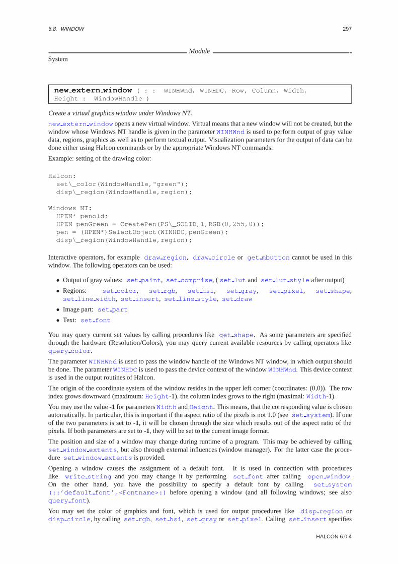
6.8. WINDOW 297
ModuleSystem
new extern window ( : : WINHWnd, WINHDC, Row, Column, Width,Height : WindowHandle )
Create a virtual graphics window under Windows NT.
new extern window opens a new virtual window. Virtual means that a new window will not be created, but thewindow whose Windows NT handle is given in the parameterWINHWndis used to perform output of gray valuedata, regions, graphics as well as to perform textual output. Visualization parameters for the output of data can bedone either using Halcon commands or by the appropriate Windows NT commands.
Example: setting of the drawing color:
Halcon:set\_color(WindowHandle,"green");disp\_region(WindowHandle,region);
Windows NT:HPEN* penold;HPEN penGreen = CreatePen(PS\_SOLID,1,RGB(0,255,0));pen = (HPEN*)SelectObject(WINHDC,penGreen);disp\_region(WindowHandle,region);
Interactive operators, for exampledraw region , draw circle or get mbutton cannot be used in thiswindow. The following operators can be used:
• Output of gray values:set paint , set comprise , ( set lut and set lut style after output)
• Regions: set color , set rgb , set hsi , set gray , set pixel , set shape ,set line width , set insert , set line style , set draw
• Image part: set part
• Text: set font
You may query current set values by calling procedures likeget shape . As some parameters are specifiedthrough the hardware (Resolution/Colors), you may query current available resources by calling operators likequery color .
The parameterWINHWndis used to pass the window handle of the Windows NT window, in which output shouldbe done. The parameterWINHDCis used to pass the device context of the windowWINHWnd. This device contextis used in the output routines of Halcon.
The origin of the coordinate system of the window resides in the upper left corner (coordinates: (0,0)). The rowindex grows downward (maximum:Height -1), the column index grows to the right (maximal:Width -1).
You may use the value-1 for parametersWidth andHeight . This means, that the corresponding value is chosenautomatically. In particular, this is important if the aspect ratio of the pixels is not 1.0 (seeset system ). If oneof the two parameters is set to-1, it will be chosen through the size which results out of the aspect ratio of thepixels. If both parameters are set to-1, they will be set to the current image format.
The position and size of a window may change during runtime of a program. This may be achieved by callingset window extents , but also through external influences (window manager). For the latter case the proce-dure set window extents is provided.
Opening a window causes the assignment of a default font. It is used in connection with procedureslike write string and you may change it by performingset font after calling open window .On the other hand, you have the possibility to specify a default font by callingset system(::’default font’,<Fontname>:) before opening a window (and all following windows; see alsoquery font ).
You may set the color of graphics and font, which is used for output procedures likedisp region ordisp circle , by calling set rgb , set hsi , set gray or set pixel . Calling set insert specifies
HALCON 6.0.4

298 CHAPTER 6. GRAPHICS
how graphics is combined with the content of the image repeat memory. Thereto you may achieve by calling e.g.set insert (::’not’:) to eliminate the font after writing text twice at the same position.
The content of the window is not saved, if other windows overlap the window. This must be done in the programcode that handles the Windows NT window in the calling program.
For graphical output (disp image , disp region , etc.) you may adjust the window by calling procedureset part in order to represent a logical clipping of the image format. In particular this implies that only this part(appropriately scaled) of images and regions is displayed. Before you close your window, you have to close theHalcon-window.
Steps to use newexternwindow:
Creation: • Create a Windows-window.
• Call newexternwindow with theWINHWndof the above created window.
Use: • Before drawing in the window you have to call the method setwindow dc. This ensures that the halcondrawing routines use the right DC. After drawing call again setwindow dc, but this time with the addressof a long set to zero, this ensures that Halcon can delete the created graphic objects.
Destroy: • Call closewindow.
AttentionNote that parameters asRow, Column , Width andHeight are constrained through the output device, i.e., thesize of the Windows NT desktop.
Parameter
. WINHWnd(input control) . . . . . . . . . . . . . . . . . . . . . . . . . . . . . . . . . . . . . . . . . . . . . . . . . . . . . . . . . . . integer; integerWindows windowhandle of a previously created window.Restriction : WINHWnd6= 0
. WINHDC(input control) . . . . . . . . . . . . . . . . . . . . . . . . . . . . . . . . . . . . . . . . . . . . . . . . . . . . . . . . . . . . . integer; integerDevice context of WINHWnd.Restriction : WINHDC6= 0
. Row(input control) . . . . . . . . . . . . . . . . . . . . . . . . . . . . . . . . . . . . . . . . . . . . . . . . . . . . . . . rectangle.origin.y; integerRow coordinate of upper left corner.Default Value : 0Restriction : Row≥ 0
. Column (input control) . . . . . . . . . . . . . . . . . . . . . . . . . . . . . . . . . . . . . . . . . . . . . . . . . . . rectangle.origin.x; integerColumn coordinate of upper left corner.Default Value : 0Restriction : Column ≥ 0
. Width (input control) . . . . . . . . . . . . . . . . . . . . . . . . . . . . . . . . . . . . . . . . . . . . . . . . . . . . rectangle.extent.x; integerWidth of the window.Default Value : 512Restriction : (Width > 0) ∨ (Width = -1 )
. Height (input control) . . . . . . . . . . . . . . . . . . . . . . . . . . . . . . . . . . . . . . . . . . . . . . . . . . . rectangle.extent.y; integerHeight of the window.Default Value : 512Restriction : (Height > 0) ∨ (Height = -1 )
. WindowHandle (outputcontrol) . . . . . . . . . . . . . . . . . . . . . . . . . . . . . . . . . . . . . . . . . . . . . . . . . . window; integerWindow identifier.
Example
HTuple m_tHalconWindow ;Hobject m_objImage ;
WM_CREATE:/* here you should create your extern halcon window*/HTuple tWnd, tDC ;::set_check("˜father") ;tWnd = (INT)((INT*)&m_hWnd) ;
HALCON/HDevelop Reference Manual, 2003-7-21

6.8. WINDOW 299
tDC = (INT)(INT*)GetWindowDC() ;::new_extern_window(tWnd, tDC, 0, 0, sizeTotal.cx, sizeTotal.cy, &m_tHalconWindow) ;::set_check("father") ;
WM_PAINT:/* here you can draw halcon objects */long l = 0 ;if (m_thWindow != -1) {/* don´t forget to set the dc !! */HTuple tDC((INT)(INT*)&pDC->m_hDC) ;HTuple tDCNull((INT)(INT*)&l) ;::set_window_dc(m_tHalconWindow,tDC) ;::disp_obj(pDoc->m_objImage, m_tHalconWindow) ;/* release the graphic objects */::set_window_dc(m_tHalconWindow, tDCNull) ;}
WM_CLOSE:/* close the halcon window */if (m_tHalconWindow != -1) {::close_window(m_tHalconWindow) ;}
ResultIf the values of the specified parameters are correctnew extern window returns 2 (HMSG TRUE). If neces-sary, an exception is raised.
Parallelization Informationnew extern window is local and processedcompletely exclusivelywithout parallelization.
Possible Predecessor Functionsreset obj db
Possible Successor Functionsset color , query window type , get window type , set window type , get mposition ,set tposition , set tshape , set window extents , get window extents , query color ,set check , set system
Alternativesopen window , open textwindow
See Alsoopen window , disp region , disp image , disp color , set lut , query color , set color ,set rgb , set hsi , set pixel , set gray , set part , set part style , query window type ,get window type , set window type , get mposition , set tposition ,set window extents , get window extents , set window attr , set check , set system
ModuleSystem
open textwindow ( : : Row, Column, Width, Height, BorderWidth,BorderColor, BackgroundColor, FatherWindow, Mode,Machine : WindowHandle )
Open a textual window.
open textwindow opens a new textual window, which can be used to perform textual input and output, aswell as to perform output of images. All output (write string , read string , disp region , etc.) isredirected to this window, if the same logical window numberWindowHandle is used.
Besides the mouse cursor textual windows possess also a textual cursor which indicates the current writing position(more exactly: the lower left corner of the output string without consideration of descenders). Its position isindicated through an underscore or another type (the indication of this position may also be disabled (= default
HALCON 6.0.4
300 CHAPTER 6. GRAPHICS
setting); cf. set tshape ). You may set or query the position by calling the proceduresset tposition orget tposition .
After you opened a textual window the position of the cursor is set to (H,0). Whereby H significates the height ofthe default font less the descenders. But the cursor is not shown. Hence the output starts for writing in the upperleft corner of the window.
You may query the colors of the background and the image edges by callingquery color . In the same wayyou may usequery color in a window of type ’invisible’. During output (write string ) you may set theclipping of text out of the window edges by callingset check (::’∼text’:). This disables the creation of errormessages, if text passes over the edge of the window.
The origin of the coordinate system of the window resides in the upper left corner (coordinates: (0,0)). The rowindex grows downward (maximal:Height -1), the column index grows to the right (maximal:Width -1).
The parameterMachine indicates the name of the computer, which has to open the window. In case of a X-window, TCP-IP only sets the name, DEC-Net sets in addition a colon behind the name. The ”‘server”’ or the”‘screen”’, respectively, are not specified. If the empty string is passed the environment variable DISPLAY isused. It indicates the target computer. At this the name is indicated in common syntax
<Host>:0.0
.
Position and size of a window may change during runtime of a program. This may be achieved by callingset window extents , but also through external interferences (window manager). In the latter case the proce-dure set window extents is provided.
Opening a window causes the assignment of a called default font. It is used in connection withprocedures like write string and you may overwrite it by performing set font after callingopen textwindow . On the other hand you have the possibility to specify a default font by callingset system(::’default font’,<Fontname>:) before opening a window (and all following windows; see alsoquery font ).
You may set the color of the font (write string , read string ) by calling set color , set rgb ,set hsi , set gray or set pixel . Calling set insert specifies how the text or the graphics, respectively,is combined with the content of the image repeat memory. So you may achieve by calling e.g.set insert (::’not’:) to eliminate the font after writing text twice at the same position.
Normally every output (e.g.write string , disp region , disp circle , etc.) in a window is terminatedby a ”‘flush”’. This causes the data to be fully visible on the display after termination of the output procedure. Butthis is not necessary in all cases, in particular if there are permanently output tasks or there is a mouse procedureactive. Therefore it is more favorable (i.e. more rapid) to store the data until sufficient data is available. You maystop this behavior by callingset system(::’flush graphic’,’false’:) .
The content of windows is saved (in case it is supported by special driver software); i.e. it is preserved, also ifthe window is hidden by other windows. But this is not necessary in all cases: If you use a textual windowe.g. as a parent window for other windows, you may suppress the security mechanism for it and save the nec-essary memory at the same moment. You achieve this before opening the window by callingset system(::’backing store’,’false’:) .
Difference: graphical window - textual window
• In contrast to graphical windows (open window ) you may specify more parameters (color, edge) for atextual window while opening it.
• You may use textual windows only for input of user data (read string ).
• Using textual windows, the output of images, regions and graphics is ”‘clipped”’ at the edges. Whereasduring the use of graphical windows the edges are ”‘zoomed”’.
• The coordinate system (e.g. withget mbutton or get mposition ) consists of display coordinatesindependently of image size. The maximum coordinates are equal to the size of the window minus 1. Incontrast to this, graphical windows (open window ) use always a coordinate system, which corresponds tothe image format.
The parameterMode specifies the mode of the window. It can have following values:
’visible’: Normal mode for textual windows: The window is created according to the parameters and all inputsand outputs are possible.
HALCON/HDevelop Reference Manual, 2003-7-21

6.8. WINDOW 301
’invisible’: Invisible windows are not displayed in the display. Parameters likeRow, Column , BorderWidth ,BorderColor , BackgroundColor andFatherWindow do not have any meaning. Output to thesewindows has no effect. Input (read string , mouse, etc.) is not possible. You may use these windows toquery representation parameter for an output device without opening a (visible) window. General queries aree.g. query color and get string extents .
’transparent’: These windows are transparent: the window itself is not visible (edge and background), butall the other operations are possible and all output is displayed. Parameters likeBorderColor andBackgroundColor do not have any meaning. A common use for this mode is the creation of mousesensitive regions.
’buffer’: These are also not visible windows. The output of images, regions and graphics is not visible onthe display, but is stored in memory. Parameters likeRow, Column , BorderWidth , BorderColor ,BackgroundColor andFatherWindow do not have any meaning. You may use buffer windows, if youprepare output (in the background) and copy it finally withcopy rectangle in a visible window. An-other usage might be the rapid processing of image regions during interactive manipulations. Textual inputand mouse interaction are not possible in this mode.
AttentionYou have to keep in mind that parameters likeRow, Column , Width andHeight are restricted by the outputdevice. Is a father window (FatherWindow <> ’root’) specified, then the coordinates are relative to this window.
Parameter
. Row(input control) . . . . . . . . . . . . . . . . . . . . . . . . . . . . . . . . . . . . . . . . . . . . . . . . . . . . . . . rectangle.origin.y; integerRow index of upper left corner.Default Value : 0Typical Range of Values :0≤ Row(lin)Minimal Value Step : 1Recommended Value Step :1Restriction : Row≥ 0
. Column (input control) . . . . . . . . . . . . . . . . . . . . . . . . . . . . . . . . . . . . . . . . . . . . . . . . . . . rectangle.origin.x; integerColumn index of upper left corner.Default Value : 0Typical Range of Values :0≤ Column (lin)Minimal Value Step : 1Recommended Value Step :1Restriction : Column ≥ 0
. Width (input control) . . . . . . . . . . . . . . . . . . . . . . . . . . . . . . . . . . . . . . . . . . . . . . . . . . . . rectangle.extent.x; integerWindow’s width.Default Value : 256Typical Range of Values :0≤ Width (lin)Minimal Value Step : 1Recommended Value Step :1Restriction : Width > 0
. Height (input control) . . . . . . . . . . . . . . . . . . . . . . . . . . . . . . . . . . . . . . . . . . . . . . . . . . . rectangle.extent.y; integerWindow’s height.Default Value : 256Typical Range of Values :0≤ Height (lin)Minimal Value Step : 1Recommended Value Step :1Restriction : Height > 0
. BorderWidth (input control) . . . . . . . . . . . . . . . . . . . . . . . . . . . . . . . . . . . . . . . . . . . . . . . . . . . . . . integer; integerWindow border’s width.Default Value : 2Typical Range of Values :0≤ BorderWidth (lin)Minimal Value Step : 1Recommended Value Step :1Restriction : BorderWidth ≥ 0
. BorderColor (input control) . . . . . . . . . . . . . . . . . . . . . . . . . . . . . . . . . . . . . . . . . . . . . . . . . . . . . . . . string; stringWindow border’s color.Default Value : ’white’
HALCON 6.0.4

302 CHAPTER 6. GRAPHICS
. BackgroundColor (input control) . . . . . . . . . . . . . . . . . . . . . . . . . . . . . . . . . . . . . . . . . . . . . . . . . . .string; stringBackground color.Default Value : ’black’
. FatherWindow (input control) . . . . . . . . . . . . . . . . . . . . . . . . . . . . . . . . . . . . . . . . . . . . . integer; integer/ stringLogical number of the father window. For the display as father you may specify ’root’ or 0.Default Value : 0Restriction : FatherWindow ≥ 0
. Mode (input control) . . . . . . . . . . . . . . . . . . . . . . . . . . . . . . . . . . . . . . . . . . . . . . . . . . . . . . . . . . . . . . . . . .string; stringWindow mode.Default Value : ’visible’Value List : Mode∈ {’visible’, ’invisible’, ’transparent’, ’buffer’}
. Machine (input control) . . . . . . . . . . . . . . . . . . . . . . . . . . . . . . . . . . . . . . . . . . . . . . . . . . . . . . . . . . . . . string; stringComputer name, where the window has to be opened or empty string.Default Value : ”
. WindowHandle (outputcontrol) . . . . . . . . . . . . . . . . . . . . . . . . . . . . . . . . . . . . . . . . . . . . . . . . . . window; integerWindow identifier.
Example
open_textwindow(0,0,900,600,1,’black’,’slate blue’,’root’,’visible’,’’WindowHandle)
open_textwindow(10,10,300,580,3,’red’,’blue’,Father,’visible’,’’WindowHandle)
open_window(10,320,570,580,Father,’visible’,’’WindowHandle)set_color(WindowHandle,’red’)read_image(Image,’affe’)disp_image(Image,WindowHandle)repeat()get_mposition(WindowHandle,Row,Column,Button)get_grayval(Image,Row,Column,1,Gray)write_string(WindowHandle,[’ Position (’,Row,’,’,Column,’) ’])write_string(WindowHandle,[’Gray value (’,Gray,’) ’])new_line(WindowHandle)until(Button = 4)close_window(WindowHandle)clear_obj(Image).
ResultIf the values of the specified parameters are correctopen textwindow returns 2 (HMSG TRUE). If necessaryan exception handling is raised.
Parallelization Informationopen textwindow is local and processedcompletely exclusivelywithout parallelization.
Possible Predecessor Functionsreset obj db
Possible Successor Functionsset color , query window type , get window type , set window type , get mposition ,set tposition , set tshape , set window extents , get window extents , query color ,set check , set system
Alternativesopen window
See Alsowrite string , read string , new line , get string extents , get tposition , set color ,query window type , get window type , set window type , get mposition , set tposition ,set tshape , set window extents , get window extents , query color , set check ,set system
ModuleSystem
HALCON/HDevelop Reference Manual, 2003-7-21

6.8. WINDOW 303
open window ( : : Row, Column, Width, Height, FatherWindow, Mode,Machine : WindowHandle )
Open a graphics window.
open window opens a new window, which can be used to perform output of gray value data, regions, graphics aswell as to perform textual output. All output (disp region , disp image , etc.) is redirected to this window,if the same logical window numberWindowHandle is used.
The background of the created window is set to black in advance and it has a white border, which is 2 pixels wide(see alsoset window attr(::’border width’,<Breite>:) .
Certain parameters used for the editing of output data are assigned to a window. These parameters are consideredduring the output itself (e.g. withdisp image or disp region ). They are not specified by an output pro-cedure, but by ”‘configuration procedures”’. If you want to set e.g. the color red for the output of regions, youhave to callset color(::WindowHandle,’red’:) before callingdisp region . These parameters arealways set for the window with the logical window numberWindowHandle and remain assigned to a window aslong as they will be overwritten. You may use the following configuration procedures:
• Output of gray values:set paint , set comprise , ( set lut and set lut style after output)
• Regions: set color , set rgb , set hsi , set gray , set pixel , set shape ,set line width , set insert , set line style , set draw
• Image clipping: set part
• Text: set font
You may query current set values by calling procedures likeget shape . As some parameters are specifiedthrough the hardware (Resolution/Colors), you may query current available ressources by callingquery color .
The origin of the coordinate system of the window resides in the upper left corner (coordinates: (0,0)). The rowindex grows downward (maximal:Height -1), the column index grows to the right (maximal:Width -1). Youhave to keep in mind, that the range of the coordinate system is independent of the window size. It is specifiedonly through the image format (seereset obj db).
The parameterMachine indicates the name of the computer, which has to open the window. In case of a X-window, TCP-IP only sets the name, DEC-Net sets in addition a colon behind the name. The ”‘server”’ resp. the”‘screen”’ are not specified. If the empty string is passed the environment variable DISPLAY is used. It indicatesthe target computer. At this the name is indicated in common syntax
<Host>:0.0
.
You may use the value ”‘-1”’ for parametersWidth andHeight . This means, that the according value has to bespecified automatically. In particular this is of importance, if the proportion of pixels is not 1.0 (seeset system ):Is one of the two parameters set to ”‘-1”’, it will be specified through the size which results out of the proportionof pixels. Are both parameters set to ”‘-1”’, they will be set to the maximum image format, which is currentlyused (further information about the currently used maximum image format can be found in the description ofget system using ”‘width”’ or ”‘height”’).
Position and size of a window may change during runtime of a program. This may be achieved by callingset window extents , but also through external interferences (window manager). In the latter case the proce-dure set window extents is provided.
Opening a window causes the assignment of a called default font. It is used in connection withprocedures like write string and you may overwrite it by performing set font after callingopen window . On the other hand you have the possibility to specify a default font by callingset system(::’default font’,<Fontname>:) before opening a window (and all following windows; see alsoquery font ).
You may set the color of graphics and font, which is used for output procedures likedisp region ordisp circle , by calling set rgb , set hsi , set gray or set pixel . Calling set insert specifieshow graphics is combined with the content of the image repeat memory. Thereto you may achieve by calling e.g.set insert (::’not’:) to eliminate the font after writing text twice at the same position.
Normally every output (e.g.disp image , disp region , disp circle , etc.) in a window is terminated bya called ”‘flush”’. This causes the data to be fully visible on the display after termination of the output procedure.
HALCON 6.0.4
304 CHAPTER 6. GRAPHICS
But this is not necessary in all cases, in particular if there are permanently output tasks or if there is a mouseprocedure active. Therefore it is more favorable (i.e. more rapid) to store the data until sufficient data is available.You may stop this behavior by callingset system(::’flush graphic’,’false’:) .
The content of windows is saved (in case it is supported by special driver software); i.e. it is preserved, also ifthe window is hidden by other windows. But this is not necessary in all cases: If the content of a window is builtup permanently new (copy rectangle ), you may suppress the security mechanism for that and hence youcan save the necessary memory. This is done by callingset system(::’backing store’,’false’:)before opening a window. In doing so you save not only memory but also time to compute. This is significant forthe output of video clips (seecopy rectangle ).
For graphical output (disp image , disp region , etc.) you may adjust the window by calling procedureset part in order to represent a logical clipping of the image format. In particular this implicates that you obtainthis clipping (with appropriate enlargement) of images and regions only.
Difference: graphical window - textual window
• Using graphical windows the layout is not as variable as concerned to textual windows.
• You may use textual windows for the input of user data only (read string ).
• During the output of images, regions and graphics a ”‘zooming”’ is performed using graphical windows:Independent on size and side ratio of the window images are transformed in that way, that they are displayedin the window by filling it completely. On the opposite side using textual windows the output does not careabout the size of the window (only if clipping is necessary).
• Using graphical windows the coordinate system of the window corresponds to the coordinate system ofthe image format. Using textual windows, its coordinate system is always equal to the display coordinatesindependent on image size.
The parameterMode determines the mode of the window. It may have following values:
’visible’: Normal mode for graphical windows: The window is created according to the parameters and all inputand output are possible.
’invisible’: Invisible windows are not displayed in the display. Parameters likeRow, Column andFatherWindow do not have any meaning. Output to these windows has no effect. Input (read string ,mouse, etc.) is not possible. You may use these windows to query representation parameter for anoutput device without opening a (visible) window. Common queries are e.g.query color andget string extents .
’transparent’: These windows are transparent: the window itself is not visible (edge and background), but allthe other operations are possible and all output is displayed. A common use for this mode is the creation ofmouse sensitive regions.
’buffer’: These are also not visible windows. The output of images, regions and graphics is not visible on thedisplay, but is stored in memory. Parameters likeRow, Column andFatherWindow do not have anymeaning. You may use buffer windows, if you prepare output (in the background) and copy it finally withcopy rectangle in a visible window. Another usage might be the rapid processing of image regionsduring interactive manipulations. Textual input and mouse interaction are not possible in this mode.
AttentionYou may keep in mind that parameters asRow, Column , Width andHeight are constrained by the outputdevice. If you specify a father window (FatherWindow <> ’root’) the coordinates are relative to this window.
Parameter
. Row(input control) . . . . . . . . . . . . . . . . . . . . . . . . . . . . . . . . . . . . . . . . . . . . . . . . . . . . . . . rectangle.origin.y; integerRow index of upper left corner.Default Value : 0Typical Range of Values :0≤ Row(lin)Minimal Value Step : 1Recommended Value Step :1Restriction : Row≥ 0
HALCON/HDevelop Reference Manual, 2003-7-21

6.8. WINDOW 305
. Column (input control) . . . . . . . . . . . . . . . . . . . . . . . . . . . . . . . . . . . . . . . . . . . . . . . . . . . rectangle.origin.x; integerColumn index of upper left corner.Default Value : 0Typical Range of Values :0≤ Column (lin)Minimal Value Step : 1Recommended Value Step :1Restriction : Column ≥ 0
. Width (input control) . . . . . . . . . . . . . . . . . . . . . . . . . . . . . . . . . . . . . . . . . . . . . . . . . . . . rectangle.extent.x; integerWidth of the window.Default Value : 256Typical Range of Values :0≤ Width (lin)Minimal Value Step : 1Recommended Value Step :1Restriction : (Width > 0) ∨ (Width = -1 )
. Height (input control) . . . . . . . . . . . . . . . . . . . . . . . . . . . . . . . . . . . . . . . . . . . . . . . . . . . rectangle.extent.y; integerHeight of the window.Default Value : 256Typical Range of Values :0≤ Height (lin)Minimal Value Step : 1Recommended Value Step :1Restriction : (Height > 0) ∨ (Height = -1 )
. FatherWindow (input control) . . . . . . . . . . . . . . . . . . . . . . . . . . . . . . . . . . . . . . . . . . . . . integer; integer/ stringLogical number of the father window. To specify the display as father you may enter ’root’ or 0.Default Value : 0Restriction : FatherWindow ≥ 0
. Mode (input control) . . . . . . . . . . . . . . . . . . . . . . . . . . . . . . . . . . . . . . . . . . . . . . . . . . . . . . . . . . . . . . . . . .string; stringWindow mode.Default Value : ’visible’Value List : Mode∈ {’visible’, ’invisible’, ’transparent’, ’buffer’}
. Machine (input control) . . . . . . . . . . . . . . . . . . . . . . . . . . . . . . . . . . . . . . . . . . . . . . . . . . . . . . . . . . . . . string; stringName of the computer on which you want to open the window. Otherwise the empty string.Default Value : ”
. WindowHandle (outputcontrol) . . . . . . . . . . . . . . . . . . . . . . . . . . . . . . . . . . . . . . . . . . . . . . . . . . window; integerWindow identifier.
Example
open_window(0,0,400,-1,’root’,’visible’,’’,WindowHandle)read_image(Image,’fabrik’)disp_image(Image,WindowHandle)write_string(WindowHandle,’File, fabrik.ima’)new_line(WindowHandle)get_mbutton(WindowHandle,_,_,_)set_lut(WindowHandle,’temperature’)set_color(WindowHandle,’blue’)write_string(WindowHandle,’temperature’)new_line(WindowHandle)write_string(WindowHandle,’Draw Rectangle’)new_line(WindowHandle)draw_rectangle1(WindowHandle,Row1,Column1,Row2,Column2)set_part(Row1,Column1,Row2,Column2)disp_image(Image,WindowHandle)new_line(WindowHandle).
ResultIf the values of the specified parameters are correctopen window returns 2 (HMSG TRUE). If necessary anexception handling is raised.
Parallelization Informationopen window is local and processedcompletely exclusivelywithout parallelization.
HALCON 6.0.4

306 CHAPTER 6. GRAPHICS
Possible Predecessor Functionsreset obj db
Possible Successor Functionsset color , query window type , get window type , set window type , get mposition ,set tposition , set tshape , set window extents , get window extents , query color ,set check , set system
Alternativesopen textwindow
See Alsodisp region , disp image , disp color , set lut , query color , set color , set rgb ,set hsi , set pixel , set gray , set part , set part style , query window type ,get window type , set window type , get mposition , set tposition ,set window extents , get window extents , set window attr , set check , set system
ModuleSystem
query window type ( : : : WindowTypes )
Query all available window types.
query window type returns a tupel which contains all devices or software systems, respectively, which areused to display image objects. You may usequery window type usefully while developing machine indepen-dent programs. Possible values are:
’X-Window’ X-Window Version 11.
’pixmap’ Windows are not displayed, but managed in memory. In this manner it is possible to port Halconprograms to computers without graphical display.
’PostScript’ Objects are output to a PostScript File.
Parameter
. WindowTypes (outputcontrol) . . . . . . . . . . . . . . . . . . . . . . . . . . . . . . . . . . . . . . . . . . . . . . . . . string-array; stringNames of available window types.
Resultquery window type always returns 2 (HMSG TRUE).
Parallelization Informationquery window type is local and processedcompletely exclusivelywithout parallelization.
Possible Predecessor Functionsreset obj db
ModuleSystem
set window attr ( : : AttributeName, AttributeValue : )
Set window’s characteristics.
You may useset window attr to set specific characteristics of graphical windows. With it you may modifyfollowing default parameters of a window:
’border width’ Width of the window border in pixels.
’border color’ Color of the window border.
’background color’ Background color of the window.
’window title’ Name of the window in the titlebar.
HALCON/HDevelop Reference Manual, 2003-7-21

6.8. WINDOW 307
AttentionYou have to callset window attr beforecalling open window .
Parameter
. AttributeName (input control) . . . . . . . . . . . . . . . . . . . . . . . . . . . . . . . . . . . . . . . . . . . . . . . . . . . . . string; stringName of the attribut, which has to be modified.Value List : AttributeName ∈ {’border width’, ’border color’, ’backgroundcolor’, ’window title’}
. AttributeValue (input control) . . . . . . . . . . . . . . . . . . . . . . . . . . . . . . . . . . . . . . . . . . . . string; string/ integerValue of the attribut, which has to be set.Value List : AttributeValue ∈ {0, 1, 2, ’white’, ’black’, ’MyName’, ’default’}
ResultIf the parameters are correctset window attr returns 2 (HMSG TRUE). If necessary an exception handlingis raised.
Parallelization Informationset window attr is reentrant, local, and processedwithoutparallelization.
Possible Predecessor Functionsopen window , set draw , set color , set colored , set line width , open textwindow
See Alsoopen window
ModuleSystem
set window dc ( : : WindowHandle, WINHDC : )
Set the device context of a virtual graphics window (Windows NT).
set window dc sets the device context of a window previously opened withnew extern window . All output( disp region , disp image , etc.) is done in the window with this device context.
The parameterWINHDCcontains the device context of the window in which Halcon should output its data. Thisdevice context is used in all output routines of Halcon.
AttentionThe windowWindowHandle has to be created withnew extern window beforehand.
Parameter
. WindowHandle (input control) . . . . . . . . . . . . . . . . . . . . . . . . . . . . . . . . . . . . . . . . . . . . . . . . . . . window; integerWindow identifier.
. WINHDC(input control) . . . . . . . . . . . . . . . . . . . . . . . . . . . . . . . . . . . . . . . . . . . . . . . . . . . . . . . . . . . . . integer; integerdevicecontext of WINHWnd.Restriction : WINHDC6= 0
Example
hWnd = createWINDOW(...)new_extern_window(hwnd, hdc, 0,0,400,-1,WindowHandle)set_device_context(WindowHandle, hdc)read_image(Image,’fabrik’)disp_image(Image,WindowHandle)write_string(WindowHandle,’File, fabrik.ima’)new_line(WindowHandle)get_mbutton(WindowHandle,_,_,_)set_lut(WindowHandle,’temperature’)set_color(WindowHandle,’blue’)write_string(WindowHandle,’temperature’)new_line(WindowHandle)write_string(WindowHandle,’Draw Rectangle’)new_line(WindowHandle)
HALCON 6.0.4

308 CHAPTER 6. GRAPHICS
draw_rectangle1(WindowHandle,Row1,Column1,Row2,Column2)set_part(Row1,Column1,Row2,Column2)disp_image(Image,WindowHandle)new_line(WindowHandle).
ResultIf the values of the specified parameters are correct,set window dc returns 2 (HMSG TRUE). If necessary,an exception is raised.
Parallelization Informationset window dc is local and processedcompletely exclusivelywithout parallelization.
Possible Predecessor Functionsnew extern window
Possible Successor Functionsdisp image , disp region
See Alsonew extern window , disp region , disp image , disp color , set lut , query color ,set color , set rgb , set hsi , set pixel , set gray , set part , set part style ,query window type , get window type , set window type , get mposition , set tposition ,set window extents , get window extents , set window attr , set check , set system
ModuleSystem
set window extents ( : : WindowHandle, Row, Column, Width, Height : )
Modify position and size of a window.
set window extents positions the upper left corner of the output window at (Row,Column ) and changes thesize of the window toWidth andHeight at the same time.
AttentionIf you modify the size of a window an adaptation of the displayed date to the new format is not processed automat-ically. This has to be done by the program in performing another output of these data.
Parameter
. WindowHandle (input control) . . . . . . . . . . . . . . . . . . . . . . . . . . . . . . . . . . . . . . . . . . . . . . . . . . . window; integerWindow identifier.
. Row(input control) . . . . . . . . . . . . . . . . . . . . . . . . . . . . . . . . . . . . . . . . . . . . . . . . . . . . . . . rectangle.origin.y; integerRow index of upper left corner in target position.Default Value : 0Typical Range of Values :0≤ Row(lin)Minimal Value Step : 1Recommended Value Step :1
. Column (input control) . . . . . . . . . . . . . . . . . . . . . . . . . . . . . . . . . . . . . . . . . . . . . . . . . . . rectangle.origin.x; integerColumn index of upper left corner in target position.Default Value : 0Typical Range of Values :0≤ Column (lin)Minimal Value Step : 1Recommended Value Step :1
. Width (input control) . . . . . . . . . . . . . . . . . . . . . . . . . . . . . . . . . . . . . . . . . . . . . . . . . . . . rectangle.extent.x; integerWidth of the window.Default Value : 512Typical Range of Values :0≤ Width (lin)Minimal Value Step : 1Recommended Value Step :1
HALCON/HDevelop Reference Manual, 2003-7-21

6.8. WINDOW 309
. Height (input control) . . . . . . . . . . . . . . . . . . . . . . . . . . . . . . . . . . . . . . . . . . . . . . . . . . . rectangle.extent.y; integerHeight of the window.Default Value : 512Typical Range of Values :0≤ Height (lin)Minimal Value Step : 1Recommended Value Step :1
ResultIf the window is valid and the parameters are correctset window extents returns 2 (HMSG TRUE). Ifnecessary an exception handling is raised.
Parallelization Informationset window extents is local and processedcompletely exclusivelywithout parallelization.
Possible Predecessor Functionsopen window , open textwindow
See Alsoget window extents , open window , open textwindow
ModuleSystem
set window type ( : : WindowType : )
Specify a window type.
set window type determines on which type of output device the output is going to be displayed. This spec-ification is going to be used by procedureopen window while opening the windows. You may open differentwindows on different types of output devices. Therefore you have to specify the wanted type before opening. Youmay request the available types of output devices by calling procedurequery window type . Possible valuesare:
’X-Window’ X-Window Version 11.
’WIN32-Window’ Microsoft Windows.
’pixmap’ Windows are not displayed, but managed in memory only. In this manner you may port Halcon pro-grams to computers without graphical display.
’PostScript’ Objects are output to a PostScript File.
A useful usage ofset window type could be the development of machine independent programs.
Parameter
. WindowType (input control) . . . . . . . . . . . . . . . . . . . . . . . . . . . . . . . . . . . . . . . . . . . . . . . . . . . . . . . . . string; stringName of the window type which has to be set.Default Value : ’X-Window’Value List : WindowType ∈ {’X-Window’, ’WIN32-Window’, ’pixmap’, ’PostScript’}
ResultIf the type of the output device is available, thenset window type returns 2 (HMSG TRUE). If necessary anexception handling is raised.
Parallelization Informationset window type is local and processedcompletely exclusivelywithout parallelization.
Possible Predecessor Functionsopen window , open textwindow
See Alsoopen window , open textwindow , query window type , get window type
ModuleSystem
HALCON 6.0.4

310 CHAPTER 6. GRAPHICS
slide image ( : : WindowHandleSource1, WindowHandleSource2,WindowHandle : )
Interactive output from two window buffers.
slide image divides the window horizontal in two logical areas dependent of the mouse position. The contentof the first indicated window is copied in the upper area, the content of the second window is copied in the lowerarea. If you press the left mouse button you may scroll the delimitation between the two areas (you may movethe mouse outside the window, too. In doing so the position of the mouse relative to the window determines theborderline).
Pressing the right mouse button in the window terminates the procedureslide image .
A useful application of procedureslide image might be the visualisation of the effect of a filtering operationfor an image. The output is directed to the current set window (WindowHandle ).
AttentionThe three windows must have the same size and have to reside on the same computer.
Parameter
. WindowHandleSource1 (input control) . . . . . . . . . . . . . . . . . . . . . . . . . . . . . . . . . . . . . . . . . . window; integerLogical window number of the ”‘upper window”’.
. WindowHandleSource2 (input control) . . . . . . . . . . . . . . . . . . . . . . . . . . . . . . . . . . . . . . . . . . window; integerLogical window number of the ”‘lower window”’.
. WindowHandle (input control) . . . . . . . . . . . . . . . . . . . . . . . . . . . . . . . . . . . . . . . . . . . . . . . . . . . window; integerWindow identifier.
Example
read_image(Image,’fabrik’)sobel_amp(Image,Amp,’sum_abs’,3)open_window(0,0,-1,-1,’root’,’buffer’,’’,WindowHandle)disp_image(Amp,WindowHandle)sobel_dir(Image,Dir,’sum_abs’,3)open_window(0,0,-1,-1,’root’,’buffer’,’’,WindowHandle)disp_image(Dir,WindowHandle)open_window(0,0,-1,-1,’root’,’visible’,’’,WindowHandle)slide_image(Puffer1,Puffer2,WindowHandle).
ResultIf the both windows exist and one of these windows is validslide image returns 2 (HMSG TRUE). If neces-sary an exception handling is raised.
Parallelization Informationslide image is local and processedcompletely exclusivelywithout parallelization.
Possible Predecessor Functionsopen window , open textwindow
Alternativescopy rectangle , get mposition
See Alsoopen window , open textwindow , move rectangle
ModuleSystem
HALCON/HDevelop Reference Manual, 2003-7-21

Chapter 7
Image
7.1 Access
get grayval ( Image : : Row, Column : Grayval )
Access the gray values of an image object.
The operatorGrayval is a tuple of floating point numbers, integer respectively, which returns the gray values ofseveral pixels ofImage . The line coordinates of the pixels are in the tupleRow, the columns inColumn .
AttentionThe type of the values ofGrayval depends on the type of the gray values.Gray values which do not belong to the image can also be accessed. The state of these gray values is not ascer-tained.The operatorget grayval involves a lot of work. It is not suitable for programming image processing opera-tions such as filters. In this case it is more useful to use the procedureget image pointer1 or to directly usethe C interface for integrating own procedures.
Parameter
. Image (input object) . . . . . . . . . . . . . . . . . . . . . . . . . . . . . . . . . . . . . . . . . . . . . . . . . . . . . . . . . . . . . . . image; HobjectImage whose gray value is to be accessed.
. Row(input control) . . . . . . . . . . . . . . . . . . . . . . . . . . . . . . . . . . . . . . . . . . . . . . . . . . . . . . . . . . point.y(-array); integerLine numbers of pixels to be viewed.Default Value : 0Value Suggestions :Row∈ {0, 64, 128, 256, 512, 1024}Typical Range of Values :0≤ Row≤ 32768 (lin)Minimal Value Step : 1Recommended Value Step :1Restriction : (0 ≤ Row) ∧ (Row< height(Image ))
. Column (input control) . . . . . . . . . . . . . . . . . . . . . . . . . . . . . . . . . . . . . . . . . . . . . . . . . . . . . .point.x(-array); integerColumn numbers of pixels to be viewed.Default Value : 0Value Suggestions :Column ∈ {0, 64, 128, 256, 512, 1024}Typical Range of Values :0≤ Column ≤ 32768 (lin)Minimal Value Step : 1Recommended Value Step :1Parameter Number : Column = RowRestriction : (0 ≤ Column ) ∧ (Column < width(Image ))
. Grayval (outputcontrol) . . . . . . . . . . . . . . . . . . . . . . . . . . . . . . . . . . . . . . . . . . . . . grayval(-array); real/ integerGray values of indicated pixels.Parameter Number : Grayval = Row
ResultIf the state of the parameters is correct the operatorget grayval returns the value 2 (HMSG TRUE).
311

312 CHAPTER 7. IMAGE
The behavior in case of empty input (no input images available) is set via the operatorset system(’no object result’,<Result>) . If necessary an exception handling is raised.
Parallelization Informationget grayval is reentrantand processedwithoutparallelization.
Possible Predecessor Functionsread image
Alternativesget image pointer1
See Alsoset grayval
ModuleImage / region / XLD management
get image pointer1 ( Image : : : Pointer, Type, Width, Height )
Access the pointer of a channel.
The operatorget image pointer1 returns a C pointer to the first channel of the imageImage . Additionallythe image type (Type = ’byte’, ’integer’, ’float’ etc.) and the image size (width and height) are returned. Con-sequently a direct access to the image data in the HALCON databank from the HALCON host language via thepointer is possible. An image is stored in HALCON as a vector of image lines.
AttentionThe operatorget image pointer1 should only be used for entry into newly created images, since otherwisethe gray values of other images might be overwritten (see relational structure).
Parameter
. Image (input object) . . . . . . . . . . . . . . . . . . . . . . . . . . . . . . . . . . . . . . . . . . . . . . . . . . . . . . . . . . . . . . . image; HobjectInput image.
. Pointer (outputcontrol) . . . . . . . . . . . . . . . . . . . . . . . . . . . . . . . . . . . . . . . . . . . . . . . . . . . . . . . . . . pointer; integerPointer to the image data in the HALCON databank.
. Type (outputcontrol) . . . . . . . . . . . . . . . . . . . . . . . . . . . . . . . . . . . . . . . . . . . . . . . . . . . . . . . . . . . . . . . . string; stringType of image.Value List : Type ∈ {’int1’, ’int2’, ’int4’, ’byte’, ’real’, ’direction’, ’cyclic’, ’complex’, ’dvf’, ’lut’ }
. Width (outputcontrol) . . . . . . . . . . . . . . . . . . . . . . . . . . . . . . . . . . . . . . . . . . . . . . . . . . . . . . . . . . . . extent.x; integerWidth of image.
. Height (outputcontrol) . . . . . . . . . . . . . . . . . . . . . . . . . . . . . . . . . . . . . . . . . . . . . . . . . . . . . . . . . . .extent.y; integerHeight of image.
Example
Hobject Bild;char typ[128];long width,height;unsigned char *ptr;
read_image(&Bild,"fabrik");get_image_pointer1(Bild,(long*)&ptr,typ,&width,&height);
ResultThe operatorget image pointer1 returns the value 2 (HMSG TRUE) if exactly one image was passed.The behavior in case of empty input (no input images available) is set via the operatorset system(’no object result’,<Result>) . If necessary an exception handling is raised.
Parallelization Informationget image pointer1 is reentrantand processedwithoutparallelization.
Possible Predecessor Functionsread image
HALCON/HDevelop Reference Manual, 2003-7-21

7.1. ACCESS 313
Alternativesset grayval , get grayval , get image pointer3
See Alsopaint region , paint gray
ModuleImage / region / XLD management
get image pointer1 rect ( Image : : : PixelPointer, Width, Height,VerticalPitch, HorizontalBitPitch, BitsPerPixel )
Access to the image data pointer and the image data inside the smallest rectangle of the domain of the input image.
The operator get image pointer1 rect returns the pointerPixelPointer which points to the be-ginning of the image data inside the smallest rectangle of the domain ofImage . VerticalPitchcorresponds to the width of the input imageImage multiplied with the number of bytes per pixel(HorizontalBitPitch / 8). Width and Height correspond to the size of the smallest rectangle of theinput region. HorizontalBitPitch is the horizontal distance (in bits) between two neighbouring pixels.BitsPerPixel is the number of used bits per pixel. get image pointer1 rect is symmetrical togen image1 rect .
AttentionThe operator get image pointer1 rect should only be used for entry into newly created images, sinceotherwise the gray values of other images might be overwritten (see relational structure).
Parameter
. Image (input object) . . . . . . . . . . . . . . . . . . . . . . . . . . . . . . . . . . . . . . . . . . . . . . image; Hobject: byte / int2 / int4Input image (Himage).
. PixelPointer (outputcontrol) . . . . . . . . . . . . . . . . . . . . . . . . . . . . . . . . . . . . . . . . . . . . . . . . . . . pointer; integerPointer to the image data.
. Width (outputcontrol) . . . . . . . . . . . . . . . . . . . . . . . . . . . . . . . . . . . . . . . . . . . . . . . . . . . . . . . . . . . . extent.x; integerWidth of the output image.
. Height (outputcontrol) . . . . . . . . . . . . . . . . . . . . . . . . . . . . . . . . . . . . . . . . . . . . . . . . . . . . . . . . . . .extent.y; integerHeight of the output image.
. VerticalPitch (outputcontrol) . . . . . . . . . . . . . . . . . . . . . . . . . . . . . . . . . . . . . . . . . . . . . . . . . . integer; integerWidth(input image)*(HorizontalBitPitch/8).
. HorizontalBitPitch (outputcontrol) . . . . . . . . . . . . . . . . . . . . . . . . . . . . . . . . . . . . . . . . . . . integer; integerDistance between two neighbouring pixels in bits .Default Value : 8Value List : HorizontalBitPitch ∈ {8, 16, 32}
. BitsPerPixel (outputcontrol) . . . . . . . . . . . . . . . . . . . . . . . . . . . . . . . . . . . . . . . . . . . . . . . . . . . integer; integerNumber of used bits per pixel.Default Value : 8Value List : BitsPerPixel ∈ {8, 16, 32}
Example
Hobject image,reg,imagereduced;char typ[128];long width,height,vert_pitch,hori_bit_pitch,bits_per_pix, winID;unsigned char *ptr;
open_window(0,0,512,512,"black",winID);read_image(&image,"monkey");draw_region(®,winID);reduce_domain(image,reg,&imagereduced);get_image_pointer1_rect(imagereduced,(long*)&ptr,&width,&height,
&vert_pitch,&hori_bit_pitch,&bits_per_pix);
HALCON 6.0.4
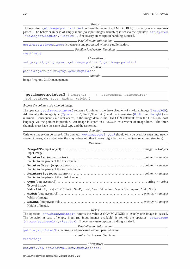
314 CHAPTER 7. IMAGE
ResultThe operator get image pointer1 rect returns the value 2 (HMSG TRUE) if exactly one image waspassed. The behavior in case of empty input (no input images available) is set via the operatorset system(’no object result’,<Result>) . If necessary an exception handling is raised.
Parallelization Informationget image pointer1 rect is reentrantand processedwithoutparallelization.
Possible Predecessor Functionsread image
Alternativesset grayval , get grayval , get image pointer3 , get image pointer1
See Alsopaint region , paint gray , gen image1 rect
ModuleImage / region / XLD management
get image pointer3 ( ImageRGB : : : PointerRed, PointerGreen,PointerBlue, Type, Width, Height )
Access the pointers of a colored image.
The operatorget image pointer3 returns a C pointer to the three channels of a colored image (ImageRGB).Additionally the image type (Type = ’byte’, ’int2’,’float’ etc.) and the image size (Width andHeight ) arereturned. Consequently a direct access to the image data in the HALCON databank from the HALCON hostlanguage via the pointer is possible. An image is stored in HALCON as a vector of image lines. The threechannels must have the same pixel type and the same size.
AttentionOnly one image can be passed. The operatorget image pointer3 should only be used for entry into newlycreated images, since otherwise the gray values of other images might be overwritten (see relational structure).
Parameter
. ImageRGB(input object) . . . . . . . . . . . . . . . . . . . . . . . . . . . . . . . . . . . . . . . . . . . . . . . . . . . . . . . . . . . image; HobjectInput image.
. PointerRed (outputcontrol) . . . . . . . . . . . . . . . . . . . . . . . . . . . . . . . . . . . . . . . . . . . . . . . . . . . . . . pointer; integerPointer to the pixels of the first channel.
. PointerGreen (outputcontrol) . . . . . . . . . . . . . . . . . . . . . . . . . . . . . . . . . . . . . . . . . . . . . . . . . . . pointer; integerPointer to the pixels of the second channel.
. PointerBlue (outputcontrol) . . . . . . . . . . . . . . . . . . . . . . . . . . . . . . . . . . . . . . . . . . . . . . . . . . . . pointer; integerPointer to the pixels of the third channel.
. Type (outputcontrol) . . . . . . . . . . . . . . . . . . . . . . . . . . . . . . . . . . . . . . . . . . . . . . . . . . . . . . . . . . . . . . . . string; stringType of image.Value List : Type ∈ {’int1’, ’int2’, ’int4’, ’byte’, ’real’, ’direction’, ’cyclic’, ’complex’, ’dvf’, ’lut’ }
. Width (outputcontrol) . . . . . . . . . . . . . . . . . . . . . . . . . . . . . . . . . . . . . . . . . . . . . . . . . . . . . . . . . . . . extent.x; integerWidth of image.
. Height (outputcontrol) . . . . . . . . . . . . . . . . . . . . . . . . . . . . . . . . . . . . . . . . . . . . . . . . . . . . . . . . . . .extent.y; integerHeight of image.
ResultThe operator get image pointer3 returns the value 2 (HMSG TRUE) if exactly one image is passed.The behavior in case of empty input (no input images available) is set via the operatorset system(’no object result’,<Result>) . If necessary an exception handling is raised.
Parallelization Informationget image pointer3 is reentrantand processedwithoutparallelization.
Possible Predecessor Functionsread image
Alternativesset grayval , get grayval , get image pointer1
HALCON/HDevelop Reference Manual, 2003-7-21

7.2. CHANNEL 315
See Alsopaint region , paint gray
ModuleImage / region / XLD management
get image time ( Image : : : MSecond, Second, Minute, Hour, Day, YDay,Month, Year )
Request time at which the image was created.
The operatorget image time returns the time at which the image was created.
Parameter
. Image (input object) . . . . . . . . . . . . . . . . . . . . . . . . . . . . . . . . . . . . . . . . . . . . . . . . . . . . . . . . . . . . . . . image; HobjectInput image.
. MSecond (outputcontrol) . . . . . . . . . . . . . . . . . . . . . . . . . . . . . . . . . . . . . . . . . . . . . . . . . . . . . . . . . . integer; integerMilliseconds (0..999).
. Second (outputcontrol) . . . . . . . . . . . . . . . . . . . . . . . . . . . . . . . . . . . . . . . . . . . . . . . . . . . . . . . . . . . integer; integerSeconds (0..59).
. Minute (outputcontrol) . . . . . . . . . . . . . . . . . . . . . . . . . . . . . . . . . . . . . . . . . . . . . . . . . . . . . . . . . . . integer; integerMinutes (0..59).
. Hour (outputcontrol) . . . . . . . . . . . . . . . . . . . . . . . . . . . . . . . . . . . . . . . . . . . . . . . . . . . . . . . . . . . . . . integer; integerHours (0..11).
. Day (outputcontrol) . . . . . . . . . . . . . . . . . . . . . . . . . . . . . . . . . . . . . . . . . . . . . . . . . . . . . . . . . . . . . . . . integer; integerDay of the month (1..31).
. YDay (outputcontrol) . . . . . . . . . . . . . . . . . . . . . . . . . . . . . . . . . . . . . . . . . . . . . . . . . . . . . . . . . . . . . . integer; integerDay of the year (1..365).
. Month (outputcontrol) . . . . . . . . . . . . . . . . . . . . . . . . . . . . . . . . . . . . . . . . . . . . . . . . . . . . . . . . . . . . . integer; integerMonth (1..12).
. Year (outputcontrol) . . . . . . . . . . . . . . . . . . . . . . . . . . . . . . . . . . . . . . . . . . . . . . . . . . . . . . . . . . . . . . integer; integerYear (xxxx).
ResultThe operator get image time returns the value 2 (HMSG TRUE) if exactly one image was passed.The behavior in case of empty input (no input images available) is set via the operatorset system(’no object result’,<Result>) . If necessary an exception handling is raised.
Parallelization Informationget image time is reentrant, local, and processedwithoutparallelization.
Possible Predecessor Functionsread image , grab image
See Alsocount seconds
ModuleImage / region / XLD management
7.2 Channel
access channel ( MultiChannelImage : Image : Channel : )
Access a channel of a multichannel image.
The operator access channel accesses a channel of the (multichannel) input image. The result is a one-channel image. The definition domain of the input is adopted. The channels are numbered from 1 to n. Thenumber of channels can be determined via the operatorcount channels .
HALCON 6.0.4

316 CHAPTER 7. IMAGE
Parameter
. MultiChannelImage (input object) . . . . . . . . . . . . . . . . . . . . . . . . . . . . . . . . . .multichannel-image; HobjectMultichannel image.
. Image (outputobject) . . . . . . . . . . . . . . . . . . . . . . . . . . . . . . . . . . . . . . . . . . . . . . . . singlechannel-image; HobjectOne channel of MultiChannelImage.
. Channel (input control) . . . . . . . . . . . . . . . . . . . . . . . . . . . . . . . . . . . . . . . . . . . . . . . . . . . . . . . . . . channel; integerIndex of channel to be accessed.Default Value : 1Value Suggestions :Channel ∈ {1, 2, 3, 4, 5, 6, 7, 8, 9, 10, 11, 12}Typical Range of Values :1≤ Channel
Example
read_image(&Color,"patras"); /* Farbbild einlesen */access_channel(Color,&Red,1); /* Rotkanal extrahieren */disp_image(Red,WindowHandle);
Parallelization Informationaccess channel is reentrantand processedwithoutparallelization.
Possible Predecessor Functionscount channels
Possible Successor Functionsdisp image
Alternativesdecompose2 , decompose3 , decompose4 , decompose5
See Alsocount channels
ModuleImage / region / XLD management
append channel ( MultiChannelImage, Image : ImageExtended : : )
Append additional matrices (channels) to the image.
The operator append channel appends the matrices of the imageImage to the matricesof MultiChannelImage . The result is an image containing as many matrices (channels) asMultiChannelImage and Image combined. The definition domain of the ouptput image is calculated asthe average of the definition domains of both input images.
Parameter
. MultiChannelImage (input object) . . . . . . . . . . . . . . . . . . . . . . . . . . . . . . . . . . . . . . . . . . . . . . image; HobjectMultichannel image.
. Image (input object) . . . . . . . . . . . . . . . . . . . . . . . . . . . . . . . . . . . . . . . . . . . . . . . . . . . . . . . . . . . . . . . image; HobjectImage to be appended.
. ImageExtended (outputobject) . . . . . . . . . . . . . . . . . . . . . . . . . . . . . . . . . . . . . . multichannel-image; HobjectImage appended byImage .
Parallelization Informationappend channel is reentrantand processedwithoutparallelization.
Possible Successor Functionsdisp image
Alternativescompose2 , compose3 , compose4 , compose5
ModuleImage / region / XLD management
HALCON/HDevelop Reference Manual, 2003-7-21
7.2. CHANNEL 317
channels to image ( Images : MultiChannelImage : : )
Convert one-channel images into a multichannel image
The operatorchannels to image converts several one-channel images into a multichannel image. The newdefinition domain is the average of the definition domains of the input images.
Parameter
. Images (input object) . . . . . . . . . . . . . . . . . . . . . . . . . . . . . . . . . . . . . . . . . . .singlechannel-image-array; HobjectOne-channel images to be combined into a one-channel image.
. MultiChannelImage (outputobject) . . . . . . . . . . . . . . . . . . . . . . . . . . . . . . . . .multichannel-image; HobjectMultichannel image.
Parallelization Informationchannels to image is reentrant, local, and processedwithoutparallelization.
Possible Successor Functionscount channels , disp image
ModuleImage / region / XLD management
compose2 ( Image1, Image2 : MultiChannelImage : : )
Convert two images into a two-channel image.
The operatorcompose2 converts 2 one-channel images into a 2-channel image. The definition domain is calcu-lated as the intersection of the definition domains of the input images.
Parameter
. Image1 (input object) . . . . . . . . . . . . . . . . . . . . . . . . . . . . . . . . . . . . . . . . . singlechannel-image(-array); HobjectInput image 1.
. Image2 (input object) . . . . . . . . . . . . . . . . . . . . . . . . . . . . . . . . . . . . . . . . . singlechannel-image(-array); HobjectInput image 2.
. MultiChannelImage (outputobject) . . . . . . . . . . . . . . . . . . . . . . . . . .multichannel-image(-array); HobjectMultichannel image.
Parallelization Informationcompose2 is reentrantand automaticallyparallelized(on tuple level).
Possible Successor Functionsdisp image
Alternativesappend channel
See Alsodecompose2
ModuleImage / region / XLD management
compose3 ( Image1, Image2, Image3 : MultiChannelImage : : )
Convert 3 images into a three-channel image.
The operatorcompose3 converts 3 one-channel images into a 3-channel image. The definition domain is calcu-lated as the intersection of the definition domains of the input images.
HALCON 6.0.4
318 CHAPTER 7. IMAGE
Parameter
. Image1 (input object) . . . . . . . . . . . . . . . . . . . . . . . . . . . . . . . . . . . . . . . . . singlechannel-image(-array); HobjectInput image 1.
. Image2 (input object) . . . . . . . . . . . . . . . . . . . . . . . . . . . . . . . . . . . . . . . . . singlechannel-image(-array); HobjectInput image 2.
. Image3 (input object) . . . . . . . . . . . . . . . . . . . . . . . . . . . . . . . . . . . . . . . . . singlechannel-image(-array); HobjectInput image 3.
. MultiChannelImage (outputobject) . . . . . . . . . . . . . . . . . . . . . . . . . .multichannel-image(-array); HobjectMultichannel image.
Parallelization Informationcompose3 is reentrantand automaticallyparallelized(on tuple level).
Possible Successor Functionsdisp image
Alternativesappend channel
See Alsodecompose3
ModuleImage / region / XLD management
compose4 ( Image1, Image2, Image3, Image4 : MultiChannelImage : : )
Convert 4 images into a four-channel image.
The operatorcompose4 converts 4 one-channel images into a 4-channel image. The definition domain is calcu-lated as the intersection of the definition domains of the input images.
Parameter
. Image1 (input object) . . . . . . . . . . . . . . . . . . . . . . . . . . . . . . . . . . . . . . . . . singlechannel-image(-array); HobjectInput image 1.
. Image2 (input object) . . . . . . . . . . . . . . . . . . . . . . . . . . . . . . . . . . . . . . . . . singlechannel-image(-array); HobjectInput image 2.
. Image3 (input object) . . . . . . . . . . . . . . . . . . . . . . . . . . . . . . . . . . . . . . . . . singlechannel-image(-array); HobjectInput image 3.
. Image4 (input object) . . . . . . . . . . . . . . . . . . . . . . . . . . . . . . . . . . . . . . . . . singlechannel-image(-array); HobjectInput image 4.
. MultiChannelImage (outputobject) . . . . . . . . . . . . . . . . . . . . . . . . . .multichannel-image(-array); HobjectMultichannel image.
Parallelization Informationcompose4 is reentrantand automaticallyparallelized(on tuple level).
Possible Successor Functionsdisp image
Alternativesappend channel
See Alsodecompose4
ModuleImage / region / XLD management
compose5 ( Image1, Image2, Image3, Image4,Image5 : MultiChannelImage : : )
Convert 5 images into a five-channel image.
HALCON/HDevelop Reference Manual, 2003-7-21

7.2. CHANNEL 319
The operatorcompose5 converts 5 one-channel images into a 5-channel image. The definition domain is calcu-lated as the intersection of the definition domains of the input images.
Parameter
. Image1 (input object) . . . . . . . . . . . . . . . . . . . . . . . . . . . . . . . . . . . . . . . . . singlechannel-image(-array); HobjectInput image 1.
. Image2 (input object) . . . . . . . . . . . . . . . . . . . . . . . . . . . . . . . . . . . . . . . . . singlechannel-image(-array); HobjectInput image 2.
. Image3 (input object) . . . . . . . . . . . . . . . . . . . . . . . . . . . . . . . . . . . . . . . . . singlechannel-image(-array); HobjectInput image 3.
. Image4 (input object) . . . . . . . . . . . . . . . . . . . . . . . . . . . . . . . . . . . . . . . . . singlechannel-image(-array); HobjectInput image 4.
. Image5 (input object) . . . . . . . . . . . . . . . . . . . . . . . . . . . . . . . . . . . . . . . . . singlechannel-image(-array); HobjectInput image 5.
. MultiChannelImage (outputobject) . . . . . . . . . . . . . . . . . . . . . . . . . .multichannel-image(-array); HobjectMultichannel image.
Parallelization Informationcompose5 is reentrantand automaticallyparallelized(on tuple level).
Possible Successor Functionsdisp image
Alternativesappend channel
See Alsodecompose5
ModuleImage / region / XLD management
compose6 ( Image1, Image2, Image3, Image4, Image5,Image6 : MultiChannelImage : : )
Convert 6 images into a six-channel image.
The operatorcompose6 converts 6 one-channel images into a 6-channel image. The definition domain is calcu-lated as the intersection of the definition domains of the input images.
Parameter
. Image1 (input object) . . . . . . . . . . . . . . . . . . . . . . . . . . . . . . . . . . . . . . . . . singlechannel-image(-array); HobjectInput image 1.
. Image2 (input object) . . . . . . . . . . . . . . . . . . . . . . . . . . . . . . . . . . . . . . . . . singlechannel-image(-array); HobjectInput image 2.
. Image3 (input object) . . . . . . . . . . . . . . . . . . . . . . . . . . . . . . . . . . . . . . . . . singlechannel-image(-array); HobjectInput image 3.
. Image4 (input object) . . . . . . . . . . . . . . . . . . . . . . . . . . . . . . . . . . . . . . . . . singlechannel-image(-array); HobjectInput image 4.
. Image5 (input object) . . . . . . . . . . . . . . . . . . . . . . . . . . . . . . . . . . . . . . . . . singlechannel-image(-array); HobjectInput image 5.
. Image6 (input object) . . . . . . . . . . . . . . . . . . . . . . . . . . . . . . . . . . . . . . . . . singlechannel-image(-array); HobjectInput image 6.
. MultiChannelImage (outputobject) . . . . . . . . . . . . . . . . . . . . . . . . . .multichannel-image(-array); HobjectMultichannel image.
Parallelization Informationcompose6 is reentrantand automaticallyparallelized(on tuple level).
Possible Successor Functionsdisp image
HALCON 6.0.4

320 CHAPTER 7. IMAGE
Alternativesappend channel
See Alsodecompose6
ModuleImage / region / XLD management
compose7 ( Image1, Image2, Image3, Image4, Image5, Image6,Image7 : MultiChannelImage : : )
Convert 7 images into a seven-channel image.
The operatorcompose7 converts 7 one-channel images into a 7-channel image. The definition domain is calcu-lated as the intersection of the definition domains of the input images.
Parameter
. Image1 (input object) . . . . . . . . . . . . . . . . . . . . . . . . . . . . . . . . . . . . . . . . . singlechannel-image(-array); HobjectInput image 1.
. Image2 (input object) . . . . . . . . . . . . . . . . . . . . . . . . . . . . . . . . . . . . . . . . . singlechannel-image(-array); HobjectInput image 2.
. Image3 (input object) . . . . . . . . . . . . . . . . . . . . . . . . . . . . . . . . . . . . . . . . . singlechannel-image(-array); HobjectInput image 3.
. Image4 (input object) . . . . . . . . . . . . . . . . . . . . . . . . . . . . . . . . . . . . . . . . . singlechannel-image(-array); HobjectInput image 4.
. Image5 (input object) . . . . . . . . . . . . . . . . . . . . . . . . . . . . . . . . . . . . . . . . . singlechannel-image(-array); HobjectInput image 5.
. Image6 (input object) . . . . . . . . . . . . . . . . . . . . . . . . . . . . . . . . . . . . . . . . . singlechannel-image(-array); HobjectInput image 6.
. Image7 (input object) . . . . . . . . . . . . . . . . . . . . . . . . . . . . . . . . . . . . . . . . . singlechannel-image(-array); HobjectInput image 7.
. MultiChannelImage (outputobject) . . . . . . . . . . . . . . . . . . . . . . . . . .multichannel-image(-array); HobjectMultichannel image.
Parallelization Informationcompose7 is reentrantand automaticallyparallelized(on tuple level).
Possible Successor Functionsdisp image
Alternativesappend channel
See Alsodecompose7
ModuleImage / region / XLD management
count channels ( MultiChannelImage : : : Channels )
Count channels of image.
The operatorcount channels counts the number of channels of all input images.
Parameter
. MultiChannelImage (input object) . . . . . . . . . . . . . . . . . . . . . . . . . (multichannel-)image(-array); HobjectOne- or multichannel image.
. Channels (outputcontrol) . . . . . . . . . . . . . . . . . . . . . . . . . . . . . . . . . . . . . . . . . . . . . . . . . . integer(-array); integerNumber of channels.
HALCON/HDevelop Reference Manual, 2003-7-21

7.2. CHANNEL 321
Example
read_image(&Color,"patras");count_channels(Color,&num_channels);for (i=1; i<=num_channels; i++){
access_channel(Color,&Channel,i);disp_image(Channel,WindowHandle);clear_obj(Channel);
}
Parallelization Informationcount channels is reentrantand processedwithoutparallelization.
Possible Successor Functionsaccess channel , append channel , disp image
See Alsoappend channel , access channel
ModuleImage / region / XLD management
decompose2 ( MultiChannelImage : Image1, Image2 : : )
Convert a two-channel image into two images.
The operatordecompose2 converts a 2-channel image into two one-channel images with the same definitiondomain.
Parameter
. MultiChannelImage (input object) . . . . . . . . . . . . . . . . . . . . . . . . . . . multichannel-image(-array); HobjectMultichannel image.
. Image1 (outputobject) . . . . . . . . . . . . . . . . . . . . . . . . . . . . . . . . . . . . . . . . singlechannel-image(-array); HobjectOutput image 1.
. Image2 (outputobject) . . . . . . . . . . . . . . . . . . . . . . . . . . . . . . . . . . . . . . . . singlechannel-image(-array); HobjectOutput image 2.
Parallelization Informationdecompose2 is reentrantand automaticallyparallelized(on tuple level).
Possible Predecessor Functionscount channels
Possible Successor Functionsdisp image
Alternativesaccess channel , image to channels
See Alsocompose2
ModuleImage / region / XLD management
decompose3 ( MultiChannelImage : Image1, Image2, Image3 : : )
Convert a three-channel image into three images.
The operatordecompose3 converts a 3-channel image into three one-channel images with the same definitiondomain.
HALCON 6.0.4

322 CHAPTER 7. IMAGE
Parameter
. MultiChannelImage (input object) . . . . . . . . . . . . . . . . . . . . . . . . . . . multichannel-image(-array); HobjectMultichannel image.
. Image1 (outputobject) . . . . . . . . . . . . . . . . . . . . . . . . . . . . . . . . . . . . . . . . singlechannel-image(-array); HobjectOutput image 1.
. Image2 (outputobject) . . . . . . . . . . . . . . . . . . . . . . . . . . . . . . . . . . . . . . . . singlechannel-image(-array); HobjectOutput image 2.
. Image3 (outputobject) . . . . . . . . . . . . . . . . . . . . . . . . . . . . . . . . . . . . . . . . singlechannel-image(-array); HobjectOutput image 3.
Parallelization Informationdecompose3 is reentrantand automaticallyparallelized(on tuple level).
Possible Predecessor Functionscount channels
Possible Successor Functionsdisp image
Alternativesaccess channel , image to channels
See Alsocompose3
ModuleImage / region / XLD management
decompose4 ( MultiChannelImage : Image1, Image2, Image3, Image4 : : )
Convert a four-channel image into four images.
The operatordecompose4 converts a 4-channel image into four one-channel images with the same definitiondomain.
Parameter
. MultiChannelImage (input object) . . . . . . . . . . . . . . . . . . . . . . . . . . . multichannel-image(-array); HobjectMultichannel image.
. Image1 (outputobject) . . . . . . . . . . . . . . . . . . . . . . . . . . . . . . . . . . . . . . . . singlechannel-image(-array); HobjectOutput image 1.
. Image2 (outputobject) . . . . . . . . . . . . . . . . . . . . . . . . . . . . . . . . . . . . . . . . singlechannel-image(-array); HobjectOutput image 2.
. Image3 (outputobject) . . . . . . . . . . . . . . . . . . . . . . . . . . . . . . . . . . . . . . . . singlechannel-image(-array); HobjectOutput image 3.
. Image4 (outputobject) . . . . . . . . . . . . . . . . . . . . . . . . . . . . . . . . . . . . . . . . singlechannel-image(-array); HobjectOutput image 4.
Parallelization Informationdecompose4 is reentrantand automaticallyparallelized(on tuple level).
Possible Predecessor Functionscount channels
Possible Successor Functionsdisp image
Alternativesaccess channel , image to channels
See Alsocompose4
ModuleImage / region / XLD management
HALCON/HDevelop Reference Manual, 2003-7-21

7.2. CHANNEL 323
decompose5 ( MultiChannelImage : Image1, Image2, Image3, Image4,Image5 : : )
Convert a five-channel image into five images.
The operatordecompose5 converts a 5-channel image into five one-channel images with the same definitiondomain.
Parameter
. MultiChannelImage (input object) . . . . . . . . . . . . . . . . . . . . . . . . . . . multichannel-image(-array); HobjectMultichannel image.
. Image1 (outputobject) . . . . . . . . . . . . . . . . . . . . . . . . . . . . . . . . . . . . . . . . singlechannel-image(-array); HobjectOutput image 1.
. Image2 (outputobject) . . . . . . . . . . . . . . . . . . . . . . . . . . . . . . . . . . . . . . . . singlechannel-image(-array); HobjectOutput image 2.
. Image3 (outputobject) . . . . . . . . . . . . . . . . . . . . . . . . . . . . . . . . . . . . . . . . singlechannel-image(-array); HobjectOutput image 3.
. Image4 (outputobject) . . . . . . . . . . . . . . . . . . . . . . . . . . . . . . . . . . . . . . . . singlechannel-image(-array); HobjectOutput image 4.
. Image5 (outputobject) . . . . . . . . . . . . . . . . . . . . . . . . . . . . . . . . . . . . . . . . singlechannel-image(-array); HobjectOutput image 5.
Parallelization Informationdecompose5 is reentrantand automaticallyparallelized(on tuple level).
Possible Predecessor Functionscount channels
Possible Successor Functionsdisp image
Alternativesaccess channel , image to channels
See Alsocompose5
ModuleImage / region / XLD management
decompose6 ( MultiChannelImage : Image1, Image2, Image3, Image4,Image5, Image6 : : )
Convert a six-channel image into six images.
The operatordecompose6 converts a 6-channel image into six one-channel images with the same definitiondomain.
Parameter
. MultiChannelImage (input object) . . . . . . . . . . . . . . . . . . . . . . . . . . . multichannel-image(-array); HobjectMultichannel image.
. Image1 (outputobject) . . . . . . . . . . . . . . . . . . . . . . . . . . . . . . . . . . . . . . . . singlechannel-image(-array); HobjectOutput image 1.
. Image2 (outputobject) . . . . . . . . . . . . . . . . . . . . . . . . . . . . . . . . . . . . . . . . singlechannel-image(-array); HobjectOutput image 2.
. Image3 (outputobject) . . . . . . . . . . . . . . . . . . . . . . . . . . . . . . . . . . . . . . . . singlechannel-image(-array); HobjectOutput image 3.
. Image4 (outputobject) . . . . . . . . . . . . . . . . . . . . . . . . . . . . . . . . . . . . . . . . singlechannel-image(-array); HobjectOutput image 4.
. Image5 (outputobject) . . . . . . . . . . . . . . . . . . . . . . . . . . . . . . . . . . . . . . . . singlechannel-image(-array); HobjectOutput image 5.
HALCON 6.0.4

324 CHAPTER 7. IMAGE
. Image6 (outputobject) . . . . . . . . . . . . . . . . . . . . . . . . . . . . . . . . . . . . . . . . singlechannel-image(-array); HobjectOutput image 6.
Parallelization Informationdecompose6 is reentrantand automaticallyparallelized(on tuple level).
Possible Predecessor Functionscount channels
Possible Successor Functionsdisp image
Alternativesaccess channel , image to channels
See Alsocompose6
ModuleImage / region / XLD management
decompose7 ( MultiChannelImage : Image1, Image2, Image3, Image4,Image5, Image6, Image7 : : )
Convert a seven-channel image into seven images.
The operatordecompose7 converts a 7-channel image into seven one-channel images with the same definitiondomain.
Parameter
. MultiChannelImage (input object) . . . . . . . . . . . . . . . . . . . . . . . . . . . multichannel-image(-array); HobjectMultichannel image.
. Image1 (outputobject) . . . . . . . . . . . . . . . . . . . . . . . . . . . . . . . . . . . . . . . . singlechannel-image(-array); HobjectOutput image 1.
. Image2 (outputobject) . . . . . . . . . . . . . . . . . . . . . . . . . . . . . . . . . . . . . . . . singlechannel-image(-array); HobjectOutput image 2.
. Image3 (outputobject) . . . . . . . . . . . . . . . . . . . . . . . . . . . . . . . . . . . . . . . . singlechannel-image(-array); HobjectOutput image 3.
. Image4 (outputobject) . . . . . . . . . . . . . . . . . . . . . . . . . . . . . . . . . . . . . . . . singlechannel-image(-array); HobjectOutput image 4.
. Image5 (outputobject) . . . . . . . . . . . . . . . . . . . . . . . . . . . . . . . . . . . . . . . . singlechannel-image(-array); HobjectOutput image 5.
. Image6 (outputobject) . . . . . . . . . . . . . . . . . . . . . . . . . . . . . . . . . . . . . . . . singlechannel-image(-array); HobjectOutput image 6.
. Image7 (outputobject) . . . . . . . . . . . . . . . . . . . . . . . . . . . . . . . . . . . . . . . . singlechannel-image(-array); HobjectOutput image 7.
Parallelization Informationdecompose7 is reentrantand automaticallyparallelized(on tuple level).
Possible Predecessor Functionscount channels
Possible Successor Functionsdisp image
Alternativesaccess channel , image to channels
See Alsocompose7
ModuleImage / region / XLD management
HALCON/HDevelop Reference Manual, 2003-7-21

7.3. CREATION 325
image to channels ( MultiChannelImage : Images : : )
Convert a multichannel image into One-channel images
The operatorimage to channels generates a one-channel image for each channel of the multichannel imagein MultiChannelImage . The definition domains are adopted from the input image. As many images arecreated asMultiChannelImage has channels.
Parameter
. MultiChannelImage (input object) . . . . . . . . . . . . . . . . . . . . . . . . . . . . . . . . . .multichannel-image; HobjectMultichannel image to be decomposed.
. Images (outputobject) . . . . . . . . . . . . . . . . . . . . . . . . . . . . . . . . . . . . . . . . . singlechannel-image-array; HobjectGenerated one-channel images.
Parallelization Informationimage to channels is reentrantand processedwithoutparallelization.
Possible Predecessor Functionscount channels
Possible Successor Functionsdisp image
Alternativesaccess channel , decompose2 , decompose3 , decompose4 , decompose5
ModuleImage / region / XLD management
7.3 Creation
copy image ( Image : DupImage : : )
Copy an image and allocate new memory for it.
copy image copies the first channel of the input image into a new (single-channel) image with the same domainas the imput image. In contrast to HALCON operators such ascopy obj , the image is copied into a newlyallocated memory segment. This can be used to modify the gray values of the new image, for example (seeget image pointer1 ).
Parameter
. Image (input object) . . . . . . . . . . . . . . . . . . . . . . . . . . . . . . . . . . . . . . . . . . . . . . . . . . . . . . . . . . . . . . . image; HobjectImage to be copied.
. DupImage (outputobject) . . . . . . . . . . . . . . . . . . . . . . . . . . . . . . . . . . . . . . . . . . . . . . . . . . . . . . . . . image; HobjectCopied image.
Parallelization Informationcopy image is reentrantand processedwithoutparallelization.
Possible Predecessor Functionsread image , gen image const
Possible Successor Functionsset grayval , get image pointer1
Alternativesset grayval , paint gray , gen image const , gen image proto
See Alsoget image pointer1
ModuleBasic operators
HALCON 6.0.4

326 CHAPTER 7. IMAGE
gen image1 ( : Image : Type, Width, Height, PixelPointer : )
Create an image from a pointer to the pixels.
The operatorgen image1 creates an image of the sizeWidth × Height . The pixels inPixelPointer arestored line-sequentially. The type of the given pixels (PixelPointer ) must correspond toType . The storagefor the new image is newly created by HALCON . Thus, the storage on thePixelPointer can be released afterthe call. Since the type of the parameterPixelPointer is generic (long) a cast has to be used for the call.
Parameter
. Image (outputobject) . . . . . . . . . . . . . . . . . . . . . . . . . . . . . . . . . . . . . . . . . . . . . . . . . . . . . . . . . . . . . . image; HobjectCreated image with new image matrix.
. Type (input control) . . . . . . . . . . . . . . . . . . . . . . . . . . . . . . . . . . . . . . . . . . . . . . . . . . . . . . . . . . . . . . . . . .string; stringPixel type.Default Value : ’byte’Value List : Type ∈ {’int1’, ’int2’, ’int4’, ’byte’, ’real’, ’direction’, ’cyclic’ }
. Width (input control) . . . . . . . . . . . . . . . . . . . . . . . . . . . . . . . . . . . . . . . . . . . . . . . . . . . . . . . . . . . . . extent.x; integerWidth of image.Default Value : 512Value Suggestions :Width ∈ {128, 256, 512, 1024}Typical Range of Values :1≤ Width ≤ 512 (lin)Minimal Value Step : 1Recommended Value Step :10Restriction : Width ≥ 1
. Height (input control) . . . . . . . . . . . . . . . . . . . . . . . . . . . . . . . . . . . . . . . . . . . . . . . . . . . . . . . . . . . .extent.y; integerHeight of image.Default Value : 512Value Suggestions :Height ∈ {128, 256, 512, 1024}Typical Range of Values :1≤ Height ≤ 512 (lin)Minimal Value Step : 1Recommended Value Step :10Restriction : Height ≥ 1
. PixelPointer (input control) . . . . . . . . . . . . . . . . . . . . . . . . . . . . . . . . . . . . . . . . . . . . . . . . . . . . integer; integerPointer to first gray value.
Example
void NewImage(Hobject *new){
unsigned char image[768*525];int r,c;for (r=0; r<525; r++)
for (c=0; c<768; c++)image[r*768+c] = c % 255;
gen_image1(new,"byte",768,525,(long)image);}
ResultIf the parameter values are correct, the operatorgen image1 returns the value 2 (HMSG TRUE). Otherwise anexception handling is raised.
Parallelization Informationgen image1 is reentrantand processedwithoutparallelization.
Possible Predecessor Functionsgen image const , get image pointer1
Alternativesgen image3 , gen image const , get image pointer1
See Alsoreduce domain , paint gray , paint region , set grayval
HALCON/HDevelop Reference Manual, 2003-7-21

7.3. CREATION 327
ModuleImage / region / XLD management
gen image1 extern ( : Image : Type, Width, Height, PixelPointer,ClearProc : )
Create an image from a pointer on the pixels with storage management.
The operator gen image1 extern creates an image of the sizeWidth × Height . The pixels inPixelPointer are stored line-sequentially. The type of the given pixels (PixelPointer ) must correspondto Type . Since the type of the parameterPixelPointer is generic (long) a cast must be used for the call.
The memory for the new image is not newly allocated by HALCON , contrary togen image1 , and thus is notcopied either. This means that the memory space thatPixelPointer points to must be released by deleting theobjectImage . This is done by the procedureClearProc provided by the caller. This procedure must have thefollowing signature:
void ClearProc(void* ptr);
It is called when deletingImage . If the memory shall not be released (in the case of frame grabbers orstatic memory) a procedure “without trunk” or the NULL-Pointer can be passed. Analogous to the parameterPixelPointer the pointer has to be passed to the procedure by casting it to long.
Parameter
. Image (outputobject) . . . . . . . . . . . . . . . . . . . . . . . . . . . . . . . . . . . . . . . . . . . . . . . . . . . . . . . . . . . . . . image; HobjectCreated HALCON image.
. Type (input control) . . . . . . . . . . . . . . . . . . . . . . . . . . . . . . . . . . . . . . . . . . . . . . . . . . . . . . . . . . . . . . . . . .string; stringPixel type.Default Value : ’byte’Value List : Type ∈ {’int1’, ’int2’, ’int4’, ’byte’, ’real’, ’direction’, ’cyclic’ }
. Width (input control) . . . . . . . . . . . . . . . . . . . . . . . . . . . . . . . . . . . . . . . . . . . . . . . . . . . . . . . . . . . . . extent.x; integerWidth of image.Default Value : 512Value Suggestions :Width ∈ {128, 256, 512, 1024}Typical Range of Values :1≤ Width ≤ 512 (lin)Minimal Value Step : 1Recommended Value Step :10Restriction : Width ≥ 1
. Height (input control) . . . . . . . . . . . . . . . . . . . . . . . . . . . . . . . . . . . . . . . . . . . . . . . . . . . . . . . . . . . .extent.y; integerHeight of image.Default Value : 512Value Suggestions :Height ∈ {128, 256, 512, 1024}Typical Range of Values :1≤ Height ≤ 512 (lin)Minimal Value Step : 1Recommended Value Step :10Restriction : Height ≥ 1
. PixelPointer (input control) . . . . . . . . . . . . . . . . . . . . . . . . . . . . . . . . . . . . . . . . . . . . . . . . . . . . integer; integerPointer to the first gray value.
. ClearProc (input control) . . . . . . . . . . . . . . . . . . . . . . . . . . . . . . . . . . . . . . . . . . . . . . . . . . . . . . . . . integer; integerPointer to the procedure re-releasing the memory of the image when deleting the object.Default Value : 0
Example
void NewImage(Hobject *new){
unsigned char *image;int r,c;image = malloc(640*480);for (r=0; r<480; r++)
HALCON 6.0.4
328 CHAPTER 7. IMAGE
for (c=0; c<640; c++)image[r*640+c] = c % 255;
gen_image1_extern(new,"byte",640,480,(long)image,(long)free);}
ResultThe operatorgen image1 extern returns the value 2 (HMSG TRUE) if the parameter values are correct.Otherwise an exception handling is raised.
Parallelization Informationgen image1 extern is reentrantand processedwithoutparallelization.
Alternativesgen image1 , gen image const , get image pointer1
See Alsoreduce domain , paint gray , paint region , set grayval
ModuleImage / region / XLD management
gen image1 rect ( : Image : PixelPointer, Width, Height,VerticalPitch, HorizontalBitPitch, BitsPerPixel, DoCopy, ClearProc : )
Create an image with a rectangular domain from a pointer on the pixels (with storage management).
The operatorgen image1 rect creates an image of size (VerticalPitch /(HorizontalBitPitch / 8))* Height . The pixels pointed to byPixelPointer are stored line by line. Since the type of the parameterPixelPointer is generic (long) a cast must be used for the call.VerticalPitch determines the distance(in bytes) between pixel m in row n and pixel m in row n+1 inside of memory. All rows of the ’input image’ havethe same vertical pitch. The width of the output image equalsVerticalPitch / (HorizontalBitPitch /8). The height of input and output image are equal. The domain of the output imageImage is a rectangle of thesizeWidth * Height . The parameterHorizontalBitPitch is the horizontal distance (in bits) between twoneighbouring pixels.BitsPerPixel is the number of used bits per pixel. IfHorizontalBitPitch = 16andBitsPerPixel = 16 thenImage is of type int4 (DoCopy has to be ’true’).
If DoCopy is set ’true’, the image data pointed to byPixelPointer is copied and memory for the new image isnewly allocated by HALCON . Else the image data is not duplicated and the memory space thatPixelPointerpoints to must be released when deleting the objectImage . This is done by the procedureClearProc providedby the caller. This procedure must have the following signature:
void ClearProc(void* ptr);
It is called when deletingImage . If the memory shall not be released (in the case of frame grabbers orstatic memory) a procedure ”without trunk” or the NULL-pointer can be passed. Analogously to the parame-ter PixelPointer the pointer has to be passed to the procedure by casting it to long. IfDoCopy is ’true’ thenClearProc is irrelevant. The operatorgen image1 rect is symmetrical toget image pointer1 rect .
Parameter
. Image (outputobject) . . . . . . . . . . . . . . . . . . . . . . . . . . . . . . . . . . . . . . . . . . . . . image; Hobject: byte / int2 / int4Created HALCON image.
. PixelPointer (input control) . . . . . . . . . . . . . . . . . . . . . . . . . . . . . . . . . . . . . . . . . . . . . . . . . . . . integer; integerPointer to the first pixel.
. Width (input control) . . . . . . . . . . . . . . . . . . . . . . . . . . . . . . . . . . . . . . . . . . . . . . . . . . . . . . . . . . . . . extent.x; integerWidth of the image.Default Value : 512Value Suggestions :Width ∈ {128, 256, 512, 1024}Typical Range of Values :1≤ Width ≤ 512 (lin)Minimal Value Step : 1Recommended Value Step :10Restriction : Width ≥ 1
HALCON/HDevelop Reference Manual, 2003-7-21

7.3. CREATION 329
. Height (input control) . . . . . . . . . . . . . . . . . . . . . . . . . . . . . . . . . . . . . . . . . . . . . . . . . . . . . . . . . . . .extent.y; integerHeight of the image.Default Value : 512Value Suggestions :Height ∈ {128, 256, 512, 1024}Typical Range of Values :1≤ Height ≤ 512 (lin)Minimal Value Step : 1Recommended Value Step :10Restriction : Height ≥ 1
. VerticalPitch (input control) . . . . . . . . . . . . . . . . . . . . . . . . . . . . . . . . . . . . . . . . . . . . . . . . . . . integer; integerDistance (in bytes) between pixel m in row n and pixel m in row n+1 of the ’input image’.Restriction : VerticalPitch ≥ (Width · (HorizontalBitPitch /8))
. HorizontalBitPitch (input control) . . . . . . . . . . . . . . . . . . . . . . . . . . . . . . . . . . . . . . . . . . . . integer; integerDistance between two neighbouring pixels in bits .Default Value : 8Value List : HorizontalBitPitch ∈ {8, 16, 32}
. BitsPerPixel (input control) . . . . . . . . . . . . . . . . . . . . . . . . . . . . . . . . . . . . . . . . . . . . . . . . . . . . integer; integerNumber of used bits per pixel.Default Value : 8Value List : BitsPerPixel ∈ {8, 9, 10, 11, 12, 13, 14, 15, 16, 32}Restriction : BitsPerPixel ≤ HorizontalBitPitch
. DoCopy (input control) . . . . . . . . . . . . . . . . . . . . . . . . . . . . . . . . . . . . . . . . . . . . . . . . . . . . . . . . . . . . . . . string; stringCopy image data.Default Value : ’false’Value Suggestions :DoCopy ∈ {’true’, ’false’}
. ClearProc (input control) . . . . . . . . . . . . . . . . . . . . . . . . . . . . . . . . . . . . . . . . . . . . . . . . . . . . . . . . . integer; integerPointer to the procedure releasing the memory of the image when deleting the object.Default Value : 0
Example
void NewImage(Hobject *new){
unsigned char *image;int r,c;
image = malloc(640*480);for (r=0; r<480; r++)
for (c=0; c<640; c++)image[r*640+c] = c % 255;
gen_image1_rect(new,(long)image,400,480,640,8,8,’false’,(long)free);}
ResultThe operatorgen image1 rect returns the value 2 (HMSG TRUE) if the parameter values are correct. Oth-erwise an exception handling is raised.
Parallelization Informationgen image1 rect is reentrantand processedwithoutparallelization.
Alternativesgen image1 , gen image1 extern
See Alsoget image pointer1 rect
ModuleImage / region / XLD management
HALCON 6.0.4
330 CHAPTER 7. IMAGE
gen image3 ( : ImageRGB : Type, Width, Height, PixelPointerRed,PixelPointerGreen, PixelPointerBlue : )
Create an image from three pointers to the pixels (red/green/blue).
The operator gen image3 creates a three-channel image of the sizeWidth × Height . The pixels inPixelPointerRed , PixelPointerGreen andPixelPointerBlue are stored line-sequentially. Thetype of the given pixels (PixelPointerRed etc.) must correspond to the name of the pixels (Type ). Thestorage for the new image is newly created by HALCON . Thus, it can be released after the call. Since the type ofthe parameters (PixelPointerRed etc.) is generic (long) a “cast” must be used for the call.
Parameter
. ImageRGB(outputobject) . . . . . . . . . . . . . . . . . . . . . . . . . . . . . . . . . . . . . . . . . . . . . . . . . . . . . . . . . image; HobjectCreated image with new image matrix.
. Type (input control) . . . . . . . . . . . . . . . . . . . . . . . . . . . . . . . . . . . . . . . . . . . . . . . . . . . . . . . . . . . . . . . . . .string; stringPixel type.Default Value : ’byte’Value List : Type ∈ {’int1’, ’int2’, ’int4’, ’byte’, ’real’, ’direction’, ’cyclic’ }
. Width (input control) . . . . . . . . . . . . . . . . . . . . . . . . . . . . . . . . . . . . . . . . . . . . . . . . . . . . . . . . . . . . . extent.x; integerWidth of image.Default Value : 512Value Suggestions :Width ∈ {128, 256, 512, 1024}Typical Range of Values :1≤ Width ≤ 512 (lin)Minimal Value Step : 1Recommended Value Step :10
. Height (input control) . . . . . . . . . . . . . . . . . . . . . . . . . . . . . . . . . . . . . . . . . . . . . . . . . . . . . . . . . . . .extent.y; integerHeight of image.Default Value : 512Value Suggestions :Height ∈ {128, 256, 512, 1024}Typical Range of Values :1≤ Height ≤ 512 (lin)Minimal Value Step : 1Recommended Value Step :10
. PixelPointerRed (input control) . . . . . . . . . . . . . . . . . . . . . . . . . . . . . . . . . . . . . . . . . . . . . . . . integer; integerPointer to first red value (channel 1).
. PixelPointerGreen (input control) . . . . . . . . . . . . . . . . . . . . . . . . . . . . . . . . . . . . . . . . . . . . . . integer; integerPointer to first green value (channel 2).
. PixelPointerBlue (input control) . . . . . . . . . . . . . . . . . . . . . . . . . . . . . . . . . . . . . . . . . . . . . . . integer; integerPointer to first blue value (channel 3).
Example
void NewRGBImage(Hobject *new){
unsigned char red[768*525];unsigned char green[768*525];unsigned char blue[768*525];int r,c;for (r=0; r<525; r++)
for (c=0; c<768; c++){
red[r*768+c] = c % 255;green[r*768+c] = (767 - c) % 255;blue[r*768+c] = r % 255;
}gen_image3(new,"byte",768,525,(long)red,(long)green,(long)blue);
}
main(){
HALCON/HDevelop Reference Manual, 2003-7-21
7.3. CREATION 331
Hobject rgb;open_window(0,0,768,525,0,"","",&WindowHandle);NewRGBImage(&rgb);disp_color(rgb,WindowHandle);clear_obj(rgb);
}
ResultIf the parameter values are correct, the operatorgen image3 returns the value 2 (HMSG TRUE). Otherwise anexception handling is raised.
Parallelization Informationgen image3 is reentrantand processedwithoutparallelization.
Possible Predecessor Functionsgen image const , get image pointer1
Possible Successor Functionsdisp color
Alternativesgen image1 , compose3 , gen image const
See Alsoreduce domain , paint gray , paint region , set grayval , get image pointer1 ,decompose3
ModuleImage / region / XLD management
gen image const ( : Image : Type, Width, Height : )
Create an image with constant gray value.
The operatorgen image const creates an image of the indicated size. The height and width of the image aredetermined byHeight andWidth . HALCON supports the following image types:
’byte’ 1 byte per pixel (0..255)
’int1’ 1 byte per pixel (-127..127)
’int2’ 2 bytes per pixel (-32767..32767)
’int4’ 4 bytes per pixel (-2147483647..2147483647)
’real’ 4 bytes per pixel, floating point
’complex’ two matrices of the typereal
’dvf’ two matrices of the typeint1
’dir’ 1 byte per pixel (0..180)
’cyclic’ 1 byte per pixel; cyclic arithmetics (0..255).
The default value 0 is set via the operatorset system(’init new image’,<’true’/’false’>) .
Parameter
. Image (outputobject) . . . . . . . . . . . . . . . . . . . . . . . . . . . . . . . . . . . . . . . . . . . . . . . . . . . . . . . . . . . . . . image; HobjectCreated image with new image matrix.
. Type (input control) . . . . . . . . . . . . . . . . . . . . . . . . . . . . . . . . . . . . . . . . . . . . . . . . . . . . . . . . . . . . . . . . . .string; stringPixel type.Default Value : ’byte’Value List : Type ∈ {’int1’, ’int2’, ’int4’, ’byte’, ’real’, ’direction’, ’cyclic’, ’complex’, ’dvf’, ’lut’ }
HALCON 6.0.4

332 CHAPTER 7. IMAGE
. Width (input control) . . . . . . . . . . . . . . . . . . . . . . . . . . . . . . . . . . . . . . . . . . . . . . . . . . . . . . . . . . . . . extent.x; integerWidth of image.Default Value : 512Value Suggestions :Width ∈ {128, 256, 512, 1024}Typical Range of Values :1≤ Width ≤ 512 (lin)Minimal Value Step : 1Recommended Value Step :10Restriction : Width ≥ 1
. Height (input control) . . . . . . . . . . . . . . . . . . . . . . . . . . . . . . . . . . . . . . . . . . . . . . . . . . . . . . . . . . . .extent.y; integerHeight of image.Default Value : 512Value Suggestions :Height ∈ {128, 256, 512, 1024}Typical Range of Values :1≤ Height ≤ 512 (lin)Minimal Value Step : 1Recommended Value Step :10Restriction : Height ≥ 1
Example
gen_image_const(&New,"byte",width,height);get_image_pointer1(New,(long*)&pointer,"byte",width,height);for (row=0; row<height-1; row++)
for (col=0; col<width-1; col++)pointer[row*width+col] = (row + col) % 256;
ResultIf the parameter values are correct, the operatorgen image const returns the value 2 (HMSG TRUE). Oth-erwise an exception handling is raised.
Parallelization Informationgen image const is reentrantand processedwithoutparallelization.
Possible Successor Functionspaint region , reduce domain , get image pointer1 , copy obj
Alternativesgen image1 , gen image3
See Alsoreduce domain , paint gray , paint region , set grayval , get image pointer1
ModuleImage / region / XLD management
gen image gray ramp ( : ImageGrayRamp : Alpha, Beta, Mean, Row,Column, Width, Height : )
Create a gray value ramp.
The operatorgen image gray ramp creates a gray value ramp according to the following equation:
ImageGrayRamp ′(r, c) = Alpha (r − Row) + Beta (c− Column ) + Mean
The size of the image is determined byWidth andHeight The gray values are of the typebyte. Gray valuesoutside the valid area are clipped.
Parameter
. ImageGrayRamp (outputobject) . . . . . . . . . . . . . . . . . . . . . . . . . . . . . . . . . . . . . . . . . . . . . image; Hobject: byteCreated image with new image matrix.
HALCON/HDevelop Reference Manual, 2003-7-21
7.3. CREATION 333
. Alpha (input control) . . . . . . . . . . . . . . . . . . . . . . . . . . . . . . . . . . . . . . . . . . . . . . . . . . . . . . . . . . . . . . . . number; realGradient in line direction.Default Value : 1.0Value Suggestions :Alpha ∈ {-2.0, -1.0, -0.5, -0.0, 0.5, 1.0, 2.0}Minimal Value Step : 0.000001Recommended Value Step :-0.005
. Beta (input control) . . . . . . . . . . . . . . . . . . . . . . . . . . . . . . . . . . . . . . . . . . . . . . . . . . . . . . . . . . . . . . . . . .number; realGradient in column direction.Default Value : 1.0Value Suggestions :Beta ∈ {-2.0, -1.0, -0.5, -0.0, 0.5, 1.0, 2.0}Minimal Value Step : 0.000001Recommended Value Step :-0.005
. Mean (input control) . . . . . . . . . . . . . . . . . . . . . . . . . . . . . . . . . . . . . . . . . . . . . . . . . . . . . . . . . . . . . . . . . .number; realMean gray value.Default Value : 128Value Suggestions :Mean∈ {0, 20, 40, 60, 80, 100, 120, 140, 160, 180, 200, 220, 255}Minimal Value Step : 1Recommended Value Step :10
. Row(input control) . . . . . . . . . . . . . . . . . . . . . . . . . . . . . . . . . . . . . . . . . . . . . . . . . . . . . . . . . . . . . . . . .point.y; integerLine index of reference point.Default Value : 256Value Suggestions :Row∈ {128, 256, 512, 1024}Minimal Value Step : 1Recommended Value Step :10
. Column (input control) . . . . . . . . . . . . . . . . . . . . . . . . . . . . . . . . . . . . . . . . . . . . . . . . . . . . . . . . . . . . point.x; integerColumn index of reference point.Default Value : 256Value Suggestions :Column ∈ {128, 256, 512, 1024}Minimal Value Step : 1Recommended Value Step :10
. Width (input control) . . . . . . . . . . . . . . . . . . . . . . . . . . . . . . . . . . . . . . . . . . . . . . . . . . . . . . . . . . . . . extent.x; integerWidth of image.Default Value : 512Value Suggestions :Width ∈ {128, 256, 512, 1024}Typical Range of Values :1≤ Width ≤ 512 (lin)Minimal Value Step : 1Recommended Value Step :10Restriction : Width ≥ 1
. Height (input control) . . . . . . . . . . . . . . . . . . . . . . . . . . . . . . . . . . . . . . . . . . . . . . . . . . . . . . . . . . . .extent.y; integerHeight of image.Default Value : 512Value Suggestions :Height ∈ {128, 256, 512, 1024}Typical Range of Values :1≤ Height ≤ 512 (lin)Minimal Value Step : 1Recommended Value Step :10Restriction : Height ≥ 1
ResultIf the parameter values are correctgen image gray ramp returns the value 2 (HMSG TRUE). Otherwise anexception handling is raised.
Parallelization Informationgen image gray ramp is reentrantand processedwithoutparallelization.
Possible Predecessor Functionsmoments gray plane
Possible Successor Functionspaint region , reduce domain , get image pointer1 , copy obj
Alternativesgen image1
HALCON 6.0.4

334 CHAPTER 7. IMAGE
See Alsoreduce domain , paint gray
ModuleImage / region / XLD management
gen image proto ( Image : ImageCleared : Grayval : )
Set the gray values of an image to a specified value.
gen image proto sets the gray values of the imageImageCleared to the valueGrayval . The input imageis not modified. It is merely used to determine the size of the output image.
Parameter
. Image (input object) . . . . . . . . . . . . . . . . . . . . . . . . . . . . . . . . . . . . . . . . . . . . . . . . . . . . . . . . . . . . . . . image; HobjectImage, whose gray values are to be cleared.
. ImageCleared (outputobject) . . . . . . . . . . . . . . . . . . . . . . . . . . . . . . . . . . . . . . . . . . . . . . . . . . . . image; HobjectImage with constant gray value.
. Grayval (input control) . . . . . . . . . . . . . . . . . . . . . . . . . . . . . . . . . . . . . . . . . . . . . . . . . . . . . number; real/ integerGray value to be used for the output image.Default Value : 0Value Suggestions :Grayval ∈ {0, 1, 2, 5, 10, 16, 32, 64, 128, 253, 254, 255}
Resultgen image proto returns 2 (HMSG TRUE) if all parameters are correct. If necessary, an exception is raised.
Parallelization Informationgen image proto is reentrantand processedwithoutparallelization.
Possible Predecessor Functionstest obj def
Alternativesset grayval , paint gray , gen image const , copy image
See Alsoget image pointer1
ModuleBasic operators
gen image surface second order ( : ImageSurface : Type, Alpha, Beta,Gamma, Delta, Epsilon, Zeta, Row, Col, Width, Height : )
Create a curved gray surface with second order polynomial.
The operatorgen image surface second order creates a curved gray value surface according to the fol-lowing equation:
ImageSurface (r, c) = Alpha (r−Row)∗∗2+Beta (c−Col )∗∗2+Gamma(r−Row)∗(c−Col )+Delta (r−Row)+Delta (c−C
The size of the image is determined byWidth andHeight . The gray values are of the typeType . Gray valuesoutside the valid area are clipped.
Parameter
. ImageSurface (outputobject) . . . . . . . . . . . . . . . . . . . . . . . . . . . . . . . . . . . . . . . . . image; Hobject: byte / realCreated image with new image matrix.
. Type (input control) . . . . . . . . . . . . . . . . . . . . . . . . . . . . . . . . . . . . . . . . . . . . . . . . . . . . . . . . . . . . . . . . . .string; stringPixel type.Default Value : ’byte’Value List : Type ∈ {’byte’, ’real’}
HALCON/HDevelop Reference Manual, 2003-7-21

7.3. CREATION 335
. Alpha (input control) . . . . . . . . . . . . . . . . . . . . . . . . . . . . . . . . . . . . . . . . . . . . . . . . . . . . . . . . . . . . . . . . number; realSecond order coefficent in line direction.Default Value : 1.0Value Suggestions :Alpha ∈ {-2.0, -1.0, -0.5, -0.0, 0.5, 1.0, 2.0}Minimal Value Step : 0.000001Recommended Value Step :-0.005
. Beta (input control) . . . . . . . . . . . . . . . . . . . . . . . . . . . . . . . . . . . . . . . . . . . . . . . . . . . . . . . . . . . . . . . . . .number; realSecond order coefficent in column direction.Default Value : 1.0Value Suggestions :Beta ∈ {-2.0, -1.0, -0.5, -0.0, 0.5, 1.0, 2.0}Minimal Value Step : 0.000001Recommended Value Step :-0.005
. Gamma(input control) . . . . . . . . . . . . . . . . . . . . . . . . . . . . . . . . . . . . . . . . . . . . . . . . . . . . . . . . . . . . . . . . number; realMixed second order coefficent.Default Value : 1.0Value Suggestions :Gamma∈ {-2.0, -1.0, -0.5, -0.0, 0.5, 1.0, 2.0}Minimal Value Step : 0.000001Recommended Value Step :-0.005
. Delta (input control) . . . . . . . . . . . . . . . . . . . . . . . . . . . . . . . . . . . . . . . . . . . . . . . . . . . . . . . . . . . . . . . . number; realFirst order coefficent in line direction.Default Value : 1.0Value Suggestions :Delta ∈ {-2.0, -1.0, -0.5, -0.0, 0.5, 1.0, 2.0}Minimal Value Step : 0.000001Recommended Value Step :-0.005
. Epsilon (input control) . . . . . . . . . . . . . . . . . . . . . . . . . . . . . . . . . . . . . . . . . . . . . . . . . . . . . . . . . . . . . number; realFirst order coefficent ibn column direction.Default Value : 1.0Value Suggestions :Epsilon ∈ {-2.0, -1.0, -0.5, -0.0, 0.5, 1.0, 2.0}Minimal Value Step : 0.000001Recommended Value Step :-0.005
. Zeta (input control) . . . . . . . . . . . . . . . . . . . . . . . . . . . . . . . . . . . . . . . . . . . . . . . . . . . . . . . . . . . . . . . . . .number; realZero order coefficentDefault Value : 1.0Value Suggestions :Zeta ∈ {-2.0, -1.0, -0.5, -0.0, 0.5, 1.0, 2.0}Minimal Value Step : 0.000001Recommended Value Step :-0.005
. Row(input control) . . . . . . . . . . . . . . . . . . . . . . . . . . . . . . . . . . . . . . . . . . . . . . . . . . . . . . . . . . . . . . . . . . . number; realline coordinate of the apex of the surfaceDefault Value : 256.0Value Suggestions :Row∈ {0.0, 128.0, 256.0, 512.0}Minimal Value Step : 0.000001Recommended Value Step :-0.005
. Col (input control) . . . . . . . . . . . . . . . . . . . . . . . . . . . . . . . . . . . . . . . . . . . . . . . . . . . . . . . . . . . . . . . . . . . number; realColumn coordinate of the apex of the surfaceDefault Value : 256.0Value Suggestions :Col ∈ {0.0, 128.0, 256.0, 512.0}Minimal Value Step : 0.000001Recommended Value Step :-0.005
. Width (input control) . . . . . . . . . . . . . . . . . . . . . . . . . . . . . . . . . . . . . . . . . . . . . . . . . . . . . . . . . . . . . extent.x; integerWidth of image.Default Value : 512Value Suggestions :Width ∈ {128, 256, 512, 1024}Typical Range of Values :1≤ Width ≤ 512 (lin)Minimal Value Step : 1Recommended Value Step :10Restriction : Width ≥ 1
HALCON 6.0.4

336 CHAPTER 7. IMAGE
. Height (input control) . . . . . . . . . . . . . . . . . . . . . . . . . . . . . . . . . . . . . . . . . . . . . . . . . . . . . . . . . . . .extent.y; integerHeight of image.Default Value : 512Value Suggestions :Height ∈ {128, 256, 512, 1024}Typical Range of Values :1≤ Height ≤ 512 (lin)Minimal Value Step : 1Recommended Value Step :10Restriction : Height ≥ 1
ResultIf the parameter values are correctgen image surface second order returns the value 2 (HMSG TRUE).Otherwise an exception handling is raised.
Parallelization Informationgen image surface second order is reentrant, local, and processedwithoutparallelization.
See Alsogen image gray ramp
ModuleImage / region / XLD management
region to bin ( Region : BinImage : ForegroundGray, BackgroundGray,Width, Height : )
Convert a region into a binary byte-image.
region to bin converts the input region given inRegion into a byte-image and assigns a gray value ofForegroundGray to all pixels in the region. If the input region is larger than the generated image, it is clippedat the image borders. The background is set toBackgroundGray .
Parameter
. Region (input object) . . . . . . . . . . . . . . . . . . . . . . . . . . . . . . . . . . . . . . . . . . . . . . . . . . . . . . region(-array); HobjectRegions to be converted.
. BinImage (outputobject) . . . . . . . . . . . . . . . . . . . . . . . . . . . . . . . . . . . . . . . . . . . . . . . . . . . . image; Hobject: byteResult image of dimension Width× Height containing the converted regions.
. ForegroundGray (input control) . . . . . . . . . . . . . . . . . . . . . . . . . . . . . . . . . . . . . . . . . . . . . . . . . . integer; integerGray value in which the regions are displayed.Default Value : 255Value Suggestions :ForegroundGray ∈ {0, 1, 50, 100, 128, 150, 200, 254, 255}Typical Range of Values :0≤ ForegroundGray ≤ 255 (lin)Recommended Value Step :1
. BackgroundGray (input control) . . . . . . . . . . . . . . . . . . . . . . . . . . . . . . . . . . . . . . . . . . . . . . . . . . integer; integerGray value in which the background is displayed.Default Value : 0Value Suggestions :BackgroundGray ∈ {0, 1, 50, 100, 128, 150, 200, 254, 255}Typical Range of Values :0≤ BackgroundGray ≤ 255 (lin)Recommended Value Step :1
. Width (input control) . . . . . . . . . . . . . . . . . . . . . . . . . . . . . . . . . . . . . . . . . . . . . . . . . . . . . . . . . . . . . extent.x; integerWidth of the image to be generated.Default Value : 512Value Suggestions :Width ∈ {256, 512, 1024}Typical Range of Values :1≤ Width ≤ 1024 (lin)Minimal Value Step : 1Recommended Value Step :16Restriction : Width ≥ 1
HALCON/HDevelop Reference Manual, 2003-7-21
7.3. CREATION 337
. Height (input control) . . . . . . . . . . . . . . . . . . . . . . . . . . . . . . . . . . . . . . . . . . . . . . . . . . . . . . . . . . . .extent.y; integerHeight of the image to be generated.Default Value : 512Value Suggestions :Height ∈ {256, 512, 1024}Typical Range of Values :1≤ Height ≤ 1024 (lin)Minimal Value Step : 1Recommended Value Step :16Restriction : Height ≥ 1
ComplexityO(2 ∗ Height ∗ Width ).
Resultregion to bin always returns 2 (HMSG TRUE). The behavior in case of empty input (no regions given) canbe set via set system(’no object result’,<Result>) and the behavior in case of an empty inputregion via set system(’empty region result’,<Result>) . If necessary, an exception handling israised.
Parallelization Informationregion to bin is reentrantand automaticallyparallelized(on tuple level).
Possible Predecessor Functionsthreshold , connection , regiongrowing , pouring
Possible Successor Functionsget grayval
Alternativesregion to label , paint region , set grayval
See Alsogen image proto , paint gray
ModuleImage / region / XLD management
region to label ( Region : ImageLabel : Type, Width, Height : )
Convert regions to a label image.
region to label converts the input regions into a label image according to their index (1..n), i.e., the firstregion is painted with the gray value 1, the second the gray value 2, etc. Only positive gray values are used. Forbyte-images the index is entered modulo 256.
Regions larger than the generated image are clipped appropriately. If regions overlap the regions with the higherimage are entered (i.e., they are painted in the order in which they are contained in the input regions). If so desired,the regions can be made non-overlapping by callingexpand region .
The background, i.e., the area not covered by any regions, is set to 0. This can be used to test in which image rangeno region is present.
Parameter
. Region (input object) . . . . . . . . . . . . . . . . . . . . . . . . . . . . . . . . . . . . . . . . . . . . . . . . . . . . . . region(-array); HobjectRegions to be converted.
. ImageLabel (outputobject) . . . . . . . . . . . . . . . . . . . . . . . . . . . . . . . . . . . . . . image; Hobject: byte / int2 / int4Result image of dimension Width× Height containing the converted regions.
. Type (input control) . . . . . . . . . . . . . . . . . . . . . . . . . . . . . . . . . . . . . . . . . . . . . . . . . . . . . . . . . . . . . . . . . .string; stringPixel type of the result image.Default Value : ’int2’Value List : Type ∈ {’byte’, ’int2’, ’int4’ }
HALCON 6.0.4

338 CHAPTER 7. IMAGE
. Width (input control) . . . . . . . . . . . . . . . . . . . . . . . . . . . . . . . . . . . . . . . . . . . . . . . . . . . . . . . . . . . . . extent.y; integerWidth of the image to be generated.Default Value : 512Value Suggestions :Width ∈ {64, 128, 256, 512, 1024}Typical Range of Values :1≤ Width ≤ 1024 (lin)Minimal Value Step : 1Recommended Value Step :16Restriction : Width ≥ 1
. Height (input control) . . . . . . . . . . . . . . . . . . . . . . . . . . . . . . . . . . . . . . . . . . . . . . . . . . . . . . . . . . . .extent.x; integerHeight of the image to be generated.Default Value : 512Value Suggestions :Height ∈ {64, 128, 256, 512, 1024}Typical Range of Values :1≤ Height ≤ 1024 (lin)Minimal Value Step : 1Recommended Value Step :16Restriction : Height ≥ 1
ComplexityO(2 ∗ Height ∗ Width ).
Resultregion to label always returns 2 (HMSG TRUE). The behavior in case of empty input (no regions given)can be set viaset system(’no object result’,<Result>) and the behavior in case of an empty inputregion via set system(’empty region result’,<Result>) . If necessary, an exception handling israised.
Parallelization Informationregion to label is reentrantand automaticallyparallelized(on tuple level).
Possible Predecessor Functionsthreshold , regiongrowing , connection , expand region
Possible Successor Functionsget grayval , get image pointer1
Alternativesregion to bin , paint region
See Alsolabel to region
ModuleImage / region / XLD management
region to mean ( Regions, Image : ImageMean : : )
Paint regions with their average gray value.
region to mean returns an image in which the regionsRegions are painted with their average gray valuebased on the imageImage . This operator is mainly intended to visualize segmentation results.
Parameter
. Regions (input object) . . . . . . . . . . . . . . . . . . . . . . . . . . . . . . . . . . . . . . . . . . . . . . . . . . . . . region(-array); HobjectInput regions.
. Image (input object) . . . . . . . . . . . . . . . . . . . . . . . . . . . . . . . . . . . . . . . . . . . . . . . . . . . . . . . . . image; Hobject: byteoriginal gray-value image.
. ImageMean (outputobject) . . . . . . . . . . . . . . . . . . . . . . . . . . . . . . . . . . . . . . . . . . . . . . . . . . image; Hobject: byteResult image with painted regions.
Example
read_image(Image,’fabrik’)region_growing(Image,Regions,3,3,6,100)
HALCON/HDevelop Reference Manual, 2003-7-21

7.4. DOMAIN 339
region_to_mean(Regions,Image,Disp)disp_image(Disp,WindowHandle)set_draw(WindowHandle,’margin’)set_color(WindowHandle,’black’)disp_region(Regions,WindowHandle).
Resultregion to mean returns 2 (HMSG TRUE) if all parameters are correct. If the input is empty the behaviourcan be set viaset system(’no object result’,<Result>) . If necessary, an exception is raised.
Parallelization Informationregion to mean is reentrantand automaticallyparallelized(on tuple level, channel level).
Possible Predecessor Functionsregiongrowing , connection
Possible Successor Functionsdisp image
Alternativespaint region , intensity
ModuleImage filters
7.4 Domain
add channels ( Regions, Image : GrayRegions : : )
Add gray values to regions.
The operatoradd channels adds the gray values fromImage to the regions inRegions . All channels ofImage are adopted. The definition domain is calculated as the average of the definition domain of the image withthe region. Thus the new definition domain can be a subset of the input region. The size of the matrix is notchanged.
Parameter
. Regions (input object) . . . . . . . . . . . . . . . . . . . . . . . . . . . . . . . . . . . . . . . . . . . . . . . . . . . . . region(-array); HobjectInput regions (without gray values).
. Image (input object) . . . . . . . . . . . . . . . . . . . . . . . . . . . . . . . . . . . . . . . . . . . (multichannel-)image; Hobject: anyGray image for regions.
. GrayRegions (outputobject) . . . . . . . . . . . . . . . . . . . . . . . . . . . . . . . . . . . . . . . . . . . . . . image(-array); HobjectRegions with gray values (also gray images).Parameter Number : Regions = GrayRegions
Parallelization Informationadd channels is reentrantand automaticallyparallelized(on tuple level).
Possible Predecessor Functionsthreshold , regiongrowing , gen circle , draw region
Possible Successor Functionsthreshold , regiongrowing , get domain
Alternativeschange domain , reduce domain
See Alsofull domain , get domain , intersection
ModuleImage / region / XLD management
HALCON 6.0.4

340 CHAPTER 7. IMAGE
change domain ( Image, NewDomain : ImageNew : : )
Change definition domain of an image.
The operator change domain uses the indicated region as new definition domain. Unlike the operatorreduce domain it does not form the intersection of the previous definition domain. This can lead to errorsparticularly when the region is larger than the image matrix. The size of the matrix is not changed.
AttentionDue to running time the transferred region is not checked for consistency (i.e., whether it fits with the imagematrix). Incorrect regions lead to system hang-ups during subsequent operations.
Parameter
. Image (input object) . . . . . . . . . . . . . . . . . . . . . . . . . . . . . . . . . . . . . . . . . . . . . . . . . . . . . . . . image(-array); HobjectInput image.
. NewDomain (input object) . . . . . . . . . . . . . . . . . . . . . . . . . . . . . . . . . . . . . . . . . . . . . . . . . . . . . . . . . region; HobjectNew definition domain.
. ImageNew (outputobject) . . . . . . . . . . . . . . . . . . . . . . . . . . . . . . . . . . . . . . . . . . . . . . . . . . image(-array); HobjectImage with new definition domain.
Parallelization Informationchange domain is reentrantand automaticallyparallelized(on tuple level).
Possible Predecessor Functionsget domain
Alternativesreduce domain
See Alsofull domain , get domain , intersection
ModuleImage / region / XLD management
full domain ( Image : ImageFull : : )
Expand the domain of an image to maximum.
The operatorfull domain enters a rectangle with the edge length of the image as new definition domain. Thismeans that all pixels of the matrix are included in further operations. Thus the same definition domain is obtainedas by reading or generating an image. The size of the matrix is not changed.
Parameter
. Image (input object) . . . . . . . . . . . . . . . . . . . . . . . . . . . . . . . . . . . . . . . . . . . . . . . . . . . . . . . . image(-array); HobjectInput image.
. ImageFull (outputobject) . . . . . . . . . . . . . . . . . . . . . . . . . . . . . . . . . . . . . . . . . . . . . . . . . image(-array); HobjectImage with maximum definition domain.
Parallelization Informationfull domain is reentrantand automaticallyparallelized(on tuple level).
Possible Predecessor Functionsget domain
Alternativeschange domain , reduce domain
See Alsoget domain , gen rectangle1
ModuleImage / region / XLD management
HALCON/HDevelop Reference Manual, 2003-7-21

7.4. DOMAIN 341
get domain ( Image : Domain : : )
Get the domain of an image.
The operatorget domain returns the definition domains of all input images as a region.
Parameter
. Image (input object) . . . . . . . . . . . . . . . . . . . . . . . . . . . . . . . . . . . . . . . . . . . . . . . . . . . . . . . . image(-array); HobjectInput images.
. Domain (outputobject) . . . . . . . . . . . . . . . . . . . . . . . . . . . . . . . . . . . . . . . . . . . . . . . . . . . . . region(-array); HobjectDefinition domains of input images.
Parallelization Informationget domain is reentrantand automaticallyparallelized(on tuple level).
Possible Successor Functionschange domain , reduce domain , full domain
See Alsoget domain , change domain , reduce domain , full domain
ModuleImage / region / XLD management
rectangle1 domain ( Image : ImageReduced : Row1, Column1, Row2,Column2 : )
Reduce the domain of an image to a rectangle.
The operatorrectangle1 domain reduces the definition domain of the given image to the specified rectangle.The old domain of the input image is ignored. The size of the matrix is not changed.
Parameter
. Image (input object) . . . . . . . . . . . . . . . . . . . . . . . . . . . . . . . . . . . . . . . . . . . . . . . . . . . . . . . . image(-array); HobjectInput image.
. ImageReduced (outputobject) . . . . . . . . . . . . . . . . . . . . . . . . . . . . . . . . . . . . . . . . . . . . . image(-array); HobjectImage with reduced definition domain.
. Row1(input control) . . . . . . . . . . . . . . . . . . . . . . . . . . . . . . . . . . . . . . . . . . . . . . . . . . . . . . rectangle.origin.y; integerLine index of upper left corner of image area.Default Value : 100Value Suggestions :Row1∈ {10, 20, 50, 100, 200, 300, 500}Typical Range of Values :0≤ Row1≤ 1024
. Column1 (input control) . . . . . . . . . . . . . . . . . . . . . . . . . . . . . . . . . . . . . . . . . . . . . . . . . rectangle.origin.x; integerColumn index of upper left corner of image area.Default Value : 100Value Suggestions :Column1 ∈ {10, 20, 50, 100, 200, 300, 500}Typical Range of Values :0≤ Column1 ≤ 1024
. Row2(input control) . . . . . . . . . . . . . . . . . . . . . . . . . . . . . . . . . . . . . . . . . . . . . . . . . . . . . . rectangle.origin.y; integerLine index of lower right corner of image area.Default Value : 200Value Suggestions :Row2∈ {10, 20, 50, 100, 200, 300, 500}Typical Range of Values :0≤ Row2≤ 1024
. Column2 (input control) . . . . . . . . . . . . . . . . . . . . . . . . . . . . . . . . . . . . . . . . . . . . . . . . . rectangle.origin.x; integerColumn index of lower right corner of image area.Default Value : 200Value Suggestions :Column2 ∈ {10, 20, 50, 100, 200, 300, 500}Typical Range of Values :0≤ Column2 ≤ 1024
Parallelization Informationrectangle1 domain is reentrantand automaticallyparallelized(on tuple level).
HALCON 6.0.4

342 CHAPTER 7. IMAGE
Possible Predecessor Functionsget domain
Alternativeschange domain , reduce domain , add channels
See Alsofull domain , get domain , intersection
ModuleImage / region / XLD management
reduce domain ( Image, Region : ImageReduced : : )
Reduce the domain of an image.
The operatorreduce domain reduces the definition domain of the given image to the indicated region. Thenew definition domain is calculated as the intersection of the old definition domain with the region. Thus, the newdefinition domain can be a subset of the region. The size of the matrix is not changed.
Parameter
. Image (input object) . . . . . . . . . . . . . . . . . . . . . . . . . . . . . . . . . . . . . . . . . . . . . . . . . . . . . . . . image(-array); HobjectInput image.
. Region (input object) . . . . . . . . . . . . . . . . . . . . . . . . . . . . . . . . . . . . . . . . . . . . . . . . . . . . . . . . . . . . . region; HobjectNew definition domain.
. ImageReduced (outputobject) . . . . . . . . . . . . . . . . . . . . . . . . . . . . . . . . . . . . . . . . . . . . . image(-array); HobjectImage with reduced definition domain.
Parallelization Informationreduce domain is reentrantand automaticallyparallelized(on tuple level).
Possible Predecessor Functionsget domain
Alternativeschange domain , rectangle1 domain , add channels
See Alsofull domain , get domain , intersection
ModuleImage / region / XLD management
7.5 Features
area center gray ( Regions, Image : : : Area, Row, Column )
Compute the area and center of gravity of a region in a gray value image.
area center gray computes the area and center of gravity of the regionsRegions that have gray valueswhich are defined by the imageImage . This operator is similar toarea center , but in contrast to thatoperator, the gray values of the image are taken into account while computing the area and center of gravity.
The areaA of a regionR in the image with the gray valuesg(r, c) is defined as
A =∑
(r,c)∈R
g(r, c).
This means that the area is defined by the volume of the gray value functiong(r, c). The center of gravity is definedby the first two normalized moments of the gray valuesg(r, c), i.e., by(m1,0,m0,1), where
mp,q =1A
∑(r,c)∈R
rpcqg(r, c).
HALCON/HDevelop Reference Manual, 2003-7-21

7.5. FEATURES 343
Parameter
. Regions (input object) . . . . . . . . . . . . . . . . . . . . . . . . . . . . . . . . . . . . . . . . . . . . . . . . . . . . . region(-array); HobjectRegion(s) to be examined.
. Image (input object) . . . . . singlechannel-image; Hobject: byte / cyclic / direction / int1 / int2 / int4 / realGray value image.
. Area (outputcontrol) . . . . . . . . . . . . . . . . . . . . . . . . . . . . . . . . . . . . . . . . . . . . . . . . . . . . . . . . . . . . . real(-array); realGray value volume of the region.
. Row(outputcontrol) . . . . . . . . . . . . . . . . . . . . . . . . . . . . . . . . . . . . . . . . . . . . . . . . . . . . . . . . . . . point.y(-array); realRow coordinate of the gray value center of gravity.
. Column (outputcontrol) . . . . . . . . . . . . . . . . . . . . . . . . . . . . . . . . . . . . . . . . . . . . . . . . . . . . . . . point.x(-array); realColumn coordinate of the gray value center of gravity.
Resultarea center gray returns 2 (HMSG TRUE) if all parameters are correct and no error oc-curs during execution. If the input is empty the behavior can be set viaset system(::’no object result’,<Result>:) . If necessary, an exception handling is raised.
Parallelization Informationarea center gray is reentrantand automaticallyparallelized(on tuple level).
Possible Predecessor Functionsthreshold , regiongrowing , connection
Alternativesarea center
See Alsoarea center xld , elliptic axis gray
ModuleImage filters
cooc feature image ( Regions, Image : : LdGray, Direction : Energy,Correlation, Homogeneity, Contrast )
Calculate a co-occurrence matrix and derive gray value features thereof.
The call of cooc feature image corresponds to the consecutive execution of the operatorsgen cooc matrix and cooc feature matrix . If several direction matrices of the co-occurrence matrixare to be evaluated consecutively, it is more efficient to generate the matrix viagen cooc matrix and thencall the operatorcooc feature matrix for the resulting matrix. The parameterDirection transfers thedirection of the neighborhood in angle or’mean’. In the case of’mean’ the mean value is calculated in all fourdirections.
Parameter
. Regions (input object) . . . . . . . . . . . . . . . . . . . . . . . . . . . . . . . . . . . . . . . . . . . . . . . . . . . . . region(-array); HobjectRegion to be examined.
. Image (input object) . . . . . . . . . . . . . . . . . . . . . . . . . . . . . . . . . . . . . . . . . . . . . . . . . . . . . . . . . image; Hobject: byteCorresponding gray values.
. LdGray (input control) . . . . . . . . . . . . . . . . . . . . . . . . . . . . . . . . . . . . . . . . . . . . . . . . . . . . . . . . . . . . . integer; integerNumber of gray values to be distinguished (2LdGray ).Default Value : 6Value List : LdGray ∈ {1, 2, 3, 4, 5, 6, 7, 8}
. Direction (input control) . . . . . . . . . . . . . . . . . . . . . . . . . . . . . . . . . . . . . . . . . . . . . . . . . . integer; integer/ stringDirection in which the matrix is to be calculated.Default Value : 0Value List : Direction ∈ {0, 45, 90, 135, ’mean’}
. Energy (outputcontrol) . . . . . . . . . . . . . . . . . . . . . . . . . . . . . . . . . . . . . . . . . . . . . . . . . . . . . . . . . . real(-array); realGray value energy.
. Correlation (outputcontrol) . . . . . . . . . . . . . . . . . . . . . . . . . . . . . . . . . . . . . . . . . . . . . . . . . . . real(-array); realCorrelation of gray values.
HALCON 6.0.4
344 CHAPTER 7. IMAGE
. Homogeneity (outputcontrol) . . . . . . . . . . . . . . . . . . . . . . . . . . . . . . . . . . . . . . . . . . . . . . . . . . . real(-array); realLocal homogeneity of gray values.
. Contrast (outputcontrol) . . . . . . . . . . . . . . . . . . . . . . . . . . . . . . . . . . . . . . . . . . . . . . . . . . . . . . . . real(-array); realGray value contrast.
ResultThe operatorcooc feature image returns the value 2 (HMSG TRUE) if an image with defined gray values(byte) is entered and the parameters are correct. The behavior in case of empty input (no input images available)is set via the operatorset system(::’no object result’,<Result>:) , the behavior in case of emptyregion is set viaset system(::’empty region result’,<Result>:) . If necessary an exception han-dling is raised.
Parallelization Informationcooc feature image is reentrantand automaticallyparallelized(on tuple level).
Possible Predecessor Functionsgen cooc matrix
Alternativescooc feature matrix
See Alsointensity , min max gray , entropy gray , select gray
ModuleImage filters
cooc feature matrix ( CoocMatrix : : : Energy, Correlation,Homogeneity, Contrast )
Calculate gray value features from a co-occurrence matrix.
The procedure calculates from a co-occurence matrix (CoocMatrix ) the energy (Energy ), correlation(Correlation ), local homogeneity (Homogeneity ) and contrast (Contrast ).
The operatorcooc feature matrix calculates the gray value features from the part of the input matrix gen-erated by gen cooc matrix corresponding to the direction matrix indicated by the parametersLdGray andDirection according to the following formulae:
Energy:
Energy =width∑i,j=0
c2ij
(Measure for image homogeneity)
Correlation:
Correlation =
∑widthi,j=0 (i− ux)(j − uy)cij
sxsy
(Measure for gray value dependencies)
Local homogeneity:
Homogeneity =width∑i,j=0
11 + (i− j)2
cij
Contrast:
Contrast =width∑i,j=0
(i− j)2cij
(Measure for the size of the intensity differences)
HALCON/HDevelop Reference Manual, 2003-7-21
7.5. FEATURES 345
wherewidth = Width of CoocMatrixcij = Entry of co-occurrence matrixux =
∑widthi,j=0 i ∗ cij
uy =∑width
i,j=0 j ∗ cijs2x =
∑widthi,j=0 (i− ux)2 ∗ cij
s2y =∑width
i,j=0 (i− uy)2 ∗ cij
AttentionThe region of the input image is disregarded.
Parameter
. CoocMatrix (input object) . . . . . . . . . . . . . . . . . . . . . . . . . . . . . . . . . . . . . . . . . . . . . . . . . . image; Hobject: int4Co-occurrence matrix.
. Energy (outputcontrol) . . . . . . . . . . . . . . . . . . . . . . . . . . . . . . . . . . . . . . . . . . . . . . . . . . . . . . . . . . . . . . . . . real; realHomogeneity of the gray values.
. Correlation (outputcontrol) . . . . . . . . . . . . . . . . . . . . . . . . . . . . . . . . . . . . . . . . . . . . . . . . . . . . . . . . . . real; realCorrelation of gray values.
. Homogeneity (outputcontrol) . . . . . . . . . . . . . . . . . . . . . . . . . . . . . . . . . . . . . . . . . . . . . . . . . . . . . . . . . . real; realLocal homogeneity of gray values.
. Contrast (outputcontrol) . . . . . . . . . . . . . . . . . . . . . . . . . . . . . . . . . . . . . . . . . . . . . . . . . . . . . . . . . . . . . . real; realGray value contrast.
ResultThe operatorcooc feature matrix returns the value 2 (HMSG TRUE) if an image with defined gray valuesis passed and the parameters are correct. The behavior in case of empty input (no input images available) is set viathe operatorset system(::’no object result’,<Result>:) . If necessary an exception handling israised.
Parallelization Informationcooc feature matrix is reentrantand automaticallyparallelized(on tuple level).
Possible Predecessor Functionsgen cooc matrix
Alternativescooc feature image
See Alsointensity , min max gray , entropy gray , select gray
ModuleImage filters
elliptic axis gray ( Regions, Image : : : Ra, Rb, Phi )
Compute the orientation and major axes of a region in a gray value image.
The operatorelliptic axis gray calculates the length of the axes and the orientation of the ellipse havingthe “same orientation” and the “aspect ratio” as the input region. Several input regions can be passed inRegionsas tuples. The length of the major axisRa and the minor axisRb as well as the orientation of the major axis withregard to the x-axis (Phi ) are determined. The angle is returned in radians. The calculation is done analogouslyto elliptic axis . The only difference is that inelliptic axis gray the gray value moments are usedinstead of the region moments. The gray value moments are derived from the input imageImage . For thedefinition of the gray value moments, seearea center gray .
Parameter
. Regions (input object) . . . . . . . . . . . . . . . . . . . . . . . . . . . . . . . . . . . . . . . . . . . . . . . . . . . . . region(-array); HobjectRegion(s) to be examined.
. Image (input object) . . . . . singlechannel-image; Hobject: byte / cyclic / direction / int1 / int2 / int4 / realGray value image.
HALCON 6.0.4

346 CHAPTER 7. IMAGE
. Ra (outputcontrol) . . . . . . . . . . . . . . . . . . . . . . . . . . . . . . . . . . . . . . . . . . . . . . . . . . . . . . . . . . . . . . . . real(-array); realMajor axis of the region.
. Rb (outputcontrol) . . . . . . . . . . . . . . . . . . . . . . . . . . . . . . . . . . . . . . . . . . . . . . . . . . . . . . . . . . . . . . . . real(-array); realMinor axis of the region.
. Phi (outputcontrol) . . . . . . . . . . . . . . . . . . . . . . . . . . . . . . . . . . . . . . . . . . . . . . . . . . . . . . . . . angle.rad(-array); realAngle enclosed by the major axis and the x-axis.
Resultelliptic axis gray returns 2 (HMSG TRUE) if all parameters are correct and no er-ror occurs during execution. If the input is empty the behavior can be set viaset system(::’no object result’,<Result>:) . If necessary, an exception handling is raised.
Parallelization Informationelliptic axis gray is reentrantand automaticallyparallelized(on tuple level).
Possible Predecessor Functionsthreshold , regiongrowing , connection
Possible Successor Functionsgen ellipse
Alternativeselliptic axis
See Alsoarea center gray
ModuleImage filters
entropy gray ( Regions, Image : : : Entropy, Anisotropy )
Determine the entropy and anisotropy of images.
The operatorentropy gray creates the histogram of relative frequencies of the gray values in the input imageand calculates from these frequencies the entropy and the anisotropy coefficient for each region fromRegionsaccording to the following formulae:
Entropy:
Entropy = −255∑0
rel[i] ∗ log2(rel[i])
Anisotropy coefficient:
Anisotropy =∑k
0 rel[i] ∗ log2(rel[i])Entropy
where
rel[i] = Histogram of relative gray value frequencies
i = Gray value of input image(0 . . . 255)
k = Smallest possible gray value with∑k
0 rel[i] ≥ 0.5
Parameter
. Regions (input object) . . . . . . . . . . . . . . . . . . . . . . . . . . . . . . . . . . . . . . . . . . . . . . . . . . . . . region(-array); HobjectRegions where the features are to be determined.
. Image (input object) . . . . . . . . . . . . . . . . . . . . . . . . . . . . . . . . . . . . . . . . . . . . . . . . . . . . . . . . . image; Hobject: byteGray value image.
. Entropy (outputcontrol) . . . . . . . . . . . . . . . . . . . . . . . . . . . . . . . . . . . . . . . . . . . . . . . . . . . . . . . . . real(-array); realInformation content (entropy) of the gray values.Assertion : (0 ≤ Entropy ) ∧ (Entropy ≤ 8)
. Anisotropy (outputcontrol) . . . . . . . . . . . . . . . . . . . . . . . . . . . . . . . . . . . . . . . . . . . . . . . . . . . . . real(-array); realMeasure of the symmetry of gray value distribution.
HALCON/HDevelop Reference Manual, 2003-7-21
7.5. FEATURES 347
ComplexityIf F is the area of the region the runtime complexity isO(F + 255).
ResultThe operatorentropy gray returns the value 2 (HMSG TRUE) if an image with defined gray values is enteredand the parameters are correct. The behavior in case of empty input (no input images available) is set via theoperator set system(::’no object result’,<Result>:) , the behavior in case of empty region isset via set system(::’empty region result’,<Result>:) . If necessary an exception handling israised.
Parallelization Informationentropy gray is reentrantand automaticallyparallelized(on tuple level).
Alternativesselect gray
See Alsoentropy image , gray histo , fuzzy entropy , fuzzy perimeter
ModuleImage filters
fit surface first order ( Regions, Image : : Algorithm, Iterations,ClippingFactor : Alpha, Beta, Gamma )
Calculate gray value moments and approximation by a first order surface (plane).
The operatorfit surface first order calculates the gray value moments and the parameters of the ap-proximation of the gray values by a first order surface. The calculation is done by minimizing the distance betweenthe gray values and the surface. A first order surface is described by the following formula:
Image ′(r, c) = Alpha (r − r center) + Beta (c− c center) + Gamma
r center and ccenter are the coordinates of the center of the input region. By the minimization process the param-eters fromAlpha to Gammais calculated.
The algorithm used for the fitting can be selected viaAlgorithm :
’regression’ Standard ’least squares’ line fitting.
’huber’ Weighted ’least squares’ fitting, where the impact of outliers is decreased based on the approach ofHuber.
’tukey’ Weighted ’least squares’ fitting, where the impact of outliers is decreased based on the approach ofTukey.
The parameterClippingFactor (a scaling factor for the standard deviation) controls the amount of dampingoutliers: The smaller the value chosen forClippingFactor the more outliers are detected. The detection ofoutliers is repeated. The parameterIterations specifies the number of iterations. In the modus ’regression’this value is ignored.
Parameter
. Regions (input object) . . . . . . . . . . . . . . . . . . . . . . . . . . . . . . . . . . . . . . . . . . . . . . . . . . . . . region(-array); HobjectRegions to be checked.
. Image (input object) . . . . . . . . . . . . . . . . . . . . . . . . . . . . . . . . . . . . . . . . . . . . . . . . . . . . image; Hobject: byte / realCorresponding gray values.
. Algorithm (input control) . . . . . . . . . . . . . . . . . . . . . . . . . . . . . . . . . . . . . . . . . . . . . . . . . . . . . . . . . . . string; stringAlgorithm for the fitting.Default Value : ’regression’Value List : Algorithm ∈ {’regression’, ’huber’, ’tukey’}
. Iterations (input control) . . . . . . . . . . . . . . . . . . . . . . . . . . . . . . . . . . . . . . . . . . . . . . . . . . . . . . . integer; integerMaximum number of iterations (unused for ’regression’).Default Value : 5Restriction : Iterations ≥ 0
HALCON 6.0.4

348 CHAPTER 7. IMAGE
. ClippingFactor (input control) . . . . . . . . . . . . . . . . . . . . . . . . . . . . . . . . . . . . . . . . . . . . . . . . . . . . . . . real; realClipping factor for the elimination of outliers.Default Value : 2.0Value List : ClippingFactor ∈ {1.0, 1.5, 2.0, 2.5, 3.0}Restriction : ClippingFactor > 0
. Alpha (outputcontrol) . . . . . . . . . . . . . . . . . . . . . . . . . . . . . . . . . . . . . . . . . . . . . . . . . . . . . . . . . . . . real(-array); realParameter Alpha of the approximating surface.
. Beta (outputcontrol) . . . . . . . . . . . . . . . . . . . . . . . . . . . . . . . . . . . . . . . . . . . . . . . . . . . . . . . . . . . . . real(-array); realParameter Beta of the approximating surface.
. Gamma(outputcontrol) . . . . . . . . . . . . . . . . . . . . . . . . . . . . . . . . . . . . . . . . . . . . . . . . . . . . . . . . . . . . real(-array); realParameter Gamma of the approximating surface.
ResultThe operatorfit surface second order returns the value 2 (HMSG TRUE) if an image with the definedgray values (byte) is entered and the parameters are correct. If necessary an exception handling is raised.
Parallelization Informationfit surface first order is reentrantand automaticallyparallelized(on tuple level).
See Alsomoments gray plane , fit surface second order
ModuleImage filters
fit surface second order ( Regions, Image : : Algorithm, Iterations,ClippingFactor : Alpha, Beta, Gamma, Delta, Epsilon, Zeta )
Calculate gray value moments and approximation by a second order surface.
The operator fit surface second order calculates the gray value moments and the parameters of theapproximation of the gray values by a second order surface. The calculation is done by minimizing the distancebetween the gray values and the surface. A second order surface is described by the following formula:
Image (r, c) = Alpha (r−r center)∗∗2+Beta (c−c center)∗∗2+Gamma(r−r center)∗(c−c center)+Delta (r−r center)+
r center and ccenter are the coordinates of the center of the input region. By the minimization process the param-eters fromAlpha to Zeta is calculated.
The algorithm used for the fitting can be selected viaAlgorithm :
’regression’ Standard ’least squares’ fitting.
’huber’ Weighted ’least squares’ fitting, where the impact of outliers is decreased based on the approach ofHuber.
’tukey’ Weighted ’least squares’ fitting, where the impact of outliers is decreased based on the approach ofTukey.
The parameterClippingFactor (a scaling factor for the standard deviation) controls the amount of dampingoutliers: The smaller the value chosen forClippingFactor the more outliers are detected. The detection ofoutliers is repeated. The parameterIterations specifies the number of iterations. In the modus ’regression’this value is ignored.
Parameter
. Regions (input object) . . . . . . . . . . . . . . . . . . . . . . . . . . . . . . . . . . . . . . . . . . . . . . . . . . . . . region(-array); HobjectRegions to be checked.
. Image (input object) . . . . . . . . . . . . . . . . . . . . . . . . . . . . . . . . . . . . . . . . . . . . . . . . . . . . image; Hobject: byte / realCorresponding gray values.
. Algorithm (input control) . . . . . . . . . . . . . . . . . . . . . . . . . . . . . . . . . . . . . . . . . . . . . . . . . . . . . . . . . . . string; stringAlgorithm for the fitting.Default Value : ’regression’Value List : Algorithm ∈ {’regression’, ’tukey’, ’huber’}
HALCON/HDevelop Reference Manual, 2003-7-21

7.5. FEATURES 349
. Iterations (input control) . . . . . . . . . . . . . . . . . . . . . . . . . . . . . . . . . . . . . . . . . . . . . . . . . . . . . . . integer; integerMaximum number of iterations (unused for ’regression’).Default Value : 5Restriction : Iterations ≥ 0
. ClippingFactor (input control) . . . . . . . . . . . . . . . . . . . . . . . . . . . . . . . . . . . . . . . . . . . . . . . . . . . . . . . real; realClipping factor for the elimination of outliers.Default Value : 2.0Value List : ClippingFactor ∈ {1.0, 1.5, 2.0, 2.5, 3.0}Restriction : ClippingFactor > 0
. Alpha (outputcontrol) . . . . . . . . . . . . . . . . . . . . . . . . . . . . . . . . . . . . . . . . . . . . . . . . . . . . . . . . . . . . real(-array); realParameter Alpha of the approximating surface.
. Beta (outputcontrol) . . . . . . . . . . . . . . . . . . . . . . . . . . . . . . . . . . . . . . . . . . . . . . . . . . . . . . . . . . . . . real(-array); realParameter Beta of the approximating surface.
. Gamma(outputcontrol) . . . . . . . . . . . . . . . . . . . . . . . . . . . . . . . . . . . . . . . . . . . . . . . . . . . . . . . . . . . . real(-array); realParameter Gamma of the approximating surface.
. Delta (outputcontrol) . . . . . . . . . . . . . . . . . . . . . . . . . . . . . . . . . . . . . . . . . . . . . . . . . . . . . . . . . . . . real(-array); realParameter Deltaa of the approximating surface.
. Epsilon (outputcontrol) . . . . . . . . . . . . . . . . . . . . . . . . . . . . . . . . . . . . . . . . . . . . . . . . . . . . . . . . . real(-array); realParameter Epsilon of the approximating surface.
. Zeta (outputcontrol) . . . . . . . . . . . . . . . . . . . . . . . . . . . . . . . . . . . . . . . . . . . . . . . . . . . . . . . . . . . . . real(-array); realParameter Zeta of the approximating surface.
ResultThe operatorfit surface second order returns the value 2 (HMSG TRUE) if an image with the definedgray values (byte) is entered and the parameters are correct. If necessary an exception handling is raised.
Parallelization Informationfit surface second order is reentrantand automaticallyparallelized(on tuple level).
See Alsomoments gray plane , fit surface first order
ModuleImage filters
fuzzy entropy ( Regions, Image : : Apar, Cpar : Entropy )
Determine the fuzzy entropy of regions.
fuzzy entropy calculates the fuzzy entropy of a fuzzy set. To do so, the image is regarded as a fuzzy set. Theentropy then is a measure of how well the image approximates a white or black image. It is defined as follows:
H(X) = 1MNln2
∑l Te(l)h(l)
whereM ×N is the size of the image, andh(l) is the histogram of the image. Furthermore,
Te(l) = −µ(l) lnµ(l) − (1 − µ(l)) ln(1 − µ(l))
Here,u(x(m,n)) is a fuzzy membership function defining the fuzzy set (seefuzzy perimeter ). The samerestrictions hold as infuzzy perimeter .
Parameter
. Regions (input object) . . . . . . . . . . . . . . . . . . . . . . . . . . . . . . . . . . . . . . . . . . . . . . . . . . . . . region(-array); HobjectRegions for which the fuzzy entropy is to be calculated.
. Image (input object) . . . . . . . . . . . . . . . . . . . . . . . . . . . . . . . . . . . . . . . . . . . . . . . . . . . . . . . . . image; Hobject: byteInput image containing the fuzzy membership values.
HALCON 6.0.4

350 CHAPTER 7. IMAGE
. Apar (input control) . . . . . . . . . . . . . . . . . . . . . . . . . . . . . . . . . . . . . . . . . . . . . . . . . . . . . . . . . . . . . . . integer; integerStart of the fuzzy function.Default Value : 0Value Suggestions :Apar ∈ {0, 5, 10, 20, 50, 100}Typical Range of Values :0≤ Apar ≤ 255 (lin)Minimal Value Step : 1Recommended Value Step :5
. Cpar (input control) . . . . . . . . . . . . . . . . . . . . . . . . . . . . . . . . . . . . . . . . . . . . . . . . . . . . . . . . . . . . . . . integer; integerEnd of the fuzzy function.Default Value : 255Value Suggestions :Cpar ∈ {50, 100, 150, 200, 220, 255}Typical Range of Values :0≤ Cpar ≤ 255 (lin)Minimal Value Step : 1Recommended Value Step :5Restriction : Apar ≤ Cpar
. Entropy (outputcontrol) . . . . . . . . . . . . . . . . . . . . . . . . . . . . . . . . . . . . . . . . . . . . . . . . . . . . . . . . . real(-array); realFuzzy entropy of a region.
Example
/* To find a Fuzzy Entropy from an Image */read_image(Image,’affe’)fuzzy_entropy(Trans,Trans,0,255,Entro).
ResultThe operatorfuzzy entropy returns the value 2 (HMSG TRUE) if the parameters are correct. Otherwise anexception is raised.
Parallelization Informationfuzzy entropy is reentrantand automaticallyparallelized(on tuple level).
See Alsofuzzy perimeter
BibliographyM.K. Kundu, S.K. Pal: ‘”Automatic selection of object enhancement operator with quantitative justification basedon fuzzy set theoretic measures”; Pattern Recognition Letters 11; 1990; pp. 811-829.
ModuleImage filters
fuzzy perimeter ( Regions, Image : : Apar, Cpar : Perimeter )
Calculate the fuzzy perimeter of a region.
The operatorfuzzy perimeter is used to determine the differences of fuzzy membership between an imagepoint and its neighbor points. The right and lower neighbor are taken into account. The fuzzy perimeter is thendefined as follows:
p(X) =M−1∑m=1
N−1∑n=1
|µX(xm,n) − µX(xm,n+1)| +M−1∑m=1
N−1∑n=1
|µX(xm,n) − µX(xm+1,n)|
whereM × N is the size of the image, andu(x(m,n)) is the fuzzy membership function (i.e., the input image).This implementation uses Zadeh’s Standard-S function, which is defined as follows:
µX(x) =
0, x ≤ a
2(
x−ac−a
2), a < x ≤ b
1 − 2(
x−ac−a
2), b < x ≤ c
1, c ≤ x
HALCON/HDevelop Reference Manual, 2003-7-21
7.5. FEATURES 351
The parametersa, b andc obey the following restrictions:b = a+c2 is the inflection point of the function,∆b =
b − a = c − b is the bandwith, and forx = b µ(x) = 0.5 holds. In fuzzy perimeter , the parametersApar
andCpar are defined as follows:b is Apar +Cpar2 .
Parameter
. Regions (input object) . . . . . . . . . . . . . . . . . . . . . . . . . . . . . . . . . . . . . . . . . . . . . . . . . . . . . region(-array); HobjectRegions for which the fuzzy perimeter is to be calculated.
. Image (input object) . . . . . . . . . . . . . . . . . . . . . . . . . . . . . . . . . . . . . . . . . . . . . . . . . . . . . . . . . image; Hobject: byteInput image containing the fuzzy membership values.
. Apar (input control) . . . . . . . . . . . . . . . . . . . . . . . . . . . . . . . . . . . . . . . . . . . . . . . . . . . . . . . . . . . . . . . integer; integerStart of the fuzzy function.Default Value : 0Value Suggestions :Apar ∈ {0, 5, 10, 20, 50, 100}Typical Range of Values :0≤ Apar ≤ 255 (lin)Minimal Value Step : 1Recommended Value Step :5
. Cpar (input control) . . . . . . . . . . . . . . . . . . . . . . . . . . . . . . . . . . . . . . . . . . . . . . . . . . . . . . . . . . . . . . . integer; integerEnd of the fuzzy function.Default Value : 255Value Suggestions :Cpar ∈ {50, 100, 150, 200, 220, 255}Typical Range of Values :0≤ Cpar ≤ 255 (lin)Minimal Value Step : 1Recommended Value Step :5Restriction : Apar ≤ Cpar
. Perimeter (outputcontrol) . . . . . . . . . . . . . . . . . . . . . . . . . . . . . . . . . . . . . . . . . . . . . . . . . . . . . . real(-array); realFuzzy perimeter of a region.
Example
/* To find a Fuzzy Entropy from an Image */read_image(Image,’affe’)fuzzy_perimeter(Trans,Trans,0,255,Per).
ResultThe operatorfuzzy perimeter returns the value 2 (HMSG TRUE) if the parameters are correct. Otherwisean exception is raised.
Parallelization Informationfuzzy perimeter is reentrantand automaticallyparallelized(on tuple level).
See Alsofuzzy entropy
BibliographyM.K. Kundu, S.K. Pal: ‘”Automatic selection of object enhancement operator with quantitative justification basedon fuzzy set theoretic measures”; Pattern Recognition Letters 11; 1990; pp. 811-829.
ModuleImage filters
gen cooc matrix ( Regions, Image : Matrix : LdGray, Direction : )
Calculate the co-occurrence matrix of a region in an image.
The operatorgen cooc matrix determines from the input regions how often the gray valuesi andj are locatednext to each other in a certain direction (0, 45, 90, 135degrees), stores this number in the co-occurrence matrix atthe locations(i, j) and(j, i) (the matrix is symmetrical), and finally scalse the matrix with the number of entries.LdGray indicates the number of gray values to be distinguished (namely2LdGray ).
Example (LdGray = 2, i.e. 4 gray values are distinguished):
HALCON 6.0.4

352 CHAPTER 7. IMAGE
Input image Co-occurrence matrixwith gray values: (not scaled)
0 0 3 2 0 0 1 0 1 1 01 1 2 0 2 2 0 1 0 1 11 2 3 0 2 0 1 1 1 0 0
1 0 1 0 0 1 0 0
0 2 0 0 0 1 0 02 2 1 0 1 2 0 10 1 0 2 0 0 2 00 0 2 0 0 1 0 0
Parameter
. Regions (input object) . . . . . . . . . . . . . . . . . . . . . . . . . . . . . . . . . . . . . . . . . . . . . . . . . . . . . region(-array); HobjectRegion to be checked.
. Image (input object) . . . . . . . . . . . . . . . . . . . . . . . . . . . . . . . . . . . . . . . . . . . . . . . . . . . . . . . . . image; Hobject: byteImage providing the gray values.
. Matrix (outputobject) . . . . . . . . . . . . . . . . . . . . . . . . . . . . . . . . . . . . . . . . . . . . . . . . image(-array); Hobject: int4Co-occurrence matrix (matrices).
. LdGray (input control) . . . . . . . . . . . . . . . . . . . . . . . . . . . . . . . . . . . . . . . . . . . . . . . . . . . . . . . . . . . . . integer; integerNumber of gray values to be distinguished (2LdGray ).Default Value : 6Value List : LdGray ∈ {1, 2, 3, 4, 5, 6, 7, 8}Typical Range of Values :1≤ LdGray ≤ 256 (lin)Minimal Value Step : 1Recommended Value Step :1
. Direction (input control) . . . . . . . . . . . . . . . . . . . . . . . . . . . . . . . . . . . . . . . . . . . . . . . . . . . . . . . . . integer; integerDirection of neighbor relation.Default Value : 0Value List : Direction ∈ {0, 45, 90, 135}
ResultThe operatorgen cooc matrix returns the value 2 (HMSG TRUE) if an image with defined gray values isentered and the parameters are correct. The behavior in case of empty input (no input images available) is set viathe operatorset system(::’no object result’,<Result>:) , the behavior in case of empty regionis set viaset system(::’empty region result’,<Result>:) . If necessary an exception handling israised.
Parallelization Informationgen cooc matrix is reentrantand automaticallyparallelized(on tuple level).
Possible Predecessor Functionsdraw region , gen circle , gen ellipse , gen rectangle1 , gen rectangle2 , threshold ,erosion circle , gauss image , smooth image , sub image
Alternativescooc feature image
See Alsocooc feature matrix
ModuleImage filters
gray histo ( Regions, Image : : : AbsoluteHisto, RelativeHisto )
Calculate the gray value distribution.
The operatorgray histo calculates for the image (Image ) within Regions the absolute (AbsoluteHisto )and relative (RelativeHisto ) histogram of the gray values.
HALCON/HDevelop Reference Manual, 2003-7-21
7.5. FEATURES 353
Both histograms are tupels of 256 values, which — beginning at 0 — contain the frequencies of the individual grayvalues of the image.
AbsoluteHisto indicates the absolute frequencies of the gray values in integers, andRelativeHisto indi-cates the relative, i.e. the absolute frequencies divided by the area of the image as floating point numbers.
real-, int2- andint4-images are transformed intobyte-images (first the largest and smallest gray value in the imageare determined, and then the original gray values are mapped linearly into the area 0..255) and then processedas mentioned above. The histogram can also be returned directly as a graphic via the operatorsset paint(::WindowHandle,’histogram’:) and disp image .
AttentionReal, int2 and int4 images are reduced to 256 gray values.
Parameter
. Regions (input object) . . . . . . . . . . . . . . . . . . . . . . . . . . . . . . . . . . . . . . . . . . . . . . . . . . . . . region(-array); HobjectRegion in which the histogram is to be calculated.
. Image (input object) . . . . . . . . . . . . . . . . . . . image; Hobject: byte / cyclic / direction / int1 / int2 / int4 / realImage the gray value distribution of which is to be calculated.
. AbsoluteHisto (outputcontrol) . . . . . . . . . . . . . . . . . . . . . . . . . . . . . . . . . . . . . . . . . . histogram-array; integerAbsolute frequencies of the gray values.
. RelativeHisto (outputcontrol) . . . . . . . . . . . . . . . . . . . . . . . . . . . . . . . . . . . . . . . . . . . . .histogram-array; realFrequencies, normalized to the area of the region.
ComplexityIf F is the area of the region the runtime complexity isO(F + 255).
ResultThe operatorgray histo returns the value 2 (HMSG TRUE) if the image has defined gray values and theparameters are correct. The behavior in case of empty input (no input images available) is set via the opera-tor set system(::’no object result’,<Result>:) , the behavior in case of empty region is set viaset system(::’empty region result’,<Result>:) . If necessary an exception handling is raised.
Parallelization Informationgray histo is reentrantand processedwithoutparallelization.
Possible Successor Functionshisto to thresh , gen region histo
Alternativesmin max gray , intensity
See Alsoset paint , disp image , histo 2dim , scale image max, entropy gray
ModuleImage filters
gray projections ( Region, Image : : Mode : HorProjection,VertProjection )
Calculate horizontal and vertical gray-value projections.
gray projections calculates the horizontal and vertical gray-value projections, i.e., the mean values in thehorizontal and vertical direction of the gray values of the input imageImage within the input regionRegion .
If Mode= ’simple’ is selected the projection is performed in the direction of the coordinate axes of the image, i.e.:
HorProjection (r) =∑
(r+r′,c+c′)∈Region
Image (r + r′, c+ c′)
VertProjection (c) =∑
(r+r′,c+c′)∈Region
Image (r + r′, c+ c′)
HALCON 6.0.4
354 CHAPTER 7. IMAGE
Here,(r′, c′) denotes the upper left corner of the smallest enclosing axis-parallel rectangle of the input region (seesmallest rectangle1 ). Hence, the horizontal projection returns a one-dimensional function that reflects thevertical gray value changes. Likewise, the vertical projection returns a function that reflects the horizontal grayvalue changes.
If Mode = ’rectangle’is selected the projection is performed in the direction of the major axes of the smallestenclosing rectangle of arbitrary orientation of the input region (seesmallest rectangle2 ). Here, the hor-izontal projection direction corresponds to the smaller axis, while the vertical direction corresponds to the largeraxis. In this mode, all gray values within the smallest enclosing rectangle of arbitrary orientation of the inputregion are used to compute the projections.
Parameter
. Region (input object) . . . . . . . . . . . . . . . . . . . . . . . . . . . . . . . . . . . . . . . . . . . . . . . . . . . . . . . . . . . . . region; HobjectRegion to be processed.
. Image (input object) . . . . . . . . . . . . . . . . . . . . . . . . . . . . . . . . . . . . . . . . . . . . . . . . . . . . image; Hobject: byte / int2Grayvalues for projections.
. Mode (input control) . . . . . . . . . . . . . . . . . . . . . . . . . . . . . . . . . . . . . . . . . . . . . . . . . . . . . . . . . . . . . . . . . .string; stringMethod to compute the projections.Default Value : ’simple’Value List : Mode∈ {’simple’, ’rectangle’}
. HorProjection (outputcontrol) . . . . . . . . . . . . . . . . . . . . . . . . . . . . . . . . . . . . . . . . . . . . . . . . . . real-array; realHorizontal projection.
. VertProjection (outputcontrol) . . . . . . . . . . . . . . . . . . . . . . . . . . . . . . . . . . . . . . . . . . . . . . . . . real-array; realVertical projection.
Parallelization Informationgray projections is reentrantand processedwithoutparallelization.
ModuleImage filters
histo 2dim ( Regions, ImageCol, ImageRow : Histo2Dim : : )
Calculate the histogram of two-channel gray value images.
The operatorhisto 2dim calculates the 2-dimensional histogram of two images withinRegions . The grayvalues of channel 1 (ImageCol ) are interpreted as row index, those of channel 2 (ImageRow) as column index.The gray value at one pointP (g1, g2) in the output imageHisto2Dim indicates the frequency of the gray valuecombination (g1,g2) with g1 indicating the line index andg2 the column index.
Parameter
. Regions (input object) . . . . . . . . . . . . . . . . . . . . . . . . . . . . . . . . . . . . . . . . . . . . . . . . . . . . . region(-array); HobjectRegion in which the histogram is to be calculated.
. ImageCol (input object) . . . . . . . . . . . . . . . . . . . . . . . . . . . . . . image; Hobject: byte / direction / cyclic / int1Channel 1.
. ImageRow (input object) . . . . . . . . . . . . . . . . . . . . . . . . . . . . . . . . . . . . . . . . . . . . . . . . . . . . . image; Hobject: byteChannel 2.
. Histo2Dim (outputobject) . . . . . . . . . . . . . . . . . . . . . . . . . . . . . . . . . . . . . . . . . . . . . . . . . . . image; Hobject: int4Histogram to be calculated.
Example
read_image(Image,’affe’)texture_laws(Image,Texture,’el’,1,5)draw_region(Region,WindowHandle)histo_2dim(Region,Texture,Image,Histo2Dim)disp_image(Histo2Dim,WindowHandle).
ComplexityIf F is the plane of the region, the runtime complexity isO(F + 2562).
HALCON/HDevelop Reference Manual, 2003-7-21

7.5. FEATURES 355
ResultThe operator histo 2dim returns the value 2 (HMSG TRUE) if both images have defined gray val-ues. The behavior in case of empty input (no input images available) is set via the operatorset system(::’no object result’,<Result>:) , the behavior in case of empty region is set viaset system(::’empty region result’,<Result>:) . If necessary an exception handling is raised.
Parallelization Informationhisto 2dim is reentrantand processedwithoutparallelization.
Possible Predecessor Functionsdecompose3 , decompose2 , draw region
Possible Successor Functionsthreshold , class 2dim sup , pouring , local max, gray skeleton
Alternativesgray histo
See Alsoget grayval
ModuleImage filters
intensity ( Regions, Image : : : Mean, Deviation )
Calculate the mean and deviation of gray values.
The operator intensity calculates the mean and the deviation of the gray values in the input image withinRegions . If R is a region,p a pixel fromR with the gray valueg(p) andF the plane (F = |R|), the features aredefined by:
Mean :=
∑p∈R g(p)F
Deviation :=
√∑p∈R (g(p) − Mean)2
F
AttentionThe calculation ofDeviation does not follow the usual definition if the region of the image contains only onepixel. In this case 0.0 is returned.
Parameter
. Regions (input object) . . . . . . . . . . . . . . . . . . . . . . . . . . . . . . . . . . . . . . . . . . . . . . . . . . . . . region(-array); HobjectRegions the features of which are to be calculated.
. Image (input object) . . . . . . . . . . . . . . . . . . . . . . . . . . . . . . . . . . . . image; Hobject: byte / int1 / int2 / int4 / realGray value image.
. Mean (outputcontrol) . . . . . . . . . . . . . . . . . . . . . . . . . . . . . . . . . . . . . . . . . . . . . . . . . . . . . . . . . . . . . real(-array); realMean gray value of a region.
. Deviation (outputcontrol) . . . . . . . . . . . . . . . . . . . . . . . . . . . . . . . . . . . . . . . . . . . . . . . . . . . . . . real(-array); realDeviation of gray values within a region.
ComplexityIf F is the area of the region, the runtime complexity isO(F ).
ResultThe operatorintensity returns the value 2 (HMSG TRUE). The behavior in case of empty input (no input im-ages available) is set via the operatorset system(::’no object result’,<Result>:) , the behaviorin case of empty region is set viaset system(::’empty region result’,<Result>:) . If necessaryan exception handling is raised.
Parallelization Informationintensity is reentrantand automaticallyparallelized(on tuple level).
HALCON 6.0.4
356 CHAPTER 7. IMAGE
Possible Successor Functionsthreshold
Alternativesselect gray , min max gray
See Alsomean image , mean image , gray histo
ModuleImage filters
min max gray ( Regions, Image : : Percent : Min, Max, Range )
Determine the minimum and maximum gray values within regions.
The operator min max gray creates the histogram of the absolute frequencies of the gray values withinRegions in the input imageImage (see gray histo ) and calculates the number of pixelsPercent cor-responding to the area of the input image. Then it goes inwards on both sides of the histogram by this number ofpixels and determines the smallest and the largest gray value:
e.g.:Area = 60, percent = 5, i.e. 3 pixelshistogram = [2,8,0,7,13,0,0,. . . ,0,10,10,5,3,1,1]⇒ Maximum = 255, Minimum = 0, Range = 255
min max gray returns: Maximum = 253, Minimum = 1, Range = 252
If Percent is set at 50,Min = Max = Median. IfPercent is 0 no histogram is calculated in order to enhancethe runtime.
AttentionIn case of int2, int4- and real-imagesPercent has to be 0.
Parameter
. Regions (input object) . . . . . . . . . . . . . . . . . . . . . . . . . . . . . . . . . . . . . . . . . . . . . . . . . . . . . region(-array); HobjectRegions, the features of which are to be calculated.
. Image (input object) . . . . . . . . . . . . . . . . . . . . . . . . . . . . . . . . . . . . image; Hobject: byte / int1 / int2 / int4 / realGray value image.
. Percent (input control) . . . . . . . . . . . . . . . . . . . . . . . . . . . . . . . . . . . . . . . . . . . . . . . . . . . . . number; real/ integerPercentage below (above) the absolute maximum (minimum).Default Value : 0Value Suggestions :Percent ∈ {0, 1, 2, 5, 7, 10, 15, 20, 30, 40, 50}Restriction : (0 ≤ Percent ) ∧ (Percent ≤ 50)
. Min (outputcontrol) . . . . . . . . . . . . . . . . . . . . . . . . . . . . . . . . . . . . . . . . . . . . . . . . . . . . . . . . . . . . . . real(-array); real“Minimum” gray value.
. Max (outputcontrol) . . . . . . . . . . . . . . . . . . . . . . . . . . . . . . . . . . . . . . . . . . . . . . . . . . . . . . . . . . . . . . real(-array); real“Maximum” gray value.Assertion : Max≥ Min
. Range (outputcontrol) . . . . . . . . . . . . . . . . . . . . . . . . . . . . . . . . . . . . . . . . . . . . . . . . . . . . . . . . . . . . real(-array); realDifference between Max and Min.Assertion : Range ≥ 0
Example
/* Threshold segmentation with training region: */read_image(Image,’fabrik’)draw_region(Region,WindowHandle)min_max_gray(Region,Image,5,Min,Max,_)threshold(Bild,Seg,Min,Max)disp_region(Seg,WindowHandle).
HALCON/HDevelop Reference Manual, 2003-7-21

7.5. FEATURES 357
ComplexityIf F is the area of the region the runtime complexity isO(F ) if Percent = 0,O(F + 255) otherwise.
ResultThe operatormin max gray returns the value 2 (HMSG TRUE) if the input image has the defined gray valuesand the parameters are correct. The behavior in case of empty input (no input images available) is set via theoperatorset system(::’no object result’,<Result>:) . The behaviour in case of an empty regionis set via the operatorset system(::’empty region result’,<Result>:) . If necessary an exceptionhandling is raised.
Parallelization Informationmin max gray is reentrantand processedwithoutparallelization.
Possible Predecessor Functionsdraw region , gen circle , gen ellipse , gen rectangle1 , threshold , regiongrowing
Possible Successor Functionsthreshold
Alternativesselect gray , intensity
See Alsogray histo , scale image , scale image max, learn ndim norm
ModuleImage filters
moments gray plane ( Regions, Image : : : MRow, MCol, Alpha, Beta,Mean )
Calculate gray value moments and approximation by a plane.
The operatormoments gray plane calculates the gray value moments and the parameters of the approxima-tion of the gray values by a plane. The calculation is carried out according to the following formula:
MRow=1F 2
∑(r,c)∈Regions
(r − r)(Image (r, c) − Mean) MCol =1F 2
∑(r,c)∈Regions
(c− c)(Image (r, c) − Mean)
Alpha =MRowFm02 −m11MCol
Fm20m02 −m2
11 Beta =m20MColF − MRowFm11
m20m02 −m211
whereF is the plane,r, c the center, andm11,m20, andm02 the scaled moments ofRegions .
The parametersAlpha , Beta andMean describe a plane above the region:
Image ′(r, c) = Alpha (r − r) + Beta (c− c) + Mean
ThusAlpha indicates the gradient in the direction of the line axis (“down”),Beta the gradient in the direction ofthe column axis (to the “right”).
AttentionFor regions that consist either of only 1 pixel or of several pixels lying on a common line the approximation of theplane is under-determined. In this case, the values forAlpha andBeta are set to 0.
Parameter
. Regions (input object) . . . . . . . . . . . . . . . . . . . . . . . . . . . . . . . . . . . . . . . . . . . . . . . . . . . . . region(-array); HobjectRegions to be checked.
. Image (input object) . . . . . . . . . . . . . . . . . . . . . . . . . . . . . . . . . . . . . . . . . . . . . . . . . . . . image; Hobject: byte / realCorresponding gray values.
. MRow(outputcontrol) . . . . . . . . . . . . . . . . . . . . . . . . . . . . . . . . . . . . . . . . . . . . . . . . . . . . . . . . . . . . . real(-array); realMixed moments along a line.
HALCON 6.0.4

358 CHAPTER 7. IMAGE
. MCol (outputcontrol) . . . . . . . . . . . . . . . . . . . . . . . . . . . . . . . . . . . . . . . . . . . . . . . . . . . . . . . . . . . . . real(-array); realMixed moments along a column.
. Alpha (outputcontrol) . . . . . . . . . . . . . . . . . . . . . . . . . . . . . . . . . . . . . . . . . . . . . . . . . . . . . . . . . . . . real(-array); realParameter Alpha of the approximating plane.
. Beta (outputcontrol) . . . . . . . . . . . . . . . . . . . . . . . . . . . . . . . . . . . . . . . . . . . . . . . . . . . . . . . . . . . . . real(-array); realParameter Beta of the approximating plane.
. Mean (outputcontrol) . . . . . . . . . . . . . . . . . . . . . . . . . . . . . . . . . . . . . . . . . . . . . . . . . . . . . . . . . . . . . real(-array); realMean gray value.
ResultThe operatormoments gray plane returns the value 2 (HMSG TRUE) if an image with the defined grayvalues (byte) is entered and the parameters are correct. The behavior in case of empty input (no input imagesavailable) is set via the operatorset system(::’no object result’,<Result>:) , the behavior incase of empty region is set viaset system(::’empty region result’,<Result>:) . If necessary anexception handling is raised.
Parallelization Informationmoments gray plane is reentrantand automaticallyparallelized(on tuple level).
Possible Predecessor Functionsdraw region , gen circle , gen ellipse , gen rectangle1 , gen rectangle2 , threshold ,regiongrowing
See Alsointensity , moments region 2nd
BibliographyR. Haralick, L. Shapiro; “Computer and Robot Vision”; Addison-Wesley, 1992, pp 75-76
ModuleImage filters
plane deviation ( Regions, Image : : : Deviation )
Calculate the deviation of the gray values from the approximating image plane.
The operatorplane deviation calculates the deviation of the gray values inImage from the approximationof the gray values through a plane. Contrary to the standard deviation in case ofintensity slanted gray valueplanes also receive the value zero. The gray value plane is calculated according togen image gray ramp .
If F is the plane,α, β, µ the parameters of the image plane and(r′, c′) the center,Deviation is defined by:
Deviation =
√sum(r,c)∈Regions ((α(r − r′) + β(c− c′) + µ) − Image (r, c))2
F.
AttentionIt should be noted that the calculation ofDeviation does not follow the usual definition. It is defined to returnthe value 0.0 for an image with only one pixel.
Parameter
. Regions (input object) . . . . . . . . . . . . . . . . . . . . . . . . . . . . . . . . . . . . . . . . . . . . . . . . . . . . . region(-array); HobjectRegions, of which the plane deviation is to be calculated.
. Image (input object) . . . . . . . . . . . . . . . . . . . . . . . . . . . . . . . . . . . . . . . . . . . . . . . . . . . . . . . . . image; Hobject: byteGray value image.
. Deviation (outputcontrol) . . . . . . . . . . . . . . . . . . . . . . . . . . . . . . . . . . . . . . . . . . . . . . . . . . . . . . real(-array); realDeviation of the gray values within a region.
ComplexityIf F is the area of the region the runtime complexity amounts toO(F ).
ResultThe operator plane deviation returns the value 2 (HMSG TRUE) if Image is of the type byte.The behavior in case of empty input (no input images available) is set via the operatorset system
HALCON/HDevelop Reference Manual, 2003-7-21

7.5. FEATURES 359
(::’no object result’,<Result>:) , the behavior in case of empty region is set viaset system(::’empty region result’,<Result>:) . If necessary an exception handling is raised.
Parallelization Informationplane deviation is reentrantand automaticallyparallelized(on tuple level).
Alternativesintensity , gen image gray ramp , sub image
See Alsomoments gray plane
ModuleImage filters
select gray ( Regions, Image : SelectedRegions : Features, Operation,Min, Max : )
Select regions based on gray value features.
The operatorselect gray has a number of regions (Regions ) as input. For each of these regions the features(Features ) are calculated. If each (Operation = ’and’) or at least one (Operation = ’or’) of the calculatedfeatures is within the limits determined by the parameter, the region is transferred (duplicated) into the output. TheparameterImage contains an image which returns the gray values for calculating the features.
Condition:
Min i ≤ Features i(Regions , Image ) ≤ Maxi
Possble values forFeatures :
’area’ Gray value volume of region (seearea center gray )
’row’ Row index of the center of gravity (seearea center gray )
’column’ Column index of the center of gravity (seearea center gray )
’ra’ Major axis of equivallent ellipse (seeelliptic axis gray )
’rb’ Minor axis of equivallent ellipse (seeelliptic axis gray )
’phi’ Orientation of equivallent ellipse (seeelliptic axis gray )
’min’ Minimum gray value (seemin max gray )
’max’ Maximum gray value (seemin max gray )
’mean’ Mean gray value (seeintensity )
’deviation’ Deviation of gray values (seeintensity )
’plane deviation’ Deviation from the approximating plane (seeplane deviation )
’anisotropy’ Anisotropy (seeentropy gray )
’entropy’ Entropy (seeentropy gray )
’fuzzy entropy’ Fuzzy entropie of region (seefuzzy entropy , with a fuzzy function from Apar=0 toCpar=255)
’fuzzy perimeter’ Fuzzy perimeter of region (seefuzzy perimeter , with a fuzzy function from Apar=0 toCpar=255)
’moments row’ Mixed moments along a row (seemoments gray plane )
’moments column’ Mixed moments along a column (seemoments gray plane )
’alpha’ Approximating plane, parameter Alpha (seemoments gray plane )
’beta’ Approximating plane, parameter Beta (seemoments gray plane )
AttentionIf only one feature is used the value ofOperation is meaningless. Several features are processed in the order inwhich they are entered.
HALCON 6.0.4

360 CHAPTER 7. IMAGE
Parameter
. Regions (input object) . . . . . . . . . . . . . . . . . . . . . . . . . . . . . . . . . . . . . . . . . . . . . . . . . . . . . . region-array; HobjectRegions to be examined.
. Image (input object) . . . . . . . . . . . . . . . . . . . . . . . . . . . . . . . . . . . . . . . . . image; Hobject: byte / int2 / int4 / realGray value image.
. SelectedRegions (outputobject) . . . . . . . . . . . . . . . . . . . . . . . . . . . . . . . . . . . . . . . . . . region-array; HobjectRegions having features within the limits.
. Features (input control) . . . . . . . . . . . . . . . . . . . . . . . . . . . . . . . . . . . . . . . . . . . . . . . . . . . . . string(-array); stringNames of the features.Default Value : ’mean’Value List : Features ∈ {’area’, ’row’, ’column’, ’ra’, ’rb’, ’phi’, ’min’, ’max’, ’mean’, ’deviation’,’plane deviation’, ’anisotropy’, ’entropy’, ’fuzzyentropy’, ’fuzzy perimeter’, ’momentsrow’,’momentscolumn’, ’alpha’, ’beta’}
. Operation (input control) . . . . . . . . . . . . . . . . . . . . . . . . . . . . . . . . . . . . . . . . . . . . . . . . . . . . . . . . . . . string; stringLogical connection of features.Default Value : ’and’Value List : Operation ∈ {’and’, ’or’}
. Min (input control) . . . . . . . . . . . . . . . . . . . . . . . . . . . . . . . . . . . . . . . . . . . . . . . . . . . . number(-array); real/ integerLower limit(s) of features.Default Value : 128.0Value Suggestions :Min ∈ {0.5, 1.0, 10.0, 20.0, 50.0, 128.0, 255.0, 1000.0}
. Max (input control) . . . . . . . . . . . . . . . . . . . . . . . . . . . . . . . . . . . . . . . . . . . . . . . . . . . . number(-array); real/ integerUpper limit(s) of features.Default Value : 255.0Value Suggestions :Max∈ {0.5, 1.0, 10.0, 20.0, 50.0, 128.0, 255.0, 1000.0}
ComplexityIf F is the area of the region andN the number of features the runtime complexity isO(F ∗N).
ResultThe operatorselect gray returns the value 2 (HMSG TRUE) if the input image has the defined gray valuesand the parameters are correct. The behavior in case of empty input (no input images available) is set via theoperator set system(::’no object result’,<Result>:) , the behavior in case of empty region isset via set system(::’empty region result’,<Result>:) . If necessary an exception handling israised.
Parallelization Informationselect gray is reentrantand automaticallyparallelized(on tuple level).
Possible Predecessor Functionsconnection , mean image , entropy image , sobel amp, median separate
Possible Successor Functionsselect shape , select gray , shape trans , reduce domain , count obj
See Alsodeviation image , entropy gray , intensity , mean image , min max gray , select obj
ModuleImage filters
shape histo all ( Region, Image : : Feature : AbsoluteHisto,RelativeHisto )
Determine a histogram of features along all threshold values.
The operatorshape histo all carries out 255 threshold operations withinRegion with the gray values ofImage . The entryi in the histogram corresponds to the number of connected components/holes of this imagesegmented with the thresholdi (Feature = ’connectedcomponents’, ’holes’) or the mean value of the featurevalues of the regions segmented in this way (Feature = ’convexity’ , ’compactness’, ’ansisometry’), respec-tively.
HALCON/HDevelop Reference Manual, 2003-7-21

7.5. FEATURES 361
The histogram can also be displayed directly as a graphic via the operatorsset paint(::WindowHandle,’component histogram’:) and disp image .
AttentionThe operatorshape histo all expects a region and exactly one gray value image as input. Because of thepower of this operator the runtime ofshape histo all is relatively large!
Parameter
. Region (input object) . . . . . . . . . . . . . . . . . . . . . . . . . . . . . . . . . . . . . . . . . . . . . . . . . . . . . . . . . . . . . region; HobjectRegion in which the features are to be examined.
. Image (input object) . . . . . . . . . . . . . . . . . . . . . . . . . . . . . . . . . . . . . . . . . . . . . . . . . . . . . . . . . image; Hobject: byteGray value image.
. Feature (input control) . . . . . . . . . . . . . . . . . . . . . . . . . . . . . . . . . . . . . . . . . . . . . . . . . . . . . . . . . . . . . string; stringFeature to be examined.Default Value : ’connectedcomponents’Value List : Feature ∈ {’connectedcomponents’, ’convexity’, ’compactness’, ’anisometry’, ’holes’}
. AbsoluteHisto (outputcontrol) . . . . . . . . . . . . . . . . . . . . . . . . . . . . . . . . . . . . histogram-array; real/ integerAbsolute distribution of the feature.
. RelativeHisto (outputcontrol) . . . . . . . . . . . . . . . . . . . . . . . . . . . . . . . . . . . . . . . . . . . . .histogram-array; realRelative distribution of the feature.
Example
/* Simulation von shape_histo_all mit Merkmal ’connected_components’: */my_shape_histo_all(Region,Image,AbsHisto,RelHisto):
reduce_domain(Region,Image,RegionGray)for(0,255,i)
threshold(RegionGray,Seg,i,255)connect_and_holes(Seg,AbsHisto[i],_)clear_obj([Seg,H])
end_for()eval(0,Sum)for(0,255,i)
eval(Sum+AbsHisto[i],Sum)end_for()for(0,255,i)
eval(AbsHisto[i]/Sum,RelHisto[i])end_for()
ComplexityIf F is the area of the input region andN the mean number of connected components the runtime complexity isO(255(F +
√F√N)).
ResultThe operatorshape histo all returns the value 2 (HMSG TRUE) if an image with the defined gray val-ues is entered. The behavior in case of empty input (no input images) is set via the operatorset system(::’no object result’,<Result>:) , the behavior in case of empty region is set viaset system(::’empty region result’,<Result>:) . If necessary an exception handling is raised.
Parallelization Informationshape histo all is reentrantand processedwithoutparallelization.
Possible Successor Functionshisto to thresh , threshold , gen region histo
Alternativesshape histo point
See Alsoconnection , convexity , compactness , connect and holes , entropy gray , gray histo ,set paint , count obj
ModuleImage filters
HALCON 6.0.4
362 CHAPTER 7. IMAGE
shape histo point ( Region, Image : : Feature, Row,Column : AbsoluteHisto, RelativeHisto )
Determine a histogram of features along all threshold values.
Like shape histo all the operatorshape histo point carries out 255 threshold value operations withinRegion with the gray values ofImage . Contrary toshape histo all only the segmented region containingthe pixel (Row, Column ) is taken into account here. The entryi in the histogram then corresponds to the numberof holes of this region segmented with the thresholdi (Feature = ’holes’) or the feature value of the region(Feature = ’convexity’ , ’compactness’, ’ansisometry’), respectively.
The histogram can also be displayed directly as a graphic via the operatorsset paint(::WindowHandle,’component histogram’:) and disp image .
Parameter
. Region (input object) . . . . . . . . . . . . . . . . . . . . . . . . . . . . . . . . . . . . . . . . . . . . . . . . . . . . . . . . . . . . . region; HobjectRegion in which the features are to be examined.
. Image (input object) . . . . . . . . . . . . . . . . . . . . . . . . . . . . . . . . . . . . . . . . . . . . . . . . . . . . . . . . . image; Hobject: byteGray value image.
. Feature (input control) . . . . . . . . . . . . . . . . . . . . . . . . . . . . . . . . . . . . . . . . . . . . . . . . . . . . . . . . . . . . . string; stringFeature to be examined.Default Value : ’convexity’Value List : Feature ∈ {’convexity’, ’compactness’, ’anisometry’, ’holes’}
. Row(input control) . . . . . . . . . . . . . . . . . . . . . . . . . . . . . . . . . . . . . . . . . . . . . . . . . . . . . . . . . . . . . . . . .point.y; integerRow of the pixel which the region must contain.Default Value : 256Value Suggestions :Row∈ {10, 50, 100, 200, 300, 400}
. Column (input control) . . . . . . . . . . . . . . . . . . . . . . . . . . . . . . . . . . . . . . . . . . . . . . . . . . . . . . . . . . . . point.x; integerColumn of the pixel which the region must contain.Default Value : 256Value Suggestions :Column ∈ {10, 50, 100, 200, 300, 400}
. AbsoluteHisto (outputcontrol) . . . . . . . . . . . . . . . . . . . . . . . . . . . . . . . . . . . . histogram-array; real/ integerAbsolute distribution of the feature.
. RelativeHisto (outputcontrol) . . . . . . . . . . . . . . . . . . . . . . . . . . . . . . . . . . . . . . . . . . . . .histogram-array; realRelative distribution of the feature.
ResultThe operatorshape histo point returns the value 2 (HMSG TRUE) if an image with defined gray valuesis entered. The behavior in case of empty input (no input images available) is set via the operatorset system(::’no object result’,<Result>:) , the behavior in case of empty region is set viaset system(::’empty region result’,<Result>:) . If necessary an exception handling is raised.
Parallelization Informationshape histo point is reentrantand processedwithoutparallelization.
Possible Predecessor Functionsget mbutton , area center
Possible Successor Functionshisto to thresh , threshold , gen region histo
Alternativesshape histo all
See Alsoconnection , connect and holes , convexity , compactness , set paint
ModuleImage filters
HALCON/HDevelop Reference Manual, 2003-7-21
7.6. FORMAT 363
7.6 Format
change format ( Image : ImagePart : Width, Height : )
Change image size.
The operatorchange format increases or decreases the size of the input images to the indicated height or width,respectively. If the image is reduced, parts are cut off at the “right” or “lower” edge of the image, respectively.If the image is enlarged, the additional areas are set to 0. The definition domain of the new image is equal to thedomain of the input image, clipped to the size of the new image. No zooming is carried out.
Parameter
. Image (input object) . . . . . . . . . . . . . . . . . . . . . . . . . . . . . . . . . . . . . . . . . . . . . . . . . . . . . . . . image(-array); HobjectInput image.
. ImagePart (outputobject) . . . . . . . . . . . . . . . . . . . . . . . . . . . . . . . . . . . . . . . . . . . . . . . . . image(-array); HobjectImage with new format.
. Width (input control) . . . . . . . . . . . . . . . . . . . . . . . . . . . . . . . . . . . . . . . . . . . . . . . . . . . . . . . . . . . . . extent.x; integerWidth of new image.Default Value : 512Value Suggestions :Width ∈ {32, 64, 128, 256, 512, 768, 1024}
. Height (input control) . . . . . . . . . . . . . . . . . . . . . . . . . . . . . . . . . . . . . . . . . . . . . . . . . . . . . . . . . . . .extent.y; integerHeight of new image.Default Value : 512Value Suggestions :Height ∈ {32, 64, 128, 256, 512, 525, 1024}
Parallelization Informationchange format is reentrantand automaticallyparallelized(on tuple level).
Possible Successor Functionsdisp image
Alternativescrop part
See Alsozoom image size , zoom image factor
ModuleImage / region / XLD management
crop domain ( Image : ImagePart : : )
Cut out of defined gray values.
The operatorcrop domain cuts a rectangular area from the input images. This rectangle is the smallest sur-rounding rectangle of the domain of the imput image. The new definition domain includes all pixels of the newimage. The new image matrix has the size of the rectangle.
Parameter
. Image (input object) . . . . . . . . . . . . . . . . . . . . . . . . . . . . . . . . . . . . . . . . . . (multichannel-)image(-array); HobjectInput image.
. ImagePart (outputobject) . . . . . . . . . . . . . . . . . . . . . . . . . . . . . . . . . . . (multichannel-)image(-array); HobjectImage area.
Parallelization Informationcrop domain is reentrantand automaticallyparallelized(on tuple level).
Possible Successor Functionsdisp image
Alternativescrop part , crop rectangle1 , change format , reduce domain
HALCON 6.0.4
364 CHAPTER 7. IMAGE
See Alsozoom image size , zoom image factor
ModuleImage / region / XLD management
crop domain rel ( Image : ImagePart : Top, Left, Bottom, Right : )
Cut out an image area relative to the domain.
crop domain rel cuts a rectangular area from the input images. The area is determined by the surroundingrectangle of the domain of the input image. The rectangle can be influenced by the control parameters to modifyat the top (Top), at the left (Left ), at the bottom (Bottom ), and at the right (Right ). Positive values results ina smaller, negative values in a larger size. If all parameters are set to zero, the region remains unchanged.
Parameter
. Image (input object) . . . . . . . . . . . . . . . . . . . . . . . . . . . . . . . . . . . . . . . . . . (multichannel-)image(-array); HobjectInput image.
. ImagePart (outputobject) . . . . . . . . . . . . . . . . . . . . . . . . . . . . . . . . . . . (multichannel-)image(-array); HobjectImage area.
. Top (input control) . . . . . . . . . . . . . . . . . . . . . . . . . . . . . . . . . . . . . . . . . . . . . . . . . . . . . . . . . . . . . . . . . integer; integerNumber of rows clipped at the top.Default Value : -1Value Suggestions :Top ∈ {-20, -10, -5, -3, -2, -1, 0, 1, 2, 3, 4, 5, 10, 20}
. Left (input control) . . . . . . . . . . . . . . . . . . . . . . . . . . . . . . . . . . . . . . . . . . . . . . . . . . . . . . . . . . . . . . . integer; integerNumber of columns clipped at the left.Default Value : -1Value Suggestions :Left ∈ {-20, -10, -5, -3, -2, -1, 0, 1, 2, 3, 4, 5, 10, 20}
. Bottom (input control) . . . . . . . . . . . . . . . . . . . . . . . . . . . . . . . . . . . . . . . . . . . . . . . . . . . . . . . . . . . . . integer; integerNumber of rows clipped at the bottom.Default Value : -1Value Suggestions :Bottom ∈ {-20, -10, -5, -3, -2, -1, 0, 1, 2, 3, 4, 5, 10, 20}
. Right (input control) . . . . . . . . . . . . . . . . . . . . . . . . . . . . . . . . . . . . . . . . . . . . . . . . . . . . . . . . . . . . . . integer; integerNumber of columns clipped at the right.Default Value : -1Value Suggestions :Right ∈ {-20, -10, -5, -3, -2, -1, 0, 1, 2, 3, 4, 5, 10, 20}
Resultcrop domain rel returns 2 (HMSG TRUE) if all parameters are correct. The behavior in case of empty input(no regions given) can be set viaset system(’no object result’,<Result>) and the behavior incase of an empty input region viaset system(’empty region result’,<Result>) . If necessary, anexception handling is raised.
Parallelization Informationcrop domain rel is reentrantand automaticallyparallelized(on tuple level, channel level).
Possible Predecessor Functionsreduce domain , threshold , connection , regiongrowing , pouring
Alternativescrop domain , crop rectangle1
See Alsosmallest rectangle1 , intersection , gen rectangle1 , clip region
ModuleImage / region / XLD management
crop part ( Image : ImagePart : Row, Column, Width, Height : )
Cut out a rectangular image area.
HALCON/HDevelop Reference Manual, 2003-7-21
7.6. FORMAT 365
The operatorcrop part cuts a rectangular area from the input images. The area is indicated by a rectangle(upper left corner and size). The area must be within the image. The definition domain includes all pixels of thenew image. The new image matrix has the size of a rectangle.
Parameter
. Image (input object) . . . . . . . . . . . . . . . . . . . . . . . . . . . . . . . . . . . . . . . . . . (multichannel-)image(-array); HobjectInput image.
. ImagePart (outputobject) . . . . . . . . . . . . . . . . . . . . . . . . . . . . . . . . . . . (multichannel-)image(-array); HobjectImage area.
. Row(input control) . . . . . . . . . . . . . . . . . . . . . . . . . . . . . . . . . . . . . . . . . . . . . . . . . . . . . . . rectangle.origin.y; integerLine index of upper left corner of image area.Default Value : 100Value Suggestions :Row∈ {10, 20, 50, 100, 200, 300, 500}Typical Range of Values :0≤ Row≤ 1024
. Column (input control) . . . . . . . . . . . . . . . . . . . . . . . . . . . . . . . . . . . . . . . . . . . . . . . . . . . rectangle.origin.x; integerColumn index of upper left corner of image area.Default Value : 100Value Suggestions :Column ∈ {10, 20, 50, 100, 200, 300, 500}Typical Range of Values :0≤ Column ≤ 1024
. Width (input control) . . . . . . . . . . . . . . . . . . . . . . . . . . . . . . . . . . . . . . . . . . . . . . . . . . . . rectangle.extent.x; integerWidth of new image.Default Value : 128Value Suggestions :Width ∈ {32, 64, 128, 256, 512, 768}Typical Range of Values :0≤ Width ≤ 1024
. Height (input control) . . . . . . . . . . . . . . . . . . . . . . . . . . . . . . . . . . . . . . . . . . . . . . . . . . . rectangle.extent.y; integerHeight of new image.Default Value : 128Value Suggestions :Height ∈ {32, 64, 128, 256, 512, 525}Typical Range of Values :0≤ Height ≤ 1024
Parallelization Informationcrop part is reentrantand automaticallyparallelized(on tuple level).
Possible Successor Functionsdisp image
Alternativescrop rectangle1 , crop domain , change format , reduce domain
See Alsozoom image size , zoom image factor
ModuleImage / region / XLD management
crop rectangle1 ( Image : ImagePart : Row1, Column1, Row2,Column2 : )
Cut out a rectangular image area.
The operatorcrop rectangle1 cuts a rectangular area from the input images. The area is indicated by arectangle (upper left and lower right corner). The area must be within the image. The definition domain includesall pixels of the new image. The new image matrix has the size of a rectangle.
Parameter
. Image (input object) . . . . . . . . . . . . . . . . . . . . . . . . . . . . . . . . . . . . . . . . . . (multichannel-)image(-array); HobjectInput image.
. ImagePart (outputobject) . . . . . . . . . . . . . . . . . . . . . . . . . . . . . . . . . . . (multichannel-)image(-array); HobjectImage area.
HALCON 6.0.4
366 CHAPTER 7. IMAGE
. Row1(input control) . . . . . . . . . . . . . . . . . . . . . . . . . . . . . . . . . . . . . . . . . . . . . . . . . . . . . . rectangle.origin.y; integerLine index of upper left corner of image area.Default Value : 100Value Suggestions :Row1∈ {10, 20, 50, 100, 200, 300, 500}Typical Range of Values :0≤ Row1≤ 1024
. Column1 (input control) . . . . . . . . . . . . . . . . . . . . . . . . . . . . . . . . . . . . . . . . . . . . . . . . . rectangle.origin.x; integerColumn index of upper left corner of image area.Default Value : 100Value Suggestions :Column1 ∈ {10, 20, 50, 100, 200, 300, 500}Typical Range of Values :0≤ Column1 ≤ 1024
. Row2(input control) . . . . . . . . . . . . . . . . . . . . . . . . . . . . . . . . . . . . . . . . . . . . . . . . . . . . . rectangle.corner.y; integerLine index of lower right corner of image area.Default Value : 200Value Suggestions :Row2∈ {10, 20, 50, 100, 200, 300, 500}Typical Range of Values :0≤ Row2≤ 1024
. Column2 (input control) . . . . . . . . . . . . . . . . . . . . . . . . . . . . . . . . . . . . . . . . . . . . . . . . . rectangle.corner.x; integerColumn index of lower right corner of image area.Default Value : 200Value Suggestions :Column2 ∈ {10, 20, 50, 100, 200, 300, 500}Typical Range of Values :0≤ Column2 ≤ 1024
Parallelization Informationcrop rectangle1 is reentrantand automaticallyparallelized(on tuple level).
Possible Successor Functionsdisp image
Alternativescrop part , crop domain , change format , reduce domain
See Alsozoom image size , zoom image factor
ModuleImage / region / XLD management
tile channels ( Image : TiledImage : NumColumns, TileOrder : )
Tile multiple images into a large image.
tile channels tiles an image consisting of multiple channels into a large single-channel image. The inputimage Image containsNum images of the same size, which are stored in the individual channels. The out-put imageTiledImage contains a single channel image, where theNum input channels have been tiled intoNumColumns columns. In particular, this means thattile channels cannot tile color images. For thispurpose,tile images can be used. The parameterTileOrder determines the order in which the images arecopied into the output in the cases in which this is not already determined byNumColumns (i.e., if NumColumns!= 1 andNumColumns != Num). If TileOrder = ’horizontal’ the images are copied in the horizontal direction,i.e., the second channel ofImage will be to the right of the first channel. IfTileOrder = ’vertical’ the imagesare copied in the vertical direction, i.e., the second channel ofImage will be below the first channel. The domainof TiledImage is obtained by copying the domain ofImage to the corresponding locations in the output im-age. IfNumis not a multiple ofNumColumns the output image will have undefined gray values in the lower rightcorner of the image. The output domain will reflect this.
Parameter
. Image (input object) . . . . . . multichannel-image(-array); Hobject: byte / int1 / cyclic / direction / int2 /int4 / real
Input image.
. TiledImage (outputobject) . . . . . . . . . . . . . . . . . . . . . . . . . . . . . . . . . . singlechannel-image(-array); HobjectTiled output image.
HALCON/HDevelop Reference Manual, 2003-7-21

7.6. FORMAT 367
. NumColumns (input control) . . . . . . . . . . . . . . . . . . . . . . . . . . . . . . . . . . . . . . . . . . . . . . . . . . . . . . . integer; integerNumber of columns to use for the output image.Default Value : 1Value Suggestions :NumColumns∈ {1, 2, 3, 4, 5, 6, 7}Restriction : NumColumns ≥ 1
. TileOrder (input control) . . . . . . . . . . . . . . . . . . . . . . . . . . . . . . . . . . . . . . . . . . . . . . . . . . . . . . . . . . . string; stringOrder of the input images in the output image.Default Value : ’vertical’Value List : TileOrder ∈ {’horizontal’, ’vertical’}
Example
/* Grab 5 single-channel images and stack them vertically. */gen_rectangle1 (Image, 0, 0, Height-1, Width-1)for I := 1 to 5 by 1
grab_image_async (ImageGrabbed, FGHandle, -1)append_channel (Image, ImageGrabbed, Image)
endfortile_channels (Image, TiledImage, 1, ’vertical’)
Resulttile channels returns 2 (HMSG TRUE) if all parameters are correct and no error occurs during execution.If the input is empty the behavior can be set viaset system(::’no object result’,<Result>:) . Ifnecessary, an exception handling is raised.
Parallelization Informationtile channels is reentrantand automaticallyparallelized(on tuple level).
Possible Predecessor Functionsappend channel
Alternativestile images , tile images offset
See Alsochange format , crop part , crop rectangle1
ModuleImage / region / XLD management
tile images ( Images : TiledImage : NumColumns, TileOrder : )
Tile multiple image objects into a large image.
tile images tiles multiple input image objects, which must contain the same number of channels, into a largeimage. The input image objectImages containsNumimages, which may be of different size. The output imageTiledImage contains as many channels as the input images. In the output image theNuminput images have beentiled into NumColumns columns. Each tile has the same size, which is determined by the maximum width andheight of all input images. If an input image is smaller than the tile size it is copied to the center of the respectivetile. The parameterTileOrder determines the order in which the images are copied into the output in the casesin which this is not already determined byNumColumns (i.e., if NumColumns != 1 andNumColumns != Num).If TileOrder = ’horizontal’ the images are copied in the horizontal direction, i.e., the second image ofImageswill be to the right of the first image. IfTileOrder = ’vertical’ the images are copied in the vertical direction,i.e., the second image ofImages will be below the first image. The domain ofTiledImage is obtained bycopying the domains ofImages to the corresponding locations in the output image. IfNumis not a multiple ofNumColumns the output image will have undefined gray values in the lower right corner of the image. The outputdomain will reflect this.
Parameter
. Images (input object) . . . . . . (multichannel-)image-array; Hobject: byte / int1 / cyclic / direction / int2 /int4 / real
Input images.
HALCON 6.0.4

368 CHAPTER 7. IMAGE
. TiledImage (outputobject) . . . . . . . . . . . . . . . . . . . . . . . . . . . . . . . . . . . . . . . . . (multichannel-)image; HobjectTiled output image.
. NumColumns (input control) . . . . . . . . . . . . . . . . . . . . . . . . . . . . . . . . . . . . . . . . . . . . . . . . . . . . . . . integer; integerNumber of columns to use for the output image.Default Value : 1Value Suggestions :NumColumns∈ {1, 2, 3, 4, 5, 6, 7}Restriction : NumColumns ≥ 1
. TileOrder (input control) . . . . . . . . . . . . . . . . . . . . . . . . . . . . . . . . . . . . . . . . . . . . . . . . . . . . . . . . . . . string; stringOrder of the input images in the output image.Default Value : ’vertical’Value List : TileOrder ∈ {’horizontal’, ’vertical’}
Example
/* Grab 5 (multi-channel) images and stack them vertically. */gen_empty_obj (Images)for I := 1 to 5 by 1
grab_image_async (ImageGrabbed, FGHandle, -1)concat_obj (Images, ImageGrabbed, Images)
endfortile_images (Images, TiledImage, 1, ’vertical’)
Resulttile images returns 2 (HMSG TRUE) if all parameters are correct and no error occurs during execution. Ifthe input is empty the behavior can be set viaset system(::’no object result’,<Result>:) . Ifnecessary, an exception handling is raised.
Parallelization Informationtile images is reentrantand automaticallyparallelized(onchannel level).
Possible Predecessor Functionsappend channel
Alternativestile channels , tile images offset
See Alsochange format , crop part , crop rectangle1
ModuleImage / region / XLD management
tile images offset ( Images : TiledImage : OffsetRow, OffsetCol,Row1, Col1, Row2, Col2, Width, Height : )
Tile multiple image objects into a large image with explicit positioning information.
tile images offset tiles multiple input image objects, which must contain the same number of channels,into a large image. The input image objectImages containsNum images, which may be of different size. Theoutput imageTiledImage contains as many channels as the input images. The size of the output image isdetermined by the parametersWidth andHeight . The position of the upper left corner of the input images inthe output images is determined by the parametersOffsetRow andOffsetCol . Both parameters must containexactlyNumvalues. Optionally, each input image can be cropped to an arbitrary rectangle that is smaller than theinput image. To do so, the parametersRow1, Col1 , Row2, andCol2 must be set accordingly. If any of these fourparameters is set to-1, the corresponding input image is not cropped. In any case, all four parameters must containNumvalues. If the input images are cropped the position parametersOffsetRow andOffsetCol refer to theupper left corner of the cropped image. If the input images overlap each other in the output image (while takinginto account their respective domains), the image with the higher index inImages overwrites the image data ofthe image with the lower index. The domain ofTiledImage is obtained by copying the domains ofImages tothe corresponding locations in the output image.
AttentionIf the input images all have the same size and tile the output image exactly, the operatortile images usuallywill be slightly faster.
HALCON/HDevelop Reference Manual, 2003-7-21
7.6. FORMAT 369
Parameter
. Images (input object) . . . . . . (multichannel-)image-array; Hobject: byte / int1 / cyclic / direction / int2 /int4 / real
Input images.
. TiledImage (outputobject) . . . . . . . . . . . . . . . . . . . . . . . . . . . . . . . . . . . . . . . . . (multichannel-)image; HobjectTiled output image.
. OffsetRow (input control) . . . . . . . . . . . . . . . . . . . . . . . . . . . . . . . . . . . . . . . . . . . . . . . . . . . point.y-array; integerRow coordinate of the upper left corner of the input images in the output image.Default Value : 0Value Suggestions :OffsetRow ∈ {0, 50, 100, 150, 200, 250}
. OffsetCol (input control) . . . . . . . . . . . . . . . . . . . . . . . . . . . . . . . . . . . . . . . . . . . . . . . . . . . point.x-array; integerColumn coordinate of the upper left corner of the input images in the output image.Default Value : 0Value Suggestions :OffsetCol ∈ {0, 50, 100, 150, 200, 250}
. Row1(input control) . . . . . . . . . . . . . . . . . . . . . . . . . . . . . . . . . . . . . . . . . . . . . . . . rectangle.origin.y-array; integerRow coordinate of the upper left corner of the copied part of the respective input image.Default Value : -1Value Suggestions :Row1∈ {-1, 0, 10, 20, 50, 100, 200, 300, 500}
. Col1 (input control) . . . . . . . . . . . . . . . . . . . . . . . . . . . . . . . . . . . . . . . . . . . . . . . . rectangle.origin.x-array; integerColumn coordinate of the upper left corner of the copied part of the respective input image.Default Value : -1Value Suggestions :Col1 ∈ {-1, 0, 10, 20, 50, 100, 200, 300, 500}
. Row2(input control) . . . . . . . . . . . . . . . . . . . . . . . . . . . . . . . . . . . . . . . . . . . . . . . . rectangle.corner.y-array; integerRow coordinate of the lower right corner of the copied part of the respective input image.Default Value : -1Value Suggestions :Row2∈ {-1, 0, 10, 20, 50, 100, 200, 300, 500}
. Col2 (input control) . . . . . . . . . . . . . . . . . . . . . . . . . . . . . . . . . . . . . . . . . . . . . . . . rectangle.corner.x-array; integerColumn coordinate of the lower right corner of the copied part of the respective input image.Default Value : -1Value Suggestions :Col2 ∈ {-1, 0, 10, 20, 50, 100, 200, 300, 500}
. Width (input control) . . . . . . . . . . . . . . . . . . . . . . . . . . . . . . . . . . . . . . . . . . . . . . . . . . . . . . . . . . . . . extent.x; integerWidth of the output image.Default Value : 512Value Suggestions :Width ∈ {32, 64, 128, 256, 512, 768, 1024, 2048, 4096}
. Height (input control) . . . . . . . . . . . . . . . . . . . . . . . . . . . . . . . . . . . . . . . . . . . . . . . . . . . . . . . . . . . .extent.y; integerHeight of the output image.Default Value : 512Value Suggestions :Height ∈ {32, 64, 128, 256, 512, 525, 1024, 2048, 4096}
Example
/* Grab 2 (multi-channel) NTSC images, crop the bottom 5 lines off *//* of each image, the right 5 columns off of the first image, and *//* the left five lines off of the second image, and put the cropped *//* images side-by-side. */gen_empty_obj (Images)for I := 1 to 2 by 1
grab_image_async (ImageGrabbed, FGHandle, -1)concat_obj (Images, ImageGrabbed, Images)
endfortile_images_offset (Images, TiledImage, [0,635], [0,0], [0,0],
[0,5], [474,474], [634,639])
Resulttile images offset returns 2 (HMSG TRUE) if all parameters are correct and no er-ror occurs during execution. If the input is empty the behavior can be set viaset system(::’no object result’,<Result>:) . If necessary, an exception handling is raised.
HALCON 6.0.4

370 CHAPTER 7. IMAGE
Parallelization Informationtile images offset is reentrantand automaticallyparallelized(onchannel level).
Possible Predecessor Functionsappend channel
Alternativestile channels , tile images
See Alsochange format , crop part , crop rectangle1
ModuleImage / region / XLD management
7.7 Framegrabber
close all framegrabbers ( : : : )
Close all frame grabbers.
The operatorclose all framegrabbers closes all frame grabbers. It is used to cope with deadlocks result-ing from damaged frame grabber handles (in that case the use ofclose framegrabber is impossible).
AttentionSince all frame grabbers are closed byclose all framegrabbers all frame grabber handles become invalid.
ResultIf it is possible to close the frame grabbers the operatorclose all framegrabbers returns the value 2(H MSG TRUE). Otherwise an exception handling is raised.
Parallelization Informationclose all framegrabbers is local and processedcompletely exclusivelywithout parallelization.
Possible Predecessor Functionsgrab image
See Alsoopen framegrabber
ModuleImage / region / XLD management
close framegrabber ( : : FGHandle : )
Close specified frame grabber.
The operatorclose framegrabber closes the frame grabber specified byFGHandle . In particular possiblestorage space for data buffers is released and the frame grabber is made available for other processes.
Parameter
. FGHandle (input control) . . . . . . . . . . . . . . . . . . . . . . . . . . . . . . . . . . . . . . . . . . . . . . . . . . . . framegrabber; integerHandle of the frame grabber to be closed.
ResultIf the frame grabber is open the operatorclose framegrabber returns the value 2 (HMSG TRUE). Other-wise an exception handling is raised.
Parallelization Informationclose framegrabber is local and processedcompletely exclusivelywithout parallelization.
Possible Predecessor Functionsgrab image
See Alsoopen framegrabber
HALCON/HDevelop Reference Manual, 2003-7-21

7.7. FRAMEGRABBER 371
ModuleImage / region / XLD management
get framegrabber lut ( : : FGHandle : ImageRed, ImageGreen,ImageBlue )
Query frame grabber lut.
The operatorget framegrabber lut queries the lut of the frame grabber specified byFGHandle . Thisoperation is not supported for all kinds of frame grabbers.
Parameter
. FGHandle (input control) . . . . . . . . . . . . . . . . . . . . . . . . . . . . . . . . . . . . . . . . . . . . . . . . . . . . framegrabber; integerHandle of the desired frame grabber.
. ImageRed (outputcontrol) . . . . . . . . . . . . . . . . . . . . . . . . . . . . . . . . . . . . . . . . . . . . . . . . . . . integer-array; integerRed level of the lut entries.
. ImageGreen (outputcontrol) . . . . . . . . . . . . . . . . . . . . . . . . . . . . . . . . . . . . . . . . . . . . . . . . . integer-array; integerGreen level of the lut entries.
. ImageBlue (outputcontrol) . . . . . . . . . . . . . . . . . . . . . . . . . . . . . . . . . . . . . . . . . . . . . . . . . . integer-array; integerBlue level of the lut entries.
ResultThe operatorget framegrabber lut returns the value 2 (HMSG TRUE) if the frame grabber is open.
Parallelization Informationget framegrabber lut is reentrantand processedwithoutparallelization.
Possible Predecessor Functionsopen framegrabber
Possible Successor Functionsset framegrabber lut
See Alsoset framegrabber lut , open framegrabber
ModuleImage / region / XLD management
get framegrabber param ( : : FGHandle, Param : Value )
Get specific parameters for a frame grabber.
The operatorget framegrabber param returns specific parameter values for the frame grabber specified byFGHandle . The standard parameters listed below are available for all frame grabbers. Additional parametersmay be supported by specific frame grabbers. A list of those can be obtained with the query’parameter’ viainfo framegrabber .
Standard values forParam, seeopen framegrabber :
’name’ Name of the frame grabber interface.
’horizontal resolution’ Horizontal resolution of the frame grabber.
’vertical resolution’ Vertical resolution of the frame grabber.
’image width’ Width of the desired image part.
’image height’ Height of the desired image part.
’start row’ Row coordinate of upper left corner of desired image part.
’start column’ Column coordinate of upper left corner of desired image part.
’field’ Selected video field or full frame.
’bits per channel’ Number of transferred bits per pixel and image channel.
’color space’ Color space of resulting image.
HALCON 6.0.4

372 CHAPTER 7. IMAGE
’gain’ Amplification factor for video amplifier.
’external trigger’ External triggering (’true’ / ’false’).
’camera type’ Type of used camera (frame grabber specific).
’device’ Device the frame grabber is linked to.
’port’ Port of the frame grabber the video input is linked to.
’line in’ Camera input line of multiplexer (optional).
Parameter
. FGHandle (input control) . . . . . . . . . . . . . . . . . . . . . . . . . . . . . . . . . . . . . . . . . . . . . . . . . . . . framegrabber; integerHandle of the frame grabber to be used.
. Param (input control) . . . . . . . . . . . . . . . . . . . . . . . . . . . . . . . . . . . . . . . . . . . . . . . . . . . . . . . . . string(-array); stringParameter of interest.Default Value : ’revision’Value Suggestions :Param ∈ {’name’, ’horizontalresolution’, ’verticalresolution’, ’imagewidth’,’image height’, ’start row’, ’start column’, ’field’, ’bits per channel’, ’colorspace’, ’gain’, ’externaltrigger’,’cameratype’, ’device’, ’port’, ’line in’, ’grab timeout’, ’volatile’, ’revision’}
. Value (outputcontrol) . . . . . . . . . . . . . . . . . . . . . . . . . . . . . . . . . . . . . . . . . . . string(-array); string/ real / integerParameter value.
ResultIf the frame grabber is open and the specified parameter is supported by the frame grabber, the operatorget framegrabber param returns the value 2 (HMSG TRUE). Otherwise an exception handling is raised.
Parallelization Informationget framegrabber param is reentrantand processedwithoutparallelization.
Possible Predecessor Functionsopen framegrabber
Possible Successor Functionsgrab image , grab region , grab image start , grab image async , grab region async ,close framegrabber
See Alsoopen framegrabber , info framegrabber , set framegrabber param
ModuleImage / region / XLD management
grab image ( : Image : FGHandle : )
Grab an image from the specified frame grabber.
The operator grab image grabs an image via the frame grabber specified byFGHandle . The de-sired operational mode of the frame grabber as well as a suitable image area can be adjusted via theoperator open framegrabber . Additional (frame grabber specific) settings might be possible viaset framegrabber param .
Parameter
. Image (outputobject) . . . . . . . . . . . . . . . . . . . . . . . . . . . . . . . . . . . . . . . . . . . . . . . . . . image; Hobject: byte / int2Grabbed image.
. FGHandle (input control) . . . . . . . . . . . . . . . . . . . . . . . . . . . . . . . . . . . . . . . . . . . . . . . . . . . . framegrabber; integerHandle of the frame grabber to be used.
Example
// Select a suitable frame grabber FgNameinfo_framegrabber(FgName,’ports’,Information,Val)// Choose the port P and the input line L your camera is connected toopen_framegrabber(FgName,1,1,0,0,0,0,’default’,-1,’default’,-1.0,
’default’,’default’,’default’,P,L,FgHandle)
HALCON/HDevelop Reference Manual, 2003-7-21

7.7. FRAMEGRABBER 373
grab_image(Img,FgHandle)close_framegrabber(FgHandle).
ResultIf the frame grabber is open the operatorgrab image returns the value 2 (HMSG TRUE). Otherwise an excep-tion handling is raised.
Parallelization Informationgrab image is reentrantand processedwithoutparallelization.
Possible Predecessor Functionsopen framegrabber , grab image start
Possible Successor Functionsgrab image , grab image start , grab image async , close framegrabber
See Alsoopen framegrabber , info framegrabber , set framegrabber param
ModuleImage / region / XLD management
grab image async ( : Image : FGHandle, MaxDelay : )
Grab of an image from the specified frame grabber and start of the asynchronous grab of the next image.
The operatorgrab image async grabs an image via theframe grabber specified byFGHandle and starts theasynchronous grab of the next image. The desired operational mode of the frame grabber as well as a suitableimage area can be adjusted via the operatoropen framegrabber . Additional (frame grabber specific) settingsmight be possible viaset framegrabber param . The grab of the next image is finished viagrab imageor again via grab image async . If more thanMaxDelay ms have passed since the asynchronous grab wasstarted, a new image is grabbed (the asynchronously grabbed image is considered as too old). If a negative valueis assigned toMaxDelay this control mechanism is deactivated.
Parameter
. Image (outputobject) . . . . . . . . . . . . . . . . . . . . . . . . . . . . . . . . . . . . . . . . . . . . . . . . . . image; Hobject: byte / int2Grabbed image.
. FGHandle (input control) . . . . . . . . . . . . . . . . . . . . . . . . . . . . . . . . . . . . . . . . . . . . . . . . . . . . framegrabber; integerHandle of the frame grabber to be used.
. MaxDelay (input control) . . . . . . . . . . . . . . . . . . . . . . . . . . . . . . . . . . . . . . . . . . . . . . . . . . . . . . . . . . . . number; realMaximum tolerated delay beteween the start of the asynchronous grab and the delivery of the image [ms].Default Value : -1.0Value Suggestions :MaxDelay ∈ {-1.0, 20.0, 33.3, 40.0, 66.6, 80.0, 99.9}
Example
// Select a suitable frame grabber FgNameinfo_framegrabber(FgName,’ports’,Information,Val)// Choose the port P and the input line L your camera is connected toopen_framegrabber(FgName,1,1,0,0,0,0,’default’,-1,’default’,-1.0,
’default’,’default’,’default’,P,L,FgHandle)// grab image + start next grabgrab_image_async(Img,FgHandle,-1.0)// Process Img ...// Finish asynchronous grab + start next grabgrab_image_async(Img,FgHandle,-1.0)close_framegrabber(FgHandle).
ResultIf the frame grabber is open and supports asynchronous grabbing the operatorgrab image async returns thevalue 2 (HMSG TRUE). Otherwise an exception handling is raised.
HALCON 6.0.4

374 CHAPTER 7. IMAGE
Parallelization Informationgrab image async is reentrantand processedwithoutparallelization.
Possible Predecessor Functionsopen framegrabber
Possible Successor Functionsgrab image , grab image async , close framegrabber
See Alsograb image start , open framegrabber , info framegrabber , set framegrabber param
ModuleImage / region / XLD management
grab image start ( : : FGHandle, MaxDelay : )
Start an asynchronous grab of an image from the specified frame grabber.
The operator grab image start starts an asynchronous grab of an image via the frame grabber specifiedby FGHandle . The desired operational mode of the frame grabber as well as a suitable image area can beadjusted via the operatoropen framegrabber . Additional (frame grabber specific) settings might be pos-sible via set framegrabber param . The grab is finished viagrab image , grab image async ,grab region , or grab region async . If one of those operators is called more thanMaxDelay ms later, anew image is grabbed (the asynchronously grabbed image is considered as to old). If a negative value is assignedto MaxDelay this control mechanism is deactivated.
Parameter
. FGHandle (input control) . . . . . . . . . . . . . . . . . . . . . . . . . . . . . . . . . . . . . . . . . . . . . . . . . . . . framegrabber; integerHandle of the frame grabber to be used.
. MaxDelay (input control) . . . . . . . . . . . . . . . . . . . . . . . . . . . . . . . . . . . . . . . . . . . . . . . . . . . . . . . . . . . . number; realMaximum tolerated delay between the start of the asynchronous grab and the delivery of the image [ms].Default Value : -1.0Value Suggestions :MaxDelay ∈ {20.0, 33.3, 40.0, 66.6, 80.0, 99.9}
Example
// Select a suitable frame grabber FgNameinfo_framegrabber(FgName,’ports’,Information,Val)// Choose the port P and the input line L your camera is connected toopen_framegrabber(FgName,1,1,0,0,0,0,’default’,-1,’default’,-1.0,
’default’,’default’,’default’,P,L,FgHandle)grab_image(Img,FgHandle)// Start next grabgrab_image_start(FgHandle,-1.0)// Process Img ...// Finish asynchronous grabgrab_image(Img,FgHandle)close_framegrabber(FgHandle).
ResultIf the frame grabber is open and supports asynchronous grabbing the operatorgrab image start returns thevalue 2 (HMSG TRUE). Otherwise an exception handling is raised.
Parallelization Informationgrab image start is reentrantand processedwithoutparallelization.
Possible Predecessor Functionsopen framegrabber
Possible Successor Functionsgrab image , grab region , grab image async , grab region async , close framegrabber
HALCON/HDevelop Reference Manual, 2003-7-21
7.7. FRAMEGRABBER 375
See Alsoopen framegrabber , info framegrabber , set framegrabber param
ModuleImage / region / XLD management
grab region ( : Region : FGHandle : )
Grab and segment an image from the specified frame grabber.
The operator grab region grabs an image via the frame grabber specified byFGHandle and segmentsit. The desired operational mode of the frame grabber as well as a suitable image area can be adjustedvia the operatoropen framegrabber . Additional (frame grabber specific) settings might be possible viaset framegrabber param .
Parameter
. Region (outputobject) . . . . . . . . . . . . . . . . . . . . . . . . . . . . . . . . . . . . . . . . . . . . . . . . . . . . . region(-array); HobjectGrabbed and segmented image: Region(s).
. FGHandle (input control) . . . . . . . . . . . . . . . . . . . . . . . . . . . . . . . . . . . . . . . . . . . . . . . . . . . . framegrabber; integerHandle of the frame grabber to be used.
Example
// Select a suitable frame grabber FgNameinfo_framegrabber(FgName,’ports’,Information,Val)// Choose the port P and the input line L your camera is connected toopen_framegrabber(FgName,1,1,0,0,0,0,’default’,-1,’default’,-1.0,
’default’,’default’,’default’,P,L,FgHandle)// grab and segment imagegrab_region(Region,FgHandle)// Process Region ...close_framegrabber(FgHandle).
ResultIf the frame grabber is open the operatorgrab region returns the value 2 (HMSG TRUE). Otherwise anexception handling is raised.
Parallelization Informationgrab region is reentrantand processedwithoutparallelization.
Possible Predecessor Functionsopen framegrabber , grab image start
Possible Successor Functionsgrab region , grab region async , grab image start , grab image , grab image async ,close framegrabber
See Alsoopen framegrabber , info framegrabber , set framegrabber param
ModuleImage / region / XLD management
grab region async ( : Region : FGHandle, MaxDelay : )
Grab and segment an image from the specified frame grabber and start the asynchronous grab of the next image.
The operatorgrab region async grabs an image via the frame grabber specified byFGHandle , segmentsit, and starts the asynchronous grab of the next image. The desired operational mode of the frame grabber as wellas a suitable image area can be adjusted via the operatoropen framegrabber . Additional (frame grabberspecific) settings might be possible viaset framegrabber param . The grab of the next image is finished
HALCON 6.0.4

376 CHAPTER 7. IMAGE
via grab region or again via grab region async . If more thanMaxDelay ms have passed since theasynchronous grab was started, a new image is grabbed (the asynchronously grabbed image is considered as tooold). If a negative value is assigned toMaxDelay this control mechanism is deactivated.
Parameter
. Region (outputobject) . . . . . . . . . . . . . . . . . . . . . . . . . . . . . . . . . . . . . . . . . . . . . . . . . . . . . region(-array); HobjectGrabbed and segmented image: Region(s).
. FGHandle (input control) . . . . . . . . . . . . . . . . . . . . . . . . . . . . . . . . . . . . . . . . . . . . . . . . . . . . framegrabber; integerHandle of the frame grabber to be used.
. MaxDelay (input control) . . . . . . . . . . . . . . . . . . . . . . . . . . . . . . . . . . . . . . . . . . . . . . . . . . . . . . . . . . . . number; realMaximum tolerated delay beteween the start of the asynchronous grab and the delivery of the image [ms].Default Value : -1.0Value Suggestions :MaxDelay ∈ {-1.0, 20.0, 33.3, 40.0, 66.6, 80.0, 99.9}
Example
// Select a suitable frame grabber FgNameinfo_framegrabber(FgName,’ports’,Information,Val)// Choose the port P and the input line L your camera is connected toopen_framegrabber(FgName,1,1,0,0,0,0,’default’,-1,’default’,-1.0,
’default’,’default’,’default’,P,L,FgHandle)// grab image, segment it, and start next grabgrab_region_async(Region,FgHandle,-1.0)// Process Region ...// Finish asynchronous grab, segment this image, and start next grabgrab_region_async(Region,FgHandle,-1.0)close_framegrabber(FgHandle).
ResultIf the frame grabber is open the operatorgrab region async returns the value 2 (HMSG TRUE). Otherwisean exception handling is raised.
Parallelization Informationgrab region async is reentrantand processedwithoutparallelization.
Possible Predecessor Functionsopen framegrabber , grab image start
Possible Successor Functionsgrab region , grab region async , grab image start , grab image , grab image async ,close framegrabber
See Alsoopen framegrabber , info framegrabber , set framegrabber param
ModuleImage / region / XLD management
info framegrabber ( : : Name, Query : Information, ValueList )
Information about the specified frame grabber.
The operatorinfo framegrabber returns information about the frame grabberName. The desired informa-tion is specified viaQuery . A textual description according to the selected topic is returned inInformation .If applicable,ValueList contains a list of supported values. Up to now, the following queries are possible:
’camera types’: Description of the frame grabber specific parameter ’CameraType’, seeopen framegrabber .
’defaults’: Framegrabber specific default values inValueList , see open framegrabber .
’general’: General information (inInformation ).
HALCON/HDevelop Reference Manual, 2003-7-21
7.7. FRAMEGRABBER 377
’info boards’: Information about currently installed boards, connected ports, etc. This data is especially usefulfor the auto-detect functionality of ActivVisionTools.
’parameters’: List of all frame grabber specific parameters which are accessible viaset framegrabber param and get framegrabber param .
’ports’: Description of the ports (signal, connectors etc.) inInformation and the port numbers inValueList .
’revision’: Version number of the frame grabber interface.
Please check also the directorydoc/html/manualsfor files describing selected frame grabbers.
Parameter
. Name(input control) . . . . . . . . . . . . . . . . . . . . . . . . . . . . . . . . . . . . . . . . . . . . . . . . . . . . . . . . . . . . . . . . . .string; stringFrame grabber of interest.Default Value : ’File’Value Suggestions :Name∈ {’Barracuda’, ’Bcam1394’, ’BitFlow’, ’CCi4’, ’DFG-BW’, ’DFG-LC’,’DirectShow’, ’DqVll’, ’DT315x’, ’DT3162’, ’File’, ’Fire-i’, ’FirePackage’, ’FlashBus’, ’FlashBusMX’,’Ginga’, ’Ginga++’, ’IDS’, ’Inspecta’, ’MatrixVision’, ’Meteor1’, ’MultiCam’, ’Opteon’, ’PCEye’, ’PicPort’,’PicPortPro’, ’PicProdigy’, ’PX’, ’PXC’, ’PXD’, ’PXR’, ’Ramses1’, ’TWAIN’, ’VideoPort’}
. Query (input control) . . . . . . . . . . . . . . . . . . . . . . . . . . . . . . . . . . . . . . . . . . . . . . . . . . . . . . . . . . . . . . . . string; stringName of the chosen query.Default Value : ’info boards’Value List : Query ∈ {’cameratypes’, ’defaults’, ’general’, ’infoboards’, ’parameters’, ’ports’, ’revision’}
. Information (outputcontrol) . . . . . . . . . . . . . . . . . . . . . . . . . . . . . . . . . . . . . . . . . . . . . . . . . . . . . . . string; stringTextual information (according toQuery ).
. ValueList (outputcontrol) . . . . . . . . . . . . . . . . . . . . . . . . . . . . . . . . . . . . . string(-array); string/ integer / realIf applicable, a list of values (according toQuery ).
Example
// Select a suitable frame grabber FgNameinfo_framegrabber(FgName,’ports’,Information,Val)// Choose the port P and the input line L your camera is connected toopen_framegrabber(FgName,1,1,0,0,0,0,’default’,-1,’default’,-1.0,
’default’,’default’,’default’,P,L,FgHandle)grab_image(Img,FgHandle)close_framegrabber(FgHandle).
ResultIf the parameter values are correct and the desired frame grabber is available at call time,info framegrabberreturns the value 2 (HMSG TRUE). Otherwise an exception handling is raised.
Parallelization Informationinfo framegrabber is local and processedcompletely exclusivelywithout parallelization.
Possible Predecessor Functionsopen framegrabber
Possible Successor Functionsopen framegrabber
See Alsoopen framegrabber
ModuleImage / region / XLD management
open framegrabber ( : : Name, HorizontalResolution,VerticalResolution, ImageWidth, ImageHeight, StartRow, StartColumn, Field,BitsPerChannel, ColorSpace, Gain, ExternalTrigger, CameraType, Device,Port, LineIn : FGHandle )
Open and configure a frame grabber.
HALCON 6.0.4

378 CHAPTER 7. IMAGE
The operatoropen framegrabber opens and configures the chosen frame grabber. During this process theconnection to the frame grabber is tested, the frame grabber is (normally) locked for other processes, and ifnecessary memory is reserved as data buffer. The image is actually grabbed via the operatorsgrab image ,grab region , grab image async , or grab region async . If the frame grabber is not needed anymore,it should be closed via the operatorclose framegrabber , releasing it for other processes. This automaticallyhappens when a frame grabber is reopened. Some frame grabbers allow to open several instances of the sameframe grabber class (up to 5).
For some parameters frame grabber specific default values can be chosen explicitly (see the parameter descriptionbelow). Additional information for a specific frame grabber is available viainfo framegrabber . Pleasecheck also the directorydoc/html/manualsfor files describing selected frame grabbers.
The meaning of the particular parameters is as follows:
HorizontalResolution, VerticalResolution Desired resolution of the frame grabber.
ImageWidth, ImageHeight Size of the image area to be returned bygrab image etc.
StartRow, StartColumn StartRow, StartColumn upper left corner of the desired image area.
Field Desired half image (’first’ , ’second’, or ’next’ ) or selection of a full image.
BitsPerChannel Number of bits, which are transferred from the frame grabber board per pixel and image channel(typically 5, 8, 10, 12, or 16 Bits).
ColorSpace Specify to grab single-channel (’gray’) or three-channel images (’rgb’, ’yuv’, ...).
Gain Amplification factor for the video amplifier (if available).
ExternalTrigger Activation of external triggering (if available).
CameraType Frame grabber specific parameter (string type) to specify the type of the used camera, which can beinquired via info framegrabber .
Device Device name of the frame grabber card.
Port Port of the frame grabber the video signal is connected to.
LineIn Camera input line of multiplexer (if available).
The operatoropen framegrabber returns a handle (FGHandle ) to the opened frame grabber.
AttentionDue to the multitude of supported frame grabbers a large number of parameters is necessary for the operatoropen framegrabber . However, not all parameters are needed for a specific frame grabber.
Parameter
. Name(input control) . . . . . . . . . . . . . . . . . . . . . . . . . . . . . . . . . . . . . . . . . . . . . . . . . . . . . . . . . . . . . . . . . .string; stringHALCON frame grabber interface, i.e. name of the corresponding DLL (Windows) or shared library (UNIX).Default Value : ’File’Value Suggestions :Name∈ {’Barracuda’, ’Bcam1394’, ’BitFlow’, ’CCi4’, ’DFG-BW’, ’DFG-LC’,’DirectShow’, ’DqVll’, ’DT315x’, ’DT3162’, ’File’, ’Fire-i’, ’FirePackage’, ’FlashBus’, ’FlashBusMX’,’Ginga’, ’Ginga++’, ’IDS’, ’Inspecta’, ’MatrixVision’, ’Meteor1’, ’MultiCam’, ’Opteon’, ’PCEye’, ’PicPort’,’PicPortPro’, ’PicProdigy’, ’PX’, ’PXC’, ’PXD’, ’PXR’, ’Ramses1’, ’TWAIN’, ’VideoPort’}
. HorizontalResolution (input control) . . . . . . . . . . . . . . . . . . . . . . . . . . . . . . . . . . . . . . . . .extent.x; integerDesired horizontal resolution of frame grabber (1: full resolution, 2: half resolution, 4: quarter resolution).Default Value : 1Value Suggestions :HorizontalResolution ∈ {1, 2, 4, 768, 720, 640, 384, 320, 192, 160}
. VerticalResolution (input control) . . . . . . . . . . . . . . . . . . . . . . . . . . . . . . . . . . . . . . . . . . . extent.y; integerDesired vertical resolution of frame grabber (1: full resolution, 2: half resolution, 4: quarter resolution).Default Value : 1Value Suggestions :VerticalResolution ∈ {1, 2, 4, 576, 480, 288, 240, 144, 120}
. ImageWidth (input control) . . . . . . . . . . . . . . . . . . . . . . . . . . . . . . . . . . . . . . . . . . . . . rectangle.extent.x; integerWidth of desired image part (0:HorizontalResolution - 2*StartColumn ).Default Value : 0Value Suggestions :ImageWidth ∈ {-1, 0}
. ImageHeight (input control) . . . . . . . . . . . . . . . . . . . . . . . . . . . . . . . . . . . . . . . . . . . . rectangle.extent.y; integerHeight of desired image part (0:VerticalResolution - 2*StartRow ).Default Value : 0Value Suggestions :ImageHeight ∈ {-1, 0}
HALCON/HDevelop Reference Manual, 2003-7-21
7.7. FRAMEGRABBER 379
. StartRow (input control) . . . . . . . . . . . . . . . . . . . . . . . . . . . . . . . . . . . . . . . . . . . . . . . . rectangle.origin.y; integerLine number of upper left corner of desired image part, forImageHeight = 0: Height of a border.Default Value : 0Value Suggestions :StartRow ∈ {-1, 0}
. StartColumn (input control) . . . . . . . . . . . . . . . . . . . . . . . . . . . . . . . . . . . . . . . . . . . . rectangle.origin.x; integerColumn number of upper left corner of desired image part, forImageWidth = 0: Width of a border.Default Value : 0Value Suggestions :StartColumn ∈ {-1, 0}
. Field (input control) . . . . . . . . . . . . . . . . . . . . . . . . . . . . . . . . . . . . . . . . . . . . . . . . . . . . . . . . . . . . . . . . string; stringDesired half image or for full image.Default Value : ’default’Value Suggestions :Field ∈ {’first’, ’second’, ’next’, ’interlaced’, ’progressive’, ’default’}
. BitsPerChannel (input control) . . . . . . . . . . . . . . . . . . . . . . . . . . . . . . . . . . . . . . . . . . . integer(-array); integerNumber of transferred bits per pixel and image channel (-1: frame grabber specific default value).Default Value : -1Value Suggestions :BitsPerChannel ∈ {5, 8, 10, 12, 16, -1}
. ColorSpace (input control) . . . . . . . . . . . . . . . . . . . . . . . . . . . . . . . . . . . . . . . . . . . . . . . . . . string(-array); stringSpecify to grab single-channel (’gray’) or three-channel (’rgb’, ’yuv’, ...) images (’default’: frame grabberspecific default value, mostly ’rgb’).Default Value : ’default’Value Suggestions :ColorSpace ∈ {’gray’, ’rgb’, ’yuv’, ’default’ }
. Gain (input control) . . . . . . . . . . . . . . . . . . . . . . . . . . . . . . . . . . . . . . . . . . . . . . . . . . . . . . . . . . . . . . . . . . . . . real; realAmplification factor for video amplifier (-1.0: frame grabber specific default value).Default Value : -1.0Value Suggestions :Gain ∈ {0.25, 0.5, 0.75, 1.0, -1.0}
. ExternalTrigger (input control) . . . . . . . . . . . . . . . . . . . . . . . . . . . . . . . . . . . . . . . . . . . . . . . . . . .string; stringExternal triggering.Default Value : ’default’Value List : ExternalTrigger ∈ {’true’, ’false’, ’default’}
. CameraType (input control) . . . . . . . . . . . . . . . . . . . . . . . . . . . . . . . . . . . . . . . . . . . . . . . . . . string(-array); stringType of used camera (frame grabber specific) (’default’: frame grabber specific default value).Default Value : ’default’Value Suggestions :CameraType ∈ {’ntsc’, ’pal’, ’auto’, ’default’}
. Device (input control) . . . . . . . . . . . . . . . . . . . . . . . . . . . . . . . . . . . . . . . . . . . . . . . . . . . . . . . . string(-array); stringDevice the frame grabber is linked to (’default’: frame grabber specific default value).Default Value : ’default’Value Suggestions :Device ∈ {’-1’, ’0’, ’1’, ’2’, ’3’, ’default’ }
. Port (input control) . . . . . . . . . . . . . . . . . . . . . . . . . . . . . . . . . . . . . . . . . . . . . . . . . . . . . . . . integer(-array); integerPort of the frame grabber the video signal is linked to (-1: frame grabber specific default value).Default Value : -1Value Suggestions :Port ∈ {0, 1, 2, 3, -1}
. LineIn (input control) . . . . . . . . . . . . . . . . . . . . . . . . . . . . . . . . . . . . . . . . . . . . . . . . . . . . . . integer(-array); integerCamera input line of multiplexer.Default Value : -1Value Suggestions :LineIn ∈ {1, 2, 3, 4, -1}
. FGHandle (outputcontrol) . . . . . . . . . . . . . . . . . . . . . . . . . . . . . . . . . . . . . . . . . . . . . . . . . . . framegrabber; integerHandle of the opened frame grabber.
Example
// Select a suitable frame grabber FgNameinfo_framegrabber(FgName,’ports’,Information,Val)// Choose the port P and the input line L your camera is connected toopen_framegrabber(FgName,1,1,0,0,0,0,’default’,-1,’default’,-1.0,
’default’,’default’,’default’,P,L,FgHandle)grab_image(Img,FgHandle)close_framegrabber(FgHandle).
HALCON 6.0.4

380 CHAPTER 7. IMAGE
ResultIf the parameter values are correct and the desired frame grabber is available at call time,open framegrabberreturns the value 2 (HMSG TRUE). Otherwise an exception handling is raised.
Parallelization Informationopen framegrabber is local and processedcompletely exclusivelywithout parallelization.
Possible Predecessor Functionsinfo framegrabber
Possible Successor Functionsgrab image , grab region , grab image start , grab image async , grab region async ,set framegrabber param
See Alsoinfo framegrabber , close framegrabber , grab image
ModuleImage / region / XLD management
set framegrabber lut ( : : FGHandle, ImageRed, ImageGreen,ImageBlue : )
Set frame grabber lut.
The operatorset framegrabber lut sets the lut of the frame grabbers spezified byFGHandle . This oper-ation is not supported for all kinds of frame grabbers.
Parameter
. FGHandle (input control) . . . . . . . . . . . . . . . . . . . . . . . . . . . . . . . . . . . . . . . . . . . . . . . . . . . . framegrabber; integerHandle of the desired frame grabber.
. ImageRed (input control) . . . . . . . . . . . . . . . . . . . . . . . . . . . . . . . . . . . . . . . . . . . . . . . . . . . . integer-array; integerRed level of the lut entries.
. ImageGreen (input control) . . . . . . . . . . . . . . . . . . . . . . . . . . . . . . . . . . . . . . . . . . . . . . . . . . integer-array; integerGreen level of the lut entries.
. ImageBlue (input control) . . . . . . . . . . . . . . . . . . . . . . . . . . . . . . . . . . . . . . . . . . . . . . . . . . . integer-array; integerBlue level of the lut entries.
ResultThe operatorset framegrabber lut returns the value 2 (HMSG TRUE) if the transferred lut is correct andthe frame grabber is open.
Parallelization Informationset framegrabber lut is reentrantand processedwithoutparallelization.
Possible Predecessor Functionsopen framegrabber , get framegrabber lut
Possible Successor Functionsgrab image , grab region , grab image start , grab image async , grab region async
See Alsoget framegrabber lut , open framegrabber
ModuleImage / region / XLD management
set framegrabber param ( : : FGHandle, Param, Value : )
Set specific parameters for a frame grabber.
The operator set framegrabber param sets specific parameters for the frame grabber specified byFGHandle .
HALCON/HDevelop Reference Manual, 2003-7-21

7.8. MANIPULATION 381
Parameter
. FGHandle (input control) . . . . . . . . . . . . . . . . . . . . . . . . . . . . . . . . . . . . . . . . . . . . . . . . . . . . framegrabber; integerHandle of the frame grabber to be used.
. Param (input control) . . . . . . . . . . . . . . . . . . . . . . . . . . . . . . . . . . . . . . . . . . . . . . . . . . . . . . . . . string(-array); stringParameter to be set.Value Suggestions :Param ∈ {’continuousgrabbing’, ’externaltrigger’, ’gain’, ’imageheight’,’image width’, ’port’, ’start column’, ’start row’, ’trigger signal’, ’volatile’}
. Value (input control) . . . . . . . . . . . . . . . . . . . . . . . . . . . . . . . . . . . . . . . . . . . . string(-array); string/ real / integerParameter value.
ResultIf the frame grabber is open and the specified parameter / parameter value is supported by the frame grabber, theoperator set framegrabber param returns the value 2 (HMSG TRUE). Otherwise an exception handlingis raised.
Parallelization Informationset framegrabber param is reentrantand processedwithoutparallelization.
Possible Predecessor Functionsopen framegrabber
Possible Successor Functionsgrab image , grab region , grab image start , grab image async , grab region async ,close framegrabber
See Alsoopen framegrabber , info framegrabber , get framegrabber param
ModuleImage / region / XLD management
7.8 Manipulation
paint gray ( ImageSource, ImageDestination : MixedImage : : )
Copy the gray values of an image into another image.
paint gray copies the gray values of the images given inImageSource into the image inImageDestination . Only the gray values of the domain ofImageSource are copied (seereduce domain ).
Parameter
. ImageSource (input object) . . . . . . . . . . . . . . . . . . . . . . . . . . . . . . . . . . . . . . . . . . . . . . . . . . . . . . image; HobjectInput image containing the desired gray values.
. ImageDestination (input object) . . . . . . . . . . . . . . . . . . . . . . . . . . . . . . . . . . . . . . . . . . . . . . . . image; HobjectInput image to be painted over.
. MixedImage (outputobject) . . . . . . . . . . . . . . . . . . . . . . . . . . . . . . . . . . . . . . . . . . . . . . . . . . . . . . . image; HobjectResult image.
Example
/* Copy of a segment (circle) of the image ’affe’ into a new image (New):*/
read_image(Image,’affe’)gen_circle(Circle,200,200,150)reduce_domain(Image,Circle,Mask)/* New image with black (0) background */gen_image_proto(Image,New1,0.0)/* Copy of a segment of the image ’affe’ into New1 */paint_gray(Mask,New1,New).
HALCON 6.0.4

382 CHAPTER 7. IMAGE
Resultpaint gray returns 2 (HMSG TRUE) if all parameters are correct. If necessary, an exception is raised.
Parallelization Informationpaint gray is reentrantand processedwithoutparallelization.
Possible Predecessor Functionsread image , gen image const , gen image proto
Alternativesget image pointer1 , set grayval , copy image
See Alsopaint region
ModuleBasic operators
paint region ( Region, Image : ImageResult : Grayval, Type : )
Paint a region in an image with a constant gray value.
paint region paints the regions given inRegion with a constant gray value into the image given inImage .These gray values can either be specified for each channel once, valid for all objects, or for each object separately.To define latter, group the channel gray valuesg of each object and concatenate them to a tuple according to theobjects order, e.g., for a three channel image:
[g(channel1,object1), g(channel2,object1), g(channel3,object1), g(channel1,object2), . . .]
If all regions should be painted with the same color it is sufficient to define the gray values of the first region (object1). The parameterType determines whether the region should be painted filled (’fill’ ) or whether only itsboundary should be painted (’margin’ ). The resulting image is returned inImageResult .
Attentionpaint region should only be used to paint into newly created images (gen image const ), because other-wise the gray values of other existing images may be overwritten.
Parameter
. Region (input object) . . . . . . . . . . . . . . . . . . . . . . . . . . . . . . . . . . . . . . . . . . . . . . . . . . . . . . region(-array); HobjectRegions to be painted into the input image.
. Image (input object) . . . . . . . . . . . . . . . . . . . . . . . . . . . . . . . . . . . . . . . . . . . . . . . . . . . . . . . . . . . . . . . image; HobjectImage in which the regions are to be painted.
. ImageResult (outputobject) . . . . . . . . . . . . . . . . . . . . . . . . . . . . . . . . . . . . . . . . . . . . . . . . . . . . . image; HobjectImage containing the result.
. Grayval (input control) . . . . . . . . . . . . . . . . . . . . . . . . . . . . . . . . . . . . . . . . . . . . . . . . number-array; real/ integerDesired gray values of the regions.Default Value : 255.0Value Suggestions :Grayval ∈ {0.0, 1.0, 2.0, 5.0, 10.0, 16.0, 32.0, 64.0, 128.0, 253.0, 254.0, 255.0}
. Type (input control) . . . . . . . . . . . . . . . . . . . . . . . . . . . . . . . . . . . . . . . . . . . . . . . . . . . . . . . . . . . . . . . . . .string; stringPaint regions filled or as boundaries.Default Value : ’fill’Value List : Type ∈ {’fill’, ’margin’ }
Example
/* Copy of a rectangle in a new image (New) */
read_image(Image,’affe’)gen_rectangle1(Rectangle,100.0,100.0,300.0,300.0)reduce_domain(Image,Rectangle,Mask)/* generate a black image */
HALCON/HDevelop Reference Manual, 2003-7-21

7.8. MANIPULATION 383
gen_image_proto(Image,New1,0.0)/* copy a white rectangle */paint_region(Mask,New1,New,255.0,’fill’,).
Resultpaint region returns 2 (HMSG TRUE) if all parameters are correct. If the input is empty the behavior can beset via set system(::’no object result’,<Result>:) . If necessary, an exception is raised.
Parallelization Informationpaint region is reentrantand processedwithoutparallelization.
Possible Predecessor Functionsread image , gen image const , gen image proto , reduce domain
Alternativesset grayval , paint gray
See Alsoreduce domain , set draw , gen image const
ModuleBasic operators
set grayval ( Image : : Row, Column, Grayval : )
Set single gray values in an image.
set grayval sets the gray values of the input imageImage at the positions (Row,Column ) to the valuesspecified byGrayval . The number of values inGrayval must match the number of points passed to theoperator.
Parameter
. Image (input object) . . . . . . . . . . . . . . . . . . . . . . . . . . . . . . . . . . . . . . . . . . . . . . . . . . . . . . . . . . . . . . . image; HobjectImage to be modified.
. Row(input control) . . . . . . . . . . . . . . . . . . . . . . . . . . . . . . . . . . . . . . . . . . . . . . . . . . . . . . . . . . point.y(-array); integerRow coordinates of the pixels to be modified.Default Value : 0Value Suggestions :Row∈ {0, 10, 50, 127, 255, 511}Typical Range of Values :0≤ RowRestriction : (0 ≤ Row) ∧ (Row< height(Image ))
. Column (input control) . . . . . . . . . . . . . . . . . . . . . . . . . . . . . . . . . . . . . . . . . . . . . . . . . . . . . .point.x(-array); integerColumn coordinates of the pixels to be modified.Default Value : 0Value Suggestions :Column ∈ {0, 10, 50, 127, 255, 511}Typical Range of Values :0≤ ColumnRestriction : (0 ≤ Column ) ∧ (Column < width(Image ))
. Grayval (input control) . . . . . . . . . . . . . . . . . . . . . . . . . . . . . . . . . . . . . . . . . . . . . . .grayval(-array); real/ integerGray values to be used.Default Value : 255.0Value Suggestions :Grayval ∈ {0.0, 1.0, 10.0, 128.0, 255.0}
Resultset grayval returns 2 (HMSG TRUE) if all parameters are correct. If the input is empty the behavior can beset via set system(::’no object result’,<Result>:) . If necessary, an exception is raised.
Parallelization Informationset grayval is reentrantand processedwithoutparallelization.
Possible Predecessor Functionsread image , get image pointer1 , gen image proto , gen image1
Alternativesget image pointer1 , paint gray , paint region
HALCON 6.0.4

384 CHAPTER 7. IMAGE
See Alsoget grayval , gen image const , gen image1 , gen image proto
ModuleBasic operators
7.9 Type-Conversion
complex to real ( ImageComplex : ImageReal, ImageImaginary : : )
Convert a complex image into two real images.
complex to real converts a complex imageImageComplex into two real imagesImageReal andImageImaginary , which contain the real and imaginary part of the complex image.
Parameter
. ImageComplex (input object) . . . . . . . . . . . . . . . . . . . . . . . . . . . . . . . . . . . . image(-array); Hobject: complexComplex image.
. ImageReal (outputobject) . . . . . . . . . . . . . . . . . . . . . . . . . . . . . . . . . . . . . . . . . . . . image(-array); Hobject: realReal part.
. ImageImaginary (outputobject) . . . . . . . . . . . . . . . . . . . . . . . . . . . . . . . . . . . . . image(-array); Hobject: realImaginary part.
Parallelization Informationcomplex to real is reentrantand automaticallyparallelized(on tuple level).
See Alsoreal to complex
ModuleImage / region / XLD management
convert image type ( Image : ImageConverted : NewType : )
Convert the type of an image.
convert image type converts images of an arbitrary type into an arbitrary new image type. If the conversionis done from a larger to a smaller gray value range (e.g., from ’int4’ to ’byte’), too large or too small values aresimply “clipped.” It is therefore advisable to adapt the range of gray values by callingscale image beforecalling this operator.
AttentionIf the source and destination image type are identical, no new image matrix is allocated.
Parameter
. Image (input object) . . . . . . . . . . . . . . . . . . . . . . . . . . . . . . . . . . . . (multichannel-)image(-array); Hobject: anyImage whose image type is to be changed.
. ImageConverted (outputobject) . . . . . . . . . . . . . . . . . . . . . . . (multichannel-)image(-array); Hobject: anyConverted image.
. NewType (input control) . . . . . . . . . . . . . . . . . . . . . . . . . . . . . . . . . . . . . . . . . . . . . . . . . . . . . . . . . . . . . string; stringDesired image type (i.e., type of the gray values).Default Value : ’byte’Value List : NewType ∈ {’int1’, ’int2’, ’int4’, ’byte’, ’real’, ’direction’, ’cyclic’, ’complex’, ’dvf’, ’lut’ }
Resultconvert image type returns 2 (HMSG TRUE) if all parameters are correct. If the input is empty the be-haviour can be set viaset system(’no object result’,<Result>) . If necessary, an exception israised.
Parallelization Informationconvert image type is reentrantand automaticallyparallelized(on tuple level, channel level, domain level).
HALCON/HDevelop Reference Manual, 2003-7-21
7.9. TYPE-CONVERSION 385
Possible Predecessor Functionsscale image
See Alsoscale image , abs image
ModuleImage / region / XLD management
dvf to int1 ( VectorField : Row, Col : : )
Convert a displacement vector field into two int1-images.
dvf to int1 converts the displacement vector fieldVectorField into two int1-imagesRowandCol . Theoutput images contain the displacements inx- andy-direction, respectively.
Parameter
. VectorField (input object) . . . . . . . . . . . . . . . . . . . . . . . . . . . . . . . . . . . . . . . . . . . image(-array); Hobject: dvfDisplacement vector field.
. Row(outputobject) . . . . . . . . . . . . . . . . . . . . . . . . . . . . . . . . . . . . . . . . . . . . . . . . . . . . image(-array); Hobject: int1Displacement along y.
. Col (outputobject) . . . . . . . . . . . . . . . . . . . . . . . . . . . . . . . . . . . . . . . . . . . . . . . . . . . . image(-array); Hobject: int1Displacement along x.
Parallelization Informationdvf to int1 is reentrantand automaticallyparallelized(on tuple level).
Possible Predecessor Functionsmean image , optical flow match , fill dvf
See Alsooptical flow match
ModuleImage / region / XLD management
int1 to dvf ( Row, Col : VectorField : : )
Convert two int1-images into a displacement vector field.
int1 to dvf converts two int1-imagesRow andCol into a displacement vector fieldVectorField . Theinput images contain the displacements inx- andy-direction, respectively.
Parameter
. Row(input object) . . . . . . . . . . . . . . . . . . . . . . . . . . . . . . . . . . . . . . . . . . . . . . . . . . . . . image(-array); Hobject: int1Displacement along y.
. Col (input object) . . . . . . . . . . . . . . . . . . . . . . . . . . . . . . . . . . . . . . . . . . . . . . . . . . . . . image(-array); Hobject: int1Displacement along x.
. VectorField (outputobject) . . . . . . . . . . . . . . . . . . . . . . . . . . . . . . . . . . . . . . . . . image(-array); Hobject: dvfDisplacement vector field.
Parallelization Informationint1 to dvf is reentrantand automaticallyparallelized(on tuple level).
Possible Predecessor Functionsdvf to int1
Possible Successor Functionsoptical flow match , fill dvf
ModuleImage / region / XLD management
HALCON 6.0.4

386 CHAPTER 7. IMAGE
real to complex ( ImageReal, ImageImaginary : ImageComplex : : )
Convert two real images into a complex image.
real to complex converts two real imagesImageReal andImageImaginary , which contain the real andimaginary part of a complex image, into a complex imageImageComplex .
Parameter
. ImageReal (input object) . . . . . . . . . . . . . . . . . . . . . . . . . . . . . . . . . . . . . . . . . . . . . image(-array); Hobject: realReal part.
. ImageImaginary (input object) . . . . . . . . . . . . . . . . . . . . . . . . . . . . . . . . . . . . . . image(-array); Hobject: realImaginary part.
. ImageComplex (outputobject) . . . . . . . . . . . . . . . . . . . . . . . . . . . . . . . . . . . image(-array); Hobject: complexComplex image.
Parallelization Informationreal to complex is reentrantand automaticallyparallelized(on tuple level).
See Alsocomplex to real
ModuleImage / region / XLD management
HALCON/HDevelop Reference Manual, 2003-7-21

Chapter 8
Lines
8.1 Access
approx chain ( : : Row, Column, MinWidthCoord, MaxWidthCoord,ThreshStart, ThreshEnd, ThreshStep, MinWidthSmooth, MaxWidthSmooth,MinWidthCurve, MaxWidthCurve, Weight1, Weight2, Weight3 : ArcCenterRow,ArcCenterCol, ArcAngle, ArcBeginRow, ArcBeginCol, LineBeginRow,LineBeginCol, LineEndRow, LineEndCol, Order )
Approximate a contour by arcs and lines.
The coordinates of a curve are approximated by a row of lines and arcs. The procedure tries values froma user-definable range for certain parameters. The limits of these ranges are explicitly stated in the parame-ter list of the function (MinWidthCoord ... MaxWidthCoord, ThreshStart ... ThreshEnd, MinWidthSmooth ...MaxWidthSmooth, MinWidthCurve ... MaxWidthCurve). Additionally, the step width for the parameter area ofthe threshold value for pointed corners has to be indicated (ThreshStep). By narrowing the covered areas theruntime of the calculation can be shortened, but the result may deteriorate.
The parameters Weight1, Weight2 and Weight3 indicate whether the desired weighting is placed more on precisionof the approximation, obtaining as much large segments as possible or as few small segments as possible. Thus,for (Weight1,Weight2,Weight3) (1,0,0) creates a very precise approximation and (0,1,1) an approximation with asfew large segments as possible.
The result of the procedure is returned separately as arcs and lines. If one is interested in the sequence of thesegments the individual resulting elements can be read successively from the resulting tuples; the sequence can betaken from the return parameter order (0: next element is next line segment, 1: next element is next arc segment).
AttentionContours which can possibly consist of only one segment should also be examined with a threshold maximum(ThreshEnd)> 1.0, because otherwise at least one “corner point” is determined in any case.
Parameter
. Row(input control) . . . . . . . . . . . . . . . . . . . . . . . . . . . . . . . . . . . . . . . . . . . . . . . . . . . . . . . . . . . . . . . . .point.y; integerRow of the contour.Default Value : 32
. Column (input control) . . . . . . . . . . . . . . . . . . . . . . . . . . . . . . . . . . . . . . . . . . . . . . . . . . . . . . . . . . . . point.x; integerColumn of the contour.Default Value : 32
. MinWidthCoord (input control) . . . . . . . . . . . . . . . . . . . . . . . . . . . . . . . . . . . . . . . . . . . . . . . . . . . . . . . . . real; realMinimum width of Gauss operator for coordinate smoothing (> 0.4).Default Value : 0.5Value Suggestions :MinWidthCoord ∈ {0.5, 0.7, 1.0, 1.2, 1.5, 1.7}Typical Range of Values :0.4≤ MinWidthCoord ≤ 3.0 (lin)Minimal Value Step : 0.01Recommended Value Step :0.1
387

388 CHAPTER 8. LINES
. MaxWidthCoord (input control) . . . . . . . . . . . . . . . . . . . . . . . . . . . . . . . . . . . . . . . . . . . . . . . . . . . . . . . . . real; realMaximum width of Gauss operator for coordinate smoothing (> 0.4).Default Value : 2.4Value Suggestions :MaxWidthCoord ∈ {0.5, 0.7, 1.0, 1.2, 1.5, 1.7}Typical Range of Values :0.4≤ MaxWidthCoord ≤ 3.0 (lin)Minimal Value Step : 0.01Recommended Value Step :0.1
. ThreshStart (input control) . . . . . . . . . . . . . . . . . . . . . . . . . . . . . . . . . . . . . . . . . . . . . . . . . . . . . . . . . . . . real; realMinimum threshold value of the curvature for accepting a corner (relative to the largest curvature present).Default Value : 0.3Value Suggestions :ThreshStart ∈ {0.3, 0.4, 0.5, 0.6, 0.7, 0.8}Typical Range of Values :0.1≤ ThreshStart ≤ 0.9 (lin)Minimal Value Step : 0.01Recommended Value Step :0.1
. ThreshEnd (input control) . . . . . . . . . . . . . . . . . . . . . . . . . . . . . . . . . . . . . . . . . . . . . . . . . . . . . . . . . . . . . . real; realMaximum threshold value of the curvature for accepting a corner (relative to the largest curvature present).Default Value : 0.9Value Suggestions :ThreshEnd ∈ {0.3, 0.4, 0.5, 0.6, 0.7, 0.8}Typical Range of Values :0.1≤ ThreshEnd ≤ 0.9 (lin)Minimal Value Step : 0.01Recommended Value Step :0.1
. ThreshStep (input control) . . . . . . . . . . . . . . . . . . . . . . . . . . . . . . . . . . . . . . . . . . . . . . . . . . . . . . . . . . . . . real; realStep width for threshold increase.Default Value : 0.2Value Suggestions :ThreshStep ∈ {0.3, 0.4, 0.5}Typical Range of Values :0.1≤ ThreshStep ≤ 0.9 (lin)Minimal Value Step : 0.01Recommended Value Step :0.1
. MinWidthSmooth (input control) . . . . . . . . . . . . . . . . . . . . . . . . . . . . . . . . . . . . . . . . . . . . . . . . . . . . . . . real; realMinimum width of Gauss operator for smoothing the curvature function (> 0.4).Default Value : 0.5Value Suggestions :MinWidthSmooth ∈ {0.5, 0.7, 1.0, 1.2, 1.5, 1.7}Typical Range of Values :0.4≤ MinWidthSmooth ≤ 3.0 (lin)Minimal Value Step : 0.01Recommended Value Step :0.1
. MaxWidthSmooth (input control) . . . . . . . . . . . . . . . . . . . . . . . . . . . . . . . . . . . . . . . . . . . . . . . . . . . . . . . real; realMaximum width of Gauss operator for smoothing the curvature function.Default Value : 2.4Value Suggestions :MaxWidthSmooth ∈ {0.5, 0.7, 1.0, 1.2, 1.5, 1.7}Typical Range of Values :0.4≤ MaxWidthSmooth ≤ 3.0 (lin)Minimal Value Step : 0.01Recommended Value Step :0.1
. MinWidthCurve (input control) . . . . . . . . . . . . . . . . . . . . . . . . . . . . . . . . . . . . . . . . . . . . . . . . . . . integer; integerMinimum width of curve area for curvature determination (> 0.4).Default Value : 2Value Suggestions :MinWidthCurve ∈ {2, 5, 7}Typical Range of Values :1≤ MinWidthCurve ≤ 12 (lin)Minimal Value Step : 1Recommended Value Step :2
. MaxWidthCurve (input control) . . . . . . . . . . . . . . . . . . . . . . . . . . . . . . . . . . . . . . . . . . . . . . . . . . . integer; integerMaximum width of curve area for curvature determination.Default Value : 12Value Suggestions :MaxWidthCurve ∈ {2, 5, 7}Typical Range of Values :1≤ MaxWidthCurve ≤ 20 (lin)Minimal Value Step : 1Recommended Value Step :2
HALCON/HDevelop Reference Manual, 2003-7-21

8.1. ACCESS 389
. Weight1 (input control) . . . . . . . . . . . . . . . . . . . . . . . . . . . . . . . . . . . . . . . . . . . . . . . . . . . . . . . . . . . . . . . . . real; realWeighting factor for approximation precision.Default Value : 1.0Value Suggestions :Weight1 ∈ {0.0, 0.5, 1.0}Typical Range of Values :0.0≤ Weight1 ≤ 1.0 (lin)Minimal Value Step : 0.1Recommended Value Step :0.5
. Weight2 (input control) . . . . . . . . . . . . . . . . . . . . . . . . . . . . . . . . . . . . . . . . . . . . . . . . . . . . . . . . . . . . . . . . . real; realWeighting factor for large segments.Default Value : 1.0Value Suggestions :Weight2 ∈ {0.0, 0.5, 1.0}Typical Range of Values :0.0≤ Weight2 ≤ 1.0 (lin)Minimal Value Step : 0.1Recommended Value Step :0.5
. Weight3 (input control) . . . . . . . . . . . . . . . . . . . . . . . . . . . . . . . . . . . . . . . . . . . . . . . . . . . . . . . . . . . . . . . . . real; realWeighting factor for small segments.Default Value : 1.0Value Suggestions :Weight3 ∈ {0.0, 0.5, 1.0}Typical Range of Values :0.0≤ Weight3 ≤ 1.0 (lin)Minimal Value Step : 0.1Recommended Value Step :0.5
. ArcCenterRow (outputcontrol) . . . . . . . . . . . . . . . . . . . . . . . . . . . . . . . . . . . . . . . . . .arc.center.y-array; integerRow of the center of an arc.
. ArcCenterCol (outputcontrol) . . . . . . . . . . . . . . . . . . . . . . . . . . . . . . . . . . . . . . . . . .arc.center.x-array; integerColumn of the center of an arc.
. ArcAngle (outputcontrol) . . . . . . . . . . . . . . . . . . . . . . . . . . . . . . . . . . . . . . . . . . . . . . . . . arc.angle.rad-array; realAngle of an arc.
. ArcBeginRow (outputcontrol) . . . . . . . . . . . . . . . . . . . . . . . . . . . . . . . . . . . . . . . . . . . arc.begin.y-array; integerRow of the starting point of an arc.
. ArcBeginCol (outputcontrol) . . . . . . . . . . . . . . . . . . . . . . . . . . . . . . . . . . . . . . . . . . . arc.begin.x-array; integerColumn of the starting point of an arc.
. LineBeginRow (outputcontrol) . . . . . . . . . . . . . . . . . . . . . . . . . . . . . . . . . . . . . . . . . line.begin.y-array; integerRow of the starting point of a line segment.
. LineBeginCol (outputcontrol) . . . . . . . . . . . . . . . . . . . . . . . . . . . . . . . . . . . . . . . . . line.begin.x-array; integerColumn of the starting point of a line segment.
. LineEndRow (outputcontrol) . . . . . . . . . . . . . . . . . . . . . . . . . . . . . . . . . . . . . . . . . . . . . . line.end.y-array; integerRow of the ending point of a line segment.
. LineEndCol (outputcontrol) . . . . . . . . . . . . . . . . . . . . . . . . . . . . . . . . . . . . . . . . . . . . . . line.end.x-array; integerColumn of the ending point of a line segment.
. Order (outputcontrol) . . . . . . . . . . . . . . . . . . . . . . . . . . . . . . . . . . . . . . . . . . . . . . . . . . . . . . . integer-array; integerSequence of line (value 0) and arc segments (value 1).
Example
/* read edge image */read_image(&Image,"fig1_kan");/* construct edge region */hysteresis_threshold(Image,&RK1,64,255,40,1);connection(RK1,&Rand);/* fetch chain code */T_get_region_contour(Rand,&Rows,&Columns);firstline = get_i(Tline,0);firstcol = get_i(Tcol,0);/* approximation with lines and circular arcs */set_d(t1,0.4,0);set_d(t2,2.4,0);
set_d(t3,0.3,0);
HALCON 6.0.4

390 CHAPTER 8. LINES
set_d(t4,0.9,0);
set_d(t5,0.2,0);
set_d(t6,0.4,0);set_d(t7,2.4,0);
set_i(t8,2,0);set_i(t9,12,0);
set_d(t10,1.0,0);set_d(t11,1.0,0);set_d(t12,1.0,0);
T_approx_chain(Rows,Columns,t1,t2,t3,t4,t5,t6,t7,t8,t9,t10,t11,t12,&Bzl,&Bzc,&Br,&Bwl,&Bwc,&Ll0,&Lc0,&Ll1,&Lc1,&order);
nob = length_tuple(Bzl);nol = length_tuple(Ll0);/* draw lines and arcs */set_i(WindowHandleTuple,WindowHandle,0) ;set_line_width(WindowHandle,4);if (nob>0) T_disp_arc(Bzl,Bzc,Br,Bwl,Bwc);set_line_width(WindowHandle,1);if (nol>0) T_disp_line(WindowHandleTuple,Ll0,Lc0,Ll1,Lc1);
ResultThe operatorapprox chain returns the value 2 (HMSG TRUE) if the parameters are correct. Otherwise anexception is raised.
Parallelization Informationapprox chain is reentrantand processedwithoutparallelization.
Possible Predecessor Functionssobel amp, edges image , get region contour , threshold , hysteresis threshold
Possible Successor Functionsset line width , disp arc , disp line
Alternativesget region polygon , approx chain simple
See Alsoget region chain , smallest circle , disp circle , disp line
ModuleRegion processing
approx chain simple ( : : Row, Column : ArcCenterRow, ArcCenterCol,ArcAngle, ArcBeginRow, ArcBeginCol, LineBeginRow, LineBeginCol,LineEndRow, LineEndCol, Order )
Approximate a contour by arcs and lines.
The contour of a curve is approximated by a sequence of lines and arcs.
The result of the procedure is returned separately as arcs and lines. If one is interested in the sequence of thesegments the individual resulting elements can be read successively from the resulting tuples. The sequence can betaken from the return parameter order (0: next element is next line segment, 1: next element is next arc segment).
The operator approx chain simple behaves similarly asapprox chain except that in the case ofapprox chain simple the missing parameters are internally allocated as follows: MinWidthCoord = 1.0,MaxWidthCoord = 3.0, ThreshStart = 0.5, ThreshEnd = 0.9, ThreshStep = 0.3, MinWidthSmooth = 1.0,MaxWidthSmooth = 3.0, MinWidthCurve = 2, MaxWidthCurve = 9, Weight1 = 1.0, Weight2 = 1.0, Weight3 =1.0.
HALCON/HDevelop Reference Manual, 2003-7-21

8.1. ACCESS 391
Parameter
. Row(input control) . . . . . . . . . . . . . . . . . . . . . . . . . . . . . . . . . . . . . . . . . . . . . . . . . . . . . . . . . . . . . . . . .point.y; integerRow of the contour.Default Value : 32
. Column (input control) . . . . . . . . . . . . . . . . . . . . . . . . . . . . . . . . . . . . . . . . . . . . . . . . . . . . . . . . . . . . point.x; integerColumn of the contour.Default Value : 32
. ArcCenterRow (outputcontrol) . . . . . . . . . . . . . . . . . . . . . . . . . . . . . . . . . . . . . . . . . .arc.center.y-array; integerRow of the center of an arc.
. ArcCenterCol (outputcontrol) . . . . . . . . . . . . . . . . . . . . . . . . . . . . . . . . . . . . . . . . . .arc.center.x-array; integerColumn of the center of an arc.
. ArcAngle (outputcontrol) . . . . . . . . . . . . . . . . . . . . . . . . . . . . . . . . . . . . . . . . . . . . . . . . . arc.angle.rad-array; realAngle of an arc.
. ArcBeginRow (outputcontrol) . . . . . . . . . . . . . . . . . . . . . . . . . . . . . . . . . . . . . . . . . . . arc.begin.y-array; integerRow of the starting point of an arc.
. ArcBeginCol (outputcontrol) . . . . . . . . . . . . . . . . . . . . . . . . . . . . . . . . . . . . . . . . . . . arc.begin.x-array; integerColumn of the starting point of an arc.
. LineBeginRow (outputcontrol) . . . . . . . . . . . . . . . . . . . . . . . . . . . . . . . . . . . . . . . . . line.begin.y-array; integerRow of the starting point of a line segment.
. LineBeginCol (outputcontrol) . . . . . . . . . . . . . . . . . . . . . . . . . . . . . . . . . . . . . . . . . line.begin.x-array; integerColumn of the starting point of a line segment.
. LineEndRow (outputcontrol) . . . . . . . . . . . . . . . . . . . . . . . . . . . . . . . . . . . . . . . . . . . . . . line.end.y-array; integerRow of the ending point of a line segment.
. LineEndCol (outputcontrol) . . . . . . . . . . . . . . . . . . . . . . . . . . . . . . . . . . . . . . . . . . . . . . line.end.x-array; integerColumn of the ending point of a line segment.
. Order (outputcontrol) . . . . . . . . . . . . . . . . . . . . . . . . . . . . . . . . . . . . . . . . . . . . . . . . . . . . . . . integer-array; integerSequence of line (value 0) and arc segments (value 1).
Example
/* read edge image */read_image(&Image,"fig1_kan");/* construct edge region */hysteresis_threshold(Image,&RK1,64,255,40,1);connection(RK1,&Rand);/* fetch chain code */T_get_region_contour(Rand,&Rows,&Columns);firstline = get_i(Tline,0);firstcol = get_i(Tcol,0);/* approximation with lines and circular arcs */T_approx_chain_simple(Rows,Columns,
&Bzl,&Bzc,&Br,&Bwl,&Bwc,&Ll0,&Lc0,&Ll1,&Lc1,&order);nob = length_tuple(Bzl);nol = length_tuple(Ll0);/* draw lines and arcs */set_i(WindowHandleTuple,WindowHandle,0) ;set_line_width(WindowHandle,4);if (nob>0) T_disp_arc(Bzl,Bzc,Br,Bwl,Bwc);set_line_width(WindowHandle,1);if (nol>0) T_disp_line(WindowHandleTuple,Ll0,Lc0,Ll1,Lc1);
ResultThe operatorapprox chain simple returns the value 2 (HMSG TRUE) if the parameters are correct. Oth-erwise an exception is raised.
Parallelization Informationapprox chain simple is reentrantand processedwithoutparallelization.
Possible Predecessor Functionssobel amp, edges image , get region contour , threshold , hysteresis threshold
HALCON 6.0.4

392 CHAPTER 8. LINES
Possible Successor Functionsset line width , disp arc , disp line
Alternativesget region polygon , approx chain
See Alsoget region chain , smallest circle , disp circle , disp line
ModuleRegion processing
8.2 Features
line orientation ( : : RowBegin, ColBegin, RowEnd, ColEnd : Phi )
Calculate the orientation of lines.
The operatorline orientation returns the orientation (−π/2 < Phi ≤ π/2) of the given lines. If morethan one line is to be treated the line and column indices can be passed as tuples. In this casePhi is, of course,also a tuple and contains the corresponding orientations.
The procedure is typically applied to model lines in order to select parallel image lines, which were found, e.g., bydetect edge segments , via the operatorselect lines .
Parameter
. RowBegin (input control) . . . . . . . . . . . . . . . . . . . . . . . . . . . . . . . . . . . . . . . . . line.begin.y(-array); real/ integerRow coordinates of the starting points of the input lines.
. ColBegin (input control) . . . . . . . . . . . . . . . . . . . . . . . . . . . . . . . . . . . . . . . . . line.begin.x(-array); real/ integerColumn coordinates of the starting points of the input lines.
. RowEnd(input control) . . . . . . . . . . . . . . . . . . . . . . . . . . . . . . . . . . . . . . . . . . . . . . line.end.y(-array); real/ integerRow coordinates of the ending points of the input lines.
. ColEnd (input control) . . . . . . . . . . . . . . . . . . . . . . . . . . . . . . . . . . . . . . . . . . . . . . line.end.x(-array); real/ integerColumn coordinates of the ending points of the input lines.
. Phi (outputcontrol) . . . . . . . . . . . . . . . . . . . . . . . . . . . . . . . . . . . . . . . . . . . . . . . . . . . . . . . . . angle.rad(-array); realOrientation of the input lines.
Resultline orientation always returns the value 2 (HMSG TRUE).
Parallelization Informationline orientation is reentrantand processedwithoutparallelization.
Possible Predecessor Functionssobel amp, edges image , threshold , hysteresis threshold , split skeleton region ,split skeleton lines
Possible Successor Functionsset line width , disp line
Alternativesline position , select lines , partition lines
See Alsoline position , select lines , partition lines , detect edge segments
ModuleRegion processing
line position ( : : RowBegin, ColBegin, RowEnd, ColEnd : RowCenter,ColCenter, Length, Phi )
Calculate the center of gravity, length, and orientation of a line.
HALCON/HDevelop Reference Manual, 2003-7-21

8.2. FEATURES 393
The operator line position returns the center (RowCenter , ColCenter ), the (Euclidean) length(Length ) and the orientation (−π/2 < Phi ≤ π/2) of the given lines. If more than one line is to be treated theline and column indices can be passed as tuples. In this case the output parameters, of course, are also tuples.
The routine is applied, for example, to model lines in order to determine search regions for the edge detection (detect edge segments ).
Parameter
. RowBegin (input control) . . . . . . . . . . . . . . . . . . . . . . . . . . . . . . . . . . . . . . . . . . . . . . . line.begin.y(-array); integerRow coordinates of the starting points of the input lines.
. ColBegin (input control) . . . . . . . . . . . . . . . . . . . . . . . . . . . . . . . . . . . . . . . . . . . . . . . line.begin.x(-array); integerColumn coordinates of the starting points of the input lines.
. RowEnd(input control) . . . . . . . . . . . . . . . . . . . . . . . . . . . . . . . . . . . . . . . . . . . . . . . . . . . line.end.y(-array); integerRow coordinates of the ending points of the input lines.
. ColEnd (input control) . . . . . . . . . . . . . . . . . . . . . . . . . . . . . . . . . . . . . . . . . . . . . . . . . . . line.end.x(-array); integerColumn coordinates of the ending points of the input lines.
. RowCenter (outputcontrol) . . . . . . . . . . . . . . . . . . . . . . . . . . . . . . . . . . . . . . . . . . . . . . . . . . . point.y(-array); realRow coordinates of the centers of gravity of the input lines.
. ColCenter (outputcontrol) . . . . . . . . . . . . . . . . . . . . . . . . . . . . . . . . . . . . . . . . . . . . . . . . . . . point.x(-array); realColumn coordinates of the centers of gravity of the input lines.
. Length (outputcontrol) . . . . . . . . . . . . . . . . . . . . . . . . . . . . . . . . . . . . . . . . . . . . . . . . . . . . . . . . . . real(-array); realEuclidean length of the input lines.
. Phi (outputcontrol) . . . . . . . . . . . . . . . . . . . . . . . . . . . . . . . . . . . . . . . . . . . . . . . . . . . . . . . . . angle.rad(-array); realOrientation of the input lines.
Resultline position always returns the value 2 (HMSG TRUE).
Parallelization Informationline position is reentrantand processedwithoutparallelization.
Possible Predecessor Functionssobel amp, edges image , threshold , hysteresis threshold , split skeleton region ,split skeleton lines
Possible Successor Functionsset line width , disp line
Alternativesline orientation , select lines , partition lines
See Alsoline orientation , select lines , partition lines , detect edge segments
ModuleRegion processing
partition lines ( : : RowBeginIn, ColBeginIn, RowEndIn, ColEndIn,Feature, Operation, Min, Max : RowBeginOut, ColBeginOut, RowEndOut,ColEndOut, FailRowBOut, FailColBOut, FailRowEOut, FailColEOut )
Partition lines according to various criteria.
The operatorpartition lines divides lines into two sets according to various criteria. For each input line theindicated features (Feature ) are calculated. If each (Operation = ’and’) or at least one (Operation = ’or’)of the calculated features is within the given limits (Min ,Max) the line is transferred into the first set (parametersRowBeginOut to ColEndOut ), otherwise into the second set (parametersFailRowBOut to FailColEOut ).
Condition: Mini ≤ Featurei(Line) ≤Maxi
Possible values forFeature :
’length’ (Euclidean) length of the line
HALCON 6.0.4

394 CHAPTER 8. LINES
’row’ Line index of the center
’column’ Column index of the center
’phi’ Orientation of the line (−π2 < ϕ ≤ π
2 )
AttentionIf only one feature is used the value ofOperation is meaningless. Several features are processed according tothe sequence in which they are passed.
Parameter
. RowBeginIn (input control) . . . . . . . . . . . . . . . . . . . . . . . . . . . . . . . . . . . . . . . . . . . . . line.begin.y-array; integerRow coordinates of the starting points of the input lines.
. ColBeginIn (input control) . . . . . . . . . . . . . . . . . . . . . . . . . . . . . . . . . . . . . . . . . . . . . line.begin.x-array; integerColumn coordinates of the starting points of the input lines.
. RowEndIn (input control) . . . . . . . . . . . . . . . . . . . . . . . . . . . . . . . . . . . . . . . . . . . . . . . . . . line.end.y-array; integerRow coordinates of the ending points of the input lines.
. ColEndIn (input control) . . . . . . . . . . . . . . . . . . . . . . . . . . . . . . . . . . . . . . . . . . . . . . . . . . line.end.x-array; integerColumn coordinates of the ending points of the input lines.
. Feature (input control) . . . . . . . . . . . . . . . . . . . . . . . . . . . . . . . . . . . . . . . . . . . . . . . . . . . . . . string(-array); stringFeatures to be used for selection.Value List : Feature ∈ {’length’, ’row’, ’column’, ’phi’ }
. Operation (input control) . . . . . . . . . . . . . . . . . . . . . . . . . . . . . . . . . . . . . . . . . . . . . . . . . . . . . . . . . . . string; stringDesired combination of the features.Value List : Operation ∈ {’and’, ’or’}
. Min (input control) . . . . . . . . . . . . . . . . . . . . . . . . . . . . . . . . . . . . . . . . . . . . . . . string(-array); string/ integer / realLower limits of the features or ’min’.Default Value : ’min’
. Max (input control) . . . . . . . . . . . . . . . . . . . . . . . . . . . . . . . . . . . . . . . . . . . . . . . string(-array); string/ integer / realUpper limits of the features or ’max’.Default Value : ’max’
. RowBeginOut (outputcontrol) . . . . . . . . . . . . . . . . . . . . . . . . . . . . . . . . . . . . . . . . . . . line.begin.y-array; integerRow coordinates of the starting points of the lines fulfilling the conditions.
. ColBeginOut (outputcontrol) . . . . . . . . . . . . . . . . . . . . . . . . . . . . . . . . . . . . . . . . . . . line.begin.x-array; integerColumn coordinates of the starting points of the lines fulfilling the conditions.
. RowEndOut (outputcontrol) . . . . . . . . . . . . . . . . . . . . . . . . . . . . . . . . . . . . . . . . . . . . . . . line.end.y-array; integerRow coordinates of the ending points of the lines fulfilling the conditions.
. ColEndOut (outputcontrol) . . . . . . . . . . . . . . . . . . . . . . . . . . . . . . . . . . . . . . . . . . . . . . line.begin.x-array; integerColumn coordinates of the ending points of the lines fulfilling the conditions.
. FailRowBOut (outputcontrol) . . . . . . . . . . . . . . . . . . . . . . . . . . . . . . . . . . . . . . . . . . . line.begin.y-array; integerRow coordinates of the starting points of the lines not fulfilling the conditions.
. FailColBOut (outputcontrol) . . . . . . . . . . . . . . . . . . . . . . . . . . . . . . . . . . . . . . . . . . . line.begin.x-array; integerColumn coordinates of the starting points of the lines not fulfilling the conditions.
. FailRowEOut (outputcontrol) . . . . . . . . . . . . . . . . . . . . . . . . . . . . . . . . . . . . . . . . . . . . . line.end.y-array; integerRow coordinates of the ending points of the lines not fulfilling the conditions.
. FailColEOut (outputcontrol) . . . . . . . . . . . . . . . . . . . . . . . . . . . . . . . . . . . . . . . . . . . . . line.end.x-array; integerColumn coordinates of the ending points of the lines not fulfilling the conditions.
ResultThe operatorpartition lines returns the value 2 (HMSG TRUE) if the parameter values are correct. Oth-erwise an exception is raised.
Parallelization Informationpartition lines is reentrantand processedwithoutparallelization.
Possible Predecessor Functionssobel amp, edges image , threshold , hysteresis threshold , split skeleton region ,split skeleton lines
Possible Successor Functionsset line width , disp line
HALCON/HDevelop Reference Manual, 2003-7-21
8.2. FEATURES 395
Alternativesline orientation , line position , select lines , select lines longest
See Alsoselect lines , select lines longest , detect edge segments , select shape
ModuleRegion processing
select lines ( : : RowBeginIn, ColBeginIn, RowEndIn, ColEndIn, Feature,Operation, Min, Max : RowBeginOut, ColBeginOut, RowEndOut, ColEndOut )
Select lines according to various criteria.
The operator select lines chooses lines according to various criteria. For every input line the indicatedfeatures (Feature ) are calculated. If each (Operation = ’and’) or at least one (Operation = ’or’) of thecalculated features is within the given limits (Min ,Max) the line is transferred into the output.
Condition: Mini ≤ Featurei(Line) ≤Maxi
Possible values forFeature :
’length’ (Euclidean) length of the line
’row’ Line index of the center
’column’ Column index of the center
’phi’ Orientation of the line (−π2 < ϕ ≤ π
2 )
AttentionIf only one feature is used the value ofOperation is meaningless. Several features are processed according tothe sequence in which they are passed.
Parameter
. RowBeginIn (input control) . . . . . . . . . . . . . . . . . . . . . . . . . . . . . . . . . . . . . . . . . . . . . line.begin.y-array; integerRow coordinates of the starting points of the input lines.
. ColBeginIn (input control) . . . . . . . . . . . . . . . . . . . . . . . . . . . . . . . . . . . . . . . . . . . . . line.begin.x-array; integerColumn coordinates of the starting points of the input lines.
. RowEndIn (input control) . . . . . . . . . . . . . . . . . . . . . . . . . . . . . . . . . . . . . . . . . . . . . . . . . . line.end.y-array; integerRow coordinates of the ending points of the input lines.
. ColEndIn (input control) . . . . . . . . . . . . . . . . . . . . . . . . . . . . . . . . . . . . . . . . . . . . . . . . . . line.end.x-array; integerColumn coordinates of the ending points of the input lines.
. Feature (input control) . . . . . . . . . . . . . . . . . . . . . . . . . . . . . . . . . . . . . . . . . . . . . . . . . . . . . . string(-array); stringFeatures to be used for selection.Default Value : ’length’Value List : Feature ∈ {’length’, ’row’, ’column’, ’phi’ }
. Operation (input control) . . . . . . . . . . . . . . . . . . . . . . . . . . . . . . . . . . . . . . . . . . . . . . . . . . . . . . . . . . . string; stringDesired combination of the features.Default Value : ’and’Value List : Operation ∈ {’and’, ’or’}
. Min (input control) . . . . . . . . . . . . . . . . . . . . . . . . . . . . . . . . . . . . . . . . . . . . . . . string(-array); string/ integer / realLower limits of the features or ’min’.Default Value : ’min’
. Max (input control) . . . . . . . . . . . . . . . . . . . . . . . . . . . . . . . . . . . . . . . . . . . . . . . string(-array); string/ integer / realUpper limits of the features or ’max’.Default Value : ’max’
. RowBeginOut (outputcontrol) . . . . . . . . . . . . . . . . . . . . . . . . . . . . . . . . . . . . . . . . . . . line.begin.y-array; integerRow coordinates of the starting points of the output lines.
. ColBeginOut (outputcontrol) . . . . . . . . . . . . . . . . . . . . . . . . . . . . . . . . . . . . . . . . . . . line.begin.x-array; integerColumn coordinates of the starting points of the output lines.
HALCON 6.0.4
396 CHAPTER 8. LINES
. RowEndOut (outputcontrol) . . . . . . . . . . . . . . . . . . . . . . . . . . . . . . . . . . . . . . . . . . . . . . . line.end.y-array; integerRow coordinates of the ending points of the output lines.
. ColEndOut (outputcontrol) . . . . . . . . . . . . . . . . . . . . . . . . . . . . . . . . . . . . . . . . . . . . . . . line.end.x-array; integerColumn coordinates of the ending points of the output lines.
ResultThe operatorselect lines returns the value 2 (HMSG TRUE) if the parameter values are correct. Otherwisean exception is raised.
Parallelization Informationselect lines is reentrantand processedwithoutparallelization.
Possible Predecessor Functionssobel amp, edges image , threshold , hysteresis threshold , split skeleton region ,split skeleton lines
Possible Successor Functionsset line width , disp line
Alternativesline orientation , line position , partition lines
See Alsopartition lines , select lines longest , detect edge segments , select shape
ModuleRegion processing
select lines longest ( : : RowBeginIn, ColBeginIn, RowEndIn, ColEndIn,Num : RowBeginOut, ColBeginOut, RowEndOut, ColEndOut )
Select the longest input lines.
The operatorselect lines longest selects theNumlongest input lines from the input lines described bythe tuplesRowBeginIn , ColBeginIn , RowEndIn andColEndIn .
Parameter
. RowBeginIn (input control) . . . . . . . . . . . . . . . . . . . . . . . . . . . . . . . . . . . . . . . . . . . . . line.begin.y-array; integerRow coordinates of the starting points of the input lines.
. ColBeginIn (input control) . . . . . . . . . . . . . . . . . . . . . . . . . . . . . . . . . . . . . . . . . . . . . line.begin.x-array; integerColumn coordinates of the starting points of the input lines.
. RowEndIn (input control) . . . . . . . . . . . . . . . . . . . . . . . . . . . . . . . . . . . . . . . . . . . . . . . . . . line.end.y-array; integerRow coordinates of the ending points of the input lines.
. ColEndIn (input control) . . . . . . . . . . . . . . . . . . . . . . . . . . . . . . . . . . . . . . . . . . . . . . . . . . line.end.x-array; integerColumn coordinates of the ending points of the input lines.
. Num(input control) . . . . . . . . . . . . . . . . . . . . . . . . . . . . . . . . . . . . . . . . . . . . . . . . . . . . . . . . . . . . . . . . . integer; integer(Maximum) desired number of output lines.Default Value : 10
. RowBeginOut (outputcontrol) . . . . . . . . . . . . . . . . . . . . . . . . . . . . . . . . . . . . . . . . . . . line.begin.y-array; integerRow coordinates of the starting points of the output lines.
. ColBeginOut (outputcontrol) . . . . . . . . . . . . . . . . . . . . . . . . . . . . . . . . . . . . . . . . . . . line.begin.x-array; integerColumn coordinates of the starting points of the output lines.
. RowEndOut (outputcontrol) . . . . . . . . . . . . . . . . . . . . . . . . . . . . . . . . . . . . . . . . . . . . . . . line.end.y-array; integerRow coordinates of the ending points of the output lines.
. ColEndOut (outputcontrol) . . . . . . . . . . . . . . . . . . . . . . . . . . . . . . . . . . . . . . . . . . . . . . . line.end.x-array; integerColumn coordinates of the ending points of the output lines.
ResultThe operatorselect lines longest returns the value 2 (HMSG TRUE) if the parameter values are correct.Otherwise an exception is raised.
Parallelization Informationselect lines longest is reentrantand processedwithoutparallelization.
HALCON/HDevelop Reference Manual, 2003-7-21

8.2. FEATURES 397
Possible Predecessor Functionssobel amp, edges image , threshold , hysteresis threshold , split skeleton region ,split skeleton lines
Possible Successor Functionsset line width , disp line
Alternativesline orientation , line position , select lines , partition lines
See Alsoselect lines , partition lines , detect edge segments , select shape
ModuleRegion processing
HALCON 6.0.4

398 CHAPTER 8. LINES
HALCON/HDevelop Reference Manual, 2003-7-21

Chapter 9
Morphology
9.1 Gray-Values
dual rank ( Image : ImageRank : MaskType, Radius, ModePercent,Margin : )
Opening, Median and Closing with circle or rectangle mask.
The operatordual rank carries out a non-linear transformation of the gray values of all input images (Image ).Circles or squares can be used as structuring elements. The operatordual rank effects two consecutive callsof rank image . At the first call the range gray value is calculated with the indicated range (ModePercent ).The result of this calculation is the input of a further call ofrank image , this time using the range value100−ModePercent .
When filtering different parameters for margin control (Margin ) can be chosen:
0...255 Pixels outside the image edges are assumed to be constant(with the indicated gray value).
-1 Continuation of edge pixels.-2 cyclic continuation of image edges.-3 Reflection of pixels at image edges.
A range filtering is calculated according to the following scheme: The indicated mask is put over the image to befiltered in such a way that the center of the mask touches all pixels once. For each of these pixels all neighboringpixels covered by the mask are sorted in an ascending sequence corresponding to their gray values. Each sortedsequence of gray values contains the same number of gray values like the mask has image points. The n-th highestelement, (=ModePercent , rank values between0 . . . 100 in percent) is selected and set as result gray value inthe corresponding result image.
If ModePercent is 0, then the operator equals to the gray value opening (gray opening ). If ModePercentis 50, the operator results in the median filter, which is applied twice (median image ). TheModePercent 100in dual rank means that it calculates the gray value closing (gray closing ). Choosing parameter valuesinside this range results in a smooth transformation of these operators.
Parameter
. Image (input object) . . . . . . . . . . . . . . . . . . . . . . . . . . . . . . . . . . . . (multichannel-)image(-array); Hobject: byteImage to be filtered.
. ImageRank (outputobject) . . . . . . . . . . . . . . . . . . . . . . . . . . . . . . . . . . . . multichannel-image(-array); HobjectFiltered Image.
. MaskType (input control) . . . . . . . . . . . . . . . . . . . . . . . . . . . . . . . . . . . . . . . . . . . . . . . . . . . . . . . . . . . . string; stringShape of the mask.Default Value : ’circle’Value List : MaskType ∈ {’circle’, ’rectangle’}
399
400 CHAPTER 9. MORPHOLOGY
. Radius (input control) . . . . . . . . . . . . . . . . . . . . . . . . . . . . . . . . . . . . . . . . . . . . . . . . . . . . . . . . . . . . . integer; integerRadius of the filter mask.Default Value : 1Value Suggestions :Radius ∈ {1, 2, 3, 4, 5, 6, 7, 8, 9, 11, 15, 19, 25, 31, 39, 47, 59}Typical Range of Values :1≤ Radius ≤ 101Minimal Value Step : 1Recommended Value Step :2
. ModePercent (input control) . . . . . . . . . . . . . . . . . . . . . . . . . . . . . . . . . . . . . . . . . . . . . . . . . . . . . . integer; integerFilter Mode: 0 corresponds to a gray value opening , 50 corresponds to a median and 100 to a gray valuesclosing.Default Value : 10Value Suggestions :ModePercent ∈ {0, 2, 5, 10, 15, 20, 40, 50, 60, 80, 85, 90, 95, 98, 100}Typical Range of Values :0≤ ModePercent ≤ 100Minimal Value Step : 1Recommended Value Step :2
. Margin (input control) . . . . . . . . . . . . . . . . . . . . . . . . . . . . . . . . . . . . . . . . . . . . . . . . . . . . . . . . . . . . . integer; integerMargin control: 0...255 (constant), -1 (margin points continued), -2 (cyclic continuation), -3 (mirroring).Default Value : -3Typical Range of Values :-3≤ Margin ≤ 255
Example
read_image(Image,’fabrik’)dual_rank(Image,ImageOpening,’circle’,10,10,-3)disp_image(ImageOpening,WindowHandle).
ComplexityFor each pixel: O(
√F ∗ 10) with F = area of the structuring element.
ResultIf the parameter values are correct the operatordual rank returns the value 2 (HMSG TRUE). Thebehavior in case of empty input (no input images available) is set via the operatorset system(’no object result’,<Result>) . If necessary an exception handling is raised.
Parallelization Informationdual rank is reentrantand automaticallyparallelized(on tuple level, channel level).
Possible Predecessor Functionsread image
Possible Successor Functionsthreshold , dyn threshold , sub image , regiongrowing
Alternativesrank image , gray closing , gray opening , median image
See Alsogen circle , gen rectangle1 , gray erosion rect , gray dilation rect , sigma image
BibliographyW. Eckstein, O. Munkelt “Extracting Objects from Digital Terrain Model” Remote Sensing and Reconstruction forThreedimensional Objects and Scenes, SPIE Symposium on Optical Science, Engeneering, and Instrumentation,July 1995, San Diego
ModuleImage filters
gen disc se ( : SE : Width, Height, Smax : )
Generate ellipsoidal structuring elements for gray morphology.
gen disc se generates an ellipsoidal structuring element (SE) for gray morphology of images. The parametersWidth andHeight determine the length of the two major axes of the ellipse. The value ofSmax determines
HALCON/HDevelop Reference Manual, 2003-7-21

9.1. GRAY-VALUES 401
the maximum gray value of the structuring element. For the generation of arbitrary structuring elements, seeread gray se .
Parameter
. SE (outputobject) . . . . . . . . . . . . . . . . . . . . . . . . . . . . . . . . . . . . . . . . . . . . . . . . . . . . . . . . . . . . image; Hobject: byteGenerated structuring element.
. Width (input control) . . . . . . . . . . . . . . . . . . . . . . . . . . . . . . . . . . . . . . . . . . . . . . . . . . . . . . . . . . . . . . integer; integerWidth of the structuring element.Default Value : 5Value Suggestions :Width ∈ {0, 1, 2, 3, 4, 5, 10, 15, 20}Typical Range of Values :0≤ Width ≤ 511 (lin)Minimal Value Step : 1Recommended Value Step :1
. Height (input control) . . . . . . . . . . . . . . . . . . . . . . . . . . . . . . . . . . . . . . . . . . . . . . . . . . . . . . . . . . . . . integer; integerHeight of the structuring element.Default Value : 5Value Suggestions :Height ∈ {0, 1, 2, 3, 4, 5, 10, 15, 20}Typical Range of Values :0≤ Height ≤ 511 (lin)Minimal Value Step : 1Recommended Value Step :1
. Smax(input control) . . . . . . . . . . . . . . . . . . . . . . . . . . . . . . . . . . . . . . . . . . . . . . . . . . . . . . . . . . . . . . . integer; integerMaximum gray value of the structuring element.Default Value : 0Value Suggestions :Smax∈ {0, 1, 2, 5, 10, 20, 30, 40}Typical Range of Values :0≤ Smax≤ 255 (lin)Minimal Value Step : 1Recommended Value Step :1
Resultgen disc se returns 2 (HMSG TRUE) if all parameters are correct. If necessary, an exception is raised.
Parallelization Informationgen disc se is reentrantand processedwithoutparallelization.
Possible Successor Functionsgray erosion , gray dilation , gray opening , gray closing , gray tophat , gray bothat
Alternativesread gray se
See Alsoread image , paint region , paint gray , crop part
ModuleImage filters
gray bothat ( Image, SE : ImageBotHat : : )
Perform a gray value bottom hat transformation on an image.
gray bothat applies a gray value bottom hat transformation to the input imageImage with the structuringelementSE. The gray value bottom hat transformation of an imagei with a structuring elements is defined as
bothat(i, s) = (i • s) − i,
i.e., the difference of the closing of the image withs and the image (seegray closing ). For the generation ofstructuring elements, seeread gray se .
HALCON 6.0.4

402 CHAPTER 9. MORPHOLOGY
Parameter
. Image (input object) . . . . . . . . . . . . . . . . . . . . . . . . . . . . . . . . . . . . . . . . . . . . . . . . . . image(-array); Hobject: byteInput image.
. SE (input object) . . . . . . . . . . . . . . . . . . . . . . . . . . . . . . . . . . . . . . . . . . . . . . . . . . . . . . . . . . . . . image; Hobject: byteStructuring element.
. ImageBotHat (outputobject) . . . . . . . . . . . . . . . . . . . . . . . . . . . . . . . . . . . . . . . . . image(-array); Hobject: byteBottom hat image.
Resultgray bothat returns 2 (HMSG TRUE) if the structuring element is not the empty region. Otherwise, anexception is raised.
Parallelization Informationgray bothat is reentrantand automaticallyparallelized(on tuple level).
Possible Predecessor Functionsread gray se , gen disc se
Possible Successor Functionsthreshold
Alternativesgray closing
See Alsogray tophat , top hat , gray erosion rect , sub image
ModuleImage filters
gray closing ( Image, SE : ImageClosing : : )
Perform a gray value closing on an image.
gray closing applies a gray value closing to the input imageImage with the structuring elementSE. Thegray value closing of an imagei with a structuring elements is defined as
i • s = (i⊕ s) s ,
i.e., a dilation of the image withs followed by an erosion withs (see gray dilation and gray erosion ).For the generation of structuring elements, seeread gray se .
Parameter
. Image (input object) . . . . . . . . . . . . . . . . . . . . . . . . . . . . . . . . . . . . . . . . . . . . . . . . . . image(-array); Hobject: byteInput image.
. SE (input object) . . . . . . . . . . . . . . . . . . . . . . . . . . . . . . . . . . . . . . . . . . . . . . . . . . . . . . . . . . . . . image; Hobject: byteStructuring element.
. ImageClosing (outputobject) . . . . . . . . . . . . . . . . . . . . . . . . . . . . . . . . . . . . . . . image(-array); Hobject: byteGray-closed image.
Resultgray closing returns 2 (HMSG TRUE) if the structuring element is not the empty region. Otherwise, anexception is raised.
Parallelization Informationgray closing is reentrantand automaticallyparallelized(on tuple level).
Possible Predecessor Functionsread gray se
Alternativesdual rank
See Alsoclosing , gray dilation , gray erosion
HALCON/HDevelop Reference Manual, 2003-7-21

9.1. GRAY-VALUES 403
ModuleImage filters
gray dilation ( Image, SE : ImageDilation : : )
Perform a gray value dilation on an image.
gray dilation applies a gray value dilation to the input imageImage with the structuring elementSE. Thegray value dilation of an imagei with a structuring elements at the pixel positionx is defined as:
(i⊕ s)(x) = max{f(x− z) + s(z)|z ∈ S}
Here,S is the domain of the structuring elements, i.e., the pixelsz wheres(z) > 0 (see read gray se ).
Parameter
. Image (input object) . . . . . . . . . . . . . . . . . . . . . . . . . . . . . . . . . . . . . . . . . . . . . . . . . . image(-array); Hobject: byteInput image.
. SE (input object) . . . . . . . . . . . . . . . . . . . . . . . . . . . . . . . . . . . . . . . . . . . . . . . . . . . . . . . . . . . . . image; Hobject: byteStructuring element.
. ImageDilation (outputobject) . . . . . . . . . . . . . . . . . . . . . . . . . . . . . . . . . . . . . . image(-array); Hobject: byteGray-dilated image.
Resultgray dilation returns 2 (HMSG TRUE) if the structuring element is not the empty region. Otherwise, anexception is raised.
Parallelization Informationgray dilation is reentrantand automaticallyparallelized(on tuple level).
Possible Predecessor Functionsread gray se
Possible Successor Functionssub image , gray erosion
Alternativesgray dilation rect
See Alsogray opening , gray closing , dilation1 , gray skeleton
ModuleImage filters
gray dilation rect ( Image : ImageMax : MaskHeight, MaskWidth : )
Determine the maximum gray value within a rectangle.
gray dilation rect calculates the maximum gray value of the input imageImage within a rectangular maskof size (MaskHeight , MaskWidth ) for each image point. The resulting image is returned inImageMax . If theparametersMaskHeight or MaskWidth are even, they are changed to the next larger odd value. At the borderof the image the gray values are mirrored.
Parameter
. Image (input object) . . . . . . . . . . . . . . . . . . . . . . . . . . . . . . image(-array); Hobject: byte / direction / int4 / realImage for which the maximum gray values are to be calculated.
. ImageMax (outputobject) . . . . . . . . . . . . . . . . . . . . . . . . image(-array); Hobject: byte / direction / int4 / realImage containing the maximum gray values.
HALCON 6.0.4

404 CHAPTER 9. MORPHOLOGY
. MaskHeight (input control) . . . . . . . . . . . . . . . . . . . . . . . . . . . . . . . . . . . . . . . . . . . . . . . . . . . . . . extent.y; integerHeight of the filter mask.Default Value : 11Value Suggestions :MaskHeight ∈ {3, 5, 7, 9, 11, 13, 15}Typical Range of Values :3≤ MaskHeight ≤ 511Minimal Value Step : 2Recommended Value Step :2Restriction : odd(MaskHeight )
. MaskWidth (input control) . . . . . . . . . . . . . . . . . . . . . . . . . . . . . . . . . . . . . . . . . . . . . . . . . . . . . . . .extent.x; integerWidth of the filter mask.Default Value : 11Value Suggestions :MaskWidth ∈ {3, 5, 7, 9, 11, 13, 15}Typical Range of Values :3≤ MaskWidth ≤ 511Minimal Value Step : 2Recommended Value Step :2Restriction : odd(MaskWidth )
Resultgray dilation rect returns 2 (HMSG TRUE) if all parameters are correct. If the input is empty the be-haviour can be set viaset system(’no object result’,<Result>) . If necessary, an exception israised.
Parallelization Informationgray dilation rect is reentrantand automaticallyparallelized(on tuple level, channel level, domain level).
See Alsogray skeleton
ModuleImage filters
gray erosion ( Image, SE : ImageErosion : : )
Perform a gray value erosion on an image.
gray erosion applies a gray value erosion to the input imageImage with the structuring elementSE. Thegray value erosion of an imagei with a structuring elements at the pixel positionx is defined as:
(i s)(x) = min{f(x+ z) − s(z)|z ∈ S}
Here,S is the domain of the structuring elements, i.e., the pixelsz wheres(z) > 0 (see read gray se ).
Parameter
. Image (input object) . . . . . . . . . . . . . . . . . . . . . . . . . . . . . . . . . . . . . . . . . . . . . . . . . . image(-array); Hobject: byteInput image.
. SE (input object) . . . . . . . . . . . . . . . . . . . . . . . . . . . . . . . . . . . . . . . . . . . . . . . . . . . . . . . . . . . . . image; Hobject: byteStructuring element.
. ImageErosion (outputobject) . . . . . . . . . . . . . . . . . . . . . . . . . . . . . . . . . . . . . . . image(-array); Hobject: byteGray-eroded image.
Resultgray erosion returns 2 (HMSG TRUE) if the structuring element is not the empty region. Otherwise, anexception is raised.
Parallelization Informationgray erosion is reentrantand automaticallyparallelized(on tuple level).
Possible Predecessor Functionsread gray se
Possible Successor Functionsgray dilation , sub image
HALCON/HDevelop Reference Manual, 2003-7-21

9.1. GRAY-VALUES 405
Alternativesgray erosion rect
See Alsogray opening , gray closing , erosion1 , gray skeleton
ModuleImage filters
gray erosion rect ( Image : ImageMin : MaskHeight, MaskWidth : )
Determine the minimum gray value within a rectangle.
gray erosion rect calculates the minimum gray value of the input imageImage within a rectangular maskof size (MaskHeight , MaskWidth ) for each image point. The resulting image is returned inImageMin . If theparametersMaskHeight or MaskWidth are even, they are changed to the next larger odd value. At the borderof the image the gray values are mirrored.
Parameter
. Image (input object) . . . . . . . . . . . . . . . . . . . . . . . . . . . . . . image(-array); Hobject: byte / direction / int4 / realImage for which the minimum gray values are to be calculated.
. ImageMin (outputobject) . . . . . . . . . . . . . . . . . . . . . . . . image(-array); Hobject: byte / direction / int4 / realImage containing the minimum gray values.
. MaskHeight (input control) . . . . . . . . . . . . . . . . . . . . . . . . . . . . . . . . . . . . . . . . . . . . . . . . . . . . . . extent.y; integerHeight of the filter mask.Default Value : 11Value Suggestions :MaskHeight ∈ {3, 5, 7, 9, 11, 13, 15}Typical Range of Values :3≤ MaskHeight ≤ 511 (lin)Minimal Value Step : 2Recommended Value Step :2Restriction : odd(MaskHeight )
. MaskWidth (input control) . . . . . . . . . . . . . . . . . . . . . . . . . . . . . . . . . . . . . . . . . . . . . . . . . . . . . . . .extent.x; integerWidth of the filter mask.Default Value : 11Value Suggestions :MaskWidth ∈ {3, 5, 7, 9, 11, 13, 15}Typical Range of Values :3≤ MaskWidth ≤ 511 (lin)Minimal Value Step : 2Recommended Value Step :2Restriction : odd(MaskWidth )
Resultgray erosion rect returns 2 (HMSG TRUE) if all parameters are correct. If the input is empty the behaviourcan be set viaset system(’no object result’,<Result>) . If necessary, an exception is raised.
Parallelization Informationgray erosion rect is reentrantand automaticallyparallelized(on tuple level, channel level, domain level).
See Alsogray dilation rect
ModuleImage filters
gray opening ( Image, SE : ImageOpening : : )
Perform a gray value opening on an image.
gray opening applies a gray value opening to the input imageImage with the structuring elementSE. Thegray value opening of an imagei with a structuring elements is defined as
HALCON 6.0.4
406 CHAPTER 9. MORPHOLOGY
i ◦ s = (i s) ⊕ s ,
i.e., an erosion of the image withs followed by a dilation withs (see gray erosion and gray dilation ).For the generation of structuring elements, seeread gray se .
Parameter
. Image (input object) . . . . . . . . . . . . . . . . . . . . . . . . . . . . . . . . . . . . . . . . . . . . . . . . . . image(-array); Hobject: byteInput image.
. SE (input object) . . . . . . . . . . . . . . . . . . . . . . . . . . . . . . . . . . . . . . . . . . . . . . . . . . . . . . . . . . . . . image; Hobject: byteStructuring element.
. ImageOpening (outputobject) . . . . . . . . . . . . . . . . . . . . . . . . . . . . . . . . . . . . . . . image(-array); Hobject: byteGray-opened image.
Resultgray opening returns 2 (HMSG TRUE) if the structuring element is not the empty region. Otherwise, anexception is raised.
Parallelization Informationgray opening is reentrantand automaticallyparallelized(on tuple level).
Possible Predecessor Functionsread gray se
Alternativesdual rank
See Alsoopening , gray dilation , gray erosion
ModuleImage filters
gray range rect ( Image : ImageResult : MaskHeight, MaskWidth : )
Determine the gray value range within a rectangle.
gray range rect calculates the gray value range, i.e., the difference(max−min) of the maximum and min-imum gray values, of the input imageImage within a rectangular mask of size (MaskHeight , MaskWidth )for each image point. The resulting image is returned inImageResult . If the parametersMaskHeight orMaskWidth are even, they are changed to the next larger odd value. At the border of the image the gray valuesare mirrored.
Parameter
. Image (input object) . . . . . . . . . . . . . . . . . . . . . . . . . . . . . . image(-array); Hobject: byte / direction / int4 / realImage for which the gray value range is to be calculated.
. ImageResult (outputobject) . . . . . . . . . . . . . . . . . . . . image(-array); Hobject: byte / direction / int4 / realImage containing the gray value range.
. MaskHeight (input control) . . . . . . . . . . . . . . . . . . . . . . . . . . . . . . . . . . . . . . . . . . . . . . . . . . . . . . extent.y; integerHeight of the filter mask.Default Value : 11Value Suggestions :MaskHeight ∈ {3, 5, 7, 9, 11, 13, 15}Typical Range of Values :3≤ MaskHeight ≤ 511 (lin)Minimal Value Step : 2Recommended Value Step :2Restriction : odd(MaskHeight )
HALCON/HDevelop Reference Manual, 2003-7-21
9.1. GRAY-VALUES 407
. MaskWidth (input control) . . . . . . . . . . . . . . . . . . . . . . . . . . . . . . . . . . . . . . . . . . . . . . . . . . . . . . . .extent.x; integerWidth of the filter mask.Default Value : 11Value Suggestions :MaskWidth ∈ {3, 5, 7, 9, 11, 13, 15}Typical Range of Values :3≤ MaskWidth ≤ 511 (lin)Minimal Value Step : 2Recommended Value Step :2Restriction : odd(MaskWidth )
Resultgray range rect returns 2 (HMSG TRUE) if all parameters are correct. If the input is empty the behaviourcan be set viaset system(’no object result’,<Result>) . If necessary, an exception is raised.
Parallelization Informationgray range rect is reentrantand automaticallyparallelized(on tuple level, channel level, domain level).
Alternativesgray dilation rect , gray erosion rect , sub image
ModuleImage filters
gray tophat ( Image, SE : ImageTopHat : : )
Perform a gray value top hat transformation on an image.
gray tophat applies a gray value top hat transformation to the input imageImage with the structuring elementSE. The gray value top hat transformation of an imagei with a structuring elements is defined as
tophat(i, s) = i− (i ◦ s),
i.e., the difference of the image and its opening withs (see gray opening ). For the generation of structuringelements, seeread gray se .
Parameter
. Image (input object) . . . . . . . . . . . . . . . . . . . . . . . . . . . . . . . . . . . . . . . . . . . . . . . . . . image(-array); Hobject: byteInput image.
. SE (input object) . . . . . . . . . . . . . . . . . . . . . . . . . . . . . . . . . . . . . . . . . . . . . . . . . . . . . . . . . . . . . image; Hobject: byteStructuring element.
. ImageTopHat (outputobject) . . . . . . . . . . . . . . . . . . . . . . . . . . . . . . . . . . . . . . . . . image(-array); Hobject: byteTop hat image.
Resultgray tophat returns 2 (HMSG TRUE) if the structuring element is not the empty region. Otherwise, anexception is raised.
Parallelization Informationgray tophat is reentrantand automaticallyparallelized(on tuple level).
Possible Predecessor Functionsread gray se , gen disc se
Possible Successor Functionsthreshold
Alternativesgray opening
See Alsogray bothat , top hat , gray erosion rect , sub image
ModuleImage filters
HALCON 6.0.4
408 CHAPTER 9. MORPHOLOGY
read gray se ( : SE : FileName : )
Load a structuring element for gray morphology.
read gray se loads a structuring element for gray morphology from a file. The file names of these structur-ing elements must end in ’.gse’ (for gray-scale structuring element). This suffix is automatically appended byread gray se to the passed file name, and thus must not be passed. The structuring element’s data must becontained in the file in the following format: The first two numbers in the file determine the width and height ofthe structuring element, and determine a rectangle enclosing the structuring element. Both values must be greaterthan 0. Then, Width*Height integer numbers follow, with the following interpretation: Values smaller than 0 areregarded as not belonging to the region of the structuring element, i.e., they are not considered in morphologicaloperations. This allows the creation of irregularly shaped, not connected structuring elements. All other valuesare regarded as the corresponding values for gray morphology. Structuring elements are stored internally as byte-images, with negative values being mapped to 0, and all other values increased by 1. Thus, normal byte-imagescan also be used as structuring elements. However, care should be taken not to use too large images, since theruntime is proportional to the area of the image times the area of the structuring element.
Parameter
. SE (outputobject) . . . . . . . . . . . . . . . . . . . . . . . . . . . . . . . . . . . . . . . . . . . . . . . . . . . . . . . . . . . . image; Hobject: byteGenerated structuring element.
. FileName (input control) . . . . . . . . . . . . . . . . . . . . . . . . . . . . . . . . . . . . . . . . . . . . . . . . . . . . . . . . . filename; stringName of the file containing the structuring element.
Resultread gray se returns 2 (HMSG TRUE) if all parameters are correct. If the file cannot be opened, 5(H MSG FAIL) is returned. Otherwise, an exception is raised.
Parallelization Informationread gray se is reentrantand processedwithoutparallelization.
Possible Successor Functionsgray erosion , gray dilation , gray opening , gray closing , gray tophat , gray bothat
Alternativesgen disc se
See Alsoread image , paint region , paint gray , crop part
ModuleImage filters
9.2 Region
bottom hat ( Region, StructElement : RegionBottomHat : : )
Compute the bottom hat of regions.
bottom hat computes theclosing of Region with StructElement . The difference between the resultof the closing and the original region is called the bottom hat. In contrast toclosing , which merges regionsunder certain circumstances,bottom hat computes the regions generated by such a merge.
The position ofStructElement is meaningless, since a closing operation is invariant with respect to the choiceof the reference point.
Structuring elements (StructElement ) can be generated with operators such asgen circle ,gen rectangle1 , gen rectangle2 , gen ellipse , draw region , gen region polygon ,gen region points , etc.
Parameter
. Region (input object) . . . . . . . . . . . . . . . . . . . . . . . . . . . . . . . . . . . . . . . . . . . . . . . . . . . . . . region(-array); HobjectRegions to be processed.
HALCON/HDevelop Reference Manual, 2003-7-21
9.2. REGION 409
. StructElement (input object) . . . . . . . . . . . . . . . . . . . . . . . . . . . . . . . . . . . . . . . . . . . . . . . . . . . . region; HobjectStructuring element (position independent).
. RegionBottomHat (outputobject) . . . . . . . . . . . . . . . . . . . . . . . . . . . . . . . . . . . . . . . . . region(-array); HobjectResult of the bottom hat operator.
Example
read_image (Image,’/bilder/name.ext’)threshold (Image,Regions,128,255)gen_circle (Circle,0,0,16)bottom_hat (Regions,Circle,RegionBottomHat).
Resultbottom hat returns 2 (HMSG TRUE) if all parameters are correct. The behavior in case of empty or no inputregion can be set via:
• no region: set system(’no object result’,<RegionResult>)
• empty region: set system(’empty region result’,<RegionResult>)
Otherwise, an exception is raised.
Parallelization Informationbottom hat is reentrantand automaticallyparallelized(on tuple level).
Possible Predecessor Functionsthreshold , regiongrowing , connection , union1 , watersheds , class ndim norm ,gen circle , gen ellipse , gen rectangle1 , gen rectangle2 , draw region ,gen region points , gen struct elements , gen region polygon filled
Possible Successor Functionsreduce domain , select shape , area center , connection
Alternativesclosing , difference
See Alsotop hat , morph hat , gray bothat , opening
ModuleMorphology
boundary ( Region : RegionBorder : BoundaryType : )
Reduce a region to its boundary.
boundary computes the boundary of a region by using morphological operations. The parameterBoundaryType determines the type of boundary to compute:
’inner’, ’inner filled’ and ’outer’.
boundary computes the contour of each input region. The resulting regions consist only of the minimal borderof the input regions. IfBoundaryType is set to ’inner’, the contour lies within the original region, if it is setto ’outer’, it is one pixel outside of the original region. IfBoundaryType is set to ’innerfilled’, holes in theinterior of the input region are suppressed.
Parameter
. Region (input object) . . . . . . . . . . . . . . . . . . . . . . . . . . . . . . . . . . . . . . . . . . . . . . . . . . . . . . region(-array); HobjectRegions for which the boundary is to be computed.
. RegionBorder (outputobject) . . . . . . . . . . . . . . . . . . . . . . . . . . . . . . . . . . . . . . . . . . . . . region(-array); HobjectResulting boundaries.
. BoundaryType (input control) . . . . . . . . . . . . . . . . . . . . . . . . . . . . . . . . . . . . . . . . . . . . . . . . . . . . . . . string; stringBoundary type.Default Value : ’inner’Value List : BoundaryType ∈ {’inner’, ’outer’, ’inner filled’}
HALCON 6.0.4
410 CHAPTER 9. MORPHOLOGY
Example
#include "HalconCpp.h"
main(){
HWindow w;HRegion circ1 = HRegion::GenCircle (20, 10, 10.5);
circ1.Display (w);w.Click ();
HRegion marg1 = circ1.Boundary ("inner");w.SetColor ("red");marg1.Display (w);w.Click ();
return(0);}
ComplexityLetF be the area of the input region. Then the runtime complexity for one region is
O(3√F ) .
Resultboundary returns 2 (HMSG TRUE) if all parameters are correct. The behavior in case of empty or no inputregion can be set via:
• no region: set system(’no object result’,<RegionResult>)
• empty region: set system(’empty region result’,<RegionResult>)
Otherwise, an exception is raised.
Parallelization Informationboundary is reentrantand automaticallyparallelized(on tuple level).
Possible Predecessor Functionsthreshold , regiongrowing , connection , union1 , watersheds , class ndim norm
Possible Successor Functionsreduce domain , select shape , area center , connection
Alternativesdilation circle , erosion circle , difference
See Alsofill up
ModuleMorphology
closing ( Region, StructElement : RegionClosing : : )
Close a region.
A closing operation is defined as a dilation followed by a Minkowsi subtraction. By applyingclosingto a region, larger structures remain mostly intact, while small gaps between adjacent regions and holes smallerthanStructElement are closed, and the regions’ boundaries are smoothed. Allclosing variants share theproperty that separate regions are not merged, but remain separate objects. The position ofStructElement ismeaningless, since a closing operation is invariant with respect to the choice of the reference point.
HALCON/HDevelop Reference Manual, 2003-7-21

9.2. REGION 411
Structuring elements (StructElement ) can be generated with operators such asgen circle ,gen rectangle1 , gen rectangle2 , gen ellipse , draw region , gen region polygon ,gen region points , etc.
Attentionclosing is applied to each input region separately. If gaps between different regions are to be closed,union1or union2 has to be called first.
Parameter
. Region (input object) . . . . . . . . . . . . . . . . . . . . . . . . . . . . . . . . . . . . . . . . . . . . . . . . . . . . . . region(-array); HobjectRegions to be closed.
. StructElement (input object) . . . . . . . . . . . . . . . . . . . . . . . . . . . . . . . . . . . . . . . . . . . . . . . . . . . . region; HobjectStructuring element (position-invariant).
. RegionClosing (outputobject) . . . . . . . . . . . . . . . . . . . . . . . . . . . . . . . . . . . . . . . . . . . region(-array); HobjectClosed regions.
Example
#include <iostream.h>#include "HalconCpp.h"
main(){
cout << "Reproduction of ’closing ()’ using " << endl;cout << "’dilation()’ and ’minkowski_sub1()’" << endl;
HByteImage img("monkey");HWindow w;
HRegion circ = HRegion::GenCircle (10, 10, 1.5);HRegionArray regs = (img >= 128).Connection();
HRegionArray dilreg = regs.Dilation1 (circ, 1);HRegionArray minsub = dilreg.MinkowskiSub1 (circ, 1);
img.Display (w); w.Click ();w.SetColor ("red"); regs.Display (w); w.Click ();w.SetColor ("green"); dilreg.Display (w); w.Click ();w.SetColor ("blue"); minsub.Display (w); w.Click ();
return(0);}
ComplexityLetF1 be the area of the input region, andF2 be the area of the structuring element. Then the runtime complexityfor one region is:
O(2 ·√F1 ·
√F2) .
Resultclosing returns 2 (HMSG TRUE) if all parameters are correct. The behavior in case of empty or no inputregion can be set via:
• no region: set system(’no object result’,<RegionResult>)
• empty region: set system(’empty region result’,<RegionResult>)
Otherwise, an exception is raised.
Parallelization Informationclosing is reentrantand automaticallyparallelized(on tuple level).
HALCON 6.0.4

412 CHAPTER 9. MORPHOLOGY
Possible Predecessor Functionsthreshold , regiongrowing , connection , union1 , watersheds , class ndim norm ,gen circle , gen ellipse , gen rectangle1 , gen rectangle2 , draw region ,gen region points , gen struct elements , gen region polygon filled
Possible Successor Functionsreduce domain , select shape , area center , connection
Alternativesclosing circle , closing golay
See Alsodilation1 , erosion1 , opening , minkowski sub1
ModuleMorphology
closing circle ( Region : RegionClosing : Radius : )
Close a region with a circular structuring element.
closing circle behaves analogously toclosing , i.e., the regions’ boundaries are smoothed and holeswithin a region which are smaller than the circular structuring element of radiusRadius are closed. Theclosing circle operation is defined as a dilation followed by a Minkowski subtraction, both with the samecircular structuring element.
Attentionclosing circle is applied to each input region separately. If gaps between different regions are to be closed,union1 or union2 has to be called first.
Parameter
. Region (input object) . . . . . . . . . . . . . . . . . . . . . . . . . . . . . . . . . . . . . . . . . . . . . . . . . . . . . . region(-array); HobjectRegions to be closed.
. RegionClosing (outputobject) . . . . . . . . . . . . . . . . . . . . . . . . . . . . . . . . . . . . . . . . . . . region(-array); HobjectClosed regions.
. Radius (input control) . . . . . . . . . . . . . . . . . . . . . . . . . . . . . . . . . . . . . . . . . . . . . . . . . . . . . . . . . . real; real/ integerRadius of the circular structuring element.Default Value : 3.5Value Suggestions :Radius ∈ {1.5, 2.5, 3.5, 4.5, 5.5, 7.5, 9.5, 12.5, 15.5, 19.5, 25.5, 33.5, 45.5, 60.5, 110.5}Typical Range of Values :0.5≤ Radius ≤ 511.5 (lin)Minimal Value Step : 1.0Recommended Value Step :1.0
Example
my_closing_circle(Hobject In, double Radius, Hobject *Out){
Hobject tmp, StructElement;gen_circle(StructElement,100.0,100.0,Radius);dilation1(In,StructElement,&tmp,1);minkowski_sub1(tmp,StructElement,Out,1);clear_obj(tmp); clear_obj(StructElement);
}
ComplexityLetF1 be the area of the input region. Then the runtime complexity for one region is:
O(4 ·√F1 · Radius ) .
Resultclosing circle returns 2 (HMSG TRUE) if all parameters are correct. The behavior in case of empty or noinput region can be set via:
HALCON/HDevelop Reference Manual, 2003-7-21
9.2. REGION 413
• no region: set system(’no object result’,<RegionResult>)
• empty region: set system(’empty region result’,<RegionResult>)
Otherwise, an exception is raised.
Parallelization Informationclosing circle is reentrantand automaticallyparallelized(on tuple level).
Possible Predecessor Functionsthreshold , regiongrowing , connection , union1 , watersheds , class ndim norm
Possible Successor Functionsreduce domain , select shape , area center , connection
Alternativesrank region , fill up , closing , closing circle , closing golay
See Alsodilation1 , minkowski sub1 , erosion1 , opening
ModuleMorphology
closing golay ( Region : RegionClosing : GolayElement, Rotation : )
Close a region with an element from the Golay alphabet.
closing golay is defined as a Minkowski addition followed by a Minkowski subtraction. First the Minkowskiaddition of the input region (Region ) with the structuring element from the Golay alphabet defined byGolayElement andRotation is computed. Then the Minkowski subtraction of the result and the structuringelement rotated by 180◦ is performed.
The following structuring elements are available:
’l’, ’m’, ’d’, ’c’, ’e’, ’i’, ’f’, ’f2’, ’h’, ’k’.
The rotation numberRotation determines which rotation of the element should be used, and whether the fore-ground (even) or background version (odd) of the selected element should be used. The Golay elements, togetherwith all possible rotations, are described with the operatorgolay elements .
closing golay serves to close holes smaller than the structuring element, and to smooth regions’ boundaries.
AttentionNot all values ofRotation are valid for any Golay element. For some of the values ofRotation , the resultingregions are identical to the input regions.
Parameter
. Region (input object) . . . . . . . . . . . . . . . . . . . . . . . . . . . . . . . . . . . . . . . . . . . . . . . . . . . . . . region(-array); HobjectRegions to be closed.
. RegionClosing (outputobject) . . . . . . . . . . . . . . . . . . . . . . . . . . . . . . . . . . . . . . . . . . . region(-array); HobjectClosed regions.
. GolayElement (input control) . . . . . . . . . . . . . . . . . . . . . . . . . . . . . . . . . . . . . . . . . . . . . . . . . . . . . . . string; stringStructuring element from the Golay alphabet.Default Value : ’h’Value List : GolayElement ∈ {’l’, ’m’, ’d’, ’c’, ’e’, ’i’, ’f’, ’f2’, ’h’, ’k’ }
. Rotation (input control) . . . . . . . . . . . . . . . . . . . . . . . . . . . . . . . . . . . . . . . . . . . . . . . . . . . . . . . . . . integer; integerRotation of the Golay element. Depending on the element, not all rotations are valid.Default Value : 0Value List : Rotation ∈ {0, 2, 4, 6, 8, 10, 12, 14, 1, 3, 5, 7, 9, 11, 13, 15}
ComplexityLetF be the area of an input region. Then the runtime complexity for one region is:
O(6 ·√F ) .
HALCON 6.0.4

414 CHAPTER 9. MORPHOLOGY
Resultclosing golay returns 2 (HMSG TRUE) if all parameters are correct. The behavior in case of empty or noinput region can be set via:
• no region: set system(’no object result’,<RegionResult>)
• empty region: set system(’empty region result’,<RegionResult>)
Otherwise, an exception is raised.
Parallelization Informationclosing golay is reentrantand automaticallyparallelized(on tuple level).
Possible Predecessor Functionsthreshold , regiongrowing , connection , union1 , watersheds , class ndim norm
Possible Successor Functionsreduce domain , select shape , area center , connection
Alternativesclosing
See Alsoerosion golay , dilation golay , opening golay , hit or miss golay , thinning golay ,thickening golay , golay elements
ModuleMorphology
closing rectangle1 ( Region : RegionClosing : Width, Height : )
Close a region with a rectangular structuring element.
closing rectangle1 performs adilation rectangle1 followed by an erosion rectangle1 onthe input regionRegion . The size of the rectangular structuring element is determined by the parametersWidthandHeight . As is the case for allclosing variants, regions’ boundaries are smoothed and holes within aregion which are smaller than the rectangular structuring element are closed.
Attentionclosing rectangle1 is applied to each input region separately. If gaps between different regions are to beclosed,union1 or union2 has to be called first.
Parameter
. Region (input object) . . . . . . . . . . . . . . . . . . . . . . . . . . . . . . . . . . . . . . . . . . . . . . . . . . . . . . region(-array); HobjectRegions to be closed.
. RegionClosing (outputobject) . . . . . . . . . . . . . . . . . . . . . . . . . . . . . . . . . . . . . . . . . . . region(-array); HobjectClosed regions.
. Width (input control) . . . . . . . . . . . . . . . . . . . . . . . . . . . . . . . . . . . . . . . . . . . . . . . . . . . . . . . . extent.x; integer/ realWidth of the structuring rectangle.Default Value : 10Value Suggestions :Width ∈ {1, 2, 3, 4, 5, 7, 9, 12, 15, 19, 25, 33, 45, 60, 110, 150, 200}Typical Range of Values :1≤ Width ≤ 511 (lin)Minimal Value Step : 1Recommended Value Step :1
. Height (input control) . . . . . . . . . . . . . . . . . . . . . . . . . . . . . . . . . . . . . . . . . . . . . . . . . . . . . . extent.y; integer/ realHeight of the structuring rectangle.Default Value : 10Value Suggestions :Height ∈ {1, 2, 3, 4, 5, 7, 9, 12, 15, 19, 25, 33, 45, 60, 110, 150, 200}Typical Range of Values :1≤ Height ≤ 511 (lin)Minimal Value Step : 1Recommended Value Step :1
HALCON/HDevelop Reference Manual, 2003-7-21
9.2. REGION 415
ComplexityLet F1 be the area of an input region andH be the height of the rectangle. Then the runtime complexity for oneregion is:
O(2 ·√F1 · log 2(H)) .
Resultclosing rectangle1 returns 2 (HMSG TRUE) if all parameters are correct. The behavior in case of emptyor no input region can be set via:
• no region: set system(’no object result’,<RegionResult>)
• empty region: set system(’empty region result’,<RegionResult>)
Otherwise, an exception is raised.
Parallelization Informationclosing rectangle1 is reentrantand automaticallyparallelized(on tuple level).
Possible Predecessor Functionsthreshold , regiongrowing , connection , union1 , watersheds , class ndim norm
Possible Successor Functionsreduce domain , select shape , area center , connection
Alternativesclosing
See Alsodilation rectangle1 , erosion rectangle1 , opening rectangle1 , gen rectangle1
ModuleMorphology
dilation1 ( Region, StructElement : RegionDilation : Iterations : )
Dilate a region.
dilation1 dilates the input regions with a structuring element. By applyingdilation1 to a region, itsboundary gets smoothed. In the process, the area of the region is enlarged. Furthermore, disconnected regionsmay be merged. Such regions, however, remain logically distinct region. The dilation is a set-theoretic regionoperation. It uses the union operation.
Let M (StructElement ) andR (Region ) be two regions, whereM is the structuring element andR is theregion to be processed. Furthermore, letm be a point inM . Then the displacement vector~vm = (dx, dy) isdefined as the difference of the center of gravity ofM and the vector~m. Let t~vm
(R) denote the translation of aregionR by a vector~v. Then
dilation1 (R,M) :=⋃
m∈M
t−~vm(R)
For each pointm in M a translation of the regionR is performed. The union of all these translations is the dilationof R with M . dilation1 is similar to the operatorminkowski add1 , the difference is that indilation1the structuring element is mirrored at the origin. The position ofStructElement is meaningless, since thedisplacement vectors are determined with respect to the center of gravity ofM .
The parameterIterations determines the number of iterations which are to be performed with the structuringelement. The result of iterationn− 1 is used as input for iterationn. From the above definition it follows that anempty region is generated in case of an empty structuring element.
Structuring elements (StructElement ) can be generated with operators such asgen circle ,gen rectangle1 , gen rectangle2 , gen ellipse , draw region , gen region polygon ,gen region points , etc.
HALCON 6.0.4
416 CHAPTER 9. MORPHOLOGY
AttentionA dilation always results in enlarged regions. Closely spaced regions which may touch or overlap as a result ofthe dilation are still treated as two separate regions. If the desired behavior is to merge them into one region, theoperatorunion1 has to be called first.
Parameter
. Region (input object) . . . . . . . . . . . . . . . . . . . . . . . . . . . . . . . . . . . . . . . . . . . . . . . . . . . . . . region(-array); HobjectRegions to be dilated.
. StructElement (input object) . . . . . . . . . . . . . . . . . . . . . . . . . . . . . . . . . . . . . . . . . . . . . . . . . . . . region; HobjectStructuring element.
. RegionDilation (outputobject) . . . . . . . . . . . . . . . . . . . . . . . . . . . . . . . . . . . . . . . . . . region(-array); HobjectDilated regions.
. Iterations (input control) . . . . . . . . . . . . . . . . . . . . . . . . . . . . . . . . . . . . . . . . . . . . . . . . . . . . . . . integer; integerNumber of iterations.Default Value : 1Value Suggestions :Iterations ∈ {1, 2, 3, 4, 5, 6, 7, 8, 9, 10, 12, 15, 17, 20, 30, 40, 50}Typical Range of Values :1≤ Iterations (lin)Minimal Value Step : 1Recommended Value Step :1
ComplexityLetF1 be the area of the input region, andF2 be the area of the structuring element. Then the runtime complexityfor one region is:
O(√F1 ·
√F2 · Iterations ) .
Resultdilation1 returns 2 (HMSG TRUE) if all parameters are correct. The behavior in case of empty or no inputregion can be set via:
• no region: set system(’no object result’,<RegionResult>)
• empty region: set system(’empty region result’,<RegionResult>)
Otherwise, an exception is raised.
Parallelization Informationdilation1 is reentrantand automaticallyparallelized(on tuple level).
Possible Predecessor Functionsthreshold , regiongrowing , connection , union1 , watersheds , class ndim norm ,gen circle , gen ellipse , gen rectangle1 , gen rectangle2 , draw region ,gen region points , gen struct elements , gen region polygon filled
Possible Successor Functionsreduce domain , add channels , select shape , area center , connection
Alternativesminkowski add1 , minkowski add2 , dilation2 , dilation golay , dilation seq
See Alsoerosion1 , erosion2 , opening , closing
ModuleMorphology
dilation2 ( Region, StructElement : RegionDilation : Row, Column,Iterations : )
Dilate a region (using a reference point).
dilation2 dilates the input regions with a structuring element (StructElement ) having the reference point(Row,Column ). dilation2 has a similar effect asdilation1 , the difference is that the reference point of the
HALCON/HDevelop Reference Manual, 2003-7-21
9.2. REGION 417
structuring element can be chosen arbitrarily. The parameterIterations determines the number of iterationswhich are to be performed with the structuring element. The result of iterationn− 1 is used as input for iterationn.
An empty region is generated in case of an empty structuring element.
Structuring elements (StructElement ) can be generated with operators such asgen circle ,gen rectangle1 , gen rectangle2 , gen ellipse , draw region , gen region polygon ,gen region points , etc.
AttentionA dilation always results in enlarged regions. Closely spaced regions which may touch or overlap as a result ofthe dilation are still treated as two separate regions. If the desired behavior is to merge them into one region, theoperatorunion1 has to be called first.
Parameter
. Region (input object) . . . . . . . . . . . . . . . . . . . . . . . . . . . . . . . . . . . . . . . . . . . . . . . . . . . . . . region(-array); HobjectRegions to be dilated.
. StructElement (input object) . . . . . . . . . . . . . . . . . . . . . . . . . . . . . . . . . . . . . . . . . . . . . . . . . . . . region; HobjectStructuring element.
. RegionDilation (outputobject) . . . . . . . . . . . . . . . . . . . . . . . . . . . . . . . . . . . . . . . . . . region(-array); HobjectDilated regions.
. Row(input control) . . . . . . . . . . . . . . . . . . . . . . . . . . . . . . . . . . . . . . . . . . . . . . . . . . . . . . . . . . . . . . . . .point.y; integerRow coordinate of the reference point.Default Value : 0
. Column (input control) . . . . . . . . . . . . . . . . . . . . . . . . . . . . . . . . . . . . . . . . . . . . . . . . . . . . . . . . . . . . point.x; integerColumn coordinate of the reference point.Default Value : 0
. Iterations (input control) . . . . . . . . . . . . . . . . . . . . . . . . . . . . . . . . . . . . . . . . . . . . . . . . . . . . . . . integer; integerNumber of iterations.Default Value : 1Value Suggestions :Iterations ∈ {1, 2, 3, 4, 5, 7, 11, 17, 25, 32, 64, 128}Typical Range of Values :1≤ Iterations (lin)Minimal Value Step : 1Recommended Value Step :1
ComplexityLetF1 be the area of the input region, andF2 be the area of the structuring element. Then the runtime complexityfor one region is:
O(√F1 ·
√F2 · Iterations ) .
Resultdilation2 returns 2 (HMSG TRUE) if all parameters are correct. The behavior in case of empty or no inputregion can be set via:
• no region: set system(’no object result’,<RegionResult>)
• empty region: set system(’empty region result’,<RegionResult>)
Otherwise, an exception is raised.
Parallelization Informationdilation2 is reentrantand automaticallyparallelized(on tuple level).
Possible Predecessor Functionsthreshold , regiongrowing , connection , union1 , watersheds , class ndim norm ,gen circle , gen ellipse , gen rectangle1 , gen rectangle2 , draw region ,gen region points , gen struct elements , gen region polygon filled
Possible Successor Functionsreduce domain , add channels , select shape , area center , connection
Alternativesminkowski add1 , minkowski add2 , dilation1 , dilation golay , dilation seq
HALCON 6.0.4
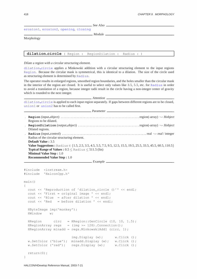
418 CHAPTER 9. MORPHOLOGY
See Alsoerosion1 , erosion2 , opening , closing
ModuleMorphology
dilation circle ( Region : RegionDilation : Radius : )
Dilate a region with a circular structuring element.
dilation circle applies a Minkowski addition with a circular structuring element to the input regionsRegion . Because the circular mask is symmetrical, this is identical to a dilation. The size of the circle usedas structuring element is determined byRadius .
The operator results in enlarged regions, smoothed region boundaries, and the holes smaller than the circular maskin the interior of the region are closed. It is useful to select only values like3.5, 5.5, etc. forRadius in orderto avoid a translation of a region, because integer radii result in the circle having a non-integer center of gravitywhich is rounded to the next integer.
Attentiondilation circle is applied to each input region separately. If gaps between different regions are to be closed,union1 or union2 has to be called first.
Parameter
. Region (input object) . . . . . . . . . . . . . . . . . . . . . . . . . . . . . . . . . . . . . . . . . . . . . . . . . . . . . . region(-array); HobjectRegions to be dilated.
. RegionDilation (outputobject) . . . . . . . . . . . . . . . . . . . . . . . . . . . . . . . . . . . . . . . . . . region(-array); HobjectDilated regions.
. Radius (input control) . . . . . . . . . . . . . . . . . . . . . . . . . . . . . . . . . . . . . . . . . . . . . . . . . . . . . . . . . . real; real/ integerRadius of the circular structuring element.Default Value : 3.5Value Suggestions :Radius ∈ {1.5, 2.5, 3.5, 4.5, 5.5, 7.5, 9.5, 12.5, 15.5, 19.5, 25.5, 33.5, 45.5, 60.5, 110.5}Typical Range of Values :0.5≤ Radius ≤ 511.5 (lin)Minimal Value Step : 1.0Recommended Value Step :1.0
Example
#include <iostream.h>#include "HalconCpp.h"
main(){
cout << "Reproduction of ’dilation_circle ()’" << endl;cout << "First = original image " << endl;cout << "Blue = after dilation " << endl;cout << "Red = before dilation " << endl;
HByteImage img("monkey");HWindow w;
HRegion circ = HRegion::GenCircle (10, 10, 1.5);HRegionArray regs = (img >= 128).Connection();HRegionArray minadd = regs.MinkowskiAdd1 (circ, 1);
img.Display (w); w.Click ();w.SetColor ("blue"); minadd.Display (w); w.Click ();w.SetColor ("red"); regs.Display (w); w.Click ();
return(0);}
HALCON/HDevelop Reference Manual, 2003-7-21

9.2. REGION 419
ComplexityLetF1 be the area of an input region. Then the runtime complexity for one region is:
O(2 · Radius ·√F1) .
Resultdilation circle returns 2 (HMSG TRUE) if all parameters are correct. The behavior in case of empty orno input region can be set via:
• no region: set system(’no object result’,<RegionResult>)
• empty region: set system(’empty region result’,<RegionResult>)
Otherwise, an exception is raised.
Parallelization Informationdilation circle is reentrantand automaticallyparallelized(on tuple level).
Possible Predecessor Functionsthreshold , regiongrowing , connection , union1 , watersheds , class ndim norm
Possible Successor Functionsreduce domain , select shape , area center , connection
Alternativesminkowski add1 , minkowski add2 , expand region , dilation1 , dilation2 ,dilation rectangle1
See Alsogen circle , erosion circle , closing circle , opening circle
ModuleMorphology
dilation golay ( Region : RegionDilation : GolayElement, Iterations,Rotation : )
Dilate a region with an element from the Golay alphabet.
dilation golay dilates a region with the selected elementGolayElement from the Golay alphabet. Thefollowing structuring elements are available:
’l’, ’m’, ’d’, ’c’, ’e’, ’i’, ’f’, ’f2’, ’h’, ’k’.
The rotation numberRotation determines which rotation of the element should be used, and whether the fore-ground (even) or background version (odd) of the selected element should be used. The Golay elements, togetherwith all possible rotations, are described with the operatorgolay elements . The operator works by shiftingthe structuring element over the region to be processed (Region ). For all positions of the structuring element thatintersect the region, the corresponding reference point (relative to the structuring element) is added to the outputregion. This means that the union of all translations of the structuring element within the region is computed.
The parameterIterations determines the number of iterations which are to be performed with the structuringelement. The result of iterationn− 1 is used as input for iterationn.
AttentionNot all values ofRotation are valid for any Golay element. For some of the values ofRotation , the resultingregions are identical to the input regions.
Parameter
. Region (input object) . . . . . . . . . . . . . . . . . . . . . . . . . . . . . . . . . . . . . . . . . . . . . . . . . . . . . . region(-array); HobjectRegions to be dilated.
. RegionDilation (outputobject) . . . . . . . . . . . . . . . . . . . . . . . . . . . . . . . . . . . . . . . . . . region(-array); HobjectDilated regions.
. GolayElement (input control) . . . . . . . . . . . . . . . . . . . . . . . . . . . . . . . . . . . . . . . . . . . . . . . . . . . . . . . string; stringStructuring element from the Golay alphabet.Default Value : ’h’Value List : GolayElement ∈ {’l’, ’m’, ’d’, ’c’, ’e’, ’i’, ’f’, ’f2’, ’h’, ’k’ }
HALCON 6.0.4

420 CHAPTER 9. MORPHOLOGY
. Iterations (input control) . . . . . . . . . . . . . . . . . . . . . . . . . . . . . . . . . . . . . . . . . . . . . . . . . . . . . . . integer; integerNumber of iterations.Default Value : 1Value Suggestions :Iterations ∈ {1, 2, 3, 4, 5, 6, 7, 8, 9, 10, 12, 15, 17, 20, 30, 40, 50}Typical Range of Values :1≤ Iterations (lin)Minimal Value Step : 1Recommended Value Step :1
. Rotation (input control) . . . . . . . . . . . . . . . . . . . . . . . . . . . . . . . . . . . . . . . . . . . . . . . . . . . . . . . . . . integer; integerRotation of the Golay element. Depending on the element, not all rotations are valid.Default Value : 0Value List : Rotation ∈ {0, 2, 4, 6, 8, 10, 12, 14, 1, 3, 5, 7, 9, 11, 13, 15}
ComplexityLetF be the area of an input region. Then the runtime complexity for one region is:
O(3 ·√F ) .
Resultdilation golay returns 2 (HMSG TRUE) if all parameters are correct. The behavior in case of empty or noinput region can be set via:
• no region: set system(’no object result’,<RegionResult>)
• empty region: set system(’empty region result’,<RegionResult>)
Otherwise, an exception is raised.
Parallelization Informationdilation golay is reentrantand automaticallyparallelized(on tuple level).
Possible Predecessor Functionsthreshold , regiongrowing , connection , union1 , watersheds , class ndim norm
Possible Successor Functionsreduce domain , select shape , area center , connection
Alternativesdilation1 , dilation2 , dilation seq
See Alsoerosion golay , opening golay , closing golay , hit or miss golay , thinning golay ,thickening golay , golay elements
ModuleMorphology
dilation rectangle1 ( Region : RegionDilation : Width, Height : )
Dilate a region with a rectangular structuring element.
dilation rectangle1 applies a dilation with a rectangular structuring element to the input regionsRegion .The size of the structuring rectangle isWidth × Height . The operator results in enlarged regions, and the holessmaller than the rectangular mask in the interior of the regions are closed.
dilation rectangle1 is a very fast operation because the height of the rectangle enters only logarithmicallyinto the runtime complexity, while the width does not enter at all. This leads to excellent runtime efficiency, evenin the case of very large rectangles (edge length> 100).
Attentiondilation rectangle1 is applied to each input region separately. If gaps between different regions are to beclosed,union1 or union2 has to be called first.
HALCON/HDevelop Reference Manual, 2003-7-21

9.2. REGION 421
Parameter
. Region (input object) . . . . . . . . . . . . . . . . . . . . . . . . . . . . . . . . . . . . . . . . . . . . . . . . . . . . . . region(-array); HobjectRegions to be dilated.
. RegionDilation (outputobject) . . . . . . . . . . . . . . . . . . . . . . . . . . . . . . . . . . . . . . . . . . region(-array); HobjectDilated regions.
. Width (input control) . . . . . . . . . . . . . . . . . . . . . . . . . . . . . . . . . . . . . . . . . . . . . . . . . . . . . . . . . . . . . extent.x; integerWidth of the structuring rectangle.Default Value : 10Value Suggestions :Width ∈ {1, 2, 3, 4, 6, 10, 15, 20, 30, 50, 70, 100, 150, 200}Typical Range of Values :1≤ Width ≤ 511 (lin)Minimal Value Step : 1Recommended Value Step :10
. Height (input control) . . . . . . . . . . . . . . . . . . . . . . . . . . . . . . . . . . . . . . . . . . . . . . . . . . . . . . . . . . . .extent.y; integerHeight of the structuring rectangle.Default Value : 10Value Suggestions :Height ∈ {1, 2, 3, 4, 6, 10, 15, 20, 30, 50, 70, 100, 150, 200}Typical Range of Values :1≤ Height ≤ 511 (lin)Minimal Value Step : 1Recommended Value Step :10
Example
#include <iostream.h>#include "HalconCpp.h"
main(){
cout << "Reproduction of ’dilation_rectangle ()’" << endl;cout << "First = original image " << endl;cout << "Blue = after dilation " << endl;cout << "Red = after segmentation " << endl;
HByteImage img("monkey");HWindow w;
HRegionArray regs = (img >= 220).Connection();HRegionArray dilreg = regs.DilationRectangle1 (2, 4);
img.Display (w); w.Click ();w.SetColor ("blue"); dilreg.Display (w); w.Click ();w.SetColor ("red"); regs.Display (w); w.Click ();
return(0);}
ComplexityLet F1 be the area of an input region andH be the height of the rectangle. Then the runtime complexity for oneregion is:
O(√F1 · ld(H)) .
Resultdilation rectangle1 returns 2 (HMSG TRUE) if all parameters are correct. The behavior in case of emptyor no input region can be set via:
• no region: set system(’no object result’,<RegionResult>)
• empty region: set system(’empty region result’,<RegionResult>)
HALCON 6.0.4
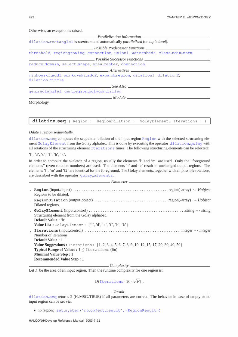
422 CHAPTER 9. MORPHOLOGY
Otherwise, an exception is raised.
Parallelization Informationdilation rectangle1 is reentrantand automaticallyparallelized(on tuple level).
Possible Predecessor Functionsthreshold , regiongrowing , connection , union1 , watersheds , class ndim norm
Possible Successor Functionsreduce domain , select shape , area center , connection
Alternativesminkowski add1 , minkowski add2 , expand region , dilation1 , dilation2 ,dilation circle
See Alsogen rectangle1 , gen region polygon filled
ModuleMorphology
dilation seq ( Region : RegionDilation : GolayElement, Iterations : )
Dilate a region sequentially.
dilation seq computes the sequential dilation of the input regionRegion with the selected structuring ele-mentGolayElement from the Golay alphabet. This is done by executing the operatordilation golay withall rotations of the structuring elementIterations times. The following structuring elements can be selected:
’l’, ’d’, ’c’, ’f’, ’h’, ’k’.
In order to compute the skeleton of a region, usually the elements ’l’ and ’m’ are used. Only the “foregroundelements” (even rotation numbers) are used. The elements ’i’ and ’e’ result in unchanged output regions. Theelements ’l’, ’m’ and ’f2’ are identical for the foreground. The Golay elements, together with all possible rotations,are described with the operatorgolay elements .
Parameter
. Region (input object) . . . . . . . . . . . . . . . . . . . . . . . . . . . . . . . . . . . . . . . . . . . . . . . . . . . . . . region(-array); HobjectRegions to be dilated.
. RegionDilation (outputobject) . . . . . . . . . . . . . . . . . . . . . . . . . . . . . . . . . . . . . . . . . . region(-array); HobjectDilated regions.
. GolayElement (input control) . . . . . . . . . . . . . . . . . . . . . . . . . . . . . . . . . . . . . . . . . . . . . . . . . . . . . . . string; stringStructuring element from the Golay alphabet.Default Value : ’h’Value List : GolayElement ∈ {’l’, ’d’, ’c’, ’f’, ’h’, ’k’ }
. Iterations (input control) . . . . . . . . . . . . . . . . . . . . . . . . . . . . . . . . . . . . . . . . . . . . . . . . . . . . . . . integer; integerNumber of iterations.Default Value : 1Value Suggestions :Iterations ∈ {1, 2, 3, 4, 5, 6, 7, 8, 9, 10, 12, 15, 17, 20, 30, 40, 50}Typical Range of Values :1≤ Iterations (lin)Minimal Value Step : 1Recommended Value Step :1
ComplexityLetF be the area of an input region. Then the runtime complexity for one region is:
O(Iterations · 20 ·√F ) .
Resultdilation seq returns 2 (HMSG TRUE) if all parameters are correct. The behavior in case of empty or noinput region can be set via:
• no region: set system(’no object result’,<RegionResult>)
HALCON/HDevelop Reference Manual, 2003-7-21

9.2. REGION 423
• empty region: set system(’empty region result’,<RegionResult>)
Otherwise, an exception is raised.
Parallelization Informationdilation seq is reentrantand automaticallyparallelized(on tuple level).
Possible Predecessor Functionsthreshold , regiongrowing , connection , union1 , watersheds , class ndim norm
Possible Successor Functionsreduce domain , select shape , area center , connection
Alternativesdilation1 , dilation2 , dilation golay
See Alsoerosion seq , hit or miss seq , thinning seq
ModuleMorphology
erosion1 ( Region, StructElement : RegionErosion : Iterations : )
Erode a region.
erosion1 erodes the input regions with a structuring element. By applyingerosion1 to a region, its boundarygets smoothed. In the process, the area of the region is reduced. Furthermore, connected regions may be split.Such regions, however, remain logically one region. The erosion is a set-theoretic region operation. It uses theintersection operation.
Let M (StructElement ) andR (Region ) be two regions, whereM is the structuring element andR is theregion to be processed. Furthermore, letm be a point inM . Then the displacement vector~vm = (dx, dy) isdefined as the difference of the center of gravity ofM and the vector~m. Let t~vm
(R) denote the translation of aregionR by a vector~v. Then
erosion1 (R,M) :=⋂
m∈M
t−~vm(R).
For each pointm in M a translation of the regionR is performed. The intersection of all these translations isthe erosion ofR with M . erosion1 is similar to the operatorminkowski sub1 , the difference is that inerosion1 the structuring element is mirrored at the origin. The position ofStructElement is meaningless,since the displacement vectors are determined with respect to the center of gravity ofM .
The parameterIterations determines the number of iterations which are to be performed with the structuringelement. The result of iterationn− 1 is used as input for iterationn. From the above definition it follows that themaximum region is generated in case of an empty structuring element.
Structuring elements (StructElement ) can be generated with operators such asgen circle ,gen rectangle1 , gen rectangle2 , gen ellipse , draw region , gen region polygon ,gen region points , etc.
Parameter
. Region (input object) . . . . . . . . . . . . . . . . . . . . . . . . . . . . . . . . . . . . . . . . . . . . . . . . . . . . . . region(-array); HobjectRegions to be eroded.
. StructElement (input object) . . . . . . . . . . . . . . . . . . . . . . . . . . . . . . . . . . . . . . . . . . . . . . . . . . . . region; HobjectStructuring element.
. RegionErosion (outputobject) . . . . . . . . . . . . . . . . . . . . . . . . . . . . . . . . . . . . . . . . . . . region(-array); HobjectEroded regions.
HALCON 6.0.4

424 CHAPTER 9. MORPHOLOGY
. Iterations (input control) . . . . . . . . . . . . . . . . . . . . . . . . . . . . . . . . . . . . . . . . . . . . . . . . . . . . . . . integer; integerNumber of iterations.Default Value : 1Value Suggestions :Iterations ∈ {1, 2, 3, 4, 5, 6, 7, 8, 9, 10, 12, 15, 17, 20, 30, 40, 50}Typical Range of Values :1≤ Iterations (lin)Minimal Value Step : 1Recommended Value Step :1
ComplexityLetF1 be the area of the input region, andF2 be the area of the structuring element. Then the runtime complexityfor one region is:
O(√F1 ·
√F2 · Iterations ) .
Resulterosion1 returns 2 (HMSG TRUE) if all parameters are correct. The behavior in case of empty or no inputregion can be set via:
• no region: set system(’no object result’,<RegionResult>)
• empty region: set system(’empty region result’,<RegionResult>)
Otherwise, an exception is raised.
Parallelization Informationerosion1 is reentrantand automaticallyparallelized(on tuple level).
Possible Predecessor Functionsthreshold , regiongrowing , watersheds , class ndim norm , gen circle , gen ellipse ,gen rectangle1 , gen rectangle2 , draw region , gen region points ,gen struct elements , gen region polygon filled
Possible Successor Functionsconnection , reduce domain , select shape , area center
Alternativesminkowski sub1 , minkowski sub2 , erosion2 , erosion golay , erosion seq
See Alsotranspose region
ModuleMorphology
erosion2 ( Region, StructElement : RegionErosion : Row, Column,Iterations : )
Erode a region (using a reference point).
erosion2 erodes the input regions with a structuring element (StructElement ) having the reference point(Row,Column ). erosion2 has a similar effect aserosion1 , the difference is that the reference point of thestructuring element can be chosen arbitrarily. The parameterIterations determines the number of iterationswhich are to be performed with the structuring element. The result of iterationn− 1 is used as input for iterationn.
A maximum region is generated in case of an empty structuring element.
Structuring elements (StructElement ) can be generated with operators such asgen circle ,gen rectangle1 , gen rectangle2 , gen ellipse , draw region , gen region polygon ,gen region points , etc.
HALCON/HDevelop Reference Manual, 2003-7-21
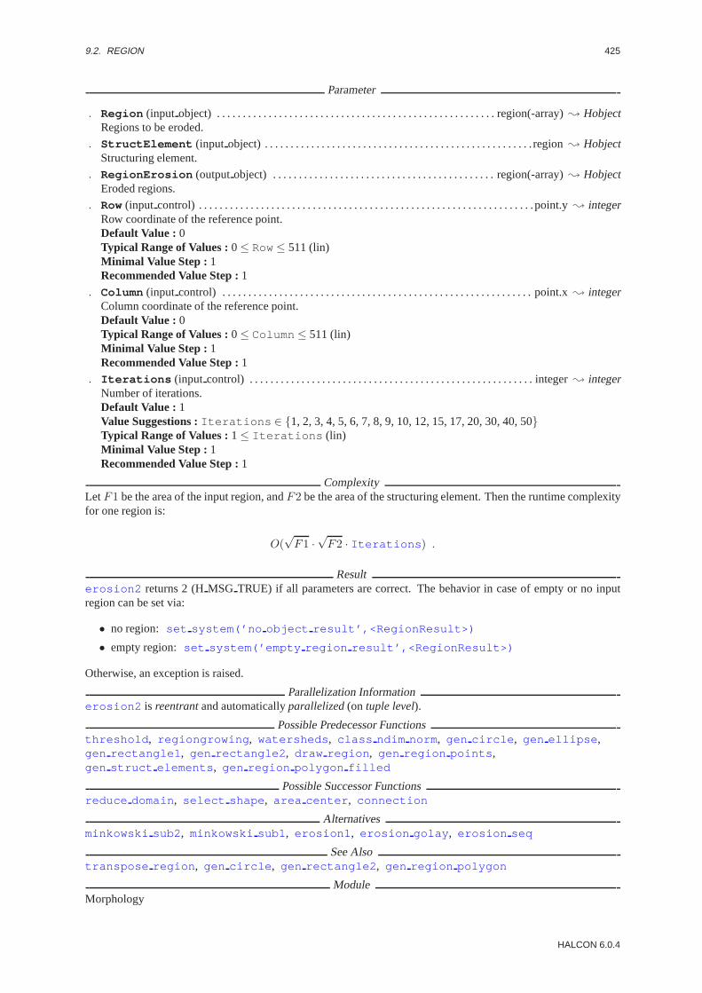
9.2. REGION 425
Parameter
. Region (input object) . . . . . . . . . . . . . . . . . . . . . . . . . . . . . . . . . . . . . . . . . . . . . . . . . . . . . . region(-array); HobjectRegions to be eroded.
. StructElement (input object) . . . . . . . . . . . . . . . . . . . . . . . . . . . . . . . . . . . . . . . . . . . . . . . . . . . . region; HobjectStructuring element.
. RegionErosion (outputobject) . . . . . . . . . . . . . . . . . . . . . . . . . . . . . . . . . . . . . . . . . . . region(-array); HobjectEroded regions.
. Row(input control) . . . . . . . . . . . . . . . . . . . . . . . . . . . . . . . . . . . . . . . . . . . . . . . . . . . . . . . . . . . . . . . . .point.y; integerRow coordinate of the reference point.Default Value : 0Typical Range of Values :0≤ Row≤ 511 (lin)Minimal Value Step : 1Recommended Value Step :1
. Column (input control) . . . . . . . . . . . . . . . . . . . . . . . . . . . . . . . . . . . . . . . . . . . . . . . . . . . . . . . . . . . . point.x; integerColumn coordinate of the reference point.Default Value : 0Typical Range of Values :0≤ Column ≤ 511 (lin)Minimal Value Step : 1Recommended Value Step :1
. Iterations (input control) . . . . . . . . . . . . . . . . . . . . . . . . . . . . . . . . . . . . . . . . . . . . . . . . . . . . . . . integer; integerNumber of iterations.Default Value : 1Value Suggestions :Iterations ∈ {1, 2, 3, 4, 5, 6, 7, 8, 9, 10, 12, 15, 17, 20, 30, 40, 50}Typical Range of Values :1≤ Iterations (lin)Minimal Value Step : 1Recommended Value Step :1
ComplexityLetF1 be the area of the input region, andF2 be the area of the structuring element. Then the runtime complexityfor one region is:
O(√F1 ·
√F2 · Iterations ) .
Resulterosion2 returns 2 (HMSG TRUE) if all parameters are correct. The behavior in case of empty or no inputregion can be set via:
• no region: set system(’no object result’,<RegionResult>)
• empty region: set system(’empty region result’,<RegionResult>)
Otherwise, an exception is raised.
Parallelization Informationerosion2 is reentrantand automaticallyparallelized(on tuple level).
Possible Predecessor Functionsthreshold , regiongrowing , watersheds , class ndim norm , gen circle , gen ellipse ,gen rectangle1 , gen rectangle2 , draw region , gen region points ,gen struct elements , gen region polygon filled
Possible Successor Functionsreduce domain , select shape , area center , connection
Alternativesminkowski sub2 , minkowski sub1 , erosion1 , erosion golay , erosion seq
See Alsotranspose region , gen circle , gen rectangle2 , gen region polygon
ModuleMorphology
HALCON 6.0.4

426 CHAPTER 9. MORPHOLOGY
erosion circle ( Region : RegionErosion : Radius : )
Erode a region with a circular structuring element.
erosion circle applies a Minkowski subtraction with a circular structuring element to the input regionsRegion . Because the circular mask is symmetrical, this is identical to an erosion. The size of the circle usedas structuring element is determined byRadius .
The operator results in reduced regions, smoothed region boundaries, and the regions smaller than the circularmask are eliminated. It is useful to select only values like3.5, 5.5, etc. forRadius in order to avoid a translationof a region, because integer radii result in a circle having a non-integer center of gravity which is rounded to thenext integer.
Parameter
. Region (input object) . . . . . . . . . . . . . . . . . . . . . . . . . . . . . . . . . . . . . . . . . . . . . . . . . . . . . . region(-array); HobjectRegions to be eroded.
. RegionErosion (outputobject) . . . . . . . . . . . . . . . . . . . . . . . . . . . . . . . . . . . . . . . . . . . region(-array); HobjectEroded regions.
. Radius (input control) . . . . . . . . . . . . . . . . . . . . . . . . . . . . . . . . . . . . . . . . . . . . . . . . . . . . . . . . . . real; real/ integerRadius of the circular structuring element.Default Value : 3.5Value Suggestions :Radius ∈ {1.5, 2.5, 3.5, 4.5, 5.5, 7.5, 9.5, 12.5, 15.5, 19.5, 25.5, 33.5, 45.5, 60.5, 110.5}Typical Range of Values :0.5≤ Radius ≤ 511.5 (lin)Minimal Value Step : 1.0Recommended Value Step :1.0
Example
#include <iostream.h>#include "HalconCpp.h"
main(){
cout << "Simulation of ’erosion_circle ()’" << endl;cout << "First = original image " << endl;cout << "Red = after segmentation " << endl;cout << "Blue = after erosion " << endl;
HByteImage img("monkey");HWindow w;
HRegion circ = HRegion::GenCircle (10, 10, 1.5);HRegionArray regs = (img >= 128).Connection();HRegionArray minsub = regs.MinkowskiSub1 (circ, 1);
img.Display (w); w.Click ();w.SetColor ("red"); regs.Display (w); w.Click ();w.SetColor ("blue"); minsub.Display (w); w.Click ();
return(0);}
ComplexityLetF1 be the area of an input region. Then the runtime complexity for one region is:
O(2 · Radius ·√F1) .
Resulterosion circle returns 2 (HMSG TRUE) if all parameters are correct. The behavior in case of empty or noinput region can be set via:
HALCON/HDevelop Reference Manual, 2003-7-21
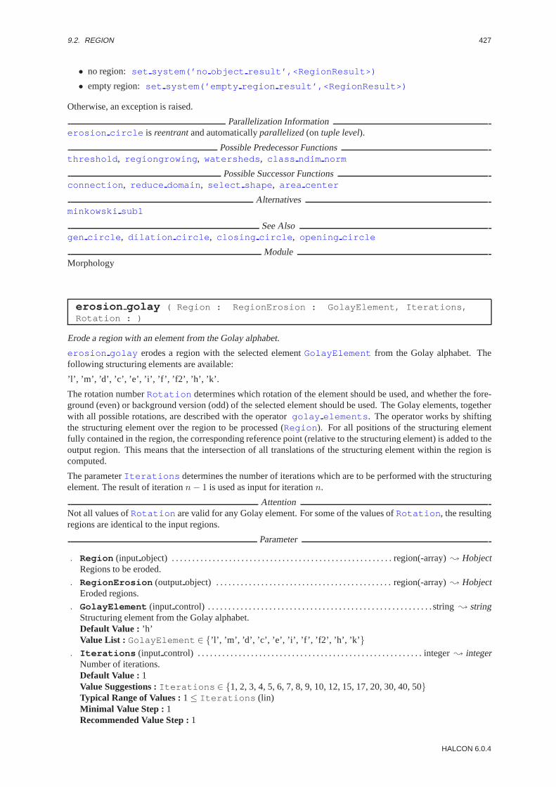
9.2. REGION 427
• no region: set system(’no object result’,<RegionResult>)
• empty region: set system(’empty region result’,<RegionResult>)
Otherwise, an exception is raised.
Parallelization Informationerosion circle is reentrantand automaticallyparallelized(on tuple level).
Possible Predecessor Functionsthreshold , regiongrowing , watersheds , class ndim norm
Possible Successor Functionsconnection , reduce domain , select shape , area center
Alternativesminkowski sub1
See Alsogen circle , dilation circle , closing circle , opening circle
ModuleMorphology
erosion golay ( Region : RegionErosion : GolayElement, Iterations,Rotation : )
Erode a region with an element from the Golay alphabet.
erosion golay erodes a region with the selected elementGolayElement from the Golay alphabet. Thefollowing structuring elements are available:
’l’, ’m’, ’d’, ’c’, ’e’, ’i’, ’f’, ’f2’, ’h’, ’k’.
The rotation numberRotation determines which rotation of the element should be used, and whether the fore-ground (even) or background version (odd) of the selected element should be used. The Golay elements, togetherwith all possible rotations, are described with the operatorgolay elements . The operator works by shiftingthe structuring element over the region to be processed (Region ). For all positions of the structuring elementfully contained in the region, the corresponding reference point (relative to the structuring element) is added to theoutput region. This means that the intersection of all translations of the structuring element within the region iscomputed.
The parameterIterations determines the number of iterations which are to be performed with the structuringelement. The result of iterationn− 1 is used as input for iterationn.
AttentionNot all values ofRotation are valid for any Golay element. For some of the values ofRotation , the resultingregions are identical to the input regions.
Parameter
. Region (input object) . . . . . . . . . . . . . . . . . . . . . . . . . . . . . . . . . . . . . . . . . . . . . . . . . . . . . . region(-array); HobjectRegions to be eroded.
. RegionErosion (outputobject) . . . . . . . . . . . . . . . . . . . . . . . . . . . . . . . . . . . . . . . . . . . region(-array); HobjectEroded regions.
. GolayElement (input control) . . . . . . . . . . . . . . . . . . . . . . . . . . . . . . . . . . . . . . . . . . . . . . . . . . . . . . . string; stringStructuring element from the Golay alphabet.Default Value : ’h’Value List : GolayElement ∈ {’l’, ’m’, ’d’, ’c’, ’e’, ’i’, ’f’, ’f2’, ’h’, ’k’ }
. Iterations (input control) . . . . . . . . . . . . . . . . . . . . . . . . . . . . . . . . . . . . . . . . . . . . . . . . . . . . . . . integer; integerNumber of iterations.Default Value : 1Value Suggestions :Iterations ∈ {1, 2, 3, 4, 5, 6, 7, 8, 9, 10, 12, 15, 17, 20, 30, 40, 50}Typical Range of Values :1≤ Iterations (lin)Minimal Value Step : 1Recommended Value Step :1
HALCON 6.0.4
428 CHAPTER 9. MORPHOLOGY
. Rotation (input control) . . . . . . . . . . . . . . . . . . . . . . . . . . . . . . . . . . . . . . . . . . . . . . . . . . . . . . . . . . integer; integerRotation of the Golay element. Depending on the element, not all rotations are valid.Default Value : 0Value List : Rotation ∈ {0, 2, 4, 6, 8, 10, 12, 14, 1, 3, 5, 7, 9, 11, 13, 15}
ComplexityLetF be the area of an input region. Then the runtime complexity for one region is:
O(3 ·√F ) .
Resulterosion golay returns 2 (HMSG TRUE) if all parameters are correct. The behavior in case of empty or noinput region can be set via:
• no region: set system(’no object result’,<RegionResult>)
• empty region: set system(’empty region result’,<RegionResult>)
Otherwise, an exception is raised.
Parallelization Informationerosion golay is reentrantand automaticallyparallelized(on tuple level).
Possible Predecessor Functionsthreshold , regiongrowing , watersheds , class ndim norm
Possible Successor Functionsreduce domain , select shape , area center , connection
Alternativeserosion seq , erosion1 , erosion2
See Alsodilation golay , opening golay , closing golay , hit or miss golay , thinning golay ,thickening golay , golay elements
ModuleMorphology
erosion rectangle1 ( Region : RegionErosion : Width, Height : )
Erode a region with a rectangular structuring element.
erosion rectangle1 applies an erosion with a rectangular structuring element to the input regionsRegion .The size of the structuring rectangle isWidth × Height . The operator results in reduced regions, and the areassmaller than the rectangular mask are eliminated.
erosion rectangle1 is a very fast operation because the height of the rectangle enters only logarithmicallyinto the runtime complexity, while the width does not enter at all. This leads to excellent runtime efficiency, evenin the case of very large rectangles (edge length> 100).
Regions containing small connecting strips between large areas are separated only seemingly. They remain logi-cally one region.
Parameter
. Region (input object) . . . . . . . . . . . . . . . . . . . . . . . . . . . . . . . . . . . . . . . . . . . . . . . . . . . . . . region(-array); HobjectRegions to be eroded.
. RegionErosion (outputobject) . . . . . . . . . . . . . . . . . . . . . . . . . . . . . . . . . . . . . . . . . . . region(-array); HobjectEroded regions.
. Width (input control) . . . . . . . . . . . . . . . . . . . . . . . . . . . . . . . . . . . . . . . . . . . . . . . . . . . . . . . . . . . . . extent.x; integerWidth of the structuring rectangle.Default Value : 10Value Suggestions :Width ∈ {1, 2, 3, 4, 6, 10, 15, 20, 30, 50, 70, 100}Typical Range of Values :1≤ Width ≤ 511 (lin)Minimal Value Step : 1Recommended Value Step :1
HALCON/HDevelop Reference Manual, 2003-7-21

9.2. REGION 429
. Height (input control) . . . . . . . . . . . . . . . . . . . . . . . . . . . . . . . . . . . . . . . . . . . . . . . . . . . . . . . . . . . .extent.y; integerHeight of the structuring rectangle.Default Value : 10Value Suggestions :Height ∈ {1, 2, 3, 4, 6, 10, 15, 20, 30, 50, 70, 100}Typical Range of Values :1≤ Height ≤ 511 (lin)Minimal Value Step : 1Recommended Value Step :1
ComplexityLet F1 be the area of an input region andH be the height of the rectangle. Then the runtime complexity for oneregion is:
O(√F1 · ld(H)) .
Resulterosion rectangle1 returns 2 (HMSG TRUE) if all parameters are correct. The behavior in case of emptyor no input region can be set via:
• no region: set system(’no object result’,<RegionResult>)
• empty region: set system(’empty region result’,<RegionResult>)
Otherwise, an exception is raised.
Parallelization Informationerosion rectangle1 is reentrantand automaticallyparallelized(on tuple level).
Possible Predecessor Functionsthreshold , regiongrowing , watersheds , class ndim norm
Possible Successor Functionsreduce domain , select shape , area center , connection
Alternativeserosion1 , minkowski sub1
See Alsogen rectangle1
ModuleMorphology
erosion seq ( Region : RegionErosion : GolayElement, Iterations : )
Erode a region sequentially.
erosion seq computes the sequential erosion of the input regionRegion with the selected structuring elementGolayElement from the Golay alphabet. This is done by executing the operatorerosion golay with allrotations of the structuring elementIterations times. The following structuring elements can be selected:
’l’, ’d’, ’c’, ’f’, ’h’, ’k’.
Only the “foreground elements” (even rotation numbers) are used. The elements ’i’ and ’e’ result in unchangedoutput regions. The elements ’l’, ’m’ and ’f2’ are identical for the foreground. The Golay elements, together withall possible rotations, are described with the operatorgolay elements .
Parameter
. Region (input object) . . . . . . . . . . . . . . . . . . . . . . . . . . . . . . . . . . . . . . . . . . . . . . . . . . . . . . region(-array); HobjectRegions to be eroded.
. RegionErosion (outputobject) . . . . . . . . . . . . . . . . . . . . . . . . . . . . . . . . . . . . . . . . . . . region(-array); HobjectEroded regions.
. GolayElement (input control) . . . . . . . . . . . . . . . . . . . . . . . . . . . . . . . . . . . . . . . . . . . . . . . . . . . . . . . string; stringStructuring element from the Golay alphabet.Default Value : ’h’Value List : GolayElement ∈ {’l’, ’d’, ’c’, ’f’, ’h’, ’k’ }
HALCON 6.0.4
430 CHAPTER 9. MORPHOLOGY
. Iterations (input control) . . . . . . . . . . . . . . . . . . . . . . . . . . . . . . . . . . . . . . . . . . . . . . . . . . . . . . . integer; integerNumber of iterations.Default Value : 1Value Suggestions :Iterations ∈ {1, 2, 3, 4, 5, 6, 7, 8, 9, 10, 12, 15, 17, 20, 30, 40, 50}Typical Range of Values :1≤ Iterations (lin)Minimal Value Step : 1Recommended Value Step :1
ComplexityLetF be the area of an input region. Then the runtime complexity for one region is:
O(Iterations · 20 ·√F ) .
Resulterosion seq returns 2 (HMSG TRUE) if all parameters are correct. The behavior in case of empty or no inputregion can be set via:
• no region: set system(’no object result’,<RegionResult>)
• empty region: set system(’empty region result’,<RegionResult>)
Otherwise, an exception is raised.
Parallelization Informationerosion seq is reentrantand automaticallyparallelized(on tuple level).
Possible Predecessor Functionsthreshold , regiongrowing , watersheds , class ndim norm
Possible Successor Functionsconnection , reduce domain , select shape , area center
Alternativeserosion golay , erosion1 , erosion2
See Alsodilation seq , hit or miss seq , thinning seq
ModuleMorphology
fitting ( Region, StructElements : RegionFitted : : )
Perform a closing after an opening with multiple structuring elements.
fitting performs anopening and a closing successively on the input regions. The eight structuring ele-ments normally used for this operation can be generated with the operatorgen struct elements . However,other user-defined structuring elements can also be used. LetR be the input region(s) and letMi denote the struc-turing elements. Furthermore, letP be the result of the opening andQ be the final result. Then the operator canbe formalized as follows:
P =n⋃
i=1
(R ◦Mi)
Q =n⋂
i=1
(P •Mi)
Regions larger than the structuring elements are preserved, while small gaps are closed.
HALCON/HDevelop Reference Manual, 2003-7-21

9.2. REGION 431
Parameter
. Region (input object) . . . . . . . . . . . . . . . . . . . . . . . . . . . . . . . . . . . . . . . . . . . . . . . . . . . . . . region(-array); HobjectRegions to be processed.
. StructElements (input object) . . . . . . . . . . . . . . . . . . . . . . . . . . . . . . . . . . . . . . . . . . . region(-array); HobjectStructuring elements.
. RegionFitted (outputobject) . . . . . . . . . . . . . . . . . . . . . . . . . . . . . . . . . . . . . . . . . . . . . region(-array); HobjectFitted regions.
Resultfitting returns 2 (HMSG TRUE) if all parameters are correct. The behavior in case of empty or no inputregion can be set via:
• no region: set system(’no object result’,<RegionResult>)
• empty region: set system(’empty region result’,<RegionResult>)
Otherwise, an exception is raised.
Parallelization Informationfitting is reentrantand processedwithoutparallelization.
Possible Predecessor Functionsgen struct elements , gen region points
Possible Successor Functionsreduce domain , select shape , area center , connection
Alternativesopening , closing , connection , select shape
ModuleMorphology
gen struct elements ( : StructElements : Type, Row, Column : )
Generate standard structuring elements.
gen struct elements serves to generate eight structuring elements normally used in the operatorfitting .The default value’noise’ of the parameterType generates elements especially suited for the elimination of noise.
h h h
x x x
h h h
M1
h
h
h
x
x
x
h
h
h
M2
h
h h
x
x
x
h h
h
M3
h h
h
x
x
x
h
h h
M4
h x h
x x h
h h h
M5
h x h
h x x
h h h
M6
h h h
x x h
h x h
M7
h h h
h x x
h x h
M8
Parameter
. StructElements (outputobject) . . . . . . . . . . . . . . . . . . . . . . . . . . . . . . . . . . . . . . . . . . region(-array); HobjectGenerated structuring elements.
. Type (input control) . . . . . . . . . . . . . . . . . . . . . . . . . . . . . . . . . . . . . . . . . . . . . . . . . . . . . . . . . . . . . . . . . .string; stringType of structuring element to generate.Default Value : ’noise’Value List : Type ∈ {’noise’}
HALCON 6.0.4

432 CHAPTER 9. MORPHOLOGY
. Row(input control) . . . . . . . . . . . . . . . . . . . . . . . . . . . . . . . . . . . . . . . . . . . . . . . . . . . . . . . . . . . . . . . . .point.y; integerRow coordinate of the reference point.Default Value : 1Value Suggestions :Row∈ {0, 1, 10, 50, 100, 200, 300, 400}Typical Range of Values :−∞≤ Row≤ ∞ (lin)
. Column (input control) . . . . . . . . . . . . . . . . . . . . . . . . . . . . . . . . . . . . . . . . . . . . . . . . . . . . . . . . . . . . point.x; integerColumn coordinate of the reference point.Default Value : 1Value Suggestions :Column ∈ {0, 1, 10, 50, 100, 200, 300, 400}Typical Range of Values :−∞≤ Column ≤∞ (lin)
Resultgen struct elements returns 2 (HMSG TRUE) if all parameters are correct. Otherwise, an exception israised.
Parallelization Informationgen struct elements is reentrantand processedwithoutparallelization.
Possible Successor Functionsfitting , hit or miss , opening , closing , erosion2 , dilation2
See Alsogolay elements
ModuleMorphology
golay elements ( : StructElement1, StructElement2 : GolayElement,Rotation, Row, Column : )
Generate the structuring elements of the Golay alphabet.
golay elements generates the structuring elements from the Golay alphabet. The parameterGolayElementdetermines the name of the structuring element, whileRotation determines its rotation. The structuring elementsare intended for use inhit or miss : In StructElement1 the structuring element for the foreground isreturned, while inStructElement2 the structuring element for the background is returned.RowandColumndetermine the reference point of the structuring element.
The rotations are numbered from 0 to 15. This does not mean, however, that there are 16 different rotations: Evenvalues denote rotations of the foreground elements, while odd values denote rotations of the background elements.
For golay elements only even values are accepted, and determine the Golay element forStructElement1 .The next larger odd value is used forStructElement2 . There are no rotations for the Golay elements ’h’ and ’i’.Therefore, only the values 0 and 1 are possible as “rotations” (and hence only 0 forgolay elements ). The ele-ment ’e’ has only four possible rotations, and hence the rotation must be between 0 and 7 (forgolay elementsthe values 0, 2, 4, or 6 must be used).
The tables below show the elements of the Golay alphabet with all possible rotations. The characters used havethe following meaning:
• Foreground pixel
◦ Background pixel
· Don’t care pixel
The names of the elements and their rotation numbers are displayed below the respective element. The elementswith even number contain the foreground pixels, while the elements with odd numbers contain the backgroundpixels.
• • •• • •• • •h(0,1)
◦ ◦ ◦◦ ◦ ◦◦ ◦ ◦
i(0,1)
HALCON/HDevelop Reference Manual, 2003-7-21
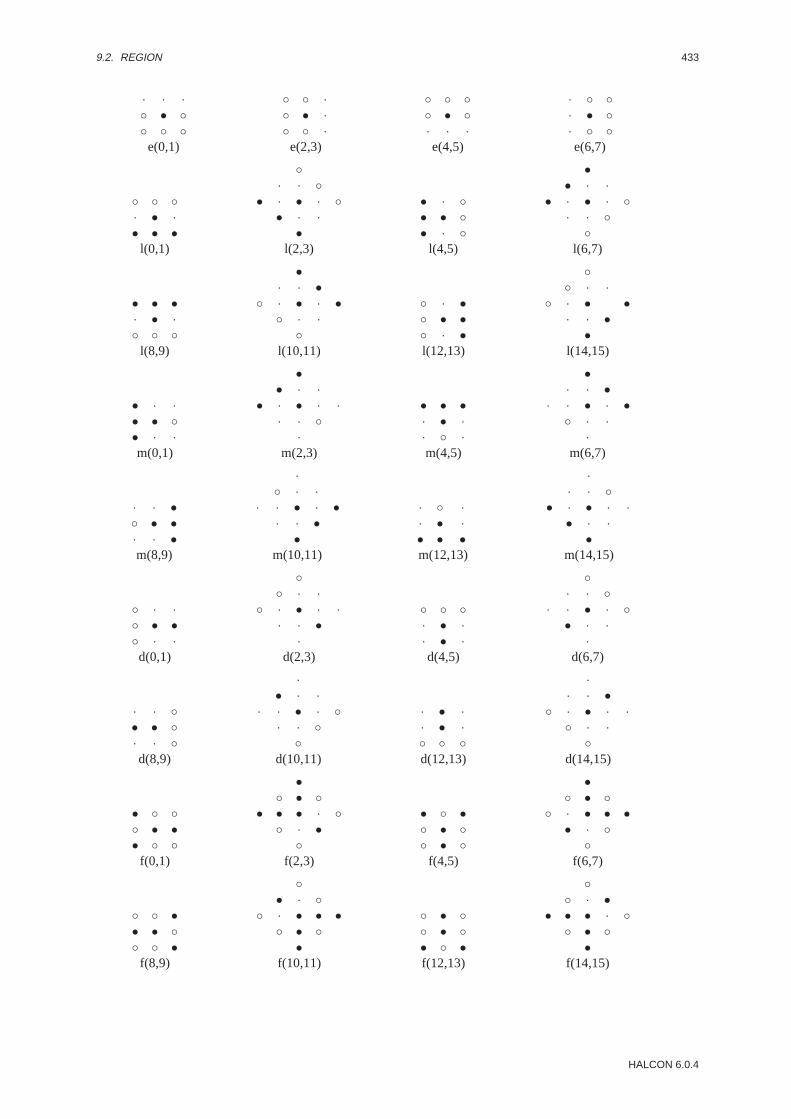
9.2. REGION 433
· · ·◦ • ◦◦ ◦ ◦e(0,1)
◦ ◦ ·◦ • ·◦ ◦ ·e(2,3)
◦ ◦ ◦◦ • ◦· · ·e(4,5)
· ◦ ◦· • ◦· ◦ ◦e(6,7)
◦ ◦ ◦· • ·• • •
l(0,1)
◦· · ◦
• · • · ◦• · ·
•l(2,3)
• · ◦• • ◦• · ◦
l(4,5)
•• · ·
• · • · ◦· · ◦
◦l(6,7)
• • •· • ·◦ ◦ ◦
l(8,9)
•· · •
◦ · • · •◦ · ·
◦l(10,11)
◦ · •◦ • •◦ · •l(12,13)
◦◦ · ·
◦ · • •· · •
•l(14,15)
• · ·• • ◦• · ·m(0,1)
•• · ·
• · • · ·· · ◦
·m(2,3)
• • •· • ·· ◦ ·m(4,5)
•· · •
· · • · •◦ · ·
·m(6,7)
· · •◦ • •· · •m(8,9)
·◦ · ·
· · • · •· · •
•m(10,11)
· ◦ ·· • ·• • •m(12,13)
·· · ◦
• · • · ·• · ·
•m(14,15)
◦ · ·◦ • •◦ · ·d(0,1)
◦◦ · ·
◦ · • · ·· · •
·d(2,3)
◦ ◦ ◦· • ·· • ·d(4,5)
◦· · ◦
· · • · ◦• · ·
·d(6,7)
· · ◦• • ◦· · ◦d(8,9)
·• · ·
· · • · ◦· · ◦
◦d(10,11)
· • ·· • ·◦ ◦ ◦d(12,13)
·· · •
◦ · • · ·◦ · ·
◦d(14,15)
• ◦ ◦◦ • •• ◦ ◦
f(0,1)
•◦ • ◦
• • • · ◦◦ · •
◦f(2,3)
• ◦ •◦ • ◦◦ • ◦
f(4,5)
•◦ • ◦
◦ · • • •• · ◦
◦f(6,7)
◦ ◦ •• • ◦◦ ◦ •
f(8,9)
◦• · ◦
◦ · • • •◦ • ◦
•f(10,11)
◦ • ◦◦ • ◦• ◦ •f(12,13)
◦◦ · •
• • • · ◦◦ • ◦
•f(14,15)
HALCON 6.0.4

434 CHAPTER 9. MORPHOLOGY
• • •◦ • ◦◦ ◦ ◦f2(0,1)
•◦ · •
◦ · • · •◦ · ◦
◦f2(2,3)
◦ ◦ •◦ • •◦ ◦ •f2(4,5)
◦◦ · ◦
◦ · • · •◦ · •
•f2(6,7)
◦ ◦ ◦◦ • ◦• • •f2(8,9)
◦◦ · ◦
• · • · ◦• · ◦
•f2(10,11)
• ◦ ◦• • ◦• ◦ ◦f2(12,13)
•• · ◦
• · • · ◦◦ · ◦
◦f2(14,15)
• • ◦· • ·· · ·k(0,1)
•· · •
· · • · ◦· · ·
·k(2,3)
· · •· • •· · ◦k(4,5)
·· · ·
· · • · •· · •
◦k(6,7)
· · ·· • ·◦ • •k(8,9)
·· · ·
◦ · • · ·• · ·
•k(10,11)
◦ · ·• • ·• · ·k(12,13)
◦• · ·
• · • · ·· · ·
·k(14,15)
• · ·• ◦ ·• · ·c(0,1)
•• · ·
• · ◦ · ·· · ·
·c(2,3)
• • •· ◦ ·· · ·c(4,5)
•· · •
· · ◦ · •· · ·
·c(6,7)
· · •· ◦ •· · •c(8,9)
·· · ·
· · ◦ •· · •
•c(10,11)
· · ·· ◦ ·• • •c(12,13)
·· · ·
• ◦ · ·• · ·
•c(14,15)
Parameter
. StructElement1 (outputobject) . . . . . . . . . . . . . . . . . . . . . . . . . . . . . . . . . . . . . . . . . . . . . . . . . region; HobjectStructuring element for the foreground.
. StructElement2 (outputobject) . . . . . . . . . . . . . . . . . . . . . . . . . . . . . . . . . . . . . . . . . . . . . . . . . region; HobjectStructuring element for the background.
. GolayElement (input control) . . . . . . . . . . . . . . . . . . . . . . . . . . . . . . . . . . . . . . . . . . . . . . . . . . . . . . . string; stringName of the structuring element.Default Value : ’l’Value List : GolayElement ∈ {’l’, ’m’, ’d’, ’c’, ’e’, ’i’, ’f’, ’f2’, ’h’, ’k’ }
. Rotation (input control) . . . . . . . . . . . . . . . . . . . . . . . . . . . . . . . . . . . . . . . . . . . . . . . . . . . . . . . . . . integer; integerRotation of the Golay element. Depending on the element, not all rotations are valid.Default Value : 0Value List : Rotation ∈ {0, 2, 4, 6, 8, 10, 12, 14}
. Row(input control) . . . . . . . . . . . . . . . . . . . . . . . . . . . . . . . . . . . . . . . . . . . . . . . . . . . . . . . . . . . . . . . . .point.y; integerRow coordinate of the reference point.Default Value : 16Value Suggestions :Row∈ {0, 16, 32, 128, 256}Typical Range of Values :0≤ Row≤ 511 (lin)Minimal Value Step : 1Recommended Value Step :1
HALCON/HDevelop Reference Manual, 2003-7-21

9.2. REGION 435
. Column (input control) . . . . . . . . . . . . . . . . . . . . . . . . . . . . . . . . . . . . . . . . . . . . . . . . . . . . . . . . . . . . point.x; integerColumn coordinate of the reference point.Default Value : 16Value Suggestions :Column ∈ {0, 16, 32, 128, 256}Typical Range of Values :0≤ Column ≤ 511 (lin)Minimal Value Step : 1Recommended Value Step :1
Resultgolay elements returns 2 (HMSG TRUE) if all parameters are correct. Otherwise, an exception is raised.
Parallelization Informationgolay elements is reentrantand processedwithoutparallelization.
Possible Successor Functionshit or miss
Alternativesgen region points , gen struct elements , gen region polygon filled
See Alsodilation golay , erosion golay , opening golay , closing golay , hit or miss golay ,thickening golay
BibliographyJ. Serra: ”‘Image Analysis and Mathematical Morphology”’. Volume I. Academic Press, 1982
ModuleMorphology
hit or miss ( Region, StructElement1,StructElement2 : RegionHitMiss : Row, Column : )
Hit-or-miss operation for regions.
hit or miss performs the hit-or-miss-transformation. First, an erosion with the structuring elementStructElement1 is done on the input regionRegion . Then an erosion with the structuring elementStructElement2 is performed on the complement of the input region. The intersection of the two resultingregions is the resultRegionHitMiss of hit or miss .
The hit-or-miss-transformation selects precisely the points for which the conditions given by the structuring ele-mentsStructElement1 andStructElement2 are fulfilled. StructElement1 determines the conditionfor the foreground pixels, whileStructElement2 determines the condition for the background pixels. In orderto obtain sensible results,StructElement1 andStructElement2 must fit like key and lock. In any case,StructElement1 andStructElement2 must be disjunct.RowandColumn determine the reference pointof the structuring elements.
Structuring elements (StructElement1 , StructElement2 ) can be generated by calling operators likegen struct elements , gen region points , etc.
Parameter
. Region (input object) . . . . . . . . . . . . . . . . . . . . . . . . . . . . . . . . . . . . . . . . . . . . . . . . . . . . . . region(-array); HobjectRegions to be processed.
. StructElement1 (input object) . . . . . . . . . . . . . . . . . . . . . . . . . . . . . . . . . . . . . . . . . . . . . . . . . . region; HobjectErosion mask for the input regions.
. StructElement2 (input object) . . . . . . . . . . . . . . . . . . . . . . . . . . . . . . . . . . . . . . . . . . . . . . . . . . region; HobjectErosion mask for the complements of the input regions.
. RegionHitMiss (outputobject) . . . . . . . . . . . . . . . . . . . . . . . . . . . . . . . . . . . . . . . . . . . region(-array); HobjectResult of the hit-or-miss operation.
HALCON 6.0.4

436 CHAPTER 9. MORPHOLOGY
. Row(input control) . . . . . . . . . . . . . . . . . . . . . . . . . . . . . . . . . . . . . . . . . . . . . . . . . . . . . . . . . . . . . . . . .point.y; integerRow coordinate of the reference point.Default Value : 16Value Suggestions :Row∈ {0, 16, 32, 128, 256}Typical Range of Values :0≤ Row≤ 511 (lin)Minimal Value Step : 1Recommended Value Step :1
. Column (input control) . . . . . . . . . . . . . . . . . . . . . . . . . . . . . . . . . . . . . . . . . . . . . . . . . . . . . . . . . . . . point.x; integerColumn coordinate of the reference point.Default Value : 16Value Suggestions :Column ∈ {0, 16, 32, 128, 256}Typical Range of Values :0≤ Column ≤ 511 (lin)Minimal Value Step : 1Recommended Value Step :1
ComplexityLet F be the area of an input region,F1 the area of the structuring element 1, andF2 the area of the structuringelement 2. Then the runtime complexity for one object is:
O(√
F ·(√
F1 +√F2
)).
Resulthit or miss returns 2 (HMSG TRUE) if all parameters are correct. The behavior in case of empty or no inputregion can be set via:
• no region: set system(’no object result’,<RegionResult>)
• empty region: set system(’empty region result’,<RegionResult>)
Otherwise, an exception is raised.
Parallelization Informationhit or miss is reentrantand automaticallyparallelized(on tuple level).
Possible Predecessor Functionsgolay elements , gen struct elements , threshold , regiongrowing , connection ,union1 , watersheds , class ndim norm
Possible Successor Functionsdifference , reduce domain , select shape , area center , connection
Alternativeshit or miss golay , hit or miss seq , erosion2 , dilation2
See Alsothinning , thickening , gen region points , gen region polygon filled
ModuleMorphology
hit or miss golay ( Region : RegionHitMiss : GolayElement,Rotation : )
Hit-or-miss operation for regions using the Golay alphabet.
hit or miss golay performs the hit-or-miss-transformation for the input regionsRegion (using struc-turing elements from the Golay alphabet). First, an erosion with the foreground of the structuring elementGolayElement is done on the input regionRegion . Then an erosion with the background of the structur-ing elementGolayElement is performed on the complement of the input region. The intersection of the tworesulting regions is the resultRegionHitMiss of hit or miss golay . The following structuring elementsare available:
’l’, ’m’, ’d’, ’c’, ’e’,’i’, ’f’, ’f2’, ’h’, ’k’.
HALCON/HDevelop Reference Manual, 2003-7-21

9.2. REGION 437
The rotation numberRotation determines which rotation of the element should be used. The hit-or-miss-transformation selects precisely the points for which the conditions given by the selected Golay element are ful-filled.
AttentionNot all values ofRotation are valid for any Golay element.
Parameter
. Region (input object) . . . . . . . . . . . . . . . . . . . . . . . . . . . . . . . . . . . . . . . . . . . . . . . . . . . . . . region(-array); HobjectRegions to be processed.
. RegionHitMiss (outputobject) . . . . . . . . . . . . . . . . . . . . . . . . . . . . . . . . . . . . . . . . . . . region(-array); HobjectResult of the hit-or-miss operation.
. GolayElement (input control) . . . . . . . . . . . . . . . . . . . . . . . . . . . . . . . . . . . . . . . . . . . . . . . . . . . . . . . string; stringStructuring element from the Golay alphabet.Default Value : ’h’Value List : GolayElement ∈ {’l’, ’m’, ’d’, ’c’, ’e’, ’i’, ’f’, ’f2’, ’h’, ’k’ }
. Rotation (input control) . . . . . . . . . . . . . . . . . . . . . . . . . . . . . . . . . . . . . . . . . . . . . . . . . . . . . . . . . . integer; integerRotation of the Golay element. Depending on the element, not all rotations are valid.Default Value : 0Value List : Rotation ∈ {0, 2, 4, 6, 8, 10, 12, 14, 1, 3, 5, 7, 9, 11, 13, 15}
ComplexityLetF be the area of an input region. Then the runtime complexity for one region is:
O(6 ·√F ) .
Resulthit or miss golay returns 2 (HMSG TRUE) if all parameters are correct. The behavior in case of empty orno input region can be set via:
• no region: set system(’no object result’,<RegionResult>)
• empty region: set system(’empty region result’,<RegionResult>)
Otherwise, an exception is raised.
Parallelization Informationhit or miss golay is reentrantand automaticallyparallelized(on tuple level).
Possible Predecessor Functionsthreshold , regiongrowing , connection , union1 , watersheds , class ndim norm
Possible Successor Functionsreduce domain , select shape , area center , connection
Alternativeshit or miss seq , hit or miss
See Alsoerosion golay , dilation golay , opening golay , closing golay , thinning golay ,thickening golay , golay elements
ModuleMorphology
hit or miss seq ( Region : RegionHitMiss : GolayElement : )
Hit-or-miss operation for regions using the Golay alphabet (sequential).
hit or miss golay performs the hit-or-miss-transformation for the input regionsRegion using all rotationsof a structuring element from the Golay alphabet. The result of the operator is the union of all intermediate resultsof the respective rotations. The following structuring elements are available:
’l’, ’m’, ’d’, ’c’, ’e’, ’i’, ’f’, ’f2’, ’h’, ’k’.
HALCON 6.0.4

438 CHAPTER 9. MORPHOLOGY
The Golay elements, together with all possible rotations, are described with the operatorgolay elements .
Parameter
. Region (input object) . . . . . . . . . . . . . . . . . . . . . . . . . . . . . . . . . . . . . . . . . . . . . . . . . . . . . . region(-array); HobjectRegions to be processed.
. RegionHitMiss (outputobject) . . . . . . . . . . . . . . . . . . . . . . . . . . . . . . . . . . . . . . . . . . . region(-array); HobjectResult of the hit-or-miss operation.
. GolayElement (input control) . . . . . . . . . . . . . . . . . . . . . . . . . . . . . . . . . . . . . . . . . . . . . . . . . . . . . . . string; stringStructuring element from the Golay alphabet.Default Value : ’h’Value List : GolayElement ∈ {’l’, ’m’, ’d’, ’c’, ’e’, ’i’, ’f’, ’f2’, ’h’, ’k’ }
ComplexityLetF be the area of an input region, andR be the number of rotations. Then the runtime complexity for one regionis:
O(R · 6 ·√F ) .
Resulthit or miss seq returns 2 (HMSG TRUE) if all parameters are correct. The behavior in case of empty or noinput region can be set via:
• no region: set system(’no object result’,<RegionResult>)
• empty region: set system(’empty region result’,<RegionResult>)
Otherwise, an exception is raised.
Parallelization Informationhit or miss seq is reentrantand automaticallyparallelized(on tuple level).
Possible Predecessor Functionsthreshold , regiongrowing , connection , union1 , watersheds , class ndim norm
Possible Successor Functionsreduce domain , select shape , area center , connection
Alternativeshit or miss golay , hit or miss
See Alsothinning seq , thickening seq
ModuleMorphology
minkowski add1 ( Region,StructElement : RegionMinkAdd : Iterations : )
Perform a Minkowski addition on a region.
minkowski add1 dilates the input regions with a structuring element. By applyingminkowski add1 to aregion, its boundary gets smoothed. In the process, the area of the region is enlarged. Furthermore, disconnectedregions may be merged. Such regions, however, remain logically distinct region. The Minkowski addition is aset-theoretic region operation. It is based on translations and union operations.
Let M (StructElement ) andR (Region ) be two regions, whereM is the structuring element andR is theregion to be processed. Furthermore, letm be a point inM . Then the displacement vector~vm = (dx, dy) isdefined as the difference of the center of gravity ofM and the vector~m. Let t~vm
(R) denote the translation of aregionR by a vector~v. Then
minkowski add1 (R,M) :=⋃
m∈M
t~vm(R)
HALCON/HDevelop Reference Manual, 2003-7-21
9.2. REGION 439
For each pointm in M a translation of the regionR is performed. The union of all these translations is theMinkowski addition ofR with M . minkowski add1 is similar to the operatordilation1 , the differenceis that in dilation1 the structuring element is mirrored at the origin. The position ofStructElement ismeaningless, since the displacement vectors are determined with respect to the center of gravity ofM .
The parameterIterations determines the number of iterations which are to be performed with the structuringelement. The result of iterationn− 1 is used as input for iterationn. From the above definition it follows that anempty region is generated in case of an empty structuring element.
Structuring elements (StructElement ) can be generated with operators such asgen circle ,gen rectangle1 , gen rectangle2 , gen ellipse , draw region , gen region polygon ,gen region points , etc.
AttentionA Minkowski addition always results in enlarged regions. Closely spaced regions which may touch or overlap asa result of the dilation are still treated as two separate regions. If the desired behavior is to merge them into oneregion, the operatorunion1 has to be called first.
Parameter
. Region (input object) . . . . . . . . . . . . . . . . . . . . . . . . . . . . . . . . . . . . . . . . . . . . . . . . . . . . . . region(-array); HobjectRegions to be dilated.
. StructElement (input object) . . . . . . . . . . . . . . . . . . . . . . . . . . . . . . . . . . . . . . . . . . . . . . . . . . . . region; HobjectStructuring element.
. RegionMinkAdd (outputobject) . . . . . . . . . . . . . . . . . . . . . . . . . . . . . . . . . . . . . . . . . . . region(-array); HobjectDilated regions.
. Iterations (input control) . . . . . . . . . . . . . . . . . . . . . . . . . . . . . . . . . . . . . . . . . . . . . . . . . . . . . . . integer; integerNumber of iterations.Default Value : 1Value Suggestions :Iterations ∈ {1, 2, 3, 4, 5, 6, 7, 8, 9, 10, 12, 15, 17, 20, 30, 40, 50}Typical Range of Values :1≤ Iterations (lin)Minimal Value Step : 1Recommended Value Step :1
ComplexityLetF1 be the area of the input region, andF2 be the area of the structuring element. Then the runtime complexityfor one region is:
O(√F1 ·
√F2 · Iterations ) .
Resultminkowski add1 returns 2 (HMSG TRUE) if all parameters are correct. The behavior in case of empty or noinput region can be set via:
• no region: set system(’no object result’,<RegionResult>)
• empty region: set system(’empty region result’,<RegionResult>)
Otherwise, an exception is raised.
Parallelization Informationminkowski add1 is reentrantand automaticallyparallelized(on tuple level).
Possible Predecessor Functionsthreshold , regiongrowing , connection , union1 , watersheds , class ndim norm ,gen circle , gen ellipse , gen rectangle1 , gen rectangle2 , draw region ,gen region points , gen struct elements , gen region polygon filled
Possible Successor Functionsreduce domain , select shape , area center , connection
Alternativesminkowski add2 , dilation1
See Alsotranspose region , minkowski sub1
ModuleMorphology
HALCON 6.0.4

440 CHAPTER 9. MORPHOLOGY
minkowski add2 ( Region, StructElement : RegionMinkAdd : Row, Column,Iterations : )
Dilate a region (using a reference point).
minkowski add2 computes the Minkowski addition of the input regions with a structuring element(StructElement ) having the reference point (Row,Column ). minkowski add2 has a similar effect asminkowski add1 , the difference is that the reference point of the structuring element can be chosen arbitrarily.The parameterIterations determines the number of iterations which are to be performed with the structuringelement. The result of iterationn− 1 is used as input for iterationn.
An empty region is generated in case of an empty structuring element.
Structuring elements (StructElement ) can be generated with operators such asgen circle ,gen rectangle1 , gen rectangle2 , gen ellipse , draw region , gen region polygon ,gen region points , etc.
AttentionA Minkowski addition always results in enlarged regions. Closely spaced regions which may touch or overlap asa result of the dilation are still treated as two separate regions. If the desired behavior is to merge them into oneregion, the operatorunion1 has to be called first.
Parameter
. Region (input object) . . . . . . . . . . . . . . . . . . . . . . . . . . . . . . . . . . . . . . . . . . . . . . . . . . . . . . region(-array); HobjectRegions to be dilated.
. StructElement (input object) . . . . . . . . . . . . . . . . . . . . . . . . . . . . . . . . . . . . . . . . . . . . . . . . . . . . region; HobjectStructuring element.
. RegionMinkAdd (outputobject) . . . . . . . . . . . . . . . . . . . . . . . . . . . . . . . . . . . . . . . . . . . region(-array); HobjectDilated regions.
. Row(input control) . . . . . . . . . . . . . . . . . . . . . . . . . . . . . . . . . . . . . . . . . . . . . . . . . . . . . . . . . . . . . . . . .point.y; integerRow coordinate of the reference point.Typical Range of Values :1≤ Row≤ 511 (lin)Minimal Value Step : 1Recommended Value Step :1
. Column (input control) . . . . . . . . . . . . . . . . . . . . . . . . . . . . . . . . . . . . . . . . . . . . . . . . . . . . . . . . . . . . point.x; integerColumn coordinate of the reference point.Typical Range of Values :1≤ Column ≤ 511 (lin)Minimal Value Step : 1Recommended Value Step :1
. Iterations (input control) . . . . . . . . . . . . . . . . . . . . . . . . . . . . . . . . . . . . . . . . . . . . . . . . . . . . . . . integer; integerNumber of iterations.Default Value : 1Value Suggestions :Iterations ∈ {1, 2, 3, 4, 5, 6, 7, 8, 9, 10, 12, 15, 17, 20, 30, 40, 50}Typical Range of Values :1≤ Iterations (lin)Minimal Value Step : 1Recommended Value Step :1
ComplexityLetF1 be the area of the input region, andF2 be the area of the structuring element. Then the runtime complexityfor one region is:
O(√F1 ·
√F2 · Iterations ) .
Resultminkowski add2 returns 2 (HMSG TRUE) if all parameters are correct. The behavior in case of empty or noinput region can be set via:
• no region: set system(’no object result’,<RegionResult>)
• empty region: set system(’empty region result’,<RegionResult>)
Otherwise, an exception is raised.
HALCON/HDevelop Reference Manual, 2003-7-21

9.2. REGION 441
Parallelization Informationminkowski add2 is reentrantand automaticallyparallelized(on tuple level).
Possible Predecessor Functionsthreshold , regiongrowing , connection , union1 , watersheds , class ndim norm ,gen circle , gen ellipse , gen rectangle1 , gen rectangle2 , draw region ,gen region points , gen struct elements , gen region polygon filled
Possible Successor Functionsreduce domain , select shape , area center , connection
Alternativesminkowski add1 , dilation1
See Alsotranspose region
ModuleMorphology
minkowski sub1 ( Region,StructElement : RegionMinkSub : Iterations : )
Erode a region.
minkowski sub1 computes the Minkowski subtraction of the input regions with a structuring element. Byapplying minkowski sub1 to a region, its boundary gets smoothed. In the process, the area of the region isreduced. Furthermore, connected regions may be split. Such regions, however, remain logically one region. TheMinkowski subtraction is a set-theoretic region operation. It uses the intersection operation.
Let M (StructElement ) andR (Region ) be two regions, whereM is the structuring element andR is theregion to be processed. Furthermore, letm be a point inM . Then the displacement vector~vm = (dx, dy) isdefined as the difference of the center of gravity ofM and the vector~m. Let t~vm
(R) denote the translation of aregionR by a vector~v. Then
minkowski sub1 (R,M) :=⋂
m∈M
t~vm(R)
For each pointm in M a translation of the regionR is performed. The intersection of all these translations is theMinkowski subtraction ofR with M . minkowski sub1 is similar to the operatorerosion1 , the differenceis that in erosion1 the structuring element is mirrored at the origin. The position ofStructElement ismeaningless, since the displacement vectors are determined with respect to the center of gravity ofM .
The parameterIterations determines the number of iterations which are to be performed with the structuringelement. The result of iterationn− 1 is used as input for iterationn. From the above definition it follows that themaximum region is generated in case of an empty structuring element.
Structuring elements (StructElement ) can be generated with operators such asgen circle ,gen rectangle1 , gen rectangle2 , gen ellipse , draw region , gen region polygon ,gen region points , etc.
Parameter
. Region (input object) . . . . . . . . . . . . . . . . . . . . . . . . . . . . . . . . . . . . . . . . . . . . . . . . . . . . . . region(-array); HobjectRegions to be eroded.
. StructElement (input object) . . . . . . . . . . . . . . . . . . . . . . . . . . . . . . . . . . . . . . . . . . . . . . . . . . . . region; HobjectStructuring element.
. RegionMinkSub (outputobject) . . . . . . . . . . . . . . . . . . . . . . . . . . . . . . . . . . . . . . . . . . . region(-array); HobjectEroded regions.
. Iterations (input control) . . . . . . . . . . . . . . . . . . . . . . . . . . . . . . . . . . . . . . . . . . . . . . . . . . . . . . . integer; integerNumber of iterations.Default Value : 1Value Suggestions :Iterations ∈ {1, 2, 3, 4, 5, 6, 7, 8, 9, 10, 12, 15, 17, 20, 30, 40, 50}Typical Range of Values :1≤ Iterations (lin)Minimal Value Step : 1Recommended Value Step :1
HALCON 6.0.4

442 CHAPTER 9. MORPHOLOGY
ComplexityLetF1 be the area of the input region, andF2 be the area of the structuring element. Then the runtime complexityfor one region is:
O(√F1 ·
√F2 · Iterations ) .
Resultminkowski sub1 returns 2 (HMSG TRUE) if all parameters are correct. The behavior in case of empty or noinput region can be set via:
• no region: set system(’no object result’,<RegionResult>)
• empty region: set system(’empty region result’,<RegionResult>)
Otherwise, an exception is raised.
Parallelization Informationminkowski sub1 is reentrantand automaticallyparallelized(on tuple level).
Possible Predecessor Functionsthreshold , regiongrowing , connection , union1 , watersheds , class ndim norm ,gen circle , gen ellipse , gen rectangle1 , gen rectangle2 , draw region ,gen region points , gen struct elements , gen region polygon filled
Possible Successor Functionsreduce domain , select shape , area center , connection
Alternativesminkowski sub2 , erosion1
See Alsotranspose region
ModuleMorphology
minkowski sub2 ( Region, StructElement : RegionMinkSub : Row, Column,Iterations : )
Erode a region (using a reference point).
minkowski sub2 computes the Minkowski subtraction of the input regions with a structuring element(StructElement ) having the reference point (Row,Column ). minkowski sub2 has a similar effect asminkowski sub1 , the difference is that the reference point of the structuring element can be chosen arbitrarily.The parameterIterations determines the number of iterations which are to be performed with the structuringelement. The result of iterationn− 1 is used as input for iterationn.
A maximum region is generated in case of an empty structuring element.
Structuring elements (StructElement ) can be generated with operators such asgen circle ,gen rectangle1 , gen rectangle2 , gen ellipse , draw region , gen region polygon ,gen region points , etc.
Parameter
. Region (input object) . . . . . . . . . . . . . . . . . . . . . . . . . . . . . . . . . . . . . . . . . . . . . . . . . . . . . . region(-array); HobjectRegions to be eroded.
. StructElement (input object) . . . . . . . . . . . . . . . . . . . . . . . . . . . . . . . . . . . . . . . . . . . . . . . . . . . . region; HobjectStructuring element.
. RegionMinkSub (outputobject) . . . . . . . . . . . . . . . . . . . . . . . . . . . . . . . . . . . . . . . . . . . region(-array); HobjectEroded regions.
HALCON/HDevelop Reference Manual, 2003-7-21
9.2. REGION 443
. Row(input control) . . . . . . . . . . . . . . . . . . . . . . . . . . . . . . . . . . . . . . . . . . . . . . . . . . . . . . . . . . . . . . . . .point.y; integerRow coordinate of the reference point.Default Value : 0Value Suggestions :Row∈ {0, 10, 16, 32, 64, 100, 128}Typical Range of Values :0≤ Row≤ 511 (lin)Minimal Value Step : 1Recommended Value Step :1
. Column (input control) . . . . . . . . . . . . . . . . . . . . . . . . . . . . . . . . . . . . . . . . . . . . . . . . . . . . . . . . . . . . point.x; integerColumn coordinate of the reference point.Default Value : 0Value Suggestions :Column ∈ {0, 10, 16, 32, 64, 100, 128}Typical Range of Values :0≤ Column ≤ 511 (lin)Minimal Value Step : 1Recommended Value Step :1
. Iterations (input control) . . . . . . . . . . . . . . . . . . . . . . . . . . . . . . . . . . . . . . . . . . . . . . . . . . . . . . . integer; integerNumber of iterations.Default Value : 1Value Suggestions :Iterations ∈ {1, 2, 3, 4, 5, 6, 7, 8, 9, 10, 12, 15, 17, 20, 30, 40, 50}Typical Range of Values :1≤ Iterations (lin)Minimal Value Step : 1Recommended Value Step :1
ComplexityLetF1 be the area of the input region, andF2 be the area of the structuring element. Then the runtime complexityfor one region is:
O(√F1 ·
√F2 · Iterations ) .
Resultminkowski sub2 returns 2 (HMSG TRUE) if all parameters are correct. The behavior in case of empty or noinput region can be set via:
• no region: set system(’no object result’,<RegionResult>)
• empty region: set system(’empty region result’,<RegionResult>)
Otherwise, an exception is raised.
Parallelization Informationminkowski sub2 is reentrantand automaticallyparallelized(on tuple level).
Possible Predecessor Functionsthreshold , regiongrowing , watersheds , class ndim norm , gen circle , gen ellipse ,gen rectangle1 , gen rectangle2 , draw region , gen region points ,gen struct elements , gen region polygon filled
Possible Successor Functionsreduce domain , select shape , area center , connection
Alternativesminkowski sub1 , erosion1 , erosion2 , erosion golay , erosion seq
See Alsogen circle , gen rectangle2 , gen region polygon
ModuleMorphology
morph hat ( Region, StructElement : RegionMorphHat : : )
Compute the union ofbottom hat and top hat .
HALCON 6.0.4

444 CHAPTER 9. MORPHOLOGY
morph hat computes the union of the regions that are removed by anopening operation with the regions thatare added by aclosing operation. Hence this is the union of the results oftop hat and bottom hat . Theposition ofStructElement does not influence the result.
Structuring elements (StructElement ) can be generated with operators such asgen circle ,gen rectangle1 , gen rectangle2 , gen ellipse , draw region , gen region polygon ,gen region points , etc.
AttentionThe individual regions are processed separately.
Parameter
. Region (input object) . . . . . . . . . . . . . . . . . . . . . . . . . . . . . . . . . . . . . . . . . . . . . . . . . . . . . . region(-array); HobjectRegions to be processed.
. StructElement (input object) . . . . . . . . . . . . . . . . . . . . . . . . . . . . . . . . . . . . . . . . . . . . . . . . . . . . region; HobjectStructuring element (position-invariant).
. RegionMorphHat (outputobject) . . . . . . . . . . . . . . . . . . . . . . . . . . . . . . . . . . . . . . . . . . region(-array); HobjectUnion of top hat and bottom hat.
Example
#include <iostream.h>#include "HalconCpp.h"
main(){
cout << "Reproduction of ’dilation_circle ()’" << endl;cout << "First = original image " << endl;cout << "Red = after segmentation " << endl;cout << "Blue = after erosion " << endl;
HByteImage img("monkey");HWindow w;
HRegion circ = HRegion::GenCircle (10, 10, 1.5);HRegionArray regs = (img >= 128).Connection();HRegionArray tophat = regs.TopHat (circ);HRegionArray bothat = regs.BottomHat (circ);HRegionArray unionX = tophat.Union2 (bothat);
img.Display (w); w.Click ();w.SetColor ("red"); regs.Display (w); w.Click ();w.SetColor ("blue"); tophat.Display (w); w.Click ();w.SetColor ("green"); bothat.Display (w); w.Click ();w.SetColor ("white"); unionX.Display (w); w.Click ();
return(0);}
Resultmorph hat returns 2 (HMSG TRUE) if all parameters are correct. The behavior in case of empty or no inputregion can be set via:
• no region: set system(’no object result’,<RegionResult>)
• empty region: set system(’empty region result’,<RegionResult>)
Otherwise, an exception is raised.
Parallelization Informationmorph hat is reentrantand automaticallyparallelized(on tuple level).
Possible Predecessor Functionsthreshold , regiongrowing , connection , union1 , watersheds , class ndim norm ,
HALCON/HDevelop Reference Manual, 2003-7-21

9.2. REGION 445
gen circle , gen ellipse , gen rectangle1 , gen rectangle2 , draw region ,gen region points , gen struct elements , gen region polygon filled
Possible Successor Functionsreduce domain , select shape , area center , connection
Alternativestop hat , bottom hat , union2
See Alsoopening , closing
ModuleMorphology
morph skeleton ( Region : RegionSkeleton : : )
Compute the morphological skeleton of a region.
morph skeleton computes the skeleton of the input regions (Region ) using morphological transformations.The computation yields a disconnected skeleton (gaps in the diagonals) having a width of one or two pixels. Thecalculation uses the Golay element ’h’, i.e., an 8-neighborhood. This is equivalent to the maximum-norm.
Parameter
. Region (input object) . . . . . . . . . . . . . . . . . . . . . . . . . . . . . . . . . . . . . . . . . . . . . . . . . . . . . . region(-array); HobjectRegions to be processed.
. RegionSkeleton (outputobject) . . . . . . . . . . . . . . . . . . . . . . . . . . . . . . . . . . . . . . . . . . region(-array); HobjectResulting morphological skeleton.
Resultmorph skeleton returns 2 (HMSG TRUE) if all parameters are correct. The behavior in case of empty or noinput region can be set via:
• no region: set system(’no object result’,<RegionResult>)
• empty region: set system(’empty region result’,<RegionResult>)
Otherwise, an exception is raised.
Parallelization Informationmorph skeleton is reentrantand automaticallyparallelized(on tuple level).
Possible Predecessor Functionsthreshold , regiongrowing , connection , union1 , watersheds , class ndim norm
Possible Successor Functionsskeleton , reduce domain , select shape , area center , connection
Alternativesskeleton , thinning
See Alsothinning seq , morph skiz
ModuleMorphology
morph skiz ( Region : RegionSkiz : Iterations1, Iterations2 : )
Thinning of a region.
morph skiz first performs a sequential thinning (thinning seq ) of the input region with the element ’l’ ofthe Golay alphabet. The number of iterations is determined by the parameterIterations1 . Then a sequentialthinning of the resulting region with the element ’e’ of the Golay alphabet is carried out. The number of iterations
HALCON 6.0.4

446 CHAPTER 9. MORPHOLOGY
for this step is determined by the parameterIterations2 . The skiz operation serves to compute a kind ofskeleton of the input regions, and to prune the branches of the resulting skeleton. If the skiz operation is applied tothe complement of the region, the region and the resulting skeleton are separated.
If very large values or ’maximal’ are passed forIterations1 or Iterations2 , the processing stops if nomore changes occur.
Parameter
. Region (input object) . . . . . . . . . . . . . . . . . . . . . . . . . . . . . . . . . . . . . . . . . . . . . . . . . . . . . . region(-array); HobjectRegions to be thinned.
. RegionSkiz (outputobject) . . . . . . . . . . . . . . . . . . . . . . . . . . . . . . . . . . . . . . . . . . . . . . . . region(-array); HobjectResult of the skiz operator.
. Iterations1 (input control) . . . . . . . . . . . . . . . . . . . . . . . . . . . . . . . . . . . . . . . . . . . . . . . integer; integer/ stringNumber of iterations for the sequential thinning with the element ’l’ of the Golay alphabet.Default Value : 100Value Suggestions :Iterations1 ∈ {’maximal’, 0, 1, 2, 3, 5, 7, 10, 15, 20, 30, 40, 50, 70, 100, 150, 200,300, 400}Typical Range of Values :0≤ Iterations1 (lin)Minimal Value Step : 1Recommended Value Step :1
. Iterations2 (input control) . . . . . . . . . . . . . . . . . . . . . . . . . . . . . . . . . . . . . . . . . . . . . . . integer; integer/ stringNumber of iterations for the sequential thinning with the element ’e’ of the Golay alphabet.Default Value : 1Value Suggestions :Iterations2 ∈ {’maximal’, 0, 1, 2, 3, 4, 5, 6, 7, 8, 9, 10, 12, 15, 17, 20, 30, 40, 50}Typical Range of Values :0≤ Iterations2 (lin)Minimal Value Step : 1Recommended Value Step :1
ComplexityLetF be the area of the input region. Then the runtime complexity for one region is
O((Iterations1 + Iterations2 ) · 3 ·√F ) .
Resultmorph skiz returns 2 (HMSG TRUE) if all parameters are correct. The behavior in case of empty or no inputregion can be set via:
• no region: set system(’no object result’,<RegionResult>)
• empty region: set system(’empty region result’,<RegionResult>)
Otherwise, an exception is raised.
Parallelization Informationmorph skiz is reentrantand automaticallyparallelized(on tuple level).
Possible Predecessor Functionsthreshold , regiongrowing , connection , union1 , watersheds , class ndim norm
Possible Successor Functionspruning , reduce domain , select shape , area center , connection , background seg ,complement
Alternativesskeleton , thinning seq , morph skeleton , interjacent
See Alsothinning , hit or miss seq , difference
ModuleMorphology
opening ( Region, StructElement : RegionOpening : : )
Open a region.
HALCON/HDevelop Reference Manual, 2003-7-21

9.2. REGION 447
An opening operation is defined as an erosion followed by a Minkowsi addition. By applyingopening to aregion, larger structures remain mostly intact, while small structures like lines or points are eliminated. In contrast,a closing operation results in small gaps being retained or filled up (seeclosing ).
opening serves to eliminate small regions (smaller thanStructElement ) and to smooth the boundaries of aregion. The position ofStructElement is meaningless, since an opening operation is invariant with respect tothe choice of the reference point.
Structuring elements (StructElement ) can be generated with operators such asgen circle ,gen rectangle1 , gen rectangle2 , gen ellipse , draw region , gen region polygon ,gen region points , etc.
Parameter
. Region (input object) . . . . . . . . . . . . . . . . . . . . . . . . . . . . . . . . . . . . . . . . . . . . . . . . . . . . . . region(-array); HobjectRegions to be opened.
. StructElement (input object) . . . . . . . . . . . . . . . . . . . . . . . . . . . . . . . . . . . . . . . . . . . . . . . . . . . . region; HobjectStructuring element (position-invariant).
. RegionOpening (outputobject) . . . . . . . . . . . . . . . . . . . . . . . . . . . . . . . . . . . . . . . . . . . region(-array); HobjectOpened regions.
Example
/* Large regions in an aerial picture (beech trees or meadows): */read_image(Image,’wald1’)threshold(Image,Light,80,255)gen_circle(StructElement1,100,100,2)gen_circle(StructElement2,100,100,20)/* close the small gap */closing(Light,StructElement1,H)/* selecting the large regions */opening(H,StructElement2,Large).
/* Selecting of edges with certain orientation: */read_image(Image,’fabrik’)sobel_amp(Image,Sobel,’sum_abs’,3)threshold(Sobel,Edges,10,255)gen_rectangle2(StructElement,100,100,3.07819,20,1)opening(Edges,StructElement,Direction).
ComplexityLetF1 be the area of the input region, andF2 be the area of the structuring element. Then the runtime complexityfor one region is:
O(2 ·√F1 ·
√F2) .
Resultopening returns 2 (HMSG TRUE) if all parameters are correct. The behavior in case of empty or no inputregion can be set via:
• no region: set system(’no object result’,<RegionResult>)
• empty region: set system(’empty region result’,<RegionResult>)
Otherwise, an exception is raised.
Parallelization Informationopening is reentrantand automaticallyparallelized(on tuple level).
Possible Predecessor Functionsthreshold , regiongrowing , connection , union1 , watersheds , class ndim norm ,gen circle , gen ellipse , gen rectangle1 , gen rectangle2 , draw region ,gen region points , gen struct elements , gen region polygon filled
HALCON 6.0.4

448 CHAPTER 9. MORPHOLOGY
Possible Successor Functionsreduce domain , select shape , area center , connection
Alternativesminkowski add1 , erosion1 , opening circle
See Alsogen circle , gen rectangle2 , gen region polygon
ModuleMorphology
opening circle ( Region : RegionOpening : Radius : )
Open a region with a circular structuring element.
opening circle is defined as an erosion followed by a Minkowsi addition with a circular structuring element(see example).opening serves to eliminate small regions (smaller than the circular structuring element) and tosmooth the boundaries of a region.
Parameter
. Region (input object) . . . . . . . . . . . . . . . . . . . . . . . . . . . . . . . . . . . . . . . . . . . . . . . . . . . . . . region(-array); HobjectRegions to be opened.
. RegionOpening (outputobject) . . . . . . . . . . . . . . . . . . . . . . . . . . . . . . . . . . . . . . . . . . . region(-array); HobjectOpened regions.
. Radius (input control) . . . . . . . . . . . . . . . . . . . . . . . . . . . . . . . . . . . . . . . . . . . . . . . . . . . . . . . . . . real; real/ integerRadius of the circular structuring element.Default Value : 3.5Value Suggestions :Radius ∈ {1.5, 2.5, 3.5, 4.5, 5.5, 7.5, 9.5, 12.5, 15.5, 19.5, 25.5, 33.5, 45.5, 60.5, 110.5}Typical Range of Values :0.5≤ Radius ≤ 511.5 (lin)Minimal Value Step : 1.0Recommended Value Step :1.0
Example
/* Large regions in an aerial picture (beech trees or meadows): */read_image(Image,’wald1’)threshold(Image,Light,80,255)/* close the small gap */closing_circle(LightH,2)/* selecting the large regions */opening_circle(H,Large,20).
ComplexityLetF1 be the area of the input region. Then the runtime complexity for one region is:
O(4 ·√F1 · Radius ) .
Resultopening circle returns 2 (HMSG TRUE) if all parameters are correct. The behavior in case of empty or noinput region can be set via:
• no region: set system(’no object result’,<RegionResult>)
• empty region: set system(’empty region result’,<RegionResult>)
Otherwise, an exception is raised.
Parallelization Informationopening circle is reentrantand automaticallyparallelized(on tuple level).
HALCON/HDevelop Reference Manual, 2003-7-21

9.2. REGION 449
Possible Predecessor Functionsthreshold , regiongrowing , connection , union1 , watersheds , class ndim norm
Possible Successor Functionsreduce domain , select shape , area center , connection
Alternativesopening , dilation1 , minkowski add1 , gen circle
See Alsotranspose region
ModuleMorphology
opening golay ( Region : RegionOpening : GolayElement, Rotation : )
Open a region with an element from the Golay alphabet.
opening golay is defined as a Minkowski subtraction followed by a Minkowski addition. First the Minkowskisubtraction of the input region (Region ) with the structuring element from the Golay alphabet defined byGolayElement andRotation is computed. Then the Minkowski addition of the result and the structuringelement rotated by 180◦ is performed.
The following structuring elements are available:
’l’, ’m’, ’d’, ’c’, ’e’, ’i’, ’f’, ’f2’, ’h’, ’k’.
The rotation numberRotation determines which rotation of the element should be used, and whether the fore-ground (even) or background version (odd) of the selected element should be used. The Golay elements, togetherwith all possible rotations, are described with the operatorgolay elements .
opening golay serves to eliminate regions smaller than the structuring element, and to smooth regions’ bound-aries.
AttentionNot all values ofRotation are valid for any Golay element. For some of the values ofRotation , the resultingregions are identical to the input regions.
Parameter
. Region (input object) . . . . . . . . . . . . . . . . . . . . . . . . . . . . . . . . . . . . . . . . . . . . . . . . . . . . . . region(-array); HobjectRegions to be opened.
. RegionOpening (outputobject) . . . . . . . . . . . . . . . . . . . . . . . . . . . . . . . . . . . . . . . . . . . region(-array); HobjectOpened regions.
. GolayElement (input control) . . . . . . . . . . . . . . . . . . . . . . . . . . . . . . . . . . . . . . . . . . . . . . . . . . . . . . . string; stringStructuring element from the Golay alphabet.Default Value : ’h’Value List : GolayElement ∈ {’l’, ’m’, ’d’, ’c’, ’e’, ’i’, ’f’, ’f2’, ’h’, ’k’ }
. Rotation (input control) . . . . . . . . . . . . . . . . . . . . . . . . . . . . . . . . . . . . . . . . . . . . . . . . . . . . . . . . . . integer; integerRotation of the Golay element. Depending on the element, not all rotations are valid.Default Value : 0Value List : Rotation ∈ {0, 2, 4, 6, 8, 10, 12, 14, 1, 3, 5, 7, 9, 11, 13, 15}
ComplexityLetF be the area of an input region. Then the runtime complexity for one region is:
O(6 ·√F ) .
Resultopening golay returns 2 (HMSG TRUE) if all parameters are correct. The behavior in case of empty or noinput region can be set via:
• no region: set system(’no object result’,<RegionResult>)
• empty region: set system(’empty region result’,<RegionResult>)
HALCON 6.0.4

450 CHAPTER 9. MORPHOLOGY
Otherwise, an exception is raised.
Parallelization Informationopening golay is reentrantand automaticallyparallelized(on tuple level).
Possible Predecessor Functionsthreshold , regiongrowing , connection , union1 , watersheds , class ndim norm
Possible Successor Functionsreduce domain , select shape , area center , connection
Alternativesopening seg , opening
See Alsoerosion golay , dilation golay , closing golay , hit or miss golay , thinning golay ,thickening golay , golay elements
ModuleMorphology
opening rectangle1 ( Region : RegionOpening : Width, Height : )
Open a region with a rectangular structuring element.
opening rectangle1 performs anerosion rectangle1 followed by a dilation rectangle1 onthe input regionRegion . The size of the rectangular structuring element is determined by the parametersWidthandHeight . As is the case for allopening variants, larger structures are preserved, while small regions likelines or points are eliminated.
Parameter
. Region (input object) . . . . . . . . . . . . . . . . . . . . . . . . . . . . . . . . . . . . . . . . . . . . . . . . . . . . . . region(-array); HobjectRegions to be opened.
. RegionOpening (outputobject) . . . . . . . . . . . . . . . . . . . . . . . . . . . . . . . . . . . . . . . . . . . region(-array); HobjectOpened regions.
. Width (input control) . . . . . . . . . . . . . . . . . . . . . . . . . . . . . . . . . . . . . . . . . . . . . . . . . . . . . . . . extent.x; integer/ realWidth of the structuring rectangle.Default Value : 10Value Suggestions :Width ∈ {1, 2, 3, 4, 5, 7, 9, 12, 15, 19, 25, 33, 45, 60, 110, 150, 200}Typical Range of Values :1≤ Width ≤ 511 (lin)Minimal Value Step : 1Recommended Value Step :1
. Height (input control) . . . . . . . . . . . . . . . . . . . . . . . . . . . . . . . . . . . . . . . . . . . . . . . . . . . . . . extent.y; integer/ realHeight of the structuring rectangle.Default Value : 10Value Suggestions :Height ∈ {1, 2, 3, 4, 5, 7, 9, 12, 15, 19, 25, 33, 45, 60, 110, 150, 200}Typical Range of Values :1≤ Height ≤ 511 (lin)Minimal Value Step : 1Recommended Value Step :1
ComplexityLet F1 be the area of an input region andH be the height of the rectangle. Then the runtime complexity for oneregion is:
O(2 ·√F1 · ld(H)) .
Resultopening rectangle1 returns 2 (HMSG TRUE) if all parameters are correct. The behavior in case of emptyor no input region can be set via:
• no region: set system(’no object result’,<RegionResult>)
• empty region: set system(’empty region result’,<RegionResult>)
HALCON/HDevelop Reference Manual, 2003-7-21

9.2. REGION 451
Otherwise, an exception is raised.
Parallelization Informationopening rectangle1 is reentrantand automaticallyparallelized(on tuple level).
Possible Predecessor Functionsthreshold , regiongrowing , watersheds , class ndim norm
Possible Successor Functionsreduce domain , select shape , area center , connection
Alternativesopening , gen rectangle1 , dilation rectangle1 , erosion rectangle1
See Alsoopening seg , opening golay
ModuleMorphology
opening seg ( Region, StructElement : RegionOpening : : )
Separate overlapping regions.
The opening seg operation is defined as a sequence of the following operators:erosion1 , connectionand dilation1 (see example). Only one iteration is done inerosion1 and dilation1 .
opening seg serves to separate overlapping regions whose area of overlap is smaller thanStructElement .It should be noted that the resulting regions can overlap without actually merging (seeexpand region ).opening seg uses the center of gravity as the reference point of the structuring element.
Structuring elements (StructElement ) can be generated with operators such asgen circle ,gen rectangle1 , gen rectangle2 , gen ellipse , draw region , gen region polygon ,gen region points , etc.
Parameter
. Region (input object) . . . . . . . . . . . . . . . . . . . . . . . . . . . . . . . . . . . . . . . . . . . . . . . . . . . . . . region(-array); HobjectRegions to be opened.
. StructElement (input object) . . . . . . . . . . . . . . . . . . . . . . . . . . . . . . . . . . . . . . . . . . . . . . . . . . . . region; HobjectStructuring element (position-invariant).
. RegionOpening (outputobject) . . . . . . . . . . . . . . . . . . . . . . . . . . . . . . . . . . . . . . . . . . . . . region-array; HobjectOpened regions.
Example
/* Simulation of opening_seg */opening_seg(Region,StructElement,RegionOpening):
erosion1(Region,StructElement,H1,1) >connection(H1,H2)dilation1(H2,StructElement,RegionOpening,1)clear_obj([H1,H2]).
ComplexityLetF1 be the area of the input region, andF2 be the area of the structuring element. Then the runtime complexityfor one region is:
O(√F1 ·
√F2 ·
√√F1) .
Resultopening seg returns 2 (HMSG TRUE) if all parameters are correct. The behavior in case of empty or no inputregion can be set via:
• no region: set system(’no object result’,<RegionResult>)
HALCON 6.0.4
452 CHAPTER 9. MORPHOLOGY
• empty region: set system(’empty region result’,<RegionResult>)
Otherwise, an exception is raised.
Parallelization Informationopening seg is reentrantand automaticallyparallelized(on tuple level).
Possible Predecessor Functionsthreshold , regiongrowing , connection , union1 , watersheds , class ndim norm ,gen circle , gen ellipse , gen rectangle1 , gen rectangle2 , draw region ,gen region points , gen struct elements , gen region polygon filled
Possible Successor Functionsexpand region , reduce domain , select shape , area center , connection
Alternativeserosion1 , connection , dilation1
ModuleMorphology
pruning ( Region : RegionPrune : Length : )
Prune the branches of a region.
pruning removes branches from a skeleton (Region ) having a length less thanLength . All other branchesare preserved.
Parameter
. Region (input object) . . . . . . . . . . . . . . . . . . . . . . . . . . . . . . . . . . . . . . . . . . . . . . . . . . . . . . region(-array); HobjectRegions to be processed.
. RegionPrune (outputobject) . . . . . . . . . . . . . . . . . . . . . . . . . . . . . . . . . . . . . . . . . . . . . . region(-array); HobjectResult of the pruning operation.
. Length (input control) . . . . . . . . . . . . . . . . . . . . . . . . . . . . . . . . . . . . . . . . . . . . . . . . . . . . . . . . . . . . . integer; integerLength of the branches to be removed.Default Value : 2Value Suggestions :Length ∈ {1, 2, 3, 4, 5, 6, 7, 8, 9, 10, 12, 15, 17, 20, 30, 40, 50}Typical Range of Values :1≤ Length ≤ 511 (lin)Minimal Value Step : 1Recommended Value Step :1
ComplexityLetF be the area of the input region. Then the runtime complexity for one region is
O(Length · 3 ·√F ) .
Resultpruning returns 2 (HMSG TRUE) if all parameters are correct. The behavior in case of empty or no inputregion can be set via:
• no region: set system(’no object result’,<RegionResult>)
• empty region: set system(’empty region result’,<RegionResult>)
Otherwise, an exception is raised.
Parallelization Informationpruning is reentrantand automaticallyparallelized(on tuple level).
Possible Predecessor Functionsmorph skiz , skeleton , thinning seq
Possible Successor Functionsreduce domain , select shape , area center , connection
HALCON/HDevelop Reference Manual, 2003-7-21

9.2. REGION 453
See Alsomorph skeleton , junctions skeleton
ModuleMorphology
thickening ( Region, StructElement1,StructElement2 : RegionThick : Row, Column, Iterations : )
Add the result of a hit-or-miss operation to a region.
thickening performs a thickening of the input regions using morphological operations. The operator firstapplies a hit-or-miss-transformation toRegion (cf. hit or miss ), and then adds the detected points to theinput region. The parameterIterations determines the number of iterations performed.
For the choice of the structuring elementsStructElement1 andStructElement2 , as well as forRowandColumn , the same restrictions described underhit or miss apply.
The structuring elements (StructElement1 and StructElement2 ) can be generated by callinggolay elements , for example.
AttentionIf the reference point is contained inStructElement1 the input region remains unchanged.
Parameter
. Region (input object) . . . . . . . . . . . . . . . . . . . . . . . . . . . . . . . . . . . . . . . . . . . . . . . . . . . . . . region(-array); HobjectRegions to be processed.
. StructElement1 (input object) . . . . . . . . . . . . . . . . . . . . . . . . . . . . . . . . . . . . . . . . . . . . . . . . . . region; HobjectStructuring element for the foreground.
. StructElement2 (input object) . . . . . . . . . . . . . . . . . . . . . . . . . . . . . . . . . . . . . . . . . . . . . . . . . . region; HobjectStructuring element for the background.
. RegionThick (outputobject) . . . . . . . . . . . . . . . . . . . . . . . . . . . . . . . . . . . . . . . . . . . . . . region(-array); HobjectResult of the thickening operator.
. Row(input control) . . . . . . . . . . . . . . . . . . . . . . . . . . . . . . . . . . . . . . . . . . . . . . . . . . . . . . . . . . . . . . . . .point.y; integerRow coordinate of the reference point.Default Value : 16Value Suggestions :Row∈ {0, 2, 4, 8, 16, 32, 128}Typical Range of Values :0≤ Row≤ 511 (lin)Minimal Value Step : 1Recommended Value Step :1
. Column (input control) . . . . . . . . . . . . . . . . . . . . . . . . . . . . . . . . . . . . . . . . . . . . . . . . . . . . . . . . . . . . point.x; integerColumn coordinate of the reference point.Default Value : 16Value Suggestions :Column ∈ {0, 2, 4, 8, 16, 32, 128}Typical Range of Values :0≤ Column ≤ 511 (lin)Minimal Value Step : 1Recommended Value Step :1
. Iterations (input control) . . . . . . . . . . . . . . . . . . . . . . . . . . . . . . . . . . . . . . . . . . . . . . . . . . . . . . . integer; integerNumber of iterations.Default Value : 1Value Suggestions :Iterations ∈ {1, 2, 3, 4, 5, 6, 7, 8, 9, 10, 12, 15, 17, 20, 30, 40, 50, 70, 100, 200,400}Typical Range of Values :1≤ Iterations (lin)Minimal Value Step : 1Recommended Value Step :1
ComplexityLet F be the area of an input region,F1 the area of the structuring element 1, andF2 the area of the structuringelement 2. Then the runtime complexity for one object is:
O(
Iterations ·√F ·
(√F1 +
√F2
)).
HALCON 6.0.4
454 CHAPTER 9. MORPHOLOGY
Resultthickening returns 2 (HMSG TRUE) if all parameters are correct. The behavior in case of empty or no inputregion can be set via:
• no region: set system(’no object result’,<RegionResult>)
• empty region: set system(’empty region result’,<RegionResult>)
Otherwise, an exception is raised.
Parallelization Informationthickening is reentrantand automaticallyparallelized(on tuple level).
Possible Predecessor Functionsgolay elements , threshold , regiongrowing , connection , union1 , watersheds ,class ndim norm , gen circle , gen ellipse , gen rectangle1 , gen rectangle2 ,draw region , gen region points , gen struct elements , gen region polygon filled
Possible Successor Functionsreduce domain , select shape , area center , connection
Alternativesthickening golay , thickening seq
See Alsohit or miss
ModuleMorphology
thickening golay ( Region : RegionThick : GolayElement, Rotation : )
Add the result of a hit-or-miss operation to a region (using a Golay structuring element).
thickening golay performs a thickening of the input regions using morphological operations and structur-ing elements from the Golay alphabet. The operator first applies a hit-or-miss-transformation toRegion (cf.hit or miss golay ), and then adds the detected points to the input region. The following structuring elementsare available:
’l’, ’m’, ’d’, ’c’, ’e’, ’i’, ’f’, ’f2’, ’h’, ’k’.
The rotation numberRotation determines which rotation of the element should be used. The Golay elements,together with all possible rotations, are described with the operatorgolay elements .
AttentionNot all values ofRotation are valid for any Golay element.
Parameter
. Region (input object) . . . . . . . . . . . . . . . . . . . . . . . . . . . . . . . . . . . . . . . . . . . . . . . . . . . . . . region(-array); HobjectRegions to be processed.
. RegionThick (outputobject) . . . . . . . . . . . . . . . . . . . . . . . . . . . . . . . . . . . . . . . . . . . . . . region(-array); HobjectResult of the thickening operator.
. GolayElement (input control) . . . . . . . . . . . . . . . . . . . . . . . . . . . . . . . . . . . . . . . . . . . . . . . . . . . . . . . string; stringStructuring element from the Golay alphabet.Default Value : ’h’Value List : GolayElement ∈ {’l’, ’m’, ’d’, ’c’, ’e’, ’i’, ’f’, ’f2’, ’h’, ’k’ }
. Rotation (input control) . . . . . . . . . . . . . . . . . . . . . . . . . . . . . . . . . . . . . . . . . . . . . . . . . . . . . . . . . . integer; integerRotation of the Golay element. Depending on the element, not all rotations are valid.Default Value : 0Value List : Rotation ∈ {0, 2, 4, 6, 8, 10, 12, 14, 1, 3, 5, 7, 9, 11, 13, 15}
ComplexityLetF be the area of an input region. Then the runtime complexity for one region is:
O(6 ·√F ) .
HALCON/HDevelop Reference Manual, 2003-7-21

9.2. REGION 455
Resultthickening golay returns 2 (HMSG TRUE) if all parameters are correct. The behavior in case of empty orno input region can be set via:
• no region: set system(’no object result’,<RegionResult>)
• empty region: set system(’empty region result’,<RegionResult>)
Otherwise, an exception is raised.
Parallelization Informationthickening golay is reentrantand automaticallyparallelized(on tuple level).
Possible Successor Functionsreduce domain , select shape , area center , connection
Alternativesthickening , thickening seq
See Alsoerosion golay , hit or miss golay
ModuleMorphology
thickening seq ( Region : RegionThick : GolayElement, Iterations : )
Add the result of a hit-or-miss operation to a region (sequential).
thickening seq calculates the sequential thickening of the input regions with a structuring element from theGolay alphabet (GolayElement ). To do so, thickening seq calls the operatorthickening golaywith all possible rotations of the structuring elementIterations times. The following structuring elements areavailable:
’l’, ’m’, ’d’, ’c’, ’e’, ’i’, ’f’, ’f2’, ’h’, ’k’.
The Golay elements, together with all possible rotations, are described with the operatorgolay elements . Forall elements of the Golay alphabet, except for ’c’, the foreground and background masks are exchanged in order tohave an effect for them on the outer boundary of the region. The element ’c’ can be used to generate the convexhull of the input region if enough iterations are performed.
Parameter
. Region (input object) . . . . . . . . . . . . . . . . . . . . . . . . . . . . . . . . . . . . . . . . . . . . . . . . . . . . . . region(-array); HobjectRegions to be processed.
. RegionThick (outputobject) . . . . . . . . . . . . . . . . . . . . . . . . . . . . . . . . . . . . . . . . . . . . . . region(-array); HobjectResult of the thickening operator.
. GolayElement (input control) . . . . . . . . . . . . . . . . . . . . . . . . . . . . . . . . . . . . . . . . . . . . . . . . . . . . . . . string; stringStructuring element from the Golay alphabet.Default Value : ’h’Value List : GolayElement ∈ {’l’, ’m’, ’d’, ’c’, ’e’, ’i’, ’f’, ’f2’, ’h’, ’k’ }
. Iterations (input control) . . . . . . . . . . . . . . . . . . . . . . . . . . . . . . . . . . . . . . . . . . . . . . . . . . . . . . . integer; integerNumber of iterations.Default Value : 1Value Suggestions :Iterations ∈ {1, 2, 3, 4, 5, 6, 7, 8, 9, 10, 12, 15, 17, 20, 30, 40, 50, 70, 100, 200}Typical Range of Values :1≤ Iterations (lin)Minimal Value Step : 1Recommended Value Step :1
ComplexityLetF be the area of an input region. Then the runtime complexity for one region is:
O(Iterations · 6 ·√F ) .
HALCON 6.0.4

456 CHAPTER 9. MORPHOLOGY
Resultthickening seq returns 2 (HMSG TRUE) if all parameters are correct. The behavior in case of empty or noinput region can be set via:
• no region: set system(’no object result’,<RegionResult>)
• empty region: set system(’empty region result’,<RegionResult>)
Otherwise, an exception is raised.
Parallelization Informationthickening seq is reentrantand automaticallyparallelized(on tuple level).
Possible Successor Functionsreduce domain , select shape , area center , connection
Alternativesthickening golay , thickening
See Alsoerosion golay , thinning seq
ModuleMorphology
thinning ( Region, StructElement1, StructElement2 : RegionThin : Row,Column, Iterations : )
Remove the result of a hit-or-miss operation from a region.
thinning performs a thinning of the input regions using morphological operations. The operator first applies ahit-or-miss-transformation toRegion (cf. hit or miss ), and then removes the detected points from the inputregion. The parameterIterations determines the number of iterations performed.
For the choice of the structuring elementsStructElement1 andStructElement2 , as well as forRowandColumn , the same restrictions described underhit or miss apply.
Structuring elements (StructElement1 , StructElement2 ) can be generated with operators suchas gen circle , gen rectangle1 , gen rectangle2 , gen ellipse , draw region ,gen region polygon , gen region points , etc.
Parameter
. Region (input object) . . . . . . . . . . . . . . . . . . . . . . . . . . . . . . . . . . . . . . . . . . . . . . . . . . . . . . region(-array); HobjectRegions to be processed.
. StructElement1 (input object) . . . . . . . . . . . . . . . . . . . . . . . . . . . . . . . . . . . . . . . . . . . . . . . . . . region; HobjectStructuring element for the foreground.
. StructElement2 (input object) . . . . . . . . . . . . . . . . . . . . . . . . . . . . . . . . . . . . . . . . . . . . . . . . . . region; HobjectStructuring element for the background.
. RegionThin (outputobject) . . . . . . . . . . . . . . . . . . . . . . . . . . . . . . . . . . . . . . . . . . . . . . . . region(-array); HobjectResult of the thinning operator.
. Row(input control) . . . . . . . . . . . . . . . . . . . . . . . . . . . . . . . . . . . . . . . . . . . . . . . . . . . . . . . . . . . . . . . . .point.y; integerRow coordinate of the reference point.Default Value : 0Typical Range of Values :0≤ Row≤ 511 (lin)Minimal Value Step : 1Recommended Value Step :1
. Column (input control) . . . . . . . . . . . . . . . . . . . . . . . . . . . . . . . . . . . . . . . . . . . . . . . . . . . . . . . . . . . . point.x; integerColumn coordinate of the reference point.Default Value : 0Typical Range of Values :0≤ Column ≤ 511 (lin)Minimal Value Step : 1Recommended Value Step :1
HALCON/HDevelop Reference Manual, 2003-7-21

9.2. REGION 457
. Iterations (input control) . . . . . . . . . . . . . . . . . . . . . . . . . . . . . . . . . . . . . . . . . . . . . . . . . . . . . . . integer; integerNumber of iterations.Default Value : 1Value Suggestions :Iterations ∈ {1, 2, 3, 4, 5, 6, 7, 8, 9, 10, 12, 15, 17, 20, 30, 40, 50}Typical Range of Values :1≤ Iterations (lin)Minimal Value Step : 1Recommended Value Step :1
ComplexityLet F be the area of an input region,F1 the area of the structuring element 1, andF2 the area of the structuringelement 2. Then the runtime complexity for one object is:
O(
Iterations ·√F ·
(√F1 +
√F2
)).
Resultthinning returns 2 (HMSG TRUE) if all parameters are correct. The behavior in case of empty or no inputregion can be set via:
• no region: set system(’no object result’,<RegionResult>)
• empty region: set system(’empty region result’,<RegionResult>)
Otherwise, an exception is raised.
Parallelization Informationthinning is reentrantand automaticallyparallelized(on tuple level).
Possible Predecessor Functionsthreshold , regiongrowing , connection , union1 , watersheds , class ndim norm ,gen circle , gen ellipse , gen rectangle1 , gen rectangle2 , draw region ,gen region points , gen struct elements , gen region polygon filled
Possible Successor Functionsreduce domain , select shape , area center , connection
Alternativesthinning golay , thinning seq
See Alsohit or miss
ModuleMorphology
thinning golay ( Region : RegionThin : GolayElement, Rotation : )
Remove the result of a hit-or-miss operation from a region (using a Golay structuring element).
thinning golay performs a thinning of the input regions using morphological operations and structuringelements from the Golay alphabet. The operator first applies a hit-or-miss-transformation toRegion (cf.hit or miss golay ), and then removes the detected points from the input region. The following structuringelements are available:
’l’, ’m’, ’d’, ’c’, ’e’, ’i’, ’f’, ’f2’, ’h’, ’k’.
The rotation numberRotation determines which rotation of the element should be used. The Golay elements,together with all possible rotations, are described with the operatorgolay elements .
AttentionNot all values ofRotation are valid for any Golay element.
HALCON 6.0.4

458 CHAPTER 9. MORPHOLOGY
Parameter
. Region (input object) . . . . . . . . . . . . . . . . . . . . . . . . . . . . . . . . . . . . . . . . . . . . . . . . . . . . . . region(-array); HobjectRegions to be processed.
. RegionThin (outputobject) . . . . . . . . . . . . . . . . . . . . . . . . . . . . . . . . . . . . . . . . . . . . . . . . region(-array); HobjectResult of the thinning operator.
. GolayElement (input control) . . . . . . . . . . . . . . . . . . . . . . . . . . . . . . . . . . . . . . . . . . . . . . . . . . . . . . . string; stringStructuring element from the Golay alphabet.Default Value : ’h’Value List : GolayElement ∈ {’l’, ’m’, ’d’, ’c’, ’e’, ’i’, ’f’, ’f2’, ’h’, ’k’ }
. Rotation (input control) . . . . . . . . . . . . . . . . . . . . . . . . . . . . . . . . . . . . . . . . . . . . . . . . . . . . . . . . . . integer; integerRotation of the Golay element. Depending on the element, not all rotations are valid.Default Value : 0Value List : Rotation ∈ {0, 2, 4, 6, 8, 10, 12, 14, 1, 3, 5, 7, 9, 11, 13, 15}
ComplexityLetF be the area of an input region. Then the runtime complexity for one region is:
O(6 ·√F ) .
Resultthinning golay returns 2 (HMSG TRUE) if all parameters are correct. The behavior in case of empty or noinput region can be set via:
• no region: set system(’no object result’,<RegionResult>)
• empty region: set system(’empty region result’,<RegionResult>)
Otherwise, an exception is raised.
Parallelization Informationthinning golay is reentrantand automaticallyparallelized(on tuple level).
Possible Successor Functionsreduce domain , select shape , area center , connection
Alternativesthinning seq , thinning
See Alsoerosion golay , hit or miss golay
ModuleMorphology
thinning seq ( Region : RegionThin : GolayElement, Iterations : )
Remove the result of a hit-or-miss operation from a region (sequential).
thinning seq calculates the sequential thinning of the input regions with a structuring element from the Golayalphabet (GolayElement ). To do so,thinning seq calls the operatorthinning golay with all possiblerotations of the structuring elementIterations times. If Iterations is chosen large enough, the operatorcalculates the skeleton of a region if the structuring elements ’l’ or ’m’ are used. For the element ’c’ the backgroundand foreground are exchanged in order to have an effect on the interior boundary of a region. If a very large valueor ’maximal’ is passed forIterations the iteration stops if no more changes occur. The following structuringelements are available:
’l’ Skeleton, similar toskeleton . This structuring element is also used inmorph skiz .
’m’ A skeleton with many “hairs” and multiple (parallel) branches.
’d’ A skeleton without multiple branches, but with many gaps, similar tomorph skeleton .
’c’ Uniform erosion of the region.
HALCON/HDevelop Reference Manual, 2003-7-21

9.2. REGION 459
’e’ One pixel wide lines are shortened. This structuring element is also used inmorph skiz .
’i’ Isolated points are removed. (OnlyIterations = 1 is useful.)
’f’ Y-junctions are eliminated. (OnlyIterations = 1 is useful.)
’f2’ One pixel long branches and corners are removed. (OnlyIterations = 1 is useful.)
’h’ A kind of inner boundary, which, however, is thicker than the result ofboundary , is generated. (OnlyIterations = 1 is useful.)
’k’ Junction points are eliminated, but also new ones are generated.
The Golay elements, together with all possible rotations, are described with the operatorgolay elements .
Parameter
. Region (input object) . . . . . . . . . . . . . . . . . . . . . . . . . . . . . . . . . . . . . . . . . . . . . . . . . . . . . . region(-array); HobjectRegions to be processed.
. RegionThin (outputobject) . . . . . . . . . . . . . . . . . . . . . . . . . . . . . . . . . . . . . . . . . . . . . . . . region(-array); HobjectResult of the thinning operator.
. GolayElement (input control) . . . . . . . . . . . . . . . . . . . . . . . . . . . . . . . . . . . . . . . . . . . . . . . . . . . . . . . string; stringStructuring element from the Golay alphabet.Default Value : ’l’Value List : GolayElement ∈ {’l’, ’m’, ’d’, ’c’, ’e’, ’i’, ’f’, ’f2’, ’h’, ’k’ }
. Iterations (input control) . . . . . . . . . . . . . . . . . . . . . . . . . . . . . . . . . . . . . . . . . . . . . . . . integer; integer/ stringNumber of iterations. For ’f’, ’f2’, ’h’ and ’i’ the only useful value is 1.Default Value : 20Value Suggestions :Iterations ∈ {’maximal’, 1, 2, 3, 4, 5, 6, 7, 8, 9, 10, 15, 20, 30, 40, 50, 70, 100, 150,200}Typical Range of Values :1≤ Iterations (lin)Minimal Value Step : 1Recommended Value Step :1
ComplexityLetF be the area of an input region. Then the runtime complexity for one region is:
O(Iterations · 6 ·√F ) .
Resultthinning seq returns 2 (HMSG TRUE) if all parameters are correct. The behavior in case of empty or noinput region can be set via:
• no region: set system(’no object result’,<RegionResult>)
• empty region: set system(’empty region result’,<RegionResult>)
Otherwise, an exception is raised.
Parallelization Informationthinning seq is reentrantand automaticallyparallelized(on tuple level).
Possible Predecessor Functionsthreshold , regiongrowing , connection , union1 , watersheds , class ndim norm ,gen circle , gen ellipse , gen rectangle1 , gen rectangle2 , draw region ,gen region points , gen struct elements , gen region polygon filled
Possible Successor Functionspruning , reduce domain , select shape , area center , connection , complement
Alternativesskeleton , morph skiz , expand region
See Alsohit or miss seq , erosion golay , difference , thinning golay , thinning ,thickening seq
ModuleMorphology
HALCON 6.0.4

460 CHAPTER 9. MORPHOLOGY
top hat ( Region, StructElement : RegionTopHat : : )
Compute the top hat of regions.
top hat computes theopening of Region with StructElement . The difference between the originalregion and the result of the opening is called the top hat. In contrast toopening , which splits regions undercertain circumstances,top hat computes the regions removed by such a splitting.
The position ofStructElement is meaningless, since an opening operation is invariant with respect to thechoice of the reference point.
Structuring elements (StructElement ) can be generated with operators such asgen circle ,gen rectangle1 , gen rectangle2 , gen ellipse , draw region , gen region polygon ,gen region points , etc.
Parameter
. Region (input object) . . . . . . . . . . . . . . . . . . . . . . . . . . . . . . . . . . . . . . . . . . . . . . . . . . . . . . region(-array); HobjectRegions to be processed.
. StructElement (input object) . . . . . . . . . . . . . . . . . . . . . . . . . . . . . . . . . . . . . . . . . . . . . . . . . . . . region; HobjectStructuring element (position independent).
. RegionTopHat (outputobject) . . . . . . . . . . . . . . . . . . . . . . . . . . . . . . . . . . . . . . . . . . . . . region(-array); HobjectResult of the top hat operator.
Resulttop hat returns 2 (HMSG TRUE) if all parameters are correct. The behavior in case of empty or no input regioncan be set via:
• no region: set system(’no object result’,<RegionResult>)
• empty region: set system(’empty region result’,<RegionResult>)
Otherwise, an exception is raised.
Parallelization Informationtop hat is reentrantand automaticallyparallelized(on tuple level).
Possible Predecessor Functionsthreshold , regiongrowing , connection , union1 , watersheds , class ndim norm ,gen circle , gen ellipse , gen rectangle1 , gen rectangle2 , draw region ,gen region points , gen struct elements , gen region polygon filled
Possible Successor Functionsreduce domain , select shape , area center , connection
Alternativesopening , difference
See Alsobottom hat , morph hat , gray tophat , opening
ModuleMorphology
HALCON/HDevelop Reference Manual, 2003-7-21
Chapter 10
Object
10.1 Information
count obj ( Objects : : : Number )
Number of objects in a tuple.
The operatorcount obj determines for the object parameterObjects the number of objects it contains. Inthis connection it should be noted that object is not the same as connection component (seeconnection ). Forexample, the number of objects of a region not consisting of three connected parts is 1.
AttentionIn Prolog and Lisp the length of the list is not necessarily identical with the number of objects. This is the casewhen object keys are contained which were created in the compact mode (keys from compact and normal mode canbe used as a mixture). See in this connectionset system(::’compact object’,<true/false>:) .
Parameter
. Objects (input object) . . . . . . . . . . . . . . . . . . . . . . . . . . . . . . . . . . . . . . . . . . . . . . . . . . . . . . object-array; HobjectObjects to be examined.
. Number (outputcontrol) . . . . . . . . . . . . . . . . . . . . . . . . . . . . . . . . . . . . . . . . . . . . . . . . . . . . . . . . . . . integer; integerNumber of objects in the tupleObjects .
ComplexityRuntime complexity:O(|Objects |).
ResultIf the surrogates are correct, i.e. all objects are present in the HALCON operator data base, the operatorcount obj returns the value 2 (HMSG TRUE). The behavior in case of empty input (no input objects avail-able) is set via the operatorset system(::’no object result’,<Result>:) .
Parallelization Informationcount obj is reentrantand processedwithoutparallelization.
See Alsocopy obj , obj to integer , connection , set system
ModuleBasic operators
get channel info ( Object : : Request, Channel : Information )
Informations about the components of an image object.
The operatorget channel info gives information about the components of an image object. The followingrequests (Request ) are currently possible:
461

462 CHAPTER 10. OBJECT
’creator’ Output of the names of the procedures which initially created the image components (not the object).
’type’ Output of the type of image component (’byte’, ’int1’, ’int2’, ’int4’, ’real’, ’direction’, ’cyclic’, ’complex’,’dvf’, ’lut’). The component 0 is of type ’region’ or ’xld’.
In the tupleChannel the numbers of the components about which information is required are stated. Aftercarrying outget channel info , Information contains a tuple of strings (one string per entry inChannel )with the required information.
Parameter
. Object (input object) . . . . . . . . . . . . . . . . . . . . . . . . . . . . . . . . . . . . . . . . . . . . . . . . . . . . . . . . . . . . . object; HobjectImage object to be examined.
. Request (input control) . . . . . . . . . . . . . . . . . . . . . . . . . . . . . . . . . . . . . . . . . . . . . . . . . . . . . . . . . . . . . string; stringRequired information about object components.Default Value : ’creator’Value List : Request ∈ {’creator’, ’type’}
. Channel (input control) . . . . . . . . . . . . . . . . . . . . . . . . . . . . . . . . . . . . . . . . . . . . . . . . . . . .channel(-array); integerComponents to be examined (0 for region/XLD).Default Value : 0Value Suggestions :Channel ∈ {0, 1, 2, 3, 4, 5, 6, 7, 8}
. Information (outputcontrol) . . . . . . . . . . . . . . . . . . . . . . . . . . . . . . . . . . . . . . . . . . . . . . . . string(-array); stringRequested information.
ResultIf the parameters are correct the operatorget channel info returns the value 2 (HMSG TRUE). Otherwisean exception is raised.
Parallelization Informationget channel info is reentrantand processedwithoutparallelization.
Possible Predecessor Functionsread image
See Alsocount relation
ModuleBasic operators
get obj class ( Object : : : Class )
Name of the class of an image object.
get obj class returns the name of the corresponding class to each object. The following classes are possible:
’image’ Object with region (definition domain) and at least one channel.
’region’ Object with a region without gray values.
’xld cont’ XLD object as contour
’xld poly’ XLD object as polygon
’xld parallel’ XLD object with parallel polygons
Parameter
. Object (input object) . . . . . . . . . . . . . . . . . . . . . . . . . . . . . . . . . . . . . . . . . . . . . . . . . . . . . . object(-array); HobjectImage objects to be examined.
. Class (outputcontrol) . . . . . . . . . . . . . . . . . . . . . . . . . . . . . . . . . . . . . . . . . . . . . . . . . . . . . . . . string(-array); stringName of class.
ResultIf the parameter values are correct the operatorget obj class returns the value 2 (HMSG TRUE). Otherwisean exception is raised.
HALCON/HDevelop Reference Manual, 2003-7-21

10.1. INFORMATION 463
Parallelization Informationget obj class is reentrantand automaticallyparallelized(on tuple level).
Possible Successor Functionsdisp image , disp region , disp xld
See Alsoget channel info , count relation
ModuleBasic operators
test equal obj ( Objects1, Objects2 : : : )
Compare image objects regarding equality.
The operator test equal obj compares the regions and gray value components of all objects of the twoinput parameters. The n-th object inObjects1 is compared to the n-th object inObjects2 (for all n). Ifall corresponding regions are equal and the number of regions is also identical the operatortest equal objreturns the value TRUE, otherwise FALSE.
AttentionImage matrices are not compared regarding their contents. Thus, two images are “equal” if they are at the sameplace in the store. If the input parameters are empty and the behavior was set via the operatorset system(::’no object result’,’true’:) , the operator test equal obj returns TRUE, since all input (=empty set) is equal.
Parameter
. Objects1 (input object) . . . . . . . . . . . . . . . . . . . . . . . . . . . . . . . . . . . . . . . . . . . . . . . . . . . . . object-array; HobjectTest objects.
. Objects2 (input object) . . . . . . . . . . . . . . . . . . . . . . . . . . . . . . . . . . . . . . . . . . . . . . . . . . . . . object-array; HobjectComparative objects.
ComplexityIf F is the area of a region the runtime complexity isO(1) or O(
√F ) if the result is TRUE andO(
√F ) if the
result is FALSE.
ResultThe operator test equal obj returns the value 2 (HMSG TRUE) if both object tuples are iden-tical. If the tuples differ in at least one placetest equal obj returns 3 (HMSG FALSE). Thebehavior in case of empty input (no input objects available) is set via the operatorset system(::’no object result’,<Result>:) . If the number of objects differs an exception is raised.
Parallelization Informationtest equal obj is reentrantand processedwithoutparallelization.
See Alsotest equal region
Return Valuebool
ModuleBasic operators
test equal region ( Regions1, Regions2 : : : )
Test whether the regions of two objects are identical.
The operator test equal region compares the regions of the two input parameters. The n-th element inRegions1 is compared to the n-th object inRegions2 (for all n). If all regions are equal and the number ofregions is identical the operatortest equal region returns the value TRUE, otherwise FALSE.
HALCON 6.0.4
464 CHAPTER 10. OBJECT
Parameter
. Regions1 (input object) . . . . . . . . . . . . . . . . . . . . . . . . . . . . . . . . . . . . . . . . . . . . . . . . . . . region(-array); HobjectTest regions.
. Regions2 (input object) . . . . . . . . . . . . . . . . . . . . . . . . . . . . . . . . . . . . . . . . . . . . . . . . . . . region(-array); HobjectComparative regions.Parameter Number : Regions1 = Regions2
ComplexityIf F is the area of a region the runtime complexity isO(1) orO(
√F ) if the result is TRUE,O(
√F ) if the result is
FALSE.
ResultThe operator test equal region returns the value 2 (HMSG TRUE) if both object tuples are iden-tical. If the tuples differ in at least one placetest equal region returns 3 (HMSG FALSE).The behavior in case of empty input (no input objects available) is set via the operatorset system(::’no object result’,<Result>:) . If the number of objects differs an exception is raised.
Parallelization Informationtest equal region is reentrantand processedwithoutparallelization.
Alternativesintersection , complement , area center
See Alsotest equal obj
Return Valuebool
ModuleBasic operators
test obj def ( Object : : : )
Test whether an object is already deleted.
The operator test obj def checks whether the object still exists in the HALCON operator data base (i.e.whether the surrogate is still valid). This check especially makes sense before deleting an object if it is not surethat the object has already been deleted by a prior deleting operator (clear obj ).
AttentionThe operatortest obj def can return TRUE even if the object was already deleted because the surrogates ofdeleted objects are re-used for new objects. In this context see the example.
Parameter
. Object (input object) . . . . . . . . . . . . . . . . . . . . . . . . . . . . . . . . . . . . . . . . . . . . . . . . . . . . . . . . . . . . . object; HobjectObject to be checked.
Example
Herror err;circle(&Circle,100.0,100.0,100.0);err = test_obj_def(Circle);printf("Result for test_obj_def (H_MSG_TRUE): %d\n",err);clear_obj(Circle);err = test_obj_def(Circle);printf("Result for test_obj_def (H_MSG_FALSE): %d\n",err);gen_rectangle1(&Rectangle,200.0,200.0,300.0,300.0);err = test_obj_def(Circle);printf("Result for test_obj_def (H_MSG_TRUE!!!): %d\n",err);
ComplexityThe runtime complexity isO(1).
HALCON/HDevelop Reference Manual, 2003-7-21
10.2. MANIPULATION 465
ResultThe operator test obj def returns the value 2 (HMSG TRUE) if an object with this surrogate ispresent in the HALCON operator data base, otherwise the value 3 (HMSG FALSE) is returned. Thebehavior in case of empty input (no input objects available) is set via the operatorset system(::’no object result’,<Result>:) .
Parallelization Informationtest obj def is reentrantand processedwithoutparallelization.
Possible Predecessor Functionsclear obj , gen circle , gen rectangle1
See Alsoset check , clear obj , reset obj db
Return Valuebool
ModuleBasic operators
10.2 Manipulation
clear obj ( Objects : : : )
Delete an iconic object from the HALCON database.
clear obj deletes iconic objects, which are no longer needed, from the HALCON database. It should be notedthat clear obj is the only way to delete objects from the database, and hence to reclaim their memory, in allhost languages except Smalltalk and C++.
Images and regions are normally used by several iconic objects at the same time (uses less memory!). This has theconsequence that a region or an image is only deleted if all objects using it have been deleted.
The operatorreset obj db can be used to reset the system and clear all remaining iconic objects.
AttentionRegarding the use of local variables: Because only local variables are deleted on exit of a subroutine (or a rulein Prolog), while the HALCON database is not updated, it is necessary to clear local objects before exiting thesubroutine. Special care has to be taken if backtracking is possible in Prolog (before reaching theclear objstatements).
Parameter
. Objects (input object) . . . . . . . . . . . . . . . . . . . . . . . . . . . . . . . . . . . . . . . . . . . . . . . . . . . . . object(-array); HobjectObjects to be deleted.
Resultclear obj returns 2 (HMSG TRUE) if all objects are contained in the HALCON database. If not all objects arevalid (e.g., already cleared), an exception is raised, which also clears all valid objects. The operatorset check(::’˜clear’:) can be used to suppress the raising of this exception. If the input is empty the behavior can beset via set system(::’no object result’,<Result>:) . If necessary, an exception is raised.
Parallelization Informationclear obj is reentrantand processedwithoutparallelization.
Possible Predecessor Functionstest obj def
Alternativesreset obj db
See Alsotest obj def , set check
ModuleBasic operators
HALCON 6.0.4

466 CHAPTER 10. OBJECT
concat obj ( Objects1, Objects2 : ObjectsConcat : : )
Concatenate two iconic object tuples.
concat obj concatenates the two tuples of iconic objectsObjects1 andObjects2 into a new object tupleObjectsConcat . Hence, this tuple contains all the objects of the two input tuples:
ObjectsConcat = [Objects1 ,Objects2 ]
In ObjectsConcat the objects ofObjects1 are stored first, followed by the objects ofObjects2 . Theorder of the objects is preserved. As usual, only the objects are copied, and not the corresponding images andregions, i.e., no new memory is allocated.concat obj is designed especially for HALCON/C. In languageslike Smalltalk, Prolog, and C++ it is not needed.
concat obj should not be confused withunion1 or union2 , in which regions are merged, i.e., in which thenumber of objects is modified.
concat obj can be used to concatenate objects of different image object types (e.g., images and XLD contours)into a single object. This is only recommended if it is necessary to accumulate in a single object variable, forexample, the results of an image processing sequence. It should be noted that the only operators that can handlesuch object tuples of mixed type areconcat obj , copy obj , select obj , and disp obj . For technicalreasons, object tuples of mixed type must not be created in HDevelop.
Parameter
. Objects1 (input object) . . . . . . . . . . . . . . . . . . . . . . . . . . . . . . . . . . . . . . . . . . . . . . . . . . . .object(-array); HobjectObject tuple 1.
. Objects2 (input object) . . . . . . . . . . . . . . . . . . . . . . . . . . . . . . . . . . . . . . . . . . . . . . . . . . . .object(-array); HobjectObject tuple 2.
. ObjectsConcat (outputobject) . . . . . . . . . . . . . . . . . . . . . . . . . . . . . . . . . . . . . . . . . . . . . object-array; HobjectConcatenated objects.
Example
/* generate a tuple of a circle and a rectangle */
gen_circle(&Circle,200.0,400.0,23.0);gen_rectangle1(&Rectangle,23.0,44.0,203.0,201.0);concat_obj(Circle,Rectangle,&CirclAndRectangle);clear_obj(Circle); clear_obj(Rectangle);disp_region(CircleAndRectangle,WindowHandle);
ComplexityRuntime complexity:O(|Objects1 | + |Objects2 |);Memory complexity of the result objects:O(|Objects1 | + |Objects2 |)
Resultconcat obj returns 2 (HMSG TRUE) if all objects are contained in the HALCON database. If the input isempty the behavior can be set viaset system(::’no object result’,<Result>:) . If necessary, anexception is raised.
Parallelization Informationconcat obj is reentrantand processedwithoutparallelization.
See Alsocount obj , copy obj , select obj , disp obj
ModuleBasic operators
copy obj ( Objects : ObjectsSelected : Index, NumObj : )
Copy an iconic object in the HALCON database.
HALCON/HDevelop Reference Manual, 2003-7-21

10.2. MANIPULATION 467
copy obj copiesNumObj iconic objects beginning with indexIndex (starting with 1) from the iconic inputobject tupleObjects to the output objectObjectsSelected . If -1 is passed forNumObjall objects beginningwith Index are copied. No new storage is allocated for the regions and images. Instead, new objects containingreferences to the existing objects are created. The number of objects in an object tuple can be queried with theoperatorcount obj .
Parameter
. Objects (input object) . . . . . . . . . . . . . . . . . . . . . . . . . . . . . . . . . . . . . . . . . . . . . . . . . . . . . object(-array); HobjectObjects to be copied.
. ObjectsSelected (outputobject) . . . . . . . . . . . . . . . . . . . . . . . . . . . . . . . . . . . . . . . . . object(-array); HobjectCopied objects.
. Index (input control) . . . . . . . . . . . . . . . . . . . . . . . . . . . . . . . . . . . . . . . . . . . . . . . . . . . . . . . . . . . . . . integer; integerStarting index of the objects to be copied.Default Value : 1Value Suggestions :Index ∈ {1, 2, 3, 4, 5, 10, 20, 50, 100, 200, 500, 1000, 2000, 5000}Typical Range of Values :1≤ IndexRestriction : Index ≤ number(Objects )
. NumObj (input control) . . . . . . . . . . . . . . . . . . . . . . . . . . . . . . . . . . . . . . . . . . . . . . . . . . . . . . . . . . . . . integer; integerNumber of objects to be copied or -1.Default Value : 1Value Suggestions :NumObj∈ {-1, 1, 2, 3, 4, 5, 10, 20, 50, 100, 200, 500, 1000, 2000, 5000}Typical Range of Values :-1≤ NumObjRestriction : ((NumObj+ Index ) ≤ number(Objects )) ∧ (NumObj 6= 0)
Example
/* Access all regions */
count_obj(Regions,Num)for(1,Num,i)
copy_obj(Regions,Single,i,1)get_region_polygon(Single,5.0,Line,Column)disp_polygon(WindowHandle,Line,Column)clear_obj(Single)
loop().
ComplexityRuntime complexity:O(|Objects | + NumObj);Memory complexity of the result object:O(NumObj)
Resultcopy obj returns 2 (HMSG TRUE) if all objects are contained in the HALCON database andall parameters are correct. If the input is empty the behavior can be set viaset system(::’no object result’,<Result>:) . If necessary, an exception is raised.
Parallelization Informationcopy obj is reentrantand processedwithoutparallelization.
Possible Predecessor Functionscount obj
Alternativesselect obj
See Alsocount obj , concat obj , obj to integer , copy image
ModuleBasic operators
gen empty obj ( : EmptyObject : : )
Create an empty object tuple.
HALCON 6.0.4

468 CHAPTER 10. OBJECT
The operatorgen empty obj creates an empty tuple. This means that the output parameter does not contain anyobjects. Thus, the operatorcount obj returns 0. However,clear obj can be called for the output. It shouldbe noted that no objects must not be confused with an empty region. In case of an empty region, i.e. a region with0 pixels count obj returns the value 1.
Parameter
. EmptyObject (outputobject) . . . . . . . . . . . . . . . . . . . . . . . . . . . . . . . . . . . . . . . . . . . . . . . . . . . . . object; HobjectNo objects.
Parallelization Informationgen empty obj is reentrantand processedwithoutparallelization.
ModuleImage / region / XLD management
integer to obj ( : Objects : SurrogateTuple : )
Convert an “integer number” into an iconic object.
integer to obj is the inverse operator toobj to integer . All surrogates of objects passed inSurrogateTuple are stored as objects. In contrast toobj to integer , the objects are duplicated.integer to obj is intended especially for use in HALCON/C, because iconic objects and control parametersare treated differently in C.
AttentionThe objects are duplicated in the database.
Parameter
. Objects (outputobject) . . . . . . . . . . . . . . . . . . . . . . . . . . . . . . . . . . . . . . . . . . . . . . . . . . . . . object-array; HobjectCreated objects.
. SurrogateTuple (input control) . . . . . . . . . . . . . . . . . . . . . . . . . . . . . . . . . . . . . . . . . . . . integer-array; integerTuple of object surrogates.
Resultinteger to obj returns 2 (HMSG TRUE) if all parameters are correct, i.e., if they are valid object keys. Ifthe input is empty the behavior can be set viaset system(::’no object result’,<Result>:) . Ifnecessary, an exception is raised.
Parallelization Informationinteger to obj is reentrantand processedwithoutparallelization.
See Alsoobj to integer
ModuleBasic operators
obj to integer ( Objects : : Index, Number : SurrogateTuple )
Convert an iconic object into an “integer number.”
obj to integer storesNumber, starting at indexIndex , of the database keys of the input objectObjectsas integer numbers in the output parameterSurrogateTuple . This facilitates a direct access to an arbitraryelement ofObjects . In conjunction withcount obj (returns the number of objects inObjects ) the elementsof Objects can be processed successively. The objects are not duplicated byobj to integer and thus mustnot be cleared byclear obj .
AttentionThe objects’ data is not duplicated.
HALCON/HDevelop Reference Manual, 2003-7-21

10.2. MANIPULATION 469
Parameter
. Objects (input object) . . . . . . . . . . . . . . . . . . . . . . . . . . . . . . . . . . . . . . . . . . . . . . . . . . . . . . object-array; HobjectObjects for which the surrogates are to be returned.
. Index (input control) . . . . . . . . . . . . . . . . . . . . . . . . . . . . . . . . . . . . . . . . . . . . . . . . . . . . . . . . . . . . . . integer; integerStarting index of the surrogates to be returned.Default Value : 1Typical Range of Values :1≤ Index
. Number (input control) . . . . . . . . . . . . . . . . . . . . . . . . . . . . . . . . . . . . . . . . . . . . . . . . . . . . . . . . . . . . . integer; integerNumber of surrogates to be returned.Default Value : 1Restriction : (Number + Index ) ≤ number(Objects )
. SurrogateTuple (outputcontrol) . . . . . . . . . . . . . . . . . . . . . . . . . . . . . . . . . . . . . . . . . . . integer-array; integerTuple containing the surrogates.
Example
/* Access the i-th element: */obj_to_integer(Objects,i,1,Surrogat).
ComplexityRuntime complexity:O(|Objects | + Number)
Resultobj to integer returns 2 (HMSG TRUE) if all parameters are correct. If the input is empty the behavior canbe set viaset system(::’no object result’,<Result>:) . If necessary, an exception is raised.
Parallelization Informationobj to integer is reentrantand processedwithoutparallelization.
Possible Predecessor Functionstest obj def
Alternativescopy obj , select obj , copy image , gen image proto
See Alsointeger to obj , count obj
ModuleBasic operators
select obj ( Objects : ObjectSelected : Index : )
Select an object from an object tuple.
select obj copies the iconic object with indexIndex (starting with 1) from the iconic input object tupleObjects to the output objectObjectSelected . No new storage is allocated for the regions and images.Instead, new objects containing references to the existing objects are created. The number of objects in an objecttuple can be queried with the operatorcount obj .
Parameter
. Objects (input object) . . . . . . . . . . . . . . . . . . . . . . . . . . . . . . . . . . . . . . . . . . . . . . . . . . . . . object(-array); HobjectObjects, of which one is to be selected.
. ObjectSelected (outputobject) . . . . . . . . . . . . . . . . . . . . . . . . . . . . . . . . . . . . . . . . . . . . . . . . . object; HobjectSelected object.
. Index (input control) . . . . . . . . . . . . . . . . . . . . . . . . . . . . . . . . . . . . . . . . . . . . . . . . . . . . . . . . . . . . . . integer; integerIndex of the object to be selected.Default Value : 1Value Suggestions :Index ∈ {1, 2, 3, 4, 5, 6, 7, 8, 9, 10, 50, 100, 200, 500, 1000, 2000, 5000}Typical Range of Values :1≤ Index
HALCON 6.0.4

470 CHAPTER 10. OBJECT
Example
/* Access to all Regions */
count_obj(Regions,&Num);for (i=1; i<=Num; i++){
select_obj(Regions,&Single,i);T_get_region_polygon(Single,5.0,&Row,&Column);T_disp_polygon(WindowHandleTuple,Row,Column);destroy_tuple(Row);destroy_tuple(Column);clear_obj(Single);
}
ComplexityRuntime complexity:O(|Objects |
Resultselect obj returns 2 (HMSG TRUE) if all objects are contained in the HALCON database andall parameters are correct. If the input is empty the behavior can be set viaset system(::’no object result’,<Result>:) . If necessary, an exception is raised.
Parallelization Informationselect obj is reentrantand processedwithoutparallelization.
Possible Predecessor Functionscount obj
Alternativescopy obj
See Alsocount obj , concat obj , obj to integer
ModuleBasic operators
HALCON/HDevelop Reference Manual, 2003-7-21

Chapter 11
Regions
11.1 Access
get region chain ( Region : : : Row, Column, Chain )
Contour of an object as chain code.
The operatorget region chain returns the contour of a region. A contour is a series of pixels describing theoutline of the region. The contour “lies on” the region. It starts at the smallest line number; in that line at the pixelwith the largest column index. The rotation occurs clockwise. Holes of the region are ignored. The direction code(chain code) is defined as follows:
3 2 14 ∗ 05 6 7
The operator get region chain returns the code in the form of a tuple. In case of an empty region theparametersRowandColumn are zero andChain is the empty tuple.
AttentionHoles of the region are ignored. Only one region may be passed, and it must have exactly one connection compo-nent.
Parameter
. Region (input object) . . . . . . . . . . . . . . . . . . . . . . . . . . . . . . . . . . . . . . . . . . . . . . . . . . . . . . . . . . . . . region; HobjectRegion to be transformed.
. Row(outputcontrol) . . . . . . . . . . . . . . . . . . . . . . . . . . . . . . . . . . . . . . . . . . . . . . . . . . . . . . . . . . chain.begin.y; integerLine of starting point.
. Column (outputcontrol) . . . . . . . . . . . . . . . . . . . . . . . . . . . . . . . . . . . . . . . . . . . . . . . . . . . . . .chain.begin.x; integerColumn of starting point.
. Chain (outputcontrol) . . . . . . . . . . . . . . . . . . . . . . . . . . . . . . . . . . . . . . . . . . . . . . . . . . . . chain.code-array; integerDirection code of the contour (from starting point).Typical Range of Values :0≤ Chain ≤ 7
ResultThe operator get region chain normally returns the value 2 (HMSG TRUE). If more than one con-nection component is passed an exception handling is caused. The behavior in case of empty input (no in-put regions available) is set via the operatorset system(’no object result’,<Result>) . Thebehavior in case of empty region (the region is the empty set) is set via the operatorset system(’empty region result’,<Result>) . If necessary an exception handling is raised.
Parallelization Informationget region chain is reentrantand processedwithoutparallelization.
Possible Predecessor Functionssobel amp, threshold , skeleton , edges image , gen rectangle1 , gen circle
471

472 CHAPTER 11. REGIONS
Possible Successor Functionsapprox chain , approx chain simple
See Alsocopy obj , get region contour , get region polygon
ModuleRegion processing
get region contour ( Region : : : Rows, Columns )
Access the contour of an object.
The operator get region contour returns the contour of a region. A contour is a result of line (Rows)and column coordinates (Columns ), describing the boundary of the region. The contour lies on the region. Itstarts at the smallest line number. In that line at the pixel with the largest column index. The rotation direction isclockwise. The first pixel of the contour is identical with the last. Holes of the region are ignored. The operatorget region contour returns the coordinates in the form of tuples. An empty region is passed as empty tuple.
AttentionHoles of the region are ignored. Only one region may be passed, and this region must have exactly one connectioncomponent.
Parameter
. Region (input object) . . . . . . . . . . . . . . . . . . . . . . . . . . . . . . . . . . . . . . . . . . . . . . . . . . . . . . . . . . . . . region; HobjectOutput region.
. Rows (outputcontrol) . . . . . . . . . . . . . . . . . . . . . . . . . . . . . . . . . . . . . . . . . . . . . . . . . . . . . . .contour.y-array; integerLine numbers of the contour pixels.
. Columns (outputcontrol) . . . . . . . . . . . . . . . . . . . . . . . . . . . . . . . . . . . . . . . . . . . . . . . . . . contour.x-array; integerColumn numbers of the contour pixels.Parameter Number : Columns = Rows
ResultThe operatorget region contour normally returns the value 2 (HMSG TRUE). If more than one connectioncomponent is passed an exception handling is caused. The behavior in case of empty input (no input regionsavailable) is set via the operatorset system(’no object result’,<Result>) .
Parallelization Informationget region contour is reentrantand processedwithoutparallelization.
Possible Predecessor Functionssobel amp, threshold , skeleton , edges image , gen rectangle1 , gen circle
See Alsocopy obj , get region chain , get region polygon
ModuleRegion processing
get region convex ( Region : : : Rows, Columns )
Access convex hull as contour.
The operatorget region convex returns the convex hull of a region as polygon. The polygon is the minimumresult of line (Rows) and column coordinates (Columns ) describing the hull of the region. The polygon pixelslie on the region. The polygon starts at the smallest line number; in this line at the pixel with the largest columnindex. The rotation direction is clockwise. The first pixel of the polygon is identical with the last. The operatorget region convex returns the coordinates in the form of tuples. An empty region is passed as empty tuple.
HALCON/HDevelop Reference Manual, 2003-7-21

11.1. ACCESS 473
Parameter
. Region (input object) . . . . . . . . . . . . . . . . . . . . . . . . . . . . . . . . . . . . . . . . . . . . . . . . . . . . . . . . . . . . . region; HobjectOutput region.
. Rows (outputcontrol) . . . . . . . . . . . . . . . . . . . . . . . . . . . . . . . . . . . . . . . . . . . . . . . . . . . . . . .contour.y-array; integerLine numbers of contour pixels.
. Columns (outputcontrol) . . . . . . . . . . . . . . . . . . . . . . . . . . . . . . . . . . . . . . . . . . . . . . . . . . contour.x-array; integerColumn numbers of the contour pixels.Parameter Number : Columns = Rows
ResultThe operatorget region convex returns the value 2 (HMSG TRUE).
Parallelization Informationget region convex is reentrantand processedwithoutparallelization.
Possible Predecessor Functionsthreshold , skeleton , dyn threshold
Possible Successor Functionsdisp polygon
Alternativesshape trans
See Alsoselect obj , get region contour
ModuleRegion processing
get region points ( Region : : : Rows, Columns )
Access the pixels of a region.
The operatorget region points returns the region data in the form of coordinate lists. The coordinates aresorted in the following order:
(r1, c1) ≤ (r2, c2) := (r1 < r2) ∨ (r1 = r2) ∧ (c1 ≤ c2)
get region points returns the coordinates in the form of tuples. An empty region is passed as empty tuple.
AttentionOnly one region may be passed.
Parameter
. Region (input object) . . . . . . . . . . . . . . . . . . . . . . . . . . . . . . . . . . . . . . . . . . . . . . . . . . . . . . . . . . . . . region; HobjectThis region is accessed.
. Rows (outputcontrol) . . . . . . . . . . . . . . . . . . . . . . . . . . . . . . . . . . . . . . . . . . . . . . . . . . . coordinates.y-array; integerLine numbers of the pixels in the region
. Columns (outputcontrol) . . . . . . . . . . . . . . . . . . . . . . . . . . . . . . . . . . . . . . . . . . . . . . . coordinates.x-array; integerColumn numbers of the pixels in the region.Parameter Number : Columns = Rows
ResultThe operatorget region points normally returns the value 2 (HMSG TRUE). If more than one connectioncomponent is passed an exception handling is caused. The behavior in case of empty input (no input regionsavailable) is set via the operatorset system(’no object result’,<Result>) .
Parallelization Informationget region points is reentrantand processedwithoutparallelization.
Possible Predecessor Functionssobel amp, threshold , connection
HALCON 6.0.4
474 CHAPTER 11. REGIONS
Alternativesget region runs
See Alsocopy obj , gen region points
ModuleRegion processing
get region polygon ( Region : : Tolerance : Rows, Columns )
Polygon approximation of a region.
The operatorget region polygon calculates a polygon to approximate the edge of a region. A polygonis a sequence of line (Rows) and column coordinates (Columns ). It describes the contour of the region. Onlythe base points of the polygon are returned. The parameterTolerance indicates how large the maximum dis-tance between the polygon and the edge of the region may be. Holes of the region are ignored. The operatorget region polygon returns the coordinates in the form of tuples.
AttentionHoles of the region are ignored. Only one region may be passed, and this region must have exactly one connectioncomponent.
Parameter
. Region (input object) . . . . . . . . . . . . . . . . . . . . . . . . . . . . . . . . . . . . . . . . . . . . . . . . . . . . . . . . . . . . . region; HobjectRegion to be approximated.
. Tolerance (input control) . . . . . . . . . . . . . . . . . . . . . . . . . . . . . . . . . . . . . . . . . . . . . . . . . . .number; real/ integerMaximum distance between the polygon and the edge of the region.Default Value : 5.0Value Suggestions :Tolerance ∈ {0.0, 2.0, 5.0, 10.0}Typical Range of Values :0.0≤ Tolerance (lin)Minimal Value Step : 0.01Recommended Value Step :1.0
. Rows (outputcontrol) . . . . . . . . . . . . . . . . . . . . . . . . . . . . . . . . . . . . . . . . . . . . . . . . . . . . . . polygon.y-array; integerLine numbers of the base points of the contour.
. Columns (outputcontrol) . . . . . . . . . . . . . . . . . . . . . . . . . . . . . . . . . . . . . . . . . . . . . . . . . . polygon.x-array; integerColumn numbers of the base points of the contour.Parameter Number : Columns = Rows
ResultThe operatorget region polygon normally returns the value 2 (HMSG TRUE). If more than one connectioncomponent is passed an exception handling is caused. The behavior in case of empty input (no input regionsavailable) is set via the operatorset system(’no object result’,<Result>) .
Parallelization Informationget region polygon is reentrantand processedwithoutparallelization.
Possible Predecessor Functionssobel amp, threshold , skeleton , edges image
See Alsocopy obj , gen region polygon , disp polygon , get region chain , get region contour ,set line approx
ModuleRegion processing
get region runs ( Region : : : Row, ColumnBegin, ColumnEnd )
Access the runlength coding of a region.
HALCON/HDevelop Reference Manual, 2003-7-21

11.2. AFFINE-TRANSFORMATIONS 475
The operatorget region runs returns the region data in the form of chord tuples. The chord representationis caused by examining a region line by line with ascending line number (= from “top” to “bottom”). Every line ispassed from left to right (ascending column number); storing all starting and ending points of region segments (=chords). Thus a region can be described by a sequence of chords, a chord being defined by line number, starting andending points (column number). The operatorget region runs returns the three components of the chords inthe form of tuples. In case of an empty region three empty tuples are returned.
AttentionOnly one region may be passed.
Parameter
. Region (input object) . . . . . . . . . . . . . . . . . . . . . . . . . . . . . . . . . . . . . . . . . . . . . . . . . . . . . . . . . . . . . region; HobjectOutput region.
. Row(outputcontrol) . . . . . . . . . . . . . . . . . . . . . . . . . . . . . . . . . . . . . . . . . . . . . . . . . . . . . . . . . .chord.y-array; integerLine numbers of the chords.
. ColumnBegin (outputcontrol) . . . . . . . . . . . . . . . . . . . . . . . . . . . . . . . . . . . . . . . . . . . . . chord.x1-array; integerColumn numbers of the starting points of the chords.Parameter Number : ColumnBegin = Row
. ColumnEnd (outputcontrol) . . . . . . . . . . . . . . . . . . . . . . . . . . . . . . . . . . . . . . . . . . . . . . . . chord.x2-array; integerColumn numbers of the ending points of the chords.Parameter Number : ColumnEnd = Row
ResultThe operator get region runs normally returns the value 2 (HMSG TRUE). If more than one region ispassed an exception handling is caused. The behavior in case of empty input (no input regions available) is set viathe operatorset system(’no object result’,<Result>) .
Parallelization Informationget region runs is reentrantand processedwithoutparallelization.
Possible Predecessor Functionsthreshold , connection
Alternativesget region points
See Alsocopy obj , gen region runs
ModuleRegion processing
11.2 Affine-Transformations
affine trans region ( Region : RegionAffineTrans : HomMat2D,Interpolate : )
Transform a region using an affine transformation.
affine trans region applies an arbitrary affine transformation, i.e., scaling, rotation, translation, and skew-ing, to a region. The affine map is described by the transformation matrix given inHomMat2D, which is built up byusing hom mat2d identity , hom mat2d scale , hom mat2d rotate , and hom mat2d translate .The components of the homogeneous transformation matrix are interpreted as follows: therow coordinate of theimage corresponds to thex coordinate of the matrix, while thecolumncoordinate of the image corresponds to they coordinate of the matrix. This is necessary to obtain a right-handed coordinate system, which is assumed for thehomogeneous transformation matrices, also for the image. In particular, by doing so roatations are performed inthe correct direction. Note that the (x,y) order of the matrices quite naturally corresponds to the usual (row,column)order for coordinates in the image.
The parameterInterpolate determines whether the transformation is to be done by using interpolation in-ternally. This can lead to smoother region boundaries, especially if regions are enlarged. However, the runtimeincreases drastically.
Attentionaffine trans region in general is not reversible (clipping and discretization during rotation and scaling).
HALCON 6.0.4
476 CHAPTER 11. REGIONS
The components of the homogeneous transformation matrix are interpreted as follows: therow coordinate of theimage corresponds to thex coordinate of the matrix, while thecolumncoordinate of the image corresponds to they coordinate of the matrix. This is necessary to obtain a right-handed coordinate system, which is assumed for thehomogeneous transformation matrices, also for the image. In particular, by doing so roatations are performed inthe correct direction. Note that the (x,y) order of the matrices quite naturally corresponds to the usual (row,column)order for coordinates in the image.
Parameter
. Region (input object) . . . . . . . . . . . . . . . . . . . . . . . . . . . . . . . . . . . . . . . . . . . . . . . . . . . . . . region(-array); HobjectRegion(s) to be rotated and scaled.
. RegionAffineTrans (outputobject) . . . . . . . . . . . . . . . . . . . . . . . . . . . . . . . . . . . . . . region(-array); HobjectTransformed output region(s).Parameter Number : RegionAffineTrans = Region
. HomMat2D(input control) . . . . . . . . . . . . . . . . . . . . . . . . . . . . . . . . . . . . . . . . . . . . . . . . . . . . . . affine2d-array; realInput transformation matrix.Parameter Number : 6
. Interpolate (input control) . . . . . . . . . . . . . . . . . . . . . . . . . . . . . . . . . . . . . . . . . . . . . . . . . . . . . . . . string; stringShould the transformation be done using interpolation?Default Value : ’false’Value List : Interpolate ∈ {’true’, ’false’}
Resultaffine trans region returns 2 (HMSG TRUE) if all parameters are correct. The behavior in case of emptyinput (no regions given) can be set viaset system(’no object result’,<Result>) , the behavior incase of an empty input region viaset system(’empty region result’,<Result>) , and the behaviorin case of an empty result region viaset system(’store empty region’,<true/false>) . If neces-sary, an exception handling is raised.
Parallelization Informationaffine trans region is reentrantand automaticallyparallelized(on tuple level).
Possible Predecessor Functionshom mat2d identity , hom mat2d scale , hom mat2d translate , hom mat2d invert ,hom mat2d rotate
Possible Successor Functionsselect shape
Alternativesmove region , mirror region , zoom region
See Alsoaffine trans image
ModuleRegion processing
mirror region ( Region : RegionMirror : RowColumn, WidthHeight : )
Reflect a region about the x- or y-axis.
mirror region reflects a region about the x- or y-axis (parameterRowColumn). The parameterWidthHeight specifies the corresponding image width or height respectively, i.e., it is two times the coordi-nate of the axis of symmetry.
Parameter
. Region (input object) . . . . . . . . . . . . . . . . . . . . . . . . . . . . . . . . . . . . . . . . . . . . . . . . . . . . . . region(-array); HobjectRegion(s) to be reflected.
. RegionMirror (outputobject) . . . . . . . . . . . . . . . . . . . . . . . . . . . . . . . . . . . . . . . . . . . . . region(-array); HobjectReflected region(s).Parameter Number : RegionMirror = Region
HALCON/HDevelop Reference Manual, 2003-7-21
11.2. AFFINE-TRANSFORMATIONS 477
. RowColumn (input control) . . . . . . . . . . . . . . . . . . . . . . . . . . . . . . . . . . . . . . . . . . . . . . . . . . . . . . . . . . . string; stringCoordinate of the axis of symmetry.Default Value : ’row’Value List : RowColumn∈ {’column’, ’row’}
. WidthHeight (input control) . . . . . . . . . . . . . . . . . . . . . . . . . . . . . . . . . . . . . . . . . . . . . . . . . . . . . . integer; integerHeight or width of the corresponding image.Default Value : 512Value Suggestions :WidthHeight ∈ {128, 256, 512, 525, 768, 1024}Typical Range of Values :1≤ WidthHeight ≤ 1024 (lin)Minimal Value Step : 1Recommended Value Step :1Restriction : WidthHeight > 0
Example
read_image(&Image,"affe");threshold(Image,&Seg,128.0,255.0);mirror_region(Seg,&Mirror,"row",512);disp_region(Mirror,WindowHandle);
Parallelization Informationmirror region is reentrantand automaticallyparallelized(on tuple level).
Possible Predecessor Functionsthreshold , connection , regiongrowing , pouring
Possible Successor Functionsselect shape , disp region
Alternativesaffine trans region
See Alsozoom region
ModuleRegion processing
move region ( Region : RegionMoved : Row, Column : )
Translate a region.
move region translates the input regions by the vector given by (Row, Column ). If necessary, the resultingregions are clipped with the current image format.
Parameter
. Region (input object) . . . . . . . . . . . . . . . . . . . . . . . . . . . . . . . . . . . . . . . . . . . . . . . . . . . . . . region(-array); HobjectRegion(s) to be moved.
. RegionMoved (outputobject) . . . . . . . . . . . . . . . . . . . . . . . . . . . . . . . . . . . . . . . . . . . . . . region(-array); HobjectTranslated region(s).Parameter Number : RegionMoved = Region
. Row(input control) . . . . . . . . . . . . . . . . . . . . . . . . . . . . . . . . . . . . . . . . . . . . . . . . . . . . . . . . . . . . . . . . .point.y; integerRow coordinate of the vector by which the region is to be moved.Default Value : 30Value Suggestions :Row∈ {-128, -64, -32, -16, -10, -8, -4, -2, -1, 0, 1, 2, 4, 5, 8, 10, 16, 32, 64, 128}Typical Range of Values :-512≤ Row≤ 512 (lin)Minimal Value Step : 1Recommended Value Step :10
HALCON 6.0.4
478 CHAPTER 11. REGIONS
. Column (input control) . . . . . . . . . . . . . . . . . . . . . . . . . . . . . . . . . . . . . . . . . . . . . . . . . . . . . . . . . . . . point.x; integerRow coordinate of the vector by which the region is to be moved.Default Value : 30Value Suggestions :Column ∈ {-128, -64, -32, -16, -10, -8, -4, -2, -1, 0, 1, 2, 4, 5, 8, 10, 16, 32, 64, 128}Typical Range of Values :-512≤ Column ≤ 512 (lin)Minimal Value Step : 1Recommended Value Step :10
ComplexityLetF be the area of the input region. Then the runtime complexity isO(F ).
Resultmove region always returns the value 2 (HMSG TRUE). The behavior in case of empty input (no regionsgiven) can be set viaset system(’no object result’,<Result>) , the behavior in case of an empty in-put region viaset system(’empty region result’,<Result>) , and the behavior in case of an emptyresult region via set system(’store empty region’,<true/false>) . If necessary, an exceptionhandling is raised.
Parallelization Informationmove region is reentrantand automaticallyparallelized(on tuple level).
Possible Predecessor Functionsthreshold , connection , regiongrowing , pouring
Possible Successor Functionsselect shape , disp region
See Alsoaffine trans image , mirror region , zoom region
ModuleRegion processing
transpose region ( Region : Transposed : Row, Column : )
Reflect a region about a point.
transpose region reflects a region about a point. The fixed point is given byColumn andRow. The imageP ′ of a pointP is determined by the following requirement:
If P = S, thenP ′ = S, i.e., the pointS is the fixed point of the mapping. IfP 6= S, S is the center point of a linesegment connectingP andP ′. Therefore, the following equations result:
Column =x+ x′
2
Row =y + y′
2.
If Row and Column are set to the origin, the in morphology often used transposition results. Hencetranspose region is often used to reflect (transpose) a structuring element.
Parameter
. Region (input object) . . . . . . . . . . . . . . . . . . . . . . . . . . . . . . . . . . . . . . . . . . . . . . . . . . . . . . region(-array); HobjectRegion to be reflected.
. Transposed (outputobject) . . . . . . . . . . . . . . . . . . . . . . . . . . . . . . . . . . . . . . . . . . . . . . . . region(-array); HobjectTransposed region.
. Row(input control) . . . . . . . . . . . . . . . . . . . . . . . . . . . . . . . . . . . . . . . . . . . . . . . . . . . . . . . . . . . . . . . . .point.y; integerRow coordinate of the reference point.Default Value : 0Value Suggestions :Row∈ {0, 64, 128, 256, 512}Typical Range of Values :0≤ Row≤ 511 (lin)Minimal Value Step : 1Recommended Value Step :1
HALCON/HDevelop Reference Manual, 2003-7-21
11.2. AFFINE-TRANSFORMATIONS 479
. Column (input control) . . . . . . . . . . . . . . . . . . . . . . . . . . . . . . . . . . . . . . . . . . . . . . . . . . . . . . . . . . . . point.x; integerColumn coordinate of the reference point.Default Value : 0Value Suggestions :Column ∈ {0, 64, 128, 256, 512}Typical Range of Values :0≤ Column ≤ 511 (lin)Minimal Value Step : 1Recommended Value Step :1
ComplexityLetF be the area of the input region. Then the runtime complexity for one region is
O(√F ) .
Resulttranspose region returns 2 (HMSG TRUE) if all parameters are correct. The behavior in case of empty orno input region can be set via:
• no region: set system(’no object result’,<RegionResult>)
• empty region: set system(’empty region result’,<RegionResult>)
Otherwise, an exception is raised.
Parallelization Informationtranspose region is reentrantand automaticallyparallelized(on tuple level).
Possible Successor Functionsreduce domain , select shape , area center , connection
See Alsodilation1 , opening , closing
ModuleMorphology
zoom region ( Region : RegionZoom : ScaleWidth, ScaleHeight : )
Zoom a region.
zoom region enlarges or reduces the regions given inRegion in the x- and y-direction by the given scalefactorsScaleWidth andScaleHeight .
Parameter
. Region (input object) . . . . . . . . . . . . . . . . . . . . . . . . . . . . . . . . . . . . . . . . . . . . . . . . . . . . . . region(-array); HobjectRegion(s) to be zoomed.
. RegionZoom (outputobject) . . . . . . . . . . . . . . . . . . . . . . . . . . . . . . . . . . . . . . . . . . . . . . . . region(-array); HobjectZoomed region(s).Parameter Number : RegionZoom = Region
. ScaleWidth (input control) . . . . . . . . . . . . . . . . . . . . . . . . . . . . . . . . . . . . . . . . . . . . . . . . . . . . . . . . . extent.x; realScale factor in x-direction.Default Value : 2.0Value Suggestions :ScaleWidth ∈ {0.25, 0.5, 1.0, 2.0, 3.0}Typical Range of Values :0.0≤ ScaleWidth ≤ 100.0 (lin)Minimal Value Step : 0.01Recommended Value Step :0.5
. ScaleHeight (input control) . . . . . . . . . . . . . . . . . . . . . . . . . . . . . . . . . . . . . . . . . . . . . . . . . . . . . . . . extent.y; realScale factor in y-direction.Default Value : 2.0Value Suggestions :ScaleHeight ∈ {0.25, 0.5, 1.0, 2.0, 3.0}Typical Range of Values :0.0≤ ScaleHeight ≤ 100.0 (lin)Minimal Value Step : 0.01Recommended Value Step :0.5
HALCON 6.0.4

480 CHAPTER 11. REGIONS
Parallelization Informationzoom region is reentrantand automaticallyparallelized(on tuple level).
Possible Predecessor Functionsthreshold , connection , regiongrowing , pouring
Possible Successor Functionsselect shape , disp region
See Alsozoom image size , zoom image factor
ModuleRegion processing
11.3 Creation
gen checker region ( : RegionChecker : WidthRegion, HeightRegion,WidthPattern, HeightPattern : )
Create a checkered region.
The operatorgen checker region returns a checkered region. Every black field of the checkerboard belongsto the region. The horizontal and vertical expansion of the region is limited byWidthRegion , HeightRegionrespectively, the size of the fields of the checkerboard byWidthPattern × HeightPattern .
AttentionIf a very small pattern is chosen (WidthPattern < 4) the created region requires much storage.
Parameter
. RegionChecker (outputobject) . . . . . . . . . . . . . . . . . . . . . . . . . . . . . . . . . . . . . . . . . . . . . . . . . . region; HobjectCreated checkerboard region.
. WidthRegion (input control) . . . . . . . . . . . . . . . . . . . . . . . . . . . . . . . . . . . . . . . . . . . . . . . . . . . . . extent.x; integerLargest occurringx value of the region.Default Value : 511Value Suggestions :WidthRegion ∈ {10, 20, 31, 63, 127, 255, 300, 400, 511}Typical Range of Values :1≤ WidthRegion ≤ 1024 (lin)Minimal Value Step : 1Recommended Value Step :10Restriction : WidthRegion ≥ 1
. HeightRegion (input control) . . . . . . . . . . . . . . . . . . . . . . . . . . . . . . . . . . . . . . . . . . . . . . . . . . . extent.y; integerLargest occurringy value of the region.Default Value : 511Value Suggestions :HeightRegion ∈ {10, 20, 31, 63, 127, 255, 300, 400, 511}Typical Range of Values :1≤ HeightRegion ≤ 1024 (lin)Minimal Value Step : 1Recommended Value Step :10Restriction : HeightRegion ≥ 1
. WidthPattern (input control) . . . . . . . . . . . . . . . . . . . . . . . . . . . . . . . . . . . . . . . . . . . . . . . . . . . extent.y; integerWidth of a field of the checkerboard.Default Value : 64Value Suggestions :WidthPattern ∈ {1, 2, 4, 8, 16, 20, 32, 64, 100, 128, 200, 300, 500}Typical Range of Values :1≤ WidthPattern ≤ 1024 (lin)Minimal Value Step : 1Recommended Value Step :10Restriction : (WidthPattern > 0) ∧ (WidthPattern < WidthRegion )
HALCON/HDevelop Reference Manual, 2003-7-21

11.3. CREATION 481
. HeightPattern (input control) . . . . . . . . . . . . . . . . . . . . . . . . . . . . . . . . . . . . . . . . . . . . . . . . . . extent.y; integerHeight of a field of the checkerboard.Default Value : 64Value Suggestions :HeightPattern ∈ {1, 2, 4, 8, 16, 20, 32, 64, 100, 128, 200, 300, 500}Typical Range of Values :1≤ HeightPattern ≤ 1024 (lin)Minimal Value Step : 1Recommended Value Step :10Restriction : (HeightPattern > 0) ∧ (HeightPattern < HeightRegion )
Example
gen_checker_region(Checker,512,512,32,64:)set_draw(WindowHandle,’fill’)set_part(WindowHandle,0,0,511,511)disp_region(Checker,WindowHandle)
ComplexityThe required storage (in bytes) for the region is:
O((WidthRegion ∗ HeightRegion )/WidthPattern )
ResultThe operatorgen checker region returns the value 2 (HMSG TRUE) if the parameter values are correct.Otherwise an exception handling is raised. The clipping according to the current image format is set via theoperatorset system(’clip region’,<’true’/’false’>) .
Parallelization Informationgen checker region is reentrantand processedwithoutparallelization.
Possible Successor Functionspaint region
Alternativesgen grid region , gen region polygon filled , gen region points , gen region runs ,gen rectangle1 , concat obj , gen random region , gen random regions
See Alsohamming change region , reduce domain
ModuleRegion processing
gen circle ( : Circle : Row, Column, Radius : )
Create a circle.
The operatorgen circle generates one or more circles described by the center andRadius . If several circlesshall be generated the coordinates must be passed in the form of tuples.
The coordinate system runs from (0,0) (upper left corner) to (Width-1,Height-1). Seeget system andreset obj db in this context.
If an integer value (1,2,3..) is given for the radius the result is an even-numbered diameter and thus an asymmetricalcircle. In case of an odd-numbered diameter (radius = 1.5,2.5,3.5...) a symmetrical circle is obtained.
If the circle extends beyond the image edge it is clipped to the current image format according to the value of thesystem flag ’clipregion’ (set system ).
Parameter
. Circle (outputobject) . . . . . . . . . . . . . . . . . . . . . . . . . . . . . . . . . . . . . . . . . . . . . . . . . . . . . region(-array); HobjectGenerated circle.
HALCON 6.0.4

482 CHAPTER 11. REGIONS
. Row(input control) . . . . . . . . . . . . . . . . . . . . . . . . . . . . . . . . . . . . . . . . . . . . . . circle.center.y(-array); real/ integerLine index of center.Default Value : 200.0Value Suggestions :Row∈ {0.0, 10.0, 50.0, 100.0, 200.0, 300.0}Typical Range of Values :1.0≤ Row≤ 1024.0 (lin)Minimal Value Step : 1.0Recommended Value Step :10.0
. Column (input control) . . . . . . . . . . . . . . . . . . . . . . . . . . . . . . . . . . . . . . . . . . circle.center.x(-array); real/ integerColumn index of center.Default Value : 200.0Value Suggestions :Column ∈ {0.0, 10.0, 50.0, 100.0, 200.0, 300.0}Typical Range of Values :1.0≤ Column ≤ 1024.0 (lin)Minimal Value Step : 1.0Recommended Value Step :10.0
. Radius (input control) . . . . . . . . . . . . . . . . . . . . . . . . . . . . . . . . . . . . . . . . . . . .circle.radius(-array); real/ integerRadius of circle.Default Value : 100.5Value Suggestions :Radius ∈ {1.0, 1.5, 2.0, 2.5, 3, 3.5, 4, 4.5, 5.5, 6.5, 7.5, 9.5, 11.5, 15.5, 20.5, 25.5, 31.5,50.5}Typical Range of Values :1.0≤ Radius ≤ 1024.0 (lin)Minimal Value Step : 1.0Recommended Value Step :10.0Restriction : Radius > 0.0
Example
open_window(0,0,-1,-1,’root’,’visible’,’’,WindowHandle)read_image(Image,’meer’)gen_circle(Circle,300.0,200.0,150.5)reduce_domain(Image,Circle,Mask)disp_color(Mask,WindowHandle).
ComplexityRuntime complexity:O(Radius ∗ 2)
Storage complexity (byte):O(Radius ∗ 8)
ResultIf the parameter values are correct, the operatorgen circle returns the value 2 (HMSG TRUE).Otherwise an exception handling is raised. The clipping according to the current image format is setvia the operator set system(’clip region’,<’true’/’false’>) . If an empty region is cre-ated by clipping (the circle is completely outside of the image format) the operatorset system(’store empty region’,<true/false>) determines whether the empty region is put out.
Parallelization Informationgen circle is reentrantand processedwithoutparallelization.
Possible Successor Functionspaint region , reduce domain
Alternativesgen ellipse , gen region polygon filled , gen region points , gen region runs ,draw circle
See Alsodisp circle , set shape , smallest circle , reduce domain
ModuleRegion processing
gen ellipse ( : Ellipse : Row, Column, Phi, Radius1, Radius2 : )
Create an ellipse.
HALCON/HDevelop Reference Manual, 2003-7-21
11.3. CREATION 483
The operatorgen ellipse generates one or more ellipses with the center (Row, Column ), the orientationPhiand the half-radiiRadius1 andRadius2 . The angle is indicated in arc measure according to thex axis inmathematically positive direction. More than one region can be created by passing tuples of parameter values.
The center must be located within the image coordinates. The coordinate system runs from (0,0) (upper left corner)to (Width-1,Height-1). Seeget system and reset obj db in this context. If the ellipse reaches beyond theedge of the image it is clipped to the current image format according to the value of the system flag ’clipregion’ (set system ).
Parameter
. Ellipse (outputobject) . . . . . . . . . . . . . . . . . . . . . . . . . . . . . . . . . . . . . . . . . . . . . . . . . . . . region(-array); HobjectCreated ellipse(s).
. Row(input control) . . . . . . . . . . . . . . . . . . . . . . . . . . . . . . . . . . . . . . . . . . . . . ellipse.center.y(-array); real/ integerLine index of center.Default Value : 200.0Value Suggestions :Row∈ {0.0, 10.0, 20.0, 50.0, 100.0, 256.0, 300.0, 400.0}Typical Range of Values :1.0≤ Row≤ 1024.0 (lin)Minimal Value Step : 1.0Recommended Value Step :10.0
. Column (input control) . . . . . . . . . . . . . . . . . . . . . . . . . . . . . . . . . . . . . . . . . ellipse.center.x(-array); real/ integerColumn index of center.Default Value : 200.0Value Suggestions :Column ∈ {0.0, 10.0, 20.0, 50.0, 100.0, 256.0, 300.0, 400.0}Typical Range of Values :1.0≤ Column ≤ 1024.0 (lin)Minimal Value Step : 1.0Recommended Value Step :10.0
. Phi (input control) . . . . . . . . . . . . . . . . . . . . . . . . . . . . . . . . . . . . . . . . . . . . ellipse.angle.rad(-array); real/ integerOrientation of the longer radius (Radius1).Default Value : 0.0Value Suggestions :Phi ∈ {-1.178097, -0.785398, -0.392699, 0.0, 0.392699, 0.785398, 1.178097}Typical Range of Values :-1.178097≤ Phi ≤ 1.178097 (lin)Minimal Value Step : 0.01Recommended Value Step :0.1
. Radius1 (input control) . . . . . . . . . . . . . . . . . . . . . . . . . . . . . . . . . . . . . . . . ellipse.radius1(-array); real/ integerLonger radius.Default Value : 100.0Value Suggestions :Radius1 ∈ {2.0, 5.0, 10.0, 20.0, 50.0, 100.0, 256.0, 300.0, 400.0}Typical Range of Values :1.0≤ Radius1 ≤ 1024.0 (lin)Minimal Value Step : 1.0Recommended Value Step :10.0Restriction : Radius1 > 0
. Radius2 (input control) . . . . . . . . . . . . . . . . . . . . . . . . . . . . . . . . . . . . . . . . ellipse.radius2(-array); real/ integerShorter radius.Default Value : 60.0Value Suggestions :Radius2 ∈ {1.0, 2.0, 4.0, 5.0, 10.0, 20.0, 50.0, 100.0, 256.0, 300.0, 400.0}Typical Range of Values :1.0≤ Radius2 ≤ 1024.0 (lin)Minimal Value Step : 1.0Recommended Value Step :10.0Restriction : (Radius2 > 0) ∧ (Radius2 ≤ Radius1 )
Example
open_window(0,0,-1,-1,’root’,’visible’,’’,WindowHandle)set_insert(WindowHandle,’xor’)repeat()
get_mbutton(WindowHandle,Row,Column,Button)gen_ellipse(Ellipse,Row,Column,Column / 300.0,
(Row mod 100)+1,(Column mod 50) + 1)disp_region(Ellipse,WindowHandle)clear_obj(Ellipse)
HALCON 6.0.4

484 CHAPTER 11. REGIONS
until(Button = 1).
ComplexityRuntime complexity:O(Radius1 ∗ 2)
Storage complexity (byte):O(Radius1 ∗ 8)
ResultIf the parameter values are correct, the operatorgen ellipse returns the value 2 (HMSG TRUE). Other-wise an exception handling is raised. The clipping according to the current image format is set via the operatorset system(’clip region’,<’true’/’false’>) .
Parallelization Informationgen ellipse is reentrantand processedwithoutparallelization.
Possible Successor Functionspaint region , reduce domain
Alternativesgen circle , gen region polygon filled , draw ellipse
See Alsodisp ellipse , set shape , smallest circle , reduce domain
ModuleRegion processing
gen empty region ( : EmptyRegion : : )
Create an empty region.
The operatorgen empty region creates an empty region. This means that the output parameter contains anobject. Thus,count obj returns 1. The area of the region is 0. Most of the shape features are undefined (0). Itshould be noted that an empty region must not be confused with the empty tuple.
Parameter
. EmptyRegion (outputobject) . . . . . . . . . . . . . . . . . . . . . . . . . . . . . . . . . . . . . . . . . . . . . . . . . . . . . region; HobjectEmpty region (no pixels).
Parallelization Informationgen empty region is reentrantand processedwithoutparallelization.
ModuleRegion processing
gen grid region ( : RegionGrid : RowSteps, ColumnSteps, Type, Width,Height : )
Create a region from lines or pixels.
The operatorgen grid region creates a grid constructed of lines (Type = ’lines’) or pixels (Type = ’points’).In case of ’lines’ continuous lines are returned, in case of ’points’ only the intersections of the lines. Starting fromthe pixel (0,0) to the pixel (Height -1,Width -1) the grid is built up at stepping widthRowSteps in line directionandColumnSteps in column direction. In the ’lines’ modeRowSteps , ColumnSteps respectively, can beset to zero. In this case only columns, lines respectively, are created.
AttentionIf a very small pattern is chosen (RowSteps < 4 oderColumnSteps < 4) the created region requires muchstorage.
In the ’points’ modeRowSteps andColumnSteps must not be set to zero.
HALCON/HDevelop Reference Manual, 2003-7-21

11.3. CREATION 485
Parameter
. RegionGrid (outputobject) . . . . . . . . . . . . . . . . . . . . . . . . . . . . . . . . . . . . . . . . . . . . . . . . . . . . . . region; HobjectCreated lines/pixel region.
. RowSteps (input control) . . . . . . . . . . . . . . . . . . . . . . . . . . . . . . . . . . . . . . . . . . . . . . . . . . . . extent.y; integer/ realStep width in line direction or zero.Default Value : 10Value Suggestions :RowSteps ∈ {0, 2, 3, 4, 5, 7, 10, 15, 20, 30, 50, 100}Typical Range of Values :0≤ RowSteps ≤ 512 (lin)Minimal Value Step : 1Recommended Value Step :10Restriction : (RowSteps > 1) ∨ (RowSteps = 0)
. ColumnSteps (input control) . . . . . . . . . . . . . . . . . . . . . . . . . . . . . . . . . . . . . . . . . . . . . . . .extent.x; integer/ realStep width in column direction or zero.Default Value : 10Value Suggestions :ColumnSteps ∈ {0, 2, 3, 4, 5, 7, 10, 15, 20, 30, 50, 100}Typical Range of Values :0≤ ColumnSteps ≤ 512 (lin)Minimal Value Step : 1Recommended Value Step :10Restriction : (ColumnSteps > 1) ∨ (ColumnSteps = 0)
. Type (input control) . . . . . . . . . . . . . . . . . . . . . . . . . . . . . . . . . . . . . . . . . . . . . . . . . . . . . . . . . . . . . . . . . .string; stringType of created pattern.Default Value : ’lines’Value List : Type ∈ {’lines’, ’points’}
. Width (input control) . . . . . . . . . . . . . . . . . . . . . . . . . . . . . . . . . . . . . . . . . . . . . . . . . . . . . . . . . . . . . extent.x; integerMaximum width of pattern.Default Value : 512Value Suggestions :Width ∈ {128, 256, 512, 1024}Typical Range of Values :1≤ Width ≤ 1024 (lin)Minimal Value Step : 1Recommended Value Step :10Restriction : Width ≥ 1
. Height (input control) . . . . . . . . . . . . . . . . . . . . . . . . . . . . . . . . . . . . . . . . . . . . . . . . . . . . . . . . . . . .extent.y; integerMaximum height of pattern.Default Value : 512Value Suggestions :Height ∈ {128, 256, 512, 1024}Typical Range of Values :1≤ Height ≤ 1024 (lin)Minimal Value Step : 1Recommended Value Step :10Restriction : Height ≥ 1
Example
read_image(Image,’fabrik’)gen_grid_region(Raster,10,10,’lines’,512,512)reduce_domain(Image,Raster,Mask)sobel_amp(Mask,GridSobel,’sum_abs’,3)disp_image(GridSobel,WindowHandle).
ComplexityThe necessary storage (in bytes) for the region is:O((ImageWidth/ColumnSteps) ∗ (ImageHeight/RowSteps))
ResultIf the parameter values are correct the operatorgen grid region returns the value 2 (HMSG TRUE). Oth-erwise an exception handling is raised. The clipping according to the current image format is set via the operatorset system(’clip region’,<’true’/’false’>) .
Parallelization Informationgen grid region is reentrantand processedwithoutparallelization.
HALCON 6.0.4
486 CHAPTER 11. REGIONS
Possible Successor Functionsreduce domain , paint region
Alternativesgen region line , gen region polygon , gen region points , gen region runs
See Alsogen checker region , reduce domain
ModuleRegion processing
gen random region ( : RegionRandom : Width, Height : )
Create a random region.
The operatorgen random region returns a random region. During this process every pixel in the image area[0 . . .Width − 1][0 . . .Height − 1] is adapted into the region with the probability 0.5. The created region can beimagined as the threshold formation in an image with noise.
This procedure is particularly important for the creation of uncorrelated binary patterns. The random pattern iscreated by the C function “nrand48()”.
AttentionIf Width andHeight are chosen large (> 100) the created region may require much storage space due to theinternally used runlength coding. The gray values of the output region are undefined.
Parameter
. RegionRandom (outputobject) . . . . . . . . . . . . . . . . . . . . . . . . . . . . . . . . . . . . . . . . . . . . . . . . . . . . region; HobjectCreated random region with expansionWidth x Height .
. Width (input control) . . . . . . . . . . . . . . . . . . . . . . . . . . . . . . . . . . . . . . . . . . . . . . . . . . . . . . . . . . . . . extent.x; integerMaximum horizontal expansion of random region.Default Value : 128Value Suggestions :Width ∈ {16, 32, 50, 64, 100, 128, 256, 300, 400, 512}Typical Range of Values :1≤ Width ≤ 512 (lin)Minimal Value Step : 1Recommended Value Step :10Restriction : Width > 0
. Height (input control) . . . . . . . . . . . . . . . . . . . . . . . . . . . . . . . . . . . . . . . . . . . . . . . . . . . . . . . . . . . .extent.y; integerMaximum vertical expansion of random region.Default Value : 128Value Suggestions :Height ∈ {16, 32, 50, 64, 100, 128, 256, 300, 400, 512}Typical Range of Values :1≤ Height ≤ 512 (lin)Minimal Value Step : 1Recommended Value Step :10Restriction : Height > 0
ComplexityThe worst case for the storage complexity for the created region (in byte) is:O(Width ∗Height ∗ 2).
ResultIf the parameter values are correct, the operatorgen random region returns the value 2 (HMSG TRUE).Otherwise an exception handling is raised. The clipping according to the current image format is set via theoperatorset system(’clip region’,<’true’/’false’>) .
Parallelization Informationgen random region is reentrantand processedwithoutparallelization.
Possible Successor Functionspaint region , reduce domain
See Alsogen checker region , hamming change region , add noise distribution ,add noise white , reduce domain
HALCON/HDevelop Reference Manual, 2003-7-21
11.3. CREATION 487
ModuleRegion processing
gen random regions ( : Regions : Type, WidthMin, WidthMax, HeightMin,HeightMax, PhiMin, PhiMax, NumRegions, Width, Height : )
Create random regions like circles, rectangles and ellipses.
The operatorgen random region generates circles, rectangles and ellipses whose parameters are determinedat random. In each case only one lower, upper limit respectively, is given. The position is always random andcannot be determined by parameters. The parameterNumRegions indicates how many regions shall be created.
Parameter
. Regions (outputobject) . . . . . . . . . . . . . . . . . . . . . . . . . . . . . . . . . . . . . . . . . . . . . . . . . . . . . region-array; HobjectCreated regions.
. Type (input control) . . . . . . . . . . . . . . . . . . . . . . . . . . . . . . . . . . . . . . . . . . . . . . . . . . . . . . . . . . . . . . . . . .string; stringType of regions to be created.Default Value : ’circle’Value List : Type ∈ {’circle’, ’ring’, ’ellipse’, ’rectangle1’, ’rectangle2’}
. WidthMin (input control) . . . . . . . . . . . . . . . . . . . . . . . . . . . . . . . . . . . . . . . . . . . . . . . . . . . . number; real/ integerMinimum width of the region.Default Value : 10.0Value Suggestions :WidthMin ∈ {1.0, 3.0, 5.0, 10.0, 20.0, 40.0, 80.0}Typical Range of Values :1.0≤ WidthMin ≤ 511.0 (lin)Minimal Value Step : 1.0Recommended Value Step :10.0Restriction : WidthMin > 0
. WidthMax (input control) . . . . . . . . . . . . . . . . . . . . . . . . . . . . . . . . . . . . . . . . . . . . . . . . . . . . number; real/ integerMaximum width of the region.Default Value : 20.0Value Suggestions :WidthMax ∈ {1.0, 3.0, 5.0, 10.0, 20.0, 40.0, 80.0}Typical Range of Values :1.0≤ WidthMax ≤ 511.0 (lin)Minimal Value Step : 1.0Recommended Value Step :10.0Restriction : WidthMax > 0
. HeightMin (input control) . . . . . . . . . . . . . . . . . . . . . . . . . . . . . . . . . . . . . . . . . . . . . . . . . . .number; real/ integerMinimum height of the region.Default Value : 10.0Value Suggestions :HeightMin ∈ {1.0, 3.0, 5.0, 10.0, 20.0, 40.0, 80.0}Typical Range of Values :1.0≤ HeightMin ≤ 511.0 (lin)Minimal Value Step : 1.0Recommended Value Step :10.0Restriction : HeightMin > 0
. HeightMax (input control) . . . . . . . . . . . . . . . . . . . . . . . . . . . . . . . . . . . . . . . . . . . . . . . . . . .number; real/ integerMaximum height of the region.Default Value : 30.0Value Suggestions :HeightMax ∈ {1.0, 3.0, 5.0, 10.0, 20.0, 40.0, 80.0}Typical Range of Values :1.0≤ HeightMax ≤ 511.0 (lin)Minimal Value Step : 1.0Recommended Value Step :10.0Restriction : HeightMax > 0
HALCON 6.0.4

488 CHAPTER 11. REGIONS
. PhiMin (input control) . . . . . . . . . . . . . . . . . . . . . . . . . . . . . . . . . . . . . . . . . . . . . . . . . . . . . . . number; real/ integerMinimum rotation angle of the region.Default Value : -0.7854Value Suggestions :PhiMin ∈ {0.0, 0.1, 0.3, 0.6, 0.9, 1.2, 1.5}Typical Range of Values :0.0≤ PhiMin ≤ 6.28 (lin)Minimal Value Step : 0.001Recommended Value Step :0.10Restriction : PhiMin > 0
. PhiMax (input control) . . . . . . . . . . . . . . . . . . . . . . . . . . . . . . . . . . . . . . . . . . . . . . . . . . . . . . . number; real/ integerMaximum rotation angle of the region.Default Value : 0.7854Value Suggestions :PhiMax ∈ {0.0, 0.1, 0.3, 0.6, 0.9, 1.2, 1.5}Typical Range of Values :0.0≤ PhiMax ≤ 6.28 (lin)Minimal Value Step : 0.001Recommended Value Step :0.10Restriction : PhiMax > 0
. NumRegions (input control) . . . . . . . . . . . . . . . . . . . . . . . . . . . . . . . . . . . . . . . . . . . . . . . . . . . . . . . integer; integerNumber of regions.Default Value : 100Value Suggestions :NumRegions ∈ {1, 5, 20, 100, 200, 500, 1000, 2000}Typical Range of Values :1≤ NumRegions ≤ 2000 (lin)Minimal Value Step : 1Recommended Value Step :10Restriction : NumRegions > 0
. Width (input control) . . . . . . . . . . . . . . . . . . . . . . . . . . . . . . . . . . . . . . . . . . . . . . . . . . . . . . . . . . . . . . integer; integerMaximum horizontal expansion.Default Value : 512Value Suggestions :Width ∈ {128, 256, 512, 1024}Typical Range of Values :1≤ Width ≤ 1024 (lin)Minimal Value Step : 1Recommended Value Step :10Restriction : Width > 0
. Height (input control) . . . . . . . . . . . . . . . . . . . . . . . . . . . . . . . . . . . . . . . . . . . . . . . . . . . . . . . . . . . . . integer; integerMaximum vertical expansion.Default Value : 512Value Suggestions :Height ∈ {128, 256, 512, 1024}Typical Range of Values :1≤ Height ≤ 1024 (lin)Minimal Value Step : 1Recommended Value Step :10Restriction : Height > 0
ResultIf the parameter values are correctgen random regions returns the value 2 (HMSG TRUE). Otherwise anexception handling is raised. The clipping according to the current image format is determined by the operatorset system(’clip region’,<’true’/’false’>) .
Parallelization Informationgen random regions is reentrantand processedwithoutparallelization.
Possible Successor Functionspaint region
ModuleRegion processing
gen rectangle1 ( : Rectangle : Row1, Column1, Row2, Column2 : )
Create a rectangle parallel to the coordinate axes.
The operator gen rectangle1 generates one or more rectangles parallel to the coordinate axes which are
HALCON/HDevelop Reference Manual, 2003-7-21

11.3. CREATION 489
described by the upper left corner (Row1, Column1 ) and the lower right corner (Row2, Column2 ). More thanone region can be created by passing a tuple of corner points. The coordinate system runs from (0,0) (upper leftcorner) to (Width-1,Height-1). Seeget system and reset obj db in this context.
Parameter
. Rectangle (outputobject) . . . . . . . . . . . . . . . . . . . . . . . . . . . . . . . . . . . . . . . . . . . . . . . . . region(-array); HobjectCreated rectangle.
. Row1(input control) . . . . . . . . . . . . . . . . . . . . . . . . . . . . . . . . . . . . . . . . . rectangle.origin.y(-array); real/ integerLine of upper left corner point.Default Value : 30.0Value Suggestions :Row1∈ {0.0, 10.0, 20.0, 50.0, 100.0, 200.0}Typical Range of Values :−∞≤ Row1≤ ∞ (lin)Minimal Value Step : 1.0Recommended Value Step :10.0
. Column1 (input control) . . . . . . . . . . . . . . . . . . . . . . . . . . . . . . . . . . . . . rectangle.origin.x(-array); real/ integerColumn of upper left corner point.Default Value : 20.0Value Suggestions :Column1 ∈ {0.0, 10.0, 20.0, 50.0, 100.0, 200.0}Typical Range of Values :−∞≤ Column1 ≤∞ (lin)Minimal Value Step : 1.0Recommended Value Step :10.0
. Row2(input control) . . . . . . . . . . . . . . . . . . . . . . . . . . . . . . . . . . . . . . . . . rectangle.corner.y(-array); real/ integerLine of lower right corner point.Default Value : 100.0Value Suggestions :Row2∈ {10.0, 20.0, 50.0, 100.0, 200.0, 300.0, 400.0, 500.0, 511.0}Typical Range of Values :−∞≤ Row2≤ ∞ (lin)Minimal Value Step : 1.0Recommended Value Step :10.0Restriction : Row2≥ Row1
. Column2 (input control) . . . . . . . . . . . . . . . . . . . . . . . . . . . . . . . . . . . . . rectangle.corner.x(-array); real/ integerColumn of lower right corner point.Default Value : 200.0Value Suggestions :Column2 ∈ {10.0, 20.0, 50.0, 100.0, 200.0, 300.0, 400.0, 500.0, 511.0}Typical Range of Values :−∞≤ Column2 ≤∞ (lin)Minimal Value Step : 1.0Recommended Value Step :10.0Restriction : Column2 ≥ Column1
Example
/* Contrast improvement in a rectangular region of interest */
read_image(Image,’fabrik’)open_window(0,0,-1,-1,’root’,’visible’,’’,WindowHandle)disp_image(Image,WindowHandle)draw_rectangle1(WindowHandle,Row1,Column1,Row2,Column2)gen_rectangle1(Rectangle,Row1,Column1,Row2,Column2)reduce_domain(Image,Rectangle,Mask)emphasize(Mask,Emphasize,9,9,1.0)disp_image(Emphasize,WindowHandle).
ResultIf the parameter values are correct, the operatorgen rectangle1 returns the value 2 (HMSG TRUE). Oth-erwise an exception handling is raised. The clipping according to the current image format is set via the operatorset system(’clip region’,<’true’/’false’>) .
Parallelization Informationgen rectangle1 is reentrantand processedwithoutparallelization.
Possible Successor Functionspaint region , reduce domain
HALCON 6.0.4
490 CHAPTER 11. REGIONS
Alternativesgen rectangle2 , gen region polygon , fill up , gen region runs , gen region points ,gen region line
See Alsodraw rectangle1 , reduce domain , smallest rectangle1
ModuleRegion processing
gen rectangle2 ( : Rectangle : Row, Column, Phi, Length1, Length2 : )
Create a rectangle of any orientation.
The operatorgen rectangle2 generates one or more rectangles with the center (Row, Column ) , the orienta-tion Phi and the half edge lengthsLength1 andLength2 . The orientation is given in arc measure and indicatesthe angle between the horizontal axis andLength1 (mathematically positive). The coordinate system runs from(0,0) (upper left corner) to (Width-1,Height-1). Seeget system and reset obj db in this context. Morethan one region can be created by passing one tuple of corner points.
AttentionThe gray values of the output objects are undefined.
Parameter
. Rectangle (outputobject) . . . . . . . . . . . . . . . . . . . . . . . . . . . . . . . . . . . . . . . . . . . . . . . . . region(-array); HobjectCreated rectangle.
. Row(input control) . . . . . . . . . . . . . . . . . . . . . . . . . . . . . . . . . . . . . . . . . . rectangle2.center.y(-array); real/ integerLine index of the center.Default Value : 50.0Value Suggestions :Row∈ {10.0, 20.0, 50.0, 100.0, 200.0, 300.0, 400.0, 500.0}Typical Range of Values :−∞≤ Row≤ ∞ (lin)Minimal Value Step : 1.0Recommended Value Step :10.0
. Column (input control) . . . . . . . . . . . . . . . . . . . . . . . . . . . . . . . . . . . . . . rectangle2.center.x(-array); real/ integerColumn index of the center.Default Value : 100.0Value Suggestions :Column ∈ {10.0, 20.0, 50.0, 100.0, 200.0, 300.0, 400.0, 500.0}Typical Range of Values :−∞≤ Column ≤∞ (lin)Minimal Value Step : 1.0Recommended Value Step :10.0
. Phi (input control) . . . . . . . . . . . . . . . . . . . . . . . . . . . . . . . . . . . . . . . . rectangle2.angle.rad(-array); real/ integerAngle of longitudinal axis to horizontal (arc measure).Default Value : 0.0Value Suggestions :Phi ∈ {-1.178097, -0.785398, -0.392699, 0.0, 0.392699, 0.785398, 1.178097}Typical Range of Values :-1.178097≤ Phi ≤ 1.178097 (lin)Minimal Value Step : 0.001Recommended Value Step :0.1Restriction : ((−pi /2) < Phi ) ∧ (Phi ≤ (pi /2))
. Length1 (input control) . . . . . . . . . . . . . . . . . . . . . . . . . . . . . . . . . . . . . rectangle2.hwidth(-array); real/ integerHalf width.Default Value : 200.0Value Suggestions :Length1 ∈ {3.0, 5.0, 10.0, 15.0, 20.0, 50.0, 100.0, 200.0, 300.0, 500.0}Typical Range of Values :−∞≤ Length1 ≤∞ (lin)Minimal Value Step : 1.0Recommended Value Step :10.0
HALCON/HDevelop Reference Manual, 2003-7-21

11.3. CREATION 491
. Length2 (input control) . . . . . . . . . . . . . . . . . . . . . . . . . . . . . . . . . . . . . rectangle2.hheight(-array); real/ integerHalf height.Default Value : 100.0Value Suggestions :Length2 ∈ {1.0, 2.0, 3.0, 5.0, 10.0, 15.0, 20.0, 50.0, 100.0, 200.0}Typical Range of Values :−∞≤ Length2 ≤∞ (lin)Minimal Value Step : 1.0Recommended Value Step :10.0Restriction : Length2 ≤ Length1
ResultIf the parameter values are correct the operatorgen rectangle2 returns the value 2 (HMSG TRUE). Other-wise an exception handling is raised. The clipping according to the current image format is set via the operatorset system(’clip region’,<’true’/’false’>) .
Parallelization Informationgen rectangle2 is reentrantand processedwithoutparallelization.
Possible Successor Functionspaint region , reduce domain
Alternativesgen rectangle1 , gen region polygon filled , gen region polygon , gen region points ,fill up
See Alsodraw rectangle2 , reduce domain , smallest rectangle2 , gen ellipse
ModuleRegion processing
gen region histo ( : Region : Histogram, Row, Column, Scale : )
Convert a histogram into a region.
gen region histo converts a histogram created withgray histo into a region. The effect of the threecontrol parameters is the same as indisp image and set paint .
Parameter
. Region (outputobject) . . . . . . . . . . . . . . . . . . . . . . . . . . . . . . . . . . . . . . . . . . . . . . . . . . . . . . . . . . . . region; HobjectRegion containing the histogram.
. Histogram (input control) . . . . . . . . . . . . . . . . . . . . . . . . . . . . . . . . . . . . . . . . . . . . . . . . histogram-array; integerInput histogram.
. Row(input control) . . . . . . . . . . . . . . . . . . . . . . . . . . . . . . . . . . . . . . . . . . . . . . . . . . . . . . . . . . . . . . . . .point.y; integerRow coordinate of the center of the histogram.Default Value : 255Value Suggestions :Row∈ {100, 200, 255, 300, 400}Typical Range of Values :0≤ Row≤ 511
. Column (input control) . . . . . . . . . . . . . . . . . . . . . . . . . . . . . . . . . . . . . . . . . . . . . . . . . . . . . . . . . . . . point.x; integerColumn coordinate of the center of the histogram.Default Value : 255Value Suggestions :Column ∈ {100, 200, 255, 300, 400}Typical Range of Values :0≤ Column ≤ 511
. Scale (input control) . . . . . . . . . . . . . . . . . . . . . . . . . . . . . . . . . . . . . . . . . . . . . . . . . . . . . . . . . . . . . . integer; integerScale factor for the histogram.Default Value : 1Value List : Scale ∈ {1, 2, 3, 4, 5, 6, 7}Typical Range of Values :1≤ Scale ≤ 10 (lin)Minimal Value Step : 1Recommended Value Step :1
Resultgen region histo returns 2 (HMSG TRUE) if all parameters are correct. If necessary, an exception handlingis raised.
HALCON 6.0.4
492 CHAPTER 11. REGIONS
Parallelization Informationgen region histo is reentrantand processedwithoutparallelization.
Possible Predecessor Functionsgray histo
See Alsodisp channel , set paint
ModuleRegion processing
gen region hline ( : Regions : Orientation, Distance : )
Store input lines described in Hesse normal shape as regions.
The operatorgen region hline stores the lines described in Hesse normal shape as regions. A line is de-termined by the distance from the line to the origin (Distance , corresponds to the length of the normal vector)and the direction of the normal vector (Orientation , corresponds to the orientation of the line±π/2). Thedirections were defined in such a way that atOrientation = 0 the normal vector lies in the direction of the Xaxis, which corresponds to a vertical line. AtOrientation = π/2 the normal vector points in the direction ofthe Y axis, i.e. a horizontal line is described.
AttentionThe lines are clipped to the current maximum image format.
Parameter
. Regions (outputobject) . . . . . . . . . . . . . . . . . . . . . . . . . . . . . . . . . . . . . . . . . . . . . . . . . . . . region(-array); HobjectCreated regions (one for every line), clipped to maximum image format.Parameter Number : Regions = Distance
. Orientation (input control) . . . . . . . . . . . . . . . . . . . . . . . . . . . . . . . hesseline.angle.rad(-array); real/ integerOrientation of the normal vector in radians.Default Value : 0.0Value Suggestions :Orientation ∈ {-0.78, 0.0, 0.78, 1.57}Typical Range of Values :−∞≤ Orientation ≤∞ (lin)Recommended Value Step :0.02Parameter Number : Orientation = Distance
. Distance (input control) . . . . . . . . . . . . . . . . . . . . . . . . . . . . . . . . . . . . hesseline.distance(-array); real/ integerDistance from the line to the coordinate origin (0.0).Default Value : 200Value Suggestions :Distance ∈ {10, 50, 100, 200, 300, 400}Typical Range of Values :−∞≤ Distance ≤∞ (lin)Recommended Value Step :1
ResultThe operatorgen region hline always returns the value 2 (HMSG TRUE).
Parallelization Informationgen region hline is reentrantand processedwithoutparallelization.
Alternativesgen region line
See Alsohough lines
ModuleRegion processing
gen region line ( : RegionLines : BeginRow, BeginCol, EndRow,EndCol : )
Store input lines as regions.
HALCON/HDevelop Reference Manual, 2003-7-21

11.3. CREATION 493
The operatorgen region line stores the given lines (with starting point [BeginRow ,BeginCol ] and endingpoint [EndRow, EndCol ]) as region.
Parameter
. RegionLines (outputobject) . . . . . . . . . . . . . . . . . . . . . . . . . . . . . . . . . . . . . . . . . . . . . . region(-array); HobjectCreated regions.
. BeginRow (input control) . . . . . . . . . . . . . . . . . . . . . . . . . . . . . . . . . . . . . . . . . . . . . . . line.begin.y(-array); integerLine coordinates of the starting points of the input lines.Default Value : 100Value Suggestions :BeginRow ∈ {10, 50, 100, 200, 300, 400}Typical Range of Values :−∞≤ BeginRow ≤∞ (lin)Minimal Value Step : 1Recommended Value Step :1
. BeginCol (input control) . . . . . . . . . . . . . . . . . . . . . . . . . . . . . . . . . . . . . . . . . . . . . . . line.begin.x(-array); integerColumn coordinates of the starting points of the input lines.Default Value : 50Value Suggestions :BeginCol ∈ {10, 50, 100, 200, 300, 400}Typical Range of Values :−∞≤ BeginCol ≤∞ (lin)Minimal Value Step : 1Recommended Value Step :1
. EndRow(input control) . . . . . . . . . . . . . . . . . . . . . . . . . . . . . . . . . . . . . . . . . . . . . . . . . . . line.end.y(-array); integerLine coordinates of the ending points of the input lines.Default Value : 150Value Suggestions :EndRow∈ {50, 100, 200, 300, 400, 500}Typical Range of Values :−∞≤ EndRow≤∞ (lin)Minimal Value Step : 1Recommended Value Step :1
. EndCol (input control) . . . . . . . . . . . . . . . . . . . . . . . . . . . . . . . . . . . . . . . . . . . . . . . . . . . line.end.x(-array); integerColumn coordinates of the ending points of the input lines.Default Value : 250Value Suggestions :EndCol ∈ {50, 100, 200, 300, 400, 500}Typical Range of Values :−∞≤ EndCol ≤∞ (lin)Minimal Value Step : 1Recommended Value Step :1
ResultThe operatorgen region line always returns the value 2 (HMSG TRUE). The clipping according to thecurrent image format is determined by the operatorset system(’clip region’,<’true’/’false’>) .
Parallelization Informationgen region line is reentrantand processedwithoutparallelization.
Possible Predecessor Functionssplit skeleton lines
Alternativesgen region hline
ModuleRegion processing
gen region points ( : Region : Rows, Columns : )
Store individual pixels as image region.
The operatorgen region points creates a region described by a number of pixels. The pixels do not have tobe stored in a fixed order, but the best runtime behavior is obtained when the pixels are stored in ascending order.The order is as follows:
(l1, c1) ≤ (l2, c2) := (l1 < l2) ∨ (l1 = l2) ∧ (c1 ≤ c2)
HALCON 6.0.4
494 CHAPTER 11. REGIONS
The indicated coordinates stand for two consecutive pixels in the tupel.
Parameter
. Region (outputobject) . . . . . . . . . . . . . . . . . . . . . . . . . . . . . . . . . . . . . . . . . . . . . . . . . . . . . . . . . . . . region; HobjectCreated region.
. Rows (input control) . . . . . . . . . . . . . . . . . . . . . . . . . . . . . . . . . . . . . . . . . . . . . . . . . . coordinates.y(-array); integerLines of the pixels in the region.Default Value : 100Value Suggestions :Rows∈ {0, 10, 30, 50, 100, 200, 300, 500}Typical Range of Values :−∞≤ Rows≤ ∞ (lin)Minimal Value Step : 1Recommended Value Step :1
. Columns (input control) . . . . . . . . . . . . . . . . . . . . . . . . . . . . . . . . . . . . . . . . . . . . . . coordinates.x(-array); integerColumns of the pixels in the region.Default Value : 100Value Suggestions :Columns ∈ {0, 10, 30, 50, 100, 200, 300, 500}Typical Range of Values :−∞≤ Columns ≤∞ (lin)Minimal Value Step : 1Recommended Value Step :1Parameter Number : Columns = Rows
ComplexityF shall be the number of pixels. If the pixels are sorted in ascending order the runtime complexity is:O(F ),otherwiseO(log(F ) ∗ F ).
ResultThe operatorgen region points returns the value 2 (HMSG TRUE) if the pixels are located within theimage format. Otherwise an exception handling is raised. The clipping according to the current image format is setvia the operatorset system(’clip region’,<’true’/’false’>) . If an empty region is created (bythe clipping or by an empty input) the operatorset system(’store empty region’,<true/false>)determines whether the region is returned or an empty object tuple.
Parallelization Informationgen region points is reentrant, local, and processedwithoutparallelization.
Possible Predecessor Functionsget region points
Possible Successor Functionspaint region , reduce domain
Alternativesgen region polygon , gen region runs , gen region line
See Alsoreduce domain
ModuleRegion processing
gen region polygon ( : Region : Rows, Columns : )
Store a polygon as an image object.
The operatorgen region polygon creates a region from a polygon row described by a series of line andcolumn coordinates. The created region consists of the pixels of the routes defined thereby, wherein it is linearilyinterpolated between the base points.
AttentionThe region is automatically closed and not filled. The gray values of the output regions are undefined.
HALCON/HDevelop Reference Manual, 2003-7-21

11.3. CREATION 495
Parameter
. Region (outputobject) . . . . . . . . . . . . . . . . . . . . . . . . . . . . . . . . . . . . . . . . . . . . . . . . . . . . . . . . . . . . region; HobjectCreated region.
. Rows (input control) . . . . . . . . . . . . . . . . . . . . . . . . . . . . . . . . . . . . . . . . . . . . . . . . . . . . . . . polygon.y-array; integerLine indices of the base points of the region contour.Default Value : 100Value Suggestions :Rows∈ {0, 10, 30, 50, 100, 200, 300, 500}Typical Range of Values :−∞≤ Rows≤ ∞ (lin)Minimal Value Step : 1Recommended Value Step :1
. Columns (input control) . . . . . . . . . . . . . . . . . . . . . . . . . . . . . . . . . . . . . . . . . . . . . . . . . . . polygon.x-array; integerColum indices of the base points of the region contour.Default Value : 100Value Suggestions :Columns ∈ {0, 10, 30, 50, 100, 200, 300, 500}Typical Range of Values :−∞≤ Columns ≤∞ (lin)Minimal Value Step : 1Recommended Value Step :1Parameter Number : Columns = Rows
Example
/* Polygon-approximation*/get_region_polygon(Region,7,Row,Column)/* store it as a region */gen_region_polygon(Pol,Row,Column)/* fill up the hole */fill_up(Pol,Filled).
ResultIf the base points are correct the operatorgen region polygon returns the value 2 (HMSG TRUE). Oth-erwise an exception handling is raised. The clipping according to the current image format is set via the opera-tor set system(’clip region’,<’true’/’false’>) . If an empty region is created (by the clippingor by an empty input) the operatorset system(’store empty region’,<true/false>) determineswhether the region is returned or an empty object tuple.
Parallelization Informationgen region polygon is reentrant, local, and processedwithoutparallelization.
Possible Predecessor Functionsget region polygon , draw polygon
Alternativesgen region polygon filled , gen region points , gen region runs
See Alsofill up , reduce domain , get region polygon , draw polygon
ModuleRegion processing
gen region polygon filled ( : Region : Rows, Columns : )
Store a polygon as a “filled” region.
The operatorgen region polygon filled creates a region from a polygon containing the corner points ofthe region (line and column coordinates) either clockwise or anti-clockwise. Contrary togen region polygona “filled” region is returned here.
HALCON 6.0.4

496 CHAPTER 11. REGIONS
Parameter
. Region (outputobject) . . . . . . . . . . . . . . . . . . . . . . . . . . . . . . . . . . . . . . . . . . . . . . . . . . . . . . . . . . . . region; HobjectCreated region.
. Rows (input control) . . . . . . . . . . . . . . . . . . . . . . . . . . . . . . . . . . . . . . . . . . . . . . . . . . . . . . . polygon.y-array; integerLine indices of the base points of the region contour.Default Value : 100Value Suggestions :Rows∈ {0, 10, 30, 50, 100, 200, 300, 500}Typical Range of Values :−∞≤ Rows≤ ∞ (lin)Minimal Value Step : 1Recommended Value Step :1
. Columns (input control) . . . . . . . . . . . . . . . . . . . . . . . . . . . . . . . . . . . . . . . . . . . . . . . . . . . polygon.x-array; integerColumn indices of the base points of the region contour.Default Value : 100Value Suggestions :Columns ∈ {0, 10, 30, 50, 100, 200, 300, 500}Typical Range of Values :−∞≤ Columns ≤∞ (lin)Minimal Value Step : 1Recommended Value Step :1Parameter Number : Columns = Rows
Example
/* Polygon approximation */T_get_region_polygon(Region,7,&Row,&Column);T_gen_region_polygon_filled(&Pol,Row,Column);/* fill up with original gray value */reduce_domain(Image,Pol,&New);
ResultIf the base points are correct the operatorgen region polygon filled returns the value 2 (HMSG TRUE).Otherwise an exception handling is raised. The clipping according to the current image format is set via the oper-ator set system(’clip region’,<’true’/’false’>) . If an empty region is created (by the clippingor by an empty input) the operatorset system(’store empty region’,<true/false>) determineswhether the region is returned or an empty object tuple.
Parallelization Informationgen region polygon filled is reentrant, local, and processedwithoutparallelization.
Possible Predecessor Functionsget region polygon , draw polygon
Alternativesgen region polygon , gen region points , draw polygon
See Alsogen region polygon , reduce domain , get region polygon , gen region runs
ModuleRegion processing
gen region runs ( : Region : Row, ColumnBegin, ColumnEnd : )
Create an image region from a runlength coding.
The operatorgen region runs creates a region described by the input runlength structure. The runlengthrepresentation is created by examining a region line by line with ascending line number (= from “top” to “bottom”).Every line runs through from left to right (ascending column number). All starting and ending points being storedby region segments (=runs). Thus a region can be described by a sequence of runs, a run being defined by linenumber as well as starting and ending points (column number).
The storing is fastest when the runs are sorted. The order is as follows:
(l1, b1, e1) ≤ (l2, b2, e2) := (l1 < l2) ∨ (l1 = l2) ∧ (b1 ≤ b2)
HALCON/HDevelop Reference Manual, 2003-7-21
11.3. CREATION 497
.
Parameter
. Region (outputobject) . . . . . . . . . . . . . . . . . . . . . . . . . . . . . . . . . . . . . . . . . . . . . . . . . . . . . . . . . . . . region; HobjectCreated region.
. Row(input control) . . . . . . . . . . . . . . . . . . . . . . . . . . . . . . . . . . . . . . . . . . . . . . . . . . . . . . . . . chord.y(-array); integerLines of the runs.Default Value : 100Value Suggestions :Row∈ {0, 50, 100, 200, 300, 500}Typical Range of Values :−∞≤ Row≤ ∞ (lin)Minimal Value Step : 1Recommended Value Step :10
. ColumnBegin (input control) . . . . . . . . . . . . . . . . . . . . . . . . . . . . . . . . . . . . . . . . . . . . . chord.x1(-array); integerColumns of the starting points of the runs.Default Value : 50Value Suggestions :ColumnBegin ∈ {0, 50, 100, 200, 300, 500}Typical Range of Values :−∞≤ ColumnBegin ≤∞ (lin)Minimal Value Step : 1Recommended Value Step :10Parameter Number : ColumnBegin = Row
. ColumnEnd (input control) . . . . . . . . . . . . . . . . . . . . . . . . . . . . . . . . . . . . . . . . . . . . . . . . chord.x2(-array); integerColumns of the ending points of the runs.Default Value : 200Value Suggestions :ColumnEnd ∈ {50, 100, 200, 300, 500}Typical Range of Values :−∞≤ ColumnEnd ≤ ∞ (lin)Minimal Value Step : 1Recommended Value Step :10Parameter Number : ColumnEnd = RowRestriction : ColumnEnd ≥ ColumnBegin
ComplexityF shall be the number of pixels. If the pixels are sorted in ascending order the runtime complexity is:O(F ),otherwise it isO(log(F ) ∗ F ).
ResultIf the data is correct the operatorgen region runs returns the value 2 (HMSG TRUE), otherwise an excep-tion handling is raised. The clipping according to the current image format is set via the operatorset system(’clip region’,<’true’/’false’>) . If an empty region is created (by the clipping or by an empty in-put) the operatorset system(’store empty region’,<true/false>) determines whether the regionis returned or an empty object tuple.
Parallelization Informationgen region runs is reentrant, local, and processedwithoutparallelization.
Possible Predecessor Functionsget region runs
Alternativesgen region points , gen region polygon , gen region line , gen region polygon filled
See Alsoreduce domain
ModuleRegion processing
label to region ( LabelImage : Regions : : )
Extract regions with equal gray values from an image.
label to region segments an image into regions of equal gray value. One output region is generated for eachgray value occuring in the image. This is similar to callingthreshold multiple times, and accumulating the
HALCON 6.0.4

498 CHAPTER 11. REGIONS
results with concat obj . Another related operator isregiongrowing . However, label to regiondoes not perform aconnection operation on the resulting regions, i.e., they may be disconnected. A typicalapplication of label to region is the segmentation of label images, hence its name.
The number of output regions is limited by the system parameter ’maxoutp obj par’, which can be read via
get system (::’max outp obj par’:<Anzahl>).
Attentionlabel to region is not implemented for images of type ’real’. The input images must not contain negativegray values.
Parameter
. LabelImage (input object) . . . . . . . . . . . . . . . . . . . . . . . . . . . . . . . . image(-array); Hobject: byte / int2 / int4Label image.
. Regions (outputobject) . . . . . . . . . . . . . . . . . . . . . . . . . . . . . . . . . . . . . . . . . . . . . . . . . . . . . region-array; HobjectRegions having a constant gray value.
ComplexityLetx1 be the minimum x-coordinate,x2 the maximum x-coordinate,y1 be the minimum y-coordinate, andy2 themaximum y-coordinate of a particular gray value. Furthermore, letN be the number of different gray values in theimage. Then the runtime complexity isO(N ∗ (x2 − x1 + 1) ∗ (y2 − y1 + 1))
Resultlabel to region returns 2 (HMSG TRUE) if the gray values lie within a correct range. The behavior with re-spect to the input images and output regions can be determined by setting the values of the flags’no object result’ ,’empty region result’ , and’store empty region’ with set system . If necessary, an exception is raised.
Parallelization Informationlabel to region is reentrantand automaticallyparallelized(on tuple level).
Possible Predecessor Functionsmin max gray , sobel amp, gauss image , reduce domain , diff of gauss
Possible Successor Functionsconnection , dilation1 , erosion1 , opening , closing , rank region , shape trans ,skeleton
See Alsothreshold , concat obj , regiongrowing , region to label
ModuleRegion processing
11.4 Features
area center ( Regions : : : Area, Row, Column )
Area and center of regions.
The operator area center calculates the area and the center of the input regions. The area is defined asthe number of pixels of a region. The center is calculated as the mean value of the line or column coordinates,respectively, of all pixels.
If more than one region is passed the results are stored in tuples, the index of a value in the tuple corresponding tothe index of the input region. In case of empty region all parameters have the value 0.0 if no other behavior wasset (seeset system ).
Parameter
. Regions (input object) . . . . . . . . . . . . . . . . . . . . . . . . . . . . . . . . . . . . . . . . . . . . . . . . . . . . . region(-array); HobjectRegion(s) to be examined.
. Area (outputcontrol) . . . . . . . . . . . . . . . . . . . . . . . . . . . . . . . . . . . . . . . . . . . . . . . . . . . . . . . integer(-array); integerArea of the region.
. Row(outputcontrol) . . . . . . . . . . . . . . . . . . . . . . . . . . . . . . . . . . . . . . . . . . . . . . . . . . . . . . . . . . . point.y(-array); realLine index of the center.
HALCON/HDevelop Reference Manual, 2003-7-21

11.4. FEATURES 499
. Column (outputcontrol) . . . . . . . . . . . . . . . . . . . . . . . . . . . . . . . . . . . . . . . . . . . . . . . . . . . . . . . point.x(-array); realColumn index of the center.
Example
#include <iostream.h>#include "HalconCpp.h"
main(){
Tuple area, row, column;
HImage img ("affe");HWindow w;
img.Display (w);w.Click ();
HRegionArray reg = (img >= 164).Connection ();
reg.Display (w);w.Click ();
area = reg.AreaCenter (&row, &column);
for (int i = 0; i < reg.Num (); i++){
cout << "Row [" << i << "]" << "= " << row[i].D ();cout << "\t\tColumn [" << i << "]" << "= " << column[i].D () << endl;
}
cout << "Total number of regions: " << reg.Num () << endl;return(0);
}
ComplexityIf F is the area of a region the mean runtime complexity isO(
√F ).
ResultThe operator area center returns the value 2 (HMSG TRUE) if the input is not empty. Thebehavior in case of empty input (no input regions available) is set via the operatorset system(’no object result’,<Result>) . The behavior in case of empty region (the region is the empty set) isset via set system(’empty region result’,<Result>) . If necessary an exception handling is raised.
Parallelization Informationarea center is reentrantand automaticallyparallelized(on tuple level).
Possible Predecessor Functionsthreshold , regiongrowing , connection
See Alsoselect shape
ModuleRegion processing
circularity ( Regions : : : Circularity )
Shape factor for the circularity (similarity to a circle) of a region.
The operatorcircularity calculates the similarity of the input region with a circle.
HALCON 6.0.4
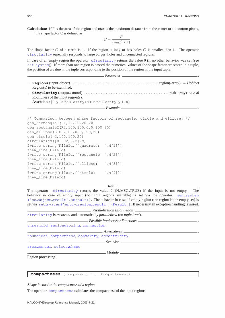
500 CHAPTER 11. REGIONS
Calculation: If F is the area of the region and max is the maximum distance from the center to all contour pixels,the shape factor C is defined as:
C =F
(max2 ∗ π)
The shape factorC of a circle is 1. If the region is long or has holesC is smaller than 1. The operatorcircularity especially responds to large bulges, holes and unconnected regions.
In case of an empty region the operatorcircularity returns the value 0 (if no other behavior was set (seeset system )). If more than one region is passed the numerical values of the shape factor are stored in a tuple,the position of a value in the tuple corresponding to the position of the region in the input tuple.
Parameter
. Regions (input object) . . . . . . . . . . . . . . . . . . . . . . . . . . . . . . . . . . . . . . . . . . . . . . . . . . . . . region(-array); HobjectRegion(s) to be examined.
. Circularity (outputcontrol) . . . . . . . . . . . . . . . . . . . . . . . . . . . . . . . . . . . . . . . . . . . . . . . . . . . real(-array); realRoundness of the input region(s).Assertion : (0 ≤ Circularity ) ∧ (Circularity ≤ 1.0 )
Example
/* Comparison between shape factors of rectangle, circle and ellipse: */gen_rectangle1(R1,10,10,20,20)gen_rectangle2(R2,100,100,0.0,100,20)gen_ellipse(E100,100,0.0,100,20)gen_circle(,C,100,100,20)circularity([R1,R2,E,C],M)fwrite_string(FileId,[’quadrate: ’,M[1]])fnew_line(FileId)fwrite_string(FileId,[’rectangle: ’,M[2]])fnew_line(FileId)fwrite_string(FileId,[’ellipse: ’,M[3]])fnew_line(FileId)fwrite_string(FileId,[’circle: ’,M[4]])fnew_line(FileId)
ResultThe operator circularity returns the value 2 (HMSG TRUE) if the input is not empty. Thebehavior in case of empty input (no input regions available) is set via the operatorset system(’no object result’,<Result>) . The behavior in case of empty region (the region is the empty set) isset via set system(’empty region result’,<Result>) . If necessary an exception handling is raised.
Parallelization Informationcircularity is reentrantand automaticallyparallelized(on tuple level).
Possible Predecessor Functionsthreshold , regiongrowing , connection
Alternativesroundness , compactness , convexity , eccentricity
See Alsoarea center , select shape
ModuleRegion processing
compactness ( Regions : : : Compactness )
Shape factor for the compactness of a region.
The operatorcompactness calculates the compactness of the input regions.
HALCON/HDevelop Reference Manual, 2003-7-21

11.4. FEATURES 501
Calculation: If L is the length of the contour (seecontlength ) andF the area of the region the shape factorC is defined as:
C =L2
4Fπ
The shape factorC of a circle is 1. If the region is long or has holesC is larger than 1. The operatorcompactness responds to the course of the contour (roughness) and to holes. In case of an empty regionthe operatorcompactness returns the value 0 if no other behavior was set (seeset system ). If more thanone region is passed the numerical values of the shape factor are stored in a tuple, the position of a value in thetuple corresponding to the position of the region in the input tuple.
Parameter
. Regions (input object) . . . . . . . . . . . . . . . . . . . . . . . . . . . . . . . . . . . . . . . . . . . . . . . . . . . . . region(-array); HobjectRegion(s) to be examined.
. Compactness (outputcontrol) . . . . . . . . . . . . . . . . . . . . . . . . . . . . . . . . . . . . . . . . . . . . . . . . . . . real(-array); realCompactness of the input region(s).Assertion : (Compactness ≥ 1.0 ) ∨ (Compactness = 0)
ResultThe operator compactness returns the value 2 (HMSG TRUE) if the input is not empty. Thebehavior in case of empty input (no input regions available) is set via the operatorset system(’no object result’,<Result>) . The behavior in case of empty region (the region is the empty set) isset via set system(’empty region result’,<Result>) . If necessary an exception handling is raised.
Parallelization Informationcompactness is reentrantand automaticallyparallelized(on tuple level).
Possible Predecessor Functionsthreshold , regiongrowing , connection
Alternativescompactness , convexity , eccentricity
See Alsocontlength , area center , select shape
ModuleRegion processing
connect and holes ( Regions : : : NumConnected, NumHoles )
Number of connection components and holes
The operatorconnect and holes calculates the number of connection components and the number of holesof each region ofRegions .
If more than one region is passed the numerical values of the output control parametersNumConnected andNumHoles are each stored in a tuple, the position of a value in the tuple corresponding to the position of theregion in the input tuple.
Parameter
. Regions (input object) . . . . . . . . . . . . . . . . . . . . . . . . . . . . . . . . . . . . . . . . . . . . . . . . . . . . . region(-array); HobjectRegion(s) to be examined.
. NumConnected (outputcontrol) . . . . . . . . . . . . . . . . . . . . . . . . . . . . . . . . . . . . . . . . . . . . integer(-array); integerNumber of connection components of a region.
. NumHoles (outputcontrol) . . . . . . . . . . . . . . . . . . . . . . . . . . . . . . . . . . . . . . . . . . . . . . . . . . integer(-array); integerNumber of holes of a region.
ResultThe operator connect and holes returns the value 2 (HMSG TRUE) if the input is not empty.The behavior in case of empty input (no input regions available) is set via the operatorset system(’no object result’,<Result>) . The behavior in case of empty region (the region is the empty set)is set via set system(’empty region result’,<Result>) .
HALCON 6.0.4

502 CHAPTER 11. REGIONS
Parallelization Informationconnect and holes is reentrantand automaticallyparallelized(on tuple level).
Possible Predecessor Functionsthreshold , regiongrowing , connection
Alternativeseuler number
See Alsoconnection , fill up, fill up shape , union1
ModuleRegion processing
contlength ( Regions : : : ContLength )
Contour length of a region.
The operator contlength calculates the total length of the contour (sum of all connection components ofthe region) for each region ofRegions . The distance between two neighboring contour points parallel to thecoordinate axes is rated 1, the distance in the diagonal is rated
√2. If more than one region is passed the numerical
values of the contour length are stored in a tuple, the position of a value in the tuple corresponding to the positionof the region in the input tuple. In case of an empty region the operatorcontlength returns the value 0.
AttentionThe contour of holes is not calculated.
Parameter
. Regions (input object) . . . . . . . . . . . . . . . . . . . . . . . . . . . . . . . . . . . . . . . . . . . . . . . . . . . . . region(-array); HobjectRegion(s) to be examined.
. ContLength (outputcontrol) . . . . . . . . . . . . . . . . . . . . . . . . . . . . . . . . . . . . . . . . . . . . . . . . . . . . . real(-array); realContour length of the input region(s).Assertion : ContLength ≥ 0
Example
#include <iostream.h>#include "HalconCpp.h"
int main (int argc, char *argv[]){
if (argc < 2){
cout << "Usage: " << argv[0] << " <# of regions> " << endl;return (-1);
}
HWindow w;HRegionArray reg;
int NumOfElements = atoi (argv[1]);
cout << "Draw " << NumOfElements << " regions " << endl;
for (int i=0; i < NumOfElements; i++){
reg[i] = w.DrawRegion ();}
Tuple circ = reg.Circularity ();
HALCON/HDevelop Reference Manual, 2003-7-21
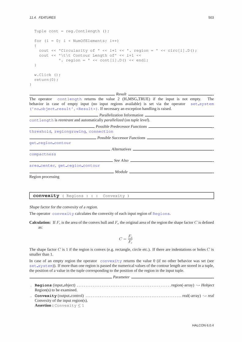
11.4. FEATURES 503
Tuple cont = reg.Contlength ();
for (i = 0; i < NumOfElements; i++){
cout << "Circularity of " << i+1 << ". region = " << circ[i].D();cout << "\t\t Contour Length of" << i+1 <<
". region = " << cont[i].D() << endl;}
w.Click ();return(0);
}
ResultThe operator contlength returns the value 2 (HMSG TRUE) if the input is not empty. Thebehavior in case of empty input (no input regions available) is set via the operatorset system(’no object result’,<Result>) . If necessary an exception handling is raised.
Parallelization Informationcontlength is reentrantand automaticallyparallelized(on tuple level).
Possible Predecessor Functionsthreshold , regiongrowing , connection
Possible Successor Functionsget region contour
Alternativescompactness
See Alsoarea center , get region contour
ModuleRegion processing
convexity ( Regions : : : Convexity )
Shape factor for the convexity of a region.
The operatorconvexity calculates the convexity of each input region ofRegions .
Calculation: If Fc is the area of the convex hull andFo the original area of the region the shape factorC is definedas:
C =Fo
Fc
The shape factorC is 1 if the region is convex (e.g. rectangle, circle etc.). If there are indentations or holesC issmaller than 1.
In case of an empty region the operatorconvexity returns the value 0 (if no other behavior was set (seeset system )). If more than one region is passed the numerical values of the contour length are stored in a tuple,the position of a value in the tuple corresponding to the position of the region in the input tuple.
Parameter
. Regions (input object) . . . . . . . . . . . . . . . . . . . . . . . . . . . . . . . . . . . . . . . . . . . . . . . . . . . . . region(-array); HobjectRegion(s) to be examined.
. Convexity (outputcontrol) . . . . . . . . . . . . . . . . . . . . . . . . . . . . . . . . . . . . . . . . . . . . . . . . . . . . . . real(-array); realConvexity of the input region(s).Assertion : Convexity ≤ 1
HALCON 6.0.4

504 CHAPTER 11. REGIONS
ResultThe operator convexity returns the value 2 (HMSG TRUE) if the input is not empty. The be-havior in case of empty input (no input regions available) is set via the operatorset system(’no object result’,<Result>) . The behavior in case of empty region (the region is the empty set) isset via set system(’empty region result’,<Result>) . If necessary an exception handling is raised.
Parallelization Informationconvexity is reentrantand automaticallyparallelized(on tuple level).
Possible Predecessor Functionsthreshold , regiongrowing , connection
See Alsoselect shape , area center , shape trans
ModuleRegion processing
diameter region ( Regions : : : Row1, Column1, Row2, Column2,Diameter )
Maximal distance between two boundary points of a region.
The operatordiameter region calculates the maximal distance between two boundary points of a region. Thecoordinates of these two extremes and the distance between them will be returned.
AttentionIf the region is empty, the results ofRow1, Column1 , Row2andColumn2 (all of them = 0) may lead to confu-sion.
Parameter
. Regions (input object) . . . . . . . . . . . . . . . . . . . . . . . . . . . . . . . . . . . . . . . . . . . . . . . . . . . . . region(-array); HobjectRegions to be examined.
. Row1(outputcontrol) . . . . . . . . . . . . . . . . . . . . . . . . . . . . . . . . . . . . . . . . . . . . . . . . . . . line.begin.y(-array); integerRow index of the first extreme point.
. Column1 (outputcontrol) . . . . . . . . . . . . . . . . . . . . . . . . . . . . . . . . . . . . . . . . . . . . . . . line.begin.x(-array); integerColumn index of the first extreme point.
. Row2(outputcontrol) . . . . . . . . . . . . . . . . . . . . . . . . . . . . . . . . . . . . . . . . . . . . . . . . . . . . . line.end.y(-array); integerRow index of the second extreme point.
. Column2 (outputcontrol) . . . . . . . . . . . . . . . . . . . . . . . . . . . . . . . . . . . . . . . . . . . . . . . . line.end.x(-array); integerColumn index of the second extreme point.
. Diameter (outputcontrol) . . . . . . . . . . . . . . . . . . . . . . . . . . . . . . . . . . . . . . . . . . . . . . . . . . . . number(-array); realDistance of the two extreme points.
ComplexityIf F is the area of a region, the runtime complexity amounts toO(
√F ) on average.
ResultThe operatordiameter region returns the value 2 (HMSG TRUE), if the input is not empty. The reactionto empty input (no input regions are available) may be determined with the help of the operatorset system(’no object result’,<Result>) . The reaction concerning an empty region (region is the empty set)will be determined by the operatorset system(’empty region result’,<Result>) . If necessary anexception handling is raised.
Parallelization Informationdiameter region is reentrantand automaticallyparallelized(on tuple level).
Possible Predecessor Functionsthreshold , regiongrowing , connection , runlength features
Possible Successor Functionsdisp line
Alternativessmallest rectangle2
HALCON/HDevelop Reference Manual, 2003-7-21
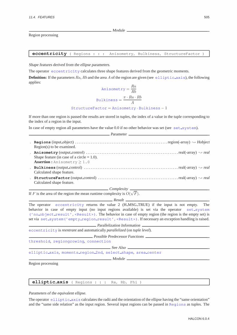
11.4. FEATURES 505
ModuleRegion processing
eccentricity ( Regions : : : Anisometry, Bulkiness, StructureFactor )
Shape features derived from the ellipse parameters.
The operatoreccentricity calculates three shape features derived from the geometric moments.
Definition: If the parametersRa,Rb and the areaA of the region are given (seeelliptic axis ), the followingapplies:
Anisometry =Ra
Rb
Bulkiness =π · Ra · Rb
A
StructureFactor = Anisometry · Bulkiness − 1
If more than one region is passed the results are stored in tuples, the index of a value in the tuple corresponding tothe index of a region in the input.
In case of empty region all parameters have the value 0.0 if no other behavior was set (seeset system ).
Parameter
. Regions (input object) . . . . . . . . . . . . . . . . . . . . . . . . . . . . . . . . . . . . . . . . . . . . . . . . . . . . . region(-array); HobjectRegion(s) to be examined.
. Anisometry (outputcontrol) . . . . . . . . . . . . . . . . . . . . . . . . . . . . . . . . . . . . . . . . . . . . . . . . . . . . . real(-array); realShape feature (in case of a circle = 1.0).Assertion : Anisometry ≥ 1.0
. Bulkiness (outputcontrol) . . . . . . . . . . . . . . . . . . . . . . . . . . . . . . . . . . . . . . . . . . . . . . . . . . . . . . real(-array); realCalculated shape feature.
. StructureFactor (outputcontrol) . . . . . . . . . . . . . . . . . . . . . . . . . . . . . . . . . . . . . . . . . . . . . . real(-array); realCalculated shape feature.
ComplexityIf F is the area of the region the mean runtime complexity isO(
√F ).
ResultThe operator eccentricity returns the value 2 (HMSG TRUE) if the input is not empty. Thebehavior in case of empty input (no input regions available) is set via the operatorset system(’no object result’,<Result>) . The behavior in case of empty region (the region is the empty set) isset via set system(’empty region result’,<Result>) . If necessary an exception handling is raised.
Parallelization Informationeccentricity is reentrantand automaticallyparallelized(on tuple level).
Possible Predecessor Functionsthreshold , regiongrowing , connection
See Alsoelliptic axis , moments region 2nd , select shape , area center
ModuleRegion processing
elliptic axis ( Regions : : : Ra, Rb, Phi )
Parameters of the equivalent ellipse.
The operatorelliptic axis calculates the radii and the orientation of the ellipse having the “same orientation”and the “same side relation” as the input region. Several input regions can be passed inRegions as tuples. The
HALCON 6.0.4
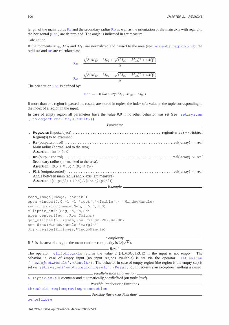
506 CHAPTER 11. REGIONS
length of the main radiusRa and the secondary radiusRb as well as the orientation of the main axis with regard tothe horizontal (Phi ) are determined. The angle is indicated in arc measure.
Calculation:
If the momentsM20, M02 andM11 are normalized and passed to the area (seemoments region 2nd ), theradii Ra andRb are calculated as:
Ra =
√8(M20 +M02 +
√(M20 −M02)2 + 4M2
11)
2
Rb =
√8(M20 +M02 −
√(M20 −M02)2 + 4M2
11)
2The orientationPhi is defined by:
Phi = −0.5atan2(2M11,M02 −M20)
If more than one region is passed the results are stored in tuples, the index of a value in the tuple corresponding tothe index of a region in the input.
In case of empty region all parameters have the value 0.0 if no other behavior was set (seeset system(’no object result’,<Result>) ).
Parameter
. Regions (input object) . . . . . . . . . . . . . . . . . . . . . . . . . . . . . . . . . . . . . . . . . . . . . . . . . . . . . region(-array); HobjectRegion(s) to be examined.
. Ra (outputcontrol) . . . . . . . . . . . . . . . . . . . . . . . . . . . . . . . . . . . . . . . . . . . . . . . . . . . . . . . . . . . . . . . . real(-array); realMain radius (normalized to the area).Assertion : Ra ≥ 0.0
. Rb (outputcontrol) . . . . . . . . . . . . . . . . . . . . . . . . . . . . . . . . . . . . . . . . . . . . . . . . . . . . . . . . . . . . . . . . real(-array); realSecondary radius (normalized to the area).Assertion : (Rb ≥ 0.0 ) ∧ (Rb ≤ Ra)
. Phi (outputcontrol) . . . . . . . . . . . . . . . . . . . . . . . . . . . . . . . . . . . . . . . . . . . . . . . . . . . . . . . . . . . . . . real(-array); realAngle between main radius and x axis (arc measure).Assertion : ((−pi /2) < Phi ) ∧ (Phi ≤ (pi /2))
Example
read_image(Image,’fabrik’)open_window(0,0,-1,-1,’root’,’visible’,’’,WindowHandle)regiongrowing(Image,Seg,5,5,6,100)elliptic_axis(Seg,Ra,Rb,Phi)area_center(Seg,_,Row,Column)gen_ellipse(Ellipses,Row,Column,Phi,Ra,Rb)set_draw(WindowHandle,’margin’)disp_region(Ellipses,WindowHandle)
ComplexityIf F is the area of a region the mean runtime complexity isO(
√F ).
ResultThe operator elliptic axis returns the value 2 (HMSG TRUE) if the input is not empty. Thebehavior in case of empty input (no input regions available) is set via the operatorset system(’no object result’,<Result>) . The behavior in case of empty region (the region is the empty set) isset via set system(’empty region result’,<Result>) . If necessary an exception handling is raised.
Parallelization Informationelliptic axis is reentrantand automaticallyparallelized(on tuple level).
Possible Predecessor Functionsthreshold , regiongrowing , connection
Possible Successor Functionsgen ellipse
HALCON/HDevelop Reference Manual, 2003-7-21

11.4. FEATURES 507
Alternativessmallest rectangle2 , orientation region
See Alsomoments region 2nd , select shape , set shape
BibliographyR. Haralick, L. Shapiro “Computer and Robot Vision” Addison-Wesley, 1992, pp. 73-75
ModuleRegion processing
euler number ( Regions : : : EulerNumber )
Calculate the Euler number.
The procedureeuler number calculates the Euler number, i.e. the difference between the number of connectioncomponents and the number of holes.
If more than one region is passed the results are stored in tuples, the index of a value in the tuple corresponding tothe index of a region in the input.
Parameter
. Regions (input object) . . . . . . . . . . . . . . . . . . . . . . . . . . . . . . . . . . . . . . . . . . . . . . . . . . . . . region(-array); HobjectRegion(s) to be examined.
. EulerNumber (outputcontrol) . . . . . . . . . . . . . . . . . . . . . . . . . . . . . . . . . . . . . . . . . . . . . . integer(-array); integerCalculated Euler number.
ResultThe operator euler number returns the value 2 (HMSG TRUE) if the input is not empty. Thebehavior in case of empty input (no input regions available) is set via the operatorset system(’no object result’,<Result>) . The behavior in case of empty region (the region is the empty set) isset via set system(’empty region result’,<Result>) . If necessary an exception handling is raised.
Parallelization Informationeuler number is reentrantand automaticallyparallelized(on tuple level).
Possible Predecessor Functionsthreshold , regiongrowing , connection
Alternativesconnect and holes
ModuleRegion processing
find neighbors ( Regions1, Regions2 : : MaxDistance : RegionIndex1,RegionIndex2 )
Search direct neighbors.
The operatorfind neighbors determines neighboring regions withRegions1 andRegions2 containingthe regions to be examined.Regions1 can have three different states:
• Regions1 is empty:In this case all regions inRegions2 are permutatively checked for neighborhood.
• Regions1 consists of one region:The regions ofRegions1 are compared to all regions inRegions2 .
• Regions1 consists of the same number of regions asRegions2 :Here all regions at the n-th position inRegions1 andRegions2 are checked for the neighboring relation.
The operatorfind neighbors uses the city block distance between neighboring regions. It can be specifiedby the parameterMaxDistance . neighboring regions are located at the n-th position inRegionIndex1 and
HALCON 6.0.4
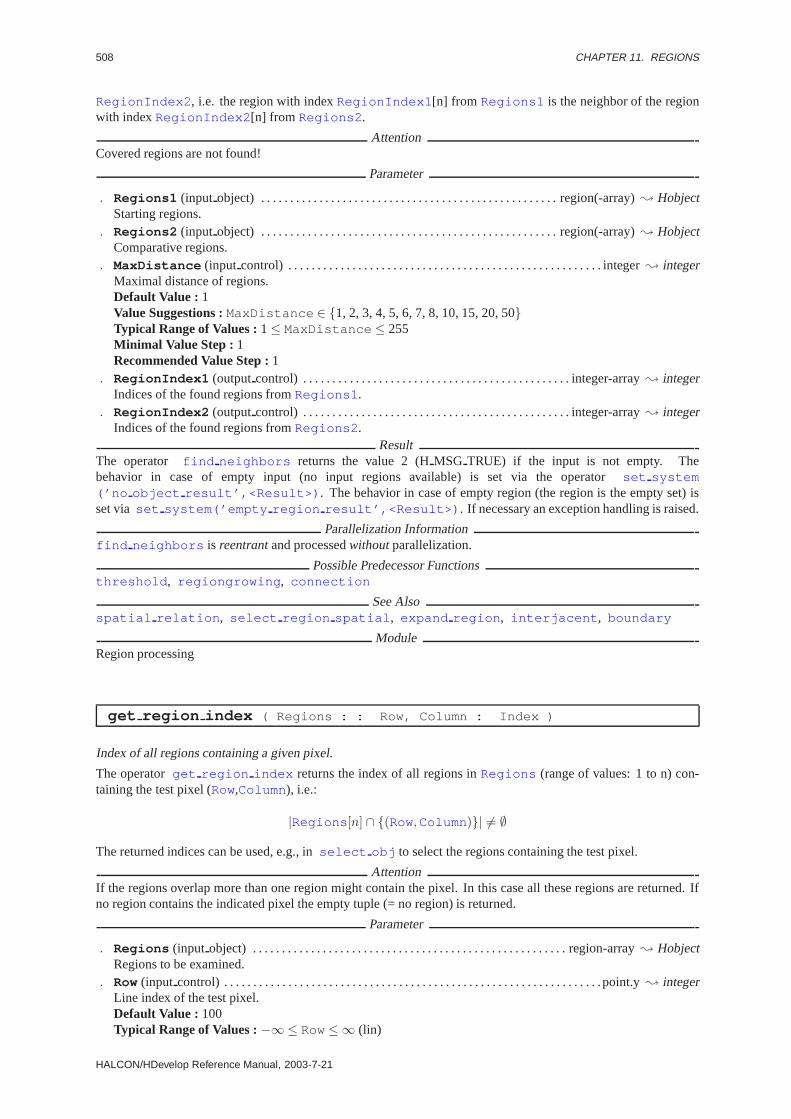
508 CHAPTER 11. REGIONS
RegionIndex2 , i.e. the region with indexRegionIndex1 [n] from Regions1 is the neighbor of the regionwith indexRegionIndex2 [n] from Regions2 .
AttentionCovered regions are not found!
Parameter
. Regions1 (input object) . . . . . . . . . . . . . . . . . . . . . . . . . . . . . . . . . . . . . . . . . . . . . . . . . . . region(-array); HobjectStarting regions.
. Regions2 (input object) . . . . . . . . . . . . . . . . . . . . . . . . . . . . . . . . . . . . . . . . . . . . . . . . . . . region(-array); HobjectComparative regions.
. MaxDistance (input control) . . . . . . . . . . . . . . . . . . . . . . . . . . . . . . . . . . . . . . . . . . . . . . . . . . . . . . integer; integerMaximal distance of regions.Default Value : 1Value Suggestions :MaxDistance ∈ {1, 2, 3, 4, 5, 6, 7, 8, 10, 15, 20, 50}Typical Range of Values :1≤ MaxDistance ≤ 255Minimal Value Step : 1Recommended Value Step :1
. RegionIndex1 (outputcontrol) . . . . . . . . . . . . . . . . . . . . . . . . . . . . . . . . . . . . . . . . . . . . . . integer-array; integerIndices of the found regions fromRegions1 .
. RegionIndex2 (outputcontrol) . . . . . . . . . . . . . . . . . . . . . . . . . . . . . . . . . . . . . . . . . . . . . . integer-array; integerIndices of the found regions fromRegions2 .
ResultThe operator find neighbors returns the value 2 (HMSG TRUE) if the input is not empty. Thebehavior in case of empty input (no input regions available) is set via the operatorset system(’no object result’,<Result>) . The behavior in case of empty region (the region is the empty set) isset via set system(’empty region result’,<Result>) . If necessary an exception handling is raised.
Parallelization Informationfind neighbors is reentrantand processedwithoutparallelization.
Possible Predecessor Functionsthreshold , regiongrowing , connection
See Alsospatial relation , select region spatial , expand region , interjacent , boundary
ModuleRegion processing
get region index ( Regions : : Row, Column : Index )
Index of all regions containing a given pixel.
The operatorget region index returns the index of all regions inRegions (range of values: 1 to n) con-taining the test pixel (Row,Column ), i.e.:
|Regions [n] ∩ {(Row,Column )}| 6= ∅
The returned indices can be used, e.g., inselect obj to select the regions containing the test pixel.
AttentionIf the regions overlap more than one region might contain the pixel. In this case all these regions are returned. Ifno region contains the indicated pixel the empty tuple (= no region) is returned.
Parameter
. Regions (input object) . . . . . . . . . . . . . . . . . . . . . . . . . . . . . . . . . . . . . . . . . . . . . . . . . . . . . . region-array; HobjectRegions to be examined.
. Row(input control) . . . . . . . . . . . . . . . . . . . . . . . . . . . . . . . . . . . . . . . . . . . . . . . . . . . . . . . . . . . . . . . . .point.y; integerLine index of the test pixel.Default Value : 100Typical Range of Values :−∞≤ Row≤ ∞ (lin)
HALCON/HDevelop Reference Manual, 2003-7-21
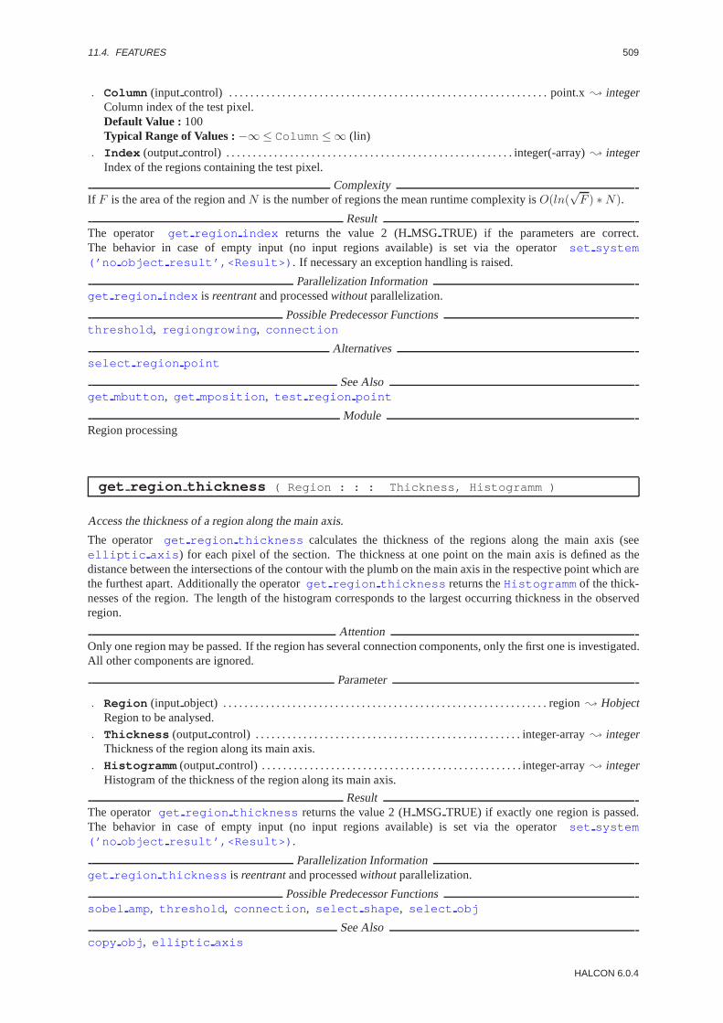
11.4. FEATURES 509
. Column (input control) . . . . . . . . . . . . . . . . . . . . . . . . . . . . . . . . . . . . . . . . . . . . . . . . . . . . . . . . . . . . point.x; integerColumn index of the test pixel.Default Value : 100Typical Range of Values :−∞≤ Column ≤∞ (lin)
. Index (outputcontrol) . . . . . . . . . . . . . . . . . . . . . . . . . . . . . . . . . . . . . . . . . . . . . . . . . . . . . . integer(-array); integerIndex of the regions containing the test pixel.
ComplexityIf F is the area of the region andN is the number of regions the mean runtime complexity isO(ln(
√F ) ∗N).
ResultThe operator get region index returns the value 2 (HMSG TRUE) if the parameters are correct.The behavior in case of empty input (no input regions available) is set via the operatorset system(’no object result’,<Result>) . If necessary an exception handling is raised.
Parallelization Informationget region index is reentrantand processedwithoutparallelization.
Possible Predecessor Functionsthreshold , regiongrowing , connection
Alternativesselect region point
See Alsoget mbutton , get mposition , test region point
ModuleRegion processing
get region thickness ( Region : : : Thickness, Histogramm )
Access the thickness of a region along the main axis.
The operator get region thickness calculates the thickness of the regions along the main axis (seeelliptic axis ) for each pixel of the section. The thickness at one point on the main axis is defined as thedistance between the intersections of the contour with the plumb on the main axis in the respective point which arethe furthest apart. Additionally the operatorget region thickness returns theHistogramm of the thick-nesses of the region. The length of the histogram corresponds to the largest occurring thickness in the observedregion.
AttentionOnly one region may be passed. If the region has several connection components, only the first one is investigated.All other components are ignored.
Parameter
. Region (input object) . . . . . . . . . . . . . . . . . . . . . . . . . . . . . . . . . . . . . . . . . . . . . . . . . . . . . . . . . . . . . region; HobjectRegion to be analysed.
. Thickness (outputcontrol) . . . . . . . . . . . . . . . . . . . . . . . . . . . . . . . . . . . . . . . . . . . . . . . . . . integer-array; integerThickness of the region along its main axis.
. Histogramm (outputcontrol) . . . . . . . . . . . . . . . . . . . . . . . . . . . . . . . . . . . . . . . . . . . . . . . . . integer-array; integerHistogram of the thickness of the region along its main axis.
ResultThe operatorget region thickness returns the value 2 (HMSG TRUE) if exactly one region is passed.The behavior in case of empty input (no input regions available) is set via the operatorset system(’no object result’,<Result>) .
Parallelization Informationget region thickness is reentrantand processedwithoutparallelization.
Possible Predecessor Functionssobel amp, threshold , connection , select shape , select obj
See Alsocopy obj , elliptic axis
HALCON 6.0.4

510 CHAPTER 11. REGIONS
ModuleRegion processing
hamming distance ( Regions1, Regions2 : : : Distance, Similarity )
Hamming distance between two regions.
The operatorhamming distance returns the hamming distance between two regions, i.e. the number of pixelsof the regions which are different (Distance ), i.e. the number of pixels contained in one region but not in theother:
Distance = |Regions1 ∩ Regions2 | + |Regions2 ∩ Regions1 |
The parameterSimilarity describes the similarity between the two regions based on the hamming distanceDistance :
Similarity = 1 − Distance
|Regions1 | + |Regions2 |
If both regions are emptySimilarity is set to 0. The regions with the same index from both input parametersare always compared.
AttentionIn both input parameters the same number of regions must be passed.
Parameter
. Regions1 (input object) . . . . . . . . . . . . . . . . . . . . . . . . . . . . . . . . . . . . . . . . . . . . . . . . . . . region(-array); HobjectRegions to be examined.
. Regions2 (input object) . . . . . . . . . . . . . . . . . . . . . . . . . . . . . . . . . . . . . . . . . . . . . . . . . . . region(-array); HobjectComparative regions.
. Distance (outputcontrol) . . . . . . . . . . . . . . . . . . . . . . . . . . . . . . . . . . . . . . . . . . . . . . . . . . integer(-array); integerHamming distance of two regions.Assertion : Distance ≥ 0
. Similarity (outputcontrol) . . . . . . . . . . . . . . . . . . . . . . . . . . . . . . . . . . . . . . . . . . . . . . . . . . . . . real(-array); realSimilarity of two regions.Assertion : (0 ≤ Similarity ) ∧ (Similarity ≤ 1)
ComplexityIf F is the area of a region the mean runtime complexity isO(
√F ).
Resulthammingdistance returns the value 2 (HMSG TRUE) if the number of objects in both parameters is the sameand is not 0. The behavior in case of empty input (no input objects available) is set via the operatorset system(’no object result’,<Result>) . The behavior in case of empty region (the region is the empty set) isset via set system(’empty region result’,<Result>) . If necessary an exception handling handlingis raised.
Parallelization Informationhamming distance is reentrantand automaticallyparallelized(on tuple level).
Possible Predecessor Functionsthreshold , regiongrowing , connection
Alternativesintersection , complement , area center
See Alsohamming change region
ModuleRegion processing
HALCON/HDevelop Reference Manual, 2003-7-21
11.4. FEATURES 511
hamming distance norm ( Regions1, Regions2 : : Norm : Distance,Similarity )
Hamming distance between two regions using normalization.
The operatorhamming distance norm returns the hamming distance between two regions, i.e. the number ofpixels of the regions which are different (Distance ). Before calculating the different the region inRegions1are normalized according to the regions inRegions2 . The result is the number of pixels contained in one regionbut not in the other:
Distance = |Norm(Regions1 ) ∩ Regions2 | + |Regions2 ∩Norm(Regions1 )|
The parameterSimilarity describes the similarity between the two regions based on the hamming distanceDistance :
Similarity = 1 − Distance
|Norm(Regions1 )| + |Regions2 |
The following types of normalization are available:
’center’: The region is moved so that both regions have the save center of gravity.
If both regions are emptySimilarity is set to 0. The regions with the same index from both input parametersare always compared.
AttentionIn both input parameters the same number of regions must be passed.
Parameter
. Regions1 (input object) . . . . . . . . . . . . . . . . . . . . . . . . . . . . . . . . . . . . . . . . . . . . . . . . . . . region(-array); HobjectRegions to be examined.
. Regions2 (input object) . . . . . . . . . . . . . . . . . . . . . . . . . . . . . . . . . . . . . . . . . . . . . . . . . . . region(-array); HobjectComparative regions.
. Norm (input control) . . . . . . . . . . . . . . . . . . . . . . . . . . . . . . . . . . . . . . . . . . . . . . . . . . . . . . . . . . . string(-array); stringType of normalization.Default Value : ’center’Value List : Norm ∈ {’center’}
. Distance (outputcontrol) . . . . . . . . . . . . . . . . . . . . . . . . . . . . . . . . . . . . . . . . . . . . . . . . . . integer(-array); integerHamming distance of two regions.Assertion : Distance ≥ 0
. Similarity (outputcontrol) . . . . . . . . . . . . . . . . . . . . . . . . . . . . . . . . . . . . . . . . . . . . . . . . . . . . . real(-array); realSimilarity of two regions.Assertion : (0 ≤ Similarity ) ∧ (Similarity ≤ 1)
ComplexityIf F is the area of a region the mean runtime complexity isO(
√F ).
Resulthammingdistancenorm returns the value 2 (HMSG TRUE) if the number of objects in both parameters isthe same and is not 0. The behavior in case of empty input (no input objects available) is set via the opera-tor set system(’no object result’,<Result>) . The behavior in case of empty region (the region isthe empty set) is set viaset system(’empty region result’,<Result>) . If necessary an exceptionhandling is raised.
Parallelization Informationhamming distance norm is reentrantand processedwithoutparallelization.
Possible Predecessor Functionsthreshold , regiongrowing , connection
Alternativesintersection , complement , area center
See Alsohamming change region
ModuleRegion processing
HALCON 6.0.4

512 CHAPTER 11. REGIONS
inner circle ( Regions : : : Row, Column, Radius )
Largest inner circle of a region.
The operatorinner circle determines the largest inner circle of a region, i.e. the circle with the largest area ofall circles that fit into the region. For this circle the center (Row,Column ) and the radius (Radius ) are calculated.The output of the procedure is chosen in such a way that it can be used as input for the HALCONproceduresdisp circle and gen circle .
If several regions are passed inRegions corresponding tuples are returned as output parameters. In case of emptyregion all parameters have the value 0.0 if no other behavior was set (seeset system ).
AttentionIf several inner circles are present at a region only one solution is returned.
Parameter
. Regions (input object) . . . . . . . . . . . . . . . . . . . . . . . . . . . . . . . . . . . . . . . . . . . . . . . . . . . . . region(-array); HobjectRegions to be examined.
. Row(outputcontrol) . . . . . . . . . . . . . . . . . . . . . . . . . . . . . . . . . . . . . . . . . . . . . . . . . . . . . circle.center.y(-array); realLine index of the center.
. Column (outputcontrol) . . . . . . . . . . . . . . . . . . . . . . . . . . . . . . . . . . . . . . . . . . . . . . . . . circle.center.x(-array); realColumn index of the center.
. Radius (outputcontrol) . . . . . . . . . . . . . . . . . . . . . . . . . . . . . . . . . . . . . . . . . . . . . . . . . . circle.radius(-array); realRadius of the inner circle.Assertion : Radius ≥ 0
Example
read_image(Image,’fabrik’)open_window(0,0,-1,-1,’root’,’visible’,’’,WindowHandle)regiongrowing(Image,Seg,5,5,6,100)select_shape(Seg,H,’area’,’and’,100,2000)inner_circle(H,Row,Column,Radius)gen_circle(Circles,Row,Column,Radius:)set_draw(WindowHandle,’margin’)disp_region(Circles,WindowHandle)
ComplexityIf F is the area of the region andR is the radius of the inner circle the runtime complexity isO(
√F ∗R).
ResultThe operator inner circle returns the value 2 (HMSG TRUE) if the input is not empty. Thebehavior in case of empty input (no input regions available) is set via the operatorset system(’no object result’,<Result>) , the behavior in case of empty region is set viaset system(’empty region result’,<Result>) . If necessary an exception handling is raised.
Parallelization Informationinner circle is reentrantand automaticallyparallelized(on tuple level).
Possible Predecessor Functionsthreshold , regiongrowing , connection , runlength features
Possible Successor Functionsgen circle , disp circle
Alternativeserosion circle
See Alsoset shape , select shape , smallest circle
ModuleRegion processing
HALCON/HDevelop Reference Manual, 2003-7-21
11.4. FEATURES 513
moments region 2nd ( Regions : : : M11, M20, M02, Ia, Ib )
Geometric moments of regions.
The operator moments region 2nd calculates the moments (M20, M02) and the product of inertia of theaxes through the center parallel to the coordinate axes (M11). Furthermore the main axes of inertia (Ia , Ib ) arecalculated.
Calculation: Z0 andS0 are the coordinates of the center of a regionR with the areaF . Then the momentsMij
are defined by:Mij =
∑(Z,S)∈R
(Z0 − Z)i(S0 − S)j
whereinZ andS run through all pixels of the regionR.Furthermore,
h =M20 +M02
2thenIa andIb are defined by:
Ia = h+√h2 −M20 ∗M02 +M112
Ib = h−√h2 −M20 ∗M02 +M112
If more than one region is passed the results are stored in tuples, the index of a value in the tuple corresponding tothe index of a region in the input.
In case of empty region all parameters have the value 0.0 if no other behavior was set (seeset system ).
Parameter
. Regions (input object) . . . . . . . . . . . . . . . . . . . . . . . . . . . . . . . . . . . . . . . . . . . . . . . . . . . . . region(-array); HobjectRegions to be examined.
. M11 (outputcontrol) . . . . . . . . . . . . . . . . . . . . . . . . . . . . . . . . . . . . . . . . . . . . . . . . . . . . . . . . . . . . . . real(-array); realProduct of inertia of the axes through the center parallel to the coordinate axes.
. M20 (outputcontrol) . . . . . . . . . . . . . . . . . . . . . . . . . . . . . . . . . . . . . . . . . . . . . . . . . . . . . . . . . . . . . . real(-array); realMoment of 2nd order (line-dependent).
. M02 (outputcontrol) . . . . . . . . . . . . . . . . . . . . . . . . . . . . . . . . . . . . . . . . . . . . . . . . . . . . . . . . . . . . . . real(-array); realMoment of 2nd order (column-dependent).
. Ia (outputcontrol) . . . . . . . . . . . . . . . . . . . . . . . . . . . . . . . . . . . . . . . . . . . . . . . . . . . . . . . . . . . . . . . . real(-array); realThe one main axis of inertia.
. Ib (outputcontrol) . . . . . . . . . . . . . . . . . . . . . . . . . . . . . . . . . . . . . . . . . . . . . . . . . . . . . . . . . . . . . . . . real(-array); realThe other main axis of inertia.
ComplexityIf F is the area of the region the mean runtime complexity isO(
√F ).
ResultThe operator moments region 2nd returns the value 2 (HMSG TRUE) if the input is not empty.The behavior in case of empty input (no input regions available) is set via the operatorset system(’no object result’,<Result>) . The behavior in case of empty region (region is the empty set) is setvia set system(’empty region result’,<Result>) . If necessary an exception handling is raised.
Parallelization Informationmoments region 2nd is reentrantand automaticallyparallelized(on tuple level).
Possible Predecessor Functionsthreshold , regiongrowing , connection
Alternativesmoments region 2nd invar
See Alsoelliptic axis
ModuleRegion processing
HALCON 6.0.4
514 CHAPTER 11. REGIONS
moments region 2nd invar ( Regions : : : M11, M20, M02 )
Geometric moments of regions.
The operator moments region 2nd invar calculates the scaled moments (M20, M02) and the procut ofinertia of the axes through the center parallel to the coordinate axes (M11).
Calculation: Z0 andS0 are the coordinates of the center of a regionR with the areaF . Then the momentsMij
are defined by:
Mij =1F 2
∑(Z,S)∈R
(Z0 − Z)i(S0 − S)j
whereinZ andS run through all pixels of the regionR.
If more than one region is passed the results are stored in tuples, the index of a value in the tuple corresponding tothe index of a region in the input.
In case of empty region all parameters have the value 0.0 if no other behavior was set (seeset system ).
Parameter
. Regions (input object) . . . . . . . . . . . . . . . . . . . . . . . . . . . . . . . . . . . . . . . . . . . . . . . . . . . . . region(-array); HobjectRegions to be examined.
. M11 (outputcontrol) . . . . . . . . . . . . . . . . . . . . . . . . . . . . . . . . . . . . . . . . . . . . . . . . . . . . . . . . . . . . . . real(-array); realProduct of inertia of the axes through the center parallel to the coordinate axes.
. M20 (outputcontrol) . . . . . . . . . . . . . . . . . . . . . . . . . . . . . . . . . . . . . . . . . . . . . . . . . . . . . . . . . . . . . . real(-array); realMoment of 2nd order (line-dependent).
. M02 (outputcontrol) . . . . . . . . . . . . . . . . . . . . . . . . . . . . . . . . . . . . . . . . . . . . . . . . . . . . . . . . . . . . . . real(-array); realMoment of 2nd order (column-dependent).
ComplexityIf F is the area of the region the mean runtime complexity isO(
√F ).
ResultThe operatormoments region 2nd invar returns the value 2 (HMSG TRUE) if the input is not empty.The behavior in case of empty input (no input regions available) is set via the operatorset system(’no object result’,<Result>) . The behavior in case of empty region (the region is the empty set) isset via set system(’empty region result’,<Result>) . If necessary an exception handling is raised.
Parallelization Informationmoments region 2nd invar is reentrantand processedwithoutparallelization.
Possible Predecessor Functionsthreshold , regiongrowing , connection
Alternativesmoments region 2nd
See Alsoelliptic axis
ModuleRegion processing
moments region 2nd rel invar ( Regions : : : PHI1, PHI2 )
Geometric moments of regions.
The operatormoments region 2nd rel invar calculates the scaled relative moments (PHI1 , PHI2 ).
Calculation: The momentsPHI1 andPHI2 are defined by:
PHI1 = V20 + V02
PHI2 = (V20 + V02)2 + V 211
HALCON/HDevelop Reference Manual, 2003-7-21

11.4. FEATURES 515
If more than one region is passed the results are stored in tuples, the index of a value in the tuple corresponding tothe index of a region in the input.
In case of empty region all parameters have the value 0.0 if no other behavior was set (seeset system ).
Parameter
. Regions (input object) . . . . . . . . . . . . . . . . . . . . . . . . . . . . . . . . . . . . . . . . . . . . . . . . . . . . . region(-array); HobjectRegions to be examined.
. PHI1 (outputcontrol) . . . . . . . . . . . . . . . . . . . . . . . . . . . . . . . . . . . . . . . . . . . . . . . . . . . . . . . . . . . . . real(-array); realMoment of 2nd order.
. PHI2 (outputcontrol) . . . . . . . . . . . . . . . . . . . . . . . . . . . . . . . . . . . . . . . . . . . . . . . . . . . . . . . . . . . . . real(-array); realMoment of 2nd order.
ResultThe operator moments region 2nd rel invar returns the value 2 (HMSG TRUE) if the input is notempty. The behavior in case of empty input (no input regions available) is set via the operatorset system(’no object result’,<Result>) . The behavior in case of empty region (the region is the empty set) isset via set system(’empty region result’,<Result>) . If necessary an exception handling is raised.
Parallelization Informationmoments region 2nd rel invar is reentrantand automaticallyparallelized(on tuple level).
Possible Predecessor Functionsthreshold , regiongrowing , connection
Alternativesmoments region 2nd
See Alsoelliptic axis
ModuleRegion processing
moments region 3rd ( Regions : : : M21, M12, M03, M30 )
Geometric moments of regions.
The operator moments region 3rd calculates the translation-invariant central moments (M21, M12, M03,M30) of order(p+ q).
Calculation: x andy are the coordinates of the center of a regionR with the areaZ. Then the momentsMpq aredefined by:
Mpq =∑i=1
MZ(xi, yi)(xi − x)p(yi − y)q
wherein arex = m10m00
andy = m01m00
.
If more than one region is passed the results are stored in tuples, the index of a value in the tuple corresponding tothe index of a region in the input.
In case of empty region all parameters have the value 0.0 if no other behavior was set (seeset system ).
Parameter
. Regions (input object) . . . . . . . . . . . . . . . . . . . . . . . . . . . . . . . . . . . . . . . . . . . . . . . . . . . . . region(-array); HobjectRegions to be examined.
. M21 (outputcontrol) . . . . . . . . . . . . . . . . . . . . . . . . . . . . . . . . . . . . . . . . . . . . . . . . . . . . . . . . . . . . . . real(-array); realoment of 3nd order (line-dependent).
. M12 (outputcontrol) . . . . . . . . . . . . . . . . . . . . . . . . . . . . . . . . . . . . . . . . . . . . . . . . . . . . . . . . . . . . . . real(-array); realMoment of 3nd order (column-dependent).
. M03 (outputcontrol) . . . . . . . . . . . . . . . . . . . . . . . . . . . . . . . . . . . . . . . . . . . . . . . . . . . . . . . . . . . . . . real(-array); realMoment of 3nd order (column-dependent).
HALCON 6.0.4

516 CHAPTER 11. REGIONS
. M30 (outputcontrol) . . . . . . . . . . . . . . . . . . . . . . . . . . . . . . . . . . . . . . . . . . . . . . . . . . . . . . . . . . . . . . real(-array); realMoment of 3nd order (line-dependent).
ComplexityIf Z is the area of the region the mean runtime complexity isO(
√Z).
ResultThe operator moments region 3rd returns the value 2 (HMSG TRUE) if the input is not empty.The behavior in case of empty input (no input regions available) is set via the operatorset system(’no object result’,<Result>) . The behavior in case of empty region (the region is the empty set) isset via set system(’empty region result’,<Result>) . If necessary an exception handling is raised.
Parallelization Informationmoments region 3rd is reentrantand automaticallyparallelized(on tuple level).
Possible Predecessor Functionsthreshold , regiongrowing , connection
Alternativesmoments region 2nd
See Alsoelliptic axis
ModuleRegion processing
moments region 3rd invar ( Regions : : : M21, M12, M03, M30 )
Geometric moments of regions.
The operatormoments region 3rd invar calculates the scale-invariant moments (M21, M12, M03, M30).
Calculation: Then the momentsMij are defined by:
Mpq =µpq
µ3
wobeip+ q >= 2 undµ = µ00 = m00 sind.wherein arep+ q >= 2 andµ = µ00 = m00.
If more than one region is passed the results are stored in tuples, the index of a value in the tuple corresponding tothe index of a region in the input.
In case of empty region all parameters have the value 0.0 if no other behavior was set (seeset system ).
Parameter
. Regions (input object) . . . . . . . . . . . . . . . . . . . . . . . . . . . . . . . . . . . . . . . . . . . . . . . . . . . . . region(-array); HobjectRegions to be examined.
. M21 (outputcontrol) . . . . . . . . . . . . . . . . . . . . . . . . . . . . . . . . . . . . . . . . . . . . . . . . . . . . . . . . . . . . . . real(-array); realMoment of 3nd order (line-dependent).
. M12 (outputcontrol) . . . . . . . . . . . . . . . . . . . . . . . . . . . . . . . . . . . . . . . . . . . . . . . . . . . . . . . . . . . . . . real(-array); realMoment of 3nd order (column-dependent).
. M03 (outputcontrol) . . . . . . . . . . . . . . . . . . . . . . . . . . . . . . . . . . . . . . . . . . . . . . . . . . . . . . . . . . . . . . real(-array); realMoment of 3nd order (column-dependent).
. M30 (outputcontrol) . . . . . . . . . . . . . . . . . . . . . . . . . . . . . . . . . . . . . . . . . . . . . . . . . . . . . . . . . . . . . . real(-array); realMoment of 3nd order (line-dependent).
ComplexityIf Z is the area of the region the mean runtime complexity isO(
√Z).
ResultThe operatormoments region 3rd invar returns the value 2 (HMSG TRUE) if the input is not empty.The behavior in case of empty input (no input regions available) is set via the operatorset system
HALCON/HDevelop Reference Manual, 2003-7-21

11.4. FEATURES 517
(’no object result’,<Result>) . The behavior in case of empty region (the region is the empty set) isset via set system(’empty region result’,<Result>) . If necessary an exception handling is raised.
Parallelization Informationmoments region 3rd invar is reentrantand automaticallyparallelized(on tuple level).
Possible Predecessor Functionsthreshold , regiongrowing , connection
Alternativesmoments region 2nd
See Alsoelliptic axis
ModuleRegion processing
moments region central ( Regions : : : I1, I2, I3, I4 )
Geometric moments of regions.
The operatormoments region central calculates the central moments (I1 , I2 , I3 , I4 ).
Calculation: Then the momentsIi are defined by:I1 = µ20µ02 − µ211
I2 = (µ30µ03 − µ21µ12)2 − 4(µ30µ12 − µ221)(µ21µ03 − µ2
12)
I3 = µ20(µ21µ03 − µ212) − µ11(µ30µ03 − µ21µ12) + µ02(µ30µ12 − µ2
21)
I4 = µ230µ
302 − 6µ30µ21µ11µ
202 + 6µ30µ12µ02(2µ2
11 − µ20µ02)+ µ30µ03(6µ20µ11µ02 − 8µ3
11) + 9µ221µ20µ
202 − 18µ21µ12µ20µ11µ02
+ 6µ21µ03µ20(2µ211 − µ20µ02) + 9µ2
12µ220µ02 − 6µ12µ03µ11µ
220 + µ2
03µ320
If more than one region is passed the results are stored in tuples, the index of a value in the tuple corresponding tothe index of a region in the input.
In case of empty region all parameters have the value 0.0 if no other behavior was set (seeset system ).
Parameter
. Regions (input object) . . . . . . . . . . . . . . . . . . . . . . . . . . . . . . . . . . . . . . . . . . . . . . . . . . . . . region(-array); HobjectRegions to be examined.
. I1 (outputcontrol) . . . . . . . . . . . . . . . . . . . . . . . . . . . . . . . . . . . . . . . . . . . . . . . . . . . . . . . . . . . . . . . . real(-array); realMoment of 2nd order.
. I2 (outputcontrol) . . . . . . . . . . . . . . . . . . . . . . . . . . . . . . . . . . . . . . . . . . . . . . . . . . . . . . . . . . . . . . . . real(-array); realMoment of 2nd order.
. I3 (outputcontrol) . . . . . . . . . . . . . . . . . . . . . . . . . . . . . . . . . . . . . . . . . . . . . . . . . . . . . . . . . . . . . . . . real(-array); realMoment of 2nd order.
. I4 (outputcontrol) . . . . . . . . . . . . . . . . . . . . . . . . . . . . . . . . . . . . . . . . . . . . . . . . . . . . . . . . . . . . . . . . real(-array); realMoment of 3nd order.
ComplexityIf Z is the area of the region the mean runtime complexity isO(
√Z).
ResultThe operator moments region central returns the value 2 (HMSG TRUE) if the input is not empty.The behavior in case of empty input (no input regions available) is set via the operatorset system(’no object result’,<Result>) . The behavior in case of empty region (the region is the empty set) isset via set system(’empty region result’,<Result>) . If necessary an exception handling is raised.
Parallelization Informationmoments region central is reentrantand automaticallyparallelized(on tuple level).
HALCON 6.0.4

518 CHAPTER 11. REGIONS
Possible Predecessor Functionsthreshold , regiongrowing , connection
Alternativesmoments region 2nd
See Alsoelliptic axis
ModuleRegion processing
moments region central invar ( Regions : : : PSI1, PSI2, PSI3, PSI4 )
Geometric moments of regions.
The operatormoments region central invar calculates the moments (PSI1 , PSI2 , PSI3 , PSI4 ) thatare invariant under translation and general linear transformations.
Calculation: Then the momentsψi are defined by:ψ1 = I1µ4
ψ2 = I2µ10
ψ3 = I3µ7
ψ4 = I4µ11
If more than one region is passed the results are stored in tuples, the index of a value in the tuple corresponding tothe index of a region in the input.
In case of empty region all parameters have the value 0.0 if no other behavior was set (seeset system ).
Parameter
. Regions (input object) . . . . . . . . . . . . . . . . . . . . . . . . . . . . . . . . . . . . . . . . . . . . . . . . . . . . . region(-array); HobjectRegions to be examined.
. PSI1 (outputcontrol) . . . . . . . . . . . . . . . . . . . . . . . . . . . . . . . . . . . . . . . . . . . . . . . . . . . . . . . . . . . . . real(-array); realMoment of 2nd order.
. PSI2 (outputcontrol) . . . . . . . . . . . . . . . . . . . . . . . . . . . . . . . . . . . . . . . . . . . . . . . . . . . . . . . . . . . . . real(-array); realMoment of 2nd order.
. PSI3 (outputcontrol) . . . . . . . . . . . . . . . . . . . . . . . . . . . . . . . . . . . . . . . . . . . . . . . . . . . . . . . . . . . . . real(-array); realMoment of 2nd order.
. PSI4 (outputcontrol) . . . . . . . . . . . . . . . . . . . . . . . . . . . . . . . . . . . . . . . . . . . . . . . . . . . . . . . . . . . . . real(-array); realMoment of 2nd order.
ComplexityIf Z is the area of the region the mean runtime complexity isO(
√Z).
ResultThe operator moments region central invar returns the value 2 (HMSG TRUE) if the input is notempty. The behavior in case of empty input (no input regions available) is set via the operatorset system(’no object result’,<Result>) . The behavior in case of empty region (the region is the empty set) isset via set system(’empty region result’,<Result>) . If necessary an exception handling is raised.
Parallelization Informationmoments region central invar is reentrantand automaticallyparallelized(on tuple level).
Possible Predecessor Functionsthreshold , regiongrowing , connection
Alternativesmoments region 2nd
HALCON/HDevelop Reference Manual, 2003-7-21

11.4. FEATURES 519
See Alsoelliptic axis
ModuleRegion processing
orientation region ( Regions : : : Phi )
Orientation of a region.
The operator orientation region calculates the orientation of the region. The operator is based onelliptic axis . In addition the point on the contour with maximal distance to the center of gravity is cal-culated. If the column coordinate of this point is less than the column coordinate of the center of gravity the valueof π is added to the angle.
If more than one region is passed the results are stored in tuples, the index of a value in the tuple corresponding tothe index of a region in the input.
In case of empty region all parameters have the value 0.0 if no other behavior was set (seeset system(’no object result’,<Result>) ).
Parameter
. Regions (input object) . . . . . . . . . . . . . . . . . . . . . . . . . . . . . . . . . . . . . . . . . . . . . . . . . . . . . region(-array); HobjectRegion(s) to be examined.
. Phi (outputcontrol) . . . . . . . . . . . . . . . . . . . . . . . . . . . . . . . . . . . . . . . . . . . . . . . . . . . . . . . . . . . . . . real(-array); realOrientation of region (arc measure).Assertion : ((−pi /2) < Phi ) ∧ (Phi ≤ ((3 · pi )/2))
ComplexityIf F is the area of a region the mean runtime complexity isO(
√F ).
ResultThe operator orientation region returns the value 2 (HMSG TRUE) if the input is not empty.The behavior in case of empty input (no input regions available) is set via the operatorset system(’no object result’,<Result>) . The behavior in case of empty region (the region is the empty set) isset via set system(’empty region result’,<Result>) . If necessary an exception handling is raised.
Parallelization Informationorientation region is reentrantand automaticallyparallelized(on tuple level).
Possible Predecessor Functionsthreshold , regiongrowing , connection
Possible Successor Functionsdisp arrow
Alternativeselliptic axis , smallest rectangle2
See Alsomoments region 2nd , line orientation
ModuleRegion processing
roundness ( Regions : : : Distance, Sigma, Roundness, Sides )
Shape factors from contour.
The operatorroundness examines the distance between the contour and the center of the area. In particularthe mean distance (Distance ), the deviation from the mean distance (Sigma ) and two shape features derivedtherefrom are determined.Roundness is the relation between mean value and standard deviation, andSidesindicates the number of polygon pieces if a regular polygon is concerned.
HALCON 6.0.4

520 CHAPTER 11. REGIONS
The contour for calculating the features is determined depending on the global neighborhood (seeset system ).
Calculation:
If p is the center of the area,p i the pixels andF the area of the contour.
Distance =1F
∑||p− p i||
Sigma 2 =1F
∑(||p− p i|| − Distance )2
Roundness = 1 − Sigma
Distance
Sides = 1.4111(
Distance
Sigma
)0.4724
If more than one region is passed the results are stored in tuples, the index of a value in the tuple corresponding tothe index of a region in the input.
In case of empty region all parameters have the value 0.0 if no other behavior was set (seeset system ).
Parameter
. Regions (input object) . . . . . . . . . . . . . . . . . . . . . . . . . . . . . . . . . . . . . . . . . . . . . . . . . . . . . region(-array); HobjectRegion(s) to be examined.
. Distance (outputcontrol) . . . . . . . . . . . . . . . . . . . . . . . . . . . . . . . . . . . . . . . . . . . . . . . . . . . . . . . . real(-array); realMean distance from the center.Assertion : Distance ≥ 0.0
. Sigma (outputcontrol) . . . . . . . . . . . . . . . . . . . . . . . . . . . . . . . . . . . . . . . . . . . . . . . . . . . . . . . . . . . . real(-array); realStandard deviation ofDistance .Assertion : Sigma ≥ 0.0
. Roundness (outputcontrol) . . . . . . . . . . . . . . . . . . . . . . . . . . . . . . . . . . . . . . . . . . . . . . . . . . . . . . real(-array); realShape factor for roundness.Assertion : Roundness ≤ 1.0
. Sides (outputcontrol) . . . . . . . . . . . . . . . . . . . . . . . . . . . . . . . . . . . . . . . . . . . . . . . . . . . . . . . . . . . . real(-array); realNumber of polygon sides.Assertion : Sides ≥ 0
ComplexityIf F is the area of a region the mean runtime complexity isO(
√F ).
ResultThe operator roundness returns the value 2 (HMSG TRUE) if the input is not empty. The be-havior in case of empty input (no input regions available) is set via the operatorset system(’no object result’,<Result>) , the behavior in case of empty region is set viaset system(’empty region result’,<Result>) . If necessary an exception handling is raised.
Parallelization Informationroundness is reentrantand automaticallyparallelized(on tuple level).
Possible Predecessor Functionsthreshold , regiongrowing , connection
Alternativescompactness
See Alsocontlength
BibliographyR. Haralick, L. Shapiro “Computer and Robot Vision” Addison-Wesley, 1992, pp. 61
ModuleRegion processing
HALCON/HDevelop Reference Manual, 2003-7-21

11.4. FEATURES 521
runlength distribution ( Region : : : Foreground, Background )
Distribution of runs needed for runlength encoding of a region.
The operatorrunlength distribution calculates the distribution of the runs of a region of the fore- andbackground. The frequency of the occurrence of a certain length is calculated. Runs of infinite length are notcounted. Therefore the background are the holes of the region. As many values are passed as set by the maximumlength of fore- or background, respectively. The length of both tuples usually differs. The first entry of the tuples isalways 0 (no runs of the length 0). If there are no blanks the empty tuple is passed atBackground . Analogouslythe empty tuple is passed in case of an empty region atForeground .
Parameter
. Region (input object) . . . . . . . . . . . . . . . . . . . . . . . . . . . . . . . . . . . . . . . . . . . . . . . . . . . . . . . . . . . . . region; HobjectRegion to be examined.
. Foreground (outputcontrol) . . . . . . . . . . . . . . . . . . . . . . . . . . . . . . . . . . . . . . . . . . . . . . . . . integer-array; integerLength distribution of the region (foreground).
. Background (outputcontrol) . . . . . . . . . . . . . . . . . . . . . . . . . . . . . . . . . . . . . . . . . . . . . . . . . integer-array; integerLength distribution of the background.
ComplexityIf n is the number of runs of the region the runtime complexity isO(n).
ResultThe operator runlength distribution returns the value 2 (HMSG TRUE) if the input is not empty.The behavior in case of empty input (no input regions available) is set via the operatorset system(’no object result’,<Result>) . If more than one region is passed an exception handling is raised.
Parallelization Informationrunlength distribution is reentrantand processedwithoutparallelization.
Possible Predecessor Functionsthreshold , select obj
Alternativesrunlength features
See Alsorunlength features
ModuleRegion processing
runlength features ( Regions : : : NumRuns, KFactor, LFactor,MeanLength, Bytes )
Characteristic values for runlength coding of regions.
The operator runlength features calculates for every input region fromRegions the number of runsnecessary for storing this region with the aid of runlength coding. Furthermore the so-called ”‘K-factor”’ is deter-mined, which indicates by how much the number of runs differs from the ideal of the square in which this value is1.0.
The K-factor (KFactor ) is calculated according to the formula:
KFactor =NumRuns√
Area
whereinArea indicates the area of the region. It should be noted that the K-factor can be smaller than 1.0 (in caseof long horizontal regions).
The L-factor (LFactor ) indicates the mean number of runs for each line index occurring in the region.
MeanLength indicates the mean length of the runs. The parameterBytes indicates how many bytes are neces-sary for coding the region with runlengths.
HALCON 6.0.4

522 CHAPTER 11. REGIONS
AttentionAll features calculated by the operatorrunlength features are not rotation invariant because the runlengthcoding depends on the direction. The operatorrunlength features does not serve for calculating shapefeatures but for controlling and analysing the efficiency of the runlength coding.
Parameter
. Regions (input object) . . . . . . . . . . . . . . . . . . . . . . . . . . . . . . . . . . . . . . . . . . . . . . . . . . . . . region(-array); HobjectRegions to be examined.
. NumRuns(outputcontrol) . . . . . . . . . . . . . . . . . . . . . . . . . . . . . . . . . . . . . . . . . . . . . . . . . . . integer(-array); integerNumber of runs.Assertion : 0 ≤ NumRuns
. KFactor (outputcontrol) . . . . . . . . . . . . . . . . . . . . . . . . . . . . . . . . . . . . . . . . . . . . . . . . . . . . . . . . . real(-array); realStoring factor in relation to a square.Assertion : 0 ≤ KFactor
. LFactor (outputcontrol) . . . . . . . . . . . . . . . . . . . . . . . . . . . . . . . . . . . . . . . . . . . . . . . . . . . . . . . . . real(-array); realMean number of runs per line.Assertion : 0 ≤ LFactor
. MeanLength (outputcontrol) . . . . . . . . . . . . . . . . . . . . . . . . . . . . . . . . . . . . . . . . . . . . . . . . . . . . . real(-array); realMean length of runs.Assertion : 0 ≤ MeanLength
. Bytes (outputcontrol) . . . . . . . . . . . . . . . . . . . . . . . . . . . . . . . . . . . . . . . . . . . . . . . . . . . . . . integer(-array); integerNumber of bytes necessary for coding the region.Assertion : 0 ≤ Bytes
ComplexityThe mean runtime complexity isO(1).
ResultThe operatorrunlength features returns the value 2 (HMSG TRUE) if the input is not empty. If necessaryan exception handling is raised.
Parallelization Informationrunlength features is reentrantand automaticallyparallelized(on tuple level).
Possible Predecessor Functionsthreshold , regiongrowing , connection , runlength features
See Alsorunlength features , runlength distribution
ModuleRegion processing
select region point ( Regions : DestRegions : Row, Column : )
Choose all regions containing a given pixel.
The operator select region point selects alle regions fromRegions containing the test pixel(Row,Column ), i.e.:
|Regions [n] ∩ {(Row,Column )}| = 1
AttentionIf the regions overlap more than one region might contain the pixel. In this case all these regions are returned. Ifno region contains the indicated pixel the empty tuple (= no region) is returned.
Parameter
. Regions (input object) . . . . . . . . . . . . . . . . . . . . . . . . . . . . . . . . . . . . . . . . . . . . . . . . . . . . . . region-array; HobjectRegions to be examined.
. DestRegions (outputobject) . . . . . . . . . . . . . . . . . . . . . . . . . . . . . . . . . . . . . . . . . . . . . . . . region-array; HobjectAll regions containing the test pixel.
HALCON/HDevelop Reference Manual, 2003-7-21

11.4. FEATURES 523
. Row(input control) . . . . . . . . . . . . . . . . . . . . . . . . . . . . . . . . . . . . . . . . . . . . . . . . . . . . . . . . . . . . . . . . .point.y; integerLine index of the test pixel.Default Value : 100Typical Range of Values :−∞≤ Row≤ ∞ (lin)
. Column (input control) . . . . . . . . . . . . . . . . . . . . . . . . . . . . . . . . . . . . . . . . . . . . . . . . . . . . . . . . . . . . point.x; integerColumn index of the test pixel.Default Value : 100Typical Range of Values :−∞≤ Column ≤∞ (lin)
Example
read_image(Image,’fabrik’)open_window(0,0,-1,-1,’root’,’visible’,’’,WindowHandle)disp_image(Image)regiongrowing(Image,Seg,3,3,5,0)set_color(WindowHandle,’red’)set_draw(WindowHandle,’margin’)Button := 1while (Button = 1)
fwrite_string(FileId,’Select the region with the mouse (End right button)’)fnew_line(FileId)get_mbutton(WindowHandle,Row,Column,Button)select_region_point(Seg,Single,Row,Column)disp_region(Single,WindowHandle)
endwhile
ComplexityIf F is the area of the region andN is the number of regions, the mean runtime complexity isO(ln(
√F ) ∗N).
ResultThe operator select region point returns the value 2 (HMSG TRUE) if the parameters are correct.The behavior in case of empty input (no input regions available) is set via the operatorset system(’no object result’,<Result>) . If necessary an exception handling is raised.
Parallelization Informationselect region point is reentrantand processedwithoutparallelization.
Possible Predecessor Functionsthreshold , regiongrowing , connection
Alternativestest region point
See Alsoget mbutton , get mposition
ModuleRegion processing
select region spatial ( Regions1,Regions2 : : Direction : RegionIndex1, RegionIndex2 )
Pose relation of regions.
The operator select region spatial chooses the regions fromRegions2 which are sufficient for theneighboring relationDirection . The regions to be examined have to be passed inRegions1 or Regions2 ,respectively.Regions1 can have three different states:
• Regions1 is empty:In this case all regions inRegions2 are permutatively checked for neighborhood.
• Regions1 consists of one region:The regions ofRegions1 are compared to all regions inRegions2 .
HALCON 6.0.4

524 CHAPTER 11. REGIONS
• Regions1 consists of the same number of regions asRegions2 :The regions at the n-th position inRegions1 andRegions2 are each checked for a neighboring relation.
Possible values forDirection are:
’left’: Regions2 is left of Regions1
’right’: Regions2 is right ofRegions1
’above’: Regions2 is aboveRegions1
’below’: Regions2 is belowRegions1
The operator select region spatial calculates the centers of the regions to be compared and decidesaccording to the angle between the center straight lines and the x axis whether the direction relation is fulfilled.The relation is fulfilled within the area of -45 degree to +45 degree around the coordinate axes. Thus, the directionrelation can be understood in such a way that the center of the second region must be located left (or right, above,below) of the center of the first region. The indices of the regions fulfilling the direction relation are located at then-th position inRegionIndex1 andRegionIndex2 , i.e. the region with the indexRegionIndex2 [n] hasthe indicated relation with the region with the indexRegionIndex1 [n]. Access to regions via the index can beobtained via the operatorcopy obj .
Parameter
. Regions1 (input object) . . . . . . . . . . . . . . . . . . . . . . . . . . . . . . . . . . . . . . . . . . . . . . . . . . . region(-array); HobjectStarting regions
. Regions2 (input object) . . . . . . . . . . . . . . . . . . . . . . . . . . . . . . . . . . . . . . . . . . . . . . . . . . . region(-array); HobjectComparative regions
. Direction (input control) . . . . . . . . . . . . . . . . . . . . . . . . . . . . . . . . . . . . . . . . . . . . . . . . . . . . . . . . . . . string; stringDesired neighboring relation.Default Value : ’left’Value List : Direction ∈ {’left’, ’right’, ’above’, ’below’ }
. RegionIndex1 (outputcontrol) . . . . . . . . . . . . . . . . . . . . . . . . . . . . . . . . . . . . . . . . . . . . . . integer-array; integerIndices in the input tuples (Regions1 or Regions2 ), respectively.
. RegionIndex2 (outputcontrol) . . . . . . . . . . . . . . . . . . . . . . . . . . . . . . . . . . . . . . . . . . . . . . integer-array; integerIndices in the input tuples (Regions1 or Regions2 ), respectively.
ResultThe operatorselect region spatial returns the value 2 (HMSG TRUE) if Regions2 is not empty. Thebehavior in case of empty parameterRegions2 (no input regions available) is set via the operatorset system(’no object result’,<Result>) . The behavior in case of empty region (the region is the empty set) isset via set system(’empty region result’,<Result>) . If necessary an exception handling is raised.
Parallelization Informationselect region spatial is reentrantand processedwithoutparallelization.
Possible Predecessor Functionsthreshold , regiongrowing , connection
Alternativesarea center , intersection
See Alsospatial relation , find neighbors , copy obj , obj to integer
ModuleRegion processing
select shape ( Regions : SelectedRegions : Features, Operation, Min,Max : )
Choose regions with the aid of shape features.
The operatorselect shape chooses regions according to shape. For each input region fromRegions theindicated features (Features ) are calculated. If each (Operation = ’and’) or at least one (Operation = ’or’)
HALCON/HDevelop Reference Manual, 2003-7-21

11.4. FEATURES 525
of the calculated features is within the default limits (Min ,Max) the region is adapted into the output (duplicated).Condition:Mini ≤ Featurei(Object) ≤Maxi
Possible values forFeatures :
’area’: Area of the object
’row’: Row index of the center
’column’: Column index of the center
’width’: Width of the region
’height’: Height of the region
’row1’: Row index of upper left corner
’column1’: Column index of upper left corner
’row2’: Row index of lower right corner
’column2’: Column index of lower right corner
’circularity’: Circularity (seecircularity )
’compactness’: Compactness (seecompactness )
’contlength’: Total length of contour (see operatorcontlength )
’convexity’: Convexity (seeconvexity )
’ra’: Main radius of the equivalent ellipse (seeelliptic axis )
’rb’: Secondary radius of the equivalent ellipse (seeelliptic axis )
’phi’: Orientation of the equivalent ellipse (seeelliptic axis )
’anisometry:’ Anisometry (seeeccentricity )
’bulkiness:’ Bulkiness (see operatoreccentricity )
’struct factor:’ Structur Factor (see operatoreccentricity )
’outer radius’: Radius of smallest surrounding circle (seesmallest circle )
’inner radius’: Radius of largest inner circle (seeinner circle )
’dist mean’: Mean distance from the region border to the center (see operatorroundness )
’dist deviation:’ Deviation of the distance from the region border from the center (see operatorroundness )
’roundness’: Roundness (see operatorroundness )
’num sides’: Number of polygon sides (see operatorroundness )
’connect num’: Number of connection components (see operatorconnect and holes )
’holes num’: Number of holes (see operatorconnect and holes )
’max diameter’: Maximum diameter of the region (see operatordiameter region )
’orientation’: Orientation of the region (see operatororientation region )
’euler number’: Euler number (see operatoreuler number )
’rect2 phi’: Orientation of the smallest surrounding rectangle (see operatorsmallest rectangle2 )
’rect2 len1’: Half the length of the smallest surrounding rectangle (see operatorsmallest rectangle2 )
’rect2 len2’: Half the width of the smallest surrounding rectangle (see operatorsmallest rectangle2 )
’moments m11’: Geometric moments of the region (see operatormoments region 2nd )
’moments m20’: Geometric moments of the region (see operatormoments region 2nd )
’moments m02’: Geometric moments of the region (see operatormoments region 2nd )
’moments ia’: Geometric moments of the region (see operatormoments region 2nd )
’moments ib’: Geometric moments of the region (see operatormoments region 2nd )
’moments m11 invar’: Geometric moments of the region (see operatormoments region 2nd invar )
’moments m20 invar’: Geometric moments of the region (see operatormoments region 2nd invar )
’moments m02 invar’: Geometric moments of the region (see operatormoments region 2nd invar )
’moments phi1’: Geometric moments of the region (see operatormoments region 2nd rel invar )
HALCON 6.0.4
526 CHAPTER 11. REGIONS
’moments phi2’: Geometric moments of the region (see operatormoments region 2nd rel invar )
’moments m21’: Geometric moments of the region (see operatormoments region 3rd )
’moments m12’: Geometric moments of the region (see operatormoments region 3rd )
’moments m03’: Geometric moments of the region (see operatormoments region 3rd )
’moments m30’: Geometric moments of the region (see operatormoments region 3rd )
’moments m21 invar’: Geometric moments of the region (see operatormoments region 3rd invar )
’moments m12 invar’: Geometric moments of the region (see operatormoments region 3rd invar )
’moments m03 invar’: Geometric moments of the region (see operatormoments region 3rd invar )
’moments m30 invar’: Geometric moments of the region (see operatormoments region 3rd invar )
’moments i1’: Geometric moments of the region (see operatormoments region central )
’moments i2’: Geometric moments of the region (see operatormoments region central )
’moments i3’: Geometric moments of the region (see operatormoments region central )
’moments i4’: Geometric moments of the region (see operatormoments region central )
’moments psi1’: Geometric moments of the region (see operatormoments region central invar )
’moments psi2’: Geometric moments of the region (see operatormoments region central invar )
’moments psi3’: Geometric moments of the region (see operatormoments region central invar )
’moments psi4’: Geometric moments of the region (see operatormoments region central invar )
If only one feature (Features ) is used the value ofOperation is meaningless. Several features are processedin the sequence in which they are entered.
Parameter
. Regions (input object) . . . . . . . . . . . . . . . . . . . . . . . . . . . . . . . . . . . . . . . . . . . . . . . . . . . . . . region-array; HobjectRegions to be examined.
. SelectedRegions (outputobject) . . . . . . . . . . . . . . . . . . . . . . . . . . . . . . . . . . . . . . . . . . region-array; HobjectRegions fulfilling the condition.
. Features (input control) . . . . . . . . . . . . . . . . . . . . . . . . . . . . . . . . . . . . . . . . . . . . . . . . . . . . . string(-array); stringShape features to be checked.Default Value : ’area’Value List : Features ∈ {’area’, ’row’, ’column’, ’width’, ’height’, ’row1’, ’column1’, ’row2’, ’column2’,’circularity’, ’compactness’, ’contlength’, ’convexity’, ’ra’, ’rb’, ’phi’, ’anisometry’, ’bulkiness’,’struct factor’, ’outer radius’, ’innerradius’, ’maxdiameter’, ’distmean’, ’distdeviation’, ’roundness’,’num sides’, ’orientation’, ’connectnum’, ’holesnum’, ’euler number’, ’rect2phi’, ’rect2 len1’, ’rect2 len2’,’momentsm11’, ’momentsm20’, ’momentsm02’, ’momentsia’, ’momentsib’, ’momentsm11 invar’,’momentsm20 invar’, ’momentsm02 invar’, ’momentsphi1’, ’momentsphi2’, ’momentsm21’,’momentsm12’, ’momentsm03’, ’momentsm30’, ’momentsm21 invar’, ’momentsm12 invar’,’momentsm03 invar’, ’momentsm30 invar’, ’momentsi1’, ’momentsi2’, ’momentsi3’, ’momentsi4’,’momentspsi1’, ’momentspsi2’, ’momentspsi3’, ’momentspsi4’}
. Operation (input control) . . . . . . . . . . . . . . . . . . . . . . . . . . . . . . . . . . . . . . . . . . . . . . . . . . . . . . . . . . . string; stringLinkage type of the individual features.Default Value : ’and’Value List : Operation ∈ {’and’, ’or’}
. Min (input control) . . . . . . . . . . . . . . . . . . . . . . . . . . . . . . . . . . . . . . . . . . . . . . . . real(-array); real/ integer / stringLower limits of the features or ’min’.Default Value : 150.0Typical Range of Values :0.0≤ Min ≤ 99999.0Minimal Value Step : 0.001Recommended Value Step :1.0
. Max (input control) . . . . . . . . . . . . . . . . . . . . . . . . . . . . . . . . . . . . . . . . . . . . . . . . real(-array); real/ integer / stringUpper limits of the features or ’max’.Default Value : 99999.0Typical Range of Values :0.0≤ Max≤ 99999.0Minimal Value Step : 0.001Recommended Value Step :1.0Restriction : Max≥ Min
HALCON/HDevelop Reference Manual, 2003-7-21

11.4. FEATURES 527
Example
/* where are the eyes of the ape ? */read_image(Image’affe’)threshold(Image,S1,160,255)connection(S1,S2)select_shape(S2,Eyes,[’area’,’anisometry’],’and’,[500,1.0],[50000,1.7])disp_region(Eyes,WindowHandle)
ResultThe operator select shape returns the value 2 (HMSG TRUE) if the input is not empty. Thebehavior in case of empty input (no input objects available) is set via the operatorset system(’no object result’,<Result>) . The behavior in case of empty region (the region is the empty set) isset via set system(’empty region result’,<Result>) . If necessary an exception handling is raised.
Parallelization Informationselect shape is reentrantand processedwithoutparallelization.
Possible Predecessor Functionsthreshold , regiongrowing , connection , runlength features
Possible Successor Functionsselect shape , select gray , shape trans , reduce domain , count obj
See Alsoarea center , circularity , compactness , contlength , convexity , elliptic axis ,eccentricity , inner circle , smallest circle , smallest rectangle1 ,smallest rectangle2 , roundness , connect and holes , diameter region ,orientation region , moments region 2nd , moments region 2nd invar ,moments region 2nd rel invar , moments region 3rd , moments region 3rd invar ,moments region central , moments region central invar , select obj
ModuleRegion processing
select shape proto ( Regions, Pattern : SelectedRegions : Feature,Min, Max : )
Choose regions having a certain relation to each other.
The operator select shape proto selects regions based on certain relations between the regions. Everyregion fromRegions is compared to the union of regions fromPattern . The limits (Min and Max) arespecified absolutely or in percent (0..100), depending on the feature. Possible values forFeature are:
’distance dilate’ The minimum distance in the maximum norm from the edge ofPattern to the edge of everyregion fromRegions is determined (seedistance rr min dil ).
’distance contour’ The minimum Euclidean distance from the edge ofPattern to the edge of every regionfrom Regions is determined. (seedistance rr min ).
’distance center’ The Euclidean distance from the center ofPattern to the center of every region fromRegions is determined.
’covers’ It is examined how well the regionPattern fits into the regions fromRegions . If there is no shiftso thatPattern is a subset ofRegions the overlap is 0. IfPattern corresponds to the region after acorresponding shift the overlap is 100. Otherwise the area of the opening ofRegions with Pattern is putinto relation with the area ofRegions (in percent).
’fits’ It is examined whetherPattern can be shifted in such a way that it fits inRegions . If this is possible thecorresponding region is copied fromRegions . The parametersMin andMax are ignored.
’overlaps abs’ The area of the intersection ofPattern and every region inRegions is computed.
’overlaps rel’ The area of the intersection ofPattern and every region inRegions is computed. The relativeoverlap is the ratio of the area of the intersection and the are of the respective region inRegions (in percent).
HALCON 6.0.4

528 CHAPTER 11. REGIONS
Parameter
. Regions (input object) . . . . . . . . . . . . . . . . . . . . . . . . . . . . . . . . . . . . . . . . . . . . . . . . . . . . . region(-array); HobjectRegions to be examined.
. Pattern (input object) . . . . . . . . . . . . . . . . . . . . . . . . . . . . . . . . . . . . . . . . . . . . . . . . . . . . . region(-array); HobjectRegion compared toRegions .
. SelectedRegions (outputobject) . . . . . . . . . . . . . . . . . . . . . . . . . . . . . . . . . . . . . . . . . region(-array); HobjectRegions fulfilling the condition.
. Feature (input control) . . . . . . . . . . . . . . . . . . . . . . . . . . . . . . . . . . . . . . . . . . . . . . . . . . . . . . string(-array); stringShape features to be checked.Default Value : ’covers’Value List : Feature ∈ {’distancecenter’, ’distancedilate’, ’distancecontour’, ’covers’, ’fits’,’overlapsabs’, ’overlapsrel’}
. Min (input control) . . . . . . . . . . . . . . . . . . . . . . . . . . . . . . . . . . . . . . . . . . . . . . . . . . . . . . . . . . . number; real/ integerLower border of feature.Default Value : 50.0Value Suggestions :Min ∈ {0.0, 1.0, 5.0, 10.0, 20.0, 30.0, 50.0, 60.0, 70.0, 80.0, 90.0, 95.0, 99.0, 100.0,200.0, 400.0}Typical Range of Values :0.0≤ MinMinimal Value Step : 0.001Recommended Value Step :5.0
. Max (input control) . . . . . . . . . . . . . . . . . . . . . . . . . . . . . . . . . . . . . . . . . . . . . . . . . . . . . . . . . . . number; real/ integerUpper border of the feature.Default Value : 100.0Value Suggestions :Max∈ {0.0, 10.0, 20.0, 30.0, 50.0, 60.0, 70.0, 80.0, 90.0, 95.0, 99.0, 100.0, 200.0, 300.0,400.0}Typical Range of Values :0.0≤ MaxMinimal Value Step : 0.001Recommended Value Step :5.0
Example
#include <iostream.h>#include "HalconCpp.h"
int main (int argc, char *argv[]){
if (argc < 2){
cout << "Usage: " << argv[0] << " <radius of circle>" << endl;exit (1);
}
double rad = atof (argv[1]);HImage img ("affe");HWindow w;
img.Display (w);
HRegion circ = HRegion::GenCircle (100, 100, rad);HRegionArray reg = img.Regiongrowing (3, 3, 5, 0);HRegionArray seg = reg.SelectShapeProto (circ, "fits", 0, 0);
w.SetColor ("red");seg.Display (w);w.Click ();return(0);
}
ResultThe operator select shape proto returns the value 2 (HMSG TRUE) if the input is not empty.
HALCON/HDevelop Reference Manual, 2003-7-21
11.4. FEATURES 529
The behavior in case of empty input (no input regions available) is set via the operatorset system(’no object result’,<Result>) . The behavior in case of empty region (the region is the empty set) isset via set system(’empty region result’,<Result>) . If necessary an exception handling is raised.
Parallelization Informationselect shape proto is reentrantand processedwithoutparallelization.
Possible Predecessor Functionsconnection , draw region , gen circle , gen rectangle1 , gen rectangle2 , gen ellipse
Possible Successor Functionsselect gray , shape trans , reduce domain , count obj
Alternativesselect shape
See Alsoopening , erosion1 , distance rr min dil , distance rr min
ModuleRegion processing
select shape std ( Regions : SelectedRegions : Shape, Percent : )
Select regions of a given shape.
The operatorselect shape std compares the shape of the given regions with default shapes. If the regionhas a similar shape it is adopted into the output. Possible values forShape are:
’max area’ The largest region is selected.
’rectangle1’ The surrounding rectangle parallel to the coordinate axes is determined via the operatorsmallest rectangle1 . If the area difference in percent is larger thanPercent the region is adopted.
’rectangle1’ The smallest surrounding rectangle with any orientation is determined via the operatorsmallest rectangle2 . If the area difference in percent is larger thanPercent the region is adopted.
Parameter
. Regions (input object) . . . . . . . . . . . . . . . . . . . . . . . . . . . . . . . . . . . . . . . . . . . . . . . . . . . . . region(-array); HobjectInput regions to be selected.
. SelectedRegions (outputobject) . . . . . . . . . . . . . . . . . . . . . . . . . . . . . . . . . . . . . . . . . region(-array); HobjectRegions with desired shape.
. Shape (input control) . . . . . . . . . . . . . . . . . . . . . . . . . . . . . . . . . . . . . . . . . . . . . . . . . . . . . . . . . . . . . . . . string; stringShape features to be checked.Default Value : ’max area’Value List : Shape ∈ {’max area’, ’rectangle1’, ’rectangle2’}
. Percent (input control) . . . . . . . . . . . . . . . . . . . . . . . . . . . . . . . . . . . . . . . . . . . . . . . . . . . . . . . . . . . . . . . . . real; realSimilarity measure.Default Value : 70.0Value Suggestions :Percent ∈ {10.0, 30.0, 50.0, 60.0, 70.0, 80.0, 90.0, 95.0, 100.0}Typical Range of Values :0.0≤ Percent ≤ 100.0 (lin)Minimal Value Step : 0.1Recommended Value Step :10.0
Parallelization Informationselect shape std is reentrantand processedwithoutparallelization.
Possible Predecessor Functionsthreshold , regiongrowing , connection , smallest rectangle1 , smallest rectangle2
Alternativesintersection , complement , area center
See Alsosmallest rectangle1 , smallest rectangle2
HALCON 6.0.4

530 CHAPTER 11. REGIONS
ModuleRegion processing
smallest circle ( Regions : : : Row, Column, Radius )
Smallest surrounding circle of a region.
The operatorsmallest circle determines the smallest surrounding circle of a region, i.e. the circle with thesmallest area of all circles containing the region. For this circle the center (Row,Column ) and the radius (Radius )are calculated. The procedure is applied when, for example, the location and size of circular objects (e.g. coins)which, however, are not homogeneous inside or have broken edges due to bad segmentation, has to be determined.The output of the procedure is selected in such a way that it can be used as input for the HALCONproceduresdisp circle and gen circle .
If several regions are passed inRegions corresponding tuples are returned as output parameter. In case of emptyregion all parameters have the value 0.0 if no other behavior was set (seeset system ).
Parameter
. Regions (input object) . . . . . . . . . . . . . . . . . . . . . . . . . . . . . . . . . . . . . . . . . . . . . . . . . . . . . region(-array); HobjectRegions to be examined.
. Row(outputcontrol) . . . . . . . . . . . . . . . . . . . . . . . . . . . . . . . . . . . . . . . . . . . . . . . . . . . . . circle.center.y(-array); realLine index of the center.
. Column (outputcontrol) . . . . . . . . . . . . . . . . . . . . . . . . . . . . . . . . . . . . . . . . . . . . . . . . . circle.center.x(-array); realColumn index of the center.
. Radius (outputcontrol) . . . . . . . . . . . . . . . . . . . . . . . . . . . . . . . . . . . . . . . . . . . . . . . . . . circle.radius(-array); realRadius of the surrounding circle.Assertion : Radius ≥ 0
Example
read_image(Image,’fabrik’)open_window(0,0,-1,-1,’root’,’visible’,’’,WindowHandle)regiongrowing(Image,Seg,5,5,6,100:)select_shape(Seg,H,’area’,’and’,100,2000)smallest_circle(H,Row,Column,Radius)gen_circle(Circles,Row,Column,Radius)set_draw(WindowHandle,’margin’)disp_region(Circles,WindowHandle)
ComplexityIf F is the area of the region andN is the number of supporting points of the convex hull, the mean runtimecomplexity isO(
√F +N3).
ResultThe operator smallest circle returns the value 2 (HMSG TRUE) if the input is not empty. Thebehavior in case of empty input (no input regions available) is set via the operatorset system(’no object result’,<Result>) . The behavior in case of empty region (the region is the empty set) isset via set system(’empty region result’,<Result>) . If necessary an exception handling is raised.
Parallelization Informationsmallest circle is reentrantand automaticallyparallelized(on tuple level).
Possible Predecessor Functionsthreshold , regiongrowing , connection , runlength features
Possible Successor Functionsgen circle , disp circle
Alternativeselliptic axis , smallest rectangle1 , smallest rectangle2
See Alsoset shape , select shape , inner circle
HALCON/HDevelop Reference Manual, 2003-7-21

11.4. FEATURES 531
ModuleRegion processing
smallest rectangle1 ( Regions : : : Row1, Column1, Row2, Column2 )
Surrounding rectangle parallel to the coordinate axes.
The operator smallest rectangle1 calculates the surrounding rectangle of all input regions (paral-lel to the coordinate axes). The surrounding rectangle is described by the coordinates of the corner pixels(Row1,Column1 ,Row2,Column2 )
If more than one region is passed inRegions , the results are stored in tuples, the index of a value in the tuplecorresponding to the index of a region in the input. In case of empty region all parameters have the value 0 if noother behavior was set (seeset system ).
AttentionIn case of empty region the result ofRow1,Column1 , Row2andColumn2 (all are 0) can lead to confusion.
Parameter
. Regions (input object) . . . . . . . . . . . . . . . . . . . . . . . . . . . . . . . . . . . . . . . . . . . . . . . . . . . . . region(-array); HobjectRegions to be examined.
. Row1(outputcontrol) . . . . . . . . . . . . . . . . . . . . . . . . . . . . . . . . . . . . . . . . . . . . . rectangle.origin.y(-array); integerLine index of upper left corner point.
. Column1 (outputcontrol) . . . . . . . . . . . . . . . . . . . . . . . . . . . . . . . . . . . . . . . . . rectangle.origin.x(-array); integerColumn index of upper left corner point.
. Row2(outputcontrol) . . . . . . . . . . . . . . . . . . . . . . . . . . . . . . . . . . . . . . . . . . . . . rectangle.corner.y(-array); integerLine index of lower right corner point.
. Column2 (outputcontrol) . . . . . . . . . . . . . . . . . . . . . . . . . . . . . . . . . . . . . . . . . rectangle.corner.x(-array); integerColumn index of lower right corner point.
ComplexityIf F is the area of the region the mean runtime complexity isO(sqrt(F )).
ResultThe operator smallest rectangle1 returns the value 2 (HMSG TRUE) if the input is not empty.The behavior in case of empty input (no input regions available) is set via the operatorset system(’no object result’,<Result>) . The behavior in case of empty region (the region is the empty set) isset via set system(’empty region result’,<Result>) . If necessary an exception handling is raised.
Parallelization Informationsmallest rectangle1 is reentrantand automaticallyparallelized(on tuple level).
Possible Predecessor Functionsthreshold , regiongrowing , connection , runlength features
Possible Successor Functionsdisp rectangle1 , gen rectangle1
Alternativessmallest rectangle2 , area center
See Alsoselect shape
ModuleRegion processing
smallest rectangle2 ( Regions : : : Row, Column, Phi, Length1,Length2 )
Smallest surrounding rectangle with any orientation.
HALCON 6.0.4

532 CHAPTER 11. REGIONS
The operator smallest rectangle2 determines the smallest surrounding rectangle of a region, i.e. therectangle with the smallest area of all rectangles containing the region. For this rectangle the center, the inclinationand the two radii are calculated.
The procedure is applied when, for example, the location of a scenery of several regions (e.g. printedtext on a rectangular paper or in rectangular print (justified lines)) must be found. The parameters ofsmallest rectangle2 are chosen in such a way that they can be used directly as input for the HALCON-proceduresdisp rectangle2 and gen rectangle2 .
If more than one region is passed inRegions the results are stored in tuples, the index of a value in the tuplecorresponding to the index of a region in the input. In case of empty region all parameters have the value 0.0 if noother behavior was set (seeset system ).
Parameter
. Regions (input object) . . . . . . . . . . . . . . . . . . . . . . . . . . . . . . . . . . . . . . . . . . . . . . . . . . . . . region(-array); HobjectRegions to be examined.
. Row(outputcontrol) . . . . . . . . . . . . . . . . . . . . . . . . . . . . . . . . . . . . . . . . . . . . . . . . . rectangle2.center.y(-array); realLine index of the center.
. Column (outputcontrol) . . . . . . . . . . . . . . . . . . . . . . . . . . . . . . . . . . . . . . . . . . . . .rectangle2.center.x(-array); realColumn index of the center.
. Phi (outputcontrol) . . . . . . . . . . . . . . . . . . . . . . . . . . . . . . . . . . . . . . . . . . . . . . . rectangle2.angle.rad(-array); realOrientation of the surrounding rectangle (arc measure)Assertion : ((−pi /2) < Phi ) ∧ (Phi ≤ (pi /2))
. Length1 (outputcontrol) . . . . . . . . . . . . . . . . . . . . . . . . . . . . . . . . . . . . . . . . . . . . rectangle2.hwidth(-array); realFirst radius (half length) of the surrounding rectangle.Assertion : Length1 ≥ 0.0
. Length2 (outputcontrol) . . . . . . . . . . . . . . . . . . . . . . . . . . . . . . . . . . . . . . . . . . . rectangle2.hheight(-array); realSecond radius (half width) of the surrounding rectangle.Assertion : (Length2 ≥ 0.0 ) ∧ (Length2 ≤ Length1 )
Example
read_image(Image,’fabrik’)open_window(0,0,-1,-1,’root’,’visible’,’’,WindowHandle)regiongrowing(Image,Seg,5,5,6,100)smallest_rectangle2(Seg,Row,Column,Phi,Length1,Length2)gen_rectangle2(Rectangle,Row,Column,Phi,Length1,Length2)set_draw(WindowHandle,’margin’)disp_region(Rectangle,WindowHandle)
ComplexityIf F is the area of the region andN is the number of supporting points of the convex hull, the runtime complexityisO(
√F +N2).
ResultThe operator smallest rectangle2 returns the value 2 (HMSG TRUE) if the input is not empty.The behavior in case of empty input (no input regions available) is set via the operatorset system(’no object result’,<Result>) . The behavior in case of empty region (the region is the empty set) isset via set system(’empty region result’,<Result>) . If necessary an exception handling is raised.
Parallelization Informationsmallest rectangle2 is reentrantand automaticallyparallelized(on tuple level).
Possible Predecessor Functionsthreshold , regiongrowing , connection , runlength features
Possible Successor Functionsdisp rectangle2 , gen rectangle2
Alternativeselliptic axis , smallest rectangle1
See Alsosmallest circle , set shape
ModuleRegion processing
HALCON/HDevelop Reference Manual, 2003-7-21

11.4. FEATURES 533
spatial relation ( Regions1, Regions2 : : Percent : RegionIndex1,RegionIndex2, Relation1, Relation2 )
Pose relation of regions with regard to the coordinate axes.
The operator spatial relation selects regions located byPercent percent “left”, “right”, “above” or“below” other regions.Regions1 andRegions2 contain the regions to be compared.Regions1 can havethree states:
• Regions1 is empty:In this case all regions inRegions2 are permutatively checked for neighborhood.
• Regions1 consists of one region:The regions ofRegions1 are compared to all regions inRegions2 .
• Regions1 consists of the same number of regions asRegions2 :Regions1 andRegions2 are checked for a neighboring relation.
The percentagePercent is interpreted in such a way that the area of the second region has to be located reallyleft/right or above/below the region margins of the first region by at leastPercent percent. The indices ofthe regions that fulfill at least one of these conditions are then located at the n-th position in the output parame-tersRegionIndex1 andRegionIndex2 . Additionally the output parametersRelation1 andRelation2contain at the n-th position the type of relation of the region pair (RegionIndex1 [n], RegionIndex2 [n]),i.e. region with indexRegionIndex2 [n] has the relationRelation1 [n] andRelation2 [n] with region withindexRegionIndex1 [n].
Possible values forRelation1 andRelation2 are:
Relation1: ’left’, ’right’ or ”
Relation2: ’above’, ’below’ or ”
In RegionIndex1 andRegionIndex2 the indices of the regions in the tuples of the input regions (Regions1or Regions2 ), respectively, are entered as image identifiers. Access to chosen regions via the index can beobtained by the operatorcopy obj .
Parameter
. Regions1 (input object) . . . . . . . . . . . . . . . . . . . . . . . . . . . . . . . . . . . . . . . . . . . . . . . . . . . region(-array); HobjectStarting regions.
. Regions2 (input object) . . . . . . . . . . . . . . . . . . . . . . . . . . . . . . . . . . . . . . . . . . . . . . . . . . . region(-array); HobjectComparative regions.
. Percent (input control) . . . . . . . . . . . . . . . . . . . . . . . . . . . . . . . . . . . . . . . . . . . . . . . . . . . . . . . . . . . integer; integerPercentage of the area of the comparative region which must be located left/right or above/below the regionmargins of the starting region.Default Value : 50Value Suggestions :Percent ∈ {0, 10, 20, 30, 40, 50, 60, 70, 80, 90, 100}Typical Range of Values :0≤ Percent ≤ 100 (lin)Minimal Value Step : 1Recommended Value Step :10Restriction : (0 ≤ Percent ) ∧ (Percent ≤ 100 )
. RegionIndex1 (outputcontrol) . . . . . . . . . . . . . . . . . . . . . . . . . . . . . . . . . . . . . . . . . . . . . . integer-array; integerIndices of the regions in the tuple of the input regions which fulfill the pose relation.
. RegionIndex2 (outputcontrol) . . . . . . . . . . . . . . . . . . . . . . . . . . . . . . . . . . . . . . . . . . . . . . integer-array; integerIndices of the regions in the tuple of the input regions which fulfill the pose relation.
. Relation1 (outputcontrol) . . . . . . . . . . . . . . . . . . . . . . . . . . . . . . . . . . . . . . . . . . . . . . . . . . . . string-array; stringHorizontal pose relation in whichRegionIndex2 [n] stands withRegionIndex1 [n].
. Relation2 (outputcontrol) . . . . . . . . . . . . . . . . . . . . . . . . . . . . . . . . . . . . . . . . . . . . . . . . . . . . string-array; stringVertical pose relation in whichRegionIndex2 [n] stands withRegionIndex1 [n].
ResultThe operator spatial relation returns the value 2 (HMSG TRUE) if Regions2 is not empty andPercent is correctly choosen. The behavior in case of empty parameterRegions2 (no input regions avail-able) is set via the operatorset system(’no object result’,<Result>) . The behavior in case of
HALCON 6.0.4

534 CHAPTER 11. REGIONS
empty region (the region is the empty set) is set viaset system(’empty region result’,<Result>) .If necessary an exception handling is raised.
Parallelization Informationspatial relation is reentrantand processedwithoutparallelization.
Possible Predecessor Functionsthreshold , regiongrowing , connection
Alternativesarea center , intersection
See Alsoselect region spatial , find neighbors , copy obj , obj to integer
ModuleRegion processing
test region point ( Regions : : Row, Column : )
Test if the region consists of the given point.
test region point tests if at least one input region ofRegions consists of the test point (Row,Column ).
AttentionIn case of empty input (= no region) andset system(’no object result’,’true’) FALSE is returned(no region contains the pixel).
The test pixel is not contained in an empty region (no pixel of the region corresponds to the pixel). If all regionsare empty FALSE is also returned, i.e. an empty region behaves as if it did not exist.
Parameter
. Regions (input object) . . . . . . . . . . . . . . . . . . . . . . . . . . . . . . . . . . . . . . . . . . . . . . . . . . . . . region(-array); HobjectRegion(s) to be examined.
. Row(input control) . . . . . . . . . . . . . . . . . . . . . . . . . . . . . . . . . . . . . . . . . . . . . . . . . . . . . . . . . . . . . . . . .point.y; integerLine index of the test pixel.Default Value : 100Typical Range of Values :0≤ Row≤ 512 (lin)Minimal Value Step : 1Recommended Value Step :1
. Column (input control) . . . . . . . . . . . . . . . . . . . . . . . . . . . . . . . . . . . . . . . . . . . . . . . . . . . . . . . . . . . . point.x; integerColumn index of the test pixel.Default Value : 100Typical Range of Values :0≤ Column ≤ 512 (lin)Minimal Value Step : 1Recommended Value Step :1
ComplexityIf F is the area of one region andN is the number of regions, the runtime complexity isO(ln(
√F ) ∗N).
ResultThe operatortest region point returns the value 2 (HMSG TRUE) if a region contains the test pixel. If thisis not the casetest region point returns 3 (HMSG FALSE). The behavior in case of empty input (no inputregions available) is set via the operatorset system(’no object result’,<Result>) . If necessary anexception handling is raised.
Parallelization Informationtest region point is reentrantand processedwithoutparallelization.
Possible Predecessor Functionsthreshold , regiongrowing , connection
Alternativesunion1 , intersection , area center
See Alsoselect region point
HALCON/HDevelop Reference Manual, 2003-7-21

11.5. SETS 535
Return Valuebool
ModuleRegion processing
11.5 Sets
complement ( Region : RegionComplement : : )
Return the complement of a region.
complement determines the complement of the input region(s).
If the system flag’clip region’ is ’false’ (see set system ) the complement is done virtually by setting thecomplement flag ofRegion to TRUE. For succeeding operations the de Morgan laws are applied while calculatingresults.
If the system flag’clip region’ is ’true’ the difference of the largest image processed so far (seereset obj db)and the input region is returned.
Parameter
. Region (input object) . . . . . . . . . . . . . . . . . . . . . . . . . . . . . . . . . . . . . . . . . . . . . . . . . . . . . . region(-array); HobjectInput region(s).
. RegionComplement (outputobject) . . . . . . . . . . . . . . . . . . . . . . . . . . . . . . . . . . . . . . . region(-array); HobjectComplemented regions.Parameter Number : RegionComplement = Region
Resultcomplement always returns the value 2 (HMSG TRUE). The behavior in case of empty input (no regions given)can be set viaset system(’no object result’,<Result>) and the behavior in case of an empty inputregion via set system(’empty region result’,<Result>) . If necessary, an exception handling israised.
Parallelization Informationcomplement is reentrantand automaticallyparallelized(on tuple level).
Possible Predecessor Functionsthreshold , connection , regiongrowing , pouring , class ndim norm
Possible Successor Functionsselect shape
See Alsodifference , union1 , union2 , intersection , reset obj db , set system
ModuleRegion processing
difference ( Region, Sub : RegionDifference : : )
Calculate the difference of two regions.
difference calculates the set-theoretic difference of two regions:
(Regions inRegion ) − (Regions inSub)
The resulting region is defined as the input region (Region ) with all points fromSub removed.
AttentionEmpty regions are valid for both parameters. On output, empty regions may result. The value of the system flag’store empty region’ determines the behavior in this case.
HALCON 6.0.4

536 CHAPTER 11. REGIONS
Parameter
. Region (input object) . . . . . . . . . . . . . . . . . . . . . . . . . . . . . . . . . . . . . . . . . . . . . . . . . . . . . . region(-array); HobjectRegions to be processed.
. Sub (input object) . . . . . . . . . . . . . . . . . . . . . . . . . . . . . . . . . . . . . . . . . . . . . . . . . . . . . . . . . . region(-array); HobjectThe union of these regions is subtracted from Region.
. RegionDifference (outputobject) . . . . . . . . . . . . . . . . . . . . . . . . . . . . . . . . . . . . . . . region(-array); HobjectResulting region.
Example
/* provides the region X without the points in Y */difference(X,Y,RegionDifference)
ComplexityLetN be the number of regions,F 1 be their average area, andF 2 be the total area of all regions inSub. Thenthe runtime complexity isO(F 1 ∗ log(F 1) +N ∗ (
√F 1 +
√F 2)).
Resultdifference always returns the value 2 (HMSG TRUE). The behavior in case of empty input (no regions given)can be set viaset system(’no object result’,<Result>) and the behavior in case of an empty inputregion via set system(’empty region result’,<Result>) . If necessary, an exception handling israised.
Parallelization Informationdifference is reentrantand processedwithoutparallelization.
Possible Predecessor Functionsthreshold , connection , regiongrowing , pouring , class ndim norm
Possible Successor Functionsselect shape , disp region
See Alsointersection , union1 , union2 , complement
ModuleRegion processing
intersection ( Region1, Region2 : RegionIntersection : : )
Calculate the intersection of two regions.
intersection calculates the intersection of the regions inRegion1 with the regions inRegion2 . Eachregion inRegion1 is intersected with all regions inRegion2 . The order of regions inRegionIntersectionis identical to the order of regions inRegion1 .
AttentionEmpty input regions are permitted. Because empty result regions are possible, the system flag’store empty region’ should be set appropriately.
Parameter
. Region1 (input object) . . . . . . . . . . . . . . . . . . . . . . . . . . . . . . . . . . . . . . . . . . . . . . . . . . . . . region(-array); HobjectRegions to be intersected with all regions in Region2.
. Region2 (input object) . . . . . . . . . . . . . . . . . . . . . . . . . . . . . . . . . . . . . . . . . . . . . . . . . . . . . region(-array); HobjectRegions with which Region1 is intersected.
. RegionIntersection (outputobject) . . . . . . . . . . . . . . . . . . . . . . . . . . . . . . . . . . . . . region(-array); HobjectResult of the intersection.Parameter Number : RegionIntersection ≤ Region1
ComplexityLetN be the number of regions inRegion1 , F1 be their average area, andF2 be the total area of all regions inRegion2 . Then the runtime complexity isO(F1 log (F1) +N ∗ (
√F1 +
√F2)).
HALCON/HDevelop Reference Manual, 2003-7-21

11.5. SETS 537
Resultintersection always returns 2 (HMSG TRUE). The behavior in case of empty input (no regions given) canbe set via set system(’no object result’,<Result>) and the behavior in case of an empty inputregion via set system(’empty region result’,<Result>) . If necessary, an exception handling israised.
Parallelization Informationintersection is reentrantand processedwithoutparallelization.
Possible Predecessor Functionsthreshold , connection , regiongrowing , pouring
Possible Successor Functionsselect shape , disp region
See Alsounion1 , union2 , complement
ModuleRegion processing
union1 ( Region : RegionUnion : : )
Return the union of all input regions.
union1 computes the union of all input regions and returns the result inRegionUnion .
Parameter
. Region (input object) . . . . . . . . . . . . . . . . . . . . . . . . . . . . . . . . . . . . . . . . . . . . . . . . . . . . . . . . region-array; HobjectRegions of which the union is to be computed.
. RegionUnion (outputobject) . . . . . . . . . . . . . . . . . . . . . . . . . . . . . . . . . . . . . . . . . . . . . . . . . . . . . region; HobjectUnion of all input regions.Parameter Number : RegionUnion ≤ Region
Example
/* Union of segmentation results: */threshold(Image,Region1,128,255)dyn_threshold(Image,Mean,Region2,5,’light’)concat_obj(Region1,Region2,Regions)union1(Regions,RegionUnion).
ComplexityLetF be the sum of all areas of the input regions. Then the runtime complexity isO(log(
√F ) ∗
√F ).
Resultunion1 always returns 2 (HMSG TRUE). The behavior in case of empty input (no regions given) can be setvia set system(’no object result’,<Result>) and the behavior in case of an empty input region viaset system(’empty region result’,<Result>) . If necessary, an exception handling is raised.
Parallelization Informationunion1 is reentrantand processedwithoutparallelization.
Possible Predecessor Functionsthreshold , connection , regiongrowing , pouring
Possible Successor Functionsselect shape , disp region
Alternativesunion2
See Alsointersection , complement
ModuleRegion processing
HALCON 6.0.4

538 CHAPTER 11. REGIONS
union2 ( Region1, Region2 : RegionUnion : : )
Return the union of two regions.
union2 computes the union of the region inRegion1 with all regions inRegion2 . This means thatunion2is not commutative!
Parameter
. Region1 (input object) . . . . . . . . . . . . . . . . . . . . . . . . . . . . . . . . . . . . . . . . . . . . . . . . . . . . . region(-array); HobjectRegion for which the union with all regions in Region2 is to be computed.
. Region2 (input object) . . . . . . . . . . . . . . . . . . . . . . . . . . . . . . . . . . . . . . . . . . . . . . . . . . . . . region(-array); HobjectRegions which should be added to Region1.
. RegionUnion (outputobject) . . . . . . . . . . . . . . . . . . . . . . . . . . . . . . . . . . . . . . . . . . . . . . region(-array); HobjectResulting regions.Parameter Number : RegionUnion = Region1
ComplexityLetF be the sum of all areas of the input regions. Then the runtime complexity isO(log(
√F ) ∗
√F ).
Resultunion2 always returns 2 (HMSG TRUE). The behavior in case of empty input (no regions given) can be setvia set system(’no object result’,<Result>) and the behavior in case of an empty input region viaset system(’empty region result’,<Result>) . If necessary, an exception handling is raised.
Parallelization Informationunion2 is reentrantand processedwithoutparallelization.
Possible Predecessor Functionsthreshold , connection , regiongrowing , pouring
Possible Successor Functionsselect shape , disp region
Alternativesunion1
See Alsointersection , complement
ModuleRegion processing
11.6 Transformation
background seg ( Foreground : BackgroundRegions : : )
Determine the connected components of the background of given regions.
background seg determines connected components of the background of the foreground regions given inForeground . This operator is normally used after an edge operator in order to determine the regions enclosedby the extracted edges. The connected components are determined using 4-neighborhood.
Parameter
. Foreground (input object) . . . . . . . . . . . . . . . . . . . . . . . . . . . . . . . . . . . . . . . . . . . . . . . . . region(-array); HobjectInput regions.
. BackgroundRegions (outputobject) . . . . . . . . . . . . . . . . . . . . . . . . . . . . . . . . . . . . . . . .region-array; HobjectConnected components of the background.
Example
/* Simulation of background_seg: */background_seg(Foreground,BackgroundRegions):
complement(Foreground,Background)
HALCON/HDevelop Reference Manual, 2003-7-21

11.6. TRANSFORMATION 539
get_system(’neighborhood’,Save)set_system(’neighborhood’,4)connection(Background,BackgroundRegions)
clear_obj(Background)set_system(’neighborhood’,Save).
/* Segmentation with edge filter: */read_image(Image,’fabrik’)sobel_dir(Image,Sobel,Dir,’sum_sqrt’,3)threshold(Sobel,Edges,20,255)skeleton(Edges,Margins)background_seg(Margins,Regions).
ComplexityLet F be the area of the background,H andW be the height and width of the image, andN be the number ofresulting regions. Then the runtime complexity isO(H +
√F ∗
√N).
Resultbackground seg always returns the value 2 (HMSG TRUE). The behavior in case of empty input (no regionsgiven) can be set viaset system(’no object result’,<Result>) and the behavior in case of an emptyinput region viaset system(’empty region result’,<Result>) . If necessary, an exception handlingis raised.
Parallelization Informationbackground seg is reentrantand processedwithoutparallelization.
Possible Predecessor Functionsthreshold , connection , regiongrowing , pouring , class ndim norm
Possible Successor Functionsselect shape
Alternativescomplement , connection
See Alsothreshold , hysteresis threshold , skeleton , expand region , set system , sobel amp,edges image , roberts , bandpass image
ModuleRegion processing
clip region ( Region : RegionClipped : Row1, Column1, Row2,Column2 : )
Clip a region to a rectangle.
clip region clips the input regions to the rectangle given by the four control parameters.clip region ismore efficient than callingintersection with a rectangle generated bygen rectangle1 .
Parameter
. Region (input object) . . . . . . . . . . . . . . . . . . . . . . . . . . . . . . . . . . . . . . . . . . . . . . . . . . . . . . region(-array); HobjectRegion to be clipped.
. RegionClipped (outputobject) . . . . . . . . . . . . . . . . . . . . . . . . . . . . . . . . . . . . . . . . . . . region(-array); HobjectClipped regions.
. Row1(input control) . . . . . . . . . . . . . . . . . . . . . . . . . . . . . . . . . . . . . . . . . . . . . . . . . . . . . . rectangle.origin.y; integerRow coordinate of the upper left corner of the rectangle.Default Value : 0Value Suggestions :Row1∈ {0, 128, 200, 256}Typical Range of Values :−∞≤ Row1≤ ∞ (lin)
HALCON 6.0.4

540 CHAPTER 11. REGIONS
. Column1 (input control) . . . . . . . . . . . . . . . . . . . . . . . . . . . . . . . . . . . . . . . . . . . . . . . . . rectangle.origin.x; integerColumn coordinate of the upper left corner of the rectangle.Default Value : 0Value Suggestions :Column1 ∈ {0, 128, 200, 256}Typical Range of Values :−∞≤ Column1 ≤∞ (lin)
. Row2(input control) . . . . . . . . . . . . . . . . . . . . . . . . . . . . . . . . . . . . . . . . . . . . . . . . . . . . . rectangle.corner.y; integerRow coordinate of the lower right corner of the rectangle.Default Value : 256Value Suggestions :Row2∈ {128, 200, 256, 512}Typical Range of Values :0≤ Row2≤ 511 (lin)Minimal Value Step : 1Recommended Value Step :10
. Column2 (input control) . . . . . . . . . . . . . . . . . . . . . . . . . . . . . . . . . . . . . . . . . . . . . . . . . rectangle.corner.x; integerColumn coordinate of the lower right corner of the rectangle.Default Value : 256Value Suggestions :Column2 ∈ {128, 200, 256, 512}Typical Range of Values :0≤ Column2 ≤ 511 (lin)Minimal Value Step : 1Recommended Value Step :10
Resultclip region returns 2 (HMSG TRUE) if all parameters are correct. The behavior in case of empty input(no regions given) can be set viaset system(’no object result’,<Result>) and the behavior incase of an empty input region viaset system(’empty region result’,<Result>) . If necessary, anexception handling is raised.
Parallelization Informationclip region is reentrantand automaticallyparallelized(on tuple level).
Possible Predecessor Functionsthreshold , connection , regiongrowing , pouring
Possible Successor Functionsselect shape , disp region
Alternativesintersection , gen rectangle1 , clip region rel
ModuleRegion processing
clip region rel ( Region : RegionClipped : Top, Bottom, Left,Right : )
Clip a region relative to its size.
clip region rel clips a region to a rectangle lying within the region. The size of the rectangle is determinedby the enclosing rectangle of the region, which is reduced by the values given in the four control parameters. Allfour parameters must contain numbers larger or equal to zero, and determine by which amount the rectangle isreduced at the top (Top), at the bottom (Bottom ), at the left (Left ), and at the right (Right ). If all parametersare set to zero, the region remains unchanged.
Parameter
. Region (input object) . . . . . . . . . . . . . . . . . . . . . . . . . . . . . . . . . . . . . . . . . . . . . . . . . . . . . . region(-array); HobjectRegions to be clipped.
. RegionClipped (outputobject) . . . . . . . . . . . . . . . . . . . . . . . . . . . . . . . . . . . . . . . . . . . region(-array); HobjectClipped regions.
HALCON/HDevelop Reference Manual, 2003-7-21

11.6. TRANSFORMATION 541
. Top (input control) . . . . . . . . . . . . . . . . . . . . . . . . . . . . . . . . . . . . . . . . . . . . . . . . . . . . . . . . . . . . . . . . . integer; integerNumber of rows clipped at the top.Default Value : 1Value Suggestions :Top ∈ {0, 1, 2, 3, 4, 5, 7, 10, 20, 30, 50}Typical Range of Values :0≤ Top (lin)Minimal Value Step : 1Recommended Value Step :1
. Bottom (input control) . . . . . . . . . . . . . . . . . . . . . . . . . . . . . . . . . . . . . . . . . . . . . . . . . . . . . . . . . . . . . integer; integerNumber of rows clipped at the bottom.Default Value : 1Value Suggestions :Bottom ∈ {0, 1, 2, 3, 4, 5, 7, 10, 20, 30, 50}Typical Range of Values :0≤ Bottom (lin)Minimal Value Step : 1Recommended Value Step :1
. Left (input control) . . . . . . . . . . . . . . . . . . . . . . . . . . . . . . . . . . . . . . . . . . . . . . . . . . . . . . . . . . . . . . . integer; integerNumber of columns clipped at the left.Default Value : 1Value Suggestions :Left ∈ {0, 1, 2, 3, 4, 5, 7, 10, 20, 30, 50}Typical Range of Values :0≤ Left (lin)Minimal Value Step : 1Recommended Value Step :1
. Right (input control) . . . . . . . . . . . . . . . . . . . . . . . . . . . . . . . . . . . . . . . . . . . . . . . . . . . . . . . . . . . . . . integer; integerNumber of columns clipped at the right.Default Value : 1Value Suggestions :Right ∈ {0, 1, 2, 3, 4, 5, 7, 10, 20, 30, 50}Typical Range of Values :0≤ Right (lin)Minimal Value Step : 1Recommended Value Step :1
Resultclip region rel returns 2 (HMSG TRUE) if all parameters are correct. The behavior in case of empty input(no regions given) can be set viaset system(’no object result’,<Result>) and the behavior incase of an empty input region viaset system(’empty region result’,<Result>) . If necessary, anexception handling is raised.
Parallelization Informationclip region rel is reentrantand automaticallyparallelized(on tuple level).
Possible Predecessor Functionsthreshold , connection , regiongrowing , pouring
Possible Successor Functionsselect shape , disp region
Alternativessmallest rectangle1 , intersection , gen rectangle1 , clip region
ModuleRegion processing
connection ( Region : ConnectedRegions : : )
Compute connected components of a region.
connection determines the connected components of the input regions given inRegion . The neighborhoodused for this can be set viaset system(’neighborhood’,<4/8>) . The default is 8-neighborhood, whichis useful for determining the connected components of the foreground. The maximum number of connected com-ponents that is returned byconnection can be set viaset system(’max connection’,<Num>) . Thedefault value of0 causes all connected components to be returned. The inverse operator ofconnection isunion1 .
HALCON 6.0.4

542 CHAPTER 11. REGIONS
Parameter
. Region (input object) . . . . . . . . . . . . . . . . . . . . . . . . . . . . . . . . . . . . . . . . . . . . . . . . . . . . . . region(-array); HobjectInput region.
. ConnectedRegions (outputobject) . . . . . . . . . . . . . . . . . . . . . . . . . . . . . . . . . . . . . . . . . region-array; HobjectConnected components.
Example
read_image(Image,’affe’)set_colored(WindowHandle,12)threshold(Image,Light,150.0,255.0)count_obj(Light,Number1)fwrite_string(’Nummber of regions after threshold = ’+Number1)fnew_line()disp_region(Light,WindowHandle)connection(Light,Many)count_obj(Many,Number2)fwrite_string(’Nummber of regions after threshold = ’+Number2)fnew_line()disp_region(Many,WindowHandle).
ComplexityLet F be the area of the input region andN be the number of generated connected components. Then the runtimecomplexity isO(
√F ∗
√N).
Resultconnection always returns the value 2 (HMSG TRUE). The behavior in case of empty input (no regions given)can be set viaset system(’no object result’,<Result>) and the behavior in case of an empty inputregion via set system(’empty region result’,<Result>) . If necessary, an exception handling israised.
Parallelization Informationconnection is reentrantand processedwithoutparallelization.
Possible Predecessor Functionsauto threshold , threshold , dyn threshold , erosion1
Possible Successor Functionsselect shape , select gray , shape trans , set colored , dilation1 , count obj ,reduce domain , add channels
Alternativesbackground seg
See Alsoset system , union1
ModuleRegion processing
distance transform ( Region : DistanceImage : Metric, Foreground,Width, Height : )
Compute the distance transformation of a region.
distance transform computes for every point of the input regionRegion (or its complement, respectively)the distance of the point to the border of the region. The parameterForeground determines whether the dis-tances are calculated for all points within the region (Foreground = ’true’ ) or for all points outside the region(Foreground = ’false’). The distance is computed for every point of the output imageDistanceImage ,which has the specified dimensionsWidth andHeight . The input region is always clipped to the extent ofthe output image. If it is important that the distances within the entire region should be computed, the regionshould be moved (seemove region ) so that it has only positive coordinates and the width and height of the
HALCON/HDevelop Reference Manual, 2003-7-21

11.6. TRANSFORMATION 543
output image should be large enough to contain the region. The extent of the input region can be obtained withsmallest rectangle1 .
The parameterMetric determines which metric is used for the calculation of the distances. IfMetric = ’city-block’ , the distance is calculated from the shortest path from the point to the border of the region, where onlyhorizontal and vertical “movements” are allowed. They are weighted with a distance of 1. IfMetric = ’chess-board’ , the distance is calculated from the shortest path to the border, where horizontal, vertical, and diagonal“movements” are allowed. They are weighted with a distance of 1. IfMetric = ’octagonal’, a combination ofthese approaches is used, which leads to diagonal paths getting a higher weight. IfMetric = ’chamfer-3-4’,horizontal and vertical movements are weighted with a weight of 3, while diagonal movements are weighted witha weight of 4. To normalize the distances, the resulting distance image is divided by 3. Since this normalizationstep takes some time, and one usually is interested in the relative distances of the points, the normalization canbe suppressed withMetric = ’chamfer-3-4-unnormalized’. Finally, if Metric = ’euclidean’, the computeddistance is approximately Euclidean.
Parameter
. Region (input object) . . . . . . . . . . . . . . . . . . . . . . . . . . . . . . . . . . . . . . . . . . . . . . . . . . . . . . region(-array); HobjectRegion for which the distance to the border is computed.
. DistanceImage (outputobject) . . . . . . . . . . . . . . . . . . . . . . . . . . . . . . . . . . . . . . . . . . . . . image; Hobject: int4Image containing the distance information.
. Metric (input control) . . . . . . . . . . . . . . . . . . . . . . . . . . . . . . . . . . . . . . . . . . . . . . . . . . . . . . . . . . . . . . . string; stringType of metric to be used for the distance transformation.Default Value : ”city-block”Value List : Metric ∈ {”city-block”, ”chessboard”, ”octagonal”, ”chamfer-3-4”,”chamfer-3-4-unnormalized”, ”euclidean”}
. Foreground (input control) . . . . . . . . . . . . . . . . . . . . . . . . . . . . . . . . . . . . . . . . . . . . . . . . . . . . . . . . . string; stringCompute the distance for pixels inside (true) or outside (false) the input region.Default Value : ’true’Value List : Foreground ∈ {’true’, ’false’}
. Width (input control) . . . . . . . . . . . . . . . . . . . . . . . . . . . . . . . . . . . . . . . . . . . . . . . . . . . . . . . . . . . . . extent.x; integerWidth of the output image.Default Value : 640Value Suggestions :Width ∈ {160, 192, 320, 384, 640, 768}Typical Range of Values :1≤ Width
. Height (input control) . . . . . . . . . . . . . . . . . . . . . . . . . . . . . . . . . . . . . . . . . . . . . . . . . . . . . . . . . . . .extent.y; integerHeight of the output image.Default Value : 480Value Suggestions :Height ∈ {120, 144, 240, 288, 480, 576}Typical Range of Values :1≤ Height
Example
/* Step towards extracting the medial axis of a shape: */gen_rectangle1 (Rectangle1, 0, 0, 200, 400)gen_rectangle1 (Rectangle2, 200, 0, 400, 200)union2 (Rectangle1, Rectangle2, Shape)distance_transform (Shape, DistanceImage, ’chessboard’, ’true’, 640, 480)
ComplexityThe runtime complexity isO(Width ∗ Height ).
Resultdistance transform returns HMSG 2 (H MSG TRUE) if all parameters are correct.
Parallelization Informationdistance transform is reentrantand automaticallyparallelized(on tuple level).
Possible Predecessor Functionsthreshold , dyn threshold , regiongrowing
Possible Successor Functionsthreshold
HALCON 6.0.4

544 CHAPTER 11. REGIONS
See Alsoskeleton
BibliographyP. Soille: “Morphological Image Analysis, Principles and Applications”; Springer Verlag Berlin Heidelberg NewYork, 1999.
G. Borgefors: “Distance Transformations in Arbitrary Dimensions”; Computer Vision, Graphics, and Image Pro-cessing, Vol. 27, pages 321–345, 1984.
P.E. Danielsson: “Euclidean Distance Mapping”; Computer Graphics and Image Processing, Vol. 14, pages 227–248, 1980.
ModuleRegion processing
eliminate runs ( Region : RegionClipped : ElimShorter, ElimLonger : )
Eliminate runs of a given length.
eliminate runs eliminates all runs of the run length encoding of the input regions which are shorter thanElimShorter or longer asElimLonger .
Parameter
. Region (input object) . . . . . . . . . . . . . . . . . . . . . . . . . . . . . . . . . . . . . . . . . . . . . . . . . . . . . . region(-array); HobjectRegion to be clipped.
. RegionClipped (outputobject) . . . . . . . . . . . . . . . . . . . . . . . . . . . . . . . . . . . . . . . . . . . region(-array); HobjectClipped regions.
. ElimShorter (input control) . . . . . . . . . . . . . . . . . . . . . . . . . . . . . . . . . . . . . . . . . . . . . . . . . . . . . . integer; integerAll runs which are shorter are eliminated.Default Value : 3Value Suggestions :ElimShorter ∈ {2, 3, 4, 5, 6, 8, 10, 12, 15}Typical Range of Values :1≤ ElimShorter ≤ 500 (lin)Minimal Value Step : 1Recommended Value Step :1
. ElimLonger (input control) . . . . . . . . . . . . . . . . . . . . . . . . . . . . . . . . . . . . . . . . . . . . . . . . . . . . . . . integer; integerAll runs which are longer are eliminated.Default Value : 1000Value Suggestions :ElimLonger ∈ {50, 100, 200, 500, 1000, 2000}Typical Range of Values :1≤ ElimLonger ≤ 10000 (lin)Minimal Value Step : 1Recommended Value Step :10
Resulteliminate runs returns 2 (HMSG TRUE) if all parameters are correct. The behavior in case of empty input(no regions given) can be set viaset system(’no object result’,<Result>) and the behavior incase of an empty input region viaset system(’empty region result’,<Result>) . If necessary, anexception handling is raised.
Parallelization Informationeliminate runs is reentrantand automaticallyparallelized(on tuple level).
Possible Predecessor Functionsthreshold , connection , regiongrowing , pouring
Possible Successor Functionserosion1 , dilation1 , disp region
Alternativesshape trans
ModuleRegion processing
HALCON/HDevelop Reference Manual, 2003-7-21

11.6. TRANSFORMATION 545
expand region ( Regions, ForbiddenArea : RegionExpanded : Iterations,Mode : )
Fill gaps between regions or split overlapping regions.
expand region closes gaps between the input regions, which resulted from the suppression of small regions ina segmentation operator, for example, (mode’image’), or to separate overlapping regions (mode’region’ ). Bothuses result from the expansion of regions. The operator works by adding or removing a one pixel wide “strip” to aregion.
The expansion takes place only in regions, which are designated as not “forbidden” (parameterForbiddenArea ). The number of iterations is determined by the parameterIterations . By passing’max-imal’ , expand region iterates until convergence, i.e., until no more changes occur. By passing 0 for thisparameter, all non-overlapping regions are returned. The two modes of operation (’image’ and’region’ ) are dif-ferent in the following ways:
’image’ The input regions are expanded iteratively until they touch another region or the image border. Becauseexpand region processes all regions simultaneously, gaps between regions are distributed evenly to allregions. Overlapping regions are split by distributing the area of overlap evenly to both regions.
’region’ No expansion of the input regions is performed. Instead, only overlapping regions are split by distributingthe area of overlap evenly to the respective regions. Because the intersection with the original region iscomputed after the shrinking operation gaps in the output regions may result, i.e., the segmentation is notcomplete. This can be prevented by callingexpand region a second time with the complement of theoriginal regions as “forbidden area.”
Parameter
. Regions (input object) . . . . . . . . . . . . . . . . . . . . . . . . . . . . . . . . . . . . . . . . . . . . . . . . . . . . . region(-array); HobjectRegions for which the gaps are to be closed, or which are to be separated.
. ForbiddenArea (input object) . . . . . . . . . . . . . . . . . . . . . . . . . . . . . . . . . . . . . . . . . . . . . . . . . . . . region; HobjectRegions in which no expasion takes place.
. RegionExpanded (outputobject) . . . . . . . . . . . . . . . . . . . . . . . . . . . . . . . . . . . . . . . . . . region(-array); HobjectExpanded or separated regions.
. Iterations (input control) . . . . . . . . . . . . . . . . . . . . . . . . . . . . . . . . . . . . . . . . . . . . . . . . integer; integer/ stringNumber of iterations.Default Value : ’maximal’Value Suggestions :Iterations ∈ {’maximal’, 0, 1, 2, 3, 5, 7, 10, 15, 20, 30, 50, 70, 100, 200}Typical Range of Values :0≤ Iterations ≤ 1000 (lin)Minimal Value Step : 1Recommended Value Step :1
. Mode (input control) . . . . . . . . . . . . . . . . . . . . . . . . . . . . . . . . . . . . . . . . . . . . . . . . . . . . . . . . . . . . . . . . . .string; stringExpansion mode.Default Value : ’image’Value List : Mode∈ {’image’, ’region’}
Example
read_image(Image,’fabrik’)threshold(Image,Light,100,255)disp_region(Light,WindowHandle)connection(Light,Seg)expand_region(Seg,[],Exp1,’maximal’,’image’)set_colored(WindowHandle,12)set_draw(WindowHandle,’margin’)disp_region(Exp1,WindowHandle)
Resultexpand region always returns the value 2 (HMSG TRUE). The behavior in case of empty input (no regionsgiven) can be set viaset system(’no object result’,<Result>) , the behavior in case of an empty in-put region viaset system(’empty region result’,<Result>) , and the behavior in case of an empty
HALCON 6.0.4

546 CHAPTER 11. REGIONS
result region via set system(’store empty region’,<true/false>) . If necessary, an exceptionhandling is raised.
Parallelization Informationexpand region is reentrantand processedwithoutparallelization.
Possible Predecessor Functionspouring , threshold , dyn threshold , regiongrowing
Alternativesdilation1
See Alsoexpand gray , interjacent , skeleton
ModuleRegion processing
fill up ( Region : RegionFillUp : : )
Fill up holes in regions.
fill up fills up holes in regions. The number of regions remains unchanged. The neighborhood type is set viaset system(’neighborhood’,<4/8>) (default: 8-neighborhood).
Parameter
. Region (input object) . . . . . . . . . . . . . . . . . . . . . . . . . . . . . . . . . . . . . . . . . . . . . . . . . . . . . . region(-array); HobjectInput regions containing holes.
. RegionFillUp (outputobject) . . . . . . . . . . . . . . . . . . . . . . . . . . . . . . . . . . . . . . . . . . . . . region(-array); HobjectRegions without holes.
Resultfill up returns 2 (HMSG TRUE) if all parameters are correct. The behavior in case of empty input (no regionsgiven) can be set viaset system(’no object result’,<Result>) and the behavior in case of an emptyinput region viaset system(’empty region result’,<Result>) . If necessary, an exception handlingis raised.
Parallelization Informationfill up is reentrantand automaticallyparallelized(on tuple level).
Possible Predecessor Functionsthreshold , connection , regiongrowing , pouring
Possible Successor Functionsselect shape , disp region
Alternativesfill up shape
See Alsoboundary
ModuleRegion processing
fill up shape ( Region : RegionFillUp : Feature, Min, Max : )
Fill up holes in regions having given shape features.
fill up shape fills up those holes in the input regionRegion having given shape features. The parameterFeature determines the shape feature to be used, whileMin andMax determine the range the shape feature hasto lie in in order for the hole to be filled up.
HALCON/HDevelop Reference Manual, 2003-7-21

11.6. TRANSFORMATION 547
Parameter
. Region (input object) . . . . . . . . . . . . . . . . . . . . . . . . . . . . . . . . . . . . . . . . . . . . . . . . . . . . . . region(-array); HobjectInput region(s).
. RegionFillUp (outputobject) . . . . . . . . . . . . . . . . . . . . . . . . . . . . . . . . . . . . . . . . . . . . . region(-array); HobjectOutput region(s) with filled holes.
. Feature (input control) . . . . . . . . . . . . . . . . . . . . . . . . . . . . . . . . . . . . . . . . . . . . . . . . . . . . . . . . . . . . . string; stringShape feature used.Default Value : ’area’Value List : Feature ∈ {’area’, ’compactness’, ’convexity’, ’anisometry’, ’phi’, ’ra’, ’rb’, ’innercircle’,’outer circle’}
. Min (input control) . . . . . . . . . . . . . . . . . . . . . . . . . . . . . . . . . . . . . . . . . . . . . . . . . . . . . . . . . . . number; real/ integerMinimum value for Feature.Default Value : 1.0Value Suggestions :Min ∈ {0.0, 1.0, 10.0, 50.0, 100.0, 500.0, 1000.0, 10000.0}Typical Range of Values :0.0≤ Min
. Max (input control) . . . . . . . . . . . . . . . . . . . . . . . . . . . . . . . . . . . . . . . . . . . . . . . . . . . . . . . . . . . number; real/ integerMaximum value for Feature.Default Value : 100.0Value Suggestions :Max∈ {10.0, 50.0, 100.0, 500.0, 1000.0, 10000.0, 100000.0}Typical Range of Values :0.0≤ Max
Example
read_image(&Image,"affe");threshold(Image,&Seg,120.0,255.0);fill_up_shape(Seg,&Filled,"area",0.0,200.0);
Resultfill up shape returns 2 (HMSG TRUE) if all parameters are correct. The behavior in case of empty input(no regions given) can be set viaset system(’no object result’,<Result>) and the behavior incase of an empty input region viaset system(’empty region result’,<Result>) . If necessary, anexception handling is raised.
Parallelization Informationfill up shape is reentrantand automaticallyparallelized(on tuple level).
Possible Predecessor Functionsthreshold , connection , regiongrowing , pouring
Possible Successor Functionsselect shape , disp region
Alternativesfill up
See Alsoselect shape , connection , area center
ModuleRegion processing
hamming change region ( InputRegion : OutputRegion : Width, Height,Distance : )
Generate a region having a given Hamming distance.
hamming change region changes the region in the left upper part of the image given byWidth andHeightsuch that the resulting regions have a Hamming distance ofDistance to the input regions. This is done byadding or removingDistance points from the input region.
AttentionIf Width andHeight are chosen too large the resulting region requires a lot of memory.
HALCON 6.0.4

548 CHAPTER 11. REGIONS
Parameter
. InputRegion (input object) . . . . . . . . . . . . . . . . . . . . . . . . . . . . . . . . . . . . . . . . . . . . . . . region(-array); HobjectRegion to be modified.
. OutputRegion (outputobject) . . . . . . . . . . . . . . . . . . . . . . . . . . . . . . . . . . . . . . . . . . . . . region(-array); HobjectRegions having the required Hamming distance.
. Width (input control) . . . . . . . . . . . . . . . . . . . . . . . . . . . . . . . . . . . . . . . . . . . . . . . . . . . . . . . . . . . . . extent.x; integerWidth of the region to be changed.Default Value : 100Value Suggestions :Width ∈ {64, 128, 256, 512}Typical Range of Values :1≤ Width ≤ 512 (lin)Minimal Value Step : 1Recommended Value Step :10Restriction : Width > 0
. Height (input control) . . . . . . . . . . . . . . . . . . . . . . . . . . . . . . . . . . . . . . . . . . . . . . . . . . . . . . . . . . . .extent.y; integerHeight of the region to be changed.Default Value : 100Value Suggestions :Height ∈ {64, 128, 256, 512}Typical Range of Values :1≤ Height ≤ 512 (lin)Minimal Value Step : 1Recommended Value Step :10Restriction : Height > 0
. Distance (input control) . . . . . . . . . . . . . . . . . . . . . . . . . . . . . . . . . . . . . . . . . . . . . . . . . . . . . . . . . . integer; integerHamming distance between the old and new regions.Default Value : 1000Value Suggestions :Distance ∈ {100, 500, 1000, 5000, 10000}Typical Range of Values :0≤ Distance ≤ 10000 (lin)Minimal Value Step : 1Recommended Value Step :10Restriction : (Distance ≥ 0) ∧ (Distance < (Width · Height ))
ComplexityMemory requirement of the generated region (worst case):O(2 ∗ Width ∗ Height ).
Resulthamming change region returns 2 (HMSG TRUE) if all parameters are correct. The behavior in case ofempty input (no regions given) can be set viaset system(’no object result’,<Result>) . If neces-sary, an exception handling is raised.
Parallelization Informationhamming change region is reentrantand automaticallyparallelized(on tuple level).
Possible Predecessor Functionsconnection , regiongrowing , pouring , class ndim norm
Possible Successor Functionsselect shape
See Alsohamming distance
ModuleRegion processing
interjacent ( Region : RegionInterjacent : Mode : )
Partition the image plane using given regions.
interjacent partitions the image plane using the regions given inRegion . The result is a region containingthe extracted separating lines. The following modes of operation can be used:
’medial axis’ This mode is used for regions that do not touch or overlap. The operator will find separating linesbetween the regions which partition the background evenly between the input regions. This corresponds tothe following calls:
HALCON/HDevelop Reference Manual, 2003-7-21
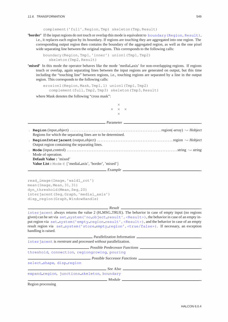
11.6. TRANSFORMATION 549
complement(’full’,Region,Tmp) skeleton(Tmp,Result)
’border’ If the input regions do not touch or overlap this mode is equivalent toboundary(Region,Result) ,i.e., it replaces each region by its boundary. If regions are touching they are aggregated into one region. Thecorresponding output region then contains the boundary of the aggregated region, as well as the one pixelwide separating line between the original regions. This corresponds to the following calls:
boundary(Region,Tmp1,’inner’) union1(Tmp1,Tmp2)skeleton(Tmp2,Result)
’mixed’ In this mode the operator behaves like the mode ’medialaxis’ for non-overlapping regions. If regionstouch or overlap, again separating lines between the input regions are generated on output, but this timeincluding the “touching line” between regions, i.e., touching regions are separated by a line in the outputregion. This corresponds to the following calls:
erosion1(Region,Mask,Tmp1,1) union1(Tmp1,Tmp2)complement(full,Tmp2,Tmp3) skeleton(Tmp3,Result)
where Mask denotes the following “cross mask”:
×× × ×
×
Parameter
. Region (input object) . . . . . . . . . . . . . . . . . . . . . . . . . . . . . . . . . . . . . . . . . . . . . . . . . . . . . . region(-array); HobjectRegions for which the separating lines are to be determined.
. RegionInterjacent (outputobject) . . . . . . . . . . . . . . . . . . . . . . . . . . . . . . . . . . . . . . . . . . . . . region; HobjectOutput region containing the separating lines.
. Mode (input control) . . . . . . . . . . . . . . . . . . . . . . . . . . . . . . . . . . . . . . . . . . . . . . . . . . . . . . . . . . . . . . . . . .string; stringMode of operation.Default Value : ’mixed’Value List : Mode∈ {’medial axis’, ’border’, ’mixed’}
Example
read_image(Image,’wald1_rot’)mean(Image,Mean,31,31)dyn_threshold(Mean,Seg,20)interjacent(Seg,Graph,’medial_axis’)disp_region(Graph,WindowHandle)
Resultinterjacent always returns the value 2 (HMSG TRUE). The behavior in case of empty input (no regionsgiven) can be set viaset system(’no object result’,<Result>) , the behavior in case of an empty in-put region viaset system(’empty region result’,<Result>) , and the behavior in case of an emptyresult region via set system(’store empty region’,<true/false>) . If necessary, an exceptionhandling is raised.
Parallelization Informationinterjacent is reentrantand processedwithoutparallelization.
Possible Predecessor Functionsthreshold , connection , regiongrowing , pouring
Possible Successor Functionsselect shape , disp region
See Alsoexpand region , junctions skeleton , boundary
ModuleRegion processing
HALCON 6.0.4

550 CHAPTER 11. REGIONS
junctions skeleton ( Region : EndPoints, JuncPoints : : )
Find junctions and end points in a skeleton.
junctions skeleton detects junctions and end points in a skeleton (seeskeleton ). The junctions in theinput regionRegion are output as a region inJuncPoints , while the end points are output as a region inEndPoints .
Parameter
. Region (input object) . . . . . . . . . . . . . . . . . . . . . . . . . . . . . . . . . . . . . . . . . . . . . . . . . . . . . . region(-array); HobjectInput skeletons.
. EndPoints (outputobject) . . . . . . . . . . . . . . . . . . . . . . . . . . . . . . . . . . . . . . . . . . . . . . . . . region(-array); HobjectExtracted end points.Parameter Number : EndPoints = Region
. JuncPoints (outputobject) . . . . . . . . . . . . . . . . . . . . . . . . . . . . . . . . . . . . . . . . . . . . . . . . region(-array); HobjectExtracted junctions.Parameter Number : JuncPoints = Region
Example
/* non-connected branches of a skeleton */skeleton(Region,Skeleton)junctions_skeleton(Skeleton,EPoints,JPoints)difference(S,JPoints,Rows)set_system(’heighbourhood’,4)connection(Rows,Parts).
ComplexityLetF be the area of the input region. Then the runtime complexity isO(F ).
Resultjunctions skeleton always returns the value 2 (HMSG TRUE). The behavior in case of empty input (noregions given) can be set viaset system(’no object result’,<Result>) , the behavior in case ofan empty input region viaset system(’empty region result’,<Result>) , and the behavior in caseof an empty result region viaset system(’store empty region’,<true/false>) . If necessary, anexception handling is raised.
Parallelization Informationjunctions skeleton is reentrantand automaticallyparallelized(on tuple level).
Possible Predecessor Functionsskeleton
Possible Successor Functionsarea center , connection , get region points , difference
See Alsopruning , split skeleton region
ModuleRegion processing
merge regions line scan ( CurrRegions,PrevRegions : CurrMergedRegions, PrevMergedRegions : ImageHeight,MergeBorder, MaxImagesRegion : )
Merge regions from line scan images.
The operatormerge regions line scan connects adjacent regions, which were segmentated from adjacentimages with the heightImageHeight . This operator was especially designed to process regions that were ex-tracted from images grabbed by a line scan camera.CurrRegions contains the regions from the current imageandPrevRegions the regions from the previous one.
HALCON/HDevelop Reference Manual, 2003-7-21
11.6. TRANSFORMATION 551
With the help of the parameterMergeBorder two cases can be distinguished: If the top (first) line of the currentimage touches the bottom (last) line of the previous image,MergeBorder must be set to’top’ , otherwise setMergeBorder to ’bottom’ .
If the operator merge regions line scan is used recursivly, the parameterMaxImagesRegion deter-mines the maximum number of images which are covered by a merged region. All older region parts are removed.
The operator merge regions line scan returns two region arrays.PrevMergedRegions containsall those regions from the previous input regionsPrevRegions , which could not be merged with a currentregion. CurrMergedRegions collects all current regions together with the merged parts from the previ-ous images. Merged regions will exceed the original image, because the previous regions are moved upward(MergeBorder =’top’ ) or downward (MergeBorder =’bottom’ ) according to the image height. For this thesystem parameter’clip region’ (see alsoset system ) will internaly be set to’false’.
Parameter
. CurrRegions (input object) . . . . . . . . . . . . . . . . . . . . . . . . . . . . . . . . . . . . . . . . . . . . . . . region(-array); HobjectCurrent input regions.
. PrevRegions (input object) . . . . . . . . . . . . . . . . . . . . . . . . . . . . . . . . . . . . . . . . . . . . . . . region(-array); HobjectMerged regions from the previous iteration.
. CurrMergedRegions (outputobject) . . . . . . . . . . . . . . . . . . . . . . . . . . . . . . . . . . . . . . region(-array); HobjectCurrent regions, merged with old ones where applicable.
. PrevMergedRegions (outputobject) . . . . . . . . . . . . . . . . . . . . . . . . . . . . . . . . . . . . . . region(-array); HobjectRegions from the previous iteration which could not be merged with the current ones.
. ImageHeight (input control) . . . . . . . . . . . . . . . . . . . . . . . . . . . . . . . . . . . . . . . . . . . . . . . . . . . . . . integer; integerHeight of the line scan images.Default Value : 512Value List : ImageHeight ∈ {240, 480, 512}
. MergeBorder (input control) . . . . . . . . . . . . . . . . . . . . . . . . . . . . . . . . . . . . . . . . . . . . . . . . . . . . . . . . string; stringImage line of the current image, which touches the previous image.Default Value : ”top”Value List : MergeBorder ∈ {”top”, ”bottom”}
. MaxImagesRegion (input control) . . . . . . . . . . . . . . . . . . . . . . . . . . . . . . . . . . . . . . . . . . . . . . . . integer; integerMaximum number of images for a single region.Default Value : 3Value Suggestions :MaxImagesRegion ∈ {1, 2, 3, 4, 5}
ResultThe operatormerge regions line scan returns the value 2 (HMSG TRUE) if the given parameters arecorrect. Otherwise, an exception will be raised.
Parallelization Informationmerge regions line scan is reentrantand processedwithoutparallelization.
ModuleRegion processing
partition dynamic ( Region : Partitioned : Distance, Percent : )
Partition a region horizontally into rectangles.
partition dynamic partitions the input region into rectangles having an average width ofDistance . Theregion is not split exactly inton parts, but rather starting from the calculated splitting point positions having aminimum number of set pixels in the vertical directions are extracted. The search area is at most plus/minus thewidth of a rectangle. IfPercent is passed as 100, this search area is used fully. If it is passed as 0, no search isdone.
If the region is smaller than the given size its output remains unchanged. A partition is only done if the size of theregion is at least 1.5 times the size of the rectangle given by the parameters.
HALCON 6.0.4

552 CHAPTER 11. REGIONS
Parameter
. Region (input object) . . . . . . . . . . . . . . . . . . . . . . . . . . . . . . . . . . . . . . . . . . . . . . . . . . . . . . region(-array); HobjectRegion to be partitioned.
. Partitioned (outputobject) . . . . . . . . . . . . . . . . . . . . . . . . . . . . . . . . . . . . . . . . . . . . . . . . region-array; HobjectPartitioned region.
. Distance (input control) . . . . . . . . . . . . . . . . . . . . . . . . . . . . . . . . . . . . . . . . . . . . . . . . . . . . . . . . . . . . . . . . real; realWidth of the individual rectangles.
. Percent (input control) . . . . . . . . . . . . . . . . . . . . . . . . . . . . . . . . . . . . . . . . . . . . . . . . . . . . . . . . . . . . . . . . . real; realMaximum shift of the partition point.Default Value : 20Value Suggestions :Percent ∈ {0, 10, 20, 30, 40, 50, 70, 90, 100}Typical Range of Values :0≤ Percent ≤ 100
Resultpartition dynamic returns 2 (HMSG TRUE) if all parameters are correct. The behavior in case of emptyinput (no regions given) can be set viaset system(’no object result’,<Result>) , the behavior incase of an empty input region viaset system(’empty region result’,<Result>) , and the behaviorin case of an empty result region viaset system(’store empty region’,<true/false>) . If neces-sary, an exception handling is raised.
Parallelization Informationpartition dynamic is reentrantand automaticallyparallelized(on tuple level).
Possible Predecessor Functionsthreshold , connection
Alternativespartition rectangle
See Alsointersection , smallest rectangle1 , shape trans , clip region
ModuleRegion processing
partition rectangle ( Region : Partitioned : Width, Height : )
Partition a region into rectangles of equal size.
partition rectangle partitions the input region into rectangles having an extent ofWidth timesHeight .The region is always split into rectangles of equal size. Therefore,Width andHeight are adapted to the actualsize of the region. If the region is smaller than the given size its output remains unchanged. A partition is onlydone if the size of the region is at least 1.5 times the size of the rectangle given by the paramters.
Parameter
. Region (input object) . . . . . . . . . . . . . . . . . . . . . . . . . . . . . . . . . . . . . . . . . . . . . . . . . . . . . . region(-array); HobjectRegion to be partitioned.
. Partitioned (outputobject) . . . . . . . . . . . . . . . . . . . . . . . . . . . . . . . . . . . . . . . . . . . . . . region(-array); HobjectPartitioned region.
. Width (input control) . . . . . . . . . . . . . . . . . . . . . . . . . . . . . . . . . . . . . . . . . . . . . . . . . . . . . . . . . . . . . . . . . . . . real; realWidth of the individual rectangles.
. Height (input control) . . . . . . . . . . . . . . . . . . . . . . . . . . . . . . . . . . . . . . . . . . . . . . . . . . . . . . . . . . . . . . . . . . real; realHeight of the individual rectangles.
Resultpartition rectangle returns 2 (HMSG TRUE) if all parameters are correct. The behavior in case of emptyinput (no regions given) can be set viaset system(’no object result’,<Result>) , the behavior incase of an empty input region viaset system(’empty region result’,<Result>) , and the behaviorin case of an empty result region viaset system(’store empty region’,<true/false>) . If neces-sary, an exception handling is raised.
HALCON/HDevelop Reference Manual, 2003-7-21
11.6. TRANSFORMATION 553
Parallelization Informationpartition rectangle is reentrantand automaticallyparallelized(on tuple level).
Possible Predecessor Functionsthreshold , connection
Alternativespartition dynamic
See Alsointersection , smallest rectangle1 , shape trans , clip region
ModuleRegion processing
rank region ( Region : RegionCount : Width, Height, Number : )
Rank operator for regions.
rank region calculates the binary rank operator. A filter mask of sizeHeight x Width ) is used. In theprocess, for each point in the region the number of points ofRegion lying within the filter mask are counted. Ifthis number is greater or equal toNumber, the current point is added to the output region. If
Number =Height ∗ Width
2,
is chosen, the median operator is obtained.
AttentionFor Height andWidth only odd values> 3 are valid. If invalid parameters are chosen they are convertedautomatically (without raising an exception handling) to the next larger even values.
Parameter
. Region (input object) . . . . . . . . . . . . . . . . . . . . . . . . . . . . . . . . . . . . . . . . . . . . . . . . . . . . . . region(-array); HobjectRegion(s) to be transformed.
. RegionCount (outputobject) . . . . . . . . . . . . . . . . . . . . . . . . . . . . . . . . . . . . . . . . . . . . . . region(-array); HobjectResulting region(s).
. Width (input control) . . . . . . . . . . . . . . . . . . . . . . . . . . . . . . . . . . . . . . . . . . . . . . . . . . . . . . . . . . . . . extent.x; integerWidth of the filter mask.Default Value : 15Value Suggestions :Width ∈ {3, 5, 7, 9, 11, 13, 15, 17, 19, 21}Typical Range of Values :3≤ Width ≤ 511 (lin)Minimal Value Step : 2Recommended Value Step :2Restriction : (Width ≥ 3) ∧ odd(Width )
. Height (input control) . . . . . . . . . . . . . . . . . . . . . . . . . . . . . . . . . . . . . . . . . . . . . . . . . . . . . . . . . . . .extent.y; integerHeight of the filter mask.Default Value : 15Value Suggestions :Height ∈ {3, 5, 7, 9, 11, 13, 15, 17, 19, 21}Typical Range of Values :3≤ Height ≤ 511 (lin)Minimal Value Step : 2Recommended Value Step :2Restriction : (Height ≥ 3) ∧ odd(Height )
. Number (input control) . . . . . . . . . . . . . . . . . . . . . . . . . . . . . . . . . . . . . . . . . . . . . . . . . . . . . . . . . . . . . integer; integerMinimum number of points lying within the filter mask.Default Value : 70Value Suggestions :Number ∈ {5, 10, 20, 40, 60, 80, 90, 120, 150, 200}Typical Range of Values :1≤ Number ≤ 1000 (lin)Minimal Value Step : 1Recommended Value Step :10Restriction : Number > 0
HALCON 6.0.4
554 CHAPTER 11. REGIONS
Example
read_image(Image,’affe’)mean_image(Image,Mean,5,5)dyn_threshold(Mean,Points,25)rank_region(Points,Textur,15,15,30)gen_circle(Mask,10,10,3)opening1(Textur,Mask,Seg).
ComplexityLetF be the area of the input region. Then the runtime complexity isO(F ∗ 8).
Resultrank region returns 2 (HMSG TRUE) if all parameters are correct. The behavior in case of empty input(no regions given) can be set viaset system(’no object result’,<Result>) and the behavior incase of an empty input region viaset system(’empty region result’,<Result>) . If necessary, anexception handling is raised.
Parallelization Informationrank region is reentrantand automaticallyparallelized(on tuple level).
Possible Predecessor Functionsthreshold , connection , regiongrowing , pouring , class ndim norm
Possible Successor Functionsselect shape , disp region
Alternativesclosing rectangle1 , expand region
See Alsorank image , mean image
ModuleRegion processing
remove noise region ( InputRegion : OutputRegion : Type : )
Remove noise from a region.
remove noise region removes noise from a region. In mode ’n4’, a structuring element consisting of thefour neighbors of a point is generated. A dilation with this structuring element is performed, and the intersectionof the result and the input region is calculated. Thus all pixels having no 4-connected neighbor are removed.
Parameter
. InputRegion (input object) . . . . . . . . . . . . . . . . . . . . . . . . . . . . . . . . . . . . . . . . . . . . . . . region(-array); HobjectRegions to be modified.
. OutputRegion (outputobject) . . . . . . . . . . . . . . . . . . . . . . . . . . . . . . . . . . . . . . . . . . . . . region(-array); HobjectLess noisy regions.
. Type (input control) . . . . . . . . . . . . . . . . . . . . . . . . . . . . . . . . . . . . . . . . . . . . . . . . . . . . . . . . . . . . . . . . . .string; stringMode of noise removal.Default Value : ’n 4’Value List : Type ∈ {’n 4’, ’n 8’, ’n 48’}
ComplexityLetF be the area of the input region. Then the runtime complexity isO(
√F ∗ 4).
Resultremove noise region returns 2 (HMSG TRUE) if all parameters are correct. The behavior in case of emptyinput (no regions given) can be set viaset system(’no object result’,<Result>) . If necessary, anexception handling is raised.
Parallelization Informationremove noise region is reentrantand automaticallyparallelized(on tuple level).
HALCON/HDevelop Reference Manual, 2003-7-21
11.6. TRANSFORMATION 555
Possible Predecessor Functionsconnection , regiongrowing , pouring , class ndim norm
Possible Successor Functionsselect shape
See Alsodilation1 , intersection , gen region points
ModuleRegion processing
shape trans ( Region : RegionTrans : Type : )
Transform the shape of a region.
shape trans transforms the shape of the input regions depending on the parameterType :
’convex’ Convex hull.
’ellipse’ Ellipse with the same moments and area as the input region.
’outer circle’ Smallest enclosing circle.
’inner circle’ Largest circle fitting into the region.
’rectangle1’ Smallest enclosing rectangle parallel to the coordinate axes.
’rectangle2’ Smallest enclosing rectangle.
’inner center’ The point on the skeleton of the input region having the smallest distance to the center of gravityof the input region.
Parameter
. Region (input object) . . . . . . . . . . . . . . . . . . . . . . . . . . . . . . . . . . . . . . . . . . . . . . . . . . . . . . region(-array); HobjectRegions to be transformed.
. RegionTrans (outputobject) . . . . . . . . . . . . . . . . . . . . . . . . . . . . . . . . . . . . . . . . . . . . . . region(-array); HobjectTransformed regions.
. Type (input control) . . . . . . . . . . . . . . . . . . . . . . . . . . . . . . . . . . . . . . . . . . . . . . . . . . . . . . . . . . . . . . . . . .string; stringType of transformation.Default Value : ’convex’Value List : Type ∈ {’convex’, ’ellipse’, ’outercircle’, ’inner circle’, ’rectangle1’, ’rectangle2’,’inner center’}
ComplexityLetF be the area of the input region. Then the runtime complexity isO(F ).
Resultshape trans returns 2 (HMSG TRUE) if all parameters are correct. The behavior in case of empty input (noregions given) can be set viaset system(’no object result’,<Result>) . If necessary, an exceptionhandling is raised.
Parallelization Informationshape trans is reentrantand automaticallyparallelized(on tuple level).
Possible Predecessor Functionsconnection , regiongrowing
Possible Successor Functionsdisp region , regiongrowing mean, area center
See Alsoconvexity , elliptic axis , area center , smallest rectangle1 , smallest rectangle2 ,set shape , select shape , inner circle
ModuleRegion processing
HALCON 6.0.4
556 CHAPTER 11. REGIONS
skeleton ( Region : Skeleton : : )
Compute the skeleton of a region.
skeleton computes the skeleton of the input regions.
Parameter
. Region (input object) . . . . . . . . . . . . . . . . . . . . . . . . . . . . . . . . . . . . . . . . . . . . . . . . . . . . . . region(-array); HobjectRegion to be thinned.
. Skeleton (outputobject) . . . . . . . . . . . . . . . . . . . . . . . . . . . . . . . . . . . . . . . . . . . . . . . . . . region(-array); HobjectResulting skeleton.Parameter Number : Skeleton = Region
ComplexityLetF be the area of the enclosing rectangle of the input region. Then the runtime complexity isO(F ) (per region).
Resultskeleton returns 2 (HMSG TRUE) if all parameters are correct. The behavior in case of empty input (no re-gions given) can be set viaset system(’no object result’,<Result>) and the behavior in case of anempty input region viaset system(’empty region result’,<Result>) . If necessary, an exceptionhandling is raised.
Parallelization Informationskeleton is reentrantand automaticallyparallelized(on tuple level).
Possible Predecessor Functionssobel amp, edges image , bandpass image , threshold , hysteresis threshold
Possible Successor Functionsjunctions skeleton , pruning
Alternativesmorph skeleton , thinning
See Alsogray skeleton , sobel amp, edges image , roberts , bandpass image , threshold
BibliographyEckardt, U. “Verd”unnung mit Perfekten Punkten”, Proceedings 10. DAGM-Symposium, IFB 180, Zurich, 1988
ModuleRegion processing
sort region ( Regions : SortedRegions : SortMode, Order, RowOrCol : )
Sorting of regions with respect to their relative position.
The operatorsort region sorts the regions with respect to their relative position. All sorting methods with theexception of’character’ use one point of the region. With the help of the parameterRowOrCol = ’row’ thesepoints will be sorted according to their row and then according to their column. By using’column’ , the columnvalue will be used first. The following values are available for the parameterSortMode :
’character’ The regions will be treated like characters in a row and will be sorted according to their order in theline: If two regions overlap horizontally, they will be sorted with respect to their column values, otherwisethey will be sorted with regard to their row values.
’first point’ The point with the lowest column value in the first row of the region.
’last point’ The point with the highest column value in the last row of the region.
’upper left’ Upper left corner of the surrounding rectangle.
’upper right’ Upper right corner of the surrounding rectangle.
’lower left’ Lower left corner of the surrounding rectangle.
’lower right’ Lower right corner of the surrounding rectangle.
HALCON/HDevelop Reference Manual, 2003-7-21

11.6. TRANSFORMATION 557
The parameterOrder determines whether the sorting order is increasing or decreasing: using’true’ the order willbe increasing, using’false’ the order will be decreasing.
Parameter
. Regions (input object) . . . . . . . . . . . . . . . . . . . . . . . . . . . . . . . . . . . . . . . . . . . . . . . . . . . . . . region-array; HobjectRegions to be sorted.
. SortedRegions (outputobject) . . . . . . . . . . . . . . . . . . . . . . . . . . . . . . . . . . . . . . . . . . . . . region-array; HobjectSorted regions.
. SortMode (input control) . . . . . . . . . . . . . . . . . . . . . . . . . . . . . . . . . . . . . . . . . . . . . . . . . . . . . . . . . . . . string; stringKind of sorting.Default Value : ’first point’Value List : SortMode ∈ {’character’, ’firstpoint’, ’last point’, ’upper left’, ’lower left’, ’upper right’,’lower right’}
. Order (input control) . . . . . . . . . . . . . . . . . . . . . . . . . . . . . . . . . . . . . . . . . . . . . . . . . . . . . . . . . . . . . . . . string; stringIncreasing or decreasing sorting order.Default Value : ’true’Value List : Order ∈ {’true’, ’false’}
. RowOrCol (input control) . . . . . . . . . . . . . . . . . . . . . . . . . . . . . . . . . . . . . . . . . . . . . . . . . . . . . . . . . . . . string; stringSorting first with respect to row, then to column.Default Value : ’row’Value List : RowOrCol ∈ {’row’, ’column’}
ResultIf the parameters are correct, the operatorsort region returns the value 2 (HMSG TRUE). Otherwise anexception will be raised.
Parallelization Informationsort region is reentrantand processedwithoutparallelization.
Possible Successor Functionsdo ocr multi , do ocr single
ModuleRegion processing
split skeleton lines ( SkeletonRegion : : MaxDistance : BeginRow,BeginCol, EndRow, EndCol )
Split lines represented by one pixel wide, non-branching lines.
split skeleton lines splits lines represented by one pixel wide, non-branching regions into shorter linesbased on their curvature. A line is split if the maximum distance of a point on the line to the line segmentconnecting its end points is larger thanMaxDistance (split & merge algorithm). The start and end points ofthe approximating line segments are returned inBeginRow , BeginCol , EndRow, andEndCol .
AttentionThe input regions must represent non-branching lines, that is single branches of the skeleton.
Parameter
. SkeletonRegion (input object) . . . . . . . . . . . . . . . . . . . . . . . . . . . . . . . . . . . . . . . . . . . . . region-array; HobjectInput lines (represented by 1 pixel wide, non-branching regions).
. MaxDistance (input control) . . . . . . . . . . . . . . . . . . . . . . . . . . . . . . . . . . . . . . . . . . . . . . . . . . . . . . integer; integerMaximum distance of the line points to the line segment connecting both end points.Default Value : 3Value Suggestions :MaxDistance ∈ {1, 2, 3, 4, 5, 6, 7, 8, 9, 10}Typical Range of Values :1≤ MaxDistance ≤ 500 (lin)Minimal Value Step : 1Recommended Value Step :1
. BeginRow (outputcontrol) . . . . . . . . . . . . . . . . . . . . . . . . . . . . . . . . . . . . . . . . . . . . . . . line.begin.y-array; integerRow coordinates of the start points of the output lines.
HALCON 6.0.4

558 CHAPTER 11. REGIONS
. BeginCol (outputcontrol) . . . . . . . . . . . . . . . . . . . . . . . . . . . . . . . . . . . . . . . . . . . . . . . line.begin.x-array; integerColumn coordinates of the start points of the output lines.
. EndRow(outputcontrol) . . . . . . . . . . . . . . . . . . . . . . . . . . . . . . . . . . . . . . . . . . . . . . . . . . . line.end.y-array; integerRow coordinates of the end points of the output lines.
. EndCol (outputcontrol) . . . . . . . . . . . . . . . . . . . . . . . . . . . . . . . . . . . . . . . . . . . . . . . . . . . line.end.x-array; integerColumn coordinates of the end points of the output lines.
Example
read_image(Image,’fabrik’)edges_image (Image, ImaAmp, ImaDir, ’lanser2’, 0.5, ’nms’, 8, 16)threshold (ImaAmp, RawEdges, 8, 255)skeleton (RawEdges, Skeleton)junctions_skeleton (Skeleton, EndPoints, JuncPoints)difference (Skeleton, JuncPoints, SkelWithoutJunc)connection (SkelWithoutJunc, SingleBranches)select_shape (SingleBranches, SelectedBranches, ’area’, ’and’, 16, 99999)split_skeleton_lines (SelectedBranches, 3, BeginRow, BeginCol, EndRow,
EndCol).
Resultsplit skeleton lines always returns the value 2 (HMSG TRUE). The behavior in case of empty input(no regions given) can be set viaset system(’no object result’,<Result>) , the behavior in case ofan empty input region viaset system(’empty region result’,<Result>) , and the behavior in caseof an empty result region viaset system(’store empty region’,<true/false>) . If necessary, anexception handling is raised.
Parallelization Informationsplit skeleton lines is reentrantand automaticallyparallelized(on tuple level).
Possible Predecessor Functionsconnection , select shape , skeleton , junctions skeleton , difference
Possible Successor Functionsselect lines , partition lines , disp line
See Alsosplit skeleton region , detect edge segments
ModuleRegion processing
split skeleton region (SkeletonRegion : RegionLines : MaxDistance : )
Split lines represented by one pixel wide, non-branching regions.
split skeleton region splits lines represented by one pixel wide, non-branching regions into shorter linesbased on their curvature. A line is split if the maximum distance of a point on the line to the line segment connectingits end points is larger thanMaxDistance (split & merge algorithm). However, not the approximating lines arereturned, but rather the original lines split into several output regions.
AttentionThe input regions must represent non-branching lines, that is single branches of the skeleton.
Parameter
. SkeletonRegion (input object) . . . . . . . . . . . . . . . . . . . . . . . . . . . . . . . . . . . . . . . . . . . region(-array); HobjectInput lines (represented by 1 pixel wide, non-branching regions).
. RegionLines (outputobject) . . . . . . . . . . . . . . . . . . . . . . . . . . . . . . . . . . . . . . . . . . . . . . . . region-array; HobjectSplit lines.
HALCON/HDevelop Reference Manual, 2003-7-21

11.6. TRANSFORMATION 559
. MaxDistance (input control) . . . . . . . . . . . . . . . . . . . . . . . . . . . . . . . . . . . . . . . . . . . . . . . . . . . . . . integer; integerMaximum distance of the line points to the line segment connecting both end points.Default Value : 3Value Suggestions :MaxDistance ∈ {1, 2, 3, 4, 5, 6, 7, 8, 9, 10}Typical Range of Values :1≤ MaxDistance ≤ 500 (lin)Minimal Value Step : 1Recommended Value Step :1
Example
read_image(Image,’fabrik’)edges_image (Image, ImaAmp, ImaDir, ’lanser2’, 0.5, ’nms’, 8, 16)threshold (ImaAmp, RawEdges, 8, 255)skeleton (RawEdges, Skeleton)junctions_skeleton (Skeleton, EndPoints, JuncPoints)difference (Skeleton, JuncPoints, SkelWithoutJunc)connection (SkelWithoutJunc, SingleBranches)select_shape (SingleBranches, SelectedBranches, ’area’, ’and’, 16, 99999)split_skeleton_region (SelectedBranches, Lines, 3)
Resultsplit skeleton region always returns the value 2 (HMSG TRUE). The behavior in case of empty input(no regions given) can be set viaset system(’no object result’,<Result>) , the behavior in case ofan empty input region viaset system(’empty region result’,<Result>) , and the behavior in caseof an empty result region viaset system(’store empty region’,<true/false>) . If necessary, anexception handling is raised.
Parallelization Informationsplit skeleton region is reentrantand automaticallyparallelized(on tuple level).
Possible Predecessor Functionsconnection , select shape , skeleton , junctions skeleton , difference
Possible Successor Functionscount obj , select shape , select obj , area center , elliptic axis ,smallest rectangle2 , get region polygon , get region contour
See Alsosplit skeleton lines , get region polygon , gen polygons xld
ModuleRegion processing
HALCON 6.0.4

560 CHAPTER 11. REGIONS
HALCON/HDevelop Reference Manual, 2003-7-21

Chapter 12
Segmentation
auto threshold ( Image : Regions : Sigma : )
Segment an image using thresholds determined from its histogram.
auto threshold segments a single-channel image using multiple thresholding. First the relative histogram ofthe gray values is determined. Then relevant minima are extracted from the histogram, which are used successivelyas parameters for a thresholding operation. The thresholds used are 0, 255, and all minima extracted from thehistogram (after the histogram has been smoothed). For each gray value intervaloneregion is generated. Thus,the number of regions is the number of minima + 1. The larger the value ofSigma is chosen, the less regionswill be extracted. This operator is particularly suited if the regions to be extracted exhibit similar gray values(homogeneous regions).
Parameter
. Image (input object) . . . . . . . . . . . . . . . . . . . . . . . . . . . . . . . . . . . . . . . . . . . . . . . . . . image(-array); Hobject: byteImage to be segmented.
. Regions (outputobject) . . . . . . . . . . . . . . . . . . . . . . . . . . . . . . . . . . . . . . . . . . . . . . . . . . . . . region-array; HobjectRegions with gray values within the automatically determined intervals.
. Sigma (input control) . . . . . . . . . . . . . . . . . . . . . . . . . . . . . . . . . . . . . . . . . . . . . . . . . . . . . . . . number; real/ integerSigma for the Gaussian smoothing of the histogram.Default Value : 2.0Value Suggestions :Sigma ∈ {0.0, 0.5, 1.0, 2.0, 3.0, 4.0, 5.0}Typical Range of Values :0.0≤ Sigma ≤ 100.0 (lin)Minimal Value Step : 0.01Recommended Value Step :0.3Restriction : Sigma ≥ 0.0
Example
#include "HalconCpp.h"#include <iostream.h>
int main (int argc, char *argv[]){
if (argc != 2){
cout << "Usage : " << argv[0] << " ’image’ " << endl;return (-1);
}
HImage image (argv[1]),med;
HWindow w;
561

562 CHAPTER 12. SEGMENTATION
w.SetDraw ("margin");w.SetColored (12);
image.Display (w);
med = image.MedianImage ("circle", 3, -3);med.Display (w);
HRegionArray reg = med.AutoThreshold2 (2.0);HRegionArray con = reg.Connection ();
cout << "Display image after AutoThreshold2 segmentation " << endl;con.Display (w);w.Click ();
return (0);}
Parallelization Informationauto threshold is reentrantand automaticallyparallelized(on tuple level).
Possible Predecessor Functionsanisotrope diff , median image , illuminate
Possible Successor Functionsconnection , select shape , select gray
Alternativesgray histo , smooth funct 1d gauss , threshold
ModuleRegion processing
bin threshold ( Image : Region : : )
Segment a black-and-white image using an automatically determined threshold.
bin threshold segments a single-channel gray value image using an automatically determined threshold. Firstthe relative histogram of the gray values is determined. Then relevant minima are extracted from the histogram,which are used as parameters for a thresholding operation. In order to reduce the number of minima, the histogramis smoothed with a Gaussian, as inauto threshold . The mask size is enlarged until there is only one minimumin the smoothed histogram. The selected region contains the pixels with gray values from 0 to the minimum. Thisoperator is particularly suited for the segmentation of dark characters on a light paper.
Parameter
. Image (input object) . . . . . . . . . . . . . . . . . . . . . . . . . . . . . . . . . . . . . . . . . . . . . . . . . . image(-array); Hobject: byteImage to be segmented.
. Region (outputobject) . . . . . . . . . . . . . . . . . . . . . . . . . . . . . . . . . . . . . . . . . . . . . . . . . . . . . region(-array); HobjectDark regions of the image.
Example
#include "HalconCpp.h"#include <iostream.h>
int main (int argc, char *argv[]){
if (argc != 2){
cout << "Usage : " << argv[0] << " ’image’ " << endl;return (-1);
HALCON/HDevelop Reference Manual, 2003-7-21

563
}
HImage image (argv[1]),med;
HWindow w;
w.SetDraw ("margin");w.SetShape ("rectangle1");w.SetColored (12);
image.Display (w);
HRegionArray reg = image.BinThreshold();HRegionArray con = reg.Connection ();
cout << "Display image after BinThreshold segmentation " << endl;con.Display (w);w.Click ();
return (0);}
Parallelization Informationbin threshold is reentrantand automaticallyparallelized(on tuple level).
Possible Predecessor Functionsanisotrope diff , median image , illuminate
Possible Successor Functionsconnection , select shape , select gray
Alternativesauto threshold , char threshold , gray histo , smooth funct 1d gauss , threshold
ModuleRegion processing
char threshold ( Image, HistoRegion : Characters : Sigma,Percent : Threshold )
Perform a threshold segmentation for extracting characters.
The main application ofchar threshold is to segment single-channel images of dark characters on brightpaper. The operator works as follows: First, a histogram of the gray values in the imageImage is computed forthe points in the regionHistoRegion . To eliminate noise, the histogram is smoothed with the givenSigma(Gaussian smoothing). In the histogram, the background (white paper) corresponds to a large peak at high grayvalues, while the characters form a small peak at low gray values. In contrast to the operatorbin threshold ,which locates the minimum between the two peaks, here the threshold for the segmentation is determined inrelation to the maximum of the histogram, i.e., the background, with the following condition:
histogram[threshold] ∗ 100.0 < histogram[maximum] ∗ (100.0 − Percent )
For example, if you choosePercent = 95 the operator locates the gray value whose frequency is at most 5percent of the maximum frequency. Becausechar threshold assumes that the characters are darker than thebackground, the threshold is searched for “to the left” of the maximum.
In comparison to bin threshold , this operator should be used if there is no clear minimum between thehistogram peaks corresponding to the characters and the background, respectively, or if there is no peak corre-sponding to the characters at all. This may happen, e.g., if the image contains only few characters or in the case ofa non-uniform illumination.
HALCON 6.0.4

564 CHAPTER 12. SEGMENTATION
Parameter
. Image (input object) . . . . . . . . . . . . . . . . . . . . . . . . . . . . . . . . . . . . . . . . . . . . . . . . . . image(-array); Hobject: byteImage to be segmented.
. HistoRegion (input object) . . . . . . . . . . . . . . . . . . . . . . . . . . . . . . . . . . . . . . . . . . . . . . . . . . . . . . region; HobjectRegion in which the histogram is computed.
. Characters (outputobject) . . . . . . . . . . . . . . . . . . . . . . . . . . . . . . . . . . . . . . . . . . . . . . . . region(-array); HobjectDark regions (characters).
. Sigma (input control) . . . . . . . . . . . . . . . . . . . . . . . . . . . . . . . . . . . . . . . . . . . . . . . . . . . . . . . . . . . . . . . . number; realSigma for the Gaussian smoothing of the histogram.Default Value : 2.0Value Suggestions :Sigma ∈ {0.0, 0.5, 1.0, 2.0, 3.0, 4.0, 5.0}Typical Range of Values :0.0≤ Sigma ≤ 50.0 (lin)Minimal Value Step : 0.01Recommended Value Step :0.2
. Percent (input control) . . . . . . . . . . . . . . . . . . . . . . . . . . . . . . . . . . . . . . . . . . . . . . . . . . . . . number; real/ integerPercentage for the gray value difference.Default Value : 95Value Suggestions :Percent ∈ {90, 92, 95, 96, 97, 98, 99, 99.5, 100}Typical Range of Values :0.0≤ Percent ≤ 100.0 (lin)Minimal Value Step : 0.1Recommended Value Step :0.5
. Threshold (outputcontrol) . . . . . . . . . . . . . . . . . . . . . . . . . . . . . . . . . . . . . . . . . . . . . . . . integer(-array); integerCalculated threshold.
Example
#include "HalconCpp.h"#include <iostream.h>
int main (int argc, char *argv[]){
if (argc != 2){
cout << "Usage : " << argv[0] << " ’image’ " << endl;return (-1);
}
HImage image (argv[1]),med;
HWindow w;
w.SetDraw ("margin");w.SetShape ("rectangle1");w.SetColored (12);
image.Display (w);
HRegionArray reg = image.CharThreshold(0,5,&Threshold);HRegionArray con = reg.Connection ();
cout << "Display image after CharThreshold segmentation " << endl;con.Display (w);w.Click ();
return (0);}
Parallelization Informationchar threshold is reentrantand automaticallyparallelized(on tuple level).
HALCON/HDevelop Reference Manual, 2003-7-21

565
Possible Predecessor Functionsanisotrope diff , median image , illuminate
Possible Successor Functionsconnection , select shape , select gray
Alternativesbin threshold , auto threshold , gray histo , smooth funct 1d gauss , threshold
ModuleRegion processing
check difference ( Image, Pattern : Selected : Mode, DiffLowerBound,DiffUpperBound, GrayOffset, AddRow, AddCol : )
Compare two images pixel by pixel.
check difference selects from the input imageImage those pixels (go = gImage ), whosegray value difference to the corresponding pixels inPattern is inside (outside) of the interval[DiffLowerBound ,DiffLowerBound ]. The pixels ofPattern are translated by(AddRow,AddCol ) withrespect toImage . Let gp be the gray value fromPattern translated by(AddRow,AddCol ) w.r.t. go.
If the selected modeMode is ’diff inside’, a pixelgo is selected if
g o− g p− GrayOffset > DiffLowerBound and
g o− g p− GrayOffset < DiffUpperBound .
If the mode is set to ’diffoutside’, a pixelgo is selected if
g o− g p− GrayOffset ≤ DiffLowerBound or
g o− g p− GrayOffset ≥ DiffUpperBound .
This test is performed for all points of the domain (region) ofImage , intersected with the domain of the translatedPattern . All points fulfilling the above condition are aggregated in the output region. The two images may beof different size. Typically,Pattern is smaller thanImage .
Parameter
. Image (input object) . . . . . . . . . . . . . . . . . . . . . . . . . . . . . . . . . . . . . . . . . . . . . . . . . . image(-array); Hobject: byteImage to be examined.
. Pattern (input object) . . . . . . . . . . . . . . . . . . . . . . . . . . . . . . . . . . . . . . . . . . . . . . . image(-array); Hobject: byteComparison image.
. Selected (outputobject) . . . . . . . . . . . . . . . . . . . . . . . . . . . . . . . . . . . . . . . . . . . . . . . . . . region(-array); HobjectPoints in which the two images are similar/different.
. Mode (input control) . . . . . . . . . . . . . . . . . . . . . . . . . . . . . . . . . . . . . . . . . . . . . . . . . . . . . . . . . . . . . . . . . .string; stringMode: return similar or different pixels.Default Value : ’diff outside’Value Suggestions :Mode∈ {’diff inside’, ’diff outside’}
. DiffLowerBound (input control) . . . . . . . . . . . . . . . . . . . . . . . . . . . . . . . . . . . . . . . . . . . . . . . . . number; integerLower bound of the tolerated gray value difference.Default Value : -5Value Suggestions :DiffLowerBound ∈ {0, -1, -2, -3, -5, -7, -10, -12, -15, -17, -20, -25, -30}Typical Range of Values :-255≤ DiffLowerBound ≤ 255 (lin)Minimal Value Step : 1Recommended Value Step :2Restriction : (-255 ≤ DiffLowerBound ) ∧ (DiffLowerBound ≤ 255 )
HALCON 6.0.4

566 CHAPTER 12. SEGMENTATION
. DiffUpperBound (input control) . . . . . . . . . . . . . . . . . . . . . . . . . . . . . . . . . . . . . . . . . . . . . . . . . number; integerUpper bound of the tolerated gray value difference.Default Value : 5Value Suggestions :DiffUpperBound ∈ {0, 1, 2, 3, 5, 7, 10, 12, 15, 17, 20, 25, 30}Typical Range of Values :-255≤ DiffUpperBound ≤ 255 (lin)Minimal Value Step : 1Recommended Value Step :2Restriction : (-255 ≤ DiffUpperBound ) ∧ (DiffUpperBound ≤ 255 )
. GrayOffset (input control) . . . . . . . . . . . . . . . . . . . . . . . . . . . . . . . . . . . . . . . . . . . . . . . . . . . . . . number; integerOffset gray value subtracted from Image.Default Value : 0Value Suggestions :GrayOffset ∈ {-30, -25, -20, -17, -15, -12, -10, -7, -5, -3, -2, -1, 0, 1, 2, 3, 5, 7, 10,12, 15, 17, 20, 25, 30}Typical Range of Values :-255≤ GrayOffset ≤ 255 (lin)Minimal Value Step : 1Recommended Value Step :2Restriction : (-255 ≤ GrayOffset ) ∧ (GrayOffset ≤ 255 )
. AddRow(input control) . . . . . . . . . . . . . . . . . . . . . . . . . . . . . . . . . . . . . . . . . . . . . . . . . . . . . . . . . . . . point.y; integerRow coordinate, by which Pattern is translated.Default Value : 0Value Suggestions :AddRow∈ {-200, -100, -20, -10, 0, 10, 20, 100, 200}Typical Range of Values :-32000≤ AddRow≤ 32000 (lin)Minimal Value Step : 1Recommended Value Step :1
. AddCol (input control) . . . . . . . . . . . . . . . . . . . . . . . . . . . . . . . . . . . . . . . . . . . . . . . . . . . . . . . . . . . . point.x; integerColumn coordinate, by which Pattern is translated.Default Value : 0Value Suggestions :AddCol ∈ {-200, -100, -20, -10, 0, 10, 20, 100, 200}Typical Range of Values :-32000≤ AddCol ≤ 32000 (lin)Minimal Value Step : 1Recommended Value Step :1
ComplexityLetF be the number of valid pixels. Then the runtime complexity isO(F ).
Resultcheck difference returns 2 (HMSG TRUE) if all parameters are correct. The behavior with respect tothe input images and output regions can be determined by setting the values of the flags’no object result’ ,’empty region result’ , and’store empty region’ with set system . If necessary, an exception is raised.
Parallelization Informationcheck difference is reentrantand automaticallyparallelized(on tuple level).
Possible Successor Functionsconnection , select shape , reduce domain , select gray , rank region , dilation1 ,opening
Alternativessub image , dyn threshold
ModuleRegion processing
class 2dim sup ( ImageCol, ImageRow,FeatureSpace : RegionClass2Dim : : )
Segment an image using two-dimensional pixel classification.
class 2dim sup classifies the points in two-channel images using a two-dimensional feature space. For eachpoint, two gray values (one from each image) are used as features. The feature space is represented by the inputregion. The classification is done as follows:
HALCON/HDevelop Reference Manual, 2003-7-21

567
A point from the input region of an image is accepted if the point(gc, gl), which is determined by the respectivegray values, is contained in the regionFeatureSpace . gl is here a gray value from the imageImageRow, whilegc is the corresponding gray value fromImageCol .
LetP be a point with the coordinatesP = (L,C), gl be the gray value at position(L,C) in the imageImageRow,andgc be the gray value at position(L,C) in the imageImageCol . Then the pointP is aggregated into the outputregion if
(gc, gl) ∈ FeatureSpace
gl is interpreted as row coordinate andgc as colum coordinate.
For the generation ofFeatureSpace , seehisto 2dim . The feature space can be modified by applying regiontransformation operators, such asrank region , dilation1 , shape trans , elliptic axis , etc.,before callingclass 2dim sup .
The parametersImageCol andImageRow must contain an equal number of images with the same respectivesize. The image points are taken from the intersection of the domains of both images (seereduce domain ).
Parameter
. ImageCol (input object) . . . . . . . . . . . . . . . . . . . . . . . image(-array); Hobject: byte / int1 / cyclic / directionInput image (first channel).
. ImageRow (input object) . . . . . . . . . . . . . . . . . . . . . . . . . . . . . . . . . . . . . . . . . . . . . . image(-array); Hobject: byteInput image (second channel).
. FeatureSpace (input object) . . . . . . . . . . . . . . . . . . . . . . . . . . . . . . . . . . . . . . . . . . . . . . region(-array); HobjectRegion defining the feature space.
. RegionClass2Dim (outputobject) . . . . . . . . . . . . . . . . . . . . . . . . . . . . . . . . . . . . . . . . . region(-array); HobjectClassified regions.
Example
#include "HalconCpp.h"#include <iostream.h>
int main (int argc, char *argv[]){
if (argc != 2){
cout << "Usage : " << argv[0] << " ’image’ " << endl;return (-1);
}
HRegion feats, cd2reg;HImage image (argv[1]),
text1, text2,mean1, mean2,histo;
HWindow win;long nc;
if ((nc = image.CountChannels ()) != 3){
cout << argv[1] << " is not a rgb-image " << endl;return (-2);
}
image.Display (win);
win.SetColor ("green");cout << "Draw the region of interrest " << endl;
HALCON 6.0.4

568 CHAPTER 12. SEGMENTATION
HRegion region = win.DrawRegion ();
text1 = image.TextureLaws ("el", 2, 5);mean1 = text1.MeanImage (21, 21);text2 = mean1.TextureLaws ("es", 2, 5);mean2 = text2.MeanImage (21, 21);
histo = region.Histo2dim (mean1, mean2);feats = histo.Threshold (1.0, 1000000.0);
win.SetDraw ("fill");win.SetColor ("red");
feats.Display (win);
cout << "Charakteristics area in red" << endl;
cd2reg = mean1.Class2dimSup (mean2, feats);
win.SetColor ("blue");cd2reg.Display (win);
cout << "Result of classification in blue " << endl;win.Click ();return (0);
}
ComplexityLetF be the area of the input region. Then the runtime complexity isO(2562 + F ).
Resultclass 2dim sup always returns 2 (HMSG TRUE). The behavior with respect to the input images and out-put regions can be determined by setting the values of the flags’no object result’ , ’empty region result’ , and’store empty region’ with set system . If necessary, an exception is raised.
Parallelization Informationclass 2dim sup is reentrantand automaticallyparallelized(on tuple level).
Possible Predecessor Functionshisto 2dim , threshold , draw region , dilation1 , opening , shape trans
Possible Successor Functionsconnection , select shape , select gray
Alternativesclass ndim norm , class ndim box , threshold , histo 2dim
ModuleRegion processing
class 2dim unsup ( Image1, Image2 : Classes : Threshold,NumClasses : )
Segment two images by clustering.
class 2dim unsup performs a classification with two single-channel images. First a two-dimensional his-togram of the two images is computed (histo 2dim ). In this histogram the first maximum is extracted; it servesas the first cluster center. The histogram is computed with the intersection of the domains of both images (seereduce domain ). After this, all pixels in the images, which are at mostThreshold pixels from the clustercenter in the maximum norm, are determined. These pixels form one output region. Next, the pixels thus classifiedare deleted from the histogram so that they are not taken into account for the next class. In this modified histogram
HALCON/HDevelop Reference Manual, 2003-7-21

569
again the maximum is extracted; it again serves as a cluster center. The above steps are repeatedNumClassestimes; thus,NumClasses output regions result. Only pixels defined in both images are returned.
AttentionBoth input images must have the same size.
Parameter
. Image1 (input object) . . . . . . . . . . . . . . . . . . . . . . . . . . . . . . . . . . . . . . . . . . . . . . . . . . . . . . . image; Hobject: byteFirst input image.
. Image2 (input object) . . . . . . . . . . . . . . . . . . . . . . . . . . . . . . . . . . . . . . . . . . . . . . . . . . . . . . . image; Hobject: byteSecond input image.
. Classes (outputobject) . . . . . . . . . . . . . . . . . . . . . . . . . . . . . . . . . . . . . . . . . . . . . . . . . . . . . region-array; HobjectSegmentation result.
. Threshold (input control) . . . . . . . . . . . . . . . . . . . . . . . . . . . . . . . . . . . . . . . . . . . . . . . . . . . . . . . . . integer; integerThreshold (maximum distance to the cluster’s center).Default Value : 15Value Suggestions :Threshold ∈ {0, 2, 5, 8, 12, 17, 20, 30, 50, 70}
. NumClasses (input control) . . . . . . . . . . . . . . . . . . . . . . . . . . . . . . . . . . . . . . . . . . . . . . . . . . . . . . . integer; integerNumber of classes (cluster centers).Default Value : 5Value Suggestions :NumClasses ∈ {1, 2, 3, 4, 5, 6, 7, 8, 9, 10, 12, 15, 20, 30, 40, 50}
Example
#include "HalconCpp.h"#include <iostream.h>
int main (int argc, char *argv[]){
if (argc != 2){
cout << "Usage : " << argv[0] << " ’image’ " << endl;return (-1);
}
HImage colimg (argv[1]),green, blue;
HWindow w;long nc;
if ((nc = colimg.CountChannels ()) != 3){
cout << argv[1] << " is not a rgb-image " << endl;return (-2);
}
colimg.Display (w);
HImage red = colimg.Decompose3 (&green, &blue);HRegionArray seg = red.Class2dimUnsup (green, 15, 5);
w.SetDraw ("margin");w.SetColored (12);seg.Display (w);w.Click ();
return (0);}
HALCON 6.0.4
570 CHAPTER 12. SEGMENTATION
Resultclass 2dim unsup returns 2 (HMSG TRUE) if all parameters are correct. The behavior with respect tothe input images and output regions can be determined by setting the values of the flags’no object result’ ,’empty region result’ , and’store empty region’ with set system . If necessary, an exception is raised.
Parallelization Informationclass 2dim unsup is reentrantand processedwithoutparallelization.
Possible Predecessor Functionsdecompose2 , decompose3 , median image , anisotrope diff , reduce domain
Possible Successor Functionsselect shape , select gray , connection
Alternativesthreshold , histo 2dim , class 2dim sup , class ndim norm , class ndim box
ModuleRegion processing
class ndim box ( MultiChannelImage : Regions : ClassifHandle : )
Classify pixels using hyper-cuboids.
class ndim box classifies the pixels of the multi-channel image given inMultiChannelImage . To do so,the classificatorClassifHandle created withcreate class box is used. The classificator can be trainedusing class ndim box or as described withcreate class box . More information on the structure of theclassificator can be found also under that operator.
MultiChannelImage is a multi channel image. Its pixel values are used for the classification.
Parameter
. MultiChannelImage (input object) . . . . . . multichannel-image(-array); Hobject : byte / int1 / int2 /int4 / real / direction / cyclic
Multi-channel input image.. Regions (outputobject) . . . . . . . . . . . . . . . . . . . . . . . . . . . . . . . . . . . . . . . . . . . . . . . . . . . . . region-array; Hobject
Segmentation result.. ClassifHandle (input control) . . . . . . . . . . . . . . . . . . . . . . . . . . . . . . . . . . . . . . . . . . . . . . . . . classbox ; integer
Classificator’s handle number.
Example
read_image(Bild,’meer’)disp_image(Image,WindowHandle)set_color(WindowHandle,’green’)fwrite_string(’Draw the learning region’)fnew_line()draw_region(Reg1,WindowHandle)reduce_domain(Image,Reg1,Foreground)set_color(WindowHandle,’red’)fwrite_string(’Draw Background’)fnew_line()draw_region(Reg2,WindowHandle)reduce_domain(Image,Reg2,Background)fwrite_string(’Start to learn’)fnew_line()create_classif(ClassifHandle)class_ndim_box(Foreground,Background,Image,ClassifHandle)fwrite_string(’start to classificate’)fnew_line()class_ndim_box(Image,Res,ClassifHandle)set_draw(WindowHandle,’fill’)
HALCON/HDevelop Reference Manual, 2003-7-21

571
disp_region(Res,WindowHandle)free_classif(ClassifHandle).
ComplexityLet N be the number of hyper-cuboids andF be the area of the input region. Then the runtime complexity isO(N ∗ F ).
Resultclass ndim box returns 2 (HMSG TRUE) if all parameters are correct. The behavior with respect tothe input images and output regions can be determined by setting the values of the flags’no object result’ ,’empty region result’ , and’store empty region’ with set system . If necessary, an exception is raised.
Parallelization Informationclass ndim box is local and processedcompletely exclusivelywithout parallelization.
Possible Predecessor Functionscreate class box , learn class box , median image , compose2 , compose3 , compose4
Alternativesclass ndim norm , class 2dim sup
See Alsoclass ndim box , descript class box , create class box
ModuleRegion processing
class ndim norm ( MultiChannelImage : Regions : Metric,SingleMultiple, Radius, Center : )
Classify pixels using hyper-spheres or hyper-cubes.
class ndim norm classifies the pixels of the multi-channel image given inMultiChannelImage . The resultis returned inRegions as one region per classification object. The metric used (’euclid’ or ’maximum’) isdetermined byMetric . This paramter must be set to the same value used inlearn ndim norm . The parameteris used to determine whether one region (’single’) or multiple regions (’multiple’) have to be generated for eachcluster.Radius determines the radii or half edge length of the clusters, respectively.Center determines theircenters.
Parameter
. MultiChannelImage (input object) . . . . . . multichannel-image(-array); Hobject : byte / int1 / int2 /int4 / real
Multi-channel input image.
. Regions (outputobject) . . . . . . . . . . . . . . . . . . . . . . . . . . . . . . . . . . . . . . . . . . . . . . . . . . . . . region-array; HobjectSegmentation result.
. Metric (input control) . . . . . . . . . . . . . . . . . . . . . . . . . . . . . . . . . . . . . . . . . . . . . . . . . . . . . . . . . . . . . . . string; stringMetric to be used.Default Value : ’euclid’Value List : Metric ∈ {’euclid’, ’maximum’}
. SingleMultiple (input control) . . . . . . . . . . . . . . . . . . . . . . . . . . . . . . . . . . . . . . . . . . . . . . . . . . . . string; stringReturn one region or one region for each cluster.Default Value : ’single’Value List : SingleMultiple ∈ {’single’, ’multiple’}
. Radius (input control) . . . . . . . . . . . . . . . . . . . . . . . . . . . . . . . . . . . . . . . . . . . . . . . . number(-array); real/ integerCluster radii or half edge lengths (returned bylearn ndim norm ).
. Center (input control) . . . . . . . . . . . . . . . . . . . . . . . . . . . . . . . . . . . . . . . . . . . . . . . . number(-array); real/ integerCoordinates of the cluster centers (returned bylearn ndim norm ).
Example
#include "HalconCpp.h"#include <iostream.h>
HALCON 6.0.4

572 CHAPTER 12. SEGMENTATION
int main (){
HImage image ("meer"),t1, t2, t3,m1, m2, m3, m;
HWindow w;
w.SetColor ("green");image.Display (w);
cout << "Draw your region of interest " << endl;
HRegion testreg = w.DrawRegion ();
t1 = image.TextureLaws ("el", 2, 5); m1 = t1.MeanImage (21, 21);t2 = image.TextureLaws ("es", 2, 5); m2 = t2.MeanImage (21, 21);t3 = image.TextureLaws ("le", 2, 5); m3 = t3.MeanImage (21, 21);
m = m1.Compose3 (m2, m3);
Tuple Metric = "euclid";Tuple Radius = 20.0;Tuple MinNum = 5;Tuple NbrCha = 3;
HRegion empty;Tuple cen, t;
Radius = testreg.LearnNdimNorm (empty, m, Metric, Radius,MinNum, NbrCha, &cen, &t);
Tuple RegMod = "multiple";
HRegionArray reg = m.ClassNdimNorm (Metric, RegMod, Radius, cen, NbrCha);
w.SetColored (12);reg.Display (w);cout << "Result of classification" << endl;return (0);
}
ComplexityLetN be the number of clusters andF be the area of the input region. Then the runtime complexity isO(N ∗ F ).
Resultclass ndim norm returns 2 (HMSG TRUE) if all parameters are correct. The behavior with respect tothe input images and output regions can be determined by setting the values of the flags’no object result’ ,’empty region result’ , and’store empty region’ with set system . If necessary, an exception is raised.
Parallelization Informationclass ndim norm is reentrantand automaticallyparallelized(on tuple level).
Possible Predecessor Functionslearn ndim norm , compose2 , compose3 , compose4
Possible Successor Functionsconnection , select shape , reduce domain , select gray
Alternativesclass ndim box , class 2dim sup
See Alsodisp circle , disp rectangle1
HALCON/HDevelop Reference Manual, 2003-7-21

573
ModuleRegion processing
detect edge segments ( Image : : SobelSize, MinAmplitude, MaxDistance,MinLength : BeginRow, BeginCol, EndRow, EndCol )
Detect straight edge segments.
detect edge segments detects straight edge segments in the gray imageImage . The extracted edge seg-ments are returned as line segments with start point (BeginRow ,BeginCol ) and end point (EndRow,EndCol ).Edge detection is based on the Sobel filter, using ’sumabs’ as parameter andSobelSize as the filter mask size(see sobel amp). Only pixels with a filter response larger thanMinAmplitude are used as candidates foredge points. These thresholded edge points are thinned and split into straight segments. Due to technical reasons,edge points in which several edges meet are lost. Therefore,detect edge segments usually does not returnclosed object contours. The parameterMaxDistance controls the maximum allowed distance of an edge pointto its approximating line. For efficiency reasons, the sum of the absolute values of the coordinate differences isused instead of the Euclidean distance.MinLength controls the minimum length of the line segments. Linesshorter thanMinLength are not returned.
Parameter
. Image (input object) . . . . . . . . . . . . . . . . . . . . . . . . . . . . . . . . . . . . (multichannel-)image(-array); Hobject: byteInput image.
. SobelSize (input control) . . . . . . . . . . . . . . . . . . . . . . . . . . . . . . . . . . . . . . . . . . . . . . . . . . . . . . . . . integer; integerMask size of the Sobel operator.Default Value : 5Value List : SobelSize ∈ {3, 5, 7, 9, 11, 13}
. MinAmplitude (input control) . . . . . . . . . . . . . . . . . . . . . . . . . . . . . . . . . . . . . . . . . . . . . . . . . . . . integer; integerMinimum edge strength.Default Value : 32Value Suggestions :MinAmplitude ∈ {10, 15, 20, 25, 30, 35, 40, 45, 50, 55, 60, 65, 70, 80, 90, 100, 110}Typical Range of Values :1≤ MinAmplitude ≤ 255Minimal Value Step : 1Recommended Value Step :1Restriction : MinAmplitude ≥ 0
. MaxDistance (input control) . . . . . . . . . . . . . . . . . . . . . . . . . . . . . . . . . . . . . . . . . . . . . . . . . . . . . . integer; integerMaximum distance of the approximating line to its original edge.Default Value : 3Value Suggestions :MaxDistance ∈ {2, 3, 4, 5, 6, 7, 8}Typical Range of Values :1≤ MaxDistance ≤ 30Minimal Value Step : 1Recommended Value Step :1Restriction : MaxDistance ≥ 0
. MinLength (input control) . . . . . . . . . . . . . . . . . . . . . . . . . . . . . . . . . . . . . . . . . . . . . . . . . . . . . . . . . integer; integerMinimum lenght of to resulting line segments.Default Value : 10Value Suggestions :MinLength ∈ {3, 5, 7, 9, 11, 13, 16, 20}Typical Range of Values :1≤ MinLength ≤ 500Minimal Value Step : 1Recommended Value Step :1Restriction : MinLength ≥ 0
. BeginRow (outputcontrol) . . . . . . . . . . . . . . . . . . . . . . . . . . . . . . . . . . . . . . . . . . . . . . . line.begin.y-array; integerRow coordinate of the line segments’ start points.
. BeginCol (outputcontrol) . . . . . . . . . . . . . . . . . . . . . . . . . . . . . . . . . . . . . . . . . . . . . . . line.begin.x-array; integerColumn coordinate of the line segments’ start points.
. EndRow(outputcontrol) . . . . . . . . . . . . . . . . . . . . . . . . . . . . . . . . . . . . . . . . . . . . . . . . . . . line.end.y-array; integerRow coordinate of the line segments’ end points.
HALCON 6.0.4

574 CHAPTER 12. SEGMENTATION
. EndCol (outputcontrol) . . . . . . . . . . . . . . . . . . . . . . . . . . . . . . . . . . . . . . . . . . . . . . . . . . . line.end.x-array; integerColumn coordinate of the line segments’ end points.
Example
Htuple SobelSize,MinAmplitude,MaxDistance,MinLength;Htuple RowBegin,ColBegin,RowEnd,ColEnd;
create_tuple(&SobelSize,1);set_i(SobelSize,5,0);create_tuple(&MinAmplitude,1);set_i(MinAmplitude,32,0);create_tuple(&MaxDistance,1);set_i(MaxDistance,3,0);create_tuple(&MinLength,1);set_i(MinLength,10,0);T_detect_edge_segments(Image,SobelSize,MinAmplitude,MaxDistance,MinLength,
&RowBegin,&ColBegin,&RowEnd,&ColEnd);
Resultdetect edge segments returns 2 (HMSG TRUE) if all parameters are correct. If the input is empty thebehaviour can be set viaset system(’no object result’,<Result>) . If necessary, an exceptionhandling is raised.
Parallelization Informationdetect edge segments is reentrantand automaticallyparallelized(on tuple level, channel level).
Possible Predecessor Functionssigma image , median image
Possible Successor Functionsselect lines , partition lines , select lines longest , line position ,line orientation
Alternativessobel amp, threshold , skeleton
ModuleImage filters
dual threshold ( Image : RegionCrossings : MinSize, MinGray,Threshold : )
Threshold operator for signed images.
dual threshold segments the input image into a region with gray values≥ Threshold (“positive” regions)and a region with gray values≤ -Threshold (“negative” regions). “Positive” or “negative” regions having a sizeof less thanMinSize are suppressed, as well as regions whose maximum gray value is less thanMinGray inabsolute value.
The segmentation performed is not complete, i.e., the “positive” and “negative” regions together do not necessarilycover the entire image: Areas with a gray value between−Threshold and Threshold , −MinGray andMinGray respectively, are not taken into account.
dual threshold is usually called after applying a Laplace operator (laplace , derivate gauss ordiff of gauss ) or the difference of two images (sub image ) to an image.
The zero crossings of a Laplace image correspond to edges in an image, and are the separating regions of the“positive” and “negative” regions in the Laplace image. They can be determined by callingdual thresholdwith Threshold = 1. The parameterMinGray controls the noise invariance, whileMinSize controls theresolution of the edge detection.
Using byte images only the positive part of the operator is applied. Thereforedual threshold behaves like astandard threshold operator (threshold ) with successiveconnection and select gray .
HALCON/HDevelop Reference Manual, 2003-7-21
575
Parameter
. Image (input object) . . . . . . . . . . . . . . . . . . . . . . . . . . . . . . . . . . image(-array); Hobject: byte / int2 / int4 / realInput Laplace image.
. RegionCrossings (outputobject) . . . . . . . . . . . . . . . . . . . . . . . . . . . . . . . . . . . . . . . . . . region-array; Hobject“Positive” and “negative” regions.
. MinSize (input control) . . . . . . . . . . . . . . . . . . . . . . . . . . . . . . . . . . . . . . . . . . . . . . . . . . . . . . . . . . . integer; integerRegions smaller than MinSize are suppressed.Default Value : 20Value Suggestions :MinSize ∈ {0, 10, 20, 50, 100, 200, 500, 1000}Typical Range of Values :0≤ MinSize ≤ 10000 (lin)Minimal Value Step : 1Recommended Value Step :10
. MinGray (input control) . . . . . . . . . . . . . . . . . . . . . . . . . . . . . . . . . . . . . . . . . . . . . . . . . . . . . . . . . . . . . . . . . real; realRegions whose maximum absolute gray value is smaller than MinGray are suppressed.Default Value : 5.0Value Suggestions :MinGray ∈ {1.0, 2.0, 3.0, 4.0, 5.0, 6.0, 7.0, 9.0, 11.0, 15.0, 20.0}Typical Range of Values :0.001≤ MinGray ≤ 10000.0 (lin)Minimal Value Step : 1.0Recommended Value Step :10.0Restriction : MinGray > 0
. Threshold (input control) . . . . . . . . . . . . . . . . . . . . . . . . . . . . . . . . . . . . . . . . . . . . . . . . . . . . . . . . . . . . . . real; realRegions which have a gray value larger than Threshold (or smaller than -Threshold) are suppressed.Default Value : 2.0Value Suggestions :Threshold ∈ {1.0, 2.0, 3.0, 4.0, 5.0, 6.0, 7.0, 9.0, 11.0, 15.0, 20.0}Typical Range of Values :0.001≤ Threshold ≤ 10000.0 (lin)Minimal Value Step : 1.0Recommended Value Step :10.0Restriction : (Threshold ≥ 1) ∧ (Threshold ≤ MinGray )
Example
/* Edge detection with the Laplace operator (and edge thinning) */diff_of_gauss(Image,Laplace,2.0,1.6)/* find "‘positive"’ and "‘negative"’ regions: */dual_threshold(Laplace,Region,20,2,1)/*The zero runnings are the complement to these image section: */complement(’full’,Region,Nulldurchgaenge).
/* Simulation of \OpRef{dual_threshold} */dual_threshold(Laplace,Result,MinS,MinG,Threshold):
threshold(Laplace,Tmp1,Threshold,999999)connection(Tmp1,Tmp2)select_shape(Tmp2,Tmp3,’area’,’and’,MinS,999999)select_gray(Laplace,Tmp3,Tmp4,’max’,’and’,MinG,999999)threshold(Laplace,Tmp5,-999999,-Threshold)connection(Tmp5,Tmp6)select_shape(Tmp6,Tmp7,’area’,’and’,MinS,999999)select_gray(Laplace,Tmp7,Tmp8,’min’,’and’,-999999,-MinG)concat_obj(Tmp4,Tmp8,Result).
Resultdual threshold returns 2 (HMSG TRUE) if all parameters are correct. The behavior with respect tothe input images and output regions can be determined by setting the values of the flags’no object result’ ,’empty region result’ , and’store empty region’ with set system . If necessary, an exception is raised.
Parallelization Informationdual threshold is reentrantand automaticallyparallelized(on tuple level).
Possible Predecessor Functionsmin max gray , sobel amp, gauss image , reduce domain , diff of gauss , sub image ,derivate gauss
HALCON 6.0.4
576 CHAPTER 12. SEGMENTATION
Possible Successor Functionsconnection , dilation1 , erosion1 , opening , closing , rank region , shape trans ,skeleton
Alternativesthreshold , connection , select shape , select gray , dyn threshold , check difference
See Alsolaplace , diff of gauss , expand region
ModuleRegion processing
dyn threshold ( OrigImage, ThresholdImage : RegionDynThresh : Offset,LightDark : )
Segment an image using a local threshold.
dyn threshold selects from the input image those regions in which the pixels fulfill a threshold condition. Letgo = gOrigImage , andgm = gThresholdImage . Then the condition forLightDark = ’light’ is:
go ≥ gm + Offset
ForLightDark = ’dark’ the condition is:
go ≤ gm − Offset
ForLightDark = ’equal’ it is:
gm − Offset ≤ go ≤ gm + Offset
Finally, for LightDark = ’not equal’ it is:
gm − Offset > go ∨ go > gm + Offset
This means that all points inOrigImage whose gray value is larger then or equal to the gray value inThresholdImage plus an offset are aggregated into the resulting region.
Typically, the threshold images are smoothed versions of the original image (e.g., by applyingmean image ,gauss image , etc.). Then the effect ofdyn threshold is similar to applying threshold to a highpass-filtered version of the original image (seehighpass image ).
With dyn threshold contours of an object can be extracted, where the objects’ size (diameter) is determinedby the mask size of the lowpass filter and the amplitude of the objects’ edges:
The larger the mask size is chosen, the larger the found regions get. As a rule of thumb, the mask size should beabout twice the diameter of the objects to be extracted. It is important not to set the parameterOffset to zerobecause in this case too many small regions will be found (noise). Values between 5 and 40 are a sensible choice.The largerOffset is chosen, the smaller the extracted regions get.
All points of the input image fulfilling the above condition are stored jointly in one region. If necessary, theconnected components can be obtained by callingconnection .
AttentionIf Offset is chosen from−1 to 1 usually a very noisy region is generated, requiring large storage. IfOffsetis chosen too large (> 60, say) it may happen that no points fulfill the threshold condition (i.e., an empty region isreturned). IfOffset is chosen too small (< -60, say) it may happen that all points fulfill the threshold condition(i.e., a full region is returned).
HALCON/HDevelop Reference Manual, 2003-7-21
577
Parameter
. OrigImage (input object) . . . . . . . . . . . . . . . . . . . . . . . . . . . . . image(-array); Hobject: byte / int2 / int4 / realImage to be segmented.
. ThresholdImage (input object) . . . . . . . . . . . . . . . . . . . . . . image(-array); Hobject: byte / int2 / int4 / realImage containing the local thresholds.
. RegionDynThresh (outputobject) . . . . . . . . . . . . . . . . . . . . . . . . . . . . . . . . . . . . . . . . . region(-array); HobjectSegmented regions.
. Offset (input control) . . . . . . . . . . . . . . . . . . . . . . . . . . . . . . . . . . . . . . . . . . . . . . . . . . . . . . . number; real/ integerOffset added to ThresholdImage.Default Value : 5.0Value Suggestions :Offset ∈ {1.0, 3.0, 5.0, 7.0, 10.0, 20.0, 30.0}Typical Range of Values :-255.0≤ Offset ≤ 255.0 (lin)Minimal Value Step : 0.01Recommended Value Step :5Restriction : (-255 < Offset ) ∧ (Offset < 255 )
. LightDark (input control) . . . . . . . . . . . . . . . . . . . . . . . . . . . . . . . . . . . . . . . . . . . . . . . . . . . . . . . . . . . string; stringExtract light, dark or similar areas?Default Value : ’light’Value List : LightDark ∈ {’dark’, ’light’, ’equal’, ’not equal’}
Example
/* Looking for regions with the diameter D */mean_image(Image,Mean,D*2+1,D*2+1)dyn_threshold(Image,Mean,Seg:5,’light’)connection(Seg,Regions).
ComplexityLetF be the area of the input region. Then the runtime complexity isO(F ).
Resultdyn threshold returns 2 (HMSG TRUE) if all parameters are correct. The behavior with respect tothe input images and output regions can be determined by setting the values of the flags’no object result’ ,’empty region result’ , and’store empty region’ with set system . If necessary, an exception is raised.
Parallelization Informationdyn threshold is reentrantand automaticallyparallelized(on tuple level).
Possible Predecessor Functionsmean image , smooth image , gauss image
Possible Successor Functionsconnection , select shape , reduce domain , select gray , rank region , dilation1 ,opening
Alternativescheck difference , highpass image , sub image , threshold
See Alsomean image , smooth image , gauss image , connection , rank region , dilation1
ModuleRegion processing
expand gray ( Regions, Image,ForbiddenArea : RegionExpand : Iterations, Mode, Threshold : )
Fill gaps between regions (depending on gray value or color) or split overlapping regions.
expand gray closes gaps between the input regions, which resulted from the suppression of small regions in asegmentation operator, (mode’image’), for example, or separates overlapping regions’region’ ). Both uses resultfrom the expansion of regions. The operator works by adding a one pixel wide “strip” to a region, in which the
HALCON 6.0.4

578 CHAPTER 12. SEGMENTATION
gray values or color are different from the gray values or color of neighboring pixles on the region’s border by atmostThreshold (in each channel). For images of type’cyclic’ (e.g., direction images), also points with a grayvalue difference of at least255 − Threshold are added to the output region.
The expansion takes place only in regions, which are designated as not “forbidden” (parameterForbiddenArea ). The number of iterations is determined by the parameterIterations . By passing’maxi-mal’ , expand gray iterates until convergence, i.e., until no more changes occur. By passing 0 for this parameter,all non-overlapping regions are returned. The two modes of operation (’image’ and’region’ ) are different in thefollowing ways:
’image’ The input regions are expanded iteratively until they touch another region or the image border, or theexpansion stops because of too high gray value differences. Becauseexpand gray processes all regionssimultaneously, gaps between regions are distributed evenly to all regions with a similar gray value. Over-lapping regions are split by distributing the area of overlap evenly to both regions.
’region’ No expansion of the input regions is performed. Instead, only overlapping regions are split by distributingthe area of overlap evenly to regions having a matching gray value or color.
AttentionBecause regions are only expanded into areas having a matching gray value or color, usually gaps will remainbetween the output regions, i.e., the segmentation is not complete.
Parameter
. Regions (input object) . . . . . . . . . . . . . . . . . . . . . . . . . . . . . . . . . . . . . . . . . . . . . . . . . . . . . region(-array); HobjectRegions for which the gaps are to be closed, or which are to be separated.
. Image (input object) . . . . . . . . . . . . . . . . . . . . . . . . . . . . . . . . . . . . . . . . . . . . . . . . . . . . . . . . . . . . . . . image; HobjectImage (possibly multi-channel) for gray value or color comparison.
. ForbiddenArea (input object) . . . . . . . . . . . . . . . . . . . . . . . . . . . . . . . . . . . . . . . . . . . . . . . . . . . . region; HobjectRegions in which no expansion takes place.
. RegionExpand (outputobject) . . . . . . . . . . . . . . . . . . . . . . . . . . . . . . . . . . . . . . . . . . . . . region(-array); HobjectExpanded or separated regions.
. Iterations (input control) . . . . . . . . . . . . . . . . . . . . . . . . . . . . . . . . . . . . . . . . . . . . . . . . . string; string/ integerNumber of iterations.Default Value : ’maximal’Value Suggestions :Iterations ∈ {1, 2, 3, 4, 5, 6, 7, 8, 9, 10, ’maximal’}Typical Range of Values :1≤ Iterations ≤ 500 (lin)Minimal Value Step : 1Recommended Value Step :1
. Mode (input control) . . . . . . . . . . . . . . . . . . . . . . . . . . . . . . . . . . . . . . . . . . . . . . . . . . . . . . . . . . . . . . . . . .string; stringExpansion mode.Default Value : ’image’Value List : Mode∈ {’image’, ’region’}
. Threshold (input control) . . . . . . . . . . . . . . . . . . . . . . . . . . . . . . . . . . . . . . . . . . . . . . . . . . integer(-array); integerMaximum difference between the gray value or color at the region’s border and a candidate for expansion.Default Value : 32Value Suggestions :Threshold ∈ {5, 10, 15, 20, 25, 30, 40, 50}Typical Range of Values :1≤ Threshold ≤ 255 (lin)Minimal Value Step : 1Recommended Value Step :5
Example
#include <iostream.h>#include "HalconCpp.h"
int main (int argc, char *argv[]){
HImage image (argv[1]);HRegion empty_region;HWindow win;
HALCON/HDevelop Reference Manual, 2003-7-21

579
image.Display (win);
HRegionArray seg = (image >= 100).Connection ();
seg.Display (win);HRegionArray exp = seg.ExpandGray1 (image, empty_region,
"maximal", "image", 32);win.SetDraw ("margin");win.SetColored (12);exp.Display (win);win.Click ();
return (0);}
Resultexpand gray always returns the value 2 (HMSG TRUE). The behavior in case of empty input (no regionsgiven) can be set viaset system(’no object result’,<Result>) , the behavior in case of an empty in-put region viaset system(’empty region result’,<Result>) , and the behavior in case of an emptyresult region via set system(’store empty region’,<true/false>) . If necessary, an exceptionhandling is raised.
Parallelization Informationexpand gray is reentrantand processedwithoutparallelization.
Possible Predecessor Functionsconnection , regiongrowing , pouring , class ndim norm
Possible Successor Functionsselect shape
See Alsoexpand gray ref , expand region
ModuleRegion processing
expand gray ref ( Regions, Image,ForbiddenArea : RegionExpand : Iterations, Mode, RefGray, Threshold : )
Fill gaps between regions (depending on gray value or color) or split overlapping regions.
expand gray ref closes gaps between the input regions, which resulted from the suppression of small regionsin a segmentation operator, (mode’image’), for example, or separates overlapping regions’region’ ). Both usesresult from the expansion of regions. The operator works by adding a one pixel wide “strip” to a region, inwhich the gray values or color are different from a reference gray value or color by at mostThreshold (in eachchannel). For images of type’cyclic’ (e.g., direction images), also points with a gray value difference of at least255 − Threshold are added to the output region.
The expansion takes place only in regions, which are designated as not “forbidden” (parameterForbiddenArea ). The number of iterations is determined by the parameterIterations . By passing’max-imal’ , expand gray ref iterates until convergence, i.e., until no more changes occur. By passing 0 for thisparameter, all non-overlapping regions are returned. The two modes of operation (’image’ and’region’ ) are dif-ferent in the following ways:
’image’ The input regions are expanded iteratively until they touch another region or the image border, or theexpansion stops because of too high gray value differences. Becauseexpand gray ref processes allregions simultaneously, gaps between regions are distributed evenly to all regions with a similar gray value.Overlapping regions are split by distributing the area of overlap evenly to both regions.
’region’ No expansion of the input regions is performed. Instead, only overlapping regions are split by distributingthe area of overlap evenly to regions having a matching gray value or color.
HALCON 6.0.4
580 CHAPTER 12. SEGMENTATION
AttentionBecause regions are only expanded into areas having a matching gray value or color, usually gaps will remainbetween the output regions, i.e., the segmentation is not complete.
Parameter
. Regions (input object) . . . . . . . . . . . . . . . . . . . . . . . . . . . . . . . . . . . . . . . . . . . . . . . . . . . . . region(-array); HobjectRegions for which the gaps are to be closed, or which are to be separated.
. Image (input object) . . . . . . . . . . . . . . . . . . . . . . . . . . . . . . . . . . . . . . . . . . . . . . . . . . . . . . . . . . . . . . . image; HobjectImage (possibly multi-channel) for gray value or color comparison.
. ForbiddenArea (input object) . . . . . . . . . . . . . . . . . . . . . . . . . . . . . . . . . . . . . . . . . . . . . . . . . . . . region; HobjectRegions in which no expansion takes place.
. RegionExpand (outputobject) . . . . . . . . . . . . . . . . . . . . . . . . . . . . . . . . . . . . . . . . . . . . . region(-array); HobjectExpanded or separated regions.
. Iterations (input control) . . . . . . . . . . . . . . . . . . . . . . . . . . . . . . . . . . . . . . . . . . . . . . . . . string; string/ integerNumber of iterations.Default Value : ’maximal’Value Suggestions :Iterations ∈ {’maximal’, 1, 2, 3, 4, 5, 7, 10, 15, 20, 30, 50, 70, 100, 150, 200, 300,500}Typical Range of Values :1≤ Iterations ≤ 500 (lin)Minimal Value Step : 1Recommended Value Step :1
. Mode (input control) . . . . . . . . . . . . . . . . . . . . . . . . . . . . . . . . . . . . . . . . . . . . . . . . . . . . . . . . . . . . . . . . . .string; stringExpansion mode.Default Value : ’image’Value List : Mode∈ {’image’, ’region’}
. RefGray (input control) . . . . . . . . . . . . . . . . . . . . . . . . . . . . . . . . . . . . . . . . . . . . . . . . . . . . integer(-array); integerReference gray value or color for comparison.Default Value : 128Value Suggestions :RefGray ∈ {1, 10, 20, 50, 100, 128, 200, 255}Typical Range of Values :1≤ RefGray ≤ 255 (lin)Minimal Value Step : 1Recommended Value Step :10
. Threshold (input control) . . . . . . . . . . . . . . . . . . . . . . . . . . . . . . . . . . . . . . . . . . . . . . . . . . integer(-array); integerMaximum difference between the reference gray value or color and a candidate for expansion.Default Value : 32Value Suggestions :Threshold ∈ {4, 10, 15, 20, 25, 30, 40}Typical Range of Values :1≤ Threshold ≤ 255 (lin)Minimal Value Step : 1Recommended Value Step :5
Example
#include <iostream.h>#include "HalconCpp.h"
int main (int argc, char *argv[]){
HImage image (argv[1]);HRegion empty_region;HWindow win;
win.SetDraw ("margin");win.SetColored (12);
image.Display (win);
HRegionArray seg = (image >= 100).Connection ();seg.Display (win);
HALCON/HDevelop Reference Manual, 2003-7-21
581
Tuple iter = "maximal";Tuple mode = "image";Tuple refg = 128;Tuple thrs = 32;
HRegionArray exp = seg.ExpandGrayRef (image, empty_region,iter, mode, refg, thrs);
exp.Display (win);win.Click ();
return (0);}
Resultexpand gray ref always returns the value 2 (HMSG TRUE). The behavior in case of empty input (no re-gions given) can be set viaset system(’no object result’,<Result>) , the behavior in case of anempty input region viaset system(’empty region result’,<Result>) , and the behavior in caseof an empty result region viaset system(’store empty region’,<true/false>) . If necessary, anexception handling is raised.
Parallelization Informationexpand gray ref is reentrantand processedwithoutparallelization.
Possible Predecessor Functionsconnection , regiongrowing , pouring , class ndim norm
Possible Successor Functionsselect shape
See Alsoexpand gray , expand region
ModuleRegion processing
expand line ( Image : RegionExpand : Index, ExpandType, RowColumn,Threshold : )
Expand a region starting at a given line.
expand line generates a region by expansion, starting at a given line (row or column).
Parameter
. Image (input object) . . . . . . . . . . . . . . . . . . . . . . . . . . . . . . . . . . . . . . . . . . . . . . . . . . image(-array); Hobject: byteImage to be segmented.
. RegionExpand (outputobject) . . . . . . . . . . . . . . . . . . . . . . . . . . . . . . . . . . . . . . . . . . . . . region(-array); HobjectExtracted segments.
. Index (input control) . . . . . . . . . . . . . . . . . . . . . . . . . . . . . . . . . . . . . . . . . . . . . . . . . . . . . . . . . . . . . . integer; integerRow or column index.Default Value : 256Value Suggestions :Index ∈ {16, 64, 128, 200, 256, 300, 400, 511}Restriction : Index ≥ 0
. ExpandType (input control) . . . . . . . . . . . . . . . . . . . . . . . . . . . . . . . . . . . . . . . . . . . . . . . . . . . . . . . . . string; stringStopping criterion.Default Value : ’gradient’Value List : ExpandType ∈ {’gradient’, ’mean’}
. RowColumn (input control) . . . . . . . . . . . . . . . . . . . . . . . . . . . . . . . . . . . . . . . . . . . . . . . . . . . . . . . . . . . string; stringSegmentation mode (row or column).Default Value : ’row’Value List : RowColumn∈ {’row’, ’column’}
HALCON 6.0.4

582 CHAPTER 12. SEGMENTATION
. Threshold (input control) . . . . . . . . . . . . . . . . . . . . . . . . . . . . . . . . . . . . . . . . . . . . . . . . . . .number; real/ integerThreshold for the expansion.Default Value : 3.0Value Suggestions :Threshold ∈ {0.0, 1.0, 2.0, 3.0, 4.0, 5.0, 6.0, 7.0, 8.0, 9.0, 10.0, 13.0, 17.0, 20.0, 30.0}Typical Range of Values :1.0≤ Threshold ≤ 255.0 (lin)Minimal Value Step : 1.0Recommended Value Step :1.0Restriction : (Threshold ≥ 0.0 ) ∧ (Threshold ≤ 255.0 )
Example
#include <iostream.h>#include "HalconCpp.h"
int main (int argc, char *argv[]){
HImage image (argv[1]),gauss;
HWindow win;
win.SetDraw ("margin");win.SetColored (12);
image.Display (win);
gauss = image.GaussImage (5);
HRegionArray reg = gauss.ExpandLine (100, "mean", "row", 5.0);
reg.Display (win);win.Click ();
return (0);}
Parallelization Informationexpand line is reentrantand automaticallyparallelized(on tuple level).
Possible Predecessor Functionsgauss image , smooth image , anisotrope diff , median image , affine trans image ,rotate image
Possible Successor Functionsintersection , opening , closing
Alternativesregiongrowing mean, expand gray , expand gray ref
ModuleRegion processing
fast threshold ( Image : Region : MinGray, MaxGray, MinHeight : )
Fast selection of grayvalues within a given gray intervall.
fast threshold selects the pixels from the input image whose gray valuesg fulfill the following condition:
MinGray ≤ g ≤ MaxGray .
To reduce procesing time, the selection is done in two steps: At first all pixels along rows with distancesMinHeight are processed. In the next step the neighborhood (sizeMinHeight × MinHeight ) of all pre-viously selected points are processed.
HALCON/HDevelop Reference Manual, 2003-7-21

583
Parameter
. Image (input object) . . . . . . . . . . . . . . . . . . . . . . . . . . . . . . . . . image(-array); Hobject: byte / direction / cyclicImage to be thresholded.
. Region (outputobject) . . . . . . . . . . . . . . . . . . . . . . . . . . . . . . . . . . . . . . . . . . . . . . . . . . . . . region(-array); HobjectRegions with gray values lying in the specified interval.
. MinGray (input control) . . . . . . . . . . . . . . . . . . . . . . . . . . . . . . . . . . . . . . . . . . . . . . . . . . . . . number; real/ integerLower threshold for the gray values.Default Value : 128Value Suggestions :MinGray ∈ {0.0, 10.0, 30.0, 64.0, 128.0, 200.0, 220.0, 255.0}Typical Range of Values :0.0≤ MinGray ≤ 255.0 (lin)Minimal Value Step : 1Recommended Value Step :5.0
. MaxGray (input control) . . . . . . . . . . . . . . . . . . . . . . . . . . . . . . . . . . . . . . . . . . . . . . . . . . . . . number; real/ integerUpper threshold for the gray values.Default Value : 255.0Value Suggestions :MaxGray ∈ {0.0, 10.0, 30.0, 64.0, 128.0, 200.0, 220.0, 255.0}Typical Range of Values :0.0≤ MaxGray ≤ 255.0 (lin)Minimal Value Step : 1Recommended Value Step :5.0
. MinHeight (input control) . . . . . . . . . . . . . . . . . . . . . . . . . . . . . . . . . . . . . . . . . . . . . . . . . . . . . . . . number; integerMinimum height of objects to be extracted.Default Value : 20Value Suggestions :MinHeight ∈ {5, 10, 15, 20, 25, 30, 40, 50, 60, 70, 100}Typical Range of Values :2≤ MinHeight ≤ 200 (lin)Minimal Value Step : 1Recommended Value Step :2
ComplexityLet A be the area of the ouput region andheight the height ofImage . Then the runtime complexity isO(A +height/MinHeight ).
Resultfast threshold returns 2 (HMSG TRUE) if all parameters are correct. The behavior with respect tothe input images and output regions can be determined by setting the values of the flags’no object result’ ,’empty region result’ , and’store empty region’ with set system . If necessary, an exception is raised.
Parallelization Informationfast threshold is reentrantand automaticallyparallelized(on tuple level).
Possible Predecessor Functionshisto to thresh , min max gray , sobel amp, gauss image , reduce domain ,fill interlace
Possible Successor Functionsconnection , dilation1 , erosion1 , opening , closing , rank region , shape trans ,skeleton
Alternativesthreshold
See Alsoclass 2dim sup , hysteresis threshold , dyn threshold
ModuleRegion processing
histo to thresh ( : : Histogramm, Sigma : MinThresh, MaxThresh )
Determine gray value thresholds from a histogram.
histo to thresh determines gray value thresholds from a histogram for a segmentation of an image usingthreshold . The thresholds returned are 0, 255, and all minima extracted from the histogram. Before thethresholds are determined the histogram is smoothed with a Gaussian.
HALCON 6.0.4
584 CHAPTER 12. SEGMENTATION
Parameter
. Histogramm (input control) . . . . . . . . . . . . . . . . . . . . . . . . . . . . . . . . . . . . . . . . . . histogram-array; integer/ realGray value histogram.
. Sigma (input control) . . . . . . . . . . . . . . . . . . . . . . . . . . . . . . . . . . . . . . . . . . . . . . . . . . . . . . . . . . . . . . . . number; realSigma for the Gaussian smoothing of the histogram.Default Value : 2.0Value Suggestions :Sigma ∈ {0.5, 1.0, 2.0, 3.0, 4.0, 5.0}Typical Range of Values :0.1≤ Sigma ≤ 30.0 (lin)Minimal Value Step : 0.01Recommended Value Step :0.2
. MinThresh (outputcontrol) . . . . . . . . . . . . . . . . . . . . . . . . . . . . . . . . . . . . . . . . . . . . . . . . . . integer-array; integerMinimum thresholds.
. MaxThresh (outputcontrol) . . . . . . . . . . . . . . . . . . . . . . . . . . . . . . . . . . . . . . . . . . . . . . . . . . integer-array; integerMaximum thresholds.
Example
#include <iostream.h>#include "HalconCpp.h"
int main (int argc, char *argv[]){
if (argc != 2){
cout << "Usage : " << argv[0] << " <name of image>" << endl;return (-1);
}
HImage image (argv[1]),Smoothed;
HWindow win;
Tuple MinThres, MaxThres,HistoAbs, HistoRel,size = 10,iter = 3,thresh = 0.0;
HRegionArray reg = image.GetDomain ();
HistoAbs = reg.GrayHisto (image, &HistoRel);Smoothed = HistoAbs.FunctionSmoothMean (size, iter);MinThres = Smoothed.HistoToThresh (thresh, &MaxThres);
HRegionArray seg = image.Threshold (MinThres, MaxThres);HRegionArray con = seg.Connection ();
/* Alternativkonstrukt fuer Threshold() inAufrufkombination mit Connection()-------------------------------------------------------HRegionArray con = ((image >= MinThres) &
(image <= MaxThres)).Connection ();------------------------------------------------------- */
con.Display (win);win.Click ();
return (0);}
HALCON/HDevelop Reference Manual, 2003-7-21

585
Parallelization Informationhisto to thresh is reentrantand processedwithoutparallelization.
Possible Predecessor Functionsgray histo
Possible Successor Functionsthreshold
Alternativesauto threshold
ModuleRegion processing
hysteresis threshold ( Image : RegionHysteresis : Low, High,MaxLength : )
Perform a hysteresis threshold operation on an image.
hysteresis threshold performs a hysteresis threshold operation (due to Canny) on an image. All pointsin the input imageImage having a gray value larger than or equal toHigh are immediately accepted (“secure”points). Conversely, all points with gray values less thanLow are immediately rejected. “Potential” points withgray values between both thresholds are accepted if they are connected to “secure” points by a path of “potential”points having a length of at mostMaxLength points. This means that “secure” points influence their surroundings(hysteresis). The gray values of the input images remain unchanged. Only the regions of the image may get smaller.
Parameter
. Image (input object) . . . . . . . . . . . . . . . . . . . . . . . . . . . . . . . . . . . . . . . . . . . . . . . . . . image(-array); Hobject: byteImage to be segmented.
. RegionHysteresis (outputobject) . . . . . . . . . . . . . . . . . . . . . . . . . . . . . . . . . . . . . . . region(-array); HobjectSegmentation result.
. Low (input control) . . . . . . . . . . . . . . . . . . . . . . . . . . . . . . . . . . . . . . . . . . . . . . . . . . . . . . . . . . . . . . . . . integer; integerLower threshold for the gray values.Default Value : 30Value Suggestions :Low ∈ {5, 10, 15, 20, 30, 40, 50, 60, 70, 80, 90, 100}Typical Range of Values :0≤ Low ≤ 255 (lin)Minimal Value Step : 1Recommended Value Step :5Restriction : (0 < Low) ∧ (Low < 255 )
. High (input control) . . . . . . . . . . . . . . . . . . . . . . . . . . . . . . . . . . . . . . . . . . . . . . . . . . . . . . . . . . . . . . . integer; integerLower threshold for the gray values.Default Value : 60Value Suggestions :High ∈ {5, 10, 15, 20, 30, 40, 50, 60, 70, 80, 90, 100, 110, 120, 130}Typical Range of Values :0≤ High ≤ 255 (lin)Minimal Value Step : 1Recommended Value Step :5Restriction : ((0 < High ) ∧ (High < 255 )) ∧ (High > Low)
. MaxLength (input control) . . . . . . . . . . . . . . . . . . . . . . . . . . . . . . . . . . . . . . . . . . . . . . . . . . . . . . . . . integer; integerMaximum length of a path of “potential” points to reach a “secure” point.Default Value : 10Value Suggestions :MaxLength ∈ {1, 2, 3, 5, 7, 10, 12, 14, 17, 20, 25, 30, 35, 40, 50}Typical Range of Values :1≤ MaxLength ≤ 1000 (lin)Minimal Value Step : 1Recommended Value Step :5Restriction : MaxLength > 1
Resulthysteresis threshold returns 2 (HMSG TRUE) if all parameters are correct. The behavior with respectto the input images and output regions can be determined by setting the values of the flags’no object result’ ,’empty region result’ , and’store empty region’ with set system . If necessary, an exception is raised.
HALCON 6.0.4

586 CHAPTER 12. SEGMENTATION
Parallelization Informationhysteresis threshold is reentrantand automaticallyparallelized(on tuple level).
Alternativesdyn threshold , threshold , class 2dim sup
See Alsoedges image , sobel amp, background seg
BibliographyJ. Canny, ”‘Finding Edges and Lines in Images”’; Report, AI-TR-720, M.I.T. Artificial Intelligence Lab., Cam-bridge, MA, 1983.
ModuleRegion processing
learn ndim box ( Foreground, Background,MultiChannelImage : : ClassifHandle : )
Train the current classificator using a multi-channel image.
learn ndim box trains the classificatorClassifHandle with the gray values ofMultiChannelImageusing the points inForeground as training sample. The points inBackground are to be rejected by theclassificator. The classificator trained thus can be used inlearn ndim box to segment multi-channel images.Foreground are the points that have to be found,Background contains the points which shall not be found.
Each pixel is trained once during the training process. For points inForeground the class “0” is used, whilefor Background “1” is used. Pixels are trained by alternating points fromForeground with points fromBackground . If one region is smaller than the other, pixels are taken cyclically from the smaller region until thelarger region is exhausted.learn ndim box later accepts only points which can be classified into class “0”.
AttentionAll channels must be of the same type and have the same size.
Parameter
. Foreground (input object) . . . . . . . . . . . . . . . . . . . . . . . . . . . . . . . . . . . . . . . . . . . . . . . . . region(-array); HobjectForeground pixels to be trained.
. Background (input object) . . . . . . . . . . . . . . . . . . . . . . . . . . . . . . . . . . . . . . . . . . . . . . . . . region(-array); HobjectBackground pixels to be trained (rejection class).
. MultiChannelImage (input object) . . . . . . multichannel-image(-array); Hobject : byte / int1 / int2 /int4 / real / direction / cyclic
Multi-channel training image.. ClassifHandle (input control) . . . . . . . . . . . . . . . . . . . . . . . . . . . . . . . . . . . . . . . . . . . . . . . . . classbox ; integer
Classificator’s handle number.Complexity
Let N be the number of generated hyper-cuboids andF be the area of the input region. Then the runtime com-plexity isO(N ∗ F ).
Resultclass ndim box returns 2 (HMSG TRUE) if all parameters are correct and there is an active classificator. Thebehavior with respect to the input images can be determined by setting the values of the flags’no object result’and’empty region result’ with set system . If necessary, an exception is raised.
Parallelization Informationlearn ndim box is local and processedcompletely exclusivelywithout parallelization.
Possible Predecessor Functionscreate class box , draw region
Possible Successor Functionsclass ndim box , descript class box
Alternativeslearn class box
ModuleRegion processing
HALCON/HDevelop Reference Manual, 2003-7-21
587
learn ndim norm ( Foreground, Background, Image : : Metric, Distance,MinNumberPercent : Radius, Center, Quality )
Construct clusters forclass ndim norm .
learn ndim norm generates classification clusters from the regionForeground and the corresponding grayvalues in the multi-channel imageImage , which can be used inclass ndim norm . Background determinesa class of pixels not to be found inclass ndim norm . This parameter may be empty (empty tuple).
The parameterDistance determines the maximum distanceRadius of the clusters. It describes the minimumdistance between two cluster centers. If the parameterDistance is small the (small) hyper-cubes or hyper-spheres can approximate the feature space well. Simultaneously the runtime during classification increases.
The ratio of the number of pixels in a cluster to the total number of pixels (in percent) must be larger than thevalue ofMinNumberPercent , otherwise the cluster is not returned.MinNumberPercent serves to eliminateoutliers in the training set. If it is chosen too large many clusters are suppressed.
Two different clustering procedures can be selected: The minimum distance algorithm (n-dimensional hyper-spheres) and the maximum algorithm (n-dimensional hyper-cubes) for describing the pixels of the image to classifyin the n-dimensional histogram (parameterMetric ). The Euclidian metric usually yields the better results, buttakes longer to compute. The parameterQuality returns the quality of the clustering. It is a measure of overlapbetween the rejection class and the classificator classes. Values larger than 0 denote the corresponding ratio ofoverlap. If no rejection region is given, its value is set to 1. The regions inBackground do not influence on theclustering. They are merely used to check the results that can be expected.
Parameter
. Foreground (input object) . . . . . . . . . . . . . . . . . . . . . . . . . . . . . . . . . . . . . . . . . . . . . . . . . region(-array); HobjectForeground pixels to be trained.
. Background (input object) . . . . . . . . . . . . . . . . . . . . . . . . . . . . . . . . . . . . . . . . . . . . . . . . . region(-array); HobjectBackground pixels to be trained (rejection class).
. Image (input object) . . . . . . . . . . . . . . . . . . . . . . . . . . . . . image(-array); Hobject: byte / int1 / int2 / int4 / realMulti-channel training image.
. Metric (input control) . . . . . . . . . . . . . . . . . . . . . . . . . . . . . . . . . . . . . . . . . . . . . . . . . . . . . . . . . . . . . . . string; stringMetric to be used.Default Value : ’euclid’Value List : Metric ∈ {’euclid’, ’maximum’}
. Distance (input control) . . . . . . . . . . . . . . . . . . . . . . . . . . . . . . . . . . . . . . . . . . . . . . . . . . . . number; real/ integerMaximum cluster radius.Default Value : 10.0Value Suggestions :Distance ∈ {1.0, 2.0, 3.0, 4.0, 6.0, 8.0, 10.0, 13.0, 17.0, 24.0, 30.0, 40.0}Typical Range of Values :0.0≤ Distance ≤ 511.0 (lin)Minimal Value Step : 0.01Recommended Value Step :1.0Restriction : Radius > 0.0
. MinNumberPercent (input control) . . . . . . . . . . . . . . . . . . . . . . . . . . . . . . . . . . . . . . . . . number; real/ integerThe ratio of the number of pixels in a cluster to the total number of pixels (in percent) must be larger thanMinNumberPercent (otherwise the cluster is not output).Default Value : 0.01Value Suggestions :MinNumberPercent ∈ {0.001, 0.05, 0.1, 0.2, 0.5, 1.0, 2.0, 5.0, 10.0}Typical Range of Values :0.0≤ MinNumberPercent ≤ 100.0 (lin)Minimal Value Step : 0.01Recommended Value Step :0.1Restriction : (0 ≤ MinNumberPercent ) ∧ (MinNumberPercent ≤ 100 )
. Radius (outputcontrol) . . . . . . . . . . . . . . . . . . . . . . . . . . . . . . . . . . . . . . . . . . . . . . . . . . . . . . . . . . . . real-array; realCluster radii of half edge lengths.
. Center (outputcontrol) . . . . . . . . . . . . . . . . . . . . . . . . . . . . . . . . . . . . . . . . . . . . . . . . . . . . . . . . . . . . real-array; realCoordinates of all cluster centers.
. Quality (outputcontrol) . . . . . . . . . . . . . . . . . . . . . . . . . . . . . . . . . . . . . . . . . . . . . . . . . . . . . . . . . . . . . . . . real; realOverlap of the rejection class with the classified objects (1: no overlapping).Assertion : (0 ≤ Quality ) ∧ (Quality ≤ 1)
HALCON 6.0.4

588 CHAPTER 12. SEGMENTATION
Resultlearn ndim norm returns 2 (HMSG TRUE) if all parameters are correct. The behavior with respect to theinput images can be determined by setting the values of the flags’no object result’ and ’empty region result’with set system . If necessary, an exception is raised.
Parallelization Informationlearn ndim norm is local and processedcompletely exclusivelywithout parallelization.
Possible Predecessor Functionsmin max gray , sobel amp, gauss image , reduce domain , diff of gauss
Possible Successor Functionsclass ndim norm , connection , dilation1 , erosion1 , opening , closing , rank region ,shape trans , skeleton
See Alsoclass ndim norm , class ndim box , histo 2dim
BibliographyP. Haber”acker, ”‘Digitale Bildverarbeitung”’; Hanser-Studienb”ucher, M”unchen, Wien, 1987
ModuleRegion processing
local max ( Image : LocalMaxima : : )
Detect all local maxima in an image.
local max extracts all points in an image having a gray value larger than the gray value of all its neighbors. Theneighborhood used can be set byset system(::’neighborhood’,<4/8>) .
Parameter
. Image (input object) . . . . . . . . . . . . . . . . . . . . . . . . . . . . . image(-array); Hobject: byte / int1 / int2 / int4 / realImage to be processed.
. LocalMaxima (outputobject) . . . . . . . . . . . . . . . . . . . . . . . . . . . . . . . . . . . . . . . . . . . . . . region(-array); HobjectExtracted local maxima as regions.Parameter Number : LocalMaxima = Image
Example
#include <iostream.h>#include "HalconCpp.h"
int main (int argc, char *argv[]){
if (argc != 2){
cout << "Usage : " << argv[0] << " <name of image>" << endl;return (-1);
}
HImage image (argv[1]);HWindow win;
image.Display (win);
HImage cres = image.CornerResponse (5, 0.04);HRegionArray maxi = cres.LocalMax ();
win.SetColored (12);maxi.Display (win);win.Click ();
HALCON/HDevelop Reference Manual, 2003-7-21

589
return (0);}
Parallelization Informationlocal max is reentrantand automaticallyparallelized(on tuple level).
Possible Predecessor Functionsgauss image , smooth image
Possible Successor Functionsget region points , connection
Alternativesgray skeleton , nonmax suppression amp, plateaus , plateaus center
See Alsomonotony , topographic sketch , corner response , texture laws
ModuleRegion processing
nonmax suppression amp ( ImgAmp : ImageResult : Mode : )
Suppress non-maximum points on an edge.
nonmax suppression ampsuppresses in the regions of the imageImgAmp all points whose gray values arenot local (directed) maxima. In contrast tononmax suppression dir , a direction image is not needed. Twomodes of operation can be selected:
’hvnms’ A point is labeled as a local maximum if its gray value is larger than or equal to the gray values withina seach space of± 5 pixels, either horizontally or vertically. Non-maximum points are removed from theregion, gray values remain unchanged.
’loc max’ A point is labeled as a local maximum if its gray value is larger than or equal to the gray values of itseight neighbors.
Parameter
. ImgAmp (input object) . . . . . . . . . . . . . . . . . . . . . . . . . . . . . . . . . . . . . . . . . . . . . . . . . image(-array); Hobject: byteAmplitude (gradient magnitude) image.
. ImageResult (outputobject) . . . . . . . . . . . . . . . . . . . . . . . . . . . . . . . . . . . . . . . . . image(-array); Hobject: byteImage with thinned edge regions.
. Mode (input control) . . . . . . . . . . . . . . . . . . . . . . . . . . . . . . . . . . . . . . . . . . . . . . . . . . . . . . . . . . . . . . . . . .string; stringSelect horizontal/vertical or undirected NMS.Default Value : ’hvnms’Value List : Mode∈ {’hvnms’, ’loc max’}
Resultnonmax suppression ampreturns 2 (HMSG TRUE) if all parameters are correct. The behavior with respectto the input images and output regions can be determined by setting the values of the flags’no object result’ ,’empty region result’ , and’store empty region’ with set system . If necessary, an exception is raised.
Parallelization Informationnonmax suppression amp is reentrantand automaticallyparallelized(on tuple level, channel level).
Possible Predecessor Functionssobel amp
Possible Successor Functionsthreshold , hysteresis threshold
Alternativesgray skeleton , local max, gray dilation rect
See Alsoskeleton
HALCON 6.0.4
590 CHAPTER 12. SEGMENTATION
BibliographyS.Lanser: ”‘Detektion von Stufenkanten mittels rekursiver Filter nach Deriche”’; Diplomarbeit; Technische Uni-versit”at M”unchen, Institut f”ur Informatik, Lehrstuhl Prof. Radig; 1991.
J.Canny: ”‘Finding Edges and Rows in Images”’; Report, AI-TR-720; M.I.T. Artificial Intelligence Lab., Cam-bridge, MA; 1983.
ModuleRegion processing
nonmax suppression dir ( ImgAmp, ImgDir : ImageResult : Mode : )
Suppress non-maximum points on an edge.
nonmax suppression dir suppresses in the regions of the imageImgAmp all points whose gray valuesare not local (directed) maxima.ImgDir is a direction image giving the direction perpendicular for the localmaximum (Unit: 2 degrees, i.e., 50 degrees are coded as 25 in the image). Such images are returned, for example,by edges image . Two modes of operation can be selected:
’nms’ Each point in the image is tested whether its gray value is a local maximum perpendicular to its direction.In this mode only the two neighbors closest to the given direction are examined. If one of the two gray valuesis greater than the gray of the point to be tested, it is suppressed (i.e., removed from the input region. Thecorresponding gray value remains unchanged).
’inms’ Like ’nms’. However, the two gray values for the test are obtained by interpolation from four adjacentpoints.
Parameter
. ImgAmp (input object) . . . . . . . . . . . . . . . . . . . . . . . . . . . . . . . . . . . . . . . . . . . . . . . . . . . . . . image(-array); HobjectAmplitude (gradient magnitude) image.
. ImgDir (input object) . . . . . . . . . . . . . . . . . . . . . . . . . . . . . . . . . . . . . . . . . . . . . . . . . . . . . . image(-array); HobjectDirection image.
. ImageResult (outputobject) . . . . . . . . . . . . . . . . . . . . . . . . . . . . . . . . . . . . . . . . . . . . . . image(-array); HobjectImage with thinned edge regions.
. Mode (input control) . . . . . . . . . . . . . . . . . . . . . . . . . . . . . . . . . . . . . . . . . . . . . . . . . . . . . . . . . . . . . . . . . .string; stringSelect non-maximum-suppression or interpolating NMS.Default Value : ’nms’Value List : Mode∈ {’nms’, ’inms’}
Resultnonmax suppression dir returns 2 (HMSG TRUE) if all parameters are correct. The behavior with respectto the input images and output regions can be determined by setting the values of the flags’no object result’ ,’empty region result’ , and’store empty region’ with set system . If necessary, an exception is raised.
Parallelization Informationnonmax suppression dir is reentrantand automaticallyparallelized(on tuple level, channel level).
Possible Predecessor Functionsedges image , sobel dir
Possible Successor Functionsthreshold , hysteresis threshold
Alternativesnonmax suppression amp, gray skeleton , gray dilation rect
See Alsoskeleton
BibliographyS.Lanser: ”‘Detektion von Stufenkanten mittels rekursiver Filter nach Deriche”’; Diplomarbeit; Technische Uni-versit”at M”unchen, Institut f”ur Informatik, Lehrstuhl Prof. Radig; 1991.
J.Canny: ”‘Finding Edges and Rows in Images”’; Report, AI-TR-720; M.I.T. Artificial Intelligence Lab., Cam-bridge; 1983.
HALCON/HDevelop Reference Manual, 2003-7-21
591
ModuleRegion processing
plateaus ( Image : Plateaus : : )
Detect all gray value plateaus.
plateaus extracts all points fromImage with a gray value greater or equal to the gray value of its neighbors(8-neighborhood) and returns them inPlateaus . Each maximum is returned as a separate region.
Parameter
. Image (input object) . . . . . . . . . . . . . . . . . . . . . . . . . . . . . image(-array); Hobject: byte / int1 / int2 / int4 / realImage to be processed.
. Plateaus (outputobject) . . . . . . . . . . . . . . . . . . . . . . . . . . . . . . . . . . . . . . . . . . . . . . . . . . . . region-array; HobjectExtracted plateaus as regions (one region for each plateau).
Example
#include <iostream.h>#include "HalconCpp.h"
int main (int argc, char *argv[]){
if (argc != 2){
cout << "Usage : " << argv[0] << " <name of image>" << endl;return (-1);
}
HImage image (argv[1]);HWindow win;
image.Display (win);
HImage cres = image.CornerResponse (5, 0.04);HRegionArray maxi = cres.Plateaus ();
win.SetColored (12);maxi.Display (win);win.Click ();
return (0);}
Parallelization Informationplateaus is reentrantand automaticallyparallelized(on tuple level).
Possible Predecessor Functionsgauss image , smooth image
Possible Successor Functionsarea center , get region points , select shape
Alternativesplateaus center , gray skeleton , nonmax suppression amp, local max
See Alsomonotony , topographic sketch , corner response , texture laws
ModuleRegion processing
HALCON 6.0.4
592 CHAPTER 12. SEGMENTATION
plateaus center ( Image : Plateaus : : )
Detect the centers of all gray value plateaus.
plateaus center extracts all points fromImage with a gray value greater or equal to the gray value of itsneighbors (8-neighborhood) and returns them inPlateaus . If more than one of these points are connected(plateau), their center of gravity is returned. Each maximum is returned as a separate region.
Parameter
. Image (input object) . . . . . . . . . . . . . . . . . . . . . . . . . . . . . image(-array); Hobject: byte / int1 / int2 / int4 / realImage to be processed.
. Plateaus (outputobject) . . . . . . . . . . . . . . . . . . . . . . . . . . . . . . . . . . . . . . . . . . . . . . . . . . . . region-array; HobjectCenters of gravity of the extracted plateaus as regions (one region for each plateau).
Example
#include <iostream.h>#include "HalconCpp.h"
int main (int argc, char *argv[]){
if (argc != 2){
cout << "Usage : " << argv[0] << " <name of image>" << endl;return (-1);
}
HImage image (argv[1]);HWindow win;
image.Display (win);
HImage cres = image.CornerResponse (5, 0.04);HRegionArray maxi = cres.PlateausCenter ();
win.SetColored (12);maxi.Display (win);win.Click ();
return (0);}
Parallelization Informationplateaus center is reentrantand automaticallyparallelized(on tuple level).
Possible Predecessor Functionsgauss image , smooth image
Possible Successor Functionsarea center , get region points , select shape
Alternativesplateaus , gray skeleton , nonmax suppression amp, local max
See Alsomonotony , topographic sketch , corner response , texture laws
ModuleRegion processing
HALCON/HDevelop Reference Manual, 2003-7-21
593
pouring ( Image : Regions : Mode, MinGray, MaxGray : )
Segment an image by “pouring water” over it.
pouring regards the input image as a “mountain range.” Larger gray values correspond to mountain peaks, whilesmaller gray values correspond to valley bottoms.pouring segments the input image in several steps. First thelocal maxima are extracted, i.e., pixels which either alone or in the form of an extended plateau have larger grayvalues than their immediate neighbors (in 4-neighborhood). In the next step, the maxima thus found are the startingpoints for an expansion until “valley bottoms” are reached. The expansion is done as long as there are chains ofpixels in which the gray value gets smaller (like water running downhill from the maxima in all directions). Again,4-neighborhood is used, but with a weaker condition (smaller or equal). This means that points at valley bottomsmay belong to more than one maximum. These areas are at first not assigned to a region, but rather are split amongall competing segments in the last step. The split is done by a uniform expansion of all involved segments, until allambiguous pixels were assigned. The parameterModedetermines which steps are executed. The following valuesare possible:
’all’ This is the normal mode of operation. All steps of the segmentation are performed. The regions are assignedto maxima, and overlapping regions are split.
’maxima’ The segmentation only extracts the local maxima of the input image. No corresponding regions areextracted.
’regions’ The segmentation extracts the local maxima of the input image and the corresponding regions, whichare uniquely determined. Areas which could be assigned to more than one maximum are not split.
In order to prevent the algorithm from splitting a uniform background, which is different from the rest of theimage, the parametersMinGray andMaxGray determine gray value thresholds for regions in the image whichshould be regarded as background. All parts of the image having a gray value smaller thanMinGray or largerthanMaxGray are disregarded for the extraction of the maxima as well as for the assignment of regions. Fora complete segmentation of the image,MinGray = 0 undMaxGray = 255 should be selected. In any case,MinGray < MaxGray must be observed.
Parameter
. Image (input object) . . . . . . . . . . . . . . . . . . . . . . . . . . . . . . . . . . . . . . . . . . . . . . . . . . . . . . . . . image; Hobject: byteImage to be segmented.
. Regions (outputobject) . . . . . . . . . . . . . . . . . . . . . . . . . . . . . . . . . . . . . . . . . . . . . . . . . . . . . region-array; HobjectSegmentation result.
. Mode (input control) . . . . . . . . . . . . . . . . . . . . . . . . . . . . . . . . . . . . . . . . . . . . . . . . . . . . . . . . . . . . . . . . . .string; stringMode of operation.Default Value : ’all’Value List : Mode∈ {’all’, ’maxima’, ’regions’}
. MinGray (input control) . . . . . . . . . . . . . . . . . . . . . . . . . . . . . . . . . . . . . . . . . . . . . . . . . . . . . . . . . . . integer; integerAll gray values smaller than this threshold are disregarded.Default Value : 0Value Suggestions :MinGray ∈ {0, 10, 20, 30, 40, 50, 60, 70, 80, 90, 100, 110}Typical Range of Values :0≤ MinGray ≤ 256 (lin)Minimal Value Step : 1Recommended Value Step :10Restriction : MinGray ≥ 0
. MaxGray (input control) . . . . . . . . . . . . . . . . . . . . . . . . . . . . . . . . . . . . . . . . . . . . . . . . . . . . . . . . . . . integer; integerAll gray values larger than this threshold are disregarded.Default Value : 255Value Suggestions :MaxGray ∈ {100, 110, 120, 130, 140, 150, 160, 170, 180, 190, 200, 210, 220, 230, 240,250, 255}Typical Range of Values :0≤ MaxGray ≤ 256 (lin)Minimal Value Step : 1Recommended Value Step :10Restriction : (MaxGray ≤ 255 ) ∧ (MaxGray > MinGray )
Example
HALCON 6.0.4

594 CHAPTER 12. SEGMENTATION
/* Segmentation of a filtering Image */read_image(Image,’br2’)mean_image(Image,Mean,11,11)pouring(Mean,Seg,’all’,0,255)disp_image(Mean,WindowHandle)set_colored(WindowHandle,12)disp_region(Seg,WindowHandle).
/* Segmentation of a Image with masking of a dark backround */read_image(Image,’hand’)mean_image(ImageMean,15,15)pouring(Mean,Seg,’all’,40,255)disp_image(Mean,WindowHandle)set_colored(WindowHandle,12)disp_region(Seg,WindowHandle).
/* Segmentation of a histogram */read_image(Image,’affe’)texture_laws(Image,Texture,’el’,2,5)draw_region(Region,draw_region)reduce_domain(Texture,Region,Testreg)histo_2dim(Testreg,Texture,Region,Histo)pouring(Histo,Seg,’all’,0,255).
ComplexityLetN be the number of pixels in the input image andM be the number of found segments, where the enclosingrectangle of the segmenti containsmi pixels. Furthermore, letKi be the number of chords in segmenti. Then theruntime complexity is
O(3 ∗N + sumM (3 ∗mi) + sumM (Ki)) .
Resultpouring usually returns the value 2 (HMSG TRUE). If necessary, an exception is raised.
Parallelization Informationpouring is processed undermutual exclusionagainst itself and without parallelization.
Possible Predecessor Functionsgauss image , smooth image
Alternativeswatersheds , local max
See Alsohisto 2dim , expand region , expand gray , expand gray ref
ModuleRegion processing
regiongrowing ( Image : Regions : Row, Column, Tolerance, MinSize : )
Segment an image using regiongrowing.
regiongrowing segments images into regions of the same intensity — rastered into rectangles of sizeRow×Column . In order to decide whether two adjacent rectangles belong to the same region only the gray value of theircenter points is used. If the gray value difference is less then or equal toTolerance the rectangles are mergedinto one region.
If g1 undg2 are two gray values to be examined, they are merged into the same region if:
|g1 − g2| < Tolerance
HALCON/HDevelop Reference Manual, 2003-7-21
595
For images of type ’cyclic’, the following formulas are used:
(|g1 − g2| < Tolerance ) ∧ (|g1 − g2| ≤ 127)
(256 − |g1 − g2| < Tolerance ) ∧ (|g1 − g2| > 127)
For rectangles larger than one pixel, ususally the images should be smoothed with a lowpass filter with a size of atleastRow× Column before calling regiongrowing (so that the gray values at the centers of the regtanglesare “representative” for the whole rectangle). If the image contains little noise and the rectangles are small, thesmoothing can be omitted in many cases. This, of course, makes the whole procedure faster.
The resulting regions are collections of rectangles of the chosen sizeRow× Column . Only regions containing atleastMinSize points are returned.
Regiongrowing is a very fast operation, and thus suited for time-critical applications.
AttentionColumn andRoware automatically converted to odd values if necessary.
Parameter
. Image (input object) . . . . . . . . . . . . . . . . . . . . . . image(-array); Hobject: byte / int1 / int2 / int4 / cyclic / realImage to be segmented.
. Regions (outputobject) . . . . . . . . . . . . . . . . . . . . . . . . . . . . . . . . . . . . . . . . . . . . . . . . . . . . . region-array; HobjectExtracted segments.
. Row(input control) . . . . . . . . . . . . . . . . . . . . . . . . . . . . . . . . . . . . . . . . . . . . . . . . . . . . . . . . . . . . . . . . extent.y; integerVertical distance between tested pixels (height of the raster).Default Value : 3Value Suggestions :Row∈ {1, 3, 5, 7, 9, 11, 13, 15, 17, 19, 21}Typical Range of Values :1≤ Row≤ 99 (lin)Minimal Value Step : 2Recommended Value Step :2Restriction : (Row≥ 1) ∧ odd(Row)
. Column (input control) . . . . . . . . . . . . . . . . . . . . . . . . . . . . . . . . . . . . . . . . . . . . . . . . . . . . . . . . . . . .extent.x; integerHorizontal distance between tested pixels (height of the raster).Default Value : 3Value Suggestions :Column ∈ {1, 3, 5, 7, 9, 11, 13, 15, 17, 19, 21}Typical Range of Values :1≤ Column ≤ 99 (lin)Minimal Value Step : 2Recommended Value Step :2Restriction : (Column ≥ 1) ∧ odd(Column )
. Tolerance (input control) . . . . . . . . . . . . . . . . . . . . . . . . . . . . . . . . . . . . . . . . . . . . . . . . . . .number; real/ integerPoints with a gray value difference less then or equal to tolerance are accumulated into the same object.Default Value : 6.0Value Suggestions :Tolerance ∈ {1.0, 2.0, 3.0, 4.0, 5.0, 6.0, 7.0, 8.0, 9.0, 10.0, 12.0, 14.0, 18.0, 25.0}Typical Range of Values :1.0≤ Tolerance ≤ 127.0 (lin)Minimal Value Step : 0.01Recommended Value Step :1.0Restriction : (0 ≤ Tolerance ) ∧ (Tolerance < 127 )
. MinSize (input control) . . . . . . . . . . . . . . . . . . . . . . . . . . . . . . . . . . . . . . . . . . . . . . . . . . . . . . . . . . . integer; integerMinimum size of the output regions.Default Value : 100Value Suggestions :MinSize ∈ {1, 5, 10, 20, 50, 100, 200, 500, 1000}Typical Range of Values :1≤ MinSize ≤ 1000 (lin)Minimal Value Step : 1Recommended Value Step :5Restriction : MinSize ≥ 1
Example
read_image(Image,’fabrik’)mean_image(Image,Mean,Row,Column)regiongrowing(Mean,Result,Row,Column,6.0,100).
HALCON 6.0.4
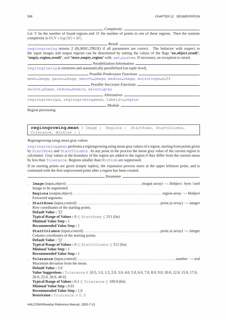
596 CHAPTER 12. SEGMENTATION
ComplexityLet N be the number of found regions andM the number of points in one of these regions. Then the runtimecomplexity isO(N ∗ log(M) ∗M).
Resultregiongrowing returns 2 (HMSG TRUE) if all parameters are correct. The behavior with respect tothe input images and output regions can be determined by setting the values of the flags’no object result’ ,’empty region result’ , and’store empty region’ with set system . If necessary, an exception is raised.
Parallelization Informationregiongrowing is reentrantand automaticallyparallelized(on tuple level).
Possible Predecessor Functionsmean image , gauss image , smooth image , median image , anisotrope diff
Possible Successor Functionsselect shape , reduce domain , select gray
Alternativesregiongrowing n, regiongrowing mean, label to region
ModuleRegion processing
regiongrowing mean ( Image : Regions : StartRows, StartColumns,Tolerance, MinSize : )
Regiongrowing using mean gray values.
regiongrowing meanperforms a regiongrowing using mean gray values of a region, starting from points givenby StartRows andStartColumns . At any point in the process the mean gray value of the current region iscalculated. Gray values at the boundary of the region are added to the region if they differ from the current meanby less thanTolerance . Regions smaller thanMinSize are suppressed.
If no starting points are given (empty tuples), the expansion process starts at the upper leftmost point, and iscontinued with the first unprocessed point after a region has been created.
Parameter
. Image (input object) . . . . . . . . . . . . . . . . . . . . . . . . . . . . . . . . . . . . . . . . . . . . . image(-array); Hobject: byte / int4Image to be segmented.
. Regions (outputobject) . . . . . . . . . . . . . . . . . . . . . . . . . . . . . . . . . . . . . . . . . . . . . . . . . . . . . region-array; HobjectExtracted segments.
. StartRows (input control) . . . . . . . . . . . . . . . . . . . . . . . . . . . . . . . . . . . . . . . . . . . . . . . . . point.y(-array); integerRow coordinates of the starting points.Default Value : ’[]’Typical Range of Values :0≤ StartRows ≤ 511 (lin)Minimal Value Step : 1Recommended Value Step :1
. StartColumns (input control) . . . . . . . . . . . . . . . . . . . . . . . . . . . . . . . . . . . . . . . . . . . . . point.x(-array); integerColumn coordinates of the starting points.Default Value : ’[]’Typical Range of Values :0≤ StartColumns ≤ 511 (lin)Minimal Value Step : 1Recommended Value Step :1
. Tolerance (input control) . . . . . . . . . . . . . . . . . . . . . . . . . . . . . . . . . . . . . . . . . . . . . . . . . . . . . . . . . . . number; realMaximum deviation from the mean.Default Value : 5.0Value Suggestions :Tolerance ∈ {0.5, 1.0, 1.5, 2.0, 3.0, 4.0, 5.0, 6.0, 7.0, 8.0, 9.0, 10.0, 12.0, 15.0, 17.0,20.0, 25.0, 30.0, 40.0}Typical Range of Values :0.1≤ Tolerance ≤ 100.0 (lin)Minimal Value Step : 0.01Recommended Value Step :1.0Restriction : Tolerance > 0.0
HALCON/HDevelop Reference Manual, 2003-7-21

597
. MinSize (input control) . . . . . . . . . . . . . . . . . . . . . . . . . . . . . . . . . . . . . . . . . . . . . . . . . . . . . . . . . . . integer; integerMinimum size of a region.Default Value : 100Value Suggestions :MinSize ∈ {0, 10, 30, 50, 100, 500, 1000, 2000}Typical Range of Values :0≤ MinSize ≤ 50000 (lin)Minimal Value Step : 1Recommended Value Step :100Restriction : MinSize ≥ 0
Resultregiongrowing mean returns 2 (HMSG TRUE) if all parameters are correct. The behavior with respectto the input images and output regions can be determined by setting the values of the flags’no object result’ ,’empty region result’ , and’store empty region’ with set system . If necessary, an exception is raised.
Parallelization Informationregiongrowing mean is reentrantand automaticallyparallelized(on tuple level).
Possible Predecessor Functionsgauss image , sigma image , anisotrope diff , median image
Possible Successor Functionsselect shape , reduce domain , opening , expand region
Alternativesregiongrowing , regiongrowing n
ModuleRegion processing
regiongrowing n ( MultiChannelImage : Regions : Metric, MinTolerance,MaxTolerance, MinSize : )
Regiongrowing for multi-channel images.
regiongrowing n performs a multi-channel regiongrowing. Then channels give rise to an n-dimensionalfeature vector. Neighboring points are aggregated into the same region if the difference of their feature vectorswith respect to the given metric lies in the interval [MinTolerance , MaxTolerance ]. Only neighbors of the4-neighborhood are examined. The following metrics can be used:
Let gA denote the gray value in the feature vectorA at pointa of the image, and likewise begB the gray valuein the feature vectorB at point a neighboring pointb. Let g(d) be the gray value with indexd. Furthermore, letMinT denoteMinTolerance andMaxT denoteMaxTolerance .
’1-norm’: Sum of absolute values
MinT ≤ 1n
∑|gA − gB| ≤MaxT
’2-norm’: Euclidian distance
MinT ≤√∑
(gA − gB)2
n≤MaxT
’3-norm’: p - Norm with p = 3
MinT ≤ 3
√∑(gA − gB)3
n≤MaxT
’4-norm’: p - Norm with p = 4
MinT ≤ 4
√∑(gA − gB)4
n≤MaxT
’n-norm’: Minkowski distance
MinT ≤ n
√∑(gA − gB)n
n≤MaxT
’max-diff’: Supremum distanceMinT ≤ max {|gA − gB|} ≤MaxT
HALCON 6.0.4
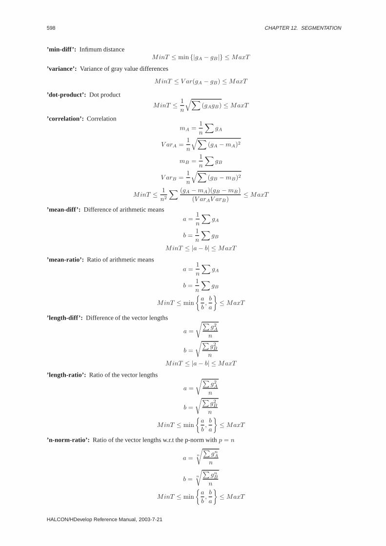
598 CHAPTER 12. SEGMENTATION
’min-diff’: Infimum distanceMinT ≤ min {|gA − gB|} ≤MaxT
’variance’: Variance of gray value differences
MinT ≤ V ar(gA − gB) ≤MaxT
’dot-product’: Dot product
MinT ≤ 1n
√∑(gAgB) ≤MaxT
’correlation’: Correlation
mA =1n
∑gA
V arA =1n
√∑(gA −mA)2
mB =1n
∑gB
V arB =1n
√∑(gB −mB)2
MinT ≤ 1n2
∑ (gA −mA)(gB −mB)(V arAV arB)
≤MaxT
’mean-diff’: Difference of arithmetic means
a =1n
∑gA
b =1n
∑gB
MinT ≤ |a− b| ≤MaxT
’mean-ratio’: Ratio of arithmetic means
a =1n
∑gA
b =1n
∑gB
MinT ≤ min{a
b,b
a
}≤MaxT
’length-diff’: Difference of the vector lengths
a =
√∑g2
A
n
b =
√∑g2
B
n
MinT ≤ |a− b| ≤MaxT
’length-ratio’: Ratio of the vector lengths
a =
√∑g2
A
n
b =
√∑g2
B
n
MinT ≤ min{a
b,b
a
}≤MaxT
’n-norm-ratio’: Ratio of the vector lengths w.r.t the p-norm withp = n
a = n
√∑gn
A
n
b = n
√∑gn
B
n
MinT ≤ min{a
b,b
a
}≤MaxT
HALCON/HDevelop Reference Manual, 2003-7-21

599
’gray-max-diff’: Difference of the maximum gray values
a = max {|gA|}
b = max {|gB|}MinT ≤ |a− b| ≤MaxT
’gray-max-ratio’: Ratio of the maximum gray values
a = max {|gA|}
b = max {|gB|}
MinT ≤ min{a
b,b
a
}≤MaxT
’gray-min-diff’: Difference of the minimum gray values
a = min {|gA|}
b = min {|gB|}MinT ≤ |a− b| ≤MaxT
’gray-min-ratio’: Ratio of the minimum gray values
a = min {|gA|}
b = min {|gB|}
MinT ≤ min{a
b,b
a
}≤MaxT
’variance-diff’: Difference of the variances over all gray values (channels)
MinT ≤ |V ar(gA) − V ar(gB)| ≤MaxT
’variance-ratio’: Ratio of the variances over all gray values (channels)
MinT ≤ V ar(gB)V ar(gA)
≤MaxT
’mean-abs-diff’: Difference of the sum of absolute values over all gray values (channels)
a =∑
d,k,k<d
|gA(d) − gA(k)|
b =∑
d,k,k<d
|gB(d) − gB(k)|
MinT ≤ |a− b|Anzahl der Summen
≤MaxT
’mean-abs-ratio’: Ratio of the sum of absolute values over all gray values (channels)
a =∑
d,k,k<d
|gA(d) − gA(k)|
b =∑
d,k,k<d
|gB(d) − gB(k)|
MinT ≤ min{a
b,b
a
}≤MaxT
HALCON 6.0.4

600 CHAPTER 12. SEGMENTATION
’max-abs-diff’: Difference of the maximum distance of the components
a = max {gA(d), gA(k)}
b = max {gB(d), gB(k)}MinT ≤ |a− b| ≤MaxT
’max-abs-ratio’: Ratio of the maximum distance of the components
a = max {gA(d), gA(k)}
b = max {gB(d), gB(k)}
MinT ≤ min{a
b,b
a
}≤MaxT
’min-abs-diff’: Difference of the minimum distance of the components
a = min {gA(d), gA(k)}, k < d
b = min {gB(d), gB(k)}, k < d
MinT ≤ |a− b| ≤MaxT
’min-abs-ratio’: Ratio of the minimum distance of the components
a = min {gA(d), gA(k)}, k < d
b = min {gB(d), gB(k)}, k < d
MinT ≤ min{a
b,b
a
}≤MaxT
’plane’: The following has to hold for alld1,d2 ∈ [1, n]:
gA(d1) > gA(d2) ⇒ gB(d1) > gB(d2)
gA(d1) < gA(d2) ⇒ gB(d1) < gB(d2)
Regions with less thanMinSize are suppressed.
Parameter
. MultiChannelImage (input object) . . . . . . . . . . . . . . . . . . . . . . . . . . . . . . . . . . image(-array); Hobject: byteMulti-channel image to be segmented.
. Regions (outputobject) . . . . . . . . . . . . . . . . . . . . . . . . . . . . . . . . . . . . . . . . . . . . . . . . . . . . . region-array; HobjectSegmented regions.
. Metric (input control) . . . . . . . . . . . . . . . . . . . . . . . . . . . . . . . . . . . . . . . . . . . . . . . . . . . . . . . . . . . . . . . string; stringMetric for the distance of the feature vectors.Default Value : ’2-norm’Value List : Metric ∈ {’1-norm’, ’2-norm’, ’3-norm’, ’4-norm’, ’n-norm’, ’max-diff’, ’min-diff’,’variance’, ’dot-product’, ’correlation’, ’mean-diff’, ’mean-ratio’, ’length-diff’, ’length-ratio’, ’n-norm-ratio’,’gray-max-diff’, ’gray-max-ratio’, ’gray-min-diff’, ’gray-min-ratio’, ’variance-diff’, ’variance-ratio’,’mean-abs-diff’, ’mean-abs-ratio’, ’max-abs-diff’, ’max-abs-ratio’, ’min-abs-diff’, ’min-abs-ratio’, ’plane’}
. MinTolerance (input control) . . . . . . . . . . . . . . . . . . . . . . . . . . . . . . . . . . . . . . . . . . . . . . .number; real/ integerLower threshold for the features’ distance.Default Value : 0.0Value Suggestions :MinTolerance ∈ {0.0, 1.0, 2.0, 3.0, 4.0, 5.0, 6.0, 7.0, 8.0, 9.0, 10.0, 12.0, 14.0, 16.0,18.0, 20.0, 25.0, 30.0}Typical Range of Values :0.0≤ MinTolerance ≤ 255.0 (lin)Minimal Value Step : 0.01Recommended Value Step :1.0
HALCON/HDevelop Reference Manual, 2003-7-21

601
. MaxTolerance (input control) . . . . . . . . . . . . . . . . . . . . . . . . . . . . . . . . . . . . . . . . . . . . . . .number; real/ integerUpper threshold for the features’ distance.Default Value : 20.0Value Suggestions :MaxTolerance ∈ {0.0, 1.0, 2.0, 3.0, 4.0, 5.0, 6.0, 7.0, 8.0, 9.0, 10.0, 12.0, 14.0, 16.0,18.0, 20.0, 25.0, 30.0}Typical Range of Values :0.0≤ MaxTolerance ≤ 255.0 (lin)Minimal Value Step : 0.01Recommended Value Step :1.0
. MinSize (input control) . . . . . . . . . . . . . . . . . . . . . . . . . . . . . . . . . . . . . . . . . . . . . . . . . . . . . . . . . . . integer; integerMinimum size of the output regions.Default Value : 30Value Suggestions :MinSize ∈ {1, 10, 25, 50, 100, 200, 500, 1000}Typical Range of Values :1≤ MinSize ≤ 10000 (lin)Minimal Value Step : 1Recommended Value Step :5
Resultregiongrowing n returns 2 (HMSG TRUE) if all parameters are correct. The behavior with respect tothe input images and output regions can be determined by setting the values of the flags’no object result’ ,’empty region result’ , and’store empty region’ with set system . If necessary, an exception is raised.
Parallelization Informationregiongrowing n is reentrantand automaticallyparallelized(on tuple level).
Possible Predecessor Functionscompose2 , compose3
Alternativesclass 2dim sup , class ndim norm , class ndim box
See Alsoregiongrowing
ModuleRegion processing
threshold ( Image : Region : MinGray, MaxGray : )
Select gray values lying within an interval.
threshold selects the pixels from the input image whose gray valuesg fulfill the following condition:
MinGray ≤ g ≤ MaxGray .
All points of an image fulfilling the condition are returned as one region. If more than one gray value interval ispassed (tuples forMinGray andMaxGray ), one separate region is returned for each interval.
Parameter
. Image (input object) . . . . . . . . . . . . . . . . . image(-array); Hobject: byte / direction / cyclic / int2 / int4 / realImage to be thresholded.
. Region (outputobject) . . . . . . . . . . . . . . . . . . . . . . . . . . . . . . . . . . . . . . . . . . . . . . . . . . . . . region(-array); HobjectRegions with gray values lying in the specified interval.
. MinGray (input control) . . . . . . . . . . . . . . . . . . . . . . . . . . . . . . . . . . . . . . . . . . . . . . number(-array); real/ integerLower threshold for the gray values.Default Value : 128.0Value Suggestions :MinGray ∈ {0.0, 10.0, 30.0, 64.0, 128.0, 200.0, 220.0, 255.0}Typical Range of Values :0.0≤ MinGray ≤ 255.0 (lin)Minimal Value Step : 0.01Recommended Value Step :5.0
HALCON 6.0.4

602 CHAPTER 12. SEGMENTATION
. MaxGray (input control) . . . . . . . . . . . . . . . . . . . . . . . . . . . . . . . . . . . . . . . . . . . . . . number(-array); real/ integerUpper threshold for the gray values.Default Value : 255.0Value Suggestions :MaxGray ∈ {0.0, 10.0, 30.0, 64.0, 128.0, 200.0, 220.0, 255.0}Typical Range of Values :0.0≤ MaxGray ≤ 255.0 (lin)Minimal Value Step : 0.01Recommended Value Step :5.0Restriction : MaxGray ≥ MinGray
Example
read_image(Image,’fabrik’)sobel_dir(Image,EdgeAmp,EdgeDir,’sum_abs’,3)threshold(EdgeAmp,Seg,50,255,2)skeleton(Seg,Rand)connection(Rand,Lines)select_shape(Lines,Edges,’area’,’and’,10,1000000).
ComplexityLetF be the area of the input region. Then the runtime complexity isO(F ).
Resultthreshold returns 2 (HMSG TRUE) if all parameters are correct. The behavior with respect to the input imagesand output regions can be determined by setting the values of the flags’no object result’ , ’empty region result’ ,and’store empty region’ with set system . If necessary, an exception is raised.
Parallelization Informationthreshold is reentrantand automaticallyparallelized(on tuple level).
Possible Predecessor Functionshisto to thresh , min max gray , sobel amp, gauss image , reduce domain ,fill interlace
Possible Successor Functionsconnection , dilation1 , erosion1 , opening , closing , rank region , shape trans ,skeleton
Alternativesclass 2dim sup , hysteresis threshold , dyn threshold
See Alsodual threshold , zero crossing , background seg , regiongrowing
ModuleRegion processing
threshold sub pix ( Image : Border : Threshold : )
Extract level crossings from an image with subpixel accuracy.
threshold sub pix extracts the level crossings at the levelThreshold of the input imageImage withsubpixel accuracy. The extracted level crossings are returned as XLD-contours inBorder . In contrast to theoperatorthreshold , threshold sub pix does not return regions, but the lines which separate regions witha gray value less thanThreshold from regions with a gray value greater thanThreshold .
For the extraction, the input image is regarded as a surface, in which the gray values are interpolated bilinearlybetween the centers of the individual pixels. Consistent with the surface thus defined, level crossing lines areextracted for each pixel and linked into topologically sound contours. This means that the level crossing contoursare correctly split at junction points. If the image contains extended areas of constant gray valueThreshold ,only the border of such areas is returned as level crossings.
HALCON/HDevelop Reference Manual, 2003-7-21
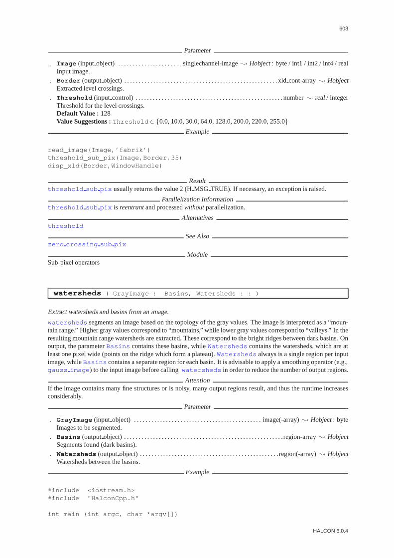
603
Parameter
. Image (input object) . . . . . . . . . . . . . . . . . . . . . . singlechannel-image; Hobject: byte / int1 / int2 / int4 / realInput image.
. Border (outputobject) . . . . . . . . . . . . . . . . . . . . . . . . . . . . . . . . . . . . . . . . . . . . . . . . . . . . . xldcont-array; HobjectExtracted level crossings.
. Threshold (input control) . . . . . . . . . . . . . . . . . . . . . . . . . . . . . . . . . . . . . . . . . . . . . . . . . . .number; real/ integerThreshold for the level crossings.Default Value : 128Value Suggestions :Threshold ∈ {0.0, 10.0, 30.0, 64.0, 128.0, 200.0, 220.0, 255.0}
Example
read_image(Image,’fabrik’)threshold_sub_pix(Image,Border,35)disp_xld(Border,WindowHandle)
Resultthreshold sub pix usually returns the value 2 (HMSG TRUE). If necessary, an exception is raised.
Parallelization Informationthreshold sub pix is reentrantand processedwithoutparallelization.
Alternativesthreshold
See Alsozero crossing sub pix
ModuleSub-pixel operators
watersheds ( GrayImage : Basins, Watersheds : : )
Extract watersheds and basins from an image.
watersheds segments an image based on the topology of the gray values. The image is interpreted as a “moun-tain range.” Higher gray values correspond to “mountains,” while lower gray values correspond to “valleys.” In theresulting mountain range watersheds are extracted. These correspond to the bright ridges between dark basins. Onoutput, the parameterBasins contains these basins, whileWatersheds contains the watersheds, which are atleast one pixel wide (points on the ridge which form a plateau).Watersheds always is a single region per inputimage, whileBasins contains a separate region for each basin. It is advisable to apply a smoothing operator (e.g.,gauss image ) to the input image before callingwatersheds in order to reduce the number of output regions.
AttentionIf the image contains many fine structures or is noisy, many output regions result, and thus the runtime increasesconsiderably.
Parameter
. GrayImage (input object) . . . . . . . . . . . . . . . . . . . . . . . . . . . . . . . . . . . . . . . . . . . . image(-array); Hobject: byteImages to be segmented.
. Basins (outputobject) . . . . . . . . . . . . . . . . . . . . . . . . . . . . . . . . . . . . . . . . . . . . . . . . . . . . . . .region-array; HobjectSegments found (dark basins).
. Watersheds (outputobject) . . . . . . . . . . . . . . . . . . . . . . . . . . . . . . . . . . . . . . . . . . . . . . . . region(-array); HobjectWatersheds between the basins.
Example
#include <iostream.h>#include "HalconCpp.h"
int main (int argc, char *argv[])
HALCON 6.0.4

604 CHAPTER 12. SEGMENTATION
{HImage image (argv[1]),
invert, gauss;HWindow win;
cout << "Gauss of original " << endl;gauss = image.GaussImage (9);image.Display (win);
cout << "Invert of Gauss " << endl;invert = gauss.InvertImage ();invert.Display (win);
HRegion watersheds;HRegionArray bassins = invert.Watersheds (&watersheds);
win.SetColored (12);bassins.Display (win);win.Click ();
return (0);}
Resultwatersheds always returns 2 (HMSG TRUE). The behavior with respect to the input images and outputregions can be determined by setting the values of the flags’no object result’ , ’empty region result’ , and’store empty region’ with set system . If necessary, an exception is raised.
Parallelization Informationwatersheds is reentrantand automaticallyparallelized(on tuple level).
Possible Predecessor Functionsgauss image , smooth image , invert image
Possible Successor Functionsexpand region , select shape , reduce domain , opening
Alternativespouring
ModuleRegion processing
zero crossing ( Image : RegionCrossing : : )
Detect zero crossings in an image.
zero crossing returns the zero crossings of the input image as a region. A pixel is accepted as a zero crossingif its gray value (inImage ) is zero, or if at least one of its neighbors of the 4-neighborhood has a different sign.
This operator is intended to be used after edge operators returning the second derivative of the image (e.g.,laplace of gauss ), which were possibly followed by a smoothing operator. In this case, the zero crossingsare (candidates for) edges.
Parameter
. Image (input object) . . . . . . . . . . . . . . . . . . . . . . . . . . . . . . . . . . . . . . . . image(-array); Hobject: int2 / int4 / realInput image.
. RegionCrossing (outputobject) . . . . . . . . . . . . . . . . . . . . . . . . . . . . . . . . . . . . . . . . . . region(-array); HobjectZero crossings (as region).
Resultzero crossing usually returns the value 2 (HMSG TRUE). If necessary, an exception is raised.
HALCON/HDevelop Reference Manual, 2003-7-21

605
Parallelization Informationzero crossing is reentrantand automaticallyparallelized(on tuple level).
Possible Predecessor Functionslaplace , laplace of gauss , derivate gauss
Possible Successor Functionsconnection , skeleton , boundary , select shape , fill up
Alternativesthreshold , dual threshold
ModuleRegion processing
zero crossing sub pix ( Image : ZeroCrossings : : )
Extract zero crossings from an image with subpixel accuracy.
zero crossing sub pix extracts the zero crossings of the input imageImage with subpixel accuracy. Theextracted zero crossings are returned as XLD-contours inZeroCrossings . Thus,zero crossing sub pixcan be used as a sub-pixel precise edge extractor if the input image is a Laplace-filtered image (seelaplace ,laplace of gauss , derivate gauss ).
For the extraction, the input image is regarded as a surface, in which the gray values are interpolated bilinearlybetween the centers of the individual pixels. Consistent with the surface thus defined, zero crossing lines areextracted for each pixel and linked into topologically sound contours. This means that the zero crossing contoursare correctly split at junction points. If the image contains extended areas of constant gray value 0, only the borderof such areas is returned as zero crossings.
Parameter
. Image (input object) . . . . . . . . . . . . . . . . . . . . . . . . . . . . singlechannel-image; Hobject: int1 / int2 / int4 / realInput image.
. ZeroCrossings (outputobject) . . . . . . . . . . . . . . . . . . . . . . . . . . . . . . . . . . . . . . . . . . . xldcont-array; HobjectExtracted zero crossings.
Example
/* Detection zero crossings of the Laplacian-of-Gaussianof an aerial image */
read_image(Image,’mreut’)derivate_gauss(Image,Laplace,3,’laplace’)zero_crossing_sub_pix(Laplace,ZeroCrossings)disp_xld(ZeroCrossings,WindowHandle)
/* Detection of edges, i.e, zero crossings of the Laplacian-of-Gaussianthat have a large gradient magnitude, in an aerial image */
read_image(Image,’mreut’)Sigma := 1.5/* Compensate the threshold for the fact that derivate_gauss(...,’gradient’)
calculates a Gaussian-smoothed gradient, in which the edge amplitudesare too small because of the Gaussian smoothing, to correspond to a trueedge amplitude of 20. */
Threshold := 20/(Sigma*sqrt(2*3.1415926))derivate_gauss(Image,Gradient,Sigma,’gradient’)threshold(Gradient,Region,Threshold,255)reduce_domain(Image,Region,ImageReduced)derivate_gauss(ImageReduced,Laplace,Sigma,’laplace’)zero_crossing_sub_pix(Laplace,Edges)disp_xld(Edges,WindowHandle)
HALCON 6.0.4

606 CHAPTER 12. SEGMENTATION
Resultzero crossing sub pix usually returns the value 2 (HMSG TRUE). If necessary, an exception is raised.
Parallelization Informationzero crossing sub pix is reentrantand automaticallyparallelized(on tuple level).
Possible Predecessor Functionslaplace , laplace of gauss , diff of gauss , derivate gauss
Alternativeszero crossing
ModuleSub-pixel operators
HALCON/HDevelop Reference Manual, 2003-7-21
Chapter 13
System
13.1 Database
count relation ( : : RelationName : NumOfTuples )
Number of entries in the HALCON database.
The operator count relation counts the number of entries in one of the four relations of the HALCONdatabase. The HALCON database is organized as follows:
There are two basic relations for region-data and image-matrices. The HALCON objects region and image areconstructed from elements from these two relations: a region consists of a pointer to a tuple in the region-datarelation. An image consists also of a pointer to a tuple in the region-data relation (like a region) and additionally ofone or more pointers to tuples in the matrix relation. If there is more than one matrix pointer, the image is called amulti-channel image.
Both regions and images are called objects. A region can be considered as the special case of an iconic objecthaving no image matrixes. For reasons of an efficient memory managment, the tuples of the region-data relationand the image-matrix relation will be used by different objects together. Therefore there may be for example moreimages than image matrices. Only the two lowlevel relations are of relevance to the memory consumption. Imageobjects (regions as well as images) consist only of references on region and matrix data and therefore only need acouple of bytes of memory.
Possible values forRelationName :
’image’: Image matrices. One matrix may also be the component of more than one image (no redundant storage).
’region’: Regions (the full and the empty region are always available). One region may of course also be thecomponent of more than one image object (no redundant storage).
’XLD’: eXtended Line Description: Contours, Polygons, paralles, lines, etc. XLD data types don’t have grayvalues and are stored with subpixel accuracy.
’object’: Iconic objects. Composed of a region (called region) and optionally image matrices (called image).
’tuple’: In the compact mode, tuples of iconic objects are stored as a surrogate in this relation. Instead of workingwith the individual object keys, only this tuple key is used. It depends on the host language, whether theobjects are passed individually (Prolog and C++) or as tuples (C, Smalltalk, Lisp, OPS-5).
Certain database objects will be created already by the operatorreset obj db and therefore have to be avail-able all the time (the undefined gray value component, the objects ’full’ (FULLREGION in HALCON/C) and’empty’ (EMPTY REGION in HALCON/C) as well as the herein included empty and full region). By callingget channel info , the operator therefore appears correspondingly also as ’creator’ of the full and empty re-gion. The procedure can be used for example to check the completeness of theclear obj operation.
607
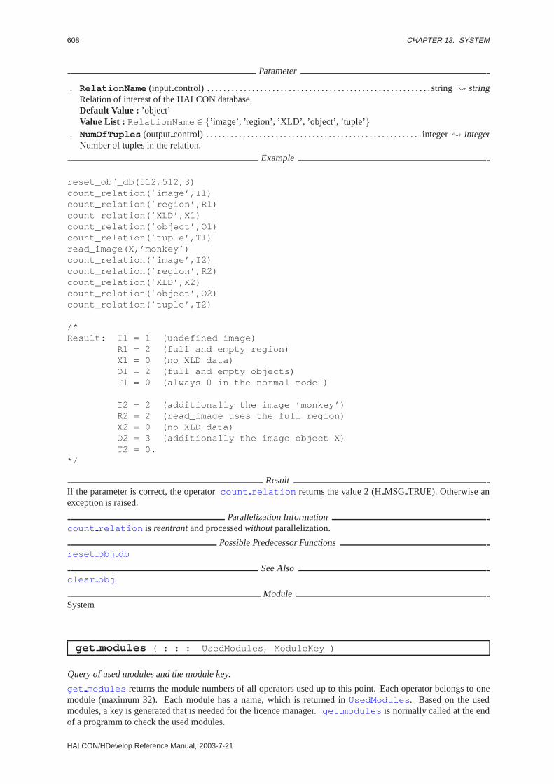
608 CHAPTER 13. SYSTEM
Parameter
. RelationName (input control) . . . . . . . . . . . . . . . . . . . . . . . . . . . . . . . . . . . . . . . . . . . . . . . . . . . . . . . string; stringRelation of interest of the HALCON database.Default Value : ’object’Value List : RelationName ∈ {’image’, ’region’, ’XLD’, ’object’, ’tuple’ }
. NumOfTuples (outputcontrol) . . . . . . . . . . . . . . . . . . . . . . . . . . . . . . . . . . . . . . . . . . . . . . . . . . . . . integer; integerNumber of tuples in the relation.
Example
reset_obj_db(512,512,3)count_relation(’image’,I1)count_relation(’region’,R1)count_relation(’XLD’,X1)count_relation(’object’,O1)count_relation(’tuple’,T1)read_image(X,’monkey’)count_relation(’image’,I2)count_relation(’region’,R2)count_relation(’XLD’,X2)count_relation(’object’,O2)count_relation(’tuple’,T2)
/*Result: I1 = 1 (undefined image)
R1 = 2 (full and empty region)X1 = 0 (no XLD data)O1 = 2 (full and empty objects)T1 = 0 (always 0 in the normal mode )
I2 = 2 (additionally the image ’monkey’)R2 = 2 (read_image uses the full region)X2 = 0 (no XLD data)O2 = 3 (additionally the image object X)T2 = 0.
*/
ResultIf the parameter is correct, the operatorcount relation returns the value 2 (HMSG TRUE). Otherwise anexception is raised.
Parallelization Informationcount relation is reentrantand processedwithoutparallelization.
Possible Predecessor Functionsreset obj db
See Alsoclear obj
ModuleSystem
get modules ( : : : UsedModules, ModuleKey )
Query of used modules and the module key.
get modules returns the module numbers of all operators used up to this point. Each operator belongs to onemodule (maximum 32). Each module has a name, which is returned inUsedModules . Based on the usedmodules, a key is generated that is needed for the licence manager.get modules is normally called at the endof a programm to check the used modules.
HALCON/HDevelop Reference Manual, 2003-7-21
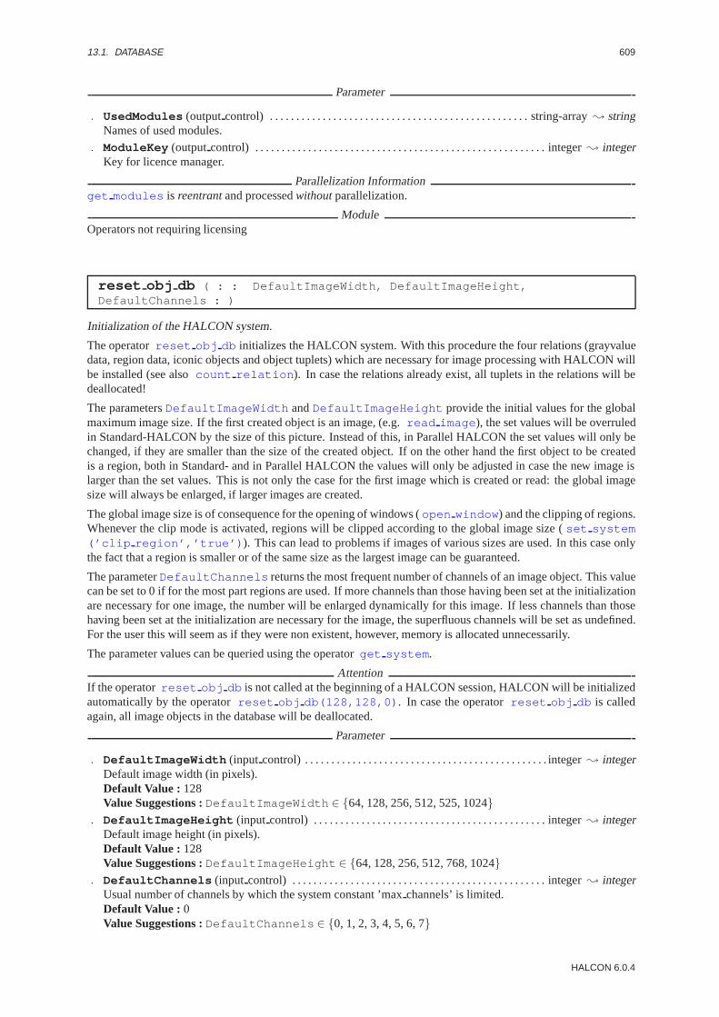
13.1. DATABASE 609
Parameter
. UsedModules (outputcontrol) . . . . . . . . . . . . . . . . . . . . . . . . . . . . . . . . . . . . . . . . . . . . . . . . . string-array; stringNames of used modules.
. ModuleKey (outputcontrol) . . . . . . . . . . . . . . . . . . . . . . . . . . . . . . . . . . . . . . . . . . . . . . . . . . . . . . . integer; integerKey for licence manager.
Parallelization Informationget modules is reentrantand processedwithoutparallelization.
ModuleOperators not requiring licensing
reset obj db ( : : DefaultImageWidth, DefaultImageHeight,DefaultChannels : )
Initialization of the HALCON system.
The operatorreset obj db initializes the HALCON system. With this procedure the four relations (grayvaluedata, region data, iconic objects and object tuplets) which are necessary for image processing with HALCON willbe installed (see alsocount relation ). In case the relations already exist, all tuplets in the relations will bedeallocated!
The parametersDefaultImageWidth andDefaultImageHeight provide the initial values for the globalmaximum image size. If the first created object is an image, (e.g.read image ), the set values will be overruledin Standard-HALCON by the size of this picture. Instead of this, in Parallel HALCON the set values will only bechanged, if they are smaller than the size of the created object. If on the other hand the first object to be createdis a region, both in Standard- and in Parallel HALCON the values will only be adjusted in case the new image islarger than the set values. This is not only the case for the first image which is created or read: the global imagesize will always be enlarged, if larger images are created.
The global image size is of consequence for the opening of windows (open window ) and the clipping of regions.Whenever the clip mode is activated, regions will be clipped according to the global image size (set system(’clip region’,’true’) ). This can lead to problems if images of various sizes are used. In this case onlythe fact that a region is smaller or of the same size as the largest image can be guaranteed.
The parameterDefaultChannels returns the most frequent number of channels of an image object. This valuecan be set to 0 if for the most part regions are used. If more channels than those having been set at the initializationare necessary for one image, the number will be enlarged dynamically for this image. If less channels than thosehaving been set at the initialization are necessary for the image, the superfluous channels will be set as undefined.For the user this will seem as if they were non existent, however, memory is allocated unnecessarily.
The parameter values can be queried using the operatorget system .
AttentionIf the operatorreset obj db is not called at the beginning of a HALCON session, HALCON will be initializedautomatically by the operatorreset obj db(128,128,0) . In case the operatorreset obj db is calledagain, all image objects in the database will be deallocated.
Parameter
. DefaultImageWidth (input control) . . . . . . . . . . . . . . . . . . . . . . . . . . . . . . . . . . . . . . . . . . . . . . integer; integerDefault image width (in pixels).Default Value : 128Value Suggestions :DefaultImageWidth ∈ {64, 128, 256, 512, 525, 1024}
. DefaultImageHeight (input control) . . . . . . . . . . . . . . . . . . . . . . . . . . . . . . . . . . . . . . . . . . . . integer; integerDefault image height (in pixels).Default Value : 128Value Suggestions :DefaultImageHeight ∈ {64, 128, 256, 512, 768, 1024}
. DefaultChannels (input control) . . . . . . . . . . . . . . . . . . . . . . . . . . . . . . . . . . . . . . . . . . . . . . . . integer; integerUsual number of channels by which the system constant ’maxchannels’ is limited.Default Value : 0Value Suggestions :DefaultChannels ∈ {0, 1, 2, 3, 4, 5, 6, 7}
HALCON 6.0.4

610 CHAPTER 13. SYSTEM
ResultThe operatorreset obj db returns the value 2 (HMSG TRUE) if the parameter values are correct. Otherwisean exception will be raised.
Parallelization Informationreset obj db is reentrantand processedwithoutparallelization.
See Alsoget channel info , count relation
ModuleOperators not requiring licensing
13.2 Error-Handling
get check ( : : : Check )
State of the HALCON control modes.
Executing the operatorget check the user can inquire what kind of control modes are currently activated andwhich are not.Check gives the tuplet containing the names of the control modes (see alsoset check ) whichare preceded by a tilde (˜, e.g. ’˜data’), if the corresponding control is deactivated.
Parameter
. Check (outputcontrol) . . . . . . . . . . . . . . . . . . . . . . . . . . . . . . . . . . . . . . . . . . . . . . . . . . . . . . . . . .string-array; stringTuplet of the currently activated control modes.
Resultget check always returns the value 2 (HMSG TRUE).
Parallelization Informationget check is reentrantand processedwithoutparallelization.
Possible Predecessor Functionsset check
See Alsoset check
ModuleSystem
get error text ( : : ErrorNumber : ErrorText )
Inquiry after the error text of a HALCON error number.
The operatorget error text returns the error text for the corresponding HALCON error number. This isindeed the same text which will be given during an exception. The operatorget error text is especially usefulif the error treatment is programmed by the users themselves (see alsoset check(::’˜give error’:) ).
AttentionUnknown error numbers will trigger a standard message.
Parameter
. ErrorNumber (input control) . . . . . . . . . . . . . . . . . . . . . . . . . . . . . . . . . . . . . . . . . . . . . . . . . . . . . . integer; integerNumber of the HALCON error.Restriction : (1 ≤ ErrorNumber ) ∧ (ErrorNumber ≤ 36000 )
. ErrorText (outputcontrol) . . . . . . . . . . . . . . . . . . . . . . . . . . . . . . . . . . . . . . . . . . . . . . . . . . . . . . . . . .string; stringCorresponding error text.
Example
HALCON/HDevelop Reference Manual, 2003-7-21
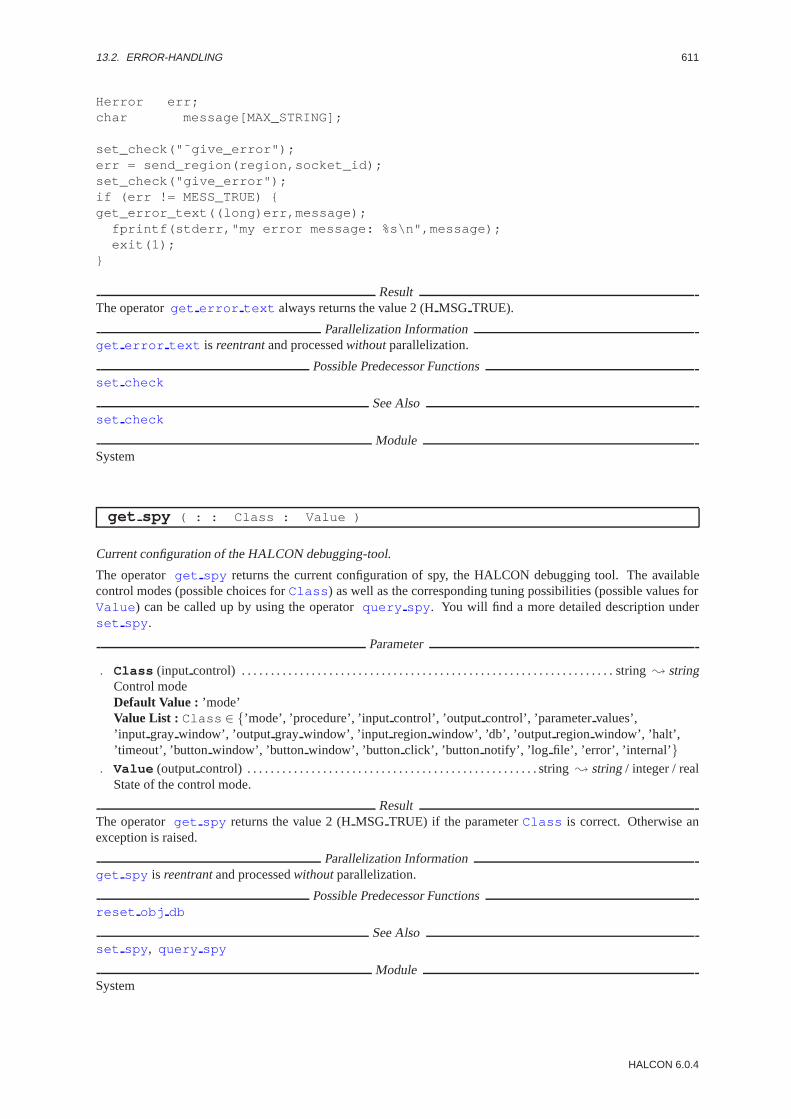
13.2. ERROR-HANDLING 611
Herror err;char message[MAX_STRING];
set_check("˜give_error");err = send_region(region,socket_id);set_check("give_error");if (err != MESS_TRUE) {get_error_text((long)err,message);
fprintf(stderr,"my error message: %s\n",message);exit(1);
}
ResultThe operatorget error text always returns the value 2 (HMSG TRUE).
Parallelization Informationget error text is reentrantand processedwithoutparallelization.
Possible Predecessor Functionsset check
See Alsoset check
ModuleSystem
get spy ( : : Class : Value )
Current configuration of the HALCON debugging-tool.
The operatorget spy returns the current configuration of spy, the HALCON debugging tool. The availablecontrol modes (possible choices forClass ) as well as the corresponding tuning possibilities (possible values forValue ) can be called up by using the operatorquery spy . You will find a more detailed description underset spy .
Parameter
. Class (input control) . . . . . . . . . . . . . . . . . . . . . . . . . . . . . . . . . . . . . . . . . . . . . . . . . . . . . . . . . . . . . . . . string; stringControl modeDefault Value : ’mode’Value List : Class ∈ {’mode’, ’procedure’, ’inputcontrol’, ’outputcontrol’, ’parametervalues’,’input gray window’, ’output gray window’, ’input regionwindow’, ’db’, ’output regionwindow’, ’halt’,’timeout’, ’button window’, ’button window’, ’button click’, ’button notify’, ’log file’, ’error’, ’internal’}
. Value (outputcontrol) . . . . . . . . . . . . . . . . . . . . . . . . . . . . . . . . . . . . . . . . . . . . . . . . . . string; string/ integer / realState of the control mode.
ResultThe operatorget spy returns the value 2 (HMSG TRUE) if the parameterClass is correct. Otherwise anexception is raised.
Parallelization Informationget spy is reentrantand processedwithoutparallelization.
Possible Predecessor Functionsreset obj db
See Alsoset spy , query spy
ModuleSystem
HALCON 6.0.4

612 CHAPTER 13. SYSTEM
query spy ( : : : Classes, Values )
Inquiring for possible settings of the HALCON debugging tool.
The operatorquery spy returns all possible settings of spy, the HALCON debugging tool, i.e. all the availablecontrol modes (Classes ) as well as the corresponding possible ways of setting (Values ). For a more detaileddescription of spy see operatorset spy .
AttentionThe values ofValues cannot be used as direct input forset spy , as they are transmitted as a symbolic constant.
Parameter
. Classes (outputcontrol) . . . . . . . . . . . . . . . . . . . . . . . . . . . . . . . . . . . . . . . . . . . . . . . . . . . . . . . string-array; stringAvailable control modes (see also setspy).
. Values (outputcontrol) . . . . . . . . . . . . . . . . . . . . . . . . . . . . . . . . . . . . . . . . . . . . . . . . . . . . . . . . string-array; stringCorresponding state of the control modes.
Resultqueryspy always returns the value 2 (HMSG TRUE).
Parallelization Informationquery spy is reentrant, local, and processedwithoutparallelization.
Possible Predecessor Functionsreset obj db
See Alsoset spy , get spy
ModuleSystem
set check ( : : Check : )
Activating and deactivating of HALCON control modes.
With the help of the operatorset check different control modes of the HALCON system can be activatedor deactivated. If a certain control mode is activated, parameters etc. will be checked at runtime. Whenever aninconsistency is hereby detected, the program will be interrupted by an exception.
It is recommendable to activate the control modes during the development of a program and to deactivate themonly after a successfully concluded testrun. For if the control mode is deactivated and an error occurs, the systemmay react in an unpredictable way.
The HALCON system provides various possible control modes which can be activated and deactivated indepen-dently. By calling the operatorset check with the name (Check ) of the desired control mode, this controlmode is activated; the control mode is deactivated by passing its name prefixed with a tilde (˜, z.B. ’˜data’).
Available control modes:
’color’: If this control mode is activated, only colors may be used which are supported by the display for thecurrently active window. Otherwise an error message is displayed.In case of deactivated control mode and non existent colors, thenearest coloris used (see alsoset color ,set gray , set rgb ).
’text’: If this control mode is activated, it will check the coordinates during the setting of the text cursor as wellas during the display of strings (write string ) to the effect whether a part of a sign would lie outside thewindowframe (a fact which is not forbidden in principle by the system).If the control mode is deactivaed, the text will be clipped at the windowframe.
’parameter’: (For HALCON/PRO only)If this control mode is activated, output parameter may not be instantiated by calling a procedure.Otherwise a normal unification mechanism is used.
’data’: (For program development)Checks the consistency of image objects (regions and grayvalue components.
HALCON/HDevelop Reference Manual, 2003-7-21
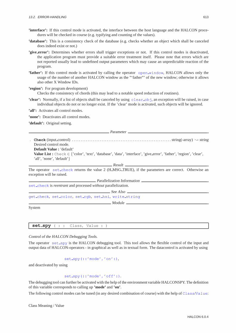
13.2. ERROR-HANDLING 613
’interface’: If this control mode is activated, the interface between the host language and the HALCON proce-dures will be checked in course (e.g. typifying and counting of the values).
’database’: This is a consistency check of the database (e.g. checks whether an object which shall be canceleddoes indeed exist or not.)
’give error’: Determines whether errors shall trigger exceptions or not. If this control modes is deactivated,the application program must provide a suitable error treatment itself. Please note that errors which arenot reported usually lead to undefined output parameters which may cause an unpredictable reaction of theprogram.
’father’: If this control mode is activated by calling the operatoropen window , HALCON allows only theusage of the number of another HALCON window as the ”‘father”’ of the new window; otherwise it allowsalso other X Window IDs.
’region’: For program development)Checks the consistency of chords (this may lead to a notable speed reduction of routines).
’clear’: Normally, if a list of objects shall be canceled by usingclear obj , an exception will be raised, in caseindividual objects do not or no longer exist. If the ’clear’ mode is activated, such objects will be ignored.
’all’: Activates all control modes.
’none’: Deactivates all control modes.
’default’: Original setting.
Parameter
. Check (input control) . . . . . . . . . . . . . . . . . . . . . . . . . . . . . . . . . . . . . . . . . . . . . . . . . . . . . . . . . string(-array); stringDesired control mode.Default Value : ’default’Value List : Check ∈ {’color’, ’text’, ’database’, ’data’, ’interface’, ’giveerror’, ’father’, ’region’, ’clear’,’all’, ’none’, ’default’}
ResultThe operator set check returns the value 2 (HMSG TRUE), if the parameters are correct. Otherwise anexception will be raised.
Parallelization Informationset check is reentrantand processedwithoutparallelization.
See Alsoget check , set color , set rgb , set hsi , write string
ModuleSystem
set spy ( : : Class, Value : )
Control of the HALCON Debugging Tools.
The operatorset spy is the HALCON debugging tool. This tool allows the flexible control of the input andoutput data of HALCON-operators - in graphical as well as in textual form. The datacontrol is activated by using
set spy(::’mode’,’on’:) ,
and deactivated by using
set spy(::’mode’,’off’:) .
The debugging tool can further be activated with the help of the environment variable HALCONSPY. The definitionof this variable corresponds to calling up’mode’ and’on’ .
The following control modes can be tuned (in any desired combination of course) with the help ofClass /Value :
Class Meaning / Value
HALCON 6.0.4

614 CHAPTER 13. SYSTEM
’operator’ When a routine is called, its name and the names of its parameters will be given (in TRIAS notation).Value: ’on’ or ’off’default: ’off’
’input control’ When a routine is called, the names and values of the input control parameters will be given.Value: ’on’ or ’off’default: ’off’
’output control’ When a routine is called, the names and values of the output control parameters are given.Value: ’on’ or ’off’default: ’off’
’parameter values’ Additional information on ’inputcontrol’ and ’outputcontrol’: indicates how many valuesper parameter shall be displayed at most (maximum tuplet length of the output).Value: tuplet length (integer)default: 4
’db’ Information concerning the 4 relations in the HALCON-database. This is especially valuable in looking forforgotten clear obj .Value: ’on’ or ’off’default: ’off’
’input gray window’ Any reading access of the gray-value component of an (input) image object will cause thegray-value component to be shown in the indicated window (Window-ID; ’none’ will deactivate this control).Value: Window-ID (integer) or ’none’default: ’none’
’output gray window’ As soon as the gray-value component of an (output) image object is set, spy will showthis gray-value component in the indicated window (Window-ID; ’none’ will deactivate this control).Value: Window-ID (integer) or ’none’default: ’none’
’input region window’ Any reading access of the region of an (input) iconic object will cause this region to beshown in the indicated (Window-ID; ’none’ will deactivate this control ).Value: Window-ID (integer) or ’none’default: ’none’
’output region window’ As soon as the region of an (output) iconic object is set, spy will show this region in theindicated window (Window-ID; ’none’ will deactivate this control ).Value: Window-ID (integer) or ’none’default: ’none’
’time’ Processing time of the operatorValue: ’on’ or ’off’default: ’off’
’halt’ Determines whether there is a halt after every individual action (’multiple’) or only at the end of each oper-ator (’single’). The parameter is only effective if the halt has been activated by ’timeout’ or ’buttonwindow’.Value: ’single’ or ’multiple’default: ’multiple’
’timeout’ After every output there will be a halt of the indicated number of seconds.Value: seconds (real)default 0.0
’button window’ Alternative to ’timeout’: after every output spy waits until the cursor indicates (’buttonclick’ =’false’) or clicks into (’buttonclick’ = ’true’) the indicated window. (Window-ID; ’none’ will deactivate thiscontrol ).Value: Window-ID (integer) or ’none’default: ’none’
’button click’ Additional option for ’buttonwindow’: determines whether or not a mouse-click has to be waitedfor after an output.Value: ’on’ or ’off’default: ’off’
’button notify’ If ’button notify’ is activated, spy generates a beep after every output. This is useful in combina-tion with ’button window’.
HALCON/HDevelop Reference Manual, 2003-7-21

13.3. INFORMATION 615
Value: ’on’ or ’off’default: ’off’
’log file’ Spy can hereby divert the text output into a file having been opened with openfile.Value: a file handle (seeopen file )
’error’ If ’error’ is activated and an internal error occurs, spy will show the internal procedures (file/line) con-cerned.Value: ’on’ or ’off’default: ’off’
’internal’ If ’internal’ is activated, spy will display the internal procedures and their parameters (file/line) whilean HALCON-operator is processed.Value: ’on’ or ’off’default: ’off’
Parameter
. Class (input control) . . . . . . . . . . . . . . . . . . . . . . . . . . . . . . . . . . . . . . . . . . . . . . . . . . . . . . . . . . . . . . . . string; stringControl modeDefault Value : ’mode’Value List : Class ∈ {’mode’, ’operator’, ’inputcontrol’, ’outputcontrol’, ’parametervalues’,’input gray window’, ’db’, ’time’, ’output gray window’, ’output regionwindow’, ’input regionwindow’,’halt’, ’timeout’, ’button window’, ’button click’, ’button notify’, ’log file’, ’error’, ’internal’}
. Value (input control) . . . . . . . . . . . . . . . . . . . . . . . . . . . . . . . . . . . . . . . . . . . . . . . . . . . string; string/ integer / realState of the control mode to be set.Default Value : ’on’Value Suggestions :Value ∈ {’on’, ’off’, 1, 2, 3, 4, 5, 10, 50, 0.0, 1.0, 2.0, 5.0, 10.0}
Example
/* init spy: Setting of the wished control modi */set_spy("mode","on");set_spy("operator","on");set_spy("input_control","on");set_spy("output_control","on");/* calling of program section, that will be examined */set_spy("mode","off");
ResultThe operatorset spy returns the value 2 (HMSG TRUE) if the parameters are correct. Otherwise an exceptionis raised.
Parallelization Informationset spy is reentrant, local, and processedwithoutparallelization.
Possible Predecessor Functionsreset obj db
See Alsoget spy , query spy
ModuleSystem
13.3 Information
disp info ( : : ProcName, Machine, DispProgram, Extension : )
Display the manual information of a procedure on the screen.
The operator disp info together with the previewerDispProgram shows the manual entry of the indi-cated procedure on the screen. The individual files (ProcName.Extension ) are located in the HALCON-Directory ”‘doc/ps/reference/LANGUAGE/*”’, whereby the value for LANGUAGE will be determined by the
HALCON 6.0.4
616 CHAPTER 13. SYSTEM
currently used host language. The directory can also be generated with the help of the operatorset system(::’reference dir’,’Pfad’:) .
Parameter
. ProcName (input control) . . . . . . . . . . . . . . . . . . . . . . . . . . . . . . . . . . . . . . . . . . . . . . . . . . . . . . . procname ; stringName of the seeked procedure.Default Value : ’read image’
. Machine (input control) . . . . . . . . . . . . . . . . . . . . . . . . . . . . . . . . . . . . . . . . . . . . . . . . . . . . . . . . . . . . . string; stringName of the computer to which the data shall be transmitted or empty string.Default Value : ”
. DispProgram (input control) . . . . . . . . . . . . . . . . . . . . . . . . . . . . . . . . . . . . . . . . . . . . . . . . . . . . . . . . string; stringName of the program which shall display the help text.Default Value : ’ghostview’Value Suggestions :DispProgram ∈ {’gs’, ’ghostview’}
. Extension (input control) . . . . . . . . . . . . . . . . . . . . . . . . . . . . . . . . . . . . . . . . . . . . . . . . . . . . . . . . . . . string; stringExtension of the helpfile.Default Value : ’ps’
ResultIf the parameter values are correct and the file and the program are available, the operatordisp info returns thevalue 2 (HMSG TRUE). Otherwise an exception handling is raised.
Parallelization Informationdisp info is reentrantand processedwithoutparallelization.
See Alsoopen window
ModuleImage / region / XLD management
get chapter info ( : : Chapter : Info )
Get information concerning the chapters on procedures.
The operator get chapter info gives information concerning the chapters on procedures. If instead ofChapter the empty string is transmitted, the routine will provide inInfo the names of all chapters. If on theother hand a certain chapter or a chapter and its subchapter(s) are indicated (by a tuple of names), the correspondingsubchapters or - in case there are no further subchapters - the names of the corresponding procedures will be given.The organization of the chapters on procedures is the same as the organization of chapters and subchapters in theHALCON-manual. Please note: The chapters on procedures respectively the subchapters concerning an individ-ual procedure can be called by using the operatorget operator info(::<Name>,’chapter’,Info:) .The Online-texts will be taken from the files english.hlp, english.sta, english.num and english.idx, which will besearched by HALCON in the currently used directory or the directory ’helpdir’ (see also get system andset system ).
Parameter
. Chapter (input control) . . . . . . . . . . . . . . . . . . . . . . . . . . . . . . . . . . . . . . . . . . . . . . . . . . . . . . string(-array); stringProcedure class or subclass of interest.Default Value : ”
. Info (outputcontrol) . . . . . . . . . . . . . . . . . . . . . . . . . . . . . . . . . . . . . . . . . . . . . . . . . . . . . . . . . . . string-array; stringProcedure classes (Chapter = ”) or procedure subclasses respectively procedures.
ResultIf the parameter values are correct and the helpfile is available, the operatorget chapter info returns thevalue 2 (HMSG TRUE). Otherwise an exception handling is raised.
Parallelization Informationget chapter info is processedcompletely exclusivelywithout parallelization.
Possible Predecessor Functionsget system , set system
HALCON/HDevelop Reference Manual, 2003-7-21

13.3. INFORMATION 617
See Alsoget operator info , get system , set system
ModuleImage / region / XLD management
get keywords ( : : ProcName : Keywords )
Get keywords which are assigned to procedures.
The operator get keywords returns all the keywords in the online-texts corresponding to those procedureswhich have the indicated substringProcName in their name. If instead ofProcName the empty string is trans-mitted, the operatorget keywords returns all keywords. The keywords of an individual procedure can also becalled by using the operatorget operator info . The online-texts will be taken from the filesenglish.hlp,english.sta, english.num, english.keyandenglish.idx, which are searched by HALCON in the currently useddirectory and in the directory ’helpdir’ (see alsoget system and set system ).
Parameter
. ProcName (input control) . . . . . . . . . . . . . . . . . . . . . . . . . . . . . . . . . . . . . . . . . . . . . . . . . . . . . . . procname ; stringSubstring in the names of those procedures for which keywords are needed.Default Value : ’get keywords’
. Keywords (outputcontrol) . . . . . . . . . . . . . . . . . . . . . . . . . . . . . . . . . . . . . . . . . . . . . . . . . . . . . .string-array; stringKeywords for the procedures.
ResultThe operatorget keywords returns the value 2 (HMSG TRUE) if the parameters are correct and the helpfilesare available. Otherwise an exception handling is raised.
Parallelization Informationget keywords is processedcompletely exclusivelywithout parallelization.
Possible Predecessor Functionsget chapter info
Alternativesget operator info
See Alsoget operator name, search operator , get param info
ModuleImage / region / XLD management
get operator info ( : : ProcName, Slot : Information )
Get information concerning a HALCON-procedure.
With the help of the operatorget operator info the online-texts concerning a certain procedure can be called(see alsoget operator name). The form of information available for all procedures (Slot ) can be calledusing the operatorquery operator info . For the time being the following slots are available:
’short’: Short description of the procedure.
’abstract’: Description of the procedure.
’procedure class’: Name(s) of the chapter(s) in the procedure hierarchy (chapter, subchapter in the HALCONmanual).
’functionality’: Functionality is equivalent to the object class to which the procedure can be assigned.
’keywords’: Keywords of the procedure (optional).
’example’: Example for the use of the procedure (optional). The operator ’example.LANGUAGE’ (LANGUAGE∈ {c,c++,smalltalk,trias}) calls up examples for a certain language if available. If the language is not indi-cated or if no example is available in this language, the TRIAS-example will be returned.
HALCON 6.0.4

618 CHAPTER 13. SYSTEM
’complexity’: Complexity of the procedure (optional).
’effect’: Not in use so far.
’alternatives’: Alternative procedures (optional).
’seealso’: Procedures containing further information (optional).
’predecessor’: Possible and sensible predecessor
’successor’: Possible and sensible successor
’result state’: Return value of the procedure (TRUE, FALSE, FAIL, VOID or EXCEPTION).
’attention’: Restrictions and advice concering the correct use of the procedure (optional).
’parameter’: Names of the parameter of the procedure (see alsoget param info ).
’references’: Literary references (optional).
’module’: The module to which the operator is assigned.
’html path’: The directory where the HTML documentation of the operator resides.
’parameter relations’: Assurances concerning the parameters (optional).
The texts will be taken from the files english.hlp, english.sta, english.key, english.num und english.idx which willbe searched by HALCON in the currently used directory or in the directory ’helpdir’ (respectively ’userhelp dir’)(see alsoget system and set system ). By adding ’.latex’ after the slotname, the text of slots containingtextual information can be made available in LATEX notation.
Parameter
. ProcName (input control) . . . . . . . . . . . . . . . . . . . . . . . . . . . . . . . . . . . . . . . . . . . . . . . . . . . . . . . procname ; stringName of the procedure on which more information is needed.Default Value : ’get operatorinfo’
. Slot (input control) . . . . . . . . . . . . . . . . . . . . . . . . . . . . . . . . . . . . . . . . . . . . . . . . . . . . . . . . . . . . . . . . . .string; stringDesired information.Default Value : ’abstract’Value List : Slot ∈ {’short’, ’abstract’, ’procedureclass’, ’functionality’, ’effect’, ’complexity’,’predecessor’, ’successor’, ’alternatives’, ’seealso’, ’keywords’, ’example’, ’attention’, ’resultstate’,’return value’, ’references’, ’sourcefiles’, ’deffile’, ’module’, ’htmlpath’}
. Information (outputcontrol) . . . . . . . . . . . . . . . . . . . . . . . . . . . . . . . . . . . . . . . . . . . . . . . . string(-array); stringInformation (empty if no information is available)
ResultThe operatorget operator info returns the value 2 (HMSG TRUE) if the parameters are correct and thehelpfiles are availabe. Otherwise an exception handling is raised.
Parallelization Informationget operator info is processedcompletely exclusivelywithout parallelization.
Possible Predecessor Functionsget keywords , search operator , get operator name, query operator info ,query param info , get param info
Possible Successor Functionsget param names, get param num, get param types
Alternativesget param names
See Alsoquery operator info , get param info , get operator name, get param num,get param types
ModuleImage / region / XLD management
get operator name ( : : Pattern : ProcNames )
Get procedures with the given string as a substring of their name.
HALCON/HDevelop Reference Manual, 2003-7-21

13.3. INFORMATION 619
The operatorget operator name takes a string (Pattern ) as input and searches all HALCON-procedureshaving this string as a substring in their name. If an empty string is entered, the names of all procedures availablewill be returned.
Parameter
. Pattern (input control) . . . . . . . . . . . . . . . . . . . . . . . . . . . . . . . . . . . . . . . . . . . . . . . . . . . . . . . . . . . . . string; stringSubstring of the seeked names (empty<=> all names).Default Value : ’info’
. ProcNames (outputcontrol) . . . . . . . . . . . . . . . . . . . . . . . . . . . . . . . . . . . . . . . . . . . . . . . . . . . . string-array; stringDetected procedure names.
ResultThe operatorget operator name returns the value 2 (HMSG TRUE) if the helpfiles are available. Otherwisean exception handling is raised.
Parallelization Informationget operator name is reentrant, local, and processedwithoutparallelization.
Possible Successor Functionsget operator info , get param names, get param num, get param types
Alternativessearch operator
See Alsoget operator info , get param names, get param num, get param types
ModuleImage / region / XLD management
get param info ( : : ProcName, ParamName, Slot : Information )
Get information concerning the procedure parameters.
The operatorget param info is used for calling up the online-texts assigned to a parameter of an indicatedprocedure. The form of information available for each parameter (Slot ), can be called up by using the operatorquery param info . At the moment the following slots are available:
’description’: Description of the parameter.
’description.latex’: Description of the parameter in LATEX notation.
’parameter class’: Parameter classes: ’inputobject’, ’outputobject’, ’input control’ oder ’outputcontrol’.
’type list’: Permitted type(s) of data for parameter values (for control parameters only). Value: ’real’, ’integer’oder ’string’.
’default type’: Default-type for parameter values (for control parameters only). This type of parameter is the oneHALCON/C uses in the ”‘simple mode”’. If ’none’ is indicated, the ”‘tuple mode”’ must be used. Value:’real’, ’integer’, ’string’ oder ’none’.
’sem type’: Semantic type of the parameter. This is important to allow the assignment of the parameters to objectclasses in object-oriented languages (C++, Smalltalk). If more than one parameter belongs semantically toone type, this fact is indicated as well. So far the the following objects are supported:object, image, region, xld,xld cont, xld para, xldpoly, xld ext para, xldmod para,integer, real, number, string,channel, grayval, window,histogram, distribution,point(.x, .y), extent(.x, .y),angle(.rad oder .deg),circle(.center.x, .center.y, .radius),arc(.center.x, .center.y, .angle.rad, .begin.x, .begin.y),ellipse(.center.x, .center.y, .angle.rad, .radius1, .radius2),line(.begin.x, .begin.y, .end.x, .end.y)
HALCON 6.0.4
620 CHAPTER 13. SYSTEM
rectangle(.origin.x, .origin.y, .corner.x, .corner.ybzw. .extent.x, .extent.y),polygon(.x, .y), contour(.x, .y),coordinates(.x, .y), chord(.x1, .x2, .y),chain(.begin.x, .begin.y, .code).
’default value’: Default-value for the parameter (for input-control parameters only). It is the question of mereinformation only (the parameter value must be transmitted explicitly, even if the default-value is used). Thisentry serves only as a notice, a point of departure for own experiments. The values have been selected so thatthey normally do not cause any errors but generate something that makes sense.
’multi value’: ’true’, if more than one value is permitted in this parameter position, otherwise ’false’.
’multichannel’: ’true’, in case the input image object may be multichannel.
’mixed type’: For control parameters exclusively and only if value tuples (’multivalue’-’true’) and various typesof data are permitted for the parameter values (’typelist’ having more than one value). In this caseSlotindicates, whether values of various types may be mixed in one tuple (’true’ or ’false’).
’values’: Selection of values (optional).
’value list’: In case a parameter can take only a limited number of values, this fact will be indicated explicitly(optional).
’valuemin’: Minimum value of a value interval.
’valuemax’: Maximum value of a value interval.
’valuefunction’: Function discribing the course of the values for a series of tests (lin, log, quadr, ...).
’steprec’: Recommended step width for the parameter values in a series of tests.
’steprec’: Minimum step width of the parameter values in a series of tests.
’valuenumber’: Expression describing the number of parameters as such or in relation to other parameters.
’assertion’: Expression describing the parameter values as such or in relation to other parameters.
The online-texts will be taken from the files english.hlp, english.sta, english.key, english.num and english.idxwhich will be searched by HALCON in the currently used directory or the directory ’helpdir’ (see alsoget system and set system ).
Parameter
. ProcName (input control) . . . . . . . . . . . . . . . . . . . . . . . . . . . . . . . . . . . . . . . . . . . . . . . . . . . . . . . procname ; stringName of the procedure on whose parameter more information is needed.Default Value : ’get paraminfo’
. ParamName(input control) . . . . . . . . . . . . . . . . . . . . . . . . . . . . . . . . . . . . . . . . . . . . . . . . . . . . . . . . . . . string; stringName of the parameter on which more information is needed.Default Value : ’Slot’
. Slot (input control) . . . . . . . . . . . . . . . . . . . . . . . . . . . . . . . . . . . . . . . . . . . . . . . . . . . . . . . . . . . . . . . . . .string; stringDesired information.Default Value : ’description’Value List : Slot ∈ {’description’, ’typelist’, ’default type’, ’semtype’, ’default value’, ’values’,’value list’, ’valuemin’, ’valuemax’, ’valuefunction’, ’valuenumber’, ’assertion’, ’steprec’, ’stepmin’,’mixed type’, ’multivalue’, ’multichannel’}
. Information (outputcontrol) . . . . . . . . . . . . . . . . . . . . . . . . . . . . . . . . . . . . . . . . . . . . . . . . string(-array); stringInformation (empty in case there is no information available).
ResultThe operatorget param info returns the value 2 (HMSG TRUE) if the parameters are correct and the help-files are available. Otherwise an exception handling is raised.
Parallelization Informationget param info is processedcompletely exclusivelywithout parallelization.
Possible Predecessor Functionsget keywords , search operator
Alternativesget param names, get param num, get param types
HALCON/HDevelop Reference Manual, 2003-7-21

13.3. INFORMATION 621
See Alsoquery param info , get operator info , get operator name
ModuleImage / region / XLD management
get param names ( : : ProcName : InpObjPar, OutpObjPar, InpCtrlPar,OutpCtrlPar )
Get the names of the parameters of a HALCON-procedure.
For the HALCON-procedure indicated inProcName the operatorget param names returns the names of theinput objects, the output objects, of the input control parameters and the output control parameters.
Parameter
. ProcName (input control) . . . . . . . . . . . . . . . . . . . . . . . . . . . . . . . . . . . . . . . . . . . . . . . . . . . . . . . procname ; stringName of the procedure.Default Value : ’get paramnames’
. InpObjPar (outputcontrol) . . . . . . . . . . . . . . . . . . . . . . . . . . . . . . . . . . . . . . . . . . . . . . . . . . . . string-array; stringNames of the input objects.
. OutpObjPar (outputcontrol) . . . . . . . . . . . . . . . . . . . . . . . . . . . . . . . . . . . . . . . . . . . . . . . . . . . string-array; stringNames of the output objects.
. InpCtrlPar (outputcontrol) . . . . . . . . . . . . . . . . . . . . . . . . . . . . . . . . . . . . . . . . . . . . . . . . . . . string-array; stringNames of the input control parameters.
. OutpCtrlPar (outputcontrol) . . . . . . . . . . . . . . . . . . . . . . . . . . . . . . . . . . . . . . . . . . . . . . . . . string-array; stringNames of the output control parameters.
ResultThe operatorget param names returns the value 2 (HMSG TRUE) if the name of the procedure exists andthe helpfiles are available. Otherwise an exception handling is raised.
Parallelization Informationget param names is reentrantand processedwithoutparallelization.
Possible Predecessor Functionsget keywords , search operator , get operator name, get operator info
Possible Successor Functionsget param num, get param types
Alternativesget operator info , get param info
See Alsoget param num, get param types , get operator name
ModuleImage / region / XLD management
get param num ( : : ProcName : CName, InpObjPar, OutpObjPar,InpCtrlPar, OutpCtrlPar, Type )
Get number of the different parameter classes of a HALCON-procedure.
The operatorget param numreturns the number of the input and output object parameters, as well as the inputand output control parameters for the indicated HALCON-procedure. Further, you will receive the name of theC-function (CName) called by the procedure. The output parameterType indicates, whether the procedure is asystem procedure or an user procedure.
HALCON 6.0.4
622 CHAPTER 13. SYSTEM
Parameter
. ProcName (input control) . . . . . . . . . . . . . . . . . . . . . . . . . . . . . . . . . . . . . . . . . . . . . . . . . . . . . . . procname ; stringName of the procedure.Default Value : ’get paramnum’
. CName(outputcontrol) . . . . . . . . . . . . . . . . . . . . . . . . . . . . . . . . . . . . . . . . . . . . . . . . . . . . . . . . . . . . . . . string; stringName of the called C-function.
. InpObjPar (outputcontrol) . . . . . . . . . . . . . . . . . . . . . . . . . . . . . . . . . . . . . . . . . . . . . . . . . . . . . . . integer; integerNumber of the input object parameters.
. OutpObjPar (outputcontrol) . . . . . . . . . . . . . . . . . . . . . . . . . . . . . . . . . . . . . . . . . . . . . . . . . . . . . . integer; integerNumber of the output object parameters.
. InpCtrlPar (outputcontrol) . . . . . . . . . . . . . . . . . . . . . . . . . . . . . . . . . . . . . . . . . . . . . . . . . . . . . . integer; integerNumber of the input control parameters.
. OutpCtrlPar (outputcontrol) . . . . . . . . . . . . . . . . . . . . . . . . . . . . . . . . . . . . . . . . . . . . . . . . . . . . . integer; integerNumber of the output control parameters.
. Type (outputcontrol) . . . . . . . . . . . . . . . . . . . . . . . . . . . . . . . . . . . . . . . . . . . . . . . . . . . . . . . . . . . . . . . . string; stringSystem procedure or user procedure.Value Suggestions :Type ∈ {’system’, ’user’}
ResultThe operatorget param numreturns the value 2 (HMSG TRUE) if the name of the procedure exists. Otherwisean exception handling is raised.
Parallelization Informationget param num is reentrantand processedwithoutparallelization.
Possible Predecessor Functionsget keywords , search operator , get operator name, get operator info
Possible Successor Functionsget param types
Alternativesget operator info , get param info
See Alsoget param names, get param types , get operator name
ModuleImage / region / XLD management
get param types ( : : ProcName : InpCtrlParType, OutpCtrlParType )
Get default data type for the control parameters of a HALCON-procedure.
The operator get param types returns the default data type for each input and output control parameter.The default type of a parameter is the type used in ”‘simple mode”’ in HALCON/C. This concerns parameterswhich allow more than one type as for examplewrite string . Hereby the types of input parameters arecombined in the variableInpCtrlParType , whereas the types of output parameters are combined in the variableOutpCtrlParType . The following types are possible:
’integer’: an integer.
’integer tuple’: an integer or a tuple of integers.
’real’: a floating point number.
’real tuple’: a floating point number or a tuple of floating point numbers.
’string’: a string.
’string tuple’: a string or a tuple of strings.
’no default’: individual value of which the type cannot be determined.
’no default tuple’: individual value or tuple of values of which the type cannot be determined.
’default’: individual value of unknown type, whereby the systems assumes it to be an ’integer’.
HALCON/HDevelop Reference Manual, 2003-7-21
13.3. INFORMATION 623
Parameter
. ProcName (input control) . . . . . . . . . . . . . . . . . . . . . . . . . . . . . . . . . . . . . . . . . . . . . . . . . . . . . . . procname ; stringName of the procedure.Default Value : ’get paramtypes’
. InpCtrlParType (outputcontrol) . . . . . . . . . . . . . . . . . . . . . . . . . . . . . . . . . . . . . . . . . . . . . string-array; stringDefault type of the input control parameters.
. OutpCtrlParType (outputcontrol) . . . . . . . . . . . . . . . . . . . . . . . . . . . . . . . . . . . . . . . . . . . . string-array; stringDefault type of the output control parameters.
ResultThe operatorget param types returns the value 2 (HMSG TRUE) if the indicated procedure name exists.Otherwise an exception handling is raised.
Parallelization Informationget param types is reentrantand processedwithoutparallelization.
Possible Predecessor Functionsget keywords , search operator , get operator name, get operator info
Alternativesget param info
See Alsoget param names, get param num, get operator info , get operator name
ModuleImage / region / XLD management
query operator info ( : : : Slots )
Query slots concerning information with relation to the operatorget operator info .
The operatorquery operator info returns the names of those online texts (Slots ) which are availableonline for each procedure. The information itself can be called up using
get operator info(::<ProcName>,<Slot>:<Information>) .
Parameter
. Slots (outputcontrol) . . . . . . . . . . . . . . . . . . . . . . . . . . . . . . . . . . . . . . . . . . . . . . . . . . . . . . . . . .string-array; stringSlotnames of the operatorget operator info .
ResultThe operatorquery operator info always returns the value 2 (HMSG TRUE).
Parallelization Informationquery operator info is local and processedcompletely exclusivelywithout parallelization.
Possible Successor Functionsget operator info
See Alsoget operator info
ModuleImage / region / XLD management
query param info ( : : : Slots )
Query slots of the online-information concerning the operatorget param info .
The operatorquery param info returns the names of those pieces of information (Slots ) which are availableonline for each parameter (online texts). The online texts themselves can be called up using
get param info(::<Procedurname>,<Parametername>,<Slot>:<Information>) .
HALCON 6.0.4

624 CHAPTER 13. SYSTEM
Parameter
. Slots (outputcontrol) . . . . . . . . . . . . . . . . . . . . . . . . . . . . . . . . . . . . . . . . . . . . . . . . . . . . . . . . . .string-array; stringSlotnames for the operatorget param info .
Resultquery param info always returns the value 2 (HMSG TRUE).
Parallelization Informationquery param info is reentrant, local, and processedwithoutparallelization.
Possible Successor Functionsget param info
See Alsoget param info
ModuleImage / region / XLD management
search operator ( : : Keyword : ProcNames )
Search names of all procedures assigned to one keyword.
The operator search operator returns the names of all procedures whose online-texts include the key-word Keyword (see also get operator info ). All available keywords are called by using the operatorget keywords(::’’: <keywords>) . The online-texts are taken from the files english.hlp, english.sta,english.key, english.num and Halcon.idx, which are searched by HALCON in the currently used directory or thedirectory ’helpdir’ (see alsoget system and get system ).
Parameter
. Keyword (input control) . . . . . . . . . . . . . . . . . . . . . . . . . . . . . . . . . . . . . . . . . . . . . . . . . . . . . . . . . . . . . string; stringKeyword for which corresponding procedures are searched.Default Value : ’Information’
. ProcNames (outputcontrol) . . . . . . . . . . . . . . . . . . . . . . . . . . . . . . . . . . . . . . . . . . . . . . . . . . . . string-array; stringProcedures whose slot ’keyword’ contains the keyword.
ResultThe operator search operator returns the value 2 (HMSG TRUE) if the parameters are correct and thehelpfiles are available. Otherwise an exception handling is raised.
Parallelization Informationsearch operator is processedcompletely exclusivelywithout parallelization.
Possible Predecessor Functionsget keywords
See Alsoget keywords , get operator info , get param info
ModuleImage / region / XLD management
13.4 Operating-System
count seconds ( : : : Seconds )
Elapsed processing time since the last call ofcount seconds .
The operatorcount seconds helps to measure the runtime. The first call of the procedure normally returns azero. Each further call returns the processing time which has elapsed in the meantime in seconds. The C-function”‘clock’” is used for the measurement.
AttentionThe time measurement is not exact and depends on the load of the computer.
HALCON/HDevelop Reference Manual, 2003-7-21

13.4. OPERATING-SYSTEM 625
Parameter
. Seconds (outputcontrol) . . . . . . . . . . . . . . . . . . . . . . . . . . . . . . . . . . . . . . . . . . . . . . . . . . . . . . . . . . . . . . . . real; realProcesstime since the program start.
Example
count_seconds(:::Start) >/* aktion to be measured */count_seconds(:::End) >eval(::End - Start:RunTime).
ResultThe operatorcount seconds always returns the value 2 (HMSG TRUE).
Parallelization Informationcount seconds is reentrantand processedwithoutparallelization.
ModuleSystem
system call ( : : Command : )
Executes a system command.
The operatorsystem call executes the system command specified by the string pointed to byCommand(C-procedure ”‘system”’). If the string is empty, an interactive shell will be started (’csh -i’).
Parameter
. Command(input control) . . . . . . . . . . . . . . . . . . . . . . . . . . . . . . . . . . . . . . . . . . . . . . . . . . . . . . . . . . . . . string; stringCommand to be called by the system.Default Value : ’ls’
ResultIf the entered operator can be executed by the system, the operatorsystem call returns the value 2(H MSG TRUE). Otherwise an exception will be raised.
Parallelization Informationsystem call is reentrantand processedwithoutparallelization.
Possible Predecessor Functionscount seconds
See Alsowait seconds , count seconds
ModuleSystem
wait seconds ( : : Seconds : )
Delaying the execution of the program.
The operatorwait seconds delays the execution by the number of seconds indicated inSeconds .
Parameter
. Seconds (input control) . . . . . . . . . . . . . . . . . . . . . . . . . . . . . . . . . . . . . . . . . . . . . . . . . . . . . . . . . . . . . . . . . real; realNumber of seconds by which the execution of the program will be delayed.Default Value : 10Restriction : Seconds ≥ 0
HALCON 6.0.4

626 CHAPTER 13. SYSTEM
ResultThe operatorwait seconds always returns the value 2 (HMSG TRUE).
Parallelization Informationwait seconds is reentrantand processedwithoutparallelization.
Possible Successor Functionssystem call
See Alsosystem call , count seconds
ModuleSystem
13.5 Parallelization
check par hw potential ( : : AllInpPars : )
Check hardware regarding its potential for parallel processing.
check par hw potential is necessary for an efficient automatic parallelization, which is used by HALCONto better utilize multiprocessor hardware in order to speed up the processing of operators. As the parallelizationof operators is done automatically, there is no need for the user to explicitely prepare or change programs fortheir parallelization. Thus, all HALCON-based programs can be used unchanged on multiprocessor hardware andnevertheless utilize the potential of parallel hardware.check par hw potential checks a given hardwarewith respect to a parallel processing of HALCON operators. At this, it examines every operator, which can besped up in principle by an automatic parallelization. Each examined operator is processed several times - bothsequentially and in parallel - with a changing set of input parameter values/images. The latter helps to evaluatedependencies between an operator’s input parameter characteristics (e.g. the size of an input image) and theefficiency of its parallel processing. At this,AllInpPars is used in the following way: In the normal case,i.e. if AllInpPars contains the default value 0 (“false”), only those input parameters are examined which aresupposed to show influence on the processing time. Other parameters are not examined so that the whole process issped up. However, in some rare cases, the internal implementation of a HALCON operator might change from oneHALCON release to another. Then, a parameter which did not show any direct influence on the processing time informer releases, may now show such an influence. In this case it is necessary to setAllInpPars to 1 (“true”) inorder to force the examination of all input parameters. If this happens, the HALCON release notes will most likelycontain an appropriate note about this fact. Overall,check par hw potential performs several test loops andcollects a lot of hardware-specific informations, which enable HALCON to optimize the automatic parallelizationfor a given hardware. The hardware information is stored so that it can be used again in future HALCON sessions.Thus, it is sufficient, to startcheck par hw potential once on each multiprocessor machine that is used forparallel processing. Of course, it should be started again, if the hardware of the machine changes, for example,by installing a new cpu, or if the operating system of the machine changes, or if the machine gets a new hostname. The latter is necessary, because HALCON identifies the machine-specific parallelization information bythe machine’s host name. If the same multiprocessor machine is used with different operating systems, suchas Windows and Linux, it is necessary to startcheck par hw potential once for each operating systemin order to correctly measure the rather strong influence of the operating system on the potential of exploitingmultiprocessor hardware. Under Windows, HALCON stores the parallelization knowledge, which belongs to aspecific machine, in the machine’s registry. At this, it uses a machine-specific registry key, which can be used bydifferent users simultaneously. In the normal case, this key can be written or changed by any user under WindowsNT. However, under Windows 2000 the key may only be changed by users with administrator privileges or byusers which at least belong to the “power user” group. For all other userscheck par hw potential showsno effect (but does not return an error). Under Linux/UNIX the parallelization information is stored in a file in theHALCON installation directory ($HALCONROOT). Again this means thatcheck par hw potential mustbe called by users with the appropriate privileges, here by users which have write access to the HALCON directory.If HALCON is used within a network under Linux/UNIX, the denoted file contains the information about everycomputer in the network for which the hardware check has been successfully completed.
AttentionDuring its test loopscheck par hw potential has to start every examined operator several times. Thus,the processing ofcheck par hw potential can take rather a long time.check par hw potential
HALCON/HDevelop Reference Manual, 2003-7-21

13.5. PARALLELIZATION 627
bases on the automatic parallelization of operators which is exclusively supported by Parallel HALCON. Thus,check par hw potential always returns an appropriate error, if it used with a non-parallel HALCON ver-sion. check par hw potential must be called by users with the appropriate privileges for storing theparallelization information permanently (see the operator’s description above for more details about this subject).
Parameter
. AllInpPars (input control) . . . . . . . . . . . . . . . . . . . . . . . . . . . . . . . . . . . . . . . . . . . . . . . . . . . . . . . integer; integerCheck every input parameter?Default Value : 0Value List : AllInpPars ∈ {0, 1}
Resultcheck par hw potential returns 2 (HMSG TRUE) if all parameters are correct.
Parallelization Informationcheck par hw potential is local and processedcompletely exclusivelywithout parallelization.
Possible Successor Functionsstore par knowledge
See Alsostore par knowledge , load par knowledge
ModuleSystem
load par knowledge ( : : FileName : )
Load knowledge about automatic parallelization from file.
load par knowledge supports the automatic parallelization of HALCON operators, which is used to better uti-lize multiprocessor hardware in order to speed up the processing of operators. To parallelize the processing of op-erators automatically HALCON needs some specific knowledge about the used hardware. This hardware-specificknowledge can be obtained by using the operatorcheck par hw potential . In the normal case, HALCONstores this knowledge in a specific file in the HALCON installation directory (Linux/UNIX) or within the “reg-istry” (Windows). This enables HALCON to use the knowledge again later on. Withload par knowledgeit is possible to load this knowledge explicitely from an ASCII file. At this,FileName denotes the name of thisfile (incl. path and file extension). The file must conform to a specific syntax and must have been stored before-hand by usingstore par knowledge . While reading the fileload par knowledge checks whether itscontent was written for the currently used computer and whether the contained parallelization information regardsthe currently used HALCON version (and revision). If this is the case,load par knowledge adopts the in-formation so that it will also be used with further HALCON sessions. Otherwise, the information is ignored andload par knowledge returns an appropriate error message.
Parameter
. FileName (input control) . . . . . . . . . . . . . . . . . . . . . . . . . . . . . . . . . . . . . . . . . . . . . . . . . . . filename.named; stringName of parallelization knowledge file.Default Value : ”
Resultload par knowledge returns 2 (HMSG TRUE) if all parameters are correct.
Parallelization Informationload par knowledge is local and processedcompletely exclusivelywithout parallelization.
Possible Predecessor Functionsstore par knowledge
See Alsostore par knowledge , check par hw potential
ModuleSystem
HALCON 6.0.4

628 CHAPTER 13. SYSTEM
store par knowledge ( : : FileName : )
Store knowledge about automatic parallelization in file.
store par knowledge supports the automatic parallelization of HALCON operators, which is used to betterutilize multiprocessor hardware in order to speed up the processing of operators. To parallelize the processingof operators automatically HALCON needs some specific knowledge about the used hardware. This hardware-specific knowledge can be obtained by calling the operatorcheck par hw potential . There, HALCONstores the knowledge in a specific file in the HALCON installation directory (Linux/UNIX) or within the “registry”(Windows). This enables HALCON to use the knowledge again later on. Withstore par knowledge it ispossible to store this knowledge explicitely as an ASCII file. At this,FileName denotes the name of this file (incl.path and file extension). The stored knowledge can be read again later on by usingload par knowledge .
Parameter
. FileName (input control) . . . . . . . . . . . . . . . . . . . . . . . . . . . . . . . . . . . . . . . . . . . . . . . . . . . filename.named; stringName of parallelization knowledge file.Default Value : ”
Resultstore par knowledge returns 2 (HMSG TRUE) if all parameters are correct.
Parallelization Informationstore par knowledge is local and processedcompletely exclusivelywithout parallelization.
Possible Predecessor Functionscheck par hw potential
Possible Successor Functionsload par knowledge
See Alsoload par knowledge , check par hw potential
ModuleSystem
13.6 Parameters
get system ( : : Query : Information )
Information concerning the currently used HALCON system parameter.
The operatorget system returns information concerning the currently activated HALCON system parameters.Some of these parameters can be changed dynamically by using the operatorset system . They are marked bya + in the list below. By passing the string ’?’ as the parameterQuery , the names of all system parameters areprovided withInformation .
The following system parameters can be queried:
Versions
’version’: HALCON version number, e.g.: 6.0
’last update’: Date of creation of the HALCON library
’revision’: Revision number of the HALCON library, e.g.: 1
Upper Limits
’max contour length’: Maximum number of contour respectively polygone control points of a region.
’max images’: Maximum total of images.
’max channels’: Maximum number of channels of an image.
’max obj per par’: Maximum number of image objects which may be used during one call up per param-eter
’max inp obj par’: Maximum number of input parameters.
’max outp obj par’: Maximum number of output parameters.
HALCON/HDevelop Reference Manual, 2003-7-21
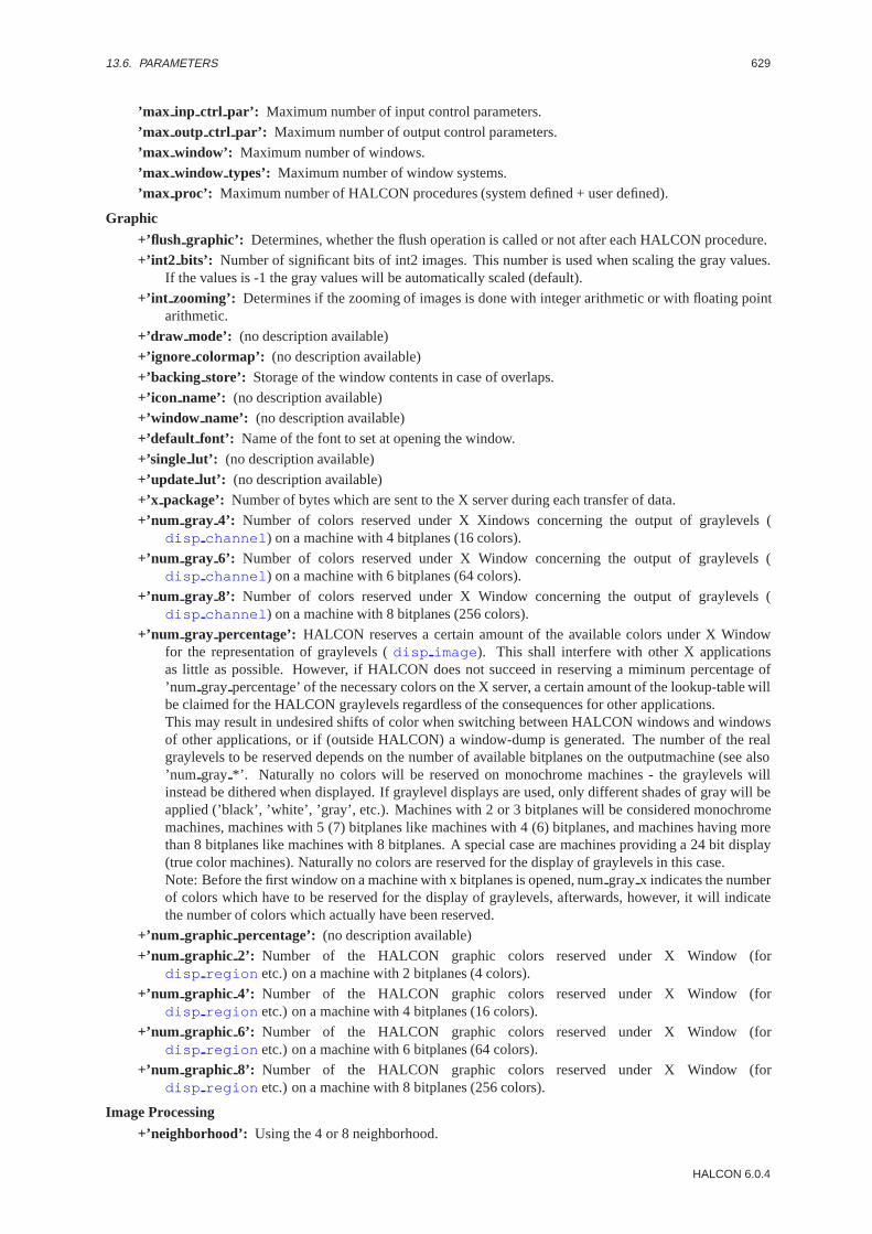
13.6. PARAMETERS 629
’max inp ctrl par’: Maximum number of input control parameters.
’max outp ctrl par’: Maximum number of output control parameters.
’max window’: Maximum number of windows.
’max window types’: Maximum number of window systems.
’max proc’: Maximum number of HALCON procedures (system defined + user defined).
Graphic
+’flush graphic’: Determines, whether the flush operation is called or not after each HALCON procedure.
+’int2 bits’: Number of significant bits of int2 images. This number is used when scaling the gray values.If the values is -1 the gray values will be automatically scaled (default).
+’int zooming’: Determines if the zooming of images is done with integer arithmetic or with floating pointarithmetic.
+’draw mode’: (no description available)
+’ignore colormap’: (no description available)
+’backing store’: Storage of the window contents in case of overlaps.
+’icon name’: (no description available)
+’window name’: (no description available)
+’default font’: Name of the font to set at opening the window.
+’single lut’: (no description available)
+’update lut’: (no description available)
+’x package’: Number of bytes which are sent to the X server during each transfer of data.
+’num gray 4’: Number of colors reserved under X Xindows concerning the output of graylevels (disp channel ) on a machine with 4 bitplanes (16 colors).
+’num gray 6’: Number of colors reserved under X Window concerning the output of graylevels (disp channel ) on a machine with 6 bitplanes (64 colors).
+’num gray 8’: Number of colors reserved under X Window concerning the output of graylevels (disp channel ) on a machine with 8 bitplanes (256 colors).
+’num gray percentage’: HALCON reserves a certain amount of the available colors under X Windowfor the representation of graylevels (disp image ). This shall interfere with other X applicationsas little as possible. However, if HALCON does not succeed in reserving a miminum percentage of’num gray percentage’ of the necessary colors on the X server, a certain amount of the lookup-table willbe claimed for the HALCON graylevels regardless of the consequences for other applications.This may result in undesired shifts of color when switching between HALCON windows and windowsof other applications, or if (outside HALCON) a window-dump is generated. The number of the realgraylevels to be reserved depends on the number of available bitplanes on the outputmachine (see also’num gray *’. Naturally no colors will be reserved on monochrome machines - the graylevels willinstead be dithered when displayed. If graylevel displays are used, only different shades of gray will beapplied (’black’, ’white’, ’gray’, etc.). Machines with 2 or 3 bitplanes will be considered monochromemachines, machines with 5 (7) bitplanes like machines with 4 (6) bitplanes, and machines having morethan 8 bitplanes like machines with 8 bitplanes. A special case are machines providing a 24 bit display(true color machines). Naturally no colors are reserved for the display of graylevels in this case.Note: Before the first window on a machine with x bitplanes is opened, numgray x indicates the numberof colors which have to be reserved for the display of graylevels, afterwards, however, it will indicatethe number of colors which actually have been reserved.
+’num graphic percentage’: (no description available)
+’num graphic 2’: Number of the HALCON graphic colors reserved under X Window (fordisp region etc.) on a machine with 2 bitplanes (4 colors).
+’num graphic 4’: Number of the HALCON graphic colors reserved under X Window (fordisp region etc.) on a machine with 4 bitplanes (16 colors).
+’num graphic 6’: Number of the HALCON graphic colors reserved under X Window (fordisp region etc.) on a machine with 6 bitplanes (64 colors).
+’num graphic 8’: Number of the HALCON graphic colors reserved under X Window (fordisp region etc.) on a machine with 8 bitplanes (256 colors).
Image Processing
+’neighborhood’: Using the 4 or 8 neighborhood.
HALCON 6.0.4
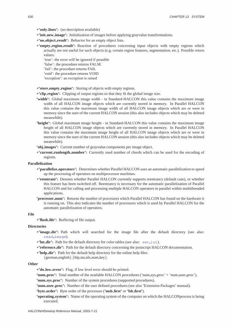
630 CHAPTER 13. SYSTEM
+’only lines’: (no description available)+’init new image’: Initialization of images before applying grayvalue transformations.
+’no object result’: Behavior for an empty object lists.+’empty region result’: Reaction of procedures concerning input objects with empty regions which
actually are not useful for such objects (e.g. certain region features, segmentation, etc.). Possible returnvalues:’true’: the error will be ignored if possible’false’: the procedure returns FALSE’fail’: the procedure returns FAIL’void’: the procedure returns VOID’exception’: an exception is raised
+’store empty region’: Storing of objects with empty regions.+’clip region’: Clipping of output regions so that they fit the global image size.
’width’: Global maximum image width - in Standard-HALCON this value contains the maximum imagewidth of all HALCON image objects which are currently stored in memory. In Parallel HALCONthis value contains the maximum image width of all HALCON image objects which are or were inmemory since the start of the current HALCON session (this also includes objects which may be deletedmeanwhile).
’height’: Global maximum image height - in Standard-HALCON this value contains the maximum imageheight of all HALCON image objects which are currently stored in memory. In Parallel HALCONthis value contains the maximum image height of all HALCON image objects which are or were inmemory since the start of the current HALCON session (this also includes objects which may be deletedmeanwhile).
’obj images’: Current number of grayvalue components per image object.+’current runlength number’: Currently used number of chords which can be used for the encoding of
regions.
Parallelization
+’parallelize operators’: Determines whether Parallel HALCON uses an automatic parallelization to speedup the processing of operators on multiprocessor machines.
+’reentrant’: Denotes whether Parallel HALCON currently supports reentrancy (default case), or whetherthis feature has been switched off. Reentrancy is necessary for the automatic parallelization of ParallelHALCON and for calling and processing multiple HALCON operators in parallel within multithreadedapplications.
’processor num’: Returns the number of processors which Parallel HALCON has found on the hardware itis running on. This also indicates the number of processors which is used by Parallel HALCON for theautomatic parallelization of operators.
File
+’flush file’: Buffering of file output.
Directories
+’image dir’: Path which will searched for the image file after the default directory (see also:read image ).
+’lut dir’: Path for the default directory for color tables (see also:set lut ).+’reference dir’: Path for the default directory concerning the postscript HALCON documentation.
+’help dir’: Path for the default help directory for the online help files:{german,english}.{hlp,sta,idx,num,key}.
Other
+’do low error’: Flag, if low level error should be printed.’num proc’: Total number of the available HALCON procedures (’numsysproc’ + ’num userproc’).
’num sysproc’: Number of the system procedures (supported procedures).’num user proc’: Number of the user defined procedures (see also ’Extension Packages’ manual).
’byte order’: Byte order of the processor (’msb first’ or ’lsb first’ ).’operating system’: Name of the operating system of the computer on which the HALCONprocess is being
executed.
HALCON/HDevelop Reference Manual, 2003-7-21
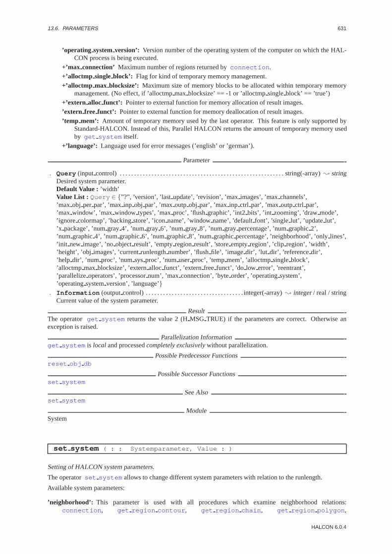
13.6. PARAMETERS 631
’operating systemversion’: Version number of the operating system of the computer on which the HAL-CON process is being executed.
+’max connection’ Maximum number of regions returned byconnection .
+’alloctmp single block’: Flag for kind of temporary memory management.
+’alloctmp max blocksize’: Maximum size of memory blocks to be allocated within temporary memorymanagement. (No effect, if ’alloctmpmax blocksize’ == -1 or ’alloctmpsingleblock’ == ’true’)
+’extern alloc funct’: Pointer to external function for memory allocation of result images.
’extern free funct’: Pointer to external function for memory deallocation of result images.
’temp mem’: Amount of temporary memory used by the last operator. This feature is only supported byStandard-HALCON. Instead of this, Parallel HALCON returns the amount of temporary memory usedby get system itself.
+’language’: Language used for error messages (’english’ or ’german’).
Parameter
. Query (input control) . . . . . . . . . . . . . . . . . . . . . . . . . . . . . . . . . . . . . . . . . . . . . . . . . . . . . . . . . string(-array); stringDesired system parameter.Default Value : ’width’Value List : Query ∈ {”?”, ’version’, ’last update’, ’revision’, ’maximages’, ’maxchannels’,’max obj per par’, ’max inp obj par’, ’max outp obj par’, ’max inp ctrl par’, ’max outp ctrl par’,’max window’, ’max window types’, ’maxproc’, ’flush graphic’, ’int2 bits’, ’int zooming’, ’drawmode’,’ignore colormap’, ’backingstore’, ’icon name’, ’windowname’, ’defaultfont’, ’single lut’, ’update lut’,’x package’, ’numgray 4’, ’num gray 6’, ’num gray 8’, ’num gray percentage’, ’numgraphic2’,’num graphic4’, ’num graphic6’, ’num graphic8’, ’num graphicpercentage’, ’neighborhood’, ’onlylines’,’init new image’, ’no object result’, ’emptyregionresult’, ’storeemptyregion’, ’clip region’, ’width’,’height’, ’obj images’, ’currentrunlengthnumber’, ’flushfile’, ’image dir’, ’lut dir’, ’referencedir’,’help dir’, ’num proc’, ’num sysproc’, ’num userproc’, ’tempmem’, ’alloctmpsingle block’,’alloctmp max blocksize’, ’externalloc funct’, ’extern free funct’, ’do low error’, ’reentrant’,’parallelizeoperators’, ’processornum’, ’max connection’, ’byteorder’, ’operatingsystem’,’operatingsystemversion’, ’language’}
. Information (outputcontrol) . . . . . . . . . . . . . . . . . . . . . . . . . . . . . . . . . . integer(-array); integer/ real / stringCurrent value of the system parameter.
ResultThe operator get system returns the value 2 (HMSG TRUE) if the parameters are correct. Otherwise anexception is raised.
Parallelization Informationget system is local and processedcompletely exclusivelywithout parallelization.
Possible Predecessor Functionsreset obj db
Possible Successor Functionsset system
See Alsoset system
ModuleSystem
set system ( : : Systemparameter, Value : )
Setting of HALCON system parameters.
The operatorset system allows to change different system parameters with relation to the runlength.
Available system parameters:
’neighborhood’: This parameter is used with all procedures which examine neighborhood relations:connection , get region contour , get region chain , get region polygon ,
HALCON 6.0.4
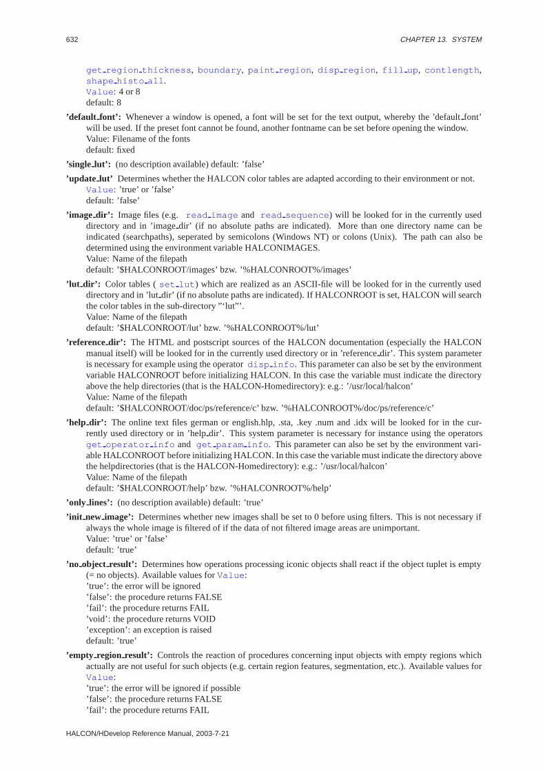
632 CHAPTER 13. SYSTEM
get region thickness , boundary , paint region , disp region , fill up , contlength ,shape histo all .Value : 4 or 8default: 8
’default font’: Whenever a window is opened, a font will be set for the text output, whereby the ’defaultfont’will be used. If the preset font cannot be found, another fontname can be set before opening the window.Value: Filename of the fontsdefault: fixed
’single lut’: (no description available) default: ’false’
’update lut’ Determines whether the HALCON color tables are adapted according to their environment or not.Value : ’true’ or ’false’default: ’false’
’image dir’: Image files (e.g. read image and read sequence ) will be looked for in the currently useddirectory and in ’imagedir’ (if no absolute paths are indicated). More than one directory name can beindicated (searchpaths), seperated by semicolons (Windows NT) or colons (Unix). The path can also bedetermined using the environment variable HALCONIMAGES.Value: Name of the filepathdefault: ’$HALCONROOT/images’ bzw. ’%HALCONROOT%/images’
’lut dir’: Color tables (set lut ) which are realized as an ASCII-file will be looked for in the currently useddirectory and in ’lutdir’ (if no absolute paths are indicated). If HALCONROOT is set, HALCON will searchthe color tables in the sub-directory ”‘lut”’.Value: Name of the filepathdefault: ’$HALCONROOT/lut’ bzw. ’%HALCONROOT%/lut’
’reference dir’: The HTML and postscript sources of the HALCON documentation (especially the HALCONmanual itself) will be looked for in the currently used directory or in ’referencedir’. This system parameteris necessary for example using the operatordisp info . This parameter can also be set by the environmentvariable HALCONROOT before initializing HALCON. In this case the variable must indicate the directoryabove the help directories (that is the HALCON-Homedirectory): e.g.: ’/usr/local/halcon’Value: Name of the filepathdefault: ’$HALCONROOT/doc/ps/reference/c’ bzw. ’%HALCONROOT%/doc/ps/reference/c’
’help dir’: The online text files german or english.hlp, .sta, .key .num and .idx will be looked for in the cur-rently used directory or in ’helpdir’. This system parameter is necessary for instance using the operatorsget operator info and get param info . This parameter can also be set by the environment vari-able HALCONROOT before initializing HALCON. In this case the variable must indicate the directory abovethe helpdirectories (that is the HALCON-Homedirectory): e.g.: ’/usr/local/halcon’Value: Name of the filepathdefault: ’$HALCONROOT/help’ bzw. ’%HALCONROOT%/help’
’only lines’: (no description available) default: ’true’
’init new image’: Determines whether new images shall be set to 0 before using filters. This is not necessary ifalways the whole image is filtered of if the data of not filtered image areas are unimportant.Value: ’true’ or ’false’default: ’true’
’no object result’: Determines how operations processing iconic objects shall react if the object tuplet is empty(= no objects). Available values forValue :’true’: the error will be ignored’false’: the procedure returns FALSE’fail’: the procedure returns FAIL’void’: the procedure returns VOID’exception’: an exception is raiseddefault: ’true’
’empty region result’: Controls the reaction of procedures concerning input objects with empty regions whichactually are not useful for such objects (e.g. certain region features, segmentation, etc.). Available values forValue :’true’: the error will be ignored if possible’false’: the procedure returns FALSE’fail’: the procedure returns FAIL
HALCON/HDevelop Reference Manual, 2003-7-21

13.6. PARAMETERS 633
’void’: the procedure returns VOID’exception’: an exception is raiseddefault: ’true’
’store empty region’: Quite a number of operations will lead to the creation of objects with an empty region (=no image points) (e.g.intersection , threshold , etc.). This parameter determines whether the objectwith an empty region will be returned as a result (’true’) or whether it will be ignored (’false’) that is no resultwill be returned.Value : ’true’ or ’false’default: ’true’
’backing store’: Determines whether the window content will be refreshed in case of overlapping of the win-dows. Some implementations of X Window are faulty; in order to avoid these errors, the storing of contentscan be deactivated. It may be recommendable in some cases to deactivate the security mechanism, if e.g.performance / memory is what matters.Value: true or falsedefault: true
’flush graphic’: After each HALCON procedure which creates a graphic output, a flush operation will be exe-cuted in order to display the data immediately on screen. This is not necessary with all programs (e.g. ifeverything is done with the help of the mouse). In this case ’flushgraphic’ can be set to ’false’ to improvethe runlength.Value: ’true’ or ’false’default: ’true’
’flush file’: This parameter determines whether the output into a file (also to the terminal) shall be buffered ornot. If the output is to be buffered, in general the data will be displayed on the terminal only after enteringthe operatorfnew line .Value: ’true’ or ’false’default: ’true’
’x package’: The output of image data via the network may cause errors owing to the heavy load on the computeror on the network. In order to avoid this, the data are transmitted in small packages. If the computer is usedlocally, these units can be enlarged at will. This can lead to a notably improved output performance.Value : package size (in bytes)default: 20480
’int2 bits’: Number of significant bits of int2 images. This number is used when scaling the gray values. If thevalues is -1 the gray values will be automatically scaled (default).Value : -1 or 9..15default: -1
’num gray 4’: Number of colors to be reserved under X Window to allow the output of graylevels dispchannelon a machine with 4 bitplanes (16 colors).Attention! This value may only be changed before the first window has been opened on the machine.Value : 2 - 12default: 8
’num gray 6’: Number of colors to be reserved under X Window to allow the output of graylevels dispchannelon a machine with 6 bitplanes (64 colors).Attention! This value may only be changed before the first window has been opened on the machine.Value : 2 - 62default: 50
’num gray 8’: Number of colors to be reserved under X Window to allow the output of graylevels dispchannelon a machine with 8 bitplanes (256 colors).Attention! This value may only be changed before the first window has been opened on the machine.Value : 2 - 254default: 140
’num gray percentage’: Under X Window HALCON reserves a part of the available colors for the representa-tion of gray values (disp channel ). This shall interfere with other X applications as little as possible.However, if HALCON does not succeed in reserving a miminum percentage of ’numgray percentage’ ofthe necessary colors on the X server, a certain amount of the lookup table will be claimed for the HALCONgraylevels regardless of the consequences. This may result in undesired shifts of color when switching be-tween HALCON windows and windows of other applications, or (outside HALCON) if a window-dump is
HALCON 6.0.4

634 CHAPTER 13. SYSTEM
generated. The number of the real graylevels to be reserved depends on the number of available bitplanes onthe outputmachine (see also ’numgray *’. Naturally no colors will be reserved on monochrome machines -the graylevels will instead be dithered when displayed. If graylevel-displays are used, only different shadesof gray will be applied (’black’, ’white’, ’gray’, etc.). Machines with 2 or 3 bitplanes will be consideredmonochrome machines, machines with 5 (7) bitplanes like machines with 4 (6) bitplanes, and machines hav-ing more than 8 bitplanes like machines with 8 bitplanes. A special case are machines providing a 24 bitdisplay (true color machines). Naturally no colors are reserved for the display of graylevels in this case.Note: This value may only be changed before the first window has been opened on the machine. For beforeopening the first window on a machine with x bitplanes, numgray x indicates the number of colors whichhave to be reserved for the display of graylevels, afterwards, however, it will indicate the number of colorswhich actually have been reserved.Value : 0 - 100default: 30
’num graphic percentage’: (no description available) default: 60
’draw mode’: (no description available) default: ’complement’
’int zooming’: (no description available) default: ’true’
’ignore colormap’: (no description available) default: ’false’
’icon name’: (no description available) default: ’default’
’num graphic 2’: Number of the graphic colors to be reserved by HALCON under X Window (concerning theoperatorsdisp region etc.) on a machine with 2 bitplanes (4 colors).Attention: This value may only be changed before the first window has been opened on the machine.Value : 0 - 2default: 2
’num graphic 4’: Number of the graphic colors to be reserved by HALCON under X Window (concerning theoperatorsdisp region etc.) on a machine with 4 bitplanes (16 colors).Attention: This value may only be changed before the first window has been opened on the machine.Value : 0 - 14default: 5
’num graphic 6’: Number of the graphic colors to be reserved by HALCON under X Window (concerning theoperatorsdisp region etc.) on a machine with 6 bitplanes (64 colors).Attention: This value may only be changed before the first window has been opened on the machine.Value : 0 - 62default: 10
’num graphic 8’: Number of the graphic colors to be reserved by HALCON under X Window (concerning theoperatorsdisp region etc.) on a machine with 8 bitplanes (256 colors).Attention: This value may only be changed before the first window has been opened on the machine.Value : 0 - 64default: 20
’graphic colors’ HALCON reserves the first numgraphicx colors form this list of color names as graphic colors.As a default HALCON uses this same list which is also returned by usingquery all colors . However,the list can be changed individually: hereby a tuplet of color names will be returned as value. It is recom-mendable that such a tuplet always includes the colors ’black’ and ’white’, and optionally also ’red’, ’green’and ’blue’. If ’default’ is set asValue , HALCON returns to the initial setting. Note: On graylevel machinesnot the first x colors will be reserved, but the first x shades of gray from the list.Attention: This value may only be changed before the first window has been opened on the machine.Value : Tuplets of X Window color namesdefault: see also queryall colors
’current runlength number’: Regions will be stored internally in a certain runlengthcode. This parameter candetermine the maximum number of chords which may be used for representing a region. Please note thatsome procedures raise the number on their own if necessary.The value can be enlarged as well as reduced.Value : maximum number of chordsdefault: 50000
’clip region’: Determines whether the regions of iconic objects of the HALCON database will be clipped tothe currently used image size or not. This is the case for example in procedures likegen circle ,
HALCON/HDevelop Reference Manual, 2003-7-21
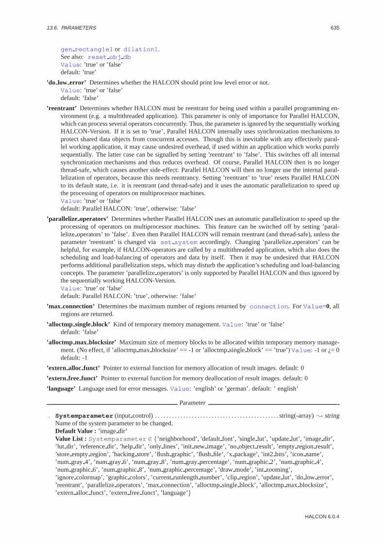
13.6. PARAMETERS 635
gen rectangle1 or dilation1 .See also:reset obj dbValue : ’true’ or ’false’default: ’true’
’do low error’ Determines whether the HALCON should print low level error or not.Value : ’true’ or ’false’default: ’false’
’reentrant’ Determines whether HALCON must be reentrant for being used within a parallel programming en-vironment (e.g. a multithreaded application). This parameter is only of importance for Parallel HALCON,which can process several operators concurrently. Thus, the parameter is ignored by the sequentially workingHALCON-Version. If it is set to ’true’, Parallel HALCON internally uses synchronization mechanisms toprotect shared data objects from concurrent accesses. Though this is inevitable with any effectively paral-lel working application, it may cause undesired overhead, if used within an application which works purelysequentially. The latter case can be signalled by setting ’reentrant’ to ’false’. This switches off all internalsynchronization mechanisms and thus reduces overhead. Of course, Parallel HALCON then is no longerthread-safe, which causes another side-effect: Parallel HALCON will then no longer use the internal paral-lelization of operators, because this needs reentrancy. Setting ’reentrant’ to ’true’ resets Parallel HALCONto its default state, i.e. it is reentrant (and thread-safe) and it uses the automatic parallelization to speed upthe processing of operators on multiprocessor machines.Value : ’true’ or ’false’default: Parallel HALCON: ’true’, otherwise: ’false’
’parallelize operators’ Determines whether Parallel HALCON uses an automatic parallelization to speed up theprocessing of operators on multiprocessor machines. This feature can be switched off by setting ’paral-lelize operators’ to ’false’. Even then Parallel HALCON will remain reentrant (and thread-safe), unless theparameter ’reentrant’ is changed viaset system accordingly. Changing ’parallelizeoperators’ can behelpful, for example, if HALCON-operators are called by a multithreaded application, which also does thescheduling and load-balancing of operators and data by itself. Then it may be undesired that HALCONperforms additional parallelization steps, which may disturb the application’s scheduling and load-balancingconcepts. The parameter ’parallelizeoperators’ is only supported by Parallel HALCON and thus ignored bythe sequentially working HALCON-Version.Value : ’true’ or ’false’default: Parallel HALCON: ’true’, otherwise: ’false’
’max connection’ Determines the maximum number of regions returned byconnection . For Value =0, allregions are returned.
’alloctmp single block’ Kind of temporary memory management.Value : ’true’ or ’false’default: ’false’
’alloctmp max blocksize’ Maximum size of memory blocks to be allocated within temporary memory manage-ment. (No effect, if ’alloctmpmax blocksize’ == -1 or ’alloctmpsingleblock’ == ’true’) Value : -1 or ¿= 0default: -1
’extern alloc funct’ Pointer to external function for memory allocation of result images. default: 0
’extern free funct’ Pointer to external function for memory deallocation of result images. default: 0
’language’ Language used for error messages.Value : ’english’ or ’german’. default: ’ english’
Parameter
. Systemparameter (input control) . . . . . . . . . . . . . . . . . . . . . . . . . . . . . . . . . . . . . . . . . . . . string(-array); stringName of the system parameter to be changed.Default Value : ’image dir’Value List : Systemparameter ∈ {’neighborhood’, ’defaultfont’, ’single lut’, ’update lut’, ’image dir’,’lut dir’, ’referencedir’, ’help dir’, ’only lines’, ’init new image’, ’no object result’, ’emptyregionresult’,’store emptyregion’, ’backingstore’, ’flushgraphic’, ’flushfile’, ’x package’, ’int2bits’, ’icon name’,’num gray 4’, ’num gray 6’, ’num gray 8’, ’num gray percentage’, ’numgraphic2’, ’num graphic4’,’num graphic6’, ’num graphic8’, ’num graphicpercentage’, ’drawmode’, ’int zooming’,’ignore colormap’, ’graphiccolors’, ’currentrunlengthnumber’, ’clip region’, ’updatelut’, ’do low error’,’reentrant’, ’parallelizeoperators’, ’maxconnection’, ’alloctmpsingleblock’, ’alloctmp max blocksize’,’extern alloc funct’, ’extern free funct’, ’language’}
HALCON 6.0.4

636 CHAPTER 13. SYSTEM
. Value (input control) . . . . . . . . . . . . . . . . . . . . . . . . . . . . . . . . . . . . . . . . . . . . string(-array); string/ integer / realNew value of the system parameter.Default Value : ’true’Value Suggestions :Value ∈ {’true’, ’false’, 0, 4, 8, 100, 140, 255}
ResultThe operator set system returns the value 2 (HMSG TRUE) if the parameters are correct. Otherwise anexception will be raised.
Parallelization Informationset system is local and processedcompletely exclusivelywithout parallelization.
Possible Predecessor Functionsreset obj db , get system , set check
See Alsoget system , set check
ModuleSystem
13.7 Serial
clear serial ( : : SerialHandle, Channel : )
Clear the buffer of a serial connection.
clear serial discards data written to the serial device referred to bySerialHandle , but not transmitted(Channel = ’output’ ), or data received, but not read (Channel = ’input’ ), or performs both these operations atonce (Channel = ’in out’ ).
Parameter
. SerialHandle (input control) . . . . . . . . . . . . . . . . . . . . . . . . . . . . . . . . . . . . . . . . . . . . . . . . . . . serialid ; integerSerial interface handle.
. Channel (input control) . . . . . . . . . . . . . . . . . . . . . . . . . . . . . . . . . . . . . . . . . . . . . . . . . . . . . . . . . . . . . string; stringBuffer to be cleared.Default Value : ’input’Value List : Channel ∈ {’input’, ’output’, ’in out’}
ResultIf the parameters are correct and the buffers of the serial device could be cleared, the operatorclear serialreturns the value 2 (HMSG TRUE). Otherwise an exception is raised.
Parallelization Informationclear serial is reentrantand processedwithoutparallelization.
Possible Predecessor Functionsopen serial
Possible Successor Functionsread serial , write serial
See Alsoread serial
ModuleSystem
close all serials ( : : : )
Close all serial devices.
close all serials closes all serial devices that have been opened withopen serial .
HALCON/HDevelop Reference Manual, 2003-7-21

13.7. SERIAL 637
Resultclose all serials returns always 2 (HMSG TRUE).
Parallelization Informationclose all serials is reentrantand processedwithoutparallelization.
Possible Predecessor Functionsopen serial
Alternativesclose serial
See Alsoopen serial , close file
ModuleSystem
close serial ( : : SerialHandle : )
Close a serial device.
close serial closes a serial device that was opened withopen serial .
Parameter
. SerialHandle (input control) . . . . . . . . . . . . . . . . . . . . . . . . . . . . . . . . . . . . . . . . . . . . . . . . . . . serialid ; integerSerial interface handle.
ResultIf the parameters are correct and the device could be closed, the operatorclose serial returns the value 2(H MSG TRUE). Otherwise an exception is raised.
Parallelization Informationclose serial is reentrantand processedwithoutparallelization.
Possible Predecessor Functionsopen serial
See Alsoopen serial , close file
ModuleSystem
get serial param ( : : SerialHandle : BaudRate, DataBits, FlowControl,Parity, StopBits, TotalTimeOut, InterCharTimeOut )
Get the parameters of a serial device.
get serial param returns the current parameter settings of the serial device passed inSerialHandle . Fora description of the parameters of a serial device, seeset serial param .
Parameter
. SerialHandle (input control) . . . . . . . . . . . . . . . . . . . . . . . . . . . . . . . . . . . . . . . . . . . . . . . . . . . serialid ; integerSerial interface handle.
. BaudRate (outputcontrol) . . . . . . . . . . . . . . . . . . . . . . . . . . . . . . . . . . . . . . . . . . . . . . . . . . . . . . . . . integer; integerSpeed of the serial interface.
. DataBits (outputcontrol) . . . . . . . . . . . . . . . . . . . . . . . . . . . . . . . . . . . . . . . . . . . . . . . . . . . . . . . . . integer; integerNumber of data bits of the serial interface.
. FlowControl (outputcontrol) . . . . . . . . . . . . . . . . . . . . . . . . . . . . . . . . . . . . . . . . . . . . . . . . . . . . . . . string; stringType of flow control of the serial interface.
. Parity (outputcontrol) . . . . . . . . . . . . . . . . . . . . . . . . . . . . . . . . . . . . . . . . . . . . . . . . . . . . . . . . . . . . . . string; stringParity of the serial interface.
HALCON 6.0.4

638 CHAPTER 13. SYSTEM
. StopBits (outputcontrol) . . . . . . . . . . . . . . . . . . . . . . . . . . . . . . . . . . . . . . . . . . . . . . . . . . . . . . . . . integer; integerNumber of stop bits of the serial interface.
. TotalTimeOut (outputcontrol) . . . . . . . . . . . . . . . . . . . . . . . . . . . . . . . . . . . . . . . . . . . . . . . . . . . integer; integerTotal timeout of the serial interface in ms.
. InterCharTimeOut (outputcontrol) . . . . . . . . . . . . . . . . . . . . . . . . . . . . . . . . . . . . . . . . . . . . . . integer; integerInter-character timeout of the serial interface in ms.
ResultIf the parameters are correct and the parameters of the device could be read, the operatorget serial paramreturns the value 2 (HMSG TRUE). Otherwise an exception is raised.
Parallelization Informationget serial param is reentrantand processedwithoutparallelization.
Possible Predecessor Functionsopen serial
Possible Successor Functionsget serial param , read serial , write serial
See Alsoset serial param
ModuleSystem
open serial ( : : PortName : SerialHandle )
Open a serial device.
open serial opens a serial device. The name of the device is determined by the parameterPortName and isoperating system specific. On Windows NT machines,’COM1’ -’COM4’ is typically used, while on Unix systemsthe serial devices usually are named’/dev/tty*’ . The parameters of the serial device, e.g., its speed or number ofdata bits, are set to the system default values for the respective device after the device has been opened. They canbe set or changed by callingset serial param .
Parameter
. PortName (input control) . . . . . . . . . . . . . . . . . . . . . . . . . . . . . . . . . . . . . . . . . . . . . . . . . . . filename.named; stringName of the serial port.Default Value : ”COM1”Value Suggestions :PortName ∈ {”COM1”, ”COM2”, ”COM3”, ”COM4”, ”/dev/ttya”, ”/dev/ttyb”,”/dev/tty00”, ”/dev/tty01”, ”/dev/ttyd1”, ”/dev/ttyd2”, ”/dev/cua0”, ”/dev/cua1”}
. SerialHandle (outputcontrol) . . . . . . . . . . . . . . . . . . . . . . . . . . . . . . . . . . . . . . . . . . . . . . . . . . serialid ; integerSerial interface handle.
ResultIf the parameters are correct and the device could be opened, the operatoropen serial returns the value 2(H MSG TRUE). Otherwise an exception is raised.
Parallelization Informationopen serial is reentrantand processedwithoutparallelization.
Possible Successor Functionsset serial param , read serial , write serial , close serial
See Alsoset serial param , get serial param , open file
ModuleSystem
read serial ( : : SerialHandle, NumCharacters : Data )
Read from a serial device.
HALCON/HDevelop Reference Manual, 2003-7-21

13.7. SERIAL 639
read serial tries to readNumCharacters from the serial device given inSerialHandle . The readcharacters are returned inData as a tuple of integers. This allows to read NUL characters, which would otherwisebe interpreted as the end of a string. If the timeout of the serial device has been set to a value greater than 0 withset serial param , read serial waits at most as long for the arrival of the first character as indicated bythe timeout. Otherwise, the operator returns immediately. In any case, the number of characters available at thetime of return are passed back to the caller, i.e., fewer characters than requested can be returned. This can bechecked by the length of the tupleData .
Parameter
. SerialHandle (input control) . . . . . . . . . . . . . . . . . . . . . . . . . . . . . . . . . . . . . . . . . . . . . . . . . . . serialid ; integerSerial interface handle.
. NumCharacters (input control) . . . . . . . . . . . . . . . . . . . . . . . . . . . . . . . . . . . . . . . . . . . . . . . . . . . integer; integerNumber of characters to read.Default Value : 1Value Suggestions :NumCharacters ∈ {1, 2, 3, 4, 5, 10, 20, 40, 100}
. Data (outputcontrol) . . . . . . . . . . . . . . . . . . . . . . . . . . . . . . . . . . . . . . . . . . . . . . . . . . . . . . . integer(-array); integerRead characters (as tuple of integers).
ResultIf the parameters are correct and the read from the device was successful, the operatorread serial returns thevalue 2 (HMSG TRUE). Otherwise an exception is raised.
Parallelization Informationread serial is reentrantand processedwithoutparallelization.
Possible Predecessor Functionsopen serial
See Alsowrite serial
ModuleSystem
set serial param ( : : SerialHandle, BaudRate, DataBits, FlowControl,Parity, StopBits, TotalTimeOut, InterCharTimeOut : )
Set the parameters of a serial device.
set serial param can be used to set the parameters of a serial device. The parameterBaudRate determinesthe input and output speed of the device. It should be noted that not all devices support all possible speeds. Thenumber of sent and received data bits is set withDataBits . The parameterFlowControl determines if andwhat kind of data flow control should be used. In the latter case, a choice between software control (’xon xoff’ ) andhardware control (’cts rts’ , ’dtr dsr’ ) can be made. If and what kind of parity check of the transmitted data shouldbe performed can be determined byParity . The number of stop bits sent is set withStopBits . Finally, twotimeout for reading from the serial device can be set. The parameterTotalTimeOut determines the maximumtime, which may pass inread serial until the first character arrives, independent of the actual number ofcharacters requested. The parameterInterCharTimeOut determines the time which may pass between thereading of individual characters, if multiple characters are requested withread serial . If one of the timeoutsis set to-1, a read waits an arbitrary amount of time for the arrival of characters. Thus, on Windows NT systems,a total timeout ofTotalTimeOut + nInterCharTimeOut results ifn characters are to be read. On Unixsystems, only one of the two timeouts can be set. Thus, if both timeouts are passed larger than -1, only the totaltimeout is used. The unit of both timeouts is milliseconds. For each parameter, the current values can be left ineffect by passing’unchanged’.
Parameter
. SerialHandle (input control) . . . . . . . . . . . . . . . . . . . . . . . . . . . . . . . . . . . . . . . . . . . . . . . . . . . serialid ; integerSerial interface handle.
. BaudRate (input control) . . . . . . . . . . . . . . . . . . . . . . . . . . . . . . . . . . . . . . . . . . . . . . . . . . . integer; integer/ stringSpeed of the serial interface.Default Value : ’unchanged’Value List : BaudRate ∈ {50, 75, 110, 134, 150, 200, 300, 600, 1200, 1800, 2400, 4800, 9600, 19200,
HALCON 6.0.4

640 CHAPTER 13. SYSTEM
38400, 57600, 76800, 115200, 153600, 230400, 307200, 460800, ’unchanged’}. DataBits (input control) . . . . . . . . . . . . . . . . . . . . . . . . . . . . . . . . . . . . . . . . . . . . . . . . . . . integer; integer/ string
Number of data bits of the serial interface.Default Value : ’unchanged’Value List : DataBits ∈ {5, 6, 7, 8, ’unchanged’}
. FlowControl (input control) . . . . . . . . . . . . . . . . . . . . . . . . . . . . . . . . . . . . . . . . . . . . . . . . . . . . . . . . string; stringType of flow control of the serial interface.Default Value : ’unchanged’Value List : FlowControl ∈ {’none’, ’xon xoff’, ’cts rts’, ’dtr dsr’, ’unchanged’}
. Parity (input control) . . . . . . . . . . . . . . . . . . . . . . . . . . . . . . . . . . . . . . . . . . . . . . . . . . . . . . . . . . . . . . . string; stringParity of the serial interface.Default Value : ’unchanged’Value List : Parity ∈ {’none’, ’odd’, ’even’, ’unchanged’}
. StopBits (input control) . . . . . . . . . . . . . . . . . . . . . . . . . . . . . . . . . . . . . . . . . . . . . . . . . . . integer; integer/ stringNumber of stop bits of the serial interface.Default Value : ’unchanged’Value List : StopBits ∈ {1, 2, ’unchanged’}
. TotalTimeOut (input control) . . . . . . . . . . . . . . . . . . . . . . . . . . . . . . . . . . . . . . . . . . . . . integer; integer/ stringTotal timeout of the serial interface in ms.Default Value : ’unchanged’Value Suggestions :TotalTimeOut ∈ {-1, 0, 100, 200, 300, 400, 500, 600, 700, 800, 900, 1000,’unchanged’}
. InterCharTimeOut (input control) . . . . . . . . . . . . . . . . . . . . . . . . . . . . . . . . . . . . . . . . integer; integer/ stringInter-character timeout of the serial interface in ms.Default Value : ’unchanged’Value Suggestions :InterCharTimeOut ∈ {-1, 0, 100, 200, 300, 400, 500, 600, 700, 800, 900, 1000,’unchanged’}
ResultIf the parameters are correct and the parameters of the device could be set, the operatorset serial paramreturns the value 2 (HMSG TRUE). Otherwise an exception is raised.
Parallelization Informationset serial param is reentrantand processedwithoutparallelization.
Possible Predecessor Functionsopen serial , get serial param
Possible Successor Functionsread serial , write serial
See Alsoget serial param
ModuleSystem
write serial ( : : SerialHandle, Data : )
Write to a serial connection.
write serial writes the characters given inData to the serial device given bySerialHandle . The datato be written is passed as a tuple of integers. This allows to write NUL characters, which would otherwise beinterpreted as the end of a string.write serial always waits until all data has been transmitted, i.e., a timoutfor writing cannot be set.
Parameter
. SerialHandle (input control) . . . . . . . . . . . . . . . . . . . . . . . . . . . . . . . . . . . . . . . . . . . . . . . . . . . serialid ; integerSerial interface handle.
. Data (input control) . . . . . . . . . . . . . . . . . . . . . . . . . . . . . . . . . . . . . . . . . . . . . . . . . . . . . . . . integer(-array); integerCharacters to write (as tuple of integers).
HALCON/HDevelop Reference Manual, 2003-7-21

13.8. SOCKETS 641
ResultIf the parameters are correct and the write to the device was successful, the operatorwrite serial returns thevalue 2 (HMSG TRUE). Otherwise an exception is raised.
Parallelization Informationwrite serial is reentrantand processedwithoutparallelization.
Possible Predecessor Functionsopen serial
See Alsoread serial
ModuleSystem
13.8 Sockets
close socket ( : : Socket : )
Close a socket.
close socket closes a socket that was previously opened with open socket accept ,open socket connect , or socket accept connect . For a detailed example, seeopen socket accept .
Parameter
. Socket (input control) . . . . . . . . . . . . . . . . . . . . . . . . . . . . . . . . . . . . . . . . . . . . . . . . . . . . . . . . . . .socketid ; integerSocket number.
Parallelization Informationclose socket is reentrantand processedwithoutparallelization.
See Alsoopen socket accept , open socket connect , socket accept connect
ModuleSystem
get next socket data type ( : : Socket : DataType )
Determine the HALCON data type of the next socket data.
get next socket data type returns the data type of the next data that are present on the socketSocketand returns it inDataType . The possible values forDataType are:
’no data’: No data are present.
’no halcon data’: Some data are present, but they are not HALCON data.
’tuple’: The next data is a tuple.
’region’: The next data is a region object.
’image’: The next data is an image object.
’xld cont’: The next data is an XLD contour.
’xld poly’: The next data is an XLD polygon.
’xld para’: The next data is an XLD parallel.
’xld mod para’: The next data is a modified XLD parallel.
’xld ext para’: The next data is an extended XLD parallel.
HALCON 6.0.4

642 CHAPTER 13. SYSTEM
Parameter
. Socket (input control) . . . . . . . . . . . . . . . . . . . . . . . . . . . . . . . . . . . . . . . . . . . . . . . . . . . . . . . . . . .socketid ; integerSocket number.
. DataType (outputcontrol) . . . . . . . . . . . . . . . . . . . . . . . . . . . . . . . . . . . . . . . . . . . . . . . . . . . . . . . . . . . string; stringData type of next HALCON data.
Parallelization Informationget next socket data type is reentrantand processedwithoutparallelization.
See Alsosend image , receive image , send region , receive region , send tuple , receive tuple
ModuleSystem
open socket accept ( : : Port : AcceptingSocket )
Open a socket that accepts connection requests.
open socket accept opens a socket that accepts incoming connection requests by other HALCON processes.This operator is the necessary first step in the establishment of a communication channel between two HALCONprocesses. The socket listens for incoming connection requests on the port number given byPort . The acceptingsocket is returned inAcceptingSocket . open socket accept returns immediately without waiting fora request from another process, done by callingopen socket connect in the other process. This allowsmultiple other processes to connect to the particular HALCON process that callsopen socket accept . Toaccept an incoming connection request,socket accept connect must be called after another process hascalled open socket connect .
Parameter
. Port (input control) . . . . . . . . . . . . . . . . . . . . . . . . . . . . . . . . . . . . . . . . . . . . . . . . . . . . . . . . . . . . . . . integer; integerPort number.Default Value : 3000Typical Range of Values :1024≤ Port ≤ 65535Minimal Value Step : 1Recommended Value Step :1
. AcceptingSocket (outputcontrol) . . . . . . . . . . . . . . . . . . . . . . . . . . . . . . . . . . . . . . . . . . . . . socketid ; integerSocket number.
Example
/* Process 1 */dev_set_colored (12)open_socket_accept (3000, AcceptingSocket)/* Busy wait for an incoming connection */dev_error_var (Error, 1)dev_set_check (’˜give_error’)OpenStatus := 5while (OpenStatus # 2)
socket_accept_connect (AcceptingSocket, ’false’, Socket)OpenStatus := Errorwait_seconds (0.2)
endwhiledev_set_check (’give_error’)/* Connection established */receive_image (Image, Socket)threshold (Image, Region, 0, 63)send_region (Region, Socket)receive_region (ConnectedRegions, Socket)area_center (ConnectedRegions, Area, Row, Column)
HALCON/HDevelop Reference Manual, 2003-7-21

13.8. SOCKETS 643
send_tuple (Socket, Area)send_tuple (Socket, Row)send_tuple (Socket, Column)close_socket (Socket)close_socket (AcceptingSocket)
/* Process 2 */dev_set_colored (12)open_socket_connect (’localhost’, 3000, Socket)read_image (Image, ’fabrik’)send_image (Image, Socket)receive_region (Region, Socket)connection (Region, ConnectedRegions)send_region (ConnectedRegions, Socket)receive_tuple (Socket, Area)receive_tuple (Socket, Row)receive_tuple (Socket, Column)close_socket (Socket)
Parallelization Informationopen socket accept is reentrantand processedwithoutparallelization.
Possible Successor Functionssocket accept connect
See Alsoopen socket connect , close socket , send image , receive image , send region ,receive region , send tuple , receive tuple
ModuleSystem
open socket connect ( : : HostName, Port : Socket )
Open a socket to an existing socket.
open socket connect opens a connection to an accepting socket on the computerHostName, which listenson portPort . The listening socket in the other HALCON process must have been created earlier with the oper-ator open socket accept . The socket thus created is returned inSocket . To establish the connection, theHALCON process, in which the accepting socket resides, must callsocket accept connect . For a detailedexample, seeopen socket accept .
Parameter
. HostName (input control) . . . . . . . . . . . . . . . . . . . . . . . . . . . . . . . . . . . . . . . . . . . . . . . . . . . . . . . . . . . . string; stringHostname of the computer to connect to.Default Value : ’localhost’
. Port (input control) . . . . . . . . . . . . . . . . . . . . . . . . . . . . . . . . . . . . . . . . . . . . . . . . . . . . . . . . . . . . . . . integer; integerPort number.Default Value : 3000Typical Range of Values :1024≤ Port ≤ 65535Minimal Value Step : 1Recommended Value Step :1
. Socket (outputcontrol) . . . . . . . . . . . . . . . . . . . . . . . . . . . . . . . . . . . . . . . . . . . . . . . . . . . . . . . . . socketid ; integerSocket number.
Parallelization Informationopen socket connect is reentrantand processedwithoutparallelization.
Possible Successor Functionssend image , receive image , send region , receive region , send tuple , receive tuple
HALCON 6.0.4

644 CHAPTER 13. SYSTEM
See Alsoopen socket accept , socket accept connect , close socket
ModuleSystem
receive image ( : Image : Socket : )
Receive an image over a socket connection.
receive image reads an image object that was sent over the socket connection determined bySocket byanother HALCON process using the operatorsend image . If no image has been sent, the HALCON processcalling receive image blocks until enough data arrives. For a detailed example, seeopen socket accept .
Parameter
. Image (outputobject) . . . . . . . . . . . . . . . . . . . . . . . . . . . . . . . . . . . . . . . . . . . . . . . . . . . . . . . image(-array); HobjectReceived image.
. Socket (input control) . . . . . . . . . . . . . . . . . . . . . . . . . . . . . . . . . . . . . . . . . . . . . . . . . . . . . . . . . . .socketid ; integerSocket number.
Parallelization Informationreceive image is reentrantand processedwithoutparallelization.
Possible Predecessor Functionsopen socket connect , socket accept connect
See Alsosend image , send region , receive region , send tuple , receive tuple ,get next socket data type
ModuleSystem
receive region ( : Region : Socket : )
Receive regions over a socket connection.
receive region reads a region object that was sent over the socket connection determined bySocketby another HALCON process using the operatorsend region . If no regions have been sent, the HAL-CON process calling receive region blocks until enough data arrives. For a detailed example, seeopen socket accept .
Parameter
. Region (outputobject) . . . . . . . . . . . . . . . . . . . . . . . . . . . . . . . . . . . . . . . . . . . . . . . . . . . . . region(-array); HobjectReceived regions.
. Socket (input control) . . . . . . . . . . . . . . . . . . . . . . . . . . . . . . . . . . . . . . . . . . . . . . . . . . . . . . . . . . .socketid ; integerSocket number.
Parallelization Informationreceive region is reentrantand processedwithoutparallelization.
Possible Predecessor Functionsopen socket connect , socket accept connect
See Alsosend region , send image , receive image , send tuple , receive tuple ,get next socket data type
ModuleSystem
HALCON/HDevelop Reference Manual, 2003-7-21

13.8. SOCKETS 645
receive tuple ( : : Socket : Tuple )
Receive a tuple over a socket connection.
receive tuple reads a tuple that was sent over the socket connection determined bySocket by anotherHALCON process using the operatorsend tuple . If no tuple has been sent, the HALCON process callingreceive tuple blocks until enough data arrives. For a detailed example, seeopen socket accept .
Parameter
. Socket (input control) . . . . . . . . . . . . . . . . . . . . . . . . . . . . . . . . . . . . . . . . . . . . . . . . . . . . . . . . . . .socketid ; integerSocket number.
. Tuple (outputcontrol) . . . . . . . . . . . . . . . . . . . . . . . . . . . . . . . . . . . . . . . . . . . . . . . . . . . . . . . . . . . . . . . string; stringReceived tuple.
Parallelization Informationreceive tuple is reentrantand processedwithoutparallelization.
Possible Predecessor Functionsopen socket connect , socket accept connect
See Alsosend tuple , send image , receive image , send region , receive region ,get next socket data type
ModuleSystem
receive xld ( : XLD : Socket : )
Receive an XLD object over a socket connection.
receive xld reads an XLD object that was sent over the socket connection determined bySocket by anotherHALCON process using the operatorsend xld . If no XLD object has been sent, the HALCON process callingreceive xld blocks until enough data arrives. For a detailed example, seesend xld .
Parameter
. XLD (outputobject) . . . . . . . . . . . . . . . . . . . . . . . . . . . . . . . . . . . . . . . . . . . . . . . . . . . . . . . . . . . . xld(-array); HobjectReceived XLD object.
. Socket (input control) . . . . . . . . . . . . . . . . . . . . . . . . . . . . . . . . . . . . . . . . . . . . . . . . . . . . . . . . . . .socketid ; integerSocket number.
Parallelization Informationreceive xld is reentrantand processedwithoutparallelization.
Possible Predecessor Functionsopen socket connect , socket accept connect
See Alsosend xld , send image , receive image , send region , receive region , send tuple ,receive tuple , get next socket data type
ModuleSystem
send image ( Image : : Socket : )
Send an image over a socket connection.
send image sends an image object over the socket connection determined bySocket . The receiving HAL-CON process must callreceive image to read the image from the socket. For a detailed example, seeopen socket accept .
HALCON 6.0.4

646 CHAPTER 13. SYSTEM
Parameter
. Image (input object) . . . . . . . . . . . . . . . . . . . . . . . . . . . . . . . . . . . . . . . . . . . . . . . . . . . . . . . . image(-array); HobjectImage to be sent.
. Socket (input control) . . . . . . . . . . . . . . . . . . . . . . . . . . . . . . . . . . . . . . . . . . . . . . . . . . . . . . . . . . .socketid ; integerSocket number.
Parallelization Informationsend image is reentrantand processedwithoutparallelization.
Possible Predecessor Functionsopen socket connect , socket accept connect
See Alsoreceive image , send region , receive region , send tuple , receive tuple ,get next socket data type
ModuleSystem
send region ( Region : : Socket : )
Send regions over a socket connection.
send region sends a region object over the socket connection determined bySocket . The receiving HAL-CON process must callreceive region to read the regions from the socket. For a detailed example, seeopen socket accept .
Parameter
. Region (input object) . . . . . . . . . . . . . . . . . . . . . . . . . . . . . . . . . . . . . . . . . . . . . . . . . . . . . . region(-array); HobjectRegions to be sent.
. Socket (input control) . . . . . . . . . . . . . . . . . . . . . . . . . . . . . . . . . . . . . . . . . . . . . . . . . . . . . . . . . . .socketid ; integerSocket number.
Parallelization Informationsend region is reentrantand processedwithoutparallelization.
Possible Predecessor Functionsopen socket connect , socket accept connect
See Alsoreceive region , send image , receive image , send tuple , receive tuple ,get next socket data type
ModuleSystem
send tuple ( : : Socket, Tuple : )
Send a tuple over a socket connection.
send tuple sends a tuple over the socket connection determined bySocket . The receiving HAL-CON process must callreceive tuple to read the tuple from the socket. For a detailed example, seeopen socket accept .
Parameter
. Socket (input control) . . . . . . . . . . . . . . . . . . . . . . . . . . . . . . . . . . . . . . . . . . . . . . . . . . . . . . . . . . .socketid ; integerSocket number.
. Tuple (input control) . . . . . . . . . . . . . . . . . . . . . . . . . . . . . . . . . . . . . . . . . . . . . . . . . . . . . . . . . . . . . . . . string; stringTuple to be sent.
HALCON/HDevelop Reference Manual, 2003-7-21
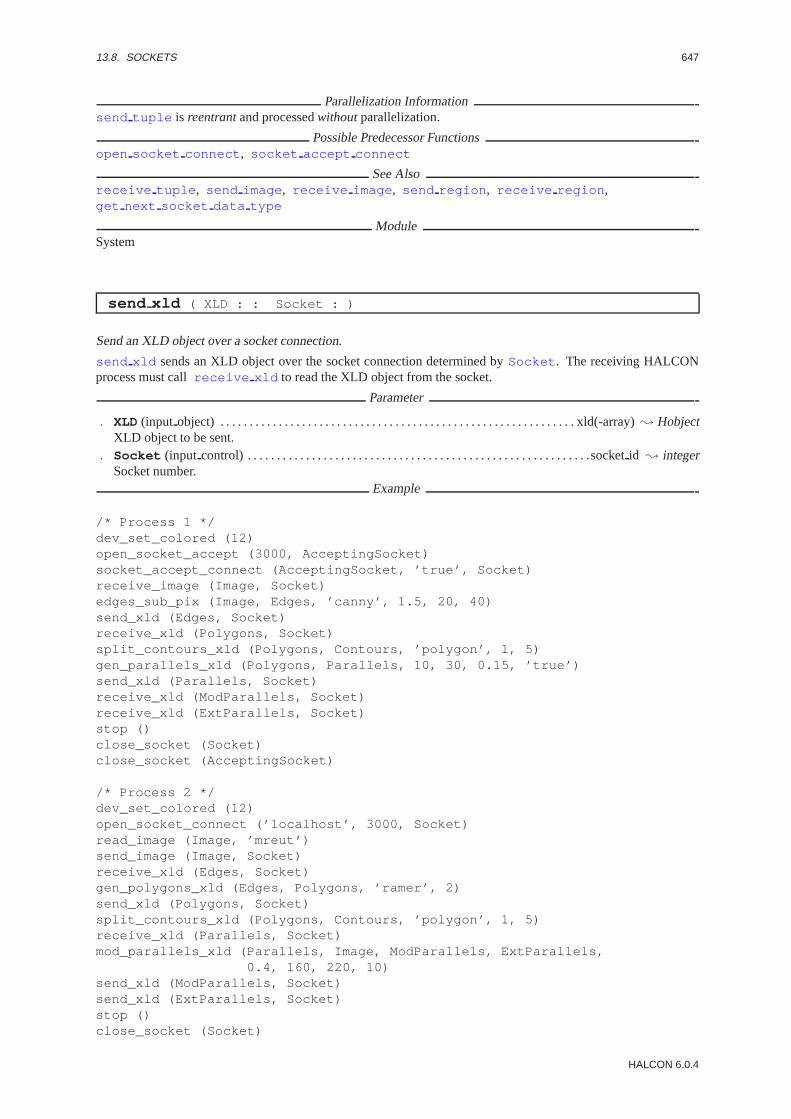
13.8. SOCKETS 647
Parallelization Informationsend tuple is reentrantand processedwithoutparallelization.
Possible Predecessor Functionsopen socket connect , socket accept connect
See Alsoreceive tuple , send image , receive image , send region , receive region ,get next socket data type
ModuleSystem
send xld ( XLD : : Socket : )
Send an XLD object over a socket connection.
send xld sends an XLD object over the socket connection determined bySocket . The receiving HALCONprocess must callreceive xld to read the XLD object from the socket.
Parameter
. XLD (input object) . . . . . . . . . . . . . . . . . . . . . . . . . . . . . . . . . . . . . . . . . . . . . . . . . . . . . . . . . . . . . xld(-array); HobjectXLD object to be sent.
. Socket (input control) . . . . . . . . . . . . . . . . . . . . . . . . . . . . . . . . . . . . . . . . . . . . . . . . . . . . . . . . . . .socketid ; integerSocket number.
Example
/* Process 1 */dev_set_colored (12)open_socket_accept (3000, AcceptingSocket)socket_accept_connect (AcceptingSocket, ’true’, Socket)receive_image (Image, Socket)edges_sub_pix (Image, Edges, ’canny’, 1.5, 20, 40)send_xld (Edges, Socket)receive_xld (Polygons, Socket)split_contours_xld (Polygons, Contours, ’polygon’, 1, 5)gen_parallels_xld (Polygons, Parallels, 10, 30, 0.15, ’true’)send_xld (Parallels, Socket)receive_xld (ModParallels, Socket)receive_xld (ExtParallels, Socket)stop ()close_socket (Socket)close_socket (AcceptingSocket)
/* Process 2 */dev_set_colored (12)open_socket_connect (’localhost’, 3000, Socket)read_image (Image, ’mreut’)send_image (Image, Socket)receive_xld (Edges, Socket)gen_polygons_xld (Edges, Polygons, ’ramer’, 2)send_xld (Polygons, Socket)split_contours_xld (Polygons, Contours, ’polygon’, 1, 5)receive_xld (Parallels, Socket)mod_parallels_xld (Parallels, Image, ModParallels, ExtParallels,
0.4, 160, 220, 10)send_xld (ModParallels, Socket)send_xld (ExtParallels, Socket)stop ()close_socket (Socket)
HALCON 6.0.4

648 CHAPTER 13. SYSTEM
Parallelization Informationsend xld is reentrantand processedwithoutparallelization.
Possible Predecessor Functionsopen socket connect , socket accept connect
See Alsoreceive xld , send image , receive image , send region , receive region , send tuple ,receive tuple , get next socket data type
ModuleSystem
socket accept connect ( : : AcceptingSocket, Wait : Socket )
Accept a connection request on a listening socket.
socket accept connect accepts an incoming connection request, generated byopen socket connectin another HALCON process, on the listening socketAcceptingSocket . The listening socket must have beencreated earlier withopen socket accept . If Wait =’true’ , socket accept connect waits until a con-nection request from another HALCON process arrives. IfWait =’false’, socket accept connect returnswith the error FAIL, if currently there are no connection requests from other HALCON processes. The resultof socket accept connect is another socketSocket , which is used for a two-way communication withanother HALCON process. After this connection has been established, data can be exchanged between the two pro-cesses by calling the appropriate send or receive operators. For a detailed example, seeopen socket accept .
Parameter
. AcceptingSocket (input control) . . . . . . . . . . . . . . . . . . . . . . . . . . . . . . . . . . . . . . . . . . . . . . socketid ; integerSocket number of the accepting socket.
. Wait (input control) . . . . . . . . . . . . . . . . . . . . . . . . . . . . . . . . . . . . . . . . . . . . . . . . . . . . . . . . . . . . . . . . . .string; stringShould the operator wait until a connection request arrives?Value List : Wait ∈ {’true’, ’false’}
. Socket (outputcontrol) . . . . . . . . . . . . . . . . . . . . . . . . . . . . . . . . . . . . . . . . . . . . . . . . . . . . . . . . . socketid ; integerSocket number.
Parallelization Informationsocket accept connect is reentrantand processedwithoutparallelization.
Possible Predecessor Functionsopen socket accept
Possible Successor Functionssend image , receive image , send region , receive region , send tuple , receive tuple
See Alsoopen socket connect , close socket
ModuleSystem
HALCON/HDevelop Reference Manual, 2003-7-21

Chapter 14
Tools
14.1 Affine-Transformations
affine trans point 2d ( : : HomMat2D, Px, Py : Qx, Qy )
Apply a homogeneous 2D transformation matrix to points.
affine trans point 2d calculates the result of applying the affine transformation, given by the homogeneous2D transformation matrixHomMat2D, to the input points (Px,Py). The resulting points are returned in (Qx,Qy).
If the coordinates (Px,Py) are image coordinates, it should be noted that the components of the homogeneoustransformation matrix are to be interpreted as follows: therow coordinate of the image corresponds to thex coor-dinate of the matrix, while thecolumncoordinate of the image corresponds to they coordinate of the matrix. Thisis necessary to obtain a right-handed coordinate system, which is assumed for the homogeneous transformationmatrices, also for the image. In particular, by doing so roatations are performed in the correct direction. Note thatthe (x,y) order of the matrices quite naturally corresponds to the usual (row,column) order for coordinates in theimage.
Parameter
. HomMat2D(input control) . . . . . . . . . . . . . . . . . . . . . . . . . . . . . . . . . . . . . . . . . . . . . . . . . . . . . . affine2d-array; realInput transformation matrix.Parameter Number : 6
. Px (input control) . . . . . . . . . . . . . . . . . . . . . . . . . . . . . . . . . . . . . . . . . . . . . . . . . . . . . . point.x(-array); real/ integerInput point (x coordinate).Default Value : 64Value Suggestions :Px ∈ {0, 16, 32, 64, 128, 256, 512, 1024}Typical Range of Values :0≤ Px ≤ 1024Minimal Value Step : 1Recommended Value Step :10
. Py (input control) . . . . . . . . . . . . . . . . . . . . . . . . . . . . . . . . . . . . . . . . . . . . . . . . . . . . . . point.y(-array); real/ integerInput point (y coordinate).Default Value : 64Value Suggestions :Py ∈ {0, 16, 32, 64, 128, 256, 512, 1024}Typical Range of Values :0≤ Py ≤ 1024Minimal Value Step : 1Recommended Value Step :10
. Qx (outputcontrol) . . . . . . . . . . . . . . . . . . . . . . . . . . . . . . . . . . . . . . . . . . . . . . . . . . . . . . . . . . . . . point.x(-array); realOutput point (x coordinate).
. Qy (outputcontrol) . . . . . . . . . . . . . . . . . . . . . . . . . . . . . . . . . . . . . . . . . . . . . . . . . . . . . . . . . . . . . point.y(-array); realOutput point (y coordinate).
Resultaffine trans point 2d always returns 2 (HMSG TRUE).
Parallelization Informationaffine trans point 2d is reentrantand processedwithoutparallelization.
649
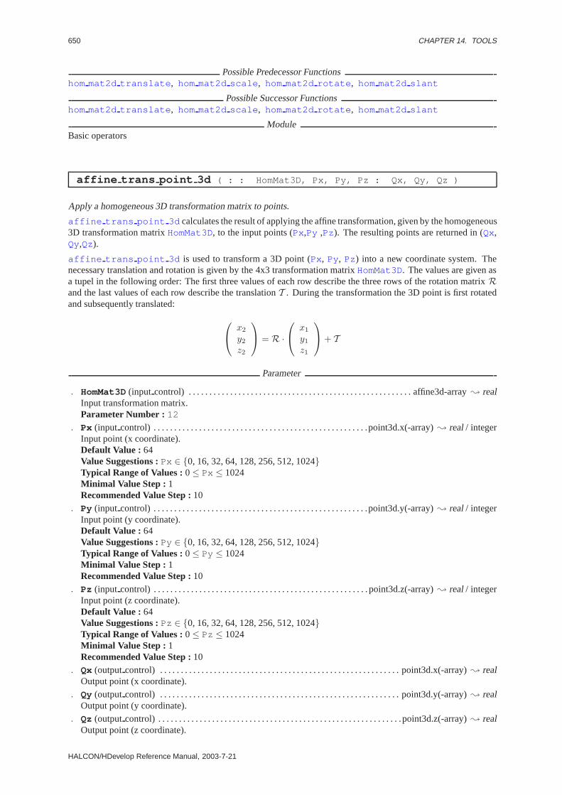
650 CHAPTER 14. TOOLS
Possible Predecessor Functionshom mat2d translate , hom mat2d scale , hom mat2d rotate , hom mat2d slant
Possible Successor Functionshom mat2d translate , hom mat2d scale , hom mat2d rotate , hom mat2d slant
ModuleBasic operators
affine trans point 3d ( : : HomMat3D, Px, Py, Pz : Qx, Qy, Qz )
Apply a homogeneous 3D transformation matrix to points.
affine trans point 3d calculates the result of applying the affine transformation, given by the homogeneous3D transformation matrixHomMat3D, to the input points (Px,Py ,Pz). The resulting points are returned in (Qx,Qy,Qz).
affine trans point 3d is used to transform a 3D point (Px, Py, Pz) into a new coordinate system. Thenecessary translation and rotation is given by the 4x3 transformation matrixHomMat3D. The values are given asa tupel in the following order: The first three values of each row describe the three rows of the rotation matrixRand the last values of each row describe the translationT . During the transformation the 3D point is first rotatedand subsequently translated:
x2
y2z2
= R ·
x1
y1z1
+ T
Parameter
. HomMat3D(input control) . . . . . . . . . . . . . . . . . . . . . . . . . . . . . . . . . . . . . . . . . . . . . . . . . . . . . . affine3d-array; realInput transformation matrix.Parameter Number : 12
. Px (input control) . . . . . . . . . . . . . . . . . . . . . . . . . . . . . . . . . . . . . . . . . . . . . . . . . . . .point3d.x(-array); real/ integerInput point (x coordinate).Default Value : 64Value Suggestions :Px ∈ {0, 16, 32, 64, 128, 256, 512, 1024}Typical Range of Values :0≤ Px ≤ 1024Minimal Value Step : 1Recommended Value Step :10
. Py (input control) . . . . . . . . . . . . . . . . . . . . . . . . . . . . . . . . . . . . . . . . . . . . . . . . . . . .point3d.y(-array); real/ integerInput point (y coordinate).Default Value : 64Value Suggestions :Py ∈ {0, 16, 32, 64, 128, 256, 512, 1024}Typical Range of Values :0≤ Py ≤ 1024Minimal Value Step : 1Recommended Value Step :10
. Pz (input control) . . . . . . . . . . . . . . . . . . . . . . . . . . . . . . . . . . . . . . . . . . . . . . . . . . . . point3d.z(-array); real/ integerInput point (z coordinate).Default Value : 64Value Suggestions :Pz ∈ {0, 16, 32, 64, 128, 256, 512, 1024}Typical Range of Values :0≤ Pz ≤ 1024Minimal Value Step : 1Recommended Value Step :10
. Qx (outputcontrol) . . . . . . . . . . . . . . . . . . . . . . . . . . . . . . . . . . . . . . . . . . . . . . . . . . . . . . . . . . point3d.x(-array); realOutput point (x coordinate).
. Qy (outputcontrol) . . . . . . . . . . . . . . . . . . . . . . . . . . . . . . . . . . . . . . . . . . . . . . . . . . . . . . . . . . point3d.y(-array); realOutput point (y coordinate).
. Qz (outputcontrol) . . . . . . . . . . . . . . . . . . . . . . . . . . . . . . . . . . . . . . . . . . . . . . . . . . . . . . . . . . .point3d.z(-array); realOutput point (z coordinate).
HALCON/HDevelop Reference Manual, 2003-7-21

14.1. AFFINE-TRANSFORMATIONS 651
Resultaffine trans point 3d always returns 2 (HMSG TRUE).
Parallelization Informationaffine trans point 3d is reentrantand processedwithoutparallelization.
Possible Predecessor Functionshom mat3d translate , hom mat3d scale , hom mat3d rotate , pose to hom mat3d
Possible Successor Functionshom mat3d translate , hom mat3d scale , hom mat3d rotate , project 3d point
ModuleBasic operators
dvf to hom mat2d ( VectorField : : : HomMat2D )
Approximate an affine map from a displacement vector field.
dvf to hom mat2d approximates an affine map from the displacement vector fieldVectorField . The affinemap is returned inHomMat2D.
If the displacement vector field has been computed from the original imageIorig and the second imageIres,the internally stored transformation matrix (seeaffine trans image ) contains a map that describes how totransform the first imageIorig to the second imageIres.
Parameter
. VectorField (input object) . . . . . . . . . . . . . . . . . . . . . . . . . . . . . . . . . . . . singlechannel-image; Hobject: dvfInput image.
. HomMat2D(outputcontrol) . . . . . . . . . . . . . . . . . . . . . . . . . . . . . . . . . . . . . . . . . . . . . . . . . . . . . affine2d-array; realOutput transformation matrix.Parameter Number : 6
Parallelization Informationdvf to hom mat2d is reentrantand processedwithoutparallelization.
Possible Predecessor Functionsoptical flow match
Possible Successor Functionsaffine trans image
Alternativesvector to hom mat2d
ModuleBasic operators
hom mat2d compose ( : : HomMat2DSecond,HomMat2DFirst : HomMat2DCompose )
Compose two homogeneous 2D transformation matrices.
hom mat2d compose composes a new 2D transformation matrix from the two input matrices. The transforma-tion given byHomMat2DFirst is applied first, followed by the transformation given byHomMat2DSecond,i.e., withHomMat2DFirst = H1, HomMat2DSecond = H2, andHomMat2DCompose= Hc is:
Hc = H2 · H1
Parameter
. HomMat2DSecond (input control) . . . . . . . . . . . . . . . . . . . . . . . . . . . . . . . . . . . . . . . . . . . . . . affine2d-array; realSecond input transformation matrix.Parameter Number : 6
HALCON 6.0.4

652 CHAPTER 14. TOOLS
. HomMat2DFirst (input control) . . . . . . . . . . . . . . . . . . . . . . . . . . . . . . . . . . . . . . . . . . . . . . . affine2d-array; realFirst input transformation matrix.Parameter Number : 6
. HomMat2DCompose(outputcontrol) . . . . . . . . . . . . . . . . . . . . . . . . . . . . . . . . . . . . . . . . . . . .affine2d-array; realOutput transformation matrix.Parameter Number : 6
Resulthom mat2d compose always returns 2 (HMSG TRUE).
Parallelization Informationhom mat2d compose is reentrantand processedwithoutparallelization.
Possible Predecessor Functionshom mat2d identity , hom mat2d translate , hom mat2d scale , hom mat2d rotate ,hom mat2d slant
Possible Successor Functionshom mat2d translate , hom mat2d scale , hom mat2d rotate , hom mat2d slant
ModuleBasic operators
hom mat2d identity ( : : : HomMat2DIdentity )
Generate the homogeneous transformation matrix of the identical 2D transformation.
hom mat2d identity generates the homogeneous2 × 3 transformation matrixHomMat2DIdentity de-scribing the identical 2D transformation.
Parameter
. HomMat2DIdentity (outputcontrol) . . . . . . . . . . . . . . . . . . . . . . . . . . . . . . . . . . . . . . . . . . affine2d-array; realTransformation matrix.Parameter Number : 6
Resulthom mat2d identity always returns 2 (HMSG TRUE).
Parallelization Informationhom mat2d identity is reentrantand processedwithoutparallelization.
Possible Successor Functionshom mat2d translate , hom mat2d scale , hom mat2d rotate , hom mat2d slant
ModuleBasic operators
hom mat2d invert ( : : HomMat2D : HomMat2DInvert )
Invert a homogeneous 2D transformation matrix.
hom mat2d invert inverts the homogeneous 2D transformation matrix given byHomMat2D. The resultingmatrix is returned inHomMat2DInvert .
Parameter
. HomMat2D(input control) . . . . . . . . . . . . . . . . . . . . . . . . . . . . . . . . . . . . . . . . . . . . . . . . . . . . . . affine2d-array; realInput transformation matrix.Parameter Number : 6
. HomMat2DInvert (outputcontrol) . . . . . . . . . . . . . . . . . . . . . . . . . . . . . . . . . . . . . . . . . . . . . affine2d-array; realOutput transformation matrix.Parameter Number : 6
HALCON/HDevelop Reference Manual, 2003-7-21

14.1. AFFINE-TRANSFORMATIONS 653
Resulthom mat2d invert returns 2 (HMSG TRUE) if the input matrix is invertible.
Parallelization Informationhom mat2d invert is reentrantand processedwithoutparallelization.
Possible Predecessor Functionshom mat2d translate , hom mat2d scale , hom mat2d rotate , hom mat2d slant
Possible Successor Functionshom mat2d translate , hom mat2d scale , hom mat2d rotate , hom mat2d slant
ModuleBasic operators
hom mat2d rotate ( : : HomMat2D, Phi, Px, Py : HomMat2DRotate )
Add a rotation to a homogeneous 2D transformation matrix.
hom mat2d rotate adds a rotation by the anglePhi to a homogeneous 2D transformation matrixHomMat2D.The point (Px,Py) is the fixed point of the transformation. The resulting matrix is returned inHomMat2DRotate .
Parameter
. HomMat2D(input control) . . . . . . . . . . . . . . . . . . . . . . . . . . . . . . . . . . . . . . . . . . . . . . . . . . . . . . affine2d-array; realInput transformation matrix.Parameter Number : 6
. Phi (input control) . . . . . . . . . . . . . . . . . . . . . . . . . . . . . . . . . . . . . . . . . . . . . . . . . . . . . . . . . angle.rad; real/ integerRotation angle.Default Value : 0.78Value Suggestions :Phi ∈ {0.1, 0.2, 0.3, 0.4, 0.78, 1.57, 3.14}Typical Range of Values :0≤ Phi ≤ 6.28318530718Minimal Value Step : 0.01Recommended Value Step :0.1
. Px (input control) . . . . . . . . . . . . . . . . . . . . . . . . . . . . . . . . . . . . . . . . . . . . . . . . . . . . . . . . . . . . . point.x; real/ integerFixed point of the transformation (x coordinate).Default Value : 0Value Suggestions :Px ∈ {0, 16, 32, 64, 128, 256, 512, 1024}Typical Range of Values :0≤ Px ≤ 1024Minimal Value Step : 1Recommended Value Step :10
. Py (input control) . . . . . . . . . . . . . . . . . . . . . . . . . . . . . . . . . . . . . . . . . . . . . . . . . . . . . . . . . . . . . point.y; real/ integerFixed point of the transformation (y coordinate).Default Value : 0Value Suggestions :Py ∈ {0, 16, 32, 64, 128, 256, 512, 1024}Typical Range of Values :0≤ Py ≤ 1024Minimal Value Step : 1Recommended Value Step :10
. HomMat2DRotate (outputcontrol) . . . . . . . . . . . . . . . . . . . . . . . . . . . . . . . . . . . . . . . . . . . . . affine2d-array; realOutput transformation matrix.Parameter Number : 6
Resulthom mat2d rotate always returns 2 (HMSG TRUE).
Parallelization Informationhom mat2d rotate is reentrantand processedwithoutparallelization.
Possible Predecessor Functionshom mat2d identity , hom mat2d translate , hom mat2d scale , hom mat2d rotate ,hom mat2d slant
Possible Successor Functionshom mat2d translate , hom mat2d scale , hom mat2d rotate , hom mat2d slant
HALCON 6.0.4

654 CHAPTER 14. TOOLS
ModuleBasic operators
hom mat2d scale ( : : HomMat2D, Sx, Sy, Px, Py : HomMat2DScale )
Add a scaling to a homogeneous 2D transformation matrix.
hom mat2d scale adds a scaling by the scale factorsSx andSy to a homogeneous 2D transformation matrixHomMat2D. The point (Px,Py) is the fixed point of the transformation. The resulting matrix is returned inHomMat2DScale .
Parameter
. HomMat2D(input control) . . . . . . . . . . . . . . . . . . . . . . . . . . . . . . . . . . . . . . . . . . . . . . . . . . . . . . affine2d-array; realInput transformation matrix.Parameter Number : 6
. Sx (input control) . . . . . . . . . . . . . . . . . . . . . . . . . . . . . . . . . . . . . . . . . . . . . . . . . . . . . . . . . . . . number; real/ integerScale factor along the x-axis.Default Value : 2Value Suggestions :Sx ∈ {0.125, 0.25, 0.5, 1, 2, 4, 8, 16}Typical Range of Values :0≤ Sx ≤ 1024Minimal Value Step : 0.001Recommended Value Step :0.125Restriction : Sx 6= 0
. Sy (input control) . . . . . . . . . . . . . . . . . . . . . . . . . . . . . . . . . . . . . . . . . . . . . . . . . . . . . . . . . . . . number; real/ integerScale factor along the y-axis.Default Value : 2Value Suggestions :Sy ∈ {0.125, 0.25, 0.5, 1, 2, 4, 8, 16}Typical Range of Values :0≤ Sy ≤ 1024Minimal Value Step : 0.001Recommended Value Step :0.125Restriction : Sy 6= 0
. Px (input control) . . . . . . . . . . . . . . . . . . . . . . . . . . . . . . . . . . . . . . . . . . . . . . . . . . . . . . . . . . . . . point.x; real/ integerFixed point of the transformation (x coordinate).Default Value : 0Value Suggestions :Px ∈ {0, 16, 32, 64, 128, 256, 512, 1024}Typical Range of Values :0≤ Px ≤ 1024Minimal Value Step : 1Recommended Value Step :10
. Py (input control) . . . . . . . . . . . . . . . . . . . . . . . . . . . . . . . . . . . . . . . . . . . . . . . . . . . . . . . . . . . . . point.y; real/ integerFixed point of the transformation (y coordinate).Default Value : 0Value Suggestions :Py ∈ {0, 16, 32, 64, 128, 256, 512, 1024}Typical Range of Values :0≤ Py ≤ 1024Minimal Value Step : 1Recommended Value Step :10
. HomMat2DScale (outputcontrol) . . . . . . . . . . . . . . . . . . . . . . . . . . . . . . . . . . . . . . . . . . . . . . affine2d-array; realOutput transformation matrix.Parameter Number : 6
Resulthom mat2d scale returns 2 (HMSG TRUE) if both scale factors are not 0.
Parallelization Informationhom mat2d scale is reentrantand processedwithoutparallelization.
Possible Predecessor Functionshom mat2d identity , hom mat2d translate , hom mat2d scale , hom mat2d rotate ,hom mat2d slant
Possible Successor Functionshom mat2d translate , hom mat2d scale , hom mat2d rotate , hom mat2d slant
HALCON/HDevelop Reference Manual, 2003-7-21

14.1. AFFINE-TRANSFORMATIONS 655
ModuleBasic operators
hom mat2d slant ( : : HomMat2D, Theta, Axis, Px, Py : HomMat2DSlant )
Add a slant to a homogeneous 2D transformation matrix.
hom mat2d slant adds a slant by the angleTheta to a homogeneous 2D transformation matrixHomMat2D.A slant is an affine transformation in which one coordinate axis remains fixed, while the other coordinate axis isrotated counterclockwise by an angleTheta . The parameterAxis determines which coordinate axis is slanted.For Axis = ’x’ , the x-axis is slanted, while forAxis = ’y’ the y-axis is slanted. The point (Px,Py) is the fixedpoint of the transformation. The resulting matrix is returned inHomMat2DSlant .
Parameter
. HomMat2D(input control) . . . . . . . . . . . . . . . . . . . . . . . . . . . . . . . . . . . . . . . . . . . . . . . . . . . . . . affine2d-array; realInput transformation matrix.Parameter Number : 6
. Theta (input control) . . . . . . . . . . . . . . . . . . . . . . . . . . . . . . . . . . . . . . . . . . . . . . . . . . . . . . .angle.rad; real/ integerSlant angle.Default Value : 0.78Value Suggestions :Theta ∈ {0.1, 0.2, 0.3, 0.4, 0.78, 1.57, 3.14}Typical Range of Values :0≤ Theta ≤ 6.28318530718Minimal Value Step : 0.01Recommended Value Step :0.1
. Axis (input control) . . . . . . . . . . . . . . . . . . . . . . . . . . . . . . . . . . . . . . . . . . . . . . . . . . . . . . . . . . . . . . . . . .string; stringCoordinate axis that is slanted.Default Value : ’x’Value List : Axis ∈ {’x’, ’y’ }
. Px (input control) . . . . . . . . . . . . . . . . . . . . . . . . . . . . . . . . . . . . . . . . . . . . . . . . . . . . . . . . . . . . . point.x; real/ integerFixed point of the transformation (x coordinate).Default Value : 0Value Suggestions :Px ∈ {0, 16, 32, 64, 128, 256, 512, 1024}Typical Range of Values :0≤ Px ≤ 1024Minimal Value Step : 1Recommended Value Step :10
. Py (input control) . . . . . . . . . . . . . . . . . . . . . . . . . . . . . . . . . . . . . . . . . . . . . . . . . . . . . . . . . . . . . point.y; real/ integerFixed point of the transformation (y coordinate).Default Value : 0Value Suggestions :Py ∈ {0, 16, 32, 64, 128, 256, 512, 1024}Typical Range of Values :0≤ Py ≤ 1024Minimal Value Step : 1Recommended Value Step :10
. HomMat2DSlant (outputcontrol) . . . . . . . . . . . . . . . . . . . . . . . . . . . . . . . . . . . . . . . . . . . . . . affine2d-array; realOutput transformation matrix.Parameter Number : 6
Resulthom mat2d slant always returns 2 (HMSG TRUE).
Parallelization Informationhom mat2d slant is reentrantand processedwithoutparallelization.
Possible Predecessor Functionshom mat2d identity , hom mat2d translate , hom mat2d scale , hom mat2d rotate ,hom mat2d slant
Possible Successor Functionshom mat2d translate , hom mat2d scale , hom mat2d rotate , hom mat2d slant
ModuleBasic operators
HALCON 6.0.4
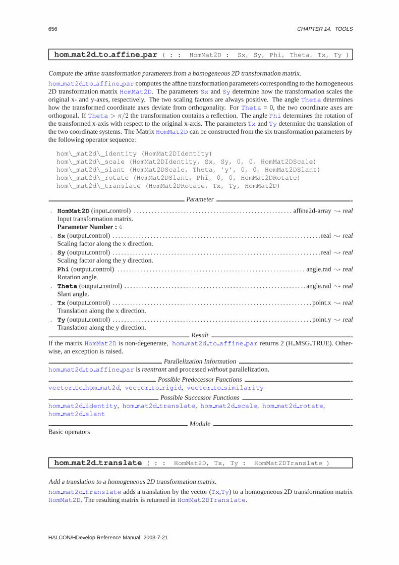
656 CHAPTER 14. TOOLS
hom mat2d to affine par ( : : HomMat2D : Sx, Sy, Phi, Theta, Tx, Ty )
Compute the affine transformation parameters from a homogeneous 2D transformation matrix.
hom mat2d to affine par computes the affine transformation parameters corresponding to the homogeneous2D transformation matrixHomMat2D. The parametersSx andSy determine how the transformation scales theoriginal x- and y-axes, respectively. The two scaling factors are always positive. The angleTheta determineshow the transformed coordinate axes deviate from orthogonality. ForTheta = 0, the two coordinate axes areorthogonal. IfTheta > π/2 the transformation contains a reflection. The anglePhi determines the rotation ofthe transformed x-axis with respect to the original x-axis. The parametersTx andTy determine the translation ofthe two coordinate systems. The MatrixHomMat2Dcan be constructed from the six transformation parameters bythe following operator sequence:
hom\_mat2d\_identity (HomMat2DIdentity)hom\_mat2d\_scale (HomMat2DIdentity, Sx, Sy, 0, 0, HomMat2DScale)hom\_mat2d\_slant (HomMat2DScale, Theta, ’y’, 0, 0, HomMat2DSlant)hom\_mat2d\_rotate (HomMat2DSlant, Phi, 0, 0, HomMat2DRotate)hom\_mat2d\_translate (HomMat2DRotate, Tx, Ty, HomMat2D)
Parameter
. HomMat2D(input control) . . . . . . . . . . . . . . . . . . . . . . . . . . . . . . . . . . . . . . . . . . . . . . . . . . . . . . affine2d-array; realInput transformation matrix.Parameter Number : 6
. Sx (outputcontrol) . . . . . . . . . . . . . . . . . . . . . . . . . . . . . . . . . . . . . . . . . . . . . . . . . . . . . . . . . . . . . . . . . . . . . . . real; realScaling factor along the x direction.
. Sy (outputcontrol) . . . . . . . . . . . . . . . . . . . . . . . . . . . . . . . . . . . . . . . . . . . . . . . . . . . . . . . . . . . . . . . . . . . . . . . real; realScaling factor along the y direction.
. Phi (outputcontrol) . . . . . . . . . . . . . . . . . . . . . . . . . . . . . . . . . . . . . . . . . . . . . . . . . . . . . . . . . . . . . . . . angle.rad; realRotation angle.
. Theta (outputcontrol) . . . . . . . . . . . . . . . . . . . . . . . . . . . . . . . . . . . . . . . . . . . . . . . . . . . . . . . . . . . . . .angle.rad; realSlant angle.
. Tx (outputcontrol) . . . . . . . . . . . . . . . . . . . . . . . . . . . . . . . . . . . . . . . . . . . . . . . . . . . . . . . . . . . . . . . . . . . . point.x; realTranslation along the x direction.
. Ty (outputcontrol) . . . . . . . . . . . . . . . . . . . . . . . . . . . . . . . . . . . . . . . . . . . . . . . . . . . . . . . . . . . . . . . . . . . . point.y; realTranslation along the y direction.
ResultIf the matrixHomMat2Dis non-degenerate,hom mat2d to affine par returns 2 (HMSG TRUE). Other-wise, an exception is raised.
Parallelization Informationhom mat2d to affine par is reentrantand processedwithoutparallelization.
Possible Predecessor Functionsvector to hom mat2d , vector to rigid , vector to similarity
Possible Successor Functionshom mat2d identity , hom mat2d translate , hom mat2d scale , hom mat2d rotate ,hom mat2d slant
ModuleBasic operators
hom mat2d translate ( : : HomMat2D, Tx, Ty : HomMat2DTranslate )
Add a translation to a homogeneous 2D transformation matrix.
hom mat2d translate adds a translation by the vector (Tx,Ty) to a homogeneous 2D transformation matrixHomMat2D. The resulting matrix is returned inHomMat2DTranslate .
HALCON/HDevelop Reference Manual, 2003-7-21
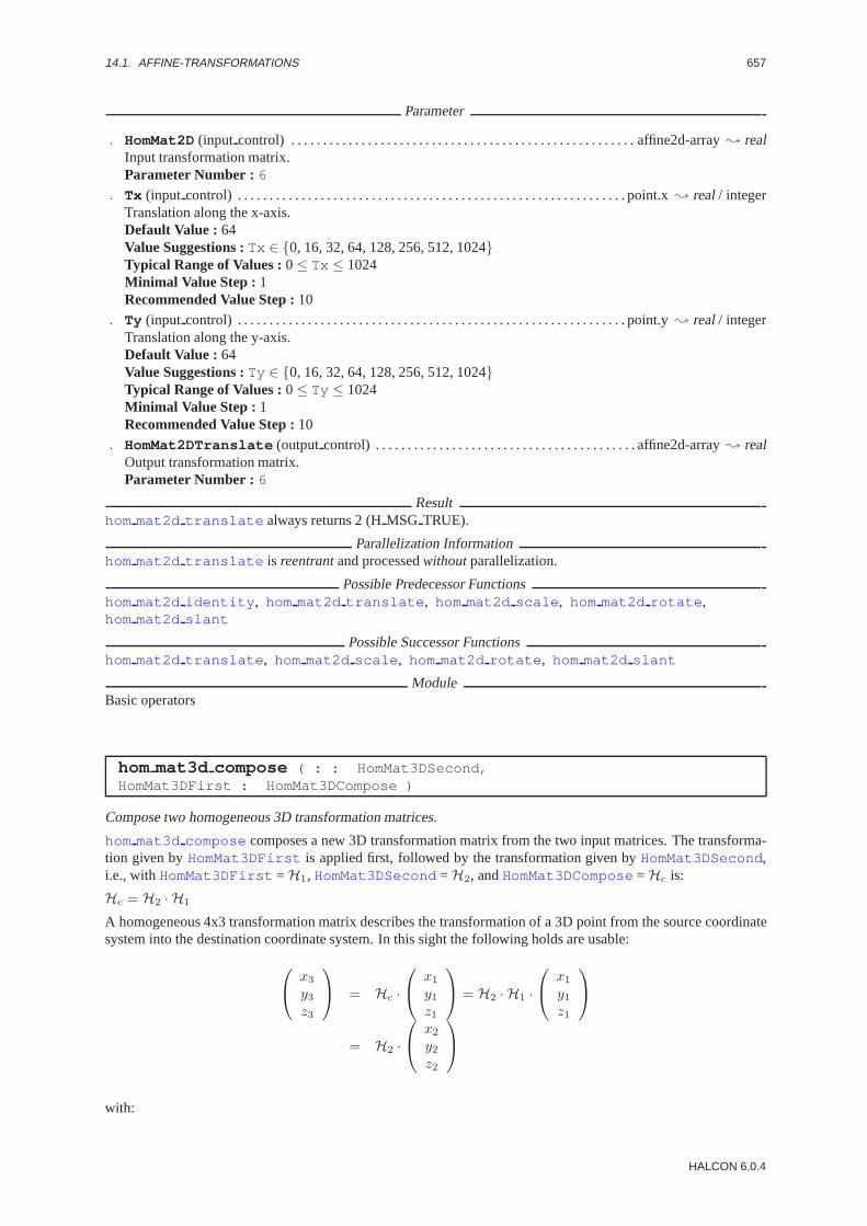
14.1. AFFINE-TRANSFORMATIONS 657
Parameter
. HomMat2D(input control) . . . . . . . . . . . . . . . . . . . . . . . . . . . . . . . . . . . . . . . . . . . . . . . . . . . . . . affine2d-array; realInput transformation matrix.Parameter Number : 6
. Tx (input control) . . . . . . . . . . . . . . . . . . . . . . . . . . . . . . . . . . . . . . . . . . . . . . . . . . . . . . . . . . . . . point.x; real/ integerTranslation along the x-axis.Default Value : 64Value Suggestions :Tx ∈ {0, 16, 32, 64, 128, 256, 512, 1024}Typical Range of Values :0≤ Tx ≤ 1024Minimal Value Step : 1Recommended Value Step :10
. Ty (input control) . . . . . . . . . . . . . . . . . . . . . . . . . . . . . . . . . . . . . . . . . . . . . . . . . . . . . . . . . . . . . point.y; real/ integerTranslation along the y-axis.Default Value : 64Value Suggestions :Ty ∈ {0, 16, 32, 64, 128, 256, 512, 1024}Typical Range of Values :0≤ Ty ≤ 1024Minimal Value Step : 1Recommended Value Step :10
. HomMat2DTranslate (outputcontrol) . . . . . . . . . . . . . . . . . . . . . . . . . . . . . . . . . . . . . . . . . affine2d-array; realOutput transformation matrix.Parameter Number : 6
Resulthom mat2d translate always returns 2 (HMSG TRUE).
Parallelization Informationhom mat2d translate is reentrantand processedwithoutparallelization.
Possible Predecessor Functionshom mat2d identity , hom mat2d translate , hom mat2d scale , hom mat2d rotate ,hom mat2d slant
Possible Successor Functionshom mat2d translate , hom mat2d scale , hom mat2d rotate , hom mat2d slant
ModuleBasic operators
hom mat3d compose ( : : HomMat3DSecond,HomMat3DFirst : HomMat3DCompose )
Compose two homogeneous 3D transformation matrices.
hom mat3d compose composes a new 3D transformation matrix from the two input matrices. The transforma-tion given byHomMat3DFirst is applied first, followed by the transformation given byHomMat3DSecond,i.e., withHomMat3DFirst = H1, HomMat3DSecond = H2, andHomMat3DCompose= Hc is:
Hc = H2 · H1
A homogeneous 4x3 transformation matrix describes the transformation of a 3D point from the source coordinatesystem into the destination coordinate system. In this sight the following holds are usable:
x3
y3z3
= Hc ·
x1
y1z1
= H2 · H1 ·
x1
y1z1
= H2 ·
x2
y2z2
with:
HALCON 6.0.4

658 CHAPTER 14. TOOLS
x2
y2z2
= H1 ·
x1
y1z1
= R1 ·
x1
y1z1
+ T1
therefore:
x3
y3z3
= R2 ·
x2
y2z2
+ T2 = R2 ·
R1 ·
x1
y1z1
+ T1
+ T2
= R2 · R1 ·
x1
y1z1
+ R2 · T1 + T2 = Rc ·
x1
y1z1
+ Tc
with:
Rotation: Rc = R2 · R2
Translation: Tc = R2 · T1 + T2
Parameter
. HomMat3DSecond (input control) . . . . . . . . . . . . . . . . . . . . . . . . . . . . . . . . . . . . . . . . . . . . . . affine3d-array; realSecond input transformation matrix.Parameter Number : 12
. HomMat3DFirst (input control) . . . . . . . . . . . . . . . . . . . . . . . . . . . . . . . . . . . . . . . . . . . . . . . affine3d-array; realFirst input transformation matrix.Parameter Number : 12
. HomMat3DCompose(outputcontrol) . . . . . . . . . . . . . . . . . . . . . . . . . . . . . . . . . . . . . . . . . . . .affine3d-array; realOutput transformation matrix.Parameter Number : 12
Example
/* read camera pose */read_pose(’campose.dat’,CamPose)/* transform pose to transformation matrix */pose_to_hom_mat3d(CamPose,HomTransMat1)/* multiply transformation matrices */hom_mat3d_compose(HomTransMat2,HomTransMat1,HomTransMatMult).
Resulthom mat3d compose always returns 2 (HMSG TRUE).
Parallelization Informationhom mat3d compose is reentrantand processedwithoutparallelization.
Possible Predecessor Functionshom mat3d identity , hom mat3d translate , hom mat3d scale , hom mat3d rotate ,pose to hom mat3d
Possible Successor Functionshom mat3d translate , hom mat3d scale , hom mat3d rotate
See Alsoaffine trans point 3d, hom mat3d identity , hom mat3d rotate , hom mat3d translate ,pose to hom mat3d , hom mat3d to pose
ModuleBasic operators
HALCON/HDevelop Reference Manual, 2003-7-21

14.1. AFFINE-TRANSFORMATIONS 659
hom mat3d identity ( : : : HomMat3DIdentity )
Generate the homogeneous transformation matrix of the identical 3D transformation.
hom mat3d identity generates the homogeneous3 × 4 transformation matrixHomMat3DIdentity de-scribing the identical 3D transformation.
Parameter
. HomMat3DIdentity (outputcontrol) . . . . . . . . . . . . . . . . . . . . . . . . . . . . . . . . . . . . . . . . . . affine3d-array; realTransformation matrix.Parameter Number : 12
Resulthom mat3d identity always returns 2 (HMSG TRUE).
Parallelization Informationhom mat3d identity is reentrantand processedwithoutparallelization.
Possible Successor Functionshom mat3d translate , hom mat3d scale , hom mat3d rotate
Alternativespose to hom mat3d
ModuleBasic operators
hom mat3d invert ( : : HomMat3D : HomMat3DInvert )
Invert a homogeneous 3D transformation matrix.
hom mat3d invert inverts the homogeneous 3D transformation matrix given byHomMat3D. The resultingmatrix is returned inHomMat3DInvert .
A homogeneous 4x3 transformation matrix describes the transformation of a 3D point from the source coordinatesystem into the destination coordinate system. In this sight the inverted transformation matrixHomMat3DInvertdescribes the transformation from the original destination coordinate system to the original source coordinatesystem. The transformation of a 3D point (given in the source coordinate system) into a destination coordinatesystem is given by a rotationR and a translationT (see affine trans point 3d). Thus, the followingholds:
x2
y2z2
= Rorg ·
x1
y1z1
+ Torg
x1
y1z1
= Rorg
−1 ·
x2
y2z2
− Torg
with Rinv = Rorg−1 andTinv = −Torg:
x1
y1z1
= Rinv ·
x2
y2z2
+ Tinv
HALCON 6.0.4

660 CHAPTER 14. TOOLS
Parameter
. HomMat3D(input control) . . . . . . . . . . . . . . . . . . . . . . . . . . . . . . . . . . . . . . . . . . . . . . . . . . . . . . affine3d-array; realInput transformation matrix.Parameter Number : 12
. HomMat3DInvert (outputcontrol) . . . . . . . . . . . . . . . . . . . . . . . . . . . . . . . . . . . . . . . . . . . . . affine3d-array; realOutput transformation matrix.Parameter Number : 12
Example
/* read camera pose */read_pose(’campose.dat’,CamPose)/* transform pose to transformation matrix */pose_to_hom_mat3d(CamPose,HomTransMat)/* invert transformation matrix */hom_mat3d_invert(HomTransMat,HomTransMatInv).
Resulthom mat3d invert returns 2 (HMSG TRUE) if the input matrix is invertible.
Parallelization Informationhom mat3d invert is reentrantand processedwithoutparallelization.
Possible Predecessor Functionshom mat3d translate , hom mat3d scale , hom mat3d rotate , pose to hom mat3d
Possible Successor Functionshom mat3d translate , hom mat3d scale , hom mat3d rotate , hom mat3d to pose
See Alsoaffine trans point 3d, hom mat3d identity , hom mat3d rotate , hom mat3d translate ,pose to hom mat3d , hom mat3d to pose , hom mat3d compose
ModuleBasic operators
hom mat3d rotate ( : : HomMat3D, Phi, Axis, Px, Py,Pz : HomMat3DRotate )
Add a rotation to a homogeneous 3D transformation matrix.
hom mat3d rotate adds a rotation around theAxis -axis by the anglePhi to a homogeneous 3D transforma-tion matrix HomMat3D. The point (Px,Py,Pz) is the fixed point of the transformation. The resulting matrix isreturned inHomMat3DRotate .
The homogeneous 4x3 transformation matrixHomMat3Ddescribes the transformation of a 3D point from thesource coordinate system into the destination coordinate system (Without Attention to the fixed point).
hom mat3d rotate is used to generate a new 4x3 transformation matrixHomMat3DRotate by rotating theAxis -axis ofHomMat3Dby the anglePhi (in mathematical positive direction).
If you want to rotate the source coordinate system, you have to invert the transformation matrix usinghom mat3d invert , rotate it usinghom mat3d rotate , and invert it back again.
The transformation of a 3D point (given in the source coordinate system) into a destination coordinate system istgiven by a rotationR and a translationT (see affine trans point 3d). Thus, the following holds:
x2
y2z2
= Rrot ·
x1
y1z1
+ Trot
= (Rφ · Rorg) ·
x2
y2z2
+ Torg
HALCON/HDevelop Reference Manual, 2003-7-21
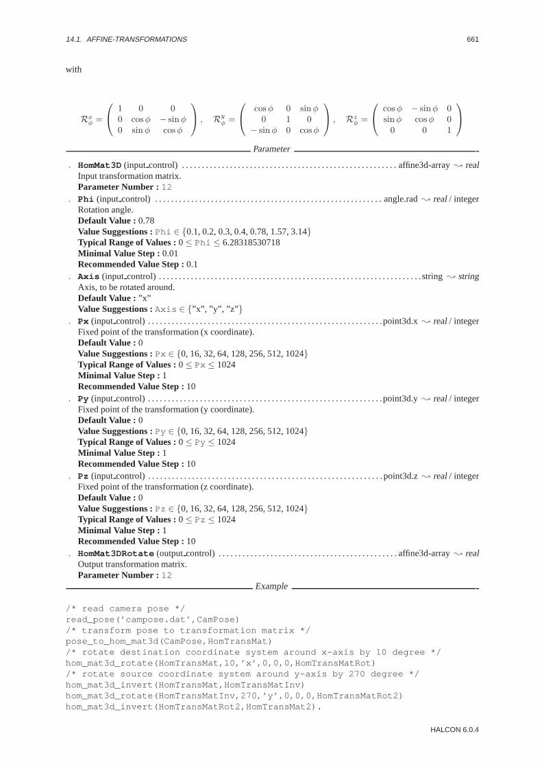
14.1. AFFINE-TRANSFORMATIONS 661
with
Rxφ =
1 0 0
0 cosφ − sinφ0 sinφ cosφ
, Ry
φ =
cosφ 0 sinφ
0 1 0− sinφ 0 cosφ
, Rz
φ =
cosφ − sinφ 0
sinφ cosφ 00 0 1
Parameter
. HomMat3D(input control) . . . . . . . . . . . . . . . . . . . . . . . . . . . . . . . . . . . . . . . . . . . . . . . . . . . . . . affine3d-array; realInput transformation matrix.Parameter Number : 12
. Phi (input control) . . . . . . . . . . . . . . . . . . . . . . . . . . . . . . . . . . . . . . . . . . . . . . . . . . . . . . . . . angle.rad; real/ integerRotation angle.Default Value : 0.78Value Suggestions :Phi ∈ {0.1, 0.2, 0.3, 0.4, 0.78, 1.57, 3.14}Typical Range of Values :0≤ Phi ≤ 6.28318530718Minimal Value Step : 0.01Recommended Value Step :0.1
. Axis (input control) . . . . . . . . . . . . . . . . . . . . . . . . . . . . . . . . . . . . . . . . . . . . . . . . . . . . . . . . . . . . . . . . . .string; stringAxis, to be rotated around.Default Value : ”x”Value Suggestions :Axis ∈ {”x”, ”y”, ”z” }
. Px (input control) . . . . . . . . . . . . . . . . . . . . . . . . . . . . . . . . . . . . . . . . . . . . . . . . . . . . . . . . . . .point3d.x; real/ integerFixed point of the transformation (x coordinate).Default Value : 0Value Suggestions :Px ∈ {0, 16, 32, 64, 128, 256, 512, 1024}Typical Range of Values :0≤ Px ≤ 1024Minimal Value Step : 1Recommended Value Step :10
. Py (input control) . . . . . . . . . . . . . . . . . . . . . . . . . . . . . . . . . . . . . . . . . . . . . . . . . . . . . . . . . . .point3d.y; real/ integerFixed point of the transformation (y coordinate).Default Value : 0Value Suggestions :Py ∈ {0, 16, 32, 64, 128, 256, 512, 1024}Typical Range of Values :0≤ Py ≤ 1024Minimal Value Step : 1Recommended Value Step :10
. Pz (input control) . . . . . . . . . . . . . . . . . . . . . . . . . . . . . . . . . . . . . . . . . . . . . . . . . . . . . . . . . . .point3d.z; real/ integerFixed point of the transformation (z coordinate).Default Value : 0Value Suggestions :Pz ∈ {0, 16, 32, 64, 128, 256, 512, 1024}Typical Range of Values :0≤ Pz ≤ 1024Minimal Value Step : 1Recommended Value Step :10
. HomMat3DRotate (outputcontrol) . . . . . . . . . . . . . . . . . . . . . . . . . . . . . . . . . . . . . . . . . . . . . affine3d-array; realOutput transformation matrix.Parameter Number : 12
Example
/* read camera pose */read_pose(’campose.dat’,CamPose)/* transform pose to transformation matrix */pose_to_hom_mat3d(CamPose,HomTransMat)/* rotate destination coordinate system around x-axis by 10 degree */hom_mat3d_rotate(HomTransMat,10,’x’,0,0,0,HomTransMatRot)/* rotate source coordinate system around y-axis by 270 degree */hom_mat3d_invert(HomTransMat,HomTransMatInv)hom_mat3d_rotate(HomTransMatInv,270,’y’,0,0,0,HomTransMatRot2)hom_mat3d_invert(HomTransMatRot2,HomTransMat2).
HALCON 6.0.4
662 CHAPTER 14. TOOLS
Resulthom mat3d rotate always returns 2 (HMSG TRUE).
Parallelization Informationhom mat3d rotate is reentrantand processedwithoutparallelization.
Possible Predecessor Functionshom mat3d identity , hom mat3d translate , hom mat3d scale , hom mat3d rotate
Possible Successor Functionshom mat3d translate , hom mat3d scale , hom mat3d rotate
See Alsohom mat3d invert , hom mat3d identity , hom mat3d rotate , hom mat3d translate ,pose to hom mat3d , hom mat3d to pose , hom mat3d compose
ModuleBasic operators
hom mat3d scale ( : : HomMat3D, Sx, Sy, Sz, Px, Py,Pz : HomMat3DScale )
Add a scaling to a homogeneous 3D transformation matrix.
hom mat3d scale adds a scaling by the scale factorsSx andSy to a homogeneous 3D transformation matrixHomMat3D. The point (Px,Py,Pz) is the fixed point of the transformation. The resulting matrix is returned inHomMat3DScale .
Parameter
. HomMat3D(input control) . . . . . . . . . . . . . . . . . . . . . . . . . . . . . . . . . . . . . . . . . . . . . . . . . . . . . . affine3d-array; realInput transformation matrix.Parameter Number : 12
. Sx (input control) . . . . . . . . . . . . . . . . . . . . . . . . . . . . . . . . . . . . . . . . . . . . . . . . . . . . . . . . . . . . number; real/ integerScale factor along the x-axis.Default Value : 2Value Suggestions :Sx ∈ {0.125, 0.25, 0.5, 1, 2, 4, 8, 112}Typical Range of Values :0≤ Sx ≤ 1024Minimal Value Step : 0.001Recommended Value Step :0.125Restriction : Sx 6= 0
. Sy (input control) . . . . . . . . . . . . . . . . . . . . . . . . . . . . . . . . . . . . . . . . . . . . . . . . . . . . . . . . . . . . number; real/ integerScale factor along the y-axis.Default Value : 2Value Suggestions :Sy ∈ {0.125, 0.25, 0.5, 1, 2, 4, 8, 112}Typical Range of Values :0≤ Sy ≤ 1024Minimal Value Step : 0.001Recommended Value Step :0.125Restriction : Sy 6= 0
. Sz (input control) . . . . . . . . . . . . . . . . . . . . . . . . . . . . . . . . . . . . . . . . . . . . . . . . . . . . . . . . . . . . number; real/ integerScale factor along the z-axis.Default Value : 2Value Suggestions :Sz ∈ {0.125, 0.25, 0.5, 1, 2, 4, 8, 112}Typical Range of Values :0≤ Sz ≤ 1024Minimal Value Step : 0.001Recommended Value Step :0.125Restriction : Sz 6= 0
HALCON/HDevelop Reference Manual, 2003-7-21

14.1. AFFINE-TRANSFORMATIONS 663
. Px (input control) . . . . . . . . . . . . . . . . . . . . . . . . . . . . . . . . . . . . . . . . . . . . . . . . . . . . . . . . . . .point3d.x; real/ integerFixed point of the transformation (x coordinate).Default Value : 0Value Suggestions :Px ∈ {0, 16, 32, 64, 128, 256, 512, 1024}Typical Range of Values :0≤ Px ≤ 1024Minimal Value Step : 1Recommended Value Step :10
. Py (input control) . . . . . . . . . . . . . . . . . . . . . . . . . . . . . . . . . . . . . . . . . . . . . . . . . . . . . . . . . . .point3d.y; real/ integerFixed point of the transformation (y coordinate).Default Value : 0Value Suggestions :Py ∈ {0, 16, 32, 64, 128, 256, 512, 1024}Typical Range of Values :0≤ Py ≤ 1024Minimal Value Step : 1Recommended Value Step :10
. Pz (input control) . . . . . . . . . . . . . . . . . . . . . . . . . . . . . . . . . . . . . . . . . . . . . . . . . . . . . . . . . . .point3d.z; real/ integerFixed point of the transformation (z coordinate).Default Value : 0Value Suggestions :Pz ∈ {0, 16, 32, 64, 128, 256, 512, 1024}Typical Range of Values :0≤ Pz ≤ 1024Minimal Value Step : 1Recommended Value Step :10
. HomMat3DScale (outputcontrol) . . . . . . . . . . . . . . . . . . . . . . . . . . . . . . . . . . . . . . . . . . . . . . affine3d-array; realOutput transformation matrix.Parameter Number : 12
Resulthom mat3d scale returns 2 (HMSG TRUE) if all three scale factors are not 0.
Parallelization Informationhom mat3d scale is reentrantand processedwithoutparallelization.
Possible Predecessor Functionshom mat3d identity , hom mat3d translate , hom mat3d scale , hom mat3d rotate
Possible Successor Functionshom mat3d translate , hom mat3d scale , hom mat3d rotate
ModuleBasic operators
hom mat3d translate ( : : HomMat3D, Tx, Ty, Tz : HomMat3DTranslate )
Add a translation to a homogeneous 3D transformation matrix.
hom mat3d translate adds a translation by the vector (Tx,Ty,Tz) to a homogeneous 3D transformationmatrixHomMat3D. The resulting matrix is returned inHomMat3DTranslate .
The homogeneous 4x3 transformation matrixHomMat3Ddescribes the transformation of a 3D point from thesource coordinate system into the destination coordinate system. In this sighthom mat3d translate is usedto generate a new 4x3 transformation matrixHomMat3DTranslate by translating the origin ofHomMat3Dalong the negative Axis by the amount (in meter) of the according to the vector (Tx,Ty ,Tz).
If you want to translate the source coordinate system, you have to invert the transformation matrix usinghom mat3d invert , translate it usinghom mat3d translate , and invert it back again.
The transformation of a 3D point (given in the source coordinate system) into a destination coordinate system istgiven by a rotationR and a translationT (see affine trans point 3d). Thus, the following holds:
x2
y2z2
= Rtrans ·
x1
y1z1
+ Ttrans
= Rorg ·
x2
y2z2
+ (Torg + Tδ)
HALCON 6.0.4

664 CHAPTER 14. TOOLS
with
Tδ =
t x
t yt z
Parameter
. HomMat3D(input control) . . . . . . . . . . . . . . . . . . . . . . . . . . . . . . . . . . . . . . . . . . . . . . . . . . . . . . affine3d-array; realInput transformation matrix.Parameter Number : 12
. Tx (input control) . . . . . . . . . . . . . . . . . . . . . . . . . . . . . . . . . . . . . . . . . . . . . . . . . . . . . . . . . . .point3d.x; real/ integerTranslation along the x-axis.Default Value : 64Value Suggestions :Tx ∈ {0, 16, 32, 64, 128, 256, 512, 1024}Typical Range of Values :0≤ Tx ≤ 1024Minimal Value Step : 1Recommended Value Step :10
. Ty (input control) . . . . . . . . . . . . . . . . . . . . . . . . . . . . . . . . . . . . . . . . . . . . . . . . . . . . . . . . . . .point3d.y; real/ integerTranslation along the y-axis.Default Value : 64Value Suggestions :Ty ∈ {0, 16, 32, 64, 128, 256, 512, 1024}Typical Range of Values :0≤ Ty ≤ 1024Minimal Value Step : 1Recommended Value Step :10
. Tz (input control) . . . . . . . . . . . . . . . . . . . . . . . . . . . . . . . . . . . . . . . . . . . . . . . . . . . . . . . . . . .point3d.z; real/ integerTranslation along the z-axis.Default Value : 64Value Suggestions :Tz ∈ {0, 16, 32, 64, 128, 256, 512, 1024}Typical Range of Values :0≤ Tz ≤ 1024Minimal Value Step : 1Recommended Value Step :10
. HomMat3DTranslate (outputcontrol) . . . . . . . . . . . . . . . . . . . . . . . . . . . . . . . . . . . . . . . . . affine3d-array; realOutput transformation matrix.Parameter Number : 12
Example
/* read camera pose */read_pose(’campose.dat’,CamPose)/* transform pose to transformation matrix */pose_to_hom_mat3d(CamPose,HomTransMat)/* translate destination coordinate along x-axis by 0.4 m */hom_mat3d_translate(HomTransMat,-0.4,0,0,HomTransMatTransl)/* translate source coordinate along y-axis by -0.03 m */hom_mat3d_invert(HomTransMat,HomTransMatInv)hom_mat3d_translate(HomTransMatInv,0,0.03,0,HomTransMatTransl2)hom_mat3d_invert(HomTransMatTransl2,HomTransMat2).
Resulthom mat3d translate always returns 2 (HMSG TRUE).
Parallelization Informationhom mat3d translate is reentrantand processedwithoutparallelization.
Possible Predecessor Functionshom mat3d identity , hom mat3d translate , hom mat3d scale , hom mat3d rotate
HALCON/HDevelop Reference Manual, 2003-7-21
14.1. AFFINE-TRANSFORMATIONS 665
Possible Successor Functionshom mat3d translate , hom mat3d scale , hom mat3d rotate
See Alsohom mat3d invert , hom mat3d identity , hom mat3d rotate , hom mat3d translate ,pose to hom mat3d , hom mat3d to pose , hom mat3d compose
ModuleBasic operators
vector angle to rigid ( : : Row1, Column1, Angle1, Row2, Column2,Angle2 : HomMat2D )
Compute a rigid affine transformation from points and angles.
vector angle to rigid computes a rigid affine transformation from a point correspondence and two corre-sponding angles. The coordinates of the original point are passed in (Row1,Column1 ), while the correspondingangle is passed inAngle1 . The coordinates of the transformed point are passed in (Row2,Column2 ), whilethe corresponding angle is passed inAngle2 . In particular, the operatorvector angle to rigid is usefulto construct a rigid affine transformation from the results of the pattern matching operators (best match rotand best match rot mg), which transforms a reference image to the current image or (if the parametersare passed in reverse order) from the current image to the reference image. The computed transformation is re-turned inHomMat2Dand can be used directly with operators that transform data using affine transformations, e.g.,affine trans image .
Parameter
. Row1(input control) . . . . . . . . . . . . . . . . . . . . . . . . . . . . . . . . . . . . . . . . . . . . . . . . . . . . . . . . . . point.y; real/ integerRow coordinate of the original point.
. Column1 (input control) . . . . . . . . . . . . . . . . . . . . . . . . . . . . . . . . . . . . . . . . . . . . . . . . . . . . . . point.x; real/ integerColumn coordinate of the original point.
. Angle1 (input control) . . . . . . . . . . . . . . . . . . . . . . . . . . . . . . . . . . . . . . . . . . . . . . . . . . . . . angle.rad; real/ integerAngle of the original point.
. Row2(input control) . . . . . . . . . . . . . . . . . . . . . . . . . . . . . . . . . . . . . . . . . . . . . . . . . . . . . . . . . . point.y; real/ integerRow coordinate of the transformed point.
. Column2 (input control) . . . . . . . . . . . . . . . . . . . . . . . . . . . . . . . . . . . . . . . . . . . . . . . . . . . . . . point.x; real/ integerColumn coordinate of the transformed point.
. Angle2 (input control) . . . . . . . . . . . . . . . . . . . . . . . . . . . . . . . . . . . . . . . . . . . . . . . . . . . . . angle.rad; real/ integerAngle of the transformed point.
. HomMat2D(outputcontrol) . . . . . . . . . . . . . . . . . . . . . . . . . . . . . . . . . . . . . . . . . . . . . . . . . . . . . affine2d-array; realOutput transformation matrix.Parameter Number : 6
Example
draw_rectangle2 (WindowID, RowTempl, ColumnTempl, PhiTempl, Length1, Length2)gen_rectangle2 (Rectangle, RowTempl, ColumnTempl, PhiTempl, Length1, Length2)reduce_domain (ImageTempl, Rectangle, ImageReduced)create_template_rot (ImageReduced, 4, 0, rad(360), rad(1), ’sort’,
’original’, TemplateID)while (true)
best_match_rot_mg (Image, TemplateID, 0, rad(360), 30, ’true’, 4, Row,Column, Angle, ErrMatch)
if (ErrMatch<255)vector_angle_to_rigid (Row, Column, Angle, RowTempl,
ColumnTempl, 0, HomMat2D)affine_trans_image (Image, ImageAffinTrans, HomMat2D, ’constant’,
’false’)endif
endwhileclear_template (TemplateID)
HALCON 6.0.4

666 CHAPTER 14. TOOLS
Parallelization Informationvector angle to rigid is reentrantand processedwithoutparallelization.
Possible Predecessor Functionsbest match rot mg, best match rot
Possible Successor Functionshom mat2d invert , affine trans image , affine trans region ,affine trans contour xld , affine trans polygon xld , affine trans point 2d
Alternativesvector to rigid
See Alsodvf to hom mat2d
ModuleBasic operators
vector to hom mat2d ( : : Rows1, Columns1, Rows2,Columns2 : HomMat2D )
Approximate an affine transformation from point correspondences.
vector to hom mat2d approximates an affine transformation from at least three point correspondences. Thepoint correspondences are passed in the tuples (Rows1,Columns1 ) and (Rows2,Columns2 ), where correspond-ing points must be at the same index positions in the tuples. If more than three point correspondences are passed thetransformation is overdetermined. In this case, the returned transformation is the transformation that minimizes thedistances between the input points (Rows1,Columns1 ) and the transformed points (Rows2,Columns2 ). Thecalculated transformation is returned inHomMat2Dand can be used directly with operators that transform datausing affine transformations, e.g.,affine trans image .
Parameter
. Rows1 (input control) . . . . . . . . . . . . . . . . . . . . . . . . . . . . . . . . . . . . . . . . . . . . . . . . . . . . . . . . . . . point.y-array; realRow coordinates of the starting points.
. Columns1 (input control) . . . . . . . . . . . . . . . . . . . . . . . . . . . . . . . . . . . . . . . . . . . . . . . . . . . . . . . point.x-array; realColumn coordinates of the starting points.
. Rows2 (input control) . . . . . . . . . . . . . . . . . . . . . . . . . . . . . . . . . . . . . . . . . . . . . . . . . . . . . . . . . . . point.y-array; realRow coordinates of the end points.
. Columns2 (input control) . . . . . . . . . . . . . . . . . . . . . . . . . . . . . . . . . . . . . . . . . . . . . . . . . . . . . . . point.x-array; realColumn coordinates of the end points.
. HomMat2D(outputcontrol) . . . . . . . . . . . . . . . . . . . . . . . . . . . . . . . . . . . . . . . . . . . . . . . . . . . . . affine2d-array; realOutput transformation matrix.Parameter Number : 6
Parallelization Informationvector to hom mat2d is reentrantand processedwithoutparallelization.
Possible Successor Functionsaffine trans image
Alternativesdvf to hom mat2d
See Alsoaffine trans image , optical flow match
ModuleBasic operators
vector to rigid ( : : Rows1, Columns1, Rows2, Columns2 : HomMat2D )
Approximate a rigid affine transformation from point correspondences.
HALCON/HDevelop Reference Manual, 2003-7-21

14.1. AFFINE-TRANSFORMATIONS 667
vector to rigid approximates a rigid affine transformation from at least two point correspondences. Thepoint correspondences are passed in the tuples (Rows1, Columns1 ) and (Rows2,Columns2 ), where corre-sponding points must be at the same index positions in the tuples. The transformation is always overdetermined.Therefore, the returned transformation is the transformation that minimizes the distances between the originalpoints (Rows1,Columns1 ) and the transformed points (Rows2,Columns2 ). The calculated transformation isreturned inHomMat2Dand can be used directly with operators that transform data using affine transformations,e.g., affine trans image .
Parameter
. Rows1 (input control) . . . . . . . . . . . . . . . . . . . . . . . . . . . . . . . . . . . . . . . . . . . . . . . . . . . . . . . . . . . point.y-array; realRow coordinates of the original points.
. Columns1 (input control) . . . . . . . . . . . . . . . . . . . . . . . . . . . . . . . . . . . . . . . . . . . . . . . . . . . . . . . point.x-array; realColumn coordinates of the original points.
. Rows2 (input control) . . . . . . . . . . . . . . . . . . . . . . . . . . . . . . . . . . . . . . . . . . . . . . . . . . . . . . . . . . . point.y-array; realRow coordinates of the transformed points.
. Columns2 (input control) . . . . . . . . . . . . . . . . . . . . . . . . . . . . . . . . . . . . . . . . . . . . . . . . . . . . . . . point.x-array; realColumn coordinates of the transformed points.
. HomMat2D(outputcontrol) . . . . . . . . . . . . . . . . . . . . . . . . . . . . . . . . . . . . . . . . . . . . . . . . . . . . . affine2d-array; realOutput transformation matrix.Parameter Number : 6
Parallelization Informationvector to rigid is reentrantand processedwithoutparallelization.
Possible Successor Functionsaffine trans image , affine trans region , affine trans contour xld ,affine trans polygon xld , affine trans point 2d
Alternativesvector to hom mat2d , vector to similarity
See Alsodvf to hom mat2d
ModuleBasic operators
vector to similarity ( : : Rows1, Columns1, Rows2,Columns2 : HomMat2D )
Approximate an similarity transformation from point correspondences.
vector to similarity approximates a similarity transformation from at least two point correspondences.The point correspondences are passed in the tuples (Rows1, Columns1 ) and (Rows2,Columns2 ), where cor-responding points must be at the same index positions in the tuples. If more than two point correspondencesare passed the transformation is overdetermined. In this case, the returned transformation is the transforma-tion that minimizes the distances between the original points (Rows1,Columns1 ) and the transformed points(Rows2,Columns2 ). The calculated transformation is returned inHomMat2Dand can be used directly withoperators that transform data using affine transformations, e.g.,affine trans image .
Parameter
. Rows1 (input control) . . . . . . . . . . . . . . . . . . . . . . . . . . . . . . . . . . . . . . . . . . . . . . . . . . . . . . . . . . . point.y-array; realRow coordinates of the original points.
. Columns1 (input control) . . . . . . . . . . . . . . . . . . . . . . . . . . . . . . . . . . . . . . . . . . . . . . . . . . . . . . . point.x-array; realColumn coordinates of the original points.
. Rows2 (input control) . . . . . . . . . . . . . . . . . . . . . . . . . . . . . . . . . . . . . . . . . . . . . . . . . . . . . . . . . . . point.y-array; realRow coordinates of the transformed points.
. Columns2 (input control) . . . . . . . . . . . . . . . . . . . . . . . . . . . . . . . . . . . . . . . . . . . . . . . . . . . . . . . point.x-array; realColumn coordinates of the transformed points.
. HomMat2D(outputcontrol) . . . . . . . . . . . . . . . . . . . . . . . . . . . . . . . . . . . . . . . . . . . . . . . . . . . . . affine2d-array; realOutput transformation matrix.Parameter Number : 6
HALCON 6.0.4

668 CHAPTER 14. TOOLS
Parallelization Informationvector to similarity is reentrantand processedwithoutparallelization.
Possible Successor Functionsaffine trans image , affine trans region , affine trans contour xld ,affine trans polygon xld , affine trans point 2d
Alternativesvector to hom mat2d , vector to rigid
See Alsodvf to hom mat2d
ModuleBasic operators
14.2 Background-Estimator
close all bg esti ( : : : )
Delete all background estimation data sets.
close all bg esti deletes the background estimation data sets and releases all used memory.
AttentionSince all estimaters are closed byclose all bg esti , all handles become invalid.
ResultIf it is possible to close the background estimation data sets the operatorclose all bg esti returns the value2 (H MSG TRUE). Otherwise an exception handling is raised.
Parallelization Informationclose all bg esti is local and processedcompletely exclusivelywithout parallelization.
Alternativesclose bg esti
See Alsocreate bg esti
ModuleBackground estimation
close bg esti ( : : BgEstiHandle : )
Delete the background estimation data set.
close bg esti deletes the background estimation data set and releases all used memory.
Parameter
. BgEstiHandle (input control) . . . . . . . . . . . . . . . . . . . . . . . . . . . . . . . . . . . . . . . . . . . . . . bgestimation; integerID of the BgEsti data set.
Example
/* read Init-Image: */read_image(InitImage,’Init_Image’)/* initialize BgEsti-Dataset with
fixed gains and threshold adaption: */create_bg_esti(InitImage,0.7,0.7,’fixed’,0.002,0.02,
’on’,7,10,3.25,15.0,BgEstiHandle)/* read the next image in sequence: */read_image(Image1,’Image_1’)
HALCON/HDevelop Reference Manual, 2003-7-21

14.2. BACKGROUND-ESTIMATOR 669
/* estimate the Background: */run_bg_esti(Image1,Region1,BgEstiHandle)/* display the foreground region: */disp_region(Region1,WindowHandle)/* read the next image in sequence: */read_image(Image2,’Image_2’)/* estimate the Background: */run_bg_esti(Image2,Region2,BgEstiHandle)/* display the foreground region: */disp_region(Region2,WindowHandle)/* etc. *//* - end of background estimation - *//* close the dataset: */close_bg_est(BgEstiHandle).
Resultclose bg esti returns 2 (HMSG TRUE) if all parameters are correct.
Parallelization Informationclose bg esti is local and processedcompletely exclusivelywithout parallelization.
Possible Predecessor Functionsrun bg esti
See Alsocreate bg esti
ModuleBackground estimation
create bg esti ( InitializeImage : : Syspar1, Syspar2, GainMode, Gain1,Gain2, AdaptMode, MinDiff, StatNum, ConfidenceC, TimeC : BgEstiHandle )
Generate and initialize a data set for the background estimation.
create bg esti creates a new data set for the background estimation and initializes it with the appropriateparameters. The estimated background image is part of this data set. The newly created set automatically becomesthe current set.
InitializeImage is used as an initial prediction for the background image. For a good prediction an image ofthe ovserved scene without moving objects should be passed inInitializeImage . That way the foregroundadaptation rate can be held low. If there is no empty scene image available, a homogenous gray image can be usedinstead. In that case the adaptation rate for the foreground image must be raised, because initially most of the imagewill be detected as foreground. The intialization image must to be of typebyte or real. Because of processingsingle-channel images, data sets must be created for every channel. Size and region ofInitializeImagedetermines size and region for all background estimations (run bg esti ) that are performed with this data set.
Syspar1 and Syspar2 are the parameters of the Kalman system matrix. The system matrix describes thesystem of the gray value changes according to Kalman filter theory. The background estimator implements adifferent system for each pixel.
GainMode defines whether a fixed Kalman gain should be used for the estimation or whether the gain shouldadapt itself depending on the difference between estimation and actual value. IfGainMode is set to’fixed’ ,thenGain1 is used as Kalman gain for pixels predicted as foreground andGain2 as gain for pixels predicted asbackground.Gain1 should be smaller thanGain2 , because adaptation of the foreground should be slower thanadaptation of the background. BothGain1 andGain2 should be smaller than1.0.
If GainMode is set to’frame’ , then tables for foreground and background estimation are computed containingKalman gains for all the 256 possible grayvalue changes.Gain1 andGain2 then denote the number of framesnecessary to adapt the difference between estimated value and actual value. So with a fixed time for adaptation(i.e. number of frames) the needed Kalman gain grows with the grayvalue difference.Gain1 should thereforebe larger thanGain2 . Different gains for different grayvalue differences are useful if the background estimatoris used for generating an ’empty’ scene assuming that there are always moving objects in the observated area. In
HALCON 6.0.4

670 CHAPTER 14. TOOLS
that case the adaptation time for foreground adaptaion (Gain1 ) must not be too big.Gain1 andGain2 shouldbe bigger than1.0.
AdaptMode denotes, whether the foreground/background decision threshold applied to the grayvalue differencebetween estimation and actual value is fixed or whether it adapts itself depending on the grayvalue deviation of thebackground pixels.
If AdaptMode is set to’off’ , the parameterMinDiff denotes a fixed threshold. The parametersStatNum ,ConfidenceC andTimeC are meaningless in this case.
If AdaptMode is set to’on’ , thenMinDiff is interpreted as a base threshold. For each pixel an offset is addedto this threshold depending on the statistical evaluation of the pixel value over time.StatNum holds the numberof data sets (past frames) that are used for computing the grayvalue variance (FIR-Filter).ConfidenceC is usedto determine the confidence interval.
The confidence interval determines the values of the background statistics if background pixels are hidden bya foreground object and thus are detected as foreground. According to the student t-distribution the confidenceconstant is4.30(3.25, 2.82, 2.26) for a confidence interval of99,8% (99,0%, 98,0%, 95,0%). TimeC holds atime constant for the exp-function that raises the threshold in case of a foreground estimation of the pixel. Thatmeans, the threshold is raised in regions where movement is detected in the foreground. That way larger changes inillumination are tolerated if the background becomes visible again. The main reason for increasing this tolerance isthe impossibility for a prediction of illumintaion changes while the background is hidden. Therefore no adaptationof the estimated background image is possible.
AttentionIf GainMode was set to’frame’ , the run-time can be extremly long for large values ofGain1 or Gain2 , becausethe values for the gains’ table are determined by a simple binary search.
Parameter
. InitializeImage (input object) . . . . . . . . . . . . . . . . . . . . . . . . . . . . . . . . . . . . . . image; Hobject: byte / realinitialization image.
. Syspar1 (input control) . . . . . . . . . . . . . . . . . . . . . . . . . . . . . . . . . . . . . . . . . . . . . . . . . . . . . . . . . . . . . . . . . real; real1. system matrix parameter.Default Value : 0.7Value Suggestions :Syspar1 ∈ {0.65, 0.7, 0.75}Typical Range of Values :0.05≤ Syspar1 ≤ 1.0Recommended Value Step :0.05
. Syspar2 (input control) . . . . . . . . . . . . . . . . . . . . . . . . . . . . . . . . . . . . . . . . . . . . . . . . . . . . . . . . . . . . . . . . . real; real2. system matrix parameter.Default Value : 0.7Value Suggestions :Syspar2 ∈ {0.65, 0.7, 0.75}Typical Range of Values :0.05≤ Syspar2 ≤ 1.0Recommended Value Step :0.05
. GainMode (input control) . . . . . . . . . . . . . . . . . . . . . . . . . . . . . . . . . . . . . . . . . . . . . . . . . . . . . . . . . . . . string; stringGain type.Default Value : ’fixed’Value List : GainMode ∈ {’fixed’, ’frame’}
. Gain1 (input control) . . . . . . . . . . . . . . . . . . . . . . . . . . . . . . . . . . . . . . . . . . . . . . . . . . . . . . . . . . . . . . . . . . . . real; realKalman gain / foreground adaptation time.Default Value : 0.002Value Suggestions :Gain1 ∈ {10.0, 20.0, 50.0, 0.1, 0.05, 0.01, 0.005, 0.001}Restriction : 0.0 ≤ Gain1
. Gain2 (input control) . . . . . . . . . . . . . . . . . . . . . . . . . . . . . . . . . . . . . . . . . . . . . . . . . . . . . . . . . . . . . . . . . . . . real; realKalman gain / background adaptation time.Default Value : 0.02Value Suggestions :Gain2 ∈ {2.0, 4.0, 8.0, 0.5, 0.1, 0.05, 0.01}Restriction : 0.0 ≤ Gain2
. AdaptMode (input control) . . . . . . . . . . . . . . . . . . . . . . . . . . . . . . . . . . . . . . . . . . . . . . . . . . . . . . . . . . . string; stringThreshold adaptation.Default Value : ’on’Value List : AdaptMode ∈ {’on’, ’off’ }
HALCON/HDevelop Reference Manual, 2003-7-21
14.2. BACKGROUND-ESTIMATOR 671
. MinDiff (input control) . . . . . . . . . . . . . . . . . . . . . . . . . . . . . . . . . . . . . . . . . . . . . . . . . . . . . . . . . . . . . . . . . real; realForeground/background threshold.Default Value : 7.0Value Suggestions :MinDiff ∈ {3.0, 5.0, 7.0, 9.0, 11.0}Recommended Value Step :0.2
. StatNum (input control) . . . . . . . . . . . . . . . . . . . . . . . . . . . . . . . . . . . . . . . . . . . . . . . . . . . . . . . . . . . integer; integerNumber of statistic data sets.Default Value : 10Value Suggestions :StatNum ∈ {5, 10, 20, 30}Typical Range of Values :1≤ StatNumRecommended Value Step :5
. ConfidenceC (input control) . . . . . . . . . . . . . . . . . . . . . . . . . . . . . . . . . . . . . . . . . . . . . . . . . . . . . . . . . . . . real; realConfidence constant.Default Value : 3.25Value Suggestions :ConfidenceC ∈ {4.30, 3.25, 2.82, 2.62}Recommended Value Step :0.01Restriction : 0.0 < ConfidenceC
. TimeC (input control) . . . . . . . . . . . . . . . . . . . . . . . . . . . . . . . . . . . . . . . . . . . . . . . . . . . . . . . . . . . . . . . . . . . . real; realConstant for decay time.Default Value : 15.0Value Suggestions :TimeC ∈ {10.0, 15.0, 20.0}Recommended Value Step :5.0Restriction : 0.0 < TimeC
. BgEstiHandle (outputcontrol) . . . . . . . . . . . . . . . . . . . . . . . . . . . . . . . . . . . . . . . . . . . . . bgestimation; integerID of the BgEsti data set.
Example
/* read Init-Image: */read_image(InitImage,’Init_Image’)/* initialize 1. BgEsti-Dataset with
fixed gains and threshold adaption: */create_bg_esti(InitImage,0.7,0.7,’fixed’,0.002,0.02,
’on’,7.0,10,3.25,15.0,BgEstiHandle1)/* initialize 2. BgEsti-Dataset with
frame orientated gains and fixed threshold */create_bg_esti(InitImage,0.7,0.7,’frame’,30.0,4.0,
’off’,9.0,10,3.25,15.0,BgEstiHandle2).
Resultcreate bg esti returns 2 (HMSG TRUE) if all parameters are correct.
Parallelization Informationcreate bg esti is local and processedcompletely exclusivelywithout parallelization.
Possible Successor Functionsrun bg esti
See Alsoset bg esti params , close bg esti
ModuleBackground estimation
get bg esti params ( : : BgEstiHandle : Syspar1, Syspar2, GainMode,Gain1, Gain2, AdaptMode, MinDiff, StatNum, ConfidenceC, TimeC )
Return the parameters of the data set.
get bg esti params returns the parameters of the data set. The returned parameters are the same as increate bg esti and set bg esti params (see these for an explanation).
HALCON 6.0.4
672 CHAPTER 14. TOOLS
Parameter
. BgEstiHandle (input control) . . . . . . . . . . . . . . . . . . . . . . . . . . . . . . . . . . . . . . . . . . . . . . bgestimation; integerID of the BgEsti data set.
. Syspar1 (outputcontrol) . . . . . . . . . . . . . . . . . . . . . . . . . . . . . . . . . . . . . . . . . . . . . . . . . . . . . . . . . . . . . . . . real; real1. system matrix parameter.
. Syspar2 (outputcontrol) . . . . . . . . . . . . . . . . . . . . . . . . . . . . . . . . . . . . . . . . . . . . . . . . . . . . . . . . . . . . . . . . real; real2. system matrix parameter.
. GainMode (outputcontrol) . . . . . . . . . . . . . . . . . . . . . . . . . . . . . . . . . . . . . . . . . . . . . . . . . . . . . . . . . . . string; stringGain type.
. Gain1 (outputcontrol) . . . . . . . . . . . . . . . . . . . . . . . . . . . . . . . . . . . . . . . . . . . . . . . . . . . . . . . . . . . . . . . . . . . real; realKalman gain / foreground adaptation time.
. Gain2 (outputcontrol) . . . . . . . . . . . . . . . . . . . . . . . . . . . . . . . . . . . . . . . . . . . . . . . . . . . . . . . . . . . . . . . . . . . real; realKalman gain / background adaptation time.
. AdaptMode (outputcontrol) . . . . . . . . . . . . . . . . . . . . . . . . . . . . . . . . . . . . . . . . . . . . . . . . . . . . . . . . . .string; stringThreshold adaptation.
. MinDiff (outputcontrol) . . . . . . . . . . . . . . . . . . . . . . . . . . . . . . . . . . . . . . . . . . . . . . . . . . . . . . . . . . . . . . . . real; realForeground / background threshold.
. StatNum (outputcontrol) . . . . . . . . . . . . . . . . . . . . . . . . . . . . . . . . . . . . . . . . . . . . . . . . . . . . . . . . . . integer; integerNumber of statistic data sets.
. ConfidenceC (outputcontrol) . . . . . . . . . . . . . . . . . . . . . . . . . . . . . . . . . . . . . . . . . . . . . . . . . . . . . . . . . . real; realConfidence constant.
. TimeC (outputcontrol) . . . . . . . . . . . . . . . . . . . . . . . . . . . . . . . . . . . . . . . . . . . . . . . . . . . . . . . . . . . . . . . . . . . real; realConstant for decay time.
Example
/* read Init-Image:*/read_image(InitImage,’Init_Image’)/* initialize BgEsti-Dataset with
fixed gains and threshold adaption: */create_bg_esti(InitImage,0.7,0.7,’fixed’,0.002,0.02,
’on’,7.0,10,3.25,15.0,BgEstiHandle)/* read the next image in sequence: */read_image(Image1,’Image_1’)/* estimate the Background: */run_bg_esti(Image1,Region1,BgEstiHandle)/* display the foreground region: */disp_region(Region1,WindowHandle)/* read the next image in sequence: */read_image(Image2,’Image_2’)/* estimate the Background: */run_bg_esti(Image2,Region2,BgEstiHandle)/* display the foreground region: */disp_region(Region2,WindowHandle)/* etc. *//* change only the gain parameter in dataset: */get_bg_esti_params(BgEstiHandle,par1,par2,par3,par4,
par5,par6,par7,par8,par9,par10)set_bg_esti_params(BgEstiHandle,par1,par2,par3,0.004,
0.08,par6,par7,par8,par9,par10)/* read the next image in sequence: */read_image(Image3,’Image_3’)/* estimate the Background: */run_bg_esti(Image3,Region3,BgEstiHandle)/* display the foreground region: */disp_region(Region3,WindowHandle)/* etc. */
HALCON/HDevelop Reference Manual, 2003-7-21

14.2. BACKGROUND-ESTIMATOR 673
Resultget bg esti params returns 2 (HMSG TRUE) if all parameters are correct.
Parallelization Informationget bg esti params is reentrantand processedwithoutparallelization.
Possible Predecessor Functionscreate bg esti
Possible Successor Functionsrun bg esti
See Alsoset bg esti params
ModuleBackground estimation
give bg esti ( : BackgroundImage : BgEstiHandle : )
Return the estimated background image.
give bg esti returns the estimated background image of the current BgEsti data set. The background imagehas the same type and size as the initialization image passed increate bg esti .
Parameter
. BackgroundImage (outputobject) . . . . . . . . . . . . . . . . . . . . . . . . . . . . . . . . . . . . . image; Hobject: byte / realEstimated background image of the current data set.
. BgEstiHandle (input control) . . . . . . . . . . . . . . . . . . . . . . . . . . . . . . . . . . . . . . . . . . . . . . bgestimation; integerID of the BgEsti data set.
Example
/* read Init-Image: */read_image(InitImage,’Init_Image’)/* initialize BgEsti-Dataset with
fixed gains and threshold adaption: */create_bg_esti(InitImage,0.7,0.7,’fixed’,0.002,0.02,
’on’,7,10,3.25,15.0,BgEstiHandle)/* read the next image in sequence: */read_image(Image1,’Image_1’)/* estimate the Background: */run_bg_esti(Image1,Region1,BgEstiHandle)/* give the background image from the aktive dataset: */give_bg_esti(BgImage,BgEstiHandle)/* display the background image: */disp_image(BgImage,WindowHandle).
Resultgive bg esti returns 2 (HMSG TRUE) if all parameters are correct.
Parallelization Informationgive bg esti is local and processedcompletely exclusivelywithout parallelization.
Possible Predecessor Functionsrun bg esti
Possible Successor Functionsrun bg esti , create bg esti , update bg esti
See Alsorun bg esti , update bg esti , create bg esti
ModuleBackground estimation
HALCON 6.0.4

674 CHAPTER 14. TOOLS
run bg esti ( PresentImage : ForegroundRegion : BgEstiHandle : )
Estimate the background and return the foreground region.
run bg esti adapts the background image stored in the BgEsti data set using a Kalman filter on each pixel andreturns a region of the foreground (detected moving objects).
For every pixel an estimation of its grayvalue is computed using the values of the current data set and its storedbackground image and the current image (PresentImage ). By comparison to the threshold (fixed or adaptive,see create bg esti ) the pixels are classified as either foreground or background.
The background estimation processes only single-channel images. Therefore the background has to be adaptedseparately for every channel.
The background estimation should be used on half- or even quarter-sized images. For this, the input images (andthe initialization image!) has to be reduced usingzoom image factor . The advantage is a shorter run-time onone hand and a low-band filtering on the other. The filtering eliminates high frequency noise and results in a morereliable estimation. As a result the threshold (seecreate bg esti ) can be lowered. The foreground regionreturned byrun bg esti then has to be enlarged again for further processing.
AttentionThe passed image (PresentImage ) must have the same type and size as the background image of the currentdata set (initialized withcreate bg esti ).
Parameter
. PresentImage (input object) . . . . . . . . . . . . . . . . . . . . . . . . . . . . . . . . . . . . . . . . . . image; Hobject: byte / realCurrent image.
. ForegroundRegion (outputobject) . . . . . . . . . . . . . . . . . . . . . . . . . . . . . . . . . . . . . . . . . . . . . . region; HobjectRegion of the detected foreground.
. BgEstiHandle (input control) . . . . . . . . . . . . . . . . . . . . . . . . . . . . . . . . . . . . . . . . . . . . . . bgestimation; integerID of the BgEsti data set.
Example
/* read Init-Image: */read_image(InitImage,’Init_Image’)/* initialize BgEsti-Dataset with
fixed gains and threshold adaption */create_bg_esti(InitImage,0.7,0.7,’fixed’,0.002,0.02,
’on’,7,10,3.25,15.0,BgEstiHandle)/* read the next image in sequence: */read_image(Image1,’Image_1’)/* estimate the Background: */run_bg_esti(Image1,Region1,BgEstiHandle)/* display the foreground region: */disp_region(Region1,WindowHandle)/* read the next image in sequence: */read_image(Image2,’Image_2’)/* estimate the Background: */run_bg_esti(Image2,Region2,BgEstiHandle)/* display the foreground region: */disp_region(Region2,WindowHandle)/* etc. */
Resultrun bg esti returns 2 (HMSG TRUE) if all parameters are correct.
Parallelization Informationrun bg esti is reentrantand processedwithoutparallelization.
Possible Predecessor Functionscreate bg esti , update bg esti
HALCON/HDevelop Reference Manual, 2003-7-21

14.2. BACKGROUND-ESTIMATOR 675
Possible Successor Functionsrun bg esti , give bg esti , update bg esti
See Alsoset bg esti params , create bg esti , update bg esti , give bg esti
ModuleBackground estimation
set bg esti params ( : : BgEstiHandle, Syspar1, Syspar2, GainMode,Gain1, Gain2, AdaptMode, MinDiff, StatNum, ConfidenceC, TimeC : )
Change the parameters of the data set.
set bg esti params is used to change the parameters of the data set. The parameters passed byset bg esti params are the same as increate bg esti (see there for an explanation).
The image format cannot be changed! To do this, a new data set with an initialization image of the appropriateformat has to be created.
To exchange the background image completely, useupdate bg esti . The current image then has to be passedfor both the input image and the update region.
AttentionIf GainMode was set to’frame’ , the run-time can be extremly long for large values ofGain1 or Gain2 , becausethe values for the gains’ table are determined by a simple binary search.
Parameter
. BgEstiHandle (input control) . . . . . . . . . . . . . . . . . . . . . . . . . . . . . . . . . . . . . . . . . . . . . . bgestimation; integerID of the BgEsti data set.
. Syspar1 (input control) . . . . . . . . . . . . . . . . . . . . . . . . . . . . . . . . . . . . . . . . . . . . . . . . . . . . . . . . . . . . . . . . . real; real1. system matrix parameter.Default Value : 0.7Value Suggestions :Syspar1 ∈ {0.65, 0.7, 0.75}Typical Range of Values :0.05≤ Syspar1 ≤ 1.0Recommended Value Step :0.05
. Syspar2 (input control) . . . . . . . . . . . . . . . . . . . . . . . . . . . . . . . . . . . . . . . . . . . . . . . . . . . . . . . . . . . . . . . . . real; real2. system matrix parameter.Default Value : 0.7Value Suggestions :Syspar2 ∈ {0.65, 0.7, 0.75}Typical Range of Values :0.05≤ Syspar2 ≤ 1.0Recommended Value Step :0.05
. GainMode (input control) . . . . . . . . . . . . . . . . . . . . . . . . . . . . . . . . . . . . . . . . . . . . . . . . . . . . . . . . . . . . string; stringGain type.Default Value : ’fixed’Value List : GainMode ∈ {’fixed’, ’frame’}
. Gain1 (input control) . . . . . . . . . . . . . . . . . . . . . . . . . . . . . . . . . . . . . . . . . . . . . . . . . . . . . . . . . . . . . . . . . . . . real; realKalman gain / foreground adaptation time.Default Value : 0.002Value Suggestions :Gain1 ∈ {10.0, 20.0, 50.0, 0.1, 0.05, 0.01, 0.005, 0.001}Restriction : 0.0 ≤ Gain1
. Gain2 (input control) . . . . . . . . . . . . . . . . . . . . . . . . . . . . . . . . . . . . . . . . . . . . . . . . . . . . . . . . . . . . . . . . . . . . real; realKalman gain / background adaptation time.Default Value : 0.02Value Suggestions :Gain2 ∈ {2.0, 4.0, 8.0, 0.5, 0.1, 0.05, 0.01}Restriction : 0.0 ≤ Gain2
. AdaptMode (input control) . . . . . . . . . . . . . . . . . . . . . . . . . . . . . . . . . . . . . . . . . . . . . . . . . . . . . . . . . . . string; stringThreshold adaptation.Default Value : ’on’Value List : AdaptMode ∈ {’on’, ’off’ }
HALCON 6.0.4

676 CHAPTER 14. TOOLS
. MinDiff (input control) . . . . . . . . . . . . . . . . . . . . . . . . . . . . . . . . . . . . . . . . . . . . . . . . . . . . . . . . . . . . . . . . . real; realForeground/background threshold.Default Value : 7.0Value Suggestions :MinDiff ∈ {3.0, 5.0, 7.0, 9.0, 11.0}Recommended Value Step :0.2
. StatNum (input control) . . . . . . . . . . . . . . . . . . . . . . . . . . . . . . . . . . . . . . . . . . . . . . . . . . . . . . . . . . . integer; integerNumber of statistic data sets.Default Value : 10Value Suggestions :StatNum ∈ {5, 10, 20, 30}Typical Range of Values :1≤ StatNumRecommended Value Step :5
. ConfidenceC (input control) . . . . . . . . . . . . . . . . . . . . . . . . . . . . . . . . . . . . . . . . . . . . . . . . . . . . . . . . . . . . real; realConfidence constant.Default Value : 3.25Value Suggestions :ConfidenceC ∈ {4.30, 3.25, 2.82, 2.62}Recommended Value Step :0.01Restriction : 0.0 < ConfidenceC
. TimeC (input control) . . . . . . . . . . . . . . . . . . . . . . . . . . . . . . . . . . . . . . . . . . . . . . . . . . . . . . . . . . . . . . . . . . . . real; realConstant for decay time.Default Value : 15.0Value Suggestions :TimeC ∈ {10.0, 15.0, 20.0}Recommended Value Step :5.0Restriction : 0.0 < TimeC
Example
/* read Init-Image:*/read_image(InitImage,’Init_Image’)/* initialize BgEsti-Dataset with
fixed gains and threshold adaption: */create_bg_esti(InitImage,0.7,0.7,’fixed’,0.002,0.02,
’on’,7.0,10,3.25,15.0,BgEstiHandle)/* read the next image in sequence: */read_image(Image1,’Image_1’)/* estimate the Background: */run_bg_esti(Image1,Region1,BgEstiHandle)/* display the foreground region: */disp_region(Region1,WindowHandle)/* read the next image in sequence: */read_image(Image2,’Image_2’)/* estimate the Background: */run_bg_esti(Image2,Region2,BgEstiHandle)/* display the foreground region: */disp_region(Region2,WindowHandle)/* etc. *//* change parameter in dataset: */set_bg_esti_params(BgEstiHandle,0.7,0.7,’fixed’,
0.004,0.08,’on’,9.0,10,3.25,20.0)/* read the next image in sequence: */read_image(Image3,’Image_3’)/* estimate the Background: */run_bg_esti(Image3,Region3,BgEstiHandle)/* display the foreground region: */disp_region(Region3,WindowHandle)/* etc. */
Resultset bg esti params returns 2 (HMSG TRUE) if all parameters are correct.
Parallelization Informationset bg esti params is reentrantand processedwithoutparallelization.
HALCON/HDevelop Reference Manual, 2003-7-21
14.2. BACKGROUND-ESTIMATOR 677
Possible Predecessor Functionscreate bg esti
Possible Successor Functionsrun bg esti
See Alsoupdate bg esti
ModuleBackground estimation
update bg esti ( PresentImage, UpDateRegion : : BgEstiHandle : )
Change the estimated background image.
update bg esti overwrites the image stored in the current BgEsti data set with the grayvalues ofPresentImage within the bounds ofUpDateRegion . This can be used for a ”‘hard”’ adaptation: Imageregions with a sudden change in (known) background can be adapted very fast this way.
AttentionThe passed image (PresentImage ) must have the same type and size as the background image of the currentdata set (initialized withcreate bg esti ).
Parameter
. PresentImage (input object) . . . . . . . . . . . . . . . . . . . . . . . . . . . . . . . . . . . . . . . . . . image; Hobject: byte / realCurrent image.
. UpDateRegion (input object) . . . . . . . . . . . . . . . . . . . . . . . . . . . . . . . . . . . . . . . . . . . . . . . . . . . . . region; HobjectRegion describing areas to change.
. BgEstiHandle (input control) . . . . . . . . . . . . . . . . . . . . . . . . . . . . . . . . . . . . . . . . . . . . . . bgestimation; integerID of the BgEsti data set.
Example
/* read Init-Image: */read_image(InitImage,’Init_Image’)/* initialize BgEsti-Dataset with
fixed gains and threshold adaption */create_bg_esti(InitImage,0.7,0.7,’fixed’,0.002,0.02,
’on’,7,10,3.25,15.0,BgEstiHandle)/* read the next image in sequence: */read_image(Image1,’Image_1’)/* estimate the Background: */run_bg_esti(Image1,Region1,BgEstiHandle)/* use the Region and the information of a knowledge base *//* to calculate the UpDateRegion */update_bg_esti(Image1,UpdateRegion,BgEstiHandle)/* then read the next image in sequence: */read_image(,Image2,’Image_2’)/* estimate the Background: */run_bg_esti(Image2,Region2,BgEstiHandle)/* etc. */
Resultupdate bg esti returns 2 (HMSG TRUE) if all parameters are correct.
Parallelization Informationupdate bg esti is reentrantand processedwithoutparallelization.
Possible Predecessor Functionsrun bg esti
HALCON 6.0.4
678 CHAPTER 14. TOOLS
Possible Successor Functionsrun bg esti
See Alsorun bg esti , give bg esti
ModuleBackground estimation
14.3 Barcode
decode 1d bar code ( : : BarCodeElements, BarCodeDescr : Characters,Reference, IsCorrect )
Decoding of a sequence of elements of a barcode.
decode 1d bar code decodes a sequence of elements which have been extracted byfind 1d bar codeor get 1d bar code into a sequence of characters. As input the widths of the elements (in pixels) areused. The discrete form as it is returned fromdiscrete 1d bar code can optionally be used. Otherwisedecode 1d bar code creates the discrete form automatically.
The result of decode 1d bar code is a sequence ofCharacters and the corresponding reference numbers(Reference ). In addition a parity check is applied, the result of which is returned inIsCorrect . If allcharacters are used to store user data (i.e. no parity is used) the value of this parameter has to be ignored.
AttentionFor bar codes of type Pharmacode the reading direction cannot be determined from the bar code data because thebar code does not specify extra characters (like start, stop, or parity check characters) that enable the determi-nation of a reading direction, and hence the bar code can always be decoded in both directions. Therefore, forPharmaCodes the results of decoding the code in both possible reading directions are returned as two values inCharacters as well asReference . The decision which Element ofCharacters andReference con-tains the correct reading direction must be made by the caller based on the orientation of the bar code (as returnedin the parameterOrientation in find 1d bar code and find 1d bar code region ). The respectivefirst element ofCharacters andReference corresponds to the standard reading direction in the orientationgiven byOrientation , while the second element corresponds to the opposite reading direction. If, for example,the orientation is 0, the first element corresponds to the reading direction from right to left. If the orientation isπ/2, the first element corresponds to the reading direction from top to bottom.
Parameter
. BarCodeElements (input control) . . . . . . . . . . . . . . . . . . . . . . . . . . . . . . . . . . . . . . . . . . . . . number-array; realWidths of the elements of the barcode.
. BarCodeDescr (input control) . . . . . . . . . . . . . . . . . . . . . . . . . . . . . . . . . . . . string-array; string/ integer / realDescription of a bar code class.
. Characters (outputcontrol) . . . . . . . . . . . . . . . . . . . . . . . . . . . . . . . . . . . . . . . . . . . . . . . . . . . string-array; stringDecoded characters in standard interpretation.
. Reference (outputcontrol) . . . . . . . . . . . . . . . . . . . . . . . . . . . . . . . . . . . . . . . . . . . . . . . . . . integer-array; integerDecoded characters as numbers.
. IsCorrect (outputcontrol) . . . . . . . . . . . . . . . . . . . . . . . . . . . . . . . . . . . . . . . . . . . . . . . . . . . . . . . integer; integerInformation whether the barcode is correct.Value List : IsCorrect ∈ {0, 1}
Example
HTuple empty; // empty list of valuesHTuple BarCodeDescr;HTuple BarcodeFound,Elements,Orientation;HTuple Characters,Reference,IsCorrect;Hobject Image,CodeRegion;
gen_1d_bar_code_descr("EAN 13",13,13,&BarCodeDescr);find_1d_bar_code(Image,&CodeRegion,BarCodeDescr,empty,empty,
HALCON/HDevelop Reference Manual, 2003-7-21

14.3. BARCODE 679
&BarcodeFound,&Elements,&Orientation);if (BarcodeFound[0].l){
decode_1d_bar_code(Elements,BarCodeDescr,&Characters,&Reference,&IsCorrect);
if (IsCorrect[0].l)for (int i=0; i<Characters.Num(); i++){
char *value = Characters[i];}
}
ResultThe operatordecode 1d bar code returns the value 2 (HMSG TRUE) if the transfered barcode descriptionis correct and the element list can be decoded.
Parallelization Informationdecode 1d bar code is reentrantand processedwithoutparallelization.
Possible Predecessor Functionsfind 1d bar code , get 1d bar code
ModuleBarcode reader
decode 2d bar code ( : : BarCodeDescr, BarCodeDimension,BarCodeData : SymbolCharacters, CorrSymbolData, DecodedData,DecodingError, StructuredAppend )
Decode 2D bar code data.
decode 2d bar code decodes (binary) data of a 2D bar code that has been extracted with the help ofget 2d bar code or get 2d bar code pos . The parameterBarCodeData contains the data val-ues, BarCodeDimension describes the size of the data matrix (see operatorget 2d bar code ), andBarCodeDescr describes the 2D bar code class (see operatorgen 2d bar code descr ).
First, the binary data are converted into a stream of 8-bit characters (SymbolCharacters ). This stream consistsof the actual, possibly erroneous data and of additional characters used by the subsequent error correcting routine.If all errors could be corrected, the resulting, still undecoded data is returned in the parameterCorrSymbolData .The parameterDecodingError contains the number of corrected errors, or a negative number if the correctionfailed.
Then, the data is decoded and returned as a tuple of ASCII characters in the parameterDecodedData . If thesymbol is part of a group of symbols (ECC 200: “Structured Append”), the parameterStructuredAppendcontains the number (place) of the symbol in the group, the overall number of symbols in the group, and a groupidentifier. If the symbol is not part of a group, the first two entries ofStructuredAppend contain a1.
Parameter
. BarCodeDescr (input control) . . . . . . . . . . . . . . . . . . . . . . . . . . . . . . . . . . . . string-array; string/ integer / realDescription of the bar code class.
. BarCodeDimension (input control) . . . . . . . . . . . . . . . . . . . . . . . . . . . . . . . . . . . . . . . . . . integer-array; integerTuple with the dimension of the examined symbol. In the case of ECC 200: width, height, symbol code.
. BarCodeData (input control) . . . . . . . . . . . . . . . . . . . . . . . . . . . . . . . . . . . . . . . . . . . . . . . . integer-array; integerTuple with the data values of the examined symbol.
. SymbolCharacters (outputcontrol) . . . . . . . . . . . . . . . . . . . . . . . . . . . . . . . . . . . . . . . . . . .string-array; stringData and error codewords of the symbol.
. CorrSymbolData (outputcontrol) . . . . . . . . . . . . . . . . . . . . . . . . . . . . . . . . . . . . . . . . . . . integer-array; integerCorrected data codewords of the symbol.
. DecodedData (outputcontrol) . . . . . . . . . . . . . . . . . . . . . . . . . . . . . . . . . . . . . . . . . . . . . . . integer-array; integerDecoded data characters as numbers.
. DecodingError (outputcontrol) . . . . . . . . . . . . . . . . . . . . . . . . . . . . . . . . . . . . . . . . . . . . . . . . . . integer; integerNumber of errors during the decoding process.
HALCON 6.0.4
680 CHAPTER 14. TOOLS
. StructuredAppend (outputcontrol) . . . . . . . . . . . . . . . . . . . . . . . . . . . . . . . . . . . . . . . . integer-array; integerIf the symbol belongs to a group (“structured append”): position in the group, total symbol number, group(“file”) id.
ResultThe return value signals incorrect parameters as well as a failure in the decoding procedure. The error code 8812,e.g., signals that the decoded data stream contained an invalid data word. Up to now, user-defined control wordscan not be handled by the operator. If such control words are detected in the decoded data stream, the error code8813 is returned.
Parallelization Informationdecode 2d bar code is reentrantand processedwithoutparallelization.
Possible Predecessor Functionsget 2d bar code
ModuleBarcode reader
discrete 1d bar code ( : : Elements, BarCodeDescr : DisrecteBarCode )
Generate a discrete barcode from the elements widths.
discrete 1d bar code converts the list of element widths (output fromfind 1d bar code orget 1d bar code ) into a discrete barcode. Thus every element is then represented by its number of modules(1,2,..) and no longer as its width in pixels.
This operator is used if the barcode type is not available so thatdecode 1d bar code cannot be applied, thusthe user wants to find the barcode with the help of HALCON operators and then himself decode the barcode. To cre-ate the barcode description the operatorgen 1d bar code descr gen is used and withfind 1d bar codethe element widths are extracted. Thendiscrete 1d bar code is used to create the list of the multiple of themodules.
Parameter
. Elements (input control) . . . . . . . . . . . . . . . . . . . . . . . . . . . . . . . . . . . . . . . . . . . . . . . . . . . . . . . number-array; realList of elements widths of the barcode.
. BarCodeDescr (input control) . . . . . . . . . . . . . . . . . . . . . . . . . . . . . . . . . . . . string-array; string/ integer / realDescription of a bar code class.
. DisrecteBarCode (outputcontrol) . . . . . . . . . . . . . . . . . . . . . . . . . . . . . . . . . . . . . . . . . number-array; integerWidths of elements as multiple of modules.
Example
HTuple empty; // empty list of valuesHTuple BarCodeDescr;HTuple BarcodeFound,Elements,Orientation;HTuple DiscreteBarCode;Hobject Image,CodeRegion;
gen_1d_bar_code_descr_gen(20,40,2,empty,empty,-1.0,"false",&BarCodeDescr);find_1d_bar_code(Image,&CodeRegion,BarCodeDescr,empty,empty,
&BarcodeFound,&Elements,&Orientation);if (BarcodeFound[0].l){
discrete_1d_bar_code(Elements,BarCodeDescr,&DiscreteBarCode);for (int i=0; i<DiscreteBarCode.Num(); i++){
int NumModules = DiscreteBarCode[i];}
}
HALCON/HDevelop Reference Manual, 2003-7-21
14.3. BARCODE 681
ResultThe operatordiscrete 1d bar code returns the value 2 (HMSG TRUE) if the transfered barcode descrip-tion is correct and the the element list can be discretized.
Parallelization Informationdiscrete 1d bar code is reentrantand processedwithoutparallelization.
Possible Predecessor Functionsfind 1d bar code , get 1d bar code
See Alsodecode 1d bar code
ModuleBarcode reader
find 1d bar code ( Image : CodeRegion : BarCodeDescr, GenericName,GenericValue : BarcodeFound, BarCodeElements, Orientation )
Look for one barcode in an image.
find 1d bar code looks for a bar code in an image. As input it needs the description of the barcode asgenerated bygen 1d bar code descr or gen 1d bar code descr gen . With this description the kindof barcode to be extracted is specified.
The result of the operator are the widths of the elements and the barcode region with its orientation. If a barcodewas foundBarcodeFound returns the value 1. Otherwise it returns 0.
To control the internal image processing the parametersGenericName andGenericValue are used. Thisis done by passing the names of the control parameters to be changed inGenericName as a list of strings. InGenericValue the values are passed at the corresponding index positions.
Normally none of the values have to be changed because the operator can adapt automatically to changing situa-tions. Only in the case of difficult capturing conditions or with special barcodes a change should be applied. Hereis the list of all parameters which can be changed:
’amplitude sobel’ Minimum amplitude for edge extraction: The first step of the search for the barcode is basedon the sobel filter. In contrast to thresholding this has the advantage of being independent of differentillumination conditions. In the case of a low contrast (difference between bright and dark elements) thisvalue can be choosen lower to find all parts of the barcode. If the contrast is very good the value can be setto a higher value. This results in a better runtime because less pixels have to be evaluated. The effect of thisparameter can be checked with the operatorsobel dir with edge type ’sumabs’.
Default value: 70
Used for: Search for bar code region
’min size element’ During the analysis of elements (or parts of them) this parameter is used to eliminate verysmall objects which do not belong to the barcode. You have to be aware that with a low image qualityelements can be divided into smaller pieces. The parameter has to be larger than the smallest piece. Withgood image quality the value can be larger to reduce runtime. In any case the value may not be larger thanthe length of one element (in pixels). The area calculated includes only the border of the elements and isthus smaller. If the value is too large parts of the barcode may be missing.
Default value: 30
Used for: Search for bar code region
’max size element’ Similar to the minimal size this parameter is used to suppress large objects. You have toknow that with a low resolution multiple elements can be extracted as one intermediate region. The valuehas thus to be larger than the size of this region. This can be the size of many elements. The area internallycalculated includes only the border of the elements. Furthermore the value should be smaller than the totalsize of the barcode.
HALCON 6.0.4

682 CHAPTER 14. TOOLS
Default value: 15000
Used for: Search for bar code region
’angle range’ This parameter has the same function as the parameter ’sumangles’ but here it is used during theinital search for elements of the barcode. It has influence on the estimation of the orientation of the elements.For low quality images this value has to be large. A small value results in a reduced runtime. The value isgiven in degrees. There is no need to change the parameter.
Default value: 24
Used for: Search for bar code region
’correct angle’ This parameter is used to decide if a region can be part of a barcode. For this the orientationof all boundary points are calculated. If enough points have the same orientation the region is accepted forfurther processing. Increasing this value reduces the amount of accepted regions and improves speed. Forlow image quality this value has to be low.
Default value: 0.5 (corresponds 50 percent)
Used for: Search for bar code region
’dilation factor’ After the initial step of finding elements these are conbined into a barcode region(CodeRegion ). This is implemented using the closing operator. The mask size is automatically es-timated. If this estimation is wrong it can be corrected using this parameter. If the barcode elements havelarge gaps the value has to be larger than one. If the barcode is very close to other objects and is wronglyconnected to this object the value can be smaller than 1. The parameter is independent of the image qualityand runtime.
Default value: 1
Used for: Search for bar code region
’sum angles’ This parameter is used for the final estimation of the orientation of the barcode region (value ofOrientation ). For this at first the orientation of the boundaries of all elements are calculated. The mostfrequent orientation is calculated. Using the neighboring orientations the mean orientation is calculated. Theparameter determines the amount of neighboring angles used for summing up. The value is given in degrees.
Default value: 40
Used for: Search for bar code region
’min area bar code’ This value is used for the final decision if the region is a barcode. The parameter specifiesthe minimum area of the barcode. This area used here consists only of the boundary pixels of the elementsand is thus smaller than the area ofCodeRegion . If areas were found which are too small the value hasto be increased. The parameter can also be used if small areas with the same orientation as the barcodeelements were found. The parameter is independent of the image quality and runtime.
Default value: 1000
Used for: Search for bar code region
’sigma project’ For the extraction of the element widths the gray values of the barcode region are projected inthe direction of the elements. The data calculated this way is smoothed to reduce noise. For barcodes withlarge gaps between the elements this value can be increased if extra elements were detected. The valueshould be larger than 0.5.
Default value: 0.7
Used for: Extraction of element widths
HALCON/HDevelop Reference Manual, 2003-7-21

14.3. BARCODE 683
’amplitude project’ For the calculation of the element widths from the gray projections this parameter controlsthe minimum amplitude (gray value difference) between dark and light elements. With a lot of noise (e.g.scratches) this value can be increased. For low contrast images the value has to be low.
Default value: 3
Used for: Extraction of element widths
’width project’ The gray value projections are calculated only in the center part of the barcode region. Theparameter specifies the half width of this area. If the orientation of the region is not estimated correctly thisvalue has to be small. If there are distortions (e.g. scratches) this value can be increased. For very smallbarcodes the value can be decreased.
Default value: 25
Used for: Extraction of element widths
’add length project’ Because the length of the barcode is sometimes to short to get get elements at the beginningand at the end the region is extended based on this parameter. If the barcode lies near to another objectresulting in a connection of both areas this value can be decreased.
Default value: 5
Used for: Extraction of element widths
’interpolation project’ With this parameter the type of interpolation used for the gray projection is determined.With a value of 1 a bilinear interpolation is used. With 0 no interpolation is used. In this case the runtime isshorter but it might result in a wrong extraction of the elements.
Default value: 1
Used for: Extraction of element widths
’max extra elements’ With this parameter, elements extracted in the vicinity of the bar code that are parallel tothe bars of the bar code, can be eliminated. Hence, this parameter enables the correct decoding of the barcode if there are extraneous bars close to the bar code. The value of maxextraelements is used for both endsof the bar code separately, so that a total of 2*maxextraelements extraneous elements (bars and spaces)can be eliminated. Hence, on each side of the bar code up to maxextraelements/2 extraneous bars can beeliminated.
Default value: 6
Used for: Extraction of element widths
Please note that these parameters should normally not be changed.
Parameter
. Image (input object) . . . . . . . . . . . . . . . . . . . . . . . . . . . . . . . . . . . . . . . . . . . . . . . . . . . . . . . . . . . . . . . image; HobjectImage with bar code inside.
. CodeRegion (outputobject) . . . . . . . . . . . . . . . . . . . . . . . . . . . . . . . . . . . . . . . . . . . . . . . . . . . . . . region; HobjectRegion of bar code.
. BarCodeDescr (input control) . . . . . . . . . . . . . . . . . . . . . . . . . . . . . . . . . . . . string-array; string/ integer / realDescription of a bar code class.
. GenericName (input control) . . . . . . . . . . . . . . . . . . . . . . . . . . . . . . . . . . . . . . . . . . . . . . . . . string(-array); stringNames of optional control parameters.Default Value : ’[]’Value List : GenericName ∈ {’amplitudesobel’, ’min size element’, ’maxsize element’, ’anglerange’,’correct angle’, ’dilation factor’, ’sum angles’, ’sigmaproject’, ’amplitudeproject’, ’width project’,’add lengthproject’, ’interpolationproject’, ’max extraelements’}
HALCON 6.0.4
684 CHAPTER 14. TOOLS
. GenericValue (input control) . . . . . . . . . . . . . . . . . . . . . . . . . . . . . . . . . . . . . . . .number(-array); real/ integerValues of optional control parameters.Default Value : ’[]’
. BarcodeFound (outputcontrol) . . . . . . . . . . . . . . . . . . . . . . . . . . . . . . . . . . . . . . . . . . . . . . . . . . . integer; integerInformation whether the barcode was found.Value List : BarcodeFound ∈ {0, 1}
. BarCodeElements (outputcontrol) . . . . . . . . . . . . . . . . . . . . . . . . . . . . . . . . . . . . . . . . . . . . number-array; realWidths of elements.
. Orientation (outputcontrol) . . . . . . . . . . . . . . . . . . . . . . . . . . . . . . . . . . . . . . . . . . . . . . . . . . . . . angle.rad; realOrientation of bar code.
Example
HTuple empty; // empty list of valuesHTuple BarCodeDescr;HTuple BarcodeFound,Elements,Orientation;HTuple Characters,Reference,IsCorrect;Hobject Image,CodeRegion;
gen_1d_bar_code_descr("EAN 13",13,13,&BarCodeDescr);find_1d_bar_code(Image,&CodeRegion,BarCodeDescr,empty,empty,
&BarcodeFound,&Elements,&Orientation);if (BarcodeFound[0].l){
decode_1d_bar_code(Elements,BarCodeDescr,&Characters,&Reference,&IsCorrect);
if (IsCorrect[0].l)for (int i=0; i<Characters.Num(); i++){
char *value = Characters[i];}
}
ResultThe operatorfind 1d bar code returns the value 2 (HMSG TRUE) if the parameters are correct.
Parallelization Informationfind 1d bar code is reentrantand processedwithoutparallelization.
Possible Predecessor Functionsgen 1d bar code descr , gen 1d bar code descr gen
Possible Successor Functionsdecode 1d bar code , discrete 1d bar code
Alternativesfind 1d bar code region
See Alsosobel dir , gray projections , gen measure rectangle2
ModuleBarcode reader
find 1d bar code region ( Image : CodeRegion : BarCodeDescr,GenericName, GenericValue : Orientation )
Look for multiple barcode regions in an image.
find 1d bar code region looks for multiple barcodes in the image. In contrast tofind 1d bar codethis operator is used if an image contains more than one barcode. Here only the regions but not the widths of theelements are extracted. For every region the orientation in radians is calculated.
HALCON/HDevelop Reference Manual, 2003-7-21
14.3. BARCODE 685
The control of the image processing is identical tofind 1d bar code . The description of the parametersGenericName andGenericValue can be found at this operator.
Parameter
. Image (input object) . . . . . . . . . . . . . . . . . . . . . . . . . . . . . . . . . . . . . . . . . . . . . . . . . . . . . . . . . . . . . . . image; HobjectImage with barcodes inside.
. CodeRegion (outputobject) . . . . . . . . . . . . . . . . . . . . . . . . . . . . . . . . . . . . . . . . . . . . . . . . region(-array); HobjectRegions of barcodes.
. BarCodeDescr (input control) . . . . . . . . . . . . . . . . . . . . . . . . . . . . . . . . . . . . string-array; string/ integer / realDescription of a bar code class.
. GenericName (input control) . . . . . . . . . . . . . . . . . . . . . . . . . . . . . . . . . . . . . . . . . . . . . . . . . string(-array); stringNames of optional parameters.Default Value : ’[]’Value List : GenericName ∈ {’amplitudesobel’, ’min size element’, ’maxsize element’, ’anglerange’,’correct angle’, ’dilation factor’, ’sum angles’}
. GenericValue (input control) . . . . . . . . . . . . . . . . . . . . . . . . . . . . . . . . . number(-array); real/ integer / stringValues of optional parameters.Default Value : ’[]’
. Orientation (outputcontrol) . . . . . . . . . . . . . . . . . . . . . . . . . . . . . . . . . . . . . . . . . . . . . . . . . . . real(-array); realOrientation of bar code.
Example
HTuple empty; // empty list of valuesHTuple BarCodeDescr;HTuple Orientations, Elements;HTuple Characters,Reference,IsCorrect;Hobject Image,CodeRegions,CodeRegion,GrayRegion;long num;
gen_1d_bar_code_descr("code 39",4,15,&BarCodeDescr);find_1d_bar_code_region(Image,&CodeRegion,BarCodeDescr,empty,empty,
&Orientations);count_obj(CodeRegions,&num);for (long i=0; i<num; i++){
select_obj(CodeRegions,&CodeRegion,i);reduce_domain(Image,CodeRegion,GrayRegion)\:get_1d_bar_code(GrayRegion,BarCodeDescr,empty,empty,Orientations[i],
&Elements);decode_1d_bar_code(Elements,BarCodeDescr,
&Characters,&Reference,&IsCorrect);}
ResultThe operatorfind 1d bar code region returns the value 2 (HMSG TRUE) if the parameters are correctand at least one barcode is found.
Parallelization Informationfind 1d bar code region is reentrantand processedwithoutparallelization.
Possible Predecessor Functionsgen 1d bar code descr , gen 1d bar code descr gen
Possible Successor Functionsget 1d bar code , count obj , select obj , reduce domain
Alternativesfind 1d bar code
See Alsosobel dir
HALCON 6.0.4
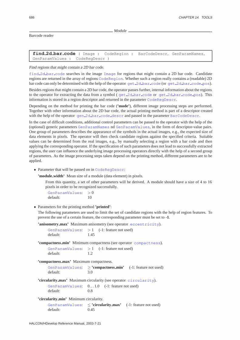
686 CHAPTER 14. TOOLS
ModuleBarcode reader
find 2d bar code ( Image : CodeRegion : BarCodeDescr, GenParamNames,GenParamValues : CodeRegDescr )
Find regions that might contain a 2D bar code.
find 2d bar code searches in the imageImage for regions that might contain a 2D bar code. Candidateregions are returned in the array of regionsCodeRegion . Whether such a region really contains a (readable) 2Dbar code can only be determined with the help of the operatorget 2d bar code (or get 2d bar code pos ).
Besides regions that might contain a 2D bar code, the operator passes further, internal information about the regionsto the operator for extracting the data from a symbol (get 2d bar code or get 2d bar code pos ). Thisinformation is stored in a region descriptor and returned in the parameterCodeRegDescr .
Depending on the method for printing the bar code (’mode’), different image processing steps are performed.Together with other information about the 2D bar code, the actual printing method is part of a descriptor createdwith the help of the operatorgen 2d bar code descr and passed in the parameterBarCodeDescr .
In the case of difficult conditions, additional control parameters can be passed to the operator with the help of the(optional) generic parametersGenParamNamesnd GenParamValues , in the form of descriptor-value pairs.One group of parameters describes the appearance of the symbols in the actual images, e.g., the expected size ofdata elements in pixels. The operator will then check candidate regions against the specified criteria. Suitablevalues can be determined from the real images, e.g., by manually selecting a region with a bar code and thenapplying the corresponding operator. If the specification of such parameters does not lead to successfully extractedregions, the user can influence the underlying image processing operators directly with the help of a second groupof parameters. As the image processing steps taken depend on the printing method, different parameters are to beapplied.
• Parameter that will be passed on inCodeRegDescr :
’module width’ Mean size of a module (data element) in pixels.
From this quantity, a set of other parameters will be derived. A module should have a size of 4 to 16pixels in order to be recognized successfully.
GenParamValues : > 0default: 10
• Parameters for the printing method’printed’ :
The following parameters are used to limit the set of candidate regions with the help of region features. Toprevent the use of a certain feature, the corresponding parameter must be set to-1.
’anisometry max’ Maximum anisometry (see operatoreccentricity ).
GenParamValues : > 1 (-1: feature not used)default: 1.45
’compactnessmin’ Minimum compactness (see operatorcompactness ).
GenParamValues : > 1 (-1: feature not used)default: 1.2
’compactnessmax’ Maximum compactness.
GenParamValues : ≥ ’compactnessmin’ (-1: feature not used)default: 3.0
’circularity max’ Maximum circularity (see operatorcircularity ).
GenParamValues : 0. . . 1.0 (-1: feature not used)default: 0.8
’circularity min’ Minimum circularity.
GenParamValues : ≤ ’circularity max’ (-1: feature not used)default: 0.45
HALCON/HDevelop Reference Manual, 2003-7-21
14.3. BARCODE 687
’deviation min’ Minimum deviation of gray values (see operatorintensity ).
GenParamValues : > 1.0 (-1: feature not used)default: 20.0
The following parameters are automatically derived from the size of a module,’module width’ , and fromparameters of the bar code descriptorBarCodeDescr (see operatorgen 2d bar code descr ). How-ever, they can be adjusted individually, too.ATTENTION: If you want to set’module width’ together with other parameters, make sure set’mod-ule width’ BEFORE the others!
’mean mask size 1’ Mask size for the first smoothing of the image.
GenParamValues : ≥ 3default: 2.5 ∗ ′module width′
’mean mask size 2’ Mask size for the second smoothing of the image.
GenParamValues : ≥ 5default: 10.0 ∗ ′module width′
’area min’ Minimum size of the symbol in pixels squared.
GenParamValues : > 0default: 0.25 ∗ ′module width′2 ∗ ′columns min′ ∗ ′rows min′
’area max’ Maximum size of the symbol in pixels squared.
GenParamValues : ≥ ’areamin’default: 4.00 ∗ ′module width′2 ∗ ′columns min′ ∗ ′rows min′
’closing mask rad’ Mask size for calling the operatorclosing circle with a test region..
GenParamValues : > 0default: ’module width’
• Parameters for the printing method’engraved darkfield’ :
’compactnessmin’ Minimum compactness (see operatorcompactness ).
GenParamValues : > 1.0 (-1: feature not used)default: 1.2
’compactnessmax’ .
GenParamValues : ≥ ’compactnessmin’ (-1: feature not used)default: 3.0
’edge thresh’ Maximum compactness.
GenParamValues : 0 . . . 255default: 120
’region rect2 rel’ Relation between the areas of the region and the smallest surrounding rectangle.
GenParamValues : < 1.0default: 0.7
’median mask rad’ Mask size for the initial median filtering (see operatormedian image ).
GenParamValues : > 0default: 0.1 ∗ ′module width′ + 0.5
• Parameters for the printing method’engraved lightfield’ :
’anisometry max’ Maximum anisometry (see operatoreccentricity ).
GenParamValues : > 1 (-1: feature not used)default: 1.45
’compactnessmin’ Minimum compactness (see operatorcompactness ).
GenParamValues : > 1 (-1: feature not used)default: 1.2
HALCON 6.0.4

688 CHAPTER 14. TOOLS
’compactnessmax’ Maximum compactness.
GenParamValues : ≥ ’compactnessmin’ (-1: feature not used)default: 3.0
’circularity max’ Maximum circularity (see operatorcircularity ).
GenParamValues : 0. . . 1.0 (-1: feature not used)default: 0.8
’circularity min’ Minimum circularity.
GenParamValues : ≤ ’circularity max’ (-1: feature not used)default: 0.45
’deviation min’ Minimum deviation of gray values (see operatorintensity ).
GenParamValues : > 1.0 (-1: feature not used)default: 20.0
’mean mask size’ Mask size for smoothing the image.
GenParamValues : ≥ 3default: 10 ∗ ′module width′
’area min’ Minimum size of the symbol in pixels squared.
GenParamValues : > 0default: 0.25 ∗ ′module width′2 ∗ ′columns min′ ∗ ′rows min′
’area max’ Maximum size of the symbol in pixels squared.
GenParamValues : ≥ ’areamin’default: 4.00 ∗ ′module width′2 ∗ ′columns min′ ∗ ′rows min′
’closing mask rad’ Mask size for calling the operatorclosing circle with a test region..
GenParamValues : > 0default: ’module width’
’opening mask rad’ Mask size for calling the operatoropening circle with a test region..
GenParamValues : > 0default: 1.5 ∗ ′module width′
Parameter
. Image (input object) . . . . . . . . . . . . . . . . . . . . . . . . . . . . . . . . . . . . . . . . . . . . . . . . . . . . . . . . . . . . . . . image; HobjectImage of one or more bar codes.
. CodeRegion (outputobject) . . . . . . . . . . . . . . . . . . . . . . . . . . . . . . . . . . . . . . . . . . . . . . . . region(-array); HobjectRegions that might contain a bar code.
. BarCodeDescr (input control) . . . . . . . . . . . . . . . . . . . . . . . . . . . . . . . . . . . . string-array; string/ integer / realDescription of a 2D bar code class to look for.
. GenParamNames(input control) . . . . . . . . . . . . . . . . . . . . . . . . . . . . . . . . . . . . . . . . . . . . . . string(-array); stringList of names of (optional) generic parameters controlling the image processing.Default Value : ’[]’Value List : GenParamNames∈ {’module width’, ’anisometrymax’, ’compactnessmin’,’compactnessmax’, ’circularity min’, ’circularity max’, ’deviationmin’, ’mean masksize’,’meanmasksize 1’, ’mean masksize 2’, ’area min’, ’area max’, ’closing maskrad’, ’openingmaskrad’,’compactnessmin’, ’compactnessmax’, ’edgethresh’, ’regionrect2 rel’, ’median maskrad’}
. GenParamValues (input control) . . . . . . . . . . . . . . . . . . . . . . . . . . . . . . number(-array); real/ integer / stringList of values of generic parameters controlling the image processing.Default Value : ’[]’Value List : GenParamValues ∈ {1, 1.1, 1.2, 1.3, 1.4, 1.5, 2, 3, 4, 5, 6, 7, 8, 9, 10, 11, 12, 13, 14, 15, 16,17, 18, 19, 20}
. CodeRegDescr (outputcontrol) . . . . . . . . . . . . . . . . . . . . . . . . . . . . . . . . . . . string-array; string/ integer / realAdditional parameters describing the bar code regions. They can be used for extracting the data (seedecode 2d bar code ).
HALCON/HDevelop Reference Manual, 2003-7-21

14.3. BARCODE 689
ResultThe operatorfind 2d bar code returns the value 2 (HMSG TRUE) if the given parameters are correct. Oth-erwise, an exception will be raised.
Parallelization Informationfind 2d bar code is reentrantand processedwithoutparallelization.
Possible Predecessor Functionsgen 2d bar code descr
Possible Successor Functionsget 2d bar code , get 2d bar code pos
ModuleBarcode reader
gen 1d bar code descr ( : : CodeName, MinCharacters,MaxCharacters : BarCodeDescr )
Generate a decscription of a 1D bar code.
gen 1d bar code descr generates a description of a one dimensional bar code. This description is used for thesearch (find 1d bar code or find 1d bar code region ) and the decoding (decode 1d bar code )of the barcode. gen 1d bar code descr is therefore the first operator in a program sequence for barcodeprocessing.gen 1d bar code descr has only to be called once at the beginning of a program. The descriptorcan be used multiple times. In the case of different types of barcodes the operator has to be called once for eachtype.
You have to be aware that this description contains only basic informations about the barcode. Thus an arbitrarydescription can be used toextract almost every type of barcode. On the other hand a specific description isimportant for thedecodingof a barcode type.
Parameter
. CodeName(input control) . . . . . . . . . . . . . . . . . . . . . . . . . . . . . . . . . . . . . . . . . . . . . . . . . . . . . . . . . . . . string; stringName of bar code.Default Value : ”EAN 13”Value List : CodeName∈ {”2/5 Industrial”, ”2/5 Interleaved”, ”Code 39”, ”Codabar”, ”Code 128”, ”Code93”, ”EAN 13”, ”EAN 13 Add-On 2”, ”EAN 13 Add-On 5”, ”EAN 8”, ”EAN 8 Add-On 2”, ”EAN 8 Add-On5”, ”UPC-A”, ”UPC-A Add-On 2”, ”UPC-A Add-On 5”, ”UPC-E”, ”UPC-E Add-On 2”, ”UPC-E Add-On 5”,”PharmaCode”}
. MinCharacters (input control) . . . . . . . . . . . . . . . . . . . . . . . . . . . . . . . . . . . . . . . . . . . . . . . . . . . integer; integerMinimum number of characters (if not fixed).Default Value : 6Value Suggestions :MinCharacters ∈ {-1, 1, 2, 3, 4, 5, 6, 7, 8, 9, 10, 12, 14, 16, 18, 20, 25, 30}
. MaxCharacters (input control) . . . . . . . . . . . . . . . . . . . . . . . . . . . . . . . . . . . . . . . . . . . . . . . . . . . integer; integerMaximum number of characters (if not fixed).Default Value : 10Value Suggestions :MaxCharacters ∈ {-1, 1, 2, 3, 4, 5, 6, 7, 8, 9, 10, 12, 14, 16, 18, 20, 25, 30, 35, 40,50}
. BarCodeDescr (outputcontrol) . . . . . . . . . . . . . . . . . . . . . . . . . . . . . . . . . . . string-array; string/ integer / realDescription of a bar code class.
Example
HTuple empty; // empty list of valuesHTuple BarCodeDescr;HTuple BarcodeFound,Elements,Orientation;HTuple Characters,Reference,IsCorrect;Hobject Image,CodeRegion;
gen_1d_bar_code_descr("EAN 13",13,13,&BarCodeDescr);find_1d_bar_code(Image,&CodeRegion,BarCodeDescr,empty,empty,
HALCON 6.0.4
690 CHAPTER 14. TOOLS
&BarcodeFound,&Elements,&Orientation);if (BarcodeFound[0].l){
decode_1d_bar_code(Elements,BarCodeDescr,&Characters,&Reference,&IsCorrect);
if (IsCorrect[0].l)for (int i=0; i<Characters.Num(); i++){
char *value = Characters[i];}
}
ResultThe operatorgen 1d bar code descr returns the value 2 (HMSG TRUE) if the transfered barcode name iscorrect.
Parallelization Informationgen 1d bar code descr is reentrantand processedwithoutparallelization.
Possible Successor Functionsfind 1d bar code , find 1d bar code region
Alternativesgen 1d bar code descr gen
ModuleBarcode reader
gen 1d bar code descr gen ( : : MinCodeLength, MaxCodeLength,ElementSizes, StartElement, StopElement, MaxSizeRatio,DiscreteCode : BarCodeDescr )
Generate a generic decscription of a 1D bar code.
gen 1d bar code descr gen generates a generic description of a one dimensional bar code. This operatoris used if the barcode description cannot be generated bygen 1d bar code descr but nonetheless has to befound by using the operatorsfind 1d bar code or find 1d bar code region . Note that in this case thebarcode cannot be deccoded bydecode 1d bar code . Thus in this case the decoding has to be done by theuser.
The values forDiscreteCode andElementSizes have to be set correctly in any case. The other values arenot so important for the extraction because they can be estimated by the system automatically.
Parameter
. MinCodeLength (input control) . . . . . . . . . . . . . . . . . . . . . . . . . . . . . . . . . . . . . . . . . . . . . . . . . . . integer; integerMinimum length of the code in modules (including start and stop elements).Default Value : 30Value List : MinCodeLength ∈ {-1, 30, 60, 90, 110, 130, 150, 200}
. MaxCodeLength (input control) . . . . . . . . . . . . . . . . . . . . . . . . . . . . . . . . . . . . . . . . . . . . . . . . . . . integer; integerMaximum length of the code in modules (including start and stop elements).Default Value : 30Value List : MaxCodeLength ∈ {-1, 30, 60, 90, 110, 130, 150, 200}
. ElementSizes (input control) . . . . . . . . . . . . . . . . . . . . . . . . . . . . . . . . . . . . . . . . . . . . . . . . . . . . integer; integerNumber of different element sizes.Default Value : 2Value List : ElementSizes ∈ {1, 2, 3, 4, 5, 6, 7}
. StartElement (input control) . . . . . . . . . . . . . . . . . . . . . . . . . . . . . . . . . . . . . . . . . . . . . integer(-array); integerList of elements of the start sequence. The width of an element is given as the number of modules. Gaps aregiven as negative values.Default Value : ’[1,-1]’
HALCON/HDevelop Reference Manual, 2003-7-21
14.3. BARCODE 691
. StopElement (input control) . . . . . . . . . . . . . . . . . . . . . . . . . . . . . . . . . . . . . . . . . . . . . . . integer(-array); integerList of elements of the stop sequence. The width of an element is given as the number of modules. Gaps aregiven as negative values.Default Value : ’[1,-1]’
. MaxSizeRatio (input control) . . . . . . . . . . . . . . . . . . . . . . . . . . . . . . . . . . . . . . . . . . . . . . . . . . . . . . .number; realMaximum ratio length to height.Default Value : 2.5Value List : MaxSizeRatio ∈ {-1, 2, 3, 4, 5, 6}
. DiscreteCode (input control) . . . . . . . . . . . . . . . . . . . . . . . . . . . . . . . . . . . . . . . . . . . . . . . . . . . . . . . string; stringDiscrete code (ignore white elements).Default Value : ’false’Value List : DiscreteCode ∈ {’true’, ’false’}
. BarCodeDescr (outputcontrol) . . . . . . . . . . . . . . . . . . . . . . . . . . . . . . . . . . . string-array; string/ integer / realDescription of a bar code class.
Example
HTuple empty; // empty list of valuesHTuple BarCodeDescr;HTuple BarcodeFound,Elements,Orientation;HTuple DiscreteBarCode;Hobject Image,CodeRegion;
gen_1d_bar_code_descr_gen(20,40,2,empty,empty,-1.0,"false",&BarCodeDescr);find_1d_bar_code(Image,&CodeRegion,BarCodeDescr,empty,empty,
&BarcodeFound,&Elements,&Orientation);if (BarcodeFound[0].l){
discrete_1d_bar_code(Elements,BarCodeDescr,&DiscreteBarCode);for (int i=0; i<DiscreteBarCode.Num(); i++){
int NumModules = DiscreteBarCode[i];}
}
ResultThe operatorgen 1d bar code descr gen returns the value 2 (HMSG TRUE) if the transfered values arecorrect.
Parallelization Informationgen 1d bar code descr gen is reentrantand processedwithoutparallelization.
Possible Successor Functionsfind 1d bar code , find 1d bar code region
Alternativesgen 1d bar code descr
ModuleBarcode reader
gen 2d bar code descr ( : : CodeType, GenParamNames,GenParamValues : BarCodeDescr )
Generate a generic description of a 2D bar code class.
gen 2d bar code descr creates a generic description of a 2D bar code. This description consists of the typeof the bar code and further characteristic features of the code.
The parameterCodeType specifies the type of the 2D bar code. Currently, the following types are supported:
’Data Matrix ECC 200’ Data Matrix type ECC 200.
HALCON 6.0.4

692 CHAPTER 14. TOOLS
The bar code can be described more closely using the parametersGenParamNamesandGenParamValues ,which form pairs of descriptors and values. The following parameters describe the size and the form of the symbols:
’columns’ Exact number of columns of the symbol.
GenParamValues : 10, 12, 14, 16, 18, 20, 22, 24, 26, 32, 36, 40,44, 48, 52, 64, 72, 80, 88, 96, 104, 120, 132, 144
default: -
’columns min’ Minimum number of columns.GenParamValues : 10...144 (even)default: 10
’columns max’ Maximum number of columns.
GenParamValues : 10...144 (even)
’rows’ Exact number of rows of the symbol.
GenParamValues : 8, 10, 12, 14, 16, 18, 20, 22, 24, 26, 32, 36, 40,44, 48, 52, 64, 72, 80, 88, 96, 104, 120, 132, 144
default: -
’rows min’ Minimum number of rows.GenParamValues : 8...144 (even)default: 8
’rows max’ Maximum number of rows.GenParamValues : 8...144 (even)default: 144
’shape’ Form of the symbol.
GenParamValues : ’square’, ’rectangle’, ’any’default: ’any’
The following parameters describe the printing method and the appearance of the bar code:
’foreground’ Appearance of bits corresponding to a logical1 (foreground).
2D bar codes can be printed dark on light or vice versa. If the appearance of bits corresponding to a logical1 can be specified in advance, computing time will be significantly reduced, especially when looking forregions that might contain a bar code (operatorfind 2d bar code ).
GenParamValues : ’any’: unknown appearance’dark’,’black’: symbols are printed dark on light’light’,’white’: symbols are printed light on dark
default: ’any’
’mode’ Method used for printing the 2D bar code.
By specifying this parameter, image processing can be optimized.
GenParamValues : ’printed’: Standard black-and-white printing. Modules appear assquare regions; neighboring modules with the same valueform one region.
’engraveddarkfield’: Modules with the value1 are engraved into the surface,e.g. by a laser. Using dark field lighting these modulesappear as dark round dots with a white corona; neighbor-ing modules with the value1 are therefore separated bygaps.
’engravedlightfield’: Similar to ’engraveddarkfield’, but using light field light-ing. Modules with the value1 therefore appear as lightdots with a dark corona; neighboring modules with thevalue1 are again separated by gaps.
default: ’printed’
HALCON/HDevelop Reference Manual, 2003-7-21

14.3. BARCODE 693
Parameter
. CodeType (input control) . . . . . . . . . . . . . . . . . . . . . . . . . . . . . . . . . . . . . . . . . . . . . . . . . . . . . . . . . . . . string; stringType of the 2D bar code.Default Value : ”Data Matrix ECC 200”Value List : CodeType ∈ {”Data Matrix ECC 200”}
. GenParamNames(input control) . . . . . . . . . . . . . . . . . . . . . . . . . . . . . . . . . . . . . . . . . . . . . . . . string-array; stringList of names of generic parameters describing the 2D bar code class.Default Value : ’[]’Value List : GenParamNames∈ {’columns’, ’columnsmin’, ’columnsmax’, ’rows’, ’rows min’,’rows max’, ’foreground’, ’shape’, ’mode’}
. GenParamValues (input control) . . . . . . . . . . . . . . . . . . . . . . . . . . . . . . . . integer-array; integer/ string / realList of values of the generic parameters describing the 2D bar code class.Default Value : ’[]’Value List : GenParamValues ∈ {8, 10, 12, 14, 16, 18, 20, 22, 24, 26, 32, 36, 40, 44, 48, 52, 64, 72, 80,88, 96, 104, 120, 132, 144, ’dark’, ’light’, ’square’, ’rectangle’, ’printed’, ’engraveddarkfield’,’engravedlightfield’, ’any’}
. BarCodeDescr (outputcontrol) . . . . . . . . . . . . . . . . . . . . . . . . . . . . . . . . . . . string-array; string/ integer / realDescription of the 2D bar code class.
Example
gen_2d_bar_code_descr (’Data Matrix ECC 200’, [’mode’,’foreground’],[’printed’,’dark’], BarCodeDescr)
ResultThe operatorgen 2d bar code descr returns the value 2 (HMSG TRUE) if the given parameters are correct.Otherwise, an exception will be raised.
Parallelization Informationgen 2d bar code descr is reentrantand processedwithoutparallelization.
Possible Successor Functionsfind 2d bar code
ModuleBarcode reader
get 1d bar code ( BarCodeRegion : : BarCodeDescr, GenericName,GenericValue, Orientation : BarCodeElements )
Extract the widths of the elements inside a barcode region.
get 1d bar code extracts the widths of the elements of a barcode inside the specified region.
The control of the processing is identical tofind 1d bar code . The description of the parametersGenericName andGenericValue can be found at this operator.
Parameter
. BarCodeRegion (input object) . . . . . . . . . . . . . . . . . . . . . . . . . . . . . . . . . . . . . . . . . . . . . . . . . . . . image; HobjectRegion of bar code.
. BarCodeDescr (input control) . . . . . . . . . . . . . . . . . . . . . . . . . . . . . . . . . . . . string-array; string/ integer / realDescription of a bar code class.
. GenericName (input control) . . . . . . . . . . . . . . . . . . . . . . . . . . . . . . . . . . . . . . . . . . . . . . . . . string(-array); stringNames of optional parameters.Default Value : ’[]’Value List : GenericName ∈ {’sigma project’, ’amplitudeproject’, ’width project’, ’addlengthproject’,’interpolationproject’, ’max extraelements’}
. GenericValue (input control) . . . . . . . . . . . . . . . . . . . . . . . . . . . . . . . . . . . . . . . .number(-array); real/ integerValues of optional parameters.Default Value : ’[]’
HALCON 6.0.4

694 CHAPTER 14. TOOLS
. Orientation (input control) . . . . . . . . . . . . . . . . . . . . . . . . . . . . . . . . . . . . . . . . . . . . . . . . . . . . . . .angle.rad; realOrientation of bar code.
. BarCodeElements (outputcontrol) . . . . . . . . . . . . . . . . . . . . . . . . . . . . . . . . . . . . . . . . . . . . number-array; realWidths of elements.
Example
HTuple empty; // empty list of valuesHTuple BarCodeDescr;HTuple Orientations, Elements;HTuple Characters,Reference,IsCorrect;Hobject Image,CodeRegions,CodeRegion,GrayRegion;long num;
gen_1d_bar_code_descr("code 39",4,15,&BarCodeDescr);find_1d_bar_code_region(Image,&CodeRegion,BarCodeDescr,empty,empty,
&Orientations);count_obj(CodeRegions,&num);for (long i=0; i<num; i++){
select_obj(CodeRegions,&CodeRegion,i);reduce_domain(Image,CodeRegion,GrayRegion)\:get_1d_bar_code(GrayRegion,BarCodeDescr,empty,empty,Orientations[i],
&Elements);decode_1d_bar_code(Elements,BarCodeDescr,
&Characters,&Reference,&IsCorrect);}
ResultThe operatorget 1d bar code returns the value 2 (HMSG TRUE) if the parameters are correct.
Parallelization Informationget 1d bar code is reentrantand processedwithoutparallelization.
Possible Predecessor Functionsfind 1d bar code region , select obj , reduce domain
Possible Successor Functionsdecode 1d bar code
Alternativesfind 1d bar code
ModuleBarcode reader
get 2d bar code ( BarCodeRegion, Image : : BarCodeDescr, CodeRegDescr,GenParamNames, GenParamValues : BarCodeDimension, BarCodeData )
Extract the values of the data elements (in ECC 200: “modules”) inside a bar code region (“Data Matrix symbol”).
get 2d bar code extracts the 2D bar code from a candidate symbol region given inBarCodeRegion andthe corresponding image given inImage . BarCodeDescr contains a descriptor of the expected bar code class,which is created with the help of the operatorgen 2d bar code descr . CodeRegDescr contains furtherinformation regarding the candidate region. This descriptor is created by the operatorfind 2d bar code .
If BarCodeRegion contains a 2D bar code, its data, i.e. the bits of the matrix, are written line by line into atuple and returned in the parameterBarCodeData . Positive values stand for a logical one, negative values for alogical zero. A value of zero signals that the data element could not be classified unambiguously.
The size of the data field is returned in the parameterBarCodeDimension . The first two entries specify thewidth and the height of the data field, the third contains a so-called symbol index which also describes its size. Thesize of the data field is not to be confused with the size of the symbol which in turn encompasses additional finderand alignment patterns.
HALCON/HDevelop Reference Manual, 2003-7-21

14.3. BARCODE 695
If no 2D bar code could be extracted the operator returns a corresponding error code.
In difficult cases, the user can influence image processing with the help of the (optional) generic parame-ters GenParamNames and GenParamValues . The width of a module in pixels (’module width’ ) doesnot need to be specified, it is part of the region descriptorCodeRegDescr . As in the case of the operatorfind 2d bar code , for the different printing methods different image processing steps are applied, leading todifferent parameters.
As a short overview, image processing falls into the following parts: First, the regionBarCodeRegion is dividedinto a dark and a light region by applying a thresholding operator. Because there must be a “silent” area aroundeach 2D bar code, this area can be examined to determine whether the bar code is printed black-on-white or viceversa. With this information, the dark and the light region can be assigned to the logical data values. Next,BarCodeRegion is approximated by a rectangle. Then, the special finder patterns that each each symbol mustcontain are searched for in the border areas of the rectangle. From the finder pattern, the size of the data matrixand the size and the position of the modules (data elements) can be determined. Finally, the value of the modulesis determined.
• Parameters controlling the classification of modules as being dark or light:
’module rad ratio’ Part of the module that is to be used for its classification.
This parameter controls which part of the module area (in percent, measured from the center) is used todetermine its value. With a ’modulerad ratio’ of 1.0, the whole area of the module will be examined.With very small ’modulerad ratio’, only one point in the middle will be examined.
GenParamValues : 0< ’module rad ratio’ ≤ 1default: printing method’printed’ , ’engraved lightfield’ : 0.3
printing method’engraved darkfield’ : 0.7
’use grayvals’ Method for the classification of modules (Selectable only for the printing methods’printed’and’engraved lightfield’ ; for the printing method’engraved darkfield’ , the gray-value-based methodis always used!).
The parameter ’usegrayvals’ controls by which method the modules are classified. If ’usegrayvals’ isset to ’no’, the module’s value is determined by examining whether the part of the module specified by’module rad ratio’ is part of the region that has been assigned the value1. If more than half of themodule is part of this region, the module is interpreted as a logical one.In the case ’usegrayvals’ is set to ’yes’, the gray values inside’module rad ratio’ are examined. Forthis, the known border parts of the symbol are used to create classificators with the features “minimumgray value”, “maximum gray value”, and “range of gray values”. A feature will be automatically ex-cluded if it cannot separate the known dark and light regions. It can also be excluded manually withthe help of the parameters below. The value of the modules is then determined by applying the trainedclassificators. In case of ambiguous results, the majority decision is adopted.If none of the gray value features can separate the test regions, the operator switches automaticallyto the region-based method in case the printing method is set to’printed’ . This can be detected byexamining the data values returned inBarCodeData : The region-based method yields multiples of 4,the gray-value-based method values between -3 and +3. If separation fails when the printing method is’engraved darkfield’ , an error code is returned. Note, that classification performance can be enhancedby chosing a suitable value for’module rad ratio’ .
GenParamValues : ’yes’, ’no’default: ’yes’
’use grayval min’ Use the feature “gray value minimum” for classifying module values.
GenParamValues : ’yes’, ’no’default: ’yes’
’use grayval max’ Use the feature “gray value maximum” for classifying module values.
GenParamValues : ’yes’, ’no’default: ’printed’ , ’engraved lightfield’ : ’yes’
’engraved darkfield’ : ’no’
’use grayval range’ Use the feature “gray value range” for classifying module values.
GenParamValues : ’yes’, ’no’default: ’yes’
HALCON 6.0.4
696 CHAPTER 14. TOOLS
• Parameters for the printing methods’printed’ and’engraved lightfield’ :
’enlarge region rad’ Enlarge the symbol region.
GenParamValues : > 0 (≤ 0: enlargment prohibited)default: 2.5
’thresh percent’ Area of the histogram in which to look for an optimal threshold.
The threshold for separating dark and light regions will be searched for in the middle ’threshpercent’percent of the gray value histogram. If ’threshpercent’ is set to 0, a threshold exactly in the middle ofthe histogram is selected. If ’threshpercent’ is set to 100, the whole histogram will be searched. Note,that the threshold influences not only the size of the data region, but also the position of the surroundingrectangle and with it, slightly, the position of the modules.
GenParamValues : 0 . . . 100default: 50
’thresh step width’ Step width for the search of the optimal threshold.
The histogram area specified in the parameter ’threshpercent’ will be stepped through using’threshstepwidth’ until an optimal separation of dark and light regions is reached. The optimumis declared to be found when the number of individual regions is at its maximum. The smaller’threshstepwidth’ is, the better a threshold can be determined, however at the cost of rising computingtime, of course.
GenParamValues : > 0default: 10
’smooth cont’ Parameter for approximating the region by a polygon (rectangle).
The parameter ’smoothcont’ controls to which degree the contour is smoothed before approximating itwith a polygon (see operatorsegment contours xld ).
GenParamValues : 0,3,5,7,9,. . .default: 5
’max line dist1’, ’max line dist2’ Distance between the contour and its approximation.
The parameters ’maxline dist1’ and ’maxline dist2’ control the maximal distance between the contourand its approximation (see operatorsegment contours xld ).
GenParamValues : ≥ 0default: 4
’min cont len’ Minimum length of the contour elements in pixel.
Contour elements shorter than ’mincont len’ will be ignored when approximating the region by arectangle. In the case of small symbols or low resolution, it can be helpful to decrease this parameter.
GenParamValues : > 0default: 50
’border width min’ Minimum width of the border search area.
The border area of the symbol region must contain the so-called finder patterns (ECC 200: two lineswith the value1, two with alternating values). To find these patterns, a search region is constructedalong the sides of the rectangle. Starting with ’borderwidth min’, the width of the seach region isincreased until the finder patterns have been detected, or until’border width max’ has been reached.
GenParamValues : > 0default: 2
’border width max’ Maximum width of the border search area.GenParamValues : ≥ ’border width min’default: 5
’border width’ Exact width of the border search area.
Alternatively, the exact width of this search area can be specified in the parameter ’borderwidth’. This
HALCON/HDevelop Reference Manual, 2003-7-21

14.3. BARCODE 697
automatically sets’border width min’ and’border width max’.GenParamValues : > 0default: -
Parameters for the printing method’engraved darkfield’ :
’median mask rad’ Mask size for the initial median filtering (see operatormedian image ).
GenParamValues : 3,5,7,. . . ,501default: ’module width’ *0.1 + 0.5
’gray erosion size’ Mask size for the subsequent gray value erosion (see operatorgray erosion rect ).
GenParamValues : 3,5,7,. . . ,511default: ’module width’ *0.18 + 3.5
’measure sigma’ Parameter for the extraction of linear edge segment pairs (see operatormeasure pairs ).
GenParamValues : 0.4. . . 100default: ’module width’ < 20: 0.7
’module width’ ≥ 20: 1.4
’measure thresh’ Parameter for the extraction of linear edge segment pairs (see operatormeasure pairs ).
GenParamValues : 1. . . 255default: 2.0
AttentionThe operatorget 2d bar code returns error codes to signal that the candidate region did not contain a valid 2Dbar code. As the region candidates extracted by the operatorfind 2d bar code can perfectly well encompassregions without a bar code, every call toget 2d bar code should be surrounded by error handling code (seeexample).
Parameter
. BarCodeRegion (input object) . . . . . . . . . . . . . . . . . . . . . . . . . . . . . . . . . . . . . . . . . . . . . . . . . . . . region; HobjectRegion that might contain a 2D bar code.
. Image (input object) . . . . . . . . . . . . . . . . . . . . . . . . . . . . . . . . . . . . . . . . . . . . . . . . . . . . . . . . . . . . . . . image; HobjectCorresponding image.
. BarCodeDescr (input control) . . . . . . . . . . . . . . . . . . . . . . . . . . . . . . . . . . . . string-array; string/ integer / realDescription of the bar code class.
. CodeRegDescr (input control) . . . . . . . . . . . . . . . . . . . . . . . . . . . . . . . . . . . . string-array; string/ integer / realAdditional parameters describing the bar code region. They can be used for extracting the data
. GenParamNames(input control) . . . . . . . . . . . . . . . . . . . . . . . . . . . . . . . . . . . . . . . . . . . . . . . . string-array; stringList of names of (optional) generic control parameters.Default Value : ’[]’
. GenParamValues (input control) . . . . . . . . . . . . . . . . . . . . . . . . . . . . . . . . . . . . . . number-array; real/ integerList of values of the generic parameters.Default Value : ’[]’
. BarCodeDimension (outputcontrol) . . . . . . . . . . . . . . . . . . . . . . . . . . . . . . . . . . . . . . . . integer-array; integerTuple with the dimension of the extracted symbol. In the case of ECC 200: data field width, height, symbolindex.
. BarCodeData (outputcontrol) . . . . . . . . . . . . . . . . . . . . . . . . . . . . . . . . . . . . . . . . . . . . . . . integer-array; integerTuple with the data values of the extracted symbol. value> 0: logical 1, value< 0: logical 0, value =0: module could not be classified.
Example
dev_error_var (ErrorCode, 1)gen_2d_bar_code_descr (’Data Matrix ECC 200’, [’mode’], [’printed’],
BarCodeDescr)
HALCON 6.0.4

698 CHAPTER 14. TOOLS
read_image (Image, ’bar2d.tif’)find_2d_bar_code (Image, CodeRegion, BarCodeDescr,
[’module_width’], [10], CodeRegDescr)SymbolNum := |CodeRegion|for i := 1 to SymbolNum by 1
ObjectSelected := CodeRegion[i]dev_set_check (’˜give_error’)get_2d_bar_code (ObjectSelected, Image, BarCodeDescr, CodeRegDescr,
[], [], BarCodeDimension, BarCodeData)err := ErrorCodedev_set_check (’give_error’)if (err = 2)
decode_2d_bar_code (BarCodeDescr, BarCodeDimension, BarCodeData,SymbolCharacters, CorrSymbolData, DecodedData,DecodingError, StructuredAppend)
if (|DecodedData|)tuple_chrt (DecodedData, String)
endifendif
endfor
ResultThe return value can signal incorrect parameters as well as the failure to extract a 2D bar code. Such a failure can bedue to different causes: If no surrounding rectangle was found, the operator returns the error code 8808. Error code8807 signals that the rectangle does not lie completely inside the image. If no finder pattern was detected inside theborder search area, the error code 8810 is returned. If the two continuous lines forming the ’L’ of the finder patterncould not be found, the error code 8809 is returned. In the case of the printing method’engraved darkfield’ , theerror code 8811 signals that none of the gray value features can separate the test regions, i.e. that modules cannotbe classified.
Parallelization Informationget 2d bar code is reentrantand processedwithoutparallelization.
Possible Predecessor Functionsfind 2d bar code
Possible Successor Functionsdecode 2d bar code
Alternativesget 2d bar code pos
ModuleBarcode reader
get 2d bar code pos ( BarCodeRegion, Image : : BarCodeDescr,CodeRegDescr, GenParamNames, GenParamValues : BarCodeDimension,BarCodeData, DataElementRow, DataElementCol )
Extract the data values of the elements (in ECC 200: “modules”) inside a bar code region (“Data Matrix symbol”)and their positions in the image.
get 2d bar code pos extracts the 2D bar code data from a candidate symbol region given inBarCodeRegion and the corresponding image given inImage elements. In contrast toget 2d bar code ,this operator also returns the positions of the data elements in the image in the parametersDataElementRowandDataElementCol . This can be used to check the result of the operator, e.g., by displaying the data in thereal image. For a description of the other parameters, seeget 2d bar code .
AttentionThe operatorget 2d bar code pos returns error codes to signal that the candidate region did not contain avalid 2D bar code. As the region candidates extracted by the operatorfind 2d bar code can perfectly wellencompass regions without a bar code, every call toget 2d bar code pos should be surrounded by errorhandling code (see example).
HALCON/HDevelop Reference Manual, 2003-7-21
14.3. BARCODE 699
Parameter
. BarCodeRegion (input object) . . . . . . . . . . . . . . . . . . . . . . . . . . . . . . . . . . . . . . . . . . . . . . . . . . . . region; HobjectRegion that might contain a bar code.
. Image (input object) . . . . . . . . . . . . . . . . . . . . . . . . . . . . . . . . . . . . . . . . . . . . . . . . . . . . . . . . . . . . . . . image; HobjectCorresponding image.
. BarCodeDescr (input control) . . . . . . . . . . . . . . . . . . . . . . . . . . . . . . . . . . . . string-array; string/ integer / realDescription of the 2D bar code class.
. CodeRegDescr (input control) . . . . . . . . . . . . . . . . . . . . . . . . . . . . . . . . . . . . string-array; string/ integer / realAdditional parameters describing the bar code region. They can be used for extracting the data.
. GenParamNames(input control) . . . . . . . . . . . . . . . . . . . . . . . . . . . . . . . . . . . . . . . . . . . . . . . . string-array; stringList of names of (optional) generic control parameters.Default Value : ’[]’
. GenParamValues (input control) . . . . . . . . . . . . . . . . . . . . . . . . . . . . . . . . . . . . . . number-array; real/ integerList of values of the generic parameters.Default Value : ’[]’
. BarCodeDimension (outputcontrol) . . . . . . . . . . . . . . . . . . . . . . . . . . . . . . . . . . . . . . . . integer-array; integerTuple with the dimension of the extracted symbol. In the case of ECC 200: data field width, height, symbolindex.
. BarCodeData (outputcontrol) . . . . . . . . . . . . . . . . . . . . . . . . . . . . . . . . . . . . . . . . . . . . . . . integer-array; integerTuple with the data values of the extracted symbol. value> 0: logical 1, value< 0: logical 0, value =0: module could not be classified.
. DataElementRow (outputcontrol) . . . . . . . . . . . . . . . . . . . . . . . . . . . . . . . . . . . . . . . . . . . . . . . . . real-array; realTuple with the row positions of the data elements of the extracted symbol in the image.
. DataElementCol (outputcontrol) . . . . . . . . . . . . . . . . . . . . . . . . . . . . . . . . . . . . . . . . . . . . . . . . . real-array; realTuple with the column positions of the data elements of the extracted symbol in the image.
Example
dev_set_check (’˜give_error’)get_2d_bar_code_pos (ObjectSelected, Image, BarCodeDescr,
CodeRegDescr, [], [], BarCodeDimension, BarCodeData,DataElementRow, DataElementCol)
err := ErrorCodedev_set_check (’give_error’)if (err = 2)
idx := 0dev_update_pc (’off’)dev_update_time (’off’)dev_update_var (’off’)for m := 0 to BarCodeDimension[0]-1 by 1
for n := 0 to BarCodeDimension[1]-1 by 1if (BarCodeData[idx]>0)
set_color (WindowHandle, ’green’)else
if (BarCodeData[idx]<0)set_color (WindowHandle, ’red’)
elseset_color (WindowHandle, ’blue’)
endifendifdisp_circle (WindowHandle, DataElementRow[idx],
DataElementCol[idx], 1)idx := idx+1
endforendfordev_update_pc (’on’)dev_update_time (’on’)dev_update_var (’on’)
HALCON 6.0.4
700 CHAPTER 14. TOOLS
decode_2d_bar_code (BarCodeDescr, BarCodeDimension, BarCodeData,SymbolCharacters, CorrSymbolData, DecodedData,DecodingError, StructuredAppend)
endif
ResultThe return value can signal incorrect parameters as well as the failure to extract a 2D bar code. Such a failure can bedue to different causes: If no surrounding rectangle was found, the operator returns the error code 8808. Error code8807 signals that the rectangle does not lie completely inside the image. If no finder pattern was detected inside theborder search area, the error code 8810 is returned. If the two continuous lines forming the ’L’ of the finder patterncould not be found, the error code 8809 is returned. In the case of the printing method’engraved darkfield’ , theerror code 8811 signals that none of the gray value features can separate the test regions, i.e., that modules cannotbe classified.
Parallelization Informationget 2d bar code pos is reentrantand processedwithoutparallelization.
Possible Predecessor Functionsfind 2d bar code
Possible Successor Functionsdecode 2d bar code
Alternativesget 2d bar code
See Alsogen 2d bar code descr
ModuleBarcode reader
14.4 Calibration
caltab points ( : : CalTabDescrFile : X, Y, Z )
Read the mark center points from the calibration table description file.
caltab points is used to read the mark center points from the calibration table description fileCalTabDescrFile . The mark center points are 3D coodinates in the calibration table coordinate system unddescribe the 3D model of the calibration table. The application of the operatorcamera calibration projectsthese model points into the image. By minimizing the distance between the projected model points and the ob-served 2D coordinates in the image (seefind marks and pose ) the exact values for the internal and externalcamera parameters are computed.
Parameter
. CalTabDescrFile (input control) . . . . . . . . . . . . . . . . . . . . . . . . . . . . . . . . . . . . . . . . . . . . . . . . . . .string; stringFile name of the calibration table description.Default Value : ’caltab.descr’
. X (outputcontrol) . . . . . . . . . . . . . . . . . . . . . . . . . . . . . . . . . . . . . . . . . . . . . . . . . . . . . . . . . . . . . . . . . . . real-array; realX-coordinates of the mark center points.
. Y (outputcontrol) . . . . . . . . . . . . . . . . . . . . . . . . . . . . . . . . . . . . . . . . . . . . . . . . . . . . . . . . . . . . . . . . . . . real-array; realY-coordinates of the mark center points.
. Z (outputcontrol) . . . . . . . . . . . . . . . . . . . . . . . . . . . . . . . . . . . . . . . . . . . . . . . . . . . . . . . . . . . . . . . . . . . real-array; realZ-coordinates of the mark center points.
Example
// read_image(Image1,’calib-01.tiff’)// find calibration pattern */find_caltab(Image1,Caltab1,’caltab.descr’,3,112,5)/* find calibration marks and start poses */
HALCON/HDevelop Reference Manual, 2003-7-21

14.4. CALIBRATION 701
find_marks_and_pose(Image1,Caltab1,’caltab.descr’,[0.008,0.0,0.000011,0.000011,384,288,768,576],128,10,18,0.9,15.0,100.0,RCoord1,CCoord1,StartPose 1
// read 3D positions of calibration marks */caltab_points(’caltab.descr’,NX,NY,NZ) >// camera calibrationcamera_calibration(NX,NY,NZ,RCoord1,CCoord1,
[0.008,0.0,0.000011,0.000011,384,288,768,576],StartPose1,11,CamParam,FinalPose,Errors)
// visualize calibration resultdisp_image(Image1,WindowHandle)set_color(WindowHandle,’red’)disp_caltab(’caltab.descr’,CamParam,FinalPose,1.0).
Resultcaltab points returns 2 (HMSG TRUE) if all parameter values are correct and the fileCalTabDescrFilehas been read successfully. If necessary, an exception handling is raised.
Parallelization Informationcaltab points is reentrantand processedwithoutparallelization.
Possible Successor Functionscamera calibration
See Alsofind caltab , find marks and pose , camera calibration , disp caltab , sim caltab ,project 3d point , get line of sight , create caltab
ModuleCamera calibration
camera calibration ( : : NX, NY, NZ, NRow, NCol, StartCamParam,NStartPose, EstimateParams : CamParam, NFinalPose, Errors )
Determine all camera parameters by a simultanous minimization process.
camera calibration performs the calibration of a video camera. Thus, known 3D model points (with coor-dinatesNX, NY, NZ) are projected in the image and the sum of the squared distance between these projections andthe corresponding image points (with coordinatesNRow, NCol ) is minimized.
In case of converging, the exact internal (CamParam) and external (NFinalPose ) camera parameters are deter-mined by this minimization algorithm. The parametersStartCamParam andNStartPose are used as initialvalues for the minimization process. Since this algorithm simultaneously handles correspondences between imageand model points from different images, it is also calledmulti image calibration .
In general camera calibration means the exact determination of the parameters, which model the (optical) projec-tion of any 3D world pointPW into a (sub-)pixel [r,c] on the CCD sensor of the camera. This is of importance, ifthe original 3D pose of an object has to be computed using an image (e.g., measuring of industrial pieces).
The underlying camera model is apinhole camera with radial distortions if the focal length passed inStartCamParam is greater than 0. It describes the transform of a 3D world pointPW into a (sub-)pixel [r,c] ofthe video image by the following equations:
PC = [x y z]T = R · PW + Tu = Focus· x
z and v = Focus· yz
ũ = 2u
1+√
1−4κ(u2+v2)and ṽ = 2v
1+√
1−4κ(u2+v2)
c = ũSx
+ Cx and r = ṽSy
+ Cy
If the focal length is passed as 0 inStartCamParam , the camera model of atelecentric camera with radialdistortions is used, i.e., it is assumed that the optics of the lens of the camera performs a parallel projection. Inthis case, the corresponding equations are:
HALCON 6.0.4

702 CHAPTER 14. TOOLS
PC = [x y z]T = R · PW + Tu = x and v = y
ũ = 2u
1+√
1−4κ(u2+v2)bzw. ṽ = 2v
1+√
1−4κ(u2+v2)
c = ũSx
+ Cx bzw. r = ṽSy
+ Cy
These equations consist of a coordinate transform from the world coordinate system into the camera coordinatesystem, a perspective or parallel projection into the image plane, a radial distortion of the projected point, andfinally a sampling and an image center displacement.
The total of 15 camera parameters can be divided into the internal and external camera parameters:
Internal camera parameters: These parameters describe the characterisctics of the used video camera, especiallythe dimension of the CCD sensor itself and the projection properties of the used combination of lens, camera,and frame grabber. The camera model (as described above) contains the following 8 parameters:
Focus: Focal length of the lens. 0 for telecentric lenses.Kappa (κ): Distortion coefficient to model the pillow- or barrel-shaped distortions caused by the lens.Sx: Scale factor, corresponds to the horizontal distance between two neighboring cells on the CCD sensor.
Attention: This value increases, if the image is subsampled!Sy: Scale factor, corresponds to the vertical distance between two neighboring cells on the CCD sensor.
Since in most cases the image signal is sampled line-synchronously, this value is determined by thedimension of the CCD sensor and needn’t be estimated for pinhole cameras by the calibration process.Attention: This value increases, if the image is subsampled!
Cx: Column coordinate of the image center point (center of the radial distortion).Cy: Row coordinate of the image center point (center of the radial distortion).ImageWidth: Width of the sampled video image. Attention: This value decreases, if the image is subsam-
pled!ImageHeight: Height of the sampled video image. Attention: This value decreases, if the image is subsam-
pled!
External camera parameters: These 7 parameters describe the position and orientation of the camera and arealso called ascamera pose. The relative position of the camera with regard of a world or object coordinatesystem is defined by a 3D translational vector (parameters 1, 2, and 3). The orientation of the camera isdescribed by the three rotation angles around the three coordinate axes (parameters 4, 5, and 6).The last value within the camera pose encodes the representation type of the described 3D transform: E.g.,the value ’0’ is the code of the representation type 1 and says, that the transform of a point is described,the 3D rotation is performed before the 3D translation, that the three rotations are specified as angles (indegree), and that the rotation order isγ-β-α, i.e., the first rotation is around the Z-axis, the second onearound the new Y-axis, and the third one around the new X-axis, which is generated after the second rotation.camera calibration operates with all types of 3D transform forNStartPose . The sense of the otherrepresentation types are explained atcreate pose .Note, that in contrast to the external camera parameters the internal ones are the same for all positions andorientations of the camera.
The use ofcamera calibration leads to some questions, which are dealed with in the following sections:
How to generate a appropriate calibration table? The simplest method to determine the internal parameter ofa CCD camera is the use of the planar calibration table generated by the operatorcreate caltab . Incase of small distances between object and lens it may be sufficient to print the calibration pattern by a laserprinter and to mount it on a cardboard. Otherwise – especially by using a wide-angle lens – it is possible toprint the PostScript file on a large inkjet printer and to mount it on a aluminum table. It is very important,that the mark coordinates in the calibration table description file correspond to the real ones on the calibrationtable with high accuracy. Thus, the calibration table description file has to be modified in accordance withthe measurement of the calibration table!
How to take a set of suitable images?If you use the planar calibration table, you can proceed in the followingway: With the combination of lens (fixed distance!), camera, and frame grabber to be calibrated a set of im-ages of the calibration table has to be taken, seeopen framegrabber and grab image . The followingitems have to be considered:
HALCON/HDevelop Reference Manual, 2003-7-21
14.4. CALIBRATION 703
• At least a total of 10 to 20 images should be taken into account.
• The calibration table has to be completely visible (incl. border!).
• Reflections etc. on the calibration table should be avoided.
• Within the set of images the calibration table should appear in different positions and orientations: Onceleft in the image, once right, once (left and right) at the bottom, once (left or right) at the top, fromdifferent distances etc. At this, the calibration table should be rotated a little around its X- and/or Y-axis,so the perspective distortions of the calibration pattern are clearly visible. Thus, the external cameraparameters (camera pose with regard of the calibration table) should be set to a large variety of differentvalues!
• The calibration table should fill at least a quarter of the whole image to ensure the robust detection of themarks.
How to extract the calibration marks in the images? If a planar calibration table is used, for each image theoperatorsfind caltab and find marks and pose can be used to determine the coordinates of thecalibration marks and to compute a rough estimate for the external camera parameters. The concatenationof these values can directly be used as initial values for the external camera parameters (NStartPose ) incamera calibration .
Obviously, images, on which the segmentation of the calibration table (find caltab ) has failed or thecalibration marks haven’t been determined successfully byfind marks and pose , should not be used.
How to find suitable initial values for the internal camera parameters ? The operatorsfind marks and pose (determination of initial values for the external camera parameters) andcamera calibration require initial values for the internal camera parameters. These parameters can beprovided by a appropriate text file (seeread cam par ), which can be generated bywrite cam par orcan be edited manually.
The following should be considered for the initial values of the single parameters:
Focus: The initial value is the nominal focal length of the the used lens, e.g., 0.008 m.
Kappa: Use 0.0 as initial value. The calibratied value normally lies between -1000.0 and -50000.0 1/m2
depending on the used lens.
Sx: The initial value for the horizontal distance between two neighboring CCD cells depends on the dimen-sion of the used CCD chip of the camera (see technical specifications of the camera). Generally, commonCCD chips are either 1/3”-Chips (e.g., SONY XC-73, SONY XC-777), 1/2”-Chips (e.g., SONY XC-999, Panasonic WV-CD50), or 2/3”-Chips (e.g., SONY DXC-151, SONY XC-77). Notice: The valueof Sx increases, if the image is subsampled! Appropriate initial values are:
Full image (768*576) Subsampling (384*288)1/3"-Chip 0.0000055 m 0.0000110 m1/2"-Chip 0.0000086 m 0.0000172 m2/3"-Chip 0.0000110 m 0.0000220 m
The value for Sx is calibrated, since the video signal of a CCD camera normally isn’t sampled pixel-synchronously.
Sy: Since most off-the-shelf cameras have quadratic pixels, the same values for Sy are valid as for Sx. Incontrast to Sx the value for Sy will NOT be calibrated for pinhole cameras, because the video signal of aCCD camera normally is sampled line-synchronously. Thus, the initial value is equal to the final value.Appropriate initial values are:
Full image (768*576) Subsampling (384*288)1/3"-Chip 0.0000055 m 0.0000110 m1/2"-Chip 0.0000086 m 0.0000172 m2/3"-Chip 0.0000110 m 0.0000220 m
Cx and Cy: Initial values for the coordinates of the image center is the half image width and half imageheight. Notice: The values of Cx and Cy decrease, if the image is subsampled! Appropriate initialvalues are:
Full image (768*576) Subsampling (384*288)Cx 384.0 192.0Cy 288.0 144.0
HALCON 6.0.4
704 CHAPTER 14. TOOLS
ImageWidth and ImageHeight: These two parameters are set by the the used frame grabber and thereforeare not calibrated. Appropriate initial values are:
Full image (768*576) Subsampling (384*288)ImageWidth 768 384ImageHeight 576 288
Which camera parameters have to be estimated?The input parameterEstimateParams is used to selectwhich camera parameters to estimate. Usually this parameter is set to’all’ , i.e., all 6 external camera pa-rameters (translation and rotation) and all internal camera parameters have to be determined. Otherwise,EstimateParams contains a tuple of strings indicating the combination of parameters to estimate.
What is the order within the single parameters? The length of the tupleNStartPose corresponds to thenumber of calibration images, e.g., using 15 images leads to a length of the tupleNStartPose equal to15 · 7 = 105 (15 times the 7 external camera parameters). The first 7 values correspond to the camera poseof the first image, the next 7 values to the pose of the second one, etc.
This fixed number of calibration images has to be considered within the tuples with the coordinates of the 3Dmodel marks and the extracted 2D marks. If 15 images are used, the length of the tuplesNRowandNColis 15 times the length of the tuples with the coordinates of the 3D model marks (NX, NY, andNZ). If everyimage consists 49 marks, the length of the tuplesNRowandNCol is 15 · 49 = 735, while the length of thetuplesNX, NY, andNZ is 49. The order of the values inNRowandNCol is “image after image”, i.e., using49 marks the first 3D model point corresponds to the 1st, 50th, 99th, 148th, 197th, 246th, etc. extracted 2Dmark.
The 3D model points can be read from a calibration table description file using the opera-tor caltab points . Initial values for the camera pose can be determined by applyingfind marks and pose for each image. The tupleNStartPose is set by the concatenation of all thesecamera poses.
What is the meaning of the output parameters?If the camera calibration process is finished successfully, i.e.,the minimization process is converged, the output parametersCamParamandNFinalPose contain thecomputed exact values for the internal and external camera parameters. The length of the tupleNFinalPosecorresponds to the length of the tupleNStartPose .
The representation types ofNFinalPose correspond to the representation type of the first tuple ofNStartPose . You can convert the representation type byconvert pose type . The sense of all kindof representation types for the 3D transform are explained atcreate pose .
The computed average errors (Errors ) give an impression of the accuracy of the calibration. The errorvalues (deviations in x- and y-coordinates) are measured in pixels.
Must I use a planar calibration table? No. The operatorcamera calibration is designed in a way, thatthe input tuplesNX, NY, NZ, NRow, andNCol can contain any 3D/2D correspondences, see the aboveparagraph explaining the order of the single parameters.Thus, it makes no difference, how the required 3D model marks and the corresponding extracted 2D marksare determined. On the one hand it is possible to use a 3D calibration pattern, on the other hand youalso can use any characteristic points (natural landmarks) with known position in the world. By settingEstimateParams to 6, it is possible to compute the world position of the camera! Hereby at least three3D/2D-correspondences are necessary as input. Homogeneous transformation matrices are useful to generateNStartPose , see program example inhom mat3d to pose and/or program example increate posefor generatingNStartPose directly.
AttentionThe minimization process of the calibration depends on the initial values of the internal (StartCamParam ) andexternal (NStartPose ) camera parameters. The computed average errorsErrors give an impression of theaccuracy of the calibration. The errors (deviations in x- and y-coordinates) are measured in pixels.
Parameter
. NX(input control) . . . . . . . . . . . . . . . . . . . . . . . . . . . . . . . . . . . . . . . . . . . . . . . . . . . . . . . . . . . . . . . . . . real-array; realOrdered Tuple with all X-coordinates of the calibration marks (in meters).
. NY(input control) . . . . . . . . . . . . . . . . . . . . . . . . . . . . . . . . . . . . . . . . . . . . . . . . . . . . . . . . . . . . . . . . . . real-array; realOrdered Tuple with all Y-coordinates of the calibration marks (in meters).
. NZ (input control) . . . . . . . . . . . . . . . . . . . . . . . . . . . . . . . . . . . . . . . . . . . . . . . . . . . . . . . . . . . . . . . . . . real-array; realOrdered Tuple with all Z-coordinates of the calibration marks (in meters).
HALCON/HDevelop Reference Manual, 2003-7-21

14.4. CALIBRATION 705
. NRow(input control) . . . . . . . . . . . . . . . . . . . . . . . . . . . . . . . . . . . . . . . . . . . . . . . . . . . . . . . . . . . . . . . . real-array; realOrdered Tuple with all row-coordinates of the extracted calibration marks (in pixels).
. NCol (input control) . . . . . . . . . . . . . . . . . . . . . . . . . . . . . . . . . . . . . . . . . . . . . . . . . . . . . . . . . . . . . . . . real-array; realOrdered Tuple with all column-coordinates of the extracted calibration marks (in pixels).
. StartCamParam (input control) . . . . . . . . . . . . . . . . . . . . . . . . . . . . . . . . . . . . . . . . . . . real-array; real/ integerInitial values for the internal camera parameters.
. NStartPose (input control) . . . . . . . . . . . . . . . . . . . . . . . . . . . . . . . . . . . . . . . . . . . . . . . pose-array; real/ integerOrdered tuple with all initial values for the external camera parameters.
. EstimateParams (input control) . . . . . . . . . . . . . . . . . . . . . . . . . . . . . . . . . . . . . . . . . . . . string; string/ integerCamera parameters to be estimated.Default Value : ’all’Value List : EstimateParams ∈ {’all’, ’alpha’, ’beta’, ’gamma’, ’transx’, ’transy’, ’transz’, ’focus’,’kappa’, ’cx’, ’cy’, ’sx’, ’sy’ }
. CamParam(outputcontrol) . . . . . . . . . . . . . . . . . . . . . . . . . . . . . . . . . . . . . . . . . . . . . .number-array; real/ integerInternal camera parameters.
. NFinalPose (outputcontrol) . . . . . . . . . . . . . . . . . . . . . . . . . . . . . . . . . . . . . . . . . . . . . .pose-array; real/ integerOrdered tuple with all external camera parameters.
. Errors (outputcontrol) . . . . . . . . . . . . . . . . . . . . . . . . . . . . . . . . . . . . . . . . . . . . . . . . . . . . . . . . . . . . real-array; realAverage error distances in pixels.
Example
// read calibration imagesread_image(Image1,’calib-01.tiff’)read_image(Image2,’calib-02.tiff’)read_image(Image3,’calib-03.tiff’)// find calibration patternfind_caltab(Image1,Caltab1,’caltab.descr’,3,112,5)find_caltab(Image2,Caltab2,’caltab.descr’,3,112,5)find_caltab(Image3,Caltab3,’caltab.descr’,3,112,5)// find calibration marks and start posesfind_marks_and_pose(Image1,Caltab1,’caltab.descr’,[0.008,0.0,
0.000011,0.000011,384,288,768,576],128,10,18,0.9,15.0,100.0,RCoord1,CCoord1,StartPose 1find_marks_and_pose(Image2,Caltab2,’caltab.descr’,[0.008,0.0,
0.000011,0.000011,384,288,768,576],128,10,18,0.9,15.0,100.0,RCoord2,CCoord2,StartPose 2find_marks_and_pose(Image3,Caltab3,’caltab.descr’,[0.008,0.0,
0.000011,0.000011,384,288,768,576],128,10,18,0.9,15.0,100.0,RCoord3,CCoord3,StartPose 3// read 3D positions of calibration markscaltab_points(’caltab.descr’,NX,NY,NZ)// camera calibration */camera_calibration(NX,NY,NZ,[RCoord1,RCoord2,RCoord3],
[CCoord1,CCoord2,CCoord3],[0.008,0.0,0.000011,0.000011,384,288,768,576],[StartPose1,StartPose2,StartPose3],11,CamParam,NFinalPose,Errors)
// write internal camera parameters to filewrite_cam_par(CamParam,’campar.dat’).
Resultcamera calibration returns 2 (HMSG TRUE) if all parameter values are correct and the desired cameraparameters have been determined by the minimization algorithm. If necessary, an exception handling is raised.
Parallelization Informationcamera calibration is reentrantand processedwithoutparallelization.
Possible Predecessor Functionsfind marks and pose , caltab points , read cam par
Possible Successor Functionswrite pose , pose to hom mat3d , disp caltab , sim caltab
See Alsofind caltab , find marks and pose , disp caltab , sim caltab , write cam par ,
HALCON 6.0.4

706 CHAPTER 14. TOOLS
read cam par , create pose , convert pose type , write pose , read pose ,pose to hom mat3d , hom mat3d to pose , caltab points , create caltab
ModuleCamera calibration
change radial distortion cam par ( : : Mode, CamParIn,Kappa : CamParOut )
Determine new camera parameters in accordance to the specified radial distortion.
change radial distortion cam par modifies the internal camera parameters in accordance to the speci-fied radial distortionKappa . Via Mode one of the following modes can be selected:
• ’fixed’ : Only Kappa is modified, the other internal camera parameters remain unchanged. In general thisleads to a change of the visible part of the scene.
• ’fullsize’ : The scale factorsS x andS y and the image center point[C x,C y]T are modified in order topreserve the visible part of the scene. Thus, all points visible in the original video image are also visible inthe modified (rectified) image. In general this leads to undefined pixels in the modified image.
• ’adaptive’ : A trade off between the other modes: The visible part of the scene is slightly reduced to preventundefined pixels in the modified image. Similiar to ’fullsize’ the scale factors and the image center point aremodified.
In all modes the radial distortion coefficientκ in CamParOut is set toKappa . The transformation of a pixel inthe modified image into the image plane usingCamParOut results in the same point as the transformation of apixel in the original image viaCamParIn .
Parameter
. Mode (input control) . . . . . . . . . . . . . . . . . . . . . . . . . . . . . . . . . . . . . . . . . . . . . . . . . . . . . . . . . . . . . . . . . .string; stringModeDefault Value : ’adaptive’Value Suggestions :Mode∈ {’fullsize’, ’adaptive’, ’fixed’}
. CamParIn (input control) . . . . . . . . . . . . . . . . . . . . . . . . . . . . . . . . . . . . . . . . . . . . . . . . . . . . . . . . . . real-array; realInternal camera parameters (original).
. Kappa (input control) . . . . . . . . . . . . . . . . . . . . . . . . . . . . . . . . . . . . . . . . . . . . . . . . . . . . . . . . . . . . . . . . . . . . real; realDesired radial distortion.Default Value : 0.0
. CamParOut (outputcontrol) . . . . . . . . . . . . . . . . . . . . . . . . . . . . . . . . . . . . . . . . . . . . . . . . . . . . . . . . real-array; realInternal camera parameters (modified).
Resultchange radial distortion cam par returns 2 (HMSG TRUE) if all parameter values are correct. Ifnecessary, an exception handling is raised.
Parallelization Informationchange radial distortion cam par is reentrantand processedwithoutparallelization.
Possible Predecessor Functionscamera calibration , read cam par
Possible Successor Functionschange radial distortion image , change radial distortion contours xld
See Alsocamera calibration , read cam par , change radial distortion image ,change radial distortion contours xld
ModuleCamera calibration
HALCON/HDevelop Reference Manual, 2003-7-21

14.4. CALIBRATION 707
change radial distortion contours xld (Contours : ContoursRectified : CamParIn, CamParOut : )
Change the radial distortion of contours.
change radial distortion contours xld changes the radial distortion of the input contoursContours in accordance to the internal camera parametersCamParIn andCamParOut . Each subpixel ofan input contour is transformed into the image plane usingCamParIn and subsequently projected into a subpixelof the corresponding contour inContoursRectified usingCamParOut .
If CamParOut was computed via change radial distortion cam par , the contoursContoursRectified are equivalent toContours obtained with a lense with a modified radial distor-tion. If κ is 0 , the contours are rectified. A subsequent pose estimation (determination of the external cameraparameters) is not affected by this operation.
Parameter
. Contours (input object) . . . . . . . . . . . . . . . . . . . . . . . . . . . . . . . . . . . . . . . . . . . . . . . . . .xldcont(-array); HobjectOriginal contours.
. ContoursRectified (outputobject) . . . . . . . . . . . . . . . . . . . . . . . . . . . . . . . . . . . . xldcont(-array); HobjectResulting contours with modified radial distortion.
. CamParIn (input control) . . . . . . . . . . . . . . . . . . . . . . . . . . . . . . . . . . . . . . . . . . . . . . . . . . . . . . . . . . real-array; realInternal camera parameter forContours .
. CamParOut (input control) . . . . . . . . . . . . . . . . . . . . . . . . . . . . . . . . . . . . . . . . . . . . . . . . . . . . . . . . . real-array; realInternal camera parameter forContoursRectified .
Parallelization Informationchange radial distortion contours xld is reentrantand processedwithoutparallelization.
Possible Predecessor Functionschange radial distortion cam par , gen contours skeleton xld , edges sub pix ,smooth contours xld
Possible Successor Functionsgen polygons xld , smooth contours xld
See Alsochange radial distortion cam par , camera calibration , read cam par ,change radial distortion image
ModuleCamera calibration
change radial distortion image ( Image,Region : ImageRectified : CamParIn, CamParOut : )
Change the radial distortion of an image.
change radial distortion image changes the radial distortion of the input imageImage in accordanceto the internal camera parametersCamParIn andCamParOut . The image size remains unchanged. Each pixelof the output image is transformed into the image plane usingCamParOut and subsequently projected into asubpixel of Image usingCamParIn . The resulting grayvalue is determined by bilinear interpolation. If thesubpixel is outside ofImage , the corresponding pixel inImageRectified is set to ’black’ and eliminatedfrom the image domain.
If CamParOut was computed viachange radial distortion cam par , ImageRectified is equiva-lent toImage obtained with a lense with a modified radial distortion. Ifκ is0 , the image is rectified. A subsequentpose estimation (determination of the external camera parameters) is not affected by this operation.
Parameter
. Image (input object) . . . . . . . . . . . . . . . . . . . . . . . . . . . . . . . . . . . . . . . . . . (multichannel-)image(-array); HobjectOriginal image.
. Region (input object) . . . . . . . . . . . . . . . . . . . . . . . . . . . . . . . . . . . . . . . . . . . . . . . . . . . . . . . . . . . . . region; HobjectRegion of interest inImage .
HALCON 6.0.4
708 CHAPTER 14. TOOLS
. ImageRectified (outputobject) . . . . . . . . . . . . . . . . . . . . . . . . . . . . (multichannel-)image(-array); HobjectResulting image with modified radial distortion.
. CamParIn (input control) . . . . . . . . . . . . . . . . . . . . . . . . . . . . . . . . . . . . . . . . . . . . . . . . . . . . . . . . . . real-array; realInternal camera parameter forImage .
. CamParOut (input control) . . . . . . . . . . . . . . . . . . . . . . . . . . . . . . . . . . . . . . . . . . . . . . . . . . . . . . . . . real-array; realInternal camera parameter forImage .
Resultchange radial distortion image returns 2 (HMSG TRUE) if all parameter values are correct and theinput is not empty. If necessary, an exception handling is raised.
Parallelization Informationchange radial distortion image is reentrantand processedwithoutparallelization.
Possible Predecessor Functionschange radial distortion cam par , read image , grab image
Possible Successor Functionsedges image , threshold
See Alsochange radial distortion cam par , camera calibration , read cam par ,change radial distortion contours xld
ModuleCamera calibration
contour to world plane xld ( Contours : ContoursTrans : CamParam,CamPose, Scale : )
Transform an XLD contour to a world plane represented by external camera parameters.
The operatorcontour to world plane xld transforms contour points given inContours into a plane inthe world coordinate system. The plane is either equal to the plane of the calibration table or parallel to it if theoperatorset origin pose has been applied previously to correct the thickness of the calibration table. In thefirst step the line of sight between the projection center and the image point is computed in the camera system,taking into account the radial distortion using the internal camera parametersCamParam. The line of sight is thentransformed into the world coordinate system using the external camera parametersCamPose. By intersecting theplane (Z=0) with the line of sight the pseudo 3d coordinates are obtained, of which the X- and the Y-coordinatesare stored in the transformed contourContoursTrans . It is possible to scale the coordinates with the parameterScale . This is particularly useful when displaying the coordinates in an image. The parameterScale mustbe specified in [unit/pixel]. The original unit is determined by the coordinates of the calibration targets. Inmany cases this unit is introduced into the calibration as ’meters’, i.e., one meter in the world coordinate systemcorresponds to one pixel in the image. In this case, it is possible to set the pixel size directly by selecting’m’ ,’cm’ , ’mm’ or ’µm’ for the parameterScale .
Parameter
. Contours (input object) . . . . . . . . . . . . . . . . . . . . . . . . . . . . . . . . . . . . . . . . . . . . . . . . . .xldcont(-array); HobjectInput XLD contours to be transformed.
. ContoursTrans (outputobject) . . . . . . . . . . . . . . . . . . . . . . . . . . . . . . . . . . . . . . . . . .xldcont(-array); HobjectTransformed XLD contours.
. CamParam(input control) . . . . . . . . . . . . . . . . . . . . . . . . . . . . . . . . . . . . . . . . . . . . . . .number-array; real/ integerInternal camera parameters.Parameter Number : 8
. CamPose(input control) . . . . . . . . . . . . . . . . . . . . . . . . . . . . . . . . . . . . . . . . . . . . . . . . . . . pose-array; real/ integerExternal camera parameters.Parameter Number : 7
. Scale (input control) . . . . . . . . . . . . . . . . . . . . . . . . . . . . . . . . . . . . . . . . . . . . . . . . . number; string/ integer / realScale oder dimensionDefault Value : ’m’Value Suggestions :Scale ∈ {’m’, ’cm’, ’mm’, ’microns’, ’ µm’, 1.0, 0.01, 0.001, ’1e-6’, 0.0254, 0.3048,0.9144}
HALCON/HDevelop Reference Manual, 2003-7-21
14.4. CALIBRATION 709
Resultcontour to world plane xld returns 2 (HMSG TRUE) if all parameter values are correct. If necessary,an exception handling is raised.
Parallelization Informationcontour to world plane xld is reentrantand processedwithoutparallelization.
Possible Predecessor Functionscreate pose , hom mat3d to pose , camera calibration , hand eye calibration ,set origin pose
See Alsoimage points to world plane
ModuleCamera calibration
convert pose type ( : : PoseIn, OrderOfTransform, OrderOfRotation,ViewOfTransform : PoseOut )
Change the representation type of 3D pose parameters.
convert pose type converts the 3D posePoseIn into a 3D posePoseOut with a different representationtype.
A 3D pose defines a 3D transformation consisting of a translation and a rotation. Halcon supports different rep-resentation types for such a transformation. This can be, for example, external camera parameters, given by a 3Dtranslation vector (in meters), three rotation angles, and the code of the representation type of the 3D transforma-tion. For example, the value ’0’ is the code of representation type 1, and signifies that the transformation of a pointis described, that the 3D rotation is applied before the translation, that the rotation is given by angles (in degrees),and that the order of the rotations isγ-β-α, i.e., the first rotation is around the z-axis, the second rotation aroundthe y-axis, and the third roation around the x-axis. The meaning of the other representation types is described withthe operatorcreate pose .
The parameterViewOfTransform determines, whether the new transformationPoseOut describes thetransformation of a point (’point’ ) or the transformation of a coordinate system (’coordinate system’).OrderOfTransform determines whether the rotation (’Rp+T’ ) or the translation (’R(p-T)’ ) is applied first.The meaning of the three rotation values is determined byOrderOfRotation . The values’gba’ and ’abg’signify that the rotation parameters describe the three rotation anglesα (around the x-axis),β (around the y-axis),andγ (around the z-axis) in the 3D transformation. For’gba’ , the rotation order isγ , β , α , and for’abg’ it isα , β , γ . If OrderOfRotation is passed as’rodriguez’ , the rotation parameters are interpreted as Rodriguezrotation vector.
Parameter
. PoseIn (input control) . . . . . . . . . . . . . . . . . . . . . . . . . . . . . . . . . . . . . . . . . . . . . . . . . . . . pose-array; real/ integer3D transformation.Parameter Number : 7
. OrderOfTransform (input control) . . . . . . . . . . . . . . . . . . . . . . . . . . . . . . . . . . . . . . . . . . . . . . . . . string; stringOrder of rotation and translation.Default Value : ”Rp+T”Value Suggestions :OrderOfTransform ∈ {”Rp+T”, ”R(p-T)” }
. OrderOfRotation (input control) . . . . . . . . . . . . . . . . . . . . . . . . . . . . . . . . . . . . . . . . . . . . . . . . . . .string; stringMeaning of the rotation values.Default Value : ”gba”Value Suggestions :OrderOfRotation ∈ {”gba”, ”abg”, ”rodriguez”}
. ViewOfTransform (input control) . . . . . . . . . . . . . . . . . . . . . . . . . . . . . . . . . . . . . . . . . . . . . . . . . . .string; stringView of transformation.Default Value : ”point”Value Suggestions :ViewOfTransform ∈ {”point”, ”coordinatesystem”}
. PoseOut (outputcontrol) . . . . . . . . . . . . . . . . . . . . . . . . . . . . . . . . . . . . . . . . . . . . . . . . . .pose-array; real/ integer3D transformation.Parameter Number : 7
HALCON 6.0.4
710 CHAPTER 14. TOOLS
Example
// get pose (external camera parameters):read_pose (’campose.dat’, Pose)// convert pose to a pose with desired semanticconvert_pose_type (Pose, ’Rp+T’, ’abg’, ’coordinate_system’, Pose2).
Resultconvert pose type returns 2 (HMSG TRUE) if all parameter values are correct. If necessary, an exceptionhandling is raised.
Parallelization Informationconvert pose type is reentrantand processedwithoutparallelization.
Possible Predecessor Functionscreate pose , hom mat3d to pose , camera calibration , hand eye calibration
Possible Successor Functionswrite pose
See Alsocreate pose , get pose type , write pose , read pose
ModuleCamera calibration
create caltab ( : : Width, CalTabDescrFile, CalTabFile : )
Generate calibration table description file and corresponding PostScript file.
create caltab generates the description of a plane calibration table. This calibration table consists of 49 blackcircular marks on a white plane, which are surrounded by a black frame. The parameterWidth sets the width(equal to the height) of the whole calibration table in meters. Using a width of 0.8 m the distance between twoneighboring marks becomes 10 cm, and the mark radius and the frame width are set to 2.5 cm.
The file CalTabDescrFile contains the calibration table description, e.g., the number of rows and columnsof the calibration table, the geometry of the surrounding frame (seefind caltab ), and the coordinates andthe radius of all calibration table marks given in the calibration table coordinate system. A file generated bycreate caltab looks like the following (comments are marked by a ’#’ at the beginning of a line):
## Description of the standard calibration table# used for the CCD-camera calibration in Halcon# (generated by create\_caltab())## Halcon version 4.11 -- Fri Feb 7 16:13:56 1997#
# 7 rows X 7 columns# Distance between mark centers [meter]: 0.1
# Number of marks per rowr 7
# Number of marks per columnc 7
# Quadratic frame (with outer and inner border) around calibration tablew 0.025o -0.41 0.41 0.41 -0.41i -0.4 0.4 0.4 -0.4
HALCON/HDevelop Reference Manual, 2003-7-21

14.4. CALIBRATION 711
# calibration marks: x y radius [Meter]
# calibration marks at y = -0.3 m-0.3 -0.3 0.025-0.2 -0.3 0.025-0.1 -0.3 0.0250 -0.3 0.0250.1 -0.3 0.0250.2 -0.3 0.0250.3 -0.3 0.025
# calibration marks at y = -0.2 m-0.3 -0.2 0.025-0.2 -0.2 0.025-0.1 -0.2 0.0250 -0.2 0.0250.1 -0.2 0.0250.2 -0.2 0.0250.3 -0.2 0.025
# calibration marks at y = -0.1 m-0.3 -0.1 0.025-0.2 -0.1 0.025-0.1 -0.1 0.0250 -0.1 0.0250.1 -0.1 0.0250.2 -0.1 0.0250.3 -0.1 0.025
# calibration marks at y = 0 m-0.3 0 0.025-0.2 0 0.025-0.1 0 0.0250 0 0.0250.1 0 0.0250.2 0 0.0250.3 0 0.025
# calibration marks at y = 0.1 m-0.3 0.1 0.025-0.2 0.1 0.025-0.1 0.1 0.0250 0.1 0.0250.1 0.1 0.0250.2 0.1 0.0250.3 0.1 0.025
# calibration marks at y = 0.2 m-0.3 0.2 0.025-0.2 0.2 0.025-0.1 0.2 0.0250 0.2 0.0250.1 0.2 0.0250.2 0.2 0.0250.3 0.2 0.025
# calibration marks at y = 0.3 m-0.3 0.3 0.025-0.2 0.3 0.025
HALCON 6.0.4

712 CHAPTER 14. TOOLS
-0.1 0.3 0.0250 0.3 0.0250.1 0.3 0.0250.2 0.3 0.0250.3 0.3 0.025
The fileCalTabFile contains the corresponding PostScript description of the calibration table.
AttentionDependent on the accuracy of the used output device (e.g. laser printer) the printed calibration table may notmatch the values in the calibration table descripton fileCalTabDescrFile exactly. Thus, the coordinates of thecalibration marks in the calibration table descripton file have to be corrected!
Parameter
. Width (input control) . . . . . . . . . . . . . . . . . . . . . . . . . . . . . . . . . . . . . . . . . . . . . . . . . . . . . . . . . . . . . . . . . . . . real; realWidth of the calibration table in meters.Default Value : 0.8Value Suggestions :Width ∈ {1.2, 0.8, 0.6, 0.4, 0.2, 0.1}Recommended Value Step :0.1Restriction : 0.0 < Width
. CalTabDescrFile (input control) . . . . . . . . . . . . . . . . . . . . . . . . . . . . . . . . . . . . . . . . . . . . . . . . . . .string; stringFile name of the calibration table description.Default Value : ’caltab.descr’
. CalTabFile (input control) . . . . . . . . . . . . . . . . . . . . . . . . . . . . . . . . . . . . . . . . . . . . . . . . . . . . . . . . . string; stringFile name of the PostSript file.Default Value : ’caltab.ps’
Example
// create calibration table with width = 80 cmcreate_caltab(0.8,’caltab.descr’,’caltab.ps’).
Resultcreate caltab returns 2 (HMSG TRUE) if all parameter values are correct and both files have been writtensuccessfully. If necessary, an exception handling is raised.
Parallelization Informationcreate caltab is processedcompletely exclusivelywithout parallelization.
Possible Successor Functionsread cam par , caltab points
See Alsofind caltab , find marks and pose , camera calibration , disp caltab , sim caltab
ModuleCamera calibration
create pose ( : : TransX, TransY, TransZ, Rot1, Rot2, Rot3,OrderOfTransform, OrderOfRotation, ViewOfTransform : Pose )
Create 3D pose parameters.
create pose creates 3D pose parametersPose , which define a 3D transformation. The translation and rotationof the 3D pose are described by parameters (TransX , TransY , TransZ ) and (Rot1 , Rot2 , Rot3 ), respectively.The parameterViewOfTransform determines whether the transformation describes the transformation of apoint (’point’ ) or of a coordinate system (’coordinate system’). OrderOfTransform determines whetherduring the transformation the rotation is applied first (’Rp+T’ ) or whether the translation is applied first (’R(p-T)’ ). The meaning of the three rotation parameters is determined byOrderOfRotation . The values’gba’ and’abg’ specify thatRot1 is the rotation angleα (around the x-axis),Rot2 is the rotation angleβ (around they-axis), andRot3 is the rotation angleγ (around the z-axis). For’gba’ , the order isγ , β , α , while for ’abg’ it is
HALCON/HDevelop Reference Manual, 2003-7-21

14.4. CALIBRATION 713
α , β , γ . If OrderOfRotation is passed as’rodriguez’ , the rotation parameters are interpreted as Rodriguezrotation vector.
Pose is a tuple of length seven. The first three values hold the translation vector [TransX , TransY , TransZ ],the following three parameters hold the rotationsRot1 , Rot2 , andRot3 , and the last value holds the so-calledrepresentation type of the 3D pose parameters, and thus the transformation.
The possible combinations ofViewOfTransform , OrderOfTransform , andOrderOfRotation lead to12 different representation types for the 3D transformations. In particular, they are:
No. OrderOfTransform OrderOfRotation ViewOfTransform Code1 ’Rp+T’ ’gba’ ’point’ 02 ’Rp+T’ ’abg’ ’point’ 23 ’Rp+T’ ’rodriguez’ ’point’ 44 ’Rp+T’ ’gba’ ’coordinate system’ 15 ’Rp+T’ ’abg’ ’coordinate system’ 36 ’Rp+T’ ’rodriguez’ ’coordinate system’ 57 ’R(p-T)’ ’gba’ ’point’ 88 ’R(p-T)’ ’abg’ ’point’ 109 ’R(p-T)’ ’rodriguez’ ’point’ 1210 ’R(p-T)’ ’gba’ ’coordinate system’ 911 ’R(p-T)’ ’abg’ ’coordinate system’ 1112 ’R(p-T)’ ’rodriguez’ ’coordinate system’ 13
Note, that in general the symbolsR andT in the parameterOrderOfTransform are not the same as within thecommon notation of a homogeneous transformation matrix.
The type of a 3D transformation can be queried withget pose type . The output of this operator, however,is not the code of the number of the transformation type, but the sight and order of the transformation, and theorder of the rotations, corresponding to the parameters ofcreate pose . Different representation types can beconverted into one another withconvert pose type . The description of these conversions is given below.
The representation type no. 1 with code ’0’ corresponds to a transformation using homogeneous transformationmatrices, seepose to hom mat3d , because when multiplying a 3D vector by a homogeneous transformationmatrix, the rotation and translation as also determined first, a point is transformed, and the rotation order is set toγ- β - α by pose to hom mat3d (see alsoaffine trans point 3d). The three rotation anglesα , β , andγ are determined by the parametersRot1 , Rot2 , andRot3 . We have:
P2 = [x y z]T = R(1) · P1 + T (1)
= Rx(α) · Ry(β) · Rz(γ) · P1 + T (1)
where:
Rx(α) =
1 0 0
0 cosα − sinα0 sinα cosα
rotation around the x-axis
Ry(β) =
cosβ 0 sinβ
0 1 0− sinβ 0 cosβ
rotation around the y-axis
Rz(γ) =
cosγ − sinγ 0
sin γ cos γ 00 0 1
rotation around the z-axis
⇒
R(1) =
r11 r12 r13
r21 r22 r23r31 r32 r33
where:
HALCON 6.0.4
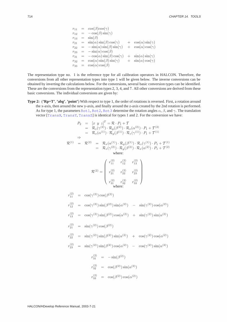
714 CHAPTER 14. TOOLS
r11 = cos(β)cos(γ)r12 = − cos(β) sin(γ)r13 = sin(β)r21 = sin(α) sin(β) cos(γ) + cos(α) sin(γ)r22 = − sin(α) sin(β) sin(γ) + cos(α) cos(γ)r23 = − sin(α) cos(β)r31 = − cos(α) sin(β) cos(γ) + sin(α) sin(γ)r32 = cos(α) sin(β) sin(γ) + sin(α) cos(γ)r33 = cos(α) cos(β)
The representation type no. 1 is the reference type for all calibration operators in HALCON. Therefore, theconversions from all other representation types into type 1 will be given below. The inverse conversions can beobtained by inverting the calculations below. For the conversions, several basic conversion types can be identified.These are the conversions from the representation types 2, 3, 4, and 7. All other conversions are derived from thesebasic conversions. The individual conversions are given by:
Type 2: (’Rp+T’ , ’abg’ , ’point’ ) With respect to type 1, the order of rotations is reversed. First, a rotation aroundthe x-axis, then around the new y-axis, and finally around the z-axis created by the 2nd rotation is performed.As for type 1, the parametersRot1 , Rot2 , Rot3 determine the rotation anglesα, β, andγ. The translationvector [TransX , TransY , TransZ ] is identical for types 1 and 2. For the conversion we have:
P2 = [x y z]T = R · P1 + T= Rz(γ(2)) · Ry(β(2)) · Rx(α(2)) · P1 + T (2)
= Rx(α(1)) · Ry(β(1)) · Rz(γ(1)) · P1 + T (1)
⇒R(1) = R(2) = Rx(α(1)) · Ry(β(1)) · Rz(γ(1)) · P1 + T (1)
= Rz(γ(2)) · Ry(β(2)) · Rx(α(2)) · P1 + T (2)
where:
R(2) =
r(2)11 r
(2)12 r
(2)13
r(2)21 r
(2)22 r
(2)23
r(2)31 r
(2)32 r
(2)33
where:
r(2)11 = cos(γ(2)) cos(β(2))
r(2)12 = cos(γ(2)) sin(β(2)) sin(α(2)) − sin(γ(2)) cos(α(2))
r(2)13 = cos(γ(2)) sin(β(2)) cos(α(2)) + sin(γ(2)) sin(α(2))
r(2)21 = sin(γ(2)) cos(β(2))
r(2)22 = sin(γ(2)) sin(β(2)) sin(α(2)) + cos(γ(2)) cos(α(2))
r(2)23 = sin(γ(2)) sin(β(2)) cos(α(2)) − cos(γ(2)) sin(α(2))
r(2)31 = − sin(β(2))
r(2)32 = cos(β(2)) sin(α(2))
r(2)33 = cos(β(2)) cos(α(2))
HALCON/HDevelop Reference Manual, 2003-7-21
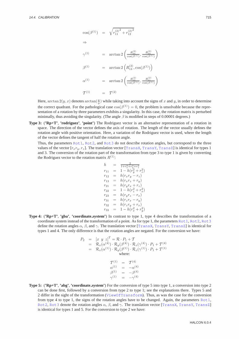
14.4. CALIBRATION 715
cos(β(1)) =√r(2)11
2+ r
(2)12
2
⇒
γ(1) = arctan 2(
R(2)23
cos(β(1)),
R(2)33
cos(β(1))
)
β(1) = arctan 2(R
(2)13 , cos(β(1))
)
α(1) = arctan 2(
R(2)12
cos(β(1)),
R(2)11
cos(β(1))
)
T (1) = T (2)
Here,arctan 2(y, x) denotesarctan(xy ) while taking into account the signs ofx andy, in order to determine
the correct quadrant. For the pathological casecos(β(1)) = 0, the problem is unsolvable because the repre-sentation of a rotation by three parameters exhibits a singularity. In this case, the rotation matrix is perturbedminimally, thus avoiding the singularity. (The angleβ is modified in steps of 0.00001 degrees.)
Type 3: (’Rp+T’ , ’rodriguez’ , ’point’ ) The Rodriguez vector is an alternative representation of a rotation inspace. The direction of the vector defines the axis of rotation. The length of the vector usually defines therotation angle with positive orientation. Here, a variation of the Rodriguez vector is used, where the lengthof the vector defines the tangent of half the rotation angle.
Thus, the parametersRot1 , Rot2 , andRot3 do not describe rotation angles, but correspond to the threevalues of the vector [rxry, rz ]. The translation vector [TransX , TransY , TransZ ] is identical for types 1and 3. The conversion of the rotation part of the transformation from type 3 to type 1 is given by convertingthe Rodriguez vector to the rotation matrixR(1):
h = 21+r2
x+r2y+r2
z
r11 = 1 − h(r2y + r2z)r12 = h(rxry − rz)r13 = h(rxrz + ry)r21 = h(ryrx + rz)r22 = 1 − h(r2z + r2x)r23 = h(ryrz − rx)r31 = h(rzrx − ry)r32 = h(rzry + rx)r33 = 1 − h(r2x + r2y)
Type 4: (’Rp+T’ , ’gba’ , ’coordinate system’) In contrast to type 1, type 4 describes the transformation of acoordinate system instead of the transformation of a point. As for type 1, the parametersRot1 , Rot2 , Rot3define the rotation anglesα, β, andγ. The translation vector [TransX , TransY , TransZ ] is identical fortypes 1 and 4. The only difference is that the rotation angles are negated. For the conversion we have:
P2 = [x y z]T = R · P1 + T= Rx(α(4)) · Ry(β(4)) · Rz(γ(4)) · P1 + T (4)
= Rx(α(1)) · Ry(β(1)) · Rz(γ(1)) · P1 + T (1)
where:
T (1) = T (4)
α(1) = −α(4)
β(1) = −β(4)
γ(1) = −γ(4)
Type 5: (’Rp+T’ , ’abg’ , ’coordinate system’) For the conversion of type 5 into type 1, a conversion into type 2can be done first, followed by a conversion from type 2 to type 1; see the explanations there. Types 5 and2 differ in the sight of the transformation (ViewOfTransform ). Thus, as was the case for the conversionfrom type 4 to type 1, the signs of the rotation angles have to be changed. Again, the parametersRot1 ,Rot2 , Rot3 denote the rotation anglesα, β, andγ. The translation vector [TransX , TransY , TransZ ]is identical for types 1 and 5. For the conversion to type 2 we have:
HALCON 6.0.4

716 CHAPTER 14. TOOLS
P2 = [x y z]T = R · P1 + T= Rz(γ(5)) · Ry(β(5)) · Rx(α(5)) · P1 + T (5)
= Rz(γ(2)) · Ry(β(2)) · Rx(α(2)) · P1 + T (2)
where:
T (2) = T (5)
α(2) = −α(5)
β(2) = −β(5)
γ(2) = −γ(5)
Type 6: (’Rp+T’ , ’rodriguez’ , ’coordinate system’) As for type 3, the rotation for type 6 is given by a Rodriguesvector. The parametersRot1 , Rot2 , andRot3 do not describe angles, but correspond to the three values ofthe vector [rx, ry, rz]. The translation vector (TransX , TransY , TransZ ) is identical to type 1. As above,the conversion of the rotation part to type 1 is done in two steps: First, the vector [rx, ry, rx] is converted toa rotation matrix, resulting in a representation of type 4. See the explanations on the conversion from type 3to type 1.
The second step is the conversion from type 4 to type 1, where additionally the rotation angles have to benegated. See the explanations on the conversion from type 4 to type 1.
Type 7: (’R(p-T)’ , ’gba’ , ’point’ ) In contrast to type 1, type 7 describes a transformation in which the translationis applied first, followed by the rotation. As for type 1, the parametersRot1 , Rot2 , andRot3 define therotation anglesα, β, andγ. For the transformation we have:
P2 = [x y z]T = R(1) · P1 + T (1)
= R(7) ·(P1 − T (7)
)= R(7) · P1 −R(7) · T (7)
⇒R(1) = R(7)
T (1) = −R(7) · T (7)
Type 8: (’R(p-T)’ , ’abg’ , ’point’ ) The conversion from type 8 to type 1 is again carried out in two steps: First,a conversion to type 7 is done. See the explanations on the conversion from type 2 to type 1. In the secondstep, a conversion from type 7 to type 1 is done. See the explanations there. The parametersRot1 , Rot2 ,andRot3 again denote the rotation anglesα, β, andγ.
Type 9: (’R(p-T)’ , ’rodriguez’ , ’point’ ) The conversion from type 9 to type 1 is again carried out in two steps:First, a conversion to type 7 is done. See the explanations on the conversion from type 3 to type 1. In thesecond step, a conversion from type 7 to type 1 is done. See the explanations there. The parametersRot1 ,Rot2 , andRot3 do not describe rotation angles, but correspond to the three values of the Rodriguez vector[rx, ry, rz ].
Type 10: (’R(p-T)’ , ’gba’ , ’coordinate system’) The conversion from type 10 to type 1 is again carried out intwo steps: First, a conversion to type 7 is done. See the explanations on the conversion from type 4 to type1. In the second step, a conversion from type 7 to type 1 is done. See the explanations there. The parametersRot1 , Rot2 , andRot3 again denote the rotation anglesα, β, andγ.
Type 11: (’R(p-T)’ , ’abg’ , ’coordinate system’) The conversion from type 11 to type 1 is carried out in threesteps: First, a conversion to type 8 is done. See the explanations on the conversion from type 5 to type 1. Inthe second step, a conversion from type 8 to type 7 is done. See the explanations on the conversion from type2 to type 1. In the third step, the conversion from type 7 to type 1 is done. See the explanations there. TheparametersRot1 , Rot2 , andRot3 again denote the rotation anglesα, β, andγ.
Type 12: (’R(p-T)’ , ’rodriguez’ , ’coordinate system’) The conversion from type 11 to type 1 is also carried outin three steps: First, a conversion to type 10 is done. See the explanations on the conversion from type 6to type 1. In the second step, a conversion from type 10 to Type 7 is done. See the explanations on theconversion from type 4 to type 1. In the third step, the conversion from type 7 to type 1 is done. See theexplanations there. The parametersRot1 , Rot2 , andRot3 do not describe rotation angles, but correspondto the three values of the Rodriguez vector [rx, ry, rz].
Useful hint: For the description of the pose of a new coordinate system within a base coordinate system, it isusually easiest to start by visualizing both coordinate systems to be identical, i.e., to lie exactly on top of oneanother. After this, the new coordinate system is translated until its origin rests in the correct position. The vectordescribing this translation is given by [TransX , TransY , TransZ ]. After this, the rotations are applied until
HALCON/HDevelop Reference Manual, 2003-7-21
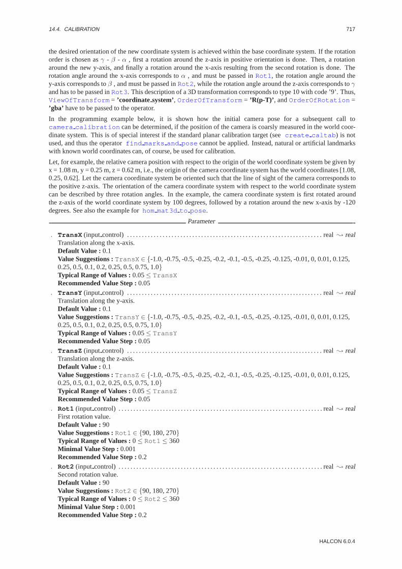
14.4. CALIBRATION 717
the desired orientation of the new coordinate system is achieved within the base coordinate system. If the rotationorder is chosen asγ - β - α , first a rotation around the z-axis in positive orientation is done. Then, a rotationaround the new y-axis, and finally a rotation around the x-axis resulting from the second rotation is done. Therotation angle around the x-axis corresponds toα , and must be passed inRot1 , the rotation angle around they-axis corresponds toβ , and must be passed inRot2 , while the rotation angle around the z-axis corresponds toγand has to be passed inRot3 . This description of a 3D transformation corresponds to type 10 with code ’9’. Thus,ViewOfTransform = ’coordinate system’, OrderOfTransform = ’R(p-T)’ , andOrderOfRotation =’gba’ have to be passed to the operator.
In the programming example below, it is shown how the initial camera pose for a subsequent call tocamera calibration can be determined, if the position of the camera is coarsly measured in the world coor-dinate system. This is of special interest if the standard planar calibration target (seecreate caltab ) is notused, and thus the operatorfind marks and pose cannot be applied. Instead, natural or artificial landmarkswith known world coordinates can, of course, be used for calibration.
Let, for example, the relative camera position with respect to the origin of the world coordinate system be given byx = 1.08 m, y = 0.25 m, z = 0.62 m, i.e., the origin of the camera coordinate system has the world coordinates [1.08,0.25, 0.62]. Let the camera coordinate system be oriented such that the line of sight of the camera corresponds tothe positive z-axis. The orientation of the camera coordinate system with respect to the world coordinate systemcan be described by three rotation angles. In the example, the camera coordinate system is first rotated aroundthe z-axis of the world coordinate system by 100 degrees, followed by a rotation around the new x-axis by -120degrees. See also the example forhom mat3d to pose .
Parameter
. TransX (input control) . . . . . . . . . . . . . . . . . . . . . . . . . . . . . . . . . . . . . . . . . . . . . . . . . . . . . . . . . . . . . . . . . . real; realTranslation along the x-axis.Default Value : 0.1Value Suggestions :TransX ∈ {-1.0, -0.75, -0.5, -0.25, -0.2, -0.1, -0.5, -0.25, -0.125, -0.01, 0, 0.01, 0.125,0.25, 0.5, 0.1, 0.2, 0.25, 0.5, 0.75, 1.0}Typical Range of Values :0.05≤ TransXRecommended Value Step :0.05
. TransY (input control) . . . . . . . . . . . . . . . . . . . . . . . . . . . . . . . . . . . . . . . . . . . . . . . . . . . . . . . . . . . . . . . . . . real; realTranslation along the y-axis.Default Value : 0.1Value Suggestions :TransY ∈ {-1.0, -0.75, -0.5, -0.25, -0.2, -0.1, -0.5, -0.25, -0.125, -0.01, 0, 0.01, 0.125,0.25, 0.5, 0.1, 0.2, 0.25, 0.5, 0.75, 1.0}Typical Range of Values :0.05≤ TransYRecommended Value Step :0.05
. TransZ (input control) . . . . . . . . . . . . . . . . . . . . . . . . . . . . . . . . . . . . . . . . . . . . . . . . . . . . . . . . . . . . . . . . . . real; realTranslation along the z-axis.Default Value : 0.1Value Suggestions :TransZ ∈ {-1.0, -0.75, -0.5, -0.25, -0.2, -0.1, -0.5, -0.25, -0.125, -0.01, 0, 0.01, 0.125,0.25, 0.5, 0.1, 0.2, 0.25, 0.5, 0.75, 1.0}Typical Range of Values :0.05≤ TransZRecommended Value Step :0.05
. Rot1 (input control) . . . . . . . . . . . . . . . . . . . . . . . . . . . . . . . . . . . . . . . . . . . . . . . . . . . . . . . . . . . . . . . . . . . . . real; realFirst rotation value.Default Value : 90Value Suggestions :Rot1 ∈ {90, 180, 270}Typical Range of Values :0≤ Rot1 ≤ 360Minimal Value Step : 0.001Recommended Value Step :0.2
. Rot2 (input control) . . . . . . . . . . . . . . . . . . . . . . . . . . . . . . . . . . . . . . . . . . . . . . . . . . . . . . . . . . . . . . . . . . . . . real; realSecond rotation value.Default Value : 90Value Suggestions :Rot2 ∈ {90, 180, 270}Typical Range of Values :0≤ Rot2 ≤ 360Minimal Value Step : 0.001Recommended Value Step :0.2
HALCON 6.0.4
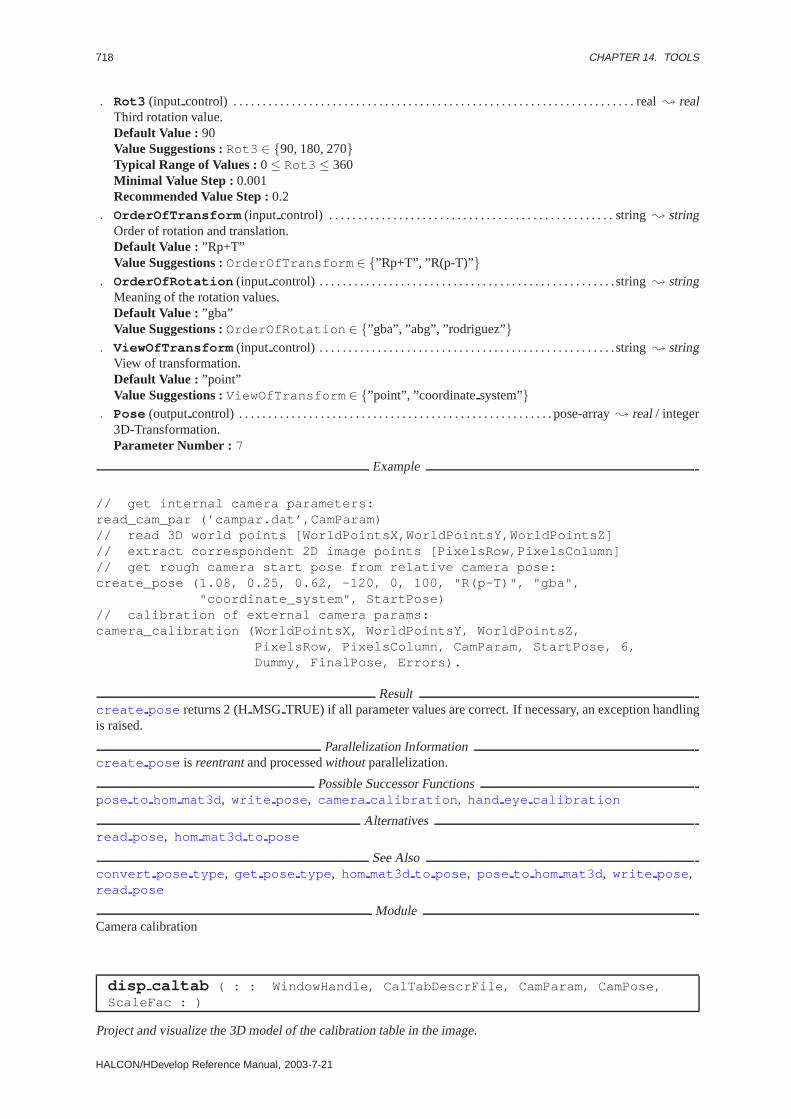
718 CHAPTER 14. TOOLS
. Rot3 (input control) . . . . . . . . . . . . . . . . . . . . . . . . . . . . . . . . . . . . . . . . . . . . . . . . . . . . . . . . . . . . . . . . . . . . . real; realThird rotation value.Default Value : 90Value Suggestions :Rot3 ∈ {90, 180, 270}Typical Range of Values :0≤ Rot3 ≤ 360Minimal Value Step : 0.001Recommended Value Step :0.2
. OrderOfTransform (input control) . . . . . . . . . . . . . . . . . . . . . . . . . . . . . . . . . . . . . . . . . . . . . . . . . string; stringOrder of rotation and translation.Default Value : ”Rp+T”Value Suggestions :OrderOfTransform ∈ {”Rp+T”, ”R(p-T)” }
. OrderOfRotation (input control) . . . . . . . . . . . . . . . . . . . . . . . . . . . . . . . . . . . . . . . . . . . . . . . . . . .string; stringMeaning of the rotation values.Default Value : ”gba”Value Suggestions :OrderOfRotation ∈ {”gba”, ”abg”, ”rodriguez”}
. ViewOfTransform (input control) . . . . . . . . . . . . . . . . . . . . . . . . . . . . . . . . . . . . . . . . . . . . . . . . . . .string; stringView of transformation.Default Value : ”point”Value Suggestions :ViewOfTransform ∈ {”point”, ”coordinatesystem”}
. Pose (outputcontrol) . . . . . . . . . . . . . . . . . . . . . . . . . . . . . . . . . . . . . . . . . . . . . . . . . . . . . . pose-array; real/ integer3D-Transformation.Parameter Number : 7
Example
// get internal camera parameters:read_cam_par (’campar.dat’,CamParam)// read 3D world points [WorldPointsX,WorldPointsY,WorldPointsZ]// extract correspondent 2D image points [PixelsRow,PixelsColumn]// get rough camera start pose from relative camera pose:create_pose (1.08, 0.25, 0.62, -120, 0, 100, "R(p-T)", "gba",
"coordinate_system", StartPose)// calibration of external camera params:camera_calibration (WorldPointsX, WorldPointsY, WorldPointsZ,
PixelsRow, PixelsColumn, CamParam, StartPose, 6,Dummy, FinalPose, Errors).
Resultcreate pose returns 2 (HMSG TRUE) if all parameter values are correct. If necessary, an exception handlingis raised.
Parallelization Informationcreate pose is reentrantand processedwithoutparallelization.
Possible Successor Functionspose to hom mat3d , write pose , camera calibration , hand eye calibration
Alternativesread pose , hom mat3d to pose
See Alsoconvert pose type , get pose type , hom mat3d to pose , pose to hom mat3d , write pose ,read pose
ModuleCamera calibration
disp caltab ( : : WindowHandle, CalTabDescrFile, CamParam, CamPose,ScaleFac : )
Project and visualize the 3D model of the calibration table in the image.
HALCON/HDevelop Reference Manual, 2003-7-21

14.4. CALIBRATION 719
disp caltab is used to visualize the calibration marks and the connecting lines between the marks of the usedcalibration table (CalTabDescrFile ) in the actual output window. Thus, the 3D model of the calibration tableis projected into the image plane using the internal camera parameters (CamParam) and the camera pose (externalcamera parameters (CamPose). The underlying camera model (pinhole camera with radial distortion) is describedin write cam par .
Typically disp caltab is used to verificate the result of the camera calibration (seecamera calibration )by superimposing it onto the original image. The actual linewidth can be set byset line width , the actualcolor can be set byset color .
The parameterScaleFac influences the number of supporting points to approximate the elliptic contours of thecalibration marks. You should increase the number of supporting points, if the image part in the actual outputwindow is displayed with magnification (seeset part ).
Parameter
. WindowHandle (input control) . . . . . . . . . . . . . . . . . . . . . . . . . . . . . . . . . . . . . . . . . . . . . . . . . . . window; integerWindow id.
. CalTabDescrFile (input control) . . . . . . . . . . . . . . . . . . . . . . . . . . . . . . . . . . . . . . . . . . . . . . . . . . .string; stringFile name of the calibration table description.Default Value : ’caltab.descr’
. CamParam(input control) . . . . . . . . . . . . . . . . . . . . . . . . . . . . . . . . . . . . . . . . . . . . . . .number-array; real/ integerInternal camera parameters.Parameter Number : 8
. CamPose(input control) . . . . . . . . . . . . . . . . . . . . . . . . . . . . . . . . . . . . . . . . . . . . . . . . . . . pose-array; real/ integerExternal camera parameters.Parameter Number : 7
. ScaleFac (input control) . . . . . . . . . . . . . . . . . . . . . . . . . . . . . . . . . . . . . . . . . . . . . . . . . . . . . . . . . . . . . . . . real; realScaling factor for the visualization.Default Value : 1.0Value Suggestions :ScaleFac ∈ {0.5, 1.0, 2.0, 3.0}Recommended Value Step :0.05Restriction : 0.0 < ScaleFac
Example
// read calibration imageread_image(Image1,’calib-01.tiff’)// find calibration patternfind_caltab(Image1,Caltab1,’caltab.descr’,3,112,5)// find calibration marks and start posesfind_marks_and_pose(Image1,Caltab1,’caltab.descr’,[0.008,0.0,
0.000011,0.000011,384,288,768,576],128,10,18,0.9,15.0,100.0,RCoord1,CCoord1,StartPose 1// read 3D positions of calibration markscaltab_points(’caltab.descr’,NX,NY,NZ)// camera calibrationcamera_calibration(NX,NY,NZ,RCoord1,CCoord1,
[0.008,0.0,0.000011,0.000011,384,288,768,576],StartPose1,11,CamParam,FinalPose,Errors)
// visualize calibration resultdisp_image(Image1,WindowHandle)set_color(WindowHandle,’red’)disp_caltab(’caltab.descr’,CamParam,FinalPose,1.0).
Resultdisp caltab returns 2 (HMSG TRUE) if all parameter values are correct. If necessary, an exception handlingis raised.
Parallelization Informationdisp caltab is local and processedcompletely exclusivelywithout parallelization.
Possible Predecessor Functionscamera calibration , read cam par , read pose
HALCON 6.0.4
720 CHAPTER 14. TOOLS
See Alsofind marks and pose , camera calibration , sim caltab , write cam par , read cam par ,create pose , write pose , read pose , project 3d point , get line of sight
ModuleCamera calibration
find caltab ( Image : Caltab : CalTabDescrFile, SizeGauss, MarkThresh,MinDiamMarks : )
Segment the calibration table region in the image.
find caltab is used to determine the region of a plane calibration table with circular marks in the input imageImage . First the input image is smoothed (seegauss image ); the size of the used filter mask is given bySizeGauss . Afterwards a thresholding operator (seethreshold ) with minimum gray valueMarkThreshand maximum gray value 255 is applied. Among the extracted connected regions the most convex region withalmost correct number of holes (corresponding to the dark marks of the calibration table) is selected. Holes witha diameter smaller than the expected size of the marksMinDiamMarks are eliminated to reduce the impact ofnoise. The number of marks is read from the calibration table description fileCalTabDescrFile . The completeexplanation of this file can be found within the description ofcreate caltab .
Parameter
. Image (input object) . . . . . . . . . . . . . . . . . . . . . . . . . . . . . . . . . . . . . . . . . . . . . . . . . . . . . . . . . image; Hobject: byteInput image.
. Caltab (outputobject) . . . . . . . . . . . . . . . . . . . . . . . . . . . . . . . . . . . . . . . . . . . . . . . . . . . . . . . . . . . . region; HobjectOutput region.
. CalTabDescrFile (input control) . . . . . . . . . . . . . . . . . . . . . . . . . . . . . . . . . . . . . . . . . . . . . . . . . . .string; stringFile name of the calibration table description.Default Value : ’caltab.descr’
. SizeGauss (input control) . . . . . . . . . . . . . . . . . . . . . . . . . . . . . . . . . . . . . . . . . . . . . . . . . . . . . . . . . integer; integerFilter size of the Gaussian.Default Value : 3Value List : SizeGauss ∈ {0, 3, 5, 7, 9, 11}
. MarkThresh (input control) . . . . . . . . . . . . . . . . . . . . . . . . . . . . . . . . . . . . . . . . . . . . . . . . . . . . . . . integer; integerThreshold value for mark extraction.Default Value : 112Value List : MarkThresh ∈ {48, 64, 80, 96, 112, 128, 144, 160}
. MinDiamMarks (input control) . . . . . . . . . . . . . . . . . . . . . . . . . . . . . . . . . . . . . . . . . . . . . . . . . . . . integer; integerExpected minimal diameter of the marks on the calibration table.Default Value : 5Value List : MinDiamMarks ∈ {3, 5, 9, 15, 30, 50, 70}
Example
// read calibration imageread_image(Image,’calib-01.tiff’)// find calibration patternfind_caltab(Image,Caltab,’caltab.descr’,3,112,5).
Resultfind caltab returns 2 (HMSG TRUE) if all parameter values are correct and an image regionis found. The behavior in case of empty input (no image given) can be set viaset system(::’no object result’,<Result>:) and the behavior in case of an empty result region viaset system(::’store empty region’,<true/false>:) . If necessary, an exception handling israised.
Parallelization Informationfind caltab is reentrantand processedwithoutparallelization.
Possible Predecessor Functionsread image
HALCON/HDevelop Reference Manual, 2003-7-21
14.4. CALIBRATION 721
Possible Successor Functionsfind marks and pose
See Alsofind marks and pose , camera calibration , disp caltab , sim caltab , caltab points ,create caltab
ModuleCamera calibration
find marks and pose ( Image, CalTabRegion : : CalTabDescrFile,StartCamParam, StartThresh, DeltaThresh, MinThresh, Alpha, MinContLength,MaxDiamMarks : RCoord, CCoord, StartPose )
Extract the 2D calibration marks from the video image and calculate initial values for the external camera param-eters.
find marks and pose is used to determine the necessary input data for the subsequent camera calibration (seecamera calibration ): On the one hand the 2D center points [RCoord ,CCoord ] of the calibration markswithin the regionCalTabRegion of the input imageImage are extracted and ordered. On the other hand arough estimate for the external camera parameters (StartPose ) is computed, i.e., the 3D pose of the camera inthe calibration table coordinate system.
In the input imageImage an edge detector is applied (seeedges image , mode ’lanser2’) to the regionCalTabRegion , which may have been found by applying the operatorfind caltab . The filter parame-ter for this edge detection can be tuned viaAlpha . In the edge image closed contours are searched for: Thenumber of closed contours must correspond to the number of calibration marks as described in the calibrationtable description fileCalTabDescrFile and the contours have to be ellipticly shaped. Contours shorter thanMinContLength are discarded, just as contours enclosing regions with a diameter larger thanMaxDiamMarks(e.g., the border of the calibration table).
For the detection of contours a threshold operator is applied to amplitude of the edge detector. All points with ahigh amplitude (i.e. borders of marks) are selected.
First, the threshold value is set toStartThresh . If the search for the closed contours or the successive poseestimate fails, this threshold value is successively decreased byDeltaThresh down to a minimum value ofMinThresh .
Each of the found contours is refined with subpixel accuracy (seeedges sub pix ) and subsequently approxi-mated by an ellipse. The center points of these ellipses represent a good approximation of the desired 2D imagecoordinates [RCoord ,CCoord ] of the calibration mark center points. The order of the values within these twotuples is in row-major order beginning at the upper left in the image. This order must correspond to the order ofthe 3D coordinates of the calibration marks in the calibration table description fileCalTabDescrFile , sincethis fixes the correspondences between extracted image marks and known model marks!
Based on the ellipse parameters for each calibration mark a rough estimate for the external camera parameters iscomputed finally. For that purpose the fixed correspondences between extracted image marks and known modelmarks are used. The estimateStartPose describes the pose of the camera in the calibration table coordinatesystem (seecreate pose ) as desired by the operatorcamera calibration .
Parameter
. Image (input object) . . . . . . . . . . . . . . . . . . . . . . . . . . . . . . . . . . . . . . . . . . . . . . . . . . . . . . . . . image; Hobject: byteInput image.
. CalTabRegion (input object) . . . . . . . . . . . . . . . . . . . . . . . . . . . . . . . . . . . . . . . . . . . . . . . . . . . . . region; HobjectRegion of the calibration table.
. CalTabDescrFile (input control) . . . . . . . . . . . . . . . . . . . . . . . . . . . . . . . . . . . . . . . . . . . . . . . . . . .string; stringFile name of the calibration table description.Default Value : ’caltab.descr’
. StartCamParam (input control) . . . . . . . . . . . . . . . . . . . . . . . . . . . . . . . . . . . . . . . . number-array; real/ integerInitial values for the internal camera parameters.
HALCON 6.0.4

722 CHAPTER 14. TOOLS
. StartThresh (input control) . . . . . . . . . . . . . . . . . . . . . . . . . . . . . . . . . . . . . . . . . . . . . . . . . . . . . number; integerInitial threshold value for contour detection.Default Value : 128Value List : StartThresh ∈ {80, 96, 112, 128, 144, 160}
. DeltaThresh (input control) . . . . . . . . . . . . . . . . . . . . . . . . . . . . . . . . . . . . . . . . . . . . . . . . . . . . . number; integerLoop value for successive reduction ofStartThresh .Default Value : 10Value List : DeltaThresh ∈ {6, 8, 10, 12, 14, 16, 18, 20, 22}
. MinThresh (input control) . . . . . . . . . . . . . . . . . . . . . . . . . . . . . . . . . . . . . . . . . . . . . . . . . . . . . . . . number; integerMinimum threshold for contour detection.Default Value : 18Value List : MinThresh ∈ {8, 10, 12, 14, 16, 18, 20, 22}
. Alpha (input control) . . . . . . . . . . . . . . . . . . . . . . . . . . . . . . . . . . . . . . . . . . . . . . . . . . . . . . . . . . . . . . . . . . . . real; realFilter parameter for contour detection, seeedges image .Default Value : 0.9Value Suggestions :Alpha ∈ {0.1, 0.2, 0.3, 0.4, 0.5, 0.6, 0.7, 0.8, 0.9, 1.0, 1.1}Typical Range of Values :0.2≤ Alpha ≤ 50.0Minimal Value Step : 0.01Recommended Value Step :0.1Restriction : Alpha > 0.0
. MinContLength (input control) . . . . . . . . . . . . . . . . . . . . . . . . . . . . . . . . . . . . . . . . . . . . . . . . . . . . . . . . . real; realMinimum length of the contours of the marks.Default Value : 15.0Value Suggestions :MinContLength ∈ {10.0, 15.0, 20.0, 30.0, 40.0, 100.0}Restriction : MinContLength > 0.0
. MaxDiamMarks (input control) . . . . . . . . . . . . . . . . . . . . . . . . . . . . . . . . . . . . . . . . . . . . . . . . . . . . . . . . . . real; realMaximum expected diameter of the marks.Default Value : 100.0Value Suggestions :MaxDiamMarks ∈ {50.0, 100.0, 150.0, 200.0, 300.0}Restriction : MaxDiamMarks > 0.0
. RCoord (outputcontrol) . . . . . . . . . . . . . . . . . . . . . . . . . . . . . . . . . . . . . . . . . . . . . . . . . . . . . . . . . . . . real-array; realTuple with row-coordinates of the detected marks.
. CCoord (outputcontrol) . . . . . . . . . . . . . . . . . . . . . . . . . . . . . . . . . . . . . . . . . . . . . . . . . . . . . . . . . . . . real-array; realTuple with column-coordinates of the detected marks.
. StartPose (outputcontrol) . . . . . . . . . . . . . . . . . . . . . . . . . . . . . . . . . . . . . . . . . . . . . . . pose-array; real/ integerEstimation for the external camera parameters.Parameter Number : 7
Example
// read calibration imageread_image(Image,’calib-01.tiff’)// find calibration patternfind_caltab(Image,Caltab1,’caltab.descr’,3,112,5)// find calibration marks and start posefind_marks_and_pose(Image,Caltab,’caltab.descr’,[0.008,0.0,
0.000011,0.000011,384,288,768,576],128,10,18,0.9,15.0,100.0,RCoord,CCoord,StartPose).
Resultfind marks and pose returns 2 (HMSG TRUE) if all parameter values are correct and an estimation for theexternal camera parameters has been determined successfully. If necessary, an exception handling is raised.
Parallelization Informationfind marks and pose is reentrantand processedwithoutparallelization.
Possible Predecessor Functionsfind caltab
Possible Successor Functionscamera calibration
HALCON/HDevelop Reference Manual, 2003-7-21

14.4. CALIBRATION 723
See Alsofind caltab , camera calibration , disp caltab , sim caltab , read cam par , read pose ,create pose , pose to hom mat3d , caltab points , create caltab , edges sub pix ,edges image
ModuleCamera calibration
get line of sight ( : : Row, Column, CamParam : PX, PY, PZ, QX, QY,QZ )
Compute the line of sight corresponding to a point in the image.
get line of sight computes the line of sight corresponding to a pixel (Row, Column ) in the image plane.The line of sight is a (straight) line in the camera coordinate system, which is described by two points (PX,PY,PZ)and (QX,QY,QZ) on the line. A pinhole or telecentric camera model with radial distortions described by the internalcamera parametersCamParamis used (seecamera calibration ). If a pinhole camera is used, the secondpoint lies on the focal plane, i.e., the output parameterQZ is equivalent to the focal length of the camera. Theequation of the line of sight is given by
x
yz
=
p x
p yp z
+ t
q x− p x
q y − p yq z − p z
.
The advantage of representing the line of sight as two points is that with this, it is easier to transform the line in3D. To do so, all that is necessary is to apply the operatoraffine trans point 3d to the two points.
Parameter
. Row(input control) . . . . . . . . . . . . . . . . . . . . . . . . . . . . . . . . . . . . . . . . . . . . . . . . . . . . . . . . . . . . . . . . . real-array; realRow coordinate of the pixel.
. Column (input control) . . . . . . . . . . . . . . . . . . . . . . . . . . . . . . . . . . . . . . . . . . . . . . . . . . . . . . . . . . . . . real-array; realColumn coordinate of the pixel.
. CamParam(input control) . . . . . . . . . . . . . . . . . . . . . . . . . . . . . . . . . . . . . . . . . . . . . . .number-array; real/ integerInternal camera parameters.Parameter Number : 8
. PX (outputcontrol) . . . . . . . . . . . . . . . . . . . . . . . . . . . . . . . . . . . . . . . . . . . . . . . . . . . . . . . . . . . . . . . . . real-array; realX coordinate of the first point on the line of sight
. PY (outputcontrol) . . . . . . . . . . . . . . . . . . . . . . . . . . . . . . . . . . . . . . . . . . . . . . . . . . . . . . . . . . . . . . . . . real-array; realY coordinate of the first point on the line of sight
. PZ (outputcontrol) . . . . . . . . . . . . . . . . . . . . . . . . . . . . . . . . . . . . . . . . . . . . . . . . . . . . . . . . . . . . . . . . . real-array; realZ coordinate of the first point on the line of sight
. QX(outputcontrol) . . . . . . . . . . . . . . . . . . . . . . . . . . . . . . . . . . . . . . . . . . . . . . . . . . . . . . . . . . . . . . . . . real-array; realX coordinate of the second point on the line of sight
. QY(outputcontrol) . . . . . . . . . . . . . . . . . . . . . . . . . . . . . . . . . . . . . . . . . . . . . . . . . . . . . . . . . . . . . . . . . real-array; realY coordinate of the second point on the line of sight
. QZ(outputcontrol) . . . . . . . . . . . . . . . . . . . . . . . . . . . . . . . . . . . . . . . . . . . . . . . . . . . . . . . . . . . . . . . . . real-array; realZ coordinate of the second point on the line of sight
Example
// get internal camera parametersread_cam_par(’campar.dat’,CamParam)// inverse projectionget_line_of_sight([50,100],[100,200],CamParam:PX,PY,PZ,QX,QY,QZ).
Resultget line of sight returns 2 (HMSG TRUE) if all parameter values are correct. If necessary, an exceptionhandling is raised.
HALCON 6.0.4

724 CHAPTER 14. TOOLS
Parallelization Informationget line of sight is reentrantand processedwithoutparallelization.
Possible Predecessor Functionsread cam par , camera calibration
Possible Successor Functionsaffine trans point 3d
See Alsocamera calibration , disp caltab , read cam par , project 3d point ,affine trans point 3d
ModuleCamera calibration
get pose type ( : : Pose : OrderOfTransform, OrderOfRotation,ViewOfTransform )
Get the representation type of 3D pose parameters.
With get pose type , the representation type of the 3D posePose can be queried.
A 3D pose defines a 3D transformation consisting of a translation and a rotation. Halcon supports different rep-resentation types for such a transformation. This can be, for example, external camera parameters, given by a 3Dtranslation vector (in meters), three rotation angles, and the code of the representation type of the 3D transforma-tion. For example, the value ’0’ is the code of representation type 1, and signifies that the transformation of a pointis described, that the 3D rotation is applied before the translation, that the rotations are given as angles (in degrees),and that the order of the rotations isγ-β-α, i.e., the first rotation is around the z-axis, the second rotation aroundthe new y-axis, and the third rotation around the x-axis created by the previous two rotations. The meaning of theother representation types is described with the operatorcreate pose .
The returned parameterViewOfTransform determines, whether the transformationPose describes thetransformation of a point (’point’ ) or the transformation of a coordinate system (’coordinate system’).OrderOfTransform determines whether the rotation (’Rp+T’ ) or the translation (’R(p-T)’ ) is applied first.The meaning of the three rotation values is determined byOrderOfRotation . The values’gba’ and ’abg’signify that the rotation values describe the three rotation anglesα (around the x-axis),β (around the y-axis), andγ (around the z-axis) in the 3D transformation. For’gba’ , the rotation order isγ , β , α , and for’abg’ it is α , β ,γ . If OrderOfRotation is ’rodriguez’ , the rotation values are interpreted as Rodriguez rotation vector.
Parameter
. Pose (input control) . . . . . . . . . . . . . . . . . . . . . . . . . . . . . . . . . . . . . . . . . . . . . . . . . . . . . . . pose-array; real/ integer3D transformation.Parameter Number : 7
. OrderOfTransform (outputcontrol) . . . . . . . . . . . . . . . . . . . . . . . . . . . . . . . . . . . . . . . . . . . . . . . . string; stringOrder of rotation and translation.
. OrderOfRotation (outputcontrol) . . . . . . . . . . . . . . . . . . . . . . . . . . . . . . . . . . . . . . . . . . . . . . . . . string; stringMeaning of the rotation values.
. ViewOfTransform (outputcontrol) . . . . . . . . . . . . . . . . . . . . . . . . . . . . . . . . . . . . . . . . . . . . . . . . . string; stringView of transformation.
Example
// get pose (external camera parameters) */read_pose (’campose.dat’, CamPose)// get semantic type of poseget_pose_type (CamPose, OrderT, OrderR, SightT).
Resultcreate pose returns 2 (HMSG TRUE) if all parameter values are correct. If necessary, an exception handlingis raised.
Parallelization Informationget pose type is reentrantand processedwithoutparallelization.
HALCON/HDevelop Reference Manual, 2003-7-21

14.4. CALIBRATION 725
Possible Predecessor Functionscreate pose , hom mat3d to pose , camera calibration , hand eye calibration
Possible Successor Functionsconvert pose type
See Alsocreate pose , convert pose type , write pose , read pose
ModuleCamera calibration
hand eye calibration ( : : NX, NY, NZ, NRow, NCol, MPointsOfImage,MRelPoses, BaseStartPose, CamStartPose, CamParam, ToEstimate,StopCriterion, MaxIterations, MinError : BaseFinalPose, CamFinalPose,NumErrors )
Perform a hand-eye-calibration.
The operatorhand eye calibration can be used to determine the 3D pose of the origin of the camera coor-dinate system with respect to the origin of the manipulator coordinate system (tool center point). This is typicallyused for robots equipped with a camera, where the pose of the camera (the “eye”) relative to the manipulator (the“hand”) has to be determined, in order to enable a video-based gripping of objects.
The assumption for the following desciption is, that the camera is fixed to the end-effector of the manipulator(hand-in-eye-configuration). In this case the calibration determines the (constant) pose of the camera in respect tothe tool coordination system of the end-effector. In the other case (the camera is stationary and looks to the movingmanipulator) the (constant) pose of the base coordination system of the manipulator in respect to the camera iscomputed. This can be performed by usinghand eye calibration , too.
hand eye calibration works in a similar manner to the conventional calibration of the exterior cameraparameters (camera pose); seecamera calibration . However, hand eye calibration not only de-termines the camera pose as a simple transformation, but as a chain of transformations from the world coordinatesystem to the base coordinate system of the active system (robot or vehicle) to the manipulator coordinate system,and finally to the camera coordinate system. Thus, the transformation of a pointPW in world coordinates to thecamera coordinate system can be described by:
PC = [x y z]T = R · PW + T= Rc (Rm (Rv · PW + Tv) + Tm) + Tc
where
Rv, Tv: Rotation and translation from the world coordinate systemto the base coordinate system of the active system (vehicle)
Rm, Tm: Rotation and translation from the base coordinate systemto the manipulator coordinate system
Rc, Tc: Rotation and translation from the manipulator coordinate systemto the camera coordinate system
The goal of the hand-eye-calibration is to determine (Rc, Tc). In order to avoid having to construct an exactly mea-sured set-up, a least-squares error adjustment is used, which estimates (Rv, Tv) as well. Therefore, measurementsreferring tok different positions of the manipulator are used. Hence, it must be possible to determine the differentpositions of the manipulator with sufficient accuracy. For a robot arm, they can be determined from the anglepositions of the individual joints of the arm. Analogously to the determination of the interior camera parameters(see camera calibration ), a large number of different manipulator positions is used to achieve more robustresults.
A Newton-type algorithm is used to minimize an error function based on normal equations. Therefore, suitablestarting values have to be passed for (Rc, Tc), and (Rv, Tv) by the user.
Starting values for (Rc, Tc) can be obtained by a coarse measurement of the set-up. Starting values for (Rv, Tv)can be obtained from the starting values for (Rc, Tc), the exterior camera parameters (Ra, Ta) (pose of the camerain the entire transformation chain; seecamera calibration ), and the corresponding pose (Rm, Tm) of themanipulator. We have:
HALCON 6.0.4

726 CHAPTER 14. TOOLS
PC = Ra · PW + Ta
= Rc (Rm (Rv · PW + Tv) + Tm) + Tc
where
Ra, Ta: Rotation and translation from the world coordinate systemto the camera coordinate system (camera pose).
The following sections discuss individual questions arising from the use ofhand eye calibration and areintended to be a guide line for using the operator in an application, as well as to aid the understanding of theoperator.
How do I get 3D model points? 3D model points, given in the world coordinate system (NX, NY, NZ), and theirassociated projections to the camera coordinate system (NRow, NCol ) form the basis of the hand-eye-calibration. In order ro be able to perform a successful hand-eye-calibration, 3D model points must beused, which were obtained from sufficiently many different positions of the manipulator.
Arbitrary known points in the world coordinate system along with their associated projections to the cameracoordinate system can be used for the calibration. However, it is usually most convenient to use a standardcalibration table, e.g., the one that can be generated withcreate caltab . By using this calibration table,the calibration table and position of the calibration marks can be extracted by usingfind caltab andfind marks and pose , respectively.
Please refer tocamera calibration for a description of the extraction of the calibration table and itsassociated 3D model points.
The parameterMPointsOfImage detemines the number of 3D model points used for each pose of themanipulator, i.e., for each image. With this, the 3D model points, which are stored in a linearized fashionin NX, NY, NZ, and their corresponding projections (NRow, NCol ) can be associated with the correspondingposition of the manipulator (MRelPoses ).
The 3D model points can be read from a calibration table description file for the standard calibration tablewith the operatorcaltab points .
How do I acquire a suitable set of images?If a planar standard calibration table is used, the following procedureshould be used: Images of the calibration table are taken with the active system to be calibrated, i.e., thecombination of the base of the manipulator (the vehicle, in case of mobile systems, which is used as afixed point for the manipulator), the manipulator (robot arm, pan-tilt-head, etc.), and the camera system; seeopen framegrabber and grab image . For the image acquisition, the following points should be takeninto account:
• At least 10 to 20 images from different positions should be taken in which the position of the camerawith respect to the calibration table is sufficiently different. The position of the calibration table mustnot be changed between images.
• In each image, the calibration table must be completely visible (including its border).
• No reflections or other disturbances should be visible on the calibration table.
• The set of images must show the calibration table from very different positions of the manipulator.The calibration table can and should be visible in different parts of the images. Furthermore, it shouldbe slightly to moderately rotated around its x- or y-axis, in order to clearly exhibit distortions of thecalibration marks. In other words, the corresponding exterior camera parameters (pose of the camerawith respect to the calibration table) should take on many different values. Consider that the manipulatoronly has six degrees of freedom (three for rotation and three for translation), while twelve degrees offreedom have to be estimated forBaseFinalPose andCamFinalPose . This means that the spaceof the degrees of freedom for the manipulator has to be used as exhaustively as possible.
• In each image, the calibration table should fill at least one quarter of the entire image, in order to ensurethe robust detection of the calibration marks.
• The interior camera parameters of the camera to be used must have been determined earlier and must bepassed inCamParam; see camera calibration . Note that changes of the image size, the focallength, the aperture, or the focus effect a change of the interior camera parameters.
• The camera must not be modified between the acquisition of the individual images, i.e., neither focallength, nor aperture, nor focus must be changed, because all calibration images use the same interiorcamera parameters. Please make sure that the focus is sufficient for the expected changes of the distancethe camera from the calibration table. Therefore, bright lighting conditions for the calibration table areimportant because smaller apertures result in larger depth of focus.
HALCON/HDevelop Reference Manual, 2003-7-21

14.4. CALIBRATION 727
How do I obtain suitable starting values? The starting values for (Rc, Tc) and (Rv, Tv) are passed as 3D posesin the parametersCamStartPose andBaseStartPose , just like the exterior camera parameters.CamStartPose can be obtained by measuring the pose of the camera in the manipulator coordinate system.This is the same procedure as the determination of starting values for the calibration of the exterior cameraparameters without using the standard calibration table. Usecreate pose to create a pose from yourmeasurements. For the measurement, it is usually easier to determine the translation of the origin of thecamera coordinate system within the manipulator coordinate system first, followed by the determination ofthe orientation.The camera coordinate system is oriented such that the line of sight of the camera corresponds to the positivez-axis. The orientation of the camera coordinate system with respect to the world coordinate system canbe described by three rotation angles. In order to determine the orientation, one can, for example, first“rotate” around the z-axis of the manipulator coordinate system, then around the new y-axis, and finallyaround the new x-axis created by the previous two rotations. In this case, the rotation angles around thex-, y-, and z-axis correspond directly to the rotation parameters ofcreate pose . Hence, according tothis description of the pose, the following settings must be passed tocreate pose : ’coordinate system’for the sight of the transformation (a transformation of a coordinate system is described),’R(p-T)’ for theorder of the transformations (first a translation, then a rotation), and’gba’ for the order of rotations (γ, β,α). This corresponds to representation type 10. For further information, please refer to the description ofcreate pose .In order to determineBaseStartPose , a calibration of the exterior camera parameters (camera calibration ) should be performed for one of the acquired images. From the pose of the cameracoordinate system in the world coordinate system thus determined, and from the other poses in the transfor-mation chain (starting values for (Rc, Tc) and exact values for the corresponding position of the manipulator(Rm, Tm)), the starting value can be determined very elegantly and easily by the use of homogeneous 3Dtransformation matrices. We have:
PC = R · PW + T= H · PW
andHv = Hm
−1 · Hc(start)−1 · Ha
whereHv : Transformation from world coordinate system to
base coordinate system (starting value)Hm : Transformation from base coordinate system and
manipulator coordinate systemHc(start) : Transformation from manipulator coordinate system
to camera coordinate system (starting value, measured)Ha : Transformation from world coordinate system to camera
coordinate system (determined from exterior calibration).
See pose to hom mat3d , affine trans point 3d , hom mat3d invert ,hom mat3d compose , and hom mat3d to pose .
How do I obtain the poses of the manipulator?The parameterMRelPoses determines the positions of themanipulator. Ifm positions were obtained by positioning the manipulator, thesem positions must be passedlinearized. The representation of these 3D poses is the same as for the exterior camera parameters andthe starting parametersCamStartPose and BaseStartPose . 3D poses are tuples of length 7, seecreate pose .It is extremely important for the algorithm of the hand-eye-calibration that the posesMRelPoses can beobtained exactly from the manipulator. The transformation of the angles of a robot arm to the representa-tion of a pose (rotation and translation) can be performed withcreate pose . It is advisable to use thesame procedure as for the determination of the starting valueCamStartPose of the camera pose in themanipulator coordinate system. The manipulator coordinate system must be oriented such that it is identicalor at least parallel to the base coordinate system in the initial position of the manipulator. In order to de-termine the poses of the individual manipulator positions, first the three translation parameters between theorigin of the base coordinate system and the origin of the manipulator coordinate system should be deter-mined. The translations should be determined along the axes of the base coordinate system when passingthem to create pose . For the orientation of the coordinate systems with respect to each other, onefirst “rotates” around the z-axis of the translated coordinate system, then around the new y-axis, and finallyaround the new x-axis created by the previous two rotations. The three rotation angles are used as parametersto create pose . Hence, according to this description of the pose, the following settings must be passed
HALCON 6.0.4

728 CHAPTER 14. TOOLS
to create pose : ’coordinate system’ for the sight of the transformation,’R(p-T)’ for the order of thetransformations, and’gba’ for the order of rotations. This corresponds to representation type 10. See alsothe description ofcreate pose .
How can I exclude individual pose parameters from the estimation?hand eye calibration estimates amaximum of 12 pose parameters. They are three rotation and three translation parameters each for the pose ofthe base coordinate system in the world coordinate system and for the pose of the camera coordinate systemin the manipulator coordinate system. However, it is possible to exclude some of these pose parameters fromthe estimation. This means that the starting values of the poses remain unchanged and are assumed constantfor the estimation of all other pose parameters. The parameterToEstimate is used to determine whichpose parameters should be estimated. InToEstimate , a list of keywords for the parameters to be estimatedis passed. They are:For the pose of the base coordinate system in the world coordinate system:
’baseTx’ = translation along the x-axis’baseTy’ = translation along the y-axis’baseTz’ = translation along the z-axis’baseRa’ = rotation around the x-axis’baseRb’ = rotation around the y-axis’baseRg’ = rotation around the z-axis
For the pose of the camera coordinate system in the manipulator coordinate system:
’camTx’ = translation along the x-axis’camTy’ = translation along the y-axis’camTz’ = translation along the z-axis’camRa’ = rotation around the x-axis’camRb’ = rotation around the y-axis’camRg’ = rotation around the z-axis
In order to estimate all 12 of the pose parameters, all 12 keywords can be passed. Alternatively, the keyword’all’ can be used.It is useful to exclude individual parameters from the estimation if some of the pose parameters have beenmeasured exactly. On the other hand, fixing some parameters reduces the degrees of freedom in the esti-mation, and thus increases the robustness to the estimated parameters, if the manipulator only has limitedmovement abilities, e.g., a pan-tilt head.
Which terminating criteria can be used for the error minimization? The error minimization terminates eitherafter a fixed number of iterations or if the error falls below a given minimum error. The parameterStopCriterion is used to choose between these two alternatives. If’CountIterations’ is passed, thealgorithm terminates afterMaxIterations iterations.If StopCriterion is passed as’MinError’ , the algorithm runs until the error falls below the er-ror threshold given inMinError . If, however, the number of iterations reaches the number given inMaxIterations , the algorithm terminates with an error message.
What is the order of the individual parameters? The length of the tupleMPointsOfImage corresponds tothe number of different positions of the manipulator. The parameterMPointsOfImage determines thenumber of model points used in the individual positions. If the standard calibration table is used, this means49 points per position (image). If 15 images were acquired,MPointsOfImage is a tuple of length 15,where all elements of the tuple have the value 49.The number of calibration images, which is determined by the length ofMPointsOfImage , must also betaken into account for the 3D model point tuples and the extracted 2D marks tuples, respectively. Hence,for 15 calibration images with 49 model points each, the tuplesNX, NY, NZ, NRow, andNCol must contain15 · 49 = 735 values each. These tuples are ordered according to the image the respective points lie in, i.e.,the first 49 values correspond to the 49 model points in the first image. The order of the 3D model points andthe extracted 2D model points must be the same in each image.The length of the tupleMRelPoses corresponds to the number of calibration images. If, for example, 15images from different positions were acquired, the length of the tupleMRelPoses is 15 · 7 = 105 (15 times7 pose parameters). The first seven parameters thus determine the pose of the manipulator in the first image,and so on.
What do the output parameters mean? If StopCriterion was set to’CountIterations’ , the output param-eters are returned, even if the algorithm didn’t converge. If, however,StopCriterion was set to’Min-Error’ , the error must fall below’MinError’ in order for output parameters to be returned.
HALCON/HDevelop Reference Manual, 2003-7-21

14.4. CALIBRATION 729
The output parameters are the pose of the base coordinate system in the world coordinate system(BaseFinalPose ) and the pose of the camera coordinate system in the manipulator coordinate system(CamFinalPose ).The representation type ofBaseFinalPose andCamFinalPose is the same as the corresponding start-ing values. It can be changed with the operatorconvert pose type . The description of the dif-ferent representation types and of their conversion can be found with the documentation of the operatorcreate pose .The parameterNumErrors contains a list of (numerical) errors from the individual iterations of the algo-rithm. Based on the evolution of the errors, it can be decided whether the algorithm has converged for thegiven starting values. The error values are returned as 3D deviations in meters. Thus, the last entry of theerror list corresponds to an estimate of the accuracy of the returned pose parameters.
AttentionThe quality of the calibration depends on the accuracy of the input parameters (position of the calibration marks andthe starting positionsBaseStartPose , CamStartPose ). Based on the returned error measuresNumErrors ,it can be decided, whether the algorithm has converged. Furthermore, the accuracy of the returned pose can beestimated. The error measures are 3D differences in meters.
Parameter
. NX(input control) . . . . . . . . . . . . . . . . . . . . . . . . . . . . . . . . . . . . . . . . . . . . . . . . . . . . . . . . . . . . . . . . . . real-array; realLinear list containing all the X-coordinates of the calibration points (in the order of the image).
. NY(input control) . . . . . . . . . . . . . . . . . . . . . . . . . . . . . . . . . . . . . . . . . . . . . . . . . . . . . . . . . . . . . . . . . . real-array; realLinear list containing all the Y-coordinates of the calibration points (in the order of the image).
. NZ (input control) . . . . . . . . . . . . . . . . . . . . . . . . . . . . . . . . . . . . . . . . . . . . . . . . . . . . . . . . . . . . . . . . . . real-array; realLinear list containing all the Z-coordinates of the calibration points (in the order of the image).
. NRow(input control) . . . . . . . . . . . . . . . . . . . . . . . . . . . . . . . . . . . . . . . . . . . . . . . . . . . . . . . . . . . . . . . . real-array; realLinear list containing all the labelled abscissas (in the order of the image).
. NCol (input control) . . . . . . . . . . . . . . . . . . . . . . . . . . . . . . . . . . . . . . . . . . . . . . . . . . . . . . . . . . . . . . . . real-array; realLinear list containing all the labelled ordinates (in the order of the image).
. MPointsOfImage (input control) . . . . . . . . . . . . . . . . . . . . . . . . . . . . . . . . . . . . . . . . . . . . integer-array; integerNumber of the calibration points for each image.
. MRelPoses (input control) . . . . . . . . . . . . . . . . . . . . . . . . . . . . . . . . . . . . . . . . . . . . . . . . pose-array; real/ integerMeasured values of relative pose of gripping device for each image.
. BaseStartPose (input control) . . . . . . . . . . . . . . . . . . . . . . . . . . . . . . . . . . . . . . . . . . .pose-array; real/ integerInitial value for robot pose in world coordinate system.
. CamStartPose (input control) . . . . . . . . . . . . . . . . . . . . . . . . . . . . . . . . . . . . . . . . . . . . pose-array; real/ integerInitial value for camera pose relative to end-effector.
. CamParam(input control) . . . . . . . . . . . . . . . . . . . . . . . . . . . . . . . . . . . . . . . . . . . . . . .number-array; real/ integerInternal camera parameters.
. ToEstimate (input control) . . . . . . . . . . . . . . . . . . . . . . . . . . . . . . . . . . . . . . . . . . . . . . . . . . . . string-array; stringParameters to be estimated (max. 12 free degrees).Default Value : ”all”Value List : ToEstimate ∈ {”all”, ”baseTx”, ”baseTy”, ”baseTz”, ”baseRa”, ”baseRb”, ”baseRg”,”camTx”, ”camTy”, ”camTz”, ”camRa”, ”camRb”, ”camRg”}
. StopCriterion (input control) . . . . . . . . . . . . . . . . . . . . . . . . . . . . . . . . . . . . . . . . . . . . . . . . . . . . . string; stringType of stopping criterion.Default Value : ”CountIterations”Value List : StopCriterion ∈ {”CountIterations”, ”MinError”}
. MaxIterations (input control) . . . . . . . . . . . . . . . . . . . . . . . . . . . . . . . . . . . . . . . . . . . . . . . . . . . integer; integerMaximum number of iterations to be executed.Default Value : 15Value Suggestions :MaxIterations ∈ {10, 15, 20, 25, 30}
. MinError (input control) . . . . . . . . . . . . . . . . . . . . . . . . . . . . . . . . . . . . . . . . . . . . . . . . . . . . . . . . . . . . . . . . real; realMinimum error used as the stopping criterion.Default Value : 0.0005Value Suggestions :MinError ∈ {0.0001, 0.0005, 0.001, 0.005, 0.01, 0.05, 0.1}
. BaseFinalPose (outputcontrol) . . . . . . . . . . . . . . . . . . . . . . . . . . . . . . . . . . . . . . . . . pose-array; real/ integerComputed pose of base system to world coodinate system.
HALCON 6.0.4

730 CHAPTER 14. TOOLS
. CamFinalPose (outputcontrol) . . . . . . . . . . . . . . . . . . . . . . . . . . . . . . . . . . . . . . . . . . . pose-array; real/ integerComputed pose of the camera relative to the coodinate system of the gripping device .
. NumErrors (outputcontrol) . . . . . . . . . . . . . . . . . . . . . . . . . . . . . . . . . . . . . . . . . . . . . . . . . . . . . . real(-array); realError measures for each iteration.
Example
HTuple CamParam, RCoord, CCoord;HTuple ManuPose, NumMarker, X, Y, Z, XPositions, YPositions;HTuple ZPositions, RCoordTmp, CCoordTmp, StartPose;HTuple ManuPoseTmp, BaseStartPose, CamStartPose, BaseFinalPose;HTuple CamFinalPose, NumErrors;Hobject Image, Caltab;char Datname[256];char CaltabName[256];
sprintf(CaltabName, "Caltab.descr");::read_cam_par("CamParam.cal",&CamParam);RCoord = HTuple();CCoord = HTuple();ManuPose = HTuple();NumMarker = HTuple();::caltab_points(CaltabName,&X,&Y,&Z);XPositions = HTuple();YPositions = HTuple();ZPositions = HTuple();// find landmarks in every imagefor (long i=0; i<=22; i++){
sprintf(Datname,"Image.%03ld.tiff",i);HImage Image(Datname);HRegion Caltab = Image.FindCaltab(CaltabName,3,150,5);RCoordTmp = Image.FindMarksAndPose(Caltab,CaltabName,CamParam,128,10,
&CCoordTmp,&StartPose);RCoord = ((HTuple)RCoord).Concat(RCoordTmp);CCoord = ((HTuple)CCoord).Concat(CCoordTmp);sprintf(Datname,"Pose.%03ld.cal",i);::read_pose(Datname,&ManuPoseTmp);ManuPose = ((HTuple)ManuPose).Concat(ManuPoseTmp);XPositions = ((HTuple)XPositions).Concat(X);YPositions = ((HTuple)YPositions).Concat(Y);ZPositions = ((HTuple)ZPositions).Concat(Z);NumMarker = ((HTuple)NumMarker).Concat(RCoordTmp.Num());
}// read start poses::read_pose("BaseStartPose.cal",&BaseStartPose);::read_pose("CameraStartPose.cal",&CamStartPose);// H A N D - E Y E - C A L I B R A T I O N::hand_eye_calibration(XPositions,YPositions,ZPositions,RCoord,CCoord,
NumMarker,ManuPose,BaseStartPose,CamStartPose,CamParam,"all","CountIterations",20,0.000670,&BaseFinalPose,&CamFinalPose,&NumErrors);
// save pose of difference between ’hand’ and ’eye’::write_pose(CamFinalPose,"CameraFinalPose.cal");
Resulthand eye calibration returns 2 (HMSG TRUE) if all parameter values are correct and the method cov-erges with an error less than the specified minimum error (ifStopCriterion = ’MinError’ ). If necessary, anexception handling is raised.
HALCON/HDevelop Reference Manual, 2003-7-21

14.4. CALIBRATION 731
Parallelization Informationhand eye calibration is reentrantand processedwithoutparallelization.
Possible Predecessor Functionsfind marks and pose
Possible Successor Functionswrite pose , convert pose type , pose to hom mat3d , disp caltab , sim caltab
See Alsofind caltab , find marks and pose , disp caltab , sim caltab , write cam par ,read cam par , create pose , convert pose type , write pose , read pose ,pose to hom mat3d , hom mat3d to pose , caltab points , create caltab
ModuleCamera calibration
hom mat3d to pose ( : : HomMat3D : Pose )
Convert homogeneous transformation matrix into 3D pose parameter.
hom mat3d to pose is used to convert a homogeneous transformation matrix into the correspondent represen-tation of the transformation as translational vector and rotational angles.
The homogeneous 4x3 transformation matrix is given as a tupelHomMat3Din the following order: The first fourvalues describe the first row of the rotation matrix and x-value of the translation vector. The next four valuesdescribe the second row of the rotation matrix and the y-value of the translation vector. These are followed by thevalues of the third row of the rotation matrix and the z-value of the translation vector.
The output tupelPose describes the external camera parameter by the 3D translational vector (in meters), thethree rotation angles and the representation type of the 3D transform. The representation type of a 3D transformgenerated byhom mat3d to pose has Type 1 with code ’0’. This means, that the transform of a point isdescribed, hereby the 3D rotation is performed before the 3D translation, that the three rotations are specified asangles (in degrees), and that the rotation order isγ-β-α, i.e., the first rotation is around the Z-axis, the second onearound the new Y-axis, and the third one around the new X-axis, which is generated after the second rotation. Thiscorrensponds to the transformation by homogenous matixes directly. This can be explained by the following holds:
PC = [x y z]T = H · PW
= R(1) · PW + T (1)
The sense of the other representation types are explained atcreate pose . With convert pose type youcan convertPose to every other kind of representation type.
The subsequent program example shows how to generate an appropriate initial camera pose forcamera calibration , if the camera pose is roughly measured in the world coordinate system. This isespecially important if no planar calibration table (seecreate caltab ) is used and therefore the operatorfind marks and pose cannot be applied. Instead of this natural or artificial landmarks with known worldposition can be used.
Let for example the relative camera position in the world coordinate system be the following: x = 1.08 m, y = 0.25m, z = 0.62 m. This means, that the origin of the camera coordinate system in world coordinates has the value[1.08, 0.25, 0.62]. The camera coordinate system is oriented that way, that the line of sight of the camera is alongthe positive Z-axis. The orientation of the camera coordinate system is given by three rotational angles. In theprogram example the camera coordinate system is first rotated by 100 degrees around the Z-axis. Subsequentlyit is rotated by -120 degree around the new (!!!) X-axis. Note that the parameter with the rotation angle inhom mat3d rotate is negated. This is because the description of a point transfomation and the description of acoordinate system transformation differs in the sign of the rotational angles. See also explanation and example atcreate pose .
Parameter
. HomMat3D(input control) . . . . . . . . . . . . . . . . . . . . . . . . . . . . . . . . . . . . . . . . . . . . . . . . . . . . . . affine3d-array; realHomogeneous transformation matrix.Parameter Number : 12
HALCON 6.0.4
732 CHAPTER 14. TOOLS
. Pose (outputcontrol) . . . . . . . . . . . . . . . . . . . . . . . . . . . . . . . . . . . . . . . . . . . . . . . . . . . . . . pose-array; real/ integerExternal camera parameters.Parameter Number : 7
Example
// read internal camera parameters:read_cam_par(’campar.dat’,CamParam)// read 3D world points [WorldPointsX,WorldPointsY,WorldPointsZ]// extract correspondent 2D image points [PixelsRow,PixelsColumn]// get rough camera pose from relative camera pose:hom_mat3d_identity(HomMat3DIdent)hom_mat3d_translate(HomMat3DIdent,-1.08,-0.25,-0.62,HomMat3DTrans)hom_mat3d_rotate(HomMat3DTrans,-100*3.14159/180,’z’,0,0,0,
HomMat3DRotZ)hom_mat3d_rotate(HomMat3DRotZ,+120*3.14159/180,’x’,0,0,0,
HomMat3DWorldStart)// convert transformation matrix to pose (rotation and translation)hom_mat3d_to_pose(HomMat3DWorldStart,StartPose)// calibration of external camera params:camera_calibration(WorldPointsX,WorldPointsY,WorldPointsZ,
PixelsRow,PixelsColumn,CamParam,StartPose,6,Dummy,FinalPose,Errors).
Resulthom mat3d to pose returns 2 (HMSG TRUE) if all parameter values are correct. If necessary, an exceptionhandling is raised
Parallelization Informationhom mat3d to pose is reentrantand processedwithoutparallelization.
Possible Predecessor Functionshom mat3d rotate , hom mat3d translate , hom mat3d invert
Possible Successor Functionscamera calibration , write pose , disp caltab , sim caltab
See Alsocreate pose , camera calibration , disp caltab , sim caltab , write pose , read pose ,pose to hom mat3d , project 3d point , get line of sight , hom mat3d rotate ,hom mat3d translate , hom mat3d invert , affine trans point 3d
ModuleCamera calibration
image points to world plane ( : : CamParam, CamPose, Rows, Cols,Scale : X, Y )
Transform image points to a world plane represented by external camera parameters.
The operatorimage points to world plane transforms image points which are given inRows andColsinto a plane in the world coordinate system. The plane is either equal to the plane of the calibration plate or parallelto it if the operator set origin pose has been applied previously to correct the thickness of the calibrationplate. In the first step the line of sight between the projection center and the image point is computed in the cameracoordinate system, taking into account the radial distortions using the internal camera parametersCamParam. Theline of sight is then transformed into the world coordinate system using the external camera parametersCamPose.By intersecting the plane (Z=0) with the line of sight the pseudo 3d coordinatesX andY are obtained. It is possibleto scale the coordinates with the parameterScale . This is particularly useful when displaying the coordinatesin an image. The parameterScale must be specified in [unit/pixel]. The original unit is determined by thecoordinates of the calibration targets. In many cases this unit is introduced into the calibration as ’meters’, i.e. onemeter in the world coordinate system corresponds to one pixel in the image. In this case, it is possible to set thepixel size directly by selecting’m’ , ’cm’ , ’mm’ or ’µm’ for the parameterScale .
HALCON/HDevelop Reference Manual, 2003-7-21

14.4. CALIBRATION 733
Parameter
. CamParam(input control) . . . . . . . . . . . . . . . . . . . . . . . . . . . . . . . . . . . . . . . . . . . . . . .number-array; real/ integerInternal camera parameters.Parameter Number : 8
. CamPose(input control) . . . . . . . . . . . . . . . . . . . . . . . . . . . . . . . . . . . . . . . . . . . . . . . . . . . pose-array; real/ integerExternal camera parameters.Parameter Number : 7
. Rows (input control) . . . . . . . . . . . . . . . . . . . . . . . . . . . . . . . . . . . . . . . . . . . . . . . coordinates.y-array; real/ integerline indices of the points to be transformedDefault Value : 100.0
. Cols (input control) . . . . . . . . . . . . . . . . . . . . . . . . . . . . . . . . . . . . . . . . . . . . . . . coordinates.x-array; real/ integercolumn indices of the points to be transformedDefault Value : 100.0
. Scale (input control) . . . . . . . . . . . . . . . . . . . . . . . . . . . . . . . . . . . . . . . . . . . . . . . . . number; string/ integer / realScale or dimensionDefault Value : ’m’Value Suggestions :Scale ∈ {’m’, ’cm’, ’mm’, ’microns’, ’ µm’, 1.0, 0.01, 0.001, ’1e-6’, 0.0254, 0.3048,0.9144}
. X (outputcontrol) . . . . . . . . . . . . . . . . . . . . . . . . . . . . . . . . . . . . . . . . . . . . . . . . . . . . . . . . . . coordinates.x-array; realx-coordinate in the world coordinate system.
. Y (outputcontrol) . . . . . . . . . . . . . . . . . . . . . . . . . . . . . . . . . . . . . . . . . . . . . . . . . . . . . . . . . . coordinates.y-array; realy-coordinate in the world coordinate system.
Resultimage points to world plane returns 2 (HMSG TRUE) if all parameter values are correct. If necessary,an exception handling is raised.
Parallelization Informationimage points to world plane is reentrantand processedwithoutparallelization.
Possible Predecessor Functionscreate pose , hom mat3d to pose , camera calibration , hand eye calibration ,set origin pose
See Alsocontour to world plane xld
ModuleCamera calibration
pose to hom mat3d ( : : Pose : HomMat3D )
Convert 3d pose parameters into homogeneous transformation matrix.
pose to hom mat3d is used to convert 3D pose parameters, like external camera parameter (camera posePose )into the equivalent homogeneous 4x3 transformation matrixHomMat3D.
This transformation matrix consists of a 3x3 rotation matrix and a translational vector. The values are given as atupelHomMat3Din the following order: The first four values describe the first row of the rotation matrix and x-value of the translation vector. The next four values describe the second row of the rotation matrix and the y-valueof the translation vector. These are followed by the values of the third row of the rotation matrix and the z-value ofthe translation vector.
The input tupelPose describes 3D pose parameters which describe a 3D transform, for example the externalcamera parameter. These are given by the 3D translational vector (in meters), the three rotational angles and thecode of the representation type of the 3D transform: E.g., the value ’0’ is the code of the representation type 1 andsays, that the transform of a point is described, hereby the 3D rotation is performed before the 3D translation, thatthe three rotations are specified as angles (in degrees), and that the rotation order isγ-β-α, i.e., the first rotationis around the Z-axis, the second one around the new Y-axis, and the third one around the new X-axis, whichis generated after the second rotation.pose to hom mat3d operates with all types of 3D transform. Thesense of the other representation types are explained atcreate pose . The 3D transform with type 1 directlycorrensponds to the transformation by homogenous matixes. This can be explained by the following holds:
HALCON 6.0.4

734 CHAPTER 14. TOOLS
PC = [x y z]T = R(1) · PW + T (1)
= H · PW
Parameter
. Pose (input control) . . . . . . . . . . . . . . . . . . . . . . . . . . . . . . . . . . . . . . . . . . . . . . . . . . . . . . . pose-array; real/ integerExternal camera parameters.Parameter Number : 7
. HomMat3D(outputcontrol) . . . . . . . . . . . . . . . . . . . . . . . . . . . . . . . . . . . . . . . . . . . . . . . . . . . . . affine3d-array; realHomogeneous transformation matrix.Parameter Number : 12
Example
// read internal camera parametersread_cam_par(’campar.dat’CamParam)// read initial camera poseread_pose(’campose.initial’,StartCamPose)// read 3D world points [WorldPointsX,WorldPointsY,WorldPointsZ]// extract correspondent 2D image points [PixelsRow,PixelsColumn]// calibration of external camera parameters:camera_calibration(WorldPointsX,WorldPointsY,WorldPointsZ,
PixelsRow,PixelsColumn,CamParam,StartCamPose,6,Dummy,FinalCamPose,Errors)
// transform FinalCamPose to 4x3 transformation matrixpose_to_hom_mat3d(FinalCamPose,HomMat3DWorldCam).
Resultpose to hom mat3d returns 2 (HMSG TRUE) if all parameter values are correct. If necessary, an exceptionhandling is raised
Parallelization Informationpose to hom mat3d is reentrantand processedwithoutparallelization.
Possible Predecessor Functionscamera calibration , read pose
Possible Successor Functionsaffine trans point 3d, hom mat3d invert , hom mat3d translate , hom mat3d rotate ,hom mat3d to pose
See Alsocreate pose , camera calibration , write pose , read pose , hom mat3d to pose ,project 3d point , get line of sight , hom mat3d rotate , hom mat3d translate ,hom mat3d invert , affine trans point 3d
ModuleCamera calibration
project 3d point ( : : X, Y, Z, CamParam : Row, Column )
Project 3D points into (sub-)pixels.
project 3d point is used to project one or more 3D points (with coordinatesX, Y, andZ) into the image plane(in pixels). The coordinatesX, Y, andZ are given in the camera coordinate system, i.e., they describe the positionof the point relative to the camera.
The internal camera parametersCamParam(Focus, Sx, Sy, Cx, Cy, Kappa (κ), ImageWidth and ImageHeight)describe the projection characteristics of the camera. The underlying camera model is apinhole camera withradial distortions if the focal length passed inCamParamis greater than 0. It describes the transform of a 3DpointPC into a (sub-)pixel [r,c] of the video image by the following equations:
HALCON/HDevelop Reference Manual, 2003-7-21

14.4. CALIBRATION 735
PC = [x y z]T
u = Focus· xz and v = Focus· y
z
ũ = 2u
1+√
1−4κ(u2+v2)and ṽ = 2v
1+√
1−4κ(u2+v2)
c = ũSx
+ Cx and r = ṽSy
+ Cy
If the focal length is passed as 0 inCamParam, the camera model of atelecentric camera with radial distortionsis used, i.e., it is assumed that the optics of the lens of the camera performs a parallel projection. In this case, thecorresponding equations are:
PC = [x y z]T = R · PW + Tu = x and v = y
ũ = 2u
1+√
1−4κ(u2+v2)bzw. ṽ = 2v
1+√
1−4κ(u2+v2)
c = ũSx
+ Cx bzw. r = ṽSy
+ Cy
These equations consist of a coordinate transform from the world coordinate system into the camera coordinatesystem, a perspective or parallel projection into the image plane, a radial distortion of the projected point, andfinally a sampling and an image center displacement.
Parameter
. X (input control) . . . . . . . . . . . . . . . . . . . . . . . . . . . . . . . . . . . . . . . . . . . . . . . . . . . . . . . . . . . . . . . . . . . . real-array; realX-coordinates of the 3D points to be projected.
. Y (input control) . . . . . . . . . . . . . . . . . . . . . . . . . . . . . . . . . . . . . . . . . . . . . . . . . . . . . . . . . . . . . . . . . . . . real-array; realY-coordinates of the 3D points to be projected.
. Z (input control) . . . . . . . . . . . . . . . . . . . . . . . . . . . . . . . . . . . . . . . . . . . . . . . . . . . . . . . . . . . . . . . . . . . . real-array; realZ-coordinates of the 3D points to be projected.
. CamParam(input control) . . . . . . . . . . . . . . . . . . . . . . . . . . . . . . . . . . . . . . . . . . . . . . .number-array; real/ integerInternal camera parameters.Parameter Number : 8
. Row(outputcontrol) . . . . . . . . . . . . . . . . . . . . . . . . . . . . . . . . . . . . . . . . . . . . . . . . . . . . . . . . . . . . . . . . real-array; realRow-coordinates of pixels.Default Value : ’ProjectedRow’
. Column (outputcontrol) . . . . . . . . . . . . . . . . . . . . . . . . . . . . . . . . . . . . . . . . . . . . . . . . . . . . . . . . . . . . real-array; realColumn-coordinates of pixels.Default Value : ’ProjectedCol’
Example
// read camera poseread_pose(campose.dat’,CamPose)// transform camera pose to transformation matrixpose_to_hom_mat3d(CamPose,HomMat3D)// transform 3D points from source into destination coordinate systemaffine_trans_point_3d([3.0,3.2],[4.5,4.5],[5.8,6.2],HomMat3D,X,Y,Z)// read internal camera parametersread_cam_par(’campar.dat’,CamParam)// project 3D points into imageproject_3d_point(X,Y,Z,CamParam,Row,Column).
Resultproject 3d point returns 2 (HMSG TRUE) if all parameter values are correct. If necessary, an exceptionhandling is raised.
Parallelization Informationproject 3d point is reentrantand processedwithoutparallelization.
HALCON 6.0.4

736 CHAPTER 14. TOOLS
Possible Predecessor Functionsread cam par , affine trans point 3d
Possible Successor Functionsgen region points , gen region polygon , disp polygon
See Alsocamera calibration , disp caltab , read cam par , get line of sight ,affine trans point 3d
ModuleCamera calibration
read cam par ( : : CamParFile : CamParam )
Read the internal camera parameters from text file.
read cam par is used to read the internal camera parametersCamParam from a text file with nameCamParFile .
The format of the text file is a (Halcon-independent) generic parameter description. Thus, arbitrary sets of parame-ters can be grouped together in a hierarchical way. The description of a single parameter within a parameter groupconsists of the following 3 lines:
Name : Shortname : Actual value ;Type : Lower bound (optional) : Upper bound (optional) ;Description (optional) ;
The Halcon operatorwrite cam par expects in the fileCamParFile the parameter group Camera:Parameter.This parameter group consists of the 8 parameters Focus, Sx, Sy, Cx, Cy, Kappa (κ), ImageWidth and ImageHeight.Comments are marked by a ’#’ at the beginning of a line. A suitable file can look like the following:
# INTERNAL CAMERA PARAMETERS
ParGroup: Camera: Parameter;"Internal CCD-camera parameters";
Focus:foc: 0.00806039;DOUBLE:0.0:;"Focal length of the lens [meter]";
Sx:sx: 1.0629e-05;DOUBLE:0.0:;"Width of a cell on the CCD-chip [meter]";
Sy:sy: 1.1e-05;DOUBLE:0.0:;"Height of a cell on the CCD-chip [meter]";
Cx:cx: 378.236;DOUBLE:0.0:;"X-coordinate of the image center [pixel]";
Cy:cy: 297.587;DOUBLE:0.0:;"Y-coordinate of the image center [pixel]";
Kappa:kappa: -2253.5;DOUBLE::;"Radial distortion coefficient [1/(meter*meter)]";
HALCON/HDevelop Reference Manual, 2003-7-21

14.4. CALIBRATION 737
ImageWidth:imgw: 768;INT:0:2048;"Width of the used calibration images [pixel]";
ImageHeight:imgh: 576;INT:0:2048;"Height of the used calibration images [pixel]";
The underlying camera model is apinhole or telecentric camera with radial distortions. A detailed descriptionof these camera models can be found with description ofwrite cam par .
Parameter
. CamParFile (input control) . . . . . . . . . . . . . . . . . . . . . . . . . . . . . . . . . . . . . . . . . . . . . . . . . . . . . . . . . string; stringFile name of internal camera parameters.Default Value : ’campar.dat’Value List : CamParFile ∈ {’campar.dat’, ’campar.initial’, ’campar.final’}
. CamParam(outputcontrol) . . . . . . . . . . . . . . . . . . . . . . . . . . . . . . . . . . . . . . . . . . . . . .number-array; real/ integerInternal camera parameters.Parameter Number : 8
Example
// get internal camera parameters:read_cam_par(’campar.dat’,CamParam).
Resultread cam par returns 2 (HMSG TRUE) if all parameter values are correct and the file has been read success-fully. If necessary an exception handling is raised.
Parallelization Informationread cam par is reentrantand processedwithoutparallelization.
Possible Successor Functionsfind marks and pose , sim caltab , create caltab , disp caltab , camera calibration
See Alsofind caltab , find marks and pose , camera calibration , disp caltab , sim caltab ,write cam par , write pose , read pose , project 3d point , get line of sight
ModuleCamera calibration
read pose ( : : PoseFile : Pose )
Read 3D pose data from text file.
read pose is used to read the 3D posePose from a text file with the namePoseFile .
The output tupelPose describes 3D pose parameters which describe a 3D transform, for example the externalcamera parameters. These are given by the 3D translational vector (in meters), the three rotation angles and thecode of the representation type of the 3D transform: E.g., the value ’0’ is the code of the representation type 1 andsays, that the transform of a point is described, hereby the 3D rotation is performed before the 3D translation, thatthe three rotations are specified as angles (in degrees), and that the rotation order isγ-β-α, i.e., the first rotationis around the Z-axis, the second one around the new Y-axis, and the third one around the new X-axis, which isgenerated after the second rotation.pose to hom mat3d operates with all types of 3D transforms. The senseof the other representation types is explained atcreate pose .
A suitable file can be generated by the operatorwrite pose and looks like the following:
# 3D POSE PARAMETERS: rotation and translation
HALCON 6.0.4

738 CHAPTER 14. TOOLS
# Used representation type:f 0
# Rotation angles [deg] or Rodriguez-vector:r -17.8134 1.83816 0.288092
# Translational vector (x y z [m]):t 0.280164 0.150644 1.7554
Parameter
. PoseFile (input control) . . . . . . . . . . . . . . . . . . . . . . . . . . . . . . . . . . . . . . . . . . . . . . . . . . . . . . . . . filename; stringFile name of the external camera parameters.Default Value : ’campose.dat’Value List : PoseFile ∈ {’campose.dat’, ’campose.initial’, ’campose.final’}
. Pose (outputcontrol) . . . . . . . . . . . . . . . . . . . . . . . . . . . . . . . . . . . . . . . . . . . . . . . . . . . . . . pose-array; real/ integerExternal camera parameters.Parameter Number : 7
Example
// get pose (external camera parameters):read_pose(’campose.dat’,CamPose).
Resultread pose returns 2 (HMSG TRUE) if all parameter values are correct and the file has been read successfully.If necessary an exception handling is raised.
Parallelization Informationread pose is reentrantand processedwithoutparallelization.
Possible Predecessor Functionsread cam par
Possible Successor Functionspose to hom mat3d , camera calibration , disp caltab , sim caltab
See Alsocreate pose , find marks and pose , camera calibration , disp caltab , sim caltab ,write pose , pose to hom mat3d , hom mat3d to pose
ModuleCamera calibration
set origin pose ( : : PoseIn, DX, DY, DZ : PoseNewOrigin )
Translate the origin of the external camera parameters.
set origin pose translates the origin of the external camera parameters (pose) by a vector, determinedby DX, DY and DZ. This can be used, for example, to correct the obtained parameters from camera calibra-tion (PoseIn ) with respect to the thickness of the calibration plate. To achieve this, the translation vectormust have the form (0,0,D), whereD is the thickness of the calibration plate. The resulting new parametersPoseNewOrigin correspond to a calibration with a calibration plate of infinitely small thickness. Therefore, itis possible to measure points in the world coordinate system (e.g., by callingimage points to world planeor contour to world plane xld ) directly in the requested measurement plane instead of the plane of thecalibration plate). In this context it is now also possible to avoid negative coordinates in the world coordinatesystem by choosing suitable values forDXandDY.
HALCON/HDevelop Reference Manual, 2003-7-21

14.4. CALIBRATION 739
Parameter
. PoseIn (input control) . . . . . . . . . . . . . . . . . . . . . . . . . . . . . . . . . . . . . . . . . . . . . . . . . . . . pose-array; real/ integeroriginal 3D transformation.Parameter Number : 7
. DX(input control) . . . . . . . . . . . . . . . . . . . . . . . . . . . . . . . . . . . . . . . . . . . . . . . . . . . . . . . . . . . . . . . . . . . . . . . . real; realtranslation of the origin in x-direction.Default Value : 0
. DY(input control) . . . . . . . . . . . . . . . . . . . . . . . . . . . . . . . . . . . . . . . . . . . . . . . . . . . . . . . . . . . . . . . . . . . . . . . . real; realtranslation of the origin in y-direction.Default Value : 0
. DZ (input control) . . . . . . . . . . . . . . . . . . . . . . . . . . . . . . . . . . . . . . . . . . . . . . . . . . . . . . . . . . . . . . . . . . . . . . . . real; realtranslation of the origin in z-direction.Default Value : 0
. PoseNewOrigin (outputcontrol) . . . . . . . . . . . . . . . . . . . . . . . . . . . . . . . . . . . . . . . . . pose-array; real/ integernew 3D description after applying the translation.Parameter Number : 7
Resultset origin pose returns 2 (HMSG TRUE) if all parameter values are correct. If necessary, an exceptionhandling is raised.
Parallelization Informationset origin pose is reentrantand processedwithoutparallelization.
Possible Predecessor Functionscreate pose , hom mat3d to pose , camera calibration , hand eye calibration
Possible Successor Functionswrite pose , pose to hom mat3d , image points to world plane ,contour to world plane xld
ModuleCamera calibration
sim caltab ( : SimImage : CalTabDescrFile, CamParam, CamPose,GrayBackground, GrayCaltab, GrayMarks, ScaleFac : )
Simulate a video image with calibration table.
sim caltab is used to generate a simulated calibration image. The calibration table description is read from thefile CalTabDescrFile and will be projected into the image plane using the given camera parameters (internalcamera parametersCamParamand external camera parametersCamPose), see alsoproject 3d point .
In the simulated image only the calibration table is shown. The image background is set to the gray valueGrayBackground , the calibration table background is set toGrayCaltab , and the calibration marks are setto the gray valueGrayMarks . The parameterScaleFac influences the number of supporting points to approxi-mate the elliptic contours of the calibration marks, see alsodisp caltab . Increasing the number of supportingpoints causes a more accurate determination of the mark boundary, but increases the computation time, too. Foreach pixel of the simulated video image, which touches a subpixel-boundary of this kind, the gray value is setlinearly betweenGrayMarks andGrayCaltab dependent on the proportion Inside/Outside.
By applying the operatorsim caltab you can generate synthetic calibration images (with known camera pa-rameters!) to test the quality of the calibration algorithm (seecamera calibration ).
Parameter
. SimImage (outputobject) . . . . . . . . . . . . . . . . . . . . . . . . . . . . . . . . . . . . . . . . . . . . . . . . . . . . image; Hobject: byteSimulated calibration image.
. CalTabDescrFile (input control) . . . . . . . . . . . . . . . . . . . . . . . . . . . . . . . . . . . . . . . . . . . . . . . . . . .string; stringFile name of the calibration table description.Default Value : ’caltab.descr’
. CamParam(input control) . . . . . . . . . . . . . . . . . . . . . . . . . . . . . . . . . . . . . . . . . . . . . . .number-array; real/ integerInternal camera parameters.Parameter Number : 8
HALCON 6.0.4
740 CHAPTER 14. TOOLS
. CamPose(input control) . . . . . . . . . . . . . . . . . . . . . . . . . . . . . . . . . . . . . . . . . . . . . . . . . . . pose-array; real/ integerExternal camera parameters.Parameter Number : 7
. GrayBackground (input control) . . . . . . . . . . . . . . . . . . . . . . . . . . . . . . . . . . . . . . . . . . . . . . . . . . integer; integerGray value of image background.Default Value : 128Value Suggestions :GrayBackground ∈ {0, 32, 64, 96, 128, 160}Restriction : (0 ≤ GrayBackground ) ≤ 255
. GrayCaltab (input control) . . . . . . . . . . . . . . . . . . . . . . . . . . . . . . . . . . . . . . . . . . . . . . . . . . . . . . . integer; integerGray value of calibration table.Default Value : 224Value Suggestions :GrayCaltab ∈ {144, 160, 176, 192, 208, 224, 240}Restriction : (0 ≤ GrayCaltab ) ≤ 255
. GrayMarks (input control) . . . . . . . . . . . . . . . . . . . . . . . . . . . . . . . . . . . . . . . . . . . . . . . . . . . . . . . . . integer; integerGray value of calibration marks.Default Value : 80Value Suggestions :GrayMarks ∈ {16, 32, 48, 64, 80, 96, 112}Restriction : (0 ≤ GrayMarks ) ≤ 255
. ScaleFac (input control) . . . . . . . . . . . . . . . . . . . . . . . . . . . . . . . . . . . . . . . . . . . . . . . . . . . . . . . . . . . . . . . . real; realScaling factor to reduce oversampling.Default Value : 1.0Value Suggestions :ScaleFac ∈ {1.0, 0.5, 0.25, 0.125}Recommended Value Step :0.05Restriction : 1.0 ≥ ScaleFac
Example
// read calibration imageread_image(Image1,’calib-01.tiff’)// find calibration patternfind_caltab(Image1,Caltab1,’caltab.descr’,3,112,5)// find calibration marks and initial posefind_marks_and_pose(Image1,Caltab1,’caltab.descr’,
[0.008,0.0,0.000011,0.000011,384,288,768,576],128,10,18,0.9,15.0,100.0,RCoord1,CCoord1,StartPose1)
// read 3D positions of calibration markscaltab_points(’caltab.descr’,NX,NY,NZ)// camera calibrationcamera_calibration(NX,NY,NZ,RCoord1,CCoord1,
[0.008,0.0,0.000011,0.000011,384,288,768,576],StartPose1,11,CamParam,FinalPose,Errors)
// simulate calibration imagesim_caltab(Image1Sim,’caltab.descr’,CamParam,FinalPose,128,224,80,1).
Resultsim caltab returns 2 (HMSG TRUE) if all parameter values are correct. If necessary, an exception handlingis raised.
Parallelization Informationsim caltab is processed undermutual exclusionagainst itself and without parallelization.
Possible Predecessor Functionscamera calibration , find marks and pose , read pose , read cam par , hom mat3d to pose
Possible Successor Functionsfind caltab
See Alsofind caltab , find marks and pose , camera calibration , disp caltab , create pose ,hom mat3d to pose , project 3d point , create caltab
ModuleCamera calibration
HALCON/HDevelop Reference Manual, 2003-7-21

14.4. CALIBRATION 741
write cam par ( : : CamParam, CamParFile : )
Write the internal camera parameters to text file.
write cam par is used to write the internal camera parametersCamParam to a text file with nameCamParFile .
The format of the text file is a (Halcon-independent) generic parameter description. Thus, arbitrary sets of parame-ters can be grouped together in a hierarchical way. The description of a single parameter within a parameter groupconsists of the following 3 lines:
Name : Shortname : Actual value ;Type : Lower bound (optional) : Upper bound (optional) ;Description (optional) ;
The following parameter types are supported in this generic format: BOOL, XBOOL (exclusive BOOL), INT,FLOAT, DOUBLE, STRING and FILESELECTOR. Comments are marked by a ’#’ at the beginning of a line.
The operatorwrite cam par writes the parameter group Camera:Parameter into the text fileCamParFile .This parameter group consists of the 8 parameters Focus, Sx, Sy, Cx, Cy, Kappa (κ), ImageWidth and ImageHeight.
The underlying camera model is apinhole camera with radial distortions if the focal length passed inCamParam is greater than 0. It describes the transform of a 3D pointPC into a (sub-)pixel [r,c] of the videoimage by the following equations:
PC = [x y z]T
u = Focus· xz and v = Focus· y
z
ũ = 2u
1+√
1−4κ(u2+v2)and ṽ = 2v
1+√
1−4κ(u2+v2)
c = ũSx
+ Cx and r = ṽSy
+ Cy
If the focal length is passed as 0 inCamParam, the camera model of atelecentric camera with radial distortionsis used, i.e., it is assumed that the optics of the lens of the camera performs a parallel projection. In this case, thecorresponding equations are:
PC = [x y z]T = R · PW + Tu = x and v = y
ũ = 2u
1+√
1−4κ(u2+v2)bzw. ṽ = 2v
1+√
1−4κ(u2+v2)
c = ũSx
+ Cx bzw. r = ṽSy
+ Cy
These equations consist of a coordinate transform from the world coordinate system into the camera coordinatesystem, a perspective or parallel projection into the image plane, a radial distortion of the projected point, andfinally a sampling and an image center displacement.
The parameterR andT describe the 3D pose of the camera coordinate system in the world coordinate system.They are calledexternal camera parameters, see alsohom mat3d to pose and create pose .
Theinternal camera parametersconsist of the focal length (Focus), the radial distortion coefficient (κ), the scalefactorSx andSy (horizontal and vertical distance between cells on the CCD chip), the image center[Cx, Cy]T ,and the used image width and height. The internal camera parameters are - in contrast to the external parameters -independent of the actual pose of the CCD camera. They describe the projection process of the used combinationof camera, lens, and frame grabber. The determination of these parameters is done by the camera calibration, seecamera calibration .
HALCON 6.0.4
742 CHAPTER 14. TOOLS
Parameter
. CamParam(input control) . . . . . . . . . . . . . . . . . . . . . . . . . . . . . . . . . . . . . . . . . . . . . . .number-array; real/ integerInternal camera parameters.Parameter Number : 8
. CamParFile (input control) . . . . . . . . . . . . . . . . . . . . . . . . . . . . . . . . . . . . . . . . . . . . . . . . . . . . . . . . . string; stringFile name of internal camera parameters.Default Value : ’campar.dat’Value List : CamParFile ∈ {’campar.dat’, ’campar.initial’, ’campar.final’}
Example
// read calibration imagesread_image(Image1,’calib-01.tiff’)read_image(Image2,’calib-02.tiff’)read_image(Image3,’calib-03.tiff’)// find calibration patternfind_caltab(Image1,Caltab1,’caltab.descr’,3,112,5)find_caltab(Image2,Caltab2,’caltab.descr’,3,112,5)find_caltab(Image3,Caltab,’caltab.descr’,3,112,5)// find calibration marks and start posesfind_marks_and_pose(Image1,Caltab1,’caltab.descr’,[0.008,0.0,
0.000011,0.000011,384,288,768,576],128,10,18,0.9,15.0,100.0,RCoord1,CCoord1,StartPose 1find_marks_and_pose(Image2,Caltab2,’caltab.descr’,[0.008,0.0,
0.000011,0.000011,384,288,768,576],128,10,18,0.9,15.0,100.0,RCoord2,CCoord2,StartPose 2find_marks_and_pose(Image3,Caltab3,’caltab.descr’,[0.008,0.0,
0.000011,0.000011,384,288,768,576],128,10,18,0.9,15.0,100.0,RCoord3,CCoord3,StartPose 3// read 3D positions of calibration markscaltab_points(’caltab.descr’NX,NY,NZ)// camera calibrationcamera_calibration(NX,NY,NZ,[RCoord1,RCoord2,RCoord3],
[CCoord1,CCoord2,CCoord3],[0.008,0.0,0.000011,0.000011,384,288,768,576],[StartPose1,StartPose2,StartPose3],11,CamParam,NFinalPose,Errors)
// write internal camera parameters to filewrite_cam_par(CamParam,’campar.dat’).
Resultwrite cam par returns 2 (HMSG TRUE) if all parameter values are correct and the file has been writtensuccessfully. If necessary an exception handling is raised.
Parallelization Informationwrite cam par is local and processedcompletely exclusivelywithout parallelization.
Possible Predecessor Functionscamera calibration
See Alsofind caltab , find marks and pose , camera calibration , disp caltab , sim caltab ,read cam par , write pose , read pose , project 3d point , get line of sight
ModuleCamera calibration
write pose ( : : Pose, PoseFile : )
Write 3D pose data to text file.
write pose is used to write 3D pose dataPose into a text file with the namePoseFile .
The input tupelPose describes 3D pose parameters which describe a 3D transform, for example the externalcamera parameters. These are given by the 3D translational vector (in meters), the three rotation angles and thecode of the representation type of the 3D transform: E.g., the value ’0’ is the code of the representation type 1 and
HALCON/HDevelop Reference Manual, 2003-7-21

14.4. CALIBRATION 743
says, that the transform of a point is described, hereby the 3D rotation is performed before the 3D translation, thatthe three rotations are specified as angles (in degrees), and that the rotation order isγ-β-α, i.e., the first rotationis around the Z-axis, the second one around the new Y-axis, and the third one around the new X-axis, which isgenerated after the second rotation.pose to hom mat3d operates with all types of 3D transform. The sense ofthe other representation types are explained atcreate pose .
A file generated bywrite pose looks like the following:
# 3D POSE PARAMETERS: rotation and translation
# Used representation type:f 0
# Rotation angles [deg] or Rodriguez-vector:r -17.8134 1.83816 0.288092
# Translational vector (x y z [m]):t 0.280164 0.150644 1.7554
Parameter
. Pose (input control) . . . . . . . . . . . . . . . . . . . . . . . . . . . . . . . . . . . . . . . . . . . . . . . . . . . . . . . pose-array; real/ integerExternal camera parameters.Parameter Number : 7
. PoseFile (input control) . . . . . . . . . . . . . . . . . . . . . . . . . . . . . . . . . . . . . . . . . . . . . . . . . . . . . . . . . filename; stringFile name of the external camera parameters.Default Value : ’campose.dat’Value List : PoseFile ∈ {’campose.dat’, ’campose.initial’, ’campose.final’}
Example
// read calibration imagesread_image(Image1,’calib-01.tiff’)read_image(Image2,’calib-02.tiff’)read_image(Image3,’calib-03.tiff’)// find calibration patternfind_caltab(Image1,Caltab1,’caltab.descr’,3,112,5)find_caltab(Image2,Caltab2,’caltab.descr’,3,112,5)find_caltab(Image3,Caltab3,’caltab.descr’,3,112,5)// find calibration marks and start poses */find_marks_and_pose(Image1,Caltab1,’caltab.descr’,[0.008,0.0,
0.000011,0.000011,384,288,768,576],128,10,18,0.9,15.0,100.0,RCoord1,CCoord1,StartPose 1find_marks_and_pose(Image2,Caltab2’caltab.descr’,[0.008,0.0,
0.000011,0.000011,384,288,768,576],128,10,18,0.9,15.0,100.0,RCoord2,CCoord2,StartPose 2find_marks_and_pose(Image3,Caltab3,’caltab.descr’,[0.008,0.0,
0.000011,0.000011,384,288,768,576],128,10,18,0.9,15.0,100.0,RCoord3,CCoord3,StartPose 3// read 3D positions of calibration markscaltab_points(’caltab.descr’,NX,NY,NZ)// camera calibrationcamera_calibration(NX,NY,NZ,[RCoord1,RCoord2,RCoord3],
[CCoord1,CCoord2,CCoord3],[0.008,0.0,0.000011,0.000011,384,288,768,576],[StartPose1,StartPose2,StartPose3],11,CamParam,NFinalPose,Errors)
// write external camera parameters of first calibration imagewrite_pose(NFinalPose[0],NFinalPose[1],NFinalPose[2],NFinalPose[3],
NFinalPose[4],NFinalPose[5],NFinalPose[6],’campose.dat’).
Resultwrite pose returns 2 (HMSG TRUE) if all parameter values are correct and the file has been written success-fully. If necessary an exception handling is raised.
Parallelization Informationwrite pose is local and processedcompletely exclusivelywithout parallelization.
HALCON 6.0.4

744 CHAPTER 14. TOOLS
Possible Predecessor Functionscamera calibration , hom mat3d to pose
See Alsocreate pose , find marks and pose , camera calibration , disp caltab , sim caltab ,read pose , pose to hom mat3d , hom mat3d to pose
ModuleCamera calibration
14.5 Fourier-Descriptor
abs invar fourier coeff ( : : RealInvar, ImaginaryInvar, CoefP, CoefQ,AZInvar : RealAbsInvar, ImaginaryAbsInvar )
Normalizing of the Fourier coefficients with respect to the displacment of the starting point.
The operatorabs invar fourier coeff normalizes the Fourier coefficients with regard to the displacementsof the starting point. These occur when an object is rotated. The contour tracerget region contour startswith recording the contour in the upper lefthand corner of the region and follows the contour clockwise. If theobject is rotated, the starting value for the contour point chain is different which leads to a phase shift in thefrequency space. The following two kinds of normalizing are available:
abs amount: The phase information will be eliminated; the normalizing does not retain the structure, i.e. if theAZ-invariants are backtransformed, no similarity with the pattern can be recognized anymore.
az invar1: AZ-invariants of the 1st order execute the normalizing with respect to displacing the starting point sothat the structure is retained; they are however more prone to local and global disturbances, in particular toprojective distortions.
Parameter
. RealInvar (input control) . . . . . . . . . . . . . . . . . . . . . . . . . . . . . . . . . . . . . . . . . . . . . . . . . . . . . . . . . real-array; realReal parts of the normalized Fourier coefficients.
. ImaginaryInvar (input control) . . . . . . . . . . . . . . . . . . . . . . . . . . . . . . . . . . . . . . . . . . . . . . . . . . real-array; realImaginary parts of the normalized Fourier coefficients.
. CoefP (input control) . . . . . . . . . . . . . . . . . . . . . . . . . . . . . . . . . . . . . . . . . . . . . . . . . . . . . . . . . . . . . . integer; integerNormalizing coefficients p.Default Value : 1Value Suggestions :CoefP ∈ {1, 2}Restriction : CoefP ≥ 1
. CoefQ (input control) . . . . . . . . . . . . . . . . . . . . . . . . . . . . . . . . . . . . . . . . . . . . . . . . . . . . . . . . . . . . . . integer; integerNormalizing coefficients q.Default Value : 1Value Suggestions :CoefQ ∈ {1, 2}Restriction : (CoefQ ≥ 1) ∧ (CoefQ 6= CoefP )
. AZInvar (input control) . . . . . . . . . . . . . . . . . . . . . . . . . . . . . . . . . . . . . . . . . . . . . . . . . . . . . . . . . . . . . string; stringOrder of the AZ-invariants.Default Value : ’abs amount’Value List : AZInvar ∈ {’abs amount’, ’azinvar1’}
. RealAbsInvar (outputcontrol) . . . . . . . . . . . . . . . . . . . . . . . . . . . . . . . . . . . . . . . . . . . . . . . . . . . . real-array; realReal parts of the normalized Fourier coefficients.
. ImaginaryAbsInvar (outputcontrol) . . . . . . . . . . . . . . . . . . . . . . . . . . . . . . . . . . . . . . . . . . . . . real-array; realImaginary parts of the normalized Fourier coefficients.
Example
get_region_contour(single,&row,&col);length_of_contour = length_tuple(row);move_contour_orig(row,col,&trow,&tcol);
HALCON/HDevelop Reference Manual, 2003-7-21

14.5. FOURIER-DESCRIPTOR 745
prep_contour_fourier(trow,tcol,"unsigned_area",¶m_scale);fourier_1dim(trow,tcol,param_scale,50,&frow,&fcol);invar_fourier_coeff(frow,fcol,1,"affine_invar",&invrow,&invcol);abs_invar_fourier_coeff(invrow,invcol,1,2,"az_invar1",&absrow,&abscol);fourier_1dim_inv(absrow,abscol,length_of_contour,&fsynrow,&fsyncol);
Parallelization Informationabs invar fourier coeff is reentrantand processedwithoutparallelization.
Possible Predecessor Functionsinvar fourier coeff
Possible Successor Functionsfourier 1dim inv , match fourier coeff
ModuleFourier descriptors
fourier 1dim ( : : Rows, Columns, ParContour, MaxCoef : RealCoef,ImaginaryCoef )
Calculate the Fourier coefficients of a parameterized contour.
The operator fourier 1dim calculates the Fourier coefficients of a parameterized contour by using avalid parameter scale. This parameter scale may, for instance, be created with the help of the procedureprep contour fourier . This function serves to calculate the Fourier coefficients of closed contours which aretreated like complex-valued curves. Therefore, in order to determine the Fourier coefficients, the Fourier transformfor periodical functions is used. Hereby the parameterMaxCoef determines theabsolutevalue+1 of the maximalnumber of Fourier coefficients, i.e. ifn coefficients are indicated, the procedure will calculate coefficients rangingfrom −n to n. The contour will be approximated without loss, ifn = numberofthecontourpoints, wherebyn = 100 approximates the contour so well that an error can hardly be distinguished;n ∈ [40, 50] however issufficient for most applications. If the parameterMaxCoef is set to 0, all coefficients will be determined.
Parameter
. Rows (input control) . . . . . . . . . . . . . . . . . . . . . . . . . . . . . . . . . . . . . . . . . . . . . . . . . . . . . . . . contour.y-array; integerRow coordinates of the contour.
. Columns (input control) . . . . . . . . . . . . . . . . . . . . . . . . . . . . . . . . . . . . . . . . . . . . . . . . . . . .contour.x-array; integerColmumn coordinates of the contour.
. ParContour (input control) . . . . . . . . . . . . . . . . . . . . . . . . . . . . . . . . . . . . . . . . . . . . . . . . . . . . . . . real-array; realParameter scale.
. MaxCoef (input control) . . . . . . . . . . . . . . . . . . . . . . . . . . . . . . . . . . . . . . . . . . . . . . . . . . . . . . . . . . . integer; integerDesired number of Fourier coefficients or all of them (0).Default Value : 50Value Suggestions :MaxCoef ∈ {0, 5, 10, 15, 20, 30, 40, 50, 60, 70, 80, 90, 100, 150, 200, 400}Restriction : MaxCoef ≥ 0
. RealCoef (outputcontrol) . . . . . . . . . . . . . . . . . . . . . . . . . . . . . . . . . . . . . . . . . . . . . . . . . . . . . . . . . real-array; realReal parts of the Fourier coefficients.
. ImaginaryCoef (outputcontrol) . . . . . . . . . . . . . . . . . . . . . . . . . . . . . . . . . . . . . . . . . . . . . . . . . . real-array; realImaginary parts of the Fourier coefficients.
Example
get_region_contour(single,&row,&col);move_contour_orig(row,col,&trow,&tcol);prep_contour_fourier(trow,tcol,"unsigned_area",¶m_scale);fourier_1dim(trow,tcol,param_scale,&frow,&fcol);invar_fourier_coeff(frow,fcol,1,"affine_invar",&invrow,&invcol);abs_invar_fourier_coeff(invrow,invcol,1,2,"az_invar1",&absrow,&abscol);
Parallelization Informationfourier 1dim is reentrantand processedwithoutparallelization.
HALCON 6.0.4
746 CHAPTER 14. TOOLS
Possible Predecessor Functionsprep contour fourier
Possible Successor Functionsinvar fourier coeff , disp polygon
ModuleFourier descriptors
fourier 1dim inv ( : : RealCoef, ImaginaryCoef, MaxCoef : Rows,Columns )
One dimensional Fourier synthesis (inverse Fourier transform).
Backtransformation of Fourier coefficients respectively of Fourier descriptors. The number of values to be back-transformed should not exceed the length of the transformed contour.
Parameter
. RealCoef (input control) . . . . . . . . . . . . . . . . . . . . . . . . . . . . . . . . . . . . . . . . . . . . . . . . . . . . . . . . . . real-array; realReal parts.
. ImaginaryCoef (input control) . . . . . . . . . . . . . . . . . . . . . . . . . . . . . . . . . . . . . . . . . . . . . . . . . . . real-array; realImaginary parts.
. MaxCoef (input control) . . . . . . . . . . . . . . . . . . . . . . . . . . . . . . . . . . . . . . . . . . . . . . . . . . . . . . . . . . . integer; integerInput of the steps for the backtransformation.Default Value : 100Value Suggestions :MaxCoef ∈ {5, 10, 15, 20, 30, 40, 50, 60, 70, 80, 90, 100, 150, 200, 400}Restriction : MaxCoef ≥ 1
. Rows (outputcontrol) . . . . . . . . . . . . . . . . . . . . . . . . . . . . . . . . . . . . . . . . . . . . . . . . . . . . . . . . . contour.y-array; realRow coordinates.
. Columns (outputcontrol) . . . . . . . . . . . . . . . . . . . . . . . . . . . . . . . . . . . . . . . . . . . . . . . . . . . . . contour.x-array; realColumn coordinates.
Example
get_region_contour(single,&row,&col);length_of_contour = row.Num();move_contour_orig(row,col,&trow,&tcol);prep_contour_fourier(trow,tcol,"unsigned_area",¶m_scale);fourier_1dim(trow,tcol,param_scale,50,&frow,&fcol);invar_fourier_coeff(frow,fcol,1,"affine_invar",&invrow,&invcol);abs_invar_fourier_coeff(invrow,invcol,1,2,"az_invar1",&absrow,&abscol);fourier_1dim_inv(absrow,abscol,length_of_contour,&fsynrow,&fsyncol);
Parallelization Informationfourier 1dim inv is reentrantand processedwithoutparallelization.
Possible Predecessor Functionsinvar fourier coeff , fourier 1dim
Possible Successor Functionsdisp polygon
ModuleFourier descriptors
invar fourier coeff ( : : RealCoef, ImaginaryCoef, NormPar,InvarType : RealInvar, ImaginaryInvar )
Normalize the Fourier coefficients.
HALCON/HDevelop Reference Manual, 2003-7-21

14.5. FOURIER-DESCRIPTOR 747
Elimination of affine information from the Fourier coefficients, determination of affine invariants. The Fouriercoefficients will be normalized suitably so that all affine correlated contours will be projected to one and the samecontour. The following levels of affine mappings are available:
1. Translations (InvarType = ’transl invar’)
2. + Rotations (InvarType = ’congr invar’)
3. + Scalings (InvarType = ’simil invar’)
4. + Slanting (InvarType = ’affine invar’)
The control parameterInvarType indicates up to which level the affine representation shall be normalized.Please note that indicating a certain level implies that the normalizing is executed with regard to all levels below.For most applications a subsequent normalizing of the starting point is recommended!
Parameter
. RealCoef (input control) . . . . . . . . . . . . . . . . . . . . . . . . . . . . . . . . . . . . . . . . . . . . . . . . . . . . . . . . . . real-array; realReal parts of the Fourier coefficients.
. ImaginaryCoef (input control) . . . . . . . . . . . . . . . . . . . . . . . . . . . . . . . . . . . . . . . . . . . . . . . . . . . real-array; realImaginary parts of the Fourier coefficients.
. NormPar (input control) . . . . . . . . . . . . . . . . . . . . . . . . . . . . . . . . . . . . . . . . . . . . . . . . . . . . . . . . . . . integer; integerInput of the normalizing coefficients.Default Value : 1Value Suggestions :NormPar ∈ {1, 2}Restriction : NormPar ≥ 1
. InvarType (input control) . . . . . . . . . . . . . . . . . . . . . . . . . . . . . . . . . . . . . . . . . . . . . . . . . . . . . . . . . . . string; stringIndicates the level of the affine mappings.Default Value : ’affine invar’Value List : InvarType ∈ {’affine invar’, ’simil invar’, ’congr invar’, ’transl invar’}
. RealInvar (outputcontrol) . . . . . . . . . . . . . . . . . . . . . . . . . . . . . . . . . . . . . . . . . . . . . . . . . . . . . . . . real-array; realReal parts of the normalized Fourier coefficients.
. ImaginaryInvar (outputcontrol) . . . . . . . . . . . . . . . . . . . . . . . . . . . . . . . . . . . . . . . . . . . . . . . . . real-array; realImaginary parts of the normalized Fourier coefficients.
Example
prep_contour_fourier(trow,tcol,"unsigned_area",¶m_scale);fourier_1dim(trow,tcol,param_scale,&frow,&fcol);invar_fourier_coeff(frow,fcol,1,"affine_invar",&invrow,&invcol);abs_invar_fourier_coeff(invrow,invcol,1,2,"az_invar1",&absrow,&abscol);
Parallelization Informationinvar fourier coeff is reentrantand processedwithoutparallelization.
Possible Predecessor Functionsfourier 1dim
Possible Successor Functionsinvar fourier coeff
ModuleFourier descriptors
match fourier coeff ( : : RealCoef1, ImaginaryCoef1, RealCoef2,ImaginaryCoef2, MaxCoef, Damping : Distance )
Similarity of two contours.
The operatormatch fourier coeff calculates the Euclidean distance between two contours which are avail-able as Fourier coefficients. In order to avoid that the higher frequencies are in some way too dominant, thefollowing attenuation can be used:
HALCON 6.0.4

748 CHAPTER 14. TOOLS
none: No attenuation.
1/index: Absolute amounts of the Fourier coefficients will be divided by their index.
1/(index*index): Absolute amounts of the Fourier coefficients will be divided by their square index.
The higher the result value, the greater the differences between the pattern and the test contour. If the number ofcoefficients is not the same, only the firstn coefficients will be compared. The parameterMaxCoef indicates thenumber of the coefficients to be compared. IfMaxCoef is set to zero, all coefficients will be used.
Parameter
. RealCoef1 (input control) . . . . . . . . . . . . . . . . . . . . . . . . . . . . . . . . . . . . . . . . . . . . . . . . . . . . . . . . . real-array; realReal parts of the pattern Fourier coefficients.
. ImaginaryCoef1 (input control) . . . . . . . . . . . . . . . . . . . . . . . . . . . . . . . . . . . . . . . . . . . . . . . . . . real-array; realImaginary parts of the pattern Fourier coefficients.
. RealCoef2 (input control) . . . . . . . . . . . . . . . . . . . . . . . . . . . . . . . . . . . . . . . . . . . . . . . . . . . . . . . . . real-array; realReal parts of the Fourier coefficients to be compared.
. ImaginaryCoef2 (input control) . . . . . . . . . . . . . . . . . . . . . . . . . . . . . . . . . . . . . . . . . . . . . . . . . . real-array; realImaginary parts of the Fourier coefficients to be compared.
. MaxCoef (input control) . . . . . . . . . . . . . . . . . . . . . . . . . . . . . . . . . . . . . . . . . . . . . . . . . . . . . . . . . . . integer; integerTotal number of Fourier coefficients.Default Value : 50Value Suggestions :MaxCoef ∈ {0, 5, 10, 15, 20, 30, 40, 50, 70, 100, 200, 400}Restriction : MaxCoef ≥ 0
. Damping (input control) . . . . . . . . . . . . . . . . . . . . . . . . . . . . . . . . . . . . . . . . . . . . . . . . . . . . . . . . . . . . . string; stringKind of attenuation.Default Value : ”1/index”Value Suggestions :Damping ∈ {’none’, ”1/index”, ”1/(index*index)”}
. Distance (outputcontrol) . . . . . . . . . . . . . . . . . . . . . . . . . . . . . . . . . . . . . . . . . . . . . . . . . . . . . . . . . . . . . . real; realSimilarity of the contours.
Example
prep_contour_fourier(trow,tcol,"unsigned_area",¶m_scale);fourier_1dim(trow,tcol,param_scale,50,&frow,&fcol);invar_fourier_coeff(frow,fcol,1,"affine_invar",&invrow,&invcol);abs_invar_fourier_coeff(invrow,invcol,1,2,
"az_invar1",&absrow,&abscol);match_fourier_coeff(contur1_row, contur1_col,
contur2_row, contur2_col, 50,"1/index", &Distance_wert);
Parallelization Informationmatch fourier coeff is reentrantand processedwithoutparallelization.
Possible Predecessor Functionsinvar fourier coeff
ModuleFourier descriptors
move contour orig ( : : Rows, Columns : RowsMoved, ColumnsMoved )
Transformation of the origin into the centre of gravity.
The operatormove contour orig relocates the input contour so that the origin lies in the centre of gravity.
HALCON/HDevelop Reference Manual, 2003-7-21

14.5. FOURIER-DESCRIPTOR 749
Parameter
. Rows (input control) . . . . . . . . . . . . . . . . . . . . . . . . . . . . . . . . . . . . . . . . . . . . . . . . . . . . . . . . contour.y-array; integerRow coordinates of the contour.
. Columns (input control) . . . . . . . . . . . . . . . . . . . . . . . . . . . . . . . . . . . . . . . . . . . . . . . . . . . .contour.x-array; integerColumn coordinates of the contour.
. RowsMoved (outputcontrol) . . . . . . . . . . . . . . . . . . . . . . . . . . . . . . . . . . . . . . . . . . . . . . . . contour.y-array; integerRow coordinates of the displaced contour.
. ColumnsMoved (outputcontrol) . . . . . . . . . . . . . . . . . . . . . . . . . . . . . . . . . . . . . . . . . . . .contour.x-array; integerColumn coordinates of the displaced contour.
Parallelization Informationmove contour orig is processedcompletely exclusivelywithout parallelization.
Possible Predecessor Functionsget region contour
Possible Successor Functionsprep contour fourier
ModuleFourier descriptors
prep contour fourier ( : : Rows, Columns, TransMode : ParContour )
Parameterize the passed contour.
The operator prep contour fourier parameterizes the transmitted contour in order to prepare it for theone dimensional Fourier transformation. Hereby the contour must be available in closed form. Three parameterfunctions are available for the control parameterTransMode :
arc: Parameterization by the radian.
signedarea: Parameterization by the signed area.
unsignedarea: Parameterization by the absolute area.
Please note that in contrast to the signed or unsigned area the affine mapping of the radian will not be transformedlinearly.
Parameter
. Rows (input control) . . . . . . . . . . . . . . . . . . . . . . . . . . . . . . . . . . . . . . . . . . . . . . . . . . . . . . . . contour.y-array; integerRow indices of the contour.
. Columns (input control) . . . . . . . . . . . . . . . . . . . . . . . . . . . . . . . . . . . . . . . . . . . . . . . . . . . .contour.x-array; integerColumn indices of the contour.
. TransMode (input control) . . . . . . . . . . . . . . . . . . . . . . . . . . . . . . . . . . . . . . . . . . . . . . . . . . . . . . . . . . . string; stringKind of parameterization.Default Value : ’signedarea’Value Suggestions :TransMode ∈ {’arc’, ’unsignedarea’, ’signedarea’}
. ParContour (outputcontrol) . . . . . . . . . . . . . . . . . . . . . . . . . . . . . . . . . . . . . . . . . . . . . . . . . . . . . . real-array; realParameterized contour.
Example
get_region_contour(single,&row,&col);move_contour_orig(row,col,&trow,&tcol);prep_contour_fourier(trow,tcol,"unsigned_area",¶m_scale);fourier_1dim(trow,tcol,param_scale,&frow,&fcol);
Parallelization Informationprep contour fourier is reentrantand processedwithoutparallelization.
HALCON 6.0.4

750 CHAPTER 14. TOOLS
Possible Predecessor Functionsmove contour orig
Possible Successor Functionsfourier 1dim
ModuleFourier descriptors
14.6 Function
abs funct 1d ( : : Function : FunctionAbsolute )
Absolute value of the y values.
abs funct 1d calculates the absolute values of all y values ofFunction .
Parameter
. Function (input control) . . . . . . . . . . . . . . . . . . . . . . . . . . . . . . . . . . . . . . . . . . . function1d-array; real/ integerInput function.
. FunctionAbsolute (outputcontrol) . . . . . . . . . . . . . . . . . . . . . . . . . . . . . . . function1d-array; real/ integerFunction with the absolute values of the y values.
Parallelization Informationabs funct 1d is reentrantand processedwithoutparallelization.
Possible Predecessor Functionscreate funct 1d pairs , create funct 1d array
ModuleTools
create funct 1d array ( : : YValues : Function )
Create a function from a sequence of y-values.
create funct 1d array creates a one-dimensional function from a set of y-valuesYValues . The resultingfunction can then be processed and analyzed with the operators for 1d functions.YValues is interpreted asfollows: the first value ofYValues is the function value at zero, the second value is the function value at one, etc.Thus, the values define a function at equidistant x values (with distance 1), starting at 0.
Alternatively, the operator create funct 1d pairs can be used to create a function.create funct 1d pairs also allows to define a function with non-equidistant x valus by specifiyingthem explicitely. Thus to get the same definition as withcreate funct 1d array , one would pass a tupleof x values to create funct 1d pairs that has the same length asYValues and contains values startingat 0 and increasing by 1 in each position. Note, however, thatcreate funct 1d pairs leads to a differentinternal representation of the function which needs more storage (because all (x,y) pairs are stored) and sometimescannot be processed as efficiently as functions created bycreate funct 1d array .
Parameter
. YValues (input control) . . . . . . . . . . . . . . . . . . . . . . . . . . . . . . . . . . . . . . . . . . . . . . number(-array); real/ integerX value for function points.
. Function (outputcontrol) . . . . . . . . . . . . . . . . . . . . . . . . . . . . . . . . . . . . . . . . . . function1d-array; real/ integerCreated function.
Parallelization Informationcreate funct 1d array is reentrantand processedwithoutparallelization.
Possible Successor Functionswrite funct 1d , gnuplot plot funct 1d , y range funct 1d , get pair funct 1d ,transform funct 1d
HALCON/HDevelop Reference Manual, 2003-7-21

14.6. FUNCTION 751
Alternativescreate funct 1d pairs , read funct 1d
See Alsofunct 1d to pairs
ModuleTools
create funct 1d pairs ( : : XValues, YValues : Function )
Create a function from a set of (x,y) pairs.
create funct 1d pairs creates a one-dimensional function from a set of pairs of (x,y) values. TheXValuesof the functions have to be passed in ascending order. The resulting function can then be processed and analyzedwith the operators for 1d functions.
Alternatively, functions can be created with the operatorcreate funct 1d array . In contrast to this operator,x values with arbitrary positions can be specified withcreate funct 1d pairs . Hence, it is the more generaloperator. It should be noted, however, that because of this generality the processing of a function created withcreate funct 1d pairs cannot be carried out as efficiently as for equidistant functions. In particular, not alloperators accept such functions. If necessary, a function can be transformed into an equidistant function with theoperatorsample funct 1d.
Parameter
. XValues (input control) . . . . . . . . . . . . . . . . . . . . . . . . . . . . . . . . . . . . . . . . . . . . . . number(-array); real/ integerX value for function points.
. YValues (input control) . . . . . . . . . . . . . . . . . . . . . . . . . . . . . . . . . . . . . . . . . . . . . . number(-array); real/ integerY-value for function points.
. Function (outputcontrol) . . . . . . . . . . . . . . . . . . . . . . . . . . . . . . . . . . . . . . . . . . function1d-array; real/ integerCreated function.
Parallelization Informationcreate funct 1d pairs is reentrantand processedwithoutparallelization.
Possible Successor Functionswrite funct 1d , gnuplot plot funct 1d , y range funct 1d , get pair funct 1d
Alternativescreate funct 1d array , read funct 1d
See Alsofunct 1d to pairs
ModuleTools
distance funct 1d ( : : Function1, Function2, Mode,Sigma : Distance )
Compute the distance of two functions.
distance funct 1d calculates the distance of two functions. The two functions may differ in length.
Parameter
. Function1 (input control) . . . . . . . . . . . . . . . . . . . . . . . . . . . . . . . . . . . . . . . . . . function1d-array; real/ integerInput function 1.
. Function2 (input control) . . . . . . . . . . . . . . . . . . . . . . . . . . . . . . . . . . . . . . . . . . function1d-array; real/ integerInput function 2.
. Mode (input control) . . . . . . . . . . . . . . . . . . . . . . . . . . . . . . . . . . . . . . . . . . . . . . . . . . . . . . . . . . . string(-array); stringModes of invariants.Default Value : ’length’Value List : Mode∈ {’length’, ’mean’}
HALCON 6.0.4
752 CHAPTER 14. TOOLS
. Sigma (input control) . . . . . . . . . . . . . . . . . . . . . . . . . . . . . . . . . . . . . . . . . . . . . . . . . . . . . . . . . number(-array); realVariance of the optional smoothing with a Gaussian filter.Default Value : 0.0Value Suggestions :Sigma ∈ {0.0, 0.5, 1.0, 1.5, 2.0, 3.0, 4.0, 5.0, 7.0, 10.0, 15.0, 20.0, 25.0, 30.0, 40.0,50.0}
. Distance (outputcontrol) . . . . . . . . . . . . . . . . . . . . . . . . . . . . . . . . . . . . . . . . . . . . . . . . . real-array; real/ integerDistance of the functions.
Parallelization Informationdistance funct 1d is reentrantand processedwithoutparallelization.
ModuleTools
funct 1d to pairs ( : : Function : XValues, YValues )
Access to the x/y values of a function.
funct 1d to pairs splits the input functionFunction into tuples for the x and y values.
Parameter
. Function (input control) . . . . . . . . . . . . . . . . . . . . . . . . . . . . . . . . . . . . . . . . . . . function1d-array; real/ integerInput function.
. XValues (outputcontrol) . . . . . . . . . . . . . . . . . . . . . . . . . . . . . . . . . . . . . . . . . . . . . . . number-array; real/ integerX values of the function.
. YValues (outputcontrol) . . . . . . . . . . . . . . . . . . . . . . . . . . . . . . . . . . . . . . . . . . . . . . . number-array; real/ integerY values of the function.
Parallelization Informationfunct 1d to pairs is reentrantand processedwithoutparallelization.
Possible Predecessor Functionscreate funct 1d pairs , create funct 1d array
ModuleTools
get pair funct 1d ( : : Function, Index : X, Y )
Access a function value using the index of the control points.
get pair funct 1d accesses a function value ofFunction . This is done by specifying the index of one ormore control points of the function.
Parameter
. Function (input control) . . . . . . . . . . . . . . . . . . . . . . . . . . . . . . . . . . . . . . . . . . . function1d-array; real/ integerInput function.
. Index (input control) . . . . . . . . . . . . . . . . . . . . . . . . . . . . . . . . . . . . . . . . . . . . . . . . . . . . . . . integer(-array); integerIndex of the control points.
. X (outputcontrol) . . . . . . . . . . . . . . . . . . . . . . . . . . . . . . . . . . . . . . . . . . . . . . . . . . . . . . . . . . . . . .number(-array); realX value at the given control points.
. Y (outputcontrol) . . . . . . . . . . . . . . . . . . . . . . . . . . . . . . . . . . . . . . . . . . . . . . . . . . . . . . . . . . . . . .number(-array); realY value at the given control points.
Parallelization Informationget pair funct 1d is reentrantand processedwithoutparallelization.
Possible Predecessor Functionscreate funct 1d pairs , create funct 1d array
ModuleTools
HALCON/HDevelop Reference Manual, 2003-7-21

14.6. FUNCTION 753
integrate funct 1d ( : : Function : Positive, Negative )
Compute the positive and negative areas of a function.
integrate funct 1d integrates the functionFunction (see create funct 1d array andcreate funct 1d pairs ) and returns the integral of the positive and negative parts of the function inPositive and Negative , respectively. Hence, the integral of the function is the differencePositive -Negative . The integration is done on the interval on which the function is defined. For the integration, thefunction is interpolated linearly.
Parameter
. Function (input control) . . . . . . . . . . . . . . . . . . . . . . . . . . . . . . . . . . . . . . . . . . . . . . . . . . . function1d-array; realInput function.
. Positive (outputcontrol) . . . . . . . . . . . . . . . . . . . . . . . . . . . . . . . . . . . . . . . . . . . . . . . . . . . . . . . . . . . number; realArea under the positive part of the function.
. Negative (outputcontrol) . . . . . . . . . . . . . . . . . . . . . . . . . . . . . . . . . . . . . . . . . . . . . . . . . . . . . .number-array; realArea under the negative part of the function.
Parallelization Informationintegrate funct 1d is reentrantand processedwithoutparallelization.
Possible Predecessor Functionscreate funct 1d pairs , create funct 1d array
See Alsocreate funct 1d array , create funct 1d pairs
ModuleTools
match funct 1d trans ( : : Function1, Function2, Border, ParamsConst,UseParams : Params, ChiSquare, Covar )
Calculate transformation parameters between two functions.
match funct 1d trans calculates the transformation parameters between two functions given as the tuplesFunction1 andFunction2 (see create funct 1d array und create funct 1d pairs ). The fol-lowing model is used for the transformation between the two functions:
y1(x) = a1y2(a3x+ a4) + a2 .
The transformation parameters are determined by a least-squares minimization of the following function:
n−1∑i=0
(y1(xi) − a1y2(a3xi + a4) + a2
)2.
The values of the functiony2 are obtained by linear interpolation. The parameterBorder determines the val-ues of the functionFunction2 outside of its domain. ForBorder =’zero’ these values are set to 0, forBorder =’constant’ they are set to the corresponding value at the border, forBorder =’mirror’ they are mirroredat the border, and forBorder =’cyclic’ they are continued cyclically. The calculated transformation parametersare returned as a 4-tuple inParams . If some of the parameter values are known, the respective parameters canbe excluded from the least-squares adjustment by setting the corresponding value in the tupleUseParams to thevalue’false’. In this case, the tupleParamsConst must contain the known value of the respective parameter. Ifa parameter is used for the adjustment (UseParams = ’true’ ), the corresponding parameter inParamsConst isignored. On output,match funct 1d trans additionally returns the sum of the squared errorsChiSquareof the resulting function, i.e., the function obtained by transforming the input function with the transformationparameters, as well as the covariance matrixCovar of the transformation parametersParams . These parameterscan be used to decide whether a successful matching of the functions was possible.
HALCON 6.0.4

754 CHAPTER 14. TOOLS
Parameter
. Function1 (input control) . . . . . . . . . . . . . . . . . . . . . . . . . . . . . . . . . . . . . . . . . . function1d-array; real/ integerFunction 1.
. Function2 (input control) . . . . . . . . . . . . . . . . . . . . . . . . . . . . . . . . . . . . . . . . . . function1d-array; real/ integerFunction 2.
. Border (input control) . . . . . . . . . . . . . . . . . . . . . . . . . . . . . . . . . . . . . . . . . . . . . . . . . . . . . . . . . . . . . . . string; stringBorder treatment for function 2.Default Value : ’constant’Value List : Border ∈ {’zero’, ’constant’, ’mirror’, ’cyclic’}
. ParamsConst (input control) . . . . . . . . . . . . . . . . . . . . . . . . . . . . . . . . . . . . . . . . . . . . . . . . . . .number-array; realValues of the parameters to remain constant.Default Value : ’[1.0,0.0,1.0,0.0]’Parameter Number : 4
. UseParams (input control) . . . . . . . . . . . . . . . . . . . . . . . . . . . . . . . . . . . . . . . . . . . . . . . . . . . . . string-array; stringShould a parameter be adapted for it?Default Value : ’[’true’,’true’,’true’,’true’]’Value List : UseParams ∈ {’true’, ’false’}Parameter Number : 4
. Params (outputcontrol) . . . . . . . . . . . . . . . . . . . . . . . . . . . . . . . . . . . . . . . . . . . . . . . . . . . . . . . . number-array; realTransformation parameters between the functions.Parameter Number : 4
. ChiSquare (outputcontrol) . . . . . . . . . . . . . . . . . . . . . . . . . . . . . . . . . . . . . . . . . . . . . . . . . . . . . . . . . .number; realQuadratic error of the output function.
. Covar (outputcontrol) . . . . . . . . . . . . . . . . . . . . . . . . . . . . . . . . . . . . . . . . . . . . . . . . . . . . . . . . . . number-array; realCovariance Matrix of the transformation parameters.Parameter Number : 16
Parallelization Informationmatch funct 1d trans is reentrantand processedwithoutparallelization.
Possible Predecessor Functionscreate funct 1d array , create funct 1d pairs
See Alsogray projections
ModuleTools
negate funct 1d ( : : Function : FunctionInverted )
Negation of the y values.
negate funct 1d negates all y values ofFunction .
Parameter
. Function (input control) . . . . . . . . . . . . . . . . . . . . . . . . . . . . . . . . . . . . . . . . . . . function1d-array; real/ integerInput function.
. FunctionInverted (outputcontrol) . . . . . . . . . . . . . . . . . . . . . . . . . . . . . . . function1d-array; real/ integerFunction with the negated y values.
Parallelization Informationnegate funct 1d is reentrantand processedwithoutparallelization.
Possible Predecessor Functionscreate funct 1d pairs , create funct 1d array
ModuleTools
HALCON/HDevelop Reference Manual, 2003-7-21
14.6. FUNCTION 755
num points funct 1d ( : : Function : Length )
Number of control points of the function.
num points funct 1d calculates the number of control points ofFunction .
Parameter
. Function (input control) . . . . . . . . . . . . . . . . . . . . . . . . . . . . . . . . . . . . . . . . . . . function1d-array; real/ integerInput function.
. Length (outputcontrol) . . . . . . . . . . . . . . . . . . . . . . . . . . . . . . . . . . . . . . . . . . . . . . . . . . . . . . . . . . . integer; integerNumber of control points.
Parallelization Informationnum points funct 1d is reentrantand processedwithoutparallelization.
Possible Predecessor Functionscreate funct 1d pairs , create funct 1d array
ModuleTools
read funct 1d ( : : FileName : Function )
Read a function from a file.
The operatorread funct 1d reads the contents ofFileName and converts it into the functionFunction .The file has be generated bywrite funct 1d .
Parameter
. FileName (input control) . . . . . . . . . . . . . . . . . . . . . . . . . . . . . . . . . . . . . . . . . . . . . . . . . . . . . . . . . filename; stringName of the file to be read.
. Function (outputcontrol) . . . . . . . . . . . . . . . . . . . . . . . . . . . . . . . . . . . . . . . . function1d(-array); real/ integerFunction from the file.
ResultIf the parameters are correct the operatorread funct 1d returns the value 2 (HMSG TRUE). If the file couldnot be openedread funct 1d returns 5 (HMSG FAIL). Otherwise an exception handling is raised.
Parallelization Informationread funct 1d is reentrantand processedwithoutparallelization.
Alternativesfread string , read tuple
See Alsowrite funct 1d , gnuplot plot ctrl , write image , write region , open file
ModuleBasic operators
sample funct 1d ( : : Function, XMin, XMax, XDist,Border : SampledFunction )
Sample a function equidistantly in an interval.
sample funct 1d samples the input functionFunction in the interval [XMin ,XMax] at equidistant pointswith the distanceXDist . The last point lies in the interval ifXMax-XMin is not an integer multiple ofXDist . Toobtain the samples, the input function is interpolated linearly. The parameterBorder determines the values of thefunctionFunction outside of its domain. ForBorder =’zero’ these values are set to 0, forBorder =’constant’they are set to the corresponding value at the border, forBorder =’mirror’ they are mirrored at the border, andfor Border =’cyclic’ they are continued cyclically.
HALCON 6.0.4

756 CHAPTER 14. TOOLS
Parameter
. Function (input control) . . . . . . . . . . . . . . . . . . . . . . . . . . . . . . . . . . . . . . . . . . . function1d-array; real/ integerInput function.
. XMin (input control) . . . . . . . . . . . . . . . . . . . . . . . . . . . . . . . . . . . . . . . . . . . . . . . . . . . . . . . . . number; real/ integerMinimum x value of the output function.
. XMax(input control) . . . . . . . . . . . . . . . . . . . . . . . . . . . . . . . . . . . . . . . . . . . . . . . . . . . . . . . . . number; real/ integerMaximum x value of the output function.Restriction : XMax> XMin
. XDist (input control) . . . . . . . . . . . . . . . . . . . . . . . . . . . . . . . . . . . . . . . . . . . . . . . . . . . . . . . . number; real/ integerDistance of the samples.Restriction : XDist > 0
. Border (input control) . . . . . . . . . . . . . . . . . . . . . . . . . . . . . . . . . . . . . . . . . . . . . . . . . . . . . . . . . . . . . . . string; stringBorder treatment for the input function.Default Value : ’constant’Value List : Border ∈ {’zero’, ’constant’, ’mirror’, ’cyclic’}
. SampledFunction (outputcontrol) . . . . . . . . . . . . . . . . . . . . . . . . . . . . . . . . . . . . . . . . function1d-array; realSampled function.
Parallelization Informationsample funct 1d is reentrantand processedwithoutparallelization.
Possible Predecessor Functionstransform funct 1d , create funct 1d array , create funct 1d pairs
ModuleTools
scale y funct 1d ( : : Function, Mult, Add : FunctionScaled )
Multiplication and addition of the y values.
scale y funct 1d multiplies and adds the y values ofFunction with the parametersMult andAdd.
Parameter
. Function (input control) . . . . . . . . . . . . . . . . . . . . . . . . . . . . . . . . . . . . . . . . . . . function1d-array; real/ integerInput function.
. Mult (input control) . . . . . . . . . . . . . . . . . . . . . . . . . . . . . . . . . . . . . . . . . . . . . . . . . . . . . . . . . . . . . . . . . .number; realFactor for scaling of the y values.Default Value : 2Value Suggestions :Mult ∈ {0.1, 0.3, 0.5, 1, 2, 5, 10}
. Add (input control) . . . . . . . . . . . . . . . . . . . . . . . . . . . . . . . . . . . . . . . . . . . . . . . . . . . . . . . . . . . . . . . . . . . number; realConstant which is added to the y values.Default Value : 0Value Suggestions :Add ∈ {-10, -5, 1, 0, 5, 10}
. FunctionScaled (outputcontrol) . . . . . . . . . . . . . . . . . . . . . . . . . . . . . . . . . . function1d-array; real/ integerTransformed function.
Parallelization Informationscale y funct 1d is reentrantand processedwithoutparallelization.
Possible Predecessor Functionscreate funct 1d pairs , create funct 1d array
ModuleTools
smooth funct 1d gauss ( : : Function, Sigma : SmoothedFunction )
Smooth an equidistant function with a Gaussian function.
HALCON/HDevelop Reference Manual, 2003-7-21

14.6. FUNCTION 757
The operatorsmooth funct 1d gauss smooths a one-dimensional function with a Gaussian function.
Parameter
. Function (input control) . . . . . . . . . . . . . . . . . . . . . . . . . . . . . . . . . . . . . . . . . . . function1d-array; real/ integerFunction to be smoothed.
. Sigma (input control) . . . . . . . . . . . . . . . . . . . . . . . . . . . . . . . . . . . . . . . . . . . . . . . . . . . . . . . . . . . . . . . . number; realSigma of the Gaussian function for the smoothing.Default Value : 2.0Value Suggestions :Sigma ∈ {0.5, 1.0, 2.0, 3.0, 4.0, 5.0}Typical Range of Values :0.1≤ Sigma ≤ 50.0 (lin)Minimal Value Step : 0.01Recommended Value Step :0.2
. SmoothedFunction (outputcontrol) . . . . . . . . . . . . . . . . . . . . . . . . . . . . . . . . . . . . . . . function1d-array; realSmoothed function.
Parallelization Informationsmooth funct 1d gauss is reentrantand processedwithoutparallelization.
Possible Predecessor Functionscreate funct 1d pairs , create funct 1d array
Possible Successor Functionsmatch funct 1d trans , distance funct 1d
ModuleTools
smooth funct 1d mean ( : : Function, SmoothSize,Iterations : SmoothedFunction )
Smooth a 1D function by averaging its values.
The operatorsmooth funct 1d mean smooths a one dimensional function by applying an average (mean)filter multiple times.
Parameter
. Function (input control) . . . . . . . . . . . . . . . . . . . . . . . . . . . . . . . . . . . . . . . . . . . function1d-array; integer/ real1D function.
. SmoothSize (input control) . . . . . . . . . . . . . . . . . . . . . . . . . . . . . . . . . . . . . . . . . . . . . . . . . . . . . . . integer; integerSize of the averaging mask.Default Value : 10Value Suggestions :SmoothSize ∈ {1, 3, 5, 7, 9, 11, 13, 15, 21, 31, 51}Typical Range of Values :1≤ SmoothSize ≤ 1000 (lin)Minimal Value Step : 1Recommended Value Step :1Restriction : SmoothSize > 0
. Iterations (input control) . . . . . . . . . . . . . . . . . . . . . . . . . . . . . . . . . . . . . . . . . . . . . . . . . . . . . . . integer; integerNumber of iterations for the smoothing.Default Value : 3Value Suggestions :Iterations ∈ {1, 2, 3, 4, 5, 6, 7, 8, 9}Typical Range of Values :1≤ Iterations ≤ 100 (lin)Minimal Value Step : 1Recommended Value Step :1Restriction : Iterations ≥ 1
. SmoothedFunction (outputcontrol) . . . . . . . . . . . . . . . . . . . . . . . . . . . . . . . . . . . . . . . function1d-array; realSmoothed function.
Parallelization Informationsmooth funct 1d mean is reentrantand processedwithoutparallelization.
Possible Predecessor Functionscreate funct 1d array
HALCON 6.0.4

758 CHAPTER 14. TOOLS
Alternativessmooth funct 1d gauss
ModuleTools
transform funct 1d ( : : Function, Params : TransformedFunction )
Transform a function using given transformation parameters.
transform funct 1d transforms the input functionFunction using the transformation parametersgiven in Params . The functionFunction is passed as a tuple (seecreate funct 1d array undcreate funct 1d pairs ). The following model is used for the transformation between the two functions(see match funct 1d trans ):
yt(x) = a1y(a3x+ a4) + a2 .
The output functionTransformedFunction is obtained by transforming the x and y values of the input func-tion separately with the above formula, i.e., the output function is not sampled again. To do so, the operatorsample funct 1d can be used.
Parameter
. Function (input control) . . . . . . . . . . . . . . . . . . . . . . . . . . . . . . . . . . . . . . . . . . . function1d-array; real/ integerInput function.
. Params (input control) . . . . . . . . . . . . . . . . . . . . . . . . . . . . . . . . . . . . . . . . . . . . . . . . . . . . . . . . . number-array; realTransformation parameters between the functions.Parameter Number : 4
. TransformedFunction (outputcontrol) . . . . . . . . . . . . . . . . . . . . . . . . . . . function1d-array; real/ integerTransformed function.
Parallelization Informationtransform funct 1d is reentrantand processedwithoutparallelization.
Possible Predecessor Functionscreate funct 1d pairs , create funct 1d array , match funct 1d trans
ModuleTools
write funct 1d ( : : Function, FileName : )
Write a function to a file.
The operatorwrite funct 1d writes the contents ofFunction to a file. The data is written in an ASCIIformat. Therefore, the file can be exchanged between different architectures. The data can be read by the operatorread funct 1d . There is no specific extension for this kind of file.
Parameter
. Function (input control) . . . . . . . . . . . . . . . . . . . . . . . . . . . . . . . . . . . . . . . . . . . function1d-array; real/ integerFunction to be written.
. FileName (input control) . . . . . . . . . . . . . . . . . . . . . . . . . . . . . . . . . . . . . . . . . . . . . . . . . . . . . . . . . filename; stringName of the file to be written.
ResultIf the parameters are correct the operatorwrite funct 1d returns the value 2 (HMSG TRUE). If the file couldnot be openedwrite funct 1d returns 5 (HMSG FAIL). Otherwise an exception handling is raised.
Parallelization Informationwrite funct 1d is reentrantand processedwithoutparallelization.
HALCON/HDevelop Reference Manual, 2003-7-21

14.6. FUNCTION 759
Possible Predecessor Functionscreate funct 1d pairs , create funct 1d array
Alternativeswrite tuple , fwrite string
See Alsoread funct 1d , write image , write region , open file
ModuleBasic operators
x range funct 1d ( : : Function : XMin, XMax )
Smallest and largest x value of the function.
x range funct 1d calculates the smallest and the largest x value ofFunction .
Parameter
. Function (input control) . . . . . . . . . . . . . . . . . . . . . . . . . . . . . . . . . . . . . . . . . . . function1d-array; real/ integerInput function.
. XMin (outputcontrol) . . . . . . . . . . . . . . . . . . . . . . . . . . . . . . . . . . . . . . . . . . . . . . . . . . . . . . . . . . . . . . . . number; realSmallest x value.
. XMax(outputcontrol) . . . . . . . . . . . . . . . . . . . . . . . . . . . . . . . . . . . . . . . . . . . . . . . . . . . . . . . . . . . . . . . . number; realLargest x value.
Parallelization Informationx range funct 1d is reentrantand processedwithoutparallelization.
Possible Predecessor Functionscreate funct 1d pairs , create funct 1d array
ModuleTools
y range funct 1d ( : : Function : YMin, YMax )
Smallest and largest y value of the function.
y range funct 1d calculates the smallest and the largest y value ofFunction .
Parameter
. Function (input control) . . . . . . . . . . . . . . . . . . . . . . . . . . . . . . . . . . . . . . . . . . . function1d-array; real/ integerInput function.
. YMin (outputcontrol) . . . . . . . . . . . . . . . . . . . . . . . . . . . . . . . . . . . . . . . . . . . . . . . . . . . . . . . . . . . . . . . . number; realSmallest y value.
. YMax(outputcontrol) . . . . . . . . . . . . . . . . . . . . . . . . . . . . . . . . . . . . . . . . . . . . . . . . . . . . . . . . . . . . . . . . number; realLargest y value.
Parallelization Informationy range funct 1d is reentrantand processedwithoutparallelization.
Possible Predecessor Functionscreate funct 1d pairs , create funct 1d array
ModuleTools
HALCON 6.0.4

760 CHAPTER 14. TOOLS
14.7 Geometry
angle ll ( : : RowA1, ColumnA1, RowA2, ColumnA2, RowB1, ColumnB1, RowB2,ColumnB2 : Angle )
Calculate the angle between two lines.
The operator angle ll calculates the angle between two lines. As input the rows and columns of the firstline (RowA1,ColumnA1 , RowA2,ColumnA2 ) and of the second line (RowB1,ColumnB1 , RowB2,ColumnB2 )are expected. The calculation in done as follows: We interpret the lines as vectors with starting pointsRowA1,ColumnA1 andRowB1,ColumnB1 and end pointsRowA2,ColumnA2 andRowB2,ColumnB2 , respec-tively. Turning the vectorA counterclockwise onto the vectorB (the center of rotation is the intersection point ofthe two lines) yields the angle. The result depends on the order of the points and on the order of the lines. TheparameterAngle returns the angle in radians. The angles range from−π ≤ Angle ≤ π.
Parameter
. RowA1(input control) . . . . . . . . . . . . . . . . . . . . . . . . . . . . . . . . . . . . . . . . . . . . . . . . . . point.y(-array); real/ integerRow of the first point of the first line.
. ColumnA1 (input control) . . . . . . . . . . . . . . . . . . . . . . . . . . . . . . . . . . . . . . . . . . . . . .point.x(-array); real/ integerColumn of the first point of the first line.
. RowA2(input control) . . . . . . . . . . . . . . . . . . . . . . . . . . . . . . . . . . . . . . . . . . . . . . . . . . point.y(-array); real/ integerRow of the second point of the first line.
. ColumnA2 (input control) . . . . . . . . . . . . . . . . . . . . . . . . . . . . . . . . . . . . . . . . . . . . . .point.x(-array); real/ integerColumn of the second point of the first line.
. RowB1(input control) . . . . . . . . . . . . . . . . . . . . . . . . . . . . . . . . . . . . . . . . . . . . . . . . . . point.y(-array); real/ integerRow of the first point of the second line.
. ColumnB1 (input control) . . . . . . . . . . . . . . . . . . . . . . . . . . . . . . . . . . . . . . . . . . . . . .point.x(-array); real/ integerColumn of the first point of the second line.
. RowB2(input control) . . . . . . . . . . . . . . . . . . . . . . . . . . . . . . . . . . . . . . . . . . . . . . . . . . point.y(-array); real/ integerRow of the second point of the second line.
. ColumnB2 (input control) . . . . . . . . . . . . . . . . . . . . . . . . . . . . . . . . . . . . . . . . . . . . . .point.x(-array); real/ integerColumn of the second point of the second line.
. Angle (outputcontrol) . . . . . . . . . . . . . . . . . . . . . . . . . . . . . . . . . . . . . . . . . . . . . . . . . . . . . . . . number(-array); realAngle between the lines.
Example
RowA1 := 255ColumnA1 := 10RowA2 := 255ColumnA2 := 501disp_line (WindowHandle, RowA1, ColumnA1, RowA2, ColumnA2)RowB1 := 255ColumnB1 := 255for i := 1 to 360 by 1
RowB2 := 255 + sin(rad(i)) * 200ColumnB2 := 255 + cos(rad(i)) * 200disp_line (WindowHandle, RowB1, ColumnB1, RowB2, ColumnB2)angle_ll (RowA1, ColumnA1, RowA2, ColumnA2,
RowB1, ColumnB1, RowB2, ColumnB2, Angle)endfor
Resultangle ll returns 2 (HMSG TRUE).
Parallelization Informationangle ll is reentrantand processedwithoutparallelization.
Alternativesangle lx
HALCON/HDevelop Reference Manual, 2003-7-21

14.7. GEOMETRY 761
ModuleBasic operators
angle lx ( : : Row1, Column1, Row2, Column2 : Angle )
Calculate the angle between one line and the vertical axis.
The operatorangle lx calculates the angle between one line and the abscissa. As input the row and column ofthe line (Row1,Column1 , Row2,Column2 ) are expected. The calculation in done as follows: We interprete theline as a vector with starting pointRow1,Column1 and end pointRow2,Column2 . Turning the vector counterclockwise onto the abscissa (center of rotation is the intersection point of the abscissa) yields the angle. The resultis dependant on the order of points of line. The parametersAngle returns the angle in radians. The angles rangefrom−π ≤ Angle ≤ π.
Parameter
. Row1(input control) . . . . . . . . . . . . . . . . . . . . . . . . . . . . . . . . . . . . . . . . . . . . . . . . . . . point.y(-array); real/ integerRow of the first point of the line.
. Column1 (input control) . . . . . . . . . . . . . . . . . . . . . . . . . . . . . . . . . . . . . . . . . . . . . . . point.x(-array); real/ integerColumn of the first point of the line.
. Row2(input control) . . . . . . . . . . . . . . . . . . . . . . . . . . . . . . . . . . . . . . . . . . . . . . . . . . . point.y(-array); real/ integerRow of the second point of the line.
. Column2 (input control) . . . . . . . . . . . . . . . . . . . . . . . . . . . . . . . . . . . . . . . . . . . . . . . point.x(-array); real/ integerColumn of the second point of the line.
. Angle (outputcontrol) . . . . . . . . . . . . . . . . . . . . . . . . . . . . . . . . . . . . . . . . . . . . . . . . . . . . . . . . number(-array); realAngle between the line and the abscissa.
Example
RowX1 := 255ColumnX1 := 10RowX2 := 255ColumnX2 := 501disp_line (WindowHandle, RowX1, ColumnX1, RowX2, ColumnX2)Row1 := 255Column1 := 255for i := 1 to 360 by 1
Row2 := 255 + sin(rad(i)) * 200Column2 := 255 + cos(rad(i)) * 200disp_line (WindowHandle, Row1, Column1, Row2, Column2)angle_lx (Row1, Column1, Row2, Column2, Angle)
endfor
Resultangle lx returns 2 (HMSG TRUE).
Parallelization Informationangle lx is reentrantand processedwithoutparallelization.
Alternativesangle ll
ModuleBasic operators
distance lr ( Region : : Row1, Column1, Row2, Column2 : DistanceMin,DistanceMax )
Calculate the distance between one line and one region.
HALCON 6.0.4

762 CHAPTER 14. TOOLS
The operatordistance lr calculates the orthogonal distance between one line and one region. As input thecoordinates of 2 points that the line represent (Row1,Column1 , Row2,Column2 ) and one region are expected.The parametersDistanceMin andDistanceMax return the result of the calculation.
AttentionDue to efficiency ofdistance lr holes are ignored. Furthermore, if the lines intersects the region a minimaldistance larger than 0.5 can be returned.
Parameter
. Region (input object) . . . . . . . . . . . . . . . . . . . . . . . . . . . . . . . . . . . . . . . . . . . . . . . . . . . . . . . . . . . . . region; HobjectInput region.
. Row1(input control) . . . . . . . . . . . . . . . . . . . . . . . . . . . . . . . . . . . . . . . . . . . . . . . . . . . point.y(-array); real/ integerRow of the first point of the line.
. Column1 (input control) . . . . . . . . . . . . . . . . . . . . . . . . . . . . . . . . . . . . . . . . . . . . . . . point.x(-array); real/ integerColumn of the first point of the line.
. Row2(input control) . . . . . . . . . . . . . . . . . . . . . . . . . . . . . . . . . . . . . . . . . . . . . . . . . . . point.y(-array); real/ integerRow of the second point of the line.
. Column2 (input control) . . . . . . . . . . . . . . . . . . . . . . . . . . . . . . . . . . . . . . . . . . . . . . . point.x(-array); real/ integerColumn of the second point of the line.
. DistanceMin (outputcontrol) . . . . . . . . . . . . . . . . . . . . . . . . . . . . . . . . . . . . . . . . . . . . . . . . number(-array); realMinimal distance between the line and the region
. DistanceMax (outputcontrol) . . . . . . . . . . . . . . . . . . . . . . . . . . . . . . . . . . . . . . . . . . . . . . . . number(-array); realMaximal distance between the line and the region
Example
dev_close_window ()read_image (Image, ’fabrik’)dev_open_window (0, 0, 512, 512, ’white’, WindowHandle)threshold (Image, Region, 180, 255)connection (Region, ConnectedRegions)select_shape (ConnectedRegions, SelectedRegions, ’area’, ’and’,
5000, 100000000)dev_clear_window ()dev_set_color (’black’)dev_display (SelectedRegions)dev_set_color (’red’)Row1 := 100Row2 := 400for Col := 50 to 400 by 4
disp_line (WindowHandle, Row1, Col+100, Row2, Col)distance_lr (SelectedRegions, Row1, Col+100, Row2, Col,
DistanceMin, DistanceMax)endfor
Resultdistance lr returns 2 (HMSG TRUE).
Parallelization Informationdistance lr is reentrantand processedwithoutparallelization.
Alternativesdistance pr , distance sr , diameter region
See Alsohamming distance , select region point , test region point , smallest rectangle2
ModuleBasic operators
HALCON/HDevelop Reference Manual, 2003-7-21

14.7. GEOMETRY 763
distance pl ( : : Row, Column, Row1, Column1, Row2,Column2 : Distance )
Calculate the distance between one point and one line.
The operatordistance pl calculates the orthogonal distance between a point (Row,Column ) and a line, givenby two arbitrary points of the line. The result is passed inDistance .
Parameter
. Row(input control) . . . . . . . . . . . . . . . . . . . . . . . . . . . . . . . . . . . . . . . . . . . . . . . . . . . . point.y(-array); real/ integerRow of the point.
. Column (input control) . . . . . . . . . . . . . . . . . . . . . . . . . . . . . . . . . . . . . . . . . . . . . . . . point.x(-array); real/ integerColumn of the point.
. Row1(input control) . . . . . . . . . . . . . . . . . . . . . . . . . . . . . . . . . . . . . . . . . . . . . . . . . . . point.y(-array); real/ integerRow of the first point of the line.
. Column1 (input control) . . . . . . . . . . . . . . . . . . . . . . . . . . . . . . . . . . . . . . . . . . . . . . . point.x(-array); real/ integerColumn of the first point of the line.
. Row2(input control) . . . . . . . . . . . . . . . . . . . . . . . . . . . . . . . . . . . . . . . . . . . . . . . . . . . point.y(-array); real/ integerRow of the second point of the line.
. Column2 (input control) . . . . . . . . . . . . . . . . . . . . . . . . . . . . . . . . . . . . . . . . . . . . . . . point.x(-array); real/ integerColumn of the second point of the line.
. Distance (outputcontrol) . . . . . . . . . . . . . . . . . . . . . . . . . . . . . . . . . . . . . . . . . . . . . . . . . . . . number(-array); realDistance between the points
Example
read_image (Image, ’mreut’)dev_open_window (0, 0, 512, 512, ’white’, WindowHandle)dev_display (Image)dev_set_color (’black’)threshold (Image, Region, 180, 255)dev_clear_window ()dev_display (Region)connection (Region, ConnectedRegions)select_shape (ConnectedRegions, SelectedRegions, ’area’, ’and’,
10000, 100000000)get_region_contour (SelectedRegions, Rows, Columns)RowLine1 := 5ColLine1 := 300RowLine2 := 300ColLine2 := 400NumberTuple := |Rows|dev_set_color (’red’)disp_line (WindowHandle, RowLine1, ColLine1, RowLine2, ColLine2)dev_set_color (’green’)for i := 1 to NumberTuple by 5
disp_line (WindowHandle, Rows[i], Columns[i]-2, Rows[i], Columns[i]+2)disp_line (WindowHandle, Rows[i]-2, Columns[i], Rows[i]+2, Columns[i])distance_pl (Rows[i], Columns[i], RowLine1, ColLine1,
RowLine2, ColLine2, Distance)endfor
Resultdistance pl returns 2 (HMSG TRUE).
Parallelization Informationdistance pl is reentrantand processedwithoutparallelization.
Alternativesdistance ps
HALCON 6.0.4

764 CHAPTER 14. TOOLS
See Alsodistance pp , distance pr
ModuleBasic operators
distance pp ( : : Row1, Column1, Row2, Column2 : Distance )
Calculate the distance between two points.
The operatordistance pp calculates the distance between pairs of points according to the following formula:
Distance =√
((Row1− Row2)2 + (Column1 − Column2 )2)
The result is passed inDistance .
Parameter
. Row1(input control) . . . . . . . . . . . . . . . . . . . . . . . . . . . . . . . . . . . . . . . . . . . . . . . . . . . point.y(-array); real/ integerRow of the first point.
. Column1 (input control) . . . . . . . . . . . . . . . . . . . . . . . . . . . . . . . . . . . . . . . . . . . . . . . point.x(-array); real/ integerColumn of the first point.
. Row2(input control) . . . . . . . . . . . . . . . . . . . . . . . . . . . . . . . . . . . . . . . . . . . . . . . . . . . point.y(-array); real/ integerRow of the second point.
. Column2 (input control) . . . . . . . . . . . . . . . . . . . . . . . . . . . . . . . . . . . . . . . . . . . . . . . point.x(-array); real/ integerColumn of the second point.
. Distance (outputcontrol) . . . . . . . . . . . . . . . . . . . . . . . . . . . . . . . . . . . . . . . . . . . . . . . . . . . . number(-array); realDistance between the points
Example
dev_close_window ()read_image (Image, ’mreut’)dev_open_window (0, 0, 512, 512, ’white’, WindowHandle)dev_display (Image)dev_set_color (’black’)threshold (Image, Region, 180, 255)dev_clear_window ()dev_display (Region)connection (Region, ConnectedRegions)select_shape (ConnectedRegions, SelectedRegions, ’area’, ’and’, 10000, 100000000)get_region_contour (SelectedRegions, Rows, Columns)RowPoint := 80ColPoint := 250NumberTuple := |Rows|dev_set_color (’red’)set_draw (WindowHandle, ’margin’)disp_circle (WindowHandle, RowPoint, ColPoint, 10)dev_set_color (’green’)for i := 1 to NumberTuple by 10
disp_line (WindowHandle, Rows[i], Columns[i]-2, Rows[i], Columns[i]+2)disp_line (WindowHandle, Rows[i]-2, Columns[i], Rows[i]+2, Columns[i])distance_pp (RowPoint, ColPoint, Rows[i], Columns[i], Distance)
endfor
Resultdistance pp returns 2 (HMSG TRUE).
Parallelization Informationdistance pp is reentrantand processedwithoutparallelization.
HALCON/HDevelop Reference Manual, 2003-7-21

14.7. GEOMETRY 765
Alternativesdistance ps
See Alsodistance pl , distance pr
ModuleBasic operators
distance pr ( Region : : Row, Column : DistanceMin, DistanceMax )
Calculate the distance between one point and one region.
The operatordistance pr calculates the distance between one point and one region. As input the column undRow of the point (Row,Column ) and one region are expected. If the pint is inside the region the minimal distanceis zero. The parametersDistanceMin andDistanceMax return the result of the calculation.
Parameter
. Region (input object) . . . . . . . . . . . . . . . . . . . . . . . . . . . . . . . . . . . . . . . . . . . . . . . . . . . . . . . . . . . . . region; HobjectInput region.
. Row(input control) . . . . . . . . . . . . . . . . . . . . . . . . . . . . . . . . . . . . . . . . . . . . . . . . . . . . point.y(-array); real/ integerRow of the point.
. Column (input control) . . . . . . . . . . . . . . . . . . . . . . . . . . . . . . . . . . . . . . . . . . . . . . . . point.x(-array); real/ integerColumn of the point.
. DistanceMin (outputcontrol) . . . . . . . . . . . . . . . . . . . . . . . . . . . . . . . . . . . . . . . . . . . . . . . . number(-array); realMinimal distance between the point and the region
. DistanceMax (outputcontrol) . . . . . . . . . . . . . . . . . . . . . . . . . . . . . . . . . . . . . . . . . . . . . . . . number(-array); realMaximal distance between the point and the region
Example
dev_close_window ()read_image (Image, ’mreut’)dev_open_window (0, 0, 512, 512, ’white’, WindowHandle)dev_set_color (’black’)threshold (Image, Region, 180, 255)connection (Region, ConnectedRegions)select_shape (ConnectedRegions, SelectedRegions, ’area’, ’and’,
10000, 100000000)Row1 := 255Column1 := 255dev_clear_window ()dev_display (SelectedRegions)dev_set_color (’red’)for i := 1 to 360 by 1
Row2 := 255 + sin(rad(i)) * 200Column2 := 255 + cos(rad(i)) * 200disp_line (WindowHandle, Row1, Column1, Row2, Column2)distance_pr (SelectedRegions, Row2, Column2,
DistanceMin, DistanceMax)endfor
Resultdistance pr returns 2 (HMSG TRUE).
Parallelization Informationdistance pr is reentrantand processedwithoutparallelization.
Alternativesdistance lr , distance sr , diameter region
HALCON 6.0.4

766 CHAPTER 14. TOOLS
See Alsohamming distance , select region point , test region point , smallest rectangle2
ModuleBasic operators
distance ps ( : : Row, Column, Row1, Column1, Row2,Column2 : DistanceMin, DistanceMax )
Calculate the distances between a point and a line segment.
The operatordistance ps calculates the minimal and maximal distance between a point (Row,Column ) anda line segment which is represented by the start point (Row1,Column1 ) and the end point (Row2,Column2 ).DistanceMax is the maximal distance between the point and the end points of the line segment.DistanceMinis identical to distance pl in the case that the point is “between” the two endpoints. Otherwise the minimaldistance to one of the endpoints is used.
Parameter
. Row(input control) . . . . . . . . . . . . . . . . . . . . . . . . . . . . . . . . . . . . . . . . . . . . . . . . . . . . point.y(-array); real/ integerRow of the first point.
. Column (input control) . . . . . . . . . . . . . . . . . . . . . . . . . . . . . . . . . . . . . . . . . . . . . . . . point.x(-array); real/ integerColumn of the first point.
. Row1(input control) . . . . . . . . . . . . . . . . . . . . . . . . . . . . . . . . . . . . . . . . . . . . . . . . . . . point.y(-array); real/ integerRow of the first point of the line segment.
. Column1 (input control) . . . . . . . . . . . . . . . . . . . . . . . . . . . . . . . . . . . . . . . . . . . . . . . point.x(-array); real/ integerColumn of the first point of the line segment.
. Row2(input control) . . . . . . . . . . . . . . . . . . . . . . . . . . . . . . . . . . . . . . . . . . . . . . . . . . . point.y(-array); real/ integerRow of the second point of the line segment.
. Column2 (input control) . . . . . . . . . . . . . . . . . . . . . . . . . . . . . . . . . . . . . . . . . . . . . . . point.x(-array); real/ integerColumn of the second point of the line segment.
. DistanceMin (outputcontrol) . . . . . . . . . . . . . . . . . . . . . . . . . . . . . . . . . . . . . . . . . . . . . . . . number(-array); realMinimal distance between the point and the line segment
. DistanceMax (outputcontrol) . . . . . . . . . . . . . . . . . . . . . . . . . . . . . . . . . . . . . . . . . . . . . . . . number(-array); realMaximal distance between the point and the line segment
Example
read_image (Image, ’mreut’)dev_open_window (0, 0, 512, 512, ’white’, WindowHandle)dev_display (Image)dev_set_color (’black’)threshold (Image, Region, 180, 255)dev_clear_window ()dev_display (Region)connection (Region, ConnectedRegions)select_shape (ConnectedRegions, SelectedRegions, ’area’, ’and’,
10000, 100000000)get_region_contour (SelectedRegions, Rows, Columns)RowLine1 := 400ColLine1 := 50RowLine2 := 50ColLine2 := 450NumberTuple := |Rows|dev_set_color (’red’)disp_line (WindowHandle, RowLine1, ColLine1, RowLine2, ColLine2)dev_set_color (’green’)for i := 1 to NumberTuple by 10
disp_line (WindowHandle, Rows[i], Columns[i]-2, Rows[i], Columns[i]+2)
HALCON/HDevelop Reference Manual, 2003-7-21

14.7. GEOMETRY 767
disp_line (WindowHandle, Rows[i]-2, Columns[i], Rows[i]+2, Columns[i])distance_ps (Rows[i], Columns[i], RowLine1, ColLine1, RowLine2, ColLine2,
DistanceMin, DistanceMax)endfor
Resultdistance ps returns 2 (HMSG TRUE).
Parallelization Informationdistance ps is reentrantand processedwithoutparallelization.
Alternativesdistance pl
See Alsodistance pp , distance pr
ModuleBasic operators
distance rr min ( Regions1, Regions2 : : : MinDistance, Row1, Column1,Row2, Column2 )
Minimum distance between the contour pixels of two regions each.
The operatordistance rr min calculates the minimum distance of pairs of regions. If several regions arepassed inRegions1 andRegions2 the distance between the contour pixels of each i-th element is calculatedand then forms the i-th entry in the output parameterMinDistance . The calculation is carried out by comparingall contour pixels. The Euclidean distance is used. The parameters (Row1,Column1 ) and (Row2, Column2 )indicate the position on the contour ofRegions1 andRegions2 , respectively, the distance between which isthe minimum distance.
AttentionEach region must consist of exactly one connection component. Both input parameters must contain the samenumber of regions. The regions must not be empty. If the regions overlap the distance is indicated as 0.0. In thiscase the positions are not reliable.
Parameter
. Regions1 (input object) . . . . . . . . . . . . . . . . . . . . . . . . . . . . . . . . . . . . . . . . . . . . . . . . . . . region(-array); HobjectRegions to be examined.
. Regions2 (input object) . . . . . . . . . . . . . . . . . . . . . . . . . . . . . . . . . . . . . . . . . . . . . . . . . . . region(-array); HobjectRegions to be examined.
. MinDistance (outputcontrol) . . . . . . . . . . . . . . . . . . . . . . . . . . . . . . . . . . . . . . . . . . . . . . . . . . . real(-array); realMinimum distance between contours of the regions.Assertion : 0 ≤ MinDistance
. Row1(outputcontrol) . . . . . . . . . . . . . . . . . . . . . . . . . . . . . . . . . . . . . . . . . . . . . . . . . . . . . . . point.y(-array); integerLine index on contour inRegions1 .
. Column1 (outputcontrol) . . . . . . . . . . . . . . . . . . . . . . . . . . . . . . . . . . . . . . . . . . . . . . . . . . . point.x(-array); integerColumn index on contour inRegions1 .
. Row2(outputcontrol) . . . . . . . . . . . . . . . . . . . . . . . . . . . . . . . . . . . . . . . . . . . . . . . . . . . . . . . point.y(-array); integerLine index on contour inRegions2 .
. Column2 (outputcontrol) . . . . . . . . . . . . . . . . . . . . . . . . . . . . . . . . . . . . . . . . . . . . . . . . . . . point.x(-array); integerColumn index on contour inRegions2 .
ComplexityIf N1,N2 are the lengths of the contours the runtime complexity isO(N1 ∗N2).
ResultThe operatordistance rr min returns the value 2 (HMSG TRUE) if the input is not empty. Otherwise anexception handling is raised.
Parallelization Informationdistance rr min is reentrantand processedwithoutparallelization.
HALCON 6.0.4

768 CHAPTER 14. TOOLS
Possible Predecessor Functionsthreshold , regiongrowing , connection
Alternativesdistance rr min dil , dilation1 , intersection
ModuleRegion processing
distance rr min dil ( Regions1, Regions2 : : : MinDistance )
Minimum distance between two regions with the help of dilatation.
The operatordistance rr min dil calculates the minimum distance between pairs of regions. If severalregions are passed inRegions1 andRegions2 the distance between the i-th elements in each case is calculated.It then forms the i-th entry in the output parameterMinDistance . The calculation is carried out with the help ofdilatation with the Golay element ’h’. The result is:
Numberiterations ∗ 2 − 1
.
The mask ’h’ has the effect that precisely the maximum metrics are calculated.
AttentionBoth parameters must contain the same number of regions. The regions must not be empty.
Parameter
. Regions1 (input object) . . . . . . . . . . . . . . . . . . . . . . . . . . . . . . . . . . . . . . . . . . . . . . . . . . . region(-array); HobjectRegions to be examined.
. Regions2 (input object) . . . . . . . . . . . . . . . . . . . . . . . . . . . . . . . . . . . . . . . . . . . . . . . . . . . region(-array); HobjectRegions to be examined.
. MinDistance (outputcontrol) . . . . . . . . . . . . . . . . . . . . . . . . . . . . . . . . . . . . . . . . . . . . . . integer(-array); integerMinimum distances of the regions.Assertion : -1 ≤ MinDistance
ResultThe operatordistance rr min dil returns the value 2 (HMSG TRUE) if the input is not empty. Otherwisean exception handling is raised.
Parallelization Informationdistance rr min dil is reentrantand processedwithoutparallelization.
Possible Predecessor Functionsthreshold , regiongrowing , connection
Alternativesdistance rr min , dilation1 , intersection
ModuleRegion processing
distance sl ( : : RowA1, ColumnA1, RowA2, ColumnA2, RowB1, ColumnB1,RowB2, ColumnB2 : DistanceMin, DistanceMax )
Calculate the distances between one line segment and one line.
The operator distance sl calculates the minimal and maximal orthogonal distance between one line seg-ment and one line. As input the columns and rows of the line segment (RowA1,ColumnA1 ,RowA2,ColumnA2 )and of the line (RowB1,ColumnB1 ,RowB2,ColumnB2 ) are expected. The parametersDistanceMin andDistanceMax return the result of the calculation. If the line segments are intersectingDistanceMin returnszero.
HALCON/HDevelop Reference Manual, 2003-7-21
14.7. GEOMETRY 769
Parameter
. RowA1(input control) . . . . . . . . . . . . . . . . . . . . . . . . . . . . . . . . . . . . . . . . . . . . . . . . . . point.y(-array); real/ integerRow of the first point of the line segment.
. ColumnA1 (input control) . . . . . . . . . . . . . . . . . . . . . . . . . . . . . . . . . . . . . . . . . . . . . .point.x(-array); real/ integerColumn of the first point of the line segment.
. RowA2(input control) . . . . . . . . . . . . . . . . . . . . . . . . . . . . . . . . . . . . . . . . . . . . . . . . . . point.y(-array); real/ integerRow of the second point of the line segment.
. ColumnA2 (input control) . . . . . . . . . . . . . . . . . . . . . . . . . . . . . . . . . . . . . . . . . . . . . .point.x(-array); real/ integerColumn of the second point of the line segment.
. RowB1(input control) . . . . . . . . . . . . . . . . . . . . . . . . . . . . . . . . . . . . . . . . . . . . . . . . . . point.y(-array); real/ integerRow of the first point of the line.
. ColumnB1 (input control) . . . . . . . . . . . . . . . . . . . . . . . . . . . . . . . . . . . . . . . . . . . . . .point.x(-array); real/ integerColumn of the first point of the line.
. RowB2(input control) . . . . . . . . . . . . . . . . . . . . . . . . . . . . . . . . . . . . . . . . . . . . . . . . . . point.y(-array); real/ integerRow of the second point of the line.
. ColumnB2 (input control) . . . . . . . . . . . . . . . . . . . . . . . . . . . . . . . . . . . . . . . . . . . . . .point.x(-array); real/ integerColumn of the second point of the line.
. DistanceMin (outputcontrol) . . . . . . . . . . . . . . . . . . . . . . . . . . . . . . . . . . . . . . . . . . . . . . . . number(-array); realMinimal distance between the line segment and the line
. DistanceMax (outputcontrol) . . . . . . . . . . . . . . . . . . . . . . . . . . . . . . . . . . . . . . . . . . . . . . . . number(-array); realMaximal distance between the line segment and the line
Example
dev_set_color (’black’)RowLine1 := 400ColLine1 := 200RowLine2 := 200ColLine2 := 400Rows := 300Columns := 50disp_line (WindowHandle, RowLine1, ColLine1, RowLine2, ColLine2)dev_set_color (’green’)n := 0for Rows := 40 to 200 by 4
disp_line (WindowHandle, Rows+n, Columns+n, Rows, Columns+n)distance_sl (Rows+n, Columns+n, Rows, Columns+n, RowLine1, ColLine1,
RowLine2, ColLine2,DistanceMin, DistanceMax)n := n+10
endfor
Resultdistance sl returns 2 (HMSG TRUE).
Parallelization Informationdistance sl is reentrantand processedwithoutparallelization.
Alternativesdistance pl
See Alsodistance ps , distance pp
ModuleBasic operators
distance sr ( Region : : Row1, Column1, Row2, Column2 : DistanceMin,DistanceMax )
Calculate the distance between one line segment and one region.
HALCON 6.0.4

770 CHAPTER 14. TOOLS
The operatordistance sr calculates the distance between one line segment and one region.Row1, Column1 ,Row2, Column2 are the the initial and end coordinates of the line segment. The parametersDistanceMin andDistanceMax contain the resulting distances.
AttentionDue to efficiency ofdistance sr holes are ignored. Furthermore, if the lines intersects the region a minimaldistance larger than 0.5 can be returned.
Parameter
. Region (input object) . . . . . . . . . . . . . . . . . . . . . . . . . . . . . . . . . . . . . . . . . . . . . . . . . . . . . . . . . . . . . region; HobjectInput region.
. Row1(input control) . . . . . . . . . . . . . . . . . . . . . . . . . . . . . . . . . . . . . . . . . . . . . . . . . . . point.y(-array); real/ integerRow of the first point of the line segment.
. Column1 (input control) . . . . . . . . . . . . . . . . . . . . . . . . . . . . . . . . . . . . . . . . . . . . . . . point.x(-array); real/ integerColumn of the first point of the line segment.
. Row2(input control) . . . . . . . . . . . . . . . . . . . . . . . . . . . . . . . . . . . . . . . . . . . . . . . . . . . point.y(-array); real/ integerRow of the second point of the line segment.
. Column2 (input control) . . . . . . . . . . . . . . . . . . . . . . . . . . . . . . . . . . . . . . . . . . . . . . . point.x(-array); real/ integerColumn of the second point of the line segment.
. DistanceMin (outputcontrol) . . . . . . . . . . . . . . . . . . . . . . . . . . . . . . . . . . . . . . . . . . . . . . . . number(-array); realMinimal distance between the line segment and the region
. DistanceMax (outputcontrol) . . . . . . . . . . . . . . . . . . . . . . . . . . . . . . . . . . . . . . . . . . . . . . . . number(-array); realMaximal distance between the line segment and the region
Example
read_image (Image, ’fabrik’)dev_open_window (0, 0, 512, 512, ’white’, WindowHandle)dev_display (Image)threshold (Image, Region, 180, 255)connection (Region, ConnectedRegions)select_shape (ConnectedRegions, SelectedRegions, ’area’, ’and’,
5000, 100000000)dev_clear_window ()dev_set_color (’black’)dev_display (SelectedRegions)dev_set_color (’red’)Row1 := 100Row2 := 400n := 0for Col := 50 to 400 by 5
disp_line (WindowHandle, Row1+n, Col, Row2-n, Col+100)distance_sr (SelectedRegions, Row1+n, Col, Row2-n, Col+100,
DistanceMin, DistanceMax)n := n+5
endfor
Resultdistance sr returns 2 (HMSG TRUE).
Parallelization Informationdistance sr is reentrantand processedwithoutparallelization.
Alternativesdistance lr , distance pr , diameter region
See Alsohamming distance , select region point , test region point , smallest rectangle2
ModuleBasic operators
HALCON/HDevelop Reference Manual, 2003-7-21

14.7. GEOMETRY 771
distance ss ( : : RowA1, ColumnA1, RowA2, ColumnA2, RowB1, ColumnB1,RowB2, ColumnB2 : DistanceMin, DistanceMax )
Calculate the distances between two line segments.
The operator distance ss calculates the minimal and maximal distance between two line segments. Asinput the rows and columns of the first line segments (RowA1,ColumnA1 , RowA2,ColumnA2 ) and of thesecond line segment (RowB1,ColumnB1 ,RowB2,ColumnB2 ) are used. The parametersDistanceMin andDistanceMax return the result of the calculation. If the line segments are intersectingDistanceMin returnszero.
Parameter
. RowA1(input control) . . . . . . . . . . . . . . . . . . . . . . . . . . . . . . . . . . . . . . . . . . . . . . . . . . point.y(-array); real/ integerRow of the first point of the line segment.
. ColumnA1 (input control) . . . . . . . . . . . . . . . . . . . . . . . . . . . . . . . . . . . . . . . . . . . . . .point.x(-array); real/ integerColumn of the first point of the line segment.
. RowA2(input control) . . . . . . . . . . . . . . . . . . . . . . . . . . . . . . . . . . . . . . . . . . . . . . . . . . point.y(-array); real/ integerRow of the second point of the line segment.
. ColumnA2 (input control) . . . . . . . . . . . . . . . . . . . . . . . . . . . . . . . . . . . . . . . . . . . . . .point.x(-array); real/ integerColumn of the second point of the line segment.
. RowB1(input control) . . . . . . . . . . . . . . . . . . . . . . . . . . . . . . . . . . . . . . . . . . . . . . . . . . point.y(-array); real/ integerRow of the first point of the line.
. ColumnB1 (input control) . . . . . . . . . . . . . . . . . . . . . . . . . . . . . . . . . . . . . . . . . . . . . .point.x(-array); real/ integerColumn of the first point of the line.
. RowB2(input control) . . . . . . . . . . . . . . . . . . . . . . . . . . . . . . . . . . . . . . . . . . . . . . . . . . point.y(-array); real/ integerRow of the second point of the line.
. ColumnB2 (input control) . . . . . . . . . . . . . . . . . . . . . . . . . . . . . . . . . . . . . . . . . . . . . .point.x(-array); real/ integerColumn of the second point of the line.
. DistanceMin (outputcontrol) . . . . . . . . . . . . . . . . . . . . . . . . . . . . . . . . . . . . . . . . . . . . . . . . number(-array); realMinimal distance between the line segments
. DistanceMax (outputcontrol) . . . . . . . . . . . . . . . . . . . . . . . . . . . . . . . . . . . . . . . . . . . . . . . . number(-array); realMaximal distance between the line segments
Example
dev_set_color (’black’)RowLine1 := 400ColLine1 := 200RowLine2 := 240ColLine2 := 400Rows := 300Columns := 50disp_line (WindowHandle, RowLine1, ColLine1, RowLine2, ColLine2)dev_set_color (’red’)n := 0for Rows := 40 to 200 by 4
disp_line (WindowHandle, Rows, Columns, Rows+n, Columns+n)distance_ss (Rows, Columns, Rows+n, Columns+n, RowLine1, ColLine1,
RowLine2, ColLine2, DistanceMin, DistanceMax)n := n+8
endfor
Resultdistance ss returns 2 (HMSG TRUE).
Parallelization Informationdistance ss is reentrantand processedwithoutparallelization.
Alternativesdistance pp
HALCON 6.0.4
772 CHAPTER 14. TOOLS
See Alsodistance pl , distance ps
ModuleBasic operators
get points ellipse ( : : Angle, Row, Column, Phi, Radius1,Radius2 : RowPoint, ColPoint )
Points of an ellipse corresponding to specific angles.
get points ellipse returns the points (RowPoint ,ColPoint ) on the specified ellipse corresponding tothe angles inAngle , which refer to the main axis of the ellipse. The ellipse itself is characterized by the center(Row, Column ), the orientation of the main axisPhi , the length of the larger half axisRadius1 , and the lengthof the smaller half axisRadius2 .
Parameter
. Angle (input control) . . . . . . . . . . . . . . . . . . . . . . . . . . . . . . . . . . . . . . . . . . . . . . . . . . . . . . . . . . . . . real(-array); realAngles corresponding to the resulting points [rad].Default Value : 0Restriction : (Angle ≥ 0) ∧ (Angle ≤ 6.283185307 )
. Row(input control) . . . . . . . . . . . . . . . . . . . . . . . . . . . . . . . . . . . . . . . . . . . . . . . . . . . . . . . . . . . . ellipse.center.y; realRow coordinate of the center of the ellipse.
. Column (input control) . . . . . . . . . . . . . . . . . . . . . . . . . . . . . . . . . . . . . . . . . . . . . . . . . . . . . . . . ellipse.center.x; realColumn coordinate of the center of the ellipse.
. Phi (input control) . . . . . . . . . . . . . . . . . . . . . . . . . . . . . . . . . . . . . . . . . . . . . . . . . . . . . . . . . . . ellipse.angle.rad; realOrientation of the main axis [rad].Restriction : (Phi ≥ 0) ∧ (Phi ≤ 6.283185307 )
. Radius1 (input control) . . . . . . . . . . . . . . . . . . . . . . . . . . . . . . . . . . . . . . . . . . . . . . . . . . . . . . . ellipse.radius1; realLength of the larger half axis.Restriction : Radius1 > 0
. Radius2 (input control) . . . . . . . . . . . . . . . . . . . . . . . . . . . . . . . . . . . . . . . . . . . . . . . . . . . . . . . ellipse.radius2; realLength of the smaller half axis.Restriction : Radius2 ≥ 0
. RowPoint (outputcontrol) . . . . . . . . . . . . . . . . . . . . . . . . . . . . . . . . . . . . . . . . . . . . . . . . . . point.row(-array); realRow coordinates of the points on the ellipse.
. ColPoint (outputcontrol) . . . . . . . . . . . . . . . . . . . . . . . . . . . . . . . . . . . . . . . . . . . . . . . point.column(-array); realColumn coordinates of the points on the ellipse.
Example
draw_ellipse(WindowHandle,Row,Column,Phi,Radius1,Radius2)get_points_ellipse([0,3.14],Row,Column,Phi,Radius1,Radius2,RowPoint,ColPoint)
Resultget points ellipse returns 2 (HMSG TRUE) if all parameter values are correct. If necessary, an exceptionis raised.
Parallelization Informationget points ellipse is reentrantand processedwithoutparallelization.
Possible Predecessor Functionsfit ellipse contour xld , draw ellipse , gen ellipse contour xld
See Alsogen ellipse contour xld
ModuleBasic operators
HALCON/HDevelop Reference Manual, 2003-7-21

14.7. GEOMETRY 773
intersection ll ( : : RowA1, ColumnA1, RowA2, ColumnA2, RowB1,ColumnB1, RowB2, ColumnB2 : Row, Column, IsParallel )
Calculate the intersection point of two lines.
The operatorintersection ll calculates the intersection point of two lines. As input the columns and rows ofthe lines (RowA1,ColumnA1 , RowA2,ColumnA2 ) and (RowB1,ColumnB1 , RowB2,ColumnB2 ) are expected.The parametersRowandColumn return the result of the calculation. If the lines are parallelIsParallel is 1else 0. In addition the values ofRowandColumn are undefined.
AttentionIf the lines are parallel the values ofRowandColumn are undefined.
Parameter
. RowA1(input control) . . . . . . . . . . . . . . . . . . . . . . . . . . . . . . . . . . . . . . . . . . . . . . . . . . point.y(-array); real/ integerRow of the first point of the first line.
. ColumnA1 (input control) . . . . . . . . . . . . . . . . . . . . . . . . . . . . . . . . . . . . . . . . . . . . . .point.x(-array); real/ integerColumn of the first point of the first line.
. RowA2(input control) . . . . . . . . . . . . . . . . . . . . . . . . . . . . . . . . . . . . . . . . . . . . . . . . . . point.y(-array); real/ integerRow of the second point of the first line.
. ColumnA2 (input control) . . . . . . . . . . . . . . . . . . . . . . . . . . . . . . . . . . . . . . . . . . . . . .point.x(-array); real/ integerColumn of the second point of the first line.
. RowB1(input control) . . . . . . . . . . . . . . . . . . . . . . . . . . . . . . . . . . . . . . . . . . . . . . . . . . point.y(-array); real/ integerRow of the first point of the second line.
. ColumnB1 (input control) . . . . . . . . . . . . . . . . . . . . . . . . . . . . . . . . . . . . . . . . . . . . . .point.x(-array); real/ integerColumn of the first point of the second line.
. RowB2(input control) . . . . . . . . . . . . . . . . . . . . . . . . . . . . . . . . . . . . . . . . . . . . . . . . . . point.y(-array); real/ integerRow of the second point of the second line.
. ColumnB2 (input control) . . . . . . . . . . . . . . . . . . . . . . . . . . . . . . . . . . . . . . . . . . . . . .point.x(-array); real/ integerColumn of the second point of the second line.
. Row(outputcontrol) . . . . . . . . . . . . . . . . . . . . . . . . . . . . . . . . . . . . . . . . . . . . . . . . . . . . . . . . . . . point.y(-array); realRow of the intersection point
. Column (outputcontrol) . . . . . . . . . . . . . . . . . . . . . . . . . . . . . . . . . . . . . . . . . . . . . . . . . . . . . . . point.x(-array); realColumn of the intersection point
. IsParallel (outputcontrol) . . . . . . . . . . . . . . . . . . . . . . . . . . . . . . . . . . . . . . . . . . . . . . number(-array); integerAre the two lines parallel?
Example
dev_set_color (’black’)RowLine1 := 350ColLine1 := 250RowLine2 := 300ColLine2 := 300Rows := 300Columns := 50disp_line (WindowHandle, RowLine1, ColLine1, RowLine2, ColLine2)n := 0for Rows := 40 to 200 by 4
dev_set_color (’red’)disp_line (WindowHandle, Rows, Columns, Rows+n, Columns+n)intersection_ll (Rows, Columns, Rows+n, Columns+n, RowLine1, ColLine1,
RowLine2, ColLine2, Row, Column, IsParallel)dev_set_color (’blue’)disp_line (WindowHandle, Row, Column-2, Row, Column+2)disp_line (WindowHandle, Row-2, Column, Row+2, Column)n := n+8
endfor
HALCON 6.0.4
774 CHAPTER 14. TOOLS
Resultintersection ll returns 2 (HMSG TRUE).
Parallelization Informationintersection ll is reentrantand processedwithoutparallelization.
ModuleBasic operators
projection pl ( : : Row, Column, Row1, Column1, Row2,Column2 : RowProj, ColProj )
Calculate the projection of a point onto a line.
The operatorprojection pl calculates the projection of a point (Row,Column ) onto a line which is representby the start point (Row1,Column1 ) and the end point (Row2,Column2 ). RowProj is the row of the projectionpoint andColProj is the column of the projection point.
Parameter
. Row(input control) . . . . . . . . . . . . . . . . . . . . . . . . . . . . . . . . . . . . . . . . . . . . . . . . . . . . point.y(-array); real/ integerRow of the point.
. Column (input control) . . . . . . . . . . . . . . . . . . . . . . . . . . . . . . . . . . . . . . . . . . . . . . . . point.x(-array); real/ integerColumn of the point.
. Row1(input control) . . . . . . . . . . . . . . . . . . . . . . . . . . . . . . . . . . . . . . . . . . . . . . . . . . . point.y(-array); real/ integerRow of the first point of the line.
. Column1 (input control) . . . . . . . . . . . . . . . . . . . . . . . . . . . . . . . . . . . . . . . . . . . . . . . point.x(-array); real/ integerColumn of the first point of the line.
. Row2(input control) . . . . . . . . . . . . . . . . . . . . . . . . . . . . . . . . . . . . . . . . . . . . . . . . . . . point.y(-array); real/ integerRow of the second point of the line.
. Column2 (input control) . . . . . . . . . . . . . . . . . . . . . . . . . . . . . . . . . . . . . . . . . . . . . . . point.x(-array); real/ integerColumn of the second point of the line.
. RowProj (outputcontrol) . . . . . . . . . . . . . . . . . . . . . . . . . . . . . . . . . . . . . . . . . . . . . . . . . . . . . number(-array); realRow of the projection
. ColProj (outputcontrol) . . . . . . . . . . . . . . . . . . . . . . . . . . . . . . . . . . . . . . . . . . . . . . . . . . . . . number(-array); realColumn of the projection
Example
dev_set_color (’black’)RowLine1 := 400ColLine1 := 200RowLine2 := 240ColLine2 := 400Rows := 300Columns := 50disp_line (WindowHandle, RowLine1, ColLine1, RowLine2, ColLine2)n := 0for Rows := 40 to 200 by 4
dev_set_color (’red’)disp_circle (WindowHandle, Rows+n, Columns, 2)projection_pl (Rows+n, Columns, RowLine1, ColLine1, RowLine2, ColLine2,
RowProj, ColProj)dev_set_color (’blue’)disp_line (WindowHandle, RowProj-2, ColProj, RowProj+2, ColProj)disp_line (WindowHandle, RowProj, ColProj-2, RowProj, ColProj+2)n := n+8
endfor
Resultprojection pl returns 2 (HMSG TRUE).
HALCON/HDevelop Reference Manual, 2003-7-21

14.8. HOUGH 775
Parallelization Informationprojection pl is reentrantand processedwithoutparallelization.
ModuleBasic operators
14.8 Hough
hough circle trans ( Region : HoughImage : Radius : )
Return the Hough-Transform for circles with a given radius.
The operator hough circle trans calculates the Hough transform for circles with a certainRadius inthe regions passed byRegion . Hereby the centres of all possible circles in the parameter space (the Houghor accumulator space respectively) will be accumulated for each point in the image space. Circle hypothesessupported by many points in the input region thereby generate a maximum in the area showing the circle’s centrein the output image (HoughImage ). The circles’ centres in the image space can be deduced from the coordinatesof these maximums by subtracting theRadius . If more than one radius is transmitted, all Hough images will beshifted according to the maximal radius.
Parameter
. Region (input object) . . . . . . . . . . . . . . . . . . . . . . . . . . . . . . . . . . . . . . . . . . . . . . . . . . . . . . . . . . . . . region; HobjectBinary edge image in which the circles are to be detected.
. HoughImage (outputobject) . . . . . . . . . . . . . . . . . . . . . . . . . . . . . . . . . . . . . . . . . . image(-array); Hobject: int2Hough transform for circles with a given radius.Parameter Number : HoughImage = Radius
. Radius (input control) . . . . . . . . . . . . . . . . . . . . . . . . . . . . . . . . . . . . . . . . . . . . . . . . . . . . . . integer(-array); integerRadius of the circle to be searched in the image.Default Value : 12Typical Range of Values :3≤ Radius (lin)Minimal Value Step : 1Recommended Value Step :1Parameter Number : (1 ≤ Radius ) ≤ 500
ResultThe operator hough circle trans returns the value 2 (HMSG TRUE) if the input is not empty.The behavior in case of empty input (no input regions available) is set via the operatorset system(’no object result’,<Result>) , the behavior in case of empty region is set viaset system(’empty region result’,<Result>) . If necessary an exception handling is raised.
Parallelization Informationhough circle trans is reentrantand processedwithoutparallelization.
ModuleRegion processing
hough circles ( RegionIn : RegionOut : Radius, Percent, Mode : )
Centres of circles for a specific radius.
hough circle trans detects the centres of circles in regions with the help of the Hough transform for circleswith a specific radius.
Parameter
. RegionIn (input object) . . . . . . . . . . . . . . . . . . . . . . . . . . . . . . . . . . . . . . . . . . . . . . . . . . . . . . . . . . region; HobjectBinary edge image in which the circles are to be detected.
. RegionOut (outputobject) . . . . . . . . . . . . . . . . . . . . . . . . . . . . . . . . . . . . . . . . . . . . . . . . . region(-array); HobjectCentres of those circles which are included in the edge image byPercent percent.Parameter Number : RegionOut = ((Radius · Percent ) · Mode)
HALCON 6.0.4
776 CHAPTER 14. TOOLS
. Radius (input control) . . . . . . . . . . . . . . . . . . . . . . . . . . . . . . . . . . . . . . . . . . . . . . . . . . . . . . integer(-array); integerRadius of the circle to be searched in the image.Default Value : 12Typical Range of Values :2≤ Radius ≤ 500 (lin)Minimal Value Step : 1Recommended Value Step :1Parameter Number : (1 ≤ Radius ) ≤ 500
. Percent (input control) . . . . . . . . . . . . . . . . . . . . . . . . . . . . . . . . . . . . . . . . . . . . . . . . . . . . integer(-array); integerIndicates the percentage (approximately) of the (ideal) circle which must be present in the edge imageRegionIn .Default Value : 60Typical Range of Values :10≤ Percent ≤ 100 (lin)Minimal Value Step : 1Recommended Value Step :5Parameter Number : (1 ≤ Percent ) ≤ 100
. Mode (input control) . . . . . . . . . . . . . . . . . . . . . . . . . . . . . . . . . . . . . . . . . . . . . . . . . . . . . . . . integer(-array); integerThe modus defines the position of the circle in question:0 - the radius is equivalent to the outer border of the set pixels.1 - the radius is equivalent to the centres of the circle lines´ pixels.2 - both 0 and 1 (a little more fuzzy, but more reliable in contrast to circles set slightly differently, necessitates50 % more processing capacity compared to 0 or 1 alone).Value List : Mode∈ {0, 1, 2}Parameter Number : (1 ≤ Mode) ≤ 3
ResultThe operator hough circles returns the value 2 (HMSG TRUE) if the input is not empty. Thebehavior in case of empty input (no input regions available) is set via the operatorset system(’no object result’,<Result>) , the behavior in case of empty region is set viaset system(’empty region result’,<Result>) . If necessary an exception handling is raised.
Parallelization Informationhough circles is reentrantand processedwithoutparallelization.
ModuleRegion processing
hough line trans ( Region : HoughImage : AngleResolution : )
Produce the Hough transform for lines within regions.
The operator hough line trans calculates the Hough transform for lines in those regions transmitted byRegion . Thereby the angles and the lengths of the lines´ normal vectors are registered in the parameter space(the Hough- or accumulator space respectively). This means that the parameterization is executed according to theHNF.
The result is registered in a newly generated Int2-Image (HoughImage ), whereby the x-axis is equivalent to theangle between the normal vector and the x-axis (in the original image), and the y-axis is equivalent to the distanceof the line from the origin.
The angle ranges from -90 to 180 degrees and will be registered with a resolution of1/AngleResolution ,which means that one pixel in x-direction is equivalent to1/AngleResolution and that theHoughImage hasa width of270 ∗ AngleResolution + 1 pixel. The height of theHoughImage corresponds to the diagonal ofthe surrounding rectangle of the input region.
The maxima in the result image are equivalent to the parameter values of the lines in the original image.
Parameter
. Region (input object) . . . . . . . . . . . . . . . . . . . . . . . . . . . . . . . . . . . . . . . . . . . . . . . . . . . . . . . . . . . . . region; HobjectBinary edge image in which lines are to be detected.
. HoughImage (outputobject) . . . . . . . . . . . . . . . . . . . . . . . . . . . . . . . . . . . . . . . . . . . . . . . . . image; Hobject: int2Hough transform for lines.
HALCON/HDevelop Reference Manual, 2003-7-21
14.8. HOUGH 777
. AngleResolution (input control) . . . . . . . . . . . . . . . . . . . . . . . . . . . . . . . . . . . . . . . . . . . . . . . . integer; integerAdjusting the resolution in the angle area.Default Value : 4Value List : AngleResolution ∈ {1, 2, 4, 8}
ResultThe operator hough line trans returns the value 2 (HMSG TRUE) if the input is not empty. Thebehavior in case of empty input (no input regions available) is set via the operatorset system(’no object result’,<Result>) , the behavior in case of empty region is set viaset system(’empty region result’,<Result>) . If necessary an exception handling is raised.
Parallelization Informationhough line trans is reentrantand processedwithoutparallelization.
Possible Predecessor Functionsthreshold , skeleton
Possible Successor Functionsthreshold , local max
See Alsohough circle trans , gen region hline
ModuleRegion processing
hough lines ( RegionIn : : AngleResolution, Threshold, AngleGap,DistGap : Angle, Dist )
Detect lines in edge images with the help of the Hough transform and returns it in HNF.
The operatorhough lines allows the selection of linelike structures in a region, whereby it is not necessarythat the individual points of a line are connected. This process is based on the Hough transform. The lines arereturned in HNF, that is by the direction and length of their normal vector.
The parameterAngleResolution defines the degree of exactness concerning the determination of the angles.It amounts to1/AngleResolution degree. The parameterThreshold determines by how many pointsof the original region a line’s hypothesis has to be supported at least in order to be taken over into the output.The parametersAngleGap andDistGap define a neighborhood of the points in the Hough image in order todetermine the local maxima. The lines are returned in HNF.
Parameter
. RegionIn (input object) . . . . . . . . . . . . . . . . . . . . . . . . . . . . . . . . . . . . . . . . . . . . . . . . . . . . . . . . . . region; HobjectBinary edge image in which the lines are to be detected.
. AngleResolution (input control) . . . . . . . . . . . . . . . . . . . . . . . . . . . . . . . . . . . . . . . . . . . . . . . . integer; integerAdjusting the resolution in the angle area.Default Value : 4Value List : AngleResolution ∈ {1, 2, 4, 8}
. Threshold (input control) . . . . . . . . . . . . . . . . . . . . . . . . . . . . . . . . . . . . . . . . . . . . . . . . . . . . . . . . . integer; integerThreshold value in the Hough image.Default Value : 100Typical Range of Values :1≤ Threshold
. AngleGap (input control) . . . . . . . . . . . . . . . . . . . . . . . . . . . . . . . . . . . . . . . . . . . . . . . . . . . . . . . . . . integer; integerMinimal distance of two maxima in the Hough image (direction: angle).Default Value : 5Typical Range of Values :0≤ AngleGap
. DistGap (input control) . . . . . . . . . . . . . . . . . . . . . . . . . . . . . . . . . . . . . . . . . . . . . . . . . . . . . . . . . . . integer; integerMinimal distance of two maxima in the Hough image (direction: distance).Default Value : 5Typical Range of Values :0≤ DistGap
. Angle (outputcontrol) . . . . . . . . . . . . . . . . . . . . . . . . . . . . . . . . . . . . . . . . . . . . . . . hesseline.angle.rad-array; realAngles (in radians) of the detected lines’ normal vectors.Typical Range of Values :-1.5707963≤ Angle ≤ 3.1415927
HALCON 6.0.4

778 CHAPTER 14. TOOLS
. Dist (outputcontrol) . . . . . . . . . . . . . . . . . . . . . . . . . . . . . . . . . . . . . . . . . . . . . . . . . .hesseline.distance-array; realDistance of the detected lines from the origin.Typical Range of Values :-1.5707963≤ Dist ≤ 3.1415927Parameter Number : Dist = Angle
ResultThe operator hough lines returns the value 2 (HMSG TRUE) if the input is not empty. Thebehavior in case of empty input (no input regions available) is set via the operatorset system(’no object result’,<Result>) , the behavior in case of empty region is set viaset system(’empty region result’,<Result>) . If necessary an exception handling is raised.
Parallelization Informationhough lines is reentrantand processedwithoutparallelization.
Possible Predecessor Functionsthreshold , skeleton
Possible Successor Functionsselect matching lines
See Alsohough line trans , gen region hline , hough circles
ModuleRegion processing
select matching lines ( RegionIn : RegionLines : AngleIn, DistIn,LineWidth, Thresh : AngleOut, DistOut )
Select those lines from a set of lines (in HNF) which fit best into a region.
Lines which fit best into a region can be selected from a set of lines which are available in HNF with the help ofthe operatorselect matching lines ; the region itself is also transmitted as a parameter (RegionIn ). Thewidth of the lines can be indicated by the parameterLineWidth . The selected lines will be returned in HNF andas regions (RegionLines ).
The lines are selected iteratively in a loop: At first, the line showing the greatest overlap with the input regionis selected from the set of input lines. This line will then be taken over into the ouput set whereby all pointsbelonging to that line will not be considered in the further steps determining overlaps. The loop will be left whenthe maximum overlap value of the region and the lines falls below a certain threshold value (Thresh ). Theselected lines will be returned as regions as well as in HNF.
Parameter
. RegionIn (input object) . . . . . . . . . . . . . . . . . . . . . . . . . . . . . . . . . . . . . . . . . . . . . . . . . . . . . . . . . . region; HobjectRegion in which the lines are to be matched.
. RegionLines (outputobject) . . . . . . . . . . . . . . . . . . . . . . . . . . . . . . . . . . . . . . . . . . . . . . . . region-array; HobjectRegion array containing the matched lines.
. AngleIn (input control) . . . . . . . . . . . . . . . . . . . . . . . . . . . . . . . . . . . . . . . . . . . . . . hesseline.angle.rad-array; realAngles (in radians) of the normal vectors of the input lines.Typical Range of Values :-1.5707963≤ AngleIn ≤ 3.1415927
. DistIn (input control) . . . . . . . . . . . . . . . . . . . . . . . . . . . . . . . . . . . . . . . . . . . . . . . . hesseline.distance-array; realDistances of the input lines form the origin.Typical Range of Values :-1.5707963≤ DistIn ≤ 3.1415927Parameter Number : DistIn = AngleIn
. LineWidth (input control) . . . . . . . . . . . . . . . . . . . . . . . . . . . . . . . . . . . . . . . . . . . . . . . . . . . . . . . . . integer; integerWidths of the lines.Default Value : 7Typical Range of Values :1≤ LineWidth
. Thresh (input control) . . . . . . . . . . . . . . . . . . . . . . . . . . . . . . . . . . . . . . . . . . . . . . . . . . . . . . . . . . . . . integer; integerThreshold value for the number of line points in the region.Default Value : 100Typical Range of Values :1≤ Thresh
HALCON/HDevelop Reference Manual, 2003-7-21

14.9. KALMAN-FILTER 779
. AngleOut (outputcontrol) . . . . . . . . . . . . . . . . . . . . . . . . . . . . . . . . . . . . . . . . . . . hesseline.angle.rad-array; realAngles (in radians) of the normal vectors of the selected lines.Typical Range of Values :-1.5707963≤ AngleOut ≤ 3.1415927Parameter Number : AngleOut ≤ AngleIn
. DistOut (outputcontrol) . . . . . . . . . . . . . . . . . . . . . . . . . . . . . . . . . . . . . . . . . . . . . hesseline.distance-array; realDistances of the selected lines from the origin.Typical Range of Values :-1.5707963≤ DistOut ≤ 3.1415927Parameter Number : DistOut = AngleOut
ResultThe operator select matching lines returns the value 2 (HMSG TRUE) if the input is not empty.The behavior in case of empty input (no input regions available) is set via the operatorset system(’no object result’,<Result>) , the behavior in case of empty region is set viaset system(’empty region result’,<Result>) . If necessary an exception handling is raised.
Parallelization Informationselect matching lines is reentrantand processedwithoutparallelization.
Possible Predecessor Functionshough lines
ModuleRegion processing
14.9 Kalman-Filter
filter kalman ( : : Dimension, Model, Measurement,PredictionIn : PredictionOut, Estimate )
Estimate the current state of a system with the help of the Kalman filtering.
The operator filter kalman returns an estimate of the current state (or also a prediction of a future state)of a discrete, stochastically disturbed, linear system. In practice, Kalman filters are used successfully in imageprocessing in the analysis of image sequences (background identification, lane tracking with the help of line tracingor region analysis, etc.). A short introduction concerning the theory of the Kalman filters will be followed by adetailed description of the routinefilter kalman itself.
KALMAN FILTER: A discrete, stochastically disturbed, linear system is characterized by the following markers:
• Statex(t): Describes the current state of the system (speeds, temperatures,...).
• Parameteru(t): Inputs from outside into the system.
• Measurementy(t): Measurements gained by observing the system. They indicate the state of the system (orat least parts of it).
• An output function describing the dependence of the measurements on the state.
• A transition function indicating how the state changes with regard to time, the current value and the parame-ters.
The output function and the transition function are linear. Their application can therefore be written as a multipli-cation with a matrix.
The transition function is described with the help of the transition matrixA(t) and the parameter matrix , the initialfunction is described by the measurement matrixC(t). HerebyC(t) characterizes the dependency of the new stateon the old,G(t) indicates the dependency on the parameters. In practice it is rarely possible (or at least too timeconsuming) to describe a real system and its behaviour in a complete and exact way. Normally only a relativelysmall number of variables will be used to simulate the behaviour of the system. This leads to an error, the so calledsystem error (also called system disturbance)v(t).
The output function, too, is usually not exact. Each measurement is faulty. The measurement errors will be calledw(t). Therefore the following system equations arise:
x(t + 1) = A(t)x(t) +G(t)u(t) + v(t)y(t) = c(t)x(t) + w(t)
HALCON 6.0.4

780 CHAPTER 14. TOOLS
The system errorv(t) and the measurement errorw(t) are not known. As far as systems are concerned whichare interpreted with the help of the Kalman filter, these two errors are considered as Gaussian distributed randomvectors (therefore the expression ”‘stochastically disturbed systems”’). Therefore the system can be calculated, ifthe corresponding expected values forv(t) andw(t) as well as the covariance matrices are known.
The estimation of the state of the system is carried out in the same way as in the Gaussian-Markov-estimation.However, the Kalman filter is a recursive algorithm which is based only on the current measurementsy(t) and thelatest statex(t). The latter implicitly also includes the knowlegde about earlier measurements.
A suitable estimate valuex 0, which is interpreted as the expected value of a random variable forx(0), must beindicated for the initial valuex(0). This variable should have an expected error value of 0 and the covariancematrixP 0 which also has to be indicated. At a certain timet the expected values of both disturbancesv(t) andw(t) should be 0 and their covariances should beQ(t) andR(t). x(t), v(t) andw(t) will usually be assumed to benot correlated (any kind of noise-process can be modelled - however the development of the necessary matrices bythe user will be considerably more demanding). The following conditions must be met by the searched estimatevaluesxt:
• The estimate valuesxt are linearly dependent on the actual valuex(t) and on the measurement sequencey(0), y(1), · · · , y(t).
• xt being hereby considered to meet its expectations, i.e.Ext = Ex(t).
• The grade criterion forxt is the criterion of minimal variance, i.e. the variance of the estimation error definedasx(t) − xt, being as small as possible.
After the initialization
x̂(0) = x0, P̂ (0) = P0
at each point in timet the Kalman filter executes the following calculation steps:
(K − III) K(t) = P̂ (t)C′(t)C(t)P̂ (t)C′(t)+R(t)
(K − IV ) xt = x̂(t) +K(t)(y(t) − C(t)x̂(t))(K − V ) P̃ (t) = P̂ (t) −K(t)C(t)P̂ (t)(K − I) x̂(t+ 1) = A(t)xt +G(t)u(t)(K − II) P̂ (t+ 1) = A(t)P̃ (t)A′(t) +Q(t)
HerebyP̃ (t) is the covariance matrix of the estimation error,x̂(t) is the extrapolation value respective the predic-tion value of the state,̂P (t) are the covariances of the prediction errorx̂ − x, K is the amplifier matrix (the socalled Kalman gain), andX ′ is the transposed of a matrixX .
Please note that the prediction of the future state is also possible with the equation (K-I). Somtimes this is veryuseful in image processing in order to determine ”‘regions of interest”’ in the next image.
As mentioned above, it is much more demanding to model any kind of noise processes. If for example the systemnoise and the measurement noise are correlated with the corresponding covariance matrixL, the equations for theKalman gain and the error covariance matrix have to be modified:
(K − III) K(t) = P̂ (t)C′(t)+L(t)
C(t)P̂ (t)+C(t)l(t)+L′C′(t)+R(t)
(K − V ) P̃ (t) = (P̂ (t) −K(t)C(t)P̂ (t))P̂ (t) −K(t)L(t)
This means that the user himself has to establish the linear system equations from (K-I) up to (K-V) with respect tothe actual problem. The user must therefore develop a mathematical model upon which the solution to the problemcan be based. Statistical characteristics describing the inaccuracies of the system as well as the measurementerrors, which are to be expected, thereby have to be estimated if they cannot be calculated exactly. Therefore thefollowing individual steps are necessary:
1. Developing a mathematical model
2. Selecting characteristic state variables
3. Establishing the equations describing the changes of these state variables and their linearization (matricesAandG)
4. Establishing the equations describing the dependency of the measurement values of the system on the statevariables and their linearization (matrixC)
HALCON/HDevelop Reference Manual, 2003-7-21

14.9. KALMAN-FILTER 781
5. Developing or estimating of statistical dependencies between the system disturbances (matrixQ)
6. Developing or estimating of statistical dependencies between the measurement errors (matrixR)
7. Initialization of the initial state
As mentioned above, the initialization of the system (point 7) hereby necessitates to indicate an estimatex0 of thestate of the system at the time 0 and the corresponding covariance matrixP0. If the exact initial state is not known,it is recommendable to set the components of the vectorx0 to the average values of the corresponding range, andto set high values forP0 (about the size of the squares of the range). After a few iterations (when the number of theaccumulated measurement values in total has exceeded the number of the system values), the values which havebeen determined in this way are also useable.
If on the other hand the initial state is known exactly, all entries forP0 have to be set to 0, becauseP0 describesthe covariances of the error between the estimated valuex0 and the actual valuex(0).
THE FILTER ROUTINE:
A Kalman filter is dependent on a range of data which can be organized in four groups:
Model parameter: transition matrixA, control matrixG including the parameteru and the measurement matrixC
Model stochastic: system-error covariance matrixQ, system-error - measurement-error covariance matrixL, andmeasurement-error covariance matrixR
Measurement vector: y
History of the system: extrapolation vector̂x and extrapolation-error covariance matrixP̂
Thereby many systems can work without input ”‘from outside”’, i.e. withoutG andu. Further, system errors andmeasurement errors are normally not correlated (L is dropped).
Actually the data necessary for the routine will be set by the following parameters:
Dimension : This parameter includes the dimensions of the status vector, the measurement vector and the con-troller vector.Dimension thereby is a vector[n,m,p], wherebyn indicates the number of the state variables,m the number of the measurement values andp the number of the controller members. For a system withoutdetermining control (i.e. without influence ”‘from outside”’) therefore[n,m,0] has to be passed.
Model : This parameter includes the lined up matrices (vectors)A,C,Q,G,u and (if necessary)L having beenstored in row-major order.Model therefore is a vector of the lengthn×n+n×m+n×n+n×p+p[+n×m].The last summand is dropped, in case the system errors and measurement errors are not correlated, i.e. thereis no value forL .
Measurement : This parameter includes the matrixR which has been stored in row-major order, and the mea-surement vectory lined up.Measurement therefore is a vector of the dimensionm×m+m.
PredictionIn / PredictionOut : These two parameters include the matrixP̂ (the extrapolation-error co-variance matrix) which has been stored in row-major order and the extrapolation vectorx̂ lined up. Thismeans, they are vectors of the lengthn × n + n. PredictionIn therefore is an input parameter, whichmust containP̂ (t) andx̂(t) at the current timet. With PredictionOut the routine returns the correspond-ing predictionsP̂ (t+ 1) andx̂(t+ 1).
Estimate : With this parameter the routine returns the matrixP̃ (the estimation-error covariance matrix) whichhas been stored in row-major order and the estimated statex̃ lined up. Estimate therefore is a vector ofthe lengthn× n+ n.
Please note that the covariance matrices (Q,R, P̂ , P̃ ) must of course be symmetric.
Parameter
. Dimension (input control) . . . . . . . . . . . . . . . . . . . . . . . . . . . . . . . . . . . . . . . . . . . . . . . . . . . integer-array; integerThe dimensions of the state vector, the measurement and the controller vector.Default Value : ’[3,1,0]’Typical Range of Values :0≤ Dimension ≤ 30
. Model (input control) . . . . . . . . . . . . . . . . . . . . . . . . . . . . . . . . . . . . . . . . . . . . . . . . . . . . . . . . . . . . . . real-array; realThe lined up matricesA,C,Q, possiblyG andu, and if necessaryL which have been stored in row-majororder.Default Value : ’[1.0,1.0,0.5,0.0,1.0,1.0,0.0,0.0,1.0,1.0,0.0,0.0,54.3,37.9,48.0,37.9,34.3,42.5,48.0,42.5,43.7]’Typical Range of Values :0.0≤ Model ≤ 10000.0
HALCON 6.0.4

782 CHAPTER 14. TOOLS
. Measurement (input control) . . . . . . . . . . . . . . . . . . . . . . . . . . . . . . . . . . . . . . . . . . . . . . . . . . . . . . real-array; realThe matrixR stored in row-major order and the measurement vectory lined up.Default Value : ’[1.2,1.0]’Typical Range of Values :0.0≤ Measurement ≤ 10000.0
. PredictionIn (input control) . . . . . . . . . . . . . . . . . . . . . . . . . . . . . . . . . . . . . . . . . . . . . . . . . . . . . real-array; realThe matrixP̂ (the extrapolation-error covariances) stored in row-major order and the extrapolation vectorx̂lined up.Default Value : ’[0.0,0.0,0.0,0.0,180.5,0.0,0.0,0.0,100.0,0.0,100.0,0.0]’Typical Range of Values :0.0≤ PredictionIn ≤ 10000.0
. PredictionOut (outputcontrol) . . . . . . . . . . . . . . . . . . . . . . . . . . . . . . . . . . . . . . . . . . . . . . . . . . real-array; realThe matrix P∗ (the extrapolation-error covariances)stored in row-major order and the extrapolation vectorx̂lined up.
. Estimate (outputcontrol) . . . . . . . . . . . . . . . . . . . . . . . . . . . . . . . . . . . . . . . . . . . . . . . . . . . . . . . . . real-array; realThe matrixP̃ (the estimation-error covariances) stored in row-major order and the estimated statex̃ lined up.
Example
// Typical procedure:// 1. To initialize the variables, which describe the model, e.g. withread_kalman(’kalman.init’,Dim,Mod,Meas,Pred)// Generation of the first measurements (typical of the first image of an// image series) with an appropriate problem-specific routine (there is a// fictitious routine extract_features in example):extract_features(Image1,Meas,Meas1)// first Kalman-Filtering:filter_kalman(Dim,Mod,Meas1,Pred,Pred1,Est1)// To use the estimate value (if need be the prediction too)// with a problem-specific routine (here use_est):use_est(Est1)// To get the next measurements (e.g. from the next image):extract_next_features(Image2,Meas1,Meas2)// if need be Update of the model parameter (a constant model)// second Kalman-Filtering:filter_kalman(Dim,Mod,Meas2,Pred1,Pred2,Est2)use_est(Est2)extract_next_features(Image3,Meas2,Meas3).// etc.
ResultIf the parameter values are correct, the operatorfilter kalman returns the value 2 (HMSG TRUE). Otherwisean exception handling will be raised.
Parallelization Informationfilter kalman is reentrantand processedwithoutparallelization.
Possible Predecessor Functionsread kalman , sensor kalman
Possible Successor Functionsupdate kalman
See Alsoread kalman , update kalman , sensor kalman
BibliographyW.Hartinger: ”‘Entwurf eines anwendungsunabh”angigen Kalman-Filters mit Untersuchungen im Bereich derBildfolgenanalyse”’; Diplomarbeit; Technische Universit”at M”unchen, Institut f”ur Informatik, Lehrstuhl Prof.Radig; 1991.
R.E.Kalman: ”‘A New Approach to Linear Filtering and Prediction Problems”’; Transactions ASME, Ser.D: Jour-nal of Basic Engineering; Vol. 82, S.34-45; 1960.
R.E.Kalman, P.l.Falb, M.A.Arbib: ”‘Topics in Mathematical System Theory”’; McGraw-Hill Book Company,New York; 1969.
HALCON/HDevelop Reference Manual, 2003-7-21

14.9. KALMAN-FILTER 783
K-P. Karmann, A.von Brandt: ”‘Moving Object Recognition Using an Adaptive Background Memory”’; Time-Varying Image Processing and Moving Object Recognition 2 (ed.: V. Cappellini), Proc. of the 3rd InterantionalWorkshop, Florence, Italy, May, 29th - 31st, 1989; Elsevier, Amsterdam; 1990.
ModuleTools
read kalman ( : : FileName : Dimension, Model, Measurement,Prediction )
Read the description file of a Kalman filter.
The operator read kalman reads the description fileFileName of a Kalman filter. Kalman filters returnan estimate of the current state (or even the prediction of a future state) of a discrete, stochastically disturbed,linear system. They are successfully used in image processing, especially in the analysis of image sequences. AKalman filtering is based on a mathematical model of the system to be examined which at any point in time hasthe following characteristics:
Model parameter: transition matrixA, control matrixG including the controller outputu and the measurementmatrixC
Model stochastic: system-error covariance matrixQ, system-error - measurement-error covariance matrixL andmeasurement-error covariance matrixR
Estimate of the initial state of the system:statex0 and corresponding covariance matrixP0
Many systems do not need entries ”‘from outside”’, and thereforeG andu can be dropped. Further, system errorsand measurement errors are normally not correlated (L is dropped). The characteristics mentioned above can bestored in an ASCII-file and then can be read with the help of the operatorread kalman . This ASCII-file musthave the following structure:
Dimension row+ content row+ matrixA+ atrixC+ matrixQ[ + matrixG + vectoru ][ + matrixL ]+ matrixR[ + matrixP0 ][ + vectorx0 ]
The dimension row thereby is always of the following form:
n =<integer>m =<integer> p =<integer>
whereby n indicates the number of the state variables, m the number of the measurement values and p the numberof the controller members (see alsoDimension ). The maximal dimension will hereby be limited by a systemconstant (= 30 for the time being).
The content row has the following form:
A ∗ C ∗Q ∗G ∗ u ∗ L ∗R ∗ P ∗ x∗and describes the following content of the file. Instead of ’∗’, ’+’ (= parameter is available) respectively ’-’ (=parameter is missing) have to be set. Please note that only the parameters marked by [...] in the above list may beleft out in the description file. If the initial state estimatea0 is missing (i.e. ’x-’), the components of the vector willsupposed to be 0.0. If the covariance matrixP0 of the initial state estimate is missing (i.e. ’P-’), the error will besupposed to be tremendous. In this case the matrix elements will be set to 10000.0. This value seems to be veryhigh, however, it is only sufficient if the range of components of the state vector x is smaller to the tenth power.(r × s) matrices will be stored per row in the following form:
HALCON 6.0.4

784 CHAPTER 14. TOOLS
< Kommentar, d.h. string >< a11 > < a12 > · · · < a1s >
......
...< ar1 > < ar2 > · · · < ars >
(the spaces and line feed characters can be chosen at will),
vectors will be stored correspondingly in the following form:
< comment, i.e.string >< a1 > · · · < ak >
The following parameter values are returned by the operatorread kalman :
Dimension : This parameter includes the dimensions of the status vector, the measurement vector and the con-troller vector.Dimension thereby is a vector[n,m,p], wherebyn indicates the number of the state variables,m the number of the measurement values andp the number of the controller members. For a system withoutdetermining control (i.e. without influence ”‘from outside”’) thereforeDimension = [n,m,0].
Model : This parameter includes the lined up matrices (vectors)A, C, Q, G, u and (if necessary)L having beenstored in row-major order.Model therefore is a vector of the lengthn×n+n×m+n×n+n×p+p[+n×m].The last summand is dropped, in case the system errors and measurement errors are not correlated, i.e. thereis no value forL .
Measurement : This parameter includes the matrixR which has been stored in row-major order.Measurement therefore is vector of the dimensionm×m.
Prediction : This parameter includes the matrixP0 (the error covariance matrix of the initial state estimate)and the initial state estimatex0 lined up. This means, it is a vector of the lengthn× n+ n.
Parameter
. FileName (input control) . . . . . . . . . . . . . . . . . . . . . . . . . . . . . . . . . . . . . . . . . . . . . . . . . . . . . . . . . filename; stringDescription file for a Kalman filter.Default Value : ”kalman.init”
. Dimension (outputcontrol) . . . . . . . . . . . . . . . . . . . . . . . . . . . . . . . . . . . . . . . . . . . . . . . . . . integer-array; integerThe dimensions of the state vector, the measurement vector and the controller vector.
. Model (outputcontrol) . . . . . . . . . . . . . . . . . . . . . . . . . . . . . . . . . . . . . . . . . . . . . . . . . . . . . . . . . . . . . real-array; realThe lined up matricesA,C,Q, possiblyG andu, and if necessaryL stored in row-major order.
. Measurement (outputcontrol) . . . . . . . . . . . . . . . . . . . . . . . . . . . . . . . . . . . . . . . . . . . . . . . . . . . . . real-array; realThe matrixR stored in row-major order.
. Prediction (outputcontrol) . . . . . . . . . . . . . . . . . . . . . . . . . . . . . . . . . . . . . . . . . . . . . . . . . . . . . . real-array; realThe matrixP0 (error covariance matrix of the initial state estimate) stored in row-major order and the initialstate estimatex0 lined up.
Example
%An example of the description-file:%%n=3 m=1 p=0%A+C+Q+G-u-L-R+P+x+%transition matrix A:%1 1 0.5%0 1 1%0 0 1%measurement matrix C:%1 0 0%system-error covariance matrix Q:%54.3 37.9 48.0%37.9 34.3 42.5
HALCON/HDevelop Reference Manual, 2003-7-21

14.9. KALMAN-FILTER 785
%48.0 42.5 43.7%measurement-error covariance matrix R:%1.2%estimation-error covariance matrix (for the initial estimate) P0:%0 0 0%0 180.5 0%0 0 100%initial estimate x0:%0 100 0%%the result of read_kalman with the upper descriptionfile%as inputparameter:%%Dimension = [3,1,0]%Model = [1.0,1.0,0.5,0.0,1.0,1.0,0.0,0.0,1.0,1.0,0.0,0.0,% 54.3,37.9,48.0,37.9,34.3,42.5,48.0,42.5,43.7]%Measurement = [1.2]%Prediction = [0.0,0.0,0.0,0.0,180.5,0.0,0.0,0.0,100.0,0.0,100.0,% 0.0].
ResultIf the description file is readable and correct, the operatorread kalman returns the value 2 (HMSG TRUE).Otherwise an exception handling will be raised.
Parallelization Informationread kalman is reentrantand processedwithoutparallelization.
Possible Successor Functionsfilter kalman
See Alsoupdate kalman , filter kalman , sensor kalman
ModuleTools
sensor kalman ( : : Dimension, MeasurementIn : MeasurementOut )
Interactive input of measurement values for a Kalman filtering.
The operator sensor kalman supports the interactive input of measurement values for a Kalman filtering.Kalman filters return an estimate of the current state (or even the prediction of a future state) of a discrete, stochas-tically disturbed, linear system. They are successfully used in image processing, especially in the analysis of imagesequences.
Each filtering is hereby based on certain measurement values. How these values are extracted from images or sen-sor data depends strongly on the individual application and therefore must be entirely up to the user. However, theoperator sensor kalman allows an interactive input of (fictitious) measurement valuesy and the correspond-ing measurement-error covariance matrixR. Especially the testing of Kalman filters during the development canhereby be facilitated.
The parametersMeasurementIn and MeasurementOut include the matrixR which has been stored inrow-major order and the measurement vectory lined up, i.e. they are vectors of the lengthDimension ×Dimension + Dimension
Parameter
. Dimension (input control) . . . . . . . . . . . . . . . . . . . . . . . . . . . . . . . . . . . . . . . . . . . . . . . . . . . . . . . . . integer; integerNumber of measurement values.Default Value : 1Typical Range of Values :0≤ Dimension ≤ 30
HALCON 6.0.4
786 CHAPTER 14. TOOLS
. MeasurementIn (input control) . . . . . . . . . . . . . . . . . . . . . . . . . . . . . . . . . . . . . . . . . . . . . . . . . . . real-array; realThe matrixR stored in row-major order and the measurement vectory lined up.Default Value : ’[1.2,1.0]’Typical Range of Values :0.0≤ MeasurementIn ≤ 10000.0
. MeasurementOut (outputcontrol) . . . . . . . . . . . . . . . . . . . . . . . . . . . . . . . . . . . . . . . . . . . . . . . . . real-array; realThe matrixR stored in row-major order and the measurement vectory lined up.
ResultIf the parameters are correct, the operatorsensor kalman returns the value 2 (HMSG TRUE). Otherwise anexception handling is raised.
Parallelization Informationsensor kalman is reentrantand processedwithoutparallelization.
Possible Successor Functionsfilter kalman
See Alsofilter kalman , read kalman , update kalman
ModuleTools
update kalman ( : : FileName, DimensionIn, ModelIn,MeasurementIn : DimensionOut, ModelOut, MeasurementOut )
Read an update file of a Kalman filter.
The operatorupdate kalman reads the update fileFileName of a Kalman filter. Kalman filters return anestimate of the current state (or even the prediction of a future state) of a discrete, stochastically disturbed, linearsystem.
A Kalman filtering is based on a mathematical model of the system to be examined which at any point in time hasthe following characteristics:
Model parameter: transition matrixA, control matrixG including the controller outputu and the measurementmatrixC
Model stochastic: system-error covariance matrixQ, system-error - measurement-error covariance matrixL andmeasurement-error covariance matrixR
Measurement vector: y
History of the system: extrapolation vector̂x and extrapolation-error covariance matrixP̂
Many systems do not need entries ”‘from outside”’ and thereforeG andu can be dropped. Further, system errorsand measurement errors are normally not correlated (L is dropped). Some of the characteristics mentioned abovemay change dynamically (from one iteration to the next). The operatorupdate kalman serves to modify partsof the system according to an update file (ASCII) with the following structure (see alsoread kalman ):
Dimension row+ content row+ matrixA+ matrixC+ matrixQ+ matrixG + vectoru+ matrixL+ matrixR
The dimension row thereby has the following form:
n =<integer>m =<integer> p =<integer>
whereby n indicates the number of the state variables, m the number of the measurement values and p the numberof the controller members (see alsoDimensionIn / DimensionOut ). The maximal dimension will hereby belimited by a system constant (= 30 for the time being). As in this case changes should take effect at a valid model,the dimensionsn andm are invariant (and will only be indicated for purposes of control).
HALCON/HDevelop Reference Manual, 2003-7-21

14.9. KALMAN-FILTER 787
The content row has the following form:
A ∗ C ∗Q ∗G ∗ u ∗ L ∗R∗and describes the further content of the file. Instead of ’∗’, ’+’ (= parameter is available) respectively ’-’ (=parameter is missing) has to be set. In contrast to description files forread kalman , the system descriptionneeds not be complete in this case. Only those parts of the system which are changed must be indicated. Theindication of estimated values is unnecessary, as these values must stem from the latest filtering according to thestructure of the filter.
(r × s) matrices will be stored in row-major order in the following form:
< comment, i.e. string >< a11 > < a12 > · · · < a1s >
......
...< ar1 > < ar2 > · · · < ars >
(the spaces/line feed characters can be chosen at will),
vectors will be stored correspondingly in the following form:
< commentar, i.e. string >< a1 > · · · < ak >
The following parameter values of the operatorread kalman will be changed:
DimensionIn / DimensionOut : These parameters include the dimensions of the state vector, measurementvector and controller vector and therefore are vectors[n,m,p], wherebyn indicates the number of the statevariables,m the number of the measurement values andp the number of the controller members.n andmare invariant for a given system, i.e. they must not differ from corresponding input values of the update file.For a system without without influence ”‘from outside”’p = 0.
ModelIn / ModelOut : These parameters include the lined up matrices (vectors)A, C, Q, G, u and if necessaryL which have been stored in row-major order.ModelIn / ModelOut therefore are vectors of the lengthn×n+n×m+n×n+n×p+p[+n×m]. The last summand is dropped if system errors and measurementerrors are not correlated, i.e. no value has been set forL .
MeasurementIn / MeasurementOut : These parameters include the matrixR stored in row-major order, andtherefore are vectors of the dimensionm×m.
Parameter
. FileName (input control) . . . . . . . . . . . . . . . . . . . . . . . . . . . . . . . . . . . . . . . . . . . . . . . . . . . . . . . . . filename; stringUpdate file for a Kalman filter.Default Value : ”kalman.updt”
. DimensionIn (input control) . . . . . . . . . . . . . . . . . . . . . . . . . . . . . . . . . . . . . . . . . . . . . . . . integer-array; integerThe dimensions of the state vector, measurement vector and controller vector.Default Value : ’[3,1,0]’Typical Range of Values :0≤ DimensionIn ≤ 30
. ModelIn (input control) . . . . . . . . . . . . . . . . . . . . . . . . . . . . . . . . . . . . . . . . . . . . . . . . . . . . . . . . . . . . real-array; realThe lined up matrices A,C,Q, possibly G and u, and if necessary L which all have been stored in row-majororder.Default Value : ’[1.0,1.0,0.5,0.0,1.0,1.0,0.0,0.0,1.0,1.0,0.0,0.0,54.3,37.9,48.0,37.9,34.3,42.5,48.0,42.5,43.7]’Typical Range of Values :0.0≤ ModelIn ≤ 10000.0
. MeasurementIn (input control) . . . . . . . . . . . . . . . . . . . . . . . . . . . . . . . . . . . . . . . . . . . . . . . . . . . real-array; realThe matrix R stored in row-major order.Default Value : ’[1,2]’Typical Range of Values :0.0≤ MeasurementIn ≤ 10000.0
. DimensionOut (outputcontrol) . . . . . . . . . . . . . . . . . . . . . . . . . . . . . . . . . . . . . . . . . . . . . . integer-array; integerThe dimensions of the state vector, measurement vector and controller vector.
. ModelOut (outputcontrol) . . . . . . . . . . . . . . . . . . . . . . . . . . . . . . . . . . . . . . . . . . . . . . . . . . . . . . . . . real-array; realThe lined up matrices A,C,Q, possibly G and u, and if necessary L which all have been stored in row-majororder.
. MeasurementOut (outputcontrol) . . . . . . . . . . . . . . . . . . . . . . . . . . . . . . . . . . . . . . . . . . . . . . . . . real-array; realThe matrix R stored in row-major order.
HALCON 6.0.4
788 CHAPTER 14. TOOLS
Example
%The following values are describing the system%%DimensionIn = [3,1,0]%ModelIn = [1.0,1.0,0.5,0.0,1.0,1.0,0.0,0.0,1.0,1.0,0.0,0.0,% 54.3,37.9,48.0,37.9,34.3,42.5,48.0,42.5,43.7]%MeasurementIn = [1,2]%%An example of the Updatefile:%%n=3 m=1 p=0%A+C-Q-G-u-L-R-%transitions at time t=15:%2 1 1%0 2 2%0 0 2%%the results of update_kalman:%%DimensionOut = [3,1,0]%ModelOut = [2.0,1.0,1.0,0.0,2.0,2.0,0.0,0.0,2.0,1.0,0.0,0.0,% 54.3,37.9,48.0,37.9,34.3,42.5,48.0,42.5,43.7]%MeasurementOut = [1.2]
ResultIf the update file is readable and correct, the operatorupdate kalman returns the value 2 (HMSG TRUE).Otherwise an exception handling is raised.
Parallelization Informationupdate kalman is reentrantand processedwithoutparallelization.
Possible Successor Functionsfilter kalman
See Alsoread kalman , filter kalman , sensor kalman
ModuleTools
14.10 Matching
clear shape model ( : : ModelID : )
Free the memory of a shape model.
The operator clear shape model frees the memory of a shape model which has been created bycreate shape model . After execution of the operatorclear shape model the model can no longer beused. The handleModelID becomes invalid.
Parameter
. ModelID (input control) . . . . . . . . . . . . . . . . . . . . . . . . . . . . . . . . . . . . . . . . . . . . . . . . . . . . . . shapemodel ; integerHandle of the model.
ResultIf the handle of the model is valid, the operatorclear shape model returns the value 2 (HMSG TRUE). Ifnecessary an exception is raised.
Parallelization Informationclear shape model is processedcompletely exclusivelywithout parallelization.
HALCON/HDevelop Reference Manual, 2003-7-21

14.10. MATCHING 789
Possible Predecessor Functionscreate shape model , read shape model , write shape model
ModuleTemplate matching
create shape model ( Template : : NumLevels, AngleStart, AngleExtent,AngleStep, Optimization, Metric, Contrast, MinContrast : ModelID )
Prepare a shape model for matching.
The operatorcreate shape model prepares a template, which is passed in the imageTemplate , as a shapemodel used for matching.
The model is generated using multiple image pyramid levels and multiple rotations and is stored in memory. Theoutput parameterModelID is a handle for this model, which is used in subsequent calls tofind shape model .
The number of pyramid levels is determined with the parameterNumLevels . It should be chosen as large as pos-sible because by this the time necessary to find the object is significantly reduced. On the other hand,NumLevelsmust be chosen such that the model is still recognizable and contains a sufficient number of points (at least four)on the highest pyramid level. This can be checked using the output ofinspect shape model . If not enoughmodel points are generated,create shape model returns with an error message. IfNumLevels is set to0, create shape model determines the number of pyramid levels automatically. In rare cases, it might hap-pen that create shape model determines a value for the number of pyramid levels that is too large or toosmall. If the number of pyramid levels is chosen too large, the model may not be recognized in the image or itmay be necessary to select very low parameters for MinScore or Greediness infind shape model in orderto find the model. If the number of pyramid levels is chosen too small, the time required to find the model infind shape model may increase. In these cases, the number of pyramid levels should be selected using theoutput of inspect shape model .
The parametersAngleStart andAngleExtent determine the range of possible rotations, in which the modelcan occur in the image. Note that the model can only be found in this range of angles byfind shape model .The parameterAngleStep determines the step length within the selected range of angles. Hence, if subpixelaccuracy is not specified infind shape model , this parameter specifies the accuracy that is achievable forthe angles in find shape model . AngleStep should be chosen based on the size of the object. Smallermodels do not possess many different discrete rotations in the image, and henceAngleStep should be chosenlarger for smaller models. IfAngleExtent is not an integer multiple ofAngleStep , AngleStep is modifiedaccordingly. The model is pre-generated for the selected angle range and stored in memory. The memory requiredto store the model is proportional to the number of angle steps and the number of points in the model. Hence, ifAngleStep is too small orAngleExtent too big, it may happen that the model no longer fits into the (virtual)memory. In this case, eitherAngleStep must be enlarged orAngleExtent must be reduced. In any case,it is desirable that the model completely fits into the main memory, because this avoids paging by the operatingsystem, and hence the time to find the object will be much smaller. Since angles can be determined with subpixelresolution byfind shape model , AngleStep ≥ 1 can be selected for models of a diameter smaller than 300pixels. If AngleStep = 0 is selected,create shape model automatically determines a suitable angle steplength based on the size of the model.
For particularly large models, it may be useful to reduce the number of model points by settingOptimizationto a value different from’none’. If Optimization = ′none′, all model points are stored. In all other cases,the number of points is reduced according to the value ofOptimization . If the number of points is reduced,it may be necessary infind shape model to set the parameterGreedinessto a smaller value, e.g., 0.7 or 0.8.For small models, the reduction of the number of model points does not result in a speed-up of the search becausein this case usually significantly more potential instances of the model must be examined.
The parameterContrast determines, which contrast the model points must have. The contrast is a measurefor local gray value differences between the object and the background and between different parts of the object.Contrast should be chosen such that only the significant features of the template are used for the model. Theeffect of this parameter can be checked in advance withinspect shape model .
With MinContrast , it can be determined which contrast the model must at least have in the recognition per-formed by find shape model . In other words, this parameter separates the model from the noise in the image.Therefore, a good choice is the range of gray value changes caused by the noise in the image. If, for exam-ple, the gray values fluctuate within a range of 10 gray levels,MinContrast should be set to 10. Obviously,
HALCON 6.0.4

790 CHAPTER 14. TOOLS
MinContrast must be smaller thanContrast . If the model should be recognized in very low contrast im-ages,MinContrast must be set to a correspondingly small value. If the model should be recognized even if itis severely occluded,MinContrast should be slightly larger than the range of gray value fluctuations createdby noise in order to ensure that the position and rotation of the model are extracted robustly and accurately byfind shape model .
The parameterMetric determines the conditions under which the model is recognized in the image. IfMetric = ′use polarity′, the object in the image and the model must have the same contrast. If, for ex-ample, the model is a bright object on a dark background, the object is found only if it is also brighter than thebackground. IfMetric = ′ignore global polarity′, the object is found in the image also if the the contrastreverses globally. In the above example, the object hence is also found if it is darker than the background. Theruntime of find shape model will increase slightly in this case. IfMetric = ′ignore local polarity′,the model is found even if the contrast changes locally. This mode can, for example, be useful if the object consistsof a part with medium gray value, within which either darker or brighter sub-objects lie. Since in this case theruntime of find shape model increases significantly, it is usually better to create several models that reflectthe possible contrast variations of the object withcreate shape model , and to match them separately withfind shape model .
Parameter
. Template (input object) . . . . . . . . . . . . . . . . . . . . . . . . . . . . . . . . . . . . . . . . . . . . . . . . . . . . . image; Hobject: byteInput image whose domain will be used to create the model.
. NumLevels (input control) . . . . . . . . . . . . . . . . . . . . . . . . . . . . . . . . . . . . . . . . . . . . . . . . . . . . . . . . . integer; integerMaximum number of pyramid levels.Default Value : 0Value List : NumLevels ∈ {0, 1, 2, 3, 4, 5, 6, 7, 8, 9, 10}
. AngleStart (input control) . . . . . . . . . . . . . . . . . . . . . . . . . . . . . . . . . . . . . . . . . . . . . . . . . . . . . . . . angle.rad; realSmallest rotation of the pattern.Default Value : -0.39Value Suggestions :AngleStart ∈ {-3.14, -1.57, -0.79, -0.39, -0.20, 0.0}
. AngleExtent (input control) . . . . . . . . . . . . . . . . . . . . . . . . . . . . . . . . . . . . . . . . . . . . . . . . . . . . . . .angle.rad; realExtent of the rotation angles.Default Value : 0.79Value Suggestions :AngleExtent ∈ {6.28, 3.14, 1.57, 0.79, 0.39}Restriction : AngleExtent ≥ 0
. AngleStep (input control) . . . . . . . . . . . . . . . . . . . . . . . . . . . . . . . . . . . . . . . . . . . . . . . . . . . . . . . . . angle.rad; realStep length of the angles (resolution).Default Value : 0Value Suggestions :AngleStep ∈ {0, 0.0175, 0.0349, 0.0524, 0.0698, 0.0873}Restriction : AngleStep ≥ 0
. Optimization (input control) . . . . . . . . . . . . . . . . . . . . . . . . . . . . . . . . . . . . . . . . . . . . . . . . . . . . . . . string; stringKind of optimization.Default Value : ’none’Value List : Optimization ∈ {’none’, ’point reductionlow’, ’point reductionmedium’,’point reductionhigh’}
. Metric (input control) . . . . . . . . . . . . . . . . . . . . . . . . . . . . . . . . . . . . . . . . . . . . . . . . . . . . . . . . . . . . . . . string; stringMatch metric.Default Value : ’use polarity’Value List : Metric ∈ {’use polarity’, ’ignore global polarity’, ’ignore local polarity’}
. Contrast (input control) . . . . . . . . . . . . . . . . . . . . . . . . . . . . . . . . . . . . . . . . . . . . . . . . . . . . . . . . . number; integerContrast of the object in the template image.Default Value : 30Value Suggestions :Contrast ∈ {10, 20, 30, 40, 60, 80, 100, 120, 140, 160}
. MinContrast (input control) . . . . . . . . . . . . . . . . . . . . . . . . . . . . . . . . . . . . . . . . . . . . . . . . . . . . . number; integerMinimum contrast of the objects in the search images.Default Value : 10Value Suggestions :MinContrast ∈ {10, 20, 20, 40}Restriction : MinContrast < Contrast
. ModelID (outputcontrol) . . . . . . . . . . . . . . . . . . . . . . . . . . . . . . . . . . . . . . . . . . . . . . . . . . . . . shapemodel ; integerHandle of the model.
HALCON/HDevelop Reference Manual, 2003-7-21

14.10. MATCHING 791
ResultIf the parameters are valid, the operatorcreate shape model returns the value 2 (HMSG TRUE). If nec-essary an exception is raised. If the parametersNumLevels andContrast are chosen such that the modelcontains too few points, the error 8510 is raised.
Parallelization Informationcreate shape model is processedcompletely exclusivelywithout parallelization.
Possible Predecessor Functionsdraw region , reduce domain , threshold
Possible Successor Functionsfind shape model , clear shape model , write shape model
Alternativescreate template rot
ModuleTemplate matching
find shape model ( Image : : ModelID, AngleStart, AngleExtent,MinScore, NumMatches, MaxOverlap, SubPixel, NumLevels, Greediness : Row,Column, Angle, Score )
Find the best matches of a shape model in an image.
The operator find shape model finds the bestNumMatches instances of the shape modelModelID inthe input imageImage . The model must have been created previously by callingcreate shape model orread shape model .
The position and rotation of the found instances of the model is returned inRow, Column andAngle . Addi-tionally, the score of each found instance is returned inScore . The score is a number between 0 and 1, which isan approximate measure of how much of the model is visible in the image. If, for example, half of the model isoccluded, the score cannot exceed 0.5.
The model is searched within those points of the domain of the image, in which the model lies completely withinthe image. This means that the model will not be found if it extends beyond the borders of the image, even if itwould achieve a score greater thanMinScore (see below). The parametersAngleStart andAngleExtentdetermine the range of rotations for which the model is searched. If necessary, the range of rotations is clippedto the range given when the model was created withcreate shape model . In particular, this means thatthe angle ranges of the model and the search must truly overlap. The angle range in the search is not adaptedmodulo 2π. To simplify the presentation, all angles in the remainder of the paragraph are given in degrees,whereas they have to be specified in radians infind shape model . Hence, if the model, for example, wascreated withAngleStart = −20 [degrees] undAngleExtent = 40 [degrees] and the angle search spacein find shape model is, for example, set toAngleStart = 350 [degrees] undAngleExtent = 20 [de-grees], the model will not be found, even though the angle ranges would overlap if they were regarded modulo 360[degrees]. To find the model, in this example it would be necessary to selectAngleStart = −10 [degrees].
The parameterMinScore determines what score a potential match must at least have to be regarded as an instanceof the model in the image. The largerMinScore is chosen, the faster the search is. If the model can be expectednever to be occluded in the images,MinScore may be set as high as 0.8 or even 0.9.
The maximum number of instances to be found can be determined withNumMatches . If more thanNumMatches instances with a score greater thanMinScore are found in the image, only the bestNumMatchesinstances are returned. If fewer thanNumMatches are found, only that number is returned, i.e., the parameterMinScore takes precedence overNumMatches .
If the model exhibits symmetries it may happen that multiple instances with similar positions but different rota-tions are found in the image. The parameterMaxOverlap determines by what fraction (i.e., a number between0 and 1) two instances may at most overlap in order to consider them as different instances, and hence to bereturned separately. If two instances overlap each other by more thanMaxOverlap only the best instance isreturned. The calculation of the overlap is based on the smallest enclosing rectangle of arbitrary orientation (seesmallest rectangle2 ) of the found instances. IfMaxOverlap = 0, the found instances may not overlapat all, while forMaxOverlap = 1 all instances are returned.
HALCON 6.0.4

792 CHAPTER 14. TOOLS
The parameterSubPixel determines whether the instances should be extracted with subpixel accuracy. IfSubPixel is set to’true’ , the position as well as the rotation is determined with subpixel accuracy.
The number of pyramid levels used during the search is determined withNumLevels . If necessary, the number oflevels is clipped to the range given when the template was created withcreate shape model . If NumLevelsis set to0, the number of pyramid levels specified increate shape model is used.
The parameterGreediness determines how “greedily” the search should be carried out. IfGreediness = 0,a safe search heuristic is used, which always finds the model if it is visible in the image. However, the search willbe relatively time consuming in this case. IfGreediness = 1, an unsafe search heuristic is used, which maycause the model not to be found in rare cases, even though it is visible in the image. ForGreediness = 1, themaximum search speed is achieved. In almost all cases, the template will always be found forGreediness =0.9.
Parameter
. Image (input object) . . . . . . . . . . . . . . . . . . . . . . . . . . . . . . . . . . . . . . . . . . . . . . . . . . . . . . . . . image; Hobject: byteInput image in which the model should be found.
. ModelID (input control) . . . . . . . . . . . . . . . . . . . . . . . . . . . . . . . . . . . . . . . . . . . . . . . . . . . . . . shapemodel ; integerHandle of the model.
. AngleStart (input control) . . . . . . . . . . . . . . . . . . . . . . . . . . . . . . . . . . . . . . . . . . . . . . . . . . . . . . . . angle.rad; realSmallest rotation of the model.Default Value : -0.39Value Suggestions :AngleStart ∈ {-3.14, -1.57, -0.78, -0.39, -0.20, 0.0}
. AngleExtent (input control) . . . . . . . . . . . . . . . . . . . . . . . . . . . . . . . . . . . . . . . . . . . . . . . . . . . . . . .angle.rad; realExtent of the rotation angles.Default Value : 0.78Value Suggestions :AngleExtent ∈ {6.28, 3.14, 1.57, 0.78, 0.39, 0.0}Restriction : AngleExtent ≥ 0
. MinScore (input control) . . . . . . . . . . . . . . . . . . . . . . . . . . . . . . . . . . . . . . . . . . . . . . . . . . . . . . . . . . . . . . . . real; realMinumum score of the instances of the model to be found.Default Value : 0.5Value Suggestions :MinScore ∈ {0.3, 0.4, 0.5, 0.6, 0.7, 0.8, 0.9, 1.0}Typical Range of Values :0≤ MinScore ≤ 1Minimal Value Step : 0.01Recommended Value Step :0.05
. NumMatches (input control) . . . . . . . . . . . . . . . . . . . . . . . . . . . . . . . . . . . . . . . . . . . . . . . . . . . . . . . integer; integerNumber of instances of the model to be found.Default Value : 1Value Suggestions :NumMatches ∈ {0, 1, 2, 3, 4, 5, 10, 20}
. MaxOverlap (input control) . . . . . . . . . . . . . . . . . . . . . . . . . . . . . . . . . . . . . . . . . . . . . . . . . . . . . . . . . . . . . real; realMaximum overlap of the instances of the model to be found.Default Value : 0.5Value Suggestions :MaxOverlap ∈ {0.0, 0.1, 0.2, 0.3, 0.4, 0.5, 0.6, 0.7, 0.8, 0.9, 1.0}Typical Range of Values :0≤ MaxOverlap ≤ 1Minimal Value Step : 0.01Recommended Value Step :0.05
. SubPixel (input control) . . . . . . . . . . . . . . . . . . . . . . . . . . . . . . . . . . . . . . . . . . . . . . . . . . . . . . . . . . . . string; stringSubpixel accuracy if’true’ .Default Value : ’true’Value List : SubPixel ∈ {’true’, ’false’}
. NumLevels (input control) . . . . . . . . . . . . . . . . . . . . . . . . . . . . . . . . . . . . . . . . . . . . . . . . . . . . . . . . . integer; integerNumber of pyramid levels used in the matching.Default Value : 0Value List : NumLevels ∈ {0, 1, 2, 3, 4, 5, 6, 7, 8, 9, 10}
HALCON/HDevelop Reference Manual, 2003-7-21
14.10. MATCHING 793
. Greediness (input control) . . . . . . . . . . . . . . . . . . . . . . . . . . . . . . . . . . . . . . . . . . . . . . . . . . . . . . . . . . . . . real; real“Greediness” of the search heuristic (0: safe but slow; 1: fast but matches may be missed).Default Value : 0.9Value Suggestions :Greediness ∈ {0.0, 0.1, 0.2, 0.3, 0.4, 0.5, 0.6, 0.7, 0.8, 0.9, 1.0}Typical Range of Values :0≤ Greediness ≤ 1Minimal Value Step : 0.01Recommended Value Step :0.05
. Row(outputcontrol) . . . . . . . . . . . . . . . . . . . . . . . . . . . . . . . . . . . . . . . . . . . . . . . . . . . . . . . . . . . . . point.y-array; realRow coordinate of the found instances of the model.
. Column (outputcontrol) . . . . . . . . . . . . . . . . . . . . . . . . . . . . . . . . . . . . . . . . . . . . . . . . . . . . . . . . . point.x-array; realColumn coordinate of the found instances of the model.
. Angle (outputcontrol) . . . . . . . . . . . . . . . . . . . . . . . . . . . . . . . . . . . . . . . . . . . . . . . . . . . . . . . . angle.rad-array; realRotation angle of the found instances of the model.
. Score (outputcontrol) . . . . . . . . . . . . . . . . . . . . . . . . . . . . . . . . . . . . . . . . . . . . . . . . . . . . . . . . . . . . . real-array; realScore of the found instances of the model.
ResultIf the parameter values are correct, the operatorfind shape model returns the value 2 (HMSG TRUE).If the input is empty (no input images are available) the behaviour can be set viaset system(’no object result’,<Result>) . If necessary, an exception is raised.
Parallelization Informationfind shape model is reentrantand processedwithoutparallelization.
Possible Predecessor Functionscreate shape model , read shape model
Alternativesbest match rot mg
ModuleTemplate matching
inspect shape model ( Image : ModelImages, ModelRegions : NumLevels,Contrast : )
Create the representation of a shape model.
inspect shape model creates a representation of a shape model. The operator is particularly useful in orderto determine the parametersNumLevels andContrast , which are used increate shape model , quicklyand conveniently. The representation of the model is created on multiple image pyramid levels, where the numberof levels is determined byNumLevels . In contrast tocreate shape model , the model is only created forthe rotation of the object in the input image, i.e.,0◦. As output, inspect shape model creates an imageobjectModelImages containing the images of the individual levels of the image pyramid as well as a regionin ModelRegions for each pyramid level that represents the model at the respective pyramid level. The in-dividual objects can be accessed withselect obj . As described forcreate shape model , the numberof pyramid levels should be chosen as large as possible, while taking into account that the model must be rec-ognizable on the highest pyramid level and must have enough model points. The parameterContrast shouldbe chosen such that only the significant features of the template object are used for the model. In its typicaluse, inspect shape model is called interactively multiple times with different parameters forNumLevelsandContrast , until a satisfactory model is obtained. After this,create shape model is called with theparameters thus obtained.
Parameter
. Image (input object) . . . . . . . . . . . . . . . . . . . . . . . . . . . . . . . . . . . . . . . . . . . . . . . . . . . . . . . . . image; Hobject: byteInput image.
. ModelImages (outputobject) . . . . . . . . . . . . . . . . . . . . . . . . . . . . . . . . . . . . . . . . . . image-array; Hobject: byteImage pyramid of the input image
. ModelRegions (outputobject) . . . . . . . . . . . . . . . . . . . . . . . . . . . . . . . . . . . . . . . . . . . . . . region-array; HobjectModel region pyramid
HALCON 6.0.4
794 CHAPTER 14. TOOLS
. NumLevels (input control) . . . . . . . . . . . . . . . . . . . . . . . . . . . . . . . . . . . . . . . . . . . . . . . . . . . . . . . . . integer; integerNumber of pyramid levels.Default Value : 4Value List : NumLevels ∈ {1, 2, 3, 4, 5, 6, 7, 8, 9, 10}
. Contrast (input control) . . . . . . . . . . . . . . . . . . . . . . . . . . . . . . . . . . . . . . . . . . . . . . . . . . . . . . . . . number; integerContrast of the object in the image.Default Value : 30Value Suggestions :Contrast ∈ {10, 20, 30, 40, 60, 80, 100, 120, 140, 160}
ResultIf the parameters are valid, the operatorinspect shape model returns the value 2 (HMSG TRUE). If nec-essary an exception is raised.
Parallelization Informationinspect shape model is reentrantand processedwithoutparallelization.
Possible Predecessor Functionsreduce domain
Possible Successor Functionsselect obj
See Alsocreate shape model
ModuleTemplate matching
read shape model ( : : FileName : ModelID )
Read a shape model from a file.
The operatorread shape model reads a shape model, which has been written withwrite shape model ,from the fileFileName .
Parameter
. FileName (input control) . . . . . . . . . . . . . . . . . . . . . . . . . . . . . . . . . . . . . . . . . . . . . . . . . . . . . . . . . filename; stringFile name.
. ModelID (outputcontrol) . . . . . . . . . . . . . . . . . . . . . . . . . . . . . . . . . . . . . . . . . . . . . . . . . . . . . shapemodel ; integerHandle of the model.
ResultIf the file name is valid, the operatorread shape model returns the value 2 (HMSG TRUE). If necessary anexception is raised.
Parallelization Informationread shape model is processedcompletely exclusivelywithout parallelization.
Possible Successor Functionsfind shape model
See Alsocreate shape model , clear shape model
ModuleTemplate matching
write shape model ( : : ModelID, FileName : )
Write a shape model to a file.
The operatorwrite shape model writes a shape model to the fileFileName . The model can be read againwith read shape model .
HALCON/HDevelop Reference Manual, 2003-7-21
14.11. MEASURE 795
Parameter
. ModelID (input control) . . . . . . . . . . . . . . . . . . . . . . . . . . . . . . . . . . . . . . . . . . . . . . . . . . . . . . shapemodel ; integerHandle of the model.
. FileName (input control) . . . . . . . . . . . . . . . . . . . . . . . . . . . . . . . . . . . . . . . . . . . . . . . . . . . . . . . . . filename; stringFile name.
ResultIf the file name is valid (write permission), the operatorwrite shape model returns the value 2(H MSG TRUE). If necessary an exception is raised.
Parallelization Informationwrite shape model is reentrantand processedwithoutparallelization.
Possible Predecessor Functionscreate shape model
ModuleTemplate matching
14.11 Measure
close measure ( : : MeasureHandle : )
Delete a measure object.
close measure deletes the measure object given byMeasureHandle . The memory used for the measureobject is freed.
Parameter
. MeasureHandle (input control) . . . . . . . . . . . . . . . . . . . . . . . . . . . . . . . . . . . . . . . . . . . . . . . measureid ; integerMeasure object handle.
ResultIf the parameter values are correct the operatorclose measure returns the value 2 (HMSG TRUE). Otherwisean exception handling is raised.
Parallelization Informationclose measure is reentrantand processedwithoutparallelization.
Possible Predecessor Functionsgen measure rectangle2 , measure pos , measure pairs
ModuleSub-pixel operators
gen measure arc ( : : CenterRow, CenterCol, Radius, AngleStart,AngleExtent, AnnulusRadius, Width, Height,Interpolation : MeasureHandle )
Prepare the extraction of straight edges perpendicular to an annular arc.
gen measure arc prepares the extraction ofstraight edges which lieperpendicularto an annular arc. Here,annular arc denotes a circular arc with an associated width. The center of the arc is passed in the parametersCenterRow andCenterCol , its radius inRadius , the starting angle inAngleStart , and its angular extentrelative to the starting angle inAngleExtent . If AngleExtent > 0, an arc with counterclockwise orientationis generated, otherwise an arc with clockwise orientation. The radius of the annular arc, i.e., half its width, isdetermined byAnnulusRadius .
The edge extraction algorithm is described in the documentation of the operatormeasure pos . As discussedthere, different types of interpolation can be used for the calculation of the one-dimensional gray value profile. ForInterpolation = ’nearest neighbor’, the gray values in the measurement are obtained from the gray valuesof the closest pixel, i.e., by constant interpolation. ForInterpolation = ’bilinear’ , bilinear interpolation isused, while forInterpolation = ’bicubic’ , bicubic interpolation is used.
HALCON 6.0.4
796 CHAPTER 14. TOOLS
With gen measure arc , all computations which can be used for multiple measurements are removed from theactual measurement. To effect this, an optimized data structure, a so-called measure object, is constructed and re-turned inMeasureHandle . In order to perform the measurement at the optimum speed, the size of the images forwhich subsequent measurements will be made must already be specified ingen measure rectangle2 withthe parametersWidth andHeight . This technique increases the speed of the actual measurement significantly.
The system parameter’int zooming’ (see set system ) affects the accuracy and speed of the calculations usedto construct the measure object. If’int zooming’ is set to’true’ , the internal calculations are performed using fixedpoint arithmetic, leading to much shorter execution times. However, the geometric accuracy is slightly lower inthis mode. If’int zooming’ is set to’false’, the internal calculations are performed using floating point arithmetic,leading to the maximum geometric accuracy, but also to significantly increased execution times.
Parameter
. CenterRow (input control) . . . . . . . . . . . . . . . . . . . . . . . . . . . . . . . . . . . . . . . . . . . . . . . . . . . point.y; real/ integerRow coordinate of the center of the arc.Default Value : 100.0Value Suggestions :CenterRow ∈ {10.0, 20.0, 50.0, 100.0, 200.0, 300.0, 400.0, 500.0}Typical Range of Values :0.0≤ CenterRow ≤ 511.0 (lin)Minimal Value Step : 1.0Recommended Value Step :10.0
. CenterCol (input control) . . . . . . . . . . . . . . . . . . . . . . . . . . . . . . . . . . . . . . . . . . . . . . . . . . . point.x; real/ integerColumn coordinate of the center of the arc.Default Value : 100.0Value Suggestions :CenterCol ∈ {10.0, 20.0, 50.0, 100.0, 200.0, 300.0, 400.0, 500.0}Typical Range of Values :0.0≤ CenterCol ≤ 511.0 (lin)Minimal Value Step : 1.0Recommended Value Step :10.0
. Radius (input control) . . . . . . . . . . . . . . . . . . . . . . . . . . . . . . . . . . . . . . . . . . . . . . . . . . . . . . . number; real/ integerRadius of the arc.Default Value : 50.0Value Suggestions :Radius ∈ {10.0, 20.0, 50.0, 100.0, 200.0, 300.0, 400.0, 500.0}Typical Range of Values :0.0≤ Radius ≤ 511.0 (lin)Minimal Value Step : 1.0Recommended Value Step :10.0
. AngleStart (input control) . . . . . . . . . . . . . . . . . . . . . . . . . . . . . . . . . . . . . . . . . . . . . . . . angle.rad; real/ integerStart angle of the arc in radians.Default Value : 0.0Value Suggestions :AngleStart ∈ {-3.14159265359, -2.35619449019, -1.5707963268, -0.785398163398,0.0, 0.785398163398, 1.5707963268, 2.35619449019, 3.14159265359}Typical Range of Values :-3.14159265359≤ AngleStart ≤ 3.14159265359 (lin)Minimal Value Step : 0.0314159265359Recommended Value Step :0.314159265359
. AngleExtent (input control) . . . . . . . . . . . . . . . . . . . . . . . . . . . . . . . . . . . . . . . . . . . . . . angle.rad; real/ integerAngular extent of the arc in radians.Default Value : 6.28318530718Value Suggestions :AngleExtent ∈ {-6.28318530718, -5.49778714378, -4.71238898038, -3.926990817,-3.14159265359, -2.35619449019, -1.5707963268, -0.785398163398, 0.785398163398, 1.5707963268,2.35619449019, 3.14159265359, 3.926990817, 4.71238898038, 5.49778714378, 6.28318530718}Typical Range of Values :-6.28318530718≤ AngleExtent ≤ 6.28318530718 (lin)Minimal Value Step : 0.0314159265359Recommended Value Step :0.314159265359Restriction : AngleExtent 6= 0.0
. AnnulusRadius (input control) . . . . . . . . . . . . . . . . . . . . . . . . . . . . . . . . . . . . . . . . . . . . . number; real/ integerRadius (half width) of the the annulus.Default Value : 10.0Value Suggestions :AnnulusRadius ∈ {10.0, 20.0, 50.0, 100.0, 200.0, 300.0, 400.0, 500.0}Typical Range of Values :0.0≤ AnnulusRadius ≤ 511.0 (lin)Minimal Value Step : 1.0Recommended Value Step :10.0Restriction : AnnulusRadius ≤ Radius
HALCON/HDevelop Reference Manual, 2003-7-21

14.11. MEASURE 797
. Width (input control) . . . . . . . . . . . . . . . . . . . . . . . . . . . . . . . . . . . . . . . . . . . . . . . . . . . . . . . . . . . . . extent.x; integerWidth of the image to be processed subsequently.Default Value : 512Value Suggestions :Width ∈ {128, 160, 192, 256, 320, 384, 512, 640, 768}Typical Range of Values :0≤ Width ≤ 1024 (lin)Minimal Value Step : 1Recommended Value Step :16
. Height (input control) . . . . . . . . . . . . . . . . . . . . . . . . . . . . . . . . . . . . . . . . . . . . . . . . . . . . . . . . . . . .extent.y; integerHeight of the image to be processed subsequently.Default Value : 512Value Suggestions :Height ∈ {120, 128, 144, 240, 256, 288, 480, 512, 576}Typical Range of Values :0≤ Height ≤ 1024 (lin)Minimal Value Step : 1Recommended Value Step :16
. Interpolation (input control) . . . . . . . . . . . . . . . . . . . . . . . . . . . . . . . . . . . . . . . . . . . . . . . . . . . . . string; stringType of interpolation to be used.Default Value : ’nearestneighbor’Value List : Interpolation ∈ {’nearestneighbor’, ’bilinear’, ’bicubic’}
. MeasureHandle (outputcontrol) . . . . . . . . . . . . . . . . . . . . . . . . . . . . . . . . . . . . . . . . . . . . . . measureid ; integerMeasure object handle.
ResultIf the parameter values are correct, the operatorgen measure arc returns the value 2 (HMSG TRUE). Oth-erwise an exception handling is raised.
Parallelization Informationgen measure arc is reentrantand processedwithoutparallelization.
Possible Predecessor Functionsdraw circle
Possible Successor Functionsmeasure pos , measure pairs
Alternativesedges sub pix
ModuleSub-pixel operators
gen measure rectangle2 ( : : Row, Column, Phi, Length1, Length2,Width, Height, Interpolation : MeasureHandle )
Prepare the extraction of straight edges perpendicular to a rectangle.
gen measure rectangle2 prepares the extraction ofstraightedges which lieperpendicularto the major axisof a rectangle. The center of the rectangle is passed in the parametersRowandColumn , the direction of the majoraxis of the rectangle inPhi , and the length of the two axes, i.e., half the diameter of the rectangle, inLength1andLength2 .
The edge extraction algorithm is described in the documentation of the operatormeasure pos . As discussedthere, different types of interpolation can be used for the calculation of the one-dimensional gray value profile. ForInterpolation = ’nearest neighbor’, the gray values in the measurement are obtained from the gray valuesof the closest pixel, i.e., by constant interpolation. ForInterpolation = ’bilinear’ , bilinear interpolation isused, while forInterpolation = ’bicubic’ , bicubic interpolation is used.
With gen measure rectangle2 , all computations which can be used for multiple measurements are re-moved from the actual measurement. To effect this, an optimized data structure, a so-called measure ob-ject, is constructed and returned inMeasureHandle . In order to perform the measurement at the optimumspeed, the size of the images for which subsequent measurements will be made must already be specified ingen measure rectangle2 with the parametersWidth andHeight . This technique increases the speed ofthe actual measurement significantly.
HALCON 6.0.4

798 CHAPTER 14. TOOLS
The system parameter’int zooming’ (see set system ) affects the accuracy and speed of the calculations usedto construct the measure object. If’int zooming’ is set to’true’ , the internal calculations are performed using fixedpoint arithmetic, leading to much shorter execution times. However, the geometric accuracy is slightly lower inthis mode. If’int zooming’ is set to’false’, the internal calculations are performed using floating point arithmetic,leading to the maximum geometric accuracy, but also to significantly increased execution times.
Parameter
. Row(input control) . . . . . . . . . . . . . . . . . . . . . . . . . . . . . . . . . . . . . . . . . . . . . . . . . rectangle2.center.y; real/ integerRow coordinate of the center of the rectangle.Default Value : 50.0Value Suggestions :Row∈ {10.0, 20.0, 50.0, 100.0, 200.0, 300.0, 400.0, 500.0}Typical Range of Values :0.0≤ Row≤ 511.0 (lin)Minimal Value Step : 1.0Recommended Value Step :10.0
. Column (input control) . . . . . . . . . . . . . . . . . . . . . . . . . . . . . . . . . . . . . . . . . . . . . rectangle2.center.x; real/ integerColumn coordinate of the center of the rectangle.Default Value : 100.0Value Suggestions :Column ∈ {10.0, 20.0, 50.0, 100.0, 200.0, 300.0, 400.0, 500.0}Typical Range of Values :0.0≤ Column ≤ 511.0 (lin)Minimal Value Step : 1.0Recommended Value Step :10.0
. Phi (input control) . . . . . . . . . . . . . . . . . . . . . . . . . . . . . . . . . . . . . . . . . . . . . . . rectangle2.angle.rad; real/ integerAngle of longitudinal axis to horizontal (radians).Default Value : 0.0Value Suggestions :Phi ∈ {-1.178097, -0.785398, -0.392699, 0.0, 0.392699, 0.785398, 1.178097}Typical Range of Values :-1.178097≤ Phi ≤ 1.178097 (lin)Minimal Value Step : 0.001Recommended Value Step :0.1Restriction : (−pi < Phi ) ∧ (Phi ≤ pi )
. Length1 (input control) . . . . . . . . . . . . . . . . . . . . . . . . . . . . . . . . . . . . . . . . . . . . rectangle2.hwidth; real/ integerHalf width.Default Value : 200.0Value Suggestions :Length1 ∈ {3.0, 5.0, 10.0, 15.0, 20.0, 50.0, 100.0, 200.0, 300.0, 500.0}Typical Range of Values :0.0≤ Length1 ≤ 511.0 (lin)Minimal Value Step : 1.0Recommended Value Step :10.0
. Length2 (input control) . . . . . . . . . . . . . . . . . . . . . . . . . . . . . . . . . . . . . . . . . . . rectangle2.hheight; real/ integerHalf height.Default Value : 100.0Value Suggestions :Length2 ∈ {1.0, 2.0, 3.0, 5.0, 10.0, 15.0, 20.0, 50.0, 100.0, 200.0}Typical Range of Values :0.0≤ Length2 ≤ 511.0 (lin)Minimal Value Step : 1.0Recommended Value Step :10.0Restriction : Length2 ≤ Length1
. Width (input control) . . . . . . . . . . . . . . . . . . . . . . . . . . . . . . . . . . . . . . . . . . . . . . . . . . . . . . . . . . . . . extent.x; integerWidth of the image to be processed subsequently.Default Value : 512Value Suggestions :Width ∈ {128, 160, 192, 256, 320, 384, 512, 640, 768}Typical Range of Values :0≤ Width ≤ 1024 (lin)Minimal Value Step : 1Recommended Value Step :16
. Height (input control) . . . . . . . . . . . . . . . . . . . . . . . . . . . . . . . . . . . . . . . . . . . . . . . . . . . . . . . . . . . .extent.y; integerHeight of the image to be processed subsequently.Default Value : 512Value Suggestions :Height ∈ {120, 128, 144, 240, 256, 288, 480, 512, 576}Typical Range of Values :0≤ Height ≤ 1024 (lin)Minimal Value Step : 1Recommended Value Step :16
HALCON/HDevelop Reference Manual, 2003-7-21
14.11. MEASURE 799
. Interpolation (input control) . . . . . . . . . . . . . . . . . . . . . . . . . . . . . . . . . . . . . . . . . . . . . . . . . . . . . string; stringType of interpolation to be used.Default Value : ’nearestneighbor’Value List : Interpolation ∈ {’nearestneighbor’, ’bilinear’, ’bicubic’}
. MeasureHandle (outputcontrol) . . . . . . . . . . . . . . . . . . . . . . . . . . . . . . . . . . . . . . . . . . . . . . measureid ; integerMeasure object handle.
ResultIf the parameter values are correct the operatorgen measure rectangle2 returns the value 2(H MSG TRUE). Otherwise an exception handling is raised.
Parallelization Informationgen measure rectangle2 is reentrantand processedwithoutparallelization.
Possible Predecessor Functionsdraw rectangle2
Possible Successor Functionsmeasure pos , measure pairs , measure thresh
Alternativesedges sub pix
ModuleSub-pixel operators
measure pairs ( Image : : MeasureHandle, Sigma, Threshold, Transition,Select : RowEdgeFirst, ColumnEdgeFirst, AmplitudeFirst, RowEdgeSecond,ColumnEdgeSecond, AmplitudeSecond, IntraDistance, InterDistance )
Extract straight edge pairs perpendicular to a rectangle.
measure pairs serves to extractstraightedge pairs which lieperpendicularto the major axis of a rectangle.
The extraction algorithm is identical tomeasure pos . In addition the edges are grouped to pairs: IfTransition = ’positive’ , the edge points with a dark-to-light transition in the direction of the major axis ofthe rectangle are returned inRowEdgeFirst andColumnEdgeFirst . In this case, the corresponding edgeswith a light-to-dark transition are returned inRowEdgeSecond andColumnEdgeSecond . If Transition =’negative’, the behavior is exactly opposite. IfTransition = ’all’ , the first detected edge defines the transitionfor RowEdgeFirst andColumnEdgeFirst . If more than one edge with the same transition is found, the firstone is used as a pair element. Finally, it is possible to select which edge pairs are returned. IfSelect is set to’all’ , all edge pairs are returned. If it is set to’first’ , only the first of the extracted edge pairs is returned, while itis set to’last’ , only the last one is returned.
The extracted edges are returned as single points which lie on the major axis of the rectangle. The correspondingedge amplitudes are returned inAmplitudeFirst andAmplitudeSecond . In addition, the distance betweeneach edge pair is returned inIntraDistance and the distance between consecutive edge pairs is returnedin InterDistance . Here, IntraDistance[i] corresponds to the distance between EdgeFirst[i] and EdgeSec-ond[i], while InterDistance[i] corresponds to the distance between EdgeSecond[i] and EdgeFirst[i+1], i.e., thetupleInterDistance contains one element less than the tuples of the edge pairs.
Attentionmeasure pairs only returns meaningful results if the assumptions that the edges are straight and perpendicularto the major axis of the rectangle are fulfilled. Thus, it should not be used to extract edges from curved objects,for example. Furthermore, the user should ensure that the rectangle is as close to perpendicular as possible to theedges in the image.
Parameter
. Image (input object) . . . . . . . . . . . . . . . . . . . . . . . . . . . . . . . . . . . . . . . . . . . .singlechannel-image; Hobject: byteInput image.
. MeasureHandle (input control) . . . . . . . . . . . . . . . . . . . . . . . . . . . . . . . . . . . . . . . . . . . . . . . measureid ; integerMeasure object handle.
HALCON 6.0.4
800 CHAPTER 14. TOOLS
. Sigma (input control) . . . . . . . . . . . . . . . . . . . . . . . . . . . . . . . . . . . . . . . . . . . . . . . . . . . . . . . . . . . . . . . . number; realSigma of gaussian smoothing.Default Value : 1.0Value Suggestions :Sigma ∈ {0.4, 0.6, 0.8, 1.0, 1.5, 2.0, 3.0, 4.0, 5.0, 7.0, 10.0}Typical Range of Values :0.4≤ Sigma ≤ 100 (lin)Minimal Value Step : 0.01Recommended Value Step :0.1Restriction : Sigma ≥ 0.4
. Threshold (input control) . . . . . . . . . . . . . . . . . . . . . . . . . . . . . . . . . . . . . . . . . . . . . . . . . . . . . . . . . . . number; realMinimum edge amplitude.Default Value : 30.0Value Suggestions :Threshold ∈ {5.0, 10.0, 20.0, 30.0, 40.0, 50.0, 60.0, 70.0, 90.0, 110.0}Typical Range of Values :1≤ Threshold ≤ 255 (lin)Minimal Value Step : 0.5Recommended Value Step :2
. Transition (input control) . . . . . . . . . . . . . . . . . . . . . . . . . . . . . . . . . . . . . . . . . . . . . . . . . . . . . . . . . string; stringLight/dark or dark/light edge.Default Value : ’all’Value List : Transition ∈ {’all’, ’positive’, ’negative’}
. Select (input control) . . . . . . . . . . . . . . . . . . . . . . . . . . . . . . . . . . . . . . . . . . . . . . . . . . . . . . . . . . . . . . . string; stringSelection of end points.Default Value : ’all’Value List : Select ∈ {’all’, ’first’, ’last’ }
. RowEdgeFirst (outputcontrol) . . . . . . . . . . . . . . . . . . . . . . . . . . . . . . . . . . . . . . . . . . . . . . . . .point.y-array; realRow coordinate of the center of the edge.
. ColumnEdgeFirst (outputcontrol) . . . . . . . . . . . . . . . . . . . . . . . . . . . . . . . . . . . . . . . . . . . . .point.x-array; realColumn coordinate of the center of the edge.
. AmplitudeFirst (outputcontrol) . . . . . . . . . . . . . . . . . . . . . . . . . . . . . . . . . . . . . . . . . . . . . . . . . real-array; realEdge amplitude of found edges (with sign).
. RowEdgeSecond (outputcontrol) . . . . . . . . . . . . . . . . . . . . . . . . . . . . . . . . . . . . . . . . . . . . . . . point.y-array; realRow coordinate of the center of the edge.
. ColumnEdgeSecond (outputcontrol) . . . . . . . . . . . . . . . . . . . . . . . . . . . . . . . . . . . . . . . . . . . point.x-array; realColumn coordinate of the center of the edge.
. AmplitudeSecond (outputcontrol) . . . . . . . . . . . . . . . . . . . . . . . . . . . . . . . . . . . . . . . . . . . . . . . .real-array; realEdge amplitude of found edges (with sign).
. IntraDistance (outputcontrol) . . . . . . . . . . . . . . . . . . . . . . . . . . . . . . . . . . . . . . . . . . . . . . . . . . real-array; realDistance between edges of an edge pair.
. InterDistance (outputcontrol) . . . . . . . . . . . . . . . . . . . . . . . . . . . . . . . . . . . . . . . . . . . . . . . . . . real-array; realDistance between consecutive edge pairs.
ResultIf the parameter values are correct the operatormeasure pairs returns the value 2 (HMSG TRUE). Otherwisean exception handling is raised.
Parallelization Informationmeasure pairs is reentrantand processedwithoutparallelization.
Possible Predecessor Functionsgen measure rectangle2
Possible Successor Functionsclose measure
Alternativesedges sub pix , measure pos
ModuleSub-pixel operators
HALCON/HDevelop Reference Manual, 2003-7-21

14.11. MEASURE 801
measure pos ( Image : : MeasureHandle, Sigma, Threshold, Transition,Select : RowEdge, ColumnEdge, Amplitude, Distance )
Extract straight edges perpendicular to a rectangle.
measure pos extractsstraightedges which lieperpendicularto the major axis of a rectangle.
The algorithm works by averaging the gray values in “slices” perpendicular to the major axis of the rectangle inorder to obtain a one-dimensional edge profile. The sampling is done at subpixel positions in the imageImageat integer row and column distances (in the coordinate frame of the rectangle) from the center of the rectan-gle. Since this involves some calculations which can be used repeatedly in several mesurements, the operatorgen measure rectangle2 is used to perform these calculations only once, and thus to increase the speed ofmeasure pos significantly. Since there is a trade-off between accuracy and speed in the subpixel calculationsof the gray values, and thus in the accuracy of the extracted edge positions, different interpolation schemes canbe selected ingen measure rectangle2 . (The interpolation only influences rectangles not aligned with theimage axes.) The measure object generated withgen measure rectangle2 is passed inMeasureHandle .
After the one-dimensional edge profile has been calculated, subpixel edge locations are computed by convolvingthe profile with the derivatives of a Gaussian smoothing kernel of standard deviationSigma . Salient edges can beselected with the parameterThreshold , which constitutes a thresold on the amplitude, i.e., the absolute value ofthe first derivative, of the edge. Additionally, it is possible to select only positive edges, i.e., edges which constitutea dark-to-light transition in the direction of the major axis of the rectangle (Transition = ’positive’ ), onlynegative edges, i.e., light-to-dark transitions (Transition = ’negative’), or both types of edges (Transition= ’all’ ). Finally, it is possible to select which edge points are returned. IfSelect is set to’all’ , all edge pointsare returned. If it is set to’first’ , only the first of the extracted edge points is returned, while it is set to’last’ , onlythe last one is returned.
The extracted edges are returned as single points which lie on the major axis of the rectangle in(RowEdge,ColumnEdge ). The corresponding edge amplitudes are returned inAmplitude . In addition, thedistance between consecutive edge points is returned inDistance . Here, Distance[i] corresponds to the distancebetween Edge[i] and Edge[i+1], i.e., the tupleDistance contains one element less than the tuplesRowEdgeandColumnEdge .
Attentionmeasure pos only returns meaningful results if the assumptions that the edges are straight and perpendicularto the major axis of the rectangle are fulfilled. Thus, it should not be used to extract edges from curved objects,for example. Furthermore, the user should ensure that the rectangle is as close to perpendicular as possible to theedges in the image.
Parameter
. Image (input object) . . . . . . . . . . . . . . . . . . . . . . . . . . . . . . . . . . . . . . . . . . . .singlechannel-image; Hobject: byteInput image.
. MeasureHandle (input control) . . . . . . . . . . . . . . . . . . . . . . . . . . . . . . . . . . . . . . . . . . . . . . . measureid ; integerMeasure object handle.
. Sigma (input control) . . . . . . . . . . . . . . . . . . . . . . . . . . . . . . . . . . . . . . . . . . . . . . . . . . . . . . . . . . . . . . . . number; realSigma of gaussian smoothing.Default Value : 1.0Value Suggestions :Sigma ∈ {0.4, 0.6, 0.8, 1.0, 1.5, 2.0, 3.0, 4.0, 5.0, 7.0, 10.0}Typical Range of Values :0.4≤ Sigma ≤ 100 (lin)Minimal Value Step : 0.01Recommended Value Step :0.1Restriction : Sigma ≥ 0.4
. Threshold (input control) . . . . . . . . . . . . . . . . . . . . . . . . . . . . . . . . . . . . . . . . . . . . . . . . . . . . . . . . . . . number; realMinimum edge amplitude.Default Value : 30.0Value Suggestions :Threshold ∈ {5.0, 10.0, 20.0, 30.0, 40.0, 50.0, 60.0, 70.0, 90.0, 110.0}Typical Range of Values :1≤ Threshold ≤ 255 (lin)Minimal Value Step : 2Recommended Value Step :0.5
HALCON 6.0.4

802 CHAPTER 14. TOOLS
. Transition (input control) . . . . . . . . . . . . . . . . . . . . . . . . . . . . . . . . . . . . . . . . . . . . . . . . . . . . . . . . . string; stringLight/dark or dark/light edge.Default Value : ’all’Value List : Transition ∈ {’all’, ’positive’, ’negative’}
. Select (input control) . . . . . . . . . . . . . . . . . . . . . . . . . . . . . . . . . . . . . . . . . . . . . . . . . . . . . . . . . . . . . . . string; stringSelection of end points.Default Value : ’all’Value List : Select ∈ {’all’, ’first’, ’last’ }
. RowEdge (outputcontrol) . . . . . . . . . . . . . . . . . . . . . . . . . . . . . . . . . . . . . . . . . . . . . . . . . . . . . . . point.y-array; realRow coordinate of the center of the edge.
. ColumnEdge (outputcontrol) . . . . . . . . . . . . . . . . . . . . . . . . . . . . . . . . . . . . . . . . . . . . . . . . . . . point.x-array; realColumn coordinate of the center of the edge.
. Amplitude (outputcontrol) . . . . . . . . . . . . . . . . . . . . . . . . . . . . . . . . . . . . . . . . . . . . . . . . . . . . . . . . real-array; realEdge amplitude of found edges (with sign).
. Distance (outputcontrol) . . . . . . . . . . . . . . . . . . . . . . . . . . . . . . . . . . . . . . . . . . . . . . . . . . . . . . . . . real-array; realDistance between consecutive edges.
ResultIf the parameter values are correct the operatormeasure pos returns the value 2 (HMSG TRUE). Otherwisean exception handling is raised.
Parallelization Informationmeasure pos is reentrantand processedwithoutparallelization.
Possible Predecessor Functionsgen measure rectangle2
Possible Successor Functionsclose measure
Alternativesedges sub pix , measure pairs
ModuleSub-pixel operators
measure projection ( Image : : MeasureHandle : GrayValues )
Extract a gray value profile perpendicular to a rectangle.
measure projection extracts a one-dimensional gray value profile perpendicular to a rectangle. This is doneby averaging the gray values in “slices” perpendicular to the major axis of the rectangle. The sampling is doneat subpixel positions in the imageImage at integer row and column distances (in the coordinate frame of therectangle) from the center of the rectangle. Since this involves some calculations which can be used repeatedlyin several projections, the operatorgen measure rectangle2 is used to perform these calculations onlyonce, and thus to increase the speed ofmeasure projection significantly. Since there is a trade-off betweenaccuracy and speed in the subpixel calculations of the gray values, different interpolation schemes can be selectedin gen measure rectangle2 (the interpolation only influences rectangles not aligned with the image axes).The measure object generated withgen measure rectangle2 is passed inMeasureHandle .
Parameter
. Image (input object) . . . . . . . . . . . . . . . . . . . . . . . . . . . . . . . . . . . . . . . . . . . .singlechannel-image; Hobject: byteInput image.
. MeasureHandle (input control) . . . . . . . . . . . . . . . . . . . . . . . . . . . . . . . . . . . . . . . . . . . . . . . measureid ; integerMeasure object handle.
. GrayValues (outputcontrol) . . . . . . . . . . . . . . . . . . . . . . . . . . . . . . . . . . . . . . . . . . . . . . . . . . . number-array; realGray value profile.
ResultIf the parameter values are correct the operatormeasure projection returns the value 2 (HMSG TRUE).Otherwise an exception handling is raised.
HALCON/HDevelop Reference Manual, 2003-7-21
14.11. MEASURE 803
Parallelization Informationmeasure projection is reentrantand processedwithoutparallelization.
Possible Predecessor Functionsgen measure rectangle2
Possible Successor Functionsclose measure
Alternativesgray projections
ModuleSub-pixel operators
measure thresh ( Image : : MeasureHandle, Sigma, Threshold,Select : RowThresh, ColumnThresh, Distance )
Extracting points with a particular grey value along a rectangle.
measure thresh extracts points for which the gray value within an one-dimensional gray value profile is equalto the specified thresholdThreshold . The gray value profile is projected onto the major axis of the measurerectangle which is passed with the parameterMeasureHandle , so the threshold points calculated within thegray value profile correspond to certain image coordinates on the rectangle’s major axis. These coordinates arereturned as the operator results inRowThresh andColumnThresh .
If the gray value profile intersects the threshold line for several times, the parameterSelect determines whichvalues to return. Possible settings are’first’ , ’last’ , ’first last’ (first and last) or’all’ . For the last two casesDistance returns the distances between the calculated points.
The gray value profile is created by averaging the gray values along all line segments, which are defined by themeasure rectangle as follows:
1. The segments are perpendicular to the major axis of the rectangle,
2. they have an integer distance to the center of the rectangle,
3. the rectangle bounds the segments.
For every line segment, the average of the gray values of all points with an integer distance to the major axis iscalculated. Due to translation and rotation of the measure rectangle with respect to the image coordinates the inputimageImage is in general sampled at subpixel positions.
Since this involves some calculations which can be used repeatedly in several projections, the operatorgen measure rectangle2 is used to perform these calculations only once in advance. Here, the measureobjectMeasureHandle is generated and different interpolation schemes can be selected.
Attentionmeasure thresh only returns meaningful results if the assumptions that the edges are straight and perpendicularto the major axis of the rectangle are fulfilled. Thus, it should not be used to extract edges from curved objects,for example. Furthermore, the user should ensure that the rectangle is as close to perpendicular as possible to theedges in the image.
Parameter
. Image (input object) . . . . . . . . . . . . . . . . . . . . . . . . . . . . . . . . . . . . . . . . . . . .singlechannel-image; Hobject: byteInput image.
. MeasureHandle (input control) . . . . . . . . . . . . . . . . . . . . . . . . . . . . . . . . . . . . . . . . . . . . . . . measureid ; integerMeasure object handle.
. Sigma (input control) . . . . . . . . . . . . . . . . . . . . . . . . . . . . . . . . . . . . . . . . . . . . . . . . . . . . . . . . . . . . . . . . number; realSigma of gaussian smoothing.Default Value : 1.0Value Suggestions :Sigma ∈ {0.0, 0.4, 0.6, 0.8, 1.0, 1.5, 2.0, 3.0, 4.0, 5.0, 7.0, 10.0}Typical Range of Values :0.4≤ Sigma ≤ 100 (lin)Minimal Value Step : 0.01Recommended Value Step :0.1Restriction : Sigma ≥ 0.0
HALCON 6.0.4
804 CHAPTER 14. TOOLS
. Threshold (input control) . . . . . . . . . . . . . . . . . . . . . . . . . . . . . . . . . . . . . . . . . . . . . . . . . . . . . . . . . . . number; realThreshold.Default Value : 128.0Typical Range of Values :0≤ Threshold ≤ 255 (lin)Minimal Value Step : 1Recommended Value Step :0.5
. Select (input control) . . . . . . . . . . . . . . . . . . . . . . . . . . . . . . . . . . . . . . . . . . . . . . . . . . . . . . . . . . . . . . . string; stringSelection of points.Default Value : ’all’Value List : Select ∈ {’all’, ’first’, ’last’, ’first last’}
. RowThresh (outputcontrol) . . . . . . . . . . . . . . . . . . . . . . . . . . . . . . . . . . . . . . . . . . . . . . . . . . . . . point.y-array; realRow coordinates of points with threshold value.
. ColumnThresh (outputcontrol) . . . . . . . . . . . . . . . . . . . . . . . . . . . . . . . . . . . . . . . . . . . . . . . . .point.x-array; realColumn coordinates of points with threshold value.
. Distance (outputcontrol) . . . . . . . . . . . . . . . . . . . . . . . . . . . . . . . . . . . . . . . . . . . . . . . . . . . . . . . . . real-array; realDistance between consecutive points.
ResultIf the parameter values are correct the operatormeasure thresh returns the value 2 (HMSG TRUE). Other-wise, an exception handling is raised.
Parallelization Informationmeasure thresh is reentrantand processedwithoutparallelization.
Possible Predecessor Functionsgen measure rectangle2
Possible Successor Functionsclose measure
Alternativesmeasure pos , edges sub pix , measure pairs
ModuleSub-pixel operators
14.12 OCR
append ocr trainf ( Character, Image : : Class, FileName : )
Adding characters to a training file.
The operator append ocr trainf serves to prepare the training with the operatortrainf ocr class box . Hereby regions, representing characters, including their grayvalues (regionand pixel) and the corresponding classname will be written into a file. An arbitrary number of regions within oneimage is supported. For each character (region) inCharacter the corresponding class name must be specifiedin Class . The grayvalues are passed via the parameterImage . The file name can be chosen at will. In contrastto write ocr trainf the characters are appended to the file. If the file does not exist a new file is generated.
Parameter
. Character (input object) . . . . . . . . . . . . . . . . . . . . . . . . . . . . . . . . . . . . . . . . . . . . . . . . . . region(-array); HobjectCharacters to be trained.
. Image (input object) . . . . . . . . . . . . . . . . . . . . . . . . . . . . . . . . . . . . . . . . . . . . . . . . . . . . . . . . . . . . . . . image; HobjectGrayvalues of the characters.
. Class (input control) . . . . . . . . . . . . . . . . . . . . . . . . . . . . . . . . . . . . . . . . . . . . . . . . . . . . . . . . . string(-array); stringClass (name) of the characters.
. FileName (input control) . . . . . . . . . . . . . . . . . . . . . . . . . . . . . . . . . . . . . . . . . . . . . . . . . . . . . . . . . filename; stringName of the training file.Default Value : ”train ocr”
HALCON/HDevelop Reference Manual, 2003-7-21
14.12. OCR 805
Example
char name[128];char class[128];
read_image(&Image,"character.tiff");bin_threshold(Image,&Dark);connection(Dark,&Character);count_obj(Character,&num);create_tuple(&Class,num);open_window(0,0,-1,-1,0,"","",&WindowHandle);set_color(WindowHandle,"red");for (i=0; i<num; i++) {
select_obj(Character,&SingleCharacter,i);clear_window(WindowHandle);disp_region(SingleCharacter,WindowHandle);printf("class of character %d ?\n",i);scanf("%s\n",class);append_ocr_trainf(Character,Image,name,class);
}
ResultIf the parameters are correct, the operatorappend ocr trainf returns the value 2 (HMSG TRUE). Otherwisean exception will be raised.
Parallelization Informationappend ocr trainf is processed undermutual exclusionagainst itself and without parallelization.
Possible Predecessor Functionsthreshold , connection , create ocr class box , read ocr
Possible Successor Functionstrainf ocr class box , info ocr class box , write ocr , do ocr multi , do ocr single
Alternativeswrite ocr trainf , write ocr trainf image
ModuleOptical character recognition
close all ocrs ( : : : )
Destroy all OCR classificators.
close all ocrs deletes all OCR classificators and frees the used memory space. All the trained data will belost.
AttentionSince all classificators are closed byclose all ocrs all handles become invalid.
ResultIf it is possible to close the OCR classificators the operatorclose all ocrs returns the value 2(H MSG TRUE). Otherwise an exception handling is raised.
Parallelization Informationclose all ocrs is processedcompletely exclusivelywithout parallelization.
Alternativesclose ocr
ModuleOptical character recognition
HALCON 6.0.4

806 CHAPTER 14. TOOLS
close ocr ( : : OcrHandle : )
Deallocation of the memory of an OCR classifier.
The operatorclose ocr deallocates the memory of the classifier having the numberOcrHandle . Herebyall corresponding data will be deleted. However, if necessary, they can be saved in advance using the operatorwrite ocr . The numberOcrHandle will be invalid after the call; but later the system can use it again for newclassifiers.
AttentionAll data of the classifier will be deleted in main memory (not on the hard disk).
Parameter
. OcrHandle (input control) . . . . . . . . . . . . . . . . . . . . . . . . . . . . . . . . . . . . . . . . . . . . . . . . . . . . . . . . . . . . ocr; integerID of the OCR classifier to be deleted.
ResultIf the parameterOcrHandle is valid, the operatorclose ocr returns the value 2 (HMSG TRUE). Otherwisean exception will be raised.
Parallelization Informationclose ocr is reentrantand processedwithoutparallelization.
Possible Predecessor Functionswrite ocr trainf
Possible Successor Functionsread ocr
ModuleOptical character recognition
concat ocr trainf ( : : SingleFiles, ComposedFile : )
Concatenation of trainings files.
The operatorconcat ocr trainf stores all characters which are contained in the filesSingleFiles into anew file with the nameComposedFile .
Parameter
. SingleFiles (input control) . . . . . . . . . . . . . . . . . . . . . . . . . . . . . . . . . . . . . . . . . . . . . . . . filename-array; stringName of the single training files.Default Value : ”
. ComposedFile (input control) . . . . . . . . . . . . . . . . . . . . . . . . . . . . . . . . . . . . . . . . . . . . . . . . . . . . filename; stringName of the composed training file.Default Value : ’all characters’
ResultIf the parameters are correct, the operatorconcat ocr trainf returns the value 2 (HMSG TRUE). Otherwisean exception will be raised.
Parallelization Informationconcat ocr trainf is processed undermutual exclusionagainst itself and without parallelization.
Possible Predecessor Functionswrite ocr trainf , append ocr trainf
Possible Successor Functionstrainf ocr class box , info ocr class box , write ocr , do ocr multi , do ocr single
ModuleOptical character recognition
HALCON/HDevelop Reference Manual, 2003-7-21
14.12. OCR 807
create ocr class box ( : : WidthPattern, HeightPattern, Interpolation,Features, Character : OcrHandle )
Creating a new OCR-classifier.
The operator create ocr class box creates a new OCR classifier. For a description of this classi-fier see operator learn class box . This classifier must then be trained with the help of the operatorstraind ocr class box or trainf ocr class box .
The parametersWidthPattern and HeightPattern indicate the size of the input-layer of the network.This size is used for the features’projection horizontal’ , ’projection vertical’ , ’pixel’ , and ’pixel invar’ totransform the character to a standard size. The bigger the standard size is, the more characters can be distinguished.Hereby the amount of time necessary for the training (as well as the number of training random samples) and thetime necessary for the recognition, however, will increase as well. The parameterInterpolation indicatesthe interpolation mode concerning the adaptation of characters in the image to the network. For more detailedinformation on this parameter see alsoaffine trans image . The value0 results in the same interpolation as’none’ in affine trans image , i.e., no interpolation is performed. For1, the same behavior as’constant’ inaffine trans image is obtained, i.e., equally wighted interpolation between adjacent pixels is used. Finally,2 results in the same interpolation as’weighted’, i.e., Gaussian interpolation between adjacent pixels is used.The parameterInterpolation must be chosen such that no aliasing occurs when the character is scaled to thestandard size. Typically, this means thatInterpolation should be set to1, except in cases where the charactersare scaled down by a large amount, in which caseInterpolation = 2 should be chosen.Interpolation =0 should only be chosen if the characters will not be scaled.
The parameterCharacter determines all the characters which have to be recognized. Normally the transmittedstrings consist of one character (e.g. alphabet). But also strings of any length can be learned. The number ofdistinguishable characters (number of strings inCharacter ) is limited to2048.
The parameterFeatures helps to chose additional features besides grayvalues in order to recognize characters.By using’default’ the features’ratio’ ans’pixel invar’ will be set.
The following features are available:
’ratio’ Ratio of the character.
’width’ Width of the character (not invariant to scaling).
’height’ Height of the character (not invariant to scaling).
’zoom factor’ Difference in size between the current character and the values ofWidthPattern andHeightPattern (not invariant to scaling).
’foreground’ Relative number of pixels in the foreground.
’foreground grid 9’ Relative number of foreground pixels in a3× 3 grid within the surrounding rectangle of thecharacter.
’foreground grid 16’ Relative number of foreground pixels in a4 × 4 grid within the surrounding rectangle ofthe character.
’anisometry’ Form feature anisometry.
’compactness’ Form feature compactness.
’convexity’ Form feature convexity.
’moments region 2nd invar’ Normed 2nd geometric moments of the region. See alsomoments region 2nd invar .
’moments region 2nd rel invar’ Normed 2nd relativ geometric moments of the region. See alsomoments region 2nd rel invar .
’moments region 3rd invar’ Normed 3rd geometric moments of the region. See alsomoments region 3rd invar .
’moments central’ Normed central geometric moments of the region. See alsomoments region central .
’phi’ Orientation (angle) of the character.
’num connect’ Number of connecting components.
’num holes’ Number of holes.
’projection horizontal’ Horizontal projection of the grayvalues.
HALCON 6.0.4

808 CHAPTER 14. TOOLS
’projection horizontal invar’ Horizontal projection of the grayvalues with are automatically scaled to maximumrange.
’projection vertical’ Vertical projection of the grayvalues.
’projection vertical invar’ Vertical projection of the grayvalues with are automatically scaled to maximumrange.
’cooc’ Values of the binary cooccurrence matrix.
’moments gray plane’ Normed grayvalue moments and the angles of the grayvalue level.
’num runs’ Number of chords in the region normed to the area.
’chord histo’ Frequency of the chords per row.
’pixel’ Grayvalue of the character.
’pixel invar’ Grayvalues of the character with automatic maximal scaling of the gray values.
Parameter
. WidthPattern (input control) . . . . . . . . . . . . . . . . . . . . . . . . . . . . . . . . . . . . . . . . . . . . . . . . . . . . integer; integerWidth of the input layer of the network.Default Value : 8Value Suggestions :WidthPattern ∈ {1, 2, 3, 4, 5, 6, 7, 8, 9, 10, 11, 12, 14, 16, 20}Typical Range of Values :1≤ WidthPattern ≤ 100
. HeightPattern (input control) . . . . . . . . . . . . . . . . . . . . . . . . . . . . . . . . . . . . . . . . . . . . . . . . . . . integer; integerHeight of the input layer of the network.Default Value : 10Value Suggestions :HeightPattern ∈ {1, 2, 3, 4, 5, 6, 7, 8, 9, 10, 11, 12, 14, 16, 20}Typical Range of Values :1≤ HeightPattern ≤ 100
. Interpolation (input control) . . . . . . . . . . . . . . . . . . . . . . . . . . . . . . . . . . . . . . . . . . . . . . . . . . . integer; integerInterpolation mode concerning scaling of characters.Default Value : 1Value List : Interpolation ∈ {0, 1, 2}
. Features (input control) . . . . . . . . . . . . . . . . . . . . . . . . . . . . . . . . . . . . . . . . . . . . . . . . . . . . . string(-array); stringAdditional features.Default Value : ’default’Value List : Features ∈ {’default’, ’zoom factor’, ’ratio’, ’width’, ’height’, ’foreground’,’foregroundgrid 9’, ’foregroundgrid 16’, ’anisometry’, ’compactness’, ’convexity’,’momentsregion2nd invar’, ’momentsregion2nd rel invar’, ’momentsregion3rd invar’,’momentscentral’, ’phi’, ’num connect’, ’numholes’, ’projectionhorizontal’, ’projectionvertical’,’projection horizontalinvar’, ’projection vertical invar’, ’chord histo’, ’num runs’, ’pixel’, ’pixel invar’,’cooc’, ’momentsgray plane’}
. Character (input control) . . . . . . . . . . . . . . . . . . . . . . . . . . . . . . . . . . . . . . . . . . . . . . . . . . . . . string-array; stringAll characters of a set.Default Value : ’[’a’,’b’,’c’]’
. OcrHandle (outputcontrol) . . . . . . . . . . . . . . . . . . . . . . . . . . . . . . . . . . . . . . . . . . . . . . . . . . . . . . . . . . . ocr; integerID of the created OCR classifier.
ResultIf the parameters are correct, the operatorcreate ocr class box returns the value 2 (HMSG TRUE). Oth-erwise an exception will be raised.
Parallelization Informationcreate ocr class box is processedcompletely exclusivelywithout parallelization.
Possible Predecessor Functionsreset obj db
Possible Successor Functionstraind ocr class box , trainf ocr class box , info ocr class box , write ocr ,ocr change char
See Alsoaffine trans image , ocr change char , moments region 2nd invar ,moments region 2nd rel invar , moments region 3rd invar , moments region central
HALCON/HDevelop Reference Manual, 2003-7-21

14.12. OCR 809
ModuleOptical character recognition
do ocr multi ( Character, Image : : OcrHandle : Class, Confidence )
Classification of characters.
The operatordo ocr multi assigns a class to everyCharacter (character). For grayvalue features the gray-values from the surrounding rectangles of the regions are used. The grayvalues will be taken from the parameterImage . For each character the corresponding class will be returned inClass and a confidence value will be re-turned inConfidence . The confidence value indicates the similarity between the input pattern and the assignedcharacter.
Parameter
. Character (input object) . . . . . . . . . . . . . . . . . . . . . . . . . . . . . . . . . . . . . . . . . . . . . . . . . . region(-array); HobjectCharacters to be recognized.
. Image (input object) . . . . . . . . . . . . . . . . . . . . . . . . . . . . . . . . . . . . . . . . . . . . . . . . . . . . . . . . . . . . . . . image; HobjectGrayvalues for the characters.
. OcrHandle (input control) . . . . . . . . . . . . . . . . . . . . . . . . . . . . . . . . . . . . . . . . . . . . . . . . . . . . . . . . . . . . ocr; integerID of the OCR classifier.
. Class (outputcontrol) . . . . . . . . . . . . . . . . . . . . . . . . . . . . . . . . . . . . . . . . . . . . . . . . . . . . . . . . string(-array); stringClass (name) of the characters.Parameter Number : Class = Character
. Confidence (outputcontrol) . . . . . . . . . . . . . . . . . . . . . . . . . . . . . . . . . . . . . . . . . . . . . . . . . . . . . real(-array); realConfidence values of the characters.Parameter Number : Confidence = Character
ResultIf the input parameters are set correctly, the operatordo ocr multi returns the value 2 (HMSG TRUE). Oth-erwise an exception will be raised.
Parallelization Informationdo ocr multi is reentrantand automaticallyparallelized(on tuple level).
Possible Predecessor Functionstraind ocr class box , trainf ocr class box , read ocr , connection , sort region
Alternativesdo ocr single
See Alsowrite ocr
ModuleOptical character recognition
do ocr single ( Character, Image : : OcrHandle : Classes,Confidences )
Classification of a character.
The operatordo ocr single assigns classes to theCharacter (characters). For grayvalue features gray-values of the surrounding rectangles of the regions will be used. The grayvalues will be taken from the paramterImage . For each character the two classes with the highest confidencenses will be returned inClasses . The cor-responding confidences will be returned inConfidences . The confidence value indicates the similarity betweenthe input pattern and the assigned character.
HALCON 6.0.4

810 CHAPTER 14. TOOLS
Parameter
. Character (input object) . . . . . . . . . . . . . . . . . . . . . . . . . . . . . . . . . . . . . . . . . . . . . . . . . . . . . . . . . region; HobjectCharacter to be recognized.
. Image (input object) . . . . . . . . . . . . . . . . . . . . . . . . . . . . . . . . . . . . . . . . . . . . . . . . . . . . . . . . . . . . . . . image; HobjectGrayvalues of the characters.
. OcrHandle (input control) . . . . . . . . . . . . . . . . . . . . . . . . . . . . . . . . . . . . . . . . . . . . . . . . . . . . . . . . . . . . ocr; integerID of the OCR classifier.
. Classes (outputcontrol) . . . . . . . . . . . . . . . . . . . . . . . . . . . . . . . . . . . . . . . . . . . . . . . . . . . . . . . string-array; stringClasses (names) of the characters.Parameter Number : 2
. Confidences (outputcontrol) . . . . . . . . . . . . . . . . . . . . . . . . . . . . . . . . . . . . . . . . . . . . . . . . . . . . . real-array; realConfidence values of the characters.Parameter Number : 2
ResultIf the input parameters are correct, the operatordo ocr single returns the value 2 (HMSG TRUE). Otherwisean exception will be raised.
Parallelization Informationdo ocr single is reentrantand processedwithoutparallelization.
Possible Predecessor Functionstraind ocr class box , trainf ocr class box , read ocr , connection , sort region
Alternativesdo ocr multi
See Alsowrite ocr
ModuleOptical character recognition
info ocr class box ( : : OcrHandle : WidthPattern, HeightPattern,Interpolation, WidthMaxChar, HeightMaxChar, Features, Characters )
Information about an OCR classifier.
The operator info ocr class box returns some information about an OCR classifier. The parameters areequivalent to those ofcreate ocr class box . The parametersWidthMaxChar andHeightMaxCharindicate the extension of the largest trained character. These values can be used to control the segmentation.
Parameter
. OcrHandle (input control) . . . . . . . . . . . . . . . . . . . . . . . . . . . . . . . . . . . . . . . . . . . . . . . . . . . . . . . . . . . . ocr; integerID of the OCR classifier.
. WidthPattern (outputcontrol) . . . . . . . . . . . . . . . . . . . . . . . . . . . . . . . . . . . . . . . . . . . . . . . . . . . integer; integerWidth of the scaled characters.
. HeightPattern (outputcontrol) . . . . . . . . . . . . . . . . . . . . . . . . . . . . . . . . . . . . . . . . . . . . . . . . . . integer; integerHeight of the scaled characters.
. Interpolation (outputcontrol) . . . . . . . . . . . . . . . . . . . . . . . . . . . . . . . . . . . . . . . . . . . . . . . . . . integer; integerInterpolation mode for scaling the characters.
. WidthMaxChar (outputcontrol) . . . . . . . . . . . . . . . . . . . . . . . . . . . . . . . . . . . . . . . . . . . . . . . . . . . integer; integerWidth of the largest trained character.
. HeightMaxChar (outputcontrol) . . . . . . . . . . . . . . . . . . . . . . . . . . . . . . . . . . . . . . . . . . . . . . . . . . integer; integerHeight of the largest trained character.
. Features (outputcontrol) . . . . . . . . . . . . . . . . . . . . . . . . . . . . . . . . . . . . . . . . . . . . . . . . . . . . . .string-array; stringUsed features.
. Characters (outputcontrol) . . . . . . . . . . . . . . . . . . . . . . . . . . . . . . . . . . . . . . . . . . . . . . . . . . . string-array; stringAll characters of the set.
HALCON/HDevelop Reference Manual, 2003-7-21

14.12. OCR 811
ResultThe operatorinfo ocr class box always returns 2 (HMSG TRUE).
Parallelization Informationinfo ocr class box is reentrantand processedwithoutparallelization.
Possible Predecessor Functionsread ocr , create ocr class box
Possible Successor Functionswrite ocr
ModuleOptical character recognition
ocr change char ( : : OcrHandle, Character : )
Defining a new conversion table for the characters.
The operator ocr change char establishes a new look-up table for the characters. Hereby the number ofstrings ofCharacter must be the same as of the classifierOcrHandle . In order to enlarge the font, theoperator ocr change char may be used as follows: More characters than actually needed will be indicatedwhen creating a network using (create ocr class box ). The lastn characters will not be used so far. Ifmore characters are needed at a later stage, these unused characters will be allocated and then trained with the helpof the operatorocr change char .
Parameter
. OcrHandle (input control) . . . . . . . . . . . . . . . . . . . . . . . . . . . . . . . . . . . . . . . . . . . . . . . . . . . . . . . . . . . . ocr; integerID of the OCR-network to be changed.
. Character (input control) . . . . . . . . . . . . . . . . . . . . . . . . . . . . . . . . . . . . . . . . . . . . . . . . . . . . . string-array; stringNew assign of characters.Default Value : ’[’a’,’b’,’c’]’
ResultIf the number of characters inCharacter is identical with the number of the characters of the network, theoperatorocr change char returns the value 2 (HMSG TRUE). Otherwise an exception will be raised.
Parallelization Informationocr change char is processedcompletely exclusivelywithout parallelization.
Possible Predecessor Functionsread ocr
Possible Successor Functionsdo ocr multi , do ocr single , write ocr
ModuleOptical character recognition
ocr get features ( Character : : OcrHandle : FeatureVector )
Access the features which correspond to a character.
The operatorocr get features calculates the features for the givenCharacter . The type and number offeatures is determined by the classifierOcrHandle . FeatureVector contains the same values which are usedinside operators liketraind ocr class box or trainf ocr class box .
Parameter
. Character (input object) . . . . . . . . . . . . . . . . . . . . . . . . . . . . . . . . . . . . . . . . . . . . . . . . . . . . . . . . . image; HobjectCharacters to be trained.
. OcrHandle (input control) . . . . . . . . . . . . . . . . . . . . . . . . . . . . . . . . . . . . . . . . . . . . . . . . . . . . . . . . . . . . ocr; integerID of the desired OCR-classifier.
HALCON 6.0.4
812 CHAPTER 14. TOOLS
. FeatureVector (outputcontrol) . . . . . . . . . . . . . . . . . . . . . . . . . . . . . . . . . . . . . . . . . . . . . . . . . . real-array; realFeature vector.
ResultIf the parameters are correct, the operatorocr get features returns the value 2 (HMSG TRUE). Otherwisean exception will be raised.
Parallelization Informationocr get features is reentrantand processedwithoutparallelization.
Possible Predecessor Functionscreate ocr class box , read ocr , reduce domain , threshold , connection
Possible Successor Functionslearn class box
See Alsotrainf ocr class box , traind ocr class box
ModuleOptical character recognition
read ocr ( : : FileName : OcrHandle )
Reading of an OCR classifier from a file.
The operatorread ocr reads an OCR classifier from a fileFileName . This file will hereby be searched inthe directory ($HALCONROOT/ocr/) as well as in the currently used directory. If too many classifiers have beenloaded, an error message will be displayed.
Parameter
. FileName (input control) . . . . . . . . . . . . . . . . . . . . . . . . . . . . . . . . . . . . . . . . . . . . . . . . . . . . . . . . . filename; stringName of the OCR classifier file.Default Value : ’testnet’
. OcrHandle (outputcontrol) . . . . . . . . . . . . . . . . . . . . . . . . . . . . . . . . . . . . . . . . . . . . . . . . . . . . . . . . . . . ocr; integerID of the read OCR classifier.
ResultIf the indicated file is available and the format is correct, the operatorread ocr returns the value 2(H MSG TRUE). Otherwise an exception will be raised.
Parallelization Informationread ocr is processedcompletely exclusivelywithout parallelization.
Possible Predecessor Functionsreset obj db
Possible Successor Functionsdo ocr multi , do ocr single , traind ocr class box , trainf ocr class box
See Alsowrite ocr , do ocr multi , traind ocr class box , trainf ocr class box
ModuleOptical character recognition
read ocr trainf ( : Characters : TrainFileNames : CharacterNames )
Read training characters from files and convert to images.
read ocr trainf reads all characters from the specified file names and converts them into images. The domainis defined according to the foreground of the characters (as specified inwrite ocr trainf ). The names of thecharacters are returned inCharacterNames . If more than one file name is given the files are processed in theorder the file names.
HALCON/HDevelop Reference Manual, 2003-7-21

14.12. OCR 813
Parameter
. Characters (outputobject) . . . . . . . . . . . . . . . . . . . . . . . . . . . . . . . . . . . . . . . . . . . image-array; Hobject: byteImages read from file.
. TrainFileNames (input control) . . . . . . . . . . . . . . . . . . . . . . . . . . . . . . . . . . . . filename.named(-array); stringNames of the training files.Default Value : ”
. CharacterNames (outputcontrol) . . . . . . . . . . . . . . . . . . . . . . . . . . . . . . . . . . . . . . . . . . . . . string-array; stringNames of the read characters.
ResultIf the parameter values are correct the operatorread ocr trainf returns the value 2 (HMSG TRUE). Other-wise an exception handling is raised.
Parallelization Informationread ocr trainf is reentrantand processedwithoutparallelization.
Possible Predecessor Functionswrite ocr trainf
Possible Successor Functionsdisp image , select obj , zoom image size
Alternativesread ocr trainf select
See Alsotrainf ocr class box
ModuleOptical character recognition
read ocr trainf names ( : : TrainFileNames : CharacterNames,CharacterCount )
Query which characters are stored in a training file.
read ocr trainf names extracts the names and frequency of all characters in the specified training files.
Parameter
. TrainFileNames (input control) . . . . . . . . . . . . . . . . . . . . . . . . . . . . . . . . . . . . filename.named(-array); stringNames of the training files.Default Value : ”
. CharacterNames (outputcontrol) . . . . . . . . . . . . . . . . . . . . . . . . . . . . . . . . . . . . . . . . . . . . string(-array); stringNames of the read characters.
. CharacterCount (outputcontrol) . . . . . . . . . . . . . . . . . . . . . . . . . . . . . . . . . . . . . . . . . . integer(-array); integerNumber of the characters.
ResultIf the parameter values are correct the operatorread ocr trainf names returns the value 2 (HMSG TRUE).Otherwise an exception handling is raised.
Parallelization Informationread ocr trainf names is reentrantand processedwithoutparallelization.
Possible Predecessor Functionswrite ocr trainf
See Alsotrainf ocr class box
ModuleOptical character recognition
HALCON 6.0.4

814 CHAPTER 14. TOOLS
read ocr trainf select ( : Characters : TrainFileNames,SearchNames : FoundNames )
Read training specific characters from files and convert to images.
read ocr trainf select reads the characters given inSearchNames from the specified files and convertsthem into images. It works simimalr toread ocr trainf but here the characters which are extracted can bespecified.
Parameter
. Characters (outputobject) . . . . . . . . . . . . . . . . . . . . . . . . . . . . . . . . . . . . . . . . . . . image-array; Hobject: byteImages read from file.
. TrainFileNames (input control) . . . . . . . . . . . . . . . . . . . . . . . . . . . . . . . . . . . . filename.named(-array); stringNames of the training files.Default Value : ”
. SearchNames (input control) . . . . . . . . . . . . . . . . . . . . . . . . . . . . . . . . . . . . . . . . . . . . . . . . . string(-array); stringNames of the characters to be extracted.Default Value : ’0’
. FoundNames (outputcontrol) . . . . . . . . . . . . . . . . . . . . . . . . . . . . . . . . . . . . . . . . . . . . . . . . . string(-array); stringNames of the read characters.
ResultIf the parameter values are correct the operatorread ocr trainf select returns the value 2(H MSG TRUE). Otherwise an exception handling is raised.
Parallelization Informationread ocr trainf select is reentrantand processedwithoutparallelization.
Possible Predecessor Functionswrite ocr trainf
Possible Successor Functionsdisp image , select obj , zoom image size
Alternativesread ocr trainf
See Alsotrainf ocr class box
ModuleOptical character recognition
testd ocr class box ( Character, Image : : OcrHandle,Class : Confidence )
Training of an OCR classifier by the input of regions.
The operatortestd ocr class box tests the confidence with which a character belongs to a given class. Anynumber of regions of an image can be passed. For each character (region) inCharacter the correspondingname (class)Class must be specified. The grayvalues are passed inImage . When the operator has finished theparameterConfidence provides information about how sure a character belongs to the (arbitrary chosen) class.
Parameter
. Character (input object) . . . . . . . . . . . . . . . . . . . . . . . . . . . . . . . . . . . . . . . . . . . . . . . . . . region(-array); HobjectCharacters to be trained.
. Image (input object) . . . . . . . . . . . . . . . . . . . . . . . . . . . . . . . . . . . . . . . . . . . . . . . . . . . . . . . . . . . . . . . image; HobjectGrayvalues for the characters.
. OcrHandle (input control) . . . . . . . . . . . . . . . . . . . . . . . . . . . . . . . . . . . . . . . . . . . . . . . . . . . . . . . . . . . . ocr; integerID of the desired OCR-classifier.
. Class (input control) . . . . . . . . . . . . . . . . . . . . . . . . . . . . . . . . . . . . . . . . . . . . . . . . . . . . . . . . . string(-array); stringClass (name) of the characters.Default Value : ”a”
HALCON/HDevelop Reference Manual, 2003-7-21
14.12. OCR 815
. Confidence (outputcontrol) . . . . . . . . . . . . . . . . . . . . . . . . . . . . . . . . . . . . . . . . . . . . . . . . . . . . . real(-array); realConfidence for the character to belong to the class.
ResultIf the parameters are correct, the operatortestd ocr class box returns the value 2 (HMSG TRUE). Other-wise an exception will be raised.
Parallelization Informationtestd ocr class box is reentrantand automaticallyparallelized(on tuple level).
Possible Predecessor Functionsread ocr , trainf ocr class box , traind ocr class box
ModuleOptical character recognition
traind ocr class box ( Character, Image : : OcrHandle,Class : AvgConfidence )
Training of an OCR classifier by the input of regions.
The operatortraind ocr class box trains the classifier directly via the input of regions in an image. Anynumber of regions of an image can be passed. For each character (region) inCharacter the correspondingname (class)Class must be specified. The grayvalues are passed inImage . When the procedure has finishedthe parameterAvgConfidence provides information about the success of the training: It contains the averageconfidence of the trained characters measured by a re-classification. The confidence of mismatched characters isset to 0 (thus, the average confidence will be decreased significantly).
Parameter
. Character (input object) . . . . . . . . . . . . . . . . . . . . . . . . . . . . . . . . . . . . . . . . . . . . . . . . . . region(-array); HobjectCharacters to be trained.
. Image (input object) . . . . . . . . . . . . . . . . . . . . . . . . . . . . . . . . . . . . . . . . . . . . . . . . . . . . . . . . . . . . . . . image; HobjectGrayvalues for the characters.
. OcrHandle (input control) . . . . . . . . . . . . . . . . . . . . . . . . . . . . . . . . . . . . . . . . . . . . . . . . . . . . . . . . . . . . ocr; integerID of the desired OCR-classifier.
. Class (input control) . . . . . . . . . . . . . . . . . . . . . . . . . . . . . . . . . . . . . . . . . . . . . . . . . . . . . . . . . string(-array); stringClass (name) of the characters.Default Value : ”a”
. AvgConfidence (outputcontrol) . . . . . . . . . . . . . . . . . . . . . . . . . . . . . . . . . . . . . . . . . . . . . . . . . . . . . . . . real; realAverage confidence during a re-classification of the trained characters.
ResultIf the parameters are correct, the operatortraind ocr class box returns the value 2 (HMSG TRUE). Oth-erwise an exception will be raised.
Parallelization Informationtraind ocr class box is processedcompletely exclusivelywithout parallelization.
Possible Predecessor Functionscreate ocr class box , read ocr
Possible Successor Functionstraind ocr class box , write ocr , do ocr multi , do ocr single
Alternativestrainf ocr class box
ModuleOptical character recognition
trainf ocr class box ( : : OcrHandle, FileName : AvgConfidence )
Training of an OCR classifier with the help of a training file.
HALCON 6.0.4

816 CHAPTER 14. TOOLS
The operatortrainf ocr class box trains the classifierOcrHandle via the indicated training files. Anynumber of files can be indicated. The parameterAvgConfidence provides information about the success ofthe training: It contains the average confidence of the trained characters measured by a re-classification. Theconfidence of mismatched characters is set to 0 (thus, the average confidence will be decreased significantly).
AttentionThe names of the characters in the file must fit the network.
Parameter
. OcrHandle (input control) . . . . . . . . . . . . . . . . . . . . . . . . . . . . . . . . . . . . . . . . . . . . . . . . . . . . . . . . . . . . ocr; integerID of the desired OCR-network.
. FileName (input control) . . . . . . . . . . . . . . . . . . . . . . . . . . . . . . . . . . . . . . . . . . . . . . . . . . filename(-array); stringName(s) of the training file(s).Default Value : ”train ocr”
. AvgConfidence (outputcontrol) . . . . . . . . . . . . . . . . . . . . . . . . . . . . . . . . . . . . . . . . . . . . . . . . . . . . . . . . real; realAverage confidence during a re-classification of the trained characters.
ResultIf the file name is correct and the data fit the network, the operatortrainf ocr class box returns the value2 (H MSG TRUE). Otherwise an exception will be raised.
Parallelization Informationtrainf ocr class box is processedcompletely exclusivelywithout parallelization.
Possible Predecessor Functionscreate ocr class box , read ocr
Possible Successor Functionstraind ocr class box , write ocr , do ocr multi , do ocr single
Alternativestraind ocr class box
ModuleOptical character recognition
write ocr ( : : OcrHandle, FileName : )
Writing an OCR classifier into a file.
The operatorwrite ocr writes the OCR classifierOcrHandle into the fileFileName . Since the data of theclassifier will be lost when the program is finished, they have to be stored after the training if the user wants to usethem again at a later execution of the program. The data can then be read with the help of the operatorread ocr .The extension will be added automatically to the parameterFileName .
AttentionThe output fileFileName must be given without extension.
Parameter
. OcrHandle (input control) . . . . . . . . . . . . . . . . . . . . . . . . . . . . . . . . . . . . . . . . . . . . . . . . . . . . . . . . . . . . ocr; integerID of the OCR classifier.
. FileName (input control) . . . . . . . . . . . . . . . . . . . . . . . . . . . . . . . . . . . . . . . . . . . . . . . . . . . . . . . . . filename; stringName of the file for the OCR classifier (without extension).Default Value : ’my ocr’
ResultIf the parameterOcrHandle is valid and the indicated file can be written, the operatorwrite ocr returns thevalue 2 (HMSG TRUE). Otherwise an exception will be raised.
Parallelization Informationwrite ocr is reentrantand processedwithoutparallelization.
Possible Predecessor Functionstraind ocr class box , trainf ocr class box
HALCON/HDevelop Reference Manual, 2003-7-21

14.12. OCR 817
Possible Successor Functionsdo ocr multi , do ocr single
See Alsoread ocr , do ocr multi , traind ocr class box , trainf ocr class box
ModuleOptical character recognition
write ocr trainf ( Character, Image : : Class, FileName : )
Storing of trained characters into a file.
The operatorwrite ocr trainf serves to prepare the training with the operatortrainf ocr class box .Hereby regions, representing characters, including their grayvalues (region and pixel) and the corresponding class-name will be written into a file. An arbitrary number of regions within one image is supported. For each character(region) inCharacter the corresponding class name must be specified inClass . The grayvalues are passedvia the parameterImage . The file name can be chosen at will.
Parameter
. Character (input object) . . . . . . . . . . . . . . . . . . . . . . . . . . . . . . . . . . . . . . . . . . . . . . . . . . region(-array); HobjectCharacters to be trained.
. Image (input object) . . . . . . . . . . . . . . . . . . . . . . . . . . . . . . . . . . . . . . . . . . . . . . . . . . . . . . . . . . . . . . . image; HobjectGrayvalues of the characters.
. Class (input control) . . . . . . . . . . . . . . . . . . . . . . . . . . . . . . . . . . . . . . . . . . . . . . . . . . . . . . . . . string(-array); stringClass (name) of the characters.
. FileName (input control) . . . . . . . . . . . . . . . . . . . . . . . . . . . . . . . . . . . . . . . . . . . . . . . . . . . . . . . . . filename; stringName of the training file.Default Value : ”train ocr”
ResultIf the parameters are correct, the operatorwrite ocr trainf returns the value 2 (HMSG TRUE). Otherwisean exception will be raised.
Parallelization Informationwrite ocr trainf is reentrantand processedwithoutparallelization.
Possible Predecessor Functionsthreshold , connection , create ocr class box , read ocr
Possible Successor Functionstrainf ocr class box , info ocr class box , write ocr , do ocr multi , do ocr single
ModuleOptical character recognition
write ocr trainf image ( Character : : Class, FileName : )
Write characters into a training file.
The operator write ocr trainf image is used to prepare the training with the operatortrainf ocr class box . Hereby regions, representing characters, including their grayvalues (regionand pixel) and the corresponding classname will be written into a file. An arbitrary number of regions within oneimage is supported. For each character (region) inCharacter the corresponding class name must be specifiedin Class . The file name can be chosen at will. In contrast towrite ocr trainf one image per character ispassed. The domain of this image defines the pixels which belong to the character.
Parameter
. Character (input object) . . . . . . . . . . . . . . . . . . . . . . . . . . . . . . . . . . . . . . . . . . . . . . . . . . image(-array); HobjectCharacters to be trained.
HALCON 6.0.4
818 CHAPTER 14. TOOLS
. Class (input control) . . . . . . . . . . . . . . . . . . . . . . . . . . . . . . . . . . . . . . . . . . . . . . . . . . . . . . . . . string(-array); stringClass (name) of the characters.
. FileName (input control) . . . . . . . . . . . . . . . . . . . . . . . . . . . . . . . . . . . . . . . . . . . . . . . . . . . . . . . . . filename; stringName of the training file.Default Value : ”train ocr”
ResultIf the parameters are correct, the operatorwrite ocr trainf image returns the value 2 (HMSG TRUE).Otherwise an exception will be raised.
Parallelization Informationwrite ocr trainf image is reentrantand processedwithoutparallelization.
Possible Predecessor Functionsthreshold , connection , create ocr class box , read ocr
Possible Successor Functionstrainf ocr class box , info ocr class box , write ocr , do ocr multi , do ocr single
Alternativeswrite ocr trainf , append ocr trainf
ModuleOptical character recognition
14.13 OCV
close all ocvs ( : : : )
Clear all OCV tools.
close all ocvs closesall OCV tools which have been opened usingcreate ocv proj or read ocv . Allhandles are invalid after this call.
AttentionThis operator is only for internal use (like e.g. a reset program in HDevelop).
Resultclose all ocvs returns always 2 (HMSG TRUE).
Parallelization Informationclose all ocvs is processedcompletely exclusivelywithout parallelization.
Possible Predecessor Functionsread ocv , create ocv proj
Alternativesclose ocv
ModuleOptical character verification
close ocv ( : : OCVHandle : )
Clear an OCV tool.
close ocv closes an open OCV tool and frees the memory. The OCV tool has been created usingcreate ocv proj or read ocv . The handle is after this call no longer valid.
Parameter
. OCVHandle (input control) . . . . . . . . . . . . . . . . . . . . . . . . . . . . . . . . . . . . . . . . . . . . . . . . . . . . . . . . . . . ocv; integerHandle of the OCV tool which has to be freed.
HALCON/HDevelop Reference Manual, 2003-7-21
14.13. OCV 819
Example
read_ocv("ocv_file",&ocv_handle);for (i=0; i<1000; i++){
grab_image_async(&Image,fg_handle,-1);reduce_domain(Image,ROI,&Pattern);do_ocv_simple(Pattern,ocv_handle,"A",
"true","true","false","true",10,&Quality);
}close_ocv(ocv_handle);
Resultclose ocv returns 2 (HMSG TRUE), if the handle is valid. Otherwise, an exception handling is raised.
Parallelization Informationclose ocv is processedcompletely exclusivelywithout parallelization.
Possible Predecessor Functionsread ocv , create ocv proj
See Alsoclose ocr
ModuleOptical character verification
create ocv proj ( : : PatternNames : OCVHandle )
Create a new OCV tool based on gray value projections.
create ocv proj creates a new OCV tool. This tool will be used to train good-patterns for the optical characterverification. The training is done using the operatortraind ocv proj . Thus traind ocv proj is normallycalled aftercreate ocv proj .
The pattern comparison is based on the gray projections: For every traing pattern the horizontal and vertical grayprojections are calculated by summing up the gray values along the rows and columns inside the region of thepattern. This operation is applied to the training patterns and the test patterns. For the training patterns the resultis stored inside the OCV tool to save runtime while comparing patterns. The OCV is done by comparing thecorresponding projections. The Quality is the similarity of the projections.
Input for create ocv proj are the names of the patterns (PatternNames ) which have to be trained. Thenumber and the names can be chosen arbitrary. In most case only one pattern will be trained, thus only one namehas to be specified. The names will be used when doing the OCV (do ocv simple ). It is possible to specifymore names than actually used. These might be trained later.
To close the OCV tool, i.e. to free the memory, the operatorclose ocv is called.
Parameter
. PatternNames (input control) . . . . . . . . . . . . . . . . . . . . . . . . . . . . . . . . . . . . . . . . . . . . . . . . string(-array); stringList of names for patterns to be trained.Default Value : ”a”
. OCVHandle (outputcontrol) . . . . . . . . . . . . . . . . . . . . . . . . . . . . . . . . . . . . . . . . . . . . . . . . . . . . . . . . . . ocv; integerHandle of the created OCV tool.
Example
create_ocv_proj("A",&ocv_handle);draw_region(&ROI,window_handle);reduce_domain(Image,ROI,&Sample);traind_ocv_proj(Sample,ocv_handle,"A","single");
HALCON 6.0.4

820 CHAPTER 14. TOOLS
Resultcreate ocv proj returns 2 (HMSG TRUE), if the parameters are correct. Otherwise, an exception handlingis raised.
Parallelization Informationcreate ocv proj is processedcompletely exclusivelywithout parallelization.
Possible Successor Functionstraind ocv proj , write ocv , close ocv
Alternativesread ocv
See Alsocreate ocr class box
ModuleOptical character verification
do ocv simple ( Pattern : : OCVHandle, PatternName, AdaptPos,AdaptSize, AdaptAngle, AdaptGray, Threshold : Quality )
Verification of a pattern using an OCV tool.
do ocv simple evaluates the pattern in (Pattern ). Before the evaluation the good-pattern has be trained byusing the operatortraind ocv proj . Both patterns should have roughly the same (relative) extent and shape.To specify which of the trained patterns is used as reference its name is specified inPatternName . The next fourparameters influence the automatic adaption:AdaptPos andAdaptSize refer to the geometry of the pattern.AdaptPos specifies whether a shift of the position will be adapted automatically.AdaptSize is used to adaptto changes in the size of the pattern.AdaptAngle is not yet implemented. The parameterAdaptGray controlsthe adaption to changes of the grayvalues. This comprises additive and multiplicative changes of the intensity.
The parameterThreshold specifies the minimum difference of the gray values to be treated as an error. In thiscase the percentage of wrong pixels is returned. If the value is below 0 the sum of all errors normalized withrespect to the size is returned.
The result of the operator is theQuality of the pattern with a value between 0 and 1. The value 1 corresponds toa pattern with no faults. The value 0 corresponds to a very big fault.
Parameter
. Pattern (input object) . . . . . . . . . . . . . . . . . . . . . . . . . . . . . . . . . . . . . . . . . . . . . . . . . . . . . image(-array); HobjectCharacters to be verified.
. OCVHandle (input control) . . . . . . . . . . . . . . . . . . . . . . . . . . . . . . . . . . . . . . . . . . . . . . . . . . . . . . . . . . . ocv; integerHandle of the OCV tool.
. PatternName (input control) . . . . . . . . . . . . . . . . . . . . . . . . . . . . . . . . . . . . . . . . . . . . . . . . . string(-array); stringName of the character.Default Value : ”a”
. AdaptPos (input control) . . . . . . . . . . . . . . . . . . . . . . . . . . . . . . . . . . . . . . . . . . . . . . . . . . . . . . . . . . . . string; stringAdaption to vertical and horizontal translation.Default Value : ”true”Value List : AdaptPos ∈ {”true”, ”false”}
. AdaptSize (input control) . . . . . . . . . . . . . . . . . . . . . . . . . . . . . . . . . . . . . . . . . . . . . . . . . . . . . . . . . . . string; stringAdaption to vertical and horizontal scaling of the size.Default Value : ”true”Value List : AdaptSize ∈ {”true”, ”false”}
. AdaptAngle (input control) . . . . . . . . . . . . . . . . . . . . . . . . . . . . . . . . . . . . . . . . . . . . . . . . . . . . . . . . . string; stringAdaption to changes of the orientation (not yet implemented).Default Value : ”false”Value List : AdaptAngle ∈ {”false”}
. AdaptGray (input control) . . . . . . . . . . . . . . . . . . . . . . . . . . . . . . . . . . . . . . . . . . . . . . . . . . . . . . . . . . . string; stringAdaption to additive and scaling gray value changes.Default Value : ”true”Value List : AdaptGray ∈ {”true”, ”false”}
HALCON/HDevelop Reference Manual, 2003-7-21

14.13. OCV 821
. Threshold (input control) . . . . . . . . . . . . . . . . . . . . . . . . . . . . . . . . . . . . . . . . . . . . . . . . . . . . . . . . . . . number; realMinimum difference between objects.Default Value : 10Value Suggestions :Threshold ∈ {-1, 0, 1, 5, 10, 15, 20, 30, 40, 50, 60, 80, 100, 150}
. Quality (outputcontrol) . . . . . . . . . . . . . . . . . . . . . . . . . . . . . . . . . . . . . . . . . . . . . . . . . . . . . . . . . real(-array); realEvaluation of the character.Typical Range of Values :0.0≤ Quality ≤ 1.0
Resultdo ocv simple returns 2 (HMSG TRUE), if the handle and the characters are correct. Otherwise, an exceptionhandling is raised.
Parallelization Informationdo ocv simple is reentrantand processedwithoutparallelization.
Possible Predecessor Functionstraind ocr class box , trainf ocr class box , read ocv , threshold , connection ,select shape
Possible Successor Functionsclose ocv
See Alsocreate ocv proj
ModuleOptical character verification
read ocv ( : : FileName : OCVHandle )
Reading an OCV tool from file.
read ocv reads an OCV tool from file. The tool will contain the same information that it contained when savingit with write ocv . After reading the tool the training can be completed for those patterns which have not beentrained so far. Otherwise a pattern comparison can be applied directly by callingdo ocv simple .
As extension ’.ocv’ is used. If this extension is not given with the file name it will be added automatically.
Parameter
. FileName (input control) . . . . . . . . . . . . . . . . . . . . . . . . . . . . . . . . . . . . . . . . . . . . . . . . . . . . . . . . . filename; stringName of the file which has to be read.Default Value : ’test ocv’
. OCVHandle (outputcontrol) . . . . . . . . . . . . . . . . . . . . . . . . . . . . . . . . . . . . . . . . . . . . . . . . . . . . . . . . . . ocv; integerHandle of read OCV tool.
Example
read_ocv("ocv_file",&ocv_handle);for (i=0; i<1000; i++){
grab_image_async(&Image,fg_handle,-1);reduce_domain(Image,ROI,&Pattern);do_ocv_simple(Pattern,ocv_handle,"A",
"true","true","false","true",10,&Quality);
}close_ocv(ocv_handle);
Resultread ocv returns 2 (HMSG TRUE), if the file is correct. If the file could not be openedread ocv returns 5(H MSG FAIL). Otherwise, an exception handling is raised.
Parallelization Informationread ocv is processedcompletely exclusivelywithout parallelization.
HALCON 6.0.4
822 CHAPTER 14. TOOLS
Possible Predecessor Functionswrite ocv
Possible Successor Functionsdo ocv simple , close ocv
See Alsoread ocr
ModuleOptical character verification
traind ocv proj ( Pattern : : OCVHandle, Name, Mode : )
Training of an OCV tool.
traind ocv proj trains patterns for an OCV tool that has been created using the operatorscreate ocv proj or read ocv . For this training one or multiple patterns are offered the system. Such apattern consists of an image with a reduced domain (ROI) for the area of the pattern. Note that the pattern shouldnot only contain foreground pixels (e.g. dark pixels of a character) but also background pixels. This can be imple-mented e.g. by the smallest surrounding rectangle of the pattern. Without this context an evaluation of the patternis not possible.
If more than one pattern has to be trained this can be achieved by multiple calls (one for each pattern) or by callingtraind ocv proj once with all patterns and a tuple of the corresponding names. The result will be in bothcases the same. However using multiple calls will normally result in a longer execution time than using one callwith all patterns.
Parameter
. Pattern (input object) . . . . . . . . . . . . . . . . . . . . . . . . . . . . . . . . . . . . . . . . . . . . . . . . . . . . . image(-array); HobjectPattern to be trained.
. OCVHandle (input control) . . . . . . . . . . . . . . . . . . . . . . . . . . . . . . . . . . . . . . . . . . . . . . . . . . . . . . . . . . . ocv; integerHandle of the OCV tool to be trained.
. Name(input control) . . . . . . . . . . . . . . . . . . . . . . . . . . . . . . . . . . . . . . . . . . . . . . . . . . . . . . . . . . . string(-array); stringName(s) of the object(s) to analyse.Default Value : ”a”
. Mode (input control) . . . . . . . . . . . . . . . . . . . . . . . . . . . . . . . . . . . . . . . . . . . . . . . . . . . . . . . . . . . . . . . . . .string; stringMode for training (only one mode implemented).Default Value : ’single’Value List : Mode∈ {’single’}
Example
create_ocv_proj("A",&ocv_handle);draw_region(&ROI,window_handle);reduce_domain(Image,ROI,&Sample);traind_ocv_proj(Sample,ocv_handle,"A","single");
Resulttraind ocv proj returns 2 (HMSG TRUE), if the handle and the training pattern(s) are correct. Otherwise,an exception handling is raised.
Parallelization Informationtraind ocv proj is processedcompletely exclusivelywithout parallelization.
Possible Predecessor Functionswrite ocr trainf , create ocv proj , read ocv , threshold , connection , select shape
Possible Successor Functionsclose ocv
See Alsotraind ocr class box
HALCON/HDevelop Reference Manual, 2003-7-21
14.14. SHAPE-FROM 823
ModuleOptical character verification
write ocv ( : : OCVHandle, FileName : )
Saving an OCV tool to file.
write ocv writes an OCV tool to file. This can be used to save the result of a training (traind ocv proj ).The whole information contained in the OCV tool is stored in the file. The file can be reloaded afterwards usingthe operatorread ocv .
As file extension ’.ocv’ is used. If this extension is not given with the file name, it will be added automatically.
Parameter
. OCVHandle (input control) . . . . . . . . . . . . . . . . . . . . . . . . . . . . . . . . . . . . . . . . . . . . . . . . . . . . . . . . . . . ocv; integerHandle of the OCV tool to be written.
. FileName (input control) . . . . . . . . . . . . . . . . . . . . . . . . . . . . . . . . . . . . . . . . . . . . . . . . . . . . . . . . . filename; stringName of the file where the tool has to be saved.Default Value : ’test ocv’
Resultwrite ocv returns 2 (HMSG TRUE), if the data is correct and the file can be written. Otherwise, an exceptionhandling is raised.
Parallelization Informationwrite ocv is reentrantand processedwithoutparallelization.
Possible Predecessor Functionstraind ocv proj
Possible Successor Functionsclose ocv
See Alsowrite ocr
ModuleOptical character verification
14.14 Shape-from
depth from focus ( MultiFocusImage : Depth, Confidence : Filter,Selection : )
Extract depth using mutiple focus levels.
The operatordepth from focus extracts the depth using a focus sequence. The images of the focus sequencehave to passed as a multi channel image (MultiFocusImage ). The depth for each pixel will be returned inDepth as the channel number. The parameterConfidence returns a confidence value for each depth estimation:The larger this value, the higher the confidence of the depth estimation is.
depth from focus selects the pixels with the best focus of all focus levels. The method used to extract thesepixels is specified by the parametersFilter andSelection :
’highpass’ The value of the focus is estimated by a highpass filter.
’bandpass’ The value of the focus is estimated by a bandpass filter.
’next maximum’ To decide which focus level has be selected, the pixel in the neighborhood with the best confi-dence is used to determine this value.
’local’ The decision for a focus level is based only on the locally calculated focus values.
HALCON 6.0.4

824 CHAPTER 14. TOOLS
Parameter
. MultiFocusImage (input object) . . . . . . . . . . . . . . . . . . . . . . . .multichannel-image(-array); Hobject: byteMultichannel gray image consisting of multiple focus levels.
. Depth (outputobject) . . . . . . . . . . . . . . . . . . . . . . . . . . . . . . . . . . . .singlechannel-image(-array); Hobject: byteDepth image.
. Confidence (outputobject) . . . . . . . . . . . . . . . . . . . . . . . . . . . . . singlechannel-image(-array); Hobject: byteConfidence of depth estimation.
. Filter (input control) . . . . . . . . . . . . . . . . . . . . . . . . . . . . . . . . . . . . . . . . . . . . . . . . . . . . . . . . string(-array); stringFilter used to find sharp pixels.Default Value : ’highpass’Value List : Filter ∈ {’highpass’, ’bandpass’}
. Selection (input control) . . . . . . . . . . . . . . . . . . . . . . . . . . . . . . . . . . . . . . . . . . . . . . . . . . . . string(-array); stringMethod used to find sharp pixels.Default Value : ’next maximum’Value List : Selection ∈ {’next maximum’, ’local’}
Example
compose3(Focus0,Focus1,Focus2,&MultiFocus);depth_from_focus(MultiFocus,&Depth,&Confidence,’highpass’,’next_maximum’);mean_image(Depth,&Smooth,15,15);select_grayvalues_from_channels(MultiChannel,Smooth,SharpImage);threshold(Confidence,HighConfidence,10,255);reduce_domain(SharpImage,HighConfidence,ConfidentSharp);
Parallelization Informationdepth from focus is reentrantand automaticallyparallelized(on tuple level).
Possible Predecessor Functionscompose2 , compose3 , compose4 , add channels , read image , read sequence
Possible Successor Functionsselect grayvalues from channels , mean image , gauss image , threshold
See Alsocount channels
ModuleTools
estimate al am ( Image : : : Albedo, Ambient )
Estimate the albedo of a surface and the amount of ambient light.
estimate al amestimates theAlbedo of a surface, i.e. the percentage of light reflected by the surface, andthe amount of ambient lightAmbient by using the maximum and minimum gray values of the image.
AttentionIt is assumed that the image contains at least one point for which the reflection function assumes its minimum, e.g.,points in shadows. Furthermore, it is assumed that the image contains at least one point for which the reflectionfunction assumes its maximum. If this is not the case, wrong values will be estimated.
Parameter
. Image (input object) . . . . . . . . . . . . . . . . . . . . . . . . . . . . . . . . . . . . . . . . . . . . . . . . . . . . . . . . image(-array); HobjectImage for which albedo and ambient are to be estimated.
. Albedo (outputcontrol) . . . . . . . . . . . . . . . . . . . . . . . . . . . . . . . . . . . . . . . . . . . . . . . . . . . . . . . . . . real(-array); realAmount of light reflected by the surface.
. Ambient (outputcontrol) . . . . . . . . . . . . . . . . . . . . . . . . . . . . . . . . . . . . . . . . . . . . . . . . . . . . . . . . . real(-array); realAmount of ambient light.
HALCON/HDevelop Reference Manual, 2003-7-21

14.14. SHAPE-FROM 825
Resultestimate al amalways returns the value 2 (HMSG TRUE).
Parallelization Informationestimate al amis reentrantand automaticallyparallelized(on tuple level).
Possible Successor Functionssfs mod lr , sfs orig lr , sfs pentland , phot stereo , shade height field
ModuleTools
estimate sl al lr ( Image : : : Slant, Albedo )
Estimate the slant of a light source and the albedo of a surface.
estimate sl al lr estimates theSlant of a light source, i.e., the angle between the light source and thepositive z-axis, and the albedo of the surface in the input imageImage , i.e. the percentage of light reflected bythe surface, using the algorithm of Lee and Rosenfeld.
AttentionTheAlbedo is assumed constant for the entire surface depicted in the image.
Parameter
. Image (input object) . . . . . . . . . . . . . . . . . . . . . . . . . . . . . . . . . . . . . . . . . . . . . . . . . . . . . . . . image(-array); HobjectImage for which slant and albedo are to be estimated.
. Slant (outputcontrol) . . . . . . . . . . . . . . . . . . . . . . . . . . . . . . . . . . . . . . . . . . . . . . . . . . . . . . angle.deg(-array); realAngle between the light sources and the positive z-axis (in degrees).
. Albedo (outputcontrol) . . . . . . . . . . . . . . . . . . . . . . . . . . . . . . . . . . . . . . . . . . . . . . . . . . . . . . . . . . real(-array); realAmount of light reflected by the surface.
Resultestimate sl al lr always returns the value 2 (HMSG TRUE).
Parallelization Informationestimate sl al lr is reentrantand automaticallyparallelized(on tuple level).
Possible Successor Functionssfs mod lr , sfs orig lr , sfs pentland , phot stereo , shade height field
ModuleTools
estimate sl al zc ( Image : : : Slant, Albedo )
Estimate the slant of a light source and the albedo of a surface.
estimate sl al zc estimates theSlant of a light source, i.e. the angle between the light source and thepositive z-axis, and the albedo of the surface in the input imageImage , i.e. the percentage of light reflected bythe surface, using the algorithm of Zheng and Chellappa.
AttentionTheAlbedo is assumed constant for the entire surface depicted in the image.
Parameter
. Image (input object) . . . . . . . . . . . . . . . . . . . . . . . . . . . . . . . . . . . . . . . . . . . . . . . . . . . . . . . . image(-array); HobjectImage for which slant and albedo are to be estimated.
. Slant (outputcontrol) . . . . . . . . . . . . . . . . . . . . . . . . . . . . . . . . . . . . . . . . . . . . . . . . . . . . . . angle.deg(-array); realAngle of the light sources and the positive z-axis (in degrees).
. Albedo (outputcontrol) . . . . . . . . . . . . . . . . . . . . . . . . . . . . . . . . . . . . . . . . . . . . . . . . . . . . . . . . . . real(-array); realAmount of light reflected by the surface.
HALCON 6.0.4
826 CHAPTER 14. TOOLS
Resultestimate sl al zc always returns the value 2 (HMSG TRUE).
Parallelization Informationestimate sl al zc is reentrantand automaticallyparallelized(on tuple level).
Possible Successor Functionssfs mod lr , sfs orig lr , sfs pentland , phot stereo , shade height field
ModuleTools
estimate tilt lr ( Image : : : Tilt )
Estimate the tilt of a light source.
estimate tilt lr estimates the tilt of a light source, i.e. the angle between the light source and the x-axisafter projection into the xy-plane, from the imageImage using the algorithm of Lee and Rosenfeld.
Parameter
. Image (input object) . . . . . . . . . . . . . . . . . . . . . . . . . . . . . . . . . . . . . . . . . . . . . . . . . . . . . . . . image(-array); HobjectImage for which the tilt is to be estimated.
. Tilt (outputcontrol) . . . . . . . . . . . . . . . . . . . . . . . . . . . . . . . . . . . . . . . . . . . . . . . . . . . . . . . .angle.deg(-array); realAngle between the light source and the x-axis after projection into the xy-plane (in degrees).
Resultestimate tilt lr always returns the value 2 (HMSG TRUE).
Parallelization Informationestimate tilt lr is reentrantand automaticallyparallelized(on tuple level).
Possible Successor Functionssfs mod lr , sfs orig lr , sfs pentland , phot stereo , shade height field
ModuleTools
estimate tilt zc ( Image : : : Tilt )
Estimate the tilt of a light source.
estimate tilt zc estimates the tilt of a light source, i.e. the angle between the light source and the x-axisafter projection into the xy-plane, from the imageImage using the algorithm of Zheng and Chellappa.
Parameter
. Image (input object) . . . . . . . . . . . . . . . . . . . . . . . . . . . . . . . . . . . . . . . . . . . . . . . . . . . . . . . . image(-array); HobjectImage for which the tilt is to be estimated.
. Tilt (outputcontrol) . . . . . . . . . . . . . . . . . . . . . . . . . . . . . . . . . . . . . . . . . . . . . . . . . . . . . . . .angle.deg(-array); realAngle between the light source and the x-axis after projection into the xy-plane (in degrees).
Resultestimate tilt zc always returns the value 2 (HMSG TRUE).
Parallelization Informationestimate tilt zc is reentrantand automaticallyparallelized(on tuple level).
Possible Successor Functionssfs mod lr , sfs orig lr , sfs pentland , phot stereo , shade height field
ModuleTools
HALCON/HDevelop Reference Manual, 2003-7-21
14.14. SHAPE-FROM 827
phot stereo ( Images : Height : Slants, Tilts : )
Reconstruct a surface from at least three gray value images.
phot stereo reconstructs a surface (i.e., the relative height of each image point) using the algorithm of Wood-ham from at least three gray value images given by the multi-channel imageImages . The light sources cor-responding to the individual images are given by the parametersSlants andTilts and are assumed to lieinfinitely far away.
Attentionphot stereo assumes that the heights are to be extracted on a lattice with step width 1. If this is not the case, thecalculated heights must be multiplied by the step width after the call tophot stereo . A Cartesian coordinatesystem with the origin in the lower left corner of the image is used internally. Since the operator is based on theFast Fourier Transform, only square images with an edge length being a power of 2 are accepted. All given imagesmust be byte-images. At least three images must be given in a multi-channel image.Slants andTilts mustcontain exactly as many light sources as the number of channels inImages . At least three of the light sourcedirections must be linearly independent.
Parameter
. Images (input object) . . . . . . . . . . . . . . . . . . . . . . . . . . . . . . . . . . . . . . . . . . . . . . . (multichannel-)image; HobjectShaded input image with at least three channels.
. Height (outputobject) . . . . . . . . . . . . . . . . . . . . . . . . . . . . . . . . . . . . . . . . . . . . . . . . . . . . . . . . . . . . image; HobjectReconstructed height field.
. Slants (input control) . . . . . . . . . . . . . . . . . . . . . . . . . . . . . . . . . . . . . . . . . . . . . . . .angle.deg-array; real/ integerAngle between the light sources and the positive z-axis (in degrees).Default Value : 45.0Value Suggestions :Slants ∈ {1.0, 5.0, 10.0, 20.0, 40.0, 60.0, 90.0}Typical Range of Values :0.0≤ Slants ≤ 180.0 (lin)Minimal Value Step : 0.01Recommended Value Step :10.0
. Tilts (input control) . . . . . . . . . . . . . . . . . . . . . . . . . . . . . . . . . . . . . . . . . . . . . . . . . angle.deg-array; real/ integerAngle between the light source and the x-axis after projection into the xy-plane (in degrees).Default Value : 45.0Value Suggestions :Tilts ∈ {1.0, 5.0, 10.0, 20.0, 40.0, 60.0, 90.0}Typical Range of Values :0.0≤ Tilts ≤ 360.0 (lin)Minimal Value Step : 0.01Recommended Value Step :10.0
ResultIf all parameters are correctphot stereo returns the value 2 (HMSG TRUE). Otherwise, an exception israised.
Parallelization Informationphot stereo is reentrantand processedwithoutparallelization.
Possible Predecessor Functionsestimate sl al lr , estimate sl al zc , estimate tilt lr , estimate tilt zc
Possible Successor Functionsshade height field
ModuleTools
select grayvalues from channels ( MultichannelImage,IndexImage : Selected : : )
Selection of gray values of a multi channel image using an index image.
The operatorselect grayvalues from channels selects gray values from aMultichannelImage .The channel number for each pixel is determined by usingIndexImage : The gray value inIndexImage isused as the channel number inMultichannelImage .
HALCON 6.0.4

828 CHAPTER 14. TOOLS
Parameter
. MultichannelImage (input object) . . . . . . . . . . . . . . . . . . . . . multichannel-image(-array); Hobject: byteMultichannel gray image.
. IndexImage (input object) . . . . . . . . . . . . . . . . . . . . . . . . . . . . . . singlechannel-image(-array); Hobject: byteImage, where gray values are interpreted als indexes.
. Selected (outputobject) . . . . . . . . . . . . . . . . . . . . . . . . . . . . . . . singlechannel-image(-array); Hobject: byteDepth image.
Example
compose3(Focus0,Focus1,Focus2,&MultiFocus);depth_from_focus(MultiFocus,&Depth,&Confidence,’highpass’,’next_maximum’);mean_image(Depth,&Smooth,15,15);select_grayvalues_from_channels(MultiChannel,Smooth,SharpImage);
Parallelization Informationselect grayvalues from channels is reentrantand automaticallyparallelized(on tuple level, domainlevel).
Possible Predecessor Functionsdepth from focus , mean image
Possible Successor Functionsdisp image
See Alsocount channels
ModuleTools
sfs mod lr ( Image : Height : Slant, Tilt, Albedo, Ambient : )
Reconstruct a surface from a gray value image.
sfs mod lr reconstructs a surface (i.e. the relative height of each image point) using the modified algorithm ofLee and Rosenfeld. The surface is reconstructed from the input imageImage , and the light source given by theparametersSlant , Tilt , Albedo andAmbient , and is assumed to lie infinitely far away in the direction givenby Slant andTilt . The parameterAlbedo determines the albedo of the surface, i.e. the percentage of lightreflected in all directions.Ambient determines the amount of ambient light falling onto the surface. It can be setto values greater than zero if, for example, the white balance of the camera was badly adjusted at the moment theimage was taken.
Attentionsfs mod lr assumes that the heights are to be extracted on a lattice with step width 1. If this is not the case, thecalculated heights must be multiplied with the step width after the call tosfs mod lr . A Cartesian coordinatesystem with the origin in the lower left corner of the image is used internally. Since the operator is based on theFast Fourier Transform, only square images with the edge length being a power of 2 are accepted.sfs mod lrcan only handle byte-images.
Parameter
. Image (input object) . . . . . . . . . . . . . . . . . . . . . . . . . . . . . . . . . . . . . . . . . . . . . . . . . . . . . . . . image(-array); HobjectShaded input image.
. Height (outputobject) . . . . . . . . . . . . . . . . . . . . . . . . . . . . . . . . . . . . . . . . . . . . . . . . . . . . . image(-array); HobjectReconstructed height field.
. Slant (input control) . . . . . . . . . . . . . . . . . . . . . . . . . . . . . . . . . . . . . . . . . . . . . . . . . . . . . . angle.deg; real/ integerAngle between the light source and the positive z-axis (in degrees).Default Value : 45.0Value Suggestions :Slant ∈ {1.0, 5.0, 10.0, 20.0, 40.0, 60.0, 90.0}Typical Range of Values :0.0≤ Slant ≤ 180.0 (lin)Minimal Value Step : 0.01Recommended Value Step :10.0
HALCON/HDevelop Reference Manual, 2003-7-21

14.14. SHAPE-FROM 829
. Tilt (input control) . . . . . . . . . . . . . . . . . . . . . . . . . . . . . . . . . . . . . . . . . . . . . . . . . . . . . . . . angle.deg; real/ integerAngle between the light source and the x-axis after projection into the xy-plane (in degrees).Default Value : 45.0Value Suggestions :Tilt ∈ {1.0, 5.0, 10.0, 20.0, 40.0, 60.0, 90.0}Typical Range of Values :0.0≤ Tilt ≤ 360.0 (lin)Minimal Value Step : 0.01Recommended Value Step :10.0
. Albedo (input control) . . . . . . . . . . . . . . . . . . . . . . . . . . . . . . . . . . . . . . . . . . . . . . . . . . . . . . . number; real/ integerAmount of light reflected by the surface.Default Value : 1.0Value Suggestions :Albedo ∈ {0.1, 0.5, 1.0, 5.0}Typical Range of Values :0.0≤ Albedo ≤ 5.0 (lin)Minimal Value Step : 0.01Recommended Value Step :0.1Restriction : Albedo ≥ 0.0
. Ambient (input control) . . . . . . . . . . . . . . . . . . . . . . . . . . . . . . . . . . . . . . . . . . . . . . . . . . . . . number; real/ integerAmount of ambient light.Default Value : 0.0Value Suggestions :Ambient ∈ {0.1, 0.5, 1.0}Typical Range of Values :0.0≤ Ambient ≤ 1.0 (lin)Minimal Value Step : 0.01Recommended Value Step :0.1Restriction : Ambient ≥ 0.0
ResultIf all parameters are correctsfs mod lr returns the value 2 (HMSG TRUE). Otherwise, an exception is raised.
Parallelization Informationsfs mod lr is reentrantand automaticallyparallelized(on tuple level).
Possible Predecessor Functionsestimate al am, estimate sl al lr , estimate sl al zc , estimate tilt lr ,estimate tilt zc
Possible Successor Functionsshade height field
ModuleTools
sfs orig lr ( Image : Height : Slant, Tilt, Albedo, Ambient : )
Reconstruct a surface from a gray value image.
sfs orig lr reconstructs a surface (i.e. the relative height of each image point) using the original algorithm ofLee and Rosenfeld. The surface is reconstructed from the input imageImage . The light source is to be given bythe parametersSlant , Tilt , Albedo andAmbient , and is assumed to lie infinitely far away in the directiongiven bySlant andTilt . The parameterAlbedo determines the albedo of the surface, i.e. the percentage oflight reflected in all directions.Ambient determines the amount of ambient light falling onto the surface. It canbe set to values greater than zero if, for example, the white balance of the camera was badly adjusted at the momentthe image was taken.
Attentionsfs orig lr assumes that the heights are to be extracted on a lattice with step width 1. If this is not the case, thecalculated heights must be multiplied with the step width after the call tosfs orig lr . A Cartesian coordinatesystem with the origin in the lower left corner of the image is used internally. Since the operator is based on theFast Fourier Transform, only square images with the edge length being a power of 2 are accepted.sfs orig lrcan only handle byte-images.
HALCON 6.0.4

830 CHAPTER 14. TOOLS
Parameter
. Image (input object) . . . . . . . . . . . . . . . . . . . . . . . . . . . . . . . . . . . . . . . . . . . . . . . . . . . . . . . . image(-array); HobjectShaded input image.
. Height (outputobject) . . . . . . . . . . . . . . . . . . . . . . . . . . . . . . . . . . . . . . . . . . . . . . . . . . . . . image(-array); HobjectReconstructed height field.
. Slant (input control) . . . . . . . . . . . . . . . . . . . . . . . . . . . . . . . . . . . . . . . . . . . . . . . . . . . . . . angle.deg; real/ integerAngle between the light source and the positive z-axis (in degrees).Default Value : 45.0Value Suggestions :Slant ∈ {1.0, 5.0, 10.0, 20.0, 40.0, 60.0, 90.0}Typical Range of Values :0.0≤ Slant ≤ 180.0 (lin)Minimal Value Step : 0.01Recommended Value Step :10.0
. Tilt (input control) . . . . . . . . . . . . . . . . . . . . . . . . . . . . . . . . . . . . . . . . . . . . . . . . . . . . . . . . angle.deg; real/ integerAngle between the light source and the x-axis after projection into the xy-plane (in degrees).Default Value : 45.0Value Suggestions :Tilt ∈ {1.0, 5.0, 10.0, 20.0, 40.0, 60.0, 90.0}Typical Range of Values :0.0≤ Tilt ≤ 360.0 (lin)Minimal Value Step : 0.01Recommended Value Step :10.0
. Albedo (input control) . . . . . . . . . . . . . . . . . . . . . . . . . . . . . . . . . . . . . . . . . . . . . . . . . . . . . . . number; real/ integerAmount of light reflected by the surface.Default Value : 1.0Value Suggestions :Albedo ∈ {0.1, 0.5, 1.0, 5.0}Typical Range of Values :0.0≤ Albedo ≤ 5.0 (lin)Minimal Value Step : 0.01Recommended Value Step :0.1Restriction : Albedo ≥ 0.0
. Ambient (input control) . . . . . . . . . . . . . . . . . . . . . . . . . . . . . . . . . . . . . . . . . . . . . . . . . . . . . number; real/ integerAmount of ambient light.Default Value : 0.0Value Suggestions :Ambient ∈ {0.1, 0.5, 1.0}Typical Range of Values :0.0≤ Ambient ≤ 1.0 (lin)Minimal Value Step : 0.01Recommended Value Step :0.1Restriction : Ambient ≥ 0.0
ResultIf all parameters are correctsfs orig lr returns the value 2 (HMSG TRUE). Otherwise, an exception israised.
Parallelization Informationsfs orig lr is reentrantand automaticallyparallelized(on tuple level).
Possible Predecessor Functionsestimate al am, estimate sl al lr , estimate sl al zc , estimate tilt lr ,estimate tilt zc
Possible Successor Functionsshade height field
ModuleTools
sfs pentland ( Image : Height : Slant, Tilt, Albedo, Ambient : )
Reconstruct a surface from a gray value image.
sfs pentland reconstructs a surface (i.e. the relative height of each image point) using the algorithm of Pent-land. The surface is reconstructed from the input imageImage . The light source must be given by the parametersSlant , Tilt , Albedo andAmbient , and is assumed to lie infinitely far away in the direction given bySlant
HALCON/HDevelop Reference Manual, 2003-7-21
14.14. SHAPE-FROM 831
andTilt . The parameterAlbedo determines the albedo of the surface, i.e. the percentage of light reflected inall directions.Ambient determines the amount of ambient light falling onto the surface. It can be set to valuesgreater than zero if, for example, the white balance of the camera was badly adjusted at the moment the image wastaken.
Attentionsfs pentland assumes that the heights are to be extracted on a lattice with step width 1. If this is not thecase, the calculated heights must be multiplied with the step width after the call tosfs pentland . A Cartesiancoordinate system with the origin in the lower left corner of the image is used internally. Since the operator isbased on the Fast Fourier Transform, only square images with the edge length being a power of 2 are accepted.sfs pentland can only handle byte-images.
Parameter
. Image (input object) . . . . . . . . . . . . . . . . . . . . . . . . . . . . . . . . . . . . . . . . . . . . . . . . . . . . . . . . image(-array); HobjectShaded input image.
. Height (outputobject) . . . . . . . . . . . . . . . . . . . . . . . . . . . . . . . . . . . . . . . . . . . . . . . . . . . . . image(-array); HobjectReconstructed height field.
. Slant (input control) . . . . . . . . . . . . . . . . . . . . . . . . . . . . . . . . . . . . . . . . . . . . . . . . . . . . . . angle.deg; real/ integerAngle between the light source and the positive z-axis (in degrees).Default Value : 45.0Value Suggestions :Slant ∈ {1.0, 5.0, 10.0, 20.0, 40.0, 60.0, 90.0}Typical Range of Values :0.0≤ Slant ≤ 180.0 (lin)Minimal Value Step : 1.0Recommended Value Step :10.0
. Tilt (input control) . . . . . . . . . . . . . . . . . . . . . . . . . . . . . . . . . . . . . . . . . . . . . . . . . . . . . . . . angle.deg; real/ integerAngle between the light source and the x-axis after projection into the xy-plane (in degrees).Default Value : 45.0Value Suggestions :Tilt ∈ {1.0, 5.0, 10.0, 20.0, 40.0, 60.0, 90.0}Typical Range of Values :0.0≤ Tilt ≤ 360.0 (lin)Minimal Value Step : 1.0Recommended Value Step :10.0
. Albedo (input control) . . . . . . . . . . . . . . . . . . . . . . . . . . . . . . . . . . . . . . . . . . . . . . . . . . . . . . . number; real/ integerAmount of light reflected by the surface.Default Value : 1.0Value Suggestions :Albedo ∈ {0.1, 0.5, 1.0, 5.0}Typical Range of Values :0.0≤ Albedo ≤ 5.0 (lin)Minimal Value Step : 0.01Recommended Value Step :0.1Restriction : Albedo ≥ 0.0
. Ambient (input control) . . . . . . . . . . . . . . . . . . . . . . . . . . . . . . . . . . . . . . . . . . . . . . . . . . . . . number; real/ integerAmount of ambient light.Default Value : 0.0Value Suggestions :Ambient ∈ {0.1, 0.5, 1.0}Typical Range of Values :0.0≤ Ambient ≤ 1.0 (lin)Minimal Value Step : 0.01Recommended Value Step :0.1Restriction : Ambient ≥ 0.0
ResultIf all parameters are correctsfs pentland returns the value 2 (HMSG TRUE). Otherwise, an exception israised.
Parallelization Informationsfs pentland is reentrantand automaticallyparallelized(on tuple level).
Possible Predecessor Functionsestimate al am, estimate sl al lr , estimate sl al zc , estimate tilt lr ,estimate tilt zc
Possible Successor Functionsshade height field
ModuleTools
HALCON 6.0.4
832 CHAPTER 14. TOOLS
shade height field ( ImageHeight : ImageShade : Slant, Tilt, Albedo,Ambient, Shadows : )
Shade a height field.
shade height field computes a shaded image from the height fieldImageHeight as if the image wereilluminated by an infinitely far away light source. It is assumed that the surface described by the height field hasLambertian reflection properties determined byAlbedo andAmbient . The parameterShadows determineswhether shadows are to be calculated.
Attentionshade height field assumes that the heights are given on a lattice with step width 1. If this is not the case, theheights must be divided by the step width before the call toshade height field . Otherwise, the derivativesused internally to compute the orientation of the surface will be estimated to steep or too flat. Example: The heightfield is given on 100*100 points on the square [0,1]*[0,1]. Then the heights must be divided by 1/100 first. ACartesian coordinate system with the origin in the lower left corner of the image is used internally.
Parameter
. ImageHeight (input object) . . . . . . . . . . . . . . . . . . . . . . . . . . . . . . . . . . . . . . . . . . . . . . . . image(-array); HobjectHeight field to be shaded.
. ImageShade (outputobject) . . . . . . . . . . . . . . . . . . . . . . . . . . . . . . . . . . . . . . . . . . . . . . . . image(-array); HobjectShaded image.
. Slant (input control) . . . . . . . . . . . . . . . . . . . . . . . . . . . . . . . . . . . . . . . . . . . . . . . . . . . . . . angle.deg; real/ integerAngle between the light source and the positive z-axis (in degrees).Default Value : 0.0Value Suggestions :Slant ∈ {1.0, 5.0, 10.0, 20.0, 40.0, 60.0, 90.0}Typical Range of Values :0.0≤ Slant ≤ 180.0 (lin)Minimal Value Step : 0.01Recommended Value Step :10.0
. Tilt (input control) . . . . . . . . . . . . . . . . . . . . . . . . . . . . . . . . . . . . . . . . . . . . . . . . . . . . . . . . angle.deg; real/ integerAngle between the light source and the x-axis after projection into the xy-plane (in degrees).Default Value : 0.0Value Suggestions :Tilt ∈ {1.0, 5.0, 10.0, 20.0, 40.0, 60.0, 90.0}Typical Range of Values :0.0≤ Tilt ≤ 360.0 (lin)Minimal Value Step : 0.01Recommended Value Step :10.0
. Albedo (input control) . . . . . . . . . . . . . . . . . . . . . . . . . . . . . . . . . . . . . . . . . . . . . . . . . . . . . . . number; real/ integerAmount of light reflected by the surface.Default Value : 1.0Value Suggestions :Albedo ∈ {0.1, 0.5, 1.0, 5.0}Typical Range of Values :0.0≤ Albedo ≤ 5.0 (lin)Minimal Value Step : 0.01Recommended Value Step :0.1Restriction : Albedo ≥ 0.0
. Ambient (input control) . . . . . . . . . . . . . . . . . . . . . . . . . . . . . . . . . . . . . . . . . . . . . . . . . . . . . number; real/ integerAmount of ambient light.Default Value : 0.0Value Suggestions :Ambient ∈ {0.1, 0.5, 1.0}Typical Range of Values :0.0≤ Ambient ≤ 1.0 (lin)Minimal Value Step : 0.01Recommended Value Step :0.1Restriction : Ambient ≥ 0.0
. Shadows (input control) . . . . . . . . . . . . . . . . . . . . . . . . . . . . . . . . . . . . . . . . . . . . . . . . . . . . . . . . . . . . . string; stringShould shadows be calculated?Default Value : ’false’Value Suggestions :Shadows ∈ {’true’, ’false’}
ResultIf all parameters are correctshade height field returns the value 2 (HMSG TRUE). Otherwise, an excep-tion is raised.
HALCON/HDevelop Reference Manual, 2003-7-21

14.14. SHAPE-FROM 833
Parallelization Informationshade height field is reentrantand automaticallyparallelized(on tuple level).
Possible Predecessor Functionssfs mod lr , sfs orig lr , sfs pentland , phot stereo
ModuleTools
HALCON 6.0.4

834 CHAPTER 14. TOOLS
HALCON/HDevelop Reference Manual, 2003-7-21
Chapter 15
Tuple
15.1 Arithmetic
tuple abs ( : : T : Abs )
Compute the absolute value of a tuple.
tuple abs computes the absolute value of the input tupleT. The absolute value of an integer number is againan integer number. The absolute value of a floating point number is a floating point number. The absolute value ofa string is not allowed.
Parameter
. T (input control) . . . . . . . . . . . . . . . . . . . . . . . . . . . . . . . . . . . . . . . . . . . . . . . . . . . . . . .number(-array); real/ integerInput tuple.
. Abs (outputcontrol) . . . . . . . . . . . . . . . . . . . . . . . . . . . . . . . . . . . . . . . . . . . . . . . . . . . number(-array); real/ integerAbsolute value of the input tuple.
Parallelization Informationtuple abs is reentrantand processedwithoutparallelization.
Alternativestuple fabs
ModuleOperators not requiring licensing
tuple acos ( : : T : ACos )
Compute the arccosine of a tuple.
tuple acos computes the arccosine of the input tupleT. The arccosine is always returned as a floating pointnumber. The arccosine of a string is not allowed.
Parameter
. T (input control) . . . . . . . . . . . . . . . . . . . . . . . . . . . . . . . . . . . . . . . . . . . . . . . . . . . . . . .number(-array); real/ integerInput tuple.Restriction : (-1 ≤ T) ≤ 1
. ACos (outputcontrol) . . . . . . . . . . . . . . . . . . . . . . . . . . . . . . . . . . . . . . . . . . . . . . . . . . . . . . . . . number(-array); realArccosine of the input tuple.
Parallelization Informationtuple acos is reentrantand processedwithoutparallelization.
Alternativestuple asin , tuple atan , tuple atan2
835

836 CHAPTER 15. TUPLE
See Alsotuple cos
ModuleOperators not requiring licensing
tuple add ( : : S1, S2 : Sum )
Add two tuples.
tuple add computes the sum of the input tuplesS1 andS2. If both tuples have the same length the correspond-ing elements of both tuples are added. Otherwise, eitherS1 or S2 must have length 1. In this case, the addition isperformed for each element of the longer tuple with the single element of the other tuple. If two integer numbersare added, the result is again an integer number. If a floating point number is added to another number, the resultis a floating point number. If two strings are added, the addition corresponds to a string concatenation. If a numberand a string are added, the number is converted to a string first. Thus, the addition also corresponds to a stringconcatenation in this case.
Parameter
. S1 (input control) . . . . . . . . . . . . . . . . . . . . . . . . . . . . . . . . . . . . . . . . . . . . . . number(-array); real/ integer / stringInput tuple 1.
. S2 (input control) . . . . . . . . . . . . . . . . . . . . . . . . . . . . . . . . . . . . . . . . . . . . . . number(-array); real/ integer / stringInput tuple 2.
. Sum(outputcontrol) . . . . . . . . . . . . . . . . . . . . . . . . . . . . . . . . . . . . . . . . . . . . number(-array); real/ integer / stringSum of the input tuples.
Parallelization Informationtuple add is reentrantand processedwithoutparallelization.
Alternativestuple sub
ModuleOperators not requiring licensing
tuple asin ( : : T : ASin )
Compute the arcsine of a tuple.
tuple asin computes the arcsine of the input tupleT. The arcsine is always returned as a floating point number.The arcsine of a string is not allowed.
Parameter
. T (input control) . . . . . . . . . . . . . . . . . . . . . . . . . . . . . . . . . . . . . . . . . . . . . . . . . . . . . . .number(-array); real/ integerInput tuple.Restriction : (-1 ≤ T) ≤ 1
. ASin (outputcontrol) . . . . . . . . . . . . . . . . . . . . . . . . . . . . . . . . . . . . . . . . . . . . . . . . . . . . . . . . . number(-array); realArcsine of the input tuple.
Parallelization Informationtuple asin is reentrantand processedwithoutparallelization.
Alternativestuple acos , tuple atan , tuple atan2
See Alsotuple sin
ModuleOperators not requiring licensing
HALCON/HDevelop Reference Manual, 2003-7-21

15.1. ARITHMETIC 837
tuple atan ( : : T : ATan )
Compute the arctangent of a tuple.
tuple atan computes the arctangent of the input tupleT. The arctangent is always returned as a floating pointnumber. The arctangent of a string is not allowed.
Parameter
. T (input control) . . . . . . . . . . . . . . . . . . . . . . . . . . . . . . . . . . . . . . . . . . . . . . . . . . . . . . .number(-array); real/ integerInput tuple.
. ATan (outputcontrol) . . . . . . . . . . . . . . . . . . . . . . . . . . . . . . . . . . . . . . . . . . . . . . . . . . . . . . . . . number(-array); realArctangent of the input tuple.
Parallelization Informationtuple atan is reentrantand processedwithoutparallelization.
Alternativestuple atan2 , tuple asin , tuple acos
See Alsotuple tan
ModuleOperators not requiring licensing
tuple atan2 ( : : Y, X : ATan )
Compute the arctangent of a tuple for all four quadrants.
tuple atan2 computes the arctangent of the input tuplesY/X while treating all four quadrants correctly. Thearctangent is always returned as a floating point number. The arctangent of a string is not allowed.
Parameter
. Y (input control) . . . . . . . . . . . . . . . . . . . . . . . . . . . . . . . . . . . . . . . . . . . . . . . . . . . . . . .number(-array); real/ integerInput tuple of the y-values.
. X (input control) . . . . . . . . . . . . . . . . . . . . . . . . . . . . . . . . . . . . . . . . . . . . . . . . . . . . . . .number(-array); real/ integerInput tuple of the x-values.
. ATan (outputcontrol) . . . . . . . . . . . . . . . . . . . . . . . . . . . . . . . . . . . . . . . . . . . . . . . . . . . . . . . . . number(-array); realArctangent of the input tuple.
Parallelization Informationtuple atan2 is reentrantand processedwithoutparallelization.
Alternativestuple atan , tuple asin , tuple acos
See Alsotuple tan
ModuleOperators not requiring licensing
tuple ceil ( : : T : Ceil )
Compute the ceiling function of a tuple.
tuple ceil computes the ceiling function of the input tupleT, i.e., the smallest integer greater than or equalto T. The ceiling function is always returned as a floating point number. The ceiling function of a string is notallowed.
HALCON 6.0.4

838 CHAPTER 15. TUPLE
Parameter
. T (input control) . . . . . . . . . . . . . . . . . . . . . . . . . . . . . . . . . . . . . . . . . . . . . . . . . . . . . . .number(-array); real/ integerInput tuple.
. Ceil (outputcontrol) . . . . . . . . . . . . . . . . . . . . . . . . . . . . . . . . . . . . . . . . . . . . . . . . . . . . . . . . . number(-array); realCeiling function of the input tuple.
Parallelization Informationtuple ceil is reentrantand processedwithoutparallelization.
Alternativestuple ceil
ModuleOperators not requiring licensing
tuple cos ( : : T : Cos )
Compute the cosine of a tuple.
tuple cos computes the cosine of the input tupleT. The cosine is always returned as a floating point number.The cosine of a string is not allowed.
Parameter
. T (input control) . . . . . . . . . . . . . . . . . . . . . . . . . . . . . . . . . . . . . . . . . . . . . . . . . . . . . . .number(-array); real/ integerInput tuple.
. Cos (outputcontrol) . . . . . . . . . . . . . . . . . . . . . . . . . . . . . . . . . . . . . . . . . . . . . . . . . . . . . . . . . . . number(-array); realCosine of the input tuple.
Parallelization Informationtuple cos is reentrantand processedwithoutparallelization.
Alternativestuple sin , tuple tan
See Alsotuple acos
ModuleOperators not requiring licensing
tuple cosh ( : : T : Cosh )
Compute the hyperbolic cosine of a tuple.
tuple cosh computes the hyperbolic cosine of the input tupleT. The hyperbolic cosine is always returned as afloating point number. The hyperbolic cosine of a string is not allowed.
Parameter
. T (input control) . . . . . . . . . . . . . . . . . . . . . . . . . . . . . . . . . . . . . . . . . . . . . . . . . . . . . . .number(-array); real/ integerInput tuple.
. Cosh (outputcontrol) . . . . . . . . . . . . . . . . . . . . . . . . . . . . . . . . . . . . . . . . . . . . . . . . . . . . . . . . . number(-array); realHyperbolic cosine of the input tuple.
Parallelization Informationtuple cosh is reentrantand processedwithoutparallelization.
Alternativestuple sinh , tuple tanh
ModuleOperators not requiring licensing
HALCON/HDevelop Reference Manual, 2003-7-21

15.1. ARITHMETIC 839
tuple div ( : : Q1, Q2 : Quot )
Divide two tuples.
tuple div computes the quotient of the input tuplesQ1 andQ2. If both tuples have the same length the cor-responding elements of both tuples are divided. Otherwise, eitherQ1 or Q2 must have length 1. In this case, thedivision is performed for each element of the longer tuple with the single element of the other tuple. If two integernumbers are divided, the result is again an integer number. If one of the operands is a floating point number, theresult is a floating point number. The division of strings is not allowed.
Parameter
. Q1 (input control) . . . . . . . . . . . . . . . . . . . . . . . . . . . . . . . . . . . . . . . . . . . . . . . . . . . . . number(-array); real/ integerInput tuple 1.
. Q2 (input control) . . . . . . . . . . . . . . . . . . . . . . . . . . . . . . . . . . . . . . . . . . . . . . . . . . . . . number(-array); real/ integerInput tuple 2.Restriction : Q2 6= 0
. Quot (outputcontrol) . . . . . . . . . . . . . . . . . . . . . . . . . . . . . . . . . . . . . . . . . . . . . . . . . number(-array); real/ integerQuotient of the input tuples.
Parallelization Informationtuple div is reentrantand processedwithoutparallelization.
Alternativestuple mult
ModuleOperators not requiring licensing
tuple exp ( : : T : Exp )
Compute the exponential of a tuple.
tuple exp computes the exponential of the input tupleT. The exponential is always returned as a floating pointnumber. The exponential of a string is not allowed.
Parameter
. T (input control) . . . . . . . . . . . . . . . . . . . . . . . . . . . . . . . . . . . . . . . . . . . . . . . . . . . . . . .number(-array); real/ integerInput tuple.
. Exp (outputcontrol) . . . . . . . . . . . . . . . . . . . . . . . . . . . . . . . . . . . . . . . . . . . . . . . . . . . . . . . . . . . number(-array); realExponential of the input tuple.
Parallelization Informationtuple exp is reentrantand processedwithoutparallelization.
Alternativestuple pow
See Alsotuple log , tuple log10
ModuleOperators not requiring licensing
tuple fabs ( : : T : Abs )
Compute the absolute value of a tuple (as floating point numbers).
tuple fabs computes the absolute value of the input tupleT. In contrast totuple abs , the absolute value isalways returned as a floating point number bytuple fabs . The absolute value of a string is not allowed.
HALCON 6.0.4

840 CHAPTER 15. TUPLE
Parameter
. T (input control) . . . . . . . . . . . . . . . . . . . . . . . . . . . . . . . . . . . . . . . . . . . . . . . . . . . . . . .number(-array); real/ integerInput tuple.
. Abs (outputcontrol) . . . . . . . . . . . . . . . . . . . . . . . . . . . . . . . . . . . . . . . . . . . . . . . . . . . . . . . . . . . number(-array); realAbsolute value of the input tuple.
Parallelization Informationtuple fabs is reentrantand processedwithoutparallelization.
Alternativestuple abs
ModuleOperators not requiring licensing
tuple floor ( : : T : Floor )
Compute the floor function of a tuple.
tuple floor computes the floor function of the input tupleT, i.e., the largest integer less than or equal toT.The floor function is always returned as a floating point number. The floor function of a string is not allowed.
Parameter
. T (input control) . . . . . . . . . . . . . . . . . . . . . . . . . . . . . . . . . . . . . . . . . . . . . . . . . . . . . . .number(-array); real/ integerInput tuple.
. Floor (outputcontrol) . . . . . . . . . . . . . . . . . . . . . . . . . . . . . . . . . . . . . . . . . . . . . . . . . . . . . . . . number(-array); realFloor function of the input tuple.
Parallelization Informationtuple floor is reentrantand processedwithoutparallelization.
Alternativestuple ceil
ModuleOperators not requiring licensing
tuple fmod ( : : T1, T2 : Fmod )
Calculate the remainder of the floating point division of two tuples.
tuple fmod computes the remainder of the floating point division of the input tuplesT1/T2. If both tuples havethe same length the division is performed for the corresponding elements of both tuples. Otherwise, eitherT1 orT2 must have length 1. In this case, the division is performed for each element of the longer tuple with the singleelement of the other tuple. The result is always a floating point number. The division of strings is not allowed.
Parameter
. T1 (input control) . . . . . . . . . . . . . . . . . . . . . . . . . . . . . . . . . . . . . . . . . . . . . . . . . . . . . number(-array); real/ integerInput tuple 1.
. T2 (input control) . . . . . . . . . . . . . . . . . . . . . . . . . . . . . . . . . . . . . . . . . . . . . . . . . . . . . number(-array); real/ integerInput tuple 2.Restriction : T2 6= 0.0
. Fmod(outputcontrol) . . . . . . . . . . . . . . . . . . . . . . . . . . . . . . . . . . . . . . . . . . . . . . . . . . . . . . . . . number(-array); realRemainder of the division of the input tuples.
Parallelization Informationtuple fmod is reentrantand processedwithoutparallelization.
See Alsotuple floor , tuple ceil
ModuleOperators not requiring licensing
HALCON/HDevelop Reference Manual, 2003-7-21

15.1. ARITHMETIC 841
tuple ldexp ( : : T1, T2 : Ldexp )
Calculate the ldexp function of two tuples.
tuple ldexp computes the ldexp function of the input tuples, i.e.,T1 ∗2T2. If both tuples have the same lengththe operation is performed for the corresponding elements of both tuples. Otherwise, eitherT1 or T2 must havelength 1. In this case, the operation is performed for each element of the longer tuple with the single element ofthe other tuple. The result is always a floating point number. The ldexp function of strings is not allowed.
Parameter
. T1 (input control) . . . . . . . . . . . . . . . . . . . . . . . . . . . . . . . . . . . . . . . . . . . . . . . . . . . . . number(-array); real/ integerInput tuple 1.
. T2 (input control) . . . . . . . . . . . . . . . . . . . . . . . . . . . . . . . . . . . . . . . . . . . . . . . . . . . . . number(-array); real/ integerInput tuple 2.
. Ldexp (outputcontrol) . . . . . . . . . . . . . . . . . . . . . . . . . . . . . . . . . . . . . . . . . . . . . . . . . . . . . . . . number(-array); realLdexp function of the input tuples.
Parallelization Informationtuple ldexp is reentrantand processedwithoutparallelization.
See Alsotuple exp
ModuleOperators not requiring licensing
tuple log ( : : T : Log )
Compute the natural logarithm of a tuple.
tuple log computes the natural logarithm of the input tupleT. The natural logarithm is always returned as afloating point number. The natural logarithm of a string is not allowed.
Parameter
. T (input control) . . . . . . . . . . . . . . . . . . . . . . . . . . . . . . . . . . . . . . . . . . . . . . . . . . . . . . .number(-array); real/ integerInput tuple.Restriction : T > 0
. Log (outputcontrol) . . . . . . . . . . . . . . . . . . . . . . . . . . . . . . . . . . . . . . . . . . . . . . . . . . . . . . . . . . . number(-array); realNatural logarithm of the input tuple.
Parallelization Informationtuple log is reentrantand processedwithoutparallelization.
Alternativestuple log10
See Alsotuple exp , tuple pow
ModuleOperators not requiring licensing
tuple log10 ( : : T : Log )
Compute the base 10 logarithm of a tuple.
tuple log10 computes the base 10 logarithm of the input tupleT. The logarithm is always returned as a floatingpoint number. The logarithm of a string is not allowed.
HALCON 6.0.4

842 CHAPTER 15. TUPLE
Parameter
. T (input control) . . . . . . . . . . . . . . . . . . . . . . . . . . . . . . . . . . . . . . . . . . . . . . . . . . . . . . .number(-array); real/ integerInput tuple.Restriction : T > 0
. Log (outputcontrol) . . . . . . . . . . . . . . . . . . . . . . . . . . . . . . . . . . . . . . . . . . . . . . . . . . . . . . . . . . . number(-array); realBase 10 logarithm of the input tuple.
Parallelization Informationtuple log10 is reentrantand processedwithoutparallelization.
Alternativestuple log
See Alsotuple exp , tuple pow
ModuleOperators not requiring licensing
tuple mult ( : : P1, P2 : Prod )
Multiply two tuples.
tuple mult computes the product of the input tuplesP1 and P2. If both tuples have the same length thecorresponding elements of both tuples are subtracted. Otherwise, eitherP1 or P2 must have length 1. In this case,the multiplication is performed for each element of the longer tuple with the single element of the other tuple. Iftwo integer numbers are multiplied, the result is again an integer number. If one of the operands is a floating pointnumber, the result is a floating point number. The multiplication of strings is not allowed.
Parameter
. P1 (input control) . . . . . . . . . . . . . . . . . . . . . . . . . . . . . . . . . . . . . . . . . . . . . . . . . . . . . number(-array); real/ integerInput tuple 1.
. P2 (input control) . . . . . . . . . . . . . . . . . . . . . . . . . . . . . . . . . . . . . . . . . . . . . . . . . . . . . number(-array); real/ integerInput tuple 2.
. Prod (outputcontrol) . . . . . . . . . . . . . . . . . . . . . . . . . . . . . . . . . . . . . . . . . . . . . . . . . number(-array); real/ integerProduct of the input tuples.
Parallelization Informationtuple mult is reentrantand processedwithoutparallelization.
Alternativestuple div
ModuleOperators not requiring licensing
tuple neg ( : : T : Neg )
Negate a tuple.
tuple neg computes the negation of the input tupleT, i.e.,Neg = −T. The negation of an integer number isagain an integer number. The negation of a floating point number is a floating point number. The negation of astring is not allowed. The negation of an empty input tuple results in an empty output tuple.
Parameter
. T (input control) . . . . . . . . . . . . . . . . . . . . . . . . . . . . . . . . . . . . . . . . . . . . . . . . . . . . . . .number(-array); real/ integerInput tuple.
. Neg (outputcontrol) . . . . . . . . . . . . . . . . . . . . . . . . . . . . . . . . . . . . . . . . . . . . . . . . . . . number(-array); real/ integerNegation of the input tuple.
HALCON/HDevelop Reference Manual, 2003-7-21
15.1. ARITHMETIC 843
Parallelization Informationtuple neg is reentrantand processedwithoutparallelization.
ModuleOperators not requiring licensing
tuple pow ( : : T1, T2 : Pow )
Calculate the power function two tuples.
tuple pow computes the power function of the input tuplesT1T2 . If both tuples have the same length the powerfunction is applied to the corresponding elements of both tuples. Otherwise, eitherT1 or T2 must have length 1.In this case, the power function is performed for each element of the longer tuple with the single element of theother tuple. The result is always a floating point number. The power function of strings is not allowed.
Parameter
. T1 (input control) . . . . . . . . . . . . . . . . . . . . . . . . . . . . . . . . . . . . . . . . . . . . . . . . . . . . . number(-array); real/ integerInput tuple 1.
. T2 (input control) . . . . . . . . . . . . . . . . . . . . . . . . . . . . . . . . . . . . . . . . . . . . . . . . . . . . . number(-array); real/ integerInput tuple 2.
. Pow (outputcontrol) . . . . . . . . . . . . . . . . . . . . . . . . . . . . . . . . . . . . . . . . . . . . . . . . . . . number(-array); real/ integerPower function of the input tuples.
Parallelization Informationtuple pow is reentrantand processedwithoutparallelization.
Alternativestuple exp
See Alsotuple log , tuple log10
ModuleOperators not requiring licensing
tuple rad ( : : Deg : Rad )
Convert a tuple from degrees to radians.
tuple rad converts the input tupleDeg from degrees to radians. The result is always returned as a floating pointnumber. The conversion of a string is not allowed.
Parameter
. Deg (input control) . . . . . . . . . . . . . . . . . . . . . . . . . . . . . . . . . . . . . . . . . . . . . . . . . . . . number(-array); real/ integerInput tuple.
. Rad (outputcontrol) . . . . . . . . . . . . . . . . . . . . . . . . . . . . . . . . . . . . . . . . . . . . . . . . . . . . . . . . . . . number(-array); realInput tuple in radians.
Parallelization Informationtuple rad is reentrantand processedwithoutparallelization.
See Alsotuple deg
ModuleOperators not requiring licensing
tuple sin ( : : T : Sin )
Compute the sine of a tuple.
HALCON 6.0.4

844 CHAPTER 15. TUPLE
tuple sin computes the sine of the input tupleT. The sine is always returned as a floating point number. Thesine of a string is not allowed.
Parameter
. T (input control) . . . . . . . . . . . . . . . . . . . . . . . . . . . . . . . . . . . . . . . . . . . . . . . . . . . . . . .number(-array); real/ integerInput tuple.
. Sin (outputcontrol) . . . . . . . . . . . . . . . . . . . . . . . . . . . . . . . . . . . . . . . . . . . . . . . . . . . . . . . . . . . number(-array); realSine of the input tuple.
Parallelization Informationtuple sin is reentrantand processedwithoutparallelization.
Alternativestuple cos , tuple tan
See Alsotuple asin
ModuleOperators not requiring licensing
tuple sinh ( : : T : Sinh )
Compute the hyperbolic sine of a tuple.
tuple sin computes the hyperbolic sine of the input tupleT. The hyperbolic sine is always returned as a floatingpoint number. The hyperbolic sine of a string is not allowed.
Parameter
. T (input control) . . . . . . . . . . . . . . . . . . . . . . . . . . . . . . . . . . . . . . . . . . . . . . . . . . . . . . .number(-array); real/ integerInput tuple.
. Sinh (outputcontrol) . . . . . . . . . . . . . . . . . . . . . . . . . . . . . . . . . . . . . . . . . . . . . . . . . . . . . . . . . number(-array); realHyperbolic sine of the input tuple.
Parallelization Informationtuple sinh is reentrantand processedwithoutparallelization.
Alternativestuple cosh , tuple tanh
ModuleOperators not requiring licensing
tuple sqrt ( : : T : Sqrt )
Compute the square root of a tuple.
tuple sqrt computes the square root of the input tupleT. The square root is always returned as a floating pointnumber. The square root of a string is not allowed.
Parameter
. T (input control) . . . . . . . . . . . . . . . . . . . . . . . . . . . . . . . . . . . . . . . . . . . . . . . . . . . . . . .number(-array); real/ integerInput tuple.Restriction : T ≥ 0
. Sqrt (outputcontrol) . . . . . . . . . . . . . . . . . . . . . . . . . . . . . . . . . . . . . . . . . . . . . . . . . . . . . . . . . number(-array); realSquare root of the input tuple.
Parallelization Informationtuple sqrt is reentrantand processedwithoutparallelization.
ModuleOperators not requiring licensing
HALCON/HDevelop Reference Manual, 2003-7-21
15.1. ARITHMETIC 845
tuple sub ( : : D1, D2 : Diff )
Subtract two tuples.
tuple sub computes the difference of the input tuplesD1 and D2. If both tuples have the same length thecorresponding elements of both tuples are subtracted. Otherwise, eitherD1 or D2 must have length 1. In this case,the subtraction is performed for each element of the longer tuple with the single element of the other tuple. If twointeger numbers are subtracted, the result is again an integer number. If one of the operands is a floating pointnumber, the result is a floating point number. The subtraction of strings is not allowed.
Parameter
. D1 (input control) . . . . . . . . . . . . . . . . . . . . . . . . . . . . . . . . . . . . . . . . . . . . . . . . . . . . . number(-array); real/ integerInput tuple 1.
. D2 (input control) . . . . . . . . . . . . . . . . . . . . . . . . . . . . . . . . . . . . . . . . . . . . . . . . . . . . . number(-array); real/ integerInput tuple 2.
. Diff (outputcontrol) . . . . . . . . . . . . . . . . . . . . . . . . . . . . . . . . . . . . . . . . . . . . . . . . . number(-array); real/ integerDifference of the input tuples.
Parallelization Informationtuple sub is reentrantand processedwithoutparallelization.
Alternativestuple add
ModuleOperators not requiring licensing
tuple tan ( : : T : Tan )
Compute the tangent of a tuple.
tuple tan computes the tangent of the input tupleT. The tangent is always returned as a floating point number.The tangent of a string is not allowed.
Parameter
. T (input control) . . . . . . . . . . . . . . . . . . . . . . . . . . . . . . . . . . . . . . . . . . . . . . . . . . . . . . .number(-array); real/ integerInput tuple.
. Tan (outputcontrol) . . . . . . . . . . . . . . . . . . . . . . . . . . . . . . . . . . . . . . . . . . . . . . . . . . . . . . . . . . . number(-array); realTangent of the input tuple.
Parallelization Informationtuple tan is reentrantand processedwithoutparallelization.
Alternativestuple sin , tuple cos
See Alsotuple atan , tuple atan2
ModuleOperators not requiring licensing
tuple tanh ( : : T : Tanh )
Compute the hyperbolic tangent of a tuple.
tuple tanh computes the hyperbolic tangent of the input tupleT. The hyperbolic tangent is always returned asa floating point number. The hyperbolic tangent of a string is not allowed.
HALCON 6.0.4
846 CHAPTER 15. TUPLE
Parameter
. T (input control) . . . . . . . . . . . . . . . . . . . . . . . . . . . . . . . . . . . . . . . . . . . . . . . . . . . . . . .number(-array); real/ integerInput tuple.
. Tanh (outputcontrol) . . . . . . . . . . . . . . . . . . . . . . . . . . . . . . . . . . . . . . . . . . . . . . . . . . . . . . . . . number(-array); realHyperbolic tangent of the input tuple.
Parallelization Informationtuple tanh is reentrant, local, and processedwithoutparallelization.
Alternativestuple sinh , tuple cosh
ModuleOperators not requiring licensing
15.2 Bit-Operations
tuple band ( : : T1, T2 : BAnd )
Compute the bitwise and of two tuples.
tuple band computes the bitwise and of the input tuplesT1 andT2. If both tuples have the same length theoperation is performed on the corresponding elements of both tuples. Otherwise, eitherT1 or T2 must have length1. In this case, the operation is performed for each element of the longer tuple with the single element of the othertuple. The input tuples must contain only integer numbers.
Parameter
. T1 (input control) . . . . . . . . . . . . . . . . . . . . . . . . . . . . . . . . . . . . . . . . . . . . . . . . . . . . . . . . . . . integer(-array); integerInput tuple 1.
. T2 (input control) . . . . . . . . . . . . . . . . . . . . . . . . . . . . . . . . . . . . . . . . . . . . . . . . . . . . . . . . . . . integer(-array); integerInput tuple 2.
. BAnd (outputcontrol) . . . . . . . . . . . . . . . . . . . . . . . . . . . . . . . . . . . . . . . . . . . . . . . . . . . . . . . integer(-array); integerBinary and of the input tuples.
Parallelization Informationtuple band is reentrantand processedwithoutparallelization.
Alternativestuple bor , tuple bxor , tuple bnot
See Alsotuple and , tuple or , tuple xor , tuple not
ModuleOperators not requiring licensing
tuple bnot ( : : T : BNot )
Compute the bitwise not of two tuples.
tuple bnot computes the bitwise not of the input tupleT. The input tuple must contain only integer numbers.
Parameter
. T (input control) . . . . . . . . . . . . . . . . . . . . . . . . . . . . . . . . . . . . . . . . . . . . . . . . . . . . . . . . . . . . integer(-array); integerInput tuple.
. BNot (outputcontrol) . . . . . . . . . . . . . . . . . . . . . . . . . . . . . . . . . . . . . . . . . . . . . . . . . . . . . . . integer(-array); integerBinary not of the input tuple.
Parallelization Informationtuple bnot is reentrantand processedwithoutparallelization.
HALCON/HDevelop Reference Manual, 2003-7-21
15.2. BIT-OPERATIONS 847
Alternativestuple band , tuple bor , tuple bxor
See Alsotuple and , tuple or , tuple xor , tuple not
ModuleOperators not requiring licensing
tuple bor ( : : T1, T2 : BOr )
Compute the bitwise or of two tuples.
tuple bor computes the bitwise or of the input tuplesT1 andT2. If both tuples have the same length theoperation is performed on the corresponding elements of both tuples. Otherwise, eitherT1 or T2 must have length1. In this case, the operation is performed for each element of the longer tuple with the single element of the othertuple. The input tuples must contain only integer numbers.
Parameter
. T1 (input control) . . . . . . . . . . . . . . . . . . . . . . . . . . . . . . . . . . . . . . . . . . . . . . . . . . . . . . . . . . . integer(-array); integerInput tuple 1.
. T2 (input control) . . . . . . . . . . . . . . . . . . . . . . . . . . . . . . . . . . . . . . . . . . . . . . . . . . . . . . . . . . . integer(-array); integerInput tuple 2.
. BOr (outputcontrol) . . . . . . . . . . . . . . . . . . . . . . . . . . . . . . . . . . . . . . . . . . . . . . . . . . . . . . . . . integer(-array); integerBinary or of the input tuples.
Parallelization Informationtuple bor is reentrantand processedwithoutparallelization.
Alternativestuple band , tuple bxor , tuple bnot
See Alsotuple and , tuple or , tuple xor , tuple not
ModuleOperators not requiring licensing
tuple bxor ( : : T1, T2 : BXor )
Compute the bitwise exclusive or of two tuples.
tuple bxor computes the bitwise exclusive or of the input tuplesT1 andT2. If both tuples have the same lengththe operation is performed on the corresponding elements of both tuples. Otherwise, eitherT1 or T2 must havelength 1. In this case, the operation is performed for each element of the longer tuple with the single element ofthe other tuple. The input tuples must contain only integer numbers.
Parameter
. T1 (input control) . . . . . . . . . . . . . . . . . . . . . . . . . . . . . . . . . . . . . . . . . . . . . . . . . . . . . . . . . . . integer(-array); integerInput tuple 1.
. T2 (input control) . . . . . . . . . . . . . . . . . . . . . . . . . . . . . . . . . . . . . . . . . . . . . . . . . . . . . . . . . . . integer(-array); integerInput tuple 2.
. BXor (outputcontrol) . . . . . . . . . . . . . . . . . . . . . . . . . . . . . . . . . . . . . . . . . . . . . . . . . . . . . . . integer(-array); integerBinary exclusive or of the input tuples.
Parallelization Informationtuple bxor is reentrantand processedwithoutparallelization.
Alternativestuple band , tuple bor , tuple bnot
See Alsotuple and , tuple or , tuple xor , tuple not
HALCON 6.0.4

848 CHAPTER 15. TUPLE
ModuleOperators not requiring licensing
tuple lsh ( : : T, Shift : Lsh )
Shift a tuple bitwise to the left.
tuple lsh shifts the tupleT bitwise to the left byShift places. If no overflow occurs, this operation isequivalent to a multiplication by2Shift . If T is negative, the result depends on the hardware. IfShift isnegative or larger than 32, the result is undefined. If both tuples have the same length the corresponding elementsof both tuples are shifted. Otherwise, eitherT or Shift must have length 1. In this case, the operation is performedfor each element of the longer tuple with the single element of the other tuple. The input tuples must contain onlyinteger numbers.
Parameter
. T (input control) . . . . . . . . . . . . . . . . . . . . . . . . . . . . . . . . . . . . . . . . . . . . . . . . . . . . . . . . . . . . integer(-array); integerInput tuple.
. Shift (input control) . . . . . . . . . . . . . . . . . . . . . . . . . . . . . . . . . . . . . . . . . . . . . . . . . . . . . . . integer(-array); integerNumber of places to shift the input tuple.
. Lsh (outputcontrol) . . . . . . . . . . . . . . . . . . . . . . . . . . . . . . . . . . . . . . . . . . . . . . . . . . . . . . . . . integer(-array); integerShifted input tuple.
Parallelization Informationtuple lsh is reentrantand processedwithoutparallelization.
Alternativestuple mult
See Alsotuple rsh
ModuleOperators not requiring licensing
tuple rsh ( : : T, Shift : Rsh )
Shift a tuple bitwise to the right.
tuple rsh shifts the tupleT bitwise to the right byShift places. This operation is equivalent to a division by2Shift . If T is negative, the result depends on the hardware. IfShift is negative or larger than 32, the result isundefined. If both tuples have the same length the corresponding elements of both tuples are shifted. Otherwise,eitherT or Shift must have length 1. In this case, the operation is performed for each element of the longer tuplewith the single element of the other tuple. The input tuples must contain only integer numbers.
Parameter
. T (input control) . . . . . . . . . . . . . . . . . . . . . . . . . . . . . . . . . . . . . . . . . . . . . . . . . . . . . . . . . . . . integer(-array); integerInput tuple.
. Shift (input control) . . . . . . . . . . . . . . . . . . . . . . . . . . . . . . . . . . . . . . . . . . . . . . . . . . . . . . . integer(-array); integerNumber of places to shift the input tuple.
. Rsh (outputcontrol) . . . . . . . . . . . . . . . . . . . . . . . . . . . . . . . . . . . . . . . . . . . . . . . . . . . . . . . . . integer(-array); integerShifted input tuple.
Parallelization Informationtuple rsh is reentrantand processedwithoutparallelization.
Alternativestuple div
See Alsotuple lsh
ModuleOperators not requiring licensing
HALCON/HDevelop Reference Manual, 2003-7-21

15.3. COMPARISON 849
15.3 Comparison
tuple equal ( : : T1, T2 : Equal )
Test, whether two tuples are equal.
tuple equal tests whether the two input tuplesT1 andT2 are equal by comparing the tuples elementwise. Twotuples are equal, if they have got the same number of elements and if their elements are equal. Two tuple elementsare equal, if they are both (integer or floating point) numbers or both are strings and contain the same value.
Parameter
. T1 (input control) . . . . . . . . . . . . . . . . . . . . . . . . . . . . . . . . . . . . . . . . . . . . . . number(-array); integer/ real / stringInput tuple 1.
. T2 (input control) . . . . . . . . . . . . . . . . . . . . . . . . . . . . . . . . . . . . . . . . . . . . . . number(-array); integer/ real / stringInput tuple 2.
. Equal (outputcontrol) . . . . . . . . . . . . . . . . . . . . . . . . . . . . . . . . . . . . . . . . . . . . . . . . . . . . . . . . . . . . . integer; integerResult of the comparison of the input tuples.
Parallelization Informationtuple equal is reentrantand processedwithoutparallelization.
Alternativestuple not equal , tuple less , tuple greater , tuple less equal , tuple greater equal
ModuleOperators not requiring licensing
tuple greater ( : : T1, T2 : Greater )
Test, whether a tuple is greater than another tuple.
tuple greater tests whether the input tupleT1 is greater thanT2. A tupleT1 is said to be greater than a tupleT2, if T1 has been found to be greater when comparing it elementwise toT2 or (for the case that the elementwisecomparison did not show thatT1 is greater thanT2) if T1 has got more elements thanT2. With the elementwisecomparison the single elements ofT1 andT2 are compared with each other one after another (i.e., the first elementof T1 is compared to the first element ofT2 and the second element ofT1 is compared to the second element ofT2etc.). If an element ofT1 is greater than its counterpart ofT2, T1 is said to be greater thanT2. As a preconditionfor comparing the tuples elementwise two corresponding elements must either both be (integer or floating point)numbers or both be strings. Otherwisetuple greater returns an error.
Parameter
. T1 (input control) . . . . . . . . . . . . . . . . . . . . . . . . . . . . . . . . . . . . . . . . . . . . . . number(-array); integer/ real / stringInput tuple 1.
. T2 (input control) . . . . . . . . . . . . . . . . . . . . . . . . . . . . . . . . . . . . . . . . . . . . . . number(-array); integer/ real / stringInput tuple 2.
. Greater (outputcontrol) . . . . . . . . . . . . . . . . . . . . . . . . . . . . . . . . . . . . . . . . . . . . . . . . . . . . . . . . . . integer; integerResult of the comparison of the input tuples.
Parallelization Informationtuple greater is reentrantand processedwithoutparallelization.
Alternativestuple greater equal , tuple less , tuple less equal , tuple equal , tuple not equal
ModuleOperators not requiring licensing
tuple greater equal ( : : T1, T2 : Greatereq )
Test, whether a tuple is greater or equal to another tuple.
HALCON 6.0.4

850 CHAPTER 15. TUPLE
tuple greater equal tests whether the input tupleT1 is greater or equal toT2. A tuple T1 is said to begreater or equal to a tupleT2, if T1 is not less thanT2. A tuple T1 is said to be less than a tupleT2, if T1 hasbeen found to be less when comparing it elementwise toT2 or (for the case that the elementwise comparison didnot show thatT1 is less thanT2) if T1 has got less elements thanT2. With the elementwise comparison the singleelements ofT1 andT2 are compared with each other one after another (i.e., the first element ofT1 is compared tothe first element ofT2 and the second element ofT1 is compared to the second element ofT2 etc.). If an elementof T1 is less than its counterpart ofT2, T1 is said to be less thanT2. As a precondition for comparing the tupleselementwise two corresponding elements must either both be (integer or floating point) numbers or both be strings.Otherwise tuple greater equal returns an error.
Parameter
. T1 (input control) . . . . . . . . . . . . . . . . . . . . . . . . . . . . . . . . . . . . . . . . . . . . . . number(-array); integer/ real / stringInput tuple 1.
. T2 (input control) . . . . . . . . . . . . . . . . . . . . . . . . . . . . . . . . . . . . . . . . . . . . . . number(-array); integer/ real / stringInput tuple 2.
. Greatereq (outputcontrol) . . . . . . . . . . . . . . . . . . . . . . . . . . . . . . . . . . . . . . . . . . . . . . . . . . . . . . . integer; integerResult of the comparison of the input tuples.
Parallelization Informationtuple greater equal is reentrantand processedwithoutparallelization.
Alternativestuple greater , tuple less , tuple less equal , tuple equal , tuple not equal
ModuleOperators not requiring licensing
tuple less ( : : T1, T2 : Less )
Test, whether a tuple is less than another tuple.
tuple less tests whether the input tupleT1 is less thanT2. A tupleT1 is said to be less than a tupleT2, if T1has been found to be less when comparing it elementwise toT2 or (for the case that the elementwise comparisondid not show thatT1 is less thanT2) if T1 has got less elements thanT2. With the elementwise comparisonthe single elements ofT1 andT2 are compared with each other one after another (i.e., the first element ofT1 iscompared to the first element ofT2 and the second element ofT1 is compared to the second element ofT2 etc.). Ifan element ofT1 is less than its counterpart ofT2, T1 is said to be less thanT2. As a precondition for comparingthe tuples elementwise two corresponding elements must either both be (integer or floating point) numbers or bothbe strings. Otherwisetuple less returns an error.
Parameter
. T1 (input control) . . . . . . . . . . . . . . . . . . . . . . . . . . . . . . . . . . . . . . . . . . . . . . number(-array); integer/ real / stringInput tuple 1.
. T2 (input control) . . . . . . . . . . . . . . . . . . . . . . . . . . . . . . . . . . . . . . . . . . . . . . number(-array); integer/ real / stringInput tuple 2.
. Less (outputcontrol) . . . . . . . . . . . . . . . . . . . . . . . . . . . . . . . . . . . . . . . . . . . . . . . . . . . . . . . . . . . . . . integer; integerResult of the comparison of the input tuples.
Parallelization Informationtuple less is reentrantand processedwithoutparallelization.
Alternativestuple less equal , tuple greater , tuple greater equal , tuple equal , tuple not equal
ModuleOperators not requiring licensing
tuple less equal ( : : T1, T2 : Lesseq )
Test, whether a tuple is less or equal to another tuple.
HALCON/HDevelop Reference Manual, 2003-7-21
15.4. CONVERSION 851
tuple less equal tests whether the input tupleT1 is less or equal toT2. A tupleT1 is said to be less or equalto a tupleT2, if T1 is not greater thanT2. A tupleT1 is said to be greater than a tupleT2, if T1 has been foundto be greater when comparing it elementwise toT2 or (for the case that the elementwise comparison did not showthat T1 is greater thanT2) if T1 has got more elements thanT2. With the elementwise comparison the singleelements ofT1 andT2 are compared with each other one after another (i.e., the first element ofT1 is compared tothe first element ofT2 and the second element ofT1 is compared to the second element ofT2 etc.). If an elementof T1 is greater than its counterpart ofT2, T1 is said to be greater thanT2. As a precondition for comparing thetuples elementwise two corresponding elements must either both be (integer or floating point) numbers or both bestrings. Otherwisetuple less equal returns an error.
Parameter
. T1 (input control) . . . . . . . . . . . . . . . . . . . . . . . . . . . . . . . . . . . . . . . . . . . . . . number(-array); integer/ real / stringInput tuple 1.
. T2 (input control) . . . . . . . . . . . . . . . . . . . . . . . . . . . . . . . . . . . . . . . . . . . . . . number(-array); integer/ real / stringInput tuple 2.
. Lesseq (outputcontrol) . . . . . . . . . . . . . . . . . . . . . . . . . . . . . . . . . . . . . . . . . . . . . . . . . . . . . . . . . . . integer; integerResult of the comparison of the input tuples.
Parallelization Informationtuple less equal is reentrantand processedwithoutparallelization.
Alternativestuple less , tuple greater , tuple greater equal , tuple equal , tuple not equal
ModuleOperators not requiring licensing
tuple not equal ( : : T1, T2 : Nequal )
Test, whether two tuples are not equal.
tuple not equal tests whether the two input tuplesT1 andT2 are not equal. Two tuples are not equal, if theyconsist of a different number of elements or if they differ when compared elementwise. Two tuple elements differ,if they are of types that may not be compared (e.g. one string and one integer) or if they differ in their values.
Parameter
. T1 (input control) . . . . . . . . . . . . . . . . . . . . . . . . . . . . . . . . . . . . . . . . . . . . . . number(-array); integer/ real / stringInput tuple 1.
. T2 (input control) . . . . . . . . . . . . . . . . . . . . . . . . . . . . . . . . . . . . . . . . . . . . . . number(-array); integer/ real / stringInput tuple 2.
. Nequal (outputcontrol) . . . . . . . . . . . . . . . . . . . . . . . . . . . . . . . . . . . . . . . . . . . . . . . . . . . . . . . . . . . integer; integerResult of the comparison of the input tuples.
Parallelization Informationtuple not equal is reentrantand processedwithoutparallelization.
Alternativestuple equal , tuple less , tuple greater , tuple less equal , tuple greater equal
ModuleOperators not requiring licensing
15.4 Conversion
tuple chr ( : : T : Chr )
Convert a tuple of integers into strings with the corresponding ASCII codes.
tuple chr converts the input tupleT, consisting of integer numbers, into a tuple of strings of length 1, thecharacters of which have the ASCII code of the corresponding input number.
HALCON 6.0.4

852 CHAPTER 15. TUPLE
Parameter
. T (input control) . . . . . . . . . . . . . . . . . . . . . . . . . . . . . . . . . . . . . . . . . . . . . . . . . . . . . . . . . . . . integer(-array); integerInput tuple.Restriction : (0 ≤ T) ≤ 255
. Chr (outputcontrol) . . . . . . . . . . . . . . . . . . . . . . . . . . . . . . . . . . . . . . . . . . . . . . . . . . . . . . . . . . . string(-array); stringStrings corresponding to the ASCII code of the input tuple.
Parallelization Informationtuple chr is reentrantand processedwithoutparallelization.
Alternativestuple chrt
See Alsotuple ord , tuple ords
ModuleOperators not requiring licensing
tuple chrt ( : : T : Chrt )
Convert a tuple of integers into strings with the corresponding ASCII codes.
tuple chrt converts the input tupleT, consisting of integer numbers, into a tuple of strings and integer numbers(where only the number 0 can occur in the output), the characters of which have the ASCII code of the correspond-ing input number. The operator tries to pack as many of the input numbers into one string as possible. Only if thevalue 0 occurs inT the current string is terminated at this point, the integer number 0 is inserted into the output,and a new string with the remaining input values is started. This operator can be used to convert data read withread serial into strings. With this mechanism it is possible to read bytes with the value 0.
Parameter
. T (input control) . . . . . . . . . . . . . . . . . . . . . . . . . . . . . . . . . . . . . . . . . . . . . . . . . . . . . . . . . . . . integer(-array); integerInput tuple.Restriction : (0 ≤ T) ≤ 255
. Chrt (outputcontrol) . . . . . . . . . . . . . . . . . . . . . . . . . . . . . . . . . . . . . . . . . . . . . . . . . string(-array); string/ integerStrings corresponding to the ASCII code of the input tuple.
Example
read_serial (SerialHandle, 100, Data)tuple_chrt (Data, Strings)
Parallelization Informationtuple chrt is reentrantand processedwithoutparallelization.
Alternativestuple chr
See Alsotuple ord , tuple ords , read serial
ModuleOperators not requiring licensing
tuple deg ( : : Rad : Deg )
Convert a tuple from radians to degrees.
tuple deg converts the input tupleRad from radians to degrees. The result is always returned as a floating pointnumber. The conversion of a string is not allowed.
HALCON/HDevelop Reference Manual, 2003-7-21

15.4. CONVERSION 853
Parameter
. Rad (input control) . . . . . . . . . . . . . . . . . . . . . . . . . . . . . . . . . . . . . . . . . . . . . . . . . . . . number(-array); real/ integerInput tuple.
. Deg (outputcontrol) . . . . . . . . . . . . . . . . . . . . . . . . . . . . . . . . . . . . . . . . . . . . . . . . . . . . . . . . . . . number(-array); realInput tuple in degrees.
Parallelization Informationtuple deg is reentrantand processedwithoutparallelization.
See Alsotuple rad
ModuleOperators not requiring licensing
tuple is number ( : : T : IsNumber )
Check a tuple (of strings) whether it represents numbers.
tuple is number checks each element of the input tupleT whether it represents a number. If the element is anumber (real or integer), 1 is returned for that element. If the element is a string, it is checked whether the stringrepresents a number. If so, 1 is returned, otherwise 0.
Parameter
. T (input control) . . . . . . . . . . . . . . . . . . . . . . . . . . . . . . . . . . . . . . . . . . . . . . . . number(-array); real/ integer / stringInput tuple.
. IsNumber (outputcontrol) . . . . . . . . . . . . . . . . . . . . . . . . . . . . . . . . . . . . . . . . . . . . . . . . . . integer(-array); integerTuple with boolean numbers.
Parallelization Informationtuple is number is reentrantand processedwithoutparallelization.
See Alsotuple number
ModuleOperators not requiring licensing
tuple number ( : : T : Number )
Convert a tuple (of strings) into a tuple of numbers.
tuple number converts the input tupleT into a tuple of numbers. If the input tuple contains numbers, they aresimply copied into the output tuple. Strings are converted into the appropriate type of number (integer or floatingpoint numbers) or are copied as strings if they do not represent a number. Note that strings starting with 0x areinterpreted as hexadecimal numbers, and strings starting with 0 as octal numbers. For example, the string ’20’ isconverted to the integer 20, ’020’ to 16, and ’0x20’ to 32.
Parameter
. T (input control) . . . . . . . . . . . . . . . . . . . . . . . . . . . . . . . . . . . . . . . . . . . . . . . . number(-array); real/ integer / stringInput tuple.
. Number (outputcontrol) . . . . . . . . . . . . . . . . . . . . . . . . . . . . . . . . . . . . . . . . number(-array); real/ integer / stringInput tuple as numbers.
Parallelization Informationtuple number is reentrantand processedwithoutparallelization.
See Alsotuple is number , tuple string
ModuleOperators not requiring licensing
HALCON 6.0.4

854 CHAPTER 15. TUPLE
tuple ord ( : : T : Ord )
Convert a tuple of strings of length 1 into a tuple of their ASCII codes.
tuple ord converts the input tupleT, which may only contain strings of length 1, into a tuple of integer numbersthat represent the ASCII code of the characters of the strings.
Parameter
. T (input control) . . . . . . . . . . . . . . . . . . . . . . . . . . . . . . . . . . . . . . . . . . . . . . . . . . . . . . . . . . . . . . . string(-array); stringInput tuple.
. Ord (outputcontrol) . . . . . . . . . . . . . . . . . . . . . . . . . . . . . . . . . . . . . . . . . . . . . . . . . . . . . . . . . integer(-array); integerASCII code of the input tuple.
Parallelization Informationtuple ord is reentrantand processedwithoutparallelization.
Alternativestuple ords
See Alsotuple chr , tuple chrt
ModuleOperators not requiring licensing
tuple ords ( : : T : Ords )
Convert a tuple of strings into a tuple of their ASCII codes.
tuple ords converts the input tupleT, which may only contain strings and integer numbers, into a tuple ofinteger numbers that represent the ASCII code of the characters of the strings. The characters of the individualstrings are output according to their order within the string and within the tuple. Integer numbers are simply copiedto an appropriate position in the output string. This operator can be used to prepare outputs withwrite serial .In particular, a byte with value 0 can be written by inserting the integer number 0 intoT.
Parameter
. T (input control) . . . . . . . . . . . . . . . . . . . . . . . . . . . . . . . . . . . . . . . . . . . . . . . . . . . . . . . string(-array); string/ integerInput tuple.
. Ords (outputcontrol) . . . . . . . . . . . . . . . . . . . . . . . . . . . . . . . . . . . . . . . . . . . . . . . . . . . . . . . integer(-array); integerASCII code of the input tuple.
Example
tuple_ords (["String 1", 0, "String 2", 0], Data)write_serial (SerialHandle, Data)
Parallelization Informationtuple ords is reentrantand processedwithoutparallelization.
Alternativestuple ord
See Alsotuple chr , tuple chrt , write serial
ModuleOperators not requiring licensing
tuple real ( : : T : Real )
Convert a tuple into a tuple of floating point numbers.
HALCON/HDevelop Reference Manual, 2003-7-21

15.4. CONVERSION 855
tuple real converts the input tupleT into a tuple of floating point numbers. The conversion of a string is notallowed.
Parameter
. T (input control) . . . . . . . . . . . . . . . . . . . . . . . . . . . . . . . . . . . . . . . . . . . . . . . . . . . . . . .number(-array); real/ integerInput tuple.
. Real (outputcontrol) . . . . . . . . . . . . . . . . . . . . . . . . . . . . . . . . . . . . . . . . . . . . . . . . . . . . . . . . . number(-array); realInput tuple as floating point numbers.
Parallelization Informationtuple real is reentrantand processedwithoutparallelization.
ModuleOperators not requiring licensing
tuple round ( : : T : Round )
Convert a tuple into a tuple of integer numbers.
tuple round converts the input tupleT into a tuple of integer numbers by roundingT to the nearest integer. Theconversion of a string is not allowed.
Parameter
. T (input control) . . . . . . . . . . . . . . . . . . . . . . . . . . . . . . . . . . . . . . . . . . . . . . . . . . . . . . .number(-array); real/ integerInput tuple.
. Round (outputcontrol) . . . . . . . . . . . . . . . . . . . . . . . . . . . . . . . . . . . . . . . . . . . . . . . . . . . . . number(-array); integerInput tuple as integer numbers.
Parallelization Informationtuple round is reentrantand processedwithoutparallelization.
ModuleOperators not requiring licensing
tuple string ( : : T, Format : String )
Convert a tuple into a tuple of strings.
tuple string converts numbers to strings or modifies strings. The operator has two parameters:T is thenumber or string that has to be converted.Format specifies the conversion. This format string consists of thefollowing four parts
<flags><field width><precision><conversion characters>
So a conversion might look like
tuple\_string(1332.4554, ’.6e’, String)
flags Zero or more flags, in any order, which modify the meaning of the conversion specification. Flags mayconsist of the following characters:
- The result of the conversion is left justified within the field.+ The result of a signed conversion always begins with a sign,+ or - .<space > If the first character of a signed conversion is not a sign, a space character is prefixed to the
result. This means that if the space flag and+ flag both appear, the space flag is ignored.# The value is to be converted to an “alternate form”. Ford ands conversions, this flag has no effect. For
o conversion (see below), it increases the precision to force the first digit of the result to be a zero. Forx or X conversion (see below), a non- zero result has0x or 0X prefixed to it. Fore, E, f , g, andGconversions, the result always contains a radix character, even if no digits follow the radix character. Forg andGconversions, trailing zeros are not removed from the result, contrary to usual behavior.
HALCON 6.0.4

856 CHAPTER 15. TUPLE
field width An optional string of decimal digits to specify a minimum field width. For an output field, ifthe converted value has fewer characters than the field width, it is padded on the left (or right, if the left-adjustment flag, - has been given) to the field width.
precision The precision specifies the minimum number of digits to appear for thed, o, x , or X conversions(the field is padded with leading zeros), the number of digits to appear after the radix character for thee andf conversions, the maximum number of significant digits for theg conversion, or the maximum number ofcharacters to be printed from a string ins conversion. The precision takes the form of a period. followedby a decimal digit string. A null digit string is treated as a zero.
conversion characters A conversion character indicates the type of conversion to be applied:
d,o,x,X The integer argument is printed in signed decimal (d), unsigned octal (o), or unsigned hexadec-imal notation (x andX). The x conversion uses the numbers and letters0123456789abcdef , andtheX conversion uses the numbers and letters0123456789ABCDEF. The precision component of theargument specifies the minimum number of digits to appear. If the value being converted can be rep-resented in fewer digits than the specified minimum, it is expanded with leading zeroes. The defaultprecision is 1. The result of converting a zero value with a precision of 0 is no characters.
f The floating-point number argument is printed in decimal notation in the style[-]dddrddd , where thenumber of digits after the radix character,r , is equal to the precision specification. If the precision isomitted from the argument, six digits are output; if the precision is explicitly 0, no radix appears.
e,E The floating-point-number argument is printed in the style[-]drddde ±dd , where there is one digitbefore the radix character, and the number of digits after it is equal to the precision. When the precisionis missing, six digits are produced; if the precision is 0, no radix character appears. TheE conversioncharacter produces a number withE introducing the exponent instead ofe. The exponent always containsat least two digits. However, if the value to be printed requires an exponent greater than two digits,additional exponent digits are printed as necessary.
g,G The floating-point-number argument is printed in stylef or e (or in styleE in the case of aGconversioncharacter), with the precision specifying the number of significant digits. The style used depends on thevalue converted; stylee is used only if the exponent resulting from the conversion is less than -4 orgreater than or equal to the precision. Trailing zeros are removed from the result. A radix characterappears only if it is followed by a digit.
s The argument is taken to be a string, and characters from the string are printed until the end of the stringor the number of characters indicated by the precision specification of the argument is reached. If theprecision is omitted from the argument, it is interpreted as infinite and all characters up to the end of thestring are printed.
b Similar to thes conversion specifier, except that the string can contain backslash-escape sequences whichare then converted to the characters they represent.
In no case does a nonexistent or insufficient field width cause truncation of a field; if the result of a conversionis wider than the field width, the field is simply expanded to contain the conversion result.
Parameter
. T (input control) . . . . . . . . . . . . . . . . . . . . . . . . . . . . . . . . . . . . . . . . . . . . . . . . number(-array); real/ integer / stringInput tuple.
. Format (input control) . . . . . . . . . . . . . . . . . . . . . . . . . . . . . . . . . . . . . . . . . . . . . . . . . . . . . . . . . . . . . . . string; stringFormat string.
. String (outputcontrol) . . . . . . . . . . . . . . . . . . . . . . . . . . . . . . . . . . . . . . . . . . . . . . . . . . . . . . . string(-array); stringInput tuple converted to strings.
Parallelization Informationtuple string is reentrantand processedwithoutparallelization.
Alternativestuple sub
ModuleOperators not requiring licensing
HALCON/HDevelop Reference Manual, 2003-7-21

15.5. CREATION 857
15.5 Creation
tuple concat ( : : T1, T2 : Concat )
Concatenate two tuple to a new one.
tuple concat concatenates the input tuplesT1 andT2 to a new tupleConcat . The first elements ofConcatconform to the elements ofT1 and the remaining elements ofConcat conform to those ofT2
Parameter
. T1 (input control) . . . . . . . . . . . . . . . . . . . . . . . . . . . . . . . . . . . . . . . . . . . . . . number(-array); integer/ real / stringInput tuple 1.
. T2 (input control) . . . . . . . . . . . . . . . . . . . . . . . . . . . . . . . . . . . . . . . . . . . . . . number(-array); integer/ real / stringInput tuple 2.
. Concat (outputcontrol) . . . . . . . . . . . . . . . . . . . . . . . . . . . . . . . . . . . . . . . . number(-array); integer/ real / stringConcatentaion of input tuples.
Parallelization Informationtuple concat is reentrantand processedwithoutparallelization.
Alternativestuple gen const , tuple str bit select , tuple select , tuple str first n,tuple str last n
ModuleOperators not requiring licensing
tuple gen const ( : : Length, Const : Newtuple )
Generate a tuple of a specific length and initialize its elements.
tuple gen const generates a new tuple inNewtuple . The input parameterLength determines the numberof elements for the new tuple. ThusLength may only consist of a single number. IfLength contains a floatingpoint number, this may only represent an integer value (without fraction). The data type and value of each elementof the new generated tuple is determined by the input parameterConst that may only consist of a single element.All elements inNewtuple have got the same data type and value as the single element inConst .
Parameter
. Length (input control) . . . . . . . . . . . . . . . . . . . . . . . . . . . . . . . . . . . . . . . . . . . . . . . . . . . . . . . number; integer/ realLength of tuple to generate.
. Const (input control) . . . . . . . . . . . . . . . . . . . . . . . . . . . . . . . . . . . . . . . . . . . . . . . . . number; integer/ real / stringConstant for initializing the tuple elements.
. Newtuple (outputcontrol) . . . . . . . . . . . . . . . . . . . . . . . . . . . . . . . . . . . . . number(-array); integer/ real / stringNew Tuple.
Parallelization Informationtuple gen const is reentrantand processedwithoutparallelization.
Alternativestuple str bit select , tuple select , tuple str first n, tuple str last n,tuple concat
ModuleOperators not requiring licensing
15.6 Element-Order
tuple inverse ( : : Tuple : Inverted )
Invert a tuple.
HALCON 6.0.4
858 CHAPTER 15. TUPLE
tuple inverse inverts the input tupleTuple . ThusInverted contains the same elements asTuple butwith the reverse order.
Parameter
. Tuple (input control) . . . . . . . . . . . . . . . . . . . . . . . . . . . . . . . . . . . . . . . . . . number(-array); integer/ real / stringInput tuple.
. Inverted (outputcontrol) . . . . . . . . . . . . . . . . . . . . . . . . . . . . . . . . . . . . . number(-array); integer/ real / stringInverted input tuple.
Parallelization Informationtuple inverse is reentrantand processedwithoutparallelization.
Alternativestuple sort , tuple sort index
ModuleOperators not requiring licensing
tuple sort ( : : Tuple : Sorted )
Sorts the elements of a tuple in ascending order.
tuple sort sorts all elements ofTuple in ascending order and returns the result withSorted . As a precon-dition the single elements ofTuple must be comparable. ThusTuple must either exclusively consist of stringsor it must only contain (integer or floating point) numbers. In the latter case integers and floating point numbersmay be mixed.
Parameter
. Tuple (input control) . . . . . . . . . . . . . . . . . . . . . . . . . . . . . . . . . . . . . . . . . . number(-array); integer/ real / stringInput tuple.
. Sorted (outputcontrol) . . . . . . . . . . . . . . . . . . . . . . . . . . . . . . . . . . . . . . . . number(-array); integer/ real / stringSorted tuple.
Parallelization Informationtuple sort is reentrantand processedwithoutparallelization.
Alternativestuple sort index , tuple inverse
ModuleOperators not requiring licensing
tuple sort index ( : : Tuple : Indices )
Sorts the elements of a tuple and returns the indices of the sorted tuple.
tuple sort index sorts all elements ofTuple in ascending order and returns the indices of the elements ofthe sorted tuple (in relation to the input tupleTuple ) with Indices . As a precondition the single elementsof Tuple must be comparable. ThusTuple must either exclusively consist of strings or it must only contain(integer or floating point) numbers. In the latter case integers and floating point numbers may be mixed.
Parameter
. Tuple (input control) . . . . . . . . . . . . . . . . . . . . . . . . . . . . . . . . . . . . . . . . . . number(-array); integer/ real / stringInput tuple.
. Indices (outputcontrol) . . . . . . . . . . . . . . . . . . . . . . . . . . . . . . . . . . . . . . . . . . . . . . . . . . number(-array); integerSorted tuple.
Parallelization Informationtuple sort index is reentrantand processedwithoutparallelization.
Alternativestuple sort , tuple inverse
HALCON/HDevelop Reference Manual, 2003-7-21

15.7. FEATURES 859
ModuleOperators not requiring licensing
15.7 Features
tuple deviation ( : : Tuple : Deviation )
Return the standard deviation of the elements of a tuple.
tuple deviation calculates the standard derivation of all elements of the input tupleTuple . It returns thederivation as a floating point number in the output parameterDeviation . The input tuple may only consist ofnumbers (integer or floating point numbers).
Parameter
. Tuple (input control) . . . . . . . . . . . . . . . . . . . . . . . . . . . . . . . . . . . . . . . . . . number(-array); integer/ real / stringInput tuple.
. Deviation (outputcontrol) . . . . . . . . . . . . . . . . . . . . . . . . . . . . . . . . . . . . . . . . . . . . . . . . . . .number(-array); realStandard deviation of tuple elements.
Parallelization Informationtuple deviation is reentrantand processedwithoutparallelization.
Alternativestuple mean, tuple sum, tuple min , tuple max, tuple length
ModuleOperators not requiring licensing
tuple length ( : : Tuple : Length )
Returns the number of elements of a tuple.
tuple length returns the number of elements of the input tupleTuple .
Parameter
. Tuple (input control) . . . . . . . . . . . . . . . . . . . . . . . . . . . . . . . . . . . . . . . . . . number(-array); integer/ real / stringInput tuple.
. Length (outputcontrol) . . . . . . . . . . . . . . . . . . . . . . . . . . . . . . . . . . . . . . . . . . . . . . . . . . . . . . . number(-array); realNumber of elements of input tuple.
Parallelization Informationtuple length is reentrantand processedwithoutparallelization.
Alternativestuple min , tuple max, tuple mean, tuple deviation , tuple sum
ModuleOperators not requiring licensing
tuple max ( : : Tuple : Max )
Returns the maximal element of a tuple.
tuple max returns the maximal element of all elements of the input tupleTuple . All elements ofTuple eitherhave to be strings or numbers (integer or floating point numbers). It is not allowed to mix strings with numericalvalues. The result parameterMax will contain a floating point number, if at least one element ofTuple is afloating point number. If all elements ofTuple are integer numbers the resulting sum will also be an integernumber.
HALCON 6.0.4

860 CHAPTER 15. TUPLE
Parameter
. Tuple (input control) . . . . . . . . . . . . . . . . . . . . . . . . . . . . . . . . . . . . . . . . . . number(-array); integer/ real / stringInput tuple.
. Max (outputcontrol) . . . . . . . . . . . . . . . . . . . . . . . . . . . . . . . . . . . . . . . . . . . . . . . . . . . . . . . . . . . number(-array); realMaximal element of the input tuple elements.
Parallelization Informationtuple max is reentrantand processedwithoutparallelization.
Alternativestuple min , tuple mean, tuple deviation , tuple sum, tuple length
ModuleOperators not requiring licensing
tuple mean ( : : Tuple : Mean )
Return the mean value of a tuple of numbers.
tuple mean returns the mean value of all elements of the input tupleTuple as a floating point number in theoutput parameterMean. The input tuple may only consist of numbers (integer or floating point numbers).
Parameter
. Tuple (input control) . . . . . . . . . . . . . . . . . . . . . . . . . . . . . . . . . . . . . . . . . . number(-array); integer/ real / stringInput tuple.
. Mean (outputcontrol) . . . . . . . . . . . . . . . . . . . . . . . . . . . . . . . . . . . . . . . . . . . . . . . . . . . . . . . . . number(-array); realMean value of tuple elements.
Parallelization Informationtuple mean is reentrantand processedwithoutparallelization.
Alternativestuple deviation , tuple sum, tuple min , tuple max, tuple length
ModuleOperators not requiring licensing
tuple min ( : : Tuple : Min )
Returns the minimal element of a tuple.
tuple min returns the minimal element of all elements of the input tupleTuple . All elements ofTuple eitherhave to be strings or numbers (integer or floating point numbers). It is not allowed to mix strings with numericalvalues. The result parameterMin will contain a floating point number, if at least one element ofTuple is afloating point number. If all elements ofTuple are integer numbers the resulting sum will also be an integernumber.
Parameter
. Tuple (input control) . . . . . . . . . . . . . . . . . . . . . . . . . . . . . . . . . . . . . . . . . . number(-array); integer/ real / stringInput tuple.
. Min (outputcontrol) . . . . . . . . . . . . . . . . . . . . . . . . . . . . . . . . . . . . . . . . . . . . . . . . . . . . . . . . . . . number(-array); realMinimal element of the input tuple elements.
Parallelization Informationtuple min is reentrantand processedwithoutparallelization.
Alternativestuple max, tuple mean, tuple deviation , tuple sum, tuple length
ModuleOperators not requiring licensing
HALCON/HDevelop Reference Manual, 2003-7-21
15.8. LOGICAL-OPERATIONS 861
tuple sum ( : : Tuple : Sum )
Return the sum of all elements of a tuple.
tuple sum returns the sum of all elements of the input tupleTuple . All elements ofTuple either have to bestrings or numbers (integer or floating point numbers). It is not allowed to mix strings with numerical values. Theresult parameterSumwill contain a floating point number, if at least one element ofTuple is a floating pointnumber. If all elements ofTuple are integer numbers the resulting sum will also be an integer number. IfTuplecontains strings, the concatenation will be used for building the sum.
Parameter
. Tuple (input control) . . . . . . . . . . . . . . . . . . . . . . . . . . . . . . . . . . . . . . . . . . number(-array); integer/ real / stringInput tuple.
. Sum(outputcontrol) . . . . . . . . . . . . . . . . . . . . . . . . . . . . . . . . . . . . . . . . . . . . . . . . . . . . . . . . . . . number(-array); realSum of tuple elements.
Parallelization Informationtuple sum is reentrantand processedwithoutparallelization.
Alternativestuple mean, tuple deviation , tuple min , tuple max, tuple length
ModuleOperators not requiring licensing
15.8 Logical-Operations
tuple and ( : : T1, T2 : And )
Compute the logical and of two tuples.
tuple and computes the logical and of the input tuplesT1 andT2. If both tuples have the same length theoperation is performed on the corresponding elements of both tuples. Otherwise, eitherT1 or T2 must have length1. In this case, the operation is performed for each element of the longer tuple with the single element of the othertuple. The input tuples must contain only integer numbers.
Parameter
. T1 (input control) . . . . . . . . . . . . . . . . . . . . . . . . . . . . . . . . . . . . . . . . . . . . . . . . . . . . . . . . . . . integer(-array); integerInput tuple 1.
. T2 (input control) . . . . . . . . . . . . . . . . . . . . . . . . . . . . . . . . . . . . . . . . . . . . . . . . . . . . . . . . . . . integer(-array); integerInput tuple 2.
. And (outputcontrol) . . . . . . . . . . . . . . . . . . . . . . . . . . . . . . . . . . . . . . . . . . . . . . . . . . . . . . . . . integer(-array); integerLogical and of the input tuples.
Parallelization Informationtuple and is reentrantand processedwithoutparallelization.
Alternativestuple or , tuple xor , tuple not
See Alsotuple band , tuple bor , tuple bxor , tuple bnot
ModuleOperators not requiring licensing
tuple not ( : : T : Not )
Compute the logical not of two tuples.
tuple not computes the logical not of the input tupleT. The input tuple must contain only integer numbers.
HALCON 6.0.4
862 CHAPTER 15. TUPLE
Parameter
. T (input control) . . . . . . . . . . . . . . . . . . . . . . . . . . . . . . . . . . . . . . . . . . . . . . . . . . . . . . . . . . . . integer(-array); integerInput tuple.
. Not (outputcontrol) . . . . . . . . . . . . . . . . . . . . . . . . . . . . . . . . . . . . . . . . . . . . . . . . . . . . . . . . . integer(-array); integerBinary not of the input tuple.
Parallelization Informationtuple not is reentrant, local, and processedwithoutparallelization.
Alternativestuple and , tuple or , tuple xor
See Alsotuple band , tuple bor , tuple bxor , tuple bnot
ModuleOperators not requiring licensing
tuple or ( : : T1, T2 : Or )
Compute the logical or of two tuples.
tuple or computes the logical or of the input tuplesT1 andT2. If both tuples have the same length the operationis performed on the corresponding elements of both tuples. Otherwise, eitherT1 or T2 must have length 1. In thiscase, the operation is performed for each element of the longer tuple with the single element of the other tuple.The input tuples must contain only integer numbers.
Parameter
. T1 (input control) . . . . . . . . . . . . . . . . . . . . . . . . . . . . . . . . . . . . . . . . . . . . . . . . . . . . . . . . . . . integer(-array); integerInput tuple 1.
. T2 (input control) . . . . . . . . . . . . . . . . . . . . . . . . . . . . . . . . . . . . . . . . . . . . . . . . . . . . . . . . . . . integer(-array); integerInput tuple 2.
. Or (outputcontrol) . . . . . . . . . . . . . . . . . . . . . . . . . . . . . . . . . . . . . . . . . . . . . . . . . . . . . . . . . . integer(-array); integerLogical or of the input tuples.
Parallelization Informationtuple or is reentrantand processedwithoutparallelization.
Alternativestuple and , tuple xor , tuple not
See Alsotuple band , tuple bor , tuple bxor , tuple bnot
ModuleOperators not requiring licensing
tuple xor ( : : T1, T2 : Xor )
Compute the logical exclusive or of two tuples.
tuple xor computes the logical exclusive or of the input tuplesT1 andT2. If both tuples have the same lengththe operation is performed on the corresponding elements of both tuples. Otherwise, eitherT1 or T2 must havelength 1. In this case, the operation is performed for each element of the longer tuple with the single element ofthe other tuple. The input tuples must contain only integer numbers.
Parameter
. T1 (input control) . . . . . . . . . . . . . . . . . . . . . . . . . . . . . . . . . . . . . . . . . . . . . . . . . . . . . . . . . . . integer(-array); integerInput tuple 1.
. T2 (input control) . . . . . . . . . . . . . . . . . . . . . . . . . . . . . . . . . . . . . . . . . . . . . . . . . . . . . . . . . . . integer(-array); integerInput tuple 2.
HALCON/HDevelop Reference Manual, 2003-7-21

15.9. SELECTION 863
. Xor (outputcontrol) . . . . . . . . . . . . . . . . . . . . . . . . . . . . . . . . . . . . . . . . . . . . . . . . . . . . . . . . . integer(-array); integerBinary exclusive or of the input tuples.
Parallelization Informationtuple xor is reentrantand processedwithoutparallelization.
Alternativestuple and , tuple or , tuple not
See Alsotuple band , tuple bor , tuple bxor , tuple bnot
ModuleOperators not requiring licensing
15.9 Selection
tuple first n ( : : Tuple, Index : Selected )
Select the first elements of a tuple.
tuple first n selects the first elements ofTuple and returns them withSelected . ThusSelectedcontains all elements ofTuple from the first element up to the “n-th” element ofTuple (including the “n-th”element). The index “n” is determined by the input parameterIndex . ThusIndex must contain a single integervalue (if Index consists of a floating point number, this must represent an integer value without fraction). Indicesof tuple elements start at 0, that means, the first tuple element has got the index 0.
Parameter
. Tuple (input control) . . . . . . . . . . . . . . . . . . . . . . . . . . . . . . . . . . . . . . . . . . number(-array); integer/ real / stringInput tuple.
. Index (input control) . . . . . . . . . . . . . . . . . . . . . . . . . . . . . . . . . . . . . . . . . . . . . . . . . . . . . . . . number; integer/ realIndex of the first element to select.
. Selected (outputcontrol) . . . . . . . . . . . . . . . . . . . . . . . . . . . . . . . . . . . . . number(-array); integer/ real / stringSelected tuple elements.
Parallelization Informationtuple first n is reentrantand processedwithoutparallelization.
Alternativestuple last n, tuple select , tuple last n, tuple str bit select , tuple concat
ModuleOperators not requiring licensing
tuple last n ( : : Tuple, Index : Selected )
Select all elements from index “n” to the end of a tuple.
Starting with the “n-th” element of the tupleTuple , tuple last n selects every element ofTuple and returnsit with Selected . ThusSelected contains all elements ofTuple from index “n” up to the last element ofTuple (including the element at position “n”). The index “n” is determined by the input parameterIndex . ThusIndex must contain a single integer value (ifIndex consists of a floating point number, this must represent aninteger value without fraction). Indices of tuple elements start at 0, that means, the first tuple element has got theindex 0.
Parameter
. Tuple (input control) . . . . . . . . . . . . . . . . . . . . . . . . . . . . . . . . . . . . . . . . . . number(-array); integer/ real / stringInput tuple.
. Index (input control) . . . . . . . . . . . . . . . . . . . . . . . . . . . . . . . . . . . . . . . . . . . . . . . . . . . . . . . . number; integer/ realIndex of the first element to select.
HALCON 6.0.4

864 CHAPTER 15. TUPLE
. Selected (outputcontrol) . . . . . . . . . . . . . . . . . . . . . . . . . . . . . . . . . . . . . number(-array); integer/ real / stringSelected tuple elements.
Parallelization Informationtuple last n is reentrantand processedwithoutparallelization.
Alternativestuple first n, tuple select , tuple str bit select , tuple concat
ModuleOperators not requiring licensing
tuple select ( : : Tuple, Index : Selected )
Select single elements of a tuple.
tuple select selects one or more single elements of the tupleTuple and returns them withSelected . Atthis, Index determines the indices of the elements to select. ThusIndex may only contain integer values (anyfloating point number withinIndex must represent an integer value without fraction). Indices of tuple elementsstart at 0, that means, the first tuple element has got the index 0.
Parameter
. Tuple (input control) . . . . . . . . . . . . . . . . . . . . . . . . . . . . . . . . . . . . . . . . . . number(-array); integer/ real / stringInput tuple.
. Index (input control) . . . . . . . . . . . . . . . . . . . . . . . . . . . . . . . . . . . . . . . . . . . . . . . . . number(-array); integer/ realIndices of the elements to select.
. Selected (outputcontrol) . . . . . . . . . . . . . . . . . . . . . . . . . . . . . . . . . . . . . number(-array); integer/ real / stringSelected tuple element.
Parallelization Informationtuple select is reentrantand processedwithoutparallelization.
Alternativestuple first n, tuple last n, tuple str bit select , tuple concat
ModuleOperators not requiring licensing
tuple select range ( : : Tuple, Leftindex, Rightindex : Selected )
Select several elements of a tuple.
tuple select range selects several consecutive elements of the input tupleTuple and returns them withSelected . At this, Leftindex determines the index of the first element andRightindex determines theindex of the last element to select. Thus both parametersLeftindex andRightindex must contain a singleinteger value (any floating point number must represent an integer value without fraction). Indices of tuple elementsstart at 0, that means, the first tuple element has got the index 0. The result tupleSelected contains every elementfrom the tupleTuple that has got an index betweenLeftindex andRightindex (including the elements atpositionLeftindex andRightindex ). The indexRightindex must be greater or equal toLeftindex .If the parameters contain equal values, only one element is selected.
Parameter
. Tuple (input control) . . . . . . . . . . . . . . . . . . . . . . . . . . . . . . . . . . . . . . . . . . number(-array); integer/ real / stringInput tuple.
. Leftindex (input control) . . . . . . . . . . . . . . . . . . . . . . . . . . . . . . . . . . . . . . . . . . . . number(-array); integer/ realIndex of first element to select.
. Rightindex (input control) . . . . . . . . . . . . . . . . . . . . . . . . . . . . . . . . . . . . . . . . . . number(-array); integer/ realIndex of last element to select.
. Selected (outputcontrol) . . . . . . . . . . . . . . . . . . . . . . . . . . . . . . . . . . . . . number(-array); integer/ real / stringSelected tuple elements.
HALCON/HDevelop Reference Manual, 2003-7-21

15.10. STRING-OPERATORS 865
Parallelization Informationtuple select range is reentrantand processedwithoutparallelization.
Alternativestuple select , tuple first n, tuple last n, tuple str bit select , tuple concat
ModuleOperators not requiring licensing
tuple str bit select ( : : Tuple, Index : Selected )
Select single character or bit from a tuple.
tuple str bit select selects a single character or bit from a tupleTuple of integer numbers and/or strings.The input parameterIndex determines the character or bit position to select.Index must contain a singlenumber. IfIndex contains a floating point number, this may only represent an integer value (without fraction).The result tupleSelected contains a new element for each element ofTuple . Let Index contain the number“n” then each element ofSelected consists of the “n-th” character (for strings) or “n-th” bit (for integers) of thecorresponding element ofTuple .
Parameter
. Tuple (input control) . . . . . . . . . . . . . . . . . . . . . . . . . . . . . . . . . . . . . . . . . . . . . . . number(-array); string/ integerInput tuple.
. Index (input control) . . . . . . . . . . . . . . . . . . . . . . . . . . . . . . . . . . . . . . . . . . . . . . . . . . . . . . . . number; integer/ realPosition of character or bit to select.
. Selected (outputcontrol) . . . . . . . . . . . . . . . . . . . . . . . . . . . . . . . . . . . . . . . . . . number(-array); string/ integerTuple containing the selected characters and bits.
Parallelization Informationtuple str bit select is reentrantand processedwithoutparallelization.
Alternativestuple str bit select , tuple select , tuple first n, tuple last n, tuple concat ,tuple strchr , tuple strrchr , tuple str first n, tuple str last n, tuple and ,tuple or , tuple xor , tuple not
ModuleOperators not requiring licensing
15.10 String-Operators
tuple environment ( : : Names : Values )
Read one or more environment variables.
tuple environment reads the content of all environment variables that are referenced by their names in theinput tupleNamesand returns the content with the output tupleValues . The input tuple may only contain strings.An empty string is returned for every name withinNamesthat does not denote a valid environment variable.
Parameter
. Names(input control) . . . . . . . . . . . . . . . . . . . . . . . . . . . . . . . . . . . . . . . . . . . . . . . . . . . . . . . . . string(-array); stringTuple containing name(s) of the environment variable(s).
. Values (outputcontrol) . . . . . . . . . . . . . . . . . . . . . . . . . . . . . . . . . . . . . . . . . . . . . . . . . . . . . . . string(-array); stringContent of the environment variable(s).
Parallelization Informationtuple environment is reentrantand processedwithoutparallelization.
Alternativestuple strstr , tuple strrstr , tuple strchr , tuple strrchr , tuple strlen ,tuple str first n, tuple str last n, tuple split
HALCON 6.0.4

866 CHAPTER 15. TUPLE
ModuleOperators not requiring licensing
tuple split ( : : T1, T2 : Splitted )
Split strings into substrings between predefined separator symbol(s).
tuple split searches within the strings of the input tupleT1 for one or more separators defined in the inputtupleT2. tuple split then splits the examined strings into the substrings between the separators. Both inputtuples may only consist of strings. Otherwisetuple split returns an error. If the elements ofT2 contain morethan one character, each character defines a separator. IfT1 consists only of one string, this is split up several timesaccording to the elements ofT2. For example: IfT1 consists of the string “data1;data2:7;data3” andT2 containsthe strings “;” and “:;”, the output tupleSplitted will comprise the strings “data1”, “data2:7”, “data3” as theresult of splitting the string ofT1 according to the first element ofT2 and “data1”, “data2”, “7” und “data3” as theresult of splitting according to the second element ofT2. If both input tuples show the same number of elements,the search is done elementwise. I.e.,tuple split will split the first string ofT1 according to the separatorsin the first element ofT2, the second string ofT1 according to the separators in the second element ofT2 and soon. If T2 only contains one string, the separators defined in this string will be used to split up all the strings ofT1. If both input tuples contain more than one element and the number of elements differs for the input tuples,tuple split returns an error.
Parameter
. T1 (input control) . . . . . . . . . . . . . . . . . . . . . . . . . . . . . . . . . . . . . . . . . . . . . . . . . . . . . . . . . . . . . string(-array); stringInput tuple 1.
. T2 (input control) . . . . . . . . . . . . . . . . . . . . . . . . . . . . . . . . . . . . . . . . . . . . . . . . . . . . . . . . . . . . . string(-array); stringInput tuple 2.
. Splitted (outputcontrol) . . . . . . . . . . . . . . . . . . . . . . . . . . . . . . . . . . . . . . . . . . . . . . . . . . . . string(-array); stringSubstrings after splitting the input strings.
Parallelization Informationtuple split is reentrantand processedwithoutparallelization.
Alternativestuple strstr , tuple strrstr , tuple strchr , tuple strrchr , tuple strlen ,tuple str first n, tuple str last n, tuple environment
ModuleOperators not requiring licensing
tuple str first n ( : : T1, T2 : Substring )
Cut the first characters up to position “n” out of string tuple.
tuple str first n cuts the first characters up to position “n” out of each string of the input tupleT1 andreturns them as new strings in the output tupleSubstring (remark: the position within strings starts with 0 forthe first character of a string). The number “n” is determined by the second input tupleT2. If T2 only containsone element, this element contains the number “n”. IfT1 andT2 have got the same number of elements, the firstelement ofT2 determines the number “n” of characters to cut out of the first string ofT1, the second element ofT2 does so for the second string ofT1 and so on. IfT2 contains more than one element andT1 contains onlyone string, tuple str first n cuts more than one substrings out of this string. The elements ofT2 thendetermine the lengths of these substrings. If both input tuples contain more than one element but differ in thenumber of elements,tuple str first n returns an error.
Parameter
. T1 (input control) . . . . . . . . . . . . . . . . . . . . . . . . . . . . . . . . . . . . . . . . . . . . . . . . . . . . . . . . . . . . . string(-array); stringInput tuple 1.
. T2 (input control) . . . . . . . . . . . . . . . . . . . . . . . . . . . . . . . . . . . . . . . . . . . . . . . . . . . . . number(-array); integer/ realInput tuple 2.
HALCON/HDevelop Reference Manual, 2003-7-21

15.10. STRING-OPERATORS 867
. Substring (outputcontrol) . . . . . . . . . . . . . . . . . . . . . . . . . . . . . . . . . . . . . . . . . . . . . . . . . . . string(-array); stringThe first characters up to position “n” of each string.
Parallelization Informationtuple str first n is reentrantand processedwithoutparallelization.
Alternativestuple str last n, tuple strstr , tuple strrstr , tuple strlen , tuple strchr ,tuple strrchr , tuple split , tuple environment
ModuleOperators not requiring licensing
tuple str last n ( : : T1, T2 : Substring )
Cut all characters starting at position “n” out of string tuple.
tuple str last n cuts all characters from positiion “n” to the end of the string out of each string of the inputtupleT1 and returns them as new strings in the output tupleSubstring . The position “n” is determined by thesecond input tupleT2. If T2 only contains one element, this element contains “n”. IfT1 andT2 have got thesame number of elements, the first element ofT2 determines the start position for the first string ofT1, the secondelement ofT2 does so for the second string ofT1 and so on. IfT2 contains more than one element andT1 containsonly one string,tuple str last n cuts more than one substrings out of this string. The elements ofT2 thendetermine the start positions for these substrings. If both input tuples contain more than one element but differ inthe number of elements,tuple str last n returns an error.
Parameter
. T1 (input control) . . . . . . . . . . . . . . . . . . . . . . . . . . . . . . . . . . . . . . . . . . . . . . . . . . . . . . . . . . . . . string(-array); stringInput tuple 1.
. T2 (input control) . . . . . . . . . . . . . . . . . . . . . . . . . . . . . . . . . . . . . . . . . . . . . . . . . . . . . number(-array); integer/ realInput tuple 2.
. Substring (outputcontrol) . . . . . . . . . . . . . . . . . . . . . . . . . . . . . . . . . . . . . . . . . . . . . . . . . . . string(-array); stringThe last characters starting at position “n”.
Parallelization Informationtuple str last n is reentrantand processedwithoutparallelization.
Alternativestuple str last n, tuple strstr , tuple strrstr , tuple strlen , tuple strchr ,tuple strrchr , tuple split , tuple environment
ModuleOperators not requiring licensing
tuple strchr ( : : T1, T2 : Position )
Forward search for a character within a string tuple.
tuple strchr searches within the strings of the input tupleT1 for the characters of the input tupleT2. Bothinput tuples may only consist of strings. Otherwisetuple strchr returns an error. If the elements ofT2 containmore than one character, only the first character of each element is considered for searching. IfT1 contains onlyone string, all the characters defined inT2 are searched in this string. Thus the output tuple consists of as manyelements asT2. Whenever a searched character has been found, the position of its first occurence gets stored in theoutput tuplePosition (remark: the position starts at 0 for the first character of a string). If a character can not befound, -1 will be returned instead of its position. If both input tuples show the same number of elements, the searchis done elementwise. I.e., the first character of the first element ofT2 is searched within the first string ofT1, thefirst character of the second element ofT2 is searched within the second string ofT1 and so on. The results ofthe elementwise searches are returned withPosition that contains as many elements asT1 andT2. If T2 onlycontains one string, its first character is searched within all strings ofT1. Thus in this casePosition consists ofas many elements asT1. If both input tuples contain more than one element and the number of elements differsfor the input tuples,tuple strchr returns an error.
HALCON 6.0.4

868 CHAPTER 15. TUPLE
Parameter
. T1 (input control) . . . . . . . . . . . . . . . . . . . . . . . . . . . . . . . . . . . . . . . . . . . . . . . . . . . . . . . . . . . . . string(-array); stringInput tuple 1.
. T2 (input control) . . . . . . . . . . . . . . . . . . . . . . . . . . . . . . . . . . . . . . . . . . . . . . . . . . . . . . . . . . . . . string(-array); stringInput tuple 2.
. Position (outputcontrol) . . . . . . . . . . . . . . . . . . . . . . . . . . . . . . . . . . . . . . . . . . . . . . . . . . integer(-array); integerPosition of searched character(s) within the string(s).
Parallelization Informationtuple strchr is reentrantand processedwithoutparallelization.
Alternativestuple strrchr , tuple strstr , tuple strrstr , tuple strlen , tuple str first n,tuple str last n, tuple split , tuple environment
ModuleOperators not requiring licensing
tuple strlen ( : : T1 : Length )
Length of every string within a tuple of strings.
tuple strlen checks the length of every string within the input tupleT1 and returns the length of each stringwith the output tupleLength . All elements ofT1 may only consist of strings. Otherwisetuple strlenreturns an error.
Parameter
. T1 (input control) . . . . . . . . . . . . . . . . . . . . . . . . . . . . . . . . . . . . . . . . . . . . . . . . . . . . . . . . . . . . . string(-array); stringInput tuple.
. Length (outputcontrol) . . . . . . . . . . . . . . . . . . . . . . . . . . . . . . . . . . . . . . . . . . . . . . . . . . . . . integer(-array); integerLength of the single strings of the input tuple.
Parallelization Informationtuple strlen is reentrantand processedwithoutparallelization.
Alternativestuple strstr , tuple strrstr , tuple strchr , tuple strrchr , tuple str first n,tuple str last n, tuple split , tuple environment
ModuleOperators not requiring licensing
tuple strrchr ( : : T1, T2 : Position )
Backward search for a character within a string tuple.
tuple strrchr searches within the strings of the input tupleT1 for the characters of the input tupleT2. Bothinput tuples may only consist of strings. Otherwisetuple strrchr returns an error. In any case backwardsearch is used, i.e., every string is examined from its last to its first character. If the elements ofT2 containmore than one character, only the first character of each element is considered for searching. IfT1 contains onlyone string, all the characters defined inT2 are searched in this string. Thus the output tuple consists of as manyelements asT2. Whenever a searched character has been found, the position of its first occurence gets stored inthe output tuplePosition . If a character can not be found, -1 will be returned instead of its position (remark:the position starts at 0 for the first character of a string). If both input tuples show the same number of elements,the search is done elementwise. I.e., the first character of the first element ofT2 is searched within the first stringof T1, the first character of the second element ofT2 is searched within the second string ofT1 and so on. Theresults of the elementwise searches are returned withPosition that contains as many elements asT1 andT2.If T2 only contains one string, its first character is searched within all strings ofT1. Thus in this casePositionconsists of as many elements asT1. If both input tuples contain more than one element and the number of elementsdiffers for the input tuples,tuple strrchr returns an error.
HALCON/HDevelop Reference Manual, 2003-7-21

15.10. STRING-OPERATORS 869
Parameter
. T1 (input control) . . . . . . . . . . . . . . . . . . . . . . . . . . . . . . . . . . . . . . . . . . . . . . . . . . . . . . . . . . . . . string(-array); stringInput tuple 1.
. T2 (input control) . . . . . . . . . . . . . . . . . . . . . . . . . . . . . . . . . . . . . . . . . . . . . . . . . . . . . . . . . . . . . string(-array); stringInput tuple 2.
. Position (outputcontrol) . . . . . . . . . . . . . . . . . . . . . . . . . . . . . . . . . . . . . . . . . . . . . . . . . . integer(-array); integerPosition of searched character within the string.
Parallelization Informationtuple strrchr is reentrantand processedwithoutparallelization.
Alternativestuple strchr , tuple strstr , tuple strrstr , tuple strlen , tuple str first n,tuple str last n, tuple split , tuple environment
ModuleOperators not requiring licensing
tuple strrstr ( : : T1, T2 : Position )
Backward search for string(s) within a string tuple.
tuple strrstr searches within the strings of the input tupleT1 for the strings of the input tupleT2. Both inputtuples may only consist of strings. Otherwisetuple strrstr returns an error. In any case backward search isused, i.e., every string is examined from its last to its first character. IfT1 contains only one string, all strings ofT2 are searched in it. Thus the output tuple consists of as many elements asT2. Whenever a searched string hasbeen found, the position of its first occurence gets stored in the output tuplePosition (positions in strings arecounted starting with 0). If a string can not be found, -1 will be returned instead of its position. If both input tuplesshow the same number of elements, the strings are searched elementwise. I.e., the first string ofT2 is searchedwithin the first string ofT1, the second string ofT2 is searched within the second string ofT1 and so on. Theresults of the elementwise searches are returned withPosition that contains as many elements asT1 andT2. IfT2 only contains one string, this is searched within all strings ofT1. Thus in this casePosition consists of asmany elements asT1. If both input tuples contain more than one element and the number of elements differs forthe input tuples,tuple strrstr returns an error.
Parameter
. T1 (input control) . . . . . . . . . . . . . . . . . . . . . . . . . . . . . . . . . . . . . . . . . . . . . . . . . . . . . . . . . . . . . string(-array); stringInput tuple 1.
. T2 (input control) . . . . . . . . . . . . . . . . . . . . . . . . . . . . . . . . . . . . . . . . . . . . . . . . . . . . . . . . . . . . . string(-array); stringInput tuple 2.
. Position (outputcontrol) . . . . . . . . . . . . . . . . . . . . . . . . . . . . . . . . . . . . . . . . . . . . . . . . . . integer(-array); integerPosition of searched string(s) within the examined string(s).
Parallelization Informationtuple strrstr is reentrantand processedwithoutparallelization.
Alternativestuple strstr , tuple strlen , tuple strchr , tuple strrchr , tuple str first n,tuple str last n, tuple split , tuple environment
ModuleOperators not requiring licensing
tuple strstr ( : : T1, T2 : Position )
Forward search for string(s) within a string tuple.
tuple strstr searches within the strings of the input tupleT1 for the strings of the input tupleT2. Both inputtuples may only consist of strings. Otherwisetuple strstr returns an error. IfT1 contains only one string, all
HALCON 6.0.4

870 CHAPTER 15. TUPLE
strings ofT2 are searched in it. Thus the output tuple consists of as many elements asT2. Whenever a searchedstring has been found, the position of its first occurence gets stored in the output tuplePosition (positions instrings are counted starting with 0). If a string can not be found, -1 will be returned instead of its position. If bothinput tuples show the same number of elements, the strings are searched elementwise. I.e., the first string ofT2 issearched within the first string ofT1, the second string ofT2 is searched within the second string ofT1 and so on.The results of the elementwise searches are returned withPosition that contains as many elements asT1 andT2. If T2 only contains one string, this is searched within all strings ofT1. Thus in this casePosition consistsof as many elements asT1. If both input tuples contain more than one element and the number of elements differsfor the input tuples,tuple strstr returns an error.
Parameter
. T1 (input control) . . . . . . . . . . . . . . . . . . . . . . . . . . . . . . . . . . . . . . . . . . . . . . . . . . . . . . . . . . . . . string(-array); stringInput tuple 1.
. T2 (input control) . . . . . . . . . . . . . . . . . . . . . . . . . . . . . . . . . . . . . . . . . . . . . . . . . . . . . . . . . . . . . string(-array); stringInput tuple 2.
. Position (outputcontrol) . . . . . . . . . . . . . . . . . . . . . . . . . . . . . . . . . . . . . . . . . . . . . . . . . . integer(-array); integerPosition of searched string(s) within the examined string(s).
Parallelization Informationtuple strstr is reentrantand processedwithoutparallelization.
Alternativestuple strrstr , tuple strlen , tuple strchr , tuple strrchr , tuple str first n,tuple str last n, tuple split , tuple environment
ModuleOperators not requiring licensing
HALCON/HDevelop Reference Manual, 2003-7-21

Chapter 16
XLD
16.1 Access
get contour xld ( Contour : : : Row, Col )
Return the coordinates of an XLD contour.
get contour xld returns the following values of the XLD contourContour :
Row Row coordinate of the contour’s pointsCol Column coordinate of the contour’s points
Parameter
. Contour (input object) . . . . . . . . . . . . . . . . . . . . . . . . . . . . . . . . . . . . . . . . . . . . . . . . . . . . . . . . . . xldcont ; HobjectInput XLD contour.
. Row(outputcontrol) . . . . . . . . . . . . . . . . . . . . . . . . . . . . . . . . . . . . . . . . . . . . . . . . . . . . . . . . . . . . . point.y-array; realRow coordinate of the contour’s points.
. Col (outputcontrol) . . . . . . . . . . . . . . . . . . . . . . . . . . . . . . . . . . . . . . . . . . . . . . . . . . . . . . . . . . . . . point.x-array; realColumn coordinate of the contour’s points.
Parallelization Informationget contour xld is reentrantand processedwithoutparallelization.
Possible Predecessor Functionsgen contours skeleton xld , lines gauss , lines facet , edges sub pix
See Alsoget contour attrib xld , query contour attribs xld , get contour global attrib xld ,query contour global attribs xld
ModuleSub-pixel operators
get lines xld ( Polygon : : : BeginRow, BeginCol, EndRow, EndCol,Length, Phi )
Return an XLD polygon’s data (as lines).
get lines xld returns the XLD polygonPolygon as a set of lines. The following values are returned:
BeginRow : Rows coordinates of the lines’ start pointsBeginCol : Columns coordinates of the lines’ start pointsEndRow: Row coordinates of the lines’ end pointsEndCol : Column coordinates of the lines’ end pointsLength : Lengths of the line segmentsPhi : Angles of the line segments
871
872 CHAPTER 16. XLD
Parameter
. Polygon (input object) . . . . . . . . . . . . . . . . . . . . . . . . . . . . . . . . . . . . . . . . . . . . . . . . . . . xldpoly(-array) ; HobjectInput XLD polygons.
. BeginRow (outputcontrol) . . . . . . . . . . . . . . . . . . . . . . . . . . . . . . . . . . . . . . . . . . . . . . . . . . line.begin.y-array; realRow coordinates of the lines’ start points.
. BeginCol (outputcontrol) . . . . . . . . . . . . . . . . . . . . . . . . . . . . . . . . . . . . . . . . . . . . . . . . . . line.begin.x-array; realColumn coordinates of the lines’ start points.
. EndRow(outputcontrol) . . . . . . . . . . . . . . . . . . . . . . . . . . . . . . . . . . . . . . . . . . . . . . . . . . . . . . line.end.y-array; realColumn coordinates of the lines’ end points.
. EndCol (outputcontrol) . . . . . . . . . . . . . . . . . . . . . . . . . . . . . . . . . . . . . . . . . . . . . . . . . . . . . . line.end.x-array; realColumn coordinates of the lines’ end points.
. Length (outputcontrol) . . . . . . . . . . . . . . . . . . . . . . . . . . . . . . . . . . . . . . . . . . . . . . . . . . . . . . . . . . . . real-array; realLengths of the line segments.
. Phi (outputcontrol) . . . . . . . . . . . . . . . . . . . . . . . . . . . . . . . . . . . . . . . . . . . . . . . . . . . . . . . . . . . angle.rad-array; realAngles of the line segments.
Parallelization Informationget lines xld is reentrantand automaticallyparallelized(on tuple level).
Possible Predecessor Functionsgen polygons xld
Alternativesget polygon xld
ModuleSub-pixel operators
get parallels xld ( Parallels : : : Row1, Col1, Length1, Phi1, Row2,Col2, Length2, Phi2 )
Return an XLD parallel’s data (as lines).
get parallels xld returns the following values of the XLD parallelsParallels :
Row1: Row coordinates of the points on polygon P1Col1 : Column coordinates of the points on polygon P1Length1 : Lengths of the line segments on polygon P1Phi1 : Angles of the line segments on polygon P1Row2: Row coordinates of the points on polygon P2Col2 : Column coordinates of the points on polygon P2Length2 : Lengths of the line segments on polygon P2Phi2 : Angles of the line segments on polygon P2
Parameter
. Parallels (input object) . . . . . . . . . . . . . . . . . . . . . . . . . . . . . . . . . . . . . . . . . . . . . . . . . . . . . . . . . . . . xld; HobjectInput XLD parallels.
. Row1(outputcontrol) . . . . . . . . . . . . . . . . . . . . . . . . . . . . . . . . . . . . . . . . . . . . . . . . . . . . . . polygon.y-array; integerRow coordinates of the points on polygon P1.
. Col1 (outputcontrol) . . . . . . . . . . . . . . . . . . . . . . . . . . . . . . . . . . . . . . . . . . . . . . . . . . . . . . polygon.x-array; integerColumn coordinates of the points on polygon P1.
. Length1 (outputcontrol) . . . . . . . . . . . . . . . . . . . . . . . . . . . . . . . . . . . . . . . . . . . . . . . . . . . . . . . . . . real-array; realLengths of the line segments on polygon P1.
. Phi1 (outputcontrol) . . . . . . . . . . . . . . . . . . . . . . . . . . . . . . . . . . . . . . . . . . . . . . . . . . . . . . . . . .angle.rad-array; realAngles of the line segments on polygon P1.
. Row2(outputcontrol) . . . . . . . . . . . . . . . . . . . . . . . . . . . . . . . . . . . . . . . . . . . . . . . . . . . . . . polygon.y-array; integerRow coordinates of the points on polygon P2.
. Col2 (outputcontrol) . . . . . . . . . . . . . . . . . . . . . . . . . . . . . . . . . . . . . . . . . . . . . . . . . . . . . . polygon.x-array; integerColumn coordinates of the points on polygon P2.
HALCON/HDevelop Reference Manual, 2003-7-21
16.2. CREATION 873
. Length2 (outputcontrol) . . . . . . . . . . . . . . . . . . . . . . . . . . . . . . . . . . . . . . . . . . . . . . . . . . . . . . . . . . real-array; realLengths of the line segments on polygon P2.
. Phi2 (outputcontrol) . . . . . . . . . . . . . . . . . . . . . . . . . . . . . . . . . . . . . . . . . . . . . . . . . . . . . . . . . .angle.rad-array; realAngles of the line segments on polygon P2.
Parallelization Informationget parallels xld is reentrantand processedwithoutparallelization.
Possible Predecessor Functionsgen parallels xld
See Alsoget polygon xld , get lines xld
ModuleSub-pixel operators
get polygon xld ( Polygon : : : Row, Col, Length, Phi )
Return an XLD polygon’s data.
get polygon xld returns the following values of the XLD polygonPolygon :
Row Row coordinates of the polygons’ pointsCol Column coordinates of the polygons’ pointsLength Lengths of the line segments between pointsi andi+ 1, respectivelyPhi Angles of the line segments between pointsi andi+ 1, respectively
Parameter
. Polygon (input object) . . . . . . . . . . . . . . . . . . . . . . . . . . . . . . . . . . . . . . . . . . . . . . . . . . . . . . . . . . xldpoly ; HobjectInput XLD polygon.
. Row(outputcontrol) . . . . . . . . . . . . . . . . . . . . . . . . . . . . . . . . . . . . . . . . . . . . . . . . . . . . . . . . . . . . . point.y-array; realRow coordinates of the polygons’ points.
. Col (outputcontrol) . . . . . . . . . . . . . . . . . . . . . . . . . . . . . . . . . . . . . . . . . . . . . . . . . . . . . . . . . . . . . point.x-array; realColumn coordinates of the polygons’ points.
. Length (outputcontrol) . . . . . . . . . . . . . . . . . . . . . . . . . . . . . . . . . . . . . . . . . . . . . . . . . . . . . . . . . . . . real-array; realLengths of the line segments.
. Phi (outputcontrol) . . . . . . . . . . . . . . . . . . . . . . . . . . . . . . . . . . . . . . . . . . . . . . . . . . . . . . . . . . . angle.rad-array; realAngles of the line segments.
Parallelization Informationget polygon xld is reentrantand processedwithoutparallelization.
Possible Predecessor Functionsgen polygons xld
Alternativesget lines xld
ModuleSub-pixel operators
16.2 Creation
gen contour polygon xld ( : Contour : Row, Col : )
Generate an XLD contour from a polygon (given as tuples).
gen contour polygon xld generates an XLD contourContour from a polygon given in the tuplesRowandCol . This operator is useful if contours have been obtained from routines outside the core library, but higherlevel operators, e.g., polygon approximation and extraction of parallels, are to be performed on the contours.
HALCON 6.0.4
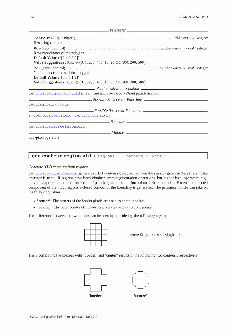
874 CHAPTER 16. XLD
Parameter
. Contour (outputobject) . . . . . . . . . . . . . . . . . . . . . . . . . . . . . . . . . . . . . . . . . . . . . . . . . . . . . . . . . xldcont ; HobjectResulting contour.
. Row(input control) . . . . . . . . . . . . . . . . . . . . . . . . . . . . . . . . . . . . . . . . . . . . . . . . . . . . . number-array; real/ integerRow coordinates of the polygon.Default Value : ’[0,1,2,2,2]’Value Suggestions :Row∈ {0, 1, 2, 3, 4, 5, 10, 20, 50, 100, 200, 500}
. Col (input control) . . . . . . . . . . . . . . . . . . . . . . . . . . . . . . . . . . . . . . . . . . . . . . . . . . . . . number-array; real/ integerColumn coordinates of the polygon.Default Value : ’[0,0,0,1,2]’Value Suggestions :Col ∈ {0, 1, 2, 3, 4, 5, 10, 20, 50, 100, 200, 500}
Parallelization Informationgen contour polygon xld is reentrantand processedwithoutparallelization.
Possible Predecessor Functionsget region contour
Possible Successor Functionssmooth contours xld , gen polygons xld
See Alsogen contours skeleton xld
ModuleSub-pixel operators
gen contour region xld ( Regions : Contours : Mode : )
Generate XLD contours from regions.
gen contour region xld generates XLD contoursContours from the regions given inRegions . Thisoperator is useful if regions have been obtained from segmentation operations, but higher level operators, e.g.,polygon approximation and extraction of parallels, are to be performed on their boundaries. For each connectedcomponent of the input regions a closed contour of the boundary is generated. The parameterMode can take onthe following values:
• ’center’ : The centers of the border pixels are used as contour points.
• ’border’ : The outer border of the border pixels is used as contour points.
The difference between the two modes can be seen by considering the following region:
where2 symbolizes a single pixel.
Then, computing the contour with’border’ and’center’ results in the following two contours, respectively:
’border’
@@ ��
�� @@
’center’
HALCON/HDevelop Reference Manual, 2003-7-21

16.2. CREATION 875
This means, for example, that countours generated with’border’ will in general have a much larger Euclideanlength (see length xld ) than countours generated with’center’ . This results from the fact that for diagonalborder elements’border’ uses two contour segments of length 1 each, whereas’center’ uses a single segment oflength
√2. Other features, e.g., the area (seearea center xld ), will obviously also have different values.
Parameter
. Regions (input object) . . . . . . . . . . . . . . . . . . . . . . . . . . . . . . . . . . . . . . . . . . . . . . . . . . . . . region(-array); HobjectInput regions.
. Contours (outputobject) . . . . . . . . . . . . . . . . . . . . . . . . . . . . . . . . . . . . . . . . . . . . . . . . xldcont(-array); HobjectResulting contours.
. Mode (input control) . . . . . . . . . . . . . . . . . . . . . . . . . . . . . . . . . . . . . . . . . . . . . . . . . . . . . . . . . . . . . . . . . .string; stringMode of contour generation.Default Value : ’border’Value List : Mode∈ {’border’, ’center’}
Parallelization Informationgen contour region xld is reentrantand processedwithoutparallelization.
Possible Successor Functionssmooth contours xld , gen polygons xld
Alternativesgen contour polygon xld , get region contour
See Alsogen contours skeleton xld
ModuleSub-pixel operators
gen contours skeleton xld ( Skeleton : Contours : Length, Mode : )
Convert a skeleton into XLD contours.
gen contours skeleton xld converts the input skeleton (e.g., edges)Skeleton , which is assumed tocontain mostly one pixel wide regions (seeskeleton ), into XLD contours. The regions are first transformedto contain only line segments in 8-neighborhood. In the process 12 special configurations are taken into account:Points for which there is a junction of three or more lines in 8-neighborhood are preserved (in all four rotations):
0 0 11 1 00 1 0
0 1 00 1 10 1 0
0 1 01 1 10 1 0
In a second step, all junction points are labelled, taking six different characteristic configurations of all four possiblerotations into account:
1 0 10 2 00 0 1
1 0 10 2 01 0 1
1 0 00 2 10 1 0
1 0 00 2 11 0 0
0 1 00 2 10 1 0
0 1 01 2 10 1 0
where 0 = background, 1 = foreground, and 2 = junction point.
After this, all contours having at leastLength points are returned. The contours generated bygen contours skeleton xld always end in junction or end points. For closed contours the first point lies inthe 8-neighborhood of the last point of the contour. Therefore, in order to determine the adjacency of contours it issufficient to just take the end points into account.
Since contours are split at junction points, possibly long contours may be split into several short segments becauseof short adjacent lines, even if they are longer thanLength points, if Mode = ’filter’ was selected. This can beavoided by settingMode = ’generalize1’. In this case, the contours are generated as if the segments shorter thanLength were not contained in the input region. In order to preserve line segments, which are split into very shortsegments by the crossing of short lines,Mode = ’generalize2’ can be selected. In this case, line segments arepreserved if they end in two junction points, even if they are shorter thanLength .
HALCON 6.0.4

876 CHAPTER 16. XLD
Parameter
. Skeleton (input object) . . . . . . . . . . . . . . . . . . . . . . . . . . . . . . . . . . . . . . . . . . . . . . . . . . . . . . . . . . region; HobjectSkeleton of which the contours are to be determined.
. Contours (outputobject) . . . . . . . . . . . . . . . . . . . . . . . . . . . . . . . . . . . . . . . . . . . . . . . . . . xldcont-array; HobjectResulting contours.
. Length (input control) . . . . . . . . . . . . . . . . . . . . . . . . . . . . . . . . . . . . . . . . . . . . . . . . . . . . . . . . . . . . . integer; integerMinimum number of points a contour has to have.Default Value : 1Value Suggestions :Length ∈ {1, 2, 3, 5, 10, 20}
. Mode (input control) . . . . . . . . . . . . . . . . . . . . . . . . . . . . . . . . . . . . . . . . . . . . . . . . . . . . . . . . . . . . . . . . . .string; stringContour filter mode.Default Value : ’filter’Value List : Mode∈ {’filter’, ’generalize1’, ’generalize2’}
Parallelization Informationgen contours skeleton xld is reentrantand processedwithoutparallelization.
Possible Predecessor Functionsskeleton
Possible Successor Functionssmooth contours xld , get contour xld , gen polygons xld
See Alsoedges image , threshold , get region contour
ModuleSub-pixel operators
gen ellipse contour xld ( : ContEllipse : Row, Column, Phi, Radius1,Radius2, StartPhi, EndPhi, PointOrder, Resolution : )
Creation of an XLD contour corresponding to an elliptic arc.
gen ellipse contour xld creates one or more elliptic arcs or closed ellipses. Ellipses are specified by theircenter (Row, Column ), the orientation of the main axisPhi , the length of the larger half axisRadius1 , and thelength of the smaller half axisRadius2 . In addition to that, elliptic arcs are characterized by the angle of the startpointStartPhi , the angle of the end pointEndPhi , and the point orderPointOrder along the boundary. Theangles in the interval[0, 2π] are measured in the coordinate system of the ellipse relative to the main axis. Thus,the two main poles correspond to the angles0 andπ, the two other poles to the anglesπ/2 and3π/2. To create aclosed ellipse the values0 and2π (with positive point order) have to be passed to the operator. The resolution of theresulting contoursContEllipse is controlled viaResolution containing the maximum Euclidean distancebetween neighboring contour points.
Parameter
. ContEllipse (outputobject) . . . . . . . . . . . . . . . . . . . . . . . . . . . . . . . . . . . . . . . . . . . . xldcont(-array); HobjectResulting contour.
. Row(input control) . . . . . . . . . . . . . . . . . . . . . . . . . . . . . . . . . . . . . . . . . . . . . . . . . . . . . ellipse.center.y(-array); realRow coordinate of the center of the ellipse.Default Value : 200.0Value Suggestions :Row∈ {0.0, 10.0, 20.0, 50.0, 100.0, 200.0, 300.0, 400.0}
. Column (input control) . . . . . . . . . . . . . . . . . . . . . . . . . . . . . . . . . . . . . . . . . . . . . . . . . ellipse.center.x(-array); realColumn coordinate of the center of the ellipse.Default Value : 200.0Value Suggestions :Column ∈ {0.0, 10.0, 20.0, 50.0, 100.0, 200.0, 300.0, 400.0}
. Phi (input control) . . . . . . . . . . . . . . . . . . . . . . . . . . . . . . . . . . . . . . . . . . . . . . . . . . . . ellipse.angle.rad(-array); realOrientation of the main axis [rad].Default Value : 0.0Value Suggestions :Phi ∈ {-1.178097, -0.785398, -0.392699, 0.0, 0.392699, 0.785398, 1.178097}Restriction : (Phi ≥ 0) ∧ (Phi ≤ 6.283185307 )
HALCON/HDevelop Reference Manual, 2003-7-21

16.2. CREATION 877
. Radius1 (input control) . . . . . . . . . . . . . . . . . . . . . . . . . . . . . . . . . . . . . . . . . . . . . . . . ellipse.radius1(-array); realLength of the larger half axis.Default Value : 100.0Value Suggestions :Radius1 ∈ {2.0, 5.0, 10.0, 20.0, 50.0, 100.0, 256.0, 300.0, 400.0}Restriction : Radius1 > 0
. Radius2 (input control) . . . . . . . . . . . . . . . . . . . . . . . . . . . . . . . . . . . . . . . . . . . . . . . . ellipse.radius2(-array); realLength of the smaller half axis.Default Value : 50.0Value Suggestions :Radius2 ∈ {1.0, 2.0, 4.0, 5.0, 10.0, 20.0, 50.0, 100.0, 256.0, 300.0, 400.0}Restriction : Radius2 ≥ 0
. StartPhi (input control) . . . . . . . . . . . . . . . . . . . . . . . . . . . . . . . . . . . . . . . . . . . . . . . . . . . . . . . . . real(-array); realAngle of the start point [rad].Default Value : 0.0Value Suggestions :StartPhi ∈ {0.0, 0.78539, 1.57079, 2.35619, 3.14159, 3.92699, 4.71238, 5.49778,6.28318}Restriction : (StartPhi ≥ 0) ∧ (StartPhi ≤ 6.283185307 )
. EndPhi (input control) . . . . . . . . . . . . . . . . . . . . . . . . . . . . . . . . . . . . . . . . . . . . . . . . . . . . . . . . . . . real(-array); realAngle of the end point [rad].Default Value : 6.28318Value Suggestions :EndPhi ∈ {0.0, 0.78539, 1.57079, 2.35619, 3.14159, 3.92699, 4.71238, 5.49778,6.28318}Restriction : (EndPhi ≥ 0) ∧ (EndPhi ≤ 6.283185307 )
. PointOrder (input control) . . . . . . . . . . . . . . . . . . . . . . . . . . . . . . . . . . . . . . . . . . . . . . . . . . string(-array); stringpoint order along the boundary.Default Value : ’positive’Value List : PointOrder ∈ {’positive’, ’negative’}
. Resolution (input control) . . . . . . . . . . . . . . . . . . . . . . . . . . . . . . . . . . . . . . . . . . . . . . . . . . . . . . . . . . . . . real; realResolution: Maximum distance bewteen neighboring contour points.Default Value : 1.5Value Suggestions :Resolution ∈ {0.5, 1.0, 1.5, 2.0, 2.5, 3.0}Restriction : Resolution > 0
Example
draw_ellipse(WindowHandle,Row,Column,Phi,Radius1,Radius2)gen_ellipse_contour_xld(Ellipse,Row,Column,Phi,Radius1,Radius2,0,6.28319,
’positive’,1.5)length_xld(Ellipse,Length).
Resultgen ellipse contour xld returns 2 (HMSG TRUE) if all parameter values are correct. If necessary, anexception is raised.
Parallelization Informationgen ellipse contour xld is reentrantand processedwithoutparallelization.
Possible Predecessor Functionsdraw ellipse
Possible Successor Functionsdisp xld , get points ellipse
ModuleSub-pixel operators
gen parallels xld ( Polygons : Parallels : Len, Dist, Alpha,Merge : )
Extract parallel XLD polygons.
HALCON 6.0.4
878 CHAPTER 16. XLD
gen parallels xld examines the XLD polygons passed inPolygons for parallelism. The resulting parallelpolygons are returned inParallels . If the parameterMerge is set to’true’ , adjacent parallel polygons arereturned in a single parallel relation. Otherwise, one parallel relation is returned for each pair of parallel linesegments. Whether two polygon segments are parallel depends on their distance (smaller thanDist ), a maximumallowed angle difference (Alpha , in radians), and a minimum length of the two polygon segments. Furthermore,the two segments have to overlap. As a side effect, a quality factor is calculated for each pair of parallels. It isbased on the normalized angular difference and the normalized length of the overlapping area:
quality =π − δα
π/22overlaplen1 + len2
with 0 ≤ q ≤ 1
Here,δα is the angle difference of the polygon segments,overlap is the length of the overlap area,len1 andl2 thelength of the polygon segments, andquality the resulting quality factor.
The quality factor is a measure of parallelism (the larger its value, the “more parallel” the polygons). Finally, thequality factors of all parallel polygon segments contained in a single polygon are added, weighted with their lengthof the overlapping area.
Parameter
. Polygons (input object) . . . . . . . . . . . . . . . . . . . . . . . . . . . . . . . . . . . . . . . . . . . . . . . . . . . xldpoly-array ; HobjectInput polygons.
. Parallels (outputobject) . . . . . . . . . . . . . . . . . . . . . . . . . . . . . . . . . . . . . . . . . . . . . . . . .xldpara-array; HobjectParallel polygons.
. Len (input control) . . . . . . . . . . . . . . . . . . . . . . . . . . . . . . . . . . . . . . . . . . . . . . . . . . . . . . . . . . . number; real/ integerMimimum length of the individual polygon segments.Default Value : 10.0Value Suggestions :Len ∈ {5.0, 10.0, 15.0, 20.0}Restriction : Len > 0.0
. Dist (input control) . . . . . . . . . . . . . . . . . . . . . . . . . . . . . . . . . . . . . . . . . . . . . . . . . . . . . . . . . number; real/ integerMaximum distance between the polygon segments.Default Value : 30.0Value Suggestions :Dist ∈ {20.0, 25.0, 30.0, 40.0, 50.0, 75.0}Restriction : Dist > 0.0
. Alpha (input control) . . . . . . . . . . . . . . . . . . . . . . . . . . . . . . . . . . . . . . . . . . . . . . . . . . . . . . . . number; real/ integerMaximum angle difference of the polygon segments.Default Value : 0.15Value Suggestions :Alpha ∈ {0.05, 0.10, 0.15, 0.20, 0.30}Restriction : (0 ≤ Alpha ) ∧ (Alpha ≤ (pi /2))
. Merge (input control) . . . . . . . . . . . . . . . . . . . . . . . . . . . . . . . . . . . . . . . . . . . . . . . . . . . . . . . . . . . . . . . . string; stringShould adjacent parallel relations be merged?Default Value : ’true’Value List : Merge ∈ {’true’, ’false’}
Parallelization Informationgen parallels xld is reentrantand processedwithoutparallelization.
Possible Predecessor Functionsgen polygons xld
Possible Successor Functionsmod parallels xld , get parallels xld
ModuleSub-pixel operators
gen polygons xld ( Contours : Polygons : Type, Alpha : )
Approximate XLD contours by polygons.
gen polygons xld approximates XLD contours (Contours ) by polygons. The type of the approximationcan be set byType . The threshold for the approximation is set viaAlpha . The procedure is able to process openas well as closed contours. The resulting approximating XLD polygons are returned inPolygons .
HALCON/HDevelop Reference Manual, 2003-7-21

16.2. CREATION 879
Contours can be approximated by the algorithms of Ramer, Ray, and Sato. The algorithm of Ramer approximatescontours such that the Euclidian distance of the approximating polygon to the contour is at mostAlpha pixel units.The algorithm of Ray does not need a threshold, and henceAlpha is ignored. Here, the contour is approximatedby maximizing the line length, while minimizing the sum of the distances of the line segment from the contour.The algorithm of Sato produces a polygon point at the point of the contour in which the distance to the end pointsof the contour is maximal. The total approximation error for each iteration is then given by(L − L′)/L, whereLis the Euclidian contour length, andL′ is the length of the approximating polygon.
Parameter
. Contours (input object) . . . . . . . . . . . . . . . . . . . . . . . . . . . . . . . . . . . . . . . . . . . . . . . . . . . xldcont-array; HobjectContours to be approximated.
. Polygons (outputobject) . . . . . . . . . . . . . . . . . . . . . . . . . . . . . . . . . . . . . . . . . . . . . . . . . . xldpoly-array ; HobjectApproximating polygons.
. Type (input control) . . . . . . . . . . . . . . . . . . . . . . . . . . . . . . . . . . . . . . . . . . . . . . . . . . . . . . . . . . . . . . . . . .string; stringType of approximation.Default Value : ’ramer’Value List : Type ∈ {’ramer’, ’ray’, ’sato’}
. Alpha (input control) . . . . . . . . . . . . . . . . . . . . . . . . . . . . . . . . . . . . . . . . . . . . . . . . . . . . . . . . number; real/ integerThreshold for the approximation.Default Value : 2.0Value Suggestions :Alpha ∈ {1.0, 1.5, 2.0, 3.0, 4.0}Restriction : Alpha > 0.0
Parallelization Informationgen polygons xld is reentrantand processedwithoutparallelization.
Possible Predecessor Functionsgen contours skeleton xld , lines gauss , lines facet , edges sub pix
Possible Successor Functionsgen parallels xld
See Alsoget region polygon
ModuleSub-pixel operators
mod parallels xld ( Parallels, Image : ModParallels,ExtParallels : Quality, MinGray, MaxGray, MaxStandard : )
Extract parallel XLD polygons enclosing a homogeneous area.
mod parallels xld selects XLD parallels enclosing homogeneous areas from the input parallelsParallels . The parameterImage contains the corresponding gray value image.
Only parallels having a quality factor larger thanQuality are examined. The algorithm performs parallel crosssections one pixel apart, and parallel to the line segments in the area of overlap between two parallel line segments.
In the first iteration, the mean gray value for each of the lines in the cross section is calculated. In the seconditeration, the standard deviations of the gray values along each line are computed.
If the mean gray value of an area between parallels lies in the interval [MinGray ,MaxGray ], and if the mean of allstandard deviations is smaller than the upper thresholdMaxStandard , the corresponding parallels are returnedas modified parallels inModParallels .
In a second step, all polygon segments adjacent to parallels bordering homogeneous areas are checked for homo-geneity. To do so, a rectangle having the witdth of the last area enclosed by a modified parallel is constructed,and checked for homogeneity using the algorithm described above. This process is continued as long as there areadjacent polygon segments. The polygons thus found are returned as extended parallels inExtParallels .
HALCON 6.0.4

880 CHAPTER 16. XLD
Parameter
. Parallels (input object) . . . . . . . . . . . . . . . . . . . . . . . . . . . . . . . . . . . . . . . . . . . . . . . . . . xldpara-array; HobjectInput XLD parallels.
. Image (input object) . . . . . . . . . . . . . . . . . . . . . . . . . . . . . . . . . . . . . . . . . . . . . . . . . . . . . . . . . . . . . . . image; HobjectCorresponding gray value image.
. ModParallels (outputobject) . . . . . . . . . . . . . . . . . . . . . . . . . . . . . . . . . . . . . . . . xldmod para-array; HobjectModified XLD parallels.
. ExtParallels (outputobject) . . . . . . . . . . . . . . . . . . . . . . . . . . . . . . . . . . . . . . . . . xldext para-array; HobjectModified XLD parallels.
. Quality (input control) . . . . . . . . . . . . . . . . . . . . . . . . . . . . . . . . . . . . . . . . . . . . . . . . . . . . . number; real/ integerMinimum quality factor (measure of parallelism).Default Value : 0.4Value Suggestions :Quality ∈ {0.1, 0.2, 0.3, 0.4, 0.5, 0.6}Restriction : (0.0 ≤ Quality ) ∧ (Quality ≤ 1.0 )
. MinGray (input control) . . . . . . . . . . . . . . . . . . . . . . . . . . . . . . . . . . . . . . . . . . . . . . . . . . . . . . . . . . . integer; integerMinimum mean gray value.Default Value : 160Value Suggestions :MinGray ∈ {80, 100, 120, 140, 160, 180}Restriction : (0 ≤ MinGray ) ∧ (MinGray ≤ 255 )
. MaxGray (input control) . . . . . . . . . . . . . . . . . . . . . . . . . . . . . . . . . . . . . . . . . . . . . . . . . . . . . . . . . . . integer; integerMaximum mean gray value.Default Value : 220Value Suggestions :MaxGray ∈ {140, 160, 180, 200, 220, 240}Restriction : ((0 ≤ MaxGray ) ∧ (MaxGray ≤ 255 )) ∧ (MaxGray ≥ MinGray )
. MaxStandard (input control) . . . . . . . . . . . . . . . . . . . . . . . . . . . . . . . . . . . . . . . . . . . . . . . . number; real/ integerMaximum allowed standard deviation.Default Value : 10.0Value Suggestions :MaxStandard ∈ {5.0, 10.0, 15.0, 20.0}Restriction : MaxStandard ≥ 0.0
Parallelization Informationmod parallels xld is reentrantand processedwithoutparallelization.
Possible Predecessor Functionsgen parallels xld
Possible Successor Functionsmax parallels xld
See Alsoinfo parallels xld
ModuleSub-pixel operators
16.3 Features
area center xld ( XLD : : : Area, Row, Column, PointOrder )
Area and center of gravity (centroid) of contours and polygons.
area center xld calculates the area and center of gravity (centroid) of the region enclosed by the contoursor polygonsXLD as well as the order of the points along the boundary. The area and centroid are computed byapplying Green’s theorem using only the points on the contour or polygon, i.e., no region is generated explicitly forthe purpose of calculating the features. If the points are arranged counterclockwise (i.e., in a positive mathematicalsense) in the contour,PointOrder will be ”positive” . It is assumed that the contours or polygons are closed. Ifthis is not the casearea center xld will artificially close the contour. If more than one contour or polygonis passed the results are stored as tuples in which the index of a value corresponds to the index of the respectivecontour or polygon inXLD.
HALCON/HDevelop Reference Manual, 2003-7-21

16.3. FEATURES 881
Parameter
. XLD (input object) . . . . . . . . . . . . . . . . . . . . . . . . . . . . . . . . . . . . . . . . . . . . . . . . . . . . . . . . . . . . . xld(-array); HobjectContours or polygons to be examined.
. Area (outputcontrol) . . . . . . . . . . . . . . . . . . . . . . . . . . . . . . . . . . . . . . . . . . . . . . . . . . . . . . . . . . . . . real(-array); realArea enclosed by the contour or polygon.
. Row(outputcontrol) . . . . . . . . . . . . . . . . . . . . . . . . . . . . . . . . . . . . . . . . . . . . . . . . . . . . . . . . . . . point.y(-array); realRow coordinate of the centroid.
. Column (outputcontrol) . . . . . . . . . . . . . . . . . . . . . . . . . . . . . . . . . . . . . . . . . . . . . . . . . . . . . . . point.x(-array); realColumn coordinate of the centroid.
. PointOrder (outputcontrol) . . . . . . . . . . . . . . . . . . . . . . . . . . . . . . . . . . . . . . . . . . . . . . . . . string(-array); stringpoint order along the boundary (”positive”/”negative”).
ComplexityLet n be the number of points of the contour or polygon. Then the run time isO(n).
Resultarea center xld returns 2 (HMSG TRUE) if the input is not empty. If the input is empty the behaviour canbe set viaset system(::’no object result’,<Result>:) . If necessary, an exception is raised.
Parallelization Informationarea center xld is reentrantand automaticallyparallelized(on tuple level).
Possible Predecessor Functionsgen contours skeleton xld , smooth contours xld , gen polygons xld
See Alsomoments xld , moments any xld , area center , moments region 2nd
ModuleSub-pixel operators
contour point num xld ( Contour : : : Length )
Return the number of points in an XLD contour.
contour point num xld returns the length of the input contourContour , i.e. its number of points, inLength .
Parameter
. Contour (input object) . . . . . . . . . . . . . . . . . . . . . . . . . . . . . . . . . . . . . . . . . . . . . . . . . . . . . . . . . . xldcont ; HobjectInput XLD contour.
. Length (outputcontrol) . . . . . . . . . . . . . . . . . . . . . . . . . . . . . . . . . . . . . . . . . . . . . . . . . . . . . . . . . . . integer; integerNumber of contour points.
Parallelization Informationcontour point num xld is reentrantand processedwithoutparallelization.
Possible Predecessor Functionsgen contours skeleton xld , lines gauss , lines facet , edges sub pix
Possible Successor Functionsget contour xld , get contour attrib xld
Alternativesget regress params xld
See Alsoquery contour attribs xld
ModuleSub-pixel operators
HALCON 6.0.4

882 CHAPTER 16. XLD
dist ellipse contour xld ( Contours : : Mode, MaxNumPoints,ClippingEndPoints, Row, Column, Phi, Radius1, Radius2 : MinDist, MaxDist,AvgDist, SigmaDist )
Distance of contours to an ellipse.
dist ellipse contour xld determines the distance between the contours inContours and an ellipsespecified by the center (Row, Column ), the orientation of the main axisPhi , the length of the larger half axisRadius1 , and the length of the smaller half axisRadius2 . Different measures for the distance of a contourpointX = (xi, yi) to the ellipse are available (Mode):
’algebraic’ The distance is measured by the algebraic distanceax2i + bxiyi + cy2
i + dxi + eyi + f , where theparametersa - f describing the ellipse are normalized in order to obtainRadius2 as distance of thecenter of the ellipse. This measure shows ahigh curvature bias: Near points of high curvature on theellipse (like the poles on the main axis) the distance is smaller than near points with low curvature.
’geometric’ The distance is measured by the deviationXF1 +XF2 − 2a, whereF1,F2 are the focal points anda corresponds toRadius1 . This measure shows alow curvature bias: Near points of high curvatureon the ellipse (like the poles on the main axis) the distance is larger than near points with low curvature.
’bisec’ The distance is measured by the distance betweenX and the intersection of the angular bisector of thetwo lines throughX and the focal points with the ellipse. This is a very good approximation of theorthogonal distance fromX to the ellipse.
The operator returns the minimum absolute distanceMinDist , the maximum absolute distanceMaxDist , theaverage absolute distanceAvgDist , and the standard deviation of the absolute distancesSigmaDist of allcontour points.
To reduce the computational load, the computation of the distances can be restricted to a subset of the contourpoints: If a value other than -1 is assigned toMaxNumPoints , only up toMaxNumPoints points - uniformlydistributed over the contour - are used. Due to artefacts in the pre-processing the start and end points of a contourmight be faulty. Therefore, it is possible to excludeClippingEndPoints points at the beginning and at theend of a contour from the computation.
Parameter
. Contours (input object) . . . . . . . . . . . . . . . . . . . . . . . . . . . . . . . . . . . . . . . . . . . . . . . . . .xldcont(-array); HobjectInput contours.
. Mode (input control) . . . . . . . . . . . . . . . . . . . . . . . . . . . . . . . . . . . . . . . . . . . . . . . . . . . . . . . . . . . . . . . . . .string; stringMethod for the determination of the distances.Default Value : ’bisec’Value List : Mode∈ {’geometric’, ’algebraic’, ’bisec’}
. MaxNumPoints (input control) . . . . . . . . . . . . . . . . . . . . . . . . . . . . . . . . . . . . . . . . . . . . . . . . . . . . integer; integerMaximum number of contour points used for the computation (-1 for all points).Default Value : -1Restriction : MaxNumPoints ≥ 3
. ClippingEndPoints (input control) . . . . . . . . . . . . . . . . . . . . . . . . . . . . . . . . . . . . . . . . . . . . . . integer; integerNumber of points at the beginning and the end of the contours to be ignored for the computation of distances.Default Value : 0Restriction : ClippingEndPoints ≥ 0
. Row(input control) . . . . . . . . . . . . . . . . . . . . . . . . . . . . . . . . . . . . . . . . . . . . . . . . . . . . . . . . . . . . ellipse.center.y; realRow coordinate of the center of the ellipse of the ellipse.
. Column (input control) . . . . . . . . . . . . . . . . . . . . . . . . . . . . . . . . . . . . . . . . . . . . . . . . . . . . . . . . ellipse.center.x; realColumn coordinate of the center of the ellipse.
. Phi (input control) . . . . . . . . . . . . . . . . . . . . . . . . . . . . . . . . . . . . . . . . . . . . . . . . . . . . . . . . . . . ellipse.angle.rad; realOrientation of the main axis [rad].Restriction : (Phi ≥ 0) ∧ (Phi ≤ 6.283185307 )
. Radius1 (input control) . . . . . . . . . . . . . . . . . . . . . . . . . . . . . . . . . . . . . . . . . . . . . . . . . . . . . . . ellipse.radius1; realLength of the larger half axis.Restriction : Radius1 > 0
. Radius2 (input control) . . . . . . . . . . . . . . . . . . . . . . . . . . . . . . . . . . . . . . . . . . . . . . . . . . . . . . . ellipse.radius2; realLength of the smaller half axis.Restriction : Radius2 ≥ 0
HALCON/HDevelop Reference Manual, 2003-7-21
16.3. FEATURES 883
. MinDist (outputcontrol) . . . . . . . . . . . . . . . . . . . . . . . . . . . . . . . . . . . . . . . . . . . . . . . . . . . . . . . . . real(-array); realMinimum distance.
. MaxDist (outputcontrol) . . . . . . . . . . . . . . . . . . . . . . . . . . . . . . . . . . . . . . . . . . . . . . . . . . . . . . . . . real(-array); realMaximum distance.
. AvgDist (outputcontrol) . . . . . . . . . . . . . . . . . . . . . . . . . . . . . . . . . . . . . . . . . . . . . . . . . . . . . . . . . real(-array); realMean distance.
. SigmaDist (outputcontrol) . . . . . . . . . . . . . . . . . . . . . . . . . . . . . . . . . . . . . . . . . . . . . . . . . . . . . . real(-array); realStandard deviation of the distance.
Example
read_image (Image, ’caltab’)find_caltab (Image, Caltab, ’caltab_big.descr’, 3, 112, 5)reduce_domain (Image, Caltab, ImageReduced)edges_sub_pix (ImageReduced, Edges, ’lanser2’, 0.5, 20, 40)select_contours_xld (Edges, EdgesClosed, ’closed’, 0, 2.0, 0, 0)select_contours_xld (EdgesClosed, EdgesMarks, ’contour_length’, 20, 100,
0, 0)fit_ellipse_contour_xld (EdgesMarks, ’fitzgibbon’, -1, 2, 0, 200, 3, 2.0,
Row, Column, Phi, Radius1, Radius2, StartPhi,EndPhi, PointOrder)
for i := 0 to |Row|-1 by 1Object_Selected := EdgesMarks[i+1]dist_ellipse_contour_xld (ObjectSelected, ’bisec’, -1, 0, Row[i],
Column[i], Phi[i], Radius1[i], Radius2[i],MinDist, MaxDist, AvgDist, SigmaDist)
endfor.
Resultdist ellipse contour xld returns 2 (HMSG TRUE) if all parameter values are correct. If necessary, anexception is raised.
Parallelization Informationdist ellipse contour xld is local and processedcompletely exclusivelywithout parallelization.
Possible Predecessor Functionsfit ellipse contour xld
ModuleSub-pixel operators
fit circle contour xld ( Contours : : Algorithm, MaxNumPoints,MaxClosureDist, ClippingEndPoints, Iterations, ClippingFactor : Row,Column, Radius, StartPhi, EndPhi, PointOrder )
Approximation of XLD contours by circles.
fit circle contour xld approximates the XLD contoursContours by circles. It does not perform asegmentation of the input contours. Thus, one has to make sure that each contour corresponds to one and only onecircle. The operator returns for each contour the center (Row, Column ), and theRadius .
The algorithm used for the fitting of circles can be selected viaAlgorithm :
’algebraic’ This approach minimizes the algebraic distance between the contour points and the resulting circle.
’ahuber’ Similar to ’algebraic’. Here the contour points are weighted to decrease the impact of outliers basedon the approach of Huber.
’atukey’ Similar to ’algebraic’. Here the contour points are weighted to decrease the impact of outliers basedon the approach of Tukey.
For ’ahuber’ and ’atukey’ a robust error statistics is used to estimate the standard deviation of the distances fromthe contour pointswithout outliers from the approximating circle. The parameterClippingFactor (a scal-ing factor for the standard deviation) controls the amount of damping outliers: The smaller the value chosen for
HALCON 6.0.4

884 CHAPTER 16. XLD
ClippingFactor the more outliers are detected. The detection of outliers and the least squares fitting is re-peated. The parameterIterations specifies the number of iterations.
To reduce the computational load, the fitting of circles can be restricted to a subset of the contour points: If a valueother than -1 is assigned toMaxNumPoints , only up toMaxNumPoints points - uniformly distributed over thecontour - are used.
For circular arcs, the points on the circle closest to the start points and end points of the original contours arechosen as start and end points. The corresponding angles refering to the X-axis are returned inStartPhi andEndPhi , see alsogen ellipse contour xld . Contours, for which the distance between their start pointsand their end points is less or equalMaxClosureDist are considered to be closed. Thus, they are approximatedby circles instead of circular arcs. Due to artefacts in the pre-processing the start and end points of a contour mightbe faulty. Therefore, it is possible to excludeClippingEndPoints points at the beginning and at the end of acontour from the fitting of circles. However, they are still used for the determination ofStartPhi andEndPhi .
Parameter
. Contours (input object) . . . . . . . . . . . . . . . . . . . . . . . . . . . . . . . . . . . . . . . . . . . . . . . . . .xldcont(-array); HobjectInput contours.
. Algorithm (input control) . . . . . . . . . . . . . . . . . . . . . . . . . . . . . . . . . . . . . . . . . . . . . . . . . . . . . . . . . . . string; stringAlgorithm for the fitting of circles.Default Value : ’algebraic’Value List : Algorithm ∈ {’algebraic’, ’ahuber’, ’atukey’}
. MaxNumPoints (input control) . . . . . . . . . . . . . . . . . . . . . . . . . . . . . . . . . . . . . . . . . . . . . . . . . . . . integer; integerMaximum number of contour points used for the computation (-1 for all points).Default Value : -1Restriction : MaxNumPoints ≥ 3
. MaxClosureDist (input control) . . . . . . . . . . . . . . . . . . . . . . . . . . . . . . . . . . . . . . . . . . . . . . . . . . . . . . . real; realMaximum distance between the end points of a contour to be considered as ’closed’.Default Value : 0.0Restriction : MaxClosureDist ≥ 0.0
. ClippingEndPoints (input control) . . . . . . . . . . . . . . . . . . . . . . . . . . . . . . . . . . . . . . . . . . . . . . integer; integerNumber of points at the beginning and at the end of the contours to be ignored for the fitting.Default Value : 0Restriction : ClippingEndPoints ≥ 0
. Iterations (input control) . . . . . . . . . . . . . . . . . . . . . . . . . . . . . . . . . . . . . . . . . . . . . . . . . . . . . . . integer; integerMaximum number of iterations.Default Value : 3Restriction : Iterations ≥ 0
. ClippingFactor (input control) . . . . . . . . . . . . . . . . . . . . . . . . . . . . . . . . . . . . . . . . . . . . . . . . . . . . . . . real; realClipping factor for the elimination of outliers (typical: 1.0 for Huber and 2.0 for Tukey).Default Value : 2.0Value List : ClippingFactor ∈ {1.0, 1.5, 2.0, 2.5, 3.0}Restriction : ClippingFactor > 0
. Row(outputcontrol) . . . . . . . . . . . . . . . . . . . . . . . . . . . . . . . . . . . . . . . . . . . . . . . . . . . . . circle.center.y(-array); realRow coordinate of the center of the circle.
. Column (outputcontrol) . . . . . . . . . . . . . . . . . . . . . . . . . . . . . . . . . . . . . . . . . . . . . . . . . circle.center.x(-array); realColumn coordinate of the center of the circle.
. Radius (outputcontrol) . . . . . . . . . . . . . . . . . . . . . . . . . . . . . . . . . . . . . . . . . . . . . . . . . . circle.radius(-array); realRadius of circle.
. StartPhi (outputcontrol) . . . . . . . . . . . . . . . . . . . . . . . . . . . . . . . . . . . . . . . . . . . . . . . . . . . . . . . . real(-array); realAngle of the start point [rad].
. EndPhi (outputcontrol) . . . . . . . . . . . . . . . . . . . . . . . . . . . . . . . . . . . . . . . . . . . . . . . . . . . . . . . . . . real(-array); realAngle of the end point [rad].
. PointOrder (outputcontrol) . . . . . . . . . . . . . . . . . . . . . . . . . . . . . . . . . . . . . . . . . . . . . . . . . string(-array); stringPoint order along the boundary.Value List : PointOrder ∈ {’positive’, ’negative’}
Resultfit circle contour xld returns 2 (HMSG TRUE) if all parameter values are correct, and circles
HALCON/HDevelop Reference Manual, 2003-7-21

16.3. FEATURES 885
could be fitted to the input contours. If the input is empty the behaviour can be set viaset system(’no object result’,<Result>) . If necessary, an exception is raised.
Parallelization Informationfit circle contour xld is local and processedcompletely exclusivelywithout parallelization.
Possible Predecessor Functionsgen contours skeleton xld , lines gauss , lines facet , edges sub pix ,smooth contours xld
Possible Successor Functionsgen ellipse contour xld , disp circle , get points ellipse
See Alsofit ellipse contour xld , fit line contour xld
ModuleSub-pixel operators
fit ellipse contour xld ( Contours : : Algorithm, MaxNumPoints,MaxClosureDist, ClippingEndPoints, VossTabSize, Iterations,ClippingFactor : Row, Column, Phi, Radius1, Radius2, StartPhi, EndPhi,PointOrder )
Approximation of XLD contours by ellipses or elliptic arcs.
fit ellipse contour xld approximates the XLD contoursContours by elliptic arcs or closed ellipses. Itdoes not perform a segmentation of the input contours. Thus, one has to make sure that each contour correspondsto one and only one elliptic structure. The operator returns for each contour the center (Row, Column ), theorientation of the main axisPhi , the length of the larger half axisRadius1 , and the length of the smaller halfaxisRadius2 of the underlying ellipse. In addition to that, the angle corresponding to the start point and the endpoint StartPhi , EndPhi , and the point order along the boundaryPointOrder is returned for elliptic arcs.These parameters are set to0, 2π, and ’positive’ for closed ellipses. The algorithm used for the fitting of ellipsescan be selected viaAlgorithm :
’fitzgibbon’ This approach minimizes the algebraic distanceax2i + bxiyi + cy2
i + dxi + eyi + f between thecontour points(xi, yi) and the resulting ellipse. The constraint4ac−b2 = 1 guarantees that the resultingpolynom characterizes an ellipse (instead of a hyperbola or a parabola).
’fhuber’ Similar to ’fitzgibbon’. Here the contour points are weighted to decrease the impact of outliers basedon the approach of Huber.
’ftukey’ Similar to ’fitzgibbon’. Here the contour points are weighted to decrease the impact of outliers basedon the approach of Tukey.
’voss’ Each input contour is transformed in an affine standard position. Based on the moments of the trans-formed contour (that is of the enclosed image region) the standard circular segment is choosen whosestandard position matches best with the standard position of the contour. The ellipse corresponding tothe standard position of the selected circular segment is re-transformed based on the affine transforma-tion which produced the standard position of the contour resulting in the ellipse matching the originalcontour. VossTabSize standard circular segments are used for this computation. To speed up theprocess the corresponding moments and other data is stored in a table which is created during the firstcall (with a specific value forVossTabSize ) to fit ellipse contour xld .
’focpoints’ Each pointP on an ellipse satisfies the constraint that the sum of distances to the focal pointsF1,F2
equals twice the length of the larger half axisa. In this approach, the deviationPF1 + PF2 − 2a isminimized for all contour points by a least squares optimization.
’fphuber’ Similar to ’focpoints’. Here aweightedleast squares optimization is done to decrease the impact ofoutliers based on the approach of Huber.
’fptukey’ Similar to ’focpoints’. Here aweightedleast squares optimization is done to decrease the impact ofoutliers based on the approach of Tukey.
For ’*Huber’ and ’*Tukey’ a robust error statistics is used to estimate the standard deviation of the distancesfrom the contour pointswithout outliers from the approximating ellipse. The parameterClippingFactor (ascaling factor for the standard deviation) controls the amount of damping outliers: The smaller the value chosen
HALCON 6.0.4
886 CHAPTER 16. XLD
for ClippingFactor the more outliers are detected. The detection of outliers and the least squares fitting in themode ’focpoints’ is repeated. The parameterIterations specifies the number of iterations.
To reduce the computational load, the fitting of ellipses can be restricted to a subset of the contour points: If avalue other than -1 is assigned toMaxNumPoints , only up toMaxNumPoints points - uniformly distributedover the contour - are used.
For elliptic arcs, the points on the ellipse closest to the start points and end points of the original contours arechosen as start and end points. The corresponding angles refering to the main axis of the ellipse are returned inStartPhi andEndPhi , see alsogen ellipse contour xld . Contours, for which the distance betweentheir start points and their end points is less or equalMaxClosureDist are considered to be closed. Thus,they are approximated by ellipses instead of elliptic arcs. Due to artefacts in the pre-processing the start and endpoints of a contour might be faulty. Therefore, it is possible to excludeClippingEndPoints points at thebeginning and at the end of a contour from the fitting of ellipses. However, they are still used for the determinationof StartPhi andEndPhi .
Parameter
. Contours (input object) . . . . . . . . . . . . . . . . . . . . . . . . . . . . . . . . . . . . . . . . . . . . . . . . . .xldcont(-array); HobjectInput contours.
. Algorithm (input control) . . . . . . . . . . . . . . . . . . . . . . . . . . . . . . . . . . . . . . . . . . . . . . . . . . . . . . . . . . . string; stringAlgorithm for the fitting of ellipses.Default Value : ’fitzgibbon’Value List : Algorithm ∈ {’fitzgibbon’, ’fhuber’, ’ftukey’, ’voss’, ’focpoints’, ’fphuber’, ’fptukey’}
. MaxNumPoints (input control) . . . . . . . . . . . . . . . . . . . . . . . . . . . . . . . . . . . . . . . . . . . . . . . . . . . . integer; integerMaximum number of contour points used for the computation (-1 for all points).Default Value : -1Restriction : MaxNumPoints ≥ 3
. MaxClosureDist (input control) . . . . . . . . . . . . . . . . . . . . . . . . . . . . . . . . . . . . . . . . . . . . . . . . . . . . . . . real; realMaximum distance between the end points of a contour to be considered as ’closed’.Default Value : 0.0Restriction : MaxClosureDist ≥ 0.0
. ClippingEndPoints (input control) . . . . . . . . . . . . . . . . . . . . . . . . . . . . . . . . . . . . . . . . . . . . . . integer; integerNumber of points at the beginning and at the end of the contours to be ignored for the fitting.Default Value : 0Restriction : ClippingEndPoints ≥ 0
. VossTabSize (input control) . . . . . . . . . . . . . . . . . . . . . . . . . . . . . . . . . . . . . . . . . . . . . . . . . . . . . . integer; integerNumber of circular segments used for the Voss approach.Default Value : 200Restriction : (VossTabSize ≥ 25) ∧ (VossTabSize ≤ 5000 )
. Iterations (input control) . . . . . . . . . . . . . . . . . . . . . . . . . . . . . . . . . . . . . . . . . . . . . . . . . . . . . . . integer; integerMaximum number of iterations (unused for ’fitzgibbon’ and ’voss’).Default Value : 3Restriction : Iterations ≥ 0
. ClippingFactor (input control) . . . . . . . . . . . . . . . . . . . . . . . . . . . . . . . . . . . . . . . . . . . . . . . . . . . . . . . real; realClipping factor for the elimination of outliers (typical: 1.0 for ’*Huber’ and 2.0 for ’*Tukey’).Default Value : 2.0Value List : ClippingFactor ∈ {1.0, 1.5, 2.0, 2.5, 3.0}Restriction : ClippingFactor > 0
. Row(outputcontrol) . . . . . . . . . . . . . . . . . . . . . . . . . . . . . . . . . . . . . . . . . . . . . . . . . . . . ellipse.center.y(-array); realRow coordinate of the center of the ellipse.
. Column (outputcontrol) . . . . . . . . . . . . . . . . . . . . . . . . . . . . . . . . . . . . . . . . . . . . . . . . ellipse.center.x(-array); realColumn coordinate of the center of the ellipse.
. Phi (outputcontrol) . . . . . . . . . . . . . . . . . . . . . . . . . . . . . . . . . . . . . . . . . . . . . . . . . . . ellipse.angle.rad(-array); realOrientation of the main axis [rad].
. Radius1 (outputcontrol) . . . . . . . . . . . . . . . . . . . . . . . . . . . . . . . . . . . . . . . . . . . . . . . ellipse.radius1(-array); realLength of the larger half axis.
. Radius2 (outputcontrol) . . . . . . . . . . . . . . . . . . . . . . . . . . . . . . . . . . . . . . . . . . . . . . . ellipse.radius2(-array); realLength of the smaller half axis.
HALCON/HDevelop Reference Manual, 2003-7-21
16.3. FEATURES 887
. StartPhi (outputcontrol) . . . . . . . . . . . . . . . . . . . . . . . . . . . . . . . . . . . . . . . . . . . . . . . . . . . . . . . . real(-array); realAngle of the start point [rad].
. EndPhi (outputcontrol) . . . . . . . . . . . . . . . . . . . . . . . . . . . . . . . . . . . . . . . . . . . . . . . . . . . . . . . . . . real(-array); realAngle of the end point [rad].
. PointOrder (outputcontrol) . . . . . . . . . . . . . . . . . . . . . . . . . . . . . . . . . . . . . . . . . . . . . . . . . string(-array); stringpoint order along the boundary.Value List : PointOrder ∈ {’positive’, ’negative’}
Example
read_image (Image, ’caltab’)find_caltab (Image, Caltab, ’caltabBig.descr’, 3, 112, 5)reduce_domain (Image, Caltab, ImageReduced)edges_sub_pix (ImageReduced, Edges, ’lanser2’, 0.5, 20, 40)select_contours_xld (Edges, EdgesClosed, ’closed’, 0, 2.0, 0, 0)select_contours_xld (EdgesClosed, EdgesMarks, ’length’, 20, 80, 0, 0)fit_ellipse_contour_xld (EdgesMarks, ’fitzgibbon’, -1, 2, 0, 200, 3, 2.0,
Row, Column, Phi, Radius1, Radius2, StartPhi,EndPhi, PointOrder)
gen_ellipse_contour_xld (EllMarks, Row, Column, Phi, Radius1, Radius2,StartPhi, EndPhi, PointOrder, 1.5)
length_xld(EllMarks,Length).
Resultfit ellipse contour xld returns 2 (HMSG TRUE) if all parameter values are correct, and ellipsescould be fitted to the input contours. If the input is empty the behaviour can be set viaset system(’no object result’,<Result>) . If necessary, an exception is raised.
Parallelization Informationfit ellipse contour xld is local and processedcompletely exclusivelywithout parallelization.
Possible Predecessor Functionsgen contours skeleton xld , lines gauss , lines facet , edges sub pix ,smooth contours xld
Possible Successor Functionsgen ellipse contour xld , disp ellipse , get points ellipse
See Alsofit line contour xld
ModuleSub-pixel operators
fit line contour xld ( Contours : : Algorithm, MaxNumPoints,ClippingEndPoints, Iterations, ClippingFactor : RowBegin, ColBegin,RowEnd, ColEnd, Nr, Nc, Dist )
Approximation of XLD contours by line segments.
fit line contour xld approximates the XLD contoursContours by line segments. It does not performa segmentation of the input contours. Thus, one has to make sure that each contour corresponds to one and onlyone line segment. The operator returns for each contour the start point (RowBegin , ColBegin ), the end point(RowEnd, ColEnd ), and the regression line to the contour given by the normal vector (Nr , Nc) of the line and itsdistanceDist from the origin, i.e., the line equation is given byrn r + cn c− d = 0.
The algorithm used for the fitting of lines can be selected viaAlgorithm :
’regression’ Standard ’least squares’ line fitting.
’huber’ Weighted ’least squares’ line fitting, where the impact of outliers is decreased based on the approachof Huber.
’tukey’ Weighted ’least squares’ line fitting, where the impact of outliers is decreased based on the approach ofTukey.
HALCON 6.0.4

888 CHAPTER 16. XLD
’drop’ Weighted ’least squares’ line fitting, where outliers are eliminated.
’gauss’ Weighted ’least squares’ line fitting, where the impact of outliers is decreased based on the mean valueand the standard deviation of the distances of all contour points from the approximating line.
For ’huber’, ’tukey’, and ’drop’ a robust error statistics is used to estimate the standard deviation of the distancesfrom the contour pointswithout outliers from the approximating line. The parameterClippingFactor (ascaling factor for the standard deviation) controls the amount of damping outliers: The smaller the value chosenfor ClippingFactor the more outliers are detected. The detection of outliers is repeated. The parameterIterations specifies the number of iterations. In the modus ’regression’ this value is ignored.
To reduce the computational load, the fitting of lines can be restricted to a subset of the contour points: If a valueother than -1 is assigned toMaxNumPoints , only up toMaxNumPoints points - uniformly distributed over thecontour - are used.
The start point and the end point of a line segment is determined by projecting the first and the last point of thecorresponding contour to the approximating line. Due to artefacts in the pre-processing the start and end pointsof a contour might be faulty. Therefore, it is possible to excludeClippingEndPoints points at the beginningand at the end of a contour from the line fitting. However, they are still used for the determination of the start pointand the end point of the line segment.
Parameter
. Contours (input object) . . . . . . . . . . . . . . . . . . . . . . . . . . . . . . . . . . . . . . . . . . . . . . . . . .xldcont(-array); HobjectInput contours.
. Algorithm (input control) . . . . . . . . . . . . . . . . . . . . . . . . . . . . . . . . . . . . . . . . . . . . . . . . . . . . . . . . . . . string; stringAlgorithm for the fitting of lines.Default Value : ’tukey’Value List : Algorithm ∈ {’regression’, ’huber’, ’tukey’, ’gauss’, ’drop’}
. MaxNumPoints (input control) . . . . . . . . . . . . . . . . . . . . . . . . . . . . . . . . . . . . . . . . . . . . . . . . . . . . integer; integerMaximum number of contour points used for the computation (-1 for all points).Default Value : -1Restriction : MaxNumPoints ≥ 3
. ClippingEndPoints (input control) . . . . . . . . . . . . . . . . . . . . . . . . . . . . . . . . . . . . . . . . . . . . . . integer; integerNumber of points at the beginning and at the end of the contours to be ignored for the fitting.Default Value : 0Restriction : ClippingEndPoints ≥ 0
. Iterations (input control) . . . . . . . . . . . . . . . . . . . . . . . . . . . . . . . . . . . . . . . . . . . . . . . . . . . . . . . integer; integerMaximum number of iterations (unused for ’regression’).Default Value : 5Restriction : Iterations ≥ 0
. ClippingFactor (input control) . . . . . . . . . . . . . . . . . . . . . . . . . . . . . . . . . . . . . . . . . . . . . . . . . . . . . . . real; realClipping factor for the elimination of outliers (typical: 1.0 for ’huber’ and ’drop’ and 2.0 for ’tukey’).Default Value : 2.0Value List : ClippingFactor ∈ {1.0, 1.5, 2.0, 2.5, 3.0}Restriction : ClippingFactor > 0
. RowBegin (outputcontrol) . . . . . . . . . . . . . . . . . . . . . . . . . . . . . . . . . . . . . . . . . . . . . . . . line.begin.y(-array); realRow coordinates of the starting points of the line segments.
. ColBegin (outputcontrol) . . . . . . . . . . . . . . . . . . . . . . . . . . . . . . . . . . . . . . . . . . . . . . . . line.begin.x(-array); realColumn coordinates of the starting points of the line segments.
. RowEnd(outputcontrol) . . . . . . . . . . . . . . . . . . . . . . . . . . . . . . . . . . . . . . . . . . . . . . . . . . . . . line.end.y(-array); realRow coordinates of the end points of the line segments.
. ColEnd (outputcontrol) . . . . . . . . . . . . . . . . . . . . . . . . . . . . . . . . . . . . . . . . . . . . . . . . . . . . . line.end.x(-array); realColumn coordinates of the end points of the line segments.
. Nr (outputcontrol) . . . . . . . . . . . . . . . . . . . . . . . . . . . . . . . . . . . . . . . . . . . . . . . . . . . . . . . . . . . . number(-array); realLine parameter: Row coordinate of the normal vector
. Nc (outputcontrol) . . . . . . . . . . . . . . . . . . . . . . . . . . . . . . . . . . . . . . . . . . . . . . . . . . . . . . . . . . . . number(-array); realLine parameter: Column coordinate of the normal vector
. Dist (outputcontrol) . . . . . . . . . . . . . . . . . . . . . . . . . . . . . . . . . . . . . . . . . . . . . . . . . . . . . . . . . number(-array); realLine parameter: Distance of the line from the origin
HALCON/HDevelop Reference Manual, 2003-7-21

16.3. FEATURES 889
Example
read_image (Image, ’mreut’)edges_sub_pix (Image, Edges, ’lanser2’, 0.5, 20, 40)gen_polygons_xld (Edges, Polygons, ’ramer’, 2)split_contours_xld (Polygons, Contours, ’polygon’, 1, 5)fit_line_contour_xld (Contours, ’regression’, -1, 0, 5, 2, RowBegin,
ColBegin, RowEnd, ColEnd, Nr, Nc).
Resultfit line contour xld returns 2 (HMSG TRUE) if all parameter values are correct, and line segmentscould be fitted to the input contours. If the input is empty the behaviour can be set viaset system(’no object result’,<Result>) . If necessary, an exception is raised.
Parallelization Informationfit line contour xld is reentrantand processedwithoutparallelization.
Possible Predecessor Functionsgen contours skeleton xld , lines gauss , lines facet , edges sub pix ,smooth contours xld
Possible Successor Functionsdisp line , select lines , line orientation
See Alsoregress contours xld , get regress params xld
ModuleSub-pixel operators
get contour angle xld ( Contour : : AngleMode, CalcMode,Lookaround : Angles )
Calculate the direction of an XLD contour for each contour point.
get contour angle xld calculates for each point of the XLD contourContour the direction of its tangent.Two modes for the output values can be chosen: By passing’abs’ for AngleMode , the resulting angles arereturned relative to the horizontal axis as angles between 0 and2π (counter-clockwise). By passing’rel’ , theabsolute value of the difference of angles to the previous contour point is returned. In this case the range of valuesis between 0 andπ.
There are three different ways of calculating the tangent direction (CalcMode ) of the contour pointi using thecontour points in the interval fromi − Lookaround to i + Lookaround . By using’range’ , the angle of theline segment between the first and last point of the interval is used. For’mean’, the average of all angles betweenconsecutive points of the contour is used. Finally, for’regress’, the direction of the regression line (the leastsquares fit of a line to the contour points in the interval) is used.Lookaround is a measure of how strongly thecontour is smoothed. The angles are returned inAngles in radians.
Parameter
. Contour (input object) . . . . . . . . . . . . . . . . . . . . . . . . . . . . . . . . . . . . . . . . . . . . . . . . . . . . . . . . . . xldcont ; HobjectInput contour.
. AngleMode (input control) . . . . . . . . . . . . . . . . . . . . . . . . . . . . . . . . . . . . . . . . . . . . . . . . . . . . . . . . . . . string; stringReturn type of the angles.Default Value : ’abs’Value List : AngleMode ∈ {’abs’, ’rel’}
. CalcMode (input control) . . . . . . . . . . . . . . . . . . . . . . . . . . . . . . . . . . . . . . . . . . . . . . . . . . . . . . . . . . . . string; stringMethod for computing the angles.Default Value : ’range’Value List : CalcMode ∈ {’range’, ’mean’, ’regress’}
. Lookaround (input control) . . . . . . . . . . . . . . . . . . . . . . . . . . . . . . . . . . . . . . . . . . . . . . . . . . . . . . . integer; integerNumber of points to take into account.Default Value : 3Restriction : Lookaround > 0
HALCON 6.0.4
890 CHAPTER 16. XLD
. Angles (outputcontrol) . . . . . . . . . . . . . . . . . . . . . . . . . . . . . . . . . . . . . . . . . . . . . . . . . . . . . . . . . . . . real-array; realDirection of the tangent to the contour points.
Parallelization Informationget contour angle xld is reentrantand processedwithoutparallelization.
Possible Predecessor Functionsgen contours skeleton xld , lines gauss , lines facet , edges sub pix
See Alsoget contour xld , get contour attrib xld
ModuleSub-pixel operators
get contour attrib xld ( Contour : : Name : Attrib )
Return point attribute values of an XLD contour.
get contour attrib xld returns the values of the attributeNameof the XLD contourContour in Attrib .Attributes are additional values defined for each contour point, e.g. the direction perpendicular to the contour(’angle’). Operators which define this kind of attributes, e.g.,lines gauss and edges sub pix , contain adescription of the name and semantics of the defined values.query contour attribs xld can be used toquery which attributes are defined for a particular contour.
Parameter
. Contour (input object) . . . . . . . . . . . . . . . . . . . . . . . . . . . . . . . . . . . . . . . . . . . . . . . . . . . . . . . . . . xldcont ; HobjectInput XLD contour.
. Name(input control) . . . . . . . . . . . . . . . . . . . . . . . . . . . . . . . . . . . . . . . . . . . . . . . . . . . . . . . . . . . . . . . . . .string; stringName of the attribute.Default Value : ’angle’Value Suggestions :Name∈ {’angle’, ’edgedirection’, ’width right’, ’width left’, ’response’, ’contrast’,’asymmetry’}
. Attrib (outputcontrol) . . . . . . . . . . . . . . . . . . . . . . . . . . . . . . . . . . . . . . . . . . . . . . . . . . . . . . . . . . . . real-array; realAttribute values.
Parallelization Informationget contour attrib xld is reentrantand processedwithoutparallelization.
Possible Predecessor Functionslines gauss , lines facet , edges sub pix
See Alsoquery contour attribs xld , get contour global attrib xld ,query contour global attribs xld
ModuleSub-pixel operators
get contour global attrib xld ( Contour : : Name : Attrib )
Return global attributes values of an XLD contour.
get contour global attrib xld returns the values of the global attributeName of the XLD con-tour Contour in Attrib . Global attributes are additional values defined for each contour, e.g., thenormal vector of the regression line of a contour (’regr norm row’ and ’regr norm col’). Operatorswhich define this kind of attributes contain a description of the name and semantics of the defined values.query contour global attribs xld can be used to query which attributes are defined for a particularcontour.
HALCON/HDevelop Reference Manual, 2003-7-21
16.3. FEATURES 891
Parameter
. Contour (input object) . . . . . . . . . . . . . . . . . . . . . . . . . . . . . . . . . . . . . . . . . . . . . . . . . . . . . . . . . . xldcont ; HobjectInput XLD contour.
. Name(input control) . . . . . . . . . . . . . . . . . . . . . . . . . . . . . . . . . . . . . . . . . . . . . . . . . . . . . . . . . . . string(-array); stringName of the attribute.Default Value : ’regr norm row’Value Suggestions :Name∈ {’regr norm row’, ’regr norm col’, ’regr meandist’, ’regr dev dist’,’cont approx’}
. Attrib (outputcontrol) . . . . . . . . . . . . . . . . . . . . . . . . . . . . . . . . . . . . . . . . . . . . . . . . . . . . . . . . . . . . real-array; realAttribute values.
Parallelization Informationget contour global attrib xld is reentrantand processedwithoutparallelization.
Possible Predecessor Functionslines gauss , lines facet , edges sub pix
See Alsoquery contour global attribs xld , get contour attrib xld ,query contour attribs xld
ModuleSub-pixel operators
get regress params xld ( Contours : : : Length, Nx, Ny, Dist, Fpx,Fpy, Lpx, Lpy, Mean, Deviation )
Return XLD contour parameters.
get regress params xld returns the following parameters for all XLD contours given inContours :
• the number of contour pointsLength ,
• the coordinatesNx andNy of the normal vector of the regression line (i.e., least-squares approximating line),
• the distanceDist of the regression line to the origin
• the sub-pixel precise coordinatesFpx andFpy of the perpendicular projection of the start point of the contouronto the regression line,
• the sub-pixel precise coordinatesLpx andLpy of the perpendicular projection of the end point of the contouronto the regression line,
• the mean of the Euclidian distance of the contour points from the regression line,
• the standard deviation of these distances.
AttentionBefore the contour parameters can be returned byget regress params xld , the parameters of the regressionline to the contour must be calculated by callingregress contours xld .
Parameter
. Contours (input object) . . . . . . . . . . . . . . . . . . . . . . . . . . . . . . . . . . . . . . . . . . . . . . . . . . . xldcont-array; HobjectInput XLD contours.
. Length (outputcontrol) . . . . . . . . . . . . . . . . . . . . . . . . . . . . . . . . . . . . . . . . . . . . . . . . . . . . . . integer-array; integerNumber of contour points.
. Nx (outputcontrol) . . . . . . . . . . . . . . . . . . . . . . . . . . . . . . . . . . . . . . . . . . . . . . . . . . . . . . . . . . . . . . point.x-array; realX-coordinate of the normal vector of the regression line.
. Ny (outputcontrol) . . . . . . . . . . . . . . . . . . . . . . . . . . . . . . . . . . . . . . . . . . . . . . . . . . . . . . . . . . . . . . point.y-array; realY-coordinate of the normal vector of the regression line.
. Dist (outputcontrol) . . . . . . . . . . . . . . . . . . . . . . . . . . . . . . . . . . . . . . . . . . . . . . . . . . . . . . . . . . . number-array; realDistance of the regression line from the origin.
. Fpx (outputcontrol) . . . . . . . . . . . . . . . . . . . . . . . . . . . . . . . . . . . . . . . . . . . . . . . . . . . . . . . . . . . . . point.x-array; realX-coordinate of the projection of the start point of the contour onto the regression line.
HALCON 6.0.4
892 CHAPTER 16. XLD
. Fpy (outputcontrol) . . . . . . . . . . . . . . . . . . . . . . . . . . . . . . . . . . . . . . . . . . . . . . . . . . . . . . . . . . . . . point.y-array; realY-coordinate of the projection of the start point of the contour onto the regression line.
. Lpx (outputcontrol) . . . . . . . . . . . . . . . . . . . . . . . . . . . . . . . . . . . . . . . . . . . . . . . . . . . . . . . . . . . . . point.x-array; realX-coordinate of the projection of the end point of the contour onto the regression line.
. Lpy (outputcontrol) . . . . . . . . . . . . . . . . . . . . . . . . . . . . . . . . . . . . . . . . . . . . . . . . . . . . . . . . . . . . . point.y-array; realY-coordinate of the projection of the end point of the contour onto the regression line.
. Mean (outputcontrol) . . . . . . . . . . . . . . . . . . . . . . . . . . . . . . . . . . . . . . . . . . . . . . . . . . . . . . . . . . . . . . .real-array; realMean distance of the contour points from the regression line.
. Deviation (outputcontrol) . . . . . . . . . . . . . . . . . . . . . . . . . . . . . . . . . . . . . . . . . . . . . . . . . . . . . . . . real-array; realStandard deviation of the distances from the regression line.
Parallelization Informationget regress params xld is reentrantand processedwithoutparallelization.
Possible Predecessor Functionsregress contours xld
Possible Successor Functionsdisp line , select lines , line orientation
See Alsofit line contour xld , get contour global attrib xld ,query contour global attribs xld , get contour xld , get contour attrib xld ,gen contours skeleton xld , lines gauss , lines facet , edges sub pix
ModuleSub-pixel operators
info parallels xld ( Parallels, Image : : : QualityMin, QualityMax,GrayMin, GrayMax, StandardMin, StandardMax )
Return information about the gray values of the area enclosed by XLD parallels.
info parallels xld calculates various gray value features of the area enclosed by the XLD parallelsParallels . The input imageImage is used to get the gray values needed for this. The algorithm used inthis operator is very similar to the one used inmod parallels xld . The operator returns ranges for the qual-ity factor (QualityMin andQualityMax ), the mean gray value (GrayMin andGrayMax ), and the standarddeviation with respect to the mean gray value (StandardMin andStandardMax ).
This operator serves to determine appropriate thresholds formod parallels xld .
Parameter
. Parallels (input object) . . . . . . . . . . . . . . . . . . . . . . . . . . . . . . . . . . . . . . . . . . . . . . . . . . xldpara-array; HobjectInput XLD Parallels.
. Image (input object) . . . . . . . . . . . . . . . . . . . . . . . . . . . . . . . . . . . . . . . . . . . . . . . . . . . . . . . . . . . . . . . image; HobjectCorresponding gray value image.
. QualityMin (outputcontrol) . . . . . . . . . . . . . . . . . . . . . . . . . . . . . . . . . . . . . . . . . . . . . . . . . . . . . . . . . . . . real; realMinimum quality factor.
. QualityMax (outputcontrol) . . . . . . . . . . . . . . . . . . . . . . . . . . . . . . . . . . . . . . . . . . . . . . . . . . . . . . . . . . . . real; realMaximum quality factor.
. GrayMin (outputcontrol) . . . . . . . . . . . . . . . . . . . . . . . . . . . . . . . . . . . . . . . . . . . . . . . . . . . . . . . . . . integer; integerMinimum mean gray value.
. GrayMax (outputcontrol) . . . . . . . . . . . . . . . . . . . . . . . . . . . . . . . . . . . . . . . . . . . . . . . . . . . . . . . . . . integer; integerMaximum mean gray value.
. StandardMin (outputcontrol) . . . . . . . . . . . . . . . . . . . . . . . . . . . . . . . . . . . . . . . . . . . . . . . . . . . . . . . . . . real; realMinimum standard deviation.
. StandardMax (outputcontrol) . . . . . . . . . . . . . . . . . . . . . . . . . . . . . . . . . . . . . . . . . . . . . . . . . . . . . . . . . . real; realMaximum standard deviation.
Parallelization Informationinfo parallels xld is reentrantand processedwithoutparallelization.
HALCON/HDevelop Reference Manual, 2003-7-21

16.3. FEATURES 893
Possible Predecessor Functionsgen parallels xld
Possible Successor Functionsmod parallels xld
See Alsointensity , min max gray
ModuleSub-pixel operators
length xld ( XLD : : : Length )
Length of contours or polygons.
length xld calculates the length of the contours or polygonsXLD. The length is calculated as the sum of theeuclidian distances of successive points on the contour or polygon. If more than one contour or polygon is passedthe results are stored as tuples in which the index of a value corresponds to the index of the respective contour orpolygon inXLD.
Parameter
. XLD (input object) . . . . . . . . . . . . . . . . . . . . . . . . . . . . . . . . . . . . . . . . . . . . . . . . . . . . . . . . . . . . . xld(-array); HobjectContours or polygons to be examined.
. Length (outputcontrol) . . . . . . . . . . . . . . . . . . . . . . . . . . . . . . . . . . . . . . . . . . . . . . . . . . . . . . . . . . real(-array); realLength of the contour or polygon.Assertion : Length ≥ 0
ComplexityLet n be the number of points of the contour or polygon. Then the run time isO(n).
Resultlength xld returns 2 (HMSG TRUE) if the input is not empty. If the input is empty the behaviour can be setvia set system(::’no object result’,<Result>:) . If necessary, an exception is raised.
Parallelization Informationlength xld is reentrantand automaticallyparallelized(on tuple level).
Possible Predecessor Functionsgen contours skeleton xld , smooth contours xld , gen polygons xld
See Alsoarea center xld , moments any xld , moments xld , contlength
ModuleSub-pixel operators
local max contours xld ( Contours,Image : LocalMaxContours : MinPercent, MinDiff, Distance : )
Select XLD contours with a local maximum of gray values.
local max contours xld selects XLD contours from the contours passed inContours , which have a localmaximum in gray values across the direction of the contour. In order to be selected, at leastMinPercent of thecontour points must have a local maximum perpendicular to the direction of the contour. The contours’ directionis determined by fitting a regression line through five neighboring points of the contour. In order to decide whetherthere is a local maximum for a contour point, a gray value profile that isDistance points wide and perpendicularto the contour is computed on both sides of the contour. If the gray value at the countour point is at leastMinDifflarger than the gray value at at least one point on each side of the profile, the contour point is labeled as a localmaximum. The selected contours are returned inLocalMaxContours .
HALCON 6.0.4
894 CHAPTER 16. XLD
Parameter
. Contours (input object) . . . . . . . . . . . . . . . . . . . . . . . . . . . . . . . . . . . . . . . . . . . . . . . . . . . xldcont-array; HobjectXLD contours to be examined.
. Image (input object) . . . . . . . . . . . . . . . . . . . . . . . . . . . . . . . . . . . . . . . . . . . . . . . . . . . . . . . . . . . . . . . image; HobjectCorresponding gray value image.
. LocalMaxContours (outputobject) . . . . . . . . . . . . . . . . . . . . . . . . . . . . . . . . . . . . . . . xldcont-array; HobjectSelected contours.
. MinPercent (input control) . . . . . . . . . . . . . . . . . . . . . . . . . . . . . . . . . . . . . . . . . . . . . . . . . number; integer/ realMinumum percentage of maximum points.Default Value : 70Value Suggestions :MinPercent ∈ {60, 70, 75, 80, 85, 90, 95}Restriction : (0.0 ≤ MinPercent ) ∧ (MinPercent ≤ 100.0 )
. MinDiff (input control) . . . . . . . . . . . . . . . . . . . . . . . . . . . . . . . . . . . . . . . . . . . . . . . . . . . . . . . . . . . integer; integerMinimum amount by which the gray value at the maximum must be larger than in the profile.Default Value : 15Value Suggestions :MinDiff ∈ {5, 8, 10, 12, 15, 20}Restriction : (0 ≤ MinDiff ) ∧ (MinDiff ≤ 255 )
. Distance (input control) . . . . . . . . . . . . . . . . . . . . . . . . . . . . . . . . . . . . . . . . . . . . . . . . . . . . . . . . . . integer; integerMaximum width of profile used to check for maxima.Default Value : 4Value Suggestions :Distance ∈ {2, 3, 4, 5, 6}Restriction : Distance ≥ 1
Parallelization Informationlocal max contours xld is reentrantand processedwithoutparallelization.
Possible Predecessor Functionsgen contours skeleton xld , lines gauss , lines facet , edges sub pix
Possible Successor Functionsgen polygons xld
See Alsosmooth contours xld
ModuleSub-pixel operators
max parallels xld ( ExtParallels : MaxPolygons : : )
Join modified XLD parallels lying on the same polygon.
max parallels xld joins all modified XLD parallels inExtParallels into a polygon if they lie on thesame original polygon segment. This means that polgons exhibiting parallelism and enclosing homogeneous areasin several places are joined into one long polygon (from the first parallel line to the last parallel line). The resultingpolygons are returned inMaxPolygons .
Parameter
. ExtParallels (input object) . . . . . . . . . . . . . . . . . . . . . . . . . . . . . . . . . . . . . . . . . . xldext para-array; HobjectExtended XLD parallels.
. MaxPolygons (outputobject) . . . . . . . . . . . . . . . . . . . . . . . . . . . . . . . . . . . . . . . . . . . . . . xldpoly-array ; HobjectMaximally extended parallels.
Parallelization Informationmax parallels xld is reentrantand processedwithoutparallelization.
Possible Predecessor Functionsmod parallels xld
Possible Successor Functionsget polygon xld , get lines xld
ModuleSub-pixel operators
HALCON/HDevelop Reference Manual, 2003-7-21
16.3. FEATURES 895
moments any xld ( XLD : : Mode, PointOrder, Area, CenterRow, CenterCol,P, Q : M )
Arbitrary geometric moments of contours or polygons.
moments any xld calculates arbitrary momentsMof the region enclosed by the contours or polygonsXLD.The moments are computed by applying Green’s theorem using only the points on the contour or polygon, i.e.,no region is generated explicitly for the purpose of calculating the features. It is assumed that the contours orpolygons are closed. If this is not the casemoments any xld will artificially close the contours or polygons.The computed moments are normalized depending on the desired modeMode:
’unnormalized’: No normalization. LetR be the enclosed image region. Then the computed momentMp,q isequivalent to
Mp,q =∫R
rpcq dr dc
’unnormalizedcentral’: Shift the region by its centroid[r̄, c̄] = [CenterRow , CenterCol ]:
Mp,q =∫R
(r − r̄)p(c− c̄)q dr dc
’normalized’: Normalization by the areaA = Area of the enclosed image region:
Mp,q =1A
∫R
rpcq dr dc
’central’: Normalization by the areaA = Area of the enclosed image region and a shift of the region by it’scentroid[r̄, c̄] = [CenterRow , CenterCol ]:
Mp,q =1A
∫R
(r − r̄)p(c− c̄)q dr dc
For the normalization of the moments three specific moments are used: The areaArea of the enclosed image re-gion and the coordinatesCenterRow ,CenterRow of it’s centroid, seearea center xld . In addition to thatmoments any xld ecpects information about the point order of the input contours/polygons inPointOrder ,see area center xld again. If more than one contour or polygon is passed,Mcontains all desired moments ofthe first contour/polygon followed by all the moments of the second contour/polygon and so forth.
Parameter
. XLD (input object) . . . . . . . . . . . . . . . . . . . . . . . . . . . . . . . . . . . . . . . . . . . . . . . . . . . . . . . . . . . . . xld(-array); HobjectContours or polygons to be examined.
. Mode (input control) . . . . . . . . . . . . . . . . . . . . . . . . . . . . . . . . . . . . . . . . . . . . . . . . . . . . . . . . . . . . . . . . . .string; stringcomputation mode.Default Value : ’unnormalized’Value Suggestions :Mode∈ {’unnormalized’, ’unnormalizedcentral’, ’normalized’, ’central’}
. PointOrder (input control) . . . . . . . . . . . . . . . . . . . . . . . . . . . . . . . . . . . . . . . . . . . . . . . . . . string(-array); stringpoint order along the boundary.Default Value : ’positive’Value Suggestions :PointOrder ∈ {’positive’, ’negative’}
. Area (input control) . . . . . . . . . . . . . . . . . . . . . . . . . . . . . . . . . . . . . . . . . . . . . . . . . . . . . . . . . . . . . . real(-array); realArea enclosed by the contour or polygon.
. CenterRow (input control) . . . . . . . . . . . . . . . . . . . . . . . . . . . . . . . . . . . . . . . . . . . . . . . . . . . . point.y(-array); realRow coordinate of the centroid.
. CenterCol (input control) . . . . . . . . . . . . . . . . . . . . . . . . . . . . . . . . . . . . . . . . . . . . . . . . . . . . point.x(-array); realColumn coordinate of the centroid.
. P (input control) . . . . . . . . . . . . . . . . . . . . . . . . . . . . . . . . . . . . . . . . . . . . . . . . . . . . . . . . . . . . point.x(-array); integerFirst index of the desired moments M[P,Q].Default Value : 1
HALCON 6.0.4

896 CHAPTER 16. XLD
. Q(input control) . . . . . . . . . . . . . . . . . . . . . . . . . . . . . . . . . . . . . . . . . . . . . . . . . . . . . . . . . . . . point.x(-array); integerSecond index of the desired moments M[P,Q].Default Value : 1
. M(outputcontrol) . . . . . . . . . . . . . . . . . . . . . . . . . . . . . . . . . . . . . . . . . . . . . . . . . . . . . . . . . . . . . . . . . real(-array); realThe computed moments.
ComplexityLet n be the number of points of the contour or polygon. Then the run time isO(n).
Resultmoments any xld returns 2 (HMSG TRUE) if the input is not empty. If the input is empty the behaviour canbe set viaset system(::’no object result’,<Result>:) . If necessary, an exception is raised.
Parallelization Informationmoments any xld is local and processedcompletely exclusivelywithout parallelization.
Possible Predecessor Functionsarea center xld , gen contours skeleton xld , smooth contours xld , gen polygons xld
Alternativesmoments xld
See Alsomoments xld , area center xld , moments region 2nd , area center
ModuleSub-pixel operators
moments xld ( XLD : : : M11, M20, M02 )
Geometric moments M20, M02, and M11 of contours or polygons.
moments xld calculates the moments (M20, M02, andM11) of the region enclosed by the contours or polygonsXLD. See moments region 2nd for the definition of these features. The moments are computed by applyingGreen’s theorem using only the points on the contour or polygon, i.e., no region is generated explicitly for thepurpose of calculating the features. It is assumed that the contours or polygons are closed. If this is not the casemoments xld will artificially close the contours or polygons. If more than one contour or polygon is passedthe results are stored as tuples in which the index of a value corresponds to the index of the respective contour orpolygon inXLD.
Parameter
. XLD (input object) . . . . . . . . . . . . . . . . . . . . . . . . . . . . . . . . . . . . . . . . . . . . . . . . . . . . . . . . . . . . . xld(-array); HobjectContours or polygons to be examined.
. M11 (outputcontrol) . . . . . . . . . . . . . . . . . . . . . . . . . . . . . . . . . . . . . . . . . . . . . . . . . . . . . . . . . . . . . . real(-array); realMixed second order moment.
. M20 (outputcontrol) . . . . . . . . . . . . . . . . . . . . . . . . . . . . . . . . . . . . . . . . . . . . . . . . . . . . . . . . . . . . . . real(-array); realSecond order moment along the row axis.
. M02 (outputcontrol) . . . . . . . . . . . . . . . . . . . . . . . . . . . . . . . . . . . . . . . . . . . . . . . . . . . . . . . . . . . . . . real(-array); realSecond order moment along the column axis.
ComplexityLet n be the number of points of the contour or polygon. Then the run time isO(n).
Resultmoments xld returns 2 (HMSG TRUE) if the input is not empty. If the input is empty the behaviour can be setvia set system(::’no object result’,<Result>:) . If necessary, an exception is raised.
Parallelization Informationmoments xld is reentrantand automaticallyparallelized(on tuple level).
Possible Predecessor Functionsgen contours skeleton xld , smooth contours xld , gen polygons xld
Alternativesmoments any xld
HALCON/HDevelop Reference Manual, 2003-7-21
16.3. FEATURES 897
See Alsomoments any xld , area center xld , moments region 2nd , area center
ModuleSub-pixel operators
query contour attribs xld ( Contour : : : Attribs )
Return the names of the defined attributes of an XLD contour.
query contour attribs xld returns the names of the defined attributes of an XLD contourContour inAttribs . Attributes are additional values defined for each contour point, e.g. the direction perpendicular to thecontour (’angle’). Operators which define this kind of attributes contain a description of the name and semanticsof the defined values.get contour attrib xld can be used to access the values of a particular attribute.
Parameter
. Contour (input object) . . . . . . . . . . . . . . . . . . . . . . . . . . . . . . . . . . . . . . . . . . . . . . . . . . . . . . . . . . xldcont ; HobjectInput contour.
. Attribs (outputcontrol) . . . . . . . . . . . . . . . . . . . . . . . . . . . . . . . . . . . . . . . . . . . . . . . . . . . . . . . string-array; stringList of the defined contour attributes.
Parallelization Informationquery contour attribs xld is reentrantand processedwithoutparallelization.
Possible Predecessor Functionslines gauss , lines facet , edges sub pix
See Alsoget contour attrib xld , get contour global attrib xld ,query contour global attribs xld
ModuleSub-pixel operators
query contour global attribs xld ( Contour : : : Attribs )
Return the names of the defined global attributes of an XLD contour.
query contour global attribs xld returns the names of the globally defined attributes of an XLDcontour Contour in Attribs . Global attributes are additional values defined for each contour, e.g.,the normal vector of the regression line of a contour (’regr norm row’ and ’regr norm col’). Operatorswhich define this kind of attributes contain a description of the name and semantics of the defined values.get contour global attrib xld can be used to access the value of a particular attribute.
Parameter
. Contour (input object) . . . . . . . . . . . . . . . . . . . . . . . . . . . . . . . . . . . . . . . . . . . . . . . . . . . . . . . . . . xldcont ; HobjectInput contour.
. Attribs (outputcontrol) . . . . . . . . . . . . . . . . . . . . . . . . . . . . . . . . . . . . . . . . . . . . . . . . . . . . . . . string-array; stringList of the defined global contour attributes.
Parallelization Informationquery contour global attribs xld is reentrantand processedwithoutparallelization.
Possible Predecessor Functionslines gauss , lines facet , edges sub pix
See Alsoget contour global attrib xld , get contour attrib xld , query contour attribs xld
ModuleSub-pixel operators
HALCON 6.0.4

898 CHAPTER 16. XLD
select contours xld ( Contours : SelectedContours : Feature, Min1,Max1, Min2, Max2 : )
Select XLD contours according to several features.
select contours xld selects XLD contours from the input contoursContours according to the followingfeatures (parameterFeature ):
’contour length’ all contours whose length is smaller than Min1 or larger than Max1 are not returned (Min2and Max2 have no influence here).
’maximum extent’ all contours whose maximum extent (as measured by their eight extremal points in row andcolumn direction, according to Haralick und Shapiro: Computer and Robot Vision, Addison-Wesley1992, chapter 3.2) is smaller thanMin1 or larger thanMax1 are not returned (Min2 andMax2 have noinfluence here).
’direction’ only contours for which the direction of the regression line is betweenMin1 andMax1 (in radians,counter-clockwise) are returned.Min1 andMax1 are mapped to the range of [0,2*PI[. (Min2 andMax2 have no influence here).
’curvature’ only contours for which the mean distance from the regression line lies betweenMin1 andMax1,and for which the standard deviation of the distances is betweenMin2 andMax2 are returned.
’closed’ only contours for which the distance between their start point and their end point is less or equalMax1pixels are returned.
’open’ only contours for which the distance between their start point and their end point is greater thanMax1pixels are returned.
If Min1 = Max1 = 0 orMin2 = Max2 = 0 is used for the selection according to curvature, the respective featurehas no influence on the selection.
AttentionBefore contour can be filtered byselect contours xld according to ’direction’ or ’curvature’, the parame-ters of the regression lines to the contours must be calculated by callingregress contours xld .
Parameter
. Contours (input object) . . . . . . . . . . . . . . . . . . . . . . . . . . . . . . . . . . . . . . . . . . . . . . . . . . . xldcont-array; HobjectInput XLD contours.
. SelectedContours (outputobject) . . . . . . . . . . . . . . . . . . . . . . . . . . . . . . . . . . . . . . . xldcont-array; HobjectOutput XLD contours.
. Feature (input control) . . . . . . . . . . . . . . . . . . . . . . . . . . . . . . . . . . . . . . . . . . . . . . . . . . . . . . . . . . . . . string; stringFeature to select contours with.Default Value : ’contour length’Value List : Feature ∈ {’contour length’, ’maximumextent’, ’direction’, ’curvature’, ’closed’, ’open’}
. Min1 (input control) . . . . . . . . . . . . . . . . . . . . . . . . . . . . . . . . . . . . . . . . . . . . . . . . . . . . . . . . . . . . . . . . . . . . . real; realLower threshold.Default Value : 0.5
. Max1 (input control) . . . . . . . . . . . . . . . . . . . . . . . . . . . . . . . . . . . . . . . . . . . . . . . . . . . . . . . . . . . . . . . . . . . . . real; realUpper threshold.Default Value : 200.0
. Min2 (input control) . . . . . . . . . . . . . . . . . . . . . . . . . . . . . . . . . . . . . . . . . . . . . . . . . . . . . . . . . . . . . . . . . . . . . real; realLower threshold.Default Value : -0.5
. Max2 (input control) . . . . . . . . . . . . . . . . . . . . . . . . . . . . . . . . . . . . . . . . . . . . . . . . . . . . . . . . . . . . . . . . . . . . . real; realUpper threshold.Default Value : 0.5
Parallelization Informationselect contours xld is reentrantand processedwithoutparallelization.
Possible Predecessor Functionsregress contours xld
See Alsoget contour xld , get contour attrib xld , gen contours skeleton xld , lines gauss ,
HALCON/HDevelop Reference Manual, 2003-7-21

16.4. TRANSFORMATION 899
lines facet , edges sub pix , get regress params xld , get contour global attrib xld ,query contour global attribs xld
BibliographyR. Haralick, L. Shapiro: ”‘Computer and Robot Vision”’ Vol. 1; Kapitel 3.2, Addison-Wesley 1992
ModuleSub-pixel operators
16.4 Transformation
add noise white contour xld (Contours : NoisyContours : NumRegrPoints, Amp : )
Add noise to XLD contours.
add noise white contour xld adds noise to the input XLD contoursContours and returns the noisycontours inNoisyContours . For each point along the original contours the local regression line (i.e. a least-squares approximating line) based onNumRegrPoints neighboring points is determined. Then the point isshifted perpendicular to this line. The length of the shifts corresponds to white noise, equally distributed in theinterval [-Amp,Amp] generated by using the C function “drand48” with an initial time dependent seed.
Parameter
. Contours (input object) . . . . . . . . . . . . . . . . . . . . . . . . . . . . . . . . . . . . . . . . . . . . . . . . . .xldcont(-array); HobjectOriginal contours.
. NoisyContours (outputobject) . . . . . . . . . . . . . . . . . . . . . . . . . . . . . . . . . . . . . . . . . .xldcont(-array); HobjectNoisy contours.
. NumRegrPoints (input control) . . . . . . . . . . . . . . . . . . . . . . . . . . . . . . . . . . . . . . . . . . . . . . . . . . . integer; integerNumber of points used to calculate the regression line.Default Value : 5Value Suggestions :NumRegrPoints ∈ {3, 5, 7, 9}Restriction : (NumRegrPoints ≥ 3) ∧ odd(NumRegrPoints )
. Amp(input control) . . . . . . . . . . . . . . . . . . . . . . . . . . . . . . . . . . . . . . . . . . . . . . . . . . . . . . . . . . . . . . . . . . . . . . real; realMaximum amplitude of the added noise (equally distributed in [-Amp,Amp]).Default Value : 1.0Value Suggestions :Amp∈ {0.25, 0.5, 1.0, 1.5, 2.0, 3.0, 4.0, 5.0, 10.0}Restriction : Amp> 0
Example
draw_ellipse(WindowHandle,Row,Column,Phi,Radius1,Radius2)gen_ellipse_contour_xld(Ellipse,Row,Column,Phi,Radius1,Radius2,0,6.28319,
’positive’)add_noise_white_contour_xld(Ellipse,NoisyEllipse,5,0.5)fit_ellipse_contour_xld (NoisyEllipse, ’fitzgibbon’, -1, 2, 0, 200, 3, 2.0,
ERow, EColumn, EPhi, ERadius1, ERadius2, EStartPhi,EEndPhi, ’EPointOrder).
Resultadd noise white contour xld returns 2 (HMSG TRUE) if all parameter values are correct. If the inputis empty the behaviour can be set viaset system(’no object result’,<Result>) . If necessary, anexception is raised.
Parallelization Informationadd noise white contour xld is reentrant, local, and processedwithoutparallelization.
Possible Predecessor Functionsgen contours skeleton xld , lines gauss , lines facet , edges sub pix ,gen ellipse contour xld
Possible Successor Functionssmooth contours xld
HALCON 6.0.4

900 CHAPTER 16. XLD
See Alsosmooth contours xld , add noise white
ModuleSub-pixel operators
affine trans contour xld (Contours : ContoursAffinTrans : HomMat2D : )
Apply an arbitrary affine transformation to an XLD contour.
affine trans contour xld applies an arbitrary affine transformation, i.e., scaling, rotation, translation, andskewing, to an XLD contour. The affine map is described by the transformation matrix given inHomMat2D, which is built up by using hom mat2d identity , hom mat2d scale , hom mat2d rotate , andhom mat2d translate . The components of the homogeneous transformation matrix are interpreted as fol-lows: therow coordinate of the image corresponds to thex coordinate of the matrix, while thecolumncoordinateof the image corresponds to they coordinate of the matrix. This is necessary to obtain a right-handed coordinatesystem, which is assumed for the homogeneous transformation matrices, also for the image. In particular, by do-ing so roatations are performed in the correct direction. Note that the (x,y) order of the matrices quite naturallycorresponds to the usual (row,column) order for coordinates in the image.
AttentionThe components of the homogeneous transformation matrix are interpreted as follows: therow coordinate of theimage corresponds to thex coordinate of the matrix, while thecolumncoordinate of the image corresponds to they coordinate of the matrix. This is necessary to obtain a right-handed coordinate system, which is assumed for thehomogeneous transformation matrices, also for the image. In particular, by doing so roatations are performed inthe correct direction. Note that the (x,y) order of the matrices quite naturally corresponds to the usual (row,column)order for coordinates in the image.
Parameter
. Contours (input object) . . . . . . . . . . . . . . . . . . . . . . . . . . . . . . . . . . . . . . . . . . . . . . . . . .xldcont(-array); HobjectInput XLD contours.
. ContoursAffinTrans (outputobject) . . . . . . . . . . . . . . . . . . . . . . . . . . . . . . . . . . . xldcont(-array); HobjectTransformed XLD contours.
. HomMat2D(input control) . . . . . . . . . . . . . . . . . . . . . . . . . . . . . . . . . . . . . . . . . . . . . . . . . . . . . . affine2d-array; realInput transformation matrix.Parameter Number : 6
Resultaffine trans contour xld returns 2 (HMSG TRUE) if all parameter values are correct. If necessary, anexception is raised.
Parallelization Informationaffine trans contour xld is reentrantand automaticallyparallelized(on tuple level).
Possible Predecessor Functionshom mat2d identity , hom mat2d translate , hom mat2d rotate , hom mat2d scale
See Alsoaffine trans image , affine trans region
ModuleSub-pixel operators
affine trans polygon xld (Polygons : PolygonsAffinTrans : HomMat2D : )
Apply an arbitrary affine transformation to an XLD polygon.
affine trans polygon xld applies an arbitrary affine transformation, i.e., scaling, rotation, translation, andskewing, to an XLD polygon. The affine map is described by the transformation matrix given inHomMat2D
HALCON/HDevelop Reference Manual, 2003-7-21
16.4. TRANSFORMATION 901
, which is built up by using hom mat2d identity , hom mat2d scale , hom mat2d rotate , andhom mat2d translate .
AttentionThe components of the homogeneous transformation matrix are interpreted as follows: therow coordinate of theimage corresponds to thex coordinate of the matrix, while thecolumncoordinate of the image corresponds to they coordinate of the matrix. This is necessary to obtain a right-handed coordinate system, which is assumed for thehomogeneous transformation matrices, also for the image. In particular, by doing so rotations are performed in thecorrect direction. Note that the (x,y) order of the matrices quite naturally corresponds to the usual (row,column)order for coordinates in the image.
The XLD contours that are possibly referenced byPolygons are neither transformed nor stored with the outputpolygons, since this is generally impossible without creating inconsistencies for the attributes of the XLD contours.Hence, operators that access the contours associated with a polygon, e.g.,split contours xld will not workcorrectly.
Parameter
. Polygons (input object) . . . . . . . . . . . . . . . . . . . . . . . . . . . . . . . . . . . . . . . . . . . . . . . . . xldpoly(-array) ; HobjectInput XLD polygons.
. PolygonsAffinTrans (outputobject) . . . . . . . . . . . . . . . . . . . . . . . . . . . . . . . . . . . xldpoly(-array) ; HobjectTransformed XLD polygons.
. HomMat2D(input control) . . . . . . . . . . . . . . . . . . . . . . . . . . . . . . . . . . . . . . . . . . . . . . . . . . . . . . affine2d-array; realInput transformation matrix.Parameter Number : 6
Resultaffine trans polygon xld returns 2 (HMSG TRUE) if all parameter values are correct. If necessary, anexception is raised.
Parallelization Informationaffine trans polygon xld is reentrantand automaticallyparallelized(on tuple level).
Possible Predecessor Functionshom mat2d identity , hom mat2d translate , hom mat2d rotate , hom mat2d scale
See Alsoaffine trans image , affine trans region , affine trans contour xld
ModuleSub-pixel operators
clip contours xld ( Contours : ClippedContours : Row1, Column1, Row2,Column2 : )
Clip an XLD contour.
clip contours xld clips all XLD contours given inContours , i.e., only contour points contained in therectangle given byRow1, Column1 , Row2, andColumn2 are returned on output. If necessary, coutours aresplit, and several new contours are produced. The resulting contours are returned inClippedContours .
Parameter
. Contours (input object) . . . . . . . . . . . . . . . . . . . . . . . . . . . . . . . . . . . . . . . . . . . . . . . . . . . xldcont-array; HobjectContours to be clipped.
. ClippedContours (outputobject) . . . . . . . . . . . . . . . . . . . . . . . . . . . . . . . . . . . . . . . xldcont(-array); HobjectClipped contours.
. Row1(input control) . . . . . . . . . . . . . . . . . . . . . . . . . . . . . . . . . . . . . . . . . . . . . . . . . . . . . . rectangle.origin.y; integerRow coordinate of the upper left corner of the clip rectangle.Default Value : 0Value Suggestions :Row1∈ {0, 500, 1000, 1500, 2000}
. Column1 (input control) . . . . . . . . . . . . . . . . . . . . . . . . . . . . . . . . . . . . . . . . . . . . . . . . . rectangle.origin.x; integerColumn coordinate of the upper left corner of the clip rectangle.Default Value : 0Value Suggestions :Column1 ∈ {0, 500, 1000, 1500, 2000}
HALCON 6.0.4

902 CHAPTER 16. XLD
. Row2(input control) . . . . . . . . . . . . . . . . . . . . . . . . . . . . . . . . . . . . . . . . . . . . . . . . . . . . . rectangle.corner.y; integerRow coordinate of the lower right corner of the clip rectangle.Default Value : 512Value Suggestions :Row2∈ {512, 1024, 1536, 2048}
. Column2 (input control) . . . . . . . . . . . . . . . . . . . . . . . . . . . . . . . . . . . . . . . . . . . . . . . . . rectangle.corner.x; integerColumn coordinate of the lower right corner of the clip rectangle.Default Value : 512Value Suggestions :Column2 ∈ {512, 1024, 1536, 2048}
Parallelization Informationclip contours xld is reentrantand processedwithoutparallelization.
Possible Predecessor Functionsgen contours skeleton xld , lines gauss , lines facet , edges sub pix
Possible Successor Functionsgen polygons xld
See Alsoclip region , crop part
ModuleSub-pixel operators
combine roads xld ( EdgePolygons, ModParallels, ExtParallels,CenterLines : RoadSides : MaxAngleParallel, MaxAngleColinear,MaxDistanceParallel, MaxDistanceColinear : )
Combine road hypotheses from two resolution levels.
combine roads xld combines road hypotheses obtained from two different resolution levels. The algorithmselects only those hypotheses which mutually support each other in both resolution levels. The parametersEdgePolygons , ModParallels and ExtParallels correspond to the road hypotheses from the high-est resolution level. The parameterCenterLines is the result of road extraction in a lower resolution level.Those of the polygonsEdgePolygons are returned for which evidence of being roadsides is found in both reso-lution levels. The parametersMaxAngleParallel andMaxAngleColinear determine the angle, that maybe formed by two parallel collinear line segments, respectively. The parametersMaxDistanceParallel andMaxDistanceColinear determine the maximum allowed distance of two parallel or colliear line segments,respectively. The combination is done using a number of rules.
Parameter
. EdgePolygons (input object) . . . . . . . . . . . . . . . . . . . . . . . . . . . . . . . . . . . . . . . . . . . . . xldpoly-array ; HobjectXLD polygons to be examined.
. ModParallels (input object) . . . . . . . . . . . . . . . . . . . . . . . . . . . . . . . . . . . . . . . . . xldmod para-array; HobjectModified parallels obtained fromEdgePolygons .
. ExtParallels (input object) . . . . . . . . . . . . . . . . . . . . . . . . . . . . . . . . . . . . . . . . . . xldext para-array; HobjectExtended parallels obtained fromEdgePolygons .
. CenterLines (input object) . . . . . . . . . . . . . . . . . . . . . . . . . . . . . . . . . . . . . . . . . . . . . . . xldpoly-array ; HobjectRoad-center-line polygons to be examined.
. RoadSides (outputobject) . . . . . . . . . . . . . . . . . . . . . . . . . . . . . . . . . . . . . . . . . . . . . . . . xldpoly-array ; HobjectRoadsides found.
. MaxAngleParallel (input control) . . . . . . . . . . . . . . . . . . . . . . . . . . . . . . . . . . . . . . . .angle.rad; real/ integerMaximum angle between two parallel line segments.Default Value : 0.523598775598Value Suggestions :MaxAngleParallel ∈ {0.349065850399, 0.523598775598, 0.6981317008}Restriction : (0 ≤ MaxAngleParallel ) ≤ (pi /2)
. MaxAngleColinear (input control) . . . . . . . . . . . . . . . . . . . . . . . . . . . . . . . . . . . . . . . .angle.rad; real/ integerMaximum angle between two collinear line segments.Default Value : 0.261799387799Value Suggestions :MaxAngleColinear ∈ {0.174532925199, 0.261799387799, 0.349065850399}Restriction : (0 ≤ MaxAngleColinear ) ≤ (pi /2)
HALCON/HDevelop Reference Manual, 2003-7-21
16.4. TRANSFORMATION 903
. MaxDistanceParallel (input control) . . . . . . . . . . . . . . . . . . . . . . . . . . . . . . . . . . . . . . . . . real; real/ integerMaximum distance between two parallel line segments.Default Value : 40Value Suggestions :MaxDistanceParallel ∈ {20, 30, 40, 50, 60}Restriction : MaxDistanceParallel > 0
. MaxDistanceColinear (input control) . . . . . . . . . . . . . . . . . . . . . . . . . . . . . . . . . . . . . . . . . real; real/ integerMaximum distance between two collinear line segments.Default Value : 40Value Suggestions :MaxDistanceColinear ∈ {20, 30, 40, 50, 60}Restriction : MaxDistanceColinear > 0
Parallelization Informationcombine roads xld is processed undermutual exclusionagainst itself and without parallelization.
Possible Predecessor Functionsmod parallels xld , gen polygons xld , affine trans contour xld
Possible Successor Functionsget polygon xld , get lines xld
See Alsolines gauss , lines facet , get channel info , edges sub pix
BibliographyC. Steger, C. Glock, W. Eckstein, H. Mayer, B. Radig; ”‘Model-based Road Extraction from Images”’; in ”‘Au-tomatic Extraction of Man-Made Objects from Aerial and Space Images”’; A. Gruen, O. Kuebler, P. Agouris(Editors); Birkh”auser Verlag (1995), pp. 275-284.
C. Heipke, C. Steger, R. Multhammer; ”‘A Hierarchical Approach to Automatic Road Extraction from AerialImagery”’; in ”‘Integrating Photogrammetric Techniques with Scene Analysis and Machine Vision II”’; D. M.McKeown, Jr., I. J. Dowman (Editors); Proc. SPIE 2486 (1995), pp. 222-231.
ModuleSub-pixel operators
gen parallel contour xld ( Contours : ParallelContours : Mode,Distance : )
Compute the parallel contour of an XLD contour.
gen parallel contour xld computes for each of the input contoursContours a parallel contour withdistanceDistance . The resulting contours are returned inParallelContours . To calculate the parallelcontour, the normal vector of the input contour is needed in every contour point. The parameterMode detemineshow these normal vectors are computed. IfMode = ’gradient’ , it is assumed that the input contours are edges,and the normal information is obtained from the gradient direction of the edge (seeedges sub pix ). Forthis, the attribute’edge direction’ must exist for the input contour. IfMode = ’contour normal’ , a possiblyexisting normal information is used to determine the normals. For this, the contour attribute’angle’ must exist(see lines gauss or edges sub pix ). Finally, if Mode = ’regression normal’ , the normal vectors aredetermined from a local line fit to each contour point. Here, the normal vectors are oriented such that they point tothe right side of the contour when the contour is traversed from start to end. In contrast to the first two modes, thismode can be used for all XLD contours, no matter how they were generated.
Parameter
. Contours (input object) . . . . . . . . . . . . . . . . . . . . . . . . . . . . . . . . . . . . . . . . . . . . . . . . . . . xldcont-array; HobjectContours to be transformed.
. ParallelContours (outputobject) . . . . . . . . . . . . . . . . . . . . . . . . . . . . . . . . . . . . . . . xldcont-array; HobjectParallel contours.
. Mode (input control) . . . . . . . . . . . . . . . . . . . . . . . . . . . . . . . . . . . . . . . . . . . . . . . . . . . . . . . . . . . . . . . . . .string; stringMode, with which the direction information is computed.Default Value : ’regressionnormal’Value Suggestions :Mode∈ {’gradient’, ’contournormal’, ’regressionnormal’}
HALCON 6.0.4

904 CHAPTER 16. XLD
. Distance (input control) . . . . . . . . . . . . . . . . . . . . . . . . . . . . . . . . . . . . . . . . . . . . . . . . . . . . number; real/ integerDistance of the parallel contour.Default Value : 1Value List : Distance ∈ {0.2, 0.4, 0.6, 0.8, 1, 2, 3, 4, 5, 7, 10, 15, 20, 30, 40, 50}
Parallelization Informationgen parallel contour xld is reentrantand processedwithoutparallelization.
Possible Predecessor Functionsgen contours skeleton xld , lines gauss , lines facet , edges sub pix ,threshold sub pix
Possible Successor Functionsgen polygons xld
See Alsoget contour xld
ModuleSub-pixel operators
merge cont line scan xld ( CurrConts, PrevConts : CurrMergedConts,PrevMergedConts : ImageHeight, Margin, MergeBorder, MaxImagesCont : )
Merge XLD contours from successive line scan images.
The operatormerge cont line scan xld connects adjacent XLD contours, which were extracted from adja-cent images with the heightImageHeight . This operator was especially designed to connect contours that wereextracted from images grabbed by a line scan camera.CurrConts contains the contours from the current imageandPrevConts the contours from the previous one.
With the help of the parameterMergeBorder two cases can be distinguished: If the top (first) line of the currentimage touches the bottom (last) line of the previous image,MergeBorder must be set to’top’ , otherwise setMergeBorder to ’bottom’ . MergeBorder defines a margin to the border. Only those end points of thecontours which are inside this margin are considered for the following merging process.
If the operatormerge cont line scan xld is used recursivly, the parameterMaxImagesCont determinesthe maximum number of images which are covered by a merged contour. All points of the merged contour froman older image are removed.
The operatormerge cont line scan xld returns two contour arrays.PrevMergedConts contains allthose contours from the previous input contoursPrevConts , which could not be merged with a current con-tour. CurrMergedConts collects all current contours together with the merged parts from the previousimages. Merged contours will exceed the original image, because the previous contours are moved upward(MergeBorder =’top’ ) or downward (MergeBorder =’bottom’ ) according to the image height.
Parameter
. CurrConts (input object) . . . . . . . . . . . . . . . . . . . . . . . . . . . . . . . . . . . . . . . . . . . . . . . . xldcont(-array); HobjectCurrent input contours.
. PrevConts (input object) . . . . . . . . . . . . . . . . . . . . . . . . . . . . . . . . . . . . . . . . . . . . . . . . xldcont(-array); HobjectMerged contours from the previous iteration.
. CurrMergedConts (outputobject) . . . . . . . . . . . . . . . . . . . . . . . . . . . . . . . . . . . . . . . xldcont(-array); HobjectCurrent contours, merged with old ones where applicable.
. PrevMergedConts (outputobject) . . . . . . . . . . . . . . . . . . . . . . . . . . . . . . . . . . . . . . . xldcont(-array); HobjectContours from the previous iteration which could not be merged with the current ones.
. ImageHeight (input control) . . . . . . . . . . . . . . . . . . . . . . . . . . . . . . . . . . . . . . . . . . . . . . . . . . . . . . integer; integerHeight of the line scan images.Default Value : 512Value List : ImageHeight ∈ {240, 480, 512}
. Margin (input control) . . . . . . . . . . . . . . . . . . . . . . . . . . . . . . . . . . . . . . . . . . . . . . . . . . . . . . . . . . . . . . . . . . real; realMaximum distance of contours from the image border.Default Value : 0Value List : Margin ∈ {0, 1, 2, 3, 4, 5}
HALCON/HDevelop Reference Manual, 2003-7-21

16.4. TRANSFORMATION 905
. MergeBorder (input control) . . . . . . . . . . . . . . . . . . . . . . . . . . . . . . . . . . . . . . . . . . . . . . . . . . . . . . . . string; stringImage line of the current image, which touches the previous image.Default Value : ”top”Value List : MergeBorder ∈ {”top”, ”bottom”}
. MaxImagesCont (input control) . . . . . . . . . . . . . . . . . . . . . . . . . . . . . . . . . . . . . . . . . . . . . . . . . . . integer; integerMaximum number of images covered by one contour.Default Value : 3Value Suggestions :MaxImagesCont ∈ {1, 2, 3, 4, 5}
ResultThe operatormerge cont line scan xld returns the value 2 (HMSG TRUE) if the given parameters arecorrect. Otherwise, an exception will be raised.
Parallelization Informationmerge cont line scan xld is reentrantand processedwithoutparallelization.
ModuleSub-pixel operators
regress contours xld ( Contours : RegressContours : Mode,Iterations : )
Calculate the parameters of a regression line to an XLD contour.
regress contours xld calculates the following parameters for the input XLD contoursContours , andstores them with the resulting contours as global attributes:
• the coordinates of the normal vector of the regression line, i.e., the least-squares approximating line, of allcontour points; the normal vector always points from the origin to the line (attributes:’regr norm row’ ,’regr norm col’),
• the mean of the Euclidian distance of the contour points from the regression line (attribute:’regr mean dist’ ),
• the standard deviation of these distances to the regression line (attribute:’regr dev dist’ ).
For Mode = ’no’ , the parameters of the regression line are calculated for all points of the contour. In addition,three different kinds of outlier treatment can be applied. Outliers are contour points which do not lie on the generalcontour direction in an “obvious” manner, and thus “distort” the resulting regression line.
Mode =
• ’drop’: All contour points further away from the contour than the mean distance to the regression line areignored for the calculation of the undistorted regression line.
• ’gauss’: The distances of the contour points are weighted according to their probability of occurence in aGaussian distribution around the normal regression line.
• ’median’: Here, also a normal distribution is assumed for the distances to the normal regression line, howeverwith the outlier-independentstandard deviationmedian(alldist.)
0.6745 . Again, the distances are weighted, and pointsfurther away than a certain distance are ignored for the undistorted regression line.
The calculation of the undistorted regression line can be iterated several times (Iterations ).
Parameter
. Contours (input object) . . . . . . . . . . . . . . . . . . . . . . . . . . . . . . . . . . . . . . . . . . . . . . . . . . . xldcont-array; HobjectInput XLD contours.
. RegressContours (outputobject) . . . . . . . . . . . . . . . . . . . . . . . . . . . . . . . . . . . . . . . . xldcont-array; HobjectResulting XLD contours.
. Mode (input control) . . . . . . . . . . . . . . . . . . . . . . . . . . . . . . . . . . . . . . . . . . . . . . . . . . . . . . . . . . . . . . . . . .string; stringType of outlier treatment.Default Value : ’no’Value List : Mode∈ {’no’, ’drop’, ’gauss’, ’median’}
HALCON 6.0.4

906 CHAPTER 16. XLD
. Iterations (input control) . . . . . . . . . . . . . . . . . . . . . . . . . . . . . . . . . . . . . . . . . . . . . . . . . . . . . . . integer; integerNumber of iterations for the outlier treatment.Default Value : 1Value Suggestions :Iterations ∈ {1, 2, 3, 5, 10, 20}
Parallelization Informationregress contours xld is reentrantand processedwithoutparallelization.
Possible Predecessor Functionsgen contours skeleton xld , lines gauss , lines facet , edges sub pix
Possible Successor Functionsget regress params xld
See Alsosmooth contours xld , get contour global attrib xld ,query contour global attribs xld
BibliographyH. Suesse, K. Voss: ”‘Adaptive Ausgleichsrechnung und Ausrei”serproblematik f”ur die digitale Bildverar-beitung”’; Proc. 15. DAGM Symposium, Springer Verlag, L”ubeck 1993
R. Haralick, L. Shapiro: ”‘Computer and Robot Vision”’ Vol. 2; Kapitel 14.9, Addison-Wesley 1992
ModuleSub-pixel operators
segment contours xld ( Contours : ContoursSplit : Mode, SmoothCont,MaxLineDist1, MaxLineDist2 : )
Segment XLD contours into line segments and circular or elliptic arcs.
segment contours xld segments the input contoursContours into lines ifMode=’lines’ , into lines and cir-cular arcs ifMode=’lines circles’, or into lines and elliptic arcs ifMode=’lines ellipses’. The segmented contoursare returned inContoursSplit . The information on whether an output contour represents a line or a circular ofelliptic arc is done via the global contour attribute’cont approx’ (see get contour global attrib xld ).If ’cont approx’=-1, the coutour is best approximated by a line segment, if’cont approx’=0, by an elliptic arc,and if ’cont approx’=1, by a circular arc.
segment contours xld first approximates the input contours by polygons. With this, the contours are over-segmented in curved areas. After this, neighboring line segments are substituted by circular or elliptic arcs, re-spectively, if the contour can be approximated better by an arc. IfSmoothCont is set to a value> 0, the inputcontours are first smoothed (seesmooth contours xld ). This can be necessary to prevent very short seg-ments in the polygonal approximation and to achieve a more robust fit with circular or elliptic arcs, because thesmoothing suppresses outliers on the contours.
The initial polygonal approximation is done by using the Ramer algorithm (seegen polygons xld ) with amaximum distance ofMaxLineDist1 . After this, circular or elliptic arcs are fit into neighboring line segments.If the maximum distance of the resulting arc to the contour is smaller than the maximum distance of the two linesegments, the two line segments are replaced with the arc. This procedure is iterated until no more changes occur.
After this, the parts of the contour that are still approximated by line segments are again segmented with a polygo-nal approximation with maximum distanceMaxLineDist2 , and the newly created line segments are mergedto circular or elliptical arcs where possible. Obviously, this changes the output only ifMaxLineDist2 <MaxLineDist1 . This two-step approach is more efficient than a one-step approach withMaxLineDist2 ,
since fewer line segments are generated in the first step, and hence the circle or ellipse fit has to be performed lessoften. Therefore, parts of the input contours that can be approximated by long arcs can be found more efficiently.In the second step, parts of the input contours that can be approximated by short arcs are found and the end partsof long arcs are refined.
Parameter
. Contours (input object) . . . . . . . . . . . . . . . . . . . . . . . . . . . . . . . . . . . . . . . . . . . . . . . . . .xldcont(-array); HobjectContours to be segmented.
. ContoursSplit (outputobject) . . . . . . . . . . . . . . . . . . . . . . . . . . . . . . . . . . . . . . . . . . . xldcont-array; HobjectSegmented contours.
HALCON/HDevelop Reference Manual, 2003-7-21

16.4. TRANSFORMATION 907
. Mode (input control) . . . . . . . . . . . . . . . . . . . . . . . . . . . . . . . . . . . . . . . . . . . . . . . . . . . . . . . . . . . . . . . . . .string; stringMode for the segmentation of the contours.Default Value : ’lines circles’Value List : Mode∈ {’lines’, ’lines circles’, ’lines ellipses’}
. SmoothCont (input control) . . . . . . . . . . . . . . . . . . . . . . . . . . . . . . . . . . . . . . . . . . . . . . . . . . . . . . . integer; integerNumber of points used for smoothing the contours.Default Value : 5Value Suggestions :SmoothCont ∈ {0, 3, 5, 7, 9}Restriction : (SmoothCont = 0) ∨ ((SmoothCont ≥ 3) ∧ odd(SmoothCont ))
. MaxLineDist1 (input control) . . . . . . . . . . . . . . . . . . . . . . . . . . . . . . . . . . . . . . . . . . . . . . . . . . . . . . . . . . real; realMaximum distance between a contour and the approximating line (first iteration).Default Value : 4.0Value Suggestions :MaxLineDist1 ∈ {1.0, 1.5, 2.0, 2.5, 3.0, 3.5}Restriction : MaxLineDist1 ≥ 0.0
. MaxLineDist2 (input control) . . . . . . . . . . . . . . . . . . . . . . . . . . . . . . . . . . . . . . . . . . . . . . . . . . . . . . . . . . real; realMaximum distance between a contour and the approximating line (second iteration).Default Value : 2.0Value Suggestions :MaxLineDist2 ∈ {1.0, 1.5, 2.0, 2.5, 3.0, 3.5}Restriction : MaxLineDist2 ≥ 0.0
Example
read_image (Image, ’pumpe’)edges_sub_pix (Image, Edges, ’canny’, 1.5, 15, 40)segment_contours_xld (Edges, ContoursSplit, ’lines_circles’, 5, 4, 2)count_obj (ContoursSplit, Number)gen_empty_obj (Lines)gen_empty_obj (Circles)for I := 1 to Number by 1
select_obj (ContoursSplit, Contour, I)get_contour_global_attrib_xld (Contour, ’cont_approx’, Type)if (Type = -1)
concat_obj (Lines, Contour, Lines)else
concat_obj (Circles, Contour, Circles)endif
endforfit_line_contour_xld (Lines, ’tukey’, -1, 0, 5, 2, RowBegin, ColBegin,
RowEnd, ColEnd, Nr, Nc)fit_circle_contour_xld (Circles, ’atukey’, -1, 2, 0, 3, 2, Row, Column,
Radius, StartPhi, EndPhi, PointOrder)
Parallelization Informationsegment contours xld is local and processedcompletely exclusivelywithout parallelization.
Possible Predecessor Functionsgen contours skeleton xld , lines gauss , edges sub pix
Possible Successor Functionsfit line contour xld , fit ellipse contour xld , fit circle contour xld
See Alsosplit contours xld , get contour global attrib xld , smooth contours xld ,gen polygons xld
ModuleSub-pixel operators
smooth contours xld ( Contours : SmoothedContours : NumRegrPoints : )
Smooth an XLD contour.
HALCON 6.0.4
908 CHAPTER 16. XLD
smooth contours xld smooths the input XLD contoursContours and returns the smoothed contours inSmoothedContours . The smoothing is done by projecting the contours’ points onto a local regression line(i.e. a least-squares approximating line), which is computed fromNumRegrPoints on each side of the currentcontour point. This operator should be called, for example, before contours are scaled.
Parameter
. Contours (input object) . . . . . . . . . . . . . . . . . . . . . . . . . . . . . . . . . . . . . . . . . . . . . . . . . . . xldcont-array; HobjectContour to be smoothed.
. SmoothedContours (outputobject) . . . . . . . . . . . . . . . . . . . . . . . . . . . . . . . . . . . . . . . xldcont-array; HobjectSmoothed contour.
. NumRegrPoints (input control) . . . . . . . . . . . . . . . . . . . . . . . . . . . . . . . . . . . . . . . . . . . . . . . . . . . integer; integerNumber of points used to calculate the regression line.Default Value : 5Value Suggestions :NumRegrPoints ∈ {3, 5, 7, 9}Restriction : (NumRegrPoints ≥ 3) ∧ odd(NumRegrPoints )
Parallelization Informationsmooth contours xld is reentrantand processedwithoutparallelization.
Possible Predecessor Functionsgen contours skeleton xld , lines gauss , lines facet , edges sub pix
Possible Successor Functionsaffine trans contour xld , gen polygons xld , local max contours xld
See Alsoget contour xld
ModuleSub-pixel operators
split contours xld ( Polygons : Contours : Mode, Weight, Smooth : )
Split XLD contours at dominant points.
split contours xld splits the contours which were used to generate the polygonsPolygons at prominentpoints. If the mode’polygon’ is selected, the contours are split at the polygons’ control points. In mode’domi-nant’ , they are split at dominant points, i.e., at points for which the calculated change of direction is larger thanthe (empirically determined) threshold2πWeight /contour length, and for which in the (empirically determined)neighborhood of
√Smooth ∗ log(contour length) points no larger change of direction occurs. The contour direc-
tion is determined from the direction of the regression line (i.e. the least-squares approximating line) through allpoints in a neighborhood ofSmooth points around a contour point. The directions thus determined are smoothedwith a Gaussian of widthSmooth . Weight is a weighting factor for the sensitiveness of the operator. The largerWeight is selected, the less dominant points are found.
Parameter
. Polygons (input object) . . . . . . . . . . . . . . . . . . . . . . . . . . . . . . . . . . . . . . . . . . . . . . . . . xldpoly(-array) ; HobjectPolygons for which the corresponding contours are to be split.
. Contours (outputobject) . . . . . . . . . . . . . . . . . . . . . . . . . . . . . . . . . . . . . . . . . . . . . . . . xldcont(-array); HobjectSplit contours.
. Mode (input control) . . . . . . . . . . . . . . . . . . . . . . . . . . . . . . . . . . . . . . . . . . . . . . . . . . . . . . . . . . . . . . . . . .string; stringMode for the splitting of the contours.Default Value : ’polygon’Value List : Mode∈ {’polygon’, ’dominant’}
. Weight (input control) . . . . . . . . . . . . . . . . . . . . . . . . . . . . . . . . . . . . . . . . . . . . . . . . . . . . . . . . . . . . . integer; integerWeight for the sensitiveness.Default Value : 1
. Smooth (input control) . . . . . . . . . . . . . . . . . . . . . . . . . . . . . . . . . . . . . . . . . . . . . . . . . . . . . . . . . . . . . integer; integerWidth of the smoothing mask.Default Value : 5
HALCON/HDevelop Reference Manual, 2003-7-21

16.4. TRANSFORMATION 909
Parallelization Informationsplit contours xld is reentrantand processedwithoutparallelization.
Possible Predecessor Functionsgen polygons xld
Possible Successor Functionsregress contours xld
See Alsogen contours skeleton xld , lines gauss , lines facet , edges sub pix
ModuleSub-pixel operators
union straight contours histo xld ( Contours : UnionContours,SelectedContours : RefLineStartRow, RefLineStartColumn, RefLineEndRow,RefLineEndColumn, Width, MaxWidth, FilterSize : HistoValues )
Merge neighboring straight contours having a similar distance from a given line.
union straight contours histo xld merges neighboring XLD contoursContours if certain criteriaare fulfilled.
The maximum and minium distance of the contours to an given reference line are calculated. From this distancesa histogram is created. If the histogram should be smoothed,FilterSize must be greater then one. Afterwardsthe resulting histogram is divided into ranges (from minima to minima). Contours which lie in the same range areconcatenated to a new contour. If the width of Range is greater thanMaxWidth , all contours in this range areignored (removed). Lies an contour in two ranges or more it is also ignored. In case there are parallel contours,there is a danger of merging neighboring contours.
The parameters of the regression line are calculated new for merged contours.
The resulting contours cannot be displayed.
AttentionBefore the contour parameters can be returned byunion straight contours histo xld , the parametersof the regression line to the contour must be calculated by callingregress contours xld .
Parameter
. Contours (input object) . . . . . . . . . . . . . . . . . . . . . . . . . . . . . . . . . . . . . . . . . . . . . . . . . . . xldcont-array; HobjectInput XLD contours.
. UnionContours (outputobject) . . . . . . . . . . . . . . . . . . . . . . . . . . . . . . . . . . . . . . . . . . . xldcont-array; HobjectOutput XLD contours.
. SelectedContours (outputobject) . . . . . . . . . . . . . . . . . . . . . . . . . . . . . . . . . . . . . . . xldcont-array; HobjectOutput XLD contours.
. RefLineStartRow (input control) . . . . . . . . . . . . . . . . . . . . . . . . . . . . . . . . . . . . . . . . . . . . line.begin.y; integery coordinate of the starting point of the reference line.Default Value : 0
. RefLineStartColumn (input control) . . . . . . . . . . . . . . . . . . . . . . . . . . . . . . . . . . . . . . . . line.begin.x; integerx coordinate of the starting point of the reference line.Default Value : 0
. RefLineEndRow (input control) . . . . . . . . . . . . . . . . . . . . . . . . . . . . . . . . . . . . . . . . . . . . . . . . line.end.y; integery coordinate of the endpoint of the reference line.Default Value : 0
. RefLineEndColumn (input control) . . . . . . . . . . . . . . . . . . . . . . . . . . . . . . . . . . . . . . . . . . . . line.end.x; integerx coordinate of the endpoint of the reference line.Default Value : 0
. Width (input control) . . . . . . . . . . . . . . . . . . . . . . . . . . . . . . . . . . . . . . . . . . . . . . . . . . . . . . . . . . . . . . integer; integerMaximum distance.Default Value : 1
. MaxWidth (input control) . . . . . . . . . . . . . . . . . . . . . . . . . . . . . . . . . . . . . . . . . . . . . . . . . . . . . . . . . . integer; integerMaximum Width between two minimas.Default Value : 1
HALCON 6.0.4
910 CHAPTER 16. XLD
. FilterSize (input control) . . . . . . . . . . . . . . . . . . . . . . . . . . . . . . . . . . . . . . . . . . . . . . . . . . . . . . . integer; integerSize of SmoothfilterDefault Value : 1Typical Range of Values :1≤ FilterSize ≤ 63
. HistoValues (outputcontrol) . . . . . . . . . . . . . . . . . . . . . . . . . . . . . . . . . . . . . . . . . . . . . . . integer-array; integerOutput Values of Histogram.
Parallelization Informationunion straight contours histo xld is reentrantand processedwithoutparallelization.
Possible Predecessor Functionsregress contours xld
See Alsofit line contour xld , get contour xld , get contour attrib xld ,gen contours skeleton xld , lines gauss , lines facet , edges sub pix ,get regress params xld , get contour global attrib xld ,query contour global attribs xld
ModuleSub-pixel operators
union straight contours xld ( Contours : UnionContours : MaxDist,MaxDiff, Percent, Mode, Iterations : )
Merge neighboring straight contours having a similar direction.
union straight contours xld merges neighboring XLD contoursContours if certain criteria are ful-filled. The merging is not done recursively, and only between two contours. The parameterIterations controlshow often this union step is executed.
Two contours are merged if the shortest distance between their end points (end points are the projections of thecontours’ first and last points onto its regression line) is smaller thanMaxDist , and if the difference in direction(i.e. the regression lines’ direction) is smaller thanMaxDiff (radians).
If only one of the criteria is fulfilled, the decision on merging can be influenced by the weighting factorPercent ,which allows the exceeding of one limit to be balanced by the other value remaining below the limit by thesame amount. The end point distance is weighted byPercent , while the directional difference is weighted by100 − Percent .
If, for example, two contours have an end point distance of 5.0 and a directional difference of 0.5 (with the limitschosen beingMaxDist = 4.0 undMaxDiff = 0.625), both values differ from the limits by 25%. By choosingPercent = 60%, the larger end point distance is weigthed more than the smaller directional difference, and thusthe contours are not merged. Contrary, ifPercent = 40% is chosen, the contours are merged.
For Percent = 100%, only the end point distance is taken into account, while forPercent = 0% only thedifference of direction is used. IfPercent = 50% both criteria are equally valid.
In case there are parallel contours, there is a danger of merging neighboring contours. If this is to be avoided,Mode= ’noparallel’ has to be chosen, while otherwiseMode = ’paralleltoo’ suffices. ForMode = ’every’, contours aremerged unconditionally. All other parameters have no influence in this case.
The parameters of the regression line are calculated anew for merged contours.
AttentionBefore the contour parameters can be returned byget regress params xld , the parameters of the regressionline to the contour must be calculated by callingregress contours xld .
Parameter
. Contours (input object) . . . . . . . . . . . . . . . . . . . . . . . . . . . . . . . . . . . . . . . . . . . . . . . . . . . xldcont-array; HobjectInput XLD contours.
. UnionContours (outputobject) . . . . . . . . . . . . . . . . . . . . . . . . . . . . . . . . . . . . . . . . . . . xldcont-array; HobjectOutput XLD contours.
. MaxDist (input control) . . . . . . . . . . . . . . . . . . . . . . . . . . . . . . . . . . . . . . . . . . . . . . . . . . . . . . . . . . . . . . . . . real; realMaximum distance of the contours’ endpoints.Default Value : 5.0
HALCON/HDevelop Reference Manual, 2003-7-21
16.4. TRANSFORMATION 911
. MaxDiff (input control) . . . . . . . . . . . . . . . . . . . . . . . . . . . . . . . . . . . . . . . . . . . . . . . . . . . . . . . . . . . . angle.rad; realMaximum difference in direction.Default Value : 0.5
. Percent (input control) . . . . . . . . . . . . . . . . . . . . . . . . . . . . . . . . . . . . . . . . . . . . . . . . . . . . . . . . . . . . . . . . . real; realWeighting factor for the two selection criteria.Default Value : 50.0
. Mode (input control) . . . . . . . . . . . . . . . . . . . . . . . . . . . . . . . . . . . . . . . . . . . . . . . . . . . . . . . . . . . . . . . . . .string; stringShould parallel contours be taken into account?Default Value : ’noparallel’Value List : Mode∈ {’noparallel’, ’paralleltoo’, ’every’}
. Iterations (input control) . . . . . . . . . . . . . . . . . . . . . . . . . . . . . . . . . . . . . . . . . . . . . . . . . string; string/ integerNumber of iterations or ’maximum’.Default Value : ’maximum’Value Suggestions :Iterations ∈ {1, 2, 3, 4, 5, 6, 7, 8, 9, 10, ’maximum’}Typical Range of Values :1≤ Iterations ≤ 500 (lin)Minimal Value Step : 1Recommended Value Step :1
Parallelization Informationunion straight contours xld is reentrantand processedwithoutparallelization.
Possible Predecessor Functionsregress contours xld
See Alsofit line contour xld , get contour xld , get contour attrib xld ,gen contours skeleton xld , lines gauss , lines facet , edges sub pix ,get regress params xld , get contour global attrib xld ,query contour global attribs xld
ModuleSub-pixel operators
HALCON 6.0.4

912 CHAPTER 16. XLD
HALCON/HDevelop Reference Manual, 2003-7-21
Index
2D-Transformation,46, 57, 475, 649, 651–656, 9003D-Projection,7233D-Transformation,650, 657, 659, 660, 662, 6633D-projection,734
abs funct 1d , 750abs image , 63abs invar fourier coeff , 744Absolute-Value,63, 750, 835, 839abstract,617Access,752access channel , 315Aceess,752adapt template , 138add channels , 339add image , 64add noise distribution , 166add noise white , 167add noise white contour xld , 899Addition, 64, 756, 836Affine-Map,57, 59–62, 475, 651, 665–667, 900Affine-Transformation,477Affine-Transformation.,476, 479affine trans contour xld , 900affine trans image , 57affine trans point 2d , 649affine trans point 3d , 650affine trans polygon xld , 900affine trans region , 475Albedo,824, 825Ambient,824and,71angle ll , 760angle lx , 761Anisometry,505, 524anisotrope diff , 170Anisotropy,346, 359append channel , 316append ocr trainf , 804approx chain , 387approx chain simple , 390Approximation,387, 390Arc, 234, 387Arccosine,835Arcs,390Arcsine,836Arctangent,837Area,342, 498, 524, 531, 880area center , 498area center gray , 342
area center xld , 880Arithmetic,63–70Arrow, 235assign , 11assurance,617, 619Attributes,890, 897Ausgabe,254auto threshold , 561Average,338, 860, 879, 889, 891, 892, 898
Background,538, 542background,668, 669, 671, 673–675, 677background-estimation,668, 669, 671, 673–675, 677background seg , 538Band-Filter,122Bandpass-Filter,123, 128, 133bandpass image , 133Barcode,678, 680, 681, 684, 689, 690, 693Barcode-description,689, 690Best-Match,139–143, 152, 153, 791best match , 139best match mg, 140best match pre mg, 141best match rot , 142best match rot mg, 143bin threshold , 562Binary-image,46Bit, 71–76Bit-Operations,846–848, 865bit and , 71bit lshift , 72bit mask, 73bit not , 73bit or , 74bit rshift , 75bit slice , 75bit xor , 76Blurring, 193, 194, 196BMP, 41, 44, 46, 292Border-Treatment,160Bottom-Hat,401, 408, 443bottom hat , 408Boundary,409boundary , 409Branches,452Break,12break , 12Buffer, 24, 299, 303, 628, 631Bulkiness,505
C-procedure,621
913

914 Index
Calibration,650, 657, 659, 660, 663, 723calibration,700, 701, 706–710, 712, 718, 720, 721,
724, 725, 731–734, 736–739, 741, 742caltab points , 700camera calibration , 701Canny-Filter,91, 94Ceiling-Function,837Center,342, 481, 498, 524, 531Center-of-Gravity,393, 395Centroid,880Chain-code,471Chaincode,387Chaincodes,390change domain , 340change format , 363change radial distortion cam par , 706change radial distortion contours xld ,
707change radial distortion image , 707Channels,609channels to image , 317Chapter,616chapter,617char threshold , 563Character,818–823Character-sequence,50Characters,812–814check difference , 565check par hw potential , 626Checkerboard,480Choice-of-regions,524Chord,521Chord-representation,474Circle, 237, 412, 418, 426, 448, 481, 487, 512, 519,
530, 906circle,206, 278, 883circularity , 499Class,462class 2dim sup , 566class 2dim unsup , 568class ndim box , 570class ndim norm , 571Classification,165, 566, 568, 570, 571, 586, 587Clear,19clear obj , 465clear rectangle , 288clear sampset , 1clear serial , 636clear shape model , 788clear template , 145clear window , 289Clearing,19, 334, 465clip contours xld , 901clip region , 539clip region rel , 540Clipping,364, 539, 540, 551, 552, 901Close,818close all bg esti , 668close all class box , 1
close all files , 48close all framegrabbers , 370close all ocrs , 805close all ocvs , 818close all serials , 636close bg esti , 668close class box , 2close edges , 85close edges length , 86close file , 48close framegrabber , 370close measure , 795close ocr , 806close ocv , 818close serial , 637close socket , 641close window , 290Closing,20, 290, 399, 401, 402, 408, 410, 412, 413,
430, 431, 443closing , 410closing circle , 412closing golay , 413closing rectangle1 , 414Clustering,568, 570, 571, 586, 587Co-occurence-Matrix,343, 344, 346, 351Coding,521Coincidence,487Color,224–227, 229color,78, 82, 251, 256–259, 262, 263, 267, 277color-coding,251, 267Color-Image,239color-image,77, 78color-lookup-table,256, 257color-space,78, 82color-space-transformation,77, 78, 82Color-Table,628, 631combine roads xld , 902Comment,12comment , 12Compactness,499, 500, 524compactness , 500Comparison,463, 820Comparison-Operators,849–851Complement,535complement , 535complex to real , 384Components,461compose2 , 317compose3 , 317compose4 , 318compose5 , 318compose6 , 319compose7 , 320concat obj , 466concat ocr trainf , 806Concatenation,466Condition,15Configuration,306configuration,258–261, 282
HALCON/HDevelop Reference Manual, 2003-7-21

Index 915
connect and holes , 501Connected-Components,360, 362, 538, 541connection , 541Connection-component,501, 507contlength , 502Contour,471, 472, 474, 502, 767contour,253, 254, 264, 270Contour-Length,893Contour-length,500, 502, 524contour-output,271contour point num xld , 881contour to world plane xld , 708Contours,85, 86, 409, 871, 873–878, 881–883, 885,
887, 889–891, 893, 897–901, 903, 905–910
contours,707Contrast,118contrast,112Contrast-enhancement,114Control,611, 626–628, 631Control-Modes,612control-parameter,621Control-Variable,23Conversion,851–855convert image type , 384convert pose type , 709Convex,472Convexity,503, 524convexity , 503convol fft , 116convol gabor , 117convol image , 160Convolution,116, 117, 124, 125, 160cooc feature image , 343cooc feature matrix , 344Coordinate-System,24, 297, 299, 303, 650, 657,
659, 660, 663copy image , 325copy obj , 466copy rectangle , 290Copying,325, 334, 381, 382, 466, 469corner response , 145Corners,145Correlation,139–143, 149, 150, 152, 153Cosine,838count channels , 320count obj , 461count relation , 607count seconds , 624Create,819create bg esti , 669create caltab , 710create class box , 2create funct 1d array , 750create funct 1d pairs , 751create ocr class box , 807create ocv proj , 819create pose , 712create shape model , 789
create template , 146create template rot , 148Creation,857crop domain , 363crop domain rel , 364crop part , 364crop rectangle1 , 365cross-reference,617, 624Cursor,233, 234cursor-position,281
Database,19, 325, 465, 466, 468, 469, 607, 609Debugging,611, 612Decode,678, 680decode 1d bar code , 678decode 2d bar code , 679decompose2 , 321decompose3 , 321decompose4 , 322decompose5 , 323decompose6 , 323decompose7 , 324default-type,619Degrees,843, 852Delete,464Deletion,288, 289depth from focus , 823Deriche-Filter,91, 94, 187derivate gauss , 87descript class box , 2Description-file,41description-file,783detect edge segments , 573dev clear obj , 19dev clear window , 19dev close inspect ctrl , 20dev close window , 20dev display , 21dev error var , 22dev inspect ctrl , 23dev map par , 23dev map prog , 24dev map var , 24dev open window , 24dev set check , 27dev set color , 27dev set colored , 28dev set draw , 29dev set line width , 30dev set lut , 30dev set paint , 31dev set part , 32dev set shape , 33dev set window , 34dev set window extents , 34dev unmap par , 36dev unmap prog , 36dev unmap var , 36dev update pc , 37
HALCON 6.0.4

916 Index
dev update time , 37dev update var , 38dev update window , 38Deviation,355, 358, 359deviation image , 189Devicecontext,307Diameter,504diameter region , 504diff of gauss , 90Difference,535difference , 535Differential-Geometry,87Diffusion-Filter,170Dilatation,768Dilation, 403, 408, 410, 412, 413, 415, 416, 418–
420, 422, 438, 440, 443, 446, 448–451,460
dilation1 , 415dilation2 , 416dilation circle , 418dilation golay , 419dilation rectangle1 , 420dilation seq , 422Direction, 871–873, 889, 891, 898, 899, 903, 907–
910Direction-code,471Discrete,680discrete 1d bar code , 680disp arc , 234disp arrow , 235disp caltab , 718disp channel , 237disp circle , 237disp color , 239disp distribution , 239disp ellipse , 240disp image , 242disp info , 615disp line , 243disp lut , 223disp obj , 244disp polygon , 245disp rectangle1 , 246disp rectangle2 , 247disp region , 248disp xld , 249Displacement-Vector-Field,154, 156, 385DISPLAY, 299, 303Display,249display,252, 260, 261, 268dist ellipse contour xld , 882Distance,504, 542, 751, 767, 768, 882distance funct 1d , 751distance lr , 761distance pl , 763distance pp , 764distance pr , 765distance ps , 766distance rr min , 767
distance rr min dil , 768distance sl , 768distance sr , 769distance ss , 771distance transform , 542Distribution,346, 352, 354, 356, 521div image , 65Division, 65, 839, 840do ocr multi , 809do ocr single , 809do ocv simple , 820Documentation,628, 631Domain,339–342drag region1 , 203drag region2 , 204drag region3 , 205draw circle , 206draw circle mod, 206draw ellipse , 207draw ellipse mod, 208draw line , 210draw line mod, 210draw lut , 224draw point , 212draw point mod, 212draw polygon , 213draw rectangle1 , 214draw rectangle1 mod, 215draw rectangle2 , 216draw rectangle2 mod, 217draw region , 218drawing,206, 210, 212, 214–218dual rank , 399dual threshold , 574dump window , 292dvf to hom mat2d , 651dvf to int1 , 385dyn threshold , 576Dynamic-Threshold,565, 576
eccentricity , 505Edge-Amplitude,91, 94, 96, 97, 100, 101, 105, 107–
109, 111Edge-Closing,85, 86Edge-Detection,85–87, 90, 91, 96–102, 104, 105,
107–109, 111, 573, 589, 590Edge-Direction,91, 94, 97, 101, 105, 108, 111, 903Edge-Preservation,170, 186Edge-Thinning,91, 589, 590Edges,85, 86, 573, 574, 589, 590, 604, 605, 795,
797, 799, 801–803edges image , 91edges sub pix , 94Elements,681eliminate min max, 172eliminate runs , 544eliminate sp , 173Ellipse,240, 345, 482, 487, 505, 772, 882, 906ellipse,207, 208, 278, 876, 885
HALCON/HDevelop Reference Manual, 2003-7-21

Index 917
elliptic axis , 505elliptic axis gray , 345emphasize , 112End-Points,550Energy,118energy gabor , 118enquire class box , 3enquire reject class box , 4Entropy,190, 346, 349, 359entropy gray , 346entropy image , 190equ histo image , 114Erosion,404, 408, 410, 412, 413, 423, 424, 426–429,
435–437, 441–443, 446, 448–451, 453–458, 460
erosion1 , 423erosion2 , 424erosion circle , 426erosion golay , 427erosion rectangle1 , 428erosion seq , 429Error-code,22Error-Control,610Error-Message,610Error-Text,610Errors,612estimate,779, 783, 786estimate al am, 824estimate sl al lr , 825estimate sl al zc , 825estimate tilt lr , 826estimate tilt zc , 826Estimation,824–826estimation,779, 783, 786Euler-number,507euler number , 507Evaluation,818–823example,617Exception,22, 610exhaustive match , 149exhaustive match mg, 150Exit, 13exit , 13expand domain gray , 161expand gray , 577expand gray ref , 579expand line , 581expand region , 545Expansion,545, 577, 579, 581Exponential,839Extension,41Extern,297, 307
fast match , 152fast match mg, 153fast threshold , 582Feature,342–350, 356–358, 498–503, 505, 507,
510–519, 521, 523, 529–531, 533, 859–861, 879, 880, 892, 893, 895, 896
Feature-Space,566, 570, 571, 586, 587Features,859, 860FFT,116–123, 125–132fft generic , 119fft image , 120fft image inv , 121File, 628, 631file-access,45File-Format,46file exists , 45File format,44Fileheader,42fill dvf , 154fill interlace , 174fill up , 546fill up shape , 546Filter, 116, 117, 124, 125, 145, 161, 310Filter-Mask,160Filter-Width,99, 176filter kalman , 779find 1d bar code , 681find 1d bar code region , 684find 2d bar code , 686find caltab , 720find marks and pose , 721find neighbors , 507find shape model , 791fit circle contour xld , 883fit ellipse contour xld , 885fit line contour xld , 887fit surface first order , 347fit surface second order , 348Fitting, 430, 431fitting , 430Floor-Function,840fnew line , 48Font,628, 631font, 279, 280, 282, 285font-size,280for , 13Foreground,542foreground,668, 669, 671, 673–675, 677Form,524Form-feature,514–518Fourier-Transformation,119–123, 126–132fourier 1dim , 745fourier 1dim inv , 746Framegrabber,370–377, 380fread char , 49fread string , 50Frei-Filter,96, 97frei amp, 96frei dir , 97Frequency,352, 354, 356Frequency-Domain,116, 117, 119, 120, 122, 123,
125–128full domain , 340funct 1d to pairs , 752Function,751
HALCON 6.0.4

918 Index
Functions,750, 752–756, 758, 759Fuzzy-Sets,349, 350fuzzy entropy , 349fuzzy perimeter , 350fwrite string , 50
Gabor-Filter,117, 118, 125Gaps,545, 577, 579Gauss-Filter,175, 187Gauss-Pyramid,154gauss distribution , 168gauss image , 175Gaussian,87, 90, 102, 104, 109, 111, 128, 175, 187,
561, 562, 583Gaussian-Function,756gen 1d bar code descr , 689gen 1d bar code descr gen , 690gen 2d bar code descr , 691gen bandfilter , 122gen bandpass , 123gen checker region , 480gen circle , 481gen contour polygon xld , 873gen contour region xld , 874gen contours skeleton xld , 875gen cooc matrix , 351gen disc se , 400gen ellipse , 482gen ellipse contour xld , 876gen empty obj , 467gen empty region , 484gen filter mask, 124gen gabor , 125gen gauss pyramid , 154gen grid region , 484gen highpass , 126gen image1 , 326gen image1 extern , 327gen image1 rect , 328gen image3 , 330gen image const , 331gen image gray ramp , 332gen image proto , 334gen image surface second order , 334gen lowpass , 127gen measure arc , 795gen measure rectangle2 , 797gen parallel contour xld , 903gen parallels xld , 877gen polygons xld , 878gen psf defocus , 193gen psf motion , 194gen random region , 486gen random regions , 487gen rectangle1 , 488gen rectangle2 , 490gen region histo , 491gen region hline , 492gen region line , 492
gen region points , 493gen region polygon , 494gen region polygon filled , 495gen region runs , 496gen sin bandpass , 128gen std bandpass , 128gen struct elements , 431generic,690Geocoding,46, 53–55Geometry,760, 761, 763–766, 768, 769, 771–774get 1d bar code , 693get 2d bar code , 694get 2d bar code pos , 698get bg esti params , 671get channel info , 461get chapter info , 616get check , 610get class box param , 4get comprise , 250get contour angle xld , 889get contour attrib xld , 890get contour global attrib xld , 890get contour xld , 871get domain , 341get draw , 250get error text , 610get fix , 251get fixed lut , 225get font , 279get framegrabber lut , 371get framegrabber param , 371get grayval , 311get hsi , 251get icon , 252get image pointer1 , 312get image pointer1 rect , 313get image pointer3 , 314get image time , 315get insert , 252get keywords , 617get line approx , 253get line of sight , 723get line style , 253get line width , 254get lines xld , 871get lut , 225get lut style , 225get mbutton , 231get modules , 608get mposition , 232get mshape, 233get next socket data type , 641get obj class , 462get operator info , 617get operator name, 618get paint , 254get pair funct 1d , 752get parallels xld , 872get param info , 619
HALCON/HDevelop Reference Manual, 2003-7-21

Index 919
get param names, 621get param num, 621get param types , 622get part , 255get part style , 255get pixel , 256get points ellipse , 772get polygon xld , 873get pose type , 724get region chain , 471get region contour , 472get region convex , 472get region index , 508get region points , 473get region polygon , 474get region runs , 474get region thickness , 509get regress params xld , 891get rgb , 257get serial param , 637get shape , 257get spy , 611get string extents , 280get system , 628get tposition , 281get tshape , 281get window extents , 293get window pointer3 , 294get window type , 295give bg esti , 673Gnuplot,219–222gnuplot close , 219gnuplot open file , 219gnuplot open pipe , 220gnuplot plot ctrl , 221gnuplot plot funct 1d , 221gnuplot plot image , 222Golay-Alphabet,413, 419, 422, 427, 429, 432, 436,
437, 445, 449, 454, 455, 457, 458golay elements , 432grab image , 372grab image async , 373grab image start , 374grab region , 375grab region async , 375Graphic,628, 631graphic,250, 252Graphics,24, 34, 234, 235, 237, 240, 297, 299, 303,
307graphics,260, 261, 718Graphics-Software,295Grauwert,254Gray-Channels,315–325Gray-Projections,681, 684, 693gray-scale-image,77, 78Gray-surface,334Gray-Value,242, 244, 338Gray-Value-Feature,342–350, 356–358, 879, 892Gray-Value-Morphology,403, 405, 406
Gray-value-scaling,116gray-value-spreading,116Gray-Value-Threshold,561–563, 565, 576, 582, 583,
601Gray-Values,163, 334, 343, 344, 346, 351, 356, 358,
381–383, 400–408, 577, 579, 879, 892Gray-values,311, 352, 354, 355, 359gray bothat , 401gray closing , 402gray dilation , 403gray dilation rect , 403gray erosion , 404gray erosion rect , 405gray histo , 352gray inside , 162gray opening , 405gray projections , 353gray range rect , 406gray skeleton , 163gray tophat , 407grayvalue,250, 254, 256, 257, 260, 261, 266, 271,
277grayvalue-interpolation,255, 276Grayvalues,145
Half-axis,345, 505Half-Images,174Hammin-distance,510, 511Hamming-Distance,547hamming change region , 547hamming distance , 510hamming distance norm , 511hand eye calibration , 725Height-Field,827–830, 832height-plot,271help,615, 617, 619, 623Hesse,492High-Pass-Filter,98Highpass-Filter,126highpass image , 98Hilbert-Transform,117, 118, 125histo 2dim , 354histo to thresh , 583Histogram,352, 354, 356, 360, 362, 491, 561–563,
566, 568, 583histogram,271Histogram-linearisation,114Histogram-spreading,114History,19, 24Hit-Or-Miss-Transformation,432, 435–437, 453–
458hit or miss , 435hit or miss golay , 436hit or miss seq , 437HNF, 776–778hole,501, 507Holes,546hom mat2d compose , 651hom mat2d identity , 652
HALCON 6.0.4

920 Index
hom mat2d invert , 652hom mat2d rotate , 653hom mat2d scale , 654hom mat2d slant , 655hom mat2d to affine par , 656hom mat2d translate , 656hom mat3d compose , 657hom mat3d identity , 659hom mat3d invert , 659hom mat3d rotate , 660hom mat3d scale , 662hom mat3d to pose , 731hom mat3d translate , 663Homogeneous-Coordinates,46, 57, 475, 649–657,
659, 660, 662, 663, 900homogeneous-coordinates,731, 733Hopfield,510, 511Hough-Transform,775–778hough circle trans , 775hough circles , 775hough line trans , 776hough lines , 777Hull, 472, 512, 530, 531hull, 278Hyper-Cube,571, 587Hyper-Cuboid,570, 586Hyper-Sphere,571, 587Hyperbolic-Cosine,838Hyperbolic-Sine,844Hyperbolic-Tangent,845Hysteresis,585Hysteresis-Thresholding,91, 94hysteresis threshold , 585
Iconic-Object,19, 325, 465, 466, 468, 469, 607if , 15ifelse , 15illuminate , 114Illumination,114Image,244, 326–328, 330–332, 334, 628, 631, 644,
645image-clipping,255, 275, 276Image-directory,41Image-Generation,336, 337Image-grabbing,371–375, 380image-matrix,263Image-Object,242, 248, 628, 631Image-object,41, 326–328, 330–332, 334, 461–464image-object,263Image-Part,363–365image-part,255, 275, 276Image-Plane,347, 348, 357, 358Image-plane,332image-repeat-memory,268Image-Restoration,198, 199image-sequences,668, 669, 671, 673–675, 677Image-Size,363–368Image-Types,384Imagedata,42
image points to world plane , 732image to channels , 325Images,609info edges , 99info framegrabber , 376info ocr class box , 810info parallels xld , 892info smooth , 176Information,346, 376, 461–463information,617Initialization,609, 626–628, 631Inner-circle,512, 524inner circle , 512input,283, 284input-parameter,621inquiry, 623insert , 16Inside,162inspect shape model , 793Inspection,23int1 to dvf , 385integer to obj , 468integrate funct 1d , 753intensity , 355Interaction,231, 232, 310interaction,203–208, 210, 212–218interjacent , 548Interlace,174Interpolation,57, 174, 900interpolation,255Intersection,364, 536, 539, 540intersection , 536intersection ll , 773invar fourier coeff , 746Inversion,66invert image , 66Iteration,170
JPEG,41, 44, 292Junctions,550junctions skeleton , 550
Kalman-filter, 668, 671, 673–675, 677, 779, 783,785, 786
keyword,617, 624Kirsch-Filter,100, 101kirsch amp, 100kirsch dir , 101kKalmanfilter,669
Label-Image,337, 497label to region , 497Lanser-Filter,91, 94laplace , 102Laplace-Filter,87, 90, 102, 104Laplace-of-Gaussian,87, 90, 104Laplace-Operator,574laplace of gauss , 104Laws-Filter,191Ldexp,841
HALCON/HDevelop Reference Manual, 2003-7-21

Index 921
learn class box , 5learn ndim box , 586learn ndim norm , 587learn sampset box , 6Least-Squares-Adjustment,753Length,871–873length xld , 893Level-Crossings,602Licence,608Light-Source,824–830, 832Line, 243, 387, 887, 906line, 210Line-Extraction,133, 134, 136Line-feed,48Line-Length,393, 395Line-length,396Line-segments,887, 906line-width,271line orientation , 392line position , 392Lines,390, 392, 393, 395, 396, 484, 487, 492, 557,
558, 573, 871lines facet , 134lines gauss , 136load par knowledge , 627Local-Maximum,589, 590, 893Local-Threshold,565, 576local max, 588local max contours xld , 893LoG, 87, 90, 104Logarithm,841Logical-Operations,861, 862Look-Up-Table,163, 223–227, 229, 230, 251, 265Loop,13, 17Lowpass-Filter,127LUT, 163, 223–227, 229, 230, 251, 265, 371, 380,
628lut, 277lut trans , 163
Main-axes-of-inertia,513–518Main-radius,524Manipulation,857, 858Manual,616manual,615, 623Map,57, 59–62, 475, 651, 665–667, 900Mask,73match fourier coeff , 747match funct 1d trans , 753Matching,138–143, 145, 146, 148–150, 152, 153,
155, 158, 159, 778, 788, 789, 791, 793,794
Matrices,609max image , 66max parallels xld , 894Maxima,588, 591–593Maximum,66, 155, 163, 356, 359, 403, 759, 859Mean,355, 359, 757Mean-Filter,172, 173, 177, 179
mean image , 177mean n, 178mean sp , 179measure pairs , 799measure pos , 801measure projection , 802measure thresh , 803Measurement,795, 797, 799, 801–803measurements,779, 783, 785, 786Medial-Axis,556Median,553Median-Filter,172, 180–184, 188, 399median image , 180median separate , 181median weighted , 182Memory,628merge cont line scan xld , 904merge regions line scan , 550Metric, 542Mexican-Hat-Operator,87, 90, 104Midrange-Filter,183midrange image , 183min image , 67min max gray , 356Minima, 561–563, 583Minimum, 67, 155, 356, 359, 405, 759, 767, 768,
860Minkowski-Addition,438, 440, 446, 448–451Minkowski-Subtraction,410, 412, 413, 441, 442minkowski add1 , 438minkowski add2 , 440minkowski sub1 , 441minkowski sub2 , 442mirror image , 59mirror region , 476mod parallels xld , 879Modules,608, 680Moments,345, 347, 348, 357, 505, 513–518, 895,
896moments any xld , 895moments gray plane , 357moments region 2nd , 513moments region 2nd invar , 514moments region 2nd rel invar , 514moments region 3rd , 515moments region 3rd invar , 516moments region central , 517moments region central invar , 518moments xld , 896Monotony,155monotony , 155morph hat , 443morph skeleton , 445morph skiz , 445Morphology, 400–410, 412, 413, 415, 416, 418–
420, 422–424, 426–432, 435–438, 440–443, 445, 446, 448–458, 460, 478
Motion-Blur, 194, 196, 198, 199Mouse,231–234
HALCON 6.0.4

922 Index
move contour orig , 748move rectangle , 295move region , 477movement,203–205mult image , 68multichannel,237Multiplication, 68, 756, 842
negate funct 1d , 754Negation,754, 842Neighborhood,154, 507neighborhood,523, 533new extern window , 297new line , 282Noise,166–169, 198, 199, 899noise,172Noise-Distribution,166–169, 239, 899Noise-Removal,554noise distribution mean, 169Non-linear-Filter,170Non-Maximum-Suppression,91, 589, 590nonmax suppression amp, 589nonmax suppression dir , 590not,73num points funct 1d , 755
obj to integer , 468Object,244, 464, 467object,42Object-choice,508, 522Object-comparison,463Object-Key,468Object-Selection,359OCR,812–814ocr change char , 811ocr get features , 811online-text,617, 623, 624open file , 51open framegrabber , 377open serial , 638open socket accept , 642open socket connect , 643open textwindow , 299open window , 303Opening,399, 405, 407, 430, 431, 443, 446, 448–
451, 460opening , 446opening circle , 448opening golay , 449opening rectangle1 , 450opening seg , 451Optical-Flow,156, 385optical flow match , 156or, 74Orientatio,524Orientation,345, 392, 393, 395, 482, 490, 505, 519,
531, 681orientation region , 519Out-Of-Focus-Blur,193, 196, 198, 199
Outer-circle,524Outliers,905Output,234, 235, 237, 239, 240, 242–244, 246, 247output,250, 253, 254, 268, 287, 718output-parameter,621Overlap,527
paint,213paint gray , 381paint region , 382Parallelization,626–628Parallels,872, 877, 879, 892, 894, 902parameter,254, 617, 619, 621–623parameter-number,621Partition,551, 552partition dynamic , 551partition lines , 393partition rectangle , 552Pattern,480, 484, 818–823Perimeter,350Phase,129, 130phase deg , 129phase rad , 130phot stereo , 827Photometric-Stereo,827Pixel,473, 493Pixel-Relations,628, 631Pixel-Types,384Pixel types,42Pixels,484, 487plane deviation , 358Plateaus,591, 592plateaus , 591plateaus center , 592plot, 271PNG,41point,212Polar-Transformation,59polar trans image , 59Polygon,245, 494, 495, 519polygon,213Polygon-Approximation,878Polygon-approximation,474polygon-approximation,269Polygon-Length,893Polygons,871–874, 878, 894, 900, 902, 908Polyline,245Pose-relation,523, 533pose to hom mat3d , 733PostScript,292Pouring,593pouring , 593Power-Function,843Power-Spectrum,129–132power byte , 131power ln , 132power real , 132prediction,779, 783, 786prep contour fourier , 749
HALCON/HDevelop Reference Manual, 2003-7-21
Index 923
Prewitt-Filter,105prewitt amp, 105prewitt dir , 105Principal-Components,164principal comp, 164procedure,621, 623Procedure-Chapters,616procedure-name,618Product-of-inertia,513–518project 3d point , 734projection,271projection pl , 774Pruning,452pruning , 452Pyramid,150
query all colors , 258query color , 258query colored , 259query contour attribs xld , 897query contour global attribs xld , 897query font , 282query gray , 260query insert , 260query line width , 261query lut , 226query mshape, 233query operator info , 623query paint , 261query param info , 623query shape , 261query spy , 612query tshape , 283query window type , 306
Radians,843, 852Radius,345, 481, 482, 505Random-pattern,486Range,356, 406Range-Filter,183Rank-Filter,180, 182–184, 188, 399Rank-Gray-Value,180, 182–184, 188, 399Rank-Operator,553rank image , 184rank region , 553read cam par , 736read char , 283read class box , 7read contour xld arc info , 53read funct 1d , 755read gray se , 408read image , 41read kalman , 783read ocr , 812read ocr trainf , 812read ocr trainf names, 813read ocr trainf select , 814read ocv , 821read polygon xld arc info , 54
read pose , 737read region , 46read sampset , 7read sequence , 42read serial , 638read shape model , 794read string , 284read template , 158read tuple , 52read world file , 46real to complex , 386receive image , 644receive region , 644receive tuple , 645receive xld , 645Rectangle,246, 247, 364, 420, 428, 450, 487, 488,
490, 531, 539, 540, 551, 552rectangle,210, 214–217, 278rectangle1 domain , 341rectification,706, 707Recursive-Filter,187reduce domain , 342reference,617Reflection,59, 476, 478Region,46, 47, 244, 248, 461, 463, 471–474, 480,
484, 487, 492, 542, 628, 631, 874region,203–205, 218, 250, 257, 261Region-choice,527region to bin , 336region to label , 337region to mean, 338Regiongrowing,594, 596, 597regiongrowing , 594regiongrowing mean, 596regiongrowing n, 597Regions,336, 337, 408–410, 412, 413, 415, 416,
418–420, 422–424, 426–432, 435–438,440–443, 445, 446, 448–458, 460, 478,535–538, 546, 555, 609, 644, 646, 875
regress contours xld , 905Regression,887, 889, 891, 893, 898, 899, 903, 905,
907–910Rekursive-Filters,91, 94Relation,607Relations,609Remainder,840remove noise region , 554reset obj db , 609Resolution-Pyramid,150Restoration,193, 194, 196return-value,617RGB,77, 78, 82rgb1 to gray , 77rgb3 to gray , 78Ridge,155roberts , 107Roberts-Filter,107Robinson-Filter,107, 108robinson amp, 107
HALCON 6.0.4

924 Index
robinson dir , 108rotate image , 60Rotation,60, 653, 655, 656, 660Roundness,499, 500roundness , 519Run,521, 544run bg esti , 674Runlength-Code,631Runlength-Coding,628Runlength-coding,474, 496, 521runlength-encoding,544runlength distribution , 521runlength features , 521Runtime,624
sample funct 1d , 755Save,821, 823scale image , 69scale image max, 116scale y funct 1d , 756Scaling,61, 62, 69, 654, 662scaling,116search operator , 624Secondary-radius,524segment contours xld , 906Segmentation,338, 375, 387, 390, 497, 538, 566,
568, 570, 571, 593, 603, 906segmentation,720select contours xld , 898select gray , 359select grayvalues from channels , 827select lines , 395select lines longest , 396select matching lines , 778select obj , 469select region point , 522select region spatial , 523select shape , 524select shape proto , 527select shape std , 529Selection,466, 468, 469, 863–865send image , 645send region , 646send tuple , 646send xld , 647sensor kalman , 785Separating-Lines,548Serial-Interface,636–640set bg esti params , 675set check , 612set class box param , 8set color , 262set colored , 263set comprise , 263set draw , 264set fix , 265set fixed lut , 226set font , 285set framegrabber lut , 380
set framegrabber param , 380set gray , 266set grayval , 383set hsi , 267set icon , 268set insert , 268set line approx , 269set line style , 270set line width , 271set lut , 227set lut style , 229set mshape, 234set offset template , 158set origin pose , 738set paint , 271set part , 275set part style , 276set pixel , 277set reference template , 159set rgb , 277set serial param , 639set shape , 278set spy , 613set system , 631set tposition , 286set tshape , 287set window attr , 306set window dc , 307set window extents , 308set window type , 309sfs mod lr , 828sfs orig lr , 829sfs pentland , 830shade height field , 832Shading,827–830, 832Shadows,832Shape,527Shape-Feature,893, 895, 896Shape-feature,499, 500, 503, 505, 510, 511, 513,
519, 529Shape-Features,546Shape-from-Shading,827–830Shape-Transformation,555shape histo all , 360shape histo point , 362shape trans , 555Sharpness,112Shen-Filter,91, 94, 187Shift, 72, 75Sigma-Filter,186sigma image , 186sim caltab , 739Similarity, 529, 751simulate defocus , 196simulate motion , 196Sine,128, 843Skeleton,445, 452, 456–458, 556, 875skeleton , 556Slant,825
HALCON/HDevelop Reference Manual, 2003-7-21

Index 925
slide image , 310Slope,155smallest circle , 530smallest rectangle1 , 531smallest rectangle2 , 531smooth contours xld , 907smooth funct 1d gauss , 756smooth funct 1d mean, 757smooth image , 187Smoothing,87, 170, 172–177, 179–184, 186–188,
399, 756, 757, 907Sobel-Filter,109, 111sobel amp, 109sobel dir , 111socket accept connect , 648Sockets,641–648sort region , 556sp distribution , 169Spatial-Domain,119, 121, 124spatial relation , 533Split-And-Merge,557, 558split contours xld , 908split skeleton lines , 557split skeleton region , 558spreading,116Square-Root,844Standard-Deviation,189, 859, 879, 891, 892, 898Stop,17stop , 17Store,821, 823store par knowledge , 628Storing-Capacity,631String,50String-Operators,865–869Structure-factor,505Structuring-Elements,400, 408sub image , 70Subtraction,70, 845Sum,861Surrogate,464, 468Surrounding-circle,524, 530surrounding-circle,278Surrounding-rectangle,524, 531Symmetry,164symmetry , 164System-Call.,625System-Parameter,628, 631system call , 625systems,779, 783, 786
Tangent,845Termination,13Test-pixel,508, 522, 534test equal obj , 463test equal region , 463test obj def , 464test region point , 534test sampset box , 9testd ocr class box , 814
Text,299text,279–285, 287text-cursor,281, 283, 287Text-file,48–51text-position,286text-size,280Texture,181, 189–191, 343, 344, 346, 351Texture-Transformation,191texture laws , 191Thickening,453–455thickening , 453thickening golay , 454thickening seq , 455Thinning,163, 445, 456–458, 556thinning , 456thinning golay , 457thinning seq , 458Threshold,360, 362, 561–563, 565, 574, 576, 582,
583, 585, 601, 803threshold , 601threshold sub pix , 602Thresholding,561–563, 583TIFF, 41, 292Tiff, 44, 46tile channels , 366tile images , 367tile images offset , 368Tiling, 366–368Tilt, 826Time-Measure,624Top-Hat,407, 443, 460top hat , 460Topographic-Primal-Sketch,165topographic sketch , 165Trace,611traind ocr class box , 815traind ocv proj , 822trainf ocr class box , 815Training,586, 587, 812–814, 822trans from rgb , 78trans to rgb , 82transform funct 1d , 758Transformation,57, 59–62, 163, 475, 542, 665–667,
753, 755, 758, 900transformation,732Transformation-Matrix,57, 475, 651, 665–667, 900Translation,477, 656, 663transpose region , 478Transposition,478trimmed mean, 188truecolor,271Tuple,467, 484, 835–855, 857–869Tuple-Length,859Tuple-length,461tuple abs , 835tuple acos , 835tuple add , 836tuple and , 861tuple asin , 836
HALCON 6.0.4

926 Index
tuple atan , 837tuple atan2 , 837tuple band , 846tuple bnot , 846tuple bor , 847tuple bxor , 847tuple ceil , 837tuple chr , 851tuple chrt , 852tuple concat , 857tuple cos , 838tuple cosh , 838tuple deg , 852tuple deviation , 859tuple div , 839tuple environment , 865tuple equal , 849tuple exp , 839tuple fabs , 839tuple first n, 863tuple floor , 840tuple fmod , 840tuple gen const , 857tuple greater , 849tuple greater equal , 849tuple inverse , 857tuple is number , 853tuple last n, 863tuple ldexp , 841tuple length , 859tuple less , 850tuple less equal , 850tuple log , 841tuple log10 , 841tuple lsh , 848tuple max, 859tuple mean, 860tuple min , 860tuple mult , 842tuple neg , 842tuple not , 861tuple not equal , 851tuple number , 853tuple or , 862tuple ord , 854tuple ords , 854tuple pow, 843tuple rad , 843tuple real , 854tuple round , 855tuple rsh , 848tuple select , 864tuple select range , 864tuple sin , 843tuple sinh , 844tuple sort , 858tuple sort index , 858tuple split , 866tuple sqrt , 844
tuple str bit select , 865tuple str first n, 866tuple str last n, 867tuple strchr , 867tuple string , 855tuple strlen , 868tuple strrchr , 868tuple strrstr , 869tuple strstr , 869tuple sub , 845tuple sum, 861tuple tan , 845tuple tanh , 845tuple xor , 862type,619Type-Conversion,384–386types,622
Union,537, 538union1 , 537union2 , 538union straight contours histo xld , 909union straight contours xld , 910update-file,786update bg esti , 677update kalman , 786
vector angle to rigid , 665vector to hom mat2d , 666vector to rigid , 666vector to similarity , 667Verification,818–823
wait seconds , 625Watersheds,162, 603watersheds , 603Weighting,182while , 17Wiener-Filter,193, 194, 198, 199wiener filter , 198wiener filter ni , 199Window, 19, 20, 24, 34, 290, 297, 299, 303, 306,
307, 628, 631Window-Dump,292Window-Position,308Window-Size,293, 308Window-size,34Window-Types,306World-File,46, 53–55write cam par , 741write class box , 9write contour xld arc info , 54write funct 1d , 758write image , 44write lut , 230write ocr , 816write ocr trainf , 817write ocr trainf image , 817write ocv , 823write polygon xld arc info , 55
HALCON/HDevelop Reference Manual, 2003-7-21
Index 927
write pose , 742write region , 47write serial , 640write shape model , 794write string , 287write template , 159write tuple , 52
X-Window,628, 631x range funct 1d , 759XLD, 244, 249, 645, 647, 707, 871–879, 881–883,
885, 887, 889–894, 897–903, 905–910XLD-Contours,53, 54, 249, 645, 647, 871, 873–878,
881–883, 885, 887, 889–891, 893, 897–901, 903, 905–910
XLD-contours,707XLD-Parallels,249, 645, 647, 872, 877, 879, 892,
894, 902XLD-Polygons, 54, 55, 249, 645, 647, 871–873,
878, 894, 900, 902, 908xor, 76
y range funct 1d , 759
Zero-Crossings,574, 604, 605zero crossing , 604zero crossing sub pix , 605zoom image factor , 61zoom image size , 62zoom region , 479Zooming,479
HALCON 6.0.4