
GOVERNMENT OF INDIA MINISTRY OF EXTERNAL AFFAIRS
658
GOVERNMENT OF INDIA MINISTRY OF EXTERNAL AFFAIRS GENERAL CONDITIONS OF CONTRACT OF 132 KV SUBSTATIONS FOR STRENGTHENING OF INDIA-NEPAL POWER TRANSMISSION INTERCONNECTION VOLUME-1 Consultants: - WAPCOS LIMITED (A Govt. of India Undertaking) PLOT NO. 76-C SECTOR-18, INSTITUTIONAL AREA GURGAON-122015, HARYANA, INDIA Ph.No: 91-124-2349416 Fax No: 91-124-2349184 E-mail: [email protected] CENTRAL ELECTRICITY AUTHORITY, SEWA BHAWAN , R.K.PURAM, NEW DELHI-01 June, 2014
-
Upload
khangminh22 -
Category
Documents
-
view
2 -
download
0
Transcript of GOVERNMENT OF INDIA MINISTRY OF EXTERNAL AFFAIRS

GOVERNMENT OF INDIAMINISTRY OF EXTERNAL AFFAIRS
GENERAL CONDITIONS OF CONTRACTOF
132 KV SUBSTATIONSFOR
STRENGTHENING OF INDIA-NEPALPOWER TRANSMISSION
INTERCONNECTION
VOLUME-1
Consultants: -WAPCOS LIMITED(A Govt. of India Undertaking)
PLOT NO. 76-CSECTOR-18, INSTITUTIONALAREAGURGAON-122015,HARYANA, INDIAPh.No: 91-124-2349416Fax No: 91-124-2349184E-mail: [email protected]
CENTRAL ELECTRICITYAUTHORITY,SEWA BHAWAN ,R.K.PURAM,NEW DELHI-01
June, 2014

BIDDING DOCUMENT FOR DESIGN, ENGINEERING, PROCUREMENT AND CONSTRUCTION ON
TURNKEY BASIS OF 132 kV LINE BAYS AT EXISTING SUB-STATIONS IN INDIA AND NEPAL
Volume - 1
GENERAL CONDITIONS OF CONTRACT
Table of Contents
Sl. No. Description Page No.
1. Section -1 : Information and Instructions
1-1 to 1-17
2. Section -2 : General Conditions of Contract 2-1 to 2-51
3. Section -3 : Project Features 3-1 to 3-3
4. Section-4 : Contractor Labour Regulations
4-1 to 4-10
5. Section-5 : Safety Precautions
5-1 to 5-9
6. Annexure : Forms A-1 to A-16
i. e x
1(i)
SSEECCTTIIOONN--11
IINNFFOORRMMAATTIIOONN AANNDD IINNSSTTRRUUCCTTIIOONNSS
CCOONNTTEENNTTSS
CLAUSE ITEM PAGE NO.
A. GENERAL ........................................................................................... 1
1.1 Scope of Work ................................................................................... 1
1.2 Eligible Bidders ................................................................................. 1
1.3 Qualification of the Bidders .............................................................. 2
1.4 One Bid per Bidder ............................................................................ 2
1.5 Cost of Bidding ................................................................................. 2
1.6 Site Visit and Local Conditions ......................................................... 2
B. BIDDING DOCUMENTS ....................................................................... 3
1.7 Content of Bidding Documents ......................................................... 3
1.8 Clarification of Bidding Documents ................................................... 3
1.9 Amendment of Bidding Documents ................................................... 4
C. PREPARATION OF BID......................................................................... 4
1.10 Language of Bid .............................................................................. 4
1.11 Documents Comprising the Bid ...................................................... 4
1.12 Performa of Bid .............................................................................. 5
1.13 Bid Prices ....................................................................................... 5
1.14 Currencies of Bid ............................................................................ 6
1.15 Documents Establishing Bidder's Eligibility and Qualifications ....... 6
1.16 Bid Security ................................................................................... 7
1.17 Period of Validity of Bids ................................................................ 8
1.18 Pre-Bid Meeting .............................................................................. 8
1.19 Format and Signing of Bid .............................................................. 9
D. SUBMISSION OF BIDS ......................................................................... 9
1.20 Sealing and Marking of Bids ........................................................... 9
1.21 Deadline for Submission of Bids ................................................... 11
1.22 Late Bids ...................................................................................... 11
1.23 Modification and Withdrawal of Bids ............................................ 11
E. BID OPENING AND EVALUATION ....................................................... 12
1.24 Bid Opening ................................................................................. 12
1.25 Clarification of Bids ..................................................................... 13
1.26 Examination of Bids and Determination of Responsiveness .......... 13
1.27 Correction of Errors ..................................................................... 14
1.28 Evaluation and Comparison of Bids .............................................. 14
1.29 Process to be Confidential ............................................................ 16
F. AWARD OF CONTRACT ................................................................... 16
1.30 Post-qualification ......................................................................... 16

1(ii)
1.31 Award Criteria .............................................................................. 17
1.32 Purchaser's Right to Vary Quantities ............................................ 17
1.33 Purchaser’s right to accept any Bid and to reject any or all Bids ... 17
1.34 Notification of Award .................................................................... 17
1.35 Performance Security ................................................................... 17
1.36 Signing of Agreement ................................................................... 18

1-1
SECTION-1 INFORMATION AND INSTRUCTIONS
A. GENERAL
1.1 Scope of Work
1.1.1 The Director(DPA), Ministry of External Affairs(MEA),on behalf of
President of India hereinafter called the Purchaser, for Strengthening the India-Nepal Power Transmission Interconnection Project invites sealed bids in two parts from the eligible bidders for 1 No. additional 132kV bay each at Raxaul (India), Parwanipur (Nepal), Kataiya (India), Kusaha (Nepal), Sub stations for the following works on turnkey basis:-
i) Design, Engineering, Manufacture, Assembly, Testing at manufacturer's
works before dispatch and services for supply, insurance, transportation, delivery at Project site, handling, storage and preservation at store / site, transport to place of installation, complete work of site assembly, erection, testing & commissioning of SF6 Circuit Breakers, Current Transformers, CVTs, Isolators cum earthing switches, LA’s, Control & Relay Panels, PLCC equipment, Cables etc including all the civil works, all materials as per details given in Bid Documents.
ii) All associated necessary civil works such as design, supply of material and construction of equipment foundations, cable trenches, cable trays, fencing and other earth works etc.
iii) Incidental services which are not specifically included but are required for completion of works.
1.2 Eligible Bidders
1.2.1 The reputed, experienced and financially sound Indian/Nepal manufacturers fulfilling the eligibility qualification requirements specified herein below shall be eligible to bid for supplies of equipment & materials and services under the Contract.
a) The bidder shall have annual turnover of more than 100 million
during each of the last three financial years.
b) Bidder shall have experience in design, engineering, supply, erection, testing and commissioning of at least 2 (Two) similar works of 66 kV Sub-Stations or 1 (one) similar work of higher than 66 kV voltage Sub-Stations having outdoor switchgear/equipment including all civil works in the last 10 years. The substation shall be in operation atleast for two years.
1.2.2 The Bidder shall furnish latest Income Tax/Corporate Tax Clearance
Certificates. In case such clearance certificate is not issued by concerned authority, authenticated photocopy of the latest income tax return shall

1-2
be submitted.
1.2.3 The bidder shall submit the above details with documentary evidence including copies of the annual reports, performance certificates from end users, list of past supplies, details of manufacturing and testing facilities available, copies of type test reports etc. in support of their fulfilling the eligibility requirements.
1.2.4 The purchase of Bidding Documents only will not entitle the Bidder (s)
to qualify the eligibility criteria set for the bidder. The details furnished by the Bidder along with the bid will be examined in details as per the requirements of Bidding Documents and accordingly his eligibility will be established.
1.3 Qualification of the Bidders 1.3.1 To be qualified for award of Contract, Bidders shall submit a written
‘Power of Attorney’ authorising the signatory of the Bid to commit the Bidder specifically for “Strengthening of India-Nepal Power Transmission Interconnection Project” with its validity.
1.3.2 Bidders shall also submit proposals of work methodology and schedules,
in sufficient details to demonstrate the adequacy of the Bidder’s proposal to meet the Technical Specifications and the completion time.
1.4 One Bid per Bidder 1.4.1 Each Bidder shall submit only one Bid. A Bidder who submits or
participates in more than one bid will be disqualified. 1.5 Cost of Bidding 1.5.1 The Bidder shall bear all costs associated with the preparation and
submission of his Bid and the Purchaser will in no case be responsible or liable for those costs, regardless of the conduct or outcome of the Bidding process.
1.6 Site Visit and Local Conditions 1.6.1 The Bidder shall visit and examine sites of Works & its surroundings
and obtain for himself on his own responsibility all information that may be necessary for preparing the Bid and entering into a Contract for the works. The costs of visiting the site shall be at the Bidder’s own expense.
The Bidder shall acquaint himself with the actual local conditions and
requirements thereof, including the transportation, communication facilities, utility and labour conditions and shall not claim at any time after the submission of the Bid or subsequent execution of the Contract that there was any misunderstanding with regard to the conditions specified in the Contract or prevailing at site.

1-3
1.6.2 The Bidder and any of his personnel or agents will be granted permission by the Purchaser to enter upon its premises and lands for the purpose of such inspection, but only upon the express condition that the Bidder, his personnel or agents, shall release and indemnify the Purchaser and its personnel and agents from and against all liability in respect thereof and shall be responsible for personal injury (whether fatal or otherwise), loss of or damage to property and any other loss, damage, costs and expenses however caused, which, but for the exercise of such permission would not have arisen.
1.6.3 In their own interest, the Bidders are required to familiarise themselves with the Income Tax Act, prevailing labour laws and other related Act and laws prevalent in Nepal & India. Further, the Bidders are required to comply with these laws/Acts and other relevant provisions particularly with reference to the requirement of taking insurance for equipment during transportation, storage, erection, testing and commissioning until defects liability period.
1.6.4 The Bidder shall be deemed to have carefully examined all the Bidding
Documents and also to have satisfied himself as to the nature and character of the work to be executed and where necessary of the site conditions and other relevant matters/details.
B. BIDDING DOCUMENTS
1.7 Content of Bidding Documents
1.7.1 The Bidding Documents together with any Addenda/Corrigenda thereto, issued in accordance with Clause 1.9 hereof and any minutes of pre-bid meeting issued in accordance with Clause 1.18 hereof will include the following:
Volume-1 - General Conditions of Contract
Volume-2 - Technical Specifications
Volume-3 - Guaranteed Technical Particulars
Volume-4 - Price Schedules
1.7.2 The Bidder is expected to examine all instructions, conditions,
proformae, terms, specifications and drawings in the Bidding Documents. Failure to comply with the requirements of bid submission will be at the bidder’s own risk. Pursuant to Clause 1.26 hereof, bids which are not substantially responsive to the requirements of the Bidding Documents will be rejected, for which MEA, Govt. of India shall have no liability whatsoever.
1.8 Clarification of Bidding Documents 1.8.1 A prospective bidder requiring any clarification of the Bidding

1-4
Documents may notify the Purchaser in writing or by Fax followed by the post confirmation copy at the Purchaser’s mailing address indicated in the Invitation for bids. The Purchaser will respond in writing to any request for clarification on the Bidding Documents, which it receives not later than 10 days before the Pre-Bid Meeting. Written copies of the Purchaser's response (including a description of the queries but without identifying the source of queries) will be sent to all prospective bidders who have purchased the Bidding Documents.
1.9 Amendment of Bidding Documents 1.9.1 At any time prior to the deadline for submission of bids, the Purchaser
may, for any reason, whether at its own initiative or in response to a clarification requested by a prospective bidder, modify the Bidding Documents by issuance of an Addendum/Corrigendum.
1.9.2 The Addendum/Corrigendum shall be notified in writing or by Fax
(followed by post confirmation copy) to all prospective bidders who have purchased the Bidding Documents and will be binding on them. Bidder shall acknowledge receipt of each Addendum/Corrigendum in writing or by Fax (followed by a post confirmation copy) to the Purchaser.
1.9.3 In order to afford prospective bidders, reasonable time in which to take
the Addendum/Corrigendum into account in preparing their bids, the Purchaser may, at its discretion, extend the deadline for the submission of bids.
C. PREPARATION OF BID 1.10 Language of Bid 1.10.1 The bid prepared by the bidder and all correspondence & documents
relating to the bid exchanged by the bidder and the Purchaser, shall be written in the English language. Any supporting documents or printed literature furnished by the bidder in another language shall be accompanied by an English translation of its pertinent passages. For the purpose of interpretation of bid, the English translation shall prevail.
1.11 Documents Comprising the Bid 1.11.1 The Bid prepared by the Bidder shall include the following documents:
(I) Bid Document
i) The proforma of Bid and Price Schedules completed in accordance with Clauses 1.12, 1.13 and 1.14.
ii) Filled in Guaranteed & Technical Particulars Schedules & other
schedules appended with the Bidding Documents. iii) Documentary evidence establishing bidder’s eligibility and
qualification in accordance with Clauses 1.2, 1.3 and 1.15 that the bidder is eligible to bid and is qualified to perform the

1-5
Contract. iv) Bid Security furnished in accordance with Clause 1.16.
v) Names of manufacturers or Sub-suppliers from whom the supplier proposes/intends to procure/buy various components required for completion of works.
vi) A statement of deviations and exceptions to the provisions of
the Bidding Documents in the format furnished in the Technical Specifications and a Clause-by-Clause justification on the deviations demonstrating that the deviations sought are either substantially responsive or are better than the Purchaser’s specifications.
vii) Filled in Proforma of requirement of Power Load. viii) Filled in Proforma indicating requirement of space for storage
of equipment, offices, etc.
ix) Power of Attorney of authorizing signatory for signing of bid.
1.11.2 All blank spaces on the Proforma and schedules of the Bidding Documents for completion by the bidder shall be filled in with the required information, and where not applicable to the bid, a horizontal line shall be drawn. Any tender received with blank spaces is liable to be rejected.
1.11.3 The bid shall be accompanied by drawings, data, curves, supplier’s/
manufacturer’s illustrated literature & catalogues and any other relevant information as required in the specifications or deemed necessary by the bidder to illustrate his bid.
1.11.4 No alteration shall be made to any Proforma or to any schedule. Any
correction of prices or other data must be re-written in ink both in figures and words and duly signed by the bidder.
1.12 Performa of Bid 1.12.1 The bidder shall complete the Performa of bid and Performa for Bank
Guarantee for Bid Security (Annex-I, IA & II) and the appropriate Price Schedule furnished in the Bidding Documents.
1.13 Bid Prices 1.13.1 The Bidder shall indicate in the Price Schedules, Volume-4 of the Bidding
Documents, the unit prices and total Bid prices of the goods/ services to be supplied/performed under the Contract. The format of Price Schedules (Volume-4 of Bidding Documents) shall be strictly adhered to by the Bidder.
1.13.2 Break-up of prices shall be submitted as required in the Price Schedule.

1-6
1.13.3 The Bidder shall also submit item-wise cost of mandatory &
recommended spares, tools and tackles, testing instruments and devices etc. required for operation and maintenance along with the Price Bid.
1.13.4 Price Adjustment Prices quoted by the bidder shall be “FIRM” during the execution of the
Contract. 1.14 Currencies of Bid 1.14.1 The unit rates and prices shall be offered in entirely in Indian Rupees. All
the payments due under the contract shall be made in Indian Rupees. 1.15 Documents Establishing Bidder's Eligibility and Qualifications 1.15.1 Pursuant to Clause 1.11, the Bidder shall furnish, as part of his Bid,
documents establishing the Bidder’s eligibility to Bid and his qualifications to perform the Contract.
1.15.2 The Bidder shall furnish a brief write-up, backed with adequate data,
explaining available capacity for manufacture at the works of manufacturer and to supply of the required equipment within the specified time of completion, after meeting all his current commitments.
1.15.3 The bidder shall confirm that all the facilities exist at the works of
manufacturer for inspection and testing and the same shall be demonstrated to the Purchaser or his representative at the time of inspection and witnessing of tests.
1.15.4 Reports on financial standing of the bidder such as profit and loss
statements, balance sheets and auditor’s report of the past three years, banker’s solvency certificate, and other related documents shall also be submitted with the bid.
1.15.5 The bidder shall also furnish an upto date list of installations of 132kV
substations with all particulars such as capacity of transformer, outdoor & indoor installations, name of purchaser, year of award, contract completion time, actual completion time.
1.15.6 The bidder shall furnish the performance certificate of above substations
supplied and installed by him which are operating successfully for a period of more than two years as on the last date of sale of bidding documents.
1.15.7 The bidder shall furnish the type test reports conducted in the recognised
test house/at their works on similar equipment supplied by him. 1.15.8 The bidder shall furnish information regarding current litigation, if any, in
which the Bidder is involved.

1-7
1.15.9 Bidders may note that they are subject to be disqualified, if they have made
misleading or false presentation in the Proformae, statements and attachments submitted in proof of the qualification requirements or have record of poor performance such as abandoning the work, not properly completing the Contract, inordinate delays in completion, or financial failure etc.
1.16 Bid Security
1.16.1 Pursuant to Clause 1.11, the Bidder shall furnish, as part of his Bid, Bid Security amounting to `̀̀̀ 21 Lacs.
1.16.2 The Bid Security is required to protect the Purchaser against risk of Bidder’s conduct, which would warrant the security's forfeiture, pursuant to Clause 1.16.8.
1.16.3 The Bid Security shall be denominated in Indian Rupees Favoring Pay & Accounts Officer, Ministry of External Affairs, Govt. of India and shall be in one of the following forms:
a) An irrevocable Bank Guarantee acceptable to the Purchaser issued by a
Nationalized Bank located in India, in the proforma provided in the Bidding Documents (Annex-II) and valid for 45 days beyond the validity of the Bid subject to extension from time to time.
Or b) Crossed Demand Draft/pay Order for an amount of 21 Lacs
drawn on any Nationalized Bank of India in favour of the Pay & Accounts Officer, Ministry of External Affairs, Govt. of India payable at New Delhi.
1.16.4 Any Bid not accompanied by an acceptable Bid Security will be rejected by the Purchaser as non-responsive.
1.16.5 The Bid Securities of unsuccessful Bidders will be discharged/ returned as promptly as possible but not later than 30 days after the expiry of the period of Bid validity (including extension thereof if any) prescribed by the Purchaser, pursuant to Clause 1.17.
1.16.6 Bid security of the successful Bidder will be discharged by the Purchaser after signing the Contract Agreement, pursuant to Clause 1.36, and furnishing the acceptable performance security, pursuant to Clause 1.35.
1.16.7 No interest shall be paid by the Purchaser on the Bid Security.
1.16.8 The Bid security may be forfeited:
a) If a Bidder withdraws or modifies his Bid during the period of bid validity or extension thereof; or

1-8
b) If the Bidder does not accept the correction of his Bid price, pursuant
to Clause 1.27 hereof;
c) In case of a successful Bidder, if he fails within the specified time limit to:
i) Furnish performance security in accordance with clause 1.35; or
ii) Sign the contract in accordance with Clause 1.36.
1.17 Period of Validity of Bids
1.17.1 Bids shall remain valid for acceptance for a period of 180 days from the
date of opening of Technical bid prescribed by the Purchaser, pursuant to Clause 1.24. A bid valid for a shorter period may be rejected by the Purchaser as non-responsive.
1.17.2 In exceptional circumstances, prior to expiry of the original bid validity
period, the Purchaser may solicit the Bidder's consent to an extension of the period of validity. The request and the responses thereto shall be made in writing or by Fax followed by a post confirmation copy. The validity period of bid security provided by the bidder under Clause 1.16 shall also be accordingly extended. A Bidder may refuse the request for extension of period of bid validity without forfeiting his bid security. A Bidder agreeing to the request of the Purchaser will neither be required nor permitted to modify his bid, but will be required to extend the validity of his bid security correspondingly. The provision of Clause 1.16 regarding discharge and forfeiture of bid security shall continue to apply during the extended period of bid validity.
1.18 Pre-Bid Meeting
a) A pre-bid meeting, open to all prospective bidders who have purchased
the Bidding Documents, will be on 25.07.2014 at 1100 hrs. b) The purpose of the meeting will be to clarify issues/queries sent by the
prospective Bidders on the Bidding Documents and to answer questions on any matter that may be raised at that stage.
c) The Bidder is required to submit any questions in writing or by fax
followed by a post confirmation copy so as to reach the Purchaser not later than ten days before the meeting.
d) Minutes of meeting, including text of the questions raised and
responses given, will be furnished expeditiously to all those attending the meeting and subsequently to all those who had purchased the Bidding Documents. Any modification of the Bidding Documents which may become necessary as a result of the pre-bid meeting shall be made by

1-9
the Purchaser exclusively through the issuance of an Addendum/ Corrigendum pursuant to Clause 1.9 and not through the minutes of the pre-bid meeting.
e) Non-attendance of the pre-bid meeting will not be a cause for
disqualification of a bidder.
1.19 Format and Signing of Bid
1.19.1 The bidder shall prepare and submit one original and 3 (three) copies of the documents comprising the Bid/Offer as described in Clause 1.11 hereof, bound with the volume containing the Bid proformae, and clearly marked “ORIGINAL” and “COPY” as appropriate. In the event of discrepancy between them, the original shall prevail.
1.19.2 The original and all copies of the bid shall be typed or written in indelible
ink (in case of copies, photocopies are also acceptable).
1.19.3 The bid shall be signed by a person or persons duly authorized by way of Power of Attorney (on stamp paper) to sign on behalf of the bidder with company seal, pursuant to Clauses 1.3. The bid shall contain the details such as name, official address and place of business of person(s) authorised to sign the bid. All pages of the bid including entries or amendments which have been made, shall be signed by authorised signatory.
1.19.4 The bid shall contain no alterations, omissions or additions, except those
to comply with instructions issued by the Purchaser or as necessary to correct errors made by the bidder, in which case such alternations/omissions/additions/corrections shall be initiated with date by the person or persons signing the bid.
D. SUBMISSION OF BIDS
1.20 Sealing and Marking of Bids
1.20.1 The Bidders shall submit bids for 132 kV substations with all associated
equipment and associated station auxiliaries in three (3) separate sealed covers as under;
Part-I Techno-Commercial Bid
Part-II Price Bid
Part-III Bid Security
Each part shall contain all the documents required but not limited to the following:

1-10
Part No
Name
Numbers to be submitted
Original Copy of original
I Techno-Commercial Bid 1 3
I.1 Proforma of Bid (Techno-commercial)
1 3
I.2 “Addenda/Corrigenda” if any 1 3
I.3
Documents establishing Bidder’s eligibility and qualification (refer Clauses 1.2, 1.3 & 1.15)
1
3
I.4
Power of Attorney (authorising the signatory of Bid to commit the Bidder) (Refer Clause 1.3)
1
3
I.5
Other Schedules of Technical Specification Volume-2
1
3
I.6 Schedule of Guaranteed & other Technical particulars as per proforma given in Volume-3.
1
3
I.7 PERT-Chart for completion of works 1 3
I.8
Original set of Volume 1, 2 & 3 of Bid Documents including Corrigenda/ Addenda to Bid Document duly signed with company seal on each page
1
3
II Price Bid (Volume-4) 1 3
II.1 Proforma of Bid (Price) 1 3
II.2 Price Schedules 1 3
III Bid Security 1 -
1.20.2 The original and each copy of the bid shall be separately sealed in an inner &
an outer envelope, duly marking the envelope such as “Original-Part I; Techno Commercial Offer” & “Copy: Part-I; Techno Commercial Offer” and “Original-Part II; Price Bid” & “Copy: Part-II; Price Bid”. The inner and outer envelope of bid security shall be duly marked as “Part-III; Bid Security”.
1.20.3 The inner & outer envelopes shall be addressed to the Purchaser at the
following address
Chief (E&M) WAPCOS Limited Institutional Area, 76-C, Sector 18, Gurgaon. Haryana -122 015, (India) Telephone No. – +91-124 – 2349433 Fax No. – +91-124 – 2349184/2349189 E-mail: [email protected]

1-11
and bear the project name, the Notice Inviting Tender (NIT) and Contract Package No. and the words “Do not open before 1600 hours on 11.08.2014”.
1.20.4 The inner & outer envelope shall indicate the name and address of the Bidder to enable the bid to be returned unopened in case; it is declared “late” pursuant to Clause 1.22.
1.20.5 If the outer envelope is not sealed and marked as required by Clause
1.20.2, the Purchaser shall not assume any responsibility for the misplacement or premature opening of the bid.
1.21 Deadline for Submission of Bids
1.21.1 The bids must be received by the Purchaser in the office of
Chief (E&M) WAPCOS Limited Institutional Area, 76-C, Sector 18, Gurgaon. Haryana -122 015, (India) Telephone No. – +91-124 – 2349433 Fax No. – +91-124 – 2349184/2349189 E-mail: [email protected]
Not later than 1500 hours on 11.08.2014.
1.21.2 The Purchaser may, at its discretion, extend the deadline for submission
of bids by issuing an amendment in accordance with Clause 1.9 hereof, in which case all rights and obligations of the Purchaser and bidders previously subject to the original deadline shall thereafter be subject to the new deadline as extended.
1.21.3 The bid shall be submitted in person or through courier service at the
address indicated in Clause 1.21.1. Bid submitted through fax or e-mail shall not be accepted.
1.22 Late Bids
1.22.1 Any bid received by the Purchaser after the deadline for submission of bids
prescribed by the Purchaser, pursuant to Clause 1.21, will be returned unopened to the bidder.
1.23 Modification and Withdrawal of Bids
1.23.1 The bidder may modify or withdraw his bid after the bid submission, provided that a written notice of the modification or withdrawal is received by the Purchaser prior to the deadline prescribed for submission of bids.
1.23.2 The bidders’ modification or withdrawal notice shall be prepared, sealed,
marked and delivered in accordance with the provisions of Clause 1.20 hereof for the submission of bids, with the outer and inner envelopes

1-12
additionally marked “Modification” or “Withdrawal" as appropriate.
1.23.3 Subject to Clause 1.25 hereof, no bid may be modified after the deadline for submission of bids.
1.23.4 No bid shall be withdrawn in the interval between the deadline for
submission of bids and the expiry of the period of the bid validity specified in the proforma of bid. Withdrawal of a bid during this interval shall result in the forfeiture of the bid security, pursuant to Clause 1.16.8.
E. BID OPENING AND EVALUATION
1.24 Bid Opening
1.24.1 The Purchaser shall open the Techno-commercial offer including
modifications made pursuant to Clause 1.23 and Bid Security in the presence of bidders’ authorised representatives (not more than two) who may wish to attend on 11.08.2014 at 1600 hours at the following location.
Chief (E&M) WAPCOS Limited Institutional Area, 76-C, Sector 18, Gurgaon. Haryana -122 015, (India) Telephone No. – +91-124 – 2349433 Fax No. – +91-124 – 2349184/2349189 E-mail: [email protected]
The bidders’ authorised representatives, who are present during opening of bids, shall sign a register evidencing their attendance. Envelopes marked “Withdrawal” shall be opened and read out first. Bids for which an acceptable notice of withdrawal has been submitted pursuant to Clause 1.23 hereof shall not be opened. The envelope marked “Part-III; Bid Security” will be opened after that. A bid will be rejected outright if bid security does not satisfy the requirement set forth in Clause 1.16 hereof. The “Techno-commercial Offer” i.e. Part-I shall be opened only of those bidders who have submitted the Bid Security in line with the Bidding Documents. The “Price Bid” i.e. Part-II shall be kept in the safe custody of the Purchaser and will be opened at a later date to be notified separately. The price bids of only those bidders will be opened whose techno-commercial bids have been ascertained to be responsive.
1.24.2 The bidder’s names, written notifications of bid, modifications and withdrawals, if any, the presence or absence of the requisite bid security and such other details as the Purchaser, at its discretion, may consider appropriate will be announced at the time of bid opening.

1-13
1.25 Clarification of Bids
1.25.1 To assist in the examination, evaluation and comparison of bids, the Purchaser may, at its discretion, ask any bidder for clarification of his bid. The request for clarification and the response shall be in writing and no change in price or substance of the bid shall be sought, offered or permitted except as required to confirm the correction of arithmetic errors discovered by the Purchaser during the evaluation of the bids in accordance with of Clause 1.27 hereof.
1.26 Examination of Bids and Determination of Responsiveness
1.26.1 Prior to the detailed evaluation of bids, the Purchaser will determine whether each Bid
i) Meets with the required eligibility and qualification requirements;
ii) Has been properly signed;
iii) Is complete and accompanied by the acceptable Bid Security;
iv) Is substantially responsive to the requirements of the Bidding
Documents;
v) Provides any clarification and/or substantiation that the Purchaser may require.
1.26.2 For purposes of this Clause, a substantially responsive bid is one, which conforms to all the terms, conditions and specification of the Bidding Documents without material deviation or reservation. A material deviation or reservation is one
i) Which affects in any substantial way the scope, quality or performance
of the Works;
ii) Which limits in any substantial way, inconsistent with Bidding Documents, the Purchaser’s rights or the bidder's obligations under the Contract;
iii) Whose rectification would affect unfairly the competitive position of other bidders presenting substantially responsive bids;
iv) Which is incomplete or does not include all the Works covered by the
Specification.
The Purchaser’s determination of a bid’s responsiveness shall be based on the contents of the bid itself without recourse to extrinsic evidence.
1.26.3 If a bid is not substantially responsive, the same shall be rejected by the

1-14
Purchaser, and may not subsequently be made responsive by correction or withdrawal of non-conforming deviation or reservation. Any bid which is incomplete, obscure or irregular or only for a part of the schedule is liable for rejection.
1.26.4 The Purchaser may waive any minor informality
or non-conformity or irregularity in a bid which does not constitute a material deviation, provided such a waiver does not prejudice or affect the relative ranking of any bidder.
1.26.5 Price Bids of only techno-commercially acceptable and responsive bidders
shall be opened by the Purchaser.
1.27 Correction of Errors
1.27.1 The price bids shall be checked by the Purchaser for any arithmetic errors in
computation and summation. Errors will be corrected by the Purchaser as follows:
i) Where there is discrepancy between amounts in figures and in words, the
amounts in words will govern, and
ii) Where there is discrepancy between the unit rate and the total amount derived from the multiplication of unit rate and the quantity, the unit rate as quoted will govern unless in the opinion of the Purchaser, there is an obviously gross misplacement of decimal point in the unit rate, in which case, the total of line item as quoted will govern and unit rate will be corrected accordingly.
iii) In case prices for some items are given by a bidder as lump sum where unit
rates are required, the Purchaser reserves the right to arrive at unit rate on the basis of dividing the entered lump sum amount by the specified quantity.
1.27.2 The amount stated in the Proforma of Bid will be adjusted by the Purchaser
in accordance with the above procedure for the correction of errors and shall be considered as binding upon the bidder. If the bidder does not accept the corrected amount of bid, his bid will be rejected and the Bid Security will be forfeited in accordance with Sub-Clause 1.16.8 (b) hereof.
1.28 Evaluation and Comparison of Bids 1.28.1 General The bids will be evaluated & compared by the Purchaser from the Technical
& Financial points of views so as to make a selection for the complete Work covered under the Bidding Documents.
1.28.2 Procedure for Evaluation The Purchaser shall evaluate the bids in the following steps:

1-15
a) Step-1: Substantial responsiveness
The Purchaser shall evaluate and compare only the bids determined to be substantially responsive in accordance with Clause 1.26 hereof.
b) Step-2: Techno-Commercial Evaluation
Detailed Techno-commercial Evaluation of only substantially responsive bids will be done. Techno-Commercial proposal including time schedule for supply and erection submitted by the Bidder shall conform to the conditions set forth in the Bidding Documents.
c) Step-3: Price Evaluation
Price bids of only techno-commercially responsive Bidders will be opened and evaluated by the Purchaser.
1.28.3 The Purchaser’s evaluation of a bid shall take into account the following:
a) The taxes, levies/duties that are in force from time to time in
India/Nepal, if applicable.
b) Central Excise Duty & CST.
c) Any allowance for price adjustment during the period of execution of the Contract, if provided in the bid.
d) Cost of those maintenance tools and spares recommended by the
Bidder over and above the mandatory tools & spares specified by the Purchaser in Technical Specification.
e) Cost of optional items.
1.28.4 For evaluation of bids, the following shall be considered:
a) Prices FOR project site inclusive of packing, forwarding, transportation, storage & preservation at site including intermediate storage, if any, and transportation from storage site to work site.
b) The cost of complete works of site assembly, erection, testing,
commissioning & handing over of equipments and insurance from Ex-works upto the expiry of defects liability period.
c) Loading, if any, specified in the Technical Specifications to bring the
bids at par with respect to technical performance.
d) Making any correction for errors pursuant to Clause 1.27 hereof.

1-16
e) Making an appropriate adjustment for any other acceptable quantifiable variations or deviations not reflected in the Bid price or in the above mentioned other adjustments.
f) Unconditional discount offered by the Bidder, which is not violative of
the conditions of Contract.
1.29 Process to be Confidential
1.29.1 After the opening of the bids, information relating to the examination, clarifications, evaluation & comparison of bids and recommendations concerning the award of Contract shall not be disclosed to the Bidders or other persons not officially concerned with such process.
1.29.2 Any effort by the bidder to influence the Purchaser in the process of
examination, clarification, evaluation and comparison of bids, and in the decision concerning Award of Contract, may result in the rejection of his bid.
1.29.3 The bidder shall not communicate or use in advertising, publicity or in
any other medium, photographs of the Works under this Contract, or description of the site, dimension, quantity, quality or other information, concerning the Works unless prior written permission has been obtained from the Purchaser.
1.29.4 All documents, correspondence, decisions and other matters concerning
the Contract shall be considered of confidential and restricted nature by the bidder and he shall not divulge or allow access thereto by any unauthorized persons.
F. AWARD OF CONTRACT
1.30 Post-qualification
1.30.1 The Purchaser will determine to its satisfaction whether the bidder selected, as having submitted the lowest evaluated responsive bid, is qualified to satisfactorily perform the Contract.
1.30.2 The determination will take into account the bidder’s financial, technical
and production capabilities. It will be based upon the examination of the documentary evidence of the bidder’s qualifications submitted by the bidder, pursuant to Clause 1.15, as well as such other information as the Purchaser deems necessary and appropriate.
1.30.3 An affirmative determination will be a prerequisite for award of the
Contract to the bidder. A negative determination will result in rejection of the bidder’s bid, in which event the Purchaser will proceed to the next lowest evaluated bid to make a similar determination of the bidder's capabilities to perform the Contract satisfactorily.

1-17
1.31 Award Criteria
1.31.1 Subject to provisions of Clause 1.33 hereof, the Purchaser will award the Contract to the bidder whose bid has been determined to be substantially responsive and has been determined as the lowest evaluated bid, provided further that the requisite assessment of the bidder has been made to perform the Contract satisfactorily.
1.32 Purchaser's Right to Vary Quantities
1.32.1 The Purchaser reserves the right to increase or decrease the quantity of
goods including services upto twenty five (25) percent of the Contract Price without any change in unit rates or other terms and conditions during the execution of the Contract.
1.33 Purchaser’s right to accept any Bid and to reject any or all Bids
1.33.1 The Purchaser reserves the right to accept or reject any bid, and to annul
the bidding process and reject all bids, at any time prior to Award of Contract, without thereby incurring any liability to the affected bidder or bidders or any obligation to inform the affected bidder or bidders of the grounds for the Purchaser’s action.
1.34 Notification of Award
1.34.1 Prior to the expiration of the period of bid validity, the Purchaser will
notify the successful bidder in writing or by Fax followed by confirmation copy that his bid has been accepted. This letter (hereinafter and in the condition of contract called ‘Letter of Award’) shall indicate the sum (hereinafter called the ‘Contract Price’), which the MEA, Govt. of India will pay to the Contractor in consideration of the execution of this Contract.
1.34.2 The notification of award will constitute the formation of the Contract.
1.34.3 Upon the successful bidder's furnishing of performance security pursuant
to Clause 1.35, the Purchaser will promptly notify each unsuccessful bidder and will discharge their Bid Security, pursuant to Clause 1.16.
1.35 Performance Security
1.35.1 Within thirty (30) days of the receipt of Letter of Award from the
Purchaser but not later than the date of signing of Contract Agreement, the successful bidder shall furnish to the MEA a performance security in the form of a Bank Guarantee from a Nationalized Bank for an amount equal to 10% (Ten Percent) of the Contract price in accordance with the conditions of Contract.
1.35.2 The Performance security provided by the successful bidder in the form of
an irrevocable Bank Guarantee, shall be in favour of Pay & Accounts Officer, Ministry of External Affairs, Govt. of India issued by nationalized bank located in India. The Bank Guarantee shall be on the

1-18
proforma attached as Annex-IV hereof and shall remain valid upto thirty (30) days after the date of issue of last Defects Liability Certificate.
1.36 Signing of Agreement
1.36.1 Within thirty (30) days of receipt of the Letter of Award, or a date and
time mutually agreed upon, the successful bidder or his authorised representative shall attend the office of MEA, Govt. of India for signing of the Agreement. The proforma for Agreement is attached at Annex-III.
1.36.2 Failure on the part of the successful bidder to comply with the requirement of Clause 1.35 or Clause 1.36 hereof shall constitute sufficient grounds for the annulment of the award and forfeiture of the bid security, in which event the Purchaser may either award the Work to the next lowest evaluated bidder or call for new bids.
2 (i)
SSEECCTTIIOONN--22
GGEENNEERRAALL CCOONNDDIITTIIOONNSS OOFF CCOONNTTRRAACCTT
CCOONNTTEENNTTSS
CLAUSE TITLE PAGE NO. CLAUSE-1: DEFINITIONS ............................................................................................... 1
CLAUSE-2: DUTIES AND POWERS OF ENGINEER-IN-CHARGE AND ENGINEER-IN-CHARGE’S REPRESENTATIVE ................................................................... 4
CLAUSE-3: ASSIGNMENT OF CONTRACT .................................................................... 5
CLAUSE-4: SUBLETTING ................................................................................................ 5
CLAUSE-5: LANGUAGE (S) AND LAW ............................................................................ 6
CLAUSE-6: DRAWINGS ................................................................................................... 6
CLAUSE-7: CONTRACTOR’S GENERAL RESPONSIBILITIES ...................................... 9
CLAUSE-8: CONTRACT AGREEMENT ..........................................................................15
CLAUSE-9: PERFORMANCE SECURITY .......................................................................15
CLAUSE-10: INSPECTION OF SITE ................................................................................16
CLAUSE-11: SUFFICIENCY OF BID ................................................................................17
CLAUSE-12: WORK TO BE EXECUTED IN ACCORDANCE WITH THE CONTRACT ....17
CLAUSE-13: PROGRAMME TO BE FURNISHED ............................................................17
CLAUSE-14: CONTRACTOR’S SUPERINTENDENCE .....................................................18
CLAUSE-15: CONTRACTOR’S EMPLOYEES .................................................................19
CLAUSE-16: EXTRAORDINARY TRAFFIC ......................................................................19
CLAUSE-17: SAFETY, SECURITY AND PROTECTION OF THE ENVIRONMENT .........20
CLAUSE-18: OBLIGATIONS OF THE MEA ......................................................................20
CLAUSE-19: LABOUR .......................................................................................................20
CLAUSE-20: RETURNS OF LABOUR ...............................................................................22
CLAUSE-21: WORKMANSHIP AND MATERIALS ............................................................23
CLAUSE-22: INSPECTION AND TESTING.......................................................................23
CLAUSE-23: SUSPENSION OF WORKS, TRANSPORTATION OR ERECTION ..............25
CLAUSE-24: TIME FOR COMPLETION, EFFECTIVE DATE AND COMMENCEMENT DATE ...........................................................................................................26
CLAUSE-25: EXTENSION OF TIME FOR COMPLETION ...............................................26
CLAUSE-26: RATE OF PROGRESS .................................................................................27
CLAUSE-27: LIQUIDATED DAMAGES FOR DELAY .......................................................27
CLAUSE-28: PROLONGED DELAY ..................................................................................27

2 (ii)
CLAUSE-29: TESTS ON COMPLETION ...........................................................................28
CLAUSE-30: TAKING OVER ............................................................................................29
CLAUSE-31: DEFECTS AFTER TAKING OVER ..............................................................31
CLAUSE-32: VARIATIONS ...............................................................................................33
CLAUSE-33: PAYMENT TERMS AND MODE OF PAYMENT ..........................................35
CLAUSE-34: CLAIMS .......................................................................................................38
CLAUSE-35: CURRENCIES FOR PAYMENTS ................................................................39
CLAUSE-36: RISK AND RESPONSIBILITY ....................................................................39
CLAUSE-37: CARE OF THE WORKS AND PASSING OF RISK ......................................40
CLAUSE-38: DAMAGE TO PROPERTY AND INJURY TO PERSONS .............................41
CLAUSE-39: LIMITATIONS OF LIABILITY .....................................................................42
CLAUSE-40: INSURANCE.................................................................................................42
CLAUSE-41: FORCE MAJEURE ......................................................................................44
CLAUSE-42: DEFAULT .....................................................................................................46
CLAUSE-43: INCREASE OR DECREASE OF COSTS ......................................................47
CLAUSE-44: TAXES AND DUTIES ...................................................................................48
CLAUSE-45: OWNERSHIP ................................................................................................48
CLAUSE-46: NOTICES .....................................................................................................48
CLAUSE-47: ARBITRATION ............................................................................................49
CLAUSE-48: TERMINATION OF CONTRACT FOR MEA’S CONVENIENCE ..................51
2-1
SECTION-2
GENERAL CONDITIONS OF CONTRACT
CLAUSE-1: DEFINITIONS
In the Contract, as hereinafter defined, the following words and expressions shall have the meanings hereby assigned to them, except where the context otherwise requires:
i) The Director (DPA), Ministry of External Affairs (MEA), on behalf of
President of India & legal successor in title is Purchaser, who will
employ the contractor for Strengthening the India-Nepal Power
Transmission Interconnection Project.
ii) ‘Contractor/Supplier’ means the person who has been awarded the work by the MEA and includes the Contractor’s personnel, representatives, successors and permitted assigns.
iii) ‘Engineer-in-Charge’ means the Engineer-in-Charge appointed from
time to time by the MEA and notified in writing to the Contractor to act as the Engineer-in-Charge for the purpose of the Contract.
iv) ‘Engineer-in-Charge’s Representative’ means person(s) designated
from time to time by the MEA or the Engineer-in-Charge to perform the duties set forth in Clause-2 hereof, whose authority shall be notified in writing to the Contractor by the Engineer-in-Charge.
v) “Works” shall include both permanent Works and Temporary Works
or either of them as appropriate and shall mean supply of Goods and Services.
vi) “Temporary Works” means all temporary Works of every kind other
than Contractor’s plant, equipment and machinery required in or about the execution and completion of the Works and remedying of any defects therein.
vii) “Permanent Works” means the permanent Works to be executed in
accordance with the Contract.
viii) The ‘Goods’ means all the equipment, machinery and/or other materials, which the Contractor is required to supply to MEA, Govt. of India under the Contract.
ix) ‘Services’ means services ancillary to the supply of Goods such as
but not limited to transportation, insurance from Ex-works till defect liability period, handling, storage and preservation at store/ site, erection, painting, testing and commissioning of Goods, training and other such obligations of the Contractor covered under the Contract.

2-2
x) ‘Contract’ means the agreement entered into between MEA and the Contractor as recorded in the Form of Agreement, signed by both the parties including all attachments and appendices thereto and all documents incorporated by reference there in.
xi) ‘Contract Price’ means the sum as stated in the Letter of Award
payable to the Contractor under the Contract for full and proper performance of his contractual obligations i.e. providing goods and services and remedying any defects therein in accordance with the provisions of the Contract.
xii) ‘Plant and Equipment’ or ‘Machinery’ means and include plant,
equipment, machinery, tools, appliances, other implements of all description or things of whatsoever nature other than the Temporary Works, required in or about the execution and completion of the Works and remedying of any defects therein but does not include materials or other things intended to form or forming part of the Permanent Works.
xiii) ‘Specifications’ means the specifications of Works included in the
Contract and any modification thereof or addition thereto or deduction there from as may, from time to time, decided by MEA and/or submitted by the Contractor and approved in writing by the Engineer-in-Charge.
xiv) ‘Drawings’ means the drawings referred to in the Specifications and
any modification of such drawings approved in writing by the Engineer-in-Charge and such drawings, as may, from time to time, be furnished by MEA and/or the Contractor and approved in writing by the Engineer-in-Charge.
xv) ‘Site’ means the places where the Works are to be executed and any
other places as may be specifically designated in the Contract as forming part of Site.
xvi) ‘Store’ means the place where the goods supplied under this Contract
are stored by the Contractor near to the Project site. Such place will be treated as forming part of site.
xvii) ‘Approved’ means approved in writing, including subsequent written
confirmation of previous verbal approval and ‘approval’ means approval in writing, including as aforesaid.
xviii) ‘Consultant’ means WAPCOS Limited/CEA, India, its legal
successors or permitted assigns.
xix) ‘Chief Engineer’ means the Chief Engineer-in-Charge of the Works or his successor and to whom the Engineer-in-Charge reports.
xx) ‘GoI’ means The Government of India.
2-3
xxi) ‘Sub-Contractor’ means the party or parties having direct contract with the Contractor and to whom any part of the Works has been sublet by the Contractor with the consent, in writing, of the Engineer-in-Charge and the legal successors in title to such person, but not any assignee of any such person.
xxii) ‘Manufacturer’ means the party proposing to design and/or
manufacture the Goods as specified, complete or in part.
xxiii) ‘Letter of Award’ means the letter from MEA or its representative conveying award of Works subject to such reservations as may have been stated therein.
xxiv) ‘Tests on Completion’ means the tests specified in the Contract or
otherwise agreed to by MEA and the Contractor to be performed before the Works are taken over by MEA.
xxv) ‘Day’ means a day from midnight to midnight.
xxvi) ‘Month’ means period from the beginning of a given date of a
calendar month to the end of the preceding date of the next calendar month.
xxvii) ‘Week’ means seven consecutive days.
xxviii) ‘Quarter’ means a period of three consecutive months starting from
January, April, July and October i.e. January to March, April to June, July to September and October to December.
xxix) ‘C.E.A.’ means Central Electricity Authority.
xxx) ‘Rupees’ means Rupees in Indian Currency.
xxxi) Words in singular number shall include the plural number and vice
versa where the context so requires. ‘He’ shall include ‘She’ and vice versa.
xxxii) ‘IS’ means Bureau of Indian Standard Specifications with latest
amendments or revision as currently in force at the time of execution of the Works.
xxxiii) ‘Bill of Quantities’/Price Schedule’ means the priced and completed
bill of quantities.
xxxiv) ‘Project Manager’ means the person appointed from time to time by the Contractor and notified in writing to the MEA to act as the in-charge for the purpose of the Contract.

2-4
CLAUSE-2: DUTIES AND POWERS OF ENGINEER-IN-CHARGE AND ENGINEER-IN-CHARGE’S REPRESENTATIVE
i) The Engineer-in-Charge shall carry out the duties specified in the
Contract.
ii) The Engineer-in-Charge may exercise the authority specified in or necessarily to be implied from the Contract, provided however, that if the Engineer-in-Charge is required to obtain the specific approval from a Competent Authority before exercising any such authority, he will do so and convey the decision to the Contractor.
iii) The Engineer-in-Charge’s Representative will be appointed by and be
responsible to the Engineer-in-Charge and will carry out such duties and exercise such authority as may be delegated to him by the Engineer-in-Charge under Sub-Clause (iv) of this Clause. He shall have no authority to relieve the Contractor of any of his duties or obligations under the Contract except as expressly provided hereunder or elsewhere in the Contract, nor to order any work involving delay or any extra payment by the MEA, nor to make any variation in the Works.
iv) The Engineer-in-Charge may, from time to time delegate to the
Engineer-in-Charge’s Representative any of the powers and authorities vested in the Engineer-in-Charge and he may at any time revoke such delegation. Any communication issued by the Engineer-in-Charge’s Representative to the Contractor in accordance with such delegation shall have the same effect as though it had been issued by the Engineer-in-Charge. Provided that:
a) Any failure of the Engineer-in-Charge’s Representative to
disapprove any work or materials shall not prejudice the authority of the Engineer-in-Charge thereafter to disapprove such work or materials and to give instructions for the removal or for the rectification thereof.
b) If the Contractor questions any communication of the Engineer-in-Charge’s Representative, he may refer the matter to the Engineer-in-Charge who will confirm, reverse or vary the contents of such communication.
v) The Engineer-in-Charge or the Engineer-in-Charge’s Representative may appoint any number of persons to assist the Engineer-in-Charge’s Representative in the carrying out of his duties. Such assistants shall have no authority to issue any instructions to the Contractor save in so far as such instructions may be necessary to enable them to carry out their duties and to secure their acceptance of materials, plant, equipment and machinery or workmanship as being in accordance with the Contract, and any instructions given by any of them for those purposes shall be deemed to have been given by the Engineer-in-Charge’s Representative.

2-5
vi) Instructions given by the Engineer-in-charge shall be in writing, provided that if for any reason the Engineer-in-charge considers it necessary to give any such instruction orally, the contractor shall comply with such instruction. Confirmation in writing of such oral instruction given by the Engineer-in-Charge, whether before or after the carrying out of the instruction, shall be deemed to be an instruction within the meaning of this sub-clause. Provided further that if the Contractor, within seven days, confirms in writing to the Engineer-in-Charge any oral instructions of the Engineer-in-Charge and such confirmation is not contradicted in writing within seven days by the Engineer-in-Charge, it shall be deemed to be an instruction of the Engineer-in-Charge. The provisions of this Sub-Clause shall equally apply to instructions given by the Engineer-in-Charge’s Representative and any assistants of the Engineer-in-Charge or the Engineer-in-Charge’s Representative appointed pursuant to Sub-Clause v).
CLAUSE-3: ASSIGNMENT OF CONTRACT
The Contractor shall not, without the prior consent of the MEA, assign the Contract or any part thereof, or any benefit or interest therein or there under, otherwise than by:
i) A charge in favour of the Contractor’s bankers of any monies due or
to become due under the Contract, or
ii) Assignment to the Contractor’s insurers (in cases where the insurers have discharged the Contractor’s loss or liability) of the Contractor’s right to obtain relief against any other party liable.
CLAUSE-4: SUBLETTING
i) The Contractor shall not sublet the whole of the Works. Except where otherwise provided by the Contract, the Contractor shall not sublet any part of the Works without the prior written consent of the Engineer-in-Charge. However, any such consent shall not relieve the Contractor from any liability or obligation under the Contract and he shall be responsible for the acts, defaults and neglects of any sub-contractor, his agents, servants or workmen as fully as if they were the acts, defaults or neglects of the Contractor, his own agents, servants or workmen. Provided that the Contractor shall not be required to obtain such consent for:
a) The provision of labour, or b) The purchase of materials which are in accordance with the
standards specified in the Contract, or
c) The subletting of any part of the Works for which the Sub-contractor is named in the Contract.
2-6
ii) The Contractor shall furnish unpriced copies of the major
sub-contracts (costing more than Rs. 3.0 million) to MEA, wherever these are executed. This action would, however, not involve MEA in any complications arising between the Contractor and his sub-contractor(s) or any other liabilities. This action would also be without prejudice to the provision under this Clause.
iii) In the event of a sub-contractor having undertaken towards the
Contractor in respect of the work executed or the goods, materials, plant, equipment and machinery or services supplied by such Sub-contractor, any continuing obligation extending for a period exceeding that of the Defects Liability Period or its extension under the Contract, the Contractor shall at any time, after the expiration of such period, assign to the MEA, at the MEA’s request and cost, the benefit of such obligation for the unexpired duration thereof.
CLAUSE-5: LANGUAGE (S) AND LAW
i) a) The Contract Documents shall be drawn up in English. All correspondence and documents relating to the Contract, exchanged by the Contractor and MEA, shall be submitted in the prescribed form in English. All supporting documents and printed literature in connection with the Contract shall be preferably in English. In case the supporting documents and printed literature are in any other language, these shall be accompanied by an appropriate translation in English and in that case, for the purpose of interpretation, the English translation shall govern.
b) The governing law to which the Contract is to be subjected and according to which the Contract is to be construed shall be the Law for the time being in force in Nepal or India and within the jurisdiction of Indian/Nepal Courts.
ii) Documents Mutually Explanatory Several documents forming the Contract are to be taken as mutually explanatory of one another, but in case of ambiguities or discrepancies, the documents shall take precedence in the order in which they are set out in the proforma of Agreement (Annex-III).
CLAUSE-6: DRAWINGS
i) After the award of Contract the supplier & purchaser will hold design co-ordination meetings to finalise steps to be taken to implement the Contract including procedure for submission of drawings, design details & approval thereof in such a manner & procedures which would bring out workable solution to step by step process. At least five print copies of all the drawings for any part of the Work and five
2-7
copies of complete design calculations shall be submitted by the Contractor for approval, at least 90 (ninety) days prior to the date on which such drawings are required to ensure that the work is carried out in accordance with the approved Work programme. The Engineer-in-Charge shall accord and convey the approval to the design calculations and drawings, if found in order, within thirty days from the receipt of the drawings from the Contractor. Otherwise he shall apprise the Contractor of his comments on such design calculations and drawings within the above-mentioned period.
ii) Where such comments are communicated to the Contractor, the
Contractor shall be bound to ensure that 5 (five) print copies of all the revised drawings and five copies of revised design calculations, in view of these comments, are submitted to the Engineer-in-Charge, within thirty days of receipt of these comments. Similar course of action as aforesaid, shall be taken by the Engineer-in-Charge on the revised design calculations and drawings. On receipt of approval of drawings/design processes/design calculation etc. the Contractor shall furnish four (4) copies and one (1) nos. paper type reproducible copies of approved drawings and seven copies of approved design calculation within 30 (thirty) days of such approval. In addition for Computer/AutoCAD drawings 2 sets of CDs of such approved drawings shall also be supplied.
iii) Notwithstanding the approval of the Engineer-in-Charge to the Contractor’s design and drawings, the Contractor shall be responsible for the stability of Works in accordance with the provisions of the Contract and the approval accorded shall not absolve him of his responsibility for meeting all requirements of specifications.
iv) One copy of the approved drawings shall be kept by the Contractor on the site and the same shall, at all reasonable times, be available for inspection and use by the Engineer-in-Charge and the Engineer-in-Charge’s Representative and by any other person authorized by the Engineer-in-Charge.
v) The Engineer-in-Charge shall, however, have full power and authority to modify, from time to time, during the progress of Works, the drawings approved previously in consultation with Contractor as shall be necessary for the purpose of proper execution and completion of Works. The Contractor, shall carry out and be bound by such modification.
vi) Final Drawings to be submitted by the Contractor on Completion of
Erection Work.
After completion of the erection work the Contractor shall furnish 5 (five) copies duly bound in folder) and one copy on tracing cloth of final as built drawings of the work. For computer/AutoCAD drawn drawings, two sets of floppies, CDs containing such drawings shall be supplied. Each set shall include an index showing the drawing numbers, Revision No. & Titles.

2-8
vii) Instructions/Procedures for Storage & Preservation, Installation/
Erection, Painting, Testing & Commissioning at Site and Operation & Maintenance of Goods. The Contractor shall submit five (5) sets of detailed written Instructions/ Procedures in English language, for Storage & Preservation, Installation/Erection, Painting, Testing & Commissioning at site and Operation and Maintenance manual for each components of equipment. The instructions/procedures shall be submitted as early as possible so that final reviewed copies can be made available to the field for use in planning the work well in advance of actual installation/execution and operation. After review, five (5) durable bound copies of the final instructions shall be furnished. Each of these copies shall have a presentation similar to a hardbound book, resistance to wear and tear and firmly holding each of the pages. A book shall contain a maximum of approximately 240 pages to facilitate easy handling; if the material/matter requires more space, the manual shall be divided into two (2) or more volumes. Each volume shall have its title, printed on the front of the binding and on the back of the book. The paper used, the reproduction technique, the binding, and the presentation shall be of an approved quality and type. Two (2) sets of CDs containing final Instructions/Procedures shall also be furnished.
viii) The MEA’s specification drawings, specifications and other
information to the Contractor shall remain the property of the MEA. They shall not, without the consent of the MEA, be used, copied or communicated to a third party by the Contractor unless necessary for the purposes of this Contract.
ix) The Contractor shall be responsible for any errors or omissions in
the Contractor’s drawings. Errors, if any, noticed by the Contractor in the MEA’s drawings, specification and other information shall, however, be promptly pointed out by the Contractor to the MEA. Approval by the Engineer-in-Charge of the Contractor’s drawings shall not relieve the Contractor from any responsibility under this Sub-Clause.
x) The contractor shall bear all costs, which he may incur as a result of
delay in providing drawings and other information or as a result of errors or omissions therein, for which he is responsible.
xi) The Contractor shall, at his own cost, carry out any alterations or
remedial work necessitated by such errors or omissions for which he is responsible and modify the Contractor’s drawings and such other information accordingly.

2-9
CLAUSE-7: CONTRACTOR’S GENERAL RESPONSIBILITIES
i) Contractor to carry out Work with care and diligence The Contractor shall, in accordance with the Contract and with due care and diligence, design, manufacture, assemble, test at manufacturer’s Works before dispatch, transport to site, insure till defect liability period, store and preserve, assemble and erect, test and commission the Goods and carry out the Works within the Time for Completion. The Contractor shall also provide all necessary plant, equipment and machinery, superintendence, labour and all other necessary facilities required for completion of works thereof.
ii) Contractor Responsible for Stability and Safety of Site
Operations The Contractor shall take full responsibility for the adequacy, stability and safety of all site operations and methods of execution, notwithstanding any approval by the Engineer-in-Charge. The Contractor shall provide, at his cost sufficient illumination, fire-fighting equipment in and around the place of work to the satisfaction of Engineer-in-Charge. Further, contractor shall follow the safety precaution as covered in Section-5 of this Document
iii) Instructions and Orders in Site Order Book
All instructions and orders given by the Engineer-in-Charge or his representative at site are to be maintained in the Site Order Book and shall be taken to have been conveyed to the Contractor for his compliance.
iv) Contractor’s Site Office
The Contractor must have a site office to receive normal correspondence between 9.00 AM and 5.30 PM on working days and urgent correspondence at any time on all days.
v) Shift Works a) To achieve the required progress, the Work, may be required to
be carried out round the clock. The time for completion and number of working days shall not be affected by the number of shifts each day. No extra amount on account of any shift work is payable to the Contractor.
b) Whenever the work is carried out in shifts, notice to this effect
shall be given by the Contractor to the Engineer-in-Charge regarding the details of Works he intends to carry out in shifts so that necessary supervision arrangements can be made.

2-10
vi) Setting out
The Contractor shall set out the Works in relation to original points, lines, and levels of reference given by the Engineer-in-Charge in writing, and shall provide all necessary instruments, appliances and labour for such purposes. Further shifting of point, lines and levels to the place of work shall be the responsibility of the Contractor. Before starting the erection work, Contractor may check the accuracy of points, lines and levels given by the Engineer-in-Charge.
If, at any time during the execution of the Works, any error appears in the position, levels, dimensions or alignment of the Works, the Contractor shall rectify the error.
The Contractor shall bear the cost of rectifying the error, unless the error results from incorrect information supplied in writing by the Engineer-in-Charge or from default by another Contractor, in which case the cost shall be borne by the MEA or the other Contractor as the case may be.
The checking of any setting out by the Engineer-in-Charge shall not relieve the Contractor of his responsibility for accuracy thereof.
vii) Contractor to keep Site Clean
a) During the progress of the Works, the Contractor shall keep
the site reasonably free from all unnecessary obstructions and shall remove from site any of his plant, equipment and machinery, surplus material or temporary works, no longer required. The Contractor shall also keep the site clean, tidy and orderly at all times and remove from site any wreckage, rubbish, scrap, packing material etc. promptly.
b) In case the Contractor does not keep the area clean and if
found necessary to get the area cleaned, the Engineer-in-Charge shall issue a notice of forty-eight hours to the Contractor. In the event of non-compliance by the Contractor, the Engineer-in-charge shall get the area cleaned by some other agency. The cost of such cleaning shall be borne by the Contractor. In case of rubbish, accumulating due to deposition by more than one Contractor, the share of charges to be borne by the Contractors as indicated by the Engineer-in-Charge shall be final.
viii) Clearance of Site on Completion
On the completion of the Works, the Contractor shall clear away and remove from the Site all his plant, equipment and machinery, surplus materials, rubbish and Temporary Works of every kind, and leave the whole of the Site and Works clean and in a workman like condition to the satisfaction of the Engineer-in-Charge.

2-11
ix) Giving of Notices, Payment of Fees and Compliance with Statutes and Regulations etc.
a) Giving of Notices and Payment of Fees
The Contractor shall give all notices and pay all fees required to be given or paid under any National or State Statute, Ordinance, or other Law, or any regulation, or bye-law of any local or other duly constituted authority in relation to the execution of Works and by the rules and regulations of all public bodies and companies whose property or rights are affected or may be affected in any way by the Works.
b) Compliance with Statutes, Regulations etc.
The Contractor shall conform, in all respects, with the provisions of any such Statute, Ordinance or Law as aforesaid and the regulation or bye-law of any local or other duly constituted authority which may be applicable to the Works and with such rules and regulations of public bodies and companies as aforesaid and shall keep the MEA indemnified against all penalties and liability of every kind for breach of any such Statute, Ordinance or Law, regulation or bye-law.
c) Statutory Obligations
If the cost to Contractor in the performance of the Contract shall increase or reduce by reasons of the making, passing or promulgation of any law, 30 days prior to the latest date of submission of bids, in India or Nepal or any order, regulation or by-law having the force of the law, the amount of such an increase or reduction shall be added to or deducted from the Contract Price as the case may be.
x) Opportunities for Other Contractors
a) The Contractor shall, in accordance with the requirements of
the Engineer-in-Charge, afford all reasonable opportunities for carrying out their Works to:
- Any other Contractors employed by the MEA, and
workmen, and - The workmen of the MEA, and
- The workmen of any duly constituted authorities who
may be employed in the execution on or near the Site of any work not included in the Contract or of any Contract which the MEA may enter into in connection with or ancillary to the Works.

2-12
b) The Contractor shall jointly use with other Contractors and the MEA, approach roads, access roads and adits, drainage and other facilities. The use of other Contractor’s facilities shall be coordinated by the Engineer-in-Charge between the Contractors, if required, for execution of the Works connected with the project. Cost, if any, on this account shall be settled between the Contractors concerned.
The use of common facilities shall be coordinated by the Engineer-in-Charge through meetings of various parties. In case of any conflict, the decision of the Engineer-in-Charge in the matter shall be binding on all the parties.
c) If any part of the Contractor’s work depends, for proper execution or results, upon the work of any other Contractor, the Contractor shall inspect and promptly report in writing to the Engineer-in-Charge, any defects in such work that render it unsuitable for such proper execution and results. His failure to inspect and report shall constitute an acceptance of other Contractor’s work as fit and proper for the reception of his own work, except as to defects, which may develop in the other Contractor’s work after the proper execution of his own work.
xi) Patent Rights and Royalties
a) The Contractor shall indemnify MEA from and against all
claims and proceedings for or on account of infringement of any patent rights, designs, trademark or name or other protected rights in respect of any of his plant, equipment and machinery or materials used for or in connection with the Works or any of them and from and against all claims, proceedings, damages, costs, charges and expenses, whatsoever, in respect thereof or in relation thereto.
Except where otherwise specified, the Contractor shall pay all royalties, rent and other payments or compensation, if any, for getting any materials required for the Works.
b) In the event of any claims made under or action brought against MEA in respect of any such matters, as aforesaid, the Contractor shall be immediately, notified thereof and the Contractor shall be at liberty, at his own expense, to settle any disputes or to conduct any litigation that may arise there from. Provided that the Contractor shall not be liable to indemnify the MEA, if the infringement of the patent or design or any alleged patent or design right is the direct result of an order passed by the Engineer-in-Charge in this behalf.
xii) Packing
a) The Contractor shall provide such packing of the Goods as is
required to prevent their damage or deterioration during

2-13
transit to the final destination as indicated in the Contract. The packing shall be sufficient to withstand, without limitation, rough handling during transit and exposure to extreme temperatures, humid and salt laden climate (where applicable) and precipitation during transit and open storage. Packing case size and weights shall take into consideration, the remoteness of the Goods’ final destination, the existing road condition and the absence of heavy handling facilities at all points in transit and project storage site.
b) The Contractor shall submit instructions for packing, handling, marking, storage code and documentation within and outside the package for approval by the Engineer-in-Charge. The packing, handling, marking, storage code and documentation within and outside the package shall comply strictly with such instructions. These instructions can be modified/changed at any time during the execution of works by the Engineer-in-Charge and Contractor shall comply with such instructions.
xiii) Delivery and Documents
a) Delivery of the Goods shall be made by the Contractor in
accordance with the terms specified in the Contract. The Contractor shall warrant that the goods supplied under the Contract are new, unused, of most recent or current models and incorporate all recent improvements in design and materials unless provided otherwise in the Contract. The Contractor further warrants that the goods supplied under this Contract shall have no defect arising from design, materials workmanship, installation or erection or from any act of omission of the supplier that may develop under normal use of supplied goods in conditions available at site.
b) The Contractor shall carryout all the required tests at his
works as per approved Quality Assurance Plan. No material/ goods shall be dispatched unless required shop tests have been performed and Material Dispatch Clearance Certificate (MDCC) has been issued by the Engineer-in-Charge.
c) The Contractor shall request the Engineer-in-Charge for issue
of MDCC as under:
i) In case tests at works are not to be witnessed by MEA, Contractor shall carryout these tests and submit the test certificates to Engineer-in-Charge along with request for issue of MDCC for that component.
ii) In case test at works are to be witnessed by MEA, Contractor shall submit test certificates to the Engineer-in-Charge after such inspection along with a request for issue of MDCC for that component.

2-14
iii) In case tests at works are to be witnessed by MEA and
the inspection is waived off by MEA, the procedure as at c) (i) above shall apply for issue of MDCC.
iv) MDCC shall be issued within 21 (twenty one) days after
the approval of test certificates.
d) The Contractor shall be responsible for arranging Import Licence and Customs clearance (wherever required). The MEA will assist the Contractor where required, in arranging Import Licence and Import Duty exemption certificate and obtaining clearance through the Customs. Any assistance that the MEA can give to the Contractor shall be provided on a “no responsibility basis”.
xiv) Transportation and Storage/Preservation
a) The Contractor is required under the Contract to undertake
transportation of goods from Ex-works to Project Site including clearing, forwarding and handling at port of entry (if any), storage and preservation at site, intermediate location (if any) and further transportation to work site, including handling wherever required. All necessary transportation equipment including lifting and handling equipment shall be provided and/or hired by the Contractor at his own cost.
b) Where the Contractor is required to effect delivery under any
other terms, for example, by post or to another address, the Contractor shall be required to meet all the expenses until delivery on the site.
c) Where the Contractor is required under the Contract to deliver
the goods on CIF basis, the Contractor shall arrange for ocean transportation on conference vessels or on Indian National Flag carriers. The Contractor may arrange for such transportation on alternative carriers if the conference vessels or Indian national Flag carriers are not available to transport the goods within the time periods specified in the Contract. In this case, Contractor shall submit certificate of non-availability of Conference Vessel or Indian National Flag Carrier.
xv) Spare Parts & Consumables
a) The Contractor shall carry sufficient inventories to assure ex-
stock supply of consumable such as gaskets, plugs, washers, bolts etc. Other spare parts and components shall be supplied as promptly as possible but in any case within six months of placement of order.

2-15
b) The Contractor may be required to provide any or all of the following materials and notifications pertaining to spare parts manufactured or distributed by the Contractor.
i) Such spare parts as the MEA may elect to purchase from
the Contractor, provided that its selection shall not relieve the Contractor of any warranty obligations under the Contract; and
ii) In the event of termination of production of the spare parts or their distribution, by the Contractor, the contractor shall give; - Advance notification to the MEA of the pending
termination, in sufficient time, to permit the MEA to procure the needed requirements, and
- Following such termination, furnishing at no cost
to MEA, the blueprints, drawings, and specifications of the spare parts if and when requested.
c) It shall be mandatory for the Contractor to specify the unit
rates and prices for the mandatory spare parts specified in the Schedule of Prices. The MEA, however, reserve the right, during the execution of Contract, to vary the quantity of mandatory spare parts specified in the Schedule of Prices.
xvi) Quality Assurance
In order to ensure that the Goods to be supplied under this Contract meet the specification requirements, the Contractor shall prepare a comprehensive quality assurance plan and submit the same within 30 days after commencement date of the Contract to the Engineer-in-Charge for approval. Any National or International quality assurance certificates such as IS: 14000 series/ISO 9000 series obtained by the Contractor along with its validity period shall be stated.
CLAUSE-8: CONTRACT AGREEMENT
The Contractor shall, when called upon to do so, enter into and execute a Contract Agreement in the Proforma (Annex-III), with such modification as may be necessary.
CLAUSE-9: PERFORMANCE SECURITY
i) For the due performance of the Contract, the Contractor shall, within 30 (thirty) days of receipt of notification of award but not later than the date of signing of the Contract Agreement, furnish to the MEA, a

2-16
performance security for an amount equivalent to 10 (ten) percent of the Contract Price. The cost of complying with the requirements of this Clause shall be borne by the Contractor, unless the Contract otherwise provides.
ii) The performance security shall be in the form of an irrevocable Bank Guarantee on the Proforma (Annex-IV). The Bank Guarantee shall be in favour of the Pay & Accounts Officer, Ministry of External Affairs, Govt. of India issued by Nationalized Bank located in India or Nepal.
iii) The proceeds of the performance security shall be payable to MEA as compensation for any loss, resulting from Contractor’s failure to complete his obligations under the Contract.
iv) The performance security shall be valid until 45 days after the date
of issue of last Defects Liability Certificate. No claim shall be made against the performance security after the issue of the last Defects Liability Certificate and the performance security will be discharged and returned to the Contractor within thirty days after the expiry of last Defects Liability Period.
v) If the completion of last Defects Liability Period is extended due to
the delays attributable to the Contractor, he shall, at his own cost, get the validity period of Bank Guarantee extended. Bank charges for extension of validity period of Bank Guarantee due to reasons attributable to MEA shall be born by MEA. The Contractor shall furnish the extended revised Bank Guarantee one month before the expiry date of the Original Bank Guarantee or any extension thereof. In case the extended/revised Bank Guarantee is not received by MEA within the specified period, the MEA, entirely at its discretion, shall be at liberty to encash the aforesaid Bank Guarantee.
CLAUSE-10: INSPECTION OF SITE
i) The Contractor shall be deemed to have inspected and examined the Site and its surroundings and information available in connection therewith and to have satisfied himself, as to a) The form and nature thereof b) The hydrological and climatic conditions
c) The extent and nature of work, materials necessary for the
execution and completion of the Works and remedying of any defects therein, and
d) The means of access to the Site and the accommodation he
may require and, in general, shall be deemed to have obtained all necessary information as to risks, contingencies and all other circumstances.

2-17
ii) The Contractor shall be responsible for the interpretation of any data
supplied by the MEA.
CLAUSE-11: SUFFICIENCY OF BID
i) The Contractor shall be deemed to have satisfied himself as to the correctness of the rates and prices stated in the Schedule of Prices, all of which shall, except in so far as it is otherwise provided in the Contract, cover all his obligations under the Contract and all matters and things necessary for the proper execution and completion of the Works and remedying of any defects therein.
CLAUSE-12: WORK TO BE EXECUTED IN ACCORDANCE WITH THE
CONTRACT
The Contractor shall execute and complete the Works and remedy any defects therein in strict accordance with the Contract to the satisfaction of the Engineer-in-Charge and shall comply with and adhere strictly to the Engineer-in-Charge’s instructions and directions on any matter whether mentioned in the Contract or not, touching or concerning the Works. The Contractor shall take instructions and directions only from the Engineer-in-Charge or subject to the limitations referred to in Clause-2 hereof, from the Engineer-in-charge’s Representative.
CLAUSE-13: PROGRAMME TO BE FURNISHED
i) The Contractor shall within 30 (thirty) days after the Commencement Date, submit to the Engineer-in-Charge, for his approval a detailed work programme in Primavera along with 2 (two) sets of CDs of same indicating the following: a) The order in which the Contractor proposes to carry out the
Works (including design, manufacture, supply, erection, testing and commissioning) so as to complete the works within specified time schedule.
b) The times when submission and approval of the Contractor’s drawings are required (time frame for this shall conform to that set out under Clause-6 hereof).
c) The times by which the Contractor requires the MEA
- To furnish data/specification drawings, if any - To have completed any other associated Works

2-18
The approval by the Engineer-in-Charge of the programme shall not relieve the Contractor from any of his obligations under the Contract.
ii) The programme shall cover activities on the site, procurement and delivery and no material alteration to such programme shall be made without prior approval of Engineer-in-Charge.
iii) The programme shall be in the form of a network diagram which shall show in detail and in orderly sequence all activities, their descriptions, duration, and dependencies or precedencies, necessary to the completion of the Works.
iv) The Contractor shall base his programme on the completion times and periods and other relevant Contract requirements and shall co-ordinate his programme with the information given to him by the Engineer-in-Charge concerning the project programme and programme of other Contractors to be engaged on the site to the extent that this can be done within the framework of the periods and information available at the time.
v) The Contractor shall, supply to the Engineer-in-Charge, at such
times as he may direct during the progress of the Works, such written particulars, photographs and information as are required by the Engineer-in-Charge to enable a progress record to be maintained in respect of the Works.
vi) The Contractor shall also submit a narrative report periodically with updated analysis which shall include but not be limited to the description of the problem areas, current and anticipated, delaying factors and their impact and an explanation of the corrective actions taken or proposed.
CLAUSE-14: CONTRACTOR’S SUPERINTENDENCE
The Contractor shall provide all necessary superintendence during the execution of the Works and as long thereafter as the Engineer-in-Charge may consider necessary for the proper fulfilling of the Contractor’s obligations under the Contract. The Contractor, or a competent and authorized representative approved of in writing by the Engineer-in-Charge, whose approval may at any time be withdrawn, shall give his whole time to the superintendence of the Works. Such authorized representative shall receive on behalf of the Contractor, instructions from the Engineer-in-Charge or subject to the provisions of Clause-2 hereof the Engineer-in-Charge’s Representative. If approval of the representative is withdrawn by the Engineer-in-Charge, the Contractor shall, as soon as is practicable, having regard to the requirement of replacing him as herein after mentioned, after receiving notice of such withdrawal, remove the representative from the Works and shall not thereafter employ him

2-19
again on the Works in any capacity and shall replace him by another representative approved by the Engineer-in-Charge.
CLAUSE-15: CONTRACTOR’S EMPLOYEES
i) The Contractor shall provide on the Site in connection with the execution and the completion of the Works and the remedying of any defects therein; a) Only such technical assistants as are skilled and experienced
in their respective trades and such foremen and leading hands as are competent to give proper superintendence of the Works; and
b) Such skilled, semi-skilled and unskilled labour as is necessary for the proper and timely fulfilling of the Contractor’s obligations under the Contract.
ii) The Engineer-in-Charge shall be at liberty to object to and require
the Contractor to remove forthwith from the Works any person provided by the Contractor who in the opinion of the Engineer-in-Charge, misconducts himself, or is incompetent or negligent in the proper performance of his duties, or whose presence on the site is otherwise considered by the Engineer-in-Charge to be undesirable and such persons shall not be again allowed upon the Works without the written consent of the Engineer-in-Charge. Any person so removed from the Works shall be replaced as soon as possible by a competent substitute approved by the Engineer-in-Charge.
CLAUSE-16: EXTRAORDINARY TRAFFIC
Protection of Highways and Bridges The Contractor shall use every reasonable means to prevent any of the highways or bridges communicating with or on the routes to the site from being damaged by any traffic of the Contractor or any of his subcontractors and, in particular, shall select routes, choose and use vehicles and restrict and distribute loads so that any such extraordinary traffic, as will inevitably arise from the moving of Goods or his plant, equipment and machinery and materials from and to the site, shall be limited, as far as reasonably possible, and so that no unnecessary damage may be occasioned to such highways and bridges. In case, however, highways and bridges are damaged on account of movement of any traffic of the Contractor, he shall be liable to restore the highways and bridges to their original condition at his expense.

2-20
CLAUSE-17: SAFETY, SECURITY AND PROTECTION OF THE ENVIRONMENT
The Contractor shall, throughout the execution and completion of the Works and the remedying of any defects therein;
i) Have all the regard for the safety of all persons entitled to be on the
site and keep the site and the Works in an orderly state appropriate to the avoidance of danger to such persons, and
ii) Provide and maintain, at his own cost all lights, guards, fencing, warning signs and watching, when and where necessary or required by the Engineer-in-Charge or by any duly constituted authority, for the protection of the machines, equipment, works or for the safety and convenience of the public or others, and
iii) Take all reasonable steps to protect the environment on and off the site and to avoid damage or nuisance to persons or to property of the public or others resulting from pollution, noise or other causes arising as a consequence of his methods of operation, and shall preserve and protect all existing vegetation such as trees on or adjacent to the site which do not unreasonably interfere with the execution of the Works. The Contractor shall be held responsible for all unauthorized cutting of and damage to trees, by careless operation of his plant, equipment and machinery and stockpiling of materials etc. and the MEA shall have no responsibility on this account.
CLAUSE-18: OBLIGATIONS OF THE MEA
i) Access to and Possession of the Site The Purchaser shall, in reasonable time grant the Contractor access to and possession of the site, which may, however, not be exclusive to the Contractor.
ii) Civil Works on Site
The Civil Works on the site, if any, to be provided by the Purchaser shall be in a condition suitable for the reception, movement, installation and maintenance of the Works within the time or times indicated in the programme. The Civil works required for completion of the works, shall however be carried out by the Contractor under the Contract.
CLAUSE-19: LABOUR
i) Engagement of Labour The Contractor shall make arrangements for the engagement of all labour, local or otherwise, for their transport, housing, food, medical

2-21
care etc. at his own expenses. The contractor shall not employ in connection with the Works any person who has not completed 18 years of age. No female labour shall be employed in night shifts. The contractor shall have to arrange permits for the labour/staff for their entry into Nepal at his own cost .The contractor shall not recruit or attempt to recruit his staff and labour from amongst persons in the services of Govt. of Nepal.
The labour force, technical, administrative and other personnel engaged by the Contractor in Nepal shall be confined to the nationals of India or Nepal or Country of origin of Goods/Works.
ii) Supply of Water
The Contractor shall, so far as is reasonably practicable, provide at the site, to the satisfaction of the Engineer-in-Charge or Engineer-in-Charge’s Representative, an adequate supply of drinking and other water for the use on the Works, as well as for his staff and workmen.
iii) Alcoholic Liquor or Drugs
The Contractor shall not, otherwise than in accordance with the Statutes, Ordinances and Govt. Regulations or Orders for the time being in force, import, sell, give, barter or otherwise dispose of any alcoholic liquor or drugs, or permit or suffer any such importation, sale, gift, barter or disposal by his subcontractors, agents or staff or labour.
iv) Epidemics
In the event of any outbreak of illness of an epidemic nature, the Contractor shall comply with and carry out such regulation, orders and requirements as may be made by the Government of India/Nepal, or the local medical or sanitary authorities for the purpose of dealing with and overcoming the same.
v) Disorderly Conduct etc.
The Contractor shall, at all times, take all reasonable precautions to prevent any unlawful, riotous or disorderly conduct by or amongst his staff and labour and for the preservation of peace and protection, of persons and property in the neighbourhood of the Works.
vi) Contractor to follow Labour Laws and Chathrim
The Contractor shall, in respect of labour employed by him, comply with the provision of the Labour Act & Minimum Wages Rules and Regulations, as per Chathrim issued by Ministry of Labour and Human Resoure, India/Nepal and shall indemnify the Purchaser in respect of all claims that may be made against the Purchaser for non-compliance thereof by the Contractor.

2-22
In case of non-compliance by the Contractor, the Engineer-in-Charge may take such actions as may be necessary for compliance of the Labour Act and recover the costs thereof from the Contractor.
vii) Housing for Labour Save insofar as the Contract otherwise provides, the Contractor shall provide and maintain such accommodation and amenities as he may consider necessary for all his staff and labour, employed for the purpose of or in connection with the Contract, including all fencing, water supply (both for drinking and other purposes), electricity supply, sanitation, cook houses, fire prevention and fire fighting equipment, and other requirements in connection with such accommodation or amenities. On completion of the Contract, unless otherwise agreed with the MEA, the temporary camps/housing provided by the Contractor shall be removed and the Site reinstated to its original condition, to the satisfaction of the Engineer-in-Charge.
viii) Accident Prevention Officer The Contractor shall have on his staff on Site an officer dealing only with questions regarding the safety and protection against accidents of all staff and labour. This officer shall be qualified for this work and shall have the authority to issue instructions and shall take protective measures to prevent accidents.
ix) Health and Safety Due precautions shall be taken by the Contractor, and at his own cost, to ensure the safety of his staff and labour and, in collaboration with and to the requirements of the local health authorities, to ensure that medical staff, First Aid equipment and stores, sick bay and suitable ambulance service are available at the camps, housing and on the Site at all times throughout the period of the Contract and that suitable arrangements are made for the prevention of epidemics and for all necessary welfare and hygiene requirements.
x) Observance by Sub-Contractors The Contractor shall be responsible for observance by his sub-contractors of the aforesaid provisions.
CLAUSE-20: RETURNS OF LABOUR
The Contractor shall deliver to the Engineer-in-Charge or Engineer-in-Charge’s Representative or at his office, a return in detail in such form and at such intervals as the Engineer-in-Charge may prescribe showing the supervisory staff and the number of the several classes of labour from time-to-time employed by the Contractor at the site and such information in respect of the Contractor’s plant, equipment and machinery as the Engineer-in-Charge may require.
2-23
CLAUSE-21: WORKMANSHIP AND MATERIALS
i) Manner of execution The goods to be supplied shall be manufactured and all Works to be done shall be executed in the manner set out in the Contract. Where the manner of manufacture and execution is not set out in the Contract, the Work shall be executed in a proper and workman like manner in accordance with recognized good practice.
ii) Covering up work
The Contractor shall give the Engineer-in-Charge full opportunity to examine, measure and test any work at site, which is about to be covered up or put out of view.
The Contractor shall give due notice to the Engineer-in-Charge whenever such work is ready for examination, measurement or testing.
The Engineer-in-Charge shall then, unless otherwise notifies the Contractor that he considers it unnecessary, without unreasonable delay carry out the examination, measurement or testing.
iii) Uncovering work
If so instructed by the Engineer-in-Charge, the Contractor shall expose any parts of the works. The Contractor shall reinstate and make good such works to the satisfaction of the Engineer-in-Charge.
CLAUSE-22: INSPECTION AND TESTING
i) Independent Inspection The Engineer-in-Charge shall have the right to inspect and/or to test the goods to confirm their conformity to the Contract specifications at no extra cost to the Purchaser. The Technical Specifications shall specify the inspection and tests required by Engineer-in-Charge. The Engineer-in-Charge may delegate inspection and testing of contracted equipment or a part thereof to an independent Inspector and such independent Inspector shall be considered as the Engineer-in-Charge’s Representative. Notice of such appointment shall be given by the Engineer-in-Charge to the Contractor.
ii) Inspection and Testing During Fabrication/Manufacture
The Engineer-in-Charge shall be entitled during fabrication/ manufacture to inspect, examine and test the materials and workmanship and check the progress of fabrication/manufacture of

2-24
the Goods to be supplied under the Contract. This shall take place on the Contractor’s premises. If the Goods are being fabricated/ manufactured on other premises, the Contractor shall obtain permission from the Engineer-in-Charge to carry out such inspection, examination and testing on those premises.
The Contractor shall certify that his persons conducting the tests are qualified specialist on the subject matter of relevant tests. No such inspection, examination or testing shall release the Contractor from any obligation under the Contract.
iii) Dates for Inspection and Testing
The Contractor shall give at least 30 (thirty) days notice to the Engineer-in-Charge regarding his intention to carry out the tests. The Contractor shall agree with the Engineer-in-Charge about the time and place for the testing of the Goods as provided in the Contract. The Engineer-in-Charge shall give the Contractor at least 24 hours notice of his intention to attend the tests.
If the tests are not witnessed by the Engineer-in-Charge, the Contractor shall carryout the tests himself and the test reports shall be submitted by the Contractor to the Engineer-in-Charge for his approval/comments. If the Engineer-in-Charge fails to communicate his approval/comments with in 45 (forty five) days of the receipt of test report, the report shall be deemed to have been approved by Engineer-in-Charge.
iv) Certificate of Testing When the Goods have passed the tests referred to in the Contract, the Engineer-in-Charge shall furnish to the Contractor a certificate or endorse the Contractor’s test certificate to that effect.
v) Rejection
If, as a result of the inspection, examination or testing, the Engineer–in-Charge decides that any work is defective or otherwise not in accordance with the Contract, he may reject such work and shall notify the Contractor thereof immediately. The notice shall state the Engineer-in-Charge’s objections with reasons.
The Contractor shall then, with all speed, make good the defect or ensure that any rejected work complies with the Contract.
If the Engineer-in-Charge requires such Works to be re-tested, the tests shall be repeated under the same terms and conditions. All costs incurred for the repetition of the tests shall be borne by the Contractor.
2-25
CLAUSE-23: SUSPENSION OF WORKS, TRANSPORTATION OR ERECTION
i) Order to Suspend
The Engineer-in-Charge may at any time instruct the Contractor to: a) Suspend progress of the Works, or
b) Suspend transportation of the Goods, if fabricated and
manufactured at a place other than on the site, which are ready for transportation to the site at the time specified in the programme, or if no time is specified, at the time appropriate for it to be transported, or
c) Suspend the erection of the Goods which have been delivered to the site
The Contractor shall, during suspension, protect and secure the Works or Goods affected at the Contractor’s Works or elsewhere or on the site, as the case may be, against any deterioration, loss or damage.
ii) Cost of Suspension
The additional cost, if any, incurred by the Contractor in protecting, securing and insuring the Works or the Goods in following the Engineer-in-Charge’s instructions under Sub-Clause i) of this Clause and in resumption of the Work, shall be added to the Contract Price.
The Contractor shall not be entitled to be paid any additional costs if such suspension is necessary by reason of some default on the part of Contractor.
The Contractor shall not be entitled to additional costs unless he notifies the Engineer-in-Charge of his intention to make such claim within 30 (thirty) days after receipt of the order to suspend progress or transportation or erection.
iii) Suspension Lasting more than 90 days
If suspension under Sub-Clause i) of this clause has continued for more than 90 (ninety) days, and the suspension is not due to Contractor’s default, the Contractor may, by written notice to the Engineer- in-Charge, request for permission within 30 (thirty) days after the expiry of the above period to proceed with the Works.
If permission is not granted within that time, the Contractor may treat the suspension as an omission under Clause-32 hereof, of the section it affects or if the suspension affects the whole of the Works, as an abandonment of the Contract by the Purchaser.

2-26
CLAUSE-24: TIME FOR COMPLETION, EFFECTIVE DATE AND
COMMENCEMENT DATE The Contract shall become effective after the acceptance of the performance security by the MEA and signing of Contract by the parties. The effective date shall be considered as commencement date. The time for completion of the Works or part thereof shall be as specified hereunder. The time for completion shall be reckoned from
Commencement date i.e. the date of signing of Contract Agreement by the Contractor and the MEA. Time is the essence of Contract. The delivery, erection, testing & commissioning of all substations shall be completed within a period of 6 (Six) months.
CLAUSE-25: EXTENSION OF TIME FOR COMPLETION
The Contractor may claim an extension of the Time for Completion, if the completion of the Works is delayed by any of the following causes:
i) Extra or additional work ordered in writing under Clause-32
hereof. ii) Delay by any other Contractor engaged by the MEA, which
affects this contract materially.
iii) Any suspension of the Works under Clause-23 hereof, except when due to the Contractor’s default.
iv) Any Force Majeure conditions
The Contractor shall give to the Engineer-in-Charge, notice of his intention to seek for an extension of time within 14 (fourteen) days of the circumstances becoming known to the Contractor for such an extension. The notice shall be followed as soon as possible with full supporting details. The Engineer-in-Charge will evaluate such details and grant the Contractor from time to time, either prospectively or retrospectively; such extension of Time for Completion as may be justified provided always that, the circumstances leading to the extension of Time for completion are other than through a default of the Contractor. The Engineer-in-Charge shall notify the Contractor accordingly.
2-27
CLAUSE-26: RATE OF PROGRESS
If for any reason, which does not entitle the Contractor to an extension of Time for Completion, the rate of progress of the Works or any section at any time is not commensurate with the time for completion set out under Clause-24 hereof and in the opinion of the Engineer-in-Charge does not ensure completion by the prescribed Time or extended Time for Completion, the Engineer-in-Charge shall so notify the Contractor in writing and the Contractor shall thereupon take such steps as are necessary and the Engineer-in-Charge may approve to expedite progress so as to complete the Works or such section by the prescribed time or extended time. The Contractor shall not be entitled to any additional payment for taking such steps.
CLAUSE-27: LIQUIDATED DAMAGES FOR DELAY
If the Contractor fails to complete the Work as per time period as specified in Clause-24 hereof, the purchaser shall, without prejudice to its other remedies under the Contract, deduct the amount from any monies in its hands, due or which may become due to the Contractor, as liquidated damages (which is a genuine pre-estimate agreed by the parties hereto of the loss or damage which the purchaser would have suffered on account of delay without giving any proof of the loss or damages) a sum equivalent to 0.25 (point Two FIve) percent of per day subject to a maximum of 10% of the Contract price. The payment or deduction of such damages shall not relieve the Contractor from his obligations to complete the works or from any of his obligations and liabilities under the Contract.
CLAUSE-28: PROLONGED DELAY
If at any time it appears to the Engineer-in-Charge that the Contractor is unable to adhere to the prescribed time schedule and the delay is not due to a cause for which the MEA or some other Contractor employed by it is responsible or if the liquidated damages levied in terms of the provisions under Clause-27 hereof has reached a maximum of ten percent of the Contract Price, then the MEA may at its discretion, by further notice to the Contractor either:
i) Require the Contractor to complete, or
ii) May itself complete at the Contractor’s risk and cost, provided that it does so in a reasonable manner, or
iii) Terminate the Contract.
If the MEA terminates the Contract, it shall be entitled to recover from the Contractor the loss it has suffered.

2-28
CLAUSE-29: TESTS ON COMPLETION
i) Notice of Tests
The Contractor shall give to the Engineer-in-Charge, 15 (fifteen) days notice of the date after which he will be ready to make the Tests on Completion hereinafter called the Tests. Unless otherwise agreed, the Tests shall take place within 15 (fifteen) days after the said date, on such day or days as the Engineer-in-Charge notifies the Contractor.
ii) Time for Tests
If the Engineer-in-Charge fails to notify a time after having been asked to do so, or does not attend at the time and place notified, the Contractor shall be entitled to proceed with the Test in his absence and such tests shall be deemed to have been carried out in the presence of Engineer-in-Charge.
iii) Delayed Tests If the Tests are being unduly delayed by Contractor, the Engineer-in-Charge may, by a notice, require the Contractor to make the Tests within 21 (twenty-one) days after the receipt of such notice. The Contractor shall make the Tests on such days within that period as the Contractor may fix and of which he shall give notice to the Engineer-in-charge.
If the Contractor fails to make the Tests within 21 (twenty-one) days, the Engineer-in-Charge may himself proceed with the Tests. All Tests so made by the Engineer-in-Charge shall be at the risk and cost of the Contractor and the cost thereof shall be deducted from the Contract Price. The Tests shall then be deemed to have been made in the presence of the Contractor and the results of the Tests shall be accepted as accurate.
iv) Facilities for Tests on Completion
Except where otherwise specified, the Contractor shall provide, at his cost, such labour, material, instruments, electricity, fuel, apparatus and other necessary equipment as may be required to carry out the Tests.
v) Re-Testing
If the Works or any section fails to pass the Tests, the Engineer-in-Charge may require such Tests to be repeated on the same terms and conditions. The costs on account of repetition of the Tests under this Sub-Clause or under Sub-Clause-31 vii) hereof shall be borne by the Contractor.

2-29
vi) Disagreement as to Results of Tests If the Engineer-in-Charge and the Contractor disagree on the interpretation of the Test results, each shall give a statement of his views to the other within 14 (fourteen) days after such disagreement arises. The statement shall be accompanied by all relevant evidence. In case of such disagreement the decision of the MEA shall be final.
vii) Consequences of Failure to Pass Tests on Completion
If the Works or any section fails to pass the Tests on the repetition thereof under Sub-Clause v) of this Clause, the Engineer-in-Charge shall be entitled to:
a) order one further repetition of the Tests under the conditions
of Sub-Clause v) of this Clause, or
b) reject the Works or section in which event the Contractor shall replace that part of work or section without any cost to the purchaser within a reasonable time without affecting the completion schedule. Testing on this part of work or section shall be performed in the presence of Engineer-in-Charge or his representatives as per procedure specified above.
viii) Test Certificate As soon as the Works or any section thereof has passed the Tests, a joint protocol shall be signed based upon which the Engineer-in-Charge shall issue a Certificate to the Contractor to that effect within 7 (seven) days of signing of protocol and submission of all relevant documents.
CLAUSE-30: TAKING OVER
i) Taking over The Works shall be taken over by the MEA when they have been completed in accordance with the Contract, except in minor respects that do not affect the use of the Works for their intended purpose, have passed the Tests on Completion and a Taking Over Certificate has been issued in accordance with Sub-Clause (ii) of this Clause. The mandatory spares, testing instruments & devices, tools & tackles and consumables etc required for operation & maintenance of goods under the contract shall be taken over by Purchaser at the time of issue of last Taking Over Certificate of works under the Contract.
ii) Taking Over Certificate
The Contractor may apply to the Engineer-in-Charge for issue of a Taking Over Certificate not earlier than 14 (fourteen) days before he proposes to carry out commissioning and acceptance tests on the goods under the contract.

2-30
The Engineer-in-Charge shall, within thirty days after the receipt of the Contractor’s application either:
a) Issue the Taking Over Certificate to the Contractor stating the
date on which the Works were complete and ready for taking over, or
b) Reject the application giving his reasons and specifying the work required to be done by the Contractor to enable the Taking Over Certificate to be issued.
If the Works are divided by the Contract into sections, the Contractor shall be entitled to apply for separate Taking Over Certificates for each such sections.
iii) Use before Taking Over
The Purchaser shall not use any part of the Works unless a Taking Over Certificate has been issued in respect thereof. If nevertheless, the MEA uses any part of the Works, that part which is used shall be deemed to have been taken over at the date of such use. The Engineer-in-Charge shall, on request of the Contractor, issue a Taking Over Certificate accordingly. If the MEA uses any part of the Works before taking over, the Contractor shall be given the earliest opportunity of taking such steps as may be necessary to carry out the Test on Completion.
The Works shall not be deemed to have been taken over if they are not substantially in accordance with the Contract. The provisions set out under Clauses-29 and 31 hereof shall apply as if the part had been taken over on the date it was taken into use.
iv) Interference with Tests on Completion If the Contractor is prevented from carrying out the tests on completion by a cause for which the Engineer-in-charge or other Contractors employed by the MEA are responsible, the MEA shall be deemed to have taken over the Works on the date when the Tests on Completion would have been completed but for such prevention. The Engineer-in-Charge shall issue a Taking Over Certificate accordingly.
The Works shall not be deemed to have been taken over if they are not substantially in accordance with the Contract.
If the Works are taken over under this Clause, the Contractor shall, nevertheless, carry out the Tests on Completion during the Defects Liability Period. The Engineer-in-Charge shall require the Tests on Completion to be carried out by 14 (fourteen) days notice and in accordance with the relevant provisions of Clause-29 hereof.

2-31
CLAUSE-31: DEFECTS AFTER TAKING OVER
i) Defects Liability Period The expression “Defects Liability Period” shall mean a period of Twelve months from the date the Complete Works are taken over under Clause 30 (i) hereof and the Taking Over Certificate is issued in accordance with Clause 30 (ii) hereof.
The Defects Liability Period for each item of mandatory spare parts
shall be 12 months after particular spare item has been put into operation.
ii) Notice of Defects
If any defect appears or damage occurs during the defect liability period, the Engineer-in-Charge shall forthwith notify the Contractor thereof. However, delay or failure of the Engineer-in-Charge in notifying shall not relieve the Contractor from his liability for remedying the defects at his own cost.
iii) Making Good Defects
Upon receipt of such notice, the Contractor shall be responsible for making good any defect in or damage to any part of the Works which may appear or occur during the Defects Liability Period and which arises from either;
a) Any defective materials, workmanship or design, or
b) Any act or omission of the Contractor during the Defects
Liability Period.
The Contractor shall make good the defect or damage as soon as practicable and at his own cost.
iv) Extension of Defects Liability Period
The provisions of this Clause shall apply to all replacements or renewals carried out by the Contractor as if the replacement and renewals had been taken over on the date they were completed.
The Defects Liability Period for the Works shall be extended by a period equal to the period during which the Works cannot be used by reasons of a defect or damage. If only a part of the Works is affected, the Defects Liability Period shall be extended only for that part. In neither case shall the Defects Liability Period be extended by more than twelve months.

2-32
v) Failure to Remedy Defects If the Contractor fails to remedy a defect or damage within a reasonable time, the Engineer-in-Charge may fix a final time for remedying the defect or damage.
If the Contractor fails to do so, the Engineer-in-Charge may carry out the work himself or by others at the Contractor’s risk and cost. The costs actually incurred by the Engineer-in-Charge in remedying the defect or damage shall be recovered from any payments due or which may become due to the Contractor.
vi) Removal of Defective Work
If the defect or damage is such that repairs can not be expeditiously carried out on the site, the Contractor may, with the consent of the Engineer-in-Charge and after furnishing a proper security acceptable to the Purchaser in case the item is paid for, remove from the site, for the purposes of repair, any part of the Works which is defective or damaged.
vii) Further Tests on Completion
If the replacements or renewals are such that they may affect the performance of the Works, the Engineer-in-Charge may request that the Tests on Completion be repeated to the extent necessary. The request shall be made by notice within 30 (thirty) days after the replacement or renewal. The Tests shall be carried out in accordance with Clause-29 hereof.
viii) Right of Access Until the Final Certificate of Payment has been issued, the Contractor shall have the right of access to all parts of the Works and to records of the working and performance of the Works.
Such right of access shall be during the Purchaser’s normal working hours at the Contractor’s risk and cost. Access shall also be granted to any duly authorised representative of the Contractor, whose name has been communicated in writing to the Engineer-in-Charge. Subject to the Engineer-in-Charge’s approval, the Contractor may also, at his own risk and cost, make any tests which he considers desirable.
ix) Defects Liability Certificate
When the Defects Liability Period for the Works or any part thereof has expired and the Contractor has fulfilled all his obligations under the Contract for defects in the Works or that part, the Engineer-in-Charge shall issue, within 30 (thirty) days, to the Contractor, a Defects Liability Certificate to that effect.

2-33
No certificate other than the Defects Liability Certificate referred to herein above shall be deemed to constitute approval of the Works.
x) Exclusive Remedies The Purchaser remedies under this Clause shall be in place of and to the exclusion of any other remedy in relation to defects whatsoever.
CLAUSE-32: VARIATIONS
i) The Engineer-in-Charge may make any variation in the form, quality or quantity of the Works or any part thereof or substitution for original specifications, design, drawings and instructions that may, in his opinion be necessary and for that purpose, or if for any other reason it shall, in his opinion be desirable, he shall have power to order the Contractor to do the following and the Contractor shall do the same; a) Increase or decrease the quantity of any work included in the
Contract, b) Omit or substitute any such work,
c) Change the drawings, designs specifications, character or
quality or kind of any such work,
d) Change the levels, lines, positions and dimensions of any part of the Works,
e) Execute additional work of any kind necessary for the
completion of the Works,
f) Change any specified sequence, method or timing of construction of any part of the Works,
g) Change method of despatch or packing, and
h) Change the place of delivery.
No such variations shall in any way vitiate or invalidate the Contract. Any altered, additional or substituted work which the Contractor may be directed to do in the manner above specified as part of the Work, shall be carried out by the Contractor on the same conditions in all respects on which he agreed to do the main Work. The Contractor may also at any time propose variations of the Works to the Engineer-in-Charge.

2-34
ii) Procedure to order variation The Engineer-in-Charge shall notify the Contractor of the nature and form of the variation considered necessary. After having received such notice, the Contractor shall submit to the Engineer-in-Charge.
a) A description of work, if any, to be performed and a
programme for its execution, and
b) The Contractor’s proposal for any modifications to the programme, if considered necessary, according to Clause-25 hereof or to any of the Contractor’s obligations under the Contract, and
c) The Contractor’s proposals for adjustment to the Contract
Price.
Following the receipt of the Contractor’s submission, the Engineer-in-Charge shall, decide as soon as possible whether or not the variation shall be carried out.
If the Engineer-in-Charge decides that the variation shall be carried out, he shall notify the Contractor to proceed with the variations. If the Engineer-in-Charge and the Contractor are unable to agree the adjustment of the Contract Price, the provisions of Sub-Clause (iii) of this Clause shall apply. The adjustment of Contract Price as a result of variation shall be subject to the provision under clause 1.32, Section-I of this document.
iii) Disagreement on Adjustment of the Contract Price
If the Contractor and the Engineer-in-Charge are unable to agree on the adjustment of the Contract Price, the adjustment shall be determined in accordance with the rates specified in the Schedule of Prices.
No payment shall be made for the items of Work ordered to be omitted.
Additional items of Work, which are not provided in the Schedule of Prices, shall be paid on the basis of actual expenditure relating to that item including cost of materials, fabrication/machinery, handling and installation at site plus 25% (twenty five percent) towards overheads including profits.
The price of varied items determined by the Engineer-in-Charge shall be final and binding on the Contractor. No claim of the Contractor shall be entertained by MEA in this regard.
iv) Contractor to Proceed
2-35
On receipt of the notification to proceed with the variations, the Contractor shall forthwith proceed to carry out the variation and be bound to these conditions in doing so as if such variation was stated in the Contract. The work shall not be delayed pending the granting of an extension of the time for completion or an adjustment to the Contract Price under Sub-Clause iii) of this Clause and the Contractor shall execute the varied work at the same terms and conditions provided in the Contract.
v) Records of costs
In any case where the Contractor is instructed to proceed with a variation prior to the determination of the adjustment to the Contract Price in respect thereof, the Contractor shall keep records of the cost of undertaking the variation and of time expended thereon. Such records shall be open to inspection by the Engineer-in-Charge at all reasonable times.
CLAUSE-33: PAYMENT TERMS AND MODE OF PAYMENT
i) Payment Terms for Electrical works
a) Adjustable Advance payment – 10% of the Contracted Price less provisional sum/contingencies, if any shall be released within 30 days of signings of Agreement , on submission of Bank Guarantee for an equal amount valid until 60 days beyond the time of completion or any extended time granted in the prescribed proforma (Annex-v).Such Bank Guarantee shall be executed in favour of “Pay & Accounts Officer, Ministry of External Affairs, Govt. of India” by any branch of any Nationalized Bank of India, preferably by the New Delhi branch of State Bank of India.
b) 80% of Contract Price (Ex-works) of goods shall be paid as
progressive payment/RA bills on the receipt of goods at site and on submission of supplier’s commercial invoice in triplicate, copy of GR/RR, copy of packing list, Material Dispatch Clearance Certificate (MDCC), Indemnity Bond as per format annexed at Annexure-VI, Material receipt certificate based on packing list issued by Engineer-in-Charge after receipt of goods at site and copy of insurance policy (ies) taken by the Contractor as per provisions of Contract.
c) 90% of the Contract Price in respect of transportation, handling &
insurance charges up to project storage site on prorata basis shall be paid as progressive payment on receipt of goods on site and on submission of supplier’s commercial invoice in triplicate, material receipt certificate based on packing list issued by Engineer-in-charge after receipt of goods at site and copy of Insurance Policy (ies) taken by the Contractor as per provisions of Contract.
d) 90% of the Contract Price in respect of storage & preservation
charges, handling, transportation charges from project storage to site of installation, along with prorata insurance charges for the same shall be paid in monthly installments against pro-rata contract value

2-36
of the Services completed (proper storage, preservation & handling) and certified by the Engineer-in-Charge and on submission of supplier’s commercial invoice in triplicate and copy of insurance policy(ies) taken by the contractor as per provisions of contract.
e) 90% of Erection, Testing and Commissioning charges, along with
prorata insurance charges shall be paid in monthly installments against pro-rata contract value of the work completed and certified by the Engineer-in-Charge on submission of Supplier’s commercial invoice in triplicate, completion certificate issued by EIC and copy of Insurance Policy(ies) taken by the Contractor as per provision of Contract.
f) 100% of admissible taxes/duties and levies, if any on receipt of goods
at site. g) Progressive payment (minus Insurance Charges for Defects Liability
Period) will be released within 30 (thirty) days of submission of clear bills.
h) The balance payment (minus insurance charges for Defect Liability
Period) of the contract price shall be made after successful erection, testing & commissioning & within 30 (thirty) days after issue of last Taking over Certificate by the Engineer-in-Charge.
I) Prorata payment of insurance charges for Defect Liability Period shall be paid in monthly installments during defect liability period.
II) Deduction towards income tax shall be made from every
interim payment certified by the Engineer-in-Charge in Terms of Nepal Income Tax Rules as in force from time to time.
III) If the payments are released through Demand Draft, the charges towards DD prepared shall be to the Contractor’s account.
g) The payments shall be released only after obtaining approval of competent authority in MEA. The contractor shall supply the billing breakup for approval by the client.
ii) Payment Terms for Civil Works a) Bill of Quantities
The quantities given in the Bill of Quantities are approximate and are given to provide a common basis for bidding. The Contractor shall be paid for the quantity of the work done at the approved rate in the Bill of Quantities for each item.
b) Changes in the Quantities
1) If the final quantity of the work done exceeds from the quantity in the Bill of Quantities for the particular item by more than 50 (Fifty)

2-37
percent, the Engineer-in-charge shall adjust the rate for that item to allow for such excess over change beyond 50% in quantity as Variation.
2) The Contractor shall provide the Engineer-in-Charge with a detailed cost break-up for any rate in the Bill of Quantities, if so required by Engineer in charge.
c) Variations
Any altered, additional or substituted work which the Contractor may be directed to do in the manner above specified as part of the work, shall be carried out by the Contractor on the same conditions in all respects on which he agreed to do the main Work. The unit rate entered in Bill of Quantities for the individual items shall apply for the quantities of work increased by not more than 50% of the quantities provided in the Bill of Quantities. The rate for the increased/altered/ changed in quantities, additional or substituted item shall be determined in accordance with procedure indicated under clause-33 ii d) hereof.
d) Payments for Variations
1) The rates for such items of Work as are required to be executed due
to variations as stated in Clause-33 ii c) above shall be payable in the manner as stated hereunder:
(a) If the rate for altered, additional or substituted work for which no
rate is specified in the Contract and such item of work exists in India/Nepal Schedule of Rates (CPWD/NSR), then such work shall be carried out at the rates provided in the CPWD/NSR (latest edition), modified to the extent of average % above/below of the contract as determined based on the original estimated value viz-à-viz, the awarded value of work.
(b) For derivation of rates for extra and substituted items which do not exist either in the BOQ or in the CPWD/NSR, “similar class of work” will be interpreted as items having similar procedure of working. The rates shall be derived by adding/deducting the additional /fewer materials, labour involved in the “similar class of work” in CPWD/NSR (latest edition) at scheduled rate and by adding/deducting the average tendered percentage of “similar class of work” to the schedule rate or market rate of materials/labour.
(c) If the rates of the altered, additional or substituted item of work
cannot be determined in the manner specified under clause-33) ii) d ) 1), then the rates for such items of work and the items of works exceeding the prescribed limit of 50% as aforesaid to be executed shall be determined by the Engineer-in-charge on the basis of actual analyzed cost comprising the cost of materials to be supplied by the
2-38
Contractor (including transportation and taxes, levies, if paid), wages of labour actually engaged for the particular work, cost of operation and maintenance of plant and machinery used for work plus 20% to cover the Contractor’s overhead, profit, supervision and other charges. The decision of the Engineer-in-Charge in deriving rates as aforesaid shall be conclusive and binding on the Contractor.
2) Under no circumstances the contractor shall at any stage, suspend the work on account of non-settlement on rates of such altered, additional or substituted items.
3) Any operational incidental to, or necessary for proper execution of the item included in the Bill of Quantities or in the Schedule of Rates mentioned above, whether or not, specifically indicated in the description of the item and the relevant specifications, shall be deemed to be included in the rate quoted by the tender or the rate given in the said Schedule of Rates, as the case may be. Nothing extra shall be admissible for such operations.
e) Payments:
Items of the Works for which no rate or price has been entered in the priced Bill of Quantities shall not be paid for by the MEA and shall be deemed covered by other rates and prices in the Contract.
f) Retention
1) The MEA shall retain from each payment due to the Contractor 5% of the amount included in each Interim payment certificate until completion of the whole of the works & within 30 (thirty) days after issue of last Taking over Certificate by the Engineer-in-Charge the retention amount shall be released.
2) Deductions towards Income Tax
Deductions towards Income Tax shall be made from every interim bill certified by the Engineer-in-Charge in terms of Nepal Income Tax rules as in force from time to time. Nothing in the Contract shall relieve the Contractor from his responsibility to pay any tax that may be levied in Nepal on profits made by him in respect of the Contract save as provided under ITB Clause 2.15.
CLAUSE-34: CLAIMS
i) Pursuant to the provisions under the Contract, the procedure for submitting claims by the Contractor shall be as under;
a) The Contractor shall give to the Engineer-in-Charge, a notice of
his intention to make such claim within 30 (thirty days) after such claim arises stating the reasons for his claim and

2-39
b) As soon as reasonably practical after the date of such notice, submit to the Engineer-in-Charge full and detailed particulars of his claim, but not later than 90 (ninety) days after such notice, unless otherwise agreed by the Engineer-in-Charge. The Contractor shall thereafter promptly submit such further particulars as the Engineer-in-Charge may require to assess the validity of the claim.
ii) Assessment
When the Engineer-in-Charge has received full and detailed particulars of the Contractor’s claim in accordance with Sub-Clause (i) of this Clause and such further particulars as he may have required, he shall determine whether the Contractor is entitled to additional payment and notify him accordingly. The Engineer-in-Charge may reject any claim for additional payment, which does not comply with the requirements of Sub-Clause i) of this clause and the decision of the Engineer-in-charge shall be final and binding on the Contractor.
CLAUSE-35: CURRENCIES FOR PAYMENTS
The Payments shall be made in Indian Rupees. CLAUSE-36: RISK AND RESPONSIBILITY
i) Allocation of Risks and Responsibility
The Risks of loss or damage to physical property and of death and personal injury, which arise as a consequence of the performance of the Contract, shall be allocated between the MEA and the Contractor as follows:
a) The MEA’s Risks as specified in Sub-Clause ii) below.
b) The Contractor: the Contractor’s Risks as specified in Sub-Clause iii) below.
ii) MEA’s Risks The MEA’s Risks are:
a) Loss or damage due to the use or occupation of the Works or any part thereof by the MEA; except as may be provided for in the Contract;
b) Loss or damage to the extent that it is due to the design of
any part of the Works by the MEA or those for whom the MEA is responsible.

2-40
iii) Contractor’s Risks
The Contractor’s Risks are all risks other than those identified as the MEA’s Risks.
CLAUSE-37: CARE OF THE WORKS AND PASSING OF RISK
i) Contractor’s Responsibility for the Care of the Works
The Contractor shall be responsible for the care of the Works or any section thereof from the Commencement Date until the Risk Transfer Date applicable thereto under Sub-Clause ii) of this Clause.
The Contractor shall also be responsible for the care of any part of the Works upon which any outstanding work is being performed by the Contractor during the Defects Liability Period until completion of such outstanding work.
ii) Risk Transfer Date
The Risk Transfer Date in relation to the Works or a section thereof is the earliest of either:
a) The date of issue of the Taking Over Certificate, or b) The date when the Works are deemed to have been taken
over in accordance with Clause-30 hereof, or c) The date of expiry of the notice of termination when the
Contract is terminated by the Purchaser in accordance with the Conditions of the Contract.
iii) Passing of Risk of Loss or of Damage to the Works The risk of loss or of damage to the Works or any section thereof shall pass from the Contractor to the MEA on the Risk Transfer Date applicable thereto.
iv) Loss or Damage Before Risk Transfer Date
Loss of or damage to the Works or any section thereof occurring before the Risk Transfer Date shall: a) To the extent caused by any of the Contractor’s risks, be made
good forthwith by the Contractor at his own cost, and b) To the extent caused by any of the Purchaser’s Risks, be made
good by the Contractor at the Purchaser expense if so required by the Engineer-in-Charge within 30 (thirty) days after the occurrence of the loss or damage. The price for making good

2-41
such loss and damage shall be in all circumstances reasonable and shall be agreed by the Purchaser and the Contractor, or in the absence of agreement, the MEA shall fix a reasonable price which shall be final and binding.
v) Loss or Damage after Risk Transfer Date
After the Risk Transfer Date, the Contractor’s liability in respect of loss of or damage to any part of the Works shall, except in the case of gross misconduct, be limited:
a) To the fulfillment of the Contractor’s obligations under Clause-
31 hereof in respect of defects therein, and b) To making good forthwith loss or damage caused by the
Contractor during the Defects Liability Period.
CLAUSE-38: DAMAGE TO PROPERTY AND INJURY TO PERSONS
i) Contractor’s Liability
Except as provided under Sub-Clause iii) of this Clause, the Contractor shall be liable for and shall indemnify the Purchaser against all losses, expenses and claims in respect of any loss of or damage to physical property, death or personal injury occurring before the issue of the last Defects Liability Certificate to the extent caused by;
a) Defective design, material or workmanship of the Contractor,
or
b) Negligence or breach of statutory duty of the Contractor, his
sub-contractors or their respective employees and agents.
ii) Purchaser’s Liability The Purchaser shall be liable for and shall indemnify the Contractor against all losses, expenses or claims in respect of loss of or damage to any physical property or of death or personal injury whenever occurring, to the extent caused by any of the Purchaser’s Risks.
iii) Accidents
The Contractor shall be liable for and shall indemnify the MEA against all losses, expenses or claims arising in connection with the death of or injury to any person employed by the Contractor or his sub-contractors for the purposes of the Works, unless caused by any defaults of the Engineer-in-Charge or other Contractors engaged by the MEA or by their respective employees or agents and in such cases the MEA shall be liable for and shall indemnify the Contractor

2-42
against all losses, expenses and claims arising in connection therewith.
CLAUSE-39: LIMITATIONS OF LIABILITY
i) Liability after expiration of Defects Liability Period
The Contractor shall have no liability to the MEA for any loss of or damage to the MEA’s physical property, which occurs after the expiration of the Defects Liability Period unless caused by gross misconduct of the Contractor.
ii) Exclusive Remedies
The MEA and the Contractor intend that their respective rights, obligations and liabilities as provided for in these conditions shall alone govern their rights under the Contract and in relation to the Works.
Accordingly, the remedies provided under the Contract in respect of or in consequence of:
a) Any breach of Contract, or b) Any negligent act or omission, or c) Death or personal injury, or d) Loss or damage to any property
are to be to the exclusion of any other remedy that either may have against the other under the law governing the Contract or otherwise.
iii) Mitigation of Loss or Damage In all cases the party claiming a breach of Contract or a right to be indemnified in accordance with the Contract shall be obliged to take all reasonable measures to mitigate the loss or damage.
CLAUSE-40: INSURANCE
i) The Contractor shall take all risk insurance cover for the full value of the contract plus 15% thereon from Ex-works till the expiry of the Defects Liability Period naming Purchaser as the beneficiary. In case erection and/or commissioning is delayed due to any reason, the period of insurance shall be extended to cover the actual Defect Liability Period. However, the purchaser shall reimburse the cost of insurance for extended period of delays not attributable to the Contractor. The insurance cover shall be taken against any loss or damage during;
2-43
a) Transportation of the Goods up to Project storage site, including loading/unloading, intermediate storage etc.
b) Storage & Preservation, handling i.e. transportation from
storage to the place of installation, loading/unloading etc.; c) Erection, testing and commissioning and;
d) The Defects Liability Period.
The goods supplied under the Contract shall be comprehensively insured through Insurance companies in India to cover all risks including but not limited to floods, riots, earthquakes, any other natural calamities etc. against loss or damages incidental to manufacture till the Defects Liability Period. For the items lost/ damaged during the entire period of insurance, the claim for the same will be lodged by the Contractor with the insurance company and replacement will be made by the Contractor expeditiously without any cost to the purchaser.
The claim ascertained by the insurance company on account of loss or damage will be passed on to the Contractor after the Contractor has made good the loss or damage.
ii) Contractor’s Plant, Equipment and Machinery
The Contractor shall insure his plant, equipment and machinery brought on to the site for its full replacement value, while on the site against any loss or damage caused by any of the Contractor’s Risks.
iii) Third Party Insurance
a) The Contractor shall insure against his liability due to any act
or omission on the part of Contractor, his agents, his employees, his representatives and sub-Contractors or from riots, strikes and civil commotion for any material or physical damage, loss or injury which may occur to any property, including that of the MEA, or to any person, including any employee of the MEA, by or arising out of the execution of the Works or in the performance of the Contract and occurring before the issue of the last Defects Liability Certificate.
b) Such insurance shall be affected for an amount of Rs. 0.1 (point one) million for any one loss on reinstatement basis but in total not exceeding Rs. 0.5 (point five) million, and if this ceiling is touched, the Contractor shall take a policy for the Third Party Insurance for an amount to be decided by the Engineer-in-Charge and the premium for such an additional insurance policy will be reimbursed by the MEA to the Contractor as per actuals.

2-44
c) In the event of any claim in respect of which the Contractor would be entitled to receive indemnity under the policy being brought or made against the MEA, the insurer will indemnify the MEA against such claims and any costs, charges and expenses in respect thereof.
iv) Employees The Contractor shall insure and maintain insurance against his liability under Sub-Clause-38 (iii) hereof.
v) General Requirements of Insurance Policies
The Contractor shall:
a) Submit the policies of the insurance, which he is required to
effect under the Contract together with receipts for the premiums to the Engineer-in-Charge.
b) Effect all insurances for which he is responsible with an insurer.
c) Make no material alternations to the terms of any insurance
without the MEA’s approval. If an insurer makes any material alteration to the terms, the Contractor shall forthwith notify the MEA.
d) In all respects comply with any conditions stipulated in the
insurance policies which he is required to place under the Contract.
e) Effect all insurance for which he is responsible under the Contract.
vi) Remedies on the Contractor’s failure to pay premiums
If the Contractor fails to pay the premiums, then the MEA may pay such premiums to keep in force such insurance. Premiums paid by the MEA for this purpose shall be deducted from any payments due or which may become due to the Contractor.
CLAUSE-41: FORCE MAJEURE
i) Definition of Force Majeure Force Majeure means any circumstances beyond the control of the parties, including but not limited to:
a) War and other hostilities, (whether war be declared or not),
invasion, act of foreign enemies, requisition or embargo;

2-45
b) Rebellion, revolution, insurrection, military or usurped power and civil war;
c) Ionising radiation or contamination by radio activity from any
nuclear fuel or from any nuclear waste from the combustion of nuclear fuel, radio-active toxic explosives, or other hazardous properties of any explosive nuclear assembly or nuclear components thereof;
d) Riot, commotion or disorder, except where solely restricted to
employees of the Contractor or of his sub-contractors. e) Earthquake affecting Contractor’s work.
ii) Effect of Force Majeure
Neither party shall be considered to be in default or in breach of his obligations under the Contract to the extent that performance of such obligations is prevented by any circumstances of Force Majeure which arise after the date of the Letter of Award or the date when the Contract becomes effective, whichever is the earlier.
iii) Notice of Occurrence
If either party considers that any circumstances of Force Majeure have occurred which may affect performance of his obligations, he shall promptly notify the other party.
iv) Performance to Continue Upon the occurrence of any situation of Force Majeure, the Contractor shall endeavour to continue to perform his obligations under the Contract so far as reasonably practicable. The Contractor shall notify the Engineer-in-Charge of the steps he proposes to take including any reasonable alternative means for performance, which is not prevented by Force Majeure. The Contractor shall not take any such steps unless directed so to do by the Engineer-in-Charge.
v) Additional Costs caused by Force Majeure If the Force Majeure events exceed a period of six months and if the Contractor incurs additional costs in complying with the Engineer-in-Charge’s directions under Sub-Clause (iv) of this Clause then, the Contractor shall be compensated for the additional costs and expenses during the period of Force Majeure exceeding six months and for the costs and expenses to be incurred for the continuation of execution of the Contract.
vi) Termination in Consequence of Force Majeure

2-46
If circumstances of Force Majeure have occurred and shall continue for a period of 12 (twelve) months then, notwithstanding that the Contractor may by reason thereof has been granted an extension of Time for Completion of the Works, either party shall be entitled to serve upon the other 30 (thirty)days’ notice to terminate the Contract. If at the expiry of the period of 30 (thirty) days, Force Majeure shall still continue, the Contract shall be terminated.
vii) Payment on Termination for Force Majeure
If the Contract is terminated under Sub-Clause (vi) of this Clause, the Contractor shall be paid the value of the work done. The Contractor shall also be entitled to receive; a) The amounts payable in respect of any preliminary items so far
as the work or service comprised therein has been carried out and a proper proportion, as certified by the Engineer-in-Charge, of any such item in which the work or service comprised has only been partially carried out,
b) The cost of materials or goods reasonably ordered for the
Works or for use in connection with the Works which have been delivered to the Contractor or of which the Contractor is legally liable to accept delivery. Such materials or goods shall become the property of MEA when paid for by it and the Contractor shall place the same at the MEA’s disposal,
c) The amount certified by the Engineer-in-Charge, being the
amount of any expenditures which in the circumstances was reasonably incurred by the Contractor in the expectation of completing the whole of the Works insofar as such expenditure shall not have been covered by any other payments referred to in this Sub-Clause.
CLAUSE-42: DEFAULT
i) Notice of Default
If the Contractor is not executing the Works in accordance with the Contract or is neglecting to perform his obligations there under so as to seriously affect the carrying out of the Works, the Engineer-in-Charge may give notice to the Contractor requiring him to make good such failure or neglect.
ii) Contractor’s Default
If the Contractor;
a) Has failed to comply, within a reasonable time, with a notice under Sub-Clause i) of this Clause, or

2-47
b) Assigns the Contract or subcontracts the whole or part of the Works without the MEA’s written consent, or
c) Becomes bankrupt or insolvent, has a receiving order made
against him or compounds with his creditors, or carries on business under a receiver, trustee or manager for the benefit of his creditors or goes into liquidation. the MEA may, after having given 7 (seven) days’ notice to the Contractor, terminate the Contract and expel the Contractor from the site. Any such expulsion and termination shall be without prejudice to any other rights or powers of the MEA under the Contract. The MEA may upon such termination, complete the Works itself or by any other Contractor.
iii) Valuation at Date of Termination
The Engineer-in-Charge shall, as soon as possible after such termination, certify the value of the Works and all sums then due to the Contractor as at the date of termination in accordance with Clause-33 hereof.
iv) Payment after Termination
The MEA shall not be liable to make any further payments to the Contractor until the Works have been completed and the Defects Liability Period is over. The MEA shall be entitled to recover from the Contractor the extra costs, if any, of completing the Works after allowing for any sum due to the Contractor under Sub-Clause (iii) of this Clause. If there is no such extra cost, the MEA shall pay any balance due to the Contractor.
v) Effect on Liability for Delay
The Contractor’s liability under Clauses-27 and 28 hereof shall immediately cease when the MEA expels him from the site without prejudice to any liability there under that may have already occurred.
CLAUSE-43: INCREASE OR DECREASE OF COSTS
i) Contract price of goods, services, erection, testing and commissioning etc. under the contract shall be firm during the execution of contract.
ii) For the purpose of release of receipt payments, Contractor shall submit to the Engineer-in-Charge within 45 (forty five) days of commencement date, a detailed billing schedule indicating sub-components and prices thereof along with delivery schedule of these components at site for his approval.
2-48
CLAUSE-44: TAXES AND DUTIES
i) For Supply of Goods
The prices shall include all duties, levies and taxes in India that may be levied according to the Laws and regulation, save, as provided under para 1.13 of ‘Information & Instructions’ and Clause 33 (ii) of the General Conditions of the Contract. Nothing in the contract shall relieve the contractor from his responsibility to pay any tax that may be levied in Nepal on profits made by him in respect of the Contract.
ii) Income Taxes on Staff The Contractor’s staff, personnel and labour will be liable to pay Personal Income Tax in Nepal in respect of such of their salaries and wages as are chargeable under the laws and regulations for the time being in force and the Contractor shall perform such duties in regard to such deductions thereof as may be imposed on him by such laws and regulations.
CLAUSE-45: OWNERSHIP
Ownership of goods shall pass from the Contractor to the MEA on arrival of the goods at site. However, such passing of ownership shall not in any way dilute the responsibility of the Contractor to insure the goods as per Clause-40 hereof and shall not absolve the Contractor of his obligations and liabilities under the Contract. The goods shall be handed over back to the Contractor for performance of services under the Contract for which Contractor shall submit an Indemnity Bond to the purchaser as per proforma attached at Annex-VII of the bidding document.
CLAUSE-46: NOTICES
i) Service of Notices on Contractor
All notices or written orders to be given by the MEA or by the Engineer-in-Charge to the Contractor under the terms of the Contract shall be served either by sending by post or delivering the same to the Contractor’s office on site or his principal place of business, or such other address as the Contractor shall nominate for this purpose.
ii) Service of Notices
All notices to be given to the Engineer-in-Charge under the terms of Contract shall be served by sending by post or delivering the same at his office.

2-49
iii) Change of Address Either party may change a nominated address to another address by prior written notice to the other party.
CLAUSE-47: ARBITRATION
Except where otherwise provided in the Contract all questions and disputes relating to the meaning of the specifications, design, drawings and instructions herein before mentioned and as to the quality to workmanship or materials used on the Work or as to any other question, claim, right, matter or thing whatsoever in any way arising out of or relating to the Contract, designs, drawings, specifications, estimates, instructions, orders to these conditions or otherwise concerning the Works or the execution or failure to execute the same whether arising during the progress of the Work or after the cancellation, termination, completion or abandonment thereof shall be dealt with as mentioned hereinafter.
i) If the Contractor considers any work demanded of him to be
outside the requirements of the Contract, or considers any decision of the Engineer-in-Charge on any matter in connection with or arising out of the Contract or carrying out of work to be unacceptable, he shall promptly ask the Engineer-in-Charge in writing, for written instructions or decision. Thereupon the Engineer-in-Charge shall give his written instructions or decision within a period of thirty days of such request. Upon receipt of the written instructions or decision, the Contractor shall promptly proceed without delay to comply with such instructions or decision. If the Engineer-in-Charge fails to give his instructions or decision in writing within a period of 30 (thirty) days after being requested for or if the Contractor is dissatisfied with the instructions or decision of the Engineer-in-Charge, the Contractor may within thirty days after receiving the instructions or decision, file a written appeal to the Purchaser who will constitute a committee, to resolve the dispute. The Committee shall afford an opportunity to the Contractor to be heard and to offer evidence in support of his appeal within 45 (forty-five) days of the receipt of the appeal by the MEA. The Director MEA shall give a decision on behalf of the Committee within a period of 30 (thirty) days. after the Contractor has been heard and the Contractor has given evidence in support of his appeal. If the Director MEA does not give a decision with in 30 (thirty) days, the Contractor will have the right to refer the dispute to arbitration.

2-50
If the Contractor is dissatisfied with this decision, the Contractor, within a period of thirty days from receipt of the decision, shall indicate his intention to refer the dispute to arbitration failing which the said decision shall be final and conclusive.
ii) Except where the decision has become final and conclusive in terms of Sub-para i) above, disputes or difference shall be referred for adjudication through arbitration to an Arbitral Tribunal of three arbitrators appointed jointly by the MEA and the Contractor.
Where the mandate of an arbitrator terminates, a substitute arbitrator shall be appointed according to the rules that were applicable to the appointment of the arbitrator being replaced.
The Arbitral Tribunal shall follow/be guided by the basic principles and procedures as contained in the Indian Arbitration and Conciliation Act 1996. All arbitration under the Contract shall be treated as domestic arbitration. The parties shall be free to agree on a procedure for appointing the Arbitrators. Failing any agreement for appointment of Arbitrators, each party shall appoint one Arbitrator and the two appointed Arbitrators shall appoint the third Arbitrator, who shall act as the presiding Arbitrator.
iii) The said arbitrators shall have full power to open up, revise and review any decision, opinion, direction, certificate of valuation of the MEA.
iv) If either of the parties fail to appoint its arbitrators in
pursuance of Sub-clause ii) above, within 30 days after receipt of the notice of the appointment of its arbitrators or the two appointed Arbitrators fail to agree on third Arbitrator within thirty days from the date of their appointment then the appointment shall be made, upon request of a party, by the Chief Justice, Delhi High Court, or any person or institutions designated by him.
v) Neither party shall be limited in the proceedings before such
arbitrators to the evidence or arguments put before any authority herein above for the purpose of obtaining its said decision. No decision given by any authority in accordance with the foregoing provisions shall disqualify it from being called as a witness and giving evidence before the arbitrators on any matter whatsoever relevant to the dispute or difference referred to the arbitrators as aforesaid.
vi) The reference to arbitration may proceed notwithstanding that
the Works shall not then be or be alleged to be complete, provided always that the obligations of the MEA, and the Contractor shall not be altered by reason of the arbitration

2-51
being conducted during the progress of the Works. Neither party shall be entitled to suspend such work to which the dispute relates and payment to the Contractor shall be continued to be made in terms of the Contract.
vii) a) All arbitration shall be held at New Delhi, India.
b) The language of the arbitration proceedings and that of all documents and communications between the parties shall be English.
viii) The decision of the majority of arbitrators shall be final and
binding upon both the parties.
ix) The cost of the arbitration as fixed by the arbitrators shall be borne equally by the parties unless the settlement agreement provides for a different apportionment. However, the expenses incurred by a party in connection with the preparation, and presentation of its cases prior to, during and after the arbitration proceeding shall be borne by that party.
x) All awards of arbitration shall be in writing and shall state
reasons for the amount awarded. CLAUSE-48: TERMINATION OF CONTRACT FOR MEA’s CONVENIENCE
i) The MEA shall be entitled to terminate this Contract at any time for the MEA’s convenience after giving 60 (sixty) days prior notice to the Contractor, with a copy to the Engineer-in-Charge.
ii) In the event of such termination, the Contractor shall be paid
by the MEA as provided in Sub-Clause-41 vii) hereof.

3(i)
SSEECCTTIIOONN--33
PPRROOJJEECCTT FFEEAATTUURREESS
CCOONNTTEENNTTSS
CLAUSE TITLE PAGE NO. 3.1 Introduction………………………………………………..…………..1
3.2 Project Features……………………………………….…..………….1
3.3 Scope of Work………………………………………………………….2
3.4 Background of utilities involved from Indian side…………2

3-1
SECTION-3
PROJECT FEATURES
3.1 INTRODUCTION India has been assisting Nepal to partly meet its requirement of electricity.
On the request of the Government of Nepal to increase the supply of power
to meet its enhanced requirement, the Government of India has decided to
take measures to enhance the quantum of power being supplied to Nepal.
The Project of Strengthening of India- Nepal power Transmission
Interconnection is expected to enable India to supply an additional power
of electricity to Nepal.
3.2 PROJECT FEATURES
3.2.1 At present, India is supplying power to Nepal at 132kV voltage level
through 132 kV Kataiya and Raxaul Substations of erstwhile Bihar State
Power Transmission Company Ltd (BSPTL) and through 220/132kV
Tanakpur substation of 3x40 MW Tanakpur Hydro Electric Project,NHPC,
Banbsa, Uttarakhand. Enhanced power shall be fed from Indian Grid
substation at Raxaul and Kataiya substation (BSPTL) to Parwanipur &
Kusaha sub-station in Nepal through existing as well as new transmission
lines.
The new works shall be covered under Strengthening of India-Nepal Power
Transmission Interconnection project as below.
A. 132 kV Raxaul and Parwanipur Substations
1. 132kV line bay at Raxaul substation (BSEB, India) - 1 No.
2. 132kV bay at Parwanipur substation, Nepal -1 No.
3. 132kV S/C transmission line on D/C tower -22 km
from Raxaul to Parwanipur
B. 132 kV Kataiya and Kusaha Substations
1. 132kV line bay at Kataiya substation (BSEB, India) - 1 No.
2. 132kV S/C transmission line on D/C towers from -16 km
Kataiya Sub-station to Kusaha substation to feed
power from India.
3. 132kV line, bay at Kusaha substation, Nepal -1 No.
3-2
132kV bays shall comprise SF-6 circuit breakers, Isolators cum earth
switch, CTs, CVTs, LAs, PLCC, C&R panels & G.I. Structures, grounding
etc. and all associated civil works.
3.3 SCOPE OF WORK
The brief description of works at 132kV substations is as follows:
a) 132 KV Kataiya (BSEB, India) and Kusaha (NEA, Nepal) Sub-Stations
i. Extension of 132 KV line bays at Kataiya and Kusaha 132KV sub-
stations alongwith complete equipments.
ii. Special energy Meter (SEM at the Indian end and back-up meter
at te Nepal end for the Kataiya -Kusaha 132KV line (new).
b) Raxaul (BSEB, India) and Parwanipur (NEA, Nepal) 132KV Sub -
Stations
i. Extension of 132KV line bays at the existing 132KV Raxaul and
Parwanipur sub-stations.
ii. Special Energy Meter (SEM) at the Indian end and back-up meter
at he Nepal end for the 132 KV Raxaul – Parwanipur 132KV line.
3.4 BACK GROUND OF UTILITIES INVOLVED FROM INDIAN SIDE
3.4.1 BIHAR STATE ELECTRICITY BOARD
Bihar State Electricity Board (“Board” or “BSEB”) originally constituted on
1st April 1958 under Section 5 of the Electricity (Supply) Act, 1948 and was
engaged in the management of electricity generation, transmission,
distribution and related activities in the State of Bihar Under the new 'Bihar
State Electricity Reforms Transfer Scheme 2012', the BSEB has been
unbundled into five companies:
i. Bihar State Power Company Limited (Holding Company),
ii. Bihar State Power Transmission Company,
iii. Bihar State Power Generation Company,
iv. South Bihar Power Distribution Company and
v. North Bihar Power Distribution Company.

3-3
3.4.2 BACK GROUND OF UTILITIES INVOLVED FROM NEPAL SIDE
NEPAL ELECTRICITY AUTHORITY (NEA)
Nepal Electricity Authority (NEA) was created on August 16, 1985 (Bhadra
1, 2042) under the Nepal Electricity Authority Act. 1984, through the
merger of the Department of Electricity of Ministry of Water Resources,
Nepal Electricity Corporation and related Development Boards. The primary
objective of NEA is to generate, transmit and distribute adequate, reliable
and affordable power by planning, constructing, operating and maintaining
all generation, transmission and distribution facilities in Nepal's power
system both interconnected and isolated.
4 (i)
SSEECCTTIIOONN--44
CCOONNTTRRAACCTTOORR’’SS LLAABBOOUURR RREEGGUULLAATTIIOONNSS
CCOONNTTEENNTTSS
CLAUSE TITLE PAGE NO. 4.1 SHORT TITLE ...................................................................................... 1
4.2 DEFINITIONS ....................................................................................... 1
4.3 DISPLAY OF NOTICE REGARDING WAGES, ETC. .................................. 1
4.4 PAYMENT OF WAGES .......................................................................... 2
4.5 FIXATION OF WAGE PERIODS ............................................................. 2
4.6 WAGE BOOK AND WAGE SLIPS ETC. .................................................... 2
4.7 REGISTER OF UNPAID WAGES ............................................................ 3
4.8 REGISTER OF ACCIDENTS .................................................................. 3
4.9 FINES AND DEDUCTIONS WHICH MAY BE MADE FROM WAGES .......... 4
4.10 REGISTER OF FINES ........................................................................... 5
4.11 PRESERVATION OF REGISTER ............................................................ 5
4.12 POWERS OF LABOUR WELFARE OFFICERS TO MAKE INVESTIGATION
OR ENQUIRY ....................................................................................... 5
4.13 REPORT OF LABOUR WELFARE OFFICER ........................................... 5
4.14 APPEAL AGAINST THE DECISION OF LABOUR WELFARE OFFICER...... 6
4.15 INSPECTION OF BOOKS AND SLIPS ..................................................... 6
4.14 SUBMISSION OF RETURNS .................................................................. 6
4.17 AMENDMENTS ..................................................................................... 6
4-1
SECTION-4
CONTRACTOR’S LABOUR REGULATIONS 4.1 SHORT TITLE
These regulations may be called the Contractor’s Labour Regulations”.
4.2 DEFINITIONS
In these regulations, unless otherwise expressed or indicated, the following words and expressions shall have the meaning hereby assigned to them respectively, that is to say:
i) “Labour” means workers employed by Contractor directly, or
indirectly through a sub-contractor or other persons or by an agent on his behalf but will not include supervisory staff like Section Officers, etc.
ii) “Fair Wage” means wage whether for time or piece work notified at the time of inviting bids for the work, prescribed for the area in which the work is done. Such wages will not be less than the minimum wages fixed by the Govt. of India and Nepal for that class of employee engaged on the same type of work in the same area.
iii) “Contractor” shall include every person whether a sub-contractor or headman or agent, employing labour on the work taken on contract.
Normally working hours of a worker should not exceed 9 hours a day. The working day shall be so arranged that inclusive of interval for rest, if any, it shall not spread over more than 12 hours on any day.
4.3 DISPLAY OF NOTICE REGARDING WAGES, ETC.
The Contractor shall
i) Before he commences his work on Contract, display and correctly maintain and continue to display and correctly maintain in a clean and legible condition in conspicuous place on the work, notices in English and in Hindi and local language spoken by the majority of the workers, giving the rate of wages which have been certified by the Engineer-in-Charge as fair wage and the hours of work for which such wage are earned, and
ii) Send a copy of such notices to the certifying office.

4-2
4.4 PAYMENT OF WAGES
i) Wages due to every worker shall be paid to him direct.
ii) Arrears claimed after 3 months after the completion of the Work shall not be entertained.
iii) All wages shall be paid in current coin or currency or in both. 4.5 FIXATION OF WAGE PERIODS
i) The Contractor shall fix the wage periods in respect of which the
wages shall be payable.
ii) No wage period shall exceed one month.
iii) Wages of every worker employed on the contract shall be paid;
(a) In the case of establishment in which wage period is one week within 3 days from the end of the wage period and
(b) In the case of other establishments before the expiry of the 7th day or 10th day from the end of the wage period for the number of workers employed in such establishment not exceeding 1000 and exceeding 1000 respectively.
iv) When the employment to any worker is terminated by or on
behalf of the Contractor, the wages earned by him shall be paid before the expiry of the day succeeding the one on which his employment is terminated.
v) All payments of wages shall be made on a working day except when the work is completed before the expiry of the wage period in which case final payment shall be made within 48 hours of the last working day at work site and during the working time.
4.6 WAGE BOOK AND WAGE SLIPS ETC.
i) The Contractor shall maintain a Wage Book of each worker in such forms, as may be convenient at the place of works, but the same shall include the following particulars:
a) Name of the worker.
b) Rate of daily or monthly wages.
c) Nature of work on which employed.
d) Total number of days worked during each wage period.
e) Dates and periods for which worked overtime.
f) Gross wages payable for the work during each wage period.

4-3
g) All deductions made from the wage with an indication in each case of the ground on account of which the deduction is made.
h) Wages actually paid for each wage period
i) Signature or thumb impression of the workers.
ii) The Contractor shall also issue a wage slip containing the
aforesaid particulars to each worker employed by him on the work at least a day prior to the day of disbursement of wages.
iii) The Contractor shall also issue an “Employment Card” in the prescribed ‘Form-I’ (attached) to each worker on the day of work or entry into his employment.
iv) The Contractor shall issue an ‘Attendance cum Wage Card’ as per
‘Form II’ to each worker on the day of entry into his employment. 4.7 REGISTER OF UNPAID WAGES
The Contractor shall maintain a register of unpaid wages in such form as may be convenient at the place of work but the same shall include the following particulars.
i) Full particulars of the labourers whose wages have not been paid.
ii) Reference number of the muster roll and wage register.
iii) Rate of Wages.
iv) Wage period.
v) Total amount not paid.
vi) Reasons for not making payment.
vii) How the amount of unpaid wages was utilised.
viii) Acquittance with dates.
4.8 REGISTER OF ACCIDENTS
The Contractor shall maintain a register of accidents in such form as may be convenient at the work place, but the same shall include the following particulars.
i) Full particulars of the Worker(s) who met with accident.
ii) Rate of wages.
iii) Sex.
iv) Age.
v) Nature of accident and cause of accident.

4-4
vi) Time and date of accident.
vii) Date and time when admitted in hospital.
viii) Date of discharge from the hospital.
ix) Period of treatment and result of treatment.
x) Percentage of loss of earning capacity and disability assessed by medical officer.
xi) Compensation required to be paid.
xii) Date of payment of compensation.
xiii) Amount paid with details of the person to whom the same was paid.
xiv) Authority by whom the compensation was assessed.
xv) Remarks.
4.9 FINES AND DEDUCTIONS WHICH MAY BE MADE FROM WAGES
i) The wages of a worker shall be paid to him without any deductions of any kind except the following:
a) Fines
b) Deductions for absence from duty i.e. from the place or the places where, by the terms of his employment, he is required to work. The amount of deduction shall be in proportion to the period for which he was absent.
c) Deduction for damage to or loss of goods expressly entrusted to the employed person for custody, or for loss of money or any other deduction which he is required to account, where such damage or loss is directly attributable to his neglect or default.
d) Deduction for recovery of advance or for adjustment of over payment of wages, advances granted shall be entered in a register.
e) Any other deduction which the Project Authority may, from time to time, allow.
ii) No fine shall be imposed on any worker except in respect of such
acts and omissions on his part as have been approved of by the Engineer-in-Charge.
iii) No fine shall be imposed on a worker and no deduction for
damage or loss shall be made from his wages until the worker has been given an opportunity of showing cause against such fines or deductions.

4-5
4.10 REGISTER OF FINES
i) The Contractor shall maintain a ‘Register of Fines’ and a ‘Register of Deductions for Damages or Loss’ in ‘Form Nos. III and IV’ respectively which shall be kept at the places of work.
ii) The Contractor shall maintain, both in English and in the local language, a list approved by the Engineer-in-Charge clearly stating the acts and omissions for which penalty or fine may be imposed on a workman and display it in a good condition in a conspicuous place on the work.
4.11 PRESERVATION OF REGISTER
The wage book, the wage slips, register of unpaid wages, the register of accidents, the register of fines, deduction required to be maintained under these regulations shall be preserved for 12 (Twelve) months after the date of last entry made in them and shall be made available for inspection by the Engineer-in-Charge, labour officer or any other officer authorised by the Project Authority on their behalf.
4.12 POWERS OF LABOUR WELFARE OFFICERS TO MAKE INVESTIGATION
OR ENQUIRY
The Labour Welfare Officer or any other person authorised by the Project Authority on their behalf shall have power to make enquiries with a view to ascertain and enforce, due and proper observance of the fair wage clause and the provisions of these regulations. He shall investigate into any complaint regarding the default made by the contractor or sub-contractor in regard to such provision.
4.13 REPORT OF LABOUR WELFARE OFFICER
The Labour Welfare Officer or other persons authorised as aforesaid shall submit a report of result of his investigation or enquiry to the Engineer-in-Charge concerned indicating the extent, if any, to which the default has been committed, with a note that necessary deductions from the contractor’s bill be made and the wages and other dues be paid to the labourers concerned. In case an appeal is made by the contractor under para 4.14 of these regulations, actual payment to labourers will be made by the Engineer-in-charge or authorised agent after the Project Authority has given its decision on such appeal.
The Engineer-in-Charge shall arrange payments to the labourers concerned within 45 days from the receipt of the report from the Labour Welfare Officer.
4-6
4.14 APPEAL AGAINST THE DECISION OF LABOUR WELFARE OFFICER
Any person aggrieved by the decision and recommendations of the Labour Welfare Officer or other person so authorised may appeal such decision to the Engineer-in-Charge, within 30 days from the date of decision. The decision of the Engineer-in-charge shall be final and binding upon the Contractor.
4.15 INSPECTION OF BOOKS AND SLIPS
The Contractor shall allow inspection of the wage books and the wage slips, register of unpaid wages, register of accidents, the register of fines and deductions in respect of any of his workers or his agent, at convenient time and place after due notice is received, to the Labour Welfare Officer or any other persons, authorised by Engineer-in-Charge on his behalf.
4.16 SUBMISSION OF RETURNS
The Contractor shall submit periodical returns as may be specified from time to time by the Engineer-in-Charge.
4.17 AMENDMENTS
The Project Authority may from time to time add to or amend the regulations and on any question as to the application, interpretation or affect of those regulations. The decision of the Engineer-in-Charge or of his authorised representative shall be final.

4-7
FORM-I
EMPLOYMENT CARD REGULATION (Refer para 4.4 (iii) Section IV)
Name & Sex of the worker Age or date of birth. Father’s Name Identification marks.
(Particulars of next of kin (wife and children, if any, or of dependent next to kin in case the worker has no wife or child)
Name ………………………………….. Full address of dependants (Specify village, district and state).
Sl. #
Name and address of employer (Specify whether a Contractor or Sub-Contractor).
Particulars of location of work site and description of work
done
Total period for which the worker is
employed (From……..to……)
Actual number of days worked
Leave taken (Number
of days should be specified)
1 2 3 4 5 4
FORM-I (Contd.) (BACK SIDE OF THE CARD)
Nature of work done by the worker
Wage period Wage rate (with
particulars of unit in case of piece- work)
Total wage earned by the worker during the
period shown under column (5)
Remarks Signature of the
employer
7 8 9 10 11 12
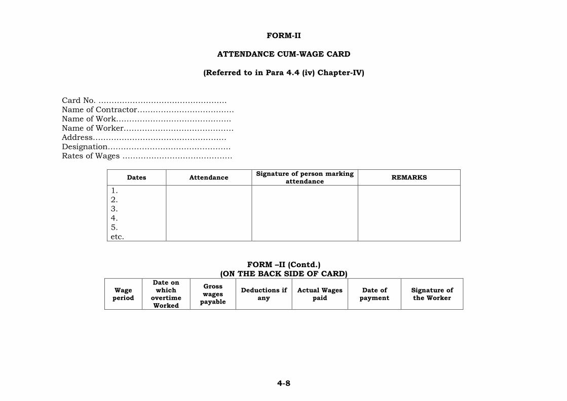
4-8
FORM-II
ATTENDANCE CUM-WAGE CARD
(Referred to in Para 4.4 (iv) Chapter-IV)
Card No. …………………………………………. Name of Contractor………………………………. Name of Work…………………………………….. Name of Worker…………………………………… Address…………………………………………… Designation……………………………………….. Rates of Wages ……………………………………
Dates Attendance Signature of person marking
attendance REMARKS
1. 2. 3. 4. 5. etc.
FORM –II (Contd.) (ON THE BACK SIDE OF CARD)
Wage period
Date on which overtime Worked
Gross
wages payable
Deductions if any
Actual Wages paid
Date of payment
Signature of the Worker
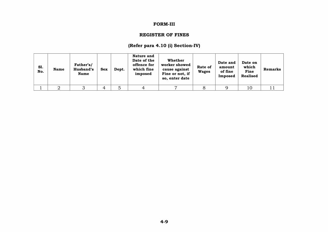
4-9
FORM-III
REGISTER OF FINES
(Refer para 4.10 (i) Section-IV)
Sl. No.
Name
Father’s/
Husband’s Name
Sex Dept.
Nature and Date of the offence for
which fine imposed
Whether worker showed
cause against Fine or not, if
so, enter date
Rate of Wages
Date and amount of fine
Imposed
Date on which Fine
Realised
Remarks
1 2 3 4 5 4 7 8 9 10 11

4-10
FORM-IV
REGISTER OF DEDUCTIONS FOR DAMAGES OR LOSS
(Refer para 4.10 (i) Section-IV)
Sl. No.
Name
Father’s/
Husband’s Name
Sex Dept.
Damage or loss caused
with date
Whether
worker showed cause against deduction, if
so, enter date
Date and amount of deduction
imposed
Number of
installmen, if any
Date on which
total amount Realised
Remarks
1 2 3 4 5 4 7 8 9 10 11

5(i)
SSEECCTTIIOONN--55
SSAAFFEETTYY PPRREECCAAUUTTIIOONNSS
CCOONNTTEENNTTSS
CLAUSE TITLE PAGE NO. 5.1 to 5.26 SAFETY PRECAUTIONS………………………………..……1 TO 9
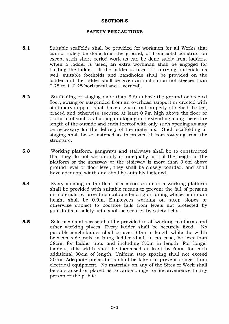
5-1
SECTION-5
SAFETY PRECAUTIONS 5.1 Suitable scaffolds shall be provided for workmen for all Works that
cannot safely be done from the ground, or from solid construction except such short period work as can be done safely from ladders. When a ladder is used, an extra workman shall be engaged for holding the ladder. If the ladder is used for carrying materials as well, suitable footholds and handholds shall be provided on the ladder and the ladder shall be given an inclination not steeper than 0.25 to 1 (0.25 horizontal and 1 vertical).
5.2 Scaffolding or staging more than 3.6m above the ground or erected
floor, swung or suspended from an overhead support or erected with stationary support shall have a guard rail properly attached, bolted, braced and otherwise secured at least 0.9m high above the floor or platform of such scaffolding or staging and extending along the entire length of the outside and ends thereof with only such opening as may be necessary for the delivery of the materials. Such scaffolding or staging shall be so fastened as to prevent it from swaying from the structure.
5.3 Working platform, gangways and stairways shall be so constructed
that they do not sag unduly or unequally, and if the height of the platform or the gangway or the stairway is more than 3.6m above ground level or floor level, they shall be closely boarded, and shall have adequate width and shall be suitably fastened.
5.4 Every opening in the floor of a structure or in a working platform
shall be provided with suitable means to prevent the fall of persons or materials by providing suitable fencing or railing whose minimum height shall be 0.9m. Employees working on steep slopes or otherwise subject to possible falls from levels not protected by guardrails or safety nets, shall be secured by safety belts.
5.5 Safe means of access shall be provided to all working platforms and
other working places. Every ladder shall be securely fixed. No portable single ladder shall be over 9.0m in length while the width between side rails in hung ladder shall, in no case, be less than 28cm, for ladder upto and including 3.0m in length. For longer ladders, this width shall be increased at least by 6mm for each additional 30cm of length. Uniform step spacing shall not exceed 30cm. Adequate precautions shall be taken to prevent danger from electrical equipment. No materials on any of the Sites of Work shall be so stacked or placed as to cause danger or inconvenience to any person or the public.
5-2
5.6 EXCAVATION AND TRENCHING
All trenches, 1.2m or more in depth, shall, at all times, be supplied with at least one ladder for each 30m length or fraction thereof. Ladder shall be extended form bottom of the trench to at least 0.9m above the surface of the ground. The side of the trenches, which are 1.5m or more in depth shall be stepped back to give suitable slope or securely held by timber bracing, so as to avoid the danger of sides to collapse. The excavated materials shall not be placed within 1.5m of the edges of the trench or half of the depth by the trench, whichever is more. Cutting shall be done from top to bottom. Under no circumstances undermining or undercutting shall be done.
5.7 DEMOLITION
Before any demolition work is commenced and also during the process of the work: i) All roads and open areas adjacent to the site shall either be
closed or suitably protected.
ii) No electric cable or apparatus, which is liable to be a source of danger over a cable or apparatus used by the operator, shall remain electrically charged.
iii) All practical steps shall be taken to prevent danger to persons employed from risk of fire or explosion or flooding. No floor, roof or other part of the structure shall be overloaded with debris or materials as to render it unsafe.
5.8 All necessary personal safety equipment as considered adequate by the Engineer-in-Charge shall be kept available for the use of the persons employed on the Site and maintained in condition suitable for immediate use, and the Contractor shall take adequate steps to ensure proper use of equipment by those concerned.
i) The Contractor shall provide rubber gauntlets, gloves, mats,
boots and galoshes, insulated platform and stools, safety belts, hand lamps, tower wagons and other special insulated devices as required for working on electrical equipment and apparatus.
ii) Workers employed on mixing asphaltic materials, cement mortar and cement concrete shall be provided with protective footwear and protective goggles.
iii) Those engaged in mixing or stacking of cement bags or any materials, which is injurious to eyes, shall be provided with protective goggles.
iv) Those engaged in welding Works shall be provided with welder’s protective eye shields.
v) Stonebreakers shall be provided with protective goggles and protective clothing and seated at sufficiently safe intervals.
vi) The Contractor shall not employ any person below the age of 18 years. Whenever a person above the age of 18 years is
5-3
employed on the work of lead painting, the following precautions shall be taken:
a) No paint containing lead, sulphate of lead or product containing their pigments shall be used except in the form of paste or readymade paint.
b) Suitable face masks shall be supplied for use by the workers when paint is applied in the form of spray or a surface having lead paint dry rubbed and scrapped.
c) Overalls shall be supplied by the Contractor to the workmen and adequate facilities shall be provided to enable the working painters to wash during the cessation of Work.
d) Measures shall be taken, whenever required, in order to prevent danger arising from the application of a paint in the form of spray.
e) Measures shall be taken, whenever practicable, to prevent danger arising out from dust caused by dry rubbing down and scrapping.
f) Suitable arrangements shall be made to prevent clothing put off during working hours, being spoiled by painting materials.
g) Cases of lead poisoning and suspected lead poisoning shall be notified and shall be subsequently verified by a medical officer appointed by the competent authority of the Project.
h) The Project Authority, when necessary, shall arrange for medical examination of workers.
i) Instructions with regard to special hygienic precautions to be taken in the painting trade shall be distributed to working painters.
vii) The Contractor shall observe all safety precautions to control
the noise on all Sites and also provide all workmen deployed in the affected areas with the necessary equipment for safety against noise.
5.9 When the Work is done near any place where there is risk of
drowning, all necessary equipment shall be provided and kept ready for use and all necessary steps taken for prompt rescue of any person in danger and adequate provision shall be made for prompt first aid treatment of all injuries likely to be sustained during the course of the Work.
5.10 Use of hoisting machines and shackle including their attachments,
anchorage and supports shall conform to the following standards or conditions:

5-4
i) These shall be of good mechanical construction, sound
materials and adequate strength and free from patent defect and shall be kept in good working order.
ii) Every rope used in hoisting or lowering materials or as a means of suspension shall be of durable quality and adequate strength and free from patent defects.
iii) Every crane driver or hoisting appliance operator shall be properly qualified for his job.
iv) In case of every hoisting machine and of every chain ring hook, shackle swivel and pulley block used in hoisting or as means of suspension, the safe working load shall be ascertained by adequate means. Every hoisting machine and all gears referred to above shall be plainly marked with the safe working load.
In case of hoisting machine having a variable safe working load, each safe working load and the conditions under which it is applicable shall be clearly indicated. No part of any machine or any gear referred to above in this paragraph shall be loaded beyond the safe working load except for the purpose of testing. The capacity of the hoisting machines shall be periodically checked.
v) The Contractor shall notify the safe working load of the machines to the Engineer-in-Charge, whenever he brings any machinery to Site of work and gets it verified by the Engineer-in-Charge or his representative.
5.11 Motors, gearing, transmission, electric wiring and other dangerous
parts of hoisting appliances shall be provided with efficient safeguards.
Hoisting appliances shall be provided with such means as shall reduce to the minimum, the risk of any part of a suspended load becoming accidentally displaced. When workmen are employed on or near electrical installations, which are already energized, insulating mats, wearing apparel, such as gloves, sleeves and boot, as may be necessary, shall be provided. The workers shall not wear any rings, watches and carry keys or other materials, which are good conductors of electricity.
5.12 All scaffolds, ladders and other safety devices mentioned or
described herein shall be maintained in safe conditions and no scaffold, ladder or equipment shall be altered or removed, while it is in use. Adequate washing facilities shall be provided at or near places of Work.
5.13 These safety provisions shall be brought to the notice of all
concerned by display on a notice board at a prominent place on the Site. The person responsible for compliance of the safety code shall be named therein by the Contractor.

5-5
5.14 To ensure effective enforcement of the rules and regulations relating
to safety precautions, the arrangements made by Contractor shall be open to inspection by the Labour officer or the Engineer-in-Charge.
5.15 In addition to above, the Contractor shall take the following specific
precautions for the Underground Works.
i) All precautions regarding safety of personnel working in tunnels/caverns/shafts, in connection with the handling of electrical installations, loading, blasting and seepage water etc. as specified in the relevant stipulations of IS codes shall be taken by the Contractor in order to ensure safe underground working. He shall also provide adequate medical, drinking water, sanitation, lighting and ventilation facilities.
ii) Emergency material shall be provided at each underground excavation heading
This equipment shall include, but not be limited to the following: - 3 stretchers
- 3 woolen blankets
- 2 appliances for artificial breathing
- 1 oxygen flask
- 3 explosion-proof lamps
- wound dressing and disinfection material
- anti-pain injections
- gas masks
iii) At least two members of the Rescue Team as described hereinafter, properly instructed and trained in the rescue procedures, shall be in each crew working underground.
iv) Prior to the commencement of construction, the Contractor shall organize and train a Rescue Team composed of his employees. This Rescue Team shall be capable to render help after accidents caused by fire, gas explosion and avalanche etc.
v) The Rescue Team shall be organized in such a way that sufficient numbers of members are ready for action at any time until the Completion of Work.
vi) The Rescue Team members shall be instructed and trained for their task by a qualified and experience person. If required, the Contractor shall hire an outside specialist to perform such training. A refresher training for all members of the Rescue Team shall be conducted at least once in every six months.
5-6
vii) Each Rescue Team member shall be skilled in giving the first aid, dealing with the appliances for artificial respiration and fire fighting equipment and shall possess a good local knowledge. Adequate equipment for reaching even the remotest working area shall be at their disposal.
viii) The Contractor shall submit the details of the proposed Rescue Team organization to the Engineer-in-Charge for approval.
5.16 The Contractor shall at all times exercise reasonable and proper precautions for the safety of the people on the Works and shall comply with the provisions of current safety law and building and construction codes as may be applicable. All machinery and equipment and other sources of physical hazards shall be properly guarded. The Contractor shall have a full time staff exclusively in charge of securing the safety of the Work ensuring that all safety regulations are followed and in charge of indoctrination and teaching course on safety to the work force.
5.17 The Contractor shall provided all necessary fencing and lights to
protect the public from accidents and shall be bound to bear all the expenses of defence of every suit, action and other proceedings at Law that may be brought by any person for injury sustained owing to neglect of the above precautions and to pay any damages and costs which may be awarded in any such suit, action and proceedings to any such persons or which may, with the consent of the Contractor be paid to compromise any claim by any person.
5.18 About his employees, the Contractor shall ensure as follows:
i) Each employee shall be provided initial indoctrination regarding safety by the Contractor so as to enable him to conduct his Work in a safe manner.
ii) No employee shall be given a new assignment of work unfamiliar to him without proper introduction as to the hazardous incident thereto, both to himself and his fellow employees.
iii) Under no circumstances shall an employee hurry or take unnecessary chances when working under hazardous conditions.
iv) Employees shall not leave naked fires unattended. Adequate fire fighting equipment shall be provided at crucial locations.
v) Employees under the influence of any intoxicating beverage, even to the slightest degree, shall not be permitted to remain on Work.
vi) There shall be suitable arrangement on every site for rendering prompt and sufficient first aid to the injured under the guidance of the Medical Officer.

5-7
vii) The staircases and passageways shall be adequately lighted.
viii) The employees, when working around moving machinery, shall not be permitted to wear loose garments. Safety shoes are recommended when working in shops or places where materials or tools are likely to fall. Only experienced workers shall be permitted to go behind guardrails or to clean around energized or moving equipment.
ix) The employees shall use the standard protection equipment intended before and after it is used.
5.19 The following precautions shall be taken for fire prevention:
i) All construction areas and storage yards shall be kept clean and well arranged.
ii) A clear space of 15m around the outer boundary of sawmill and lumber storage area may be provided. All lumber shall be stored in sections with firebreaks with a distance of 15m between consecutive sections.
iii) All combustible waste material, wood scalings and soiled rags etc shall be removed daily and burnt in suitable burning area. The sawmill and lumberyard shall be kept free from accumulation of combustible debris.
iv) Fires, welding, flame cutting shall in general not be permitted in combustible area. Fires and open flame devices shall not be left unattended.
v) Smoking shall be prohibited in all fire prone areas, flammable material storages viz. Carpentry, paint shops, garages, service stations etc. “No Smoking” signs shall be pasted on all such areas.
vi) Accumulations of flammable liquids on floors, walkways etc. should be prohibited. All spills of flammable liquids shall be cleaned up immediately.
vii) Smoke pipes from Diesel Engines passing through roof of combustible material e.g. in compressor stations on various Sites shall be insulated by asbestos. All joints of smoke pipe shall be riveted, welded or otherwise securely fastened together and supported to prevent accidental displacement or separation. The joints shall not be leaky.
viii) Flammable liquids, lubricants etc. shall be handled and transported in safe containers and drums, which can be kept tightly capped.
ix) Storage of fuels and other flammable materials and liquids shall be set not less than 100m away from the Works and permanent installations. All storage installations and tanks

5-8
shall conform to the regulations set out in relevant Indian Standards.
x) Petrol or other flammable liquids with a flash point below 100ºC shall not be used for cleaning purpose.
xi) Oxygen cylinders shall not be stored with combustible materials.
xii) All electric installation shall be properly earthen. Repairs shall not be made on electrical circuits until the circuit has been de-energized.
5.20 THE FOLLOWING FIRE FIGHTING ARRANGEMENTS SHALL BE MADE BY THE CONTRACTOR:
i) Fire extinguishers and fire buckets filled with clean dry sand,
painted red, shall be provided at all fire hazardous locations viz. Bathing and Mixing Plant, Winch houses, Workshops, store yards, Sawmill, Switchgear Room, Compressor Stations, Office establishments etc. The extinguishers shall be inspected, serviced and maintained in accordance with manufacturer’s instructions. The inspection shall be evidenced by notations on tag, attached to the extinguisher.
ii) Full reliance shall never be placed on portable hand extinguishers as all of these have a very limited capacity. Water, in ample quantity and under adequate pressure, shall always be available for fire fighting.
iii) Where a group of work points are located beyond the range of protection from a public water supply, the installation of a water system for private fire protection shall be warranted.
iv) Evacuation facilities and fire exit shall be provided at all locations featuring fire hazards.
v) Siren or other suitable fire alarm arrangement shall be made on all Sites. Warning signs shall be pasted at all locations having fire hazards.
vi) All staff shall be conversant with the use of all type of fire extinguishing apparatus.
vii) In the event of fire on electrical mains or apparatus, the effected part shall immediately be completely isolated from its source of supply of electrical energy.
viii) Demonstrations and training in fire fighting shall be conducted at sufficient intervals to ensure that sufficient personnel are familiar with and are capable of operating fire fighting equipment.

5-9
5.21 When any work is carried on, which is likely to affect the security or stability of an installation or structure or any part thereof and endanger any person employed, all practicable precautions shall be taken by shoring or otherwise to prevent collapse of structure or fall of any part thereof and thus remove the cause of danger to such structures and the persons employed.
5.22 For persons engaged in handling of corrosive materials, adequate
equipment shall be provided. 5.23 Where, in connection with any grinding, cleaning, spraying or
manipulation of any material, there is emission of dust or fume of such character and to such extent as is likely to be injurious to the health of persons employed, all practical measures shall be taken by securing adequate ventilation or by the provision and use of suitable respirators or otherwise to prevent inhalation of such dust and fume.
5.24 The Contractor shall strictly follow the safety procedures & practices
as mentioned in Indian Standard IS5216-1982 “Guide for Safety Procedure & Practices in Electrical Work” during the execution of this Contract. In this regard the Indian Electricity Rules, 1956/Nepal Electricity Supply Rules shall also be applicable to the Contractor to fulfill the safety precaution for workmen and Plant.
5.25 In addition to instructions contained here-in-above the safety
regulations contained in the following IS Codes shall also apply wherever the provisions in the codes are exhaustive in nature: 1 IS: 4556-1958 (Reaffirmed
1991) Safety Code for Tunneling Work
2 IS: 3696-1985 (Part-I) (Reaffirmed 1991)
Safety Code of Scaffolds & Ladders (Pt. I Scaffolds)
3 IS: 3696-1991 (Part-II) Safety Code of Scaffolds & Ladders (Pt. II Ladders)
4 IS: 3016-1982 (Reaffirmed 1990)
Fire precaution in welding and cutting operations
5 IS: 5216-1982 Part 1 & 2 (Reaffirmed 1990)
Guide for Safety procedures and Practices in Electrical work Part 1 – General Part-2 – Life saving techniques
5.26 Notwithstanding the above provisions, the Engineer-in-Charge may
require the Contractor to follow any other Act or Rules in force in India/Nepal in respect of Safety Precautions so as to ensure the safety of the Workmen and the Plant and the Contractor shall promptly comply with such requirements.

A- 1
ANNEXURE -I
PROFORMA OF BID (FOR TECHNICAL BID) (Refer Clause 1.12, Section-1)
Tender : Strengthening the India-Nepal Power Transmission Interconnection Project
Tender Notice
No.
:
From :
To : Director(DPA),Ministry of External Affairs,
Room No. 3121,B Block,
Jawaharlal Nehru Bhawan,
23-D,Janpath,New Delhi-110011
Sub: Bid for Additional 132 kV feeder bay each at Raxaul , Kataiya, Kusaha & Parwanipur Substations.
(Description of works)
Dear Sir,
With reference to Bidding Documents forwarded to us under your letter
no. ______ dated __________, we, the undersigned, having examined the
Bidding Documents including corrigenda/addenda for the execution of
the above named Work, offer to execute and complete the whole of the
Works in conformity with the said Bidding Documents.
We are enclosing herewith the Bid Security amounting to __________ (in
words and in figures) in the form of _______ as prescribed in Clause 1.16
of the “Information & Instructions”.
We confirm that our Bid shall remain valid for one hundred eighty (180)
calendar days and the Bid Security shall remain valid for a period of two
hundred and ten (210) calendar days from the date of opening of
Techno-Commercial Bid.
We undertake, if our bid is accepted, to commence and to complete the
whole of the works comprised in the contract within the time specified by
MEA in the Bidding Documents.
We further confirm that in the event the Bid is accepted, we shall furnish
performance security in accordance with Cl. 1.35 of the “Information &
Instructions” towards successful performance of the contract and shall
execute the Contract Agreement in accordance with clause 1.36 of the
“Information & Instructions”.

A- 2
Unless and until a formal Contract Agreement is executed, this Bid,
subsequent correspondences together with the Letter of Award of MEA
shall constitute a binding Contract between MEA and us.
We understand that MEA is at liberty not to accept the lowest Bid Price.
We also understand that MEA is at liberty not to accept any or all Bids
and MEA is at liberty to negotiate with Bidder(s) at any stage.
Dated this day of 20 .
(Signature and Full Name)
Title (affix seal here) Firm's address:
Telephone: Telex:
Cable Address: Fax:
Witness
(Signature and Full Name)

A- 3
ANNEXURE-IA PROFORMA OF BID (FOR PRICE BID)
(Refer Clause 1.12, Section-1)
Tender : Strengthening the India-Nepal Power Transmission Interconnection Project.
Tender Notice
No.
:
From :
To : Director(DPA),Ministry of External Affairs,
Room No. 3121,B Block,
Jawaharlal Nehru Bhawan,
23-D,Janpath,New Delhi-110011
Sub: Bid for Additional 132kV feeder bay each at Raxaul , Kataiya,
Kusaha & Parwanipur Substations.
(Description of works)
Dear Sir,
With reference to Bidding Documents forwarded to us under your
letter no. ______ dated __________, we, the undersigned, having examined
the Bidding Documents including corrigenda/addenda for the execution
of the above named Work, offer to execute and complete the whole of the
Works in conformity with the said Bidding Documents for the sum of
____________(in words & figure).
We are enclosing herewith the Bid Security amounting to __________ (in
words and in figures) in the form of _______ as prescribed in Clause 1.16
of the “Information & Instructions”.
We confirm that our Bid shall remain valid for one hundred eighty (180)
calendar days and the Bid Security shall remain valid for a period of two
hundred and ten (210) calendar days from the date of opening of
Techno-Commercial Bid.
We undertake, if our bid is accepted, to commence and to complete the
whole of the works comprised in the contract within the time specified by
MEA in the Bidding Documents.
We further confirm that in the event the Bid is accepted, we shall furnish
performance security in accordance with Cl. 1.35 of the “Information &
Instructions” towards successful performance of the contract and shall
execute the Contract Agreement in accordance with clause 1.36 of the
“Information & Instructions”.
A- 4
Unless and until a formal Contract Agreement is executed, this Bid,
subsequent correspondences together with the Letter of Award of MEA
shall constitute a binding Contract between MEA and us.
We understand that MEA is at liberty not to accept the lowest Bid Price.
We also understand that MEA is at liberty not to accept any or all Bids
and MEA is at liberty to negotiate with Bidder(s) at any stage.
Dated this day of 20 .
(Signature and Full Name)
Title -------------(affix seal here) Firm's address:
Telephone: Telex:
Cable Address: Fax:
Witness
(Signature and Full Name)

A- 5
Annexure-II
PROFORMA FOR BANK GUARANTEE FOR BID SECURITY (Refer Clause 1.12 Section-1)
To
Director(DPA),Ministry of External Affairs,
Room No. 3121, B Block,
Jawaharlal Nehru Bhawan,
23-D, Janpath, New Delhi-110011
WHEREAS, (Name of the Bidder)_________________ (hereinafter called “the
BIDDER”) has submitted his bid dated __________________for (Name of
Contract) ____________________(hereinafter called "the Bid").
KNOW ALL men by these presents we (Name of Bank)______________ of (Name
of Country) _________________ having our registered office at
____________(hereinafter called “the Bank”) are bound unto the Ministry of
External Affairs (MEA) in the sum of ______________ for which payment well
and truly to be made to the MEA, the Bank binds himself, his successors and
assigns by these presents.
SEALED with the Common Seal of the said Bank this ____________ day of
____________20_____
THE CONDITIONS of this obligation are;
i) If the Bidder withdraws his Bid during the period of bid validity specified
in the Proforma of Bid; or
ii) If the Bidder having been notified of the acceptance of his Bid by the
MEA during the period of bid validity;
a) fails or refuses to execute the Proforma of Agreement in
accordance with the Instructions to Bidders, if required; or
b) fails or refuses to furnish the Performance Security, in accordance
with the Instructions to Bidders.
We undertake to pay to the MEA upto the above amount upon receipt of
its first written demand, provided that in its demand the MEA will note that
amount claimed by it is due to it owing to the occurrence of one or both
conditions, specifying the occurred condition or conditions.
This Guarantee will remain in force upto and including the date 210
days after the closing date of submission of bids as stated in the Information
and Instructions and any demand in respect thereof should reach the Bank

A- 6
not later than the above date.
DATE……………. SIGNATURE OF THE BANK……. WITNESS……….. SEAL…………….
(Signature, Name and Address)
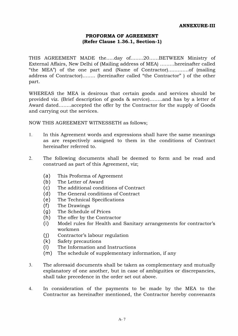
A- 7
ANNEXURE-III
PROFORMA OF AGREEMENT (Refer Clause 1.36.1, Section-1)
THIS AGREEMENT MADE the…..day of……..20……BETWEEN Ministry of
External Affairs, New Delhi of (Mailing address of MEA) ………hereinafter called
“the MEA”) of the one part and (Name of Contractor)………….of (mailing
address of Contractor)…….. (hereinafter called “the Contractor” ) of the other
part.
WHEREAS the MEA is desirous that certain goods and services should be
provided viz. (Brief description of goods & service)……..and has by a letter of
Award dated……..accepted the offer by the Contractor for the supply of Goods
and carrying out the services.
NOW THIS AGREEMENT WITNESSETH as follows;
1. In this Agreement words and expressions shall have the same meanings
as are respectively assigned to them in the conditions of Contract
hereinafter referred to.
2. The following documents shall be deemed to form and be read and
construed as part of this Agreement, viz;
(a) This Proforma of Agreement
(b) The Letter of Award
(c) The additional conditions of Contract
(d) The General conditions of Contract
(e) The Technical Specifications
(f) The Drawings
(g) The Schedule of Prices
(h) The offer by the Contractor
(i) Model rules for Health and Sanitary arrangements for contractor’s
workmen
(j) Contractor’s labour regulation
(k) Safety precautions
(l) The Information and Instructions
(m) The schedule of supplementary information, if any
3. The aforesaid documents shall be taken as complementary and mutually
explanatory of one another, but in case of ambiguities or discrepancies,
shall take precedence in the order set out above.
4. In consideration of the payments to be made by the MEA to the
Contractor as hereinafter mentioned, the Contractor hereby convenants

A- 8
with the MEA to provide goods and services and remedy defects therein
in conformity, in all respects, with the provisions of the Contract.
5. The MEA hereby covenants to pay the Contractor, in consideration of the
provisions of goods and services and remedying defects therein and
completion of the Works, the Contract Price at the times and in the
manner prescribed by the Contract.
In WITNESS whereof the parties hereto have caused their respective common
seals to be hereunto affixed (or have hereunto set their respective hands and
seals) the day and year first above written.
SIGNED, SEALED AND DELIVERED
By the said By the said
…………… …………
NAME ………… NAME …………..
On behalf of the Contractor On behalf of the MEA
In the presence of : in the presence of :
………………………. ………………………..
NAME ……………… NAME ………………..
Address……………. Address………………
………………………. …………………………

A- 9
ANNEXURE-IV
PROFORMA FOR BANK GUARANTEE FOR PERFORMANCE SECURITY
(Refer Clause 1.35, Section-1)
To
Director(DPA),
Ministry of External Affairs,
Room No. 3121,B Block,
Jawaharlal Nehru Bhawan,
23-D,Janpath,New Delhi-110011 WHEREAS (Name and Address of Contractor) …………..(hereinafter called “the Contractor”) has undertaken, in pursuance of Contract No. … dated ………..to execute (Name of Contract and Brief Description of Works)………….(hereinafter called “the Contract”).
AND WHEREAS it has been stipulated by you in the said Contract that the
Contractor shall furnish you with a Bank Guarantee by a recognized bank for
the sum specified therein as security for compliance with his obligations in
accordance with the Contract;
AND WHEREAS we have agreed to give the Contractor such a Bank Guarantee;
NOW THEREFORE we hereby affirm that we are the Guarantor and
responsible to you, on behalf of the Contractor, upto a total of
…............(Amount of Guarantee) in words and figure……..to be inserted by the
Guarantor, representing the percentage of the Contract Price, specified in the
Contract, and we undertake to pay you, upon your first written demand and
without cavil or argument, any sum or sums within the limits of
……..........[Amount of Guarantee] as aforesaid without your needing to prove
or to show grounds or reason for your demand for the sum specified therein.
We hereby waive the necessity of your demanding the said debt from the
Contractor before presenting us with the demand.
We further agree that no change or addition to or other modification of the
terms of the Contract or of the Works to be performed thereunder or of any of
the Contract documents which may be made between you and the Contractor
shall in any way release us from any liability under this guarantee, and we
hereby waive notice of any such change, addition or modification.
This guarantee is valid until the date 30 days after issue of the last Defects
Liability Certificate (Specify date).
SIGNATURE AND SEAL OF THE GUARANTOR
Name of Bank
Address Date

A- 10
ANNEXURE-V
PROFORMA FOR BANK GUARANTEE FOR ADVANCE PAYMENT
(ON A NON-JUDICIAL STAMP PAPER OF THE REQUISITE VALUE) (Refer Clause 33(i), Section-2)
1. In consideration of the President of India, The ministry of External
Affairs (MEA) (which expression shall unless repugnant to the subject or
context include its administrators, successors and assigns), (hereinafter
called the Principal) having agreed to make advance payment to (Name
and full address of the Contractor)….(hereinafter called “the
Contractor(s)”), (Which expression shall unless repugnant to the subject
or context or meaning thereof include its successors, administrators,
executors and permitted assigns), whose bid for (Name of the
Contract)……has been accepted and to whom the acceptance of the bid
has been communicated by a Letter of Award and who is required to
execute a formal agreement on conditions of productions of a Bank
Guarantee for (amount both in figures and words)……….
We, the,………… (State Bank of India or any scheduled Bank of India or
foreign bank licensed to do business in India by Reserve Bank of India
(hereinafter referred to as “the Bank”) do hereby undertake promise and
guarantee payment to the Principal on demand all the amount advanced
by the Principal to the said Contractor.
2. The Bank Further agrees that:
(i) The Principal shall have the fullest liberty without affecting in any
way the liability of the Bank under the Guarantee or Indemnity,
from time to time, to vary any of the terms and conditions of the
said Contract or to extend time for performance by the said
Contractor or to postpone for any time and from time to time any
of the powers exercisable by it against the said Contractor and
either to enforce or forbear from enforcing any of the terms and
conditions governing the said Contract or the securities available
to the Principal and the Bank shall not be released from its
liability under these presents by any exercise by the Principal of
the Liberty with reference to the matters aforesaid or by reason of
time being given to the said Contractor or any other forbearance,
act or omission on the part of the Principal or any indulgence by
the Principal to the said Contractor or of any other matter or thing
whatsoever which under the law relating to sureties would but for
this provision have the effect of a releasing the Bank from its such
liability.
(ii) These presents shall be governed by and construed in accordance
with Indian laws.

A- 11
(iii) The Bank hereby declares that it has the power to issue this
Guarantee and the undersigned has full power to do so.
(iv) The amount of Bank Guarantee shall be reduced at every six
months interval to the extent of the amount of advance adjusted.
(v) It shall not be necessary for the Principal to proceed against the
Contractor before proceeding against the Bank and the Bank
Guarantee herein contained shall be enforceable against the Bank,
notwithstanding any other security which the Principal may have
obtained or obtain from the Contractor, shall at the time when
proceedings are taken against the Bank hereunder, be outstanding
or unrealized.
(vi) The Guarantee herein contained shall remain in full force and
effect, during the period that would be taken for the performance
of the terms and conditions of the said Contract, Letter of Award
and the Agreement which is to be executed as aforesaid and that it
shall continue to be enforceable until the completion of delivery of
goods at site.
3. The Bank lastly undertakes not to revoke this Guarantee until ……….
Dated the ………. Day of …….20….. Here affix the Common Seal of the Bank

A- 12
Annexure-VI
PROFORMA FOR REQUIREMENT OF POWER LOAD
(Refer Clause 3.4 (i), Section-3)
Sl. No.
Location/Purpose
Load Requirement in KW
Expected Time Schedule
Remarks
Total
Signature of authorized person
with seal
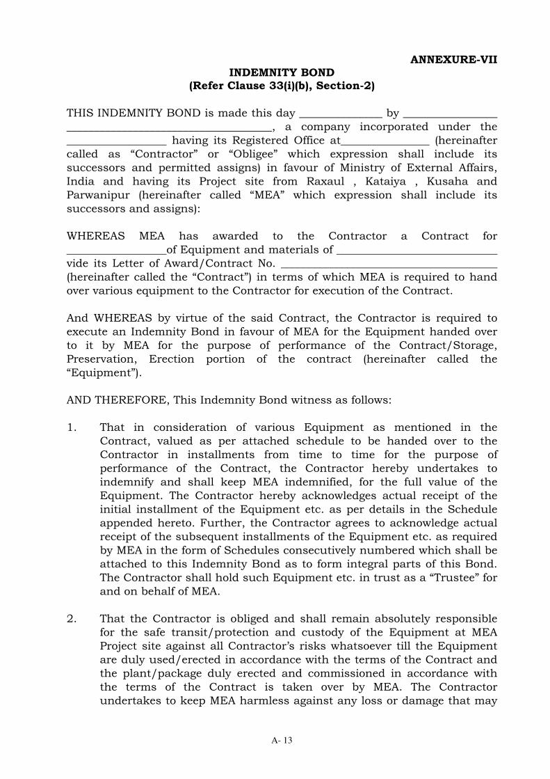
A- 13
ANNEXURE-VII INDEMNITY BOND
(Refer Clause 33(i)(b), Section-2)
THIS INDEMNITY BOND is made this day _______________ by _________________
_____________________________________, a company incorporated under the
__________________ having its Registered Office at________________ (hereinafter
called as “Contractor” or “Obligee” which expression shall include its
successors and permitted assigns) in favour of Ministry of External Affairs,
India and having its Project site from Raxaul , Kataiya , Kusaha and
Parwanipur (hereinafter called “MEA” which expression shall include its
successors and assigns):
WHEREAS MEA has awarded to the Contractor a Contract for
__________________of Equipment and materials of _____________________________
vide its Letter of Award/Contract No. _______________________________________
(hereinafter called the “Contract”) in terms of which MEA is required to hand
over various equipment to the Contractor for execution of the Contract.
And WHEREAS by virtue of the said Contract, the Contractor is required to
execute an Indemnity Bond in favour of MEA for the Equipment handed over
to it by MEA for the purpose of performance of the Contract/Storage,
Preservation, Erection portion of the contract (hereinafter called the
“Equipment”).
AND THEREFORE, This Indemnity Bond witness as follows:
1. That in consideration of various Equipment as mentioned in the
Contract, valued as per attached schedule to be handed over to the
Contractor in installments from time to time for the purpose of
performance of the Contract, the Contractor hereby undertakes to
indemnify and shall keep MEA indemnified, for the full value of the
Equipment. The Contractor hereby acknowledges actual receipt of the
initial installment of the Equipment etc. as per details in the Schedule
appended hereto. Further, the Contractor agrees to acknowledge actual
receipt of the subsequent installments of the Equipment etc. as required
by MEA in the form of Schedules consecutively numbered which shall be
attached to this Indemnity Bond as to form integral parts of this Bond.
The Contractor shall hold such Equipment etc. in trust as a “Trustee” for
and on behalf of MEA.
2. That the Contractor is obliged and shall remain absolutely responsible
for the safe transit/protection and custody of the Equipment at MEA
Project site against all Contractor’s risks whatsoever till the Equipment
are duly used/erected in accordance with the terms of the Contract and
the plant/package duly erected and commissioned in accordance with
the terms of the Contract is taken over by MEA. The Contractor
undertakes to keep MEA harmless against any loss or damage that may

A- 14
be caused to the Equipment.
3. The Contractor undertakes that the Equipment shall be used exclusively
for the performance/execution of the Contract strictly in accordance
with its terms and conditions and no part of the equipment shall be
utilized for any other work or purpose whatsoever. It is clearly
understood by the Contractor that non-observance of the obligations
under this Indemnity Bond by the Contractor shall inter-alia constitute a
criminal breach of trust on the part of the Contractor for all intents and
purpose including legal/penal consequences.
4. That MEA is and shall remain the exclusive Owner of the Equipment free
from all encumbrances, charges or liens of any kind, whatsoever. The
Equipment shall at all times be open to inspection and checking by
Engineer-in-Charge/his representative or any other employees of MEA
authorized by him in this regard. Further, MEA shall always be free at
all times to take possession of the Equipment in whatever form the
Equipment may be, if in its opinion, the Equipment are likely to be
endangered, misutilised or converted to use other than those specified in
the Contract, by any acts of omission or commission on the part of the
Contractor or any other person or on account of any reason whatsoever
and the Contractor binds himself and undertakes to comply with the
directions or demand of MEA to return the Equipment without any
demur or reservations.
5. That this Indemnity Bond is irrevocable. If at any times any loss or
damage occurs to the Equipment or the same or any part thereof if
misutilised in any manner whatsoever, then the Contractor hereby
agrees that the decision of the Engineer-in-Charge/his representative as
to assessment of loss or damage to the Equipment shall be final and
binding on the Contractor. The Contractor binds itself and undertakes to
replace the lost and/or damaged Equipment at its own cost and/or shall
pay the amount of loss to MEA without any demur, reservation or
protest. This is without prejudice to any other right or remedy that may
be available to MEA against the Contractor under the Contract and
under this Indemnity Bond.
6. That any loss or damage as stipulated in Clause-40, Section-II, Volume-I
of Bid document of the equipment and the material during transit,
storage, handling, erection, testing, commissioning & operation and
maintenance till the end of defects liability period at any stage shall be
Contractor’s responsibility and the replacement of the damaged
equipment shall be entirely at Contractor’s costs irrespective of the
amount and time of receipt of any claim by the Contractor.
And in consideration of the provisions of the Letters of Award/Contract
No. _____________________________________________, the Contractor has
the obligation to insure the equipment until the Defects Liability Period.

A- 15
Therefore, the Indemnity Bond shall apply absolutely irrespective of the
amount and time of receipt of any claim.
7. NOW THE CONDITION of the Bond is that if the Contractor shall duly
and punctually comply with the terms and conditions of this Bond to the
satisfaction of MEA, THEN, the above Bond shall be void, but otherwise,
it shall remain in full force and virtue.
IN WITNESS WHEREOF, the Contractor has hereunto set its hand through
its authorized representative under the common seal of the Company, the
day, month and year first above mentioned.
SCHEDULE NO.
Sl. No. Particulars of the
Equipment handed over Qty. Particulars of Dispatch
title Document ……………
RR/GR/B/L/AWB No. & Date
Value of the Equipment
Nu./Rs.
As per list attached
Total FOB/Ex-works value
Add pro-rata Marine/ inland transportation and Marine/inland insurance.
WITNESS For and on behalf of

A- 16
ANNEXURE-VIII
SCHEDULE OF DEVIATIONS
(Refer Clause 1.11.1(vi), Section-1)
I/we have carefully gone through the technical specifications and general
conditions and I/we satisfied myself/ourselves and hereby confirm that
my/our offer strictly conforms to the requirement of technical
specifications and general conditions except for the deviations which are
given below:
S. No. Description Stipulation in
Tender Document
Deviations Remarks
Signature of authorized person
with seal

GOVERNMENT OF INDIAMINISTRY OF EXTERNAL AFFAIRS
TECHNICAL SPECIFICATIONSOF
132 KV SUBSTATIONSFOR
STRENGTHENING OF INDIA-NEPALPOWER TRANSMISSION
INTERCONNECTION
VOLUME-2
Consultants:WAPCOS LIMITED(A Govt. of India Undertaking)
PLOT NO. 76-CSECTOR-18, INSTITUTIONALAREAGURGAON-122015,HARYANA, INDIAPh.No: 91-124-2349416Fax No: 91-124-2349184E-mail: [email protected]
CENTRAL ELECTRICITYAUTHORITY,SEWA BHAWAN ,R.K.PURAM,NEW DELHI-01
June, 2014
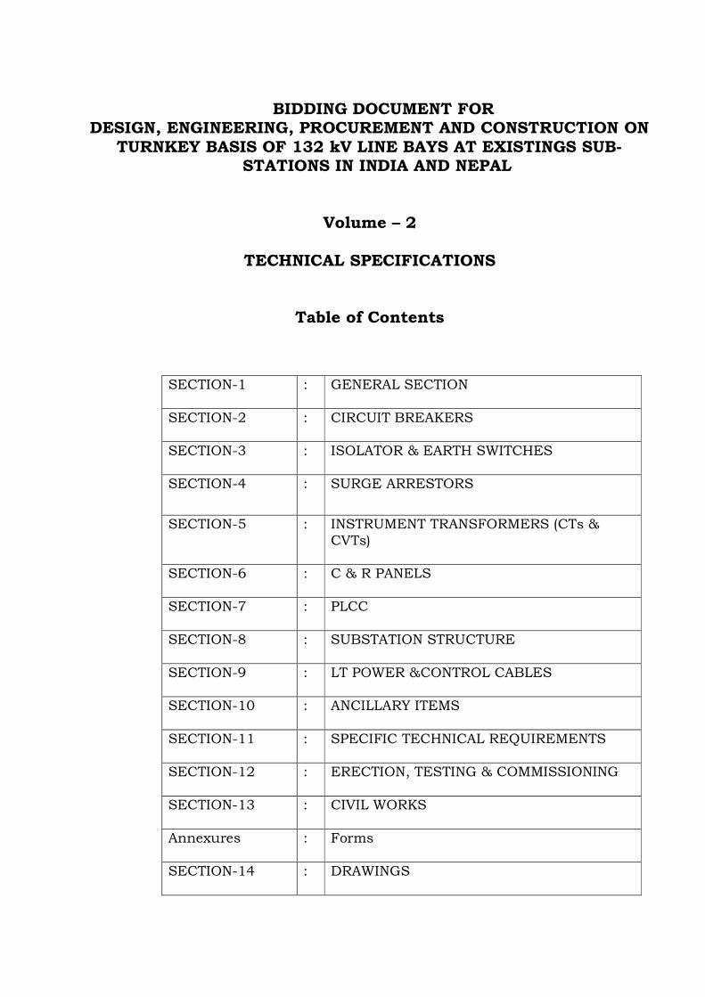
BIDDING DOCUMENT FOR
DESIGN, ENGINEERING, PROCUREMENT AND CONSTRUCTION ON
TURNKEY BASIS OF 132 kV LINE BAYS AT EXISTINGS SUB-
STATIONS IN INDIA AND NEPAL
Volume – 2
TECHNICAL SPECIFICATIONS
Table of Contents
SECTION-1 : GENERAL SECTION
SECTION-2 : CIRCUIT BREAKERS
SECTION-3 : ISOLATOR & EARTH SWITCHES
SECTION-4 : SURGE ARRESTORS
SECTION-5 : INSTRUMENT TRANSFORMERS (CTs &
CVTs)
SECTION-6 : C & R PANELS
SECTION-7 : PLCC
SECTION-8 : SUBSTATION STRUCTURE
SECTION-9 : LT POWER &CONTROL CABLES
SECTION-10 : ANCILLARY ITEMS
SECTION-11 : SPECIFIC TECHNICAL REQUIREMENTS
SECTION-12 : ERECTION, TESTING & COMMISSIONING
SECTION-13 : CIVIL WORKS
Annexures : Forms
SECTION-14 : DRAWINGS

Page 1 of 13
SECTION – 1
GENERAL
1.0 BACKGROUND
India has been assisting Nepal to partly meet its requirement of electricity. On
the request of the Government of Nepal to increase the supply of power to meet
its enhanced requirement, the Government of India has decided to take
measures to enhance the quantum of power being supplied to Nepal. To
achieve this, the existing India-Nepal Power transmission interconnections
shall be strengthened and augmented. Ministry of External Affairs (MEA) has
appointed WAPCOS Ltd. in association with Central Electricity Authority (CEA)
as Project Manager cum Consultants for this work.
At present the power is being transmitted to Nepal Govt. from the following
132kV Grid substations in India through single circuit 132kV & 33kV
transmission lines.
From To
Length of Line
i) 132kV Kataiya Grid 132kV Kusaha Grid
15km (approx.)
Substation (India) Substation (Nepal)
ii) 132kV Raxaul Grid Power is supplied to
Substation (India) Birganj, Nepal at 33kV Voltage level
iii) 220/132kV substation Mahendra Nagar Substation,
25km (approx.)
of NHPC, Tanakpur Nepal
All substations are close to India-Nepal border. The operation and maintenance
of 132kV Kataiya & Raxaul is looked after by Bihar State Power Transmission
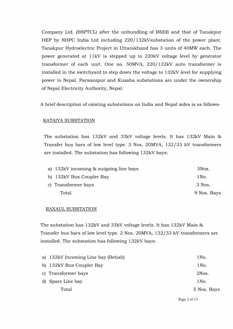
Page 2 of 13
Company Ltd. (BSPTCL) after the unbundling of BSEB and that of Tanakpur
HEP by NHPC India Ltd including 220/132kVsubstation of the power plant.
Tanakpur Hydroelectric Project in Uttarakhand has 3 units of 40MW each. The
power generated at 11kV is stepped up to 220kV voltage level by generator
transformer of each unit. One no. 50MVA, 220/132kV auto transformer is
installed in the switchyard to step down the voltage to 132kV level for supplying
power to Nepal. Parwanipur and Kusaha substations are under the ownership
of Nepal Electricity Authority, Nepal.
A brief description of existing substations on India and Nepal sides is as follows-
KATAIYA SUBSTATION
The substation has 132kV and 33kV voltage levels. It has 132kV Main &
Transfer bus bars of low level type. 3 Nos. 20MVA, 132/33 kV transformers
are installed. The substation has following 132kV bays:
a) 132kV incoming & outgoing line bays 5Nos.
b) 132kV Bus Coupler Bay 1No.
c) Transformer bays 3 Nos.
Total 9 Nos. Bays
RAXAUL SUBSTATION
The substation has 132kV and 33kV voltage levels. It has 132kV Main &
Transfer bus bars of low level type. 2 Nos. 20MVA, 132/33 kV transformers are
installed. The substation has following 132kV bays:
a) 132kV Incoming Line bay (Betiah) 1No.
b) 132kV Bus Coupler Bay 1No.
c) Transformer bays 2Nos.
d) Spare Line bay 1No.
Total 5 Nos. Bays

Page 3 of 13
The power is being supplied from this substation to Nepal Govt. through 33kV
transmission line.
2.0 SCOPE OF WORKS:
2.1 To meet the power demand of Nepal Electricity Authority(NEA) augmentation of
132 kV substations shall be carried out on turnkey basis i.e. design,
engineering, manufacturing, supply & delivery, erection, testing &
commissioning of the equipment shall be done by single contractor through
various sub-contractors. One no. additional 132kV bay of type identical to
existing bays shall be constructed at each existing 132kV substation at:
(a) Kataiya, Bihar, India
(b) Raxaul, Bihar, India
(c) Parwanipur, Nepal &
(d) Kusaha, Nepal
2.2 The works broadly cover the following:
(a) Design, engineering, manufacture, testing including testing at manufacturer’s
works, supply including transportation to site & insurance, storage at site,
erection, testing and commissioning of the following equipments/material,
complete in all respects:
S.No
Name of Equipment
Kataiya Raxaul Kusaha Parwanipur
Quantity
1) 145kV, 3 phase , 1250A,
SF6
Circuit Breaker
1 No. 1 No. 1 No. 1 No.
2) 145kV, 1250A, double
break, 3-phase Isolator
without Earth Switch
2 No. 2 No. 2 No. 2 No.
3) 145kV, 1250A, double 1 No. 1 No. 1 No. 1 No.

Page 4 of 13
break, 3-phase Isolator
with Earth Switch
4) 145kV, single phase CT
with 5-core 3 No. 3 No. 3 No. 3 No.
5) 120kV single phase LA 3 No. 3 No. 3 No. 3 No.
6) 145 kV, 1250A, single
phase Wave Trap 2 No. 2 No. 2 No. 2 No.
7) 145kV, 4400 pF, single
phase CVT 3 No. 3 No. 3 No. 3 No.
(b) Complete conventional control & protection system alongwith associated
equipment.
(c) Wave traps
(d) LT switchgear (AC/DC Distribution boards) (if required).
(e) Batteries & Battery Chargers (if required).
(f) 1.1 kV grade Power & Control cables along with complete accessories
(g) Lattice and pipe structures (galvanized)
(h) Bus Post Insulators, insulator strings and hardware, clamps & connectors,
equipment terminal connector, conductors and conductor accessories, shield
wires / ground wire, lightening masts and accessories (if required), aluminum
tubes, bus bar and earthing materials, Bay Marshalling Kiosk, cable supporting
angles/channels, cable trays & covers, junction box, buried cable trenches.
(i) Illumination of the new bay
(j) Mandatory Spares
(k) Any other equipment/material required to complete the specified scope
2.3 Civil works:
Design, Engineering and Civil work shall include but not be limited to the
following: -
(a) Foundation for Lattice, pipe and equipments support structures
Page 5 of 13
(b) Foundation for lighting poles, Bay marshalling box, panels and control
cubicles of equipments wherever required
(c) Cable trenches along with covers and sump pits
(d) Stone spreading and anti weed treatment of new bay area.
(e) Bay Control Unit.
2.4 Studies / Design calculations :
The scope of studies / design calculations shall include but not be limited to
the following:
(a) Direct stroke lightning protection
(b) Short circuit forces calculations for strung conductors and equipment
supports
(c) Calculations for selection of Bus bars, if required.
(d) Earth mat design calculations, if required.
(e) Structure design calculations for lattice and pipe structures
(f) Design calculations for equipment foundations, cable trenches, etc.
(g) Lighting design calculations for new bay
2.5 The bidders are advised to visit the substations site and acquaint themselves
with the topography, infrastructure and also the design philosophy. Before
proceeding with the construction work, the Contractor shall fully familiarize
himself with the site conditions and General arrangements & scheme etc. It
will be the responsibility of the successful bidder to execute the substation
augmentation work as per specification. All necessary works for the same
such as shifting of existing panels for rearranging as per approved scheme or
any other work shall be completed by the successful bidder. Though the
Purchaser shall endeavor to provide the various information, it shall not be
binding for the Purchaser to provide the same. The Bidder shall be fully
responsible for providing all equipment, materials, system and services
specified or otherwise which are required to complete the construction and
successful commissioning, operation & maintenance of the new bay in all
respects. All materials required for the Civil and construction/installation

Page 6 of 13
work shall be supplied by the Contractor. The cement and steel shall also be
arranged by the Contractor.
2.6 The complete design (unless specified otherwise in specification elsewhere)
and detailed engineering shall be done by the Contractor based on conceptual
tender drawings.
2.7 The design of structures, choice of conductor/aluminium pipe etc. shall
preferably match with the existing structures and conductors/pipes if designs
are found suitable.
2.8 The Contractor shall also be responsible for the overall co-ordination with
internal/external agencies, project management, training of Purchaser’s
manpower, loading, unloading, handling, moving to final destination for
successful erection, testing and commissioning of the new bay.
2.9 The equipment to be supplied shall be of reputed make & standard design as
per latest edition of relevant IS/IEC. The latest and amended up to date
edition of relevant IS/IEC shall be followed even if an older version of IS/IEC
may have been indicated in the specification.
2.10 The scope of work include preparation of single line diagrams and electrical
layouts, erection key diagrams, electrical and physical clearance diagrams,
control and protection schematics, wiring and termination schedules, civil
designs and drawings of indoor/ outdoor lighting/illumination and other
relevant drawings & documents (as applicable) required for engineering of all
facilities to be provided under this Contract.
2.11 The minimum phase to earth & phase to phase distances are indicated in the
specification.
2.12 The Purchaser may repeat some of the type tests and additional type tests as
indicated in the specification.

Page 7 of 13
3.0 Climatic and Isoceraunic Conditions
The equipments in the switchyards shall be suitable for the following
climatic & isoceraunic site conditions:
a) Location of Sub-station
Raxual & Kataiya,
Bihar (India)
Parwanipur &
Kusaha, Nepal
b) Maximum Ambient temperature 45°C
c) Maximum daily average Ambient
temperature
40°C
d) Maximum yearly average Ambient
temperature
35°C
e) Maximum ambient temperature of the air
in shade
45°C
f) Minimum ambient temperature of the air
in shade
15°C
g) Minimum temperature 0°C
h) Altitude Sea Level < 1000 MT
i) Relative Humidity 100%
j) Pollution level heavy
k) Average No. of thunder storm days per
annum
50 nos.
l) Average annual rainfall 1800 mm
m) Maximum wind pressure 130 kg/m²
n) Seismic level 0.3g
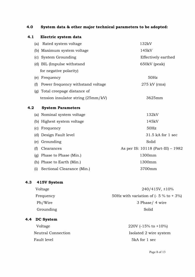
Page 8 of 13
4.0 System data & other major technical parameters to be adopted:
4.1 Electric system data
(a) Rated system voltage 132kV
(b) Maximum system voltage 145kV
(c) System Grounding Effectively earthed
(d) BIL (Impulse withstand 650kV (peak)
for negative polarity)
(e) Frequency 50Hz
(f) Power frequency withstand voltage 275 kV (rms)
(g) Total creepage distance of
tension insulator string (25mm/kV) 3625mm
4.2 System Parameters
(a) Nominal system voltage 132kV
(b) Highest system voltage 145kV
(c) Frequency 50Hz
(d) Design Fault level 31.5 kA for 1 sec
(e) Grounding Solid
(f) Clearances As per IS: 10118 (Part-III) – 1982
(g) Phase to Phase (Min.) 1300mm
(h) Phase to Earth (Min.) 1300mm
(i) Sectional Clearance (Min.) 3700mm
4.3 415V System
Voltage 240/415V, ±10%
Frequency 50Hz with variation of (- 5 % to + 3%)
Ph/Wire 3 Phase/ 4 wire
Grounding Solid
4.4 DC System
Voltage 220V (-15% to +10%)
Neutral Connection Isolated 2 wire system
Fault level 5kA for 1 sec

Page 9 of 13
4.5 PLCC System
Voltage 48V
Neutral Connection 2 wire system, (+) earthed
Combined Variation of Voltage and Frequency shall be limited to ±10%
4.6 Design of switchyard equipment
a) Operating voltage 132kV
b) Basic Insulation level 650kV
c) Power Frequency Voltage 275kV (rms)
d) Fault level 31.5kA for 1sec
4.7 Bus Bar Scheme
At present, main and transfer bus-bar system is provided at all 132kV sub-
stations. Same arrangement shall be provided for the new bays also.
4.8 Design of Bus System
i. Main bus, transfer bus & equipment bus shall be of ACSR conductor.
ii. 132 kV Bus-bar shall be sized to withstand the design fault level of 31.5 kA
for 1s.
iii. 132kV Bus-bars for new bays at all four sub-stations shall be ‘Zebra’ ACSR
conductor.
iv. The equipment connection shall be done by clamps and connectors.
4.9 Design of Tower/gantry structure based on short circuit pull of ACSR
conductor
The following parameters shall be considered:
i. Static tension of the conductor 1000 Kg per conductor
ii. Fault current and duration 31.5 kA for 1 second
4.10 Design of Insulator
The required cantilever strength for the bus bar support insulators (viz. Post
insulator stacks and also equipment insulators where the bus bar terminates on
the equipment) shall be calculated considering combined action of

Page 10 of 13
Electromagnetic forces under a three phase short circuit condition, static weight
and forces due to wind pressure.
The following numbers of 11kV disc insulators shall be used for Tension and
suspension string Insulators:
132kV Tension: 2x9 Discs
132kV Suspension: 9 Discs
5.0 SPECIFICATION
The specifications are prepared in four no. of volumes as under:
Vol. –1 General Conditions of Contract
Vol.-2 Technical Specifications
Vol. -3 Guaranteed Technical Particulars
Vol. -4 Price Schedules
6.0 AUXILIARY POWER SUPPLIES
All the existing substations have AC & DC Boards which have adequate
capacity to meet the auxiliary supply of the new additional feeders. Auxiliary
supply voltage is as under:
- 400/230V AC
- 220 V DC
In case of insufficient capacity of existing AC & DC boards, AC & DC
Distribution Boards shall be supplied for the additional new feeders along
with the power cables.
7.0 LIGHTING
Adequate Indoor & Outdoor lighting shall be provided for the additional
equipment in the substation. The Lighting distribution board will be fed from AC
main board via isolating transformer which isolates lighting system from AC
system. The Lighting system shall be designed for average lux level of 50 lux at
equipment, 20 lux at ground level in the outdoor yard and 300 lux in the control
room.

Page 11 of 13
8.0 LIGHTNING PROTECTION
Direct stroke lightning protection shall be provided for the electrical equipment
in the outdoor switchyard. The method of protection shall be followed as per
procedure laid down by Mr.Razevig.
9.0 QUALITY ASSURANCE PROGRAMME
To ensure that the equipment and materials supplied and services provided
under the scope of this contract whether manufactured or performed within the
contractor’s works or his sub-contractor’s works or at owner’s site or at any
other place of work, are in accordance with the specifications, the contractors
shall adopt suitable quality assurance programme to control such activity at all
necessary points. Such programme shall be outlined by the contractor and
shall be finally accepted by the purchaser after discussions before the award of
contract. The quality assurance programme of the contractor shall generally
cover the following:
(a) Organisation structure for the management and implementation of the
proposed quality assurance programme.
(b) Documentation control system.
(c) Qualification data for tenderer’s key personnel.
(d) The procedure for purchase of materials, parts components and selection of
sub-contractor’s services including vendor analysis, source inspection,
incoming raw material inspection, verification of materials purchased etc.
(e) System for shop manufacturing and site erection controls including process
control and fabrication and assembly control.
(f) Inspection & Test procedure both for manufacture and field activities.
(g) Control of non performing items and systems for corrective measures.
10.0 SCHEDULE OF QUANTITIES
10.1 The requirement of various items/equipment and civil works are indicated in
Bid price Schedules.

Page 12 of 13
All equipment/items and civil works which have been indicated in Bidding
forms, Price & other Schedules shall be payable on unit rate basis. During
actual execution, any variation in such quantities shall be paid based on the
unit rate under each item incorporated in Letter of award. Wherever the
quantities of items/works are not indicated, the bidder is required to estimate
the quantity required for entire execution and completion of works and
incorporate their price in respective Bidding forms, Price & other Schedules.
Bidder should include all such items in the bid proposal sheets, which are not
specifically mentioned but are essential for the execution of the Contract. Item
which explicitly may not appear in various schedules and required for
successful commissioning of the new bays shall be included in the bid price
and shall be provided at no extra cost to Purchaser.
10.2 The quantities of spares indicated in various Sections of the Specification are
tentative and may be revised as per actual requirement at the time of ordering.
11.0 TESTS & INSPECTIONS
11.1 All equipment and components shall be subjected to routine tests
according to latest edition of IEC/IS relevant standards and such other tests
including type, acceptance & site/commissioning tests as may be required to
ensure that all equipment and components are satisfactory and in
accordance with the specification. Any modification required in the testing
procedure shall be made as directed by the purchaser at no additional
cost to the purchaser. No equipment shall be dispatched from the
manufacturer’s works before the relevant tests reports have been approved by
the purchaser.
11.2 It shall be certified by the supplier that the type tests in accordance with the
latest edition of relevant IEC/IS standards have been successfully carried out
on all type of equipment, relays, meters, switches and other devices being
supplied by him. Certified copies of all type tests shall be submitted with the

Page 13 of 13
tender. The test reports shall provide sufficient data to substantiate that the
equipment offered meets the requirement of the standards.
11.3 All tests and inspection shall be made at the manufacturer's works unless
otherwise specifically agreed upon by the manufacturer and purchaser at
the time of placement of purchase order. The manufacturer shall afford
to the inspector representing the purchaser, all reasonable facilities, without
charge, to satisfy him that the material being furnished is in accordance
with the specification. The purchaser reserves the right to get any
component/ material used by the manufacturer tested from any recognized
Test House.
11.4 The inspection by the purchaser or his authorized representative shall
not relieve the bidder of his obligation of furnishing equipment in
accordance with the specification, and if at any time it is found that
equipment has not been tested as desired by Purchaser, the same would be
rejected. All expenses for inspection shall be borne by the contractor
/including lodging, boarding and airfare.
--------x--------

Page 1 of 36
SECTION-2
TECHNICAL SPECIFICATION FOR 132 KV SF6 CIRCUIT BREAKERS
1.0 GENERAL
1.1 The scope covers the design, engineering, manufacture, testing at
Manufacturer’s works before dispatch, packing and forwarding, transportation, insurance, handling, delivering at site, proper storage at site, erection, testing and commissioning of the 132 kV, three phase, SF6 Circuit Breakers complete with all materials, accessories and fittings, erection & maintenance tools & tackles, mandatory spares for the following Circuit Breakers(CBs) complete with all associated accessories such as terminal connectors, cables, cables glands, terminal blocks, switches, support structures and auxiliaries etc. as detailed below.
a) 145 kV, 3 pole, 1 no SF6 gas filled outdoor type circuit
breakers of 1250A, 31.5 kA S.C rating for 1 sec
2.0 STANDARDS
2.1 The Circuit Breaker and accessories shall conform to IEC-62271-100 / IS:2516, IEC:60694, IS-13118/IEC-60565 and other relevant IEC/IS standards of latest edition except to the extent explicitly modified in the specification and shall also be in accordance with requirement specified in this section.
2.2 Other applicable standards shall be:
IS-2099/IEC-60137
: Specifications for bushings for Alternating voltage above 1000 V
IS-7311 : Seamless high carbon steel cylinders for permanent and high pressure liquefiable gases.
IS-2825 : Pressure vessels
IEC-60376 : SF6 Gas
IS:5456 : Code of practices for testing of positive displacement type air compressors and exhaustors
IEC-60267 : Guide to testing of circuit breakers with respect to out-of-phase switching
IS-6206 : Air compressor plant
IS-325 : 3 phase induction motors
IS-2147 : Degree of protection of switchgear

Page 2 of 36
IS-1554 : Specification for PVC insulated heavy duty electric cable
IS-4759-1984 : Specifications for hot dip, zinc coating, structural steel and other allied products
IS-1271 : Classification of Insulating materials for electrical machinery & apparatus in relation to their thermal stability in service
IS-2001 : Method of HV High voltage testing
IS-2070 : Method of impulse testing
IS-2165 : Insulation coordination
IS-2544 : Specification for porcelain part insulator
IS-2633 : Method of testing weight thickness & uniformity of coating
BS-2871 : Copper & copper alloy tubes
IS-5561 : Electric Power connectors
BS-487 : Fusion Welded Steel Air Receivers
IS-4379 : Identification of the contents of Industrial Gas cylinders
IS-209 : Specification for zinc
IS-2062 : Structural steel
IS-2071 : Methods of High voltage testing
IEC-60694 : High voltage switchgear and control gear
3.0 GENERAL TECHNICAL REQUIREMENT
3.1 The circuit breaker shall be complete with terminal connectors; operating mechanism; control cabinets; piping; valves; interpole cable; cable accessories like glands, terminal blocks, marking ferrules, lugs; pressure gauge; density monitor (with graduated scale) with adequate temperature compensation; galvanized support structure for CB & control cabinets, their foundation bolts and all other circuit breaker accessories necessary for carrying out all functions that the CB is required to perform
3.2 All necessary parts to provide a complete and operable Circuit Breaker installation such as main equipment, terminals, control parts,

Page 3 of 36
connectors and other devices whether specifically called for herein or not shall be provided.
3.3 145 kV Circuit Breakers shall be designed for high speed three pole reclosing with an operating sequence and timing as specified in Section.
3.4 The support structure of Circuit Breaker as well as that of control cabinet shall be hot dip galvanized. All other parts shall be painted as per shade 697 of IS: 5.
3.5 Each Circuit Breaker pole shall be provided with two (2) independent tripping circuits, pressure switches & coils each connected to a different set of protective relays. The trip coils shall be suitable for trip circuit supervision during both open and close position of breaker. The trip circuit supervision relay would be provided on relay panels.
3.6 All the three poles of the Circuit Breaker shall close/open simultaneously.
3.7 The design shall be such as to minimize switching over voltages and the Circuit Breaker shall be suitable for full out of phase switching.
3.8 The Circuit Breaker shall be of the single pressure type. The design & construction of SF6 circuit breaker shall be such that there is minimum possibility of gas leakage and entry of moisture. There should not be any condensation of SF6 gas on the internal insulating surfaces of the circuit breaker.
3.9 The breakers shall be provided with the following:
i) Anti pumping arrangement in the closing circuit. ii) Close and trip coils suitable for operation on 220 V DC. iii) The breaker shall be complete by itself with all provisions
such as heater with thermostat, counter, 3 pin plug with socket, illumination lamp with door switch, MCBs for the control circuit and 10 NO and 10 NC breaker auxiliary contacts as spares exclusively for purchaser’s use. The terminal strip for the control circuit shall be of stud type with two nuts.
iv) Push button arrangement for safe manual operation of the breaker in case of emergency tripping with protective cover to avoid inadvertent operation.
v) Lock & key for the mechanism box. vi) Set of rigid type, aluminium terminal connectors for each
Breaker.
3.10 Necessary interlocks to prevent the closing or opening of the breaker under low air and gas pressure and device for initiating alarm shall be provided. Audio – visual indications under such conditions shall also be provided in the purchaser’s control room. It is proposed to interlock (electrically) the isolators associated with the Circuit Breaker so that they may not open/close, when breaker is closed etc. The

Page 4 of 36
details of switchyard safety interlocking scheme shall be furnished by the Bidder. All accessories required on breaker side for satisfactory operation of the scheme will be deemed to have been included in the scope of supply of this specification.
3.11 Miniature Circuit Breaker shall be provided for all auxiliary power and control circuits. Over load protection for motors shall be provided wherever required. Single phase preventer shall be provided.
3.12 Complete equipment for local control of switchgear indications and alarms, etc. shall be provided.
3.13 The guaranteed and other technical particulars for the offered circuit breakers as indicated in Section-“Guaranteed and Other Technical Particulars” need to furnish by the Bidder. Any other particulars considered necessary in addition to those listed in that section may be furnished by the Bidder.
4.0 SPECIFIC TECHNICAL REQUIREMENT
The technical parameters of the Circuit Breakers are detailed in Section-Specific Technical Requirement.
5.0 DUTY REQUIREMENT
5.1 The Circuit Breaker shall be totally restriking free as per IEC under
all duty conditions and shall be capable of performing their duties without opening resistors. The circuit breakers shall be of class C2-E1-M2 (as per IEC) with regard to restrike probability during capacitive current breaking, electrical endurance and mechanical endurance. The circuit breaker shall be of live tank type.
5.2 The rated transient recovery voltage for terminal faults shall be as
per IEC –62271-100. The measures adopted for ensuring proper operation at high rate of rise of restriking voltage and for limiting the actual values across the breaker shall be described. No opening resistors shall be necessary for ensuring conformity with the duty cycle.
5.3 The Circuit Breaker shall meet the duty requirements, for any type of fault or for any fault location, also for line switching when used on 132 kV (effectively grounded system) with transmission lines and perform make and break operations as per the stipulated duty cycles satisfactorily.
5.4 The guaranteed over voltages under all possible operating
conditions including, but not limited to, the rapid reclosing with or without faults, interrupting line charging current under conditions of high dynamic overvoltage or transformer magnetizing current, energizing or de-energizing shunt reactors, shunt capacitor banks or transformer banks shall not exceed the peak value of 2.3 p.u. of the normal phase to ground voltage crest for 132 kV circuit breakers.

Page 5 of 36
5.5 The Circuit Breaker shall also be capable of i) Interrupting the steady state and transient magnetizing
current corresponding to 132 kV rating transformers without switching overvoltage exceeding 2.3 p.u.
ii) Interrupting line/ cable charging current as specified under
Section-Specific Technical Requirement without any restrikes and without use of opening resistors.
iii) Clearing short line fault (kilometric faults) with source
impedance behind the bus equivalent to symmetrical fault current specified. The overvoltage factors under such conditions shall not exceed 1.4 p.u.
iv) Breaking 25% of the rated fault currents at twice rated
voltage under phase opposition condition.
v) Breaking small inductive current of 0.5 A to 10A without switching over voltage exceeding 2.3 p.u. The maximum over voltage value which will not be exceeded under such conditions shall also be stated.
5.6 The breaker shall be designed to interrupt at its rated interrupting
capacity when re-striking voltage has a frequency of not less than 400 cycles per second and at least 50% of nominal breaking capacity when re-striking voltage has frequency of 2000 cycles per second. The complete data for the frequency, amplitude factor etc., for the rate of rise of re-striking voltage shall be furnished.
5.7 The rated characteristics for short line faults (kilo metric faults)
shall be as specified in Section- “Specific Technical Requirement”. All Circuit Breakers shall have high capacity for breaking kilometric faults. The interrupting capacity of the Circuit Breaker for kilometric faults should be equal to its rated rupturing capacity and shall be stated. The interrupting capacity of Circuit Breaker for kilometric faults at distances equivalent to 90%, 75 % and 60% of the fault current shall be indicated. The details of tests conducted for proving the capability of the Circuit Breaker under kilometric fault conditions shall be furnished.
5.8 The breaker shall be capable of operating satisfactorily even under
conditions of phase opposition that may arise due to faulty synchronization. The maximum power which the breakers can interrupt satisfactorily under phase opposition conditions shall also be furnished.
5.9 The breaker shall satisfactorily withstand the high stresses
imposed on them during fault clearing, load rejection and re-energisation of lines with trapped charges. The breaker shall also withstand the voltages specified in Section- “Specific Technical Requirement”.

Page 6 of 36
5.10 Noise level The Circuit Breaker shall be reasonably quiet in operation. Noise level in excess of 140 dB measured at the base of the breaker would be unacceptable. Bidder shall indicate the noise level of breaker at distances of 50, 100 and 150 m from the breaker.
5.11 Total Break Time 5.11.1 The total break time as specified in Section-“Specific Technical
Requirement” shall not be exceeded under any of the following duties: i) Test duties 1, 2, 3, 4, 5 (TRV as per IEC – 62271-
100) ii) Short line faults L75, L90 (TRV as per IEC – 62271-
100)
5.11.2 Total break time of the breaker shall not be exceeded under any duty conditions specified such as with the combined variation of the trip coil voltage and pressure of arc extinguishing medium etc. While furnishing the proof of the total break time of complete Circuit Breaker, the Bidder may specifically bring out the effect of non-simultaneity between contacts within a pole or between poles and show how it is covered in the guaranteed total break time.
5.11.3 The guaranteed values shall be supported with the type test reports.
5.12 DC Component and Minimum Opening time
While furnishing particulars regarding the percentage DC component of the rated short circuit breaking current of circuit breaker, the Bidder shall note that IEC- 62271-100 requires that this value should correspond to a time interval equal to the minimum opening time of the first opening pole of the circuit breaker.
5.13 The Circuit Breaker shall be capable of satisfactorily performing all their duties including, but not limited to, clearing of faults and interrupting line charging and transformer charging currents without causing undue over voltage and showing signs of undue strain while operating under conditions of high temporary over voltage (power frequency) of the order of 1.5 p.u. for 132 kV system. The suitability of Circuit Breaker for working satisfactorily under such conditions should be explicitly guaranteed by the Bidder and it should be supported with clear technical elaboration & details.
5.14 Trip free operation
The Circuit Breaker shall be trip free.

Page 7 of 36
5.15 Recovery voltage and power factor Each Circuit Breaker shall be capable of interrupting rated short circuit breaking current under the conditions of recovery voltage corresponding to highest system voltage and power factor not exceeding 0.15.
5.16 Automatic rapid reclosing The Circuit Breaker shall be suitable for three pole and/ or single pole automatic rapid reclosing. The operating duty of these Circuit Breakers shall be as follows: O – 0.3 sec – CO – 3 min – CO where C – Closing & O – Opening.
5.17 Temperature rise The temperature rise and the maximum temperature attained by any part of the equipment when in service at site under continuous full load conditions and exposed continuously to the direct rays of the sun shall not exceed the permissible limits as per the limits given in IEC-62271-100.
5.18 Support Insulators i) The support Insulating shall comply with requirement as
given in Annexure I of this section.
ii) Support Insulators shall be designed to have ample insulation and mechanical strength and rigidity for satisfactory operation under various operating conditions detailed in this specification.
iii) The basic impulse insulation level of the external insulator
supports shall match with that of the Circuit Breaker and shall be suitable for insulation in the contaminated atmosphere. The porcelain used shall be homogenous and free from cracks, cavities, and other flaws or blemishes and glazed all over the exposed surfaces.
iv) All bushings of identical rating shall be interchangeable. The
puncture strength of the bushing shall be greater than the flashover value.
v) All ferrous parts shall be hot dip galvanized.
vi) The insulator including all the live metallic parts shall be free
from external and internal corona.
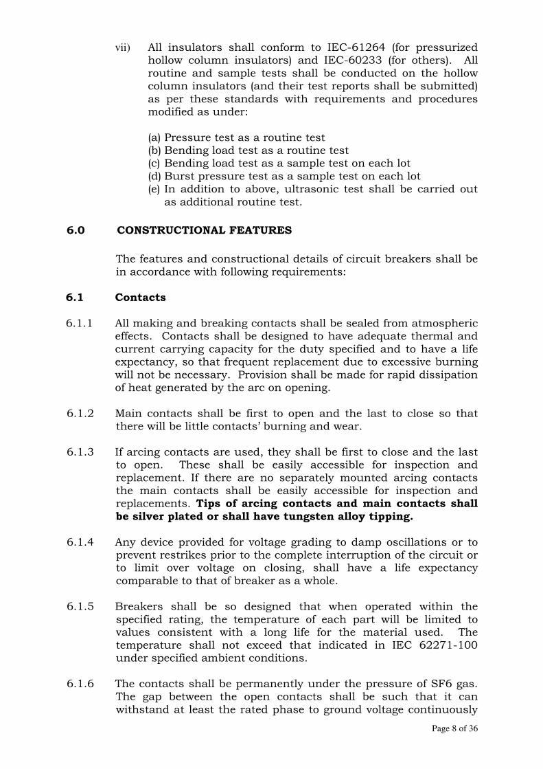
Page 8 of 36
vii) All insulators shall conform to IEC-61264 (for pressurized hollow column insulators) and IEC-60233 (for others). All routine and sample tests shall be conducted on the hollow column insulators (and their test reports shall be submitted) as per these standards with requirements and procedures modified as under:
(a) Pressure test as a routine test (b) Bending load test as a routine test (c) Bending load test as a sample test on each lot (d) Burst pressure test as a sample test on each lot (e) In addition to above, ultrasonic test shall be carried out
as additional routine test.
6.0 CONSTRUCTIONAL FEATURES
The features and constructional details of circuit breakers shall be in accordance with following requirements:
6.1 Contacts
6.1.1 All making and breaking contacts shall be sealed from atmospheric effects. Contacts shall be designed to have adequate thermal and current carrying capacity for the duty specified and to have a life expectancy, so that frequent replacement due to excessive burning will not be necessary. Provision shall be made for rapid dissipation of heat generated by the arc on opening.
6.1.2 Main contacts shall be first to open and the last to close so that there will be little contacts’ burning and wear.
6.1.3 If arcing contacts are used, they shall be first to close and the last to open. These shall be easily accessible for inspection and replacement. If there are no separately mounted arcing contacts the main contacts shall be easily accessible for inspection and replacements. Tips of arcing contacts and main contacts shall be silver plated or shall have tungsten alloy tipping.
6.1.4 Any device provided for voltage grading to damp oscillations or to prevent restrikes prior to the complete interruption of the circuit or to limit over voltage on closing, shall have a life expectancy comparable to that of breaker as a whole.
6.1.5 Breakers shall be so designed that when operated within the specified rating, the temperature of each part will be limited to values consistent with a long life for the material used. The temperature shall not exceed that indicated in IEC 62271-100 under specified ambient conditions.
6.1.6 The contacts shall be permanently under the pressure of SF6 gas. The gap between the open contacts shall be such that it can withstand at least the rated phase to ground voltage continuously

Page 9 of 36
for 8 hrs at zero gauge pressure of SF6 gas due to its leakage. The breaker should be able to withstand all dielectric stresses imposed on it in open condition at lock out pressure continuously (i.e. 2 p.u. across the breaker continuously).
6.1.7 Main contacts shall have ample area and contact pressure for
carrying the rated current and the short time rated current of the breaker without excessive temperature rise which may cause pitting or welding.
6.1.8 Diagrams showing contacts in the following positions shall be
furnished at detailed engineering stage:
i) Close position ii) Arc initiation position iii) Full arcing position iv) Arc extinction position v) Open position.
6.2 Sulphur Hexafluoride (SF6) Gas
6.2.1 SF6 gas shall comply with the requirement of the latest IEC: 60376, 60376A and 60376B and shall be suitable for use in the switchgear under the operating conditions. The various parameters of SF6 gas are given in Annexure – II of this section.
6.2.2 Sufficient SF6 gas including that will be required for Gas
Analysis during filling shall be provided to fill the Circuit Breaker installed. In addition, 10% of total gas requirement shall be supplied in separate unused cylinders as spare requirement.
6.2.3 The high pressure cylinders in which the SF6 gas is shipped and
stored at the site shall comply with requirements of the following standards and regulations:
a) IS: 4379 Identification of the contents of industrial gas cylinders.
b) IS: 7311 Seamless high carbon steel cylinders for permanent and high pressure liquefiable gases.
c) Indian Boiler Regulations
6.2.4 Test: SF6 gas shall be tested for purity, dew point, air,
hydrolysable fluorides and water content as per IEC: 60376, 60376A and 60376B and test certificates shall be furnished to Employer indicating all the tests as per IEC: 60376 for each lot of SF6 gas. Gas bottles should be tested for leakage during receipt at site.
6.3 All gasket surfaces shall be smooth, straight and reinforced, if necessary, to minimize distortion and to make a tight seal. The

Page 10 of 36
operating rod connecting the operating mechanism to the arc chamber (SF6 media) shall have adequate seals.
6.4 Temperature compensated gas density or pressure devices shall be provided along with pressure gauges for continuous indication of gas pressure in the gas chamber of each pole. The devices shall provide continuous and automatic monitoring of the stage of the gas. The monitoring device shall have alarm setting and additional trip setting appliances. These shall be set so that (a) Advanced warning can be given that the gas density pressure has reduced to an unacceptable level. (b) After an urgent alarm, the breaker shall get locked out if the pressure falls below predetermined value.
6.5 Each Circuit Breaker pole shall form an enclosure filled with SF6 gas independent of two other poles. The SF6 gas density of each pole shall be monitored and regulated by individual pressure switches.
6.6 The dial type SF6 density monitor shall be adequately temperature
compensated to monitor the density changes due to variations in ambient temperature within the body of Circuit Breaker as a whole. The density monitor shall meet the following requirements: i) It shall have graduated scale. ii) It shall be possible to dismantle the density monitor for
checking/replacement without draining the SF6 gas by using suitable interlocked non return valve coupling.
iii) It shall damp the pressure pulsation while filling the gas in
service so that the flickering of the pressure switch contacts does not take place.
6.7 Each Circuit Breaker pole is to be equipped with static filters and
desiccants. These shall be able to absorb any water vapour penetrating into the switchgear installation and all decomposed gas.
6.8 In the interrupter assembly there shall be an absorbing product box to minimize the effect of SF6 decomposition products and moisture. The material used in the construction of the Circuit Breaker shall be such as fully compatible with SF6 gas decomposition products.
6.9 The circuit breaker shall be single pressure type. All the gas seals shall be designed to ensure that leakage rate is kept to an absolute minimum under normal pressure, temperature, electrical load and fault conditions. All gas seals located at the flanges shall be of the

Page 11 of 36
O – ring type. Double O-ring seals shall be provided on each static joint. Single O ring seals having guaranteed leakage rate as specified shall also be acceptable. The material and method of sealing used and the maximum gas leakage rate that can normally be tolerated under working conditions shall be stated. The material for the O-rings shall be suitable for -15 to 50 deg C.
6.10 The SF6 gas leakage shall not be more than 1% per year under
normal operating conditions. In case the leakage is found to be greater than 1% within one year of commissioning of Circuit Breaker, the SF6 gas leaked shall be replenished by the Bidder at his own cost and also necessary rectification of the defects causing leakage more than 1% shall be carried out by the Bidder without any cost to the Purchaser. In addition to above requirement, the manufacturer shall have to supply free of cost, the total gas requirement for subsequent ten (10) years, based on actual leakage observed during first year of operation after commissioning.
6.11 Each Circuit Breaker shall be capable of withstanding a vacuum of minimum 8 milli bars without distortion or failure of any part. Facility shall be there to reduce the gas pressure within the breaker to a value not exceeding 8 milli bars within 4 hrs. or less.
6.12 Each Circuit Breaker shall be provided with suitable means to prevent gas from being conveyed to the operating mechanism housing from the tanks or porcelain enclosures or operating rods or other components.
6.13 The quantity of SF6 gas for each breaker shall be clearly stated.
6.14 The design and construction of the plant, couplings, and connections shall be such that leakage of any SF6 gas shall be so handled that accidental loss of gas to the atmosphere shall be minimum.
6.15 Provisions shall be made for attaching an operational analyzer
after installation of circuit breaker at site to record contact travel, speed & making measurement of operating timings and synchronization of contacts in one pole. In case operational analyzer is already available at a particular site, the Contractor shall have to supply a suitable adopter/ transducer so that the offered circuit breaker can be used with the operational analyzer.
7.0 OPERATING MECHANISM AND CONTROL
7.1 The 132 kV Circuit Breakers shall be operated with spring
mechanism.
7.2 The mechanism shall be housed in a weatherproof and dust proof control cabinet. The mechanism shall be suitable for operation in sub-zero temperature condition.

Page 12 of 36
7.3 The operating mechanism shall be strong, rigid, not subject to rebound and shall be readily accessible for maintenance for a man standing on ground. It shall be removable without disturbing the other parts of the Circuit Breaker. It shall be fast in action needing no critical adjustment.
7.4 The operating mechanism shall be suitable for high speed reclosing and other duties specified. During reclosing the breaker contacts shall close fully and then open.
7.5 The mechanism shall be antipumping and trip free (as per IEC
definition) under every method of closing (except during manual closing of a breaker for maintenance).
7.6 The mechanism shall be such that the failure of any auxiliary spring will not prevent tripping and will not cause trip or closing operation of the power operating devices.
7.7 The breakers shall have a mechanical open/close indicator, in addition to facilities for remote electrical indication. It shall be located in a position where it will be visible to a man standing on the ground level with the mechanism housing closed.
7.8 An operation counter visible from outside with four digit recording
mechanism for counting the number of opening operations shall be provided in the central control cabinet.
7.9 Working parts of the mechanism shall be of corrosion-resistive material. Bearings which require grease shall be equipped with pressure type grease fittings. Bearing pin, bolts, nuts and other parts shall be adequately pinned or locked to prevent loosening or changing adjustment with repeated operation of the breaker.
7.10 The Contractor shall furnish detailed operation and maintenance manual of the mechanism along with the operation manual for the Circuit Breaker. The operation manuals shall contain exploded diagrams with complete storage, handling, erection, commissioning, trouble shooting, servicing and overhauling instructions.
7.11 The operating mechanism along with its accessories shall be
mounted in sheet metal cabinet with hinged doors located near the breaker. The operating mechanism shall be provided for electrical, local and remote control. An emergency safe hand- tripping (mechanical) device shall be provided in drive mechanism. The local control cabinet is to be provided with adequate clearance/ spacing inside to facilitate maintenance or repairs.
7.12 Controls
7.12.1 Each Circuit Breaker pole of 132kV shall be provided with two (2)
independent tripping circuits pressure switches & coils each connected to a different set of protective relays.
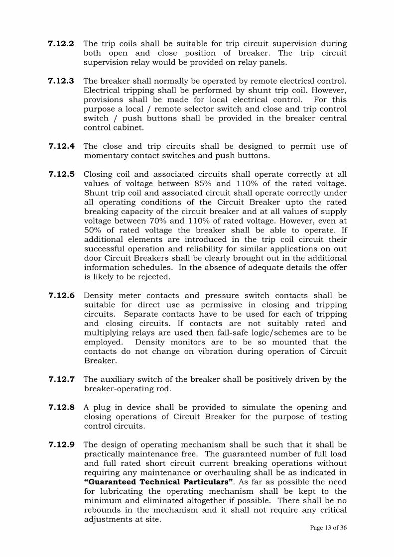
Page 13 of 36
7.12.2 The trip coils shall be suitable for trip circuit supervision during
both open and close position of breaker. The trip circuit supervision relay would be provided on relay panels.
7.12.3 The breaker shall normally be operated by remote electrical control.
Electrical tripping shall be performed by shunt trip coil. However, provisions shall be made for local electrical control. For this purpose a local / remote selector switch and close and trip control switch / push buttons shall be provided in the breaker central control cabinet.
7.12.4 The close and trip circuits shall be designed to permit use of
momentary contact switches and push buttons.
7.12.5 Closing coil and associated circuits shall operate correctly at all values of voltage between 85% and 110% of the rated voltage. Shunt trip coil and associated circuit shall operate correctly under all operating conditions of the Circuit Breaker upto the rated breaking capacity of the circuit breaker and at all values of supply voltage between 70% and 110% of rated voltage. However, even at 50% of rated voltage the breaker shall be able to operate. If additional elements are introduced in the trip coil circuit their successful operation and reliability for similar applications on out door Circuit Breakers shall be clearly brought out in the additional information schedules. In the absence of adequate details the offer is likely to be rejected.
7.12.6 Density meter contacts and pressure switch contacts shall be suitable for direct use as permissive in closing and tripping circuits. Separate contacts have to be used for each of tripping and closing circuits. If contacts are not suitably rated and multiplying relays are used then fail-safe logic/schemes are to be employed. Density monitors are to be so mounted that the contacts do not change on vibration during operation of Circuit Breaker.
7.12.7 The auxiliary switch of the breaker shall be positively driven by the breaker-operating rod.
7.12.8 A plug in device shall be provided to simulate the opening and closing operations of Circuit Breaker for the purpose of testing control circuits.
7.12.9 The design of operating mechanism shall be such that it shall be practically maintenance free. The guaranteed number of full load and full rated short circuit current breaking operations without requiring any maintenance or overhauling shall be as indicated in “Guaranteed Technical Particulars”. As far as possible the need for lubricating the operating mechanism shall be kept to the minimum and eliminated altogether if possible. There shall be no rebounds in the mechanism and it shall not require any critical adjustments at site.

Page 14 of 36
7.12.10 DC Supply for auxiliary circuits shall be monitored and
provision shall be made for remote annunciations and operation lockout in case of DC failure.
7.12.11 Curves/Graphs supported by test data indicating the opening time under close- open operation with variation of the trip coil voltage shall be submitted by the Bidder at detailed engineering stage.
7.13 Spring operated mechanism a) Spring operated mechanism shall be complete with motor.
Opening spring and closing spring with limit switch for automatic charging and other necessary accessories to make the mechanism a complete operating unit shall also be provided.
b) As long as power is available to the motor, a continuous
sequence of the closing and opening operations shall be possible. The motor shall have adequate thermal rating for this duty. It shall be adequately rated for a minimum of 10 continuous closing and opening operations.
c) After failure of power supply to the motor, one close
open operation shall be possible with the energy contained in the operating mechanism.
d) Breaker operation shall be independent of the motor which
shall be used solely for compressing the closing spring. Facility for manual charging of the closing spring shall also be provided. The motor rating shall be such that it requires not more than 30 seconds for full charging of the closing spring.
e) Closing action of Circuit Breaker shall compress the opening
spring ready for tripping.
f) When closing springs are discharged after closing a breaker, closing springs shall be automatically charged for the next operation and an indication of this shall be provided in the local and remote control cabinet.
g) Provisions shall be made to prevent a closing operation of the
breaker when the spring is in the partial charged condition. Mechanical interlocks shall be provided in the operating mechanism to prevent discharging of closing springs when the breaker is already in the closed position.
h) Motors for spring charging mechanism shall operate
satisfactorily at all AC voltages between 85% and 110% of the rated voltage. Motors shall be AC motors only. Universal

Page 15 of 36
motors are preferred. Provision shall be made to protect motors against overloads.
i) The spring operating mechanism shall have adequate energy
stored in the operating spring to close and latch the Circuit Breaker against the rated making current and also to provide the required energy for the tripping mechanism in case the tripping energy is derived from the operating mechanism.
8.0 SUPPORT STRUCTURE
8.1 The Bidder shall provide support structures along with the
foundation bolts required. The supplier shall also furnish complete loading particulars including following forces for foundation designs. a) Weight of the breaker and self-weight of structure. b) Tension, compression and shear forces on the structure. c) Loading details during opening and closing operations.
8.2 The structure design shall be such that during operation of circuit
breaker vibrations are reduced to minimum. 8.3 If required, the Bidder shall provide suitable platform with steps on
both sides of the circuit breaker for easy accessibility for monitoring the density/ pressure of gas.
8.4 The support structure shall meet the following mandatory
requirements:
a) The minimum vertical clearance from any energized metal part at terminal level to the bottom of the Circuit Breaker, where it rests on the foundation pad, shall be in line with layout drawings.
b) The minimum vertical distance from the bottom of the lowest
porcelain part of the bushings, porcelain enclosures or supporting insulators to the bottom to the Circuit Breaker base, where it rests on the foundation pad shall be 2.55 meters.
c) The minimum clearance between the live parts and earth as well
as between live parts of adjacent phases shall be 1.3 meters (excluding altitude correction factor) for 132kV system.
d) The structure shall be of galvanized steel and conform to the
latest edition of IS: 802. 9.0 PAD / TERMINAL CONNECTORS
9.1 TERMINAL PAD

Page 16 of 36
The Circuit Breaker terminal pads shall be made up of high quality electrolytic copper or aluminum. The terminal pad shall have protective covers, which shall be removed before interconnections.
9.2 TERMINAL CONNECTORS The terminal connectors shall comply with the requirement as given in Annexure-I of this Section. Bi-metallic terminal connectors suitable for zebra ACSR conductor shall be supplied. Each terminated connector shall be suitable to received horizontal and vertical connection of the station bus-bar.
10.0 INTER-POLE CABLING AND TERMINAL BLOCKS
10.1 All cables (1100 Volts grade) to be used by Contractor shall be armoured and shall be as per IS: 1554/relevant IEC.
10.2 All cables within & between circuit breaker poles shall be supplied
by the CB Manufacturer.
10.3 Only stranded conductor shall be used. Minimum size of the conductor shall be 2.5 sq. mm (copper).
10.4 The cables shall be with oxygen index Min-29 and temperature index as 250 deg. C as per relevant standards.
10.5 The wiring and terminal blocks shall be as per Annexure-I 11.0 FITTINGS AND ACCESSORIES
11.1 Following is a list of some of the major fittings and accessories to
be furnished by Bidder in the Central Control Cabinet as an integral part of the circuit breaker -
a) Cable glands (double compression type), lugs, ferrules etc. b) Local / remote changeover switch. c) Manually operated tripping push button conveniently
located to trip all three phases simultaneously with protective cover to avoid inadvertent operation.
d) Operation counter. e) Control switches to cut off control power supply. f) Fuses as per Annexure-I g) Anti pumping relay h) Pole discrepancy relay i) DC supervision relay j) The number of terminals provided shall be adequate enough
to wire out all contacts and control circuits plus 24 terminals spare for Purchaser’s future use.
k) Rating and diagram plate in accordance with IEC incorporating year of manufacture.
l) Control switching equipment like sensors, timers, relays etc.
Page 17 of 36
Central control cabinet shall be in accordance with relevant clauses in Annexure-I.
11.2 Nameplate Details This shall be as per IEC: 62271-100 A) Circuit Breaker a) Name of the Manufacturer and supplier; b) Type designation and serial no.; c) Rated service voltage, kV; d) Normal continuous current, A; e) Rated frequency cycles/sec.; f) Rated breaking capacity, kVA.;
i) Symmetrical current, kA (rms) ii) Asymmetrical current, kA (rms)
g) Making capacity, kA (peak); h) Rated short time current in kA (rms) with duration; i) Operating duty; j) Standard to which it conforms; k) Name of purchaser and purchase order No. against which
supply is made; l) Location; m) Year of manufacture; n) Rated insulation level; o) First pole to clear factor ; p) Break time, make time of complete breaker.
B) Control cabinet a) Rated voltage for operation of closing/tripping coils; b) Maximum permissible voltage for operation; c) Minimum Permissible voltage for operation of
closing/tripping coils; d) Operating mechanism for closing & opening; e) Rated supply voltage and frequency of auxiliary circuit. The rating plate shall be weather proof, corrosion proof and shall be visible to a man standing on the ground during normal service.
12.0 EARTHING TERMINAL
Each breaker shall be provided with at least two numbers of grounding terminals and clamps for receiving grounding connection. Size of grounding conductor shall be 50 mm x 8 mm GS flat.
13.0 AUXILIARY SWITCHES
13.1 Positively driven (in both directions) auxiliary switches (Contact) each of the Normally Open and Normally Closed types with

Page 18 of 36
continuous current carrying capacity at least 10 Amps shall be provided on each Circuit Breaker for remote indication, control of the Circuit Breaker and providing supply, interlocking. Auxiliary switches shall be capable of breaking at least 2 Amps at 220 V DC with Circuit Breaker time constant of not less than 20 milliseconds. These shall be installed on the frame of the breakers and shall be suitably protected against accidental arcing from the main circuit. The insulating materials for the switches and terminals shall be of ceramic or other non-tracking and non-hygroscopic materials.
13.2 The auxiliary switches shall be tested for following tests and test reports for the same shall be submitted for approval of Purchaser:
i) Electrical endurance test– A minimum of 2000 operations for
2A DC with a time constant greater than or equal to 20 milliseconds with a subsequent examination of millivolt drop/visual defects/temperature rise test.
ii) Mechanical endurance test– A minimum of 1,00,000 operations with subsequent checking of contact pressure test/visual examination.
iii) Heat run test on contacts. iv) IR/HV test etc.
14.0 GALVANISATION AND PAINTING The galvanisation of ferrous parts and painting of sheet steel work shall conform to the stipulation under BIS.
15.0 INSPECTION & TESTING
15.1 Equipment/material shall be offered for inspection in accordance
with requirement of the Specification.
15.2 In accordance with the requirements stipulated in the Specification., the circuit breaker along with its operating mechanism should have been successfully type tested as per IEC: 62271-100 and shall be subjected to routine and acceptance tests as per IEC: 62271-100. Testing facilities available at the Bidder's/Manufacturer's works shall be indicated in the bid.
15.3 The test reports of all type tests and the following additional tests
shall be submitted by the Bidder for Purchaser’s review. i) Seismic Withstand Test in unpressurised condition. ii) Radio Interference Voltage Test (RIV) iii) Test to demonstrate the Power Frequency withstand
capability of breaker in open condition at zero Gauge pressure and at lockout pressure.
iv) Out of phase closing test v) Line charging breaking current for tests. vi) Verification of the degree of protection

Page 19 of 36
vii) Low & high temperature test viii) Humidity test ix) Static terminal load test x) Critical current test (if applicable)
15.4 Tests on Associated components
Indicating and recording meters, porcelain bushings, current transformers, instruments, relays, auxiliary motors, control devices, fans, valves, and other associated components as applicable should have been tested in accordance with the relevant Indian Standards/ International Standards and the type test reports of above associated components shall be submitted during detailed engineering stage
15.5 The following routine tests shall be done on all Circuit Breakers as per IEC-62271-100 as detailed below
a) Power frequency voltage withstand dry tests b) Measurement of resistance c) Voltage withstand test on control and auxiliary Circuits d) Mechanical operating tests e) In addition to the mechanical and electrical tests specified by
IEC, the following shall also be performed.
i) Speed curves for each breaker shall be obtained with the help of a suitable operation analyzer to determine the breaker contact movement during opening, closing, auto- reclosing and trip free operation under normal as well as limiting operating conditions. The tests shall show the speed of contacts directly at various stages of operation, travel of contacts, opening time, closing time, shortest time between separation and meeting of contacts at break make operation etc. This test shall also be performed at site for which the necessary operation analyzer alongwith necessary transducers, cables, console etc. shall have to be supplied by the Bidder without any extra cost to the owner/ purchaser.
ii) Measurement of Dynamic Contact resistance for arcing
& main contacts. The measured value / signature of Dynamic Contact resistance measurement shall be taken as reference for comparing the same during operation and maintenance in future in order to ascertain the healthiness of contacts.
15.6 Site tests
All routine tests except power frequency voltage dry withstand test on breaker shall be repeated on the completely assembled breaker at site.
15.7 Commissioning tests:

Page 20 of 36
i) Bidder shall perform any additional test based on specialties of the items
as per the Field Quality Program / instructions of the equipment Supplier or Owner /employer without any extra cost to the Owner/employer. The Bidder shall arrange all instruments required for conducting these tests along with calibration certificates and shall furnish the list of instruments to the Purchaser for approval. An indicative list of tests is given below.
a) Insulation resistance of each pole b) Check adjustments, if any, suggested by manufacturer c) Breaker closing and tripping time d) Slow and power closing operating and opening e) Trip free and anti pumping operation f) Minimum pick up volts of coils g) Dynamic Contact resistance measurement h) Functional checking of control circuits, interlocks, tripping
through protective relays and auto reclose operation i) Insulation resistance of control circuits, motor etc. j) Resistance of closing and tripping coils k) SF6 gas leakage check l) Dew point measurement and SF6 gas content measurement m) Calibration of pressure switches and gas density monitor n) Checking of mechanical “CLOSE” interlock, wherever
applicable
ii) After commissioning tests have been satisfactorily completed, the Bidder, in cooperation with and under the supervision of the purchaser/owner shall conduct the final acceptance tests to determine whether all the manufacturer's guarantees and requirements of these specifications have been fulfilled.
16.0 DRAWINGS/ DOCUMENTS
16.1 Drawings to be submitted with the tender
The following drawings/catalogues shall be submitted.
I) Drawings showing the outline, weight of the equipment and accessories offered including bushings.
II) Drawings showing mounting details including foundation, for equipment offered.
III) Technical and descriptive literature giving details of the
equipment offered. 16.2 Drawings to be submitted after award of contract
Within 30 (thirty) days of the award of contract, the Bidder shall furnish 5 (five) prints of the following drawings for the approval of the Purchaser.

Page 21 of 36
a) General arrangement drawings showing plan, front and side
elevations of Circuit Breaker with all accessories, showing dimensional details, clearances, net and shipping weights etc. Dimensions shall be marked in metric units.
b) Drawing of mounting details and their recommended method of mounting.
c) Control and wiring diagrams of operating mechanism showing salient details required for connecting equipment at site.
d) Drawing giving details of name plate, terminal markings, terminal connectors etc.
e) Detailed assembly drawings showing the parts properly identified for field assembly of equipment.
f) Complete bill of materials listing out all the equipment materials and hardware to be supplied.
g) Drawing showing complete particulars of foundation and structural drawings including weights of all components, forces acting and impact loading.
h) Design drawings for the structure suitable for mounting the Circuit Breaker.
Each drawing shall be identified by a drawing number and each subsequent resubmission/revision or addition to the drawing shall be identified by a revision number. All drawings shall be thoroughly checked for accuracy and completeness and signed by a responsible officer of the Bidder on his behalf. Any mistakes or errors in drawings shall not form a basis for seeking extension of delivery period.
17.0 MANDATORY SPARE PARTS AND MAINTENANCE EQUIPMENT
Mandatory spare parts and mandatory maintenance equipment shall be supplied as listed below:
Sl. No.
Description Quantity
1. Closing coils with resistor 4 Nos.
2. Tripping coils 4 Nos.
3. One pole complete with column, interrupter, MB and operating mechanism and without support structure
4 Nos.
4. Fixed, moving and arcing contacts
4 set
5. Relays, Power contactors, Push buttons, limit switches, timers, MCBs and switch fuse units etc.
One set of each type
6. Rubber gaskets, ‘O’ rings & seals 4Sets
7. Terminal pads & connectors of each type
4 No.
8. Closing coil 8No.
9. Trip coil 8 No.

Page 22 of 36
Sl. No.
Description Quantity
10. Set of control valves (of each type) 4 sets
11. Pressure switches for one CB 4 sets
12. Remote/local change over switch 4No.
13. Pole discrepancy relay 4 Nos.
14. DC supervision relay 4 Nos.
15. Operation counter 4 Nos.
16. Density/pressure monitoring system for SF6 circuit
4 Nos.
17. Auxiliary contact assembly 4 sets
18. Pressure gauges & coupling device of each type
4 sets
19. Motor for spring charging 4 Nos.
18.0 OPERATION AND MAINTENANCE MANUAL
The Bidder shall furnish detailed operation and maintenance manual of the mechanism along with the operation manual for the Circuit Breaker. The instruction manuals shall contain exploded diagrams with complete storage, handling, erection, commissioning, troubleshooting, servicing and overhauling instructions.
19.0 DEVIATIONS
Technical deviations shall be brought out by the tenderer in the requisite schedule. The schedule for Deviations is enclosed as Annexure – I.
20.0 SCHEDULE OF DELIVERY
The bidder shall fill up the schedule of delivery of 132 kV SF6 CBs indicating the earliest delivery. The Schedule for Delivery is enclosed as Annexure – II.
21.0 SCHEDULE OF PAST INSTALLATION /PAST SUPPLIES
The bidder shall supply schedule of supplies earlier made. Name of clients, date of supply, date of commissioning be given.
22.0 COMPLETENESS OF THE OFFER Circuit Breakers shall be offered complete with all parts and accessories, which are necessary for its efficient and safe operation. Such parts and accessories shall be deemed to be within the scope of this specification whether specifically mentioned herein or not.
Page 23 of 36
ANNEXURE – I
AUXILIARIES
1.0 BUSHINGS, HOLLOW COLUMN INSULATORS, SUPPORT INSULATORS
1.1 Bushings shall be manufactured and tested in accordance with IS:
2099 & IEC: 60137 while hollow column insulators shall be manufactured and tested in accordance with IEC: 60233 / IS: 5621. The support insulators shall be manufactured and tested as per IS: 2544 / IEC: 60168 and IS: 2099 / IEC: 60273. The insulators shall also conform to IEC: 60815 as applicable.
The Bidder may also offer Composite Silicon Rubber Insulator conforming to IEC: 1109.
1.2 Support insulators, bushings and hollow column insulators shall be
manufactured from high quality porcelain. Porcelain used shall be homogenous, free from laminations, cavities and other flaws or imperfections that might affect the mechanical or dielectric quality and shall be thoroughly vitrified, tough and impervious to moisture.
1.3 Glazing of the porcelain shall be uniform, brown in colour, free from
blisters, burrs and similar other defects. Porcelain shall have a smooth surface arranged to shed away rainwater.
1.4 Support insulator/bushings/hollow column insulators shall be
designed to have ample insulation, mechanical strength and rigidity for the conditions under which they will be used. The torsional strength, tensile strength and other parameters of insulators shall suit the requirements of the specification.
1.5 When operating at normal rated voltage, there shall be no electric
discharge between the conductors and bushings, which would cause corrosion or injury to conductors, insulators or supports by the formation of substances produced by chemical action. No radio interference shall be caused by the insulators/bushings when operating at the normal rated voltage.
1.6 Bushing porcelain shall be robust and capable of withstanding the
internal pressures likely to occur in service. The design and location of clamps, the shape and the strength of the porcelain flange securing the bushing to the tank shall be such that there is no risk of fracture. All portions of the assembled porcelain enclosures and supports other than gaskets, which may in any way be exposed to the atmosphere shall be composed of completely non hygroscopic material such as metal or glazed porcelain.
1.7 All iron parts shall be hot dip galvanized complying with relevant IS
and all joints shall be air tight. Surface of joints shall be trued up with porcelain parts by grinding and metal parts by machining.

Page 24 of 36
Insulator/bushing design shall be such as to ensure a uniform compressive pressure on the joints.
1.8 The puncture strength of the bushings shall be greater than the dry
flash over voltage. 1.9 The mechanical characteristics of bushings shall match with the
requirements specified. 1.10 Bushings shall be either of oil filled condenser type, hermetically
sealed to prevent ingress of moisture and with suitable facility to indicate oil level or shall be of polycone or solid core type depending upon application.
1.11 The bushings, hollow column insulators and support insulators shall
conform to type tests and shall be subjected to routine tests in accordance with IS: 2099, IS: 2544, IEC: 60233 & IEC: 60137. In addition to this, the following tests are also to be conducted on the hollow column insulator as per standards mentioned hereunder.
i) Ultrasonic test as a routine test IEC: 60383 and IS:
4318 ii) Bending test for bushing of Surge
Arrester, CT, CVT and PT IS: 3070 (1993)/relevant IEC
iii) Bending test for insulator of isolators IS: 2544/relevant IEC
1.12 All insulators of identical ratings shall be inter-changeable. The
insulators shall be suitable for hot line washing. 1.12 Pressure due to the contacts shall not be transferred to the insulators
after the main blades of isolator are fully closed.
2.0 CONTROL CABINETS, JUNCTION BOXES, TERMINAL BOX AND MARSHALLING BOXES FOR OUTDOOR EQUIPMENT (e.g. Circuit Breaker)
The control cabinets/ boxes shall generally conform to IS: 5039/IS: 8623, IEC: 60439 as applicable and the clauses given below:
2.1 Cabinets/ boxes shall be free standing floor mounting type, wall
mounting type or pedestal mounting type as per requirement. A canopy and sealing arrangements for operating rods shall be provided in marshalling boxes/ control cabinets to prevent entry of rain water.
2.2 Control cabinets/ junction boxes/ terminal boxes shall be outdoor
type, rigidly constructed out of sheet steel or aluminium and shall be dust, water and vermin proof. Sheet steel used shall be at least 2.0 mm thick cold rolled / 2.5 mm hot rolled and properly braced to prevent wobbling. There shall be sufficient reinforcement to provide level surfaces, resistance to vibrations and rigidity during

Page 25 of 36
transportation and installation. In case of aluminium enclosed boxes the thickness of aluminium shall be such that it provides adequate rigidity and long life as comparable with sheet steel of specified thickness.
2.3 Control cabinets/ junction boxes/ terminal boxes shall be provided
with double hinged doors with padlocking/ suitable locking arrangements. The distance between two hinges shall be adequate to ensure uniform sealing pressure against atmosphere.
2.4 All doors, removable covers and plates shall be gasketed all around
with EPDM/ Neoprene gaskets. The gasket shall be tested in accordance with approved quality plan. The quality of gasket shall be such that it does not get damaged/ cracked during the ten years of operation of the equipment or its major overhaul whichever is earlier. All gasketed surfaces shall be smooth, straight and reinforced if necessary to minimise distortion and to make a tight seal. Ventilating louvers, if provided, shall have screen and filters. The screen shall be fine wire mesh made of brass.
2.5 All sheet steel works shall be degreased, pickled, phosphated and then
applied with two coats of zinc chromate primer and two coats of finishing synthetic enamel paint. The colour of finishing paint shall be light admiral grey in accordance with Shade No. 697 of IS: 5 outside and inside shall be glossy white.
2.6 The terminal boxes/ control cabinets/ junction boxes/ marshalling
boxes shall be designed for the entry of cable from bottom by means of weather proof and dust proof connections. Boxes and cabinets shall be so designed with generous clearances to avoid interference between the wiring entering from below and any terminal blocks or accessories mounted within the box or cabinet. Suitable cable gland plate projecting at least 150 mm above the base of the marshalling kiosk shall be provided for this purpose. Necessary number of cable glands shall be supplied and fitted on this gland plate. This gland plate shall have provision for some glands if needed to be provided in the future. The glands shall project at least 25 mm above the gland plate to prevent the entry of moisture in the cable crutch. The glands shall be dust tight, screw or double compression type and made up of brass. The glands shall have provision for securing armour of the cable separately and shall be provided with earthing tag. The glands shall be Nickel plated and shall conform to BS: 6121.
2.7 All electrical connections and contacts shall possess ample cross section and capacity for carrying continuously the specified current without undue heating.
2.8 All cubicles shall be provided with a thermostatically controlled space
heater, interior lighting facilities and one single-phase power outlet (3 pin) with socket. All indicating and control devices shall be mounted on the front door.
Page 26 of 36
2.9 Thermostatically controlled space heater shall maintain cubicle temperature approximately 10 deg. C above the outside air temperature. The heaters shall be suitable for 240 V AC supply voltage.
2.10 A 240 V, single phase, 50 Hz, AC plug and socket shall be provided in
the cabinet with ON – OFF switch. Plug and 15 Amp socket with switch shall be of industrial grade.
2.11 For illumination of control cabinet/ boxes, a 20 watts fluorescent tube
shall be provided. The illumination lamp shall be controlled by the door switch.
2.12 All control switches shall be of rotary switch type and toggle/ piano
switches shall not be accepted. 2.13 Positive earthing of the cabinet shall be ensured by providing two
separate earthing pads. The earth wire shall be terminated on the earthing pad and secured by the use of star or self-etching washers. Earthing of hinged door shall be done by using a separate earth wire.
2.14 The bay marshalling kiosks shall be provided with danger plate and a
diagram showing the numbering/connection/ferruling by pasting the same on the inside of the door.
2.15 Control cabinets, junction boxes, terminal boxes and marshalling
boxes shall conform to type tests and shall be subjected to routine tests in accordance with IS: 5039.
a) The following routine tests along with routine test as per
IS:5039 shall also be conducted: i) Check for wiring ii) Visual and dimension check
b) The enclosure of bay marshalling kiosk, control cabinet,
junction box and terminal box shall conform to IP-55 degree of protection as per IS: 13947. After degree of protection test on control cabinet, HV test [2.5 kV (rms) for 1 minute], insulation resistance and functional test shall also be conducted.
2.16 Motor control centre installed in control cabinets shall be as per Clause No. 9.0 of this section.
3.0 TERMINAL BLOCK
3.1 All internal wiring and external connections to equipment or to control
cubicle shall be made through terminal blocks, preferably vertically mounted on the internal side of cabinet/junction box.
3.2 The terminal blocks shall be 650 V grade and shall be rated to carry
continuously the maximum current that is expected to be carried by
Page 27 of 36
the terminals. These shall be made of moulded, non-inflammable, complete with insulated barriers, stud type terminals, washers, nuts and lock nuts. Screw clamp, overall insulated, insertion type, rail mounted terminals can be used in place of stud type terminals. But preferably the terminals blocks shall be non disconnecting stud type equivalent to Elmex type CATM4, Phoenix cage clamp type of Wago or equivalent.
3.3 The material of terminal block moulding shall not deteriorate because
of varied conditions of heat, cold, humidity, dryness etc that would be anticipated at the location where the equipment is proposed to be installed.
3.4 The terminal shall be such that maximum contact area is achieved
when a cable is terminated. The terminal shall have a locking characteristic to prevent cable from escaping from the terminal clamp unless it is done intentionally.
3.5 The conducting part in contact with cable shall preferably be tinned or
silver plated, however Nickel plated Copper or Zinc plated Steel shall also be acceptable.
3.6 The terminal blocks shall be of extendable design. 3.7 The terminal blocks shall have locking arrangement to prevent its
escape from the mounting rails. 3.8 The terminal blocks shall be fully enclosed with removable covers of
transparent, non-inflammable, non-deteriorating type plastic material. Insulating barriers shall be provided between the terminal blocks. These barriers shall not hinder the operator from carrying out the wiring without removing the barriers.
3.9 The terminals shall be provided with the marking tags for wiring
identification. 3.10 Each terminal boxes/ cubicle/ panel shall be provided with 20% spare
terminals unless otherwise specified and these spare terminals shall be uniformly distributed on all terminal blocks.
3.11 Unless otherwise specified, terminal blocks shall be suitable for connecting the following conductors on each side:
a) All circuits except CT Minimum of 2 (two) Nos. of 1.5 (one
point five) sq. mm copper flexible.
b) All CT circuits Minimum of 4 (four) nos. of 2.5 (Two point five) sq. mm copper flexible.
3.12 There shall be a minimum clearance of 250 (two hundred fifty) mm
between the first / bottom row of terminal block and the cable gland plate or side of the box. Also, the clearance between two rows of terminal blocks shall be a minimum of 150 (one hundred fifty) mm.

Page 28 of 36
3.13 The arrangements shall be in such a manner that it is possible to
safely connect or disconnect terminals on live circuits and replace fuse links when the cabinet is live. Cabinet wiring would be suitable for 60 (sixty) Deg. C as the space heater will keep the temperature 10 (ten) deg C higher than the ambient temperature.
4.0 WIRING 4.1 All wiring shall be carried out with 650 V grade, PVC insulated
stranded copper wires. The minimum size of the cable used for internal wiring shall be as follows:
All circuits except CT circuit : 1.5 sq. mm Copper CT circuits : 2.5 sq. mm Copper
4.2 All internal wiring shall be securely supported, neatly arranged, readily accessible and connected to equipment terminals and terminal blocks.
4.3 Wire terminations shall be made with solder-less crimped type of
tinned copper lugs, which firmly grip the conductor and insulation. Insulated sleeves shall be provided at all the wire terminations. Engraved core identification plastic ferrules marked to correspond with the wiring diagram shall be fitted at both ends of each wire. Ferrules shall fit tightly on the wires and shall not fall off when the wire is disconnected from terminal block.
4.4 All wires directly connected to trip circuit breaker shall be
distinguished by the addition of red coloured lettered ferrule. Number 6 & 9 shall not be included for ferrule purposes.
4.5 All terminals including spare terminals of auxiliary equipment shall be
wired upto terminal blocks. Each equipment shall have its own central control cabinet in which all contacts including spare contacts from all poles shall be wired out. Interpole cabling shall be done for all equipment.
4.6 The Contractor shall furnish all wires, conduits and terminals for the
necessary inter-phase electrical connections (where applicable) as well as between phases and common terminal boxes or control cabinets.
4.7 All input and output terminals of each control cubicle shall be tested
for surge withstand capability in accordance with relevant IEC publications, in both longitudinal and transverse modes. The contractor shall also provide all necessary filtering, surge protection, interface relays and any other measures necessary to achieve an impulse withstand level at the cable interfaces of the equipment.
Page 29 of 36
5.0 MOTORS
Motors shall be “Squirrel Cage induction motors” of sufficient size, capable of satisfactory operation for the application and duty as required by the driven equipment and shall be subjected to routine tests as per applicable standards. The motor shall be of approved make.
5.1 Stator
a) Stator Frame
The stator frames and all external parts of the motors shall be of rigid fabricated steel or of casting. They shall be suitably annealed to eliminate any residual stresses introduced during the process of fabrication of machines.
b) Stator Core
The stator laminations shall be made from suitable grade magnetic sheet steel varnished on both sides. They shall be pressed and clamped adequately to reduce the core and teeth vibrations to minimum.
c) Insulation and winding
i. All insulated winding conductors shall be of copper. The overall motor winding insulation shall be of conventional class E type. The winding shall be suitable for successful operation in hot, humid and tropical climate with the ambient temperature of 45o C. The insulation shall be given fungicidal and tropical treatment as per IS: 3202/relevant IEC.
ii. Any joints in the motor insulation such as at coil
connections or between slot and winding section shall have strength equivalent to that of slot sections for the coil.
iii. For 415-volt motors, after the coils are placed in slots and
all connections are made, entire motor assembly shall be impregnated by completely submerging core and winding in suitable insulating compound or varnish followed by proper baking. At least two additional submersions and bakes shall be applied making a total of atleast three submersions and bake treatment.
5.2 Rotor
a) Rotor shall be adequately designed to avoid overheating during
the starting and running conditions b) Rotor shall be properly balanced so as to keep the vibration
under running condition within the limits.
Page 30 of 36
c) Rotor of induction motors shall be of rigid core construction with bars firmly secured and solidly bonded to the end rings. The end ring assembly shall be such that it is free to move with the expansion of the bars without distortion. The connection of the bars to the end ring shall be made by brazing or fusion welding.
d) Rotors shall be so designed as to keep the combined critical speed with the driven equipment away from the running speed by at least 20%.
e) Rotors shall also be designed to withstand 120% of the rated speed for 2 minutes in either direction of rotation.
f) All high-speed rotors shall be constructed with provision of rebalancing the rotor on its site position without major disassembly.
5.3 Bearings
a) Depending upon the capacity and loading conditions,
manufacturer shall design suitable grease lubricated or oil lubricated bearings.
b) Greased ball and roller bearings when used shall be of reputed make subject to purchaser’s approval. The minimum standard life of the bearings shall not be less than 30,000 working hours taking all motor and driven loads into account. These shall be pressure grease gun lubricated type fitted with grease nipple and shall have grease relief devices.
c) Bearings shall be so constructed that the loss of grease and its creeping along with shaft into motor housing is prevented. It shall also prevent dirt and water from getting into the motor.
d) Unless otherwise approved, bearing lubrication system shall be such that no external forced oil or water is necessary to maintain the required oil supply or keep bearing temperature within permissible limits.
e) For oil-lubricated bearings, drain plugs shall be provided for draining any residual oil when required.
5.4 Enclosures
a) Motors to be installed outdoor shall have enclosure equivalent to IP 55 as per IS: 4691/relevant IEC. For motors to be installed indoor, the enclosure shall be dust proof equivalent to IP 54 as per IS: 4691/relevant IEC.
b) Two independent earthing points shall be provided on opposite sides of the motor for bolted connection of earthing conductor.
c) Motors shall have drain plugs so located that they will drain water, resulting from condensation or other causes from all pockets in the motor casting.
d) Motors weighing more than 25 kg shall be provided with eye bolts, lugs or other means to facilitate lifting.
5.5 Cooling method
Motors shall be of self-ventilated type having TEFC (Totally Enclosed Fan Cooled) enclosure.

Page 31 of 36
5.6 Rating plate
The rating plate shall conform to the requirements of IEC incorporating the year of manufacture.
5.7 Operational features
a) Continuous motor rating (name plate rating) shall be at least
ten (10) percent above the maximum load demand of the driven equipment at design duty point and the motor shall not be overloaded at any operating point of driven equipment that will arise in service.
b) Motors shall be capable of giving rated output without reduction
in the expected life span when operated continuously in the system having the particulars as given under Section – “Specific Technical Requirements”.
5.8 Starting requirements
a) All induction motors shall be suitable for full voltage, direct-on-
line starting. These shall be capable of starting and accelerating to the rated speed along with the driven equipment without exceeding the acceptable winding temperature even when the supply voltage drops down to 85% of the rated voltage.
b) Motors shall be capable of withstanding the electrodynamic
stresses and heating imposed if it is started at a voltage of 110% of the rated value.
c) The locked rotor current shall not exceed six (6) times the rated
full load current for all motors, subject to tolerance as given in IS: 325/relevant IEC.
d) Motors when started with the driven equipment imposing full
starting torque under the supply voltage conditions specified in the specification shall be capable of withstanding at least two successive starts from cold condition at room temperature and one start from hot condition without injurious heating of winding. The motors shall also be suitable for three equally spread starts per hour under the above referred supply condition.
e) The locked rotor withstand time under hot condition at 110% of
rated voltage shall be more than the starting time with the driven equipment at minimum permissible voltage by at least two seconds or 15% of the accelerating time which ever is greater. In case, it is not possible to meet the above requirement, the Bidder shall offer centrifugal type speed switch mounted on the motor shaft which shall remain closed for speeds lower than 20% and open for speeds above 20% of the rated speed. The speed switch shall be capable of withstanding 120% of the rated speed in either direction of rotation.

Page 32 of 36
5.9 Running requirements
a) The maximum permissible temperature rise over the ambient temperature of 45 deg. C shall be within the limits specified in IS: 325/relevant IEC (for 3 phase induction motors) after adjustment due to increased ambient temperature specified.
b) The double amplitude of motor vibration shall be within the limits
specified in IS: 4729/relevant IEC. Vibration shall also be within the limits specified by the relevant standard for the driven equipment when measured at the motor bearings.
c) All the induction motors shall be capable of running at 80% of
rated voltage for a period of 5 minutes.
d) Motors shall be capable of developing the rated full load torque even when the supply voltage drops to 70% of rated voltage. Such operation is envisaged for a period of one second. The pull out torque of the induction motors to meet this requirement shall not be less than 20% of full load torque.
e) The motors shall be capable of withstanding for 10 seconds,
without stalling or abrupt change in speed (under gradual increase of torque) an excess torque of 60% percent of their rated torque, the voltage and frequency being maintained at their rated value.
5.10 Motors shall conform to the type tests and shall be subjected to
routine tests as per IS: 325/relevant IEC. 5.11 Testing & Commissioning
An indicating list of tests is given below. Bidder shall perform any additional test based on specialties of the items as per the Field Quality Program /instructions of the equipment Supplier or Purchaser without any extra cost to the Purchaser. The Bidder shall arrange all instruments required for conducting these tests along with calibration certificates and shall furnish the list of instruments to the Purchaser for approval. a) Insulation resistance b) Phase sequence and proper direction of rotation c) Any motor operating incorrectly shall be checked to determine the cause and the conditions corrected.
6.0 FUSES
All fuses shall be of the HRC cartridge type, conforming to IS: 2208 and suitable to mount on plug-in type of fuse bases. Fuses shall be
Page 33 of 36
provided with visible operation indicators to show that they have operated. All accessible live connections shall be adequately shrouded, and it shall be possible to change fuses with the circuit live, without danger of contact with live conductor. Insulated fuses pulling handle shall be supplied with each control cabinet.
7.0 ISOLATING SWITCHES
The incoming power supply isolating switch & operating handle shall be interlocked with the control cabinet door as to prevent opening of door when main switch is closed. Device for by passing the door interlock shall also be provided. Switch handle shall have provision for locking in both fully open and fully closed positions.
8.0 TERMINAL CONNECTORS
The terminal connectors shall meet the following requirements:
8.1 Terminal Connectors shall be manufactured and tested as per IS:
5561/relevant IEC. 8.2 All castings shall be free from blow holes, surface blisters, cracks and
cavities. All sharp edges and corners shall be burred and rounded off. 8.3 No part of a clamp shall be less than the required thickness. 8.4 All ferrous parts shall be hot dipped galvanised confirming to IS:
2629/relevant IEC. 8.5 For bimetallic connectors, copper alloy liner of minimum required
thickness of 2 mm shall be cast integral with aluminium body. 8.6 Flexible connectors shall be made from tinned copper/aluminium
sheets. 8.7 All current carrying parts shall be designed and manufactured to have
minimum contact resistance. 8.8 Connectors shall be designed to be corona free in accordance with the
requirement stipulated in IS: 5561/relevant IEC. 8.9 All tests/checks on terminal connectors shall be as per IS:
5561/relevant IEC. In addition, the Bidder shall carryout an additional test to demonstrate withstand capability of wind load. The test procedure and acceptance norms shall be furnished for Purchaser’s approval.
8.10 Terminal connectors supplied shall also be suitable to withstand all
forces due to ACSR jumper of required lengths/ equipment interconnecting aluminium tube of required diameter.
9.0 MOTOR CONTROL CENTRE

Page 34 of 36
The 415 volt motor control centre conforming to requirements for control cabinets stipulated in Clause No. 2.0 of Annexure - I shall be of fixed type and fully sectionalized and shall be equipped with load break switches. Motor feeder shall be provided with isolating switch fuse unit and contactor with thermal overload relay and open phase protection. The motor contactor shall have one normally open auxiliary contact for alarm purposes. An ammeter shall be provided on the motor feeders. The motor control cabinet shall be independent from all other control circuits.

Page 35 of 36
ANNEXURE - II
SPECIFICATION AND ACCEPTANCE OF NEW SULPHUR HEXAFLUORIDE (SF6) GAS
Physical properties Colourless, odourless, non toxic and non- flammable.
Density at 20 Deg. C and 1 bar
6.08g/l
Electric strength 2 1/2 times that of Nitrogen
Compatibility Upto temperature of about 180 deg. C its compatibility with material used in electrical construction is similar to that of nitrogen.
Toxic impurities SF6 gas shall comply with the requirements of the test as per clause 22 of IEC: 60376 (latest revision)
Impurities SF6 shall not contain more than the maximum allowable quantities of impurities given below:
Impurity or group of impurities
Max. permitted concentration mass by mass
CF4 0.05 per cent
Oxygen + Nitrogen (Air)
0.05 per cent
Water 15 ppm
Acidity expressed as HF
0.3 ppm
Hydrolysable fluorides expressed as H F
1.0 ppm free from oil
Oil content Substantially
Standard sizes of cylinders 3, 5, 10, 20, 40, 80, 150 & 500 litres
Preferred sizes of cylinders 10 and 40 litres
Test pressure of cylinder 70 bars
Maximum filling ratio for tropical country
0.75 kg/l
Tests IEC 30376 (latest revision)
Toxicity test Clause No. 22

Page 36 of 36
Water content and condensation temperature
Clause no. 23, 24, 25, & 26 of IEC: 376B 1974
Carbon tetra Fluoride, Oxygen and Nitrogen
Clause No. 27, 28, 29, 30 & 31 of IEC: 376B
Hydrolysable fluoride Clause No. 32, 33, 34, 35, 36, & 37 of IEC: 376 B
Acidity Clause No. 38, 39, 40, 41 & 42 of IEC: 376B
Oil Content Section 13 of IEC: 60376 A (latest revision)

Page 1 of 21
SECTION-3
ISOLATORS AND EARTH SWITCHES
1.0 SCOPE
1.1 This part of the specification covers design, engineering, manufacture,
shop & laboratory testing before dispatch, properly packed supply and
delivery, storage, installation, testing and commissioning of the outdoor
type 145 kv,1250 A horizontal double break centre pole rotating triple
poles, gang operated isolators with/without earthing blades complete in
all respects with insulators, bimetallic connectors, arcing contacts,
operating mechanism, interlocks, auxiliary switches, indicating devices,
supporting structures, fixing details etc. for installation in 132 kV
Substations.
Any other part or the accessories which may be required for proper
assembling and functioning of the equipment shall be deemed to have
been included by the bidder in his offer, although the same may not
have been specifically mentioned in this specification.
1.2 The scope of work also includes associated civil works such as
foundation for equipment including material & accessories.
2.0 STANDARDS
The isolators shall comply in all respects to the latest IS :9921
standards including the following:
i) IS 209:1992
: Zinc ingot
ii)
IS 456:1978
: Code of practice for plain and reinforced
concrete
iii) IS 802:1995 : Code of practice for use of structural

Page 2 of 21
steel in overhead transmission line
towers. Part-I/Part-II, material loads and
permissible stress.
iv) IS 1363 :
1992
: Hexagon head bolts, screws & nuts of
product grade.
v) IS 1852 : 1985 : Rolling and cutting tolerances for hot
rolled steel products.
vi) IS 2062 : 1992 : Steel for general structural purpose
vii) IS 2071: 1981 : High voltage test technique
viii) IS 2544 : 1973 : Porcelain post-insulators for system with
nominal voltage greater than 1000V
ix) IS 2629 : 1985 : Recommended practice for hot-dip
galvanizing on iron and steel.
x) IS 2633 1986 : Methods for testing uniformity of coating
of zinc coated articles.
xi) IS 3063 : 1994 : Fasteners single and rectangular section
spring washers.
xii) IS 3716 : 1994 : Application guide for insulation
coordination.
xiii) IS 5350 : 1970 : Dimensions of indoor and outdoor
porcelain post insulators and post
insulators and post insulator unit for
system with nominal voltage greater than

Page 3 of 21
1000 V.
xiv) 1S 5561:1970 : Electric power connectors
xv)
IS: 6639: 1972 : Hexagonal bolts for steel structures.
xvi) IS : 6745 :
1972
: Method for determination of mass of zinc
coating on zinc and steel articles
xvii IS9921 : 1981 : Alternating current dis-connectors (
isolators) and earthing switches for
voltages above 1000 V.
xviii) IS : 2063 :
1987
: Classification of degrees of protection
provided by enclosures of electrical
equipment.
xix) IEC : 60694 : Common specifications for high-voltage
switch gear and control gear standards.
xx) IEC: 62271-102 : AC Isolators
2.2 The equipment complying with other internationally accepted standards
shall also be considered if they ensure performance equivalent to or
superior to Indian Standards.
3.0 TYPE & RATINGS
3.1 All Isolators required shall be double break, triple pole, single throw,
gang operated, outdoor type, rotating centre post, silver plated contacts
with pressure release mechanism for main contacts with horizontal
operating blades & insulator posts arranged vertically.

Page 4 of 21
3.2 All Isolators blades shall have rotating blade feature and pressure
relieving mechanism. All Isolators shall move sufficiently from their
fully closed position to the fully open position so that the break is
distinct and clearly visible from the ground level. The isolator blades
shall be suitable for locking in the open/closed position and shall not
return to the closed/open position in case the operating shaft gets
disconnected.
3.3 It must be specifically ensured that the moving contacts (Blades) after
its entry into the fixed contacts shall rotate through 90o.The equipment
offered by the tenderer shall be designed for a normal current rating
specified in technical particulars of the specification and suitable for
continuous service at the system voltage specified herein. The isolators
offered shall not be required to operate under load but they shall be
capable at the system voltage specified i.e 145 kV as appropriate to
handle make and break
(i) Magnetization currents of Power Transformers and capacitive
currents of bushing, bus bars, connections, very short length of
cables & currents of voltage transformers and dividers.
(ii) The capacitive charging currents of unloaded transmission lines
as indicated in the technical particulars.
4.0 CONSTRUCTIONAL FEATURES
4.1 The isolator and isolator cum earthing switch shall be provided with
high current carrying contacts on the hinge and jaw ends. All contact
surfaces shall be of silver faced copper.
4.2 Insulators shall be of porcelain and conform to IS-2544. The Insulator
stack shall comprise of minimum number of post insulators or single
piece long rod type.

Page 5 of 21
4.3 The base channels & other structural steel members such as operating
pipes, handles, phase coupling rods, operating mechanism boxes, bolts,
pins etc. shall be of requisite strength and hot dip galvanised to ensure
operational stability. All castings except current carrying parts shall be
made of malleable cast iron & cast steel.
4.4 Arcing horns shall be provided to protect the insulators.
5.0 INSULATION LEVEL
5.1 Insulation to ground, insulation between open contacts and insulation
between phases of the completely assembled Isolators and earthing
switch shall be capable of withstanding the dielectric test voltage
specified in technical requirement of specification. Insulation between
the open contacts of pole shall have at least 15% more insulation than
the insulation between the live parts of the pole to ground so that if any
flashover occurs when switch is open, it shall be to the ground.
6.0 MAIN CONTACTS
6.1 All Isolators shall have heavy duty, self aligning, and high pressure
type fixed contacts of modern design and made of hard drawn
electrolytic copper. The various parts should be accordingly finished to
ensure inter-changeability of similar components. The switch blades
forming the moving contacts shall be made from tubular section of hard
drawn electrolytic copper having suitable dia and shell thickness.
These contacts shall be liberally dimensioned so as to withstand safely
the highest short circuit currents and over voltages that may be
encountered during service at site. The surface of the contacts shall be
rendered smooth and silver plated of thickness not less than 25 micros
and it should be of high quality and shaped so as to ensure strong
wiping and self cleaning operation. In nut shell, the male and female

Page 6 of 21
contact assemblies shall be of substantial construction and design of
these assemblies shall ensure:-
i) Electro dynamic withstand ability during short circuits without
any risk of repulsion of contacts.
ii) Thermal withstands ability during short circuits.
iii) Constant contact pressure even when the live parts of the
insulator unit stacks are subjected to tensile stresses due to
linear expansion of connected bus-bar or flexible conductors
either because of temperature variation or strong winds.
iv) Wiping action during closing and opening.
v) Self alignment assuring closing of the switch without minute
adjustments.
7.0 POST INSULATORS
7.1 The post insulators shall conform to IS-2544 (amended to date) and
IS-5350 (amended to date). The insulators selected shall be for use in
medium polluted atmosphere and shall be specifically suited to meet
the particular requirement of torsion strength and cantilever loads
which they will be called upon to resist during service and at the rated
voltage. Pressure due to contact shall not be transferred to the
insulators after the main blades are fully closed.
The Electrical and Mechanical values for the complete stack should in
no way be less than those specified in IS for effectively earthed system.
8.0 CONNECTORS
8.1 Each Isolators shall be provided with appropriate number (6 number
minimum) of Bimetallic connectors suitable for Panther /Zebra ACSR
Conductor/Aluminium tube, as appropriate for a particular application.

Page 7 of 21
8.2 The maximum length of the jumpers that may be safely connected or
any special instructions considered necessary to avoid un-due load on
the post insulators should be stated by the bidders in their offer.
9.0 OPERATING MECHANISM
9.1 The 145 kV isolators shall be motor operated and remote controlled
from the control room. The motor operated isolators shall also be
suitable for local manual operation and shall have controls for electrical
operation. The Isolators shall also be provided with manual operating
mechanism. These shall be provided with ̀ ON' and OFF' indicators and
padlocking arrangements for locking in both the end positions, to
avoid un-intentional operation. The isolating distance should also be
visible for Isolators.
9.2 Operating mechanism shall provide a quick, simple and effective
operation. The degree of protection shall be IP-55.
9.3 The manual operating handles shall be mounted on the base of
supporting structure. Guide bearings shall be provided as necessary at
a height of 750 mm above the ground level. All brackets, angles, guides,
guide bearings or other member necessary for attaching the operating
mechanism and operating handles to the supporting structure and
foundations shall be supplied as an integral part of each Isolator. All
bearings shall be weather protected by means of covers & grease
retainers.
9.4 The ganging of operating mechanism shall be provided with sufficient
adjustment to allow for final alignment of the Isolator blades for
simultaneous operation. Adjustable stops shall be provided to prevent
over travel in both directions.

Page 8 of 21
9.5 The Isolator and associated operating mechanism shall be such that
Isolator can not come-out of their open or closed positions by gravity,
wind pressure, vibrations, reasonable shocks, or accidental touching of
connecting rods of the operating mechanism. Isolators shall be
capable of resisting in closed position, the dynamic and thermal effects
of maximum possible short circuit current at its terminals. They shall
be so constructed that they do not open under the influence of the
short circuit current. The operating mechanism should be of robust
construction, easy to operate by a single person and conveniently
located for local operation in the switchyard. All the three phases are
required to be opened or closed simultaneously. The mechanism should
be adjustable type and shall further be suitable for fitting necessary
interlocks and auxiliary switches and shall be provided with terminal
boxes for control and supply cables.
9.6 The operating mechanism electrically operated shall comprise one
control cabinet for each isolator equipped with requisite electrical
devices and necessary terminal blocks for termination of inter pole
wiring.
10.0 SPACE HEATER IN THE CUBICLE:
The cubicle shall be provided with a space heater of suitable rating
along with a thermostat. It shall be operated from 230 V Single Phase,
50 Hz supply. There shall be a double pole, MCB whose rating shall
match with the space heater.
A CFL type lamp of 11 W rating shall also be provided for lighting. A
5/15 A, socket of reputed make along with switch shall also be
provided. No fuse shall be acceptable and instead of it, MCBs shall be
provided where ever required.
Page 9 of 21
11.0 BEARINGS
11.1 The design and construction of the various bearings shall embody all
the features required to withstand climatic condition specified, so as to
ensure dependable and effective operation even after long periods of
inactive action of the Isolators. All bearings in the current path, except
those specifically designed as `high pressure contacts, should be
shunted by flexible copper conductors of adequate cross-section.
Bearing housings should be weather proof. Facilities should be provided
for lubrication of the bearings.
11.2 All bearings shall be filled with first fill of grease and provided with
nipples for servicing.
11.3 Thrust bearing shall be provided for the rotating Insulator.
11.4 All bearings must be of reputed and well known make and shall be
subject to the approval of the purchaser to its entire satisfaction.
12.0 INTERLOCKS
12.1 Isolators shall be provided with padlocking facility to lock them in fully
open & fully closed positions. Pedlocks with keys shall be supplied with
Isolators.
12.2 Isolators shall be provided with electrical as well as mechanical
interlocking feature. It should not open when the associated circuit
breaker is in closed position. It may be in the form of bolt interlock
comprising a coil of latch-in type to lock the Isolator driving shaft and
thus prevent Isolator operation in the latch-in condition. It shall be
possible to release the latch by energizing the coil when certain pre-set
conditions of the interlocking scheme are ful-filled. Further, a separate

Page 10 of 21
bypass switch shall be provided on local cabinet to facilitate emergency
manual operation of Isolator. The interlock should of robust design of
some reputed ̀ make' & contained in weather proof & dust tight housing
of IP-55.
13.0 AUXILIARY SWITCHES
13.1 Isolators shall be provided with 220 V. D.C. (or the voltages specified in
the technical parameters) auxiliary switches for their remote position
indication on control board and for electrical interlocking with other
equipment.
13.2 The switches shall have normally open and normally closed contacts.
All contacts should be brought out on terminals including spare one’s.
The auxiliary switches shall be of robust construction, reputed make
and housed in weather-proof and dust-tight covers mounted on the
respective operating mechanism. It shall be possible to change normally
closed contacts into normally open contacts and vice-versa at site. The
auxiliary switches shall strictly conform to IS: 9921 in all respects. The
auxiliary switches & auxiliary circuits shall be capable of carrying
current of at least 10 A continuously and breaking of the current
equivalent to at least 2A at 220 V DC with circuit time constant not
less than 20 ms.
13.3 The auxiliary switches shall be tested for following tests and test reports
for the same shall be submitted for approval of Purchaser:
i) Electrical endurance test – A minimum of 2000 operations for
2A DC with a time constant greater than or equal to 20
milliseconds with a subsequent examination of millivolt
drop/visual defects/temperature rise test

Page 11 of 21
ii) Mechanical endurance test – A minimum of 1,00,000
operations with subsequent checking of contact pressure
test/visual examination
iii) Heat run test on contacts
iv) IR/HV test etc.
14.0 ISOLATOR MOUNTING STRUCTURE
14.1 All isolators shall be suitable for mounting on galvanised steel
structure of minimum height of 2.5 metres. The mounting structures
shall be fabricated out of steel conforming to IS-2062 and designed in
accordance with IS-802 (Part-1/Sec-1 and Sec-2), IS-808 etc. The
structure shall be galvanized as per IS-2633, IS-2629 etc.
All Isolators shall be mounted rigidly in an upright position on their
own supporting structures and not on the line or bus bar structures.
Details of the supporting structures shall be supplied with the bid. The
Isolators should have requisite fixing fixtures ready for mounting them
an such structures.
14.2 All the equipment including the Isolators, supporting channels inter
connecting pipes for the poles as well as the stacks on the same pole,
down pipe, G.I. rods, operating mechanism shall be included in the
scope of supply. Provision shall also be made for proper grounding of
the down pipe rods when such rod handles are required for manual
operation.
14.3 The vertical down pipe/operating pipe for Isolators shall be `B' class
G.I. Pipes of 50 mm internal dia (minimum), hot-dip galvanised. The
Tandom pipe/phase coupling pipe for Isolators shall be `B' `class G.I.
Pipe of 25 mm internal dia (minimum), hot dip galvanised. The base
channels for isolator will also be hot dip galvanised.

Page 12 of 21
14.4 The frame of each Isolator shall be provided with reliable earthing
terminal at two ends for connection to earthing conductor suitable for
specified fault current.
Important Note : All mild steel components shall be properly galvanised
as the humidity at site is condensing in nature. On each structure
provision shall be made to earth it at two points as per requirements of
Central Electricity Authority Regulations.
15.0 EARTHING SWITCHES
15.1 Earthing switch shall be locally/manually operated. It shall be
constructionally interlocked with the isolator so that the earthing
switch can be operated only when the isolator is open and line is de-
energised.
15.2 The switch shall be of the same current carrying capacity as the main
blades. Each earthing switch shall be provided with flexible copper
strips for connections to ground mat.
15.3 The earthing switch shall be of non-ferrous material and the design
shall match the quality with that of the main isolating switch except
that high pressure contacts are not required.
15.4 The plane of movement and final position of the earth blades shall be
such that adequate electrical clearances are obtained from adjacent live
parts.
15.5 The frame of each isolator & earthing switch shall be provided with two
reliable earth terminals for connection to the earth mat.
15.6 Earth switch shall consist of three earthing links per isolator which will

Page 13 of 21
normally rest against the frames when the connected isolator is in
closed position.
16.0 WIRING
16.1 The auxiliary wiring shall consist of suitable colour/marked P.V.C. (non
inflammable) insulated electrolytic/copper wires conforming to IS-694
and IS-1554 (Part-1). The control wiring shall be of 2.5 mm2 (80
Strands/0.20 mm dia of each strand) size. The cables for remote
operation position indication and interlocking shall be P.V.C. insulated
having copper conductors.
The internal wiring shall be terminated with solder less crimping type of
tinned copper lugs. Not more than two leads shall be terminated in one
terminal. Double compression chromium plated cable glands shall be
provided. The terminal blocks shall be mounted on the mounting rails
in vertical position only, such that sufficient space is available to
terminate external cables. At least 20% spare terminals shall be
provided.
A complete wiring diagram of the interlocking circuit and
auxiliary switches should be furnished by the tenderer.
17.0 DESIGN, MATERIALS AND WORKMANSHIP
17.1 The successful tenderer shall ensure full responsibility for the
co-ordinated and adequate design. All materials used in the
construction of the equipment shall be of the appropriate class, well
finished and of approved design and make. All similar parts should be
accurately finished and interchangeable.
17.2 All ferrous parts shall be made of malleable cast iron or cast steel and
hot dip galvanised in accordance with IS-2633. Special attention shall

Page 14 of 21
be paid to give tropical treatment to all the equipment as it will be
subjected during service to extremely severe exposure to atmospheric
moisture and to long periods of high temperature. All current carrying
parts shall be of non-ferrous metal or alloys and shall be designed to
limit sharp points/edges and similar shape faces.
The temperature rise for the various parts shall be as per ISS.
18.0 TESTS & INSPECTION
Each Isolator, earthing switch and Insulator shall strictly comply with
the requirements of all the type tests and shall be subjected to all
routine tests stipulated in the relevant standards IEC-129 and IS-9921
(Part-4). All tests shall be made prior to dispatch in the presence of the
representative of the purchaser if so desired by the purchaser and test
result in quadruplicate shall be supplied to the purchaser for its
approval. No material shall be dispatched without prior approval of the
test certificates by the purchaser. Photostat copies of the type tests
already performed on the same type of isolator & isolator with E/S shall
be enclosed with tender, failing which the offers are liable to be ignored.
18.1 TESTS
Type Tests:
The following type test certificates applicable to the isolators/earthing
switches being supplied and carried out at the reputed laboratory
(acceptable to purchaser) shall be provided as per IEC-129 and IS-9921
(Part-4)-1985 or latest version thereof,
i) Dielectric tests
ii) Temperature rise test
iii) Short time withstand current and peak withstand current test.

Page 15 of 21
iv) Tests to prove the short circuit making performance of Earthing
Switches.
v) Operating and mechanical endurance tests.
Routine Test:
The following routine tests shall be carried out on each isolator duly
assembled at the woks of the manufacturer.
i) Power frequency voltage dry withstand test on the main circuit.
ii) Voltage tests on control and auxiliary circuits.
iii) Measurement of the resistance of the main circuit.
iv) Mechanical operating tests.
Note : The above tests shall be carried out strictly as per procedures &
details given in IS-9921 (Part-4) and may be repeated at site.
Site Tests:
i) All routine tests including 50 (fifty)-operation test, except power
frequency dry voltage withstand test on isolator shall be repeated
on completely assembled isolator of each type at site.
ii) After erection at site, the Bidder shall carryout the following tests
to demonstrate proper assembly and operation of the supplied
and erected isolators and earth switches:
a) Closing and opening of isolators and earthing switches.
b) Measurement of resistance across the main contacts of
isolators.
c) Measurement of resistance between the contacts of earthing
switches.

Page 16 of 21
d) Verification of proper functioning of interlocking scheme.
e) Verification of proper operation of auxiliary contacts and
signaling.
Commissioning Tests
i) An indicative list of tests on isolator and earth switch is given
below. Bidder shall perform any additional test based on
specialities of the items as per the Field Quality Program /
instructions of the manufacturer without any extra cost to the
Purchaser. The Bidder shall arrange all instruments required for
conducting these tests along with calibration certificates and
shall furnish the list of instruments to the Purchaser for
approval.
a) Insulation resistance of each pole
b) Manual and electrical operation and interlocks
c) Insulation resistance of control circuits and motors
d) Ground connections
e) Contact resistance
f) Proper alignment so as to minimize the vibration during
operation
g) Measurement of operating Torque for isolator and Earth
switch
h) Resistance of operating and interlocks coils
i) Functional check of the control schematic and electrical &
mechanical interlocks.
ii) After commissioning tests have been satisfactorily completed, the
manufacturer, in co-operation with and under the supervision of
the purchaser shall conduct the final acceptance tests to
determine whether all the manufacturer's guarantees and

Page 17 of 21
requirements of these specifications have been fulfilled.
18.2 INSPECTION
All tests and inspection shall be made at the manufacturer's
works unless otherwise specifically agreed upon by the manufacturer
and purchaser at the time of placement of purchase order. The
manufacturer shall afford to the inspector representing the
purchaser, all reasonable facilities, without charge, to satisfy him
that the material being furnished is in accordance with the
specification. The purchaser reserves the right to get any component/
material used by the manufacturer tested from any recognized Test
House.
The inspection by the purchaser or his authorized representative
shall not relieve the bidder of his obligation of furnishing
equipment in accordance with the specification, and if at any time it is
found that equipment has not been tested as desired by Purchaser, the
same would be rejected. All expenses for inspection shall be borne by
the contractor /including lodging, boarding and airfare
19.0 CABLE GLANDS
Double compression type, chrome plated brass cables glands for
terminating multicore control cables shall be provided with the
auxiliary switch boxes.
20.0 DRAWING AND LITERATURE
20.1 All the dimensioned drawings alongwith illustrated and descriptive
literature for all equipment (3 copies to consultants and two to the
purchaser) offered must be submitted within 15 days after the award of

Page 18 of 21
the contract as below:-
i) The drawings showing the outline dimensions of the Isolator and
isolator with E/S, level adjustment devices & bearing arrangement for
rotating post.
ii) Drawings showing details of main contacts (Moving as well as fixed)
and jumpering devices.
iii) Drawing showing equipment electrical interlock.
iv) Control & wiring diagram of interlocking mechanism (Both Electrical
and Mechanical).
v) Drawings giving complete dimensional details with make, type,
reference catalogue No. and details of Electrical & Mechanical
characteristics of the insulators offered for isolators.
vi) Detailed Mechanical drawing of driving mechanism, operating pipes and
coupling pipes.
- Foundation drawings of the supporting structures of Isolator.
- Dimensioned drawing and bill of material for supporting structure.
vii) The tenderer may submit any other drawings, pamphlets, brochures,
leaflets necessary in addition to the drawings stated above for
clarification.
viii) Complete bill of material shall be given in all the drawings including
therein the dimensions, the material used, the No. of such items
provided, surface treatment given to the same etc.
Considering the above, the following drawings are the minimum to be
provided with necessary details for isolators and isolators with earth
switches.
a) General arrangement for isolator and isolator with earth switch.
b) Main contact Assembly
c) Earth Switch Contact Assembly
d) Operating mechanism box for the main switch. Detailed wiring,
schematic and general arrangement drawings are to be provided,
for both the above switches.
e) Mechanical Interlock between earth switch and main switch.

Page 19 of 21
f) Name Plate details
g) Terminal connector details
h) Details of post type Insulators
21.0 NAME PLATES
21.1 Isolators and associated operating devices shall be provided with a
name plate which contains the information in accordance with
Table-1 of IS:9921 (Part-5)-1985 and IEC-129. The Aluminium
name plate of 0.56 mm should be with engraved letter size of 2 mm
and be anodised with white etched letters and black back ground.
The name plate shall also contain the purchase order no. & date,
Specification No. and the name of the purchaser, client, project,
consultant. The name plate shall be weather proof and corrosion
proof. The name plate shall be visible in the position of normal
service & installation.
Typically the name plate should be provided in the following format for
the isolator, isolator with earthing switch and for the operating device.
i) Manufacturer
ii) Designation of type
iii) Serial number
iv) Rated voltage
v) Altitude of operation(m)
vi) Lightning impulse withstand voltage at the altitude of operation
(kV)
vii) Normal current (A)
viii) Short time withstand current (kA) for 1 Sec.
ix) Short circuit making current (kA)
x) Auxiliary voltage
xi) Mechanical terminal load (N)

Page 20 of 21
xii) Total mass (Kg)
xiii) Auxiliary closing
a) Motor details
b) Volts …… Watts ……. =
c) Short time (Operating period) =
d) Motor current (A) =
xiv) Purchaser
xv) Consultant
22.0 SPARES
The following spare parts are required and the bidder shall quote their
unitprice:
145kV
1. Copper contact fingers for male & female 4 sets
contacts
2. Terminal connectors 4 sets
3. Limit switch & Auxiliary contacts 4 sets
4. Earthing blade & fixed contact assembly 4 sets
5. Motor Housing bearing assembly 4 sets
6. Motor with gear assembly 4 sets
7. Bearings 4 sets
8 Auxiliary Switch assembly complete 4 sets
9. Interlocking coils 4 sets
23.0 OPERATING HANDLE
For hand operation of the isolators & isolators with earth switches; the
operating handle (galvanised) shall be provided with each isolator &
isolator with earth switch. Besides it any other tools & plants required
for the safe operation and maintenance of the equipment shall also be
supplied by bidder.

Page 21 of 21
24.0 DEVIATION
All deviations from this specification shall be separately listed in
requisite Schedule of document in the absence of which it shall be
presumed that all the provisions of the specification are being complied
by the bidder. Tenders not strictly complying with the above are liable
for rejection. The schedule for Deviations is enclosed as Annexure – I.
25.0 GUARANTEED TECHNICAL PARTICULARS
The guaranteed and other technical particulars for the offered isolators
as indicated in Section-“Guaranteed and Other Technical Particulars”
need to furnish by the Bidder. Any other particulars considered
necessary in addition to those listed in that section may be furnished
by the Bidder.
26.0 SPECIFIC TECHNICAL PARAMETERS
The technical parameters of the Isolators are detailed in Section-
Specific Technical Requirement.

Page 1 of 11
SECTION-4
SURGE ARRESTORS
1.0 SCOPE
1.1 This part of the specification covers the design, manufacture, shop &
laboratory testing before dispatch, supply, delivery, erection, testing &
commissioning of following gapless metal (zinc) oxide Surge Arrestor
complete with discharge counter, leakage current ammeter, insulating
bases, clamps, complete fittings & accessories suitable for 132 kV
substations under the project:
• 120 kV, 10kA, single pole, outdoor type, station, heavy duty, metal
oxide, gapless type discharge class-III Surge Arrestor complete in all
respects
Any other equipment not explicitly mentioned herein but are necessary
for completeness of works specified shall also be included in the scope.
1.2 The scope of work also includes associated civil works such as
foundations for the equipments including material and accessories.
2.0 STANDARDS
2.1 The design, manufacture and performance of Surge Arrestor shall
comply with IEC: 60099-4 Part-3 and other specific requirements
stipulated in the specification. Unless otherwise specified, the
equipment, material and processes shall conform to the latest
applicable Indian/International Standards as listed hereunder:
IS: 2071-1993 : Methods of High Voltage Testing General
Definitions & Test Requirements.

Page 2 of 11
(Part-1)
IS: 2071-1974 : Test Procedures
(Part-2)
IS: 2629-1985 : Recommended Practice for hot dip galvanizing
on Iron & Steel
IS:2633-1986 : Method for Testing uniformity of coating
of zinc coated Articles.
IS 3070-1993 : Specification for surge arrestor for alternating
(Part – 3) current systems.
Metal-Oxide lightning Arrestors without gaps
IS:4759-1996 : Specification for hot dip zinc coating on Structural
Steel and Other allied products.
IS:5621-1980 : Hollow Insulators for use in Electrical
Equipment.
IS:6209-1982 : Methods of Partial discharge measurement.
IS:6745 : Method for determination of mass of zinc coating
on zinc coated iron and steel articles
ANSI/IEEE-C.62.11 : Metal oxide, Surge Arrestor for AC Power
(1982) Circuits.
IEC –60099-4 : Surge Arrestors
Page 3 of 11
The equipment complying with any other internationally accepted
standards shall also be considered if it ensures performance
equivalent to or superior to the Indian Standards.
3.0 GENERAL REQUIREMENT
3.1 The metal oxide gap less Surge Arrestor without any series or shunt
gap shall be suitable for protection of 132kV lines & associated
equipment from voltage surges resulting from natural disturbance like
lightning as well as system disturbances.
3.2 The surge arrestor shall draw negligible current at operating voltage
and at the same time offer least resistance during the flow of surge
current.
3.3 The surge arrestor shall consist of non-linear resistor elements placed
in series and housed in electrical grade porcelain housing of specified
creepage distance.
3.4 The assembly shall be hermetically sealed with suitable rubber gaskets
with effective sealing system arrangement to prevent ingress of
moisture.
3.5 The surge arrestor shall be provided with line and earth terminals of
suitable size. The Surge Arrestor shall be compatible with O-0.3sec.-
CO-3min-CO duty of CB in the system.
3.8 Surge arrestors shall have a suitable pressure relief system to avoid
damage to the porcelain housing and providing path for flow of rated
fault currents in the event of arrestor failure.

Page 4 of 11
3.9 The reference current of the arrestor shall be high enough to eliminate
the influence of grading and stray capacitance on the measured
reference voltage.
3.10 The Surge Arrestor shall be thermally stable and the bidder shall
furnish a copy of thermal stability test with the bid.
3.11 The arrestors for 132 kV system shall be suitable for mounting on steel
structures. The supplier shall furnish the drawing indicating the
dimensions, weights etc. of the surge arrestors for the design of
supporting structure and foundations.
3.12 The arrestor shall be capable of handling terminal energy for high
surges, external pollution and transient over voltage and have low
losses at operating voltages.
4.0 ARRESTOR HOUSING
4.1 The arrestor housing shall be made up of completely vitrified porcelain.
The porcelain used shall be homogenous, free from laminations, cavities
and other flaws of imperfections that might affect the mechanical and
dielectric quality. The glazing of porcelain shall be of uniform brown
colour, free from blisters, burrs and other similar defects.
Arrestors shall be complete with insulating bases, fasteners for stacking
units together, surge counters with leakage current meters and
terminal connectors.
4.2 Porcelain housing shall be so coordinated that external flashover
shall not occur due to application of any impulse or switching
surge voltage upto the maximum design value for arrestor. The
arrestors shall not fail due to arrestor porcelain contamination. The 120
Page 5 of 11
kV arrestors housing shall be designed for pressure relief class as given
in Technical Parameters of the specification.
4.3 Sealed housings shall exhibit no measurable leakage.
5.0 FITTINGS & ACCESSORIES
5.1 The surge arrestor shall be complete with insulating bases, fasteners for
stacking units together, surge counters with leakage current meters
and terminal connectors.
5.2 The terminals shall be non-magnetic, corrosion proof, robust and of
adequate size and shall be so located that incoming and outgoing
connections are made with minimum possible bends. The top metal
cap and base of surge arrestor shall be galvanized. The line terminal
shall have a built in clamping device which can be adjusted for both
horizontal and vertical take off.
5.3 Grading corona control rings if necessary shall be provided on each
complete arrestor pole for proper stress distribution.
6.0 SURGE MONITOR
6.1 A self contained discharge counter suitably enclosed for outdoor use
and requiring no auxiliary or battery supply for operation shall be
provided for each single pole unit. Leakage current meter with suitable
scale range to measure leakage current of surge arrestor shall also be
supplied within the same enclosure. The number of operations
performed by the arrestor shall be recorded by a suitable cyclometric
counter and surge monitor shall be provided with an inspection
window.
Page 6 of 11
6.2 Surge monitor shall be mounted on the support structure of the surge
arrestor at a suitable height so that the reading can be taken from
ground level through the inspection window. The surge counter body
shall be mounted with insulating spacers so that the counter body
is not in metallic connection with the structure. The incoming and
outgoing leads of surge counter shall also be suitably spaced from
structure. The length of connecting leads upto grounding point and
bends shall be minimum. The surge monitor should be tested for
IP:66.
6.3 Following performance is desired from the surge counter:
i) The surge counter shall operate for a minimum lightning
impulse current (8/20 micro sec) of 100 Amps.
ii) The surge counter shall operate perfectly if the interval time of
multiple lightning strokes is more than 0.1 second.
iii) The surge counter shall have negligible effect on the protection
level of the surge arrester.
iv) The potential across the surge counter shall be less than 50V
(crest) under normal conditions.
7.0 TESTS
7.1 Tests on Surge Arrestors
The Surge Arrestors offered shall be type tested and shall be
subjected to routine and acceptance tests in accordance with IS :

Page 7 of 11
3070 (Part-3)-1993 & IEC-60099-4. In addition, the suitability of the
Surge Arrestors shall also be established for the following:
- Residual voltage test
- Reference voltage test
- Leakage current at M.C.O.V
- P.D. test
- Sealing test
- Thermal stability test
- Aging and Energy capability test
- Watt loss test
Each metal oxide block shall be tested for guaranteed specific energy
capability in addition to routine/acceptance test as per IEC/IS.
7.2 The maximum residual voltages corresponding to nominal discharge
current of 10kA for steep current, impulse residual voltage test,
lightning impulse protection level and switching impulse level shall
generally conform to Annex-K of IEC-60099-4.
7.3 The bidder shall furnish the copies of the type tests and the
characteristics curves between the residual voltage and nominal
discharge current of the offered surge arrestor and power
frequency voltage v/s time characteristic of the surge arrestor
subsequent to impulse energy consumption as per clause 6.6 of
IS:3070 (Part-3) offered alongwith the bid.
7.4 The surge arrestor housing shall also be type tested and shall be
subjected to routine and acceptance tests in accordance with IS: 2071.
7.5 Galvanization Test
Page 8 of 11
All Ferrous parts exposed to atmospheric condition shall have passed
the type tests and be subjected to routine and acceptance tests in
accordance with IS:2633 & IS 6745.
8.0 NAME PLATE
8.1 The name plate attached to the arrestor shall carry the following
information:
- Rated Voltage
- Continuous Operation Voltage
- Normal discharge current
- Pressure relief rated current
- Manufacturers Trade Mark
- Name of Sub-station
- Year of Manufacturer
- Name of the manufacture
- Name of Client & Consultant
- Purchase Order Number along with date
9.0 INSPECTION
9.1 All tests and inspection shall be made at the manufacturer's
works unless otherwise specifically agreed upon by the manufacturer
and purchaser at the time of placement of purchase order. The
manufacturer shall afford to the inspector representing the purchaser,
all reasonable facilities, without charge to satisfy him that the
material being furnished is in accordance with these specifications.
The purchaser reserves the right to get any component/material being
used by the manufacturer of the Surge Arrestor tested from any
recognised test house.
Page 9 of 11
9.2 The inspection by the purchaser or his authorised representative
shall not relieve the bidder of his obligation of furnishing equipment
in accordance with the specification.
10.0 DRAWINGS AND INSTRUCTION MANUALS
Within 15 days of receipt of the order, the successful tenderer shall
furnish to the purchaser the following drawings and literature for
approval:
(i) Outline dimensional drawings of Surge Arrestor and all
accessories.
(ii) Assembly drawings and weights of main component parts.
(iii) Drawings of terminal clamps.
(iv) Arrangement of earthing lead.
(v) Minimum air clearance to be maintained of line components to
ground.
(vi) Name plate
(vii) Insulating base
(viii) Surge monitor
(ix) Instructions manual
(x) Drawing showing details of pressure relief valve
(xi) Volt-time characteristics of surge arrestors
(xii) Detailed dimensional drawing of porcelain housing i.e. internal
diameter, external diameter, thickness, height, profile, creepage
distance, dry arcing distance etc.
11.0 SPECIFIC TECHNICAL REQUIREMENTS
The technical parameters of the Surge Arresters are provided in
Section-Specific Technical Requirement.

Page 10 of 11
12.0 Galvanisation
i) Fabricated Steel Articles
-- 5 mm thick cover 610 g/m2
-- Under 5 mm but not less than 2 mm thickness 460 g/m2
-- Under 2 mm but not less than 1.2 mm thickness 340 g/m2
ii) Castings
-- Grey Iron, malleable iron 610 g/m2
iii) Threaded works other than tubes & tube fittings
-- Under 10 mm dia 300 g/m2
-- 10 mm dia & above 270 g/m2
13.0 INSTRUCTIONS MANUAL
13.1 Six sets of the instruction manuals shall be supplied at least four (4)
weeks before the actual despatch of equipment. The manuals shall be
in bound volumes and shall contain all the drawings and information
required for erection, operation and maintenance of the equipment.
The manuals shall include amongst others, the following particulars :
a) Marked erection prints identifying the components, parts of the
equipment as despatched with assembly drawings.
b) Detailed dimensions, assembly and description of all auxiliaries.
c) Salient technical particulars of the equipment.
d) Copies of all final approved drawings.
e) Detailed O&M instructions, users manual, catalogues etc. with
periodical check lists and proforma etc.
14.0 DEVIATIONS

Page 11 of 11
14.1 All the deviations from the specifications shall be separately listed
in requisite Schedule in the absence of which it will be presumed
that the provisions of the specifications have been fully complied with
by the bidder.
15.0 GUARANTEED TECHNICAL PARTICULARS
15.1 All Schedules annexed to the specification, shall be duly filled by the
bidder separately given in Volume-3 “Guaranteed Technical
Particulars”.

Page 1 of 25
SECTION- 5
INSTRUMENT TRANSFORMERS (CTs & CVTs)
1.0 SCOPE
1.1 This part of the specification covers the design, engineering,
manufacturers, shop testing, supply, delivery, erection, testing and
commissioning of Instrument Transformers i.e. 145 kV CTs & CVTs as
detailed below:
• 145 kV CTs at Raxaul, Parwanipur, Kusaha, Kataiya
• 145 kV CVTs at Raxaul, Parwanipur, Kusaha, Kataiya
1.2 Any other parts & accessories which may be required for proper
functioning of the equipment shall be deemed to be included by the
tenderer in his offer without any financial liability to purchaser
although the same may not have been specifically mentioned in the
schedule.
1.3 The design and workmanship shall be in accordance with the best
engineering practices to ensure satisfactory performance throughout
the service life.
1.4 Components having identical rating shall be interchangeable.
2.0 STANDARDS
The CT and CVT shall confirm to the latest editions of the following
standards:
IS: 2705 – (Part-I, II, III, IV) Specification for CT
IS: 3156-1992 Specification for voltage transformer
Page 2 of 25
IS: 335-1993 Specification for new insulating oil
IS: 5621-1980 Hollow insulator for use in electrical
equipment
IS: 2071-1974 Method of HV testing
IS: 2633-1986 Methods for testing uniformity of
coating of Zinc Coated articles
IS: 4253-1980 Specifications for gaskets
IS: 5561-1970 (Part-I) Electric Power Connector (heavy duty)
electric
IS: 9348 Specification for coupling capacitors and
Capacitor Divider
IS: 11322 Specification for partial discharge
measurement in Instrument transformer
IS: 1554 PVC insulated (Heavy duty) electric cables
The Equipment and material meeting the
requirement of any other internationally
recognized standards mentioned which
ensure a quality equal or better than the
standard mentioned above shall also be
acceptable. Where the equipment conforms
to any other standards, then salient points
of difference between the standards
adopted and those prescribed in this
specification shall be clearly brought out in
the bid and a copy of the applicable
standards shall also be enclosed by the
bidder with the bid.
3.0 CURRENT TRANSFORMERS
Page 3 of 25
3.1 Design Requirement
I. Current transformers shall have single primary either ring type, or
hair pin type and suitably designed for bringing out the secondary
terminals in a weather proof (IP 55) terminal box at the bottom.
These secondary terminals shall be terminated to stud type non
disconnecting terminal blocks inside the terminal box. This shall be
wired up to marshalling box / junction box, if required. In case ‘Bar
Primary’ inverted type current transformers are offered the
manufacturer will meet the following additional requirements:
� The secondaries shall be totally encased in metallic shielding
providing a uniform equipotential surface for even electric field
distribution.
� The lowest part of the insulation assembly shall be properly
secured to avoid any risk of damage due to transportation stresses.
� The upper part of insulation assembly resting on primary bar shall
be properly secured to avoid any damage during transportation
due to relative movement between insulation assembly and top
dome.
� Nitrogen if used for hermetic sealing (in case of live tank design)
should not come in direct contact with oil.
II. The CTs shall be supplied with suitable expansion chamber for
compensation of oil volume variation. The expansion chamber at the
top of the porcelain shall be provided for expansion of oil and shall be
tested in accordance with relevant standards. Steel Bellows / nitrogen
cushion may be provided for the purpose. Nitrogen if used for
hermetic sealing (in case of live tank design) should not come in direct

Page 4 of 25
contact with oil. The details of the same are to be furnished for
approval.
III. 145 kV CTs shall be suitable for high speed autoreclosing.
- For 145 kV class CTs, the rated extended primary current of the
CTs shall be 120% (or 150%, if applicable) of rated primary on all
cores of the CTs.
- Characteristics shall be such as to provide satisfactory
performance of burdens ranging from 25% to 100% of rated
burden over a range of 10% to 100% of rated current in case of
metering CTs and up to the accuracy limit factor /knee point
voltage in case of protection CTs.
- Current transformer’s guaranteed burdens and accuracy class are
to be intended as simultaneous for all cores.
- The current transformer shall be suitable for horizontal
transportation. It shall be ensured that the CT is able to withstand
all the stresses imposed on it while transporting and there shall be
no damage in transit. The Bidder shall submit the details of
packing design to the Purchaser for review.
- The CT shall be designed as to achieve the minimum risks of
explosion in service. Bidder/Manufacturer shall bring out in his
offer, the measures taken to achieve this.
- The wiring diagram plate for the interconnections of the three
single phase CTs shall be provided inside the marshalling box /
Junction box.

Page 5 of 25
IV. Co-ordination/ Compatibility with the Protection Scheme
The characteristics of current transformers e.g. Knee point voltage,
excitation current, accuracy limit factor, secondary winding
resistance etc. are based on the requirements of the protection
scheme as envisaged at present. The CTs shall have to match with the
requirements of the protection schemes offered by the Bidder. Before
manufacture of CTs, various parameters as mentioned above shall
have to be approved by the Purchaser.
3.2 Core
- All the cores may be continuous without any air gap. The area of
cross section of core and the flux density at rated primary current
and rated burden shall be consistent with the required
characteristics of the CTs. The cores shall be carefully annealed
and bonded after they are wound to relieve the stress during
winding.
- The magnetization curves for cores shall invariably be furnished
specifically marking the point on the curve at which knee point
voltage is obtainable and also the corresponding excitation current
shall be indicated on curve.
- All the protection cores shall be formed out of laminations of non-
ageing, high grade, Cold Rolled Grain Oriented silicon steel or
other equivalent alloys and shall be of low reactance type so as to
produce undistorted secondary current under transient conditions
at all the ratios with specified CT parameters. The cores to be used
for protective relaying proposed shall be of specified accuracy
class.

Page 6 of 25
- The metering cores in which high accuracy at low ampere turns
and low Instrument Security Factor (ISF) are required may be of
metal or such other ferromagnetic materials as dictated by design
consideration. The metering core shall be of specified accuracy
class. The Instrument Security Factor (ISF) at all ratios shall
be less than five (5). The desired ISF shall be achieved without
the use of reactor etc in the secondary winding for metering
core.
3.3 Winding
The main insulation for the windings shall consist of paper and oil
system and possess high mechanical strength, superior electrical
withstand properties and good ageing qualities to ensure long trouble
free life for the CTs. The windings shall have high mechanical
strength for safety against short circuit stresses.
a) Primary winding
- The primary winding shall consist of a single primary of suitable
design. The conducting material for primary winding may consist
of electrolytic high conductivity copper strip or aluminum tube of
sufficient area of cross-section to cater for the guaranteed short
time as well as continuous thermal current rating under the site
conditions.
- The winding may be hairpin type or ring type.
Page 7 of 25
b) Secondary winding
- The secondary winding shall be made of high conductivity
electrolytic copper wire of suitable cross section. The copper wire
shall have heavy enamel insulation which shall be immune to the
effect of insulating oil. The winding shall be provided with paper
insulation to enhance the reliability. The secondary winding shall
be uniformly distributed on the total circumference of the core.
- The rating of the secondary winding shall be one ampere.
- The secondary windings shall have continuous thermal rating, as
specified, for all ratios. The CT design shall permit the selection of
CT ratio of a particular core, different from and independent of the
CT ratio of the other cores in the same CT.
- Different ratios specified shall be achieved by secondary taps only
and primary reconnection shall not be accepted.
3.4 Primary Terminals
The primary terminals shall be of heavily tinned electrolytic copper or
aluminum alloy of 99.9% conductivity. The minimum thickness of
tinning shall be 15 microns.
3.5 Secondary Terminals
- Secondary terminal studs shall be provided with at least three nuts
and adequate plain and spring washers for fixing the leads. The
studs, nuts and washers shall be of brass, duly nickel plated. The
minimum outside diameter of the studs shall be 6 mm. A length of
at least 15mm shall be available on the studs for inserting the

Page 8 of 25
leads. The horizontal spacing between centers of the adjacent
studs shall be at least 1.5 (one point five) times the outside
circumdia of the nuts.
- The CT shall be provided with Power factor testing terminal
for measurement of tan delta and capacitance of the unit.
- Facilities shall be provided at terminal blocks in the marshalling
box for star delta formation, short circuiting and grounding of CT
secondary terminals.
3.6 Fittings & Accessories
Besides any other items recommended by the manufacturer, a list of
fittings and accessories whether specifically referred in the text of this
specification or not but required to be incorporated with the CTs is
given below for ready reference:
1. Primary terminals (copper)
2. Terminal connectors for connections from line to the CT Primary.
3. Oil level gauge
4. Pressure relief device
5. Expansion chamber or other suitable type of device for absorbing
variations in the volume of oil due to change of ambient
temperature.
6. Weather proof secondary terminal box fitted with hinged door and
complete with terminals and shorting links.
7. Lifting lugs.
8. Fixing lugs with bolts, nuts & washers for holding down the CTs on
the supporting structures.
9. Rating & diagram plates duly reverted.
Page 9 of 25
10. Oil filling plug & drain valve.
11. Two numbers earthing terminals.
3.7 Drawings, Manual & Catalogues
In addition to drawings which the tenderer may enclose to show
merits of his equipment, set of the following drawings along with
illustrated and descriptive literature for all equipments offered must
be submitted along with the tender, otherwise the tender may be
treated as incomplete:
i) Drawing showing outlines of each current transformer depicting
front, side & top views.
ii) Drawing showing inside details (Sectional View Drg.)
iii) Separate drawings showing internal details of upper tank, lower
tank, terminal box, secondary terminals, primary re-connection,
Bellows etc.
iv) Type test reports in respect of offered design & rating CTs.
v) Technical and descriptive Literature explaining the details of the
equipment.
vi) Magnetization curve for each of the secondaries of current
transformers.
vii) Drawing showing the connection & wiring diagrams of primary &
secondary windings.
As soon as possible but not later than 15 days of the award of
contract, the manufacturer shall supply four copies of drawings which
will describe the equipment in detail, for approval and shall
subsequently provide ten complete sets of final drawings.
Page 10 of 25
i) Ten copies of instruction books, maintenance manuals & spare
parts bulletins.
ii) Ten copies of descriptive literature and data on current
transformers.
3.8 Inspection & Testing
i) 132kV Current Transformers should have been successfully type
tested as per relevant IEC/IS and type test reports shall be
subjected to the routine and acceptance tests as per relevant
IS/IEC.
ii) The test reports of all type tests (as per relevant IS/IEC) and the
following additional type test shall be submitted by the Bidder for
the Purchaser’s review.
a) Radio interference voltage test.
b) Seismic withstand test.
c) Thermal stability test i.e. application of rated voltage and
rated extended thermal current simultaneously by synthetic
test circuit.
d) Thermal co-efficient test i.e. measurement of tan delta as a
function of temperature (at ambient and between 80 deg. C
& 90 deg. C) and voltage.
3.9 Routine Tests
The routine tests as per IEC: 60044-1/IS: 2705 (as amended up to
date) shall be conducted on CTs.
In addition to this, following routine tests shall also be conducted:

Page 11 of 25
i) High Voltage Power frequency withstand test on Secondary
winding as per IS: 2705 (Part-I) 1992
ii) Over voltage inter turn test – as per IS: 2705 Part I: 1992
iii) Oil leakage test
iv) Measurement of tan delta at 0.3, 0.7, 1.0 and 1.1xUm / √3
v) Measurement of capacitance
vi) Measurement of partial discharge shall be carried out as per IEC
3.10 Site tests
i) Dissolved gas analysis is to be carried out at the time of
commissioning. CTs must have adequate provision for taking
oil samples from the bottom of the CT without exposure to
atmosphere.Manufacturer/Bidder shall recommend the
frequency at which oil samples should be taken and norms for
various gases in oil after being in operation for different
durations. Bidder/ Manufacturer should also indicate the total
quantity of oil which can be withdrawn from CT for gas analysis
before refilling or further treatment of oil becomes necessary.
ii) The Bidder shall carry out other test recommended in the bid
during installation and commissioning to ensure satisfactory
performance of all the equipment supplied.
3.11 Commissioning Tests
i) An indicative list of commissioning tests is given below. Bidder
shall perform any additional test based on specialties of the
items as per the Field Quality Program / instructions of the
equipment Supplier/Manufacturer or Purchaser without any
Page 12 of 25
extra cost to the Purchaser. The Bidder shall arrange all
instruments required for conducting these tests along with
calibration certificates and shall furnish the list of instruments
to the Purchaser for approval.
a) Insulation resistance test for primary and secondary
b) Polarity test and verification of terminal markings
c) Ratio identification test - checking of all ratios on all cores by
primary injection of current
d) Dielectric test of oil (wherever applicable)
e) Magnetizing characteristics test
f) Tan Delta and capacitance measurement
g) Secondary winding resistance measurement.
ii) After commissioning tests have been satisfactorily completed, the
manufacturer, in co-operation with and under the supervision of
the Purchaser shall conduct the final acceptance tests to
determine whether all the manufacturer's/Bidder’s guarantees
and requirements of these specifications have been fulfilled.
4.0 CAPACITOR VOLTAGE TRANSFORMERS
4.1 Type
145 kV single phase voltage transformer shall be of capacitor voltage
divider type with electromagnetic units and shall be suitable for
carrier coupling also. The Capacitor Voltage Transformer (CVT) shall
be single phase, oil immersed, self- cooled, hermetically sealed and
suitable for outdoor installation.

Page 13 of 25
4.2 Design requirements
i) The capacitor voltage transformer shall be suitable for line to
ground connection. It shall be formed by two independent parts
– a capacitive potential divider column and an electromagnetic
measuring set, assembled together to constitute a complete CVT
unit.
ii) The capacitive potential divider shall be composed of series
connected capacitors fully immersed in insulating oil/liquid
having high dielectric constant and high chemical stability
contained in a hermetically sealed porcelain. An intermediate
tapping shall be provided for supplying power to the measuring
set. The capacitor shall serve as capacitive potential divider and
coupling capacitor.
iii) The measuring set shall be contained in an oil-filled welded steel
tank, which shall also form the base for mounting the capacitor
column. The measuring set shall comprise of electromagnetic
transformer whose primary is fed by the intermediate tapping
from the capacitive potential divider, a compensating reactor, a
damping device, a voltage arrester etc. To prevent the
compensating reactor, from shunting (due to its capacitance) the
carrier currents, a HF coil ahead of the compensating reactor
may be included, if considered necessary from design
considerations.
iv) The secondary terminals of the electromagnetic transformer shall
be placed inside a water-proof box outside the steel tank housing
the measuring set. The terminal box shall have hinged door
provided with locking arrangement. Necessary oil level indicator,

Page 14 of 25
drain, filling and sampling valve shall be provided on the tank.
Connection diagram and rating plate, and two grounding
terminals shall also be provided on the tank.
v) The grounding connection of the potential divider shall be led out
of the steel case through a suitable bushing. When the CVT is
not to be used for carrier coupling, the grounding connection
shall be earthed through a suitable grounding jumper/switch.
vi) The CVTs with carrier coupling devices shall be suitable for
connecting the carrier terminals to transmission lines for phase
to phase or phase to ground HF coupling for voice
communication, protective relaying, tele-metering & tele-printing
services besides the simultaneous usage as a measuring unit.
vii) Capacitor voltage transformer secondaries shall be protected by
HRC cartridge type fuses. In addition fuses provided for the
protection and metering windings shall be suitable for fuse
monitoring scheme. The secondary terminals of the CVTs shall
be terminated to the stud type non-disconnecting terminals
blocks in the individual phase secondary boxes via the fuse. The
fuses shall be provided with labels showing name of the circuit
voltage value and rated current of fuse.
viii) CVTs shall be suitable for high frequency (HF) coupling required
for power line carrier communication. Carrier signal must be
prevented from flowing into potential transformer (EMU) circuit
by means of a RF choke/reactor suitable for effectively blocking
the carrier signals over the entire carrier frequency range i.e. 100
to 500 kHz. Details of the arrangement shall be furnished along
with the bid. HF terminals of the CVT shall be brought out

Page 15 of 25
through a suitable bushing and shall be easily accessible for
connection to the coupling filters of the carrier communication
equipment, when utilized. Further Earthing link with fastener is
to be provided for HF terminal.
ix) The electromagnetic unit comprising compensating reactor,
intermediate transformer and protective & damping devices
should have separate terminal box with all the secondary
terminals brought out.
x) The damping device which should be permanently connected to
one of the secondary windings should be capable of suppressing
the Ferro resonance oscillations from no burden to the rated
burden.
xi) The electro-magnetic unit should be thermally and dielectrically
safe when the secondary terminals are loaded with the
guaranteed thermal burdens.
xii) The accuracy of 0.2 class for metering core (III core) should
be maintained through out the entire burden range upto 100
VA for 145 kV CVTs on all the three windings without any
adjustments during operation.
xiii) 145 kV CVTs shall be suitable for mounting on galvanized
support structure in accordance with stipulations of Section-
“General Technical Requirement”. The drawings of recommended
support structure will have to be submitted.
xiv) It should be ensured that access to secondary terminals is
without any danger of access to high voltage circuit. CVT shall be

Page 16 of 25
provided with a grounding switch to ensure safety at the time of
inspecting inside of equipment housing by grounding the
intermediate voltage circuits.
xv) A protective surge arrester shall be provided to prevent
breakdown of insulation by incoming surges and to limit
abnormal rise of terminal voltage of shunt capacitor/primary
winding, tuning reactor/RF choke etc due to short circuit in
transformer secondaries. In case of an alternate arrangement,
Bidder shall bring out the details in the bid.
xvi) The wiring diagram for the interconnection of the three single
phase CVTs shall be provided inside the marshalling box /
junction box of such a type and in such a manner that it does
not deteriorate with time.
xvii) Following a short circuit of the supply at primary and earth
terminals, the secondary output voltage of the CVT shall decay
within one cycle of the rated frequency (20 milli secs.), to value
less than 10 % of the peak value before short circuit.
The capacitor voltage transformers shall have sufficiently low short
circuit impedance as seen from the secondary side. The short
circuit impedance as seen from the secondary side shall not exceed
0.25 Ohm.
The designs of the compensating reactor, intermediate
transformer and the damping device, inserted in the winding of
intermediate transformer, shall be such that the phenomenon of
Ferro resonance cannot occur. These shall further conform to the
provisions of Clause 42 of IEC: 60186 A.

Page 17 of 25
xviii) The primary winding shall be connected through a compensating
reactor, between phase & neutral, with the neutral point solidly
grounded, which shall be suitable for compensating any increase
in the intermediate tapping point voltage at all loadings up to the
rated burden.
xix) The Capacitor Voltage Transformer shall be designed to meet
following requirements:
a) Comparatively low specific voltage between capacitor foils
b) Low dielectric loss over a wide frequency band
c) Low variation of capacitance due to changes of temperature
d) Very high natural frequency
e) Corona free design to keep the noise level low
f) Low stray capacitance to ground to reduce the carrier frequency
energy losses in the neighborhood of carrier connection. The
stray capacitance and the stray conductance of low voltage
terminals in high frequency range shall not exceed 300 + 0.05
Cn (where Cn is rated capacitance in Pico farads) and 50 micro
siemens respectively.
g) High mechanical strength of porcelain and its fastenings to
ensure that it is resistant against bending stresses which might
occur due to the wind pressure specified in the specification
h) A steady high frequency current of at least 1.0 amp (rms)
(equivalent to a power of 400 watts for a terminal resistance of
400 ohms) without any damage or deterioration.
xx) The electromagnetic units of the CVTs shall be designed to meet
the following requirements in connection with protective relaying
and metering.

Page 18 of 25
a) The electromagnetic units of the CVTs shall be suitable for
rapid reclosing service for three poles.
b) These must transmit accurately sudden drops of primary
voltage. The secondary output voltage following a short circuit
on primary terminals shall decay within 1 cycle of rated
frequency (20 ms) to a value less than 10% of peak value
before short circuit.
c) The measuring errors on the three phases of a set of CVT
should not differ appreciably and these should match in
respect of accuracy.
xxi) Capacitor Voltage Transformer shall be suitable for connection
directly to the line without the use of auxiliaries, such as isolating
switches but CVT will be suitable for connection through isolators
with earth switches.
xxii) If considered necessary, an oil level indicator and a pressure
relief device capable of releasing abnormal internal pressure may
be provided.
4.3 Temperature rise
Maximum temperature attained by any part of the equipment when in
service at site under full load conditions, when corrected for the
difference in ambient temperature at site and the reference ambient
temperature specified in the relevant standards / specification shall
not exceed the limits. The temperatures rise at 1.2 times the rated
primary voltage when applied continuously at rated frequency and
rated burden shall not exceed the limit specified and the temperature
rise at 1.5 times the rated primary voltage when applied for 30
seconds starting from the previous stable operating condition at rated

Page 19 of 25
frequency and rated burden shall not exceed the above temperature
limit by more than 10 deg. C
4.4 Accessories
The Capacitor Voltage Transformers shall be provided with the
accessories as specified below. Any accessories considered necessary
by the Bidder in addition to these shall also be provided and complete
details thereof shall be furnished.
I) Coupling devices (if applicable)
a) The coupling device shall be interposed between the coupling
capacitor and the carrier frequency connection to the PLCC
equipment and shall be designed to ensure efficient
transmission of signals from the carrier frequency connection
and the power line. The coupling device shall also ensure safety
of the personnel and protection of the low voltage parts of the
communication equipment against the effects of power
frequency voltage and transient over voltages. The coupling
device shall be phase to ground type and two such coupling
devices shall be connected to achieve the phase-to-phase mode
of carrier coupling. The coupling device shall be designed and
built to ensure that a fault on the power line shall not cause a
permanent interruption in the functioning of the coupling
device.
b) The coupling device, with the capacitance of the CVT shall form
an electric filter of either band pass type having a pass band of
45 to 500 kHz or high pass type having the lowest frequency as
Page 20 of 25
close to 40 kHz as possible. The exact pass band which is
guaranteed with the offered Capacitive Voltage Transformers
shall be stated.
c) Each coupling device shall comprise a drain coil, a grounding
switch, matching and isolation transformer, tuning device and
main and secondary arresters. These shall be housed in a
cubicle with a lockable door. The cubicles shall be provided
with suitable bushing at the top for high frequency connection
to low voltage terminals of the Capacitive Voltage Transformers
and suitable arrangement to receive high frequency cable for
respective connection to the PLCC equipment.
d) However, with the coupling device connected to the Capacitive
Voltage Transformers, the performance of the CVT shall not be
impaired in any respect. CVT supplier shall have necessary Co-
ordination with the Bidder of PLCC equipment in this regard
and details of coupling devices to be procured will be given to
the Bidder. Also CVTs shall be tested with the coupling devices
connected to them.
II) Grading Rings
Grading rings or other shielding arrangements, if required, may be
provided for proper voltage distribution to ensure corona free
operation of the Capacitive Voltage Transformers.
III) Cable terminations
Conveniently located suitable glands for terminating multicore PVC
control cable and cable boxes for HF cable, and necessary fasteners
for installing the cable glands and cable boxes, shall be provided.

Page 21 of 25
4.5 INSPECTION & TESTING
i) In accordance with the requirements stipulated under clause 13.0,
the Capacitor Voltage Transformers should have been
successfully type tested and shall be subjected to the routine
tests as per relevant IEC.
ii) The test reports of all the type tests (as per relevant IS/IEC) and
the following additional type tests shall be submitted by the
Bidder for the Purchaser’s review.
a) High frequency capacitance and equivalent series resistance
measurement as per IEC-60358 or IS: 9348
b) Stray capacitance and stray conductance measurement of the
low voltage terminals as per IEC-60358 or IS: 9348
c) Determination of temperature coefficient test (as per IEC-
60358 or IS: 9348)
d) Radio interference test.
e) Accuracy test over the standard frequency range as per IS:
3156 or IEC-60186
f) The Ferro-resonance type test shall be carried out on complete
CVT
g) Natural frequency of capacitor unit determination (Resonant
frequency of capacitors units).
h) Seismic withstand test
4.6 Routine Tests
145 kV CVTs shall conform to routine tests as per IEC-60186/IS:
3156. In addition, the Bidder shall also perform the following routine
tests as per relevant IS/IEC:

Page 22 of 25
i) Capacitance and loss angle measurement before and after
voltage test (as per IEC: 60358)
ii) Partial Discharge test on Capacitor dividers (as per IEC: 60358)
iii) Sealing test (as per IEC: 60358)
4.7 Site tests
The Bidder shall carry out other tests recommended in the bid during
installation and commissioning to ensure satisfactory performance of
all the equipment supplied.
4.8 Commissioning Tests
i) An indicative list of commissioning tests is given below. Bidder
shall perform any additional test based on specialties of the
items as per the Field Quality Program / instructions of the
equipment Supplier/manufacturer or Purchaser without any
extra cost to the Purchaser. The Bidder shall arrange all
instruments required for conducting these tests along with
calibration certificates and shall furnish the list of instruments
to the Purchaser for approval.
a) Insulation resistance test for primary (if applicable) and
secondary winding
b) Polarity test
c) Ratio identification test
d) Dielectric test of oil
e) Tan Delta and capacitance measurement between
i) HV – HF point
ii) HF Point – Ground point of Intermediate Transformer

Page 23 of 25
iii) HV – Ground point of Intermediate Transformer primary
winding
f) Secondary winding resistance measurement.
ii) After commissioning tests have been satisfactorily completed,
the manufacturer, in co-operation with and under the
supervision of the Purchaser shall conduct the final acceptance
tests to determine whether all the Bidder’s/ Manufacturer's
guarantees and requirements of these specifications have been
fulfilled.
5.0 MANDATORY SPARES
The bidder shall supply the following mandatory spares and the
itemized prices shall be quoted in price Schedule.
i) 145 kV CTs for lines - 4 Nos.
ii) 145 kV CVTs for lines - 4 Nos.
6.0 INSTRUCTIONS MANUAL
6.1 Six sets of the instruction manuals shall be supplied at least four (4)
weeks before the actual dispatch of equipment. The manuals shall be
in bound volumes and shall contain all the drawings and information
required for erection, operation and maintenance of the equipment.
The manuals shall include amongst others, the following particulars:
a) Marked erection prints identifying the components, parts of the
equipment as dispatched with assembly drawings.
b) Detailed dimensions, assembly and description of all auxiliaries.
c) Catalogue, Use manuals, Maintenance manual.

Page 24 of 25
d) Salient technical particulars of the equipment.
e) Copies of all final approved drawings.
f) Detailed O&M instructions with periodical check lists and
performa etc.
7.0 COMPLETENESS OF EQUIPMENT
7.1 All fittings and accessories, which may not be specifically mentioned
in the specification but which are necessary for the satisfactory
operation of the plant, shall be deemed to be included in the
specification and shall be furnished by the contractor without extra
charges. The equipment shall be complete in all details, whether such
details are mentioned in the specification or not, without any financial
liability to the Purchaser under any circumstances.
8.0 TOOLS, TACKLES AND SLINGS FOR ERECTION, TESTING &
COMMISSIONING
8.1 The supplier shall provide/arrange testing instruments, tools, tackles
and slings required for erection, testing and commissioning of the
equipment at site. The list of testing instruments, tools, tackles &
slings required to be arranged by the supplier shall be submitted
along with the bid.
9.0 DEVIATIONS FROM SPECIFICATIONS
9.1 All the deviations from the specifications shall be separately listed
in requisite Schedule in the absence of which it will be presumed
that the provisions of the specifications have been fully complied
with by the bidder. The schedule for Deviations is enclosed as
Annexure – I.
Page 25 of 25
10.0 GUARANTEED TECHNICAL PARTICULARS
GTPs annexed to the specification, shall be duly filled by the bidder
failing which the bid shall be considered non-responsive.
11.0 SPECIFIC TECHNICAL PARAMETERS
The technical parameters for CT & CVT have been provided in
Section-Specific Technical Requirement.
Page 1 of 32
SECTION- 6 CONTROL& RELAY PANELS
1.0 SCOPE 1.1 The scope covers the design, engineering, manufacture, testing at
Manufacturer’s works before dispatch, packing and forwarding, transportation, insurance, handling, delivering at site, proper storage at site, erection testing and commissioning of 132 kV Control & Relay Panels complete with all materials, accessories and fittings, erection & maintenance tools & tackles, mandatory spares as detailed in this specification.
1.2 Any material and equipments not specifically stated in this specification
but which are necessary for satisfactory operation of the equipment shall be deemed to be included unless specifically excluded and shall be supplied without any extra cost.
1.3 The contractor shall ensure that all newly installed relays have proper
coordination with existing relays. 2.0 STANDARDS 2.1 The design, manufacture and performance of all the equipment and
material provided under this specification shall generally conform to the latest issue of the following IS:-
IS: 5 Colours for ready mixed paints and channels.
IS: 375 Marking and arrangement for switching
IS: 1248 Indicating Instruments
IS: 1554 PVC Insulated cables up to and including 1100 volts
IS: 13947 Specification for Low –Voltage switchgear & control gear
IS: 2705 Current Transformers
IS: 3156 Voltage Transformers
IS: 3231 Electrical relays for power system protection
IS: 3842 Application guide for protective relays (Part I to VIII)
IS: 4237 General requirement of switch gear and control gear
IS: 6005 Code of Practice for phosphating Iron and Steel
IS: 6867 Control switches (Switching devices for Controlling
and auxiliary)
IS: 9224 HRC Carriage fuse links (Part II)
IS: 11954 Colour code of mimic

Page 2 of 32
IS: 13010 Energy Meters
IS: 8686 Specification for static protective relays
2.2 Unless otherwise specified, all equipment and material shall conform to the latest applicable Indian standards. Equipment’s complying with any other international standards will also be considered if it ensures performance of equipment equal to or superior to Indian standards.
2.3 In the event of supply of equipment conforming to any other standards the salient features of comparison shall be brought out in the bid. One copy of such standards specification in English language or their English translation shall be attached with the Bid.
2.4 The equipment shall also comply with the latest revision of Indian
Electricity Act, CEA Regulations and Indian/Nepal electricity rules besides any other statutory provisions, rules and regulations Applicable in the locations where these are to be installed.
3.0 CONSTRUCTIONAL FEATURES 3.1 Relay panels shall be of simplex type design. It is the responsibility of the
Contractor to ensure that the equipment specified and such unspecified complementary equipment required for completeness of the protective/control schemes is properly accommodated in the panels without congestion and if necessary, provide panels with larger dimensions. No price increase at a later date on this account shall be allowed. However, the width of panels that are being offered to be placed in existing switchyard control rooms, should be in conformity with the space availability in the control room.
3.2 Simplex panel shall consist of a vertical front panel with equipment
mounted thereon and having wiring access from rear for control panels & either front or rear for relay panels. In case of panel having width more than 800 mm, double leaf-doors shall be provided. Doors shall have handles with either built-in locking facility or will be provided with pad-lock. The panels should match with existing panels.
3.3 Panels shall be completely metal enclosed and shall be dust, moisture and vermin proof. The enclosure shall provide a degree of protection not less than IP-31 in accordance with IS: 2147.
3.4 Panels shall be rigid, free standing, floor mounting type and shall
comprise structural frames completely enclosed with specially selected smooth finished, cold rolled sheet of thickness not less than 3 mm for weight bearing members of the panels such as base frame, front sheet and door frames, and 2.0mm for sides, door, top and bottom portions. There shall be sufficient reinforcement to provide level transportation and installation.
3.5 All doors, removable covers and panels shall be gasketed all around with neoprene gaskets. Ventilating louvers, if provided shall have screens and filters. The screens shall be made of either brass or GI wire mesh.

Page 3 of 32
3.6 Design, materials selection and workmanship shall be such as to result in neat appearance, inside and outside with no welds, rivets or bolt head apparent from outside, with all exterior surfaces tune and smooth.
3.7 Panels shall have base frame with smooth bearing surface, which shall
be fixed on the embedded foundation channels/insert plates. Anti vibration strips made of shock absorbing materials which shall be supplied by the contractor, shall be-placed between panel & base frame.
3.8 Cable entries to the panels shall be from the bottom. Cable gland plate fitted on the bottom of the panel shall be connected to earthing of tile panel/station through a flexible braided copper conductor rigidly.
3.9 Relay panels of modern modular construction would also be acceptable.
3.10 At all Sub-Stations, panels shall be matched with the existing panels in the control room in respect of dimensions, colour, appearance and arrangement of equipment (centre lines of switches, push buttons and other equipment) on the front of the panel. Substation Automation System (SAS) does not exist.
4.0 MOUNTING 4.1 All equipment on and in panels shall be mounted and completely wired to
the terminal blocks ready for external connections. The equipment on front of panel shall be mounted flush.
4.2 Equipment shall be mounted such that removal and replacement can be accomplished individually without interruption of adjacent devices and are readily accessible without use of special tools. Terminal marking on the equipment shall be clearly visible.
4.3 The Contractor shall carry out cut out, mounting and wiring of the free issue items supplied by others which are to be mounted in his panel in accordance with the corresponding equipment manufacturer's drawings. Cut outs if any, provided for future mounting of equipment shall be properly blanked off with blanking plate.
4.4 The distance of centre lines of switches, push buttons and indicating lamps from the bottom of the panel shall be matched with existing control panels. The centre lines of relays, meters and recorders from the bottom of the panel shall be matched with existing relay panels.
4.5 The centre lines of switches, push buttons and indicating lamps shall be matched to give a neat and uniform appearance. Likewise the top lines of all meters, relays and recorders etc. shall be matched.
4.6 No equipment shall be mounted on the doors.
Page 4 of 32
5.0 PANEL INTERNAL WIRING
5.1 Panels shall be supplied complete with interconnecting wiring provided between all electrical devices mounted and wired in the panels and between the devices and terminal blocks for the devices to be connected to equipment outside the panels. When panels are arranged to be located adjacent to each other all inter panel wiring and connection between the panels shall be furnished and the wiring shall be carried out internally.
5.2 All wiring shall be carried out with 1100 V grade, single core, stranded copper conductor wires with PVC insulation and shall be Fire Retardant Low Smoke (FRLS) grade, vermin and rodent proof, which shall have oxygen index not less than 29 and temperature index not less than 250 deg. C..The minimum size of the multi-stranded copper conductor used for internal wiring shall be as follows:
♦ All circuits except current transformer circuits and voltage transformer circuits meant for energy metering - one 1.5mm sq. per lead.
♦ All current transformer circuits one 2.5 sq.mm lead.
♦ Voltage transformer circuit (for energy meters): Two 2.5 mm sq.per lead.
5.3 All internal wiring shall be securely supported, neatly arranged, readily accessible and connected to equipment terminals and terminal blocks. Wiring gutters & troughs shall be used for this purpose.
5.4 Auxiliary bus wiring for AC and DC supplies, voltage transformer circuits,
annunciation circuits and other common services shall be provided near the top of the panels running throughout the entire length of the panels.
5.5 Wire termination shall be made with solderless crimping type and tinned
copper lugs, which firmly grip the conductor. Installed sleeves shall be provided at all the wire terminations Engraved core identification plastic ferrules marked to correspond with panel wiring diagram shall be fitted at both ends of each wire. Ferrules shall fit tightly on the wire and shall not fall off when the wire is disconnected from terminal blocks. Number 6 and 9 shall not be included for ferrule purposes. The wire numbers shown in the wiring diagram shall be as per IS: 305. All wires directly connected to trip circuit breaker or device shall be distinguished by the addition of red coloured “T” lettered ferrule.
5.6 Longitudinal troughs extending throughout the full length of the panel shall be preferred for inter panel wiring. Inter-connections to adjacent panel shall be brought out to a separate set of terminal blocks located near the slots of holes meant for taking the inter-connecting wires.
5.7 Contractor shall be solely responsible for the completeness and
correctness of the internal wiring and for the proper functioning of the connected equipments.
Page 5 of 32
6.0 TERMINAL BLOCKS
6.1 All internal wiring to be connected to external equipment shall terminate on terminal blocks. Terminal blocks shall be 1100 V grade and have 10 Amps continuous rating, moulded piece, complete with insulated barriers, stud type terminals, washers, nuts and lock nuts. Markings on the terminal blocks shall correspond to wire number and terminal numbers on the wiring diagrams. All terminal blocks shall have shrouding with transparent unbreakable material.
6.2 Not more than 2 wires shall be connected to any terminal. Suitable supports shall be provided for the incoming cables. The terminal blocks shall be arranged to provide maximum accessibility to all conductor terminations. The terminal blocks shall be fully enclosed with easily removable covers and made of moulded, non-inflammable plastic material with bases and barriers moulded integrally.
6.3 Disconnecting type terminal blocks for current transformer and voltage transformer secondary leads shall be provided. Also current transformer secondary leads shall be provided with short circuiting and earthing facilities.
6.4 At least 20% spare terminals shall be provided on each panel and these spare terminals shall be uniformly distributed on all terminal blocks.
6.5 Unless otherwise specified, terminal blocks shall be suitable for connecting the following conductors of external cable on each side
♦ All CT & PT circuits: minimum of two of 2.5mm Sq. copper. ♦ AC/DC Power Supply Circuits: One of 6mm Sq. Aluminium. ♦ All other circuits: minimum of one of 2.5mm Sq. Copper.
6.6 There shall be a minimum clearance of 250mm between the first row of terminal blocks and the associated cable gland plate or panel side wall. Also the clearance between two rows of terminal blocks edges shall be minimum of 150mm.
6.7 Arrangement of the terminal block assemblies and the wiring channel within the enclosure shall be such that a row of terminal blocks is run in parallel and close proximity along each side of the wiring-duct to provide for convenient attachment of internal panel wiring. The side of the terminal block opposite the wiring duct shall be reserved for the Owner's external cable connections. All adjacent terminal blocks shall also share this field wiring corridor. All wiring shall be provided with adequate support inside the panels to hold them firmly and to enable free and flexible termination without causing strain on terminals.
6.8 The number and sizes of the Owner’s multi core incoming external cables
will be furnished to the Contractor after placement of the order. All necessary cable terminating accessories such as gland plates, supporting clamps & brackets, wiring troughs and gutters etc. (except glands & lugs) for external cables shall be included the scope of supply.

Page 6 of 32
7.0 PAINTING
7.1 All sheet steel work shall be phosphated in accordance with the IS:6005 “Code of practice for phosphating iron and steel”.
7.2 Oil, grease, dirt and swarf shall be thoroughly removed by emulsion
cleaning.
7.3 Rust and scale shall be removed by pickling with dilute acid followed by washing with running water rinsing with a slightly alkaline hot water and drying.
7.4 After phosphating, thorough rinsing shall be carried out with clean Water followed by final rinsing with dilute dichromate solution and oven drying.
7.5 The phosphate coating shall be sealed with application of two coats of
ready mixed, stoved type zinc chromate primer. The first coat may be "flash dried” while the second coat shall be stoved.
7.6 After application of the primer, two coats of finishing synthetic enamel paint shall be applied, each coat followed by stoving. The second finishing coat shall be applied after inspection of first coat of painting. The exterior colour of paint shall be of a slightly different shade to enable inspection of the painting.
7.7 A small quantity of finished paint shall be supplied for minor touching up required at site after installation of the panels.
7.8 Mimic Diagram –
(a) Coloured mimic diagram and symbols showing the exact representation of the system shall be provided in the front of control panels.
(b) Mimic diagram shall be made preferably of anodized aluminium
material which shall be screwed on to the panel and can be easily cleaned. Painted overlaid mimic is also acceptable. The mimic bus shall be 2 mm thick. The width of the mimic bus shall be 10 mm for bus bars and 7 mm for other connections.
(c) Mimic bus colour will be decided by the Purchaser and shall be
obtained from the Purchaser by the Contractor. (d) When semaphore indicators are used for isolator and circuit
breaker positions they shall be so mounted in the mimic that the isolator and circuit breaker position shall complete the continuity of mimic.
(e) Indicating lamp, one for each phase for each bus shall be provided
on the mimic to indicate bus charged condition.

Page 7 of 32
(f) Specific numbers shall be assigned to various isolators, earthing switches and circuit breakers on mimic diagram. The Contractor shall undertake to paint the same in suitable colour.
8.0 NAME PLATES AND MARKINGS
8.1 All equipment mounted on front and rear side as well as equipment
mounted inside the panels shall be provided with individual name plates with equipment designation engraved. Also on the top of each panel all front as well as rear side, large and bold nameplates shall be provided for circuit/feeder designation.
8.2 All front mounted equipment shall also be provided at the rear with individual name plates engraved with tag numbers corresponding to the one shown in the panel internal wiring to facilitate easy tracing of the wiring.
8.3 All relays and other devices shall be clearly marked with manufacture’s name, Manufacture’s type, serial number and electrical rating data.
8.4 Name Plates shall be made of non-rusting metal or 3 ply lamicold. Name plates shall be black with white engraving lettering.
8.5 All the panels shall be provided with name plate mounted inside the panel bearing LOA No &. Date, Name of the Substation & feeder and reference drawing number.
8.6 Each instrument and meter shall be prominently marked with the
quantity measured (e.g. kV, A, MW etc.). All relays and other devices shall be clearly marked with manufacturer’s name, serial numbers and electrical rating data.
8.7 Each switch shall bear clear inscription identifying its function e.g
“BREAKER”, “52A”, “SYNCHRONISHING” etc. Similar inscription shall also be provided on each device whose function is not otherwise identified. If any switch device does not bear this inscription separate name plate giving its function shall be provided for it. Switch shall also have clear inscription for each position indication e.g. “Trip-Neutral-Close”, “ON-OFF”, “R-Y-B-OFF” etc.
9.0 MISCELLANEOUS ACCESSORIES
9.1 Plug Point: 240Volt, Single phase 50Hz, AC socket with switch suitable to accept 5 Amps and 15 Amps pin round standard Indian plug, shall be provided in the interior of each cubicle with ON-OFF switch.
9.2 Interior Lighting: Each panel shall be provided with a CFL/Fluorescent lighting fixture rated for 240 Volts, single phase, 50 Hz supply for the interior illumination of the panel controlled by the respective panel door switch.
Page 8 of 32
9.3 Switches, MCBs and Fuses: Each panel shall be provided with necessary arrangements for receiving,
distributing and isolating of DC and AC supplies for various control, signalling, lighting and space heater circuits. The incoming and sub-circuits shall be separately provided with miniature circuit breakers (MCB). Selection of the main and sub-circuit MCB rating shall be such as to ensure selective clearance of sub-circuit faults. MCBs shall confirm to IS: 13947. Each MCB shall be provided with one potential free contact and the same shall be wired for annunciation purpose. However voltage transformer circuits for relaying and metering shall be protected by fuses. All fuses shall be HRC cartridge type conforming to IS: 13703 mounted on plug-in type fuse bases. Fuse carrier base as well as MCBs shall have imprints of the fuse 'rating' and ‘voltage'.
9.4 Space Heater: Each panel shall be provided with a thermostatically connected tubular space heater rated for 240V, single phase, 50 Hz Ac supply for the internal heating of the panel to prevent condensation of moisture. The fittings shall be complete with switch unit.
9.5 Other accessories:
Test link, special terminal boards and other accessories normally required for testing, operation and maintenance of all relays and meters shall be furnished by the Contractor.
10.0 EARTHING
10.1 All panels shall be equipped with an earth bus securely fixed. Location of earth bus shall ensure no radiation interference for earth systems under various switching conditions of isolators and breakers. The material and the sizes of the bus bar shall be at least 25 X 6 sq. mm perforated copper with threaded holes at a gap of 50mm with a provision of bolts and nuts for connection with cable armours and mounted equipment etc for effective earthing. When several panels are mounted adjoining each other, the earth bus shall be made continuous and necessary connectors and clamps for this purpose shall be included in the scope of supply of Contractor. Provision shall be made for extending the earth bus bars to future adjoining panels on either side.
10.2 Provision shall be made on each bus bar of the end panels for connecting substation earthing grid. Necessary terminal clamps and connectors for this purpose shall be included in the scope of supply of Contractor.
10.3 All metallic cases of relays, instruments and other panel mounted equipment including gland plate, shall be connected to the earth bus by copper wires of size not less than 2.5 sq. mm. The colour code of earthing wires shall be green.
10.4 Looping of earth connections which would result in loss of earth
Page 9 of 32
connection to other devices when the loop is broken, shall not be permitted. Earthing may be done in such a manner that no circulating current shall flow in the panel.
10.5 VT and CT secondary neutral or common lead shall be earthed at one place only at the terminal blocks where they enter the panel. Such earthing shall be made through links so that earthing may be removed from one group without disturbing continuity of earthing system for other groups.
10.6 An electrostatic discharge point shall be provided in each panel connected
to earth bus via 1 Mega Ohm resistor. 11.0 RELAYS
11.1 All relays shall conform to the requirements of IS: 3231I/EC-60255/IEC
61000 or other applicable standards. Relays shall be suitable for flush or semi-flush mounting on the front with connections from the rear.
11.2 All main protective relays shall be of numerical type and communication
protocol shall be as per IEC 61850. Further, the test levels of EMI as indicated in IEC 61850 shall be applicable to these. The relay should have a communication port for local communication for relay settings, modifications etc.
11.3 All protective relays shall be in draw out or plug-in type/modular cases
with proper testing facilities. Necessary test plugs/test handles shall be supplied loose and shall be included in contractor's scope of supply.
11.4 All AC operated relays shall be suitable for operation at 50 Hz. AC Voltage operated relays shall be suitable for 110 Volts VT secondary and current operated relays for 1 amp CT secondary. All DC operated relays and timers shall be designed for the DC voltage specified, and shall operate satisfactorily between 70% and 110% of rated voltage. Voltage operated relays shall have adequate thermal capacity for Continuous operation.
11.5 The protective relays shall be suitable for efficient and reliable operation of the protection scheme described in the specification. Necessary auxiliary relays and timers required for interlocking schemes for multiplying of contacts suiting contact duties of protective relays and monitoring of control supplies and circuits, lockout relay monitoring circuits etc. also required for the complete protection schemes described in the specification shall be provided. All protective relays shall be provided with at least two pairs of potential free isolated output contacts. Auxiliary relays and timers shall have pairs of contacts as required to complete the scheme; contacts shall be silver faced with spring action. Relay case shall have adequate number of terminals for making potential free external connections to the relay coils and contacts, including spare contacts.
11.6 All protective relays, auxiliary relays and timers except the lock out relays

Page 10 of 32
and interlocking relays specified shall be provided with self-reset type contacts. All protective relays and timers shall be provided with extremely hand reset positive action operation indicators with inscription. All protective relays which do not have built-in hand-reset operation indicators shall have additional auxiliary relays with operating indicators (Flag relays) for this purpose. Similarly, separate operating indicator (auxiliary relays) shall also be provided in the trip circuits of protections located outside the board such as Buchholz relays, oil and winding temperature protection, sudden pressure devices, fire protection etc.
11.7 Timers shall be of solid state type. Time delay in terms of milliseconds
obtained by the external capacitor resistor combination is not preferred and shall be avoided.
11.8 No control relay which shall trip the power circuit breaker when the relay is de-energised shall be employed in the circuits.
11.9 Provision shall be made for easy isolation of trip circuits of each relay for
the purpose of testing and maintenance.
11.10 Auxiliary seal-in-units provided on the protective relays shall preferably
be of shunt reinforcement type. If series relays are used the following shall be strictly ensured.
a) The operating time of the series seal-in-unit shall be sufficiently shorter than that of the trip coil or trip relay in series with which it operates to ensure definite operation of the flag indicator of the relay.
b) Seal-in-unit shall obtain adequate current for operation when one or
more relays operate simultaneously. c) Impedance of the seal-in-unit shall be small enough to permit
satisfactory operation of the trip coil on trip-relays when the D.C. Supply Voltage is minimum.
d) Trip-circuit seal-in is required for all trip outputs, irrespective of the
magnitude of the interrupted current. The trip-circuit seal-in logic shall not only seal-in the trip output(s), but also the relevant initiation signals to other scheme functions, (e.g. initiate signals to the circuit-breaker failure function, reclosing function etc.), and the alarm output signals.
e) Two methods of seal-in are required, one based on the measurement of AC current, catering for those circumstances for which the interrupted current is above a set threshold, and one based on a fixed time duration, catering for those circumstances for which the interrupted current is small (below the set threshold).
f) For the current seal-in method, the seal-in shall be maintained until
the circuit breaker opens, at which time the seal-in shall reset and the

Page 11 of 32
seal-in method shall not now revert to the fixed time duration method. For this seal-in method, the seal-in shall be maintained for the set time duration. For the line protection schemes, this time duration shall be independently settable for single-pole and three-pole tripping.
g) Seal-in by way of current or by way of the fixed duration timer shall occur irrespective of whether the trip command originates from within the main protection device itself (from any of the internal protection functions), or from an external device with its trip output routed through the main protection device for tripping. Trip-circuit seal-in shall not take place under sub-harmonic conditions (e.g. reactor ring down).
11.11 All protective relays and alarm relays shall be provided with one extra
isolated pair of contacts wired to terminals exclusively for future use.
11.12 The setting ranges of the relays offered, if different from the ones specified shall also be acceptable if they meet the functional requirements.
11.13 Any alternative/additional protections or relays considered necessary for
providing complete effective and reliable protection shall also be offered separately.
11.14 The bidder shall include in his bid a list of installations where the relays quoted have been in satisfactory operation.
11.15 All relays and their drawings shall have phase indications as R-Red, Y-
yellow, B-blue. 11.16 For numerical relays, the scope shall include the following:
a) Necessary software and hardware to up/down load the data to/from the relay from/to the personal computer installed in the substation. However, the supply of PC is not covered under this clause.
b) The relay shall have suitable communication facility for future connectivity to SCADA. The relay shall be capable of supporting IEC 60870-5-103 and 61850 protocol.
c) Features like disturbance recorder and event logger if available in numerical line protection relays shall be properly integrated into the existing system.
d) All numerical relays shall have a keypad on front for relay setting.
12.0 TRANSMISSION LINE PROTECTION 12.1 The line protection relays are required to protect the line and clear the
faults on line within shortest possible time with reliability, selectivity and

Page 12 of 32
full sensitivity to all type of faults on lines. The general concept is to have Main and back up protection for 132 KV transmission lines.
12.2 The following protections shall be provided for each of the Transmission
lines:
Main: Numerical distance protection scheme (with back up IDMT earth fault protection)
Backup: Numerical back up IDMT O/C & E/F protection 12.3 The approximate lengths of various lines terminating/originating from the
Sub Station and their line parameters, shall be provided to the successful bidder at the time of detailed engineering.
12.4 The maximum fault current could be as high as 31.5 kA but the minimum fault current could be as low as 20% of rated current of CT secondary. The starting & measuring relays characteristics should be satisfactory under these extremely varying conditions.
12.5 The protective relays shall be suitable for use with capacitor voltage transformers having non-electronic damping and transient response as per IEC.
12.6 The detailed description of the above line protections is given here under. 12.6.1 Main Numerical Distance Protection scheme:
a) shall have continuous self monitoring and diagnostic feature. b) shall be non-switched type with separate measurements for all phase
to phase and phase to ground faults c) Shall have stepped time-distance characteristics and three
independent zones (zone 1, zone-2 and zone-3) of protection. d) Shall have mho or quadrilateral or other suitably shaped
characteristics for zone-1, zone-2 and zone-3. e) Shall have 45 ms maximum operating time (including trip relay time, if
any) under given set of conditions and with CVT being used on line (with all filters included).
f) The relay shall have an adjustable characteristics angle setting range of 30 -85 degree or shall have independent resistance(R) and reactance (X) setting.
g) shall have two independent continuously variable time setting range of 0-3 seconds for zone-2 and 0-5 seconds for zone-3.
h) Shall have resetting time of less than 55 milli-seconds (including the resetting time of (trip relays).
i) shall have facilities for offset features with adjustable 10-20% of Zone-3 setting.
j) shall have variable residual compensation.
k) shall have memory circuits with defined characteristics in all three

Page 13 of 32
phases to ensure correct operation during close-up 3 phase faults and other adverse conditions and shall operate instantaneously when circuit breaker is closed to zero-volt 3 phase fault.
l) shall have weak end in-feed feature.
m) shall be suitable for single & three phase tripping. n) shall have a continuous current rating of two times of rated current.
The voltage circuit shall be capable of operation at 1.2 times rated voltage. The relay shall also be capable of carrying a high short time current of 70 times rated current without damage for a period of 1 sec.
o) shall be provided with necessary self reset type trip duty contacts for completion of the scheme (Minimum number of these trip duty contacts shall be four per phase) either through built in or through separate high speed trip relays. Making capacity of these trip contacts shall be 30 amp for 0.2 seconds with an inductive load of L/R >10 milli- seconds. If separate high speed trip relays are used, the operating time of the same shall not be more than 10 milliseconds.
p) shall be suitable for use in permissive under reach/ over reach /blocking communication mode.
q) shall have suitable number of potential free contacts for Carrier aided Tripping, Auto reclosing, CB failure, Disturbance recorder & Data acquisition system.
r) Include power swing blocking protection which shall
♦ have suitable setting range to encircle the distance protection described above.
♦ block tripping during power swing conditions.
♦ release blocking in the event of actual fault.
s) include fuse failure protection which shall monitor all the three fuses of CVT and associated cable against open circuit.
♦ inhibit trip circuits on operation and initiate annunciation.
♦ have an operating time less than 7 milliseconds.
♦ remain inoperative for system earth faults.
t) Include a directional back up Inverse Definite Minimum Time (IDMT) earth fault relay with normal inverse characteristics as per IEC 60255-3 as a built in feature or as a separate unit for 132 kV transmission lines.
u) In case the numerical distance relay is not having the built in feature

Page 14 of 32
as per above clause (t), the same can be supplied as an independent relay.
v) Must have a current reversal guard feature.
12.6.2 Back-up Directional Over Current and Earth fault protection scheme
a) shall have three over current and one earth fault element(s) which
shall be either independent or composite unit(s) b) Shall be of Numerical type c) shall include necessary VT fuse failure relays for alarm purposes. d) Directional over current Protection shall
♦ have IDMT characteristic with a definite minimum time of 3.0 seconds at 10 times setting
♦ have a variable setting range of 50-200% of rated current
♦ have a characteristic angle of 30/45 degree lead
♦ include hand reset flag indicators or LEDs.
e) Directional Earth fault Protection shall
♦ have IDMT characteristic with a definite minimum time of 3.0 seconds at 10 times setting
♦ have a variable setting range of 20-80% of rated current
♦ have a characteristic angle of 45/60 degree lag
♦ include hand reset flag indicators or LEDs
♦ include necessary separate interposing voltage transformers or have internal feature in the relay for open delta voltage to the relay.
12.6.3 All trip relays used in transmission line protection scheme shall be of
self/electrical reset type depending on application requirement.
13.0 BUS BAR PROTECTION
At existing substations, Bus-bar protection scheme with independent zones for each bus will be available. All necessary co-ordination for 'AC' and 'DC' interconnections between existing schemes (Panels) and the bays proposed under the scope of this contract shall be fully covered by the bidder. Any auxiliary relay, trip relay, flag relay etc required to facilitate the operation of the bays covered under this contract shall be fully covered in the scope of the bidder.
14.0 CIRCUIT BREAKER PROTECTION
This shall include following function:
14.1 AUTO RECLOSING function shall be separate from Main and Backup protection and shall a) have single phase and three phase reclosing facilities. b) have a continuously variable single phase dead time range of 0.1-2
seconds.
Page 15 of 32
c) have a continuously variable three phase dead time range of 0.1-2 seconds.
d) have a continuously variable reclaim time range of 5-25 seconds. e) incorporate a four-position selector switch/ from which single
phase/three phase/single and three phase auto reclosure and non-auto reclosure mode can be selected. Alternatively, the mode of auto reclosing can be selected through programming.
f) Have facilities for selecting check synchronising or dead line charging features. It shall be possible at any time to change the required feature by reconnection of links.
g) Be of single shot type. h) include check synchronising relay which shall
♦ have a time setting continuously variable between 0.5-5 seconds with a facility of additional 10 seconds.
♦ have a response time within 200 milli seconds with the timer disconnected.
♦ have a phase angle setting not exceeding 35 degree ♦ have a voltage difference setting not exceeding 10%
i) include dead line charging relay which shall
♦ have two sets of relays and each set shall be able to monitor the three phase voltage where one set shall be connected to the line CVTs with a fixed setting of 20% of rated voltage and the other set shall be connected to the bus CVTs with a fixed setting of 80% of rated voltage.
♦ incorporate necessary auxiliary relay and timers to give comprehensive scheme.
14.2 LOCAL BREAKER BACKUP PROTECTION SCHEME shall
a) be triple pole type, Solid state type b) have an operating time of less than 15 milli seconds c) have a resetting time of less than 15 milli seconds d) have three over current elements e) be arranged to get individual initiation from the corresponding phase
of main protections of line for each over current element. However, common three phase initiation is acceptable for other protections
f) have a setting range of 20-80% of rated current g) have a continuous thermal withstand two times rated current
irrespective of the setting h) have a timer with continuously adjustable setting range of 0.1-1
seconds i) have necessary auxiliary relays to make a comprehensive scheme.
14.3 TRIP CIRCUIT SUPERVISION RELAY
a) The relay shall be capable of monitoring the healthiness of each 'phase' trip-coil and associated circuit of circuit breaker during 'ON' and 'OFF' conditions.

Page 16 of 32
b) The relay shall have adequate contacts for providing connection to alarm and event logger.
c) The relay shall have time delay on drop-off of not less than 200 milli seconds and be provided with operation indications for each phase.
14.4 POLE DISCREPANCY PROTECTION SCHEME
In case close or trip signal is given to the circuit breaker and all the three poles of the breaker do not close or trip simultaneously due to some mechanical defect or otherwise, necessary scheme should be provided to give visual and audible indication of the discrepancy of the poles. In case of discrepancy under closing, a trip signal shall be given to all the three poles. The scheme shall have adjustable time relays (with a range of 0.1 to 1 sec.) to avoid its operation in case of single phase auto reclosing of the breaker.
15.0 FAULT RECORDER
In case of extension of existing substation(s) one set of Evaluation unit shall be supplied for each substation where ever Fault recorders are being used to record the graphic form of instantaneous values of voltage and current in all three phases, open or closed position of relay contacts and breakers during the system disturbances and Built-in feature of line distance relay is acceptable.
16.0 EVENT LOGGER
At existing substations where event logger is provided, necessary potential free contacts of various relays / equipment for plant and alarm states shall be provided and coordinated with existing Event Logger for proper logging of events. The drawings containing schedule of events with necessary termination details shall be submitted during detail engineering of the project.
17.0 SYNCHRONIZING EQUIPMENT
At existing substations, the synchronizing scheme shall be engineered to be compatible with the existing synchronizing scheme and synchronizing socket / switch on the panel. In substations, where synchronizing panel are available, the bidder shall carry out the shifting of the above panels, if required, to facilitate the extension of control panel placement.
18.0 TRIPPING RELAYS
High Speed Tripping Relay shall a) be instantaneous (operating time not to exceed 10 milli-seconds). b) reset within 20 milli seconds. (c) be D.C. operated
Page 17 of 32
(d) have adequate contacts to meet the requirement of scheme, other functions like auto-reclose relay, LBB relay as well as cater to associated equipment like event logger. Disturbance recorder fault Locator, etc.
(e) be provided with operation indicators for each element/coil.
19.0 DC SUPPLY SUPERIVISION RELAY
(a) The relay shall be capable of monitoring the failure of D.C. supply to which, it is connected.
(b) It shall have adequate potential free contacts to meet the scheme requirement.
(c) The relay shall have a ‘time delay on drop-off’ of not less than 100 milli seconds and be provided with operation indicator/flag.
20.0 AUXILIARY / MONITORING RELAY
Self reset auxiliary/monitoring voltage relays for specified DC voltage shall be provided for use in the interlocking schemes for multiplication of contacts, and for monitoring of control supplies and circuit. Monitoring relays for lockout relay circuit shall be connected in series with lockout relay coils. The contractor shall be responsible to ensure that the monitoring relay ratings are such that they shall positively pick up through the breaker coils / lockout relay coils monitored, but the breakers/lockout relays shall not operate with such a connection.
The supply and circuit monitoring relay shall be connected to initiate an alarm upon failure of respective supply circuit. They shall preferably have reverse flags, which drop when the relay is de-energized. Otherwise, an indicating lamp shall be provided with each monitoring relay for indication of its operation.
21.0 FLAG RELAYS
These shall have a) hand reset flag indication b) two elements c) 4 nos. contacts (NC or NO or combination as required) for each
element/coil. 22.0 DISTANCE TO FAULT LOCATOR
The distance to fault locator shall be built in feature of line distance relay and shall: a) be electronic or microprocessor based type. b) be 'On-line' type c) be suitable for breaker operating time of 2 cycles d) have built-in display unit e) the display shall be directly in percent of line length or kilometres
without requiring any further calculations

Page 18 of 32
f) have an accuracy of 3% or better for the typical conditions defined for operating timings measurement of distance relays.
g) The above accuracy should not be impaired under the following conditions:
• presence of remote end infeed
• predominant D.C. component in fault current.
• high fault arc resistance
• severe CVT transients h) shall have mutual zero sequence compensation unit if fault locator
is to be used on double circuit transmission line.
i) have facility for remote data transmission 23.0. RELAY TEST KIT
23.1 One relay test kit shall comprise of the following equipment as detailed hereunder:
4 sets Relay tools kits
4 nos. Test plugs
2 No. Special type test plugs for using with modular type cases (if applicable)
24.0 TYPE TESTS
24.1 The reports for following type tests shall be submitted by the contractor for the Protective relays:
a) Insulation tests as per IEC 60255-5.
b) High frequency disturbance test as per IEC 60255-4 (Appendix-E)-Class-III.
c) Fast transient test as per IEC 1000-4, Level-III.
d) Relay characteristics, performance and accuracy test as per IEC 60255
♦ Steady state Characteristics and operating time
♦ Dynamic Characteristics and operating time for distance protection relays and current differential protection relays
e) Tests for thermal and mechanical requirements as per IEC 60255-6.
f) Tests for rated burden as per IEC 60255-6.
g) Contact performance test as per IEC 60255-0-20
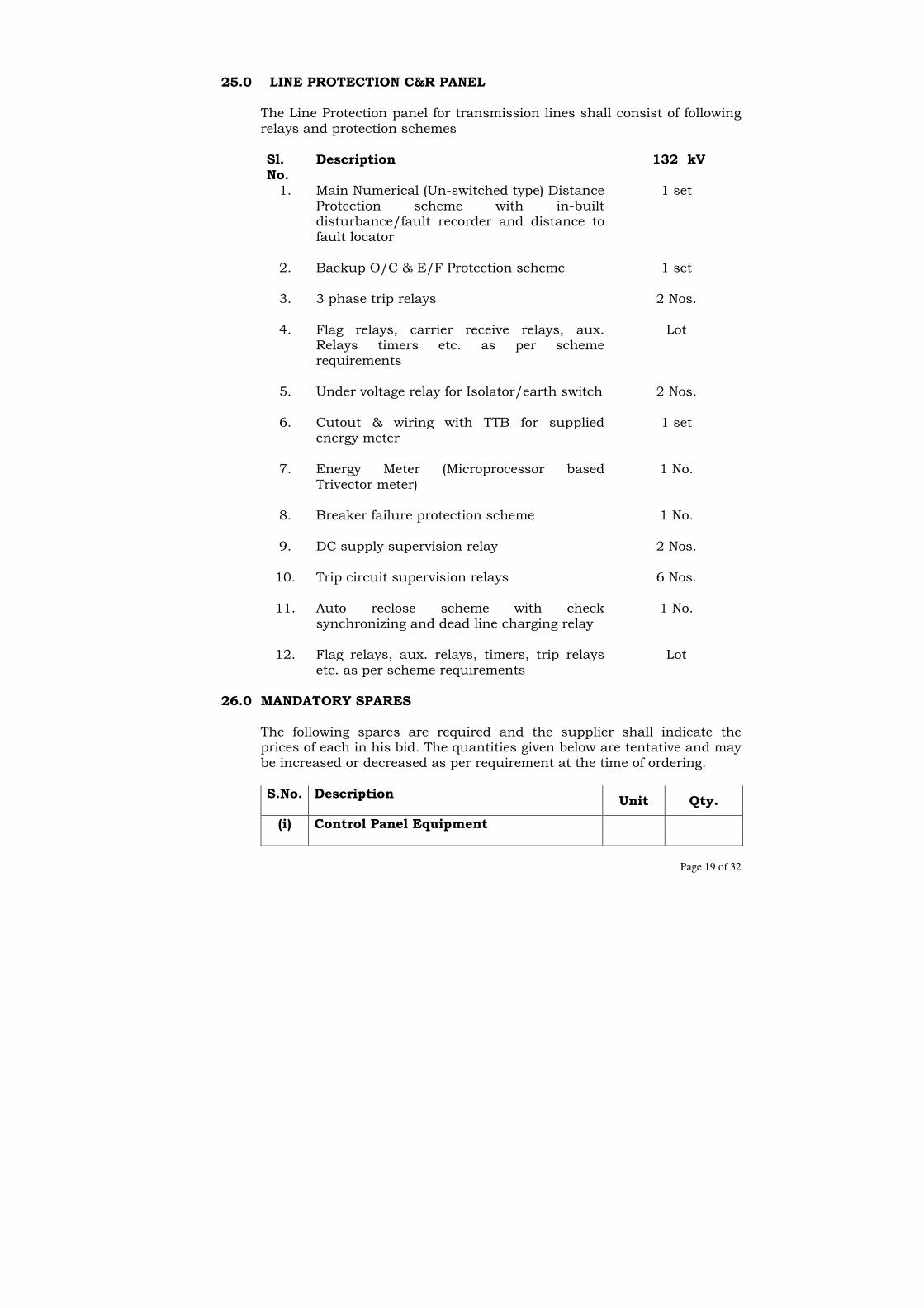
Page 19 of 32
25.0 LINE PROTECTION C&R PANEL
The Line Protection panel for transmission lines shall consist of following relays and protection schemes Sl. No.
Description 132 kV
1. Main Numerical (Un-switched type) Distance Protection scheme with in-built disturbance/fault recorder and distance to fault locator
1 set
2. Backup O/C & E/F Protection scheme
1 set
3. 3 phase trip relays
2 Nos.
4. Flag relays, carrier receive relays, aux. Relays timers etc. as per scheme requirements
Lot
5. Under voltage relay for Isolator/earth switch
2 Nos.
6. Cutout & wiring with TTB for supplied energy meter
1 set
7. Energy Meter (Microprocessor based Trivector meter)
1 No.
8. Breaker failure protection scheme
1 No.
9.
DC supply supervision relay 2 Nos.
10. Trip circuit supervision relays
6 Nos.
11. Auto reclose scheme with check synchronizing and dead line charging relay
1 No.
12. Flag relays, aux. relays, timers, trip relays etc. as per scheme requirements
Lot
26.0 MANDATORY SPARES The following spares are required and the supplier shall indicate the
prices of each in his bid. The quantities given below are tentative and may be increased or decreased as per requirement at the time of ordering.
S.No. Description
Unit Qty.
(i) Control Panel Equipment

Page 20 of 32
1. Ammeter with transducer Nos. 4
2. Ammeter selector switch Nos. 4
3. Wattmeter with transducer Nos. 4
4. Varmeter with transducer Nos. 4
5. Voltmeter with transducer Nos. 4
6. Voltmeter selector switch Nos. 4
7. Control switch for breaker Nos. 4
8. Control switch for Isolator Nos. 4
9. Semaphore indicators for breakers Nos. 4
10. Semaphore indicator for Isolator/Earth switch
Nos. 4
11. Red/Green/White indicating lamp (with complete assembly) (3 No. for each colour)
Set 8
12. Bulbs (for indication lamps) Nos. 20
13. Annunciations windows with necessary annunciation relay
Nos. 8
14. Push button Nos. 12
15. Synchronizing socket Nos. 4
16. Bulbs (for annunciation windows) Nos. 20
17. Indicating lamps with resistor & lamp cover Nos. 20
18. Energy Meter Nos. 4
19. PF Meter Nos. 4
20. Space heaters Nos. 4
21. MCBs Nos. 4 (of each rating)
22. 11W CFL Nos. 4
23. Set of fuses of each type and rating set 4
(ii) Line Protection Panel Equipment Spares
1 Main numerical distance relay Nos. 4
2 Backup directional over current E/F Relay Nos. 4

Page 21 of 32
3 Breaker failure relay Nos.
4 Trip circuit supervision relay Nos. 4
5 Auto reclose relay with check synchronising relay and dead line charging relay
Nos. 4
6 Hand reset trip relay (one relay of each type) if applicable
set 4
7 DC Supervision relay Nos. 4
8 Flag relays (one relay of each type) if applicable
Nos. 4
9 All types of auxiliary relays Nos. 4 (each type)
10 DC fail relay Nos. 4
11 AC fail relay Nos. 4
12 High speed tripping relay Nos. 4
13 Bell Nos. 4
14 Buzzer Nos. 4
15 Hooter Nos. 4
27.0 ERECTION AND MAINTENANCE TOOL EQUIPMENTS
All special testing equipment required for the installation and maintenance of the apparatus, instruments devices shall be furnished in relevant schedule.
28.0 GUARANTEED TECHNICAL PARTICULARS
The supplier shall furnish the GTPs as per Volume -III duly filled up failing which the bid shall not be considered.
29.0 SPECIFIC TECHNICAL REQUIREMENT
Technical parameters for C & R Panels have been listed in Section – “Specific Technical Requirement”
30.0 TROPICALISATION
Control room will be normally air-cooled/air-conditioned. All equipments shall however be suitable for installation in a tropical monsoon area having hot, humid climate and dry and dusty seasons with ambient conditions specified in the specification. All control wiring, equipment and accessories

Page 22 of 32
shall be protected against fungus growth, condensation, vermin and other harmful effects due to tropical environment.
31.0 INDICATING INSTRUMENTS, RECORDERS & TRANSDUCERS
31.1 All instruments, meters, recorders and transducers shall be enclosed in
dust proof, moisture resistant, black finished cases and shall be suitable for tropical use. The Bidder shall confirm that the instruments, meters and recorders offered by them are suitable for connecting to the instrument transformers having technical particulars given under Section – “Specific Technical Requirements” of the specification. All accessories including the test switches and test plugs, where applicable shall be furnished. Their elements shall be shock resistant and shielded from external magnetic fields.
31.2 Indicating instruments
a) Unless otherwise specified all electrical indicating instruments shall be of digital type with a dial of 96 mm x 96 mm size. They shall be suitable for flush mounting.
b) Instruments shall have 4-digit display; display height being not less
than 25 mm.
c) Instruments shall conform to IS: 1248 and shall have accuracy class of 1.5 or better. Watt and Var meters shall have an indication of (+) and (-) to indicate EXPORT and IMPORT respectively.
d) Digital voltage and frequency meters shall be of class 0.5 and shall
have digital display of five (5) and four (4) digits respectively with display size not less than 25 mm (height).
31.3 Electronic / Static Meter
The Electronic/Static Meter having hardware accuracy class of 0.2 with facility to give readings for different time segments for import as well as export parameters separately for the following components of power:
a) kW b) kVAR c) kWh d) kVARh e) Maximum Demand
The meter shall have non-volatile memory to store data for one year. The meter shall be supplied with Tele metering facility so that data can be sent to remote station / computer for processing or records. The Contractor shall submit details of the Energy Meter for approval of the Purchaser.
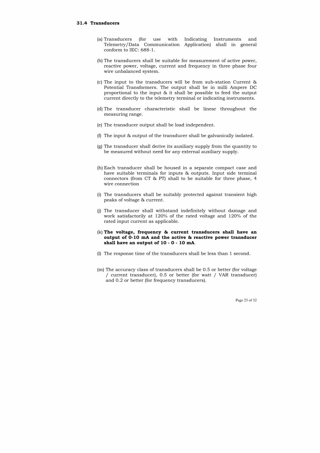
Page 23 of 32
31.4 Transducers
(a) Transducers (for use with Indicating Instruments and
Telemetry/Data Communication Application) shall in general conform to IEC: 688-1.
(b) The transducers shall be suitable for measurement of active power,
reactive power, voltage, current and frequency in three phase four wire unbalanced system.
(c) The input to the transducers will be from sub-station Current &
Potential Transformers. The output shall be in milli Ampere DC proportional to the input & it shall be possible to feed the output current directly to the telemetry terminal or indicating instruments.
(d) The transducer characteristic shall be linear throughout the
measuring range.
(e) The transducer output shall be load independent.
(f) The input & output of the transducer shall be galvanically isolated.
(g) The transducer shall derive its auxiliary supply from the quantity to be measured without need for any external auxiliary supply.
(h) Each transducer shall be housed in a separate compact case and have suitable terminals for inputs & outputs. Input side terminal connectors (from CT & PT) shall to be suitable for three phase, 4 wire connection
(i) The transducers shall be suitably protected against transient high
peaks of voltage & current.
(j) The transducer shall withstand indefinitely without damage and work satisfactorily at 120% of the rated voltage and 120% of the rated input current as applicable.
(k) The voltage, frequency & current transducers shall have an
output of 0-10 mA and the active & reactive power transducer shall have an output of 10 - 0 - 10 mA.
(l) The response time of the transducers shall be less than 1 second.
(m) The accuracy class of transducers shall be 0.5 or better (for voltage / current transducer), 0.5 or better (for watt / VAR transducer) and 0.2 or better (for frequency transducers).

Page 24 of 32
(n) The transducers shall have a low AC ripple on output less than 1%.
(o) The transducers shall be suitable for load resistance of 1000-1500
ohms.
(p) The transducer shall have dual output.
32.0 ANNUNCIATION SYSTEM
32.1 Alarm annunciation system shall be provided on the control panel by
means of visual and audible alarm in order to draw the attention of the operator to the abnormal operation conditions or the operation of some protective device. The annunciation equipment shall be suitable for operation on DC supply as specified in the specification.
32.2 The annunciation shall be of visual and audible type. The audible annunciation for the emergency signals and the warning signals shall be by means of hooter and bell respectively.
32.3 The visual annunciation shall be provided by annunciation facia flush mounted on the top of the control panels.
32.4 The annunciator facia shall be provided with translucent glass or plastic cover plates of white colour with inscriptions in black block letters. The size of the facia window shall be 35 mm x 50 mm and the size of the lettering shall not be less than 5 mm. Alarm inscriptions shall be engraved on each window in not more than three lines and shall be visible only when the facia light is on. The cover plates of the facia window shall be capable of easy removal to facilitate replacement of lamps and individual inscription plates. The transparency of cover and wattage of the lamps provided in the facia window shall be adequate to ensure clear visibility of the inscription from the location of the operator’s table in the control room having high illumination intensity (350 Lux).
32.5 Each annunciation window shall be provided with two lamps in parallel to provide safety against lamp failure. Long life lamps shall be used.
32.6 TRIP and NONTRIP facia shall be differentiated. All TRIP facia shall have red colour and all NONTRIP facia shall have white colour.
32.7 The audible alarm shall be provided by Buzzer/ Hooter /Bell having different sounds and shall be used as follows: (a) Hooter - Alarm Annunciation

Page 25 of 32
(b) Bell - Annunciation DC failure (c) Buzzer - AC supply failure
32.8 “Acknowledge”, “Reset” and “Test” push buttons for the annunciator
shall be provided. 32.9 The sequence of operation of the annunciator shall be as follows:
Alarm condition Fault
Contact Visual
Annunciation Audible
Annunciation 1 Normal Open Off Off 2 Abnormal Close Flashing On 3 Acknowledge/Accept push button pressed
a) Close Steady On Off b) Open Steady On Off
4 Reset Push button is pressed
a) Close On Off b) Open Off Off
5 Lamp Test push button pressed
Open Steady On Off
32.10 a) Visual and audible annunciation for the failure of DC supply to
the annunciation system shall also be provided and this annunciation shall operate on a 240 Volts AC supply with separate fuses. On failure of the DC power supply to the annunciation system for more than 2 to 3 Secs. (adjustable setting), a facia shall light up and the audible alarm shall sound. A separate push button shall be provided for cancellation of this audible alarm alone, but the facia window shall remain steadily lighted till the supply to the annunciation system is restored
b) A separate voltage check relay shall be provided to monitor the
failure of 240 V AC supply to the scheme mentioned in item (a) above. If the failure of supply exists for more than 2 to 3 seconds, this shall initiate the visual and audible annunciation. Visual and audible annunciation for the failure of AC supply to the annunciation system shall be provided and this annunciation shall operate on Annunciation DC and buzzer shall sound.
32.11 The annunciation system described above shall meet the following
additional requirements: a) The annunciation system shall be capable of catering for at least
20 simultaneous signals at a time.
b) One set each of the following push buttons shall be provided on each panel:
i) Reset push button for annunciation system. ii) Accept push button for annunciation system. iii) Lamp test push button for testing the facia windows.

Page 26 of 32
c) One set of the following items shall be provided common for all the control panel i) Flasher relay for annunciation system ii) Push button for flasher test iii) Three Push buttons for test of all audible alarm systems
d) These testing circuits shall be so connected that while test is being done it shall not prevent the registering of any new annunciation that may land during the test.
e) Provision shall be made for switching off the entire annunciation
system. f) The annunciations shall be of repetitive type and shall be
capable of registering the fleeting signals. Minimum duration of the fleeting signal registered by the system shall be 15 milliseconds.
g) Auxiliary relay for annunciation system shall have adequate
auxiliary potential free contacts for use in event logger. The annunciator shall be suitable for operation with normally open fault contacts which close on a fault. For fault contacts which open on fault, it shall be possible at site to change annunciator from “close to fault” to “open to fault” and vice versa.
h) In case “reset” push button is pressed before abnormality is
cleared, lamps shall continue to glow and shall go out only when normal condition is restored.
i) Any new annunciation appearing after the operation of “accept”
for previous annunciation shall provide a fresh audible alarm.
j) In case of static annunciator scheme, special precaution shall be taken to ensure that spurious alarm condition does not appear due to influence of external electromagnetic/electrostatic interference on the annunciator wiring and switching disturbances from the neighbouring circuits within the panels. The static annunciator shall meet the high voltage susceptibility test, impulse voltage withstand test, high frequency disturbance test class III and fast transient disturbance test Level III as per IEC: 60255.
k) The annunciation system to be supplied for existing sub-stations shall be engineered as an extension to the existing scheme.
33.0 CONTROL AND SELECTOR SWITCHES
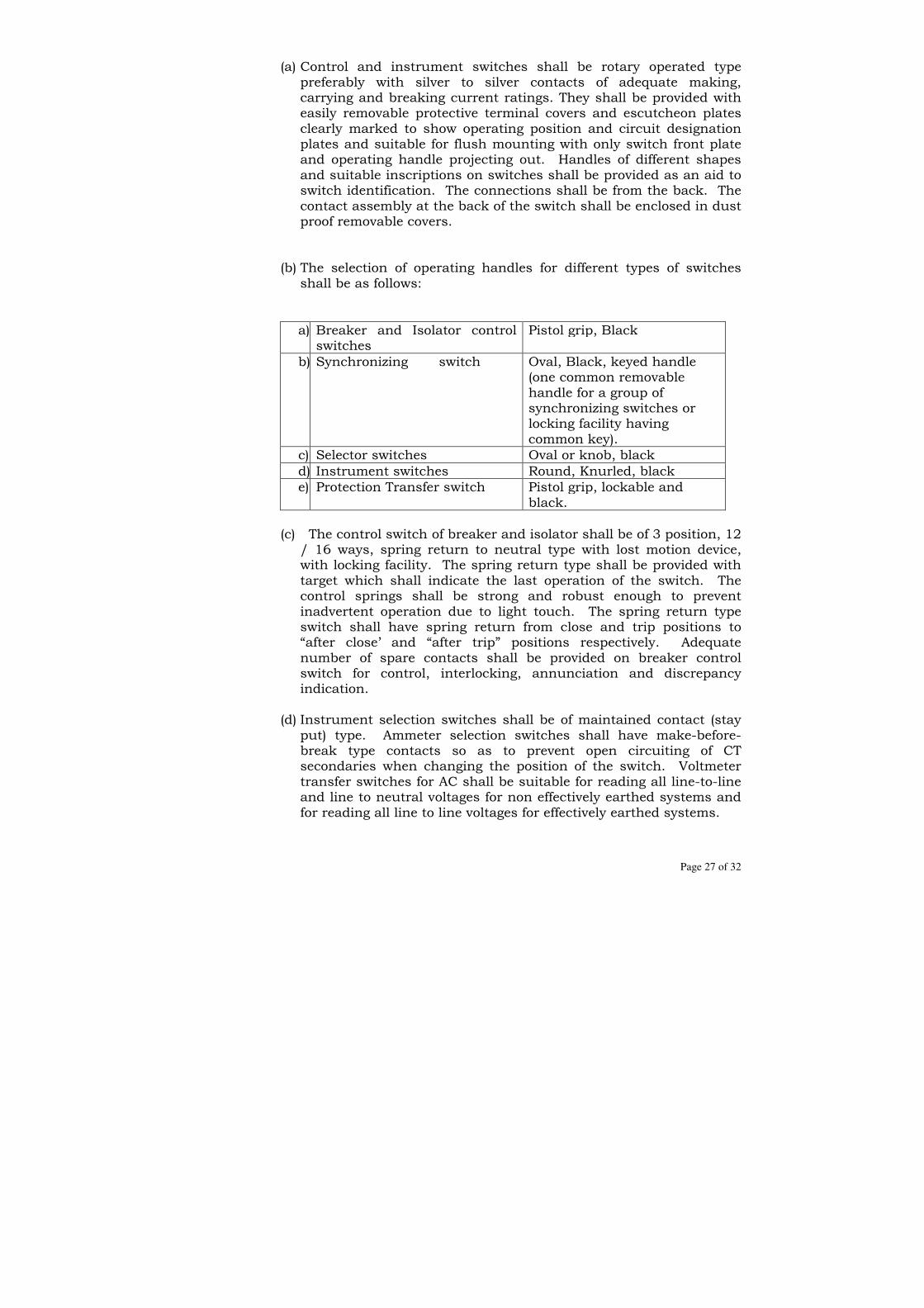
Page 27 of 32
(a) Control and instrument switches shall be rotary operated type preferably with silver to silver contacts of adequate making, carrying and breaking current ratings. They shall be provided with easily removable protective terminal covers and escutcheon plates clearly marked to show operating position and circuit designation plates and suitable for flush mounting with only switch front plate and operating handle projecting out. Handles of different shapes and suitable inscriptions on switches shall be provided as an aid to switch identification. The connections shall be from the back. The contact assembly at the back of the switch shall be enclosed in dust proof removable covers.
(b) The selection of operating handles for different types of switches shall be as follows:
a) Breaker and Isolator control switches
Pistol grip, Black
b) Synchronizing switch Oval, Black, keyed handle (one common removable handle for a group of synchronizing switches or locking facility having common key).
c) Selector switches Oval or knob, black
d) Instrument switches Round, Knurled, black
e) Protection Transfer switch Pistol grip, lockable and black.
(c) The control switch of breaker and isolator shall be of 3 position, 12
/ 16 ways, spring return to neutral type with lost motion device, with locking facility. The spring return type shall be provided with target which shall indicate the last operation of the switch. The control springs shall be strong and robust enough to prevent inadvertent operation due to light touch. The spring return type switch shall have spring return from close and trip positions to “after close’ and “after trip” positions respectively. Adequate number of spare contacts shall be provided on breaker control switch for control, interlocking, annunciation and discrepancy indication.
(d) Instrument selection switches shall be of maintained contact (stay
put) type. Ammeter selection switches shall have make-before-break type contacts so as to prevent open circuiting of CT secondaries when changing the position of the switch. Voltmeter transfer switches for AC shall be suitable for reading all line-to-line and line to neutral voltages for non effectively earthed systems and for reading all line to line voltages for effectively earthed systems.
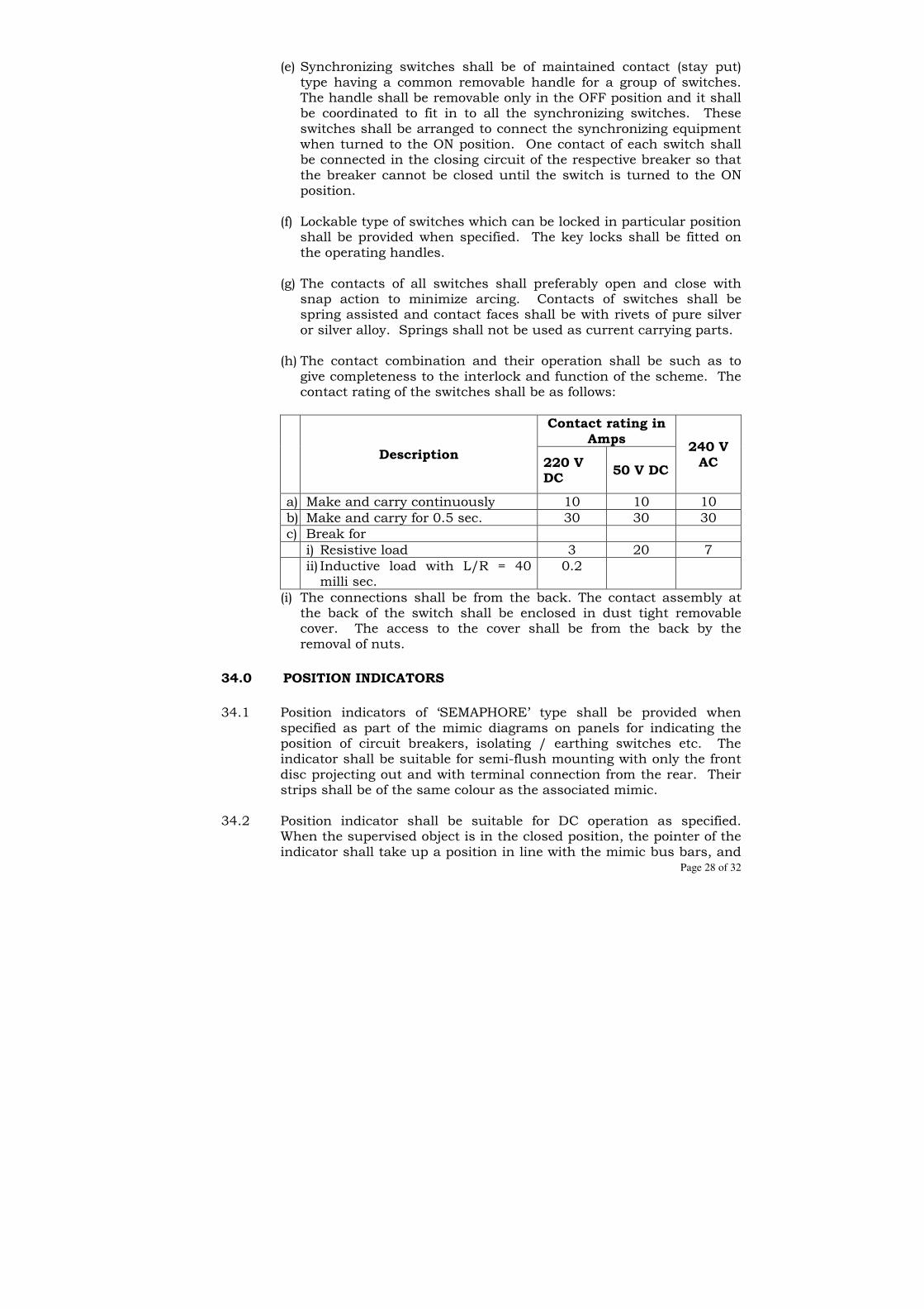
Page 28 of 32
(e) Synchronizing switches shall be of maintained contact (stay put) type having a common removable handle for a group of switches. The handle shall be removable only in the OFF position and it shall be coordinated to fit in to all the synchronizing switches. These switches shall be arranged to connect the synchronizing equipment when turned to the ON position. One contact of each switch shall be connected in the closing circuit of the respective breaker so that the breaker cannot be closed until the switch is turned to the ON position.
(f) Lockable type of switches which can be locked in particular position
shall be provided when specified. The key locks shall be fitted on the operating handles.
(g) The contacts of all switches shall preferably open and close with
snap action to minimize arcing. Contacts of switches shall be spring assisted and contact faces shall be with rivets of pure silver or silver alloy. Springs shall not be used as current carrying parts.
(h) The contact combination and their operation shall be such as to
give completeness to the interlock and function of the scheme. The contact rating of the switches shall be as follows:
Description
Contact rating in Amps
240 V AC 220 V
DC
50 V DC
a) Make and carry continuously 10 10 10
b) Make and carry for 0.5 sec. 30 30 30
c) Break for
i) Resistive load 3 20 7
ii) Inductive load with L/R = 40 milli sec.
0.2
(i) The connections shall be from the back. The contact assembly at the back of the switch shall be enclosed in dust tight removable cover. The access to the cover shall be from the back by the removal of nuts.
34.0 POSITION INDICATORS
34.1 Position indicators of ‘SEMAPHORE’ type shall be provided when
specified as part of the mimic diagrams on panels for indicating the position of circuit breakers, isolating / earthing switches etc. The indicator shall be suitable for semi-flush mounting with only the front disc projecting out and with terminal connection from the rear. Their strips shall be of the same colour as the associated mimic.
34.2 Position indicator shall be suitable for DC operation as specified.
When the supervised object is in the closed position, the pointer of the indicator shall take up a position in line with the mimic bus bars, and
Page 29 of 32
at right angles to them when the object is in the open position. When the supply failure to the indicator occurs, the pointer shall take up an intermediate position to indicate the supply failure. The rating of the indicator shall not exceed 2.5 W.
34.3 It shall not be possible to displace the position of the indicator disc due
to the accidental touch during the cleaning of the panel. 34.4 The position indicators shall withstand 120% of rated voltage on a
continuous basis.
35.0 INDICATING LAMPS
35.1 Indicating lamps shall be cluster LED type suitable for panel
mounting with rear terminal connections. Lamps shall be provided with series connected resistors preferably built in the lamp assembly. Lamps shall have translucent lamp cover to diffuse lights colored red, green, amber, clear white or blue as specified. The lamp cover shall be preferably of screwed type, unbreakable and molded from heat resisting material. The supply for these lamps shall be from DC station batteries unless stated otherwise.
35.2 Lamps and lenses shall be interchangeable and easily replaceable from
the front of the panel. Tools, if required for replacing the Lamps and lenses shall also be included in the scope of supply. Lamps shall be furnished 20% in excess of the actual numbers required and caps shall be furnished 10% in excess of actual numbers used for each colour.
35.3 The indicating lamps with resistors shall withstand 120% of rated voltage on a continuous basis.
36.0 TEST BLOCKS
Switchboard type, back connected semi flush mounting type test blocks with contacts suitably rated shall be provided with links or other devices to enable insertion of series devices into the circuit without causing open circuit in the CT secondary or to enable short circuiting of the CT secondary. Test block covers shall be removable from the front of the panels and shall be provided with suitable sealing arrangement to prevent unauthorized access to the test studs. If any test plugs are to be used with the test studs, 6 nos. of each type of such test plugs shall be supplied free with the main equipment.
37.0 PUSH BUTTONS
Push Buttons shall be of momentary contact type with rear terminal connection. These shall be suitably shrouded to prevent inadvertent operation. Integral inscription plates engraved with their functions shall be provided. All push buttons shall have two Normally Closed and two Normally Open contacts. The contact faces shall be silver

Page 30 of 32
plated. The contacts shall be able to make and carry 5 Amp. , break 1 Amp inductive load at 250 V DC.
38.0 TESTS
• The control and relay panels shall be completely assembled and subjected to the various type and routine tests as per the relevant Indian Standards in the presence of the Purchaser’s representative if desired by the purchaser.
• The bidder shall in his proposal specifically state the details of testing facilities available at his own or its principal works.
• Six (6) certified copies of test reports of the type and routine tests on the control & Relay panels as per the relevant standards shall be submitted by the bidder alongwith the bid.
39.0 DRAWINGS / DOCUMENTS Drawings/ Documents in quadruplicate incorporating the following
particulars shall be submitted by each bidder with the bid in support of the performance and suitability of the equipment offered: - i) Principal dimensional details of each control and relay panel. ii) Front and rear views of the panels with instruments, devices and
relay positions marked. iii) Details of protection schemes and annunciation system offered. iv) Literature describing the instrument relays, Energy meters and
their characteristics, technical details, relay – setting calculations etc.
v) Commissioning, operating and maintenance instruction manual for each relay.
Within 15 days of the receipt of the order the bidder shall furnish the time
schedule of submission of the following drawings for approval of the Purchaser. This schedule shall be prepared so as to ensure the delivery commitments made in the contracts:-
i) Detailed dimensional drawing of control and relay panels showing
all equipment mounted on them along with the complete panel-wise lists of equipment and lists of nameplate.
ii) Drawing of all switches and relays. iii) Outline drawing and internal wiring diagram of the panels i.e.
instrument relays, meters, annunciators and other equipment showing external wiring terminations also.
iv) Outline drawings, mounting details, internal diagrams and item wise bill of material for all devices not located in bidders panels but supplied by him with the boards.
v) Complete AC and DC, Schematic drawings of all elements of control and relays boards. These shall show all A.C power

Page 31 of 32
connections and secondary connections for relays, meters etc. with vector relationship.
vi) Complete Schematic drawing for annunciation system. vii) The bidder may submit any other drawing considered necessary in
addition to the drawing stated above.
40.0 INSPECTION
• All tests and inspection shall be made at the manufacturer's works unless otherwise specifically agreed upon by the manufacturer and purchaser at the time of placement of purchase order. The manufacturer shall afford to the inspector representing the purchaser, all reasonable facilities, without charge, to satisfy him that the material being furnished is in accordance with the specification. The purchaser reserves the right to get any component/ material used by the manufacturer tested from any recognized Test House.
• The inspection by the purchaser or his authorized representative shall not relieve the bidder of his obligation of furnishing equipment in accordance with the specification, and if at any it is found that equipment has not been tested as desired by Purchaser, the same would be rejected. All expenses for inspection shall be borne by the contractor /including lodging, boarding and airfare
41.0 INSTRUCTIONS MANUAL Eight sets of the instruction manuals shall be supplied at least four (4)
weeks before the actual dispatch of equipment. The manuals shall be in bound volumes and shall contain all the drawings and information required for erection, operation and maintenance of the C&R Panel. The manuals shall include amongst others, the following particulars: a) Marked erection prints identifying the components, parts of the panel
as dispatched with assembly drawings. b) Catalogue, users manual, maintenance manual for each type of relay
shall also be submitted.
c) Setting philosophy, setting calculations for each type of relays along with soft copy of the calculations shall also be submitted.
d) Copies of all final approved drawings. e) Detailed O&M instructions with periodical check lists and Performa
etc.

Page 32 of 32
42.0 COMPLETENESS OF EQUIPMENT All fittings and accessories, which may not be specifically mentioned in
the specification but which are necessary for the satisfactory operation of the plant, shall be deemed to be included in the specification and shall be furnished by the contractor without extra charges. The equipment shall be complete in all details, whether such details are mentioned in the specification or not, without any financial liability to the Purchaser under any circumstances.
43.0 DEVIATIONS FROM SPECIFICATIONS
All the deviations from the specifications shall be separately listed in requisite Schedule in the absence of which it will be presumed that the provisions of the specifications have been fully complied with by the bidder. The schedule for Deviations is enclosed as Annexure – I.

Page 1 of 26
SECTION- 7
TECHNICAL SPECIFICATION FOR POWER LINE
CARRIER COMMUNICATION (PLCC)
1.0 SCOPE
1.1 This specification covers frequency planning, design, engineering,
manufacture, inspection, supply, delivery, supervision of erection,
testing, commissioning and performance requirements of various items
of power line carrier communication and associated equipment as per
the Purchaser’s requirement. The equipment are required for providing the
power line carrier communication system on 132 kV Raxaul, Kataiya Grid
sub-station of BSPTCL (BSES) and 132kV Parwanipur and Kusaha sub-
station of Nepal Electricity authority(NEA). The substations shall have
suitable communication facilities between Raxaul-Parwanipur and Kataiya-
Kusaha substations of India & Nepal and therefore any requirement not
specifically brought out here but required shall be deemed to be included
without any subsequent cost to the Purchaser for this purpose.
1.2 Any other equipment not explicitly mentioned herein but are necessary for
completeness of works specified shall also be included in the scope.
1.3 The equipment offered shall be of latest design and technology. The bidder
shall bring out in his offer the alternative offered.
1.4 The scope of supply shall include all the mandatory spares and
considered to be sufficient for normal operation of equipment for 5 years.
1.5 The power line carrier communication equipment is required at existing
Raxaul, Kataiya, Parwanipur and Kusaha sub-stations in Bihar, India and
Nepal for the new 132kV transmission lines to be constructed as detailed:-
- 132kV Raxaul-Parwanipur transmission line - 17km
- 132kV Kataiya-Kusaha transmission line - 18km

Page 2 of 26
1.6 The carrier equipment offered shall also be suitable for facilities such as
teleprinting/ telemetering, telecontrol, interline tripping scheme. The relay
system is covered under a separate section. However, VFT equipment for
teleprotection for the above line is under the scope of this specification.
1.7 All the equipment to be offered against this specification, unless stated
specifically, shall be suitable for connection to 48 volts DC supply. The 48
V DC supply is provided to PLCC equipments from 48 V DC station battery
supported by boost-cum-float-chargers.
1.8 PLCC equipment covered in this specification includes:-
Line Trap H.F.Cable, PLC terminal, coupling device, VFT equipment
for teleprotection, four wire group selector, telephone set without
priority key, companders, AF couplers for TP, TPS etc.
1.9 Bidders shall also quote for all such equipment which are essential to
establish the above PLCC channels to obtain the desired functions,
whether specifically mentioned in this specification or not, but
deemed necessary for the complete and efficient functioning of the PLCC
systems.
1.10 Station 48 V D.C. battery charger shall be boost-cum-float charger and the
general characteristics shall be as that of the battery charger specification
meant for substation batteries. Further approval shall be given during
detailed engineering.
1.11 The contractor shall be responsible for co-ordinating the equipment
supplied by him with the already existing carrier equipment at the
respective substations. Contractor shall also be responsible for collecting
all the necessary information/data from the respective substations for the
installation of the equipment.
Page 3 of 26
2.0 STANDARDS
All the materials and equipment shall comply in all respects with the
requirements of the latest edition of the relevant ISI/IEC/CIGRE Standards
mentioned below:
(a) IEC Publ. 353 : Line traps
(b) IEC Publ. 99-1 of 1970 : Recommendations for Lightning
Arrestors-part-one Non-linear
resistor type arrestor.
(c) IEC Publ. 663 : Planning of (Single Sideband)
power line Carrier systems.
(d) IEC Publ. 481 : Coupling device for power line
Carrier system
(e) IEC Publ. 495 : Recommended values for
characteristic input and output
quantities of single side band
power line carrier terminals.
(f) IS: 2208 : HRC Cartridge fuses
(g) IS: 8792-1978 : Line Traps
(h) IS: 8793-1978 : Methods of tests for line traps.
(i) IS: 9859-Part-I-&II 1981 : Installation of Line traps
(j) IS: 8997-1978 : Coupling devices for PLCC systems.
(k) IS: 8998-1997 : Methods of tests for coupling
devices.
Page 4 of 26
(l) IS: 9482-1980 : Characteristics values of input and
outputs of single side band PLCC
terminals.
(m) IS: 5561-1970 : Specification for Electric Power
Connectors.
(n) IS: 1554 (Part-I) 1976 : Specification for PVC insulated (Heavy
Duty) Electrical Cables.
(o) CCITT recommendations : As applicable.
(p) CEA Regulations : As amended upto date.
(q) In addition to above
reference is invited
to following international
publications on the subject.
CIGRE : Tele Protection Report by
Committee 34&35
CIGRE : Guide on Power Line Carrier
1979.
IEC : Planning of (Single side band)
Power line carrier systems.
IEEE (USA) : Guide on Power Line Carrier
Application.
(r) IEC: 255-0-20 : Contact performance of Electrical Relays

Page 5 of 26
(s) IS: 9528 (Part I & II) 1980 : Manuals for planning of SS B PLC
system.
Reference is also invited to the list of reference given in the above
publications.
3.0 TECHNICAL DATA SHEET/DRAWINGS
3.1 Technical data sheets for all major items of equipment shall be provided by
the bidder. The technical data sheets shall specify clearly all important
parameters associated with the equipment. Sufficient performance details
shall be provided.
3.2 The bidder shall submit with his bid all drawings and sketches necessary
for a proper understanding of the equipment/ system offered.
4.0 CARRIER FREQUENCY PLAN
4.1 A power map of the region showing physical position shall be provided to
the successful bidder.
4.2 Based on these drawings the successful bidder shall prepare carrier
frequency plan for the project. The carrier frequency plan should be
prepared within one month from the date of order. Supplier's
recommendation will be referred to Ministry of Communication, for
clearance and in case any change is proposed by these authorities in the
carrier frequency plan, the modifications required will have to be done by
the bidders at no extra cost.
5.0 LINE TRAPS
5.1 Line traps shall be inserted into high voltage transmission lines to prevent
undue loss of carrier signal for all power system conditions. Its impedance
shall be negligible at power frequency (50 Hz) so as not to disturb the

Page 6 of 26
power transmission but must be relatively high over the frequency band
appropriate to carrier transmission.
5.2 Line trap shall consist of a main coil designed to carry continuously the
rated current at the maximum ambient temperature. It shall be
supplemented with a protective device and a tuning device.
5.3 The line traps for all the sections shall be broad band type. The broad
band type line traps shall be suitable for blocking the transmitted and
received frequency over the entire range of 100-500 KHz.
5.4 The tuning device shall be arranged to permit interchange without
removing the line traps.
5.5 Line traps shall be provided with a protective device which shall be so
designed and arranged that neither significant alteration in its protective
function nor physical damage shall result from either temperature rise
or the magnetic field of the main coil at continuous rated current or
rated short-time current or due to lightning. The protective device shall
neither enter into operation nor remain in operation following transient
actuation for the power frequency voltage across the line trap by the rated
short time current.
5.6 The protective device shall be shunt connected to main coil and the tuning
device.
5.7 For proper co-ordination with the lightning arrestors installed in the sub-
stations, the line traps shall be provided with protective device with
nominal discharge current of 10 kA.
5.8 The line traps should be suitable for outdoor suspension mounting and
mechanically strong to withstand the stresses due to maximum wind
pressure of 50 Kg/m2/Zone-V of IS: 802. Necessary suspension clamps for
hanging the line trap from gantry should also be provided.

Page 7 of 26
5.9 Line traps shall conform to the following technical particulars.
(i) System Voltage 132 kV
(ii) Type 1.0/1250
(iii) Inductance of main coil 0.5 mH
(iv) Continuous current rating 1250 A
(v) Short time current rating for 31.5 kA
1 sec.
(vi) Blocking Band width 100-500 kHz
(vii) Minimum resistive comp. over 570 ohm
blocking range
(viii) Maximum tapping loss 2.6 db
(ix) Material of main coil Aluminium Alloy
(x) Particulars of protective device (LA)
(a) Nominal discharge 10 kA
(b) Current rated voltage Co-ordinate with the
rated short time current as
per IS/IEC.
(xi) Accessories required Tuning Unit, Bird Barrier,
Lightning arrestor, suspension
hook, terminal pad and all
mounting accessories except
suspension disc insulators.
5.10 Bidder should offer bimetallic clamps suitable for connecting terminals
of line traps to High Tension or Station Equipment by means of ACSR
Zebra conductor.

Page 8 of 26
5.11 The line traps shall conform to latest edition of IS:8792/IS:8793, IEC:
9859 (Pt. 1) or any other internationally accepted standards which ensure
an equal or higher quality than the standard mentioned above.
6.0 COUPLING CAPACITORS/CVT
6.1 Coupling Capacitors/CVTs form a part of a separate specification and the
salient features of CVTs shall be provided.
7.0 COUPLING DEVICE
7.1 Coupling device for power line carrier circuits are devices interposed
between the coupling capacitor and the connection line to the PLCC
transmitter-receiver and shall be designed to :
(i) Ensure an efficient transmission of signals from the connection line
to the high voltage line and vice-versa.
(ii) Protect the lower voltage part of the plant against the effects of high
Voltage
7.2 The coupling devices shall be designed to perform the following functions:
The coupling unit may form a single assembly or be divided into
several separate components. The same component may take over more
than one function.
(i) Coupling Filter :
Coupling filter in conjunction with the capacitance of the coupling
capacitor shall constitute an electric filter of broad-band type. It shall
match the characteristic impedance of the high tension line with
impedance to the connection line for PLCC transmitter-receiver.
Drainage of Charging Current:
The primary of the coupling unit shall have a low impedance
not exceeding 20 ohms for the operating frequency of the power
line (50 Hz) so that the charging current of the coupling capacitor
CVT is grounded.

Page 9 of 26
(ii) Insulation :
The input and output circuits of the coupling devices shall
introduce a galvanic insulation into coupling units and should be
able to withstand a test voltage of at lest 5 kV (RMS) for 1 (one)
minute.
7.3 The coupling devices shall also be provided with a protective device
which shall protect the carrier equipment against excess voltages
which may occur when the coupling capacitor becomes defective or the
ground load connected to the coupling unit is interrupted.
7.4 The coupling unit shall conform to the following carrier frequency operating
characteristics:
(a) Method of coupling : Phase to Phase using two Phase to
earth
unit and Hybrid transformer.
(b) Primary impedance : 400 to 600 ohms.
(c) Secondary impedance : 150 ohms for balanced secondary
circuits
or 75 ohms for unbalanced secondary
circuits.
(d) Max. Composite loss : Less than 2 dB (<2 dB)
(e) Transmission Band : 30 to 500 KHz (Board - Band)
(f) Return loss : The line side & equipment side return
losses shall not be less than 12 db
over the whole of the available band
width of the coupling devices.

Page 10 of 26
(g) Peak envelope power : Not less than 650 Watts.
7.5 Two nos. phase-earth coupling units should be capable of being used to
form interphase or inter-circuit coupling. In case any separate matching
transformer or matching unit is required, the same shall be offered.
7.6 The bidder shall also offer suitable earthing switches for grounding the low
voltage terminal of the coupling capacitor for carrying out maintenance or
any other work on coupling units.
7.7 The coupling units should be housed in a weather proof casing suitable
for installation on the steel pedestal which shall also be used for
mounting coupling capacitor.
7.8 The coupling devices shall conform to latest edition of IS:8997, IS:8998,
IEC:481. Equipment meeting other internationally accepted standards,
which ensure an equal or higher quality than the standard mentioned,
will also be accepted.
8.0 HF CABLES
8.1 High frequency (HF) cable shall be used to connect the line matching
unit installed in outdoor, near the circuit wave trap, to the PLC
terminal installed indoor. The cable should be suitable for being laid
directly over the ground or in a trench. The capacitance of the cable should
be low, as to minimise attenuation in the carrier frequency range viz 100 to
500 kHz.
8.2 Cable
The cables shall have salient features as below:
Constructional Features
S.No. Item
Description Nominal
Tolerance
1 Inner
conductor
Single diameter 1.40 +0.02

Page 11 of 26
2 Dielectric Thickness 1.00 +0.15
3 Core Diameter over
dielectric
5.00 +0.1
4 Screen Braid wire
diameter
0.20 (90%
coverage)
5 Outer
protection
sheath
Thickness 2.00 +0.2
6 Protection
armouring
Thickness 0.30 (75%
coverage)
7 Overall PVC
sheath
(All dimensions
are in mm)
Thickness 2.00 +0.2
8.3 Attenuation
The frequency attenuation chart for 10 to 500 KHz must be provided for
150 Ohms balanced HF cable 75 ohm imbalance load.
The maximum acceptable attenuation per kilometer at different frequencies
are given below:
Frequency Attenuation (db/KM)
1.0 0.30
3.0 0.40
10.0 0.80
30.0 1.20
50.0 1.40
100.0 2.00
150.0 2.40
200.0 2.80
250.0 3.10
300.0 3.30
400.0 3.90

Page 12 of 26
450.0 4.30
500.0 4.70
8.4 Service Engineering Data
The impedance of the cable shall be in accordance with output impedance
of the PLC terminal and secondary impedance of coupling device.
8.5 Construction
The cable should consist of two solid inner conductors of plain annealed
and high conductivity electrolytic copper, semi air spaced dielectric of
composite helical threads and tube of polyethylene, dummy cores to make
it reasonably round, taped with polyester tape, screen covered with
braiding of annealed tinned copper conductor, polyethylene sheathed and
duly covered with G.I. Wire armouring. The cable should be finished with
overall sheath of suitable PVC compound black in colour. The diameter of
each inner conductor should be 1.40 mm (nominal).
8.6 Specimen
A specimen of the offered cable may be called for from successful bidder as
per following details:-
(i) Overall length of specimen 30 cm.
(ii) 2.4 cm. of each layer of material comprising the cable should be
made bare so that each layer, is clearly visible.
(iii) The specimen should bear markings of the names or symbol of the
manufacture and type of cable along the length with a clear spacing
of 20 cm. Bidder not accompanied with specimen may not be
considered.
8.7 Lengths of Cables
Page 13 of 26
The cable should be supplied in one length for the substation separately
wound on a single drum each.
8.8 Marking
Marking on the Drum:
The following markings should be provided on each drum:-
(i) Manufacturer's name
(ii) Year of manufacturer and lot no.
(iii) Exact length of cable in the drum and brief particulars of the cable.
(iv) Gross weight
(v) Name of consignee and destination railway station.
8.9 Marking on the Cable
The outer sheath of the cable shall be marked "Ministry of External Affairs
(MEA)".
8.10 Test
The HF cable should be subjected to the following tests as per the
procedure laid down in BS-2316.
1. Dielectric strength of core (Minimum)
2. Insulation Resistance
3. Capacitance (Max.)
4. Spark test on sheath (Min.)
5. Attenuation
6. Characteristic Impedance
7. Resistance of inner conductor (Max.)
9.0 POWER LINE CARRIER TERMINALS
9.1 General

Page 14 of 26
Bidders shall offer voice frequency companders as optional items which
can be used in PLCC system already equipped with such companders.
Each PLCC terminal shall be complete with HF hybrid and filter. PLCC
terminal shall be mounted in floor mounting sheet metal cabinets. The
terminals shall be provided with built-in indicating instruments to facilitate
checking of important voltage and current values, easy inspection and
replacement. The carrier sets shall be provided with suitable supervision
and alarm facilities. The individual parts of the carrier set should be side
back to back and against wall. All component parts of the carrier sets shall
be suitably tropicalised and protected against bad effects of humidity,
fungus, etc. Building block principle should be employed in the
construction of carrier sets. The PLCC terminals shall be provided with
emergency call facility from the carrier set for point to point contact with
the next station complete with telephone suitable for hanging in-side the
cabinet. Each carrier cabinet shall be vermin proof and provided with
a fan for ventilation. A cable and socket for connection of the HF cable
from the coupling device shall be provided. The carrier sets to be offered in
the bid will be as follows:
Double channel SSB based on the state of art technology fixed frequency
carrier sets suitable for speech and super-imposed signals to be used on
the short circuit line.
9.2 Because of the shortage of the carrier frequencies available for PLCC
system, PLCC terminals using single band modulations are to be offered.
Latest version of PLCC terminals is required for speech, telemetering and
telecontrol channel.
9.3 PLC terminals shall conform to the following electrical characteristics
(These characteristics refer to the single channel PLCC terminals).
(a) Mode of transmission : Single side band amplitude
Modulation Twin channel
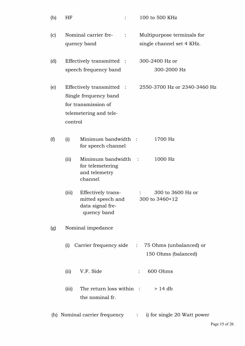
Page 15 of 26
(b) HF : 100 to 500 KHz
(c) Nominal carrier fre- : Multipurpose terminals for
quency band single channel set 4 KHz.
(d) Effectively transmitted : 300-2400 Hz or
speech frequency band 300-2000 Hz
(e) Effectively transmitted : 2550-3700 Hz or 2340-3460 Hz
Single frequency band
for transmission of
telemetering and tele-
control
(f) (i) Minimum bandwidth : 1700 Hz
for speech channel
(ii) Minimum bandwidth : 1000 Hz
for telemetering
and telemetry
channel
(iii) Effectively trans- : 300 to 3600 Hz or
mitted speech and 300 to 3460+12
data signal fre-
quency band
(g) Nominal impedance
(i) Carrier frequency side : 75 Ohms (unbalanced) or
150 Ohms (balanced)
(ii) V.F. Side : 600 Ohms
(iii) The return loss within : > 14 db
the nominal fr.
(h) Nominal carrier frequency : i) for single 20 Watt power

Page 16 of 26
Power (peak envelope carrier at the output
power available set channel of hybrid
at line output terminal
at a resistive load equal
to the nominal load
impedance)
(i) Max. frequency error : 2.0 Hz Man.
between Trans. /
receiving V.F. Signal
(j) Relative levels (VF : Across 600 Ohms
side)
(i) 4-wire transmit : OdBr to (-) 17 dBr.
(ii) 4-wire receive : 8dBr to (-) 3.5 dBr.
(iii) 2-wire transmit : 0 dBr.
(iv) 2-wire receive : (-)7 dBr.
(k) Level regulation : Level variation of + 30 dB
(Automatic gain if the receive HF is reduced
control) to + 0.5 dB at VF output.
(l) Telephone signalling : By frequency shift keying
channel pulse distortion of the
telephone signalling channel
at signaling speed of 10
impulse per second shall be
less than 5 millisecond in
back to back operation of
one pair of terminals.
(m) Permissible limit for
variation of overall
loss (attenuation) of
the speech channel
relation to 800 Hz for

Page 17 of 26
back to back operation
of one pair of terminal
without compander.
300-400 Hz :-0.87 to + 3.0 db | of + 1.5 db for the
400-600 Hz :-0.87 to + 1.74 db | complete band of
600-2400 Hz :-0.87 to +0.87 | 300 db to 2400 Hz
2400-3000 Hz:-0.87 to +1.74 | (without db comp-
3000-3400 Hz:-0.87 to 3.0 db | ander)
(n) RF sensitivity 45 db
(o) Noise performance
(i) Noise generated The weighted telephone noise
without the terminals level measured at the speech
out of a pair of PLC termi-
nals without compander shall
not exceed -60 dbmop, measu-
rement shall be carried out
as per IEC specification No.
495 of 1974.
(ii) S/N ratio (as per 35 db
report committee No.14
"(Tele-transmission of
CIGRE 1962) for voice
Communication referred
to 1 milliwatt at a
relative level of zero"
(iii) S/N ratio (as per 29 dB
report committee No.14
"Tele-transmission for
frequency shift keying"

Page 18 of 26
(p) Telephone signalling channel:
(i) The signalling channel shall be operated by a potential
from open or closed contact at the transmit side and
provide a potential free changeover contact at the recieving
side.
(ii) All the relays to be provided in the speech circuits shall be
hermetically sealed.
(q) Power supply for PLC terminals:
The PLC terminals shall be suitable for working at 48 V DC supply
with positive pole earthed and with following supply voltage variation
limits:
(i) Stated performance requirement to be satisfied 48 V DC
(+15%-10%)
(ii) Terminal shall remain operational, when the supply voltage
is raised by 20% of its nominal value without any damage
or failure to the equipment as per IEC 495 of 1974.
9.4 Cabinet having PLC terminals must not be more than 2000 mm in height.
The cabinet shall be suitable for top or bottom cable entries.
9.5 The bidder shall provide suitable means so that in the event of any
short circuit of the output terminals of the power supply unit in the
carrier terminals, the unit is switched off from the supply without
causing any damage to the power supply unit itself. This is necessary to
provide protection against any accidental short circuit or short circuit due
to failure of some components in the circuits.

Page 19 of 26
9.6 The power consumption of the PLC terminals shall be minimum and shall
be commensurate with the output power of the PLC terminals as specified
to keep the size of the battery optimum.
9.7 The PLC terminals offered shall comply with the following
construction/design features.
(a) All equipment shall be as far as possible of modular construction and
the modules or sub-units shall be of the plug-in type for easy
replacement.
(b) Equipment shall use solid state components of latest design
techniques.
(c) The design shall permit the rapid and positive recognition of defects
and facilitate easy repair.
(d) Indications shall be provided for fault location.
(e) All components shall be readily accessible to the maintenance
technician for easy disassembly and replacement.
(f) All components and modules shall be clearly and unambiguously
marked and all wiring colour-coded and tagged. Only colour coded
ribbon cable wires and internal wires with solder disconnections will
be exempted from tagging.
(g) Easily accessible and clearly marked test points shall be provided at
all the important points in the circuit. Meters shall be provided for
monitoring essential voltage and current levels.
(h) Safety equipment such as protective covers and interlocks shall be
provided.
(i) Screw-type terminals shall be provided on the racks for
interconnection wiring. All such terminal blocks shall be mounted on
the rear.

Page 20 of 26
(j) Ground terminals with isolating links shall be provided.
10.0 EQUIPMENT FOR TELEPROTECTION
10.1 The bidders shall offer voice frequency transmission equipment for
teleprotection signal. During transmission of teleprotection signals or
when the fault has been located by the protective relays, speech channel
in the carrier set and other unimportant superimposed signals shall be
disconnected and the entire power of the carrier set will be made
available for transmission of teleprotection signals. The teleprotection
channel shall be provided in such a manner that the time interval that
elapses between the instant command is received from protection relays
from the transmitting side and the time this command is passed on to the
protection relays at the distant side shall not be more than 25
milliseconds.
10.2 The carrier protection equipment shall be offered for transmission of single
protection command. The equipment for single circuit protection shall be
flexible to be additionally equipped for double circuit protection if
necessary in future. The protection equipment shall be provided with
interconnection unit suitable for connection to the protective relays.
Separate counters to register trip command signals sent and received shall
be provided.
10.3 It shall be possible to test operational reliability of the protection channel
over the carrier link. It shall be possible to test the protection link from
inner side of the two ends of the PLCC link. During healthy conditions of
the transmission link this test procedure must not initiate any false
tripping command and the equipment shall remain fully operative. During
testing a genuine trip command is given, it shall over ride the test signal,
thereby energising the appropriate output in the receiver station.
10.4 Due to acute shortage of PLC frequencies that can be made available
for new channels and certain other advantages, the bidders shall offer

Page 21 of 26
the only in-band type teleprotection signals and arranged in such a
manner that the superimposed signalling frequency band is kept free for
telemetering and teleprinting etc. In other words, the transmission of
teleprotection signal should take place within the speech band instead of
superimposed signalling band. Bidders shall offer equipment keeping the
above in view.
The V.F.T. equipment shall conform to the following electrical
characteristics:-
(a) Transmission time : Less than 25 ms including contractor
delay.
(b) Alarm ouput : It should provide an alarm if the pilot or
signals are incorrect or the power supply
fails.
(c) Ambient temperature : Date accurate: 0-45 C Equipment
Functional
(d) Transmission level : Trip Approx. 100 modulation
Test-suitable value
Pilot-suitable value
(e) Channel requirement : It shall be suitable for single circuit.
(f) Test : It shall provide facility for suitable test
While in operation without tripping of the
circuit breakers of the associated lines.
10.5 The equipment offered shall not only be insensitive to nominal corona
noise which exists on high tension lines but also against impulse type of
noise which is created by operation of circuit breaker, isolators and
electrical surges. Bidders shall explain clearly in their bid as to how their

Page 22 of 26
equipment has been rendered insensitive to corona noise and impulse type
of noise.
10.6 The equipment shall have high reliability and high security of operations
within the stipulated transmission time. The bidders shall specifically
indicate the reliability expressed numerically fail to trip rate and security
expressed numerically as a false trip for the equipment offered by him.
10.7 The equipment shall be complete with built - in alarm circuit and
necessary contacts for supervising the failure of the protection
circuit/equipment etc.
11.0 FOUR-WIRE GROUP SELECTOR
11.1 The four wire group selectors covered in this specification will be for
important links in the network of exchanges on power line carrier.
The four wire group selectors shall serve to receive and register various
signals from the local exchange and repeat them to other group selectors in
a form suitable for transmission over power line carrier, and shall also have
facilities for random switching.
The group selector shall be able to generate different pulses during the
various stages of a call as detailed below:
(i) "Engage" pulse : 200-250 ms make
70-90 ms break
70-90 ms make
(ii) "Priority" pulse : 200-250 ms make
70-90 ms break
70-90 ms make
(iii) "Digit" pulse : 50 ms make - 50 ms break

Page 23 of 26
(iv) Inter digit pause : 500 ms minimum
(v) "Release" pulse : 800 ms minimum
The F.G.S unit as per equipment schedule shall handle calls for upto ten
directions in addition to the calls from their local exchanges.
The "Exchange Number" can either be single digit or two digit. By suitable
planning it shall be possible to have a mixed single or two digit working
also.
The digit pulses regenerated by the group selector shall be adjustable in
ratio and frequency by adjustable resistors. This shall compensate for a
possible change after a length of service.
It shall be possible of busy the selector, if required for maintenance by
operating a key. When the key is operated the selector at the other end of
the line shall also be busy. A lamp in the cabinet shall be on if the selector
is already busy on the call.
Fuse alarms shall be provided when fuse blows due to a fault. The fuse
alarm lamp shall light in the lamp and key cabinet to indicate the selector
in which the fuse has blown. Audible alarm shall also be selected if it is
connected.
The group selectors shall be housed in dust proof steel cabinets of suitable
design to facilitate efficient maintenance of the same.
The four wire group selectors of electronic type may only be offered which
shall work on a supply voltage of 48 V D.C. with operating voltage limits +
15% and -10%.
12.0 CARRIER FREQUENCY PLAN
In Bihar and Nepal, the PLCC system is in operation at different 132kV &
220kV substations.

Page 24 of 26
The exact frequencies at all the substations under BSTCL & NEA shall be
provided.
13.0 TESTS
Reports of all types of tests for each component/part as stipulated in the
relevant ISI /IEC (latest version) shall be furnished along with the bid.
Routine tests relevant to ISI/IEC shall be carried out on each type of
equipment. Type tests as per relevant IEC shall be carried out on the
prescribed number of equipment, required by the Employer at the time of
placing orders. These tests shall be carried out in the presence of Owner's
representative, if so desired by the Owner.
14.0 INSPECTION
14.1 All tests and inspection shall be made at the manufacturer's
works unless otherwise specifically agreed upon by the manufacturer
and purchaser at the time of placement of purchase order. The
manufacturer shall afford to the inspector representing the purchaser, all
reasonable facilities, without charge, to satisfy him that the material being
furnished is in accordance with the specification. The purchaser reserves
the right to get any component/ material used by the manufacturer tested
from any recognized Test House.
14.2 The inspection by the purchaser or his authorized representative
shall not relieve the bidder of his obligation of furnishing equipment in
accordance with the specification, and if at any it is found that equipment
has not been tested as desired by Purchaser, the same would be rejected.
15.0 SPARES
15.1 Mandatory Spares
Mandatory spares considered to be sufficient for successful operation and
maintenance of equipment for a period of 5 years are listed below. The

Page 25 of 26
bidder may review the above spares and may add the spares, which are
essentially required for the satisfactory operation & maintenance of the
equipment. The Bidder shall accordingly quote the itemized price of these
spares in the price Schedule.
i) Coupling Device 2 No.
ii) Line Traps 2 No.
iii) Set of electronic Card for each type of PLC Terminal 2 No.
iv) Protection Coupler 2 No.
15.2 Recommended Spares
The bidder may recommend the spares in addition to the mandatory
spares, the itemized prices of the spares shall be quoted in price Schedule.
16.0 INSTRUCTIONS MANUAL
16.1 Six sets of the instruction manuals shall be supplied at least four (4) weeks
before the actual dispatch of equipment. The manuals shall be in bound
volumes and shall contain all the drawings and information required for
erection, operation and maintenance of the PLCC equipment/Panel. The
manuals shall include amongst others, the following particulars:
a) Marked erection prints identifying the components, parts of the
equipment/panel as dispatched with assembly drawings.
b) Catalogue, users manual, maintenance manual shall also be
submitted.
c) Copies of all final approved drawings.
d) Detailed O&M instructions with periodical check lists and Performa
etc.
17.0 COMPLETENESS OF EQUIPMENT
17.1 All fittings and accessories, which may not be specifically mentioned in the
specification but which are necessary for the satisfactory operation of the

Page 26 of 26
plant, shall be deemed to be included in the specification and shall be
furnished by the contractor without extra charges. The equipment shall be
complete in all details, whether such details are mentioned in the
specification or not, without any financial liability to the Purchaser under
any circumstances.
18.0 TOOLS, TACKLES AND SLINGS FOR ERECTION, TESTING &
COMMISSIONING AND OPERATION AND MAINTENANCE
18.1 The supplier shall provide all testing instruments, tools, tackles and slings
required for erection, testing and commissioning of the equipment at site.
The list of testing instruments, tools, tackles & slings required to be
arranged by the supplier shall be submitted along with the bid required for
operation and maintenance.
19.0 DEVIATIONS FROM SPECIFICATIONS
19.1 All the deviations from the specifications shall be separately listed in the
requisite Schedule and in the absence of which it will be presumed that the
provisions of the specifications have been fully complied with by the bidder.
The schedule for Deviations is enclosed as Annexure – I.
20.0 GUARANTEED TECHNICAL PARTICULARS
The Schedules given in volume-III of specification shall be duly filled by the
bidder.
21.0 MODEM
2 No. modem (one for each channel) shall be provided for both end of the
line for RTU purpose. The required power supply shall also be supplied
along with the modem.
Modem shall be capable of transmitting data at configurable BOD rate (up
to 2400 BOD) through PLCC in IEC-101 protocol to remote station.

Page 1 of 36
Section-8
SUBSTATION STRUCTURES (Including Supporting Structure for Sub Station Equipment)
1. GENERAL
1.1 This part of the specification covers detailed technical requirement for design, fabrication, galvanizing, testing before dispatch and supply of steel structures i.e. gantry towers (columns) & beams (girders), lightening mast for installation of conductors, shielding wire, luminaries etc. and equipment support structures i.e. CBs, Isolators, Instrument Transformer (CTs, PTs/ CVTs), Lightning Arrestors etc. and accessories (i.e. nuts, bolts, washers etc.) required.
1.2 Approximate quantities of structure are given in the schedule of requirements in price schedule (Volume-IV). The quantities are only indicative and may need to be revised based on actual design.
1.3 The supply shall also include all types of bolts, nuts, washers,
hangers, step bolts, ladders, step bolt inserts in concrete and foundation bolts as also 2½% extra bolts and nuts, flat washers, spring washers required after erection for future maintenance. Base plates, number plates, phase plates, danger plates, foundation and mounting bolts, embedded plates, clamps, gusset plates, equipment mounting bolts, structure earthing bolts, spring washers, fixing plates, angles & bolts for structure mounted or ground mounted marshalling boxes and other related items shall also be supplied. The supply shall be complete with any other accessories, if required, for the substation structures.
1.4 a) The bidder shall indicate the guaranteed weights of each
category of Structural steel works including equipment lattice / pipe support structures as per requirement stipulated in relevant Clauses of Section- “Guaranteed and other technical particulars (Volume-III)” of this document
b) The unit rates as per tonne basis for each of the above items
and total price for each of the above items shall be given in the bid proposal sheet.
c) In case of change in scope of work the guaranteed tonnage of steel shall be adjusted accordingly.

Page 2 of 36
d) In case actual tonnage of steel is less than guaranteed tonnage, payment shall be made based on unit rates to the extent of actual tonnage.
e) In case actual tonnage of steel exceeds guaranteed tonnage, no extra payment shall be made to the contractor.
f) The rates as quoted above shall also include preparation of designs, drawings, supply of final copies and reproducible, manuals, supply of all materials, transportation, labour, erection, plant and equipment freight insurance, erectable fixtures, fittings and all temporary and permanent works necessary for satisfactory completion of job in all respects.
1.5 No sublet orders shall be placed by the contractor with any other
manufacturer or suppliers without prior approval of the Purchaser and when such approval is given, copies of all drawings / specifications referred to in the sublet orders shall be furnished to the Purchaser.
2. GENERAL TECHNICAL REQUIREMENTS:
2.1 The design, manufacture and performance of the steel structures
and accessories shall, in general, comply with the relevant IS standards of latest edition including amendments except to the extent explicitly modified in the specification and shall also be in accordance with requirements specified in this section. A list of relevant Standards is given in Section- I – “General Technical Requirements”.
2.2 All work shall be done strictly as per latest relevant Indian
Standards and codes of practices whether specifically mentioned in the specifications or not. All materials shall be of best quality conforming to the relevant Indian standards.
2.3 Except otherwise specified or implied, the design, manufacturing,
fabrication, galvanization shall conform to the provisions of latest editions of IS: 802 (Part-I) & (Part-II) for lattice structures and IS: 800 for other general parts.
2.4 For all main structures i.e. columns, beams and lightning mast,
fully galvanized lattice steel structures using G.I. bolts & nuts connections shall be used as self supporting structures designed to carry the conductors with the necessary insulators, earth wire, luminaries and all fittings under specified loading conditions.
2.5 The Contractor shall furnish the most economical design for beams, columns, lightning mast and equipment support structures that can be supported on the foundations either with Stub Angles or Base Plate Assembly. No welding or riveting shall be allowed in lattice super- structures. The stubs shall be galvanized from the

Page 3 of 36
top of the stub to 300 mm below. Templates for setting the stubs of the structures need only be painted and not galvanized. The equipment support structures shall normally be fixed to foundations with foundation bolts. The exposed portion of the foundation bolts shall also be galvanized as per the relevant codes.
2.6 All the structures shall be so designed that only the rationalized ISI
metric sections preferably of mild steel of tested quality as per latest edition of IS: 2062 are used in the columns, beams and lightning mast.
2.7 Structural steel of tested quality conforming to IS: 2062 shall be
used for the fabrication of stubs, templates, super structures and other steel parts. Steel section in accordance with IS: 808 (latest) shall be used in switchyard lattice structures, stubs and stub setting templates. All sections shall be of tested quality conforming to IS: 2062 ( latest ) Pipe Sections shall be as per IS:1161 (latest)
2.8 Any fabrication wastages shall deem to be considered while quoting
rates and Purchaser shall not accept any liability in connection with wastage of steel during fabrication or otherwise. The Contractor shall indicate at detailed engineering, the complete details of the steel sections, angles, plates, pipes etc. required by him to fabricate the specified quantity of various structures as per this specification. Substitution if any, of steel sections of the structures by higher sizes, due to non-availability or other reasons, shall be to the Contractor’s account and Purchaser shall not accept any liability on this account.
a) While designing columns, gantries, etc., Contractor shall
ensure adequate electrical clearances as stipulated in relevant standards / codes / rules and regulations / specifications.
b) The Contractor shall furnish all labours, erection
equipment and all materials including steel required for the completion of the work in accordance with the approved fabrication drawings, specifications and as directed by the Purchaser.
c) Fixing of all the structures to the foundations shall be by
means of base plate and anchor bolts in case of equipment support structures and stubs / base plate in case of gantry columns, lightening mast which are included in the scope of the supplier.
3. SPECIFIC TECHNICAL REQUIREMENTS

Page 4 of 36
The technical parameters relevant to structural works are detailed in Section- “Specific Technical Requirements”.
4. GUARANTEED AND OTHER TECHNICAL PARTICULARS
The guaranteed and other technical particulars for the structural works are indicated in Section- “Guaranteed and Other Technical Particulars (Volume-III)”. Any other particulars considered necessary shall also be given by the tenderer in addition to those listed in that Section.
5. DRAWINGS / DOCUMENTS:
5.1 DRAWINGS/DOCUMENTS TO BE SUBMITTED WITH THE BID:
The contractor shall submit with his bid, general arrangement drawings for each type of structure such as column, beam, lightning mast and equipment support structure etc. covered in this specification showing sizes of all sections, parts, fittings, bolts and attachments for insulators, ground wire, under hung insulators, conductors etc. for purchaser’s review. The contractor shall also furnish with the tender the tentative requirement of steel sections required for each type columns, beams, lightning mast and equipment support structure etc.
5.2 DRAWINGS / DOCUMENTS TO BE SUBMITTED AFTER AWARD OF CONTRACT:
5.2.1 After award of contract, the Contractor for approval of the
Purchaser shall submit analysis, design and detailed fabrication drawings along with supporting calculations for all structures and items covered under the scope of supply.
5.2.2 The Contractor shall furnish the following drawings and documents:
i) Fully dimensioned drawing for each type of column,
equipment structure (lattice / pipe type) and beam complete with sizes of all steel sections, fittings, bolts, attachments etc. and clearances available.
ii) General arrangement drawing showing location of various
structures, gantries, equipment supporting structures (lattice/pipe type). The Contractor shall also furnish drawings for mounting details of various equipment structures.
Page 5 of 36
iii) Dimensioned drawings for stubs and / or base plate assembly.
iv) Dimensioned drawings for stub setting templates.
v) Loading diagram for all structures, (columns, beams and equipment structures for the equipment) under different working conditions. The loading diagram shall also indicate the static tensions and their points of application on various gantries and beams.
vi) Design calculations for each type of structure, columns
and beams and tabulations of stresses under different design assumptions, permissible stresses for various members employed in the design of columns and beams complete with the following information: - Member reference for identification on stress
diagrams / design drawing - Transverse, longitudinal, vertical and torsion loads,
etc. under normal and short circuit conditions. - Aggregate forces, compressive / tensile based on
loadings specified under different loading conditions.
- Measured unsupported lengths. - Effective unsupported lengths. - Appropriate radii of gyration. - Sizes of members proposed. - Permissible allowable / crippling stresses. - Gross areas of sections. - Permissible allowable / crippling loads. - Number and size of bolts provided. - Net areas of sections. - Permissible tensile loads. - Aggregate cross sectional areas of bolts. - Shearing stress on bolts. - Aggregate bearing areas of bolts. - Bearing stress on bolts/ connected member. - Calculated weight of each member.
vii) Drawings showing details of keying rods, cleat angles etc.
to be provided for concrete foundations.
viii) The Contractor shall furnish to the Purchaser for approval the various contract drawings, bills of materials, bolt, nuts and washer schedules etc., as called for in the various clauses of this specification. These shall include, but shall not be limited to the following:
a) Design Calculations and drawings: All design
drawings and calculations listed above.

Page 6 of 36
b) Shop drawings: Shop drawings shall list in a space above the title, the part number and required quantity of each member detailed on the drawing. Members may be detailed separately or in places in any assembly.
c) Erection drawings: Erection drawings shall be furnished for each type of structure and shall show assembly diagram of structures clearly indicating the position of each member and the quantity and size of bolts for each joints.
d) Bill of Material: A complete bill of materials for each type of structure shall be submitted with erection drawings indicating each part number, required quantities for one tower section of member length, calculated weight and relevant design drawing reference.
e) Bolt, Nuts and Washers Schedule: Bolts, nuts and washers schedules shall list the number of bolts and washers required for each structure along with the sizes and lengths of bolts and number, type and size of washers. The shank length and length of threaded portion of various types of bolts shall be indicated in drawing/table.
5.2.3 The contractor shall be responsible for detailing of each type of
structure in accordance with this specification prior to shop
detailing and shall furnish the calculated weights of each item for
every member of structures.
5.2.4 The fabrication drawings to be prepared and furnished for reference
by the Contractor shall be based on the approved design drawings.
These drawings shall indicate complete details of fabrication and
erection including all erection, splicing details and typical
fabrication splicing details, lacing details, welds, sizes and lengths,
bill of material, schedule of bolts and all customary details in
accordance with standard structural engineering practice. The
Contractor shall furnish along with the fabrication drawings
necessary calculations regarding design of joints viz., size and
length of welds, diameter, number and grade of bolts and
calculations justifying other fabrication details like size and spacing
of pack plates, batten plates, lacings etc. as well as design of
erection and fabrication splices in accordance with latest edition of
IS: 800, IS: 802, IS: 823 & IS: 816.
5.2.5 The contractor shall prepare shop details and erection drawings
for each type of structure and submit checked prints duly authenticated to the Purchaser or his authorized representative for approval together with applicable mill certificate for the steel selected, indicating the actual yield points and other relevant intimations.
Page 7 of 36
5.2.6 The contractor shall proceed with the fabrication work only after
getting approval of these drawings and mill certificates. But such approval shall not relieve the contractor of responsibility for the correctness of drawings and their compliance with this specification or from any results or losses arising from errors and omissions on the part of the Contractor.
5.2.7 Changes in the fabrication drawings to facilitate fabrication for
speeding delivery or to permit substitution of the materials, which
is not readily available in the market, may be done only after
getting approval in writing from the Purchaser or his
representative.
5.2.8 Five (5) copies of the design drawings and subsequently detailed fabrication drawings including bolts and nuts schedule with supporting calculations shall be submitted by the Contractor for approval along with erection marking of different items and their weights etc.
5.2.9 Such approval shall, however, not relieve the Contractor of his
responsibility for the safety of the structure and good connections,
and any loss or damage occurring due to defective design or
workmanship shall be borne entirely by the Contractor.
5.2.10 All structures being supplied shall be subjected to routine tests and acceptance tests in accordance with relevant standards.
6. SUB-STATION LAYOUT:
6.1 The design of the structures shall suit the specified layout, and shall be suitable for the specified loadings and loading combinations.
6.2 The protection against direct lightning shall be either by
providing shielding wires or lightning mast. In case protection against direct lightning to be made by providing lightning masts, the number of lightening masts shall be worked out as per the required shielding angle. The details of spans and inter-connections on various equipment terminals / substation structures can be obtained from the layout plan and sections shown in drawing.
6.3 In case lightning masts are provided for shielding the
switchyard area against direct lightning, the height of the mast shall be decided for required shielding angle. The lightening mast shall also be designed for diagonal wind in addition to
Page 8 of 36
Trans and long wind. The mast shall be provided with structural steel ladder with its base up to the full height. The ladder shall be provided with protection rings. Two platforms shall be provided at suitable heights for mounting lighting fixtures (if luminaries are to be provided on the lightning mast).
6.4 For fixing luminaries on gantries / towers / lightening mast / separate illumination with poles, the structures shall be suitably designed with adequate arrangement for installing / fixing the luminaries for desired illumination intensity in the substation yard. The structures shall be provided with structural steel ladder, from its base up to the full height, the ladder shall be provided with protection rings. Platforms shall be provided for mounting of lighting fixtures. Size of platform provided shall be adequate for mounting the lighting fixtures. The platforms shall also have protection railing. The details of station lighting fixtures would be decided during detailed engineering.
6.5 Statutory requirements as laid down in the ‘Indian Electricity
Rules 1956’ or by any other statutory body applicable to such structures shall be satisfied / observed.
6.6 To allow interchangeability of equipments at a later stage, the equipment support structures shall be designed to have a provision of stool. The stool shall be provided between the equipment and its support structure to match the bus bar height. The top of stool shall be connected to the equipment and bottom of the stool shall be connected to the support structure
7. DESIGN CRITERIA
7.1 The Contractor shall indicate the methods intended to be deployed
for the design of switchyard steel structures. The analysis shall be done with modern computer programs as far as possible. The computer programme to be employed shall be prepared or approved by a recognised institution and the particulars and name of the computer programme shall also be indicated in the tender. The Contractor shall supply the names of the customers to whom the columns / structures have been supplied based on the above computer programme and also the column / structure test results proving the efficacy of the programme.
7.2 The Contractor shall also submit the design documents and
furnish computer input file of the design in a floppy / CD for checking. The Purchaser will check the column / structure designs submitted by the Contractor and if any modifications / changes are necessitated consequent to the checking; the same
Page 9 of 36
shall be carried out by the Contractor without any additional cost to the Purchaser.
7.3 The design of steel structures shall generally be based on the
procedure and a guideline as outlined in latest addition of IS: 802-Part-I and Part-2. All structures shall be designed for both the normal conditions and short circuit conditions considering all three wires on one side being broken.
7.4 The support structures for equipment shall comprise of Lattice / pipe supports as per the equipment loading diagrams furnished by the equipment manufacturer. The pipe supports shall be designed as per IS: 806 “Code of practice for steel tubes in general building construction.” Lattice type equipment support structures shall be designed as per IS: 802. IS: 800 shall be used for the items not covered by above standards.
7.5 The tenderer shall furnish economical design for all the structures based on best design practices. No welding or riveting shall be allowed in case of lattice structures.
7.6 The base width of columns and dimensions of beam shall be so chosen that there is no hindrance to various electrical clearances and various foundations for columns and equipment structures are laid as per best structural practices.
7.7 Switchyard steel structures, equipment supports structures shall be designed to withstand the following worst-case loads as applicable for respective structures.
a) All possible combinations of dead loads, service loads, wire loads under various climatic conditions.
b) Wind induced loads. c) Inertial forces induced due to seismic activities. d) Loads due to erection, commissioning and maintenance. e) All secondary effects like shrinkage etc. f) Any other special loads like short circuit force, seismic
loads etc. During service period of structures and during erection stages including dynamic loads due to equipment short circuit forces in case of support structures.
7.8 Wind pressure on structures, gantries, conductors, ground wires, insulator strings and other similar structures shall be considered as per wind zones specified in IS: 802 (part1/sec1): 1995 and also as given in Section- “Specific Technical Requirements”.
7.9 Basic design seismic co-efficient for the site is available in Section- “Specific Technical Requirements” and the appropriate inertial

Page 10 of 36
loading on various structures shall be assessed depending upon individual responses of the structures and as stipulated in latest edition of IS: 1893. The vertical seismic co-efficient where applicable may be taken as half of the horizontal seismic co-efficient. In important structures where there is possibility of amplification of vertical seismic co-efficient, IS: 1893 stipulations may be followed.
7.10 The permissible stresses for various steel structures as per worst load combinations shall be guided by latest edition of IS: 802 (Part-I/ Section2): 1992 stipulations.
8. NATURE OF LOADS
8.1 The nature of loads under the normal and abnormal conditions shall be as under.
(A) NORMAL CONDITIONS
Strung bus bars: i) Wind loads on bus bars, conductors, shield wires,
insulator string, switchyard equipment and support structures etc.
ii) Winds on approach span conductors and ground wire. iii) Unbalanced loads due to wire tensions considering all the
wires on one side being broken. iv) Deviation loads due to wire tensions. v) Dead loads of wires, insulators, substation equipment and
structure members, weight of lineman with tools etc.
(B) ABNORMAL CONDITIONS
Either of the conditions viz. short circuit conditions or earthquake conditions, whichever is more stringent, shall be considered for the design of structure members, as described below:
a) Short circuit conditions
Where short circuit loads are specified, these shall be considered in addition to the combination of loads as stipulated in normal condition.
b) Earthquake
Page 11 of 36
Where earthquake forces are specified, these shall be considered in addition to the combination of loads as stipulated in normal condition excluding the wind loads.
8.2 The structures shall be designed for the most stringent
combinations of loadings as specified above in normal and abnormal conditions and shall be able to withstand these loads without exceeding the minimum guaranteed yield stress of the material as per IS: 802 (part-1/ section 1) : 1995.
8.3 Load combinations shall be made for Transverse, Vertical and
Longitudinal loads for Normal Condition, Short Circuit Condition and Safety Maintenance condition requirements along with wind loads by considering wind normal and parallel to beam as under.
9. COMBINATION OF LOADS
A) NORMAL CONDITION: (all wires broken on one side)
WIND LOADS: Wind loads on columns, beams, conductors, jumpers, connectors, insulators, hardware etc. with wind blowing either in Transverse or Longitudinal direction.
TRANSVERSE LOADS: Component of Mechanical Tension due to conductor and earth wire deviation in Transverse direction. VERTICAL LOADS: Load due to wt. of conductor / ground wire, insulator string, accessories, jumpers and connectors etc., component of mechanical tension in vertical direction, Self-wt. of the structure.
LONGITUDINAL LOAD: Maximum longitudinal load shall be considered corresponding to mechanical tension of conductor and ground wire as stipulated above in normal conditions.
B) SHORT CIRCUIT CONDITION: (all wires broken on one side)
WIND LOADS: Wind loads on columns, beams, conductors, jumpers, connectors, insulators, hardware etc. with wind blowing either in Transverse or Longitudinal direction.
TRANSVERSE LOADS: Component of Mechanical Tension due to conductor and earth wire deviation in Transverse direction.
VERTICAL LOADS: Load due to wt. of conductor / ground wire, insulator string, accessories, jumpers and connectors etc.,

Page 12 of 36
component of mechanical tension in vertical direction, Self-wt. of the structure.
LONGITUDINAL LOAD: Maximum longitudinal load shall be considered corresponding to mechanical tension of conductor and ground wire as per calculations for Short Circuit conditions. C) SAFETY MAINTENANCE CONDITION (all wires broken on one side)
WIND LOADS: Wind loads on columns, beams, conductors, jumpers, connectors’ insulators, hardware etc. shall be considered as nil
TRANSVERSE LOADS: Component of Mechanical Tension due to conductor and earth wire deviation in Transverse direction VERTICAL LOADS: Load due to wt. of conductor / ground wire, insulator string, accessories, jumpers and connectors etc and shall be multiplied by an overload factor of 2., component of mechanical tension in vertical direction, Self-wt. of the structure
Load of 1500 N as provision of wt. of Lineman with tools and an additional Load of 3500N acting at each conductor attachment point on beam and earth wire peak shall be considered.
LONGITUDINAL LOAD: Longitudinal load shall be considered corresponding to mechanical tension of conductor and ground wire under every day temperature and nil wind. All bracing and redundant members of the columns and beams which are horizontal or inclined up to 15 degrees from horizontal shall be designed to withstand an ultimate vertical loads of 1500 N considered acting at the centre of the member independent of all other loads.
10. DESIGN PARAMETERS
10.1 The design loads of switchyard structures shall generally be based on the procedure and guide lines as outlined in IS: 802 (part-1/section-1)-1995 and as here under as also parameters given in the specific technical requirements of this specifications. The wind zone shall be ascertained by the actual location of the sub-station in the map as per IS-802 (Part1 / Sec1). The relevant design parameters for wind zone 4 shall be as under:

Page 13 of 36
a Reliability level - 1
b Terrain category –2
c Basic wind speed (Vb) -47 m/s. for wind zone –4
At 10 meter height above mean ground level in open terrain (category -4) based on peak gust velocity averaged over a short time interval of 3 seconds
d Reference wind speed “VR” = Vb/Ko, Ko =1.375
=47 / 1.375= 34.18 m/s
e Design wind speed “Vd” = VRxk1xk2 = 34.18 x 1 x 1.0 = 34.18 m/s
Factor K1 (Rel.level-1) = 1.00
Factor K2 (Terrain category-2) = 1.00
f Design wind pressure “Pd” = 0.6xVdxVd = 701 N/sqm
Columns / structures and gantries shall be designed for both normal conditions and short circuit condition. Under normal and short circuit conditions all 3 wires on one side shall be considered broken. Structures shall be designed for the maximum tensions (Normal) corresponding to any of the following conditions whichever is more critical.
(i) Full design wind pressure and everyday temperature
(ii) 36% of full design wind pressure and minimum temperature.
Provided that the ultimate tension under any of the above conditions does not exceed 70% of ultimate tensile strength of conductor / ground wire.
11. SAG TENSION CALCULATION:
11.1 Sag tension calculations for conductor and ground wire shall be
made for the following combinations

Page 14 of 36
a. Full design wind pressure on conductor / ground wire at
every day temperature b. Thirty six (36) percent Full design wind pressure on
conductor / ground wire at minimum temperature. c. Every day temperature and nil wind (Initial condition)
d. 85 degree Centigrade temp for ACSR Conductor (95 degrees
Centigrade in case of AAAC or AA Conductor) and nil wind.
e. Minimum temperature and nil wind.
11.2 The sag of Ground wire shall be maintained within 90% of the conductor sag. The effect of insulator string on calculation of conductor sag shall also be considered.
11.3 Initial tension under everyday temperature and nil wind as applicable for conductor / ground wire shall be such that maximum sag at maximum temperature is within permissible limits keeping in view the electrical clearances required from ground / equipments. Final Sag shall be maintained considering the effect of insulators string. The following minimum values of stringing tensions (tension at nil wind and everyday temperature) shall be as under:
132 kV and below: 500-1000 Kg per Sub-conductor
depending on the span length The maximum and stringing tensions in the approach spans shall be taken as per design of dead end towers and actual site conditions.
12. WIND LOADS
12.1 The wind pressure shall be assumed as acting horizontally.
12.2 The wind load on structures shall be determined assuming the
specified wind pressure to be acting on the projected area of the members on the windward face in accordance with latest edition of IS: 802 (Part-I) considering applicable Drag Coefficient, Gust Response Factor etc.
12.3 The wind load on bus bars, approach span conductors and shield wires shall be determined assuming the specified wind pressure to be acting on full projected area. In case of bundle conductors (more than one conductor per phase) wind pressure

Page 15 of 36
shall be assumed as acting on full projected area of each sub-conductor in the bundle.
12.4 The wind load on insulator string shall be calculated by taking the effective projected area of the cylinder with diameter equal to that of the insulator skirt and length based on the number of discs and hardware’s in the insulator string. The wind load shall be computed corresponding to wind pressure for bus bars. Effective projected area of string shall be assumed as 50% of the projected area of the cylinder with the diameter equal to that of the insulator skirt.
12.5 The wind load on equipment shall be calculated on projected
area based on IS 802 (latest) considering Drag Coefficient, Gust Response Factor etc.
12.6 The direction for the wind shall be so assumed such as to
produce the maximum stress in any member for the combination of wind load and wire tensions. For this condition, wind shall be assumed acting in two directions at right angles to each other and critical wind load shall be considered for the design of structures. The lightening mast shall however be designed for diagonal wind also.
13. COMPUTATION OF WIND LOADS:
A) Column, Beam and Lightning mast:
To determine the wind loads on columns, beams and lightning mast it is divided into different panels having height / length ‘h’ The resultant wind load Fwt in Newton’s, for wind normal to the panel, on a panel under consideration of height / length ‘h’ applied at the centre of gravity of the panel shall be as under Fwt = Pd x Cdt x Ae x Gt Where Pd = Design wind pressure in N/sqm Cdt = Drag coefficient for panel under consideration. Value of Cdt for different solidity ratio shall be as per table 5 of IS: 802 (part1/sec1): 1995. Ae =Total net surface area of the members in the panel under consideration projected normal to the face in sq m. Gt = Gust response factor, peculiar to the ground roughness and depends on the height above ground. Values of Gt shall be as per table 6 of IS: 802 (part1/sec1): 1995.
(B) Conductor, Ground wire and Jumpers etc.:

Page 16 of 36
The load due to wind on each conductor and ground wire, Fwc in Newton applied at supporting point normal to the line shall be determined by the following expression:
Fwc = Pd x Cdc x L x d x Gc Where: Pd =Design wind pressure, in N/sqm Cdc = Drag coefficient, taken as: 1.0 for conductor and 1.2 for ground wire.
L = Wind span, being sum of half the spans on either side of supporting structure, in meters.
d = Diameter of conductor / ground wire, in meters.
Gc = gust response factor, takes into account the turbulence of the wind and the dynamic response of the conductor. Values of Gc shall be as per table 7 of IS: 802 (part1/sec1): 1995 for the average height of conductor / ground wire above ground.
(C) Insulator Strings:
Wind load on insulator strings shall be determined on insulator length from the attachment point to the centre line of the conductor in case of suspension string and up to the end of clamp in case of tension string:
Fwi = Cdi x Pd x Ai x Gi Where,
Cdi = Drag coefficient of insulator taken as 1.2.
Pd = Design wind pressure in N / sq.m.
Ai = 50% of the area of insulator string projected on a plane which is parallel to the longitudinal axis of the string; and
Gi = Gust Response factor, peculiar to the ground roughness and depends on the height of insulator attachment point above ground. Values of Gi shall be as per Table 6 of IS: 802 part 1 (sec-1):1995.
14. WIRE TENSION LOADS
The maximum tension (Normal) for conductors and shield wires shall be based on Sag Tension Calculations as per the following conditions whichever is more stringent:

Page 17 of 36
a. Full design wind pressure on conductor / ground wire at every day temperature.
b. Thirty six (36) percent Full design wind pressure on
conductor / ground wire at minimum temperature.
The maximum tension taken for design of structures shall be subject to approval of the purchasers.
The loads due to wire tensions shall be resolved along three perpendicular directions to the beams and columns and considered accordingly in the design. The design of terminal gantries shall also be checked for +/- 30-degree or actual deviation of approaching span in both vertical and horizontal directions whichever is more stringent. For other gantries the structural layout requirements shall be adopted in the design.
The worst condition of unbalanced conductors and shield wire loads shall be assumed for the design of structures.
15. SHORT CIRCUIT LOADS
Short circuit loads shall be taken into account as specified as per IEC 865 and shall be subject to approval of purchaser.
16. EARTHQUAKE LOADS
Earthquake loads shall be calculated for the values of horizontal and vertical seismic coefficients as specified in Section- “Specific Technical Requirements”.
17. STRENGTH FACTORS RELATED TO QUALITY
The design of switchyard structures shall be carried out in accordance with the provisions covered in IS: 802 (Part –1/ Section 2): 1992. However, to account for the reduction in strength due to dimensional tolerance of the structure sections, yield strength of steel used, the following strength factors shall be considered.
(a) If steel with minimum guaranteed yield strength is used
for fabrication of steel structures, the estimated load shall be increased by a factor of 1.02, to account for dimensional tolerances.
(b) If steel of minimum guaranteed yield strength is not used for fabrication of steel structures, the estimated load shall be increased by a factor of 1.05, in addition to (a) above.

Page 18 of 36
17.1 STEEL SECTIONS
17.1.1 Steel sections in accordance with latest edition of IS: 808 to
be used in columns and beams shall be of tested quality conforming to latest edition of IS: 2062. In case High Tensile Steel (HTS) [Grade Fe 490-HT & Fe 540-HT] is used, the same shall also conform to latest edition of IS: 2062.
17.1.2 The steel sections as per any other international standards, if
used, shall be of tested quality, and a list of angle sections intended to be used in the designs shall be clearly brought out. A copy of the standard according to which steel sections are rolled shall be submitted. The Contractor shall take full responsibility for arrangement of such sections.
17.1.3 MINIMUM / MAXIMUM SIZES OF ANGLE SECTIONS
The minimum thickness of angle sections for columns & chords and bracings shall be as follows
Member
thickness (mm)
Angle sections for columns & chords (leg members, ground wire peak member etc.)
5
Bracings and Redundant members 4
The minimum angle sizes shall be 65x65x5 for leg members, 45x45x4 for bracings and horizontals and 45x30x4 for redundant for all structures.
17.2 STRESSES
17.2.1 The maximum permissible stresses of axial, bending, shear,
bearing and combined stresses for structural members and bolts in Kg/cm2 shall conform to the latest edition of IS: 802 (Part 1/ Sec 2): 1992 and IS: 800 as applicable for supporting structures fabricated from steel conforming to latest edition of IS: 2062. The formula adopted for determining the allowable / crippling stress of members and bolts shall be as per above standards.
17.2.2 Where erection stresses combined with other permissible co-
existent stresses could produce a working stress in any member greater than the specified working stresses, the additional stresses shall be added to the member or such provision be made as necessary to bring the working stress within the permissible limit. The erection stresses shall be in

Page 19 of 36
accordance with latest edition of IS: 800 and IS: 802. The stress value of HTS grade shall be according to IS: 2062.
17.3 EFFECTIVE LENGTH AND SLENDERNESS RATIO
The effective length and slenderness ratio of various members of the structures shall conform to latest edition of IS: 802 (Part 1/ Sec2)-1992.
17.4 NUMBER OF PARTS
Structural members shall be so fabricated as to be bolted together easily at site. Preference shall be given to the design with least number of parts and the one, which offers best facilities for transport, erection and maintenance. In designing the structures for minimum number of parts, the Contractor shall not, however, employ parts of such dimensions as will prove difficult to handle. The length of the longest piece shall not exceed Six (6) meters.
17.5 STEP BOLTS
One leg of each column and equipment support structure shall be provided with step-bolts conforming to the provisions of IS: 10238 (1982) and IS: 5613 (Part-2 / Section – I). Each step bolt shall be provided with two nuts to fasten the bolt securely to the column at one end and a button head at the other end to prevent slipping of feet. The step-bolts shall be capable of withstanding a vertical load of not less than 150 kg assumed as distributed load acting over the length of the bolt from the button head end. The step bolt with hexagonal head shall be spaced at a maximum distance of 450 mm centre-to-centre and shall not be less than 16mm diameter and length of 175 mm. The provision of step bolt shall be got approved from the Purchaser before mass fabrication of columns.
17.6 WEIGHTS
17.6.1 The detailed design calculation of one type of column and beam (for critical loading) and drawing shall be submitted along with the tender. The weights of structures shall be calculated by using the standard sectional weights of steel structures of the sizes indicated in the fabrication drawings and bill of materials, without taking into consideration the reduction in weight due to drilling of bolt holes, skew cuts, chamfering, etc. or increase in weight due to galvanization but taking into consideration the weight of bolts, nuts, washers, hangers, D-Shackles, ‘U’ bolts, strain plates etc. In case, the weight of the structure, finally approved and accepted by the Purchaser is more than the guaranteed weight, no extra payment shall be made to the Contractor on

Page 20 of 36
this account. If, however, the weight of the finally approved and adopted structure is less than guaranteed weight, the weight as per the finally approved design shall form the basis of payment.
17.6.2 The Contractor, while designing structures shall use only
such sizes of steel structures, which are easily procurable. If for any reason, the sections approved are not easily procurable, it is the contractor’s responsibility to procure the alternative (higher) sizes which are satisfactory from the point of view of design, fabrication, galvanization and supply the same at no additional cost to the Purchaser.
17.6.3 The quantities stated in the Price Schedule are provisional.
The Purchaser reserves the right to vary the quantities as per the requirements. The rates, terms and conditions quoted in the bid shall be valid throughout the period of the contract.
17.7 STABILITY OF STRUCTURE
The contractor shall be responsible for the stability of structures at all stages of its erection at site and shall take all necessary measures by the additions of temporary bracings and guying to ensure adequate resistance to wind and also to loads due erection equipments and their operations.
17.7.1 SAFETY PRECAUTIONS
The contractor shall strictly follow at all stages of fabrication, transportation and erection of steel structures, raw material and other tool and tackles, the stipulations contained in Indian Standard Code for safety during erection of structural steel work –IS: 7205.
17.7.2 MATERIALS AND WORKMANSHIP
All materials used in the manufacture of the sub-station structures shall be of best quality and workmanship of the highest order and shall be conforming to relevant. The workmanship and finish shall correspond to the best modern practice. All similar parts shall be made interchangeable. All plate sections and bars etc shall be carefully match marked, straightened and made true to ensure that the adjacent surfaces are in close contact throughout when assembled. Rough edge shall not be permitted anywhere in the work.
17.7.3 FABRICATION
1) General

Page 21 of 36
a) Fabrication work shall be done completely at the shop. The contractor will be required to make arrangement for inspection of the material while fabrication work is going on in the shop, if so desired by the Purchaser. However, all shop fabrication work shall be done with the designs approved by the Purchaser.
b) The Contractor shall indicate with his tender a list of: i) Workshop and fabrication equipment, which he proposes to install at the project site.
ii) Erection equipment proposed to be provided and used by him for erecting the various structures.
iii) Handling equipment for handling heavy pieces during fabrication and erection.
iv) Transportation equipment for transporting the heavy fabricated structures from the fabrication yard to the erection site.
v) In the above lists, it should be clearly indicated, which of the equipment, tools & tackles are readily available with him and which are to be procured by him for this specific job.
c) The fabrication and erection of the works shall be
carried out generally in accordance with the latest edition of IS: 802 (Part-II), IS 800 as applicable as well as the stipulations contained in these specifications. All materials shall be completely shop fabricated and finished with proper correction, materials for ready assembly in the field. Check list format, inspection certificate for fabrication, erection, alignment and protocol for handing over of structures shall be submitted by the contractor in the form as agreed to by the purchaser or his representative.
d) Identification mark shall be embossed on each and
every High Tensile Steel (HTS) section at the time of shearing of members. Mild Steel & HTS section should be clearly identifiable during the fabrication.
e) All parts of the structures shall be cut to correct
lengths and fabricated in accordance with the shop drawings approved by the Purchaser. Welding of two or more pieces to obtain the length of member specified will not be allowed. Members shall be straight to the permissible tolerances or better when required to ensure proper fit before being laid off or worked and after galvanizing.
f) Normally butt splices shall be used. The components
constituting the joint shall have a total strength greater than the heavier of the members connected.

Page 22 of 36
Lap splices may be used for connecting members of unequal sizes. The inside angle of lap splice shall be ground at the heel to fit the fillet of the outside angle. All splices shall develop full strength of the members connected through bolts. Butt as well as lap splices made above shall be as close to the main panel points as possible. The gap between the ends of two connected members in a butt joint shall not be more than 6 mm and not less than 4 mm.
g) Joints shall be so designed and detailed as to avoid
eccentricity as far as possible. However, where the connections are such that the elimination of gusset plates would result into eccentric joints, gusset plates and spacer plates may be used in conformity with modern practices. The thickness of gusset plates shall not be less than 5 mm. Where a gusset plate is required to transmit stress, its thickness shall be 2 mm more than the thickness of the thickest connected bracing members.
h) The structural members shall be accurately fabricated
to bolt together easily at site without any undue strain on them or the bolts.
i) No angle member shall have the two leg flanges
brought together by closing the angle.
j) All parts of the structures shall be accessible for inspection and cleaning. Drain holes shall be provided at all points where pockets or depression are likely to hold water.
k) All similar parts shall be made strictly
interchangeable. No rough edges shall be permitted any where throughout the work.
l) All edges cut by flame shall be ground before they are
welded. Ends of all bearing stiffeners shall be ground to fit tightly. The column splices and butt joints of strut and compression members shall be accurately ground.
17.7.4 OPERATIONS IN FABRICATION
(I) STRAIGHTENING:
All steel materials shall be straight and free from bends and twists. If the sections are distorted or twisted during transit, storage, etc., they shall be straightened and/or flattened by straightening machine at ambient

Page 23 of 36
temperature, though minor kinks or bends may be corrected by limited heating under careful supervision. Hammering shall not be permitted for straightening or flattering of members. Sharp bends shall be a cause of rejection. The criteria for accepting/rejecting distorted or twisted section shall be decided by the Purchaser.
(II) CUTTING
Cutting may be effected by shearing, cropping, sawing or by gas cutting by mechanically controlled torch. Gas cutting by hand may only be used when specifically authorized in writing by the Purchaser. The edges of all plates shall be perfectly straight and uniform throughout. Shearing, cropping, and gas cutting shall be clean, square and free from distortions and burrs, and should the Purchaser find it necessary, the edges shall be ground afterwards by the Contractor. No extra payment on this account shall be payable to the Contractor.
(III) BENDING
Mild steel angle sections up to 75 x 75 mm (thickness up to and including 6 mm) shall be bent cold up to and including angles of 10 deg. Angles above 75 x 75 mm (thickness up to and including 6 mm) and up to and including 100 x 100 m (thickness up to and including 8 mm) may also be bent cold up to bend angles of 5 deg. All other angle sections and bend angles not covered above shall be bent hot. All plates up to 12 mm thickness shall be cold worked up to a maximum bend angle of 15 deg. Hot bending shall be employed for greater bend angles and thicker plates. All hot bent material shall be air-cooled. The bends shall be of even profile and free from any surface damages. Bends on all high tensile steel sections shall be done hot. The bending of plates and section of specially required shapes shall be done either on appropriate machine or by angle smithy and black smithy work carried out, manually on bending plate.
(IV) GRINDING
a) All edges cut by flame shall be ground before they are welded. Ends of all bearing stiffener shall be ground to fit tightly at both top and bottom. The maximum permissible gap between the bearing stiffener and the flanges shall not be more than 0.1 mm locally. Metal shall not be cut and welded in making these.
Page 24 of 36
b) The column splices and butt joints of strut and compression members shall be accurately ground and closely butted over the whole section with tolerance not exceeding 0.1 mm locally at any place. Notwithstanding the above, full load shall be transferred through welds / bolts.
c) The ends of shafts together with the attached
gaskets, angles channels etc., after welding together shall be accurately ground so that the parts get connected over the entire surface of contact. Care shall be taken to see that these connecting angles or channels are fixed with such accuracy that they are not reduced in thickness by grinding by more than 1 mm.
d) The slab bases shall be similarly ground over the
bearing surfaces and shall have effective contact with the end of the shaft. The bearing face, which is to be grouted direct to a foundation, need not be ground if such face is true and parallel to the upper face. To facilitate grouting and escape of air, holes shall be provided wherever necessary in base plates.
18. CLEARANCES
The erection clearance for cleated ends of members connecting steel to steel should preferably be not greater than 2 mm at each end unless specifically approved by the Purchaser, in which case suitably designed seatings shall be provided.
19. ASSEMBLY
a) The component parts shall be assembled in such a manner that they are neither twisted nor otherwise damaged and shall be so prepared that the specified camber, if any, is provided. In order to minimize distortion in member, the component parts shall be positioned by using clamps, clips, dogs, jigs and other suitable means and fasteners (bolts and nuts) shall be placed in a balanced pattern. If the individual components are to be bolted, parallel and tapered drifts shall be used to align the parts, so that the bolts can be accurately positioned.
b) Sample columns, beams, lightning masts etc., shall be trial assembled in the manufacturer’s premises keeping in view the actual site conditions prior to dispatch to site of erection so that they can be conveniently pre-assembled before erection or conveniently assembled during erection. Necessary match marks shall be made on these

Page 25 of 36
components before disassembly in the shop and dispatching.
20. FASTENERS AND JOINTS
It shall be ensured that the fasteners provide positive attachment at all times and under the conditions when the structures are subjected to vibrating loads.
21. BOLTING
(a) Every bolt shall be provided with a washer under the nut so that no part of the threaded portion of the bolt is within the thickness of the parts bolted together.
(b) Flat and tapered washers shall be provided wherever
necessary. These washers shall be of steel and hot dip galvanized as per IS: 2629-1966. Spring washers designated as B-16 as per IS: 3063 electro-galvanized shall be provided for insertion under all nuts. The spring washers shall be electro-galvanized as per IS : 1573 and shall be of positive lock type positive lock type and 3.5 mm in thickness for 16 mm dia bolt, 4 mm for 20 mm dia bolt and 4.5 mm for 24 mm bolt as per IS:3063 – 1972.
(c) Flat washers shall be circular as per IS: 2016 and IS:
6610. Where bolt heads/nuts bear upon the beveled surfaces they shall be provided with the square tapered washers of suitable thickness to afford a seating square with the axis of the bolt.
(d) All bolts shall conform to latest edition of IS: 6639 or IS:
12427. Flat / Tapered washers shall be provided in each bolt. Spring washers shall be provided for insertion under all nuts. These washers shall be of galvanized steel and positive lock type. The hexagonal nuts used shall conform to IS : 1363 ( Part 3)
(e) All bolts shall be threaded to take the full depth of the nut
and threaded enough to permit firm gripping of the members but not further. It shall be ensured that the threaded portion of each bolt protrudes not less than 3mm and not more than 8mm when fully tightened. All nuts shall fit and tight to the point where the shank of the bolt connects the thread.

Page 26 of 36
(f) Notwithstanding anything to the contrary contained in IS: 1363, IS: 1364 and, IS: 1367 the unthreaded length of the bolt shank shall be equal to total thickness of metal being bolted together plus 2 mm. The threaded length shall be equal to at least the diameter of bolt plus 6 mm.
(g) All steel items, bolts, nuts and washers shall be hot dip galvanized.
(h) 2.5% extra bolts and nuts, spring washers, flat washers
shall be supplied after erection for future maintenance.
(i) The bolts shall preferably be chosen out of 12, 16 and 20 mm diameter ones. All bolts in a column or beam shall preferably be of the same diameter. The length of bolts shall be such that the threaded portions do not lie in the plane of contact of members. Fully threaded bolts shall not be used.
(j) To obviate bending stress in bolts or to reduce it to minimum, no bolt shall connect aggregate thickness of more than (3) times the bolt diameter and also the number of members carrying stresses to be connected by a single bolts shall not generally exceed three (excluding gusset and packing)
(k) The Contractor shall furnish bolt schedules giving
thickness of members connected, the nut and the washers and the length of shank and the threaded portion of bolts and sizes of holes and other special details of this nature.
21.1 Holes for bolting:
(a) Holes shall be cylindrical. Oval or lobbed forms of holes shall not be permitted. The diameter of the hole drilled or punched shall not be more than nominal diameter of the bolt plus 1.5 mm. Holes shall be perpendicular to the plates or angles. The accuracy of the location of holes shall be such that for any group of members when assembled, the holes shall admit the bolts at right angle to the plane of connections.
(b) Spacing of bolts and edge distances:
The minimum spacing of bolts and edge distances shall be as given below:
Bolt diameter (mm)
Hole diameter (mm)
Minimum bolt
spacing (mm)
Minimum edge
distance hole center to rolled or
Minimum edge-
distance hole center to sheared
Page 27 of 36
sawn edge (mm)
or flame cut edge
12 13.5 32 16 20
16 17.5 40 20 23
20 21.5 48 25 28
22. Locking Devices
Electro galvanised spring washers of type B of thickness indicated below corresponding to bolt diameter shall be provided for insertion under all nuts.
Bolt diameter (mm) Thickness of spring washers (mm)
12 2.5 16 3.5 20 4.0
22.1 The gap between the ends of two connected members in a butt
shall not be more than 6 mm and less than 4 mm.
22.2 The bolt gauge distances in flanges of angle sections shall generally be in accordance with Table XXXI of SP: 6(1) – Latest edition.
23. TOLERANCES
The fabrication tolerances in general shall conform to IS: 7215-1974 unless other wise specified herein under:
i) The maximum allowable differences in diameter of the holes on the two sides of the plate or angles shall be 0.8 mm i.e, the allowable taper in a punched hole shall not exceed 0.8 mm on diameter.
ii) Tolerance cumulative and between consecutive holes shall be within +/- 2 mm and +/- 1 mm respectively.
iii) Tolerance on the overall length of a member shall be within +/- 2 mm
iv) Tolerance on gauge distance shall be within +/- 1 mm.
24. GALVANISATON
24.1 All steel structures, bolts, nuts and washers, D-Shakles, link
strain plates etc shall be galvanized. Purity of zinc to be used for galvanization shall be of grade Zn 99. 95 as per IS: 209(1979). General practice used for hot dip galvanization shall be as per IS 2629-1994 Hot dip galvanization of members and heavy washers shall conform to IS: 4759 and that of fasteners to IS: 1367 (Part XIII) and IS: 5358. Spring

Page 28 of 36
washers shall be electro galvanised as per IS: 1573. The galvanization shall be done after all fabrication work is completed except that the nuts be tapped or rerun after galvanization. Threads of bolts and nuts shall have a neat fit and shall be capable of developing full strength of the bolts. All galvanised material shall withstand tests as per IS: 2633-1972. The galvanised steel members shall withstand minimum four one minute dips in copper sulphate solution as per IS: 2633.
24.2 The galvanized surface shall consist of a continuous and
uniform coating of zinc. The finished surface shall be clean, smooth and free from defects like discolored patches, bare spots, unevenness of coating spelter which is loosely attached to the steel globules, spiky deposits, blistered surface, flaking or peeling off etc. The presence of any of these defects noticed on visual / microscopic inspection shall render the material liable to rejection.
24.3 Galvanizing of each member shall be carried out in one
complete immersion. Double dipping shall not be permitted. All bolts, nuts, locknuts, washers etc shall be hot dip galvanized. Threading after galvanizing shall not be permitted. Nuts, however may be tapped but not to cause racking of the nuts on the bolts.
24.4 The amount of zinc deposit shall not be less than 610 gms
per sq.m of the surface area and in addition, the thickness of zinc at any spot shall not be less than 85 microns unless specifically mentioned. Stub members, anchor bolts shall have heavier zinc coating not less than 800 gms/sq.m. The owner/purchaser reserves the right to measure the thickness of zinc deposit by Elko meter or any other instrument acceptable to owner and reject any which shows thickness of zinc at any location less than 85 microns. Should the galvanising of the sample be found defective the entire batch of steel shall have to be regalvanised at Contractor's cost. The testing on the galvanized material shall be carried out as per IS: 2633.
24.5 The amount of zinc deposit over the threaded portion of the
bolts, nuts and screws shall be as per the table :
Mass and equivalent Thickness of Coating
Minimum Average Minimum Individual
Mass Gm / m2
Thickness µ m
Mass Gm / m2
Thickness µ m
375 54 300 43

Page 29 of 36
24.6 The uniformity of coating shall be checked as per IS: 2633 and adhesion of coating shall be tested by knife test as per IS: 2629. The threads shall have extra deposit of zinc which shall be removed by die cutting after the completion of galvanising. The removal of extra zinc shall be carefully done so that threads shall have minimum deposit of zinc on them as specified.
25. FOUNDATION BOLTS
Foundation bolts for the equipment supporting structures and elsewhere shall be embedded in first stage concrete while the foundation is cast. The Contractor shall ensure the proper alignment of these bolts to match the holes in the base plate. Grouting of block outs and the gap between the base plate and top of the concrete shall be done by the Contractor after finalisation of alignments. Each leg of the equipment supporting structures shall be connected to base plate with minimum 2 Nos. foundation bolts of size not less than 16 mm diameter. Foundation bolts shall conform to IS: 5624.
26. STUBS AND STUB SETTING
26.1 STUBS
The stubs shall mean a set of four stub angles galvanised from the top to 300 mm below (portion of the stub that will be above ground level) and the rest black and shall include cleats, bolts and nuts, etc. The black portion of the stub gets embedded in the foundation footings and hence galvanisation is not necessary.
26.2 STUB-SETTING
Stub for structure and lightning mast (if required/provided) shall be set in such a manner that the distance between the stubs and their alignment and slope shall be exactly as shown in the fabrication drawings. The Contractor shall be responsible for the stability of the structure at all stage of its erection at site and shall take all necessary measures by the additions of temporary bracings and guying to ensure adequate resistance to wind and also to loads due to erection equipment and their operation. Stub templates shall be designed, fabricated and supplied by the contractor for all types of structures. The stub templates shall be painted with anti-corrosive paints. The stub templates shall be arranged by contractor to the satisfaction

Page 30 of 36
of the purchaser. The templates shall be handed over to the purchaser after erection of columns.
26.3 GROUTING
The method of grouting the column bases shall be subject to approval of purchaser and shall be such as to ensure a complete uniformity of contact over the whole area of the steel base. The Contractor will be fully responsible for the grouting operations. The Contractor before bringing in the structural steel members shall remove all laitance and loose material by chipping and wire brushing and bring down the top of concrete to the desired level. Thereafter the columns shall be erected with base plates at the desired level with shims and pack plates. The mix for the grouting shall contain one part of cement and two parts of coarse sand.
27. DISMANTLING OF STEEL WORKS
27.1 In case it is found that certain erected structures are to be dismantled for any reason whatsoever this shall be done only on the written orders of the Purchaser. Such dismantling shall be done carefully without damaging other structures and lowered to ground and cost of such works shall be borne by the Contractor.
27.2 If the dismantling, modification, rectification, addition, etc. is
necessitated due to any discrepancy in the fabrication drawing prepared by the Contractor or during fabrication the Contractor shall be held responsible for the same despite the fact that such drawing might have been approved by the Purchaser. In such cases, the Contractor shall not be paid anything towards carrying out such modification, rectification, addition, dismantling and transportation. In case it is found that certain erection marks as already detailed and approved in fabrication drawings require additions, alternations and modifications this shall be done on the written orders of the Purchaser.
27.3 The work of additions, alterations, and modifications includes
cutting out certain portions or gouging of welds, cuttings, grinding, fabrication, welding, drilling holes specifically required for the work, straightening, removal of bends, painting and touch up painting. Additions, alterations and modifications may be ordered before erection and may have to be carried out either in site or in the fabrication shop. The scheme of dismantling where required and modifications shall be got approved from the Purchaser before the work is taken up. The quoted price shall include all these operations.

Page 31 of 36
28. PLACE OF MANUFACTURE
The supplier must have established steel fabrication facilities in his works or at the works of his associates. The galvanizing bath plant & equipment available for fabrication, testing facilities available in their works and other institution which they intend to make use of shall be stated and shall not be changed without the approval of the Purchaser.
29. TESTS
29.1 Tests at Works
a) The Contractor shall arrange for all material procured by
him to be tested as and when required and in the presence of the representative of the Purchaser & the Consultant.
b) The samples shall be cut out of the material from the locations indicated by the purchaser and samples shall be prepared in accordance with the requirements of Indian Standards specification for conducting such tests. For each set of test three samples shall be taken for tensile strength test and bend test. All these tests shall be carried out by the Contractor within his quoted price.
29.2 Rejection of materials
Notwithstanding compliance with these specifications and submission of test certificate as specified, nothing shall affect the liberty of the Purchaser to reject after delivery of material are found not suitable or not in accordance with these specification.
29.3 Materials All steel materials required for the work will be supplied by the
Contractor. The materials shall be free from all imperfections, mill scales, slag intrusions, laminations, pitting, rusts, etc. that may impair their strength, durability and appearance. All materials shall be of tested quality in accordance with requirements of IS specifications. If desired by the Purchaser, test certificates in respect of each consignment shall be submitted in triplicate. Whenever the materials are required to be used from unidentified stocks, if permitted by the Purchaser, a random sample shall be tested at an approved laboratory from each lot of 50 tonnes or less of any particular section.

Page 32 of 36
29.4 Inspection before dispatch
Each part of the fabricated steel work shall be inspected and certified by the purchaser or his authorised representative as satisfactory before it is dispatched to the erection site.
29.5 Test certificates:
Copies of all test certificates relating to material supplied by the Contractor for the works shall be submitted.
29.6 Standards for testing
a) For testing of materials, the following standards shall be adopted.
i) Method of tensile testing of steel
products other than sheet strip, wire and tube
IS: 1608
ii) Method of bend tests for steel products other than sheet, wire and tube
IS: 1599
iii) Method of chemical analysis of pig iron, cast iron and plain carbon and low alloy steel
IS: 228
iv) Code of practice for Radiographic Testing
IS: 2595
v) Recommended Practice for Radiographic Examination of fusion welded butt joints in steel plated
IS: 1182
vi) Code of practice for Ultrasonic testing by Pulse echo method
IS: 3664
- b) All steel sections shall be straight, free from twists,
cracks, flaws, laminations, rough, jagged and imperfect edges and all other defects.
c) All steel sections, including nuts, bolts etc. shall be as per relevant standards.
30. MARKING
30.1 Each individual member of the structure shall be given an
identification number, which should tally with the number shown in the structural arrangement drawings. The number should be prefixed with the type of the structure. Similar members should have the same identification number and shall be interchangeable. The structure type and member

Page 33 of 36
identification number shall be engraved into the steel members with metal die in letters and figures of 16 mm size so that these are distinctly visible even after galvanizing and remain permanent. These marks should be stamped near one end, in such a manner that no hole comes in the marks nor they should be located in between two holes which are quite near to each other and visibility of the identification marks is obstructed after fixing of nuts. Each piece shall bear the erection marks and erection sequence number.
30.2 The relevant marks and no. of structure members, or reference
no. of bolts, nuts and small components like gusset plates, various attachments etc. for easy identification.
30.3 The marking shall be stenciled in indelible ink on the top
member in the bundles of tower steel and on wooden boxes or gunny bags containing smaller components.
30.4 Detailed dispatch instruction shall be asked for by the
Contractor from the Purchaser at least four weeks ahead of the scheduled date of dispatch.
30.5 All packages shall be marked with standard packing marks as
desired by the Purchaser. 31. FOUNDATIONS
31.1 All the structures shall have concrete foundations to suit the
local conditions. The column base, wind reaction, moments and forces, uplifts, foundation bolts and base plate sizes and other data relating to the foundation shall be as per design.
31.2 The Contractor shall submit the design of all the foundations
for approval of purchaser / owner. 32. GUARANTEES
32.1 The material supplied shall be guaranteed for strength as well
as proper thickness of galvanizing for defect liability period from the completion of erection of the equipments. The Contractor shall submit detailed instruction manual for proper storage, handling and erection of the structures to avoid any damage to the structures and its coatings.
32.2 The structures shall also be guaranteed for proper fabrication
so as to ensure vertical alignments and proper matching of members of the structures.
32.3 Any structure found to be improperly and insufficiently
galvanized or has not withstood the loads will be rejected and shall be replaced by the contractor at his own cost. Any
Page 34 of 36
assembled structure, if found to be not upright will also be rejected. Structures having bolt holes drilled of smaller dia or at wrong place shall be rejected, or if considered, the necessary rectification work shall be done by the contractor at his own cost.
33. PROTOTYPE ASSEMBLIES
33.1 Before proceeding with the mass fabrication of any type of
structure, the supplier/contractor shall fabricate and assemble the proto assembly in his works, for inspection by an authorized representative of the Purchaser, one structure of each type according to the approved structure assembly arrangement drawings shall be assembled for the purpose of checking the accuracy and workmanship. Any error due to bad workmanship or wrong fabrication shall be rectified at the expense of the supplier/contractor.
33.2 No extra charge on account of erecting the proto assemblies or
getting them inspected will be permissible. It is, however, to be mentioned that responsibility for proper fitting of various members for the erection of the structure in the field will rest with the supplier/contractor and any discrepancy found at the time of erection will have to be rectified by the supplier/contractor at his cost.
34. INSPECTION AND TESTING DURING FABRICATION &
GALVANISING
34.1 The Contractor shall offer all facilities to the Purchaser or his
authorized Inspector to inspect and satisfy himself that the work in hand is in all respects according to the specification. The supplier shall make all necessary arrangements so that the material may be inspected as desired by the inspector. No material is to be dispatched till it has been inspected and approved by the Purchaser’s authorized inspector and material despatch clearance certificate (MDCC) has been issued.
34.2 Samples of fabricated substation structure materials shall be
subjected to tests as per relevant standard.
34.3 The Purchaser shall be free to carry out or get carried out under his supervision, any of the prescribed tests at any time till the completion of the contract and to any extent he may consider it necessary to determine the quality of the material used. In doing so he shall be at liberty to use any reasonable procedure. The Purchaser shall have free access at all times, while work on the contract supply is being performed, to all parts of the plant which concern the fabrication of the material to be inspected.

Page 35 of 36
34.4 Should any member of the structure be found not to comply
with any of the provisions of the relevant standards and specifications shall be liable for rejection. No members so rejected shall be re-submitted for inspection except in case the purchaser considers the defect as rectifiable. Defects, which may appear during fabrication, shall be made good with the consent of purchaser.
34.5 The contractor shall supply all gauges and templates necessary to satisfy the inspector.
34.6 The manufacturer shall use the correct grade and quality of steel. To ascertain the quality of steel used, the inspector at his discretion may get the material tested at suitable or approved laboratory.
35. PACKING
The material shall be boxed or bundled for transport in the following manner.
35.1 Angles shall be packed in bundles securely wrapped four times
around at each end and at every meter with No. 9 gauge galvanized steel wire with ends twisted tightly.
35.2 Cleat angles, brackets, fillet plates, gusset plates and similar
small loose pieces shall be nested and bolted together in multiples or securely wired together through holes, wrapped round at least four times with No. 9 gauge galvanized steel wire and ends twisted tightly. Gross weight of each bundle shall not exceed approximately 70 Kg.
35.3 Bolts, nuts, washers and other attachments shall be packed in
double gunny bags and accurately tagged in accordance with the contents. The number of bags packed in a solid box of 22 mm thick lumber with paneled ends to be securely nailed and further reinforced with 22 mm x no. 18 gauge iron band stretched entirely around the buttons with ends over lapping at least 150 mm.
35.4 All steel shall be efficiently and sufficiently protected against
damage in transit to site from any cause whatsoever. All projecting plates or bars and all ends of members at joints shall be stiffened. All straight bars and plates shall be bundled, all screwed ends and machined surfaces shall be suitably packed. Should there be any distortions of fabricated members, the contractor shall immediately report the matter to the Purchaser.

Page 36 of 36
35.5 The packing shall be carried out with caution to protect the material from moisture, salt or any impurities, which may cause rust or harmful effects.
35.6 The packages shall be new and sufficiently sturdy in construction to withstand normal service incident to shipping and field handling and appropriately marked.
36. WELDING
36.1 The welding works shall be done as per approved fabrication
drawings which should clearly indicate various details of joints to be welded, type of weld length and size of weld, whether shop weld or site weld. Symbols for welding on erection and shop drawings shall be according to IS: 813. Efforts shall be made to reduce site welding so as to avoid improper welding due to constructional difficulties.
36.2 Welding of structural steel shall be done by an electric arc
process. The procedure to be followed, materials, plant and equipment to be used and testing and inspection procedures to be applied shall be to the satisfaction of the Purchaser and shall conform generally to relevant acceptance standards viz. IS: 816, IS: 823, IS: 814 and Indian Standards hand book for metal arc welding.

Page 1 of 18
SECTION – 9
LT POWER AND CONTROL CABLES
1.0 SCOPE
This specification covers the design, manufacture, testing at
manufacture's work before despatch, packing and transportation to
site, insurance, laying, termination, testing and commissioning of Fire
Retardant Low Smoke (FRLS) type LT Power & Control Cables required
at 132kV sub-stations for Strengthening of India-Nepal Power
Transmission interconnection, MEA, Govt. of India for the TURNKEY
execution of the Project. Any other cables which may be required for
Power, Control and other systems but not specifically brought out here
or elsewhere shall be included and spelt out in the bid.
2.0 DESIGN CRITERIA
2.1 STANDARDS
The cables under this specification shall comply with the requirements
of latest edition of the following standards including amendments:
i) IS: 1554 (Part-I) PVC insulated (heavy duty) electric
cables for working voltage upto and
including 1100 V.
ii) IS: 1753 Aluminium conductors for insulated
cables.
iii) IS: 3961 Part-II Recommended current rating for PVC
insulated and PVC sheathed heavy
duty cables

Page 2 of 18
iv) IS: 3975 Metal steel wires, strips and tapes for
armouring of cables
v) IS: 4905 Methods for random sampling
vi) IS:5831 PVC insulation and sheath of electric
cables.
vii) IS: 8130 Conductors for insulated electric cables
and flexible cords.
viii) IS: 10418 Wooden drums for electric cables.
ix) IS: 10810 Method of tests for cables
x) ASTMD 2863 Standard method for measuring the
minimum oxygen concentration to
support candle like combustion of
plastic.
xi) IEEE-383 Standard for type test of IE class of
electric cables
xii) IEC-60332 (Part-I) Tests on electric cables under fire
conditions.
xiii) IEC-60754 (Part-I) Test on gases evolved during
combustion of electric cables
xiv) ASTMD – 2843 Test method for density of smoke from
the burning on decomposition of plastic

Page 3 of 18
xv) SS-4241475
(Swedish standard)
Flammability testing of cables.
2.2 CABLE DESIGN
i) The cables shall be suitable for installation in a monsoon area
having 100% relative humidity and low temperature which is
likely to accelerate rusting in steel. However for reference the
ambient temperature may be taken as 450 C with RH of 100%.
The galvanising of steel armour has to be of the highest quality
for such an ambient condition.
ii) The derating factor for the various conditions of installation
including the following shall be considered while choosing the
conductor size and calculations shall be submitted for
purchaser’s approval.
a) Maximum ambient air temperature.
b) Maximum ground temperature.
c) Depth of laying wherever applicable
d) Grouping of cables.
iii) The allowable voltage drop at the terminal of the connected
equipment shall be maximum 2.5% at full load and calculations
shall be submitted for the approval of purchaser.
iv) The minimum size of all 415 V Power Cables shall be chosen
considering the following:
a) Maximum fault level
b) Full load current of the circuit.
c) Maximum permitted time as dictated by system protections,
switchgear etc.

Page 4 of 18
v) The cable shall operate with the following requirements.
a) Maximum continuous conductor temperature and
allowable conductor temperature during short circuit shall
be taken as 70oC and 160 oC respectively for PVC insulated
cable.
b) Frequency variation + 5%, voltage variation + 10% and
combined frequency and voltage variation of + 10%
vi) Amongst the various standards given above, for design, stringent
conditions specified in the above standards shall be applicable.
3.0 VARIOUS TYPES AND SIZES OF CABLES
3.1 POWER CABLES
i) 1100 V, insulated PVC sheathed, galvanised steel wire/strip
armoured, stranded aluminium conductor cables.
a) 3 ½ core, 35 sq.mm
b) 3 ½ core, 25 sq.mm
c) 3 ½ core, 16 sq.mm
d) 2 core, 10 sq.mm
e) 4 core, 6 sq.mm
f) 2 core, 6 sq.mm
3.2 CONTROL CABLES
i) 1100 V, PVC insulated PVC sheathed, galvanised steel wire/strip
armoured, stranded copper conductor cables.
a) 2 core, 2.5 sq.mm
b) 5 core, 2.5 sq.mm
c) 7 core, 2.5 sq.mm
d) 10 core, 2.5 sq.mm

Page 5 of 18
e) 14 core, 2.5 sq.mm
f) 19 core, 2.5 sq.mm
g) 27 core, 2.5 sq.mm
The sizes of various types of Power and Control cables are tentative and shall
be finalised during detailed engineering.
4.0 GENERAL TECHNICAL REQUIREMENT
(i) The cables shall be suitable for laying in racks, ducts, covered
trenches, conduits and underground buried installation with
chances of flooding by water.
(ii) Cables shall be designed to withstand mechanical, electrical and
thermal stresses developed under steady state and transient
operating conditions.
(iii) The aluminium/copper wires used for manufacturing the cables
shall be true circular in shape before stranding and shall be of
uniformly, good quality and free from defects. All aluminium
used in the cables shall be of H2 grade.
(iv) Aluminium conductor used in power cables shall have tensile
strength of more than 100N/sq mm. The conductor of control
cables shall be manufactured from plain annealed copper. The
entire conductor shall be multi-stranded.
(v) The cables shall be designed to withstand all mechanical,
electrical and thermal stresses under steady state and transient
operating conditions.

Page 6 of 18
(vi) Suitable chemicals shall be added to the outer sheaths of all
cables to protect them from rodent and termite attack. These
chemicals shall not have any harmful effect on the human being.
(vii) The cables shall have Outer sheath of material with an oxygen
index of not less than 29 as per ASTMD-2863 and temperature
index of not less than 250 deg C.
(viii) The cable cores shall be laid up with fillers between the cores
wherever necessary. It should not stick to insulation and inner
sheath. All the cables, other than single core unarmoured cable
shall have distinct extruded PVC inner sheath black in colour as
per IS 5831.
(ix) The fillers and inner sheath shall be of non-hygroscopic flame
retardant material and shall be softer than insulation and outer
sheath shall be suitable for the operation temperature of the
cable.
(x) For single core armoured cables, armouring shall be of
aluminium wires. For multi-core armoured cables, armouring
shall be of galvanized steel as follows:
Calculated nominal size &
diameter of cable under
armour
Type of armour
a) Upto 13 mm 1.4 mm dia GS wire
b) Above 13 upto 25 mm 0.8 mm thick GS strip/1.6 mm
dia GS wire
c) Above 25 upto 40 mm 0.8 mm thick GS strip/2.0 mm
dia GS wire

Page 7 of 18
d) Above 40 upto 55 mm 1.4 mm thick GS strip/2.5 mm
dia GS wire
e) Above 55 upto 70 mm 1.4 mm thick GS strip/3.15
mm dia GS wire
f) Above 70 mm 1.4 mm thick GS strip/4 mm
dia GS wire
The gap between armour wire/strip shall not exceed one armour
wire/strip space and there shall be no cross over/over-riding of
armour wire/strip. The minimum area of coverage of armouring
shall be 90%. The breaking load of armour joint shall not be less
than 95% of that of armour wire/strip. Zinc rich paint shall be
applied on armour joint surface.
(xi) Suitable chemicals shall be added to the outer sheaths of all
cables to protect them from rodent and termite attack. These
chemicals shall not have any harmful effect on the human being.
(xii) The normal current rating of all PVC insulated cables shall be as
per IS-3961 and should suit the duty requirements for which it is
intended.
(xiii) Outer sheath shall be of black in colour for power cables and grey
in colour for control cables.
(xiv) Cores of the cables upto 5 cores shall be identified by colouring of
insulation. Following colour scheme shall be adopted:
1 core - Red, Black, Yellow or Blue
2 core - Red & Black
3 core - Red, Yellow & Blue
4 core - Red, Yellow, Blue & Black
5 core - Red, Yellow, Blue, Black & Grey
Page 8 of 18
(xv) For reduced neutral conductors the core shall be black
(xvi) For cables having more than 5 cores, core identification shall be
done by numbering insulation of core sequentially, starting by
number 1 in the inner layer (e.g. say for 10 core cable, core
numbering shall be from 1 to 10). The numbers shall be printed
on the outer surfaces of the cores. All the numbers shall be of
same colour, which shall contrast with the colour of insulation.
The colour of the insulation for all the cores shall be grey only.
The numerals shall be legible and indelible. The numbers shall
be repeated at regular intervals along the core, consecutive
numbers being inverted in relation to each other. When number
is a single numeral, a dash shall be placed underneath it. If the
number consists of two numerals, these shall be disposed one
below the other and a dash placed below the lower numeral. The
spacing between consecutive numbers shall not exceed 50 mm.
(xvii) In addition to manufacturer's identification on cables as per IS,
following marking shall also be embossed over outer sheath.
a) Cable size and voltage grade.
b) Sequential marking of length of the cable in metres at every
one metre.
The embossing shall be progressive, automatic, on line and
marking shall be legible and indelible.
(xviii) Allowable tolerance on the overall diameter of the cables shall be
+ 2 mm maximum, over the declared value in the technical data
sheets.
(xix) In plant repairs to the cables shall not be accepted.

Page 9 of 18
(xx) Identification of cores
a) The insulated cores of HT and LT power cables shall be
identified by coloured code. The control cables shall have
identification by means if indelible printing of numbers on
its cores at intervals not more than 75 mm.
b) As far as feasible, separate cables shall be provided for
circuits of different plant and auxiliaries, for circuits of
different voltages, and for circuit used separately. Power,
control and instrumentation circuit shall invariably be
taken through different routes, which shall not be laid
together on the same cable tray.
(xxi) MAKE
All the cables shall be from experienced and reputed
manufacturers with proven experience in operation for power
sub-stations or having capability to develop, test and timely
supply cables as specified in the tender specification. The
manufacturer shall have arrangements for carrying out all the
tests including special tests such as flammability test, smoke
generation test, HCL gas evaluation test as per the standards
specified and have furnished satisfactory test results.
(xxii) All the cables shall pass fire resistance test as per IS:1554 (Part-
I).
5.0 CONSTRUCTIONAL REQUIREMENTS
5.1 Cable shall have suitable fillers laid up with the conductors to provide
a substantially circular cross section before the sheath is applied.
Fillers shall be suitable for the operating temperature of the cable and
compatible with the insulating material. All materials shall be new,

Page 10 of 18
unused and of finest quality. Workmanship shall be neat, clean and of
highest grade.
5.2 The PVC insulated 1100 V grade power cables shall be of FRLS type,
of category C1 conforming to IS: 1554 (Part I) (as amended upto date)
and shall be suitable for a steady conductor temperature of 70 Deg. C.
The conductor shall be stranded aluminium. The insulation shall be
extruded PVC of Type A of IS: 5831. The inner and outer sheath shall
be of extruded PVC of Type ST-I of IS: 5831. A distinct inner sheath
shall be provided in all multi core cables. The armour shall be
aluminium wire or strip for single core cables conforming to IS: 3975.
5.3 The 1100 V grade control cables shall be FR type category C1
conforming to IS: 1554 (Part I) (as amended upto date). The conductor
shall be stranded copper. The insulation shall be extruded PVC of
Type A of IS: 5831. The inner and outer sheath shall be extruded PVC
of Type ST-1 of IS: 5831, and shall be grey in colour except where
specifically advised by the Purchaser to be black. A distinct inner
sheath shall be provided in all cables whether armoured or not. For
control cables, only round wire armouring shall be used.
5.4 The conductors shall be stranded for both aluminium and copper
cables The minimum number of strands shall be 7 (seven) except as
otherwise specified conductors. Conductors of nominal area less than
25 sq.mm shall be circular only. Cables of nominal area 25 sq.mm and
above may be circular or shaped. Cables with reduced neutral
conductor shall have sizes as per Table 1 of IS: 1554 (Part-I).
6.0 CABLE DRUMS
6.1 Cables shall be supplied in non-returnable wooden or steel drums of
heavy construction. For wooden drums the wood used for construction

Page 11 of 18
for the drum shall be properly seasoned, sound and free from defects.
Wood preservative shall be applied to the entire drum.
6.2 Bidder shall indicate in the offer the standard length for each size of
power and control cable which can be furnished on one drum. The
cable length per drum shall be subject to tolerance of + 5% of the
standards drum length agreed between Employer and bidder. The
Employer shall have the option of rejecting cables drums with shorter
lengths.
However the cable drums shall be selected so that through joints is
eliminated. Typical drum lengths shall be as follows:
a) 1.1 kV grade cables:
-- Including and above 400 mm2 400 m
-- Below 400 mm2 size 500 m
-- 1.1 kV grade control cables 1000 m
6.3 A layer of water -proof paper shall be applied to the surfaces of the
drums and over the outer most cables layer. A clear space of at least
40 mm shall be left between the cables and the logging.
6.4 Each drum shall carry the manufacturer's name, the owner's name,
address and contract number, item number and type, size and length of
cable, net and gross weight strencilled on both sides of drum. A tag
containing the same information shall be attached to the leading end of
the cable. An arrow and suitable accompanying wordings shall be
marked on one end of the reel indicating the direction in which it
should be rolled.
6.5 Packing shall be sturdy and adequate to protect the cables from any
injury due to mishandling or other conditions encountered during

Page 12 of 18
transportation handling and storage. Both cable ends shall be sealed
with PVC/Rubber caps so as to eliminate ingress of water during
transportation, storage and erection.
7.0 INSPECTION
7.1 Before dispatch the cables offered shall be made available for inspection
to a duly authorized representative of the Purchaser. Inspection may
also be made at any stage of manufacture at the option of the Purchaser
and the cables found unsatisfactory due to the material used or poor
workmanship shall be rejected. The contractor shall guarantee free
access to the places of manufacture to the Purchase representative at
all times when the work is in progress. The contractor shall inform the
Purchaser in advance the time of starting of manufacture and the
progress of manufacture of the cables offered by him so that
arrangement can be made for inspection.
7.2 Inspection and acceptance of cables by the Purchaser or his authorized
representative shall not relieve the contractor of his obligation of
furnishing cables in accordance with the specification and shall not
prevent subsequent rejection if such cables are later found to be
defective.
7.3 The cables shall comply with type tests stipulated in prescribed section
and the relevant standards. Test reports for all type tests already
carried out, shall be submitted with the tender.
7.4 All type and sizes of cables shall be subjected to routine and acceptance
tests as stipulated in relevant standards without any extra cost to the
purchaser. Cables should not be dispatched until the test reports are
duly approved by the Purchaser or his authorized representative, and
specific instructions to despatch the inspected items issued.

Page 13 of 18
7.5 The purchaser reserves the right of having any other special tests of
reasonable nature carried out at site or at manufacturer's works or at
any other place in addition to the aforesaid type and routine tests to
satisfy himself that the cables comply with the specification, without
any financial liability.
7.6 Four copies of test reports shall be supplied for approval. The reports
shall indicate clearly the governing standards and the standard values
specified for each test to facilitate checking of the test reports. Four
bound copies of the test reports shall be submitted after approval of test
reports alongwith the cables.
8.0 TESTS
All types and sizes of cables being supplied shall be subjected to type
tests, routine tests and acceptance tests as specified below and
according to relevant standards.
8.1 Type Tests
8.1.1 Type tests shall be carried out on all the types and sizes of cables if
desired or alternatively test certificates shall be acceptable. The
following shall constitute type tests:
S.No. Test Remarks
a. For Conductor
1. Annealing test For copper conductor only
2. Tensile test For aluminium conductor
only
3. Wrapping test For aluminium conductor
only
Page 14 of 18
4. Resistance test
b. For Armour Wires/Strips
5. Measurement of Dimensions
6. Tensile test
7. Elongation test
8. Torsion test For round wires only
9. Winding test For strips only
10. Resistance test
11. Zinc Coating test For G.S. strips/wires only
c. For PVC Insulation & PVC
Sheath
12. Test for thickness
13. Tensile strength and
elongation test before aging
and after aging
14. Aging in air ovens
15. Loss of mass test For PVC insulation & PVC
sheath only
16. Hot deformation test -do-
17. Heat stock test -do-
18. Shrinkage test -do-
19. Cold bend/cold Impact test -do-
20. Colour fastness -do-
21. Thermal stability test -do-
22. Bleeding and blooming test -do-
d) For Completed Cables
25. Insulation resistance test
26. High voltage test
8.1.2 Short Circuit Test
a) Short circuit test on conductors shall be carried out on cables
samples.

Page 15 of 18
b) During each short circuit test, the cable shall be subjected to
thermal (rms) and dynamic (peak) short circuit current of
specified duration.
c) The test sample shall be subject to following tests before carrying
out the short circuit test and after completion of short circuit test
(when cable has cooled down to ambient temperature).
i) Conductor resistance measurement
ii) High voltage test
iii) Tan delta measurement
iv) Volume resistivity.
d) Before applying the short circuit current, the test sample shall be
heated up to the specified maximum conductor temperature (70
deg C for PVC cables). This may be done by eddy current heating
or by giving intermittent high current impulses as per the
convenience of test station. After establishing specified conductor
temp., the cable shall be subjected to short circuit test.
e) Acceptance Criteria
After the short circuit test the test specimen shall meet the
following:
1. No visual damage
2. HV Test
3. Tan delta values as per standard
4. Conductor resistance not more than + 5%
5. Volume resistivity shall not be below the standard
acceptance value.
8.2 Acceptance Test

Page 16 of 18
Acceptance tests shall be carried out on each type and size of the cable
on the cable drums selected at random.
The following shall constitute acceptance test:
(i) Annealing test
(ii) Tensile test
(iii) Wrapping test
(iv) Resistance test
(v) Test for thickness
(vi) Tensile strength and elongation test before aging and after aging
(vii) Aging in air ovens
(viii) Hot set test
(ix) Insulation resistance test
(x) High voltage test
(xi) Measurement of eccentricity and ovality.
(xii) Flame retardant test
(xiii) Oxygen index and temperature index test as per ASTDM-2863
8.3 Routine Test
Routine test shall be carried out for each drum of cables of all type and
sizes. Following shall constitute routine tests:
(i) Resistance test
(ii) Insulation resistance test
(iii) High voltage test.
9.0 INSTRUCTIONS MANUAL
9.1 Eight sets of the instruction manuals shall be supplied atleast four (4)
weeks before the actual dispatch of equipment. The manuals shall be in
bound volumes and shall contain all the drawings and information

Page 17 of 18
required for erection, operation and maintenance of the cables. The
manuals shall include amongst others, the following particulars:
a) Detailed dimensions, assembly and cable drum details.
b) Salient technical particulars of the cable.
c) Copies of all final approved drawings.
d) Detailed O&M instructions with periodical check lists and Performa
etc.
10.0 COMPLETENESS OF EQUIPMENT
10.1 All fittings and accessories, which may not be specifically mentioned in
the specification but which are necessary for the satisfactory operation
of the plant, shall be deemed to be included in the specification and
shall be furnished by the contractor without extra charges. The
equipment shall be complete in all details, whether such details are
mentioned in the specification or not, without any financial liability to
the Purchaser under any circumstances.
11.0 TOOLS, TACKLES AND SLINGS FOR ERECTION, TESTING &
COMMISSIONING
11.1 The supplier shall provide/arrange testing instruments, tools, tackles
and slings required for erection, testing and commissioning of the
equipment at site. The list of testing instruments, tools, tackles & slings
required to be arranged by the supplier shall be submitted along with
the bid.
12.0 DEVIATIONS FROM SPECIFICATIONS
12.1 All the deviations from the specifications shall be separately listed
in the requisite Schedule in the absence of which it will be presumed

Page 18 of 18
that the provisions of the specifications have been fully complied with
by the bidder. The schedule for Deviations is enclosed as Annexure – I.
13.0 GUARANTEED TECHNICAL PARTICULARS
The schedule shall be duly filled by the bidder given in Volume-3
“Guaranteed Technical Particulars”.

Page 1 of 65
SECTION – 10
ANCILLARY ITEMS
1.0 GENERAL 1.1 This part of the specification covers detailed technical requirements in
respect of design, erection and commissioning of bus bar extension, earthing system extension, shielding system and cable laying as well as detailed technical requirements, tests at manufacturer's works for supply, storage , handling of conductor & conductor accessories, spacers for conductor, galvanised stranded steel shield wire/ ground wire, mild steel rods/G.I pipes for grounding system, earthing tension clamps for ground wire, flexible copper bonds, bus post insulators, insulators & insulator string hardware fittings, clamps and connectors, bay marshalling kiosks, terminal blocks, cable tray & tray accessories, cable glands, cable terminations, cable lugs and markers, conduit pipes and accessories and other items as specified herein required for erection and commissioning of bays at Kataiya, Raxaul (both in India), Kusaha & Parwanipur (both in Nepal) substations.
1.2 The Contractor shall be responsible not only for supply, erection,
testing & commissioning of various substation equipment / material but also for providing interconnection between various equipment and overhead cross-connections as may be required in line with final approved layout drawing and equipment manufacturer’s drawings.
1.3 The design, manufacture and performance of the various equipment /
material / ancillary items covered under this section shall, in general, comply with the relevant IEC / IS standards of latest edition including amendments except to the extent explicitly modified in the specification and shall also be in accordance with requirements specified in this section. The electrical installation shall also meet all the requirements of CEA Regulations.
1.4 The Contractor has to submit detailed layout drawings and other
relevant drawings based on which bill of quantities shall be worked and approved by the Purchaser.
1.5 After placement of order, the Contractor shall also furnish the following
in respect of new bay for the approval of Purchaser:
a) Layout drawings in detail (Plan, Sectional Elevation, Structural Layout).
b) Clearance diagram. c) Power and control cable schedules. d) Cable trench layout in the substation yard e) Earthmat design and layout along with equipment and
structure earthing. f) Direct Stroke Lightening Protection design and layout.

Page 2 of 65
2.0 STANDARDS
The equipment covered by this specification shall conform with the requirements of the latest edition of the following standards:-
IS: 1646 Code of practice for fire safety in
buildings.
IS: 398-1979 Hard Drawn stranded aluminium and steel cored aluminium conductor for overhead power transmission line purpose.
IS: 1778-1980 Reels and drums for bare conductors
IS: 731-1971 Porcelain insulators for Overhead Power Lines.
IS: 2486 (Part-I) Insulator fittings for overhead Power lines with nominal voltage greater than 1000 volts.
IS: 1521-1991 Methods for tensile testing of steel wire.
IS: 2544-1693 Porcelain Post insulator (3.3 kV and above).
IS: 2121-1981 Conductors And Earth Wire Accessories For Overhead Power Lines
IS: 2633-1992 Methods for testing uniformity of coating of zinc coated articles.
IS:3043-1987 IS: 5561 IS: 12776
Code of practice for earthing Power Connectors Galvanized Strand for earthing
IEC : 60120-1984 Dimensions of ball and socket coupling of string insulator units.
IEC: 60168-1994 Tests on indoor and outdoor post

Page 3 of 65
insulators of ceramic material or glass of systems with nominal voltage greater than 1000 V.
IEC: 60273-1990 Characteristics of indoor and outdoor post insulators for systems with nominal voltages greater than 1000 V.
IEC: 60372-1984 Locking devices for ball and socket couplings of string insulator units – dimensions and tests.
IEC: 60471-1977 Dimensions of clevis and tongue couplings of string insulator units.
ANSI – C29 Wet process porcelain insulators.
ANSI – C29.1 Test methods for electrical power insulators.
ANSI – C29.8 For wet process porcelain insulators apparatus, post type.
IEEE-80 Guide for safety in AC substation grounding
Central Electricity Authority (Measurements relating to Safety & Electric Supply) Regulations, 2010
3.0 Specific Technical Requirements
The design parameters to which the design of each ancillary item shall conform are indicated under Section – “Specific Technical Requirements”.
4.0 Guaranteed and Other Technical Particulars
The Guaranteed and Other Technical Particulars for offered equipment / material are as indicated in the Section – “Guaranteed and Other Technical Particulars”. Any other particulars considered necessary in addition to those listed in that Section or not submitted in bid shall be given at detailed engineering stage.
5.0 BUS BAR SYSTEM

Page 4 of 65
5.1 The bus bar system shall include
a) Disc insulators suitable for the switchyard meeting the requirement of creepage distance specified.
b) ACSR conductor of suitable size; The minimum size of ACSR conductor to be used for bus bar shall be ‘‘Zebra”.
c) Bus post insulators, insulator hardware, clamps &, connectors, conductor spacers, all accessories, jumper sleeves and all other items required to make bus bar systems including cross connections, equipment interconnection etc. complete in all respects.
5.2 Whether specified here specifically or not, the Contractor must
supply all the required items plus 10% extra as spare to make the bus bar arrangement complete in all respects to accomplish design, installation, tensioning, sagging, making connections with equipment, testing and commissioning of the bus bar systems.
5.3 Technical particulars of main bus bar system elements covered
under the Contractor's scope of supply are indicated under Section - “Specific Technical Requirements”.
5.4 Electrical Clearances
The design of main and transfer bus bars scheme in 132 kV yard
shall be suitable for switchyard equipment with specified BIL and shall ensure availability of the relevant minimum electrical clearances under the condition of maximum swing of conductor due to wind and short circuit forces or thermal expansion, in the horizontal and vertical planes as applicable. All elevations shall be reckoned with respect to the concrete plinth level.
5.5 Description
The substations incorporate the following features:
• The switching scheme adopted at 132 kV level shall be main and transfer bus system. The main bus conductor shall be flexible ACSR. Each phase shall be supported by means of disc insulator tension strings attached to gantry structures. The scope of work for supply and erection of bus bar system shall be as per the single line diagram and electrical layout. In case of flexible bus bar arrangement, the tension and pilot strings shall be of double string type.
• The bus bars of flexible ACSR of suitable size shall be at an elevation as per the sectional elevation drawings. In all such cases, the pull due to such connections should not subject the post insulator & equipment porcelains to the terminal mechanical loads in excess of the permissible loads. Expansion type

Page 5 of 65
connector / clamps wherever required shall be provided to absorb the effect of contraction / expansion of tubular connections, if employed.
5.6 Wherever bundled conductors are used it shall be provided with
suitable spacers fixed at intervals to ensure that bundled conductor does not collapse on the passage of rated short circuit current through it. The design of conductor clamps used in the spacers shall be such that conductors in the bundles do not suffer any damage due to tightening of the clamps
5.7 For the Bus Bar system, the tapping jumpers from the two buses to
different isolators, CTs, CVTs and cross over connections to the main bus bar shall be with double flexible ACSR conductor/phase. The equipment interconnection shall be done by flexible ACSR conductor/aluminium pipe of suitable size as decided during detail engineering. Line bays shall have overhead power conductors and jumpers with twin flexible ACSR conductor per phase.
5.8 The minimum elevation of bay bus bars shall be available under the
condition of maximum sag with the bus bar operating at temperature of eighty five (85) degrees Celsius.
5.9 The size and type of flexible conductor (single/ bundle) /
Aluminium pipe for over head connection and equipment interconnection shall be finalized and approved by the Purchaser during detail engineering.
5.10 The maximum tension in each bus bar conductor shall not exceed the value corresponding to application of loads due to wind pressure and maximum short circuit forces simultaneously to the bus bars under the minimum ambient temperature conditions. The sagging of bus bars shall be so done that sags in all phases are same. String hardware assemblies shall include suitable turnbuckles / sag adjustment devices to adjust the sag later, should it become necessary.
5.11 Suspension insulator strings shall be provided to support the
jumpers across the tension string assemblies on either sides of intermediate gantries and the jumper connections from bus bars to the equipment in the bays, wherever required. All renewable and similar parts shall be interchangeable. All components and equipment as a whole shall be designed to withstand the extremes of electromagnetic, electro-dynamic, mechanical and thermal stresses, which may be encountered during their normal and abnormal operating conditions. The bus design shall accommodate thermal expansion and contraction. The forces transmitted to the equipment terminal shall not exceed the maximum allowable values indicated by the manufacturer.
Page 6 of 65
6.0 BUS POST INSULATORS
6.1 General
The post insulators shall conform in general to latest IS: 2544/IEC-60168/IEC-60815 and IEC 60273.
6.2 General Technical Requirements
(a) Post type insulators shall consist of a porcelain part permanently
secured in metal base to be mounted on supporting steel structures. They shall be capable of being mounted upright. They shall be designed to withstand any shocks to which they may be subjected by the operation of the associated equipment. Only solid core insulators will be acceptable. The height of the insulators shall match with proposed switchyard layouts. They shall be composed of stacked units.
(b) Porcelain used shall be homogeneous, free from laminations, cavities
and other flaws or imperfections that might affect the mechanical or dielectric quality and shall be thoroughly vitrified, tough and impervious to moisture.
(c) Glazing of the porcelain shall be of uniform brown in colour, free from blisters, burrs and other similar defects.
(d) The insulator shall have alternate long and short sheds with
aerodynamic profile, The shed profile shall also meet the requirements of IEC-60815 for the specified pollution level.
(e) When operating at normal rated voltage there shall be no electric discharge between conductor and insulators which would cause corrosion or injury to conductors or insulators by the formation of substances produced by chemical action. No radio interference shall be caused when operating at normal rated voltage.
(f) The design of the insulator shall be such that stresses due to expansion and contraction in any part of the insulator shall not lead to deterioration.
(g) All ferrous parts shall be hot dip galvanised in accordance with the
latest edition of IS: 2633 & IS: 209. The zinc used for galvanization shall be grade Zn 99.95 as per IS:209. The zinc coating shall be uniform, adherent, smooth, reasonably bright, continuous and free from imperfections such as flux ash, rust stains, bulky white deposits and blisters. The metal parts shall not produce any noise generating corona under the operating conditions.

Page 7 of 65
(h) Insulators of identical rating shall be interchangeable. Insulators having sufficient cantilever strength shall be of wet process porcelain. Metal parts and hardware shall be hot dip galvanized as per relevant IS / IEC.
(i) When operated at maximum system voltage, there shall be no
electrical discharge. Corona/grading ring, if necessary, shall be provided with post insulator. However the corona-grading ring shall be deemed to have been included in the scope of the contract without any price implication.
(j) Each post insulator will be mounted on steel structure and shall be
complete with necessary fixing clamps and base for fixing the post insulator to the support structure and necessary clamps at top for clamping ACSR conductor or tubular aluminium bus to the post insulator as per the requirement of layout. The insulators shall be provided with necessary nuts, bolts & washers.
(k) The Bidder / Contractor shall make available data on all the essential features of design including the method of assembly of shells and metal parts, number of shells per insulator, the manner in which mechanical stresses are transmitted through shells to adjacent parts, provision for meeting expansion stresses, results of corona and thermal shock tests, recommended working strength and any special design or arrangement employed to increase life under service condition.
6.3 Tests
(a) The post insulators shall be subjected to type, acceptance, sample
and routine tests in accordance with IS: 2544 & IEC: 60168.
(b) In addition to acceptance/sample/routine tests as per IS: 2544 and IEC-60168, the following tests shall also be carried out.
a) Ultrasonic test as an acceptance test
b) Soundness test, metallurgical tests and magnetic test on MCI
caps and pedestal tests as acceptance test.
c) All hot dip galvanized components shall be subject to check for uniformity of thickness and weight of zinc coating on sample basis.
d) The bending test shall be carried out at 50% minimum failing
load in four directions as a routine test and at 100% minimum failing load in four directions as an acceptance test.

Page 8 of 65
e) Acceptance norms for visual defects allowed at site and also at works shall be agreed in the Quality plan.
(c) The test reports of all type tests as per relevant IS/ IEC and of
following special type test on post insulators shall be submitted at detailed engineering stage.
a) Artificial pollution test As per IEC: 507
b) Radio Interference Voltage (RIV) test As per Annexure –C
c) Power frequency withstand test (dry
& wet)
d) Lightening impulse test (dry)
e) Corona extinction voltage test As per Annexure –C f) Test for deflection under load
g) Test for mechanical strength
7.0 BUS BAR ACCESSORIES 7.1 The conductor accessories shall be free from inequalities, spills and
splits, or other defects and shall be smooth, and have true forms and adequate dimensions. The design and construction of conductor/tube accessories shall be such that they can be easily fitted and are free from unsightly projections, sharp edges etc. Bolts, nuts, washers, check nuts etc. used in the parallel groove clamps, connectors etc. shall be made of stainless steel. All parts of fittings shall be either inherently resistant to atmospheric corrosion or suitably protected against corrosion both during service and storage. All current carrying parts shall be so designed and manufactured as to minimize the contact resistance.
7.2 The technical requirement in respect of conductor, earth wire,
clamps, connectors, accessories, insulators, hardware etc. shall be as detailed in the specification.
7.3 Post Insulator Clamps/Hardware
(a) Post insulator clamps required for supporting the connections between the switchyard equipment in the various bays shall be suitable for supporting/holding ACSR conductor connections according to requirement of layout.
(b) The post insulator clamp shall permit expansion/contraction in the
conductors constituting the connections such that post insulators are not subject to any bending moment on account of the loads resulting from the expansion/contraction of the connections. The
Page 9 of 65
clamps shall be made of aluminium alloy and so designed and manufactured that visible corona never sets in under all type of operating conditions at site.
7.4 Clamps & Connectors
(a) Clamps & connectors shall conform to IS: 5561.
(b) The clamps and connectors shall be made of materials listed below:
a) For connecting
ACSR conductors Aluminium alloy casting, conforming to designation A6 of IS: 617 and shall be tested for all tests as per IS: 617.
b) For connecting equipment terminals made of copper with ACSR conductors.
Bimetallic connectors made from Aluminum alloy casting, conforming to designation A6 of IS: 617 with 2 mm thick comb- metallic liner and shall be tested as per IS: 617.
c) For connecting GI wire
Galvanised mild steel shield
d) i) Bolts, Nuts Hot dip galvanised ii) Mild steel plain
washers Electro galvanised for sizes below M12 and hot dip galvanized for others.
iii) Spring washers for (a) and (b)
Electro galvanised mild steel suitable for at least Service condition 3 as per IS: 1573
(c) All casting shall be free from blowholes, surface blisters, cracks
and cavities. All sharp edges and corners shall be burred and rounded off.
(d) No current carrying part of a clamp or connector shall be less than
10 mm thick. All ferrous parts shall be hot dip galvanized conforming to IS: 2633/ IS: 2629/ relevant.
(e) For bimetallic clamps or connectors, copper alloy liner of minimum 2 mm thickness shall be cast integral with aluminium alloy body or comb-metallic liner of minimum thickness of 2 mm shall be provided.
(f) Flexible connectors, braids or laminated straps shall be made of
electromagnetic grade of copper. The terminal clamps for bus posts shall be suitable for both expansion as well as through (fixed / sliding) type connection as required.
Page 10 of 65
(g) Size of the terminal/conductor for which the clamp/connector is suitable shall be embossed/punched/ suitably marked on each component of the clamp/connector, except on the hardware.
(h) Clamp shall be designed to carry the same current as the
conductor and the temperature rise shall be equal or less than that of the conductor at the specified ambient temperature. The rated current, for which the clamp/connector is designed with respect to the specified reference ambient temperature, shall also be indelibly marked on each component of the clamp/connector, except on the hardware.
(i) All current carrying parts shall be designed and manufactured to
have minimum contact resistance.
(j) Clamps and connector shall be designed to be corona controlled.
(k) Various fittings & accessories of the clamps & connectors shall be so designed as to eliminate sharp edges & maintain bright smooth surface. All bolts, nuts, rivets etc. shall have round profiles.
(l) As an alternative, Wedge type clamps may also be considered.
(m) Terminal connectors supplied shall also be suitable to withstand all forces due to flexible ACSR jumper of required length.
7.4.1 TESTS
(a) The clamps & connectors shall be subjected to routine tests as per IS: 5561. Type tests should have been carried out on three clamps and connectors of each type and design as per IS: 5561.
(b) The test reports of all type tests as per relevant IS/IEC shall be
submitted at detailed engineering stage for approval of Purchaser / Owner.
(c) Contractor should carryout a lateral load deflection test on each type
of connector as an acceptance test. The test procedure and acceptance norms for the same shall be mutually discussed and agreed to.
(d) All tests/checks on terminal connectors shall be as per IS: 5561. In
addition, the contractor shall carryout an additional test to demonstrate withstand capability of wind load. The test procedure and acceptance norms shall be furnished for Purchaser’s approval.
8.0 INSULATORS FOR STRUNG BUSBARS

Page 11 of 65
8.1 Standards
The insulators discs for suspension and tension string shall conform to IEC:60383 and long rod insulators shall conform to IEC: 60433 and other relevant Indian/International Standards. Insulator hardware shall conform to IS:2486.
8.2 General Disc Insulators shall be used for following suspension strings and tension strings at the gantries along with hardware fittings. The number of Disc Insulators to be provided in a string should meet the requirement of creepage distance specified in Section – “Specific Technical Requirement”.
132 kV
Single Suspension Strings (1x 9) of 90 KN. Double Tension Strings (2x 10) of 90 KN.
8.3 Drawings
The following drawings shall be submitted by the Contractor for Purchaser’s approval:
(a) Full description and illustration of the material offered.
(b) Outline drawing of each insulator unit including a cross sectional
view of the insulator shell.
(c) Drawings for complete Insulator strings shall be furnished with following information.
i) Dimensional drawings for different insulator strings. ii) EMS (Electro Mechanical Strength) iii) No. of insulator disc units in each string and its creepage
distance. iv) Minimum air gap between the arcing horn and grading/corona
rings. v) Weight of insulator discs, Hardware set and total weight of
insulator strings. vi) Tolerance if any.
(d) After placement of the award, the contractor shall submit fully
dimensioned insulator drawings containing all the details as given above, in seven (7) copies to owner for approval. After getting approval from owner and successful completion of all the routine tests, the contractor shall submit seven (7) more copies of the same drawing to the owner for further distribution and field use at Owner's end.

Page 12 of 65
8.4 Material Design and Workmanship
i) Suspension and tension insulators shall be wet process
porcelain with ball and socket connection. Insulators shall be interchangeable and shall be suitable for forming either suspension or tension strings. Each insulator shall have rated strength markings on porcelain printed and applied before firing.
ii) Porcelain used in insulator manufacture shall be
homogeneous, free from laminations, cavities and other flaws or imperfections that might affect the mechanical or dielectric quality and shall be thoroughly vitrified, tough and impervious to moisture.
iii) Glazing of the porcelain shall be uniform brown colour, free
from blisters, burrs and other similar defects. iv) All raw materials to be used in the manufacturing of these
insulators shall be subject to strict raw material quality control and to stage testing / quality control during manufacturing stage to ensure the quality of the final end product. Manufacturing shall conform to the best engineering practices adopted in the field.
v) The design of the insulator shells shall be such that stresses
due to expansion and contraction in any part of the insulator shall not lead to deterioration. Shells shall be dried under controlled conditions of humidity and temperature.
vi) All ferrous parts shall be hot dip galvanized in accordance with
the latest edition of IS: 2629/IS: 2633. The zinc to be used for
galvanizing shall conform to grade Zn 99.95 as per IS: 209. vii) Security Clips (Locking Devices)
Socket fitting shall be provided with R-shaped security clip in accordance with IS: 2486 (Parts III & IV) to provide positive locking against unintentional disengagement of socket from ball of the insulator. The security clip shall be humped to maintain the clip in the locked position and shall have prongs spread to prevent complete withdrawal from the socket .The clip end shall not project outside the recess of socket when the clip is in locked position. The locking device should be resilient, corrosion resistant and of suitable mechanical strength. The security clip shall be made of stainless steel of type AISI 302 or 304 or phosphor bronze as per IS: 7814.

Page 13 of 65
8.5 Tests
(a) In accordance with the stipulations of the specification, the suspension and tension strings, insulator and hardware shall be subjected to the following type tests, acceptance tests and routine tests:
(b) The test reports of following type tests conducted on complete
Insulator Strings with hardware fittings shall be submitted at detailed engineering stage.
1) Wet power frequency voltage test with
corona control rings As per IEC: 60383 2) Lightning impulse voltage test with corona
control rings under dry condition 3) Voltage distribution test As per Cl. 8.5 (g) 4) RIV test As per Cl. 8.5 (g) 5) Mechanical strength test As per Cl. 8.5 (g) 6) Corona Extinction voltage test As per Cl. 8.5 (g) 7) Pollution withstand voltage test As per Cl. 8.5 (g) 8) Power arc test As per Cl. 8.5 (g)
(c) The following acceptance tests shall be conducted on porcelain
insulator:
(i) Visual examination as per IEC 60383 (ii) Verification of Dimensions as per IEC 60383 (iii) Temperature cycle test as per IEC 60383 (iv) Puncture Test as per IEC 6038 (Applicable only for porcelain
insulators) (v) Galvanizing Test as per IEC 60383 (vi) Mechanical performance test as per IEC-60575 (vii) Test on locking device for ball and socket coupling as per IEC-
60372(2). (viii) Porosity test as per IEC 60383. (Applicable only for porcelain
insulators)
(d) The following routine tests shall be conducted on porcelain insulator:
(i) Visual Inspection as per IEC: 60383 (ii) Mechanical Routine Test as per IEC: 60383 (iii) Electrical Routine Test as per IEC: 60383
(e) Test during manufacture on all components as applicable on
insulator
(i) Chemical analysis of zinc used for galvanizing:

Page 14 of 65
Samples taken from the zinc ingot shall be chemically analyzed as per IS: 209. The purity of zinc shall not be less than 99.95%.
(ii) Chemical Analysis, mechanical hardness tests and magnetic particle inspection for malleable casting:
The chemical analysis, hardness tests and magnetic particle inspection for malleable casting will be as per the internationally recognized procedures for these tests. The sampling will be based on heat number and heat treatment batch. The details regarding tests will be as discussed and mututally agreed to by the Contractor and owner in Quality Assurance Program.
(f) Co-ordination For Testing
The Contractor shall take full responsibility for supply and testing of insulator discs with the required hardware fittings and shall have to also guarantee the test values and overall satisfactory performance of disc insulators with the hardware fittings.
(g) Test Details
i) Mechanical Strength Test
The complete insulator string along with its hardware fittings excluding arcing horn, corona control rings, grading ring, tension/ suspension clamps shall be subjected to a load equal to 50% of the specified minimum ultimate tensile strength (UTS) which shall be increased at a steady rate to 67% of the minimum UTS specified. The load shall be held for five minutes and then removed. After removal of the load, the string components shall not show any visual deformation and it shall be possible to disassemble them by hand. Hand tools may be used to remove cotter pins and loosen the nuts initially. The string shall then be reassembled and loaded to 50% of UTS and the load shall be further increased at a steady rate to the specified minimum UTS and held for one minute. No fracture should occur during this period. The applied load shall then be increased until the failing load is reached and the value recorded.
ii) Voltage Distribution Test The voltage across each insulator unit shall be measured by sphere gap method. The result obtained shall be converted into percentage. The voltage across any disc shall not exceed 20% & 22% for 132 kV suspension & tension insulator strings respectively.

Page 15 of 65
iii) RIV Test (Dry & Wet) Under the conditions as specified under item (iv) below, the insulator string along with complete hardware fittings shall have a radio interference voltage level below 500 microvolts at one (1) MHz when subjected to 50 Hz AC line to ground voltage of 92 kV (rms) for 132 kV under dry conditions. The tenderer is required to indicate the radio interference voltage at 1 MHz frequency under wet conditions at the corona extinction voltage (under wet condition) being generated by his hardware fittings. The test procedure shall be in accordance with IS: 8263-1976 / IEC: 60437, or its latest revision thereof.
iv) Corona Extinction Voltage Test The complete insulator string when subjected to power frequency voltage shall have a corona extinction voltage of not less than 105 kV (rms) line to ground for 132 kV under dry conditions. Tenderer is required to indicate the corona extinction voltage (rms) line to ground achievable by his products under wet conditions. At the guaranteed values of corona extinction voltage there shall be no evidence of corona on any part of the samples when all sources of corona are photographed in a darkened room. The atmospheric conditions during testing shall be recorded and the test results shall be accordingly corrected to standard atmospheric conditions with suitable correction factor as stipulated in IS: 731-1971/ IEC-60383.
v) Pollution Withstand Voltage Test The test shall be carried out in accordance with the clean fog test method (solid layer method) prescribed in Section 4 of IEC: 60507. Test procedure is as follows:-
The test object is first contaminated by dipping in contaminant solution, which is composed of salt (NaCl), non-soluble material (Kaolin) and water. Non-Soluble Deposit Density (NSDD) and salt deposit density are 0.1 mg/sq.cm and 0.03 mg/sq.cm, respectively. After having been contaminated and dried, the test object is installed in the fog chamber. The specified constant test voltage as per IEC-507 is applied to the test object and then artificial steam fog is generated. The applied voltage is maintained for 60 minutes or until flash over occurs within 60 minutes. The above procedure is repeated at least three (3) times on renewedly contaminated test object.
vi) Power Arc Test This test shall be performed on the complete string in accordance with IEC Technical Report IEC: 61467 with the following test series:

Page 16 of 65
Test Circuit Short Circuit Current Number and duration of test
B In = Isys = 40 KA Two of tn=0.2s and one of tn=0.5s.
The acceptance criteria after the completion of test series shall be following:
a) Insulator separation not permitted. b) Burning / melting of metal components, breakage of insulator
sheds, glaze removal are permitted. c) The complete insulator string along with its hardware fitting
including arcing horn, corona control ring /grading ring shall withstand 80% of UTS.
9.0 INSULATOR HARDWARE FITTINGS
9.1 General
The hardware fittings shall be as per the specification. Hardware fittings shall be suitable for single/ double suspension insulator strings and double tension insulator strings. Each hardware fitting shall be supplied complete in all respects and shall include all components indicated in the specification.
9.2 Standards
The design, identification, manufacture and performance testing of the equipment shall comply with the latest editions and amendments of the relevant Indian Standards or International Standards. The Contractor shall clearly indicate the reference standards to which the design, manufacture and performance testing of the material offered shall comply.
9.3 Details Of Hardware Fittings
Each set of hardware fittings shall be supplied complete in all respects and shall include following hardware parts: a) Suitable yoke plate for single/double suspension and double
tension strings for single conductor/ twin conductor bundle arrangements complying with the specification given here-in-after.
b) Corona control rings/grading rings with fittings for attachment to line side yoke plate.
c) Sag adjustment device for double tension assembly. d) Suspension clamp and tension i.e., dead-end clamp and
armour rods to suit conductor sizes and as detailed in clause given here-in-after.

Page 17 of 65
e) Other fittings necessary for making the string assemblies complete such as eye links, ball clevis, socket clevis, clevis-eye, clevis-clevis, chain link and anchor shackles etc.
f) 2.5% extra fasteners. g) Tolerance on overall length of the hardware fittings/complete
insulator strings shall be ±2% and on individual components ±3% or ±2 mm whichever is less.
9.4 Ball And Socket Fittings
The dimensions of the ball and socket shall be of 16 mm designation for suspension string assembly and tension string assembly in accordance with standard dimensions stated in IS: 2486 (Part-II).
9.5 Security Clips and Split Pins
(a) The security clip shall be made of stainless steel as per AISI 302 or 304-L or phosphor bronze as per IS: 7814-1985.
(b) Socket fittings shall be provided with R-shaped security clip in
accordance with IS: 2486 (Parts III & IV) to provide positive locking against unintentional disengagement of socket from the ball of the insulator. The security clip shall be humped to maintain the clip in the locked position and shall have prongs spread to prevent complete withdrawal from the socket. The clip end shall not project outside the recess of socket when the clip is in locked position. The locking device should be resilient, corrosion resistant and of suitable mechanical strength.
9.6 Corona and Radio Interference Performance
Sharp edges and scratches shall be avoided on all the hardware fittings. All surfaces must be clean, smooth, without cuts and abrasions or projections. The Bidder must give suitable assurance about the satisfactory corona and radio interference performance of the materials offered by him.
9.7 Gantry Side Arcing Horn
Either ball ended or tubular type of arcing horn shall be provided across line side insulators terminating on gantry. The design of arcing horn shall be such that the negative tolerance in the insulator string may not infringe the requirement of minimum arcing distance. The minimum arcing distance between arcing horn and corona control rings/grading ring shall be as per relevant standard.
9.8 Yoke Plates/Link Plates

Page 18 of 65
The yoke plates/link plate shall be made of mild steel or high tensile steel, hot dip galvanized. The strength of yoke plate shall be adequate to withstand the minimum ultimate tensile strength. The plates shall be either triangular or rectangular in shape. The design of yoke plate shall take into consideration the most unfavorable loading conditions likely to be experienced as a result of dimensional tolerance for disc insulators as well as components of hardware fittings within the specified range. The plates shall have suitable holes for fixing corona control rings/grading ring or arcing horn. All corners and edges shall be rounded with a radius of about 3 mm. Holes shall be cylindrical, clean cut and perpendicular to the plane of the material. The periphery of the holes shall be free from burrs.
9.9 Corona Control Rings/Grading Ring
The corona control rings/grading rings shall be made of high strength heat treated aluminium alloy tube. The brackets for supporting the rings and mounting bolts shall be of high strength aluminium alloy or hot dip galvanized mild steel. The welded joint should be of the mechanical strength of at least 20 KN (2,000 Kg.).
9.10 Sag Adjustment Device The sag adjustment device shall be of high quality mild steel or high tensile steel and hot dip galvanized. The sag adjustment device to be provided with the double tension fitting shall be of the three plate type. The sag adjustment device shall be provided with a safety locking arrangement. The device shall be of such design that the adjustment is done with ease, speed and safety.
9.11 Suspension Assembly The suspension assembly shall be suitable for ACSR conductor as per Section- “Specific Technical Requirement”. The suspension assembly shall be of free centre type.
9.12 Tension Assembly
(a) The Tension Assembly shall be suitable for ACSR conductor as per Section- “Specific Technical Requirement”.
(b) The dead end assembly shall be of bolted type with provision for
compressing jumper terminal at one end. The angle of jumper terminal to be mounted should be 30 deg. with respect to the vertical line. The area of bearing surface on all the connections shall be sufficient to ensure positive electrical and mechanical contact and avoid local heating due to I2R losses. The resistance of the clamp when compressed on the conductor shall not be

Page 19 of 65
more than 75% of the resistance of equivalent length of conductor.
(c) The outer sleeve shall be made out of E.C. grade aluminium of
purity not less than 99.5%. The steel sleeve shall be made of mild/forged steel hot dip galvanized as per IS: 226-1975.
(d) Compression Marking
Die compression length shall be clearly marked on each dead end assembly designed for continuous die compressions and shall bear the words 'COMPRESS FIRST' suitably inscribed near the point on each assembly where the compression begins. It shall bear identification marks 'COMPRESSION ZONE' and 'NON-COMPRESSION ZONE' distinctly with arrow marks showing the direction of compressions and knurling marks showing the end of the zones. Tapered aluminium filler plugs shall also be provided at the line of demarcation between compression and non-compression zone. The letters, number and other markings on the finished clamp shall be distinct and legible.
9.13 Fasteners All fasteners shall conform to IS: 6639-1972. All fasteners shall be hot dip galvanized. All bolts and nuts shall have hexagonal heads, the heads being forged out of solid truly concentric, and square with the shank, which must be perfectly straight. All bolts and nuts shall be galvanized as per IS-1367-(Part 13)/IS-2629.
9.14 Galvanizing
(a) All ferrous parts shall be hot dip galvanized in accordance with IS: 2629 and shall satisfy the tests mentioned in IS: 2633. No material shall be galvanized until all shop operations have been completed except that the nuts may be threaded and oiled after galvanizing. Minimum weight of zinc coating shall be 300 g/sq.m. for fasteners and 610 g/sq.m. for all other hot dip galvanized articles.
(b) Fasteners shall withstand four dips while spring washers shall
withstand three dips each of one minute duration in the Standard Preece test. Other galvanized material shall withstand minimum six dips each of one minute duration in the Standard Preece test.
(c) The zinc used for galvanizing shall be of grade 99.95% as per IS:
209.
9.15 Tests
The following acceptance & routine tests and tests during manufacturing shall be carried out on the fittings:
Page 20 of 65
Acceptance Tests:
(a) Visual Examination as per Cl. 5.10 of IS:2486 (Part-I) (b) Verification of Dimensions as per Cl. 5.8 of IS:2486 (Part-I)
(c) Galvanizing/Electroplating tests as per Cl. 5.9 of IS:2486 (Part-I)
(d) Slip strength test as per Cl. 5.4 of IS:2486 (Part-I)
(e) Shore hardness test for the Elastometer (if applicable as per the
value guaranteed by the Bidder). (f) Mechanical strength test for each component (including corona
control rings and arcing horns). The load shall be so applied that the component is stressed in the same way as it would be in actual service.
(g) Test on locking devices for ball and socket coupling as per IEC: 60372(2).
Routine tests on hardware fittings
(a) Visual examination as per Cl. 5.10 of IS: 2486 (Part – I) (b) Mechanical strength test as per Cl. 5.11 of IS: 2486 (Part – I)
Test during manufacture on all components as applicable on hardware fittings:
a) Chemical analysis of zinc used for galvanizing:
Samples taken from zinc ingot shall be chemically analyzed as per IS: 209. The purity of zinc shall not be less than 99.95%.
b) Chemical analysis, hardness tests and magnetic particle test
for forgings:
The chemical analysis, hardness tests and magnetic particle inspection for forgings will be as per the internationally recognized procedures for these tests. The sampling will be based on heat number and heat treatment batch. The details regarding tests will be as discussed and mutually agreed to by the Contractor and the Purchaser in Quality Assurance Program.
c) Chemical analysis and mechanical hardness tests and
magnetic particle inspection for fabricated hardware:

Page 21 of 65
The chemical analysis, hardness tests and magnetic particle inspection for fabricated hardware will be as per the internationally recognized procedures for these tests. The sampling will be based on heat number and heat treatment batch. The details regarding tests will be discussed and mutually agreed to by the Contractor and the Purchaser in Quality Assurance Program.
10.0 POWER CONDUCTOR 10.1 General
Flexible conductor shall be used for strung bus application in the switchyards.
10.2 Standards
The conductor shall comply in all respect with IS: 398- 1996 except where otherwise specified herein.
10.3 Workmanship
a) The finished conductor shall be smooth, compact, uniform and free from all imperfections including spills and splits, die marks, scratches, abrasions, scuff marks, kinks (protrusion of wires), dents press marks, cut marks, wire cross over, over riding, looseness (wire being dislocated by finger/hand pressure and/or unusual bangle noise on tapping), material inclusions, white rust, powder formation or black spots (on account of reaction with tapped rain water etc.), dirt, grit etc.
b) All the aluminium and steel strands shall be smooth, uniform
and free from all imperfections, such as spills and splits, die marks, scratches, abrasions and kinks after drawing.
c) The steel strands shall be hot dip galvanized (and shall have a
minimum zinc coating of 275 gm/sq.m) after stranding of the uncoated wire surface.
The zinc coating shall be smooth, continuous and of uniform thickness, free from imperfections and shall withstand minimum three dips after stranding in standard Preece test. The finished strands and the individual wires shall be of uniform quality and have the same properties and characteristics as prescribed in ASTM designation: B 498-74.
d) The steel strands shall be preformed and post-formed in order
to prevent spreading of strands in the event of cutting of

Page 22 of 65
composite core wire. Care shall be taken to avoid damage to galvanization during pre-forming and post-forming operation.
10.4 Materials
(a) Aluminium
The aluminium conductor strands shall consist of hard drawn aluminium wire manufactured from not less than 99.95% pure electrolytic aluminium rods of EC grade and copper content not exceeding 0.04%.
(b) Steel The steel wire strands shall be drawn from high carbon steel wire rods and shall conform to the following chemical composition:
Element % Composition Carbon - 0.5 to 0.85 Manganese - 0.5 to 1.1 Phophorous - not more than 0.035 Sulphur - not more than 0.045 Silicon - 0.1 to 0.35
(c) Zinc
The zinc used for galvanizing shall be electrolytic High Grade Zinc of
99.95% purity. It shall conform to and satisfy all the requirements of IS: 209-1979
10.5 Standard length
The flexible Conductor shall be supplied in standard lengths as required. No joint shall be allowed within a single span of stringing, jumpers and equipments interconnection.
10.6 Joint in wires
(a) Aluminium Wires
No joints shall, be permitted in the individual wires in the outermost layer of the finished conductor. However, joints in the 12 wire and 18 wire inner layers of the conductor shall be allowed but these joints shall be made by cold pressure butt welding and shall be such that no such joints are within 15 meters of each other in the complete stranded conductor. (b) Steel Wires

Page 23 of 65
There shall be no joint of any kind in the finished wire entering into the manufacture of the strand. There shall also be no strand splices in any length of the completed stranded steel core of the conductor.
10.7 Tolerances
The manufacturing tolerances shall be as per relevant IS. 10.8 Tests
10.8.1 The conductor should have been successfully type tested as per relevant IS/IEC and shall be subjected to routine and acceptance tests as per IS: 398.
10.8.2 Type Tests
In accordance with the stipulation of specification, the following type tests reports as per relevant IS/IEC of the conductor shall be submitted at detailed engineering stage for approval of purchaser: a) UTS test on stranded conductor b) Corona extinction voltage test (dry) c) Radio Interference voltage test (dry) As per Annexure
A d) DC resistance test on stranded conductor
10.8.3 Acceptance Tests
a) Visual check for joints, scratches As per Annexure
A etc. and lengths of conductor
b) Dimensional check on steel and As per Annexure A aluminium strands c) Check for lay ratios of various As per Annexure A layers d) Galvanizing test on steel strands As per Annexure A e) Torsion and Elongation test on As per Annexure A steel strands f) Breaking load test on steel

Page 24 of 65
and aluminium strands g) Wrap test on steel and aluminium
strands IS: 398 (Part II)-1996
h) DC resistance test on aluminium strands i) UTS test on welded joint As per Annexure A of aluminium strands NOTE:
All the above tests except test mentioned at (a) shall be carried out on aluminium and steel strands after stranding only.
10.8.4 Routine Tests
a) Check to ensure that the joints are as per specification. b) Check that there are no cuts, fins etc. on the strands. c) All acceptance test as mentioned above to be carried out on
each coil. 10.8.5 Tests During Manufacture
a) Chemical analysis of zinc used for galvanizing
As per Annexure-A
b) Chemical analysis of aluminium used for making aluminium strands
As per Annexure-A
c) Chemical analysis of steel used for making steel strands
As per Annexure-A
11.0 TUBULAR CONDUCTORS (If applicable)
11.1 General
Aluminium used shall be of grade 63401 WP conforming to IS: 5082. The tube shall be seamless and shall be manufactured by either of the following processes:
a) Hot extrusion process through die and mandrel (solid billet
process). After hot extrusion of tube heat treatment shall be done.
b) Bridge extrusion process and then cold drawing. After cold drawing of tube heat treatment shall be done.

Page 25 of 65
11.2 General Technical Requirements
(a) For Outside Diameter (OD) & thickness of the tube there shall be no
minus tolerance, other requirements being as per IS: 2678 and IS: 2673.
(b) Corona ball shall be provided wherever the bus extends beyond the
clamp and on free ends for sealing the ends of the tubular conductor against rain and moisture and to reduce the electrostatic discharge loss at the end points. There shall be a small drain hole at the end of each corona ball. The material of corona ball shall be aluminium or Aluminium alloy similar to that of clamps and connectors.
(c) If Rigid type tubular Aluminium pipe bus is used for interconnection
of equipment, then it shall be supported by bus post insulators, wherever required.
(d) Tubular buses shall be provided with fixed clamp at one end &
sliding/flexible type clamp on the other end for taking care of thermal expansion. Long run of tubular buses shall be complete with suitable internally mounted vibration dampers at intervals in order to achieve quick damping of vibrations arising out of Electro mechanical forces.
(e) The welds in the Aluminium tubes shall be kept to the minimum and
there shall not be more than one weld per span. The procedure and details of welding shall be furnished by the Contractor for Purchaser's/Owner’s approval. Material for welding sleeve shall be same as the aluminium tube.
(f) To minimize the vibrations in the aluminium tubes, damping
conductor shall be provided inside the aluminium tubes. For this purpose, the cut pieces of ACSR conductor which otherwise are considered wastages, shall be used as damping conductor.
(g) Details of past experience of the persons proposed to be employed for
Aluminium tube welding and test reports of welded pieces to prove the electrical and mechanical characteristics shall also be furnished by the Contractor for Purchaser's approval. Welding at site shall be done by adopting standard procedure and employing qualified welders as per ASME section IX.
(h) The aluminium tube shall be supplied in suitable cut length to
minimize wastage.
(i) The copper tube, if used shall be heavily tinned for protection against corrosion.

Page 26 of 65
11.3 Tests
The Type, Acceptance and Routine tests shall be conducted on tubular bus conductors as per IS: 5082. Also the wall thickness and ovality of the tube shall be measured by the ultrasonic methods. In addition to the above tests, 0.2% proof tests on both parent metal and Aluminium tube after welding shall be conducted.
11.4 Aluminium Tube Welding, Cutting
11.4.1 Welding
(a) Sleeves and all other materials, consumables, Tools & Plant (T & P)
and jointing equipment shall be arranged by the Contractor. For jointing work at site trailing cables shall be arranged by the Contractor.
(b) The welded joints shall be made by adopting the appropriate
standard procedure, suitably preheating the jointing surface and creating the necessary inert atmosphere around the molten metal by Argon gas. The procedure is very briefly described below. However detailed procedure to be adopted shall be submitted by the Contractor to the purchaser for approval.
(c) The ends of the two tubes to be jointed shall be tapered so that when
placed facing each other, they shall form V shape. The angle of the Vee shall be appropriate to match the thickness of the tube and the characteristic of the alloy given above.
(d) Prior to assembly of the joint all grease, oil, dirt, burrs and foreign
materials shall be removed from mating surface using suitable solvent. Any surface oxide shall be removed from joint and joint area immediately prior to welding. The jointing sleeves shall be positioned centrally around the ends to be jointed and shall fit tightly inside the tube. The jointing shall be done by using either the "argon gas shielded consumable electrodes process” or “gas shielded tungsten arc welding process".
11.4.2 Cutting And Bending Of Aluminium Tubes
(a) For each jointing job, cutting of the tube is also involved. This work of cutting the aluminium tube, welding etc. will be treated as one per joint. (Each IPS tube is in length of 6 metres. The tubes may be required to be cut in suitable length by the Contractor for jointing jobs).
(b) Bending of IPS aluminium tube - Angular bends upto 90 deg. angle
bend is also involved in a few cases. The tenderer may include in his quoted price the job of bending work also. Only the IPS tubes and sleeves shall be used for jointing work. All consumables, non-

Page 27 of 65
consumable accessories, T & P, welding transformers, welding electrodes, argon gas (for shielding), tungsten arc welding material etc. and skilled personnel shall be arranged by the Contractor.
12.0 GALVANIZED STRANDED STEEL GROUNDWIRE
12.1 General The galvanized stranded steel ground wire shall be used in switchyards for protection against direct lightning.
12.2 Standards
The galvanized steel ground wire shall generally conform to IS: 12776 (latest edition).
12.3 Workmanship
(a) All steel strands shall be smooth, uniform and free from all imperfections such as spills and splits, die marks, scratches, abrasions and kinks after drawing and also after stranding. The Ground wire shall be free from grease, metal particles, dirt etc.
(b) The finished material shall have minimum brittleness as it will be
subjected to appreciable vibration while in use.
(c) The steel strand shall be hot dip galvanized after stranding of the uncoated wire surface and shall have a minimum zinc coating of 275 gm/sq.m. The zinc coating shall be smooth, continuous, of uniform thickness, free from imperfection and shall withstand three one minute and one half minute dips after stranding in Standard Preece test. The steel wire rod shall be of such quality and purity that, when drawn to the size of the strands specified and coated with zinc, the finished strands shall be of uniform quality and have the same properties and characteristics in ASTM designation B498-74.
(d) The steel strands shall be preformed and post-formed in order to
prevent spreading of strands while cutting of composite earth wire. Care shall be taken to avoid damage to galvanization during pre-forming and post-forming operation.
(e) To avoid susceptibility towards wet storage stains (white rust), the
finished material shall be provided with a protective coating of boiled linseed oil.
12.4 Materials
(a) The steel wire strands shall be drawn from high carbon steel wire rods and shall conform to the following chemical composition:

Page 28 of 65
Element % Composition
Carbon - not more than 0.55 Manganese - 0.4 to 0.9 Phophorous - not more than 0.04 Sulphur - not more than 0.04 Silicon - 0.15 to 0.35
(b) The zinc used for galvanizing shall be electrolytic High Grade Zinc
of 99.95% purity. It shall conform to and satisfy all the requirements of IS: 209-1979
12.5 Standard Length
The earth wire shall be supplied in standard drum length of manufacturer.
12.6 Joints in Wires
There shall be no joint of any kind in the finished steel wire strand entering into the manufacture of the earth wire. There shall be no strand joints or strand splices in any length of the completed stranded earth wire.
12.7 Tolerances
The manufacturing tolerances to the extent of the following limits only shall be permitted in the Diameter of the individual steel strands and lay length of the earth wire: Standard Maximum Minimum ------------ --------------- ------------- Diameter 3.66 mm 3.75 mm 3.57 mm Lay length 181 mm 198 mm 165 mm
12.8 Tests
(a) Equipment/material shall be offered for inspection in accordance with requirement of specification.
(b) The earthwire should have been successfully type tested as per
relevant IS/IEC and shall be subjected to routine and acceptance tests as per as per IS: 398.
Type Tests:
In accordance with the stipulation of specification, the following type tests reports as per relevant IS/IEC of the conductor shall be submitted at detailed engineering stage for approval of purchaser:

Page 29 of 65
a) UTS test b) DC resistance test Annexure B
Acceptance Tests
a) Visual check for joints, scratches
etc. and length of Earth wire
Annexure B b) Dimensional check c) Galvanising test d) Lay length check e) Torsion test f) Elongation test
IS: 398 (Part-III)1976
g) Wrap test h) DC resistance test i) Breaking load test j) Chemical Analysis of steel
Routine Tests
a) Check that there are no cuts, fins etc. on the strands. b) Check for correctness of stranding.
Tests during manufacture
a) Chemical analysis of zinc
used for galvanizing Annexure B
b) Chemical analysis of steel
13.0 EARTHWIRE TENSION CLAMP 13.1 General
Compression type tension clamps shall be used to hold galvanized steel earth wire at the gantry. Anchor shackle shall be supplied which shall be suitable for attaching the tension clamp to strain plates.
13.2 Standards, General Technical Requirement & Tests The earth wire tension clamp shall conform in all respects to IS: 2121 (Part III) – 1992.
14.0 FLEXIBLE COPPER BOND 14.1 General

Page 30 of 65
The flexible copper bond shall be used to provide metallic connection between earthwire and gantry body.
14.2 Standards, General Technical Requirements and Tests
The flexible copper bond shall comply in all respects with IS: 2121 (Part III)-1992.
15.0 SPACERS (If applicable) 15.1 General
The Spacers are to be located at a suitable spacing to limit the short circuit forces as per IEC: 865. The necessary spacer span calculation shall be provided by the Contractor during detailed engineering for the approval of Purchaser.
15.2 Constructional Features (a) No magnetic material shall be used in the fabrication of spacers
except for GI bolts and nuts. (b) Spacer design shall be made to take care of fixing and removing
during installation and maintenance. (c) The design of the spacers shall be such that the conductor does not
come in contact with any sharp edge. 15.3 Standards
Spacers shall conform to IS: 10162.
15.4 Tests
Each type of spacers shall be subjected to the following type tests, acceptance tests and routine tests: Type Tests
Following type test reports shall be submitted for approval of
Purchaser:
a) Clamp slip tests
The sample shall be installed on test span of twin conductor bundle string or quadruple conductor bundle string (as applicable) at a tension of 44.2 KN. One of the clamps of the sample when subjected to a longitudinal pull of 2.5 KN parallel to the axis of the conductor shall not slip on the conductor. The permanent displacement between the conductor and the clamp of sample measured after removal of the load shall not exceed 1.0

Page 31 of 65
mm. Similar tests shall be performed on the other clamps of the same sample.
b) Fault current test as per IS : 10162 c) Corona Extinction Voltage Test (Dry).
This test shall be performed on equipment as per procedure mentioned at Annexure-C.
d) RIV Test (Dry) This test shall be performed as per procedure mentioned at Annexure-C. Maximum RIV level at 92kV (rms) line to ground for 132 kVspacer shall be 500 micro volts, across 300 ohm resistor at 1 MHz.
e) Resilience tests (if applicable) f) Tension Test g) Log decrement test (if applicable) h) Compression test i) Galvanizing test
Acceptance Tests (As per IS : 10162)
(a) Visual examination (b) Dimensional verification (c) Movement test (d) Clamp slip test (e) Clamp bolt torque test (if applicable) (f) Assembly torque test (g) Compression test (h) Tension test (i) Galvanizing test (j) Hardness test for neoprene (if applicable)
The shore hardness of different points on the elastomer surface of cushion grip shall be measured by shore hardness meter. It shall be between 65 to 80.
(k) Ultimate tensile strength test
The UTS of the retaining rods shall be measured. It shall not be less than 35 kg / sq. mm.
Routine Tests
a) Visual examination b) Dimensional verification

Page 32 of 65
16.0 EARTHING SYSTEM & EARTH MAT
16.1 Earth mat has to be laid in bay extension area and in turn has to be connected to be existing mat.
16.2 Technical particulars of Earthing system are indicated under Section - “Specific Technical Requirements”.
16.3 Earthing system installation shall be strictly in accordance with
“Guide for safety in Alternating Current Substation Grounding” -IEEE Standard 80-2000, the latest editions of CEA Regulations, relevant Indian Standards and codes of practice and regulations existing in the locality where the system is installed. The permission to work in live substation for mat work in new bay area shall be taken from competent authority.
16.4 All works such as laying the earthing conductor, cutting, bending,
supporting, welding, brazing, soldering, coating, drilling, cleating, clamping, bolting, and connecting on to structures, pipes, equipment frames, terminals, rails or other devices (i.e. risers / leads etc.), treating the joints with appropriate paint shall be in the scope of Bidder / Contractor.
16.5 Exact location of earthing conductors, earth electrodes, earth pits
and test pits and earthing connections shall be designed to suit the site conditions. The design shall be submitted for approval of Purchaser before execution of work.
16.6 The noncurrent carrying parts of equipment/devices shall be
connected to grounding mat by 50 x 8 mm G.S flats. 16.7 The conductor laid below ground level shall be mild steel black flat
and that above ground level shall be galvanised mild steel flat. 16.8 The various structures in outdoor yard shall also be grounded as per
standards by using 50x8mm size of G.S flats to the main ground mat.
16.9 All joints of grounding flat between themselves & grounding
electrodes should be over lap welded. The length of weld shall be at least double the width of grounding flat.
16.10 The earth conductors shall be free from pitting, laminations, rust,
scale and other electrical & mechanical defects. The contractor shall install the grounding system in the extended part of S/S and complete all ground connections as per approved drawing or as directed by the Engineer incharge.
16.11 The connections between earth leads and equipment shall normally
be of bolted type. Contact surfaces shall be thoroughly cleaned

Page 33 of 65
before connections. Equipment bolted connections after being tested & checked shall be painted with anti-corrosive point / compound. The connection between equipments earthing leads and between main earthing conductors shall be of welded type. For rust protection the welds shall be treated with red lead compound and afterwards thickly coated with bitumen compound and covered with bitumen impregnate & tape .All welded connections shall be made by electric arc welding.
16.12 Where diameter of bolt for connecting the earth bar to equipment
exceeds one quarter of the width of the earthing strip / flats, the connection to the bolt shall be made with a wider piece or flag of material jointed to the earth strip / flat.
16.13 Resistance of the joint shall not be more than the resistance of the
equivalent length of conductor. 16.14 A layer of crushed rock of 20 mm size (approx.) and atleast 150 mm
deep shall be spread over the switchyard area and 1.5 m beyond the periphery of grounding conductor, The crushed rock shall also be placed outside, (as approved by the purchaser), along the periphery of the fencing when the fencing is connected to the main grounding system.
16.15 A ground mat of fine mesh shall be provided below operating
mechanism of isolator. 16.16 For lightning arrestor and CVT earthing, treated earth pits shall be
provided with 50-mm dia, 3-meter long G.I pipe. 16.17 Earthing conductors buried in ground shall be laid minimum 600
mm below ground level or as otherwise decided during detailed engineering. Back filling material to be placed over burried conductors shall be free from stones and harmful mixtures. Back filing shall be placed in layer of 150 mm.
16.18 Earthing conductors embedded in the concrete floor of the building
shall have approximately 50 mm concrete cover. 16.19 A minimum earth cover of 300 mm shall be provided between earth
conductor and the bottom of trench /foundation/ underground pipes at Crossings.
16.20 Earthing conductor along their run in cable trenches etc. shall be
supported by suitable welding /cleating at interval of 750 mm to 1000 mm.
16.21 Back fill material to be placed over buried earth conductor shall be
free from stones and other harmful mixtures. Back fill materials shall be placed in layers of 150 mm, uniformly spread along the

Page 34 of 65
ditch, and tempered utilizing pneumatic tempers or other approved means. Planks or other protections shall be placed over conductors in hazardous areas after layer of earth has been placed over the conductor, but before placement of balance of back fill. If the excavated soil is found unsuitable for back filling, the Contractor shall arrange for suitable soil from outside without any expense to the Purchaser.
16.22 The Contractor shall co-ordinate laying of earth mat with civil construction and shall install the earthmat before the commencement of concrete work.
16.23 The welding equipments and all consumable items such as welding
rods etc. required for installation of the earthing system shall be arranged by the Contractor and related cost is deemed to have been included in the bid price.
16.24 Earthing pads/ terminals shall be provided for the
apparatus/equipment by the Contractor/supplier at accessible position. The connection between earthing pads and the earthing grid shall be made by two short earthing leads (one direct and another through the support structure) free from kinks and splices. In case earthing pads / terminals are not provided on the item to be earthed, the same shall be provided by the Contractor at no extra cost to the Purchaser.
16.25 Metallic pipes, conduits and cable tray sections for cable installation
shall be bonded to ensure electrical continuity and connected to earthing conductors at regular intervals. Apart from intermediate connections, beginning points shall also be connected to earthing system.
16.26 Metallic conduits shall not be used as earth continuity conductor. 16.27 Wherever earthing conductor crosses or runs along metallic
structures such as gas, water, steam conduits, etc. and steel reinforcement in concrete, it shall be bonded to the same.
16.28 Light poles, junction boxes, lighting fixtures, switches, lighting
conduits, cable and cable boxes/glands, lockout switches etc. shall be grounded in compliance with the provision of IE rules and connected to the earthing conductor of 16 SWG GI wire running along with the supply cable which in turn shall be connected to earthing grid conductor at a minimum of two points whether specifically shown or not.
16.29 Metallic frames of all electrical equipments shall be earthed by two
separate and distinct connections with earthing system. 16.30 Shield wire in substations shall be connected to the earthing grid at
every switchyard portal tower.

Page 35 of 65
16.31 Earthing of portable tools, appliances and welding equipment shall
conform to the code of practice for earthing, IS: 3043. 16.32 50 mm x 8 mm MS flat shall run on the top tier and all along the
cable trenches and the same shall be welded to each of the racks. Further this flat shall be earthed at both ends and at an interval of 30 m. The M.S. flat shall be finally painted with two coats of Red oxide primer and two coats of Post Office red enamel paint.
16.33 A 32 mm dia, 3000 mm long MS earth electrode with test link, CI
frame and cover shall be provided to connect down conductor of lightening mast and towers with peak.
16.34 Bending of large diameter rod/thick conductor shall be done
preferably by gas heating. 16.35 Provisions shall be made for thermal expansion of the rod/steel flats
by giving smooth circular bends. Bending shall not cause any fatigue in the material of bends. Drawings to this effect must be enclosed with earth mat design.
16.36 All arc welding with large dia. conductors shall be done with low
hydrogen content electrodes. 16.37 Power Cable Earthing
Metallic sheaths and armour of all multi core power cables shall be earthed at both equipment and switchgear ends as per IS 1255. Sheath and armour of single core power cables shall be earthed at switchgear end only.
16.38 Document
(a) The Contractor shall submit diagrams of the proposed connection
arrangement with equipment framework, earthing electrodes, lightning arresters, Capacitor Voltage Transformers etc and details of welded and bolted joints.
(b) The Contractor shall also furnish the following:
i) Drawing showing the layout of earthing mat earthing electrode/pipe and the system of risers and connections to the various earthing points.
ii) Estimated quantity of earthing mat conductor, risers, connection strips and their sizes based on approved design.
17.0 SHIELDING SYSTEM

Page 36 of 65
17.1 Direct Stroke Lightning Protection System
i) The Direct Stroke Lightning Protection (DSLP) system shall provide protection to the bay extension area against direct lightning for which overhead shield wires or lightening mast or combination of both in line with the existing provision at the substations shall be used.
ii) The design of masts has to be approved by the Purchaser.
iii) The design of the direct stroke lightening protection system shall
be based on a proven design method as per the applicable standards/specifications. The specifications followed for the design shall be indicated in the design documents/drawings and the relevant material relating to the design procedure followed shall be furnished by the Contractor.
iv) Assumptions, if any, on which design of the direct stroke
lightning protection offered is based shall be clearly stated in the design documents.
17.2 Design Requirements
i) Ground conductors shall be used to connect the ground wire and lightning receiver on the lightning mast to the grounding mat.
ii) Lightning protection system down conductors shall not be
connected with the conductors of the safety earthing system above ground level.
iii) Down conductors shall be cleated on the structures at 1500 mm
interval.
iv) Connection between each down conductor and rod electrodes shall be made via test joint (pad type compression clamp) located approximately 1500 mm above ground level. The rod electrode shall be further joined with the main earthmat.
v) The lightning protection system shall not be in direct contact with
underground metallic service ducts and cables.
vi) Lightning conductors shall not pass through or run inside G.I. conduit.
17.3 Drawings
The Contractor shall submit the following drawings:

Page 37 of 65
i) Layout drawings of the switchyard showing the overhead ground wires and / or light mast location on the columns and the interconnection.
ii) Scaled sectional views of the switchyard showing zones of lightning protection provided by the masts and/or ground wire in elevation.
iii) Dimensioned general arrangement drawing giving details of masts (if provided), fixing arrangements, peaks on the switchyard structures, earthing electrodes etc.
18.0 CABLE LAYING 18.1 The Contractor's scope consist of
a) Design, manufacture, shop testing, storage and handling at site etc. for supply of cable shafts, cable trays, cable supporting angles, and accessories for cable erection such as glands, lugs, hume pipes etc., cable route markers for buried cable trench, including all accessories, fittings and sundry materials to make the job complete.
b) Connecting cable trenches to existing cable trenches in the substations, if required.
c) Installation of cable trays/rack in cable trenches, vertical cable race ways and cable galleries along with all accessories, fittings etc.
d) Installation of cable trays/racks inside the control room e) Pulling and laying cables on cable trays, racks, vertical race
ways etc. pull though pipes/conduits clamped on wall or ceiling, columns or beams including inside the control room.
f) Dressing the cables and cleating / clamping on the supports including supply of cable dressing material such as cleats, clamps and hardware.
g) Termination of power and control cables at either end, supply of cable glands, cable lugs, appropriate cable compounds, sealing and jointing kits (Cable jointing shall be carried out only if essentially required.)
h) Testing of cable installations as per relevant IS. 18.2 Cable tags and markers
i) Each cable and conduit run shall be tagged with numbers that appear in the cable and conduit schedule.
ii) The tag shall be of aluminium with the number punched on it and securely attached to the cable conduit by not less than two turns of 20 SWG GI wire conforming to IS: 280. Cable tags shall be of rectangular shape for power cables and of circular shape for control cables.

Page 38 of 65
iii) Location of cables laid directly underground shall be clearly indicated with cable marker made of galvanized iron plate.
iv) Location of underground cable joints shall be indicated with cable
marker with an additional inscription "Cable joints".
v) The marker shall project 150mm above ground and shall be spaced at an interval of 30 meters and at every change in direction. They shall be located on both sides of road and drain crossings.
vi) Cable tags shall be provided on all cables at each end (just before
entering the equipment enclosure), on both sides of a wall or floor crossing on each duct/conduit entry and at each end & turning point in cable tray/trench runs. Cable tags shall be provided inside the switchgear, motor control centers, control and relay panels etc., wherever required for cable identification, where a number of cables enter together through a gland plate.
18.3 Cable Trays, Cable Supports, Accessories and Cable Mounting
Arrangements
i) The cable trays, fittings (e.g. elbows, reducers, tees etc.,) and accessories (e.g. side coupler plates, tray covers etc.) shall be fabricated out of mild steel sheets free from flaws and conforming to the IS: 2062. The cable trays, fittings, accessories and all hardware (i.e. bolts, nuts, screws, washers etc.) shall be hot dip galvanised as per IS: 2629. The minimum weight of zinc coating shall be 610 gm/sq.m and minimum thickness of zinc shall be 85 micron.
ii) The unit price quoted for supply and installation of cable
trays/supports shall include all necessary couple plates, bolts, nuts, screws, washers, and any other sundry material required to make the installation complete. For fittings like elbows tees, crosses etc., the unit rate quoted for straight length of cable trays for same width shall be applicable. The successful bidder shall determine the requirements of various fittings based on the cable trench layout drawings approved by the Purchaser.
iii) The installation of cable trays and race way covers shall also
include installation of all necessary fittings and accessories like coupler plates, drop out trays, horizontal and vertical elbows, reducers, horizontal tees, GI bolts, nuts, screws, washers, earth continuity leads between cable tray sections and any other sundry item to make the installation complete in all respects. The cable tray sections shall be bonded by GI flexible of 75 sq. mm. Contractor shall also provide suitable earthing arrangements at every 10 to 15-metre length of cable tray to receive 50 x 8 mm GS earthing conductor.
Page 39 of 65
iv) Ladder type cable trays shall consist of side rails and ladder
rungs fabricated out of 2 mm thick sheet steel. Each stringing section shall be approximately 2.5 m in length. The runs shall be spot welded to the side rail and they shall be spaced 250 mm apart. Perforated type cable tray shall also be fabricated out of 2 mm thick sheet steel.
v) The elbows, reducers, tees, crosses etc. shall be made of 2 mm
thick mild sheet steel.
vi) Cable trays shall have standard widths (300 mm, 400 mm & 600 mm. etc.).
vii) Each cable tray section and each fitting shall be provided with
two side coupler plates and associated bolts, nuts and washers. The side coupler shall consist of 3 mm thick sheet steel with two circular holes and two elliptical holes.
viii) Tray covers and raceway covers shall be made of 2 mm
thick hot dip galvanised sheet steel. Perforated covers shall be used for indoor vertical runs. Fixing of tray covers shall be with GI straps, hook bolts at every 2-metre interval.
ix) The Contractor shall provide embedded steel inserts on concrete
floors/walls and secure supports by welding to these inserts or available building steel structures.
x) The supports shall be fabricated from standard structural steel
members.
xi) Insert plates will be provided at an interval of 750 mm wherever cables are to be supported without the use of cable trays, such as in trenches, while at all other places these will be at an interval of 1500 mm.
18.4 Cable Terminations and Connections
i) The termination and connection of cables shall be done strictly in accordance with cable and termination kit manufacturer's instructions, drawings and / or as directed by the Purchaser.
ii) The work shall include all clamping, fitting, fixing, plumbing,
soldering, drilling, cutting, taping, heat shrinking (where applicable), connecting to cable terminal, shorting and grounding as required to complete the job.
iii) Supply of all consumable material shall be in the scope of the
Contractor.

Page 40 of 65
iv) The equipment will be generally provided with un drilled gland plates for cables/ conduit entry. The Contractor shall be responsible for drilling of gland plates, painting and touching up. Gas cutting shall not be used to make holes.
v) Control cable cores entering control
panel/switchgear/MCCB/MCC/ miscellaneous panels shall be neatly bunched, clamped and tied with nylon strap or PVC perforated strap to keep them in position.
vi) The Contractor shall tag/ferrule all control cable cores at all
terminations, as instructed by the Purchaser. In panels, where a large number of cables are to be terminated and cable identification may be difficult, each core ferrule may include the complete cable number as well.
vii) Spare cores shall be similarly tagged with cable numbers and
coiled up.
viii) Generally control cables shall have solid copper conductor. Bare portion of the solid conductors shall be tinned after removing the insulation and shall be terminated directly without using cable lugs.
ix) All cable entry points shall be sealed and made vermin and dust
proof. Unused openings shall be effectively closed. All cable terminations shall be solder less crimping type, and shall be crimped with proper crimping tools of standard make The crimping tools to be used shall be subject to Purchaser's approval.
x) If the cable end box or terminal enclosure provided on the
equipment is found unsuitable and requires modification, the same shall be carried out by the Contractor, as directed by the Purchaser.
18.5 Cable Glands
i) Double compression type tinned / nickel plated (coating thickness not less than 20 microns in case of tin and 10 to 15 microns in case of nickel) brass cable glands shall be provided by the Contractor for all power and control cables to provide dust and weather proof terminations.
ii) The cable glands shall be tested as per BS: 6121. They shall
comprise of heavy-duty brass casting, machine finished and tinned or nickel plated to avoid corrosion and oxidation. Rubber components used in cable gland shall be neoprene and have tested quality.

Page 41 of 65
iii) The Cable gland shall be suitable for the size of the cables to be used, their maximum and minimum overall diameter and diameter under armour of the cables. The cable glands shall be of reputed / purchaser’s approved make.
iv) The cable glands shall also be tested for dust proof and
weatherproof termination. The test procedure has to be discussed and agreed to between the Purchaser and Contractor/ cable gland manufacturer.
18.6 Cable Lugs
i) Cable lugs shall be of tinned copper solder less crimping type conforming to IS: 8309 and IS: 8394 suitable for aluminum or copper conductor (as applicable). Solder less crimping of terminals shall be done using corrosion inhibitory compound. The cable lugs shall suit the type of terminals provided on the equipment.
ii) Bimetallic lugs shall be used depending upon type of cables used.
iii) The cable lugs shall be of reputed/ purchaser’s approved make.
iv) Crimping tool used shall be of approved design and make. 18.7 Storage and handling of Cable Drums
Cable drums shall be unloaded, handled and stored in an approved manner and rolling of drums shall be avoided as far as practicable. For short distances, the drums may be rolled provided they are rolled slowly and in proper direction as marked on the drum. In absence of any indication, the drums may be rolled in the same direction as it was rolled during taking up the cables.
18.8 Directly Buried Cables
i) The Contractor shall construct the cable trenches required for directly buried cables. The construction of cable trenches for cables shall include excavation, preparation of sand bedding, soil cover, supply and installation of brick or concrete protective covers, back filling and ramming, supply and installation of route markers and joint markers. The Bidder shall ascertain the soil conditions prevailing at site, before submitting the bid.
ii) The cable (power & control) between LT station, control room cum
administrative building, DG set cum fire fighting pump house building shall be laid in the buried cable trenches. In addition to the above, for lighting purpose also, buried cable trench can be used in outdoor area.
Page 42 of 65
iii) Cable route and joint markers and RCC warning covers shall be provided wherever required. The voltage grade of cables shall be engraved on the marker.
18.9 Installation of Cables
i) Cabling shall be on cable racks, in built up trenches, vertical shafts, excavated trenches for direct burial, pulled through pipes, and conduits laid in concrete ducts, clamped on wall/ceiling/steel structures etc.
ii) Cables in outdoor switchyard shall be laid on angles
embedded in trenches, excavated trenches for direct burial, and pulled through pipes and conduit. Inside the control room building, cables shall be laid on ladder type cable trays clamped on wall/ceiling/steel structures etc.
iii) All cables from bay cable trench to equipment including and
all interpole cables (both power and control) for all equipment, shall be laid in PVC pipes of minimum 100 mm nominal outside diameter of class 4 as per IS 4985 which shall be buried in the ground at a depth of 250mm below finish formation level. Separate PVC pipes shall be laid for control and power cables. The cost for supply and installation of the same is deemed to be included.
iv) Cables shall be generally located adjoining the electrical
equipment through the pipe insert embedded in the floor. In the case of equipment located away from cable trench either pipe inserts shall be embedded in the floor connecting the cable trench and the equipment or in case the distance is small, notch/opening on the floor shall be provided. In all these cases necessary bending radii as recommended by the cable supplier shall be maintained.
v) Suitable arrangement should be used between fixed pipe / cable
trays and equipment terminal boxes, where vibration is anticipated.
vi) Cables inside the switchyard shall be laid on angle supports
at 600 mm spacing with separate tiers for control and power cables. The order of laying of various cables shall be as follows, for cables other than directly buried.
a) Power cables on top tiers b) Control, instrumentation and other service cables in
bottom tiers.
Page 43 of 65
vii) Cable supporting angles shall be welded to the supporting structures.
viii) All metal parts inside the trench shall be bonded to
earthing system.
ix) All steel structures/plates shall be painted with non-corrosive paint and earthing conductor in cable trench shall be painted green.
x) Trench wall shall clear the equipment by minimum 100 mm.
xi) Necessary opening and GI/PVC pipes shall be provided for taking
out cables for lighting fixtures.
xii) Single core cables in trefoil formation shall be laid with a distance of three times the diameter of cable between trefoil center lines. All power cables shall be laid with a minimum center to center distance equal to twice the diameter of the cable of higher size.
xiii) Trefoil clamps for single core cables shall be of pressure die
cast aluminum (LM6), nylon 6, or fibre glass and shall include necessary fitting, GI nuts, bolts, washers etc. These are required at every 2 metre of cable runs.
xiv) Power and control cables shall be securely fixed to the
trays/supports with self locking type Nylon ties with de interlocking facility at every 5 m interval for horizontal run. Vertical and inclined cable runs shall be secured with 25 mm wide and 2 mm thick aluminum strip clamps at every 2 m. Horizontal runs in cable trays/racks in trenches shall be secured using 25x6 mm aluminum flat at every 2m.
xv) Cables shall not be bent below the minimum permissible limit.
The permissible limits are as follows: Type of cable Minimum bending radius Power cable 12 D Control Cable 10 D
Where D is overall diameter of cable
xvi) Where cables cross roads and rail tracks, the cables shall
be laid in reinforced spun concrete or steel pipes, buried at not less than one metre depth.
xvii) In each cable run some extra length shall be kept at a
suitable point to enable one (for LT cables)/ two (for HT cables) straight through joints to be made, should the cable develop fault at a later date.
Page 44 of 65
xviii) Selection of cable drums for each run shall be so planned
as to avoid using straight through joints. Cable splices will not be permitted except where it is unavoidable and permitted by the Owner. If straight through joints are unavoidable, the Contractor shall use the straight through joint kit of reputed make.
xix) Control cable terminations inside equipment enclosures
shall have sufficient lengths so that the changing of termination in terminal blocks can be done without requiring any splicing.
xx) Metal screen and armour of the cable shall be bonded to the
earthing system of the station, wherever required by the Purchaser.
xxi) Rollers shall be used at intervals of about 2.0 metres, while
pulling cables.
xxii) All due care shall be taken during unreeling, laying and termination of cable to avoid damage due to twist, kink, sharp bends, etc.
xxiii) Cable ends shall be kept sealed to prevent damage. In cable
vault, fire resistant seal shall be provided underneath the panels. xxiv) Inspection on receipt, unloading and handling of cables
shall generally be in accordance with IS: 1255 and Indian Standards/ Code of Practices.
xxv) Wherever cables pass through floor or through wall
openings or other partitions, GI/PVC wall sleeves with bushes having a smooth curved internal surface so as not to damage the cable shall be supplied, installed and properly sealed by the Contactor at no extra charges.
xxvi) Contractor shall paint the tray/cable support identification
number on each run of trays/supports at an interval of 10 m.
xxvii) In case the outer sheath of a cable is damaged during handling/installation, the Contractor shall repair it at his own cost, and to the satisfaction of the Purchaser. In case any other part of a cable is damaged, a healthy cable shall replace the same, at no extra cost to the Purchaser i.e. the Contractor shall not be paid for installation and removal of the damaged cable.
xxviii) All cable terminations shall be appropriately tightened to
ensure secure and reliable connections. The Contractor shall cover the exposed part of all cable lugs with insulating tape, sleeve or paint.

Page 45 of 65
xxix) All cable work shall be arranged to minimize risk of fire and any damage which might be caused in the event of fire, wherever cables pass through floor or through wall openings or other partitions, suitable bushes of approved type shall be supplied and put into position by the Contractor. If required by the Purchaser, the Contractor shall seal the bushes after laying the cables, using fire-resisting material to prevent spreading of fire through each partition.
xxx) Standard cable grips and reels shall be utilized for cable
pulling. In using woven gasket type grips on lead sheathed cable, care shall be taken to avoid damage to the cable and seal, which shall be made up and maintained during cable installation. Maximum pull tension shall not exceed recommended value for the cable, measured by tension dynamometer.
xxxi) When power cables are laid in the proximity of
communication cables, minimum horizontal and vertical separation between power and communication cables shall be normally 600 mm, but in any case not less than 460 mm for single core cables and 300 mm for multi core cables. Power and communication cables shall, as far as possible, cross at right angles to each other.
xxxii) Jointing of cables shall be in accordance with relevant
Indian Standards code of practice and the manufacturer's special instructions. The Contractor shall arrange materials and tools required for cable jointing work. Cables shall be firmly clamped on either sides of a straight through joint. At not more than 300 mm away from the joints, identification tags shall be provided and at all cable terminations. Single core cable joints shall be marked so that phase identity at each joint can be determined easily. The joints shall be located at the most suitable places. There shall be sufficient overlap of cables to allow for the removal of cable ends, which may have been damaged.
xxxiii) Joint holes or pits shall be of sufficient dimensions to allow
the jointers to work with as much freedom as possible. When more cables are laid together, joints shall be arranged to be staggered by about 3 meters.
xxxiv) Cable seals shall be examined to ascertain if they are intact
and also that cable ends are not damaged. If the seals are found to be broken or lead sheath punctured, the cable ends shall not be jointed until after the due examination and testing by the Purchaser. Before jointing is commenced, insulation resistance of both sections of cable to be joined shall be checked by Megger and insulation values recorded.

Page 46 of 65
xxxv) Special tools, clips and saddles, glands seals, PVC sealing compound, locknut etc. for the connection and termination of cables shall be arranged by the Contractor. The cable shall be bent using special bending tools, approved by the Purchaser; cables shall not be fastened or clamped close to the point of entry to the equipment, which may vibrate severely. Special instructions furnished by the manufacturer shall be strictly followed.
xxxvi) All new cables shall be Megger tested before
commissioning, using 1000 volt Megger.
xxxvii) Cable core shall be tested for
a) Continuity b) Absence of cross phasing c) Insulation resistance to earth d) Insulation resistance between conductors,.
xxxviii) The Contractor shall arrange for all testing kit and
instruments required for field-testing. 18.10 Conduits, Pipes and Duct Installation
i) Contractor shall supply, unload, store and install all rigid conduits, pipes, flexible conduits, hume pipes, ducts etc. including all necessary sundry material such as tees, elbows, check nuts, bushing, reducer, enlargers, coupling cap, nipples, gland sealing fittings, pull boxes etc. as specified. The size of the conduit/ pipe shall be selected on the basis of 40% fill criterion. The conduit fittings shall be of the same material as conduits.
ii) Flexible conduit should be used between fixed conduit and
equipment terminal boxes, where vibration is anticipated. Flexible conduits shall be as per relevant IS. The supply of installation of such conduits shall be included in the cost of laying of cables
iii) Contractor shall have his own facility for bending, cutting and
threading the conduits at site. Cold bending should be used. All cuts and threaded ends shall be made smooth without leaving any sharp edges. Anti corrosive paint shall be applied at all field-threaded portions.
iv) All conduits / pipes shall be extended on both sides of wall / floor
openings. Exposed conduits / pipes shall be adequately clamped at an interval of about 2 m. The fabrication and installation of supports and the clamping shall be included in the scope of work by Contractor.

Page 47 of 65
v) When two lengths of conduits are joined together through a
coupling, running threads equal to twice the length of coupling shall be provided on any length to facilitate easy dismantling of two conduits.
vi) Conduit installation shall be permanently connected to earth by
means of special approved type of earthing clamps. GI pull wire of adequate size shall be laid in all conduits before installation.
vii) Each conduit run shall be painted with its designation as
indicated on the drawings, such that it can be identified at each end.
viii) Embedded conduits shall have a minimum concrete cover
of 50 mm. Positioning and ensuring proper alignment during concrete by other agencies shall be the responsibility of the Contractor.
ix) Conduit run sleeves shall be provided with the bushings at each
end.
x) Metallic conduit runs at termination shall have two locknuts and bushing for connection. Flexible conduits shall also be suitably clamped at each end with the help of bushings. Bushings shall have rounded edges so as not to damage the cables.
xi) Where embedded conduits turn upwards from a slab or fill, the
termination dimensions shown on the drawings, if any, shall be taken to represent the position of the straight extension of the conduit external to and immediately following the bend. At least one half of the arc length of the bend shall be embedded.
xii) For underground runs, Contractor shall excavate and back fill as
necessary.
xiii) All conduits/pipes shall have their ends closed by caps until cables are pulled. After cables are pulled, the ends of conduits/pipes shall be sealed in an approved manner, to prevent damage to threaded portions and entrance of moisture and foreign material.
xiv) All the un galvanised area remaining after installation of
conduits and junction boxes shall be touched up.
xv) Rigid conduits shall be flow coat metal conduits of reputed make. The outer surface of the conduits shall be coated with hot dip zinc and chromate conversion coatings. The inner surface shall have silicon epoxy ester coating for easy cable pulling. Mild steel pipes shall be hot dip galvanised. All rigid conduits/pipes shall be of a

Page 48 of 65
reputed make and shall be zinc-rich painted after threading. The Contractor shall supply this protective material and shall apply in the field. The hume pipes and accessories shall be of reinforced concrete conforming to class NP 2 of IS: 458. All tests on hume pipes shall be done as per IS: 458. Flexible conduits shall be of heat resistant lead coated steel, water leak, fire and rust proof, of reputed / purchaser approved make or equivalent.
xvi) All unarmored cable shall run within the conduits from
lighting panels to lighting fixtures, receptacles etc.
xvii) Size of conduit for lighting shall be selected by the Contractor during detailed engineering.
xviii) Exposed conduits shall be run in straight lines parallel to
building columns, beams and walls. Unnecessary bends and crossings shall be avoided to present a neat appearance.
xix) Conduit supports shall be provided at an interval of 750mm
for horizontal runs and 1000mm for vertical runs.
xx) Conduit supports shall be clamped on the approved type spacer plates or brackets by saddles or U- bolts. The spacer plates or brackets in turn, shall be securely fixed to the building steel by welding and to concrete or brickwork by grouting or by nylon rawl plugs. Wooden plug inserted in the masonary or concrete for conduit support is not acceptable.
xxi) Embedded conduits shall be securely fixed in position to
preclude any movement. In fixing embedded conduit, if welding or brazing is used, extreme care should be taken to avoid any injury to the inner surface of the conduit.
xxii) Spacing of embedded conduits shall be such as to permit
flow of concrete between them.
xxiii) Where conduits are placed along with cable trays, they shall be clamped to supporting steel at an interval of 600mm.
xxiv) For directly embedding in soil, the conduits shall be coated
with an asphalt-base compound. Concrete pier or anchor shall be provided wherever necessary to support the conduit rigidly and to hold it in place.
xxv) Conduit shall be installed in such a way as to ensure
against trouble from trapped condensation.

Page 49 of 65
xxvi) Conduits shall be kept, wherever possible at least 300mm away from hot pipes, heating devices etc. when it is evident that such proximity may reduce the service life of cables.
xxvii) Slip joints shall be provided when conduits cross structural
expansion joints or where long run of exposed conduits are installed, so that temperature change will cause no distortion due to expansion or contraction of conduit run.
xxviii) For long conduit run, pull boxes shall be provided at
suitable intervals to facilitate wiring. xxix) Conduit shall be securely fastened to junction boxes or
cabinets, each with a lock nut inside and outside the box.
xxx) Conduits joints and connections shall be made thoroughly water- tight and rust proof by application of a thread compound which insulates the joints. White lead is suitable for application on embedded conduit and red lead for exposed conduit.
xxxi) Field bends shall have a minimum radius of four (4) times
the conduit diameter. All bends shall be free of kinks, indentations of flattened surfaces. Heat shall not be applied in making any conduit bend. Separate bends may be used for this purpose.
xxxii) The entire metallic conduit system, whether embedded or
exposed, shall be electrically continuous and thoroughly grounded. Where slip joints are used, suitable bounding shall be provided around the joint to ensure a continuous ground circuit.
xxxiii) After installation, the conduits shall be thoroughly cleaned
by compressed air before pulling in the wire.
xxxiv) Lighting fixtures shall not be suspended directly from the junction box in the main conduit run.
18.11 Tests
The test report of all the type tests as per relevant IS/IEC shall be submitted at detailed engineering stage. The routine and acceptance test including deflection test as specified below on the cable trays shall be conducted as per relevant IS/IEC
i) Deflection test: A 2.5 metre straight section of 300 mm, 600 mm wide cable tray shall be simply supported at two ends. A uniformly distributed load of 76 kg per meter shall be applied along the length of tray. The maximum deflection at the mid span shall not exceed 7 mm.

Page 50 of 65
ii) Samples selected from each batch shall be subjected to tests for galvanizing. The test shall be done as per approved standard.
18.12 Post Installation Checks On Cable Trays
The following shall be checked before laying the cables on the trays
a) Check for proper painting and identification numbers of cable trays.
b) Check for continuity of power and control cable trays over the entire route.
c) Check that oil, sharp washers, bars and waste material have been removed from the trays.
d) Check for earth continuity and earth connection of cable trays. 18.13 Cable Trenches
The existing cable trenches shall be utilized as far as technically possible. Detailed engineering drawings indicating economical routing of cables for efficient operation of the substation should be prepared by the Contractor and got approved. The payment will be limited to actual quantum of work carried out as per the approved drawings.
18.14 Drawings
The Contractor shall furnish the following drawings/calculations indicating tolerances if any, for approval of the Purchaser.
i) Cable routing in the substation yard as well as in control room ii) Cable trays, racks and accessories. iii) Cable accessories including cable glands, cable lugs, junction
box etc.
The cable routing shall be finalized and approved by the Purchaser during detail engineering.
19.0 MARSHALLING KIOSK
19.1 General
i) Marshalling kiosk shall be furnished for extension bay of 132 kV
switchyard. It is intended to have all interlocking circuit of the bay through this cubicle. For this purpose, two hundred (200) terminals shall be provided in this cubicle.
ii) Marshalling kiosks shall generally conform to IS: 5039.

Page 51 of 65
iii) The Contractor shall locate the marshalling kiosks for auxiliary
and control supplies to the main equipment and connections to instrument transformers as per layout drawing.
19.2 General Technical Requirements
i) Marshalling boxes shall be free standing, floor mounting type or pedestal mounting type as per requirements with two lifting lugs. A downed or sloping roof (canopy) and sealing arrangements shall be provided to prevent entry of rain water.
ii) Marshalling kiosks shall be provided with aprons, which shall
extend from the lower edge of the doors to the level of mounting feet.
iii) Each marshalling kiosk shall be self-supporting and provided
with appropriate number of foundation bolts for fixing it.
iv) If the equipment within the marshalling kiosks is not easily accessible from Ground level, the foundations of marshalling kiosks shall be so designed that a person can stand on the foundation for operating the equipment.
v) Marshalling boxes shall be outdoor type, rigidly constructed out
of sheet steel or aluminum and shall be dust, water and vermin proof. Sheet steel used shall be at least 2.0 mm thick cold rolled / 2.5 mm hot rolled and properly braced to prevent wobbling. There shall be sufficient reinforcement to provide level surfaces, resistance to vibrations and rigidity during transportation and installation. In case of aluminum enclosed bow the thickness of aluminum shall be such that it provides adequate rigidity and long life as comparable with sheet steel of specified thickness.
vi) Each marshalling box shall be provided with double hinged doors
with padlocking arrangements. The distance between two hinges shall be adequate to ensure uniform sealing pressure against atmosphere.
vii) All doors, removable covers and plates shall be gasketed all
around with EPDM/ Neoprene gaskets. The gasket shall be tested in accordance with approved quality plan. The quality of gasket shall be such that it does not get damaged/ cracked during the ten years of operation of the equipment or its major overhaul whichever is earlier. All gasketed surfaces shall be smooth, straight and reinforced if necessary to minimize distortion and to make a tight seal. Ventilating louvers, if provided, shall have screen and filters. The screen shall be fine wire mesh made of brass.

Page 52 of 65
viii) All sheet steel works shall be degreased, pickled,
phosphated and then applied with two coats of zinc chromate primer and two coats of finishing synthetic enamel paint. The colour of finishing paint shall be the same as that of existing marshalling kiosks in the suabstations. The paint shall not scale off or wrinkle or be removed by abrasion due to normal handling.
ix) The enclosures of the marshalling kiosk shall provide a degree of
protection of not less than IP: 55 (As per IS: 13947).
x) The marshalling boxes shall be designed for the entry of cable from bottom by means of weather proof and dust proof connections and shall be so designed with generous clearances to avoid interference between the wiring entering from below and any terminal blocks or accessories mounted within the box or cabinet. Suitable cable gland plate projecting at least 150 mm above the base of the marshalling kiosk / box shall be provided for this purpose along with the proper blanking plates. Necessary number of cable glands shall be supplied and fitted on this gland plate. This gland plate shall have provision for some future glands, if needed to be provided in the future. The glands shall project at least 25 mm above the gland plate to prevent the entry of moisture in the cable crutch. The glands shall be dust tight, screw or double compression type and made up of brass. The glands shall have provision for securing armour of the cable separately and shall be provided with earthing tag. The glands shall be Nickel plated and shall conform to BS: 6121.
xi) All electrical connections and contacts shall possess ample cross
section and capacity for carrying continuously the specified current without undue heating. All internal wiring shall be carried out with 1100 V grade, single core, 2.5 sq.mm stranded copper conductor, PVC insulated wire. The internal wiring shall be securely supported, neatly arranged and readily accessible in addition to the provision of MCBs wherever required. The wiring shall be colour coded.
xii) All cubicles shall be provided with a thermostatically controlled
space heater, interior lighting facilities and one single-phase power outlet (3 pin) with socket. All indicating and control devices shall be mounted on the front door.
xiii) Thermostatically controlled space heater shall maintain cubicle
temperature to prevent condensation. The heaters shall be suitable for 240 V AC supply voltage.
xiv) A 240 V, single phase, 50 Hz, 15 Amps. AC plug and socket shall
be provided in the cabinet with ON – OFF switch for connection

Page 53 of 65
of hand lamps. Plug and 15 Amp socket with switch shall be of industrial grade.
xv) For illumination of control cabinet/ boxes, a 20 watts Compact
Fluorescent Lamps shall be provided. The illumination lamp shall be controlled by the door switch.
xvi) All control switches shall be of rotary switch type and toggle/
piano switches shall not be accepted.
xvii) The terminals shall be numbered as desired by Purchaser and shall be so staggered that the connection of external cable to any terminal block should be possible without disturbing the rest of the connection. The terminal block arrangements shall be such as to provide maximum accessibility to all conductor terminations and any arrangement preventing ready access to other terminal screws shall not be accepted. Sizes of the cable to be terminated shall be indicated to the successful bidder. The terminal blocks shall be installed at least at a height of 200 mm from bottom gland plate and gap between two terminal blocks shall be at least 150 mm.
xviii) The terminal block to be provided shall be fully enclosed
with removable covers and made of moulded, non-inflammable plastic material with blocks and barriers moulded integrally. Such blocks shall have washer and binding screws for external circuit wire connections, a white-marking strip for circuit identification and moulded plastic cover. All terminals shall be clearly marked with identification numbers of letters to facilitate connection to external wiring. Terminals shall be of non-disconnecting stud type. The type and make of terminal block shall be approved by the Purchaser.
xix) The terminal block shall be of extendable design and shall
have locking arrangement to prevent its escape from the mounting rails. The terminals shall be rated to carry continuously the maximum current expected to be carried by them and shall be provided with marking tags for wire identification.
xx) Positive earthing of the cabinet shall be ensured by
providing two separate earthing pads. The earth wire shall be terminated on the earthing pad and secured by the use of star or self-etching washers. The hinged door of marshalling kiosks should be earthed properly, connected to marshalling kiosk body by flexible copper braids.

Page 54 of 65
xxi) The marshalling kiosks shall be provided with danger plate and a diagram showing the numbering/connection / ferruling by pasting the same on the inside of the door.
19.3 Compartments
Bay marshalling kiosk shall have three separate distinct
compartments for the following purposes:
i) To receive two incoming 415V, 3 Phase, 63 Amps AC supplies with Auto changeover and MCB units and distribute minimum six outgoing 415 V, 3-phase 16 Amps supplies controlled by MCB with fuse failure remote indication.
ii) To distribute minimum ten outgoing 240 V, 10 Amps single
phase supplies to be controlled by MCB to be drawn from above 3 phase incomers.
iii) 200 nos. terminal blocks in vertical formation for interlocking
facilities.
19.4 Tests
(a) Control cabinets, junction boxes, terminal boxes and marshalling boxes shall conform to type tests and shall be subjected to routine tests in accordance with IS: 5039. Degree of protection test shall be conducted on one of the Marshalling Kiosks as per IS: 2147/ IS: 13947. After degree of protection test on control cabinet, HV test [2.5 kV (rms) for 1 minute], insulation resistance and functional test shall also be conducted. The Bidder shall offer type tested (IP: 55) Marshalling kiosks. In case this has not been subjected to IP: 55 test, the same shall be carried out by the Contractor at no extra cost to Purchaser.
(b) The following routine tests along with routine test as per IS:5039
shall also be conducted: i) Check for wiring ii) Visual and dimension check
19.5 Drawings to be submitted
The following drawings shall be submitted by the Contractor for
approval:
a) General outline drawings showing all dimensions, net weight, and foundation plan, etc.
b) Interior views showing all the elements in position within the marshalling kiosks.

Page 55 of 65
c) Circuit diagrams d) Any other detailed description or drawing, which the
Contractor considers necessary.
19.6 GALVANISING AND PAINTING
The galvanisation of ferrous parts and painting of sheet steel work shall conform to relevant Indian standards.
20.0 EQUIPMENT ERECTION DETAILS
20.1 For equipment interconnection, the surfaces of equipment terminal
pads, Aluminum tube, conductor & terminal clamps and connectors shall be properly cleaned. After cleaning, contact grease shall be applied on the contact surfaces of equipment terminal pad, aluminium tube/conductor and terminal clamps to avoid any air gap in between. Subsequently bolts of the terminal pad/terminal connectors shall be tightened and the surfaces shall be cleaned properly after equipment interconnection.
20.2 Muslin or leather cloth shall be used for cleaning the inside and
outside of hollow insulators. 20.3 All support insulators, circuit breaker interrupters and other fragile
equipment shall preferably be handled with cranes having suitable booms and handling capacity.
20.4 Bending of Aluminium tube and compressed air piping if any should
be done by a bending machine and through cold bending only. Bending shall be such that inner diameter of pipe is not reduced.
20.5 Cutting of the pipes wherever required shall be such as to avoid
flaring of the ends. Hence only a proper pipe cutting tool shall be used. Hack saw shall not be used.
20.6 Handling of equipment shall be done strictly as per
manufacturer's/supplier's instructions/instruction manual. 20.7 Handling equipment, sling ropes etc. should be tested periodically
before erection for strength. 20.8 The slings shall be of sufficient length to avoid any damage to
insulator due to excessive swing, scratching by sling ropes etc. 21.0 STORAGE
The contractor shall provide and construct adequate storage shed for proper storage of equipments, where sensitive equipments shall be stored indoors. All equipment during storage shall be protected

Page 56 of 65
against damage due to acts of nature of accidents. The storage instructions of the equipment manufacturer/purchaser shall be strictly adhered to.
22.0 TESTING AND COMMISSIONING 22.1 An indicative list of tests for testing and commissioning is given
below. Contractor shall perform any additional test based on specialties of the items as per the Field Quality Programme/instructions of the manufacturer of equipment or Purchaser without any extra cost to the Purchaser. The Contractor shall arrange all instruments and auxiliaries required for testing and commissioning of equipments along with calibration certificates and shall furnish the list of instruments to the Owner for approval.
22.2 GENERAL CHECKS
(a) Check for physical damage. (b) Visual examination of zinc coating/plating. (c) Check from name plate that all items are as per
order/specification. (d) Check tightness of all bolts, clamps and connecting terminals
using torque wrenches. (e) For oil filled equipment, check for oil leakage, if any. Also check
oil level and top up wherever necessary (if applicable). (f) Check ground connections for quality of weld and application
of zinc rich paint over weld joint of galvanised surfaces. (g) Check cleanliness of insulator and bushings. (h) All checks and tests specified by the manufacturers in their
drawings and manuals as well as all tests specified in the relevant code of erection.
(i) Check for surface finish of grading rings (Corona control ring). (j) Pressure test on all pneumatic lines at 18.5 times the rated
pressure shall be conducted(if applicable).
22.3 STATION EARTHING
(a) Check soil resistivity (b) Check continuity of grid (c) Check earth resistance of the entire grid (d) Check for weld joint and application of zinc rich paint on
galvanized surfaces. (e) Dip test on earth conductor prior to use. The galvanised steel
shall be subjected to four one minute dips in copper sulphate solution as per IS: 2633.
22.4 ACSR STRINGING WORK, TUBULAR BUS WORK AND POWER
CONNECTORS
(a) Physical check for finish

Page 57 of 65
(b) Electrical clearance check (c) Testing of torque by torque wrenches on all bus bar power
connectors and other accessories. (d) Millivolt drop test on all power connectors. (e) Sag and tension check on conductors.
22.5 ALUMINIUM TUBE WELDING
(a) Physical check (b) Millivolt drop test on all joints. (c) Dye penetration test & Radiography test on 10% sample basis
on weld joints. (d) Test check on 5% sample joints after cutting the weld piece to
observe any voids etc.
22.6 INSULATOR
Visual examination for finish, damage, creepage distance etc.
22.7 All pre/commissioning activities and works for substation equipment shall be carried out in accordance with approved Pre-Commissioning procedures including sequence of tests for substation bay equipments. The document shall be submitted by the contractor during detailed engineering stage for approval of Purchaser / Owner.

Page 58 of 65
ANNEXURE- “A”
TESTING PROCEDURE FOR CONDUCTOR
1.0 UTS Test on Stranded Conductor
Circles perpendicular to the axis of the conductor shall be marked at two places on a sample of conductor of minimum 5 m length suitably compressed with dead end clamps at either end. The load shall be increased at a steady rate up to 80 KN and held for one minute. The circles drawn shall not be distorted due to Relative movement of strands. Thereafter the load shall be increased at a steady rate to 161.2 KN and held for one minute. The applied load shall then be increased until the failing load is reached and the value recorded.
2.0 Corona Extinction Voltage Test
Two samples of conductor of 5 m length shall be strung with a spacing of 450 mm between them at a height not exceeding 8.0 m above ground. This assembly shall be tested as per Annexure-C.
3.0 Radio Interference Voltage Test
The sample assembly similar to that specified under (2.0) above shall be tested as per Annexure – “C”.
4.0 D.C Resistance Test on Stranded Conductor
On a conductor sample of minimum 5 m length two contact clamps shall be fixed with a pre-determined bolt torque. The resistance shall be measured by a Kelvin double bridge by placing the clamps initially zero meter and subsequently one meter apart. The test shall be repeated at least five times and the average value recorded. The value obtained shall be corrected to the value at 20°C as per clause no. 12.8 of IS: 398-1982. The resistance corrected at 20°C shall conform to the requirements of this specification.
5.0 Chemical Analysis of Zinc
Samples taken from the zinc ingots shall be chemically/spectrographically analyzed. The same shall be in conformity to the requirements stated in this specification.
6.0 Chemical Analysis of Aluminum and Steel

Page 59 of 65
Samples taken from the Aluminum ingots/coils/strands shall be chemically/spectrographically analyzed. The same shall be in conformity to the requirements stated in this specification.
7.0 Visual Check for Joints, Scratches etc.
Conductor drums shall be rewound in the presence of the inspector. The inspector shall visually check for scratches, joints, etc. and that the conductor generally conforms to the requirements of this specification. The length of conductor wound on the drum shall be measured with the help of counter meter during rewinding.
8.0 Dimensional Check for Steel and Aluminum Strands
The individual strands shall be dimensionally checked to ensure that they conform to the requirements of this specification.
9.0 Check for Lay-ratios of various Layers
The lay-ratios of various layers shall be checked to ensure that they conform to the requirements of this specification and clause no. 9 of IS-398-1996.
10.0 Galvanizing Test
The test procedure shall be as specified in IS: 4826-1968. The material shall conform to the requirements of this specification.
11.0 Torsion and Elongation Tests on Steel Strands
The test procedures shall be as per relevant clause of IS: 398- 1996. In torsion test, the number of complete twists before fracture shall not be less than 18 on a length equal to 100 times the standard diameter of the strand before stranding & 16 after stranding. In case test sample length of less or more than 100 times the standard diameter of the strand, the minimum number of twist will be proportionate to the length and if number comes in the fraction then it will be rounded off to next higher whole number. In elongation test, the elongation of the strand shall not be less than 4% for a gauge length of 200 mm.
12.0 Breaking load test on welded Aluminium strand
Two Aluminium wires, shall be welded as per the approved quality plan and shall be subjected to tensile load. The welded point of the wire shall be able to withstand the minimum breaking load of the individual strand guaranteed by the bidder.
Page 60 of 65
ANNEXURE- “B”
TESTING PROCEDURE FOR GALVANISED STEEL EARTHWIRE
1.0 UTS TEST
Circles perpendicular to the axis of the earth wire shall be marked at two places on a sample of earth wire of minimum 5 m length suitably compressed with dead end clamps at either end. The load shall be increased at steady rate up to 34 KN and held for one minute. The circles drawn shall not be distorted due to relative movement of strands. Thereafter, the load shall be increased at a steady rate of 68.4 KN and held for one minute. The earth wire sample shall not fail during this period. The applied load shall then be increased until the failing load is reached and value recorded.
2.0 D.C. RESISTANCE TEST
On an earthwire sample of minimum 5 m length, two contact clamps shall be fixed with a predetermined Bolt torque. The resistance shall be measured by a Kelvin double-bridge by placing the clamps initially zero meter and subsequently one meter apart. The test shall be repeated at least five times and the average value recorded. The value obtained shall be corrected to the value at 20°C shall conform to the requirements of this specification.
3.0 VISUAL CHECK FOR JOINTS, SCRATCHES ETC. AND LENGTH OF EARTHWIRE
Earth wire drums shall be rewound in the presence of the inspector. The inspector shall visually check for joints, scratches etc. and see that the earth wire generally conforms to the requirements of this specification. The length of earth wire wound on the drum shall be measured with the help of counter meter during rewinding.
4.0 TORSION AND ELONGATION TESTS
The test procedure shall be as per relevant clause of IS: 398 (Part-V). The minimum number of twists which a single steel strand shall withstand during torsion test shall be eighteen for a length equal to 100 times the standard diameter of the strand. In case the test sample length is less or more than 100 times the standard diameter of the strand, the minimum number of twists will be proportionate to the length and if number comes in the fraction then it will be rounded off to next higher whole number. In elongation test, the

Page 61 of 65
elongation of the strand shall not be less than 64% or gauge length of 200 mm.
5.0 DIMENSIONAL CHECK
The individual strands shall be dimensionally checked to ensure that they conform to the requirements of this specification.
6.0 LAY LENGTH CHECK
The lay length shall be checked to ensure that they conform to the requirements of this specification.
7.0 GALVANISING TEST
The test procedure shall as specified in IS: 4826. The material shall conform to the requirements of this specification.
8.0 CHEMICAL ANALYSIS OF ZINC USED FOR GALVANIZING
Samples taken from zinc ingots shall be chemically/spectrographically analyzed. The same shall be in conformity to the requirements stated in this specification.
9.0 CHEMICAL ANALYSIS OF STEEL
Samples taken from steel ingots/coils/strands shall be chemically/ spectrographically analyzed. The same shall be in conformity to the requirements stated in this specification.

Page 62 of 65
ANNEXURE- “C”
CORONA AND RADIO INTERFERENCE VOLTAGE (RIV) TEST
1.0 General
Unless otherwise stipulated, all equipment together with its associated connectors, where applicable, shall be tested for external corona both by observing the voltage level for the extinction of visible corona under falling power frequency voltage and by measurement of radio interference voltage (RIV).
2.0 Test Levels
The test voltage levels for measurement of external RIV and for corona extinction voltage are listed under the relevant clauses of the specification.
3.0 Test Methods for RIV 3.1 RIV tests shall be made according to measuring circuit as per
International Special-Committee on Radio Interference (CISPR) Publication 16-1(1993) Part -1. The measuring circuit shall preferably be tuned to frequency with 10% of 0.5 Mhz but other frequencies in the range of 0.5 MHz to 2 MHz may be used, the measuring frequency being recorded. The results shall be in micro volts.
3.2 Alternatively, RIV tests shall be in accordance with NEMA standard
Publication No. 107-1964, except otherwise noted herein. 3.3 In measurement of, RIV, temporary additional external corona
shielding may be provided. In measurements of RIV only standard fittings of identical type supplied with the equipment and a simulation of the connections as used in the actual installation will be permitted in the vicinity within 3.5 meters of terminals.
3.4 Ambient noise shall be measured before and after each series of tests
to ensure that there is no variation in ambient noise level. If variation is present, the lowest ambient noise level will form basis for the measurements. RIV levels shall be measured at increasing and decreasing voltages of 85%, 100%, 115% and 130% of the specified RIV test voltage for all equipment unless otherwise specified. The specified RIV test voltage for 132 KV is listed in the detailed specification together with maximum permissible RIV level in micro volts.
Page 63 of 65
3.5 The metering instruments shall be as per CISPR recommendation or equivalent device so long as it has been used by other testing authorities.
3.6 The RIV measurement may be made with a noise meter. A
calibration procedure of the frequency to which noise meter shall be tuned shall establish the ratio of voltage at the high voltage terminal to voltage read by noise meter.
4.0 Test Methods for Visible Corona
4.1 The purpose of this test is to determine the corona extinction voltage of apparatus, connectors etc. The test shall be carried out in the same manner as RIV test described above with the exception that RIV measurements are not required during test and a search technique shall be used near the onset and extinction voltage, when the test voltage is raised and lowered to determine their precise values. The test voltage shall be raised to 130% of RIV test voltage and maintained there for five minutes. In case corona inception does not take place at 130%, test shall be stopped, otherwise test shall be continued and the voltage will then be decreased slowly until all visible corona disappears. The procedure shall be repeated at least 4 times with corona inception and extinction voltage recorded each time. The corona extinction voltage for purposes of determining compliance with the specification shall be the lowest of the four values at which visible corona (negative or positive polarity) disappears. Photographs with laboratory in complete darkness shall be taken under test conditions, at all voltage steps i.e. 85%, 100%, 115% and 130%. Additional photographs shall be taken at corona inception and extinction voltages. At least two views shall be photographed in each case using Panchromatic film with an ASA daylight rating of 400 with an exposure of two minutes at a lens aperture of f/5.6 or equivalent. The photographic process shall be such that prints are available for inspection and comparison with conditions as determined from direct observation. Photographs shall be taken from above and below the level of connector so as to show corona on bushing, insulators and all parts of energised connectors. The photographs shall be framed such that test object essentially, fills the frame with no cut-off. In case corona inception does not take place at 130%, voltage shall not be increased further and corona extinction voltage shall be considered adequate.
4.2 The test shall be recorded on each photograph. Additional photograph shall be taken from each camera position with lights on

Page 64 of 65
to show the relative position of test object to facilitate precise corona location from the photographic evidence.
4.3 In addition to photographs of the test object preferably four
photographs shall be taken of the complete test assembly showing relative positions of all the test equipment and test objects. These four photographs shall be taken from four points equally spaced around the test arrangement to show its features from all sides. Drawings of the laboratory and test set up locations shall be provided to indicate camera positions and angles. The precise location of camera shall be approved by Purchaser’s inspector, after determining the best camera locations by trial energisation of test object at a voltage which results in corona.
4.4 The test to determine the visible corona extinction voltage need not
be carried out simultaneously with test to determine RIV levels. 4.5 However, both test shall be carried out with the same test set up and
as little time duration between tests as possible. No modification on treatment of the sample between tests will be allowed. Simultaneous RIV and visible corona extinction voltage testing may be permitted at the discretion of Purchaser’s inspector if, in his opinion, it will not prejudice other test.
5.0 Test Records
In addition to the information previously mentioned and the requirements specified as per CISPR or NEMA 107-1964 the following data shall be included in test report: (a) Background noise before and after test. (b) Detailed procedure of application of test voltage. (c) Measurements of RIV levels expressed in micro volts at
each level. (d) Results and observations with regard to location and type
of interference sources detected at each step. (e) Test voltage shall be recorded when measured RIV passes
through 100 microvolts in each direction. (f) Onset and extinction of visual corona for each of the four
tests required shall be recorded.
10.0 DRAWINGS AND BILL OF MATERIALS
Successful bidder shall furnish the following drawings:
(i) Sectional drawings showing the general constructional features of insulators (tension, suspension & post and hardware, conductors for equipment, bus conductors and earthwire).

Page 65 of 65
(ii) General outline diagram showing all dimensions, net weight of
each type of hardware fittings. (iii) The bidder shall give his own layout as an alternative for bid
purpose and also the design and quantity of equipment which shall suit the specific layout.
11.0 TESTS
(i) ACSR conductor, galvanised steel wire, clamps, connectors, insulators etc. shall be subjected to routine tests as per the applicable standards.
(ii) Certificates of type tests carried out on similar equipment shall be
furnished.

Page 1 of 25
SECTION – 11 SPECIFIC TECHNICAL REQUIREMENTS
1 CIRCUIT BREAKER
S.No. Description 145 kV Class
1. Type of Circuit Breaker Sulphur Hexafluoride (SF6) gas filled
2. Number of Poles Three (3)
3. Class Out door
4. Rated voltage 145 kV
5. Rated continuous current at an ambient temp. of 45 Deg. C
1250 Amps
6.
Circuit breaker class with regard to electrical endurance, mechanical endurance and re strike probability during capacitive current breaking as per IEC: 62271-100
C2-E1-M2
7 Rated short circuit current breaking capacity at specified site conditions
a. Symmetrical Breaking current 31.5 kA(rms)
b. Percentage DC component
As per Clause 4.101.2 of IEC -62271-100 Corresponding to minimum opening time under operating condition specified
c) Asymmetrical breaking current (including DC component)
To be stated by the Contractor
8 Rated short circuit making current
80 kA (Peak)
9. Short time current carrying capability
31.5 kA (rms) (for 1 sec.)
10. Rated out of phase breaking current
25% of rated breaking capacity i.e. 8 kA
11. Rated operating duty cycle O-0.3 sec.-CO-3 min-CO
Where ‘O” stands for Opening
Operation and”C” stands for Closing Operation
Note: The Breaker shall be able to interrupt the fault current without the provision of opening resistors across the contacts 12 Auto re closing Three phase auto-re closing.
13 First pole to clear factor
1.3
14 a)
Rated line charging breaking current capacity (The breaker shall be able to interrupt the rated line charging current with test voltage immediately
50 Amps (rms)
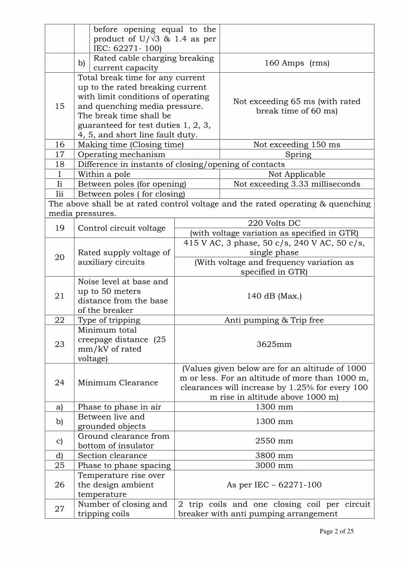
Page 2 of 25
before opening equal to the product of U/√3 & 1.4 as per IEC: 62271- 100)
b) Rated cable charging breaking current capacity
160 Amps (rms)
15
Total break time for any current up to the rated breaking current with limit conditions of operating and quenching media pressure. The break time shall be guaranteed for test duties 1, 2, 3, 4, 5, and short line fault duty.
Not exceeding 65 ms (with rated break time of 60 ms)
16 Making time (Closing time) Not exceeding 150 ms 17 Operating mechanism Spring 18 Difference in instants of closing/opening of contacts I Within a pole Not Applicable Ii Between poles (for opening) Not exceeding 3.33 milliseconds Iii Between poles ( for closing)
The above shall be at rated control voltage and the rated operating & quenching media pressures.
19 Control circuit voltage 220 Volts DC
(with voltage variation as specified in GTR)
20 Rated supply voltage of auxiliary circuits
415 V AC, 3 phase, 50 c/s, 240 V AC, 50 c/s, single phase
(With voltage and frequency variation as specified in GTR)
21
Noise level at base and up to 50 meters distance from the base of the breaker
140 dB (Max.)
22 Type of tripping Anti pumping & Trip free
23
Minimum total creepage distance (25 mm/kV of rated voltage)
3625mm
24 Minimum Clearance
(Values given below are for an altitude of 1000 m or less. For an altitude of more than 1000 m, clearances will increase by 1.25% for every 100
m rise in altitude above 1000 m) a) Phase to phase in air 1300 mm
b) Between live and grounded objects
1300 mm
c) Ground clearance from bottom of insulator
2550 mm
d) Section clearance 3800 mm 25 Phase to phase spacing 3000 mm
26 Temperature rise over the design ambient temperature
As per IEC – 62271-100
27 Number of closing and tripping coils
2 trip coils and one closing coil per circuit breaker with anti pumping arrangement

Page 3 of 25
28 Number of auxiliary contacts
Each Circuit Breaker shall be provided with an auxiliary switch with a total of 20 independent reversible single pole contacts exclusively for Owner's use. The auxiliary switch shall be factory assembled with 5 NO and 5 NC contacts for each pole for future use of the Owner/ Purchaser
29 Requirement of Simultaneity of poles
Breaker shall close, open simultaneously on all the 3 poles.
30 Rating of auxiliary contacts
10 Amps, 220 V DC
31 Breaking capacity of auxiliary contacts
2 A DC with circuit time constant not less than 20 ms
32 Rated insulation level
32.1
1.2/50 Micro second lightning impulse withstand voltage (+ve or –ve polarity)
a)
To earth (line terminals and earth and insulator housing)
650 kVp
b)
Across the open CB
650 kVp
32.2 One minute power frequency withstand voltage
a) To earth 275 kV (rms)
b) Across terminals of open Circuit Breaker
275 kV (rms)
33
Maximum radio interference voltage for any frequency between 0.5 MHZ to 2.0 MHZ in all positions
500 micro volts at 92 kV (rms)
34
Corona extinction voltage with circuit breaker in open and close positions
105 kV (rms) (Minimum)
35 Number of terminals in control cabinet
All contacts in the control circuits to be wired out up to common control cabinet plus 24 spare terminals evenly distributed on all terminal blocks exclusively for Purchaser's use
36 SF6 gas characteristics for SF6 Circuit Breaker
As per Annexure – II of Section-Circuit Breaker
37 Seismic Acceleration 0.3g Horizontal 38 Rated terminal load As per IEC: 62271-100. The breaker shall be

Page 4 of 25
designed to withstand the rated terminal loads, wind loads, earth quake load and short circuit forces.
39 Mounting On hot dipped galvanized steel support structures
40
Maximum allowable switching surge over voltage under any switching condition
As per IEC-62271-100
41 Rated characteristic for short line faults
As per IEC-62271-100 / relevant IS
2 ISOLATOR / DISCONNECT EARTH SWITCHES
S.No. Description 145 kV Class
3 Pole
1. Rated voltage 145 kV
2. Type Out door horizontal double break
type
3. Rated current at ambient temperature
1250 Amps
4. Rated short time with stand current of isolator and earth switch.
31.5 kA for 1 Sec.
5. Rated dynamic short withstand current of isolator and earth switch
80 kAp
6. Rated insulation level
a) 1.2/50 micro sec. lightning impulse withstand voltage.
i) to earth & between poles /
phases 650 kVp
ii) Across isolating distance 750 kVp
b) One minute power frequency withstand voltage
i) to earth 275 kV (rms) ii) across isolating distance 315 kV (rms)
7. Corona extinction voltage (Minimum)
105 kV (rms)
8. Temperature rise over Design ambient Temperature
As per IS: 9921, IEC: 62271-102 IEC: 60694
9. Rated induced current & voltage for earth switches
a) For electrostatic coupling - Rated induced current 2 A (rms) - Rated induced voltage 6 kV (rms) b) For electromagnetic coupling - Rated induced current 80A (rms) - Rated induced voltage 2 kV (rms)
10. Rated mechanical terminal load (Newton)
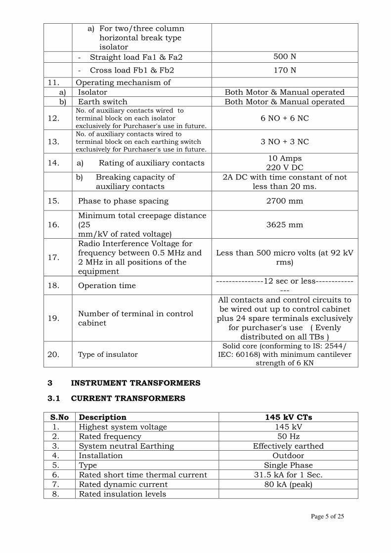
Page 5 of 25
a) For two/three column
horizontal break type isolator
- Straight load Fa1 & Fa2 500 N
- Cross load Fb1 & Fb2 170 N
11. Operating mechanism of a) Isolator Both Motor & Manual operated b) Earth switch Both Motor & Manual operated
12. No. of auxiliary contacts wired to terminal block on each isolator exclusively for Purchaser's use in future.
6 NO + 6 NC
13. No. of auxiliary contacts wired to terminal block on each earthing switch exclusively for Purchaser's use in future.
3 NO + 3 NC
14. a) Rating of auxiliary contacts 10 Amps 220 V DC
b) Breaking capacity of
auxiliary contacts 2A DC with time constant of not
less than 20 ms.
15. Phase to phase spacing 2700 mm
16. Minimum total creepage distance (25 mm/kV of rated voltage)
3625 mm
17.
Radio Interference Voltage for frequency between 0.5 MHz and 2 MHz in all positions of the equipment
Less than 500 micro volts (at 92 kV rms)
18. Operation time ---------------12 sec or less------------
---
19. Number of terminal in control cabinet
All contacts and control circuits to be wired out up to control cabinet plus 24 spare terminals exclusively
for purchaser's use ( Evenly distributed on all TBs )
20. Type of insulator Solid core (conforming to IS: 2544/ IEC: 60168) with minimum cantilever
strength of 6 KN
3 INSTRUMENT TRANSFORMERS
3.1 CURRENT TRANSFORMERS
S.No Description 145 kV CTs
1. Highest system voltage 145 kV 2. Rated frequency 50 Hz 3. System neutral Earthing Effectively earthed 4. Installation Outdoor 5. Type Single Phase 6. Rated short time thermal current 31.5 kA for 1 Sec. 7. Rated dynamic current 80 kA (peak) 8. Rated insulation levels

Page 6 of 25
8.1 1.2/50 microsecond Lighting impulse withstand voltage
±650 kVp
8.2 1 minute (Dry & Wet) power frequency withstand voltage
275 kV (rms)
9. Maximum temperature rise over an ambient temperature of 45 deg C.
As per IEC- 60044 – 1 / IS:2705
10. a) Rated primary current 600-300 A b) Rated secondary current 1 Amp
11. Visual corona extinction voltage 105 kV (rms) (Minimum)
12. One minute power frequency withstand voltage of secondary winding
3 kV for metering winding and 4.5 kV for protection winding
13.
Maximum Radio Interference Voltage for frequency between 0.5 MHz & 2 MHz in all positions of the equipment.
500 micro volts at 92 kV (rms)
14. Partial discharge level immediately after PF test
Less than 10 pico Coulombs
15. Minimum total creepage distance (25 mm/kV of rated voltage)
3625 mm
16. Type of insulation Class A 17. Seismic Acceleration 0.3 g of horizontal
18. Number of terminals in control cabinet
All terminals of control circuits are to be wired up to junction box/ marshalling box plus 20 % spares terminals exclusively for owner’s use (evenly distributed on
all TBs) 19. Rated transformation ratio 600-300/1-1-1-1-1 20. Number of cores 5 21. Minimum safety clearance
21.1 Equipment interconnection level above plinth level of 300mm over ground(1st level of interconnection)
4700 mm
21.2 Phase to earth clearance 1300 mm
21.3
Minimum height of lowest portion of insulator supporting live part above concrete plinth / level of 300 mm
2550 mm
22. Rated continuous thermal current 120% of the rated current 23. CTs shall also comply with requirements of Table I
24. Housing - Porcelain housing with cantilever strength not less than 5
KN

Page 7 of 25
TABLE – I
REQUIREMENTS FOR 145 kV CURRENT TRANSFORMERS (CTs)
No. of
Cores
Core No.
Application Current ratio
Output burden (VA)
Accuracy class as per IEC-44-1
Min. knee point voltage Vk (Volts)
Max. CT Secondary Winding resistance (Ohms) at 75 deg. C.
Maximum exciting
current in mA at knee point voltage (Vk)
5 1 Bus diff. Check
600-300/1
- PS
600 Volts at 600/1 ratio, 300 Volts at 300/1
ratio
3/1.5 60 on 600/1 tap 120 on 300/1
tap
2 Bus diff. Main
600-300/1
- PS
600 Volts at 600/1 ratio, 300 Volts at 300/1
ratio
3/1.5 60 on 600/1 tap 120 on 300/1
tap
3 Metering 600-300-150/1
20 VA 0.2 - - -
4 Trans./Line back up protection
600-300/1
- 5P - - -
5 Trans. diff./
Line protection
600-300/1
- PS
600 Volts at 600/1 ratio, 300 Volts at 300/1
ratio
3/1.5 60 on 600/1 tap 120 on 300/1
tap
Note: 1. All relaying CTs shall be of accuracy class (PS) as per IS: 4201 2. The Instrument Security Factor (ISF) for metering core shall be less than five (5) at all ratios.
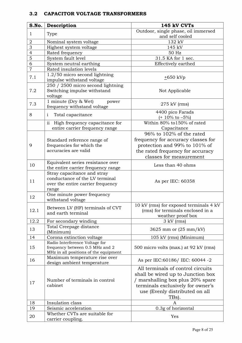
Page 8 of 25
3.2 CAPACITOR VOLTAGE TRANSFORMERS S.No. Description 145 kV CVTs
1 Type Outdoor, single phase, oil immersed
and self cooled 2 Nominal system voltage 132 kV 3 Highest system voltage 145 kV 4 Rated frequency 50 Hz 5 System fault level 31.5 KA for 1 sec. 6 System neutral earthing Effectively earthed 7 Rated insulation levels
7.1 1.2/50 micro second lightning impulse withstand voltage
+650 kVp
7.2 250 / 2500 micro second lightning Switching impulse withstand voltage
Not Applicable
7.3 1 minute (Dry & Wet) power frequency withstand voltage
275 kV (rms)
8 i Total capacitance 4400 pico Farads (+ 10% to –5%)
ii High frequency capacitance for entire carrier frequency range
Within 80% to150% of rated Capacitance
9 Standard reference range of frequencies for which the accuracies are valid
96% to 102% of the rated frequency for accuracy classes for protection and 99% to 101% of the rated frequency for accuracy
classes for measurement
10 Equivalent series resistance over the entire carrier frequency range
Less than 40 ohms
11
Stray capacitance and stray conductance of the LV terminal over the entire carrier frequency range
As per IEC: 60358
12 One minute power frequency withstand voltage
12.1 Between LV (HF) terminals of CVT and earth terminal
10 kV (rms) for exposed terminals 4 kV (rms) for terminals enclosed in a
weather proof box 12.2 For secondary winding 3 kV (rms)
13 Total Creepage distance (Minimum)
3625 mm or (25 mm/kV)
14 Corona extinction voltage 105 kV (rms) (Minimum)
15 Radio Interference Voltage for frequency between 0.5 MHz and 2 MHz in all positions of the equipment
500 micro volts (max.) at 92 kV (rms)
16 Maximum temperature rise over design ambient temperature
As per IEC:60186/ IEC: 60044 -2
17 Number of terminals in control cabinet
All terminals of control circuits shall be wired up to Junction box / marshalling box plus 20% spare terminals exclusively for owner’s use (Evenly distributed on all
TBs). 18 Insulation class A 19 Seismic acceleration 0.3g of horizontal
20 Whether CVTs are suitable for carrier coupling.
Yes

Page 9 of 25
21 Partial discharge level less than 10 pc
22 Housing Porcelain housing with cantilever strength not less than 5 KN
NOTE: The CVT shall also comply with the requirement of Table I.
TABLE – I
REQUIREMENTS OF 145 kV CAPACITOR VOLTAGE TRANSFORMERS
(CVTs)
Sl. No.
Description Requirements
1 Rated voltage primary (132/3) kV (rms)
2 Type Single phase Capacitor Voltage Transformer
3 No. of Secondaries 3
4 Rated voltage factor 1.2 – continuous; 1.5 for 30 seconds
5 Capacitance 4400 Pico Farads
Tolerance: +10% to -5%
6 Rated secondary voltage
Secondary Secondary Secondary
I II III
(110/ 3) V (110/ 3) V (110/ 3) V
7 Application Protection Protection Metering
8 Accuracy 3P 3P 0.2
9 Out put burden (Minimum)
50 VA 50 VA 50 VA
10 Phase angle error + 20 minutes (For metering core)
11 Rated total thermal burden
300 VA
Note: The accuracy of 0.2 on winding III should be maintained up to
and including a total burden of 100 VA on all the three windings.

Page 10 of 25
4 SURGE ARRESTER S.No Particulars 145 kV System
1 Rated voltage of arrester 120 kV (rms)
2 Continuous Operating Voltage (COV)
102 kV (rms)
3 Installation Outdoor
4 Type Heavy duty, station class,
gapless type 5 No. of columns Single column 6 Type of mounting Pedestal 7 Connection Phase to ground
8 Nominal discharge current (8/20 micro sec.)
10 kAp
9 Long duration discharge class 3
10
Minimum energy handling capacity (kJ/kV of rated voltage of arrester)
5 kJ/kV
11 Prospective symmetrical fault current for pressure relief test
31.5 kA (rms) for 0.2 Sec.
12 High current impulse test value (4/10 micro sec.)
100 kAp
13 Maximum Residual voltage for
13.1 Lightning impulse current
310 kVp (at 5 kA) 330 kVp (at 10 kA)
13.2 Switching impulse current 280 kVp at
1 kA
13.3 Steep current impulse at nominal discharge current
380 kVp (10 kAp)
14 Maximum PD level at 1.05 COV
50 Pico coulombs
15 Seismic acceleration 0.3 g of horizontal
16
Maximum RIV at 1.1 times phase voltage) for frequency between 0.5 MHz and 2 MHz in all positions of the equipment
500 micro V (at 92kV rms)
17 Arrester Housing
17.1 Rated voltage 145 kV
17.2 One minute power frequency withstand voltage
275 kV (rms)
17.3 Lightning impulse withstand voltage
650 kVp
17.4 Minimum total creepage distance
3625 mm
17.5 Pollution level 25 mm/kV rated voltage Heavy
(as per IEC 60071)

Page 11 of 25
Note: Other technical parameters and testing shall be as per relevant IS 5 POWER & CONTROL CABLE
Specific Technical Requirements of Power & Control Cables shall be as per relevant Clauses of Section – LT Power & Control Cables.
6 CONTROL & RELAY PANELS
1. Panel Details
1.1 Type of Panel
Simplex Panel
1.2 Height: Should match with the existing panels in the respective substations
1.3 Depth:
1.4 Width
1.5 Degree of Protection
IP 31 or better (in accordance with IS: 2147)
1.6 Material Cold Rolled Sheet steel
1.7 Thickness
Not less than 3 mm (for weight bearing members of the panels such as base frame, front sheet and door frames) Not less than 2.0 mm (for sides, door top and bottom portions)
2. Mounting Refer Clause 4.4 of Section – C & R Panels
3. Wiring
Voltage grade : 1100V All circuits except Current Transformer circuits: one 2.5 sq. mm copper. Current Transformers circuits : two 2.5 sq. mm copper.
4. Facia windows
4.1 Size: (35 mm x 50 mm)
4.2 Lettering size
Not less than 5 mm
5. The sequence of operation of the annunciator shall be as follows
Alarm condition Fault
Contact Visual
Annunciation Audible
Annunciation
1. Normal Open Off Off
2. Abnormal Close Flashing On
3. Acknowledge / Accept push button is pressed
a) Close Steady On Off
b) Open Steady On Off
4. Reset Push button is pressed
a) Close On Off
b) Open Off Off
5. Lamp Test push button is pressed
Open Steady On Off

Page 12 of 25
6. Semaphore Indicator(if asked for)
Wattage : Not to exceed 2.5 W
7. Switches Control & instrument switches : Rotary type
8. The selection of operating handles for different types of switches shall be as follows
8.1 Breaker and Isolator control switches
Pistol grip, Black
8.2 Synchronizing switch Oval, Black, keyed handle (one common removable handle for a group of synchronizing switches).
8.3 Selector switches Oval or knob, black
8.4 Instrument switches Round, Knurled, black
8.5 Protection Transfer Pistol grip, lockable switch and black.
9. The contact rating of the switches shall be as follows:
Description
Contact rating in Amps
240 V AC 220 V DC
50 V DC
9.1 Make and carry continuously 10 10 10
9.2 Make and carry for 0.5 sec. 30 30 30
9.3 Break for
9.3.1 Resistive load 3 20 7
9.3.2 Inductive load with L/R = 40 milli sec.
0.2 16 7
10. Indicating Lamps Wattage : 5 to 10 Watt
11. Synchroscope 110/√3 V phase to neutral VT secondaries
12. Synchronizing check relay
12.1 Response time Less than 200 ms
12.2 Time setting 0.5 to 3 Sec.
12.3 Phase angle setting Not exceed 35 degree
12.4 Frequency difference setting Not to exceed 0.45% at rated value and at the minimum time setting
12.5 Voltage difference setting Not to exceed 10% rated value
13. Space heaters Tubular space heaters, suitable for single phase, 240V, 50Hz
14. Push buttons
14.1 Type Momentary contact type with 2NO+2NC
14.2 Contact faces Silver plated
14.3 Rating Make and carry 5 Amp. and break 1 Amp. inductive load at 250 V DC.

Page 13 of 25
15. Earthing
Size of earth bus bar : at least 25 x 6 mm perforated at a gap of 50 mm copper Earthing of all metallic cases of relays, instruments and other panel mounted equipment
including gland plate: Connected to the earth bus by independent
copper wires of size not less than 2.5 sq.mm
16. Indicating instruments
16.1 Type Flush mounting
16.2 Size: 96 mm x 96 mm
16.3 Accuracy Class of instruments 1.5 or better
16.4 Accuracy Class of Digital bus voltage and frequency meter
Class 0.5 Frequency meter range : 45 – 55 Hz
16.5 Accuracy Class of Energy Meter
0.2 (Hardware) for static type.
17. Details of technical requirement of Relays other details
As per Technical Specification
7 EARTHING SYSTEM
Item Size Material
Main Earthing conductor 32 mm dia
rod Mild Steel
Conductor above ground level and earthing leads for equipment structures, columns and other auxiliary structures buildings.
50x8 mm Galvanized
Steel
Earthing leads for equipment earthing, cable trenches, cable trays & cables.
50x8 mm flat Galvanized
steel
Rod electrode
32 mm diameter 3000 mm long rod
Mild Steel
Pipe for LA & CVT 50mm dia, 3m long
GI
Earthing for Motors(if applicable) 25x3 mm flat Galvanised
Steel 1 DESIGN CONSIDERATION:
1.1 The design of the earthing mat shall be based on the following
1.1.1 Average soil resistivity Actual value to be
measured by Contractor (Ohm metre)
1.1.2 Magnitude of design fault current 31.5 kA

Page 14 of 25
1.1.3 Duration of fault 1 Sec.
1.1.4 Duration of shock 0.5 Sec.
1.1.5 Material of earthing mat conductor Mild steel
1.1.6 Type of joints
1.1.6.1 Permanent Welded
1.1.6.2 Suitable for testing operations Bolted
1.1.7 Values of maximum allowable temperature in
1.1.7.1 Welded joints 620 Deg. C
1.1.7.2 Bolted joints 310 Deg. C
1.1.8 Value of design ambient temperature
As per project site data
1.1.9 Type of surface layer Crushed rock of size 20 mm
1.1.10 Average resistivity of surface layer (Ohm metre)
3000
1.1.11 Thickness of surface layer and area over which to be provided.
150 mm
8 SUBSTATION LIGHTING SYSTEM
i Illumination level (Average)
a) Outdoor Switchyard area
50 Lux for main Equipment (transformer, circuit breaker, isolator etc) 20 Lux for other locations
• Ratio of minimum lux level (Emin) to average (Eav) > 0.3
• Maintenance Factor 0.65 (for out door) and 0.8 (for indoor)
ii Lighting Fixtures & Accessories
a) System Voltage
240 V AC, 50 Hz supply with supply voltage variation of -15% to + 10% and frequency variation of +/- 3%. 220 V DC with variation between +/- 10%.
b) Type of lighting Fixtures Fluorescent / incandescent lamp / Mercury Vapour Lamps / Sodium Vapour Lamp
c) Earthing terminal for Lighting fixtures
Suitable for 16 SWG GI earthing conductor
d) Reflector type Sheet steel or aluminium of not less than 22 SWG thickness
iii Receptacles
a) Type
i) Heavy duty, cast steel / aluminium ii) 5A, 15A, 240V, 2pole, 3pin type with third
pin grounded suitable for 2Cx6 sq. mm. stranded copper conductor armoured PVC cable.
iii) 63A, 415V, 3phase, 4pin suitable for (3.5C x 35 sq. mm.) Al. Conductor, PVC cable
b) Switch & switch board Steel fabricated of 16 SWG sheet with 6 mm

Page 15 of 25
Switch Board: Switch:
thick Bakelite sheet cover Piano type
iv Conduit & conduit accessories
a) Minimum size of conduit
20 mm
b) Standard length of conduit
3 meter
c) Flexible conduit cold rolled, annealed & electro galvanised, mild steel strips
d) Conduit accessories Hot dip galvanized
e) Conduit support At interval of 750 mm (for horizontal run) and at interval of 1000 mm (for vertical run)
f) Rigid Conduit Mild Steel, Heavy duty, seam welded, hot dip Galvanised.
v Junction boxes
a) Type Square / rectangle of 1.6mm sheet steel or 6mm thick pressure die-cast aluminium.
b) Suitable for
termination of 20,25,32, 40 mm dia. Conduit / glands on all sides i) Provided with 4 way terminals suitable for 2x10
sq. mm wire ii) Degree of protection IP-55 (as per IS 2147)
vi Pull out box
a) Type Circular cast iron (hot dip galvanised) with good quality Gasket lining
b) Provision At approximately 4 meter interval in a conduit run
c) Degree of protection
IP-55 (as per IS 13947)
vii Lighting panels (Indoor, Outdoor and Street Lighting)
a) Provision
i) Incomer Triple pole switch fuse unit with neutral link
ii) Out going Miniature Circuit Breakers (MCBs)
b) Switches Air break switch, heavy duty, quick make & break type (as per IS 4064)
c) Fuse
HRC cartridge type (Class 2 for AC circuit–9 kA prospective breaking current, Class 1 for DC circuit - 5 kA prospective breaking current)
d) Material & thickness Sheet steel of thickness not less than 2 mm (cold rolled) or 2.5 mm (hot rolled)
e) Degree of Protection Not less than IP 55 (as per IS: 2147) for out door panels Not less than IP 52 (as per IS: 2147) for in door panels
f) Bus bars Aluminium alloy suitable for to withstand a fault level of 9 kA for 1 sec (for AC panels)

Page 16 of 25
and 5 kA (for DC panels)
g) Terminals Stud type
h) Outgoing terminals Suitable for accepting 2x6 sq. mm cable
i) Incoming terminals Suitable for accepting 3.5Cx35 sq. mm
9 TUBULAR CONDUCTORS
1. Voltage class 145 kV
2. Size 4" IPS (EH Type)
3. Outer Diameter 114.20 mm
4. Inner diameter 97.18 mm
5. Thickness 8.51 mm
6. Cross sectional area 2825.61 (Sq .mm)
7. Type designation 63401 WP as per IS:5082
8. Tensile strength 20.5 kg/mm
9. Weight 7.7 kg/m
10. Current rating at 5 Deg. C 3000 Amps.
10 MARSHALLING KIOSK
1. Type Free standing floor mounting type or pedestal type with downed or sloping roof.
2. No. of terminals 200
3. Thickness of sheet steel 2.0 mm cold rolled/2.5 mm hot rolled.
4. Conductor for internal wiring 1100 V grade, single core 2.5 sq. mm stranded copper conductor PVC insulated
5. Incoming supplies Two (2) nos., 415 V, 3 phase, 63Amps. AC with auto-change over and MCB.
6. Outgoing supplies
i) Five (5) Nos., 15 Amps, controlled by MCB with fuse failure remote indication
ii) Ten outgoing 240 V, 10 Amps, single phase supplies controlled by MCB, to be drawn from above 3 phase incomers.
7. Terminal blocks 120 nos. in vertical formation for inter-locking facilities
8. Degree of protection IP:55 (As per IS:2147)
9. Painting To be matched with existing kiosk color
10. Other provision Double hinged doors with neoprene gaskets, padlocking arrangement, space heater.

Page 17 of 25
11 CLAMPS AND CONNECTORS
The clamps and connectors shall be made of materials listed below:
1. For connecting ACSR conductors and aluminium tubes
Aluminium alloy casting, conforming to designation A6 of IS : 617 and shall be tested for all tests as per IS : 617
2. Suspension clamps -do-
3. Dead end compression clamps connecting GI shield wire:
Galvanized mild steel
4. i) Bolts, Nuts Hot dip galvanized
ii) Mild steel plain washers
below M12. Electro galvanized
iii) Spring washers Electro galvanized
5. For connecting equipment terminals made of copper with ACSR conductors.
Bimetallic connectors made from Aluminium alloy casting, conforming to designation A6 of IS:617 with 2 mm thick comb- metallic liner and shall be tested as per IS : 617.
12 BUS POST INSULATORS
1. Rated Voltage 145 kV 2. Type Only solid core
3. Dry & wet one minute power frequency with stand voltage.
275 kV (rms)
4. 1.2 micro second Lightning impulse withstand voltage
650 kVp
5. 250/2500 Switching impulse withstand voltage
-
6. Minimum total creepage distance 3625 mm (minimum) 7. Total cantilever strength 800 kg (minimum)
8. Top p.c.d 127+0.5 mm
9. Corona extinction voltage 105 kV (rms)
10. Guaranteed loads
10.1 Bending 8000 N
10.2 Torsion 4000 N-M
10.3 Compression 130000 N-M
11. RIV for frequency between 0.5 MHz and 1 MHz and at 1.1x rated phase to earth voltage
500 micro volts at 92 kV (rms)
13 INSULATOR DISCS AND STRINGS
Disc Insulator units
a. Physical Characteristics

Page 18 of 25
1 Type Ball and Socket
2 Colour (Porcelain insulator)
Brown
3 Surface Glazed
4 Locking device R type security clip
5 Diameter 255 mm
6 Spacing 145 mm
7 Size and dimension of Pin ball shank 16 mm
8 Minimum Creepage Distance
i) Disc Insulator for substation 320 mm
9 Minimum Electro-Mechanical strength 90 KN
b. Electrical characteristics
1 Minimum impulse dry withstand test voltage (+Ve Wave)
110 kVp
2 Minimum power frequency puncture withstand test voltage
110 kV (rms)
3 Minimum power frequency one minute withstand voltage
3.1 Dry 70 kV (rms)
3.2 Wet 40 kV (rms)
4 Minimum visible discharge test voltage 9 kV (rms)
5 Maximum RIV at 10 kV (rms) 50 microvolts
c. Complete insulator strings 145 kV
1 Number of Insulator discs
1.1 For Substation
(a) Suspension string 9
(b) Double tension string 2x9
2 Lightning impulse withstand voltage 650 kVp
3 Power frequency wet one minute withstand voltage
275kV(rms)
4 Corona extinction voltage 105 kV (rms)
5 RIV at 1 MHZ for complete string i.e, including grading/corona rings, arcing horns, clamps etc., (not exceeding)
500 microvolts at 92 kV (rms)
6 Maximum voltage across any disc. 20% for suspension and 22% for tension insulator
strings
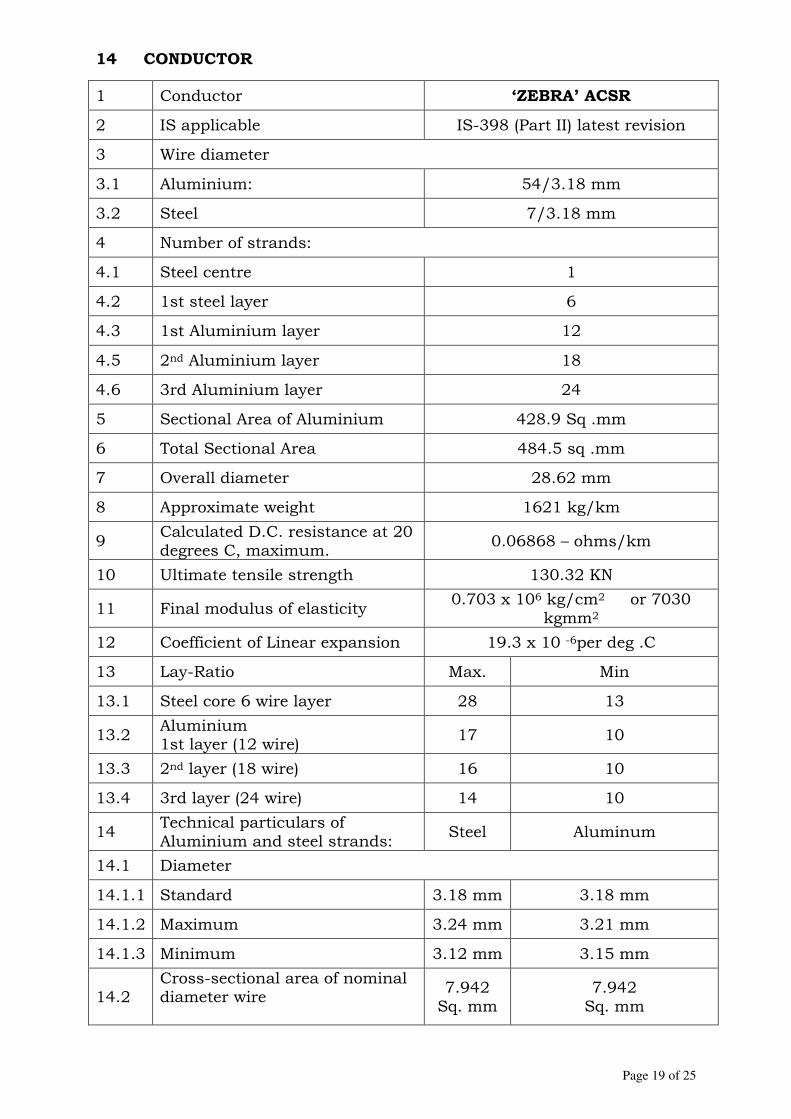
Page 19 of 25
14 CONDUCTOR
1 Conductor ‘ZEBRA’ ACSR
2 IS applicable IS-398 (Part II) latest revision
3 Wire diameter
3.1 Aluminium: 54/3.18 mm
3.2 Steel 7/3.18 mm
4 Number of strands:
4.1 Steel centre 1
4.2 1st steel layer 6
4.3 1st Aluminium layer 12
4.5 2nd Aluminium layer 18
4.6 3rd Aluminium layer 24
5 Sectional Area of Aluminium 428.9 Sq .mm
6 Total Sectional Area 484.5 sq .mm
7 Overall diameter 28.62 mm
8 Approximate weight 1621 kg/km
9 Calculated D.C. resistance at 20 degrees C, maximum.
0.06868 – ohms/km
10 Ultimate tensile strength 130.32 KN
11 Final modulus of elasticity 0.703 x 10⁶ kg/cm2 or 7030
kgmm2
12 Coefficient of Linear expansion 19.3 x 10 -6per deg .C
13 Lay-Ratio Max. Min
13.1 Steel core 6 wire layer 28 13
13.2 Aluminium 1st layer (12 wire)
17 10
13.3 2nd layer (18 wire) 16 10
13.4 3rd layer (24 wire) 14 10
14 Technical particulars of Aluminium and steel strands:
Steel Aluminum
14.1 Diameter
14.1.1 Standard 3.18 mm 3.18 mm
14.1.2 Maximum 3.24 mm 3.21 mm
14.1.3 Minimum 3.12 mm 3.15 mm
14.2 Cross-sectional area of nominal diameter wire
7.942 Sq. mm
7.942 Sq. mm
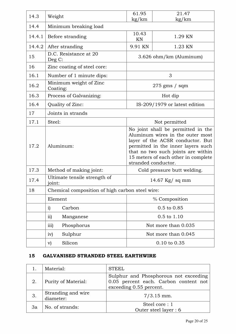
Page 20 of 25
14.3 Weight 61.95 kg/km
21.47 kg/km
14.4 Minimum breaking load
14.4.1 Before stranding 10.43 KN
1.29 KN
14.4.2 After stranding 9.91 KN 1.23 KN
15 D.C. Resistance at 20 Deg C:
3.626 ohm/km (Aluminum)
16 Zinc coating of steel core:
16.1 Number of 1 minute dips: 3
16.2 Minimum weight of Zinc Coating:
275 gms / sqm
16.3 Process of Galvanizing: Hot dip
16.4 Quality of Zinc: IS-209/1979 or latest edition
17 Joints in strands
17.1 Steel: Not permitted
17.2 Aluminum:
No joint shall be permitted in the Aluminum wires in the outer most layer of the ACSR conductor. But permitted in the inner layers such that no two such joints are within 15 meters of each other in complete stranded conductor.
17.3 Method of making joint: Cold pressure butt welding.
17.4 Ultimate tensile strength of joint:
14.67 Kg/ sq mm
18 Chemical composition of high carbon steel wire:
Element % Composition
i) Carbon 0.5 to 0.85
ii) Manganese 0.5 to 1.10
iii) Phosphorus Not more than 0.035
iv) Sulphur Not more than 0.045
v) Silicon 0.10 to 0.35
15 GALVANISED STRANDED STEEL EARTHWIRE
1. Material: STEEL
2. Purity of Material: Sulphur and Phosphorous not exceeding 0.05 percent each. Carbon content not exceeding 0.55 percent.
3. Stranding and wire diameter:
7/3.15 mm.
3a No. of strands: Steel core : 1
Outer steel layer : 6

Page 21 of 25
4. Weight: 426 kg/km
5. Single wire before stranding:
5.1 Diameter of wire strand:
3.15 mm
5.1.1 Max: 3.23 mm
5.1.2 Min: 3.07 mm
5.2 Minimum elongation in 200 mm length
4%
5.3 Minimum tensile strength
1100 N / mm2
6. Stranded wire
6.1 Length of lay
6.1.1 Maximum: 265 mm
6.1.2 Minimum: 123 mm
6.2 Minimum breaking load:
56 KN
6.3 Overall diameter: 9.45 mm
6.4 Modulus of elasticity: 19.33 x 10³ kg/mm2
6.5 Coefficient of linear expansion:
11.50 x 10⁻⁶ per deg C
6.5 D.C. resistance at 20 deg C:
3.41 ohms/km
6.6 Total sectional area:
54.55 mm2
7. Direction of lay of outer layer:
Right hand
8. Zinc coating
8.1 Number of one minute dips:
3
8.2 Number of half-minute dips:
1
8.3 Quality of Zinc: Zn 98 to IS: 209-1979/Latest revision.
8.4 Weight of coating on wire:
275 g/sq.m
8.5 Process of galvanising:
Hot dip
9. Joints: There shall be no joint in any of the wire constituting the ground wire.
10. Oiling: The galvanised ground wire shall be dipped in boiled linseed oil.
11. Chemical Composition
11.1 Element % Composition
11.2 Carbon Not more than 0.55

Page 22 of 25
11.3 Manganese 0.4 to 1.10
11.4 Phosphorus Not more than 0.05
11.5 Sulphur Not more than 0.05
11.6 Silicon 0.15 to 0.35
16 TENSION CLAMPS FOR EARTHWIRE
1. Type Bolted
2. Material
2.1 Body Forged steel
2.2 Bolts & Nuts Galvanised steel
3. Minimum failing load 6624 kg
4. Minimum slip strength 6275 kg
5. Galvanisation
5.1 Spring washers Electro galvanised
5.2 Other ferrous parts hot-dip galvanised
17 FLEXIBLE COPPER BONDS
1. Material Tinned Copper
2. Strand & Wire diameter 37/7/0.417 mm
3. Length 500 mm (approx.)
4. Connecting lugs suitable for
One for 12mm dia bolt and other for 16 mm dia bolt
5. HRH MS bolt hot-dip galvanized with nut & lock washer
16 mm dia and 40 mm long
18 INSULATOR HARDWARE
a. Free center type Suspension clamp
Material Process of Treatment
Reference Standard
1 Clamp Body/ keeper piece
High strength Al. Alloy
4600 LM-6 OR 6061/ 65032
Casted or forged & Heat treated
IS : 617 OR ASTM-B429
2
Cotter bolts Hangers, Shackles, Brackets
Mild Steel Hot dip
galvanized IS : 226-1975/ IS : 2062-1992
3 U Bolts Stainless Steel or Forged & Heat AISI 302 OR

Page 23 of 25
High Strength Al. alloy 6061/ 6063 or 65032/
63400
treated 304-L,ASTM B429
b. Tension Clamp
1 Type Bolted
2 Material
2.1 Outer sleeve EC Grade Aluminium tube formed by extrusion process.
2.2 Inner sleeve Galvanised low carbon forged steel.
3 Minimum failing load (No deformation)
95% of the breaking load conductor.
c. Arcing Horns 1 Type Loop or ball ended (on tower side)
As per IS-226 2 Material Galvanised mild steel tube/rod hot dip
galvanised d. Grading/Corona Ring
1 Material
High strength heat-treated aluminium alloy tube. (6061 / 6063/1100 type or 65032/63400 type)
As per ASTM B-429
2 Capacity to withstand load for one minute
150 kg
3 Supporting Brackets and Mounting Bolts
High strength heat treated Alloy 6061/6063/1100/65032/63400 type or Mild steel hot dip galvanised
As per IS:226 OR IS-2062-1992 or ASTM-B 429
e. Other String Hardware
1 Material
1.1 Socket ended item Forged steel/Malleable cast iron hot-dip galvanised.
1.2 Sag Adjustment device
High quality mild steel or high tensile steel, hot-dip galvanised.
As per IS : 226 –1975 / IS:2062-1992
1.3
Ball ended components, U-clevis and chain link
Drop forged steel hot-dip galvanised.
As per IS:2004 -1978
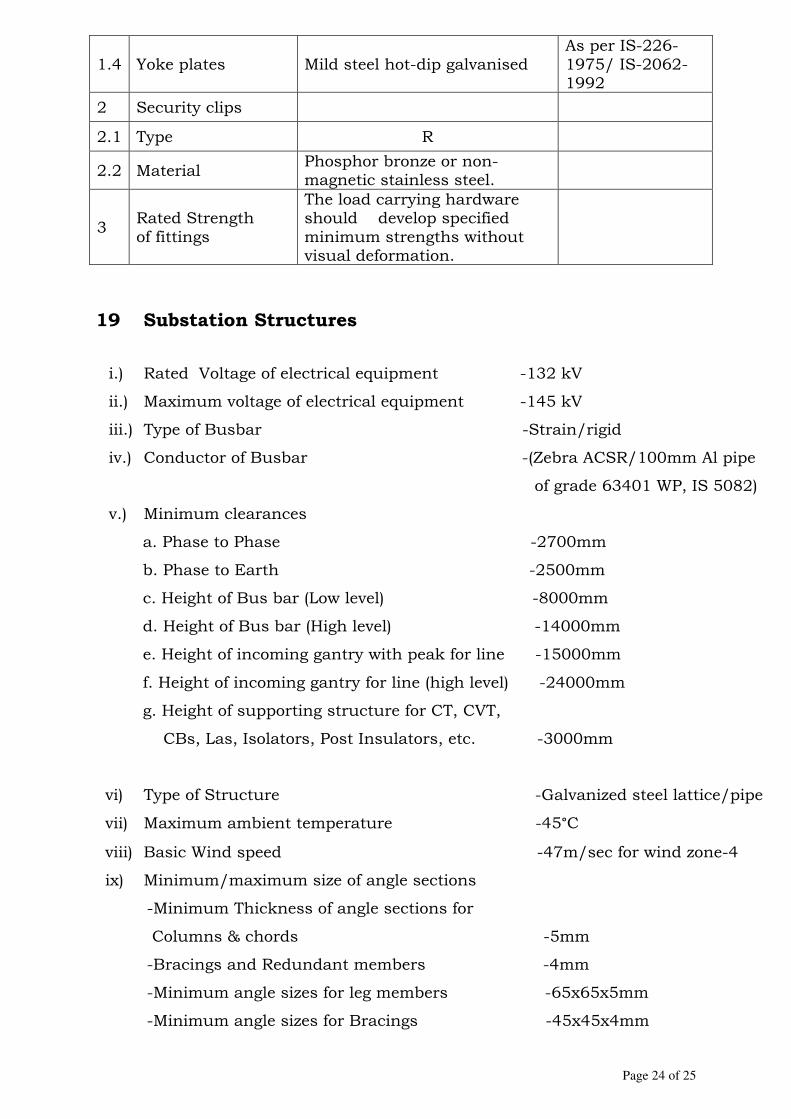
Page 24 of 25
1.4 Yoke plates Mild steel hot-dip galvanised As per IS-226-1975/ IS-2062-1992
2 Security clips
2.1 Type R
2.2 Material Phosphor bronze or non- magnetic stainless steel.
3 Rated Strength of fittings
The load carrying hardware should develop specified minimum strengths without visual deformation.
19 Substation Structures
i.) Rated Voltage of electrical equipment -132 kV
ii.) Maximum voltage of electrical equipment -145 kV
iii.) Type of Busbar -Strain/rigid
iv.) Conductor of Busbar -(Zebra ACSR/100mm Al pipe
of grade 63401 WP, IS 5082)
v.) Minimum clearances
a. Phase to Phase -2700mm
b. Phase to Earth -2500mm
c. Height of Bus bar (Low level) -8000mm
d. Height of Bus bar (High level) -14000mm
e. Height of incoming gantry with peak for line -15000mm
f. Height of incoming gantry for line (high level) -24000mm
g. Height of supporting structure for CT, CVT,
CBs, Las, Isolators, Post Insulators, etc. -3000mm
vi) Type of Structure -Galvanized steel lattice/pipe
vii) Maximum ambient temperature -45°C
viii) Basic Wind speed -47m/sec for wind zone-4
ix) Minimum/maximum size of angle sections
-Minimum Thickness of angle sections for
Columns & chords -5mm
-Bracings and Redundant members -4mm
-Minimum angle sizes for leg members -65x65x5mm
-Minimum angle sizes for Bracings -45x45x4mm
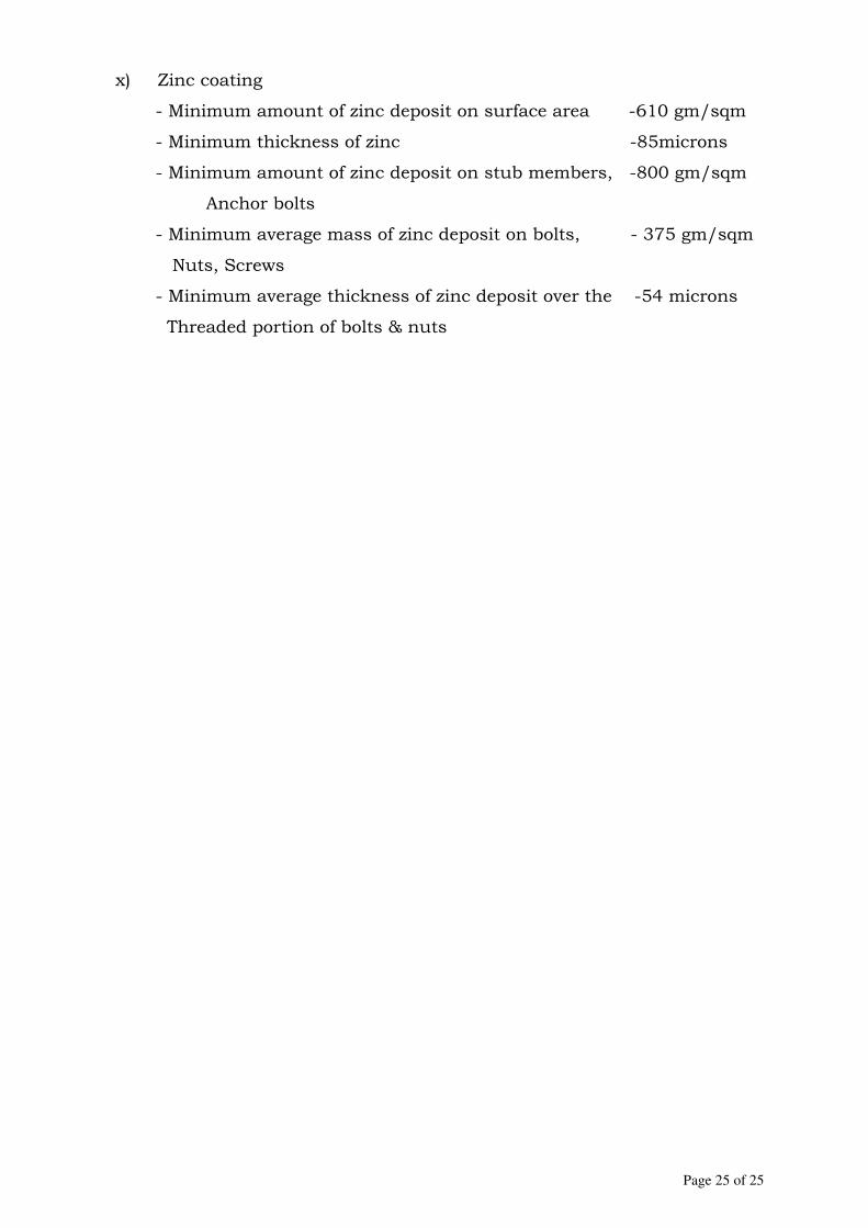
Page 25 of 25
x) Zinc coating
- Minimum amount of zinc deposit on surface area -610 gm/sqm
- Minimum thickness of zinc -85microns
- Minimum amount of zinc deposit on stub members, -800 gm/sqm
Anchor bolts
- Minimum average mass of zinc deposit on bolts, - 375 gm/sqm
Nuts, Screws
- Minimum average thickness of zinc deposit over the -54 microns
Threaded portion of bolts & nuts

Page 1 of 9
SECTION 12
ERECTION, TESTING AND COMMISSIONING OF
ELECTRICAL EQUIPMENT
1.0 GENERAL
1.1 This section covers tentative requirements for installation, testing and
commissioning of all electrical equipment for 132 kV substations, under
the Strengthening of India-Nepal Power Transmission interconnection
Project, MEA, Government of India. The electrical and associated
equipment shall be erected in conformity with the requirement of Indian
Standards, Codes/International codes and practices, Indian regulation
& Nepal safety rules and all other statutory regulations that may be
relevant to erection and testing/commissioning as per requirements of
IS/IEC and other details given elsewhere in the Project Documents.
1.2 The contractor shall furnish all labour, skilled and un-skilled,
supervisory and administrative personnel, erection tool & tackles,
transport vehicles, mobile cranes, digging/excavation equipment,
testing and commissioning equipment, implements necessary for timely
and effective execution of the contract. The installation work is
inclusive of supply of erection material, hardwares, consumable and
supply items to complete the installation under turnkey execution of
the project.
1.3 Sub-Station Checks
Contractor shall carry out the following checks at all the substations
under the project, and submit the report to Purchaser
1) The installation has been carried out in accordance with the
approved drawings.
2) Phase-to-phase and phase-to-earth clearances are provided as
required.

Page 2 of 9
3) All equipments are effectively earthed and properly connected to
the required number of earth electrodes.
4) The required ground clearance to live terminals is provided.
5) The required numbers of caution boards, fire-fighting
equipments, operating rods, insulating mats, etc. are kept in the
substation.
6) All cable trenches are provided with non-flammable covers.
7) Free accessibility is provided for all equipments for normal
operation.
8) All name plates are fixed and the equipment are fully painted.
9) All construction materials and temporary connections are
removed.
10) Earth pipe troughs and cover slabs are provided for earth
electrodes earth pits. CVT and lightning arrester earth pits are
marked for easy identification.
11) Earth electrodes are of GI/MS pipes. For earth connections,
brass bolts and nuts with lead washers are provided in the
pipes/-plates.
12) Earth pipe troughs, pits are free from rubbish and dirt and stone
jelly and the earth connections are visible and easily accessible.
13) Panels and switchgears are all vermin and damp proof and all
unused openings or holes are blocked properly.
14) The earth bus bars are checked for tightness and for corrosion
free joint surface.
15) Control switchfuses are provided at an accessible height from
ground.
16) Safety devices, horizontal and vertical barriers, bus bar
covers/shrouds, automatic safety shutters/doors interlock;
handle interlock for safe and reliable operation in all panels and
cubicles.
17) Clearances in the front, rear and sides of the switchboards are
adequate.

Page 3 of 9
18) The Isolator switch operates freely; all the blades make contact at
the same time. The arcing horns contact in advance, and the
handles are provided with locking arrangements.
19) Insulators are free from cracks and are clean.
20) In case of cable cellars, adequate arrangements to pump out
water that has entered due to seepage or other reason is provided
(if applicable).
21) Panels are clearly and indelibly numbered and labeled for
identifications both at the front and at the rear.
2.0 DETAILED DESIGN AND DRAWING
Detailed dimensional drawings and design calculation for the following
shall be submitted by the contractor to the client for scrutiny and
approval.
(a) Design of foundation for all the equipment supporting structures.
(b) Design of foundation and drawing for gantry structures.
(c) Design of foundation and drawings for 132 kV Circuit Breakers,
CTs, PTs, CVTs, LAs Isolators, etc.
(d) Design of foundation for control and relay panels.
(e) Design of foundation for 132 kV switchgear.
(f) Foundation for 415 V switchgear panel, if required.
(g) Design of the cable trenches.
(h) Layout of control room
(i) Drawing of earth mat of new bay.
(j) Any other works not mentioned but required for turnkey
execution of project, without any liability to the Purchaser.
3.0 ERECTION
3.1 Erection of the outdoor switchgear
The bidder shall assemble, install and connect all the circuit breakers,
current transformers, CVTs, lightning arrestors, coupling capacitors,
Page 4 of 9
wave traps etc as per the technical specifications. The equipment shall
be placed and leveled carefully on their respective foundation or
structures as the case may be. The operating mechanism and control
circuits of the circuit breakers shall be tested for proper opening,
closing and local/remote position indications. The opening and closing
tests shall be made from the control room and also in local operation.
The equipment will be subjected to normal commissioning tests before
putting the equipment in commercial operation.
3.2 Erection of Isolator and Isolators cum Earthing Switches
The isolators and isolators cum earthing switches as covered in the
Document of the specification shall be mounted by the bidder on the
steel structures. The poles of the switches shall be aligned accurately
and levelled on the supporting steel structures. The switches shall be
adjusted so as to permit operation with ease by one man. Each bearing
of the operating mechanism shall be properly lubricated. The
equipment shall be subjected to normal commissioning tests before
putting it in commercial operation.
3.3 Erection of Indoor equipment
The bidder shall install various indoor equipment in the control room
building which will consist of control and relay panels and LT
switchgear extension etc. All the materials such as bolts, nuts,
washeres and screws for installing the equipment, insulating tape
compound, solder, soldering paste and connectors for making the
electrical connections and hard-wood blocks for supporting the cables
shall be arranged by the contractor. Special care shall be exercised in
the station to avoid damage to the equipment. The bidder shall furnish
the patching lacquer and shall repair any damage to the lacquered
surface of the board. The cables entering at the bottom of the control
board shall be adequately supported at the trench opening by means of
aluminium clamps. Each block shall be drilled with holes to fit the
cable longitudinally and the clamped together with two through bolts.

Page 5 of 9
3.4 Erection of Control and Power cables
The bidder shall be responsible for laying the control and power cables
covered under the project. The bidder shall furnish all insulating tape
and compound, solder, soldering paste and connectors. Power and
control cables shall be run into cable trenches on supports of suitable
dimension in the switchyard and in cable conduit near equipment for
equipment connection. Conduits shall be cleaned and free from
obstructions and sharp corners. A clean, dry, tight fitting rag shall be
drawn through the conduit immediately before installing the cables.
The cables shall be installed in such a manner that there will be no cuts
or abrasion in the insulation or protective covering of the conductors.
Splicing of conductors shall be made in boxes, panel boards and
cabinets. Where a lubricant is required for pulling wire or cable only
soapstone or a similar approved material not injurious to the wire or
cable sheath shall be used. Any wire or cable damaged during
installation shall be removed and replaced at the bidder expenses. After
all cables are installed and all equipment wiring, devices and fixtures
have been connected by the bidder, he shall conduct such insulation
and operating tests as in his opinion are necessary to demonstrate the
adequacy of the electrical installations and to ensure that no damage
has occurred to the cables during the installation. All runs,
connections, soldering and taping of conductors shall be made neatly.
3.5 Erection of sub-station structures, insulators and hardwares, bus-
bars, earthing and other sundry materials
(i) The bidder shall be responsible for erection of structures,
insulators and hardwares, bus-bars, earthing and other sundry
materials etc. required for the project.
(ii) No steel structure shall be erected on foundations untill at least
14 days after placing of the concrete in foundations. Base plates
where required shall be grounded. All base plates shall be set

Page 6 of 9
accurately to the grade and alignment designated on drawings
duly approved by the purchaser. All galvanised steel shall be
handled with care to avoid bending or damage to the galvanising.
Pieces bent in handling may be used only if they can be
straightened without injury to the galvanising. The method of
erection of the structure is left to the contractor.
(iii) Insulators and busbar materials
The bidder shall install all bus-bars, insulators and hardware,
overhead ground wires over substation structures, as covered in
the specification. The bidder shall also install the conductors,
over head ground wires, hardware and insulators in the span
between the dead end tower and the sub-station structures.
Conductors which are used in tension and overhead groundwires
shall be free of joints or splices. The equipment used for stringing
the conductor and overhead ground wires shall be such that the
conductor will not be damaged or injured. All section of the
conductors damaged by the application of gripping attachments
shall be replaced before the conductors are strung.
The contractor shall also be responsible for installing the various
conductors, required for connection of the various equipment in
the sub-station.
3.6 Grounding system
The bidder shall lay the ground mat for the extended portion of the
sub-station, as per design and drawing approved for the substation.
They shall make all the grounding connections to equipment and
structures. Risers from the station ground mat for this purpose shall
also be provided by the bidder as per drawings approved by
purchaser.
3.7 Erection of lighting fixtures, sockets outlets etc.

Page 7 of 9
The bidder shall install and connect all lighting fixtures in the
switchyard. All the materials such as tape and compound, solder,
soldering paste, required for wiring of the lighting fixtures shall be
arranged by the contractor. Switchyard and control room lighting
fixtures shall be installed as per the approved drawings of illumination
design.
3.8 Electrical Conduits
The bidder shall furnish and install all embedded and exposed electrical
conduits, conduits fittings, boxes and accessories. The conduits and
the fittings shall be as per the relevant Indian/International Standard.
The underground metal/PVC conduits as per project requirements shall
be embedded in a concrete encasement. Conduits, conduit boxes and
fittings shall be secured in positions while concrete is being placed. The
threads of all embedded G.I.conduit joints shall be covered with red
lead or applied with an insulating varnish. Joints between conduits and
cabinets in outdoor installations shall be watertight. The route of all
conduits in sub-station shall be determined by the bidder.
4.0 TESTING AND COMMISSIONING
4.1 Before the substation is energised, necessary commissioning tests may
be conducted and any adjustments etc. required to be made in the
equipment may be carried out. After all the pre-commissioning tests
are successfully carried out, the substation shall be put into
commercial operation and handed over to the purchaser. The
commissioning test reports shall be submitted to the purchaser for his
approval.
4.2 The contractor shall perform all tests as per IS/International standard
and any additional tests based on specialties of the equipment without
any extra cost to the purchaser. The bidder shall arrange all
Page 8 of 9
instruments required for conducting these tests along with calibration
certificates and shall furnish the list of the instrument to the Engineer
for his approval. The tentative description is given as below.
(i) General checks
(a) Check for physical damage
(b) Check from name plate that all items are as per specification.
(c) Check tightness of all bolts, clamps and connecting terminals .
(d) Check ground connections.
(e) Check cleanliness of insulators and bushings
(ii) Circuit Breakers
(a) Insulation resistance of pole
(b) Check adjustment if any suggested by manufacturer
(c) Breaker closing and tripping operation
(d) Trip free and anti-pumping operation
(e) Minimum pick up voltage of coils
(f) Contact resistance
(g) Functional checking of SF6 Gas system
(h) Functional checking of control circuits, interlocks, tripping
through protective relays.
(i) Insulation resistance of control circuits, motor etc.
(j) Resistance of closing & tripping coils.
(iii) Isolators
(a) Insulation resistance of pole
(b) Manual & electrical operation and interlocks
(c) Insulation resistance of control circuits and motors
(d) Ground connections
(e) Contact resistance
(f) Proper alignment so as to minimise the vibration during
operation.

Page 9 of 9
(iv) Current Transformers
(a) Insulation resistance test
(b) Polarity test
(c) Ratio test
(d) Dielectric test of oil
(e) Magnetising characteristic test.
(f) Winding resistance test
(v) C.V.T
(a) Insulation resistance test
(b) Polarity test
(c) Ratio test
(d) Dielectric test of oil
(vi) Lightning Arrester
(a) Leakage current
(b) Resistance of ground connection.
(vii) Station Earthing
(a) Check soil resistivity
(b) Check continuity of ground conductor
(c) Check earth resistance of the entire grid
(d) Check for weld joint and application of zinc paint on
galvanised surface.
(viii) ACSR Conductor, Power Connectors
(a) Physical check for finish
(b) Electrical clearance check
(c) Millivolt drop test on all power connectors
(d) Sag and tension check on conductors
(ix) Insulators
(a) Visual examination for finish damage, creepage distance.

1
SECTION – 13
CIVIL WORKS
1.0 GENERAL
These Specifications cover the technical and the general requirements
for civil and structural works required in connection with extension of
existing 132 kV Substations by adding one bay for Strengthening of
India-Nepal Power Transmission Interconnection at 132kV level. The
work shall consist of detailed design and engineering, construction of
foundations for gantry towers and equipment supporting structures,
cable trenches, drainage arrangement and all other civil and
structural works required for successful commissioning of one
additional bay in existing 132kV Substations.
The civil works to be performed under this part of the contract
consists of providing labour, all materials, plant and equipments
including POL and all incidental items not shown or specified but
reasonably implied or necessary for the proper completion of all the
civil works in all respect in accordance with the approved designs and
drawings (to be prepared by the Contractor) for all the civil works
required for successful commissioning of the project strictly in
compliance with these specifications and applicable Indian Codes.
The design and engineering shall include preparation of all
construction drawings.
Expatriate Staff and Labour
The Contractor's attention is drawn to the requirements for obtaining
work permits from the Govt. of Nepal for his expatriate staff and
labour and he shall follow all procedures laid down by the Govt. of
Nepal with respect to the application for such work permits as well as
for the recruitment, termination and repatriation of his expatriate
staff and labour.
2.0 INTENT OF SPECIFICATION
The specifications are intended for the general description of the work,
quality of materials and workmanship. The specifications are not,
however, intended to cover the minute details. The work shall be
2
executed according to this specification and the relevant Indian
Standard Codes. In the absence of the latter, the work shall be
executed according to any other mutually agreed International
Standard or the best prevailing engineering practices as per
instructions of Engineer-in-Charge.
The prices quoted by bidder shall include minor details which are
obviously and fairly intended, and which may not have been included
in the description of items in their technical specification but are
essential for the satisfactory completion of the work. Quoted price
shall also include all safety measures as required by codal provisions,
local regulations etc. and for execution of all works to the satisfaction
of the Engineer-in-Charge.
The bidder is expected to get clarified any doubts about the
specifications, scope of work, site conditions etc. before tendering, in
writing from Purchaser in respect of interpretation of any portion of
these specifications.
3.0 VISIT TO PROJECT SITES
The bidders shall visit all the project sites and shall get themselves
fully and completely familiarized and satisfied with the site conditions
and soil strata existing at proposed substation sites. The bidder has
to take all responsibilities regarding the assumed soil characteristics,
safe bearing capacity of soil & other soil parameters etc.
The Purchaser shall not, under any circumstances, pay any extra
price after the acceptance of the tender, in case the Contractor is
found to have misjudged the soil conditions including sub-soil water
level at the site of work at a later date. No claim, whatsoever due to
wrong assessment of sub-soil characteristics shall be entertained.
4.0 SCOPE OF WORK
The scope as defined below is not exhaustive but only indicative and
contractor shall be required to carry out all civil works and supply all
fitting and fixtures as required for the successful commissioning of
the Control Room/Substation.
(i) Detailed Geotechnical Investigation at Project Sites for
ascertaining safe/allowable/limiting bearing capacity of soil
and other relevant properties of soil for safe design of

3
foundations and other underground facilities.
(ii) Detailed design and engineering of civil and structural works of
substations including preparation of all construction drawings.
(iii) Construction of foundations for 132kV Substation Gantry
Towers and Equipment Supporting Structures.
(iv) Construction of all cable trenches, drains etc. including
interconnection of new cable trenches and drains etc. with
existing cable trenches and drainage system of substations as
per requirements, site conditions and instruction of Engineer-
in-Charge.
(v) Leveling, grading & spreading stone grit in additional bay of
Substations.
(vi) All necessary civil and structural works in the existing control
room of Substation required in connection with proposed
extension of substation by addition of one bay.
(vii) Anti-termite treatment to the bottom and sides of excavation for
cable trenches and any other area as directed by the Engineer-
in-Charge.
(viii) Anti-weed treatment before final grading and after construction
of all foundations, cable trenches and other underground
facilities and before laying the layers of moorum and gravel.
(ix) Control Room Building:
The broad specifications and requirement of control room
building shall be as under:-
(a) The size of Control Room building shall be not less than 4.5m x
3.5m x 3.5m (height) or as per requirement whichever is more
with one attached toilet of minimum size 2.4m x 1.8m outside
the control room building with access from Control Room.
(b) Building shall be RCC framed structure with RCC foundations
with M25 grade of concrete.

4
(c) Building shall have 230 thick Brick Wall with bricks of
Class designation 10 laid in 1:5 cement mortar (1 cement:
5 Coarse Sand).
(d) Brick walls shall be provided with 12 mm thick plaster
on even surface and 15mm thick plaster on rough face
with 1:4 cement mortar ( 1 cement : 1 Coarse Sand & 3
Fine sand).
(e) 50 mm thick Damp Proof Course (DPC) at plinth level
shall be provided with plain cement concrete 1:1.5:3 (1
cement: 1.5 sand: 3 stone ballast 12mm and down gauge)
and hot bitumen @1.8 Kg/m2 shall be applied over the
dried up surface of cement concrete after properly
cleaning the surface with brushes & finally with the piece
of cloth soaked in kerosene oil. The hot bitumen shall be
applied uniformly all over, so that no blank spaces are left
anywhere.
(f) For efficient drainage of rainwater, roof concrete shall be
given a gradient of minimum 1:100 by providing screed
concrete of grade M20 using 10mm downgraded aggregate
and finished smooth. The minimum thickness of screed
concrete shall not be less than 40mm. The concrete shall
be cured for seven days and thereafter allowed to dry.
The entire roof then shall be given water proofing
treatment using high solid content liquid applied
elastomeric water proofing as per ASTM C- 836 & 898,
1.5mm thick over a layer of polymerised mastic to achieve
smooth surface and a primer coat as per manufacturer’s
specification.
Thereafter, the entire roof shall be finished by providing
cement concrete chequred tiles of 25mm thickness over
15mm cement mortar(1:3) bed over the water proofing
layer and pointed using neat 1:3 cement mortar(1
cement: 3 coarse sand).
(g) 1.0 m wide Plinth protection shall be provided all round
the building with 75 mm thick PCC 1:2:4 laid over a well
compacted layer of brick ballast (100mm compacted

5
thickness) and provided brick on edge at outer edge of
plinth protection in cement mortar 1:4.
(h) Building shall be provided with powder coated glazed
aluminum doors and windows of appropriate size.
(i) Flooring in Control Room shall be with Polished vitrified
tiles of size 600x600x7mm and 150mm high skirting.
(j) Acrylic emulsion paint over wall putty on internal walls
and ceiling and acrylic/snowcem paints on exterior walls
shall be provided.
(k) All Electrical wiring, fittings and fixtures etc. shall be
provided.
(l) Building provided shall be provided with proper
illumination of minimum 100 lux.
(m) Air-conditioning of Control Room by providing Split Air
Conditioners of appropriate capacities.
(n) Providing Ceiling Fans of approved make and appropriate
size.
(o) Cable trenches of appropriate size with all fittings and
fixtures for laying cables in Control Room.
(p) Drainage for rain water from roof though 100mm dia PVC
pipes of approved make and its disposal in the nearest
new or existing storm water drain.
Toilet shall be provided with the following finishes and facilities:
(q) Flooring with Vitrified Ceramic Anti-skid tiles of approved
size and make.
(r) Dadoing up to ceiling level with glazed ceramic tiles of
approved size & make.
(s) Oil bound distemper on ceiling.

6
(t) One water closet having flushing system, one urinal, one
shower, one wash basin of appropriate / approved sizes &
make.
(u) Laying necessary plumbing and sanitary pipe lines and
providing all fittings and fixtures.
(v) One RCC underground water tank of 2500 Litre capacity.
(w) One water storage tank of 1000 Litre capacity of approved
make at the roof of the toilet for continuous supply of
water.
(x) Tapping the water from exiting source and laying
necessary pipe line for feeding to the underground water
tank.
(y) Necessary pumping arrangement for pumping water from
underground water tank to overhead water tank.
(z) One soak pit of appropriate size for use of toilet by about
10 persons.
(aa) Disposal of waste water from wash basin, bathing area
etc suitably.
(bb) A fresh air fan of required size and of approved make.
(cc) All other specifications and finishes shall be same as for
control room.
(x) All materials, fitting and fixtures shall be conforming to
relevant Indian standard Codes and shall be of approved make.
All civil works shall be carried out as per specifications and
relevant Indian standard Codes.
(xi) All civil works whether specified or not but required for
successful completion and commissioning of the Project shall
be in the scope of this Specification.
5.0 CODES AND STANDARDS
7
Wherever references to Indian Standard Codes or any other
code/document are made, they shall refer to the latest version of the
same as existing one month prior to the due date of submission of
tenders.
6.0 MATERIALS
6.1 SUPPLY OF MATERIALS
The supply of all materials including cement, reinforcement steel and
structural steel etc. shall be in the scope of Contractor.
The materials and workmanship shall conform to relevant BIS Codes
and shall be of the best quality and to the approval of the Engineer-
in-Charge. In this Specification, the word "to the approval of the
Engineer-in-Charge" shall be deemed to be included in the
description of all materials incorporated in the Works, whether
manufactured or natural, and in the description of all operations for
the due execution of the works.
All materials shall be of approved manufacturers and origin, and
delivered at the Site well before they are to be used in the Works to
enable the Contractor to take such samples as the Engineer-in-
Charge may require for testing before approval. The Contractor shall
also provide any information required by the Engineer-in-Charge as
to the quality, weight, strength, constituents, description, etc. of the
materials.
No materials of any description shall be used without prior approval
by the Engineer-in-Charge and any material rejected as unfit for use
in the Works shall be removed immediately from the Site and without
any compensation to the Contractor.
6.2 SAMPLES
Samples of all materials shall be submitted to the Engineer-in-Charge
for approval prior to ordering or delivery to site. The Engineer-in-
Charge reserves his right to test any sample to destruction and retain
samples until the maintenance period. No payment shall be made for
samples and the bidders must include in the rates and/or price in
the BOQ for cost of samples. All materials delivered at site shall be
equal to or better in all respects than the samples approved by the
Engineer-in-Charge.

8
6.3 TESTING
For any material to be used on the Works, the tests may be directed
by the Engineer-in-Charge to be carried out at the place of
manufacture, or on the site or at laboratory. Tests may be required
on materials (natural or manufactured), soils, workmanship etc to
verify their compliance with the Specification. Samples of all such
materials together with all necessary labour, plant and apparatus for
sampling and for carrying out tests shall be supplied by the
Contractor at his own cost.
7.0 SPECIFIC TECHNICAL REQUIREMENT
7.1 General
Before, taking up the detailed design and engineering of various
works, the Contractor shall be required to prepare the detailed design
criteria for various civil works covered in the scope of this contract
and shall submit the same to the Engineer-in-Charge for approval.
No design shall be taken up without the written approval of design
criteria by the Engineer-in-Charge.
7.2 Foundations for Gantry Towers & Equipment Supporting
Structures:
The design and construction of foundations shall conform to the
following specific technical requirements:
(a) All foundations for gantry towers and equipment supporting
structures shall be of Reinforced Concrete and shall have base
plate and foundation bolts type of connection for transferring the
load from super structure to the foundations.
(b) Normally, all the four legs of gantry towers column/equipment
supporting structures shall be supported on a common
foundation i.e. raft foundation. However, for structures having
large leg spacing, isolated foundation under each leg of the
structure can be provided if feasible based on loads, soil
properties and site conditions.
(c) Foundations shall be designed for the worst combinations of dead
loads, live loads, wind and seismic loads, short circuit forces and
any other applicable loading from service conditions.

9
(d) For design of foundations, the loads arrived at foundation level
from analysis of superstructure, shall be multiplied by following
partial safety factors on load:
Normal and broken wire condition 1.2
Broken wire condition with short circuit forces 1.1
(e) The stability of foundation shall be checked against overturning,
sliding and limiting/allowable bearing capacity of soil (as
applicable). In addition, the isolated foundations shall also be
checked for uplifting.
(f) The presence of surface/sub soil water shall be duly considered
in the design of all foundations and under ground facilities.
(g) The structural design of the foundation shall be carried out as
per limit state method of design in accordance with IS: 456-2000.
(h) The chimney/pedestal of the foundations shall be at least 300
mm square providing a minimum clear concrete cover of not less
than 100 mm over any part of the foundation bolt in case of
locations where water table is not expected to rise above
foundation level and at least 450 mm square providing a
minimum clear concrete cover of not less than 150 mm over any
part of the bolt in case of locations where water table/sub soil
water is expected to rise above foundation level.
(i) The chimney/pedestal shall extend 250 mm (minimum) above
finished ground level.
(j) A lean concrete sub-base having a thickness of 100 mm and of
size 100mm more on all sides of the footing shall be provided
under structural concrete in all foundations. The lean concrete
shall be of grade M-10 (1:3:6) conforming to IS: 456. The lean
concrete sub-base provided under the footings shall not be
considered in the structural calculations.
(k) Foundation Depth
a) Minimum depth of Foundation from Finished Ground
Level for Gantry Towers shall be not less than 1.8 m

10
b) Minimum depth of Foundation from Finished Ground
Level for equipment supporting structures shall be not
less than 1.5 m.
(l) No foundation shall rest on filled up soil. The minimum depth of
foundation inside the virgin soil shall be at least 600 mm.
(m) The C.G. of leg members of Gantry towers/Equipment supporting
structure shall coincide with the C.G. of the base plate. The C.G.
of the base plate shall coincide with the C.G. of the foundation
bolts. The C.G. of the foundation bolts shall coincide with the
C.G. of the pedestal. The design of the foundation shall take into
account the additional forces resulting from any eccentricity due
to non-compliance of above requirements or due to any other
reason.
(n) The pedestal/chimney shall be designed for combined action of
axial forces viz. compression & tension and associated bending
moments due to horizontal shears in both the directions, namely
longitudinal and transverse as well as any additional moment
due to eccentricity in foundation system. The adequacy of
pedestal/chimney section shall be checked as per above and
necessary reinforcement in pedestal/chimney shall be provided
as per design requirements and provisions of IS: 456-2000. The
design shall be carried out in accordance with IS: 456 with limit
state method of design. The arrangement of reinforcement shall
comply with all the requirements specified in IS 456.
(o) The clear concrete cover to reinforcement shall not be less than
50 mm.
(p) The minimum thickness of footing slabs for gantry towers
foundations shall not be less than 300 mm and that for
equipment supporting structure 250mm.
(q) The minimum thickness of footing slabs at the edges shall not be
less than 200 mm.
(r) In the design of the footing slabs, actual soil pressure under the
footing shall be considered for calculating the maximum
moments and shears at various critical sections. The critical
sections for moments and shears shall be as specified in IS: 456.

11
The reinforcement in the footings shall be accordingly calculated
and provided.
(s) The reinforcement of both faces of base slab of foundation shall
be provided as per design requirement but it shall not be less
than 0.12% of cross sectional area at each face and in each
direction.
(t) The minimum diameter of reinforcement shall not be less than
12mm at the bottom face of foundation slab and 10mm at the top
face of foundation slab.
(u) The base slab of footing of all foundations shall be cast in single
pour without any construction joint. However, construction joint
may be allowed between footing slab and pedestals/chimneys
with a provision of suitable shear key.
7.3 Cable Trenches:
The design and construction of cable trenches shall conform to the
following specific technical requirements:
(a) Cable trenches shall be of reinforced concrete type with
removable type reinforced cement concrete covers. These
trenches shall not be used as storm water drains.
(b) The new cable trenches shall be suitably connected with existing
cable trenches as per site requirement and approved construction
drawings and/or as instructed by Engineer-in-Charge.
(c) The cable trench shall be designed for earth pressure including
sub-soil water pressure, if any. In addition, a surcharge load of
2.0 tons per sqm shall also be considered.
(d) The pre-cast RCC covers for cable trench shall be designed for a
live load of 1000kg per sqm.
(e) The minimum diameter of main reinforcement bars in cable
trenches shall be not less than 10mm and for distribution
reinforcement 8mm. The maximum spacing of reinforcement
shall be 200mm. The concrete cover to reinforcement shall be
40mm on outside faces in contact with soil/subsoil water and
25mm on the inside faces.
12
(f) The wall/bottom slab thickness of cable trenches shall be not
less than 200mm and reinforcement shall be provided on both
the faces of the wall and bottom slab. The covers of cable
trenches shall be of such design not to allow any rainwater into
them. Necessary embedded steel plates of size 100 x 10 mm
thick shall be provided in cable trenches for supporting the cable
trays.
(g) The bed of the cable trenches along their length shall be provided
a slope of 1:750 to 1:1000 by laying P.C.C. (M-20) grade concrete
layer of necessary thickness (minimum 50mm thick) in second
stage to drain any rain/seepage water, which may enter in to
them. The overall depth of various type of cable trenches shall be
so decided as to take care of above provision of longitudinal slope
along their length by laying P.C.C. in second stage without
compromising the clearance required between bottom most tray
of cable trench and bed of the cable trench.
(h) All cable trenches shall be provided with edge protection angles of
size not less than 45 x 45 x 5. The pre-cast R.C.C. slab covers for
cable trenches shall also have edge protection angle of size 45 x
45 x 5 all around. Suitable lugs shall be welded to edge
protection angles for ensuring their fixity with the concrete.
Suitable lifting hooks shall be provided for easy handling of these
covers.
(i) The top of cable trenches shall be kept 150 mm above finished
ground level.
(j) Suitable expansion joints shall be provided in cable trenches as
per I.S. specification with PVC water stop, bitumen impregnated
filler boards, bitumen sealing compound as per specifications or
as directed by the Engineer-in-Charge. The waterproofing cement
additive shall be used for the construction of cable trenches to
ensure watertight construction.
(k) In cable trenches, construction joints shall be provided with PVC
water stops.
(l) The water from new cable trenches shall be collected and
disposed off as per existing arrangement if technically feasible.
Otherwise it shall be taken to suitably located sumps from where
13
this water shall be disposed off by pumping into nearest storm
water drains. The sump pits shall be of RCC construction
covered at top with provision of man hole and rungs. The scope
shall cover all accessories like discharge pipe for transferring
water from sump pits to nearest storm water drains. The grade of
concrete for the construction of sump pits shall be grade M25
conforming to IS: 456 and this specification.
(m) The newly constructed cable trenches shall be suitably
interconnected with the existing cable trenches of the substations
as per requirement, approved construction drawings and/or as
directed by the Engineer-in-Charge.
7.4 Drainage of Substation Area:
The design and construction of storm water drains shall conform to
the following specific technical requirements:
(a) Suitable drainage arrangement shall be designed and provided by
the Contractor to drain off the rainwater quickly and efficiently
from substation area. All new drains shall be suitably connected
to the existing substation drainage system in a manner to ensure
speedy disposal of surface run off water without causing any
stagnation of water or flooding. It shall be ensured that the
existing drain in which new drain is being proposed to be
connected have the capacity to handle the additional water from
Substation area. If integration of new drainage system with the
existing drainage system is not feasible, an independent drainage
system shall be designed and provided.
(b) The drain shall be designed for earth pressure including sub-soil
water pressure, if any. In addition, a surcharge load of 2.0 tons
per sqm shall also be considered.
(c) The yard shall be sloped away from cable trenches.
(d) All surface drains shall be constructed with brick masonry in
cement sand mortar 1:4 (1 cement: 4 coarse sand). The thickness
of brick masonry shall be as per design requirement but shall be
not less than 230mm. All drains shall be plastered inside with
cement sand mortar 1:3 (1cement: 3fine sand). The thickness of
plaster shall be not less than 18 mm.

14
(e) The bricks to be used for the construction of drains shall be of
1st Class quality of Class 10 and conforming to IS: 1077. The
longitudinal slope of drains shall be so decided that there is no
accumulation of silt in the drains and rain water is disposed off
as quickly as possible without causing any flooding in the
substation area. However, the slope of drains shall not be
shallower than 1:1000.
(f) The minimum width and depth of any drain shall not be less
than 400 mm than 300 mm respectively.
(g) The newly constructed drains shall be suitably interconnected
with the existing drains of the substations as per requirement,
approved construction drawings and/or as directed by the
Engineer-in-Charge.
7.5 Final Grading and Metalling of Substation Area:
The final grading and metalling of additional bay being provided shall
conform to the following specific technical requirements:
(a) The site shall be graded to the required level and slope soon after
the completion of all the foundations, cable trenches, drains etc.
including laying of earth mat. Before laying the layers of morrum
and metal, anti weed treatment shall be given to the soil as per
specification. Thereafter a layer of 100mm thick (compacted
thickness) morrum of approved quality shall be laid. Over the
compacted layer of morrum, 150mm thick (compacted thickness)
HBG metal of nominal size 10-20mm shall be laid as a final
finish of substation area.
(b) The final grading and metalling of one new bay shall match with
the existing grading and metalling.
7.6 PREPARATION OF DETAILED DESIGN CRITERIA
Before starting the detailed design and engineering work, the
Contractor shall prepare a Design Basis Report (DBR) containing the
design criteria for all civil & structural works taking into account
specific technical requirements specified herein, relevant codes, etc.
and submit the same to the Engineer-in-Charge for approval. Design
work shall commence only after the approval of the design manual by
Engineer-in-Charge.
15
7.7 DESIGN CALCULATIONS AND CONSTRUCTION DRAWINGS
All design calculations and drawings for civil & structural works shall
be submitted by the Contractor for the approval of Engineer-in-
Charge. No construction shall commence without the approval of the
relevant design and construction drawings by the Engineer-in-Charge.
Detailed construction drawings shall be prepared by the Contractor
based on approved design and submitted to Engineer-in-Charge for
approval. No construction shall commence before the approval of the
relevant construction drawings.
7.8 CONTRACT DRAWINGS
The drawings bearing the Engineer-in-Charge approval or drawings
corrected in accordance with the comments of the Engineer-in-Charge
shall be deemed to be contract drawings and no variation there from
shall be made without the written consent of owner/consultant. Six
(6) prints of each approved construction drawings shall be submitted
to the Engineer-in-Charge.
7.9 AS MADE DRAWINGS
Three sets of paper prints and soft copy of all approved
construction/fabrication/architectural drawings showing the work
exactly as made in AUTOCAD and in pdf format shall be delivered to
the Engineer-in-Charge within one month of completion of the work
at site.
7.10 GRADE OF CONCRETE
The minimum grade of concrete for plain concrete works shall be M-
15 and that for Reinforced Cement Concrete Works M-25, until
specified otherwise in specification for specific
structure/foundation/works.
8.0 GEO-TECHNICAL INVESTIGATION
The Contractor shall be required to carry out the detailed geotechnical
investigation after the award of work for determining the soil
properties and strength and settlement parameters including
safe/allowable/limiting bearing capacity of the soil and sub-soil water
level for deciding the type of foundations to be provided for various
structures of the substation.

16
9.0 LAYOUT AND LEVELS
The layout and levels of all structures etc. shall be made by the
Contractor at his own cost from the general grid of the plot and bench
marks given by the Engineer-in-Charge. Necessary survey works shall
be conducted by the Contractor for fixing up the exact location of
different structures, foundations, trenches and all other items covered
in the scope of this Specification. Under no circumstances shall the
Contractor remove or disturb any permanent marks without approval
of the Engineer-in-Charge. The Contractor shall also provide help in
the form of instruments, materials and men at his own cost to the
Engineer-in-Charge for checking the detailed layout and levels.
However, the contractor shall be solely responsible for correctness of
layout and levels.
10.0 CONSTRUCTION METHOD
The Bidders shall submit along with his bids, Bar Chart, construction
schedule, list of construction equipments and manpower to be
deployed and a write-up on methodology to indicate broadly how he
intends to execute the civil, structural and architectural works for
complete Substation. These details shall form part of this tender. The
bidders shall also indicate in their tenders whether the design and
construction of civil, structural and architectural works shall be
carried out by them or they would engage any other firm/consultant
for carrying out these works. In the latter case, he shall submit the
details of experience of such firms/consultant along with his tender.
11.0 QUALITY ASSURANCE PROGRAM
The work shall be carried out as per approved quality assurance
program. The Contractor shall prepare a quality assurance program
and get it approved from the Engineer-in-Charge. The Contractor shall
strictly follow this quality assurance program to ensure the quality of
the civil work.
12.0 SAFETY MEASURES DURING CONSTRUTION
The Contractor shall submit for the approval of Engineer-in-Charge, the
details of construction safety procedures to be followed by him at the
site during execution of all works. These safety measures shall be in
accordance with relevant BIS Codes.

17
13.0 TECHNICAL SPECIFICATION OF EARTHWORK
13.1 Scope
This shall include all works involved in excavation for all leads and
lifts, dressing of soil, shoring, dewatering, filling around foundations
and trenches, carting of sand or good quality earth if required for
filling, disposal of residual earth at a place as directed by the
Engineer-in-Charge. The bidder must satisfy himself of the character
and volume of all works under this item and expected surface and/or
sub-soil water to be encountered. He must also satisfy himself about
general conditions of site and ascertain the existing and future
obstructions likely to come up during the execution of the Contract to
carry out the work under this scope.
13.2 Excavation in Soil
The Contractor shall carry out all excavations required for the
Permanent Works in all types of materials which may be encountered,
including boulders, ordinary rock or hard rock.
Excavation shall be finished to the lines and dimensions shown on
the drawings or directed by the Engineer-in-Charge. Final trimming
of all excavations shall be carried out by the use of hand tools.
The bottom of excavations shall be trimmed to the required levels and
when carried below such levels due to Contractor's fault, the excess
depth shall be filled up to the required level at the Contractor's cost
with cement concrete not leaner than M-10 grade or richer as directed
by the Engineer-in-Charge in each individual case.
Sides and bottoms of excavation shall be cut sharp and true to the
slopes indicated in the approved construction drawings. Under-
cutting shall not be permitted. Earth sides of excavation shall not be
used in lieu of formwork for placement of concrete unless authorized
in special cases, by the Engineer-in-Charge where limitation of space
for larger excavation necessitates such a decision.
The Contractor shall take all precautions necessary to preserve the
materials below and beyond any line of excavation in the soundest
possible condition. Excavation shall not be carried below the
foundation level of structure close by until required precautions have
been taken. Cost of such precaution shall be borne by the Contractor

18
and nothing extra shall be paid on this account.
The Contractor shall remove all vegetation and foreign materials from
the areas to be excavated or filled for the work with sufficient
clearance to permit the placing, inspection, setting of forms and
completion of all works for which the excavation was made.
The Contractor shall control the grading in the vicinity of all
excavations so that the surface of the ground shall be properly sloped
or dyked to prevent surface water from running into the excavated
areas during construction.
All excavations for installation of underground facilities such as
piping, power lines, ducts, drains, earth mat etc. shall be open cuts.
Any damage to the Works due to the Contractor's operations,
including shattering of the material beyond the excavation lines, shall
be repaired at the expense of and by the Contractor. Any and all
excess excavation for the convenience of the Contractor for any
purpose or reason, except as may be ordered in writing by the
Engineer-in-Charge, and whether or not due to the fault of the
Contractor, shall be at the expense of the Contractor and carried out
as directed by Engineer-in-Charge.
If the Contractor is directed by Engineer-in-Charge to excavate to a
lower level than that indicated on the approved construction
drawings, such additional excavation shall be paid for at the
applicable unit rate.
All excavation shall be carried out in the dry. The Contractor shall
take all necessary precautions including supplying and operation of
all necessary pumping plant to remove all water from any source
whatsoever which may enter the excavations whether these are in
progress or completed.
If excavations are carried out within 3 m of buildings or other
Constructions, the Contractor shall execute the work in a way that
shall not cause any damage or disturbances.
The Contractor shall be responsible for assumptions and conclusions
regarding the nature of materials to be excavated and difficulty in
making and maintaining the required excavation and performing the
work required as per approved construction drawing and in
19
accordance with these specifications. Coffer dams, sheeting, shoring,
bracing, draining, dewatering etc. shall be furnished and installed as
required and the cost thereof shall be deemed to be included in the
unit rate/lump-sum price.
In the case where in the opinion of the Engineer-in-Charge, the works
are likely to cause interference to the public, the Contractor shall
organize his operations in such a way as to reduce to a minimum the
interval between opening up and back-filling the excavations. No
further work shall commence until the Engineer-in-Charge has
inspected and approved the completed excavation.
All excavation operation shall include excavation and disposal of the
surplus excavated material after backfilling. The excavated surplus
material shall be disposed off at a place as directed by the Engineer-
in-Charge. Excavated material shall be placed beyond 1.5m from the
edge of the pit or half the depth of the pit whichever is more or farther
away if directed by the Engineer-in-Charge.
13.2.1 Excavations to be kept free from Water
Unless otherwise approved by the Engineer-in-Charge, the Contractor
shall make arrangements to keep all excavations dry. The Contractor
shall have due regard to the possibility of heavy seepage and provide
pumps and other equipment necessary for keeping the excavations
free from water and slush. Every precaution shall be taken so as not
to diminish the bearing capacity of the soil below foundation level. All
temporary sumps and drains constructed by the Contractor for
facilitating the construction are to be filled in or otherwise made good
as directed by the Engineer-in-Charge on completion of the relevant
part of the Works.
13.2.2 Shoring & Timbering:
Where excavation required bracing, sheeting or shoring etc, the
Contractor shall submit to the Engineer-in-Charge drawings showing
arrangement and details of proposed installation and shall not
proceed until he receives approval from the Engineer-in-Charge.
However, such approval shall not be construed as relieving the
Contractor of his responsibility for the suitability and adequacy of the
measures provided. Approved quality SAL wood shall be used for
shoring and timbering a trench.

20
13.3 Excavation in Rock
13.3.1 Scope
The rock to be excavated shall be classified under the following
categories:
Hard Rock (requiring blasting): Any rock or boulder for the excavation
of which blasting is required.
Hard rock (blasting prohibited): Any rock or boulder for the excavation
of which blasting is required but where blasting is prohibited for any
reason and excavation has to be carried out by chiseling, wedging or
any other approved method.
The specifications for excavation of soil & soft/weathered/fissured
rock shall apply to excavation work in rock also, except for the bottom
of excavation, where, depending on the type of rock, over-breaks up to
a maximum depth of 300mm below the required level may be allowed
by the Engineer-in-Charge at his discretion and paid accordingly.
Concrete backfill in such over breaks shall also be paid for. No
payment shall, however, be allowed for backfilling, if such over breaks
are required to be brought to grade by filling with only soil including
its proper compaction.
The Contractor shall procure the blasting materials, if required. The
Engineer-in-Charge shall provide assistance for the procurement of
blasting materials by the Contractor.
Blasting shall be done in accordance with and as per the procedure
approved by the Engineer-in-Charge with utmost care to minimize the
over breaks. All necessary precautions for handling and use of the
blasting materials shall be taken as per the requirements of the
relevant Safety Code. All rules under the Explosives Act or other local
rules in force shall be fully observed. Only the persons having
certificates for blasting issued by the competent authority shall be
deployed for carrying out the blasting.
Blasting shall only be carried out at certain specified times as directed
by the Engineer-in-Charge. Proper precautions for safety of persons
and property shall be taken. Where blasting is to be carried out in
proximity of other structures, sand bags etc. shall be used on top of
21
the blast holes to prevent the rock fragments from causing damage to
adjacent structures and other property.
13.3.2 Unexploded Charge:
The number of blasts to be fired and the actual number of shots
heard shall be compared and the person responsible shall satisfy
himself by examination that all blasts have exploded before people are
permitted to re-approach the work site. The withdrawal of the
unexploded charge shall not be permitted under any circumstances.
The tamping and the unexploded charge shall be flooded with water
and the hole marked in a distinguishing manner. Another hole shall
be jumped at a distance of about 450 mm off the old hole and fired in
the usual way. This process shall be continued till the original blast is
exploded.
13.3.3 Chiseling in Hard Rock:
Where blasting is prohibited or not practicable, excavation shall be
carried out by chiseling. Decision of the Engineer-in-Charge shall be
final in this regard.
13.4 Filling/Backfilling
13.4.1 General
All materials used by the Contractor for the purpose of fillings and
embankments shall be approved by the Engineer-in-Charge. Earth
used shall be free from stone, shingle or boulders larger than 75mm
in any direction, salts, organic or other foreign matter. Normally earth
excavated from the same area shall be used for filling. However if
such earth contains deleterious material, saltpeter earth etc. the
same shall not be used. All clots of earth shall be broken or removed.
The spaces around the foundations, pipes, drains etc. shall be cleared
of all debris, brick bats etc. The filling shall be done in layers not
exceeding 200mm. Each layer shall be watered, rammed and
consolidated before the succeeding one is laid. Earth shall be rammed
with iron rammers where feasible and with butt-ends of crowbars
where hammer can not be used.
After completion of foundation footings and wall and other
constructions below the elevation of the final grades and prior to
backfilling, all forms, temporary shoring, timber etc. shall be removed

22
and the excavation cleaned of all trash, debris and perishable
materials.
Special care shall be taken that no damage is caused to pipes, drains,
masonry, cables etc. Density of compaction shall not be less than
90% of the maximum dry density as determined by the Standard
Proctor Test.
No backfilling or refilling shall commence without the Engineer-in-
Charge approval. The refilling of excavations shall be commenced as
soon as practicable after the Permanent Works have been inspected
and approved by the Engineer-in-Charge.
13.4.2 Filling in Cable Trenches:
Normally, excavated earth shall be used for filling. In case, earth
contains deleterious salts it shall not be used. Where excavated
material is rock, the boulders shall be broken into pieces not bigger
than 15 cm & mixed with fine materials of decomposed rock, moorum
or earth as available to fill up voids.
Filling the trenches for pipes shall start after the joints of pipes etc.
are tested & passed. Where the trenches are excavated in soil, the
filling shall be done with earth on the sides & top of pipes in layers
not exceeding 20 cm watered & rammed and consolidated.
In case of excavation of trenches in rock the filling up to a depth of 30
cm above the crown of the pipe shall be done with fine material such
as earth, moorum or pulverized decomposed rock as available. The
remaining depth shall be done with rock filling or boulders of size not
exceeding 15cm.
13.5 Miscellaneous Requirements
The Contractor shall take adequate safety measure around the
excavated pit by providing fencing and sufficient illumination with red
lights during night to avoid accident in the excavated areas.
If any materials like steel pieces, parts of any equipment etc. are
found during excavation, the matter shall be brought to the notice of
the Engineer-in-Charge immediately and the same shall be deposited
in the project’s store by the Contractor at his own cost. Any finds of

23
archaeological interest such as relics of antiquity, coins, fossils or
other articles of value shall be delivered.
The stone etc. obtained from excavation shall remain owner’s
property. The useful portion shall be separated and deposited in
regular stacks and useless & rubbish material disposed off at places
and in the manner as directed by the Engineer-in-Charge.
14.0 TECHNICAL SPECIFICATION OF CONCRETE WORKS
14.1 Scope
This section covers the furnishing of all labour, materials and
equipments and performing of all operations required for the supply of
materials and concrete works and incidental items pertinent thereto,
all in accordance with these specifications, approved construction
drawings and directions of Engineer-in-Charge.
The Contractor shall employ a competent supervisor approved by the
Engineer-in-Charge to supervise all stages of the concrete works,
including the supervision of making of test cubes and all site tests in
consultation with the Engineer-in-Charge. The Contractor shall be
responsible for keeping all records of testing and work progress as
required by the Engineer-in-Charge.
14.2 Materials
14.2.1 Cement
Cement used shall be Ordinary Portland Cement of 33 grade or 43
grade conforming to IS: 269, IS: 8112 and IS: 12269 or Portland
Pozzolana Cement conforming to IS: 1489. Sulphate Resistant Cement
conforming to IS: 12330 shall be used in concrete mixes when
concrete is exposed to sulphate attack and shall satisfy the
requirement specified in Table 4 of IS: 456-2000. Rapid Hardening
Portland Cement conforming to IS: 8041 can be used under special
circumstances, if permitted by the Engineer-in-Charge. Cement,
which has set or partially set, shall not be used. A third party testing
of cement, if found necessary, shall be carried out by Contractor at
his own cost.
14.2.2 Aggregates

24
All aggregates shall conform to the provisions and test methods of IS:
383 and IS: 515. The aggregate shall be free from decomposed stone,
clay or other deleterious substances. The specific gravity of aggregates
shall not be less than 2.5. Samples of aggregates proposed to be used
shall be submitted free of charge in sufficient quantities to the
Engineer-in-Charge with sieve analysis data for his approval. When
aggregates, which are satisfactory to the Engineer-in-Charge, have
been selected, the Contractor shall secure the entire supply of
material from the same source so as to maintain the same quality and
grading throughout the work. Should it become necessary to change
the source or characteristics of the material supplied, this shall only
be done after additional tests and after the approval of Engineer-in-
Charge. Approved samples shall be reserved by the Engineer-in-
Charge for future reference. This approval shall not in any way relieve
the Contractor of his responsibility of producing concrete of specified
qualities.
14.2.2.1 Coarse Aggregates
The nominal size of coarse aggregate shall be as follows:
For thin RCC members with very narrow shape : 10mm
For Reinforced Concrete including foundations : 20mm
For Plain Concrete : 20mm
For Lean Concrete : 40mm
Coarse aggregate shall be crushed rock. Grading of coarse aggregates
for a particular size shall generally conform to relevant IS codes and
shall also be such as to produce a dense concrete of the specified
proportions and/or strength and consistency that shall work readily
into position without segregation.
14.2.2.2 Fine aggregates (Sand)
Coarse and fine sand shall be well graded within the limits by weight
as specified in IS: 383. Fineness modulus shall not vary by more
than plus or minus 0.20 from that of the approved sample. Fineness
modulus for sand should not be less than 2.5. Only river water sand
shall be used. Washing of aggregates by approved means shall be
carried out, if found necessary and permitted by Engineer-in-Charge.
Coarse and fine aggregate shall be batched separately.
14.2.3 Water

25
Water used for mixing and curing shall be clean, fresh and free from
organic or other deleterious matters in solution or in suspension in
such amounts that may impair the strength or durability of the
concrete. Potable water is generally satisfactory. IS: 3025 and IS:
3550 may be followed for testing, if required. The permissible limit of
solids shall be within limits corresponding to Table-1 of IS: 456-2000.
The pH value of water shall not be less than 6.
14.2.4 Admixture
The use of admixtures in concrete for promoting workability,
improving strength, entraining air or for any other purpose may be
used only with the approval of the Engineer-in-Charge. Addition of
admixture should not reduce the specified strength of concrete or
durability of concrete in any case nor increase the risk of corrosion of
reinforcement. The admixtures used shall conform to IS: 9103
14.3 Storage of materials
Storage of materials shall be as described in IS: 4082. All materials
shall be so stored as to prevent deterioration or intrusion of foreign
matter and to ensure the preservation of their quality and fitness for
the work. Any material which has deteriorated or has been damaged
or as otherwise considered defective by the Engineer-in-Charge shall
not be used and shall be removed from site immediately, failing which
the Engineer-in-Charge shall be at liberty to get the materials
removed and the cost thereof shall be realized from the Contractors’
dues. The Contractor shall maintain up-to-date accounts of receipt
issue and balance (stock wise) of all materials.
General storage shall be carried out by the Contractor in a manner
affording convenient access for identification and inspection at all
items. The storage facilities shall be subject to approval of the
Engineer-in-Charge.
Cement shall be stored by Contractor in silos or suitable weather
proof, dry leak proof and moisture proof buildings (to be furnished by
the Contractor) as far as possible and should have minimum number
of windows and close fitting doors which shall be kept closed as far as
possible. Stacking shall not be more than 10 bags high to avoid
lumping under pressure. Cement held in storage for a period of 90

26
days or longer shall be tested at an approved laboratory before being
put to use.
Aggregates shall be stored by the Contractor in areas floored with
tightly laid wooden planks or other approved hard, smooth and clean
surface, in a manner precluding intrusion of foreign materials.
Aggregate of different classes shall be stored in separate piles
sufficiently away from each other to prevent the material of edges of
piles from getting inter-mixed.
14.4 Sample of Materials
The Contractor shall submit to the Engineer-in-Charge samples of all
materials proposed for use in the production of concrete for the
works, together with a list of suppliers. The Engineer-in-Charge's
consent in writing shall be obtained for all such samples and sources
of supply before any concreting work takes place. No changes shall
subsequently be made without the Engineer-in-Charge's approval.
The Engineer-in-Charge shall have access to all sources of supply for
the purpose of inspecting and taking samples.
Materials used in the Works shall be of the qualities and kinds
specified herein and equal to approved samples, delivery shall be
made sufficiently in advance to enable further samples to be taken
and tested if required. Materials not approved shall be immediately
removed from the Works at the Contractor's cost.
Approval of materials and workmanship by the Engineer-in-Charge
shall in no way relieve the Contractor of his responsibility of ensuring
that materials and workmanship comply with the quality and
standards specified herein. All specified properties of the concrete-
making materials shall be tested with a frequency necessary to ensure
continuous compliance to the specification, and whenever new
materials are to be used.
14.5 CONCRETE- Mix design
14.5.1 General
Concrete shall be design mix and in grades designated as M15, M20
and M25 in accordance with IS: 456. In addition, the stipulations of
IS: 3370 shall also be followed in case of liquid retaining structures.
Lean concrete shall be of grade M-10 with 40 mm nominal size

27
aggregate or as indicated in approved construction drawings. Nominal
mix is recommended only when accurate control is impracticable and
not necessary.
14.5.2 Nominal Mix Concrete
Nominal mix is recommended only when accurate control is
impracticable and not necessary. When nominal mix concrete is
allowed by the Engineer-in-Charge, it shall be used only for the grade
of M-15 or lower concrete. Nominal mix concrete does not require the
preparation of trial mixes. The proportion of materials for nominal mix
concrete shall be in accordance with Table 9 of IS: 456-2000.
14.5.3 Design Mix Concrete
Concrete mix proportions for the design mix concrete shall be as per
IS: 456. The minimum cement content, maximum water cement ratio
and minimum grade of concrete to be used for different exposure
conditions shall be as per Table 5 of IS: 456-2000 (Refer Clauses
6.1.2, 8.2.4.1 and 9.1.2). Design mix concrete shall be used on all
concrete works, unless specified otherwise.
The mix proportions for all grades of concrete shall be designed to
obtain strengths corresponding to the values specified hereinafter for
respective grades of concrete. Preliminary tests as specified in the IS
code and required by the Engineer-in-Charge shall be carried out
sufficiently ahead of the actual commencement of the work with
different grades of concrete made from representative samples of
aggregates and cement expected to be used on the job to ascertain the
ratios by weight of cement to total quantity of fine and coarse
aggregate and the water cement ratio required to produce a concrete
of specified strength and desired workability.
The test reports shall be submitted to the Engineer-in-Charge. The
cost of the mix design and testing shall be borne by the Contractor.
On the basis of the preliminary test reports for trial mix, a proportion
of mix by weight of sand, water cement ratio shall be approved by the
Engineer-in-Charge, which shall be expected to give the required
strength, consistency and workability and the proportions so decided
for different grades of concrete shall be adhered to during all
concreting operations. If however, at any time the Engineer-in-Charge
feels that the quality of materials being used has changed from those
used for preliminary mix design, the Contractor shall have to carry

28
out similar trial mixes to ascertain the mix proportions and
consistency. It shall be within the competency of the Engineer-in-
Charge to reduce the number of trial batches and the number of test
specimens mentioned above. Further, the Engineer-in-Charge can
also allow adoption of the mixes already tried and found satisfactory
with similar materials, for other jobs at the same site, without any
fresh design of mix.
The mixes once approved must not be varied without prior approval of
the Engineer-in-Charge. Should however the Contractor anticipate
any change in the quality of future supply of materials than that has
been used for preliminary mix design, he shall inform the same to the
Engineer-in-Charge and bring fresh samples sufficiently ahead to
carry out fresh trial mixes. The Engineer-in-Charge shall have access
at all places and laboratory where design mix is prepared.
Design mix shall indicate the extent of variation in grade of aggregate,
which can be allowed by means of graphs and curves etc.
In designing the mix proportions of concrete, the quantity of both
cement and aggregate shall be determined by weight. The Engineer-
in-Charge may allow the quantity of aggregate to be determined by
equivalent volume basis after the relationship between the weight and
volume is well established by trial and the same shall be calibrated in
container tanks or weighed. All measuring equipment shall be
maintained in a clean and serviceable condition and their accuracy
periodically checked.
To keep the water cement ratio to the designed value, allowance shall
be made for the moisture contents in both fine and coarse aggregates
and determination of the same shall be made as frequently as directed
by the Engineer-in-Charge. The determination of moisture contents
shall be according to IS: 2386 (Part-III).
14.6 Mixing, Transporting, Placing and Compacting of Concrete
14.6.1 General
Concrete shall not be placed in any unit of the work until after the
forms, bracing, reinforcing steel and other preparations for casting
have been approved by the Engineer-in-Charge and approval given to
proceed with the casting.

29
No concrete shall be placed except in the presence of the Engineer-in-
Charge or his authorized representative. Concrete which is not placed
in accordance with the specifications or which is of inferior quality as
determined by the Engineer-in-Charge shall be removed and replaced
by the Contractor without any extra cost to the owner.
14.6.2 Mixing
All concrete shall be mixed until there is a uniform distribution of
materials and until a uniform color and consistency are obtained.
Mixing shall be done in a mechanical mixer complying with IS: 1791
and IS: 12119 and the type and size shall be subject to the approval
of the Engineer-in-Charge. The mixer shall be rotated at a speed
recommended by the manufacturer and mixing shall be continued for
at least two minutes after all materials are in the drum.
For batches larger than 0.75 cum. mixing time shall be increased by
15 seconds for each additional 0.75 cum. or fraction thereof. All
concrete shall be discharged within 3minutes after the introduction of
mixing water to the cement and aggregates or the introduction of
cement to the aggregate unless a different time is specified by the
Engineer-in-Charge.
All hardened concrete and foreign materials shall be removed from the
inner surfaces of mixing and conveying equipments. All conveyances,
buggies and barrows shall be thoroughly cleaned at frequent intervals
during the placing of concrete. Concrete shall be rapidly handled
from the mixers to the place of final deposit and shall not be delivered
by spout or trough nor dumped into carriers with a free fall from the
mixer of more than 1.5 meter. Every possible precaution shall be
taken to prevent separation or loss of the ingredients while
transporting the Concrete.
Each time the work stops, the mixer shall be thoroughly cleaned and
when the next mixing commences, the first batch shall have 10%
additional cement at no extra cost to the owner to allow for loss in the
drum.
The workability of the concrete shall be checked at frequent intervals
by slump test. If required by the Engineer-in-Charge, alternatively the
compacting factor test in accordance with IS: 1199 shall be carried
out.
The mixer drum shall be flushed clean with water. Measured quantity
of dry coarse aggregate shall be followed with measured quantity of
fine aggregate and then cement. In case damp sand is used, only half

30
of the quantity of coarse aggregate shall be added followed by cement
and sand. Finally balance quantity of the coarse aggregate shall be
added. The skip shall be raised and dry materials slopped into the
drum. The dry materials shall be mixed for at least four turns of the
drum, after which the correct quantity of water shall be added
gradually while the drum is in motion, to ensure even distribution
with the dry material. The total quantity of water for mixing shall be
introduced before 25% of mixing time has elapsed and shall be
regulated to achieve the specified water cement ratio. The complete
contents of the mixed concrete shall be emptied before recharging.
When the mixer is closed down for the day or at any time exceeding
20 minutes, the drum shall be flushed clean.
Mixing by hand shall be done only in special cases with the prior
written permission of the Engineer-in-Charge using 10% extra
cement. Stone aggregate shall be washed with water to remove dirt,
dust or any foreign materials, where necessary.
14.6.3 Transporting, Placing and Compacting
Procedure for transporting, placing, compacting and curing shall
conform to IS: 456-2000. The placing of concrete shall be a
continuous operation with no interruption in excess of 30 minutes
between the placing of continuous portions of concrete. Each layer
shall be plastic where a new layer is placed upon it. Concrete shall be
deposited close to its final position as practicable in order to prevent
segregation. Maximum vertical free fall of concrete shall not be more
than 1.50 m. The concrete shall be placed and compacted before
initial setting of concrete commences and should not be subsequently
disturbed. After initial set of concrete, no strain or vibrating
equipment shall be placed on the ends of projecting reinforcement.
Concrete shall not ordinarily be placed under water. In unavoidable
cases, such concreting shall be done only with the specific approval of
procedure and application by the Engineer-in-Charge. Additional
cement to be used in such concrete shall be not less than 10% and
relevant clauses of IS: 456-2000 shall be adhered to.
To secure maximum density and eliminate formation of air pockets,
the concrete shall be thoroughly vibrated and worked around all
reinforcement, embedded facilities and into corners of forms during
and immediately after placing. Unless other methods are authorized
by the Engineer-in-Charge, mechanical vibrators complying with IS:
31
2505, IS: 2506, IS: 2514 and IS: 4656 shall be used for this purpose,
the type and operation of which is subjected to the approval of
Engineer-in-Charge. The extent of vibration shall be through the
entire depth of each new layer and several centimeters into layer
below, with vibration applied at the point of deposit and uniformly
throughout the freshly placed concrete, no farther apart than radius
over which the vibration is visibly effective. Duration of vibration
shall be sufficient to accomplish thorough compaction and complete
embedment of reinforcement. Due to vibration the tendency for large
aggregate to gravitate to lower elevations shall not relieve the
Contractor from his responsibility of obtaining a uniform density
throughout the mass. Excess cement paste thus formed at the top of
each layer shall be removed before the succeeding layer is deposited.
Hand tamping shall not be permitted. Contractor shall provide proper
equipment or methods for compaction of concrete at corners or other
similar area where conventional methods would not be adequate. Re
tamping of concrete or mortar, which has partially hardened, shall not
be permitted.
14.6.4 Concreting at Night
Normally, no concreting shall be done at night. However, in case
concreting during night becomes necessary, proper lighting
arrangement shall be made before hand for concreting to continue at
night. If the work has to be continued at night, the following
precautions shall be observed:
- Night work for women between (6 pm & 6 am) is prohibited.
Proper lighting arrangements shall be made & the visibility level shall
be maintained. Walking platforms/ surfaces shall be properly lighted
and guardrails shall be provided. Fencing shall be erected round any
water body and it shall also be properly lighted.
Adequate and suitable lighting shall be provided for all working
places, approaches, dangerous openings and places where lifting or
lowering is going on. Recommended illumination level around
concrete mixer, mixing area, concreting area shall be 800. The
workers shall wear helmets.
14.6.5 Concreting under Water

32
Concrete shall not be deposited under water if it is practicable to de-
water the area and place concrete in the regular manner. When, it is
necessary to deposit concrete under water, the method, equipments
and materials and the proportion of mix shall be approved by the
Engineer-in-Charge before work is started. The water cement ratio
shall not exceed 0.6 and may need to be smaller depending on grade
of concrete or the type of chemical attack. Concrete cast under water
should not fall freely through the water. The concrete shall be
deposited under water by one of the approved methods such as tremie
method, drop bottom bucket, bags, grouting etc as per IS: 456 and
other applicable codes.
The concrete shall contain at least 10% more cement than that
required for the same mix placed in dry conditions. The quantity of
extra cement can be varied with the conditions of placing with prior
written permission of the Engineer-in-Charge. Such extra cement
shall be paid extra. The volume of coarse aggregate shall not be less
than 1 ½ times or more than twice the fine aggregate and slump
recommended in Clause 7.1 of IS: 456-2000.
Concrete shall be deposited continuously until it is brought to
required height. While depositing, the top surface shall be kept as
nearly level as possible and the formation of heaps shall be avoided.
To minimize formation of laitance, concrete shall not be disturbed
while being placed. If it is necessary to raise the water after placing
the concrete, the level shall be brought up slowly without creating any
waves or commotion tending to wash away cement or to disturb the
fresh concrete in any way.
14.6.6 Concreting during Rains
Normally no concreting shall commence during the rains. However, if
rain occurs after concreting has been started, then to prevent damage
to freshly laid concrete, the Contractor shall provide an adequate
supply of tarpaulins or other water proof covering material. The steel
decks, walkways may become slippery as a result of rains and
workers shall wear non skid shoes.
14.7 Construction Joints
Construction joints must be approved before concrete is poured and
should comply with IS: 11817.

33
Concreting shall be carried out continuously up to construction
joints. The position and arrangement of construction joints shall be as
indicated in approved construction drawings.
Construction joints shall be located at accessible locations to permit
cleaning out laitance, cement slurry and unsound concrete in order to
create rough/uneven surface.
At location of high Shear resistance, a shear key shall be provided.
Fresh concrete should be thoroughly vibrated near construction joints
so the mortar of new concrete flows between large aggregates and
develop proper bond with old concrete.
The vertical construction joint in a RCC wall should be formed at pre-
determined position with a temporary particleboard formwork having
suitable openings for the continuity of reinforcement. This
particleboard shall be removed after the concrete has set-in
sufficiently to retain its verticality and shape, before concreting is
resumed in the adjacent portion.
14.8 Inserts
The embedded portion of all anchors, anchor bolts, inserts, pipe,
conduit, sleeves, floor angles, frames, nosing angles etc. shall be black
without any coating or painting. All the inserts to be cast into the
concrete shall be placed in correct position before pouring. Extra care
shall be taken during pouring operation to maintain their locations.
Blockouts and openings shall be kept wherever required.
14.9 Cleaning and Finishing
Except where a special finish is called for, all exposed concrete shall
be finished as follows:
All fins and other projections shall be neatly chipped, rubbed down
and made smooth; form oil shall be entirely removed by stiff fiber
brushes. The use of acid shall not be permitted. All exposed corners
shall be slightly rounded or chamfered. Air holes, cavities and similar
imperfections shall be first saturated with water and filled with a
mortar mixture of the same composition as that used in the concrete.
After initial set of mortar, the surface shall be rubbed down with

34
burlap. A stucco coat shall be allowed to be applied to the surfaces.
The inside surfaces shall be ground smooth with carborundum stone.
Except where a separate finish is to be applied, or where a trowel
finish is called for, the horizontal concrete surfaces shall be floated.
Where a trowel finish is called for, the surface shall be floated and
steel troweled after achieving initial set to prevent excess fine
materials from working to the surface. The finish shall be brought to
a smooth dense surface, free from defects and blemishes. Neither dry
cement nor mixture of dry cement and sand shall be done after the
concrete is so hard that no mortar accumulates on the trowel and a
ringing sound is produced as the trowel is drawn over the surface.
14.10 Curing
Unless otherwise specified all concrete shall be cured by keeping all
exposed surfaces, edges and corners continuously moist for at least
10 days for Ordinary Portland Cement after being placed, by spraying,
ponding or covering with waterproof paper or moisture retaining
fabric. In case, where mineral admixtures, Portland Puzzolana Cement
or blended cements are used, minimum period of curing shall be
increased to 14 days.
Immediately after stripping of the forms, water shall be applied
directly to the concrete surfaces. The wetting down operations shall
be continuous within the curing time specified.
As an alternative to continual wetting down of walls, the use of a
sprayed-on membrane may be substituted subject to approval by the
Engineer-in-Charge.
14.11 Formwork
The shuttering shall be designed and constructed so as to remain
sufficiently rigid during placing and compaction of concrete and shall
have a smooth and even surface and the joints shall not permit
leakage of cement slurry from the concrete. For details regarding
design, detailing etc IS: 14687 shall be followed.
In general, only shuttering made of steel angles and steel plates or
shuttering made of wooden frame and min. 12mm thick laminated
waterproof plywood shall be used. All bolts and nuts shall be
35
countersunk and well ground to provide a smooth plane surface.
Where, on practical reasons, only wooden shuttering can be used,
approval for using the same shall be obtained from the Engineer-in-
Charge before starting the shuttering work. The timber used shall be
well seasoned, free from loose knots, projecting nails, splits or other
defects that may mar the surface of the concrete. It shall not be so dry
as to absorb water from concrete and swell and bulge, nor so green or
wet as to shrink after erection. Species of timbers which are not
affected appreciably by its contact with water shall be used.
Thickness of planks shall not be less than 25mm. For exposed
concrete surfaces, timber for shuttering shall be dressed on all faces
in contact with concrete. The chamfers, beveled edges and mouldings
shall be made in the form work itself.
As far as practicable, clamps shall be used to hold the forms together.
Where use of nails is unavoidable minimum number of nails shall be
used and these shall be left projecting so that they can be easily
withdrawn. Use of double head nails shall be preferred. Shuttering
shall be provided for the top faces sloping work, and anchored to
prevent floatation, where the slope exceeds 1 in 2.5.
14.11.1 Surface Treatment for Shuttering
The surfaces of shuttering that will come in contact with concrete
shall be well wetted and coated with soap solution, raw linseed oil of
approved manufacture or any other approved material (such as
polythene sheets), to prevent adhesion of concrete to form work. Soap
solution, for the purpose shall be prepared by dissolving yellow soap
in water to get the consistency of paint. Inside surfaces of forms shall
be thoroughly cleaned before application of any of the materials
mentioned above. Release agents shall be applied strictly in
accordance with the manufacturer's instructions and shall not be
allowed to come in contact with any reinforcement.
The Contractor shall be responsible for keeping the deviations of the
finished concrete structure within the limits given in IS: 456-2000,
and any rectification of work not constructed within the tolerances set
out shall be entirely at the expense of the Contractor.
14.11.2 Stripping Time
Forms shall not be released until the concrete has achieved strength

36
of at least twice the stress to which the concrete may be subjected at
time of removal of formwork.
14.12 Quality Control
The Contractor shall carry out all sampling and testing in accordance
with IS: 456, IS: 516 and other relevant BIS codes at his own cost in
Field Lab/Approved Lab by Engineer-in-Charge and submit results in
triplicate within 3 days after completion of test.
Each grade of concrete sampling shall be as follows:
Qty. of Concrete in
work
No. of Samples
Up to 5 Cum One
6 – 15 Cum Two
Above 16 Cum Three to Four
(a) At least 6 specimens per sample shall be taken and 3 numbers of
specimens shall be tested at 7 days and remaining three at 28
days.
(b) To control the consistency of the concrete from every mixing plant,
slump tests shall be carried every 2 hours or as directed by
Engineer-in-Charge in accordance with IS: 1199. Engineer-in-
Charge may waive any test for small & unimportant concreting at
his discretion.
All concrete of any given mix, poured between the takings of two
consecutive samples shall be represented by the former sample.
Random sampling procedure shall be adopted to ensure that each
concrete batch shall have a reasonable chance of being tested i.e. the
sampling shall be spread over the entire period of concreting and
cover all mixing units.
The cost of casting cubes including concrete and all other incidental
charges such as curing and carriage to the approved testing
laboratory shall be borne by the Contractor. The testing fee for the
cubes, if any, shall be borne by the Engineer-in-Charge.
The Contractor shall keep a complete record of the work of concreting
showing the date and time of placing the concrete in each portion of
the work. The record shall be available for inspection at any time by

37
the Engineer-in-Charge.
The following information for testing shall be recorded for each
cube:
• Concrete Mix and Grade
• Slump
• Maximum water-cement ratio
• Date and time for casting cubes
• Location of concrete in structure
• Cube identification mark
All cubes shall be clearly marked prior to leaving the site and no cube
shall leave the site unless documentation complying with the above
has been supplied to the Engineer-in-Charge.
7 days and 28 days compressive strength of concrete shall be as
under:
Grade of
Concrete
Compressive
Strength on 15 cm
cubes at 7 days
Characteristic
Compressive Strength
of 15cm cubes at 28
days
M 15 10.0 N/mm2 15 N/mm2
M 20 13.5 N/mm2 20 N/mm2
M 25 17.0 N/mm2 25 N/mm2
Inspection
Concreting shall be commenced only after the Engineer-in-Charge has
inspected the centering, shuttering and reinforcement placed and has
approved the same.
15.0 TECHNICAL SPECIFICATION OF REINFORCEMENT
15.1 Scope
This section of the specification shall include furnishing of all labour,
materials and equipments for cleaning, bending, placing with
arrangements for chairs, supports and suitable covers of
reinforcement steel (plain or deformed) for all reinforced concrete
works, below and above ground level in accordance with these

38
specifications, approved construction drawings and directions of
Engineer-in-Charge and shall also include furnishing of bar bending
schedule for approval of Engineer-in-Charge.
The Contractor shall ensure that all reinforcement is cut, bend,
placed and tied by competent persons. The Contractor shall notify the
Engineer-in-Charge well in advance about portions of reinforcement
work ready for inspection and shall keep a detailed record of the
planning and control of the reinforcement work.
Each consignment of the reinforcement steel shall be accompanied by
the test certificate by the manufacturer showing that the steel has
been tested and analyzed and that such tests and analysis comply in
all respects with the standards. Following tests shall be carried out
on the reinforcement: (a) Cast analysis, (b) Carbon equivalent value,
(c) Tensile strength, yield stress, elongation (d) Bend test and (e) Bond
classification.
15.2 Storage of Reinforcement
Reinforcement shall be stored on properly constructed racks at least
150 mm above ground level. The storage, cutting and bending of steel
reinforcement shall be carried out under cover on an approved, free
draining platform. The method of storing shall be such as to prevent
contamination or damage by weather or accident. Steel shall be
protected from humidity when stored.
15.3 Cutting and Bending
Reinforcing steel shall be clean and free from loose mill scales, dust,
loose rust and coats of paints, oil, grease or other coatings, which
may impair or reduce bond. It shall conform to the followings IS
Specifications.
• Mild steel & medium tensile steel bars shall conform to Grade-I of
IS: 432 Part-1 (latest).
• High strength steel bars shall conform to IS: 1786 (latest).
• Structural steel conforming to Grade-A of IS: 2062 (latest).
• Hard-drawn steel wire fabric conforming to IS: 1566 (latest).

39
All steel reinforcements, including and above 6mm diameter shall
necessarily be of tested quality. The untested steel reinforcement
shall not be allowed to be used.
Reinforcement accessories shall be furnished by the Contractor.
Binding wire shall be plastic coated wire quality not less than No. 16
swg. (1.65mm dia). Bar support, chairs and bolsters as required and
as approved by the Engineer-in-Charge shall be sufficiently strong to
support the steel reinforcement properly. No separate payment for
reinforcement accessories shall be made to the Contractor.
Contractor shall fabricate and place reinforcement to shapes and
dimensions, as per IS: 2502 "Code of Practice for Bending and Fixing
Bars for concrete Reinforcement" (latest) and as indicated in approved
construction drawings of the Contractor. The reinforcement shall be
either plain corresponding to grade Fe 250 for M.S and Fe 415/ Fe
500 for HYSD bars or deformed steel bars conforming to relevant BIS
specifications. HYSD reinforcement bars shall be used for RCC
structures.
The Contractor shall prepare bar bending schedule on the basis of the
approved construction drawings marked released for construction and
submit the same for approval to the Engineer-in-Charge. No work
shall commence without the approval of the Engineer-in-Charge.
Any adjustments in reinforcement to suit field conditions and
construction joints other than shown on approved construction
drawings shall be subject to approval of bar bending schedule by the
Engineer-in-Charge.
15.4 Placing and Fixing of Reinforcement
Reinforcement bars shall be placed in position as shown on the
approved construction drawings. The bars crossing one another shall
be tied together at every intersection with two strands of annealed
steel wire not less than no. 16 swg (1.65 mm) twisted tight to make
the skeleton of the steel work rigid so that the reinforcement does not
get displaced during the placing of concrete. Overlapping of bars
where necessary shall be done as per specification or as shown in the
construction drawings. Overlapping bar shall not touch each other
and they shall be kept apart by 25mm or diameter of bigger bar or
1.15 times the maximum size of the coarse aggregate, whichever is
40
greater, with concrete between them. Otherwise the over lapping bars
shall be bound together at intervals not exceeding twice the diameter
of such bar, with two strands of annealed steel wire not less than no.
16 swg (1.65 mm) thickness twisted tight. The overlaps shall be
staggered for different bars and located at points along the span
where neither shear not bending moment is maximum. The
reinforcement shall be fixed accurately in position so that the
reinforcement is in the correct position with relation to the formwork
to give the specified concrete cover.
The reinforcement shall be securely fixed in position so that it will not
be displaced during the passage of Contractor's traffic, the placing
and compaction of concrete or any related operation.
The Contractor shall adhere strictly to requirements for concrete cover
over steel reinforcement, protection of bars for bonding with future
extensions, columns, ties, splices, laps, spacer bars, temperature
reinforcement, mesh reinforcement and other items in connection
with proper placing.
Binding wire shall be incorporated into the spacer blocks to enable
them to be securely attached to the horizontal or vertical bars and the
Contractor shall demonstrate both that the blocks are of requisite
strength and that the means of attachment to the reinforcement are
adequate.
Welding of reinforcement will only be allowed with the specific
permission of the Engineer-in-Charge.
No reinforcement shall be bent when in position in the works without
approval of Engineer-in-Charge, whether or not is partially embedded
in hardened concrete.
Bar types, sizes and placement shall be as shown on the Drawings.
Reinforcement shall be bent and fixed in accordance with procedure
specified in IS: 2502.
16.0 TECHNICAL SPECIFICATION FOR BRICK MASONRY WORKS
16.1 Scope
This section covers the furnishing of all labour, materials and
equipments and performing of all operations required for the supply of
masonry materials and erection work and incidental items pertinent

41
thereto, all in accordance with these specifications, approved
construction drawings and directions of Engineer-in-Charge.
16.2 General Requirements
Masonry products such as face bricks, common bricks and tiles shall
be products of producers or suppliers approved by the Engineer-in-
Charge.
All materials shall be delivered to the site, stored and handled so as to
prevent inclusion of foreign substances, damage by breakage,
exposure to the weather and contact with the soil.
Cementitious materials shall be delivered in unbroken containers or
packages and stored in weatherproof enclosures.
16.3 Materials
Cement shall be Ordinary Portland Cement of 33 grade or 43 grade
conforming to IS: 269 and IS: 8112 respectively.
Water for mortar shall be clean and potable and free of salts, iron and
injurious amounts of organic matter.
Sand having fineness modulus not less than 2.25 shall conform to the
requirements of IS: 650. The grading of sand for use in masonry
mortar shall be as per IS: 2116 and IS: 383.
Common bricks shall be of Class 10 conforming to the requirements
of IS: 1077 and shall be of uniform colour, strength and size. Fly ash
lime bricks conforming to IS: 12894 or burnt clay fly ash building
bricks conforming to IS: 13757 may be used. Bricks shall not absorb
more than 20% of their own dry weight when soaked in water.
.
Crushing strength of class designation 10 bricks shall not be less
than 100 kg/sq.cm
Samples of all materials shall be submitted for the approval of the
Engineer-in-Charge.
Mortar of specified proportions as shown in the approved construction
drawings shall be mixed by volume with just enough water added to

42
produce a workable mixture. Only freshly prepared mortar shall be
used. Mortar shall conform the requirements of IS: 1925.
16.4 Bonds and Coursing
All masonry walls shall be laid with horizontal courses level and true
in English bond. All masonry units shall be laid up in full beds of
mortar with all units butted solidly against adjacent units with mortar
in between.
All masonry units having appreciable water absorption potential shall
be soaked as per relevant IS code.
Vertical surfaces of all masonry walls and partitions shall be plumb
and true to line on uneven surface with maximum total variation of
25mm in any plane or 12.5 mm in 5 meters.
Where two walls meet or intersect, the masonry course shall be
carried up together, bonding at least fifty percent of the units at the
intersection.
Horizontal surfaces of masonry not being worked on shall be
protected from the natural elements by the use of non-staining
waterproof coverings, properly secured in place.
16.5 Masonry Joints
All joints in masonry wall surfaces to receive cement plaster shall be
raked out to a depth of 12mm to create mechanical bond for the
plaster finish.
Joints in exterior walls to be left exposed shall be neatly tooled with a
weathered joint.
Where masonry shuts penetrating built-in-terms such as doors
frames etc. the joints shall be 6mm wide and raked to a depth of
20mm for subsequent caulking.
16.6 Cleaning
All exposed brickwork shall be scrubbed down with clean water and
rinsed thoroughly.
43
All work stained or discoloured during the process of cleaning shall be
replaced by the Contractor at his own expenses.
Green work shall be protected from the effects of sun, rain etc. by
suitable covering. All the masonry work shall be kept constantly
moist on the faces for a period of seven days.
The Contractor shall carry out all scaffolding and planking necessary
for efficient execution of work at all levels. The scaffolding and
planking shall be of the best material and the Contractor shall be
responsible to ensure safety of personnel working on them at all
levels.
At the end of construction, the Contractor shall ensure proper
plugging of all openings made for supporting the scaffolding.
16.7 Curing
Brickwork shall be cured for a minimum period of seven days.
17.0 TECHNICAL SPECIFICATIONS FOR PLASTERING AND POINTING
17.1 PLASTERING
17.1.1 Scope
The section covers the furnishing of all labour, materials and
equipment and performing of all operations necessary to complete all
interior and exterior plaster work.
17.1.2 Materials
Cement shall be Ordinary Portland Cement of 33 grade or 43 grade
conforming to IS: 269 and IS: 8112 respectively or Portland Pozzolana
Cement conforming to IS: 1489.
Water shall be clean, potable and free from salt, acid and injurious
amounts of organic matter.
Sand shall be clean, fine, sharp siliceous particles free from loam,
clay, salts and organic matter and shall conform to the requirement of
IS: 1542 and shall be within limits of grading Zone-III or Zone-IV.

44
The mortar of specified composition shall be used.
17.1.3 Preparation of Surfaces
Dust and mortar powder shall be brushed out of the joints. The
surface shall be made rough by hacking the brickwork during
construction at adequate intervals and adequate depth for proper
bonding. The surface shall be thoroughly washed with water, cleaned
and kept wet before plastering is commenced.
17.1.4 Plastering Process
The plaster of specified thickness shall be provided on brick masonry
works.
Plastering shall be started from the top & worked towards the ground.
The mortar shall be applied in uniform layers throughout the surface
and neatly worked over by wooden trimmers. The surface shall be
made even and the finishing completed within half an hour of the
addition of the water to the dry mortar.
All corners, angles and junctions shall be truly vertical or horizontal
as the case may be and shall be neatly finished. Rounding of corners
and junctions where required shall be done without any extra
payment.
No portion of surface shall be left out initially to be patched up later
on.
Any crack which may appear on the surface and all portions which
sound hollow where as tapped or are found to be soft or otherwise
defective, shall be cut out & re-done as directed by the Engineer-in-
Charge.
17.1.5 Curing
Curing shall be started as soon as the plaster has hardened
sufficiently. The plaster shall be kept wet for a period of at least 7
days. During this period it shall be adequately protected from the
sun, rain and other damages.

45
17.2 POINTING
17.2.1 Scope
Pointing shall be of the type specified such as ‘flush’, ‘ruled’, ‘cut’, or
‘weather struck’ and ‘raised’ etc.
17.2.2 Process of Pointing
The following general specifications shall apply to all types of pointing.
All joints shall be raked to such a depth that the minimum depth of
the new mortar measured from either the sunk surface of the finished
pointing or from the edge of the brake shall not be less than 12mm.
Mortar or specified mix only shall be used.
The mortar shall be pressed into the raked out joint with a pointing
trowel either flush, sunk or raised according to the type of pointing
required. The mortar shall not spread over the corner, edges, and
surfaces of the masonry. The pointing shall then be finished with the
proper tool as required for the particular kind of pointing specified.
The superfluous mortar shall then be cut off from the edges of the
lines and the surface of the masonry shall also be cleaned off all
mortar. The finish shall be such that the pointing is to the exact size
and shape specified in construction drawing.
17.2.3 Curing
The pointing shall be kept wet for 7 days. During this period, it shall
be suitably protected from all damages. The pointing lines shall be
truly horizontal and vertical except where the joints are slanting as in
Random Rubble Masonry. Lines of joints from different directions
shall meet neatly at the junctions instead of crossing beyond.
18.0 TECHNICAL SPECIFICATION FOR GROUTING
Non shrink flowable grout shall be used for under pinning work below
base plate of columns. Non-shrink cum plasticizer admixture shall be
added in the grout.
Type and grade of grouting for structural columns and equipment
bases shall be as indicated in the approved construction drawings.
Crushing strength of grout shall generally be one grade higher than
the base concrete. Minimum grade of grout shall be M-25.

46
Nominal thickness of grouting shall be at least 50mm for building
columns and pedestal of major equipment.
19.0 TECHNICAL SPECIFICATION FOR ANTI TERMITE TREATMENT
Pre-constructional anti termite treatment shall be given to all
vulnerable areas as decided by Engineer-in-Charge susceptible to
termite attack and shall include column pits, bottom surface and
sides of excavation of cable trenches, foundations, etc. as per IS: 6313
and other relevant BIS Codes.
*****

Annexure-I
SCHEDULE OF DEVIATIONS FROM SPECIFICATIONS
Sl.
No
Specification / Clause Deviation
from Specification
Justification
for deviation
1 2 3 4
Place: SIGNATURE OF TENDERER Date: Stamp

Annexure-II
SCHEDULE OF DELIVERY AND COMPLETION PERIOD
Sl. No. Description Period in months
1 2 3
Place: SIGNATURE OF TENDERER
Date: Stamp
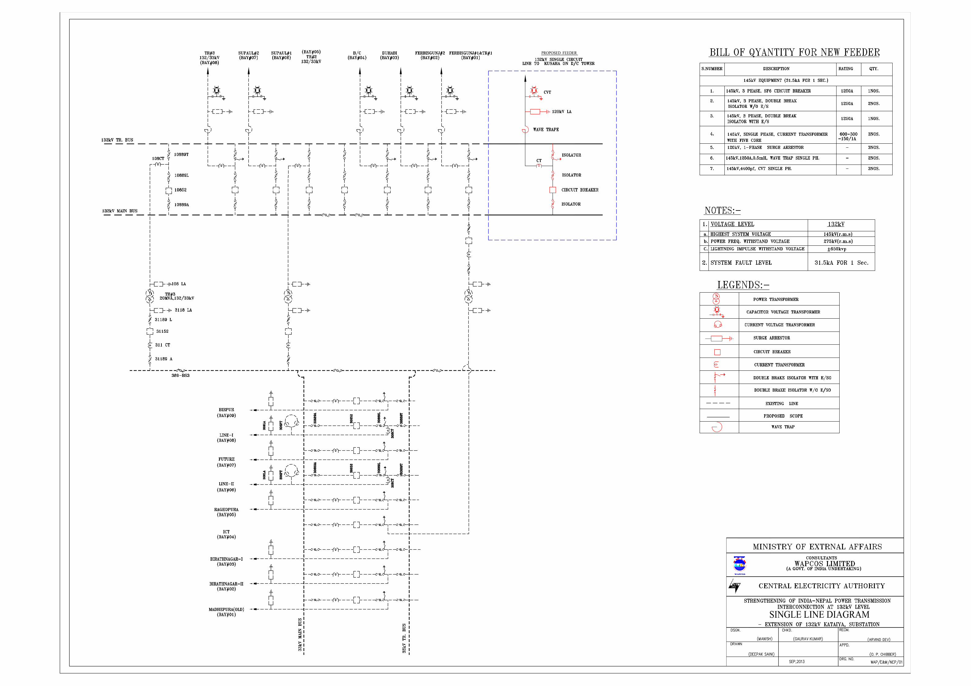
A G
OV
ERM
ENT OF I ND I A UNDERTA
KI N
G

A G
OV
ERMENT OF I ND I A UNDERTA
KIN
G

A G
OV
ERMEN T O F I N D I A U NDE RTA
KIN
G
A G
OV
E R MEN T O F I N D I A UND ERTA
KIN
G

A G
OV
ERM
ENT OF I ND I A UNDERTA
KI N
G

A G
OV
ERMEN T OF I N D I A UN DE RTA
KIN
G
A G
OV
ERME NT O F I ND I A U NDERTA
KI N
G

A G
OV
ERMENT OF I ND I A UNDERTAK
ING

A G
OVE R MEN T O F I N D I A UN DER
TAK
ING
A G
OV
ERME NT OF I ND I A UN DERT A
KIN
G

A G
OV
ERMENT O F I ND I A UNDERTA
KI N
G
GOVERNMENT OF INDIAMINISTRY OF EXTERNAL AFFAIRS
GUARANTEED TECHNICAL PARTICULARSOF
132 KV SUBSTATIONSFOR
STRENGTHENING OF INDIA-NEPALPOWER TRANSMISSION
INTERCONNECTION
VOLUME-3
Consultants:WAPCOS LIMITED(A Govt. of India Undertaking)PLOT NO. 76-CSECTOR-18, INSTITUTIONALAREAGURGAON-122015,HARYANA, INDIAPh.No: 91-124-2349416Fax No: 91-124-2349184E-mail: [email protected]
CENTRAL ELECTRICITYAUTHORITY,SEWA BHAWAN ,R.K.PURAM,NEW DELHI-01
June, 2014

BIDDING DOCUMENT FOR
DESIGN, ENGINEERING, PROCUREMENT AND CONSTRUCTION
ON
TURNKEY BASIS OF 132 kV LINE BAYS AT EXISTINGS SUB-
STATIONS IN INDIA AND NEPAL
Volume – 3
GUARANTEED TECHNICAL PARTICULARS
Table of Contents
Schedule-A CIRCUIT BREAKERS
Schedule-B ISOLATORS
Schedule-C SURGE ARRESTORS
Schedule-D CT
Schedule-E CVT
Schedule-F CONTROL & RELAY PANELS
Schedule-G PLCC
Schedule-H SUBSTATION STRUCTURE
Schedule-I LT POWER & CONTROL CABLES

1 Manufacturer’s Name and Country
2 Manufacturer’s type designation
3 Applicable Technical Standards
4 (a) Type of circuit breaker
(b) Type of tank (live/dead)
5 Rated frequency (Hz)
6 Number of poles (Nos.)
7 Whether 3 pole or single pole unit
8 No. of breaks per pole
9 Type -Outdoor
10Rated continuous current at design
temperature of 40 deg. C(Amp)
11 Rated short circuit breaking current
11.1 RMS value of AC component (kA)
11.2 Percentage DC component (%)
11.3Asymmetrical breaking current at highest
system voltage(kA)
11.4Is it possible to increase the rupturing
capacity at a later date(Yes/No)
12 Short time current rating for 1 sec. (kA)
Schedule-A
145 kVUnit
SF6 CIRCUIT BREAKERS
S.No. Description
GUARANTEED TECHNICAL PARTICULARS OF
Schedule-A Volume-3 :Guaranteed Technical Particulars 1/15

145 kVUnitS.No. Description
13 Rated operating duty cycle
14 Rated short circuit making current (kA peak)
15 First pole to clear factor
16Rated characteristics for short time faults
and rated breaking capacity(kA peak)
17Rated line charging breaking current with
temporary over voltage upto 1.4 p.u.(kA)
18Rated out of phase breaking current and
corresponding transient recovery voltage(kA, kV)
19Rated small inductive breaking current
with corresponding switching over voltage (Amp, p.u)
20
Rated cable charging breaking current
and corresponding over voltages recorded
during test
(Amp, p.u)
21(a) Maximum period between first contact
and last contact in a pole
(b) Maximum pole descrepancy
22
Rated (single) capacitor bank breaking
current and corresponding over voltages
recorded during test
(Amp, p.u)
23Data on re-striking voltage for terminal
faults
23.1 Amplitude factor
23.1.1 100% capacity
23.1.2 60% capacity
Schedule-A Volume-3 :Guaranteed Technical Particulars 2/15

145 kVUnitS.No. Description
23.1.3 30% capacity
23.1.4 10% capacity
23.2 Phase factor
23.2.1 100% capacity
23.2.2 60% capacity
23.2.3 30% capacity
23.2.4 10% capacity
23.3 Rate of rise of re-striking voltage
23.3.1 100% capacity
23.3.2 60% capacity
23.3.3 30% capacity
23.3.4 10% capacity
23.4 Transient recovery voltage
23.4.1 100% capacity (kV peak)
23.4.2 60% capacity (kV peak)
23.4.3 30% capacity (kV peak)
23.4.4 10% capacity (kV peak)
24a) Is circuit breaker re-strike free under
all conditions of operation.(Yes/No)
b) Means adopted if any to check the
voltage rise
25
Max. arcing time under any duty
condition with limiting conditions of
voltage and pressure
(ms)
Schedule-A Volume-3 :Guaranteed Technical Particulars 3/15

145 kVUnitS.No. Description
26
Maximum total break time under any
duty condition for any current up to rated
breaking current with limiting conditions
of voltage and pressure
(ms)
27 Maximum closing time (ms)
28
Minimum opening time under any duty
condition with limiting voltage and
pressure
(ms)
29
Maximum close open time under any
condition with limiting voltage and
pressure
(ms)
30
Minimum re-closing time at rated
interrupting capacity from instant of trip
coil energisation
(ms)
31 Minimum dead time for
31.1 Three phase reclosing (ms)
31.2 Single phase reclosing (ms)
31.3Limits of adjustment of dead time for
three phase reclosing(ms)
32
Difference in the instants of closing
opening of contacts at rated voltage and
pressure
32.1 Within a pole (ms)
32.2 Between poles (ms)
33
Type of device, if any, used to obtain
uniform voltage distribution between
contacts
34 Maximum temperature rise for
34.1Main contacts over ambient temperature
at site(Deg.C)
Schedule-A Volume-3 :Guaranteed Technical Particulars 4/15
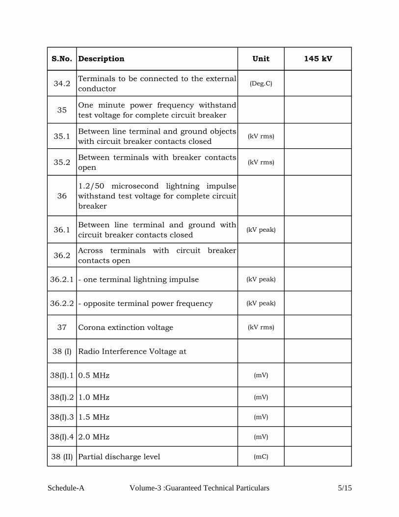
145 kVUnitS.No. Description
34.2Terminals to be connected to the external
conductor (Deg.C)
35One minute power frequency withstand
test voltage for complete circuit breaker
35.1Between line terminal and ground objects
with circuit breaker contacts closed(kV rms)
35.2Between terminals with breaker contacts
open(kV rms)
36
1.2/50 microsecond lightning impulse
withstand test voltage for complete circuit
breaker
36.1Between line terminal and ground with
circuit breaker contacts closed(kV peak)
36.2Across terminals with circuit breaker
contacts open
36.2.1 - one terminal lightning impulse (kV peak)
36.2.2 - opposite terminal power frequency (kV peak)
37 Corona extinction voltage (kV rms)
38 (I) Radio Interference Voltage at
38(I).1 0.5 MHz (mV)
38(I).2 1.0 MHz (mV)
38(I).3 1.5 MHz (mV)
38(I).4 2.0 MHz (mV)
38 (II) Partial discharge level (mC)
Schedule-A Volume-3 :Guaranteed Technical Particulars 5/15

145 kVUnitS.No. Description
39Whether the circuit breaker is fixed trip
or trip freeYes/No
40(a) a) Rated voltage of closing coils (Volts)
40(b) b) Range of pick up value (Volts)
41 (a) Rated voltage of tripping coil (Volts)
41 (b) Range of pick up value (Volts)
42Normal power consumption at rated
voltage for
42.1 Trip coil (Watts)
42.2 Closing coil (Watts)
43 Number of trip coils (Nos.)
44 Type of main contact
45 Whether arcing contact provided (Yes/No)
46 Material of
46.1 Main contact
46.2 Arcing contact
46.3 Whether contacts silver plated (Yes/No)
46.4 Minimum thickness of silver plating (mm)
46.5 Contact pressure of main contact (kg/sq. cm)
47Number of auxiliary contacts per pole
provided for Purchaser’s use.
Schedule-A Volume-3 :Guaranteed Technical Particulars 6/15

145 kVUnitS.No. Description
47.1 NO (Nos.)
47.2 NC (Nos.)
48 Rated voltage of auxiliary contacts (Volts)
49 Current capacity of auxiliary contacts
49.1 Continuous (Amp)
49.2 Breaking (Amp)
50Whether auxiliary contacts silver
plated(Yes/No)
51 SF6 circuit breakers
51.1Quantity of SF6 gas required for each
pole of circuit breaker (kg)
51.2Guaranteed maximum leakage rate of
SF6 gas per year(%)
51.3Rated pressure of SF6 in opeerating
chamber(kg/sq. cm)
51.4 SF6 density monitor provided (Yes/No)
51.5Limits of pressure of SF6 gas at which
breaker operate correctly(kg/sq. cm)
52Number of operations after which SF6 gas
replacement is necessary
52.1 At full rupturing capacity (Nos.)
52.2 At 50% of rated rupturing capacity (Nos.)
52.3 At 10% of rated rupturing capacity (Nos.)
Schedule-A Volume-3 :Guaranteed Technical Particulars 7/15

145 kVUnitS.No. Description
52.4 At rated current (Nos.)
53
Number of operations after which main
and auxiliary contacts replacement is
necessary.
53.1 At full rupturing capacity (Nos.)
53.2 At 50% of rated rupturing capacity (Nos.)
53.3 At 10% of rated rupturing capacity (Nos.)
53.4 At rated current (Nos.)
54
Number of operations at rated current
after which routine inspection /
maintenance of breaker is necessary.
(Nos.)
55
Number of operations at full rupturing
capacity after which routine
inspection/maintenance of circuit
breaker is necessary.
(Nos.)
56Parameters of SF6 gas required for initial
filling and satisfactory operation
56.1 Density (kg/sq. cm)
56.2 Dielectric strength (kV/mm)
56.3 Acidity (ppm)
56.4 Water content (ppm)
56.5 Oil content (ppm)
Schedule-A Volume-3 :Guaranteed Technical Particulars 8/15

145 kVUnitS.No. Description
56.6 Condensation temperature (Deg. C)
56.7 Resistivity (Ohm-m)
57 Support insulators column/units
57.1 Make and type
57.2 Numbers per pole (Nos.)
57.3 Weight (Kg)
57.4 Transport dimensions(mm x mm x
mm)
57.5One minute power frequency withstand
voltage(kV rms)
57.6 Lightning impulse withstand voltage (kV peak)
57.7 Corona extinction voltage (kV rms)
57.8 Creepage distance (mm)
57.9 Permissible safe cantilever strength (Kg)
57.10 Insulation class
58.11 Flash over voltage (kV)
58 Type of operating mechanism for
58.1 Closing
58.2 Opening
Schedule-A Volume-3 :Guaranteed Technical Particulars 9/15

145 kVUnitS.No. Description
59Rated pressure and limits of pressure of
operating mechanism (kg/sq. cm)
60 Pneumatic operating mechanism
60.1 Rated operating pressure (kg/sq. cm)
60.2 Range of pressure for
60.2.1 Closing (kg/sq. cm)
60.2.2 Opening (kg/sq. cm)
60.3 Air consumption at rated pressure for
60.3.1 Closing (m3)
60.3.2 Opening (m3)
60.3.3 Close - Open (m3)
60.4Number and capacity of local air
receiver(m3)
60.5
Time required for filling the air receiver to
its rated pressure from atmospheric
pressure
(minutes)
60.6 Design pressure of air receiver (kg/cm2 )
60.7
Number of closing opening operations
possible without charging the air
receiver
(Nos.)
60.8
Arrangement provided for preventing the
operation of breaker with insufficient air
pressure
Schedule-A Volume-3 :Guaranteed Technical Particulars 10/15

145 kVUnitS.No. Description
60.9 Compressor
60.9.1 Make and type
60.9.2 Number of compression stages (Nos.)
60.9.3 Compression pressure (kg/sq. cm )
60.9.4Whether compressor is provided with its
own filter. If so give type and make(Yes/No)
60.9.5Effectively delivered air in liters per hr. at
atmospheric pressure. (Ltr/hr)
60.10 Compressed air piping
60.10.
1Material
60.10.
2Inner & outer diameter (mm, mm)
60.10.
3Working pressure (kg/sq. cm )
61 Spring charged mechanism
61.1 Name of Manufacturer
61.2 Rating of motor (Volts)
61.3Time required for charging the closing
spring(Sec)
61.4Number of CO operation possible after
failure of auxiliary supply(Nos.)
Schedule-A Volume-3 :Guaranteed Technical Particulars 11/15

145 kVUnitS.No. Description
61.5
Whether indication for spring charged
condition provided in central control
cabinet.
(Yes/No)
62 Control cabinet
62.1 Manufacturer’s Name
62.2 Thickness of sheet steel (mm)
62.3 Degree of protection provided
62.4 Colour of finish paint
62.4.1 Outside
62.4.2 Inside
62.5 Control wiring
62.5.1 Rated voltage (Volts)
62.5.2 Size (Sq. mm)
62.6 Terminal Block
62.6.1 Make
62.6.2 Current rating (Amp)
63 Terminal clamps and connector
63.1 Manufacturer’s Name
Schedule-A Volume-3 :Guaranteed Technical Particulars 12/15

145 kVUnitS.No. Description
63.2 Applicable standard
63.3 Material
63.3.1 Clamp body
63.3.2 Bolts and nuts
63.3.3 Spring washer
63.3.4 Liner if any
63.4 Rated current (Amp)
63.5(a) i) Rated terminal load (Kg or N)
63.5(b) ii) Factor of Safety
63.6 Radio interference voltage (mV)
63.6 Corona extinction voltage (kV rms)
63.7
Maximum allowable span for aluminum
tube of 114.2 mm outer diameter and
97.18 mm inside diameter on equipment
terminal pad with rated fault current and
7 m and 4.5 m, phase to phase spacing .
(m)
64 Over all dimensions
64.1 Height (mm)
64.2 Width (mm)
64.3 Length (mm)
Schedule-A Volume-3 :Guaranteed Technical Particulars 13/15

145 kVUnitS.No. Description
65 Clearances
65.1 Between poles (mm)
65.2 Between live part and earth (mm)
66 Weight of
66.1 Each pole (Kg)
66.2 Complete Breaker for foundation design (Kg)
67 Impact loading on foundation design
68 Noise level
68.1 At base (dB)
68.2 At 50 m distance from base (dB)
69Seismic level for which breaker is
designed
70Compliance to technical specification
w.r.t. parameters specified for
71.1 Control cabinet Yes/No
71.2 Bushing/support insulator Yes/No
71.3 Terminal connector Yes/No
71.4 SF6 Gas Yes/No
72Enclosures
Whether the following are enclosed
Schedule-A Volume-3 :Guaranteed Technical Particulars 14/15

145 kVUnitS.No. Description
72.1Type test reports for main equipment and
auxiliaries(Yes/No)
72.2 Drawings as per specification (Yes/No)
72.3
Technical literature for circuit breaker,
SF6 gas, support insulators and
operating mechanism
(Yes/No)
72.4
Data on capabilities of circuit breaker in
terms of time and number of operations
at duties ranging from 100% fault current
to load current of the lowest possible
value without requiring any maintenance
or checks
72.5
Details on non-simulaniety between
contacts within a pole or between poles
and also show how it is covered in the
gauranteed rated break time
Date :
with seal
Signature of Authorised person
Schedule-A Volume-3 :Guaranteed Technical Particulars 15/15

1 Manufacturer’s Name and Address
2 Type Designation
3 Applicable standard
4 Rated voltage (kV)
5 Rated frequency (Hz)
6 No. of Poles (Nos.)
7Whether all three poles are ganged
together mechanically/electrically(Yes/No)
8 Rated normal current
8.1 Under site conditions (Amp)
8.2Under normal conditions as per
IS/IEC(Amp)
9Rated short time withstand current for
1 Sec./3 sec.(kA rms)
10 Rated peak short circuit current of
10.1 Isolator (kA peak)
10.2 Earthing switch (kA peak)
11Rated short circuit making current for
isolator only(kA)
12
Rated magnetizing current and
capacitive current make and break
capacity
(Amp)
ISOLATORS / DISCONNECTORS AND EARTHING SWITCHES
(145 kV)
GUARANTEED TECHNICAL PARTICULARS OF
Schedule-B
S.No. Description Unit 145 kV
Schedule-B Volume-3 :Guranteed Technical Particulars 1/9
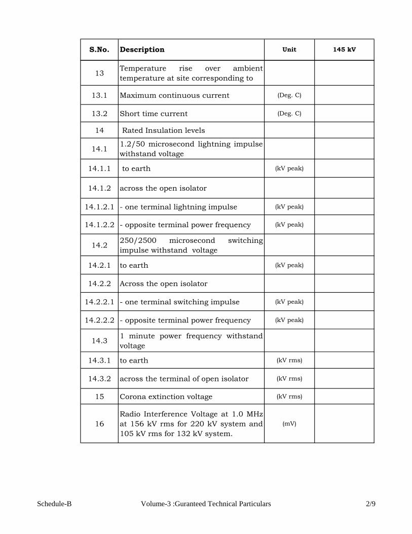
S.No. Description Unit 145 kV
13Temperature rise over ambient
temperature at site corresponding to
13.1 Maximum continuous current (Deg. C)
13.2 Short time current (Deg. C)
14 Rated Insulation levels
14.11.2/50 microsecond lightning impulse
withstand voltage
14.1.1 to earth (kV peak)
14.1.2 across the open isolator
14.1.2.1 - one terminal lightning impulse (kV peak)
14.1.2.2 - opposite terminal power frequency (kV peak)
14.2250/2500 microsecond switching
impulse withstand voltage
14.2.1 to earth (kV peak)
14.2.2 Across the open isolator
14.2.2.1 - one terminal switching impulse (kV peak)
14.2.2.2 - opposite terminal power frequency (kV peak)
14.31 minute power frequency withstand
voltage
14.3.1 to earth (kV rms)
14.3.2 across the terminal of open isolator (kV rms)
15 Corona extinction voltage (kV rms)
16
Radio Interference Voltage at 1.0 MHz
at 156 kV rms for 220 kV system and
105 kV rms for 132 kV system.
(mV)
Schedule-B Volume-3 :Guranteed Technical Particulars 2/9

S.No. Description Unit 145 kV
17Rated mechanical terminal loads for
horizontal break isolator
17.1 Longitudinal (N)
17.2 Transverse (N)
18Total operating time of Isolator & earth
switch
18.1 Opening time (Sec)
18.2 Closing time (Sec)
20
Dielectric withstand capacity of
completely assembled isolator/earth
switch
21 Main contacts (fixed and moving)
21.1 Type
21.2 Material
21.3 Whether contacts are silver plated (Yes/No)
21.4 Thickness of silver coating (Microns)
21.5 Contact area (Sq. mm)
21.6 Contact pressure (kg/sq. cm)
21.7Max. Current density under normal
current carrying capacity(A/sq. cm)
21.8
Number of operations which the
isolator can make without
deterioration of contacts.
(Nos.)
22 Auxiliary contacts
22.1 Isolator
22.1.1Total number of spare contacts
provided for purchaser’s use
22.1.1.1 NO (Nos.)
22.1.1.2 NC (Nos.)
Schedule-B Volume-3 :Guranteed Technical Particulars 3/9

S.No. Description Unit 145 kV
22.1.2 Rated voltage (Volts)
22.1.3 Rated continuous current (Amp)
22.1.4 Rated breaking current (Amp)
22.2 Earth Switch
22.2.1Total number of spare contacts
provided for Purchaser’s use
22.2.1.1 NO (Nos.)
22.2.1.2 NC (Nos.)
22.2.2 Rated voltage (Volts)
22.2.3 Rated continuous current (Amp)
22.2.4 Rated breaking current (Amp)
22.3Whether arcing contacts provided and
if so give type and material used.(Yes/No)
23 Insulators
23.1 Make
23,2 Type (solid core)
23.3 Applicable Standard
23.4 Number of insulator stacks per pole (Nos.)
23.5 Number of insulators per stack (Nos.)
23.61 minute power frequency withstand
voltage(kV rms)
23.7 Lightning impulse withstand voltage (kV peak)
23.8 Switching impulse withstand voltage (kV peak)
23.9 Visible corona extinction voltage (kV rms)
23.10 Creepage distance (mm)
Schedule-B Volume-3 :Guranteed Technical Particulars 4/9
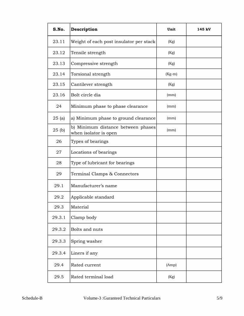
S.No. Description Unit 145 kV
23.11 Weight of each post insulator per stack (Kg)
23.12 Tensile strength (Kg)
23.13 Compressive strength (Kg)
23.14 Torsional strength (Kg-m)
23.15 Cantilever strength (Kg)
23.16 Bolt circle dia (mm)
24 Minimum phase to phase clearance (mm)
25 (a) a) Minimum phase to ground clearance (mm)
25 (b)b) Minimum distance between phases
when isolator is open(mm)
26 Types of bearings
27 Locations of bearings
28 Type of lubricant for bearings
29 Terminal Clamps & Connectors
29.1 Manufacturer’s name
29.2 Applicable standard
29.3 Material
29.3.1 Clamp body
29.3.2 Bolts and nuts
29.3.3 Spring washer
29.3.4 Liners if any
29.4 Rated current (Amp)
29.5 Rated terminal load (Kg)
Schedule-B Volume-3 :Guranteed Technical Particulars 5/9

S.No. Description Unit 145 kV
29.6Weight of clamp complete with
hardware(Kg)
29.7 Radio Interference Voltage (mV)
29.8 Corona extinction voltage (kV rms)
29.9
Maximum allowable span for
aluminum tube with applicable size
with rated fault current and applicable
phase to phase spacing for 245 kV &
36kV isolators.
(m)
30 Operating Mechanism
30.1 Type of operating mechanism
30.2 Name of manufacturer
30.3Whether inter-pole cabling included in
scope of supply(Yes/No)
30.4
Whether separate operating
mechanism provided for operation of
isolator pole and earthing switch.
(Yes/No)
30.5Electrical operation (Main Operating
Box)
30.5.1 Motor type (AC/DC)
30.5.2 Applicable standard
30.5.3 Rated voltage and current (V, A)
30.5.4Type of enclosure and method of
cooling
30.5.5Power required for closing and opening
operation (Watts)
30.5.6Running time of motor for closing and
opening operation(Sec)
30.5.7 Control supply for motor control center (Volts)
Schedule-B Volume-3 :Guranteed Technical Particulars 6/9

S.No. Description Unit 145 kV
30.6Type of manual operating mechanism
for isolator pole
30.7Force required to operate manual
operating mechanism(Kg)
30.8Whether padlocking included as per
the specification(Yes/No)
30.9Type of manual device for Earthing
Switch
30.10Force required to operate manual
device for earthing switch(Kg)
31 Interlocking
31.1
Details of mechanical interlock
between isolator and earth switch
enclosed
(Yes/No)
31.2Details of electrical interlock for
isolator and earth switch enclosed(Yes/No)
31.3 Details of electrical interlock provided (Yes/No)
31.4Details of electrical scheme to provide
remote alarm (Yes/No)
31.5
Details of electrical interlock to bring
back all three poles to open position in
case any pole fails to close within
specified time
(Yes/No)
31.6
Details of provisions to cut off supply
to the motor during manual operation
and provision for declutching the
motor.
(Yes/No)
31.7
Arrangement provided to prevent
electrical or manual operation unless
interlock conditions are satisfied.
(Yes/No)
32 Control Cabinets / Marshalling box
32.1 Manufacturer’s name
Schedule-B Volume-3 :Guranteed Technical Particulars 7/9

S.No. Description Unit 145 kV
32.2 Thickness of sheet (mm)
32.3 Degree of protection provided
32.4 Colour of finish paint
32.4.1 Outside
32.4.2 Inside
32.5 Control wiring
32.5.1 Voltage rating (Volts)
32.5.2 Size and material of conductor(Sq. mm /
SWG)
32.6 Terminal block
32.6.1 Make
32.6.2 Current rating (Amp)
32.7 Space heater rating at 240 volts (Watts)
32.8
Whether all cabling for wiring out
contacts to control cabinet included in
scope of supply
(Yes/No)
33 Size and Weight
33.1 Weight of each pole (Kg)
33.2 Space requirement i.e. length. (mm)
33.3Height of 3 phase isolator without
earth switch.(mm)
33.4 Dimension of the isolators
33.4.1 without earthing switch (mm x mm x
mm)
33.4.2 with earth switch on one side (mm x mm x
mm)
33.4.3 with earth switch on both sides(mm x mm x
mm)
Schedule-B Volume-3 :Guranteed Technical Particulars 8/9

S.No. Description Unit 145 kV
34Enclosures
Whether the following are enclosed
34.1Type test report for main equipment
and auxiliaries(Yes/No)
34.2 Drawings as per specification (Yes/No)
34.3
Technical literature for isolator,
operating mechanism and support
insulators.
(Yes/No)
35Compliance to Technical Specification
w.r.t.
35.1 MOM box Yes/No
35.2 Support insulators Yes/No
35.3 Terminal connectors Yes/No
36 (I) Tandem Pipe
36 (I).1 Size ( internal diameter) (mm)
36 (I).2 Class
36 (I).3 Material
36 (II) Down pipe
36 (II).1 Size ( internal diameter) (mm)
36 (II).2 Class
36 (II).3 Material
Date:Signature of Authorised
Person
with seal
Schedule-B Volume-3 :Guranteed Technical Particulars 9/9

S. No. Description Unit 120kV
Manufacturer’s Name and Address
1 Manufacturer’s type designation
2 Applicable technical standard
4 Arrester class and type
5 Rated voltage of arrester (kV rms)
6 Rated system voltage (kV rms)
7 Rated frequency (Hz)
8 Continuous Operating Voltage (COV) (kV rms)
9 Nominal Discharge Current (8/20 micro sec.) (kA)
10 (a) No. of units in complete arrester (Nos.)
10 (b) Voltage rating of each unit (kV rms)
10 ( c ) Height of longest unit (mm)
11 Long duration discharge class
12 (a)Minimum energy dissipation capability
(kJ/kV of rated voltage of arrester)(kJ/kV)
12 (b)
Power frequency over voltage withstand
capability immediately after discharging
energy equivalent to the minimum capability
of arrester .
(kV rms)
13Leakage current at COV and ambient
temperature
13.1 Resistive component (mA)
Schedule-C
GUARANTEED TECHNICAL PARTICULARS OF
METAL OXIDE SURGE ARRESTERS ( 120 kV)
Schedule-C Volume-3 General Technical Particulars 1/5

S. No. Description Unit 120kV
13.2 Capacitive component (mA)
13.3 Total (mA)
14
Reference voltage and corresponding
reference current guaranteed by
manufacturer
(kV rms, kA
rms)
15 Watt loss per kV at COV (Watts)
16Temporary power frequency over voltage
withstand capability
16.1 0.1 sec (kV rms)
16.2 1.0 sec (kV rms)
16.3 10 sec (kV rms)
16.4 100 sec (kV rms)
17 Maximum residual voltage for
17.1Lightning impulse current (8/20 micro sec.)
of
17.1.1 - 5 kA (kV peak)
17.1.2 - 10 kA (kV peak)
17.1.3 - 20 kA (kV peak)
17.2Switching impulse current (30-60/100-200
micro sec)
17.2.1 - 250 kA (kV peak)
17.2.2 - 1000 kA (kV peak)
17.3Steep current impulse (1/20 micro sec) at
Nominal Discharge Current(kV peak)
18High current short duration impulse (4/10
micro sec) value(kA peak)
19Low current long duration impulse current
(2000 microsec.)
20 Whether pressure relief devices provided (Yes/No)
21 Current for pressure relief test (kA)
22 Pressure relief class (As per IEC-99)
Schedule-C Volume-3 General Technical Particulars 2/5

S. No. Description Unit 120kV
23 Prospective symmetrical fault current (kA rms)
24 (a)High current value employed for pressure
relief test(kA)
24 (b)Low current value employed for pressure
relief test(Amp)
25 Metal oxide discs:
25.1 Country of manufacture
25.2 Size of discs (Diameter & Thickness) (mm, mm)
25.3How the electrical contact is ensured
between blocks
25.4Medium of heat dissipation from the blocks
to the surrounding
26 Arrester Housing:
26.1 Name of manufacturer
26.2 Wet power frequency with stand voltage (kV rms)
26.3Lightning impulse (1.2/50 micro sec.)
withstand voltage(kV peak)
26.4 Switching impulse withstand voltage (kV peak)
26.5 Total creepage distance (mm)
26.6 Dry arcing distance (mm)
26.7 Cantilever strength (N - m)
26.8 Internal diameter (mm)
26.9 Thickness (mm)
27 Partial discharge level (pC)
28 Radio Interference level at 1.1 COV (mV)
29 Total height of arrester (mm)
Schedule-C Volume-3 General Technical Particulars 3/5

S. No. Description Unit 120kV
30 Toal weight of complete arrester unit (Kg)
31 Surge Monitor
31.1 Type
31.2
Minimum lightning impulse current (8/20
micro sec.) to which surge counter will
respond faithfully
(mA Amp)
31.3
Whether the surge monitor has been
successfully tested for high current impulses,
long duration current impulse & low current
response test
(Yes/No)
31.4 Scale range of leakage current meter (mA)
32Recommended protective distance from
transformer(m)
33 Compliance to technical specification w.r.t.
33.1 Surge Monitor (Yes/No)
33.2 Support insulator (Yes/No)
33.3 Terminal connectors (Yes/No)
34Whether following curves/drawings enclosed
with offer
34.1 Volt time characteristic (Yes/No)
34.2 Voltage current characteristic of arrester (Yes/No)
34.3Type test has been conducted as per IEC –
99 - 4 (latest edition)(Yes/No)
34.4Type test report submitted along with the
offer(Yes/No)
34.5Drawing of outline dimensions for
installation (Yes/No)
Schedule-C Volume-3 General Technical Particulars 4/5

S. No. Description Unit 120kV
34.6 Drawing of mounting flange dimension detail (Yes/No)
34.7 Drawing of Earthing arrangement provided (Yes/No)
34.8 Details for surge monitor enclosed (Yes/No)
Date: Signature of Authorised Person
with seal
Schedule-C Volume-3 General Technical Particulars 5/5

Schedule-D
Sl. No. Description Unit 145kV
1 Manufacturer’s Name and Country
2 Manufacturer’s type and designation
3 Class/ installation
4 Rated voltage (kV)
5 Max. Continuous rated voltage (kV)
6 Standard to which it conforms
7 Rated frequency (Hz)
8 Core Details - Core 1
a) Rated primary current (Amp)
b) Rated secondary current (Amp)
c) Rated output (Burden) (VA)
d) Rated output at 0.8 lagging power factor (VA)
e) Class of accuracy
f) Accuracy limit factor
g) Saturation factor
h) Knee point voltage (Volts)
i) C.T. Resistance of secondary winding
corrected to 70 Deg. C
(Ohms)
j) Magnetizing current at knee-point voltage (mA)
145kV CURRENT TRANSFORMERS
GUARANTEED TECHNICAL PARTICULARS OF
Schedule-D Volume-3 Guaranteed Technical Particulars 1/7
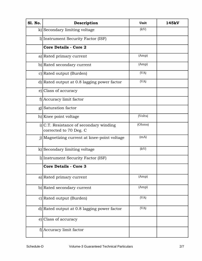
Sl. No. Description Unit 145kV
k) Secondary limiting voltage (kV)
l) Instrument Security Factor (ISF)
Core Details - Core 2
a) Rated primary current (Amp)
b) Rated secondary current (Amp)
c) Rated output (Burden) (VA)
d) Rated output at 0.8 lagging power factor (VA)
e) Class of accuracy
f) Accuracy limit factor
g) Saturation factor
h) Knee point voltage (Volts)
i) C.T. Resistance of secondary winding
corrected to 70 Deg. C
(Ohms)
j) Magnetizing current at knee-point voltage (mA)
k) Secondary limiting voltage (kV)
l) Instrument Security Factor (ISF)
Core Details - Core 3
a) Rated primary current (Amp)
b) Rated secondary current (Amp)
c) Rated output (Burden) (VA)
d) Rated output at 0.8 lagging power factor (VA)
e) Class of accuracy
f) Accuracy limit factor
Schedule-D Volume-3 Guaranteed Technical Particulars 2/7

Sl. No. Description Unit 145kV
g) Saturation factor
h) Knee point voltage (Volts)
i) C.T. Resistance of secondary winding
corrected to 70 Deg. C
(Ohms)
j) Magnetizing current at knee-point voltage (mA)
k) Secondary limiting voltage (kV)
l) Instrument Security Factor (ISF)
Core Details - Core 4
a) Rated primary current (Amp)
b) Rated secondary current (Amp)
c) Rated output (Burden) (VA)
d) Rated output at 0.8 lagging power factor (VA)
e) Class of accuracy
f) Accuracy limit factor
g) Saturation factor
h) Knee point voltage (Volts)
i) C.T. Resistance of secondary winding
corrected to 70 Deg. C
(Ohms)
j) Magnetizing current at knee-point voltage (mA)
k) Secondary limiting voltage (kV)
l) Instrument Security Factor (ISF)
Core Details - Core 5
a) Rated primary current (Amp)
Schedule-D Volume-3 Guaranteed Technical Particulars 3/7

Sl. No. Description Unit 145kV
b) Rated secondary current (Amp)
c) Rated output (Burden) (VA)
d) Rated output at 0.8 lagging power factor (VA)
e) Class of accuracy
f) Accuracy limit factor
g) Saturation factor
h) Knee point voltage (Volts)
i) C.T. Resistance of secondary winding
corrected to 70 Deg. C
(Ohms)
j) Magnetizing current at knee-point voltage (mA)
k) Secondary limiting voltage (kV)
l) Instrument Security Factor (ISF)
9 One minute power frequency withstand test
voltage of
i) Primary winding (kVrms )
ii) Secondary winding (kV)
10 1.2/50 microsecond lightning impulse
wave withstand voltage of primary winding
(kV peak)
11 One minute dry power frequency withstand
voltage
(kV rms)
12 Creepage distance (mm)
13 Rated continuous thermal current (Amp)
14 Ratios available at different taps
15 Rated short time thermal current (kA rms)
Schedule-D Volume-3 Guaranteed Technical Particulars 4/7

Sl. No. Description Unit 145kV
16 Rated time for above (Sec)
17 Rated dynamic current for primary (kA peak)
18 Class of insulation
19 Maximum temperature rise over ambient of
35.5 Deg. C at any part or oil
(Deg. C)
20 a) Corona extinction voltage (kV rms)
b) Radio Interference Voltage (mV)
c) Partial discharge level (pC)
21 Total weight (Kg)
22 Quantity of oil (litres)
23 Overall dimensions (mm x mm x
mm)
24 Heights of supporting structure (mm)
25 Drawings enclosed
i) Magnetization curve (Yes/No)
ii) Ratio and phase angle characteristics at
least up to accuracy limit factor
(Yes/No)
iii) Ratio Correction Factor curve (Yes/No)
iv) Limits of composite error at rated primary
saturation current (for protection core)
(Yes/No)
v) Base plan (Yes/No)
vi) Maximum safe loading as per drawing (Yes/No)
vii) Foundation plan showing details of
foundation bolts
(Yes/No)
viii) Foundation loading (Yes/No)
Schedule-D Volume-3 Guaranteed Technical Particulars 5/7

Sl. No. Description Unit 145kV
ix) Support structure (Yes/No)
26 Temperature Rise after passing short time
Thermal current for one second
(Deg. C)
27 Current density in primary winding
a) Normal rating (A/ sq. m)
b) Short time rating of 1 sec (A/ sq. m)
c) Dynamic rating (A/ sq. m)
28 Type of primary winding
29 Number of primary turns (Nos.)
30 Number of secondary turns (Nos.)
31 Flux density at knee point voltage (knee
point defined at the point at which 10%
increase in voltage produces a 50%
increase in magnetization current)
(Tesla)
32 Radio interference voltage
a) With terminal connector mounted (mV)
b) Under test condition (mV)
33 Variation in ratio and phase angle error
due to variation in
a) Voltage by 1% (%, %)
b) Frequency by 1 Hz (%, %)
34 Source/grade of oil and standard with
which it complies
35 Whether pressure relief device is provided (Yes/No)
Schedule-D Volume-3 Guaranteed Technical Particulars 6/7

Sl. No. Description Unit 145kV
36 Mounting details (Yes/No)
37 Whether the following are enclosed with
tender:
a) All type test reports (Yes/No)
b) Drawings as per the specification (Yes/No)
c) Technical literature for current transformer
and marshalling box.
(Yes/No)
38 Weight of CT with oil (Kg)
Note:
Date : Signature of Authorised Person
with Seal
(N.A.) be written against the item which is not applicable.
Schedule-D Volume-3 Guaranteed Technical Particulars 7/7
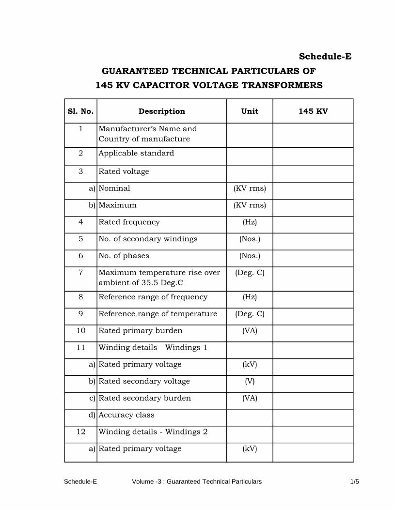
Sl. No. Description Unit 145 KV
1 Manufacturer’s Name and
Country of manufacture
2 Applicable standard
3 Rated voltage
a) Nominal (KV rms)
b) Maximum (KV rms)
4 Rated frequency (Hz)
5 No. of secondary windings (Nos.)
6 No. of phases (Nos.)
7 Maximum temperature rise over
ambient of 35.5 Deg.C
(Deg. C)
8 Reference range of frequency (Hz)
9 Reference range of temperature (Deg. C)
10 Rated primary burden (VA)
11 Winding details - Windings 1
a) Rated primary voltage (kV)
b) Rated secondary voltage (V)
c) Rated secondary burden (VA)
d) Accuracy class
12 Winding details - Windings 2
a) Rated primary voltage (kV)
Schedule-E
GUARANTEED TECHNICAL PARTICULARS OF
145 KV CAPACITOR VOLTAGE TRANSFORMERS
Schedule-E Volume -3 : Guaranteed Technical Particulars 1/5
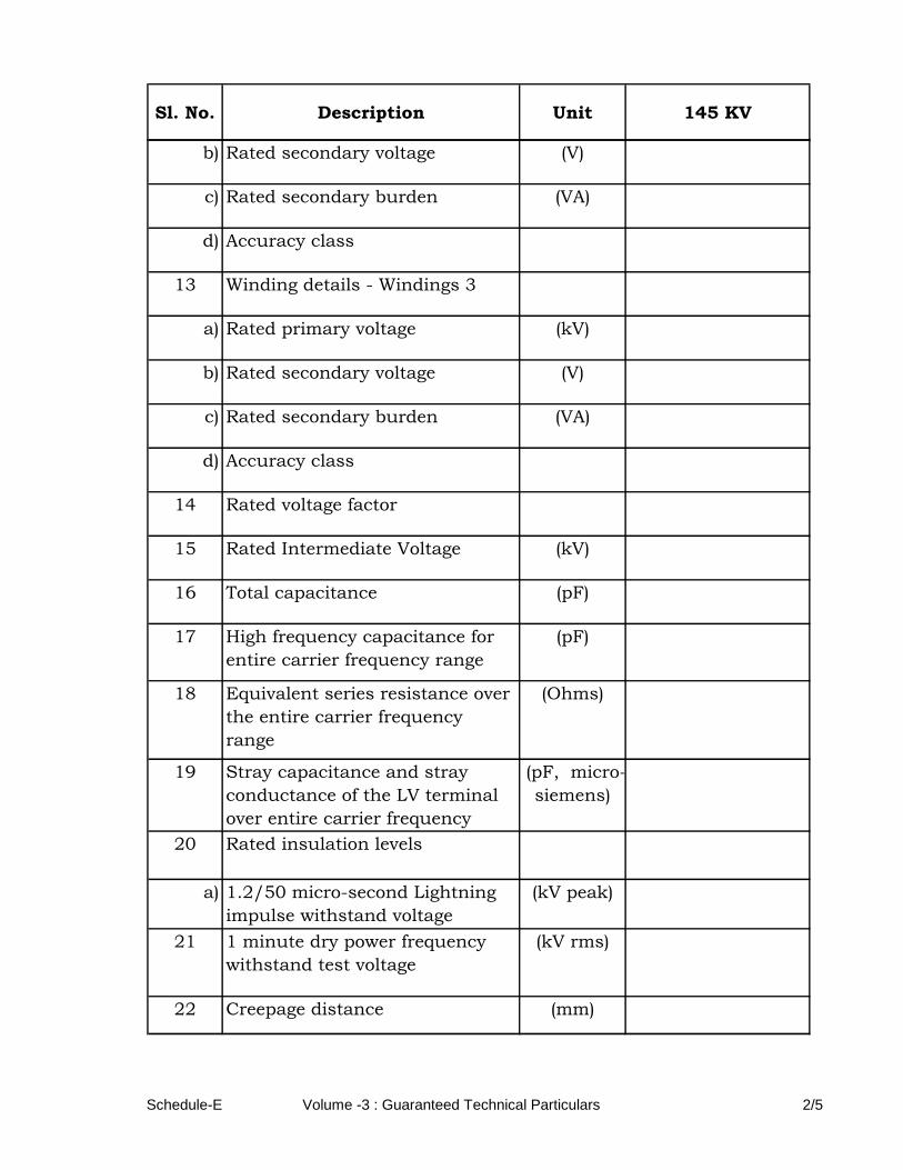
Sl. No. Description Unit 145 KV
b) Rated secondary voltage (V)
c) Rated secondary burden (VA)
d) Accuracy class
13 Winding details - Windings 3
a) Rated primary voltage (kV)
b) Rated secondary voltage (V)
c) Rated secondary burden (VA)
d) Accuracy class
14 Rated voltage factor
15 Rated Intermediate Voltage (kV)
16 Total capacitance (pF)
17 High frequency capacitance for
entire carrier frequency range
(pF)
18 Equivalent series resistance over
the entire carrier frequency
range
(Ohms)
19 Stray capacitance and stray
conductance of the LV terminal
over entire carrier frequency
range
(pF, micro-
siemens)
20 Rated insulation levels
a) 1.2/50 micro-second Lightning
impulse withstand voltage
(kV peak)
21 1 minute dry power frequency
withstand test voltage
(kV rms)
22 Creepage distance (mm)
Schedule-E Volume -3 : Guaranteed Technical Particulars 2/5
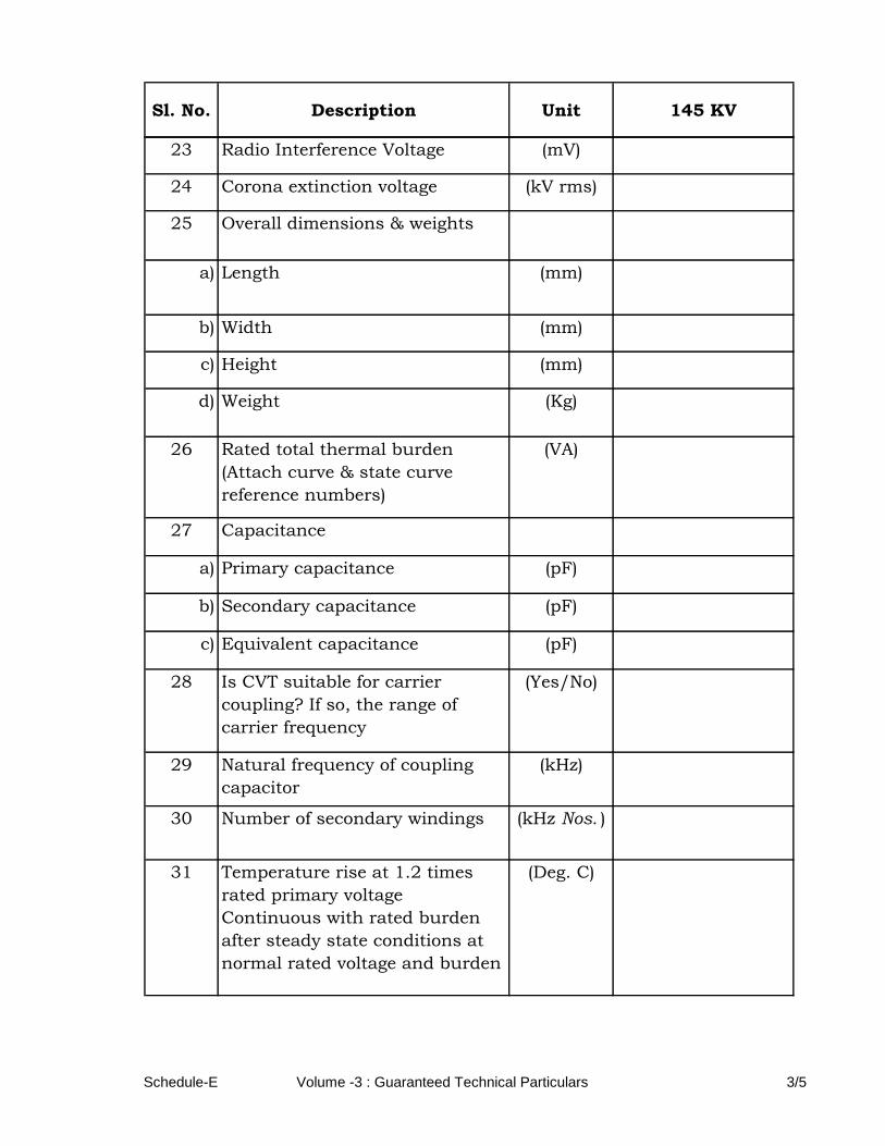
Sl. No. Description Unit 145 KV
23 Radio Interference Voltage (mV)
24 Corona extinction voltage (kV rms)
25 Overall dimensions & weights
a) Length (mm)
b) Width (mm)
c) Height (mm)
d) Weight (Kg)
26 Rated total thermal burden
(Attach curve & state curve
reference numbers)
(VA)
27 Capacitance
a) Primary capacitance (pF)
b) Secondary capacitance (pF)
c) Equivalent capacitance (pF)
28 Is CVT suitable for carrier
coupling? If so, the range of
carrier frequency
(Yes/No)
29 Natural frequency of coupling
capacitor
(kHz)
30 Number of secondary windings (kHz Nos. )
31 Temperature rise at 1.2 times
rated primary voltage
Continuous with rated burden
after steady state conditions at
normal rated voltage and burden
(Deg. C)
Schedule-E Volume -3 : Guaranteed Technical Particulars 3/5

Sl. No. Description Unit 145 KV
32 Temperature rise at 1.5 times
rated voltage for 30 sec.
(Deg. C)
33 One minute power frequency
withstand voltage on secondaries
a) Winding No. I (kV rms)
b) Winding No. II (kV rms)
c) Winding No. III (kV rms)
34 One minute power frequency
withstand voltage of HF terminal
35 Partial discharge level (pC)
36 Value of pressure for sealing test (kN/sq. m)
37 Weight of oil and the standard to
which it conforms
a) In capacitor unit (Kg)
b) In measuring unit (Kg)
38 Total weight (Kg)
39 Quantity of Oil (Liters)
40 Minimum center to center
recommended spacing between
CVTs.
(mm)
41 Clearance required from
grounded equipment at various
heights of CVTs.
(mm)
42 Mounting flange dimensional
details
Schedule-E Volume -3 : Guaranteed Technical Particulars 4/5
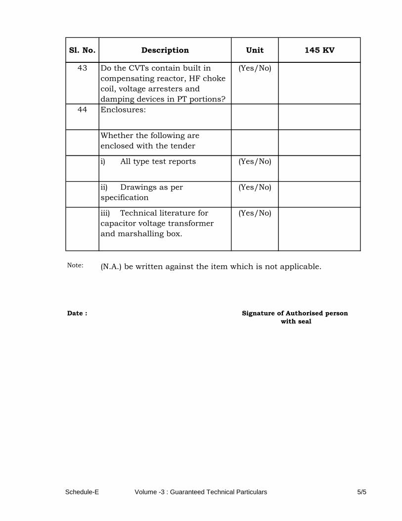
Sl. No. Description Unit 145 KV
43 Do the CVTs contain built in
compensating reactor, HF choke
coil, voltage arresters and
damping devices in PT portions?
(Yes/No)
44 Enclosures:
Whether the following are
enclosed with the tender
i) All type test reports (Yes/No)
ii) Drawings as per
specification
(Yes/No)
iii) Technical literature for
capacitor voltage transformer
and marshalling box.
(Yes/No)
Note:
Date :
(N.A.) be written against the item which is not applicable.
with seal
Signature of Authorised person
Schedule-E Volume -3 : Guaranteed Technical Particulars 5/5
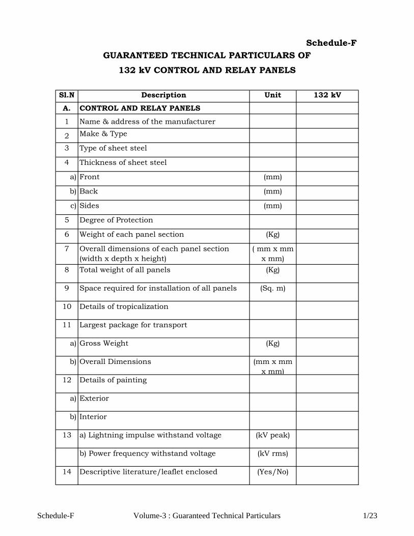
Sl.N
o.
Description Unit 132 kV
A. CONTROL AND RELAY PANELS
1 Name & address of the manufacturer
2 Make & Type
3 Type of sheet steel
4 Thickness of sheet steel
a) Front (mm)
b) Back (mm)
c) Sides (mm)
5 Degree of Protection
6 Weight of each panel section (Kg)
7 Overall dimensions of each panel section
(width x depth x height)
( mm x mm
x mm)
8 Total weight of all panels (Kg)
9 Space required for installation of all panels (Sq. m)
10 Details of tropicalization
11 Largest package for transport
a) Gross Weight (Kg)
b) Overall Dimensions (mm x mm
x mm)12 Details of painting
a) Exterior
b) Interior
13 a) Lightning impulse withstand voltage (kV peak)
b) Power frequency withstand voltage (kV rms)
14 Descriptive literature/leaflet enclosed (Yes/No)
GUARANTEED TECHNICAL PARTICULARS OF
132 kV CONTROL AND RELAY PANELS
Schedule-F
Schedule-F Volume-3 : Guaranteed Technical Particulars 1/23

Sl.N
o.
Description Unit 132 kV
15 Ref. No. and date of type test certificate
submitted16 Standards to which the panel conforms
17 Details of foundation / embedment in
foundation
B. SEMAPHORE INDICATORS
1 Make
2 Type
3 Diameter of the disc (mm)
4 Operating voltage (Volts)
5 Burden (VA)
6 Whether latch in mechanism provided (Yes/ No)
7 Descriptive literature/ leaflet enclosed (Yes/ No)
8 Ref. No. and date of type test certificate
submitted
9 Standard to which it conforms
C.TERMINAL BLOCK
1 Make
2 Type & construction
3 Applicable standard
4 No. of terminal studs per way (Nos.)
5 Rated current (Amp)
6 Rated voltage (Volts)
7 Materials used
i) Body
ii) Terminal
iii) Connecting Links
Schedule-F Volume-3 : Guaranteed Technical Particulars 2/23

Sl.N
o.
Description Unit 132 kV
iv) Support springs
v) Cover
vi) Label
vii) End stop
8 Weight in kgs. (Kg)
9 Minimum No. of conductors of area 2.5 sq.
mm suitable for connection
i) All circuits except CT (Nos.)
ii) CT circuits (4 sq. mm) (Nos.)
10 % of spare terminals on each panels (%)
11 Whether shrouding provided for terminals of
voltages more than 110 V AC / DC
(Yes/No)
12 Whether stud type brass terminals provided (Yes/No)
13 Marking
14 Descriptive literature/ leaflet enclosed (Yes/No)
15 Ref. No. and date of type test certificate
submitted
D.CONTROL SWITCHES
1 Make
2 Type of the switch
3 Type of handle (stay put or otherwise)
4 No. of possible positions of the handle with
diagrams
a) No. of contacts available in each position
i) Open (Nos.)
ii) Close (Nos.)
b) Maximum No. of contacts which can be
accommodated for each position
(Nos.)
Schedule-F Volume-3 : Guaranteed Technical Particulars 3/23

Sl.N
o.
Description Unit 132 kV
5 Rating of contacts
a) Voltage (Volts)
b) Make and carry current continuously (Amp)
c) Make and carry current for 0.5 sec (Amp)
d) Break resistive load (Amp)
e) Break inductive load with L/R = 40 m. sec (Amp)
6 Whether locking arrangement provided (Yes/No)
7 Mounting details and Drawing No.
8 Dimensions (mm)
9 Other information, if any
10 No. of slip contacts (lost motion type)
a) After close (Nos.)
b) After trip (Nos.)
c) Maximum No. of slip contacts possible (Nos.)
11 Standard to which it conforms
12 Detailed technical literature furnished (Yes/No)
13 Ref. No. and date of type test certificate
submitted
E.INDICATING LAMPS
1 Make
2 Type
3 Ratings
a) Current (Amp)
b) Voltage (Volts)
Schedule-F Volume-3 : Guaranteed Technical Particulars 4/23

Sl.N
o.
Description Unit 132 kV
c) Wattage (Watts)
4 Colour of lamp
5 Permissible voltage variation (%)
6 Whether series resistance is provided, if so (Yes/No)
a) Ohmic value (Ohms)
b) Power loss (Watts)
7 Life of lamp in burning hours (Hours)
8 Other information, if any
9 Size of lens (mm)
10 Identification inscription
11 Dimension and mounting details (mm)
12 Voltage withstand on continuous basis as a
percentage of rated voltage
(%)
13 Descriptive literature/ leaflet enclosed (Yes/No)
14 Ref. No. and date of type test certificate
submitted
15 Standard to which it conforms
F. PUSH BUTTONS
1 Make
2 Contact type (momentary/maintained)
3 Whether shrouding provided to prevent
inadvertent operation
(Yes/No)
4 Whether integral engraved inscription plates
provided
(Yes/No)
Schedule-F Volume-3 : Guaranteed Technical Particulars 5/23

Sl.N
o.
Description Unit 132 kV
5 No. of NO/NC contacts (Nos.)
6 Make and carry capacity at 250 VDC (Amp)
7 Break inductive load capacity (Amp)
8 Descriptive literature/ leaflet enclosed (Yes/No)
9 Ref. No. and date of type test certificate
submitted
10 Standard to which it conforms
G.ANNUNCIATORS
1 Make and type
2 No. of windows (Nos.)
3 Dimensions of each window (length x height
x depth)
(mm x mm
x mm)
4 No. of lamps per window (Nos.)
5 Auxiliary supply voltage (Volts)
6 Power consumption (Watt)
7 Details of auxiliary equipment such as relays
etc. furnished
(Yes/No)
8 Required instantaneous making capacity of
initiating contacts
(Amp)
9 Type of reset - (manual / self)
10 Over all dimensions of annunciator (mm x mm
x mm)
11 Particulars of wiring enclosed (Yes/No)
12 Technical literature enclosed (Yes/No)
13 Brief write up of the scheme furnished (Yes/No)
Schedule-F Volume-3 : Guaranteed Technical Particulars 6/23

Sl.N
o.
Description Unit 132 kV
14 Applicable standard
H.INDICATING METERS
1 Make and type
2 Type of movement
3 Type of mounting
4 Range
a) Effective range
b) Fiducial value
5 CT ratio
6 PT ratio
7 Details of shunt, if any
a) Rated current (Amp)
b) Rated voltage drop (Volts)
8 Accuracy class
9 Total deflection angle (Degrees)
10 Total scale length
11 Dimension (mm)
12 Reference condition of influencing quantities
13 Limits of influencing quantities for its
application
14 Limit of error for variation of each of the
influencing quantities
15 Limits of error in effective range
16 Power consumption
a) Current coil (Watts)
b) Potential coil (Watts)
Schedule-F Volume-3 : Guaranteed Technical Particulars 7/23

Sl.N
o.
Description Unit 132 kV
17 Burden
a) Current coil (VA)
b) Voltage coil (VA)
18 Short time rating
a) Current coil (Amp)
b) Voltage coil (Volts)
c) Time (Sec)
19 Other details
20 Detailed literature furnished (Yes /No)
21 Weight (Kg)
22 Whether magnetically shielded or not (Yes /No)
23 Continuous over loading
a) Current coil (Amp)
b) Potential coil (Volts)
24 Temperature at which the instruments are
calibrated
(Deg. C)
25 Ref. No. and date of type test certificate
submitted
26 Standard to which the instrument conforms.
27 Descriptive literature/ leaflet enclosed (Yes /No)
I. ENERGYMETERS
1 Make and size
2 Type of measurement
3 Measuring range
Schedule-F Volume-3 : Guaranteed Technical Particulars 8/23
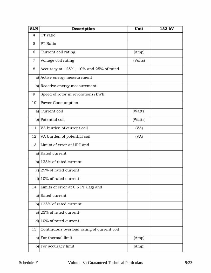
Sl.N
o.
Description Unit 132 kV
4 CT ratio
5 PT Ratio
6 Current coil rating (Amp)
7 Voltage coil rating (Volts)
8 Accuracy at 125% , 10% and 25% of rated
a) Active energy measurement
b) Reactive energy measurement
9 Speed of rotor in revolutions/kWh
10 Power Consumption
a) Current coil (Watts)
b) Potential coil (Watts)
11 VA burden of current coil (VA)
12 VA burden of potential coil (VA)
13 Limits of error at UPF and
a) Rated current
b) 125% of rated current
c) 25% of rated current
d) 10% of rated current
14 Limits of error at 0.5 PF (lag) and
a) Rated current
b) 125% of rated current
c) 25% of rated current
d) 10% of rated current
15 Continuous overload rating of current coil
a) For thermal limit (Amp)
b) For accuracy limit (Amp)
Schedule-F Volume-3 : Guaranteed Technical Particulars 9/23
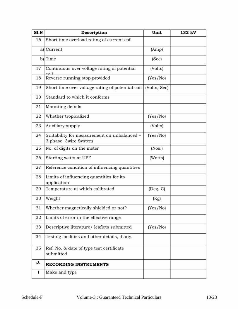
Sl.N
o.
Description Unit 132 kV
16 Short time overload rating of current coil
a) Current (Amp)
b) Time (Sec)
17 Continuous over voltage rating of potential
coil
(Volts)
18 Reverse running stop provided (Yes/No)
19 Short time over voltage rating of potential coil (Volts, Sec)
20 Standard to which it conforms
21 Mounting details
22 Whether tropicalized (Yes/No)
23 Auxiliary supply (Volts)
24 Suitability for measurement on unbalanced –
3 phase, 3wire System
(Yes/No)
25 No. of digits on the meter (Nos.)
26 Starting watts at UPF (Watts)
27 Reference condition of influencing quantities
28 Limits of influencing quantities for its
application
29 Temperature at which calibrated (Deg. C)
30 Weight (Kg)
31 Whether magnetically shielded or not? (Yes/No)
32 Limits of error in the effective range
33 Descriptive literature/ leaflets submitted (Yes/No)
34 Testing facilities and other details, if any.
35 Ref. No. & date of type test certificate
submitted.
J.RECORDING INSTRUMENTS
1 Make and type
Schedule-F Volume-3 : Guaranteed Technical Particulars 10/23

Sl.N
o.
Description Unit 132 kV
2 Type of mounting
3 Range of parameter that can be recorded
4 Range of basic movement (in case of
transducer operated system)
5 Accuracy
6 Range and choice of speeds
7 Paper width (mm)
8 Length of chart (mm)
9 Auxiliary supply
a) Voltage (Volts)
b) Current (Amp)
c) Watts (Watts)
10 Permissible variation in auxiliary supply (%)
11 Burden (VA)
12 Type of case (draw out/non draw out)
13 Detailed technical literature furnished (Yes/No)
14 Particulars of drive
15 Form of reserve drive
16 Details of arrangement for time
synchronization
17 Standard to which the recorder conforms
K.DISTANCE RELAYS
1 Maker’s name
2 Type
3 Current coil rating (Amp)
4 Maximum VA burden
i) Operating coil (VA)
Schedule-F Volume-3 : Guaranteed Technical Particulars 11/23

Sl.N
o.
Description Unit 132 kV
5 No. of Zones
i) Zone-I ,Distance km
ii) Zone-II ,Distance km
iii) Zone-III ,Distance km
6 Starting (Yes/No)
i) Overcurrent Starting
ii) Undervoltage Starting
iii) Underimpedance Starting
7 Distance Measurement (Yes/No)
i) Polygonal Characteristics
ii) Circular Characteristics
8 Tripping Time (Yes/No)
i) Zone-I (ms)
ii) Zone-II (ms)
iii) Zone-III (ms)
9 Circuit Breaker failure protection (Yes/No)
10 Neutral displacement voltage time protection
with details.
(Yes/No)
11 Switch on to fault protection (Yes/No)
12 Back up overcurrent time protection (Yes/No)
13 Power Swing blocking (Yes/No)
14 Ground fault direction determination by
steady state power evaluation.
(Yes/No)
15 Ground fault protection by steady state
current evaluation
(Yes/No)
L. OVER CURRENT AND EARTH FAULT
RELAY
I. NON - DIRECTIONAL
Schedule-F Volume-3 : Guaranteed Technical Particulars 12/23

Sl.N
o.
Description Unit 132 kV
1 Maker’s name
2 Type & reference standard
3 Current coil rating (Amp)
4 VA burden
i) Highest tap (VA)
ii) Lowest tap (VA)
5 Rated DC voltage (Volts)
6 Operating principle
7 Thermal rating (Amp)
8 Rated current & or voltage (A, V)
9 Power consumption
i) Highest tap (Watts)
ii) Lowest tap (Watts)
10 Time of operation at
i) 5 times tap setting current (ms)
ii) 10 times tap setting current (ms)
11 Type of characteristics (ms)
12 Descriptive literature/leaflets enclosed (Yes/No)
13 Contact ratings
i) Make and carry continuously (Amp)
ii) Make and carry for 0.5 sec (Amp)
iii) Break resistive load and inductive load with
40 milli sec. time constants
(Amp)
14 No. of pair of make and break contacts (Nos.)
15 Directional sensitivity (%)
16 Over current unit setting range
Schedule-F Volume-3 : Guaranteed Technical Particulars 13/23

Sl.N
o.
Description Unit 132 kV
i) Inverse time (ms)
ii) High set instantaneous unit
17 Maximum torque angle (Degrees)
II. DIRECTIONAL
1 Maker’s name
2 Type
3 Polarization
i) Current
ii) Potential
4 Current coil rating (Amp)
5 Potential coil rating (Volts)
6 VA burden
i) Current coil (VA)
ii) Highest tap (VA)
iii) Lowest tap (VA)
iv) Potential coil (VA)
7 Time of operation at
i) 5 times tap setting (ms)
ii) 10 times tap setting sec
8 Type of characteristic
9 Descriptive literature / leaflet enclosed (Yes/No)
10 Applicable standards
11 Dimensions / weights (mm, Kg)
Schedule-F Volume-3 : Guaranteed Technical Particulars 14/23
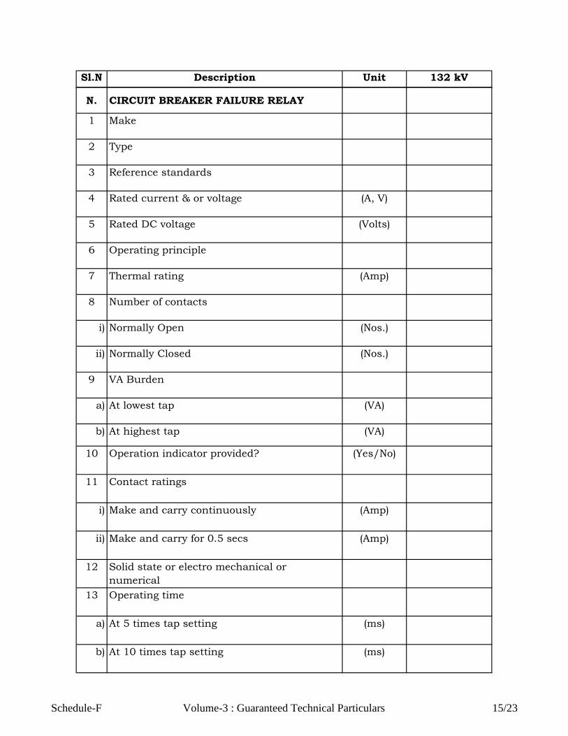
Sl.N
o.
Description Unit 132 kV
N. CIRCUIT BREAKER FAILURE RELAY
1 Make
2 Type
3 Reference standards
4 Rated current & or voltage (A, V)
5 Rated DC voltage (Volts)
6 Operating principle
7 Thermal rating (Amp)
8 Number of contacts
i) Normally Open (Nos.)
ii) Normally Closed (Nos.)
9 VA Burden
a) At lowest tap (VA)
b) At highest tap (VA)
10 Operation indicator provided? (Yes/No)
11 Contact ratings
i) Make and carry continuously (Amp)
ii) Make and carry for 0.5 secs (Amp)
12 Solid state or electro mechanical or
numerical
13 Operating time
a) At 5 times tap setting (ms)
b) At 10 times tap setting (ms)
Schedule-F Volume-3 : Guaranteed Technical Particulars 15/23

Sl.N
o.
Description Unit 132 kV
14 Resetting time (ms)
15 Setting range for current for :
a) Phase over current (%)
b) Ground over current (%)
16 Timers
a) Whether separate timers are provided for
each phase?
(Yes/No)
b) Setting range of timers. (Sec)
17 Descriptive literature / leaflets enclosed (Yes/No)
18 Reset / pick up ratio of the relay (%)
O.TRIP CIRCUIT SUPERVISION RELAY
1 Make
2 Type
3 Reference standards
4 Rated current & or voltage (A, V)
5 Rated DC voltage (Volts)
6 Operating principle
7 Solid state or electro mechanical or
numerical8 Thermal rating (Amp)
9 Number of contacts
i) Normally Open (Nos.)
ii) Normally Closed (Nos.)
Schedule-F Volume-3 : Guaranteed Technical Particulars 16/23

Sl.N
o.
Description Unit 132 kV
10 Contacts - (self reset/ hand reset)
11 Burden (VA)
12 Operation indicator provided? (Yes/No)
13 Contact ratings
i) Make and carry continuously (Amp)
ii) Make and carry for 0.5 secs (Amp)
iii) Break
a) Resistive Load (Amp)
b) Inductive Load (with L/R=40 ms) (Amp)
14 Whether pre closing and post closing
supervision provided?
(Yes/No)
15 Time delay (ms)
16 Whether external resistors are provided. If
yes, the value of the resistor
(Yes/No)
17 Descriptive literature / leaflet enclosed (Yes/No)
P. AUXILIARY CTs AND VTs
1 Make
2 Type and standard to which it conforms
3 Ratio
4 Rated output (VA)
5 Class of accuracy
6 Short time rating
a) Current (Amp)
b) Voltage (Volts)
7 Knee point voltage for Class PS (Volts)
8 Excitation current for Class PS duty at
a) KPV (mA)
Schedule-F Volume-3 : Guaranteed Technical Particulars 17/23

Sl.N
o.
Description Unit 132 kV
b) 50 percent KPV (mA)
9 Internal impedance of
a) Primary (Ohms)
b) Secondary (Ohms)
10 Temperature rise (Deg. C)
11 Mounting details
12 Overall dimensions (mm)
13 Any other details
14 One minute power frequency withstand
voltage
(kV rms)
15 Weight (Kg)
16 Location where these are to be used /
mounted.
17 Descriptive literature / leaflets enclosed (Yes/No)
Q. PANEL WIRING
1 Insulation of wiring
2 Size of wiring conductor for the following
i) PT circuits (sq. mm)
ii) CT circuits (sq. mm)
iii) DC supply circuits (sq. mm)
iv) Other circuits (sq. mm)
3 Size of earthing bar for safety earthing ( sq. mm)
4 Type of terminal provided on wiring
5 Wiring conductor (aluminum/copper)
6 Whether ferrules and insulated sleeves
provided?
(Yes/No)
7 Type and size of lugs provided (sq. mm)
8 Applicable standards
9 Descriptive literature / leaflets / circuit
diagrams enclosed?
(Yes/No)
Schedule-F Volume-3 : Guaranteed Technical Particulars 18/23

Sl.N
o.
Description Unit 132 kV
R.TRANSDUCER
1 Make
2 Type
3 Applicable standards
4 Rated input (A, V, AC/DC)
5 Rated output (A, V, AC/DC)
6 Terminal connectors
a) No. of input terminal connectors (Nos.)
b) No. of output terminal connectors (Nos.)
7 Response time (Sec)
8 Accuracy class
9 AC ripple content (%)
10 Suitable for load resistance (Ohms)
11 Temperature range (Deg. C)
12 Dimensions/weight (mm, Kg)
13 Descriptive literature / leaflets enclosed? (Yes/No)
S. DC SUPPLY SUPERVISION RELAY
Schedule-F Volume-3 : Guaranteed Technical Particulars 19/23

Sl.N
o.
Description Unit 132 kV
1 Manufacturer’s Name & Country
2 Type of Relay
3 DC rating (A, V)
4 VA Burden (VA)
5 No. of potential free output contacts (Nos.)
6 Any other data
7 Time delay on drop off (ms)
8 Operation indication / flag provided? (Yes/No)
9 Applicable standards
T. SELECTOR SWITCHES
1 Make & type designation
2 Current rating of contacts (Amp)
3 Number of contacts in each position
a) Open (Nos.)
b) Closed (Nos.)
4 Number of ways (Nos.)
5 Number of positions (Nos.)
6 Type of handle
7 Whether stay put type (Yes/No)
Schedule-F Volume-3 : Guaranteed Technical Particulars 20/23

Sl.N
o.
Description Unit 132 kV
8 Whether locking facility provided. (Yes/No)
9 Applicable standards
10 Descriptive literature / leaflets enclosed? (Yes/No)
U. BREAKER / ISOLATOR AUXILIARY
CONTACT MULTIPLICATION RELAY
1 Make & type designation
2 Rating & burden (A, V, VA)
3 No. of NO/NC contacts (Nos.)
4 Rating of contacts (A, V)
5 Applicable standards
6 Descriptive literature / leaflets enclosed? (Yes/No)
V.EARTHING
1 Material of conductor
2 Size (sq. mm)
3 Type of end connection
4 Whether sufficient number of terminal
connectors and clamps are supplied?
(Yes/No)
5 Size of copper wires for earthing (sq. mm)
6 Detailed earthing scheme enclosed? (Yes/No)
W.CIRCUIT LABELS
1 Material, size, colour (mm x mm)
Schedule-F Volume-3 : Guaranteed Technical Particulars 21/23

Sl.N
o.
Description Unit 132 kV
2 Size and colour of lettering (mm)
X.MISCELLANEOUS
1 Tools
Whether following tools included in the scope
i) Special erection tools (Yes/No)
ii) Maintenance tools (Yes/No)
2 Spares
Whether list of recommended spares for
normal maintenance for a period of 5 years
furnished
(Yes/No)
3 Drawings
Whether following items submitted.
i) General arrangement drawings (Yes/No)
ii) Schematic drawings (Yes/No)
iii) Technical & descriptive literatures of all the
components supplied
(Yes/No)
4 Test Certificates
Whether all the test certificates as listed
below are furnished:
i) Type test certificates for the following
a) Relays (Yes/No)
b) ICTs (Yes/No)
Schedule-F Volume-3 : Guaranteed Technical Particulars 22/23

Sl.N
o.
Description Unit 132 kV
c) IVTs (Yes/No)
Note:
Date:
Signature of Authorised
person
with seal
(N.A.) be written against the item which is not applicable.
Schedule-F Volume-3 : Guaranteed Technical Particulars 23/23

Schedule-G
I) Line Traps
1 Name of manufacturer
2 Type
3 Manufacturer's Type/designation
4 Rated System Voltage kV (rms)
5 Highest System Voltage kV (rms)
6 Rated Power Frequency
7 Rated Continuous Current at 40ºC ambient
8 Rated inductance
9 Rated short time current for 1 sec kA (rms)
10 Asymmetrical peak value of the first half wave of the
rated short time current
11 Nominal Discharge current of protective device at
8/20 microsecond wave
12 Minimum Resistive component of the blocking
impedance within the rated blocking bandwidth
13 Rated blocking bandwidth for Tapping loss
14 Rated tapping loss within the rated bandwidth
(Maximum value corresponding to line trap impedance
1.4 time line characteristic impedance)
15 Q Factor at 100 kHz
16 Radio Interference Voltage maximum (Micro Volt) at
320 kV (rms)
17 Visual corona extinction voltage kV rms)
18 Temperature rise (max.)
19 Standard to which conforms
ParticularsSl. No.Guaranteed
Particulars
PLCC EQUIPMENTS FOR 48 V DC SUPPLY SYSTEM &
ASSOCIATED ACCESSORIES
GUARANTEED TECHNICAL PARTICULARS OF
Schedule-G Volume-3 Guaranteed Technical Particulars 1/5

ParticularsSl. No.Guaranteed
Particulars
20 Type of Mounting and its details
II) Coupling Devices
1 Name of manufacturer
2 Type
3 Manufacturer's Type/designation
4 Rated System Voltage kV (rms)
5 Highest System Voltage kV (rms)
6 Method of coupling (phase to phase 1) using two
phase to each units & hybrid trans.)
7 Nominal line side impedance (ohm)
8 Nominal equipment side impedance
(balanced/unbalanced)
9 Composite loss dB
10 Return loss (minimum) dB
11 Bandwidth (kHz) (when used with CVT having HF
capacitance of 4400pF+10% to -5% & return loss not
less than 12dB)
12 Nominal Peak envelope power (Watt)
13 Standard to which conforms
III) PLC Coaxial Cable (Armoured)
1 Name of manufacturer
2 Type
3 Manufacturer's Type/designation
4 Rated System Voltage kV (rms)
5 Highest System Voltage kV (rms)
6 Impedance (Ohms) (to match PLCC)
balance/unbalanced
7 Maximum attenuation (dB/100m) at 20º C/kHz
8 Capacitance (pF/m)
Schedule-G Volume-3 Guaranteed Technical Particulars 2/5

ParticularsSl. No.Guaranteed
Particulars
9 Dielectric withstand voltage..='kV (50Hz)'
10 Relative signal velocity %
11 Maximum power rating (Watt)
12 Insulation Resistance
13 Maximum Temperature
14 Loop resistance (ohm/km) at 20ºC not to exceed
IV) PLCC Equipment
1 Name of manufacturer
2 Type
3 Carrier Frequency
4 Power output at HF Terminal
5 Details of Automatic gain control
6 Details of equalization of line frequency attenuation
distortion
7 Details of Connection to another PLC terminal at an IF
frequency
8 Details of matching unbalanced 75 and 125 ohms
impedance
9 Baud rate range for data cards
10 Upper cut off frequency of voice band
11 Frequency data channels
12 DC power supply voltage
13 Accuracy of carrier oscillators
14 Transmitter output level
15 Receiver pilot level
16 Receiver carrier level
17 IF oscillator level
18 Frequency Response
19 Receiver selectivity
20 Input speech level adjustment
21 Input data or telecontrol level adjustment
Schedule-G Volume-3 Guaranteed Technical Particulars 3/5

ParticularsSl. No.Guaranteed
Particulars
22 Distortion
23 Idle noise
24 Total time taken for receipt of trip command,
transmission over link, reception and issuing trip
command
a) For permissive inter-tripping
b) For direct inter-tripping
V) VF Transmission terminal for protection signals
(Protection coupler)
1 Name of manufacturer and country
2 Type, Model and catalogue number
3 Whether equipment works on coded signal principle, if
yes, furnish coding principle
4 Whether equipment is suitable for independently
protecting two circuits
5 Frequencies used in the equipment for transmission of
signal for un-coded signal transmission
a) Guard frequency
b) Working frequency (Trip System-I)
c) Working frequency (Trip System-II)
d) Working frequency (Trip System-I & II)
6 Criteria used for command transmission
7 Transmission time corresponding to telegraph speed
for transmission on PLCC channel of coded signal
a) 600 Bds
b) 400 Bds
c) 200 Bds
8 Mode of transmission of guard signal
9 Whether equipment is suitable for direct circuit
breaker tripping
10 Whether loop test is possible
Schedule-G Volume-3 Guaranteed Technical Particulars 4/5

ParticularsSl. No.Guaranteed
Particulars
11 Whether the equipment is suitable for transmitting
and receiving more than two independent commands
(please furnish details)
12 Whether receiver design provides protection against
false tripping from random noise
VI) Load Requirement
1 48 v DC Load Requirement/PLCC set in Amps
Date :
with seal
Signature of Authorised person
Schedule-G Volume-3 Guaranteed Technical Particulars 5/5

Sl.
No. Description Unit
A SUBSTATION STRUCTURE
1 Total Guaranteed Weight of Structure
in Metric Tonnes
a) Columns (MT)
b) Beams (MT)
2 Maximum stress employed in design
a) Tension in net sectional area (N/sq.
mm)
b) Compression on gross sectional area
at maximum slenderness ratio
(N/sq.
mm)
c) Shearing stress on steel bolts (N/sq.
mm)
d) Bearing stress on steel bolts (N/sq.
mm)
3 Other Particulars
a) Maximum Slenderness Ratio
i) Main leg members of columns
ii) Main boom members of beam
iii) Lattice members having calculated
stress
iv) Redundant members having
nominal stress
v) Members under tensions only
vi) Strut formula used
b) Standards according to which
properties of sections have been
adopted
c) Standard specification to which
quality of steel for the sections would
conform and technical properties of
the type of steel offered.
d) Standard to which galvanising shall
conform
e) Minimum sheared edge distances (mm)
f) Minimum rolled edge distance (mm)
Guaranteed Particulars
Schedule-H
GUARANTEED TECHNICAL PARTICULARS OF
SUBSTATION STRUCTURES
Schedule-H
Volume-3: Guaranteed Technical Particulars
1/4

Sl.
No. Description Unit Guaranteed Particulars
g) Quality of zinc used for galvanising (%)
h) Weight of zinc coating per MT of
structure weight and min. thickness
of zinc coating
(gm/MT,
gm/sq.
m)
i) Sizes of bolts and bolt holes (mm)
j) Standard to which bolt and nuts
conforms
k) Name of manufacturer of bolts and
nuts
4 Factor of Safety
a) Normal condition
b) Abnormal condition of broken wire
B EQUIPMENT SUPPORT STRUCTURE
1 Circuit Breaker
a) Type (Lattice / Pipe)
b) Guaranteed weight MT
c) Factor of Safety
i) Normal Condition
ii) Abnormal Condition
d) Weight of zinc coating per MT of
structure weight and min. thickness
of zinc coating
(gm/MT,
gm/sq.
m)
e) Size of bolts & bolt holes (mm)
2 Current Transformer
a) Type (Lattice / Pipe)
b) Guaranteed weight MT
c) Factor of Safety
i) Normal Condition
ii) Abnormal Condition
d) Weight of zinc coating per MT of
structure weight and min. thickness
of zinc coating
(gm/MT,
gm/sq.
m)
e) Size of bolts & bolt holes (mm)
3 Isolator Structure 3 Pole without
Earth switch
Schedule-H
Volume-3: Guaranteed Technical Particulars
2/4

Sl.
No. Description Unit Guaranteed Particulars
a) Type (Lattice / Pipe)
b) Guaranteed weight MT
c) Factor of Safety
i) Normal Condition
ii) Abnormal Condition
d) Weight of zinc coating per MT of
structure weight and min. thickness
of zinc coating
(gm/MT,
gm/sq.
m)
e) Size of bolts & bolt holes (mm)
4 Isolator Structure 3 Pole with Earth
switch
a) Type (Lattice / Pipe)
b) Guaranteed weight MT
Guaranteed weight ( for 2 Pole Isolator
)
MT
c) Factor of Safety
i) Normal Condition
ii) Abnormal Condition
d) Weight of zinc coating per MT of
structure weight and min. thickness
of zinc coating
(gm/MT,
gm/sq.
m)
e) Size of bolts & bolt holes (mm)
5 CVT
a) Type (Lattice / Pipe)
b) Guaranteed weight MT
c) Factor of Safety
i) Normal Condition
ii) Abnormal Condition
d) Weight of zinc coating per MT of
structure weight and min. thickness
of zinc coating
(gm/MT,
gm/sq.
m)
e) Size of bolts & bolt holes (mm)
6 Post Insulator
a) Type (Lattice / Pipe)
b) Guaranteed weight MT
c) Factor of Safety
Schedule-H
Volume-3: Guaranteed Technical Particulars
3/4

Sl.
No. Description Unit Guaranteed Particulars
i) Normal Condition
ii) Abnormal Condition
d) Weight of zinc coating per MT of
structure weight and min. thickness
of zinc coating
(gm/MT,
gm/sq.
m)
e) Size of bolts & bolt holes (mm)
7 Surge Arrestor
a) Type (Lattice / Pipe)
b) Guaranteed weight MT
c) Factor of Safety
i) Normal Condition
ii) Abnormal Condition
d) Weight of zinc coating per MT of
structure weight and min. thickness
of zinc coating
(gm/MT,
gm/sq.
m)
e) Size of bolts & bolt holes (mm)
8 Potential Transformer
a) Type (Lattice / Pipe)
b) Guaranteed weight MT
c) Factor of Safety
i) Normal Condition
ii) Abnormal Condition
d) Weight of zinc coating per MT of
structure weight and min. thickness
of zinc coating
(gm/MT,
gm/sq.
m)
e) Size of bolts & bolt holes (mm)
Note:
Date: Signature of Authorised Person
(N.A.) be written against the item which is not applicable.
with Seal
Schedule-H
Volume-3: Guaranteed Technical Particulars
4/4

S.No. Description Size35
mm²
25
mm²
10
mm²
6
mm²
4
mm²
2.5
mm²14C 7C
1 Name of the manufacturer
and country.
2 Applicable standard
3 Cable type designation
4 Voltage rating (Volts)
5 Conductor
a) Material of conductor and
flexibility class as per
IS:8130
b) Size of conductor (sq. mm)
c) Is conductor stranded (Yes/No)
d) Stranded conductor
Schedule-I
LT POWER & CONTROL CABLES
GUARANTEED TECHNICAL PARTICULARS OF
Schedule-I
Volume-3: Guaranteed Technical Particulars
1/8
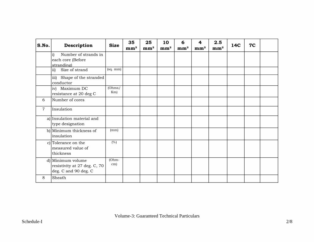
S.No. Description Size35
mm²
25
mm²
10
mm²
6
mm²
4
mm²
2.5
mm²14C 7C
i) Number of strands in
each core (Before
stranding)ii) Size of strand (sq. mm)
iii) Shape of the stranded
conductor
iv) Maximum DC
resistance at 20 deg C
(Ohms/
Km)
6 Number of cores
7 Insulation
a) Insulation material and
type designation
b) Minimum thickness of
insulation
(mm)
c) Tolerance on the
measured value of
thickness
(%)
d) Minimum volume
resistivity at 27 deg. C, 70
deg. C and 90 deg. C
(Ohm-
cm)
8 Sheath
Schedule-I
Volume-3: Guaranteed Technical Particulars
2/8

S.No. Description Size35
mm²
25
mm²
10
mm²
6
mm²
4
mm²
2.5
mm²14C 7C
a) Material for inner sheath,
type of sheathing
(extruded or wrapped) and
type designation as per
IS:5831.
b) Material for outer sheath,
type of sheathing
(extruded or wrapped) and
type designation as per
IS:5831.
c) Thickness of inner sheath
and tolerance on
measured value.
(mm, %)
d) Thickness of outer sheath
and tolerance on
measured values.
(mm, %)
9 Armour
a) Material
b) Shape
c) Dimension (mm)
10 a) Overall diameter of
cable
(mm)
b) Tolerance on diameter (%)
Schedule-I
Volume-3: Guaranteed Technical Particulars
3/8
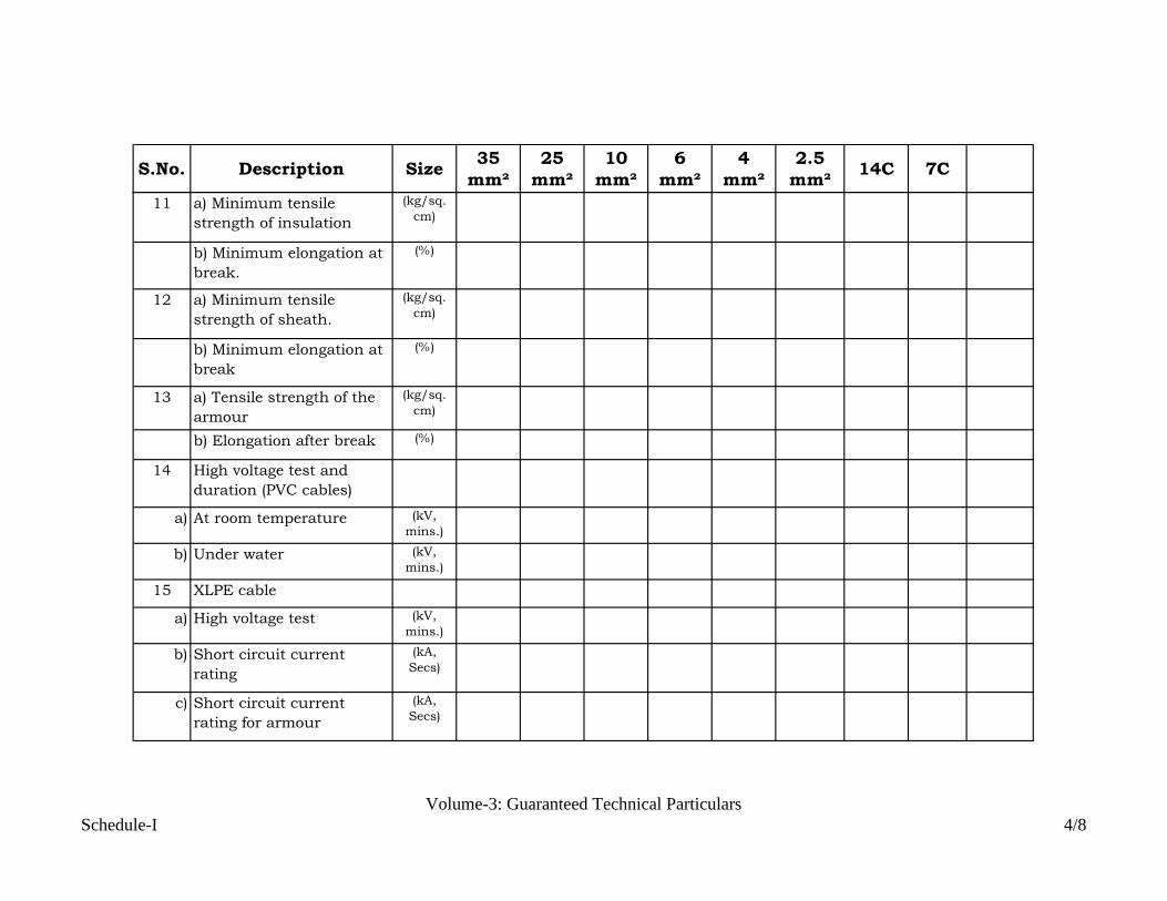
S.No. Description Size35
mm²
25
mm²
10
mm²
6
mm²
4
mm²
2.5
mm²14C 7C
11 a) Minimum tensile
strength of insulation
(kg/sq.
cm)
b) Minimum elongation at
break.
(%)
12 a) Minimum tensile
strength of sheath.
(kg/sq.
cm)
b) Minimum elongation at
break
(%)
13 a) Tensile strength of the
armour
(kg/sq.
cm)
b) Elongation after break (%)
14 High voltage test and
duration (PVC cables)
a) At room temperature (kV,
mins.)
b) Under water (kV,
mins.)
15 XLPE cable
a) High voltage test (kV,
mins.)
b) Short circuit current
rating
(kA,
Secs)
c) Short circuit current
rating for armour
(kA,
Secs)
Schedule-I
Volume-3: Guaranteed Technical Particulars
4/8

S.No. Description Size35
mm²
25
mm²
10
mm²
6
mm²
4
mm²
2.5
mm²14C 7C
16 a) Current carrying
capacity in air and
corresponding
assumptions/conditions
of installation
(Amp)
b) Current carrying
capacity under following
conditions:
i) Ambient temperature of
50 Deg. C
(Amp)
ii) Cable laid in covered
cable trenches
(Amp)
iii) 3 to 4 cable trays /
racks in trench .
(Amp)
iv) 5 to 6 cables per tray
and touching each other.
(Amp)
17 Insulation resistance at
27 Deg. C
(Ohm/k
m)
18 Capacitive reactance per
Km.
(uF/km)
19 Inductive reactance per
Km.
(Ohm/k
m)
20 Minimum bending radius. (mm)
Schedule-I
Volume-3: Guaranteed Technical Particulars
5/8

S.No. Description Size35
mm²
25
mm²
10
mm²
6
mm²
4
mm²
2.5
mm²14C 7C
21 Short circuit current
rating for 1 sec. for PVC
cable.
(kA)
22 Conductor temperature
rise during
a) Normal operation (Deg. C)
b) Short circuit (Deg. C)
23 Weight of cable per Km (Kg/km)\
24 a) Standard length of
cable per drum
(m)
b) Tolerance on length of
cable per drum
(%)
25 Net weight of drum length
of cable
(Kg)
26 Method of core
identification for
a) Cable upto five cores
b) Cable with more than five
cores
27 Please indicate writing
YES or NO whether the
following tests have been
carried out.i) Ageing test (Yes/No)
Schedule-I
Volume-3: Guaranteed Technical Particulars
6/8

S.No. Description Size35
mm²
25
mm²
10
mm²
6
mm²
4
mm²
2.5
mm²14C 7C
ii) Loss of mass test (Yes/No)
iii) Cold bend test (Yes/No)
iv) Cold impact test (Yes/No)
v) Heat shock test (Yes/No)
vi) Thermal stability as per
IEC-540
(Yes/No)
vii) Oxygen index test and
temperature index test as
per ASTM D-2863.
(Yes/No)
viii) Rodent and termite
proof test
(Yes/No)
ix) Fire retardant test (Yes/No)
28 Enclosures
a) Whether all type test
reports enclosed
(Yes/No)
b) Whether technical
literature enclosed
(Yes/No)
c) Whether tables giving
rating factors for variation
in standard conditions of
installation enclosed
(Yes/No)
Schedule-I
Volume-3: Guaranteed Technical Particulars
7/8

S.No. Description Size35
mm²
25
mm²
10
mm²
6
mm²
4
mm²
2.5
mm²14C 7C
d) Whether relevant
drawings enclosed
(Yes/No)
Note:
Date:
with seal
Signature of the Authorised
(N.A.) be written against the item which is not
Schedule-I
Volume-3: Guaranteed Technical Particulars
8/8

GOVERNMENT OF INDIAMINISTRY OF EXTERNAL AFFAIRS
PRICE SCHEDULEOF
132 KV SUBSTATIONSFOR
STRENGTHENING OF INDIA-NEPALPOWER TRANSMISSION
INTERCONNECTION
VOLUME-4
Consultants:WAPCOS LIMITED(A Govt. of India Undertaking)
PLOT NO. 76-CSECTOR-18, INSTITUTIONALAREAGURGAON-122015,HARYANA, INDIAPh.No: 91-124-2349416Fax No: 91-124-2349184E-mail: [email protected]
CENTRAL ELECTRICITYAUTHORITY,SEWA BHAWAN ,R.K.PURAM,NEW DELHI-01
June, 2014

BIDDING DOCUMENT FOR DESIGN, ENGINEERING, PROCUREMENT AND CONSTRUCTION
ON TURNKEY BASIS OF 132 kV LINE BAYS AT EXISTING SUB-
STATIONS IN INDIA AND NEPAL
Volume – 4
PRICE SCHEDULES
Table of Contents
SUMMARY OF QUOTED PRICES AND BILL OF QUANTITIES
SUMMARY OF PRICE SCHEDULE FOR ENGINEERNG, PROCUREMENT, CONSTRUCTION FOR 132kV KATAIYA, KUSAHA, RAXUAL,
PARWANIPUR SUBSTATIONS (AUGMENTATION)
KATAIYA SUBSTATION
Schedule-A: ABSTRACT OF PRICE SCHEDULE
Schedule-B: SCHEDULE OF PRICES
Schedule-C: AUGMENTATION OF CIVIL WORKS
KUSAHA SUBSTATION
Schedule-A: ABSTRACT OF PRICE SCHEDULE
Schedule-B: SCHEDULE OF PRICES
Schedule-C: AUGMENTATION OF CIVIL WORKS
RAXAUL SUBSTATION
Schedule-A: ABSTRACT OF PRICE SCHEDULE
Schedule-B: SCHEDULE OF PRICES
Schedule-C: AUGMENTATION OF CIVIL WORKS
PARWANIPUR SUBSTATION
Schedule-A: ABSTRACT OF PRICE SCHEDULE
Schedule-B: SCHEDULE OF PRICES
Schedule-C: AUGMENTATION OF CIVIL
WORKS

1
SUMMARY OF QUOTED PRICESAND BILL OF QUANTITIES
1.1 PREAMBLE
i) The Bill of Quantities for quoting rates shall be read in conjunction withthe Instructions to Bidders, Conditions of Contract, TechnicalSpecifications, Forms, Schedules, Supplementary Information andTender Drawings.
ii) The quantities given in the Bill of Quantities are approximate andprovisional and are given to provide a common basis for bidding. Thebasis of payment will be the actual quantities supplied and installed asverified by the Purchaser at the rates and prices tendered in the pricedBill of Quantities.
iii) The rates and prices quoted/tendered in the priced Bill of Quantitiesexcept insofar as it is otherwise provided under the Contract, includeall constructional plant, labour, supervision, materials, all temporaryworks and false works, erection, maintenance, establishment andoverhead charges, profit, taxation, levies, local levies and other chargestogether with all general risks, liabilities and obligations set out orimplied in the Contract and including remedy of any defects during theDefects Liability Period.
iv) The rates and prices shall be quoted entirely in Indian Currency. Therates, taxes and amount of each item will be entered in appropriatecolumn.
v) The rate or price shall be entered against each item in the Bill ofQuantities in figures in water proof ink, whether quantities are statedor not. Rates for all items shall be quoted. Omission of quoted ratesfor any item shall be considered included in other items and bidevaluation shall be done accordingly. It shall also be ensured thatidentical items occurring at different serial numbers of BOQ are notpriced at different rates.
vi) The whole cost of complying with the provisions of the Contract shall beincluded in the items provided in the priced Bill of Quantities.
vii) The method of measurement of erection work for payment shall be inaccordance with the standard practice and requirements as stated inthe relevant section of the conditions of the contract.
viii) Errors will be corrected by the Purchaser for any arithmeticalinaccuracy pursuant to relevant Clause of the Instruction to Bidders.Non acceptance of such correct figures/amounts shall render the bidliable for rejection.
ix) Tendered rates for each item provided in the bill of quantities shall besubmitted only on printed bill of quantities enclosed herewith withoutadding any alternative or condition of any sort.

2
x) Unit rates/item rates quoted must be realistic. Any rate appearingunrealistic shall render the tender as unbalanced and liable to bedisqualified.
xi) All rates shall be quoted on the tender form only in the columnsprovided. The amount for each item shall be worked out and requisitetotal given. Special care shall be taken to write the rates in figures andthe amount in figures only in such a way that interpolation is notpossible. Total Amount should be written in figures and in words, both.
xii) The description given in the Bill of Quantities shall unless otherwisestated be held to include wastage in execution, carriage, cartage andreturn of packing materials, setting, fitting and fixing in positions andall other labour necessary in and for the full and entire execution andcompletion of work as aforesaid in accordance with good practice andrecognized principles.
xiii) Recording of measurement of any item of work and/or its payment inthe interim on account or final bill shall not be considered as conclusiveevidence as to the sufficiency of any work or material to which it relatenor shall be relieve the Contractor from liabilities from any overmeasurement or defects noticed till completion of the defects liabilityperiod.
xiv) Any operation incidental or contemplated and necessary for properexecution of items quotes in Bill of Quantities shall be deemed to beincluded in the rates quoted. Nothing extra shall be admissible for suchoperations.
xv) Where the term crushed gravel/shingle, crushed stone, broken stone orstone aggregate appear in any part of these document or drawings, theyrefer to crushed material obtained from integrated crushing planthaving appropriate primary crusher, secondary crusher and vibratoryscreens.
xvi) Prices of Mandatory spares only shall be considered during bidevaluation.
xvii) Amendment which has not been authorized in writing by the Purchasershall not be made to these Bill of Quantities.
xviii) All the unused material left after completion of works shall be listed bythe Contractor and the list be submitted to the Purchaser. In case if,Purchaser intends to retain some of the items, the same shall be handedover to the Purchaser against payment on the basis of unit rates givenin the Bill of Quantities.
xix) The Contractor shall not use any of the mandatory spares suppliedagainst this order during installation of equipment.
xx) The Requirement of Recommendatory spares offered by the bidder shallbe discussed & finalized in consultation of Contractor after theplacement of work order. The Contractor shall be responsible forsupplying these in addition to Mandatory Spares.

3
xxi) The quantities given in the Bill of Quantities are approximate and aregiven to provide a common basis for bidding. The Contractor shall bepaid for the quantity of the work done at the approved rate in the Bill ofQuantities for each item.
xxii) Change in the Quantities:
1) If the final quantity of the work done exceeds from the quantity inthe Bill of Quantities for the particular item by more than 50 (Fifty)percent, the Engineer-in-charge shall adjust the rate for that itemto allow for such excess over change beyond 50% in quantity asVariation.
2) The Contractor shall provide the Engineer-in-Charge with a detailedcost break-up for any rate in the Bill of Quantities, if so required byEngineer in charge.
xxiii) Clause 33: Payment and mode of payment be referred in Volume-I(Section-2).
xxiv) Taxes and Duties:
a) The rates quoted by the contractor for both material and labour areinclusive of all taxes and duties. The contractor should give thedetail of taxes and duties in the price bid schedules. Entry Tax,Service Tax etc. and all charges on account of octroi, terminal Taxand/ or other duties/taxes on material obtained for the work shallbe borne by the contractor. The service tax as applicable onlabour/erection charges shall also be included in the quoted pricesand hence shall not be paid extra. Therefore the bidders arerequested to quote their prices keeping in view the above.
b) Wherever Excise duty is applicable, the due credit under theMODVAT (Modified Value Added Tax) policies wherever applicable,shall be taken into account by the Bidder while quoting Bid price.The compliance of this clause shall be confirmed by the bidder alongwith his bid.
c) As regard the Income Tax, surcharge on Income Tax and other taxesthe Bidder shall be responsible for such payment to the concernedauthorities.
d) Deduction of works Contract tax at source as per provisions of VATAct shall be made from the Bills of the Contractor.
e) All duties, taxes, cess, toll, royalty and other levies etc. shall be paidby the contractor, which are in force on the date of submission ofPrice Bid.

Sr.
No.NAME OF SUB-STATION PRICE IN INR
1Augmentation of 132 KV Sub-Station at KATAIYA
Substation.
2Augmentation of 132 KV Sub-Station at KUSAHA
Substation.
3Augmentation of 132 KV Sub-Station at RAXUAL
Substation.
4Augmentation of 132 KV Sub-Station at
PARWANIPUR Substation.
SUMMARY OF PRICE SCHEDULE FOR
ENGINEERNG, PROCUREMENT, CONSTRUCTION FOR 132kV KATAIYA, KUSAHA, RAXUAL, PARWANIPUR
SUBSTATIONS (AUGMENTATION)
ABSTRACT OF PRICE SCHEDULE
TOTAL

KATAIYASUBSTATION

Price in Rs.
Item
No.Description
Total Prices
(Exclusive of Taxes
& Duties)
1.
Ex-works prices (inclusive of packing and forwarding charges) of
equipment, equipment support structures & associated accessories,
conductors, hardware fittings, insulators etc. complete in all respects
(Item 19 of Schedule B-1)
2.Ex-works prices (inclusive of packing and forwarding charges) of
Mandatory Spares (Item 7 of Schedule B-2)
3.
Transportation Charges from Ex-works upto place of installation of
Project Site including Handling, Storage, Preservation, loading and
unloading (Item 3 of Schedule B-3)
4.Insurance charges from Ex-works till expiry of Defects Liability Period for
all items (Item -3 of Schedule B-4)
5.Charges for Erection, Testing and Commissioning of all items (Item - 2 of
Schedule B-5)
6.
Complete Civil works relating to foundations for gantry & Busbar,
structures, equipment, cable trenches with covers including grading and
laying, stone grit complete in all respects, as per specification (Item 10 of
Schedule-C)
7. Total Cost (1+2+3+4+5+6)
SCHEDULE-A
ABSTRACT OF PRICE SCHEDULE FOR THE AUGMENTATION OF132 kV SUB-STATION,
KATAIYA

Price in Rs.
1 2 3 4 5 6 7 8 = (5+6+7) 9 = (4 x 8)
1 Circuit Breaker
1.1 145kV, 3 Phase ,1250 A, 31.5kA S.C Rating
for 1Sec, SF6 CB
No. 1
Sub Total (1)
2 145 kV , 3 Phase, 1250A,Double break
Isolator & Isolator cum earth switch
2.1 Isolators without earthing switch No. 2
2.2 Isolators cum earthing switch No. 1
Sub Total (2)
3 Surge Arresters/Lightning Arresters
3.1 Single Phase ,120kV,10kA,Station Class
Surge Arrestor
No. 3
Sub Total (3)
Total Ex-Work Price
(inclusive of all taxes)
SCHEDULE B-1
SCHEDULE OF PRICES (EX-WORKS PRICES INCLUDING PACKING AND FORWARDING CHARGES) FOR SUPPLY OF EQUIPMENT
FOR 1 NO. LINE FEEDER AT 132 kV SUB-STATION ,KATAIYA,BSPTC(BIHAR)
Sl.
No.
Description Unit Quantity Unit Ex-Work
Price
(including
packing &
forwarding)
Excise
Duty
CST Unit Ex-
Price
(inclusive of
all taxes)
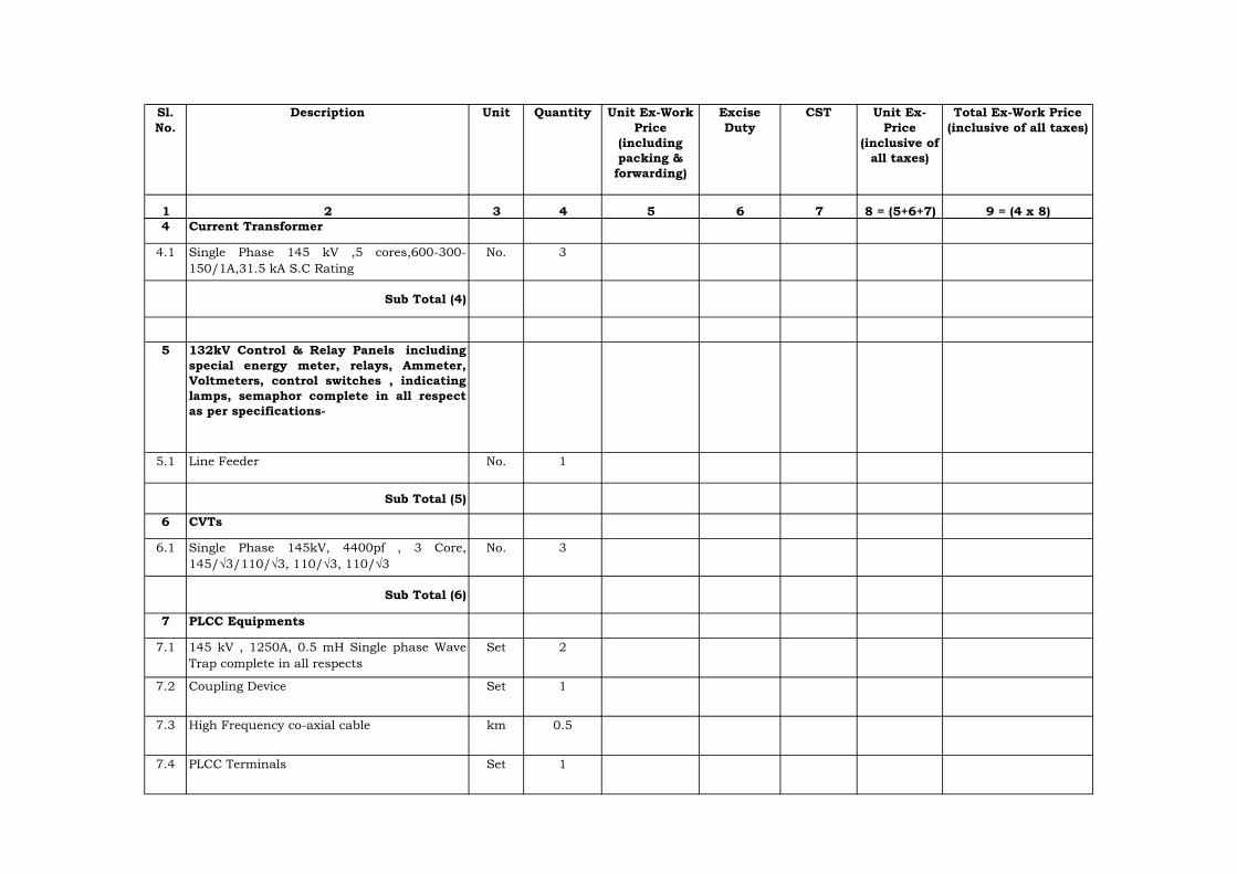
1 2 3 4 5 6 7 8 = (5+6+7) 9 = (4 x 8)
Total Ex-Work Price
(inclusive of all taxes)
Sl.
No.
Description Unit Quantity Unit Ex-Work
Price
(including
packing &
forwarding)
Excise
Duty
CST Unit Ex-
Price
(inclusive of
all taxes)
4 Current Transformer
4.1 Single Phase 145 kV ,5 cores,600-300-
150/1A,31.5 kA S.C Rating
No. 3
Sub Total (4)
5 132kV Control & Relay Panels including
special energy meter, relays, Ammeter,
Voltmeters, control switches , indicating
lamps, semaphor complete in all respect
as per specifications-
5.1 Line Feeder No. 1
Sub Total (5)
6 CVTs
6.1 Single Phase 145kV, 4400pf , 3 Core,
145/√3/110/√3, 110/√3, 110/√3
No. 3
Sub Total (6)
7 PLCC Equipments
7.1 145 kV , 1250A, 0.5 mH Single phase Wave
Trap complete in all respects
Set 2
7.2 Coupling Device Set 1
7.3 High Frequency co-axial cable km 0.5
7.4 PLCC Terminals Set 1

1 2 3 4 5 6 7 8 = (5+6+7) 9 = (4 x 8)
Total Ex-Work Price
(inclusive of all taxes)
Sl.
No.
Description Unit Quantity Unit Ex-Work
Price
(including
packing &
forwarding)
Excise
Duty
CST Unit Ex-
Price
(inclusive of
all taxes)
7.5 Telephone protection equipment Set 1
7.6 EPAX (20/10 lines) Set 1
Sub Total (7)
8 LT Power & Control Cables
8.1 1.1 kV, PVC, Copper, LT Power cable of sizes Lot 1
i) 4 C x 4 mm2
ii) 4 C x 2.5 mm2
iii) 2 C x 6 mm2
iv) 2 C x 4 mm2
v) 2 C x 2.5 mm2
vi) Single core, flexible copper cable of 2.5 mm2
vii) Single core, flexible copper cable of 4 mm2
viii) 4 Cx25 mm² PVC Alumunium Cable
ix) 4 Cx35 mm² PVC Aluminium Cable
x) Any other size required at site

1 2 3 4 5 6 7 8 = (5+6+7) 9 = (4 x 8)
Total Ex-Work Price
(inclusive of all taxes)
Sl.
No.
Description Unit Quantity Unit Ex-Work
Price
(including
packing &
forwarding)
Excise
Duty
CST Unit Ex-
Price
(inclusive of
all taxes)
8.2 1.1 kV PVC, copper, control cables of sizes Lot 1
i) 14 C x 2.5 mm2
ii) 10 C x 2.5 mm²
iii) 7 C x 2.5 mm²
Sub Total (8)
9 Earthing System
9.1 Earthing System for control room and
switchyard area including earth mat,riser
,etc. with all accessories etc. complete in all
respect for one no. additional line feeders as
per specification.
Lot 1
Sub Total (9)
10 Shielding System
10.1 Shielding system for new additional feeder
equipment area including shielding GI wire
7/3.15mm,GI earth electrods 40 mm dia & 3
meter long, 25x3 mm GI flat for down
conductor,Clamps, connectors, hardware,
test links etc. complete in all respects.
Lot 1
Sub Total (10)
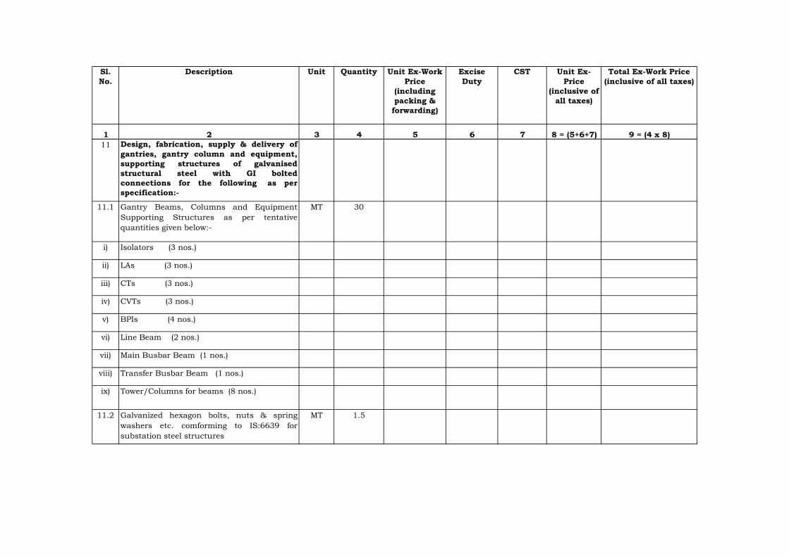
1 2 3 4 5 6 7 8 = (5+6+7) 9 = (4 x 8)
Total Ex-Work Price
(inclusive of all taxes)
Sl.
No.
Description Unit Quantity Unit Ex-Work
Price
(including
packing &
forwarding)
Excise
Duty
CST Unit Ex-
Price
(inclusive of
all taxes)
11 Design, fabrication, supply & delivery of
gantries, gantry column and equipment,
supporting structures of galvanised
structural steel with GI bolted
connections for the following as per
specification:-
11.1 Gantry Beams, Columns and Equipment
Supporting Structures as per tentative
quantities given below:-
MT 30
i) Isolators (3 nos.)
ii) LAs (3 nos.)
iii) CTs (3 nos.)
iv) CVTs (3 nos.)
v) BPIs (4 nos.)
vi) Line Beam (2 nos.)
vii) Main Busbar Beam (1 nos.)
viii) Transfer Busbar Beam (1 nos.)
ix) Tower/Columns for beams (8 nos.)
11.2 Galvanized hexagon bolts, nuts & spring
washers etc. comforming to IS:6639 for
substation steel structures
MT 1.5

1 2 3 4 5 6 7 8 = (5+6+7) 9 = (4 x 8)
Total Ex-Work Price
(inclusive of all taxes)
Sl.
No.
Description Unit Quantity Unit Ex-Work
Price
(including
packing &
forwarding)
Excise
Duty
CST Unit Ex-
Price
(inclusive of
all taxes)
11.3 Foundation bolts of appropriate diameter and
length for gantries and equipments
supporting structures as per approved design
drawings.
MT 1
Sub Total (11)
12 Bus bar materials, post insulators, disc
insulators, hardware, bus-bar conductor,
connectors, clamps etc. complete in all
respects as below :
12.1 ACSR ZEBRA conductor for 145 kV Main-1 &
Transfer Bus and equipment
Lot 1
12.2 33 kV post insulators stacks for 145 kV Main
& Transfer Bus
Lot 1
12.3 11 kV, 90 KN Disc Insualtors Lot 1
a) Tension strings of 10 units Lot 1
b) Suspension strings of 9 units Lot 1
12.4 Bolted type tension clamps to suit ACSR
ZEBRA conductor
Lot 1
12.5 Bolted type tension clamps to suit ACSR
ZEBRA conductor for equipment ie LAs, CTs,
PTs,Isolators, SF-6 Circuit Breaker etc.
Lot 1
12.6 T-connectors for ACSR ZEBRA conductor for
132 kV Main & Transfer Bus.
Lot 1
12.7 BPI clamp suitable for post insulators for
ZEBRA ACSR conductor of 132 kV Main &
Transfer Bus.
Lot 1
12.8 PG clamps suitable for ACSR ZEBRA
conductor.
Lot 1

1 2 3 4 5 6 7 8 = (5+6+7) 9 = (4 x 8)
Total Ex-Work Price
(inclusive of all taxes)
Sl.
No.
Description Unit Quantity Unit Ex-Work
Price
(including
packing &
forwarding)
Excise
Duty
CST Unit Ex-
Price
(inclusive of
all taxes)
Sub Total (12)
13 Lighting/illumination of Additional bay
13.1 Lighting system for external lighting
comprising of 415 V outdoor lighting and sub-
lighting panel, lighting fixtures, flood light ,
CFL/GLS lamp , power receptacles of suitable
ratings ,MS conduit , junction boxes, lighting
cable of suitable cross section, ceiling
fans,exhaust fans,street light pole
etc.required for outdoor yard / street
lightning complete in all respects
Lot 1
Sub Total (13)
14 AC SUPPLY
14.1 415 V AC metal enclosed distribution board
complete with MCCB s,MCBs,bus bar, bus
bar support, control wiring, terminal
blocks,fuses , labels,indications , interlocks ,
push button , switches for new additional one
number feeder
No. 1
Sub Total (14)
15 DC SUPPLY
15.1 providing additional equipment at 220 V
main DCDB that is MCCBs,MCBs,fuses ,relay
terminal block cable glands etc. complete for
the new feeders.
No. 1

1 2 3 4 5 6 7 8 = (5+6+7) 9 = (4 x 8)
Total Ex-Work Price
(inclusive of all taxes)
Sl.
No.
Description Unit Quantity Unit Ex-Work
Price
(including
packing &
forwarding)
Excise
Duty
CST Unit Ex-
Price
(inclusive of
all taxes)
Sub Total (15)
16 FIRE FIGHTING EQUIPMENT
1. Foam type extinguishers of 45 litre
capacity mounted on wheel
No. 1
2. CO
₂
fire extinguishers of 4.5 kg capacity
wall mounted
No. 1
Sub Total (16)
17 Termination Lugs, Cable Glands with
accessories for all sizes of CableLot 1
18 Any other items necessary for the
exectution of 1 no. line bay.Lot 1
19TOTAL COST (Sub Total 1 to 16+17+18)
Note: 1) Payment shall be made as per actual quantity of supply.

S.No. Quantity Ex-Works Price
inclusive of
packing and
forwarding charges
Total Ex-Works
Price inclusive of
packing and
forwarding
charges
1
1) 1 No.
2) 1 Set
3) 1 No.
4) 1 Set
5) One set of
each type
6) 1 Set
7) 1 No.Terminal pads & connectors of each type
Motor for spring charging
Auxiliary contact assembly
One pole complete with column an interrupter,
MB and operating mechanism and without
support structure
Fixed, moving and arcing contacts including
insulating nozzles for one pole of CB
Relays, Power contactors, Push buttons, limit
switches, timers, MCBs and switch fuse units
etc. Rubber gaskets, ‘O’ rings & seals
SCHEDULE B-2
EX-WORKS PRICES (INCLUSIVE OF PACKING AND FORWARDING CHARGES) OF MANDATORY SPARES
FOR 1 NO. LINE FEEDER AT 132 kV SUB-STATION ,KATAIYA,BSPTC(BIHAR)
Price in Rs.
Description of Work/Item
145 kV SF6 CIRCUIT BREAKER

S.No. Quantity Ex-Works Price
inclusive of
packing and
forwarding charges
Total Ex-Works
Price inclusive of
packing and
forwarding
charges
Description of Work/Item
8) 2 No.
9) 2 No.
10)
11) 1 Set
12) 1 No.
13) 1 No.
14) 1 No.
15) Lot
2
1) 1 set
2) 1 set Terminal connectors
Operation counter
Density/pressure monitoring system for SF6
circuit
SF-6 Gas for complete breaker
Sub-Total-1
145 kV ISOLATORS
Copper contact fingers for male & female
contacts
Closing coil
Trip coil
Pole Discrepancy relay
Remote/local change over switch
DC supervision relay
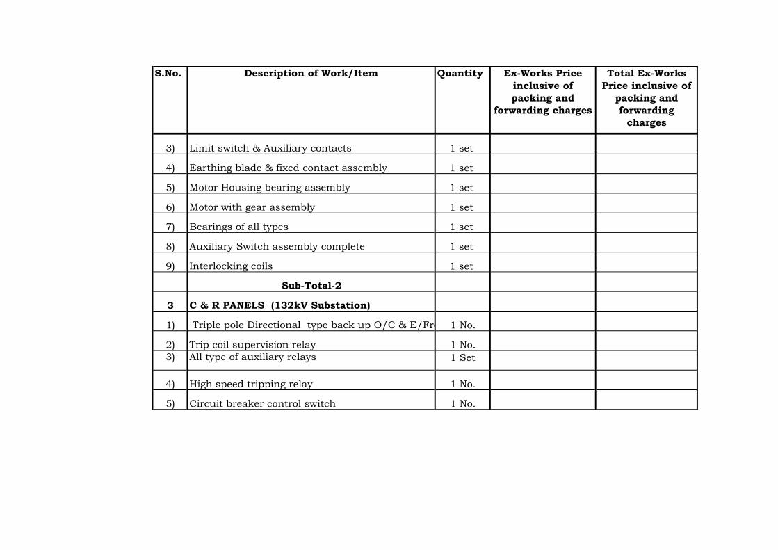
S.No. Quantity Ex-Works Price
inclusive of
packing and
forwarding charges
Total Ex-Works
Price inclusive of
packing and
forwarding
charges
Description of Work/Item
3) 1 set
4) 1 set
5) 1 set
6) 1 set
7) 1 set
8) 1 set
9) 1 set
3
1) 1 No.
2) Trip coil supervision relay 1 No.
3) All type of auxiliary relays 1 Set
4) High speed tripping relay 1 No.
5) Circuit breaker control switch 1 No.
Auxiliary Switch assembly complete
Interlocking coils
Sub-Total-2
C & R PANELS (132kV Substation)
Triple pole Directional type back up O/C & E/Frelay
Limit switch & Auxiliary contacts
Earthing blade & fixed contact assembly
Motor Housing bearing assembly
Motor with gear assembly
Bearings of all types

S.No. Quantity Ex-Works Price
inclusive of
packing and
forwarding charges
Total Ex-Works
Price inclusive of
packing and
forwarding
charges
Description of Work/Item
6) Ammeter selector switch 1 No.
7) Voltmeter selector switch 1 No.
8) 1 No.
9) Semaphone indicator for isolator /earth switch 1 No.
10) 4 No.
11) 25 No.
12) 1 No.
13) 1 No.
14) 1 No.
15) 1 No.
16) Analogue type Ammeters 1 No.
17) Analogue type voltmeters 1 No.
18) MW meters 1 No.
19) MVA meters 1 No.
20) PF Meters 1 No.
21) Energy meters 1 No.
22) Space heaters 2 No.
Push Button
Indicating lamps
Auto reclosing relay
Control switch for breaker
Control switch for Isolator
Facia Annunciators
Semaphone indicators for 132 kV breaker
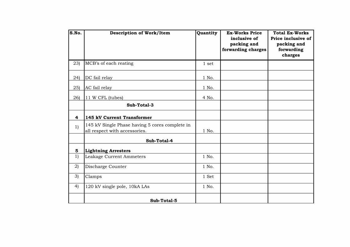
S.No. Quantity Ex-Works Price
inclusive of
packing and
forwarding charges
Total Ex-Works
Price inclusive of
packing and
forwarding
charges
Description of Work/Item
23) MCB’s of each reating 1 set
24) DC fail relay 1 No.
25) AC fail relay 1 No.
26) 11 W CFL (tubes) 4 No.
4
1)1 No.
5
1) 1 No.
2) 1 No.
3) 1 Set
4) 1 No.
Discharge Counter
Clamps
120 kV single pole, 10kA LAs
Sub-Total-5
Sub-Total-3
145 kV Current Transformer
145 kV Single Phase having 5 cores complete in
all respect with accessories.
Sub-Total-4
Lightning Arresters
Leakage Current Ammeters

S.No. Quantity Ex-Works Price
inclusive of
packing and
forwarding charges
Total Ex-Works
Price inclusive of
packing and
forwarding
charges
Description of Work/Item
6
1) 1 No.
2) 1 No.
3) 1 No.
4) 1 No.
7
Set of electronic Card for each type of PLC Terminal
Line Trap
Protection Coupler
Sub-Total-6
Grand Total (Sub-Total 1+2+3+4+5+6)
PLCC
Coupling Device

Amount in Rs.
Item No. Description of Work/Item Amount
1 2 3
Transportation charges upto Project Storage site for:
1 Complete Substation equipment as described in Schedule B-1
2 Mandatory Spares as described in Schedule B-2
3 GRAND TOTAL (1+2)
TRANSPORTATION CHARGES FROM EX-WORKS UPTO PLACE OF INSTALLATION OF
PROJECT SITE FOR 1 NO. LINE FEEDER AT 132 kV SUB-STATION
,KATAIYA,BSPTC(BIHAR)
SCHEDULE B-3

Ite
m
No.
Description of
Work/Item
During
Transportation
to Site
During Storage,
Preservation,
Handling,
Transportation
from Storage to
Place of
Installation
During Testing,
Erection &
Commissioning
During Defect
Liability
Total
Insurances
Charges
1 2 3 4 5 6 7=3+4+5+6
Insurance charges from Ex-
Works till expiry of Defect
Liability Period for the
following :
1 Complete Substation
equipment as described in
Schedule B-1
2 Mandatory Spares as
described in Schdule B-2
3 GRAND TOTAL (1+2)
SCHEDULE B-4
INSURANCE CHARGES FROM EX-WORKS TILL EXPIRY OF DEFECTS LIABILITY PERIOD FOR ALL ITEMS FOR 1
NO. LINE FEEDER AT 132 kV SUB-STATION ,KATAIYA,BSPTC(BIHAR)
Amount in Rs.

Amount in Rs.
Item
No.Description of Work/Item
Erection, Testing &
Commissioning
Charges
1 2 3
Complete work of site assembly, erection, testing and
commissioning of:
1 Complete Substation equipment as described in Schedule B-1
2 TOTAL-1
SCHEDULE B-5
CHARGES FOR ERECTION, TESTING AND COMMISSIONING OF ALL ITEMS FOR 1
NO. LINE FEEDER AT 132 kV SUB-STATION ,KATAIYA,BSPTC(BIHAR)

Sl No DESCRIPTION OF ITEM UNIT QUANTITY UNIT RATE
(in Rs)
AMOUNT
(in Rs)
(1) (2) (3) (4) (5) (6) = (4) x (5)
1. EARTH WORK
1.1 Filling using selected soil for general site grading and levelling
in layers not exceeding 300 mm (compacted thickness) and
compacting each layer upto 95% of Proctor's maximum dry
density at optimum moisture content by transporting the soil
from borrow area to the project site (borrow area shall be
arranged by contractor at his own cost) for all leads and lifts,
including cost of all the materials, labours, fuel, oil, lubricants,
equipments etc. complete as per specifications, approved
construction drawings and instructions of Engineer-in-charge.
cum 2600
1.2 Earth work in excavation by manual labour or mechanical
means (bottom 300 mm shall be excavated manually only) in
foundations, cable trenches, drains etc including dressing of
sides and ramming of bottom, keeping the excavated area dry,
disposal of surplus excavated soil after back filling of
foundations within all leads and lifts, including the cost of all
the materials, labours, fuel, oil, lubricants, equipments etc.
complete as per specifications, approved construction
drawings and instructions of Engineer-in-charge
cum 850
1.3 Extra over and above item no. 1.2 above for excavation below
water table including the cost of dewatering, all the materials,
labours, fuel, oil, lubricants, equipments etc. complete as per
specifications, approved construction drawings and
instructions of Engineer-in-charge.
cum 150
Schedule - C
CIVIL WORKS

Sl No DESCRIPTION OF ITEM UNIT QUANTITY UNIT RATE
(in Rs)
AMOUNT
(in Rs)
(1) (2) (3) (4) (5) (6) = (4) x (5)
Schedule - C
CIVIL WORKS
1.4 Back filling using selected excavated earth in trenches, on
sides of foundation etc. in layers not exceeding 200 mm in
depth, consolidating each layer upto 95% of the Proctor's
maximum dry density (MDD) of soil by ramming at optimum
moisture content (OMC) within all leads and lifts, including
cost of all the materials, labour, fuel, oil, lubricant,
equipments, disposal of surplus earth etc. complete as per
specifications, approved construction drawings and
instructions of Engineer-in-charge.
cum 650
2 PLAIN CEMENT CONCRETE
2.1 Providing and laying, ramming, vibrating, compacting Plain
Cement Concrete of M-10 grade conforming to IS:456 below
foundations, cable trenches etc. at all the depths within all
leads and lifts, including cost of all the materials, labours, fuel,
oil, lubricant, admixtures, equipments, centering and
shuttering etc.complete as per specifications, approved
construction drawings and instructions of Engineer-in-charge.
cum 55
2.2 Providing and laying, ramming, vibrating, compacting Plain
Cement Concrete of M-15 grade conforming to IS:456 below
storm water drains, for providing slope in cable trenches, slope
protections etc within all leads and lifts including the cost of
all the materials, admixtures, labours, fuel, oil, lubricants,
equipments, centering and shuttering etc. complete as per
specifications, approved construction drawings and
instructions of Engineer-in-charge.
cum 18

Sl No DESCRIPTION OF ITEM UNIT QUANTITY UNIT RATE
(in Rs)
AMOUNT
(in Rs)
(1) (2) (3) (4) (5) (6) = (4) x (5)
Schedule - C
CIVIL WORKS
3. REINFORCED CEMENT CONCRETE
3.1 Providing centering and shuttering including strutting,
propping etc for foundations, cable trenches etc and removal
of form work within all leads and lifts including the cost of all
the materials, labours, fuel, oil, lubricant, equipments etc.
complete as per specifications, approved construction
drawings and instructions of Engineer-in-charge
sqm 815
3.2 Providing & laying, ramming, vibrating, compacting, etc.
Reinforced Cement Concrete of M-25 grade conforming to
IS:456, excluding the cost of centering & shuttering,
reinforcement steel, foudation bolts, insert plates, edge
protection angles etc in foundations, cable trenches etc but
including cost of all the materials, labours, fuel, oil, lubricants,
admixtures, equipments, etc. complete as per specifications,
approved construction drawings and instructions of Engineer-
in-charge.
cum 215
3.3 Supplying, cutting & bending and fixing in position
Reinforcement Steel of Fe-415 or Fe 500 grade conforming to
IS: 1786 including cost of all the materials, labours, fuel, oil,
lubricants, equipments etc. complete as per specifications,
approved construction drawings and instructions of Engineer-
in-charge. The quoted rate shall be inclusive of all laps,
chairs, wastages, etc. The payment shall be made based on
approved bar bending schedule to be prepared by contractor.
MT 14

Sl No DESCRIPTION OF ITEM UNIT QUANTITY UNIT RATE
(in Rs)
AMOUNT
(in Rs)
(1) (2) (3) (4) (5) (6) = (4) x (5)
Schedule - C
CIVIL WORKS
3.4 Providing & fixing Pre-cast RCC Covers made with M-25 grade
concrete giving smooth finish with cement paste, cast in angle
iron frame of size 45x45x5 mm for protection of edges
(excluding the cost of reinforcement steel and angle sections
which shall be paid as per item nos 3.3 and 4.1 respectively)
including cost of all the materials, labours, fuel, oil, lubricant,
equipments etc all as per specifications, approved construction
drawings and instructions of Engineer-in-charge.
cum 7
3.5 Grouting below base plates of columns, equipment supporting
structures with cement grout 1:1 (1 Part Cement and 1 part
coarse sand) with non-shrinkage admixture (quantity of
admixture shall be as per recommendations of Manufacturer)
including cost of all the materials, labours, fuel, oil, lubricant,
equipments etc. complete as per specifications, approved
construction drawings and instructions of Engineer-in-charge.
m3 1
4 STRUCTURAL STEEL
4.1 Supplying, fabricating & fixing of structural steel plate /flats,
edge protection angles etc. in concrete in cable trenches and
precast R.C.C. covers including the cost of all the materials,
labours, fuel, oil, lubricants, equipments etc.complete as per
specifications, approved construction drawings and
instructions of Engineer-in-charge .
MT 4

Sl No DESCRIPTION OF ITEM UNIT QUANTITY UNIT RATE
(in Rs)
AMOUNT
(in Rs)
(1) (2) (3) (4) (5) (6) = (4) x (5)
Schedule - C
CIVIL WORKS
4.2 Fixing of Foundation bolts in foundations using template for
ensuring correct positioning and alignment but excluding the
cost of foundation bolts including cost of all the materials,
labours, fuel, oil, lubricant, equipments etc. complete as per
specifications, approved construction drawings and
instructions of Engineer-in-charge.
MT 1
5 FENCING AROUND EXTENSION BAY
5.1 Providing & fixing fencing around extension bay and its
integration with existing fencing having same design and
specifications as provided in the existing substation all
complete, including cost of all the materials, labours, fuel, oil,
lubricant, equipments etc as directed by Engineer-in - Charge
(The contractors shall ascertain the specfication of the
fencing at the existing substation before quoting).
sqm 110
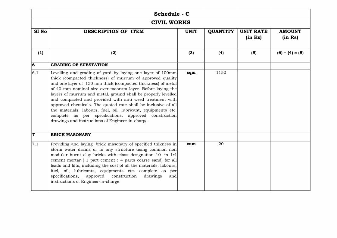
Sl No DESCRIPTION OF ITEM UNIT QUANTITY UNIT RATE
(in Rs)
AMOUNT
(in Rs)
(1) (2) (3) (4) (5) (6) = (4) x (5)
Schedule - C
CIVIL WORKS
6 GRADING OF SUBSTATION
6.1 Levelling and grading of yard by laying one layer of 100mm
thick (compacted thickness) of murrum of approved quality
and one layer of 150 mm thick (compacted thickness) of metal
of 40 mm nominal size over moorum layer. Before laying the
layers of murrum and metal, ground shall be properly levelled
and compacted and provided with anti weed treatment with
approved chemicals. The quoted rate shall be inclusive of all
the materials, labours, fuel, oil, lubricant, equipments etc.
complete as per specifications, approved construction
drawings and instructions of Engineer-in-charge.
sqm 1150
7 BRICK MASONARY
7.1 Providing and laying brick masonary of specified thikness in
storm water drains or in any structure using common non
modular burnt clay bricks with class designation 10 in 1:4
cement mortar ( 1 part cement : 4 parts coarse sand) for all
leads and lifts, including the cost of all the materials, labours,
fuel, oil, lubricants, equipments etc. complete as per
specifications, approved construction drawings and
instructions of Engineer-in-charge
cum 20

Sl No DESCRIPTION OF ITEM UNIT QUANTITY UNIT RATE
(in Rs)
AMOUNT
(in Rs)
(1) (2) (3) (4) (5) (6) = (4) x (5)
Schedule - C
CIVIL WORKS
7.2 Providing 18 mm thick plaster in drains with 1:3 cement
mortar [1 part cement : 3 parts sand (1 part coarse sand and 2
parts fine sand)] for all leads and lifts, including cost of all the
materials, labours, fuel, oil, lubricants, equipments
etc.complete as per specifications, approved construction
drawings and instructions of Engineer-in-charge.
sqm 150
8 BOUNDARY WALL
8.1 Providing Boundary Wall having same design and
specifications as at the existing substation, including cost of
all the materials, labours, fuel, oil, lubricants, equipments etc.
complete as per specifications, approved construction
drawings and instructions of Engineer-in-charge. (The
contractors shall ascertain the specfication of the
boundary wall at the existing substation before quoting
the price).
sqm 150

Sl No DESCRIPTION OF ITEM UNIT QUANTITY UNIT RATE
(in Rs)
AMOUNT
(in Rs)
(1) (2) (3) (4) (5) (6) = (4) x (5)
Schedule - C
CIVIL WORKS
9 UNIT BAY CONTROL ROOM
9.1 Providing and constructing one unit bay control room of
approximate size of 4.5 m x 3.5 m x 3.5 m height with
reinforced concrete framed stucture and brick walls having
attached toilet of size 2.4m x 1.8m outside the control room,
with all electrical, water supply and sanitary fitting & fixures
as specified in technical specification including the cost of all
the materials, labour, fuel, oil, equipments, etc. complete as
per specifications.
LS 1
10
Total
LS-Lump Sum
Note: The Bidder shall visit the site to ascertain the site conditions and the requirements before quoting the price.

KUSAHASUBSTATION

Price in Rs.
Item
No.
Description Total Prices
(Exclusive of Taxes
& Duties)
1.
Ex-works prices (inclusive of packing and forwarding charges) of
equipment, equipment support structures & associated accessories,
conductors, hardware fittings, insulators etc. complete in all respects (Item
19 of Schedule B-1)
2.Ex-works prices (inclusive of packing and forwarding charges) of
Mandatory Spares (Item 7 of Schedule B-2)
3.
Transportation Charges from Ex-works upto place of installation of Project
Site including Handling, Storage, Preservation, loading and unloading
(Item 3 of Schedule B-3)
4.Insurance charges from Ex-works till expiry of Defects Liability Period for
all items (Item 3 of Schedule B-4)
5.Charges for Erection, Testing and Commissioning of all items (Item 2 of
Schedule B-5)
6.
Complete Civil works relating to foundations for gantry & Busbar,
structures, equipment, cable trenches with covers including grading and
laying, stone grit complete in all respects, as per specification (Item - 8 of
Schedule-C)
7. Total Cost (1+2+3+4+5+6)
SCHEDULE-A
ABSTRACT OF PRICE SCHEDULE FOR THE AUGMENTATION OF132 kV SUB-STATION, KUSAHA

Sl No DESCRIPTION OF ITEM UNIT QUANTITYUNIT RATE (in
Rs)
AMOUNT
(in Rs)
(1) (2) (3) (4) (5) (6) = (4) x (5)
1. EARTH WORK
1.1 Filling using selected soil for general site grading and levelling in layers
not exceeding 300 mm (compacted thickness) and compacting each
layer upto 95% of Proctor's maximum dry density at optimum moisture
content by transporting the soil from borrow area to the project site
(borrow area shall be arranged by contractor at his own cost) for all
leads and lifts, including cost of all the materials, labours, fuel, oil,
lubricants, equipments etc. complete as per specifications, approved
construction drawings and instructions of Engineer-in-charge.
cum 2600
1.2 Earth work in excavation by manual labour or mechanical means
(bottom 150 mm shall be excavated manually only) in foundations, cable
trenches, drains etc including dressing of sides and ramming of bottom,
keeping the foundation always dry, disposal of surplus excavated soil
after back filling of foundations within all leads and lifts, including the
cost of all the materials, equipments etc. complete as per specifications,
approved construction drawings and instructions of Engineer-in-charge
cum 850
1.3 Extra over and above item no. 1.2 above for excavation below water
table including the cost of dewatering, all the materials, labours, fuel,
oil, lubricants, equipments etc. complete as per specifications, approved
construction drawings and instructions of Engineer-in-charge
cum 150
Schedule - C
Civil Works
Schedule-C 1
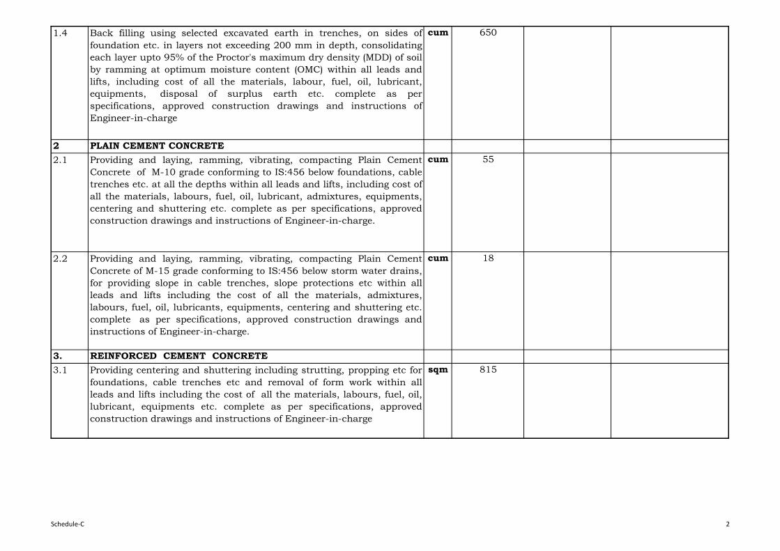
1.4 Back filling using selected excavated earth in trenches, on sides of
foundation etc. in layers not exceeding 200 mm in depth, consolidating
each layer upto 95% of the Proctor's maximum dry density (MDD) of soil
by ramming at optimum moisture content (OMC) within all leads and
lifts, including cost of all the materials, labour, fuel, oil, lubricant,
equipments, disposal of surplus earth etc. complete as per
specifications, approved construction drawings and instructions of
Engineer-in-charge
cum 650
2 PLAIN CEMENT CONCRETE
2.1 Providing and laying, ramming, vibrating, compacting Plain Cement
Concrete of M-10 grade conforming to IS:456 below foundations, cable
trenches etc. at all the depths within all leads and lifts, including cost of
all the materials, labours, fuel, oil, lubricant, admixtures, equipments,
centering and shuttering etc. complete as per specifications, approved
construction drawings and instructions of Engineer-in-charge.
cum 55
2.2 Providing and laying, ramming, vibrating, compacting Plain Cement
Concrete of M-15 grade conforming to IS:456 below storm water drains,
for providing slope in cable trenches, slope protections etc within all
leads and lifts including the cost of all the materials, admixtures,
labours, fuel, oil, lubricants, equipments, centering and shuttering etc.
complete as per specifications, approved construction drawings and
instructions of Engineer-in-charge.
cum 18
3. REINFORCED CEMENT CONCRETE
3.1 Providing centering and shuttering including strutting, propping etc for
foundations, cable trenches etc and removal of form work within all
leads and lifts including the cost of all the materials, labours, fuel, oil,
lubricant, equipments etc. complete as per specifications, approved
construction drawings and instructions of Engineer-in-charge
sqm 815
Schedule-C 2

3.2 Providing & laying, ramming, vibrating, compacting Reinforced Cement
Concrete of M-25 grade conforming to IS:456, excluding the cost of
centering & shuttering, reinforcement steel, foudation bolts, insert
plates, edge protection angles etc in foundations, cable trenches etc but
including cost of all the materials, labours, fuel, oil, lubricants,
admixtures, equipments, complete as per specifications, approved
construction drawings and instructions of Engineer-in-charge.
cum 215
3.3 Supplying, cutting & bending and fixing in position Reinforcement Steel
of Fe-415 or Fe 500 grade conforming to IS: 1786 including cost of all
the materials, labours, fuel, oil, lubricants, equipments etc. complete as
per specifications, approved construction drawings and instructions of
Engineer-in-charge. The quoted rate shall be inclusive of all laps,
chairs, wastages, etc . The payment shall be made based on approved
bar bending schedule to be prepared by Contractor.
MT 14
3.4 Providing & fixing Pre-cast RCC Covers made with M-25 grade concrete
giving smooth finish with cement paste, cast in angle iron frame of size
45x45x5 mm for protection of edges (excluding the cost of
reinforcement steel and angle sections which shall be paid as per item
nos 3.3 and 4.1 respectively) including cost of all the materials, labours,
fuel, oil, lubricant, equipments etc complete as per specifications,
approved construction drawings and instructions of Engineer-in-charge.
cum 7
3.5 Grouting below base plates of columns, equipment supporting
structures with cement grout 1:1 (1 Part Cement and 1 part coarse
sand) with non-shrinkage admixture (quantity of admixture shall be as
per recommendations of Manufacturer) including cost of all the
materials, labours, fuel, oil, lubricant, equipments etc. complete as per
specifications, approved construction drawings and instructions of
Engineer-in-charge.
m³ 1
Schedule-C 3
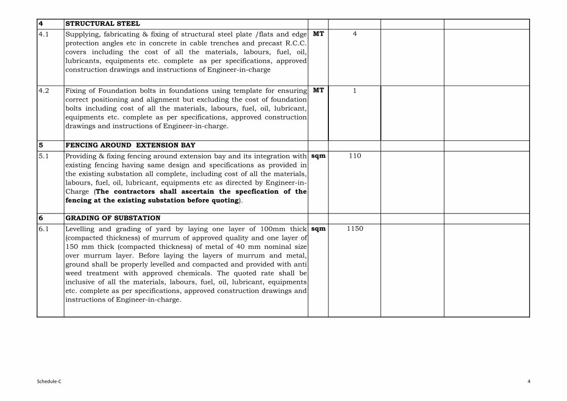
4 STRUCTURAL STEEL
4.1 Supplying, fabricating & fixing of structural steel plate /flats and edge
protection angles etc in concrete in cable trenches and precast R.C.C.
covers including the cost of all the materials, labours, fuel, oil,
lubricants, equipments etc. complete as per specifications, approved
construction drawings and instructions of Engineer-in-charge
MT 4
4.2 Fixing of Foundation bolts in foundations using template for ensuring
correct positioning and alignment but excluding the cost of foundation
bolts including cost of all the materials, labours, fuel, oil, lubricant,
equipments etc. complete as per specifications, approved construction
drawings and instructions of Engineer-in-charge.
MT 1
5 FENCING AROUND EXTENSION BAY
5.1 Providing & fixing fencing around extension bay and its integration with
existing fencing having same design and specifications as provided in
the existing substation all complete, including cost of all the materials,
labours, fuel, oil, lubricant, equipments etc as directed by Engineer-in-
Charge (The contractors shall ascertain the specfication of the
fencing at the existing substation before quoting).
sqm 110
6 GRADING OF SUBSTATION
6.1 Levelling and grading of yard by laying one layer of 100mm thick
(compacted thickness) of murrum of approved quality and one layer of
150 mm thick (compacted thickness) of metal of 40 mm nominal size
over murrum layer. Before laying the layers of murrum and metal,
ground shall be properly levelled and compacted and provided with anti
weed treatment with approved chemicals. The quoted rate shall be
inclusive of all the materials, labours, fuel, oil, lubricant, equipments
etc. complete as per specifications, approved construction drawings and
instructions of Engineer-in-charge.
sqm 1150
Schedule-C 4

7 BRICK MASONARY
7.1 Providing and laying brick masonary of specified thikness in storm
water drains or in any structure using common non modular burnt clay
bricks with class designation 10 in 1:4 cement mortar ( 1 part cement :
4 parts coarse sand) for all leads and lifts, including the cost of all the
materials, labours, fuel, oil, lubricants, equipments etc. complete as per
specifications, approved construction drawings and instructions of
Engineer-in-charge.
cum 20
7.2 Providing 18 mm thick plaster in drains with 1:3 cement mortar [1 part
cement : 3 parts sand (1 part coarse sand and 2 parts fine sand)] for all
leads and lifts, including cost of all the materials, labours, fuel, oil,
lubricants, equipments etc. complete as per specifications, approved
construction drawings and instructions of Engineer-in-charge.
sqm 150
8 Total
LS-Lump Sum
Note: The Bidder shall visit the site to ascertain the site conditions and the requirements before quoting the price.
Schedule-C 5

RAXAULSUBSTATION

Price in Rs.
Item
No.
Description Total Prices
(Exclusive of Taxes
& Duties)
1. Ex-works prices (inclusive of packing and forwarding charges) of
equipment, equipment support structures & associated accessories,
conductors, hardware fittings, insulators etc. complete in all respects
(Item 19 of Schedule B-1)
2.Ex-works prices (inclusive of packing and forwarding charges) of
Mandatory Spares (Item 7 of Schedule B-2)
3. Transportation Charges from Ex-works upto place of installation of Project
Site including Handling, Storage, Preservation, loading and unloading
(Item 3 of Schedule B-3)
4.Insurance charges from Ex-works till expiry of Defects Liability Period for
all items (Item 3 of Schedule B-4)
5. Charges for Erection, Testing and Commissioning of all items (Item 2 of
Schedule B-5)
6. Complete Civil works relating to foundations for gantry & Busbar,
structures, equipment, cable trenches with covers including grading and
laying, stone grit complete in all respects, as per specification (Item - 7 of
Schedule-C)
7. Total Cost (1+2+3+4+5+6)
SCHEDULE-A
ABSTRACT OF PRICE SCHEDULE FOR THE AUGMENTATION OF132 kV SUB-
STATION, RAXAUL

Price in Rs.
1 2 3 4 5 6 7 8 = (5+6+7) 9 = (4x8)
1 Circuit Breaker
1.1 145kV, 3 Phase ,1250 A, 31.5kA S.C Rating
for 1Sec, SF-6 CB
No. 1
Sub Total (1)
2 145 kV , 3 Phase, 1250A, Double break
Isolator & Isolator cum earth switch
2.1 Isolators without earthing switch No. 2
Sub Total (2)
2.2 Isolators cum earthing switch No. 1
3 Surge Arresters/Lightning Arresters
3.1 Single Phase, 120kV, 10kA, Station Class
Surge Arrestor
No. 3
Sub Total (3)
Unit Ex-
Work Price
(inclusive
of all taxes)
SCHEDULE OF PRICES (EX-WORKS PRICES INCLUDING PACKING AND FORWARDING CHARGES) FOR SUPPLY OF
EQUIPMENT FOR 1 NO. LINE FEEDER AT 132 KV SUB-STATION ,RAXAUL, BSPTC(BIHAR)
SCHEDULE B-1
DescriptionSl. No. Quantity Total Ex-Work
Price
(inclusive of all
taxes)
Unit Ex-
Work Price
(including
packing &
forwarding)
Unit Excise
Duty
CST

1 2 3 4 5 6 7 8 = (5+6+7) 9 = (4x8)
Unit Ex-
Work Price
(inclusive
of all taxes)
DescriptionSl. No. Quantity Total Ex-Work
Price
(inclusive of all
taxes)
Unit Ex-
Work Price
(including
packing &
forwarding)
Unit Excise
Duty
CST
4 Current Transformer
4.1 Single Phase 145 kV ,5 cores,600-300-
150/1A,31.5 kA S.C Rating
No. 3
Sub Total (4)
5 132kV Control & Relay Panels including
special energy meter, relays, Ammeter,
Voltmeters, control switches , indicating
lamps, semaphor complete in all respect as
per specifications.
5.1 Line Feeder No. 1
Sub Total (5)
6 CVTs
6.1 Single Phase 145kV, 4400pf , 3 Core,
145/√3/110/√3, 110/√3, 110/√3
No. 3
Sub Total (6)
7 PLCC Equipments
7.1 145 kV ,1250A,0.5 mH Single phase Wave
Trap complete in all respects
Set 2
7.2 Coupling Device Set 1
7.3 High Frequency co-axial cable km 0.5
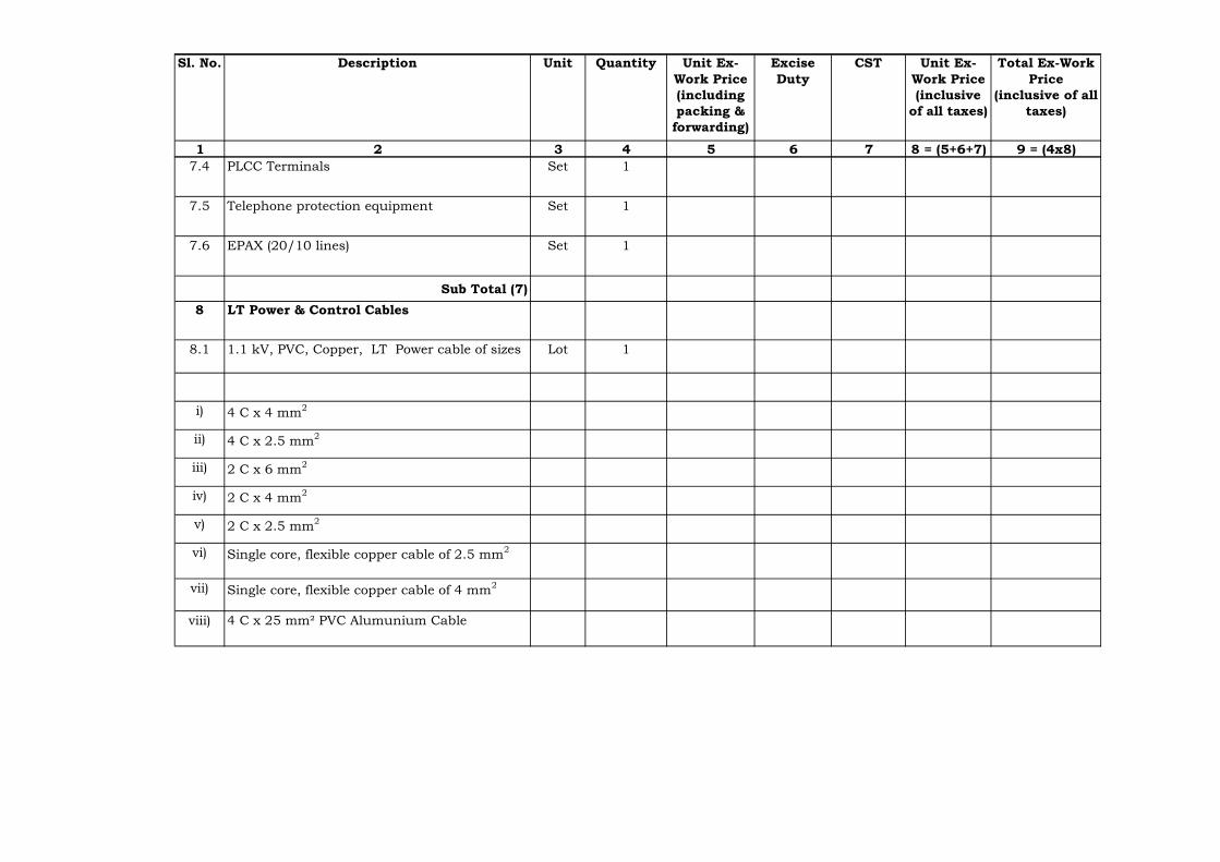
1 2 3 4 5 6 7 8 = (5+6+7) 9 = (4x8)
Unit Ex-
Work Price
(inclusive
of all taxes)
DescriptionSl. No. Quantity Total Ex-Work
Price
(inclusive of all
taxes)
Unit Ex-
Work Price
(including
packing &
forwarding)
Unit Excise
Duty
CST
7.4 PLCC Terminals Set 1
7.5 Telephone protection equipment Set 1
7.6 EPAX (20/10 lines) Set 1
Sub Total (7)
8 LT Power & Control Cables
8.1 1.1 kV, PVC, Copper, LT Power cable of sizes Lot 1
i) 4 C x 4 mm2
ii) 4 C x 2.5 mm2
iii) 2 C x 6 mm2
iv) 2 C x 4 mm2
v) 2 C x 2.5 mm2
vi) Single core, flexible copper cable of 2.5 mm2
vii) Single core, flexible copper cable of 4 mm2
viii) 4 C x 25 mm² PVC Alumunium Cable

1 2 3 4 5 6 7 8 = (5+6+7) 9 = (4x8)
Unit Ex-
Work Price
(inclusive
of all taxes)
DescriptionSl. No. Quantity Total Ex-Work
Price
(inclusive of all
taxes)
Unit Ex-
Work Price
(including
packing &
forwarding)
Unit Excise
Duty
CST
ix) 4 C x 35 mm² PVC Aluminium Cable
x) Any other size required at site
8.2 1.1 kV PVC, copper, control cables of sizes Lot 1
i) 14 C x 2.5 mm2
ii) 10 C x 2.5 mm²
iii) 7 C x 2.5 mm²
Sub Total (8)
9 Earthing System
9.1 Earthing System for control room and
switchyard area including earth mat,riser ,etc.
with all accessories etc. complete in all respect
for one no. additional line feeders as per
specification.
Lot 1
Sub Total (9)

1 2 3 4 5 6 7 8 = (5+6+7) 9 = (4x8)
Unit Ex-
Work Price
(inclusive
of all taxes)
DescriptionSl. No. Quantity Total Ex-Work
Price
(inclusive of all
taxes)
Unit Ex-
Work Price
(including
packing &
forwarding)
Unit Excise
Duty
CST
10 Shielding System
10.1 Shielding system for new additional feeder
equipment area including shielding GI wire
7/3.15mm,GI earth electrods 40 mm dia & 3
meter long, 25x3 mm GI flat for down
conductor,Clamps, connectors, hardware, test
links etc. complete in all respects.
Lot 1
Sub Total (10)
11 Design, fabrication, supply & delivery of
gantries, gantry column and equipment,
supporting structures of galvanised
structural steel with GI bolted connections
for the following as per specification:-
11.1 Gantry Beams, Columns and Equipment
Supporting Structures as per tentative
quantities given below:-
MT 18
i) Isolators (3 nos.)
ii) LAs (3 nos.)
iii) CTs (3 nos.)
iv) CVTs (3 nos.)
v) BPIs (4 nos.)
vi) Line Beam (2 nos.)
vii) Tower/Columns for beams (4 nos.)

1 2 3 4 5 6 7 8 = (5+6+7) 9 = (4x8)
Unit Ex-
Work Price
(inclusive
of all taxes)
DescriptionSl. No. Quantity Total Ex-Work
Price
(inclusive of all
taxes)
Unit Ex-
Work Price
(including
packing &
forwarding)
Unit Excise
Duty
CST
11.2 Galvanized hexagon bolts, nuts & spring
washers etc. comforming to IS:6639 for
substation steel structures
MT 1
11.3 Foundation bolts of appropriate diameter and
length for gantries and equipments supporting
structures as per approved design/ drawings.
MT 1
Sub Total (11)
12 Bus bar materials, post insulators, disc
insulators, hardware, bus-bar conductor,
connectors, clamps etc. complete in all
respects as below :
12.1 ACSR ZEBRA conductor for 145 kV Main-1 &
Transfer Bus and equipment
Lot 1
12.2 33 kV post insulators stacks for 145 kV Main
& Transfer Bus
Lot 1
12.3 11 kV, 90 KN Disc Insualtors Lot 1
a) Tension strings of 10 units Lot 1
b) Suspension strings of 9 units Lot 1
12.4 Bolted type tension clamps to suit ACSR
ZEBRA conductor
Lot 1
12.5 Bolted type tension clamps to suit ACSR
ZEBRA conductor for equipment ie LAs, CTs,
PTs,Isolators, SF-6 Circuit Breaker etc.
Lot 1
12.6 T-connectors for ACSR ZEBRA conductor for
132 kV Main & Transfer Bus.
Lot 1
12.7 BPI clamp suitable for post insulators for
ZEBRA ACSR conductor of 132 kV Main &
Transfer Bus.
Lot 1
12.8 PG clamps suitable for ACSR ZEBRA
conductor.
Lot 1
Sub Total (12)

1 2 3 4 5 6 7 8 = (5+6+7) 9 = (4x8)
Unit Ex-
Work Price
(inclusive
of all taxes)
DescriptionSl. No. Quantity Total Ex-Work
Price
(inclusive of all
taxes)
Unit Ex-
Work Price
(including
packing &
forwarding)
Unit Excise
Duty
CST
13 Lighting/illumination of Additional bay
13.1 Lighting system for external lighting
comprising of 415 V outdoor lighting and sub-
lighting panel, lighting fixtures, flood light ,
CFL/GLS lamp , power receptacles of suitable
ratings ,MS conduit , junction boxes, lighting
cable of suitable cross section, ceiling
fans,exhaust fans,street light pole etc.required
for outdoor yard / street lightning complete in
all respects
Lot 1
Sub Total (13) 14 AC SUPPLY
14.1 415 V AC metal enclosed distribution board
complete with MCCB s,MCBs,bus bar, bus bar
support, control wiring, terminal blocks,fuses,
labels, indications , interlocks , push button ,
switches for new additional one number feeder
No. 1
Sub Total (14)
15 DC SUPPLY
15.1 providing additional equipment at 220 V main
DCDB that is MCCBs,MCBs,fuses ,relay
terminal block cable glands etc. complete for
the new feeders.
No. 1
Sub Total (15)

1 2 3 4 5 6 7 8 = (5+6+7) 9 = (4x8)
Unit Ex-
Work Price
(inclusive
of all taxes)
DescriptionSl. No. Quantity Total Ex-Work
Price
(inclusive of all
taxes)
Unit Ex-
Work Price
(including
packing &
forwarding)
Unit Excise
Duty
CST
16 FIRE FIGHTING EQUIPMENT
1. Foam type extinguishers of 45 litre
capacity mounted on wheel
No. 1
2. CO2 fire extinguishers of 4.5 kg capacity
wall mounted
No. 1
Sub Total (16)
17 Termination Lugs, Cable Glands with
accessories for all sizes of CableLot 1
18 Any other items necessary for the
exectution of 1 no. line bay.Lot 1
19 TOTAL COST (Sub Total 1 to 16+17+18)
Note: 1) Payment shall be made as per actual quantity of supply.

S.No. Quantity Ex-Works Price
inclusive of
packing and
forwarding charges
Total Ex-Works
Price inclusive of
packing and
forwarding
charges
1
1) 1 No.
2) 1 Set
3) 1 No.
4) 1 Set
5) One set of
each type
6) 1 Set
Auxiliary contact assembly
Description of Work/Item
One pole complete with column an interrupter,
MB and operating mechanism and without
support structure
Relays, Power contactors, Push buttons, limit
switches, timers, MCBs and switch fuse units etc.
Fixed, moving and arcing contacts including
insulating nozzles for one pole of CB
Rubber gaskets, ‘O’ rings & seals
145 kV SF6 CIRCUIT BREAKER
Motor for spring charging
SCHEDULE B-2
EX-WORKS PRICES (INCLUSIVE OF PACKING AND FORWARDING CHARGES) OF MANDATORY SPARES 1
NO. LINE FEEDER AT 132 KV SUB-STATION ,RAXAUL, BSPTC(BIHAR)
Price in Rs.

S.No. Quantity Ex-Works Price
inclusive of
packing and
forwarding charges
Total Ex-Works
Price inclusive of
packing and
forwarding
charges
Description of Work/Item
7) 1 No.
8) 2 No.
9) 2 No.
10)
11) 1 Set
12) 1 No.
13) 1 No.
14) 1 No.
15) Lot
2
1) 1 set
2) 1 set
3) 1 set
4) 1 set
5) 1 set
Terminal connectors
Limit switch & Auxiliary contacts
Earthing blade & fixed contact assembly
145 kV ISOLATORS
Sub-Total-1
Motor Housing bearing assembly
DC supervision relay
Operation counter
Density/pressure monitoring system for SF6
circuit
Copper contact fingers for male & female contacts
SF-6 Gas for complete breaker
Remote/local change over switch
Terminal pads & connectors of each type
Closing coil
Trip coil
Pole Discrepancy relay
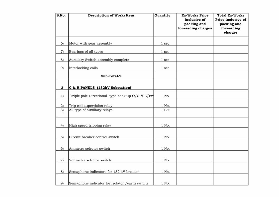
S.No. Quantity Ex-Works Price
inclusive of
packing and
forwarding charges
Total Ex-Works
Price inclusive of
packing and
forwarding
charges
Description of Work/Item
6) 1 set
7) 1 set
8) 1 set
9) 1 set
3
1) 1 No.
2) Trip coil supervision relay 1 No.
3) All type of auxiliary relays 1 Set
4) High speed tripping relay 1 No.
5) Circuit breaker control switch 1 No.
6) Ammeter selector switch 1 No.
7) Voltmeter selector switch 1 No.
8) 1 No.
9) Semaphone indicator for isolator /earth switch 1 No.
Interlocking coils
Sub-Total-2
Triple pole Directional type back up O/C & E/Frelay
C & R PANELS (132kV Substation)
Motor with gear assembly
Bearings of all types
Auxiliary Switch assembly complete
Semaphone indicators for 132 kV breaker

S.No. Quantity Ex-Works Price
inclusive of
packing and
forwarding charges
Total Ex-Works
Price inclusive of
packing and
forwarding
charges
Description of Work/Item
10) 4 No.
11) 25 No.
12) 1 No.
13) 1 No.
14) 1 No.
15) 1 No.
16) Analogue type Ammeters 1 No.
17) Analogue type voltmeters 1 No.
18) MW meters 1 No.
19) MVA meters 1 No.
20) PF Meters 1 No.
21) Energy meters 1 No.
22) Space heaters 2 No.
23) MCB’s of each reating 1 set
24) DC fail relay 1 No.
25) AC fail relay 1 No.
26) 11 W CFL (tubes) 4 No.
Push Button
Indicating lamps
Auto reclosing relay
Control switch for breaker
Control switch for Isolator
Facia Annunciators

S.No. Quantity Ex-Works Price
inclusive of
packing and
forwarding charges
Total Ex-Works
Price inclusive of
packing and
forwarding
charges
Description of Work/Item
4
1)1 No.
5
1) 1 No.
2) 1 No.
3) 1 Set
4) 1 No.
6
1) 1 No.
2) 1 No.
3) 1 No.
4) 1 No.
7
Sub-Total-3
Grand Total (Sub-Total 1+2+3+4+5+6)
Lightning Arresters
Leakage Current Ammeters
145 kV Current Transformer
Discharge Counter
120 kV single pole, 10kA LAs
PLCC
Line Trap
Sub-Total-6
Protection Coupler
Clamps
145 kV Single Phase having 5 cores complete in
all respect with accessories.
Sub-Total-4
Sub-Total-5
Coupling Device
Set of electronic Card for each type of PLC Terminal

Amount in Rs.
Item No. Description of Work/Item Amount
1 2 3
Transportation charges upto Project Storage site
for:
1 Complete Substation equipment as described in
Schedule B-1
2 Mandatory Spares as described in Schedule B-2
3 GRAND TOTAL (1+2)
TRANSPORTATION CHARGES FROM EX-WORKS UPTO PLACE OF
INSTALLATION OF PROJECT SITE 1 NO. LINE FEEDER AT 132 KV SUB-
STATION ,RAXAUL, BSPTC(BIHAR)
SCHEDULE B-3

Amount in Rs.
Item
No.
Description of
Work/Item
During
Transportatio
n to Site
During Storage,
Preserve, Handling,
Transportation from
Storage to Place of
Installation
During Testing,
Erection &
Commissioning
During Defect
Liability
Total
Insurances
Charges
1 2 3 4 5 6 7=3+4+5+6
Insurance charges from
Ex-Works till expiry of
Defect Liability Period
for the following :
1 Complete Substation
equipment as described in
Schedule B-1
2 Mandatory Spares as
described in Schdule B-2
3 GRAND TOTAL (1+2)
SCHEDULE B-4
INSURANCE CHARGES FROM EX-WORKS TILL EXPIRY OF DEFECTS LIABILITY PERIOD FOR ALL ITEMS 1 NO.
LINE FEEDER AT 132 KV SUB-STATION ,RAXAUL, BSPTC(BIHAR)

Amount in Rs.
Item
No.Description of Work/Item
Erection, Testing
& Commissioning
Charges
1 2 3
Complete work of site assembly, erection, testing and
commissioning of:
1 Complete Substation equipment as described in Schedule
B-1
2 TOTAL-1
SCHEDULE B-5
CHARGES FOR ERECTION, TESTING AND COMMISSIONING OF ALL ITEMS 1 NO.
LINE FEEDER AT 132 KV SUB-STATION ,RAXAUL, BSPTC(BIHAR)

Sl
NoDESCRIPTION OF ITEM UNIT QUANTITY
UNIT RATE (in
Rs)
AMOUNT
(in Rs)
(1) (2) (3) (4) (5) (6) = (4) x (5)
1. EARTH WORK
1.1 Earth work in excavation by manual labour or mechanical means
(bottom 300 mm shall be excavated manually only) in foundations,
cable trenches, drains etc including dressing of sides and ramming of
bottom, keeping the excavated area dry, disposal of surplus
excavated soil after back filling of foundations within all leads and
lifts, including the cost of all the materials, labours, fuel, oil,
lubricants, equipments etc.complete as per specifications, approved
construction drawings and instructions of Engineer-in-charge.
cum 575
1.2 Extra over and above item no. 1.1 above for excavation below water
table including the cost of dewatering, all the materials, labours,
fuel, oil, lubricants, equipments etc. complete as per specifications,
approved construction drawings and instructions of Engineer-in-
charge.
cum 50
1.3 Back filling using selected excavated earth in trenches, on sides of
foundation etc. in layers not exceeding 200 mm in depth,
consolidating each layer upto 95% of the Proctor's maximum dry
density (MDD) of soil by ramming at optimum moisture content
(OMC) within all leads and lifts, including cost of all the materials,
labour, fuel, oil, lubricant, equipments, disposal of surplus earth
etc. complete as per specifications, approved construction drawings
and instructions of Engineer-in-charge.
cum 400
2 PLAIN CEMENT CONCRETE
2.1 Providing and laying, ramming, vibrating, compacting Plain Cement
Concrete of M-10 grade conforming to IS:456 below foundations,
cable trenches etc. at all the depths within all leads and lifts,
including cost of all the materials, labours, fuel, oil, lubricant,
admixtures, equipments, centering and shuttering etc.complete as
per specifications, approved construction drawings and instructions
of Engineer-in-charge.
cum 45
Schedule - C
Civil Works
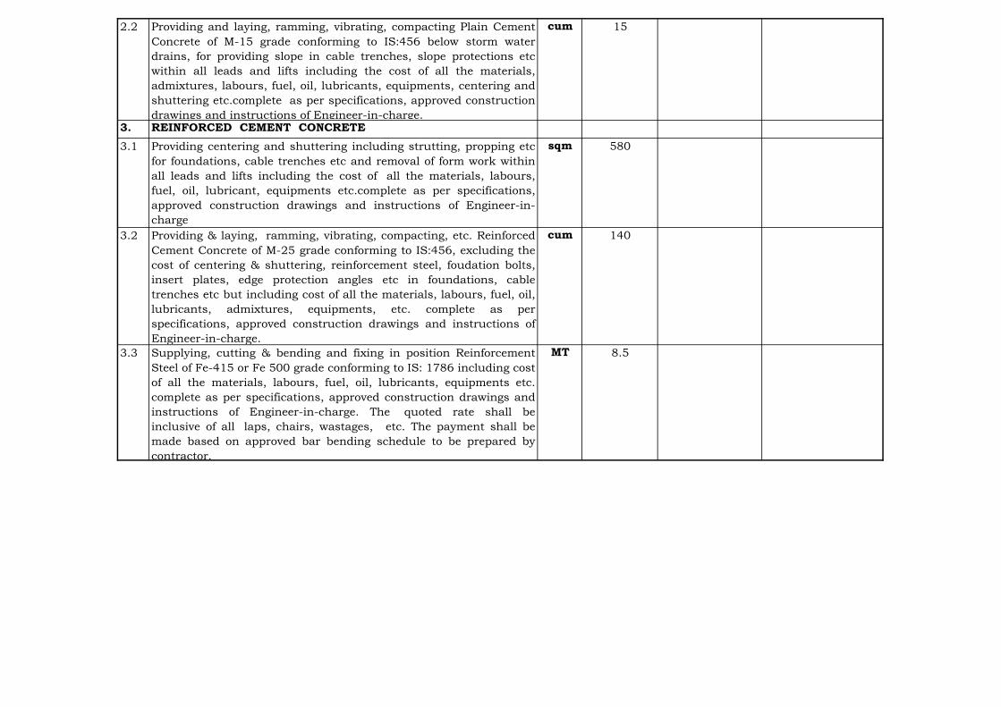
2.2 Providing and laying, ramming, vibrating, compacting Plain Cement
Concrete of M-15 grade conforming to IS:456 below storm water
drains, for providing slope in cable trenches, slope protections etc
within all leads and lifts including the cost of all the materials,
admixtures, labours, fuel, oil, lubricants, equipments, centering and
shuttering etc.complete as per specifications, approved construction
drawings and instructions of Engineer-in-charge.
cum 15
3. REINFORCED CEMENT CONCRETE
3.1 Providing centering and shuttering including strutting, propping etc
for foundations, cable trenches etc and removal of form work within
all leads and lifts including the cost of all the materials, labours,
fuel, oil, lubricant, equipments etc.complete as per specifications,
approved construction drawings and instructions of Engineer-in-
charge
sqm 580
3.2 Providing & laying, ramming, vibrating, compacting, etc. Reinforced
Cement Concrete of M-25 grade conforming to IS:456, excluding the
cost of centering & shuttering, reinforcement steel, foudation bolts,
insert plates, edge protection angles etc in foundations, cable
trenches etc but including cost of all the materials, labours, fuel, oil,
lubricants, admixtures, equipments, etc. complete as per
specifications, approved construction drawings and instructions of
Engineer-in-charge.
cum 140
3.3 Supplying, cutting & bending and fixing in position Reinforcement
Steel of Fe-415 or Fe 500 grade conforming to IS: 1786 including cost
of all the materials, labours, fuel, oil, lubricants, equipments etc.
complete as per specifications, approved construction drawings and
instructions of Engineer-in-charge. The quoted rate shall be
inclusive of all laps, chairs, wastages, etc. The payment shall be
made based on approved bar bending schedule to be prepared by
contractor.
MT 8.5
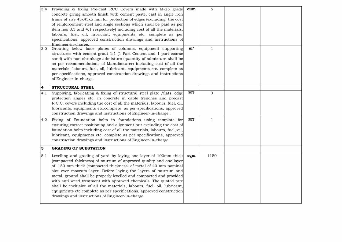
3.4 Providing & fixing Pre-cast RCC Covers made with M-25 grade
concrete giving smooth finish with cement paste, cast in angle iron
frame of size 45x45x5 mm for protection of edges (excluding the cost
of reinforcement steel and angle sections which shall be paid as per
item nos 3.3 and 4.1 respectively) including cost of all the materials,
labours, fuel, oil, lubricant, equipments etc. complete as per
specifications, approved construction drawings and instructions of
Engineer-in-charge.
cum 5
3.5 Grouting below base plates of columns, equipment supporting
structures with cement grout 1:1 (1 Part Cement and 1 part coarse
sand) with non-shrinkage admixture (quantity of admixture shall be
as per recommendations of Manufacturer) including cost of all the
materials, labours, fuel, oil, lubricant, equipments etc. complete as
per specifications, approved construction drawings and instructions
of Engineer-in-charge.
m³ 1
4 STRUCTURAL STEEL
4.1 Supplying, fabricating & fixing of structural steel plate /flats, edge
protection angles etc. in concrete in cable trenches and precast
R.C.C. covers including the cost of all the materials, labours, fuel, oil,
lubricants, equipments etc.complete as per specifications, approved
construction drawings and instructions of Engineer-in-charge .
MT 3
4.2 Fixing of Foundation bolts in foundations using template for
ensuring correct positioning and alignment but excluding the cost of
foundation bolts including cost of all the materials, labours, fuel, oil,
lubricant, equipments etc. complete as per specifications, approved
construction drawings and instructions of Engineer-in-charge.
MT 1
5 GRADING OF SUBSTATION
5.1 Levelling and grading of yard by laying one layer of 100mm thick
(compacted thickness) of murrum of approved quality and one layer
of 150 mm thick (compacted thickness) of metal of 40 mm nominal
size over moorum layer. Before laying the layers of murrum and
metal, ground shall be properly levelled and compacted and provided
with anti weed treatment with approved chemicals. The quoted rate
shall be inclusive of all the materials, labours, fuel, oil, lubricant,
equipments etc.complete as per specifications, approved construction
drawings and instructions of Engineer-in-charge.
sqm 1150

6 BRICK MASONARY
6.1 Providing and laying brick masonary of specified thikness in storm
water drains or in any structure using common non modular burnt
clay bricks with class designation 10 in 1:4 cement mortar ( 1 part
cement : 4 parts coarse sand) for all leads and lifts, including the
cost of all the materials, labours, fuel, oil, lubricants, equipments
etc. complete as per specifications, approved construction drawings
and instructions of Engineer-in-charge
cum 20
6.2 Providing 18 mm thick plaster in drains with 1:3 cement mortar [1
part cement : 3 parts sand (1 part coarse sand and 2 parts fine
sand)] for all leads and lifts, including cost of all the materials,
labours, fuel, oil, lubricants, equipments etc.complete as per
specifications, approved construction drawings and instructions of
Engineer-in-charge.
sqm 150
7 Total
LS-Lump Sum
Note: The Bidder shall visit the site to ascertain the site conditions and the requirements before quoting the price.

PARWANIPURSUBSTATION

Price in Rs.
Item
No.
Description Total Prices
(Exclusive of Taxes
& Duties)
1.Ex-works prices (inclusive of packing and forwarding charges) of
equipment, equipment support structures & associated accessories,
conductors, hardware fittings, insulators etc. complete in all respects
(Item 19 of Schedule B-1)
2.Ex-works prices (inclusive of packing and forwarding charges) of
Mandatory Spares (Item 7 of Schedule B-2)
3.Transportation Charges from Ex-works upto place of installation of
Project Site including Handling, Storage, Preservation, loading and
unloading (Item 3 of Schedule B-3)
4.Insurance charges from Ex-works till expiry of Defects Liability Period for
all items (Item 3 of Schedule B-4)
5.Charges for Erection, Testing and Commissioning of all items (Item 2 of
Schedule B-5)
6. Complete Civil works relating to foundations for gantry & Busbar,
structures, equipment, cable trenches with covers including grading and
laying, stone grit complete in all respects, as per specification (Item - 8 of
Schedule-C)
7. Total Cost (1+2+3+4+5+6)
SCHEDULE-A
ABSTRACT OF PRICE SCHEDULE FOR THE AUGMENTATION OF132 kV SUB-STATION,
PARWANIPUR
132 kV Substation

Price in Rs.
1 2 3 4 5 6 7 8 = (5+6+7) 9 = (4x8)
1 Circuit Breaker
1.1 145kV, 3 Phase ,1250 A, 31.5kA S.C Rating
for 1Sec, SF-6 CB
No. 1
Sub Total (1)
2 145 kV , 3 Phase, 1250A,Double break
Isolator & Isolator cum earth switch
2.1 Isolators without earthing switch No. 2
2.2 Isolators cum earthing switch No. 1
Sub Total (2)
3 Surge Arresters/Lightning Arresters
3.1 Single Phase ,120kV, 10kA, Station Class
Surge Arrestor
No. 3
Sub Total (3)
4 Current Transformer
4.1 Single Phase 145 kV ,5 cores,600-300-
150/1A,31.5 kA S.C Rating
No. 3
Sub Total (4)
CST Unit Ex-
Work Price
(inclusive of
all taxes)
SCHEDULE B-1
SCHEDULE OF PRICES (EX-WORKS PRICES INCLUDING PACKING AND FORWARDING CHARGES) FOR SUPPLY OF EQUIPMENT FOR 1
NO. LINE FEEDER AT 132 kV SUB-STATION , PARWANIPUR, NEA(NEPAL)
Sl. No. Description Unit Quantity Excise
Duty
Total Ex-
Work Price
(inclusive of
all taxes)
Unit Ex-
Work Price
(including
packing &
forwarding)
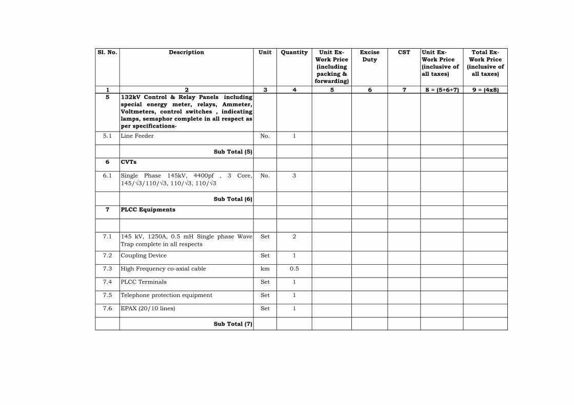
1 2 3 4 5 6 7 8 = (5+6+7) 9 = (4x8)
CST Unit Ex-
Work Price
(inclusive of
all taxes)
Sl. No. Description Unit Quantity Excise
Duty
Total Ex-
Work Price
(inclusive of
all taxes)
Unit Ex-
Work Price
(including
packing &
forwarding)
5 132kV Control & Relay Panels including
special energy meter, relays, Ammeter,
Voltmeters, control switches , indicating
lamps, semaphor complete in all respect as
per specifications-
5.1 Line Feeder No. 1
Sub Total (5)
6 CVTs
6.1 Single Phase 145kV, 4400pf , 3 Core,
145/√3/110/√3, 110/√3, 110/√3
No. 3
Sub Total (6)
7 PLCC Equipments
7.1 145 kV, 1250A, 0.5 mH Single phase Wave
Trap complete in all respects
Set 2
7.2 Coupling Device Set 1
7.3 High Frequency co-axial cable km 0.5
7.4 PLCC Terminals Set 1
7.5 Telephone protection equipment Set 1
7.6 EPAX (20/10 lines) Set 1
Sub Total (7)

1 2 3 4 5 6 7 8 = (5+6+7) 9 = (4x8)
CST Unit Ex-
Work Price
(inclusive of
all taxes)
Sl. No. Description Unit Quantity Excise
Duty
Total Ex-
Work Price
(inclusive of
all taxes)
Unit Ex-
Work Price
(including
packing &
forwarding)
8 LT Power & Control Cables
8.1 1.1 kV, PVC, Copper, LT Power cable of sizes Lot 1
i) 4 C x 4 mm2
ii) 4 C x 2.5 mm2
iii) 2 C x 6 mm2
iv) 2 C x 4 mm2
v) 2 C x 2.5 mm2
vi) Single core, flexible copper cable of 2.5 mm2
vii) Single core, flexible copper cable of 4 mm2
viii) 4 C x 25 mm² PVC Alumunium Cable
ix) 4 C x 35 mm² PVC Aluminium Cable
x) Any other size required at site
8.2 1.1 kV PVC, copper, control cables of sizes Lot 1
i) 14 C x 2.5 mm2
ii) 10 C x 2.5 mm²
iii) 7 C x 2.5 mm²
Sub Total (8)

1 2 3 4 5 6 7 8 = (5+6+7) 9 = (4x8)
CST Unit Ex-
Work Price
(inclusive of
all taxes)
Sl. No. Description Unit Quantity Excise
Duty
Total Ex-
Work Price
(inclusive of
all taxes)
Unit Ex-
Work Price
(including
packing &
forwarding)
9 Earthing System
9.1 Earthing System for control room and
switchyard area including earth mat,riser
,etc. with all accessories etc. complete in all
respect for one no. additional line feeders as
per specification.
Lot 1
Sub Total (9)
10 Shielding System Lot 1
10.1 Shielding system for new additional feeder
equipment area including shielding GI wire
7/3.15mm,GI earth electrods 40 mm dia & 3
meter long, 25x3 mm GI flat for down
conductor,Clamps, connectors, hardware,
test links etc. complete in all respects.
Sub Total (10)
11 Design, fabrication, supply & delivery of
gantries, gantry column and equipment,
supporting structures of galvanised
structural steel with GI bolted connections
for the following as per specification:-
11.1 Gantry Beams, Columns and Equipment
Supporting Structures as per tentative
quantities given below:-
MT 18
i) Isolators (3 nos.)
ii) LAs (3 nos.)
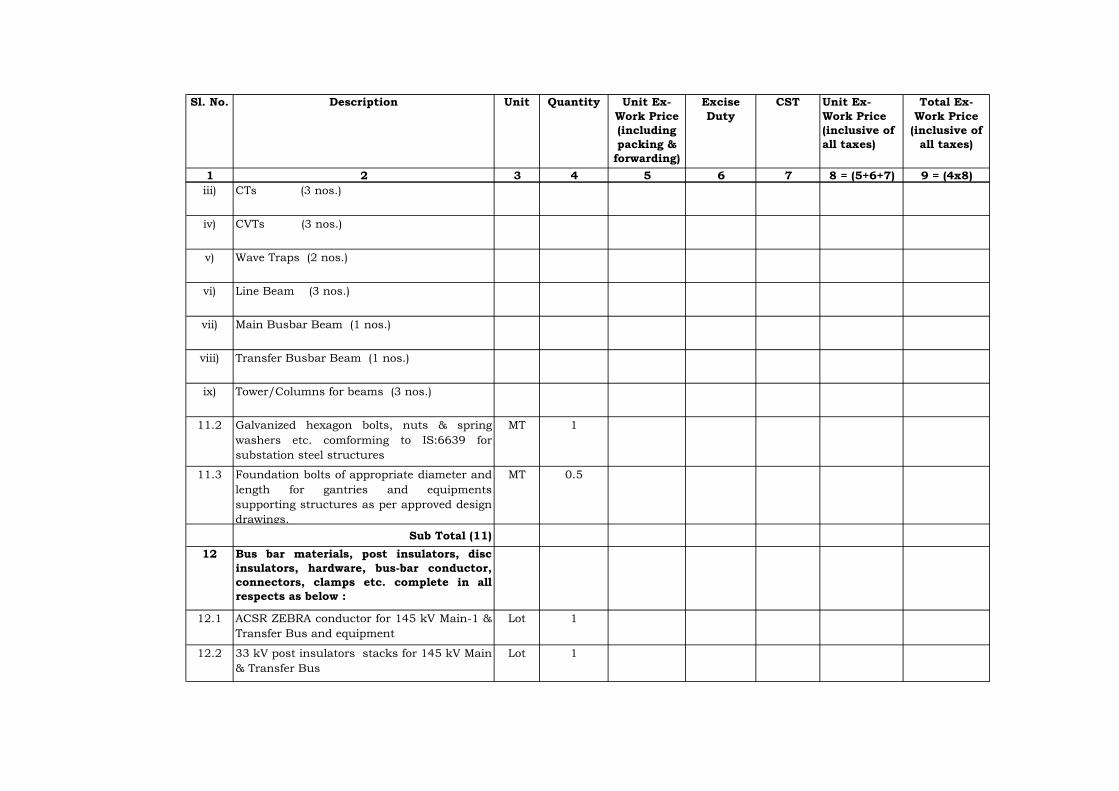
1 2 3 4 5 6 7 8 = (5+6+7) 9 = (4x8)
CST Unit Ex-
Work Price
(inclusive of
all taxes)
Sl. No. Description Unit Quantity Excise
Duty
Total Ex-
Work Price
(inclusive of
all taxes)
Unit Ex-
Work Price
(including
packing &
forwarding)
iii) CTs (3 nos.)
iv) CVTs (3 nos.)
v) Wave Traps (2 nos.)
vi) Line Beam (3 nos.)
vii) Main Busbar Beam (1 nos.)
viii) Transfer Busbar Beam (1 nos.)
ix) Tower/Columns for beams (3 nos.)
11.2 Galvanized hexagon bolts, nuts & spring
washers etc. comforming to IS:6639 for
substation steel structures
MT 1
11.3 Foundation bolts of appropriate diameter and
length for gantries and equipments
supporting structures as per approved design
drawings.
MT 0.5
Sub Total (11)
12 Bus bar materials, post insulators, disc
insulators, hardware, bus-bar conductor,
connectors, clamps etc. complete in all
respects as below :
12.1 ACSR ZEBRA conductor for 145 kV Main-1 &
Transfer Bus and equipment
Lot 1
12.2 33 kV post insulators stacks for 145 kV Main
& Transfer Bus
Lot 1

1 2 3 4 5 6 7 8 = (5+6+7) 9 = (4x8)
CST Unit Ex-
Work Price
(inclusive of
all taxes)
Sl. No. Description Unit Quantity Excise
Duty
Total Ex-
Work Price
(inclusive of
all taxes)
Unit Ex-
Work Price
(including
packing &
forwarding)
12.3 11 kV, 90 KN Disc Insualtors Lot 1
a) Tension strings of 10 units Lot 1
b) Suspension strings of 9 units Lot 1
12.4 Bolted type tension clamps to suit ACSR
ZEBRA conductor
Lot 1
12.5 Bolted type tension clamps to suit ACSR
ZEBRA conductor for equipment ie LAs, CTs,
PTs,Isolators, SF-6 Circuit Breaker etc.
Lot 1
12.6 T-connectors for ACSR ZEBRA conductor for
132 kV Main & Transfer Bus.
Lot 1
12.7 BPI clamp suitable for post insulators for
ZEBRA ACSR conductor of 132 kV Main &
Transfer Bus.
Lot 1
12.8 PG clamps suitable for ACSR ZEBRA
conductor.
Lot 1
Sub Total (12)
13 Lighting/illumination of Additional bay
13.1 Lighting system for external lighting
comprising of 415 V outdoor lighting and sub-
lighting panel, lighting fixtures, flood light ,
CFL/GLS lamp , power receptacles of suitable
ratings ,MS conduit , junction boxes, lighting
cable of suitable cross section, ceiling
fans,exhaust fans,street light pole
etc.required for outdoor yard / street
lightning complete in all respects
Lot 1
Sub Total (13)
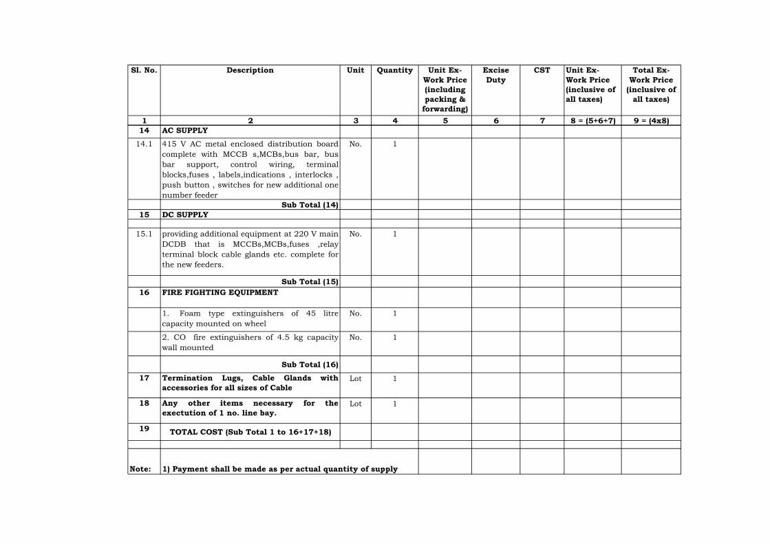
1 2 3 4 5 6 7 8 = (5+6+7) 9 = (4x8)
CST Unit Ex-
Work Price
(inclusive of
all taxes)
Sl. No. Description Unit Quantity Excise
Duty
Total Ex-
Work Price
(inclusive of
all taxes)
Unit Ex-
Work Price
(including
packing &
forwarding)
14 AC SUPPLY
14.1 415 V AC metal enclosed distribution board
complete with MCCB s,MCBs,bus bar, bus
bar support, control wiring, terminal
blocks,fuses , labels,indications , interlocks ,
push button , switches for new additional one
number feeder
No. 1
Sub Total (14)
15 DC SUPPLY
15.1 providing additional equipment at 220 V main
DCDB that is MCCBs,MCBs,fuses ,relay
terminal block cable glands etc. complete for
the new feeders.
No. 1
Sub Total (15)
16 FIRE FIGHTING EQUIPMENT
1. Foam type extinguishers of 45 litre
capacity mounted on wheel
No. 1
2. CO
₂
fire extinguishers of 4.5 kg capacity
wall mounted
No. 1
Sub Total (16)
17 Termination Lugs, Cable Glands with
accessories for all sizes of Cable
Lot 1
18 Any other items necessary for the
exectution of 1 no. line bay.
Lot 1
19 TOTAL COST (Sub Total 1 to 16+17+18)
Note: 1) Payment shall be made as per actual quantity of supply

S.N
o.
Quantity Ex-Works Price
inclusive of
packing and
forwarding charges
Total Ex-Works
Price inclusive of
packing and
forwarding
charges
1
1) 1 No.
2) 1 Set
3) 1 No.
4) 1 Set
5) One set
of each
type
6) 1 Set
7) 1 No.
SCHEDULE B-2
EX-WORKS PRICES (INCLUSIVE OF PACKING AND FORWARDING CHARGES) OF MANDATORY
SPARES
Price in Rs.
Description of Work/Item
145 kV SF6 CIRCUIT BREAKER
Motor for spring charging
Auxiliary contact assembly
One pole complete with column an interrupter,
MB and operating mechanism and without
support structure
Fixed, moving and arcing contacts including
insulating nozzles for one pole of CB
Relays, Power contactors, Push buttons, limit
switches, timers, MCBs and switch fuse units
etc.
Rubber gaskets, ‘O’ rings & seals
Terminal pads & connectors of each type

S.N
o.
Quantity Ex-Works Price
inclusive of
packing and
forwarding charges
Total Ex-Works
Price inclusive of
packing and
forwarding
charges
Description of Work/Item
8) 2 No.
9) 2 No.
10)
11) 1 Set
12) 1 No.
13) 1 No.
14) 1 No.
15) Lot
Remote/local change over switch
DC supervision relay
Operation counter
Density/pressure monitoring system for SF6
circuit
SF-6 Gas for complete breaker
Sub-Total-1
Closing coil
Trip coil
Pole Discrepancy relay
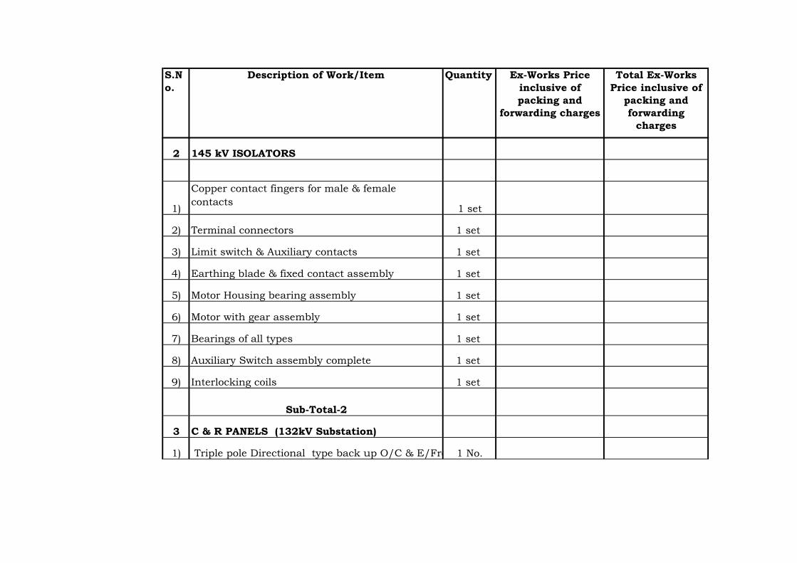
S.N
o.
Quantity Ex-Works Price
inclusive of
packing and
forwarding charges
Total Ex-Works
Price inclusive of
packing and
forwarding
charges
Description of Work/Item
2
1) 1 set
2) 1 set
3) 1 set
4) 1 set
5) 1 set
6) 1 set
7) 1 set
8) 1 set
9) 1 set
3
1) 1 No.
145 kV ISOLATORS
Copper contact fingers for male & female
contacts
Terminal connectors
Limit switch & Auxiliary contacts
Earthing blade & fixed contact assembly
C & R PANELS (132kV Substation)
Triple pole Directional type back up O/C & E/Frelay
Motor Housing bearing assembly
Motor with gear assembly
Bearings of all types
Auxiliary Switch assembly complete
Interlocking coils
Sub-Total-2

S.N
o.
Quantity Ex-Works Price
inclusive of
packing and
forwarding charges
Total Ex-Works
Price inclusive of
packing and
forwarding
charges
Description of Work/Item
2) Trip coil supervision relay 1 No.
3) All type of auxiliary relays 1 Set
4) High speed tripping relay 1 No.
5) Circuit breaker control switch 1 No.
6) Ammeter selector switch 1 No.
7) Voltmeter selector switch 1 No.
8) 1 No.
9) Semaphone indicator for isolator /earth switch 1 No.
10) 4 No.
11) 25 No.
12) 1 No.
13) 1 No.
14) 1 No.
15) 1 No.
16) Analogue type Ammeters 1 No.
17) Analogue type voltmeters 1 No.
Semaphone indicators for 132 kV breaker
Push Button
Indicating lamps
Auto reclosing relay
Control switch for breaker
Control switch for Isolator
Facia Annunciators
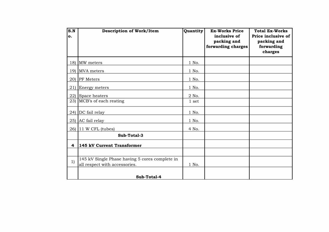
S.N
o.
Quantity Ex-Works Price
inclusive of
packing and
forwarding charges
Total Ex-Works
Price inclusive of
packing and
forwarding
charges
Description of Work/Item
18) MW meters 1 No.
19) MVA meters 1 No.
20) PF Meters 1 No.
21) Energy meters 1 No.
22) Space heaters 2 No.
23) MCB’s of each reating 1 set
24) DC fail relay 1 No.
25) AC fail relay 1 No.
26) 11 W CFL (tubes) 4 No.
4
1)1 No.
145 kV Current Transformer
145 kV Single Phase having 5 cores complete in
all respect with accessories.
Sub-Total-4
Sub-Total-3

S.N
o.
Quantity Ex-Works Price
inclusive of
packing and
forwarding charges
Total Ex-Works
Price inclusive of
packing and
forwarding
charges
Description of Work/Item
5
1) 1 No.
2) 1 No.
3) 1 Set
4) 1 No.
6
1) 1 No.
2) 1 No.
3) 1 No.
4) 1 No.
7
Lightning Arresters
Leakage Current Ammeters
Discharge Counter
Clamps
120 kV single pole, 10kA LAs
Sub-Total-5
Sub-Total-6
Grand Total (Sub-Total 1+2+3+4+5+6)
PLCC
Coupling Device
Set of electronic Card for each type of PLC Terminal
Line Trap
Protection Coupler
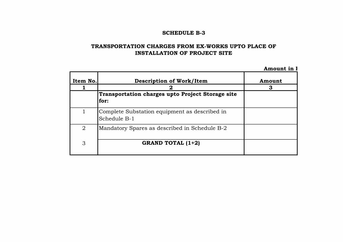
Amount in Rs.
Item No. Description of Work/Item Amount
1 2 3
Transportation charges upto Project Storage site
for:
1 Complete Substation equipment as described in
Schedule B-1
2 Mandatory Spares as described in Schedule B-2
3 GRAND TOTAL (1+2)
SCHEDULE B-3
TRANSPORTATION CHARGES FROM EX-WORKS UPTO PLACE OF
INSTALLATION OF PROJECT SITE

Amount in Rs.
Item
No.
Description of
Work/Item
During
Transportat
ion to Site
During Storage,
Preserve,
Handling,
Transportation
from Storage to
Place of
During Testing,
Erection &
Commissioning
During Defect
Liability
Total
Insurances
Charges
1 2 3 4 5 6 7=3+4+5+6
Insurance charges from
Ex-Works till expiry of
Defect Liability Period
for the following :
1 Complete Substation
equipment as described in
Schedule B-1
2 Mandatory Spares as
described in Schdule B-2
3 GRAND TOTAL (1+2)
SCHEDULE B-4
INSURANCE CHARGES FROM EX-WORKS TILL EXPIRY OF DEFECTS LIABILITY PERIOD FOR ALL ITEMS
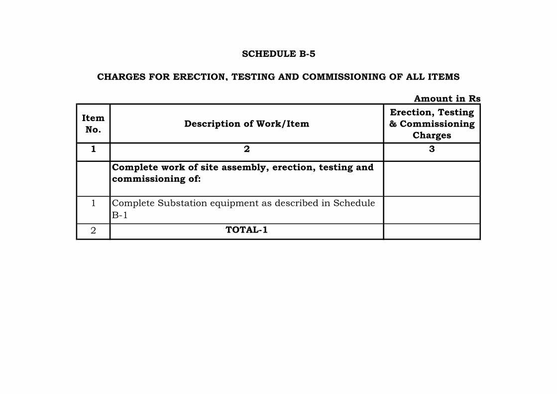
Amount in Rs.
Item
No.Description of Work/Item
Erection, Testing
& Commissioning
Charges
1 2 3
Complete work of site assembly, erection, testing and
commissioning of:
1 Complete Substation equipment as described in Schedule
B-1
2 TOTAL-1
SCHEDULE B-5
CHARGES FOR ERECTION, TESTING AND COMMISSIONING OF ALL ITEMS

Sl
No
DESCRIPTION OF ITEM UNIT QUANTITY UNIT RATE
(in Rs)
AMOUNT
(in Rs)
(1) (2) (3) (4) (5) (6) = (4) x (5)
1. EARTH WORK
1 Earth work in excavation by manual labour or mechanical
means (bottom 300 mm shall be excavated manually only) in
foundations, cable trenches, drains etc including dressing of
sides and ramming of bottom, keeping the excavated area dry,
disposal of surplus excavated soil after back filling of
foundations within all leads and lifts, including the cost of all
the materials, labours, fuel, oil, lubricants, equipments etc.
complete as per specifications, approved construction
drawings and instructions of Engineer-in-charge.
cum 650
1 Extra over and above item no. 1.2 above for excavation below
water table including the cost of dewatering, all the materials,
labours, fuel, oil, lubricants, equipments etc. complete as per
specifications, approved construction drawings and
instructions of Engineer-in-charge.
cum 25
1 Back filling using selected excavated earth in trenches, on
sides of foundation etc. in layers not exceeding 200 mm in
depth, consolidating each layer upto 95% of the Proctor's
maximum dry density (MDD) of soil by ramming at optimum
moisture content (OMC) within all leads and lifts, including
cost of all the materials, labour, fuel, oil, lubricant,
equipments, disposal of surplus earth etc. complete as per
specifications, approved construction drawings and
instructions of Engineer-in-charge.
cum 440
2 PLAIN CEMENT CONCRETE
2 Providing and laying, ramming, vibrating, compacting Plain
Cement Concrete of M-10 grade conforming to IS:456 below
foundations, cable trenches etc. at all the depths within all
leads and lifts, including cost of all the materials, labours,
fuel, oil, lubricant, admixtures, equipments, centering and
shuttering etc.complete as per specifications, approved
construction drawings and instructions of Engineer-in-
charge.
cum 35
Schedule - C
Civil Works

2 Providing and laying, ramming, vibrating, compacting Plain
Cement Concrete of M-15 grade conforming to IS:456 below
storm water drains, for providing slope in cable trenches,
slope protections etc within all leads and lifts including the
cost of all the materials, admixtures, labours, fuel, oil,
lubricants, equipments, centering and shuttering etc.complete
as per specifications, approved construction drawings and
instructions of Engineer-in-charge.
cum 12
3. REINFORCED CEMENT CONCRETE
3 Providing centering and shuttering including strutting,
propping etc for foundations, cable trenches etc and removal
of form work within all leads and lifts including the cost of all
the materials, labours, fuel, oil, lubricant, equipments
etc.complete as per specifications, approved construction
drawings and instructions of Engineer-in-charge
sqm 500
3 Providing & laying, ramming, vibrating, compacting, etc.
Reinforced Cement Concrete of M-25 grade conforming to
IS:456, excluding the cost of centering & shuttering,
reinforcement steel, foudation bolts, insert plates, edge
protection angles etc in foundations, cable trenches etc but
including cost of all the materials, labours, fuel, oil,
lubricants, admixtures, equipments, etc. complete as per
specifications, approved construction drawings and
instructions of Engineer-in-charge.
cum 150
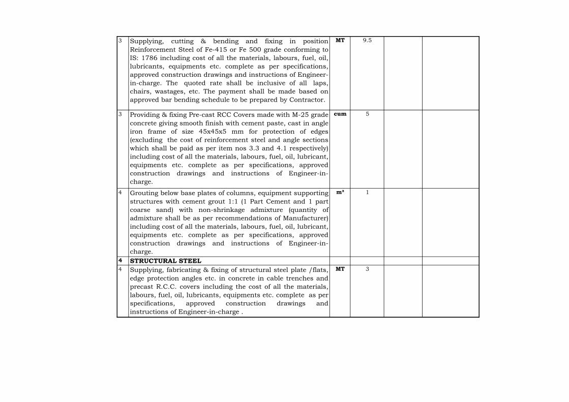
3 Supplying, cutting & bending and fixing in position
Reinforcement Steel of Fe-415 or Fe 500 grade conforming to
IS: 1786 including cost of all the materials, labours, fuel, oil,
lubricants, equipments etc. complete as per specifications,
approved construction drawings and instructions of Engineer-
in-charge. The quoted rate shall be inclusive of all laps,
chairs, wastages, etc. The payment shall be made based on
approved bar bending schedule to be prepared by Contractor.
MT 9.5
3 Providing & fixing Pre-cast RCC Covers made with M-25 grade
concrete giving smooth finish with cement paste, cast in angle
iron frame of size 45x45x5 mm for protection of edges
(excluding the cost of reinforcement steel and angle sections
which shall be paid as per item nos 3.3 and 4.1 respectively)
including cost of all the materials, labours, fuel, oil, lubricant,
equipments etc. complete as per specifications, approved
construction drawings and instructions of Engineer-in-
charge.
cum 5
4 Grouting below base plates of columns, equipment supporting
structures with cement grout 1:1 (1 Part Cement and 1 part
coarse sand) with non-shrinkage admixture (quantity of
admixture shall be as per recommendations of Manufacturer)
including cost of all the materials, labours, fuel, oil, lubricant,
equipments etc. complete as per specifications, approved
construction drawings and instructions of Engineer-in-
charge.
m³ 1
4 STRUCTURAL STEEL
4 Supplying, fabricating & fixing of structural steel plate /flats,
edge protection angles etc. in concrete in cable trenches and
precast R.C.C. covers including the cost of all the materials,
labours, fuel, oil, lubricants, equipments etc. complete as per
specifications, approved construction drawings and
instructions of Engineer-in-charge .
MT 3
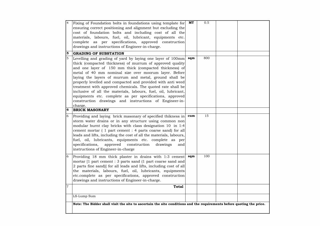
4 Fixing of Foundation bolts in foundations using template for
ensuring correct positioning and alignment but excluding the
cost of foundation bolts and including cost of all the
materials, labours, fuel, oil, lubricant, equipments etc.
complete as per specifications, approved construction
drawings and instructions of Engineer-in-charge.
MT 0.5
5 GRADING OF SUBSTATION
5 Levelling and grading of yard by laying one layer of 100mm
thick (compacted thickness) of murrum of approved quality
and one layer of 150 mm thick (compacted thickness) of
metal of 40 mm nominal size over moorum layer. Before
laying the layers of murrum and metal, ground shall be
properly levelled and compacted and provided with anti weed
treatment with approved chemicals. The quoted rate shall be
inclusive of all the materials, labours, fuel, oil, lubricant,
equipments etc. complete as per specifications, approved
construction drawings and instructions of Engineer-in-
charge.
sqm 800
6 BRICK MASONARY
6 Providing and laying brick masonary of specified thikness in
storm water drains or in any structure using common non
modular burnt clay bricks with class designation 10 in 1:4
cement mortar ( 1 part cement : 4 parts coarse sand) for all
leads and lifts, including the cost of all the materials, labours,
fuel, oil, lubricants, equipments etc. complete as per
specifications, approved construction drawings and
instructions of Engineer-in-charge
cum 15
6 Providing 18 mm thick plaster in drains with 1:3 cement
mortar [1 part cement : 3 parts sand (1 part coarse sand and
2 parts fine sand)] for all leads and lifts, including cost of all
the materials, labours, fuel, oil, lubricants, equipments
etc.complete as per specifications, approved construction
drawings and instructions of Engineer-in-charge.
sqm 100
7 Total
LS-Lump Sum
Note: The Bidder shall visit the site to ascertain the site conditions and the requirements before quoting the price.