
Genius - Broadcasting Services
30
Operating manual (Rel. 1.4) Sede BOLOGNA: Via Caduti Di Sabbiuno 6/F – 40011 Anzola Emilia - Bologna - Italy Tel. +39 051 736555 - Fax. +39 051 736170 Sede BERGAMO: Via Italia 1 – 24030 Medolago (Bg) – Italy e-mail: [email protected] - web site: www.axeltechnology.com Genius Multifunction Changeover
-
Upload
khangminh22 -
Category
Documents
-
view
1 -
download
0
Transcript of Genius - Broadcasting Services

Operating manual
(Rel. 1.4)
Sede BOLOGNA: Via Caduti Di Sabbiuno 6/F – 40011 Anzola Emilia - Bologna - Italy
Tel. +39 051 736555 - Fax. +39 051 736170
Sede BERGAMO: Via Italia 1 – 24030 Medolago (Bg) – Italy
e-mail: [email protected] - web site: www.axeltechnology.com
Genius
Multifunction Changeover

This manual is for use with the following product : Genius MKII Axel Technology SRL All Rights Reserved Via Caduti Di Sabbiuno 6/F - 40011 Anzola Emilia - Bologna - Italy Tel. +39 051 736555 – + 39 051 736154 Fax. +39 051 736170 e-mail: [email protected] - web site: www.axeltechnology.com Information in this document is subject to change without notice and does not represent a commitment on the part of the vendor. This manual images could differ a bit from the equipment actual design. Axel Technology SRL shall not be liable for any loss or damage whatsoever arising from the use of information or any error contained in this manual. No part of this manual may be reproduced or transmitted in any form or by any means, electronic or mechanical, including photocopying, recording, information storage and retrieval systems, for any purpose other than the purchaser’s personal use, without the express written permission of Axel Technology SRL.
TABLE OF CONTENTS
Pag. 3
1 TABLE OF CONTENTS
1 TABLE OF CONTENTS........................................................................................................................................ 3 2 INTRODUCTION................................................................................................................................................... 4 3 SAFETY WARNINGS / ISTRUZIONI PER LA SICUREZZA......................................................................... 6
3.1 FOREWORD.................................................................................................................................................... 6 4 SAFETY WARNINGS ........................................................................................................................................... 7 5 CONSIGNES DE SÉCURITÉ IMPORTANTES................................................................................................. 8 6 ISTRUZIONI IMPORTANTI PER LA SICUREZZA........................................................................................ 9 7 WICHTIGE SICHERHEITSHINWEISE .......................................................................................................... 10 8 INSTRUCCIONES IMPORTANTES DE SEGURIDAD ................................................................................. 11 9 UNPACKING AND INSPECTION..................................................................................................................... 12 10 FIRST INSTALLATION RECOMMENDATIONS.......................................................................................... 13
10.1 POWER SUPPLY CABLE .............................................................................................................................. 13 10.2 AC MAINS VOLTAGE SETTING (230 V / 115 V) ............................................................................................ 13 10.3 FUSE REPLACEMENT.................................................................................................................................. 14 10.4 PROTECTION AGAINST LIGHTNING........................................................................................................... 14 10.5 VENTILATION ............................................................................................................................................... 14
11 GENERAL EQUIPMENT DESCRIPTION....................................................................................................... 15 11.1 FRONT PANEL .............................................................................................................................................. 15 11.2 REAR PANEL................................................................................................................................................. 16 11.3 BLOCK DIAGRAM ......................................................................................................................................... 18
12 BASIC AUDIO SETTINGS ................................................................................................................................. 19 12.1 INPUT IMPEDANCE SETTING...................................................................................................................... 19 12.2 INPUT LEVEL ADJUSTMENT........................................................................................................................ 19 12.3 INPUT LEVELS – FINE TUNING.................................................................................................................... 19
13 THE AUDIO DETECTOR STAGE .................................................................................................................... 20 13.1 HOW THE AUDIO DETECTOR WORKS ....................................................................................................... 20 13.2 THRESHOLD SET-UP ................................................................................................................................... 21 13.3 FAIL TIME SET-UP ........................................................................................................................................ 21 13.4 RECOVERY TIME.......................................................................................................................................... 21
14 AUXILIARY FUNCTIONS................................................................................................................................. 22 14.1 MULTIPLAY ................................................................................................................................................... 22 14.2 ADDITION OF A 50 US PRE-EMPHASIS TO INPUT B / MP3 BACK-UP SOURCE........................................ 22 14.3 ADDITION OF A PILOT TONE TO INPUT B / MP3 BACK-UP SOURCE........................................................ 23 14.4 INSERTION OF AN EXTERNAL RDS (RADIO DATA SYSTEM) SIGNAL...................................................... 23 14.5 THE ‘MIX’ OUTPUT MODE ............................................................................................................................ 24 14.6 THE ‘RESET’ COMMAND.............................................................................................................................. 24 14.7 INTERNAL TRIMMER LIST ........................................................................................................................... 24 14.8 JUMPER &TRIMMER SUMMARY ................................................................................................................. 25 14.9 TRIMMER & JUMPERS POSITION LAYOUT ................................................................................................ 26
15 INTERFACE AND PORT DESCRIPTION....................................................................................................... 27 15.1 REMOTE INTERFACE DESCRIPTION ......................................................................................................... 27 15.2 EXTERNAL + 48 VOLT INTERFACE (OPTIONAL) ............................................................................................ 28
16 FAQS AND ADDITIONAL NOTES ON BACK-UP MP3 PLAYER .............................................................. 29 17 TECHNICAL SPECIFICATIONS...................................................................................................................... 30 18 WARRANTY......................................................................................................................................................... 30
INTRODUCTION
Pag. 4
2 INTRODUCTION HIGHLIGHTS
- AUTOMATIC stereo audio changeover - Fully adjustable audio-detector built-in
- Manual (local and remote) or automatic operation
- MPX switching capability
- Independent gain control for each input
- Capability to start stand-by sources
- Full set of relays associated to ‘blank’ detecting and input switching
- Optional MP3 built-in reader acting as back-up audio source
The Genius is an audio changeover with 2 stereo inputs and 1 stereo output. It fulfils the needs of every radio station for manual or automatic (on ‘emergency’) switching between different audio sources. The Genius constantly monitors the Main stereo audio feed and, in the events it drops below a set threshold for a given period, a stand-by source (such as a CD Player, an alternative link, etc ) will be automatically routed to the Output in order to keep the broadcasting running. Delay time before switching and before resuming the normal state are easily configurable by means of trimmers and jumpers in a large range of values. Up to 3 internal relays can be associated to the ‘blank’ audio detection and to A/B Input switching for further alarm signalling, external signal routing, CD players start, etc. The Genius audio interface includes XLR balanced inputs and outputs, with two pairs of PinRca unbalanced for associated ‘foldback’ outputs. The main Output is available in either XLR balanced or unbalanced (PinRca) connectors. An hardware bypass (via relay) connects the A Input pair to the Output XLRs in case of AC power failure or whenever the unit is unintentionally turned off. In addition to audio I/O on XLRs, the Genius features two coaxial inputs and one coaxial output on Bnc connectors for switching MPX (FM Multiplex), Video, RDS, etc. When set in the ‘automatic/emergency’ mode, the Genius is typically used for automatic switching between a main program (satellite) and local back-up source at the transmitter sites, to overcome ‘blank’ status in the event of radio automation freezing, etc. Featuring an optional, internal MP3 reader (see GENIUS-ALM version) as back-up audio source, the GENIUS allows to overcome any ‘blank’ or silence time in radio broadcasting. Whenever a main audio lacks on INPUT ‘A’ occurs, the GENIUS wait the pre-set ‘silence time’ before switching over the internal Mp3 Back-Up audio source, that plays audio files from the local SD CARD. When main audio resumes, the GENIUS switches back over the INPUT ‘A’ source. Audio files contained on the SD CARD are played in a sequenced mode. Besides being driven by its built-in audio detector stage, Genius switching can be also controlled from any external commands, provided through a fully-featured optoinsulated Remote Interface. This way, the Genius may become, for example, a simple ‘slave’ audio switcher for the radio automation software and thus be used for switching between the main program and a local advertising when ‘adv break time’ is on, to connect/disconnect remote audio sources, etc. The third and last operating mode for the Genius is the manual one, where a front panel knob allows immediate selection of either A or B source. Its ideal application is at the radio studios, to switch between studio feeds and Master Control Room outputs, to bypass some equipment in the event of maintenance jobs, etc. For further help, the Genius may also apply a gain control (in the – 10 to + 10 dB range) to each source, in order to make audio switching as much ‘smooth’ as possible. An internal 19 KHz oscillator may be used to add a FM Pilot on the output, to get a ‘stereo-like’ broadcasting in the event an unprocessed or not-stereo coded source is routed to the output. In the same way, the Genius may also pre-emphasize the B-sourced signal for broadcast purposes.

INTRODUCTION
Pag. 5
For all these simple but useful peculiar features genius can be deemed as a….. genial equipment !

SAFETY WARNINGS / ISTRUZIONI PER LA SICUREZZA
Pag. 6
3 SAFETY WARNINGS / ISTRUZIONI PER LA SICUREZZA
SAFETY WARNINGS
CONSIGNES DE SÉCURITÉ IMPORTANTES
ISTRUZIONI IMPORTANTI PER LA SICUREZZA
WICHTIGE SICHERHEITSHINWEISE
INSTRUCCIONES IMPORTANTES DE SEGURIDAD
(Rel. 1.2)
3.1 FOREWORD For your own safety and to avoid invalidation of the warranty all text marked with these Warning Symbols should be read carefully.
Information in this manual is subject to change without notice and does not represent a commitment on the part of the vendor. The manufacturer shall not be liable for any loss or damage whatsoever arising from the use of information or any error contained in this manual, or through any mis-operation or fault in hardware contained in the product. It is recommended that all maintenance and service on the product should be carried out by the manufacturer or its authorised agents. The manufacturer cannot accept any liability whatsoever for any loss or damage caused by service, maintenance or repair by unauthorised personnel.

SAFETY WARNINGS
Pag. 7
4 SAFETY WARNINGS The installation and servicing instructions in this manual are for use by qualified personnel only. - Read All Instructions. All safety and operating instructions must be read before operating the product. They also
must be retained for future reference, as it contains a number of useful hints for determining the best combination of equipment settings for Yr particular application.
- Heed All Warnings. All warnings on the product and those listed in the operating instructions must be adhered to.
- Heat. This product must be situated away from any heat sources such as radiators or other products (including power amplifiers or transmitters) that produce heat.
- Power Sources. This product must be operated from the type of power source indicated on the marking label and in the installation instructions. If you are not sure of the type of power supplied to your facility, consult your local power company. Make sure the AC main voltage corresponds to that indicated in the technical specifications. If a different voltage (ex. 110/115 VAC) is available, open the equipment closure and set the voltage switch on the main supply circuit, located behind the AC socket
- Power Cord Protection. Power supply cords must be routed so that they are not likely to be walked on nor pinched by items placed upon or against them. Pay particular attention to the cords at AC wall plugs and convenience receptacles, and at the point where the cord plugs into the product
- Use only with a cart, stand, tripod, bracket, or table specified by the manufacturer, or sold with the apparatus. When a cart is used, use caution when moving the cart/apparatus combination to avoid injury from tip-over.
- Lightning. For added protection for this product during a lightning storm, or when it is left unattended and unused for long periods of time, unplug it from the AC wall outlet and the audio connections. This will prevent damage to the product due to lightning and power line surges
- Installation. Configuration and installation should only be carried out by a competent installation engineer
- Cabling. Using high quality wires, well protected. Make sure the cable integrity.
This symbol alerts you to the presence of dangerous voltage inside the closure – voltage which may be sufficient to constitute a risk of shock. Do not perform any servicing other than that contained in the operating instructions. Refer all servicing to qualified personnel
The exclamation point within an equilateral triangle is intended to alert the user to the presence of important operating and maintenance (servicing) instructions in the literature accompanying the appliance.
Do not change the voltage setting or replace the mains fuse without first turning the unit off and unplugging the mains cord
Make sure the AC main voltage corresponds to that indicated in the technical specifications. THIS APPARATUS MUST BE EARTHED !
To avoid risk of fire use the correct value fuse, as indicated on the label stuck on the right side of the unit.
This apparatus uses a single pole mains switch and does therefore not separate the unit completely from the mains power. To completely separate from mains power (f.i. in the event of danger) unplug mains power cord. As the MAINS plug is the disconnect device, the disconnect device shall remain readily operable.

CONSIGNES DE SÉCURITÉ IMPORTANTES
Pag. 8
5 CONSIGNES DE SÉCURITÉ IMPORTANTES - Lire ces consignes
- Conserver ces consignes
- Observer tous les avertissements
- Suivre toutes les consignes
- Ne pas utiliser cet appareil à proximité de l’eau
- Ne pas obstruer les ouvertures de ventilation. Installer en respectant les consignes du fabricant
- Ne pas installer à proximité d'une source de chaleur telle qu'un radiateur, une bouche de chaleur, un poêle ou d'autres appareils (dont les amplificateurs) produisant de la chaleur.
- Ne pas annuler la sécurité de la fiche de terre, la troisième branche est destinée à la sécurité. Si la fiche fournie ne s'adapte pas à la prise électrique, demander à un électricien de remplacer la prise hors normes.
- Protéger le cordon d'alimentation afin que personne ne marche dessus et que rien ne le pince, en particulier aux fiches, aux prises de courant et au point de sortie de l’appareil
- Utiliser uniquement les accessoires spécifiés par le fabricant
- Utiliser uniquement avec un chariot, un support ou une table spécifié par le fabricant ou vendu avec l’appareil. Si un chariot est utilisé, déplacer l’ensemble chariot–appareil avec précaution afin de ne pas le renverser, ce qui pourrait entraîner des blessures
- Débrancher l’appareil pendant les orages ou quand il ne sera pas utilisé pendant longtemps.
- Confier toute réparation à du personnel qualifié. Des réparations sont nécessaires si l’appareil est endommagé d’une façon quelconque, par exemple: cordon ou prise d’alimentation endommagé, liquide renversé ou objet tombé à l’intérieur de l’appareil, exposition de l’appareil à la pluie ou à l’humidité, appareil qui ne marche pas normalement ou que l’on a fait tomber.
- NE PAS exposer cet appareil aux égouttures et aux éclaboussements. Ne pas poser des objets contenant de l'eau, comme des vases, sur l'appareil
Ce symbole indique la présence d'une tension dangereuse dans l'appareil constituant un risque de choc électrique.
Ce symbole indique que la documentation fournie avec l'appareil contient des instructions d'utilisation et d'entretien importantes.
Avant de modifier le commutateur de changement de tension ou replacer le fusible il faut débrancher l’appareil de la prise électrique. Pendant son usage, l’appareil doit etre branchee à la prise de terre
Utiliser le fusible principal AC avec le valeur qui est indiquée sur l'étiquette collée sur le coffret.
Assurez-vous que la tension principale AC correspond à celle indiquée dans les spécifications techniques.
L’interrupteur d’alimentation interrompt un pôle du réseau d’alimentation excepté le conducteur de terre de protection. En cas de danger, debrancher le cordon d'alimentation. Parce que la prise du réseau de alimentation est utilisée comme dispositif de déconnexion, ce dispositif doit demeuré aisément accessible
ISTRUZIONI IMPORTANTI PER LA SICUREZZA
Pag. 9
6 ISTRUZIONI IMPORTANTI PER LA SICUREZZA - Leggere le presenti istruzioni
- Conservare queste istruzioni
- Osservare tutte le avvertenze
- Seguire scrupolosamente tutte le istruzioni
- Non usare questo apparecchio in prossimità di acqua
- Non ostruire alcuna apertura per il raffreddamento. Installare l’apparecchio seguendo le istruzioni
- Non installare l'apparecchio accanto a fonti di calore quali radiatori, aperture per l'afflusso di aria calda, forni o altri apparecchi (amplificatori inclusi) che generino calore
- Non rimuovere il terminale di connessione a terra sul cordone di alimentazione: esso ha lo scopo di tutelare l’incolumità dell’utilizzatore. Se la spina in dotazione non si adatta alla presa di corrente, rivolgersi ad un elettricista per far eseguire le modifiche necessarie.
- Evitare di calpestare il cavo di alimentazione o di comprimerlo, specialmente in corrispondenza della spina e del punto di inserzione sull’apparato.
- Utilizzare solo dispositivi di collegamento e gli accessori specificati dal produttore.
- Utilizzare l’apparecchio solo con un carrello, un sostegno, una staffa o un tavolo di tipo specificato dal produttore o venduto insieme all’apparecchio. Se si utilizza un carrello, fare attenzione negli spostamenti per evitare infortuni causati da ribaltamenti del carrello stesso.
- Scollegare l’apparecchio dalla presa di corrente durante i temporali o quando inutilizzato a lungo
- Per qualsiasi intervento, rivolgersi a personale di assistenza qualificato. È’ necessario intervenire sull’apparecchio ogniqualvolta si verificano danneggiamenti di qualsiasi natura. Ad esempio, la spina o il cavo di alimentazione sono danneggiati, è entrato liquido nell’apparecchio o sono caduti oggetti su di esso, l’apparecchio è stato esposto alla pioggia o all’umidità, non funziona normalmente o è caduto.
- Non esporre a sgocciolamenti o spruzzi. Non appoggiare sull'apparecchio oggetti pieni di liquidi, ad esempio vasi da fiori.
Questo simbolo indica la presenza di alta tensione all'interno dell'apparecchio, che comporta rischi di scossa elettrica.
Questo simbolo indica la presenza di istruzioni importanti per l'uso e la manutenzione nella documentazione in dotazione all'apparecchio.
Non sostituire il fusibile o cambiare la tensione di alimentazione senza aver prima scollegato il cordone di alimentazione. L’APPARATO DEVE ESSERE CONNESSO A TERRA.
Sostituire il fusibile generale con uno di identico valore, come indicato sulla etichetta applicata sul mobile dell’apparato
Assicurarsi che la tensione di rete corrisponda a quella per la quale è configurato l’apparecchio
Questo apparato utilizza un interruttore di alimentazione di tipo unipolare e l’isolamento dalla rete elettrica non è pertanto completo. Per ottenere un isolamento totale (ad esempio in caso di pericolo), scollegare il cordone di alimentazione. Inoltre, poichè la spina di alimentazione è utilizzata come dispositivo di sezionamento, essa deve restare facilmente raggiungibile

WICHTIGE SICHERHEITSHINWEISE
Pag. 10
7 WICHTIGE SICHERHEITSHINWEISE - Diese Hinweise LESEN
- Diese Hinweise AUFHEBEN
- Alle Warnhinweise BEACHTEN
- Alle Anweisungen BEFOLGEN
- Dieses Gerät NICHT in der Nähe von Wasser verwenden
- KEINE Lüftungsöffnungen verdecken. Gemäß den Anweisungen des Herstellers einbauen
- Nicht in der Nähe von Wärmequellen, wie Heizkörpern, Raumheizungen, Herden oder anderen Geräten (einschließlich Verstärkern) installieren, die Wärme erzeugen
- Die Schutzfunktion des Schukosteckers NICHT umgehen. Bei Steckern für die USA gibt es polarisierte Stecker, bei denen ein Leiter breiter als der andere ist; US-Stecker mit Erdung verfügen über einen dritten Schutzleiter. Bei diesen Steckerausführungen dient der breitere Leiter bzw. der Schutzleiter Ihrer Sicherheit. Wenn der mitgelieferte Stecker nicht in die Steckdose passt, einen Elektriker mit dem Austauschen der veralteten Steckdose beauftragen
- VERHINDERN, dass das Netzkabel gequetscht oder darauf getreten wird, insbesondere im Bereich der Stecker, Netzsteckdosen und an der Austrittsstelle vom Gerät
- NUR das vom Hersteller angegebene Zubehör und entsprechende Zusatzgeräte verwenden.
- NUR in Verbindung mit einem vom Hersteller angegebenen oder mit dem Gerät verkauften Transportwagen, Stand, Stativ, Träger oder Tisch verwenden. Wenn ein Transportwagen verwendet wird, beim Verschieben der Transportwagen-Geräte- Einheit vorsichtig vorgehen, um Verletzungen durch Umkippen
- Das Netzkabel dieses Geräts während Gewittern oder bei längeren Stillstandszeiten aus der Steckdose ABZIEHEN.
- Alle Reparatur- und Wartungsarbeiten von qualifiziertem Kundendienstpersonal DURCHFÜHREN LASSEN. Kundendienst ist erforderlich, wenn das Gerät auf irgendwelche Weise beschädigt wurde, z.B. wenn das Netzkabel oder der Netzstecker beschädigt wurden, wenn Flüssigkeiten in das Gerät verschüttet wurden oder Fremdkörper hineinfielen, wenn das Gerät Regen oder Feuchtigkeit ausgesetzt war, nicht normal funktioniert oder fallen gelassen wurde.
- Dieses Gerät vor Tropf- und Spritzwasser SCHÜTZEN. KEINE mit Wasser gefüllten Gegenstände wie zum Beispiel Vasen auf das Gerät STELLEN.
Dieses Symbol zeigt an, dass gefährliche Spannungswerte, die ein Stromschlagrisiko darstellen, innerhalb dieses Geräts auftreten.
Dieses Symbol zeigt an, dass das diesem Gerät beiliegende Handbuch wichtige Betriebs- und Wartungsanweisungen enthält.
Vor Änderung der Netzspannung oder Sicherungswechsel Netzkabel trennen. Das Gerät muss für den Betrieb geerdet werden.
Hauptsicherung nur mit einer gleichwertigen austauschen (s. entsprechende Etikette).
Vor Einschalten Netzspannungseinstellung am Gerät überprüfen bzw. anpassen.
Inpoliger Netzschalter. In Notfälle oder für Wartungsarbeiten Netzkabel trennen. Der Netzstecker fungiert auch als Trennelement muss deshalb zugänglich bleiben
INSTRUCCIONES IMPORTANTES DE SEGURIDAD
Pag. 11
8 INSTRUCCIONES IMPORTANTES DE SEGURIDAD - LEA estas instrucciones
- CONSERVE estas instrucciones
- PRESTE ATENCION a todas las advertencias.
- SIGA todas las instrucciones
- NO utilice este aparato cerca del agua
- NO obstruya ninguna de las aberturas de ventilación. Instálese según lo indicado en las instrucciones del fabricante
- No instale el aparato cerca de fuentes de calor tales como radiadores, registros de calefacción, estufas u otros aparatos (incluyendo amplificadores) que produzcan calor
- NO anule la función de seguridad del enchufe polarizado o con clavija de puesta a tierra. Un enchufe polarizado tiene dos patas, una más ancha que la otra. Un enchufe con puesta a tierra tiene dos patas y una tercera clavija con puesta a tierra. La pata más ancha o la tercera clavija se proporciona para su seguridad. Si el toma corriente no es del tipo apropiado para el enchufe, consulte a un electricista para que sustituya el toma corriente de estilo anticuado
- PROTEJA el cable eléctrico para evitar que personas lo pisen o estrujen, particularmente en sus enchufes, en los toma corrientes y en el punto en el cual sale del aparato
- UTILICE únicamente los accesorios especificados por el fabricante
- UTILICESE únicamente con un carro, pedestal, escuadra o mesa del tipo especificado por el fabricante o vendido con el aparato. Si se usa un carro, el mismo debe moverse con sumo cuidado para evitar que se vuelque con el aparato
- DESENCHUFE el aparato durante las tormentas eléctricas, o si no va a ser utilizado por un lapso prolongado.
- TODA reparación debe ser llevada a cabo por técnicos calificados. El aparato requiere reparación si ha sufrido cualquier tipo de daño, incluyendo los daños al cordón o enchufe eléctrico, si se derrama líquido sobre el aparato o si caen objetos en su interior, si ha sido expuesto a la lluvia o la humedad, si no funciona de modo normal, o si se ha caído.
- NO exponga este aparato a chorros o salpicaduras de líquidos. NO coloque objetos llenos con líquido, tales como floreros, sobre el aparato .
Este símbolo indica que la unidad contiene niveles de voltaje peligrosos que representan un riesgo de choques eléctricos.
Este símbolo indica que la literatura que acompaña a esta unidad contiene instrucciones importantes de funcionamiento y mantenimiento.
Antes de cambiar la alimentacion de voltaje o de cambiar el fusible, desconecte el cable de alimentacion. Para reducir el riesgo de descargas electricas, esta unidad debe ser conectada a tierra.
Remplaze el fusible con lo mismo, que corresponde a lo indicado en el panel del equipo.
Antes de encender, controlar que la linea de alimentacion de voltaje corresponda a la indicada
El interruptor de alimentación es unipolar. En el caso de peligro, desconecte el cable de alimentación. Porque la clavija de conexion a red sirve por la desconection de la unidad, la clavija debe ser ubicada en proximidad de la unidad

9 UNPACKING AND INSPECTION Your equipment was packed carefully at the factory in a container designed to protect the unit during shipment. Nevertheless, we recommend making a careful inspection of the shipping carton and the contents for any signs of physical damage. Damage & Claims If damage is evident, do not discard the container or packing material. Contact your carrier immediately to file a claim for damages. Customarily, the carrier requires you, the consignee, to make all damage claims. It will be helpful to retain the shipping documents and the waybill number. Save all packing materials! If You should ever have to ship the unti (e.g. for servicing), it is best to ship it in the original carton with its packing materials because both the carton and packing material have been carefully designed to protect the unit. Under normal conditions no user maintenance or calibration are required. Internal links and preset controls may be set to configure the unit during installation. Any service work required should be carried out by qualified service personnel only. We are able to offer further product support through our worldwide network of approved dealers and service agents.
To help us provide the most efficient service please would you keep a record of the unit serial number, and date and place of purchase to be quoted in any communication regarding this product.
The actual equipment Serial Number is indicated on the silver label stuck on the rear panel of the equipment closure.

FIRST INSTALLATION RECOMMENDATIONS
Pag. 13
10 FIRST INSTALLATION RECOMMENDATIONS
10.1 POWER SUPPLY CABLE A power supply cable of approx. 2 mt length is supplied with the device, which has a moulded IEC plug attached – this is a legal requirement. The type of plug for the power supply depends on the country in which it is delivered. If for any reason, you need to use this appliance with a different plug, you should use the following wiring guidelines in replacing the exsisting plug with the new one:
Earth Green, or green and yellow Neutral (N) Blue Live (L) Brown
Supply cables should be laid in such a manner that one does not step or walk on them. They should not be squashed by any objects.
THIS EQUIPMENT MUST BE EARTHED. The chassis is always connected to mains earth to ensure your safety: check your mains wiring and earthing before switching on.
10.2 AC MAINS VOLTAGE SETTING (230 V / 115 V)
BE SURE THAT THE UNIT IS SET TO THE CORRECT MAINS/LINE VOLTAGE FOR YOUR COUNTRY BEFORE PLUGGING IT INTO THE WALL OUTLET !
The actual Mains voltage is indicated on the label stuck on the equipment closure. Should the type of power at the operation location not be known, please contact your dealer or electricity company.
If, for some reason, the unit is to be operated at a mains input voltage which is different to that as supplied, you need to open the top cover and set properly the voltage change-over switch which is located inside, close to the transformer. You also need to replace the AC main fuse, according to information provided on the external label or on the Technical Specifications table at the end of this user manual.
CAUTION: TO REDUCE THE RISK OF ELECTRICAL SHOCK, ALWAYS DISCONNECT THE AC MAINS CABLE BEFORE ALTERING THE CHANGE-OVER SWITCH. NO USER SERVICEABLE PARTS INSIDE. REFER SERVICING TO QUALIFIED SERVICE PERSONNEL.
FIRST INSTALLATION RECOMMENDATIONS
Pag. 14
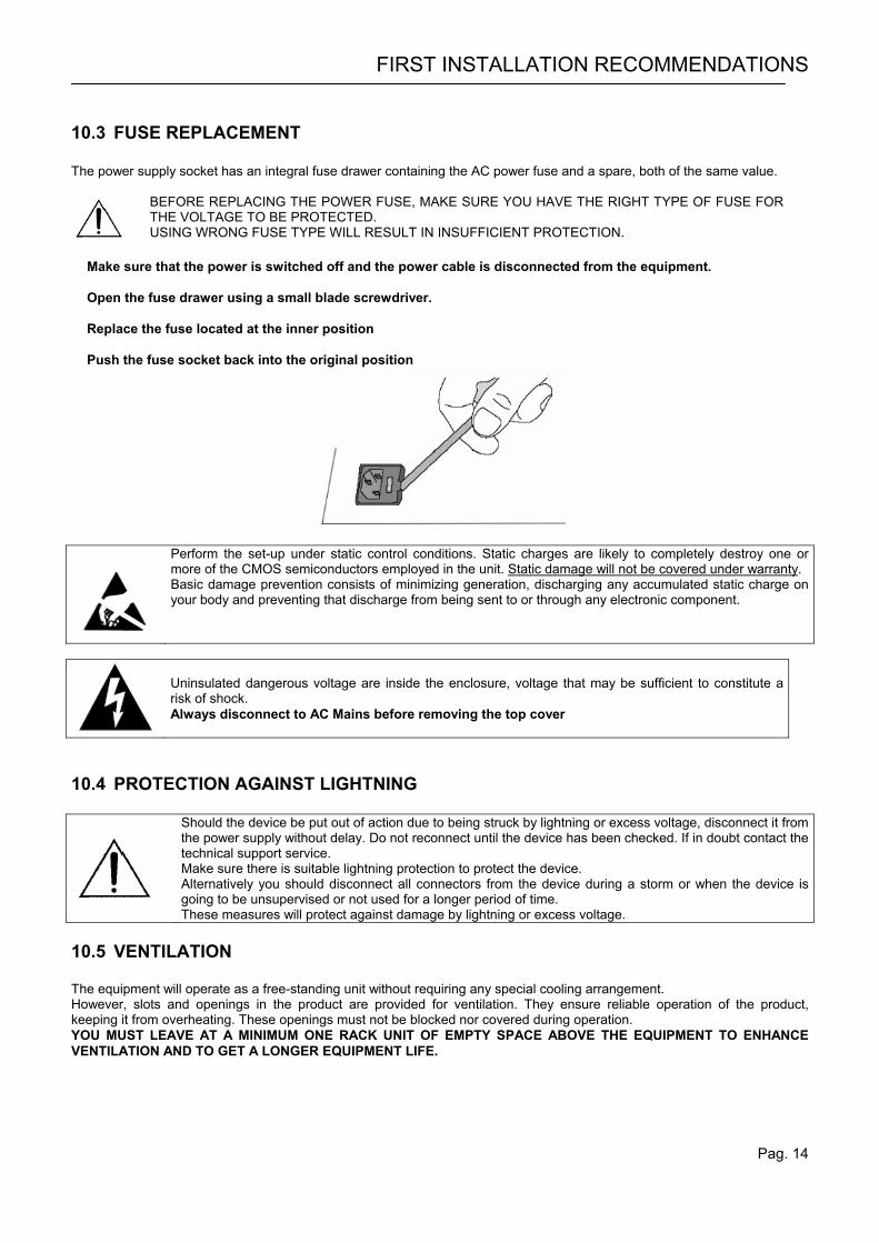
10.3 FUSE REPLACEMENT The power supply socket has an integral fuse drawer containing the AC power fuse and a spare, both of the same value.
BEFORE REPLACING THE POWER FUSE, MAKE SURE YOU HAVE THE RIGHT TYPE OF FUSE FOR THE VOLTAGE TO BE PROTECTED. USING WRONG FUSE TYPE WILL RESULT IN INSUFFICIENT PROTECTION.
Make sure that the power is switched off and the power cable is disconnected from the equipment. Open the fuse drawer using a small blade screwdriver. Replace the fuse located at the inner position Push the fuse socket back into the original position
Perform the set-up under static control conditions. Static charges are likely to completely destroy one or more of the CMOS semiconductors employed in the unit. Static damage will not be covered under warranty. Basic damage prevention consists of minimizing generation, discharging any accumulated static charge on your body and preventing that discharge from being sent to or through any electronic component.
Uninsulated dangerous voltage are inside the enclosure, voltage that may be sufficient to constitute a risk of shock. Always disconnect to AC Mains before removing the top cover
10.4 PROTECTION AGAINST LIGHTNING
Should the device be put out of action due to being struck by lightning or excess voltage, disconnect it from the power supply without delay. Do not reconnect until the device has been checked. If in doubt contact the technical support service. Make sure there is suitable lightning protection to protect the device. Alternatively you should disconnect all connectors from the device during a storm or when the device is going to be unsupervised or not used for a longer period of time. These measures will protect against damage by lightning or excess voltage.
10.5 VENTILATION The equipment will operate as a free-standing unit without requiring any special cooling arrangement. However, slots and openings in the product are provided for ventilation. They ensure reliable operation of the product, keeping it from overheating. These openings must not be blocked nor covered during operation. YOU MUST LEAVE AT A MINIMUM ONE RACK UNIT OF EMPTY SPACE ABOVE THE EQUIPMENT TO ENHANCE VENTILATION AND TO GET A LONGER EQUIPMENT LIFE.
Pag. 15
11 GENERAL EQUIPMENT DESCRIPTION
11.1 FRONT PANEL
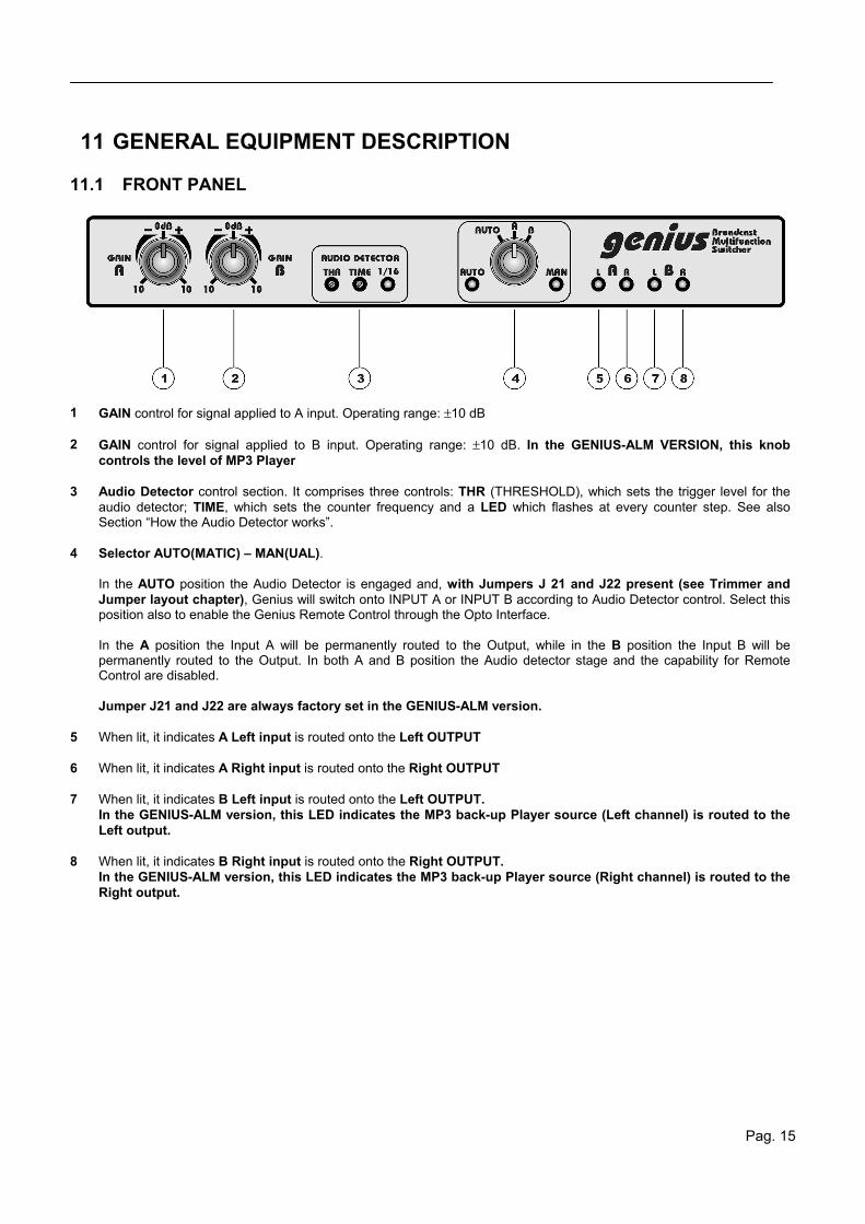
1 GAIN control for signal applied to A input. Operating range: ±10 dB 2 GAIN control for signal applied to B input. Operating range: ±10 dB. In the GENIUS-ALM VERSION, this knob
controls the level of MP3 Player 3 Audio Detector control section. It comprises three controls: THR (THRESHOLD), which sets the trigger level for the
audio detector; TIME, which sets the counter frequency and a LED which flashes at every counter step. See also Section “How the Audio Detector works”.
4 Selector AUTO(MATIC) – MAN(UAL).
In the AUTO position the Audio Detector is engaged and, with Jumpers J 21 and J22 present (see Trimmer and Jumper layout chapter), Genius will switch onto INPUT A or INPUT B according to Audio Detector control. Select this position also to enable the Genius Remote Control through the Opto Interface. In the A position the Input A will be permanently routed to the Output, while in the B position the Input B will be permanently routed to the Output. In both A and B position the Audio detector stage and the capability for Remote Control are disabled. Jumper J21 and J22 are always factory set in the GENIUS-ALM version.
5 When lit, it indicates A Left input is routed onto the Left OUTPUT 6 When lit, it indicates A Right input is routed onto the Right OUTPUT 7 When lit, it indicates B Left input is routed onto the Left OUTPUT.
In the GENIUS-ALM version, this LED indicates the MP3 back-up Player source (Left channel) is routed to the Left output.
8 When lit, it indicates B Right input is routed onto the Right OUTPUT.
In the GENIUS-ALM version, this LED indicates the MP3 back-up Player source (Right channel) is routed to the Right output.
GENERAL EQUIPMENT DESCRIPTION
Pag. 16
11.2 REAR PANEL
R RL LR R RL
L L L
B AOUT
Input-AOutput Input-B
R
1 3 2 1 3 2 132132132 132
Interface OptoSD Card
foldbackFoldbackFoldbackSerial Detect
1 2 3 4 5 6 7 8 9 10 11
1213
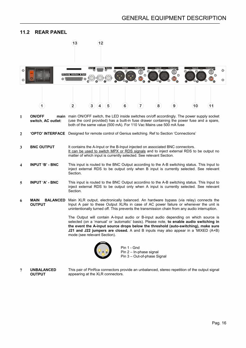
1 ON/OFF main
switch, AC outlet: main ON/OFF switch, the LED inside switches on/off accordingly. The power supply socket (use the cord provided) has a built-in fuse drawer containing the power fuse and a spare, both of the same value (500 mA). For 110 Vac Mains use 500 mA fuse
2 ‘OPTO’ INTERFACE Designed for remote control of Genius switching. Ref to Section ‘Connections’
3 BNC OUTPUT It contains the A-Input or the B-Input injected on associated BNC connectors.
It can be used to switch MPX or RDS signals and to inject external RDS to be output no matter of which input is currently selected. See relevant Section.
4 INPUT ‘B’ - BNC This input is routed to the BNC Output according to the A-B switching status. This Input to
inject external RDS to be output only when B input is currently selected. See relevant Section.
5 INPUT ‘A’ - BNC This input is routed to the BNC Output accordino to the A-B switching status. This Input to
inject external RDS to be output only when A input is currently selected. See relevant Section.
6 MAIN BALANCED
OUTPUT Main XLR output, electronically balanced. An hardware bypass (via relay) connects the Input A pair to these Output XLRs in case of AC power failure or whenever the unit is unintentionally turned off. This prevents the transmission chain from any audio interruption. The Output will contain A-Input audio or B-input audio depending on which source is selected (on a ‘manual’ or ‘automatic’ basis). Please note, to enable audio switching in the event the A-input source drops below the threshold (auto-switching), make sure J21 and J22 jumpers are closed. A and B inputs may also appear in a ‘MIXED (A+B) mode (see relevant Section).
1 3 2
Pin 1 - Gnd Pin 2 – In-phase signal Pin 3 – Out-of-phase Signal
7 UNBALANCED
OUTPUT This pair of PinRca connectors provide an unbalanced, stereo repetition of the output signal appearing at the XLR connectors.
GENERAL EQUIPMENT DESCRIPTION
Pag. 17
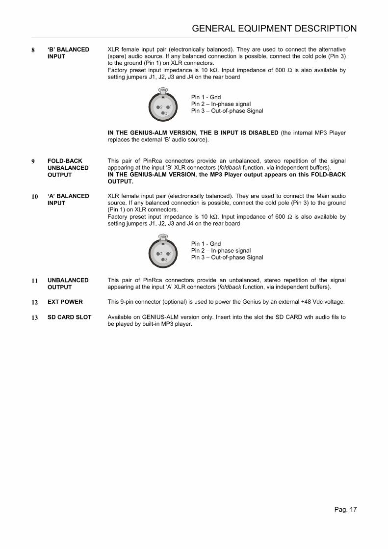
8 ‘B’ BALANCED INPUT
XLR female input pair (electronically balanced). They are used to connect the alternative (spare) audio source. If any balanced connection is possible, connect the cold pole (Pin 3) to the ground (Pin 1) on XLR connectors. Factory preset input impedance is 10 kΩ. Input impedance of 600 Ω is also available by setting jumpers J1, J2, J3 and J4 on the rear board
1
3
2
Pin 1 - Gnd Pin 2 – In-phase signal Pin 3 – Out-of-phase Signal
IN THE GENIUS-ALM VERSION, THE B INPUT IS DISABLED (the internal MP3 Player replaces the external ‘B’ audio source).
9 FOLD-BACK
UNBALANCED OUTPUT
This pair of PinRca connectors provide an unbalanced, stereo repetition of the signal appearing at the input ‘B’ XLR connectors (foldback function, via independent buffers). IN THE GENIUS-ALM VERSION, the MP3 Player output appears on this FOLD-BACK OUTPUT.
10 ‘A’ BALANCED
INPUT XLR female input pair (electronically balanced). They are used to connect the Main audio source. If any balanced connection is possible, connect the cold pole (Pin 3) to the ground (Pin 1) on XLR connectors. Factory preset input impedance is 10 kΩ. Input impedance of 600 Ω is also available by setting jumpers J1, J2, J3 and J4 on the rear board
1
3
2
Pin 1 - Gnd Pin 2 – In-phase signal Pin 3 – Out-of-phase Signal
11 UNBALANCED
OUTPUT This pair of PinRca connectors provide an unbalanced, stereo repetition of the signal appearing at the input ‘A’ XLR connectors (foldback function, via independent buffers).
12 EXT POWER This 9-pin connector (optional) is used to power the Genius by an external +48 Vdc voltage. 13 SD CARD SLOT Available on GENIUS-ALM version only. Insert into the slot the SD CARD wth audio fils to
be played by built-in MP3 player.
GENERAL EQUIPMENT DESCRIPTION
Pag. 18
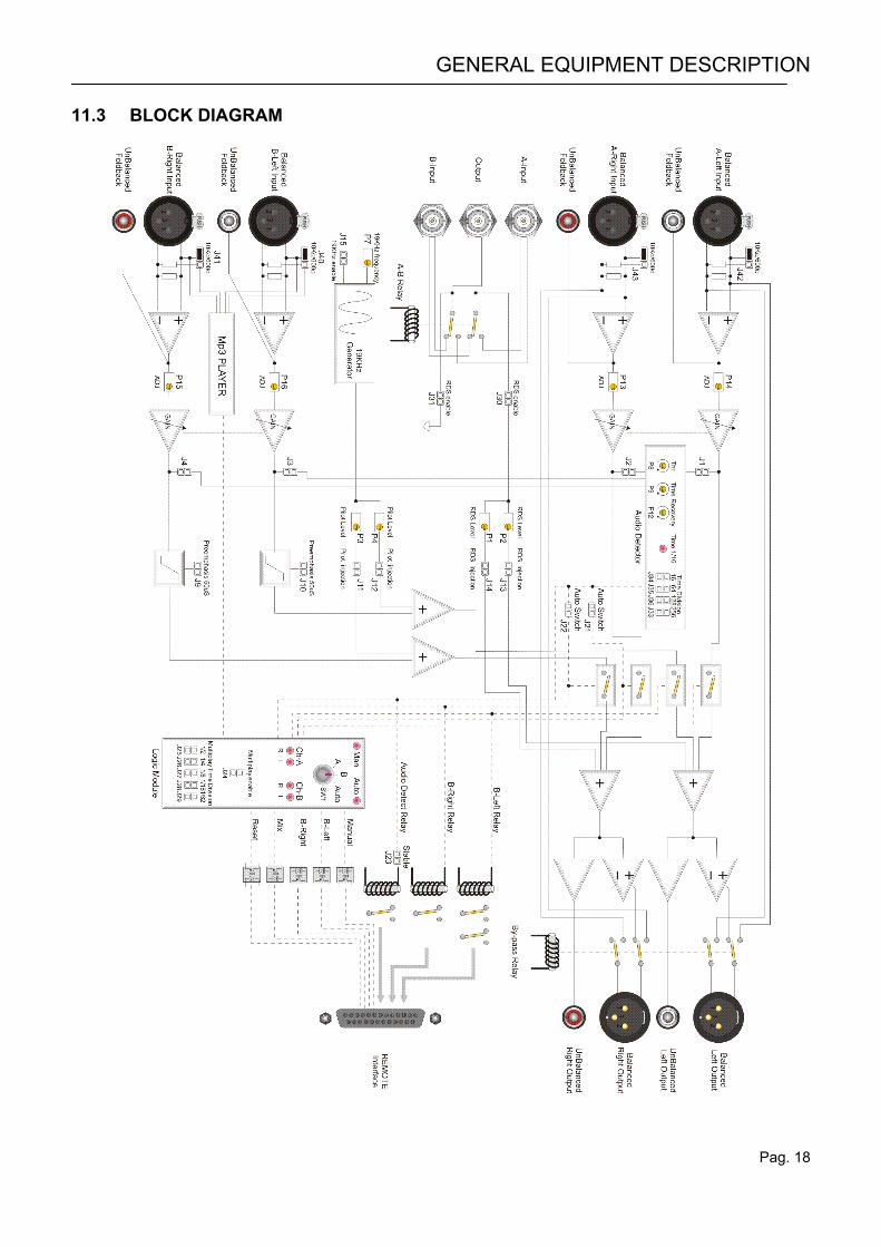
11.3 BLOCK DIAGRAM
BASIC AUDIO SETTINGS
Pag. 19
12 BASIC AUDIO SETTINGS
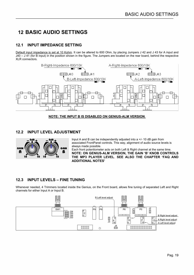
12.1 INPUT IMPEDANCE SETTING Default input impedance is set at 10 Kohm. It can be altered to 600 Ohm, by placing Jumpers J 42 and J 43 for A input and J40 – J 41 (for B input) in the position shown in the figure. The Jumpers are located on the rear board, behind the respective XLR connectors.
NOTE: THE INPUT B IS DISABLED ON GENIUS-ALM VERSION. 12.2 INPUT LEVEL ADJUSTMENT
Input A and B can be independently adjusted into a +/- 10 dB gain from associated FrontPanel controls. This way, alignment of audio source levels is always made possible. Each front potentiometer acts on both Left & Right channel at the same time. NOTE: ON GENIUS-ALM VERSION, THE GAIN ‘B’ KNOB CONTROLS THE MP3 PLAYER LEVEL. SEE ALSO THE CHAPTER ‘FAQ AND ADDITIONAL NOTES’
12.3 INPUT LEVELS – FINE TUNING Whenever needed, 4 Trimmers located inside the Genius, on the Front board, allows fine tuning of separated Left and Right channels for either Input A or Input B.
THE AUDIO DETECTOR STAGE
Pag. 20
13 THE AUDIO DETECTOR STAGE
13.1 HOW THE AUDIO DETECTOR WORKS Audio is monitored as a mono or a stereo signal. 4 Jumpers allow to choose which source will feed the Audio Detector stage (i.e. which source will be monitored by the Detector stage). Jumpers are J1, J2, J3 and J4 (see Block Diagram). By default, Jumpers J1 and J2 only are fitted (and thus Input A only is constantly monitored by the Detector). In the default configuration, should both Left and Right channels fall below the preset threshold (typically set to around -20dBu), the fail timer is started. If the fail time elapses without the signal recovering, then an alarm is triggered via an ‘Audio Detect Relay’ closure to alert the user. The relay closure may be Permanent or Momentary depending on J23 Jumper. With Jumpers J21 and J22 fitted, the alarm trigging will ba also associated, at the same time, to an audio input switching from Input A to Input B, where B represents a ‘Spare’ / Back-Up audio source. 4 LEDs on the Front Panel indicates the actual Channels (Input A – Left and/or Right and Input B- Left and/or Right) routed to the Output. When B Input is routed to the output, two optocouplers (B-Left and B-Right) close on the Remote Interface. Audio input switching from Input A to Input B also causes B-Left and B-Right relay to switch. Those contact closure may be used for external purposes (start to external devices, tallys, signalling, etc). As soon as the Main input is restored the Genius will revert to that and clear alarms and Relay closures. The restore (recovery) time for audio is generally factory pre-set at around 3 seconds, to ignore momentary levels above the threshold when re-connecting equipment.
INPUT A
OUTPUT
INPUT B
THR
Recovery time
Hold
Time Unit
Blank time
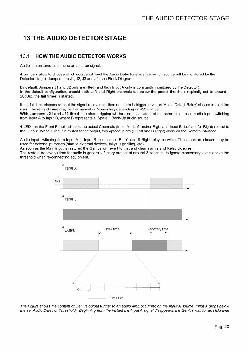
The Figure shows the content of Genius output further to an audio drop occurring on the Input A source (Input A drops below the set Audio Detector Threshold). Beginning from the instant the Input A signal disappears, the Genius wait for an Hold time
THE AUDIO DETECTOR STAGE
Pag. 21
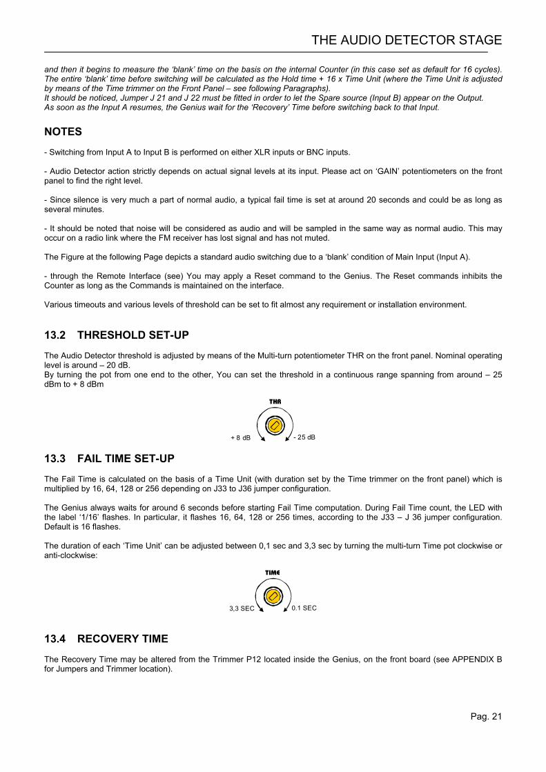
and then it begins to measure the ‘blank’ time on the basis on the internal Counter (in this case set as default for 16 cycles). The entire ‘blank’ time before switching will be calculated as the Hold time + 16 x Time Unit (where the Time Unit is adjusted by means of the Time trimmer on the Front Panel – see following Paragraphs). It should be noticed, Jumper J 21 and J 22 must be fitted in order to let the Spare source (Input B) appear on the Output. As soon as the Input A resumes, the Genius wait for the ‘Recovery’ Time before switching back to that Input. NOTES - Switching from Input A to Input B is performed on either XLR inputs or BNC inputs. - Audio Detector action strictly depends on actual signal levels at its input. Please act on ‘GAIN’ potentiometers on the front panel to find the right level. - Since silence is very much a part of normal audio, a typical fail time is set at around 20 seconds and could be as long as several minutes. - It should be noted that noise will be considered as audio and will be sampled in the same way as normal audio. This may occur on a radio link where the FM receiver has lost signal and has not muted. The Figure at the following Page depicts a standard audio switching due to a ‘blank’ condition of Main Input (Input A). - through the Remote Interface (see) You may apply a Reset command to the Genius. The Reset commands inhibits the Counter as long as the Commands is maintained on the interface. Various timeouts and various levels of threshold can be set to fit almost any requirement or installation environment. 13.2 THRESHOLD SET-UP The Audio Detector threshold is adjusted by means of the Multi-turn potentiometer THR on the front panel. Nominal operating level is around – 20 dB. By turning the pot from one end to the other, You can set the threshold in a continuous range spanning from around – 25 dBm to + 8 dBm
THR
+ 8 dB - 25 dB 13.3 FAIL TIME SET-UP The Fail Time is calculated on the basis of a Time Unit (with duration set by the Time trimmer on the front panel) which is multiplied by 16, 64, 128 or 256 depending on J33 to J36 jumper configuration. The Genius always waits for around 6 seconds before starting Fail Time computation. During Fail Time count, the LED with the label ‘1/16’ flashes. In particular, it flashes 16, 64, 128 or 256 times, according to the J33 – J 36 jumper configuration. Default is 16 flashes. The duration of each ‘Time Unit’ can be adjusted between 0,1 sec and 3,3 sec by turning the multi-turn Time pot clockwise or anti-clockwise:
TIME
3,3 SEC 0.1 SEC 13.4 RECOVERY TIME The Recovery Time may be altered from the Trimmer P12 located inside the Genius, on the front board (see APPENDIX B for Jumpers and Trimmer location).
AUXILIARY FUNCTIONS
Pag. 22
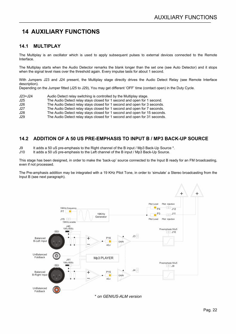
14 AUXILIARY FUNCTIONS 14.1 MULTIPLAY The Multiplay is an oscillator which is used to apply subsequent pulses to external devices connected to the Remote Interface. The Multiplay starts when the Audio Detector remarks the blank longer than the set one (see Auto Detector) and it stops when the signal level rises over the threshold again. Every impulse lasts for about 1 second. With Jumpers J23 and J24 present, the Multiplay stage directly drives the Audio Detect Relay (see Remote Interface description). Depending on the Jumper fitted (J25 to J29), You may get different ‘OFF’ time (contact open) in the Duty Cycle. J23+J24 Audio Detect relay switching is controlled by the Multiplay stage. J25 The Audio Detect relay stays closed for 1 second and open for 1 second. J26 The Audio Detect relay stays closed for 1 second and open for 3 seconds. J27 The Audio Detect relay stays closed for 1 second and open for 7 seconds. J28 The Audio Detect relay stays closed for 1 second and open for 15 seconds. J29 The Audio Detect relay stays closed for 1 second and open for 31 seconds. 14.2 ADDITION OF A 50 US PRE-EMPHASIS TO INPUT B / MP3 BACK-UP SOURCE J9 It adds a 50 uS pre-emphasis to the Right channel of the B input / Mp3 Back-Up Source *. J10 It adds a 50 uS pre-emphasis to the Left channel of the B input / Mp3 Back-Up Source. This stage has been designed, in order to make the ‘back-up’ source connected to the Input B ready for an FM broadcasting, even if not processed. The Pre-amphasis addition may be integrated with a 19 KHz Pilot Tone, in order to ‘simulate’ a Stereo broadcasting from the Input B (see next paragraph).
19KHz enable
19KHz frequency
Pilot Level
Pilot Level
Pilot injection
Pilot injection
J40
J15
P7P4 J12
P3 J11
J10
J9
P16
P15J4
J3
J41
BalancedB-Left Input
BalancedB-Right Input
UnBalancedFoldback Mp3 PLAYER
UnBalancedFoldback
Preemphasis 50uS
Preemphasis 50uS
132
132
10KΩ/600Ω
10KΩ/600Ω
ADJ
ADJ
GAIN
GAIN
19KHzGenerator
* on GENIUS-ALM version
AUXILIARY FUNCTIONS
Pag. 23
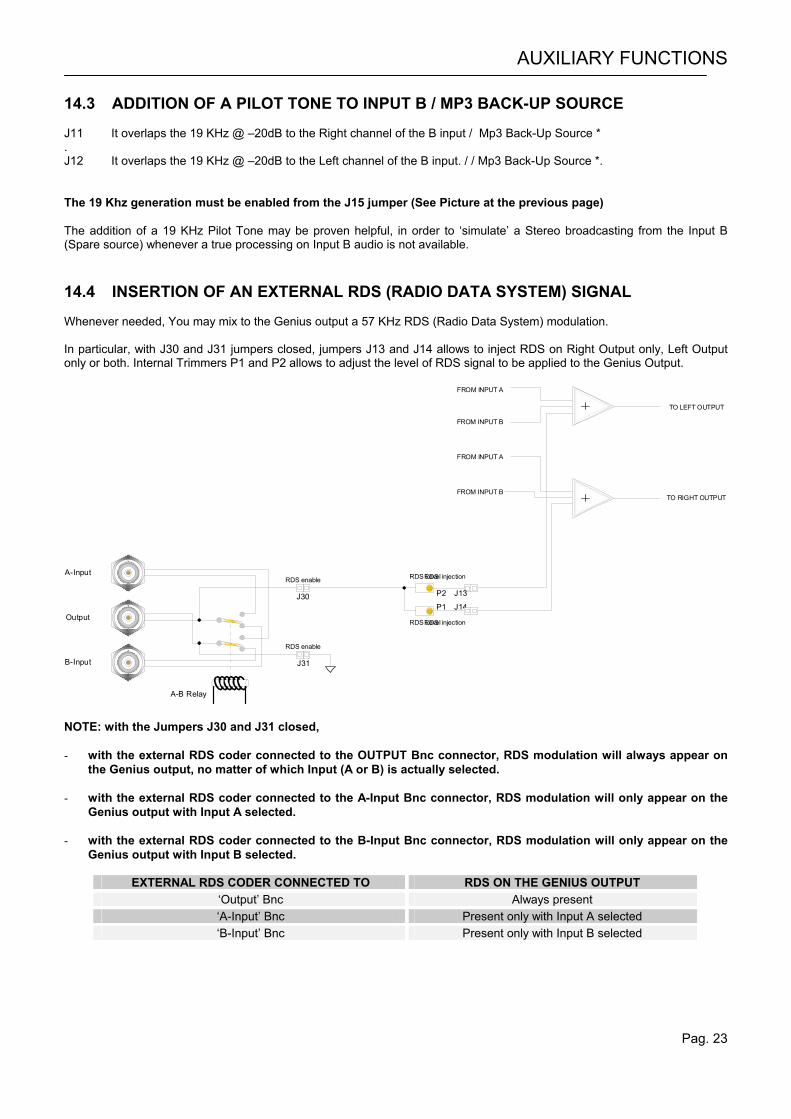
14.3 ADDITION OF A PILOT TONE TO INPUT B / MP3 BACK-UP SOURCE J11 It overlaps the 19 KHz @ –20dB to the Right channel of the B input / Mp3 Back-Up Source * . J12 It overlaps the 19 KHz @ –20dB to the Left channel of the B input. / / Mp3 Back-Up Source *. The 19 Khz generation must be enabled from the J15 jumper (See Picture at the previous page) The addition of a 19 KHz Pilot Tone may be proven helpful, in order to ‘simulate’ a Stereo broadcasting from the Input B (Spare source) whenever a true processing on Input B audio is not available. 14.4 INSERTION OF AN EXTERNAL RDS (RADIO DATA SYSTEM) SIGNAL Whenever needed, You may mix to the Genius output a 57 KHz RDS (Radio Data System) modulation. In particular, with J30 and J31 jumpers closed, jumpers J13 and J14 allows to inject RDS on Right Output only, Left Output only or both. Internal Trimmers P1 and P2 allows to adjust the level of RDS signal to be applied to the Genius Output.
A-B Relay
A-Input
B-Input
RDS enable
RDS enable
RDS Level
RDS Level
RDS injection
FROM INPUT A
TO LEFT OUTPUT
TO RIGHT OUTPUT
FROM INPUT A
FROM INPUT B
FROM INPUT B
RDS injectionOutput
P2 J13
J31
J30P1 J14
NOTE: with the Jumpers J30 and J31 closed, - with the external RDS coder connected to the OUTPUT Bnc connector, RDS modulation will always appear on
the Genius output, no matter of which Input (A or B) is actually selected. - with the external RDS coder connected to the A-Input Bnc connector, RDS modulation will only appear on the
Genius output with Input A selected. - with the external RDS coder connected to the B-Input Bnc connector, RDS modulation will only appear on the
Genius output with Input B selected.
EXTERNAL RDS CODER CONNECTED TO RDS ON THE GENIUS OUTPUT ‘Output’ Bnc Always present ‘A-Input’ Bnc Present only with Input A selected ‘B-Input’ Bnc Present only with Input B selected
AUXILIARY FUNCTIONS
Pag. 24
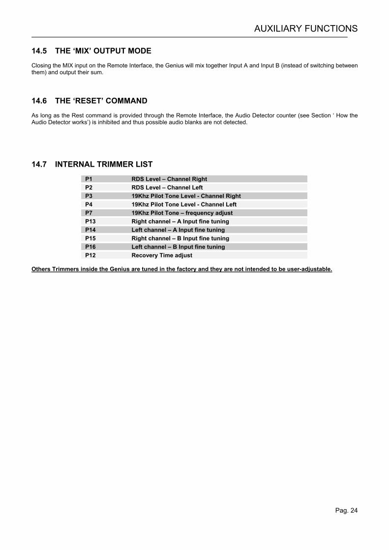
14.5 THE ‘MIX’ OUTPUT MODE Closing the MIX input on the Remote Interface, the Genius will mix together Input A and Input B (instead of switching between them) and output their sum. 14.6 THE ‘RESET’ COMMAND As long as the Rest command is provided through the Remote Interface, the Audio Detector counter (see Section ‘ How the Audio Detector works’) is inhibited and thus possible audio blanks are not detected. 14.7 INTERNAL TRIMMER LIST
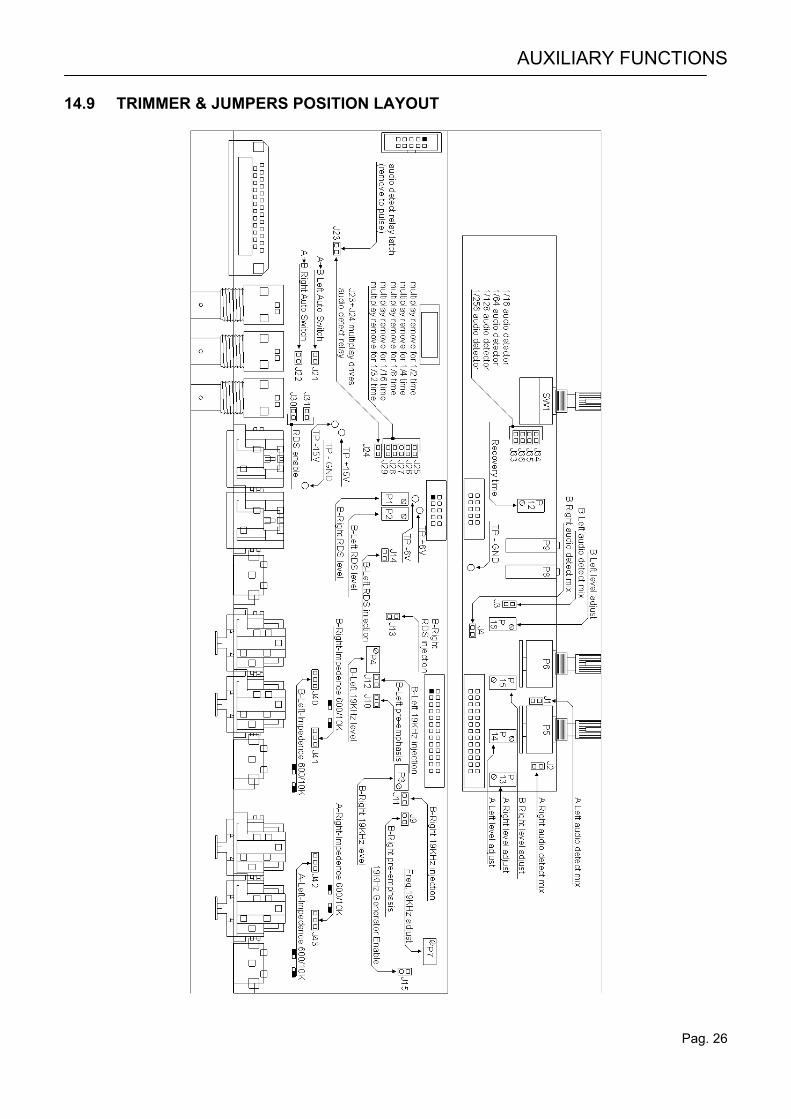
P1 RDS Level – Channel Right P2 RDS Level – Channel Left P3 19Khz Pilot Tone Level - Channel Right P4 19Khz Pilot Tone Level - Channel Left P7 19Khz Pilot Tone – frequency adjust P13 Right channel – A Input fine tuning P14 Left channel – A Input fine tuning P15 Right channel – B Input fine tuning P16 Left channel – B Input fine tuning P12 Recovery Time adjust
Others Trimmers inside the Genius are tuned in the factory and they are not intended to be user-adjustable.
AUXILIARY FUNCTIONS
Pag. 25
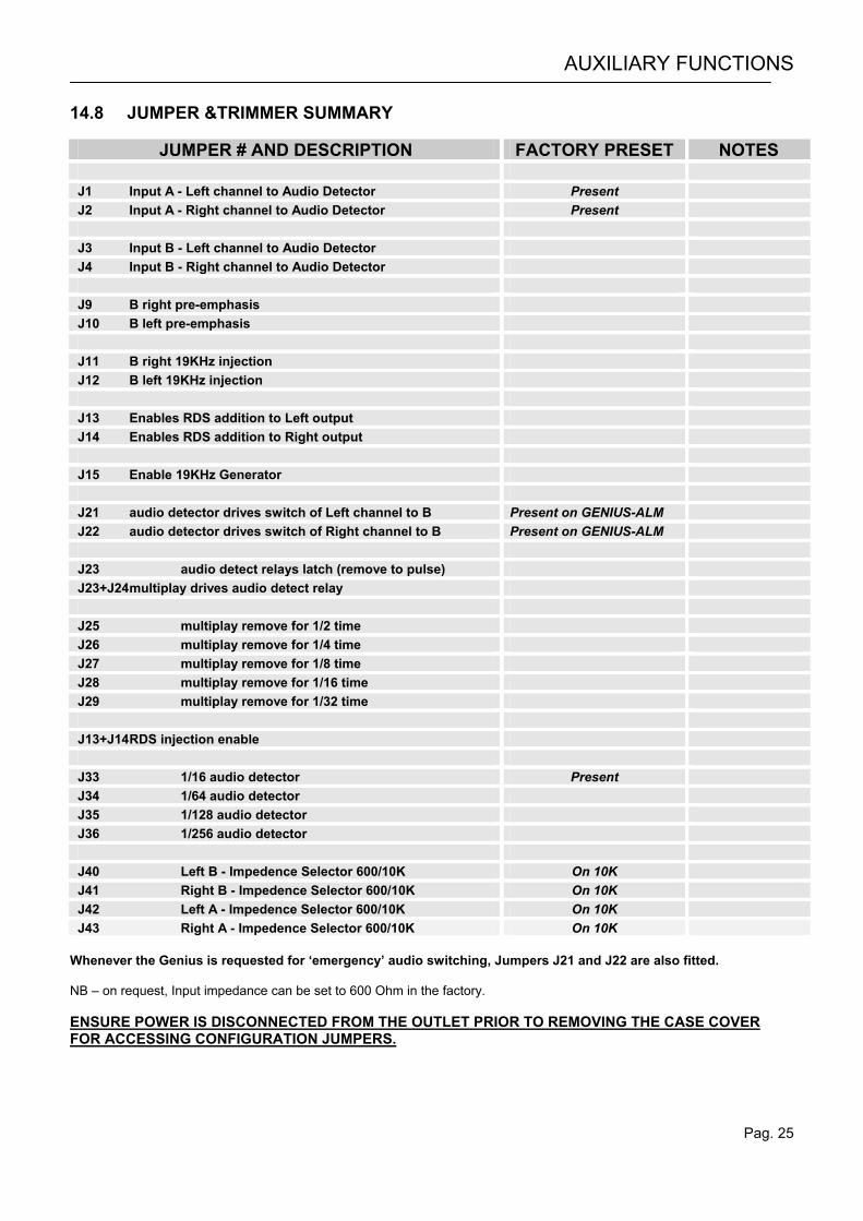
14.8 JUMPER &TRIMMER SUMMARY
JUMPER # AND DESCRIPTION FACTORY PRESET NOTES J1 Input A - Left channel to Audio Detector Present J2 Input A - Right channel to Audio Detector Present J3 Input B - Left channel to Audio Detector J4 Input B - Right channel to Audio Detector J9 B right pre-emphasis J10 B left pre-emphasis J11 B right 19KHz injection J12 B left 19KHz injection J13 Enables RDS addition to Left output J14 Enables RDS addition to Right output J15 Enable 19KHz Generator J21 audio detector drives switch of Left channel to B Present on GENIUS-ALM J22 audio detector drives switch of Right channel to B Present on GENIUS-ALM J23 audio detect relays latch (remove to pulse) J23+J24 multiplay drives audio detect relay J25 multiplay remove for 1/2 time J26 multiplay remove for 1/4 time J27 multiplay remove for 1/8 time J28 multiplay remove for 1/16 time J29 multiplay remove for 1/32 time J13+J14 RDS injection enable J33 1/16 audio detector Present J34 1/64 audio detector J35 1/128 audio detector J36 1/256 audio detector J40 Left B - Impedence Selector 600/10K On 10K J41 Right B - Impedence Selector 600/10K On 10K J42 Left A - Impedence Selector 600/10K On 10K J43 Right A - Impedence Selector 600/10K On 10K
Whenever the Genius is requested for ‘emergency’ audio switching, Jumpers J21 and J22 are also fitted. NB – on request, Input impedance can be set to 600 Ohm in the factory. ENSURE POWER IS DISCONNECTED FROM THE OUTLET PRIOR TO REMOVING THE CASE COVER FOR ACCESSING CONFIGURATION JUMPERS.
AUXILIARY FUNCTIONS
Pag. 26
14.9 TRIMMER & JUMPERS POSITION LAYOUT
INTERFACE AND PORT DESCRIPTION
Pag. 27
15 INTERFACE AND PORT DESCRIPTION
15.1 REMOTE INTERFACE DESCRIPTION
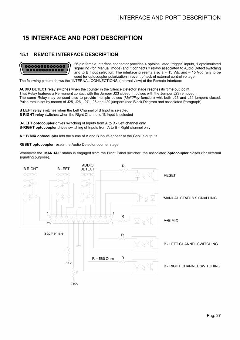
25-pin female Interface connector provides 4 optoinsulated “trigger” inputs, 1 optoinsulated signalling (for ‘Manual’ mode) and it connects 3 relays associated to Audio Detect switching and to B Input selection. The interface presents also a + 15 Vdc and – 15 Vdc rails to be used for optocoupler polarization in event of lack of external control voltage.
The following picture shows the ‘INTERNAL CONNECTIONS’ (Internal view) of the Remote Interface: AUDIO DETECT relay switches when the counter in the Silence Detector stage reaches its ‘time out’ point. That Relay features a Permanent contact with the Jumper J23 closed. It pulses with the Jumper J23 removed. The same Relay may be used also to provide multiple pulses (MultiPlay function) whit both J23 and J24 jumpers closed. Pulse rate is set by means of J25, J26, J27, J28 and J29 jumpers (see Block Diagram and associated Paragraph) B LEFT relay switches when the Left Channel of B Input is selected B RIGHT relay switches when the Right Channel of B Input is selected B-LEFT optocoupler drives switching of Inputs from A to B - Left channel only B-RIGHT optocoupler drives switching of Inputs from A to B - Right channel only A + B MIX optocoupler lets the sume of A and B inputs appear at the Genius outputs. RESET optocoupler resets the Audio Detector counter stage Whenever the ‘MANUAL’ status is engaged from the Front Panel switcher, the associated optocoupler closes (for external signaling purpose).
R = 560 Ohm
R
R
R
R
113
25 14
AUDIO DETECTB LEFTB RIGHT
‘MANUAL’ STATUS SIGNALLING
RESET
A+B MIX
B - LEFT CHANNEL SWITCHING
B - RIGHT CHANNEL SWITCHING
25p Female
+ 15 V
- 15 V

INTERFACE AND PORT DESCRIPTION
Pag. 28
Pin 1 MANUAL Status signalling (Emitter of optocoupler) Pin 2 MANUAL Status signalling (Collector of optocoupler) Pin 3 Time counter RESET - optocoupled command (Anode) Pin 4 Time counter RESET - optocoupled command (Cathode) Pin 5 Audio Detect relay COMMON Pin 6 Audio Detect relay NORMALLY CLOSED Pin 7 Audio Detect relay NORMALLY OPEN Pin 8 B Input selected – Left channel - 1° Relay contact NORMALLY OPEN Pin 9 B Input selected – Left channel - 1° Relay contact NORMALLY CLOSED Pin 10 B Input selected – Left channel - 1° Relay contact COMMON Pin 11 B Input selected – Left channel - 2° Relay contact COMMON Pin 12 B Input selected – Left channel - 2° Relay contact NORMALLY CLOSED Pin 13 B Input selected – Left channel - 2° Relay contact NORMALY OPEN Pin 14 A+B MIX – optocoupled command (Anode) Pin 15 A+B MIX – optocoupled command (Cathode) Pin 16 A to B Left channel switching - optocoupled command (Anode) Pin 17 A to B Left channel switching - optocoupled command (Cathode) Pin 18 A to B Right channel switching - optocoupled command (Anode) Pin 19 A to B Right channel switching - optocoupled command (Cathode) Pin 20 GND Pin 21 +15Vcc Pin 22 –15Vcc Pin 23 B Input selected – Right channel Relay NORMALLY OPEN Pin 24 B Input selected – Right channel Relay NORMALLY CLOSED Pin 25 B Input selected – Right channel Relay COMMON For a correct polarization, max current allowed on Optocoupler is 10 mA. Nominal: 5 mA. Current-limited + / - 15Vdc source is available on pins 21 and 22. 15.2 EXTERNAL + 48 VOLT INTERFACE (optional)
An optional 9-pin Male DB9 connector is fitted on the rear panel, in order to power the Genius by an external + 48 Vdc voltage. For easier connection, Pins from 1 to 5 are internally short-circuited. They must be connected to the GROUND of external power supply. Pins from 6 to 9 are also internally shortcircuited. They must be connected to the POSITIVE RAIL of external power supply
Pin 1, 2, 3, 4, 5 GND Pin 6, 7, 8, 9 + 48 Vdc
1
6
5
9

FAQS AND ADDITIONAL NOTES ON BACK-UP MP3 PLAYER
Pag. 29
16 FAQS AND ADDITIONAL NOTES ON BACK-UP MP3 PLAYER
Featuring an optional, internal MP3 reader (see GENIUS-ALM version) as back-up audio source, the GENIUS allows to overcome any ‘blank’ or silence time in radio broadcasting. As soon as main audio lacks on INPUT ‘A’, the GENIUS waits for the pre-set ‘silence time’ before switching over the internal Mp3 Back-Up audio source. When main audio resumes, the GENIUS switches back over the INPUT ‘A’ source. Audio files contained on the SD CARD are played in a sequenced mode and sequence restarts every time the GENIUS switches on that back-up source.
Q1: when playing Mp3 audio material from the SD card, the Genius output level is much more lower than when routing the input ‘A’ to the output
A. Make sure of the following elements:
- the Gain B knob on the front panel is turned to its max - the audio files on the SD Card have been normalized, i.e. automatically adjusted to their max level - the audio files on the SD Card are already processed - A source is not saturing Input A Q2: when playing Mp3 audio material from the SD card, audio quality at the Genius output is worst than when selecting Input A
A. Make sure the Played files are recorded @ 128 kbit/sec at least. Avoid to use very low bt-rate
files.
Q3: which files can be played? A: the Genius plays MP3, WAV, PCM files. It also supports variable bit rate for MP3
Q4: which is the max size for the memory Card supported? A: 2 Gigabyte card (standard SD-Type)
TECHNICAL SPECIFICATIONS
Pag. 30
17 TECHNICAL SPECIFICATIONS
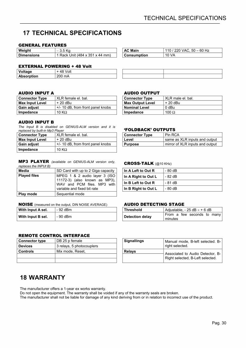
GENERAL FEATURES Weight ∼ 3.5 Kg AC Main 110 / 220 VAC, 50 – 60 Hz Dimensions 1 Rack Unit (484 x 351 x 44 mm) Consumption 10 VA
EXTERNAL POWERING + 48 Volt Voltage + 48 Volt Absorption 200 mA
AUDIO INPUT A AUDIO OUTPUT Connector Type XLR female el. bal. Connector Type XLR male el. bal. Max Input Level + 20 dBu Max Output Level + 20 dBu Gain adjust +/- 10 dB, from front panel knobs Nominal Level 0 dBu Impedance 10 KΩ Impedance 100 Ω AUDIO INPUT B The Input B is disabled on GENIUS-ALM version and it is replaced by built-in Mp3 Player
‘FOLDBACK’ OUTPUTS Connector Type XLR female el. bal. Connector Type Pin RCA Max Input Level + 20 dBu Level same as XLR inputs and output Gain adjust +/- 10 dB, from front panel knobs Purpose mirror of XLR inputs and output Impedance 10 KΩ MP3 PLAYER (available on GENIUS-ALM version only, replaces the INPUt B)
CROSS-TALK (@10 KHz)
Media SD Card with up to 2 Giga capacity In A Left to Out R - 80 dB In A Right to Out L - 82 dB
In B Left to Out R - 81 dB
Played files MPEG 1 & 2 audio layer 3 (ISO 11172-3) (also known as MP3), WAV and PCM files. MP3 with variable and fixed bit rate
In B Right to Out L - 80 dB Play mode Sequential mode NOISE (measured on the output, DIN NOISE AVERAGE) AUDIO DETECTING STAGE With Input A sel. - 92 dBm Threshold Adjustable, - 25 dB ÷ + 6 dB
With Input B sel. - 90 dBm Detection delay From a few seconds to many minutes
REMOTE CONTROL INTERFACE Connector type DB 25 p female Signallings Devices 3 relays, 5 photocouplers
Manual mode, B-left selected. B-right selected.
Controls Mix mode, Reset, Relays
Associated to Audio Detector, B-Right selected, B-Left selected.
18 WARRANTY The manufacturer offers a 1-year ex works warranty. Do not open the equipment. The warranty shall be voided if any of the warranty seals are broken. The manufacturer shall not be liable for damage of any kind deriving from or in relation to incorrect use of the product.