Experiment Guide For Development Board MTK V15-6 - Star ...
123
STAR ENGINEERING TRAINING AND DEVELOPMENT UNIT Experiment Guide For Development Board MTK V15-6 8-bit AVR, 8051 and PIC Microcontrollers Star Engineering Team 6/15/2015 Contact Details Stars Team: Supervision: Asst. Prof. M. Farhan Khan (PhD, in progress)… +923332156027 Programming/ Testing: Naveed Ahmed (DAE)…………………………………… +923343311436 Programming/ Testing: Muhammad Haris (BE)………………………………… +923232705044 PCB Designing: Ikram Ansari (DAE)……………………………………… +923453101574 Hardware: M. Zeeshan Raza Khan………………………………… +923312020243 Study of Microcontrollers is essential for the students of Electrical Engineering and all related fields. Microcontrollers provide a way for home, environment and industrial Automation. 40 pin 8-bit AVR, 8051 and PIC Microcontrollers are provided separately on development board with their basic hardware like crystal oscillator, in-system programming port and power supply etc. Peripherals are also given separately so that user may connect any on-board peripheral with any available Microcontroller using jumper wires.
-
Upload
khangminh22 -
Category
Documents
-
view
0 -
download
0
Transcript of Experiment Guide For Development Board MTK V15-6 - Star ...

STAR ENGINEERING TRAINING AND DEVELOPMENT UNIT
Experiment Guide For Development Board
MTK V15-6 8-bit AVR, 8051 and PIC Microcontrollers
Star Engineering Team
6/15/2015
Contact Details Stars Team: Supervision: Asst. Prof. M. Farhan Khan (PhD, in progress)… +923332156027 Programming/ Testing: Naveed Ahmed (DAE)…………………………………… +923343311436 Programming/ Testing: Muhammad Haris (BE)………………………………… +923232705044 PCB Designing: Ikram Ansari (DAE)……………………………………… +923453101574 Hardware: M. Zeeshan Raza Khan………………………………… +923312020243
Study of Microcontrollers is essential for the students of Electrical Engineering and all related fields. Microcontrollers provide a way for home, environment and industrial Automation. 40 pin 8-bit AVR, 8051 and PIC Microcontrollers are provided separately on development board with their basic hardware like crystal oscillator, in-system programming port and power supply etc. Peripherals are also given separately so that user may connect any on-board peripheral with any available Microcontroller using jumper wires.

1 Star Engineering Training and Development Unit For feedbacks and queries contact at +923332156027 or email: [email protected]
Contents 1 Hardware Details MTK V15-6 ......................................................................................................... 5
1.1 Schematic ............................................................................................................................... 5
1.2 Board Layout .......................................................................................................................... 6
1.3 Printed Circuit Board .............................................................................................................. 7
1.3.1 Top view ......................................................................................................................... 7
............................................................................................................................................................ 7
1.3.2 Bottom view ................................................................................................................... 8
1.4 Soldered Board MTK V15-6 .................................................................................................... 9
1.4.1 Unpowered Board .......................................................................................................... 9
1.4.2 Powered Board ............................................................................................................. 10
1.5 Component List .................................................................................................................... 11
1.6 Hardware Blocks MTK V15-6 ................................................................................................ 14
1.6.1 Power Supply, Reset and Crystal .................................................................................. 14
1.6.2 PIC, AVR and 8051 based Microcontrollers .................................................................. 14
1.6.3 4-Digit Multiplexed Common Anode 7 Segment Display ............................................. 15
1.6.4 LCD Display Module ...................................................................................................... 16
1.6.5 8-bit LED Bar Graph Display (Indicators) ...................................................................... 16
1.6.6 Stepper Motor Driver ................................................................................................... 17
1.6.7 On-Board A to D Converter ADC0831........................................................................... 18
1.6.8 RS232 Line Driver for UART .......................................................................................... 18
1.6.9 DC Motor Driver H-Bridge L293D ................................................................................. 19
1.6.10 4 SPDT Relays and Drivers ............................................................................................ 20
1.6.11 8x8 Dot Matrix Display ................................................................................................. 21
2 Tutorial for 8051 ........................................................................................................................... 22
3 Tutorial for AVR ............................................................................................................................ 30
4 Tutorial for PIC16F877 .................................................................................................................. 37
5 Program Burning/ Downloading for AVR and 8051 ..................................................................... 41
6 Program Burning/ Downloading for PIC ....................................................................................... 44
7 Practical ........................................................................................................................................ 48
7.1 Practical No. 1 (Check Signal Key)Increase/Decrease a single binary count on the LEDs at port as shown in hardware connection when a button at port as shown in hardware connection is pressed. ............................................................................................................................................ 48
7.1.1 Hardware Connections: ................................................................................................ 48
7.1.2 Apparatus: .................................................................................................................... 48

2 Star Engineering Training and Development Unit For feedbacks and queries contact at +923332156027 or email: [email protected]
7.1.3 Algorithm & Flow Chart: .............................................................................................. 48
7.1.4 AVR Program C Code: ................................................................................................... 49
7.1.5 8051 Program C Code: ................................................................................................. 50
7.1.6 PIC Program C Code: .................................................................................................... 51
7.1.7 Exercise: ....................................................................................................................... 52
7.1.8 Conclusion: ................................................................................................................... 52
7.2 Practical No. 2 (Stepper Motor Control System) ................................................................. 53
7.2.1 Hardware Connections: ............................................................................................... 53
7.2.2 Apparatus: .................................................................................................................... 53
7.2.3 Algorithm ..................................................................................................................... 53
7.2.4 AVR Program C Code: ................................................................................................... 54
7.2.5 8051 Program C Code: ................................................................................................. 55
7.2.6 PIC Program C Code: .................................................................................................... 56
7.2.7 Exercise: ....................................................................................................................... 58
7.2.8 Conclusion: ................................................................................................................... 58
7.3 Practical No. 3 (4-Digit Multiplexed 7-Segment Led Driver) Generate pattern in increasing/ decreasing order on 4-digit multiplexed 7-segment display when a button at port as shown in hardware connection is pressed. Set the counting speed of 2 counts per second. ........................ 59
7.3.1 Hardware Connections: ............................................................................................... 59
7.3.2 Apparatus: .................................................................................................................... 59
7.3.3 Algorithm ..................................................................................................................... 59
7.3.4 AVR Program C Code: ................................................................................................... 60
7.3.5 8051 Program C Code: ................................................................................................. 62
7.3.6 PIC Program C Code: .................................................................................................... 65
7.3.7 Exercise: ....................................................................................................................... 68
7.3.8 Conclusion: ................................................................................................................... 68
7.4 Practical No. 4 (uart_lcd_counting) ..................................................................................... 69
7.4.1 Hardware Connections: ............................................................................................... 69
7.4.2 Apparatus: .................................................................................................................... 69
7.4.3 Algorithm ..................................................................................................................... 69
7.4.4 AVR Program C Code: ................................................................................................... 70
7.4.5 8051 Program C Code: ................................................................................................. 70
7.4.6 PIC Program C Code: .................................................................................................... 74
7.4.7 Exercise: ....................................................................................................................... 74
7.4.8 Conclusion: ................................................................................................................... 74

3 Star Engineering Training and Development Unit For feedbacks and queries contact at +923332156027 or email: [email protected]
7.5 Practical No. 5 (uart_Stringreqst)User press 1, 2, 3, 4 button from keyboard on pc set with baud rate 9600, lcd show massages with respect to number user enter from keyboard. .............. 75
7.5.1 Hardware Connections: ................................................................................................ 75
7.5.2 Apparatus: .................................................................................................................... 75
7.5.3 Algorithm ...................................................................................................................... 76
7.5.4 AVR Program C Code: ................................................................................................... 77
7.5.5 8051 Program C Code: .................................................................................................. 78
7.5.6 PIC Program C Code: ..................................................................................................... 81
7.5.7 Exercise: ........................................................................................................................ 82
7.5.8 Conclusion: ................................................................................................................... 83
7.6 Practical No. 6 (UART DC motor).Use UART with baud rate of 9600bps to receive the speed level (0-9) for a DC Motor from Hyper Terminal. Drive a DC Motor through PWM using timer zero according to received speed level. Also acknowledge by reflecting the received character. .......... 84
7.6.1 Hardware Connections: ................................................................................................ 84
7.6.2 Apparatus: .................................................................................................................... 84
7.6.3 Algorithm ...................................................................................................................... 84
7.6.4 AVR Program C Code: ................................................................................................... 85
7.6.5 8051 Program C Code: .................................................................................................. 85
7.6.6 PIC Program C Code: ..................................................................................................... 87
7.6.7 Exercise: ........................................................................................................................ 88
7.6.8 Conclusion: ................................................................................................................... 88
7.7 Practical NO. 7(Dot Matrix Display) Display 0-9 counting on dot matrix display interface via port as shown in hardware connection and port as shown in hardware connection using timer interrupt refresh the display in 2ms. ................................................................................................ 89
7.7.1 Hardware Connections: ................................................................................................ 89
7.7.2 Apparatus: .................................................................................................................... 89
7.7.3 Algorithm ...................................................................................................................... 90
7.7.4 AVR Program C Code: ................................................................................................... 91
7.7.5 8051 Program C Code: .................................................................................................. 92
7.7.6 PIC Program C Code: ..................................................................................................... 95
7.7.7 Exercise: ........................................................................................................................ 97
7.7.8 Conclusion: ................................................................................................................... 97
7.8 Practical No. 8 (Filling Bottle) ............................................................................................... 98
7.8.1 Hardware Connections: ................................................................................................ 98
7.8.2 Apparatus: .................................................................................................................... 98
7.8.3 Algorithm ...................................................................................................................... 99

4 Star Engineering Training and Development Unit For feedbacks and queries contact at +923332156027 or email: [email protected]
7.8.4 AVR Program C Code: ................................................................................................. 100
7.8.5 8051 Program C Code: ............................................................................................... 101
7.8.6 PIC Program C Code: .................................................................................................. 105
7.8.7 Exercise: ..................................................................................................................... 106
7.8.8 Conclusion: ................................................................................................................. 106
7.9 Practical No. 9(ADC_UART_LCD) Display the equivalent decimal of ADC input on the LCD module and also send this value through UART with Baud Rate=9600bps................................... 107
7.9.1 Hardware Connections: ............................................................................................. 107
7.9.2 Apparatus: .................................................................................................................. 107
7.9.3 Algorithm ................................................................................................................... 108
7.9.4 AVR Program C Code: ................................................................................................. 108
7.9.5 8051 Program C Code: ............................................................................................... 110
7.9.6 PIC Program C Code: .................................................................................................. 114
7.9.7 Exercise: ..................................................................................................................... 116
7.9.8 Conclusion: ................................................................................................................. 116
7.10 Practical No.10 (Frequency Counter) ................................................................................. 117
7.10.1 Hardware Connections: ............................................................................................. 117
7.10.2 Apparatus: .................................................................................................................. 117
7.10.3 Algorithm ................................................................................................................... 117
7.10.4 AVR Program C Code: ................................................................................................. 118
7.10.5 8051 Program C Code: ............................................................................................... 118
7.10.6 PIC Program C Code: .................................................................................................. 122
7.10.7 Exercise: ..................................................................................................................... 122
7.10.8 Conclusion: ................................................................................................................. 122

5 Star Engineering Training and Development Unit For feedbacks and queries contact at +923332156027 or email: [email protected]
1 Hardware Details MTK V15-6
1.1 Schematic

6 Star Engineering Training and Development Unit For feedbacks and queries contact at +923332156027 or email: [email protected]
1.2 Board Layout

7 Star Engineering Training and Development Unit For feedbacks and queries contact at +923332156027 or email: [email protected]
1.3 Printed Circuit Board
1.3.1 Top view

8 Star Engineering Training and Development Unit For feedbacks and queries contact at +923332156027 or email: [email protected]
1.3.2 Bottom view
9 Star Engineering Training and Development Unit For feedbacks and queries contact at +923332156027 or email: [email protected]
1.4 Soldered Board MTK V15-6
1.4.1 Unpowered Board

10 Star Engineering Training and Development Unit For feedbacks and queries contact at +923332156027 or email: [email protected]
1.4.2 Powered Board

11 Star Engineering Training and Development Unit For feedbacks and queries contact at +923332156027 or email: [email protected]
1.5 Component List
LABEL PART
NUMBER
NAME/SPACIFICATION PACKAGE
U1 ATMEGA16 Microcontroller 40pin PDIP U2 AT89S52 Microcontroller 40pin PDIP
U3 PIC16F877A Microcontroller 40pin PDIP U4 Bridge 4pin 2A
U5 ,U13 LM7805 Voltage Regulator
U6 ULN2003 IC 16pin U7 ADC0831 External ADC 8pin
U8 MAX232 IC 16pin U9 L293D IC H Bridge 16pin
U10 ,U11 ULN2803 IC 18pin
Q1,Q2,Q3,Q4 C1815 Transistor PNP Q5,Q6,Q7,Q8 A1015 Transistor PNP
LCD Module 16*2 7 Segment Common
Anode Dot-matrix
DB9FC DB 9 Female Connector R/A 9 Pin RLY1RLY2 RLY3RL4
Relay 12Volt
CON1,CON2 Crimp Shell Connector 5 pin
CON 3,CON4 Crimp Shell Connector 6 pin
CON7,CON8, CON9,CON10, CON11,CON12, CON13,CON14, CON15,CON16, CON17,CON5
Crimp Shell Connector 2 pin
VER 5k Multi turn pot
HD1,HD2,HD3, HD4,HD5,HD6, HD7,HD8,HD11 ,HD12,HD13, HD15,HD17
Single Line Header Male 8pin

12 Star Engineering Training and Development Unit For feedbacks and queries contact at +923332156027 or email: [email protected]
HD21,HD22
HD10,HD14, HD25,HD18
Single Line Header Male 4pin
HD9,HD26 Single Line Header Male 7pin HD20,HD24, HD19
Single Line Header Male 3pin
HD16 Single Line Header Male 16pin
D1,D2,D3,D4, 1N4007 Diodes D9,D10 1N4148 Diodes
D5,D6,D7,D8, 1N5408 Diodes
XTL1,XTL2, XTL3
11.0592MH Crystal
LED2,LED3, LED4 ,LED5
GREEN
LED6 ,LED1 RED SW1,SW2,SW3 SW3,SW4,SW5 SW6,SW7
Micro Switch
C4,C5,C6,C7, C8,C9
22 µf Capacitor Non Polar
C10C11C12 C13
10 µf Capacitor Polar
C3C15 470 µf Capacitor Polar C1C14 1000 µf Capacitor Polar
R1,R2,R3,R4, R5,R6,R7,R8, R9,R10,R11, R12,R13,R27, R40
R 1KΩ Resistances 1/4Watt
R14,R15,R16, R17,R18,R19, R20,R21
330Ω Resistances 1/4Watt
R22,R23,R24, R25
15KΩ Resistances 1/4Watt
R28,R29,R30, R31
15KΩ Resistances 1/4Watt
13 Star Engineering Training and Development Unit For feedbacks and queries contact at +923332156027 or email: [email protected]
R32,R33,R34, R35,R36,R37, R38,R39
330Ω Resistances 1/4Watt
R42 470Ω Resistances 1/4Watt
R26,R41 4.7KΩ Resistances 1/4Watt
CON18 Terminal Block R/A 2pin

14 Star Engineering Training and Development Unit For feedbacks and queries contact at +923332156027 or email: [email protected]
1.6 Hardware Blocks MTK V15-6
1.6.1 Power Supply, Reset and Crystal
1.6.2 PIC, AVR and 8051 based Microcontrollers

15 Star Engineering Training and Development Unit For feedbacks and queries contact at +923332156027 or email: [email protected]
1.6.3 4-Digit Multiplexed Common Anode 7 Segment Display

16 Star Engineering Training and Development Unit For feedbacks and queries contact at +923332156027 or email: [email protected]
1.6.4 LCD Display Module
1.6.5 8-bit LED Bar Graph Display (Indicators)

17 Star Engineering Training and Development Unit For feedbacks and queries contact at +923332156027 or email: [email protected]
1.6.6 Stepper Motor Driver

18 Star Engineering Training and Development Unit For feedbacks and queries contact at +923332156027 or email: [email protected]
1.6.7 On-Board A to D Converter ADC0831
1.6.8 RS232 Line Driver for UART

19 Star Engineering Training and Development Unit For feedbacks and queries contact at +923332156027 or email: [email protected]
1.6.9 DC Motor Driver H-Bridge L293D

20 Star Engineering Training and Development Unit For feedbacks and queries contact at +923332156027 or email: [email protected]
1.6.10 4 SPDT Relays and Drivers

21 Star Engineering Training and Development Unit For feedbacks and queries contact at +923332156027 or email: [email protected]
1.6.11 8x8 Dot Matrix Display

22 Star Engineering Training and Development Unit For feedbacks and queries contact at +923332156027 or email: [email protected]
2 Tutorial for 8051
Below are the system requirements for Kiel µ vision, The IDE for programming 8051
microcontrollers.
Operating system requirement
Kiel Microvision supports XP, Vista, Windows7, windows8 and windows8.1 (32bit/64bit).
Hardware Requirement
Minimum Recommended
Memory 1GB 4GB
Disk space 350MB* 2GB
Processor 1.5GHz single core Dual core
Disk space listed depends on features selected during installation. Does not include
temporary space required by the installer.
Note that the most important requirement is memory. 2GB of memory or more memory is
highly recommended, it will run with 1GB but it will be slow.
Installation Insert the CD, open the folder of KIEL UVISION9 and extract KIEL901
This is a full version of kiel.
1. Run C51V901.exe
2. Follow read me file instruction
3. Install
5. Run and Enjoy.

23 Star Engineering Training and Development Unit For feedbacks and queries contact at +923332156027 or email: [email protected]
Start a new project in 8051 controller. 1. Project> New uvision Project.
24 Star Engineering Training and Development Unit For feedbacks and queries contact at +923332156027 or email: [email protected]
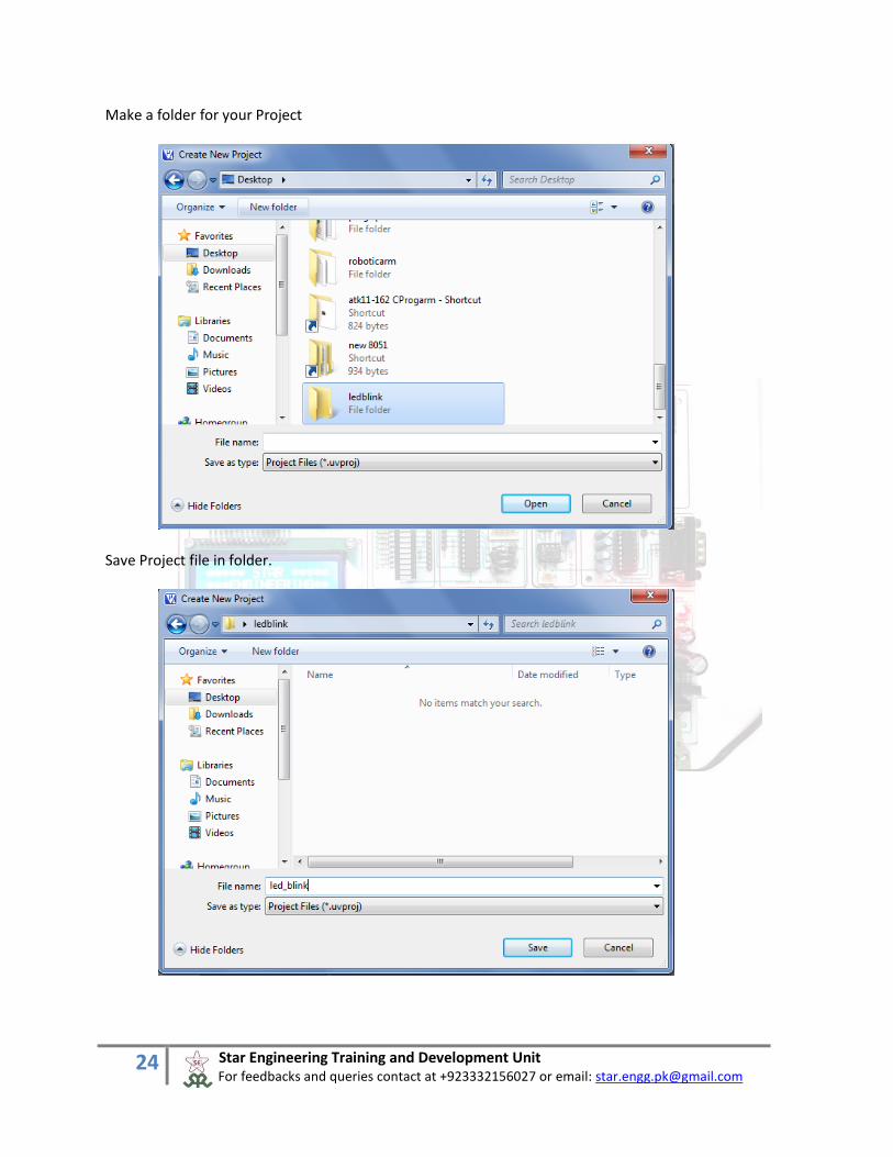
Make a folder for your Project
Save Project file in folder.

25 Star Engineering Training and Development Unit For feedbacks and queries contact at +923332156027 or email: [email protected]
Select your device for your Project.
Open a new file for your Project. Type your codes.
26 Star Engineering Training and Development Unit For feedbacks and queries contact at +923332156027 or email: [email protected]
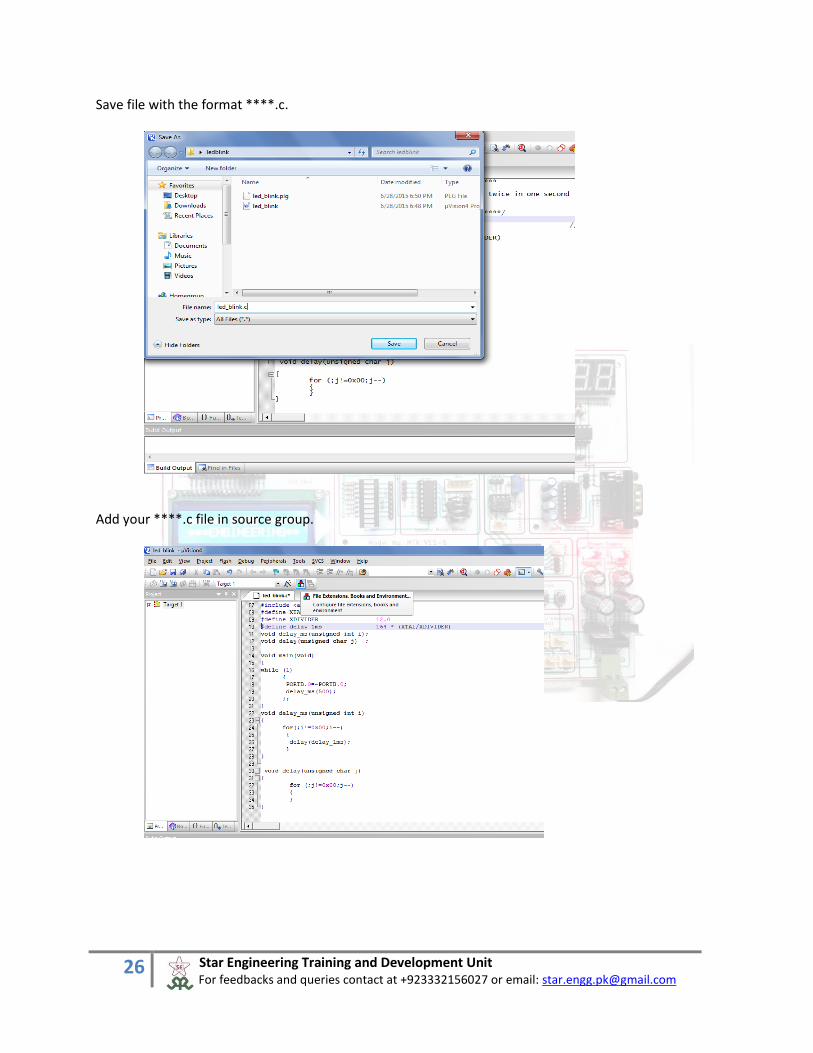
Save file with the format ****.c.
Add your ****.c file in source group.

27 Star Engineering Training and Development Unit For feedbacks and queries contact at +923332156027 or email: [email protected]
Press “ADD FILE “ Button and add ****.c file of your Project file.

28 Star Engineering Training and Development Unit For feedbacks and queries contact at +923332156027 or email: [email protected]
Now you can compile it. As you see file is compile but there are no hex file generated.

29 Star Engineering Training and Development Unit For feedbacks and queries contact at +923332156027 or email: [email protected]
For hex file you have to make a check on “Creat HEX file” in project menu Option for target.
Now hex file generated while compile your file.

30 Star Engineering Training and Development Unit For feedbacks and queries contact at +923332156027 or email: [email protected]
3 Tutorial for AVR
Below are the system requirements for Code vision AVR, the IDE for programming AVR
microcontrollers
Operating system requirement
It is supported by XP, Vista, Windows7, windows8 and windows8.1 (32bit/64bit).
Hardware Requirement
Minimum Recommended
Memory 1GB 4GB
Disk space 350MB* 2GB
Processor 1.5GHz single core Dual core
Disk space listed depends on features selected during installation. Does not include
temporary space required by the installer.
Note that the most important requirement is memory. 2GB of memory or more memory is
highly recommended, it will run with 1GB but it will be slow.
Installation Insert the CD, open the folder of CODE VISION AVR.
This is a full version of CODE VISION AVR.
1. Run Setup.exe.
2. Follow read me file instruction.
3. Install.
4.Copy file “cvavr” from crack folder and paste it in “c:\program file\cvavr\bin\” or drive where you
install code vision avr in “bin” folder.
5. Run and Enjoy.

31 Star Engineering Training and Development Unit For feedbacks and queries contact at +923332156027 or email: [email protected]
Start a new project in 8051 controller. 1. Project> New µ vision Project.
Press new file button as shown in above image. Select Project in file type and press ok.
Press yes Button for wizard for new project. Wizard can help you to set preset values for I/O ports, timer interrupts etc.

32 Star Engineering Training and Development Unit For feedbacks and queries contact at +923332156027 or email: [email protected]
As shown in below image you can chose xtal, chip, also set your codes for Lcd I/O ports etc.

33 Star Engineering Training and Development Unit For feedbacks and queries contact at +923332156027 or email: [email protected]
Press ”Generate program” Button, as shown in image Make a new folder for your project.

34 Star Engineering Training and Development Unit For feedbacks and queries contact at +923332156027 or email: [email protected]
And save project file in new folder you make.
After project wizard is finished type your codes.

35 Star Engineering Training and Development Unit For feedbacks and queries contact at +923332156027 or email: [email protected]
After compile the project as you see there is no error.

36 Star Engineering Training and Development Unit For feedbacks and queries contact at +923332156027 or email: [email protected]
After compile the project as you see in image there are many files for project.
In “EXE” folder you have hex file for burn in atmaga16.

37 Star Engineering Training and Development Unit For feedbacks and queries contact at +923332156027 or email: [email protected]
4 Tutorial for PIC16F877
Below are the system requirements for Code Composer Studio
Operating system requirement
CCS supported by XP, Vista, Windows7, windows8 and windows8.1 (32bit/64bit).
Hardware Requirement
Minimum Recommended
Memory 1GB 4GB
Disk space 350MB* 2GB
Processor 1.5GHz single core Dual core
Disk space listed depends on features selected during installation. Does not include
temporary space required by the installer.
Note that the most important requirement is memory. 2GB of memory or more memory is
highly recommended, it will run with 1GB but it will be slow.
Installation Insert the CD, open the folder of pic ccs compiler
This is a full version of CCS's PIC IDE. It is PCWH however it is fully unlocked to Program PCW's PIC's
also. Installation Instructions:
1. Run pcwhupd.exe
2. Install
3. Run Patcher and Patch Installation
4. Replace pcb, pch, and pcm.crg in the installation directory with the ones provided in this folder
5. Run and Enjoy.

38 Star Engineering Training and Development Unit For feedbacks and queries contact at +923332156027 or email: [email protected]
Start the CCS
First of all close all the programs
Select a New Source File

39 Star Engineering Training and Development Unit For feedbacks and queries contact at +923332156027 or email: [email protected]
Save a file in a specific folder
Make a program

40 Star Engineering Training and Development Unit For feedbacks and queries contact at +923332156027 or email: [email protected]
Compile a program
When compiling the program this window will appear
eck this window that program is successfully build or not
When program is successfully build hex file automatically generated in the folder where program is saved.

41 Star Engineering Training and Development Unit For feedbacks and queries contact at +923332156027 or email: [email protected]
5 Program Burning/ Downloading for AVR and 8051
Below are the system requirements for program downloader for AVR and 8051
Operating system requirement
XP, Vista, Windows7 (32bit/64bit).
Hardware Requirement
Minimum Recommended
Memory 1GB 4GB
Disk space 350MB* 2GB
Processor 1.5GHz single core Dual core
Disk space listed depends on features selected during installation. Does not include
temporary space required by the installer.
Note that the most important requirement is memory. 2GB of memory or more memory is
highly recommended, it will run with 1GB but it will be slow.
Installation Insert the CD, open the folder of progisp172 - GUI Software.
This is a full version of progisp172 - GUI Software.
1. Plug USB ISP in PC
2. Install Hardware driver from ‘USBasp-win-driver-x86-x64-ia64-v1.2.4’ folder
3. Run progisp.exe from ‘progisp172 - GUI Software’ folder. (installation is not required)
After Installation of driver Run Prog ISP as circled below.

42 Star Engineering Training and Development Unit For feedbacks and queries contact at +923332156027 or email: [email protected]
Select Microcontroller and Hex file for burning then press auto with suitable checks as mentioned below

43 Star Engineering Training and Development Unit For feedbacks and queries contact at +923332156027 or email: [email protected]
Now press ‘Ctrl + U’ to Program Fuses. Following page will appear.
Press ‘Read’ at left. You will watch current state of Fuse bits. Now set above state by clicking on individual bits. Finally write above Fuse state. This will enable external crystal and serial ISP mode. Warning: If ‘SPIEN’ bit is set to ‘1’ then In-System Programming (ISP) mode will be disabled and can now only be enabled by programming the chip fuses using Universal (Parallel) programmer.

44 Star Engineering Training and Development Unit For feedbacks and queries contact at +923332156027 or email: [email protected]
6 Program Burning/ Downloading for PIC
Below are the system requirements for PICKIT 2
Operating system requirement
PICKIT 2 supports XP, Vista, Windows7, windows8 and windows8.1 (32bit/64bit).
Hardware Requirement
Minimum Recommended
Memory 1GB 4GB
Disk space 350MB* 2GB
Processor 1.5GHz single core Dual core
Disk space listed depends on features selected during installation. Does not
include temporary space required by the installer.
Note that the most important requirement is memory. 2GB of memory or more
memory is highly recommended, it will run with 1GB but it will be slow.
Installation
Insert the CD, open the folder of PICKIT 2 and run the setup
Note:
If setup is not running and give the error of installing frame work
So, follow these steps
Open control panel -->goto program -->click on turn windows features on or off -->check on .NET
FRAMEWORK 3.5(include .net 2.0 and 3.0)-->then click ok
Downloading and installing will automatically start PICkit 2 PROGRAMMER APPLICATION tutorial The PICkit 2 Programmer application allows you to program all supported devices listed in the PICkit 2. The programming interface appears as shown in below

45 Star Engineering Training and Development Unit For feedbacks and queries contact at +923332156027 or email: [email protected]
Steps of write the hex file
1. Installing the PICkit 2 Hardware Connect usb with pc and connector with the board of pickit2.
2. Launching the PICkit 2 Programmer Application
When application start, automatically device will be detect

46 Star Engineering Training and Development Unit For feedbacks and queries contact at +923332156027 or email: [email protected]
3. Importing a Hex File

47 Star Engineering Training and Development Unit For feedbacks and queries contact at +923332156027 or email: [email protected]
4. Writing the Program to the Device
5. Programming successfully done
48 Star Engineering Training and Development Unit For feedbacks and queries contact at +923332156027 or email: [email protected]
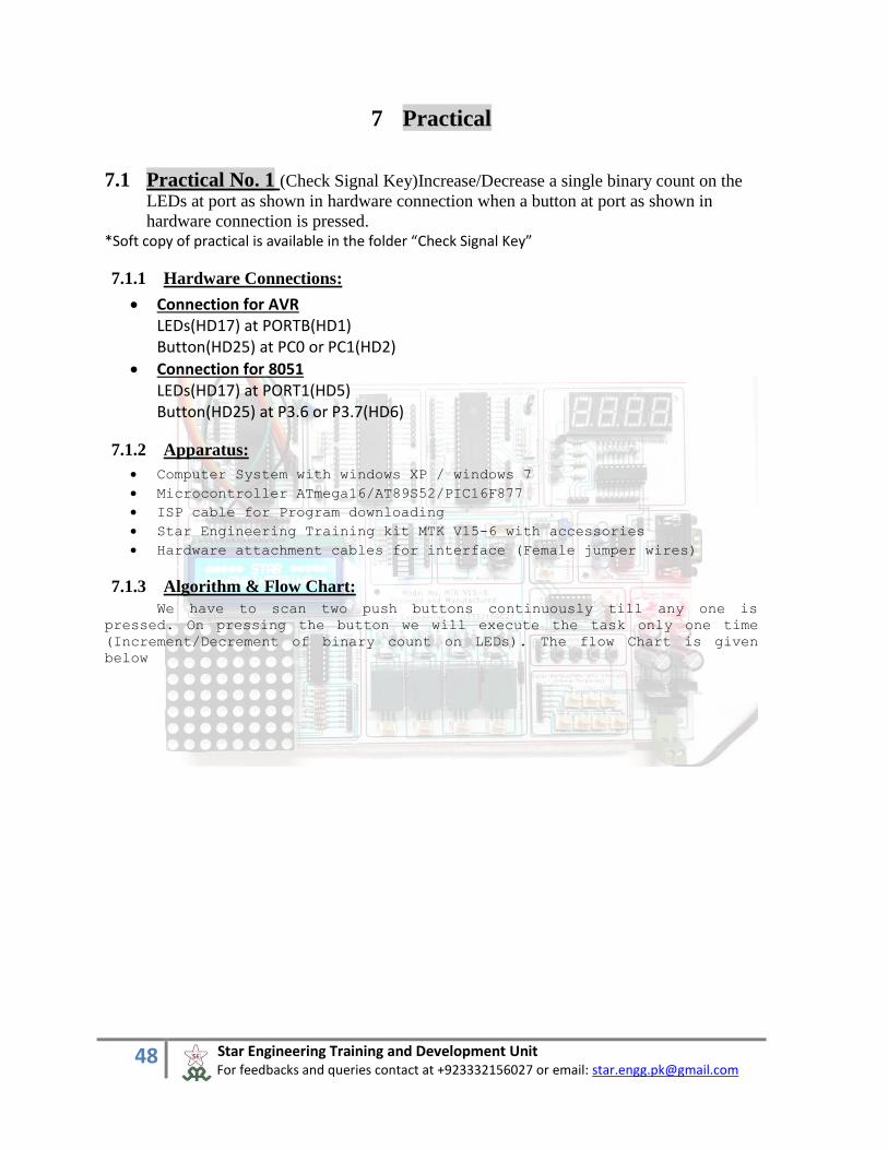
7 Practical
7.1 Practical No. 1 (Check Signal Key)Increase/Decrease a single binary count on the
LEDs at port as shown in hardware connection when a button at port as shown in
hardware connection is pressed. *Soft copy of practical is available in the folder “Check Signal Key”
7.1.1 Hardware Connections:
Connection for AVR LEDs(HD17) at PORTB(HD1) Button(HD25) at PC0 or PC1(HD2)
Connection for 8051 LEDs(HD17) at PORT1(HD5) Button(HD25) at P3.6 or P3.7(HD6)
7.1.2 Apparatus:
Computer System with windows XP / windows 7
Microcontroller ATmega16/AT89S52/PIC16F877
ISP cable for Program downloading
Star Engineering Training kit MTK V15-6 with accessories
Hardware attachment cables for interface (Female jumper wires)
7.1.3 Algorithm & Flow Chart:
We have to scan two push buttons continuously till any one is
pressed. On pressing the button we will execute the task only one time
(Increment/Decrement of binary count on LEDs). The flow Chart is given
below

49 Star Engineering Training and Development Unit For feedbacks and queries contact at +923332156027 or email: [email protected]
7.1.4 AVR Program C Code:
#include <mega16.h> #include <delay.h> #define SW1 PINC.0 #define SW2 PINC.1
START
N
Y
N
Y
PB1 Pressed
PB2 Pressed
A
B
PBI Pressed
CNT++
NOT(CNT)
P1=CNT
Delay 15ms
Delay 15ms
PB2 Pressed
CNT--
NOT(CNT)
P1=CNT
Delay 15ms
Delay 15ms
Initialize
A => CHK_PB1
B => CHK_PB2
Initial value of CNT is 00H
LEDs are connected at P1
LEDs are active low

50 Star Engineering Training and Development Unit For feedbacks and queries contact at +923332156027 or email: [email protected]
void main(void) // Main loop unsigned char cnt=0; // Declare your local variables here PORTB=0xFF; // To enable internal pull-up resister DDRB=0xFF; // For outward direction PORTC.0=1; // To enable internal pull-up resister PORTC.1=1; // To enable internal pull-up resister while (1) while (SW1==0) // Loop while key is pressed at PD6, Active low delay_ms(15); cnt++; // For Increment PORTB=~cnt; // Invert the variable value to drive active low LED's while (SW1==0); // Empty loop, Wait to release the key delay_ms(15); ; while (SW2==0) // Loop while key is pressed at PD7, Active low delay_ms(15); cnt--; // For Decrement PORTB=~cnt; // Invert the variable value to drive active low LED's while (SW2==0) // Empty loop, Wait to release the key ; delay_ms(15); ; ;
7.1.5 8051 Program C Code:
#include <at89x51.h> #define XTAL 11.059200 //Crystal frequency #define XDIVIDER 12.0 //Divider #define delay_1ms 164 * (XTAL/XDIVIDER) sbit SW1 = P3^6; sbit SW2 = P3^7; void delay_ms(unsigned int i); void delay(unsigned char j) ; void main (void) unsigned char cnt=0; while (1)

51 Star Engineering Training and Development Unit For feedbacks and queries contact at +923332156027 or email: [email protected]
while (SW1==0) // Wait for switch at p3_6 press P1 = ~cnt; //Invert it and send it to PORT 1 cnt++; // increamentcnt while (SW2==0) // Wait for switch at p3_7 release delay_ms(25); // call wait function while (SW2==0) // Wait for switch at p3_6 press P1 = ~cnt; //Invert it and send it to PORT 1 cnt--; // Decreamentcnt while (SW2==0) // Wait for switch at p3_7 release delay_ms(25); //call wait function void delay_ms(unsigned int i) for(;i!=0x00;i--) delay(delay_1ms); void delay(unsigned char j) for (;j!=0x00;j--)
7.1.6 PIC Program C Code:
#include <16f877a.h> //include pic16f877a header file #use delay(clock=20M) // define clock frequency #FUSES HS,NOWDT // define fuses high speed and no watch dog timer void main () // main loop int a,b,cnt=0; port_b_pullups(true); // internally pullups port b

52 Star Engineering Training and Development Unit For feedbacks and queries contact at +923332156027 or email: [email protected]
while(1) a=input(PIN_b0); //input state is saved in int a b=input(PIN_b1); //input state is saved in int b if (a==0) delay_ms(15); cnt++; output_d(~cnt); // sent data in portD delay_ms(15); if (b==0) delay_ms(15); cnt--; output_d(~cnt); delay_ms(15);
7.1.7 Exercise:
Type the program, assemble/compile it, and make its object file and
hex file.
Now download the HEX file in Microcontroller’s code memory
Use star trainer to run/execute the program and check results
Now make a program and its flowchart with the same objective.
7.1.8 Conclusion:
We can use the program format for scanning/checking multiple push
buttons.
We can also use the program format for executing tasks on key down
or key up events.

53 Star Engineering Training and Development Unit For feedbacks and queries contact at +923332156027 or email: [email protected]
7.2 Practical No. 2 (Stepper Motor Control System)
Run a stepper motor in clockwise direction with maximum speed, when a button at port bit as shown in hardware connection is pressed, in CW or CCW and motor should continue to run till key is pressed. *Soft copy of practical is available in the folder “Stepper motor”
7.2.1 Hardware Connections:
Connection for AVR MOTOR(HD18) at PORTB(HD1) Button(HD25) at PC0 or PC1(HD2)
Connection for 8051 MOTOR(HD18) at PORT1(HD5) Button(HD25) at P3.6 or P3.7(HD6)
7.2.2 Apparatus:
Computer System with windows XP / windows 7
Microcontroller ATmega16/AT89S52/PIC16F877
ISP cable for Program downloading
Star Engineering Training kit MTK V15-6 with accessories
Hardware attachment cables for interface (Female jumper wires)
7.2.3 Algorithm
Run a stepper motor in clockwise direction with maximum speed, when a
button at PD6 is pressed in CW, when a button at PD7 is pressed in CCW and
motor should continue to run till key is pressed.
START
N
Y
N
Y
PB1 Pressed
PB2 Pressed
A
B
Initialize
Delay
Delay
Send step cw to Stepper motor
Send step ccw to Stepper motor

54 Star Engineering Training and Development Unit For feedbacks and queries contact at +923332156027 or email: [email protected]
7.2.4 AVR Program C Code:
#include <mega16.h>
#include <delay.h>
#define SW1 PINC.0
#define SW2 PINC.1
void main(void) // Main Loop
DDRB=0x0F; // For outward direction
PORTC.0=1; // To enable internal pull-up resisters
PORTC.1=1; // To enable internal pull-up resisters
while (1)
while(SW1==0)
if(PORTB.0==1)
PORTB.0=0;
PORTB.1=1;
else if(PORTB.1==1)
PORTB.1=0;
PORTB.2=1;
else if(PORTB.2==1)
PORTB.2=0;
PORTB.3=1;
else
PORTB.3=0;
PORTB.0=1;
delay_ms(50);
while(SW2==0)
if(PORTB.3==1)
PORTB.3=0;
PORTB.2=1;
else if(PORTB.2==1)
PORTB.2=0;
PORTB.1=1;
else if(PORTB.1==1)
PORTB.1=0;
PORTB.0=1;
else

55 Star Engineering Training and Development Unit For feedbacks and queries contact at +923332156027 or email: [email protected]
PORTB.0=0;
PORTB.3=1;
delay_ms(50);
;
7.2.5 8051 Program C Code:
#include <at89x51.h> #define XTAL 11.059200 //Crystal frequency #define XDIVIDER 12.0 //Divider #define delay_1ms 164 * (XTAL/XDIVIDER) sbit SW1 = P3^6; sbit SW2 = P3^7; #define LOW 0 #define HIGH 1 void delay_ms(unsigned int i); void delay(unsigned char j) ; void main(void) SW1 = 0x01; SW2 = 0x01; while(1) if(SW1==0) P1=0x66; delay_ms(100); P1=0xCC; delay_ms(100); P1=0x99; delay_ms(100); P1=0x33; delay_ms(100); if(SW2 == 0) P1=0x66; delay_ms(100); P1=0x33; delay_ms(100); P1=0x99; delay_ms(100); P1=0xCC;

56 Star Engineering Training and Development Unit For feedbacks and queries contact at +923332156027 or email: [email protected]
delay_ms(100); void delay_ms(unsigned int i) for(;i!=0x00;i--) delay(delay_1ms); void delay(unsigned char j) for (;j!=0x00;j--)
7.2.6 PIC Program C Code:
#include <16f877a.h> //include pic16f877a header file #use delay(clock=20M) // define clock frequency #FUSES HS,NOWDT // define fuses high speed and no watch dog timer void main () // main loop int a,b,c,d,e,f; port_b_pullups(true);// internally pullups port b while(1) e=input_state(pin_b0); //input state is saved in int f=input_state(pin_b1); while(e==0) //loop will continue until e==1 a=input_state(pin_d0); b=input_state(pin_d1); c=input_state(pin_d2); d=input_state(pin_d3); e=input_state(pin_b0); f=input_state(pin_b1); if(a==1)

57 Star Engineering Training and Development Unit For feedbacks and queries contact at +923332156027 or email: [email protected]
output_low(PIN_D0); // pin D0 low output_high(PIN_D1); // pin d1 high delay_ms(500); else if(b==1) output_low(PIN_D1); output_high(PIN_D2); delay_ms(500); else if(c==1) output_low(PIN_D2); output_high(PIN_D3); delay_ms(500); else output_low(PIN_D3); output_high(PIN_D0); delay_ms(500); if(f==0) a=input_state(pin_d0); b=input_state(pin_d1); c=input_state(pin_d2); d=input_state(pin_d3); e=input_state(pin_b0); f=input_state(pin_b1); if(d==1) output_low(PIN_D3); output_high(PIN_D2); delay_ms(500); else if(c==1) output_low(PIN_D2); output_high(PIN_D1); delay_ms(500);

58 Star Engineering Training and Development Unit For feedbacks and queries contact at +923332156027 or email: [email protected]
else if(b==1) output_low(PIN_D1); output_high(PIN_D0); delay_ms(500); else output_low(PIN_D0); output_high(PIN_D3); delay_ms(500);
7.2.7 Exercise:
Type the program, assemble/ compile it, make its object file and hex
file.
Now download the HEX file in Microcontroller’s code memory
Use MTK V15-6 to run/ execute the program and check results.
Run a stepper motor in anti clockwise direction with maximum speed,
when a button at PD6 or PD7 is pressed, motor should continue to run
till key is pressed rather cw or ccw.
7.2.8 Conclusion:
We can also use the program format for executing the tasks after
certain duration of key press.
The program is also giving us the concept of giving a little
security on the operations executed by pressing a key.

59 Star Engineering Training and Development Unit For feedbacks and queries contact at +923332156027 or email: [email protected]
7.3 Practical No. 3 (4-Digit Multiplexed 7-Segment Led Driver) Generate pattern in
increasing/ decreasing order on 4-digit multiplexed 7-segment display when a button at
port as shown in hardware connection is pressed. Set the counting speed of 2 counts
per second. *Soft copy of practical is available in the folder “single_digit_7seg”.
7.3.1 Hardware Connections:
Connection for AVR 7-Segment(HD15) at PORTB(HD1) Button(HD25) at PC0 or PC1(HD2) Digit Select(HD14) PORTA(HD3) Lower Nibble
Connection for 8051 LEDs(HD15) at PORT1(HD5) Button(HD25) at P3.6 or P3.7(HD6) Digit Select(HD14) Port0(HD7) Higher Nibble
7.3.2 Apparatus:
Computer System with windows XP / windows 7
Microcontroller ATmega16/AT89S52/PIC16F877
ISP cable for Program downloading
Star Engineering Training kit MTK V15-6 with accessories
Hardware attachment cables for interface (Female jumper wires)
7.3.3 Algorithm
Display decimal pattern on 4-Digit 7-Segment display with increasing/decreasing order when button on PORTD, PD6 or PD7 is pressed.
START
N
N
Y
PB1 Pressed
PB2 Pressed
A
B
Initialize
Delay
Delay
Cnt=cnt+1
Cnt=cnt-1

60 Star Engineering Training and Development Unit For feedbacks and queries contact at +923332156027 or email: [email protected]
7.3.4 AVR Program C Code:
#include <mega16.h> #include <delay.h> #include <ATKv10_1.h> #define SW1 PINC.0 #define SW2 PINC.1 unsigned int cnt; flash unsigned char SegCod[16]=0x3F, 0x06, 0x5B, 0x4F, 0x66, 0x6D, 0x7D, 0x07, 0x7F, 0x6F, 0x77, 0x7C, 0x39, 0x5E, 0x79, 0x71; unsigned char GetSegDig16Bit(unsigned char Number, unsigned char digit) unsigned char dig1, dig2, dig3, dig4;
Refresh Display
If digit1 selected
N
Y Disable digit1
Enable digit1
7Seg port=Selected Digit code of cnt
If digit2 selected
N
Y Disable digit2
Enable digit3
7Seg port=Selected Digit code of cnt
If digit3 selected
N
Y Disable digit3
Enable digit4
7Seg port=Selected Digit code of cnt
Disable digit4
Enable digit1
7Seg port=Selected Digit code of cnt
Return

61 Star Engineering Training and Development Unit For feedbacks and queries contact at +923332156027 or email: [email protected]
dig1 =SegCod[Number%10]; Number/=10; dig2 =SegCod[Number%10]; Number/=10; dig3 =SegCod[Number%10]; Number/=10; dig4 =0x3F; if(digit==1) return dig1; else if(digit==2) return dig2; else if(digit==3) return dig3; else if(digit==4) return dig4; else return 0; interrupt [TIM0_COMP] void RefreshDisplay(void) if (PORTA.0==0) PORTA.0=1; PORTA.1=0; PORTB=GetSegDig16Bit(cnt,2); else if (PORTA.1==0) PORTA.1=1; PORTA.2=0; PORTB=GetSegDig16Bit(cnt,3); else if (PORTA.2==0) PORTA.2=1; PORTA.3=0; PORTB=GetSegDig16Bit(cnt,4); else PORTA.3=1; PORTA.0=0; PORTB=GetSegDig16Bit(cnt,1);

62 Star Engineering Training and Development Unit For feedbacks and queries contact at +923332156027 or email: [email protected]
void main(void) DDRB=0xFF; // For outward direction PORTA=0xFE; DDRA=0xFF; // For outward direction PORTC.0=1; // To enable internal pull-up resistor PORTC.1=1; // To enable internal pull-up resistor TCCR0=0x0D; // Timer0, ctc mode, prescaler = 1024 OCR0=39; // Load OCR0 TIMSK=0x02; // Timer0 o/p compare match int. enable SREG.7=1; // Enable globle interrupt while (1) while (SW1==0) // Monitor pinc.0 cnt++; // Increment in verible delay_ms(50); ; while (SW2==0) // Monitor pinc.1 cnt--; // Decrement in verible delay_ms(50); ; ;
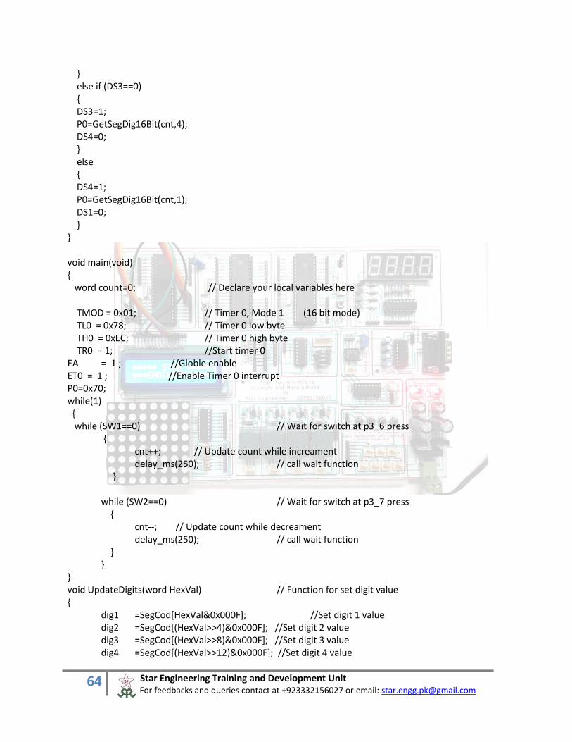
7.3.5 8051 Program C Code:
#include <at89x51.h> #define XTAL 11.059200 //Crystal frequency #define XDIVIDER 12.0 //Divider #define delay_1ms 164 * (XTAL/XDIVIDER) #define DS1 P2_7 #define DS2 P2_6 #define DS3 P2_5 #define DS4 P2_4 #define SW1 P3_6 #define SW2 P3_7 typedef unsigned char byte; typedef unsigned int word; byte dig1=0x3F,dig2=0x3F,dig3=0x3F,dig4=0x3F;

63 Star Engineering Training and Development Unit For feedbacks and queries contact at +923332156027 or email: [email protected]
unsigned char SegCod[16]=0x3F, 0x06, 0x5B, 0x4F, 0x66, 0x6D, 0x7D, 0x07, 0x7F, 0x6F, 0x77, 0x7C, 0x39, 0x5E, 0x79, 0x71; void UpdateDigits(word HexVal); void delay_ms(unsigned int i); void delay(unsigned char j); unsigned int cnt; unsigned char GetSegDig16Bit(unsigned char Number, unsigned char digit) unsigned char dig1, dig2, dig3, dig4; dig1 =SegCod[Number%10]; Number/=10; dig2 =SegCod[Number%10]; Number/=10; dig3 =SegCod[Number%10]; Number/=10; dig4 =0x3F; if(digit==1) return dig1; else if(digit==2) return dig2; else if(digit==3) return dig3; else if(digit==4) return dig4; else return 0; void timer0_int (void) interrupt 1 //Interrupt for timer 0 TL0=0x78; TH0=0xEC; if (DS1==0) DS1=1; P0=GetSegDig16Bit(cnt,2); DS2=0; else if (DS2==0) DS2=1; P0=GetSegDig16Bit(cnt,3); DS3=0;
64 Star Engineering Training and Development Unit For feedbacks and queries contact at +923332156027 or email: [email protected]
else if (DS3==0) DS3=1; P0=GetSegDig16Bit(cnt,4); DS4=0; else DS4=1; P0=GetSegDig16Bit(cnt,1); DS1=0; void main(void) word count=0; // Declare your local variables here TMOD = 0x01; // Timer 0, Mode 1 (16 bit mode) TL0 = 0x78; // Timer 0 low byte TH0 = 0xEC; // Timer 0 high byte TR0 = 1; //Start timer 0 EA = 1 ; //Globle enable ET0 = 1 ; //Enable Timer 0 interrupt P0=0x70; while(1) while (SW1==0) // Wait for switch at p3_6 press cnt++; // Update count while increament delay_ms(250); // call wait function while (SW2==0) // Wait for switch at p3_7 press cnt--; // Update count while decreament delay_ms(250); // call wait function void UpdateDigits(word HexVal) // Function for set digit value dig1 =SegCod[HexVal&0x000F]; //Set digit 1 value dig2 =SegCod[(HexVal>>4)&0x000F]; //Set digit 2 value dig3 =SegCod[(HexVal>>8)&0x000F]; //Set digit 3 value dig4 =SegCod[(HexVal>>12)&0x000F]; //Set digit 4 value

65 Star Engineering Training and Development Unit For feedbacks and queries contact at +923332156027 or email: [email protected]
void delay_ms(unsigned int i) //Function for DELAY for(;i!=0x00;i--) delay(delay_1ms); void delay(unsigned char j) for (;j!=0x00;j--)
7.3.6 PIC Program C Code:
#include <16f877a.h> //include pic16f877a header file #use delay(clock=20M) // define clock frequency #FUSES HS,NOWDT // define fuses high speed and no watch dog timer int a,b,c,d,e,f; unsigned int cnt; unsigned char SegCod[16]=0x3F, 0x06,0x5B,0X4F,0X66,0X6D,0X7D,0X07,0X7F,0X6F,0X77,0X7C,0X39,0X5E,0X79,0X71; unsigned char GetSegDig16Bit(unsigned char Number,unsigned char digit) // function unsigned char dig1,dig2,dig3,dig4; dig1 = segCod[Number%10]; Number/=10; dig2= segCod[Number%10]; Number/=10; dig3= segCod[Number%10]; Number/=10;

66 Star Engineering Training and Development Unit For feedbacks and queries contact at +923332156027 or email: [email protected]
dig4=0x3F; if(digit==1) return dig1; else if (digit==2) return dig2; else if(digit==3) return dig3; else if(digit==4) return dig4; else return 0; void main () // main loop port_b_pullups(true); setup_timer_1 ( T1_INTERNAL | T1_DIV_BY_4 ); enable_interrupts(INT_TIMER1); enable_interrupts(GLOBAL); while(1) e=input(PIN_b0); f=input(PIN_b1); while(e==0) e=input(PIN_b0); cnt++; delay_ms(300); while(f==0)

67 Star Engineering Training and Development Unit For feedbacks and queries contact at +923332156027 or email: [email protected]
f=input(PIN_b1); cnt--; delay_ms(300); #int_timer1 //interrupt timer routine void timer0interrupt(void) a=input_state(PIN_c0); b=input_state(PIN_c1); c=input_state(PIN_c2); d=input_state(PIN_c3); if(a==0) output_high(PIN_C0); //delay_us(20); output_d(GetSegDig16Bit(cnt,2)); //delay_us(20); output_low(PIN_C1); else if(b==0) output_high(PIN_C1); //delay_us(20); output_d(GetSegDig16Bit(cnt,3)); //delay_us(20); output_low(PIN_C2); else if(c==0) output_high(PIN_C2); //delay_us(20); output_d(GetSegDig16Bit(cnt,4)); //delay_us(20); output_low(PIN_C3);

68 Star Engineering Training and Development Unit For feedbacks and queries contact at +923332156027 or email: [email protected]
else output_high(PIN_C3); //delay_us(20); output_d(GetSegDig16Bit(cnt,1)); //delay_us(20); output_low(PIN_C0); //set_timer1(63974); //timer1 is 16bit 2^16=65536 set_timer1(59286); //timer1 is 16bit 2^16=65536
7.3.7 Exercise:
Type the program, assemble/compile it, and make its object file and
hex file.
Now download the HEX file in Microcontroller’s code memory
Use star trainer to run/ execute the program and check results
Generate the binary pattern in increasing/decreasing order on 4digit
multiplexed 7 segment display at PORTB, when a button at PD6 or PD7
is pressed. Set the counting speed of 1 count per second.
Now make a program with the same objective but for decimal pattern
(counting)
7.3.8 Conclusion:
We can also use the program format for executing the repetitive
tasks with constant speed.
The program is also giving us the concept of deterministic pattern
generation (7 segment codes etc.)

69 Star Engineering Training and Development Unit For feedbacks and queries contact at +923332156027 or email: [email protected]
7.4 Practical No. 4 (uart_lcd_counting)
Increase a variable after each second and display its decimal equivalent on the LCD and send it also to the USART. Let baud rate 9600 bps with XTAL = 11.0592MHZ *Soft copy of practical is available in the folder “uart_lcd_counting”
7.4.1 Hardware Connections:
Connection for AVR LCD(HD16) at PORTC(HD4) RS(HD16) at PD6(HD2) or EN(HD16) at PD7(HD2) RX(HD20) at PD0(HD2) or TX(HD20) at PD1(HD2)
Connection for 8051 LCD(HD16) at PORT2(HD8) RS(HD16) at P0.6(HD7) or EN(HD16) at P0.7(HD7) RX(HD20) at P3.0(HD2) or TX(HD20) at P3.1(HD2)
7.4.2 Apparatus:
Computer System with windows XP / windows 7
Microcontroller ATmega16/AT89S52/PIC16F877
ISP cable for Program downloading
Star Engineering Training kit MTK V15-6 with accessories
Hardware attachment cables for interface (Female jumper wires)
7.4.3 Algorithm
Increase a variable after each second and display its decimal equivalent on the LCD and send it also to the USART
START
A
Initialize
Cnt=cnt+1
Send ASCII digit of cnt on LCD
and UART

70 Star Engineering Training and Development Unit For feedbacks and queries contact at +923332156027 or email: [email protected]
7.4.4 AVR Program C Code:
#include <mega16.h>
#include <delay.h>
#include <ATKv10_1.h>
void main(void)
unsigned int count=0; // Declare your local variables here
Init_LCD();
UCSRB=0x08; //Enable the transmit
UBRRL=71; //9600 baud rate on 11.0592MHz
UBRRH=0;
wrLCDcmd(0x80);
LCD_msg("Counting= ");
delay_ms(2000);
while (1)
wrLCDcmd(0xCA);
UpdateDigits(count++);
delay_ms(250);
7.4.5 8051 Program C Code:
#include <at89x51.h> #define XTAL 11.059200 //Crystal frequency #define XDIVIDER 12.0 //Divider #define delay_1ms 164 * (XTAL/XDIVIDER) #define regs P0_6 #define en P0_7 #define lcd P2 #define LOW 0 #define HIGH 1 void LCD_msg(char *p); //unsigned char flash *p void wrLCDnibble(unsigned char L); void wrLCDchr(unsigned char display); void Init_LCD(); void wrLCDcmd(unsigned char command); void delay_ms(unsigned int i); void delay(unsigned char j) ; void UpdateDigits(unsigned int Number); void Bin2BCD(unsigned char bin);

71 Star Engineering Training and Development Unit For feedbacks and queries contact at +923332156027 or email: [email protected]
void main(void) unsigned char cnt=0; SCON = 0x50; TMOD = 0x20; //use timer 1, 8-bit auto reload TH1 = -3; //9600 baud rate TR1 = 1; //start timer 1 en=0; Init_LCD(); wrLCDcmd(0x82); LCD_msg("LCD Counting"); while(1) wrLCDcmd(0xC0); Bin2BCD(cnt); cnt++;
delay_ms(100); /* call wait function */ void wrLCDnibble(unsigned char L) unsigned char y=0; y = lcd& 0x0F; L &= 0xF0; lcd = L | y; en=1; delay_ms(1); en=0; delay_ms(15); void wrLCDcmd(unsigned char x) delay_ms(1); regs=0; wrLCDnibble(x); x = x << 4; wrLCDnibble(x); void wrLCDchr(unsigned char x) delay_ms(2); regs=1; wrLCDnibble(x);

72 Star Engineering Training and Development Unit For feedbacks and queries contact at +923332156027 or email: [email protected]
x = x << 4; wrLCDnibble(x); void LCD_msg(char *p) while(*p!=0) wrLCDchr(*p); SBUF=*p++; void Init_LCD(void) regs=0; en=0; delay_ms(50); wrLCDnibble(0x30); delay_ms(50); wrLCDnibble(0x30); delay_ms(50); wrLCDnibble(0x30); delay_ms(50); wrLCDnibble(0x20); delay_ms(50); wrLCDcmd(0x28); delay_ms(50); wrLCDcmd(0x01); delay_ms(50); wrLCDcmd(0x0C); delay_ms(50); wrLCDcmd(0x06); delay_ms(50); void UpdateDigits(unsigned int Number) unsigned char dig1, dig2, dig3, dig4, dig5; dig1 =(Number%10)+0x30; Number/=10; dig2 =(Number%10)+0x30; Number/=10; dig3 =(Number%10)+0x30; Number/=10; dig4 =(Number%10)+0x30; Number/=10; dig5 =(Number%10)+0x30;

73 Star Engineering Training and Development Unit For feedbacks and queries contact at +923332156027 or email: [email protected]
SBUF=dig5; wrLCDchr(dig5); SBUF=dig4; wrLCDchr(dig4); SBUF=dig3; wrLCDchr(dig3); SBUF=dig2; wrLCDchr(dig2); SBUF=dig1; wrLCDchr(dig1); SBUF=0x0A; void delay_ms(unsigned int i) for(;i!=0x00;i--) delay(delay_1ms); void delay(unsigned char j) for (;j!=0x00;j--) void Bin2BCD(unsigned char bin) unsigned char dig1, dig2,dig3; dig1=bin%10; bin=bin/10; dig2=bin%10; bin=bin/10; dig3=bin; dig1=dig1|0x30; dig2=dig2|0x30; dig3=dig3|0x30; wrLCDchr(dig3); SBUF=dig3; while(TI==0) TI=0; wrLCDchr(dig2); SBUF=dig2; while(TI==0) TI=0; wrLCDchr(dig1);

74 Star Engineering Training and Development Unit For feedbacks and queries contact at +923332156027 or email: [email protected]
SBUF=dig1; while(TI==0) TI=0; SBUF='\r'; while(TI==0) TI=0;
7.4.6 PIC Program C Code:
#include <16f877a.h> //include pic16f877a header file #use delay(clock=20M) // define clock frequency #FUSES HS,NOWDT // define fuses high speed and no watch dog timer #use rs232(baud=9600, xmit=PIN_C6,rcv=PIN_C7) //define baoude rate and transmitter and receiver pins #include <LCD Driver.c> // load lcd driver void main () // main loop unsigned int cnt=0; lcd_init(); while(1) lcd_gotoxy(1,1); printf(lcd_putc,"Counting=%d ",cnt ); // print on lcd printf("Counting=%d ",cnt); //print on hyperterminal cnt++; delay_ms(1000);
7.4.7 Exercise:
Type the program, assemble/compile it, and make its object file and
hex file.
Now download the HEX file in Microcontroller’s code memory
Use MTK V15-6 to run/ execute the program and check results
Now write a C language program for ATmega16/AT89S52/PIC16F877 to
transmit the count on usart and lcd continuously.
7.4.8 Conclusion:
We can also use the program format for executing the tasks after
certain duration of key press.
The program is also giving us the concept of giving a little
security on the operations executed by pressing a key.

75 Star Engineering Training and Development Unit For feedbacks and queries contact at +923332156027 or email: [email protected]
7.5 Practical No. 5 (uart_Stringreqst)User press 1, 2, 3, 4 button from keyboard on pc
set with baud rate 9600, lcd show massages with respect to number user enter from
keyboard.
*Soft copy of practical is available in the folder “uart_Stringreqst”
7.5.1 Hardware Connections:
Connection for AVR LCD(HD16) at PORTC(HD4) RS(HD16) at PD6(HD2) or EN(HD16) at PD7(HD2) RX(HD20) at PD0(HD2) or TX(HD20) at PD1(HD2)
Connection for 8051 LCD(HD16) at PORT2(HD8) RS(HD16) at P0.6(HD7) or EN(HD16) at P0.7(HD7) RX(HD20) at P3.0(HD2) or TX(HD20) at P3.1(HD2)
7.5.2 Apparatus:
Computer System with windows XP / windows 7
Microcontroller ATmega16/AT89S52/PIC16F877
ISP cable for Program downloading
Star Engineering Training kit MTK V15-6 with accessories
Hardware attachment cables for interface (Female jumper wires)

76 Star Engineering Training and Development Unit For feedbacks and queries contact at +923332156027 or email: [email protected]
7.5.3 Algorithm
User press 1, 2, 3, 4 button from keyboard on pc set with baud rate 9600, lcd show massages with respect to number user enter from keyboard.
If Character=”1”
N
Y
Clear LCD
Show massage1
START
Initialize
Delay
If Character=”2”
N
Y
Clear LCD
Show massage2
Delay
If Character=”3”
N
Y
Clear LCD
Show massage4
Delay
If Character=”4”
N
Y
Clear LCD
Show massage4
Delay
Wait for new character from UART

77 Star Engineering Training and Development Unit For feedbacks and queries contact at +923332156027 or email: [email protected]
7.5.4 AVR Program C Code:
#include <mega16.h> #include <delay.h> #include <ATKv10_1.h> void main(void) Init_LCD(); UCSRB=0x18; //ENABLE receive and tranmit UBRRL=71; //9600 baudrate UBRRH=0; Wait4TxC(0x0D); //0x0D= new line UDR=0x0A; wrLCDcmd(0xC3); LCD_msg("----------------"); while (1) Wait4RxC(); if(UDR=='1') UDR=0x0D; Wait4TxC(0x31); UDR=0x0A; wrLCDcmd(0x83); LCD_msg("First Message"); else if(UDR=='2') UDR=0x0D; Wait4TxC(0x32); UDR=0x0A; wrLCDcmd(0x83); LCD_msg("Second Message"); else if(UDR=='3') UDR=0x0D; Wait4TxC(0x33); UDR=0x0A; wrLCDcmd(0x83); LCD_msg("Third Message"); else UDR=0x0D;

78 Star Engineering Training and Development Unit For feedbacks and queries contact at +923332156027 or email: [email protected]
Wait4TxC(0x34); UDR=0x0A; wrLCDcmd(0x83); LCD_msg("Press 1, 2 or 3");
7.5.5 8051 Program C Code:
#include <at89x51.h> #define XTAL 11.059200 //Crystal frequency #define XDIVIDER 12.0 //Divider #define delay_1ms 164 * (XTAL/XDIVIDER) #define regs P0_6 #define en P0_7 #define lcd P2 #define LOW 0 #define HIGH 1 void LCD_msg(char *p); //unsigned char flash *p void wrLCDnibble(unsigned char L); void wrLCDchr(unsigned char display); void Init_LCD(); void wrLCDcmd(unsigned char command); void delay_ms(unsigned int i); void delay(unsigned char j) ; void UpdateDigits(unsigned int Number); void main(void) unsigned char My_byte; SCON = 0x50; TMOD = 0x20; TH1 = -3; TR1 = 1; en=0; Init_LCD(); wrLCDcmd(0x82); LCD_msg("LCD Massage"); while(1) P1_0=~P1_0; // delay_ms(500); while (RI==1)

79 Star Engineering Training and Development Unit For feedbacks and queries contact at +923332156027 or email: [email protected]
My_byte=SBUF; if(My_byte==0x31) wrLCDcmd(0x0C0); // To write the Command byte on LCD LCD_msg("M. Irfan"); // To write a massege on LCD delay_ms(100); if(My_byte==0x32) wrLCDcmd(0x0C0); // To write the Command byte on LCD LCD_msg("Juma Khan"); // To write a massege on LCD delay_ms(100); if(My_byte==0x33) wrLCDcmd(0x0C0); // To write the Command byte on LCD LCD_msg("Muneeb Alam"); // To write a massege on LCD delay_ms(100); if(My_byte==0x34) wrLCDcmd(0x0C0); // To write the Command byte on LCD LCD_msg("Mohsin Shahid"); // To write a massege on LCD delay_ms(100); RI=0; ; void wrLCDnibble(unsigned char L) unsigned char y=0; y = lcd & 0x0F; L &= 0xF0; lcd = L | y; en=1; delay_ms(1); en=0; delay_ms(15); void wrLCDcmd(unsigned char x) delay_ms(1); regs=0;

80 Star Engineering Training and Development Unit For feedbacks and queries contact at +923332156027 or email: [email protected]
wrLCDnibble(x); x = x << 4; wrLCDnibble(x); void wrLCDchr(unsigned char x) delay_ms(2); regs=1; wrLCDnibble(x); x = x << 4; wrLCDnibble(x); void LCD_msg(char *p) while(*p!=0) wrLCDchr(*p); delay_ms(2); SBUF=*p++; void Init_LCD(void) regs=0; en=0; delay_ms(50); wrLCDnibble(0x30); delay_ms(50); wrLCDnibble(0x30); delay_ms(50); wrLCDnibble(0x30); delay_ms(50); wrLCDnibble(0x20); delay_ms(50); wrLCDcmd(0x28); delay_ms(50); wrLCDcmd(0x01); delay_ms(50); wrLCDcmd(0x0C); delay_ms(50); wrLCDcmd(0x06); delay_ms(50); void UpdateDigits(unsigned int Number)

81 Star Engineering Training and Development Unit For feedbacks and queries contact at +923332156027 or email: [email protected]
unsigned char dig1, dig2, dig3, dig4, dig5; dig1 =(Number%10)+0x30; Number/=10; dig2 =(Number%10)+0x30; Number/=10; dig3 =(Number%10)+0x30; Number/=10; dig4 =(Number%10)+0x30; Number/=10; dig5 =(Number%10)+0x30; SBUF=dig5; wrLCDchr(dig5); SBUF=dig4; wrLCDchr(dig4); SBUF=dig3; wrLCDchr(dig3); SBUF=dig2; wrLCDchr(dig2); SBUF=dig1; wrLCDchr(dig1); SBUF=0x0A; void delay_ms(unsigned int i) for(;i!=0x00;i--) delay(delay_1ms); void delay(unsigned char j) for (;j!=0x00;j--)
7.5.6 PIC Program C Code:
#include <16f877a.h> //include pic16f877a header file #use delay(clock=20M) // define clock frequency #FUSES HS,NOWDT // define fuses high speed and no watch dog timer #use rs232(baud=9600, xmit=PIN_C6,rcv=PIN_C7) //define baoude rate and transmitter and receiver pins #include <LCD Driver.c> // load lcd driver void main () // main loop

82 Star Engineering Training and Development Unit For feedbacks and queries contact at +923332156027 or email: [email protected]
char x=0; lcd_init(); // initializing lcd lcd_gotoxy(1,1); printf(lcd_putc,"-----------------"); while(1) x=getc(); //get character from receiving pin if(x=='1') lcd_gotoxy(1,1); printf(lcd_putc,"FIRST MESSAGE "); delay_ms(100); else if(x=='2') lcd_gotoxy(1,1); printf(lcd_putc,"SECOND MESSAGE "); delay_ms(100); else if(x=='3') lcd_gotoxy(1,1); printf(lcd_putc,"THIRD MESSAGE "); delay_ms(100); else lcd_gotoxy(1,1); printf(lcd_putc,"Press 1, 2 or 3 "); delay_ms(100);
7.5.7 Exercise:
Type the program, assemble/compile it, make its object file and hex
file.
Now download the HEX file in Microcontroller’s code memory
Use MTK V15-6 to run/execute the program and check results.
Now write a C language program to transmit and receive a string of
massage when user press 1, 2, 3.
Now make a program with the same objective but you have to toggle
the LED if the key press duration lies between 4 to 6 seconds.

83 Star Engineering Training and Development Unit For feedbacks and queries contact at +923332156027 or email: [email protected]
7.5.8 Conclusion:
We can also use the program format for executing the tasks after
certain duration of key press.
The program is also giving us the concept of giving a little
security on the operations executed by pressing a key.

84 Star Engineering Training and Development Unit For feedbacks and queries contact at +923332156027 or email: [email protected]
7.6 Practical No. 6 (UART DC motor).Use UART with baud rate of 9600bps to receive
the speed level (0-9) for a DC Motor from Hyper Terminal. Drive a DC Motor through
PWM using timer zero according to received speed level. Also acknowledge by
reflecting the received character. *Soft copy of practical is available in the folder “uart_dc_motor”.
7.6.1 Hardware Connections:
Connection for AVR LCD(HD16) at PORTC(HD4) RS(HD16) at PD6(HD2) or EN(HD16) at PD7(HD2) RX(HD20) at PD0(HD2) or TX(HD20) at PD1(HD2) Motor(HD24 “E”) at PORTB.3(HD1)
Connection for 8051 LCD(HD16) at PORT2(HD8) RS(HD16) at P0.6(HD7) or EN(HD16) at P0.7(HD7) RX(HD20) at P3.0(HD2) or TX(HD20) at P3.1(HD2) Motor(HD24 “E”) at P1.3(HD5)
7.6.2 Apparatus:
Computer System with windows XP / windows 7
Microcontroller ATmega16/AT89S52/PIC16F877
ISP cable for Program downloading
Star Engineering Training kit MTK V15-6 with accessories
Hardware attachment cables for interface (Female jumper wires)
7.6.3 Algorithm
Control DC motor with RS232(UART Communication),when user press any numeric button On key board from 0-9 then speed of motor increases/deceases.
START
Initialize
Wait for new character from UART
Convert character to 8-bit number as PWM
MODE

85 Star Engineering Training and Development Unit For feedbacks and queries contact at +923332156027 or email: [email protected]
7.6.4 AVR Program C Code:
#include <mega16.h>
#include <delay.h>
#include <ATKv10_1.h>
void main(void) // Main loop
unsigned char x=0; // Declare your local variables here
PORTB=0xFF; // To enable internal pull-up resister
DDRB=0xFF; // For outward direction
TCCR0=0x6D; // PWM
OCR0=128;
UCSRB=0x18; // To enable the TxD and RxD
UBRRH=0;
UBRRL=71; // To set the baud rate=9600 with XTAL=11.0952 MHz
Init_LCD(); // To initialized the LCD
while (1)
LCD_msg("Enter Speed Level for DC Motor (0 to 9): ");
Wait4RxC();
x=UDR0;
if((x>='0')&&(x<='9')) // Checking valid value
OCR0=(x-0x30)*28; // For Scaling value 0 to 255
Wait4TxC(x);
Wait4TxC(0x0D);
;
7.6.5 8051 Program C Code:
#include <at89x51.h> #define XTAL 11.059200 //Crystal frequency #define XDIVIDER 12.0 //Divider #define delay_1ms 164 * (XTAL/XDIVIDER) #define motor P1_3 #define led_err P1_6 #define LOW 0 #define HIGH 1 #define motor P1_3 //void MSDelay(unsigned int value); void delay_ms(unsigned int i); void delay(unsigned char j); unsigned int x=0,y=20000,z; void timer_0() interrupt 1 if (motor==0) motor=1;

86 Star Engineering Training and Development Unit For feedbacks and queries contact at +923332156027 or email: [email protected]
z=0-x; TH0=z/256; TL0=z%256; else motor=0; z=x-y; TH0=z/256; TL0=z%256; void main(void) unsigned char chr=0; SCON = 0x50; //8-bit, 1 stop bit, REN enable TMOD = 0x21; //Timer 1, mode 2(auto-reload) TH1 = 0xfd; //set baud rate 9600 TR1 = 1; //Start timer 1 TR0 = 1; //Start timer 0 ET0 = 1; //Enable Timer 0 overflow flag EA = 1; //Globle Interrupt TH0 = 0x00; TL0 = 0x00; while(1) while(RI==0); //Wait to receive chr=SBUF; //Save value RI=0; if((chr>='0')&&(chr<='9')) x=2222*(chr-'0'); led_err=1; // Turn OFF error indicator else led_err=0; // Turn ON error indicator void delay_ms(unsigned int i) for(;i!=0x00;i--) delay(delay_1ms);

87 Star Engineering Training and Development Unit For feedbacks and queries contact at +923332156027 or email: [email protected]
void delay(unsigned char j) for (;j!=0x00;j--)
7.6.6 PIC Program C Code:
#include <16f877a.h> #use delay(clock=20M) #FUSES HS,NOWDT #include <LCD Driver.c> #use rs232(baud=9600, xmit=PIN_C6,rcv=PIN_C7) char x=0; unsigned int y,z; void main () setup_ccp1(ccp_PWM); lcd_init(); output_high(pin_c0); output_low(pin_c1); //for direction while(1) x=getc(); lcd_gotoxy(1,1); printf(lcd_putc,"Enter (0to9)"); if((x>='0')&&(x<='9')) y=((x-(0x30))*28); y=y/2; set_pwm1_duty(y); setup_timer_2(T2_div_by_16,127,1); lcd_gotoxy(1,2); printf(lcd_putc,"%c , %u "x,y); printf("%c",x); else

88 Star Engineering Training and Development Unit For feedbacks and queries contact at +923332156027 or email: [email protected]
lcd_gotoxy(1,2); printf(lcd_putc,"press 0 to 9"); printf("plz");
7.6.7 Exercise:
Type the program, assemble/compile it, and make its object file and
hex file.
Now download the HEX file in Microcontroller’s code memory
Use star trainer to run/ execute the program and check results.
Now make a program to use UART with baud rate of 9600bps to receive
the speed level (0-9) for a DC Motor from Hyper Terminal. Write C
Language program for ATmega162 to drive a DC Motor through PWM using
timer zero according to received speed level. Also acknowledge by
reflecting the received character.
7.6.8 Conclusion:
We can also use the program format for executing the tasks after
certain duration of key press.
The program is also giving us the concept of giving a little
security on the operations executed by pressing a key.

89 Star Engineering Training and Development Unit For feedbacks and queries contact at +923332156027 or email: [email protected]
7.7 Practical NO. 7(Dot Matrix Display) Display 0-9 counting on dot matrix display
interface via port as shown in hardware connection and port as shown in hardware
connection using timer interrupt refresh the display in 2ms. *Soft copy of practical is available in the folder “dotmatrixcounting”
7.7.1 Hardware Connections:
Connection for AVR Colum(HD21) at PORTB(HD1) ROW(HD22) at PORTA(HD3)
Connection for 8051 Colum(HD21) at PORT1(HD5) ROW(HD22) at PORT0(HD7)
7.7.2 Apparatus:
Computer System with windows XP / windows 7
Microcontroller ATmega16/AT89S52/PIC16F877
ISP cable for Program downloading
Star Engineering Training kit MTK V15-6 with accessories
Hardware attachment cables for interface (Female jumper wires)

90 Star Engineering Training and Development Unit For feedbacks and queries contact at +923332156027 or email: [email protected]
7.7.3 Algorithm
Display 0-9 counting on dot matrix display interface via portb and porta using timer interrupt refresh the display in 2ms RefreshMatr
ix
If colum1 selected
N
Y Disable colum1
Enable colum2
Send row data
Return
If colum2 selected
N
Y Disable colum2
Enable colum3
Send row data
If colum3 selected
N
Y Disable colum3
Enable colum4
Send row data
If colum4 selected
N
Y Disable colum4
Enable colum5
Send row data
If colum5 selected
N
Y Disable colum5
Enable colum6
Send row data
If colum6 selected
N
Y Disable colum6
Enable colum7
Send row data
If colum7 selected
N
Y Disable colum7
Enable colum8
Send row data
Disable colum8
Enable colum1
Send row data
91 Star Engineering Training and Development Unit For feedbacks and queries contact at +923332156027 or email: [email protected]
7.7.4 AVR Program C Code:
#include <mega16.h>
#include <delay.h>
#include <ATKv10_1.h>
unsigned char MatArray[9]=0x81, 0x42, 0x24, 0x18, 0x18, 0x00, 0x00,
0x00; // For Initial character of cross sign
unsigned char
ASCII[51]=0x3E,0x51,0x49,0x45,0x3E,0x02,0x42,0x7F,0x40,0x00,0x42,0x61,0x5
1,0x49,0x46,0x21,0x41,0x45,0x4B,0x31,0x18,0x14,0x12,0x7F,0x10,0x27,0x45,0x
45,0x45,0x39,0x3C,0x4A,0x49,0x49,0x30,0x01,0x71,0x09,0x05,0x03,0x36,0x49,0
x49,0x49,0x36,0x06,0x49,0x49,0x29,0x1E;
interrupt [20] void RefreshMatrix(void)
if(PORTB.0==1)
PORTB.0=0;
PORTB.1=1;
PORTA=MatArray[1];
else if(PORTB.1==1)
PORTB.1=0;
PORTB.2=1;
PORTA=MatArray[2];
else if(PORTB.2==1)
PORTB.2=0;
PORTB.3=1;
PORTA=MatArray[3];
else if(PORTB.3==1)
PORTB.3=0;
PORTB.4=1;
PORTA=MatArray[4];
else if(PORTB.4==1)
PORTB.4=0;
PORTB.5=1;
PORTA=MatArray[5];
else if(PORTB.5==1)
PORTB.5=0;
PORTB.6=1;
PORTA=MatArray[6];
else if(PORTB.6==1)
PORTB.6=0;
PORTB.7=1;

92 Star Engineering Training and Development Unit For feedbacks and queries contact at +923332156027 or email: [email protected]
PORTA=MatArray[7];
else
PORTB.7=0;
PORTB.0=1;
PORTA=MatArray[0];
void main(void)
unsigned char x=0, y=0;
PORTA=0x00;
DDRA=0xFF;
PORTB=0xFE;
DDRB=0xFF;
PORTC=0x0F;
TCCR0=0x0D;
OCR0=35;
TIMSK=0x02;
SREG.7=1;
while (1)
delay_ms(1000);
if(++x==10) x=0;
y=x*5;
MatArray[0]=ASCII[y];
MatArray[1]=ASCII[y+1];
MatArray[2]=ASCII[y+2];
MatArray[3]=ASCII[y+3];
MatArray[4]=ASCII[y+4];
;
7.7.5 8051 Program C Code:
#include <at89x51.h> #define XTAL 11.059200 //Crystal frequency #define XDIVIDER 12.0 //Divider #define delay_1ms 164 * (XTAL/XDIVIDER) #define DS1 P0_0 #define DS2 P0_1 #define DS3 P0_2 #define DS4 P0_3 #define DS5 P0_4
93 Star Engineering Training and Development Unit For feedbacks and queries contact at +923332156027 or email: [email protected]
#define DS6 P0_5 #define DS7 P0_6 #define DS8 P0_7 void delay_ms(unsigned int i); void delay(unsigned char j); unsigned char MatArray[9]=0x81, 0x42, 0x24, 0x18, 0x18, 0x00, 0x00, 0x00; // For Initial character of cross sign unsigned char ASCII[51]=0x3E,0x51,0x49,0x45,0x3E,0x02,0x42,0x7F,0x40,0x00,0x42,0x61,0x51,0x49,0x46,0x21,0x41,0x45,0x4B,0x31,0x18,0x14,0x12,0x7F,0x10,0x27,0x45,0x45,0x45,0x39,0x3C,0x4A,0x49,0x49,0x30,0x01,0x71,0x09,0x05,0x03,0x36,0x49,0x49,0x49,0x36,0x06,0x49,0x49,0x29,0x1E; void timer0_int (void) interrupt 1 //Interrupt for timer 0 if(DS1==1) DS2 = 1; DS1 = 0; P1=MatArray[1]; else if(DS2==1) DS3=1; DS2=0; P1=MatArray[2]; else if(DS3==1) DS3=0; DS4=1; P1=MatArray[3]; else if(DS4==1) DS4=0; DS5=1; P1=MatArray[4]; else if(DS5==1) DS5=0; DS6=1; P1=MatArray[5];

94 Star Engineering Training and Development Unit For feedbacks and queries contact at +923332156027 or email: [email protected]
else if(DS6==1) DS6=0; DS7=1; P1=MatArray[6]; else if(DS7==1) DS7=0; DS8=1; P1=MatArray[7]; else DS8=0; DS1=1; P1=MatArray[0]; void main(void) unsigned char x=0, y=0; TMOD = 0x01; // Timer 0, Mode 1 (16 bit mode) TL0 = 0x78; // Timer 0 low byte TH0 = 0xEC; // Timer 0 high byte TR0 = 1; //Start timer 0 EA = 1 ; //Globle enable ET0 = 1 ; //Enable Timer 0 interrupt while (1) delay_ms(1000); if(++x==10) x=0; y=x*5; MatArray[0]=ASCII[y]; MatArray[1]=ASCII[y+1]; MatArray[2]=ASCII[y+2]; MatArray[3]=ASCII[y+3]; MatArray[4]=ASCII[y+4]; ; void delay_ms(unsigned int i) //Function for DELAY for(;i!=0x00;i--)

95 Star Engineering Training and Development Unit For feedbacks and queries contact at +923332156027 or email: [email protected]
delay(delay_1ms); void delay(unsigned char j) for (;j!=0x00;j--)
7.7.6 PIC Program C Code:
#include <16f877a.h> #use delay(clock=20M) #FUSES HS,NOWDT unsigned char MatArray[9]=0x81, 0x42, 0x24, 0x18, 0x18, 0x00, 0x00, 0x00; unsigned char ASCII[51]=0x3E,0x51,0x49,0x45,0x3E,0x02,0x42,0x7F,0x40,0x00,0x42,0x61,0x51,0x49,0x46,0x21,0x41,0x45,0x4B,0x31,0x18,0x14,0x12,0x7F,0x10,0x27,0x45,0x45,0x45,0x39,0x3C,0x4A,0x49,0x49,0x30,0x01,0x71,0x09,0x05,0x03,0x36,0x49,0x49,0x49,0x36,0x06,0x49,0x49,0x29,0x1E; int D0,D1,D2,D3,D4,D5,D6,D7; #int_timer1 void timer0interrupt(void) // #int_timer associates the following function with the D0=input_state(PIN_D0); ///column D1=input_state(PIN_D1); D2=input_state(PIN_D2); D3=input_state(PIN_D3); D4=input_state(PIN_D4); D5=input_state(PIN_D5); D6=input_state(PIN_D6); D7=input_state(PIN_D7); if(D0==1) output_low(pin_d0); output_b(MatArray[1]); output_high(pin_d1); else if(D1==1) output_low(pin_d1); output_b(MatArray[2]); output_high(pin_d2); else if(D2==1)

96 Star Engineering Training and Development Unit For feedbacks and queries contact at +923332156027 or email: [email protected]
output_low(pin_d2); output_b(MatArray[3]); output_high(pin_d3); else if(D3==1) output_low(pin_d3); output_b(MatArray[4]); output_high(pin_d4); else if(D4==1) output_low(pin_d4); output_b(MatArray[5]); output_high(pin_d5); else if(D5==1) output_low(pin_d5); output_b(MatArray[6]); output_high(pin_d6); else if(D6==1) output_low(pin_d6); output_b(MatArray[7]); output_high(pin_d7); else output_low(pin_d7); output_b(MatArray[0]); output_high(pin_d0); set_timer1(59286); void main(void) unsigned char x=0, y=0; setup_timer_1 ( T1_INTERNAL | T1_DIV_BY_4 ); enable_interrupts(INT_TIMER1); enable_interrupts(GLOBAL); while (1) delay_ms(1000);
97 Star Engineering Training and Development Unit For feedbacks and queries contact at +923332156027 or email: [email protected]
if(++x==10) x=0; y=x*5; MatArray[0]=ASCII[y]; MatArray[1]=ASCII[y+1]; MatArray[2]=ASCII[y+2]; MatArray[3]=ASCII[y+3]; MatArray[4]=ASCII[y+4];
7.7.7 Exercise:
Type the program, assemble/compile it, and make its object file and
hex file.
Now download the HEX file in Microcontroller’s code memory
Use star trainer to run/execute the program and check results
Use dot-matrix Display with ATmega16/8051/pic18f877 to display count
0-9 on dot-matrix display
7.7.8 Conclusion:
We can also use the program format for executing the repetitive
tasks with constant speed.
The program is also giving us the concept of deterministic pattern
generation (7 segment codes etc.)

98 Star Engineering Training and Development Unit For feedbacks and queries contact at +923332156027 or email: [email protected]
7.8 Practical No. 8 (Filling Bottle) Control a conveyer based bottle filling station. Read the signal from bottle detector, drive conveyer
and filling valve port as shown in hardware connection. Run the system and wait for bottle, use the filling delay of 10 Second and show the count of filled bottles on LCD. (Inputs are active low and outputs are active high). *Soft copy of practical is available in the folder “filling_bottle”
7.8.1 Hardware Connections:
Connection for AVR LCD(HD16) at PORTC(HD4) RS(HD16) at PD6(HD2) or EN(HD16) at PD7(HD2) RELAY(HD23) at PA4-6(HD3) Button(HD25) at PORTC.0-2(HD4)
Connection for 8051 LCD(HD16) at PORT2(HD8) RS(HD16) at P0.6(HD7) or EN(HD16) at P0.7(HD7) RELAY(HD23) at P0.0-0.3(HD7) Button(HD25) at PORT3.2-3.4(HD6)
7.8.2 Apparatus:
Computer System with windows XP / windows 7
Microcontroller ATmega16/AT89S52/PIC16F877
ISP cable for Program downloading
Star Engineering Training kit MTK V15-6 with accessories
Hardware attachment cables for interface (Female jumper wires)

99 Star Engineering Training and Development Unit For feedbacks and queries contact at +923332156027 or email: [email protected]
7.8.3 Algorithm
Control a conveyer based bottle filling station. Use PD2 to read the signal from bottle detector, PE0 to drive conveyer and PA5 for filling valve. Run the system and wait for bottle, use the filling delay of 10 Second and show the count of filled bottles on LCD. (Inputs are active low and outputs are active high).
START
Bottle
Detector
=1
A
Initialize
Delay
CONVAYO
R=1
N Y
CONVAYO
R=0
Tank is empty
N Y
Turn On
nozzel
Turn Off
nozzel
Tank is full N
Y
Turn on
pump
Turn off
pump

100 Star Engineering Training and Development Unit For feedbacks and queries contact at +923332156027 or email: [email protected]
7.8.4 AVR Program C Code:
#include <mega16.h>
#include <delay.h>
#include <ATKv10_1.h>
#define BOT_Detector PINC.0
#define UP_LVL PINC.1
#define DWN_LVL PINC.2
#define CONVAYOR PORTA.4
#define Nozil PORTA.5
#define PUMP PORTA.6
void main (void) // Main loop
unsigned int cnt=0; // Declare your local variables here
DDRA.4=1; // For outward direction
DDRA.5=1; // For outward direction
DDRA.6=1; // For outward direction
PUMP=0;
Nozil=0;
CONVAYOR=0;
Init_LCD(); // To initialized the LCD
PORTC.0=1; // To enable internal pull-up resister
PORTC.1=1; // To enable internal pull-up resister
PORTC.2=1; // To enable internal pull-up resister
while(1)
CONVAYOR=1; //(Active High - Turn on
Convair)
while(BOT_Detector==1) //(Active Low - Bottle Detector)
CONVAYOR=0; //(Turn off Convair)
delay_ms(1000);
if(DWN_LVL==1) //(Active Low - Down Level
Detector)
wrLCDcmd(0x80); // To write the Command byte on
LCD
LCD_msg("Tank Filling started"); // To write a massege on LCD
PUMP=1; //(Active High - Turn on Pump)
while(UP_LVL==1) //(Active Low - Up Level
Detector)
PUMP=0; //(Active High - Turn off Pump)
wrLCDcmd(0x80); // To write the Command byte on
LCD
LCD_msg("Tank has been filled"); // To write a massege on LCD
delay_ms(1000);
wrLCDcmd(0x80); // To write the Command byte on
LCD
LCD_msg("Wait for Bottle"); // To write a massege on LCD
delay_ms(1000);

101 Star Engineering Training and Development Unit For feedbacks and queries contact at +923332156027 or email: [email protected]
wrLCDcmd(0x80); // To write the Command byte on
LCD
LCD_msg("Bottle Filling Started"); // To write a massege on LCD
Nozil=1; //(Active High - Filling Nozil
Open)
delay_ms(10000);
wrLCDcmd(0x80); // To write the Command byte on
LCD
LCD_msg("Filling Completed"); // To write a massege on LCD
Nozil=0; // Active High - Filling Nozil
Close
delay_ms(1000);
wrLCDcmd(0xC0); // To write the Command byte on
LCD
UpdateDigits(++cnt); // Counting of bottle
7.8.5 8051 Program C Code:
#include <at89x51.h> #define XTAL 11.059200 //Crystal frequency #define XDIVIDER 12.0 //Divider #define delay_1ms 164 * (XTAL/XDIVIDER) #define regs P0_6 #define en P0_7 #define lcd P2 #define LOW 0 #define HIGH 1 void LCD_msg(char *p); void wrLCDnibble(unsigned char L); void wrLCDchr(unsigned char display); void Init_LCD(); void wrLCDcmd(unsigned char command); void delay_ms(unsigned int i); void delay(unsigned char j) ; void UpdateDigits(unsigned int Number); void main(void) unsigned char cnt=0; en=0; Init_LCD(); wrLCDcmd(0x82); LCD_msg("LCD Counting"); while(1) P0_3=1; //CONVYER

102 Star Engineering Training and Development Unit For feedbacks and queries contact at +923332156027 or email: [email protected]
while(P3_2==1) //BOTTLE DETECTOR P0_3=0; delay_ms(1000); if(P3_4==1) //(Active Low - Down Level Detector) wrLCDcmd(0x80); // To write the Command byte on LCD LCD_msg("Tank Filling started"); // To write a massege on LCD P0_0=1; //PUMP while(P3_3==1) //(Active Low - Up Level Detector) P0_0=0; //(Active High - Turn off Pump) wrLCDcmd(0x80); // To write the Command byte on LCD LCD_msg("Tank has been filled"); // To write a massege on LCD delay_ms(1000); wrLCDcmd(0x80); // To write the Command byte on LCD LCD_msg("Wait for Bottle"); // To write a massege on LCD delay_ms(1000); wrLCDcmd(0x80); // To write the Command byte on LCD LCD_msg("Bottle Filling Started"); // To write a massege on LCD P0_1=1; //(Active High - Filling Nozil Open) delay_ms(10000); wrLCDcmd(0x80); // To write the Command byte on LCD LCD_msg("Filling Completed"); // To write a massege on LCD P0_1=0; // Active High - Filling Nozil Close delay_ms(1000); wrLCDcmd(0xC0); // To write the Command byte on LCD UpdateDigits(++cnt); // Counting of bottle void wrLCDnibble(unsigned char L) unsigned char y=0; y = lcd& 0x0F; L &= 0xF0; lcd = L | y; en=1; delay_ms(1); en=0; delay_ms(15); void wrLCDcmd(unsigned char x)

103 Star Engineering Training and Development Unit For feedbacks and queries contact at +923332156027 or email: [email protected]
delay_ms(1); regs=0; wrLCDnibble(x); x = x << 4; wrLCDnibble(x); void wrLCDchr(unsigned char x) delay_ms(2); regs=1; wrLCDnibble(x); x = x << 4; wrLCDnibble(x); void LCD_msg(char *p) while(*p!=0) wrLCDchr(*p); SBUF=*p++; void Init_LCD(void) regs=0; en=0; delay_ms(50); wrLCDnibble(0x30); delay_ms(50); wrLCDnibble(0x30); delay_ms(50); wrLCDnibble(0x30); delay_ms(50); wrLCDnibble(0x20); delay_ms(50); wrLCDcmd(0x28); delay_ms(50); wrLCDcmd(0x01); delay_ms(50); wrLCDcmd(0x0C); delay_ms(50); wrLCDcmd(0x06); delay_ms(50);

104 Star Engineering Training and Development Unit For feedbacks and queries contact at +923332156027 or email: [email protected]
void UpdateDigits(unsigned int Number) unsigned char dig1, dig2, dig3, dig4, dig5; dig1 =(Number%10)+0x30; Number/=10; dig2 =(Number%10)+0x30; Number/=10; dig3 =(Number%10)+0x30; Number/=10; dig4 =(Number%10)+0x30; Number/=10; dig5 =(Number%10)+0x30; SBUF=dig5; wrLCDchr(dig5); SBUF=dig4; wrLCDchr(dig4); SBUF=dig3; wrLCDchr(dig3); SBUF=dig2; wrLCDchr(dig2); SBUF=dig1; wrLCDchr(dig1); SBUF=0x0A; void delay_ms(unsigned int i) for(;i!=0x00;i--) delay(delay_1ms); void delay(unsigned char j) for (;j!=0x00;j--)

105 Star Engineering Training and Development Unit For feedbacks and queries contact at +923332156027 or email: [email protected]
7.8.6 PIC Program C Code:
#include <16f877a.h> //include pic16f877a header file #use delay(clock=20M) // define clock frequency #FUSES HS,NOWDT // define fuses high speed and no watch dog timer #include <LCD Driver.c> // load lcd driver void main () // main loop unsigned int cnt=0; int a,b,c; port_b_pullups(true); lcd_init(); while(1) output_high(PIN_A3); // turn on conveyor belt a=input(PIN_B0); while(a==1) // turn on conveyor belt until bottle not detect a=input(PIN_B0); output_low(PIN_A3); //bottle is detected turn off conveyor delay_ms(1000); b=input(PIN_B2); //down level detector if(b==0) //down level dettector detected the liquid is low level lcd_gotoxy(1,1); printf(lcd_putc,"Tank Fill strt"); output_high(PIN_E0); // pump motor start c=input(PIN_B1); // up level detector while(c==1) // turn on pump motor until up level detector not detect the up level c=input(PIN_B1); output_low(PIN_E0); //turn off pump, up level detector detected the up level lcd_gotoxy(1,1); printf(lcd_putc,"Tank filled "); delay_ms(1000); lcd_gotoxy(1,1); printf(lcd_putc,"Wait 4 Bottle "); delay_ms(1000); lcd_gotoxy(1,1); printf(lcd_putc,"Bottle Fill Strt "); output_high(PIN_A5); // filling nozzle on delay_ms(10000); lcd_gotoxy(1,1); printf(lcd_putc,"Fill Completed "); output_low(PIN_A5); //filling nozzle off

106 Star Engineering Training and Development Unit For feedbacks and queries contact at +923332156027 or email: [email protected]
delay_ms(1000); cnt++; //increament lcd_gotoxy(1,2); printf(lcd_putc,"Bottle=%d",cnt );
7.8.7 Exercise:
Type the program, assemble/ compile it, make its object file and hex
file.
Now download the HEX file in Microcontroller’s code memory
Use star trainer to run/ execute the program and check results
Write a program code for the same objective with parallel operation
of tank filling and filling bottle.
7.8.8 Conclusion:
We can use the program format for scanning/ checking multiple push
buttons.
We can also use the program format for executing tasks on key down
or key up events.

107 Star Engineering Training and Development Unit For feedbacks and queries contact at +923332156027 or email: [email protected]
7.9 Practical No. 9(ADC_UART_LCD) Display the equivalent decimal of ADC input
on the LCD module and also send this value through UART with Baud Rate=9600bps. *Soft copy of practical is available in the folder “ADC_UART_LCD”
7.9.1 Hardware Connections:
Connection for AVR LCD(HD16) at PORTC(HD4) RS(HD16) at PD6(HD2) or EN(HD16) at PD7(HD2) RELAY(HD23) at PB.3(HD1) RX(HD20) at PD0(HD2) or TX(HD20) at PD1(HD2) ADC chip select(HD19) PORTA.0(HD3) ADC clock (HD19) PORTA.1(HD3)
ADC Data (HD19) PINA.2(HD3)
Connection for 8051 LCD(HD16) at PORT2(HD8) RS(HD16) at P0.6(HD7) or EN(HD16) at P0.7(HD7) RELAY(HD23) at P0.3(HD7) RX(HD20) at P3.0(HD2) or TX(HD20) at P3.1(HD2) ADC chip select(HD19) P0_0(HD7) ADC clock(HD19) P0_1(HD7) ADC Data(HD19) P0_2(HD7)
7.9.2 Apparatus:
Computer System with windows XP / windows 7
Microcontroller ATmega16/AT89S52/PIC16F877
ISP cable for Program downloading
Star Engineering Training kit MTK V15-6 with accessories
Hardware attachment cables for interface (Female jumper wires)

108 Star Engineering Training and Development Unit For feedbacks and queries contact at +923332156027 or email: [email protected]
7.9.3 Algorithm
Using ADC 0831 display equivalent decimal value on lcd and also send it on UART transmission.
7.9.4 AVR Program C Code:
#include <mega32.h> #include <delay.h> #include <ATKv10_1.h> #define LOW 0 #define HIGH 1 #define ADC_CS PORTA.0 #define ADC_SK PORTA.1 #define ADC_DT PINA.2 #define Relay PORTB.3 unsigned char SetPoint=50,ADC; void pulseADC(void) ADC_SK=1; delay_ms(1); ADC_SK=0; delay_ms(1);
START
N Y If
ADC>=SETPOINT
A
Initialize
Read ADC
Send ADC value on LCD and UART
TURN ON RELAY
Turn Off Relay
A
Delay

109 Star Engineering Training and Development Unit For feedbacks and queries contact at +923332156027 or email: [email protected]
void ADCdata(void) unsigned char j=0x80; ADC=0; for (j=0x80; j> 0x01; j>>=1) pulseADC(); if(ADC_DT==1) ADC=ADC+j; pulseADC(); if(ADC_DT==1) ADC=ADC+j; void readADC(void) ADC_CS=0; delay_ms(1); pulseADC(); ADCdata(); delay_ms(1); ADC_CS=1; void main(void) unsigned char SetPoint=50; // Declare your local variables here Init_LCD(); // Initiallize lcd UCSRB=0x08; // Enable USART UBRRL=71; // Set the baud rate UBRRH=0; DDRB.3=1; // For outward direction DDRA.0=1; // For outward direction DDRA.1=1; // For outward direction PORTA.2=1; // To enable internal pull-up resister wrLCDcmd(0x80); // To write the Command byte on LCD LCD_msg(" ADC Data Test "); // To write a message on LCD wrLCDcmd(0xC0); // To write the Command byte on LCD LCD_msg("LM35 Tmp. Sensor"); // To write a message on LCD

110 Star Engineering Training and Development Unit For feedbacks and queries contact at +923332156027 or email: [email protected]
delay_ms(2000); while (1) readADC(); // Call ADC read function wrLCDcmd(0xC0); // To write the Command byte on LCD LCD_msg("Tmp. Value: "); // To write a message on LCD UpdateDigits(ADC); // To display ADC value if(ADC>=SetPoint) Relay = 0; // To check the ADC Value else Relay = 1; // Relay On delay_ms(25); UART_LCD_SendVar(); delay_ms(250);
7.9.5 8051 Program C Code:
#include <at89x51.h> #define XTAL 11.059200 //Crystal frequency #define XDIVIDER 12.0 //Divider #define delay_1ms 164 * (XTAL/XDIVIDER) #define regs P0_6 #define en P0_7 #define lcd P2 #define LOW 0 #define HIGH 1 #define ADC_CS P0_0 #define ADC_SK P0_1 #define ADC_DT P0_2 #define Relay P0_3 void LCD_msg(char *p); void wrLCDnibble(unsigned char L); void wrLCDchr(unsigned char display); void Init_LCD(); void wrLCDcmd(unsigned char command); void delay_ms(unsigned int i); void delay(unsigned char j); void UpdateDigits(unsigned int Number); void UART_msg(char *ptr); void Wait4TxC(unsigned char x); void Wait4RxC(void); void readADC(void); void pulseADC(void); void ADCdata(void);

111 Star Engineering Training and Development Unit For feedbacks and queries contact at +923332156027 or email: [email protected]
unsigned int ADC, SetPoint=50; unsigned char mybyte; void main(void) unsigned char cnt=0; SCON = 0x50; //8-bit, 1 stop bit, REN enable TMOD = 0x20; //Timer 1, mode 2(auto-reload),Timer 0, Mode 1(16 bit mode) TH1 = -3; //set baud rate 9600 TR1 = 1; //Start timer 1 en=0; //Set P0_7 Init_LCD(); // Initialize LCD Module wrLCDcmd(0x80); // To write lcd command LCD_msg(" ADC Data Test "); // To write a message on LCD wrLCDcmd(0x0C0); // To write lcd command LCD_msg("LM35 Tmp. Sensor "); // To write a message on LCD delay_ms(2000); while(1) wrLCDcmd(0xC0); // To write the Command byte on LCD LCD_msg("Tmp. Value: "); // To write a message on LCD readADC(); // call function of readADC wrLCDcmd(0xCB); // To write the Command byte on LCD UpdateDigits(ADC); //Convert hex to ASCII Write on LCD if(ADC>=SetPoint) Relay = 0; // To check the ADC Value else Relay = 1; // Relay On delay_ms(25); //call wait function void delay_ms(unsigned int i) for(;i!=0x00;i--) delay(delay_1ms); void delay(unsigned char j) for (;j!=0x00;j--) void wrLCDnibble(unsigned char L)

112 Star Engineering Training and Development Unit For feedbacks and queries contact at +923332156027 or email: [email protected]
unsigned char y=0; y = lcd & 0x0F; L &= 0xF0; lcd = L | y; en=1; delay_ms(1); en=0; delay_ms(15); void wrLCDcmd(unsigned char x) delay_ms(1); regs=0; wrLCDnibble(x); x = x << 4; wrLCDnibble(x); void wrLCDchr(unsigned char x) delay_ms(2); regs=1; wrLCDnibble(x); x = x << 4; wrLCDnibble(x); void LCD_msg(char *p) while(*p!=0) wrLCDchr(*p); SBUF=*p++; void Init_LCD(void) regs=0; en=0; delay_ms(50); wrLCDnibble(0x30); delay_ms(50); wrLCDnibble(0x30); delay_ms(50); wrLCDnibble(0x30);
113 Star Engineering Training and Development Unit For feedbacks and queries contact at +923332156027 or email: [email protected]
delay_ms(50); wrLCDnibble(0x20); delay_ms(50); wrLCDcmd(0x28); delay_ms(50); wrLCDcmd(0x01); delay_ms(50); wrLCDcmd(0x0C); delay_ms(50); wrLCDcmd(0x06); delay_ms(50); void Wait4TxC(unsigned char x) SBUF=x; while(TI==0); void UpdateDigits(unsigned int Number) unsigned char dig1, dig2, dig3, dig4, dig5; dig1 =(Number%10)+0x30; Number/=10; dig2 =(Number%10)+0x30; Number/=10; dig3 =(Number%10)+0x30; Number/=10; dig4 =(Number%10)+0x30; Number/=10; dig5 =(Number%10)+0x30; wrLCDchr(dig3); Wait4TxC(dig3); wrLCDchr(dig2); Wait4TxC(dig2); wrLCDchr(dig1); Wait4TxC(dig1); void readADC(void) ADC_CS=0; delay_ms(1); pulseADC(); ADCdata(); delay_ms(1);

114 Star Engineering Training and Development Unit For feedbacks and queries contact at +923332156027 or email: [email protected]
ADC_CS=1; void pulseADC(void) ADC_SK=1; delay_ms(1); ADC_SK=0; delay_ms(1); void ADCdata(void) unsigned char j=0x80; ADC=0; for (j=0x80; j> 0x01; j>>=1) pulseADC(); if(ADC_DT==1) ADC=ADC+j; pulseADC(); if(ADC_DT==1) ADC=ADC+j;
7.9.6 PIC Program C Code:
#include <16f877a.h> //include pic16f877a header file #use delay(clock=20M) // define clock frequency #FUSES HS,NOWDT // define fuses high speed and no watch dog timer #use rs232(baud=9600, xmit=PIN_C6,rcv=PIN_C7) //define baoude rate and transmitter and receiver pins #include <LCD Driver.c> // load lcd driver #define ADC_CS PIN_B0 #define ADC_SK PIN_B1 #define ADC_DT PIN_B2 unsigned int ADC=0,a; unsigned char j; void pulseADC(void) output_high(ADC_SK);

115 Star Engineering Training and Development Unit For feedbacks and queries contact at +923332156027 or email: [email protected]
delay_ms(1); output_low(ADC_SK); delay_ms(1); a=input(ADC_DT); void ADCdata(void) j=0x80; ADC=0; for (j=0x80; j>=0x01; j>>=1) pulseADC(); if(a==1) ADC=ADC+j; pulseADC(); if(a==1) ADC=ADC+j; void readADC(void) output_low(ADC_CS); delay_ms(1); pulseADC(); ADCdata(); delay_ms(1); output_high(ADC_CS); void main () // main loop lcd_init(); lcd_gotoxy(1,1); printf(lcd_putc,"Temperature sensor " ); delay_ms(2000); while(1) readADC(); lcd_gotoxy(1,2); printf(lcd_putc,"%u ",ADC); printf("%u ",ADC); delay_ms(300);
116 Star Engineering Training and Development Unit For feedbacks and queries contact at +923332156027 or email: [email protected]
7.9.7 Exercise:
Type the program, assemble/compile it, and make its object file and
hex file.
Now download the HEX file in Microcontroller’s code memory
Use star trainer to run/execute the program and check results.
Now write a C language program to control the temperature of a
boiler. Use LM35 with 8 bit in ADC 0831 interface with ATmega16 to
get temperature feedback and a potentiometer to get set point
through channel one and channel two.
Now make a program and its flowchart with the same objective but you
have to toggle the LED if the key press duration lies between 4 to 6
seconds.
7.9.8 Conclusion:
We can also use the program format for executing the tasks after
certain duration of key press.
The program is also giving us the concept of giving a little
security on the operations executed by pressing a key.

117 Star Engineering Training and Development Unit For feedbacks and queries contact at +923332156027 or email: [email protected]
7.10 Practical No.10 (Frequency Counter) Display the frequency of analog input signal (Use 220V mains supply as input or function generator). Hint external interrupt may be used for zero crossing counting and the value of count will show the frequency after each second. *Soft copy of practical is available in the folder “zero_crossing”
7.10.1 Hardware Connections:
Connection for AVR LCD(HD16) at PORTC(HD4) RS(HD16) at PD6(HD2) or EN(HD16) at PD7(HD2) Interrupt(HD26) at PD.2(HD2)
Connection for 8051 LCD(HD16) at PORT2(HD8) RS(HD16) at P0.6(HD7) or EN(HD16) at P0.7(HD7) Interrupt(HD26) at P3.2(HD6)
7.10.2 Apparatus:
Computer System with windows XP / windows 7
Microcontroller ATmega16/AT89S52/PIC16F877
ISP cable for Program downloading
Star Engineering Training kit MTK V15-6 with accessories
Hardware attachment cables for interface (Female jumper wires)
7.10.3 Algorithm
Read 220 volt AC frequency and display On LCD using external interrupt
START
A
Initialize
Delay 1 S
Update LCD values
Cnt=0
Ext isr
Cnt=cnt+1
return

118 Star Engineering Training and Development Unit For feedbacks and queries contact at +923332156027 or email: [email protected]
7.10.4 AVR Program C Code:
#include <mega16.h>
#include <delay.h>
#include <ATKv10_1.h>
unsigned int cnt=0;
interrupt [EXT_INT0] void ext_int0_isr(void)
cnt++; // For Increment
void main(void) // Main Program
GICR=0x40;
MCUCR=0x02;
Init_LCD(); // To initialized the LCD
SREG.7=1; // To enable global interrupt
LCD_msg("Frequency="); // To write a message on LCD
while (1)
delay_ms(1000);
wrLCDcmd(0x8A); // To write the Command byte on LCD
UpdateDigits(cnt);// To display the implemented count
cnt=0;
;
7.10.5 8051 Program C Code:
#include <at89x51.h> #define XTAL 11.059200 //Crystal frequency #define XDIVIDER 12.0 //Divider #define delay_1ms 164 * (XTAL/XDIVIDER) #define regs P0_6 #define en P0_7 #define lcd P2 #define LOW 0 #define HIGH 1 void LCD_msg(char *p); //unsigned char flash *p void wrLCDnibble(unsigned char L); void wrLCDchr(unsigned char display); void Init_LCD(); void wrLCDcmd(unsigned char command); void UpdateDigits(unsigned int Number); void delay_ms(unsigned int i); void delay(unsigned char j) ; void Bin2BCD(unsigned char bin); unsigned char cnt=0; void Ext_int0 (void) interrupt 0

119 Star Engineering Training and Development Unit For feedbacks and queries contact at +923332156027 or email: [email protected]
EA=0; cnt++; EA=1; void main (void) EA=1; EX0=1; IT0=1; en=0; Init_LCD(); wrLCDcmd(0x80); LCD_msg("Frequency:"); while (1) delay_ms(1000);
wrLCDcmd(0x8c); Bin2BCD(cnt); cnt=0; void wrLCDnibble(unsigned char L) unsigned char y=0; y = lcd& 0x0F; L &= 0xF0; lcd = L | y; en=1; delay_ms(1); en=0; delay_ms(15); void wrLCDcmd(unsigned char x) delay_ms(1); regs=0; wrLCDnibble(x); x = x << 4; wrLCDnibble(x); void wrLCDchr(unsigned char x)

120 Star Engineering Training and Development Unit For feedbacks and queries contact at +923332156027 or email: [email protected]
delay_ms(2); regs=1; wrLCDnibble(x); x = x << 4; wrLCDnibble(x); void LCD_msg(char *p) while(*p!=0) wrLCDchr(*p); SBUF=*p++; void Init_LCD(void) regs=0; en=0; delay_ms(50); wrLCDnibble(0x30); delay_ms(50); wrLCDnibble(0x30); delay_ms(50); wrLCDnibble(0x30); delay_ms(50); wrLCDnibble(0x20); delay_ms(50); wrLCDcmd(0x28); delay_ms(50); wrLCDcmd(0x01); delay_ms(50); wrLCDcmd(0x0C); delay_ms(50); wrLCDcmd(0x06); delay_ms(50); void UpdateDigits(unsigned int Number) unsigned char dig1, dig2, dig3, dig4, dig5; dig1 =(Number%10)+0x30; Number/=10; dig2 =(Number%10)+0x30; Number/=10; dig3 =(Number%10)+0x30; Number/=10;

121 Star Engineering Training and Development Unit For feedbacks and queries contact at +923332156027 or email: [email protected]
dig4 =(Number%10)+0x30; Number/=10; dig5 =(Number%10)+0x30; SBUF=dig5; wrLCDchr(dig5); SBUF=dig4; wrLCDchr(dig4); SBUF=dig3; wrLCDchr(dig3); SBUF=dig2; wrLCDchr(dig2); SBUF=dig1; wrLCDchr(dig1); SBUF=0x0A; void delay_ms(unsigned int i) for(;i!=0x00;i--) delay(delay_1ms); void delay(unsigned char j) for (;j!=0x00;j--) void Bin2BCD(unsigned char bin) unsigned char dig1, dig2,dig3; dig1=bin%10; bin=bin/10; dig2=bin%10; bin=bin/10; dig3=bin; dig1=dig1|0x30; dig2=dig2|0x30; dig3=dig3|0x30; wrLCDchr(dig3); SBUF=dig3;while(TI==0) TI=0; wrLCDchr(dig2); SBUF=dig2;while(TI==0) TI=0; wrLCDchr(dig1);

122 Star Engineering Training and Development Unit For feedbacks and queries contact at +923332156027 or email: [email protected]
7.10.6 PIC Program C Code:
#include <16f877a.h> //include pic16f877a header file #use delay(clock=20M) // define clock frequency #FUSES HS,NOWDT // define fuses high speed and no watch dog timer #include <LCD Driver.c> // load lcd driver unsigned int cnt; #INT_EXT //external interrupt routine void EXT_ISR(void) cnt++; void main () // main loop lcd_init(); enable_interrupts(GLOBAL); enable_interrupts(INT_EXT); ext_int_edge(H_TO_L); while(1) delay_ms(1000); lcd_gotoxy(1,1); printf(lcd_putc,"FREQUENCY=%u",cnt); cnt=0;
7.10.7 Exercise:
Type the program, assemble/compile it, and make its object file and
hex file.
Now download the HEX file in Microcontroller’s code memory
Use star trainer to run/ execute the program and check results
Now write a C language program for ATmega16/AT89S52/PIC16F877 to
display the phase shift (Phase Difference in micro second) of two
analog inputs.
Hint: External interrupts may be used for zero crossing detections
and a counter will run during two zero crossings. Counter value show
the phase shift.
7.10.8 Conclusion:
We can also use the program format for executing the tasks after
certain duration of key press.
The program is also giving us the concept of giving a little
security on the operations executed by pressing a key.