Experiences in developing collaborative engineering environments: An action research approach
18
Experiences in developing collaborative engineering environments: An action research approach Ricardo Mejı ´a * , Ada ´n Lo ´pez, Arturo Molina Centro de Innovacio ´n en Disen ˜o y Tecnologı ´a, Tecnolo ´gico de Monterrey, Campus Monterrey, Av. Garza Sada 2501, 64849 Monterrey, Mexico Received 9 June 2005; accepted 13 July 2006 Available online 13 November 2006 Abstract Due to the increasing amount of collaborative work in engineering, it is now necessary to create environments that foster the coordination and cooperation among engineering groups. The aim of this paper is to present a methodology to design and integrate ‘Collaborative Engineering Environments’ supported by tools that enable cooperative work and intellectual capital sharing. The resulting methodology to create ‘Collaborative Engineering Environments’ was developed and refined through a set of action research cycles applied to three case studies. The experiences and reflections of every case are described to contribute to a better understanding of how collaborative environments should be built up. # 2006 Elsevier B.V. All rights reserved. Keywords: Collaborative engineering; Action research; Product design; Information and communication technologies 1. Introduction Strategic thinking in organizations has changed due to the advances in information and communication technologies (ICT). To remain competitive in this changing scenario, companies are focusing more and more on business globaliza- tion and collaboration with technological partners across the product life cycle. Market conditions have led to an upgraded concept where collaborative design must be achieved to support virtual product realization in the new information era. Product development processes are being executed more and more remotely due to market globalization and expansion. Companies should not think only in their local markets but they have to consider potential worldwide opportunities. Under this concept, information and communication technologies (ICT) play a very important role. Technologies involved in product development are becoming more collaborative and integrated from the information point of view. Not only client–end user relationship are more globally undertaking but also supply chain (customer–suppliers) operations requires a worldwide conception. Authors in the field have worked in developing specialized systems to support a specific stage in product development as a first approach to global collaboration. Typical cases are collaborative CAD systems or technologies related to computerized product modelling. An increasing number of organizations are using virtual tools for product develop- ment. These systems are characteristically 3-D computer graphic systems with user-interactive control and viewer- centred perspectives. For example, aeronautic industry and various auto manufactures have experienced substantial improvements and reduce design rework, reporting cost savings and reduction in development time as a result of the use of virtual environment technologies and digital models [1,2]. Several systems have been developed to support the collaboration in specific activities within the product life cycle with a major emphasis in CAD stages. Within these systems can be mentioned: Deneb [3], CyberReview [4], Web-based conceptual design [5] and CyberCAD [6]. There are also other systems, which are focused on the integration of coordination tools, workflows and also knowledge and information, like the CyberCO [7], WebBlow [8], P_PROCE [9] and KdCPD [10]. The integration of Internet-enabled collaboration tools is explored in some systems and also in an integrated way. It can be by integration of commercial software applications [11] or through developed applications [12]. www.elsevier.com/locate/compind Computers in Industry 58 (2007) 329–346 * Corresponding author. Tel.: +52 81 8158 2032; fax: +52 81 8328 4123. E-mail addresses: [email protected] (R. Mejı ´a), [email protected] (A. Lo ´pez), [email protected] (A. Molina). 0166-3615/$ – see front matter # 2006 Elsevier B.V. All rights reserved. doi:10.1016/j.compind.2006.07.009
-
Upload
independent -
Category
Documents
-
view
1 -
download
0
Transcript of Experiences in developing collaborative engineering environments: An action research approach
www.elsevier.com/locate/compind
Computers in Industry 58 (2007) 329–346
Experiences in developing collaborative engineering environments:
An action research approach
Ricardo Mejıa *, Adan Lopez, Arturo Molina
Centro de Innovacion en Diseno y Tecnologıa, Tecnologico de Monterrey, Campus Monterrey, Av. Garza Sada 2501, 64849 Monterrey, Mexico
Received 9 June 2005; accepted 13 July 2006
Available online 13 November 2006
Abstract
Due to the increasing amount of collaborative work in engineering, it is now necessary to create environments that foster the coordination and
cooperation among engineering groups. The aim of this paper is to present a methodology to design and integrate ‘Collaborative Engineering
Environments’ supported by tools that enable cooperative work and intellectual capital sharing. The resulting methodology to create ‘Collaborative
Engineering Environments’ was developed and refined through a set of action research cycles applied to three case studies. The experiences and
reflections of every case are described to contribute to a better understanding of how collaborative environments should be built up.
# 2006 Elsevier B.V. All rights reserved.
Keywords: Collaborative engineering; Action research; Product design; Information and communication technologies
1. Introduction
Strategic thinking in organizations has changed due to the
advances in information and communication technologies
(ICT). To remain competitive in this changing scenario,
companies are focusing more and more on business globaliza-
tion and collaboration with technological partners across the
product life cycle. Market conditions have led to an upgraded
concept where collaborative design must be achieved to support
virtual product realization in the new information era.
Product development processes are being executed more and
more remotely due to market globalization and expansion.
Companies should not think only in their local markets but they
have to consider potential worldwide opportunities. Under this
concept, information and communication technologies (ICT)
play a very important role. Technologies involved in product
development are becoming more collaborative and integrated
from the information point of view. Not only client–end user
relationship are more globally undertaking but also supply
chain (customer–suppliers) operations requires a worldwide
conception.
* Corresponding author. Tel.: +52 81 8158 2032; fax: +52 81 8328 4123.
E-mail addresses: [email protected] (R. Mejıa), [email protected]
(A. Lopez), [email protected] (A. Molina).
0166-3615/$ – see front matter # 2006 Elsevier B.V. All rights reserved.
doi:10.1016/j.compind.2006.07.009
Authors in the field have worked in developing specialized
systems to support a specific stage in product development as
a first approach to global collaboration. Typical cases are
collaborative CAD systems or technologies related to
computerized product modelling. An increasing number of
organizations are using virtual tools for product develop-
ment. These systems are characteristically 3-D computer
graphic systems with user-interactive control and viewer-
centred perspectives. For example, aeronautic industry and
various auto manufactures have experienced substantial
improvements and reduce design rework, reporting cost
savings and reduction in development time as a result of
the use of virtual environment technologies and digital
models [1,2].
Several systems have been developed to support the
collaboration in specific activities within the product life cycle
with a major emphasis in CAD stages. Within these systems can
be mentioned: Deneb [3], CyberReview [4], Web-based
conceptual design [5] and CyberCAD [6]. There are also other
systems, which are focused on the integration of coordination
tools, workflows and also knowledge and information, like the
CyberCO [7], WebBlow [8], P_PROCE [9] and KdCPD [10].
The integration of Internet-enabled collaboration tools is
explored in some systems and also in an integrated way. It can
be by integration of commercial software applications [11] or
through developed applications [12].
R. Mejıa et al. / Computers in Industry 58 (2007) 329–346330
Research efforts are converging into the creation of
‘‘environments’’ to support the collaboration among multi-
disciplinary teams in product life cycle engineering. However,
there are differences and similarities among collaborative
engineering approaches. For example ref. [13], identified three
major forces that will affect the design community: speed of
information, expansion of scope and degree of concurrency.
Understanding the implication of these forces would lead to
structural changes in design. The transformations include
expanding the scope of design, linking customers and suppliers
proactively throughout the entire value chain, and collaborating
across boundaries.
The characteristics of collaborative systems, according to
Yang and Xue [14] are:
� C
ollaboration among product development partners, datamodelling, system architecture design and security manage-
ment are recognized as the four key issues in developing
Web-based manufacturing systems.
� W
eb-based manufacturing systems have been developed andused for supporting different product development life-cycle
activities.
� A
mong all the problems to be solved the open architecture,dynamic distributed data and system modelling issues are
considered critical.
Many definitions and names have been given to collabora-
tive systems, such as collaborative engineering environment
[15], collaborative design environment [16], Web-based
manufacturing system [14], virtual collaborative environment
[17], virtual workspace system [18] and collaborative devel-
opment environment [19], among others. However, the
common idea is to enable collaboration and interaction among
partners on the development of a project regardless of their
locations and incorporating information and tools according to
a design activity. The reason is that product and services are
nowadays being developed by project workteams distributed
into different areas of a company or associated to several
companies onto a common project and not necessarily in the
same location.
Although many collaborative systems have been developed,
many problems need to be solved for developing the next-
generation collaborative systems. Among these problems, the
following issues were identified by Xue and Xu [20]: open
architecture distributed data modelling; open architecture
distributed system modelling; accessibility and security of
modules; geometric and non-geometric modelling; design
library modelling; and collaboration of product development.
Additionally, as reviewed by Xie et al. [11], the research on and
implementation of Internet-based systems are far behind
industrial expectation for product development processes.
Therefore, it is necessary for industries to understand the
development conditions and current available technology so
that they can properly select the best strategy for developing
Web-based collaborative environments.
The main purpose of this paper is to contribute to a better
understanding of the development conditions and current
available technology for developing, what the authors of this
paper call, ‘Collaborative Engineering Environment’ (CEE). To
achieve this goal, the paper describes the experiences acquired
during the development of three case studies representing such
environments.
The experiences presented here are the result of an evolving
learning loop. Every case led to reflections that cognitively
nurtured the planning of the following case in a recursive
fashion. This learning process was structured and systematic
and followed the basic principles of the action research
methodology.
2. Action research
Action research (AR) is a research strategy classified as an
inductive approach (as opposed to a deductive one) and it refers
to the involvement of researchers as co-practitioners in the
setting where the research is made [21]. Gill and Johnson [22]
typify AR as an ‘ideographic method’ that ‘emphasises the
analysis of subjective accounts that one generates by ‘‘getting
inside’’ situations and involving oneself in the everyday flow of
life’.
Since the phrase was coined by Lewin in the 1940s [23],
many definitions and concepts of AR have been proposed. The
following concepts help to achieve a better understanding of
this important methodology:
� ‘
(AR) aims to contribute both to the practical concerns ofpeople in an immediate problematic situation and to the goals
of social science by joint collaboration within a mutually
acceptable framework’ [24].
� ‘A
R is undertaken by participants in social situations toimprove their practices and their understanding’ [25].
� ‘A
R is collaborative, critical and self-critical inquiry bypractitioners (e.g. teachers and managers) into a major
problem or issue or concern in their own practice. They own
the problem and feel responsible and accountable for solving
it through team work and through following a cyclical
practice’ [26].
� ‘A
R is a flexible spiral process which allows action (change,improvement) and research (understanding, knowledge) to be
achieved at the same time. In most of its forms it does this by:
(a) using a cyclic or spiral process which alternates between
action and critical reflection and (b) in the later cycles,
continuously refining methods, data and interpretation in the
light of the understanding developed in the earlier cycles’
[27].
� ‘A
R embodies a strategy for studying change in organiza-tions. This strategy involves the formulation of a theory,
intervention and action-taking in order to introduce change
into the study subject, and analysis of the ensuing change
behaviour of the study subject’ [28].
Most writers on this topic state or assume that action
research is cyclic, or at least spiral in structure. One crucial step
in each cycle consists of critical reflection. The researcher and
other team members live the action first and then critique what
R. Mejıa et al. / Computers in Industry 58 (2007) 329–346 331
has already happened. A well known cycle is that of Kemmis
and McTaggart [29], where action research occurs through a
dynamic and complementary process, which consists of four
essential ‘moments’: planning, action, observation and
reflection. The improved understanding emerging from the
critical reflection is then used in designing the later steps.
Although AR has its origins in social sciences, it has been
used in several fields. From our interests, it is interesting to
point out that AR has been studied as a method for information
systems research for many years [30]. The cycles provide a
useful way of thinking in describing an AR process.
Researching a particular issue usually involves going through
a number of cycles. This allows practices and understandings to
be refined or changed over time. For these reasons, the authors
of this paper have used the AR as research methodology for the
ideation, implementation and refining of a structured method to
design and integrate CEE. The AR spiral process allowed
action (CEE implementations) and research (refine methodol-
ogy) to be achieved at the same time. As a result of this
research, the authors have formalized a methodology for design
and integration of CEE, which will be detailed in Section 3 of
this paper.
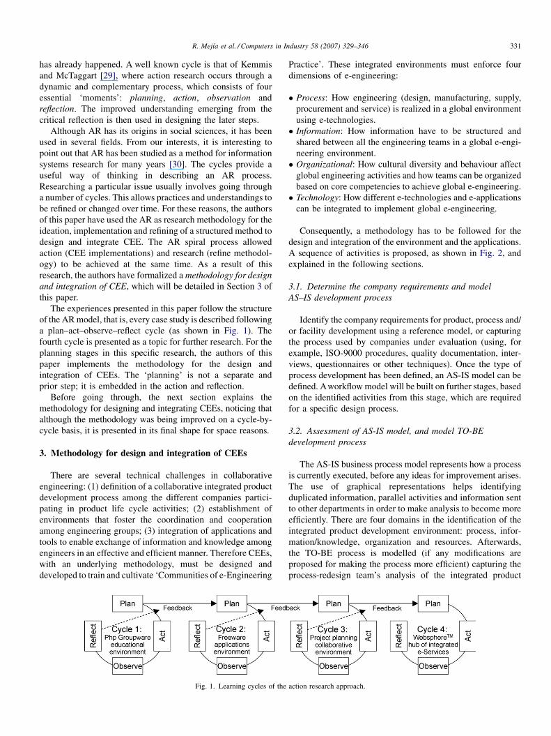
The experiences presented in this paper follow the structure
of the AR model, that is, every case study is described following
a plan–act–observe–reflect cycle (as shown in Fig. 1). The
fourth cycle is presented as a topic for further research. For the
planning stages in this specific research, the authors of this
paper implements the methodology for the design and
integration of CEEs. The ‘planning’ is not a separate and
prior step; it is embedded in the action and reflection.
Before going through, the next section explains the
methodology for designing and integrating CEEs, noticing that
although the methodology was being improved on a cycle-by-
cycle basis, it is presented in its final shape for space reasons.
3. Methodology for design and integration of CEEs
There are several technical challenges in collaborative
engineering: (1) definition of a collaborative integrated product
development process among the different companies partici-
pating in product life cycle activities; (2) establishment of
environments that foster the coordination and cooperation
among engineering groups; (3) integration of applications and
tools to enable exchange of information and knowledge among
engineers in an effective and efficient manner. Therefore CEEs,
with an underlying methodology, must be designed and
developed to train and cultivate ‘Communities of e-Engineering
Fig. 1. Learning cycles of the
Practice’. These integrated environments must enforce four
dimensions of e-engineering:
� P
ac
rocess: How engineering (design, manufacturing, supply,
procurement and service) is realized in a global environment
using e-technologies.
� I
nformation: How information have to be structured andshared between all the engineering teams in a global e-engi-
neering environment.
� O
rganizational: How cultural diversity and behaviour affectglobal engineering activities and how teams can be organized
based on core competencies to achieve global e-engineering.
� T
echnology: How different e-technologies and e-applicationscan be integrated to implement global e-engineering.
Consequently, a methodology has to be followed for the
design and integration of the environment and the applications.
A sequence of activities is proposed, as shown in Fig. 2, and
explained in the following sections.
3.1. Determine the company requirements and model
AS–IS development process
Identify the company requirements for product, process and/
or facility development using a reference model, or capturing
the process used by companies under evaluation (using, for
example, ISO-9000 procedures, quality documentation, inter-
views, questionnaires or other techniques). Once the type of
process development has been defined, an AS-IS model can be
defined. Aworkflow model will be built on further stages, based
on the identified activities from this stage, which are required
for a specific design process.
3.2. Assessment of AS-IS model, and model TO-BE
development process
The AS-IS business process model represents how a process
is currently executed, before any ideas for improvement arises.
The use of graphical representations helps identifying
duplicated information, parallel activities and information sent
to other departments in order to make analysis to become more
efficiently. There are four domains in the identification of the
integrated product development environment: process, infor-
mation/knowledge, organization and resources. Afterwards,
the TO-BE process is modelled (if any modifications are
proposed for making the process more efficient) capturing the
process-redesign team’s analysis of the integrated product
tion research approach.
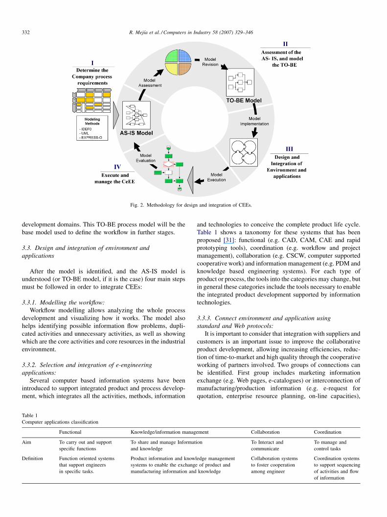
Fig. 2. Methodology for design and integration of CEEs.
R. Mejıa et al. / Computers in Industry 58 (2007) 329–346332
development domains. This TO-BE process model will be the
base model used to define the workflow in further stages.
3.3. Design and integration of environment and
applications
After the model is identified, and the AS-IS model is
understood (or TO-BE model, if it is the case) four main steps
must be followed in order to integrate CEEs:
3.3.1. Modelling the workflow:
Workflow modelling allows analyzing the whole process
development and visualizing how it works. The model also
helps identifying possible information flow problems, dupli-
cated activities and unnecessary activities, as well as showing
which are the core activities and core resources in the industrial
environment.
3.3.2. Selection and integration of e-engineering
applications:
Several computer based information systems have been
introduced to support integrated product and process develop-
ment, which integrates all the activities, methods, information
Table 1
Computer applications classification
Functional Knowledge/information manag
Aim To carry out and support
specific functions
To share and manage Informat
and knowledge
Definition Function oriented systems
that support engineers
in specific tasks.
Product information and know
systems to enable the exchange
manufacturing information and
and technologies to conceive the complete product life cycle.
Table 1 shows a taxonomy for these systems that has been
proposed [31]: functional (e.g. CAD, CAM, CAE and rapid
prototyping tools), coordination (e.g. workflow and project
management), collaboration (e.g. CSCW, computer supported
cooperative work) and information management (e.g. PDM and
knowledge based engineering systems). For each type of
product or process, the tools into the categories may change, but
in general these categories include the tools necessary to enable
the integrated product development supported by information
technologies.
3.3.3. Connect environment and application using
standard and Web protocols:
It is important to consider that integration with suppliers and
customers is an important issue to improve the collaborative
product development, allowing increasing efficiencies, reduc-
tion of time-to-market and high quality through the cooperative
working of partners involved. Two groups of connections can
be identified. First group includes marketing information
exchange (e.g. Web pages, e-catalogues) or interconnection of
manufacturing/production information (e.g. e-request for
quotation, enterprise resource planning, on-line capacities),
ement Collaboration Coordination
ion To Interact and
communicate
To manage and
control tasks
ledge management
of product and
knowledge
Collaboration systems
to foster cooperation
among engineer
Coordination systems
to support sequencing
of activities and flow
of information
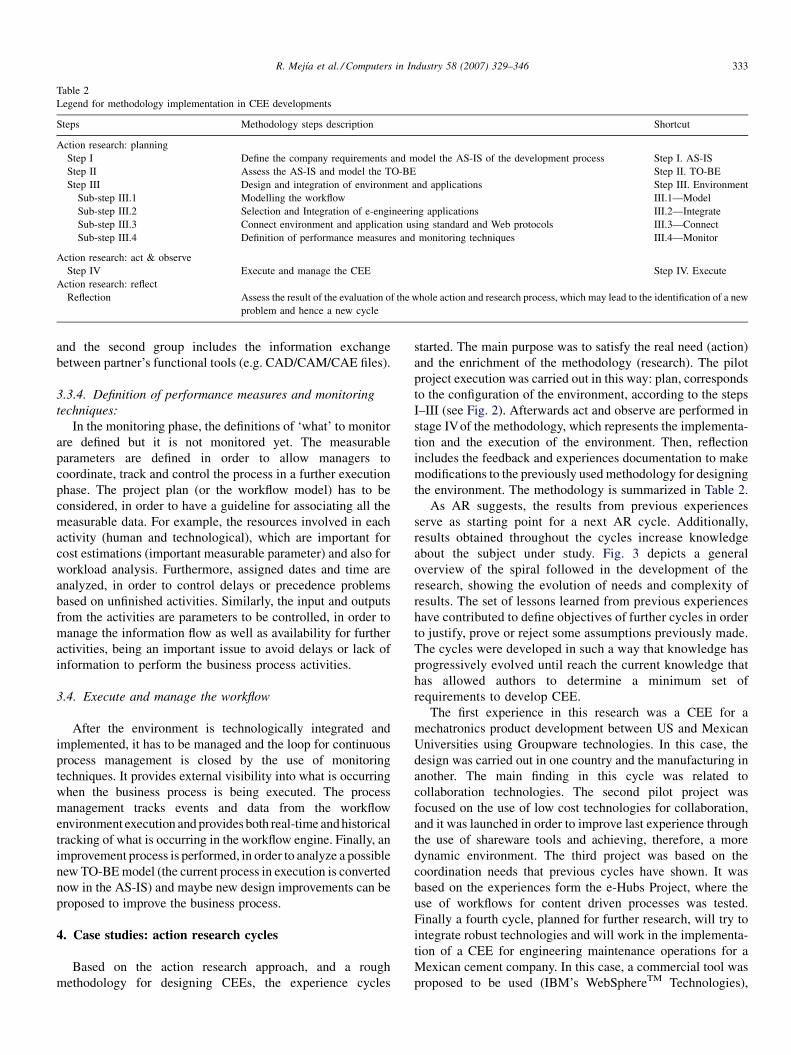
Table 2
Legend for methodology implementation in CEE developments
Steps Methodology steps description Shortcut
Action research: planning
Step I Define the company requirements and model the AS-IS of the development process Step I. AS-IS
Step II Assess the AS-IS and model the TO-BE Step II. TO-BE
Step III Design and integration of environment and applications Step III. Environment
Sub-step III.1 Modelling the workflow III.1—Model
Sub-step III.2 Selection and Integration of e-engineering applications III.2—Integrate
Sub-step III.3 Connect environment and application using standard and Web protocols III.3—Connect
Sub-step III.4 Definition of performance measures and monitoring techniques III.4—Monitor
Action research: act & observe
Step IV Execute and manage the CEE Step IV. Execute
Action research: reflect
Reflection Assess the result of the evaluation of the whole action and research process, which may lead to the identification of a new
problem and hence a new cycle
R. Mejıa et al. / Computers in Industry 58 (2007) 329–346 333
and the second group includes the information exchange
between partner’s functional tools (e.g. CAD/CAM/CAE files).
3.3.4. Definition of performance measures and monitoring
techniques:
In the monitoring phase, the definitions of ‘what’ to monitor
are defined but it is not monitored yet. The measurable
parameters are defined in order to allow managers to
coordinate, track and control the process in a further execution
phase. The project plan (or the workflow model) has to be
considered, in order to have a guideline for associating all the
measurable data. For example, the resources involved in each
activity (human and technological), which are important for
cost estimations (important measurable parameter) and also for
workload analysis. Furthermore, assigned dates and time are
analyzed, in order to control delays or precedence problems
based on unfinished activities. Similarly, the input and outputs
from the activities are parameters to be controlled, in order to
manage the information flow as well as availability for further
activities, being an important issue to avoid delays or lack of
information to perform the business process activities.
3.4. Execute and manage the workflow
After the environment is technologically integrated and
implemented, it has to be managed and the loop for continuous
process management is closed by the use of monitoring
techniques. It provides external visibility into what is occurring
when the business process is being executed. The process
management tracks events and data from the workflow
environment execution and provides both real-time and historical
tracking of what is occurring in the workflow engine. Finally, an
improvement process is performed, in order to analyze a possible
new TO-BE model (the current process in execution is converted
now in the AS-IS) and maybe new design improvements can be
proposed to improve the business process.
4. Case studies: action research cycles
Based on the action research approach, and a rough
methodology for designing CEEs, the experience cycles
started. The main purpose was to satisfy the real need (action)
and the enrichment of the methodology (research). The pilot
project execution was carried out in this way: plan, corresponds
to the configuration of the environment, according to the steps
I–III (see Fig. 2). Afterwards act and observe are performed in
stage IVof the methodology, which represents the implementa-
tion and the execution of the environment. Then, reflection
includes the feedback and experiences documentation to make
modifications to the previously used methodology for designing
the environment. The methodology is summarized in Table 2.
As AR suggests, the results from previous experiences
serve as starting point for a next AR cycle. Additionally,
results obtained throughout the cycles increase knowledge
about the subject under study. Fig. 3 depicts a general
overview of the spiral followed in the development of the
research, showing the evolution of needs and complexity of
results. The set of lessons learned from previous experiences
have contributed to define objectives of further cycles in order
to justify, prove or reject some assumptions previously made.
The cycles were developed in such a way that knowledge has
progressively evolved until reach the current knowledge that
has allowed authors to determine a minimum set of
requirements to develop CEE.
The first experience in this research was a CEE for a
mechatronics product development between US and Mexican
Universities using Groupware technologies. In this case, the
design was carried out in one country and the manufacturing in
another. The main finding in this cycle was related to
collaboration technologies. The second pilot project was
focused on the use of low cost technologies for collaboration,
and it was launched in order to improve last experience through
the use of shareware tools and achieving, therefore, a more
dynamic environment. The third project was based on the
coordination needs that previous cycles have shown. It was
based on the experiences form the e-Hubs Project, where the
use of workflows for content driven processes was tested.
Finally a fourth cycle, planned for further research, will try to
integrate robust technologies and will work in the implementa-
tion of a CEE for engineering maintenance operations for a
Mexican cement company. In this case, a commercial tool was
proposed to be used (IBM’s WebSphereTM Technologies),
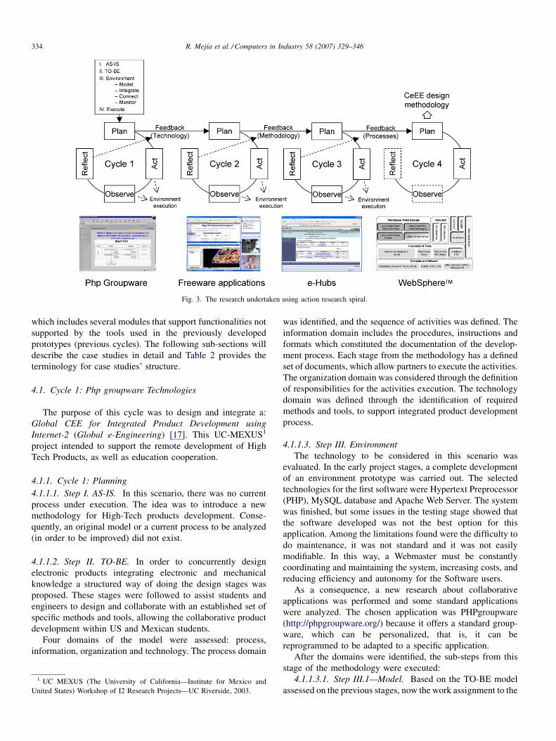
Fig. 3. The research undertaken using action research spiral.
R. Mejıa et al. / Computers in Industry 58 (2007) 329–346334
which includes several modules that support functionalities not
supported by the tools used in the previously developed
prototypes (previous cycles). The following sub-sections will
describe the case studies in detail and Table 2 provides the
terminology for case studies’ structure.
4.1. Cycle 1: Php groupware Technologies
The purpose of this cycle was to design and integrate a:
Global CEE for Integrated Product Development using
Internet-2 (Global e-Engineering) [17]. This UC-MEXUS1
project intended to support the remote development of High
Tech Products, as well as education cooperation.
4.1.1. Cycle 1: Planning
4.1.1.1. Step I. AS-IS. In this scenario, there was no current
process under execution. The idea was to introduce a new
methodology for High-Tech products development. Conse-
quently, an original model or a current process to be analyzed
(in order to be improved) did not exist.
4.1.1.2. Step II. TO-BE. In order to concurrently design
electronic products integrating electronic and mechanical
knowledge a structured way of doing the design stages was
proposed. These stages were followed to assist students and
engineers to design and collaborate with an established set of
specific methods and tools, allowing the collaborative product
development within US and Mexican students.
Four domains of the model were assessed: process,
information, organization and technology. The process domain
1 UC MEXUS (The University of California—Institute for Mexico and
United States) Workshop of I2 Research Projects—UC Riverside, 2003.
was identified, and the sequence of activities was defined. The
information domain includes the procedures, instructions and
formats which constituted the documentation of the develop-
ment process. Each stage from the methodology has a defined
set of documents, which allow partners to execute the activities.
The organization domain was considered through the definition
of responsibilities for the activities execution. The technology
domain was defined through the identification of required
methods and tools, to support integrated product development
process.
4.1.1.3. Step III. Environment
The technology to be considered in this scenario was
evaluated. In the early project stages, a complete development
of an environment prototype was carried out. The selected
technologies for the first software were Hypertext Preprocessor
(PHP), MySQL database and Apache Web Server. The system
was finished, but some issues in the testing stage showed that
the software developed was not the best option for this
application. Among the limitations found were the difficulty to
do maintenance, it was not standard and it was not easily
modifiable. In this way, a Webmaster must be constantly
coordinating and maintaining the system, increasing costs, and
reducing efficiency and autonomy for the Software users.
As a consequence, a new research about collaborative
applications was performed and some standard applications
were analyzed. The chosen application was PHPgroupware
(http://phpgroupware.org/) because it offers a standard group-
ware, which can be personalized, that is, it can be
reprogrammed to be adapted to a specific application.
After the domains were identified, the sub-steps from this
stage of the methodology were executed:
4.1.1.3.1. Step III.1—Model. Based on the TO-BE model
assessed on the previous stages, now the work assignment to the
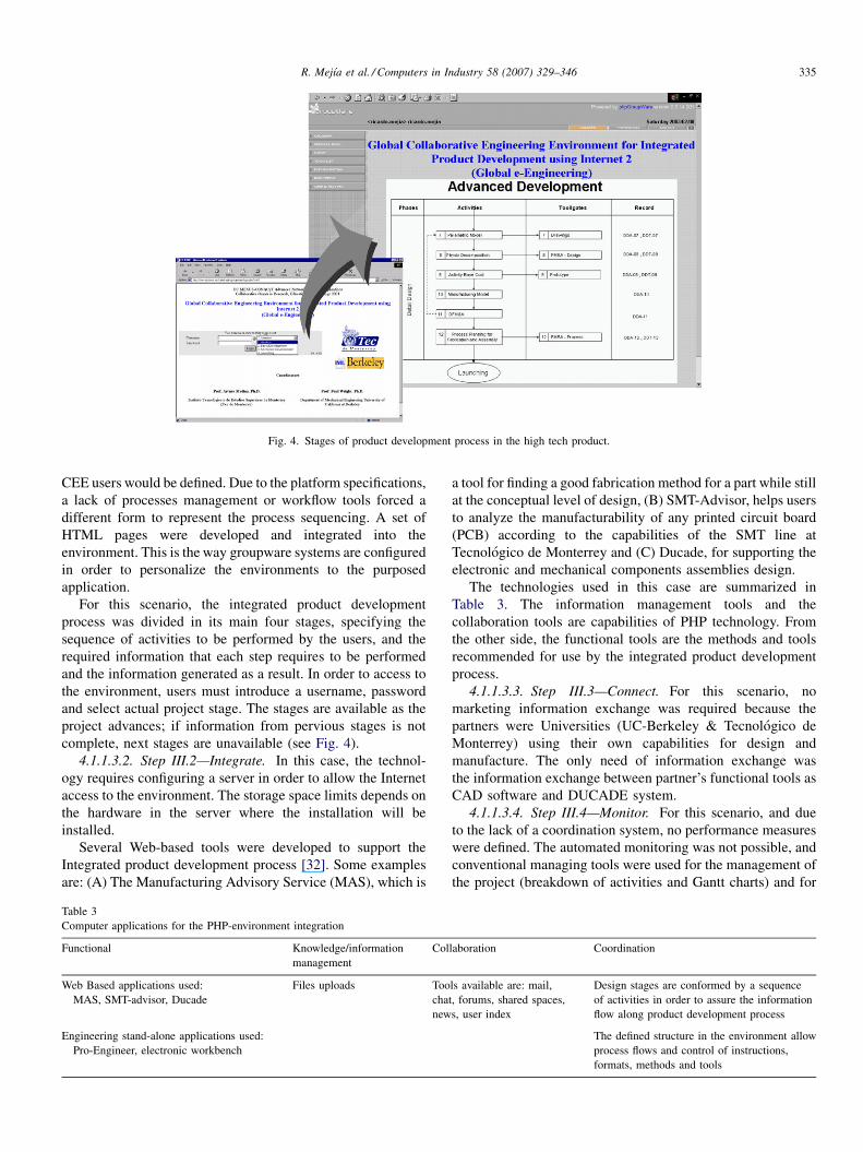
Fig. 4. Stages of product development process in the high tech product.
R. Mejıa et al. / Computers in Industry 58 (2007) 329–346 335
CEE users would be defined. Due to the platform specifications,
a lack of processes management or workflow tools forced a
different form to represent the process sequencing. A set of
HTML pages were developed and integrated into the
environment. This is the way groupware systems are configured
in order to personalize the environments to the purposed
application.
For this scenario, the integrated product development
process was divided in its main four stages, specifying the
sequence of activities to be performed by the users, and the
required information that each step requires to be performed
and the information generated as a result. In order to access to
the environment, users must introduce a username, password
and select actual project stage. The stages are available as the
project advances; if information from pervious stages is not
complete, next stages are unavailable (see Fig. 4).
4.1.1.3.2. Step III.2—Integrate. In this case, the technol-
ogy requires configuring a server in order to allow the Internet
access to the environment. The storage space limits depends on
the hardware in the server where the installation will be
installed.
Several Web-based tools were developed to support the
Integrated product development process [32]. Some examples
are: (A) The Manufacturing Advisory Service (MAS), which is
Table 3
Computer applications for the PHP-environment integration
Functional Knowledge/information
management
Col
Web Based applications used:
MAS, SMT-advisor, Ducade
Files uploads Too
cha
new
Engineering stand-alone applications used:
Pro-Engineer, electronic workbench
a tool for finding a good fabrication method for a part while still
at the conceptual level of design, (B) SMT-Advisor, helps users
to analyze the manufacturability of any printed circuit board
(PCB) according to the capabilities of the SMT line at
Tecnologico de Monterrey and (C) Ducade, for supporting the
electronic and mechanical components assemblies design.
The technologies used in this case are summarized in
Table 3. The information management tools and the
collaboration tools are capabilities of PHP technology. From
the other side, the functional tools are the methods and tools
recommended for use by the integrated product development
process.
4.1.1.3.3. Step III.3—Connect. For this scenario, no
marketing information exchange was required because the
partners were Universities (UC-Berkeley & Tecnologico de
Monterrey) using their own capabilities for design and
manufacture. The only need of information exchange was
the information exchange between partner’s functional tools as
CAD software and DUCADE system.
4.1.1.3.4. Step III.4—Monitor. For this scenario, and due
to the lack of a coordination system, no performance measures
were defined. The automated monitoring was not possible, and
conventional managing tools were used for the management of
the project (breakdown of activities and Gantt charts) and for
laboration Coordination
ls available are: mail,
t, forums, shared spaces,
s, user index
Design stages are conformed by a sequence
of activities in order to assure the information
flow along product development process
The defined structure in the environment allow
process flows and control of instructions,
formats, methods and tools
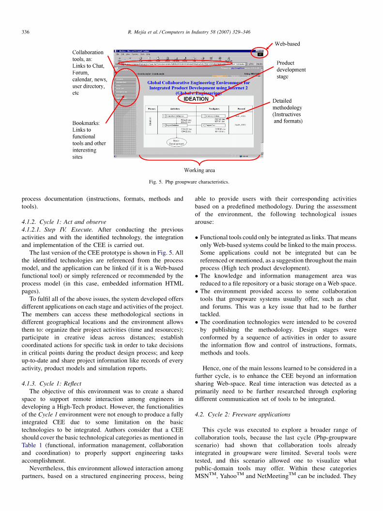
Fig. 5. Php groupware characteristics.
R. Mejıa et al. / Computers in Industry 58 (2007) 329–346336
process documentation (instructions, formats, methods and
tools).
4.1.2. Cycle 1: Act and observe
4.1.2.1. Step IV. Execute. After conducting the previous
activities and with the identified technology, the integration
and implementation of the CEE is carried out.
The last version of the CEE prototype is shown in Fig. 5. All
the identified technologies are referenced from the process
model, and the application can be linked (if it is a Web-based
functional tool) or simply referenced or recommended by the
process model (in this case, embedded information HTML
pages).
To fulfil all of the above issues, the system developed offers
different applications on each stage and activities of the project.
The members can access these methodological sections in
different geographical locations and the environment allows
them to: organize their project activities (time and resources);
participate in creative ideas across distances; establish
coordinated actions for specific task in order to take decisions
in critical points during the product design process; and keep
up-to-date and share project information like records of every
activity, product models and simulation reports.
4.1.3. Cycle 1: Reflect
The objective of this environment was to create a shared
space to support remote interaction among engineers in
developing a High-Tech product. However, the functionalities
of the Cycle 1 environment were not enough to produce a fully
integrated CEE due to some limitation on the basic
technologies to be integrated. Authors consider that a CEE
should cover the basic technological categories as mentioned in
Table 1 (functional, information management, collaboration
and coordination) to properly support engineering tasks
accomplishment.
Nevertheless, this environment allowed interaction among
partners, based on a structured engineering process, being
able to provide users with their corresponding activities
based on a predefined methodology. During the assessment
of the environment, the following technological issues
arouse:
� F
unctional tools could only be integrated as links. That meansonly Web-based systems could be linked to the main process.
Some applications could not be integrated but can be
referenced or mentioned, as a suggestion throughout the main
process (High tech product development).
� T
he knowledge and information management area wasreduced to a file repository or a basic storage on a Web space.
� T
he environment provided access to some collaborationtools that groupware systems usually offer, such as chat
and forums. This was a key issue that had to be further
tackled.
� T
he coordination technologies were intended to be coveredby publishing the methodology. Design stages were
conformed by a sequence of activities in order to assure
the information flow and control of instructions, formats,
methods and tools.
Hence, one of the main lessons learned to be considered in a
further cycle, is to enhance the CEE beyond an information
sharing Web-space. Real time interaction was detected as a
primarily need to be further researched through exploring
different communication set of tools to be integrated.
4.2. Cycle 2: Freeware applications
This cycle was executed to explore a broader range of
collaboration tools, because the last cycle (Php-groupware
scenario) had shown that collaboration tools already
integrated in groupware were limited. Several tools were
tested, and this scenario allowed one to visualize what
public-domain tools may offer. Within these categories
MSNTM, YahooTM and NetMeetingTM can be included. They
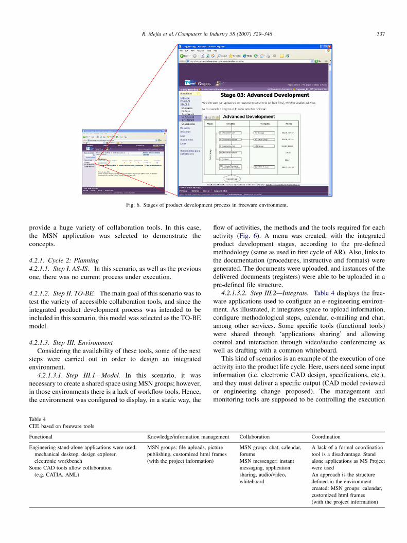
Fig. 6. Stages of product development process in freeware environment.
R. Mejıa et al. / Computers in Industry 58 (2007) 329–346 337
provide a huge variety of collaboration tools. In this case,
the MSN application was selected to demonstrate the
concepts.
4.2.1. Cycle 2: Planning
4.2.1.1. Step I. AS-IS. In this scenario, as well as the previous
one, there was no current process under execution.
4.2.1.2. Step II. TO-BE. The main goal of this scenario was to
test the variety of accessible collaboration tools, and since the
integrated product development process was intended to be
included in this scenario, this model was selected as the TO-BE
model.
4.2.1.3. Step III. Environment
Considering the availability of these tools, some of the next
steps were carried out in order to design an integrated
environment.
4.2.1.3.1. Step III.1—Model. In this scenario, it was
necessary to create a shared space using MSN groups; however,
in those environments there is a lack of workflow tools. Hence,
the environment was configured to display, in a static way, the
Table 4
CEE based on freeware tools
Functional Knowledge/information mana
Engineering stand-alone applications were used:
mechanical desktop, design explorer,
electronic workbench
MSN groups: file uploads, pi
publishing, customized html
(with the project information
Some CAD tools allow collaboration
(e.g. CATIA, AML)
flow of activities, the methods and the tools required for each
activity (Fig. 6). A menu was created, with the integrated
product development stages, according to the pre-defined
methodology (same as used in first cycle of AR). Also, links to
the documentation (procedures, instructive and formats) were
generated. The documents were uploaded, and instances of the
delivered documents (registers) were able to be uploaded in a
pre-defined file structure.
4.2.1.3.2. Step III.2—Integrate. Table 4 displays the free-
ware applications used to configure an e-engineering environ-
ment. As illustrated, it integrates space to upload information,
configure methodological steps, calendar, e-mailing and chat,
among other services. Some specific tools (functional tools)
were shared through ‘applications sharing’ and allowing
control and interaction through video/audio conferencing as
well as drafting with a common whiteboard.
This kind of scenarios is an example of the execution of one
activity into the product life cycle. Here, users need some input
information (i.e. electronic CAD design, specifications, etc.),
and they must deliver a specific output (CAD model reviewed
or engineering change proposed). The management and
monitoring tools are supposed to be controlling the execution
gement Collaboration Coordination
cture
frames
)
MSN group: chat, calendar,
forums
A lack of a formal coordination
tool is a disadvantage. Stand
alone applications as MS Project
were used
MSN messenger: instant
messaging, application
sharing, audio/video,
whiteboard
An approach is the structure
defined in the environment
created: MSN groups: calendar,
customized html frames
(with the project information)
R. Mejıa et al. / Computers in Industry 58 (2007) 329–346338
of this task, and the common information (i.e. uploaded in this
shared environment) is centralized.
4.2.1.3.3. Step III.3—Connect. The key issue in connecting
applications is the exchange formats among functional tools. In
this kind of environments, the transferring of information
between computer applications can be managed through file
uploading from the environment. Nevertheless, this stage was not
executed, because connectivity efforts were not required.
4.2.1.3.4. Step III.4—Monitor. The monitoring stage was
not executed as well, because there was not a coordination
system able to track and control the defined performance
indicators.
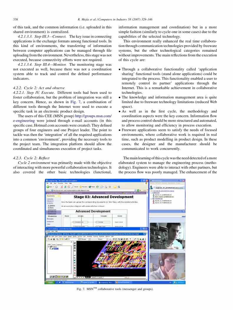
4.2.2. Cycle 2: Act and observe
4.2.2.1. Step IV. Execute. Different tools had been used to
foster collaboration, but the problem of integration was still a
key concern. Hence, as shown in Fig. 7, a combination of
different tools through the Internet were used to execute a
specific task in an electronic product design.
The users of this CEE (MSN group) http://groups.msn.com/
e-engineering were joined through e-mail accounts (in this
specific case, Hotmail.com accounts were created). They defined
groups of four engineers and one Project leader. The point to
tackle was then the ‘integration’ of all the required applications
into a common ‘environment’, providing the necessary tools to
the project team. The integration platform should allow the
coordinated and simultaneous execution of project tasks.
4.2.3. Cycle 2: Reflect
Cycle 2 environment was primarily made with the objective
of interacting with more powerful collaboration technologies. It
also covered the other basic technologies (functional,
Fig. 7. MSNTM collaborative to
information management and coordination) but in a more
simple fashion (similarly to cycle-one in some cases) due to the
capabilities of the selected technology.
This environment really enhanced the real time collabora-
tion through communication technologies provided by freeware
systems, but the other technological categories remained
without improvements. The main reflections from the execution
of this cycle are:
� T
ols
hrough a collaborative functionality called ‘application
sharing’ functional tools (stand alone applications) could be
integrated to the process. This functionality enabled a user to
remotely control its partner’ applications through the
Internet. This is a remarkable achievement in collaborative
technologies.
� T
he knowledge and information management area is quitelimited due to freeware technology limitations (reduced Web
space).
� A
s well as in the first cycle, the methodology andcoordination aspects were the key concern. Information flow
and process control should be more structured and automated,
to allow monitoring and efficiency in process execution.
� F
reeware applications seem to satisfy the needs of focusedenvironments, where collaborative work is required in real
time, such as product modelling in product design. In these
cases, the designer and the manufacturer should be
communicated to work concurrently.
Themain learning of this cyclewas the need detected of a more
elaborated system to manage the engineering process (metho-
dology). Engineers were able to interact with other partners, but
the process flow was poorly managed. The enhancement of the
(messenger and groups).
R. Mejıa et al. / Computers in Industry 58 (2007) 329–346 339
coordination technologies should beconsidered ina furthercycle,
to make a more dynamic environment.
4.3. Cycle 3: e-Engineering enabled by Holonomic and
Universal Broker services
This cycle integrated the experiences gained in the two prior
cycles. The need for more stable and robust platforms guided to
the selection of more robust applications. It primarily tackled the
engineering process automation (coordination technologies).
This experience was developed in collaboration with the
European e-HUBs consortium,2 funded by the European
Commission’s IST program in 2002 to develop a Web hosted
platform for planning e-engineering projects. The authors were
part of the consortium and have participated in the system’s
requirement specification and integration model (where previous
cycles’ experiences were included in the contribution). Those
specifications were provided to an industrial partner in
information technologies (also part of the consortium) and they
carried out the construction of a prototype system. The authors of
the article were in charge of one of the two ‘‘test beds’’
implementation with industrial and research partners from
Mexico and Europe.
The project aimed at a set of Web hosted services that enable
projects to be efficiently planned through a so-called e-Hub.
The project targeted the conceptual development and imple-
mentation of e-Hubs, a novel concept for the realisation of
distant co-engineering [33]. A generic conceptual framework
was developed and a prototype implementation of the generic
concepts was benchmarked in co-engineering processes within
the development life cycle and manufacturing process of
customized products.
The e-HUBs project ended in summer 2004. The main result
was a first generation prototype with unprecedented project
planning functionality [34]. The prototype is currently running
and some of its functionalities will be described in the
following section.
4.3.1. Cycle 3: Planning
4.3.1.1. Step I. AS-IS. For the e-HUBs software prototype,
two domain-specific scenarios from different disciplines were
evaluated. The first scenario or ‘test-bed’ dealt with seismic risk
assessment procurement in a large construction project, whose
client was a Dutch design firm and the engineering service
provider was an Italian small and medium enterprise (SME).
The second test-bed dealt with the engineering of a structural
part for a trailer. In this case, the client was a steel-making
company and the engineering provider was an SME cluster in
Mexico. The e-Hubs’ focus was on project planning where the
partners involved had not a standardized process, that is, there
was a lack of an AS-IS model.
2 The e-Hubs Consortium consists of: TU Delft (NL), RWTH (GE), Design
Solutions (NL), European Dynamics (GR), CKA (BE), GeoDeco (IT), Lough-
borough University (UK) with affiliated partners Tecnologico de Monterrey/
IECOS (Mexico) and NUMA (Brazil), Georgia Tech (USA) and Penn State
(USA).
The strategy followed to generate the TO-BE model was to
analyze and improve a planning stage of an already developed
project in a company called integration, engineering and
construction systems (IECOS). IECOS had made a market
analysis for its client to identify potential product for new
markets based on the client’s expertise—which is metalwork-
ing manufacturing. IECOS identified several possible new
products and developed a specific project called ‘Design
process of a Dry-Freight Van for Trailer’. At the end of the
benchmarking phase, the client decided to outsource the
engineering of the new product to IECOS due to the lack of
internal engineering capability and expertise. Hence, the
planning process of this project was reviewed, improved and
later used as a model.
4.3.1.2. Step II. TO-BE. To create the workflow, the product
design scenario was analyzed and an overall evaluation of the
generic process for project planning was performed. After that,
the original project planning was compared to the real
execution. Then, a detailed evaluation was performed
comparing each task in order to progressively identify trouble
spots and their originators. These issues were useful to
determine preventive activities in a project planning workflow,
pursuing the prevention of potential problems during project
execution.
Information was gathered to prevent issues that could cause
problems during project execution. Topics like project duration,
project design, parties involved and changes during execution
where discussed. However, these topics were too generic and
therefore it was necessary to create detailed documents to
support a specific domain. For that reason, the testbeds required
the design and integration of dedicated workflows to support
the collaborative project planning in their specific domains
(civil and manufacturing engineering). In the product design
scenario, a set of supporting documents were defined based on
the experience and knowledge generated (aligned with the
PMBOK from the PMI [35]). For example, three supporting
workflows for engineering project planning were identified in
the product design scenario:
Document A: environment control/external factors: In this
document problems detected in execution were grouped,
creating a set of fields to be considered by the partners from
the beginning of the preparation phases. They were called
‘categories’ grouping common difficulty spots as techno-
logical, market conditions, regulations, etc.
Document B: change management control ( product): This
document intended to guide project planners in negotiating,
from the beginning, a set of conditions for dealing with
change requests. The workflow managed a flow of activities
working upon a set of variables that would guide partners to
a discussion of conditions, until an agreement was reached.
Document C: risk identification: Usually between two
partners, there are several areas with a high level of risk, for
example proficiency, information management, technology,
etc. This workflow intended to show users common risk
areas in engineering projects. A set of activities would guide
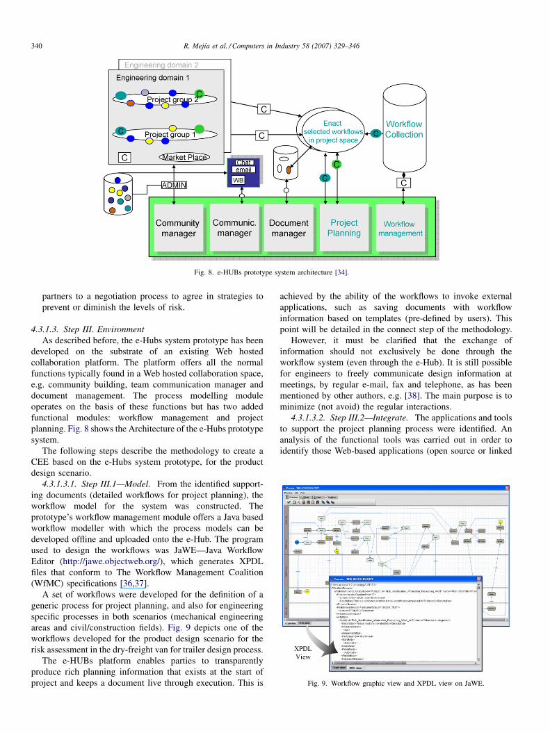
Fig. 8. e-HUBs prototype system architecture [34].
R. Mejıa et al. / Computers in Industry 58 (2007) 329–346340
partners to a negotiation process to agree in strategies to
prevent or diminish the levels of risk.
Fig. 9. Workflow graphic view and XPDL view on JaWE.
4.3.1.3. Step III. Environment
As described before, the e-Hubs system prototype has been
developed on the substrate of an existing Web hosted
collaboration platform. The platform offers all the normal
functions typically found in a Web hosted collaboration space,
e.g. community building, team communication manager and
document management. The process modelling module
operates on the basis of these functions but has two added
functional modules: workflow management and project
planning. Fig. 8 shows the Architecture of the e-Hubs prototype
system.
The following steps describe the methodology to create a
CEE based on the e-Hubs system prototype, for the product
design scenario.
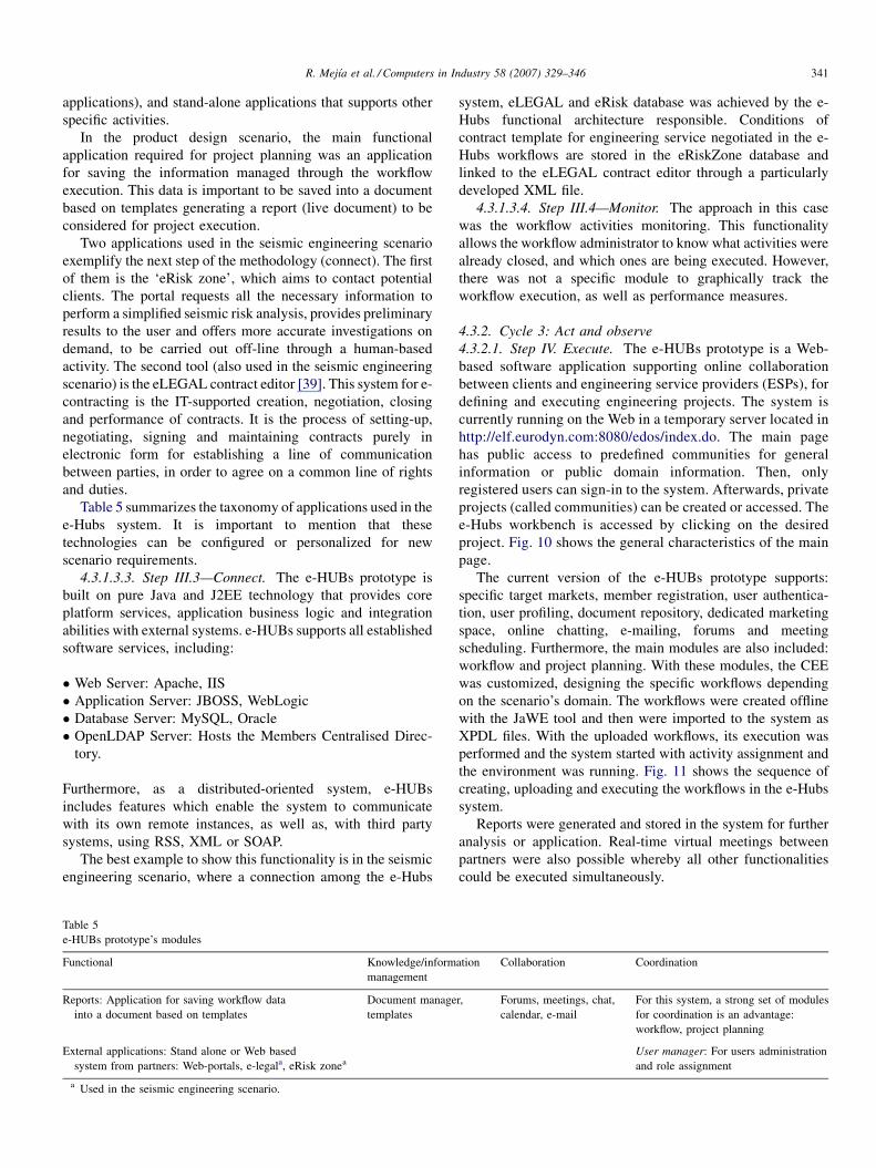
4.3.1.3.1. Step III.1—Model. From the identified support-
ing documents (detailed workflows for project planning), the
workflow model for the system was constructed. The
prototype’s workflow management module offers a Java based
workflow modeller with which the process models can be
developed offline and uploaded onto the e-Hub. The program
used to design the workflows was JaWE—Java Workflow
Editor (http://jawe.objectweb.org/), which generates XPDL
files that conform to The Workflow Management Coalition
(WfMC) specifications [36,37].
A set of workflows were developed for the definition of a
generic process for project planning, and also for engineering
specific processes in both scenarios (mechanical engineering
areas and civil/construction fields). Fig. 9 depicts one of the
workflows developed for the product design scenario for the
risk assessment in the dry-freight van for trailer design process.
The e-HUBs platform enables parties to transparently
produce rich planning information that exists at the start of
project and keeps a document live through execution. This is
achieved by the ability of the workflows to invoke external
applications, such as saving documents with workflow
information based on templates (pre-defined by users). This
point will be detailed in the connect step of the methodology.
However, it must be clarified that the exchange of
information should not exclusively be done through the
workflow system (even through the e-Hub). It is still possible
for engineers to freely communicate design information at
meetings, by regular e-mail, fax and telephone, as has been
mentioned by other authors, e.g. [38]. The main purpose is to
minimize (not avoid) the regular interactions.
4.3.1.3.2. Step III.2—Integrate. The applications and tools
to support the project planning process were identified. An
analysis of the functional tools was carried out in order to
identify those Web-based applications (open source or linked
R. Mejıa et al. / Computers in Industry 58 (2007) 329–346 341
applications), and stand-alone applications that supports other
specific activities.
In the product design scenario, the main functional
application required for project planning was an application
for saving the information managed through the workflow
execution. This data is important to be saved into a document
based on templates generating a report (live document) to be
considered for project execution.
Two applications used in the seismic engineering scenario
exemplify the next step of the methodology (connect). The first
of them is the ‘eRisk zone’, which aims to contact potential
clients. The portal requests all the necessary information to
perform a simplified seismic risk analysis, provides preliminary
results to the user and offers more accurate investigations on
demand, to be carried out off-line through a human-based
activity. The second tool (also used in the seismic engineering
scenario) is the eLEGAL contract editor [39]. This system for e-
contracting is the IT-supported creation, negotiation, closing
and performance of contracts. It is the process of setting-up,
negotiating, signing and maintaining contracts purely in
electronic form for establishing a line of communication
between parties, in order to agree on a common line of rights
and duties.
Table 5 summarizes the taxonomy of applications used in the
e-Hubs system. It is important to mention that these
technologies can be configured or personalized for new
scenario requirements.
4.3.1.3.3. Step III.3—Connect. The e-HUBs prototype is
built on pure Java and J2EE technology that provides core
platform services, application business logic and integration
abilities with external systems. e-HUBs supports all established
software services, including:
� W
Ta
e-
Fu
Re
Ex
a
eb Server: Apache, IIS
� A
pplication Server: JBOSS, WebLogic� D
atabase Server: MySQL, Oracle� O
penLDAP Server: Hosts the Members Centralised Direc-tory.
Furthermore, as a distributed-oriented system, e-HUBs
includes features which enable the system to communicate
with its own remote instances, as well as, with third party
systems, using RSS, XML or SOAP.
The best example to show this functionality is in the seismic
engineering scenario, where a connection among the e-Hubs
ble 5
HUBs prototype’s modules
nctional Knowledge/inform
management
ports: Application for saving workflow data
into a document based on templates
Document manage
templates
ternal applications: Stand alone or Web based
system from partners: Web-portals, e-legala, eRisk zonea
Used in the seismic engineering scenario.
system, eLEGAL and eRisk database was achieved by the e-
Hubs functional architecture responsible. Conditions of
contract template for engineering service negotiated in the e-
Hubs workflows are stored in the eRiskZone database and
linked to the eLEGAL contract editor through a particularly
developed XML file.
4.3.1.3.4. Step III.4—Monitor. The approach in this case
was the workflow activities monitoring. This functionality
allows the workflow administrator to know what activities were
already closed, and which ones are being executed. However,
there was not a specific module to graphically track the
workflow execution, as well as performance measures.
4.3.2. Cycle 3: Act and observe
4.3.2.1. Step IV. Execute. The e-HUBs prototype is a Web-
based software application supporting online collaboration
between clients and engineering service providers (ESPs), for
defining and executing engineering projects. The system is
currently running on the Web in a temporary server located in
http://elf.eurodyn.com:8080/edos/index.do. The main page
has public access to predefined communities for general
information or public domain information. Then, only
registered users can sign-in to the system. Afterwards, private
projects (called communities) can be created or accessed. The
e-Hubs workbench is accessed by clicking on the desired
project. Fig. 10 shows the general characteristics of the main
page.
The current version of the e-HUBs prototype supports:
specific target markets, member registration, user authentica-
tion, user profiling, document repository, dedicated marketing
space, online chatting, e-mailing, forums and meeting
scheduling. Furthermore, the main modules are also included:
workflow and project planning. With these modules, the CEE
was customized, designing the specific workflows depending
on the scenario’s domain. The workflows were created offline
with the JaWE tool and then were imported to the system as
XPDL files. With the uploaded workflows, its execution was
performed and the system started with activity assignment and
the environment was running. Fig. 11 shows the sequence of
creating, uploading and executing the workflows in the e-Hubs
system.
Reports were generated and stored in the system for further
analysis or application. Real-time virtual meetings between
partners were also possible whereby all other functionalities
could be executed simultaneously.
ation Collaboration Coordination
r, Forums, meetings, chat,
calendar, e-mail
For this system, a strong set of modules
for coordination is an advantage:
workflow, project planning
User manager: For users administration
and role assignment
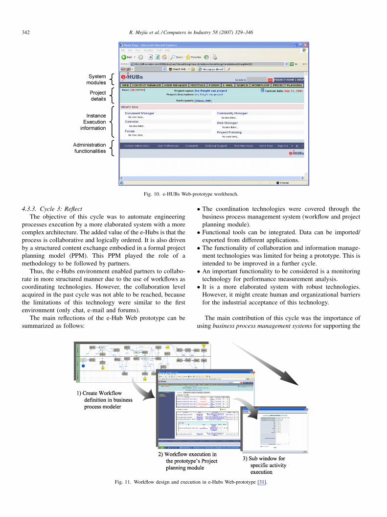
Fig. 10. e-HUBs Web-prototype workbench.
R. Mejıa et al. / Computers in Industry 58 (2007) 329–346342
4.3.3. Cycle 3: Reflect
The objective of this cycle was to automate engineering
processes execution by a more elaborated system with a more
complex architecture. The added value of the e-Hubs is that the
process is collaborative and logically ordered. It is also driven
by a structured content exchange embodied in a formal project
planning model (PPM). This PPM played the role of a
methodology to be followed by partners.
Thus, the e-Hubs environment enabled partners to collabo-
rate in more structured manner due to the use of workflows as
coordinating technologies. However, the collaboration level
acquired in the past cycle was not able to be reached, because
the limitations of this technology were similar to the first
environment (only chat, e-mail and forums).
The main reflections of the e-Hub Web prototype can be
summarized as follows:
Fig. 11. Workflow design and executi
� T
on
he coordination technologies were covered through the
business process management system (workflow and project
planning module).
� F
unctional tools can be integrated. Data can be imported/exported from different applications.
� T
he functionality of collaboration and information manage-ment technologies was limited for being a prototype. This is
intended to be improved in a further cycle.
� A
n important functionality to be considered is a monitoringtechnology for performance measurement analysis.
� I
t is a more elaborated system with robust technologies.However, it might create human and organizational barriers
for the industrial acceptance of this technology.
The main contribution of this cycle was the importance of
using business process management systems for supporting the
in e-Hubs Web-prototype [31].
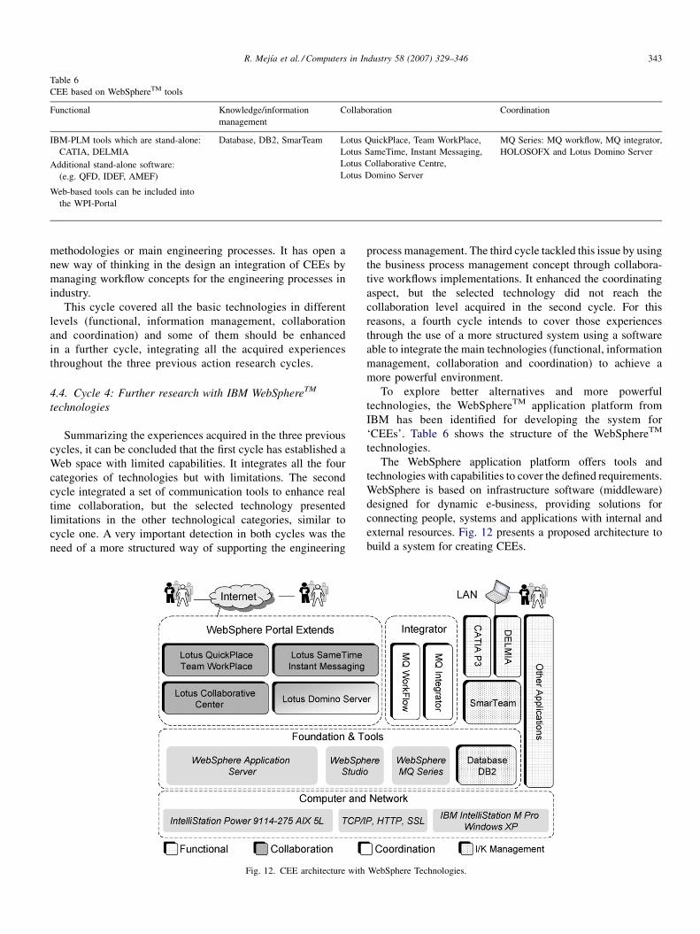
Table 6
CEE based on WebSphereTM tools
Functional Knowledge/information
management
Collaboration Coordination
IBM-PLM tools which are stand-alone:
CATIA, DELMIA
Database, DB2, SmarTeam Lotus QuickPlace, Team WorkPlace,
Lotus SameTime, Instant Messaging,
Lotus Collaborative Centre,
Lotus Domino Server
MQ Series: MQ workflow, MQ integrator,
HOLOSOFX and Lotus Domino Server
Additional stand-alone software:
(e.g. QFD, IDEF, AMEF)
Web-based tools can be included into
the WPI-Portal
R. Mejıa et al. / Computers in Industry 58 (2007) 329–346 343
methodologies or main engineering processes. It has open a
new way of thinking in the design an integration of CEEs by
managing workflow concepts for the engineering processes in
industry.
This cycle covered all the basic technologies in different
levels (functional, information management, collaboration
and coordination) and some of them should be enhanced
in a further cycle, integrating all the acquired experiences
throughout the three previous action research cycles.
4.4. Cycle 4: Further research with IBM WebSphereTM
technologies
Summarizing the experiences acquired in the three previous
cycles, it can be concluded that the first cycle has established a
Web space with limited capabilities. It integrates all the four
categories of technologies but with limitations. The second
cycle integrated a set of communication tools to enhance real
time collaboration, but the selected technology presented
limitations in the other technological categories, similar to
cycle one. A very important detection in both cycles was the
need of a more structured way of supporting the engineering
Fig. 12. CEE architecture with
process management. The third cycle tackled this issue by using
the business process management concept through collabora-
tive workflows implementations. It enhanced the coordinating
aspect, but the selected technology did not reach the
collaboration level acquired in the second cycle. For this
reasons, a fourth cycle intends to cover those experiences
through the use of a more structured system using a software
able to integrate the main technologies (functional, information
management, collaboration and coordination) to achieve a
more powerful environment.
To explore better alternatives and more powerful
technologies, the WebSphereTM application platform from
IBM has been identified for developing the system for
‘CEEs’. Table 6 shows the structure of the WebSphereTM
technologies.
The WebSphere application platform offers tools and
technologies with capabilities to cover the defined requirements.
WebSphere is based on infrastructure software (middleware)
designed for dynamic e-business, providing solutions for
connecting people, systems and applications with internal and
external resources. Fig. 12 presents a proposed architecture to
build a system for creating CEEs.
WebSphere Technologies.
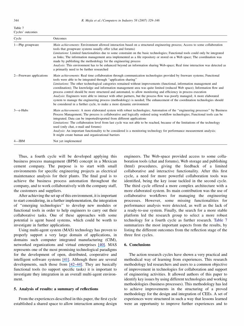
Table 7
Cycles’ outcomes
Cycle Outcomes
1—Php groupware Main achievements: Environment allowed interaction based on a structured engineering process; Access to some collaboration
tools that groupware systems usually offer (chat and forums)
Limitations: Limited functionalities due to some constraint on the basic technologies; Functional tools could only be integrated
as links; The information management area implemented as a file repository or stored on a Web space; The coordination was
made by publishing the methodology for the engineering process
Analysis: This environment has to be enhanced beyond an information sharing Web-space; Real time interaction was detected as
a primarily need to be further researched
2—Freeware applications Main achievements: Real time collaboration through communication technologies provided by freeware systems; Functional
tools were able to be integrated through ‘‘application sharing’’
Limitations: The other technological categories remained without improvements (functional, information management and
coordination); The knowledge and information management area was quite limited (reduced Web space); Information flow and
process control should be more structured and automated, to allow monitoring and efficiency in process execution
Analysis: Engineers were able to interact with other partners, but the process flow was poorly managed; A more elaborated
system to manage the engineering process (methodology) is needed; The enhancement of the coordination technologies should
be considered in a further cycle, to make a more dynamic environment
3—e-Hubs Main achievements: A more elaborated system with robust technologies; Automation of the ‘‘engineering processes’’ by Business
Process Management; The process is collaborative and logically ordered using workflow technologies; Functional tools can be
integrated. Data can be imported/exported from different applications
Limitations: The collaboration level from last cycle was not able to be reached, because of the limitations of the technology
used (only chat, e-mail and forums)
Analysis: An important functionality to be considered is a monitoring technology for performance measurement analysis;
It might create human and organizational barriers
4—IBM Not yet implemented
R. Mejıa et al. / Computers in Industry 58 (2007) 329–346344
Thus, a fourth cycle will be developed applying this
business process management (BPM) concept in a Mexican
cement company. The purpose is to start with small
environments for specific engineering projects as electrical
maintenance analysis for their plants. The final goal is to
achieve the business process automation throughout the
company, and to work collaboratively with the company staff,
the customers and suppliers.
After achieving the set up of this environment, it is important
to start considering, in a further implementation, the integration
of ‘‘emerging technologies’’ to develop new modules or
functional tools in order to help engineers to carry out their
collaborative tasks. One of these approaches with some
potential is agent based systems, which could be worth to
investigate in further applications.
Using multi-agent system (MAS) technology has proven to
properly support a very large domain of applications, in
domains such computer integrated manufacturing (CIM),
networked organizations and virtual enterprises [40]. MAS
represents one of the most promising technological paradigms
for the development of open, distributed, cooperative and
intelligent software systems [41]. Although there are several
developments, such those from [42–44]. They are basically
functional tools (to support specific tasks) it is important to
investigate they integration in an overall multi-agent environ-
ment.
5. Analysis of results: a summary of reflections
From the experiences described in this paper, the first cycle
established a shared space to allow interaction among design
engineers. The Web-space provided access to some colla-
boration tools (chat and forums), Web storage and publishing
(html) procedures, giving the feedback of a limited
collaborative and interactive functionality. After this first
cycle, a need for more powerful collaboration tools was
identified, being the key issue tackled in the second cycle.
The third cycle offered a more complex architecture with a
more elaborated system. Its main contribution was the use of
collaborative workflows for managing the engineering
processes. However, some missing functionalities for
performance analysis were detected, as well as the lack of
a ready-to-use system. Finally, the search for a more stable
platform led the research group to select a more robust
technology for a fourth cycle as further research. Table 7
summarizes the most important aspects from the results, by
listing the different outcomes from the reflection stage of the
three first cycles.
6. Conclusions
The action research cycles have shown a very practical and
methodical way of learning from experiences. This research
methodology led researchers and users to a common objective
of improvement in technologies for collaboration and support
of engineering activities. It allowed authors of this paper to
identify key issues by using different technologies and working
methodologies (business processes). This methodology has led
to achieve improvements in the structuring of a proved
methodology for the design and integration of CEEs. A set of
experiences were structured in such a way that lessons learned
were an opportunity to improve further experiences and to
R. Mejıa et al. / Computers in Industry 58 (2007) 329–346 345
enrich the knowledge on CEEs creation. An important remark
is that not all the technical shortcomings should be tackled in
the next cycle, but it can be done two or three cycles afterwards.
Perhaps more importantly, the learning process brought about a
methodology for the design and integration of CEEs that will
guide researchers and practitioners to build up their customised
CEEs.
Acknowledgements
The authors acknowledge the Chair in Mechatronics from
the Instituto Tecnologico y de Estudios Superiores de
Monterrey (Tecnologico de Monterrey, Campus Monterrey),
UC MEXUS-CONACyT Advanced Networks Services Appli-
cation Collaborative Grant and the ‘IBM SUR Grant’ for their
funding and support in the development of this research.
The e-HUB pilot project was part of the e-HUBs consortium
(IST-2001-34031) sponsored by the European Commission,
and authors acknowledge all e-Hubs partners.
References
[1] S.P. Keller, Simulation-based acquisition: real world examples, Army
RD&A (1998) 25–26.
[2] G.M. Bochenek, J.M. Ragusa, Virtual collaborative design environments:
a review, issues, some research, and the future, International Conference
on Management of Engineering and Technology, PICMET 01, 2001.
[3] J.P. Harrison, Virtual collaborative simulation environment for integrated
product and process development, in: Proceeding of the IEEE Interna-
tional Symposium on High Performance Distributed Computing, vol. 6–9,
1996, 19–22.
[4] Huang, Q. George, Web-based support for collaborative product design
review, Journal of Computers in Industry 48 (1) (2002) 71–88.
[5] S.F. Qina, R. Harrisonb, A.A. Westb, I.N. Jordanovc, D.K. Wrighta, A
framework of Web-based conceptual design, Computers in Industry 50 (2)
(2003) 153–164.
[6] F.E.H. Tay, A. Roy, CyberCAD: a collaborative approach in 3D-CAD
technology in a multimedia-supported environment, Computers in Indus-
try 52 (2) (2003) 127–145.
[7] G. Huang, L. Mak, Agent-based collaboration between distributed Web
applications: case study on collaborative design for X, Using CyberCO,
Concurrent Engineering: Research and applications 10 (4) (2002) 279–290.
[8] Y. Wanga, W. Shena, H. Ghenniwab, WebBlow: a Web/agent-based
multidisciplinary design optimization environment, Computers in Indus-
try 52 (September (1)) (2003) 17–28.
[9] F. Qian, Z. Shenseng, Product development process management system
based on P_PROCE Model, Concurrent Engineering: Research and
Applications 10 (September (3)) (2002) 203–211.
[10] K. Rodriguez, A. Al-Ashaab, Knowledge Web-based system architecture
for collaborative product development, Computers in Industry 56 (1)
(2005) 125–140.
[11] S.Q. Xie, Y.L. Tu, R.Y.K. Fung, Z.D. Zhou, Rapid one-of-a-kind product
development via the Internet: a literature review of the state-of-the-art and
a proposed platform, International Journal of Production Research 41
(2003) 4257–4298.
[12] W.D. Li, J.Y.H. Fuh, Y.S. Wong, An Internet-enabled integrated system for
co-design and concurrent engineering, Computers in Industry 55 (1)
(2004) 87–103.
[13] M. Tseng, T. Kjellberg, S.C.Y. Lu, Design in the New e-Commerce Era,
Cirp Annals-Manufacturing Technology 52 (2003) 509–519.
[14] H. Yang, D. Xue, Recent research on developing Web-based manufactur-
ing systems: a review, International Journal of Production Research 41
(2003) 3601–3629.
[15] W.K. McQUAY, Distributed collaborative environments for 21st Century
modeling and simulation, Simulation 76 (2001) 95–96.
[16] W. Shen, Editorial of the special issue on knowledge sharing in
collaborative design environments, Computers in Industry 52 (2003)
1–3.
[17] J. Aca, R. Mejıa, M. Velandia, E. Garcıa, N. Galeano, H. Ahuett,
A. Molina, P. Wright, Integrated product development in virtual
enterprises supported by Web-based applications, in: L.M. Camar-
inha-Matos, H. Afsarmanesh (Eds.), Process and Foundations for
Virtual Organizations, Kluwer Academic Publishers, 2003 , pp.
361–368.
[18] J. Heckel, The virtual workspace system: an enabling technology for
collaborative engineering applications, in: Proceedings of the Workshop
on Enabling Technologies for Collaborative Enterprise, Boston, MA,
(1997), pp. 10–16.
[19] H.F. Wang, Y.L. Zhang, CAD/CAM integrated system in collaborative
development environment, Robotics and Computer Integrated Manufac-
turing 18 (2002) 135–145.
[20] D. Xue, Y. Xu, Web-based distributed system and database modeling for
concurrent design, Computer-Aided Design 35 (2003) 433–452.
[21] M.N.K. Saunders, P. Lewis, Research Methods For Business Students,
Harlow Financial Times: Prentice Hall, 2000.
[22] J. Gill, P. Johnson, Research Methods for Managers, third ed., Sage, 2002.
[23] K. Lewin, Action research and minority problems, Journal of Social Issues
2 (1946) 34–46.
[24] R. Rapoport, Three dilemmas in action research, Human Relations 23
(1970) 499–513.
[25] A. Bowling, Research Methods in Health, Open University Press,
Buckingham, 1997.
[26] O. Zuber-Skerritt, New Directions in Action Research, Falmer Press,
1996.
[27] B. Dick, Action research: action and research, In the seminar: doing good
action research held at Southern Cross University, 2002.
[28] R. Baskervillea, J. Pries-Hejeb, Grounded action research: a method for
understanding IT in practice., Accounting, Management and Information
Technologies 9 (1999) 1–23.
[29] S. Kemmis, R. McTaggart (Eds.), The Action Research Planner, Deakin
University, Geelong, 1988.
[30] R. Baskerville, T. Wood-Harper, A critical perspective on action research
as a method for information systems research, Journal of Information
Technology 11 (1996) 235–246.
[31] R. Mejıa, L. Canche, C. Rodrıguez, H. Ahuett, A. Molina, G. Augenbroe,
Designing a HUB to offer e-Engineering brokerage services for Virtual
Enterprises, in: L.M. Camarinha-Matos (Ed.), Virtual Enterprises and
Collaborative Networks, Kluwer Academic Publishers, 2004, pp. 453–
460.
[32] A. Molina, J. Aca, P. Wright, Global collaborative engineering environ-
ment for integrated product development, International Journal of Com-
puter Integrated Manufacturing 18 (2005) 635–651.
[33] e-Hubs, e-Engineering enabled by Holonomic and Universal Broker
Services, Technical Annex-1, Description of Work, IST project: IST-
2001-34031, 2001.
[34] G. Augenbroe, e-HUBs: e-engineering enabled by Holonomic and Uni-
versal Broker services, in: Proceedings of the eChallenges conference,
Vienna, 2004.
[35] PMBOK, A Guide to the Project Management Body of Knowledge, first
ed., PMI, Project Management Institute, USA, 2000.
[36] D. Hollingsworth, Workflow management coalition specification: the
workflow reference model, WfMC specification, 1994.
[37] WFMC, Workflow Process Definition Interface: XML Process Definition
Language, Lighthouse Point FL: Workflow Management Coalition
(WFMC-TC-1025), 2002 (available from: http://wfmc.org/standards/
docs.htm).
[38] W. Derks, R. Weston, A. West, R. Harrison, D. Shorter, Role of workow
management systems in product engineering, International Journal of
Production Research 41 (2003) 3393–3418.
[39] T.M. Hassan, C. Carter, M. Hannus, Y. Hyvarinen, e-Legal: defining a
frame-work for legally admissible use of ICT in virtual enterprises, in: K.
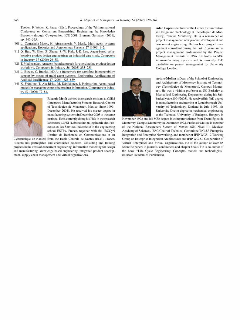
R. Mejıa et al. / Computers in Industry 58 (2007) 329–346346
Thoben, F. Weber, K. Pawar (Eds.), Proceedings of the 7th International
Conference on Concurrent Enterprising: Engineering the Knowledge
Economy through Co-operation, ICE 2001, Bremen, Germany, (2001),
pp. 347–355.
[40] L. Camarinha-Matos, H. Afsarmanesh, V. Marık, Multi-agent systems
applications, Robotics and Autonomous Systems 27 (1999) 1–2.
[41] Q. Hao, W. Shen, Z. Zhang, S.-W. Park, J.-K. Lee, Agent-based colla-
borative product design engineering: an industrial case study, Computers
in Industry 57 (2006) 26–38.
[42] T. Madhusudan, An agent-based approach for coordinating product design
workflows, Computers in Industry 56 (2005) 235–259.
[43] L. Biegus, C. Branki, InDiA: a framework for workflow interoperability
support by means of multi-agent systems, Engineering Applications of
Artificial Intelligence 17 (2004) 825–839.
[44] K. Framling, T. Ala-Risku, M. Karkkainen, J. Holmstrom, Agent-based
model for managing composite product information, Computers in Indus-
try 57 (2006) 72–81.
Ricardo Mejıa worked as research assistant at CSIM
(Integrated Manufacturing Systems Research Center)
of Tecnologico de Monterrey, Mexico (June 1999–
December 2004). He received his master degree in
manufacturing systems in December 2003 at the same
institute. He is currently doing his PhD in the research
laboratory LIPSI (Laboratoire en Ingenierie des Pro-
cessus et des Services Industriels) in the engineering
school ESTIA, France, together with the IRCCyN
(Institut de Recherche en Communications et en
Cybernetique de Nantes) from the Ecole Centrale de Nantes (ECN), France.
Ricardo has participated and coordinated research, consulting and training
projects in the areas of concurrent engineering, information modelling for design
and manufacturing, knowledge based engineering, integrated product develop-
ment, supply chain management and virtual organizations.
Adan Lopez is lecturer at the Center for Innovation
in Design and Technology at Tecnologico de Mon-
terrey, Campus Monterrey. He is a researcher on
project management, new product development and
concurrent engineering. He has been project man-
agement consultant during the last 15 years and is
project management professional by the Project
Management Institute in USA. He holds an MSc
in manufacturing systems and is currently PhD
candidate on project management by University
College London.
Arturo Molina is Dean of the School of Engineering
and Architecture of Monterrey Institute of Technol-
ogy (Tecnologico de Monterrey), Campus Monter-
rey. He was a visiting professor at UC Berkeley at
Mechanical Engineering Department during his Sab-
batical year (2004/2005). He received his PhD degree
in manufacturing engineering at Loughborough Uni-
versity of Technology, England in July 1995, his
University Doctor degree in mechanical engineering
at the Technical University of Budapest, Hungary in
November 1992 and his MSc degree in computer science from Tecnologico de
Monterrey, Campus Monterrey in December 1992. Professor Molina is member
of the National Researchers System of Mexico (SNI-Nivel II), Mexican
Academy of Sciences, IFAC Chair of Technical Committee WG 5.3 Enterprise
Integration and Enterprise Networking, and member of IFIP WG5.12 Working
Group on Enterprise Integration Architectures and IFIP WG 5.3 Cooperation of
Virtual Enterprises and Virtual Organizations. He is the author of over 65
scientific papers in journals, conferences and chapter books. He is co-author of
the book ‘‘Life Cycle Engineering: Concepts, models and technologies’’
(Kluwer Academics Publishers).