Jacques Derrida obituary (symposium w/ Butler, Spivak, Critchley, etc)
Upload
khangminh22Category
view
0download
0
GMV SPA FLUID DYNAMIC EQUIPMENTS AND LIFT COMPONENTS
UNI EN ISO 9001 Certified Company
1.02
ENG
ü ü
* 1 0 9 9 1 8 0 2 EN *
SELL TECH WORK CUST USER
English ORIGINAL INSTRUCTIONS
MIUM ETC
MANUAL INSTALLATION USE AND MAINTENANCE
ETC SYSTEM
MODEL: q 80÷240 VAC q 40÷60 VDC q 80÷180 VDC
ENG ETC SYSTEM INSTALLATION, USE AND MAINTENANCE MANUAL 2 / 12
10991802 EN - 1.02 - 20.02.2019
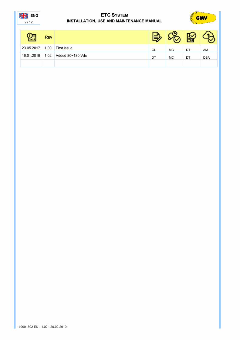
REV
23.05.2017 1.00 First issue GL MC DT AM
16.01.2019 1.02 Added 80÷180 Vdc DT MC DT DBA

ETC SYSTEM INSTALLATION, USE AND MAINTENANCE MANUAL
ENG 3 / 12
10991802 EN - 1.02 - 20.02.2019
ENG MANUAL INSTALLATION USE AND MAINTENANCE
EN
ETC SYSTEM ELECTRONIC SYSTEM TO CONTROL TIME AND QUALITY OF THE TRAVEL AS A FUNCTION OF THE FLUID TEMPERATURE OF THE POWER UNIT
INDEX
0 GENERAL PART 4 0.1 INTRODUCTORY INFORMATIONS 4
0.1.1 PRODUCT DESCRIPTION 4 0.1.2 DEFINITIONS 4 0.1.3 TERMS AND SYMBOLS USED 4 0.1.4 CLEANING 4 0.1.5 DISPOSAL OF MATERIALS 4 0.1.6 MAIN REFERENCE STANDARDS 5 0.1.7 SAFETY DURING ISTALLATION OR MAINTENANCE 5 0.1.8 EQUIPMENT 5 0.1.9 MATERIALS OFF LOADING AND STORAGE 6 0.1.10 INSTALLATION DOCUMENTS 6
0.2 FEATURES 6 0.3 ADVANTAGES 6 1 TECHNICAL DATA 7 1.1 TECHNICAL SPECIFICATIONS 7 1.2 HOW IT WORKS 7 1.3 VERSIONS 8
1.3.1 TERMINAL MAPPING FOR WIRING 9 2 INSTALLATION 9 2.1 INSTALLATION INSTRUCTION 9 2.2 CONNECTION DIAGRAM 10
Info and support:
FLUID DYNAMIC EQUIPMENTS AND LIFT COMPONENTS
UNI EN ISO 9001 CERTUFIED COMPANY
GMV SPA VIA DON GNOCCHI, 10 - 20016 PERO - MILANO (ITALY) - TEL. +39 02 33930.1 - FAX +39 02 3390379 - E-MAIL: [email protected] VIA PER BIANDRATE, 110/112 – 28100 NOVARA (ITALY) – TEL. +39 0321 677 611 – FAX +39 0321 677690 - E-MAIL: [email protected]
Please visit www.gmv.it to check for
any updated versions of this document or further information about GMV products
Doc. n° 10991802 Rev. 1.02 - 20.02.2019 File: ETC-MIUM-10991802EN-102.docx - (J2)

ENG ETC SYSTEM INSTALLATION, USE AND MAINTENANCE MANUAL 4 / 12
10991802 EN - 1.02 - 20.02.2019
0 GENERAL PART
0.1 INTRODUCTORY INFORMATIONS
0.1.1 PRODUCT DESCRIPTION
Thank you for choosing this product; GMV, innovative company, world-wide leader in hydraulic components for lift design, production and sale, just created, to offer customers all the economic and technical advantages, but most of all to give more safety and comfort to daily users.
The ETC device is the result of the GMV research. It is applied to most of the GMV power units equipped with a 3010 valve and is able to reduce the total
energy consumption of the lift system by reducing the leveling time. The levelling time, is that where the motor runs but the system is in low speed phase. This means that the
motor uses the available energy in small part for lifting, losing it into heat. At this step starts the capability of the device in order to reduce the energy loss. As a result of this reduction,
managed by ETC, we have the reduction of the FLY time, due to a longer high-speed travel time and a shorter levelling time, limiting all the energy loss. So we get the best system efficiency.
0.1.2 DEFINITIONS
In this manual you can apply the definitions as indicated in the following standards and regulations: EN81-20 e EN81-50 Safety regulations for the construction and installation of lifts
EN ISO 12100 Safety of machinery - Principles for risk assessment UNI EN ISO 7010 Graphic symbols: Safety signs and colours
EN12016 e EN12015 Electromagnetic compatibility
CEI EN 61439-1 Low voltage switchgear and control gear assemblies (LV control panels)
0.1.3 TERMS AND SYMBOLS USED
NOTE Indicates information which contents must be seriously taken in consideration.
WARNING Indicates that the described operation is likely to cause, damages to the system or physical damages if performed without complying with the safety standards.
WARNING Indicates that the described operation is likely to cause, damages to the system or physical damages if performed without switch off the main power and complying with the safety standards. (Electrocution, lightning, etc.).
Space for notes
0.1.4 CLEANING
WARNING Do not use liquids to clean the electrical parts
0.1.5 DISPOSAL OF MATERIALS
The product contains recyclable materials. Do not disperse in the environment but work in separate collection (Directive 2006/66/EC).
In particular, the following materials, when replaced, must not be dispersed in the environment but must be delivered to authorized collection centers, the manufacturer or, preferably certified, specialized companies.
Electrical and electronic equipment, batteries and / or accumulators, lamps. (RAEE)

ETC SYSTEM INSTALLATION, USE AND MAINTENANCE MANUAL
ENG 5 / 12
10991802 EN - 1.02 - 20.02.2019
0.1.6 MAIN REFERENCE STANDARDS
For anything that is not expressly given in this manual, reference should be made to the local standards and regulations in force, observing in particular:
Direttiva 2006/42/CE Machine Directive – in relation to machines, and amending Directive 95/16/CE (recast) Direttiva 2014/33/UE Lifts Directive - on the harmonisation of the laws of the Member States relating to lifts and safety
components for lifts Directive 2014/35/CE Low Voltage Directive – on the harmonisation of the laws of the Member States relating to the
making available on the market of electrical equipment designed for use within certain voltage limits Direttiva 2004/108/CE Electromagnetic Compatibility Directive (EMC) – approximation of laws in member States
regarding electromagnetic compatibility, and repealing Directive 89/336/CEE
Norme EN-81 serie completa Safety regulations for the construction and installation of lifts Refer to the complete series and, in particular to:
EN 81-20 Safety rules for the construction and installation of lifts – Lift for the transport of persons and goods - Part 20: Passengers and goods passenger lifts
EN 81-50 Safety rules for the construction and installation of lifts – Examinations and tests - Part 50: Design rules, calculations, examinations and tests of lift components
EN 81-70 Safety regulations for the construction and installation of lifts – Particular applications for lifts for the transport of persons and goods - Part 70: Accessibility to lifts for persons, including persons with disabilities
CEI EN 60439-1 Low voltage switchgear and control gear assemblies (LV control panels) Part 1: Type tested assemblies (AS) and partially type tested assemblies (ANS)
EN 12015 Electromagnetic compatibility – Product family standard for lifts, escalators and moving walkways – Emission
EN 12016 Electromagnetic compatibility – Product family standard for lifts, escalators and moving walkways – Immunity
UNI EN 13015 Maintenance for lifts and escalators: Rules for maintenance instructions UNI EN ISO 7010 Graphic symbols – Safety signs and colours – Registered safety signs UNI EN ISO 13857 Machine safety – Safety distance to avoid access to dangerous areas with arms or legs UNI EN ISO 12100 Safety of machinery - Principles for risk assessment ISO 14798 Lifts (elevators), escalators and mobile walkways
– Risks assessment and reduction methodology
0.1.7 SAFETY DURING ISTALLATION OR MAINTENANCE
During the installation and maintenance, it is compulsory to observe the applicable national job security regulations.
WARNING Before beginning any of the installation operations, ALWAYS check that all the mechanical and electrical safety devices are, turned on and in perfect working order.
0.1.8 EQUIPMENT
No special tools are required unless expressly provided by component manufacturers supplied by third parties. In this case, the related features and operating instructions are indicated in the manuals attached to them.

ENG ETC SYSTEM INSTALLATION, USE AND MAINTENANCE MANUAL 6 / 12
10991802 EN - 1.02 - 20.02.2019
0.1.9 MATERIALS OFF LOADING AND STORAGE
q Verify that all materials received are those ordered and are complete. q Check the condition of all components and materials upon reception at the building yard, to verify if any
damage occurred during transport; immediately inform GMV Spa in case any part is missing or in case of damage.
q Store the electrical and electronic components in a cool and dry place in their original packages q If, for any reason, it were not possible to install the plant immediately, periodically check the stored
components to prevent possible damages due to a prolonged storage in bad conditions. q Check if the documentation related to the plant is enclosed.
0.1.10 INSTALLATION DOCUMENTS
The documents to use for installation purposes are those required by the applicable standards, in particular: - THIS MANUAL - THE WIRING DIAGRAMS (EN81-1-2:2010)
To ensure correct and safe system maintenance, all the documentation must be carefully conserved by the installation manager. You must remember that this documentation is an integral part of the system and must be complete and carefully conserved. Furthermore, to ensure it is always legible, it must not be damaged, incomplete or have any torn or ruined
pages when it needs consulting.
GMV Spa will not assume any responsibility if the instructions included in this manual are not observed. GMV SpA remains available for any clarification regarding the use of the product.
0.2 FEATURES
Here are the ETC following features: • It can be applied to most of the GMV power units equipped with a 3010 valve. • It consists of two components: a module containing an electronic card with different terminal board
connections and a temperature probe to connect. • Simply to install thanks to the unified DIN guide. • ETC module has a built-in software able to self-learning the system operating conditions: automatically
manages the stroke distances and the levelling time by a fast self-tuning according to its pre-set parameters, both for up travel and down travel.
• It specifically manages the levelling time and distance, reducing and subsequently making them steady when the fluid temperature (and its viscosity) changes, thanks to the data sent from the temperature probe. Consequently, forces a balance by adjusting the FLY time in high-speed.
• It is not requested any further modification on the 3010 valve so as it could be in standard version and adjusted subsequently, more times in the mounting phase of the ETC module.
• Specific adjusting tools or potentiometer on the control panel are not needed. • Built-in electronic feedback circuit.
0.3 ADVANTAGES
ETC device has the following advantages: • Energetically optimizes the operation of the system, allowing the same amount of travels with less energy
total consumption. • At the same consumption, it allows a more intensive usage of the system. • A lower thermal stress both for the motor and the fluid, takes to a longer duration of the system (at the
same travel amount, the motor runs for less time). • ETC device could be installed even on pre-existing plants. • Plant modification is not necessary. • It allows, in most cases, to remove oil and valve heaters, managing the performance of the lift in order to
make the system free from the temperature variations • Any specific kind of fluid is not needed, because all the changes of viscosity will be identified and
managed. • Any specific skill of the technician is not needed because isn’t requested any parameter pre-setting

ETC SYSTEM INSTALLATION, USE AND MAINTENANCE MANUAL
ENG 7 / 12
10991802 EN - 1.02 - 20.02.2019
1 TECHNICAL DATA
1.1 TECHNICAL SPECIFICATIONS
Static pressure with full load in car 45 bar
Pressure with empty car 12 bar Fluid temperature -5 ÷ 75 °C Maximum car speed 1,00 m/s
FLUID TEMPERATURE
SPEED DISTANCE
Minimum distance between two contiguous floors
0 ÷ 70 °C ≤ 0,63 m/s 2,0 m < 15 °C ≤ 1,00 m/s 2,8 m ≥ 15 °C 2,0 m
Minimum distance between floor and acceleration contacts Up Dral, S [m] Vn [m/s] Down DRAL, D [m] 0,25 0,00<V≤ 0,30 0,35 0,35 0,30<V≤ 0,40 0,45 0,45 0,40<V≤ 0,50 0,55 0,60 0,50<V≤ 0,60 0,70 0,80 0,60<V≤ 0,70 0,90
1.2 HOW IT WORKS
ETC device works processing the pre-set delays for VML cursor, acquiring the temperature readings sent by the probe, in order to reduce the levelling distances while adjusting the FLY time in high-speed phase, both in up-travel and in down-travel.
3010 VALVE WORKING
INPUT SIGNALS OUTPUT SIGNALS CONTROL PANEL MAIN VALVE Up signal (VMP) VML Electrovalve Down signal (VMD) Speed signal
ETC DEVICE WORKING
INPUT SIGNALS OUTPUT SIGNALS CONTROL PANEL Up signal (VMP) Down signal (VMD) ETC DEVICE MAIN VALVE Speed signal VML Electrovalve EXTERNAL CONDITION Temperature Probe
In the power unit standard operating mode, signals directly control the main valve. So the system is allways affected by the change of temperature and viscosity.
ETC device controls the signals to the VML electrovalve, (that produces the switch between high and low speed) in order to minimize both FLY time and energy consumption, depending on external conditions.

ENG ETC SYSTEM INSTALLATION, USE AND MAINTENANCE MANUAL 8 / 12
10991802 EN - 1.02 - 20.02.2019
LED LIGHTS IN THE WORKING PHASE:
The ETC System has 3 leds: - the led n.13, green for Upward - the led n.14, yellow to check the device status - the led n.15, green for Downward
DEVICE POWERING ON - the green led n.15 (downward), quickly flashes for few seconds. - As a first test, the system checks the temperature is between 15°C – 50°C,
- In case the temperature does not match the range, the led n.14 yellow led blinks The lift could start running regularly.
- Once the temperature reaches the range limit, the device checks that there are no signals (up, down, error) and starts tuning the values if necessary.
WORKING ERRORS. • Up and Down signals (leds 13 and 15) flash simultaneously • Up or Down signals are off when when high speed signals is on • Levelling phase too short • Travel time too short
Any abnormal working, put in error the ETC card and the yellow led n.14 starts blinking to the next trave.
At the floor, the yellow led n.14 is on.The remaining leds stay off. At the start, the device clears the timer of the high speed travel. It turns into a listening mode to aquire the low speed signal.In the high speed phase the green led n.13 in on and n.15 flashes. There is any tuning if the high speed time travel is less than 3,5 seconds. Otherwise: The device adjusts the FLY-time at the measured temperature, according to the pre-set time delay [s] and the pre-set time delay percent [%], set via the dip-switches.
DIRECTION DIPSWITCH OFF ON Up travel 1 long [s] short [s] 2 less [%] more [%] Down travel 3 long [s] short [s] 4 less [%] more [%]
At the end of the delay calculation, the yellow led turns on and the “in-travel” leds n.13 or 15 turn in fixed mode.
In the landing phase (without any signals) the yellow error led n.14 turns in fixed mode and the green “in-travel” leds n.13 and 15 stay off.
1.3 VERSIONS
There are different versions of ETC device • Version AC cod. 70205637 to connect coils from 80 to 240 Volt AC ; • Version DC cod. 70205638 to connect coils from 40 to 60 Volt DC;
cod. 70205693 to connect coils from 80 to 180 Volt DC.

ETC SYSTEM INSTALLATION, USE AND MAINTENANCE MANUAL
ENG 9 / 12
10991802 EN - 1.02 - 20.02.2019
1.3.1 TERMINAL MAPPING FOR WIRING
ID INITIALS DESCRIPTION VERSION INPUT AC DC 1 (*) DW+ Input of Down travel signal Phase + Positive 2 (*) COM Neutral - Negative 3 (*) COM Input of Up travel signal Neutral - Negative 4 (*) UP+ Phase + Positive 5 JACK Programming interface (Jack-in 3,5 mm) 8 HI-SPD Input of High speed signal Phase + Positive 9 COM Neutral - Negative 10 Nero 0V Thermal probe wire 0V 11 Nero IN IN 12 Not used - 16 (**) DC 24V - DC 24V - - Negative 17 (**) DC 24V+ DC 24V + + Positive LED 13 LED UP Up travel Green 14 ERR Error Yellow 15 LED DW Down travel Green OUTPUT 6 COM VML coil Neutral - Negativo 7 VML Phase + Positivo
(*): The VMP “UP travel” input (n.3, n.4 clamps) and the VMD “DOWN travel” input (n.1,n.2 clamps) must never be active at the same time. In the absence of the input signal of the upward command (VMP not included), produce throw a normally open contact (“N.O.” from the UP travel control panel switch) the UP signal input loss for the n.4- clamp and connect for DC current the negative (COM) to n.3 clamp or in case of alternate current, the Neutral wire to n.3 clamp. (**): if the control panel could not provide 24 VDC power, you should provide an optional power (24 VDC,1A)
2 INSTALLATION
2.1 INSTALLATION INSTRUCTION
1. Power off the control panel 2. Place the ETC device in the control panel on the DIN standard
guide 3. Perform the electrical wiring following the mapping according
to the type of device supplied (AC / DC) 4. Place the end of the thermal probe (black colored) in the
power unit tank. Attention: the probe must be under the minimum fluid level of the power unit, taking care to position it, far from the motor windings and any heating resistors of the fluid. e.g.: Place it on the outlet grid filter.
5. Move the leveling contacts, to obtain the same slow-down levelling distance for all the stops (distance-set) Note: you can get different distance-sets between UP and DOWN travel according to the different speed between the two directions.
6. Power ON the control panel and restart the system 7. Make an UP travel call and a DOWN travel call between two
floors (not extreme) to verify the operating. 8. ETC system will self-learn the operating conditions and it will
star the correct adjusting after 3-4 travels. 9. Let the system run regularly

ENG ETC SYSTEM INSTALLATION, USE AND MAINTENANCE MANUAL 10 / 12
10991802 EN - 1.02 - 20.02.2019
2.2 CONNECTION DIAGRAM
Connect to the ETC device (§ 1.3.1) : - The alternate current coils according to AC mapping version - The direct current coils according to DC mapping version
LEGEND: SB Tank STT Temperature probe QM Control panel J mini-jack TRS 3,5 mm 3010 3010 distributor

ETC SYSTEM INSTALLATION, USE AND MAINTENANCE MANUAL
ENG 11 / 12
10991802 EN - 1.02 - 20.02.2019
IT
Riproduzione vietata. Tutti i diritti sono riservati. Nessuna parte del presente documento può essere riprodotta o diffusa con un mezzo qualsiasi, fotocopie, microfilm o altro, senza il consenso scritto di GMV Spa. GMV Spa, qualora intervengano migliorie tecniche, costruttive o di produzione, si riserva il diritto di modificare il prodotto e/o il presente documento, in parte o completamente, senza alcun preavviso. I disegni, le descrizioni e le caratteristiche indicate nel presente documento sono puramente indicativi. Per tutti i dati non inclusi nel presente documento fare riferimento alla documentazione di ogni componente. Allo scopo di preservare la sicurezza del prodotto si consiglia di non utilizzare parti o pezzi di ricambio non originali e in ogni caso non approvati da GMV Spa GMV Spa declina ogni responsabilità in caso non venga osservato quanto indicato nel presente documento.
EN
All rights reserved. Any kind of exploitation in any form and by any means is forbidden without a written permission of GMV Spa. GMV Spa, within technical or manufacturing progress, reserves the right to modify parts or this manual without notice. Drawings, descriptions and data included in this manual are indicatives. For all the data not included in this manual refer to the documents of any single part. To guarantee the products security, do not use spare parts not genuine or not approved by GMV Spa. GMV Spa will not assume any responsibility if the instructions included in this manual are not observed.
DE
Alle Rechte vorbehalten. Jede Art der Reproduktion und Vervielfältigung, egal in welcher Form und mit welchen Mitteln, ist ohne vorherige schriftliche Genehmigung der GMV SpA untersagt. Die GMV SpA behält sich jederzeit Änderungen ohne Vorankündigung aufgrund technischen Fortschritts und/oder Änderung der Produktionsmethode und Produktverbesserungen vor. Die Angaben in Zeichnungen, Beschreibungen und Datenblättern, die in diesem Handbuch veröffentlicht werden, sind bindend. Alle übrigen Hinweise und Informationen, die sich auf Komponenten oder Teile beziehen, die nicht in diesem Handbuch vorliegen, sind den jeweiligen eigenen Datenblättern und eigenen Handbüchern bzw. Anleitungen zu entnehmen. Für die Wahrung der Produkt- und Betriebssicherheit bzw. Garantie wird darauf hingewiesen, dass nur durch GMV SpA geprüfte, freigegebene und geeignete Originalersatzteile Verwendung finden dürfen. Bei Mißachtung der in diesem Handbuch und/oder technischer Anleitung gegebenen Anweisungen, Hinweise und Empfehlungen übernimmt die GMV SpA oder deren Vertriebsgesellschaften keinerlei Verantwortung und Haftung.
ES
Prohibida la reproducción. Reservados todos los derechos. Ninguna parte del presente documento puede ser reproducida o difundida por cualquier medio: fotocopia, microfilm u otros, sin el permiso escrito de GMV Spa. GMV Spa, se reserva el derecho de modificar el producto y/o el presente documento, en parte o completamente, sin preaviso alguno. Los esquemas, dibujos, descripciones y las características indicadas en el presente documento son puramente indicativos. Para mayor información consultar la documentación de cada componente. Para conservar la fiabilidad del producto se aconseja no usar recambios o piezas no originales o en cualquier caso no autorizadas por GMV Spa GMV Spa declina toda responsabilidad en caso que no se siga cuanto se indica en el presente documento.
FR
Tous droits réservés. Toute sorte d’exploitation sous quelque forme que ce soit et quelque moyen que ce soit est interdite sans la permission écrite de la société GMV. La société GMV, compte tenu des progrès techniques et des évolutions du processus de fabrication, se réserve le droit de modifier des pièces ou ce manuel sans avertissement préalable. Les dessins, descriptions et données incluses dans ce manuel sont donnés à titre indicatif. Pour toutes les données non incluses dans ce manuel, se référer à la documentation spécifique à chaque pièce unitaire. Pour garantir la sûreté de fonctionnement de l’installation, utiliser uniquement des pièces de rechange d’origine ou approuvées par la société GMV. La société GMV n’assumera aucune responsabilité si les instructions incluses dans ce manuel ne sont pas respectées.
PL
Wszystkie prawa zastrzeżone. Edytowanie całości lub fragmentów niniejszej instrukcji w dowolnej formie i w dowolny sposób jest zabronione bez pisemnej zgody GMV Spa. GMV Spa, w związku z postępem technicznym i produkcyjnym, zastrzega sobie prawo do zmian podzespołów lub podręcznika bez informowania o tym. Rysunki, opisy i dane podane w niniejszym podręczniku są jedynie orientacyjne. Informacje niepodane w niniejszej instrukcji można odnaleźć w innych dokumentach/instrukcjach. W celu zapewnienia bezpieczeństwa, nie należy używać części nie oryginalnych lub niezatwierdzonych przez GMV Spa. GMV Spa nie ponosi żadnej odpowiedzialności za szkody, jeżeli instrukcje podane w niniejszym podręczniku nie są przestrzegane.
PT
Todos os direitos são reservados. É proibida a reprodução ou difusão do todo ou de parte deste documento, através de qualquer meio, fotocópias, microfilme ou outro, sem a autorização escrita da GMV Spa. Sempre que existam melhorias técnicas, construtivas ou de produção, a GMV Spa reserva-se o direito de modificar o produto e/ou o presente documento, em parte ou na sua totalidade, sem pré-aviso. Os desenhos, as descrições e as características indicadas neste documento são puramente indicativos. Para todos os dados não incluídos neste documento, deverá tomar-se como referência a documentação de cada componente. Para garantir a segurança do produto desaconselha-se a utilização de componentes ou peças que não sejam de origem ou não aprovadas pela GMV Spa A GMV Spa declina qualquer responsabilidade caso não seja respeitado tudo o que se encontra indicado no presente documento.
SV
Alla rättigheter är reserverade. All sorts exploatering i någon form är förbjuden utan skriftligt godkännand av GMV Spa GMV Spa förbehåller sig rätten att modifiera produkten eller denna manual utan föregående meddelande till följd av förbättringar i konstruktionsteknik eller produktion. Ritningar, beskrivningar och angivna egenskaper i denna manual är endast av vägledande karaktär. GMV Spa påtar sig inget ansvar för följderna av att anvisningarna i denna instruktionsbok inte följs eller av att icke godkända delar eller reservdelar används. Använd endast originaldelar eller andra delar som är godkända av GMV Spa för att inte äventyra produktens säkerhet.

ENG ETC SYSTEM INSTALLATION, USE AND MAINTENANCE MANUAL 12 / 12
10991802 EN - 1.02 - 20.02.2019
FLUID DYNAMIC EQUIPMENTS AND LIFT COMPONENTS
GMV SPA VIA DON GNOCCHI, 10 - 20016 PERO – MILANO (ITALY) TEL. +39 02 33930.1 - FAX +39 02 3390379 STRADA PER BIANDRATE, 110/112 - 28100 NOVARA (ITALY) TEL. +39 0321 677611 - FAX +39 0321 677690 HTTP://WWW.GMV.IT - E-MAIL: [email protected]
FILE: ETC-MIUM-10991802EN-102.DOCX - (J2)
Copyright © 2022 FDOKUMEN