Enriching networked applications and services through usergenerated content
Upload
khangminh22Category
view
3download
0
HAL Id: tel-02078912https://tel.archives-ouvertes.fr/tel-02078912
Submitted on 25 Mar 2019
HAL is a multi-disciplinary open accessarchive for the deposit and dissemination of sci-entific research documents, whether they are pub-lished or not. The documents may come fromteaching and research institutions in France orabroad, or from public or private research centers.
L’archive ouverte pluridisciplinaire HAL, estdestinée au dépôt et à la diffusion de documentsscientifiques de niveau recherche, publiés ou non,émanant des établissements d’enseignement et derecherche français ou étrangers, des laboratoirespublics ou privés.
Enriching the internet control-plane for improved trafficengineeringChi Dung Phung
To cite this version:Chi Dung Phung. Enriching the internet control-plane for improved traffic engineering. Networkingand Internet Architecture [cs.NI]. Sorbonne Université, 2018. English. �NNT : 2018SORUS017�. �tel-02078912�

LABORATOIRE D’INFORMATIQUE DE PARIS 6
ENRICHING THE INTERNET CONTROL-PLANE FORIMPROVED TRAFFIC ENGINEERING
Advisor:Dr. Stefano SECCI
Doctoral Dissertation of:Chi Dung PHUNG
2018

These
Presentee pour obtenir le grand de docteur de la Sorbonne Universite
Specialite: Informatique
Chi Dung PHUNG
AMELIORATION DU PLAN DE CONTROLE D’INTERNET AVECDE NOUVELLES SOLUTIONS D’INGENIERIE DE TRAFIC
Soutenue le 30 mars 2018 devant le jury compose de :
Rapporteurs: Dr. Mathieu BOUET Thales Communications & Security.Prof. Guillaume URVOY-KELLER Universite de Nice Sophia Antipolis.
Examinateurs: Prof. Nadia BOUKHATEM Telecom ParisTech.Prof. Dominique GAITI Universite de technologie de Troyes.Dr. Luigi IANNONE Telecom ParisTech.Prof. Guy PUJOLLE Sorbonne Universite.Dr. Damien SAUCEZ Inria.
Invite: Mohamed BOUCADAIR Orange.
Directeur de these: Dr. Stefano SECCI Sorbonne Universite.

LABORATOIRE D’INFORMATIQUE DE PARIS 6
ENRICHING THE INTERNET CONTROL-PLANE FORIMPROVED TRAFFIC ENGINEERING
Author: Chi Dung PHUNG.
Defended on March 30, 2018, in front of the committee composed of:
Referees: Dr. Mathieu BOUET Thales Communications & Security.Prof. Guillaume URVOY-KELLER Universite de Nice Sophia Antipolis.
Examiners: Prof. Nadia BOUKHATEM Telecom ParisTech.Prof. Dominique GAITI Universite de technologie de Troyes.Dr. Luigi IANNONE Telecom ParisTech.Prof. Guy PUJOLLE Sorbonne Universite.Dr. Damien SAUCEZ Inria.
Invited: Mohamed BOUCADAIR Orange.
Advisor: Dr. Stefano SECCI Sorbonne Universite.


I
To my father and my family!

Abstract
One of the major challenges in the evolution of the Internet architecture is the defini-
tion of a protocol architecture that allows to solve the following major issues in Internet
routing and traffic forwarding capabilities: (i) keeping a routing state that is manageable
with current and forthcoming computing infrastructure – i.e., with few millions of states;
(ii) offering a scalable pull architecture in support of data-plane programmability; (iii)
offering a scalable forwarding plane able to be regularly optimized with only active flows
information; (iv) offering locator/identifier separation for advanced IP mobility; (v) is
incrementally deployable; (vi) can enhance the support of over-the-top services.
The Locator/Identifier Separation Protocol (LISP) has been identified as one of the
rising protocols in this respect. In its current status, it supports the above mentioned
requirements at a level that is acceptable for basic networking environments. However, it
shows too limited capacities when it comes to take into consideration fault resiliency and
capability to react fast to network state updates. These shortcomings can be compensated
by enhancing the control-plane architecture, and the routing algorithms therein. In this
dissertation, we propose new protocol features and experiment novel control-plane primi-
tives, as well as hybrid distributed-centralized routing state dissemination algorithms, to
scale with different network conditions.
We first design and build own open source LISP data-plane and control plane node,
comparing it with other implementations, showing how our implementation can scale for
large networks and reach performances suitable for real deployments. We present how our
implementation served to operate all network nodes (data-plane and control-plane nodes)
of a large scale experimentation testbed, the LISP-Lab testbed.
Then we propose a novel LISP-based solution for VM live migrations across geograph-
ically separated datacenters over wide area IP networks. Experimenting it at large scale,
we show that with our approach we can easily reach sub-second downtimes upon Internet-
wide migration, even for very distant clients.
Moreover, we investigate cross-layer network optimization protocols, in particular in
relation with the Multipath Transport Control Protocol (MPTCP) to which LISP can
III
IV
deliver path diversity in support of bandwidth increase, confidentiality support and con-
nection reliability, also using LISP traffic engineering network overlays. Despite we could
benefit from only few overlay network nodes, we could experimentally evaluate our pro-
posals showing the positive impact by using our solution, the negative impact of long
round-trip times on some MPTCP subflows, and the strong correlation between the dif-
ferential round-trip time among subflows and the throughput performance.
Finally, we worked on a framework to improve LISP operation at the Internet scale, by
facilitating cooperation between LISP Mapping Systems and introducing more automation
in the LISP connectivity service delivery procedure. We believe such optimization could
raise awareness among the service providers’ community, yielding new business opportu-
nities related to LISP mapping services and the enforcement of advanced inter-domain
traffic engineering policies for the sake of better quality of service guarantees.
Resume en Langue Francaise
L’un des defis majeurs de l’evolution de l’architecture Internet est la definition d’une ar-
chitecture protocolaire permettant d’ameliorer le routage, et en particulier (i) conserver
un systeme de routage gerable avec les technologies actuelles et futures - c’est-a-dire,
avec quelques millions d’etats ; (ii) offrir une architecture apte a faciliter la programma-
bilite du plan de transfert ; (iii) proposer un systeme de routage evolutif pouvant etre
regulierement optimise avec uniquement les informations sur les flux actifs ; (iv) fournir
une separation entre localisateurs et identificateurs pour la mobilite IP avancee ; (v) fa-
ciliter un deploiement incremental ; (vi) mieux servir les services applicatifs ”over-the-top”.
Le protocole LISP (Locator/Identifier Separation Protocol) a ete identifie comme l’un
des protocoles emergents a ce egard. Dans son etat actuel, il repond tres bien aux besoins
susmentionnes. Cependant, il subit des limitations lorsqu’il s’agit de prendre en compte
la resilience et la capacite a reagir rapidement aux mises a jour de l’etat du reseau. Ces
inconvenients peuvent etre compenses en ameliorant l’architecture du plan de controle et
ses algorithmes de routage. Dans cette these, nous proposons un nouvelle architectures
reseau-systeme et experimentons de nouvelles primitives de plan de controle, ainsi que
d’algorithmes de diffusion des etats, en testant son passage a l’echelle avec differentes
conditions de reseau.
Nous concevons et construisons d’abord un nœud de plan de donnees et de plan de
controle LISP open source. Nous le comparons avec d’autres implementations en montrant
que notre implementation atteint des performances adaptees aux vrais deploiements. Nous
montrons comment notre implementation a permis la mise en oeuvre d’une plateforme
d’experimentation a grande echelle, la plate-forme LISP-Lab, en operation aussi bien les
fonctions de plan de transfert que les fonctions de plan de controle.
En suite, nous proposons une nouvelle solution pour les migrations a chaud de machines
virtuelles a travers des centres de donnees geographiquement repartis sur des reseaux IP
etendus. Des tests dans un testbed reel connecte nativement a Internet montrent qu’avec
notre approche, nous pouvons facilement atteindre des temps d’arret inferieurs a la seconde
lors de la migration sur une grande echelle, meme pour des clients tres distants.
V
VI
En outre, nous avons etudie des protocoles d’optimisation de reseau multicouche,
en particulier en relation avec le protocole MPTCP (Multipath Transport Control Pro-
tocol), auquel LISP peut offrir une diversite de chemins pour l’agregation de bande
passante, ainsi qu’une plus grande confidentialite et fiabilite des connexions. Bien que
nous ne puissions beneficier que de quelques nœuds de reseau superposes, nous avons pu
evaluer experimentalement nos propositions en montrant l’impact positif de notre solution,
l’impact negatif des longs temps d’aller-retour sur certains sous-flux MPTCP, et la forte
correlation entre le temps d’aller-retour differentiel et le debit.
Enfin, nous avons travaille sur une refonte du plan de controle de LISP afin d’ameliorer
son fonctionnement du a l’echelle d’Internet, en facilitant la cooperation entre le ssystemes
de mapping LISP et en introduisant plus d’automatisation dans la procedure de fourni-
ture de services de connectivite LISP. Nous croyons qu’une telle optimisation pourrait
sensibiliser la communaute des fournisseurs de services, generant de nouvelles opportu-
nites commerciales liees aux services de cartographie LISP et l’application de politiques
d’ingenierie de trafic interdomaines avancees dans le but d’obtenir de meilleures garanties
de qualite de service.
Contents
Abstract III
Resume en Langue Francaise V
Table of contents VII
List of Figures XI
List of Tables XIII
Acronyms XV
1 Introduction 1
2 Routing node design and experimentation 5
2.1 LISP introduction . . . . . . . . . . . . . . . . . . . . . . . . . . . . . . . . 5
2.1.1 Data-plane . . . . . . . . . . . . . . . . . . . . . . . . . . . . . . . . 10
2.1.2 Control-plane . . . . . . . . . . . . . . . . . . . . . . . . . . . . . . . 11
2.2 LISP implementations . . . . . . . . . . . . . . . . . . . . . . . . . . . . . . 14
2.2.1 Cisco IOS . . . . . . . . . . . . . . . . . . . . . . . . . . . . . . . . . 14
2.2.2 OpenLISP . . . . . . . . . . . . . . . . . . . . . . . . . . . . . . . . . 14
2.2.3 LISPMob . . . . . . . . . . . . . . . . . . . . . . . . . . . . . . . . . 15
2.2.4 PyLISP . . . . . . . . . . . . . . . . . . . . . . . . . . . . . . . . . . 15
2.2.5 Other implementations . . . . . . . . . . . . . . . . . . . . . . . . . . 15
2.3 Enhancement of the OpenLISP data-plane . . . . . . . . . . . . . . . . . . . 16
2.4 Control plane implementation and evaluation . . . . . . . . . . . . . . . . . 17
2.4.1 Control-plane system architecture . . . . . . . . . . . . . . . . . . . 17
2.4.2 Control-plane modules . . . . . . . . . . . . . . . . . . . . . . . . . . 18
2.4.3 Running the control plane . . . . . . . . . . . . . . . . . . . . . . . . 20
2.4.4 Evaluation . . . . . . . . . . . . . . . . . . . . . . . . . . . . . . . . 22
VII
VIII CONTENTS
2.4.5 Perspectives . . . . . . . . . . . . . . . . . . . . . . . . . . . . . . . . 26
2.5 LISP experimental platforms . . . . . . . . . . . . . . . . . . . . . . . . . . 26
2.5.1 LISP4.net platform . . . . . . . . . . . . . . . . . . . . . . . . . . . . 27
2.5.2 LISP-Lab platform . . . . . . . . . . . . . . . . . . . . . . . . . . . . 28
3 Large-Scale Virtual Machine Migrations with LISP 31
3.1 Introduction . . . . . . . . . . . . . . . . . . . . . . . . . . . . . . . . . . . . 31
3.2 Background . . . . . . . . . . . . . . . . . . . . . . . . . . . . . . . . . . . . 33
3.2.1 Live VM migration and IP mobility . . . . . . . . . . . . . . . . . . 33
3.2.2 Layer 2 over Layer 3 overlay tunneling solutions . . . . . . . . . . . 34
3.2.3 Triangular routing solutions vs LISP rerouting . . . . . . . . . . . . 35
3.2.4 Existing LISP-based mobility management solutions . . . . . . . . . 37
3.3 Proposed LISP-based VM migration solution . . . . . . . . . . . . . . . . . 38
3.3.1 Change priority message format . . . . . . . . . . . . . . . . . . . . . 39
3.3.2 VM migration process . . . . . . . . . . . . . . . . . . . . . . . . . . 40
3.3.3 Implementation aspects . . . . . . . . . . . . . . . . . . . . . . . . . 42
3.4 Testbed evaluation . . . . . . . . . . . . . . . . . . . . . . . . . . . . . . . . 44
3.5 Conclusion . . . . . . . . . . . . . . . . . . . . . . . . . . . . . . . . . . . . 53
4 Enhancing MPTCP with LISP traffic engineering extensions 55
4.1 Introduction . . . . . . . . . . . . . . . . . . . . . . . . . . . . . . . . . . . . 55
4.2 LISP traffic engineering . . . . . . . . . . . . . . . . . . . . . . . . . . . . . 58
4.3 Explicit locator path binding modes . . . . . . . . . . . . . . . . . . . . . . 59
4.3.1 Destination-based stateful ELP binding . . . . . . . . . . . . . . . . 60
4.3.2 Source-based stateless ELP binding . . . . . . . . . . . . . . . . . . 62
4.4 A-MPTCP overlay provisioning steps . . . . . . . . . . . . . . . . . . . . . . 62
4.4.1 Destination-based stateful ELP binding . . . . . . . . . . . . . . . . 63
4.4.2 Source-based stateless ELP binding . . . . . . . . . . . . . . . . . . 64
4.5 Overlay network design . . . . . . . . . . . . . . . . . . . . . . . . . . . . . 66
4.5.1 State of the art . . . . . . . . . . . . . . . . . . . . . . . . . . . . . . 66
4.5.2 Link-disjoint-differential-delay routing problem (LD3R) . . . . . . . 67
4.6 Experimental results . . . . . . . . . . . . . . . . . . . . . . . . . . . . . . . 68
4.6.1 Implementation details . . . . . . . . . . . . . . . . . . . . . . . . . . 69
4.6.2 Network testbed . . . . . . . . . . . . . . . . . . . . . . . . . . . . . 69
4.6.3 Tests characterization . . . . . . . . . . . . . . . . . . . . . . . . . . 74
4.6.4 Throughput results . . . . . . . . . . . . . . . . . . . . . . . . . . . . 75
4.7 Conclusion . . . . . . . . . . . . . . . . . . . . . . . . . . . . . . . . . . . . 77
CONTENTS IX
5 Improving the Inter Domain Management of Locator/ID Separation
Protocol (LISP) Networks 79
5.1 Introduction . . . . . . . . . . . . . . . . . . . . . . . . . . . . . . . . . . . . 79
5.2 Challenges of LISP operation at the Internet scale . . . . . . . . . . . . . . 80
5.3 A framework for improving LISP operation at large scale . . . . . . . . . . 81
5.3.1 An interconnect framework for a global Mapping System . . . . . . 81
5.3.2 Functional blocks for inter-domain LISP operation . . . . . . . . . . 82
5.4 Mapping system discovery . . . . . . . . . . . . . . . . . . . . . . . . . . . 84
5.4.1 A new LISP BGP community attribute . . . . . . . . . . . . . . . . 84
5.4.2 A new interior gateway protocol feature . . . . . . . . . . . . . . . . 85
5.5 Negotiation, interconnect and invocation . . . . . . . . . . . . . . . . . . . . 87
5.5.1 Negotiation cycle . . . . . . . . . . . . . . . . . . . . . . . . . . . . . 87
5.5.2 Novel control plane primitives . . . . . . . . . . . . . . . . . . . . . . 88
5.6 Experimental results . . . . . . . . . . . . . . . . . . . . . . . . . . . . . . . 89
5.7 Perspectives . . . . . . . . . . . . . . . . . . . . . . . . . . . . . . . . . . . . 91
6 Conclusions 93
Software contributions 95
Publications 97
References 99

List of Figures
2.1 An example of LISP communications between two LISP sites. . . . . . . . . 10
2.2 LISP DDT mapping system workflow . . . . . . . . . . . . . . . . . . . . . 12
2.3 LISP DDT example . . . . . . . . . . . . . . . . . . . . . . . . . . . . . . . 13
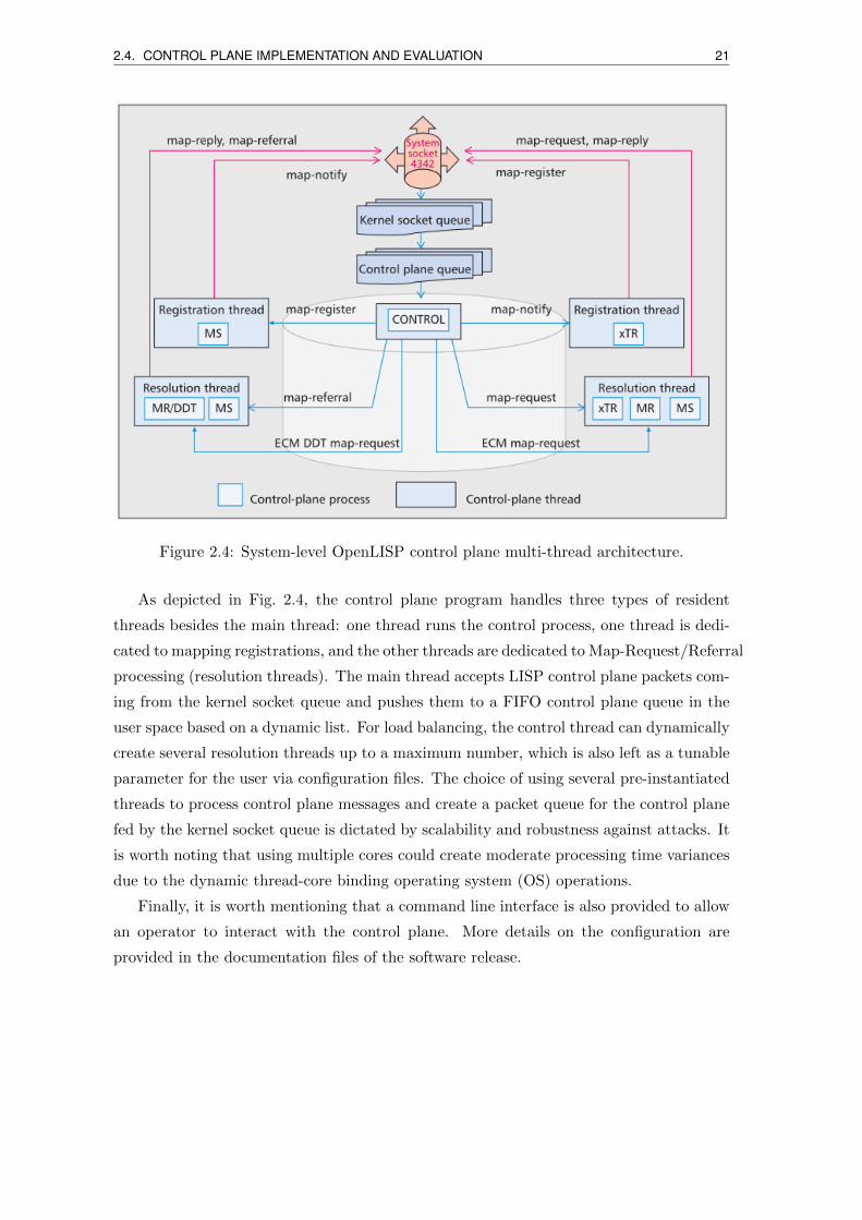
2.4 System-level OpenLISP control plane multi-thread architecture. . . . . . . . 21
2.5 Control plane processing latency as a function of the number of LISP sites. 23
2.6 Insight on the mapping database radix tree structure. . . . . . . . . . . . . 24
2.7 Average number of received. . . . . . . . . . . . . . . . . . . . . . . . . . . . 25
2.8 LISP4.net network, 2018. Source: lisp4.net. . . . . . . . . . . . . . . . . . 27
2.9 LISP-Lab partners locations. . . . . . . . . . . . . . . . . . . . . . . . . . . 28
2.10 LISP-Lab platform IP topology. . . . . . . . . . . . . . . . . . . . . . . . . . 29
3.1 Triangular routing vs LISP rerouting. . . . . . . . . . . . . . . . . . . . . . 36
3.2 CHANGE PRIORITY message format. . . . . . . . . . . . . . . . . . . . . 39
3.3 Example of CP signaling exchange during a VM migration. . . . . . . . . . 42
3.4 Testbed network scope. . . . . . . . . . . . . . . . . . . . . . . . . . . . . . 44
3.5 Bandwidth during migration with SMR and CP approaches. . . . . . . . . . 45
3.6 Total migration duration (boxplot statistics). . . . . . . . . . . . . . . . . . 46
3.7 Migration duration and downtime composition. . . . . . . . . . . . . . . . . 46
3.8 Average measured RTT during migrations. . . . . . . . . . . . . . . . . . . 47
3.9 Boxplot statistics of lost packets for the three LISP sites (INRIA, VNU,
UFRJ). . . . . . . . . . . . . . . . . . . . . . . . . . . . . . . . . . . . . . . 48
3.10 Boxplot statistics of downtime the three LISP sites (INRIA, VNU, UFRJ). 49
3.11 Boxplot statistics of offset for the three LISP sites (INRIA, VNU, UFRJ). . 50
3.12 Boxplot statistics of mapping convergence for the three LISP sites (INRIA,
VNU, UFRJ). . . . . . . . . . . . . . . . . . . . . . . . . . . . . . . . . . . . 51
3.13 Average measured RTT during migrations. . . . . . . . . . . . . . . . . . . 52
4.1 A 2-subflow A-MPTCP scenario. . . . . . . . . . . . . . . . . . . . . . . . . 57
XI
XII LIST OF FIGURES
4.2 Two LISP Canonical Address Format (LCAF) control-plane header types. . 61
4.3 A-MPTCP stateful provisioning steps. . . . . . . . . . . . . . . . . . . . . . 63
4.4 A-MPTCP stateless provisioning steps. . . . . . . . . . . . . . . . . . . . . . 64
4.5 Packet loss rate for different number of ELPs, in stateless and statefull modes. 71
4.6 Correlation scatter of throughput vs differential RTT. . . . . . . . . . . . . 72
4.7 Average RTT cumulative distribution functions for the different ELPs and
sources. . . . . . . . . . . . . . . . . . . . . . . . . . . . . . . . . . . . . . . 73
4.8 Throughput performance for different number of ELPs, in stateless and
statefull modes. . . . . . . . . . . . . . . . . . . . . . . . . . . . . . . . . . . 75
4.9 ELPs contribution to the MPTCP connection throughput. . . . . . . . . . . 76
5.1 MS Interconnect Example. . . . . . . . . . . . . . . . . . . . . . . . . . . . . 81
5.2 Functional Blocks for Inter-Domain LISP Operation. . . . . . . . . . . . . . 82
5.3 Discovering MS Components with OSPF. . . . . . . . . . . . . . . . . . . . 86
5.4 CPNP-based negotiation cycle and new LISP primitives used for the inter-
connection and invocation phases. . . . . . . . . . . . . . . . . . . . . . . . 87
5.5 Mapping resolution latency results over the LISP-LAB testbed. . . . . . . . 90

List of Tables
2.1 Namespace related characteristics of the architectures [5]. . . . . . . . . . . 9
2.2 Deployment related characteristics of the reviewed architectures [5]. . . . . 9
XIII

Acronyms
ALT Alternative LISP Topology.
AMPTCP Augmented MPTCP.
APNIC Asia Pacific Network Information Center.
AS Autonomous System.
BGP Border Gateway Protocol.
CDF Cumulative Distribution Functions.
CP CHANGE PRIORITY.
CPNP Connectivity Provisioning Negotiation Protocol.
DDT Delegated Database Tree.
DFZ Default-Free Zone.
DNS Domain Name Service.
EID Endpoint IDentifier.
ETR Egress Tunnel Router.
FIFO First In First Out.
HA Home Agents.
IaaS Infrastructure as a Service.
IETF Internet Engineering Task Force.
ITR Ingress Tunnel Router.
LCAF LISP Canonical Address Format.
LISP Locator/Identifier Separation Protocol.
XV
XVI Acronyms
LISP-MN LISP Mobile Node.
LISP-TE LISP Traffic Engineering.
LSA Link State Advertisements.
MIB Mapping Information Base.
MIP Mobile IP.
MPTCP Multipath TCP.
MR Map Resolver.
MS Map Server.
MSFD Mapping Service Function Discovery.
NTP Network Time Protocol.
NVGRE Network Virtualization using Generic Routing Encapsulation.
OOR Open Overlay Router.
OS Operating System.
OSPF Open Shortest Path First.
PETR Proxy Egress Tunnel Router.
PID Path Identifier.
PITR Proxy Ingress Tunnel Router.
PQO Provision Quotation Order.
PxTR PITR/PETR.
RLOC Routing LOCators.
RTR Re-Encapsulating Tunneling Router.
RTT round-trip-time.
SMR Solicit-Map-Request.
STT Stateless Transport Tunneling.
TCP Transmission Control Protocol.
TLV Type-Length-Value.
TRILL TRansparent Interconnection of a Lot of Links.
VM Virtual Machines.

Acronyms XVII
VXLAN Virtual eXtensible LAN.
xTR ITR/ETR.

Chapter 1
Introduction
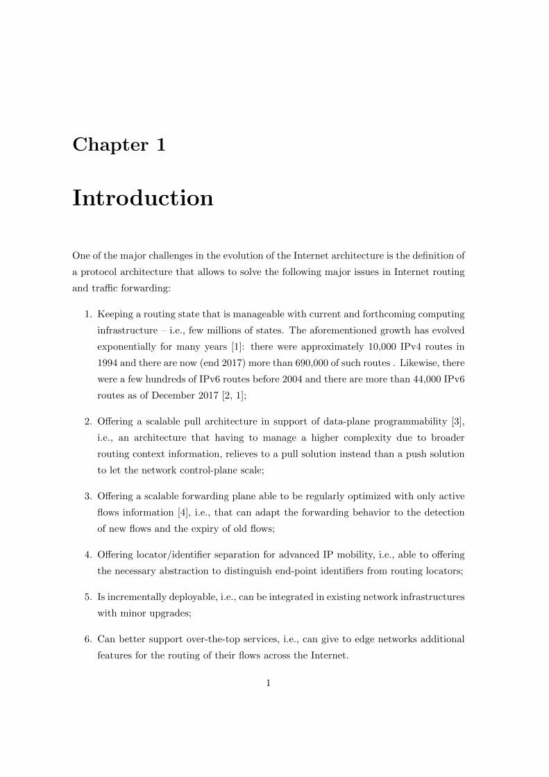
One of the major challenges in the evolution of the Internet architecture is the definition of
a protocol architecture that allows to solve the following major issues in Internet routing
and traffic forwarding:
1. Keeping a routing state that is manageable with current and forthcoming computing
infrastructure – i.e., few millions of states. The aforementioned growth has evolved
exponentially for many years [1]: there were approximately 10,000 IPv4 routes in
1994 and there are now (end 2017) more than 690,000 of such routes . Likewise, there
were a few hundreds of IPv6 routes before 2004 and there are more than 44,000 IPv6
routes as of December 2017 [2, 1];
2. Offering a scalable pull architecture in support of data-plane programmability [3],
i.e., an architecture that having to manage a higher complexity due to broader
routing context information, relieves to a pull solution instead than a push solution
to let the network control-plane scale;
3. Offering a scalable forwarding plane able to be regularly optimized with only active
flows information [4], i.e., that can adapt the forwarding behavior to the detection
of new flows and the expiry of old flows;
4. Offering locator/identifier separation for advanced IP mobility, i.e., able to offering
the necessary abstraction to distinguish end-point identifiers from routing locators;
5. Is incrementally deployable, i.e., can be integrated in existing network infrastructures
with minor upgrades;
6. Can better support over-the-top services, i.e., can give to edge networks additional
features for the routing of their flows across the Internet.
1

2
Among the various proposals that have been discussed over the years to improve In-
ternet traffic forwarding efficiency, those that consist in separating the information that
is specific to the location where a terminal is connected to the Internet (“where”) from
the information that is specific to the identity of the terminal (“who”) have attracted a
growing interest within the Internet community.
It is generally admitted that the ability to separate the “where” from the “who”
allows to get rid of a highly polluting single addressing space, thereby reducing the size
of the tables maintained by Internet routers. Multiple Identifier/Locator split addressing
protocols were discussed in the last two decades, as documented in [5]. Among them, the
Locator/ID Separation Protocol (LISP) is a protocol that differentiates from most of the
other approaches in that it does not imply any modification of terminal devices. Also,
LISP has been the subject of an important standardization effort for several years [6].
In its current status, LISP supports the above mentioned requirements at a level that
is acceptable for basic networking environments. However, it shows too limited capacities
when it comes to take into consideration fault resiliency and capability to react fast to
network state updates [7]. These shortcomings can be compensated by enhancing the
control-plane architecture, and the routing algorithms therein. In this dissertation, we
propose new protocol features and experimenting novel control-plane primitives, as well
as hybrid distributed-centralized routing state dissemination algorithms, to scale with
different network conditions.
The remainder of this dissertation is as follows:
• Chapter 2 presents the design and implementation aspect of our open source LISP
data-plane and control plane node, comparing it with other implementations, show-
ing that our implementation is scalable enough for large networks and reaches per-
formances suitable for real deployments. We then describe the LISP-Lab experimen-
tation platform that was built solely relying on it.
• Chapter 3 presents a novel LISP-based solution we proposed for live virtual machine
migration across geographically distant datacenters over wide area IP networks. We
tested it experimentally at large scale, showing that with our approach we can easily
reach sub-second downtimes upon Internet-wide migration, even for very distant
clients.
• Chapter 4 describes a cross-layer network optimization protocol proposal that ad-
dresses the enhancement of the Multipath Transport Control Protocol (MPTCP) to
which LISP can deliver path diversity in support of bandwidth increase, confiden-
tiality support and connection reliability, also using LISP traffic engineering network

3
overlays. Despite we could benefit from only few overlay network nodes, we could
experimentally evaluate our proposals showing the positive impact by using our so-
lution, the negative impact of long Round-Trip Times (RTTs) on some MPTCP
subflows, and the strong correlation between the differential RTT among subflows
and the throughput performance.
• Chapter 5 proposes a framework to improve LISP cooperation at the Internet scale,
by facilitating cooperation between LISP Mapping Systems and introducing more
automation in the LISP connectivity service delivery procedure.
• Chapter 6 concludes the dissertations and opens up new perspectives.

Chapter 2
Routing node design and
experimentation
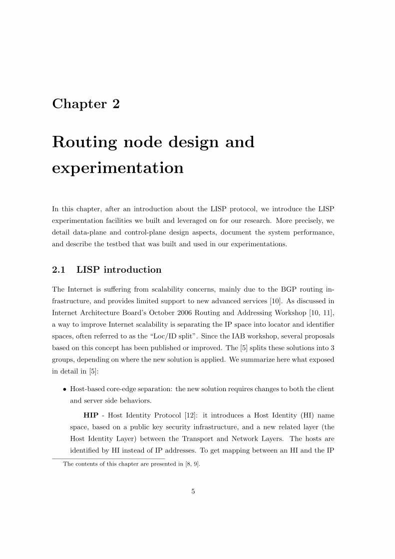
In this chapter, after an introduction about the LISP protocol, we introduce the LISP
experimentation facilities we built and leveraged on for our research. More precisely, we
detail data-plane and control-plane design aspects, document the system performance,
and describe the testbed that was built and used in our experimentations.
2.1 LISP introduction
The Internet is suffering from scalability concerns, mainly due to the BGP routing in-
frastructure, and provides limited support to new advanced services [10]. As discussed in
Internet Architecture Board’s October 2006 Routing and Addressing Workshop [10, 11],
a way to improve Internet scalability is separating the IP space into locator and identifier
spaces, often referred to as the “Loc/ID split”. Since the IAB workshop, several proposals
based on this concept has been published or improved. The [5] splits these solutions into 3
groups, depending on where the new solution is applied. We summarize here what exposed
in detail in [5]:
• Host-based core-edge separation: the new solution requires changes to both the client
and server side behaviors.
HIP - Host Identity Protocol [12]: it introduces a Host Identity (HI) name
space, based on a public key security infrastructure, and a new related layer (the
Host Identity Layer) between the Transport and Network Layers. The hosts are
identified by HI instead of IP addresses. To get mapping between an HI and the IP
The contents of this chapter are presented in [8, 9].
5
6 2.1. LISP INTRODUCTION
address, HIP can use several ways like a new DNS Resource Record or a distributed
hash table.
LIN6 - Location Independent Addressing for IPv6 [13]: it is a protocol support-
ing multihoming and mobility in IPv6. Similarly to HIP, LIN6 also adds a new layer
between the Transport and Network Layers, but instead of dividing the network
addresses into two separate namespaces as in HIP, it is based on an “embedded”
addressing model: the LIN6 generalized ID (the identifier of the node used in the
transport and upper layers) and the LIN6 address (used in network layer) are 128
bits in length and share the same common lower 64 bits (LIN6 ID).
MAT - Mobile IP with Address Translation [14]: it uses two addresses for a
mobile node: the “Home Address” to specify a node’s identity, and, the “Mobile
Address” for the network layer. Similar HIT, MAT also divided network layer into
two sublayers: a “MAT sublayer” that performs address translation, and a “Delivery
sublayer” that delivers packets according to the translated destination address. For
the mapping resolving, MAT uses DNS like LIN6.
FARA - Forwarding directive, Association and Rendezvous Architecture [15]:
it uses an Association Id (Aid) to identify a communication between two hosts. To
set up the Aid, the source host looks up for a ”Forward Directive (FD)” of the
destination host by querying the so-called FARA directory service, which resembles
DNS.
MILSA - Mobility and Multihoming Supporting Identifier-Locator Split Archi-
tecture [16]: it introduces a new HUI Mapping Sublayer at the network layer to
perform the mapping between identifiers and locators. The end host registers their
mapping with the responsible Realm Zone Bridging Servers (RZBS) and sends map
request to its RZBS which then follows the resolution hierarchy until a mapping is
found.
SHIM6 - Level 3 Multihoming Shim Protocol for IPv6 [17]: it adds a new
sublayer within the network layer (called the SHIM6 layer). SHIM6 creates a context
between two communicating parties with a 4-way handshake with a set of available
addresses for the nodes. One of these addresses is used as Upper Layer Identifier,
useful for session identification, while all the other available addresses are used as
locators.
Six/One [18]: it has a similar concept than SHIM6. However, what makes it
different from SHIM6, is the fact that all the host addresses differ only in their 64
lower order bits.
2.1. LISP INTRODUCTION 7
ILNP - Identifier Locator Network Protocol [19]: it introduces two new terms,
“Node Identifier (NID)”, which is the unique name of a node, and the Locator, which
is topologically tied and used for routing and packet forwarding. Applications use
FQDNs instead of using the identifier directly. The mapping from an FQDN to a
set of Identifiers and Locators is for each host stored in new DNS resource records.
Packets contain the source and destination in the form of a pair Identifier-Locator.
These pairs are encoded in IPv4 and IPv6 packet headers in different ways.
• Gateway-based solutions: they require changing both the end-hosts and the middle-
boxes.
TRIAD - Translating Relaying Internet Architecture [20]: it was proposed to
solve the problem of IPv4 address depletion in the NATted Internet without the
painful transition to IPv6. Internet is viewed as a hierarchical set of interconnected
realms and the firewall or border router is extended to act as TRIAD relay agent
between realms. TRIAD advocates the use of DNS names to identify each end-host
uniquely from different contexts.
IPNL - Internet Protocol Next Layer [21]: it is a NAT-extended Internet pro-
tocol architecture designed to scalably solve the address depletion problem of IPv4
like TRIAD. The architecture requires changing both hosts and NAT boxes.
I3 - Internet Indirection Infrastructure [22]: when a sender has some data to
send, it sends out a pair (“id”, “data”), where “id” is the logical address of the
destination and “data” is the actual payload it wishes to send. The Chord lookup
protocol [23] is used for creating an overlay of I3 servers which are responsible for
handling the rendezvous and forwarding between senders and receivers.
4+4 [24]: A 4+4 extended address is formed by concatenating a 32-bit public
address with a 32-bit private address. They are also called “level 1” and “level 2”
addresses. Hosts use DNS to check which level of address is needed to use for its
outer/inner packet. The gateway swaps between the level 1 and level 2 address.
This approach has its own drawbacks which include failure of end-to-end security
mechanisms, a significant overhead involved with assigning a FQDN to each host
and having two entries in the DNS system, thus, requiring two lookups.
NodeID - Node Identity Internetworking Architecture [25]: it builds on HIP to
provide identity based overlay routing for hosts to discover their mutual, routable
IP addresses. Thus, NodeID avoids the use of a special DNS Resource Record or a
HIP proxy for determining the address corresponding to a Host Identity.
NUTSS [26]: it introduces two types of middleboxes: policy-boxes, which
8 2.1. LISP INTRODUCTION
handle policy decisions (firewall-like entities), and forwarding middleboxes, such as
NATs, which forward traffic and perform address/port translation. Each network
has at least one P-box, which is connected to a P-box at a higher hierarchical level
and a host registers itself through a hierarchy of P-boxes.
HRA - Hierarchical Routing Architecture [27]: HRA has two levels of mapping
similarly to HIP. When an end-host A wishes to communicate with another end-host
B, it firstly obtains the locator and the Locator Domains (LD) ID information of
destination host B from a distributed hash table before initializing a communication.
Upon obtaining the LD ID and locator information, A fills in the destination IP
address with the destination host locator of B, if the LD ID obtained is the same as
its own. Otherwise, it fills the destination IP address in the IP header with that of
its LD Border Routers (LDBR) locator. In such a scenario, the LDBR of A rewrites
the source IP address with its own locator, and the destination IP address with the
LDBR address matching the LD ID of B.
Mobile IP [28, 29]: MobileIP defines Home Address acts as the identifier and
a Care-of Address as the locator. In contrast to many other approaches, both the
identifiers and the locators in Mobile IP are routable addresses. It is not a solution
for multihomed networks and causes problems in site renumbering [30]. Mobile IP
requires additional infrastructure elements called Home Agents.
• Network-based core-edge separation: these solutions are realized at the middle boxes
(e.g., at edge-routers) without changing the end-point behavior.
GSE - Global, Site, and End-system address elements [31]: it is an alternate
IPv6 architecture. The proposed IPv6 address contains a 6-Byte “Routing Goop
(RG)”, a 2-Byte “Site Topology Partition (STP)” and an 8-Byte “End System Des-
ignator (ESD)”. When creating a packet, the source host fills the destination address
with a 128-bit IPv6 address that it receives from a DNS lookup for the destination.
This address includes the RG of the destination as provided in the DNS response.
The packet leaves the site through one of the border routers, which modifies the
source RG to be used for the packets on the return path of this communication
session.
LISP - Locator/ID Separation Protocol [6], which we describe in details in the
following.
Tables 2.1 and 2.2 summarizes and draws a complete comparison between the above
protocols in terms of namespace related characteristics and deployment strategies.

2.1. LISP INTRODUCTION 9
Architecture IPv4 IPv6 Multihoming Mobility Site renumbering Internet transparency Disjoint Structured
HIP√ √ √ √ √ √ √
LIN6√ √ √ √ √
MAT√ √ √ √
FARA√ √ √ √
MILSA√ √ √ √ √ √
SHIM6√ √ √
Six/One√ √ √ √ √
ILNP√ √ √ √ √ √
TRIAD√ √ √ √
IPNL√ √ √ √ √ √
i3√ √ √ √ √ √
4+4√ √ √ √ √ √
NodeID√ √ √ √ √ √
NUTSS√ √ √ √ √ √ √ √
HRA√ √ √ √ √ √
Mobile IP√ √ √ √
GSE√ √ √ √ √
LISP√ √ √ √ √ √ √ √
Table 2.1: Namespace related characteristics of the architectures [5].
Architecture Data-plane Deployment Legacy apps Infrastructure changesoperation
HIP Rewrite, Tunnel Host-based√
New FQDN record per host (optional)LIN6 Rewrite Host-based Mapping Agents for nodes, FQDN/MAMAT Rewrite Host-based
√IMS for nodes with DNS entry for each IMS
FARA Rewrite Host-based FARA directory service (fDS)MILSA Rewrite Host-based DNS like names for every node, RZBS serversSHIM6 Rewrite Host-based IPv6 OptionsSix/One Rewrite Host-based Changes to edge network routers (Optional)ILNP Rewrite Host-based
√FQDN/node, ARP modied for ILNPv4
TRIAD Rewrite Gateway-based√
FQDN/Node, WRAP supporting Relay AgentsIPNL Rewrite, Tunnel Gateway-based
√DNS name for every node, upgraded Routers
i3 Rewrite Gateway-based√
i3 servers4+4 Rewrite Gateway-based
√DNS name for every node, upgraded NATs
NodeID Rewrite Gateway-based√
NodeID Routers for routing in static coreNUTSS Rewrite Gateway-based
√P-boxes and M-boxes
HRA Rewrite Gateway-based LDBRs, IPv6 ext. headers, new IPv4 payload, FQDN/hostMobile IP Tunnel Gateway-based
√Home Agents
GSE Rewrite Network-based Two-faced DNSLISP Tunnel Network-based
√Tunnel Routers
Table 2.2: Deployment related characteristics of the reviewed architectures [5].
10 2.1. LISP INTRODUCTION
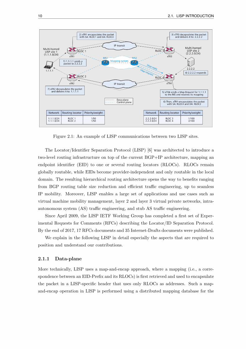
Figure 2.1: An example of LISP communications between two LISP sites.
The Locator/Identifier Separation Protocol (LISP) [6] was architected to introduce a
two-level routing infrastructure on top of the current BGP+IP architecture, mapping an
endpoint identifier (EID) to one or several routing locators (RLOCs). RLOCs remain
globally routable, while EIDs become provider-independent and only routable in the local
domain. The resulting hierarchical routing architecture opens the way to benefits ranging
from BGP routing table size reduction and efficient traffic engineering, up to seamless
IP mobility. Moreover, LISP enables a large set of applications and use cases such as
virtual machine mobility management, layer 2 and layer 3 virtual private networks, intra-
autonomous system (AS) traffic engineering, and stub AS traffic engineering.
Since April 2009, the LISP IETF Working Group has completed a first set of Exper-
imental Requests for Comments (RFCs) describing the Locator/ID Separation Protocol.
By the end of 2017, 17 RFCs documents and 35 Internet-Drafts documents were published.
We explain in the following LISP in detail especially the aspects that are required to
position and understand our contributions.
2.1.1 Data-plane
More technically, LISP uses a map-and-encap approach, where a mapping (i.e., a corre-
spondence between an EID-Prefix and its RLOCs) is first retrieved and used to encapsulate
the packet in a LISP-specific header that uses only RLOCs as addresses. Such a map-
and-encap operation in LISP is performed using a distributed mapping database for the
2.1. LISP INTRODUCTION 11
first packet of a new destination EID; then the mapping is cached locally for all subse-
quent packets. The LISP control plane is based on signaling protocols necessary to handle
EID-to-RLOC registrations and resolutions, dynamically populating mapping caches at
LISP network nodes. Since several RLOCs can be registered for the same EID, priority
and weight metrics are associated with each RLOC in order to decide which one to use
(highest priority) or how to do loadbalancing (proportionally to the weights if priorities
are equal) [32].
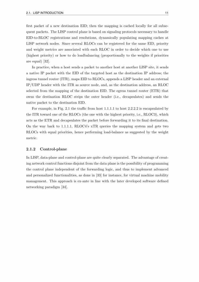
In practice, when a host sends a packet to another host at another LISP site, it sends
a native IP packet with the EID of the targeted host as the destination IP address; the
ingress tunnel router (ITR), maps EID to RLOCs, appends a LISP header and an external
IP/UDP header with the ITR as source node, and, as the destination address, an RLOC
selected from the mapping of the destination EID. The egress tunnel router (ETR) that
owns the destination RLOC strips the outer header (i.e., decapsulates) and sends the
native packet to the destination EID.
For example, in Fig. 2.1 the traffic from host 1.1.1.1 to host 2.2.2.2 is encapsulated by
the ITR toward one of the RLOCs (the one with the highest priority, i.e., RLOC3), which
acts as the ETR and decapsulates the packet before forwarding it to its final destination.
On the way back to 1.1.1.1, RLOC4’s xTR queries the mapping system and gets two
RLOCs with equal priorities, hence performing load-balance as suggested by the weight
metric.
2.1.2 Control-plane
In LISP, data-plane and control-plane are quite clearly separated. The advantage of creat-
ing network control functions disjoint from the data plane is the possibility of programming
the control plane independent of the forwarding logic, and thus to implement advanced
and personalized functionalities, as done in [33] for instance, for virtual machine mobility
management. This approach is ex-ante in line with the later developed software defined
networking paradigm [34].
12 2.1. LISP INTRODUCTION
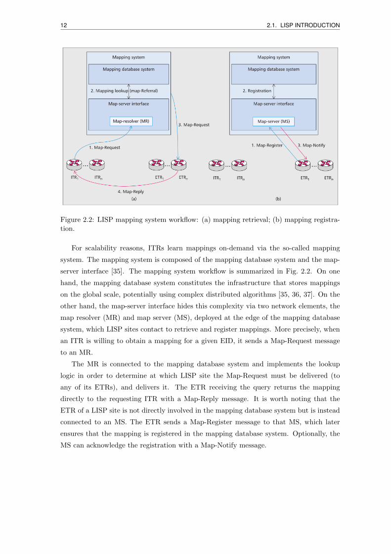
Figure 2.2: LISP mapping system workflow: (a) mapping retrieval; (b) mapping registra-tion.
For scalability reasons, ITRs learn mappings on-demand via the so-called mapping
system. The mapping system is composed of the mapping database system and the map-
server interface [35]. The mapping system workflow is summarized in Fig. 2.2. On one
hand, the mapping database system constitutes the infrastructure that stores mappings
on the global scale, potentially using complex distributed algorithms [35, 36, 37]. On the
other hand, the map-server interface hides this complexity via two network elements, the
map resolver (MR) and map server (MS), deployed at the edge of the mapping database
system, which LISP sites contact to retrieve and register mappings. More precisely, when
an ITR is willing to obtain a mapping for a given EID, it sends a Map-Request message
to an MR.
The MR is connected to the mapping database system and implements the lookup
logic in order to determine at which LISP site the Map-Request must be delivered (to
any of its ETRs), and delivers it. The ETR receiving the query returns the mapping
directly to the requesting ITR with a Map-Reply message. It is worth noting that the
ETR of a LISP site is not directly involved in the mapping database system but is instead
connected to an MS. The ETR sends a Map-Register message to that MS, which later
ensures that the mapping is registered in the mapping database system. Optionally, the
MS can acknowledge the registration with a Map-Notify message.
2.1. LISP INTRODUCTION 13
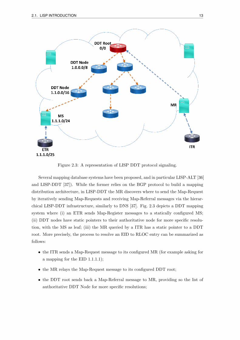
Figure 2.3: A representation of LISP DDT protocol signaling.
Several mapping database systems have been proposed, and in particular LISP-ALT [36]
and LISP-DDT [37]). While the former relies on the BGP protocol to build a mapping
distribution architecture, in LISP-DDT the MR discovers where to send the Map-Request
by iteratively sending Map-Requests and receiving Map-Referral messages via the hierar-
chical LISP-DDT infrastructure, similarly to DNS [37]. Fig. 2.3 depicts a DDT mapping
system where (i) an ETR sends Map-Register messages to a statically configured MS;
(ii) DDT nodes have static pointers to their authoritative node for more specific resolu-
tion, with the MS as leaf; (iii) the MR queried by a ITR has a static pointer to a DDT
root. More precisely, the process to resolve an EID to RLOC entry can be summarized as
follows:
• the ITR sends a Map-Request message to its configured MR (for example asking for
a mapping for the EID 1.1.1.1);
• the MR relays the Map-Request message to its configured DDT root;
• the DDT root sends back a Map-Referral message to MR, providing so the list of
authoritative DDT Node for more specific resolutions;
14 2.2. LISP IMPLEMENTATIONS
• the MR chooses one of the DDT nodes to send the Map-Request message to, and
then receives a new list of authoritative DDT node for more specific resolutions.
This process is repeated until the Map-Request message reaches the MS to which
the ETR registers the EID prefix to which the EID belongs.
• the MS send back a Map-Referral message (including an acknowledgement) to the
MR and forwards the Map-Request message to an authoritative ETR (or directly
sends back a Map-Reply message if the ETR sets a proxy bit in the Map-Register
message to allow for proxied replies).
• the ETR (or the MS in case of proxied reply) sends a Map-Reply message with the
requested mapping information to the ITR.
2.2 LISP implementations
In this section, we synthetically review existing and publicly known LISP implementations,
both commercial and open source ones.
2.2.1 Cisco IOS
Cisco has been the major driver for LISP standardization and experimentation since its
inception. Both LISP data-plane and control-plane functions are supported and available
across a wide range of Cisco router and switch operating systems. Cisco continues to
introduce new LISP features and functions to provide within the network expect in the
data-center network environment.
The current LISP implementation in Cisco nodes include the standard LISP features, as
well as some proprietary features that are partially documented related to virtual machine
mobility management [38]. Nevertheless, the current implementation does not include all
the features we needed for this thesis, such as LISP traffic engineering and canonical
address format features, as elaborated in the following chapters.
2.2.2 OpenLISP
OpenLISP [39] is an open source implementation of the LISP data plane in a FreeBSD
environment.
The standard core LISP data-plane functions are patched to the FreeBSD kernel and
a socket is introduced to allow communication with the control plane in the user space.
[39] shows that the cost of running LISP in terms of forwarding latency is acceptable and
the impact on end-to-end flows is minimal.
2.2. LISP IMPLEMENTATIONS 15
Very partial control-plane features are present, essentially limited to map-request and
map-reply message processing. Hence as a standalone node, an OpenLISP node is not
able to handle all control plane signaling within a LISP network, and is able to deploy
only the xTR behavior.
2.2.3 LISPMob
LISPMob is a multi-platform implementation of the LISP mobile node (LISP-MN) vari-
ant [40] intended for mobile devices (e.g., smartphones); in LISP-MN, mobile nodes are
full-fledged xTRs relying on a lightweight version of the control plane. LISPMob is imple-
mented in the user space and compatible with Linux and Android. Even though LISP-
Mob is intended for mobile devices, it does not preclude its usage on routers; however,
the limited control plane functionalities and its user space implementation would make it
innapropriate for large-scale operational networks.
Since 2016, the project is renamed to OOR [41] (Open Overlay Router) to full sup-
porting LISP function in SDN/NFV environments. The control-plane extent is however
still limited.
2.2.4 PyLISP
PyLISP [42] is a Python implementation of LISP. This library provides basic data-plane
and control-plane functions for the xTR behavior, and some command line tools to perform
actions like asking a map resolver for a mapping and directly querying a DDT node.
Although it was planned to add other LISP behaviors such as MS, MR or DDT node, in
fact, these parts have never been released for PyLISP. Nonetheless, it is a good training
tool for a beginner, as it is simple to install and to run in the user space.
2.2.5 Other implementations
Among the above mentioned implementations, three are open source: OpenLISP, LISP-
Mob, and PyLISP. The Cisco implementation is quite well documented but only in terms
of user interface.
In addition, we resume in the following additional implementations that have either a
limited scope, or are only marginally documented.
• AVM GmbH announced in 2012 that they support LISP in firmware for their
FRITZ!Box-devices in FRITZ!OS 6.00 (a residential broadband access device), and
also supported in later versions. It is unfortunately not well documented.
16 2.3. ENHANCEMENT OF THE OPENLISP DATA-PLANE
• OpenDayLight (ODL) [43] is an SDN controller that offers, since 2013, LISP as one
of its SouthBound Interface (SBI) protocols under the so-called LISP Flow Mapping
Service. This service provides Map-Server and Map-Resolver behaviors, for data
plane nodes, as well as to ODL applications. Mapping data can go beyond basic EID-
to-RLOC entries, and can include a variety of routing policies and traffic engineering
metrics. ODL applications and services can use a northbound interface to define
specific mappings and policies in the LISP Mapping Service.
• Open Network Operating System (ONOS) [44] is another SDN controller that also
introduces LISP as one of its southbound protocols, since 2017. All basic LISP
features are offered in the current version. At the time being, LISP mapping entries
do not exploit distributed core primitives that historically differentiate ONOS from
ODL. Performance tests were recently run against the LISP SBI [45], leading to
important improvement making the SBI more scalable for large networks.
• OpenVSwitch (OVS) [46] is a software switch that, since 2013, supports LISP as one
of its layer 3 tunneling protocols. OVS code is mostly contributed by Cisco. The
implementation requires the use of static LISP tunnel endpoints, and LISP routing
rules are not implemented as standard switching rules; they are instead implemented
by means of ad-hoc tunneling interfaces.
• LISPERS.net [47] is a closed source software of LISP developed by Dino Farinacci.
It supports all the LISP behaviors, and offers GUI management interface as well.
Unfortunately, it is not well documented and runs at user space.
2.3 Enhancement of the OpenLISP data-plane
Among the open source implementations, the single one being well documented and sci-
entifically evaluated, while allowing for high-performance networking is the OpenLISP
implementation. Hence we selected OpenLISP as starting implementation for our experi-
mental research activity.
In order to make OpenLISP data-plane usable to build a fully-fledge LISP network,
we extended it to add the following standard features:
• LISP Proxy Ingress Tunnel Router (Proxy-ITR): used to provide connectivity be-
tween sites which use LISP EIDs and those which do not. They act as gateways
between those parts of the Internet which are not using LISP (the legacy Internet)
A given Proxy-ITR advertises one or more highly aggregated EID prefixes into the
public Internet and acts as the ITR for traffic received from the public Internet.
2.4. CONTROL PLANE IMPLEMENTATION AND EVALUATION 17
• LISP Proxy Egress Tunnel Router (Proxy-ETR): Proxy-ETRs provide a LISP (Routable
or Non-Routable EID) site’s ITRs the ability to send packets to non-LISP sites in
cases where unencapsulated packets (the default mechanism) would fail to be de-
livered. Proxy-ETRs function by having an ITR encapsulate all non-LISP destined
traffic to a pre-configured Proxy-ETR.
• Re-Encapsulating Tunneling Router (RTR): An RTR acts like an ETR to remove a
LISP header, then acts as an ITR to prepend a new LISP header. This is known as
Re-encapsulating Tunneling. Doing this allows a packet to be re-routed by the RTR
without adding the overhead of additional tunnel headers.
Specific features were also added to the data-plane node, in the frame of the solutions
presented in the next chapters where these features are described.
2.4 Control plane implementation and evaluation
Although OpenLISP supports both data-plane and control-plane functions, as a standalone
node, an OpenLISP node is not able to handle all control plane signaling within a LISP
network. Only map-request and map-reply message processing was made available in
OpenLISP.
In order to cope with such limitations, we worked on a complete control plane im-
plementation, with the goal to integrate it with the OpenLISP node, while keeping the
data and control plane parts independent of each other for performance and modularity
reasons, as detailed hereafter.
In the following, we detail the resulting control plane architecture, and related imple-
mentation aspects, before describing a performance evaluation we run against some of the
implementations described in the previous section.
2.4.1 Control-plane system architecture
We describe the design of our control plane implementation, issued under a BSD licence.
Given that the main role of the LISP control plane is the management of EID-to-RLOC
mappings with the mapping system, in the following we first focus on the design of the
mapping database, and then we detail the different modules.
The heart of the OpenLISP control plane is the EID-to-RLOC mapping database,
synthetically referred to as map-table in the following. Each map-entry of the map-table
consists of an EID prefix with a list of RLOCs, each RLOC associated with a structure
that contains the RLOC address and related attributes (i.e., priority and weight). The
18 2.4. CONTROL PLANE IMPLEMENTATION AND EVALUATION
three network elements involved in the control plane, ETR, MS, and MR, serve different
purposes; hence, they implement their own map-table logic, as detailed hereafter.
ETR’s map-entries correspond to the mappings for the different EID prefixes of the
LISP site it serves and should register via an MS. Each such map-entry must have at least
one RLOC address.
Map-Servers maintain EID prefix registrations for the LISP sites they serve and for
EID prefixes not assigned yet. Therefore, we distinguish the following two map-entry
types:
• Registered map-entries are built on Map-Register messages received from ETRs and
are associated with meta-information about the registering site (e.g., cryptographic
keys authorized to register mappings, contact addresses). The MS can use these
entries to directly reply to Map-Request messages on behalf of ETRs if commissioned
to do so.
• Negative map-entries are used to define range of IP prefixes that belong to the EID
space but do not require LISP encapsulation. Requests for such prefixes generate
negative map-replies.
Map-Resolvers maintain a map-table to speed up mapping resolution, and we distin-
guish the next two types of entries:
• Negative map-entries are similar to an MS’s negative map-entries. An MR hence
immediately sends a negative Map-Reply for not yet assigned EID prefixes.
• Referral map-entries contain the addresses of other DDT nodes (MRs) that are
supposed to provide more specific LISP-DDT mappings (i.e., have a longer EID prefix
match). Even though they are logically separated, map-tables are implemented
within a compact radix tree data structure instance optimized for fast IP prefix
lookup [48]. Actually, as our implementation is dual-stack, we maintain two radix
tree instances, one for IPv4 EIDs and the other for IPv6 EIDs.
2.4.2 Control-plane modules
Our control plane implementation includes the essential features to operate a multi-site
LISP network, including all the LISP-DDT logic and complete support of both IPv4 and
IPv6. In order to operate the control plane independent of the data plane, it is divided
into independent modules with different functionalities (Fig. 2.2).
As depicted in Fig. 2.2, the control plane receives the messages from a dedicated queue,
which gets them in turn from the kernel’s UDP socket queue. The control plane is based on
2.4. CONTROL PLANE IMPLEMENTATION AND EVALUATION 19
one general orchestration processes (i.e., control) and three specialized processes that im-
plement MR, MS, and xTR network element logics. The treatment of mapping-resolution
related and registration-related messages within these processes is isolated thanks to the
use of threads. Each process is composed of several modules, as described in the following.
The xTR process includes the following three modules:
• MAP-REGISTER module: Implemented at the ETR interface; it sends periodic
information (each 60s, as recommended in [6]) about map-entry registration to at
least one MS. Note that ETRs are authenticated by an MS using their preconfigured
shared key.
In order to support mapping system multitenancy, going beyond the current stan-
dards, the module allows specifying different keys for different MSs to allow an xTR
to join LISP networks managed by independent MS stakeholders.
• MAP-REPLY module: Implemented at the ETR interface, it receives and processes
Map-Requests coming from the ITR or MSs. According to the standard, Map-
Requests must be encapsulated (Encapsulated Control Message, ECM) Map-Request
when sent to MRs, but are sent natively to ETRs. Our implementation supports
these two modes with any combination of IPv4/IPv6 encapsulation. Upon reception
of a Map-Request, an ETR replies with the corresponding Map-Reply.
• PLANE-INTERWORKING module: This module allows the control plane to inter-
act with the data plane and hence to form a full-fledged OpenLISP xTR. In order
to perform data plane functions, the OpenLISP data plane maintains a mapping
information base (MIB) consisting of the LISP cache (storing short lived mappings
in an on-demand fashion) and LISP database. OpenLISP also provides a low-level
abstraction called Mapping Socket to add or remove mappings from the MIB locally
on the machine (e.g., by means of a daemon or using the command line). This in-
terworking module uses the control plane to maintain the database interacting with
the data plane through the Mapping Socket [39].
The MS process includes the following two modules:
• MAP-REGISTER module: Implemented at the MS interface, it receives Map-Register
messages from ETRs and updates the MS map-table accordingly. The MS verifies
the authenticity of the Map-Register messages and ensures that their EID-prefixes
belong to the LISP sites of which it is in charge.
In normal operations, mappings of given sites are stable with time. However, the
specification requires periodically re-registering mappings. Therefore, to improve
20 2.4. CONTROL PLANE IMPLEMENTATION AND EVALUATION
performance, our control plane hashes the Map-Register message to check whether
the mapping has changed since the last registration, complete registration being
done only upon a mapping update. If the ETR asks for a notification, a Map-Notify
message is sent back to the ETR.
• MAP-REQUEST module: Upon Map-Request reception, the module has a choice
between two actions, depending on the map-table entry that corresponds to the
EID in the Map-Request. If the EID corresponds to the EID prefix of a registered
map-entry, the MS sends a Map-Reply back or forwards the Map-Request to one
of the RLOCs in the map-entry, depending on the value of the proxy bit in the
Map-Register message. If, instead, the EID corresponds to a site managed by the
MS but has no active registration, a negative Map-Reply is sent back.
The Map-Resolver process contains the following two modules:
• MAP-REQUEST module: It accepts and processes Map-Requests from xTRs. For
DDT signaling, the Map-Request follows the map-referral chain until it reaches an
MS or an ETR, or the number of referral nodes it passed through exceeds the max-
imum allowed number. To speed up performance, the MR caches map-referral mes-
sages in its map-table so that it can reuse it for further Map-Requests covered by
the EID prefix.
• MAP-REFERRAL module: It accepts the LISP-DDT Map-Requests to which it
replies with a map-referral message. We provide in the control plane package a
sample configuration that can be used to set up a DDT root [37].
Finally, the control process aims to orchestrate other processes. It is in charge of
receiving control plane messages from the LISP network and dispatching them to the
appropriate control plane process. A first-in first-out (FIFO) queue is used to absorb
demand burstiness and catch messages coming from the UDP socket kernel queue. This
process also populates the map-table, used by control plane processes, according to the
device configuration file.
2.4.3 Running the control plane
The OpenLISP control plane process listens on the UDP 4342 LISP control port. It runs
in the user space to allow easier programmability of its features, while the OpenLISP data
plane runs in the kernel to give higher performance to data plane functions. Even though
our control plane is designed for a FreeBSD environment, it can be adapted to Linux.
2.4. CONTROL PLANE IMPLEMENTATION AND EVALUATION 21
Figure 2.4: System-level OpenLISP control plane multi-thread architecture.
As depicted in Fig. 2.4, the control plane program handles three types of resident
threads besides the main thread: one thread runs the control process, one thread is dedi-
cated to mapping registrations, and the other threads are dedicated to Map-Request/Referral
processing (resolution threads). The main thread accepts LISP control plane packets com-
ing from the kernel socket queue and pushes them to a FIFO control plane queue in the
user space based on a dynamic list. For load balancing, the control thread can dynamically
create several resolution threads up to a maximum number, which is also left as a tunable
parameter for the user via configuration files. The choice of using several pre-instantiated
threads to process control plane messages and create a packet queue for the control plane
fed by the kernel socket queue is dictated by scalability and robustness against attacks. It
is worth noting that using multiple cores could create moderate processing time variances
due to the dynamic thread-core binding operating system (OS) operations.
Finally, it is worth mentioning that a command line interface is also provided to allow
an operator to interact with the control plane. More details on the configuration are
provided in the documentation files of the software release.
22 2.4. CONTROL PLANE IMPLEMENTATION AND EVALUATION
2.4.4 Evaluation
We evaluated the performance of our LISP control plane by stressing an OpenLISP node
running on a physical machine with a 2.67 GHz dual-core CPU and 2 Gbytes RAM. The
evaluation focuses on the OpenLISP node system performance itself, independent of the
LISP Beta Network topology. We do not account for packets not handled by the control
plane due to drops in the network. Indeed, since LISP uses UDP to deliver both data
plane and control plane messages, some of them may be dropped and definitely lost by
intermediate nodes in an operational context, and the sender eventually retransmits the
packet after timeout. Therefore, the number of messages the control plane can handle
depends on the provisioning of the kernel’s UDP queue size, but also on the frequency
with which the control plane program picks up packets from a kernel’s queue and how
fast it processes the messages. In order to avoid modifying the system configuration, we
added in our control plane, more specifically in the control thread, a FIFO queue that is
overprovisioned so that the kernel’s queue occupancy remains as small as possible. In the
tests we used a control plane queue size of 100,000 packets; we tested the feasibility using
smaller sizes (1000, 500, and 100), with no visible effects on performance, as well as with
very high rates (more than 4000 packets/s).
In the following we evaluate the control plane processing latency. For the MS, it
corresponds to the time taken to check the validity of the Map-Register message, update
the mapping into the mapping system, and send back Map-Notify messages when needed.
When generating the Map-Register messages in the tests, around 5 percent are randomly
set to require a Map-Notify. For the MR, the processing latency corresponds to the
mapping lookup time and the time to send the Map-Reply back. Fig. 2.5 displays the
processing latency for both MS and MR as a function of the number of connected LISP
sites (i.e., the number of different mappings).
To carry out our measurements, we use a LISP site composed of two xTRs and one
MS/MR node. xTRs send traffic at the maximum rate over a 100 Mb/s link with the
MS/MR, stressing the control plane with almost 3000 packets/s in the control plane input
queue. For the sake of realism, we fed the EID-to-RLOC database IPv4 prefixes of the
DANTE public routing table, fragmenting /16 prefixes into /24 prefixes: thus, we obtain
a mapping database of more than 260,000 different EID prefixes. Randomly picking up
EID prefixes from the database, we construct s sites, each site having from 1 to e EID
prefixes (e.g., for multihoming TE or IP mobility management). We vary s from 200 to
2000 (roughly from one to 10 times the number of sites currently connected to the LISP
Beta Network), with a step of 100 sites; e takes a random value between 1 and 100, so
as to also include LISP sites intensively performing multihoming traffic engineering and
2.4. CONTROL PLANE IMPLEMENTATION AND EVALUATION 23
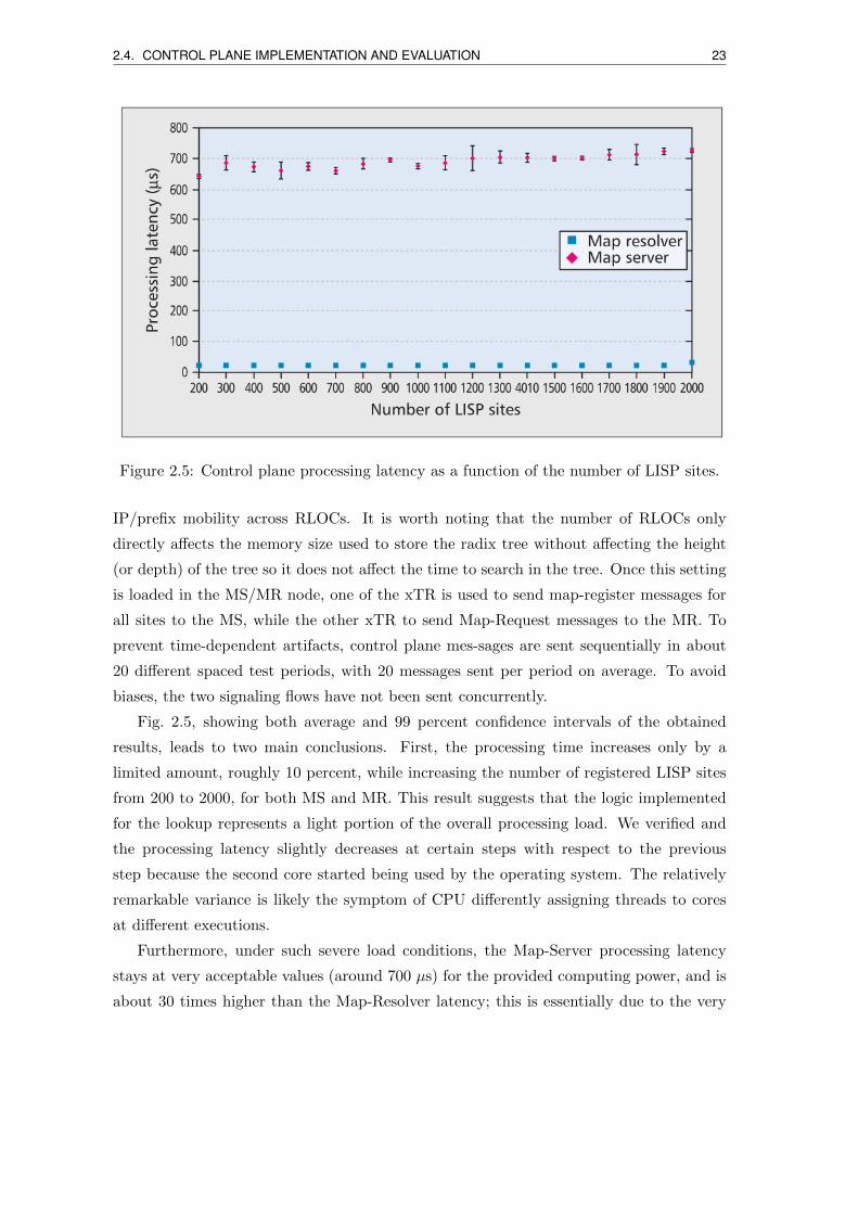
Figure 2.5: Control plane processing latency as a function of the number of LISP sites.
IP/prefix mobility across RLOCs. It is worth noting that the number of RLOCs only
directly affects the memory size used to store the radix tree without affecting the height
(or depth) of the tree so it does not affect the time to search in the tree. Once this setting
is loaded in the MS/MR node, one of the xTR is used to send map-register messages for
all sites to the MS, while the other xTR to send Map-Request messages to the MR. To
prevent time-dependent artifacts, control plane mes-sages are sent sequentially in about
20 different spaced test periods, with 20 messages sent per period on average. To avoid
biases, the two signaling flows have not been sent concurrently.
Fig. 2.5, showing both average and 99 percent confidence intervals of the obtained
results, leads to two main conclusions. First, the processing time increases only by a
limited amount, roughly 10 percent, while increasing the number of registered LISP sites
from 200 to 2000, for both MS and MR. This result suggests that the logic implemented
for the lookup represents a light portion of the overall processing load. We verified and
the processing latency slightly decreases at certain steps with respect to the previous
step because the second core started being used by the operating system. The relatively
remarkable variance is likely the symptom of CPU differently assigning threads to cores
at different executions.
Furthermore, under such severe load conditions, the Map-Server processing latency
stays at very acceptable values (around 700 µs) for the provided computing power, and is
about 30 times higher than the Map-Resolver latency; this is essentially due to the very
24 2.4. CONTROL PLANE IMPLEMENTATION AND EVALUATION
high number of sites and prefixes to register, the fact that first, Map-Register messages
need to be authenticated via HMAC, and then the mapping database possibly may need
to be updated (hence roughly a quadratic time complexity). Map-Reply and Map-Notify
messages that are close in size and written with a linear complexity have a similar light
impact on the processing latency of MR and MS, respectively.
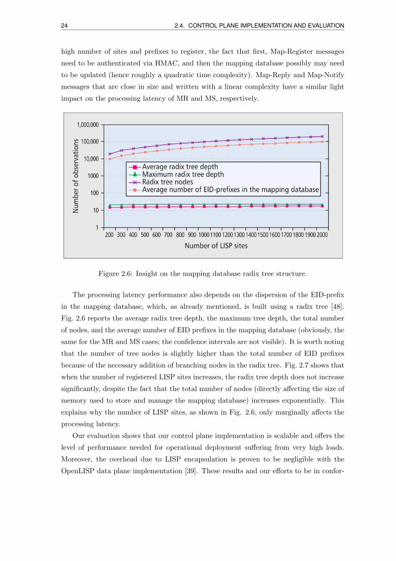
Figure 2.6: Insight on the mapping database radix tree structure.
The processing latency performance also depends on the dispersion of the EID-prefix
in the mapping database, which, as already mentioned, is built using a radix tree [48].
Fig. 2.6 reports the average radix tree depth, the maximum tree depth, the total number
of nodes, and the average number of EID prefixes in the mapping database (obviously, the
same for the MR and MS cases; the confidence intervals are not visible). It is worth noting
that the number of tree nodes is slightly higher than the total number of EID prefixes
because of the necessary addition of branching nodes in the radix tree. Fig. 2.7 shows that
when the number of registered LISP sites increases, the radix tree depth does not increase
significantly, despite the fact that the total number of nodes (directly affecting the size of
memory used to store and manage the mapping database) increases exponentially. This
explains why the number of LISP sites, as shown in Fig. 2.6, only marginally affects the
processing latency.
Our evaluation shows that our control plane implementation is scalable and offers the
level of performance needed for operational deployment suffering from very high loads.
Moreover, the overhead due to LISP encapsulation is proven to be negligible with the
OpenLISP data plane implementation [39]. These results and our efforts to be in confor-
2.4. CONTROL PLANE IMPLEMENTATION AND EVALUATION 25
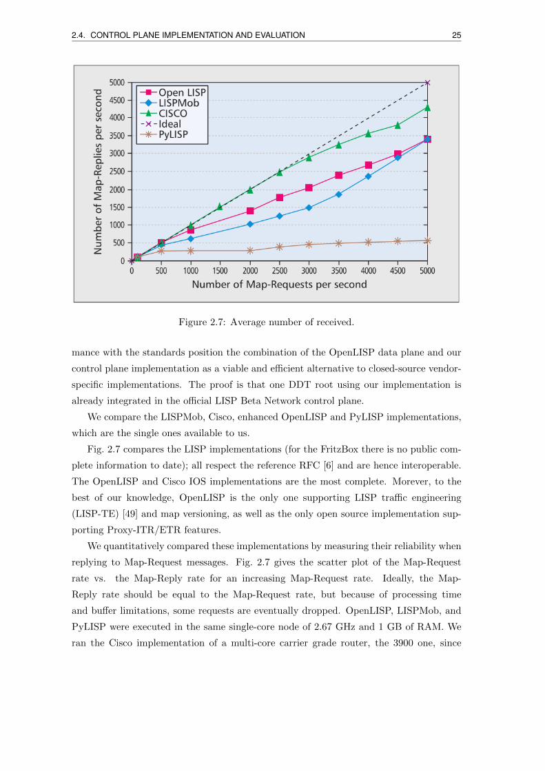
Figure 2.7: Average number of received.
mance with the standards position the combination of the OpenLISP data plane and our
control plane implementation as a viable and efficient alternative to closed-source vendor-
specific implementations. The proof is that one DDT root using our implementation is
already integrated in the official LISP Beta Network control plane.
We compare the LISPMob, Cisco, enhanced OpenLISP and PyLISP implementations,
which are the single ones available to us.
Fig. 2.7 compares the LISP implementations (for the FritzBox there is no public com-
plete information to date); all respect the reference RFC [6] and are hence interoperable.
The OpenLISP and Cisco IOS implementations are the most complete. Morever, to the
best of our knowledge, OpenLISP is the only one supporting LISP traffic engineering
(LISP-TE) [49] and map versioning, as well as the only open source implementation sup-
porting Proxy-ITR/ETR features.
We quantitatively compared these implementations by measuring their reliability when
replying to Map-Request messages. Fig. 2.7 gives the scatter plot of the Map-Request
rate vs. the Map-Reply rate for an increasing Map-Request rate. Ideally, the Map-
Reply rate should be equal to the Map-Request rate, but because of processing time
and buffer limitations, some requests are eventually dropped. OpenLISP, LISPMob, and
PyLISP were executed in the same single-core node of 2.67 GHz and 1 GB of RAM. We
ran the Cisco implementation of a multi-core carrier grade router, the 3900 one, since
26 2.5. LISP EXPERIMENTAL PLATFORMS
tested lower-grade Cisco routers did stop the LISP control plane when approaching a few
thousand Map-Requests per second. Results between the open source implementation and
the Cisco implementations are therefore not directly comparable, but are reported for the
sake of clarity. The Cisco one consequently appears as the most robust implementation,
dropping about 10 percent of the control plane messages, only starting at around 4000
messages/s. Among the open source implementations, OpenLISP slightly outperforms
LISPMob for low and mid-range rates, despite the additional features to manage, but has
similar performance at higher rates. PyLISP in its current implementation is not very
scalable and shows very poor performance already at 500 Map-Requests/s. Overall, these
results show that the more mature implementations are those with a longer history.
2.4.5 Perspectives
Thanks to our development effort, an OpenLISP node can today run as the single fully
featured open source LISP implementation.
Our performance evaluation combined with the data plane performance evaluation in
[33] shows that our implementation is scalable enough for large networks and reaches per-
formances suitable for real deployments. Our implementation is currently mature enough
to be deployed in operational networks, and is actually used to interconnect at least seven
LISP sites to the worldwide LISP Beta Network testbed and to the LISP-Lab testbeds,
correctly handling both data plane and control plane operations. Moreover, we have just
integrated an OpenLISP DDT root server into the current worldwide LISP DDT hierar-
chy. We are currently enhancing the traffic engineering features to support various working
modes concurrently, and we plan to add security features, integrating the related upcoming
Internet Engineering Task Force (IETF) specification on the matter. We recently ported
the control plane to the Linux environment; another important milestone already planned
is to port the data plane to Linux as well, and the whole Open-LISP node to other BSD
flavors (e.g., OpenBSD and Net-BSD).
2.5 LISP experimental platforms
We describe in the following two open LISP platforms. One managed by Cisco, and one by
the ANR LISP-LAB project coordinated by Universite Pierre et Marie Curie - Sorbonne
Universite. I strongly contributed to the construction, integration and management of the
LISP-LAB platform.
2.5. LISP EXPERIMENTAL PLATFORMS 27
2.5.1 LISP4.net platform
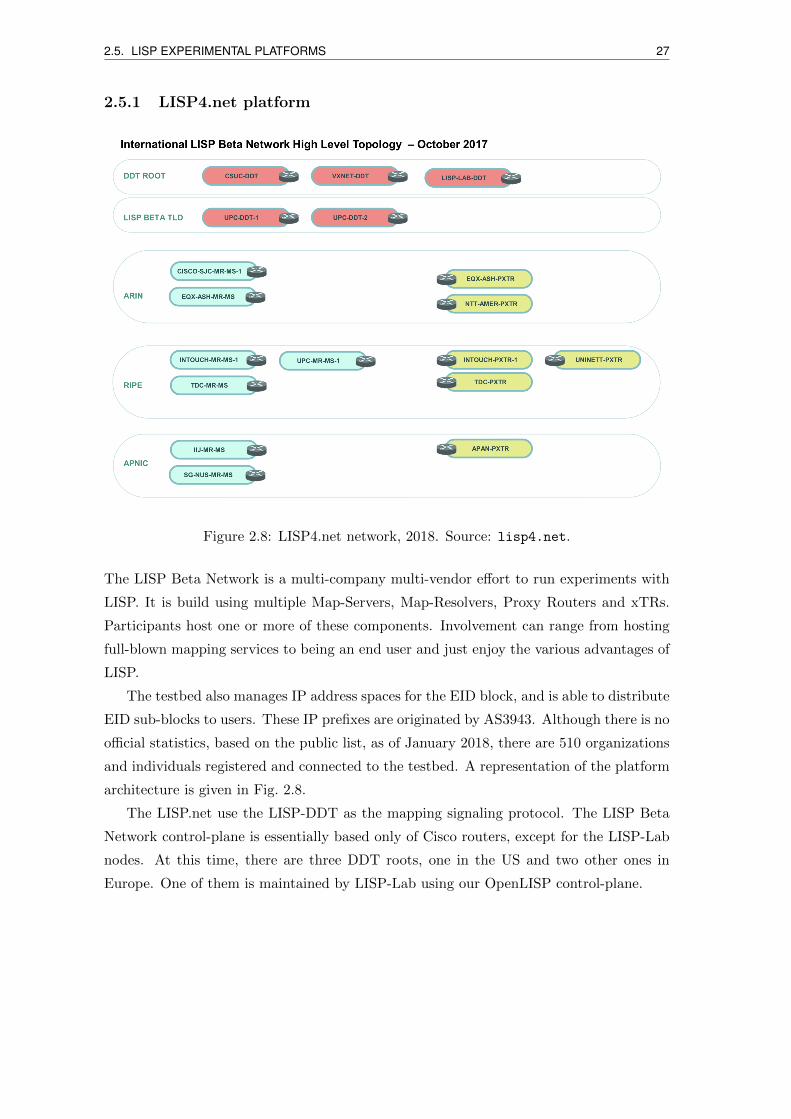
Figure 2.8: LISP4.net network, 2018. Source: lisp4.net.
The LISP Beta Network is a multi-company multi-vendor effort to run experiments with
LISP. It is build using multiple Map-Servers, Map-Resolvers, Proxy Routers and xTRs.
Participants host one or more of these components. Involvement can range from hosting
full-blown mapping services to being an end user and just enjoy the various advantages of
LISP.
The testbed also manages IP address spaces for the EID block, and is able to distribute
EID sub-blocks to users. These IP prefixes are originated by AS3943. Although there is no
official statistics, based on the public list, as of January 2018, there are 510 organizations
and individuals registered and connected to the testbed. A representation of the platform
architecture is given in Fig. 2.8.
The LISP.net use the LISP-DDT as the mapping signaling protocol. The LISP Beta
Network control-plane is essentially based only of Cisco routers, except for the LISP-Lab
nodes. At this time, there are three DDT roots, one in the US and two other ones in
Europe. One of them is maintained by LISP-Lab using our OpenLISP control-plane.
28 2.5. LISP EXPERIMENTAL PLATFORMS
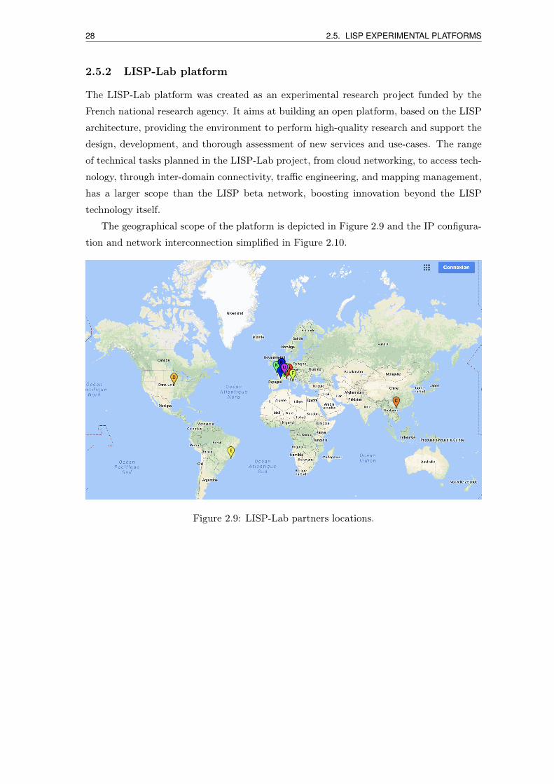
2.5.2 LISP-Lab platform
The LISP-Lab platform was created as an experimental research project funded by the
French national research agency. It aims at building an open platform, based on the LISP
architecture, providing the environment to perform high-quality research and support the
design, development, and thorough assessment of new services and use-cases. The range
of technical tasks planned in the LISP-Lab project, from cloud networking, to access tech-
nology, through inter-domain connectivity, traffic engineering, and mapping management,
has a larger scope than the LISP beta network, boosting innovation beyond the LISP
technology itself.
The geographical scope of the platform is depicted in Figure 2.9 and the IP configura-
tion and network interconnection simplified in Figure 2.10.
Figure 2.9: LISP-Lab partners locations.
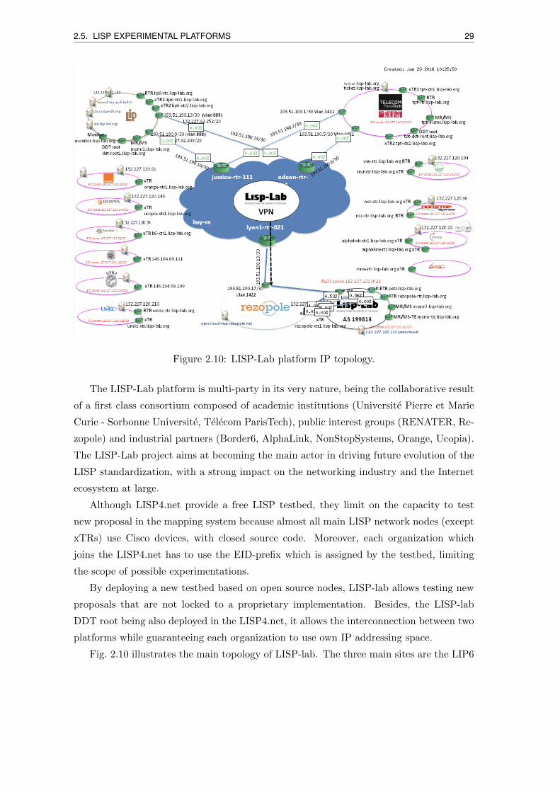
2.5. LISP EXPERIMENTAL PLATFORMS 29
Figure 2.10: LISP-Lab platform IP topology.
The LISP-Lab platform is multi-party in its very nature, being the collaborative result
of a first class consortium composed of academic institutions (Universite Pierre et Marie
Curie - Sorbonne Universite, Telecom ParisTech), public interest groups (RENATER, Re-
zopole) and industrial partners (Border6, AlphaLink, NonStopSystems, Orange, Ucopia).
The LISP-Lab project aims at becoming the main actor in driving future evolution of the
LISP standardization, with a strong impact on the networking industry and the Internet
ecosystem at large.
Although LISP4.net provide a free LISP testbed, they limit on the capacity to test
new proposal in the mapping system because almost all main LISP network nodes (except
xTRs) use Cisco devices, with closed source code. Moreover, each organization which
joins the LISP4.net has to use the EID-prefix which is assigned by the testbed, limiting
the scope of possible experimentations.
By deploying a new testbed based on open source nodes, LISP-lab allows testing new
proposals that are not locked to a proprietary implementation. Besides, the LISP-lab
DDT root being also deployed in the LISP4.net, it allows the interconnection between two
platforms while guaranteeing each organization to use own IP addressing space.
Fig. 2.10 illustrates the main topology of LISP-lab. The three main sites are the LIP6

30 2.5. LISP EXPERIMENTAL PLATFORMS
laboratory of Universite Pierre et Marie Curie - Sorbonne Universite, Telecom ParisTech,
and RENATER. The interconnect between the main site is provided over RENATER
with a layer-3 VPN mesh with links of 1 Gbps. For load balancing and the stability of the
system, the mapping system is deployed in the three sites, each site includes at least one
MS and one MR. For communication with non-LISP networks, we deployed two PxTRs,
one beyond RENATER and Rezopole, and one beyond the Alphalink network.
Chapter 3
Large-Scale Virtual Machine
Migrations with LISP
Nowadays, the rapid growth of Cloud computing services is stressing the network commu-
nication infrastructure in terms of resiliency and programmability. This evolution reveals
missing blocks of the current Internet Protocol architecture, in particular in terms of vir-
tual machine mobility management for addressing and locator-identifier mapping. In this
chapter, we propose some changes to the Locator/Identifier Separation Protocol (LISP)
to cope with this gap. We define novel control-plane functions and evaluate them exhaus-
tively in the worldwide public LISP testbed, involving five LISP sites distant from a few
hundred kilometers to many thousands kilometers.
3.1 Introduction
As a matter of fact, network virtualization has revolutionized datacenter networking. Once
solely based on physical server and mainframe interconnections, Cloud datacenters increas-
ingly deploy virtualization servers that host, send and receive virtual machines (VMs), to
and from local and distant locations. This evolution raises many networking issues in
terms of address continuity and traffic routing. When and how should VMs maintain (or
use) the same (or multiple) Ethernet and/or IP addresses upon migration, have been and
still are open research questions in Cloud networking. Similar challenges appear with the
emergence of advanced services such as Infrastructure as a Service (IaaS) [52], often re-
quiring multiple VMs physically located at different sites to communicate with each other
as well as with its users, which keep communicating while moving across datacenters [53].
The contents of this chapter are presented in [33, 50, 51]. My contribution included both the protocolsolution design and its implementation in strong coordination with P. Raad.
31
32 3.1. INTRODUCTION
In virtualization nodes, the hypervisor is a software-level abstraction module essential
to concurrently manage several VMs on a physical machine. VM migration is a service
included in most hypervisors to move VMs from one physical machine to another, com-
monly within a datacenter. Migrations are executed for several reasons, ranging from fault
management, energy consumption minimization, and quality-of-service improvement. In
legacy Cloud networks, VM location was bound to a single facility, due to storage area
network and addressing constraints. Eventually, thanks to novel protocols and high-speed
low-latency networks, storage networks can span metropolitan and wide area networks,
and VM locations can span the whole Internet over very long distances.
Multiple solutions are being tested to make VMs’ location volatile [54, 55, 56]. The
main trend is to allow transparent VM migrations by developing advanced functionalities
at the hypervisor level [54]. In terms of addressing, the main problem lies in the possibility
of scaling from public Clouds and intra-provider Clouds to private and hybrid Clouds, i.e.,
seamlessly migrating a virtual server with a global IP across the Internet and wide area IP
networks. Multiple solutions exist to handle addressing issues, ranging from simple ones
with centralized ad-hoc address mapping using MAC-in-MAC or IP-in-IP encapsulation, or
a mix of both of them, to more advanced ones with a distributed control-plane supporting
VM mobility and location management. Several commercial (non-standard) solutions
extend (virtual) local area networks across wide area networks, such as [55] and [56]
handling differently layer-2 and layer-3 inter-working.
Among the standards to handle VM mobility and addressing issues, we can mention
recent efforts to define a distributed control-plane in TRILL (Transparent Interconnection
of a Lot of Links) architecture [57] to manage a directory that pilots layer-2 encapsula-
tion. However, maintaining layer-2 long-distance connectivity is often economically pro-
hibitive, a too high barrier for small emerging Cloud service providers, and not scalable
enough when the customers are mostly Internet users (i.e., not privately interconnected
customers). At the IP layer, the addressing continuity can be guaranteed using ad-hoc
VM turntables as suggested in [58], or Mobile IP as proposed in [59], which however can
increment propagation and transmission delays due to triangular routing: the traffic has
to pass through the VM original network, before being encapsulated and sent to the new
VM location.
More recently, the Location/Identifier Separation Protocol (LISP) [6], mainly pro-
posed to solve Internet routing scalability and traffic engineering issues, is now considered
for VM mobility and has already attracted the attention for some commercial solutions
[38]. In order to efficiently handle locator-identifier mappings, LISP offers a distributed
control-plane, decoupled from the data-plane. An advantage of LISP is that it can avoid
3.2. BACKGROUND 33
triangular routing, with encapsulations performed at the first LISP capable IP node. Nev-
ertheless, based on current standards and literature, there are missing functionalities to
guarantee low VM migration downtimes with LISP. Moreover, those experiments cannot
be reproduced in absence of open source solutions.
The contribution of this chapter is the definition and the evaluation of novel LISP
functionalities to obtain high performance in large-scale live VM migration. We provide
all the elements to reproduce the results, including reference to an open source implemen-
tation of our proposition. Our solution is based on the definition of LISP control-plane
messages to fast update EID-locator mappings, hence overcoming the long latency of ba-
sic LISP mechanisms. We validate and evaluate our solution using the worldwide LISP
Beta Network and LISP-Lab nodes, piloting five LISP sites in four countries worldwide.
The chapter is organized as follows. Section 3.2 briefly presents the background. Section
3.3 describes our protocol extension proposition. Section 3.4 reports experimental results.
Section 3.5 concludes the chapter and discusses future works.
3.2 Background
In this section we describe the state of the art live VM migration networking.
3.2.1 Live VM migration and IP mobility
Live VM migration is a feature introduced in recent hypervisors; it allows moving a running
VM between two (physical) host containers without disconnecting the client or application.
For most of the hypervisors, live migration is limited to situations in which source and
destination hosts look like connected to the same local area network. The main reason
is that the machine being migrated needs to keep the same routing view of the network
(e.g., gateway, IP subnet) before and after the migration. Alternatively, in some legacy
solutions, upon migration the VM changes its IP address, e.g., via the DHCP, to avoid the
additional complexity needed to ensure that the origin IP address is not already used in
the destination network, and to transfer the routing table; VM’s IP readdressing implies,
however, long convergence and loss of too many packets.
In order to perform Internet-wide migrations with IP continuity, authors in [59] and [60]
propose an IP mobility solution. The logic is implemented in the hypervisor, interacting
with the VM before and after its migration to update IP addresses in the VM routing table.
While [59] succeeds in bringing lower service downtime compared to [60], the hypervisor
has to alter the VM configuration to support the IP mobility feature, which leads to
scalability concerns. Moreover, as the authors state, the performance of their solution is
34 3.2. BACKGROUND
expected to worsen in large-scale global live migrations, because of the online signaling
nature of the proposition and many-way signaling latencies.
Authors in [61] propose to adapt the Mobile IP (MIP) protocol [62] to pilot Internet-
scale VM migrations, implementing it in the hypervisor. Their solution, called HyperMIP,
is invoked whenever a VM is created, destroyed or migrated; as in MIP, it involves Home
Agents (HA) to keep the connection alive. Whenever a VM changes a location, a tunnel
is established between the HA and the source hypervisor to keep the client connected to
the VM. The destination hypervisor then destroys the tunnel when the VM registers its
new IP address to the HA. However, HyperMIP still introduces an important signaling
overhead due to HA tunnel establishment.
Alternatively, to minimize signaling latencies, authors in [58] propose to use an ex-
ternal agent to orchestrate the migration from the beginning to the end, by proactively
establishing circuits between the involved containers (source and destination hypervisors)
offline, so as to rapidly switch the traffic upon migration, then redirecting the client-VM
traffic via dynamic reconfiguration of IP tunnels. They achieve a near second network
downtime while migrating machines across wide area networks, with a maximum network
downtime around 3.8 seconds. Despite being a more secure approach, with respect to
[59], [60] and [61] their solution involves lower-layer technologies, hence can be excessively
costly.
3.2.2 Layer 2 over Layer 3 overlay tunneling solutions
The above described solutions tackle large-scale VM live migration using Layer 3 tunneling
( [59], [60] and [61]), or Layer 3-Layer 1 interaction [58]. More recently, at the IETF,
attention has been given to Layer 2 over Layer 3 (L2o3), Ethernet over IP, virtual network
overlay solutions, so as to avoid IP reconfiguration to the VM, and service continuity
upon migration of VMs across virtualization servers. Virtual eXtensible LAN (VXLAN)
[63], Stateless Transport Tunneling (STT) [64], and Network Virtualization using Generic
Routing Encapsulation (NVGRE) [65], are recent propositions, already implemented by
many commercial stakeholders (e.g., Microsoft, VMWare) and open source virtual switches
(e.g., OpenVSwitch), worth being discussed hereafter.
VXLAN [63] is a stateless L2o3 logic that extends the Layer 2 communication domain
over IP networks, extending a VLAN broadcast domain thanks to MAC-to-IP encapsula-
tion between hypervisors, even if communicating VMs and endpoints are in different IP
segments. Basically, when a VM wants to communicate with another VM on a different
host, a ‘tunnel endpoint’ implemented in the hypervisor receives the frame, verifies that
the target VM is on the same VXLAN segment via standard signaling, and then appends
3.2. BACKGROUND 35
an IP address corresponding to the destination tunnel endpoint, and a VXLAN header.
Upon reception, the destination tunnel endpoint verifies the packet, decapsulates it and
forwards it to the VM target. Therefore, thanks to the VLAN broadcast domain exten-
sion, a VM belonging to a VXLAN segment can migrate to a VXLAN endpoint in another
IP segment, and its traffic is consequently encapsulated by the source VXLAN endpoint
toward the destination VXLAN endpoint.
Functionally, NVGRE [65] is a similar L2o3 tunneling solution, with a different header
(VXLAN uses a UDP shim header to easily pass through middle-boxes, while NVGRE
does not hence limiting its scope to a single administrative network), and with no speci-
fied control-plane to distribute MAC-to-IP mappings (in VXLAN, multicast mechanisms
do allow resolving these mappings). Encapsulating Ethernet traffic over IP allows a bet-
ter bottleneck management thanks to various IP traffic engineering and load-balancing
mechanisms. Both VXLAN and NVGRE, however, do not allow typical Ethernet network
interface controllers to perform TCP offloading (intermediate fragmentation done by the
hardware to boost performances). This is instead allowed by Stateless Transport Tunnel-
ing [64] (STT), another stateless L2o3 tunneling protocol, which uses a fake TCP header
inside the IP header to allow interface-level TCP optimizations. From a VM mobility
and traffic routing perspective, it offers the same encapsulation path than VXLAN and
NVGRE, but as NVGRE it has difficulties to pass through Internet middle-boxes and its
deployment is also limited to a single administrative domain such as a DC network.
All these technologies (VXLAN, NVGRE, STT) share as reference use-cases intra-DC
and inter-DC communications, i.e., between VMs hosted in different virtualization servers
potentially in different IP subnets. Therefore, they are not readily applicable to the Cloud
access communication usecase, involving an IP user and a VM-based IP server, mainly
targeted by our LISP proposition. The user endpoint is typically not a virtualization
server and is not connected to the same DC fabric than the server, and can potentially be
everywhere in the Internet.
3.2.3 Triangular routing solutions vs LISP rerouting
From the IP routing perspective of an Internet client accessing a server running in a VM,
the legacy approaches can be considered as triangular routing (or indirect forwarding)
solutions - the traffic has to reach the VM source network and/or container before being
encapsulated and sent to the new VM location. Triangular routing solutions typically
offer higher client-server path latency, than LISP-enabled direct rerouting. A higher path
latency implies a higher transfer time, namely for TCP-based connections given that the
round-trip-time (RTT) has an impact on TCP acknowledgments reception. Therefore, as
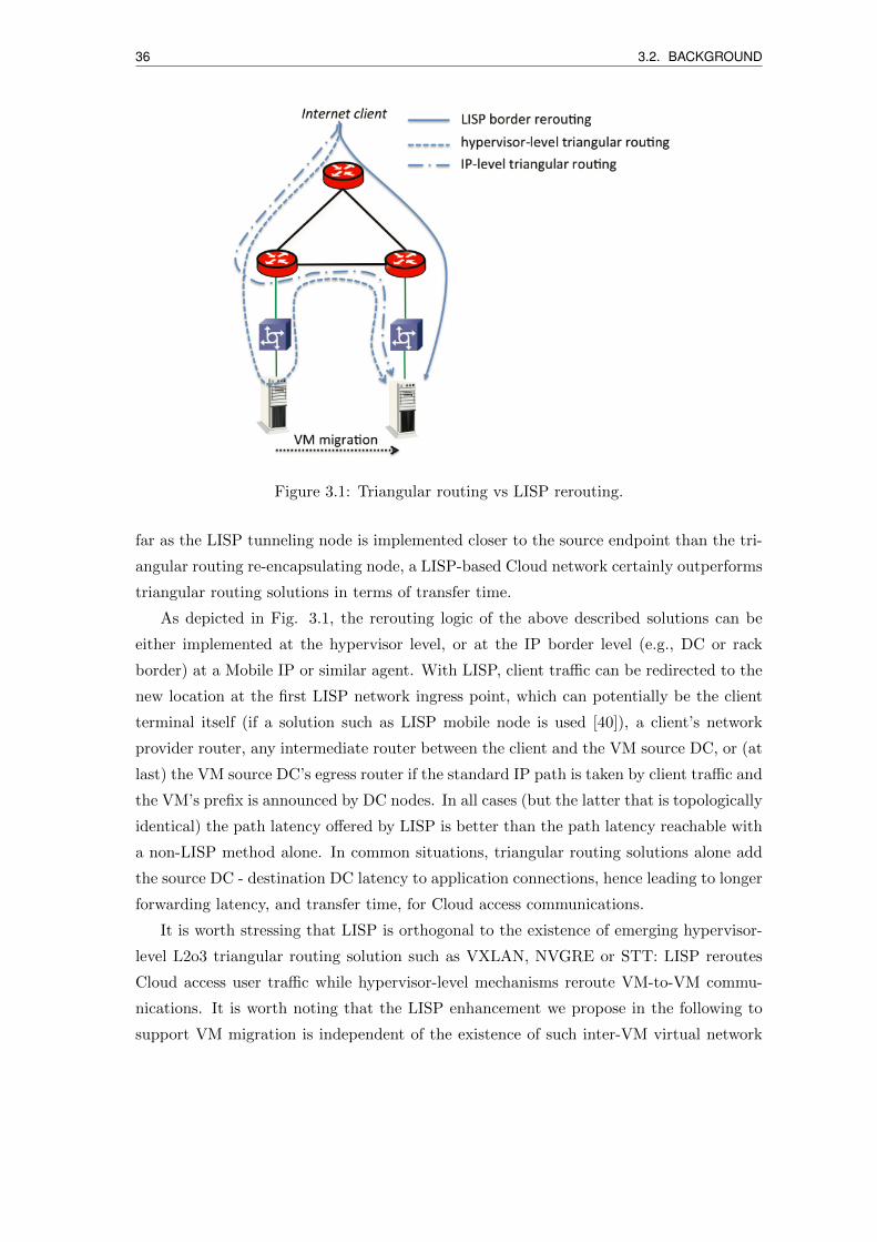
36 3.2. BACKGROUND
Figure 3.1: Triangular routing vs LISP rerouting.
far as the LISP tunneling node is implemented closer to the source endpoint than the tri-
angular routing re-encapsulating node, a LISP-based Cloud network certainly outperforms
triangular routing solutions in terms of transfer time.
As depicted in Fig. 3.1, the rerouting logic of the above described solutions can be
either implemented at the hypervisor level, or at the IP border level (e.g., DC or rack
border) at a Mobile IP or similar agent. With LISP, client traffic can be redirected to the
new location at the first LISP network ingress point, which can potentially be the client
terminal itself (if a solution such as LISP mobile node is used [40]), a client’s network
provider router, any intermediate router between the client and the VM source DC, or (at
last) the VM source DC’s egress router if the standard IP path is taken by client traffic and
the VM’s prefix is announced by DC nodes. In all cases (but the latter that is topologically
identical) the path latency offered by LISP is better than the path latency reachable with
a non-LISP method alone. In common situations, triangular routing solutions alone add
the source DC - destination DC latency to application connections, hence leading to longer
forwarding latency, and transfer time, for Cloud access communications.
It is worth stressing that LISP is orthogonal to the existence of emerging hypervisor-
level L2o3 triangular routing solution such as VXLAN, NVGRE or STT: LISP reroutes
Cloud access user traffic while hypervisor-level mechanisms reroute VM-to-VM commu-
nications. It is worth noting that the LISP enhancement we propose in the following to
support VM migration is independent of the existence of such inter-VM virtual network
3.2. BACKGROUND 37
overlay mechanisms. Their integration with our LISP-based Cloud access solution could
bring advantages in terms of transfer time only for inter-VM communications.
As compared to legacy IP-level triangular routing solution, with our proposition de-
scribed in the next sections, we can obtain service downtime between 150 and 200 ms,
depending on the signaling scope. With respect to the alternative methods at the state of
the art described in 3.2.1, we can assess that:
• with HyperMIP [66], authors experienced 2 to 4 s of downtime, which is many times
more than our approach;
• similarly in [60] Mobile IPv6 signaling is used to detect VM location change, reaching
a minimum overhead around 2500 ms, linearly increasing with the network delay,
hence significantly higher than our approach;
• authors in [58] went a step further implementing pro-active circuit provisioning,
reaching an application downtime varying between 800 and 1600 ms, which is more
than 4 times higher than with our approach.
3.2.4 Existing LISP-based mobility management solutions
In a LISP network, the VM can keep the same IP. Two mechanisms at the state of the art
can perform this operation. One is a host-based LISP implementation called LISPmob [40]:
the host implements a tiny xTR with basic LISP functions, using the network-assigned
IP(s) as RLOC(s) and registering mapping updates for its EID with the mapping servers.
Essentially conceived for mobile equipment, LISPmob could also be installed in the VM;
there would be, however, a problem with most current hypervisors that impose the VM
external address to be in the same subnet before and upon migration, which practically
limits the LISPmob usability only to situations where source and destination networks
are either LISP sites themselves, or layer-2 over wide area network (WAN) solutions. In
the first case, a double encapsulation is needed, which could increase mapping latency,
overhead and create MTU issues. There may also be scalability issues with a high number
of VMs.
Another method to handle VM mobility via LISP is actually implemented in some
Cisco products, only partially documented in [38]. The xTR automatically changes the
mapping upon reception of outgoing data-plane traffic from an EID that has been reg-
istered as mobile node. The solution has an attracting light impact on IP operations,
yet it seems to be weak against EID spoofing, and it seems not to have authentication
mechanisms. Moreover, in order to guarantee fast mapping convergence, it seems that
38 3.3. PROPOSED LISP-BASED VM MIGRATION SOLUTION
additional logic would need to be implemented in the VM or in the hypervisor to allow
sending outgoing artificial data traffic even if no real outgoing traffic exists.
3.3 Proposed LISP-based VM migration solution
We propose a novel solution to support WAN VM live migration exploiting the LISP
protocol. We implemented our solution in the open source OpenLISP control-plane im-
plementation [8] [67], which complements the OpenLISP data-plane [68].
As described above, a live migration technique should be able to move a VM keeping
its unique EID, from its actual DC to a new DC maintaining all VM connections alive.
As a preliminary step, the source and destination DCs have to share the same internal
subnet, i.e., the VM unique EID should be routable beyond its RLOC, wherever it is. LISP
supports a large number of locators, and does not set constraints on RLOC addressing
– i.e., the RLOCs can take an IP address belonging not simply to different subnets, but
also to different Autonomous System networks. The current VM location can be selected
leveraging on RLOC metrics. We introduce two main enhancements:
• a new LISP control-plane message to speed up RLOC priority update;
• a migration process allowing hypervisor-xTR coordination for mapping system up-
date.
Our solution involves the following network nodes: the source VM container and the
destination VM container, both managed by an hypervisor, the VM being migrated from
one to the other, LISP border routers at the source DC and at the destination DC, the
Cloud user accessing the VM.
In the following, we present the novel LISP control-plane message we introduce for
communications between the involved LISP nodes, then we describe the VM migration
process, and finally we discuss implementation aspects.

3.3. PROPOSED LISP-BASED VM MIGRATION SOLUTION 39
Figure 3.2: CHANGE PRIORITY message format.
3.3.1 Change priority message format
We introduce a new type of LISP control-plane message we call CHANGE PRIORITY
(CP).
As depicted in Fig. 3.2, we use a new control-plane type field value equal to 5, and
use two bits to define message sub-types to be managed by both xTR and VM containers’
hypervisors:
• H (Hypervisor) bit: this bit is set to 1 when the message is sent by the destination
hypervisor (the hypervisor that receives the VM), indicating to the xTR that it has
just received a new EID. With the H bit set, the record count should be set to 0 and
the REC field is empty;
• C (Update Cache) bit: this bit is set to 1 when an xTR wants to update the mapping
cache of another xTR. With the C bit set, the record count is set to the number of
locators and the REC field contains the RLOC information to rapidly update the
receiver mapping cache.
The other fields have the same format and function as for the MAP-REGISTER message
fields [6], i.e., with EID and RLOC fields, a nonce field used to guarantee session controls,
40 3.3. PROPOSED LISP-BASED VM MIGRATION SOLUTION
and HMAC authentication fields useful to secure the communication (with the important
feature that the authentication key used for CP messages can be different than the key
used by MAP-REGISTER, provided that the xTR is able to handle different keys as
provided in [8] [67]).
3.3.2 VM migration process
The LISP mapping system has to be updated whenever the VM changes its location.
Before the migration process starts, the xTRs register the VM’s EID as a single /32 prefix
or as a part of larger EID (sub-)prefix. The involved devices communicate with each
other to atomically update the priority attribute of the EID-to-RLOC mapping database
entries. The following steps describe the LISP-based VM migration process we propose
and demonstrate.
1. The migration is initialized by the hypervisor hosting the VM; once the migration
process ends, the destination hypervisor (the container that receives the VM) sends
a CP message to its xTR (also called destination xTR) with the H bit set to 1, and
the VM’s EID in the EID-prefix field.
2. Upon reception, the destination xTR authenticates the message, performs an EID-
to-RLOC lookup and sets the highest priority to its own locators in the mapping
database with a MAP-REGISTER message. Then, it sends a CP message, with H
and C bits set to 0, to update the mapping database of the xTR that was managing
the EID before the migration (also called source xTR).
3. Before the VM changes its location, the source xTR keeps a trace file of all the
RLOCs that have recently requested it (we call them client xTRs), i.e., that have
the VM RLOCs in their mapping cache.
4. When the source xTR receives the CP message from the destination xTR, it au-
thenticates it and updates the priorities for the matching EID-prefix entry in its
database.
5. In order to redirect the client traffic, there are two different client-redirection possibil-
ities, whether the client xTR is a standard router not supporting CP signaling (e.g.,
a Cisco router implementing the standard LISP control-plane [6]), or an advanced
router including the CP logic (e.g., an OpenLISP router with the control-plane [8]
[67]).
• For the first case, the source xTR sends a SMR to standard client xTRs, which
3.3. PROPOSED LISP-BASED VM MIGRATION SOLUTION 41
triggers mapping update as of [6] (MAP-REQUEST to the MR and/or to the
RLOCs, followed by a MAP-REPLY to the xTR).
• For the second case, in order to more rapidly redirect the traffic to the VM’s new
location (destination xTR), the source xTR sends a CP message with C bit set
to 1 directly to all the client xTRs, which will therefore process it immediately
(avoiding at least one client xTR-MR round-trip-time).
6. Upon EID mapping update, the client xTRs update their mapping cache and start
redirecting the traffic to the VM’s new routing locator(s).
All in all, updating the mapping database of the nodes involved in a VM migration
requires two compulsory message exchanges (one message that notifies the destination
DC about the migration process and another one that is used to notify the source DC),
and optionally a number of additional messages equal to the number of clients that are
communicating with the VM to inform the xTR clients’ about the updates. Considering
only the location update messages for the LISP mapping system does not make our solution
heavier than triangular routing solution (e.g., Mobile IP). Additional signaling messages
are generated with respect to triangular routing solutions if VM clients’s mapping updates
are considered. The limited increase of control messages is indeed counterbalanced by more
significant benefits, in terms of resiliency and convergence, of our solution with respect to
triangular routing ones.
It is worth noting that our solution fully relies on control-plane features. It is our
methodology choice to avoid mixing data-plane and control-plane functions (for example
proposing a specific usage of Map-Versioning or Locator Status Bit field in the data-plane
[69]). The main advantage of creating network control functions disjoint from the data-
plane is the possibility to program the control-plane independently of the forwarding logic,
hence to implement advanced and personalized functionalities. This separation respects
the current design trend in networking called Software Defined Networking [70]. Thanks
to that, new functionalities can be added rapidly to the OpenLISP control-plane and allow
rapid deployment even using pre-existing basic data-plane elements.
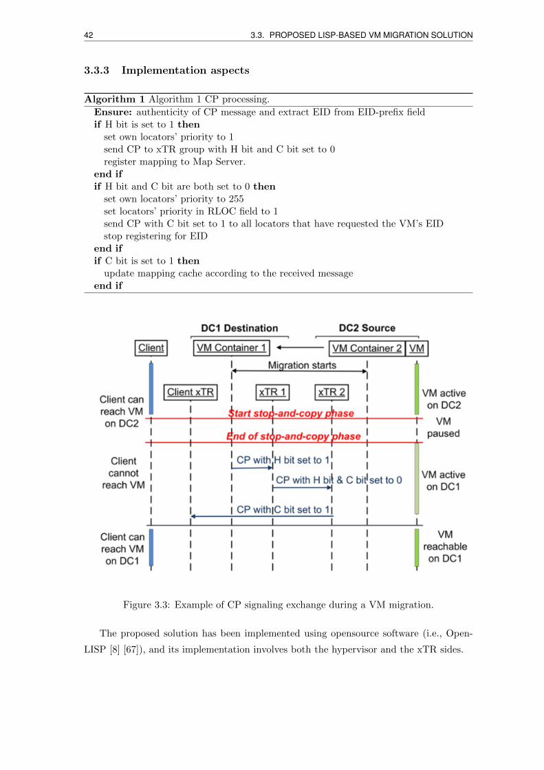
42 3.3. PROPOSED LISP-BASED VM MIGRATION SOLUTION
3.3.3 Implementation aspects
Algorithm 1 Algorithm 1 CP processing.
Ensure: authenticity of CP message and extract EID from EID-prefix fieldif H bit is set to 1 then
set own locators’ priority to 1send CP to xTR group with H bit and C bit set to 0register mapping to Map Server.
end ifif H bit and C bit are both set to 0 then
set own locators’ priority to 255set locators’ priority in RLOC field to 1send CP with C bit set to 1 to all locators that have requested the VM’s EIDstop registering for EID
end ifif C bit is set to 1 then
update mapping cache according to the received messageend if
Figure 3.3: Example of CP signaling exchange during a VM migration.
The proposed solution has been implemented using opensource software (i.e., Open-
LISP [8] [67]), and its implementation involves both the hypervisor and the xTR sides.
3.3. PROPOSED LISP-BASED VM MIGRATION SOLUTION 43
1. On the hypervisor: we integrated a new function that interacts with LIBVIRT (a
management kit handling multiple VMs in the KVM hypervisor) [71] to trigger CP
message generation. When a live migration starts, the hypervisor creates a “paused”
instance of the VM on the destination host. Meanwhile, LIBVIRT monitors the
migration phase from the start to the end. If the migration is successfully completed,
LIBVIRT checks if the VM is running on the target host and, if yes, it sends a CP
message to its xTR on the UDP LISP control port 4342. The VM EID is included
in the EID-prefix field.
2. On the xTR: we implemented the Algorithm 1 function in the OpenLISP control-
plane [8]. While the OpenLISP data-plane logic runs in the kernel of a FreeBSD
machine, the control-plane runs in the user space. The control-plane has a new fea-
ture to capture control-plane message type 5 and the logic to handle CP signaling5.
3. A signaling example: upon receiving a client request, or as triggered by a consolida-
tion engine, a VM needs to be migrated to another public DC. As in the Fig. 3.3
example, VM Container 2 starts migrating VM from DC2 to DC1 while the Client
is still connected. When the migration reaches the so called stop-and-copy phase
(i.e., the phase dedicated to transfer the “dirty pages”, which are pages updated
too frequently to be transferred while the VM runs [72]), the VM stops and begins
transferring its last memory pages. Meanwhile, the Client loses the connection, but
keeps directing the traffic to DC2.
The hypervisor on VM Container 1 detects that VM is now successfully running,
indicating the end of the migration. Then the VM Container 1 announces that the
VM has changed its location by sending to xTR 1 a CP message with the H bit set.
Upon reception, xTR 1 sends a CP with H bit and C bit set to 0 to notify xTR 2
about the new location of VM: xTR 1 updates the priorities for VM’s EID entry in
its database.
When xTR 2 receives the CP message, it matches the EID-prefix to the entries
within its mapping database, and modifies the priorities accordingly, then it stops
registering VM’s EID. As mentioned in Section 3.3.2, xTR 2 keeps a trace file of all
the locators that recently requested the VM’s EID. In this example, only one client
is communicating with VM, so xTR 2 sends a CP message with C-bit set to the
Client’s xTR.
Finally, the Client’s xTR receives the CP message, maps VM’s EID, and updates its
cache, then starts redirecting Client’s traffic to VM’s new location (DC1).
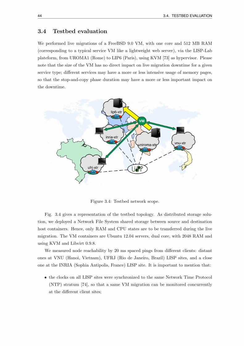
44 3.4. TESTBED EVALUATION
3.4 Testbed evaluation
We performed live migrations of a FreeBSD 9.0 VM, with one core and 512 MB RAM
(corresponding to a typical service VM like a lightweight web server), via the LISP-Lab
plateform, from UROMA1 (Rome) to LIP6 (Paris), using KVM [73] as hypervisor. Please
note that the size of the VM has no direct impact on live migration downtime for a given
service type; different services may have a more or less intensive usage of memory pages,
so that the stop-and-copy phase duration may have a more or less important impact on
the downtime.
Figure 3.4: Testbed network scope.
Fig. 3.4 gives a representation of the testbed topology. As distributed storage solu-
tion, we deployed a Network File System shared storage between source and destination
host containers. Hence, only RAM and CPU states are to be transferred during the live
migration. The VM containers are Ubuntu 12.04 servers, dual core, with 2048 RAM and
using KVM and Libvirt 0.9.8.
We measured node reachability by 20 ms spaced pings from different clients: distant
ones at VNU (Hanoi, Vietnam), UFRJ (Rio de Janeiro, Brazil) LISP sites, and a close
one at the INRIA (Sophia Antipolis, France) LISP site. It is important to mention that:
• the clocks on all LISP sites were synchronized to the same Network Time Protocol
(NTP) stratum [74], so that a same VM migration can be monitored concurrently
at the different client sites;
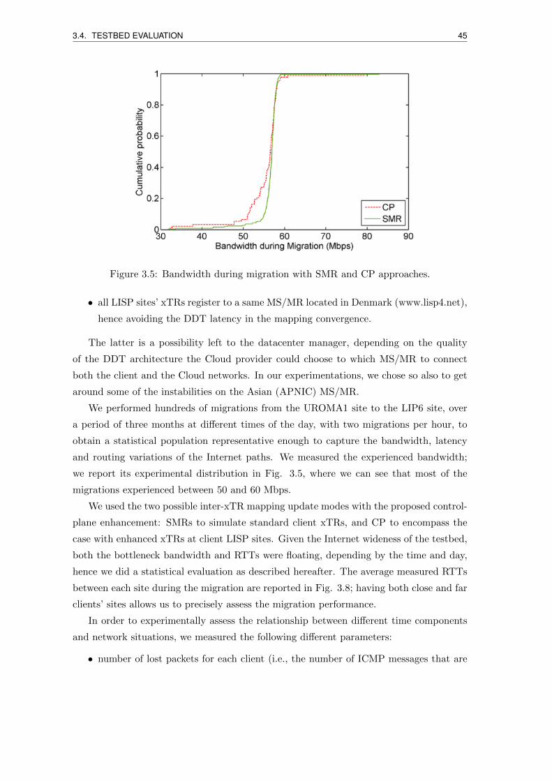
3.4. TESTBED EVALUATION 45
Figure 3.5: Bandwidth during migration with SMR and CP approaches.
• all LISP sites’ xTRs register to a same MS/MR located in Denmark (www.lisp4.net),
hence avoiding the DDT latency in the mapping convergence.
The latter is a possibility left to the datacenter manager, depending on the quality
of the DDT architecture the Cloud provider could choose to which MS/MR to connect
both the client and the Cloud networks. In our experimentations, we chose so also to get
around some of the instabilities on the Asian (APNIC) MS/MR.
We performed hundreds of migrations from the UROMA1 site to the LIP6 site, over
a period of three months at different times of the day, with two migrations per hour, to
obtain a statistical population representative enough to capture the bandwidth, latency
and routing variations of the Internet paths. We measured the experienced bandwidth;
we report its experimental distribution in Fig. 3.5, where we can see that most of the
migrations experienced between 50 and 60 Mbps.
We used the two possible inter-xTR mapping update modes with the proposed control-
plane enhancement: SMRs to simulate standard client xTRs, and CP to encompass the
case with enhanced xTRs at client LISP sites. Given the Internet wideness of the testbed,
both the bottleneck bandwidth and RTTs were floating, depending by the time and day,
hence we did a statistical evaluation as described hereafter. The average measured RTTs
between each site during the migration are reported in Fig. 3.8; having both close and far
clients’ sites allows us to precisely assess the migration performance.
In order to experimentally assess the relationship between different time components
and network situations, we measured the following different parameters:
• number of lost packets for each client (i.e., the number of ICMP messages that are
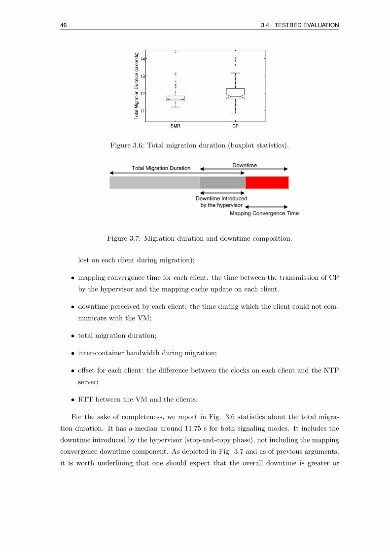
46 3.4. TESTBED EVALUATION
Figure 3.6: Total migration duration (boxplot statistics).
Figure 3.7: Migration duration and downtime composition.
lost on each client during migration);
• mapping convergence time for each client: the time between the transmission of CP
by the hypervisor and the mapping cache update on each client.
• downtime perceived by each client: the time during which the client could not com-
municate with the VM;
• total migration duration;
• inter-container bandwidth during migration;
• offset for each client: the difference between the clocks on each client and the NTP
server;
• RTT between the VM and the clients.
For the sake of completeness, we report in Fig. 3.6 statistics about the total migra-
tion duration. It has a median around 11.75 s for both signaling modes. It includes the
downtime introduced by the hypervisor (stop-and-copy phase), not including the mapping
convergence downtime component. As depicted in Fig. 3.7 and as of previous arguments,
it is worth underlining that one should expect that the overall downtime is greater or
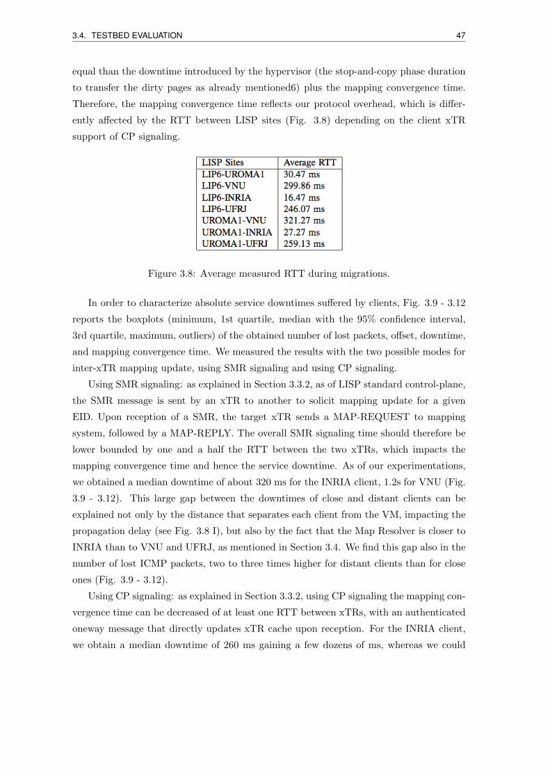
3.4. TESTBED EVALUATION 47
equal than the downtime introduced by the hypervisor (the stop-and-copy phase duration
to transfer the dirty pages as already mentioned6) plus the mapping convergence time.
Therefore, the mapping convergence time reflects our protocol overhead, which is differ-
ently affected by the RTT between LISP sites (Fig. 3.8) depending on the client xTR
support of CP signaling.
Figure 3.8: Average measured RTT during migrations.
In order to characterize absolute service downtimes suffered by clients, Fig. 3.9 - 3.12
reports the boxplots (minimum, 1st quartile, median with the 95% confidence interval,
3rd quartile, maximum, outliers) of the obtained number of lost packets, offset, downtime,
and mapping convergence time. We measured the results with the two possible modes for
inter-xTR mapping update, using SMR signaling and using CP signaling.
Using SMR signaling: as explained in Section 3.3.2, as of LISP standard control-plane,
the SMR message is sent by an xTR to another to solicit mapping update for a given
EID. Upon reception of a SMR, the target xTR sends a MAP-REQUEST to mapping
system, followed by a MAP-REPLY. The overall SMR signaling time should therefore be
lower bounded by one and a half the RTT between the two xTRs, which impacts the
mapping convergence time and hence the service downtime. As of our experimentations,
we obtained a median downtime of about 320 ms for the INRIA client, 1.2s for VNU (Fig.
3.9 - 3.12). This large gap between the downtimes of close and distant clients can be
explained not only by the distance that separates each client from the VM, impacting the
propagation delay (see Fig. 3.8 I), but also by the fact that the Map Resolver is closer to
INRIA than to VNU and UFRJ, as mentioned in Section 3.4. We find this gap also in the
number of lost ICMP packets, two to three times higher for distant clients than for close
ones (Fig. 3.9 - 3.12).
Using CP signaling: as explained in Section 3.3.2, using CP signaling the mapping con-
vergence time can be decreased of at least one RTT between xTRs, with an authenticated
oneway message that directly updates xTR cache upon reception. For the INRIA client,
we obtain a median downtime of 260 ms gaining a few dozens of ms, whereas we could
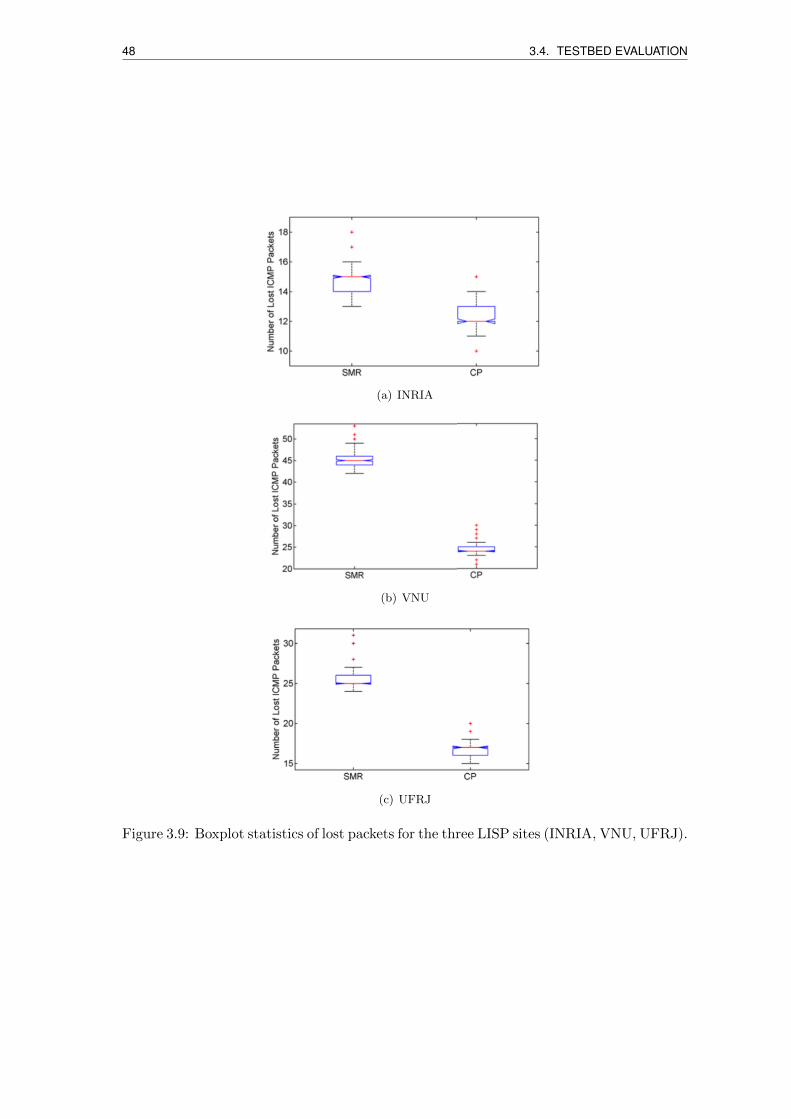
48 3.4. TESTBED EVALUATION
(a) INRIA
(b) VNU
(c) UFRJ
Figure 3.9: Boxplot statistics of lost packets for the three LISP sites (INRIA, VNU, UFRJ).
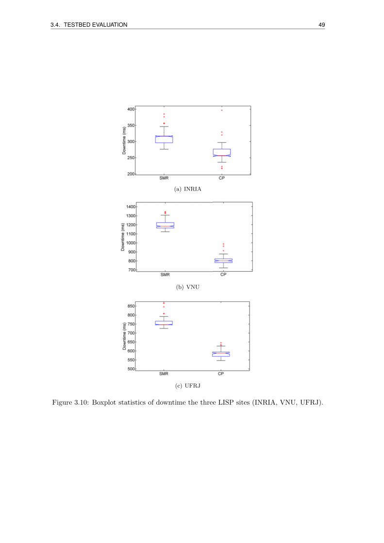
3.4. TESTBED EVALUATION 49
(a) INRIA
(b) VNU
(c) UFRJ
Figure 3.10: Boxplot statistics of downtime the three LISP sites (INRIA, VNU, UFRJ).
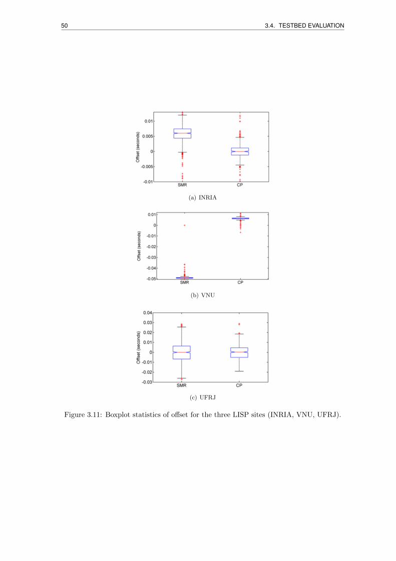
50 3.4. TESTBED EVALUATION
(a) INRIA
(b) VNU
(c) UFRJ
Figure 3.11: Boxplot statistics of offset for the three LISP sites (INRIA, VNU, UFRJ).
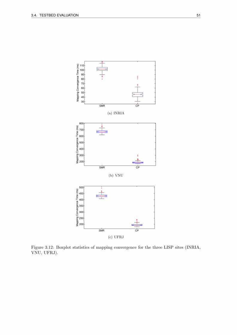
3.4. TESTBED EVALUATION 51
(a) INRIA
(b) VNU
(c) UFRJ
Figure 3.12: Boxplot statistics of mapping convergence for the three LISP sites (INRIA,VNU, UFRJ).
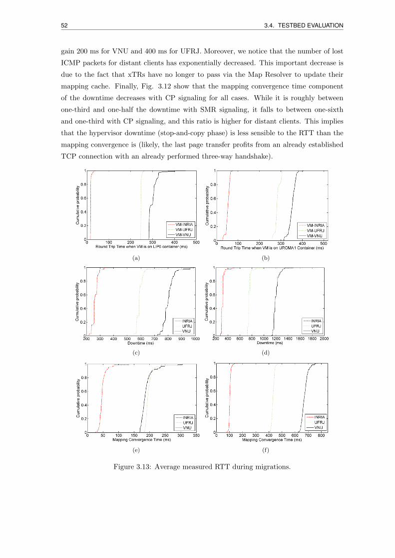
52 3.4. TESTBED EVALUATION
gain 200 ms for VNU and 400 ms for UFRJ. Moreover, we notice that the number of lost
ICMP packets for distant clients has exponentially decreased. This important decrease is
due to the fact that xTRs have no longer to pass via the Map Resolver to update their
mapping cache. Finally, Fig. 3.12 show that the mapping convergence time component
of the downtime decreases with CP signaling for all cases. While it is roughly between
one-third and one-half the downtime with SMR signaling, it falls to between one-sixth
and one-third with CP signaling, and this ratio is higher for distant clients. This implies
that the hypervisor downtime (stop-and-copy phase) is less sensible to the RTT than the
mapping convergence is (likely, the last page transfer profits from an already established
TCP connection with an already performed three-way handshake).
(a) (b)
(c) (d)
(e) (f)
Figure 3.13: Average measured RTT during migrations.
3.5. CONCLUSION 53
It is worth noticing that these measurements may suffer from a small error due to
clock synchronization. As mentioned above, the xTRs have synchronized clocks over the
same NTP stratum. The median of the offsets is represented in Fig. 3.11. While it is
negligible for close clients, it is of a few dozens of ms for distant clients, however less than
the 5% of the downtime. A more precise insight on the simulation parameters is given
by the cumulative distribution functions (CDFs) in Fig. 3.13. The RTT CDFs show us
that, from an Internet path perspective, VNU appears as more distant than UFRJ from
the VMs, with a similar RTT gap before and after the migration. With respect to the
downtime, the relative gap between VNU and UFRJ clients with CP and SMR is similar.
In terms of mapping convergence time, the VNU-UFRJ gap changes significantly, the
reason is likely due to the RTT amplification with SMR.
3.5 Conclusion
In this chapter, we propose a novel LISP-based solution for VM live migrations across
geographically separated datacenters over wide area IP networks. We tested it via the
global LISP testbed. We can summarize our major contributions as follows:
• we defined and implemented a new type of LISP control-plane message to update
VM location upon migration, with the interaction between hypervisors and LISP
routers;
• we performed extensive (hundreds) Internet-wide migrations between LISP sites
(LIP6 in Paris, UROMA1 in Rome) via the LISP testbed, including the case of
clients close to source and destination containers (INRIA - Sophia Antipolis), and
the case of distant clients (VNU - Hanoi, UFRJ - Rio de Janeiro);
• by exhaustive statistical analysis on measured relevant parameters and analytical
discussions, we characterized the related functionalities is publicly available, see [8]
[67]. Part of the CP signaling logic was implemented into LIBVIRT.
• relationship between the service downtime, the mapping convergence time and the
RTT; we showed that with our approach we can easily reach sub-second downtimes
upon Internet-wide migration, even for very distant clients.
It is worth mentioning that the technology described in this chapter was used in a
further work exploring how to trigger virtual machine mobility based on user mobility,
described in [75].


Chapter 4
Enhancing MPTCP with LISP
traffic engineering extensions
In this chapter we describe further extensions to the LISP architecture we propose to sup-
port Multipath Transmission Control Protocol (MPTCP) communications over multiple
paths. In particular, we describe how to leverage on LISP traffic engineering and further
extensions for enhancing MPTCP communications.
4.1 Introduction
The Internet relies heavily on two protocols - the Internet Protocol (IP) and the Transmis-
sion Control Protocol (TCP). In the network layer, IP provides an unreliable datagram
service trying to ensure that any host can exchange packets with any other host. In
transport layer, TCP provides a reliable byte-stream service on top of IP. Indeed, even
if TCP and IP are separate protocols, the separation between them is not complete. To
differentiate the individual data stream among incoming packets, a receiving end host de-
multiplexes the packets based on source and destination IP addresses, port numbers, and
protocol identifiers. This implies that a TCP connection is bound to the IP addresses used
on the client and the server at connection-establishment time. TCP connections cannot
move from one IP address to another. When a host changes the active interface, it obtains
a new IP address. All existing TCP connections must be torn down and new connections
must be created.
The MPTCP protocol architecture allows packets of the same TCP connection to
be sent via different paths to an MPTCP-capable destination. The MPTCP paths are
called subflows and are defined by pairs of source and destination IP addresses or ports.
The contents of this chapter are presented in [76].
55
56 4.1. INTRODUCTION
MPTCP uses the same signaling as the one used for initiating a normal TCP connection,
but the SYN, SYN/ACK, and ACK packets also carry the MP CAPABLE header option,
and the connection initialization is the one corresponding to the first subflow. Additional
subflows also begin in the same way as when initiating a normal TCP connection, but
the SYN, SYN/ACK, and ACK packets carry the MP JOIN header option. The subflows
are terminated similarly to a regular TCP connection with a four-way FIN handshake,
while the MPTCP connection is terminated by a connection-level FIN with a DATA FIN
signaled in the Data Sequence Signal (DSN) option.
MPTCP adoption is expected to explode in the next few years, as it is readily available
in many mobile devices (e.g., in Apple iOS 7 and OSX 10.10,and for the Linux kernel).
Even if multi-homed endpoint situations are certainly becoming a reality for mobile de-
vices (where a portable device typically has multiple interfaces like 3/4G, WiFi, etc) and
servers (that can be equipped with several high-speed interfaces), the de-facto strongly
dominant network interconnection configuration today uses a single network interface by
an application connection for both outgoing and incoming traffic forwarding at a given
time. Indeed, the potential of MPTCP may get unexploited because, even if multiple
subflows can be created by modifying the source port numbers while keeping the same
pair of IP interfaces, their routing in the wide-area Internet segment is subject to non
deterministic bottlenecks.
Passing from multipath communications within a local area network to communications
across the wide area network, bottleneck is commonly experienced in the Internet segment
(typically because of traffic shaping and node/link congestion). Moreover, load balancing
at the autonomous system (AS) level is typically not done today, as investigated in [77].
One of the reasons is that such extensions in the Border Gateway Protocol (BGP) failed
to be standardized [78], even if a few vendors and open source implementations support
it (e.g., [79]). Even if Multipath BGP had to be massively deployed, it would not to
guarantee deterministic end-to-end multipath forwarding for MPTCP subflows. In order
to compensate for such BGP shortcomings, building network overlays appear as a viable
solution as shown in [66]
Recently, for cases where at least one of the two endpoints belongs to a multihomed
network registered to a Locator/Identifier Separation Protocol (LISP) [6] network, authors
in [80][81] investigate the opportunity of building a network overlay exploiting LISP border
routers as multipath forwarding nodes for MPTCP subflows - the solution was named the
Augmented MPTCP (A-MPTCP). The idea is to exploit endpoint network loose path
diversity information, i.e., the IP routing locators (RLOCs), to balance different subflows
over different loose paths that have chances of not sharing a bottleneck in the wide area
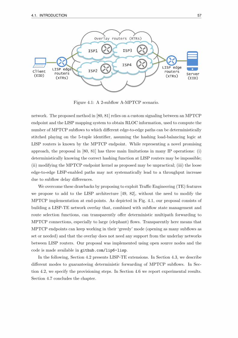
4.1. INTRODUCTION 57
Figure 4.1: A 2-subflow A-MPTCP scenario.
network. The proposed method in [80, 81] relies on a custom signaling between an MPTCP
endpoint and the LISP mapping system to obtain RLOC information, used to compute the
number of MPTCP subflows to which different edge-to-edge paths can be deterministically
stitched playing on the 5-tuple identifier, assuming the hashing load-balancing logic at
LISP routers is known by the MPTCP endpoint. While representing a novel promising
approach, the proposal in [80, 81] has three main limitations in many IP operations: (i)
deterministically knowing the correct hashing function at LISP routers may be impossible;
(ii) modifying the MPTCP endpoint kernel as proposed may be unpractical; (iii) the loose
edge-to-edge LISP-enabled paths may not systematically lead to a throughput increase
due to subflow delay differences.
We overcome these drawbacks by proposing to exploit Traffic Engineering (TE) features
we propose to add to the LISP architecture [49, 82], without the need to modify the
MPTCP implementation at end-points. As depicted in Fig. 4.1, our proposal consists of
building a LISP-TE network overlay that, combined with subflow state management and
route selection functions, can transparently offer deterministic multipath forwarding to
MPTCP connections, especially to large (elephant) flows. Transparently here means that
MPTCP endpoints can keep working in their ‘greedy’ mode (opening as many subflows as
set or needed) and that the overlay does not need any support from the underlay networks
between LISP routers. Our proposal was implemented using open source nodes and the
code is made available in github.com/lip6-lisp.
In the following, Section 4.2 presents LISP-TE extensions. In Section 4.3, we describe
different modes to guaranteeing deterministic forwarding of MPTCP subflows. In Sec-
tion 4.2, we specify the provisioning steps. In Section 4.6 we report experimental results.
Section 4.7 concludes the chapter.
58 4.2. LISP TRAFFIC ENGINEERING
4.2 LISP traffic engineering
When two LISP networks exchange traffic, a source endpoint identifier (EID) in a site
sends a packet to a destination EID in the other LISP site. Packets are encapsulated
by an ingress tunnel router (ITR) toward the decapsulating egress tunnel router (ETR).
The path from the ITR to the ETR is determined by the underlying routing protocol and
metrics it uses to select a shortest path (typically BGP and interior gateway protocols).
The ITR creates an IP-(UDP-LISP-)IP tunnel to ETR so that all the packets between the
EIDs are encapsulated and sent via the tunnel.
The LISP Mapping System [35] defines a control-plane based on two main interfaces:
• Map-Resolver (MR): accepts map-requests from ITRs and allows resolving the
EID-to-RLOC mapping using a distributed mapping database;
• Map-Server (MS): learns authoritative EID-to-RLOC mappings from ETR via Map-
Register messages and publishes them in the mapping database.
The LISP Delegated Database Tree (LISP-DDT) is a hierarchical, distributed database
protocol, which embodies the delegation of authority to provide mappings from LISP EIDs
to RLOCs, forwarding map-request across Map-Resolvers and Map-Servers.
The xTR (i.e., ITR/ETR) functionality is present in source and destination LISP
routers [6]. For packets from source to destination, source xTR acts as ITR and destination
xTR acts as ETR; for reverse traffic their role is reversed, i.e., destination xTR acts as
ITR and source xTR acts as ETR.
In LISP Traffic Engineering (LISP-TE) extensions to the basic LISP mode are spec-
ified to allow using a loose path between ITR and ETR by introducing intermediate re-
encapsulating tunneling routers (RTRs) [49]. There are several reasons why these features
can be interesting. For instance:
• There may not be sufficient capacity or degraded performance provided by the net-
works over a given subpath.
• There may be a policy set to avoid a particular subpath.
• There may be specific network functions (e.g., monitoring, traffic inspection nodes)
or even a chain of network functions performed along one or many subpaths.
The ability to pilot RTRs allows us to explicitly manage subpaths between RTRs.
This makes the ITR-ETR direct path, from a basic LISP perspective, a composition of
subpaths between ITR, RTRs, and ETR. This somehow is a form of Internet-scale segment
routing; indeed there is recently also interest to use LISP-TE for segment routing [83]:
4.3. EXPLICIT LOCATOR PATH BINDING MODES 59
segment routing combines source routing and tunneling to steer traffic through the transit
network. In LISP-TE, the ETR can register multiple Explicit Locator Paths (ELPs) each
identifying a path as a chain of RLOCs from source to destination. An RTR is a router
that acts as both an ETR, by decapsulating packets where the destination address in the
‘outer’ IP header is one of its own RLOCs, and an ITR, by making a decision where to
encapsulate the packet based on the next locator in the ELP towards the ETR.
In addition to the set of EID prefixes to register, the map-register message includes
one or more RLOCs to be used by the MS when forwarding map-requests received
through the mapping system. An ETR may request that the MS answers map-requests
on its behalf by setting the “proxy map-reply” flag (P-bit) in the Map-Register mes-
sage.
In a LISP-TE context, building a LISP-TE overlay for A-MPTCP communications
between two endpoints, say a source endpoint and a destination endpoint, shall be done
in such a way that:
1. The destination xTRs register a set of ELPs on a per-EID-prefix basis (e.g., based
on local information on the path states and traffic statistics);
2. The mapping system replies to map-requests coming from clients with one or many
ELPs to use as loose forwarding inter-domain paths;
3. Different subflows from the source to the destination are forwarded over different
ELPs, at least on the most unloaded direction, so that intermediate RTRs determin-
istically guarantee no bottleneck.
As far as communications are asymmetric, using A-MPTCP in a single direction can
be sufficient. Otherwise, its implementation in both directions shall be decorrelated from
each other, especially because Internet routing is often not symmetric. Different modes
are conceivable to implement the above three steps. To ensure a deterministic binding of
subflows to ELP, and hence ensure high performance, states have to be maintained at the
LISP network nodes. Implementing the subflow forwarding can imply only control-plane
operations, and also data-plane operations. The control on the overlay usage can be left
to the destination, to the source, or inter-domain controllers, as elaborated in the next
sections.
4.3 Explicit locator path binding modes
We propose two possible ELP binding modes for MPTCP communications, describing
protocol-level features needed. The specific signaling is later detailed in Section 4.4.
60 4.3. EXPLICIT LOCATOR PATH BINDING MODES
When the source EID sends a packet to the destination EID, source ITR sends a map-
request message to the map resolver to get the ETR RLOC. When there are multiple
ELPs defined leading to the destination ETR, that ETR may be reachable by different
paths. The map-reply is sent by the destination ETR supposing map-reply proxying
is not enabled. The mapping of ELP to subflows can be decided either at the destination
ETR before replying with a single ELP or at the source ITR. Such a decision needs to be
taken for each new subflow upon the detection of the MPTCP connection at the source
xTR. Hence we have two modes of ELP-to-subflow binding operation described hereafter.
4.3.1 Destination-based stateful ELP binding
In this mode of operation, the destination ETR, upon receiving the map-request trig-
gered by the detection of a new MPTCP subflow at the source ITR, sends one single ELP
to the source so that the source associates that ELP with the subflow. When the source
sends another requests upon the detection of an additional subflow, it sends a different
ELP from the list of ELPs it has. In order to allow the ETR differentiate among different
subflows, the source ITR first and the RTRs then must send the flow information in the
map-request. This is possible by sending map-request with the LISP Canonical Ad-
dress Format (LCAF) [82] message type 4 (see Fig. 4.2a) transporting four fields: source
EID, destination EID, source TCP port and destination TCP port. The fifth field of the
5-tuple is protocol identifier and in this case it is TCP. In the reference single-homed end-
point situation, a TCP subflow is then identified based on source port because the other
fields are equal for all subflows.
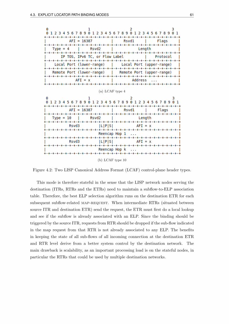
4.3. EXPLICIT LOCATOR PATH BINDING MODES 61
(a) LCAF type 4
(b) LCAF type 10
Figure 4.2: Two LISP Canonical Address Format (LCAF) control-plane header types.
This mode is therefore stateful in the sense that the LISP network nodes serving the
destination (ITRs, RTRs and the ETRs) need to maintain a subflow-to-ELP association
table. Therefore, the best ELP selection algorithm runs on the destination ETR for each
subsequent subflow-related map-request. When intermediate RTRs (situated between
source ITR and destination ETR) send the request, the ETR must first do a local lookup
and see if the subflow is already associated with an ELP. Since the binding should be
triggered by the source ITR, requests from RTR should be dropped if the sub-flow indicated
in the map request from that RTR is not already associated to any ELP. The benefits
in keeping the state of all sub-flows of all incoming connection at the destination ETR
and RTR level derive from a better system control by the destination network. The
main drawback is scalability, as an important processing load is on the stateful nodes, in
particular the RTRs that could be used by multiple destination networks.
62 4.4. A-MPTCP OVERLAY PROVISIONING STEPS
4.3.2 Source-based stateless ELP binding
An alternative is to let the LISP nodes serving the destination network stay stateless.
This is possible by letting the destination ETR send the complete list of all ELPs along
with their priorities to the source ITR and intermediate RTRs. Source ITR and RTRs
can therefore send a standard non-LCAF map-request upon detection of a new subflow.
The response is encapsulated using LCAF type 10 (see Fig. 4.2b) containing all the ELPs.
The source ITR then selects the best path from the set of ELPs and associates each
subflow with different ELP; the best ELP selection algorithm is later described. In this
mode, the destination ETR and the RTRs do not need to keep any state about sub-flows
associations to ELPs. This makes it a more scalable solution in [81]). However, the
destination network does not have any control over sub-flow forwarding. There is still
a missing brick: intermediate RTRs still need to identify the ELP associated to a given
subflow. In absence of alternative techniques to uniquely identify the best ELP, we propose
two light-way alternative methods:
1. Path Identifier (PID): the source ITR uses a field in the LISP data plane shim header
(the flag field or the instance-ID field) to code an ELP identifier corresponding to
the binding, that is a consecutive number of the ELP in the LCAF-10 map-reply.
In a convergent state, this order is later maintained also in the replies to RTRs.
The mechanism would be altered if the set of registered ELPs changes during the
transmission, which can be considered a rare event during a single connection.
2. ELP Link-Disjointness (ELD): in case ELPs do not share any RTR-to-RTR link,then
identifying the path in the data-plane is not necessary. Upon receiving the LCAF-10
map-reply, the RTR can recognize the ELP based on the previous RTR address
included in the outer header source address field. This implicit ELP recognition
avoids therefore extra-work at the source ITR, yet it requires the destination to
register link-disjoint ELP, which could be a best practice as it is a win-win option,
if the RTR topology is sufficiently rich.
4.4 A-MPTCP overlay provisioning steps
We specify in the following the A-MPTCP overlay provisioning steps for the two binding
modes.
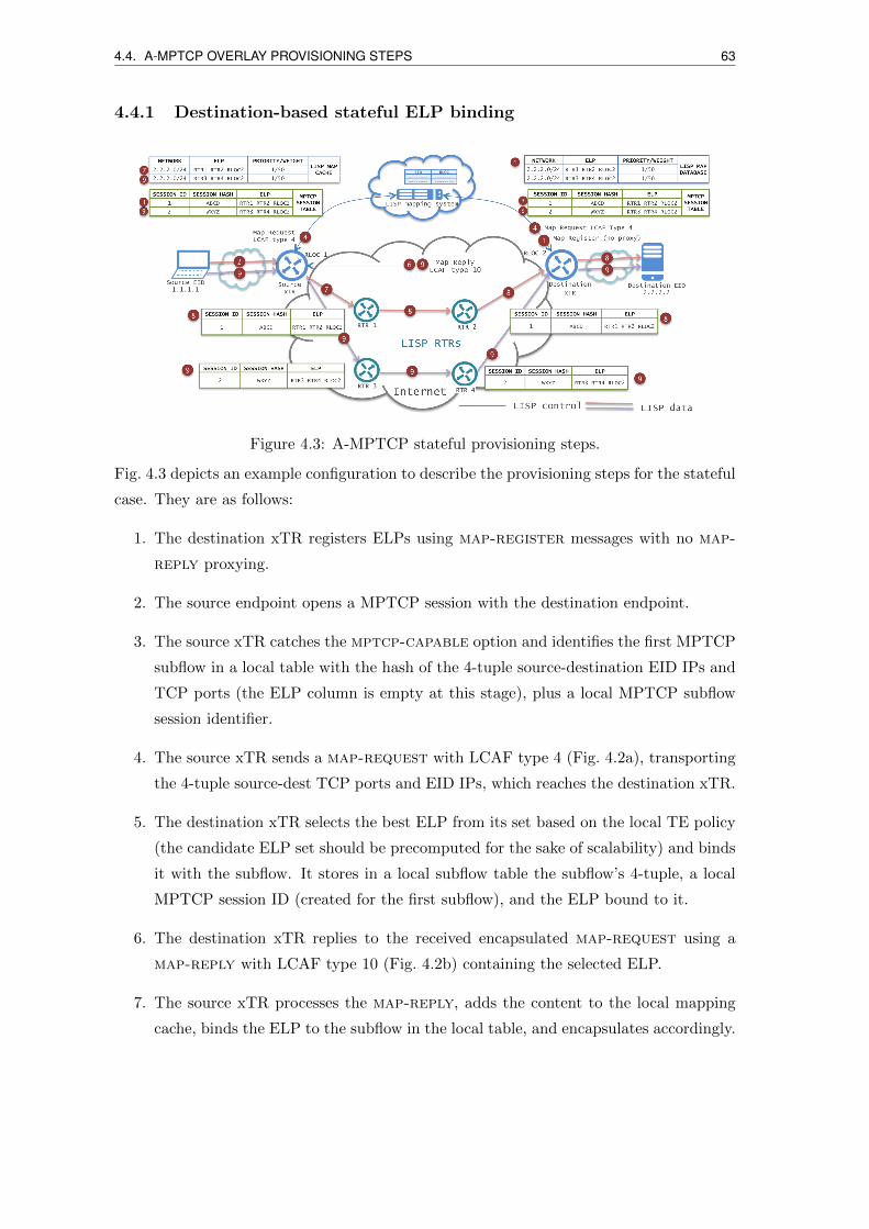
4.4. A-MPTCP OVERLAY PROVISIONING STEPS 63
4.4.1 Destination-based stateful ELP binding
Figure 4.3: A-MPTCP stateful provisioning steps.
Fig. 4.3 depicts an example configuration to describe the provisioning steps for the stateful
case. They are as follows:
1. The destination xTR registers ELPs using map-register messages with no map-
reply proxying.
2. The source endpoint opens a MPTCP session with the destination endpoint.
3. The source xTR catches the mptcp-capable option and identifies the first MPTCP
subflow in a local table with the hash of the 4-tuple source-destination EID IPs and
TCP ports (the ELP column is empty at this stage), plus a local MPTCP subflow
session identifier.
4. The source xTR sends a map-request with LCAF type 4 (Fig. 4.2a), transporting
the 4-tuple source-dest TCP ports and EID IPs, which reaches the destination xTR.
5. The destination xTR selects the best ELP from its set based on the local TE policy
(the candidate ELP set should be precomputed for the sake of scalability) and binds
it with the subflow. It stores in a local subflow table the subflow’s 4-tuple, a local
MPTCP session ID (created for the first subflow), and the ELP bound to it.
6. The destination xTR replies to the received encapsulated map-request using a
map-reply with LCAF type 10 (Fig. 4.2b) containing the selected ELP.
7. The source xTR processes the map-reply, adds the content to the local mapping
cache, binds the ELP to the subflow in the local table, and encapsulates accordingly.

64 4.4. A-MPTCP OVERLAY PROVISIONING STEPS
8. Afterwards, upon reception of the first encapsulated packet(s), intermediate RTRs
first send a map-request to the destination ETR as in step 4, which replies with
a LCAF type 10 map-reply as in step 6, acting then as in step 7. Depending
on single-layer or multi-layer path signaling mode, they may either encapsulate the
packet and send it to the ELP next hop or send another map request for the next
hop, get the intra-domain ELP for next hop and then send the packet to the first
entry in the ELP.
9. The source xTRs catches each additional subflow for each MPTCP flow, based on
variation of source port only and MPTCP syn+mp-join options, update the subflow
table and send for each new subflow a map-request as in point 4 - 8.
10. When source and destination xTRs catch the termination of a subflow (based on
MPTCP option FIN) or a subflow is timeout, they clean the entry from the subflow
table.
4.4.2 Source-based stateless ELP binding
Figure 4.4: A-MPTCP stateless provisioning steps.
Fig. 4.4 depicts an example configuration to describe the provisioning steps for the stateless
case. They are as follows:
1. The destination xTR registers ELPs using map-register messages with LCAF type
10. Destination xTR can set the proxy bit indifferently either map-reply proxy or
no proxy.
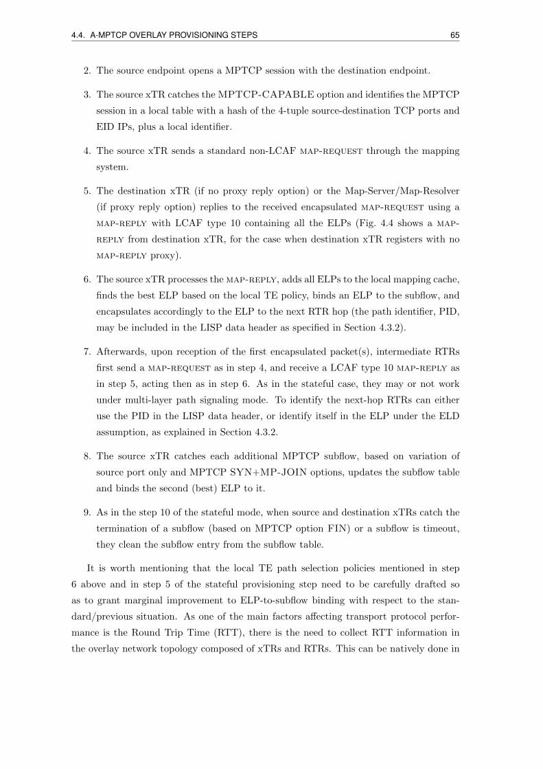
4.4. A-MPTCP OVERLAY PROVISIONING STEPS 65
2. The source endpoint opens a MPTCP session with the destination endpoint.
3. The source xTR catches the MPTCP-CAPABLE option and identifies the MPTCP
session in a local table with a hash of the 4-tuple source-destination TCP ports and
EID IPs, plus a local identifier.
4. The source xTR sends a standard non-LCAF map-request through the mapping
system.
5. The destination xTR (if no proxy reply option) or the Map-Server/Map-Resolver
(if proxy reply option) replies to the received encapsulated map-request using a
map-reply with LCAF type 10 containing all the ELPs (Fig. 4.4 shows a map-
reply from destination xTR, for the case when destination xTR registers with no
map-reply proxy).
6. The source xTR processes the map-reply, adds all ELPs to the local mapping cache,
finds the best ELP based on the local TE policy, binds an ELP to the subflow, and
encapsulates accordingly to the ELP to the next RTR hop (the path identifier, PID,
may be included in the LISP data header as specified in Section 4.3.2).
7. Afterwards, upon reception of the first encapsulated packet(s), intermediate RTRs
first send a map-request as in step 4, and receive a LCAF type 10 map-reply as
in step 5, acting then as in step 6. As in the stateful case, they may or not work
under multi-layer path signaling mode. To identify the next-hop RTRs can either
use the PID in the LISP data header, or identify itself in the ELP under the ELD
assumption, as explained in Section 4.3.2.
8. The source xTR catches each additional MPTCP subflow, based on variation of
source port only and MPTCP SYN+MP-JOIN options, updates the subflow table
and binds the second (best) ELP to it.
9. As in the step 10 of the stateful mode, when source and destination xTRs catch the
termination of a subflow (based on MPTCP option FIN) or a subflow is timeout,
they clean the subflow entry from the subflow table.
It is worth mentioning that the local TE path selection policies mentioned in step
6 above and in step 5 of the stateful provisioning step need to be carefully drafted so
as to grant marginal improvement to ELP-to-subflow binding with respect to the stan-
dard/previous situation. As one of the main factors affecting transport protocol perfor-
mance is the Round Trip Time (RTT), there is the need to collect RTT information in
the overlay network topology composed of xTRs and RTRs. This can be natively done in
66 4.5. OVERLAY NETWORK DESIGN
a LISP network by enabling the so-called ‘RLOC probing’functionality [6] that by piggy-
backing map-request messages is able to collect RTT information. Once collected, this
information can be used for the TE path selection policy run over the weighted overlay
network graph.
4.5 Overlay network design
The TE path selection policy is a routing problem that requires finding an efficient set of
ELPs for a given ITR/ETR pair with constraints specific to the A-MPTCP scenario.
The most important parameter when transmitting data of a same MPTCP connection
over different subflows, each experiencing an RTT independent of the other subflows, is
not the overall RTT, but rather the differential RTT between subflows. Indeed, a too
high difference between subflow RTTs may make some subflows useless (discarded by
the local MPTCP scheduling algorithm), and may also cause the head-of-line blocking
issue due to packet disordering at the destination endpoint buffer (i.e., the source can no
longer transmit packets if the destination has not yet acknowledged previously transmitted
packets; this is typically caused by out-of-order packets due to different experienced RTTs)
[84].
In the A-MPTCP context, the ELP set computation corresponds to a LISP-TE overlay
network design problem. The ETR should compute a set of ELPs based on a representative
set of ITRs, which should then be used as default set of ELPs to register with the mapping
system. Then, in the stateful case, the ELP set is filtered based on the ITR sending the
map-request, and ELPs are sequentially bound to subflows, which needs ELPs to be
sorted (based on a reference estimated number of paths per connection).
In the stateless case instead, the ITR receives the full overlay graph (i.e., ELP set) and
has to locally extract the ELPs from it. Both cases share the same reference link-disjoint-
differential-delay routing problem.
In the following, we present the state of the art on multipath provisioning aiming at
differential delay aware routing algorithms, along with the problem’s formal definition and
our adopted heuristic.
4.5.1 State of the art
Multipath provisioning has been extensively studied to increase resiliency of both transport
[85] and wireless networks [86], and to cope with the requirements of high bandwidth
applications [87], and for congestion control [88].
When data is routed through multiple disjoint paths, the delay incurred by each phys-
4.5. OVERLAY NETWORK DESIGN 67
ically disjoint path may differ. Such delay difference is commonly called differential delay
(DD). DD imposes buffering requirements at destination to accomplish data reordering.
DD routing was first studied in [89, 90, 91] for Ethernet over optical transport archi-
tectures. Minimizing DD when including a new path into a group of paths was modeled
as a two sided constraint paths problem and it was demonstrated to be NP-complete [89];
hence, a heuristic based on a modified link weight k-shortest path was proposed. The
authors of [90] demonstrated that the DD routing is NP-hard and that it is as hard as the
longest path problem; they present heuristics based on the flow maximization over a pre-
computed set of paths known to satisfy the DD constraints. Cumulative differential aware
routing was proposed in [91] to accurately model the memory requirement constraint, by
considering the amount of flow on each subpath. However, none of those works considered
path disjointness.
To the best of our knowledge [92, 93] are the first works that presented a reliable mul-
tipath (disjoint paths) provisioning model with DD constraints, which is also an NP-hard
problem. In [92] the specific problem is to provision a connection with requirements on
bandwidth, reliability as well as minimum and maximum delay. They proposed a pseudo-
polynomial time solution, and a fully polynomial time approximation using a restricted
maximum flow formulation over a transformed graph. Due to the complexity of the formu-
lations, a heuristic based on a max flow algorithm followed by a simple differential delay
constraint check was proposed. The problem studied in [93] is to provide reliability and
reduce backup path bandwidth, by computing the maximum cardinality set of disjoint
paths that meet a DD Constraint (DDC). Authors of [93] presented a heuristic to max-
imize the cardinality of paths set that meets a DDC. This heuristic builds an auxiliary
graph using only the merge nodes of k-link-disjoint paths between source and destination,
then compute all possible permutations of those paths.
4.5.2 Link-disjoint-differential-delay routing problem (LD3R)
The network is represented as a directed graph G(V,E,D) where V is the set of nodes,
E is the set of directed links and D represents the one-way delay experienced on each
link. It is important to notice that the routing problem does not account for volume of
flow allocation on each subpath, as this will be let to MPTCP congestion control. Thus
we can consider unit capacity links to preserve link-disjointness. A connection request
R(s, t,DDC), where s, t is the ITR/ETR pair and DDC is the differential delay constraint.
Our objective for the source-destination based approach (for one MPTCP connection) is
to find the maximal set of link-disjoint paths that meet the DDC and low total cost.

68 4.6. EXPERIMENTAL RESULTS
Complexity
An instance of this problem will be to find at least two disjoint paths with equal delay.
The problem of finding two paths with equal delay was proven to be harder than the
Longest Path Problem [90]. Therefore the LD3R problem is NP-hard.
Heuristic
Due to the NP-hardness of the LD3R problem, we present a modified version of the SPLIT-
DDCKDP algorithm [93] in Alg. 2. Additional details about such an optimization problem
can be found at [94].
Algorithm 2 k-disjoint ELP permutation.
INPUT: Directed graph G(V,E,D), a demand of MPTCP connection between the pairs, t and the maximal DDC.PROBLEM: Find P , the set of k-link-disjoint paths from s to t, subject to differentialdelay of paths is ≤ DDC.Find the initial set P using extension of Bhandari’s algorithm [95] to find k-link-disjointpaths from s to t.if k < 2 then
use the shortest path.else
Find set of merge nodes (MN) appearing on two or more paths of P .Generate G′ as a directed multigraph of MN nodes. Every path in G connecting twoMNs becomes a directed edge in G with delay equal to the original path delay.Generate P with all simple paths from s to t in G′.Generate all maximal subsets of P ′ that are link-disjoint.For each subset, calculate which meets the DDC.Select the subset of maximum cardinality. If more than one such subset, choose theset with minimum total distance.
end if
4.6 Experimental results
The proposed framework was implemented and tested through large-scale experiments, as
described in the following.
We preferred running tests using real routing and end-point nodes rather than simula-
tors because the complexity of the MPTCP+LISP-TE combined network system is such
that using discrete-time event simulators would risk to introduce too much determinism
with the risk of low credibility.
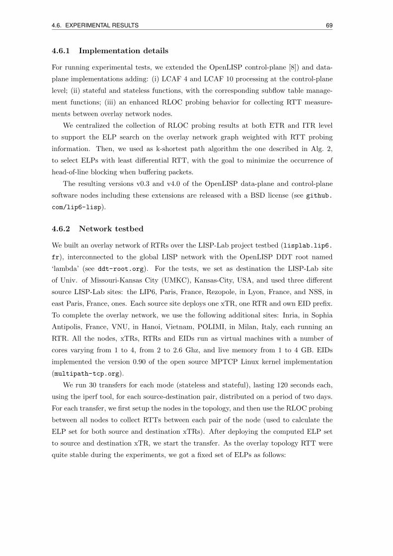
4.6. EXPERIMENTAL RESULTS 69
4.6.1 Implementation details
For running experimental tests, we extended the OpenLISP control-plane [8]) and data-
plane implementations adding: (i) LCAF 4 and LCAF 10 processing at the control-plane
level; (ii) stateful and stateless functions, with the corresponding subflow table manage-
ment functions; (iii) an enhanced RLOC probing behavior for collecting RTT measure-
ments between overlay network nodes.
We centralized the collection of RLOC probing results at both ETR and ITR level
to support the ELP search on the overlay network graph weighted with RTT probing
information. Then, we used as k-shortest path algorithm the one described in Alg. 2,
to select ELPs with least differential RTT, with the goal to minimize the occurrence of
head-of-line blocking when buffering packets.
The resulting versions v0.3 and v4.0 of the OpenLISP data-plane and control-plane
software nodes including these extensions are released with a BSD license (see github.
com/lip6-lisp).
4.6.2 Network testbed
We built an overlay network of RTRs over the LISP-Lab project testbed (lisplab.lip6.
fr), interconnected to the global LISP network with the OpenLISP DDT root named
‘lambda’ (see ddt-root.org). For the tests, we set as destination the LISP-Lab site
of Univ. of Missouri-Kansas City (UMKC), Kansas-City, USA, and used three different
source LISP-Lab sites: the LIP6, Paris, France, Rezopole, in Lyon, France, and NSS, in
east Paris, France, ones. Each source site deploys one xTR, one RTR and own EID prefix.
To complete the overlay network, we use the following additional sites: Inria, in Sophia
Antipolis, France, VNU, in Hanoi, Vietnam, POLIMI, in Milan, Italy, each running an
RTR. All the nodes, xTRs, RTRs and EIDs run as virtual machines with a number of
cores varying from 1 to 4, from 2 to 2.6 Ghz, and live memory from 1 to 4 GB. EIDs
implemented the version 0.90 of the open source MPTCP Linux kernel implementation
(multipath-tcp.org).
We run 30 transfers for each mode (stateless and stateful), lasting 120 seconds each,
using the iperf tool, for each source-destination pair, distributed on a period of two days.
For each transfer, we first setup the nodes in the topology, and then use the RLOC probing
between all nodes to collect RTTs between each pair of the node (used to calculate the
ELP set for both source and destination xTRs). After deploying the computed ELP set
to source and destination xTR, we start the transfer. As the overlay topology RTT were
quite stable during the experiments, we got a fixed set of ELPs as follows:

70 4.6. EXPERIMENTAL RESULTS
• the LIP6-UMKC communications, ELP1 was via LIP6-UMKC, ELP2 via Rezopole-
UMKC, ELP3 via NSS-UMKC, and ELP4 via VNU-UMKC;
• for NSS-UMKC communications, ELP1 was via NSS-UMKC, ELP2 via Rezopole-
UMKC, ELP3 via LIP6-UMKC, and ELP4 via VNU-UMKC;
• for Rezopole-UMKC communications, ELP1 was via Rezopole-UMKC, ELP2 via
LIP6-UMKC, ELP3 via NSS-UMKC, and ELP4 via VNU-UMKC.
In the following, SLX and SFX indicates the stateless and stateful tests, respectively,
run with a number of X ELPs. SD stands for standard transmission, that is using basic
LISP-MPTCP communications with LISP-TE stitching as in [96, 81] with two subflows.
SDY , SLXY and SFXY indicates the Y th subflow used in SD, SL and SF modes, respec-
tively.
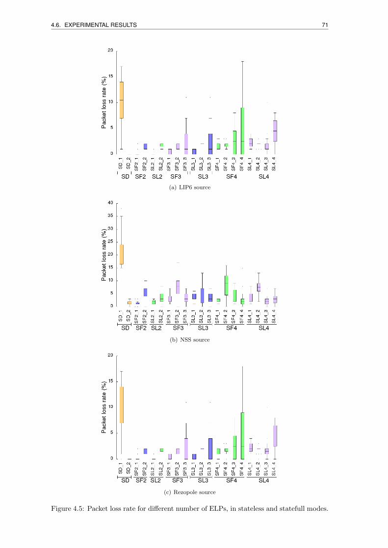
4.6. EXPERIMENTAL RESULTS 71
(a) LIP6 source
(b) NSS source
(c) Rezopole source
Figure 4.5: Packet loss rate for different number of ELPs, in stateless and statefull modes.
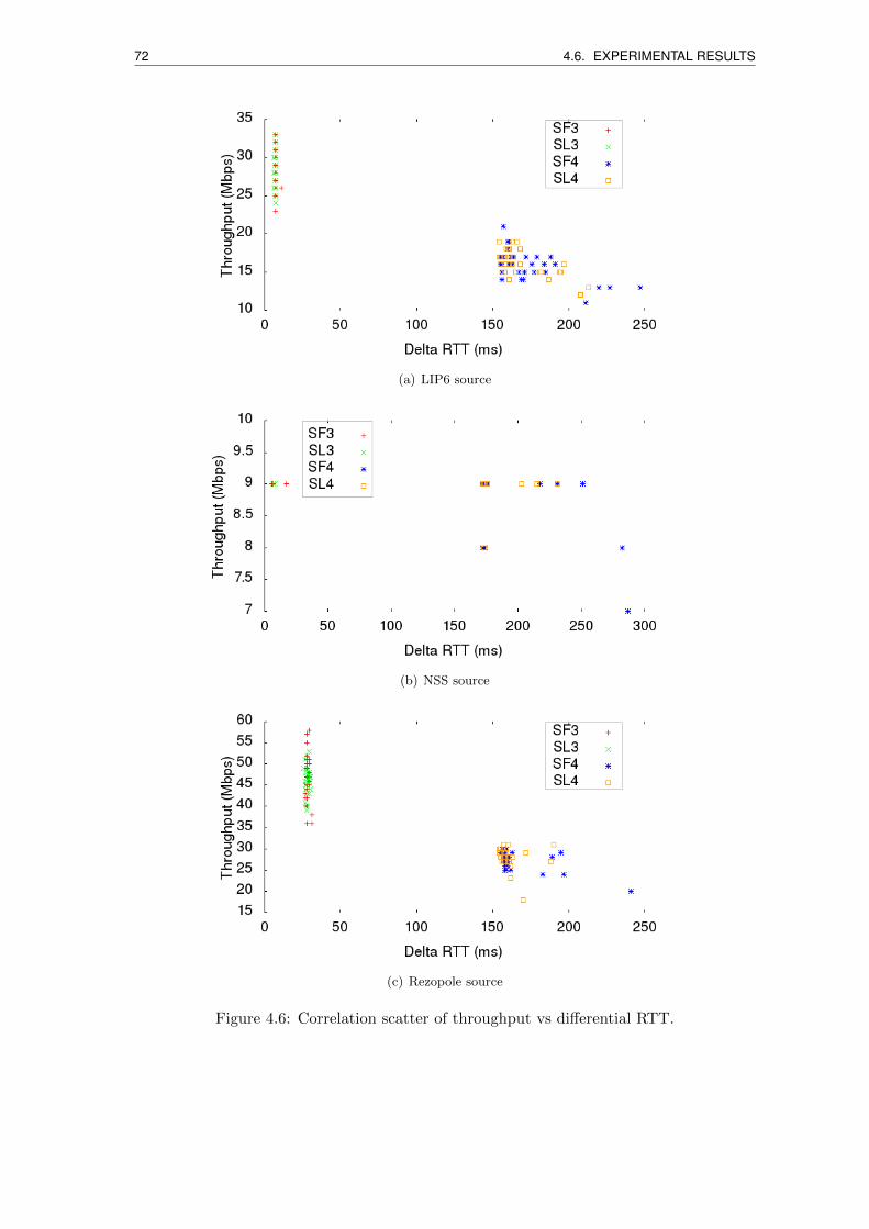
72 4.6. EXPERIMENTAL RESULTS
(a) LIP6 source
(b) NSS source
(c) Rezopole source
Figure 4.6: Correlation scatter of throughput vs differential RTT.
4.6. EXPERIMENTAL RESULTS 73
(a) LIP6 source
(b) NSS source
(c) Rezopole source
Figure 4.7: Average RTT cumulative distribution functions for the different ELPs andsources.
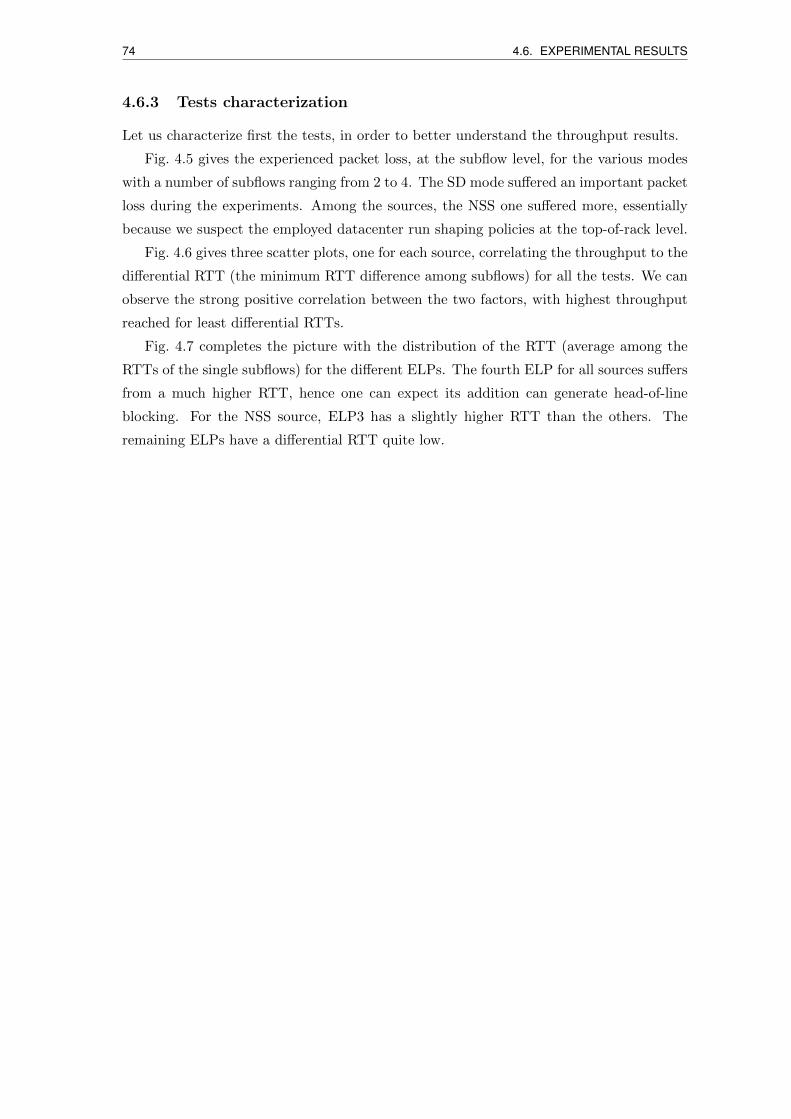
74 4.6. EXPERIMENTAL RESULTS
4.6.3 Tests characterization
Let us characterize first the tests, in order to better understand the throughput results.
Fig. 4.5 gives the experienced packet loss, at the subflow level, for the various modes
with a number of subflows ranging from 2 to 4. The SD mode suffered an important packet
loss during the experiments. Among the sources, the NSS one suffered more, essentially
because we suspect the employed datacenter run shaping policies at the top-of-rack level.
Fig. 4.6 gives three scatter plots, one for each source, correlating the throughput to the
differential RTT (the minimum RTT difference among subflows) for all the tests. We can
observe the strong positive correlation between the two factors, with highest throughput
reached for least differential RTTs.
Fig. 4.7 completes the picture with the distribution of the RTT (average among the
RTTs of the single subflows) for the different ELPs. The fourth ELP for all sources suffers
from a much higher RTT, hence one can expect its addition can generate head-of-line
blocking. For the NSS source, ELP3 has a slightly higher RTT than the others. The
remaining ELPs have a differential RTT quite low.
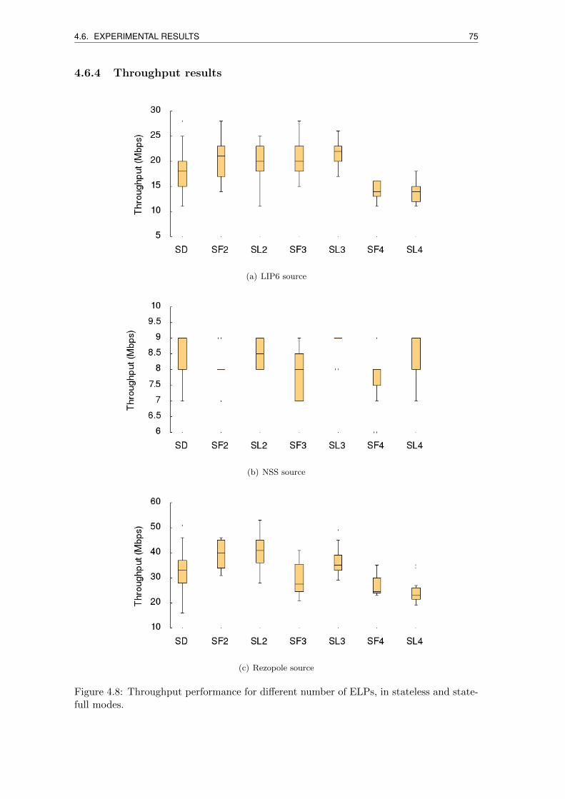
4.6. EXPERIMENTAL RESULTS 75
4.6.4 Throughput results
(a) LIP6 source
(b) NSS source
(c) Rezopole source
Figure 4.8: Throughput performance for different number of ELPs, in stateless and state-full modes.
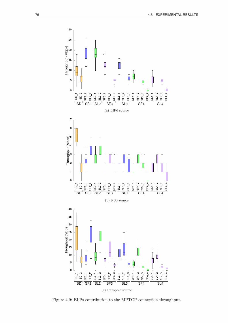
76 4.6. EXPERIMENTAL RESULTS
(a) LIP6 source
(b) NSS source
(c) Rezopole source
Figure 4.9: ELPs contribution to the MPTCP connection throughput.
4.7. CONCLUSION 77
Fig. 4.8 reports the achieved performance in terms of throughput for the different source-
destination pairs, under the stateful and stateless modes, with the number of ELPs ranging
from 1 to 4. We can notice that there is practically no improvement with the NSS source:
this is likely the result of the many retransmissions due to the observed higher packet loss
rates, likely due to shaping in the source network. For the other two sources, the gain
ranges from 10% to 25% with two paths, hence without adding paths with respect to SD,
just bypassing the default routes by using the network overlay. Adding a third ELP leads
marginal gains only for the LIP6 source. Adding the fourth ELP, with high RTT, does
decrease the throughput as expected, likely because of head-of-line blocking. Finally, an
important observation is that there is no better mode in terms of throughput performance
between stateless and statefull modes.
With a deeper look to the subflow contribution to the throughput, shown in Fig. 4.9,
also in perspective with the ELP RTTs qualified in Fig. 4.7, we can observe that the
fourth ELP does indeed bring a very low, in practice null contribution, besides causing
likely buffering issues. Then, we can see the impact of the scheduler, which load mostly
one subflow (the least RTT one), this subflow often being the first one (because we can see
there can be a very low difference between the RTTs of ELP1 and ELP2 for all sources).
We identify in the scheduler an important potential of further bandwidth aggregation, as
other ELPs with very close RTT to the least RTT one could be used more with another
type of scheduler. Unfortunately, such an advanced scheduler is still not designed and
implemented as of our knowledge.
4.7 Conclusion
We described in this chapter a novel overlay network protocol architecture based on
MPTCP and LISP-TE protocols, with some extensions in particular to the overlay routers
state management. Despite we could benefit from only few overlay network nodes, we could
experimentally evaluate our proposals showing the positive impact by using our overlay
network, the negative impact of long RTTs on some MPTCP subflows, and the strong cor-
relation between the differential RTT among subflows and the throughput performance.
Different directions of further investigations are open. First, we believe our approach,
making use of an incrementally deployable protocol such as LISP, can be a viable one for
building an overlay network across network domains such as via internet exchange points
or software-defined network domains. Second, the major limitation to the achievable
throughput gain being represented by the MPTCP scheduler, we plan to design a new
scheduler able to better aggregate bandwidth on multiple subflows with different RTT
performance. As introducing an advanced scheduler may be too difficult to do at the

78 4.7. CONCLUSION
device level, and as devices may not even be MPTCP capable, one promising direction is
to integrate it into MPTCP proxies using frameworks such as the one described in [97].
Chapter 5
Improving the Inter Domain
Management of Locator/ID
Separation Protocol (LISP)
Networks
In this chapter, we propose a framework to improve LISP operations at the Internet scale,
by facilitating cooperation between the LISP Mapping Systems and introducing more
automation in the LISP connectivity service delivery procedure.
5.1 Introduction
The large majority of the Identifier/Locator split protocols need a Mapping System that
maintains mappings between the Identifier and the Locator information, and provides
resolution services accordingly [99]. Several LISP mapping database systems have been
proposed, but the Delegated Database Tree (LISP-DDT) [37] is the one currently de-
ployed by operational implementations. LISP-DDT proposes a hierarchical resolution
model like the DNS (Domain Name Service) system. Such hierarchical structure may
affect resolution times, besides raising political concerns due to potential country-centric
management, where the mastering of root DNS servers can influence the quality of the
resolution service at the Internet scale. In LISP-DDT, when a mapping resolution request
is issued, it is relayed from a resolver node to another one, passing through a DDT, un-
The contents of this chapter are presented in [98] and are the result of a collaboration with M. Boucadairand C. Jacquenet from Orange, who defined the main specification I marginally enhanced for its imple-mentation. A tutorial and technical demonstration video is available at http://www.lisp-lab.org/msx.
79
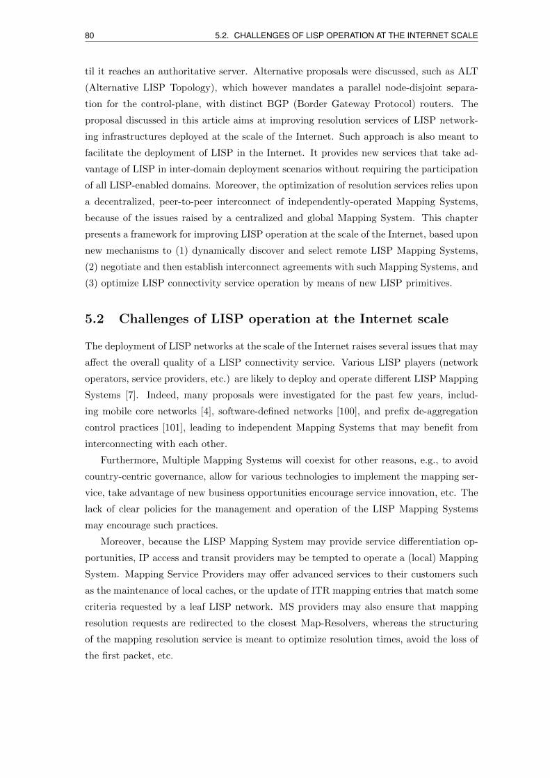
80 5.2. CHALLENGES OF LISP OPERATION AT THE INTERNET SCALE
til it reaches an authoritative server. Alternative proposals were discussed, such as ALT
(Alternative LISP Topology), which however mandates a parallel node-disjoint separa-
tion for the control-plane, with distinct BGP (Border Gateway Protocol) routers. The
proposal discussed in this article aims at improving resolution services of LISP network-
ing infrastructures deployed at the scale of the Internet. Such approach is also meant to
facilitate the deployment of LISP in the Internet. It provides new services that take ad-
vantage of LISP in inter-domain deployment scenarios without requiring the participation
of all LISP-enabled domains. Moreover, the optimization of resolution services relies upon
a decentralized, peer-to-peer interconnect of independently-operated Mapping Systems,
because of the issues raised by a centralized and global Mapping System. This chapter
presents a framework for improving LISP operation at the scale of the Internet, based upon
new mechanisms to (1) dynamically discover and select remote LISP Mapping Systems,
(2) negotiate and then establish interconnect agreements with such Mapping Systems, and
(3) optimize LISP connectivity service operation by means of new LISP primitives.
5.2 Challenges of LISP operation at the Internet scale
The deployment of LISP networks at the scale of the Internet raises several issues that may
affect the overall quality of a LISP connectivity service. Various LISP players (network
operators, service providers, etc.) are likely to deploy and operate different LISP Mapping
Systems [7]. Indeed, many proposals were investigated for the past few years, includ-
ing mobile core networks [4], software-defined networks [100], and prefix de-aggregation
control practices [101], leading to independent Mapping Systems that may benefit from
interconnecting with each other.
Furthermore, Multiple Mapping Systems will coexist for other reasons, e.g., to avoid
country-centric governance, allow for various technologies to implement the mapping ser-
vice, take advantage of new business opportunities encourage service innovation, etc. The
lack of clear policies for the management and operation of the LISP Mapping Systems
may encourage such practices.
Moreover, because the LISP Mapping System may provide service differentiation op-
portunities, IP access and transit providers may be tempted to operate a (local) Mapping
System. Mapping Service Providers may offer advanced services to their customers such
as the maintenance of local caches, or the update of ITR mapping entries that match some
criteria requested by a leaf LISP network. MS providers may also ensure that mapping
resolution requests are redirected to the closest Map-Resolvers, whereas the structuring
of the mapping resolution service is meant to optimize resolution times, avoid the loss of
the first packet, etc.
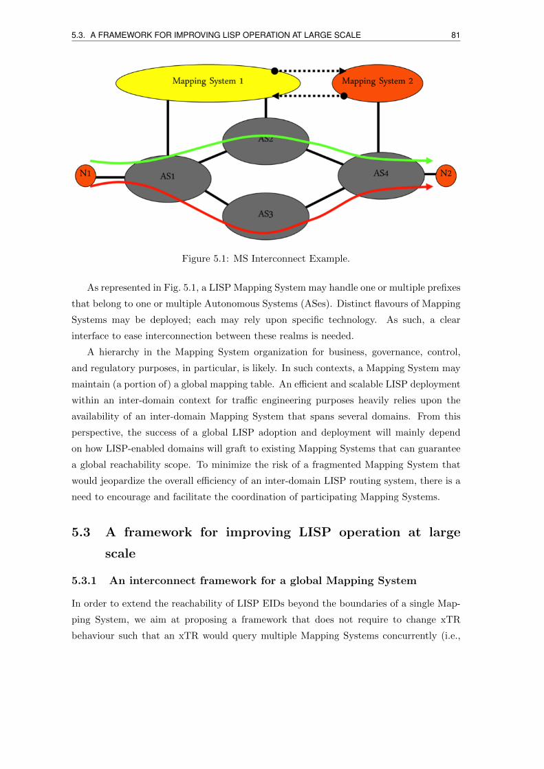
5.3. A FRAMEWORK FOR IMPROVING LISP OPERATION AT LARGE SCALE 81
Figure 5.1: MS Interconnect Example.
As represented in Fig. 5.1, a LISP Mapping System may handle one or multiple prefixes
that belong to one or multiple Autonomous Systems (ASes). Distinct flavours of Mapping
Systems may be deployed; each may rely upon specific technology. As such, a clear
interface to ease interconnection between these realms is needed.
A hierarchy in the Mapping System organization for business, governance, control,
and regulatory purposes, in particular, is likely. In such contexts, a Mapping System may
maintain (a portion of) a global mapping table. An efficient and scalable LISP deployment
within an inter-domain context for traffic engineering purposes heavily relies upon the
availability of an inter-domain Mapping System that spans several domains. From this
perspective, the success of a global LISP adoption and deployment will mainly depend
on how LISP-enabled domains will graft to existing Mapping Systems that can guarantee
a global reachability scope. To minimize the risk of a fragmented Mapping System that
would jeopardize the overall efficiency of an inter-domain LISP routing system, there is a
need to encourage and facilitate the coordination of participating Mapping Systems.
5.3 A framework for improving LISP operation at large
scale
5.3.1 An interconnect framework for a global Mapping System
In order to extend the reachability of LISP EIDs beyond the boundaries of a single Map-
ping System, we aim at proposing a framework that does not require to change xTR
behaviour such that an xTR would query multiple Mapping Systems concurrently (i.e.,
82 5.3. A FRAMEWORK FOR IMPROVING LISP OPERATION AT LARGE SCALE
configured with multiple mapping servers of independent Mapping Systems). These Map-
ping Systems need to interconnect to extend the reachability scope and avoid pressure
on PxTR devices. Also, various Mapping Systems encourage the enforcement of policies
that aim at optimizing LISP forwarding: for example, policies that consist in avoiding the
solicitation of specific domains or regions (e.g., for security reasons).
It is essential to encourage the deployment and the operation of a global Mapping
System at the scale of the Internet instead of a fragmented Mapping System.
Fig. 5.1 depicts an example of LISP Mapping interconnect: while domains 1 and 2 use
Mapping System 1, domain 4 uses Mapping System 2. Mapping Systems 1 and 2 are inde-
pendent, meaning that the LISP traffic exchanged between node N1 and node N2 should
use the PxTR. By interconnecting both Mapping Systems, communications between N1
and N2 can be natively LISP-forwarded without invoking any PxTR. Moreover, optimiz-
ing such LISP interconnection can also reduce the resolution time compared to the use of
a centralized, hierarchical Mapping System such as LISP-DDT.
Figure 5.2: Functional Blocks for Inter-Domain LISP Operation.
5.3.2 Functional blocks for inter-domain LISP operation
The settlement of LISP Mapping System interconnects is decomposed into several func-
tional blocks, as represented in Fig. 5.2:
• Discovery and Advertisement: Discover and Advertise LISP Mapping Systems
that are willing to interconnect as well as those that are ready to service leaf LISP
networks. A leaf LISP-enabled network may subscribe to the mapping service pro-
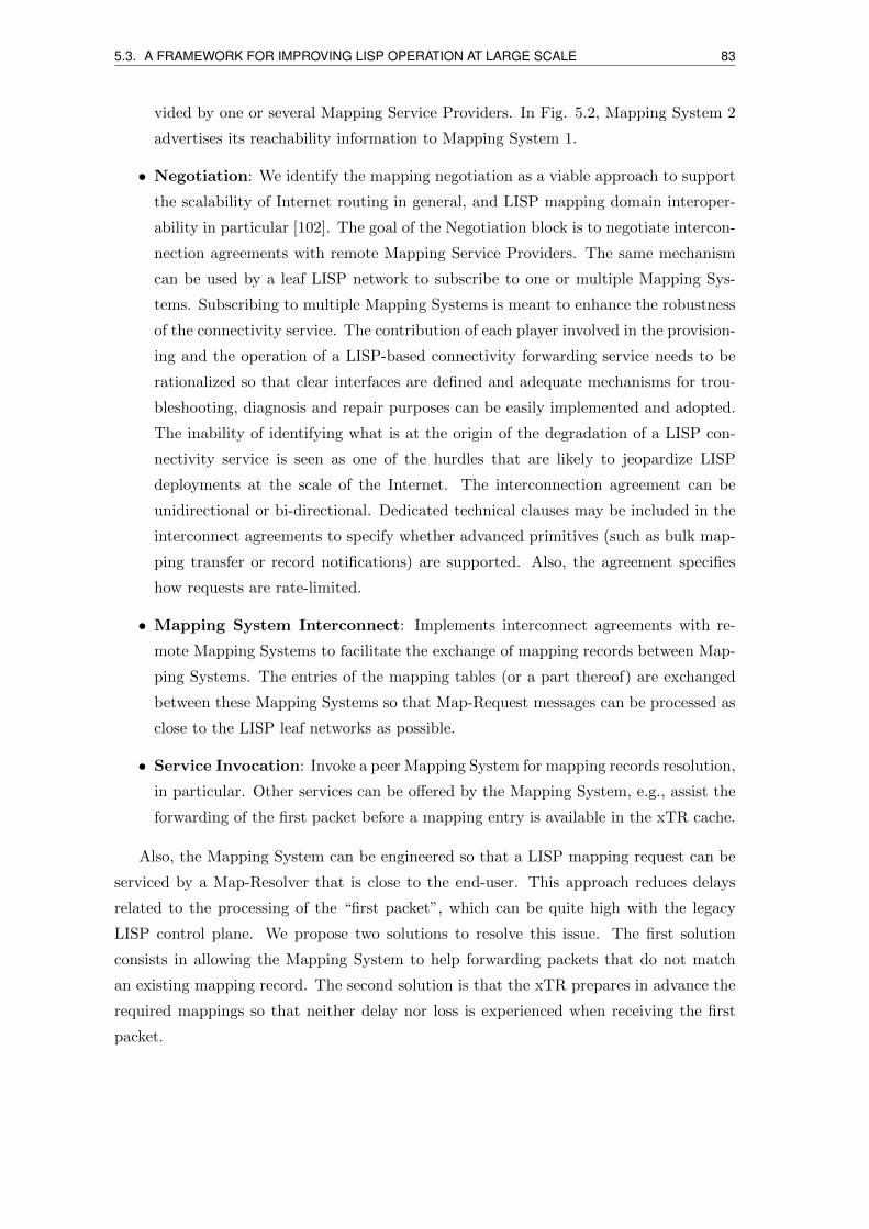
5.3. A FRAMEWORK FOR IMPROVING LISP OPERATION AT LARGE SCALE 83
vided by one or several Mapping Service Providers. In Fig. 5.2, Mapping System 2
advertises its reachability information to Mapping System 1.
• Negotiation: We identify the mapping negotiation as a viable approach to support
the scalability of Internet routing in general, and LISP mapping domain interoper-
ability in particular [102]. The goal of the Negotiation block is to negotiate intercon-
nection agreements with remote Mapping Service Providers. The same mechanism
can be used by a leaf LISP network to subscribe to one or multiple Mapping Sys-
tems. Subscribing to multiple Mapping Systems is meant to enhance the robustness
of the connectivity service. The contribution of each player involved in the provision-
ing and the operation of a LISP-based connectivity forwarding service needs to be
rationalized so that clear interfaces are defined and adequate mechanisms for trou-
bleshooting, diagnosis and repair purposes can be easily implemented and adopted.
The inability of identifying what is at the origin of the degradation of a LISP con-
nectivity service is seen as one of the hurdles that are likely to jeopardize LISP
deployments at the scale of the Internet. The interconnection agreement can be
unidirectional or bi-directional. Dedicated technical clauses may be included in the
interconnect agreements to specify whether advanced primitives (such as bulk map-
ping transfer or record notifications) are supported. Also, the agreement specifies
how requests are rate-limited.
• Mapping System Interconnect: Implements interconnect agreements with re-
mote Mapping Systems to facilitate the exchange of mapping records between Map-
ping Systems. The entries of the mapping tables (or a part thereof) are exchanged
between these Mapping Systems so that Map-Request messages can be processed as
close to the LISP leaf networks as possible.
• Service Invocation: Invoke a peer Mapping System for mapping records resolution,
in particular. Other services can be offered by the Mapping System, e.g., assist the
forwarding of the first packet before a mapping entry is available in the xTR cache.
Also, the Mapping System can be engineered so that a LISP mapping request can be
serviced by a Map-Resolver that is close to the end-user. This approach reduces delays
related to the processing of the “first packet”, which can be quite high with the legacy
LISP control plane. We propose two solutions to resolve this issue. The first solution
consists in allowing the Mapping System to help forwarding packets that do not match
an existing mapping record. The second solution is that the xTR prepares in advance the
required mappings so that neither delay nor loss is experienced when receiving the first
packet.

84 5.4. MAPPING SYSTEM DISCOVERY
This framework advocates for a global Mapping System to be maintained locally. To
that extent, we present hereafter new LISP primitives to allow for bulk retrieval of map-
pings and subscription to notifications when a predefined set of filters are hit.
5.4 Mapping system discovery
We present in the following sub-sections routing protocol extensions to dynamically ad-
vertise and discover Mapping Systems within and beyond a network domain.
5.4.1 A new LISP BGP community attribute
Because the design and operation of a consistent LISP Mapping System are critical for
the adoption of the protocol at large scale, means to dynamically discover other Mapping
Systems that are open to cooperate in inter-domain LISP deployment scenarios are re-
quired. A LISP domain may need to discover available Mapping Systems so that it can
rely upon those Mapping Systems to extend the reachability scope.
We propose to support the discovery of LISP Mapping Systems that are deployed in
distinct administrative domains with a specific Border Gateway Protocol (BGP) com-
munity attribute [103]. The detailed format of the new BGP community is described in
[104]. An advantage of adopting a BGP community attribute is that Mapping System
interconnection functions can be integrated in standard BGP decision-process filters; on
the other hand, a disadvantage is that a current practice is to filter out all the unknown
BGP community attributes. Standardising this BGP Extended Communities will help
this announcement to be safely propagated.
This BGP Extended Communities attribute is used to inform other domains about
the support of the mapping service. EID that can be serviced with LISP will be tagged
accordingly. Note that an EID can be serviced by multiple Mapping Systems. Remote
LISP Mapping Systems will rely upon that BGP-based advertising capability to discover
the existence and the status of other Mapping Systems.
Once a Mapping System is discovered, a local Mapping System can solicit the remote
Mapping System to enter negotiation discussions for the establishment of an intercon-
nection agreement with that remote Mapping System. The contact IP address provided
as part of the BGP Extended Communities attribute will be used to contact a remote
Mapping System to request for further LISP-related capabilities, possibly negotiate an in-
terconnection agreement and, consequently, extend the scope of the networks that can be
serviced using LISP. Also, leaf LISP-aware networks can rely upon the information carried
in the BGP Extended Communities attribute to discover Mapping Systems that may be
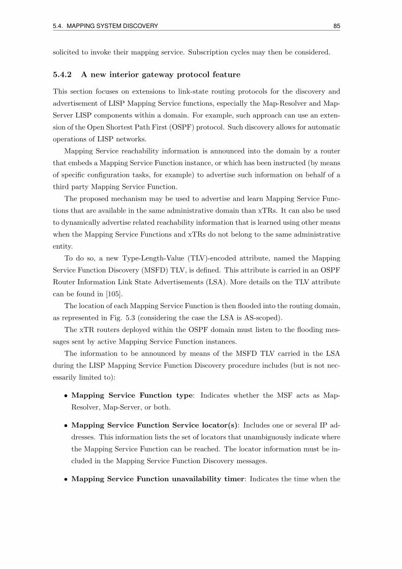
5.4. MAPPING SYSTEM DISCOVERY 85
solicited to invoke their mapping service. Subscription cycles may then be considered.
5.4.2 A new interior gateway protocol feature
This section focuses on extensions to link-state routing protocols for the discovery and
advertisement of LISP Mapping Service functions, especially the Map-Resolver and Map-
Server LISP components within a domain. For example, such approach can use an exten-
sion of the Open Shortest Path First (OSPF) protocol. Such discovery allows for automatic
operations of LISP networks.
Mapping Service reachability information is announced into the domain by a router
that embeds a Mapping Service Function instance, or which has been instructed (by means
of specific configuration tasks, for example) to advertise such information on behalf of a
third party Mapping Service Function.
The proposed mechanism may be used to advertise and learn Mapping Service Func-
tions that are available in the same administrative domain than xTRs. It can also be used
to dynamically advertise related reachability information that is learned using other means
when the Mapping Service Functions and xTRs do not belong to the same administrative
entity.
To do so, a new Type-Length-Value (TLV)-encoded attribute, named the Mapping
Service Function Discovery (MSFD) TLV, is defined. This attribute is carried in an OSPF
Router Information Link State Advertisements (LSA). More details on the TLV attribute
can be found in [105].
The location of each Mapping Service Function is then flooded into the routing domain,
as represented in Fig. 5.3 (considering the case the LSA is AS-scoped).
The xTR routers deployed within the OSPF domain must listen to the flooding mes-
sages sent by active Mapping Service Function instances.
The information to be announced by means of the MSFD TLV carried in the LSA
during the LISP Mapping Service Function Discovery procedure includes (but is not nec-
essarily limited to):
• Mapping Service Function type: Indicates whether the MSF acts as Map-
Resolver, Map-Server, or both.
• Mapping Service Function Service locator(s): Includes one or several IP ad-
dresses. This information lists the set of locators that unambiguously indicate where
the Mapping Service Function can be reached. The locator information must be in-
cluded in the Mapping Service Function Discovery messages.
• Mapping Service Function unavailability timer: Indicates the time when the
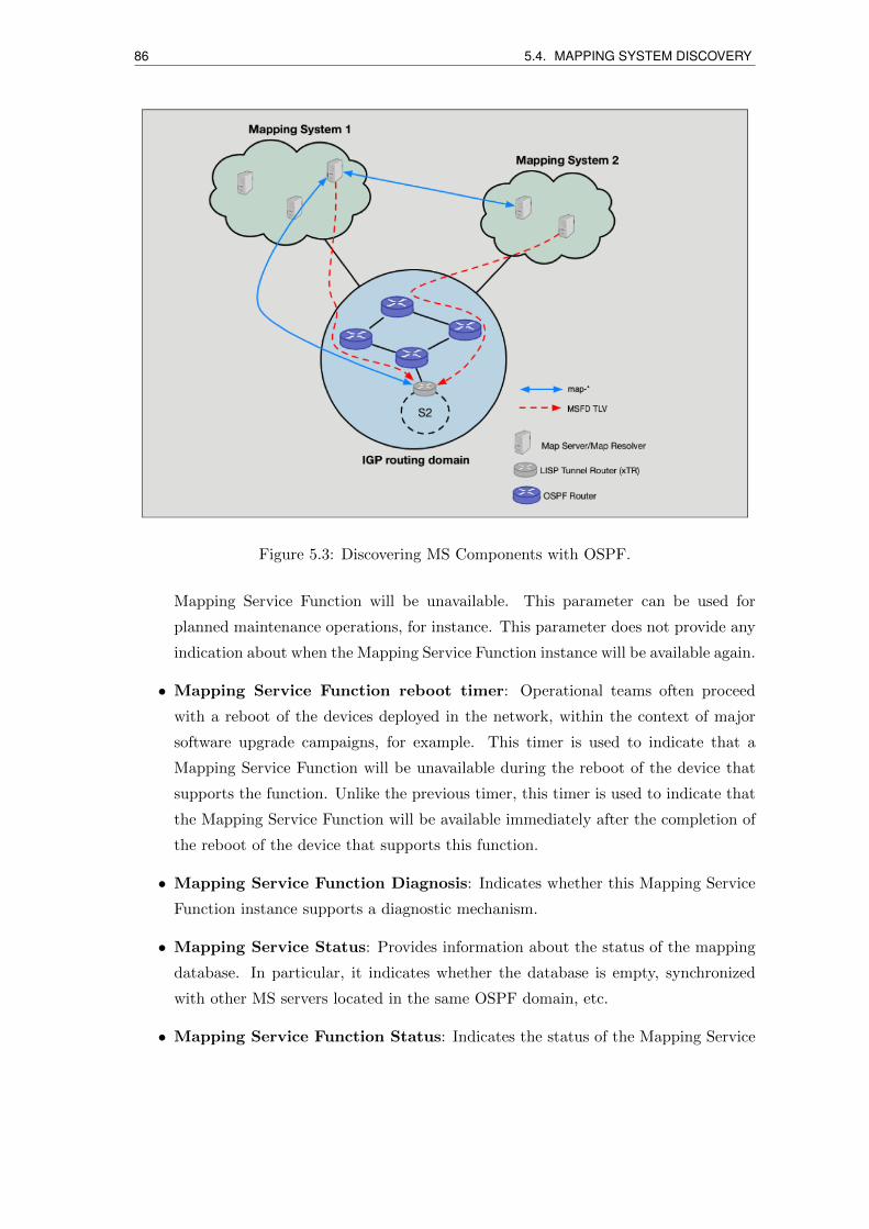
86 5.4. MAPPING SYSTEM DISCOVERY
Figure 5.3: Discovering MS Components with OSPF.
Mapping Service Function will be unavailable. This parameter can be used for
planned maintenance operations, for instance. This parameter does not provide any
indication about when the Mapping Service Function instance will be available again.
• Mapping Service Function reboot timer: Operational teams often proceed
with a reboot of the devices deployed in the network, within the context of major
software upgrade campaigns, for example. This timer is used to indicate that a
Mapping Service Function will be unavailable during the reboot of the device that
supports the function. Unlike the previous timer, this timer is used to indicate that
the Mapping Service Function will be available immediately after the completion of
the reboot of the device that supports this function.
• Mapping Service Function Diagnosis: Indicates whether this Mapping Service
Function instance supports a diagnostic mechanism.
• Mapping Service Status: Provides information about the status of the mapping
database. In particular, it indicates whether the database is empty, synchronized
with other MS servers located in the same OSPF domain, etc.
• Mapping Service Function Status: Indicates the status of the Mapping Service
5.5. NEGOTIATION, INTERCONNECT AND INVOCATION 87
Figure 5.4: CPNP-based negotiation cycle and new LISP primitives used for the intercon-nection and invocation phases.
Function Instance (Enabled, Disabled).
All but the first two information items are optional and may therefore be included
in the Mapping Service Function Discovery messages. Additional capabilities such as the
support of mapping bulk retrieval or notifications may also be advertised.
5.5 Negotiation, interconnect and invocation
This section presents the proposed control plane extensions to support the negotiation,
interconnection and invocation of functional blocks, as illustrated by Fig. 5.4.
5.5.1 Negotiation cycle
The proposal is to conduct the interMapping System negotiation cycle by means of CPNP
(Connectivity Provisioning Negotiation Protocol) [106]. CPNP is meant to dynamically
exchange and negotiate the connectivity provisioning parameters between two LISP Map-
ping Systems. CPNP is used as a tool to introduce automation in the negotiation proce-
dure, thereby fostering the overall mapping service delivery process. CPNP can be used to
88 5.5. NEGOTIATION, INTERCONNECT AND INVOCATION
negotiate the parameters to connect two Mapping Systems or subscribe to services offered
by a given Mapping System. For security reasons, an authentication session can be made
before the negotiation begins. With CPNP, each agreement can be identified by a local
identifier (the CUSTOMER AGREEMENT IDENTIFIER) assigned by a local Mapping
System but also with a unique identifier (the PROVIDER AGREEMENT IDENTIFIER)
assigned by a peer Mapping System.
CPNP accommodates both technical and business-related requirements. Indeed, it
supports various negotiation modes, including administrative validation operations. In
particular, CPNP adopts a Quotation Order/Offer/Answer model where: (1) the Client
specifies its requirements via a Provision Quotation Order (PQO), (2) the Server makes
an offer to either address the requirements of the PQO or suggests a counter-proposal that
partially addresses the requirements of the PQO or declines the PQO, then (3) the Client
either accepts or declines the offer. Fig. 5.4 shows typical CPNP negotiation cycles.
The PROVIDER AGREEMENT IDENTIFIER that is returned during the negotia-
tion phase may be included in service invocation messages to ease correlating requests
within a negotiation context (e.g., CPNP context). Particularly, the integration of the
PROVIDER AGREEMENT IDENTIFIER in a Map-Request or a Map-Reply requires
some modification to the message formats.
5.5.2 Novel control plane primitives
New LISP control plane primitives are defined to support the subscription and intercon-
nection to Mapping Services, let alone their serviceability:
• Map-Subscribe/Map-Subscribe-Ack messages are exchanged between Mapping Ser-
vices, possibly including a number of mapping filters that the Mapping Service could
support to trigger notifications to maintain the entries of the mapping database; the
mapping “filter” is a novel feature of the proposed control plane primitives. A filter
is used to transport any useful information, like flow and AS identifiers, for instance.
• Map-Bulk-Request/Map-Bulk-Reply messages are used to bypass the limitation of
current LISP control plane primitives as far as the dissemination of mapping in-
formation is concerned. They allow to query multiple EID-prefixes with a single
mapping request message by exploiting the mapping filter. In practice, the whole
mapping database can be retrieved by exchanging one Map-Bulk-Request and as
many Map-Bulk-Reply.
• Map-Solicit-Request messages are used, in the proposed framework, to enhance the
robustness of LISP networks during such ITR failure events. While recovering from
5.6. EXPERIMENTAL RESULTS 89
a failure, an ITR sends a Map-Solicit-Request to discovery other ITRs in the same
routing domain. Upon receipt of the Map-Solicit-Request, another ITR replies with
a Map-Solicit-Response message. With this process, the ITR has a list of peer ITRs,
thanks to this Map-Bulk-Request/Reply signaling that runs between local xTRs to
retrieve a copy of their mapping caches.
These features are detailed in [107, 108, 109]. It is worth mentioning that these novel
control-plane primitives are not meant to replace existing basic LISP control plane prim-
itives. Rather, they are meant to extend the LISP control plane behaviour in order to
make LISP meeting the network management expectations of Internet Services and Net-
work Providers more easily.
5.6 Experimental results
We implemented the Mapping System interconnect scheme described in the previous sec-
tions and evaluated it within the LISP-LAB experimental platform. This platform which
runs its own mapping system, is connected to the ‘LISP4.net’ mapping system via DDT.
We extended the LIP6-LISP OpenLISP control plane to support the new xTR features as
well as and the relevant MS interfaces [8]. Moreover, the Quagga router implementation
was extended to include the new TLVs in both BGP and OSPF daemons . Fig. 5.5 reports
the time required to retrieve a mapping entry from the Mapping System in three scenarios:
• Proposed framework: the inter-domain mapping system framework as discussed in
this chapter.
• Local network DDT root, i.e., the LISP-LAB DDT root, which is also the ‘LISP4.net’
DDT lambda root , located in LIP6, Paris.
• ‘LISP4.net’ DDT omega root, which is located in Barcelona.
About seven hundred mapping resolutions (i.e., Map-Requests followed by Map-Replies)
were executed for each case during three days. The proposed framework uses two LISP
sites, one in LIP6 facility, Paris, France, and another one in the LyonIX facility, Lyon,
France. We also deployed three MRs located in LIP6; while the first one utilizes our pro-
posed framework using a dedicated MS in LyonIX for handling mapping resolutions, the
two others run the DDT protocol with the lambda DDT root located in the same LIP6
network for one MR, and with the omega DDT located in Barcelona for the other MR3.
The ETR located in Lyon registers the same EID-prefix on the dedicated MS in Lyon,
and on another standard MS in Lyon linked to the DDT roots.
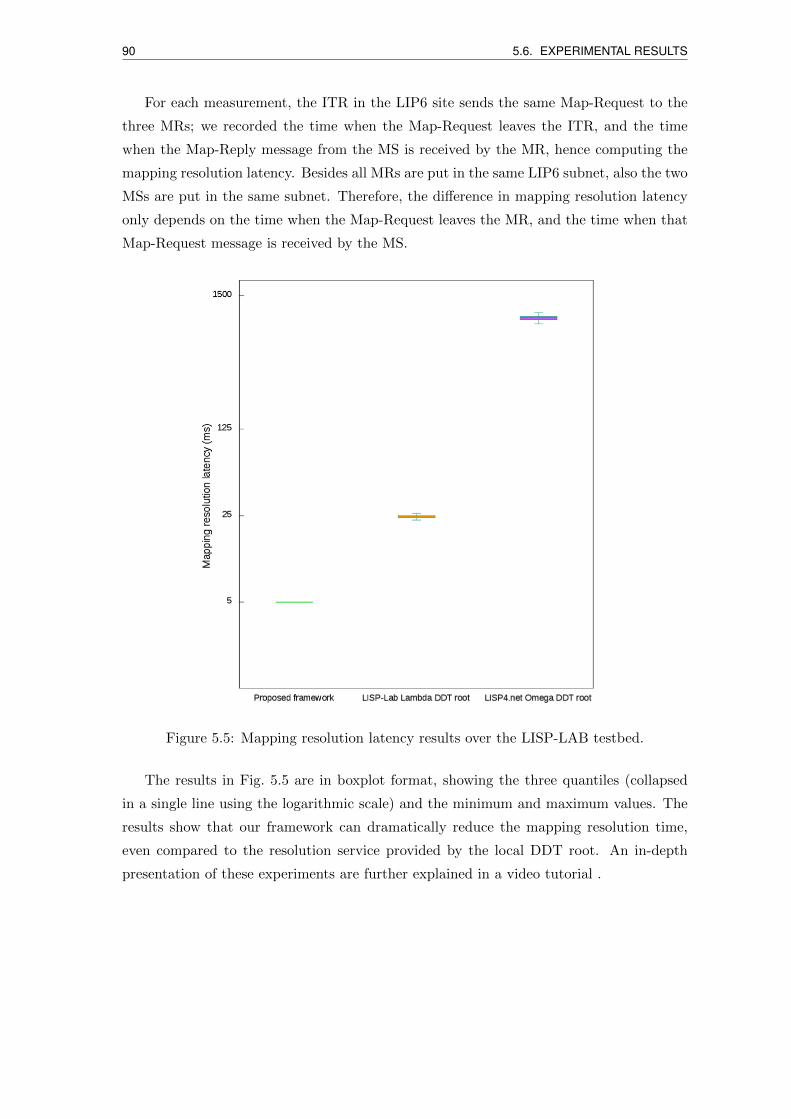
90 5.6. EXPERIMENTAL RESULTS
For each measurement, the ITR in the LIP6 site sends the same Map-Request to the
three MRs; we recorded the time when the Map-Request leaves the ITR, and the time
when the Map-Reply message from the MS is received by the MR, hence computing the
mapping resolution latency. Besides all MRs are put in the same LIP6 subnet, also the two
MSs are put in the same subnet. Therefore, the difference in mapping resolution latency
only depends on the time when the Map-Request leaves the MR, and the time when that
Map-Request message is received by the MS.
Figure 5.5: Mapping resolution latency results over the LISP-LAB testbed.
The results in Fig. 5.5 are in boxplot format, showing the three quantiles (collapsed
in a single line using the logarithmic scale) and the minimum and maximum values. The
results show that our framework can dramatically reduce the mapping resolution time,
even compared to the resolution service provided by the local DDT root. An in-depth
presentation of these experiments are further explained in a video tutorial .
5.7. PERSPECTIVES 91
5.7 Perspectives
LISP is a promising protocol to improve the forwarding of Internet traffic while mastering
the growth of routing tables. Yet, LISP failed to be massively adopted so far, partly
because of the operation of its Mapping System that may undesirably delay forwarding
decisions at the cost of jeopardizing the performance of the LISP connectivity service.
This chapter discussed a framework to improve LISP operation at the Internet scale, by
facilitating cooperation between LISP Mapping Systems and introducing more automation
in the LISP connectivity service delivery procedure.
We believe such optimization could raise awareness among the service providers’ com-
munity, yielding new business opportunities such as the monetization of LISP mapping
services and the enforcement of advanced, service-inferred, inter-domain traffic engineering
policies for the sake of better and strict QoS guarantees.

Chapter 6
Conclusions
The design and implementation of LISP control-plane extensions as well as novel LISP
data-plane functions in support of Internet routing needs allowed us to conduct the ex-
perimental studies documented in this thesis. By means of empirical evaluations of our
proposal, we could stress advantages as well as limitations of the LISP architecture, high-
lighting space of further applied networking research in the field. During our work, we
attempted at performing reproducible research and at targeting integration of our propos-
als in realistic prototypes, making them scalable enough for large networks and trying to
reach performances suitable for real deployments.
The novel LISP-based solution in support of live VM migrations across geographically
separated datacenters over wide area IP networks showed that with our approach we can
easily reach sub-second downtimes upon Internet-wide migration, even for very distant
clients. These activities were also run in the frame of the NU@GE investissement d’avenir
and FUI RAVIR projects, thanks to which our technology was transferred to Non Stop
System, a SME that was active in the area of infrastructure-as-a-service provisioning.
About our work on cross-layer network optimization protocols, despite we could benefit
from only a few overlay network nodes, we could experimentally evaluate our proposals
showing the positive impact by using our overlay network, the negative impact of long
RTTs on some MPTCP subflows, and the strong correlation between the differential RTT
among subflows and the throughput performance. We are working toward the definition of
advanced scheduling and buffer management techniques, on the line of the work described
in [110], as well as the design of an advanced MPTCP scheduler taking into consideration
subflow delays. These activities were lead in the frame of the LISP-LAB and European
Institute of Technology (EIT) Digital and ICT-Labs projects. They have also recently
lead to a collaboration with 21net, an SME active in the area of bandwidth aggregation
for trains. We believe the proposed framework, leveraging on LCAF LISP-TE features, is
93
94
a more viable way than currently considered OpenFlow-based networks for inter-domain
SDN operations, because of the partially distributed logic in forwarding rule configuration.
Finally, the third contribution, about the novel LISP mapping system interconnection
architecture, was formulated in tight synergy with Orange labs. It is currently under
discussion at the IETF. We believe such solutions could raise awareness among the ser-
vice providers’ community, yielding new business opportunities related to LISP mapping
services and the enforcement of advanced inter-domain traffic engineering policies for the
sake of better and strict QoS guarantees.
We traced in the corresponding chapters important perspectives for further research.
It is worth mentioning the need for a tighter integration of LISP primitives in cloud
stack and hypervisors for virtual machine mobility management, the possibility to define
advanced MPTCP scheduler to cope with the large RTT variations one can experience at
the Internet LISP scale, and the integration of mapping system interconnection primitives
into provider network management systems, such as SDN systems.
In this respect, another activity recently started is the enhancement of the integration
of LISP in ONOS [44]. This is expected to open many new possibilities of experimental
research, namely in the field of multi-domain distributed network control.
Software contributions
We list in the following the open source code contributions developed and used for this
thesis.
• LIP6-LISP data-plane - enhanced OpenLISP data-plane implementation, running in
the kernel of the FreeBSD Operating System, including additional behaviors (PxTR,
RTR) and the advanced features described in Chapter 4: https://github.com/
lip6-lisp/data-plane.
• LIP6-LISP Control Plane - open source implementation of the LISP Control Plane,
including advanced features described in Chapters 3-5: https://github.com/lip6-lisp/
control-plane.
• Quagga-ext - an extended version of open source network routing software Quagga,
to include the new TLVs in both BGP and OSPF daemons described in Chapter 5:
https://github.com/lip6-lisp/quagga-ext
• ONOS LISP South Bound Interface (SBI) - Open source implementation of LISP as
a southbound plugin for the ONOS controller, including the MS and MR behaviors:
https://wiki.onosproject.org/display/ONOS/LISP+Subsystem+Support.
95

Publications
International journal with peer review
1. D. Phung Chi, S. Secci, D. Saucez, and L. Iannone. “The OpenLISP control-plane
architecture”. In: IEEE Network Magazine 38 (2 2014), pp. 34–40
2. P. Raad, S. Secci, D. Phung Chi, A. Cianfrani, P. Gallard, and G. Pujolle.
“Achieving Sub-Second Downtimes in Large-Scale Virtual Machine Live Migrations
with LISP”. in: IEEE Trans. Network and Service Managent 11.2 (2014), pp. 133–
143
International conferences with peer review
3. D. Phung Chi, M. Coudron, and S. Secci. “Internet Acceleration with LISP Traffic
Engineering and Multipath TCP”. in: Proc. of 21st Conference on Innovation in
Clouds, Internet and Networks (ICIN 2018) (February 2018)
4. D. Nguyen Ho Dac, D. Phung Chi, S. Secci, B. Felix, and M. Nogueira. “Can
MPTCP Secure Internet Communications from Man-in-the-Middle Attacks?” In:
Proc. of 13th International Conference on Network and Service Management (CNSM
2017) (November 2017)
5. P. Raad, S. Secci, D. Phung Chi, and P. Gallard. “PACAO: Protocol Architecture
for Cloud Access Optimization”. In: 1st IEEE Conference on Network Softwariza-
tion (NETSOFT). Apr. 2015, pp. 13–17
6. Y. Benchaib, S. Secci, and D. Phung Chi. “Transparent Cloud Access Perfor-
mance Augmentation via an MPTCP-LISP Connection Proxy”. In: Proc. of 2015
ACM/IEEE Symposium on Architectures for Networking and Communications Sys-
tems (ANCS 2015) (2015), pp. 201–201
97
98
7. P. Raad, G. Colombo, D. Phung Chi, S.Secci A. Cianfrani, P. Gallard, and G.
Pujolle. “Achieving sub-second downtimes in Internet virtual machine live migra-
tions with LISP”. in: Proc. IEEE/IFIP Int. Symposium on Integrated Network
Management (2013)
8. D. Phung Chi, S. Secci, G. Pujolle, and P. Radd P. Gallard. “An Open Control-
Plane Implementation for LISP networks”. In: Proc. of 2012 International Confer-
ence on Network Infrastructure and Digital Content (IC-NIDC) (September 2012)
9. P. Raad, G. Colombo, D. Phung Chi, S. Secci A. Cianfrani, P. Gallard, and G.
Pujolle. “Demonstrating LISP-based Virtual Machine Mobility for Cloud Networks”.
In: IEEE 1st International Conference on Cloud Networking (CloudNet2012) (2012),
pp. 200–202
Submitted
10. M. Boucadair, C. Jacquenet, D. Phung Chi, and S. Secci. “Improving the Inter Do-
main Management of Locator/ID Separation Protocol (LISP) Networks”. In: IEEE
Communications Magazine - Network and Service Management Series (submitted)
(2018)
References
[1] G. Huston. “Analyzing the Internet’s BGP routing table”. In: The Internet Protocol
Journal 4.1 (2001), pp. 2–15.
[2] CIDR report. Online. url: http://cidr-report.org.
[3] H. Kim and N. Feamster. “Improving network management with software defined
networking”. In: IEEE Communications Magazine 51.2 (Feb. 2013), pp. 114–119.
[4] M. Portoles-Comeras et al. “An evolutionary path for the evolved packet system”.
In: IEEE Communications Magazine 53.7 (2015), pp. 184–191.
[5] M. Komua, M. Sethia, and N. Beijara. “A survey of identifier–locator split address-
ing architectures”. In: Computer Science Review 17 (2015), pp. 25–42.
[6] D. Farinacci et al. The Locator/ID Separation Protocol (LISP). RFC 6830. IETF
technical report. Jan. 2013.
[7] T. Jeong et al. “Experience on the Development of LISP-enabled Services: an ISP
Perspective”. In: 1st IEEE Conference on Network Softwarization (NETSOFT).
Apr. 2015, pp. 1–9.
[8] D. Phung Chi et al. “The OpenLISP control-plane architecture”. In: IEEE Network
Magazine 38 (2 2014), pp. 34–40.
[9] D. Phung Chi et al. “An Open Control-Plane Implementation for LISP networks”.
In: Proc. of 2012 International Conference on Network Infrastructure and Digital
Content (IC-NIDC) (September 2012).
[10] D. Meyer, L. Zhang, and K. Fall. Report from the IAB Workshop on Routing and
Addressing. RFC 4984. IETF technical report. Sept. 2007.
[11] T. Li and Ed. Recommendation for a Routing Architecture. RFC 6115. IETF tech-
nical report. Feb. 2011.
[12] R. Moskowitz and P. Nikander. Host Identity Protocol (HIP) architecture. RFC
4423. IETF technical report. 2006.
99
100 REFERENCES
[13] F. Teraoka, M. Ishiyama, and M. Kunishi. LIN6: A Solution to Multihoming and
Mobility in IPv6. Internet draft. IETF technical report. 2003.
[14] R. Inayat et al. “MAT: An end-to-end mobile communication architecture with
seamless IP handoff support for the next generation Internet”. In: Web and Com-
munication Technologies and Internet-Related Social 2713 (2003).
[15] D. Clark et al. “FARA: Reorganizing the addressing architecture”. In: ACM SIG-
COMM Workshop on Future Directions in Network Architecture (2003).
[16] J. Pan et al. “MILSA: A mobility and multihoming supporting identi er locator
split architecture for naming in the next generation Internet”. In: Global Telecom-
munications Conference (2008).
[17] E. Nordmark and M. Bagnulo. Shim6: Level 3 multihoming shim protocol for IPv6.
RFC - Proposed Standard 5533. IETF technical report. 2009.
[18] C. Vogt. Six/One: A Solution for Routing and Addressing in IPv6. Internet-Draft.
IETF technical report. 2009.
[19] R. Atkinson and S. Bhatti. Identifier-Locator Network Protocol (ILNP) Architec-
tural Description. Request for Comments 6740. IETF technical report. 2012.
[20] D.R. Cheriton and M. Gritter. TRIAD: A scalable deployable NAT-based Internet
architecture. Tech. rep. 2000.
[21] P. Francis and R. Gummadi. “IPNL: A NAT-extended Internet architecture”. In:
ACM SIGCOMM Computer Communications (2001).
[22] I. Stoica et al. “Internet indirection infrastructure”. In: ACM SIGCOMM Computer
Communications (2002).
[23] I. Stoica et al. “Chord: A scalable peer-to-peer lookup service for Internet applica-
tions”. In: ACM SIGCOMM Computer Communications (2001).
[24] Z. Turanyi et al. “4 + 4: An architecture for evolving the Internet address space back
toward transparency”. In: ACM SIGCOMM Computer Communications (2003).
[25] B. Ahlgren et al. “A node identity internetworking architecture”. In: Proceedings
of 25th IEEE International Conference on Computer Communications, INFOCO
(2006).
[26] S. Guha and P.P. Francis. “An end-middle-end approach to connection establish-
ment”. In: Proceedings of SIGCOMM (2007).
[27] X. Xu and D. Guo. “Hierarchical Routing Architecture (HRA)”. In: Next Genera-
tion Internet Networks NGI, IEEE (2008).
REFERENCES 101
[28] C. Perkins. IP mobility support for IPv4, revised. Request for Comments 5944.
IETF technical report. 2010.
[29] C. Perkins, D. Johnson, and J. Arkko. Mobility support in IPv6. Request for Com-
ments 6275. IETF technical report. 2011.
[30] B. Carpenter, R. Atkinson, and H. Flinck. Renumbering still needs work. Internet-
Draft 5887. Informational. 2010.
[31] M.O’Dell. GSE—AnalternateaddressingarchitectureforIPv6. Internet-Draft. IETF
technical report. 1997.
[32] S. Secci, K. Liub, and B. Jabbari. “Efficient Inter-Domain Traffic Engineering
with Transit-Edge Hierarchical Routing”. In: Computer Networks 57.4 (Mar. 2013),
pp. 976–989.
[33] P. Raad et al. “Achieving Sub-Second Downtimes in Large-Scale Virtual Machine
Live Migrations with LISP”. In: IEEE Trans. Network and Service Managent 11.2
(2014), pp. 133–143.
[34] “Software Defined Networking: The New Norm for Networks”. In: ONF White
Paper (2012).
[35] V. Fuller and D. Farinacci. Locator/ID Separation Protocol (LISP) Map-Server
Interface. RFC 6833. IETF technical report. Jan. 2013.
[36] V. Fuller et al. Locator/ID Separation Protocol Alternative Logical Topology (LISP+ALT).
RFC 6836. IETF technical report. Jan. 2013.
[37] V. Fuller et al. Locator/ID Separation Protocol Delegated Database Tree (LISP-
DDT). RFC 8111. IETF technical report. May 2017.
[38] Cisco. “Locator ID Separation Protocol (LISP) VM mobility solution”. In: Cisco
Systems, Inc., Tech. Rep. Document ID:1477005247794150 (2011 updated 2014).
[39] L. Iannone, D. Saucez, and O. Bonaventure. “Implementing the Locator/ID Sep-
aration Protocol: Design and Experience”. In: Computer Networks 55 (4 2011),
pp. 948–958.
[40] D. Farinacci et al. LISP Mobile Node. Tech. rep. draft-ietf-lisp-mn-01. IETF tech-
nical report. 2017.
[41] Open Overlay Route. Online. url: https://www.openoverlayrouter.org.
[42] PyLISP open source. Online. url: https://github.com/steffann/pylisp.
[43] OpenDaylight. Online. url: https://www.opendaylight.org.
[44] ONOS project. Online. url: https://onosproject.org.

102 REFERENCES
[45] ONOS security & performance analysis brigade. Online. url: https://wiki.
onosproject.org/pages/viewpage.action?pageId=12422167.
[46] Open VSwitch. Online. url: http://openvswitch.org.
[47] LISPERS website. Online. url: LISPERS.net.
[48] G. Wright and W. Stevens. RTCP/IP Illustrated Volume 2 The Implementation.
Professional Computing Series. Addison-Wesley.
[49] D. Farinacci, P. Lahiri, and M. Kowal. “LISP Traffic Engineering Use-Cases”. In:
draft-farinacci-lisp-te-07. IETF technical report (2014).
[50] P. Raad et al. “Achieving sub-second downtimes in Internet virtual machine live mi-
grations with LISP”. In: Proc. IEEE/IFIP Int. Symposium on Integrated Network
Management (2013).
[51] P. Raad et al. “Demonstrating LISP-based Virtual Machine Mobility for Cloud
Networks”. In: IEEE 1st International Conference on Cloud Networking (Cloud-
Net2012) (2012), pp. 200–202.
[52] S. Bhardwaj, L. Jain, and S. Jain. “Cloud computing: a study of infrastructure as
a service (IAAS)”. In: Int. J. Engineering and Inf. Technol. 2 (2010), pp. 60–63.
[53] Q. Duan, Y. Yan, and A.V. Vasilakos. “A survey on service-oriented network virtu-
alization toward convergence of networking and cloud computing”. In: IEEE Trans.
Network and Service Management 9 (4 2012), pp. 373–392.
[54] M. Nelson et al. “Fast transparent migration for virtual machines”. In: Proc.
USENIX Annual Technical Conference (2005).
[55] S. Setty. “vMotion architecture, performance, and best practices in VMware vSphere
5”. In: VMware, Inc., Tech. Rep. (2011).
[56] Cisco. “Cisco overlay transport virtualization technology introduction and deploy-
ment considerations”. In: Cisco Systems, Inc., Tech. Rep. (2012).
[57] L. Dunbar et al. Directory Assistance Problem and High-Level Design Proposal.
RFC 7067. IETF technical report. Nov. 2013.
[58] F. Travostino et al. “Seamless live migration of virtual machines over the MAN/WAN”.
In: Future Generation Computer Systems 22 (2006), pp. 901–907.
[59] F. Travostino et al. “A performance improvement method for the global live mi-
gration of virtual machine with IP mobility”. In: Proc. ICMU (2010).
REFERENCES 103
[60] E. Harney et al. “The efficacy of live virtual machine migrations over the internet”.
In: Proc. Int. Workshop on Virtualization Technology in Distributed Computing
(2007), p. 8.
[61] Q. Li et al. “Hypermip: hypervisor controlled mobile IP for virtual machine live
migration across networks”. In: Proc. IEEE High Assurance Systems Engineering
Symposium (2008), pp. 80–88.
[62] C. Perkins. IP Mobility Support for IPv4. RFC 3344. IETF technical report. Aug.
2002.
[63] T. Sridhar and al. “VxL AN: a framework for overlaying virtualized layer 2 networks
over layer 3 networks”. In: draft-mahalingam-dutt-dcops-vxlan-04. IETF technical
report (2013).
[64] E.B. Davie and J. Gross. “Stateless transport tunneling protocol for network vir-
tualization (STT)”. In: draft-davie-stt-04. IETF technical report (2013).
[65] M.S. et al. “NVGRE: Network Virtualization using Generic Routing Encapsula-
tion”. In: draft-sridharan-virtualization-nvgre-03. IETF technical report (2013).
[66] D. Andersen et al. “Resilient Overlay Networks”. In: ACM SIGCOMM Computer
Communication Review 32 (2002), pp. 1–66.
[67] OpenLISP control plane. Online. url: http://github/lip6- lisp/control-
plane.
[68] L. Iannone et al. “OpenLISP: an open source implementation of the Locator/ID
Separation Protocol”. In: ACM SIGCOMM, demo paper (2009).
[69] L. Iannone et al. Locator/ID Separation Protocol (LISP) Map-Versioning. RFC
6834. IETF technical report. 2013.
[70] “Software defined networking: the new norm for networks”. In: white paper,ONF
(2012).
[71] Libvirt: the virtualization API. Online. url: http://libvirt.org/.
[72] C. Clark et al. “Live migration of virtual machines”. In: Proc. Conference on Net-
worked Systems Design & Implementation 2 (2005), pp. 273–286.
[73] A. Kivity et al. “KVM: the Linux virtual machine monitor”. In: Proc. Linux Sym-
posium 1 (2007), pp. 225–230.
[74] D. Mills. “Internet time synchronization: the network time protocol”. In: IEEE
Trans. Commun 39 (1991), pp. 1482–1493.
104 REFERENCES
[75] P. Raad et al. “PACAO: Protocol Architecture for Cloud Access Optimization”. In:
1st IEEE Conference on Network Softwarization (NETSOFT). Apr. 2015, pp. 13–
17.
[76] D. Phung Chi, M. Coudron, and S. Secci. “Internet Acceleration with LISP Traffic
Engineering and Multipath TCP”. In: Proc. of 21st Conference on Innovation in
Clouds, Internet and Networks (ICIN 2018) (February 2018).
[77] E. Elena, J.L. Rougier, and S. Secci. “Characterisation of AS-level Path Deviations
and Multipath in Internet Routing”. In: Proc. of NGI 2010 (2010).
[78] A. Lange. “Issues in Revising BGP-4”. In: draft-ietf-idr-bgp-issues-06. IETF tech-
nical report (2012).
[79] “Configuring BGP to Select Multiple BGP Paths”. In: JUNOS document ().
[80] M. Coudron, S. Secci, and G. Pujolle. “Augmented Multipath TCP Communica-
tions”. In: Proc. of IEEE ICNP (2013).
[81] M. Coudron et al. “Cross-layer Cooperation to Boost Multipath TCP Performance
in Cloud Networks”. In: Proc. of IEEE CLOUDNET (2013).
[82] D. Farinacci, D. Meyer, and J. Snijders. “LISP Canonical Address Format (LCAF)”.
In: draft-ietf-lisp-lcaf-05. IETF technical report (2014).
[83] F. Brockners et al. “LISP Extensions for Segment Routing”. In: draft-brockners-
lisp-sr-01. IETF technical report (2014).
[84] N. McKeown et al. “Achieving 100% throughput in an input-queued switch”. In:
IEEE Transactions on Communications 47 (8 1999), pp. 1260–1267.
[85] S. Rai et al. “Reliable multipath provisioning for high-capacity backbone mesh
networks”. In: IEEE/ACM Trans. on Networking 15 (4 2007), pp. 803–812.
[86] S.J. Lee and M. Gerla. “Split multipath routing with maximally disjoint paths in
ad hoc networks”. In: Proc. of IEEE ICC (2001).
[87] J. Chen, S.H. Chan, and V. O. Li. “Multipath routing for video delivery over
bandwidth-limited networks”. In: IEEE J. on Selected Areas in Communications
22 (10 2004), pp. 1920–1932.
[88] F. Paganini and E. Mallada. “A Unified Approach to Congestion Control and Node-
Based Multipath Routing”. In: IEEE/ACM Trans. on Networking 17 (5 2009),
pp. 1413–1426.
[89] S.S. Ahuja, T. Korkmaz, and M. Krunz. “Minimizing the differential delay for
virtually concatenated Ethernet over SONET systems”. In: Proc. of ICCCN (2004).
REFERENCES 105
[90] A. Srivastava et al. “Differential delay aware routing for Ethernet over SONETSDH”.
In: Proc. of IEEE INFOCOM (2005).
[91] A. Srivastava. “Flow aware differential delay routing for next-generation Ethernet
over SONETSDH”. In: Proc. of IEEE ICC (2006).
[92] W. Zhang et al. “Reliable adaptive multipath provisioning with bandwidth and
differential delay constraints”. In: Proc. of IEEE INFOCOM (2010).
[93] H. Sheng, C. U. Martel, and B. Mukherjee. “Survivable Multipath Provisioning
With Differential Delay Constraint in Telecom Mesh Networks”. In: IEEE/ACM
Trans. on Networking 19 (3 2011), pp. 657–669.
[94] R. Alvizu et al. “Differential delay constrained multipath routing for SDN and
optical networks”. In: Electronic Notes in Discrete Mathematics 52 (2016), pp. 277–
284.
[95] R. Bhandari. Survivable networks: algorithms for diverse routing. Springer, 1999.
[96] M. Coudron, S. Secci, and G. Pujolle. “Augmented Multipath TCP Communica-
tions”. In: Proc. of IEEE ICNP 2013 (2013).
[97] M. Boucadair et al. “Extensions for Network-Assisted MPTCP Deployment Mod-
els”. In: draft-boucadair-mptcp-plain-mode-10. IETF technical report (March 2017).
[98] M. Boucadair et al. “Improving the Inter Domain Management of Locator/ID Sepa-
ration Protocol (LISP) Networks”. In: IEEE Communications Magazine - Network
and Service Management Series (submitted) (2018).
[99] M. Hoefling, M. Menth, and M. Hartmann. “A Survey of Mapping Systems for
Locator/Identifier Split Internet Routing”. In: IEEE Communications Surveys &
Tutorials 15 (4 2013).
[100] A. Rodriguez-Natal et al. “LISP: a southbound SDN protocol?” In: IEEE Commu-
nications Magazine 53 (7 2015), pp. 201–207.
[101] M. Yannuzzi et al. “Managing interdomain traffic in Latin America: a new perspec-
tive based on LISP”. In: IEEE Communications Magazine 47 (7 2009), pp. 40–48.
[102] R. Sambasivan et al. “Bootstrapping evolvability for inter-domain routing”. In:
Proc. of the 14th ACM Workshop on Hot Topics in Networks. 2015.
[103] S. Sangli, D. Tappan, and Y. Rekhter. BGP Extended Communities Attribute. RFC
4360. IETF technical report. 2006.
[104] M. Boucadair and C. Jacquenet. “LISP Mapping Service Discovery at Large”. In:
draft-boucadair-lisp-idr-ms-discovery-01 (2016).
106 REFERENCES
[105] M. Boucadair and C. Jacquenet. “LISP Mapping Service Functions Discovery (LMSFD)
using OSPF”. In: draft-boucadair-lisp-function-discovery-02 (2016).
[106] M. Boucadair et al. “Connectivity Provisioning Negotiation Protocol (CPNP)”. In:
draft-boucadair-connectivity-provisioning-protocol-12. IETF technical report (2016).
[107] M. Boucadair and C. Jacquenet. “Improving Mapping Services in LISP Networks,
draft-boucadair-lisp-subscribe-02”. In: draft-boucadair-lisp-subscribe-02 (2015).
[108] M. Boucadair and C. Jacquenet. “LISP Mapping Bulk Retrieval, draft-boucadair-
lisp-bulk-01”. In: LISP Mapping Bulk Retrieval, draft-boucadair-lisp-bulk-01 (2016).
[109] M. Boucadair and C. Jacquenet. “Improving ITR Resiliency in Locator/ID Sepa-
ration Protocol (LISP) Networks”. In: draft-boucadair-lisp-itr-failure-01 (2015).
[110] M. Coudron, D. Nguyen Ho Dac, and S. Secci. “Enhancing Buffer Dimensioning
for Multipath TCP”. In: International Conference on the Network of the Future
(2016).
[111] D. Nguyen Ho Dac et al. “Can MPTCP Secure Internet Communications from Man-
in-the-Middle Attacks?” In: Proc. of 13th International Conference on Network and
Service Management (CNSM 2017) (November 2017).
[112] Y. Benchaib, S. Secci, and D. Phung Chi. “Transparent Cloud Access Perfor-
mance Augmentation via an MPTCP-LISP Connection Proxy”. In: Proc. of 2015
ACM/IEEE Symposium on Architectures for Networking and Communications Sys-
tems (ANCS 2015) (2015), pp. 201–201.
Copyright © 2022 FDOKUMEN


![4.1.1] plane waves](https://static.fdokumen.com/doc/165x107/6322513728c445989105b845/411-plane-waves.jpg)