eng_teka_manu_encimeras.pdf - Tradeinn
25
INSTALLATION INSTRUCTIONS AND RECOMMENDATIONS FOR USE AND MAINTENANCE GLASS GAS HOBS EINBAU-ANLEITUNG UND EMPFEHLUNGEN FÜR GEBRAUCH UND INSTANDHALTUNG GAS-KOCHFELDER AUF GLAS INSTRUCTIONS POUR L’INSTALLATION ET RECOMMANDATIONS D’UTILISATION ET D’ENTRETIEN PLAQUES DE CUISSON CG.1 4G AI AL / CG Lux-70 4G AI AL / CG Lux-60 4G Al AL CG Lux-70 5G Al AL / CG Lux-70 5G AI TR AL CGC 4G AI AL / CG Lux-75 2G AI TR AL / CG Lux-86 3G AI TR AL CG Lux-60 4G AI / CG Lux-70 4G AI / CG Lux-70 5G AI CG Lux-70 5G AI TR / CG Lux-75 2G AI TR / CG Lux-86 3G AI TR VR 90 4G AI TR AL / VR 90 4G AI TR / CG Lux-60 3G AI AL TR
-
Upload
khangminh22 -
Category
Documents
-
view
1 -
download
0
Transcript of eng_teka_manu_encimeras.pdf - Tradeinn
INSTALLATION INSTRUCTIONSAND RECOMMENDATIONS FOR USE AND MAINTENANCE
GLASS GAS HOBS
EINBAU-ANLEITUNG UND EMPFEHLUNGEN FÜR GEBRAUCH UND INSTANDHALTUNG
GAS-KOCHFELDER AUF GLAS
INSTRUCTIONS POUR L’INSTALLATIONET RECOMMANDATIONS D’UTILISATION ET D’ENTRETIEN
PLAQUES DE CUISSON
CG.1 4G AI AL / CG Lux-70 4G AI AL / CG Lux-60 4G Al AL CG Lux-70 5G Al AL / CG Lux-70 5G AI TR AL
CGC 4G AI AL / CG Lux-75 2G AI TR AL / CG Lux-86 3G AI TR ALCG Lux-60 4G AI / CG Lux-70 4G AI / CG Lux-70 5G AI
CG Lux-70 5G AI TR / CG Lux-75 2G AI TR / CG Lux-86 3G AI TRVR 90 4G AI TR AL / VR 90 4G AI TR / CG Lux-60 3G AI AL TR
Contents / Inhalt / Table des Matières
IntroductionUser Guide
InstallationPositioning the hobsPositioning the ovenAnchoring the hobConnecting the gasConnecting the electricityGas conversion
Technical informationDimensions and powersTechnical data
Use and MaintenanceElements of a burnerIgniting the burnersAnti-accidental turn mechanism on the gas controlsSafety sistem componentsMaintenance of the glassSuggestions for effective usethe burnersMaintenance of the burnersEnvironmental considerationsReminderCleaning and care
If something doesn’t work
Page 49
11111212141415
171718
191919
202021
2122222324
25
GB DE
PräsentationHinweise zum Gebrauch
EinbauEinbauort für die KochfelderEinbauort für den OfenVerankerung des KochfeldsGasanschlussElektrischer AnschlussUmstellung auf andere Gasart
Technische InformationAbmessungen und LeistungenTechnische Daten
Gebrauch und InstandhaltungBrenneraufbauAnzünden der GasbrennerSchutz gegen versehentliches Drehender GashähneBestandteile eines Systemsfür sicheren GebrauchGebrauch der KochzonenTipps für den korrekten Gebrauchder Gasbrenner Instandhaltung der BrennerUmweltangelegenheitenNicht vergessenReinigung und Pflege
Im Störungsfall
Seite 426
28282929313232
353536
373737
38
3839
4040414243
45
2
3
PrésentationGuide d’utilisation
InstallationLogement des tables de cuissonLogement du fourAncrage de la table de cuissonRaccordement au gazBranchement électriqueAdaptation du gaz
Informations techniquesDimensions et puissancesCaractéristiques techniques
Utilisation et entretienÉléments d'un brûleurAllumage des brûleursSystème de blocage descommandes de gazComposants d’un systèmede sécuritéRecommandations pour une bonne utilisation du verreRecommandations pour une bonneutilisation des brûleursEntretien des brûleursConsidérations environnementalesRappelNettoyage et entretien
Si quelque chose ne fonctionne pas
FR
Page 4 46
48484949515252
545455
565656
57
57
58
5859
596061
62

Introduction / Einführung / Présentation
4
CG Lux-60 4G Al AL / CG Lux-60 4G AI
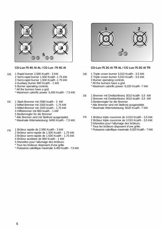
1 Rapid burner 2,580 Kcal/h - 3 kW.2 Semi-rapid burner 1,500 Kcal/h -1.75 kW.3 Semi-rapid burner 1,500 Kcal/h -1.75 kW.4 Auxiliary burner 860 Kcal/h - 1 kW.5 Burner operating controls.* All the burners have a grid.* Maximum calorific power: 6,450 Kcal/h - 7.5 kW.
1 Stark-Brenner mit 2580 kcal/h - 3 kW2 Mittel-Brenner mit 1500 kcal/h - 1,75 kW3 Mittel-Brenner mit 1500 kcal/h - 1,75 kW4 Hilfsbrenner mit 860 kcal/h - 1 kW5 Bedienregler für die Brenner* Alle Brenner sind mit Stellrost ausgestattet.* Maximale Wärmeleistung: 6450 Kcal/h - 7,5 kW.
1 Brûleur rapide de 2.580 Kcal/h - 3 kW.2 Brûleur semi-rapide de 1.500 Kcal/h - 1,75 kW.3 Brûleur semi-rapide de 1.500 Kcal/h - 1,75 kW.4 Brûleur auxiliaire de 860 Kcal/h - 1 kW.5 Manettes pour l’allumage des brûleurs.* Tous les brûleurs disposent d’une grille.* Puissance calorifique maximale: 6.450 Kcal/h - 7,5 kW.
CGC 4G AI AL
1 Rapid burner 2,580 Kcal/h - 3 kW.2 Semi-rapid burner 1,500 Kcal/h -1.75 kW.3 Semi-rapid burner 1,500 Kcal/h -1.75 kW.4 Auxiliary burner 860 Kcal/h - 1 kW.* All the burners have a grid.* Maximum calorific power: 6,450 Kcal/h - 7.5 kW.
1 Stark-Brenner mit 2580 kcal/h - 3 kW2 Mittel-Brenner mit 1500 kcal/h - 1,75 kW3 Mittel-Brenner mit 1500 kcal/h - 1,75 kW4 Hilfsbrenner mit 860 kcal/h - 1 kW* Alle Brenner sind mit Stellrost ausgestattet.* Maximale Wärmeleistung: 6450 Kcal/h - 7,5 kW.
1 Brûleur rapide de 2.580 Kcal/h - 3 kW.2 Brûleur semi-rapide de 1.500 Kcal/h - 1,75 kW.3 Brûleur semi-rapide de 1.500 Kcal/h - 1,75 kW.4 Brûleur auxiliaire de 860 Kcal/h - 1 kW.* Tous les brûleurs disposent d’une grille.* Puissance calorifique maximale: 6.450 Kcal/h - 7,5 kW.
GB
DE
FR
GB
DE
FR
1 2
3 4
5
1 2
3 4
5
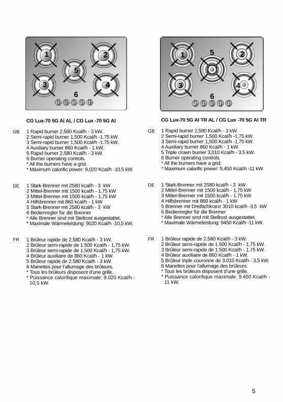
CG Lux-70 5G Al AL / CG Lux -70 5G AI
1 Rapid burner 2,580 Kcal/h - 3 kW.2 Semi-rapid burner 1,500 Kcal/h -1.75 kW.3 Semi-rapid burner 1,500 Kcal/h -1.75 kW.4 Auxiliary burner 860 Kcal/h - 1 kW.5 Rapid burner 2,580 Kcal/h - 3 kW.6 Burner operating controls.* All the burners have a grid.* Maximum calorific power: 9,020 Kcal/h -10.5 kW.
1 Stark-Brenner mit 2580 kcal/h - 3 kW2 Mittel-Brenner mit 1500 kcal/h - 1,75 kW3 Mittel-Brenner mit 1500 kcal/h - 1,75 kW4 Hilfsbrenner mit 860 kcal/h - 1 kW5 Stark-Brenner mit 2580 kcal/h - 3 kW6 Bedienregler für die Brenner* Alle Brenner sind mit Stellrost ausgestattet.* Maximale Wärmeleistung: 9020 Kcal/h -10,5 kW.
1 Brûleur rapide de 2.580 Kcal/h - 3 kW.2 Brûleur semi-rapide de 1.500 Kcal/h - 1,75 kW.3 Brûleur semi-rapide de 1.500 Kcal/h - 1,75 kW.4 Brûleur auxiliaire de 860 Kcal/h - 1 kW.5 Brûleur rapide de 2.580 Kcal/h - 3 kW.6 Manettes pour l’allumage des brûleurs.* Tous les brûleurs disposent d’une grille.* Puissance calorifique maximale: 9.020 Kcal/h -
10,5 kW.
CG Lux-70 5G AI TR AL / CG Lux -70 5G AI TR
1 Rapid burner 2,580 Kcal/h - 3 kW.2 Semi-rapid burner 1,500 Kcal/h -1.75 kW.3 Semi-rapid burner 1,500 Kcal/h -1.75 kW.4 Auxiliary burner 860 Kcal/h - 1 kW.5 Triple crown burner 3,010 Kcal/h - 3.5 kW.6 Burner operating controls.* All the burners have a grid.* Maximum calorific power: 9,450 Kcal/h -11 kW.
1 Stark-Brenner mit 2580 kcal/h - 3 kW2 Mittel-Brenner mit 1500 kcal/h - 1,75 kW3 Mittel-Brenner mit 1500 kcal/h - 1,75 kW4 Hilfsbrenner mit 860 kcal/h - 1 kW5 Brenner mit Dreifachkranz 3010 kcal/h -3,5 kW6 Bedienregler für die Brenner* Alle Brenner sind mit Stellrost ausgestattet.* Maximale Wärmeleistung: 9450 Kcal/h -11 kW.
1 Brûleur rapide de 2.580 Kcal/h - 3 kW.2 Brûleur semi-rapide de 1.500 Kcal/h - 1,75 kW.3 Brûleur semi-rapide de 1.500 Kcal/h - 1,75 kW.4 Brûleur auxiliaire de 860 Kcal/h - 1 kW.5 Brûleur triple couronne de 3.010 Kcal/h - 3,5 kW.6 Manettes pour l’allumage des brûleurs.* Tous les brûleurs disposent d’une grille.* Puissance calorifique maximale: 9.450 Kcal/h -
11 kW.
GB
DE
FR
GB
DE
FR
1 2
3 4
5
6
1 2
3 4
5
6
6
CG-Lux-70 4G AI AL / CG Lux -70 4G AI
1 Rapid burner 2,580 Kcal/h - 3 kW.2 Semi-rapid burner 1,500 Kcal/h -1.75 kW.3 Semi-rapid burner 1,500 Kcal/h -1.75 kW.4 Auxiliary burner 860 Kcal/h - 1 kW.5 Burner operating controls.* All the burners have a grid.* Maximum calorific power: 6,450 Kcal/h - 7.5 kW.
1 Stark-Brenner mit 2580 kcal/h - 3 kW2 Mittel-Brenner mit 1500 kcal/h - 1,75 kW3 Mittel-Brenner mit 1500 kcal/h - 1,75 kW4 Hilfsbrenner mit 860 kcal/h - 1 kW5 Bedienregler für die Brenner* Alle Brenner sind mit Stellrost ausgestattet.* Maximale Wärmeleistung: 6450 Kcal/h - 7,5 kW.
1 Brûleur rapide de 2.580 Kcal/h - 3 kW.2 Brûleur semi-rapide de 1.500 Kcal/h - 1,75 kW.3 Brûleur semi-rapide de 1.500 Kcal/h - 1,75 kW.4 Brûleur auxiliaire de 860 Kcal/h - 1 kW.5 Manettes pour l’allumage des brûleurs.* Tous les brûleurs disposent d’une grille.* Puissance calorifique maximale: 6.450 Kcal/h - 7,5 kW.
CG-Lux-75 2G AI TR AL / CG Lux-75 2G AI TR
1 Triple crown burner 3,010 Kcal/h - 3.5 kW.2 Triple crown burner 3,010 Kcal/h - 3.5 kW.3 Burner operating controls.* All the burners have a grid.* Maximum calorific power: 6,020 Kcal/h -7 kW.
1 Brenner mit Dreifachkranz 3010 kcal/h -3,5 kW2 Brenner mit Dreifachkranz 3010 kcal/h -3,5 kW3 Bedienregler für die Brenner* Alle Brenner sind mit Stellrost ausgestattet.* Maximale Wärmeleistung: 6020 Kcal/h -7 kW.
1 Brûleur triple couronne de 3.010 Kcal/h - 3,5 kW.2 Brûleur triple couronne de 3.010 Kcal/h - 3,5 kW.3 Manettes pour l’allumage des brûleurs.* Tous les brûleurs disposent d’une grille.* Puissance calorifique maximale: 6.020 Kcal/h - 7 kW.
GB
DE
FR
GB
DE
FR
1 2
3 45
1 2
3
7
CG-Lux-86 3G AI TR AL / CG Lux-86 3G AI TR
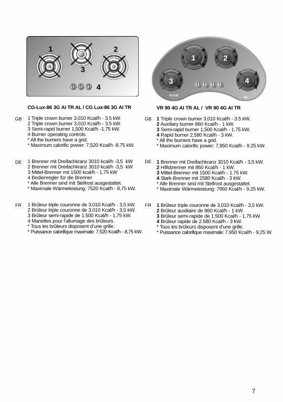
1 Triple crown burner 3,010 Kcal/h - 3.5 kW.2 Triple crown burner 3,010 Kcal/h - 3.5 kW.3 Semi-rapid burner 1,500 Kcal/h -1.75 kW.4 Burner operating controls.* All the burners have a grid.* Maximum calorific power: 7,520 Kcal/h -8.75 kW.
1 Brenner mit Dreifachkranz 3010 kcal/h -3,5 kW2 Brenner mit Dreifachkranz 3010 kcal/h -3,5 kW3 Mittel-Brenner mit 1500 kcal/h - 1,75 kW4 Bedienregler für die Brenner* Alle Brenner sind mit Stellrost ausgestattet.* Maximale Wärmeleistung: 7520 Kcal/h - 8,75 kW.
1 Brûleur triple couronne de 3.010 Kcal/h - 3,5 kW.2 Brûleur triple couronne de 3.010 Kcal/h - 3,5 kW.3 Brûleur semi-rapide de 1.500 Kcal/h - 1,75 kW.4 Manettes pour l’allumage des brûleurs.* Tous les brûleurs disposent d’une grille.* Puissance calorifique maximale: 7.520 Kcal/h - 8,75 kW.
GB
DE
FR
VR 90 4G AI TR AL / VR 90 4G AI TR
1 Triple crown burner 3,010 Kcal/h - 3.5 kW.2 Auxiliary burner 860 Kcal/h - 1 kW.3 Semi-rapid burner 1,500 Kcal/h - 1.75 kW.4 Rapid burner 2,580 Kcal/h - 3 kW.* All the burners have a grid.* Maximum calorific power: 7,950 Kcal/h - 9.25 kW.
1 Brenner mit Dreifachkranz 3010 Kcal/h - 3,5 kW.2 Hilfsbrenner mit 860 Kcal/h - 1 kW.3 Mittel-Brenner mit 1500 Kcal/h - 1.75 kW.4 Stark-Brenner mit 2580 Kcal/h - 3 kW.* Alle Brenner sind mit Stellrost ausgestattet.* Maximale Wärmeleistung: 7950 Kcal/h - 9.25 kW.
1 Brûleur triple couronne de 3.010 Kcal/h - 3,5 kW.2 Brûleur auxiliaire de 860 Kcal/h - 1 kW.3 Brûleur semi-rapide de 1.500 Kcal/h - 1,75 kW.4 Brûleur rapide de 2.580 Kcal/h - 3 kW.* Tous les brûleurs disposent d’une grille.* Puissance calorifique maximale: 7.950 Kcal/h - 9,25 W.
1 2
3 4
GB
DE
FR
1 2
3
4

8
1
2
3
CG LUX-60 3G AI AL TR
1 Triple crown burner 3,010 Kcal/h - 3.5 kW.2 Rapid burner 2,580 Kcal/h - 3 kW.3 Auxiliary burner 860 Kcal/h - 1 kW.* All the burners have a grid.* Maximum calorific power: 6,450 Kcal/h - 7.5 kW.
1 Brenner mit Dreifachkranz 3010 Kcal/h - 3,5 kW.2 Stark-Brenner mit 2580 Kcal/h - 3 kW.3 Hilfsbrenner mit 860 Kcal/h - 1 kW.* Alle Brenner sind mit Stellrost ausgestattet.* Maximale Wärmeleistung: 6450 Kcal/h - 7,5 kW.
1 Brûleur triple couronne de 3.010 Kcal/h - 3,5 kW.2 Brûleur rapide de 2.580 Kcal/h - 3 kW.3 Brûleur auxiliaire de 860 Kcal/h - 1 kW.* Tous les brûleurs disposent d’une grille.* Puissance calorifique maximale: 6.450 Kcal/h - 7,5 W.
GB
DE
FR
1 2
3 4
GB
DE
FR
CG.1 4G AI AL
1 Semi-rapid burner 1,500 Kcal/h -1.75 kW.2 Auxiliary burner 860 Kcal/h - 1 kW.3 Semi-rapid burner 1,500 Kcal/h -1.75 kW.4 Rapid burner 2,580 Kcal/h -3 kW.* All the burners have a grid.* Maximum calorific power: 6,400 Kcal/h - 7.5 kW.
1 Mittel-Brenner mit 1500 kcal/h - 1,75 kW2 Hilfsbrenner mit 860 kcal/h - 1 kW3 Mittel-Brenner mit 1500 kcal/h - 1,75 kW4 Stark-Brenner mit 2580 kcal/h - 3 kW* Alle Brenner sind mit Stellrost ausgestattet.* Maximale Wärmeleistung: 6400 Kcal/h - 7,5 kW.
1 Brûleur semi-rapide de 1.500 Kcal/h - 1,75 kW.2 Brûleur auxiliaire de 860 Kcal/h - 1 kW.3 Brûleur semi-rapide de 1.500 Kcal/h - 1,75 kW.4 Brûleur rapide de 2.580 Kcal/h - 3 kW.* Tous les brûleurs disposent d’une grille.* Puissance calorifique maximale: 6.400 Kcal/h -7,5 kW.
9
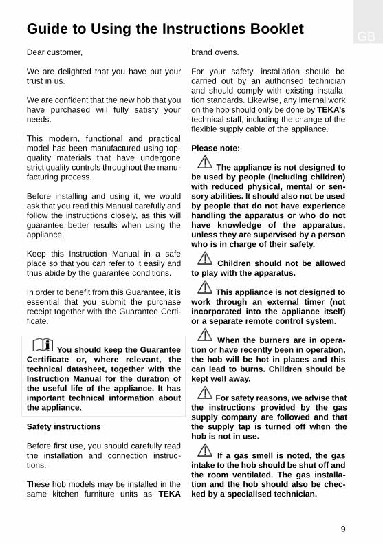
GBGuide to Using the Instructions BookletDear customer,
We are delighted that you have put yourtrust in us.
We are confident that the new hob that youhave purchased will fully satisfy yourneeds.
This modern, functional and practicalmodel has been manufactured using top-quality materials that have undergonestrict quality controls throughout the manu-facturing process.
Before installing and using it, we wouldask that you read this Manual carefully andfollow the instructions closely, as this willguarantee better results when using theappliance.
Keep this Instruction Manual in a safeplace so that you can refer to it easily andthus abide by the guarantee conditions.
In order to benefit from this Guarantee, it isessential that you submit the purchasereceipt together with the Guarantee Certi-ficate.
You should keep the GuaranteeCertificate or, where relevant, thetechnical datasheet, together with theInstruction Manual for the duration ofthe useful life of the appliance. It hasimportant technical information aboutthe appliance.
Safety instructions
Before first use, you should carefully readthe installation and connection instruc-tions.
These hob models may be installed in thesame kitchen furniture units as TEKA
brand ovens.
For your safety, installation should becarried out by an authorised technicianand should comply with existing installa-tion standards. Likewise, any internal workon the hob should only be done by TEKA’stechnical staff, including the change of theflexible supply cable of the appliance.
Please note:
The appliance is not designed tobe used by people (including children)with reduced physical, mental or sen-sory abilities. It should also not be usedby people that do not have experiencehandling the apparatus or who do nothave knowledge of the apparatus,unless they are supervised by a personwho is in charge of their safety.
Children should not be allowedto play with the apparatus.
This appliance is not designed towork through an external timer (notincorporated into the appliance itself)or a separate remote control system.
When the burners are in opera-tion or have recently been in operation,the hob will be hot in places and thiscan lead to burns. Children should bekept well away.
For safety reasons, we advise thatthe instructions provided by the gassupply company are followed and thatthe supply tap is turned off when thehob is not in use.
If a gas smell is noted, the gasintake to the hob should be shut off andthe room ventilated. The gas installa-tion and the hob should also be chec-ked by a specialised technician.

In the event of the burner flamesbeing accidentally extinguished, turnoff the burner control and do notattempt to re-ignite the burner for atleast one minute.
This appliance must be usedexclusively for cooking, never for otherpurposes such as heating a room.
GB
10
GB
11
Important
INSTALLATION AND SETUP SHOULDBE CARRIED OUT BY AN AUTHORISEDTECHNICIAN IN LINE WITH CURRENTINSTALLATION STANDARDS.
Positioning the hobs
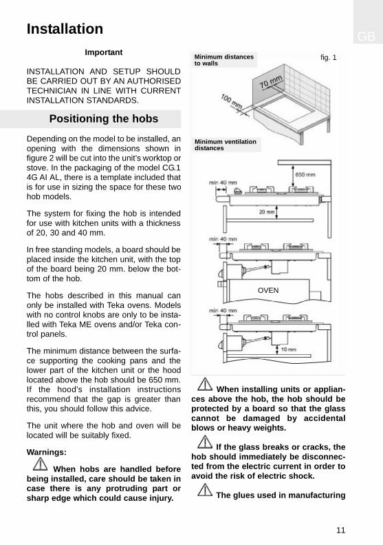
Depending on the model to be installed, anopening with the dimensions shown infigure 2 will be cut into the unit’s worktop orstove. In the packaging of the model CG.14G AI AL, there is a template included thatis for use in sizing the space for these twohob models.
The system for fixing the hob is intendedfor use with kitchen units with a thicknessof 20, 30 and 40 mm.
In free standing models, a board should beplaced inside the kitchen unit, with the topof the board being 20 mm. below the bot-tom of the hob.
The hobs described in this manual canonly be installed with Teka ovens. Modelswith no control knobs are only to be insta-lled with Teka ME ovens and/or Teka con-trol panels.
The minimum distance between the surfa-ce supporting the cooking pans and thelower part of the kitchen unit or the hoodlocated above the hob should be 650 mm.If the hood’s installation instructionsrecommend that the gap is greater thanthis, you should follow this advice.
The unit where the hob and oven will belocated will be suitably fixed.
Warnings:
When hobs are handled beforebeing installed, care should be taken incase there is any protruding part orsharp edge which could cause injury.
When installing units or applian-ces above the hob, the hob should beprotected by a board so that the glasscannot be damaged by accidentalblows or heavy weights.
If the glass breaks or cracks, thehob should immediately be disconnec-ted from the electric current in order toavoid the risk of electric shock.
The glues used in manufacturing
Installation
fig. 1Minimum distancesto walls
Minimum ventilationdistances
OVEN

the kitchen unit and in the adhesive onthe decorative laminate of the worktopsurface should be made to tolerate tem-peratures of up to 100ºC.
TEKA assumes no responsibilityfor any malfunction or damage causedby faulty installation.
PLEASE REMEMBER THAT THE GUA-RANTEE DOES NOT COVER THEGLASS IF IT SUFFERS A VIOLENTBLOW OR IF IT IS USED IMPROPERLY.
Positioning the oven
See the corresponding manual.
Anchoring the hob
When the gap has been properly sized, thesealing washer should be put on the lowerface of the glass. Silicone should not beapplied between the glass and the unitworktop because if it becomes neces-sary to remove the hob from its position,the glass could break when trying todetach it.
To secure the hob to the cabinet, four brac-kets should be fastened to the existing holeson the bottom part of the casing (two in thefront and two in the back). There are twopossibilities of where the brackets may beplaced, just as is shown in figure 3.
Depending on the thickness of the cabinet, itmay be necessary to use the self tappingscrews that are provided as compliments forsecuring; insert them in the circular holes ofthe bracket. The thread of this hole will bemade when the screw is inserted inside of it.The thread should be made before faste-ning the bracket to the hob.
GB
12
fig. 11
575 max.
WL
575 max.
575 max.
WL
WL
fig. 3
* With granite hobs, the measurement may be 580 mm.
Fitting holes
Sealing washer
Sealing washer
The dimensions L and W are shown in the table"Dimensions and characteristics" of the TechnicalInformation section.

GB
13
Hob model CGC 4G AI AL is mounted byinserting the quick nuts into the holeswhere the screws go (see fig. 5) and thenattaching the appropriate clip, dependingon the worktop’s thickness (20, 30 and 40mm) and tightening the screws until it isfirmly fastened.
If an oven is being installed beneath thehob, avoid the power cable coming intocontact with very hot components.
ATTACHING THE HOB TO THE OVENOR THE CONTROL PANEL
The hob has four cardan telescopic shafts
for this purpose. (See fig. 6).
The way to join them is as follows:
1 Turn off the electricity.2 Detach the cardan telescopic shafts a
few centimetres.3 Remove the four pins from the ends (A).4 Put the oven part-way into its space,
taking care not to drag the cardan teles-copic shafts coming from the hob, andleaving enough space to put in the otherends of the telescopic shafts into theshafts in the rear part of the controlpanel, and then replace the pins.
5 To make the electric connection betwe-en the two appliances, attach the hob’sconnector to the oven’s connector.
6 Complete the definitive positioning of theoven, ensuring that the cardan telescopicshafts are firmly in position and that thetelescopic pipes are well-aligned wheninserted so that moving is quite simple.
7 Place the hob controls’ caps in the oven,as described in the oven’s instructionmanual. The caps that need to be pla-
fig. 5
Sealing washerWorktopScrewFixing clipRapid screw
Model CGC 4G AI AL:
fig. 6
Pins
fig. 4
Sealing washer
Sealing washer
Models CG.1 4G AI AL:

ced are those that are included withthe hob - the ones that come with theoven can be discarded.
8 To operate the control knobs, they firsthave to be pressed in, and then turnedin order to release the safety device.
This cooker includes caps for all TEKAovens except models RT-600 and RT-800.Caps for these two models should berequested from the distribution outlet or theappropriate TEKA official technical service.
Connecting the Gas
Connecting the hob to the gas mainsshould be done in compliance with thecurrent installation standards and/or regu-lations, and by a qualified technician (anauthorised installing engineer). The gasconnection for these hotplates should bemade with rigid piping, because theappliance is a stationery one, where it isdestined for the EC market. The hob has athreaded connection of 1/2’’ in diameter(as per EN ISO 228-1 ) or 1/2’’ with a coni-cal thread (as per EN 10226-1), dependingon the regulations in the destination
country.
For markets with an EN ISO 228-1 1/2’’connection, a 10/12 mm copper pipe isprovided as an accessory for welding tothe gas intake pipe.
Ventilation slots should also be made atthe site in compliance with current norms.Connecting the hob’s gas intake to themains should be done in compliance withthe basic gas installation standards forresidential premises.
TEKA assumes no responsibility for anymalfunction or damage that arises from anincorrect or faulty installation.
In order that the hob is not damaged bytightening the nut on the gas connectionpipe, a maximum torque of 300 cm * Kgfshould be applied.
When the gas connection has been made,the installation should be checked to ensu-re that it is completely sealed. If the checkis done using air, care should be taken thatthe test pressure is no more than 200g/cm² Where air is not available, soapywater should be applied to ensure thatthere are no leaks in the connections. Tes-ting should never be done using aflame.
When the hob has been installed, checkthat the burner minimums are properlyadjusted. To do this, light the burners andcheck that they do not go out if you switchquickly from the maximum to the minimum.
Whenever the gas connection nut is remo-ved, its washer should be changed.
Connecting the Electricity
(Only hobs with automatic ignition or elec-tric hotplates)
GB
14
fig. 7
Flexible supply cableConnectorProtective casing for electrics
Rear view of the Control Panel:

GB
15
Before connecting the hob to the electricmains, check that the voltage and fre-quency of the mains matches what isshown on the hob’s rating plate, which islocated lower down, and on the guaranteecertificate or, where appropriate, the tech-nical datasheet supplied, which should bekept together with this manual.
The connection is made via an omnipolarswitch or plug where accessible, which issuitable for the intensity to be toleratedand which has a minimum gap of 3 mmbetween its contacts, which will ensuredisconnection in case of emergency orwhen cleaning the hob. It should also becorrectly earthed in line with current stan-dards.
The connection should include correctearthing, in compliance with currentnorms.If the flexible supply cable fitted to theseappliances ever needs to be changed, itshould be replaced by TEKA’s official service.
Gas conversion
Important!
Any alteration that is to be made to theappliance to convert it to a differenttype of gas should only be carried outby a qualified technician.
Information for Technical Assis-tance: whenever the type of gas or theappliance’s pressure is changed, the newregulation plate should be placed on top ofthe old one so that the new features canbe seen after the change.
The tasks involved in conversion are:* Replace the injectors.* Adjust the taps’ minimums.
The injectors required for each gas type
are shown in table 1.
To replace the injectors, follow these ins-tructions:
1 Remove the grids and upper parts of theburner so that the injector can be seen.
2 Using a number 7 pipe spanner, removethe injectors and replace them with thenew ones. Take care to press the injectordown firmly so that there is no leakage.
3 Replace the grid and burners that werepreviously removed.
When the injectors have been changed,this is how to adjust the minimums:
Hobs CG.1 4G AI AL and CGC 4G AI AL
1 Turn the burners on to their minimum.2 Take the oven or the control panel out so
that you can access the gas taps.3 Use a slim, grooved screwdriver to turn
the screw located to the right or in thecentre of the gas tap’s shaft (the flameincreases when you turn to the left anddecreases when you turn to the right).
4 When properly adjusted, check that theflame does not go out when you turn theknob quickly from maximum to minimum.
5 On hob CGC 4G AI AL, in order toaccess the taps’ regulator screw, youfirst have to lift up the cover that protectsthe taps and then take out the twoscrews that fasten this cover to thebody.
Other hobs
1 Turn the burners on to their minimum.2 Pull the taps’ controls firmly upwards to
remove them.3 Use a slim, grooved screwdriver to turn
the screw located to the right or in thecentre of the gas tap’s shaft (the flameincreases when you turn to the left anddecreases when you turn to the right).

GB
16
Burner Family
Second ThirdGroup H Group E+ Group 3+
Triple crown 135 T 135 T 95
Rapid 116 Y 116 Y 85
Semi-rapid 97 Z 97 Z 66
Auxiliary 72 X 72 X 50
Ø injector expressed in 1/100 mm.
Table 1
4 When properly adjusted, check that theflame does not go out when you turn theknob quickly from maximum to mini-mum.
TEKA INDUSTRIAL, S.A. assumes noresponsibility for any hob malfunction if thegas conversion or the adjustment of theburners’ minimums has not been carriedout by TEKA’s official personnel.
GB
17
Technical Information
Dimensions and powers
Models
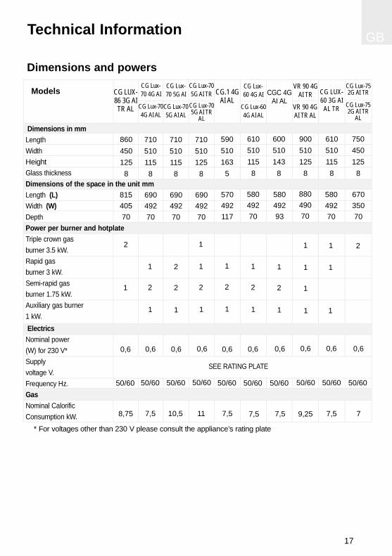
SEE RATING PLATE
* For voltages other than 230 V please consult the appliance’s rating plate
Dimensions in mmLengthWidthHeightGlass thicknessDimensions of the space in the unit mmLength (L)Width (W)DepthPower per burner and hotplateTriple crown gasburner 3.5 kW.Rapid gasburner 3 kW.Semi-rapid gas burner 1.75 kW.Auxiliary gas burner 1 kW.ElectricsNominal power (W) for 230 V*Supply voltage V.Frequency Hz.GasNominal Calorific Consumption kW.
CGC 4GAI AL
CG Lux-60 4G AI
CG Lux-604G AI AL
6105101158
6005101438
9005101258
88049070
58049270
58049293
50/60 50/60
0,6 0,6
7,5 9,257,5
1
1
1
1
1
2
1
1
2
1
50/60
0,6
VR 90 4GAI TR
VR 90 4GAI TR AL
CG.1 4GAI AL
5905101635
570492117
7,5
1
2
1
50/60
0,6
CG LUX-60 3G AI
AL TR
1
1
1
6105101158
58049270
7,5
50/60
0,6
CG LUX-86 3G AITR AL
8604501258
81540570
2
1
8,75
50/60
0,6
CG Lux-70 4G AI
CG Lux-704G AI AL
7105101158
69049270
1
2
1
7,5
50/60
0,6
CG Lux-70 5G AI
CG Lux-705G AI AL
7105101158
69049270
2
2
1
10,5
50/60
0,6
CG Lux-705G AI TR
CG Lux-705G AI TR
AL
7105101258
69049270
11
50/60
0,6
1
1
2
1
7
50/60
0,6
CG Lux-752G AI TR
CG Lux-752G AI TR
AL
2
750450125
8
67035070

GB
18
Technical data
COMMON FEATURES FOR ALL MODELSWITH ELECTRIC HOTPLATES AND AUTO-MATIC IGNITION
The supply voltage and frequency will beas shown on the rating plate.
If an electric hotplate gets cracked, thehob should be disconnected from the elec-tricity current.
COMMON FEATURES FOR ALLMODELS WITH GAS BURNERS
Warnings:
a) Before installation, make sure that thelocal supply conditions (the gas type andpressure) are compatible with the applian-ce’s setup.b) The setup conditions for this applianceare written on the label (or the ratingplate).c) This appliance should not be connectedto a device for removing combustionproducts. It should be installed and con-nected in compliance with the current ins-tallation standards. Special attentionshould be paid to the regulations applyingto ventilation.
A gas cooking appliance produ-ces heat and moisture at the site whereit is installed. The kitchen should beprovided with suitable ventilation: natu-ral ventilation sources should be keptclear, a window opened, or an effectivemechanical ventilation system device,such as a hood, installed.
The intense and prolonged useof the appliance may call for comple-mentary ventilation, such as opening awindow, or more efficient ventilationsuch as increasing the power of themechanical ventilation if this exists.
Class 3 Hob.
CountryFranceUnited KingdomGreeceItaly
CategoryII2E+3+II2H3+
I3+II2H3+
Table 2
Table 3Semi-rapid
1,750,170,190,130,130,47
Nominal Calorific Consumption
Auxiliar
10,100,110,070,070,33
Rapid
30,290,330,220,210,77
3,50,330,380,250,241,55
s
kWG-20 (Nm3/h)G-25 (Nm3/h)G-30 (Kg/h)G-31 (Kg/h)
20 (mbar)25 (mbar)29 (mbar)37 (mbar)
* Consumption over Gross Calorific Value (H )Performance %
kW>52 >52 -->52
Burner
Nominal Consumption*
Triplecrown
Reduced calorific consumption

GB
19
Elements of a burner
Whenever you reassemble a burner,check that all the components are pro-perly in place, as a part that is wronglypositioned can lead to overheating anddamage the glass.
Igniting the burners
* Make sure that the knobs are in theircorrect position.
* Turn on the gas at the mains or turn thegas cylinder’s tap.
* Press down the burner control.* Keeping the burner control pressed
down, turn it all the way till the gas igni-tes. Keep it pressed down for between 2
and 5 seconds so that the safety ther-mocouple can take effect.
* Set the control to the position required.
With hob CGC 4G AI AL y CG.1 4G AIAL, proceed as follows: (See fig. 10)
* Make sure that the knobs are in theircorrect position.
* Turn on the gas at the mains or turn thegas cylinder’s tap.
* Press the control knob and at the sametime turn it anti-clockwise to the On posi-tion (the spark symbol). When the gasignites, keep the knob at this position forbetween 2 and 5 seconds to enable thesafety thermocouple to work.
* Set the control to the position required.
The ignition (ceramic and electrode)should be cleaned regularly and care-fully in order to avoid ignition problems.Check, too, that the grooves in the bur-ners have not become obstructed.
Use and Maintenance
fig. 8
Grid accessoryGridDiffusing coverDiffusing crownInjectorInjector holder
fig. 9
‘Burner in operation’ indicator
Knob position when not in use
Maximum gas position
Minimum gas position
Off position
Star (On position)
With hobs CG Lux-75 and CG Lux-86 youcan use pans with a concave base (e.g.woks) on the grid that is designed for thisuse.
Only pans with a minimum diameter of 140mm should be used on each burner. If youwish to use a pan with a diameter of 120mm or smaller, it should be placed on theauxiliary burner. On hobs CG Lux-75 andCG Lux-86, the grid accessory has to beused (element A in fig. 8).
The device shall not be operatedfor more than 15 seconds. If after 15seconds the burner has not lit, stop thedevice and open the compartment doorand/or wait at least 1 minute beforeattemting a futher ignition of the burner.
Anti-accidental turn system on gas controls
On models without the safety sys-tem (without the gas cut-off device), thegas taps are equipped with a mechanicalsystem that prevents the controls from
being freely turned from the off position tothe on position (and, therefore, preventsany accidental escape of gas from the bur-ners) if the control has not previouslybeen pressed down.
If at any time while using the hobyou notice that a control can be turnedfrom the off position without it needingto be pressed down beforehand (forexample: due to dirt which may havegot into the gas taps and built up there)you should, for your own safety, getquickly in touch with technical assis-tance in order to resolve this fault.
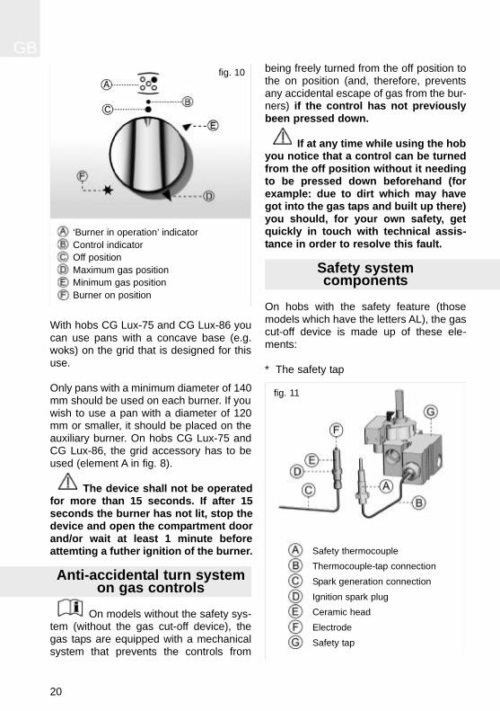
Safety systemcomponents
On hobs with the safety feature (thosemodels which have the letters AL), the gascut-off device is made up of these ele-ments:
* The safety tap
GB
20
‘Burner in operation’ indicatorControl indicatorOff positionMaximum gas positionMinimum gas positionBurner on position
fig. 10
Safety thermocoupleThermocouple-tap connectionSpark generation connectionIgnition spark plugCeramic headElectrodeSafety tap
fig. 11
GB
21
* The safety thermocouple, next to the burner* The thermocouple-tap connection
The thermocouple sends an electric signalto the tap which identifies whether the bur-ner has a flame. During ignition, the tapshould be held down for at least 5seconds, until the thermocouple has hea-ted up and can send a satisfactory electricsignal to the tap. Should the burner go out,the absence of a flame is detected by thethermocouple, which makes the safety tapcut off the flow of gas.
Maintenance of the glass
* When using a roasting dish, clay pots orany utensil that reflects heat down-wards, it is essential that the grid acces-sory is used, for otherwise the high tem-perature that is reflected downwardscould damage the glass or the burners.
* The grid accessory can be used whencooking with pans that have a smallbase or when a very low heat is requi-red, for slow cooking or to keep foodwarm. When it is used, the burner is lessefficient.
* If you notice that the glass is broken orcracked, set all the hotplate controls to“zero” (turned off) turn off the gas tapand disconnect the electricity. Then con-tact TEKA’s Technical Service.
* Do not use the glass surface as a stora-ge area.
* Do not put aluminium foil, tin foil or plas-tics on the surface of the glass.
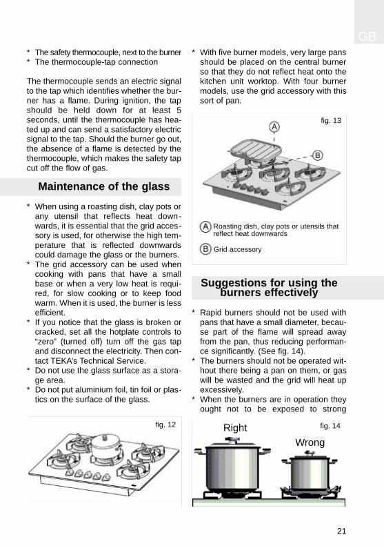
* With five burner models, very large pansshould be placed on the central burnerso that they do not reflect heat onto thekitchen unit worktop. With four burnermodels, use the grid accessory with thissort of pan.
Suggestions for using the burners effectively
* Rapid burners should not be used withpans that have a small diameter, becau-se part of the flame will spread awayfrom the pan, thus reducing performan-ce significantly. (See fig. 14).
* The burners should not be operated wit-hout there being a pan on them, or gaswill be wasted and the grid will heat upexcessively.
* When the burners are in operation theyought not to be exposed to strong
fig. 12
Grid accessory
fig. 13
Roasting dish, clay pots or utensils thatreflect heat downwards
fig. 14RightWrong
draughts, because as well as losingcalorific power, there is the danger ofthe flame going out, which would lead togas escaping and could cause an acci-dent. This point is particularly importantwhen the burners are operating at theirminimum power.
* If the burner makes the pans smoky, orif the tip of the flame is yellow, the bur-ner should be cleaned. If this anomalypersists, contact the Technical Assistan-ce Service in order that the main air inletcan be adjusted or the gas supply pipecleaned.
* Cast iron plates should not be used onthe grid, because they reflect too muchheat onto the cooker’s hotplate.
* Pans placed on the burners should notjut out beyond the edge of the hotplate,so that the reflected flame does notdamage worktops with a plastic surface.
* Use pans with a flat base.
Maintenance of the burners
Whenever the gas taps are removed, youshould change the washer that is betweenthe taps and the supply pipe.
The burners are working properly when theirflame is stable and a greeny-blue colour. Ifthe tips of the flames are yellow, the burnersneed to be cleaned; if the problem persists,contact the Technical Service.
In order to guarantee the gas installation isproperly sealed and the burners are wor-king properly, the hob needs to be inspec-ted by specialised Technical Service per-sonnel at least once every year.
Note:
Any alteration or adjustment needed bythe appliance should be made by aut-horised technical personnel.
Environmentalconsiderations
The symbol on the product or onits packaging indicates that this pro-duct may not be treated as householdwaste. Instead it shall be handed overto the applicable collection point for therecycling of electrical and electronicequipment. By ensuring this product isdisposed of correctly, you will help pre-vent potential negative consequencesfor the environment and human health,which could otherwise be caused byinappropriate waste handling of thisproduct, please contact your local cityoffice, your household waste disposalservice or the shop where you purcha-sed the product.
Packaging materials are organic andfully recyclable. Plastic componentsare identified by marking >PE<, >LD<,>EPS<, etc. Throw out packaging mate-rials, such as household waste, in thecontainer of your municipality..
GB
22

GB
23
Do not use small pans on large burners, or the flamewill spread.
Match pans to burners to make best use of the heat.
Do not place the pan away from the centre of the burner.
Place the pan properly, in the middle of the burner.
Do not use utensils that reflect a lot of heat down-wards directly onto the grid.
When using roasting dishes, clay pots or pans thatreflect heat downwards, use the grid accessory.
Do not place the pans directly on the burner.
Place the pans on the grid.
Do not use sharp objects on the cooker.
When the grids have been used they should be cle-aned when they have cooled down.
Do not use heavy weights or hit the cooker withheavy objects.
Handle pans with care on and around the cooker.
Reminder

GB
24
For best care of the glass, it should be cle-aned when it is cold, with suitable pro-ducts. It should be cleaned after each use,so that cleaning is easier and there is nobuild-up of dirt from repeated use.
When cleaning the glass, the degree ofsoiling should be taken into considera-tion, and the following guidelines follo-wed:
* When soiling is light and not stuck fast,a damp cloth and a soft detergent canbe used.
* Staining or grease should be cleanedwith cleaning products that are suitablefor glass.
* If any objects or plastic utensils or sugarmelts onto the glass, it should be removedimmediately, while hot, using a scraper.
* Never use aggressive or abrasive clea-ning products that could cause scrat-ches, such as oven cleaning aerosols,rust removers or sponges or scourerswith a hard surface.
* Do not slide pans over the glass, as theycan cause scratches.
* Ensure that the liquid does not evapora-te from pans, because the heat buildingup at the base could damage the burneror the glass.
* The glass will tolerate light bangs frombig pans that do not have sharp edges.Be careful with impacts from small,sharp instruments. Do not bang pansagainst the edge of the glass, since thiscan damage the glass irreparably.
* Do not spill cold liquids on the glass orburners when they are hot.
* Do not stand or lean on the glass, as itmight break and cause damage.
To clean and care for other compo-nents, follow these guidelines:
* The grids should be cleaned with a non-abrasive scourer when they have cooleddown.
* The burners - the grooves in particular -should be cleaned at regular intervals;they should be put into warm, soapywater and cleaned with a scourer or astiff brush.
* Do not clean the enamel burners’ diffu-sing covers while they are still hot. Abra-sive products can cause damage: vine-gar, coffee, milk, salty water and tomatojuice that have lengthy contact with theenamel surfaces.
* The stainless steel should be washed insoapy water using a soft cloth. If themetal is yellowish after this, we suggestthe use of lemon, vinegar, dilute ammo-nia or a cleaning product that containsdilute ammonia. You can keep the metalshiny by gently rubbing with a polish thatcan be easily obtained from outlets selling cleaning products.
* The control panel should be cleanedwith soapy water and a soft cloth.
* When cleaning the appliance with theburners removed, care should be takennot to allow liquid or other objects to getinto the bend of the injector holder.
* When cleaning, do not use products thatcan harm aluminium, such as soda, oil,etc.
* The ignition unit (ceramic and electrode)must be periodically cleaned with care inorder to prevent ignition problems. Acheck should also be made that the bur-ner slots are not obstructed.
Cleaning and care
GB
25
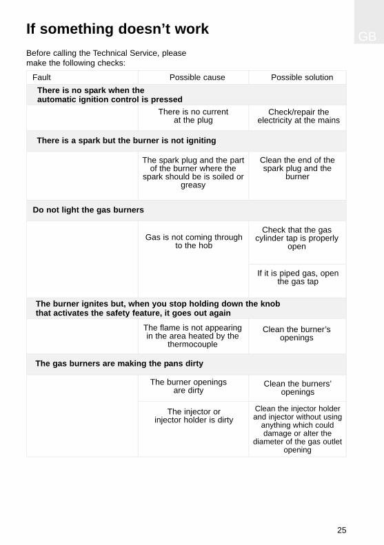
If something doesn’t work
Fault Possible cause Possible solutionThere is no spark when theautomatic ignition control is pressed
There is no current at the plug
Check/repair the electricity at the mains
The gas burners are making the pans dirty
The burner openingsare dirty
Clean the burners’openings
The injector or injector holder is dirty
Clean the injector holderand injector without using
anything which coulddamage or alter the
diameter of the gas outletopening
Before calling the Technical Service, pleasemake the following checks:
There is a spark but the burner is not igniting
The spark plug and the partof the burner where the
spark should be is soiled orgreasy
Clean the end of thespark plug and the
burner
Do not light the gas burners
Gas is not coming throughto the hob
Check that the gascylinder tap is properly
open
If it is piped gas, openthe gas tap
The burner ignites but, when you stop holding down the knobthat activates the safety feature, it goes out again
The flame is not appearingin the area heated by the
thermocouple
Clean the burner’s openings