Electronic Prescription System.pdf - LIMU-DR Home
47
- 1 - Libyan International Medical University Faculty of Information Technology Department of Health Informatics Project Title: Electronic Prescription System This project is presented as fulfillment of the requirement for Bachelor degree of Information Technology (Health Informatics) Done by student:Rabha Mohamed Saad Student number:632 Supervised by :Dr.TawfiqAltwil Spring 2015-2016
-
Upload
khangminh22 -
Category
Documents
-
view
3 -
download
0
Transcript of Electronic Prescription System.pdf - LIMU-DR Home

- 1 -
Libyan International Medical University
Faculty of Information Technology
Department of Health Informatics
Project Title:
Electronic Prescription System
This project is presented as fulfillment of the requirement for
Bachelor degree of Information Technology
(Health Informatics)
Done by student:Rabha Mohamed Saad
Student number:632
Supervised by :Dr.TawfiqAltwil
Spring 2015-2016

- 2 -
Dedicate
We must and we move past our steps in the university life of
pause go back to the years we spent in the university campus
with valued our professors who have given us so much great
efforts in building tomorrow's generation to send the nation
again ...
Before we offer our deepest gratitude and appreciation and love
to those who carried the message in the most sacred of life ...
To us who paved the road of science and knowledge ...
All our professors Distinguished…….

- 3 -
Thanks and Appreciation
Requires to be first to thank Almighty God who helped me in completing this
research, we do not have at this moment, but to raise our sincere deepest thanks and
appreciation to an area not endure the paper to:
Dr. Tawfig Tawill
Thanked him for his help me. Do not skimp and self-giving. To remove this
achievement which translates tender facade work, and projection creativity, and its
scale collection, hoping to God Almighty that we've come to the required level ...
I also extend my sincere thanks to:
Mr. Ihab Al-Falah
Miss. Heba Magrabi
Dr. Esam Aldnaa
For their effort to demonstrate what I've ever had from Assistance extend my sincere
thanks to all the teachers who have graced the teaching throughout my studies.

- 4 -
Index
Contents page number
Introduction 6
Chapter One
Feasibility Study
1.1 Preface 11
1.2 About Benghazi Debates Center 11
1.3 E-Prescription 11
1.4 Problem definition 12
1.5 Current system 12
1.6 The proposed system 12
1.7 Investigation of the current environment 13
1.8 business system options 13
Chapter Two
Requirements Analysis
2.1 preface 15
2.2 data flow diagram 15
2.3 entity relationship diagram 16
Chapter Three
Requirements Specification
3.1 preface 20
3.2 project purpose 20
3.3 project scope 20
3.4 general description of system 20
3.5 system constraints 20
3.6 requirements description 22
Chapter four
Logical System Specification
4.1 preface 25
4.2 structural design of system 25
4.3 activity diagram 29
4.4 Graphical user interface 34
Chapter five

- 5 -
Table index
Content Page Number
2.1 illustrates the symbol 16
2.2 ERD illustrates the symbol 18
3.1 functional requirements 23
4.1 SQL data type 26
4.2 patient file 27
4.3 diagnosis file 27
4.4 doctor file 28
4.5 pharmacy file 28
4.6 prescription file 29
4.7 user name 29
Figure index
Content Page number
2.1 DFD for e-prescription system 17
2.2 ERD for e-prescription system 19
4.1 Relation diagram SQL 30
4.2 Patient data entry 31
4.3 diagnosis data entry 32
4.4 prescription data entry 33
4.5 Search ,Edit and delete data 34
4.6 view prescription 35
Physical design and Implementation
5.1 preface 44
5.2 implementation 44
5.3 programming language 44
5.4 codes from system 45
References 48

- 6 -
Introduction
Health Information Technology
The term "health information technology" (health IT) is a broad concept that
encompasses a set of technologies to store, share, and analyze health information.
Increasingly, health care providers are using health IT to improve patient care. But
health IT isn't just for health care providers. It can be use health IT to make better
communication between patients and doctors, learn and share information about
patient’s health, and take actions that will improve the quality of life. Health IT lets
patients be a key part of the team that keeps them healthy.
Types of Health Information Technology
Electronic health records (EHRs) allows hospitals or doctors keep records of
patients health information, such as the history of diseases and which medications
they are taking. Up until now, most hospitals and doctors stored this information in
paper files.EHRs are electronic systems that store patient’s health information.EHRs
allow doctors to more easily keep track of patient’s health information and may
enable them to access patient’s information when patient has a problem even if their
office is closed. EHRs also make it easier for doctor to share information with
specialists and others so that everyone who needs patient information has it available
when they need it.Some EHRs may also allow you to log in to a web portal to view
your own health record, lab results, and treatment plan, and to email your doctor .
Personal health records (PHRs).A PHR is a lot like an EHR, except that patient
controls what kind of information goes into it.Patient can use a PHR to keep track of
information from his/her doctor visits, but the PHR can also reflect his/her life outside
the doctor's office and his/her health priorities, such as tracking food intake, exercise,
and blood pressure. Sometimes, PHR can link with his/her doctor's EHR.
e-Health Tools"e-Health tools" that patient can use on his/her own, if he/she wish,
that may be considered a part of the broader health IT world. These include:

- 7 -
Personal health tools, these are tools that help patient check his/her health, get
feedback, and keep track of his/her progress to better manage his/her health
.Examples include smart phone "apps" that can help patient set and monitor fitness
goals and cell phone text reminders to take your medicine on time.
Online communities can help people connect with one another to try to maximize
good health (such as during pregnancy) or to respond to concerns about poor health.
Through online communities patient can share information with -- and emotionally
support -- others facing similar concerns about a particular disease or disability.These
e-health tools are designed to place patient at the center of care – helping to put the "I"
in health IT.
Management of Health IT systems
Due to the threat of patient data breaches, widespread use of mobile health devices
and telemedicine technologies, and updates to health IT-related incentive programs
and regulations, providers that adopt health IT systems sometimes replace or upgrade
their systems.
E-prescribing.A paper prescription can get lost or misread. E-prescribing allows your
doctor to communicate directly with your pharmacy. This means you can go to the
pharmacy to pick up medicine without having to bring the paper prescription.
Proposed Project
We don’t doubt that health informatics is very common and helpful which the services
are much better and tasks are easier,in this project, e-Prescription system was built. E-
prescription is the process of electronically generating and sending a prescription
order, so that doctors and other medical practitioners can transmit an electronic
prescription to a pharmacy directly from the point of care. e-Prescription system
improves accuracy, enhances patient safety and quality of care since there is no
handwriting for the pharmacist to interpret or calling in prescriptions .The system
enters the patient information ,drug. He takes and his diagnose, and retrieve data as
reports.

- 8 -
Project Methodology
In this project, Software Development Life Cycle SDLC approach was used for
software development. The SDLC illustrates the software development process in a
linear sequential flow; hence it is also referred to as a linear-sequential life cycle
model. This means that any phase in the development process begins only if the
previous phase is complete.
SDLC Model is used widely in Software Engineering to ensure success of the project.
In this approach, the whole process of software development is divided into separate
phases.

- 9 -
Structured Systems Analysis and Design Methodology (SSADM) was used for
developing this project,which is an approach to analysis and design of information
systems. SSADM was produced for the Central Computer and Telecommunications
Agency, a UK government office concerned with the use of technology in
government, from 1980 onwards.
SSADM divides an application development project into modules, stages, steps, and
tasks, and provides a framework for describing projects in a fashion suited to
managing the project. SSADM's objectives are to:
• Improve project management & control
• Make more effective use of experienced and inexperienced development staff
• Develop better quality systems
• Make projects resilient to the loss of staff
• Enable projects to be supported by computer-based tools such as computer-
aided software engineering systems
• Establish a framework for good communications between participants in a
project
SSADM covers those aspects of the life-cycle of a system from the feasibility study
stage to the production of a physical design. SSADM's steps, or stages, are:
• Feasibility study
• Requirement Analysis
• Requirement Specification
• Logical System Specification
• Physical design and Implementation.
The following paragraphs describe the project chapters in brief:
Chapter one Feasibility Study:

- 10 -
This chapter includes the study of the current regime in Benghazi Diabetes Centre is
simple and a summary of the proposed system, a medical prescription , know their
goals system ,including investigation of current environment phase and business
system options phase .
Chapter two Requirements Analysis
In this chapter the requirements of the complete system are clearly defined and
understood. Any model represents the current system should describe the functions
performed and how to save data.
Chapter three Requirements Specification
The purpose of this chapter is to describe the system in terms of implementation at the
various software and also hardware with which it deals and specifications of those
devices and including.
Chapter four Logical System Specification
This stage is the stage parallel to the stage of writing software and designing the system it
depends on special programs and devices and shifting theories proposed objectives into
programs to be executed materially.
Chapter five Physical Design and Implementation
This stage is follows the design directly and where the application of the system, and here we
can enter real data and the final delivery of the system after making sure there are no defects
in the system.

- 11 -
Chapter One
Feasibility Study

- 12 -
1.1 Preface
The initial study phase is a phase that precedes the two phases of analysis, design and
study the primitive initial definition of the problem and determine the desired goals of
pacing, here are the initial study, take a look at the dimensions of the project through
frequent visits to the center of Benghazi Diabetes and Documentation Center began.
1.2 Benghazi Debates Center
The Center was established in 1969 at the hands of Dr. Othman Alcadekke Stadium
and was a room at the Hospital of the Republic and was the first clinic for follow-up
of diabetes in the Middle East and North Africa and then moved to a clinic, Cdi-
Hussein.
In 1977 and until the present time is in the same headquarters and provides services to
more than 70,000 AC Ali Center and is virtually the only place in the eastern region
of Libya.
It provides services to the Center for follow-up clinics for diabetes, divided into three
days for women and three days for men.
With clinics castrating him place such as(Diabetic foot, Eye Clinic, Dental clinic,
Clinic pregnant women with diabetes)Clinic, Dermatologist.
1.3 E-Prescription
E-prescriptions are computer-generated prescriptions created by healthcare provider
and sent directly to pharmacy, Instead of writing out prescription on a piece of paper,
doctor or other healthcare provider enters it directly into his or her computer.
Prescription travels from your doctor or other healthcare provider’s computer to the
pharmacy’s computer. E-prescriptions are sent electronically through a private,
secure, and closed network.
1.4 Problem definition
With the beginning of each new day is witnessing the world in which we live a
growing momentum of the information in various spheres of life, including health

- 13 -
care, it has been the introduction of IT in health care to help providers of care and
prevent a lot of mistakes in the health care, including diagnosis and prescription
medical, as in manual system there probability the occurrence of errors and the loss of
patient data and which is reflected in the patient's health.
1.5 Benghazi Diabetes Center current system
The current system in Benghazi Diabetes Centre is a manual system and all medical
prescriptions managed manually.
1.5.1 Disadvantage
• Difficulty reading prescription.
• Do not write the dose of the drug.
• Ambiguous nomenclature.
• Time waste.
• Non-registration data in records.
• Failure to obtain the required data.
• Overlapping prescription for patients to pharmacist.
• Manual system does not give detailed reports fast.
1.6 The proposed system
We have graduate students doing health file-mail to the center of Benghazi Diabetes
systems to help improve the quality of service the foreground of the patient and
improve the performance of jobs at the center. These are in the project I take a penalty
on medical prescription.
1.6.1 Objectives
• Saving time and effort.
• Reduces the risk of readmissions.
• Reduces the number of lost prescriptions.
• Prevents prescription drug errors.
• Improve the quality of services provided to the patient.
• Eliminate the problem of security weakness by setting a password.

- 14 -
• Rapid access to different data and produce reports detailed.
1.7 Investigation of the current environment
In Benghazi Diabetes Center the environment was equipped with a set of computers.
They have proper infrastructure and employee well trained and have connected with
local area network. So the environment will be suitable to be used for a new proposed
system.
1.8 Business System Options
This system was billed as gradation project so don’t include any payment process.

- 15 -
Chapter Two
Requirements Analysis

- 16 -
2.1 Preface
This chapter describes system requirements analysis for e-Prescription system, which
is a systematic approach to identify problems and opportunities and objectives,
analyzing the information flows in organizations and designing the information
systems to solve problems. This stage is can be achieved by specific techniques such
as DFD and ERDs. DFD illustrates how data is processed by a system in terms of
inputs and outputs. As its name indicates its focus is on the flow of information,
where data comes from, where it goes and how it gets stored. An entity relationship
diagram (ERD) shows the relationships of entity sets stored in a database. An entity in
this context is a component of data. In other words, ER diagrams illustrate the logical
structure of databases. Those tasks that go into determining the needs or conditions to
meet a new product, taking into account of the possibly conflicting requirements of
the various stakeholders, such as beneficiaries or users.
2.2 Data Flow Diagram (DFD) is a graphical representation of the "flow" of data
through an information system, modeling its process aspects. A DFD is often used as
a preliminary step to create an overview of the system, which can later be
elaborated. DFDs can also be used for the visualization of data processing (structured
design).
A Data Flow Diagram (DFD) shows what kind of information will be input to and
output from the system, where the data will come from and go to, and where the data
will be stored. It does not show information about the timing of process or
information about whether processes will operate in sequence.
Table 2.1 illustrates the symbol DFD
Symbol Function Symbol
External Entity
Process
0.0
Process flow

- 17 -
Data source Database.DB
Doctor
0.1
Log in
0.2
Diagnosis
0.3
write
Prescription
Pharmacist
Users.DB
Patient.DB
Doctoe.DB
Diagnosis.DB
retervingsave
Prescription.DB
Doctor.DB
Patient .DB
Drugs.DB
SAVE
Read
0.4
Mange drugs
Drugs.DB
0.5
provde
Drugs
Save
Patient
save
Figure 2.1 DFD for e-Prescription system

- 18 -
2.3 Entity Relationship Diagram model (ERD model)
ERD describes inter-related things of interest in a specific domain of knowledge. An
ERD model is composed of entity types (which classify the things of interest) and
specifies relationships that can exist between instances of those entity types.
In software engineering an ERD model is commonly formed to represent things that a
business needs to remember in order to perform business processes. Consequently, the
ERD model becomes an abstract data model that defines a data or information
structure that can be implemented in database, typically a relational database.
Table 2.2 ERD illustrates the symbol
Symbol Function Symbol
Actor Patient
Verb Have
Relation one to one
Relation many to many
Relation one to many

- 19 -
Doctor
Prescribing
Prescription
Get Patient
Have
Diagnosis
DO
1
M
M
1
1
1
1
M
Contain
Drugs
Get
M
N
M
N
Figure 2.1: ERD for e-Prescription

- 20 -
Chapter three
Requirements Specification

- 21 -
3.1 Preface
This chapter is an intermediate stage between the current system analysis and design
of the new system this stage aims to prepare exact specifications of the system.
3.2 The purpose of the project
Has this document was written to document the specifications of the system of
medical prescription and objective of this work is a manual system to convert the
electronic system to make work more accurate and faster to implement, and also to
facilitate access to reports.
3.3 Project Scope
The proposed system helps to accomplish the functions described in the process use
cases, and documentation of each case, and also to produce reports and queries.
3.4 General Description of the System
3.4.1 System Function
The system provides the user with many functions which
• Registration, data modification and the powers of the users.
• Registration and edit patient data.
• Save and edit diagnosis.
• Registration and data modification medicine.
• Save and edit medical prescription for the patient.
• Reports.
3.5 System constraints
System constraints dived into general and design constraints.
3.5.1 General constraints system
System Manager is authorized to give powers to use the system and the
process is summarized as follows.

- 22 -
Input: It contains the user name and passwords.
Processing: the system should ensure that the username and password are correct.
Output: it will show a massage on the monitor if the user name or password is
incorrect if it's not will take you to the window that you authorized to open.
2.5.2 Design constraints
Hardware limitation
Monitor, Printer Machine, The device's memory should be at least 2GB.
Software limitation
• Windows 7 operating system or any update latest version of windows.
• Visual basic 2010 .net application.
About the programming language used in this project:
I used the language (Visual basic.net 2010) for writing software and designing
screens.
Reasons for selecting this language :
• Discovery of errors in real time where they are used as a language
interpreter (Just In Time Compiler).
• Support dealing with SQL.
• Support reports .
• Characterized by the rest of the visual languages to respond to events(event
programming).
• Microsoft SQL Server 2008 database management system .
SQL It is an abbreviation for (Structured Query Language)This language used in
dealing with databases, and are used to extract, update and add data and database.

- 23 -
3.6 Requirements description
Table 3.1 Functional Requirements
Use case Data Entry Data processing Output data
Managing patient
data ( Add, edit and
delete)
Patient (name, id
number, date of
birth , etc)
System must be
certain that the data
entered in the case
is that they are
correct Date
Take out an alert
message, in the case
that the input wrong or
no data entry is
determined
Recording user data
User name password
System must be
certain that the data
entered in the case
is that they are
correct Date
Take out an alert
message, in the case
that the input wrong or
no data entry is
determined
Save the diagnosis
of disease
Patient name patient
id diagnosis doctor
(name ,number)
System must be
certain that the data
entered in the case
is that they are
correct Date
Take out an alert
message, in the case
that the input wrong or
no data entry is
determined
Save the
prescription to the
patient
Patient name patient
number drugs (name
,does)etc
System must be
certain that the data
entered in the case
is that they are
correct Date
Take out an alert
message, in the case
that the input wrong or
no data entry is
determined
Data recording
medication
Drug name drug id
dose expire
date , etc
System must be
certain that the data
entered in the case
is that they are
correct Date
Take out an alert
message, in the case
that the input wrong or
no data entry is
determined
Printing Reports Selection of data to
be printed
System must be
certain that the data
entered in the case
is that they are
correct Date
Take out an alert
message, in the case
that the input wrong or
no data entry is
determined

- 24 -
3.6.1 Non-Functional Requirements
• Speed must be fast system response to commands.
• The system should be connected by local area network.
• The system must be able to serve the number of users.
• Be user interfaces follow a clear and consistent format and follow certain
standards in terms of colors so as not to harm the user into.

- 25 -
Chapter Four
Logical System Specification

- 26 -
4.1 Preface
The goal of this stage is to produce a detailed design of the data that will be used as a
base for database design files, programs, and also will be described and a description
of logically to be utilized in the completion of the physical description of the program.
4.2 Structural Design of the System
4.2.1 Database Design
It was used (SQL SERVER) where he has a huge storage capacity of the
largest(ACCESS) information to clarify the types of fields used in the database as
table.
Table 4.1: SQL data type
Information about the Type Stored value Type
Variable length unicode data maximum 4000 characters
Variable Nvarchar
Allows whole numbers between 2,147,483,648 and
2,147,483,647
Storage is 4 bytes
Numerical Big int
Variable length character string maximum 2GB of text
data Text Text
Allows 0,1 or null 0 or 1 Bit
Variable length binary data maximum 2GB Binary data Image
Output figures are correct process stores if impropriety 0
and 1 if true Numerical Int
From January 1,1753 to December 31,9999 with an
accuracy of 3.33 milliseconds
Storage is 8 bytes
Date Datetime
4.4.2 Data normalization
After completion of stages of data normalization Friday become the database tables
Notes :
This mark * means that the field is a primary key.
Composite key is to make two or more keys primary keys one.

- 27 -
Table 4.2 patient file
Keys Description Field Type Field name
* Patient number Int Pa_number
Patient name Nvarchar (50) Pa_name
Mother name Nvarchar (20) Mothername
Date of birth Date time DOB
Patient city Nvarchar (20) Pa_city
Patient area Nvarchar (20) Pa_area
Patient street Nvarchar (20) Pa_street
Patient nationality Nvarchar (20) Pa_nationality
Gender Nvarchar (10) Gender
Marital status Nvarchar (10) Maital_status
Patient phone number Nvarchar (20) Pa_phone
Patient job Nvarchar (25) Job
Date of opening patient file Date time Open_date
Table 4.3 Diagnosis file
Keys Description Field Type Field Name
* Diagnosis date Date time Dignosiss_date
* Patient number Int Pa_number
Patient name Nvarchar (50) Pa_name
Patient diagnosis Text Diagnosis
Doctor number Int Doc_number
Doctor name Nvarchar (60) Doc_name
Table 4.4 Doctor file.

- 28 -
Keys Description Field Type Field Name
* Doctor number Int Doc_number
Doctor name Nvarchar (60) Doc_name
Doctor nationality Nvarchar (10) Doc_nationality
Doctor gender Nvarchar(10) Doc_gender
Doctor qualification Nvarchar (20) Qualified
Doctor specialization Nvarchar (20) Specialization
Doctor city Nvarchar(20) Doc_city
Doctor area Nvarchar (20) Doc_area
Doctor street Nvarchar (20) Doc_street
Table 4.5 Pharmacy file
Keys Description Field type Field name
* Drug Code Big int Drug_code
Drug Name Nvarchar(200) Drug_name
Drug stock Nvarchar (20) Stock
Drug expire date Date time Expire
If the drugs have conditions to
prescript it
Nvarchar(100) Allowed_drug
Drug dosage form Nvarchar(50) Drug_type
Drug dose Nvarchar (50) Dose
- 29 -
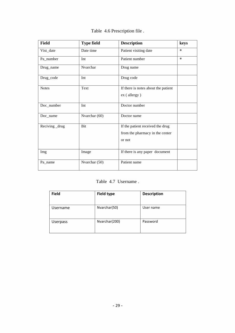
Table 4.6 Prescription file .
keys Description Type field Field
* Patient visiting date Date time Vist_date
* Patient number Int Pa_number
Drug name Nvarchar Drug_name
Drug code Int Drug_code
If there is notes about the patient
ex ( allergy )
Text Notes
Doctor number Int Doc_number
Doctor name Nvarchar (60) Doc_name
If the patient received the drug
from the pharmacy in the center
or not
Bit Reciving _drug
If there is any paper document Image Img
Patient name Nvarchar (50) Pa_name
Table 4.7 Username .
Description Field type Field
User name Nvarchar(50) Username
Password Nvarchar(200) Userpass

- 30 -
Figure 4.1 Relation Diagram SQL
4.3 Activity Diagram
In Unified Modeling Language (UML), an activity diagram is a graphical
representation of an executed set of procedural system activities and considered a
state chart diagram variation. Activity diagrams describe parallel and conditional
activities, use cases and system functions at a detailed level.
4.3.1 Activity Diagram Symbols Meaning
The start symbol represents the beginning of a process or workflow in an
activity diagram. It can be used by itself or with a note symbol that explains
the starting point.
The activity symbol is the main component of an activity diagram. These
shapes indicate the activities that make up a modeled process.

- 31 -
The connector symbol is represented by arrowed lines that show the
directional flow, or control flow, of the activity. An incoming arrow starts a
step of an activity; once the step is completed, the flow continues with the
outgoing arrow.
The decision symbol is a diamond shape; it represents the branching or
merging of various flows with the symbol acting as a frame or container.
The end symbol represents the completion of a process or workflow.
Enter patient data
All the data has been
entered
Massage box
"data has been
saved ”
noyes
Figer 4.2 Patient Data Entry in The System

- 32 -
Enter diagnosis
data
Patient number
found it
Massage box “Patient
number is not found it” All the data has
been entered
no
yes
no
yes
Massage box “data has been saved”
Want the diagnosis
as report
no
yes
Report shown
Figure 4.3 Diagnosis Data Entry

- 33 -
Enter prescription
data
Patient number found
it
Massage box “Patient
number is not found
it” All the data has been
entered
no
yes
no
yes
Massage box “data has been saved”
Want the
prescription as
report
no
yes
Report shown
Figurer 4.4 Prescription Data Entry

- 34 -
Search for the
required data
Find it
noyes
Edit it
Edit the
required data
Delete it
Massage box
"data has been
changed”
Delete the
required data
Massage box
“data has been
delete it”
yes
no
yes
no
Figure 4.5 Search, Edit and Delete Data

- 35 -
View
prescription
View all prescription for
specific patient
View only last
prescription Enter patient
number
Not found
Massage box
“this patient is
found”
View all
prescription
no
no
yes
yes
no
yesEnter patient
number
View last
prescription
Finger 4.6 view prescriptions
4.4 GUI Graphical User Interface
This screen is login screen which the user enter username and the password then he
gets to screen he can view.
Figure 4.8 login screen

- 36 -
Figure 4.9 Main menu which the user enter to his desire screen
Figure 4.10 Patient screen all the process related to patient data

- 37 -
Figure 4.11 Prescription screen
Figure 4.12 Diagnosis screen

- 38 -
Figure 4.13 Pharmacy screen
Figure 4.14 Users screen

- 39 -
Figure 4.15 View prescriptions by choice
Figure 4.16 View last prescription

- 40 -
Figure 4.17 All prescription for specific patient
This screen is searching for patient prescriptions but the patient number is wrong
Figure 4.18 search screen

- 41 -
Figure 4.19 screen show patient prescriptions Appear
Figure 4.20 Reports screen

- 42 -
Chapter five
Physical design and Implementation

- 43 -
5.1 Preface
In this chapter we will discuss the last phase of the project which is considered the
application and the parallel phase of the design phase, which is about transforming
what has been understood in the analysis phase and what has been outfitted in the
design phase into reality.
5.2 Implementation phase
After analysis and design of the system started in one of the main stages of the project
which is the implementation phase. In this phase will be the actual and practical
planning of the main parts in the system and then reprogrammed.
5.3 About the programming language used
5.3.1 Visual basic
Is the development environment and programming language from Microsoft based on
the language of the famous BASIC. It is classified as programming languages beings.
Since Microsoft began issuing Visual Basic, which is the convergence of a huge and
popular considerable success among programmers due to the extreme ease in
exchange for extreme complexity faced by any programmer seeking to Windows
programming using C or C ++. Overall fit Visual Basic data earmarked for small
businesses, applications and programs accounts database applications and is
convenient and easy and serve their purpose as well as it allows the programmer to
focus on solving the problem often does not face technical difficulties while writing a
Visual Basic program. But it stayed to mention that Visual Basic programs are not
complete translated into the machine language such as C ++ or Delphi, but translated
into a middle code communicates with linking library called "Run Time library" and
its name MSVBM ??.Dll replaced with question marks version number .
5.3.2 Visual basic 2010 .net
In April 2010, Microsoft released Visual Basic 2010. Microsoft had planned to
use Dynamic Language Runtime (DLR) for that release but shifted to a co-evolution
strategy between Visual Basic and sister language C# to bring both languages into
closer parity with one another. Visual Basic's innate ability to interact dynamically

- 44 -
with CLR and COM objects has been enhanced to work with dynamic languages built
on the DLR such as IronPython and IronRuby. The Visual Basic compiler was
improved to infer line continuation in a set of common contexts, in many cases
removing the need for the "_" line continuation character. Also, existing support of
inline Functions was complemented with support for inline Subs as well as multi-line
versions of both Sub and Function lambdas.
5.3.3 Visual Basic Features
▪ Quick and easy language to create Windows applications.
▪ It supports object-oriented programming, but that this is not fully.
▪ Is the language of Visual Basic language of object-Curve.
▪ Easy to learn and understand.
▪ Ease of errors in which the discovery.
▪ Reliance on HTML and so making him easy to use and understand.
▪ When you write the correct orders give you examples will confirm the validity of
writing code.
▪ It enables you to skip some of the mistakes when writing specific code.
5.4 Examples of codes from the system
This code if for adding new patient .
DimsqlAsString = "insert into patient(pa_number,pa_name, mothername, DOB, pa_city,pa_area,pa_street,pa_nationality,gender,maital_status,pa_phone,job,open_date) values("& TextBox1.Text &", N'"& TextBox2.Text &"', N'"& TextBox3.Text &"', CONVERT(DATETIME, '"& DateTimePicker1.Value &"', 103) , N'"& TextBox4.Text &"', N'"& TextBox5.Text &"', N'"& TextBox6.Text &"', N'"& TextBox7.Text &"', N'"& ComboBox2.Text &"', N'"& ComboBox1.Text &"', N'"& TextBox8.Text &"', N'"& TextBox9.Tdext &"', CONVERT(DATETIME, '"& DateTimePicker2.Value &"', 103) )" DimcmdAsNewSqlCommand(sql, conn) cmd.ExecuteNonQuery() MsgBox("data has been saved") This code for edit the diagnosis Dim conn AsNewSqlConnection conn.ConnectionString = "Data Source=HOME-PC\SQLEXPRESS;Initial Catalog=epresc;Integrated Security=True" conn.Open()

- 45 -
DimsqlAsString = " update dignosiss set pa_name = N'"& TextBox2.Text &"', dignosis= N'"& TextBox3.Text &"' where dignosiss_date = CONVERT(DATETIME, '"& DateTimePicker1.Value &"', 103) and pa_number ="& TextBox1.Text &"" DimcmdAsNewSqlCommand(sql, conn) cmd.ExecuteNonQuery() MsgBox("data have been changed") DateTimePicker1.Value = Date.Today TextBox1.Text = "" TextBox2.Text = "" TextBox3.Text = "" TextBox4.Text = "" TextBox5.Text = "" conn.Close() This code for search Dim conn AsNewSqlConnection Dim DR AsSqlDataReader conn.ConnectionString = "Data Source=HOME-PC\SQLEXPRESS;Initial Catalog=epresc;Integrated Security=True" conn.Open() Withcmd .Connection = conn .CommandText = "select * from presicriping where vist_date = CONVERT(DATETIME, '"& DateTimePicker1.Value &"', 103) and pa_number = "& TextBox1.Text &" " DR = .ExecuteReader EndWith WhileDR.Read TextBox10.Text = DR("pa_name") Dim s AsString = DR("drug_name") Dim t() AsString t = s.Split("_______") For i = 0 Tot.Length - 1 ListBox1.Items.Add(t(i)) Next TextBox2.Text = DR("notes") TextBox11.Text = DR("doc_number") IfDR("img").ToString.Length> 0 Then DimmsAsNewMemoryStream(CType(DR("img"), Byte())) PictureBox2.Image = Image.FromStream(ms) EndIf EndWhile
This code is for all prescription for specific patient
Dim conn AsNewSqlClient.SqlConnection conn.ConnectionString = "Data Source=HOME-PC\SQLEXPRESS;Initial Catalog=epresc;Integrated Security=True" conn.Open() Dim DS AsNewDataSet Dim Da AsNewSqlClient.SqlDataAdapter("SELECT * FROM presicriping WHERE (pa_number = "& TextBox1.Text &")", conn)

- 46 -
Da.Fill(DS) ReportViewer1.LocalReport.ReportPath = "C:\Users\home\Documents\Visual Studio 2010\Projects\eprec\WindowsApplication4\Report3.rdlc" DimrdsAsNewReportDataSource("DataSet1", DS.Tables(0)) ReportViewer1.LocalReport.DataSources.Clear() ReportViewer1.LocalReport.DataSources.Add(rds) ReportViewer1.LocalReport.Refresh() Me.ReportViewer1.RefreshReport()
This code for delete
Dim conn AsNewSqlConnection conn.ConnectionString = "Data Source=HOME-PC\SQLEXPRESS;Initial Catalog=epresc;Integrated Security=True" conn.Open() DimsqlAsString = "delete from presicriping where vist_date=( CONVERT(DATETIME, '"& DateTimePicker1.Value &"', 103)) and pa_number = "& TextBox1.Text &" " DimcmdAsNewSqlCommand(sql, conn) cmd.ExecuteNonQuery() MsgBox("Data has been deleted") DateTimePicker1.Value = Today TextBox1.Text = "" TextBox10.Text = "" ListBox1.Items.Clear() TextBox2.Text = "" TextBox11.Text = "" PictureBox2.Image = Nothing ComboBox1.Refresh() conn.Close()
References
https://www.techopedia.com/definition/27489/activity-diagram
http://msdn.microsoft.com/en-us/library/we86c8x2%28VS.100%29.aspx
Graduated previous project
Medicare Improvements for Patients and Providers Act, Pub L No. 110-275, 112 Stat
2066 (2008).
The National Progress Report on E-prescribing and Interoperable Healthcare, 2009.
Arlington, VA: Surescripts; 2010

- 47 -
Chris Gane and Trish Sarson. Structured Systems Analysis: Tools and
Techniques. McDonnell Douglas Systems Integration Company, 1977
John Azzolini (2000). Introduction to Systems Engineering Practices. July 2001.
http://www.redsoft.org/ebook/14/books/26/b1426.swf
Avison, D.E. & Fitzgerald, G. (2003).Information Systems Development:
Methodologies, Techniques and Tools. (3rd ed), McGraw-Hill, London. Chapters
20.1, 20.3