EE2022 Electrical Energy Systems Lecture 6: Three‐Phase Circuit Analysis
45
EE2022 Electrical Energy Systems 1/29/2015 EE2022: Electrical Energy Systems ‐ Three phase Circuit Analysis 1 Lecture 6: Three‐Phase Circuit Analysis
-
Upload
independent -
Category
Documents
-
view
3 -
download
0
Transcript of EE2022 Electrical Energy Systems Lecture 6: Three‐Phase Circuit Analysis

EE2022 Electrical Energy Systems
1/29/2015 EE2022: Electrical Energy Systems ‐ Three phase Circuit Analysis 1
Lecture 6: Three‐Phase Circuit Analysis

Learning Outcomes
• To calculate the complex power, voltages and currents in single phase and balanced three‐phase AC circuits and able to describe their relationships using Phasor diagrams.– Be able to solve balanced three‐phase circuit problems.
– Be able to calculate three‐phase power.
1/29/2015 EE2022: Electrical Energy Systems ‐ Three phase Circuit Analysis 2

Outline
• Three‐Phase Circuit Analysis– Generation, Transmission, and Distribution.– Three‐phase balanced systems.– Advantages of three‐phase balanced systems.
• Three‐Phase voltage and current– Line‐to‐neutral voltage– Line‐to‐Line voltage– Line current.– Delta/Wye configuration.
1/29/2015 EE2022: Electrical Energy Systems ‐ Three phase Circuit Analysis 3

Generation, Transmission and Distribution
1/29/2015 EE2022: Electrical Energy Systems ‐ Three phase Circuit Analysis 4Source: http://venturebeat.com/2010/10/29/super‐grid‐introduction/
Three lines
Three lines
Three lines
Three lines
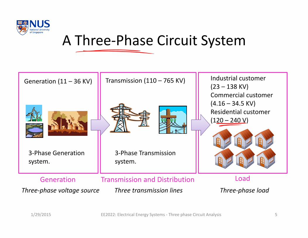
A Three‐Phase Circuit System
1/29/2015 EE2022: Electrical Energy Systems ‐ Three phase Circuit Analysis 5
3‐Phase Generation system.
3‐Phase Transmission system.
Generation (11 – 36 KV) Transmission (110 – 765 KV) Industrial customer (23 – 138 KV)Commercial customer (4.16 – 34.5 KV)Residential customer (120 – 240 V)
Generation Transmission and Distribution LoadThree‐phase voltage source Three transmission lines Three‐phase load

Three‐Phase Voltage Sources
1/29/2015 EE2022: Electrical Energy Systems ‐ Three phase Circuit Analysis 6
Va
Vb
Vc120° All three voltage sources
have the same voltage magnitude,with 120 degrees apart.
Phase sequence: abc(positive)

Three Single‐Phase Circuits
1/29/2015 EE2022: Electrical Energy Systems ‐ Three phase Circuit Analysis 7
Generation Transmission Load
These lines can be combined.
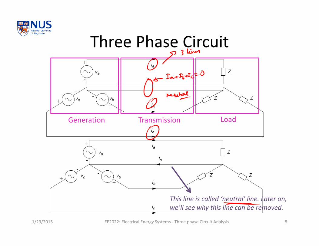
Three Phase Circuit
1/29/2015 EE2022: Electrical Energy Systems ‐ Three phase Circuit Analysis 8
Generation Transmission Load
This line is called ‘neutral’ line. Later on, we’ll see why this line can be removed.

Balanced Three‐Phase Circuit
1/29/2015 EE2022: Electrical Energy Systems ‐ Three phase Circuit Analysis 9
Va
Vb
VcThree‐phase circuit is said to be balanced when the impedances in the 3 phases are identical.
Identical impedances in 3 phases!
Three‐phase voltage source with identical magnitude and 120 phase differences

Balanced Three‐Phase Circuit
1/29/2015 EE2022: Electrical Energy Systems ‐ Three phase Circuit Analysis 10
Va
Vb
Vc
Ia
Ic
Ib
Ia
Va
0 n a b cI I I I
IaIc
Ib
0
Neutral line can be removed

Advantages of Balanced 3‐Phase Systems
• When compared to three single‐phase circuits, three‐phase circuits have better use of equipment and materials– More power can be transmitted
per conductor– Lesser power losses in the
conductors• This implies reduced capital
and operating costs of transmission and distribution.
• We can calculate voltage and current for only one phase and refer to other phases easily.
1/29/2015 EE2022: Electrical Energy Systems ‐ Three phase Circuit Analysis 11
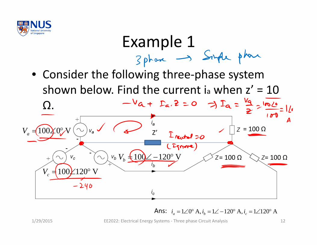
Example 1
• Consider the following three‐phase system shown below. Find the current ia when z’ = 10 Ω.
1/29/2015 EE2022: Electrical Energy Systems ‐ Three phase Circuit Analysis 12
Z’V 0100 aV
V 120100 bV
V 120100 cV
= 100 Ω
= 100 Ω = 100 Ω
Ans: A 1201 A, 1201 A, 01 cba iii

THREE‐PHASE CURRENT AND VOLTAGE
Line‐to‐Neutral VoltageLine‐to‐line voltageLine currentWye‐Delta connection
1/29/2015 EE2022: Electrical Energy Systems ‐ Three phase Circuit Analysis 13
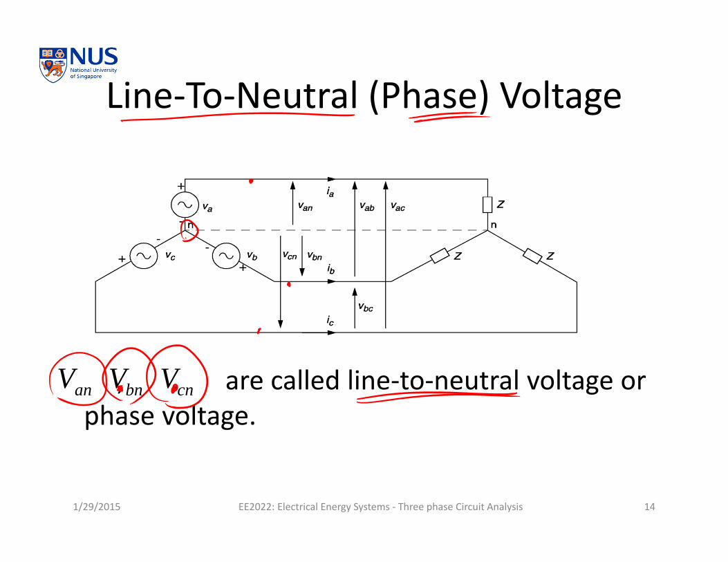
Line‐To‐Neutral (Phase) Voltage
1/29/2015 EE2022: Electrical Energy Systems ‐ Three phase Circuit Analysis 14
, , are called line‐to‐neutral voltage or phase voltage.
anV bnV cnV

Line‐To‐Line Voltage
• Voltage is given as line‐to‐line voltage by convention.
• KVL:
1/29/2015 EE2022: Electrical Energy Systems ‐ Three phase Circuit Analysis 15
anV
bnV
cnVbnV
abV
n
303 anbnanab VVVV
neutral-LineLine-Line 3VV 30°

Line Current
1/29/2015 EE2022: Electrical Energy Systems ‐ Three phase Circuit Analysis 16
, , are called line currents.ai bi ci
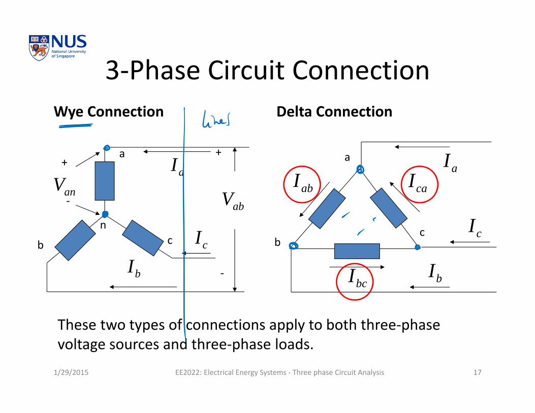
3‐Phase Circuit ConnectionWye Connection Delta Connection
1/29/2015 EE2022: Electrical Energy Systems ‐ Three phase Circuit Analysis 17
n
a
b c
+
‐
+
‐
aI
bIcI
abVanVa
bc
aI
bI
cI
abI
bcI
caI
These two types of connections apply to both three‐phase voltage sources and three‐phase loads.

Line Current VS Phase CurrentWye Connection Delta Connection
1/29/2015 EE2022: Electrical Energy Systems ‐ Three phase Circuit Analysis 18
n
A
B C
aI
bI
cI
A
BC
abI
bcI
caI
0
Currents through the three‐phase conductor lines are called ‘Line currents’.Currents carried by the load impedance are called ‘Phase currents’ or ‘Load Current.
aI
bI
cI

Delta‐Connected Load
• , , are called Phase currents.
• We can find relationship between line currents and phase currents using KCL,
1/29/2015 EE2022: Electrical Energy Systems ‐ Three phase Circuit Analysis 19
A
B C
aI
bI
cI
abI
bcI
caI
n
aI
bI
cI
abI
bcI
caI
caI
303 abcaaba IIII
abI bcI caI
PhaseLine 3 II

Delta‐Wye Load Transformation
1/29/2015 EE2022: Electrical Energy Systems ‐ Three phase Circuit Analysis 20
303 anab VV
Z Z
Z
aI
bI
cI
A
B C
+
‐
abVYZ
YZ YZ
aI
bI
cI
A
B C
+
‐
abV
303 aba II
Y3ZZ

Example 3• For a balanced Y‐connected
three phase voltage source and Y‐connected load system with a line voltage of 440 V and three equal resistive loads of 100 Ω per phase, assume positive sequence, what will be the magnitudes of – (a) the line‐to‐neutral voltage,– (b) the phase current, – (c) the line current?
1/29/2015 EE2022: Electrical Energy Systems ‐ Three phase Circuit Analysis 21

Example 4
• For a balanced Y‐connected three phase generator with the line‐to‐neutral voltage of 80 V, ∆‐connected load of 120 Ω, assume positive sequence, find– (a) the line‐to‐line voltage,– (b) the voltage across a
resistor, – (c) the current through a
resistor?
1/29/2015 EE2022: Electrical Energy Systems ‐ Three phase Circuit Analysis 22

Summary• Three‐phase voltage sources
– Positive and negative sequences• Balanced three‐phase circuit
– Conditions– Advantages
• Balanced three‐phase circuit– Line‐to‐neutral (phase) voltage– Line‐to‐line (line) voltage
– Line current• Wye‐Delta connection• Delta‐Wye load transformation
1/29/2015 EE2022: Electrical Energy Systems ‐ Three phase Circuit Analysis 23
neutral-LineLine-Line 3VV
Y3ZZ

• Three‐Phase Circuit Analysis– Three‐phase complex power– Per Phase analysis
1/29/2015 EE2022: Electrical Energy Systems ‐ Three phase Circuit Analysis 24

Three Phase Power Calculation
• Three phase power is found from summation of each phase power.
1/29/2015 EE2022: Electrical Energy Systems ‐ Three phase Circuit Analysis 25
***3 ccnbbnaan IVIVIVS
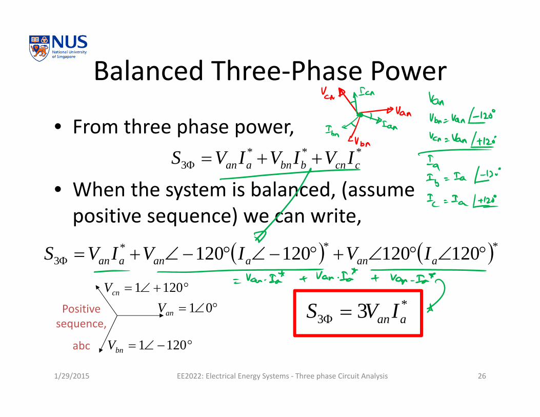
Balanced Three‐Phase Power
• From three phase power,
• When the system is balanced, (assume positive sequence) we can write,
1/29/2015 EE2022: Electrical Energy Systems ‐ Three phase Circuit Analysis 26
*3 3 aan IVS
***3 120120120120 aanaanaan IVIVIVS
***3 ccnbbnaan IVIVIVS
01anV
1201bnV
1201cnVPositive sequence,
abc

Balanced Three‐Phase Load
• Three‐phase load can be connected in either Wye or Delta connection.
• 3‐phase load parameter is given as total apparent power ( ) with power factor.
• The voltage given is Line‐to‐line voltage.• We can find three‐phase real and reactive power as follows.
1/29/2015 EE2022: Electrical Energy Systems ‐ Three phase Circuit Analysis 27
3S
p.f.3 313 SPP
sinp.f.cossin3 31
313
SSQQ
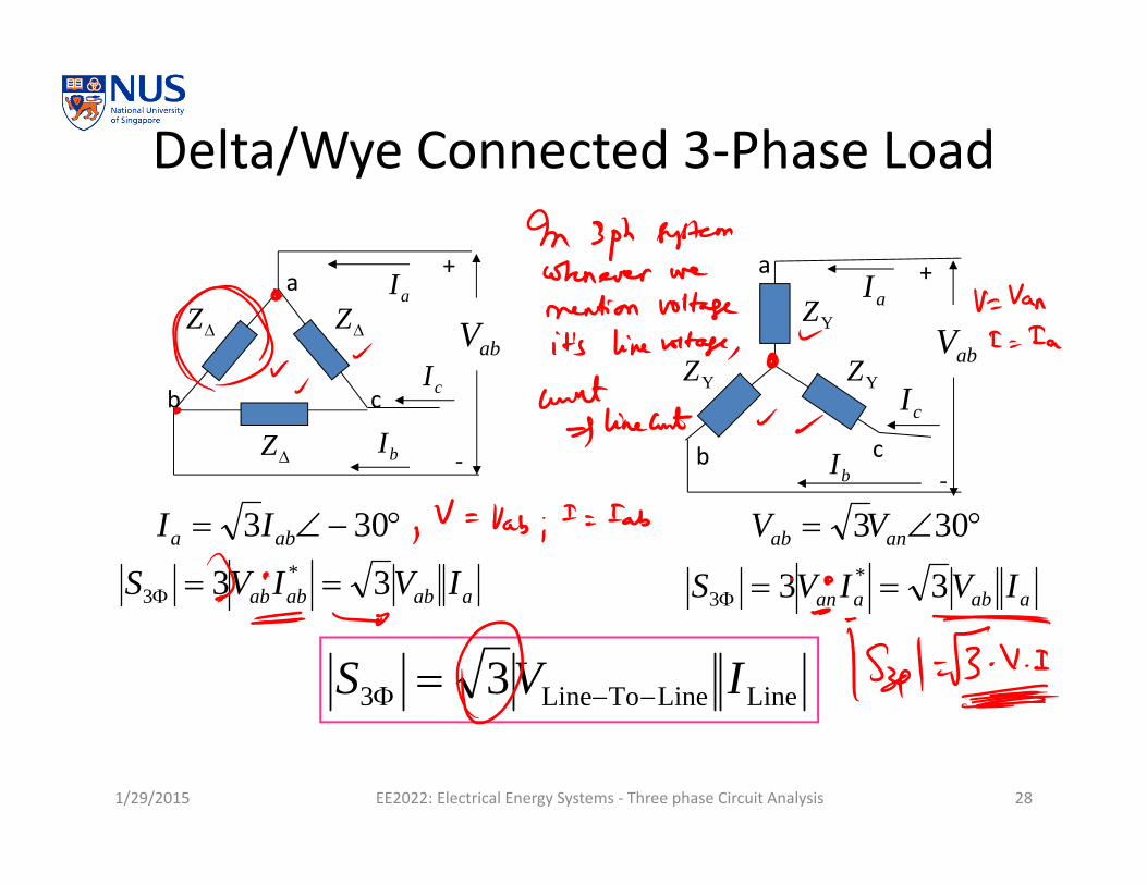
Delta/Wye Connected 3‐Phase Load
1/29/2015 EE2022: Electrical Energy Systems ‐ Three phase Circuit Analysis 28
LineLineToLine3 3 IVS
Z Z
Z
aI
bI
cI
a
b c
+
‐
abV YZ
YZ YZ
aI
bI
cI
a
b c
+
‐
abV
aababab IVIVS 33 *3
303 anab VV 303 aba II
aabaan IVIVS 33 *3

1/29/2015 EE2022: Electrical Energy Systems ‐ Three phase Circuit Analysis 29

Example 1
• A 3Ф load of 300 MVA, 100 kV at 0.85 p.f. lagging, find– The magnitude of line current– Three‐phase (real) power
1/29/2015 EE2022: Electrical Energy Systems ‐ Three phase Circuit Analysis 30
LineI
LoadP
Ans: 1732 A, 255 MW.
3Φ, 300 MVA, 0.85 pf lagging
?line I+
‐kV 100line-to-line V
Phase a
Phase b
Phase c
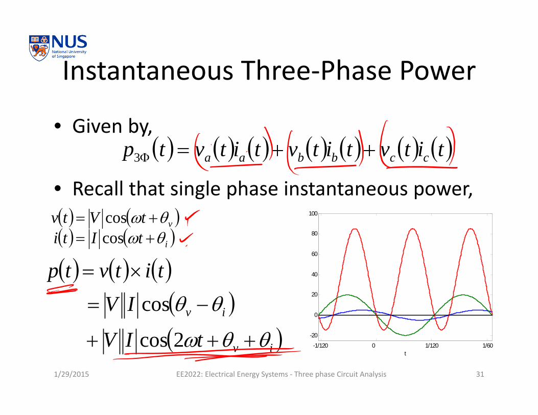
Instantaneous Three‐Phase Power
• Given by,
• Recall that single phase instantaneous power,
1/29/2015 EE2022: Electrical Energy Systems ‐ Three phase Circuit Analysis 31
titvtitvtitvtp ccbbaa 3
iv
iv
tIV
IVtitvtp
2cos
cos
-1/120 0 1/120 1/60
-20
0
20
40
60
80
100
t
vtVtv cos itIti cos

Instantaneous Three‐Phase Power
• For a balanced three‐phase system,
• We can find three phase instantaneous power as,
• Constant power transfer to load.
1/29/2015 EE2022: Electrical Energy Systems ‐ Three phase Circuit Analysis 32
PIVtp aa 3cos33
4802coscos
2402coscos
2coscos3
ivccivcc
ivbbivbb
ivaaivaa
tIVIV
tIVIV
tIVIVtp
=0

An Additional Advantage of Balanced 3‐Phase Circuit
• Constant power transfer to load.– This also implies constant mechanical power input for a generator.
– When mechanical power input is constant, mechanical shaft torque is also constant.
– This helps to reduce shaft vibration and noise, extending the machine’s lifetime.
1/29/2015 EE2022: Electrical Energy Systems ‐ Three phase Circuit Analysis 33

PER PHASE ANALYSIS
AssumptionSingle‐line diagramExample example example…
1/29/2015 EE2022: Electrical Energy Systems ‐ Three phase Circuit Analysis 34

Per Phase Analysis: Assumption
1/29/2015 EE2022: Electrical Energy Systems ‐ Three phase Circuit Analysis 35
Va
Ia
Vb
Ib
120º
Vc Ic
120º
It must be balanced three‐phase circuit.
0 n a b cI I I I

Steps of Per Phase Analysis
• Make sure that the three‐phase system is balanced.– The three‐phase sources need to have the same magnitude with 120 degree phase difference.
– The three‐phase impedances must be of the same value (both phase and magnitude).
• Convert all Delta‐connected sources/loads toWye‐connected sources/loads.
• Per phase analysis reduce three‐phase circuit to single‐phase circuit. We can apply the same concept used in single‐phase.
1/29/2015 EE2022: Electrical Energy Systems ‐ Three phase Circuit Analysis 36

Single‐Line Diagram• Show the interconnections of a transmission system– Generator– Load– Transmission line– Transformer
• This is a representation of a 3Ф circuit. Each line represents three conductors in three‐phase system.
1/29/2015 EE2022: Electrical Energy Systems ‐ Three phase Circuit Analysis 37
G1 G2
Load L1
TL1
TL2 TL3
T1 T2
T3

Example 2
• Given a one‐line diagram,
If the voltage source is . Find,1. Current magnitude supplied by source, , and,2. Current magnitude through a capacitor, .
1/29/2015 EE2022: Electrical Energy Systems ‐ Three phase Circuit Analysis 38
V 3Line-Line V
Source,Δ‐Connected
Positive sequence.Load 1, Δ‐Connected Capacitor: ZC = ‐j15
Load 2, Y‐Connected Inductive: ZL = j10
j5j2.5
12 3SI
CI
SICI

Example 2: 3Ф Circuit Diagram
1/29/2015 EE2022: Electrical Energy Systems ‐ Three phase Circuit Analysis 39
‐+
‐ +
+‐
j2.5
j2.5
j2.5
‐j15
‐j15
‐j15
j5
j5
j5
j10
j10
j10abV
bcV
caV1a
1b1c 2c
2a
2b
3a
3b3c
SI
CI

Example 2: Convert from Δ → Y
5315
3jjZZY
1/29/2015 EE2022: Electrical Energy Systems ‐ Three phase Circuit Analysis 40
j2.5
j2.5
j2.5
j5
j5
j5
j10
j10
j10
anV
bnVcnV
1a
1b1c2c
2a
2b
3a
3b3c
SI
+‐
+ ‐ ‐ + ‐j5
‐j5
‐j5
3013030330
3ab
anVV
Use voltage source as angle reference

Example 2: 1‐Phase diagram
305.15.22 Sana IjVV1/29/2015 EE2022: Electrical Energy Systems ‐ Three phase Circuit Analysis 41
5
551055105.2 jjjj
jjjjZeq
j2.5 j5
j10 301anV
1a 2a 3a
SI
+‐ ‐j5
We will use this to find CI
A 602.0905301
5301
jZVI
eq
anS

Example 2: Final Calculation
1/29/2015 EE2022: Electrical Energy Systems ‐ Three phase Circuit Analysis 42
12022 ab VV
A 9010
39015
120305.1305.115
22
jVVI ba
C
‐+
‐ +
+‐
j2.5
j2.5
j2.5
‐j15
‐j15
‐j15
j5
j5
j5
j10
j10
j10abV
bcV
caV1a
1b1c 2c
2a
2b
3a
3b3c
SI
CI
Ans: 901732.0,602.0 CS II

Practice Problem 1
• (Final EE2022 AY2011/12 semester 1) Find the voltage V1 and current I2.– Hint: remove the impedances that are in neutral line (why can we do this?) and transform delta to wye connection.
1/29/2015 EE2022: Electrical Energy Systems ‐ Three phase Circuit Analysis 43
j0.1 Ω j0.1 Ω
j1.0 Ω
j1.0 Ω+‐
+ ‐ ‐ +
‐j2.4 Ωj1.0 Ω
‐j2.4 Ω
‐j2.4 Ω
j0.1 Ω
j0.1 Ω
j0.1 Ω
j0.1 Ω
0.01+ j0.05 ΩHz 50 ,0120 AV
C’
A’
B’
A”
B”C”C
A
B
+
‐1V
2I
Ans: 12041.103,037.125 21 IV

Practice Problem 2• (Final EE2022 AY2011/12 semester 1) A balanced three‐phase
voltage source feeds a balanced three‐phase load shown below, find .– Hint: Assume that line‐to‐line voltage at the load has reference angle
of 0 degree. Then, find line current magnitude and angle at the load. Calculate line‐to‐neutral voltage from source using V_source(line‐to‐neutral) = I_line×j1.0 + V_load(line‐to‐neutral). Then, use relationship between line‐to‐line voltage and line‐to‐neutral voltage to find V_source(line‐to‐line).
1/29/2015 EE2022: Electrical Energy Systems ‐ Three phase Circuit Analysis 44
linetoline, SV
Ans: 601.61 V
j1.0 Ω
j1.0 Ω
j1.0 Ω
+
‐
V(rms) 230linetoline, LV3Φ Load,
Y‐connected,100 kVA at 0.8 p.f. lagging
3Φ Source
+
‐
linetoline, SV
lineI

Summary
• Three‐phase complex power,
• Per phase analysis– Only applied to balanced three‐phase circuit.– Need to convert all Delta‐connected load/sources to Wye‐connected load/sources.
– Same analysis as single‐phase circuit.
1/29/2015 EE2022: Electrical Energy Systems ‐ Three phase Circuit Analysis 45
LineLineToLine3 3 IVS