EASA.2016.FC19 SC.003 EUROCAE Study:
73
EASA.2016.FC19 SC.003 EUROCAE Study: ATN/OSI and ATN/IPS comparison
-
Upload
khangminh22 -
Category
Documents
-
view
0 -
download
0
Transcript of EASA.2016.FC19 SC.003 EUROCAE Study:

EASA.2016.FC19 SC.003 EUROCAE Study: ATN/OSI and ATN/IPS comparison

Disclaimer This study has been carried out for the European Union Aviation Safety Agency by an external organization and expresses the opinion of the organization undertaking the study. The views expressed in the study have not been adopted, endorsed or in any way approved by the European Union Aviation Safety Agency. Consequently it should not be relied upon as a statement, as any form of warranty, representation, undertaking, contractual, or other commitment binding in law upon the European Aviation Safety Agency. Ownership of all copyright and other intellectual property rights in this material including any documentation, data and technical information, remains vested to the European Union Aviation Safety Agency. All logo, copyrights, trademarks, and registered trademarks that may be contained within are the property of their respective owners. Reproduction of this study, in whole or in part, is permitted under the condition that the full body of this Disclaimer remains clearly and visibly affixed at all times with such reproduced part.

EUROCAE COMMUNICATION SARL au capital de 50 000 € - RCS Nanterre B 424 467 066 9-23 rue Paul Lafargue "Le Triangle" building TVA intracommunautaire FR 51 424 467 066 - APE :7490B 93200 Saint-Denis, France Code SIRET : 424 467 066 000 25 www.eurocae.net Tel : +33 1 49 46 19 65
EUROCAE COMMUNICATION Subsidiary of EUROCAE Association
The European Organisation for Civil Aviation Equipment
EASA – EUROCAE Framework Contract N° EASA.2016.FC19
Special Contract N° 2016-003
Deliverable N°1
ATN/OSI and ATN/IPS comparison
V 1.0.0

EASA SC 2016-003 ATN/OSI and ATN/IPS comparison D1 v1.0.0
2
Authoring & Approval
Prepared By
Luc Deneufchâtel & Emmanuel Chaput Technical experts
Reviewed By
Anna Guégan TPM
Approved By
Christian Schleifer Director
Document History
Edition Date Status Author Justification
00.01.00 20/06/2018 Draft Luc Deneufchâtel
00.09.01 17/09/2018 Mature draft Luc Deneufchâtel Updated after internal review
00.09.02 26/10/2018 Final Luc Deneufchâtel Inclusion of EASA comments
01.00.00 13/11/2018 Approved Christian Schleifer

EASA SC 2016-003 ATN/OSI and ATN/IPS comparison D1 v1.0.0
3
Table of content
1. Introduction 7
2. Scope of the study 8
2.1. Historical background 8
2.2. Mobile communication architecture models 8
2.3. Main Transport and Network layers mechanisms 9
2.4. Functional and performance comparison between ATN/OSI and ATN/IPS 9
2.5. Conclusions and Recommendations 9
3. Scope of Deliverable 1 10
4. Data communication historical background 11
4.1. ICAO initial data communication developments 11
4.2. ICAO activities associated with Internet protocol 13
5. Communication architecture models 16
5.1. Comparative basic scenario 16
5.1.1. End-to-end communication service scenario 17
5.1.2. Application layer message structure 18
5.2. The ISO model ATN architecture 19
5.3. The IP model and ATN architecture 20
5.4. General remarks on the transport layer functions 22
5.4.1.Detailed functions 23
5.4.1.1. Connection-oriented communication 23
5.4.1.2. Same order delivery 23
5.4.1.3. Reliability 23
5.4.1.4. Flow control 24
5.4.1.5. Congestion avoidance 24
5.4.1.6. Multiplexing 24
5.5. The Air Traffic Management data exchange needs 24
5.6. The ATN communication layer stack interrelationship 25
5.6.1. Link layer 27
5.6.2. Network layer 28
5.6.3. Mobility 29
5.6.4. Transport layer 29
5.6.5. Routing and addressing 29

EASA SC 2016-003 ATN/OSI and ATN/IPS comparison D1 v1.0.0
4
6. Main Transport and Network layers mechanisms 31
6.1. Main Transport layer ISO protocols 31
6.1.1. Air/ground ATN router: 31
6.1.2. Aircraft end systems and ground end systems 31
6.1.3. ATN Communications Services 32
6.1.3.1. ATN upper layer communications service (ULCS) 32
6.1.3.2. ATN Internet communications service (ICS) 32
6.1.4. The ISO transport layer protocol TP 4 32
6.1.5. Interdomain Routing Protocol (IDRP - ISO 10747) 33
6.1.6. Connection Less Network Protocol (CLNP) 33
6.1.7. SubNetwork Dependent Convergence Functions (SNDCF) 33
6.2. Main Network and Transport layer protocols in the IP model 34
6.2.1. TCP/IP 35
6.2.2. UDP 35
6.2.3. Performance issues 35
6.2.3.1. IP is connectionless 36
6.2.3.2. IP address and mobility 36
6.2.3.3. TCP three parts 37
6.2.3.4. Security 38
6.2.4. TCP/IP improvements 38
6.2.4.1. Multi-Protocol Label Switching (MPLS) 39
6.2.4.2. IPv6 39
6.2.4.3. Network level mobility 39
6.2.4.4. Transport level mobility 42
6.2.4.5. TCP Connection setup 44
6.2.4.6. TCP Slow Start 46
6.2.4.7. TCP congestion avoidance 46
6.5.5. Addressing and routing 49
7. Performance and functional comparison between ATN/OSI and ATN/IPS 50
7.1. Radio-link system 50
7.1.1. VDL Mode 2 Physical and MAC layers 50
7.1.2. LDACS Physical and MAC layers 53
7.1.3. Radio-link infrastructure entry process 53
7.1.3.1. VDL Mode 2 entry process 53
7.1.3.2. LDACS entry process 54
7.1.4. Radio-link network mobility 54

EASA SC 2016-003 ATN/OSI and ATN/IPS comparison D1 v1.0.0
5
7.1.4.1. VDL Mode 2 mobility 54
7.1.4.2. LDACS mobility 55
7.1.5. Some performance consideration 55
7.2. TCP/IP performance 56
7.2.1. TCP overhead 56
7.2.2. TCP connection setup 57
7.2.2. IP overhead 58
7.2.3. Link layer overhead 58
7.2.4. Network and domain mobility 58
7.2.5. Security 59
7.2.6. TCP add-ons 59
7.2.7. Summary of the analysis 60
8. Conclusions and recommendations 61
Annex 1 66
Annex 2 68
Annex 3 69

EASA SC 2016-003 ATN/OSI and ATN/IPS comparison D1 v1.0.0
6
List of Figures:
Figure 1 ICAO ATN concept .......................................................................................................................... 11
Figure 2 Analysis case description ................................................................................................................ 17
Figure 3 The protocol stack ........................................................................................................................... 18
Figure 4 Interaction scheme .......................................................................................................................... 18
Figure 5 Data communication OSI model ...................................................................................................... 19
Figure 6 Data communication IPS model ..................................................................................................... 21
Figure 7 IP architecture and associated protocol elements ....................................................................... 22
Figure 8 Steps necessary to conduct an application interaction ................................................................ 25
Figure 9 Connection set up implications per layer ...................................................................................... 26
Figure 10 Induced overhead within underneath layers ................................................................................ 26
Figure 11 Virtual Circuit establishment exchanges on X.25 ...................................................................... 28
Figure 12 TCP-IP model .................................................................................................................................. 34
Figure 13 TCP phases .................................................................................................................................... 38
Figure 14 Mobile IP principle ........................................................................................................................ 40
Figure 15 IP handover mechanism ................................................................................................................. 40
Figure 16 X25 connexion mechanism .......................................................................................................... 41
Figure 17 Multiple paths TCP IP ................................................................................................................... 43
Figure 18 MP TCP interactions .................................................................................................................... 43
Figure 19 TCP connection mechanism ......................................................................................................... 44
Figure 20 TCP Quick Start principles ........................................................................................................... 45
Figure 21 TCP CUBIC behaviour .................................................................................................................. 48
Figure 22 CSMA p persistent performances ............................................................................................... 51
Figure 23 Interaction model ........................................................................................................................... 52
Figure 24 VDL Mode 2 initial entry process ................................................................................................... 53
Figure 25 The IP protocol stack .................................................................................................................... 56
Figure 26 TCP initiation interactions .............................................................................................................. 56
Figure 27 TCP data encapsulation ................................................................................................................ 56
Figure 28 IP encapsulation ............................................................................................................................. 58

EASA SC 2016-003 ATN/OSI and ATN/IPS comparison D1 v1.0.0
7
1. Introduction
25 years ago, ICAO has selected the International Standard Organisation (ISO) Open System
Interconnection (OSI) model to be used as the basic reference standard for all data communication
associated with Air Traffic Management (ground/ground and air/ ground).
Consequently, ICAO has developed the Aeronautical Telecommunication Network (ATN) standard
which is the aviation implementation of the OSI model. The relevant ICAO materials were published
in the 90s’.
At a later stage, ICAO has also considered the potential use of another set of standards known as
Internet Protocol (IP) as an alternate solution to cope with the aviation needs. This specific
consideration was driven by the fact that IP became the “de facto” global standard solution for all the
telecommunication networks since 2000.
After a first recognition of IP as the most appropriate solution to support ground/ground services,
ICAO is now considering using IP for the air/ground communication domain as well, following the
development of Mobile IP complements. In parallel AEEC, RTCA and EUROCAE are undertaking
coordinated activities to develop the appropriate standards for the implementation of IP-based data
communication between ground-based ATS units and aircraft. The set of standards selected from the
IP world to satisfy aviation safety communication needs has been consolidated in the IP Suite (IPS).
IPS is therefore the selected part of the IP standards that are applicable to support these safety
communications.
In the USA, there is a very clear policy expressed by the FAA to accelerate the implementation of
IPS-based air/ground data communication, with eventually the possibility to skip the ATN/OSI step in
contradiction with the European region. This policy decision in the USA is derived from the fact that
seven years ago the FAA has decided to postpone the implementation of ATN/OSI & VDL Mode 2
technology in support of ATN B1 services until 2025. FAA’s initial data communication deployment
plan was approximately synchronised and coherent with the European decision. The decision to
postpone the programme was mainly due to budget constraints.
There is now a clear strategy in the USA to skip the deployment of ATN/OSI and to implement as
quickly as possible the ATN/IPS solution even though the definition is not yet complete at ICAO and
the associated standards have yet to be developed.
In this context of significant divergence on mobile data communication technology deployment
between Europe and the USA, it is essential to understand the challenges associated with both
technologies and to identify the benefits of migrating from ATN/OSI toward ATN/IPS in terms of
performance, cost and flexibility.
In this context it is important to recall that the ICAO strategy, recognised within the various regional
R&D programmes (SESAR, Nextgen, Carats, ...), is to consider ATN/IPS as the global convergence
solution for air/ground mobile data communication. All new technologies1 (i.e. LDACS, AeroMACS,
Next generation satellite communication) should be designed and developed as IP-native to be
consistent with this strategy.
1 Technology here means radio link technology (physical and link communication layers)

EASA SC 2016-003 ATN/OSI and ATN/IPS comparison D1 v1.0.0
8
2. Scope of the study
Based upon the identification of the Air Traffic Management operational needs, the purpose of this
study is to analyse and compare the two potential technology options for the architecture of the
air/ground mobile safety data communications system, that are:
The ATN OSI solution that has been standardised by ICAO in the 90’s (nearly 30 years
ago). Its deployment has been decided in Europe with the setting up of the Single
European Sky Regulation 29/2009. The completion of this first phase is expected to be
achieved in 2020,
The ATN/IPS solution on which ICAO is finalising the standardisation and that is
considered as the convergence solution at worldwide level
This study report is structured along the following sections:
Data communication historical background
Communication architecture models
Main Transport and Network layers mechanisms
Performance and functional comparison between ATN/OSI and ATN/IPS
Conclusions and recommendations
.
2.1. Historical background
The first step (section 4) will provide an historical background of the data communication definition
activities at international level and the associated ICAO activities and deliveries regarding air/ground
data communication. The section will also describe the current situation regarding data-link
deployment (what technologies and their relationship with the ICAO standards).
2.2. Mobile communication architecture models
The second step (section 5) will assess the actual needs in terms of network and transport layer
functionalities to support short and long-terms ATM data-link requirements. The description of these
functionalities will be supported by a very simple scenario representing an end-to-end interaction
between an airborne system and a ground system. It will define the various levels of networks that
are indeed used to make these end-to-end interactions possible.
The section will identify the various functionalities provided by the transport layer within a typical radio
communication network.
It will identify the mechanisms in place at the different layers of the communication protocol stack to
successfully complete an end-to-end transaction, regardless from the technology used.

EASA SC 2016-003 ATN/OSI and ATN/IPS comparison D1 v1.0.0
9
The section will also address the connected and connectionless mechanisms, the mobility issues
associated with the various network levels (radio link network, telecommunication service providers
network, the transport level network, …)
2.3. Main Transport and Network layers mechanisms
This step of the study (section 6) will describe the different mechanisms covering the network and
transport layer functions in the ISO model and in the IP model. The main points addressed in this
section will be the following:
The mobility aspects
The security aspects
The routing and addressing aspects
This section will also list and describe the main evolutions within the IP world regarding mobility,
security and performance.
2.4. Functional and performance comparison between ATN/OSI and ATN/IPS
In this part of the study (section 7), the mechanisms associated with the end to end scenario as
presented in section 5 and documented in section 6 will be compared using two sets of technologies:
ATN/OSI over VDL Mode 2 (the reference mandated situation in Europe today)
ATN/IPS over LDACS (one of the target configurations for the future of ATM mobile air/ground
communications).
This section also provides some information on the potential benefits coming from the latest
development of TCP/IP when applied to the ATN.
2.5. Conclusions and Recommendations
The last part (section 8) will provide conclusions regarding the potential technology evolution from
ISO model toward and IP model, considering the key performance contribution of the supporting
radio-link technology.
This section will also offer a set of recommendations regarding the need to continue to work on
ATN/IPS content, the consistency between the deployment of a modern radio link technology and the
migration toward ATN/IPS and the constraints associated with a worldwide transition.

EASA SC 2016-003 ATN/OSI and ATN/IPS comparison D1 v1.0.0
10
3. Scope of Deliverable 1
The deliverable, Deliverable 1 (D1), consists in a single report. This report presents the study
described above and its conclusion.

EASA SC 2016-003 ATN/OSI and ATN/IPS comparison D1 v1.0.0
11
4. Data communication historical background
In the scope of this document, Internet Protocol Suite (IPS) is used to refer to the IP Suite that is
currently selected by ICAO in the frame of the activity of its Communication Panel (to be noted that it
is not yet completed).
When IP will be used it will refer to the Internet Protocol in general including the RFC intended to add
new functions, new services and amending the baseline itself.
4.1. ICAO initial data communication developments
Since the work conducted by the Future Air Navigation System (FANS) Committee in the beginning of
the 90’s, mobile data communications between aircraft and ground-based ATM system (i.e. end-to-
end exchanges) have been recognised as major technical enablers to Air Traffic Management
modernisation.
To address this need for air/ground mobile communication, the FANS committee promoted the
concept of network of networks by introducing the Aeronautical Telecommunication Network (ATN).
The basic objective of the ATN (essentially covered by the transport layer) is to ensure continuous
and transparent end-to-end connectivity in mobility. This function intends to maintain transparent
connectivity between ground-based applications and their airborne counterparts during a flight.
Figure 1 ICAO ATN concept

EASA SC 2016-003 ATN/OSI and ATN/IPS comparison D1 v1.0.0
12
The ATN network and transport layers intended to create a “network” including several subnetworks
from the point of view of the ATM services/applications layer. Such network provides global
connectivity between ATN nodes known as “ATN air/ground routers2”. According to the figure 1 above
this networking layer establishes the connectivity between aircraft end system and ANSP end system
or Airline end system in a way that is independent from the radio communication technology.
This connectivity is to be provided over multiple subnetwork infrastructures using various
technologies. At the initiation of the ATN concept by the FANS committee, the following sub-
networks/technologies were identified:
SSR Mode Select (Mode S),
Very High Frequency (VHF) Digital Link (VDL) Mode 2,
Aeronautical Mobile Satellite Service (AMSS),
High Frequency Data Link (HFDL).
Moreover, the ATN standard included a provision to add future radio-link subnetwork/technology.
Over the last 20 years, a few new aviation radio-link technologies have emerged, some of these are
already deployed. These subnetworks include new SATCOM networks (i.e. Iridium Next or Inmarsat
Iris Precursor) and AeroMACS, a wireless networks solution for airport surface communications
based upon IEEE 802.16 “WIMAX” implementation. These new technologies are IP-native
technologies.
The main objective of the ATN concept was to provide a technical framework that could
accommodate the integration of new communication technology supporting the data communication
services, in a way that is transparent for the application layer. The intention was to ensure continuous
end-to-end connectivity between the aircraft end system and the ATC ground-based end system
along the aircraft flight.
This continuous end-to-end data exchanges had to use various communication networks in a
transparent way from the end-to-end service point of view.
At the same time, to answer the worldwide need for data communication, including oceanic airspace,
as identified by the FANS committee to improve the ATM performances, Boeing launched a first
generation of data communication system: the FANS system, known as FANS-1.
This system was providing ATC services and was based upon a legacy technology known as
ACARS. ACARS is an old communication protocol using a character-oriented data format developed
in the late 70’s.
This FANS1 technology is used for the provision of Automatic Dependent Surveillance (ADS) and
Controller Pilot Data Link Communications (CPDLC). It was initially implemented as an additional
software package within the Flight Management System (FMS) of the Boeing 747-400. It used
existing satellite technology (Inmarsat Data-2 service) and VHF-based ACARS communications and
was targeted at operations in the South Pacific Oceanic region.
A similar product was later developed by Airbus for the A-340 and A-330: FANS-A. It had a different
implementation architecture and is no more integrated within FMS but within a new communication
dedicated component – the ATSU-.
2 To be noted that the ATN router must be able to establish communication with any technology dependent subnetwork. To be noted that each aircraft is fitted with an ATN router in the ICAO ATN concept.
The ATN network of networks

EASA SC 2016-003 ATN/OSI and ATN/IPS comparison D1 v1.0.0
13
Ten years before this ICAO initiative, the International Standard Organisation (ISO) has developed
the Open System Interconnection (OSI) architecture logical model. The foundation ISO document is
the ISO 7498 published in 1984. The OSI logical model defines seven layers to be used to develop
interoperable communication components (from the physical technological layer up to the
service/application layer) to ensure full interoperability despite the heterogeneity of the radio link
technologies developed at that period.
ICAO decided to adopt such model to build the Aeronautical Telecommunication Network (ATN) as
an aviation application of the OSI model. The main purpose of the ATN was to provide a clear
framework within which future aviation radio communication technologies could be easily
accommodated without impacting the already deployed data communication services/applications.
To fully define the ATN concept and facilitate its implementation, ICAO has developed over the last
30 years several studies addressing the mobile air/ground data communication based upon this OSI
architecture model.
To start with, ICAO published, in 1994, the first set of materials referencing several ISO basic
standards associated with the OSI model.
The ATN was foreseen by ICAO as a key enabler to facilitate the integration of emerging radio
communication technologies. During this period, ICAO has developed the VDL Mode 2 standard
including the ISO 8208 protocol (i.e. X25) providing the convergence layer to the ATN transport layer.
In the same timeframe ICAO material incorporated the Inmarsat technical requirements (known as
“classic aero”) for the Satcom sub network. This last standard provided two potential convergence
layers, the data 2 mode was providing compatibility with ACARS-based protocols, while the data 3
mode was including the ATN/OSI convergence layer (i.e. X.25). To be noted that this mode was
never really used during the last two decades by the satellite technology, except in the frame of some
R&D project funded by the European Commission before the setting up of the SESAR programme.
4.2. ICAO activities associated with Internet protocol
At the same time as the publication of ICAO’s standards3 (i.e. in the 90’s), the Internet concept
developed by Berkley University became an attractive solution to satisfy the global need for data
communication internetworking. It was indeed a pragmatic implementation of the reference OSI
model, bringing several simplifications to make the final solution more flexible and more efficient.
Progressively, this way of implementing the basic OSI model appears to be the right one from the
communication service provider’s point of view. IP implementation became the de facto universal
standard for the ground network deployment, replacing the older ISO-based solutions (e.g. X.25).
Around 2000s, the global move of the communication market and industry to IP drove ICAO to
consider this simplified implementation of the OSI model. ICAO recognised IP as the de facto
standard for data communications ground-based network and has started to assess its applicability to
the aviation domain. For ground/ground networks and associated services/applications, IP solution
appeared clearly to be the right solution. Therefore, ICAO made recommendations to implement IP-
based networks for ground/ground ATM communications.
3 ICAO Doc 9880 ATN/OSI and ICAO Doc. 9705-AN/956 – Manual of Technical Provisions for the Aeronautical
Telecommunications Network (ATN) Second Edition, December 1999, including identified PDRs.
EASA SC 2016-003 ATN/OSI and ATN/IPS comparison D1 v1.0.0
14
Regarding the use of IP-based technology for air/ground data communications, ICAO recognised at
the time that IP was not mature enough to address correctly the mobility requirements (from an
aircraft point of view) and that security aspects emerging as a major requirement for data
communications (i.e. air/ground data communications) were not yet satisfactorily addressed.
ICAO decided to postpone the application of IPS for air/ground communication to a later stage where
IP standards would become more mature on these two key aspects.
From 2005 onward, the deployment of IP-based ground networks by ICAO member States has grown
regularly facilitated by the availability of mature IP network components from industry. This
technology is today the technical solution for ground-based data communication infrastructure for
ANSPs.
Therefore, ANSPs migrated their legacy data communication ground network based upon X.25 or
frame relay technologies towards IP based technology. Consequently, the usage of ISO protocols for
ground data communication was no more appropriate for the ground application and the usage of IP
was considered a better solution.
On request of the member States, the ICAO Aeronautical Mobile Communication Panel (AMCP) set
up a new Working Group (WG I) to translate the IP baseline, including the appropriate RFCs4
selection, within appropriate ICAO material (IPS). Annex 10 SARPS were modified to include two
potential solutions for data communications: the already defined ATN/OSI based upon the OSI model
and ATN/IPS based upon the IP model and associated protocols.
ICAO published the Manual on the Aeronautical Telecommunication Network (ATN) using Internet
Protocol Suite (IPS) Standards and Protocol - ICAO DOC 9896’s first edition in 2010 and second
edition in 2015. The evolution of this document is assigned to the Communication Panel with a third
edition planned for 2020.
WG-I is one of the working groups of the ICAO Communication Panel (CP) that oversees this activity.
ICAO DOC 9896’s evolution includes the completion/evolution of the ATN/IPS work both for
air/ground and ground/ground segments covering: IPS implementation guidance development, IPS
security, DNS, Mobility, Naming and Addressing, Consideration of transition aspects from
existing/legacy systems (including guidance on dealing with the mixed equipage environment and
identification/determination of need for gateways), Configuration Management – not limited to
handling of RFCs, Integration with different systems, QOS, COS issues (ref. item 2 of the Work
Programme - Job Card on ATN/IPS).
Other ICAO Panels (i.e. AVSEC, RPASP, IMP) are involved as required in the IPS evolution mainly
for operational and security requirements definition. The development of an IPS security technical
framework, raising questions on security policy and operational issues for consideration by other
panels was already initiated within WG-I.
In complement to these developments, ICAO clearly recommended the implementation of ATN/IPS
for all the ground/ground data communication applications and ATN/OSI for the air/ground data
communication applications.
4 RFC : Request for Change

EASA SC 2016-003 ATN/OSI and ATN/IPS comparison D1 v1.0.0
15
During the last decade, WG I of the Aeronautical Communication Panel5 has continued to work on IP
evolutions, especially regarding mobility and security. Based upon these new developments the level
of maturity of IP technology to be used for air/ground communications was achieved.
Avionic manufacturers and aircraft manufacturers started activities to standardise the IP-based
components to facilitate the deployment and the approval of these new communication components.
Two parallel activities have been initiated in the last two years in complement of the ICAO Communication Panel WG-I that is continuing its work:
AEEC has set up an activity some months ago
RTCA has just decided to launch an activity on the subject
AEEC activity description can be found in Annex 3.
Following this movement and to contribute to it by providing the European context and issues,
EUROCAE set up in 2018 a new WG-108 dealing with ATN/IPS. It should be a joint activity with
RTCA to support global harmonisation and interoperability.
The Terms of Reference of WG-108 have been recently revised and approved by the TAC in August
2018, adding the two following documents:
Document type Draft title Target date MASPS MASPS on ATN/IPS end-to-end interoperability
and certification T0 + 24 months
TS Technical Standard of Aviation Profiles for ATN/IPS
T0 + 12 months
The first deliverable, expected to be completed within one year, will be Technical Standards defining
the Aviation Profiles for ATN/IPS. This document will identify the applicable RFC and select the
appropriate options among all the IP capabilities.
5 ACP has been replaced by the Communication Panel since 2013

EASA SC 2016-003 ATN/OSI and ATN/IPS comparison D1 v1.0.0
16
5. Communication architecture models
This section describes the communication architectures that can be used to fulfil efficiently the needs
for aeronautical communication services. It briefly describes the two predominant network models.
The ISO model is based on a virtual circuit paradigm, while the IP model is connection-less.
The ISO model and the protocols selected for the aeronautical communication services have been
designed nearly 30 years ago, while the IP model and the associated solutions have been enhanced
constantly since their initial development and have benefited from the very quick development of
commercial mobile communications that have brought significant feedbacks facilitating the constant
improvement of this technology.
This section also shows how the stacking of multiple layer protocols/mechanisms highlights the need
for a trade-off between reliability (i.e. guaranty of the successful exchange) and overall performance
such as a fair and efficient use of the resources and the achievement of the end-to-end message
delivery latency. The most challenging features of each architecture to satisfy the aeronautical safety
communications are also pinpointed.
5.1. Comparative basic scenario
For this analysis, a simplified reference scenario has been selected. It is described in the following
figure 2. This scenario is considering an End Airborne application (AS) exchanges messages with an
End Ground application (GS).
The aircraft during its flight will be communicating with several adjacent ground stations (e.g. VDL
Mode 2 or LDACS ground stations). Each of these ground stations is part of a radio-link operator
network. During the flight, communication could be necessary with a ground station belonging to
another radio link operator (e.g. ARINC to SITA or SITA to ARINC). This specific handover will
generate a set of transactions to switch from one network to the other one.
At the application level, the GS is part of another higher-level network providing connectivity between
specific end users (i.e. ANSP or airline dispatch centre and aircraft). We consider that all these end
system facilities are interconnected at the transport network level.6 This means that in the ATN/OSI
model, the end-systems are interconnected via the various ATN air/ground routers.
6 See Figure 1 on the ATN concept description

EASA SC 2016-003 ATN/OSI and ATN/IPS comparison D1 v1.0.0
17
Figure 2 Analysis case description
5.1.1. End-to-end communication service scenario
To compare the performance of the different options, a basic end-to-end message exchange is used
to define the communication scenario. This selected scenario is not necessarily covering a
foreseeable operational need but provides a simple model. The scenario is the following:
The aircraft sends periodically its position to the ground end system (i.e. ANSP control centre).
Each downlinked message is acknowledged at the ground application level, keeping in mind
that, depending on the implementation (i.e. ISO or IP), some additional interactions at
transport, network, or link layer could also be necessary (including specific
acknowledgements) could be implemented at these various levels. Such multiple level
acknowledgements are common. It is always a trade-off between the reliability of the
exchanges introduced by the acknowledgements and the latency performance deterioration
due to overhead.

EASA SC 2016-003 ATN/OSI and ATN/IPS comparison D1 v1.0.0
18
The protocol stack across the various layers can be represented as in the following figure.
Figure 3 The protocol stack
For this comparison, the application layer is the same for both solutions (either IP and ISO).
are The major differences between these two architectures concern the network and transport layers.
Regarding the physical and link layers, the current VDL Mode 2 technology has been selected even
though it must be noted that implementing IP above VDL Mode 2 is not recommended by this study.
5.1.2. Application layer message structure
At the application layer, the messages to exchange have the following characteristics:
Data message length L = 2048 bytes
Acknowledge message length l = 20 bytes
The general behaviour of the end-to-end applications (i.e. AS and GS levels) is described in the
following figure (where n is the number of application message in the sequence):
Figure 4 Interaction scheme
Aircraft position and trajectory message (4D trajectory update) constitutes the core part of the
messages. They are sent within a very low period of time Tm (about several minutes).

EASA SC 2016-003 ATN/OSI and ATN/IPS comparison D1 v1.0.0
19
5.2. The ISO model ATN architecture
To cope with the growing development of data exchanges and to provide a coherent framework for
network definition and implementation, a huge activity was initiated at ISO level to try to provide the
necessary standards and good practices for an efficient development of data communication
networks focusing at that time on local computer networking, and later, on wide area networks.
An architecture model was developed by ISO to ensure backward compatibility framework for the
industry while considering the very rapid changes in this domain.
This model known as OSI model structures the data communication mechanisms into seven layers.
Each layer is interacting with the next ones through standardised interfaces thus ensuring the
backward compatibility when one layer must be updated. The OSI model structure standard, ISO
7498, was published in 1984.
It was intended to become the global reference to implement data communication network for all
industry sectors. This is the main reason that led ICAO to adopt this model and to make usage of the
protocols developed by ISO to cover these seven layers (mainly from layer 2 to layer 4).
The following scheme presents this model.
Layer
Name Data
packaging
Function
7 Application Data High-level APIs, including resource sharing, remote file access
6 Presentation Data Translation of data between a networking service and an application; including character encoding, data compression and encryption/decryption
5 Session Data Managing communication sessions, i.e. continuous exchange of information in the form of multiple back-and-forth transmissions between two nodes
4 Transport Segment Reliable transmission of data segments between points on a network, including segmentation, acknowledgement and multiplexing
3 Network Packet Structuring and managing a multi-node network, including addressing, routing and traffic control
2 Data-link Frame Reliable transmission of data frames between two nodes connected by a physical layer
1 Physical Bit/Symbol Transmission and reception of raw bit streams over a physical medium
Figure 5 Data communication OSI model
It must be noted that this model and the associated standards have never been fully implemented in
any domain.
The main objective of the standards developed by ISO was to ensure very high reliability for the end-
to-end communications using acknowledgment mechanisms at each layer and to define clear layer
interfaces. Simplifications were made rather quickly regarding the OSI model. The most significant

EASA SC 2016-003 ATN/OSI and ATN/IPS comparison D1 v1.0.0
20
one was to merge de facto the layers 5, 6 and 7 recognising that there is no benefit to keep these
layers separated.
One of the key elements developed by ISO was the usage of X.25 as the common mechanism to
interface the layer 3 and layer 4. This standard has been published as ISO 8208.
Within the ICAO ATN/OSI definition, X.25 has been selected as the common interface between the
various radio-link technologies and the common transport layer (i.e. the ATN in the ICAO framework).
Therefore X.25 was selected as the convergence interface between heterogeneous technologies and
the common ATN transport layer to facilitate the integration of new technology from the upper
communication layers perspective.
X.25 is known as a robust piece of protocol providing a high guaranty of integrity/protection for the
exchanges, but not necessarily an efficient one in terms of overhead (i.e. it includes a number of
acknowledgment mechanisms that weaken the exchange if the lower layer is not performing
suitably.7)
In the case of ATN/OSI the communication infrastructure is composed of:
A network of air/ground (A/G) Data Link VHF Ground Stations (VGS) (VDL Mode 2),
A set of air/ground routers8,
A set of Ground/Ground Routers (for interconnection with other A OSI architecture model
CSPs and with ANSPs)
The overall architecture implies the deployment of ATN ground/ground routers that provide the
interfaces between the air side of the ATN and the various physical local ground networks within the
end system operating entities (i.e. ANSPs, Airlines, etc.).
The ATN communication traffic (packets) is encapsulated, using subnetwork Dependent
Convergence Functions (SNDCF), to be send within the different radio-link networks.
The ICAO ATN/OSI infrastructure also includes the ATN end system function.
ATN end systems formally include the complete 7-layer protocol stack hosting the appropriate
application(s). They can communicate with other ATN End Systems to provide end-to-end
communication services.
5.3. The IP model and ATN architecture
The IP model was not created as an alternative to the OSI model but rather as a pragmatic way to
implement this ISO reference model without using systematically the recommended ISO protocols.
The IP model also merges the upper layers (5 to 7) within a single application layer as it was already
foreseen by the community even with the OSI model.
The major change in the IP model is the simplification of the layer 3 to make it more efficient. It was
developed considering the trend of the computer data exchanges over high capacity networks for
7 In the case of VDL Mode 2 subnetwork the marginal Bit Error Rate (BER) of the technology will generate many retransmissions for each acknowledgment in the upper layers. 8 In order to interoperate with the Air-Ground Communication Service Provider (ACSP), the ANSP operates an ATN Ground-Ground Router

EASA SC 2016-003 ATN/OSI and ATN/IPS comparison D1 v1.0.0
21
which the guaranty of the exchange at the lower layer level is very high. In such condition it was
considered that acknowledgement should be limited and not repeated at all layer levels.
The following figure provides the structure of the IP model:
Layer
Name Data
packaging
Function
7 Application Data High-level APIs, including resource sharing, remote file access, data presentation and session management
4 Transport Segment Reliable transmission of data segments between points on a network, including segmentation, acknowledgement and multiplexing
3 Internet Packet Structuring and managing a multi-node network, including addressing, routing and traffic control and robust logical exchanges
2 Link Frame Based upon the LLC protocol from IEEE or HDLC from ISO
1 Physical Bit/Symbol Transmission and reception of raw bit streams over a physical medium
Figure 6 Data communication IPS model
This evolution is also based upon another basic principle that must be carefully considered when
addressing the aviation air/ground communication domain: the assumption is that the lower layers
(data-link and physical layers) provide a data exchange capacity widely exceeding the average traffic
demand. This assumption means that the performance radio-link is very efficient and therefore does
not justify the implementation of several stacked mechanisms ensuring a good end-to-end quality of
service.
When considering VDL Mode 2 technology because the exchange of a given frame is not guaranteed
when the channel loading crosses a threshold that is quite low (i.e. 30 to 40%), it leads to serious
congestion issues at the link layer level that impact the end-to-end performances regardless from the
mechanisms implemented in the higher layers.
This indicates that the logical choice of the IP model must be consistent with the behaviour of the
radio-link communication layers. IP mechanisms are working well if the radio-link technologies are
performing correctly.
The following figure presents the protocols associated with the various layers in the IP model.
It also identifies the current aviation ground/service over IP recognised by ICAO (e.g. Aeronautical
Messaging Handling System or Voice over IP).

EASA SC 2016-003 ATN/OSI and ATN/IPS comparison D1 v1.0.0
22
.
DNS
BGP-4ICMPv6
TCP
IPv6
UDP
MPLS 802.X
AMHSVoIP
FTP
AIDC
SNMPv3
Network Access Links
Application
Layer
Transport
Layer
Network
Layer
Link Layer
Doc 9705 G-G Applications
… others
in red the ICAO selected services
Figure 7 IP architecture and associated protocol elements
Since its initial development by Berkley University, the IP model and associated protocols have
continuously evolved to cope with the very quick evolution of the communication needs. The main
drivers for these evolutions were the rapid growth of the mobile network in the telephony world and
the integration of the various exchanges over common networks (i.e. Video streaming, mobile TV,
computer mobility, etc.). This market evolution pushes the need to adapt IP to mobile usage while its
initial definition was focusing on high capacity local networks.
Today a number of the issues that were identified by ICAO as not yet mature (i.e. security and
mobility) have been progressed significantly with the definition of appropriate evolution. IP V6 was the
first major change to cope with mobility and to resolve the address limitation of V4. The introduction of
the Mobile IP complementing protocol is considered today as the appropriate answer to the mobility
need from the aviation point of view.
5.4. General remarks on the transport layer functions
The transport layer plays a similar logical role in the communication protocol stack in the Internet
Protocol Suite and in the OSI model.
The transport layer is responsible for delivering data to the appropriate end system application
process from an end-to-end connectivity perspective.
Mobility essentially consists in maintaining one or more paths between the applications of ground end
systems and the applications of avionics communication end systems. Mobility should allow the
application message exchanges using these paths to operate in a transparent way from an end-to-
end perspective.
This is primarily a routing challenge and a dynamic routing maintenance question. Routing
maintenance refers to the mechanism to keep updated a routing database between end systems. The
end-to-end routing database is accessed by the forwarding protocol (i.e., CLNP or IP) to move data
packets through the network on a hop-by-hop basis and to provide the inputs to the routing
mechanisms that are implemented in the lower layers.
Static routing mechanisms cannot support such mobility. This is because an aircraft is moving fast
during its flight phase; it is crossing multiple subnetworks and within each subnetwork need to
connect sequentially to several ground stations. Such need inherently requires a dynamic

EASA SC 2016-003 ATN/OSI and ATN/IPS comparison D1 v1.0.0
23
management of the connection routing process at various level of the communication protocol stack.
It requires adaptive routing mechanism at these various levels.
5.4.1. Detailed functions
The transport layer is also in charge of statistical multiplexing of data from different application
processes, i.e. forming data segments, and segmenting the data into several data segments if
necessary.
In the IP model, transport layer is also adding source and destination port numbers9 in the header of
each transport layer data segment. In the OSI model, this function is supported by the session layer.
The protocols of the transport layer provide end-to-end communication services for applications. It
provides the following services: connection-oriented communication, reliability, flow control, and
multiplexing.
Transport layer services are conveyed to an application via an appropriate interface to the transport
layer protocols. The following sections develop the features of the key services:
5.4.1.1. Connection-oriented communication
Basically, from aviation safety communication perspective, the end-to-end exchanges must be
supported by an end-to-end connection-oriented mechanism. It is normally easier for an application to
interpret a connection as a data stream rather than having to deal with the underlying connection-less
models, such as the datagram model of the User Datagram Protocol (UDP) and of the Internet
Protocol (IP).
, at this level of the communication protocol stack the need is to establish and maintain a connection
between the end system for their exchanges.
5.4.1.2. Same order delivery
The network layer doesn't generally guarantee that data packets will arrive in the same order that
they were sent, but often this is a desirable feature10. This is usually done using segment numbering,
with the receiver passing them to the application in order. This can cause head-of-line blocking.
5.4.1.3. Reliability
Packets may be lost during lower layers exchanges due to network congestion or errors. By means of
an error detection code, such as a checksum, the transport protocol may check that the application
message is not corrupted at transport level, and verify correct receipt by sending an ACK or NACK
9 Together with the source and destination IP address, the port numbers constitutes a network socket, i.e. an
identification address of the process-to-process communication 10 It is one basic function included in X.25 but not in the IP stack

EASA SC 2016-003 ATN/OSI and ATN/IPS comparison D1 v1.0.0
24
message to the sender. Automatic repeat request schemes to lower layers may be used to retransmit
lost or corrupted messages.
5.4.1.4. Flow control
The data transmission stream between two nodes must sometimes be managed to prevent an end
system from transmitting more messages than can be supported by the receiving data buffer, causing
a buffer overrun11. This can also be used to improve efficiency by reducing buffer underrun.
5.4.1.5. Congestion avoidance
Congestion control mechanisms can control traffic entry into a network, so as to avoid congestive
collapse at network level by attempting to avoid overload of any of the processing or radio-link
networks. It could undertake resource reducing steps, such as reducing the rate of sending packets.
For example, automatic repeat requests may keep the network in a congested state. This situation
can be avoided by adding congestion avoidance to the flow control, including slow-start. This keeps
the bandwidth consumption at a low level in the beginning of the transmission, or after packet
retransmission.
5.4.1.6. Multiplexing
With IP, ports can provide multiple endpoints on a single node. For example, the name on a postal
address is a kind of multiplexing and distinguishes between different recipients of the same location.
Computer applications will each listen for information on their own ports, which enables the use of
more than one network service at the same time. This is part of the transport layer in the TCP/IP
model whereas in the OSI model it is included in the session layer.
5.5. The Air Traffic Management data exchange needs
In the case of aviation mobile communications, there is a need for a robust and efficient transport
layer to:
- ensure the end-to-end connectivity maintenance with mobility (i.e. end-to-end routing) when
the aircraft is flying from its departure to its destination airport using several different communication
networks (i.e. different technologies or different communication service providers),
- to ensure the maintenance of the end-to-end connectivity and its associated performances
using different networks and communication technologies,
- to ensure the correct segmentation of the end-to-end application messages to cope with the
constraints of the various subnetworks.
11 In case of IP this is a function of TCP, while X 25 in the ISO model is providing such service

EASA SC 2016-003 ATN/OSI and ATN/IPS comparison D1 v1.0.0
25
In the ATN/OSI model, the structuring choice has been to select the X.25 protocol as the
convergence layer between the various subnetworks and the transport layer. This choice is probably
the most dimensioning one when comparing OSI implementation and IP implementation.
This selection of X.25 protocol layer as the convergence layer applicable to subnetwork technology
was simply an application of the ISO model recommendation. It appears that this convergence layer
creates significant overhead through systematic acknowledgment handshakes in addition to the
acknowledgment handshakes provided at each layer within the whole ATN protocol stack.
5.6. The ATN communication layer stack interrelationship
To materialise the complete set of exchanges that takes place over the radio-link to ensure message
exchanges between ground (GS) and airborne (AS) ATM related applications, a simplified model of
the complete communication protocol stack is used.
The following figure illustrates first the logical sequence of the interaction in a time-oriented manner.
Figure 8 Steps necessary to conduct an application interaction
This figure identifies the set of exchanges that are necessary to start the transmission of application
messages over the complete protocol stack.
This set of exchanges represent the overhead needed before allowing the first message exchange
from the aircraft station (AS) to the ground station (GS) or from the GS to the AS.
For the sake of simplicity, we focus on the protocols that are supposed to provide the performance
enhancement.
For this overhead evaluation, the three main sequential steps are identified, as depicted in figure 4.
The setup phase can be described as a multiple-layer phase, as each layer can need a connection
setup mechanism.

EASA SC 2016-003 ATN/OSI and ATN/IPS comparison D1 v1.0.0
26
Figure 9 Connection set up implications per layer
The application message exchange setup leads indeed to at least three secondary transactions: at
link layer, at network layer and at transport layer. The following sections will address these induced
secondary transactions.
When an application message is sent from an AS, and later when the application level
acknowledgment from the GS application is received, both messages have been encapsulated
appropriately within transport, network and link layers.
At each of these layers, depending on the protocol used, specific acknowledgment messages may
also have been sent. These layer-specific acknowledgments themselves may also generate
cascaded specific acknowledgment messages in the underlying layers. This multiplication effect could
lead to significant overhead. The following figure aims at illustrating this large induced overhead.
Figure 10 Induced overhead within underneath layers
It represents all the frames that could be sent over the radio-link to allow the transmission of a single
message from the AS application to the GS application. The same process is also taking place from
the GS application to the AS application for the response message. The same induced overhead also
applies to the application acknowledgment message!

EASA SC 2016-003 ATN/OSI and ATN/IPS comparison D1 v1.0.0
27
The three main layers exchanges (link, network and transport) are identified in the above figure:
F for a frame at link layer,
P for a packet at network and transport layer.
The colour used in this figure are also materialising the layer exchanges:
Blue for the application level
Yellow for the network and transport levels
Green for the radio-link level
These accumulated exchanges must be considered as the worst case, the usage of well-designed
timers (i.e. to avoid delay receiving acknowledgment) and piggy-backing techniques (i.e. merging of
acknowledgment messages concerning different layers in a single message) could reduce the
number of acknowledgment messages and thus the generated overhead.
To consider an example of piggy backing, some link layer ACK may be integrated within a network
layer acknowledgment packet to reduce indeed the number of subsequent transactions. Such
mechanism should be defined to not impact the end-to-end performance (i.e. reliability).
Furthermore, at each layer, the message (i.e. service data unit) may be segmented if necessary and
sent through several consecutive protocol data units. This means that a single message at a layer
level could lead to multiple message exchanges at the lower layer. This is another element to
consider when estimating the total overhead associated with an application message exchange.
Moreover, to minimise the negative impact of the data segmentation, some countermeasures have
been defined. For example, window mechanisms can be defined in connection-based protocols. This
allows to send multiple consecutive messages without waiting for the individual acknowledgement to
each message included in this window.
In addition, there is usually an initial logon step at the radio-link level before any message exchange
can take place this radio-link.
To be noted that another logon process is similarly needed for the initial end-to-end connection.
5.6.1. Link layer
The role of the link layer is to introduce some reliability on top of a non-perfect physical layer. Losses
can come from transmission errors (i.e. BER characteristics) and from MAC sublayer failures (i.e.
probability to access the radio-link).
HDLC-based link layer protocols have been designed to ensure the efficiency of the radio-link layer. It
manages the need for retransmission: the basic handover mechanisms between the radio-link ground
stations to maintain the data stream without break.
The link layer could be very efficient if the physical layer is designed to provide a very low frame error
rate performance that reduces the need for retransmission at the physical level.

EASA SC 2016-003 ATN/OSI and ATN/IPS comparison D1 v1.0.0
28
Therefore, there is a need to carefully design12 the radio-link to ensure consistency between the
physical layer performances and the link layer protocol efficiency. The efficiency of these two lower
layers is essential to provide a good end-to-end performance.
As far as the link layer is concerned, the most widely used protocol is HDLC. A derivative of HDLC is
used for VDL Mode 2: AVLC.
5.6.2. Network layer
At the network layer, VDL Mode 2 integration is achieved using X.25 (i.e. ISO 8208). This protocol is
connection-based. It requires the setup of a Switch Virtual Circuit (SVC) before any packet
transmission can take place. The following figure presents the SVC setup process.
Figure 11 Virtual Circuit establishment exchanges on X.25
It is important to note that this process is far more complex than what the figure shows. On the radio
link, each X.25 message is embedded in a frame that is sent through the MAC functions and the
physical transmission of the radio link.
Therefore, these above mechanism (i.e. X25 SVC) could also suffer from the delay introduced at the
radio-link layer. The delays could be caused by the low performance of the MAC layer (e.g.
Mechanism used to access to the radio channel) or by the loss of a frame (e.g. frame rejection due to
numerous bit transmission errors). These aspects must be carefully addressed in the design of the
radio-link itself.
Outside the radio-link network environment, the messages must be routed to and from the dedicated
domain (e.g. ANSP or airline system). This process also introduces delay; however, since it is not
related to the VHF link, we will not discuss this further here.
12 The design of a radio link is mainly twofold: - a modulation scheme presenting a good performance in terms of Bit error rate (BER) - a set of mechanism to ensure the efficient allocation of the communication resources to answer to the required quality of service associated with each packet to transmit (including in particular the prioritisation between these packet)

EASA SC 2016-003 ATN/OSI and ATN/IPS comparison D1 v1.0.0
29
5.6.3. Mobility
The aircraft mobility is another important aspect of the comparison and the evaluation of the total
overhead.
In any radio-link system, there is a need to use ground station handovers mechanisms to ensure that
the aircraft is connected to the most appropriate ground station when flying over the radio-link
infrastructure.
If the aircraft is about to connect to a new ground station (i.e. a “new cell”13) while already connected
to a previous one, the handover should ensure that the higher layers connections are not broken.
These layers should not detect any change in the behaviour of the underneath layer. This requires
implementing a “make before break” handover mechanism at the link layer level.
This handover by itself will introduce new link layer signalisation exchanges. Depending on the radio-
link design, such handover could be simple or more complex. The identification of the next ground
station, that needs to be the most appropriate one, is a key function that contributes to maintaining
link efficiency.
5.6.4. Transport layer
The transport layer is implemented to introduce and maintain the end-to-end connection
independently from the lower layer changes, while maintaining the required quality of service from the
end-to-end perspective. The most significant protocols, in both models, are then connection-oriented.
To be noted that all the transactions associated with this layer must be subsequently embedded in
network packets and radio-link frames as described previously. Conversely, these transactions are de
facto affected by all potential deficiencies of the lower layers and from the radio-link technology
limitations.
5.6.5. Routing and addressing
The scenario presented at the beginning of this section introduces some addressing and routing
challenges. Each network element in this scenario must have a unique address and the routing tables
of the routers must be updated accordingly.
Address attribution must be regulated by some authority. Both X.25 and IP14 architectures define an
address format allowing such a hierarchical management, so there is no technical issue here. The
size of the network is not a problem: both architectures have shown their scalability capacity.
13 We use here the classic terminology of the commercial ground mobile networks 14 IP v6 offers many possibilities, like the capability to directly address a node. It must be noted that the current acivities on use of IP to support future ATM mobile communications (i.e. ICAO, RTCA & EUROCAE and AEEC) are not necessarily considering all these IP V6 capabilities. Further discussions are needed on these topics to avoid to discard beneficial capabilities for simplification reasons.

EASA SC 2016-003 ATN/OSI and ATN/IPS comparison D1 v1.0.0
30
Routing protocols must be defined and normalised to ensure that the different entities can
communicate and exchange routing information between multiple domains. Here again, both
architectures have proven that they can handle this task.

EASA SC 2016-003 ATN/OSI and ATN/IPS comparison D1 v1.0.0
31
6. Main Transport and Network layers mechanisms
Following the in-depth description of their most relevant properties, we now discuss the strengths and
weaknesses of both ISO an IP models to face aeronautical safety communications challenges.
First, it must be noted that the ISO model is the most relevant model when using VDL Mode 2 radio-
link technology15. This technology is characterised by low performance and high sensibility to channel
loading due to the CSMA access mode. The low performances of the VDL Mode 2 technology justify
the use of X.25 to recover these deficiencies, even though X.25 generates by itself a very significant
overhead on VDL Mode 2 network.
Conversely, for modern radio-link technologies such as LDACS, the IP model is much more
appropriate.
6.1. Main Transport layer ISO protocols
This section is providing some technical details on the major protocols supporting the ISO model.
They are presented in association with the key elements of the ATN architecture.
These key elements are the following:
Air/ground ATN router
End systems
6.1.1. Air/ground ATN router:
ATN router capabilities:
Routing Information Exchange functions (Inter Domain Routing Protocol, Intermediate
System to Intermediate System, End System to Intermediate System)
Data Relay function (Connection Less Network Protocol)
Subnetwork control functions: Mobile SubNetwork Dependent Convergence Function (i.e.
X.25)
6.1.2. Aircraft end systems and ground end systems
The end systems include:
Data Link Application (e.g. CPDLC)
ATN Upper Layers
TP4 Transport Protocol
15 More technical details on VDL Mode 2 technology are presented in section 7.1.1

EASA SC 2016-003 ATN/OSI and ATN/IPS comparison D1 v1.0.0
32
6.1.3. ATN Communications Services
Two functions were selected from the OSI model tool kit to interface the transport layer with the
application layer:
ATN upper layer communication service
ATN Internet communication service
6.1.3.1. ATN upper layer communications service (ULCS)
The ATN communications service upper layer provides the CM (Connexion Management) and
Controller–pilot data link communications (CPDLC) applications with a Dialogue Service. This
Dialogue Service is used to establish, maintain and terminate connections between air and ground
end systems.
The ULCS also incorporates a minimal profile of the OSI Session and Presentation layers as well as
elements of the application layer, including the Association Control Service Element (ACSE).
6.1.3.2. ATN Internet communications service (ICS)
The ATN Internet communications service provides end-to-end communications to fixed and mobile
end systems over various types of subnetwork. It provides the Class 4 transport service (TP4) used
by the ULCS. The ATN internet communications service specifies the use of connectionless network
protocol (CLNP) for packet forwarding and the use of inter-domain routing protocol (IDRP) for
updating the routing information used by intermediate systems.
6.1.4. The ISO transport layer protocol TP 4
The Open Systems Interconnection (OSI) model for telecommunication identifies five protocol levels
for the transport layer. The transport layer manages end-to-end control and end-to-end error checking
to ensure complete data transfer.
These proposed transport protocols increase in complexity from TP0 to TP4. TP0 to TP3 works only
with connection-oriented communications, in which a session connection must be established before
any data is sent.TP4 can also work with connectionless communications not requiring an established
session connection before sending data.
TP0 performs segmentation and reassembly (SAR) tasks. To respond to restrictions in a particular communications channel or to reduce latency, it may be necessary to break a packet into smaller pieces before transmitting. TP0 discerns the size of the smallest maximum protocol data unit (PDU) supported by any of the underlying networks and segments the packets accordingly. The packet segments are reassembled at the receiver.

EASA SC 2016-003 ATN/OSI and ATN/IPS comparison D1 v1.0.0
33
TP1 performs SAR tasks and adds error recovery. It assigns numbers to identify each PDU and resends any PDU whose receipt is not acknowledged (NAK). If there is a great number of unacknowledged PDUs, TP1 can reinitiate the connection.
TP2 adds multiplexing and demultiplexing capabilities to the SAR tasks performed by TP0 and TP1.
TP3 combines all the features of the three lower protocols.
TP4 is the OSI equivalent of Transmission Control Protocol (TCP). Similarly to TCP, TP4 adds reliable transport to the services featured by TP3. TP4 is the most commonly used of all the OSI transport protocols.
6.1.5. Interdomain Routing Protocol (IDRP - ISO 10747)
The "Protocol for Exchange of Inter-Domain Routing Information" is a routing protocol designed to provide connections between different OSI routing domains.
In the case of ATN/OSI, the protocol implements "mobile routing». When an aircraft moves across several ground network domains along its flight path, the protocol ensures the provision of a continuous connection path even through the handover from a network to another.
In addition, the protocol is used for the exchange of routing information between Boundary Intermediate System (BIS) belonging to different routing domains.
The IDRP (i.e. ISO 10747) closest relative in the IP protocol family is the Border Gateway Protocol.
6.1.6. Connection Less Network Protocol (CLNP)
ISO CLNP is a datagram network protocol. CLNP provides essentially the same maximum datagram
size. In addition, where datagrams need to cross a network whose maximum packet size is smaller
than the size of the datagram, CLNP provides mechanisms for fragmentation (data unit identification,
fragment/total length and offset).
A checksum computed on the CLNP header provides a verification that the information used in
processing the CLNP datagram has been transmitted correctly. A lifetime control mechanism ("Time
to Live") also imposes a limit on the amount of time a datagram can remain in the network.
A set of options provides control functions needed or useful in some situations but unnecessary for
the most common communications.
6.1.7. SubNetwork Dependent Convergence Functions (SNDCF)
The SNDCP layer primarily converts, encapsulates and segments external network formats
(potentially including Internet Protocol Datagrams) into subnetwork formats (called SNPDUs).It also
performs compression of data units to improve data transmission efficiency.

EASA SC 2016-003 ATN/OSI and ATN/IPS comparison D1 v1.0.0
34
SNDCP provides services to the higher layers which may include connectionless and connection-
oriented mode, compression, multiplexing and segmentation.
The Mobile SNDCF function has been specified by ICAO on the assumption that it would be common
to all mobile subnetworks. One implementation of this function was intended to be able to operate
over the other ICAO-recognised subnetworks. The function of the Mobile SNDCF is to provide the
transport layer protocols a common interface to operate over the known mobile subnetworks.
Considering the limited bandwidth available for such subnetworks, one of the primary functions of the
Mobile SNDCF is to implement compression techniques. Such techniques may significantly reduce
the amount of data that is transferred over the air/ground network.
6.2. Main Network and Transport layer protocols in the IP model
The Internet model is simpler than the OSI model. It consists in 4 layers as shown in the following
figure.
Figure 12 TCP-IP model
Transport protocols as well as network protocols are clearly defined by IETF RFCs. Many application
protocols are also defined this way. Link layer protocols are used in a very pragmatic approach: as
soon as a new technology “X” can be used to carry IP packets, an “IP over X” layer is developed and
implemented. Some RFCs are published to provide guidance for implementation if needed. This
process is efficient and has played an important role in the success of IP technology.
Another major element of IP success is the simplicity of the network layer.
Since its introduction in 1983, the IP protocol has been designed with simplicity in mind. That is the reason why it is so easy to implement any new “IP over X” as soon as “X” technology is emerging.
The drawback of this design is that IP remains independent from the underlying “X” technology and IP cannot adapt based on the technology’s properties. If “X” has poor performance, then IP applications will probably fail and, on the other hand, if “X” has some high-performance features, IP could not be able, without significant changes, to benefit from these features.
As example, X could be LDACS or VDL2. It will inherit from the performances of these technologies
(either good or poor) as for any ‘X technology’. They have both been designed for packet based
communications, and could operate in either in connected mode (e.g. X.25) or connection less mode
(e.g. IP) environment.
So IP versatility is a real strength here : the protocol is very efficient, but depending upon the level of
reliability of the link layer (this is really the case for LDACS, and not so much for VDL2, with the help
of the AVLC protocol).

EASA SC 2016-003 ATN/OSI and ATN/IPS comparison D1 v1.0.0
35
For some circuit-based tehnologies or QoS enabled techniques (e.g. Assynchronous Transfer Mode),
this versatility is an issue. IP is unable to efficiently deal with connection setup and tear-down.
Connexion Admission Control does not exist in IP and thus quality of service can not be negociated
between the application and the network.
6.2.1. TCP/IP
TCP supports end-to-end connections, i.e. provides connection-oriented communication over an
underlying packet oriented datagram network. A byte-stream is delivered while hiding the packet
mode communication for the application processes. This involves connection establishment, dividing
of the data stream into packets called segments, segment numbering and reordering of out-of-order
data packets.
TCP provides end-to-end reliable communication, i.e. error recovery by means of error detecting code
and automatic repeat request (ARQ) protocol. The ARQ protocol also provides flow control, which
may be combined with congestion avoidance.
TCP is used for many internet applications, including HTTP web browsing and email transfer.
TCP/IP is the connected mode transport protocol used in the IP networks to provide connected
services. It is operating in addition to the basic UDP protocol described in the next section.
Normally, TCP cannot run without IP. That is why the normal way to proceed is to systematically
install the whole TCP/IP protocol stack in all systems.
6.2.2. UDP
UDP is a very simple protocol, and does not provide virtual circuits, nor reliable communication,
delegating these functions to the application level. UDP packets are called datagrams, rather than
segments.
UDP may be used for multicasting and broadcasting, since retransmissions are not possible to a
large amount of hosts. UDP typically gives higher throughput and shorter latency. It is therefore often
used for real-time multimedia communication where packet loss can be occasionally accepted, for
example: IP-TV, IP-telephony and for online computer games.
6.2.3. Performance issues
, Performance issues arose following TCP/IP stack implementation choices. These issues were
identified and fixed, leading to several improvements to the basic IP stack. Before focusing on the
most significant evolutions, we will briefly describe the main issues observed in TCP/IP
implementation.

EASA SC 2016-003 ATN/OSI and ATN/IPS comparison D1 v1.0.0
36
6.2.3.1. IP is connectionless
The IP protocol, which is the core of the protocol stack, is connectionless. The first consequence is
the great simplicity of the protocol, leading to light implementation, even on small embedded systems.
The secondary, and major, consequences concern end-to-end performances. There are pros and
cons, of course, leading to the fact that selecting connectionless vs connected mode is a trade-off
choice.
On the one hand, a connection-based service implies to start with a connection setup. For example,
the connection setup can beX.25 and the routing and processing of a call message to set up a Switch
Virtual Circuit, or ATM SVC setup process. This setup is time consuming and can dramatically
jeopardise performance for short communications (e.g. sporadic transmission of few bytes or dozens
of bytes). Furthermore, rerouting a previously established connection become a complex process.
On the other hand, while setting up a network-level connection, the network can ensure that
resources are available all along the end-to-end path. The resources can be allocated to the
communication path based upon some interlayer quality of service mechanisms providing strong
performance guarantees for the end system application.
Therefore, on a network that is not heavily loaded, a connectionless protocol such a as IP is much
more efficient than a connection-based one like X.25. Any data can be sent without delay, as no
connection setup is needed, and will be delivered in a timely fashion (due to the low load).
Conversely, if the network is loaded and some congestion events occur, then connection-oriented
schemes are safer. The cost of the connection setup and management is counterweighted by the
guarantees required by some applications. For instance, this is the case for many aviation safety
communications.
6.2.3.2. IP address and mobility
One of the most significant difference between IPv4 and IPv6, at least at first sight, is the address
availability size. However, there is no real problem with IPv4 addresses per se. The problem that the
community had to face, starting in the mid 90’s, was the upcoming limit of address availability due to
the speed of IP usage growth. That is the reason for which IPv6 has been quickly specified and
considerably enlarge address availability.
However, mobility in IP is not an easy process since it was not the main concern at the start of IP
development. The definition of the IPv4 address is correlated to this issue. An IP address is used to
uniquely identify a host in a network, regardless of its location in the network. This is the purpose of
the destination address in an IP packet.

EASA SC 2016-003 ATN/OSI and ATN/IPS comparison D1 v1.0.0
37
The issue is that this address is also used by the routers, based on the routing tables, to find a path to
the destination through the network. Therefore, for scalability reasons, addresses cannot be arbitrarily
allocated (e.g. close devices must have close addresses), otherwise the routing tables would
extremely complex and impossible to use, while routing protocols would have to carry amounts of
data too large.
A non-mobile network, does not encounter such challenge: addresses are allocated in a hierarchical
way and can define using both “who” and “where”. The problem arises with mobility:
should the address follow the device and increase signalling and routing tables?
should the device change its IP address, aborting current connections?
Network and transport layer solutions come with different answers to these questions.
6.2.3.3. TCP three parts
TCP is the most widely used transport protocol in IP. Its performance behaviour is therefore
important. Due to the large number of TCP implementation and its heavily usage without significant
drawbacks, the overall behaviour of TCP is unchanged since Van Jacobson’s proposal in 1988 to
avoid large software changes. It is based on three distinct phases:
The connection setup is based on SYN/SYN-ACK/ACK segments. The duration of this part is at least one Round Trip Time (RTT) and a half. For historical reasons, no data can be sent during this phase. This has a large impact on performance for short connections. However, this step is important as, during it, the two communicating entities exchange some essential parameters for their communication.
The slow start is a period used to increase the transmission rate (and thus the available bandwidth for the application). Van Jacobson has shown the necessity of such an initial “warm up” of the transmission rate to alleviate the congestion phenomena in the network. For this purpose, he has defined CWND, a congestion window parameter that limits the number of segments that has been sent and not yet acknowledged. The connection starts with a very low value for CWND, (so, basically in a “send and wait” mode), and, during the slow start, CWND grows exponentially with time.
The congestion avoidance is a TCP algorithm that defines the long-term behaviour (and performance) of the connection. In this phase, CWND follows the famous Additive Increase, Multiply Decrease (AIMD) behaviour: as far as there is no congestion, CWND grows linearly with time (additive increase), and after a congestion it is divided (multiply decreased).
CWND is seen as a throughput. It is the number of segments that can be sent without any
acknowledgement during a RTT. Assuming a constant RTT, CWND is roughly proportional to the
throughput. One can thus easily understand that this is a crucial parameter for long term connections.

EASA SC 2016-003 ATN/OSI and ATN/IPS comparison D1 v1.0.0
38
The following picture summarises the three main TCP phases.
Figure 13 TCP phases
6.2.3.4. Security
In the early days of IP specification, security did not hold the same place as today. IP designers had
probably not in mind a worldwide network on which virtually any device and human being could have
access. Therefore, IP presents important weaknesses related to security. It does not offer the
possibility to identify the sender of a packet, to check its integrity and to ensure privacy.
Significant work has been done during this last decade, but further work must still be conducted in
this area.
One of the most widely-used tool in the IP architecture is IPSec. This protocol suite allows encryption
of data and authentication. It can be used in a transport mode, where only the data is encrypted, or in
tunnel mode, where the whole IP packet is encrypted and transmitted as the payload of another IP
packet. Different cryptographic algorithms have been defined and can be used.
Some alternative solutions exist, those are implemented at the transport layer or within the application
itself (e.g. SSH).
6.2.4. TCP/IP improvements
Many major improvements have been proposed during the last three decades to alleviate the
performance issues briefly described in the previous section. Some of these evolutions concern IP,
while others focus on TCP.
It is important to understand that because of the size of the Internet and the large number of activities
depending on it, it is extremely difficult to implement a significant change in its protocols; backward
compatibility is vital in any new deployment.
For this reason, there have been no real new IP version. IPv6 has been standardised in 1998 but has
not yet replaced IPv4, 20 years later. Even then, IPv6 does not introduce any tremendous evolution.
The most significant answers to IP weaknesses such as connection-less, security and mobility have
been implemented outside IP, in some companion protocols such as MPLS, IPSec and Mobile IP.

EASA SC 2016-003 ATN/OSI and ATN/IPS comparison D1 v1.0.0
39
Another consequence is that most of TCP evolutions are algorithmic and do not change the protocol
itself. This means that these evolutions are still compatible with the very first implementations.
Another important point to understand is the fact most of the issues to tackle are performance issues
and are there strongly correlated to congestion. Congestion is a network-level issue. Solutions should
thus be implemented in IP as some are implemented in X.25. However, most of congestion control
techniques at the network layer are connection based such as in admission control and hop-by-hop
flow control and are thus irrelevant in IP.
For this reason, most of the congestion control mechanisms that have been widely implemented in
the IP stack are TCP algorithms. TCP, as a transport layer protocol, is not efficient to detect
congestion, but it can be useful to alleviate congestion for example by reducing CWND and then the
throughput sent in the network.
6.2.4.1. Multi-Protocol Label Switching (MPLS)
MPLS is a protocol that has been primarily designed to associate performance of virtual-circuit based
architectures such as ATM and IP versatility. It is today a very efficient tool for traffic engineering.
MPLS is very rarely used in access networks and thus probably irrelevant in this study. It is, however,
a very smart and powerful way to make IP benefit from some of the connection-based architectures
without redefining the core of the network.
6.2.4.2. IPv6
As already stated, IPv6 is not a Copernican revolution. Its standardisation was made necessary by
the rapid shrinking of the IPv4 available address pool and the rapid growth of routing tables.
However, most of the interesting features introduced by IPv6 can be implemented in or with IPv4,
although sometimes in a less elegant way.
So, we will not further discuss the differences between IPv6 and IPv4 in this document.
6.2.4.3. Network level mobility
Mobility is of course an important issue for long distance wireless communications. Mobility can be
handled at different levels. Cellular networks can provide such a feature, it could be implemented at
the network level (e.g. in IP), or it can be dealt with, to some extent, at the transport layer.
Since this section is dedicated to the IP stack, we will focus first on the network and then on the
transport layers.

EASA SC 2016-003 ATN/OSI and ATN/IPS comparison D1 v1.0.0
40
Mobile IP.
The mobile IP introduces another option for the identification/localisation objectives of the IP address,
as described in the following figure. A mobile node (MN) has a fixed address within its home network.
When visiting a foreign network, it must discover and contact a foreign agent (FA). The mobile node
then uses a new address, the care-of address, to communicate with the FA.
Figure 14 Mobile IP principle
A tunnel is then set up between the FA and the home agent (HA). The HA is a router in the home
network of the mobile node on the path towards the home address of the MN. The HA must be aware
of the MN position. When a corresponding node (CN) sends packets to the home address of the MN,
the HA routes these packets in the tunnel established with the FA of the visited network. At the other
end of the tunnel, the FA can de-encapsulate the packets and transmit them to the MN. On the return
path, the MN can transmit packets to the CN with or without encapsulation through the tunnel,
depending on the constraints (some routers can forbid the resulting triangular routing). With IPv6,
there is no need for a tunnel, so the light overhead introduced by some encapsulation protocol is
avoided.
In the case of an aircraft as the MN, when the AS needs to handover from one network to a new one,
some explicit procedure must be used as described in the following figure.
Figure 15 IP handover mechanism

EASA SC 2016-003 ATN/OSI and ATN/IPS comparison D1 v1.0.0
41
The AS acts as the Mobile Node and must discover the FA (i.e. not belonging to the current network
environment) implemented in the next network. This discovery is a two-way process based upon the
DHCP protocol. Then, the MN sends a registration request (which is routed to its HA) and will
eventually receive the corresponding registration response from the FA. With IPv4, the traffic will then
be embedded in a tunnel, however this extra overhead will not affect too much the radio-link, as far as
the tunnel is setup between the HA and the FA. With IPv6, the process is basically the same, even
though some message names change (the registration is now a binding, …) and a tunnel is not
needed anymore.
Once again, all these messages will suffer from the extra delays that could be introduced by the
radio-link (e.g. for VDL Mode 2 the CSMA low efficiency and AVLC retransmissions, …). Depending
on the radio-link technology and associated performances, dedicated timers must be used to ensure
the reliability and efficiency of these mechanisms.
It must be noted that this handover process is far more efficient on modern links such as LDACS with
allocated resources, low delay and a low residual packet loss, than with VDL Mode 2.
The VDL Mode 2 architecture is based on ISO protocols. At the transport layer, the connection setup
is a two-way sequence described in the following picture.
Figure 16 X25 connexion mechanism
The connection request data unit is sent by the initiator (the AS in our scenario). This message is
used to transmit some parameters, such as the data unit size, the selected class and options. The
packet is then routed toward the dedicated system that will accept the connection setup through a
Connection Confirmation message.
It is worth noting here that the X.25 packets will be acknowledged through RR packets. Each packet
is encapsulated in a frame that is also acknowledged through the dedicated protocol (namely AVLC).
In complement, each frame will also suffer loss probability, CSMA delay, etc. Of course, all these
protocols have been optimised for efficiency, and the timers are tuned to avoid most of the
acknowledgment messages, as far as possible.
On one hand, most of the frames are hopefully useless, and may not even be transmitted when using
a reliable radio-link technology. On the other hand, in case of a poor radio-link technology (i.e. VDL
Mode 2), these could introduce a huge overhead created by significant redundancy on an already
overloaded radio-link.
The TCP connection setup is a three-way handshake, described earlier in this document. However,
TCP implements its own retransmission timer and procedure and thus it does not rely on the
underlying protocols for reliability.

EASA SC 2016-003 ATN/OSI and ATN/IPS comparison D1 v1.0.0
42
Implemented on top of a VDL Mode 2 architecture, TCP will suffer from the delay introduced by the
underlying mechanisms. But it will, however, benefit from the fast retransmission procedures from
AVLC. If such a retransmission fails to recover the lost segment, TCP will trigger a retransmission by
itself, thus creating an intermediate retransmission mechanism such as the one implemented in X.25.
It could be considered that the X25mechanism is indeed useless.
With the LDACS proposed radio-link architecture, the TCP setup mechanism could be efficient. No
extra overhead is added by intermediate layers, and the low residual packet loss ratio is achieved by
the appropriate design of radio-link protocol: any loss will be recovered, at the link layer, or at the
TCP layer otherwise. Furthermore, the resource allocation procedure of LDACS guarantees a
deterministic link layer transmission delay.
Mobile IP performance presents some challenges. Signalling messages are necessary and the tunnel
implies some extra overhead, but the main problems are the high handover latency and packet loss
ratio. This is particularly challenging in high mobility conditions. Some micro-mobility solutions have
been proposed for frequent short distance mobility [6]. Likewise, some optimisations for mobile IPv6
has been defined, such as Hierarchical MIPv6 with specific implementation on global mobility on one
side and local mobility on the other side, or Fast MIPv6 which tries to reduce the handover latency
with the help of proactive techniques aiming a “make before break” procedure.
Another optimisation comes from PMIPv6 (Proxy MIPv6). PMIPv6 is the only network-based mobility
architecture that has been standardized by IETF. With PMIP, the mobile node (the AS) is not involved
anymore in the network-level management of its own mobility. The basic idea is that the FA will take
care of the mobility on behalf on the AS (hence the name).
6.2.4.4. Transport level mobility
IP mobility comes with some drawbacks. Because of the IP address management and the routing
mechanisms, it is difficult for the MN to keep its IP address, to have a seamless handover and use
the best routes.
The transport layer can introduce some help: if a TCP connection can be kept live during address
updates, then some of these drawbacks are alleviated. This is the purpose of the two protocols that
we will describe here.
MP-TCP
Multipath TCP (MP-TCP) is an IETF working group that has been created in 2009 to extend TCP so
that it could benefit from multiple paths from a source to a destination. The aim is to improve both its
performance and resilience; however, MP-TCP is also efficient to handle mobility, allowing a “make
before break” technique. MP-TCP architecture is described in RFC 6182 and the protocol itself in
RFC 6824, while congestion control issues are discussed in RFC 6536.
MP TCP has been designed with backward compatibility in mind, so it is heavily based on TCP
options.

EASA SC 2016-003 ATN/OSI and ATN/IPS comparison D1 v1.0.0
43
The basic scheme is described in the following figure. User data stream is sent through multiple
channels, three of which represented here, called “paths” or “sub flows”.
Figure 17 Multiple paths TCP IP
Each sub flow is managed as a single independent TCP connection, with its own numbering scheme,
retransmission mechanism, congestion control algorithm. The mapping between the application
stream and each sub flow numbering is implemented with the help of TCP options. If a lost segment
has to be retransmitted on a sub flow, it can also be retransmitted on other sub flows to increase the
probability of recovery.
A MP-TCP connection setup looks like a legacy TCP one with the option MP_CAPABLE, as
described in the following figure. Then adding a new path is also a TCP connection setup, with the
option MP_JOIN. Some keys are also embedded in these messages to insert the new path into the
correct MP-TCP connection.
Figure 18 MP TCP interactions
MP-TCP does not specify how the user data stream split across the multiple paths is done. Round
Robin techniques could be used for load sharing, or a path could be specified as preferred and
another one as backup, to create resilience.

EASA SC 2016-003 ATN/OSI and ATN/IPS comparison D1 v1.0.0
44
The congestion control mechanisms used on each sub flow is not defined either. Different TCP
flavours can be implemented depending on the links characteristics.
MP-TCP different paths can be bound to different addresses and ports, so it does not depend on any
mobility scheme from the underlying layers. Furthermore, a new path can be set up before an older
one has been torn down. Therefore, MP-TCP is an easy and efficient solution for mobility [5].
SCTP
The Stream Control Transmission Protocol (SCTP) is a reliable transport layer protocol, just as TCP.
The SCTP has been proposed by the SIGTRAN working group. This IETF group has been dedicating
its first decade of the 2000s to the definition of a signalling architecture and of the relevant protocols
to transport telephonic signalling (such as SS7, ISUP, Q.931, …) across the Internet.
The SCTP protocol is one of the most famous propositions of this working group and is dedicated to
the reliable transmission of multiple messages flows. Among its multiple properties, we can notice:
the multiplexing of several data streams in one single connection; the reliable transmission of message streams with message order and frontier preserved; no head-of-line blocking (a stream A will not be block behind a message for a stream B that
could not be delivered); multi-homing service like MP-TCP.
Even though it was primarily designed to carry signalling streams, SCTP offers some interesting
features for mobile applications. Some of these concepts have been integrated in more recent
protocols.
6.2.4.5. TCP Connection setup
The TCP connection setup plays an important role in the performance of a TCP connection. First, the
three-way handshake described in the following figure needs 1.5 RTT. This could take a long time in
some networks with a large impact on very short connections.
Figure 19 TCP connection mechanism

EASA SC 2016-003 ATN/OSI and ATN/IPS comparison D1 v1.0.0
45
Secondly, this handshake is used to define some of the options and important parameters of the
connection. Finally, it can be used for the first evaluation of the round-trip time.
TCP Quick Start
TCP Quick Start has been described in RFC 4782. The basic idea is that the application (through the
transport protocol) “ask” the network for available bandwidth. For this purpose, the TCP SYN
segment is used to ask for bandwidth, and the SYN-ACK from the network server is then used by the
network to inform the application of the usable bandwidth, as depicted in the following figure.
If this process can be successfully implemented, then the source is aware of the available bandwidth
along the path to the destination, so it can tune its CWND on this value, and thus skip the slow start
process.
Figure 20 TCP Quick Start principles
However, this proposition highlights some of the issues previously described. TCP needs to interact
with the IP layer as it cannot know by itself the status of the network, being an end-to-end protocol.
The data collected through this process cannot really be trusted. For example, some of the routers
may not implement Quick Start or the route could change, etc. If it is not fully implemented on the
Internet, this solution is not effective; and because of that, editors are not willing today to implement it.
Jumpstart
Jumpstart is based on a slightly different idea. It is described in “TCP ex machina: computer-
generated congestion control”. Segments are spread evenly among a full RTT based on a RTT
estimation and on the amount of available data.
This proposition is interesting and gives some good results in a non-congested network, but it is too
aggressive in a congested network and becomes counterproductive.
Fast Restart
Fast Restart is a proposition to change the slow start for some equivalent behaviour of UDP. The
idea, that could have been re-used for TCP, is to increase the acceleration of the slow start by
quadrupling the congestion window instead of doubling it in some situation. This could have been an
interesting solution but has never been implemented.

EASA SC 2016-003 ATN/OSI and ATN/IPS comparison D1 v1.0.0
46
TCP Fast Open
TCP Fast Open is another proposition described in ‘TCP Fast Open”, CoNEXT 2011, based on the
use of a “cookie”. The first connection from a client to a server is set up in the legacy SYN/SYN-
ACK/ACK way, but the server message embeds a cookie. This cookie can then be sent by the client
in the SYN segment of subsequent connections, set up immediately, then avoiding one RTT.
6.2.4.6. TCP Slow Start
The TCP slow start is probably the mechanism that has received the less contributions. There are
probably multiple reasons for that. First, performance in the case of short connections is mainly driven
by the connection setup mechanism, while long-lived connection performance depends on congestion
avoidance.
Nevertheless, most of the works done on Slow Start usage are complementing the Slow Start with an
efficient congestion avoidance.
Consequently, the most significant contributions (RFC 2414, RFC 3390, RFC 6928) are based on an
increase of the initial value of CWND, so that the slow start is preserved and not modified, but it is
dramatically shortened. The most widely used value for CWND is 10 since RFC 6928. This value has
been chosen so that most of the web pages can be transferred within a single window (and thus
during a single RTT).
The general belief in 2018 seems to be that the initial congestion window can be chosen to be a large
value, but that the most important question is to select the appropriate sender rate to transmit the first
window.
Initial Spreading
Initial Spreading, proposed during a PhD thesis in TeSA, is a precursor in this area. The idea is to
send the first window regardless of its size, evenly dispatched among a full RTT. It has been shown
that such a strategy works well in a non-congested network and outperform legacy strategy in a
congested network.
6.2.4.7. TCP congestion avoidance
The TCP congestion avoidance algorithm defines the long-term behaviour of TCP connection. As
such, it has a huge effect of the Internet congestion phenomena. The AIMD algorithm defined by Van
Jacobson has been used for more than twenty years. This algorithm is not perfect as it fails in terms
of congestion avoidance performance. It has been shown that it is unable to use the high bandwidth
provided by modern networks.
To be more specific, TCP has trouble with “long fat networks” (LFN). A long network is a network with
a high delay (e.g. transcontinental) and a fat one is one with high throughput. The problem is that
TCP increases CWND (and then the used throughput) of one segment (roughly 10kbit) every RTT.

EASA SC 2016-003 ATN/OSI and ATN/IPS comparison D1 v1.0.0
47
Assuming a current throughput (e.g. with the help of the slow start) of 500 Mbit/s, we need 1000 RTT
to reach 600 Mbit/s. If the RTT is 20 ms, the process lasts 20 seconds. However, if a packet is lost,
the multiplicative decrease will instantaneously half this value.
Multiple studies have been made to settle a TCP performance evaluation. At the simplest level [1],
TCP long term throughput is proportional to:
MSS/(RTT x sqrt(p))
where
MSS is the maximum segment size; RTT is the round-trip time; p is the IP packet loss rate.
The throughput increases while p decreases, but this equation does not tell us that it decreases
because of retransmissions. It indicates that each time a segment is lost, the parameter CWND is
divided by 2, the same being true for the throughput.
One might think that with modern networks, e.g. optical fibre, the packet loss ratio is low and thus this
phenomenon should almost vanish. There are two reasons why this is unlikely to come true. First, it is
well-known that on terrestrial networks most of the packet losses are due to congestion, not to
transmission errors. The situation may of course be different in a radio-link wireless context such as
ATN communications.
The second reason is more surprising. It appears that legacy TCP algorithms (e.g. those
implemented in TCP New Reno) need some packets to be lost. The behaviour of TCP, such as
switching from additional increase to multiplicative decrease, is driven by loss events. Without any
packet loss, TCP will increase its throughput assuming a high value for flow control limitation until
some router queue overloads, resulting in a major congestion event.
Finally, TCP performance is also strongly correlated to the round-trip time. The higher the RTT is, the
longer TCP needs to increase its throughput. This leads to unfairness, long distance connections
being disadvantaged, and to poor efficiency on long networks, as already stated.
Within this context, important efforts have been done to improve TCP performance. Because of the
tremendous challenges, evolution comes slowly. Internet equilibrium is based on TCP New Reno
behaviour and cannot be jeopardised, so any new algorithm cannot be more aggressive than New
Reno (it must be “TCP friendly”). However, a new algorithm would need to be significantly more
efficient, otherwise it would be useless.

EASA SC 2016-003 ATN/OSI and ATN/IPS comparison D1 v1.0.0
48
Such an evolution of New Reno behaviour should be driven by the reduction of losses: it would aim to
alleviate congestion but cannot remove all losses. These paradoxical requirements are at the heart of
Initial Spreading proposition trade of.
TCP Cubic
TCP Cubic is one of the most successful TCP congestion control contribution [2]. The CWND
management is described in the picture below.
TCP Rack (the new standard?)
TCP Rack is a new loss detection algorithm that has been proposed in the mid 2010’s: TCP Rack is
described in an Internet-Draft [4] but is already widely implemented. This is not a new congestion
management algorithm, but a new loss detection mechanism. If TCP is loss-based, Rack can be of
great help for TC performance enhancement.
The basic idea beyond TCP Rack (for Recent Acknowledge) is to use the notion of time, instead of
sequence number, to detect losses. To do so, Rack uses per packet timestamps (an option present in
TCP) as well as SACK (Selective Acknowledge).
Rack can be useful in some situations such as tail drop (a common issue for short communications
such as web page download), lost retransmissions and reordering.
Figure 21 TCP CUBIC behaviour
The multiple decrease is still implemented and thus the throughput is severely decreased in case of a
segment loss. However, the congestion window CWND is managed in a different way: it is computed
as a cubic function of time. This leads to a three-part curve that can be seen in the figure above with
the following properties:
The first part follows roughly the behaviour of TCP New Reno of a slow (quasi linear) increase. This makes Cubic “TCP friendly”

EASA SC 2016-003 ATN/OSI and ATN/IPS comparison D1 v1.0.0
49
The second part, which is almost constant, aims to stabilise the throughput in case of congestion event.
The third part implements a fast CWND increase, as it is a cubic function of time. Furthermore, this increasing phase does not depend on RTT. Although not TCP friendly anymore, it applies to throughput values that New Reno cannot reach, and therefore does not affect it.
Some parameters must be finely tuned to ensure a good trade-off between TCP friendliness and
efficiency.
TCP Compound
Based on a somehow similar approach, TCP Compound [3] attempts to combine the loss-based
behaviour of TCP New Reno and the delay-based one of TCP Vegas. Here again, parameter tuning
is important to implement a TCP friendly algorithm within the limits of New Reno nominal behaviour
and to reach high performance when New Reno cannot compete.
6.5.5. Addressing and routing
The scenario described in section 5 is quite simple and was used only to provide a simple
comparison framework. However, several organisation levels must be considered (e.g. radio-link
network operators, ANSPs, Airlines), some of which being very large. The first consequence is the
fact that the address management and the routing table maintenance are complex processes.
Fortunately, IP comes with lots of well-defined, efficient tools.
The address management is defined by IANA through a hierarchical procedure. As far as every
organisation follows the official process, there is no specific issue here.
In the Internet, routing tables are maintained with the help of some specific protocols. Autonomous
systems are interconnected through the Border Gateway Protocol (BGP). This inter-domain routing
protocol has been used for decades in the Internet. The IP networks of operators and service
providers considered in this study have already some form of interconnection and the BGP protocol is
probably already used for routing management.
All the tools needed to ensure proper addressing and routing process in the context of the selected
scenario previously described in section 5, are already deployed and have proven their maturity.

EASA SC 2016-003 ATN/OSI and ATN/IPS comparison D1 v1.0.0
50
7. Performance and functional comparison between ATN/OSI
and ATN/IPS
In section 5.3, we have considered the induced overhead resulting from the specific mechanisms
implemented at the various layers of the communication system by detailing these various
interactions starting from a simple message exchange between an AS and a GS application.
The purpose of this section 7 is now to apply this scenario, with a focus on considering and
comparing the following infrastructures:
the current situation characterised by the usage of VDL Mode 2 and ATN OSI, which is
mandated for data-link services in Europe;
a potential evolution in the future using IP Suite, currently under investigation at ICAO level,
that would be using another generation of radio-link such as the LDACS technology.
This section intends to show that the benefits associated with the second infrastructure (i.e. LDACS
and ATN/IPS) are essentially coming from the quality and reliability of the radio-link. This is because
the infrastructure has been designed to provide a deterministic behaviour in terms of access
mechanisms (i.e. MAC layer design) and radio link resources management. This will be developed in
the first subsection.
The benefits associated with the use of IP are equally obvious. The use of IP reduces significantly the
overhead generated by the various specific layer mechanisms. The subsection 7.2 is dedicated to the
analysis of these benefits.
The same architecture model as the one described in section 5.3 will be used to conduct this
comparison through the radio link layers (physical, MAC and link), the network and transport layers.
7.1. Radio-link system
Radio-link resource management is, of course, the cornerstone of an efficient radio-link
communication network. We will focus in this subsection on the limitations of VDL Mode 2 and on the
improvement that can be foreseen in a much modern technology such as LDACS.
For this purpose, we will briefly describe some features of the physical and MAC layers of both
infrastructures. Our aim here is to show how these features impact the system performance. We will
emphasise the impact with the description of the logon procedure and mobility. The logon procedure
encompasses the interactions needed between the AS end system and the GS end system to enable
data exchanges through the radio-link network. However, most of the impact can be extended to any
other level, from the link layer up to the application.
7.1.1. VDL Mode 2 Physical and MAC layers
For VDL Mode 2, the following parameters [7] [8] are considered:
Modulation: D8PSK
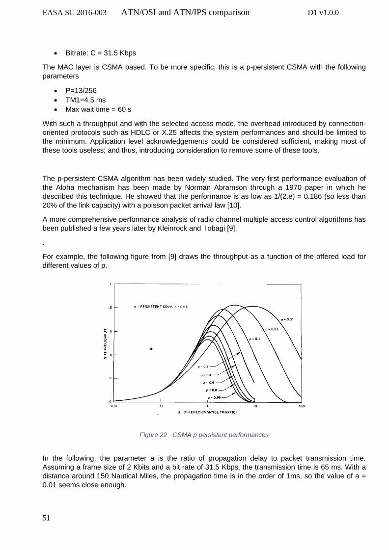
EASA SC 2016-003 ATN/OSI and ATN/IPS comparison D1 v1.0.0
51
Bitrate: C = 31.5 Kbps
The MAC layer is CSMA based. To be more specific, this is a p-persistent CSMA with the following
parameters
P=13/256
TM1=4.5 ms
Max wait time = 60 s
With such a throughput and with the selected access mode, the overhead introduced by connection-
oriented protocols such as HDLC or X.25 affects the system performances and should be limited to
the minimum. Application level acknowledgements could be considered sufficient, making most of
these tools useless; and thus, introducing consideration to remove some of these tools.
The p-persistent CSMA algorithm has been widely studied. The very first performance evaluation of
the Aloha mechanism has been made by Norman Abramson through a 1970 paper in which he
described this technique. He showed that the performance is as low as 1/(2.e) = 0.186 (so less than
20% of the link capacity) with a poisson packet arrival law [10].
A more comprehensive performance analysis of radio channel multiple access control algorithms has
been published a few years later by Kleinrock and Tobagi [9].
.
For example, the following figure from [9] draws the throughput as a function of the offered load for
different values of p.
Figure 22 CSMA p persistent performances
In the following, the parameter a is the ratio of propagation delay to packet transmission time.
Assuming a frame size of 2 Kbits and a bit rate of 31.5 Kbps, the transmission time is 65 ms. With a
distance around 150 Nautical Miles, the propagation time is in the order of 1ms, so the value of a =
0.01 seems close enough.

EASA SC 2016-003 ATN/OSI and ATN/IPS comparison D1 v1.0.0
52
We can then notice on the figure that the optimal p value is close to 0.03; the value chosen for VDL
Mode 2 (p=13/256=0.05) is thus good. However, even if the throughput may seem correct (close to
80 % of the link capacity), one must notice that this maximum needs a very high input load (close to
160 % of the link capacity). This means that, to reach this “optimal” value, half of the offered frames
must be lost.
Consequently, the main advantage of the p-persistent CSMA MAC layer is that it is really simple to
implement. It does not need any synchronisation between the devices or any allocation mechanism.
However, the loss probability is high and thus recovery mechanisms are needed in the upper layers.
The transmission time for a data packet (length L=2048 bytes) is TL= 520ms and for an
acknowledgement (length l=20 bytes) Tl = 5ms. The chronogram for a successful transmission is
shown in the following diagram.
Figure 23 Interaction model
During this process, a frame is sent, and an ACK is used to acknowledge the frame. However, the
frame can be lost (second frame in the figure) as well as the ACK (first case in the figure). With the
help of a retransmission timer, the frame is retransmitted until the acknowledge is received. Of
course, most protocols use a maximum number of retransmissions.
We are assuming a frame error probability q and that frame losses are supposed uniformly distributed
and independent. We are assuming the same probability for both data and ACK messages. The
probability for a successful transmission without any retransmission is thus .
The probability for a successful transmission after k retransmissions is .
The duration of one step (data and SYN transmission, successful or not) is
where is the propagation time. We assume here that the retransmission
timer is as short as possible, so our result is rather optimistic on this point.
The expected value for a successful transmission duration in then
Of course, as expected, this value depends heavily on the frame loss probability. Therefore, the
residual frame error rate given by the medium access algorithm is an important value for the
application performance.

EASA SC 2016-003 ATN/OSI and ATN/IPS comparison D1 v1.0.0
53
7.1.2. LDACS Physical and MAC layers
We will not describe here LDACS system. Physical layer has been designed with state-of-the-art
features such as high efficiency modulation and coding schemes, clever access mode. The residual
bit error rate is thus significantly improved with LDACS than with older systems, while the link
efficiency is much higher.
The most significant improvement, as far as the network architecture design is concerned, is the
resource allocation strategy through the MAC scheme. The important point to keep in mind here is
that the random procedure previously described for VDL Mode 2 is only used once in LDACS for an
AS to enter the system. We will describe the entry process in the next subsection.
The consequence with LDACS, is that transmission resources are allocated and reserved to the AS.
Access is thus guaranteed in each frame, knowing for sure that it will not collide with any other
transmission. Such systematic and deterministic resource allocation guaranty the exchange of an AS
request to get allocation of communication resources for its use in the next frame. Frame losses are
thus only bit error transmission, whose rate has been dramatically shortened by selection of robust
modulation scheme and appropriate coding technique.
7.1.3. Radio-link infrastructure entry process
During the logon phase at link layer level, the AS enters the radio-link network, and the link is
established between the AS and the ground station in the radio-link network. This process can take
place either during the initial entry of a new aircraft within the system, or during a handover due to
mobility (e.g. change of ground station) or load sharing (e.g. change of channel like in VDL Mode 2).
7.1.3.1. VDL Mode 2 entry process
In VDL Mode 2 system, this process can be described by the following picture.
Figure 24 VDL Mode 2 initial entry process
An important point to be noticed here, is that each message is sent using the MAC algorithm of the
radio-link technology. Each message can experiment a long delay as previously described, due to
collision or frame loss. For example, this delay in VDL Mode 2 with the CSMA access mechanism
heavily depends on the system load on the channel. In that case, the delay is almost a consequence
of the p-persistent Aloha mechanism.

EASA SC 2016-003 ATN/OSI and ATN/IPS comparison D1 v1.0.0
54
However, in case of overload and high frame error rate in the radio-link (limit of radio coverage),
some time-outs may occur leading to re-transmissions and the associated excessive overhead.
7.1.3.2. LDACS entry process
With LDACS technology, the logon procedure is far more complex. First, a message exchange similar
to the XID_CMD_LE/XID_RSP_LE occurs. Then, the AS sends a CELL_RQST control message to
the ground station within the radio-link network through the RACH channel of the return link to
request cell entry. In response, the ground station uses the CCCH channel of the forward link to grant
the AS all the needed codes (Subscriber Access Code, Control Offset, …) with a CELL_RES
response message.
In this process, the RACH channel is used; this is the only contention-based channel. The channel is
used for cell access procedure which is implemented with the following algorithm:
The AS sends a request on the RACH channel. This request can be lost before the contention process. For example, a collision may occur with another transmission from a different AS. The AS starts a timer.
On reception of the AS, the ground station answers through the CCCH channel.
If a time-out occurs on the AS, then the request must be transmitted again after a delay that is increased exponentially; the delay is doubled after each failed attempt.
This process introduces a random and possibly long delay, just as the one in VDL Mode 2. However,
it is fundamental to understand that by design it is the sole random delay (except the delay introduced
by retransmissions due to bit error rate) in such a system.
Of course, the system must be well enough designed to allow the successful completion of this
process. If an AS cannot receive a positive answer from the ground station, it will not be able to log
on to the system and communicate.
7.1.4. Radio-link network mobility
7.1.4.1. VDL Mode 2 mobility
For VDL Mode 2, the setup mechanism (frames SABM/UA) is implemented with the help of the
previously described frame. For example, the XID_ frames have been introduced in AVLC to tackle
mobility management. Therefore, this setup will not introduce any additional delay.
With AVLC, the process previously described almost applies, and thus, with the help of the design of
these protocols (AVLC is an HDLC enhancement with mobility dedicated mechanisms) the delays are
roughly the same. For example, with the collaboration of the two VDL ground stations, an AS is
running a make-before-break handover implemented through XID_CMD_HO frames sent on both the
new link and the old one.

EASA SC 2016-003 ATN/OSI and ATN/IPS comparison D1 v1.0.0
55
7.1.4.2. LDACS mobility
In LDACS, some extra mechanisms are needed to implement mobility. There are multiple options
available and the most relevant here is probably a network-based one. If the AS remains within a
single operator network, it is possible to keep its IP address unchanged. With PMIPv6, the AS
mobility can then be implemented on the ground station, without the need for any dedicated message
exchange on the radio-link. This means that in such a situation, communications with the AS can
continue seamlessly.
7.1.5. Some performance consideration
Let us briefly sum up the multiple elements that constrain communication performance in a VDL
Mode 2 system.
The physical layer implements a modulation and coding scheme providing a theoritical bit rate
of 31.5 Kbit/s.
The medium access control then allows, in the very best case, to reach 80% of this bitrate, so
at most 25 Kbit/s.
The frame format (header and trailer) will then introduce a small performance loss (e.g. 3%).
Because of the link budget, the Packet Error Rate (PER) reduces the link performance. Some
packets are “lost” (such packets are received with some erroneous bits, detected by AVLC).
The consequence of such a loss is a retransmission, and then an increased load on the
system. PER is really complex to compute, as it heavily depends on reception conditions
(antena gain, transmission power, distance, noise, …)
The protocol overhead (connection setup, mobility management) introduces some delay in the
communication scheme. However, the consequence on the link performance (overall
throughput) is low if such events are rare. At the application level, the delay introduced in the
setup procedure is also low (a few milliseconds for 150 NM for example).
Finally, and that is probably a salient issue, the low remaning bitrate must be shared by all the
aircraft sharing the same VDL Mode 2 channel. Furthermore, each aircraft uses the channel
for two different application domains (AOC and ATC).
As a consequence each application could expect only a few hundreds of bits per second capacity,
without any guarantee (non deterministic behaviour).
It is then clear that the performance issue can not be deal with by a single tool. The whole
architecture must be designed consistently based on the available technologies. The legacy
TP4/X.25/AVLC/VDL2 is a perfect example of such a design. The main issue is the physical layer
performance, so the most efficient transmission technique has been used, completed by lots of
reliability enhancement protocols. As a consequence, an important overhead impairs the global
performance of the system.
A more modern system can now be implemented with a far less error/loss prone radio management
(better coding scheme, more efficient medium access control, …). As a consequence, the protocol
stack can be alleviated, eg replacing X.25 by IP. HDLC could also be withdrawn.

EASA SC 2016-003 ATN/OSI and ATN/IPS comparison D1 v1.0.0
56
7.2. TCP/IP performance
In the previous section, we have identified and described the differences between VDL Mode 2 and
LDACS radio-link system having major consequences on protocol behaviour and performances. In
this section, we are analysing the TCP/IP architecture and demonstrating that it is the most suitable
choice for transport over LDACS. LDACS is a far more efficient radio-link technology which brings the
largest improvements in comparison with the legacy VDL Mode 2 over ATN/OSI.
The following figure describes the protocol stack used in the IP option.
Figure 25 The IP protocol stack
7.2.1. TCP overhead
As far as the downlink aircraft data is concerned, the overhead can be evaluated as follows:
TCP connection setup and teardown can be described easily as the following:
z
Figure 26 TCP initiation interactions
Data encapsulation is made in a very simple way in TCP:
Figure 27 TCP data encapsulation

EASA SC 2016-003 ATN/OSI and ATN/IPS comparison D1 v1.0.0
57
The overhead for each message can be evaluated very easily. OHTCP=40 + OHTCP_OPT where
OHTCP_OPT depends on the options that have been activated. These options depend on the TCP
extensions implemented. Whatever the flavour of TCP, the options field cannot exceed 40 bytes
because the TCP header length is limited to 15 words of 32 bytes.
7.2.2. TCP connection setup
As previously stated, the TCP connection setup is a three-way handshake. It introduces a 1.5 RTT
delay before any data transmission. If the connection is to be set up for every application message
and ACK exchange, the total cost would be excessive, but it could be acceptable for some of the
aviation safety services. However, if the connection can be set up once for all (or a least once every
time a handover occurs due to network mobility change), the overhead can be neglected. This could
be a way to optimise the overhead in function of the quality of service defined at application level.
Using the same figures as in the previous sections, the duration of a three-way handshake, assuming
a frame length of:
LSYN = LACK = 64 bytes is given by:
T3w = TSYN + TP + TSYN + Tp + TACK = 50 ms
Here again, we assume the longest distance between the aircraft and the ground station (150 Nm).
This delay has been computed assuming a perfect behaviour of the underlying layers (no link layer
retransmission, and a successful MAC access), and assuming short delays and high efficiency on the
ground network.
The main drawback of such a “one connection per message” scheme, is the extra load it implies. As
soon as the application wants to send a new message, it needs to wait tens of milliseconds for the
connection setup, which is acceptable, but the network must send another three more (small)
messages, leading to more collisions. However, if the delay is kept low, a teardown of the TCP
connection after an application transmission can be considered as an option; followed by the setup on
a new connection for the next message.
If the TCP connection is not turned down, but the applications do not exchange messages, no TCP
message is sent either. This is a good point for the system load, however a consequence is that TCP
is not aware of any underlying disconnection that could turn of the connection. Some TCP flavours
implement a “keep alive timer” so that an empty segment (a probe, with the smallest size) is sent on a
periodic basis to identify a disconnect event so that the application can re-open the connection as
soon as possible in order to be available for the next application transmission.

EASA SC 2016-003 ATN/OSI and ATN/IPS comparison D1 v1.0.0
58
7.2.2. IP overhead
IP being by nature connectionless, the overhead associated is very low.
Here again, with a very simple encapsulation such as the following, we can easily compute IP
overhead.
Figure 28 IP encapsulation
IPOH = IPH + IPO
where
IPH is the header length, IPH, v4 = 20 for IPv4 and IPH, v6 = 40 for IPv6.
IPO is the size of the options, if any. Usually IPO = 0 for IPv4. IPO depends on the features that
are used with IPv6.
7.2.3. Link layer overhead
TCP/IP is widely used over IEEE networks through an 802.2 logical link control type 1 (aka LLC1).
This protocol is quite simple and connection-less, so that the overhead is small and constant.
One can also imagine the use of HDLC or a similar protocol for layer 2. The associated signalling
overhead must then be considered such as the setup procedure and the acknowledge mechanisms.
As for the transport layer, if a connection-oriented protocol (e.g. HDLC, LLC3 …) is used for
performance reasons, then the question of the life duration of the connection arises.
7.2.4. Network and domain mobility
Mobility is an important feature and, depending on the level used to implement it, the overhead can
be very different.
Mobile IP introduces some latency and some significant packet losses. If no message is transmitted
during a handover, the change is transparent for the upper layers. However, if a message is send
during a handover, it can be significantly delayed due to the need to wait for the new link to be set up.
The main issue with handover management take place in implementation at the lower layer (link
layer). If the physical layer deficiency leads to link outages, the upper layers can buffer the messages
and ensure that they will be delivered without loss but with significant delay. The buffering process
and the retransmission mechanisms involved (acknowledgement, retransmission timer, …)
dramatically increase the end-to-end delay.
In the case of VDL Mode 2, a make-before-break mechanism (through the XID_CMD_HO frame) is
included, but the random nature of the MAC mechanism can lead to poor performances in case of

EASA SC 2016-003 ATN/OSI and ATN/IPS comparison D1 v1.0.0
59
channel loading above 40%. Resource reservation-based schemes such as those introduced with
LADCS are far more efficient to build robust handover procedures alleviating consequences on high
layer protocols.
If multiple links must be used at the same time, MP-TCP can be useful to minimise this delay with the
help of redundant links. For example, a satellite link could be used when the terrestrial radio link
technology performance decreases under a predefined threshold (possibly suggesting an upcoming
handover). Then this multiple path could be used either for load balancing, needed because of a high
load of the main link, or for reliability if the terrestrial link becomes unusable during the handover.
7.2.5. Security
Security is a real issue, so the most relevant tool must be chosen wisely. Encryption algorithms used
with IPSec can introduce large overhead (tens of bytes for each message), and the architecture setup
(key exchange, …) could lead to a large amount of signalling messages. More studies are probably
necessary to define the most efficient trade-off.
However, the choice of the security architecture, protocols and algorithms is outside of the scope of
this study. The overhead depends on this choice, not on the protocol stack that is used on the radio-
link (VDL Mode 2, LDACS) or at the network layer (connection mode X.25 of connection-less IP).
IPSec has been designed to suit IP needs and weaknesses, but it can be adapted to other
technologies. Cyphering can be implemented in different layers, from physical to application layer,
depending on the system needs (can we transmit the addresses, the headers, … on the air without
any encryption?). This choice can have consequences on the implementation of the networking stack,
but not on its design.
7.2.6. TCP add-ons
Some relevant TCP add-ons have been described in the previous section. Most of them may
generate only limited additional overhead and signalling messages. Most of these options aim at
improving the overall performance. Some options have been defined to introduce new features. The
limited overhead they introduce must be assessed in a trade-off between features and performance.
If the foreseen applications are short messages (several Kbytes) sent from and to the AS and the GS
through a network in which the radio-link is the bottleneck, almost any modern flavour of TCP is
suitable: compound, cubic, or even New Reno. With the help of a high CWND initial value (e.g. 10
segments, a widely used value), the whole message will be sent in a row, avoiding the slow-start
algorithm. The differences between all these versions is purely algorithmic, so there is no extra
overhead here.
One of the most recent TCP loss detection algorithms is RACK. Among its advantages, this algorithm
can repair tail drop. If the last segment of an application message is lost, TCP needs a long delay
before delivering the full message (with the retransmit segment data). In the aeronautical context, this
leads to increase the end-to-end delay.
RACK is therefore an interesting option to implement. It does not generate any extra overhead by
itself, however, it needs TCP SACK (Selective ACKnowledge) and timestamps to be implemented.
Timestamps is a 10 bytes option (increasing TCP header length from 20 to 30 bytes). TCP SACK
overhead can change depending on the losses, however the TCP overhead cannot be larger that 60

EASA SC 2016-003 ATN/OSI and ATN/IPS comparison D1 v1.0.0
60
bytes and, in this context, it is very unlikely that a SACK option would span across more than 10
bytes.
Multipath TCP is also an important TCP enhancement that could be considered. First, it creates no
constraints and no specific overhead. It is not yet widely deployed in the Internet because its
deployment would involve a long process to deploy and depend upon the motivations of users and/or
providers. In the ATN context and in the perspective of a multilink requirement to support advanced
ATM applications, Multipath TCP should be considered as a useful mechanism to manage handover
procedures and load balancing among multiple links.
7.2.7. Summary of the analysis
A major conclusion of this part is that modern TCP/IP implementation is a good solution for ATN
deployment. This protocol stack is both simple and versatile. It can ensure:
the needed reliability for such communications with the help of a connection-oriented protocol
such as TCP;
the efficient use of scarce resources that come with the available physical layer;
a rich toolbox allowing mobility, security, and all needed features.
On one hand some connection-oriented protocols can be used for communications lasting up to
several dozens of minutes, with only few short messages exchanged. In this case, the same
connection is used during the whole communication, thus drastically limiting the signalling overhead.
On the other hand, stacking several connection-oriented protocols (e.g. TP4/X.25/HDLC) is
counterproductive. The multilayer acknowledgement mechanisms will introduce large delays in the
communication.
Mobility can be implemented through multiple mechanisms. As far as TCP is planned to be used as
the transport protocol, MP-TCP seems to provide very interesting and promising capabilities for a
multilink architecture. This option allows some redundancy with the help of simultaneous multiple
links during the hand over and/or with an additional backup link such as satellite. As we recall MP-
TCP does not introduce any significant overhead.
However, mobility can also be implemented through Mobile IP (MIPv4 or MIPv6, depending on the
relevant IP flavour). This could be useful depending on the addressing and routing schemes of the
various operators involved. The extra delay introduced by triangular routing can be kept very low and
less significant than the delay of the radio-links used by the plane.
Some improvement schemes such as HMIPv6 can be useful to deal with the need to have multiple
links used simultaneously.
A critical question is the choice of the MAC layer algorithm. CSMA has some scalability issues and
may not be relevant with increasing channel load. A centralised allocation scheme will be able to
guarantee some form of quality of service, but because of the sporadic nature of communications
(one message every tens of minutes), a large amount of resources may be unnecessarily allocated. A
polling mechanism or a dedicated slotted scheme could be introduced to alleviate the collision
probability.

EASA SC 2016-003 ATN/OSI and ATN/IPS comparison D1 v1.0.0
61
8. Conclusions and recommendations
This study has been conducted following the steps identified in the Terms of Reference.
The historical background of ICAO activities regarding air/ground mobile data-link communications
have been addressed as a first step. It shows that the choice made by ICAO more than 25 years ago
are only starting to be implemented today in a very limited part of the ICAO member states.
The second step justifies why ISO protocols have been selected by ICAO to satisfy the operational
needs for mobile air/ground data communications. These choice was fully justified at the time they
have been made. But taking into consideration the very late deployment of the selected technologies
(i.e. at least 25 years later in a limited part of the world), it is obvious that significant progress have
been made in the technology domain that could provide much better results today. This step also
highlights the role of the Transport layer protocol to ensure the end to end connectivity within the
aviation mobility context.
The third step of this study compares the two options (i.e. ATN/OSI and ATN/IPS) regarding
functionalities and associated performances. The main element resides in the fact that the IP world
has been developed with the intend to simplify the network layer protocols and therfore to gain in
performances by reducing these intermediate overhead.
The last step focuses on the new developments completed or on-going within the IP domain and their
potential benefits for aviation safety communication needs.
As presented in this report, IP Suite has been developed in a continuous manner to respond
effectively to the evolution of the usage of these protocols.
At the start of IP development, the major need was the interconnection of various machines through
fixed network in the most efficient manner with the shortest latency associated with data exchanges.
As a foundation principle, the protocol is built upon the assurance that the basic capacity of the
underneath communication infrastructure is not constrained and that the exchange data flow is not
limited by the performance of this infrastructure (i.e. very low bit error rate). This foundation principle
is still valid today with the extended usage of IP Suite. The simplification of the protocol interactions at
network level is based upon this key principle. Therefore, if the communication infrastructure is not
performing correctly (i.e. limited throughput or poor BER), the efficiency of the IP Suite will not be
noticeable.
This indicates that the logical choice of the IP model must be consistent with the behaviour of
the radio-link communication layers. IP mechanisms are working well if the radio-link
technologies are performing correctly.
A highly significant change introduced in the IP Suite was the version 6 of IP. This version tackled a
key issue associated with the expansion of IP usage in wide area networks, including the emerging
mobile networks. IP V6 provide an answer to the limited addressing capability of IP V4, thus providing
the capability for global addressing necessary to cope with large-scale wide area networks.
Mobility was not the concern of the IP initial developers, even if the mobility issue has emerged
quickly with the usage of IP-based services in all commercial mobile communication networks. Here
again, IPv6 is very useful with its address scheme.

EASA SC 2016-003 ATN/OSI and ATN/IPS comparison D1 v1.0.0
62
In the case of ATM applications, communication performances are always linked to a safety level
requirement. The probability to complete an end-to-end transaction within a given time duration is
always defined considering the operational consequence of a non-completion of the transaction.
This is the main driver that has conducted to select the ISO protocol stack. It was embedding several
secure acknowledgments at the different levels of the protocol stack up to the operational
acknowledgment at end-user level. The negative counterpart is the addition of signalisation, creating
a significant overhead loading to the communication infrastructure.
The TCP service provided over an IP protocol stack is based upon mechanisms ensuring the
establishment of the end-to-end connection and the acknowledgment of the transaction at its level,
usually complemented by the acknowledgment at the application level.
Regarding the IP part, the analysis shows that the mechanisms used in the signalisation have been
drastically simplified in comparison to the X.25 networking protocol. This choice was made because
the underneath communication infrastructure considered at the start of IP development was
performing well and does not suffer from capacity limitations.
IP is thus providing a very efficient interface at network level essentially using a connection-less
interaction in the network. The benefits of the connection-less mechanism is a significant reduction of
the signalisation at the network layer in comparison to the similar function in the ISO environment (i.e.
mainly the X.25 contribution). The quality and guaranty of the transaction is achieved within the
communication infrastructure using TCP allowing a connection-oriented transaction.
Therefore, one of the possible trade-off for the medium term will be to promote radio communication
technologies that perform well (deterministic behaviour using communication resources management
mechanism) and are able to be integrated within an IP environment or within an ISO environment.
This would allow for a smooth transition and the possibility to benefit from the new technologies even
in a legacy environment (i.e. ATN/OSI X.25 environment).
The full migration to an IP environment will provide a capacity benefit by removing the overhead
generated by the X.25 interface, that is part of the ISO environment. Several new technologies that
are either ready to be deployed (i.e. AeroMACS16), at the end of the development phase (i.e. Iris
Precursor) or at the start of the development phase (i.e. LDACS) have been designed to provide a
good behaviour of the radio link with low bit error rate, efficient entry mechanism and resources
management. These features are necessary to ensure consistency with the IP protocol foundation
that is connectionless.
The simplification of the signalisation within the various layers of the communication stack, was one
of the main motivation to move towards IP. The other driver was the recognition of IP as a de facto
industry standard for all mobile communications and therefore the availability of IP software
component on the market.
Regarding this last argument, it is not yet clear if such COTS IP software package from the market
could satisfy the regulatory requirements for software safety assurance applicable to the aeronautical
safety communication services.
16 It must be noted that AeroMACS technology has been selected to capitalise upon a large scale production of COTS products without the need to re-develop it for the benefit of the aviation community. Unfortunatly the mobile communication world wide market has evolved very quickly making WIMAX technology obsolete and replace by LTE technology. The consequence of this technology move is that the availability of COTS product is already critical and its production is now stopped. At this stage there is no identified development of avionic component that could lead to the use of such technology for mobile (i.e. aircraft at airport)

EASA SC 2016-003 ATN/OSI and ATN/IPS comparison D1 v1.0.0
63
On top of these considerations, there is one topic that still needs to be more deeply addressed, it is
the cybersecurity robustness of these protocols. Today, the level of security that can be guaranteed is
difficult to assess, subject to interrogation and remains the main barrier to widespread use and
deployment of IP for aeronautical safety services in the aircraft.
Coping with this security issue, will require implementing specific security measures beyond the Air Traffic Management/Control services, to protect the aircraft from external threats.
Standardisation working groups are investigating several potential cybersecurity mitigations (i.e. EUROCAE WG-72). ICAO has started the Secure Dialog Service subgroup to provide, at application-level, a network-agnostic security solution. Additionally, the ARINC Industry Activities Airlines Electronic Engineering Committee (AEEC) Network Information Security group is working to develop complementary requirements to be incorporated within the IP standards as appropriate. The completion of the standardisation and the associated validation activity for the new radio communication technology supporting Safety services is a long process. This process must be completed to initiate the deployment of this new technology and its initial operation. Europe is today the sole area in the world implementing ATN/OSI associated with VDL mode 2 technology to support the initial introduction of data-link services in full compliance with ICAO standards. Such deployment is governed by the EC Regulation (EC-2009/29) and the deployment is already very advanced even though it is not yet completed. Due to some technical problems that have been detected during the first phase of the deployment, the current EC mandate has been delayed by 5 years. The ground deployment completion was fixed in February this year while the aircraft deployment is fixed for February 2020. In the meantime, several actions have been undertaken to address these technical issues, including the deployment of a multifrequency infrastructure over Europe. The investment associated with this deployment programme both on air and ground sides is massive. The technology, ATN/OSI & VDL mode 2, is thus very unlikely to be replaced by a new one before 2030 +. For European stakeholders the challenge caused by the alternate ICAO solution (i.e. ATN/IPS) is to have the guaranty that it will fit with the operational requirements (including safety and associated software SWAL) for future services emerging in this long-time frame (after 2030). According to agreed ICAO policy, the ATN/IPS is the convergence technology for worldwide data link deployment and it is associated with new radio-link technologies based upon IP (i.e. LDACS, AeroMACS, Satellite,). The deployment of these technologies is not planned before 2035 (except AeroMACS17 that is ready but limited to airport surface communications and also facing some COTS obsolescence issues). Based upon these conclusions, the following recommendations are made:
1. Considering the general constraints associated with the available aviation spectrum and the limited expected bandwidth of the communication system in these frequency bands, overhead generated by the various protocol layers should be limited. This requirement should lead to consider IP as a good approach at network layer level.
2. Considering the central need for mobility, the basic use of MIP V6 should be the right baseline
for mobility management.
3. Considering the direct negative impact of the protocol overhead on end to end performances, the improvements to MIP V6 baseline should also contribute to reduce the overall protocol
17 There is no plan identified for AeroMACS deployment in Europe today

EASA SC 2016-003 ATN/OSI and ATN/IPS comparison D1 v1.0.0
64
overhead and to use efficiently the radio-link limited resources. They include inter alia: Multi Path TCP, HMIPv6 and FMIPv6.
4. New radio communication technologies should be designed in such a way that they can
provide the appropriate interface to an IP network protocol and to the X.25 SNDCF network interface for transition reasons. This would allow these technologies to be introduced during the transition from ATN/OSI existing network toward a future ATN/IPS environment.
5. TCP protocol layer should be used on top of IP to provide the appropriate connection-oriented
transactions satisfying the safety requirement objective of the aviation safety communication services.
6. Security aspects and requirements should be addressed urgently to validate the IP technology potential and eventually to define appropriate mitigations to integrate in the current IP protocol.
7. Considering the intended use of the future ATM data link services and their safety associated
requirements, the software assurance constraints for the future service must be assessed to define the certification baseline that should be attached to the whole communication protocol stack in the near future.

EASA SC 2016-003 ATN/OSI and ATN/IPS comparison D1 v1.0.0
65
Bibliography
[1] Pagano, Michele, and Raffaello Secchi. "A survey on TCP performance evaluation and modeling." Proc. of Int'l Working Conf. on Performance Modelling and Evaluation of Heterogeneous Networks (HET-NET 2004), Ilkley, UK. 2004. [2] Sangtae Ha, Injong Rhee, and Lisong Xu. 2008. CUBIC: a new TCP-friendly high-speed TCP
variant. SIGOPS Oper. Syst. Rev. 42, 5 (July 2008), 64-74.
[3] TAN, Kun, SONG, Jingmin, ZHANG, Qian, et al. A compound TCP approach for high-speed
and long-distance networks. INFOCOM 2006.
[4] Y. Cheng, N. Cardwell, N. Dukkipati and P. Jha. “RACK: a time-based fast loss detection
algorithm for TCP”. Internet-Draft.
[5] Costin Raiciu, Dragos Niculescu, Marcelo Bagnulo, and Mark James Handley. 2011.
Opportunistic mobility with multipath TCP. In Proceedings of the sixth international workshop on
MobiArch (MobiArch '11). ACM, New York, NY, USA, 7-12. DOI:
https://doi.org/10.1145/1999916.1999919
[6] A. T. Campbell, J. Gomez, Sanghyo Kim, Chieh-Yih Wan, Z. R. Turanyi and A. G. Valko,
"Comparison of IP micromobility protocols," in IEEE Wireless Communications, vol. 9, no. 1, pp. 72-
82, Feb. 2002.
[7] ETSI. “VHF air-ground Digital Link (VDL) Mode 2; Technical characteristics and methods of
measurement for ground-based equipment; Part 1: Physical layer and MAC sub-layer “. ETSI EN
301 841-1 v1.3.1, 2010.
[8] ETSI. “Electromagnetic compatibility and Radio spectrum Matters (ERM); VHF air-ground
digital Link (VDL) Mode 2; Technical characteristics and methods of measurement for ground-based
equipment; Part 2: Upper layers”. ETSI EN 301 841-2 V1.1.1
[9] Kleinrock, Leonard, and Fouad Tobagi. "Packet switching in radio channels: Part I--Carrier
sense multiple-access modes and their throughput-delay characteristics." IEEE transactions on
Communications 23.12 (1975): 1400-1416.
[10] Norman Abramson. “THE ALOHA SYSTEM—Another alternative for computer
Communications”. AFIPS’70, Fall joint computer conference, 1970.

EASA SC 2016-003 ATN/OSI and ATN/IPS comparison D1 v1.0.0
66
Annex 1
FANS committee activities and reports
FANS Phase I
On 25 and 28 November 1983, the ICAO Council established the Special Committee on Future Air Navigation Systems (FANS) with the following terms of reference:
“To study technical, operational, institutional and economic questions, including cost/benefit effects, relating to future potential air navigation systems; to identify and asses new concepts and new technology, including satellite technology, which may have future benefits for the development of international civil aviation including the likely implications they would have for users and providers of such systems; and to make recommendations thereon for an over-all long-term projection for the co-ordinated evolutionary development of air navigation for international civil aviation over a period of the order of twenty-five years”
The Committee made a comprehensive assessment of the characteristics and the capabilities of the, at that time, present air navigation systems and of their implementation in various parts of the world. Their shortcomings around the world amounted to essentially three factors:
the propagation limitations of current line-of-sight systems and/or accuracy and reliability limitations imposed by the variability of propagation characteristics of other systems;
the difficulty, caused by a variety of reasons, to implement present CNS systems and operate them in a consistent manner in large parts of the world; and
the limitations of voice communication and the lack of digital air-ground data interchange systems to support automated systems in the air and on the ground.
Four years after the FANS Committee started its work and at the end of its fourth and final meeting (Montreal, 2 – 20 May 1988), the Committee presented to the ICAO Council and to the international aviation community at large, a consolidated proposal for the future global air navigation system. (See ICAO Doc 9524, FANS/4 REPORT)
Essentially, the Committee concluded that the application of satellite technology was the only then viable solution that would enable international civil aviation to overcome the shortcomings of the, at that time, current CNS systems and to fulfil the needs and requirements of the foreseeable future on a global basis.
The main features of the “new technology” global concept of CNS system proposed by the committee may be recapitulated as follows:
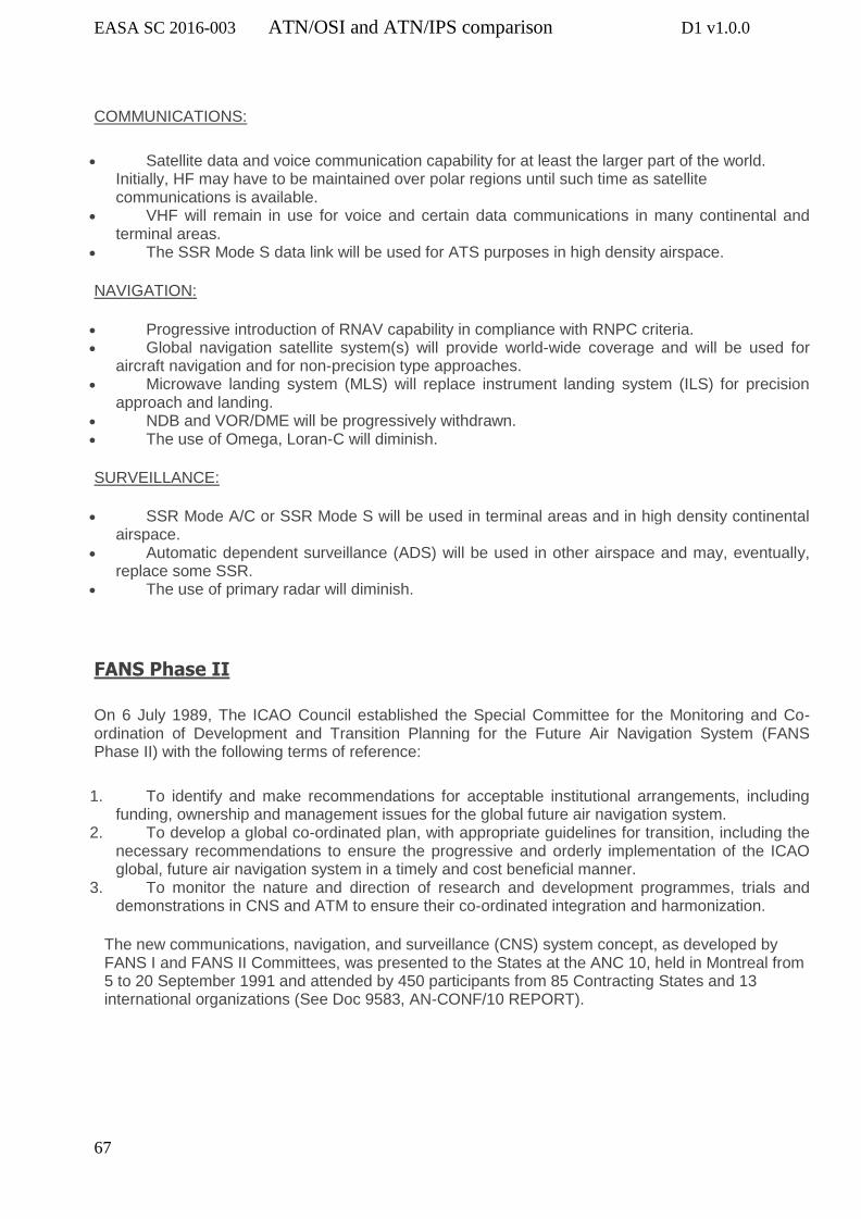
EASA SC 2016-003 ATN/OSI and ATN/IPS comparison D1 v1.0.0
67
COMMUNICATIONS:
Satellite data and voice communication capability for at least the larger part of the world. Initially, HF may have to be maintained over polar regions until such time as satellite communications is available.
VHF will remain in use for voice and certain data communications in many continental and terminal areas.
The SSR Mode S data link will be used for ATS purposes in high density airspace.
NAVIGATION:
Progressive introduction of RNAV capability in compliance with RNPC criteria. Global navigation satellite system(s) will provide world-wide coverage and will be used for
aircraft navigation and for non-precision type approaches. Microwave landing system (MLS) will replace instrument landing system (ILS) for precision
approach and landing. NDB and VOR/DME will be progressively withdrawn. The use of Omega, Loran-C will diminish.
SURVEILLANCE:
SSR Mode A/C or SSR Mode S will be used in terminal areas and in high density continental airspace.
Automatic dependent surveillance (ADS) will be used in other airspace and may, eventually, replace some SSR.
The use of primary radar will diminish.
FANS Phase II
On 6 July 1989, The ICAO Council established the Special Committee for the Monitoring and Co-ordination of Development and Transition Planning for the Future Air Navigation System (FANS Phase II) with the following terms of reference:
1. To identify and make recommendations for acceptable institutional arrangements, including funding, ownership and management issues for the global future air navigation system.
2. To develop a global co-ordinated plan, with appropriate guidelines for transition, including the necessary recommendations to ensure the progressive and orderly implementation of the ICAO global, future air navigation system in a timely and cost beneficial manner.
3. To monitor the nature and direction of research and development programmes, trials and demonstrations in CNS and ATM to ensure their co-ordinated integration and harmonization.
The new communications, navigation, and surveillance (CNS) system concept, as developed by FANS I and FANS II Committees, was presented to the States at the ANC 10, held in Montreal from 5 to 20 September 1991 and attended by 450 participants from 85 Contracting States and 13 international organizations (See Doc 9583, AN-CONF/10 REPORT).

EASA SC 2016-003 ATN/OSI and ATN/IPS comparison D1 v1.0.0
68
Annex 2
The main steps in the FANS data-link airborne capability evolution
ICAO established special committee on the Future Air Navigation System (FANS) charged at developing the operational concepts for the future of Air Traffic Management (ATM)
1985
ICAO FANS Committee Report published. Transition from analog CNS to digital CNS ATM system. ICAO created ADS panel to standardise ADS/CPDLC applications, initially designed to be implemented within the ATN environment
1988
As it was uncertain when the ATN network would happen, Boeing decided to develop a FANS-1 ADS/CPDLC package using ACARS network. The package was certified in 1995. Initial ANSP implementations
1995
Airbus ‘‘FANS-A’’ Package also certified. Collectively, Boeing and Airbus implementations are referred to as FANS-1/A.
2000
ATN-Based CPDLC Implemented in Maastricht UAC under the Link 2000+ program
2004
FANS-1/A implemented by ANSPs in many locations worldwide 2005 onward

EASA SC 2016-003 ATN/OSI and ATN/IPS comparison D1 v1.0.0
69
Annex 3
AEEC IP activities
Following the adoption of a new task in September 2015 (APIM 15-004 during AEEC Mid-Term
Session), the Internet Protocol Suite (IPS) for Aeronautical Safety Services subcommittee has been
created. This subcommittee is co-chaired by Airbus and Boeing, with active participation from other
key industrial partners (Honeywell, Rockwell, Airtel ATN, Thales, Rockwell IMS, SITA …) and support
from FAA and Eurocontrol.
The goal of this group is to develop an industry roadmap and a development plan for defining
IPS for Aeronautical Safety Services, including airborne, ground-based and space-based
communication systems, coordinating with aviation Standards Development Organizations (SDOs),
Air Navigation Service Providers (ANSPs) and others with an interest.
The IPS Subcommittee is preparing a detailed technical definition of IPS for aeronautical safety
services in a new ARINC Standard, in a 2 steps approach:
Step 1 (completion planned by mid 2017) : Roadmap for standardization and main architecture impacts of IPS introduction,
Step 2 (completion planned by mid 2019) : Development of an ARINC Standard for IPS.
During step1, the subcommittee has define the perimeter that needs to be standardized for IPS (air-
to-ground and end-to-end) and the timeframe in which each part shall be standardized by the
appropriate standardization body (ICAO, RTCA, EUROCAE, ARINC).
The output of Step 1 is the roadmap that has been completed in 2017. This roadmap anwers the
following questions:
What shall be standardized (equipment? Interfaces? Protocols? Performances? Profiles?
Which body shall support the standardization (AEEC, ICAO, RTCA, EUROCAE…)?
When the standardization shall be achieved?
How the standards will be validated?
This roadmap, endorsed by all stakeholders, addresses the following main topics:
a) Clarification of the scope to be addressed by ATN/IPS

EASA SC 2016-003 ATN/OSI and ATN/IPS comparison D1 v1.0.0
70
• Definition of long-term needs for IPS for aeronautical safety services • Who will be the “users” of IPS (ATC, AOC Regularity of Flight)? • Which functional, performance, safety and data security requirements apply? • Which communication means will be supported?
b) Deployment roadmaps and their impacts on the solution
• Deployment roadmaps (Europe and US) including transition phases during which ACARS, ATN/OSI, and IPS will co-exist
• How aircraft equipped with ACARS, ATN/OSI and aircraft with IPS will be accommodated?
c) High-level Aircraft architecture
• Impact of data security requirements • ATN/IPS integration in different types of airborne avionics (A429 based, AFDX based, others) • Interfaces with applications, radios, other systems • Multi-link considerations (how many stacks and communication media?) • Possible co-existence with ACARS and ATN/OSI datalinks • Retrofit versus forward fit considerations • Design Assurance level • Security Assurance level
d) End-to-end architecture:
• Mandatory requirements for interoperability • Mobility, addressing requirements (for ATC and AOC traffic) • Security management – PKI considerations
e) Ground components aspects:
• Ground gateways • End systems • Impact on existing ACARS and ATN/OSI ground-based infrastructure?