Design of Canal Fall - Jamia Millia Islamia
83
Design of Canal Fall Dr. Quamrul Hassan Professor Department of Civil Engineering Faculty of Engineering & Technology Jamia Millia Islamia, New Delhi
-
Upload
khangminh22 -
Category
Documents
-
view
1 -
download
0
Transcript of Design of Canal Fall - Jamia Millia Islamia

Design of Canal Fall
Dr. Quamrul Hassan
Professor Department of Civil Engineering
Faculty of Engineering & Technology
Jamia Millia Islamia, New Delhi

Prof. Quamrul Hassan, JMI

Prof. Quamrul Hassan, JMI

Canal Fall?
Designed slope
Available
ground slope(steeper than
designed CB slope)
Vertical drop
A fall is a structure constructed across a channel to permit lowering down of its water level and dissipatethe surplus energy possessed by the falling water which may otherwise scour the bed and banks of channel.
Prof. Quamrul Hassan, JMI

Prof. Quamrul Hassan, JMI

Prof. Quamrul Hassan, JMI
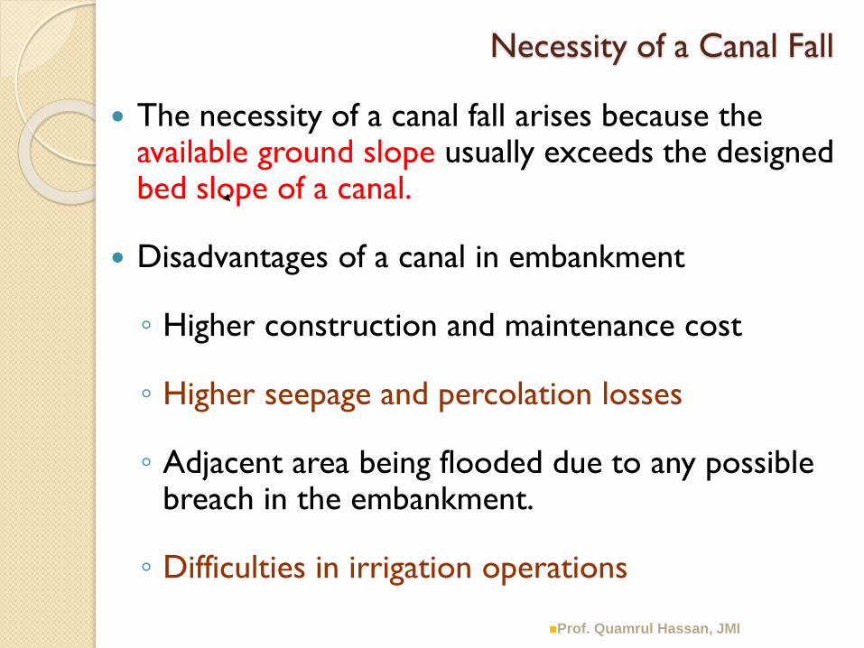
Necessity of a Canal Fall
The necessity of a canal fall arises because the available ground slope usually exceeds the designed bed slope of a canal.
Disadvantages of a canal in embankment
◦ Higher construction and maintenance cost
◦ Higher seepage and percolation losses
◦ Adjacent area being flooded due to any possible breach in the embankment.
◦ Difficulties in irrigation operations
Prof. Quamrul Hassan, JMI

Location of Fall
Main canal:- Economy in the “cost of excavation and filling” vs cost of Fall.
Branch Canals and Distributary Channels:- The Falls are located with consideration to command area.
◦ Procedure – To fix FSL required at the head of the off taking channels and outlets and mark them on the L-section of the canal.
◦ The FSL of the canal can then be marked as to cover all the commanded points, thereby deciding suitable locations for falls in canal FSL, and hence in canal beds.
The location of Falls may also be influenced by the possibility of combining it with a bridge, regulator, or some other masonry work, since such combinations often result in economy and better regulation.
Prof. Quamrul Hassan, JMI

Types of Falls
Ogee Fall
Rapids
Stepped Fall
Trapezoidal Notch Falls
Well Type falls or cylinder falls or syphon well drops
Simple vertical drop type and Sarda type falls
Straight glacis fall
Montague type fall
Inglis fall or Baffle fall
Prof. Quamrul Hassan, JMI
Prof. Quamrul Hassan, JMI

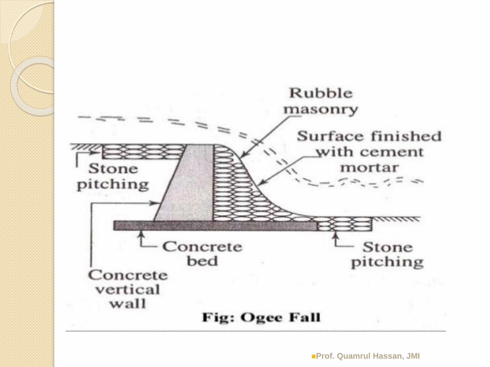
Ogee Fall
Constructed in olden days (Ganga canal)
water is gradually led down by providing convex and
concave curves Heavy drawdown on the u/s side resulting in lower depth,
higher velocities and consequent bed erosion
due to smooth transition, kinetic energy of flow was not at all dissipated, causing erosion of d/s beds and banks.
Prof. Quamrul Hassan, JMI

Prof. Quamrul Hassan, JMI
Prof. Quamrul Hassan, JMI

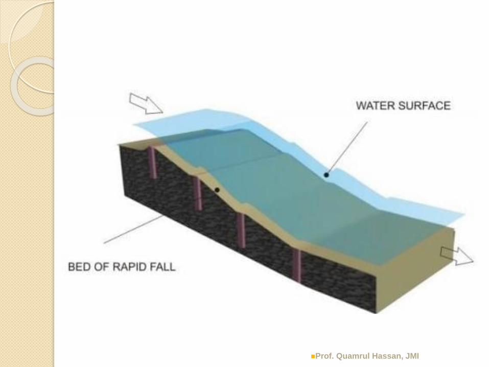
Rapids
In Western Yamuna canal, long rapids at slopes 1:15 to 1:20 (gently sloping glacis) with boulder facings, were Provided.
worked quite satisfactorily, but were very expensive.
Hence, now obsolete.
Prof. Quamrul Hassan, JMI

Stepped Fall
Prof. Quamrul Hassan, JMI

Prof. Quamrul Hassan, JMI

Stepped Fall
Stepped falls were the modified form of rapid falls in the respect that the long glacis of the rapid falls were replaced by the floors in steps.
However, the cost of construction of the stepped falls was also very high.
Prof. Quamrul Hassan, JMI

Stepped Fall
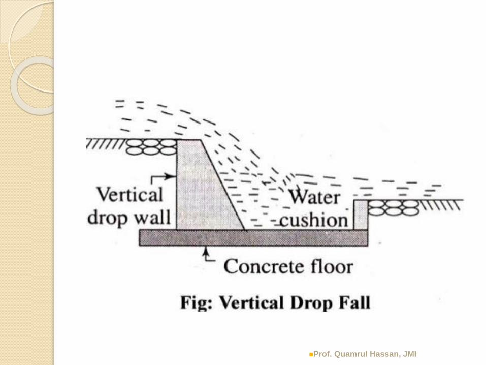
After Stepped fall, it was recognised that better dissipation of energy could be achieved through vertical impact of falling jet of water on the floor.
As such, vertical falls with cistern were evolved.
However, earlier types of vertical falls were not well developed and gave trouble.
These were superseded by trapezoidal notch, for sometime.
But it lead the development of vertical drop type fall and glacis type fall.
Prof. Quamrul Hassan, JMI

Trapezoidal Notch Fall
Prof. Quamrul Hassan, JMI

Prof. Quamrul Hassan, JMI

Prof. Quamrul Hassan, JMI

Trapezoidal Notch Fall
Developed by Reid (1894)
Consists of a number of trapezoidal notches constructed in a high crested wall across the channel with a smooth entrance and a flat circular lip projecting d/s from each notch to spread out the falling jet.
Notches could be designed to maintain the normal water depth in the u/s channel at any two discharges, as the variation at intermediate value is small.
These falls remained quite popular, till simpler, economical and better modern falls were developed.
Prof. Quamrul Hassan, JMI

Well Type falls or cylinder falls or
syphon well drops
d/s well is necessary for falls greater than 1.8 m and for discharges greater than 0.29 cumec.
Very useful for affecting larger drops for smaller discharges.
Commonly used as tail escapes for small canals, or where high levelled smaller drains do outfall into a low level bigger drain.
Prof. Quamrul Hassan, JMI
Prof. Quamrul Hassan, JMI

Prof. Quamrul Hassan, JMI

Sarda Fall
Simple vertical drop type and Sarda type falls
u/s CBL
d/s CBL
Drop wall
u/s bed
pitching
d/s bed
pitching
d/s HFL
u/s HFL
Water cushion
Prof. Quamrul Hassan, JMI

Prof. Quamrul Hassan, JMI

Simple vertical drop type and Sarda type falls
Introduced in Sarda canal system in UP (required large nos of falls)
In that area, a thin layer of sandy clay overlaid a stratum of pure sand.
The clear nappe leaving the crest is made to impinge into a cistern below.
The cistern provides a water cushion and helps to dissipate the surplus energy of the falling jet.
Prof. Quamrul Hassan, JMI

Prof. Quamrul Hassan, JMI

Prof. Quamrul Hassan, JMI

Straight Glacis Fall
This is modern type of fall.
Hydraulic jump is made to occur on the glacis, causing sufficient energy dissipation.
Suitable upto 60 cumecs discharge and 1.5 m drop.Prof. Quamrul Hassan, JMI

Prof. Quamrul Hassan, JMI
Montague type of Fall
Prof. Quamrul Hassan, JMI
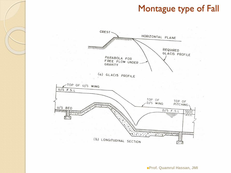
Montague type of Fall
Energy dissipation on a straight glacis remains incomplete due to vertical component of velocity remaining incomplete.
An improvement in energy dissipation may be brought about in this type of fall by replacing the straight glacis by a parabolic glacis, commonly known as Montague profile.
The curve glacis is difficult to construct.
Generally not adopted in India.
Prof. Quamrul Hassan, JMI

Prof. Quamrul Hassan, JMI

Inglis fall or Baffle fall
Prof. Quamrul Hassan, JMI

Inglis fall or Baffle fall
A straight glacis fall added with a baffle platform and a baffle wall, was developed by Inglis and is called “Inglisfall” or “baffle fall”.
Quite suitable for all discharges and for drops of more than 1.5 m
Prof. Quamrul Hassan, JMI

Design of Sarda type Fall
Complete design of Sarda type fall consists of the following : -
Crest wall
cistern
Impervious floor
d/s protection
u/s approach
Prof. Quamrul Hassan, JMI

Design of Sarda type Fall – Crest wall
(1) Design of crest wall
(i) Length of crest wall
In case of future development of irrigation &
increase in discharge capacity
normally length of crest wall = bed width of channel
length of crest wall = bed width of channel + water depth
Prof. Quamrul Hassan, JMI

Design of Sarda type Fall – Crest wall
(ii) Shape of crest wall
For discharge < 14 cumec →
crest wall rectangular in section with both u/s
and d/s faces vertical.
For discharge > 14 cumec →
crest wall TRAPEZOIDAL in section with u/s
face having a slope of 1 in 3 and d/s face 1 in 8.
Prof. Quamrul Hassan, JMI

Design of Sarda type Fall – Crest wall
Prof. Quamrul Hassan, JMI

Design of Sarda type Fall – Crest wall
Prof. Quamrul Hassan, JMI

Design of Sarda type Fall – Crest wall
(ii) Shape of crest wall
Rectangular crest wall
where G = sp gravity of the material of the crest wall (for masonry G =2)
Trapezoidal crest wall
G
dHB
dB
1
55.0
dHB 55.0
Prof. Quamrul Hassan, JMI

Design of Sarda type Fall – Crest wall
(iii) Discharge formula
Rectangular crest wall
where L = length of crest wall
Trapezoidal crest wall
(iv) Crest level for free overfall condition
Crest level = u/s FSL - H
61
23
835.1
B
HLHQ
61
23
99.1
B
HLHQ
Prof. Quamrul Hassan, JMI
Design of Sarda type Fall – Crest wall
(v) Bed protection u/s of crest wall
Brick pitching is laid on the channel bed for 2 to
4 m length, sloping downwards towards the
crest wall at 1 in 10.
Prof. Quamrul Hassan, JMI

Design of Sarda type Fall – Cistern
(2) Design of cistern
(neglecting the small velocity of approach head, E may
be replaced by H)
Lc EHL 5 32
)(4
1LEHx
Prof. Quamrul Hassan, JMI

Design of Sarda type Fall – Impervious Floor
(3) Design of Impervious Floor
Bligh’s theory – for small & medium falls
Khosla’s theory – for large falls
Maximum seepage head :
when there is water on the u/s side upto the top of crest wall and there is no flow on the d/s side.
Thus the Maximum seepage head = d
Out of the total length of the impervious floor a minimum length ld is to be provided on the d/s of toe of the crest wall, which is
ld = 2(D1+1.2) + HLProf. Quamrul Hassan, JMI

Design of Sarda type Fall – Impervious Floor
Draw HGL and determine thickness of floor
Minm thickness on u/s side = 0.3 m
Minm thickness on d/s side = 0.3-0.4 for small falls
= 0.4-0.6 for large falls
Cutoffs /curtain walls
(a) u/s cutoff : Minimum depth = D1/3
D1 = u/s Full supply depth
(b) d/s cut off : Minimum depth = D2/2
D2 = d/s Full supply depthProf. Quamrul Hassan, JMI
Design of Sarda type Fall – Protection Works
(4) Downstream protection works
i. Bed protection
ii. Downstream wings
iii. Side protection
iv. Energy dissipators
Prof. Quamrul Hassan, JMI

Design of Sarda type Fall – d/s protection
(i) Bed protection
The bed of the channel needs to be protected for some length on the d/s of the impervious floor.
consists of dry brick pitching (i.e. brick laid dry without mortar), about 200 mm thick (one brick on edge laid over one flat brick) resting on 100 mm ballast.
Table gives length of pitching and no. of curtain walls (depending upon Head over crest), required to hold the pitching.
It is provided horizontal upto end of masonry wings then sloping downwards at 1 in 10.
Prof. Quamrul Hassan, JMI

Design of Sarda type Fall – d/s protection
(ii) Downstream wings (Wing walls)
After the crest wall the wings are stepped down
to the required level of the downstream wings.
The d/s wings are kept vertical for a length varying
from 5 to 8 times (E. HL) from the crest.
The wings are then flared or warped, that is their
water face is gradually inclined from vertical to a
slope of 1.5:1 or 1:1
In the latter case, warping is continued in the side
pitching till a slope of 1.5:1 is attained. Prof. Quamrul Hassan, JMI

Design of Sarda type Fall – d/s protection works
(iii) Side protection
After the warped wings, pitching protection is
provided on the sides.
The side pitching consists of either one brick on
edge or 1.5 brick on edge (i.e. one brick on edge
placed over one flat brick) laid in cement mortar.
In the latter case, warping is continued in the side
pitching till a slope of 1.5:1 is attained.
The side pitching is curtailed at an angle of 45o
from the end of the bed pitching in plan.
(contd…)Prof. Quamrul Hassan, JMI

Design of Sarda type Fall – d/s protection works
(iii) Side protection
• A toe wall is provided between the bed pitching
and the side pitching to provide a firm support
for the side pitching.
The toe wall is usually 1 ½ brick (i.e. about 0.4
m) thick and of depth equal to D2/2.
Prof. Quamrul Hassan, JMI

Design of Sarda type Fall – d/s protection
(iv) Energy Dissipators
Energy dissipators are not provided for small
discharges. However, for large discharges,
additional energy dissipators are provided.
The energy dissipators consist of two rows of
friction blocks in the cistern and two rows of
cube blocks on the impervious floor at its d/s end.
Both the friction blocks and cube blocks are
staggered.
Prof. Quamrul Hassan, JMI

Design of Sarda type Fall – d/s protection
(iv) Energy Dissipators
Size and position of friction blocks
a) Length of block = 2dc
b) Width of block = dc
c) Height of block = dc
d) Distance of first row of blocks from d/s toe of the crest wall = 1.5dc
e) Spacing between two rows of block = dc
f) Spacing between blocks in same row = 2dc
Where dc is the critical depth. Prof. Quamrul Hassan, JMI

Design of Sarda type Fall – d/s protection
(iv) Energy Dissipators
Size and position of cube blocks
a) Length of block = 0.1 D2
b) Width of block = 0.1 D2
c) Height of block = 0.1 D2
d) Spacing between the two rows of blocks = 0.1 D2
e) Spacing between blocks in the same row= 0.1 D2
Where, D2 is d/s full supply depth
One of the two rows of cube blocks is provided just at the d/s end of the impervious floor and the other one is provided on the u/s side at above noted spacing.
Prof. Quamrul Hassan, JMI

Design of Sarda type Fall – u/s protection
Design of u/s approach
The u/s approach consist of wing walls (wings).
For discharge <14 cumecs, the wing walls may be
splayed straight at an angle of 45o from the u/s
edge of crest wall.
For greater discharges, the wing walls are made
segmental (curve) from the u/s edge of crest wall,
with radius equal to 5 to 6 times H, subtending
an angle of 600 at the centre and then carried
along straight lines tangential to segment.
Prof. Quamrul Hassan, JMI

Design Problem - Sarda type Fall
Design a Sarda type Fall for the following data:
upstream / downstream
Full supply discharge, (cumec) = 45 / 45
Full Supply level (m) = 118.30 / 116.80
Full supply depth (m) = 1.8 / 1.8
Bed width (m) = 28 / 28
Bed level (m) = 116.50 / 115
Drop = 1.5 m
Design the floor on the basis of Bligh’s creep theory,
taking coefficient of creep = 8
Prof. Quamrul Hassan, JMI

Design of Sarda type Fall – Crest wall
Prof. Quamrul Hassan, JMI

Design problem - Sarda type Fall
Step 1, Calculation of H & d
Since Q > 14 cumec, trapezoidal crest wall will be provided.
L = Length of crest wall= bed width of channel = 28 m
H + d = D1 + drop in bed level, or
= u/s FSL – d/s CBL
= 118.30 – 115 = 3.30 m
61
23
99.1
B
HLHQ
Prof. Quamrul Hassan, JMI

Design problem - Sarda type Fall
Step 1, Calculation of H & d
Therefore,
61
23
99.1
B
HLHQ
dHB 55.0
m 0.13.355.0 B
61
23
0.12899.145
HH
m 88.0HProf. Quamrul Hassan, JMI

Design problem - Sarda type Fall
Step 1, Calculation of H & d
Since, H = 0.88 m
H + d = 3.30 m
Therefore, d = 3.30 – 0.88 = 2.42 m
Height of crest wall above u/s bed (h)
h = D1 – H
= 1.8 – 0.88
= 0.92 mProf. Quamrul Hassan, JMI

Design problem - Sarda type Fall
Step 2, Design of Crest wall
Top width B = 1.0 m
Slope of u/s face = 1 in 3
Slope of d/s face = 1 in 8
Assuming channel side slope = 1:1
u/s TEL = u/s FSL + velocity head
= 118.30 + 0.036 = 118.336 m
m/s 84.0)8.128(8.1
45
av
036.081.92
84.0
2 headvelocity
22
g
va
Prof. Quamrul Hassan, JMI

Design problem - Sarda type Fall
Step 2, Design of Crest wall
u/s TEL = u/s FSL + velocity head
= 118.30 + 0.036
= 118.336 m
Crest level = u/s FSL – H
= 118.30 – 0.88
= 117.42 (above d/s FSL 116.80 m, free flow)
E = u/s TEL – crest level
= 118.336 – 117.42 = 0.916 m
m/s 84.0)8.128(8.1
45
av
036.081.92
84.0
2 headvelocity
22
g
va
Prof. Quamrul Hassan, JMI

Design problem - Sarda type Fall
Step 3, Design of Cistern
E = 0.916 m
HL = u/s FSL – d/s FSL
= 118.30 – 116.80
= 1.5 m
RL of bed of cistern = RL of d/s bed – x = 115 – 0.31
= 114.69 m
m 86.55.1916.055 Lc EHL
m 31.0)5.1916.0(4
1)(
4
13
23
2
LEHx
Prof. Quamrul Hassan, JMI

Design problem - Sarda type Fall
Step 4, Design of Impervious floor
Seepage head, Hs = d = 2.42 m
Bligh’s coefficient, C = 8
Therefore, required length of creep
= 8 × 2.42 = 19.36 m
u/s cutoff d1 = 1.0 m (Minm D1/3 = 1.8/3 = 0.6 m)
d/s cutoff d2 = 1.5 m (Minm D2 /2 = 1.8/2 = 0.9 m)
The vertical length of creep = 2 (1.0 + 1.5) = 5 m
Hence, length of horizontal impervious floor = 19.36 – 5
= 14.36 m say 15mProf. Quamrul Hassan, JMI
Design problem - Sarda type Fall
Step 4, Design of Impervious floor
Provide 15 m length of impervious floor.
Minimum length of impervious floor to be provided
on the d/s of the crest wall ld
ld = 2 (D1 +1.2) + HL
= 2 (1.80 + 1.2) + 1.5
= 7.5 m
Provide ld = 8 m. The balance of the length 15 – 8 = 7
m is provided under and u/s of the crest wall. Prof. Quamrul Hassan, JMI

Design problem - Sarda type Fall
Step 4, Design of Impervious floor
Calculation of uplift pressure and thickness of floor
Total creep length = 15 + 2 (1.0 + 1.5)
(i) The uplift pressure under the u/s floor will be counter
balanced by the weight of water and hence no thickness
is required. However, provide a minimum thickness of
0.4m
(ii) For other points the minimum vertical ordinate between
Bligh’s HGL and the floor level gives the uplift pressure.
Prof. Quamrul Hassan, JMI

Design problem - Sarda type Fall
Step 4, Design of Impervious floor
Calculation of uplift pressure and thickness of floor
(ii) For other points the minimum vertical ordinate between Bligh’s HGL and the floor level gives the uplift pressure.
The maximum unbalanced head under the d/s toe of the crest wall
mx 64.131.0)45.01(42.220
127142.2
m 32.1124.2
64.1
1
head unbalancedrequired Thickness
GProf. Quamrul Hassan, JMI
Design problem - Sarda type Fall
Step 4. Design of Impervious floor
Provide 1.4 m thick cement concrete floor overlaid
by 0.2 m brick pitching.
Provide a minimum thickness of 0.6 m overlaid by
0.2m thick brick pitching at the d/s end of the
floor.
The thickness of the floor at intermediate points
may be varied as per requirements of uplift
pressures.
Prof. Quamrul Hassan, JMI

Design problem - Sarda type Fall
Step 5, Design of d/s wings
Provide d/s wings vertical for a length of
6(E HL) = 6 6(0.916 × 1.5 = 7.03 say 7 m
Then,
the wings would be warped to 1:1 slope at a splay of 1 in 3.
Height of top of d/s wings above bed
= water depth + freeboard
= 1.8 + 0.5 = 2.3 m
Horizontal projection of this on 1:1 slope = 2.3 m, with a splay of 1 in 3, length of warped wings measured along the centre line of the channel = 2.3 × 3 = 6.9 say 7 m
Prof. Quamrul Hassan, JMI
Design problem - Sarda type Fall
Step 5, Design of d/s bed protection - (a) Bed pitching
Provide about 200 mm thick dry brick pitching consisting of one brick on edge laid over one flat brick resting on 100 mm ballast.
From Table, for H = 0.88 m,
Length of bed pitching = 9.0 + 2 HL= 9.0 + 2×1.5 = 12 m
This should be provided horizontal upto the end of masonry wings and then sloping downwards at 1 in 10.
Since, the warped wings commence from 1 m u/s of the d/s end of the impervious floor,
the length of the horizontal pitching = 7-1 = 6m
the length of sloping pitching is therefore = 12- 6 = 6 mProf. Quamrul Hassan, JMI

Design problem - Sarda type Fall
Step 5, Design of d/s bed protection -
(b) Curtain wall
Thickness of curtain wall = 1 ½ brick (0.4 m)
From Table, for H = 0.88 m,
Depth of curtain wall = 0.75 m, say 1.0 m
Provide 0.4 m thick and 1 m deep curtain wall at the d/s end of bed pitching.
(c) Side pitching
Provide about 200 mm thick side pitching consisting of one brick on edge laid over one flat brick in cement mortar. The side pitching should be warped from a slope of 1:1 to 1.5:1 and it should be curtailed at an angle of 45o from the end of bed pitching in plan.
Prof. Quamrul Hassan, JMI
Design problem - Sarda type Fall
Step 5, Design of d/s bed protection -
(d) Toe wall
Thickness of toe wall = 1 ½ brick (0.4 m)
Depth of toe wall =
d/s water depth / 2 = 0.9 m
say 1m
Provide 0.4 m thick and 1 m deep toe wall between the bed pitching and side pitching.
(e) Energy Disipator
Prof. Quamrul Hassan, JMI

Design problem - Sarda type Fall
Step 5, Design of d/s bed protection -
(e) Energy Disipator
q = Q/b = 45/28 = 1.607 m3/s/m
calculation for dc = (q2/g )1/3 = (1.6072 /9.81)1/3
= 0.641 m
= say 0.7 m (for providing friction blocks)
Prof. Quamrul Hassan, JMI

Design problem - Sarda type Fall
Step 5, Design of d/s bed protection -
(e) Energy Disipator
Size and position of friction blocks
a) Length of block = 2dc = 1.4 m
b) Width of block = dc = 0.7 m
c) Height of block = dc = 0.7 m
d) Distance of first row of blocks from d/s toe of the crest wall = 1.5dc= 1.05 m say 1.0 m
e) Spacing between two rows of block = dc= 0.7 m
f) Spacing between blocks in same row = 2dc= 1.4 m
Prof. Quamrul Hassan, JMI

Design problem - Sarda type Fall
Step 5, Design of d/s bed protection -
(e) Energy Dissipator
Size and position of cube blocks
Length of block = 0.1 D2 = 0.1(1.8) = 0.18 m = 0.2 m (say)
Width of block = 0.1 D2 = 0.2 m
Height of block = 0.1 D2 = 0.2 m
Spacing between the two rows of blocks = 0.1 D2 = 0.2 m
Spacing between blocks in the same row = 0.1 D2 = 0.2 m
Where, D2 is d/s full supply depth
One of the two rows of cube blocks is provided just at the d/s end of the impervious floor and the other one is provided on the u/s side at above noted spacing.
Prof. Quamrul Hassan, JMI

Prof. Quamrul Hassan, JMI

Design problem - Sarda type Fall
Step 5, Design of u/s approach
Radius of segmental (or curved) portion of the u/s wings
= 5 to 6 times H
= 5 to 6 times 0.88
= 4.4 to 5.28 m
Thus provide u/s wings having segmental (or curved) portion
of radius 5 m and subtending an angle of 60o at the centre
from u/s edge of the crest wall.
The wings should then be carried along the straight lines
tangential to the segment and embedded in the earthen
banks of the channel by a minimum of 1 m from the line
of FSL.Prof. Quamrul Hassan, JMI

Design problem - Sarda type Fall
Prof. Quamrul Hassan, JMI

Acknowledgements
Irrigation Engineering and Hydraulic Structures, by S.K. Garg, Khanna Publishers, New Delhi
Irrigation and Water Resources Engineering, G.L. Asawa, New Age International (P) Ltd Publishers, New Delhi
Theory and Design of Irrigation Structures Vol. 1 by Varshney, Nem Chand
Irrigation Water Resources and Water Power Engineering by P.N. Modi, Standard Book House, New Delhi
Prof. Quamrul Hassan, JMI

Prof. Quamrul Hassan, JMI

https://www.slideshare.net/gauravhtandon
1/canal-fall
https://theconstructor.org/water-
resources/canal-falls-types-
importance/12894/
Prof. Quamrul Hassan, JMI