design and simulation of 120 capacity automobile parking ...
12
Bajopas Volume 8 Number 2 December, 2015 Bayero Journal of Pure and Applied Sciences, 8(2): 175 - 186 Received: June, 2015 Accepted: October, 2015 ISSN 2006 – 6996 DESIGN AND SIMULATION OF 120 CAPACITY AUTOMOBILE PARKING CONTROL SYSTEM USING UP/DOWN DECADE COUNTERS Galadanci, G.S.M., Gana, S. M. and Aliyu, H.A. Department of Physics, Bayero University P.M.B. 3011, Kano Email: [email protected], [email protected] , Tel: 08037260380, 08037504446 ABSTRACT In this work, a 120 capacity automobile parking control system was designed and simulated. The design was carried out using 3-cascaded 74HC190 decade up/down counters in connection with MCT6 phototransistor optocoupler sensors, Gated S/R latch, LEDs display, logic gates and DC motor circuitry. The up/down counters were used for both up count from 1 to 120 and down count from 120 to 0. The sensors are placed at both the entry and exit gate of the parking lot in order to provide a pulse to the up/down counter whenever an automobile enters or leaves the parking lot. The DC motor circuitry is used to control the gate(entry gate) by closing the entry when the counter counts up to 120, so that no automobile will be allowed in. When one or more automobile leave(s) the parking lot through the exit gate the counter counts down, and the DC motor circuitry drives the entry gate open to allow access for the same number of automobiles that leave(s) the parking lot. The design was implemented and simulated using National instrument (multisim 11.0) and proteus softwares. The simulation results shows that the system functioned as desired. Keywords: Decade up/down counters, phototransistor optocoupler, Gated S/R latch, LEDs display, logic gates and DC motor circuitry. INTRODUCTION The advancement and progress of nations is measured by the possibility of their use and application of latest invented technologies in all aspects of life. Control engineering is one of the aspects which have been given a great deal by many researchers (Wada et al, (2003); Pohl et al, (2006); Chandni et al, (2015)). It is quiet helpful to bring a means of monitoring a parking garage automatically rather than manually because of many reasons such as immediate and low delay in operation. Nigeria is a little backward in term of embracing such wonderful development like many other developing countries . Even though, in some part of the country similar system development are already in used, but most of which are imported rather than being developed in the country. Hence in view of the stated problems, there is a need to embark upon investigation on how to design and simulate an electronic automobile parking control system. Some years back people and organizations used heavy metal gates which require the use of human strength to open or close their garage. After the advent of digital electronics, much problems were overcomed in many countries, including the problem stated above. This research focused and put more emphasis on our dear country to identify the need to inform or mobilize our community so as to have an idea on how to design and produce a digital automobile parking control system; which do not require the use of human strength to either uplift or shift the gate (no need to employ gateman), and is faster in operation, inexpensive, more reliable and qualitative in order to compete with other developed countries and minimize importation of similar systems. In this research work the design, implementation and simulation of an electronic automobile parking control system using discrete components that has the capacity of 120 parking space is presented (Galadanci et. al., 2013). The design was carried out and implemented using simulation softwares multisim version 11 and proteus 8. However, the project is limited for only 120 cars into a 120 capacity parking garage. The system is mainly for public and private parking where many cars up to 120 are expected to be parked where sensors are designed to detect only cars, barrier at the gate will remain opened (raised) until the counter counts 120 then it will be lowered to block further entry. THEORETICAL BACKGROUND Digital systems are created to perform data processing and control tasks. Architecture tailored is what distinguishes one system from another to efficiently execute the tasks for which it was designed. Today digital technologies are dominants because digital systems are easier to design, accurate and precise, also information are stored easily and portably in digital systems.The main building blocks of automobile parking control system are the sequential devices like up/down binary counters, combinational devices like logic gates. Others include seven segment LED displays for display and sensors. The up/down counter which is a negative edge triggered is operated using S-R latch or any other 555 timer that fits. http://dx.doi.org/10.4314/bajopas.v8i2.29 175
-
Upload
khangminh22 -
Category
Documents
-
view
0 -
download
0
Transcript of design and simulation of 120 capacity automobile parking ...
Bajopas Volume 8 Number 2 December, 2015
Bayero Journal of Pure and Applied Sciences, 8(2): 175 - 186 Received: June, 2015 Accepted: October, 2015 ISSN 2006 – 6996
DESIGN AND SIMULATION OF 120 CAPACITY AUTOMOBILE PARKING CONTROL SYSTEM USING UP/DOWN DECADE COUNTERS
Galadanci, G.S.M., Gana, S. M. and Aliyu, H.A. Department of Physics, Bayero University P.M.B. 3011, Kano
Email: [email protected], [email protected], Tel: 08037260380, 08037504446
ABSTRACT In this work, a 120 capacity automobile parking control system was designed and simulated. The design was carried out using 3-cascaded 74HC190 decade up/down counters in connection with MCT6 phototransistor optocoupler sensors, Gated S/R latch, LEDs display, logic gates and DC motor circuitry. The up/down counters were used for both up count from 1 to 120 and down count from 120 to 0. The sensors are placed at both the entry and exit gate of the parking lot in order to provide a pulse to the up/down counter whenever an automobile enters or leaves the parking lot. The DC motor circuitry is used to control the gate(entry gate) by closing the entry when the counter counts up to 120, so that no automobile will be allowed in. When one or more automobile leave(s) the parking lot through the exit gate the counter counts down, and the DC motor circuitry drives the entry gate open to allow access for the same number of automobiles that leave(s) the parking lot. The design was implemented and simulated using National instrument (multisim 11.0) and proteus softwares. The simulation results shows that the system functioned as desired. Keywords: Decade up/down counters, phototransistor optocoupler, Gated S/R latch, LEDs display, logic gates and DC motor circuitry.
INTRODUCTION The advancement and progress of nations is measured
by the possibility of their use and application of latest invented technologies in all aspects of life. Control
engineering is one of the aspects which have been given a great deal by many researchers (Wada et al,
(2003); Pohl et al, (2006); Chandni et al, (2015)). It is quiet helpful to bring a means of monitoring a parking
garage automatically rather than manually because of many reasons such as immediate and low delay in
operation. Nigeria is a little backward in term of embracing such wonderful development like many
other developing countries . Even though, in some part of the country similar system development are already
in used, but most of which are imported rather than being developed in the country. Hence in view of the
stated problems, there is a need to embark upon
investigation on how to design and simulate an electronic automobile parking control system. Some
years back people and organizations used heavy metal gates which require the use of human strength to open
or close their garage. After the advent of digital electronics, much problems were overcomed in many
countries, including the problem stated above. This research focused and put more emphasis on our dear
country to identify the need to inform or mobilize our community so as to have an idea on how to design and
produce a digital automobile parking control system; which do not require the use of human strength to
either uplift or shift the gate (no need to employ gateman), and is faster in operation, inexpensive, more
reliable and qualitative in order to compete with other
developed countries and minimize importation of similar systems.
In this research work the design, implementation and simulation of an electronic automobile parking
control system using discrete components that has the capacity of 120 parking space is presented (Galadanci
et. al., 2013). The design was carried out and implemented using simulation softwares multisim
version 11 and proteus 8. However, the project is limited for only 120 cars into a 120 capacity parking
garage. The system is mainly for public and private parking where many cars up to 120 are expected to be
parked where sensors are designed to detect only cars, barrier at the gate will remain opened (raised) until the
counter counts 120 then it will be lowered to block further entry.
THEORETICAL BACKGROUND
Digital systems are created to perform data processing and control tasks. Architecture tailored is
what distinguishes one system from another to efficiently execute the tasks for which it was designed.
Today digital technologies are dominants because digital systems are easier to design, accurate and
precise, also information are stored easily and portably in digital systems.The main building blocks of
automobile parking control system are the sequential devices like up/down binary counters, combinational
devices like logic gates. Others include seven segment LED displays for display and sensors. The up/down
counter which is a negative edge triggered is operated using S-R latch or any other 555 timer that fits.
http://dx.doi.org/10.4314/bajopas.v8i2.29
175
Bajopas Volume 8 Number 2 December, 2015
The 120 count was achieved by decoding the three
cascaded up/down counters using basic logic gates such that for every 0 through 9 counts of the first
counter the second counter is enabled via its terminal count to advance through its state from 0 through 9.
Similarly at terminal count of the second counter the third counter is allowed or enabled to advance through
its state to count 1 which is its maximum number of counts. Once the third counter counts 1 while the
second is at 2 and the first counter is at count 0
making a total of 120 counts the decoding gates becomes active and hold the counters at that 120
count. Each up count represents a detected car entering into the garage by the sensor placed at the
entry likewise each down count represents a detected car leaving the garage by the sensor placed at the exit.
Additional circuitries are required for these operations especially at the entry when the garage is fully
occupied at 120 counts and at the exit when the garage is empty at 000 counts. In all these sections
the operations are displayed using seven segment displays to show the respective counts. Finally all these
sections; the counter section, sensor section, S/R latch section and display section are then connected
together to form the design of the complete system.
The design was carried out and implemented using simulation softwares multisim version 11 and proteus
8. However, the project is limited for only 120 cars into a 120 parking garage, the project is mainly for public
and private parking where many cars up to 120 are expected to be parked, the sensors are designed to
detect only cars, the barrier at the gate will remain opened (raised) until the counter counts 120 then it
will be lowered to block further entry.
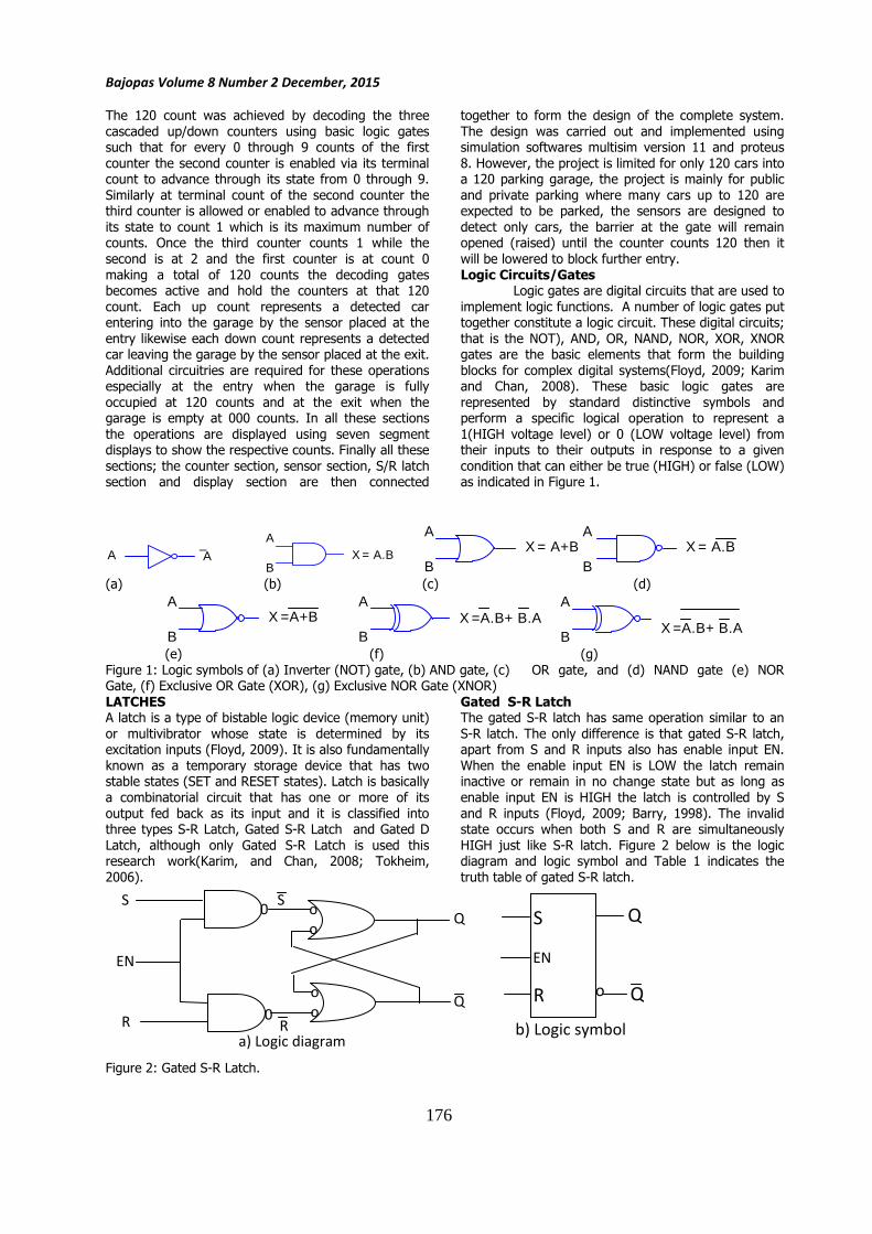
Logic Circuits/Gates Logic gates are digital circuits that are used to
implement logic functions. A number of logic gates put together constitute a logic circuit. These digital circuits;
that is the NOT), AND, OR, NAND, NOR, XOR, XNOR gates are the basic elements that form the building
blocks for complex digital systems(Floyd, 2009; Karim and Chan, 2008). These basic logic gates are
represented by standard distinctive symbols and perform a specific logical operation to represent a
1(HIGH voltage level) or 0 (LOW voltage level) from their inputs to their outputs in response to a given
condition that can either be true (HIGH) or false (LOW) as indicated in Figure 1.
A A
A
BX = A.B
A
BX = A+B
A
BX = A.B
(a) (b) (c) (d)
A
BX =A+B
A
BX =A.B+ B.A
A
BX =A.B+ B.A
(e) (f) (g)
Figure 1: Logic symbols of (a) Inverter (NOT) gate, (b) AND gate, (c) OR gate, and (d) NAND gate (e) NOR Gate, (f) Exclusive OR Gate (XOR), (g) Exclusive NOR Gate (XNOR)
LATCHES A latch is a type of bistable logic device (memory unit)
or multivibrator whose state is determined by its excitation inputs (Floyd, 2009). It is also fundamentally
known as a temporary storage device that has two stable states (SET and RESET states). Latch is basically
a combinatorial circuit that has one or more of its
output fed back as its input and it is classified into three types S-R Latch, Gated S-R Latch and Gated D
Latch, although only Gated S-R Latch is used this research work(Karim, and Chan, 2008; Tokheim,
2006).
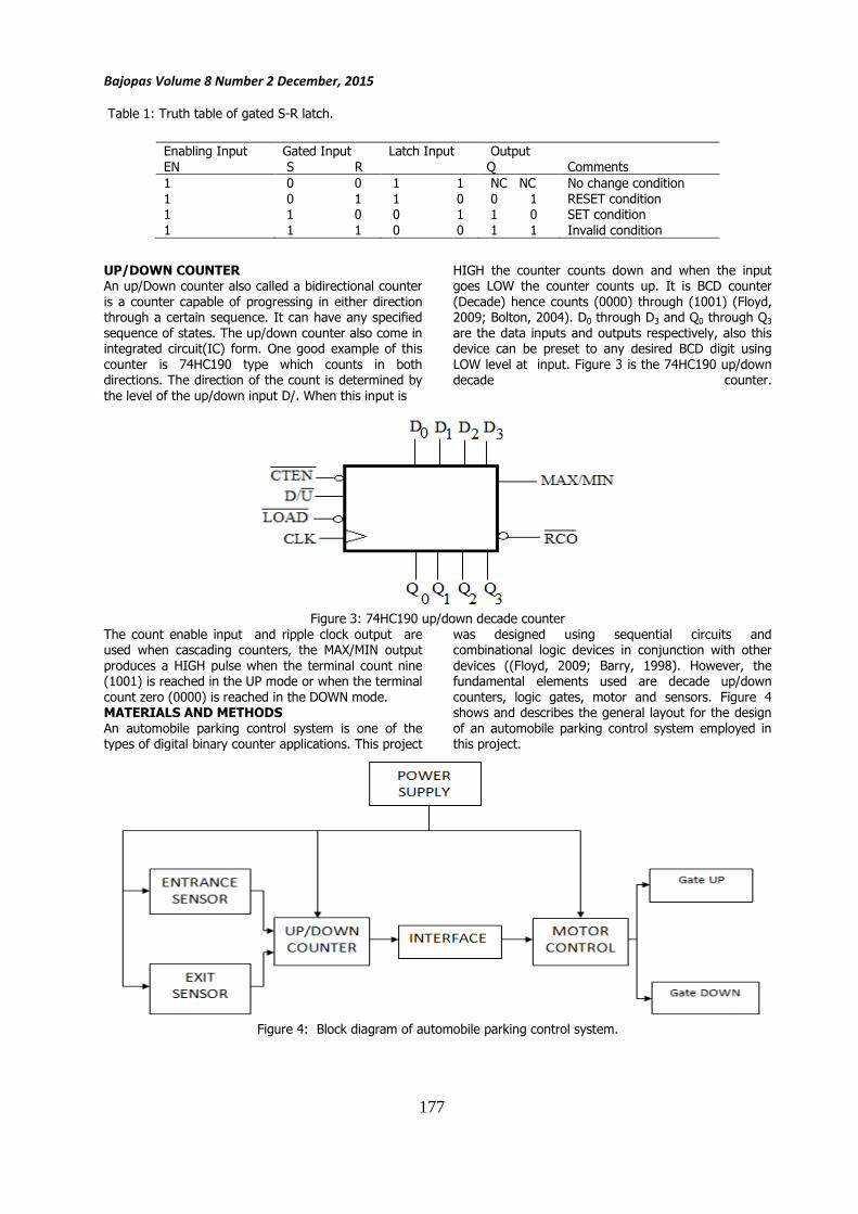
Gated S-R Latch The gated S-R latch has same operation similar to an
S-R latch. The only difference is that gated S-R latch, apart from S and R inputs also has enable input EN.
When the enable input EN is LOW the latch remain inactive or remain in no change state but as long as
enable input EN is HIGH the latch is controlled by S
and R inputs (Floyd, 2009; Barry, 1998). The invalid state occurs when both S and R are simultaneously
HIGH just like S-R latch. Figure 2 below is the logic diagram and logic symbol and Table 1 indicates the
truth table of gated S-R latch.
Figure 2: Gated S-R Latch.
o
o
o
o
Q
Q
S
R 0
S
R
a) Logic diagram
0
EN
Q
Q R
S
o
b) Logic symbol
EN
176
Bajopas Volume 8 Number 2 December, 2015
Table 1: Truth table of gated S-R latch.
UP/DOWN COUNTER An up/Down counter also called a bidirectional counter
is a counter capable of progressing in either direction through a certain sequence. It can have any specified
sequence of states. The up/down counter also come in integrated circuit(IC) form. One good example of this
counter is 74HC190 type which counts in both directions. The direction of the count is determined by
the level of the up/down input D/. When this input is
HIGH the counter counts down and when the input goes LOW the counter counts up. It is BCD counter
(Decade) hence counts (0000) through (1001) (Floyd, 2009; Bolton, 2004). D0 through D3 and Q0 through Q3
are the data inputs and outputs respectively, also this device can be preset to any desired BCD digit using
LOW level at input. Figure 3 is the 74HC190 up/down decade counter.
Figure 3: 74HC190 up/down decade counter
The count enable input and ripple clock output are used when cascading counters, the MAX/MIN output
produces a HIGH pulse when the terminal count nine (1001) is reached in the UP mode or when the terminal
count zero (0000) is reached in the DOWN mode. MATERIALS AND METHODS
An automobile parking control system is one of the types of digital binary counter applications. This project
was designed using sequential circuits and combinational logic devices in conjunction with other
devices ((Floyd, 2009; Barry, 1998). However, the fundamental elements used are decade up/down
counters, logic gates, motor and sensors. Figure 4 shows and describes the general layout for the design
of an automobile parking control system employed in this project.
Figure 4: Block diagram of automobile parking control system.
Enabling Input
EN
Gated Input
S R
Latch Input
Output
Q
Comments
1 0 0 1 1 NC NC No change condition
1 0 1 1 0 0 1 RESET condition 1 1 0 0 1 1 0 SET condition
1 1 1 0 0 1 1 Invalid condition
177
Bajopas Volume 8 Number 2 December, 2015
MCT62
1
8
7
MCT6
1kΩ56Ω
1kΩ56Ω
VCC5V
RT1 RT3
RT2 RT4
PT1
PT2
IR LED1
IR LED2
To the input ofcounter
To the input ofcounter
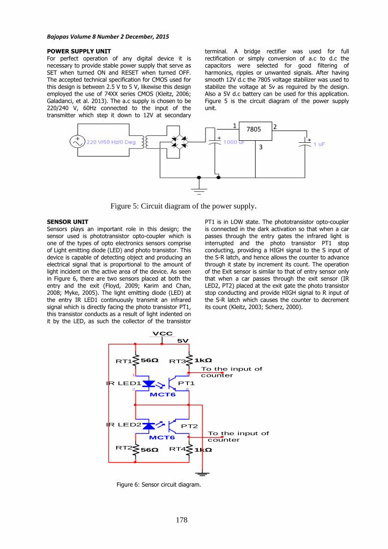
POWER SUPPLY UNIT
For perfect operation of any digital device it is necessary to provide stable power supply that serve as
SET when turned ON and RESET when turned OFF. The accepted technical specification for CMOS used for
this design is between 2.5 V to 5 V, likewise this design employed the use of 74XX series CMOS (Kleitz, 2006;
Galadanci, et al. 2013). The a.c supply is chosen to be 220/240 V, 60Hz connected to the input of the
transmitter which step it down to 12V at secondary
terminal. A bridge rectifier was used for full
rectification or simply conversion of a.c to d.c the capacitors were selected for good filtering of
harmonics, ripples or unwanted signals. After having smooth 12V d.c the 7805 voltage stabilizer was used to
stabilize the voltage at 5v as reguired by the design. Also a 5V d.c battery can be used for this application.
Figure 5 is the circuit diagram of the power supply unit.
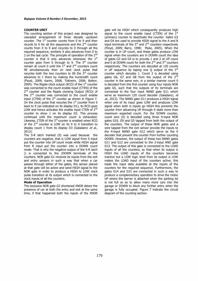
SENSOR UNIT
Sensors plays an important role in this design; the sensor used is phototransistor opto-coupler which is
one of the types of opto electronics sensors comprise of Light emitting diode (LED) and photo transistor. This
device is capable of detecting object and producing an electrical signal that is proportional to the amount of
light incident on the active area of the device. As seen in Figure 6, there are two sensors placed at both the
entry and the exit (Floyd, 2009; Karim and Chan, 2008; Myke, 2005). The light emitting diode (LED) at
the entry IR LED1 continuously transmit an infrared
signal which is directly facing the photo transistor PT1, this transistor conducts as a result of light indented on
it by the LED, as such the collector of the transistor
PT1 is in LOW state. The phototransistor opto-coupler
is connected in the dark activation so that when a car passes through the entry gates the infrared light is
interrupted and the photo transistor PT1 stop conducting, providing a HIGH signal to the S input of
the S-R latch, and hence allows the counter to advance through it state by increment its count. The operation
of the Exit sensor is similar to that of entry sensor only that when a car passes through the exit sensor (IR
LED2, PT2) placed at the exit gate the photo transistor stop conducting and provide HIGH signal to R input of
the S-R latch which causes the counter to decrement
its count (Kleitz, 2003; Scherz, 2000).
Figure 6: Sensor circuit diagram.
7805 1 2
3
Figure 5: Circuit diagram of the power supply.
178
Bajopas Volume 8 Number 2 December, 2015
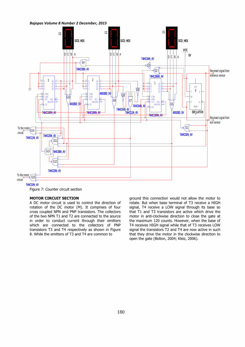
COUNTER UNIT The counting section of this project was designed by
cascaded arrangement of three decade up/down counter. The 1st counter counts from 0 to 9 and then
recycle to 0 for all the sequences and the 2nd counter counts from 0 to 9 and recycles to 0 through all the
required sequence, similarly it also advances from 0 to 2 on the last cycle. The principle of operation of the 2nd
counter is that it only advances whenever the 1st
counter goes from 0 through to 9. The 3rd counter remain at count 0 until the 1st and 2nd counters count
99 simultaneously then on next clock pulse that recycles both the two counters to 00 the 3rd counter
advances to 1 there by making the hundredth count (Floyd, 2009; Karim, 2008; Tokheim, 2006; Bolton.
2004). The Ripple clock output (RCO) of the 1st counter was connected to the count enable input (CTEN) of the
2nd counter and the Ripple clocking Output (RCO) of the 2nd counter was connected to the count enable
input (CTEN) of the 3rd counter as shown in Figure 7. On the clock pulse that recycles the 1st counter from 0
back to 9 (as indicated on its display D1), its RCO goes LOW and hence activates the enable input CTEN of 2nd
counter to show 1 on its display D2. This process continued until the maximum count is exhausted.
Likewise, CTEN of the 3rd counter is enabled when RCO of the 2nd counter is LOW on its 9 to 0 transition to
display count 1 from its display D3 (Galadanci et al., 2013). The S-R latch marked (0) was used because the
counters are negative, that is LOW signal from S input put the counter into UP count mode while HIGH signal
from R input put the counter into a DOWN count mode. That is why the negative output of the S-R latch
() is connected to the /DOWN terminals of the counters. NOR gate G1 receives its inputs from the exit
and entry sensors in such a way that when a car passes through either of the gates, the sensor placed
at that gate will be active and send HIGH signal to the NOR gate in order to produce a HIGH to LOW clock
pulse transition at its output which is connected to the clock inputs of all the counters.
Mode of Operation The exclusive NOR gate G2 shortened XNOR detect the
presence of car at both the entry and exit at the same
time, if that happened both the inputs of the XNOR
gate will be HIGH which consequently produces high signal to the count enable input (CTEN) of the 1st
(primary) counter to deactivate the counter. Gates G3 and G4 are used to provide HIGH signal to the A and B
input terminals of the 3rd and 2nd counters respectively (Floyd, 2009; Barry, 1998; Myke, 2005). When the
counter is in UP count, and these gates produce LOW signal when the counters are in DOWN count the idea
of gates G3 and G4 is to provide 1 and 2 at UP count
and 0 at DOWN count for both the 2nd and 3rd counters respectively. The counters are decoded at 120 counts
in UP sequence by taping one Q output of the 3rd counter which decodes 1. Count 2 is decoded using
gates G6, G7 and G8 from the output of the 2nd counter in the same vein, in a similar manner count 0
is decoded from the first counter using four inputs NOR gate G5, such that the outputs of its terminals are
connected to the four input NAND gate G11 which serve as maximum 120 count decoder (Galadanci, et al., 2013). The NAND gate G11 produces a HIGH signal when one of its input goes LOW and produces LOW
signal when both is inputs go HIGH this prevents the counter from advancing UP through it state more than
maximum expected count. For the DOWN counter, count zero (0) is decoded using three 4-input NOR
gates G10, G9 and G5 tapped from both the output of the counters. The output of these NOR gates and a
wire tapped from the exit sensor provide the inputs to
the 4-input NAND gate G12 which serve as the 0 decoder that prevent the counter from further counting
DOWN. However, the output of these two NAND gates G11 and G12 are connected to the 2-input AND gate
G13. The output of this gate is connected to the LOAD inputs of all the counters, so that when its output is
HIGH the LOAD inputs of the counters becomes inactive but a LOW logic level from its output is LOW
makes the LOAD input of the counters active; this loads the input data available at the inputs of the
counters for the required sequence. Furthermore, the gates G14 and G15 are connected in such a way to
produce a complementary operation to drive the motor UP where the barrier is attached when the parking lot
is not full so as to allow many more cars into the garage or DOWN to block any further entry when the
garage is fully occupied. Figure 7 indicate the circuit
diagram of the counting section.
179
Bajopas Volume 8 Number 2 December, 2015
74HC190N_4V
A15
B1
C10
D9
~U/D5
QA 3
QB 2
QC 6
QD 7
~CTEN4
~LOAD11
~RCO 13
MAX/MIN 12
CLK14
74HC190N_4V
A15
B1
C10
D9
~U/D5
QA 3
QB 2
QC 6
QD 7
~CTEN4
~LOAD11
~RCO 13
MAX/MIN 12
CLK14
74HC190N_4V
A15
B1
C10
D9
~U/D5
QA 3
QB 2
QC 6
QD 7
~CTEN4
~LOAD11
~RCO 13
MAX/MIN 12
CLK14
SR_LATCH
S Q
~QR
RESET
EN
SET
74HC02N_4V
DCD_HEXDCD_HEXDCD_HEX
VCC5V
74HC08N_4V
4002BD_5V
4002BD_5V
4002BD_5V
74HC08N_4V
74HC266N_4V
74HC11N_4V 74HC20N_4V
74HC10N_4V
123
G1
G2G3
G4
G5
G6
G7G8
G9G10
G11
G12
G13
G14
G15
0
D3 D2 D1
74HC04N_4V
74HC04N_4V74HC04N_4V
74HC11N_4V
74HC20N_4V
To the motorcircuit
To the motorcircuit
Received signal fromentrance sensor
Received signal fromexit sensor
ABCD ABCDD C B A
Figure 7: Counter circuit section
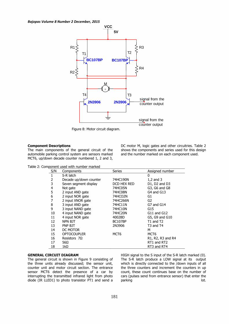
MOTOR CIRCUIT SECTION
A DC motor circuit is used to control the direction of rotation of the DC motor (M). It comprises of four
cross coupled NPN and PNP transistors. The collectors of the two NPN T1 and T2 are connected to the source
in order to conduct current through their emitters which are connected to the collectors of PNP
transistors T3 and T4 respectively as shown in Figure
8. While the emitters of T3 and T4 are common to
ground this connection would not allow the motor to
rotate. But when base terminal of T3 receive a HIGH signal, T4 receive a LOW signal through its base so
that T1 and T3 transistors are active which drive the motor in anti-clockwise direction to close the gate at
the maximum 120 counts. However, when the base of T4 receives HIGH signal while that of T3 receives LOW
signal the transistors T2 and T4 are now active in such
that they drive the motor in the clockwise direction to open the gate (Bolton, 2004; Kleiz, 2006).
180
Bajopas Volume 8 Number 2 December, 2015
2N3906 2N3906
BC107BP BC107BP
A
VCC5V
M
T1 T2
T3T4
R1
R2
R3
R4
signal from thecounter output
signal from thecounter output
Figure 8: Motor circuit diagram.
Component Descriptions The main components of the general circuit of the
automobile parking control system are sensors marked MCT6, up/down decade counter numbered 1, 2 and 3,
DC motor M, logic gates and other circuitries. Table 2 shows the components and series used for this design
and the number marked on each component used.
Table 2: Component used with number marked
S/N Components Series Assigned number
1 S-R latch 0 2 Decade up/down counter 74HC190N 1,2 and 3
3 Seven segment display DCD HEX RED D1, D2 and D3 4 Not gate 74HC05N G3, G6 and G8
5 2 input AND gate 74HC08N G4 and G13 6 2 input NOR gate 74HCO2N G1
7 2 input XNOR gate 74HC266N G2 8 3 input AND gate 74HC11N G7 and G14
9 3 input NAND gate 74HC10N G15 10 4 input NAND gate 74HC20N G11 and G12
11 4 input NOR gate 4002BD G5, G9 and G10
12 NPN BJT BC107BP T1 and T2 13 PNP BJT 2N3906 T3 and T4
14 DC MOTOR M 15 OPTOCOUPLER MCT6 MCT6
16 Resistors 7Ω R1, R2, R3 and R4 17 56Ω RT1 and RT2
18 1kΩ RT3 and RT4
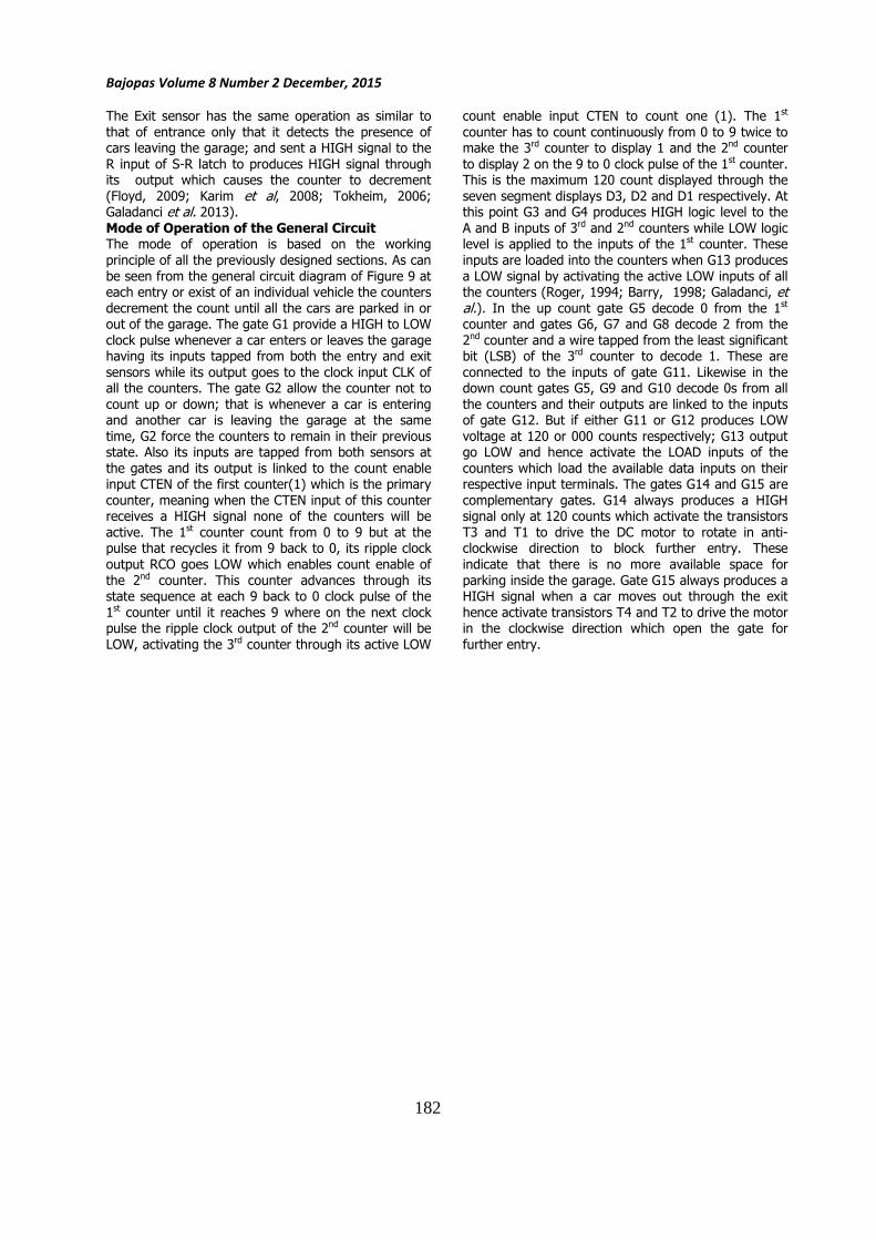
GENERAL CIRCUIT DIAGRAM The general circuit is shown in Figure 9 consisting of
the three units already discussed; the sensor unit,
counter unit and motor circuit section. The entrance sensor MCT6 detect the presence of a car by
interrupting the transmitted infrared light from photo diode (IR LLED1) to photo transistor PT1 and send a
HIGH signal to the S input of the S-R latch marked (0). The S-R latch produce a LOW signal at its output
which is directly connected to the /down inputs of all
the three counters and increment the counters in up count, these count continues base on the number of
cars (pulses send from entrance sensor) that enter the parking lot.
181
Bajopas Volume 8 Number 2 December, 2015
The Exit sensor has the same operation as similar to
that of entrance only that it detects the presence of cars leaving the garage; and sent a HIGH signal to the
R input of S-R latch to produces HIGH signal through its output which causes the counter to decrement
(Floyd, 2009; Karim et al, 2008; Tokheim, 2006; Galadanci et al. 2013).
Mode of Operation of the General Circuit The mode of operation is based on the working
principle of all the previously designed sections. As can
be seen from the general circuit diagram of Figure 9 at each entry or exist of an individual vehicle the counters
decrement the count until all the cars are parked in or out of the garage. The gate G1 provide a HIGH to LOW
clock pulse whenever a car enters or leaves the garage having its inputs tapped from both the entry and exit
sensors while its output goes to the clock input CLK of all the counters. The gate G2 allow the counter not to
count up or down; that is whenever a car is entering and another car is leaving the garage at the same
time, G2 force the counters to remain in their previous state. Also its inputs are tapped from both sensors at
the gates and its output is linked to the count enable input CTEN of the first counter(1) which is the primary
counter, meaning when the CTEN input of this counter receives a HIGH signal none of the counters will be
active. The 1st counter count from 0 to 9 but at the pulse that recycles it from 9 back to 0, its ripple clock
output RCO goes LOW which enables count enable of
the 2nd counter. This counter advances through its state sequence at each 9 back to 0 clock pulse of the
1st counter until it reaches 9 where on the next clock pulse the ripple clock output of the 2nd counter will be
LOW, activating the 3rd counter through its active LOW
count enable input CTEN to count one (1). The 1st
counter has to count continuously from 0 to 9 twice to make the 3rd counter to display 1 and the 2nd counter
to display 2 on the 9 to 0 clock pulse of the 1st counter. This is the maximum 120 count displayed through the
seven segment displays D3, D2 and D1 respectively. At this point G3 and G4 produces HIGH logic level to the
A and B inputs of 3rd and 2nd counters while LOW logic level is applied to the inputs of the 1st counter. These
inputs are loaded into the counters when G13 produces
a LOW signal by activating the active LOW inputs of all the counters (Roger, 1994; Barry, 1998; Galadanci, et al.). In the up count gate G5 decode 0 from the 1st counter and gates G6, G7 and G8 decode 2 from the
2nd counter and a wire tapped from the least significant bit (LSB) of the 3rd counter to decode 1. These are
connected to the inputs of gate G11. Likewise in the down count gates G5, G9 and G10 decode 0s from all
the counters and their outputs are linked to the inputs of gate G12. But if either G11 or G12 produces LOW
voltage at 120 or 000 counts respectively; G13 output go LOW and hence activate the LOAD inputs of the
counters which load the available data inputs on their respective input terminals. The gates G14 and G15 are
complementary gates. G14 always produces a HIGH signal only at 120 counts which activate the transistors
T3 and T1 to drive the DC motor to rotate in anti-clockwise direction to block further entry. These
indicate that there is no more available space for
parking inside the garage. Gate G15 always produces a HIGH signal when a car moves out through the exit
hence activate transistors T4 and T2 to drive the motor in the clockwise direction which open the gate for
further entry.
182
Ba
jop
as
Vo
lum
e 8
Nu
mb
er
2 D
ece
mb
er,
20
15
MCT62
1
8
7
MCT6
1kΩ56Ω
1kΩ56Ω2N3906 2N3906
BC107BP BC107BP
7Ω
7Ω 7Ω
7Ω
A
VCC5V
M
T1T2
T3T4
R1
R2
R3
R4
74HC190N_4V
A15
B1
C10
D9
~U/D5
QA 3
QB 2
QC 6
QD 7
~CTEN4
~LOAD11
~RCO 13
MAX/MIN 12
CLK14
74HC190N_4V
A15
B1
C10
D9
~U/D5
QA 3
QB 2
QC 6
QD 7
~CTEN4
~LOAD11
~RCO 13
MAX/MIN 12
CLK14
74HC190N_4V
A15
B1
C10
D9
~U/D5
QA 3
QB 2
QC 6
QD 7
~CTEN4
~LOAD11
~RCO 13
MAX/MIN 12
CLK14
SR_LATCH
S Q
~QR
RESET
EN
SET
74HC02N_4V
DCD_HEXDCD_HEXDCD_HEX
VCC5V
74HC08N_4V
4002BD_5V
4002BD_5V
4002BD_5V
74HC08N_4V
74HC266N_4V
74HC11N_4V 74HC20N_4V
74HC10N_4V
123
G1
G2G3
G4
G5
G6
G7G8
G9G10
G11
G12
G13
G14
G15
0
D3 D2 D1
74HC04N_4V
74HC04N_4V74HC04N_4V
74HC11N_4V
74HC20N_4V
VCC5V
RT1 RT3
RT2 RT4
PT1
PT2
IR LED1
IR LED2
D C B A ABCD ABCD
Fig
ure
9:
Genera
l ci
rcuit o
f a
120 c
apaci
ty A
uto
mobile
park
ing c
ontr
ol sy
stem
S
IMU
LA
TIO
N
In
the s
imula
tion s
oft
ware
, se
nso
rs c
annot
funct
ioned
so
switch
es
are
use
d
to
contr
ol
the
inputs
.
Com
bin
ational
logic
gate
s w
ere
si
mula
ted
by
consi
dering t
heir f
unct
ions
usi
ng t
ruth
table
for
them
to b
e p
roperly p
lace
d w
here
they s
hould
be.
Up/d
ow
n
counte
rs s
peci
fica
lly d
eca
de w
ere
use
d t
o p
roduce
the
maxim
um
count
of
120.
183
Bajopas Volume 8 Number 2 December, 2015
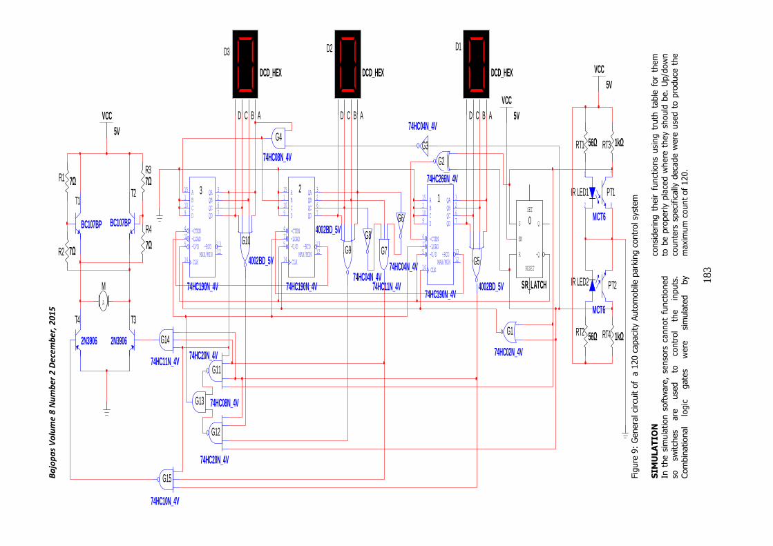
The 3rd counter was considered as a hundredth counter
(it counts in hundred) and the 2nd counter regarded as a tenth counter while the 1st counter considered to be
the unit counter. The design was simulated using national instrument electronics software (multisim
version 11.0). The other part of the design that
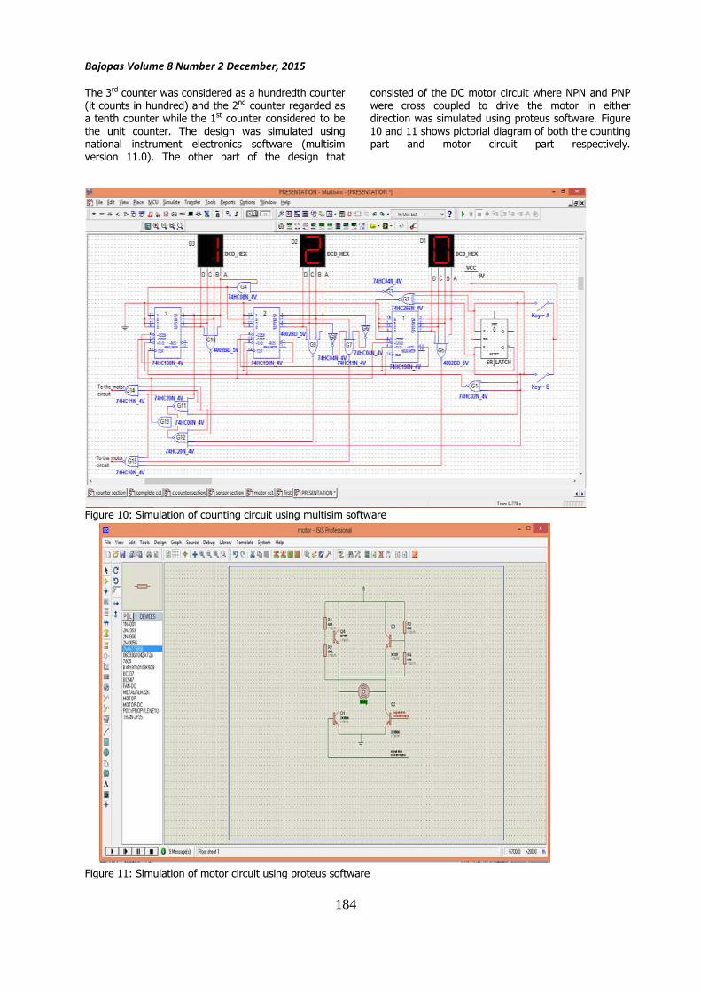
consisted of the DC motor circuit where NPN and PNP
were cross coupled to drive the motor in either direction was simulated using proteus software. Figure
10 and 11 shows pictorial diagram of both the counting part and motor circuit part respectively.
Figure 10: Simulation of counting circuit using multisim software
Figure 11: Simulation of motor circuit using proteus software
184
Bajopas Volume 8 Number 2 December, 2015
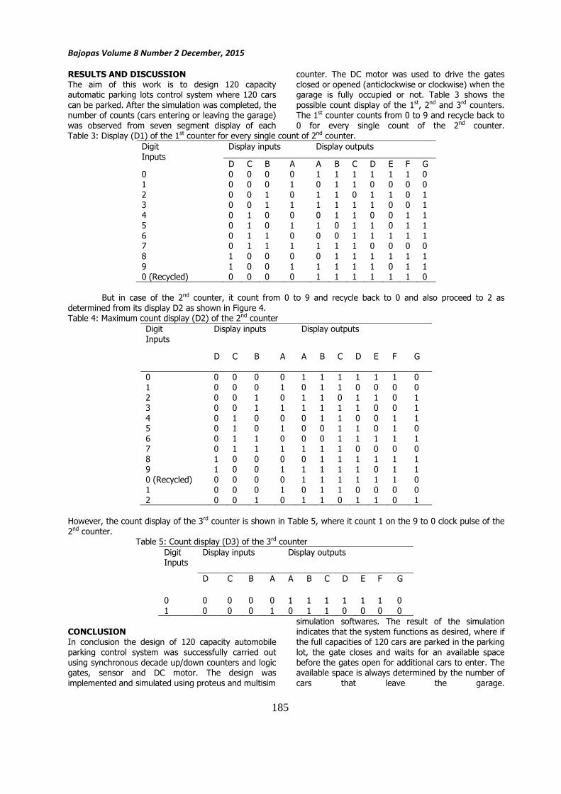
RESULTS AND DISCUSSION
The aim of this work is to design 120 capacity automatic parking lots control system where 120 cars
can be parked. After the simulation was completed, the number of counts (cars entering or leaving the garage)
was observed from seven segment display of each
counter. The DC motor was used to drive the gates
closed or opened (anticlockwise or clockwise) when the garage is fully occupied or not. Table 3 shows the
possible count display of the 1st, 2nd and 3rd counters. The 1st counter counts from 0 to 9 and recycle back to
0 for every single count of the 2nd counter.Table 3: Display (D1) of the 1st counter for every single count of 2nd counter.
Digit
Inputs
Display inputs Display outputs
D C B A A B C D E F G
0 0 0 0 0 1 1 1 1 1 1 0 1 0 0 0 1 0 1 1 0 0 0 0
2 0 0 1 0 1 1 0 1 1 0 1 3 0 0 1 1 1 1 1 1 0 0 1
4 0 1 0 0 0 1 1 0 0 1 1 5 0 1 0 1 1 0 1 1 0 1 1
6 0 1 1 0 0 0 1 1 1 1 1 7 0 1 1 1 1 1 1 0 0 0 0
8 1 0 0 0 0 1 1 1 1 1 1
9 1 0 0 1 1 1 1 1 0 1 1 0 (Recycled) 0 0 0 0 1 1 1 1 1 1 0
But in case of the 2nd counter, it count from 0 to 9 and recycle back to 0 and also proceed to 2 as
determined from its display D2 as shown in Figure 4. Table 4: Maximum count display (D2) of the 2nd counter
Digit
Inputs
Display inputs Display outputs
D C B A A B C D E F G
0 0 0 0 0 1 1 1 1 1 1 0
1 0 0 0 1 0 1 1 0 0 0 0
2 0 0 1 0 1 1 0 1 1 0 1 3 0 0 1 1 1 1 1 1 0 0 1
4 0 1 0 0 0 1 1 0 0 1 1 5 0 1 0 1 0 0 1 1 0 1 0
6 0 1 1 0 0 0 1 1 1 1 1 7 0 1 1 1 1 1 1 0 0 0 0
8 1 0 0 0 0 1 1 1 1 1 1 9 1 0 0 1 1 1 1 1 0 1 1
0 (Recycled) 0 0 0 0 1 1 1 1 1 1 0 1 0 0 0 1 0 1 1 0 0 0 0
2 0 0 1 0 1 1 0 1 1 0 1
However, the count display of the 3rd counter is shown in Table 5, where it count 1 on the 9 to 0 clock pulse of the
2nd counter. Table 5: Count display (D3) of the 3rd counter
Digit Inputs
Display inputs Display outputs
D C B A A B C D E F G
0 0 0 0 0 1 1 1 1 1 1 0
1 0 0 0 1 0 1 1 0 0 0 0
CONCLUSION In conclusion the design of 120 capacity automobile
parking control system was successfully carried out
using synchronous decade up/down counters and logic gates, sensor and DC motor. The design was
implemented and simulated using proteus and multisim
simulation softwares. The result of the simulation
indicates that the system functions as desired, where if the full capacities of 120 cars are parked in the parking
lot, the gate closes and waits for an available space
before the gates open for additional cars to enter. The available space is always determined by the number of
cars that leave the garage.
185
Bajopas Volume 8 Number 2 December, 2015
RECOMMENDATION This work is recommended to be carried out using
programmable integrated circuit (PIC) instead of up/down counter and logic gates. It can also be
designed to count up to 999 which is much easier
because less logic gates will be required. It is also more feasible to used software that can take
incorporated both the sensor and counter section for more efficient simulation.
REFERENCES Barry, P. (1998). Fundamentals of Digital Electronics.
National Instruments Corporation. Texas: U. S. A. Page 36-45 Bolton, W. (2004).
Instrumentation and Control System.
Elsevier Science & Technology Books. Chandni, P., Monalisa S., Priya, S, and Sejal, S(2015).:
Rotary Automated Car Parking System, International Journal of Engineering Science
and Innovative Technology (IJESIT) Volume 4, Issue 2, March 2015
loyd, T. L. (2009). Digital Fundamentals. Tenth edition. Pearson Prentice Hall Education
International. Upper saddle River: New Jersey.
Galadanci G.S.M., Gana S. M. and Abdullahi, M., Design and Implementation of Digital Clock
using Frequency Dividers and 555 timer, Journal of Nigerian Association of
Mathematical Physics, Nigeria, Volume 23, March 2013.
Karim M. A. and Chan. X. (2008). Digital design basic concept and principles. U. S. Taylor and
Francis group. U.S.A
Kleitz, W. (2006). Digital Electronics with VHDL. Pearson Prentice Hall Education International.
Upper saddle River: New Jersey. Page 541-
547 Mark, B. (2003). Digital Design: A Comprehensive
Guide to Digital Electronics and Computer System Architecture. McGraw-Hill Companies.
New York: USA.
Myke, P. (2005). Digital Electronics Demystified. McGraw-Hill Companies. New York: USA.
Pohl, J., Sethsson, M., Degerman, P., and Larsson, J.(2006) “A semi-automated parallel parking
system for passenger cars”, Proc. IMechE Vol. 220 Part D: J. Automobile Engineering, 2006,
pp. 53. Roger L. T. (1994). Theory and problems of digital
principles 3rd
Edition, schaum’s outline series. Mc Graw Hill companies. New York: USA. Page 240-244
Scherz, P. (2000). Practical Electronics for Inventors.
McGraw-Hill Companies. New York: USA. Tokheim R. L. (2006). Digital electronics principles and
applications. Seventh edition, McGraw-Hill Companies.
Wada, M., Yoon, K.S., Hashimoto, H. (2003): “Development of Advanced Parking
Assistance System,” IEEE Transactions On Industrial Electronics, vol. 50, pp. 4-17,
February 2003.
:
186