design and development of an automatic speed limiter
99
DESIGN AND DEVELOPMENT OF AN AUTOMATIC SPEED LIMITER FOR CITY MINIBUS TAXI USING A MICROCONTROLLER-BASED ELECTROMAGNET Miftah Fantahun Endris A Thesis Submitted to The Department of Mechanical Systems and Vehicle Engineering School of Mechanical, Chemical and Materials Engineering A Thesis Submitted in Partial Fulfillment of the Requirement for the Degree of Master’s in Automotive Engineering Office of Graduate Studies Adama Science and Technology University Adama NOV, 2020 GC
-
Upload
khangminh22 -
Category
Documents
-
view
0 -
download
0
Transcript of design and development of an automatic speed limiter

DESIGN AND DEVELOPMENT OF AN AUTOMATIC SPEED LIMITER
FOR CITY MINIBUS TAXI USING A MICROCONTROLLER-BASED
ELECTROMAGNET
Miftah Fantahun Endris
A Thesis Submitted to
The Department of Mechanical Systems and Vehicle Engineering
School of Mechanical, Chemical and Materials Engineering
A Thesis Submitted in Partial Fulfillment of the Requirement for the Degree of
Master’s in Automotive Engineering
Office of Graduate Studies
Adama Science and Technology University
Adama
NOV, 2020 GC
DESIGN AND DEVELOPMENT OF AN AUTOMATIC SPEED LIMITER
FOR CITY MINIBUS TAXI USING A MICROCONTROLLER-BASED
ELECTROMAGNET
Miftah Fantahun Endris
Advisor: Assistant prof. Mekonnen Liben
A Thesis Submitted to
The Department of Mechanical Systems and Vehicle Engineering
School of Mechanical, Chemical and Materials Engineering
A Thesis Submitted in Partial Fulfillment of the Requirement for the Degree of
Master’s in Automotive Engineering
Office of Graduate Studies
Adama Science and Technology University
Adama
NOV, 2020 GC
APPROVAL OF BOARD OF EXAMINERS
We, the undersigned, members of the Board of Examiners of the final open defense by Miftah
Fantahun have read and evaluated his thesis entitled “Design and Development of An Automatic
Speed Limiter for City Minibus Taxi Using a Microcontroller-Based Electromagnet” and
examined the candidate. This is, therefore, to certify that the thesis has been accepted in partial
fulfillment of the requirement of the Degree of Master’s in Automotive Engineering
_____________________________ _____________________ ___________________
Advisor Signature Date
_____________________________ _____________________ ___________________
Chairperson Signature Date
_____________________________ _____________________ ___________________
Internal Examiner Signature Date
_____________________________ _____________________ ___________________
External Examiner Signature Date
_____________________________ _____________________ ___________________
Head of the Department Signature Date
_____________________________ _____________________ ___________________
School Dean Signature Date
_____________________________ _____________________ ___________________
Post Graduate Dean Signature Date
ADVISOR’S APPROVAL SHEET
To: Mechanical Systems and Vehicle Engineering department
Subject: Thesis Submission
This is to certify that the thesis entitled “Design and Development of An
Automatic Speed Limiter for City Minibus Taxi Using a Microcontroller-Based
Electromagnet” submitted in partial fulfillment of the requirements for the degree
of Master’s in Automotive Engineering, the Graduate program of the department
of Mechanical Systems and Vehicle Engineering and has been carried out by
Miftah Fantahun Endris Id. No PGR/18292/11, under my supervision. Therefore,
I recommend that the student has fulfilled the requirements and hence hereby he
can submit the thesis to the department.
Assistant prof. Mekonnen Liben ______________ ____________
Name of major advisor Signature Date

i
DECLARATION
I hereby declare that this MSc Thesis is my original work and has not been
presented for a degree in any other university, and all sources of material used for
this thesis have been duly acknowledged.
Name:
Miftah Fantahun Endris
Signature: _________________________________
This MSc Thesis has been submitted for examination with my approval as thesis
advisor.
Name:
Assistant prof. Mekonnen Liben
Signature: __________________________________
Date of submission: _________________________

ii
ACKNOWLEDGMENT
All praise to the Almighty Allah whose knowledge and compassion extends to all His creations.
This work would not have been completed without His endless grace and kindness upon me.
And then I thank my advisor Assistant prof. Mekonnen Liben for giving me direction in
selecting a study area which most of the previous MSc graduate students did not concern on it.
I thank Dr Harish Kalla for introducing me Arduino boards and the programming. I also thank
Muhammed Abubeker a mechanic in Two Brothers Flour and Biscuit Factory workshop for his
effort in doing workshop works of the electromagnet in the lock down time due to COVID-19.
Miftah Fantahun

iii
TABLE OF CONTENTS
CONTENT PAGE
DECLARATION .................................................................................................. i
ACKNOWLEDGMENT ..................................................................................... ii
LIST OF TABLES ............................................................................................ vii
LIST OF FIGURES ......................................................................................... viii
ACRONYMS AND ABBREVIATIONS ........................................................... x
ABSTRACT ....................................................................................................... xii
CHAPTER ONE .................................................................................................. 1
INTRODUCTION ............................................................................................... 1
1.1 Background ....................................................................................................................... 1
1.2 Statement of the Problem .................................................................................................. 5
1.3 Objectives ......................................................................................................................... 6
1.3.1 General Objective .................................................................................................................... 6
1.3.2 Specific Objectives .................................................................................................................. 6
1.4 Scope of the study ............................................................................................................. 7
1.5 Significance of the study ................................................................................................... 7
1.6 Limitation of the study ...................................................................................................... 7
CHAPTER TWO ................................................................................................. 8
LITERATURE REVIEW ................................................................................... 8
2.1 Effects of speed ................................................................................................................. 8
2.2 Nilsson power model ........................................................................................................ 9
2.3 Speed and fatality rate ..................................................................................................... 10
2.4 Speed limiter and greenhouse gases ............................................................................... 13

iv
2.5 Road traffic accident severity in Ethiopia ....................................................................... 13
2.5 Minibus and RTA in Ethiopia ......................................................................................... 14
2.6 Speed managing methods ............................................................................................... 15
2.7 Microcontroller ............................................................................................................... 15
2.8 Pedal forces and travel distance ...................................................................................... 16
2.9 Speed limit in Ethiopia ................................................................................................... 17
2.10 City vehicle speed limit of 30 kmph ............................................................................. 18
2.11 Variable speed limit ...................................................................................................... 18
2.12 Research works on speed limiter .................................................................................. 19
2.13 Impact of speed limiter ................................................................................................. 22
2.14 Speed limiter challenges ............................................................................................... 24
2.15 Speed limiter and congestion ........................................................................................ 25
2.16 Literature Summary ...................................................................................................... 26
2.17 Research gap ................................................................................................................. 26
CHAPTER THREE .......................................................................................... 28
MATERIALS AND METHODS ..................................................................... 28
3.1 Materials ......................................................................................................................... 28
3.1.1 Arduino ATMEGA2560 microcontroller .............................................................................. 29
3.1.2 Hall effect sensor ................................................................................................................... 30
3.1.3 Bread board ........................................................................................................................... 31
3.1.4 Jumper wires ......................................................................................................................... 32
3.1.5 Voltage source ....................................................................................................................... 32
3.1.6 OLED display ........................................................................................................................ 32
3.1.7 Sheet metal core .................................................................................................................... 33
3.1.8 Coil ........................................................................................................................................ 33
3.1.9 Relay Module ........................................................................................................................ 34

v
3.1.10 Voltage booster ................................................................................................................... 34
3.1.11 A6 GSM/GPRS Module ...................................................................................................... 35
3.1.12 LCD display ........................................................................................................................ 36
3.1.13 SD card module ................................................................................................................... 36
3.1.14 DS3231 RTC (Real Time Clock) Module ........................................................................... 37
3.1.15 Push button, RGB, resistors and Multimeter ....................................................................... 37
3.2 Methods ........................................................................................................................... 39
3.2.1 Literature Review .................................................................................................................. 39
3.2.2 Data Collection ...................................................................................................................... 39
3.2.3 Arduino Mega microcontroller programming ....................................................................... 39
3.2.4 Flowchart of the program ...................................................................................................... 42
3.2.5 Simulation ............................................................................................................................. 44
3.2.6 Prototype Construction .......................................................................................................... 44
3.2.7 Process description ................................................................................................................ 44
3.2.8 Electromagnet construction ................................................................................................... 46
3.2.9 EMS 2017 Software .............................................................................................................. 46
CHAPTER FOUR ............................................................................................. 49
RESULT AND DISCUSSION .......................................................................... 49
4.1 Speed limiter circuit result .............................................................................................. 49
4.1.1 Speed measurement ............................................................................................................... 49
4.1.2 Speed limit selection ............................................................................................................. 49
4.1.3 Over speed detection ............................................................................................................. 53
4.1.4 Over speed recording ............................................................................................................ 53
4.1.5 Sending SMS message .......................................................................................................... 55
4.2 Electromagnet simulation result ..................................................................................... 55
vi
CHAPTER FIVE ............................................................................................... 61
SUMMARY, CONCLUSION AND RECOMMENDATION ....................... 61
5.1 Summary ......................................................................................................................... 61
5.2 Conclusion ...................................................................................................................... 61
5.3 Recommendation ............................................................................................................ 62
5.4 Future works ................................................................................................................... 62
References .......................................................................................................... 63
Appendix ............................................................................................................ 71
Appendix I: Arduino sketch for speed limiter ...................................................................... 71
Appendix II: Dimensions of the Electromagnet ................................................................... 83

vii
LIST OF TABLES
TABLE PAGE
Table 3. 1 List of material for the system .................................................................................. 28
Table 3. 2 Arduino Mega microcontroller data sheet ................................................................ 30
Table 3. 3 Operators and their description ................................................................................ 40
Table 3. 4 Data types and their size and range .......................................................................... 40
Table 4. 1 Sample data from recorded speed in SD card .......................................................... 54
Table 4. 2 Coil information ....................................................................................................... 55
Table 4. 3 Core information ...................................................................................................... 56
Table 4. 4 magnetic flux with rated voltage .............................................................................. 60

viii
LIST OF FIGURES
FIGURE PAGE
Figure 1. 1 Road traffic accident in the regions of Ethiopia Source ........................................... 2
Figure 1. 2 Serious injuries and fatalities in Ethiopia from 2008 to 2013 GC ............................ 3
Figure 1. 3 Speed Violation in East Shewa Cities and Towns .................................................... 4
Figure 2. 1 Initial speed and braking distance relation ................................................................ 9
Figure 2. 2 Effect of change in mean speed on fatal, serious and all injuries .......................... 11
Figure 2. 3 Risk of death with age regarding by collision speed............................................... 11
Figure 2. 4 Fatality risk with different speed level .................................................................... 12
Figure 2. 5 Death risk percentage and field of vision with speed ............................................. 12
Figure 2. 6 Brake and accelerator pedal force using HiAce 5th generation model .................... 17
Figure 2. 7 Vehicle speed with and without speed limiter ........................................................ 24
Figure 3. 1 Arduino Mega microcontroller ............................................................................... 29
Figure 3. 2 VMA 313 hall effect sensor .................................................................................... 31
Figure 3. 3 Bread board ............................................................................................................. 31
Figure 3. 4 Jumper wires ........................................................................................................... 32
Figure 3. 5 OLED display with 128x64 pixels .......................................................................... 33
Figure 3. 6 E-shaped sheet metal ............................................................................................... 33
Figure 3. 7 copper wire for coil ................................................................................................. 34
Figure 3. 8 One channel relay module ....................................................................................... 34
Figure 3. 9 DC voltage booster up to 35V ................................................................................. 35
Figure 3. 10 A6 GSM/GPRS module ........................................................................................ 35
Figure 3. 11 16 X 2 LCD with blue background ....................................................................... 36
Figure 3. 12 SD card module ..................................................................................................... 36
Figure 3. 13 DS3231 Real time clock........................................................................................ 37
Figure 3. 14 Apparatus used for the project .............................................................................. 38
Figure 3. 15 Flow chart of the program ..................................................................................... 43
Figure 3. 16 Block diagram of the speed limiter ....................................................................... 45
Figure 4. 1 LCD showing speed limit 30 KPH green RGB lighting up .................................... 49
Figure 4. 2 The circuit diagram of the project without A6 GSM module ................................. 50

ix
Figure 4. 3 Schematic diagram of the speed limiter .................................................................. 51
Figure 4. 4 LCD showing Selected speed limit 50 kmph .......................................................... 52
Figure 4. 5 LCD showing selected speed 70 kmph ................................................................... 52
Figure 4. 6 Over speeding detecting Red RGB lighting up ....................................................... 53
Figure 4. 7 Graph of Sample data from over speed recording SD card .................................... 54
Figure 4. 8 Screen shot from a cell phone of the SMS .............................................................. 55
Figure 4. 9 Magnetic flux density at 12V .................................................................................. 57
Figure 4. 11 Magnetic flux density at 36V ................................................................................ 58
Figure 4. 13 Magnetic flux density at 60V ................................................................................ 59

x
ACRONYMS AND ABBREVIATIONS
AC : Alternating current
ARM : Advanced RISC machine
CMV : Commercial Motor Vehicle
CS : Chip select
DC : Direct current
ECU : Electronic Control Unit
EEPROM : Electrically erasable programmable read-only memory
EM : Electromagnet
EMS : Electromagnet simulation
EU : European Union
FEA : Finite element analysis
GDP : Gross Domestic Product
GHG : Greenhouse Gas
GPRS : General Packet Radio Service
GPS : Global Positioning System
GSM : Global System for Mobile Communications
ICSP : In-circuit serial programming
IDE : Integrated development environment
IR : InfraRed
LCD : Liquid Crystal Display
LED : Light Emitting Diode
MISO : Master In Slave Out
MOSI : Master-out, Slave-in
NVMe : Nonvolatile memory express
OLED : Organic Light-Emitting Diode
PWM : Pulse Width Modulation
RAM : Random access memory
RF : Radio Frequency
RGB : Red, Green and Blue
RPM : Revolution per minuit

xi
RTAs : Road Traffic Accidents
RTC : Real time clock
SCK : Serial Clock
SCL : Serial Clock Line
SD : Secure Digital
SDA : Serial data line
SIM : Subscriber identification module
SL : Speed Limiter
SMS : Short Message Service
SPI : Serial Peripheral Interface
SRAM : Static Random Access Memory
SSD : Solid-state drive
UART : Universal Asynchronous Receiver/Transmitter
USB : Universal Serial Bus
VSL : Variable Speed Limit
WHO : World Health Organization
xii
ABSTRACT
Ethiopia is experiencing an increase in road traffic accidents, much of which is caused due to
human fault like over speeding. Among the frequent participants of road traffic accidents,
minibus taxis cover the largest percentage. This study tried to make a speed limiter
incorporating a strong electromagnet for restricting the driver by making the accelerator pedal
stick to the magnet not to go further beyond the proper speed limit for minibus taxi. Selecting
relevant materials for the system, writing the algorithm for the system, designing the circuit,
preparing the electromagnet and making a prototype for its functionality are the main methods
followed. Since most commercial vehicles in our country do not have a working speedometer,
the designed speed limiter has its own speed measuring system using the effective wheel radius
of a common minibus taxi. Arduino Mega microcontroller calculates the speed of the vehicle by
measuring the period between two pulses from a hall sensor which is utilized to calculate the
revolution per minute and velocity of a vehicle wheel. With this reference, the program
compares the calculated speed with the nominated speed limit by a push button and activates
an electromagnet by using a relay to act on the accelerator pedal of the vehicle. 30, 50 and 70
kmph are the three pre-set speed limits which were added to the limiter to effectively use the
speed limiter inside the town zone. The designated speed limit is displayed on a 16X2 liquid
crystal display. The display also shows whether speed limit is selected or not. When the driver
does not select one of the pre-set speed limits which are mandatory, provided that the car is
inside the town zone, a message is sent to the owner of the vehicle or other enforcing authorities.
But even if the driver does not select one of the speed limits, the limiter selects 30 kmph as its
default speed limit and speeds above 30 kmph is recorded in secure digital card with 1 second
time interval. The electromagnet was simulated in solid work electromagnetic simulation
software with varying the voltage. The simulation gave the values of magnetic flux density in
different areas of the electromagnet. As the result indicated voltage value more than 36V gave
a good fixing ability for the ferromagnetic material and a delay of 10 seconds is required in
order to inform through a message.
Keywords: Arduino Mega microcontroller, Hall sensor, Electromagnet, Push button, Secure
digital card, Minibus taxi

1
CHAPTER ONE
INTRODUCTION
1.1 Background
The amount of road traffic losses in life, continues to climb, reaching 1.35 million in 2016.
However, the rates of fatalities relative to the extent of the world’s population has stabilized in
recent years (WHO, 2018). Human error including driving misbehavior contributes to over 90
percent of road vehicle accidents, and speeding is considered to be risky (Sahebi et al., 2019).
Most of these deaths are in developing and middle-income countries having rapid economic
growth. From collected 39 studies of 15 different African countries the road traffic injury
percentage enlarged from 40.7 per 100,000 population in the 1990s to 92.9 per 100,000
population between 2010 and 2015 with the four- wheeler having highest road traffic death rate.
As well as being a public health problem, road traffic injuries are a development issue.
Developing and middle- income countries lose approximately 3% of GDP as a result of road
traffic crashes (Bikila Teklu, 2014).
Among the encounters of the urban transport in Ethiopia is high rate of traffic accidents. (Federal
et al., 2011).Excessive (speed above speed limit) and inappropriate speed (speed too high for
the prevailing condition, but within speed limit) is the number one road safety problem in many
countries repeatedly contributing to as much as one third of fatal accidents and an aggravation
factor in all accidents. Throughout the world, in recent times road traffic accidents caused by
over speeding have increased. Over speeding is a main reason of accidents on highways and
roads. Many drivers especially in low income countries do not see their speedometers during
driving or the speedometer is not properly working in our case this will negatively affect the
time of response of the driver in incidents.
Excessive speed, pedestrians and livestock in the roadway, random local driving habits and the
absence of adherence to basic safety standards for vehicles are daily hazards. Many vehicles are
unregistered, and many drivers lack basic driver training, licensure or insurance. Emergency
service areas are inadequate to nonexistent in many parts of the country (US Travel Advisory,
2020).

2
A population growth rate of approximately 3% and estimated annual increases in the motor
vehicle fleet of 10-15% is increasing upward pressure on road trauma suffered in Ethiopia.
Figure 1.1 shows the number of road traffic accidents in 9 regions and two Administrative states.
Figure 1. 1 Road traffic accident in the regions of Ethiopia Source:(Martin Small, 2018)
The current systems for collection of fatality, serious injury and related road safety data mean
that firm conclusions are difficult to draw about the scale of the problem. For example, fatalities
recorded in official statistics have varied to those published by the World Health Organization
(WHO).
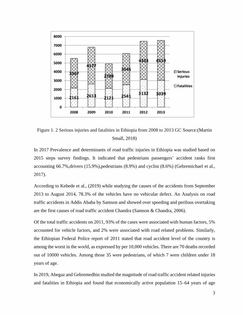
As shown in Figure 1.2, there are to some extent more serious injuries than fatalities, whereas
there are typically many times more serious injuries than fatalities in jurisdictions with upright
practice data systems. Nevertheless, the circumstances appear clear. Ethiopia has a major road
safety problem. It is becoming worse, and will continue to do so unless major institutional,
policy and investment reforms are affected (Martin Small, 2018).
Gam
bel
a
Hara
ri
Ben
. G
um
uz
Afa
r
Dir
e D
aw
a
Som
ali
a
SN
NP
Tig
ray
Am
hara
Ad
dis
Ab
ab
a
Oro
mia
3
Figure 1. 2 Serious injuries and fatalities in Ethiopia from 2008 to 2013 GC Source:(Martin
Small, 2018)
In 2017 Prevalence and determinants of road traffic injuries in Ethiopia was studied based on
2015 steps survey findings. It indicated that pedestrians passengers’ accident ranks first
accounting 66.7%,drivers (15.9%),pedestrians (8.9%) and cyclist (8.6%) (Gebremichael et al.,
2017).
According to Kebede et al., (2019) while studying the causes of the accidents from September
2013 to August 2014, 78.3% of the vehicles have no vehicular defect. An Analysis on road
traffic accidents in Addis Ababa by Samson and showed over speeding and perilous overtaking
are the first causes of road traffic accident Chandra (Samson & Chandra, 2006).
Of the total traffic accidents on 2011, 93% of the cases were associated with human factors, 5%
accounted for vehicle factors, and 2% were associated with road related problems. Similarly,
the Ethiopian Federal Police report of 2011 stated that road accident level of the country is
among the worst in the world, as expressed by per 10,000 vehicles. There are 70 deaths recorded
out of 10000 vehicles. Among those 35 were pedestrians, of which 7 were children under 18
years of age.
In 2019, Abegaz and Gebremedhin studied the magnitude of road traffic accident related injuries
and fatalities in Ethiopia and found that economically active population 15–64 years of age

4
contributed to nearly 85% of the total burden of road traffic accidents (RTAs). Especially adults
15–29 years take the highest toll and two-thirds of the victims are male. These finding were
indicative of the high loss of productivity associated with road accidents in Ethiopia (Abegaz &
Gebremedhin, 2019).
Minister of transport on pilot radar control program, which was conducted in East Shewa Zone
of Ethiopia, indication majority of drivers do not respect the speed limit rule of the road. The
graph below shows that speed violation in some cities and towns is sometimes up to three times
higher than the posted legal limit (Minister of Transport, February,2011)
Figure 1. 3 Speed Violation in East Shewa Cities and Towns source: (Minister of Transport,
February,2011)
Like any developing economies, Ethiopia has been experiencing large number of traffic accident
annually. About 3% of the Ethiopian population met a traffic accident which is equivalent to
about 3 million people who met traffic accident in 2015 (Traffic & Fact, 2020). If the trend is
not arrested, the problem of RTA on the social and economic will be more serious as the number
of vehicles increases. In this respect the Ethiopian transport authority is preparing different
solution which includes new speed limit proclamation in Addis Ababa city where almost one
third of the country’s registered vehicle locates.
5
In Addis Ababa, where walking accounts for more than 60% of travel, there were 2409 deaths
reported between 2003 and 2009. The majority of accidents (75.24%) involved vehicles used
for more than five years. Those failures can be minimized by incorporating speed limiting device
on vehicles. Since the lower the speed the car is travelling the shortest the stopping distance will
be which in fact reduce the damage due to the accidents (Akloweg et al., 2011).
Speed adaptation through in-car devices has been studied for more than 15 years (Chikezie et
al., 2017). In 1976 a speed limiter by using a solenoid valve for controlling a vacuum actuator
to override the manual throttle towards closed position was prepared. Later on, in 2002, a speed
limiter by providing a resistance force for the accelerator pedal, in order to make the driver not
exceed the speed limit. As the automotive industry continued to develop, the accelerator pedal
position began to be known by position sensor and this position was used as a signal or the ECU
to limit the speed of the vehicle. Now a days, as GSM and GPS become the necessary features
of modern vehicles and vehicles are becoming fully autonomous, the speed limiters of these
days are considering those features as an input for the speed limiting system for a better
calibration. Such systems for speed adaptation can contribute to a significant improvement of
road safety.
There are many types of speed limiters based on the method of operation of each include
Centrifugal, Mechanical, Pneumatic, Electronic and Hydraulic speed limiter. Amongst those
listed, the Electronic control speed limiter is more flexible and more reliable (HJÄLMDAHL et
al., 2002).
1.2 Statement of the Problem
In our country most of the transportation inside cities is done by minibus taxis. Most of the cars
imported were used, they are not in a safe condition for passengers and pedestrians. Many
studies done in identifying the causes of road traffic accident including the vehicle type indicated
that minibus taxis have a major role. Among the causes of most of the accidents human factor
exhibits more than 70% and speeding has a direct or indirect relation (Bikila Teklu, 2014). From
engineering remedies, for controlling and reducing speeding problem speed limiter is one of the
best solutions. Our country is making a campaign on 30 kmph speed limits but to effectively
implement this city speed limit this is not enough; a speed limiter is needed. Despite this fact
most of the cars are not in a comfortable condition even to install and calibrate the existing speed

6
limiters, most of them need high level of internet access to operate. Some of them are made to
operate on specific speed limit which makes them not versatile and all of them need an existing
external speed measuring device. some of them work by turning off the whole engine which can
be a problem for an accident. In some cases, the speed limiter should give an emergency exit
strategy but most of them does not have. Others have emergency exit but does not have another
strategy for those who are using it out of its purpose which reduces the effectiveness of the
limiter. So, a speed limiter which is capable of improving those weakness by:
Incorporating a separate speed measuring system for the limiter input.
Adding different speed limit values for the limiter.
Informing pedestrians and passengers the current condition of the vehicle’s speed and
speed limit.
Introducing strong electromagnet which sticks on the pedal once the pedal is closer to
the electromagnet.
Informing enforcing authorities about the usage of the speed limiter and speeds above
30 kmph is needed.
1.3 Objectives
1.3.1 General Objective
The main objective of this project is to design and develop a microcontroller-based speed limiter
for minibus taxis of our country.
1.3.2 Specific Objectives
The specific objectives of this work are:
• Designing a circuit of speed limiting system.
• Writing an algorithm for the microcontroller.
• Interfacing program with corresponding electronic component.
• Modeling the electromagnet to know the needed voltage rating for the coil and the place
with highest magnetic flux density.
• Developing the system on a small prototype and testing its functionality.
7
1.4 Scope of the study
The study tried to control the accelerator pedal with electromagnet and try the effectiveness with
a ferromagnetic material. It is made to only measure the speed of common minibus taxi. For
other vehicle types different effective radius should be provided. The study added speed
recording feature with three pre-set speed limits only which makes it compatible with city car
speed limits. The electromagnet was formed by selecting a microwave transformer and making
the primary winding of the transformer as a coil around an E-shaped sheet metal so shape needs
a modification for a compatible installation inside the vehicle. Only the magnetic flux density
was simulated, So, the force analysis is not addressed. since the force in different sections of
the electromagnet is different, the force cannot be calculated by a simple force and magnetic
flux density relation. It covered simulation of the electromagnet and a prototype of the whole
system.
1.5 Significance of the study
This thesis will pave a way for many students and graduates how to program a microcontroller
using ARDUINO and using it for speed limiters in minibus taxi. The program includes most of
the instructions in Arduino IDE which makes it easier to study the programming of Arduino
microcontroller. This thesis paves a way to use an electromagnetic control to accelerator pedal.
1.6 Limitation of the study
In executing this thesis work, there were different limitations. From those limitations, the
following are the major ones:
A 2D simulation EMS software which is only available through buying for making the
force analysis in different sections.
An inflation in costs of transport and different electronics component. Due to the
global pandemic disease COVID-19:
Absence of magnetic hall effect sensor library inside proteus 8.9 simulation software
makes the implementation of the program in the prototype only.

8
CHAPTER TWO
LITERATURE REVIEW
2.1 Effects of speed
Excessive and inappropriate speed is the most important factor contributing to the road injury
problem faced by many countries. The higher the speed the greater the stopping distance
required, and hence the increased risk of a crash. As more kinetic energy must be absorbed
during a high-speed impact, there is a higher risk of injury (Eric Howard, Lori Mooren, Goran
Nilsson, Allan Quimby, 2008).
The crash rate and severity of road traffic accidents rise as speed increases (Abegaz et al., 2014),
(IIHS, 2017) and (Aarts & Van Schagen, 2006). There are many contributing factors for this:
First, high speeds reduce the time drivers have available to process information, to
decide whether or not to react and, finally, to execute an action. This means the distance
covered during normal reaction time periods increases with an increase in speed.
Second, as braking distance is proportional to the square of the speed, the distance
between starting to brake and coming to a complete standstill also increases greatly with
increasing speed. The time needed is composed of two elements: the reaction time of the
driver (approximately 1 second in standard conditions) and the braking time. Figure 2.1
below shows the relationship between speed and braking distance (Ms Anna Vadeby,
Blair Turner et al, 2018).

9
Figure 2. 1 Initial speed and braking distance relation (R Elvik et al., 2004)
Thirdly, the possibility of avoiding collisions reduces as speed increases. As an example,
as shown in Figures 2.1, with a speed of 80 km/h on a dry road, it takes around 22 meters
(the distance travelled during a reaction time of approximately 1 second) to react to an
event, and a total of 57 meters to come to a standstill. If a pedestrian runs onto the road
36 meters ahead, the car driver would most probably kill the pedestrian if driving at 70
km/h or more, hurt the pedestrian if driving at 60 km/h and avoid hitting the child if
driving at 50 km/h. However, if the pedestrian runs out on to the road 15 meters ahead
of the driver, the probability is that the pedestrian would be fatally injured at 50 km/h
and all higher speeds (Ms Anna Vadeby, Blair Turner, 2018).
2.2 Nilsson power model
The relationship between serious injury accidents, fatal accidents and speed has been modelled
by Nilsson and is commonly illustrated by the Power Model. The Power Model consists of one
equation for fatalities, one for fatal and serious injuries and one for all injured road users. The
Model suggests that the number of fatal accidents, serious injury accidents (including fatal
accidents), and all police reported injury accidents (including fatal and serious injury accidents)
change in proportion to, respectively, the fourth, third and second power of the relative change
in the mean speed of traffic (Rune Elvik et al., 2004).

10
According to this model which can be applied to the common range of speeds. If there were
400 fatal accidents per year in a town and 500 people died due to those accidents and a 10%
reduction in the mean speed will have the following effect on the number of fatal accidents and
fatalities.
Fatal accidents after
fatal accidents before= (
speed after
speed before)
4
Source: (Rune Elvik et al., 2004)
So, the fatal accidents after the reduction on the mean speed will be:
Fatal accidents after = (speed after
speed before)
4
× fatal accidents before
speed after = speed before − speed before × 10%
speed after
speed before=
9
10= 0.9
Fatal accidents after = (0.9)4 × 400 = 262
number of fatalities =
Fatal accidents after + (0.98(number of fatalities before − fatal accidents))
number of fatalities = 262 + (0.98(500 − 400)) ≈ 305
The fatal accident reduced from 400 to 262 and the number of fatalities from 500 to 305. This
predicts how much reducing mean speed affect the road accident fatalities mathematically. The
remaining two formulas of Nilsson’s power model works as the previous example.
2.3 Speed and fatality rate
In united states Florida from 1993-1996 vehicle travel speed below 20 mph (32.1 kmph) has the
lowest fatality percentage with only 1.1%. As the speed raises from 20 mph the fatality rate will
increase with a more than double rate (Transportation, 1999).
Based on the Nilsson Power Model, a 5% increase in mean speed leads to approximately a 10%
increase in all injury accidents and a 20% increase in fatal accidents. Similarly, for a 5 %

11
decrease in mean speed there are typically 10% fewer injury accidents and 20% fewer fatal
accidents. Figure 2.2 below shows relation between mean speed change and different RTAs.
Figure 2. 2 Effect of change in mean speed on fatal, serious and all injuries
The probability of a pedestrian being killed in a car accident increases with the impact speed as
shown in Figure2.3 below. Results from on-the-scene inquiries of collisions relating pedestrians
and cars showed that 90% of pedestrians survive being hit by a car at speeds of 30 km/h; whereas
only 20% survive at speeds of 50 km/h (Angeles & Weston, 2006).
Figure 2. 3 Risk of death with age regarding by collision speed (Patterson et al., 2000).
Source: Data for figure generated from formula in Evans (1991, p26)
12
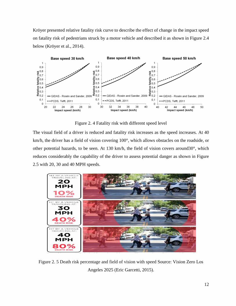
Kröyer presented relative fatality risk curve to describe the effect of change in the impact speed
on fatality risk of pedestrians struck by a motor vehicle and described it as shown in Figure 2.4
below (Kröyer et al., 2014).
Figure 2. 4 Fatality risk with different speed level
The visual field of a driver is reduced and fatality risk increases as the speed increases. At 40
km/h, the driver has a field of vision covering 100°, which allows obstacles on the roadside, or
other potential hazards, to be seen. At 130 km/h, the field of vision covers around30°, which
reduces considerably the capability of the driver to assess potential danger as shown in Figure
2.5 with 20, 30 and 40 MPH speeds.
Figure 2. 5 Death risk percentage and field of vision with speed Source: Vision Zero Los
Angeles 2025 (Eric Garcetti, 2015).

13
Many studies have highlighted the dangers drivers face when they exceed speed limits. It shown
that:
speed makes all road users sense less safe;
speed makes significant stress which chiefs to fatigue and carelessness;
the higher the speed, the narrower the field of vision;
excessive speed makes steering and controlling a vehicle harder;
braking distance rises with speed;
in a collision, the higher the speed, the greater the impact and the subsequent
consequences (Transports & Est, 2009) and (Mccabe et al., 2013).
2.4 Speed limiter and greenhouse gases
Using speed limiter has a positive effect on GHG. As reported in (Delhaye et al., 2016) when
they studied the role of speed limiters in light commercial vehicle on CO2 regulation, fixing the
speed limit 110 kmph has a CO2 reduction of 6.4% and a NOx reduction of 17% on rural and
urban areas.
2.5 Road traffic accident severity in Ethiopia
The world health organization report of 2009 stated that over 1.2 million people die each year
on the world’s roads, with millions more sustaining serious injuries and living with long-term
adverse health consequences. Worldwide, road traffic crashes are a leading cause of death
among young people, and the main cause of death among those aged 15–29 years (Toroyan,
2009). This number raised to 1.35 million in 2016 (WHO, 2018). About 3% of the Ethiopian
population met a traffic accident which is equivalent to about 3 million people who met traffic
accident in 2015 (Traffic & Fact, 2020).
A study on Adult limb fractures in Tikur Anbessa Hospital caused by road traffic accident
showed that 64.8% of the victims were aged between 15 and 36 which showed that RTA was
affecting more the productive part of the society (Admassie et al., 2010).
A study to identify the magnitude of road traffic accident related injuries and fatalities in
Ethiopia grounded on secondary data from survey of Ethiopian Demographic and Health which
was conducted in 2016 including RTAs in the past 12 months on 75,271 members of 16,650
families. The families were selected from all the regions of Ethiopia using stratified cluster

14
sampling procedure. Among the sampled family members enumerated, 123 encountered RTAs
in the reference period and rate of RTA-related injury was 163 (Abegaz & Gebremedhin, 2019).
In 2013 characteristics of police-reported road traffic crashes in Ethiopia for the period July
2005 to June 2011 (six years) using a summarized data collected by the Ethiopian Police
Commission was studied. The number of vehicles was also obtained from the Ethiopian
Transport Authority in different categories. The population number data was gotten from the
Ethiopian Statistics Agency which was conducted in 2007. Then, road crashes were categorized
using descriptive analysis to examine the relationships among factors and to identify possible
causes and contributing factors. Crashes were analyzed in terms of vehicle type, and findings
indicated that commercial vehicles were involved in 38.4% of fatalities and 37.8% of injuries
in the six-year period (Getu S Tulu et al., 2013).
A study was done by Fesseha and Teshager on road traffic accident in Amhara National
Regional State using a secondary data which were collected by Amhara National Regional State
Police Commission from 2007-2011 showed the number of accidents with its causes. They got
more than half (51%) of all crashes involved cargo vehicles followed by passenger vehicles
which constitute one-third (34.5%) of all the accidents. 54.8% of the accidents happened on
interstate highways. The largest number of deaths were from the passengers and pedestrians
were the main victims in the urban areas. From the listed errors of drivers in the causes of the
accident, failure to give priority to pedestrians and speeding were mentioned (Fesseha Hailu
and Teshager Sileshi, 2008).
2.5 Minibus and RTA in Ethiopia
In 2015, Crashes were analyzed in terms of vehicle type by Segni Tulu and his findings indicated
that commercial vehicles were involved in 38.4% of fatalities and 37.8% of injuries in the given
time period. Minibus taxis and buses were also involved in 34.5% of fatalities. However, these
trucks and buses currently make up only 18.22% and 12.49% respectively of the vehicle
population in the country (Segni Tulu, 2015).
According to Kebede and his co-workers while studying emergency medicine and critical care
in Addis Ababa based on an analysis of police report on 2013/14 identified minibus taxi accident

15
victims covered 20.94% of the whole victims involving frequency which is the highest among
the listed 16 vehicle types (Kebede et al., 2019).
Abegaz studied the effects of excessive speeding and falling asleep while driving on crash injury
severity in Ethiopia and get minibus or vans and two- or three-wheeled vehicles (bicycle,
motorcycle and Bajaj taxi) having greater probability of higher crash severity (Abegaz et al.,
2014).
In a study done in Finote Selam to know the determinants of fatal car accident risk in the city
from September 2009 to January 2018 from the listed four vehicle types associated with RTAs
minibus taxi has the highest-level having slight (34), serious (45) and fatal (34) injuries (Tadege,
2020).
A study done in Wolaita Zone to identify the determinants of Traffic Fatalities and Injuries in
the zone indicted that even if buses and minibuses taxis played an essential role in public
transportation, the results showed that these vehicles pose a significantly greater fatal or serious
injury risk to pedestrians (B. Zewude, 2016).
2.6 Speed managing methods
Maximum speed limits are posted to inform drivers of the highest speed that is considered safe
and reasonable for ideal traffic, road, and weather conditions. Speed limits also establish a basis
for the enforcement of legislation for unreasonably high travel speeds (Savolainen et al., 2014).
Safety measures for countering speeding issue are traditionally subdivided into the 3E’s:
engineering (e.g. roundabouts), enforcement (e.g. speed cameras) and education (e.g. public
campaigns) (Marchau et al., 2010).
These remedies were also listed among the measures by Bikila Teklu while studying Addis
Ababa Road Traffic Accident Study and Possible Engineering Solutions as remedies for solving
speeding problem in the city(Bikila Teklu, 2014).
2.7 Microcontroller
Microcontroller refers to a single device; however, it contains the entire microcomputer on that
single chip. Therefore, a microcontroller will have a processor, on-board memory and a variety
of IO devices. While using a microcontroller instead of a microcomputer simplifies the overall
16
design, to accomplish this it sacrifices the flexibility. A microcomputer can be configured to
have specific quantities of memory or devices attached. Microcontrollers are generally limited
to the memory sizes and peripherals that the manufacturers dictate (Alley, 2011)
2.8 Pedal forces and travel distance
Accelerator pedal consists of three main parts namely pedal plate, pedal arm and pivot shaft
(Chhabra et al., 2011).
There are three types of accelerator pedals: piston type as in heavy duty vehicles, pendulum as
in common minibus HiAce and the organ-type pedal as in Isuzu (Xi et al., 2018).
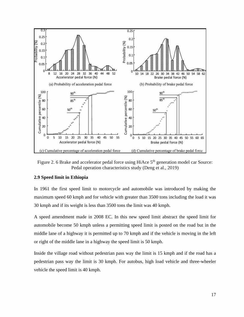
Brake pedal forces are higher than those of the accelerator pedal force as shown in Figure 2.6
below and the amplitude of the brake pedal forces corresponding to the maximum use frequency
are higher than that of accelerator pedal forces (Deng et al., 2019).
Accelerator pedals are constantly designed so that the pedal itself can be hard-pressed down to
the floor with the user's toe or upper portion of the foot, while the heel remains on the floor
(Vedaprabha & Ali, 2015).
The minimum range required to accommodate 99% of the population requires that the
accelerator pedals be able to be adjusted between 68.6 and 83 cm for a seat height of 15 cm,
between 68.8 and 81.7 cm for a seat height of 20 cm, and between 66.4 and 83.0 cm for a seat
height of 25 cm (Freeman & Haslegrave, 2004).
17
Figure 2. 6 Brake and accelerator pedal force using HiAce 5th generation model car Source:
Pedal operation characteristics study (Deng et al., 2019)
2.9 Speed limit in Ethiopia
In 1961 the first speed limit to motorcycle and automobile was introduced by making the
maximum speed 60 kmph and for vehicle with greater than 3500 tons including the load it was
30 kmph and if its weight is less than 3500 tons the limit was 40 kmph.
A speed amendment made in 2008 EC. In this new speed limit abstract the speed limit for
automobile become 50 kmph unless a permitting speed limit is posted on the road but in the
middle lane of a highway it is permitted up to 70 kmph and if the vehicle is moving in the left
or right of the middle lane in a highway the speed limit is 50 kmph.
Inside the village road without pedestrian pass way the limit is 15 kmph and if the road has a
pedestrian pass way the limit is 30 kmph. For autobus, high load vehicle and three-wheeler
vehicle the speed limit is 40 kmph.
18
To implement this speed limit effectively the government is buying a speed limiting devices and
speed recording devices with a lot amount of money.
speed limits, enforcement and speed controlling device were mentioned as a remedy by Bikila
while studying Addis Ababa road traffic accident study and possible engineering solutions and
by international institute for highway safety in America while indicating the countermeasures
to be taken for reducing speeding related crashes, they mentioned (Bikila Teklu, 2014) and
(IIHS, 2017).
In Kenya, no vehicle that is enclosed by the road speed limit legislation proceed on a public
road lacking an approved road speed limiter device being installed and calibrated and sealed and
in ownership of an authorized certificate of agreement or with the device interfered with or with
the device in a defective condition (Zimwatha, 2011).
2.10 City vehicle speed limit of 30 kmph
Our country is doing campaign to increase the awareness in respecting a speed limit of 30 kmph
for improving the road safety.
In Britain, 32 km/h (20 mi/h) zones appear to be highly successful at reducing vehicle speeds
and casualties (Federal Administration, 1999).
Higher vehicle speeds are strongly related with both a greater possibility of pedestrian crash
incidence and more serious pedestrian injuries. It was estimated that only 5 percent of
pedestrians would die when struck by a vehicle traveling at 20 miles per hour or 32.186 km per
hour or less (Hanowski et al., 2012).
2.11 Variable speed limit
Variable speed limits (VSL) strategies have been demonstrated to successfully improve traffic
dynamics characteristics (Yang et al., 2018).
Setting speed limits is complex and frequently controversial. The process is frequently observed
as a practical exercise, but the decision involves value judgments and trade-offs that are
frequently touched through the political process by state legislatures and city councils. Speed
limits represent understood trade-offs among safety, efficiency of travel, and feasibility of
enforcement (US Committee for Guidance on Setting and Enforcing Speed Limits, 1998).

19
In selecting the speed limit reducing travel time on one hand and reducing road accidents on the
other hand plays the largest role and other factors like vehicle fuel consumption and emission
rate of air pollutants have been neglected (Hosseinlou et al., 2015).
Ghods and his team members studied the effect of car or truck differential speed limits on two-
lane highways to know the safety action using microscopic simulation and get the same mean
operating speed with the posted speed limit from uniform speed limit and differential speed limit
control strategy (Ghods et al., 2012). Variable speed limit has an advantage of successfully
improving the traffic dynamics characteristics (Yang et al., 2018).
2.12 Research works on speed limiter
A system for limiting the speed of a gasoline engine made by David and his team members
which includes a responsive circuit to the engine speed which provides control signals to a
solenoid valve which in turn controls a vacuum actuator. The vacuum actuator then overrides a
manual throttle control to move the throttle towards closed position when a governed engine
speed is approached (David G. Beyerlein; Roland G. Kibler; Bruce H. Van Vlack, all of Flint,
1976).
Active accelerator pedal (AAP) is a system which applies a resistance to the accelerator pedal
when the driver attempts to exceed the speed limit, If necessary, the driver can override the
system by pressing the accelerator pedal harder (kick-down function) in emergency cases
(HJÄLMDAHL et al., 2002).
In 2011 an automatic speed controller was designed by receiving road speed limit allowed from
a traffic signal posts which is equipped with RF transmitter through the vehicle’s RF receiver.
The system receives the accelerator pedal position from a separate microcontroller other than
the vehicle’s ECU and sends a signal message to the ECU to act up on the speed limit received
(Kameswari et al., 2011)..
In 2016 Priyadarshini and his team aimed to offer simple and effective solution for controlling
the speed of the vehicle automatically and uses intelligent speed adaptation which is actually an
aggregate term for different distinct frameworks. They used radio beacons, dead reckoning,
optical recognition, GPS and ARM microcontroller as a core device. An extension to the
existing system was improved which obviously controls the speed of the vehicle based on its

20
position determined by the GPS coordinates and a switch initially present in on state enters into
off state, where the user uses this in crisis condition allotted by sending a message to close traffic
control unit with usage of GSM. Based on the obtained GPS values the speed of the vehicle is
controlled (Priyadarshini et al., 2016).
Saivignesh and his colleagues made an automatic Vehicle Speed Limiter which is based on radio
frequency by Controlling Throttle Valve. They used RF communication method for controlling
purpose. In order to implement this in public then they need to attach the RF receiver along with
the vehicle and the transmitter with the specified Zones. The transmitters send coded signals to
interpreted by the ECU with some delay of time. Whenever the car enters into these zones their
receivers will receive this code and then the speed of the vehicles is limited automatically by
taking controlling the throttle valve thereby, the limited speed of the zone’s will be respected
(Saivignesh H et al., 2015).
In 2015 AbdelGawad made a simple electro-mechanical automotive speed control system by
controlling the flow of air in the inlet manifold through electric motor. They used a remote-
control unit, a receiver, screen, amplifiers, microcontroller, two relays, transistors, memory,
regulator and battery. The control system finally able to limit the engine speed according to the
pre-set vehicle speed limits and has no noticeable bad effect on the engine performance. The
mechanism is simple, inexpensive and the air/fuel ratio and the exhaust component percentage
shows no change. Vehicles with conventional carburetor can use this speed controlling system
with small modification (AbdelGawad, 2015).
Sethuramalingam and his team members tried to create an onboard speed regulation module for
vehicles that controls the speed of the vehicle in every second by comparing its speed with the
speed limit of different location which is obtained by geographic positioning system and global
system for mobile technology. The algorithm used for position matching and subsequent speed
limit extraction relays on both GSM and GPS input signals, complementing each other and thus
avoiding limitations of using them individually for position tracking. Validating the input also
done before interpreting for further decision. As a result, if some error is obtained through
checking the process seizes and begin with new inputs. It also has a special provision for limiting
the speed in sensitive areas without affecting the speed limits of the complete speed zone in
which the place of concern lies (Sethuramalingam et al., 2014).
21
Chikezie and his colleagues introduced an embedded voice activated automobile speed limiter.
The system was primarily designed to alert the driver through a voice activated command when
the speed of the car accelerates from 80km/h to 95km/h at an interval of 5km/h. The design uses
Arduino software which in ATMEGA328P microcontroller, Resistors, Diodes, Transistors,
Relays, Proteus 8.5 professional and Multisim. An automobile speed limiter with voice activated
prompt command system was designed, simulated and observed working adequately according
to the design specifications. There is also a voice command system which signals the driver
when he tries to travel and overtake dangerously (Chikezie et al., 2017).
Matthews and his colleagues developed an intelligent in -vehicle wireless multilingual over-
speed announcer and reporter. The device works in this format, the road safety agency sets a
speed limit for vehicles by sending an SMS code to the device. Upon receiving the code, the
device’s over-speed announcer is set. An embedded global system for mobile in the device
senses the speed of the traveling vehicle and its position by GPRS. When the driver reaches a
location with assigned speed the device senses and initiates the electronic relay switch which
activates a vocal warning from the memory in the audio module. It is used as a method of gaining
tax income for the government (Matthews et al., 2018).
Gopal and his friends made an automatic speed surveillance and vehicle alerting system by
means of internet of things to provide a fully autonomous and flexible system for the process of
speed monitoring and detecting to regulate the traffic that can occur at any point of the roads.
The system uses a radio frequency identification reader, a control board, LCD screen, buzzer
and ECU. This ensures the dynamic speed control over areas therefore making the control
system more adaptive and responsive (Gopal et al., 2019).
Jain with his team members designed a system aiming primary detection and aware of
dangerous vehicle driving patterns related to hasty driving. The system needs an IR transmitter
and receiver, a control circuit and a buzzer. A traffic police officer using this system will provide
the speed limit depending upon the traffic condition at different location. While the vehicle
travels from one set point to the other the time consumed will be calculated by the control circuit
and shows that on the provided display. Moreover, if the vehicle crosses the speed limit, a buzzer
sounds alerting the police (Jain et al., 2015).

22
Enokela & Agbo developed a microcontroller-based vehicle speed controller. It is designed to
control the speed of a car in a particular zone where the government assigned on it a speed limit.
The speed controller has three speed limit choices with 40,80 and 120 km/h by using switches.
These speed limit will be used to compare the actual vehicle speed of the car from the speed
sensor of the vehicle with it. While comparing, when the actual speed is more than the selected
speed limit for the zone, an actuator will come to operation to limit the speed. A microcontroller
takes inputs from the switches and the speedometer both; depending on the choices the
microcontroller sends output signal to LED and LCD for lightning and displaying message
respectively. So, the system will give early caution to warn the driver and also prevent over-
speeding (Enokela & Agbo, 2015).
2.13 Impact of speed limiter
Ivan and his friends presented how car speeds are related to reasonable, environmental and
economic sustainability of urban areas. through the relation between vehicle speeds and road
crash casualties, severity of pedestrian crashes, generation of harmful emissions, and relative
desirability of neighboring land based on reported research findings with reported experience
and recommended that speed limits should be set to limit fatality risk, not according to driver
selections and vehicle speeds in inner city and inhabited areas should be kept below 25 mi/h
(preferably 20 mi/h) to support growing sustainability of urban areas (Ivan et al., 2012).
Hanowski and his friends reported a research on the safety impacts of speed limiter device
installations on commercial motor vehicles aiming to identify speed limiter effect in reducing
the severity and frequency of crashes and accidents, best practices in speed limiter applications,
and identification of carrier, insurer, and enforcement official views related to speed limiter
implementation. To accomplish this, they used a peer review to obtain feedback on the proposed
research design and analyses, CMV stakeholders were interviewed, vehicle and crash data were
collected directly from motor carriers, crash data were reduced to standardize crash types across
carriers, and the crash data were analyzed. The first safety analysis was concerned on trucks.
They take a sample of 138,000 trucks from 20 truck fleets and analyzed more than 15,000
crashes. The result showed that using speed limiters on trucks will reduce about 50 percent of
the crash rate by comparing the trucks having speed limiter and those which are not having it.

23
Most fleet owners also show a positive attitude towards using speed limiter for their trucks
because of its negligible cost and its safety (Hanowski et al., 2012).
Boer and his friends studied environmental and safety impacts of speed limiters for vans in
Europe by determining the relative emission reduction when driving at a lower speed and
estimating the total emission reduction on an EU scale by the obtained reduction percentage for
the effects on GHG emissions. For the effects on traffic safety which can be described by the
number of fatalities and severe injuries they used Nilsson formula. The estimated average
reduction potential over all roads is 4-5% CO2 emission reduction for speed limiters at 110km/h
and 6-7% at 100km/h. in case of safety, a speed reduction of 112 to 97km/h results in a reduction
of the number of fatalities and severe injuries on 44 and 35% respectively (Boer et al., 2010).
Gao with his team members studied the effect of posted speed limit on the dispersion of traffic
flow speed. for this purpose, three speed limits with 80, 100, 120 km/h were selected for
observation, and traffic volume, speed and other parameters. The distinguishing speeds, such as
average speed, V15 and V85, were evaluation indicators, where V15 and V85 are the speeds of
the 15th and 85th percentiles measured at the feature points of the road when the traffic was in
a free-flow state and the weather was good. A statistical analysis was used to analyze the
collected data. The driver’s driving speed decreases in the restricted flow due the increase in
traffic volume not the speed limit. In a free-flow state, when the posted speed limit is increased
and the average speed and the V85 also amplified by approximately the same magnitude. The
advanced the speed limit was, the larger the speed difference between V15 and V85 (Gao et al.,
2019).
Camilla with her colleagues presented an investigation of the relationships between speed with
road characteristics and driver’s behavior. The analysis was based on speed and driver
characteristics of 425 cars by analyzing GPS-based speed statistics called floating car. The
results showed that the wider the road, the faster the vehicles and for each kilometer extra road;
the speed is increased by 2.7 km/h (Camilla Sloth Andersen et al., 2016).
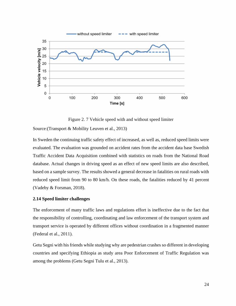
So, the speed limiter reduces the speed differences between various vehicles because the
maximum speed is limited to a certain speed level by the limiter as shown in Figure 2.7 below.
24
Figure 2. 7 Vehicle speed with and without speed limiter
Source:(Transport & Mobility Leuven et al., 2013)
In Sweden the continuing traffic safety effect of increased, as well as, reduced speed limits were
evaluated. The evaluation was grounded on accident rates from the accident data base Swedish
Traffic Accident Data Acquisition combined with statistics on roads from the National Road
database. Actual changes in driving speed as an effect of new speed limits are also described,
based on a sample survey. The results showed a general decrease in fatalities on rural roads with
reduced speed limit from 90 to 80 km/h. On these roads, the fatalities reduced by 41 percent
(Vadeby & Forsman, 2018).
2.14 Speed limiter challenges
The enforcement of many traffic laws and regulations effort is ineffective due to the fact that
the responsibility of controlling, coordinating and law enforcement of the transport system and
transport service is operated by different offices without coordination in a fragmented manner
(Federal et al., 2011).
Getu Segni with his friends while studying why are pedestrian crashes so different in developing
countries and specifying Ethiopia as study area Poor Enforcement of Traffic Regulation was
among the problems (Getu Segni Tulu et al., 2013).
25
A field study in Netherlands, Spain and Sweden on the effects of in-car speed limiters carried
and among the respondents for the question “How did you experience driving with the speed
limiter compared to driving without the SL concerning stress?” 43% of the respondents said that
they feel Slightly more stressing and 17% of them Much more stressing which more than half
of the respondents are uncomfortable with the speed limiter (Várhelyi & Mäkinen, 2001).
A study made by Hassen regarding risky driving behaviors for road traffic accident among
drivers in Mekele obtained Significant proportion 303 (86.6%) of respondents for the questioner
provided were not following the suggested speed limit of driving in the city. The key motive for
not following the speed limit by the respondents was somebody who has talent in driving did
not see the importance of speed limit 99 (25.5%). In general, 233 (66.6%) of the drivers were
found to be risky. Out of the total drivers with risky driving behavior, 129 (55.4%), 59 (25.3%)
and 45 (19.3%) were house car, taxi and Bajaj drivers respectively (Hassen et al., 2011).
A research in California freeways no indication of changes in 30-second speed patterns emerged
prior to crash occurrence. Moreover, having more lanes for vehicle provide more speed for the
vehicle using the lanes (Kockelman & Ma, 2010). Slightly higher number of short time-
headways and increased frustration and stress caused by speed limiter seen in Field trials with
in-car speed limiter in Netherlands, Spain and Sweden representing most of European countries
(Mäkinen & Várhelyi, 1998). The introduction of speed limiters set at 105 km/h increases safety
in uncongested region. As maximum speed is set at 110 km/h the safety gains from the
introduction of limiters becomes less pronounced. A result that holds for the uncongested region
of traffic flow. Maximum safety gains were obtained when the maximum control speed was set
at 90 km/h for the uncongested traffic volumes under consideration (Saccomanno et al., 2008).
and in some emergency cases, drivers have to exceed the preset speed. some other effects of
speed limiters, such as increased travel times are listed among the side effects of speed limiter
(Toledo et al., 2007).
2.15 Speed limiter and congestion
A study by Gila Albert while evaluating the benefits of active speed limiters on high ways roads
with 100, 120 and 130 kmph speed limits. The results showed that implementing speed limiters
have a reducing effect on the congestion level of a road and he got also a negligible impact on
all types of congestion level (Gila Albert, 2007).

26
2.16 Literature Summary
The reviewed literatures showed that, speed in our country case is the major contributor in
increasing the number of fatal and serious accidents, property losses, greenhouse gases and
congestion. Vehicles which are used for passenger transportation inside cities need a greater
concern since they are carrying many lives inside. There were different mechanisms used as a
remedy for solving speeding problem inside cities. So far, speed limiting device was introduced
which works either by blocking the flow of air through inlet manifold with a separate motor
driven throttle or restricting the flow of fuel by a solenoid. The recent speed limiters incorporate
GPS information for knowing the speed limit of different location and automatically setting the
speed limit for the car and the limiter regulating authority can observe the usage of the driver
where ever a satellite coverage is available. Despite the fact that speed limiter devices introduced
many years ago, our country started to apply in aggressively in 2008 EC, when a new speed
limit amendment made for city vehicles. From different strategies for limiting speed of the
vehicle, the literatures showed that variable speed limiting is better than fixed speed limiting
strategy. Almost all speed limiters which are available now in the market need a properly
functioning speedometer as an input for the device and those which measures the speed of the
vehicle uses satellite data for measuring. Adding various features on speed limiters like
overspeed detection, warning lights, overspeed recording and informing third party about the
speed limiter condition gives the speed limiter a better capacity for effectively limiting the
speed. There are two types of overspeed detecting devices introduced, one calibrated inside the
vehicle and the other is installed on different spot areas of the road. This detecting device gives
information for all road users and enforcing authorities about dangerous vehicle travel.
Overspeed recording gives the speed of the vehicle before an accident for insurance claims
which replaces the traditional method of knowing the speed of the vehicle before an accident.
As the literatures showed the maximum pushing force on the accelerator pedal is 52N, which is
l0N lower than the force on the brake pedal, this paves a way to counter act a reaction force with
a strong electromagnet for fixing the pedal in its normal position.
2.17 Research gap
These literatures showed that minibus taxis in Ethiopia are one of the major road traffic accident
contributors. From the causes, driver’s fault occupies the most percentage and speeding over the

27
limit is among the day to day faults of the drivers in radio and other reporting medias. In order
to reduce the severity of injuries and crashes speed limiting device or system was invented so
far. Our country is planning to implement a speed limiter in all commercial vehicles and begin
implementing speed limits in different road types in the capital city Addis Ababa where much
of the country’s registered vehicles locate.
Many kinds of speed limiting devices have been introduced throughout the world. Among those
electronic speed limiters are more reliable and effective. But most of the speed limiters which
are available now needs high level of road development, RF speed spot, GPS service, internet
access and a properly working separate vehicle speed measuring device which our country’s
most minibus taxis does not have. And some of them only signals the driver to reduce its speed
or warns him, which in our case most of our drivers do not care about most of the vehicle’s
dashboard signals and even traffic police calls. And some act up shutting the engine which can
cause unexpected accident again since there will be no movement until the vehicle stalls and
starts again. And some only signals the driver by increasing the force on the accelerator pedal
but the driver can push the pedal with a greater force and run the vehicle with fast speed. Even
though this is useful in emergency cases, it decreases the speed limiter’s effectiveness in a place
where most of the drivers enjoy over speeding in road with full of pedestrians. This thesis
introduced a technology transfer which improved the existing speed limiters by adding different
useful features as separate speed input for the limiter, speed recording and informing third party
SMS message about the selected speed limit by the driver.

28
CHAPTER THREE
MATERIALS AND METHODS
3.1 Materials
The speed limiting system needs a number of electrical components for receiving a signal from
a microcontroller and changing it to an electromagnet which enables the accelerator pedal to be
rigid. Table 3.1 below lists the utilized materials for the speed limiter.
Table 3. 1 List of material for the system
No Items Quantity
1 ATMEGA2560 microcontroller 1
2 VMA313 hall effect sensor 1
3 Neodymium magnet 1
4 Bread board 1
5 Jumper wires 58
6 9V battery 1
7 12V battery 1
8 128x64 OLED display 1
9 E-shaped sheet metal 144
10 copper wire for coil 78m
11 One channel relay module 1
12 Voltage booster 1
13 A6 GSM/GPRS module 1
14 16 X 2 LCD display 1
15 SD card module 1
16 DS3231 RTC 1
17 220Ω resistor 6
18 20KΩ resistor 1
19 RGB 2
20 Push button 4

29
3.1.1 Arduino ATMEGA2560 microcontroller
Arduino is a versatile programmable hardware board designed for designers and prototype
makers. Arduino nano, Uno and Mega blue circuit boards, mythically enchanting its name from
a local pub in Italy, has in a very short time inspired a new age group of to make all custom of
remote projects found anywhere from the blessed grounds of our universities to the roasting
desert sands of a particularly ill-famed yearly arts anniversary and just about all over the place
in between. There are different types of Arduino board like Nano, UNO and MEGA which are
the most common. Figure 3.1 below shows the main components of Arduino mega
microcontroller.
Figure 3. 1 Arduino Mega microcontroller
This microcontroller comes from a company called Atmel and the chip is known as an AVR.
The Arduino Mega 2560 is a microcontroller board based on the ATmega2560. It has 54 digital
input/output pins (of which 14 can be used as PWM outputs), 16 analog inputs, 4 UARTs
(hardware serial ports), a 16 MHz crystal oscillator, a USB connection, a power jack, an ICSP
header, and a reset button. It contains everything needed to support the microcontroller; simply
connect it to a computer with a USB cable or power it with a AC to DC adapter or battery to get
started. The Mega is compatible with most shields designed for the Arduino. The programming

30
is done by ARDUINO IDE commercial software. Table 3.2 presents the data sheet of
ATmega2560 microcontroller (Evans, 2011).
Table 3. 2 Arduino Mega microcontroller data sheet
Microcontroller ATmega2560
Operating Voltage 5V
Input Voltage (recommended) 7-12V
Input Voltage (limits) 6-20V
Digital I/O Pins 54 (of which 14 provide PWM output)
Analog Input Pins 16
DC Current per I/O Pin 40 mA
DC Current for 3.3V Pin 50 mA
Flash memory 256 KB of which 8 KB used by bootloader
SRAM 8 KB
EEPROM 4 KB
Clock Speed 16 MHz
The microcontroller which will be utilized in the system should be programmed for receiving
input from hall sensor which will be positioned on the top of the rim of the front wheel inside
and compare with the pre-set speed limit and sends an output signal for actuating the accelerator
pedal cable.
3.1.2 Hall effect sensor
There are two types of speed measurement one is by using speedometer cable and permanent
magnet which gives analog reading of the speed and the other is using hall effect sensors to
detect the appearance of a magnet which gives digital reading of the speed of the vehicle.
For the thesis work, the researcher used VMA313 hall effect sensor which has one signal pin
labeled on the top by letter S which receives signal when a magnet nears it, Vin pin in the middle
to serve as a signal voltage for the sensor and ground pin labeled negative sign on the top as
shown in the Figure 3.2.

31
Figure 3. 2 VMA 313 hall effect sensor
3.1.3 Bread board
This board is a prototyping board which has two source and ground rows on the top and on the
bottom and two vertically connected pin hole rows each having four pin holes. The upper and
lower most corner pins are all horizontally connected except in midway but one jumper wire
can connect the two separated rows horizontally as shown in Figure3.3 below.
Figure 3. 3 Bread board

32
3.1.4 Jumper wires
These wires are used to connect the pins on the Arduino board with the bread board and other
components of the circuit. They are three types female-female, male-female and male-male as
shown in Figure 3.4 below.
Figure 3. 4 Jumper wires
3.1.5 Voltage source
A 12v lead acid rechargeable battery is used as a source of the voltage for the electromagnet at
first but for greater DC voltage source a rectified AC voltage is used and 9V Max-day battery
which is also rechargeable is used for the Arduino board, A6 GSM/GPRS module, OLED
display, SD card module and real time clock module.
3.1.6 OLED display
Organic light emitting diode display is used as a device to display the speed of the vehicle in
km/h. There are different types of OLED display based on the number of pixels vertically and
horizontally. In this thesis work, a 128x64 display was used which has 128 pixels horizontally
and 64 pixels vertically. It has four pins the ground, Vcc, SCL (serial clock) and SDA (serial
data) as in Figure 3.5 below.

33
Figure 3. 5 OLED display with 128x64 pixels
3.1.7 Sheet metal core
Since in electromagnet, having an iron as a core for the electromagnet increases the magnetic
field intensity produced. Sheet metal is selected for it having high reluctance for magnetic field
production. The sheet metals selected are microwave transformer sheet metals as shown in
Figure 3.6 below.
Figure 3. 6 E-shaped sheet metal
3.1.8 Coil
The coil is used to create strong electromagnet on the surrounding core when current passes
through it. Having a cable with high conductivity value like gold, makes the field much stronger
but the cost is very high. So, a copper wire is selected as a wire for the coil as shown in Figure
3.7 below.

34
Figure 3. 7 copper wire for coil
3.1.9 Relay Module
Relay module for powering the electromagnet by receiving a signal voltage from one of the
digital pins of Arduino board and making the 35V or greater voltage circuit for the
electromagnet. There are one, two, three and even four channel relay modules. A one channel
relay module as shown in Figure 3.8 is selected since one input from the microcontroller is
enough for the system to operate.
Figure 3. 8 One channel relay module
3.1.10 Voltage booster
Voltage booster like in Figure 3.9 which increases the voltage rating of the 12V battery up to
35V and providing the needed amount of voltage for high current flow through the coil of the
electromagnet to get high magnetic field strength.

35
Figure 3. 9 DC voltage booster up to 35V
3.1.11 A6 GSM/GPRS Module
The module shown in Figure 3.10 is A6 GSM module, an upgraded version of SIM900 with its
additional features. It supports dual-band GSM/GPRS network, available for GPRS and SMS
message data remote transmission. It has small current usage up to 0.003Amp in sleep mode. It
communicates with the Arduino board via UART port using AT Commands from the manual.
It has a working frequency of 850/900/1800/1900MHz, and a working voltage between 4.5 and
5.5 which can be gained by 5V mobile charger with a extreme current of 2Amp through external
power supply. It has an onboard SIM card holder which installs mini or micro SIM cards. It can
work with different baud rate up to 115200bds. It can call or send SMS message from every
place where network is available. It has also microphone for hearing and respond in calls as a
phone does.
Figure 3. 10 A6 GSM/GPRS module

36
3.1.12 LCD display
Liquid crystal display (LCD) is a type of flat panel display which uses liquid crystals in its
primary form of operation. A 16x2 LCD shown in Figure 3.11 is used for the project to display
the selected speed limit by the drivers in different road types. It has a blue background with
bright white text for effect and can display two rows of 16 characters each.
Figure 3. 11 16 X 2 LCD with blue background
3.1.13 SD card module
This is a module which is used to write and read data to and form an SD card (Secure Digital
Cards). The module shown in Figure 3.12 uses FTA formatted micro SD card before use and
SPI (Serial peripheral interface). It only wants 3.3V to operate. The module has six pins which
are select chip pin (CS), serial clock pin (SCK), MOSI (Output serial peripheral interface),
MISO (input serial peripheral interface), power pin and ground pin.
Figure 3. 12 SD card module
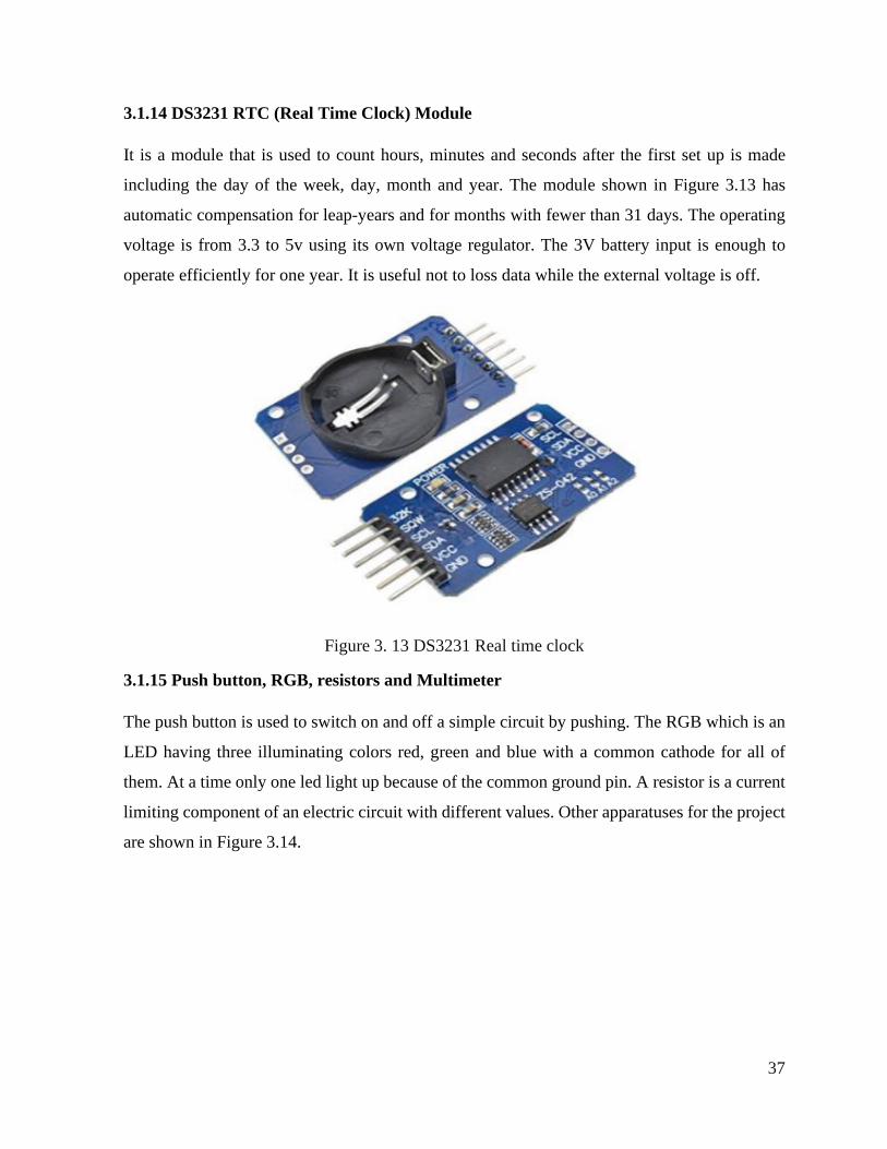
37
3.1.14 DS3231 RTC (Real Time Clock) Module
It is a module that is used to count hours, minutes and seconds after the first set up is made
including the day of the week, day, month and year. The module shown in Figure 3.13 has
automatic compensation for leap-years and for months with fewer than 31 days. The operating
voltage is from 3.3 to 5v using its own voltage regulator. The 3V battery input is enough to
operate efficiently for one year. It is useful not to loss data while the external voltage is off.
Figure 3. 13 DS3231 Real time clock
3.1.15 Push button, RGB, resistors and Multimeter
The push button is used to switch on and off a simple circuit by pushing. The RGB which is an
LED having three illuminating colors red, green and blue with a common cathode for all of
them. At a time only one led light up because of the common ground pin. A resistor is a current
limiting component of an electric circuit with different values. Other apparatuses for the project
are shown in Figure 3.14.
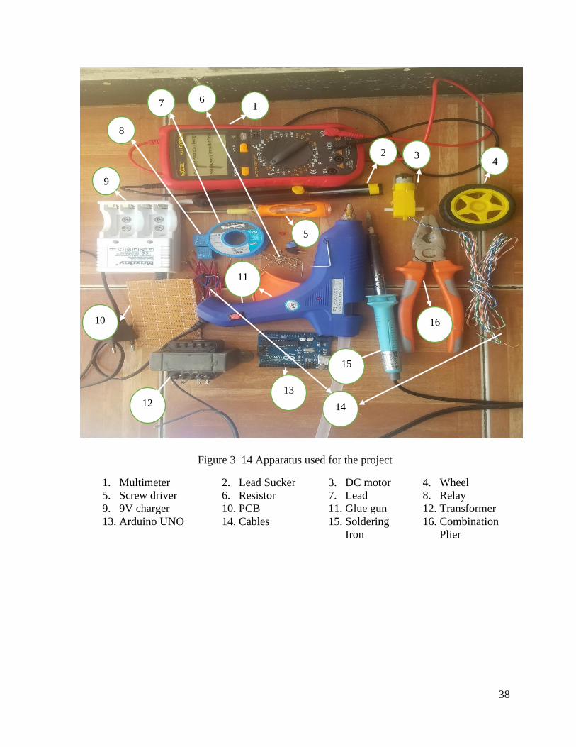
38
Figure 3. 14 Apparatus used for the project
1. Multimeter 2. Lead Sucker 3. DC motor 4. Wheel
5. Screw driver 6. Resistor 7. Lead 8. Relay
9. 9V charger 10. PCB 11. Glue gun 12. Transformer
13. Arduino UNO 14. Cables 15. Soldering
Iron
16. Combination
Plier
1
3 4
9
5
2
11
6
10 16
13
15
12 14
8
7

39
3.2 Methods
3.2.1 Literature Review
Since the study needs deep literature review to identify which type of vehicle is participating in
most accidents, injuring passengers and pedestrians by observing quantitative data types on the
causes of the accident and designing a speed limiting system, searching such kind of data is the
first step.
3.2.2 Data Collection
For the purpose of the applicability of the proposed speed limiter in accelerator pedal of minibus
taxi, the different kinds of accelerator pedal on minibus taxi are observed to make the system to
be used in all types of minibus models with same wheel radius.
3.2.3 Arduino Mega microcontroller programming
The programming is done by ARDUINO commercial software which is called as Arduino IDE.
The C programming language is fragmented into blocks of code called functions that form the
main building blocks of any program. In Arduino IDE there are two have two setup () and loop
(), each containing statements that do specific actions performed in order from top to bottom.
void setup ()
void loop ()
Statements inside the void setup will be used to configure the state of input and output pins, as
well as other actions that we only need to run once. Conversely, loop ()
will perform whatever actions are inside of it over and over again for an eternity, assuming
limitless power as a prerequisite.
Since the language that the Arduino microcontroller used is case sensitive a letter is uppercase
or lowercase must match exactly between what is entered and the syntax of the
function, variable, or other statement being used.
A variable declared inside the loop or other function is called local variable but if it is declared
before setup function it is known as global variable. Arithmetic Operators: +, -, *, /, Compound

40
Operators: ++, --, +=, -=, *=, /= and Comparative Operators are available in the program as
listed in Table 3.3 below and variable types as in Table 3.4 below.
Table 3. 3 Operators and their description
Symbol Description Examples
( ) Parenthesis (x+y) *z
++ -- , , Increment, decrement x++, y--
* / % Multiplication, division, modulus x * 1.5
+ - Addition, subtraction y + 10
< > <= >= Less than, greater than comparisons if (x < 255)
== != Is, is not equal to if (x == HIGH)
&& Logical AND if (x == HIGH && x > y)
|| Logical OR if (x == HIGH || x > y)
= += -= *= /= Assignment and compound assignments x = y
Table 3. 4 Data types and their size and range
Name Size Range
Boolean 1 bit true or false
byte 8 bits 0 to 255
char 8 bits -128 to 127
int 16 bits -32,768 to 32,767
long 32 bits -2,147,483,648 to 2,147,483,647
float 32 bits 3.4028235E+38 to 3.4028235E+38
unsigned char 8 bits 0 to 255
Unsigned int 16 bits 0 to 65,535
unsigned long 32 bits 0 to 4,294,967,295
3.2.3.1 Controlling statements
The if statement is the simplest of the control structures and is among the most prominent
method for Arduino decision making. It will perform a block of code if a specific condition is
met. The basic syntax for an if statement looks as follows:
if (condition)

41
statements
The for statement, or for loop, is an iterative statement that allows the Arduino to repeatedly
execute lines of code in a loop a specified number of times. The basic syntax of a for loop
follows:
for (declaration; condition; increment)
statements
The while statement is substitute of the for loops. Even if for statement is fairly common to
Arduino programmers, but there are other ways to structure iterative loops. Where the if
statement executed a statement once if a condition was met, and the for-loop cycles through a
specified number of times, the while statement, or while loop, is used to continuously execute a
statement so long as the condition remains true. The basic syntax of a while statement looks like
the following:
while (condition)
statements
The switch statement is like a really nifty version of the if statement in that it can execute one
or more blocks of code, depending on a range of conditions. The basic syntax of the switch
statement is as follows:
switch (expression)
case constant:
statements;
default:
Map () function will take the value from the variable analog Value with expected values that
begin at 0 and go up to a maximum of 1023, and map these values to the new values of 0 to 255.
This statement effectively converts a range of values from 0 to1023 to 0 to 255. The beginning
and ending values can be changed accordingly. The basic syntax of the map () function is:
map (value, from Low, from High, to Low, to High)
42
Delay () function is used to create a short pause in the middle of a program. The syntax for the
function follows.
delay(time)
Inside the microcontroller on the Arduino board there are three on-board hardware timers that
work in the background to handle repetitive tasks like incrementing counters or keeping track
of program operations.
The attachInterrupt () function enables hardware interrupts and links a hardware pin to an ISR
to be called when the interrupt is triggered. This function also specifies the type of state change
that will trigger the interrupt. Its syntax follows:
attachInterrupt (interrupt, function, mode)
3.2.3.2 Timers
Each of these timers is already being used in one capacity or another, usually for handling
hardware PWM and system timing. It measures the time from the beginning of the code
interpretation until then in millisecond and microsecond. Where the millis () function returns
the current operating time in milliseconds, the micros () function does the same, but in
microseconds.
3.2.3.3 Libraries
To use a library in an Arduino sketch, we need to tell the compiler which library we want to use.
There are two ways to do this. The first is to use a #include pre-processor directive at the
beginning of the sketch to specify the library’s file name, as follows:
#include <LibraryName.h>
There are many libraries for writing Arduino sketch, SD library, OLED display library, LCD
library, servo library, motor shield library, software serial library and so on.
3.2.3.4 Analog and digital functions
In digital functions the writing and reading of signals is only HIGH and LOW which is equal
to 5V and 0V. the analog write ranges from 0 up to 255 and reading range is from 0- 1023.
3.2.4 Flowchart of the program
A flowchart is an illustrative representation of an algorithm. The flowchart can be helpful for
both writing programs and explaining the program to others. This flow chart as shown in Figure

43
3.15 below only includes the hall effect sensor, RGB, electromagnet, SMS module and LCD
display due to lack of space in writing the complete flow chart in one page.
start
Input form hall sensor
period= current micros-previous micros
If
speed<30
Green
LED
If
SL=30
RED LED
&Activate
electromagne
t
If
speed<50
Yellow LED
If
SL=50
Red LED
If
speed<70
If
SL=70
RED LED & Activate electromagnet
RPM=60*1/period
Speed (Kmph)=2π*radius*RPM/60*3.6
RED LED & Activate
electromagnet
No Yes
No Yes
Yes
No
Yes No
Yes SL is
OFF
No
Yes
No
Send SMS
End
Figure 3. 15 Flow chart of the program

44
3.2.5 Simulation
After accomplishing all the circuit design of the speed limiter, simulation of the electromagnet
is done by using EMS 2017 electromagnetic simulation software.
3.2.6 Prototype Construction
When all the design and simulation of the speed limiter is over, prototype was prepared in order
to see the actual functionality of the system considering the pedal as some ferromagnetic
material.
3.2.7 Process description
In the project Arduino Mega microcontroller is chosen for its big flash memory for long program
sketch and a greater number of digital and analog pins. Observing the response of VMA313 hall
sensor on serial monitor of the Arduino by connecting it with digital pin number 3.
The hall effect sensor senses magnetic field of certain direction. Based on the sensor reading,
the microcontroller reads the time when the magnet reaches the sensor and by saving the time
in a volatile data type the previous time and the current time, the time between two pulses which
gives the period of the revolution will be calculated.
After the period is known the RPM will be calculated by using the frequency which is the inverse
of period.
Frequency is the inverse of the period so by dividing 1 by its period the frequency is calculated
and then by using the effective wheel radius of the car to calculate the circumference the speed
in m/s will be solved. this speed will be converted to km/h by dividing the m/s by 3.6. The speed
will be displayed this speed in OLED display.
After the speed is calculated the microcontroller sends a signal voltage to different pins to
control RGB LED and electromagnet triggering pin which goes to the relay. This process is
described in Figure 3.16 as a block diagram.

45
Figure 3. 16 Block diagram of the speed limiter
For constructing the electromagnet selecting the core material for the electromagnet which is
compressed E shaped sheet metal that produces one pole at the middle and two poles at the ends
with the same polarity but different with the middle one. Since the magnetic field created in a
current carrying wire is not strong so in order to make the produced magnetic field greater a
ferromagnetic core is inserted.
The 3D assembly will be prepared using solid works and simulation is done by EM works
feature which is incorporated inside solid works to simulate electromagnet.
Finally, the best voltage that provide enough amount of force not to be pressed by the driver’s
foot force on the accelerator pedal will be selected. The GSM and SD card module with the
system make the enforcement and regulation easier.
Rotating wheel
VMA hall effect sensor
Microcontroller
Speed on OLED
Push button SL
selection Selected SL on
LCD
Over speed RGB
Selected SL
RGB
Relay for
Electromagnet
Electromagnet
GSM module for
SMS Over speed
recording SD
card
Date and time
from RTC module

46
3.2.8 Electromagnet construction
Microwave oven transformer is utilized to create a strong electromagnet. It has a thick 285 turns
primary winding which can withstand greater current. By inserting a ferromagnetic material
inside the coil, the magnetic field intensity will increase. The magnetron tube has magnetic
segments tuned to the output frequency and the input frequency. It is called a “magnetron”
because the tube is inside a strong magnetic field, which interacts with the voltage across the
tuned segments.
3.2.9 EMS 2017 Software
EMS is a 3D electromagnetic simulator software set, based on the powerful finite element
method. Currently, it is the only electromagnet simulation software.
SOLIDWORKS EMS (Electromagnet Simulation) which is Certified with Gold by solid works
study four main areas which are electromechanical, electromagnetic, power electronics, and
electromagnetic behavior. It makes the software preferable for developing motors and solenoids,
testing transformer’s different parameters with the heat model and simulating permanent magnet
and electromagnet.
It has magnetostatic for permanent magnet, electrostatic, electric conduction, AC magnetic,
transient magnetic and AC electric analysis types each having its own parameter and result.
3.2.9.1 Electrostatic Analysis
Electrostatic is a division of science that deals with the phenomena arising from stationary
and/or slow-moving electric charges. Electrostatic calculation respites on the assumption that
the electric field is irrotational, i.e. the coil of the electric field is worthless. From Faraday’s
law, this assumption points toward the absence or near-absence of a varying magnetic fields
with time, i.e. the time derivative of the magnetic field is zero. Which indicates that, absence of
magnetic field or electric current are not a precondition for electrostatics. But, if they do exist,
they must not vary with time, or in the worst-case, they must vary with time only very slowly.
In some occasion’s electrostatics and magnetostatics may be required for accurate predictions.
47
3.2.9.2 Conduction Analysis
Electric Conduction is based on the electrostatic estimations. Unlike the Electrostatic analysis
which deals with insulators and conductors, the Electric Conduction deals with only conducting
materials and medias which can sustain electron flow.
3.2.9.3 Magnetostatic Analysis
Magnetostatics is the study of static magnetic fields. In electrostatics, the charges are stationary,
whereas here, the currents are steady or DC. As it turns out magnetostatics is a good estimation
even when the currents are not static as long as the currents do not differ rapidly
3.2.9.4 AC Magnetic
AC, or alternating current, Magnetic, is the study of magnetic fields due to alternating, or time
harmonic, currents. In this case the current which will be applied for the coils of the
electromagnet is alternating or varying from 0 to high amplitude in both directions.
3.2.9.5 Transient Magnetic
Transient Magnetic, is the study of magnetic fields due to time varying currents, typically caused
by rushes in currents.
Solid works Simulation is an FEA (Finite Element Analysis) product that allows users to
validate and test designs quickly and efficiently. But for using solid works simulation There
are a very critical requirement.
Best Processor for SOLIDWORKS Simulation
The quicker processors and more cores, Simulation can now be solved faster and faster. Clock
speed is the most important driver of Simulation solve time, so prioritize clock speed over the
number of cores. an optimum system would be 16 cores at a clock speed of over 3.5 GHz.
Higher RAM
48
A system with 32-64 GB of RAM is acceptable for most users since it’s generally desirable to
have slightly more RAM accessible than a typical Simulation user may actually need. Although
as little as 16 GB is enough for many typical studies, certain Simulation functions (e.g. meshing,
solving and viewing results) require larger amounts of RAM especially if the study has a large
number of elements in meshing results.
High-quality SSD or NVMe hard drive is also useful weather the RAM of the computer
is lower or higher.

49
CHAPTER FOUR
RESULT AND DISCUSSION
4.1 Speed limiter circuit result
4.1.1 Speed measurement
The speed of the vehicle appears starting from 8kmph this is due to the zero debouncing time
sated to 900000 micro seconds which means the program will wait a period of 0.9 second to
show a zero value of the speed. As this waiting period increases the detection of lower speed
level will also increases.
4.1.2 Speed limit selection
As stated in the new proclamation there are different speed limit on different road types, vehicle
types and the area where the road is located from those speed limits three where chosen as stated
in methodology 30,50 and 70 kmph. The design has a push button for choosing the legal speed
limit at every time and this selected speed limit will appear on LCD screen for the passengers
inside and pedestrians outside the vehicle in order to judge whether the driver is respecting the
speed limit or not. Figure 4.1, 4.3 and 4.4 shows how the selected speed limit is displayed on
the LCD.
Figure 4. 1 LCD showing speed limit 30 KPH green RGB lighting up
13 10 9
8
4
12
7 6 5 2
1
3
11

50
Figure 4. 2 The circuit diagram of the project without A6 GSM module
1. VMA 313 hall sensor 2. LCD 3. SD card module
4. Potentiometer 5. OLED display 6. Push Button
7. Selected SL RGB 8. RTC module 9. A6 GSM module
10. 9V battery 11. Arduino Mega 12. Overspeed RGB
13. 12V battery
Over speed RGB RTC Module OLED SL selection
Red = 43 SCL = 21 SCL = 21 S30 = 40
Green = 44 SDA = 20 SDA = 20 S50 = 41
Blue = 45 VCC = 5V VCC =5V S70 = 42
GND = GND GND = GND GND = GND Button = 39
LCD display SD Card Module A6 GSM/GPRS Hall sensor
GND = GND CS = 53 UTX = 12 Sig = 3
VCC = 5V SCK = 52 URX = 13 VCC = 5V
V0 = MOSI = 51 GND1 = GND GND = GND
RS = 1 MISO = 50 GND2 = GND
R/W = GND VCC = 5V VCC = 5V Relay Pin
E = 2 GND = GND In 1 = 46
D4,D5,D6,D7 =4,5,6,7
A=5V
K = GND

51
Figure 4. 3 Schematic diagram of the speed limiter
RT
C
VM
A 3
13
ATMEGA 2560 microcontroller
LCD 16X2 OLED
128X64
SL
RGB A6 GSM
Over
speed
RGB
13 12 7 6 5 4 3 2 1 20
41 42 46 39 50 51 52 53
GND
Vin
21
40
43
44
+
-
45
SD
module
Push
butt
on
20K
Ω
22
0Ω
220Ω
22
0Ω
220Ω 220Ω 2
20Ω
Relay
module

52
Figure 4. 4 LCD showing Selected speed limit 50 kmph
Figure 4. 5 LCD showing selected speed 70 kmph

53
4.1.3 Over speed detection
Whenever the driver exceeds the selected and legal speed limit the red LED will glow indicating
that the vehicle is in over speeding condition and needs proper attention and if another blue LED
light up, it indicates that the selected speed limit is 30 kmph and green for 50 kmph and red for
70 kmph.
Figure 4. 6 Over speeding detecting Red RGB lighting up
4.1.4 Over speed recording
As the vehicle starts exceeding the speed limit the SD card module will record the speed of the
vehicle with one second interval which will be useful for insurance claims. It is also useful for
the owners of minibus taxi to know the behavior of their driver in respecting the speed limit. A
recorded data from an experiment is listed in Table 4.1 below.

54
Table 4. 1 Sample data from recorded speed in SD card
Day/Month/Year Hours: Minutes: Seconds Speed above 30 Kmph
13-06-20 17:16:58 32.47
13-06-20 17:16:59 33.48
13-06-20 17:17:00 33.03
13-06-20 17:17:02 32.63
13-06-20 17:17:03 36.63
13-06-20 17:17:04 39.46
13-06-20 17:17:05 39.05
13-06-20 17:17:07 39.52
14-06-20 16:03:54 30.07
14-06-20 16:03:59 31.48
14-06-20 16:04:12 32.46
14-06-20 16:04:15 33.02
The data from the SD card module can be used to make a graph regarding the driver’s speed
limit respect and it only needs little amount of storage memory. This result only needs 19.1 kb
of memory space.
Figure 4. 7 Graph of Sample data from over speed recording SD card
05
1015202530354045
17
:16
:58
17
:16
:59
17
:17
:00
17
:17
:02
17
:17
:03
17
:17
:04
17
:17
:05
17
:17
:07
16
:03
:54
16
:03
:59
16
:04
:12
16
:04
:15
16
:04
:16
16
:04
:17
16
:04
:18
16
:04
:20
16
:04
:21
16
:04
:22
16
:04
:23
16
:04
:24
1:5
8:1
4
1:5
8:2
1
1:5
8:2
7
2:0
0:0
7
2:0
0:1
3
2:0
0:1
9
2:0
0:2
5
13-06-20
13-06-20
13-06-20
13-06-20
13-06-20
13-06-20
13-06-20
13-06-20
14-06-20
14-06-20
14-06-20
14-06-20
14-06-20
14-06-20
14-06-20
14-06-20
14-06-20
14-06-20
14-06-20
14-06-20
15-06-20
15-06-20
15-06-20
15-06-20
15-06-20
15-06-20
15-06-20
Speed above 30 Kmph
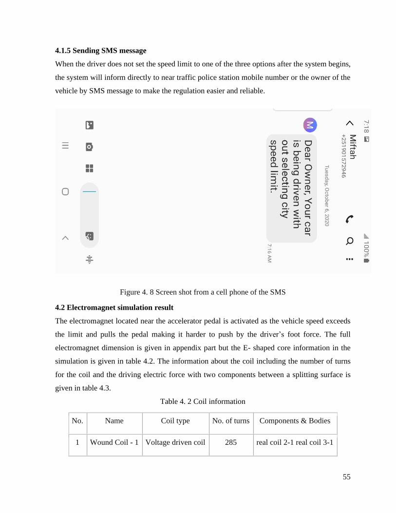
55
4.1.5 Sending SMS message
When the driver does not set the speed limit to one of the three options after the system begins,
the system will inform directly to near traffic police station mobile number or the owner of the
vehicle by SMS message to make the regulation easier and reliable.
Figure 4. 8 Screen shot from a cell phone of the SMS
4.2 Electromagnet simulation result
The electromagnet located near the accelerator pedal is activated as the vehicle speed exceeds
the limit and pulls the pedal making it harder to push by the driver’s foot force. The full
electromagnet dimension is given in appendix part but the E- shaped core information in the
simulation is given in table 4.2. The information about the coil including the number of turns
for the coil and the driving electric force with two components between a splitting surface is
given in table 4.3.
Table 4. 2 Coil information
No. Name Coil type No. of turns Components & Bodies
1 Wound Coil - 1 Voltage driven coil 285 real coil 2-1 real coil 3-1

56
Table 4. 3 Core information
No Part Name
Material
Name
Permeability
Type
1 Air Geometry Real Assembley-1-Body 1
(Boss-Extrude1) Air Isotropic
2 real coil 2-1-Body 1 (Fillet5) Copper Isotropic
3 real coil 3-1-Body 1 (Fillet5) Copper Isotropic
4 real electromagnet-1-Body 1 (Boss-Extrude1) Mild Steel Isotropic

57
Figure 4. 9 Magnetic flux density at 12V
As Figure 4.9 showed the simulation result when the driving voltage through the coils is 12V,
the maximum magnetic flux density is 32.9T with the ocean color surface having 8.9T, which
is not enough for resisting the maximum pulling force of 62N by the driver on accelerator pedal
as experimented in the prototype. So, a greater voltage input is needed for properly attaching
and fixing the accelerator pedal mechanism.

58
Figure 4. 10 Magnetic flux density at 36V
Figure 4.9 showed the simulation result when the driving voltage through the coils is 36V, where
the maximum magnetic flux density is 65.9T with the ocean color surface having 17.89T, which
is enough for resisting a pulling force of 62N as experimented in the prototype. So, a voltage
input that is greater than 36V makes the magnetic field strength higher.

59
Figure 4. 11 Magnetic flux density at 60V
As the results showed, the maximum magnetic flux with a driving voltage of 12V is 32.9 T. But
the magnetic flux density of the area which is selected for the ferromagnetic material on the
accelerator pedal is the ocean color area with a magnetic flux density of 8.9T. The amount of
the magnetic flux raised to 17.9T on this area when the voltage raised to 24V. When the driving
voltage is 36V the magnetic flux on the ocean color area became 26.9T, with the maximum flux
density of 65.9T as indicated. The magnetic flux continued to raise to 35.9 and 44.9T when the
voltage raised to 48 and 60V respectively. The magnetic flux density with the corresponding
voltage through the coil on that area is listed in Table 4.4 below. This showed that a minimum
of 36 V supply can give 26.9 T magnetic flux density which can be enough for resisting the
pulling force of the driver as observed in the experiment with the prototype even if the correct
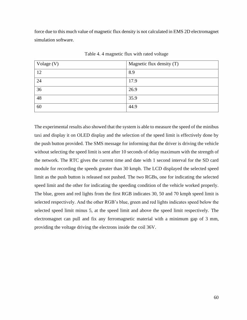
60
force due to this much value of magnetic flux density is not calculated in EMS 2D electromagnet
simulation software.
Table 4. 4 magnetic flux with rated voltage
Volage (V) Magnetic flux density (T)
12 8.9
24 17.9
36 26.9
48 35.9
60 44.9
The experimental results also showed that the system is able to measure the speed of the minibus
taxi and display it on OLED display and the selection of the speed limit is effectively done by
the push button provided. The SMS message for informing that the driver is driving the vehicle
without selecting the speed limit is sent after 10 seconds of delay maximum with the strength of
the network. The RTC gives the current time and date with 1 second interval for the SD card
module for recording the speeds greater than 30 kmph. The LCD displayed the selected speed
limit as the push button is released not pushed. The two RGBs, one for indicating the selected
speed limit and the other for indicating the speeding condition of the vehicle worked properly.
The blue, green and red lights from the first RGB indicates 30, 50 and 70 kmph speed limit is
selected respectively. And the other RGB’s blue, green and red lights indicates speed below the
selected speed limit minus 5, at the speed limit and above the speed limit respectively. The
electromagnet can pull and fix any ferromagnetic material with a minimum gap of 3 mm,
providing the voltage driving the electrons inside the coil 36V.
61
CHAPTER FIVE
SUMMARY, CONCLUSION AND RECOMMENDATION
5.1 Summary
This speed limiter is able to counter act the frequently participants of road traffic accidents
which are minibus taxis’ excessive speeding in the most effective way. Since the designed speed
limiter automatically makes the accelerator pedal fixed with strong electromagnet after the pedal
nears the electromagnet, the driver cannot push the pedal once the pedal is magnetized until the
speed decreases below the selected speed limit. The designed speed limiter has its own speed
measuring system using the effective wheel radius of common minibus taxi which covers the
gap of the malfunctioning speedometer in our cities’ minibus taxis. The speed limiter has 30, 50
and 70 kmph pre-set speed limits which enables it effective in all kinds of roads of the cities.
The selection of speed limit is done by a push button. For giving information to pedestrian
outside and passengers inside there is RGB LED and LCD display which enables to know the
selected speed limit by the minibus taxi driver and has an information to identify either the
driver is driving with selecting the proper speed limit or not. The recording of speeds above 30
kmph makes it easier for knowing the speed of the vehicle before a crash happens which is
useful in insurance claims and give an external third person the driving habit of the driver respect
to the 30 kmph city speed limit.
5.2 Conclusion
The design performs two of the three traditional road traffic accident remedies for speeding
which are vehicle technology and enforcement. It was observed that:
The speed measuring system measured the vehicles speed which makes it easier for
installation because it doesn’t need the manufacturers ECU data for speed detection.
The OLED showed for the driver the current speed of the vehicle in km per hour.
The LCD and one of the RGBs showed the selected speed limit for the passengers and
the road users respectively.
The strong electromagnet locked a ferromagnetic material which can be attached in the
accelerator pedal mechanism.
62
The design is able to inform a third party by SMS message, that the vehicle is being
driven without selectin one of the speed limits pre-sated.
The system records speeds above 30kmph in one second interval.
5.3 Recommendation
For implementing the design, a ferromagnetic material should be prepared and attached
to the existing accelerator pedal or the cable mechanism.
For making the full circuit in a single PCB the full design should be send to PCB makers
and get the current designed PCB for the system instead of the bread board that was used
in the project.
For making the design to be implemented large industries should participate in
manufacturing this speed limiter for the mass production needed for the country.
For further development of the speed limiter, industries should communicate with the
thesis worker and Adama science and technology university.
5.4 Future works
The installation of the system on the existing minibus pedals needs a brief study
including the position on the accelerator pedal without affecting the ergonomically listed
benefits of the existing accelerator pedal dimensions.
The speed limiter selection system able the driver to select the proper speed limit on
different road types accordingly, but as the frequency of changing increases the push
button will not respond so in the future one can improve the response ability of the push
by using its improvement parameters.
For the future work this system while sending an SMS message since the statements
used for messaging contain many delays, the other devices functionality will be affected
by those delays so it needs another library which doesn’t use a delay to send or receive
SMS. This can be done by using the Millis and Micros time counters inside the Arduino
board.

63
REFERENCES
Aarts, L., & Van Schagen, I. (2006). Driving speed and the risk of road crashes: A review.
Accident Analysis and Prevention, 38(2), 215–224.
https://doi.org/10.1016/j.aap.2005.07.004
AbdelGawad, A. F. (2015). Proposed Simple Electro-Mechanical Automotive Speed Control
System. American Journal of Aerospace Engineering, 2(1), 1.
https://doi.org/10.11648/j.ajae.s.2015020101.11
Abegaz, T., Berhane, Y., Worku, A., Assrat, A., & Assefa, A. (2014). Effects of excessive
speeding and falling asleep while driving on crash injury severity in Ethiopia: A
generalized ordered logit model analysis. Accident Analysis and Prevention, 71, 15–21.
https://doi.org/10.1016/j.aap.2014.05.003
Abegazid, T., & Gebremedhinid, S. (2019). Magnitude of road traffic accident related injuries
and fatalities in Ethiopia. https://doi.org/10.1371/journal.pone.0202240
Admassie, D., Yirga, T., & Wamisho, B. L. (2010). Adult limb fractures in Tikur Anbessa
Hospital caused by road traffic injuries: Half year plain radiographic pattern. Ethiopian
Journal of Health Development, 24(1), 61–63.
Administration, F. H. (1999). Implementation of Pedestrian Safety Facilities in the United
Kingdom (Issue December).
Akloweg, Y., Hayshi, Y., & Kato, H. (2011). The effect of used cars on african road traffic
accidents: A case study of addis ababa, ethiopia. International Journal of Urban Sciences,
15(1), 61–69. https://doi.org/10.1080/12265934.2011.580153
Alley, P. (2011). Introductory Microcontroller Programming by. May.
Angeles, L., & Weston, J. F. (2006). Speed Management. ORGANISATION FOR ECONOMIC
CO-OPERATION AND DEVELOPMENT. https://doi.org/10.1080/10587259608037873
B. Zewude, K. A. (2016). Determinants of Traffic Fatalities and Injuries in Wolaita Zone ,. Civil

64
and Environmental Research, 8(10), 38–42.
Bikila Teklu, D. (2014). Addis Ababa Road Traffic Accident Study and Possible Engineering
Solutions: Case Study of Akaki-Kaliti Sub City Roads. In Ethiopian Journal of Community
Engagement.
Boer, E. Den, Brouwer, F., Smokers, R., & Verbeek, M. (2010). in Europe Environmental and
safety impacts. May.
Camilla Sloth Andersen, Kristian Hegner Reinau, & Niels Agerholm. (2016). The Relationship
between Road Characteristics and Speed Collected from Floating Car Data. Journal of
Traffic and Transportation Engineering, 4(6), 1–10. https://doi.org/10.17265/2328-
2142/2016.06.001
Chhabra, P., Katyal, P., & Gulati, V. (2011). Concurrent Design and Prototyping of Composite
Accelerator Pedal. 2(4), 561–576.
Chikezie, N. O., Ezinne, A. G., Nkemdirim, A. C., & Olukunle, A. A. (2017). An Embedded
Voice Activated Automobile Speed Limiter: A Design Approach for Cars. International
Journal of Engineering Science Invention ISSN (Online, 6(4), 2319–6734. www.ijesi.org
David G. Beyerlein; Roland G. Kibler; Bruce H. Van Vlack, all of Flint, M. (1976). United
States Patent TO ” 1C6. https://patents.google.com/patent/US4003160A/en
Delhaye, E., Van Essen, H., ’t Hoen, M., & Verbeek, M. (2016). Consideration of the role of
speed limiters in light commercial vehicle CO 2 regulation. In Transport & Mobility
Leuven (Issue March). http://www.tmleuven.be
Deng, T. M., Fu, J. hou, Shao, Y. M., Peng, J. shuan, & Xu, J. (2019). Pedal operation
characteristics and driving workload on slopes of mountainous road based on naturalistic
driving tests. Safety Science, 119(December 2017), 40–49.
https://doi.org/10.1016/j.ssci.2018.10.011
Elvik, R, Christensen, P., & Helene Amundsen, A. (2004). Aalborg Universitet Speed and road
accidents an evaluation of the power model Elvik, Rune; Christensen, Peter; Helene
Amundsen, Astrid.
65
Elvik, Rune, Christensen, P., & Helene Amundsen, Amundsen, A. (2004). Aalborg University
Speed and road accidents an evaluation of the power model.
Enokela, J. A., & Agbo, D. O. (2015). Development of a Microcontroller Based Car Speed
Controller. 6(6), 9–17.
Eric Garcetti. (2015). Eliminating Traffic Deaths in Los Angeles By 2025 (Issue august).
Eric Howard, Lori Mooren, Goran Nilsson, Allan Quimby, A. V. (2008). Speed management: a
road safety manual for decision-makers and practitioners. In Global Road Safety
Partnership. https://doi.org/10.1136/ip.2006.013490
Evans, B. (2011). Beginning Arduino Programming. Beginning Arduino Programming.
https://doi.org/10.1007/978-1-4302-3778-5
Federal, T. H. E., Republic, D., Transport, M. O. F., & Ababa, A. (2011). the Federal
Democratic Republic of Ethiopia Ministry of Transport Transport Policy of Addis Ababa.
August.
Fesseha Hailu and Teshager Sileshi. (2008). Original article Road traffic accident : The
neglected health problem in Amhara National Regional State , Ethiopia. Ethiop. J. Health
Dev. 2014;28(1), 7.
Freeman, R., & Haslegrave, C. M. (2004). The Determination of Optimal Pedal Positioning for
Automobiles Using Jack. SAE Transactions, 113, 843–848.
http://www.jstor.org/stable/44700007
Gao, C., Xu, J., Li, Q., & Yang, J. (2019). The effect of posted speed limit on the dispersion of
traffic flow speed. Sustainability (Switzerland), 11(13).
https://doi.org/10.3390/su11133594
Gebremichael, M., Guta, M., Gedefaw, M., Bekele, A., Shiferaw, F., Gelibo, T., Getachew, T.,
Mudie, K., Amenu, K., Defar, A., Teklie, H., Tadele, T., Getnet, M., Gonfa, G., Feleke,
Y., Yadeta, D., Challa, F., Tadesse, Y., & Bekele, A. (2017). Prevalence and determinants
of road traffic injuries in Ethiopia: Based on the 2015 STEPS survey findings. Ethiopian
Journal of Health Development, 31(Specialissue1), 340–347.
66
Ghods, A. H., Saccomanno, F., & Guido, G. (2012). Effect of Car/Truck Differential Speed
Limits on Two-lane Highways Safety Operation Using Microscopic Simulation. Procedia
- Social and Behavioral Sciences, 53, 833–840.
https://doi.org/10.1016/j.sbspro.2012.09.932
Gila Albert, T. T. and S. H. (2007). Evaluating the Benefits of Active Speed Limiters and. 1–12.
Gopal, A., Haricharann, D. V., Harikoushik, A., Ambrish, V., & Vineeth, V. V. (2019).
Automatic speed surveillance and vehicle alerting system using internet of things (IoT).
International Journal of Innovative Technology and Exploring Engineering, 8(4S), 252–
255.
H, S., M, M. S., M, N., B, D. S., P, N., & M, I. (2015). RF Based Automatic Vehicle Speed
Limiter by Controlling Throttle Valve. International Journal of Innovative Research in
Science, Engineering and Technology, 4(1), 18722–18728.
https://doi.org/10.15680/IJIRSET.2015.0401051
Hanowski, R. J., Bergoffen, G., Hickman, J. S., Guo, F., Murray, D., Bishop, R., Johnson, S., &
Camden, M. (2012). Research on the Safety Impacts of Speed Limiter Device Installations
on Commercial Motor Vehicles. March, 94. https://doi.org/10.21949/1502748
Hassen, A., Godesso, A., Abebe, L., & Girma, E. (2011). Risky driving behaviors for road traffic
accident among drivers in Mekele city, Northern Ethiopia. BMC Research Notes, 4(1), 535.
https://doi.org/10.1186/1756-0500-4-535
HJÄLMDAHL, M., ALMQVIST, S., & VÁRHELYI, A. (2002). Speed Regulation By in-Car
Active Accelerator Pedal. IATSS Research, 26(2), 60–66. https://doi.org/10.1016/s0386-
1112(14)60044-3
Hosseinlou, M. H., Kheyrabadi, S. A., & Zolfaghari, A. (2015). Determining optimal speed
limits in traffic networks. IATSS Research, 39(1), 36–41.
https://doi.org/10.1016/j.iatssr.2014.08.003
IIHS. (2017). Safety Board Calls Speeding “National Safety Issue.” Status Report, 52(7), n.p.
http://www.iihs.org/iihs/sr/statusreport/article/52/7/3%0Ahttps://trid.trb.org/view/149000
6

67
Ivan, J., Jonsson, T., & Borsos, A. (2012). Motor vehicle speeds: Recommendations for urban
sustainability. Transportation Research Record, 2301, 1–8. https://doi.org/10.3141/2301-
01
Jain, M., Kumar, P., Singh, P., Narayan Arora, C., & Sharma, A. (2015). Detection of Over
Speeding Vehicles on Highways. International Journal of Computer Science and Mobile
Computing, 4(4), 613–619. www.ijcsmc.com
Kameswari, U. J., Satwik, M., Lokesh, A., & Reddy, G. V. (2011). A Design Model for
Automatic Vehicle Speed Controller Throttle body. 35(9), 19–24.
Kebede, A., Beyene, T., & Geremew, H. (2019). Cronicon EC EMERGENCY MEDICINE AND
CRITICAL CARE Ethiopia: An Analysis of Police Report 2013/14. 3, 128–138.
Kockelman, K. K., & Ma, J. (2010). Freeway Speeds and Speed Variations Preceding Crashes,
Within and Across Lanes. In Journal of the Transportation Research Forum (Issue 1964).
https://doi.org/10.5399/osu/jtrf.46.1.976
Kröyer, H. R. G., Jonsson, T., & Várhelyi, A. (2014). Relative fatality risk curve to describe the
effect of change in the impact speed on fatality risk of pedestrians struck by a motor
vehicle. Accident Analysis and Prevention, 62, 143–152.
https://doi.org/10.1016/j.aap.2013.09.007
Mäkinen, T., & Várhelyi, A. (1998). Field trials with in-car speed limiter. 9th International
Conference Road Safety in Europe.
http://www.lth.se/fileadmin/tft/dok/KFBkonf/6VarhelyiMakinen.PDF
Marchau, V., Van Nes, N., Walta, L., & Morsink, P. (2010). Enhancing speed management by
in-car speed assistance systems. IET Intelligent Transport Systems, 4(1), 3–11.
https://doi.org/10.1049/iet-its.2009.0038
Martin Small. (2018). National Road Safety Management Framework.
Matthews, V. O., Noma-Osaghae, E., & Uzairue, S. I. (2018). An Intelligent In-Vehicle
Wireless Multilingual Over-Speed Announcer and Reporter. International Research
Journal of Engineering and Technology, 5(08), 285–288.

68
Mccabe, K., Schoneman, K., & Arcaya, M. (2013). Community Speed Reduction and Public
Health : a Technical Report (Issue December).
Ms Anna Vadeby, Blair Turner, K. M. (2018). Speed and crash risk. In ITF (International
Transport Forum). https://doi.org/10.1007/s11219-006-6001-3
Patterson, T. L., Frith, J. W., & Small, M. W. (2000). Down with speed: a review of the
literature, and the impact of speed on New Zealanders. Accident Compensation
Corporation and Land Transport Safety Authority.
Priyadarshni, V., Gopi Krishna, P., & Sreenivasa Ravi, K. (2016). GPS and GSM enabled
embedded vehicle speed limiting device. Indian Journal of Science and Technology, 9(17).
https://doi.org/10.17485/ijst/2016/v9i17/93045
Saccomanno, F., Philp, C., Cunto, F., Sooklall, R., Thiffault, P., Spoerri, A., Tremblay, P.,
Orribine, B., & Hakomaki, E. (2008). Transport Canada Public Works and Government
Services Canada Safety Implications of Mandated Truck Speed Limiters on Canadian
Highways (Issue May). https://www.tc.gc.ca/media/documents/roadsafety/tp14807e.pdf
Sahebi, S., Nassiri, H., van Wee, B., & Araghi, Y. (2019). Incorporating car owner preferences
for the introduction of economic incentives for speed limit enforcement. Transportation
Research Part F: Traffic Psychology and Behaviour, 64, 509–521.
https://doi.org/10.1016/j.trf.2019.05.014
Samson, F., & Chandra, A. (2006). Analysis of road traffic accidents in Addis Ababa: Traffic
simulation Analysis of Traffic Accident In Addis Ababa: Traffic Simulation Analysis of
Traffic Accident In Addis Ababa: Traffic Simulation (Issue June).
http://citeseerx.ist.psu.edu/viewdoc/download?doi=10.1.1.455.9544&rep=rep1&type=pdf
Savolainen, P., Gates, T., Hacker, E., Davis, A., Frazier, S., Russo, B., Rista, E., Hacker, E.,
Russo, B., & Rista, E. (2014). Evaluating the Impacts of Speed Limit Policy Alternatives.
https://trid.trb.org/view/1607583
Segni Tulu, G. (2015). PEDESTRIAN CRASHES IN ETHIOPIA: Identification of Contributing
Factors through Modelling of Exposure and Road Environment Variables in Civil
Engineering.

69
Sethuramalingam, T. K., Devi, R. N., & Sangeetha, K. (2014). Speed Control for Motor Vehicles
Using Global Positioning System. 6951–6956.
Tadege, M. (2020). Determinants of fatal car accident risk in Finote Selam town, Northwest
Ethiopia. BMC Public Health, 20(1), 1–8. https://doi.org/10.1186/s12889-020-08760-z
Toledo, T., Albert, G., & Hakkert, S. (2007). Impact of active speed limiters on traffic flow and
safety: Simulation-based evaluation. Transportation Research Record, 2019, 169–180.
https://doi.org/10.3141/2019-20
Toroyan, T. (2009). Global status report on road safety. Injury Prevention, 15(4), 286.
https://doi.org/10.1136/ip.2009.023697
Traffic, R., & Fact, A. (2020). Ethiopia STEPS Survey 2015.
Transport & Mobility Leuven, -, TNO, & Delft, C. (2013). Final Report - Evaluation study on
Speed Limitation Devices.
Transportation, U. S. D. of. (1999). Literature review on vehicle travel speed and pedestrian
injuries (Issue October 1999).
Transports, M., & Est, R. (2009). New requirement regarding Direction des communications
speed limiters and pre-set at 105 km / h or less .
Travel Advisory, U. S. D. of S. (2020). Ethiopia 2020 OSAC Crime & Safety Report Ethiopia
2020 OSAC Crime & Safety Report.
Tulu, Getu S, Washington, S., & King, M. J. (2013). Characteristics of Police-reported Road
Traffic Crashes in Ethiopia over a Six Year Period. 1–13.
Tulu, Getu Segni, Washington, S., King, M. J., & Haque, M. M. (2013). Why are pedestrian
crashes so different in developing countries? A review of relevant factors in relation to
their impact in Ethiopia. Australasian Transport Research Forum, ATRF 2013 -
Proceedings, October, 1–18.
US Committee for Guidance on Setting and Enforcing Speed Limits. (1998). Special Report
254: Managing Speed - Review of Current Practice for Setting and Enforcing Speed Limits.
In Transportation Research Board National Research Council.

70
https://books.google.co.uk/books?hl=en&lr=&id=pARs53U6NAQC&oi=fnd&pg=PA1&
dq=who+managing+speed&ots=HaoC0A4FTn&sig=VHEUAHsYd0EwpDhVVW-
PkIPsDi0#v=onepage&q=who managing speed&f=false
Vadeby, A., & Forsman, Å. (2018). Traffic safety effects of new speed limits in Sweden.
Accident Analysis and Prevention, 114, 34–39. https://doi.org/10.1016/j.aap.2017.02.003
Várhelyi, A., & Mäkinen, T. (2001). The effects of in-car speed limiters: Field studies.
Transportation Research Part C: Emerging Technologies, 9(3), 191–211.
https://doi.org/10.1016/S0968-090X(00)00025-5
Vedaprabha, H. C., & Ali, H. (2015). Stress and Deformation Analysis of Accelerated Pedal
Mechanism. International Journal of Engineering and Management Research (IJEMR),
5(3), 364–369.
WHO. (2018). World Health Statistics 2018. In http://apps.who.int/iris.
https://doi.org/10.1063/1.4914609
Xi, Y., Brooks, J., Venhovens, P., Rosopa, P., Desjardins, J., McConomy, S., Belle, L., Drouin,
N., Hennessy, S., Kopera, K., McKee, J., Tanner, S., Truesdail, C., Lococo, K., & Staplin,
L. (2018). Understanding the Automotive Pedal Usage and Foot Movement Characteristics
of Older Drivers. SAE Technical Papers, 2018-April. https://doi.org/10.4271/2018-01-
0495
Yang, H., Zhai, X., & Zheng, C. (2018). Effects of variable speed limits on traffic operation
characteristics and environmental impacts under car-following scenarios: Simulations in
the framework of Kerner’s three-phase traffic theory. Physica A: Statistical Mechanics and
Its Applications, 509, 567–577. https://doi.org/10.1016/j.physa.2018.05.032
Zimwatha. (2011). PUBLIC REVIEW DRAFT Maximum road speed limiters for motor
vehicles Part 1: Specification for installed requirements. January. http://www.kebs.org
71
APPENDICES
Appendix I: Arduino sketch for speed limiter
/*This program sketch reads an interrupt pin from pin number 3 which is a hardware interrupt
pin from hall sensor and measures the time between two pulses which is used to calculate the
RPM and velocity of a vehicle wheel. With this reference the program compares the calculated
speed with the selected speed limit by a push button and activates a electromagnet by using relay
to act on the accelerator pedal of a vehicle and as the speed of the vehicle increases from the
selected speed limit the SD card will record the speed and the time of each speed with one
second interval. LCD display will display weather speed limit is selected or not and the value if
it is selected. As a default speed limit value 30 kmph is selected. */
#include<LiquidCrystal.h>
const int RS=1,EN=2,D4=4,D5=5,D6=6,D7=7;
LiquidCrystal LCD(RS,EN,D4,D5,D6,D7);
#define Button 39
#define S30 40
#define S50 42
#define S70 41
int state=0;
int old=0;
int buttonpull=0;
int SL;
#include<SD.h>
#include<SPI.h>
#include<DS3231.h>
File SLFile;
DS3231 RTC(SDA, SCL);
#include <SoftwareSerial.h>
SoftwareSerial Message(12,13);//where the GSM module Tx and Rx connected Respectively
byte endMsg = 0x1A;

72
const unsigned long ZeroWait=900000;
volatile unsigned long LastMicroMeasured;
volatile unsigned long PeriodBetweenPulses=ZeroWait+1000;
volatile unsigned long PeriodSum=ZeroWait+1000;
float FrequencyRaw;
float RPM;
unsigned long CurrentMicros=micros();
unsigned long ZeroDebouncingExtra;
float vehiclespeed;
const float radius=0.311;
const float pi=3.14;
const int RGBE[]=43,44,45,46;
const int CS=53;
#include <Adafruit_GFX.h>
#include <Adafruit_SSD1306.h>
Adafruit_SSD1306 display(128, 64);
#include <Fonts/FreeMonoBold18pt7b.h>
void setup()
Message.begin(9600);
delay(1000);
SD.begin();
RTC.begin();

73
for(int i=0; i<4; i++)pinMode(RGBE[i], OUTPUT);
attachInterrupt(digitalPinToInterrupt(3), Pulse_Event, RISING);
delay(1000);
display.begin(SSD1306_SWITCHCAPVCC, 0x3C);
display.clearDisplay();
display.setTextColor(WHITE);
display.setRotation(0);
//display.setTextWrap(false);
display.dim(0);
pinMode(Button,OUTPUT);
pinMode(S30,OUTPUT);//Blue LED pin 40
pinMode(S50,OUTPUT);//Green LED pin 41
pinMode(S70,OUTPUT);//Red LED pin 42
digitalWrite(S30,LOW);
digitalWrite(S50,LOW);
digitalWrite(S70,LOW);
LCD.begin(16,2);
LCD.setCursor(0,0);
LCD.write("SL not Activated");
void loop()
buttonpull=digitalRead(Button);
if(buttonpull ==1)
delay(50);
buttonpull = digitalRead(Button);

74
if(buttonpull == 0)
state=old+1;
//Serial.println(state);
else
delay(100);
switch (state)
case 1:
digitalWrite(S30,HIGH);
digitalWrite(S50, LOW);
digitalWrite(S70,LOW);
old=state;
LCD.clear();
LCD.print(" SL Activated.");
SL=30;
break;
case 2:
digitalWrite(S30,LOW);
digitalWrite(S50, HIGH);
digitalWrite(S70,LOW);
old=state;
LCD.clear();
LCD.print(" SL Activated.");
SL=50;

75
break;
case 3:
digitalWrite(S30,LOW);
digitalWrite(S50, LOW);
digitalWrite(S70,HIGH);
old=state;
LCD.clear();
LCD.print(" SL Activated.");
SL=70;
break;
default:
digitalWrite(S30,LOW);
digitalWrite(S50, LOW);
digitalWrite(S70,LOW);
old=0;
LCD.setCursor(0,0);
LCD.print("SL not Selected.");
SL=30;
break;
LCD.setCursor(0,1);
LCD.print(" SL= ");
76
LCD.print(SL);
LCD.print(" KPH");
CurrentMicros = micros();
if(CurrentMicros<LastMicroMeasured)
LastMicroMeasured=CurrentMicros;
FrequencyRaw=1000000./PeriodSum;
if(PeriodBetweenPulses>ZeroWait - ZeroDebouncingExtra|| CurrentMicros -
LastMicroMeasured>ZeroWait -ZeroDebouncingExtra)
FrequencyRaw=0;
ZeroDebouncingExtra=1000;
PeriodSum=ZeroWait+500;
else
ZeroDebouncingExtra=0;
RPM =FrequencyRaw * 60.;
vehiclespeed = 2*pi*radius*RPM/60.;
vehiclespeed =vehiclespeed*36.;
vehiclespeed =vehiclespeed/10.;
char Speed[10];
dtostrf(vehiclespeed, 6, 0, Speed);
display.clearDisplay();

77
display.setFont(&FreeMonoBold18pt7b);
display.setTextSize(0);
display.setCursor(0,25);
display.println("Speed:");
display.setCursor(0,60);
display.println(Speed);
display.display();
if(vehiclespeed <SL-5)
digitalWrite(RGBE[0], LOW);
digitalWrite(RGBE[1], LOW);
digitalWrite(RGBE[2], HIGH);
else if(vehiclespeed >=SL-5 && vehiclespeed<SL)
digitalWrite(RGBE[0], LOW);
digitalWrite(RGBE[1], HIGH);
digitalWrite(RGBE[2], LOW);
else if (vehiclespeed >SL)
digitalWrite(RGBE[0], HIGH);
digitalWrite(RGBE[1], LOW);
digitalWrite(RGBE[2],LOW);
SLFile=SD.open("Sd.txt", FILE_WRITE);
78
if (SLFile)
SLFile.print(RTC.getDateStr());
SLFile.print(",");
SLFile.print(RTC.getTimeStr());
SLFile.print(",");
SLFile.println(vehiclespeed);
SLFile.close();
while (RGBE[0]== HIGH)
digitalWrite(RGBE[3],HIGH);
if(S30==LOW && S50==LOW && S70==LOW)
SendSMS;
void Pulse_Event()
PeriodBetweenPulses=micros()-LastMicroMeasured;
LastMicroMeasured=micros();
PeriodSum =PeriodBetweenPulses;

79
void SendSMS()
while (ATcheck() != true)
delay(1000);
while (ATBaudrate("9600") != true)
delay(1000);
while (AT_SMS_format() != true)
delay(1000);
while (AT_SMS_sending("+251922109593") != true)
delay(1000);
Message.print("Dear Owner: Your car is violating city car speed limit. Please, contact your
driver! ");
delay(1000);
Message.write(endMsg);
delay(5000);
boolean ATcheck()

80
String incoming;
Message.println("AT");
delay(500);
while (Message.available())
byte in = Message.read();
incoming += (char)in;
if (incoming.indexOf("OK") != -1)
incoming = "";
return true;
incoming = "";
return false;
boolean ATBaudrate(String baud)
String incoming;
String command = "AT+IPR=" + baud;
Message.println(command);
delay(500);
while (Message.available())
byte in = Message.read();
incoming += (char)in;
if (incoming.indexOf("OK") != -1)

81
incoming = "";
return true;
incoming = "";
return false;
boolean AT_SMS_format()
String incoming;
String command = "AT+CMGF=1";
Message.println(command);
delay(500);
while (Message.available())
byte in = Message.read();
incoming += (char)in;
if (incoming.indexOf("OK") != -1)
incoming = "";
return true;
incoming = "";
return false;
boolean AT_SMS_sending(String cellNumber)
82
String incoming;
String command = "AT+CMGS=" + cellNumber;
Message.flush();
Message.println(command);
delay(1000);
while (Message.available())
byte in = Message.read();
incoming += (char)in;
if (incoming.indexOf(">") != -1)
incoming = "";
return true;
incoming = "";
return false;

83
Appendix II: Dimensions of the Electromagnet