DEPARTMENTS OF THE ARMY AND THE AIR FORCE
1316
ARMY TM 9-2320-272-34-2 AIR FORCE TO 36A12-1C-452-2 TECHNICAL MANUAL DIRECT SUPPORT AND GENERAL SUPPORT MAINTENANCE TRUCK, 5-TON, 6X6, M939 AND M939A1 SERIES (DIESEL) TRUCK, CARGO 5-TON, 6X6, DROPSIDE, M923 (2320-01-050-2084), M923A1 (2320-01-206-4087), M925 (2320-01-047-8769), M925A1 (2320-01-206-4088); TRUCK, CARGO 5-TON, 6X6, M924 (2320-01-047-8773), M924A1 (2320-01-205-2692), M926 (2320-01-047-8772), M926A1 (2320-01-205-2693); TRUCK, CARGO: 5 TON, 6X6, XLWB, M927 (2320-01-047-8771), M927A1 (2320-01-206-4089), M928 (2320-01-047-8770), M928A1 (2320-01-206-4090); TRUCK, DUMP: 5-TON, 6X6, M929 (2320-01-047-8756), M929A1 (2320-01-206-4079), M930 (2320-01-047-8755), M930A1 (2320-01-206-4080); TRUCK, TRACTOR 5-TON, 6X6, M931 (2320-01-047-8753), M931Al (2320-01-206-4077), M932 (2320-01 -047-8752), M932A1 (2320-01 -205-2684); TRUCK, VAN, EXPANSIBLE: 5-TON, 6X6, M934 (2320-01-047-8750), M934A1 (2320-01-205-2682), M935 (2320-01-047-8751), M935A1 (2320-01-205-2683); TRUCK, MEDIUM WRECKER: 5-TON, 6X6, M936 (2320-01-047-8754), M936A1 (2320-01-206-4078) DEPARTMENTS OF THE ARMY AND THE AIR FORCE JUNE 1986
-
Upload
khangminh22 -
Category
Documents
-
view
0 -
download
0
Transcript of DEPARTMENTS OF THE ARMY AND THE AIR FORCE

A R M Y T M 9 - 2 3 2 0 - 2 7 2 - 3 4 - 2
A I R F O R C E T O 3 6 A 1 2 - 1 C - 4 5 2 - 2
T E C H N I C A L M A N U A L
D I R E C T S U P P O R T A N D
G E N E R A L S U P P O R T M A I N T E N A N C E
T R U C K , 5 - T O N , 6 X 6 , M 9 3 9 A N D
M 9 3 9 A 1 S E R I E S ( D I E S E L )
TRUCK, CARGO 5-TON, 6X6, DROPSIDE,M923 (2320-01-050-2084), M923A1 (2320-01-206-4087),M925 (2320-01-047-8769), M925A1 (2320-01-206-4088);
TRUCK, CARGO 5-TON, 6X6,M924 (2320-01-047-8773), M924A1 (2320-01-205-2692),M926 (2320-01-047-8772), M926A1 (2320-01-205-2693);
TRUCK, CARGO: 5 TON, 6X6, XLWB,M927 (2320-01-047-8771), M927A1 (2320-01-206-4089),M928 (2320-01-047-8770), M928A1 (2320-01-206-4090);
TRUCK, DUMP: 5-TON, 6X6,M929 (2320-01-047-8756), M929A1 (2320-01-206-4079),M930 (2320-01-047-8755), M930A1 (2320-01-206-4080);
TRUCK, TRACTOR 5-TON, 6X6,M931 (2320-01-047-8753), M931Al (2320-01-206-4077),M932 (2320-01 -047-8752), M932A1 (2320-01 -205-2684);
TRUCK, VAN, EXPANSIBLE: 5-TON, 6X6,M934 (2320-01-047-8750), M934A1 (2320-01-205-2682),M935 (2320-01-047-8751), M935A1 (2320-01-205-2683);
TRUCK, MEDIUM WRECKER: 5-TON, 6X6,M936 (2320-01-047-8754), M936A1 (2320-01-206-4078)
D E P A R T M E N T S O F T H E A R M Y A N D T H E A I R F O R C E
J U N E 1 9 8 6


TMTO
9-2320-272-34-236A12-1C-452-2
CHANGEHEADQUARTERS
DEPARTMENT OF THE ARMYNO. 2 Washington D.C., 18 March 1991
TECHNICAL MANUAL
VOLUME 2 OF 2DIRECT SUPPORT AND GENERAL SUPPORT MAINTENANCE
TRUCK, 5-TON, 6X6, M939, M39A1 AND M939A2 SERIES(DIESEL)
TRUCK, CARGO, DROPSIDE: 5-TON, 6X6
M923 (2320-01-050-2084), M923A1 (2320-01-206-4087), M923A2 (2320-01-230-0307),
M925 (2320-01-047-8769), M925A1 (2320-01-206-4088), M925A2 (2320-01-230-0308),
TRUCK, CARGO: 5-TON, 6X6,
M924 (2320-01-047-8773), M924A1 (2320-01-205-2692)
M926 (2320-01 -047-8772), M926A1 (2320-01 -205-2693)
TRUCK, CARGO, XLWB: 5-TON, 6X6,
M927 (2320-01-047-8771), M927A1 (2320-01-206-4089), M927A2 (2320-01-230-0309),
M928 (2320-01-047-8770), M928A1 (2320-01-206-4090), M928A2 (2320-01-230-0310),
TRUCK, DUMP, 5-TON, 6X6
M929 (2320-01-047-8756), M929A1 (2320-01-206-4079), M929A2 (2320-01-230-0305),
M930 (2320-01-047-8755), M930A1 (2320-01-206-4080), M930A2 (2320-01-230-0306),
TRUCK, TRACTOR: 5-TON, 6X6
M931 (2320-01-047-8753), M931A1 (2320-01-206-4077), M931A2 (2320-01-230-0302),
M932 (2320-01-047-8752), M932A1 (2320-01-205-2684), M932A2 (2320-01-230-0303),
TRUCK, VAN, EXPANSIBLE: 5-TON, 6X6,
M934 (2320-01-047-8750), M934A1 (2320-01-205-2682), M934A2 (2320-01-230-0300),
M935 (2320-01-047-8751), M935A1 (2320-01-205-2683), M935A2 (2320-01-230-0301),
TRUCK, MEDIUM WRECKER: 5-TON, 6X6,
M936 (2320-01-047-8754), M936A1 (2320-01-206-4078 ), M936A2 (2320-01-230-0304),
TM 9-2320-272-34-2, dated 10 June 1986, is changed as follows:
1. Remove old pages and insert new pages as indicated below.
2. New or changed material is indicated by a vertical bar in the margin of the page.
REMOVE PAGES
iii and iv
8-15 and 8-16
8-67 through 8-115
(8-116 Blank)
9-1 through 9-6
9-11 and 9-12
9 - 2 7 a n d 9 - 2 8
9-31 through 9-40
9-47 through 9-60
INSERT PAGES
iii and iv
8-15 and 8-16
8-67 through 8-115
(8-116 Blank)
9-1 through 9-6
9-11 and 9-12
9-27 and 9-28
9-31 through 9-40
9-47 through 9-60
REMOVE PAGES
18-61 and 18-62
18-83 and 18-84
18-95 through 18-98
N o n e
19-1 and 19-2
19-9 through 19-12
19-19 and 19-20
19-23 and 19-24
INSERT PAGES
18-61 and 18-62
18-83 and 18-84
18-95 through 18-98
18.1 through 18.1-289
(18.1-290 Blank)
19-1 and 19-2
19-9 through 19-12
19-19 and 19-20
19-23 and 19-24

TM 9-2320-272-34-2
REMOVE PAGES INSERT PAGES REMOVE PAGES INSERT PAGES
9-63 through 9-74 9-63 through 9-74 19-45 and 19-46 19-45 and 19-46
9-77 through 9-82 9-77 through 9-82 19-49 and 19-50 19-49 and 19-50
9-107 through 9-122 9-107 through 9-122 19–75 through 19-82 19-75 through 19-82
10-5 and 10-6 10-5 and 10-6 20-1 and 20-2 2 0 - 1 a n d 2 0 - 2
10-37 through
10-55 through
11-1 through
11-13 through
10-40 1 0 - 3 7 t h r o u g h 1 0 - 4 0 2 0 - 4 1 a n d 2 0 - 4 2 2 0 - 4 1 a n d 2 0 - 4 2
10–58 1 0 - 5 5 ( 1 0 - 5 6 / 1 0 - 5 7 20-57 (20-58 Blank) 20-57 (20-58 Blank)
Blank) and 10-58 21-37 through 21-50 21-37 through 21-50.1
11-4 11-1 through 11-4 (21-50.2 Blank)
11-46 1 1 - 1 3 t h r o u g h 1 1 - 4 6 N o n e 2 1 - 5 5 t h r o u g h 2 1 - 6 5
11-51 through 11-64 11-51 through 11-64 (21-66 Blank)
15-13 through 15-18 1 5 - 1 3 t h r o u g h 1 5 - 1 8 A - 1 a n d A - 2 A-1 and A-2
17-1 through 17-4 17-1 through 17-4 C-5 (C-6 Blank) C-5 (C-6 Blank)
17-13 through 17-15 17-13 through 17-15 D-1 (D-2 Blank) D-1 (D-2 Blank)
(17-16 Blank) (17-16 Blank) Index 1 through Index 16 Index 1 through Index 16
18-1 and 18-2 18-1 and 18–2
3. File this change sheet in front of the publication for reference purposes.
By Order of the Secretary of the Army:
Official:
PATRICIA P. HICKERSONColonel, United States Army
The Adjutant General
By Order of the Secretary of the Air Force;
CARL E. VUONOGeneral, United States Army
Chief of Staff
MERRILL A. McPEAKGeneral, United States Air Force
Chief of StaffOfficial;
CHARLES C. McDONALDGeneral, United States Air Force
Commander, Air Force Logistics Command


●
●
●
●
●
●
●
TM 9-2320-272-34-2
WARNING
EXHAUST GASES CAN KILL
1. DO NOT operate your vehicle engine in enclosed area.
2. DO NOT idle vehicle engine with cab windows closed.
3. DO NOT drive vehicle with inspection plates or cover plates removed.
4. BE ALERT at all times for exhaust odors.
5. BE ALERT for exhaust poisoning symptoms, they are:
Headache Dizziness Sleepiness Loss of muscular control
6. If YOU SEE another person with exhaust poisoning symptoms: Remove person from area Expose to open air Keep person warm
Do not permit person to move Administer artificial respiration, if necessary*
* For artificial respiration, refer to FM 21-11.
WARNING SUMMARY
Do not disconnect air lines before draining air reservoirs. Small parts under pressure may shoot out withhigh velocity, causing injury to personnel.Weight of vehicle must remain supported on jack stands at all times. Do not attempt to support weight ofvehicle on hydraulic jack. Injury to personnel may result if jack fails.All personnel must stand clear during hoisting operations. A snapped cable, shifting, or swinging load maycause injury to personnel.Eyeshields must be worn when cleaning with a wire brush. Flying rust and metal particles may causeinjury to personnel.
Compressed air source will not exceed 30 psi (207 kPa). When cleaning with compressed air, eyeshieldsmust be worn. Failure to wear eyeshields may result in injury to personnel.Valve cover is under extreme tension. Do not remove all screws until limiting valve is positioned so vise willhold cover, or outer spring may fly out causing injury to personnel.Be careful when removing small retaining ring. Spring tension under “O” ring may release when retainingring is removed, causing injury to personnel.
Warning a

TM 9-2320-272-34-2
WARNING SUMMARY (Cont’d)
●
●
●
●
●
●
●
●
●
●
Personnel must stand clear of vehicle when vehicle engine is running. Vehicle may suddenly move, causinginjury to personnel.Adhesive material is flammable. Keep away from open flame, or injury to personnel may result.
Use eyeshields when removing/installing door glass. Glass may shatter causing injury to personnel.Never work under dump body until safety braces are properly positioned. Injury to personnel may result ifdump body suddenly lowers.Make sure dump control lever is in neutral and not moved. Injury to personnel may result if lift cylinder isoperated when not secured.The elevating cylinder is heavy. Remove/install with the aid of assistant and a lifting device, or injury topersonnel may result.Before hoisting outer boom away from/onto wrecker, make sure inner boom is properly fastened to outerboom, or injury to personnel may result.Inner boom must be supported at sheave to prevent tilting until hoist chain can be properly positionedaround inner boom, or injury to personnel may result.Make sure all lines are fastened clear of the gondola to avoid snagging during removal or injury topersonnel may result.Keep hydraulic oil reservoir away from open flame during inspection or repair. Failure to do this mayresult in injury to personnel.The front/rear winch is heavy. Use hoist during repair, or injury to personnel may result.
Warning b

* ARMY TM 9-2320-272-34-2AIR FORCE TO 36A12-1C-452-2
TECHNICAL MANUALNO. 9-2320-272-34-2
TECHNICAL ORDERNO. 36A12-1C-452-2
TECHNICAL MANUAL
VOLUME 2 OF 2
DEPARTMENTS OF THE ARMYAND THE AIR FORCE
Washington D. C., 26 April 1990
DIRECT SUPPORT AND GENERAL SUPPORT MAINTENANCETRUCK, 5-TON, 6X6, M939, M939A1 AND M939A2 SERIES
Model
Truck, Cargo, DropsideTruck, Cargo, DropsideTruck, Cargo, DropsideTruck, Cargo, DropsideTruck, Cargo, DropsideTruck, Cargo, DropsideTruck, CargoTruck, CargoTruck, CargoTruck, CargoTruck, Cargo, XLWBTruck, Cargo, XLWBTruck, Cargo, XLWBTruck, Cargo, XLWBTruck, Cargo, XLWBTruck, Cargo, XLWBTruck, DumpTruck, DumpTruck, DumpTruck, DumpTruck, DumpTruck, DumpTruck, TractorTruck, TractorTruck, TractorTruck, TractorTruck, TractorTruck, TractorTruck, Van, ExpansibleTruck, Van, ExpansibleTruck, Van, ExpansibleTruck, Van, Expansible, W/HLGTruck, Van, Expansible, W/HLGTruck, Van, Expansible, W/HLGTruck, Medium WreckerTruck, Medium WreckerTruck, Medium Wrecker
M923M923A1M923A2M925M925A1M925A2M924M924A1M926M926A1M927M927A1M927A2M928M928A1M928A2M929M929A1M929A2M930M930A1M930A2M931M931A1M931A2M932M932A1M932A2M934M934A1M934A2M935M935A1M935A2M936M936A1M936A2
NSN Without Winch
2320-01-050-20842320-01-206-40872320-01-230-0307
(DIESEL)
NSN With Winch
2320-01-047-87692320-01-206-40882320-01-230-0308
2320-01-047-87732320-01-205-2692
2320-01-047-87722320-01-205-2693
2320-01-047-87712320-01-206-40892320-01-230-0309
2320-01-247-87702320-01-206-40902320-01-230-0310
2320-01-047087562320-01-206-40792320-01-230-0305
2320-01-047-87552320-01-206-40802320-01-230-0306
2320-01-047-87532320-01-206-40772320-01-230-0302
2320-01-047-87522320-01-205-26842320-01-230-0303
2320-01-047-87502320-01-205-26822320-01-230-03002320-01-047-87512320-01-205-26832320-01-230-0301
2320-01-047-87542320-01-206-40782320-01-230-0304
This manual is published in two parts. TM 9-2320-272-34-1 contains chapters 1 through 7, and TM 9-2320-272-34-2 contains chapters 8 through 21, appendices A, B, C, D, and E. This manual contains a table of contents and alphabetized index for chapters 8 through 21.* This publication supersedes TM 9-2320-272-34-2 dated 8 October 1982 and all changes.
Change 1 i

TM 9-2320-272-34-2
DIRECT SUPPORT AND GENERAL SUPPORT MAINTENANCETRUCK, 5 -TON, 6X6, M939, M939A1 AND M939A2 SERIES
(DIESEL)
REPORTING OF ERRORSYou can help improve this manual. If you find any mistakes or if you know of a way toimprove the procedures, please let us know. Mail your letter, DA Form 2028 (Recom-mended Changes to Publications and Blank Forms), or DA Form 2028-2 located in backof this manual direct to: Commander, U.S. Army Tank-Automotive Command, ATTN:AMSTA-MB, Warren, Michigan 48397-5000. A reply will be furnished to you.
VOLUME 2 OF 2
CHAPTER 8. TRANSFER CASE MAINTENANCE . . . . . . . . . . . . . . . . . . . . . . . . . . . . . . . . . . . . . . .
Page
8-1
Section I. Description and Data . . . . . . . . . . . . . . . . . . . . . . . . . . . . . . . . . . . . . . . . . . . . . . . . . . . . . . 8-1II. Transfer Case and Components Maintenance . . . . . . . . . . . . . . . . . . . . . . . . . . . . . . . . 8-3
CHAPTER 9. FRONT AND REAR AXLES MAINTENANCE . . . . . . . . . . . . . . . . . . . . . . . . . . . . . . . . 9-1
Section I. Description and Data . . . . . . . . . . . . . . . . . . . . . . . . . . . . . . . . . . . . . . . . . . . . . . . . . . . . . . 9-1II. Front Axle Maintenance . . . . . . . . . . . . . . . . . . . . . . . . . . . . . . . . . . . . . . . . . . . . . . . . . . 9-3
III. Rear Axle Maintenance . . . . . . . . . . . . . . . . . . . . . . . . . . . . . . . . . . . . . . . . . . . . . . . . . . . . 9-81IV. Axle Tests and Adjustments . . . . . . . . . . . . . . . . . . . . . . . . . . . . . . . . . . . . . . . . . . . . . . . . 9-125
CHAPTER 10. COMPRESSED AIR AND BRAKE SYSTEMS MAINTENANCE . . . . . . . . . . . . . .10-1
Section I. Description and Data . . . . . . . . . . . . . . . . . . . . . . . . . . . . . . . . . . . . . . . . . . . . . . . . . . . . . . 10-1II. Compressed Air and Brake Systems Components Maintenance . . . . . . . . . . . . . . . . 10-5
CHAPTER 11. POWER STEERING SYSTEM MAINTENANCE . . . . . . . . . . . . . . . . . . . . . . . . . . . . . 11-1
Section I. Description and Data . . . . . . . . . . . . . . . . . . . . . . . . . . . . . . . . . . . . . . . . . . . . . . . . . . . . . . 11-1II. General Maintenance Instructions . . . . . . . . . . . . . . . . . . . . . . . . . . . . . . . . . . . . . . . . . . 11-3
III. Power Steering System Maintenance . . . . . . . . . . . . . . . . . . . . . . . . . . . . . . . . . . . . . . . . 11-3
CHAPTER 12. FRAME MAINTENANCE . . . . . . . . . . . . . . . . . . . . . . . . . . . . . . . . . . . . . . . . . . . . . . . . 12-1
Section I. Description and Data . . . . . . . . . . . . . . . . . . . . . . . . . . . . . . . . . . . . . . . . . . . . . . . . . . . . . . 12-1II. Frame Maintenance . . . . . . . . . . . . . . . . . . . . . . . . . . . . . . . . . . . . . . . . . . . . . . . . . . . . . . . 12-1
III. Repair and Replacement Standards . . . . . . . . . . . . . . . . . . . . . . . . . . . . . . . . . . . . . . . . . 12-1
CHAPTER 13. FRONT SHEET METAL MAINTENANCE . . . . . . . . . . . . . . . . . . . . . . . . . . . . . . . . . 13-1
Section I. Description . . . . . . . . . . . . . . . . . . . . . . . . . . . . . . . . . . . . . . . . . . . . . . . . . . . . . . . . . . . . . . . 13-1II. Front Sheet Metal Maintenance . . . . . . . . . . . . . . . . . . . . . . . . . . . . . . . . . . . . . . . . . . . . . 13-1
ii Change 1
TM 9-2320-272-34-2
CHAPTER 14.
Section I.II.
CHAPTER 15.
Section I.II.
CHAPTER 16.
Section I.II.
CHAPTER 17.
Section I.II.
CHAPTER 18.
Section I.II.
III.
CAB MAINTENANCE . . . . . . . . . . . . . . . . . . . . . . . . . . . . . . . . . . . . . . . . . . . . . . . . . . . .
Description and Data . . . . . . . . . . . . . . . . . . . . . . . . . . . . . . . . . . . . . . . . . . . . . . . . . . . . . . . . . . . .Cab and Cab Components Maintenance . . . . . . . . . . . . . . . . . . . . . . . . . . . . . . . . . . . . . . . . . . . .
CARGO BODY (M923, M924, M925, M926, M927, AND M928) MAINTENANCE
Description and Data . . . . . . . . . . . . . . . . . . . . . . . . . . . . . . . . . . . . . . . . . . . . . . . . . . . . . . . . . . . . .Cargo Body Components Maintenance . . . . . . . . . . . . . . . . . . . . . . . . . . . . . . . . . . . . . . . . . . . . .
DUMP BODY (M929 and M930) MAINTENANCE . . . . . . . . . . . . . . . . . . . . .
Description and Data . . . . . . . . . . . . . . . . . . . . . . . . . . . . . . . . . . . . . . . . . . . . . . . . . . . . . . . . . . .Dump Body Maintenance . . . . . . . . . . . . . . . . . . . . . . . . . . . . . . . . . . . . . . . . . . . . . . . . . . . . . . .
FIFTH WHEEL MAINTENANCE . . . . . . . . . . . . . . . . . . . . . . . . . . . . . . . . . . . . . . . . .
Description and Data . . . . . . . . . . . . . . . . . . . . . . . . . . . . . . . . . . . . . . . . . . . . . . . . . . . . . . . . .Fifth Wheel Maintenance . . . . . . . . . . . . . . . . . . . . . . . . . . . . . . . . . . . . . . . . . . . . . . . . . . . . . . .
WRECKER BODY (M936) MAITENANCE . . . . . . . . . . . . . . . . . . . . . . . . . . .
Description and Data . . . . . . . . . . . . . . . . . . . . . . . . . . . . . . . . . . . . . . . . . . . . . . . . . . . . . . . . . . .Wrecker Body Components Replacement . . . . . . . . . . . . . . . . . . . . . . . . . . . . . . . . . . . . . . . .Wrecker Body Components . . . . . . . . . . . . . . . . . . . . . . . . . . . . . . . . . . . . . . . . . . . . . . . . . . . . .
CHAPTER 18.1. VAN BODY MAINTENANCE . . . . . . . . . . . . . . . . . . . . . . . . . . . . . . . . . . . . . . . . . . . . . .
Section I.II.
III.
CHAPTER 19.
Section I.II.
III.IV.
CHAPTER 20.
Section I.II.
III.
Description and Data . . . . . . . . . . . . . . . . . . . . . . . . . . . . . . . . . . . . . . . . . . . . . . . . . . . . . . . . .Van Body Components Maintenance . . . . . . . . . . . . . . . . . . . . . . . . . . . . . . . . . . . . . . . . . . . .Van Body Electrical Components Replacement . . . . . . . . . . . . . . . . . . . . . . . . . . . . . . . . . . .
WINCH MAINTENANCE . . . . . . . . . . . . . . . . . . . . . . . . . . . . . . . . . . . . . . . . . . . . . . . . .
Description and Data . . . . . . . . . . . . . . . . . . . . . . . . . . . . . . . . . . . . . . . . . . . . . . . . . . . . . . . . . . .Front Winch Components Maintenance . . . . . . . . . . . . . . . . . . . . . . . . . . . . . . . . . . . . . . . . .Rear Winch Components Maintenance . . . . . . . . . . . . . . . . . . . . . . . . . . . . . . . . . . . . . . . . . .Repair and Replacement Standards . . . . . . . . . . . . . . . . . . . . . . . . . . . . . . . . . . . . . . . . . . . . .
POWER TAKEOFF MAINTENANCE . . . . . . . . . . . . . . . . . . . . . . . . . . . . . . . . . . . . .
Description and Data . . . . . . . . . . . . . . . . . . . . . . . . . . . . . . . . . . . . . . . . . . . . . . . . . . . . . . . . . . .Transfer Case Power Takeoff and Controls Maintenance . . . . . . . . . . . . . . . . . . . . . . . . .Transmission Power Takeoff and Controls Maintenance . . . . . . . . . . . . . . . . . . . . . . . . . .
14-1
14-114-1
15-1
15-115-3
16-1
16-116-1
17-1
17-117-1
18-1
18-118-118-77
18.1-1
18.1-118.1-118.1-163
19-1
19-119-319-9119-138
20-1
20-120-320-33
Change 2 i i i

TM 9-2320-272-34-2
CHAPTER 21. SPECIAL PURPOSE KITS . . . . . . . . . . . . . . . . . . . . . . . . . . . . . . . . . . . . . . . . . . . . . . . 21-1
Section I.II.
III.IV.
V. VI .
APPENDIX A
APPENDIX B
APPENDIX C
APPENDIX D
APPENDIX E
INDEX
Engine Coolant Heater Kit Replacement . . . . . . . . . . . . . . . . . . . . . . . . . . . . . . . . . . . . . . . . 21-1Personnel Fuel Burning Heater Kit Replacement . . . . . . . . . . . . . . . . . . . . . . . . . . . . . . . . 21-21Deepwater Fording Kit . . . . . . . . . . . . . . . . . . . . . . . . . . . . . . . . . . . . . . . . . . . . . . . . . . . . . . . . . 21-38Hand Air Brake Kit . . . . . . . . . . . . . . . . . . . . . . . . . . . . . . . . . . . . . . . . . . . . . . . . . . . . . . . . . . . . 21-51Radiator and Hood Cover Kit . . . . . . . . . . . . . . . . . . . . . . . . . . . . . . . . . . . . . . . . . . . . . . . . . . . 21-51Air Conditioner Kit . . . . . . . . . . . . . . . . . . . . . . . . . . . . . . . . . . . . . . . . . . . . . . . . . . . . . . . . . . . . . 21-55
REFERENCES . . . . . . . . . . . . . . . . . . . . . . . . . . . . . . . . . . . . . . . . . . . . . . . . . . . . . . . . . . . . . . . . A-1
REPAIR PARTS, SPECIAL TOOLS, AND EQUIPMENT . . . . . . . . . . . . . . . . . . . . . . . . . B-1
EXPENDABLE/DURABLE SUPPLIES AND MATERIALS LIST . . . . . . . . . . . . . . . . . C-1
ILLUSTRATED LIST OF MANUFACTURED ITEMS . . . . . . . . . . . . . . . . . . . . . . . . . . . . D-1
TORQUE LIMITS . . . . . . . . . . . . . . . . . . . . . . . . . . . . . . . . . . . . . . . . . . . . . . . . . . . . . . . . . . . . . . E-1
. . . . . . . . . . . . . . . . . . . . . . . . . . . . . . . . . . . . . . . . . . . . . . . . . . . . . . . . . . . . . . . . . . . . . . . . . . . . . . . .Index 1
iv Change 2

TM 9-2320-272-34-2
CHAPTER 8TRANSFER CASE MAINTENANCE
Section I. DESCRIPTION AND DATA
8-1. GENERALThis section provides various operating functions of the transfer case and its components. Tabulated datafor the transfer case is provided in table 8-1.
8-2. DESCRIPTION - TRANSFER CASEa. The transfer case is a gearbox located between the transmission and forward-rear axle. Its purpose is to
transfer driving power from the transmission to the front axle as well as the rear axles. It also provides anextra gear reduction (low range operation, refer to TM 9-2320-272 -10). The drop box design enables the frontaxle propeller shaft to clear the underside of the engine.
b. The transfer case is equipped with an air-operated front-wheel drive shift cylinder, electrically-actuatedinterlock system and an air-actuated interlock cylinder.
1) The front-wheel drive automatically engages when the transfer case is shifted to low range.2) The electrically-actuated interlock valve system is to prevent transfer case engagement when
transmission is not in neutral. Electrical power supplied from transfer case switch energizes the interlocksolenoid and dumps air pressure into the atmosphere. This releases pressure from the interlock air cylinderand the transfer case can be shifted.
c. The transfer case is equipped with an oil pump and speedometer drive gear.
TRANSFER CASETable 8-1. Transfer Case Tabulated Data
Make . . . . . . . . . . . . . . . . . . . . . .. . . . . . . . . . . . . . . . . . . . . . . . . . . . . . . . . . . . . . . . . . . . . . . . . . . . . . RockwellModel . . . . . . . . . . . . . . . . . . . . . . . . . . . . . . . . . . . . . . . . . . . . . . . . . . . . . . . . . . . . . . . . . . . . . . . . . . . . .. T-1138Type . . . . . . . . . . . . . . . . . . . . . . . . . . . . . . . . . . . . . . . . . . . . . . . . . . . . . . Two-speed with front-wheel driveRatios:
Low speed . . . . . . . . . . . . . . . . . . . . . . . . . . . . . . . . . . . . . . . . . . . . . . . . . . . . . . . . . . . . . . . . . . . . 1.790 to 1High speed . . . . . . . . . . . . . . . . . . . . . . . . . . . . . . . . . . . . . . . . . . . . . . . . . . . . . . . . . . . . . . . . . . . . 0.732 to 1Speedometer output . . . . . . . . . . . . . . . . . . . . . . . . . . . . . . . . . . . . . . . . . . . . . . . . . . . . . . . . . . . 2.050 to 1
Lubrication capacity . . . . . . . . . . . . . . . . . . . . . . . . . . . . . . . . . . . . . . . . . . . . . . . . . . . 10 pints (4.73 liters)Front axle declutch . . . . . . . . . . . . . . . . . . . . . . . . . . . . . . . . . . . . . . . . . . . . . . . . . . . . . . . . . . . Air operatedOil pump Constant running, self-priming reversibleParking brake size . . . . . . . . . . . . . . . . . . . . . . . . . . . . . . . . . . 12 in. dia. x 3 in. width (304.8 x 76.2 mm)Dry weight . . . . . . . . . . . . . . . . . . . . . . . .. . . . . . . . . . . . . . . . . . . . . . . . . . . . . . . . . . 550 pounds (249.7 kg)
TA 350412
8-1 (8-2 blank)


TM 9-2320-272-34-2
Section Il. TRANSFER CASE AND COMPONENTS MAINTENANCE
8-3. TRANSFER CASE MAINTENANCE TASK SUMMARY
TASK PROCEDURESPARA.
8-4.8-5.
8-6.
8-7.
8-8.
8-9.8-10.
8-11.8-12.8-13.
8-14.8-15.
8-16.8-17.8-18.8-19.8-20.
Transfer Case Interlock Valve Replacement
Transfer Case Interlock Valve F(M936)ReplacementTransfer Case Interlock Air CylinderReplacementTransfer Case Front Axle EngagementAir Cylinder ReplacementTransfer Case Front Axle EngagementControl Valve ReplacementTransfer Case Shift Lever MaintenanceTransfer Case Shift Lever Shift RodMaintenance
Transfer Case Cross-Shaft ReplacementTransfer Case Shift Rod MaintenanceTransfer Case Speedometer Drive Gear andDriven Shaft ReplacementTransfer Case Switch ReplacementTransfer Case Capacitor Replacement
Transfer Case Transorb Diode ReplacementTransfer Case Oil Pump ReplacementTransfer Case ReplacementTransfer Case (M936) Replacement
Transfer Case Repair
8-48-8
8-10
8-12
8-14
8-168-18
8-208-228-26
8-308-32
8-368-388-408-528-68
8-3

TM 9-2320-272-34-2
8-4. TRANSFER CASE INTERLOCK VALVE REPLACEMENTThis task covers:
a. Removal b. Installation
INITIAL SETUP:Equipment
Applicable ModelsConditionReference Condition Description
All except M936 TM 9-2320-272-10 Parking brake set.
Test EquipmentTM 9-2320-272-10 Air reservoirs drained.
TM 9-2320-272-20-2 Dump spare tire carrier removedNone (M929 and M930 only).
Special Tools Special Environmental ConditionsNone None
Materials/PartsLockwasherTwo locknutsSealing tape (Appendix C, Item 30)
Personnel Required General Safety InstructionsWheeled vehicle repairman MOS 63W (2) Do not disconnect air lines before
draining air reservoirs.Manual References
TM 9-2320-272-10TM 9-2320-272-34P
S T E P LOCATION ITEM ACTION REMARKSN O .
a . Removal
1.
2.
3.4.
8-4
WARNING
Do not disconnect air lines before draining air reservoirs. Smallparts under pressure may shoot out with high velocity, causinginjury to personnel.
NOTETag air lines and wires for installation.
Adapter elbow (5) Interlock valve supply Disconnect.line (6)
Adapter elbow (2) Air cylinder supply line Disconnect.(1)
Adapter elbow (11 ) Vent line (12) Disconnect.
Connector (9) Wire (8) Disconnect.
NOTEAssistant will help with step 5.

TM 9-2320-272-34-2
8-4. TRANSFER CASE INTERLOCK VALVE REPLACEMENT (Cont’d)
STEP LOCATION ITEM ACTION REMARKSN O .
5. Frame (7) Locknut (17), washer
6. Bracket (13)
7. Interlock valve (3)
(18), diode groundwire (19), locknut (20),interlock valve groundwire (16), lockwasher(21), cable clamp (15),wire (22), and screw(10)
Two screws (14) andinterlock valve (3)Three adapter elbows(2), (5), (11), andadapter (4)
Remove. Discard lockwasher(21) and two locknuts(17) and (20).
Remove.
Remove.
8-5

TM 9-2320-272-34-2
8-4. TRANSFER CASE INTERLOCK VALVE REPLACEMENT (Cont’d)
LOCATION ITEM ACTION REMARKS
b. Installation
NOTEClean all male pipe threads and wrap with sealing tape beforeinstallation.
8. Elbow (2), adapter (4), Install on interlockand two elbows (5) valve (3).and (11)
9. Interlock valve (3) Install on bracket (13)with two screws (14).
NOTEAssistant will help with step 10.
10. Interlock valve ground Install on frame (7)wire (16) with screw (10), wire
(22), cable clamp (15),new lockwasher (21),new locknut (20),diode ground wire(19), washer (18), andnew locknut (17).
11. Wire (8) Connect to connector(9).
12. Vent line (12) Connect to elbow (11).
13. Air cylinder supply line Connect to elbow (2).(1)
14. Interlock valve supply Connect to elbow (5).line (6)
8-6

TM 9-2320-272-34-2
8-4. TRANSFER CASE INTERLOCK VALVE REPLACEMENT (Cont’d)
STEP LOCATION ITEM ACTION REMARKSN O .
END OF TASK!
FOLLOW-ON TASKS: ●
●
Start engine (TM 9-2320-272-10) and allow air pressure to build to normal operatingrange. Check interlock valve for leaks. Road test vehicle.Install dump spare tire carrier (M929 and M930) (TM 9-2320-272-20-2).
TA 350414
8-7

TM 9-2320-272-34-2
I 8-5. TRANSFER CASE INTERLOCK VALVE (M936) REPLACEMENTThis task covers:
a. Removal b. Installation
INITIAL SETUP:Equipment
Applicable ModelsM936
ConditionReference Condition Description
TM 9-2320-272-10 Parking brake set.
Test EquipmentPara. 8-19 Transfer case (M936) removed.
NoneSpecial Tools
NoneMaterials/Parts
Sealing tape (Appendix C, Item 30)Personnel Required
Wheeled vehicle repairman MOS 63WManual References
TM 9-2320-272-10TM 9-2320-272-34P
Special Environmental Conditions.None
General Safety InstructionsNone
STEP LOCATIONN O . ITEM ACTION REMARKS
a . R e m o v a l
1. Interlock valve bracket(5)
2. Interlock valve (2)
Two screws (1) and Remove.interlock valve (2)Three elbows (3) and Remove.adapter (4)
I b. Installation
Wrap all male pipe threads with sealing tape before installation.
3.
4.
Adapter (4) and three Install on interlockelbows (3) valve (2).
Interlock valve (2) Install on interlockvalve bracket (5) withtwo screws (1).
8-8

TM 9-2320-272-34-2
8-5. TRANSFER CASE INTERLOCK VALVE (M936) REPLACEMENT (Cont’d)
STEP LOCATION ITEM ACTION REMARKSN O . I
END OF TASK!
FOLLOW-ON TASK: Install transfer case (M936) (para. 8-19).TA 350415
8-9

TM 9-2320-272-34-2
8-6. TRANSFER CASE INTERLOCK AIR CYLINDER REPLACEMENTThis task covers:
a. Removal b. Installation
INITIAL SETUP:EquipmentCondition
Applicable ModelsAll
Test EquipmentNone
Special ToolsNone
Materials/PartsSealing tape (Appendix C, Item 30)
Personnel RequiredWheeled vehicle repairman MOS 63W
Manual ReferencesTM 9-2320-272-10TM 9-2320-272-34P
Reference Condition DescriptionTM 9-2320-272-10 Parking brake set.TM 9-2320-272-10
Para. 8-19TM 9-2320-272-10
TM 9-2320-272-10
Air resevoirs drained.Transfer case removed (M936 only).Spare tire removed (M923,M924, and M929 only)Dump body raised (M929 only).
Special Environmental ConditionsNone
General Safety InstructionsDo not disconnect air lines beforedraining air reservoirs.
STEP LOCATION ITEM ACTION REMARKSN O .
WARNING
Do not disconnect air lines before draining air reservoirs. Smallparts under pressure may shoot out with high velocity, causinginjury to personnel.
1. Elbow (2)
2. Bracket (8)
3.4. Transfer case (5) Air interlock cylinder Remove.
(1) and pushrod (4)
5. Air interlock cylinder Elbow (2) Remove.(1)
Interlock air cylinder Disconnect.supply line (3)
Two screws (7) and Remove.washers (6)Bracket (8) Remove.
8-10

TM 9-2320-272-34-2
8-6. TRANSFER CASE INTERLOCK AIR CYLINDER REPLACEMENT (Cont’d)
STEP LOCATION ITEM ACTION REMARKSN O .
b . I n s t a l l a t i o n
NOTE
6.
7.
8.
9.
Wrap all male pipe threads with sealing tape before installation.
Elbow (2) Install on interlock aircylinder (1).
Pushrod (4) and Install on transfer caseinterlock air cylinder (5).(1)Interlock air cylinder Connect to elbow (2).supply line (3)Bracket (8) Install with two
washers (6) andscrews (7).
END OF TASK!
FOLLOW-ON TASKS: Install transfer case (M936 only) (para. 8-19). Install spare tire (M923, M924, and M929 only) (TM 9-2320-272-10).
● Lower dump body (M929 only) (TM 9-2320-272-10).● Start engine (TM 9-2320-272-10) and allow air pressure to build up to normal operating
range. Check for air leaks. Road test vehicle.TA 350416
8-11

TM 9-2320-272-34-2
8-7. TRANSFER CASE FRONT AXLE ENAGEMENT AIR CYLINDER REPLACEMENTThis task covers:
a. Removal b. Installation
INITIAL SETUP:EquipmentCondition
Applicable ModelsAll
Test EquipmentNone
Special ToolsNone
Materials/PartsSealing tape (Appendix C, Item 30)
Reference Condition DescriptionTM 9-2320-272-10 Parking brake set.TM 9-2320-272-10 Air reservoirs drained.
TM 9-2320-272-20-1 Transfer case to forward-rear axlepropeller shaft removed (M936 only).
Special Environmental ConditionsNone
Personnel RequiredWheeled vehicle repairman MOS 63W
Manual ReferencesTM 9-2320-272-10TM 9-2320-272-20-1TM 9-2320-272-34P
General Safety InstructionsDo not disconnect air lines beforedraining air reservoirs.
STEP LOCATION ITEM ACTION REMARKSN O .
WARNING
Do not disconnect air lines before draining air reservoirs. Smallparts under pressure may shoot out with high velocity, causinginjury to personnel.
a . R e m o v a l
1. Elbow (1)
2. Air cylinder cover (3)3. Transfer case cover (7)
4.
b. Installation
5.
8-12
Air supply line (2
Elbow (1)Four screws (9) andlocking tabs (10), aircylinder cover (3), andbrass washer (8)Air cylinder (11),plunger (6), seal (5),and brass washer (4)
Disconnect.
Remove.Remove.
Remove.
Brass washer (4), Install on transfer case Tighten 6-10 lb-ftcylinder (11), seal (5), cover (7) with fourplunger (6), brass locking tabs (10) and Make sure locking tabswasher (8), and air screws (9). (10) are bent tocylinder cover (3) prevent screws (9)
from loosening.

TM 9-2320-272-34-2
8-7. TRANSFER CASE FRONT AXLE ENGAGEMENT AIR CYLINDERREPLACEMENT (Cont’d)
Step LOCATION ITEM ACTION REMARKSN O .
NOTEClean all male pipe threads and wrap with sealing tape before
6.
7.
installation.Elbow (1)
Air supply line (2)
Install on air cylindercover (3).Connect to elbow (1).
END OF TASK!
FOLLOW-ON TASK: Start engine (TM 9-2320-272-10) and allow air pressure to build up to normal operatingrange. Check front axle engagement air cylinder for leaks. Road test vehicle.
TA 350417
8-13

TM 9-2320-272-34-2
8-8. TRANSFER CASE FRONT AXLE ENGAGEMENT CONTROL VALVE REPLACEMENTThis task covers:
a. Removal b. Installation
INITIAL SETUP:EquipmentCondition
Applicable ModelsAll
Test EquipmentNone
Special ToolsNone
Materials/PartsTwo lockwashersSealing tape (Appendix C, Item 30)
Personnel RequiredWheeled vehicle repairman MOS 63W
Manual ReferencesTM 9-2320-272-10TM 9-2320-272-34P
Reference Condition DescriptionTM 9-2320-272-10 Parking brake set.TM 9-2320-272-10 Air reservoirs drained.
Special Environmental ConditionsNone
General Safety InstructionsDo not disconnect air lines beforedraining air reservoirs.
STEP LOCATION ITEM ACTION REMARKSN O .
WARNING
Do not disconnect air lines before draining air reservoirs. Smallparts under pressure will shoot out with high velocity, causinginjury to personnel.
1.
2.
3.
4.5.
Adapter elbow (3) and Three air lines (4) Remove.elbows (6) and (7)Control valve (9) Elbow (7) and pipe (8) Remove.
Elbow (6) and pipe (5) Remove.
Adapter elbow (3) Remove.
Front transfer case Two screws (2) and Remove.bracket (10) lockwashers (1), and
control valve (9)
Tag for installation.
Tag pipe (8) for instal-lation.Tag pipe (5) for instal-lation.
Discard lockwashers(1).
8-14

TM 9-2320-272-34-2
8-8. TRANSFER CASE FRONT AXLE ENGAGEMENT CONTROL VALVEREPLACEMENT (Cont’d)
STEPN O . LOCATION ITEM ACTION REMARKS
b. Installation
NOTEWrap all male pipe threads with sealing tape before installation.
6. Control valve (9)
7. Adapter elbow (3)
8. Pipe (5) and elbow (6)
9. Pipe (8) and elbow (7)
10. Three air lines (4)
Install on front trans-fer case bracket (10)with two screws (2)and new lockwashers(1).Install on control valve(9).Install on control valve(9).Install on control valve(9).Connect to adapterelbow (3) and elbows(6) and (7).
END OF TASK!
FOLLOW-ON TASK: Start engine (TM 9-2320-272-10) and allow air pressure to build up to normal operatingrange. Check for air leaks and proper front axle engagement. Road test vehicle.
TA 350418
Change 2 8-15

TM 9-2320-272-34-2
8-9. TRANSFER CASE SHIFT LEVER MAINTENANCEThis task covers:
a. Removal c. Installationb. Cleaning, Inspection, and Repair
INITIAL SETUP:EquipmentCondition
Applicable Models ReferenceAll TM 9-2320-272-10
Para. 8-14Test Equipment
NoneSpecial Tools
NoneMaterials/Parts
Two cotter pinsCrocus cloth (Appendix C, Item 6)
Personnel RequiredWheeled vehicle repairman MOS 63W
Manual ReferencesTM 9-2320-272-10TM 9-2320-272-34P
Condition DescriptionParking brake set.Transfer case switch removed.
Special Environmental ConditionsNone
General Safety InstructionsKeep fire extinguisher nearby whenusing drycleaning solvent.
STEP LOCATION ITEM ACTION REMARKSN O .
a. Removal
1. Shift lever (2) to shift Cotter pin (5) and Remove.rod (6) clevis pin (7)
2. Shift lever (2) to shift Cotter pin (4), washer Remove.lever bracket (9) (3), pivot pin (8), and
shift lever (2)
Discard cotter pin (5).
Discard cotter pin (4).
b. Cleaning, Inspection, and Repair
WARNING
3.
4.
Drycleaning solvent is flammable and will not be used near openflame. Use only in well-ventilated places. Failure to do this mayresult in injury to personnel.
Shift lever (2) a. Clean with dryclean-ing solvent.
b. Inspect for cracks or breaks. if cracked or broken.
Shift lever bushing (1) a. Inspect for cracks, Replace bushing (1) ifbreaks, and pits. cracked or broken.
If pitted, remove withcrocus cloth.
8-16

TM 9-2320-272-34-2
8-9. TRANSFER CASE SHIFT LEVER MAINTENANCE (Cont’d)
STEP LOCATION ITEM ACTION REMARKSN O .
5.
NOTEPerform steps 4b and 5 if bushing (1) is to be replaced.
b. Remove from shiftlever (2).
New shift lever bushing Install into shift lever(1) (2).
Use arbor press andmandrel.
Use arbor press andmandrel.
c. Installation
6. Shift lever (2) a.
b.
Install on shift leverbracket (9) withpivot pin (8),washer (3), and newcotter pin (4).
Install on shift rod(6) with clevis pin(7) and new cotterpin (5).
END OF TASK!
FOLLOW-ON TASK: Install transfer case switch (para. 8-14).TA 350419
8-17

TM 9-2320-272-34-2
8-10. TRANSFER CASE SHIFT LEVER SHIFT ROD MAINTENANCEThis task covers:
a. Removal c. Installationb. Adjustment
INITIAL SETUP:EquipmentCondition
Applicable Models Reference Condition DescriptionAll TM 9-2320-272-10 Parking brake set.
Test EquipmentNone
Special ToolsNone
Materials/PartsTwo cotter pins
Personnel RequiredWheeled vehicle repairman MOS 63W
Manual ReferencesTM 9-2320-272-10TM 9-2320-272-34P
Special Environmental ConditionsNone
General Safety InstructionsNone
STEP LOCATION ITEM ACTION REMARKSN O .
1. Cross-shaft lever (3)and transfer case shiftlever (6)
2. Shift rod (1)
3.
4.
Two cotter pins (4) Remove. Discard two cotter pinsand clevis pins (2) and (4).shift rod (1)
Jamnut (7)
Clevis (5)
Jamnut (7)
Shift rod (1)
Loosen.Adjust until distancebetween centers ofholes at either end ofclevis (5) is 9-5/8 in.(23.3 cm).Install against clevis(5).
Install on transfer caseshift lever (6) andcross-shaft lever (3)with two clevis pins (2)and new cotter pins(4).
8-18

TM 9-2320-272-34-2
8-10. TRANSFER CASE SHIFT LEVER SHIFT ROD MAINTENANCE (Cont’d)
STEP LOCATION ITEM ACTION REMARKS
END OF TASK!
FOLLOW-ON TASK: Check transfer case shift lever for proper operation (TM 9-2320-272- 10). Road test vehicle.T A 3 5 0 4 2 0
8-19

TM 9-2320-272-34-2
8-11. TRANSFER CASE CROSS-SHAFT REPLACEMENTThis task covers:
a. Removal b. Installation
INITIAL SETUP:EquipmentCondition
Applicable ModelsAll
Test EquipmentNone
Special ToolsNone
Materials/PartsTwo cotter pinsTwo woodruff keys
Personnel RequiredWheeled vehicle repairman MOS 63W
Manual ReferencesTM 9-2320-272-10TM 9-2320-272-34P
Reference Condition DescriptionTM 9-2320-272-10 Parking brake set.
Special Environmental ConditionsNone
General Safety InstructionsNone
STEP LOCATION ITEM ACTION REMARKSN O .
a. Removal
1.
2.
3.
4.
5.
6.
7.
Shift lever shift rod(17) to cross-shaftlever (15)Transfer case shift rod(11) to cross-shaftlever (9)
Cross-shaft lever (15)
Cross-shaft (5)
Cross-shaft lever (9)
Cross-shaft (5)
Cotter pin (16) andclevis pin (14)
Cotter pin (12) andclevis pin (10)
Locknut (1) and screw(2)
Woodruff key (18)
Locknut (4) and screw(8)
Cross-shaft lever (9)
Woodruff key (13)
Remove.
Remove.
Loosen, and removecross-shaft lever (15)from cross-shaft (5).
Remove from slot (7).
Loosen, and removecross-shaft lever (9)and cross-shaft (5)from cross-shaftbracket (3).
Remove.
Remove from slot (6).
Discard cotter pin(16).
Discard cotter pin(12).
Discard woodruff key(18).
Discard woodruff key(13).
8-20

TM 9-2320-272-34-2
8-11. TRANSFER CASE CROSS-SHAFT REPLACEMENT (Cont’d)
STEP LOCATION ITEM ACTION REMARKSN O .
b. Installation
8.
9.
10.
11.
12.
13.
14.
Cross-shaft lever (9)and new woodruff key(13)Cross-shaft (5)
New woodruff key (18)
Cross-shaft lever (15)
Screws (2) and (8) andlocknuts (1) and (4)Transfer case shift rod(11)
Shift lever shift rod(17)
Install on cross-shaft(5) and in slot (6).
Install on cross-shaftbracket (3).Install in slot (7) oncross-shaft (5).
Install on cross-shaft(5).Tighten.
Install on cross-shaftlever (9) with clevis pin(10) and new cotterpin (12).Install on cross-shaftlever (15) with clevispin (14) and newcotter pin (16).
END OF TASK!
FOLLOW-ON TASK: Check transfer case shift lever for proper operation (TM 9-2320-272-10). Road test vehicle.TA 350421
8-21

TM 9-2320-272-34-2
8-12. TRANSFER CASE SHIFT ROD MAINTENANCEThis task covers:
a. Removal c. Adjustmentb. Cleaning, Inspection, and Repair d. Installation
INITIAL SETUP:Equipment
Applicable ModelsAll
Test EquipmentNone
Special ToolsNone
Materials/PartsTwo cotter pinsLockwasher
Personnel RequiredWheeled vehicle repairman MOS 63W
Manual ReferencesTM 9-2320-272-10TM 9-2320-272-34P
ConditionReference Condition Description
TM 9-2320-272-10 Parking brake set.
Special Environmental ConditionsNone
General Safety InstructionsKeep tire extinguisher nearby whenusing drycleaning solvent.
STEP LOCATION ITEM ACTION REMARKSN O .
1. Shift rod (7) to shift Cotter pin (6) and Remove, and discon- Discard cotter pin (6).shaft (4) clevis pin (5) nect shift rod (7).
2. Shift rod (7) to cross- Cotter pin (1) and Remove, and discon- Discard cotter pin (l).shaft lever (2) clevis pin (3) nect shift rod (7).
I b. Cleaning, Inspection, and Repair
WARNINGDrycleaning solvent is flammable and will not be used near openflame. Use only in well-ventilated places. Failure to do this mayresult in injury to personnel.
3. Shift rod (7) a.
b.
4. Valve cam (8) a.
Clean with dryclean-i n g s o l v e n t .Inspect for cracks,breaks, and bends.
Inspect for cracks,breaks, and bends.
Replace shift rod (7) ifcracked, broken, orb e n t .If cracked, broken, orbent, replace.
8-22

TM 9-2320-272-34-2
8-12. TRANSFER CASE SHIFT ROD MAINTENANCE (Cont’d)
STEP LOCATION ITEM ACTION REMARKSNO.
5.
NOTEPerform steps 4b and 5 only if valve cam is to be replaced.
b. Unscrew clevis (9) Place in soft-jawed vise.
New valve cam (8)
and remove valve Discard lockwashercam (8), lockwasher (10).
(11) from shift rod(7).
Install on shift rod (7)with jamnut (11), newlockwasher (10), andclevis (9).
8-23

TM 9-2320-272-34-2
8-12. TRANSFER CASE SHIFT ROD MAINTENANCE (Cont’d)
STEP LOCATION ITEM ACTION REMARKSNO.
6. Valve cam (9) Jamnut (8) on shift Loosen.rod (7)
7. Clevis (10) Adjust until distancebetween centers ofboth clevis holes is9-17/32 in. (24 cm).
8. Tighten. Remove from soft-jawed vise.
d. Installation
9.
8-24
Jamnut (8)
Shift rod (7) a. Install on cross-shaft lever (2) withclevis pin (3) andnew cotter pin (1).
b. Install on shift shaft(4) with clevis pin(5) and new cotterpin (6).

TM 9-2320-272-34-2
8-12. TRANSFER CASE SHIFT ROD MAINTENANCE (Cont’d)
STEP LOCATION ITEM ACTION REMARKSNO.
END OF TASK!
FOLLOW-ON TASK: Check transfer case shift lever for proper operation (TM 9-2320-272-10). Road testvehicle.
TA 350423
8-25

TM 9-2320-272-34-2
8-13. TRANSFER CASE SPEEDOMETER DRIVE GEAR AND DRIVEN SHAFTREPLACEMENT
This task covers:
a. Removal b. Installation
INITIAL SETUP:EquipmentCondition
Applicable Models Reference Condition DescriptionAll TM 9-2320-272-10 Parking brake set.
LO 9-2320-272-12 Transfer case drained.TM 9-2320-272-20-2 Parking brakeshoes and dustcovers
Test Equipment removed.
NoneSpecial Tools Special Environmental Conditions
None None
Materials/PartsWoodruff keySnapringGasket sealant (Appendix C, Item 13)
Personnel RequiredWheeled vehicle repairman MOS 63W
Manual ReferencesTM 9-2320-272-10TM 9-2320-272-20-2TM 9-2320-272-34PLO 9-2320-272-12
General Safety InstructionsNone
STEP LOCATION ITEM ACTION REMARKSN O .
1. Speedometer driveadapter (5)
2. Transfer case (13)
3. Speedometer drivegear cover (9)
4.5. Intermediate shaft
(14)
Speedometer drive Disconnect.shaft (6)Two screws (2) and Remove .washers (1), fourscrews (7) andwashers (8), andspeedometer drive gearcover (9)
Speedometer drive a.adapter (5)
b.
c.
Place in soft-jawedvise.Remove, and slidedriven shaft (4)from cover (9).Remove from soft-jawed vise.
Sleeve bushing (3) Remove.
Snapring ( 10) and Remove.speedometer drive gear(11)
Discard snapring (10).
8-26

TM 9-2320-272-34-2
8-13. TRANSFER CASE SPEEDOMETER DRIVE GEAR AND DRIVEN SHAFTREPLACEMENT (Cont’d)
STEPNO. LOCATION ITEM ACTION REMARKS
6. Woodruff key (12) Remove. Discard woodruff key(12).
TA 350424
8-27

TM 9-2320-272-34-2
8-13. TRANSFER CASE SPEEDOMETER DRIVE GEAR AND DRIVEN SHAFTREPLACEMENT (Cont’d)
STEP LOCATION ITEM ACTION REMARKSNO.
b. Installation
7.
8.
9.
10.
11.
12.
8-28
New woodruff key (12)
Speedometer drivegear (11)
Sleeve bushing (3)
Speedometer drivenshaft (4)
Speedometer drivegear cover (9)
Speedometer driveshaft (6)
Install on intermediateshaft (14).Install on intermediateshaft (14) with newsnapring (10).Install in speedometergear cover (9).Install in speedometergear cover (9) withspeedometer driveadapter (5).Install on transfer case Apply gasket sealant to(13) with two screws cover (9).(2) and washers (l),and four screws (7)and washers (8).
Connect tospeedometer driveadapter (5).

TM 9-2320-272-34-2
8-13. TRANSFER CASE SPEEDOMETER DRIVE GEAR AND DRIVEN SHAFTREPLACEMENT (Cont’d).
STEP LOCATION ITEM ACTION REMARKSNO.
FOLLOW-ON TASKS: ●
●
END OF TASK!Install parking brakeshoes and dustcovers (TM 9-2320-272-20-2).Fill transfer case to proper oil level (LO 9-2320-272-12).Start engine (TM 9-2320-272-10). Check for oil leaks and road test vehicle.
TA 350425
8-29

TM 9-2320-272-34-2
8-14. TRANSFER CASE SWITCH REPLACEMENTThis task covers:
a. Removal b. Installation
INITIAL SETUP:EquipmentCondition
Applicable Models Reference Condition Description
All TM 9-2320-272-10 Parking brake set.
Test EquipmentNone
Special Tools Special Environmental Conditions
None None
Materials/PartsSix lockwashers
Personnel RequiredWheeled vehicle repairman MOS 63W
Manual ReferencesTM 9-2320-272-10TM 9-2320-272-34P
General Safety InstructionsNone
LOCATION ITEM ACTION
1.
2.
3.
4.
5.
6.
Underside of cab floor(9)
Cab floor (9)Transfer control shiftlever (4)
Switch (1)
Transfer control shiftlever (4)
b. Installation
7.
Wire (13) and wire(10)
Wire (13) and wire(10)
Grommet (8)Two screws (7),lockwashers (6) andclamps (5)Four screws (3) andlockwashers (2)Switch (1) with twowires (10) and (13),and pushbutton (14)
Switch (1) with twowires (10) and (13)and pushbutton (14)
Disconnect fromconnectors (11 ) and(12).Pull through grommet(8) on cab floor (9).Remove.Remove.
Remove.
Remove.
Install on transfercontrol shift lever (4)with four new lock-
Tag for installation.
Discard lockwashers(6).
Discard lockwashers(2).
washers (2) andscrews (3).
8-30

TM 9-2320-272-34-2
8-14. TRANSFER CASE SWITCH REPLACEMENT (Cont’d)
STEP LOCATION ITEM ACTION REMARKSNO.
8.
9.
10.
FOLLOW-ON TASK:
Two wires (10) and Install in two clamps(13) (5) with two new lock-
washers (6) andscrews (7) on transfercontrol shift lever (4).
Grommet (8) Install on cab floor (9).
Two wires (10) and a. Pull through(13) grommet (8) and
cab floor (9).
b. Connect to connec-tors (11) and (12).
END OF TASK!
Road test vehicle and check for proper operation of transfer case control shift lever(TM 9-2320-272-10).
TA 350426
8-31

TM 9-2320-272-34-2
I 8-15. TRANSFER CASE CAPACITOR REPLACEMENTThis task covers:
a. Removal b. Installation
INITIAL SETUP:EquipmentCondition
Applicable ModelsAll
Test EquipmentNone
Special ToolsNone
Materials/PartsNone
Personnel RequiredWheeled vehicle repairman MOS 63W
Manual ReferencesTM 9-2320-272-10TM 9-2320-272 -20-1TM 9-2320-272-34P
General Safety InstructionsNone
Reference Condition DescriptionTM 9-2320-272-10 Parking brake set.
TM 9-2320-272-20-1 Transfer case to front axle propellershaft removed.
Special Environmental ConditionsNone
STEP LOCATION ITEM ACTION REMARKSNO.
a. Removal
1. Transfer casecapacitor (4)
2.
3.
8-32
NOTETag wires for installation.
Three wires (3), (5), Disconnect one eachand (6) from transfer case
switch connector (2),transmission solenoidadapter (7), and inter-lock valve adapter(13).
Two wires (11) and Disconnect one each(12) from transfer case
switch connector (1)and front wiringharness connector(10).
Front wiring harness Screw (9) and trans- Remove.clamp (8) fer case capacitor (4)

TM 9-2320-272-34-2
8-15. TRANSFER CASE CAPACITOR REPLACEMENT (Cont’d)
LOCATION ITEM ACTION REMARKS
8-33

TM 9-2320-272-34-2
8-15. TRANSFER CASE CAPACITOR REPLACEMENT (Cont’d)
STEP LOCATION ITEM ACTION REMARKSNO.
b. Installation
4. Transfer case capaci- Aline with front wiringtor (4) harness clamp (8) and
install with screw (9).
5. Two wires (11) and Connect to marked(12) locations at front
wiring harnessconnector (10) andtransfer case switchconnector (1).
6. Three wires (3), (5), Connect to markedand (6) locations at interlock
valve adapter (13),transmission solenoidadapter (7), andtransfer case switchconnector (2).
8-34

TM 9-2320-272-34-2
8-15. TRANSFER CASE CAPACITOR REPLACEMENT (Cont’d)
STEP LOCATION ITEM ACTION REMARKSNO.
FOLLOW-ON TASKS ●
●
END OF TASK!
Install transfer case to front axle propeller shaft (TM 9-2320-272-20-1).Check transfer case shift lever for proper operation (TM 9-2320-272-10). Road testvehicle.
TA 350428
8-35

TM 9-2320-272-34-2
8-16. TRANSFER CASE TRANSORB DIODE REPLACEMENTThis task covers
a. Removal b. Installation
INITIAL SETUPEquipmentCondition
Applicable Models Reference Condition DescriptionAll TM 9-2320-272-10 Parking brake set.
Test EquipmentNone
Special Tools Special Environmental ConditionsNone None
Materials/PartsLockwasherTwo locknuts
Personnel RequiredWheeled vehicle repairman MOS 63W (2)
General Safety InstructionsNone
Manual ReferencesTM 9-2320-272-10TM 9-2320-272-34P
STEP LOCATION ITEM ACTION REMARKSNO.
I a. Removal
NOTEAssistant will help with step 1.
1. Vehicle frame (4) Locknut (9), washer(10), transorb diodeground wire (8), lock-nut (11), ground wire(7), lockwasher (12),cable clamp (6), andscrew (5)
2. Front wiring harness Transorb diode wireconnector (1) (2)
Remove.
Disconnect, andremove transorb diode(3).
b. Installation
3. Transorb diode wire(2)
Connect to front wiringharness connector (1).
Discard locknuts (9)and (11), and lock-washer (12).
8-36

TM 9-2320-272-34-2
I 8-16. TRANSFER CASE TRANSORB DIODE REPLACEMENT (Cont’d)
LOCATION ITEM ACTION REMARKS
4.
NOTEAssistant will help with step 4.
Transorb diode ground Install on vehicle framewire (8) and transorb (4) with screw (5),diode (3) cable clamp (6), new
lockwasher (12),ground wire (7), newlocknut (11), washer(10), and new locknut(9).
FOLLOW-ON TASK:
END OF TASK!
Check transfer case shift lever for proper operation (TM 9-2320-272-10). Road testvehicle.
TA 350429
8-37

TM 9-2320-272-34-2
8-17. TRANSFER CASE OIL PUMP REPLACEMENTThis task covers:
a. Removal b. Installation
INITIAL SETUP:EquipmentCondition
Applicable Models Reference Condition DescriptionAll except M936 TM 9-2320-272-10 Parking brake set.
LO 9-2320-272-12 Transfer case drained.Test Equipment
NoneSpecial Tools Special Environmental Conditions
None None
Materials/PartsGasket sealant (Appendix C, Item 13)Sealing tape (Appendix C, Item 30)
Personnel Required General Safety InstructionsWheeled vehicle repairman MOS 63W None
Manual ReferencesTM 9-2320-272-10TM 9-2320-272-34PLO 9-2320-272-12
STEP LOCATION ITEM ACTION REMARKSNO.
NOTEHave drainage container ready to catch oil.
1. Elbow (3) Hose (4) Disconnect.
2. Oil pump (1) Elbow (3) Remove.3. Transfer case (2) Six screws (5), washers Remove. Mark position of pump
(6), and oil pump (1) (1) for installation.
b. Installation
4. Oil pump (1) Install with six Apply gasket sealant towashers (6) and mating surfaces.screws (5). Tighten 40-65 lb-ft
(54-88
5.
6.
Elbow (3)
Hose (4)
Install.
Connect.
Wrap male pipethreads with sealingtape.
8-38

TM 9-2320-272-34-2
8-17. TRANSFER CASE OIL PUMP REPLACEMENT (Cont’d)
STEP LOCATION ITEM ACTION REMARKSNO.
END OF TASK!
FOLLOW-ON TASKS ● Fill transfer case to proper oil level (LO 9-2320-272-12).● Road test vehicle (TM 9-2320-272-10) and check for leaks.
TA 350430
8-39

TM 9-2320-272-34-2
I 8-18. TRANSFER CASE REPLACEMENTThis task covers:
a. Removal b. Installation
INITIAL SETUPEquipmentCondition
Applicable Models Reference Condition DescriptionAll except M936 TM 9-2320-272-10 Parking brake set.
LO 9-2320-272-12 Transfer case drained.TM 9-2320-272-20-2 Wet reservoir removed.TM 9-2320-272-20-1 Transfer case to forward-rear axle
propeller shaft removed.TM 9-2320-272-10 Spare tire removed (M923, M925, M924,
M926, M929, and M930).Para. 8-4 Transfer case interlock valve removed.Para. 8-8
Test EquipmentTransfer case front axle engagementcontrol valve removed.
None Para. 8-12 Transfer case shift rod removed.
Special Tools Special Environmental ConditionsNone None
Materials/PartsTwenty-one locknutsFour lockwashersSealing tape (Appendix C, Item 30)
Personnel RequiredWheeled vehicle repairman MOS 63W (2)
Manual ReferencesTM 9-2320-272-10TM 9-2320-272-20-1TM 9-2320-272-20-2TM 9-2320-272-34PLO 9-2320-272-12
STEP LOCATION ITEM ACTION REMARKSNO.
General Safety InstructionsNone
1.
2.
3.
8-40
NOTEPlace transfer case lever in “HIGH”. This prevents propeller shaftfrom turning when loosening screws.
Transfer case input Four screws (8) andflange (2) lockwashers (7)
Transfer case front Eight screws (4) andoutput flange (3) locknuts (5)
Parking brake cable Locknut (21)(11) to brakedrumlever (22)
Remove, and lower Discard lockwasherspropeller shaft (1). (7).
Remove, and move Discard locknuts (5).propeller shaft (6) toone side.Remove. Discard locknut (21).

TM 9-2320-272-34-2
8-18. TRANSFER CASE REPLACEMENT (Cont’d)
STEP LOCATION ITEM ACTION REMARKSNO.
4. Rear transfer case Two locknuts (18), Remove. Discard locknuts (18).bracket (19) screws (9), clamp (10),
and spacer (20)
5. Speedometer drive Speedometer drive Disconnect.shaft adapter (17) shaft (15)
6. Transfer case cover Screw (12), washer Remove.(16) (13), and clamp (14)
8-41

TM 9-2320-272-34-2
8-18. TRANSFER CASE REPLACEMENT (Cont’d)
STEP LOCATION ITEM ACTION REMARKSNO.
Screw (4), clamp (3),and clamp (1)
NOTE
7. Top of transfer case Remove, and move(6) speedometer drive
shaft (5) and parkingbrake cable (2) to oneside.
8.
9.10.11.
12.
13.14.
15.16.17.
18.
Two elbows (8)Elbow (8)Air cylinder elbow (11)
Interlock air cylinderelbow (9)Two vent tees (14) and(15)Vent tee (15)Inspection cover fitting(19)Inspection cover (18)
Air cylinder (17)Interlock air cylinder(16)Transfer case (6)
19.
20. Transfer case cover(26)
Tag air lines for installation.
Two vent lines (13) Disconnect.
Interlock vent line (7) Disconnect.
Supply line (12) Disconnect.
Supply line (10) Disconnect.
Three elbows (8) Remove.
Vent tee (14) Remove.
Vent tee (15) Remove.
Fitting (19) Remove.
Elbow (11) Remove.
Elbow (9) Remove.
Two screws (22) and Remove.interlock valve bracket(23)Three screws (21 ) and Remove.front axle engagementcontrol valve bracket(20)Two screws (25), Remove.washers (27), and reartransfer case bracket(24)
8-42

TM 9-2320-272-34-2
8-18. TRANSFER CASE REPLACEMENT (Cont’d)
8 - 4 3

TM 9-2320-272-34-2
I 8-18. TRANSFER CASE REPLACEMENT (Cont’d)
STEP LOCATION ITEM ACTION REMARKSNO.
21. Hydraulic jack (8) Position under trans-fer case (9).
22. Two transfer case Three locknuts (7), Remove. Discard locknuts (7).mounting brackets (4) screws (2), insulatorsand frame (6) (3), and washers (1)
23. Transfer case (9) Hydraulic jack (8) Raise, and remove Raise transfer case (9)three insulators (5). high enough to allow
removal of brackets(4).
24. Seven locknuts (10) Remove. Discard locknuts (10).and two brackets(4)
25. Hydraulic jack (8) Lower, and removetransfer case (4) fromunderside of vehicle.
26. Hydraulic jack (8) Transfer case (9) Remove.27. Transfer case (9) Seven studs (11) Remove.
8-44

TM 9-2320-272-34-2
I 8-18. TRANSFER CASE REPLACEMENT (Cont’d)
STEP LOCATIONNO. ITEM ACTION REMARKS
8-45

TM 9-2320-272-34-2
I 8-18. TRANSFER CASE REPLACEMENT (Cont’d) I
STEP LOCATION ITEM ACTION REMARKSNO.
b. Installation
28.
29.
30.
31.
32.
33.
8-46
Seven studs (1)
Transfer case (2)
Install on transfer case(2).a. Install on hydraulic
jack (10) andposition undervehicle.
b. Raise into positionso two transfer casebrackets (6) can beinstalled.
Two transfer case Install on transfer case Tighten 125-135 lb-ftbrackets (6) (2) with seven new
locknuts (11).Three insulators (7) Place between frame
(8) and brackets (6).
Transfer case (2) and a. Lower into positionbrackets (6) on three insulators
(7).b. Install on frame (8) Tighten 50-60 lb-ft
with three insulators (68-81 (5), washers (3),screws (4), and newlocknuts (9).
Hydraulic jack (10) Remove from under-side of vehicle.

TM 9-2320-272-34-2
8-18. TRANSFER CASE REPLACEMENT (Cont’d)
STEP LOCATION ITEMNO. ACTION REMARKS
8-47

TM 9-2320-272-34-2
8-18. TRANSFER CASE REPLACEMENT (Cont’d)
STEP LOCATION ITEM ACTION REMARKSNO.
34.
35.
36.
37.
38.
39.
40.
41.42.
43.
44.
45.46.
47.
Rear transfer case Install on transfer case Tighten 40-55 lb-ftbracket (6) cover (8) with two
washers (9) andscrews (7).
Front axle engagement Install on transfer case Do not tighten.control valve bracket (1) with three screws(5) (2).
Interlock valve bracket Install on transfer case Do not tighten.(4) (1) with two screws
(3).
NOTEWrap all male pipe threads with sealing tape before installation.
Elbow (12) Install on interlock aircylinder (13).
Elbow (14) Install on air cylinder(15).
Fitting (17) Install on inspectioncover (16).
Vent tee (11) Install on inspectioncover fitting (17).
Vent tee (18) Install on vent tee (11).Three elbows (10) Install on two vent tees
(11) and (18).
Supply line (20) Connect to interlockair cylinder elbow (12).
Supply line (21) Connect to air cylinderelbow (14).
Interlock vent line (19) Connect to elbow (10).Two vent lines (22) Connect to two elbows
(10).
Speedometer drive Install on top of trans- Tighten screws (2),shaft (27) and parking fer case (1) with clamp (3), (26), and (28),brake cable (24) (25), clamp (23), and 30-40 lb-ft (41-54
screw (26).
8-48

TM 9-2320-272-34-2
8-18. TRANSFER CASE REPLACEMENT (Cont’d)
8 - 4 9

TM 9-2320-272-34-2
I 8-18. TRANSFER CASE REPLACEMENT (Cont’d)
STEP LOCATION ITEM ACTION REMARKSNO.
48. Speedometer drive a.shaft (7)
b.
49. Parking brake cable (3) a.
b.
50.
51.
Connect to speed-ometer drive shaftadapter (9).Install on transfercase cover (8) withclamp (6), washer(5), and screw (4).Install throughbrakedrum lever(14) with new lock-nut (13).Install on reartransfer casebracket (11 ) withspacer (12), clamp(2), two screws (1),and new locknuts(10).
Propeller shaft (20) Install on transferfront output flange(17) with eight screws(18) and new locknuts(19).
Propeller shaft (15) Install on transferinput flange (16) withfour new lockwashers(21) and screws (22).
Tighten 40-55 lb-ft(54-75
Tighten 32-40 lb-ft(43-54
Tighten 32-40 lb-ft(43-54
8-50

TM 9-2320-272-34-2
8-18. TRANSFER CASE REPLACEMENT (Cont’d)
STEP LOCATION ITEM ACTION REMARKSNO.
END OF TASK!FOLLOW-ON TASKS ● Install transfer case shift rod (para. 8-12).
● Install transfer case front axle engagement control valve (para. 8-8).● Install transfer case interlock valve (para. 8-4).● Check parking brake adjustment (TM 9-2320-272-20-2).● Install transfer case to forward-rear axle propeller shaft (TM 9-2320-272-20-1).● Install wet reservoir (TM 9-2320-272-20-2).● Fill transfer case to proper oil level (LO 9-2320-272-12).● Install spare tire if removed (TM 9-2320-272-10).
TA 350436
8-51

TM 9-2320-272-34-2
8-19. TRANSFER CASE (M936) REPLACEMENTThis task covers:
a. Removal b. Installation
INITIAL SETUP:EquipmentCondition
Applicable Models Reference Condition DescriptionM936 TM 9-2320-272-10 Parking brake set.
LO 9-2320-272-12 Transfer case drained.TM 9-2320-272-20-1 Transfer case to forward-rear axle
propeller shaft removed.TM 9-2320-272-20-1 Transmission to transfer propeller shaft
removed.Para. 8-8 Transfer case front axle engagement
Test EquipmentNone
control valve removed.Para. 8-12 Transfer case shift rod removed.
Special Tools Special Environmental ConditionsNone None
Materials/PartsTwenty-nine locknutsFive lockwashersCotter pinSealing tape (Appendix C, Item 30)
Personnel RequiredWheeled vehicle repairman MOS 63W (2)
Manual ReferencesTM 9-2320-272-10TM 9-2320-272 -20-1TM 9-2320-272-20-2TM 9-2320-272-34PLO 9-2320-272-12
General Safety InstructionsNone
STEP LOCATION ITEM ACTION REMARKSNO.
1.
2.
3.
4.
5.
8-52
Flange (3)
PTO select lever (6)
PTO cable bracket (13)to PTO cable (8)
Transfer case cover(24)
Parking brake cable(18) to brakedrumlever (30)
Four screws (5), Remove, and slide Discard lockwasherslockwashers (2), and propeller shaft (4) (2).nuts (1) rearward.
Cotter pin (14) and Remove. Discard cotter pin (14).clevis pin (7)Two locknuts (12), Remove. Discard locknuts (12).screws (10), clamp (9),and spacer (11) Two screws (22), Remove. Tag cable bracket (13)washers (23), and PTO for installation.cable bracket (13)Locknut (29) Remove. Discard locknut (29).

TM 9-2320-272-34-2
I 8-19. TRANSFER CASE (M936) REPLACEMENT (Cont’d)
STEP LOCATION ITEM ACTION REMARKSNO.
6.
7.
8.
Rear transfer case Two locknuts (27), Remove. Discard locknuts (27).bracket (28) screws (16), clamp
(17), and spacer (15)
Speedometer drive Speedometer drive Disconnect.shaft adapter (26) shaft (25)Transfer case cover Screw (20), washer(24) (19), and clamp (21)
Remove.
TA 350437
8-53

TM 9-2320-272-34-2
8-19. TRANSFER CASE (M936) REPLACEMENT (Cont’d)
STEP LOCATION ITEM ACTION REMARKSNO.
9. Eight screws (3) and Remove and move Discard locknuts (4).
10.
11.
12.13.
14.
15.
16.17.18.
19.
Transfer front outputflange (2)
Transfer case cover(14)
Top of transfer case(6)
Air cylinder elbow (20)Interlock air cylinderelbow (17) andinterlock valve elbow(15)Interlock valve elbow(18)Interlock vent elbow(24)Elbow (27)Two elbows (28)Connector (22)
Frame (37)
locknuts (4) propeller shaft (1) toone side.
Two screws (12), Remove.washers (13), and reartransfer case bracket(11)Screw (9), clamp (8), Remove, and moveand clamp (7) speedometer drive
shaft (10) and parkingbrake cable (5) to oneside.
NOTETag air lines for installation.
Supply line (21) Disconnect.
Supply line (16) Disconnect.
Supply line (19) Disconnect.
Interlock vent line (25) Disconnect.
Interlock vent line (25) Disconnect.
Two vent lines (26) Disconnect.Wire (23) Disconnect.
Locknut (31), washer Remove.(30), diode groundwire (32), locknut (33),interlock valve groundwire (34), lockwasher(35), cable clamp (36),and screw (29)
Tag location of bracket(11) for installation.
Tag wire (23) forinstallation.Discard two locknuts(31) and (33) andlockwasher (35).
8-54

TM 9-2320-272-34-2
8-19. TRANSFER CASE (M936) REPLACEMENT (Cont’d)
TA 350438
8-55

TM 9-2320-272-34-2
8-19. TRANSFER CASE (M936) REPLACEMENT (Cont’d)
STEP LOCATION ITEM ACTION REMARKSNO.
Hydraulic jack (12)20.
21. Two transfer casemounting brackets (8)to frame brackets (2)and (10)
22. Transfer case (13)
23. Frame (4)
2 4 .
25. Transfer case (13)
26.27. PTO shaft (16)
28. Hydraulic jack (12)
Three locknuts (11),screws (5), insulators(7), and washers (6)
Hydraulic jack (12)
Three screws (3),locknuts (1), and rightframe bracket (2)Hydraulic jack (12)and transfer case (13)
Seven locknuts (14)and two brackets (8)Seven studs (15)Locknut (19), washer(18), and flange (17)Transfer case (13)
Position under transfercase (13).Remove.
Raise, and removethree insulators (9).
Remove.
a. Lower.b. Remove from
underside of vehicle.
Remove.
Remove.Remove.
Remove.
Discard locknuts (11).
Raise high enough toallow removal of rightframe bracket (2).Discard locknuts (1).
Make sure mountingbrackets (8) clearframe bracket (10) andframe (4).Discard locknuts (14).
Discard locknut (19).
Use lifting device.
8-56

8-19.
TM 9-2320-272-34-2
STEP LOCATION ITEM ACTION REMARKSNO.
TA 350439
8-57

TM 9-2320-272-34-2
8-19. TRANSFER CASE (M936) REPLACEMENT (Cont’d)
STEP LOCATIONNO. ITEM ACTION REMARKS
29. Vent tees (2) and (10)30. Vent tee (2)31. Inspection cover fitting
(3)
32. Inspection cover (9)33. Interlock air cylinder
cover (5)34. Air cylinder cover (8)35. Transfer case (15)
36. Interlock valve bracket(11)
37. Transfer case (15)
Three elbows (1)Vent tee (10)Vent tee (2)
Fitting (3)Elbow (4)
Elbow (7)Three screws (13) andfront axle engagementcontrol valve bracket(14)Interlock valve (6)
Two screws (12) andinterlock valve bracket(11)
Remove.Remove.Remove.
Remove.Remove.
Remove.Remove.
Remove.
Remove.
Refer to para. 8-5.
8-58

TM 9-2320-272-34-2
I 8-19. TRANSFER CASE (M936) REPLACEMENT (Cont’d)
STEP LOCATION ITEM ACTION REMARKSNO.
8-59
TM 9-2320-272-34-2
8-19. TRANSFER CASE (M936) REPLACEMENT (Cont’d)
STEP LOCATION ITEM ACTION REMARKSNO.
b. Installation
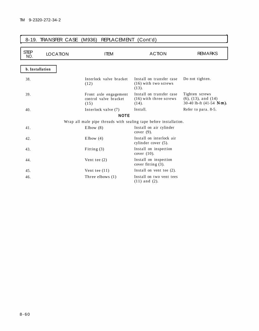
38.
39.
40.
41.
42.
43.
44.
45.
46.
Interlock valve bracket(12)
Front axle engagementcontrol valve bracket(15)Interlock valve (7)
NOTE
Install on transfer case(16) with two screws(13).Install on transfer case(16) with three screws(14).Install.
Do not tighten.
Tighten screws(6), (13), and (14)30-40 lb-ft (41-54
Refer to para. 8-5.
Wrap all male pipe threads with sealing tape before installation.Elbow (8) Install on air cylinder
cover (9).
Elbow (4) Install on interlock aircylinder cover (5).
Fitting (3) Install on inspectioncover (10).
Vent tee (2) Install on inspectioncover fitting (3).
Vent tee (11) Install on vent tee (2).
Three elbows (1) Install on two vent tees(11) and (2).
8-60

TM 9-2320-272-34-2
8-19. TRANSFER CASE [M936) REPLACEMENT (Cont’d)
STEP LOCATION ITEM ACTION REMARKSNO.
TA 350441
8-61

TM 9-2320-272-34-2
8-19. TRANSFER CASE (M936) REPLACEMENT (Cont’d) ISTEP LOCATION ITEM ACTION REMARKSNO.
47. Transfer case (6) Install on hydraulic Use lifting device.jack (18).
48. Flange (2)
49. Seven studs (5)
50. Two transfer casemounting brackets(14)
51. Transfer case (6)
52. Right frame bracket(8)
53. Three insulators (15)
54. Transfer case (6) andbrackets (14)
55. Hydraulic jack (18)
Install on PTO shaft(1) with washer (3)and new locknut (4).Install on transfer case(6).Install on transfer case Tighten 125-135 lb-ft(6) with seven new (170-183 locknuts (19).a. Position under
vehicle.
b. Raise into positionso right framebracket (8) can beinstalled.
Install on frame (10) Tighten 120 lb-ftwith three screws (9) (163 and new locknuts (7).Place between framebrackets (8) and (16),and transfer casemounting brackets(14).
a. Lower into positionon three insulators(15).
b. Install on frame Tighten 50-60 lb-ftbrackets (8) and (68-81 (16) with threeinsulators (13),washers (12), screws(11), and new lock-nuts (17).
Remove from under-side of vehicle.
8-62

TM 9-2320-272-34-2
8-19. TRANSFER CASE (M936) REPLACEMENT (Cont’d)
STEP LOCATIONNO. ITEM ACTION REMARKS
TA 350442
8-63

TM 9-2320-272-34-2
8-19. TRANSFER CASE (M936) REPLACEMENT (Cont’d)
STEP LOCATION ITEM ACTION REMARKSNO.
56. Interlock valve ground Install to frame (2)wire (5)
57.
58.
59.
60.
61.
62.
63.
64.
65.
66.
Diode ground wire (7)
Wire (22)
Two vent lines (10)
Interlock vent line (11)
Supply line (18)
Supply line (15)
Supply line (20)
Speedometer driveshaft (28) and parkingbrake cable (33)
Rear transfer casebracket (29)
Propeller shaft (37)
with screw (1), cableclamp (3), new lock-washer (4), and newlocknut (6).Install with washer (8)and new locknut (9).Connect to connector(21).
Connect to two elbows(13).
a. Connect to elbow(12).
b. Connect to interlockvent elbow (23).
Connect to interlockvalve elbow (17).Connect to interlockair cylinder elbow (16)and interlock valveelbow (14).Connect to air cylinderelbow (19).
Install on top of trans- Tighten 30-40 lb-ftfer case (24) with (41-54 clamp (25), clamp(26), and screw (27).Install on transfer case Tighten 40-55 lb-ftcover (32) with two (54-75 washers (31 ) andscrews (30).Install on transfer Tighten 32-40 lb-ftoutput flange (34) with (43-54 eight screws (35) andnew locknuts (36).
8-64

TM 9-2320-272-34-2
I 8-19. TRANSFER CASE (M936) REPLACEMENT (Cont’d)
8 - 6 5

8-19.
TM 9-2320-272-34-2
STEP LOCATION ITEM ACTION REMARKSNO.
67. Speedometer drive Connect toshaft (20) speedometer drive
68.
69.
70.
71.
8-66
Parking brake cable(13)
PTO cable bracket (8)
PTO cable (3)
Propeller shaft (29)
a.
b.
a.
b.
adapter (21).Install on transfer Tighten 40-55 lb-ftcase cover (19) with (54-75 clamp (16), washer(14), and screw (15).Install throughbrake drum lever(25) with new lock-nut (24).Install on rear trans-fer case bracket (23)with spacer (10),clamp (12), twoscrews (11), andnew locknuts (22).
Install on transfer case Tighten 40-55 lb-ftcover (19) with two (54-75 washers (18) andscrews (17).a.
b.
Install on PTO cablebracket (8) withspacer (6), clamp(4), two screws (5),and new locknuts(7).Install on PTO selectlever (1) with clevispin (2) and newcotter pin (9).
Install on flange (28)with four screws (30),new lockwashers (27),and nuts (26).

TM 9-2320-272-34-2
8-19. TRANSFER CASE (M936) REPLACEMENT (Cont’d)
STEP LOCATION ITEM ACTION REMARKSNO.
FOLLOW-ON TASKS: ●
●
●
●
●
Install transfer case shift rod (para. 8-12).Install transfer case front axle engagement control valve (para. 8-8).Check parking brake adjustment (TM 9-2320-272-20-2).Install transmission to transfer propeller shaft (TM 9-2320-272-20-1).Install transfer case to forward-rear axle propeller shaft (TM 9-2320-272-20-1).
● Fill transfer case to proper oil level (LO 9-23-0-272-12).TA 350444
8-67

TM 9-2320-272-34-2
8-20. TRANSFER CASE REPAIR
This task covers:a. Disassembly c. Reassembly and Adjustmentb. Cleaning and Inspection
INITIAL SETUPEquipmentCondition
Applicable Models Reference Condition DescriptionAll
Para. 8-18 Transfer case removed.Test Equipment
None
Special ToolsCrowfoot wrench GGG-C-1507Two flange puller standoffs (Appendix D, Item 1)
Materials/PartsShimsFive sealsThree locknutsFour locking platesSnapringWoodruff keyPower takeoff gasketPower takeoff sealAdhesive sealant (Appendix C, Item 2)GAA grease (Appendix C, Item 11)Gasket sealant (Appendix C, Item 13)GO 80/90 gear oil (Appendix C, Item 18)Sealing compound (Appendix C, Item 26)
Special Environmental ConditionsNone
Personnel Required General Safety Instructions
Wheeled vehicle repairman MOS 63W (2) ● Keep fire extinguisher nearby when
Manual References ●
using drycleaning solvent. -
Support transfer case with woodblocks before performingdisassembly.
TM 9-214TM 9-2320-272-10TM 9-2320-272-34P
STEP LOCATION ITEM ACTION REMARKSNO.
W A R N I N G
Transfer case is heavy. Use wood blocking to prevent transfer casefrom tipping over and causing injury to personnel.
1. Transfer case (4) Clean exterior thorough- Refer to para. 2-7.ly.
2. Transfer case cover (6)
3. Transfer case housing (4)
8-68 Change 2
Interlock air cylinder Remove. Use crowfoot wrench.(3) and pushrod (5)Eight screws (2) and Remove.inspection plate (1)

TM 9-2320-272-34-2
8-20. TRANSFER CASE REPAIR (Cont’d)
STEPNO. LOCATION ITEM ACTION REMARKS
4. Transfer case output Locknut (7), washer (8), Remove. Discard locknut (7).shaft (15) and transfer case output
flange (9) Tag flange (9) forinstallation.
5. Parking brakedrum ( 10) Remove.6. Brakeshoe backing Actuating plate (11) Remove.
plate (12)7. Companion flange (14) Four screws (17), dust- Remove.
cover (13), and brakeshoeassembly (16)
8-69Change 2

TM 9-2320-272-34-2
8-20. TRANSFER CASE REPAIR (Cont’d)
STEPNO. LOCATION ITEM ACTION REMARKS
8. Elbow (3) and elbow (5) Oil line (4) Remove.9. Transfer case oil pump Elbow (3) Remove.
(2)NOTE
Steps 10 and 11 are required only when vehicle is equipped withtransfer power takeoff.
10. Elbows (5) and (10) Oil line (8)11. Transfer power takeoff Elbow (10)
(9)12. Adapter fitting (6) Elbow (5)13. Transfer case cover (1) Adapter fitting (6) and
filter screen (7)13.1 Six screws (13), washers
(12), and oil pump (11)
13.2 Front axle engagementair cylinder cover (14)
8-70 Change 2
Remove.Remove.
Remove.
Remove.
Remove. Mark position of oilpump (11) forinstallation.
a.
b.
c.
Bend tabs of fourlocking plates (15)away from screws (16).Remove four screws Discard locking plates(16), locking plates (15) and gasket (21).(15), cover (14), cylin-der (18), piston (19),and gasket (21) fromtransfer case cover (1)and declutch shaft (22).Remove seals (17) and Discard seals (17)(20) from cover (14) and (20).and piston (19).

TM 9-2320-272-34-2
8-20. TRANSFER CASE REPAIR (Cont’d)
STEPLOCATIONNO. ITEM ACTION REMARKS
Change 2 8-71

TM 9-2320-272-34-2
8-20. TRANSFER CASE REPAIR (Cont’d)
14.
15. Main flange (1) andoutput flange (8)
16.
17. Main input shaft (2)18. Front output shaft (5)
Chain (10) a. Install on mainflange (1) with twowashers (3) andscrew (4).
b. Install on outputflange (8) withscrew (6), twowashers (7), andnut (9).
Two locknuts (12) andwashers (11)Nut (9), two washers(7), screw (6), screw(4), two washers (3),and chain (10)Main flange (1)Front output flange (8)
Remove.
Remove.
Remove.Remove.
Discard locknuts (12).
Use puller.Use puller.Tag for installation.
8-72 Change 2

TM 9-2320-272-34-2
8-20. TRANSFER CASE REPAIR (Cent’d)
STEP LOCATIONNO. ITEM ACTION REMARKS
8-73

TM 9-2320-272-34-2
8-20. TRANSFER CASE REPAIR (Cont’d)
STEPNO. LOCATION ITEM ACTION REMARKS
NOTESteps 19 and 20 are required only when vehicle is equipped withtransfer power takeoff.
19. Transfer case cover (4)
20. Main input shaft (7)
22.
23.24. Transfer case cover (4)
25. Backing platecompanion flange (12)
26. Transfer case cover (4)
27. Transfer case housing(14)
Six screws (2), washers Remove.(3), transfer power take-off (1), and gasket (5)Setscrew (6), power Remove.takeoff drive gear (9),and seal (8)
Setscrew (21), collar Remove.(23), and seal (19)Baffle (18) Remove.Seven screws (27), Remove.washers (26), flange(12), and shim pack (13)Dust shield (10) and Remove.flange seal (11)Four screws (25), two Remove.screws (24), six wash-ers (22), and gear cover(20)Nineteen screws (16), Remove.washers (17), andtransfer case cover (4)
Discard gasket (5).
Discard seal (8).
Discard seal (19).
Discard seal (11).
Use puller. Drivescrew over inter-mediate shaft (15)and two long screwsthrough puller intotransfer case cover (14).
TA 350449
8-74 Change 2

TM 9-2320-272-34-2
8-20. TRANSFER CASE REPAIR (Cont’d)
STEPNO. LOCATION ITEM ACTION REMARKS
Change 2 8-75

TM 9-2320-272-34-2
8-20. TRANSFER CASE REPAIR (Cont'd)
STEP LOCATION ITEM ACTION REMARKSNO.
28. Hi-lo shift fork (2) Setscrew (3) and hi-lo Remove.shift shaft (4)
29. Synchronizer gear(1)30. Three bearing races (8)
31. Declutch fork(10)32. Transfer case housing
(14)
Shift fork (2) Remove.Main input shaft Remove.assembly (7), rear out-put shaft assembly (6),and intermediate shaftassembly (5).Setscrew (11) Remove.Declutch shaft (13), Remove.declutch fork (10),spring (12), and slidingclutch (9)
Replace spring (12) ifbroken or distorted.
8-76 Change 2

TM 9-2320-272-34-2
8-20. TRANSFER CASE REPAIR (Cont'd)
STEPNO. LOCATION ITEM ACTION REMARKS
Change 2 8-77
TA 350452

TM 9-2320-272-34-2
8-20. TRANSFER CASE REPAIR (Cont’d)
STEP LOCATION ITEM ACTION REMARKSNO.
33. Transfer case housing(1)
34.
35. Input shaft cover (4)
36. Intermediate shaftcover (9)
37. Transfer case housing(1)
38.
39. Front output shaftcover (17)
40. Transfer case housing(1)
Hi-lo shift shaft seal Remove. Discard seal (2).(2)Six screws (6) and Remove. Mark position forwashers (5), main installation.input shaft cover (4),and shim pack (3)Input shaft seal (7) Remove. Discard seal (7).
Plug (12) Remove.
Six screws (11) and Remove.washers (10), inter-mediate shaft cover (9)and shim pack (8)Six screws (15) andwashers (16), andfront output shaftcover (17)
Output shaft seal (14)
Front output shaft(13)
Remove.
Remove.
Remove.
Discard seal (14).
8-78

TM 9-2320-272-34-2
8-20. TRANSFER CASE REPAIR (Cont’d)
TA 350453
8-79

TM 9-2320-272-34-2
8-20. TRANSFER CASE REPAIR (Cont’d)
STEPLOCATION ITEM ACTION REMARKSNO.
41.
41.1
42.43.
Front output shaft (1) Front output shaft Remove. Use flat axle type
Bearing (2) Remove.
roller bearing (2)
Snapring (3)
bearing puller.Tag bearing (2) forinstallation.Inspect snapring (3)for tightness. Replaceif damaged.
Rear output shaft (5) Spacer (8) Remove.Rear output shaft Remove. Use arbor press androller bearings (4) and mandrel. (7), and gear (6)
Tag gear (6) andbearings (4) and (7)for installation.
8 - 8 0 Change 2

TM 9-2320-272-34-2
8-20. TRANSFER CASE REPAIR (Cont'd)
STEPNO. LOCATION ITEM ACTION REMARKS
44. Intermediate shaft (11) Snapring (16) and speed- Remove. Discard snapring (16).ometer drive gear (15)
45.
46.
47.
Woodruff key (12) Remove. Discard woodruff key(12).
Intermediate roller Remove.bearing (14) and inter-mediate high-speedgear (13).
Intermediate roller Remove.bearing (9) andintermediate low-speedgear (10)
Use arbor press andmandrel.
Tag gear (13) andbearing (14) forinstallation.Use arbor press andmandrel.
Tag bearing (9) andgear (10) forinstallation.
Change 2 8-81

TM 9-2320-272-34-2
8-20. TRANSFER CASE REPAIR (Cont'd)
STEP LOCATION ITEM ACTION REMARKSNO.
48. Main input shaft (6)
49.
50.
51.52.
53.
b. Cleaning and Inspection
Companion flangespacer (1)Main input shaft rollerbearing (8), bearingspacer (9), and high-speed gear (10)
High-speed gear spacer(11)Synchronizer gear (12)Main input shaft rollerbearing (2), bearingspacer (3), and low-speed gear (4)
Low-speed gear spacer(5)
Remove.
Remove. Use arbor press andmandrel.
Tag bearing (8) andspacer (9) forinstallation.
Remove. Tag spacer (11) forinstallation.
Remove.Remove. Use arbor press and
mandrel.
Tag bearing ( 2) andspacer (3) forinstallation.
Remove. Tag spacer (5) forinstallation.
WARNINGDrycleaning solvent is flammable and will not be used near openflame. Use only in well-ventilated places. Failure to do this mayresult in injury to personnel.
54. Main input shaft (6) Two roll pins (7) Inspect for breaks Replace if broken.
NOTESteps 55 and 56 are performed only if roll pins are to be replaced.
55. Two roll pins (7)56. Two new roll pins
(7)57. All transfer case gears,
shafts, spacers,washers, covers, andshims
8-82 Change 2
Remove.Install in main inputshaft (6).a.
b.
Clean with dryclean-ing solvent.
Inspect for scores, Replace if scored,breaks, cracks, broken, cracked,chips, and pitting. chipped, or pitted.

TM 9-2320-272-34-2
8-20. TRANSFER CASE REPAIR (Cont'd)
STEP LOCATION ITEM ACTION REMARKSNO.
Change 2 8 - 8 3

TM 9-2320-272-34-2
8-20. TRANSFER CASE REPAIR (Cont’d)
STEPLOCATION ITEM ACTION REMARKSNO.
WARNINGDrycleaning solvent is flammable and will not be used near openflame. Use only in well-ventilated places. Failure to do this mayresult in injury to personnel.
58. Transfer case housing (8)and transfer case cover(3)
58.1. Filler (5) and drain (6)plugs.
58.2. Three dowel pins (2)
58.3. Freeze plugs (7) and(9)
59. Bearing (4)
60. Transfer case housing Bearing races (1)(8) and transfer casecover (3)
NOTE
a.
b.
c.
a.
b.
Clean with dryclean-ing solvent.
Clean matingsurfaces.Inspect for breaks,cracks, and strippedthreads.
Remove.
Inspect for strippedthreads.
Inspect for bends andbreaks.Inspect for looseness.
a. Clean with dryclean-ing solvent andallow to air dry.
b. Inspect.
a. Inspect.
Replace if broken,cracked or threads arenot repairable. Referto para. 2-9.
Replace if threads arestripped.Replace if bent orbroken.Replace if loose ormissing.
Refer to TM 9-214.If damaged, replacebearing (4) and bear-ing race (1).Refer to TM 9-214.
Perform steps 60b. and 61 only if bearings or bearing races are to bereplaced.
b. Remove by tapping Tag bearing races (1)alternately on outer for installation.edge.
61. New bearing race (1) Press into transfer case Use arbor press andhousing (8). mandrel.
8 - 4 Change 2

TM 9-2320-272-34-2
8-20. TRANSFER CASE REPAIR (Cont'd)
STEP LOCATION ITEM ACTION REMARKSNO.
Change 2 8-85

TM 9-2320-272-34-2
8-20. TRANSFER CASE REPAIR (Cont'd)
STEP LOCATION ITEM ACTION REMARKSNO.
I c. Reassembly and Adjustment
NOTECoat all gears and bearing assemblies with gear oil during
62.
63.
64.
65.
66.
67.
68.
69.
reassembly.Low-speed gear spacer(5)
Low-speed gear (4)and bearing spacer (3)
Main input shaft rollerbearing (2)
Synchronizer gear (13)
High-speed gear spacer(12)
High-speed gear (11)and bearing spacer(10)
Main input shaft rollerbearing (9)Companion flangespacer (1)
Install on main inputshaft (6) and alinewith dowel pin (8).Install on main inputshaft (6).
Install on main inputshaft (6).
Install on main inputshaft (6).Install on main inputshaft (6) and alinewith dowel pin (7).Install on main inputshaft (6).
Install on main inputshaft (6).Install on main inputshaft (6).
Make sure bearingspacer (3) minimumthickness is 0.265 in.(6.73 mm).Make sure gear spacer(5) is alined on dowelpin (8).Use arbor press andmandrel.
Make sure bearingspacer (10) minimumthickness is 0.143 in.(3.63 mm).Make sure gearspacer (12) is alinedon dowel pin (7).Use arbor press andmandrel.
8-86 Change 2

TM 9-2320-272-34-2
8-20. TRANSFER CASE REPAIR (Cont'd)
STEPNO. LOCATION ITEM ACTION REMARKS
Change 2 8-87

TM 9-2320-272-34-2
8-20. TRANSFER CASE REPAIR (Cont'd)
STEP LOCATION ITEM ACTION REMARKSNO.
70. Intermediate low-speed Install on intermediate Use arbor press andgear (2) and intermediate shaft (3). mandrel.roller bearing (1)
71.
72.73.
74.
75.
Intermediate high-speedgear (5) and roller bear-ing (6)
New woodruff key (4)Speedometer gear (7)
Rear output shaftdriven gear (11) andrear output shaftroller bearings (9) and(12)
Rear output shaftspacer (13)
76. Front output shaftroller bearing (15)
76.1. New snapring (16)
Install on shaft (3). Use arbor press andmandrel.Make sure high-speedgear (5) width is 3.875in. (98.43 mm).
Install on shaft (3).Install on intermediateshaft (3) over woodruffkey (4) with new snap-ring (8).Install on rear outputshaft (10).
Install on shaft (10).
Install on front outputshaft (14).Install on bearing (15)
Use arbor press andmandrel.
Make sure driven gear(11) width is 3.75 in.(95.25 mm).
Use arbor press andmandrel.Make sure snapringside of bearing racefaces toward splinedend of shaft (14).
8-88 Change 2

TM 9-2320-272-34-2
8-20. TRANSFER CASE REPAIR (Cont'd)
STEP LOCATION ITEM ACTION REMARKSNO.
Change 2 8-89

TM 9-2320-272-34-2
8-20. TRANSFER CASE REPAIR (Cont’d)
STEP LOCATIONN O . ITEM ACTION REMARKS
77. Front output shaft (8) Install in transfer caseuntil snapring (9) isflush with housing (1).
NOTEApply GAA grease to inside diameter of all seals.
78. New front output shaftseal (4)
79. Front output shaftcover (7) and transfercase housing (1)
80. Front output shaftcover (7)
81. New input shaft seal(3)
Install in front outputshaft cover (7).
Apply a thin coating ofgasket sealant tomating surfaces.Install on transfer case Tighten 40-65 lb-fthousing (1) with six (54-88 washers (6) andscrews (5).
Install in main inputshaft cover (2).
8-90

TM 9-2320-272-34-2
8-20. TRANSFER CASE REPAIR (Cont’d)
STEP LOCATIONN O . ITEM ACTION REMARKS
TA 350460
8-91

TM 9-2320-272-34-2
8-20. TRANSFER CASE REPAIR (Cont'd)
STEPN O . LOCATION ITEM ACTION REMARKS
82.
83.
84.
85.
86.
87.
88.
89.
Sliding clutch (1)
Declutch fork (2)
Declutch spring (4)
Declutch shaft (5)
Declutch fork (2)
Intermediate shaftassembly (9), rearoutput shaft assembly(10), and main inputshaft assembly (11)Hi-lo shift fork (12)
Hi-lo shift shaft (14)
Install on front outputshaft (7).Install on sliding clutch(1).Place under declutchfork (2).Install through fork (2),spring (4), and on transfercase housing (6).Install on shaft (5) withsetscrew (3) at setscrewhole.Install into threebearing races (8).
Install on synchronizergear (15).
Install into hi-lo shiftfork (12) with setscrew(13) at setscrew hole.
Tighten setscrew (3)20-35 lb-ft (27-47
Make sure flat side offork hub faces towardsrear of transfer casehousing (6).Tighten setscrew (13)50-85 lb-ft (68-115
8-92 Change 2

TM 9-2320-272-34-2
8-20. TRANSFER CASE REPAIR (Cont'd)
STEPLOCATION ITEM ACTION REMARKSNO.
Change 2 8-93

TM 9-2320-272-34-2
8-20. TRANSFER CASE REPAIR (Cont'd).
STEPNO. LOCATION ITEM ACTION REMARKS
90. Three dowel pins (2) Install in transfer casecover (1).
91. Transfer case cover (1) Apply light coating ofand transfer case gasket sealant tohousing (5) mating surfaces.
92. Transfer case cover (1) Aline dowel pins (2) on Tighten 40-65 lb-fttransfer case housing (54-88 (5) and install withnineteen washers (3)and screws (4).
93. Bearing race (8) Tap alternately aroundouter edge to seatagainst main inputshaft (6) roller bearing.
94. Baffle (7) Install on main inputshaft (6).
NOTESteps 95 through 97 are required only when vehicle is equippedwith transfer power takeoff.
95.96.
97.
Setscrew (9) Apply adhesive sealant.New seal (10) and Install on main input Tighten 12-16 lb-ftpower takeoff drive shaft (6) with setscrew (16-22 gear (11) (9) at recess in shaft (6).New gasket (14) and Install on transfer case Tighten 40-65 lb-fttransfer power takeoff cover (1) with six (54-88 (15) washers (13) and
screws (12).
8-94

TM 9-2320-272-34-2
8-20. TRANSFER CASE REPAIR (Cont’d)
STEP LOCATION NO. ITEM ACTION REMARKS
Change 2 8-95

TM 9-2320-272-34-2
8-20. TRANSFER CASE REPAIR (Cont'd)
STEP LOCATIONNO. ITEM ACTION REMARKS
98.99.
Setscrew (3)New seal (4)
100.
101.
102.
Retaining collar (2)
Oil pump (12) andtransfer case cover(11)
NOTEBe sure to aline pump drive with
Oil pump (12)
103.
104.
105.
106.
Speedometer drivegear cover (9) andtransfer case cover(11)Speedometer drivegear cover (9)
New backing platecompanion flange seal(15) and dust shield (14)New hi-lo shift shaftseal (18)
Apply adhesive sealant.Install on retainingcollar (2) with large liptoward baffle (10).Install on main inputshaft (5) with setscrew(3) at recess in shaft (5).Apply light coating ofgasket sealant tomating surfaces.
slot on main input shaft.
Install on transfer casecover (11) with sixwashers (13) andscrews (1).Apply light coating ofgasket sealant tomating surfaces.
Tighten 12-16 lb-ft(16-22 N·m).
Tighten 40-65 lb-ft(54-88 N·m).
Install on transfer casecover (11) with sixwashers (6), fourscrews (8), and twoscrews (7).Install in backing platecompanion flange (16).
Tighten 40-65 lb-ft(54-88 N·m).
Apply gasket sealant toouter diameter and installin transfer case housing (17).
8-96 Change 2

TM 9-2320-272-34-2
8-20. TRANSFER CASE REPAIR (Cont'd)
STEP LOCATION ITEM ACTION REMARKSNO.
8-97

TM 9-2320-272-34-2
8-20. TRANSFER CASE REPAIR (Cont'd)
STEPLOCATION ITEM ACTION REMARKSNO.
N O T EStep 107 establishes starting shim pack thickness.
107. Intermediate shaft a.cover (2)
b.
Install on transfercase (1) and tapalternately aroundouter edge with soft-faced hammer.Use feeler gage (3)and measureclearance betweencover (2) andtransfer case (1).
108. Transfer case (1) Intermediate shaft Remove.cover (2)
N O T EUse measurement obtained in step 107b. plus a 0.003 in. (0.076mm) shim for starting shim pack thickness.
109. Starting shim pack (5)and intermediate shaftcover (2)
110. Dial indicator (8)
N O T E
Install on transfer case(1) with six washers (6)and screws (7).
Mount on transfer case(1) and positionplunger tip (9) throughhole in cover (2) onintermediate shaft (4).
Steps 111 through 114 are performed to make sure intermediateshaft will rotate freely without end play.
111. Intermediate shaft Check end play asassembly (4) follows:
a.
b.
c.
d.
Use prybar (10)through inspectionhole and force torear of transfer case(1).Set dial indicator (8)to zero.Use prybar (10) throughinspection hole andforce to front oftransfer case (1).
Record measurement.
Do not apply sealer tomating surface.
Tighten 40-65 lb-ft(54-88 N·m).
Record reading on Use reading fordial indicator (8) number of shims (5) toand add 0.003-0.006 be removed.in. (0.076-0. 152 mm)to reading.
8-98 Change 2

TM 9-2320-272-34-2
8-20. TRANSFER CASE REPAIR (Cont'd)
STEP LOCATIONNO. ITEM ACTION REMARKS
8-99

8-20. TRANSFER CASE REPAIR (Cont'd)
STEPLOCATION ITEM ACTION REMARKSNO.
112. Transfer case (1) Dial indicator (2) Remove.113. Six screws (6), washers Remove.
(5), and intermediateshaft cover (4)
N0TEUse reading obtained in step 111d. for number or thickness of shimsto be removed for intermediate shaft adjustment.
114. Shims (3) Remove amountrecorded in step 111d.
115. Shim pack (3) Remove.
116.
117.
118.
Do not use sealing compound on shims.
TM 9-2320-272-34-2
CAUTION
8-100 Change 2
Transfer case (1) and Apply a light coating ofintermediate shaft sealing compound tocover (4) mating surfaces.
Shim pack (3) and Install on transfer caseintermediate shaft (1) with six washerscover (4) (5) and screws (6).
Plug (7) Install on intermediateshaft cover (4).
Do not coat shims (3)with sealingcompound.Tighten 40-60 lb-ft(54-81 N·m).
Tighten 35-60 lb-ft(47-81 N·m).

TM 9-2320-272-34-2
8-20. TRANSFER CASE REPAIR (Cont'd)
STEP LOCATIONNO. ITEM ACTION REMARKS
Change 2 8-101

TM 9-2320-272-34-2
8-20. TRANSFER CASE REPAIR (Cont'd)
STEPLOCATION ITEM ACTION REMARKSNO.
NOTEStep 119 establishes starting shim pack thickness.
119. Main input shaft cover a.(3)
b.
Install on transfercase (2) and tapalternately aroundouter edge with soft-faced hammer.Use feeler gage (1)and measureclearance betweencover (3) andtransfer case (2).
Record measurement.
120. Transfer case (2) Main input shaft cover Remove.(3)
NOTEUse measurement obtained in step 119b. plus a 0.003 in. (0.076 mm)shim for starting shim pack thickness.
121. Starting shim pack (5)and main input shaftcover (3)
122. Dial indicator (8)
123. Main input shaftassembly (4)
8-102 Change 2
Install on transfer case(2) with six washers(6) and screws (7).
Mount on transfer case(2) and positionindicator plunger tip(9) on main input
Check end play asfollows:a.
b.
c.
d.
Use prybar (10)through inspectionhole and force torear of transfer case(2).Set dial indicator (8)to zero.Use prybar (10)through inspectionhole and force tofront of transfercase (2).Record reading ondial indicator (8).
Do not apply sealingcompound to matingsurfaces.Tighten 40-65 lb-ft(54-88 N·m).
End play should be0.0001-0.005 in.(0.00254-0.127 mm).

TM 9-2320-272-34-2
8-20. TRANSFER CASE REPAIR (Cont'd)
STEP LOCATION ITEM ACTION REMARKSNO.
Change 2 8-103

TM 9-2320-272-34-2
8-20. TRANSFER CASE REPAIR (Cont’d)
STEP LOCATION ITEM ACTION REMARKSN O .
124. Transfer case (1) Dial indicator (2)125. Six screws (6), washers
(5), and main inputshaft cover (4)
NOTE
Remove.Remove.
Use reading obtained in step 123d for number or thickness ofshims, to be removed or added, for main input shaft adjustment.
126. Shims (3) Remove or add ifnecessary.
127. Shim pack (3) Remove.CAUTION
Do not use sealing compound on shims.128. Transfer case (1) and Apply a light coating of Do not coat shims (3)
main input shaft cover sealing compound to with sealing(4) mating surfaces. compound.
129. Shim pack (3) and Install on transfer case Tighten 40-65 lb-ftmain input shaft cover (1) with six washers (54-88 N·m).(4) (5) and screws (6).
8-104

TM 9-2320-272-34-2
8-20. TRANSFER CASE REPAIR (Cont’d)
S T E PLOCATION ITEM ACTION REMARKSN O .
8-105

TM 9-2320-272-34-2
I 8-20. TRANSFER CASE REPAIR (Cont'd)
I STEP LOCATION ITEM ACTION REMARKSNO. I
NOTEStep 130 establishes starting shim pack thickness.
130. Backing plate a.companion flange (3)
b.
Install on transfercase cover (1) andtap alternatelyaround outer edgewith soft-facedhammer.Use feeler gage (4) Record measurement.and measure clear-ance between flange(3) and cover (1).
131. Transfer case cover (1) Backing plate Remove.companion flange (3)
NOTEUse measurement obtained in step 130b. plus a 0.003 in. (0.076mm) shim for starting shim pack thickness.
132. Starting shim pack (5) Install on transfer case Do not apply sealingand backing plate cover (1) with seven compound to matingcompanion flange (3) washers (6) and surfaces.
screws (7).Tighten 60-100 lb-ft(81-136 N·m).
133. Dial indicator (10) Mount on transfer casecover (1) and positionindicator plunger tip(11) on rear outputshaft (2).
134. Rear output shaft Check end play asassembly (2) follows:
a.
b.
c.
Use prybar (8)through inspectionhole and force tofront of transfercase (9).Set dial indictor (10)to zero.Use prybar (8)through inspectionhole and force torear of transfer case(9).
d. Record reading on End play should bedial indicator (10). 0.0001-0.005 in.
(0.00254-0.127 mm).
8 - 1 0 6 Change 2

TM 9-2320-272-34-2
8-20. TRANSFER CASE REPAIR (Cont'd)
STEPLOCATIONNO. ITEM ACTION REMARKS
Change 2 8-107

TM 9-2320-272-34-2
8-20. TRANSFER CASE REPAIR (Cont'd)
STEP LOCATION ITEM ACTION REMARKS NO.
135. Transfer case cover (1) Dial indicator (2) Remove.136. Seven screws (5), Remove.
washers (4), andbacking platecompanion flange (6)
NOTEUse reading obtained in step 134d. for number or thickness ofshims, to be removed or added for rear output shaft adjustment.
137. Shims (3) Remove or add ifnecessary.
138. Shims (3) Remove.
CAUTION
Do not use sealing compound on shims.
139.
140.
Transfer case cover (1) Apply light coating ofand backing plate sealing compound tocompanion flange (6) mating surfaces.Shim pack (3) and Install on transfer casebacking plate cover (1) with sevencompanion flange (6) washers (4) and
screws (5).
Do not coat shims (3)with sealingcompound.Tighten 110-145 lb-ft(149-197 N·m).
8-108 Change 2

TM 9-2320-272-34-2
8-20. TRANSFER CASE REPAIR (Cont'd)
STEP LOCATIONNO. ITEM ACTION REMARKS
Change 2 8-109

TM 9-2320-272-34-2
8-20. TRANSFER CASE REPAIR (Cont'd)
STEP LOCATION ITEM ACTION REMARKSNO.
NOTEApply GAA grease to inside diameter of all seals.
140.1. Two washers (4) Apply thin coating ofgasket sealant tomating surfaces.
141. Main input flange (3) Install on main inputshaft (2).
142. Front output flange Install on front output(6) shaft (1).
143. Chain (12) a. Install on mainflange (3) with twowashers (7) andscrew (8).
b. Install on outputflange (6) withscrew (9), twowashers (10), andnut (11).
NOTEAssistant will help with step 145.
145. Two washers (4) and Install on main inputnew locknuts (5) shaft (2) and front
output shaft (1).
8-110 Change 2
Install chain (12)to prevent flanges (3)and (6) from turning.
Tighten 360-600 lb-ft(458-814 N·m).

TM 9-2320-272-34-2
8-20. TRANSFER CASE REPAIR (Cont'd)
STEP LOCATION ITEM ACTION REMARKSNO.
8-111

TM 9-2320-272-34-2
8-20. TRANSFER CASE REPAIR (Cont'd)
STEP LOCATION ITEM ACTION REMARKSNO.
147.
148.
149.
150.
151.
152.
152.1.152.2.152.3
Filter screen (12) and Install on transfer caseadapter fitting (11) cover (1).Elbow (10) Install on adapter Tighten elbow (10)
fitting (11). 15 lb-ft (20 N·m).
NOTESteps 149 and 150 are required only when vehicle is equipped withtransfer power takeoff.
Elbow (18)
Oil line (16)
Elbow (7)
Oil line (8)
New seal (3)New seal (14)New gasket (15),piston (13), air cylinder(9), and cover (6)
8-112 Change 2
Install on transferpower takeoff (17).Connect to elbow (18)and elbow (10).Install nipple endon oil pump (2).Connect to elbow (10)and elbow (7).Install in cover (6).Install on piston (13).a. Install on transfer
case cover (1) withfour new lockingplates (5) and screws(4).
b. Bend tabs of lockingplates (5) againstscrews (4).
Tighten elbow (18)26 lb-ft (35 N·m).
Tighten elbow (7) 20lb-ft (27 N·m).
Tighten screws (4)6-10 lb-ft (8-13 N·m).

TM 9-2320-272-34-2
8-20. TRANSFER CASE REPAIR (Contd)
STEP LOCATION ITEM ACTION REMARKSNO.
Change 2 8-113

152.2.
TM 9-2320-272-34-2
8-20. TRANSFER CASE REPAIR (Cont'd)
STEP LOCATION ITEM ACTION REMARKSNO.
153.
154.
155.
156.
Parking brake Assemble.
Brakeshoe assembly Install on companion(12) and dustcover (9) flange (10) with four
screws (13).Actuating plate (6) Install against backing
plate (7) so retaineropening (5) fits overbrake lever stud (8) ofbacking plate (7).
NOTEApply GAA grease to inside diameter of all seals.
Brakedrum (4) and Install on transfer casetransfer output flange output shaft (11).(3)
NOTEAssistant will help with step 156.
Thrust washer (2)
Nut (17), two washers(16), screw (15), screw(14), two washers (18),and chain (19)Inspection plate (20)and transfer case (23)
Inspection plate (20)
Pushrod (24) andinterlock air cylinder(22).
Apply thin coating ofgasket sealant andinstall with newlocknut (1).Remove.
Apply thin coating ofgasket sealant tomating surfaces.Install on transfer case(23) with eight screws(21).Install on transfer casecover (25).
Refer to TM 9-2320-272-20-2.Tighten 180-230 lb-ft(244-312 N·m).
Tighten 450-600 lb-ft(610-814 N·m).
Do not tighten.
Apply sealant onthreads of interlockair cylinder (22).Use crowfoot wrench.Tighten 30-40 lb-ft
156.1. Main flange (3) andoutput flange (6)
157.
158.
159.
8-114 Change 2
(41-54 N·m).

TM 9-2320-272-34-2
8-20. TRANSFER CASE REPAIR (Cont'd)
STEPNO. LOCATION ITEM ACTION REMARKS
END OF TASK!
FOLLOW-ON TASK: Install transfer case (para. 8-18).
8-115 (8-116 blank)


TM 9-2320-272-34-2
CHAPTER 9FRONT AND REAR AXLES MAINTENANCE
NOTE
Refer to TM 9-2320-358-24&P for unique M939A2 maintenance procedures.
Section I. DESCRIPTION AND DATA
9-1. GENERAL
This section provides description and data for the front axle, the forward-rear axle, the rear-rear axle, andthe carrier differentials. For axle tabulated data, see table 9-1.
9-2. DESCRIPTION-FRONT AND REAR AXLES
a. The front axle is a hypoid, double reduction, single speed unit installed to the underside of front springs.The differential transmits power from the transfer case to left and right axle shafts. Universal joints at theouter end of each shaft permit delivery of power to wheels under all conditions.
b. The two rear axles mounted in tandem, are hypoid, double reduction single speed units. The differentialstransmit driving power from driving propeller shaft to the left and right axle shafts.
Change 2 9 - 1

TM 9-2320-272-34-2
9-2. DESCRIPTION – FRONT AND REAR AXLES (Cont’d)
1. Forward-Rear Axle Assembly 10. Pinion Retaining Cover2. Forward-Rear Axle Carrier Differential 11. Differential Top Cover3. Rear Axle Bogie Assembly 12. Differential Rear Companion Flange4. Bogie Support Bracket 13. Differential Rear Bearing Cover5. Upper Torque Rod 14. Differential Mounting Flange6. Lower Torque Rod 15. Differential Side Cover7. Rear-Rear Carrier Differential 16. Differential Pinion Retaining Cover8. Rear-Rear Axle Assembly 17. Differential Front Companion Flange9. Carrier Differential
Table 9-1. Front and Rear Axle Tabulated Data
FRONT AXLE:Make . . . . . . . . . . . . . . . . . . . . . . . . . . . . . . . . . . . . . . . . . . . . . . . . . . . . . . . . . . . . . . . . Rockwell InternationalModel . . . . . . . . . . . . . . . . . . . . . . . . . . . . . . . . . . . . . . . . . . . . . . . . . . . . . . . . . . . . . . . . . . . . . . FM1240-RFAX-1Gear ratio . . . . . . . . . . . . . . . . . . . . . . . . . . . . . . . . . . . . . . . . . . . . . . . . . . . . . . . . . . . . . . . . . . . . . . . . . . .6.443:1Load rating . . . . . . . . . . . . . . . . . . . . . . . . . . . . . . . . . . . . . . . . . . . . . . . . . . . . . . . . . . . . . . .17,000 lb (7727 kg)Maximum speed . . . . . . . . . . . . . . . . . . . . . . . . . . . . . . . . . . . . . . . . . . . . . . . . . . . . . . . . . . . . . . . . . .3,000 rpm
REAR AXLE:Make . . . . . . . . . . . . . . . . . . . . . . . . . . . . . . . . . . . . . . . . . . . . . . . . . . . . . Rockwell InternationalModels . . . . . . . . . . . . . . . . . . . . . . . . . . . . . . . . . . . . . . . . . . . . . . . . . . . . . . . . . . . . Rear-Rear M1240-RDAX-1
Forward-Rear M1240-RDAX-2Gear ratio . . . . . . . . . . . . . . . . . . . . . . . . . . . . . . . . . . . . . . . . . . . . . . . . . . . . . . . . . . . . . . . . . . . . . . . . . . .6.443:1Load rating . . . . . . . . . . . . . . . . . . . . . . . . . . . . . . . . . . . . . . . . . . . . . . . . . . . . . . . . . . . . . ..17,000 lb (7727 kg)Maximum speed . . . . . . . . . . . . . . . . . . . . . . . . . . . . . . . . . . . . . . . . . . . . . . . . . . . . . . . . . . . . . . . . . .3,000 rpm
TA 350615
9-2

TM 9-2320-272-34-2
Section Il. FRONT AXLE MAINTENANCE
9-3. FRONT AXLE MAINTENANCE TASK SUMMARY
TASKPARA.
PROCEDURES PAGENO.
9-4. Spindle Bearing Sleeve Maintenance 9-49-5. Steering Knuckle Assembly Maintenance 9-69-6. Front Axle Assembly Replacement 9-189-7. Front Axle Carrier Differential Assembly Maintenance 9-269-8. Differential and Differential Carrier Maintenance 9-28
9-3

TM 9-2320-272-34-2
9-4. SPINDLE BEARING SLEEVE AND OIL SEAL MAINTENANCE
This task covers:a. Removal c. Installationb. Inspection
INITIAL SETUP:Equipment
Applicable Models ConditionAl l Reference Condition Description
Front axle shaft and universaljoint removed.
Test Equipment TM 9-2320-272-20-1None
Special ToolsSpindle bearing sleeve remover 7950127Spindle bearing sleeve replacer 7950129Oil seal installer tool
Special Environmental ConditionsNone
General Safety InstructionsNoneMaterials/Parts
Oil sealsPersonnel RequiredWheeled vehicle repairman MOS 63W
Manual ReferencesTM 9-2320-272-20-1
LOCATION ITEM ACTION REMARKS
TM 9-2320-272-34P
I a. Removal
1. Steering knuckle Oil seal (3)housing (4)
Remove.
2. Spindle (2) Spindle bearing sleeve Inspect for nicks,cracks, and scoring.
Machine insidediameter.
Measure inside
If nicked, cracked orscored, replace bearingsleeve (1).Machine to 2.249 ±.002 in. (57.150 ±.051 mm).Inside diameter should
a.
b.
c.
(1)
diameter. be 2.249 ± .002 in.(57.150 ± .051 mm).Replace if innerdiameter is more than2.251 in. (57.18 mm).
Steps 3 and 4 are performed only if spindle bearing sleeve is beingreplaced.
3. Spindle (2) Spindle bearing sleeve Remove. Use spindle bearing(1) sleeve remover.
4. New spindle bearing Install in spindle (2). Use spindle bearingsleeve (1) sleeve replacer.
9-4 Change 2

TM 9-2320-272-34-2
9-4. SPINDLE BEARING SLEEVE AND OIL SEAL MAINTENANCE (Cont'd)
STEPLOCATION ITEM ACTIONNO. REMARKS
6.
New spindle bearingsleeve (1)
Oil seal (3)
Install in spindle (2). Use spindle bearingsleeve replacer.
Install in steeringknuckle housing (4).
END OF TASK!
FOLLOW-ON TASK: Install front axle shaft and universal joint (TM 9-2320-272-20-1).
Change 2 9-5

TM 9-2320-272-34-2
9-5. STEERING KNUCKLE ASSEMBLY MAINTENANCEThis task covers:
a. Removal c. Installationb. Cleaning and Inspection d. End Play Test
INITIAL SETUP:EquipmentCondition
Applicable Models Reference Condition DescriptionAll TM 9-2320-272-20-1 Front axle shaft removed.
Test EquipmentNone
Special Tools Special Environmental ConditionsNone None
MateriaIs/PartsLockwireThree cotter pinsFour lockwashersGAA grease (Appendix C, Item 11)Sealing compound (Appendix C, Item 13)
Personnel RequiredWheeled vehicle repairman MOS 63W (2)
Manual ReferencesTM 9-2320-272-10TM 9-2320-272-20-1TM 9-2320-272-34PLO 9-2320-272-12
General Safety InstructionsKeep fire extinguisher nearby whendrycleaning solvent is used.
LOCATION ITEM ACTION REMARKS
1.
2.
3.
4.
NOTEPerform step 1 for left steering knuckle only.
Steering knuckle arm Cotter pin (10), slotted Remove.(3) nut (9) and drag link
(8)NOTE
Perform steps 2 and 3 for right steering knuckle only.Cotter pin (28) and Remove.slotted nut (27)Socket assembly (25) Remove together.and ball stud (26)
Steering knuckle (1) Cotter pin (13), slotted Remove.nut (14) and tie rod(15)
Discard cotter pin (10).
Discard cotter pin(28).
Discard cotter pin (13).
9-6

TM 9-2320-272-34-2
9-5. STEERING KNUCKLE ASSEMBLY MAINTENANCE (Cont’d)
STEP LOCATION ITEM ACTION REMARKSN O .
5. Grease fitting (7) and Remove. Discard lockwashersfour nuts (6), lock- (5).washers (5), bushings(4), and steeringknuckle arm (3)
6. Steering knuckle (1) Spacer (11 ) and upper Remove. Using two pull boltsleeve assembly (2) holes (12) to remove.
7. Seal guard (22) Two screws (24) and Remove.washers (23)
9.
8. Steering knuckle (1) Grease fitting (19), and Remove.four screws (20),washers (21 ), lowerplate (18), and sealguard (22)Lower sleeve assembly Remove. Using two pull bolt(17) holes (16) on
lower sleeve assembly(17) to remove.
TA 350617
9-7

TM 9-2320-272-34-2
9-5. STEERING KNUCKLE ASSEMBLY MAINTENANCE (Cont’d)
STEP LOCATION ITEM ACTION REMARKSNO.
10. Steering knuckle (4) Lockwire (3) and Remove. Discard lockwire (3).twelve screws (1)
11. Dust seal plate (2) Pull clear. Do not remove.
12. Dust and moisture seal Pull clear of steering Do not remove.(7) knuckle (4).
13. Axle kingpins (6) and Steering knuckle (4) Remove.(8)
b. Cleaning and Inspection
Clean with dry-cleaning solvent.
c.
Inspect for cracks.
Check inside ofbearing sleeves (12)and (13) for bearingwear.
15. Steering knuckle (4) Studs (5) and studs Inspect for stripped(9) threads.
NOTEDo not perform step 16 unless new studs are to be installed.
16. New studs (5) and new Install in steeringstuds (9) knuckle (4).
17. Stop bolt (10) and jam- a. Inspect for bends.nut (11)
NOTEDo not perform steps 17b and 18 unless new stop bolt is to beinstalled.
b. Break weld and Discard.remove.
Drycleaning solvent is flammable and will not be used near openflame. Use only in well-ventilated places. Failure to do this mayresult in injury to personnel.
14. Steering knuckle (4) a.and lower plate (14),upper sleeve (12) andlower sleeve (13)
b. If cracked or scoredreplace.
If inside surfaces areworn more than1.505 in. (38 mm)replace inside bearingsleeves (12) and (13).If stripped replace.
18. New stop bolt (10) and Install on steering Do not weld.new jamnut (11) knuckle (4).
9-8

TM 9-2320-272-34-2
I 9-5. STEERING KNUCKLE ASSEMBLY MAINTENANCE (Cont’d)
STEP LOCATION ITEM ACTION REMARKSNO.
TA 350618
9-9

TM 9-2320-272-34-2
9-5. STEERING KNUCKLE ASSEMBLY MAINTENANCE (Cont’d)
STEP LOCATION ITEM ACTION REMARKSN O .
NOTE● Steps 19 through 21 are performed only when bearing sleeve
must be replaced.● Steps are the same for upper and lower sleeve assemblies.
19. Sleeve (3) Place in arbor press(1) with mandrel (2)and press out bearingsleeve (4).
20. New bearing sleeve (4) Press into sleeve Use arbor press (1)assembly (3). and mandrel (2).
21. Bearing sleeve (4) Machine inside Machine to 1.500 in.diameter. (3.81 cm.).
9 - 1 0

TM 9-2320-272-34-2
9-5. STEERING KNUCKLE ASSEMBLY MAINTENANCE (Cont'd)
STEPNO. LOCATION ITEM ACTION REMARKS
c. Installation
22.
23.
24.
25.
NOTEThe following steps are the same for left and right steeringknuckles.
Steering knuckle (5)
Upper sleeve assembly(7)
Spacer (8)
Lower sleeve assembly(11)
Position on kingpins (9)and (10) with steering armstuds (6) facing upward.Lubricate and aline withupper kingpin (9) andsteering arm studs (6).Coat mounting flangeand bottom of steeringknuckle (5) with seal-ing compound.Position on upper sleeveassembly.Lubricate and positionto steering knuckle (5)until seated on lowerkingpin (10). Coat mount-ing flange with sealingcompound.
Change 2 9-11

TM 9-2320-272-34-2
9-5. STEERING KNUCKLE ASSEMBLY MAINTENANCE (Cont’d)
STEP LOCATION ITEM ACTION REMARKSNO.
26. Steering knuckle arm(3)
a.
b.
Install on steeringarm studs (2) withfour bushings (4),washers (5), andnuts (6).Install grease fitting
27. Dust and moisture seal(17) and dust sealplate (16)
28. Lower plate (8) andlower end of seal guard(13)
29. Upper end of sealguard (13)
30. Tie rod (25)
Coat studs (2) withsealing compound andtighten nuts (6) 155-170 lb-ft (210-231 N·m).
( 7 ) .
With plate (16) overseal (17), install onsteering knuckle (1)with twelve screws(19) and new lockwire(18).a.
b.
c.
Coat with sealingcompound and posi-tion over lowersleeve assembly (10)with “Wheel End”stamping out anddown.
Install on steeringknuckle (1) withfour washers (12)and screws (11).Install grease fitting
Make sure seal guard(13) is installed to twofront mounting holes.
Tighten screws (11 )105-135 lb-ft(142-183 N·m).
(9).
Install on steeringknuckle (1) with twowashers (14) andscrews (15).Install on steeringknuckle (1) withslotted nut (24) andnew cotter pin (23).
Tighten screws (15)105-135 lb-ft(142-183 N·m).
Tighten nut (24)140-180 lb-ft(190-244 N·m).
• Perform step 31 for left steering knuckle arm only.
• Assistant will help with step 31.31. Drag link (20) Position to steering
knuckle arm (3) andinstall with slotted nut(22) and new cotterpin (21).
Tighten nut (22)140-180 lb-ft(190-244 N·m).
9-12

TM 9-2320-272-34-2
9-5. STEERING KNUCKLE ASSEMBLY MAINTENANCE (Cont’d)
STEP LOCATION ITEM ACTION REMARKSNO.
NOTEPerform step 32 for right steering knuckle arm only.
32. Socket assembly (27), Install on steering Tighten nut (29)ball stud (26), nut knuckle arm (3). 140-180 lb-ft(29), and new cotterpin (28)
(190-244 N·m).
9 - 1 3

TM 9-2320-272-34-2
.
9-5. STEERING KNUCKLE ASSEMBLY MAINTENANCE (Cont’d)
STEP LOCATION ITEM ACTION REMARKSNO.
33. Dial indicator (3) with a. Position on frontmagnetic stand axle housing (5)
next to steering arm(4) as shown.
b. Adjust until meas-uring point (2)touches center ofsteering armmounting plate (1).
34. Lever (7) and fulcrum Position beneath(6) steering knuckle.
35. Steering knuckle (8) Pry upward with lever(7) and fulcrum (6)while observing move-ment of dial indicator(3) pointer.
36. Axle housing (5) Dial indicator (3) Remove.37. Steering knuckle (8) Lever (7) and fulcrum Remove.
(6)
9-14
Note position ofpointer in dialindicator (3).
A support stand maybe used as fulcrum (6).If pointer indicates0.004-0.014 (0.1-0.3 mm) knuckle endplay is within limits.If pointer indicatesmore than 0.14(0.3 mm) install athicker spacer.If pointer indicates lessthan 0.004 (0.1 mm)install a thinner spacer.

TM 9-2320-272-34-2
9-5. STEERING KNUCKLE ASSEMBLY MAINTENANCE (Cont’d)
STEP LOCATION ITEM ACTION REMARKSNO.
END OF TASK!
FOLLOW-ON TASKS: ● Install front axle shaft (TM 9-2320-272-20-1). ● Lubricate (LO 9-2320-272-12). ● Adjust steering knuckle turning angle (para. 9-18). ● Start engine (TM 9-2320-272-10) and road test vehicle.
TA 350622
9-15

TM 9-2320-272-34-2
I 9-6. FRONT AXLE ASSEMBLY REPLACEMENTThis task covers:
a. Removal b. Installation
INITIAL SETUP:EquipmentCondition
Applicable Models Reference Condition DescriptionAll TM 9-2320-272-10 Parking brake set.
TM 9-2320-272-10 Rear wheels blocked.TM 9-2320-272-10 Air reservoirs drained.
TM 9-2320-272-20-2 Front wheels removed. TM 9-2320-358-24&P CTIS air lines removed from
axle (M939A2)
Test EquipmentNone
Special ToolsNone
Materials/PartsTen locknutsTwo cotter pinsEight lockwashersLubricating oil, OE/HDO 30(Appendix C, Item 17)Sealing tape (Appendix C, Item 30)
Personnel Required General Safety InstructionsWheeled vehicle repairman MOS 63W (2) • Do not attempt to support weight of
vehicle on hydraulic jack.
Special Environmental ConditionsNone
Manual ReferencesTM 9-2320-272-10TM 9-2320-272-20-2TM 9-2320-272-34PLO 9-2320-272-12
• Do not disconnect air lines beforedraining air reservoirs.
STEP LOCATION ITEM ACTION REMARKSNO.
WARNING
Weight of vehicle must remain supported on jack stands at alltimes. Do not attempt to support weight of vehicle on hydraulicjack. Injury to personnel may result if jack fails.
1. Hydraulic jack (4) with Position under frontaxle fixture axle differential
housing (5) and raisevehicle.
2. Two jack stands (3) Fully extend jackstands (3) undersprings (2) and aheadof left and right springhangers (1).
9-16 Change 1

TM 9-2320-272-34-2
9-6. FRONT AXLE ASSEMBLY REPLACEMENT (Cont’d)
STEP LOCATION ITEM ACTION REMARKSNO.
3. Hydraulic jack (4) with Lower only enough for Leave jack (4) in placeaxle fixture springs (2) to rest on to support front axle
jack stands (3). differential housing (5).
WARNINGDo not disconnect air lines before draining air reservoirs. Smallparts under pressure may shoot out with high velocity, causinginjury to personnel.
4. Left and right service Two primary lines (6) Disconnect. Tag all air lines forbrake chambers (10) and vent lines (8) installation and tie up
and out of the way.
5. Two adapter fittings Remove.(7) and adapter elbows(9)
NOTESteps 6 and 7 are for left side of vehicle.
6. Drag link ball shaft Cotter pin (13) and Remove. Discard cotter pin (13).(15) slotted nut (11 )
7. Steering knuckle arm Drag link ball shaft Remove. Tie drag link (16) up(14) (15) and clear of axle (12).
TA 350623
9-17

TM 9-2320-272-34-2
9-6. FRONT AXLE ASSEMBLY REPLACEMENT (Cont’d)
STEP LOCATION ITEM ACTION REMARKSNO.
NOTESteps 8 through 11 are for right side of vehicle.
8. Steering assist cylinder(2)
9.
10. Steering knuckle ball(5)
11.
12. Left and right lowerspring seat (14)
13. Differential flange (10)
14.
15. Two left and rightspring U-bolts (7)
Cotter pin (1)
Adjustable plug (6)
Clip (3) and felt pad(4)Steering assist cylinder(2)Two locknuts (18),washers (17), andshock absorbers (8)Eight locknuts (9) andscrews (12)
Front axle propellershaft (13)Eight nuts (16) andlockwashers (15) andtwo lower spring seats(14)
Remove and bend clip(3) back.Loosen and tapsteering assist cylinder(2) until disconnectedfrom steering knuckleball (5).Remove.
Tie clear of steeringknuckle ball (5).Remove.
Remove and separatepropeller shaft flange(11) from differentialflange (10).Tie clear of front axleassembly.Remove.
Discard cotter pin (1).
Discard locknuts (18).
Discard locknuts (9).
Discard lockwashers(15).
9-18

TM 9-2320-272-34-2
9-6. FRONT AXLE ASSEMBLY REPLACEMENT (Cont’d)
STEP LOCATION ITEM ACTION REMARKSNO.
9 - 1 9

TM 9-2320-272-34-2
9-6. FRONT AXLE ASSEMBLY REPLACEMENT (Cont’d)
STEP LOCATION ITEM ACTION REMARKSNO.
16. Front axle (4) Lower hydraulic jack(5) until front axle (4)is clear of spring U-bolts (6).
17. Front axle (4) Left and right upper Remove.spring seat (1)
NOTEAssistant will help with step 18.
18. Front axle (4) Pull out from underfront of vehicle withhydraulic jack (5).
CAUTIONWhen positioning front axle, make sure spring U-bolts are properlyalined so spring center bolt heads enter alinement holes in frontaxle spring seats. Axle anchor pins must aline to upper spring seatbrackets or damage to equipment will result.
19. Front axle (4) Support with hydraulicjack (5) equipped withfront axle fixture.
20. Left and right upper Place over left andspring seat (1) right anchor pins (3)
on front axle housing(4).
NOTEAssistant will help with step 21.
21. Front axle (4)
22. Left and right lowerspring seats (12)
23. Front propeller shaftflange (10)
24. Left and right shockabsorbers (7)
Raise with hydraulicjack (5) until spring U-bolts (6) are throughupper springs seats (1)and springs (2) rest onupper spring seats (1).Slide through four U-bolts (6) and installwith eight new lock-washers (13) and nuts(14).Install on differentialflange (9) with eightscrews (11) and newlocknuts (8).
Install on lower springseats (12) ,with twowashers (15) and newlocknuts (16).
Tighten 350-400 lb-ft(475-542 N·m).
Tighten 32-40 lb-ft (43-54 N·m).
9-20

TM 9-2320-272-34-2
9-6. FRONT AXLE ASSEMBLY REPLACEMENT (Cont’d)
STEP LOCATION ITEM ACTION REMARKSNO.
9-21

TM 9-2320-272-34-2
9-6. FRONT AXLE ASSEMBLY REPLACEMENT (Cont’d)
STEP LOCATION ITEM ACTION REMARKSNO.
NOTESteps 25 through 28 are for right side of vehicle.
25. Clip (3) and felt pad(4)
26. Steering assist cylinder(2)
27.28.
29.
30.
31.
32.
33.
New cotter pin (1)Clip (3)
NOTE
Place over steeringknuckle ball (5).
a. Position on steeringknuckle ball (5).
b. Tighten adjustableplug (6) and thenback off until slotsaline with holes insocket (7).
Install.Bend over felt pad (4)and socket (7).
Steps 29 and 30 are for left side of vehicle.Drag link ball shaft Install in steering(16) knuckle arm (15) with
slotted nut (13).
New cotter pin (14) Install.NOTE
Clean all male pipe threads and wrap with sealing tape beforeinstallation.
Two adapter fittings Install on left and right(9) and adapter elbows service brake chambers(11) (12).Two primary lines (8) Install to adapter
fittings (9).Two vent lines (10) Install to adapter
elbows (11).
Soak felt pad (4) withoil before installation.
Tighten 140-180 lb-ft(190-244 N·m).
9 - 2 2

TM 9-2320-272-34-2
9-6. FRONT AXLE ASSEMBLY REPLACEMENT (Cont’d)
STEP LOCATIONNO. ITEM ACTION REMARKS
END OF TASK! TA 350626
FOLLOW-ON TASKS: ● For (M939A2) Install CTIS air lines (TM 9-2320-358-24&P).● Install front wheels (TM 9-2320-272-20-2).● Lubricate front axle (LO 9-2320-272-12).● Check and adjust steering assist cylinder travel (TM 9-2320-272-20-2).● Start engine (TM 9-2320-272-10) and allow air pressure to buildup to normal. Check for
air leaks at brake chambers. Road test vehicle.
Change 1 9-23

TM 9-2320-272-34-2
9-7. FRONT AXLE CARRIER DIFFERENTIAL ASSEMBLY MAINTENANCEThis task covers:
a. Removal c. Installationb. Cleaning and Inspection
INITIAL SETUP:EquipmentCondition
Applicable Models ReferenceAll LO 9-2320-272-12
Para. 9-6TM 9-2320-272-20-1
Test EquipmentNone
Special ToolsNone
Materials/PartsCrocus cloth (Appendix C, Item 6)Sealing compound (Appendix C, Item 13)
Personnel RequiredWheeled vehicle repairman MOS 63W (2)
Manual ReferencesTM 9-2320-272-20-1TM 9-2320-272-34PLO 9-2320-272-12
Condition DescriptionFront axle differential drained.Front axle assembly removed.Front axle shafts removed.
Special Environmental ConditionsNone
General Safety Instructions● All personnel must stand clear during
hoisting operations.● Fire extinguisher will be kept nearby
when using drycleaning solvent.● Eyeshields must be worn when
cleaning with a wire brush.
STEP LOCATION ITEM ACTION REMARKSNO.
1. Carrier differential Eighteen nuts (4) and Remove.assembly (3) to axle washers (5)housing (7)
2. Lifting sling (2) Attach to carrierdifferential assembly(3) and attach to lifthoist (1).
WARNING
All personnel must stand clear during hoisting operations. Asnapped cable, shifting or swinging load may cause injury topersonnel.
CAUTIONWhen hoisting carrier differential assembly out of axle housing, usecare not to damage mounting studs. Assistant will guide assemblyout of housing.
3. Carrier differential Lift straight out of axleassembly (3) housing (7).
9-24

TM 9-2320-272-34-2
9-7. FRONT AXLE CARRIER DIFFERENTIAL ASSEMBLY MAINTENANCE (Cont’d
STEP LOCATION ITEM ACTION REMARKSNO.
b. Cleaning and Inspection
●
●
4.
5.
WARNING
Drycleaning solvent is flammable and will not be used near openflame. Use only in well-ventilated places. Failure to do this mayresult in injury to personnel.Eyeshields must be worn when cleaning with a wire brush. Flyingrust and metal particles may cause injury to personnel.
Differential flange (6) Clean sealing com- Use wire brush and dry-and axle housing (7) pound from mating cleaning solvent.
surfaces.
Mounting studs (8) Clean sealing com- Use wire brush and dry-pound from threads. cleaning solvent.
TA 350627
9-25

TM 9-2320-272-34-2
9-7. FRONT AXLE CARRIER DIFFERENTIAL ASSEMBLY MAINTENANCE (Cont’d) ISTEP LOCATION ITEM ACTION REMARKSNO.
I
6. Differential flange (6) Inspect for nicks, If nicked, cracked, or
7.
8.
9.
10.
11.
9-26
and axle housing (7) burrs, and cracks. heavily burred, replace.mating surfaces If lightly burred,
remove with crocuscloth.
Mounting studs (8) Inspect for bends and If bent, or if threadsdamaged threads. are damaged, replace
studs (8).
NOTEDifferential flange and axle housing mating surfaces must beabsolutely clean before applying new sealing compound.
Sealing compound Apply generous buteven amount arounddifferential flange (6)and axle housing (7)mating surfaces, andaround all axlehousing mountingstuds (8).
Lifting sling (2) Attach to carrierassembly (3) andattach to lift hoist (1).
WARNINGAll personnel must stand clear during hoisting operation. Asnapped cable, shifting or swinging load may cause injury topersonnel.
CAUTIONWhen hoisting carrier assembly onto axle housing, use care not todamage mounting studs. Assistant will guide assembly ontohousing.
Carrier assembly (3) Lower onto axle Tighten nuts (4)housing (7), and install 160-205 lb-ft (217-278on mounting studs (8) N·m).with eighteen washers(5), and nuts (4).
Lift hoist (1) and Remove from carrierlifting sling (2) assembly (3).

TM 9-2320-272-34-2
9-7. FRONT AXLE CARRIER DIFFERENTIAL ASSEMBLY MAINTENANCE (Cont’d)
STEPNO. LOCATION ITEM ACTION REMARKS
FOLLOW-ON TASKS: ●
●
●
●
END OF TASK!
Install front axle shafts (TM 9-2320-272-20-1).Install front axle assembly (para. 9-6).Fill differential with lubricant (LO 9-2320-272-12).Start engine (TM 9-2320-272-10) and road test vehicle.
TA 350628
9-27

TM 9-2320-272-34-2
9-8. DIFFERENTIAL AND DIFFERENTIAL CARRIER MAINTENANCE
This task covers:a. Disassembly c. Reassembly and Adjustmentb. Cleaning, Inspection, and Repair
INITIAL SETUP: EquipmentCondition
Applicable Models Reference Condition DescriptionAll Para. 9-7 Differential and carrier removed
Test Equipment (from front axle only).
None Para. 9-12 Differential and carrier removed
Special Tools(from rear axle only).
Two puller screws 8366689 Special Environmental ConditionsBearing remover/replacer 7950159 None
Spacer kit 5704278Wear sleeve kit (99293)Two cotter pinsTwo oil sealsSafety wire MS51095-410Twelve lockwashersCrocus cloth (Appendix C, Item 6)GAA grease (Appendix C, Item 11)Lubricating oil, GO 80/90
(Appendix C, Item 18)Prussian blue (Appendix C, Item 20)Sealing compound (Appendix C, Item 24)Sealing compound (Appendix C, Item 26)18 in. twine string (Appendix C, Item 32)White lead pigment (Appendix C, Item 34)Personnel RequiredWheeled vehicle repairman MOS 63W (2)
Materials/PartsGasket and shim kit
General Safety Instructions None
Manual ReferencesTM 9-2320-272-34PLO 9-2320-272-12
STEP LOCATION ITEM ACTION REMARKSNO.
1. Two screws (2) and Two safety wires (1) Remove. Discard safety wiresfour screws (4) (1).
2. Two bearing caps (6) Two screws (2) and Remove.adjusting nut locks (3)
9-28 Change 2

TM 9-2320-272-34-2
9-8. DIFFERENTIAL AND DIFFERENTIAL CARRIER MAINTENANCE (Cont’d)
STEP LOCATION ITEM ACTION REMARKSNO.
CAUTION
3.
4.5.
6.
Scribe bearing caps and saddles for installation. These items aremachine matched and damage will result if they are intermixed.
Bearing saddles (10) Four screws (4), Remove.washers (5), and twobearing caps (6)Two adjusting nuts (9) Remove.
Differential carrier Two bearing cups (8) Remove. Separate and tag forgear assembly (7) installation.
Bearing saddles (10) Differential carrier Remove.gear assembly (7)
TA 350629
9-29

TM 9-2320-272-34-2
9-8. DIFFERENTIAL AND DIFFERENTIAL CARRIER MAINTENANCE (Cont’d) I
7.8.
9.
10.
11.
STEP LOCATION ITEM ACTION REMARKSNO.
Eight slotted nuts (8) Safety wire (7) Remove. Discard safety wire (7).
Differential gear Eight slotted nuts (8) Remove.housings (1) and and screws (11)helical drive gear (4)
Two gear housings and helical drive gear must be scribed forinstallation. These items are machine matched and damage mayresult if they are intermixed.
Helical drive gear (4) Two differential gearhousings (1)
Two differential gear Two bearing cones (6)housings (1)
Spider (5) Two thrust washers
Remove. Use hammer and brassdrift.
Remove. Use arbor press orbearing remover.Separate and tag forinstallation.
Remove.(2) and side bevelgears (3), four thrustwashers (10) andspider bevel gears (9)
TA 350630
9-30

TM 9-2320-272-34-2
9-8. DIFFERENTIAL AND DIFFERENTIAL CARRIER MAINTENANCE (Cont’d)
STEPNO. LOCATION ITEM ACTION REMARKS
12. Drive shaft assembly Two cotter pins (12) Remove.(16) and nuts (13)
13. Two companion flanges Pull from drive shaft,(14) (16) splines.
NOTE● Perform step 13.1 for companion flanges installed with wear
sleeves.● Remove wear sleeve only if inspection requires replacement.
13.1. Companion flanges Two wear sleeves (21) Remove.(14)
14. Rear bearing cover Six screws (22) and Remove.(20) lockwashers (23)
15. Drive shaft assembly Rear bearing cover Remove.(16) (20), gasket (18), and
thrust washer (17)
16. Rear bearing cover Oil seal (19) Remove.(20)
Discard cotter pins(12).
Discard wear sleeves(21).Discard lockwashers(23).Discard gasket (18).
Clean gasket remainsfrom mating surfaces.
Discard oil seal (19).
Change 2 9-31

TM 9-2320-272-34-2
9-8. DIFFERENTIAL AND DIFFERENTIAL CARRIER MAINTENANCE (Cont’d)
STEP LOCATIONN O . ITEM ACTION
17.
18.
19.
Front bearing cover (4)
Differential carrierhousing (1)
Front bearing cover (4)
Eight screws (5) and Remove.washers (6)Front bearing cover (4) Remove.and gasket (2)
Oil seal (3) Remove.
REMARKS
Discard gasket (2).Clean gasket remainsfrom mating surfaces.Discard oil seal (3).
9-32

TM 9-2320-272-34-2
9-8. DIFFERENTIAL AND DIFFERENTIAL CARRIER MAINTENANCE (Cont’d)
STEP LOCATION ITEM ACTION REMARKSNO.
20.
21.
22.
Differential carrier Drive shaft assembly Remove.housing (1) (9)
Drive shaft assembly Shims (8) Remove.(9)
Differential carrierhousing (1)
Bearing (7) Remove.
Discard shims (8).
Count and recordnumber of shims (8)used for installation.
TA 350633
9-33

TM 9-2320-272-34-2
Discard tab lockwasher(2).
9-8. DIFFERENTIAL AND DIFFERENTIAL CARRIER MAINTENANCE (Cont’d)
S T E P L O C A T I O NITEM ACTION REMARKSNO.
23. Drive shaft (5) Place in soft-jawed vise(7).
24. Drive shaft (5) Rear bearing race (6) Remove. Use soft drift.25. Tab lockwasher (2) Bend open locktab.26. Outer nut (1) Remove.27. Tab lockwasher (2) Remove.
and keywasher (3)28. Inner nut (4) Remove.
9-34 Change 2

TM 9-2320-272-34-2
9-8. DIFFERENTIAL AND DIFFERENTIAL CARRIER MAINTENANCE (Cont’d)
STEP LOCATION ITEM ACTION REMARKSNO.
29.
30.31.
Drive shaft assembly Outer bearing cone (8), Remove. Tap lightly on retainer(5) retainer assembly (10), (10) to loosen bearing
and collar (12) cone (8).
Retainer assembly (10) Outer bearing cup (9) Remove.
Inner bearing cup (11) Remove.
TA 350635
9-35

TM 9-2320-272-34-2
9-8. DIFFERENTIAL AND DIFFERENTIAL CARRIER MAINTENANCE (Cont'd)
STEPNO. LOCATION ITEM ACTION REMARKS
32. Drive shaft (3) Remove from vise.33. Bevel pinion gear (2) Drive shaft (3) Remove. Use arbor press.
35. Bevel pinion gear (2) Inner bearing cone (1) Remove. Use arbor press.
9-36 Change 2

TM 9-2320-272-34-2
9-8. DIFFERENTIAL AND DIFFERENTIAL CARRIER MAINTENANCE (Cont'd)
STEPNO. LOCATION ITEM ACTION REMARKS
36. Differential gear Eight screws (4), Remove.housing (7) washers (5), and side
cover (6)37. Six screws (10), lock- Remove. Record total shim
washers (11), bearing thickness. Discardretaining plate (9), shims (8) and lock-and shims (8) washers (11).
Change 2 9-37

TM 9-2320-272-34-2
9-8. DIFFERENTIAL AND DIFFERENTIAL CARRIER MAINTENANCE (Cont'd)
STEPNO. LOCATION ITEM ACTION REMARKS
38. Helical gearshaft (2) Safety wire (6), threescrews (7), andretaining plate (5)
39. Cap assembly (4) Two puller screws (8)
40. Differential carrier Cap assembly (4) andhousing (1) shims (3)
41. Cap assembly (4) Two puller screws (8)42. Inner bearing cup (12),
bearing cone (11),outer bearing CUP (9),and bearing cone (10)
Remove.
a. Install in jackingholes in cap assem-bly (4).
b. Tighten evenly untilcap assembly (4) isfree.
Remove.
Remove.Remove.
Discard wire (6).
Record total shimthickness for installa-tion. Discard shims (3).
Use arbor press.
TA 350638
9-38 Change 2

TM 9-2320-272-34-2
9-8. DIFFERENTIAL AND DIFFERENTIAL CARRIER MAINTENANCE (Cont'd)
STEPNO. LOCATION ITEM ACTION REMARKS
43. Access cover (15) Ten screws (13) and Remove.washers (14)
44. Differential carrier Access cover (15) Remove.housing (1)
Clean sealant remainsfrom mating surfaces.
TA 350639
Change 2 9-39

TM 9-2320-272-34-2
9-8. DIFFERENTIAL AND DIFFERENTIAL CARRIER MAINTENANCE (Cont'd)
STEPNO. LOCATION ITEM ACTION REMARKS
45.
46.
47.
48.
49.
9-40
Differential carrier Two soft-iron spacershousing (1) (5)
Hypoid drive gear (6) Helical gearshaft (2)
Helical gearshaft (2) Key (3) and spacingwasher (4)
Differential carrier Two soft-iron spacershousing (1) (5)
Hypoid drive gear (6)
Place between hypoidgear (6) and carrierhousing (1).Remove. Use arbor press.
Use cylinder undershaft (2) to allowclearance from press.
Remove.
Remove.
Remove.
TA 350640
Change 2

TM 9-2320-272-34-2
9-8. DIFFERENTIAL AND DIFFERENTIAL CARRIER MAINTENANCE (Cont’d)
STEP LOCATION ITEM ACTION REMARKSNO.
50. Differential carrier Screw (9) Remove.housing (1)
Drive bearing sleeve out by tapping evenly. Scoring will occur ifsleeve tilts in housing.
51. Bearing sleeve (8) Remove.
52. Hypoid drive gear (6) Roller bearing (7) Remove. Use arbor press.
TA 350641
9-41

TM 9-2320-272-34-2
9-8. DIFFERENTIAL AND DIFFERENTIAL CARRIER MAINTENANCE (Cont’d)
STEP LOCATION ITEM ACTION REMARKSNO.
b. Cleaning, Inspection, and Repair
53. All differential carrier Clean. Refer to para. 2-7.components
CAUTIONDifferential carrier housing and caps are machine matched partsand cannot be intermixed.
54. Differential carrierhousing (1) and twocaps (3)
55. Differential carrierhousing (1), two caps(3) and adjusting nuts(2)
56. Differential carrierhousing (1) tappedholes
Check for cracks and If cracked or distorted,distortion. replace.
Check for stripped and If threads are strippedcrossed threads. or crossthreaded,
replace.
Check for stripped and If threads are strippedcrossed threads. or crossthreaded,
retap.
TA 350642
9-42

TM 9-2320-272-34-2
9-8. DIFFERENTIAL AND DIFFERENTIAL CARRIER MAINTENANCE (Cont’d)
STEP LOCATION ITEM ACTION REMARKSNO.
57. Two bearing cups (4) Check for chips and If chipped or distorted,and bearing cones (5) distortion. replace.
58. Two differential case Check for chips, burrs, If chipped, cracked,halves (7) cracks, scoring, pitting, scored, pitted, or
and breaks. broken, replace.
59. Two differential case Measure outside andhalves (6) and bearings inside diameters.(5)
Remove burrs withhoning stone.
If press fitmeasurement is lessthan 0.0015 in. orgreater than 0.0035 in.(0.0381 to 0.0889 mm),replace.
TA 350643
9-43

TM 9-2320-272-34-2
9-8. DIFFERENTIAL AND DIFFERENTIAL CARRIER MAINTENANCE (Cont’d)
STEP LOCATION I T E M ACTION REMARKSNO.
NOTEIf one spider gear or side gear is damaged, replace all four spider
60.
61.
62.
63.
64.
66.
gears and both side gears.Helical drive gear (3),four spider bevel gears(5) and two side bevelgears (2)
Spider (4)
Four thrust washers(6) and two thrustwashers (1)Spider (4)
Four spider bevel gears(5)
Spider (4) and spiderbevel gears (5)
Check for chips, burrs,cracks, scoring, pitting,and breaks.
Check for chips,cracks, scoring, andbreaks.Check for scoring anduneven wear.
Measure outsidediameter.
Measure insidediameter.
Measure fit.
If chipped, cracked,scored, pitted, orbroken, replace.Remove burrs withhoning stone.If chipped, cracked,scored or broken,replace.If scored or wornunevenly, replace.
If measurement is lessthan 1.122 in. orgreater than 1.123 in.(28.4988 to28.5242 mm),replace.If measurement is lessthan 1.128 in. orgreater than 1.130 in.(28.6512 to 28.702 mm),replace.If clearance measure-ment is less than 0.005in. or greater than0.008 in. (0.127 to0.2032 mm), replace.
TA 350644
9-44

TM 9-2320-272-34-2
9-8. DIFFERENTIAL AND DIFFERENTIAL CARRIER MAINTENANCE (Cont’d)
STEP LOCATION ITEM ACTION REMARKSNO.
66. Bearing assemblies(12) and (13), androller bearing (8)
67. Hypoid drive gear (7)and helical gearshaft(11)
68. Sleeve (9) and thrustwasher (10)
Check for chips. If chipped or distorted,replace.
Check for chips, If chipped, cracked,cracks, scoring, burrs, scored, or teeth broken,and broken teeth. replace.
Remove burrs withhoning stone.
Check for cracks and If cracked or scored,scoring. replace.
TA 350645
9-45

TM 9-2320-272-34-2
9-8. DIFFERENTIAL AND DIFFERENTIAL CARRIER MAINTENANCE (Cont’d)
STEP LOCATION ITEM ACTION REMARKSNO.
69. Roller bearing (2) and Measure inner and If press fit measure-hypoid drive gear (1) outer diameters. ment is greater
than 0.0060 in.(0.1524 mm), replace.
70,
71.
9-46
Roller bearing (2) and Measure outer and If clearance fit measure-bearing sleeve (3) inner diameters. ment is less than 0.0032
in. or greater than0.0058 in. (0.08128 to0.14732 mm), replace.
Bearing cones (5) and Measure inner and If press fit(6) and helical outer diameters. measurement is lessgearshaft (4) than 0.0005 in. or
greater than 0.0015 in.(0.0127 to 0.0381 mm),replace.
TA 350646

TM 9-2320-272-34-2
9-8. DIFFERENTIAL AND DIFFERENTIAL CARRIER MAINTENANCE (Cont'd)
STEP LOCATION ITEM ACTION REMARKSNO.
72. Outer bearing assembly Check for scoring,(7), inner bearing pitting, flaking, andassembly (8), and rear cracks.bearing assembly (11)Bevel pinion gear (9), Check for chips, burrs,73.drive shaft (10), anddifferential carrierhousing (12)
scoring, cracks, andbreaks.
If scored, pitted,flaked, or cracked,replace.
If chipped, scored,cracked, or broken,replace.
Remove burrs withhoning stone.
Change 2 9-47

TM 9-2320-272-34-2
9-8. DIFFERENTIAL AND DIFFERENTIAL CARRIER MAINTENANCE (Cont'd)
STEPNO. LOCATION ITEM ACTION REMARKS
74.
77.
75.
76.
Outer bearing cone (1)and bevel pinion gear(3)
Inner bearing cone (2)and bevel pinion gear(3)
Rear bearing cone (5)and drive shaft (4)
Rear bearing cup (6)and differential carrierhousing (7)
Measure inner andouter diameters.
Measure inner andouter diameters.
Measure inner andouter diameters.
Measure inner andouter diameters.
If press fit measure-ment is less than0.0002 in. or greaterthan 0.0022 in. (0.0050to 0.0558 mm), replace.If press fit measure-ment is less than0.001 in. or greaterthan 0.0025 in. (0.0254to 0.0635 mm), replace.If press fit measure-ment is less than0.0006 in. or greaterthan 0.0019 in. (0.0152to 0.0482 mm), replace.If press fit measure-ment is less than0.0005 in. or greaterthan 0.0007 in. (0.0127to 0.0177 mm), replace.
9-48 Change 2

9-8.
TM 9-2320-272-34-2
STEP LOCATION ITEM ACTION REMARKSNO.
c. Reassembly and Adjustment
NOTECoat all bearings and gears with lubricating oil during reassembly.
78. Outer bearing cup (8) Press into retainer (9). Use bearingand inner bearing cup remover/replacer.(10) Thick side of cups
must face towardinside of retainer (9).
TA 35049
9-49

TM 9-2320-272-34-2
9-8. DIFFERENTIAL AND DIFFERENTIAL CARRIER MAINTENANCE (Cent’d)
STEP LOCATION ITEM ACTION REMARKSNO.
79. Inner bearing cone (1) Install on bevel pinion Wide end of cone (1)gear (2). must face gear (2).
N O T EWhite lead pigment is used as a high pressure lubricant.
81.
82.
Drive shaft (6) Coat long splined end(4) with white leadpigment.
Bevel pinion gear (2) a. Position on drive Aline splines inshaft (6) with key- bevel pinion gear (2)way (3). with splines in long
splined end (4).b. Press on shaft (6) Use arbor press.
until gear (2) isfirmly seated againstshoulder (5).
9-50 Change 2

TM 9-2320-272-34-2
9-8. DIFFERENTIAL AND DIFFERENTIAL CARRIER MAINTENANCE (Cont'd)
STEPLOCATION ITEM ACTION REMARKSNO.
83. Drive shaft (6) Place in soft-jawed vise(11).
NOTECollar is used to set preload on bevel pinion gear bearings. Make
84.
85.
86.
sure collar removed in disassembly is installed for preload test.
Collar (10) Install on drive shaft(6).
Retainer assembly (9) Install on drive shaft
cone (1).Outer bearing cone (7) Install on retainer (9).
Flange (8) must faceouter end of shaft (6).
TA 350651
Change 2 9-51

TM 9-2320-272-34-2
9-8. DIFFERENTIAL AND DIFFERENTIAL CARRIER MAINTENANCE (Cont'd)
STEPLOCATION ITEM ACTIONNO. REMARKS
87. Inner nut (4) Install on drive shaft(5).
Make sure stud (6) isfacing shaft (5) outerend.
88. Key washer (3) Install on drive shaft(5).
89. New lockwasher (2) Install on drive shaft(5).
Tighten 800-1000 lb-ft(1085-1356 N·m).Make sure hole alineswith inner nut stud (6).Make sure stud (7)alines with key washer(3) hole.Tighten 1000-1200 lb-ft(1356-1627 N·m).
90. Outer nut (1) Install on drive shaft(5).
9-52 Change 2

TM 9-2320-272-34-2
9-8. DIFFERENTIAL AND DIFFERENTIAL CARRIER MAINTENANCE (Cont'd)
STEPNO. LOCATION ITEM ACTION REMARKS
91. String (10) a.
b.
Wrap aroundretainer assembly(8).Connect to bearing
92.
preload pound scale(9).
Preload pound scale Pull to check preload. Original bearing pre-(9) load must be 4 to 8
lb-ft (0.5 to 0.9 N·m).Pull on scale (9) mustbe 1.2 to 2.4 lbs (0.544to 1.0896 kg).New bearing preloadmust be 12 to 18 lb-in.(1.4 to 2.0 N·m).Pull on scale (9) mustbe 3.6 to 5.5 lbsto 2.497 kg).
N O T E● If preload is not within given limits, perform steps 93 through 96.● If preload is within given limits, go on to step 97.
1.634
9-53

TM 9-2320-272-34-2
9-8. DIFFERENTIAL AND DIFFERENTIAL CARRIER MAINTENANCE (Cont’d)
STEP LOCATION ITEM ACTION REMARKSNO.
93. Drive shaft (4) Outer nut (10) lock- Remove.washer (9), keywasher(8) and inner nut (7)
94. Retainer (2) Outer bearing cone (1) Remove.95. Drive shaft (4) Retainer (2) and collar Remove.
(3)
NOTEThickness of original collar can be reduced by rubbing with crocus
96.
cloth laid on flat surface.
Bevel pinion gear (6) a.
b.
c.
If preload exceeds Select collar from bevelgiven limits (refer to pinion gear spacer kit.step 92), use thickercollar (3).If preload is lessthan given limits(refer to step 92),use thinner collar(3).Repeat steps 84through 92 untilpreload is correct.
9-54
TA 350654

TM 9-2320-272-34-2
9-8. DIFFERENTIAL AND DIFFERENTIAL CARRIER MAINTENANCE (Cont’d)
STEPNO. LOCATION ITEM ACTION REMARKS
97. Tab lockwasher (9) Bend locktab overouter nut (10).
98. Bearing inner race (11 ) Install on drive shaft(4).
99. Drive shaft (4) Remove from vise (5).
100. Bearing (13) Install in differential Use arbor press.carrier housing (12).
TA 350655
9-55

TM 9-2320-272-34-2
9-8. DIFFERENTIAL AND DIFFERENTIAL CARRIER MAINTENANCE (Cont'd)
STEPNO. LOCATION ITEM ACTION REMARKS
101. Bearing (1) Install on bevel drivegear (5) hub.
102. Spacing washer (4) Install on helical gear-shaft (2).
103. Key (3) Install in helical gear-shaft (2).
NOTEWhite lead pigment is used as high pressure lubricant.
Helical gearshaft (2) Coat keyed end withwhite lead pigment.
104.
TA 350656
9-56 Change 2

TM 9-2320-272-34-2
9-8. DIFFERENTIAL AND DIFFERENTIAL CARRIER MAINTENANCE (Cont’d)
STEP LOCATION ITEM ACTION REMARKSNO.
105. Sleeve (7) a.
b.
Place in differentialcarrier housing (6),with notches (8)toward shoulder ofbore (10).Install in shoulder ofbore (10).
Install and tighten.106. Screw (9)
TA 350657
9-57

TM 9-2320-272-34-2
9-8. DIFFERENTIAL AND DIFFERENTIAL CARRIER MAINTENANCE (Cont'd)
STEP LOCATION ITEM ACTION REMARKSN O .
107. Bevel drive gear (4) Place in differential Hub of gear (4) restscarrier housing (6). on arbor press adapter
(5).108. Helical gearshaft (1) a.
b.
c.
109.110.
9-58 Change 2
Place through bore(3).Aline key (2) withdrive gear (4)keyway.Install in bevel Use arbor press. Usedrive gear (4). stand off to hold gear
(4) up from case.Adapter (5) Remove.Differential carrier Turn over with borehousing (6) (3) on bottom side.

TM 9-2320-272-34-2
9-8. DIFFERENTIAL AND DIFFERENTIAL CARRIER MAINTENANCE (Cont'd)
STEPNO. LOCATION ITEM ACTION REMARKS
111. Bearing (7) Install in sleeve (8).
112.
113.
114.
Inner bearing cup (10) Install in cap (9).
Inner bearing (11) and Install in cap (9).outer bearing (12)Outer bearing cup (13) Install in cap (9).
Thick side of cup (10)must face cap (9) boreouter side.Use bearing remover/replacer.Wide ends must faceeach other.Use bearing remover/replacer.
TA 350659
Change 2 9-59

TM 9-2320-272-34-2
9-8. DIFFERENTIAL AND DIFFERENTIAL CARRIER MAINTENANCE (Cont'd)
STEPNO. LOCATION ITEM ACTION REMARKS
115. New shims (3)
116. Cap assembly (4)
117. Retaining plate (5)
118. New safety wire (6)
Place needed number Start with sameon differential carrier number of shims (3)housing (1) and aline removed.holes.a. Place over end of Use alinement bolts.
helical gearshaft (2)and aline holes.
b. Press in place. Use arbor press.Install with three Tighten 42-54 lb-ftscrews (7). (57-73 N·m).Install on three screws(7).
9-60 Change 2

TM 9-2320-272-34-2
9-8. DIFFERENTIAL AND DIFFERENTIAL CARRIER MAINTENANCE (Cont’d)
STEP LOCATION ITEM ACTION REMARKSNO.
119. New shims (8) and Position on differential Select same numberouter bearing cover (9) carrier housing (1) shims (8) removed.
with holes alined.120. Six new lockwashers Install. Tighten 60-100 lb-ft
(10) and screws (11) (81-136 N·m).
TA 350661
9-61

TM 9-2320-272-34-2
9-8. DIFFERENTIAL AND DIFFERENTIAL CARRIER MAINTENANCE (Cont’d)
STEP LOCATION ITEM ACTION REMARKSNO.
121. String (2) a. Wrap around helicalgear shaft (3).
b. Connect to bearingpreload pound scale(l).
122. Preload pound scale Pull to check preload.(1)
NOTE● If preload is not within given limits, do steps 123 through 126.
● If preload is within given limits, go on to step 127.
Original bearings mustbe preloaded at 4 to 8lb-in. (0.5 to 0.9 N·m).Pull on scale (1) mustbe 1.5 to 3 lbs (0.681 to1.362 kg).New bearing preloadmust be 12 to 18 lb-in.(1.4 to 2.0 N·m).Pull on scale (1) mustbe 4.5 to 6.7 pounds(2.04-3.041 kg).
TA 350662
9-62

TM 9-2320-272-34-2
9-8. DIFFERENTIAL AND DIFFERENTIAL CARRIER MAINTENANCE (Cont’d)
STEPN o . LOCATION ITEM ACTION REMARKS
124.
125.
123. Differential carrier Six screws (8) and Remove.housing (4) lockwashers (7)
CAUTIONDo not jam any tool between bearing cap assembly and outerbearing cover. Shims will be damaged.
Outer bearing cover Remove.(6)Shims (5) a. If preload check was
b.
126. Shims (5) and outer a.bearing cover (6)
b.
more than givenlimits, add shims (5)or use thicker shim.
If preload check wasless than givenlimits, reducenumber of shims (5)or use thinner shim.
Install with sixlockwa.shers (7) andscrews (8).
Repeat steps 121and 122 untilpreload is correct.
Tap only on outer edgeof cover (6).
Use gasket and shimkit.
Use gasket and shimkit.
TA 350663
9-63

TM 9-2320-272-34-2
9-8. DIFFERENTIAL AND DIFFERENTIAL CARRIER MAINTENANCE (Cont'd)
STEP LOCATION ITEM ACTION REMARKSNO.
127.
128.
Drive shaft assembly a. Insert in differential Start with same(4), retainer (7), and housing bore (1). number of shimsshims (2) removed.
b. Aline inner race (3)with bearing (8).
c. Aline holes.Eight washers (5) and Install. Tighten 93-120 lb-ftscrews (6) (126-163 N·m).
4
TA 350664
9-64 Change 2

TM 9-2320-272-34-2
9-8. DIFFERENTIAL AND DIFFERENTIAL CARRIER MAINTENANCE (Cont'd)
STEPNO. LOCATION ITEM ACTION REMARKS
129.
130.
Three bevel gear (11) Coat with prussianteeth (9) blue.Main shaft (10) Turn and check
pattern on drivegear teeth (9).
NOTEIf pattern is not correct, do steps 131 through 147.If pattern is correct, go to step 148.
Pattern should becentered and covertwo-thirds of gearteeth (9).
Change 2 9-65

TM 9-2320-272-34-2
9-8. DIFFERENTIAL AND DIFFERENTIAL CARRIER MAINTENANCE (Cont'd)
STEP LOCATION ITEM ACTION REMARKSNO.
131. Differential earner Eight screws (4) and Remove.housing (1) washers (5)
CAUTION
Do not jam any tool between differential housing and bearingretainer shims when removing shaft assembly. Shims will bedamaged.
132.
133.
134.
Drive shaft assembly Remove.(3) and shims (2)Six screws (6) and Remove.washers (7)Cover (8) and shims Remove.(9)
Tag shims (9) forinstallation.
TA 350666
9-66

TM 9-2320-272-34-2
9-8. DIFFERENTIAL AND DIFFERENTIAL CARRIER MAINTENANCE (Cont'd)
STEPNO. LOCATION ITEM ACTION REMARKS
135. Helical gearshaft (10) Three screws (15) andretaining plate (14)
136. Cap assembly (12) Two puller screws (13)
137. Differential carrierhousing (1)
138. Cap assembly (12)
Cap assembly (12) andshims (11)Two puller screws (13)
Remove.
a. Install in jackingholes.
b. Tighten until capassembly (12) is freeof helical gearshaft(10).
Remove.
Remove.
Change 2 9-67

TM 9-2320-272-34-2
9-8. DIFFERENTIAL AND DIFFERENTIAL CARRIER MAINTENANCE (Cont’d)
STEP LOCATION ITEM ACTION REMARKSNO.
139. Hypoid drive gear (5)
140.
141.
Driveshaft assembly (1)and cap assembly (3)
Driveshaft assembly (1)and cap assembly (3)
a.
b.
a.
b.
a.
b.
If tooth pattern,checked in step 130,looked like patterns6 or 7, do step 140.If tooth patternlooked like patterns8 or 9, do step 141. Remove one shimfrom shims (2) oruse thinner shim.
Add one shim toshims (4) or usethicker shim.Add one shim toshims (2) or usethicker shim.Remove one shim
Use gasket and shimkit.
Use gasket and shimkit.
Use gasket and shimkit
Use gasket and shimfrom shims (4) oruse thicker shim.
kit.
9 - 6 8

TM 9-2320-272-34-2
9-8. DIFFERENTIAL AND DIFFERENTIAL CARRIER MAINTENANCE (Cont'd)
STEPNO. LOCATION ITEM ACTION REMARKS
142. Shims (12) Place on differentialcarrier housing (10)and aline holes.
143. Cap assembly (13) a. Place over end of Use alinement bolts.helical gearshaft(11) and aline holes.
b. Press in place. Use arbor press.
143.1. Bevel gear (5) Turn and check bevel Backlash should begear (5) backlash. between 0.005 and
0.015 in. (0.1270 and0.3810 mm).
144. Retaining plate (14) Install with three Tighten 42-54 lb-ftscrews (16). (57-73 N·m).
145. Safety wire (15) Install on three screws(16).
TA 350669
Change 2 9-69

TM 9-2320-272-34-2
9-8. DIFFERENTIAL AND DIFFERENTIAL CARRIER MAINTENANCE (Cont’d)
STEP LOCATION ITEM ACTION REMARKSNO.
146. Shims (2) and outer Position on differentialbearing cover (3) carrier housing (1)
with holes alined.147. Six lockwashers (4) a.
and screws (5) b.
9-70
Install. Tighten 60-100 lb-ft
Repeat steps 129 (81-136 N·m).and 130 untilpattern is correct.
TA 350670

TM 9-2320-272-34-2
9-8. DIFFERENTIAL AND DIFFERENTIAL CARRIER MAINTENANCE (Cont'd)
STEPNO. LOCATION ITEM ACTION REMARKS
148. New gasket (7) a.
b.
Coat with light filmof sealing compound.
Place on differential
Use permatex no. 2.
149.
151.
Side cover (8)
carrier housing (1)and aline holes.
Install with eightwashers (10) andscrews (9).
Access cover (12) andgasket (11)
a. Coat gasket (11) withlight film of sealingcompound.
Tighten 27-40 lb-ft(37-54 N·m).
Use permatex no. 2.
b.
c.
Position on differentialcarrier housing (1) andaline holes.
Install with ten Tighten 27-40 lb-ftwashers (13) and (37-54 N·m).screws (6).
TA 350671
Change 2 9-71

TM 9-2320-272-34-2
9-8. DIFFERENTIAL AND DIFFERENTIAL CARRIER MAINTENANCE (Cont’d)
STEP LOCATION ITEM ACTION REMARKSNO.
1 5 2 . New oil seal (3) a.
153.
154.
9-72
New gasket (2)
b.
c.
a.
b.
Lubricate insidediameter withGAA grease.
Coat outsidediameter withsealing compound.
Press into frontbearing cover (4).
Coat with light filmo f s e a l i n g c o m -pound.
Place on bearingretainer (1) andaline holes.
Front bearing cover (4) Install over gasket (2)with oil seal (3) with eight washers (6)
and screws (5).
Use loctite RC/640.
Use permatex no. 2
Tighten 93-120 lb-ft(126-163 N·m).
TA 350672

TM 9-2320-272-34-2
9-8. DIFFERENTIAL AND DIFFERENTIAL CARRIER MAINTENANCE (Cont'd)
STEPNO. LOCATION ITEM ACTION REMARKS
155. New oil seal (10)
156. New gasket (9)
157. Thrust washer (8) andrear bearing cover (11)with oil seal (10)
a. Lubricate insidediameter with GAAgrease.
b. Coat outsidediameter withsealing compound.
c. Press into rearbearing cover (11).
a. Coat with light filmof sealing compound.
b. Place on differentialcarrier housing (7)and aline holes.
Install over gasket (9)with six new lock-washers (12) andscrews (13).
Use loctite RC/640.
Use permatex no. 2.
Tighten 24-40 lb-ft(33-54 N·m).
Change 2 9-73

TM 9-2320-272-34-2
9-8. DIFFERENTIAL AND DIFFERENTIAL CARRIER MAINTENANCE (Cont'd)
STEP LOCATION ITEM ACTION REMARKSNO.
N 0 T E● All companion flanges must be installed with wear sleeve.● Perform step 157.1 for front differential carrier.● Perform step 157.2 for rear differential carrier.
157.1. New wear sleeve (1) a.
b.
Install on companionflange (3) 0.25 in.(6.35 mm) (distance'A') from shaft end (2).Remove flange (4)from wear sleeve (1)at precut line.
157.2. New wear sleeve (1) Install on companionflange (3) 0.125 in.(3.175 mm) (distance'A' from flange shaftend (2).
Do not drive companion flanges on drive shaft assembly. Damage tobearings will result.
158. Two companion flanges Install on drive shafts (7) Tighten 300-400 lb-ft(3) with two nuts (6). (407-542 N·m).
159. Two new cotter pins Install in drive shafts(5) (7).
9-73.1 Change 2

TM 9-2320-272-34-2
9-8. DIFFERENTIAL CARRIER MAINTENANCE (Cont'd)
9-73.2

TM 9-2320-272-34-2
9-8. DIFFERENTIAL AND DIFFERENTIAL CARRIER MAINTENANCE (Cont'd)
STEP LOCATION ITEM ACTION REMARKSNO.
160.
161.
162.
163.
164.
9-74 Change 2
Two bearing cones (1)
Gear housings (2) and(3)
Lay on bench withflange side up.
Thrust washer (7) and Place in gear housingside gear (8) (3).Four spider gears (5) Install on spider (9),and thrust washers (6) and place in gear
housing (3).Side gear (10) and Place in gear housing Make sure all gearthrust washer (4) (3). teeth are in mesh.
Install on differential Use arbor press.gear housings (2) and(3).

TM 9-2320-272-34-2
9-8. DIFFERENTIAL AND DIFFERENTIAL CARRIER MAINTENANCE (Cont’d)
STEP LOCATION ITEM ACTION REMARKSNO.
165. Helical drive gear (14) a.and gear housings (2)and (3)
b.
c.
New safety wire (12) a.
b.
c.
166.
Place together as anassembly and alineholes.
Install with eightscrews (15) andnuts (13).Aline slots in nuts(13) with holes inscrews (15).
Install through holesin eight screws (15).Twist wire (12) endstogether until tight.Cut excess wire (12)ends.
Make sure marks,made during dis-assembly, on gear (14)and housings (2) and(3) aline.Tighten 130-170 lb-ft(176-231 N·m).
Tighten nuts (13) asnecessary to next slotonly.
TA 350675
9-75

TM 9-2320-272-34-2
9-8. DIFFERENTIAL AND DIFFERENTIAL CARRIER MAINTENANCE (Cont’d)
STEP LOCATION ITEM ACTION REMARKSNO.
167. Differential carrier Place in differential Make sure drive gear
168.
gear assembly (3) carrier assembly (6). teeth (4) mesh withpinion gear (5).
Two bearing cups (1) Install on two bearings Make sure cups (1) are(2). seated in carrier
assembly (6).
TA 350676
9-76

TM 9-2320-272-34-2
9-8. DIFFERENTIAL AND DIFFERENTIAL CARRIER MAINTENANCE (Cont'd)
STEPNO. LOCATION ITEM ACTION REMARKS
169.
170.171.
172.
Two caps (9) Place on differentialbearing saddle (11)and install with fourscrews (7) andwashers (8).
Two adjusting nuts (10) Partially install.Four screws (7) Tighten enough to
firmly hold bearingcups (1) in place.
Two adjusting nuts (10) Tighten alternatelyuntil touching races.
Finger tighten fourscrews (7).
Keep helical gear (3)centered on helicalpinion gear (5) pinionwhile alternatelytightening adjustingnuts (10).
Change 2 9-77

TM 9-2320-272-34-2
I 9-8. DIFFERENTIAL AND DIFFERENTIAL CARRIER MAINTENANCE (Cont'd)
STEPLOCATION ITEM ACTION REMARKSNO.
Tighten four screwsTurn to seat bearings.(1) 310-340 lb-ft(420-461 N·m).
173. Helical drive gear (2)
174. Dial indicator (3)
175. Two adjusting nuts (4)
176. Helical drive gear (2)
9-78 Change 2
a. Place against sideface of helical drivegear (2).
b. Push and pull drivegear (2) and checkreading.
Tighten gradually whilepushing and pullingdrive gear (2).Turn in one direction.
Tighten until dialindicator (3) readingis 0.000 in.Check that runout is0.008 in. (0.2032 mm)or less. Repeat steps170 and 171 if more.

TM 9-2320-272-34-2
9-8. DIFFERENTIAL AND DIFFERENTIAL CARRIER MAINTENANCE (Cont'd)
STEP LOCATION ITEM ACTION REMARKSNO.
177. Dial indicator (3) Place against helicaldrive gear (2) tooth.
NOTEHold helical drive gear to prevent movement when measuringbacklash.
178. Helical drive gear (2) Rock back and forth Dial indicatorand take reading. reading should be
between 0.009 and0.020 in. (0.23 and0.51 mm).If reading is notwithin 0.009 and0.20 in. (0.23 and0.51 mm), replacepinion (5) and helicaldrive gear (2).
TA 350679
Change 2 9-79

TM 9-2320-272-34-2
9-8. DIFFERENTIAL AND DIFFERENTIAL CARRIER MAINTENANCE (Cont'd)
STEPNO. LOCATION ITEM ACTION REMARKS
179. Two nuts (6) Tighten nuts (6). Tighten 15-35 lb-in.
180.
181.
(1.3-4.0 N·m).Ensure notch of eachnut (6) alines withtop center of cap (5).
Two adjusting nut Install with two screws Tighten 66-85 lb-ftlocks (4) (3). (90-115 N·m).Safety wire (2) Install on screws (1)
and (3).
FOLLOW-ON TASKS:
9-80 Change 2
END OF TASK!!
Install differential carrier assembly:(para. 9-7, front axle only).(para. 9-12, rear axle only).
TA 350680

TM 9-2320-272-34-2
Section III. REAR AXLE MAINTENANCE
9-9. REAR AXLE MAINTENANCE TASK SUMMARY
TASKPARA.
PROCEDURES PAGENO.
9-10. Rear-Rear Axle Assembly Replacement 9-829-11. Forward-Rear Axle Assembly Replacement 9-929-12. Rear Axle Carrier Differential Assembly 9-102
Maintenance9-13. Upper and Lower Torque Rod Repair 9-1089-14. Front Differential Oil Seal Replacement 9-1169-15. Rear Differential Oil Seal Replacement 9-1209-16. Cross Tube Replacement 9-122
Change 2 9-81

TM 9-2320-272-34-2
9-10. REAR-REAR AXLE ASSEMBLY REPLACEMENT
This task covers:a. Removal b. Installation
INITIAL SETUP:
Applicable Models
Test EquipmentNone
Special TOOISNone
Materials/PartsEight locknutsTwenty-two lockwashersLubricating oil OE/HDO 10
(Appendix C, Item 16)Sealing tape (Appendix C, Item 30)
EquipmentConditionReference Condition Description
TM 9-2320-272-10 Air reservoirs drained. TM 9-2320-358-24&P CTIS air lines removed from axle
(M939A2).
Special Environmental ConditionsNone
Personnel Required General Safety Instructions
Light-wheeled vehicle mechanic MOS 63W (3) ● Do not attempt to support weight ofvehicle on hydraulic jack.
Manual References ● Do not disconnect air lines beforeTM 9-2320-272-10 draining air reservoirs.TM 9-2320-272-20-1TM 9-2320-272-20-2TM 9-2320-272-34PTM 9-2320-358-24&P
STEPNO. LOCATION ITEM ACTION REMARKS
1.
2.
3.
W A R N I N G
Weight of vehicle must remain supported on jack stands at alltimes. Do not attempt to support weight of vehicle on hydraulicjack. Injury to personnel may result if jack fails.
Hydraulic jack (14) Position under rear-with axle fixture rear axle differential
housing (15) and raisevehicle.
Four wheels (5) Remove.
Four jack stands (11) Position under springseats (12) and rear-rear axle (4), and lowervehicle until springseats (12) and axle (4)rests on stands (11).
Refer to TM 9-2320-272-20-2.
9-82 Change 2

TM 9-2320-272-34-2
9-10. REAR-REAR AXLE ASSEMBLY REPLACEMENT (Cont’d)
STEP LOCATION ITEM ACTION REMARKSNO.
4. Front propeller shaft Eight screws (3) and Remove.flange (2) to rear-rear locknuts (13)companion flange (1)
WARNINGDo not disconnect air lines before draining air reservoirs. Smallparts under pressure may shoot out with high velocity, causinginjury to personnel.
NOTETag all lines for installation.
5. Right and left service Two primary lines (7) Disconnect.brake chambers (9) and vent lines (6)
6. Two adapter elbows Remove.(8) and elbows (10)
Discard locknuts (13)and tie propeller shaftflange (2) up and outof the way.
TA 350681
9-83

TM 9-2320-272-34-2
9-10. REAR-REAR AXLE ASSEMBLY REPLACEMENT (Cont’d)
STEP LOCATION ITEM ACTION REMARKSNO.
7. Disconnect.
8.
9.
10.
11.
12.
13.
14.
16.
16.
Right and left springbrakes (12)
Two adapter fittings(5)Mounting plate (9)
Differential housing (7)
Right and left springbrakes (12)
Right and left upperspring brackets (24)
Right and left servicebrake chambers (35)
Upper torque rodbracket (21 ) to uppertorque rod plate (20)
Right and left upperspring brackets (24)
Two vent lines (1), ventlines (2), secondarylines (11), and springbrake override lines(10)Four adapter elbows(13), two elbows (14)and tee fittings (15)
Primary line (6) andsecondary line (8)Two adapter fittings(5)Two screws (3) andlockwashers (4), andmounting plate (9)Four nuts (31) andlockwashers (30), twoU-bolts (25) and U-boltbrackets (26)
NOTE
Remove.
Disconnect.
Remove.
Remove.
Remove.
Assistant will help with step 13.Two nuts (27) and lock-washers (28), fourwashers (23), twoscrews (22) and brakechamber brackets (29)
Four nuts (41 ) andlockwashers (40), twoU-bolts (36), andU-bolt brackets (37)
NOTE
Remove.
Remove.
Allows access toscrews (3).Discard lockwashers(4).
Discard lockwashers(30). Soak nuts (31 ) inlubricating oil.
Discard lockwashers(28).
Discard lockwashers(40).
Assistant will help with steps 15 through 18.Four nuts (19), lock- Remove. Discard lockwasherswashers (18), and (18). Upper bracketscrews (17) (21 ) will remain
attached to torque rod(16).
Two nuts (38) and Remove. Discard lockwasherslockwashers (39), four (39).washers (33), twoscrews (32) and brakechamber brackets (34)
9-84

TM 9-2320-272-34-2
9-10. REAR-REAR AXLE ASSEMBLY REPLACEMENT (Cont’d)
STEP LOCATION ITEM ACTION REMARKSNO.
9-85

TM 9-2320-272-34-2
I 9-10. REAR-REAR AXLE ASSEMBLY REPLACEMENT (Cont’d)
STEP LOCATION ITEM ACTION REMARKSNO.
17. Axle housing (4) Four nuts (6) and Remove. Discard lockwasherslockwashers (5), two (5).screws (2) and rightand left upper springbrackets (1)
Right and left upper Spring seat wear pads Remove. If cracked or pitted,18.spring brackets (1) (3) replace pad (3). Refer
to TM 9-2320-272-20-1.
NOTEAssistants will help with step 19.
19. Rear-rear axle (10) a.
b.
Remove jackstands(9) that supportaxle (10).Pull axle (10) outfrom rear of vehiclewith hydraulic jack(11) and place ontwo jack stands(9).
b. Installation
WARNING
20.
21.
22.
Weight of vehicle must remain supported on jack stands at alltimes. Do not attempt to support weight of vehicle on hydraulicjack. Injury to personnel may result if jack fails.
NOTEAssistants will help with steps 20 through 25.
Hydraulic jack (11) a. Position under rear-with axle fixture rear axle (10).
b. Raise axle (10) untiljack stands (9) areclear and removejack stands (9).
Rear-rear axle (10) Using hydraulic jack(11), position undersprings (7).
Left and right spring Install in left and rightseat wear pads (3) upper spring brackets
(l).
9-86

TM 9-2320-272-34-2
9-10. REAR-REAR AXLE ASSEMBLY REPLACEMENT (Cont’d)
STEP LOCATION ITEM ACTION REMARKSNO.
23. Left and right upper a. Slide onto leafspring brackets (1) spring assemblies
(7) and place onaxle housing (4)over dowel pin (8).
TA 350683
9-87

TM 9-2320-272-34-2
9-10. REAR-REAR AXLE ASSEMBLY REPLACEMENT (Cont’d)
STEP LOCATION ITEM ACTION REMARKSNO.
b. Install each upper Finger tighten only.spring bracket (4)with two screws (3),new lockwashers(6), and nuts (7).
24. Left and right service Install each with screw Finger tighten only.brake chamber (15), two washers (16),brackets (17) new lockwasher (22)
and nut (21).
25. Upper torque rod Install to upper torque Dowel pin (30)bracket (25) rod plate (27) with positions torque rod
four screws (26), new bracket (25) on axlelockwashers (28), and housing (31).nuts (29).
26. Left and right U-bolt Install each to servicebrackets (20) brake chamber (18)
with U-bolt (19), twonew lockwashers (23),and nuts (24).
NOTEAssistant will help with step 27.
27. Left and right springbrake brackets (11)
28. Left and right U-boltbrackets (8)
a.
b.
a.
b.
Install each withscrew (1), twowashers (2), newlockwasher (10),and nut (9).
Tighten two nuts Tighten 350-375 lb-ft(7), nut (21), and (475-509 N·m).nut (9).
Loosely assembleU-bolt brackets (8)to spring brakebrackets (11) withU-bolt (5), and twolockwashers (14)and nuts (13).
Install brackets (8)to right and leftspring brakes (12).
9-88

TM 9-2320-272-34-2
9-10. REAR-REAR AXLE ASSEMBLY REPLACEMENT (Cont’d)
STEP LOCATION ITEM ACTION REMARKSNO.
TA 350684
9-89

TM 9-2320-272-34-2
9-10. REAR-REAR AXLE ASSEMBLY REPLACEMENT (Cont’d)
STEP LOCATION ITEM ACTION REMARKSNO.
29. Mounting plate (9) Install to differentialhousing (7) with twonew lockwashers (4)and screws (3).
NOTEAll male pipe threads must be wrapped with sealing tape beforeinstallation.
30. Two adapter fittings(5)
31. Primary line (6) andsecondary line (8)
32. Two adapter elbows(13), elbow (14), andtee (15)
33. Vent line (1), vent line(2), spring brakeoveride line (10) andsecondary line (11)
34. Adapter elbow (22)and elbow (23)
35. Primary line (21) andvent line (20)
Install.
Connect to adapterelbows (13), elbow(14), and tee (15).
Install each to springbrake chambers (12).
Connect each to springbrake chambers (12).
Install each in left andright service brakechambers (12).Connect line (21) toadapter elbow (22),and line (20) to elbow(23) in left and rightservice brake chambers(12).
Assistant will help with step 36.36. Front propeller shaft Install to rear-rear Tighten 32-40 lb-ft
flange (17) companion flange (16) (43-54 N·m).with eight screws (18)and new locknuts (24).
37. Four wheels (19) Install. Refer to TM 9-2320-272-20-2.
38. Hydraulic jack (25) Remove from rear-rearwith axle fixture axle assembly (26).
9-90

TM 9-2320-272-34-2
9-10. REAR-REAR AXLE ASSEMBLY REPLACEMENT (Cont’d)
STEP LOCATIONNO. ITEM ACTION REMARKS
END OF TASK!
FOLLOW-ON TASKS: ● For (M939A2) Install CTIS air lines (TM 9-2320-358-24&P).● Lubricate rear-rear axle (LO 9-2320-272-12).● Start engine (TM 9-2320-272-10) and allow air pressure to build up to normal
operating range. Check for air leaks. Road test vehicle.
Change 1 9-91

TM 9-2320-272-34-2
I 9-11. FORWARD-REAR AXLE ASSEMBLY REPLACEMENTThis task covers:
a . R e m o v a l b. Installation
INITIAL SETUP:
Applicable ModelsAll
EquipmentConditionReference Condition Description
TM 9-2320-272-10 Air reservoirs drained.TM 9-2320-272-20-2 Forward-rear wheels removed.TM 9-2320-358-24&P CTIS airlines removed from
axle (M939A2)Test Equipment
None
Special ToolsNone
Materials/PartsSixteen locknutsTwenty-two lockwashersSealing tape (Appendix C, Item 30)
Personnel RequiredWheeled vehicle repairman MOS 63W (3)
Special Environmental ConditionsNone
GeneraI Safety Instructions● Do not attempt to support weight of
vehicle on hydraulic jack.● Do not disconnect air lines before
draining air reservoirs.Manual References
TM 9-2320-272-10TM 9-2320-272-20-1TM 9-2320-272-20-2TM 9-2320-272-34P
STEP LOCATION ITEM ACTION REMARKSNO.
WARNING
Weight of vehicles must remain supported on jack stands at alltimes. Do not attempt to support weight of vehicle on hydraulicjack. Injury to personnel may result if jack fails.
1.
2.
3.
9-92
Hydraulic jack (8) withaxle fixture
Four jack stands (12)
Front companion Eight screws (6) andflange (4) to propeller locknuts (10)shaft flange (5)
Change 1
Position underforward-rear axledifferential housing (7)and raise vehicle.Position under spring Leave jack (8) in placeseats (13) and wheel to support forward-hubs (9), and lower rear axle and differ-vehicle until resting on ential housing (7).stands (12).Remove. Discard locknuts (10)
and tie propeller shaftflange (6) up and outof the way.

TM 9-2320-272-34-2
9-11. FORWARD-REAR AXLE ASSEMBLY REPLACEMENT (Cont’d)
STEPNO. LOCATION ITEM ACTION REMARKS
4.
5.
6.
Rear companion flange Eight screws (1) and Remove. Discard locknuts (11)(3) to rear propeller locknuts (11) and tie propeller shaftshaft flange (2) flange (2) up and out
of the way.
WARNING
Do not disconnect air lines before draining air reservoirs. Smallparts under pressure may shoot out with high velocity, causinginjury to personnel.
NOTETag all lines for installation.
Right and left service Two primary lines (17) Disconnect.brake chambers (14) and vent lines (18)
Two adapter elbows Remove.(16) and elbows (15)
TA 350686
9-93
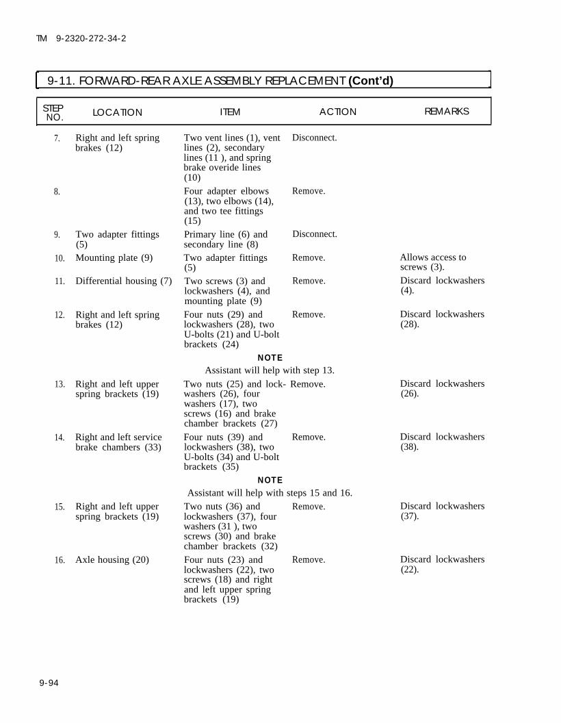
TM 9-2320-272-34-2
9-11. FORWARD-REAR AXLE ASSEMBLY REPLACEMENT (Cont’d)
STEP LOCATION ITEM ACTION REMARKSNO.
7. Disconnect.
8.
9.
10.
11.
12.
13.
14.
15.
16.
Right and left springbrakes (12)
Two adapter fittings(5)Mounting plate (9)
Differential housing (7)
Right and left springbrakes (12)
Right and left upperspring brackets (19)
Right and left servicebrake chambers (33)
Right and left upperspring brackets (19)
Axle housing (20)
Two vent lines (1), ventlines (2), secondarylines (11 ), and springbrake overide lines(10)Four adapter elbows(13), two elbows (14),and two tee fittings(15)Primary line (6) andsecondary line (8)Two adapter fittings(5)Two screws (3) andlockwashers (4), andmounting plate (9)Four nuts (29) andlockwashers (28), twoU-bolts (21) and U-boltbrackets (24)
NOTE
Remove.
Disconnect.
Remove.
Remove.
Remove.
Assistant will help with step 13.
Two nuts (25) and lock- Remove.washers (26), fourwashers (17), twoscrews (16) and brakechamber brackets (27)
Four nuts (39) and Remove.lockwashers (38), twoU-bolts (34) and U-boltbrackets (35)
NOTEAssistant will help with steps 15 and 16.
Two nuts (36) and Remove.lockwashers (37), fourwashers (31 ), twoscrews (30) and brakechamber brackets (32)Four nuts (23) and Remove.
Allows access toscrews (3).Discard lockwashers(4).
Discard lockwashers(28).
Discard lockwashers(26).
Discard lockwashers(38).
Discard lockwashers(37).
Discard lockwashers(22).lockwashers (22), two
screws (18) and rightand left upper springbrackets (19)
9-94

TM 9-2320-272-34-2
9-11. FORWARD-REAR AXLE ASSEMBLY REPLACEMENT (Cont’d)
STEP LOCATIONNO. ITEM ACTION REMARKS
9 - 9 5

TM 9-2320-272-34-2
9-11. FORWARD-REAR AXLE ASSEMBLY REPLACEMENT (Cont’d)
STEP LOCATION ITEM ACTION REMARKSNO.
17. Right and left upper Spring seat wear pads Remove. If cracked or pitted,
18.
19.
spring brackets (1) (2)
Upper torque rod Four nuts (10), lock- Remove.bracket (13) to upper washers (9), andtorque rod plate (8) screws (6)
NOTEAssistants will help with step 19.
Forward-rear axle (11) Pull axle (11) out fromside of vehicle withhydraulic jack (15)and place on two jackstands (14).
b. Installation
NOTEAssistants will help with step 20.
20.
21.
22.
23.
24.
9-96
Hydraulic jack (15) a. Position underforward-rear axle(11).
b. Raise axle (11) untiljack stands (14) areclear.
c. Remove jack stands(14).
replace pad (2).
Refer to TM 9-2320-272-20-1.
Discard lockwashers(9).Upper bracket (13) willremain attached totorque rod (7).
Forward-rear axle (11) Using hydraulic jack(15), position undersprings (4).
Upper torque rod Install to upper torque Dowel pin (12) posi-bracket (13) rod plate (8) with four tions torque rod
screws (6), new lock- bracket (13) on axlewashers (9), and nuts housing (3).(10).
Left and right spring Install in right and leftseat wear pad (2) upper spring bracket
(1).Left and right upper Slide onto leaf springspring brackets (1) assemblies (4) and
install on axle housing(3) over dowel pin (5).

TM 9-2320-272-34-2
I 9-11. FORWARD-REAR AXLE ASSEMBLY REPLACEMENT (Cont’d)
STEP LOCATION ITEM ACTION REMARKSNO.
TA 350688
9-97

TM 9-2320-272-34-2
9-11. FORWARD-REAR AXLE ASSEMBLY REPLACEMENT (Cent’d)
STEP LOCATION ITEM ACTION REMARKSNO.
25. Left and right upper Install each with two Finger tighten only.spring brackets (4) screws (3), new lock-
washers (6), and nuts(7).
26. Left and right service Install each with screw Finger tighten only.brake chamber (15), two washers (16),brackets (17) new lockwasher (22),
and nut (21).
27. Left and right U-bolt Install each to servicebrackets (20) brake chamber (18)
with U-bolt (19), twonew lockwashers (23),and nuts (24).
NOTEAssistant will help with step 28.
28. Left and right springbrake brackets (11)
29. Left and right U-boltbrackets (8)
30. Mounting plate (34)
a. Install each withscrew (1), twowashers (2), newlockwasher (10),and nut (9).
b. Tighten two nuts(7), nut (21), andnut (9).
Install each to springbrake chamber (12)with U-bolt (5), twonew lockwashers (14)and nuts (13).
Install to differentialhousing (31) with twonew lockwashers (28)and screws (27).
Clean all male pipe threads and wrap with sealing tape beforeinstallation.
31. Two adapter fittings(29) and (33)
32. Primary line (30) andsecondary line (32)
33. Two adapter elbows(37), elbow (38), andtee (39)
34. Vent line (25), vent line(26), spring brakeoverride line (35) andsecondary line (36)
Install.
Connect.
Install each to springbrake chamber (12).
Connect to adapterelbows (37), elbow(38), and tee (39).
Tighten 350-375 lb-ft(475-509 N·m).
9-98

TM 9-2320-272-34-2
9-11. FORWARD-REAR AXLE ASSEMBLY REPLACEMENT (Cont’d)
STEP LOCATIONNO. ITEM ACTION REMARKS
9-99

TM 9-2320-272-34-2
I 9-11. FORWARD-REAR AXLE ASSEMBLY REPLACEMENT (Cont’d) ILOCATION ITEM ACTION REMARKS
35. Adapter elbow (13) Install each in left andand elbow (12) right service brake
chamber (11).36. Primary line (14) and Install each in left and
vent line (15) right service brakechamber (11).
NOTEAssistant will help with steps 37 and 38.
Rear propeller shaftflange (2)
37. Install to rearcompanion flange (3)with eight screws (1)and new locknuts (10).
Front propeller shaftflange (5)
Hydraulic jack (8) withaxle fixture
Install to frontcompanion flange (4)with eight screws (6)and new locknuts (9).Remove from forward-rear axle assembly (7).
Tighten 32-40 lb-ft(43-54 N·m).
9-100

TM 9-2320-272-34-2
I 9-11. FORWARD-REAR AXLE ASSEMBLY REPLACEMENT (Cont’d)
LOCATION ITEM ACTION REMARKS
FOLLOW-ON TASKS: ●
●
●
●
END OF TASK!
For (M939A2) Install CTIS air lines (TM 9-2320-358-24&P).Install front-rear wheels (TM 9-2320-272-20-2).Lubricate front-rear axle (LO 9-2320-272-12).Start engine (TM 9-2320-272-10) and allow air pressure to build up to normaloperating range. Check for air leaks. Road test vehicle.
TA 350690
Change 1 9-101

TM 9-2320-272-34-2
I 9-12. REAR AXLE CARRIER DIFFERENTIAL ASSEMBLY MAINTENANCE IThis task covers:
a. Removal c. Installationb. Cleaning and Inspection
INITIAL SETUPEquipmentCondition
Applicable Models ReferenceAll LO 9-2320-272-12
Para. 9-10
Para. 9-11
TM 9-2320-272-20-1
TM 9-2320-272-20-1
Test EquipmentNone
Special ToolsNone
Materials/PartsCrocus cloth (Appendix C, Item 6)Sealing compound (Appendix C, Item 13)
Personnel RequiredWheeled vehicle repairman MOS 63W (2)
Manual ReferencesTM 9-2320-272-20-1TM 9-2320-272-34PLO 9-2320-272-12
Condition DescriptionAxle differential drained.Rear-rear axle assembly removed(as required).Forward-rear axle assembly removed(as required).Rear-rear axle shafts removed(as required).Forward-rear axle shafts removed(as required).
Special Environmental ConditionsNone
General Safety Instructions• All personnel must stand clear during
hoisting operations.• Fire extinguisher will be kept nearby
when drycleaning solvent is used.• Eyeshields must be worn when
cleaning with a wire brush.
STEP LOCATION ITEM ACTION REMARKSNO.
NOTEThis procedure is the same for both the rear-rear and forward-rearcarrier differentials. The rear-rear differential is covered here.
1. Lifting sling (1) Attach to carrierassembly (6) andattach to lift hoist (2).
2. Rear-rear axle housing Eighteen nuts (3), and Remove.(5) washers (4), and
carrier assembly (6)
9-102

TM 9-2320-272-34-2
I 9-12. REAR AXLE CARRIER DIFFERENTIAL ASSEMBLY MAINTENANCE (Cont’d)
STEP LOCATION ITEM ACTION REMARKSNO.
TA 350691
9-103

TM 9-2320-272-34-2
I 9-12. REAR AXLE CARRIER DIFFERENTIAL ASSEMBLY MAINTENANCE (Cent’d)
STEP LOCATION ITEM ACTION REMARKSNO.
WARNING
All personnel must stand clear during hoisting operations. Asnapped cable, shifting or swinging load may cause injury topersonnel.
CAUTIONWhen hoisting carrier assembly out of axle housing, use care not todamage mounting studs. Assistant will guide assembly out ofhousing.
3. Carrier assembly (1) Lift straight out fromaxle housing (4).
b. Cleaning and Inspection
4.
5.
6.
7.
●
●
WARNING
Drycleaning solvent is flammable and will not be used near openflame. Use only in well-ventilated places. Failure to do this mayresult in injury to personnel.Eyeshields must be worn when cleaning with a wire brush. Flyingrust and metal particles may cause injury to personnel.
Differential flange (2) Remove sealingand axle housing (4) compound.mating surfacesMounting studs (3) Remove sealing
compound.Differential flange (2) Inspect for nicks,and axle housing (4) burrs, and cracks.mating surfaces
Mounting studs (3) Inspect for bends anddamaged threads.
Use wire brush anddrycleaning solvent.
Use wire brush anddrycleaning solvent.If nicked, cracked, orheavily burred, replace.If lightly burred, ornicked, remove withcrocus cloth.If bent, or if threadsare damaged, replacestuds (3).
9-104

TM 9-2320-272-34-2
9-12. REAR AXLE CARRIER DIFFERENTIAL ASSEMBLY MAINTENANCE (Cont’d)
STEP LOCATION ITEM ACTION REMARKSNO.
TA 350692
9-105

TM 9-2320-272-34-2
9-12. REAR AXLE CARRIER DIFFERENTIAL ASSEMBLY MAINTENANCE (Cont’d)
STEP LOCATION ITEM ACTION REMARKSNO.
c. Installation
8.
NOTEDifferential flange and axle housing mating surfaces must be cleanbefore applying sealing compound.
Sealing compound Apply generous, buteven amount arounddifferential flange (5)and axle housing (6)mating surfaces andaround all axlehousing mountingstuds (7).
9. Lifting sling (1) Attach to carrierassembly (8) andattach to lift hoist (2).
WARNINGAll personnel must stand clear during hoisting operations. Asnapped cable, shifting or swinging load may cause injury topersonnel.
When hoisting carrier assembly onto axle housing, use care not todamage mounting studs. Assistant will guide assembly ontohousing.
10. Carrier assembly (8) Lower into axle hous-ing (6), and install tomounting studs (7)with eighteen washers(4) and nuts (3) andtighten.
11. Lifting hoist (2) and Detach from carrierlifting sling (1) assembly (8).
9-106

TM 9-2320-272-34-2
9-12. REAR AXLE CARRIER DIFFERENTIAL ASSEMBLY MAINTENANCE (Cont’d)
STEPNO. LOCATION ITEM ACTION REMARKS
END OF TASK!
FOLLOW-ON TASKS: ● Install rear-rear axle shafts if removed (TM 9-2320-272-20-1).● Install rear-rear axle assembly if removed (para. 9-10).● Install forward-rear axle assembly if removed (para. 9-11).● Install forward-rear axle shafts if removed (TM 9-2320-272-20-1).● Fill differential with lubricant (LO 9-2320-272-12).
TA 350693
9-107

TM 9-2320-272-34-2
9-13. UPPER AND LOWER TORQUE ROD REPAIR
This task covers:a. Disassembly b. Assembly
INITIAL SETUP:
EquipmentCondition
Applicable Models ReferenceAll TM 9-2320-272-10
Test EquipmentNone
Special TookNone
Materials/Parts
TM 9-2320-272-20-2
Two ball and bushings
Personnel RequiredLight-wheeled vehicle mechanic MOS 63W
Manual ReferencesTM 9-2320-272-10TM 9-2320-272-20-2TM 9-2320-272-34P
Condition DescriptionParking brake set.Upper/lower torque rods removed.
Special Environmental ConditionsNone
General Safety InstructionsNone
STEPNO. LOCATION ITEM ACTION REMARKS
NOTEWhen replacing ball and bushing, replace both. Step 1 covers one side.
1. Torque rod (1) Ball and bushing (2) Remove. Use arbor press.
2.
NOTEBall and bushing must be pressed in on champer side (3) only.
Ball and bushing (2) Press into torque rod (1). Use arbor press.
9-108 Change 2

TM 9-2320-272-34-2
I 9-13. UPPER AND LOWER TORQUE ROD REPAIR (Cont'd)
STEPLOCATIONNO. ITEM ACTION REMARKS
INSTALLATION
END OF TASK!FOLLOW-ON TASK: Upper/lower torque rod(s) installed (TM 9-2320-272-20-2)
Change 2 9-109 (9-110-9-115 Deleted)

TM 9-2320-272-34-2
9-14. FRONT DIFFERENTIAL OIL SEAL REPLACEMENT
This task covers:a. Removal b. Installation
INITIAL SETUP:EquipmentCondition
Applicable Models Reference Condition DescriptionAll TM 9-2320-272-10 Parking brake set.
TM 9-2320-272-10 Rear wheels blocked.TM 9-2320-272-20-2 Propeller shaft removed
Test Equipment (as required).None
Special ToolsNone Special Environmental Conditions
NoneMaterials/Parts
Wear sleeve kitOil sealCotter pinTwo gasketsGAA grease (Appendix C, Item 11)Sealing compound (Appendix C, Item 13)
Personnel RequiredWheeled vehicle repairman MOS 63W
Manual References
General Safely InstructionsNone
TM 9-2320-272-10TM 9-2320-272-20-2TM 9-2320-272-34P
STEPNO. LOCATION ITEM ACTION REMARKS
1. Pinion drive shaft (9) Cotter pin (1) and Remove. Discard cotter pin (1).slotted nut (12)
2. Companion flange (2) Pull from pinion driveshaft (9) splines.
NOTE• Perform step 2.1 if companion flange is installed with wear sleeve.• Remove wear sleeve only if inspection requires replacement.
2.1. Companion flange (2) Wear sleeve (3) Remove. Discard wear sleeve(3).
CAUTION
Do not jam any tool between differential and pinion shaft retainerwhen removing front bearing cover. Shims will be damaged.
3. Eight screws (11), Remove. Tap only on outer edgewashers (10), and front of front bearing coverbearing cover (4) (4).
9-116 Change 2

TM 9-2320-272-34-2
9-14. FRONT DIFFERENTIAL OIL SEAL REPLACEMENT (Cont'd)
STEPNO. LOCATION ITEM ACTION REMARKS
4. Front bearing cover (4)
5. Pinion shaft retainer(8)
Differential oil seal (6) Remove. Discard oil seal (6) andand front bearing gasket (5).cover gasket (5) Clean gasket remains
from mating surfaces.Pinion shaft retainer Remove. Discard gasket (7).gasket (7) Clean gasket remains
from mating surfaces.
Change 2 9-117

TM 9-2320-272-34-2
I
9-14. FRONT DIFFERENTIAL OIL SEAL REPLACEMENT (Cont'd)
STEP LOCATIONNO. ITEM ACTION REMARKS
b. Installation
6. New pinion shaftretainer gasket (6)
7. New front bearingcover gasket (4)
8. New differential oilseal (5)
9. Front bearing cover (3)with gasket (4) anddifferential oil seal (5)
Coat with sealingcompound and placeon pinion shaftretainer (7).Place in small end offront bearing cover (3).a.
b.
c.
Lubricate insidediameter of seal (5)with GAA grease.Coat outside diam-eter of seal (5)with sealing com-pound.Press into frontbearing cover (3).
Install on pinion shaftretainer gasket (6)with eight washers (9)and screws (10).
Tighten 93-120 lb-ft(125-163 N·m).
● Companion flange must be installed with wear sleeve. ● Perform step 9.1 if wear sleeve was removed.
9.1. New wear sleeve (12) a.
b.
Install on companionflange (2) 0.250 in.(6.35 mm) (distance‘A’) from flange shaftend (14).Remove flange (13)of wear sleeve (12)atprecut line.
10. Companion flange (2) Install on pinion driveshaft (8) splines withslotted nut (11).
11. New cotter pin (1) Install in slotted nut(11) pinion drive
Tighten 300-400 lb-ft(407-542 N·m).
9-118 Change 2

TM 9-2320-272-34-2
9-14. FRONT DIFFERENTIAL OIL SEAL REPLACEMENT (Cont'd)
STEPNO. LOCATION ITEM ACTION REMARKS
Change 2 9-119

TM 9-2320-272-34-2
9-15. REAR DIFFERENTIAL OIL SEAL REPLACEMENT
This task covers:a. Removal b. Installation
INITIAL SETUPEquipmentCondition
Applicable Models Reference Condition DescriptionAll TM 9-2320-272-10 Parking brake set.
TM 9-2320-272-10 Rear wheels blocked.
Test EquipmentTM 9-2320-272-20-2 Propeller shaft removed
None(as required).
Special ToolsNone Special Environmental Conditions
NoneMaterials/Parts
Wear sleeve kitCotter pinOil sealGasketGAA grease (Appendix C, Item 11)Sealing compound (Appendix C, Item 13) General Safety Instructions
Personnel RequiredWheeled vehicle repairman MOS 63W
None
Manual ReferencesTM 9-2320-272-10TM 9-2320-272-20-2TM 9-2320-272-34P
STEP LOCATION ITEM ACTION REMARKSNO.
1. Pinion drive shaft (2) Cotter pin (8) and Remove. Discard cotter pin (8).slotted nut (9)
2. Companion flange (7) Pull from pinion driveshaft (2) splines.
NOTE● Peform step 2.1 if companion flange was installed with wear sleeve.● Remove wear sleeve only if inspection requires replacement.
2.1. Companion flange (7) Wear sleeve (6)
3. Six screws (10), washers(11), and rear cap (4)
4. Rear cap (4) Differential oil seal (5)5. Rear pinion shaft Cap gasket (3)
retainer (1)
Remove. Discard wear sleeve(6).
Remove.
Remove. Discard oil seal (5).Remove. Discard gasket (3).
Clean gasket remainsfrom mating surfaces.
9-120 Change 2

TM 9-2320-272-34-2
9-15. REAR DIFFERENTIAL OIL SEAL REPLACEMENT (Cont'd)
STEPNO. LOCATION ITEM ACTION REMARKS
Change 2 9-121

TM 9-2320-272-34-2
9-15. REAR DIFFERENTIAL OIL SEAL REPLACEMENT (Cont'd)
STEPN O . LOCATION ITEM ACTION REMARKS
6.
7.
8.
●
●
8.1.
9.
10.
New cap gasket (3) Coat with sealing com-pound and install onrear pinion shaftretainer (1).
New differential oil a. Lubricate insideseal (5) diameter of seal (5)
with GAA grease.b. Coat outside dia-
meter of seal (5) withsealing compound.
c. Press into rear cap(4).
Rear cap (4) with oil Install on rear pinionseal (5) shaft retainer (1) with
six washers (10) andscrews (9).
NOTECompanion flange must be installed with wear sleeve.Perform step 8.1 if wear sleeve was removed.
New wear sleeve (11) Install on companionflange (6) 0.125 in.(3.175 mm) (distance'A') from flange shaftend (12).
Companion flange (6) Install on pinion driveshaft (2) splines withslotted nut (8).
New cotter pin (7) Install through pinion
Tighten 93-120 lb-ft(126-163 N·m).
Tighten slotted nut (8)300-400 lb-ft (407-542 N·m).
drive shaft (2) and slottednut (8).
9-121.1 Change 2

TM 9-2320-272-34-2
9-15. REAR DIFFERENTIAL OIL SEAL REPLACEMENT (Cont'd]
STEPNO. LOCATION ITEM ACTION REMARKS
END OF TASK!FOLLOW-ON TASKS: ● Install propeller shaft (TM 9-2320-272-20-2) if removed.
● Remove blocks from rear wheels (TM 9-2320-272-10).● Start engine (TM 9-2320-272-10) and road test vehicle.● Check rear differential oil seal for leaks (TM 9-2320-272-20-1).
Change 2 9-121.2

TM 9-2320-272-34-2
9-16. CROSS TUBE REPLACEMENTThis task covers:
a. Removal b. Installation
INITIAL SETUP:EquipmentCondition
Applicable Models Reference Condition DescriptionAll Para. 9-10 Rear-rear axle removed (as required).
Para. 9-11 Forward-rear axle removed (asrequired).
Para. 9-13 Torque rods (four lower) removed.TM 9-2320-272-20-1 Rear springs removed.TM 9-2320-272-20-1 Spring seats removed.
Test EquipmentNone
Special Tools Special Environmental ConditionsNone None
Materials/PartsEight locknuts
Personnel Required General Safety InstructionsWheeled vehicle repairman MOS 63W (2) Do not attempt to support weight of
vehicle on a hydraulic jack.Manual References
TM 9-2320-272-20-1TM 9-2320-272-34P
STEP LOCATION ITEM ACTION REMARKSN O .
WARNING
Weight of vehicle must remain supported on support stands at alltimes. Do not attempt to support weight of vehicle on a hydraulicjack. Injury to personnel may result if jack fails.
a. Removal
1. Cross tube (3) to rearaxle bogie support (1)
2.
3.
9-122
Eight locknuts (4) and Remove.screws (2)
NOTEAssistant will help with step 2.
Cross tube (3) Remove.
NOTEAssistant will help with step 3.
Cross tube (3) Install on rear axlebogie support (1) witheight screws (2) andnew locknuts (4).
Discard locknuts (4).
Tighten new locknuts(4) 1200-1300 lb-ft(1627-1763 N·m).

TM 9-2320-272-34-2
9-16. CROSS TUBE REPLACEMENT (Cont’d)
STEP LOCATION ITEM ACTION REMARKSNO.
END OF TASK!
FOLLOW-ON TASKS: ● Install spring seats (TM 9-2320-272-20-1).● Install rear springs (TM 9-2320-272-20-1).● Install torque rods (para. 9-13).● Install rear-rear axle (para. 9-10) if removed.● Install forward-rear axle (para. 9-11) if removed.
TA 350702
9-123 (9-124 blank)


TM 9-2320-272-34-2
Section IV. AXLE TESTS AND ADJUSTMENTS
9-17. AXLE TEST AND ADJUSTMENT TASK SUMMARY
TASK PROCEDURES PAGEPARA. NO.
9-18. Steering Stop Adjustment 9-126
9-19. Axle Leakage Test 9-130
9-125

TM 9-2320-272-34-2
9-18. STEERING STOP ADJUSTMENTThis task covers:
Turning Angle Adjustment
INITIAL SETUP:Equipment
Applicable ModelsAll
Test EquipmentCamber and caster gage set
Special ToolsNone
Materials/PartsTwo adjustment screwsTwo nuts
Personnel RequiredWheeled vehicle repairman MOS 63WMetal worker MOS 44B
ConditionReference Condition Description
TM 9-2320-272-10 Parking brake set.TM 9-2320-272-10 Tires properly inflated.
Special Environmental ConditionsNone
General Safety InstructionsNone
Manual ReferencesTM 9-2320-272-10TM 9-2320-272-34P
STEP LOCATION ITEM ACTION REMARKSN O .
Turning Angle Adjustment
1.
2.
3.
4.
5.
6.
9-126
Left front wheel (8) Position straightahead.
Left front wheel (8) Alinement device (9) Position 3 in. (7.6 mm)from outer tire surface.
Turning radius gage Place against outer tire(7) surface.Pointer (11) Center with wheel (8)
aline with zero degreemark on base scale(10).
Left front wheel (8) a. Turn outward tostop.
b. Read degrees of Correct travel is 28travel. degrees, if not correct,
adjust.NOTE
Only perform steps 6 through 8 if adjustment is necessary.Left steering knuckle Adjustment screw (3) Break welds (4) and Discard screw (3) and(1) and nut (6) remove screw (3) and nut (6).
nut (6).

TM 9-2320-272-34-2
9-18. STEERING STOP ADJUSTMENT (Cont’d)
STEP LOCATION ITEM ACTION REMARKSNO.
7. New adjustment screw a. Thread nut (6) all(3) and nut (6)
b.
c.
d.
the way up on screw(3).Thread into back oftie rod arm (5) asfar as possible.Turn screw (3) out Screw (3) becomesuntil screw head con- turn angle stop.tacts axle housing(2).Hold screw (3) in Nut (6) locks positionposition and turn of adjustment screwnut (6) clockwise (3).until it contacts theback of tie rod arm(5).
e. Tighten nut (6) to65-85 lb-ft (88-115 N·m).
8. Left steering knuckle Adjustment screw (3) Tack weld nut (6) to Screw (3) and nut (6)(1) and nut (6) screw (3) and to back become fixed parts of
of tie rod arm (5). left steering knuckle(1).
NOTERepeat steps 1 through 8 for right front wheel turning angleadjustment.
END OF TASK!
FOLLOW-ON TASK: Start engine (TM 9-2320-272-10) and road test vehicle.TA 350703
9-127

TM 9-2320-272-34-2
9-19. AXLE LEAKAGE TESTThis task covers:
a. Test b. Corrective Action
INITIAL SETUP:EquipmentCondition
Applicable ModelsAll
Test EquipmentAir pressure gage (0-160 psi)
Special ToolsNone
Materials/PartsPipe nippleTee connectorQuick disconnect coupling
Personnel RequiredWheeled vehicle repairman MOS 63W
Manual ReferencesTM 9-2320-272-10TM 9-2320-272-34P
Reference Condition DescriptionTM 9-2320-272-10 Parking brake set.TM 9-2320-272-10 Rear wheels blocked.
Special Environmental ConditionsNone
General Safety InstructionsNone
STEP LOCATION ITEM ACTION REMARKSNO.
1. Axle housing (1) Breather assembly (2) Remove.2. Pipe nipple (3) and tee Install in place of
connector (4) breather assembly (2).3. Air pressure gage (5) Install each on tee con-
and quick disconnect nector (4) as shown.coupling (6)
9-128

TM 9-2320-272-34-2
9-19. AXLE LEAKAGE TEST (Cont’d)
TA 350704
9-129

TM 9-2320-272-34-2
9-19. AXLE LEAKAGE TEST (Cont’d)
STEP LOCATION ITEM ACTION REMARKSNO.
CAUTIONDo not allow air pressure to exceed 15 psi (103.4 kPa). Seals will bedamaged if air pressure exceeds 15 psi (103.4 kPa).
4. Air supply hose (4)
5. Air pressure gage (1)
b. Corrective Action
6. Axle housing (7) Carrier differential (8)
7. Air pressure gage (1),air supply hose (4),quick disconnectcoupling (3), teeconnector (2), andpipe nipple (5)
8. Breather assembly (6)
a.
b.
a.
b.
c.
a.
b.
c .
Connect to quickdisconnect coupling(3) and to airsupply.Turn on air. Compressed air should
now fill axle assembly.
Observe. Disconnectair supply hose (4)when pressurereaches 8 psi(55.2 kPa).When disconnectingair supply hose (4),begin timing 45-sec-ond period.After 45 secondstake reading of airpressure gage (1).
Tighten all nuts andscrews.Apply soapsudsaround carrier differ-ential (8).
A faster than 5 psi(34.5 kPa) escape ratein 45 seconds indicatesa leak. Correct perpara. 9-19b. -
Air bubbles willindicate defective ormissing sealing com-pound. To correct, seepara. 9-7 (front axle)or para. 9-12 (rearaxle.
Shutoff air supplyand bleed pressurefrom carrier differ-ential (8).
Disconnect from axlehousing (7) andremove.
Install in axle housing(7).
9-130

TM 9-2320-272-34-2
9-19. AXLE LEAKAGE TEST (Cont’d)
STEP LOCATION ITEM ACTION REMARKSNO.
TA 350705
9-131 (9-132 blank)


TM 9-2320-272-34-2
CHAPTER 10COMPRESSED AIR AND BRAKE SYSTEMS MAINTENANCE
NOTE
Refer to TM 9-2320-358-24&P for unique M939A2 maintenance procedures.
Section I. DESCRIPTION AND DATA
10-1. DESCRIPTION – AIR COMPRESSOR
a. The single cylinder air compressor is a standard accessory on the NHC-250 diesel engine.b. The air compressor shown is driven from the accessory drive gear in the front gearcase. The air
compressor is flange mounted to the accessory drive, which is mounted directly to the rear of the frontgearcase. The air compressor is cooled and lubricated by the engine’s cooling and lubrication systems.
4.
AIR COMPRESSORCoolant Inlet and Outlet Ports 5. Intake ValveUnloader Valve 6. Exhaust ValveAir Governor Connection 7. Lubrication PassageAir Inlet
TA 350567
Change 1 10-1

TM 9-2320-272-34-2
I 10-1. DESCRIPTION - AIR COMPRESSOR (Cont’d)
Table 10-1. Air Compressor Tabulated Data
Compressor Capacity @ 1250 rpm . . . . . . . . . . . . . . . . . . . . . . . . . . . . . . . . . . . . . . . . . . . . . . . . . 13.2 CFM (6.23 l/sec)Cylinders . . . . . . . . . . . . . . . . . . . . . . . . . . . . . . . . . . . . . . . . . . . . . . . . . . . . . . . . . . . . . . . . . . . . . . . . . . . . . . . . . . . . . . . . . . 1Piston Displacement. . . . . . . . . . . . . . . . . . . . . . . . . . . . . . . . . . . . . . . . . . . . . . . . . . . . . . . . . . . 18.05 cu. in. (296 ml)Bore . . . . . . . . . . . . . . . . . . . . . . . . . . . . . . . . . . . . . . . . . . . . . . . . . . . . . . . . . . . . . . . . . . . . . . . . . . . . . . . 3.63 in. (92.07 mm)Stroke . . . . . . . . . . . . . . . . . . . . . . . . . . . . . . . . . . . . . . . . . . . . . . . . . . . . . . . . . . . . . . . . . . . . . . . . . . . . 1.75 in. (44.45 mm)Speed . . . . . . . . . . . . . . . . . . . . . . . . . . . . . . . . . . . . . . . . . . . . . . . . . . . . . . . . . . . . . . . . . . . . . . . . . . . . . . Engine speedCoolant . . . . . . . . . . . . . . . . . . . . . . . . . . . . . . . . . . . . . . . . . . . . . . . . . . . . . . . . . . . . . . . . . . . . . . . . . . . . . . . . Engine coolantLubrication . . . . . . . . . . . . . . . . . . . . . . . . . . . . . . . . . . . . . . . . . . . . . . . . . . . . . . . . . . . . . . . . . . . . . . . . . . . . . . . . Engine oilWater inlet tubing and outlet tubing outside diameter . . . . . . . . . . . . . . . . . . . . . . . . . . . . . . . . . . 0.50 in. (12.70 mm)Air inlet tubing, inside diameter . . . . . . . . . . . . . . . . . . . . . . . . . . . . . . . . . . . . . . . . . . . . . . . . . . . . . . 0.88 in. (22.22 mm)Air outlet tubing, inside diameter . . . . . . . . . . . . . . . . . . . . . . . . . . . . . . . . . . . . . . . . . . . . . . . . . . . . 0.50 in. ( 12.70 mm)Height overall (approx) . . . . . . . . . . . . . . . . . . . . . . . . . . . . . . . . . . . . . . . . . . . . . . . . . . . . . . . . . . . . 12.25 in. (31.11 cm)Width overall (approx) . . . . . . . . . . . . . . . . . . . . . . . . . . . . . . . . . . . . . . . . . . . . . . . . . . . . . . . . . . . . . . 5.75 in. (14.60 cm)Length overall (approx) . . . . . . . . . . . . . . . . . . . . . . . . . . . . . . . . . . . . . . . . . . . . . . . . . . . . . . . . . . . . . . 9 in. (22.86 cm)Weight overall (approx) . . . . . . . . . . . . . . . . . . . . . . . . . . . . . . . . . . . . . . . . . . . . . . . . . . . . . . . . . . . . . . . . 40 lb (18.14 kg)
10-2. DESCRIPTION - BRAKESHOES AND SYSTEM COMPONENTS
a. The shoe components are shown in installed position. Incorrect installation will prevent automaticadjusters from working. The long radius of the shoe web points to the star wheel of the adjustable plunger,and the arrow stamped on the shoe web points to the anchor plunger in the forward wheel rotation.
b. Refer to TM 9-2320-272-20-1 for complete description and data of the brake components.
1. Shoe Lining2. Shoe Web
3. Adjustable Plunger Star Wheel4. Anchor Plunger
10-2
TA 350568

TM 9-2320-272-34-2
10-2. DESCRIPTION – BRAKESHOES AND SYSTEM COMPONENTS (Cont’d)
1. Anchor Plunger2. Shoe Lining
3. Shoe Web4. Adjustable Plunger Star Wheel
TA 350569
10-3 (10-4 blank)


TM 9-2320-272-34-2
Section Il. COMPRESSED AIR AND BRAKE SYSTEMSCOMPONENTS MAINTENANCE
10-3. AIR COMPRESSOR AND BRAKE SYSTEMS MAINTENANCE TASK SUMMARY
PARA.NO.
PROCEDURES PAGENO.
10-4.10-5.10-6.10-7.10-8.10-9.
10-10.10-11.10-12.
10-13.
Air Compressor MaintenanceAir Compressor ReplacementFront Brake Actuator RepairRear Brake Actuator RepairBrake Pedal (Treadle) Valve RepairDeleted
Relay Valve RepairLimiting Valve RepairTransfer Case Front Axle EngagementControl Valve ReplacementService Brake Brakedrum Maintenance
10-610-3010-3810-4410-50
10-5810-6410-70
10-70
Change 2 10-5

TM 9-2320-272-34-2
10-4. AIR COMPRESSOR MAINTENANCEThis task covers:
a. Disassembly c. Inspection and repairb. Cleaning d. Assembly
INITIAL SETUP:EquipmentCondition
Applicable Models Reference Condition DescriptionAll Para. 10-5 Air compressor removed.
Test EquipmentDepth micrometerOutside diameter micrometerInside diameter micrometerFeeler gageCylinder bore dial gageSpring testerDial indicator gage
Special Tools Special Environmental ConditionsMounting plate 3375133 None
Materials/PartsRepair kit 3011472Repair kit AR-73350Twelve lockwashersAnti-seize compound (Appendix C, Item 3)Lubricating oil (Appendix C, Item 17)
Personnel Required General Safety InstructionsWheeled vehicle repairman MOS 63W ● Fire extinguisher will be kept nearby
when drycleaning solvent is used.● Eye protection must be worn when
using compressed air.Manual References
TM 9-2320-272-34P
STEP LOCATION ITEM ACTION REMARKSNO.
a . D i sa s sembly
1. Air compressor (8) Mounting plate (5) and Install.two screws (7)
2. Mounting plate (5) and Secure tightly in viseair compressor (8) (6).
3. Cylinder head cover Two screws (10), lock- Remove.(4) washers (9), washers
(1), air inlet connec-tion (2), and gasket (3)
Discard lockwashers(9) and gasket (3).
10-6

TM 9-2320-272-34-2
10-4. AIR COMPRESSOR MAINTENANCE (Cont’d)
STEP LOCATION ITEM ACTION REMARKSNO.
TA 350570
10-7

TM 9-2320-272-34-2
I 10-4. AIR COMPRESSOR MAINTENANCE (Cont’d)
STEP LOCATION ITEM ACTION REMARKSNO.
4. Remove.
5.
6.
Cylinder head cover(6)
Unloader valve assem-bly (2)
Intake valve assembly(4)
Two screws (1), andwashers (7), unloadervalve assembly (2),unloader valve spring(3), intake valveassembly (4), andintake valve spring (5)Unloader cap (10), “O”ring (12) and packingseal (11)Intake valve seat (9)and disk valve (8)
Remove from unloader Discard “O” ring (12)valve body (13). and packing seal (11).
Separate.
10-8

TM 9-2320-272-34-2
10-4. AIR COMPRESSOR MAINTENANCE (Cont’d)
STEP LOCATION ITEM ACTION REMARKSNO.
TA 350571
10-9

TM 9-2320-272-34-2
I 10-4. AIR COMPRESSOR MAINTENANCE (Cont’d)
STEP LOCATION ITEM ACTION REMARKSNO.
7. Cylinder head (12) Remove. Discard lockwashers
8. Crankcase (14)
9. Cylinder head (12)
10. Exhaust valve seat (7)
11. Cylinder head (12)
12. Crankcase (14)
Four screws (1), lock-washers (2), washers(3), cylinder headcover (4), and gasket(5)
Cylinder head (12) andgasket (13)Exhaust valve seat (7)
“O” ring (6), packingseal (8), and exhaustvalve (9)Wear plate (11) andexhaust valve spring(10)Six screws (15), lock-washers (16), and fourwashers (19)
(2) and gasket (5).
Remove. Discard gasket (13).
Remove by pressingexhaust valve seat (7)from bottom side ofcylinder head (12).Remove.
Remove.
Remove.
Discard “0” ring (6)and packing seal (8).
Use care when removing crankshaft from connecting rod to avoiddamage.
13. Front support (18), Remove as an Rotate crankshaft (22)crankshaft (22), and assembly. 90 degrees before orgasket (17) after top dead center
of piston for ease ofremoval. Discardgasket (17).
14. Crankshaft (22) Pipe plug (23) Remove.15. Front support (18) Drive coupling (20), Remove.
thrust washer (21),and crankshaft (22)
Use arbor press.
10-10

TM 9-2320-272-34-2
10-4. AIR COMPRESSOR MAINTENANCE (Cont’d)
STEPNO. LOCATION ITEM ACTION REMARKS
TA 350572
10-11

TM 9-2320-272-34-2
I 10-4. AIR COMPRESSOR MAINTENANCE (Cont’d)
STEP LOCATION ITEM ACTION REMARKSNO.
16. Crankcase (9) Piston (7) and Remove through crank-connecting rod (8) case (9) cylinder.
17. Piston (7) a. Top compressionring (1)
b. Intermediatecompression ring (2)
c. Oil ring expander(4) and two oil rings(3)
18. Two retaining rings(5), piston pin (6), andconnecting rod (8)
Remove. Discard topcompression ring (1).
Remove. Discard intermediatecompression ring (2).
Remove. Discard oil rings (3)and oil ring expander(4).
Remove. If piston pin (6)cannot be removedfrom piston (7) byhand pressure, placepiston (7) in hot waterto expand piston pinbore (10) to allowremoval. Driving pin(6) from piston (7)may damage piston(7).
10-12

TM 9-2320-272-34-2
10-4. AIR COMPRESSOR MAINTENANCE (Cont’d)
STEP LOCATIONNO. ITEM ACTION REMARKS
TA 350573
10-13

TM 9-2320-272-34-2
10-4. AIR COMPRESSOR MAINTENANCE (Cont’d)
STEP LOCATION ITEM ACTION REMARKS NO.
● Drycleaning solvent is flammable and will not be used near openflame. Use only in well-ventilated places. Failure to do this mayresult in injury to personnel.
● Compressed air source will not exceed 30 psi (207 kPa). Whencleaning with compressed air, eyeshields must be worn. Failureto wear eyeshields may result in injury to personnel.
19. Crankcase (1) Mounting plate (3), Remove.and two screws (2)
20. All metal parts a. Immerse and clean Clean gasket remainsin drycleaning from all surfaces.solvent.
b. Remove all carbon, Make sure all matingrust and scale. surfaces are clean and
smooth, withoutdamage.
c. Blow dry with Make sure that interiorcompressed air. drilled oil passages (5)
in crankshaft (4) arethoroughly cleaned.
10-14

TM 9-2320-272-34-2
10-4. AIR COMPRESSOR MAINTENANCE (Cont’d)
STEP LOCATION ITEM ACTION REMARKSNO.
21. Exhaust valve (6) Measure seat height. Use depth micrometer(7). If seat height isless than 0.485 in.(12.32 mm), replace.
22. Intake valve (9) a. Measure seat height. If height is less than
23. Unloader cap (8)
0.270 in. (6.86 mm),replace.
b. Measure intake valve Surface must be flatsurface (10). within 0.001 in. (0.03
mm) total micrometerreading. If not, replace.
a. Check narrow part If scored or excessivelyfor scoring and worn, replace.excessive wear.
b. Check seating If distorted, pitted, orsurface for worn, replace.distortion, pitting,and wear.
TA 350575
10-15

TM 9-2320-272-34-2
10-4. AIR COMPRESSOR MAINTENANCE (Cont’d)
STEP LOCATION. ITEM ACTION REMARKSNO.
24. Cylinder head (5) and Check for cracks and If cracked or broken,cylinder head cover (4) breaks.
25. Unloader valve spring Measure spring(l), intake valve spring characteristics.(2), and exhaust valvespring (3)
26. Crankshaft (6) a.
b.
Check for scratches,scoring, and wear.
Measure journals(7), (8), and (9).
replace.
Use spring tester anddial gage. If less thanacceptable wear limits,replace. Wear limit forunloader valve spring(1) is 12.00 lb (5.4 kg).Wear limit for intakevalve spring (2) is0.55 lb (0.25 kg). Wearlimit for exhaust valvespring (3) is 8.00 lb(3.63 kg).
If scratched, scored, orworn, replace.
Use outside diametermicrometer. If lessthan acceptable wearlimits, replace. Wearlimit for journal (7) is1.871 in. (47.52 mm).Wear limit for journal(9) is 1.933 in. (49.10mm). Wear limit forjournal (8) is 1.871 in,(47.52 mm).
10-16

TM 9-2320-272-34-2
10-4. AIR COMPRESSOR MAINTENANCE (Cont’d)
STEP LOCATION ITEM ACTION REMARKSNO.
TA 350576
10-17

TM 9-2320-272-34-2
10-4. AIR COMPRESSOR MAINTENANCE (Cont’d)
STEP LOCATION ITEM ACTION REMARKSNO.
27. Front support (3) a. Check for scratches, Replace if scratched,scoring, and wear.
b. Measure thrustflange (1).
28. Thrust bearing (4) Measure thickness.
29. Support bearing (2) a. Check for scoringand wear.
b. Measure insidediameter.
30. Drive gear (5) Inspect for wear,scoring, and damage.
scored, or worn.Use outside diametermicrometer. Replace,if measurement isless than 1.287 in.(32.69 mm).Replace, if measure-ment is less than0.240 in. (6.10 mm).
If scored or worn,replace.
Use inside diametermicrometer. Replace ifmeasurement is morethan 1.887 in.(47.69 mm).If scored, excessivelyworn, or damaged,replace.
TA 350577
10-18

TM 9-2320-272-34-2
10-4. AIR COMPRESSOR MAINTENANCE (Cont’d)
STEP LOCATION ITEM ACTION REMARKSNO.
31. Connecting rod Check for scoring andbushing (10) damage.
32. Connecting rod (9) a. Check for bend andtwist.
33.
34.
Piston pin (7)
Piston (6)
b. Measure innerdiameter of pistonend (12) and crank-shaft (11) end ofconnecting rod (9).
Measure outsidediameter.
a.
b.
c.
Make visual checkfor scoring, cracks,wear, and damage.Measure skirt (8)diameter.
Measure pin bore(13) diameter.
If scored or damaged,replace connecting rod(9).
If bend exceeds0.002 in. (0.05 mm) orif twist exceeds0.004 in. (0.10 mm),replace.
If piston end exceeds0.689 in. (17.50 mm),replace. If crankshaftend exceeds 1.935 in.(49.15 mm), replace.
If measurement is lessthan 0.687 in.(17.45 mm), replace.
If scored, cracked,worn, or damaged,replace.
If measurement is lessthan 3.617 in. (91.86mm) at 70°F (21°C),replace.If measurement ismore than 0.689 in.(17.50 mm) at 70°F(21°C), replace.
TA 350578
10-19

TM 9-2320-272-34-2
I 10-4. AIR COMPRESSOR MAINTENANCE (Cont’d)
STEP LOCATION ITEM ACTION REMARKSNO.
35. Piston (2) a.
b.
c.
36.
37. Crankcase (8)
Crankcase (8) a.
b.
c.
d.
Install new ring (3)in groove (4).Insert 0.004 in.(0.10 mm) feelergage (1) betweenring and groove.Compress ring (3)into groove (4).
Seat piston ring (6)in unworn portion ofbore (5).Measure ring endgap with feeler gage(7).Inspect bore (5) forscoring.Check bore (5) forout-of roundnesswith a dial bore gage(9).
Crankshaft bushing Measure inner(10) diameter.
If ring (3) can bepressed below pistonsurface with feelergage (1) in place,replace piston (2).
Gap should be 0.010 to0.020 in. (0.25 to0.51 mm).Hone bore as requiredto remove glaze.Maximum out-of-round is 0.002 in. (0.04mm). If not withinspecifications, honebore to receive 0.010,0.020, or 0.030 in.(0.25, 0.51, or 0.76mm) oversize pistonand rings.Use inside diametermicrometer. Ifmeasurement exceeds1.878 in. (47.70 mm),replace.
10-20

TM 9-2320-272-34-2
10-4. AIR COMPRESSOR MAINTENANCE (Cont’d)
STEP LOCATIONNO. ITEM ACTION REMARKS
TA 350579
10-21

TM 9-2320-272-34-2
I 10-4. AIR COMPRESSOR MAINTENANCE (Cont’d)
STEP LOCATION ITEM ACTION REMARKSNO.
38. Retaining ring (11) Install in piston pinring groove in pistonpin bore (10).
39. Connecting rod (9) Place piston end inpiston (8).
CAUTIONDo not drive piston pin into bore. Damage to piston will result.
40. Piston pin (7) Install through pistonpin bore (10) andconnecting rod (9)until seated againstretaining ring (11).
NOTEIf pin cannot be installed by hand pressure, heat piston in hotwater to expand pin bore.
41. Retaining ring (6) Install in piston pinbore (10).
42. Oil ring (4) and two Install in bottomexpander rings (3) and piston ring groove.(5)
Expander rings (3)and (5) gaps and oilring (4) gaps must be180 degrees apart.Make sure ends ofexpander rings (3) and(5) do not overlap.
10-22

TM 9-2320-272-34-2
10-4. AIR COMPRESSOR MAINTENANCE (Cont’d)
STEP LOCATION ITEM ACTION REMARKSNO.
43. Compression ring (1) a. Install. Compression ring (1) isand intermediate ring b. Stagger gaps 180 installed with word(2) degrees apart. “top” toward crown of
piston (12).c. Lubricate with clean
lubricating oil.
TA 350580
10-23

TM 9-2320-272-34-2
I 10-4. AIR COMPRESSOR MAINTENANCE (Cont’d)
STEP LOCATION ITEM ACTION REMARKSNO.
44. Air compressor crank- Install on mountingcase (3) plate (5) with two
screws (4).45. Mounting plate (5) and Install tightly in vise
crankcase (3) (6).46. Ring compressor (1) Install on piston and
connecting rodassembly (2).
CAUTIONDo not force piston into cylinder. This can crack rings and/or
47.
48.
damage cylinder wall. -
Piston and rodassembly (2) andcrankcase (3)Piston and rodassembly (2)
Lubricate with cleanlubricating oil.
Install in crankcase (3)cylinder bore.
10-24
TA 350581

TM 9-2320-272-34-2
10-4. AIR COMPRESSOR MAINTENANCE (Cont’d)
STEP LOCATIONN O . ITEM ACTION REMARKS
49. Crankshaft (10)
50. Pipe plug (11)
51. Thrust bearing (8)
52. Drive gear (7)
Lubricate and install incrankshaft support (9).
Install in crankshaft(10).
Install in support (9) Install with notcheson crankshaft (10) toward crankshaftend. (10).Install on crankshaft Install with (10). end of gear
crankshaft arbor press.
protruding(7) toward(10). Use
TA 350582
10-25

TM 9-2320-272-34-2
10-4. AIR COMPRESSOR MAINTENANCE (Cont’d)
STEP LOCATION ITEM ACTION REMARKSNO.
53. Crankshaft (7), Install in crankcase (1)support assembly (6), as follows:and new gasket (8)
a. Position piston (2) This will allow crank-at 90 degrees before shaft (7) to be installedor after top dead through connectingcenter. rod (9).
b. Insert crankshaft(7) and supportassembly (6) incrankcase (1) andconnecting rod (9)journal.
c. Install on crankcase Tighten 30-35 lb-ft(1) with four (41-48 N·m).washers (5) and sixscrews (3) and newlockwashers (4).
10-26
TA 350583

TM 9-2320-272-34-2
10-4. AIR COMPRESSOR MAINTENANCE [Cont’d)
STEPNO. LOCATION ITEM ACTION REMARKS
54.
55.
56.
57.
Exhaust valve (18),new “O” ring (15), andpacking seal (17)Wear plate (20),exhaust valve spring(19), and valve seat(16)New gasket (22) andcylinder head (21 )New gasket (14) andcylinder head cover(13)
Install on exhaustvalve seat (16).
Install in cylinder head Use thumb pressure to(21). press valve seat (16)
into position incylinder head (21 ).
Install on crankcase(l).Install on cylinderhead (21) with fournew lockwashers (11),washers (12), andscrews (10).
TA 350584
10-27

TM 9-2320-272-34-2
10-4. AIR COMPRESSOR MAINTENANCE (Cont’d)I
STEP LOCATION ITEM ACTION REMARKSNO.
58. New “O” ring (12), new Install in unloader cappacking seal (11 ), andunloader valve (10)
59. Intake valve (8)
60. Intake valve seatassembly (4) andintake valve spring (5)
61. Unloader spring (3)and unloader capassembly (2)
(13) .
Install on intake valveseat (9).Install in cylinder headcover (6).
Install in cylinder headcover (6) with twoscrews (1) andwashers (7).
10-28
TA 350585

TM 9-2320-272-34-2
10-4. AIR COMPRESSOR MAINTENANCE (Cont’d)
STEP LOCATION ITEM ACTION REMARKSNO.
62. New gasket (18) and Install on cylinderair inlet connection head cover (13) with(17) two washers (16), new
lockwashers (15), andscrews (14).
Mounting plate (20) Remove.and two screws (22)Mounting plate (20) Remove.
63. Crankcase (19)
64. Vise (21)
END OF TASK!
FOLLOW-ON TASK: Install air compressor (para. 10-5).
TA 350586
10-29

TM 9-2320-272-34-2
10-5. AIR COMPRESSOR REPLACEMENTThis task covers:
a. Removal b. Installation and Timing
INITIAL SETUP:EquipmentCondition
Applicable Models Reference Condition Description
All TM 9-2320-272-10 Air reservoirs drained.TM 9-2320-272-10 Left splash shield removed.
Para. 4-4 Fuel pump removed.TM 9-2320-272-20-2 Power steering pump removed.
Test EquipmentNone
Special Tools Special Environmental Conditions
None None
Materials/PartsNine lockwashersHousing support gasketFour tube insertsSealing tape (Appendix C, Item 30)
Personnel RequiredWheeled vehicle repairman MOS 63W
Manual ReferencesTM 9-2320-272-10TM 9-2320-272-20-2TM 9-2320-272-34P
General Safety InstructionsDo not disconnect air lines beforedraining air reservoirs.
STEP LOCATION ITEM ACTION REMARKSNO.
Do not disconnect air lines before draining air reservoirs. Smallparts under pressure may shoot out with high velocity, causinginjury to personnel.
1.
2.
3.
10-30
Air compressor (2) Coolant outlet line (1) Disconnect from airand engine oil cooler compressor elbow (5)(16) and engine oil cooler
elbow (15).
Coolant outlet line Nut (13), lockwasher Remove.support bracket (10) (12), washer (11),
screw (7), washer (8),clamp (9) and coolantoutlet line (1)
Air compressor elbow Coolant inlet line (4) Remove.(3) and water pumpfitting (6)
Discard inserts (14)from ends of line (l).Discard lockwasher(12).
Discard inserts (14)from ends of line (4).

TM 9-2320-272-34-2
10-5. AIR COMPRESSOR REPLACEMENT (Cont’d)
STEP LOCATION ITEM ACTION REMARKSNO.
4. Engine block (17) Four screws (19), Remove.washers (18) andpower steering pumppivot bracket (20)
TA 350587
10-31

TM 9-2320-272-34-2
I 10-5. AIR COMPRESSOR REPLACEMENT (Cont’d)
STEP LOCATION ITEM ACTION REMARKSNO.
5. Unloader valve body(1)
6. Compressor head (11)
7. Compressor inlet (9)
8. Compressor head (11)
9. Air compressor (18)
10. Air compressor (18) toaccessory drivehousing (13)
11. Air compressor (18) tobracket (30)
12. Engine (29) to bracket(30)
13.
14.15.
16.
10-32
Air compressor togovernor air line (3)
Air compressor toalcohol evaporator airline (4)Air intake tube (7)
Compressor to supplyreservoir air line (6)Screw (23), lockwasher(22), washer (21),ground cable (20), andlockwasher (19)Two screws (25),lockwashers (24), twoscrews (12), lock-washers (17), washers(16), and nuts (15)Screw (28), lockwasher(27), and washer (26)Screw (33), washer(31), and lockwasher(32)
Screw (34)
Air compressor (18)
Gasket (14)
Coupling drive (35)
Disconnect fromadapter elbow (2).Disconnect fromadapter elbow (10).
Loosen two clamps (8)and disconnect.
Disconnect fromadapter (5).
Remove.
Remove.
Remove.
Remove.
Loosen and movebracket (30) down.Remove.
Remove.
Remove.
Discard lockwashers(22) and (19).
Discard lockwashers(17) and (24).
Discard lockwasher(27).Discard lockwasher(32).
Discard gasket (14).Clean gasket remainsfrom mating surfaces.

TM 9-2320-272-34-2
10-5. AIR COMPRESSOR REPLACEMENT (Cont’d)
STEPNO. LOCATION ITEM ACTION REMARKS
TA 350588
10-33

TM 9-2320-272-34-2
10-5. AIR COMPRESSOR REPLACEMENT (Cont’d)
STEP LOCATION ITEM ACTION REMARKSNO.
b. Installation and Timing
17.
●
18.
19.
20.
21.
Coupling drive (2) Position in accessorydrive housing (1) overaccessory drive (3).
NOTEIf installing new compressor, use fittings from old compressor.Clean all male pipe threads and wrap with sealing tape beforeinstallation.Make sure oil passage holes in new gasket are open, and alinewith oil passages before installation.
New gasket (6) Aline on accessorydrive housing (1).
Air compressor (10) a.
b.
c.
Bar engine to “l-6”valve set positionindex mark (4).
Set air compressortiming mark point-ing between 9 and10 o’clock looking atcoupling end.Install on accessorydrive housing (1) with two screws(17), new lock-washers (16), twoscrews (5), newlockwashers (7),washers (9) andnuts (8).
Ground cable (12) Install on air com-pressor (10) with newlockwasher (11),washer (13), newlockwasher (14) andscrew (15).a. Install on air com-
pressor (10) withscrew (20), newlockwasher (19),and washer (18).
b. Install on engine(21) with screw(25), new lock-washer (24), andwasher (23). Tightenscrew (26).
Bracket (22)
10-34

TM 9-2320-272-34-2
10-5. AIR COMPRESSOR REPLACEMENT (Cont’d)
STEPNO. LOCATION ITEM ACTION REMARKS
10-35

TM 9-2320-272-34-2
10-5. AIR COMPRESSOR REPLACEMENT (Cont’d)
STEP LOCATION ITEM ACTION REMARKSNO.
22. Coolant outlet line (5) Connect to air com- Use new inserts (11)
23. Coolant outlet line (5)
24. Power steering pumppivot bracket (4)
25. Coolant inlet line (8)
26. Air intake tube (27)
27.
28.
29.
Air compressor toalcohol evaporator airline (24)Air compressor togovernor air line (23)
Air compressor tosupply reservoir airline (26)
pressor elbow (9), and on each end of line (5).oil cooler (13) elbow(12).Install on outlet linesupport bracket (17)with screw (14),washer (15), clamp(16), washer (18), newlockwasher (19), andnut (20).Install on engine block(1) with four washers(2) and screws (3).Connect to water Use new inserts (11)pump fitting (10) and on each end of line (8).air compressor (6)elbow (7).Connect to compressorinlet air connection(29) with two clamps(28).Install on head cover(31) adapter elbow(30).Install on unloadervalve body (21 )adapter elbow (22).Connect to compressorhead adapter (25).
10-36
TA 350590

TM 9-2320-272-34-2
10-5. AIR COMPRESSOR REPLACEMENT (Cont’d)
STEP LOCATION ITEM ACTION REMARKSNO.
FOLLOW-ON TASKS: ●
●
●
●
END OF TASK!
Install fuel pump (para. 4-4).Install power steering pump (TM 9-2320-272-20-2).Start engine (TM 9-2320-272-10) and check air compressor for leaks and properoperation.Install left splash shield (TM 9-2320-272-10).
TA 350591
10-37

TM 9-2320-272-34-2
10-6. FRONT BRAKE ACTUATOR REPAIR .This task covers:
a. Disassembly of Adjustable Actuator d. Reassembly of Stationary Actuatorb. Disassembly of Stationary Actuator e. Reassembly of Adjustable Actuatorc. Cleaning and Inspection
INITIAL SETUP:Equipment
Applicable Models ConditionAll Reference Condition Description
Test Equipment TM 9-2320-272-20-2 Brake chambers removed.None TM 9-2320-272-20-2 Brakeshoes removed.
Special Tools TM 9-2320-272-20-2 Front brake spider removed.
None Special Environmental ConditionsMaterials/Parts None
Anchor plunger kit 1173 (left)Anchor plunger kit 1174 (right) General Safety Instructions
Adjuster parts kit 1164 NoneLint-free cloth (Appendix C, Item 7)
Personnel RequiredWheeled vehicle repairman MOS 63W
Manual ReferencesTM 9-2320-272-20-2TM 9-2320-272-34P
STEP LOCATION ITEM ACTION REMARKSNO.
NOTEDo not perform this procedure unless actuator repair kit is available.
a. Disassembly of Adjustable Actuator
1. Back of adjustingplunger housing (11)
2. Adjusting plungerhousing (11)
3.4.5.
10-38 Change 2
Wedge assembly (15)
Two hollow screws (10),gaskets (9), springs (8),and adjusting pawls (7)Two adjusting bolts (3)Two plunger seals (4)Two adjusting sleeves(5) and adjustingplungers (6)
Remove. Discard wedgeassembly (15).
Remove. Discard screws (10),gaskets (9), springs(8), and pawls (7).
Remove. Discard bolts (3).Remove. Discard seals (4).Remove. Discard sleeves (5)
and plungers (6).

TM 9-2320-272-34-2
I 10-6. FRONT BRAKE ACTUATOR REPAIR (Cont’d)
STEPNO. LOCATION ITEM ACTION REMARKS
b. Disassembly of Stationary Actuator
6. Anchor plunger Two guide screws (12) Remove.housing (14) and gaskets (13)
7. Two anchor plungers Remove.(1) and seals (2)
Discard screws (12)and gaskets (13).Discard plungers (1)and seals (2).
TA 350592
10-39

TM 9-2320-272-34-2
10-6. FRONT BRAKE ACTUATOR REPAIR (Cont’d)
STEP LOCATIONNO.
c. Cleaning and Inspection
ITEM ACTION REMARKS
8. Adjusting plunger Wipe clean with lint- Replace spiderhousing (6) and free cloth and inspect assembly if eitheranchor plunger for cracks, breaks, housing (1) or (6) ishousing (1) chips, and pitting. cracked, broken,
chipped, or pitted.(Refer to TM 9-2320272-20-2).
d. Reassembly of Stationary Actuator
CAUTION
Keep all anchor plunger parts together. Intermixing right and leftplunger parts will cause brake system damage.
NOTECoat all new metal parts, lips of seals, and plunger housing boreswith a light film of grease included with new parts kit.
9. Two new anchor Place piece of tapeplungers (3) over slots in noses of
anchor plungers (3) toprotect lips of seals (2).
10. Two new seals (2) Install into doublegrooves of anchorplungers (3).
11. Two new anchor a.plungers (3)
b.
Position in anchorplunger housing (1)with guide grooves(8) and guide screwholes (7) alined.Seat seals (2) in
Make sure correct "L"or "R" anchor plungeris installed in bore ofanchor housing (1).
Use hammer and
12.
10-40 Change 2
anchor plungerhousing (1).
Two new gaskets (4) Install in anchorand guide screws (5) plunger housing (1)
and anchor plungers(3) grooves (8).
1-3/4 in. wrenchsocket to seat.Tighten guide screws(5) 15-20 lb-ft(20-27 N·m).

TM 9-2320-272-34-2
10-6. FRONT BRAKE ACTUATOR REPAIR (Cont’d)
STEP LOCATION ITEM ACTION REMARKSNO.
TA 350593
10-41

TM 9-2320-272-34-2
I 10-6. FRONT BRAKE ACTUATOR REPAIR (Cont’d)
STEP LOCATION ITEM ACTION REMARKSNO.
e. Reassembly of Adjustable Actuator
NOTECoat all parts with light film of GAA grease before reassembly.
13. Two new adjusting Position in adjustingplungers (5) plunger housing (12)
with guide groove (6)and adjusting pawl (7)hole alined.
14. Two new adjusting Position in eachsleeves (4) adjusting plunger (5).
NOTEAdjusting pawls have teeth and flats on one end and chamferededge on the other end. When performing step 16, make sureadjusting pawl is positioned with chamfer toward sleeve to alinepawl and sleeve teeth.
15. Two new adjusting a.pawls (8) and newsprings (9)
b.
c.
Position in adjusting Tighten screws (11)plunger housing 15-20 lb-ft (20-27 N·m).(12) with two newgaskets (10) andinstall two newhollow screws (11).Use adjusting bolt A clicking sound and a(2) to rotate ratcheting feel willadjusting sleeve (4), indicate properand check for meshing.proper teethmeshing.Remove adjusting
16.
17.
bolt (2) after sleeve(4) is installed.
Two new plunger seals Position inner lip over Use hammer and(3) adjusting sleeve (4) 1-3/4 in. wrench
and seat outer ring of socket to seat.seal (3) in adjustingplunger housing (12).
Do not bottom adjusting bolt against seal. Seal will be damaged.Two new adjusting Install in adjusting Tighten until boltbolts (2) sleeve (4). heads are showing just
above seal (3). Thisprevents seal (3)damage during in-stallation.
10-42

TM 9-2320-272-34-2
10-6. FRONT BRAKE ACTUATOR REPAIR (Cont’d)
STEP LOCATION ITEM ACTION REMARKSNO.
18. New wedge assembly a. Install in back of(1) adjusting plunger
housing (12).
b. Check operation ofwedge assembly (1)and adjustingplungers (5).
END OF TASK!
FOLLOW-ON TASKS: • Install brake spider (TM 9-2320-272-20-2).• Install brakeshoes (TM 9-2320-272-20-2).• Install brake chambers (TM 9-2320-272-20-2).
TA 350594
10-43

TM 9-2320-272-34-2
I 10-7. REAR BRAKE ACTUATOR REPAIRThis task covers:
a. Disassembly c. Reassemblyb. Cleaning and Inspection
INITIAL SETUP:EquipmentCondition
Applicable ModelsAll
Test EquipmentNone
Special ToolsNone
Materials/PartsActuator repair kit 1105Lint-free cloth (Appendix C, Item 7)GAA grease (Appendix C, Item 11)Tape (Appendix C, Item 31 )
Personnel RequiredWheeled vehicle repairman MOS 63W
Manual ReferencesTM 9-2320-272-20-2TM 9-2320-272-34P
Reference Condition DescriptionTM 9-2320-272-20-2 Brake chambers removed.TM 9-2320-272-20-2 Brakeshoes removed.TM 9-2320-272-20-2 Rear brake spider removed.
Special Environmental ConditionsNone
General Safety InstructionsNone
STEP LOCATION ITEM ACTION REMARKSNO.
NOTEDo not perform this procedure unless actuator repair kit isavailable.
1. Back of plunger Wedge assembly (1)housing (6)
2. Plunger housing (6) Guide screw (11) andgasket (12)
3. Hollow screw (10)gasket (9), spring (8),and adjusting pawl (7)
4. Anchor plunger (13)and seal (14)
5. Adjusting bolt (2)
10-44
Remove.
Remove.
Remove.
Remove.
Remove.
Discard wedgeassembly (1).Discard screw (11) andgasket (12).Discard screw (10),gasket (9), spring (8),and pawl (7).
Discard plunger (13)and seal (14).Discard bolt (2).

TM 9-2320-272-34-2
10-7. REAR BRAKE ACTUATOR REPAIR (Cont’d)
STEP LOCATION ITEM ACTION REMARKSNO.
6. Adjusting plunger seal Remove. Discard seal (3).(3)
7. Adjusting sleeve (4) Remove. Discard sleeve (4) andand adjusting plunger adjusting plunger (5).(5)
TA 350595
10-45

TM 9-2320-272-34-2
10-7. REAR BRAKE ACTUATOR REPAIR (Cont’d)
STEP LOCATION ITEM ACTION REMARKSNO.
b. Cleaning and Inspection
8. Plunger housing (8) Wipe clean with lint- Replace spiderfree cloth and inspect assembly (7) if housingfor cracks, breaks, (8) is cracked, broken,chips, and pitting. chipped, or pitted.
(Refer to TM 9-2320-272-20-2.)
NOTECoat all metal parts, lips of seals and plunger housing bores with a
9 .light film of GAA grease before reassembly.
New anchor plunger Install as follows:seal (4) and new a. Place tape (5) overanchor plunger (2) brakeshoe web slot
on new plunger (2).
b. Slide new seal (4) onplunger (2) untilinner seal lip is insecond plungergroove (6) and outerseal lip is in firstplunger groove (3).
Tape (5) will protectseal (4).
Anchor plungers and adjusting plungers are located vertically,opposite one another. Incorrect location will prevent automaticadjuster from working.
c.
d.
Remove tape (5),and position plunger(2) and seal (4) inplunger housing (8),and tap seal (4)down until seated.Aline plunger guidegroove (1), withguide screw hole(11), install newgasket (9), andinstall with newguide screw (10).
10-46
Use hammer and1-3/4 in. wrenchsocket to seat.
Tighten screw (10)15-20 lb-ft (20-27 N·m).

TM 9-2320-272-34-2
10-7. REAR BRAKE ACTUATOR REPAIR (Cont’d)
STEP LOCATIONNO. ITEM ACTION REMARKS
TA 350596
10-47

TM 9-2320-272-34-2
10-7. REAR BRAKE ACTUATOR REPAIR (Cont’d)
STEP LOCATION ITEM ACTION REMARKSNO.
10. New adjusting plunger Position in plunger(5) housing (11) with
guide groove (6) andadjusting pawl (7) holealined.
11. New adjusting sleeve Position in adjusting(4) plunger (5).
NOTEAdjusting pawl has teeth and flats on one end and chamfered edgeon the other end. When performing step 12, make sure adjustingpawl is positioned with chamfer toward sleeve to aline pawl andsleeve teeth.
12. New adjusting pawl (7) a. Position in adjustingand new spring (8) plunger housing
(11), install newgasket (9) andsecure with newhollow screw (10).
b. Use adjusting bolt(2) to rotateadjusting sleeve (4),and check forproper teethmeshing.
c. Remove adjustingbolt (2) after sleeve(4) is installed.
13. New plunger seal (3) Position inner lip inadjusting plungerhousing (11) and tapdown until seated.
Tighten screw (10)15-20 lb-ft (20-27 N·m).
A clicking sound and aratcheting feel willindicate propermeshing.
Use hammer and1-3/4 in. wrenchsocket to seat.
Do not bottom adjusting bolt against seal. Seal will be damaged.
14. New adjusting bolt (2) Install in adjusting Tighten bolt (2) untilsleeve (4). bolt head shows just
above seal (3). This willprevent damaging theseal during installation.
15. New wedge assembly a.(1)
b.
10-48
Install in adjustingplunger housing(11).
Check operation ofwedge (1) and bothplungers.

TM 9-2320-272-34-2
10-7. REAR BRAKE ACTUATOR REPAIR (Cont’d)
STEP LOCATION ITEM ACTION REMARKSNO.
END OF TASK!
FOLLOW-ON TASKS: ● Install brake spider (TM 9-2320-272-20-2).● Install brakeshoes (TM 9-2320-272-20-2).● Install brake chambers (TM 9-2320-272-20-2).
TA 350597
10-49

TM 9-2320-272-34-2
10-8. BRAKE PEDAL (TREADLE) VALVE REPAIRThis task covers:
a. Disassembly c. Reassemblyb. Cleaning and Inspection
INITIAL SETUP:EquipmentCondition
Applicable Models Reference Condition DescriptionAll TM 9-2320-272-20-2 Brake pedal removed.
TM 9-2320-272-20-2 Brake pedal (treadle) valve removed.Test Equipment
NoneSpecial Tools Special Environmental Conditions
None None
Materials/PartsValve repair kit 289353“0” ringThree lockwashersPedal mounting plate gasketLint-free cloth (Appendix C, Item 7)
Personnel Required General Safety InstructionsWheeled vehicle repairman MOS 63W Spring tension under valve retainer
Manual ReferencesTM 9-2320-272-34P
could cause flying parts.
STEP LOCATION ITEM ACTION REMARKSNO.
NOTEDo not perform this procedure unless valve kit is available.
1.
2.
3.
4.
5.
6.
10-50
Valve body (1)
Pedal mounting plate(3)
Pedal valve body (1)
Three screws (9) andlockwashers (10)Pedal mounting plate(3) and gasket (2)
Plunger (8) and “O”ring (7)Breather valve (6)Pedal stop (5)
Lower static pistonassembly (12)
Remove.
Remove.
Remove.
Remove.
Discard lockwashers(10).Discard gasket (2).Clean gasket remainsfrom mating surfaces.Discard “O” ring (7).
Loosen locknut (4) andremove.Remove by grasping Discard lower staticlocknut (11) and piston assembly (12).pulling piston assembly(12) straight out.

TM 9-2320-272-34-2
10-8. BRAKE PEDAL (TREADLE) VALVE REPAIR (Cont’d)
STEP LOCATION ITEM ACTION REMARKSNO.
When performing step 7 be careful not to damage pedal valve body.
7. Upper static piston Loosen by rotating andassembly (13) remove.
TA 350598
10-51

TM 9-2320-272-34-2
I 10-8. BRAKE PEDAL (TREADLE) VALVE REPAIR (Cont’d)
STEP LOCATION ITEM ACTION REMARKSNO.
8. Upper static piston Large “O” ring (6) and Remove. Discard “O” rings (6)assembly (1) small “O” ring (5) and (5).
9. Upper exhaust valve Large retaining ring Remove and pullassembly (4) to upper (3) exhaust valve assemblystatic piston assembly (4) out.(1)
WARNING
Be careful when performing step 10. Spring tension under “O” ringretainer will release when small retainer ring is removed. Flyingparts may cause injury to personnel.
10. Upper exhaust valveassembly (4)
Small retaining ring(7), washer (8),external “O” ring (9),internal “O” ring (10),“O” ring retainer (11),spring (12), valveretainer (13), andexhaust valve (14)
Remove. Discard exhaust valve(14), external “O” ring(9), and internal “O”ring (10).
b. Cleaning and Inspection
12.
13.
14.
15.
10-52
Upper static pistonassembly (1) and pedalvalve body (2)
Wipe clean with lint- Replace treadle valve iffree cloth and inspect any item is cracked,for cracks, breaks, broken, chipped, orchips, and pitting. pitted.
Lubricate all parts except rubber spring with grease supplied withvalve repair kit before reassembly.
New exterior “O” ring(9) and new interior“O” ring (10)Valve retainer (13),spring (12), and “O”ring retainer (11)
Upper exhaust valveassembly (4)
New large and small“O” rings (6) and (5)
Install on “O” ringretainer (11 ).
Install on new exhaustvalve (14) with washer(8), and retaining ring(7).
Install in upper staticpiston (1) with largeretaining ring (3).Install.

10-8. BRAKE PEDAL (TREADLE) VALVE REPAIR (Cont’d)
STEP LOCATION ITEM ACTION REMARKSNO.
TM 9-2320-272-34-2
TA 350599
10-53

TM 9-2320-272-34-2
10-8. BRAKE PEDAL (TREADLE) VALVE REPAIR (Cont’d)
STEP LOCATION ITEM ACTION REMARKSNO.
seat.16. Upper static piston Position in pedal valve Use thumb pressure to
assembly (5) body (4) until seated.
17. New lower “O” ring (1) Install on new lowerand two new upper “O” static piston assemblyrings (3) (2).
18. New lower static piston Position in pedal valveassembly (2) body (4) until seated.
19. Pedal stop (9) Install in pedalmounting plate (7).
20. Breather valve (10) Install.
21. New “O” ring (11) and Install in pedalplunger (12) mounting plate (7).
NOTEDiscard retainer plate supplied with valve repair kit.
22. New gasket (6) and Install with three newpedal mounting plate lockwashers (14) and(7) screws (13).
10-54
Use thumb pressure toseat.
Do not set locking nut(8).
Use hand pressure toseat plunger.

TM 9-2320-272-34-2
10-8. BRAKE PEDAL (TREADLE) VALVE REPAIR (Cont’d)
STEP L O C A T I O N ITEM ACTION REMARKSNO.
FOLLOW-ON TASKS: ● Install brake pedal (treadle) valve (TM 9-2320-272-20-2).● Install brake pedal (TM 9-2320-272-20-2).● Start engine (TM 9-2320-272-10) and check brake pedal (treadle) valve for proper
operation.TA 350600
10-55

TM 9-2320-272-34-2
10-9. SPRING BRAKE DASH CONTROL VALVE REPAIRThis task covers:
a. Disassembly c. Reassemblyb. Cleaning and Inspection
INITIAL SETUP:EquipmentCondition
Applicable Models Reference Condition DescriptionAll TM 9-2320-272-20-2 Spring brake dash control
valve removed.
Test EquipmentNone
Special ToolsNone
Materials/PartsTwo lockwashersLocknut“O” ringSealing ringLint-free cloth (Appendix C, Item 7)
Personnel RequiredWheeled vehicle repairman MOS 63W
Manual ReferencesTM 9-2320-272-10TM 9-2320-272-20-2TM 9-2320-272-34P
Special Environmental ConditionsNone
General Safety InstructionsNone
STEP LOCATION ITEM ACTION REMARKSNO.
a. Disassembly
1. Valve cover (1)
2.
3. Plunger shaft (8)
4. Valve body (6)
5. Plunger shaft (8)
b. Cleaning and Inspection
Two screws (10) andlockwashers (9)
Valve cover sealing ring(2)Locknut (3), washer(4), and exhaust valve(5)Plunger shaft (8)“O” ring (7)
Remove and separatevalve cover (1) fromvalve body (6).Remove.
Remove.
Remove.Remove.
6.
10-56
Valve body (6), valvecover (1), and plungershaft (8)
Wipe clean with lint-free cloth and inspectfor cracks, chips,breaks and pitting.
Discard lockwashers(9).
Discard sealing ring(2).Discard locknut (3).
Discard “O” ring (7).
Replace control valveassembly if cracked,chipped, broken orpitted.

TM 9-2320-272-34-2
10-9. SPRING BRAKE DASH CONTROL VALVE REPAIR (Cont’d)
STEP LOCATION ITEM ACTION REMARKSNO.
c. Reassembly
7. New “O” ring (7)
8. Plunger shaft (8)
9. Exhaust valve (5)
10. New valve cover sealingring (2)
11. Valve cover (1)
Install on plunger shaft(8).Install in valve body(6).Install on plunger shaft(8) with washer (4)and new locknut (3).Install on valve body(6).Install on valve body(6) with two screws(10) and new lock-washers (9).
Tighten locknut (3)until valve (5) is seatedon plunger shaft (8).
Tighten until cover (1)and valve body (6) areseated.
END OF TASK!
FOLLOW-ON TASKS: ● Install spring brake dash control valve (TM 9-2320-272-20-2).● Start engine (TM 9-2320-272-10) and check spring brake dash control valve for proper
operation.TA 350601
10-57

TM 9-2320-272-34-2
10-10. RELAY VALVE REPAIRThis task covers:
a. Disassembly c. Reassemblyb. Cleaning and Inspection
INITIAL SETUP:EquipmentCondition
Applicable Models Reference Condition DescriptionAll TM 9-2320-272-20-2 Relay valve removed.
Test EquipmentNone
Special Tools Special Environmental ConditionsNone None
Materials/PartsValve repair kit 287370Eight lockwashersLint-free cloth (Appendix C, Item 7)Lubricating oil OE/HDO 10
(Appendix C, Item 16)Sealing tape (Appendix C, Item 30)
Personnel RequiredFuel and electrical systems repairer MOS 63G
Manual ReferencesTM 9-2320-272-10TM 9-2320-272-20-2TM 9-2320-272-34P
General Safety InstructionsNone
STEP LOCATION ITEM ACTION REMARKSNO.
a. Disassembly
1.
2.
3.
4.
5.
NOTEDo not perform this procedure unless valve repair kit is available.
Relay valve assembly(1)
Valve body (8) Four screws (6), lock-washers (7) and valvecover (5)Sealing ring (9)
Valve cover (5) Relay piston (10) and“O” ring (11)Capnut (2), “O” ring(3), and quick-releasediaphragm (4)
Scribe alinement markon valve cover (5) andvalve body (8).Remove.
Remove.
Remove.
Remove from valvecover (5).
Mark is used forreassembly.
Discard lockwashers(7).
Discard sealing ring (9).
Discard “O” ring (11).
Discard “O” ring (3)and diaphragm (4).
10-58

TM 9-2320-272-34-2
10-10. RELAY VALVE REPAIR (Cont’d)
STEP LOCATION ITEM ACTION REMARKSNO.
10-59

TM 9-2320-272-34-2
10-10. RELAY VALVE REPAIR (Cont’d) ISTEP LOCATION ITEM ACTION REMARKSNO.
6. Mark is used for
7. Valve body (5)
8.
I b. Cleaning and Inspection
9.
Body exhaust cover (2) Scribe alinement markand valve body (5) on exhaust cover (2)
and valve body (5).Four screws (1) and Remove.lockwashers (6), cover(2) and gasket (3)Exhaust valve assembly Remove.(4)
Valve cover (8), valve Wipe clean with lint-body (5), relay piston free cloth and inspect(7), and body exhaust for cracks, breaks,cover (2) chips, and pitting.
NOTEIf relay valve is being replaced, use adapter elbows from old relay
10.
11.
10-60
valve. Clean all male-pipe threads and wrap with sealing tape.
reassembly.
Discard gasket (3) andlockwashers (6).
Discard.
Replace relay valve ifany item is cracked,broken, chipped, orpitted.
Exhaust valve assembly Install in valve body Use thumb pressure to(4) (5) until seated. seat.Body exhaust cover (2) Install with four Tighten screws (1)and new gasket (3) screws (1) and new 2-3 lb-ft (3-4 N·m).
lockwashers (6). Aline scribe marks.

TM 9-2320-272-34-2
10-10. RELAY VALVE REPAIR (Cont’d)
STEP LOCATION ITEM ACTION REMARKSNO.
10-61

TM 9-2320-272-34-2
I 10-10. RELAY VALVE REPAIR (Cont’d)
STEP LOCATION ITEM ACTIONNO.
12. New capnut “O” ring (2) Install on capnut (1). Lubricate “O” ring (2).
13. New quick-release Install in valve cover Tighten capnut (1)diaphragm (4) (3) with capnut (1). 12 lb-ft (16 N·m).
14.
15.
16.
17.
New relay piston “O” Install on relay piston Lubricate “O” ring (10).ring (10) (9).
Relay piston (9) Install in valve cover Use thumb pressure to(3) until seated. seat.
New sealing ring (8) Install on valve body Lubricate sealing ring(7). (8).
Valve cover (3) Position on valve body Tighten 12 lb-ft(7) with alinement (16 N·m).marks alined andinstall with four newlockwashers (6) andscrews (5).
TA 350604
10-62

TM 9-2320-272-34-2
I 10-10. RELAY VALVE REPAIR (Cont’d)
STEP LOCATION ITEM ACTION REMARKSNO.
END OF TASK!
FOLLOW-ON TASKS: ● Install relay valve (TM 9-2320-272-20-2).● Start engine (TM 9-2320-272-10) and check relay valve for air leaks.
TA 350605
10-63

TM 9-2320-272-34-2
10-11. LIMITING VALVE REPAIRThis task covers:
a. Disassembly c. Reassemblyb. Cleaning and Inspection
INITIAL SETUPEquipmentCondition
Applicable Models Reference Condition DescriptionAll TM 9-2320-272-20-2 Limiting valve removed.
Test EquipmentNone
Special ToolsNone
Materials/PartsLimiting valve repair kit 289500Four lockwashers“O” ringLint-free cloth (Appendix C, Item 7)
Personnel RequiredFuel and electrical systems repairer MOS 63G
Manual ReferencesTM 9-2320-272-10TM 9-2320-272-20-2TM 9-2320-272-34P
Special Environmental ConditionsNone.
General Safety InstructionsDo not remove valve cover until valve isinstalled in vise.
STEP LOCATIONNO. ITEM ACTION REMARKS
1 .
2. Limiting valve (2)
Valve cover (9) and Scribe alinement mark Mark is used forvalve body (7) on cover (9) and body reassembly.
(7).Valve cover (9) Remove as follows:
a. Place in soft-jawed Do not overtighten visevise (1) with cover (1).(9) positioned toside.
NOTEDo not perform this procedure unless valve repair kit and “O” ringare available.
10-64

TM 9-2320-272-34-2
10-11. LIMITING VALVE REPAIR (Cont’d)
STEP LOCATIONNO. ITEM ACTION REMARKS
WARNING
Valve cover is under extreme tension. Do not remove all screwsuntil limiting valve is positioned so vise will hold cover, or outerspring may fly out, causing injury to personnel.
b. Loosen and remove Discard lockwasherstwo screws (4) and (3).lockwashers (3).
c. Change position in Do not overtighten visevise (1) until cover (1).(9) is secured.
a. Remove remainig Discard lockwasherstwo screws (5) and (6).lockwashers (6).
e. Hold hand overcover (9), and slowlyloosen vise (1) untilspring (8) tension isrelieved.
f. Remove cover (9),outer piston spring(8), and spring (10)from valve body (7).
10-65

TM 9-2320-272-34-2
10-11. LIMITING VALVE REPAIR (Cont’d)
STEP LOCATION ITEM ACTION REMARKSNO.
3. Valve cover (3) Outer piston (6) andinner piston (7)
4. “O” ring (4)
5. Outer piston (6) “O” ring (5)
6. Inner piston (7) Small “O” ring (2) andlarge “O” ring (1)
7. Exhaust valve spring(9) and exhaust valve(8)
8. Valve body (10) Exhaust port breather(11)
b. Cleaning and Inspection
9. Valve body (10), innerpiston (7), outer piston(6), and valve cover (3)
10. Exhaust valve (8)
Remove and separatepistons (6) and (7).
Remove from valvecover (3).Remove.Remove.
Remove from innerpiston (7).
Remove.
Wipe clean with lint-free cloth and inspectfor cracks, breaks,chips, and pitting.Wipe clean, and inspectfor cracks or breaks.
Discard “O” ring (4).
Discard “O” ring (5).Discard “O” rings (2)and (1).Discard valve spring(9).
Discard breather (11).
Replace limiting valveif cracked, broken,chipped, or pitted.
Replace limiting valveif cracked or broken.
10-66
TA 350607

10-11
10-11.
TM 9-2320-272-34-2
10-67

TM 9-2320-272-34-2
10-11. LIMITING VALVE REPAIR (Cont’d)
STEP LOCATION ITEM ACTION REMARKSNO.
c . Reassembly
11. Exhaust valve (2) andnew valve spring (3)
Position in inner piston(1) until top of spring(3) seats.
Use finger to pressspring (3) down.
12. New large “O” ring (4)and new small “O” ring(5)Inner piston (1)
Install on inner piston(l).
Lubricate “O” rings (4)and (5) with lubricantprovided in kit.
13. Place in outer piston(9).Install on outer piston(9).
14. New outer piston “O”ring (8)
Lubricate “O” ring (8)with lubricantprovided in kit.Lubricate “O” ring (7)with lubricantprovided in kit.Use thumb pressure toseat.
New valve cover “O”ring (7)
Install on valve cover(6).
Outer piston (9) Position in valve cover(6) until seated.
New exhaust portbreather (10)New outer pistonspring (12) and spring(11)Valve cover (6)
Install in valve body(13).Position in valve body(13).
Aline scribe marks andsecure to valve body(13) with four new lock-washers (15) and
Use soft-jawed vise (14)to hold valve body (13),and tighten screws (16)4-6 lb-ft (5-8 N·m).
screws (16).
10-68

TM 9-2320-272-34-2
10-11. LIMITING VALVE REPAIR (Cont’d)
STEP LOCATIONNO. ITEM ACTION REMARKS
FOLLOW-ON TASKS: ● Install limiting valve (TM 9-2320-272-20-2). ● Start engine (TM 9-2320-272-10) and check limiting valve for air leaks.
TA 350610
10-69

TM 9-2320-272-34-2
10-12. TRANSFER CASE FRONT AXLE ENGAGEMENT CONTROL VALVEREPLACEMENT
The procedure for replacement of the transfer case front axle engagement control valve can be found inparagraph 8-8.
10-13. SERVICE BRAKE BRAKEDRUM MAINTENANCEThe procedure for removing and inspecting the brakedrum can be found in TM 9-2320-272-20-2. If necessary,turn brakedrum on a precision turning machine to a maximum of 15.12 in. (38.40 cm).
10-70

TM 9-2320-272-34-2
CHAPTER 11POWER STEERING SYSTEM MAINTENANCE
Section I. DESCRIPTION AND DATA
11-1. DESCRIPTION - POWER STEERING GEAR
a. The M939 vehicles use one of two different models of integral power steering gears. Oil flow from thesame engine driven pump supplies oil pressure for both models of steering gears. Both models direct andcontrol oil flow and pressure to the same power assist cylinder mounted on the right side of the vehicle. Thetwo steering gears use different pitman arms. Both types of steering gears will work manually in event of oilpressure failure.
1. ROSS TYPE STEERING GEAR. This is a recirculating ball type steering gear with a rotary valve asthe control element. It has both worm gear and sector shaft adjustments in addition to two adjustable poppetvalves.
2. SHEPPARD TYPE STEERING GEAR. This is a shuttle valve and piston type steering gear withadjustable plungers controlling power assisted steering angles. There are no other external mechanicaladjustments.
b. For additional description and data on the power steering system, refer to TM 9-2320-272-20-2.c. The power steering gear is shown below. For additional steering gear data, see table 11-1.
1.2.3.4.5.6.7.8.9.
10.
1.2.3.4.5.6.7.8.9.
Power steering gear assemblyHydraulic pressure inletPoppet valve adjustmentInput shaftHydraulic oil returnSector shaftAssist cylinder portAssist cylinder portWorm gear adjustmentPoppet valve adjustment
Power steering gear assemblyHydraulic pressure inletPressure relief plungerInput shaftAssist cylinder portHydraulic oil returnSector shaftAssist cylinder portPressure relief plunger
Change 2 11-1

TM 9-2320-272-34-2
11-2. DESCRIPTION - POWER STEERING PUMP AND RESERVOIR
a. The power steering pump and reservoir are incorporated into a single assembly which is engine driven onall M939 series vehicles.
b. The power steering pump and reservoir are shown below. For additional data, see table 11-1.
1. Reservoir cap2. Power steering pump reservoir3. Power steering pump4. Power steering pump pulley
TA 350787
Table 11-1. Power Steering System Data
POWER STEERING GEARMake . . . . . . . . . . . . . . . . . . . . . . . . . . . . . . . . . . . . . . . . . . . . . . . . . . . . . . . . . . . . TRW/Ross GearModel . . . . . . . . . . . . . . . . . . . . . . . . . . . . . . . . . . . . . . . . . . . . . . . . . . . . . . . . . . . . . . . . . HFB 64Type . . . . . . . . . . . . . . . . . . . . . . . . . . . . . . . . . . . . . . . . . . . . . . . . . . . . . . . . . . . . . . . IntegralLocation . . . . . . . . . . . . . . . . . . . . . . . . . . . . . . . . . . . . . . . . . . . . . . . . . . . . . . . . Frame - left front
POWER STEERING GEARMake. . . . . . . . . . . . . . . . . . . . . . . . . . . . . . . . . . . . . . . . . . . . . . . . . . . . . . . . . . . . . SheppardModel . . . . . . . . . . . . . . . . . . . . . . . . . . . . . . . . . . . . . . . . . . . . . . . . . . . . . . . . . . . . . . . 292SAF61Location. . . . . . . . . . . . . . . . . . . . . . . . . . . . . . . . . . . . . . . . . . . . . . . . . . . . . . . . . . . . . . . Integral
. . . . . . . . . . . . . . . . . . . . . . . . . . . . . . . . . . . . . . . . . . . . . . . . . . . . . . . . Frame - left front
POWER STEERING PUMP RESERVOIRMake . . . . . . . . . . . . . . . . . . . . . . . . . . . . . . . . . . . . . . . . . . . . . . . . . . . . . . . . . . . . . . . . . . . EatonModel . . . . . . . . . . . . . . . .Location. . . . . . . . . . . . . .Location
. . . . . . . . . . . . . . . . . . . . . . . . . . . . . . . . . . . . . . . . . . . . . . . . . . . . . B
. . . . . . . . . . . . . . . . . . . . . . . . . . . . . . . . . . . . . . . . . . . . . . . Hydraulic. . . . . . . . . . . . . . . . . . . . . . . . . . . . . . . . . . Engine - left side
Section II. GENERAL MAINTENANCE INSTRUCTIONS
11-3. GENERAL
Match the trouble symptom against the troubleshooting chart (Chapter 2, table 2-1) and follow thesuggested checking sequence to prevent unnecessary repairs.
11-2 Change 2

TM 9-2320-272-34-2
11-4. PRELIMINARY MAINTENANCE CHECKLIST
The following checks must be made before gear disassembly:1.2.3.
4.5.6.
Check steering linkage and components for wear before performing hydraulic tests and adjustments.Check tire pressures. Ensure pressures are correct and equal all around. Refer to TM 9-2320-272-10.Check slip joint on steering column. Ensure it is free and lubricated. A tight slip joint can cause steeringproblems.Check oil reservoir for proper oil level. Refer to LO 9-2320-272-12.Check oil pump drivebelts for tightness, wear, or slippage. Refer to TM 9-2320-272-20-2.If problems cannot be determined during the preliminary check, you will have to test the hydraulicsystem.
11-5. MAINTENANCE PRECAUTIONS
1.2.3.4.
5.
Always use a puller. Never use a torch or hammer to remove steering arms.Do not weld any broken steering components. Replace defective or broken parts.Do not cold straighten, hot straighten, or bend any steering system part.Excessive heat will develop if power steering is held in extreme right or left turns longer than a fewseconds. This heat will damage seals and/or pump.Prevent dirt or foreign matter from entering hydraulic system. Always clean around filler caps, hose,and fitting connections before removing.
Section Ill. POWER STEERING SYSTEM MAINTENANCE
11-6. POWER STEERING MAINTENANCE TASK SUMMARY
TASKPARA. TITLE PAGE
NO.
11-7.11-8.11-9.11-9.111-10.11-10.111-11.11-12.11-13.11-13.1.11-14.
Upper Steering Column ReplacementLower Steering Column MaintenanceSteering Gear (Ross) and Mounting Bracket ReplacementSteering Gear (Sheppard) and Mounting Bracket ReplacementSteering Gear (Ross) RepairSteering Gear (Sheppard) RepairPower Steering Assist Cylinder RepairPower Steering Pump Test Equipment SetupPower Steering Tests and Adjustments (Ross)Power Steering Tests and Adjustments (Sheppard)Power Steering Gear Adjustment (on vehicle)
11-411-811-1411-19.111-2011-45.111-4611-5211-5611-63.111-64
Change 2 11-3

TM 9-2320-272-34-2
11-7. UPPER STEERING COLUMN REPLACEMENTThis task covers:
a. Removal b. Installation
INITIAL SETUP:EquipmentCondition
Applicable Models ReferenceAll
Test EquipmentNone
Special ToolsNone
Materials/PartsTwo locknutsLockWasher
Personnel RequiredWheeled vehicle repairman MOS 63W (2)
Manual ReferencesTM 9-2320-272-10TM 9-2320-272-20-1TM 9-2320-272-20-2TM 9-2320-272-34P
TM 9-2320-272-20-2TM 9-2320-272-20-1TM 9-2320-272-20-1TM 9-2320-272-20-2
TM 9-2320-272-20-1
Condition DescriptionSteering wheel removed.Horn wire disconnected.Turn signal indicator switch removed.Trailer airbrake hand control valveremoved.Horn contact brush removed.
Special Environmental ConditionsNone
General Safety InstructionsNone
LOCATION ITEM ACTION
a. R e m o v a l
1.
2.
3.
Upper steering columnuniversal joint (11)Upper steering column(3) and firewall (13)
Upper steering column(3) and instrumentpanel (1)
Nut (9), lockwasher(10), and screw (12)Two locknuts (14),washers (8), andscrews (7), and lowermounting clamp (6)
Two screws (5) andupper support clamp(4)
Remove. Discard lockwasher(10).
Remove. Discard locknuts (14).
Remove. Mark upper supportclamp (4) location onsteering column (3) forinstallation.
11-4

TM 9 -2320-272-34-2
11-7. UPPER STEERING COLUMN REPLACEMENT (Cont’d)
STEP LOCATION ITEM ACTION REMARKSN O .
4.
5.
Upper steering column(3)
Upper steering column Two clamp bushings(3)
—(2)
Remove from steeringcolumn universal joint(11) and lift outthrough floorboard(15).Slide off and remove.
TA 350788
11-5

TM 9-2320-272-34-2
11-7. UPPER STEERING COLUMN REPLACEMENT (Cont’d)
STEP LOCATION ITEM ACTION REMARKSNO.
NOTEAssistant will help with installation.
8.
11-6
Two clamp bushings Install on upper(2) steering column (3).
Upper steering column a. Lower through hole(3) in floorboard (15)
and insert splinedend into universaljoint (11).
b. Install into universaljoint (11) with screw
Nut (9)
c.
( 1 2 ) , n e w l o c k -washer (10), andnut (9).Install to instrumentpanel (1) with uppersupport clamp (4)and two screws (5).
d. Install to firewall(13) with clamp (6),two screws (7),washers (8), andnew locknuts (14).
Tighten 28-34 lb-ft(38-46 N·m).
Position horn contactbrush (16) next to fire-wall (13).
Do not tighten nut (9).
If old steering column(3) is being installed,make sure clamp (4) ispositioned over clampbushings (2) at markedlocations.
If new steering column(3) is being installeduse marking on oldcolumn (3) to deter-mine clamp (4) posi-tion.

TM 9-2320-272-34-2
11-7. UPPER STEERING COLUMN REPLACEMENT (Cont’d)
STEP LOCATIONNO. ITEM ACTION REMARKS
FOLLOW-ON TASKS: ●
●
●
●
●
●
END OF TASK!Install trailer airbrake hand control valve (TM 9-2320-272-20-2).Install turn signal indicator switch (TM 9-2320-272-20-1).Connect horn wire (TM 9-2320-272-20-1).Install horn contact brush (TM 9-2320-272-20-1).Install steering wheel (TM 9-2320-272-20-2).Start engine (TM 9-2320-272-10) and road test vehicle.
TA 350789
11-7

TM 9-2320-272-34-2
11-8. LOWER STEERING COLUMN MAINTENANCEThis task covers
a. Removal d. Reassemblyb. Disassembly e. Installationc. Cleaning and Inspection
INITIAL SETUP:
Applicable Models
EquipmentConditionReference Condition Description
All TM 9-2320-272-10 Left splash shield removed.TM 9-2320-272-20-2 Steering gear stone shield removed.
Test EquipmentNone
Special Tools Special Environmental ConditionsNone None
Materials/PartsFelt sealRetainerTwo lockwashersGAA grease (Appendix C, Item 11)Lubricating oil OE/HDO 30
(Appendix C, Item 17)Personnel RequiredWheeled vehicle repairman MOS 63W
General Safety InstructionsKeep fire extinguisher nearby whenusing drycleaning solvent.
Manual ReferencesTM 9-2320-272-10TM 9-2320-272-20-2TM 9-2320-272-34PLO 9-2320-272-12
STEP LOCATION ITEM ACTION REMARKSNO.
a . R e m o v a l NOTE
Before removing lower steering column, make sure steering wheelspokes form a “Y” and front wheels are straight ahead for propersteering wheel alinement.
1. Lower steering columnends (3) and (6)
2. Steering gear inputshaft (7) and uppersteering column shaft(4)
3. Lower steering columnupper section (12)
11-8
Two nuts (1), lock- Remove. Discard lockwasherswashers (2), and (2).screws (5)
Lower steering column Remove.(8)
Retainer (9) and felt Bend tabs (10) andseal (11) slide back on lower
section (15) of lowersteering column end(3).

TM 9-2320-272-34-2
I 11-8. LOWER STEERING COLUMN MAINTENANCE (Cont’d)
STEP LOCATION ITEM ACTION REMARKSNO.
4. Lower steering column Scribe alinementlower section (15) marks and remove.
5. Lower steering column Felt seal (11) and Remove. Discard seal (11) andlower section (15) retainer (9) retainer (9).
6. Lower steering column Three grease fittings Remove.upper section (12) and (14)two universal joints(13)
11-9
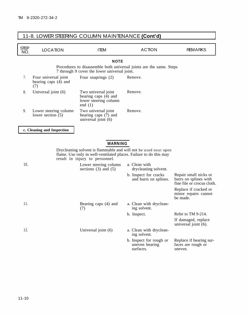
TM 9-2320-272-34-2
I 11-8. LOWER STEERING COLUMN MAINTENANCE (Cont’d)
STEP LOCATION ITEM ACTION REMARKSNO.
NOTEProcedures to disassemble both universal joints are the same. Steps7 through 9 cover the lower universal joint.
7. Four universal jointbearing caps (4) and(7)
8. Universal joint (6)
9. Lower steering columnlower section (5)
Four snaprings (2) Remove.
Two universal joint Remove.bearing caps (4) andlower steering columnend (1)Two universal joint Remove.bearing caps (7) anduniversal joint (6)
c. Cleaning and Inspection
WARNINGDrycleaning solvent is flammable and will not be used near openflame. Use only in well-ventilated places. Failure to do this may
10.
11.
12.
result in injury to personnel. -
a. Clean withLower steering columnsections (3) and (5)
Bearing caps (4) and(7)
Universal joint (6)
drycleaning solvent.b. Inspect for cracks
and burrs on splines.
a. Clean with dryclean-ing solvent.
b. Inspect.
a. Clean with dryclean-ing solvent.
b. Inspect for rough oruneven bearingsurfaces.
Repair small nicks orburrs on splines withfine file or crocus cloth.
Replace if cracked orminor repairs cannotbe made.
Refer to TM 9-214.If damaged, replaceuniversal joint (6).
Replace if bearing sur-faces are rough oruneven.
11-10

TM 9-2320-272-34-2
11-8. LOWER STEERING COLUMN MAINTENANCE (Cont’d). ,
STEP LOCATION ITEM ACTION REMARKSNO.
13.
14.
15.
NOTEProcedures to reassemble both universal joints are the same.Steps 13 through 15 cover the lower universal joint.
Universal joint (6) Install on lower section(5) of lower steeringcolumn with twouniversal joint bearingcaps (7).
Lower steering column Install on universalend (1) joint (6) with two
universal joint bearingcaps (4).
Four snaprings (2) Install on four
Make sure bearing caps(7) are positioned sosnaprings (2) can beinstalled.
Make sure bearing caps(4) are positioned sosnaprings (2) can beinstalled.
universal joint bearingcaps (4) and (7).
TA 350791
11-11

TM 9-2320-272-34-2
I 11-8. LOWER STEERING COLUMN MAINTENANCE (Cont’d) ISTEP LOCATION ITEM ACTION REMARKSNO.
16. Three grease fittings Install on two uni-(5) versal joints (4) and
lower steering columnupper section (3).
17. New felt seal (2) and Install on lower Soak felt seal (2) withnew retainer (1) steering column lower lubricating oil prior to
section (6). installation.18. Lower steering column Aline scribe marks and Apply GAA grease to
lower section (6) install in lower steering splines.column upper section(3) with felt seal (2)and retainer (1).
Before installing lower steering column make sure steering wheelspokes form a “Y” and front wheels are straight ahead for propersteering wheel alinement.
19. Lower steering column(14)
20. Lower steering columnends (9) and (12)
Install on upper Make sure screw (11)steering column shaft holes aline with(10) and steering gear grooves in shafts (10)input shaft (13). and (13).
Install with two screws Tighten 28-34 lb-ft(11), new lockwashers (38-46 N·m).(8) and nuts (7).
11-12
TA 350792

TM 9-2320-272-34-2
11-8. LOWER STEERING COLUMN MAINTENANCE (Cont’d)
STEPN O . LOCATION ITEM ACTION
END OF TASK!
FOLLOW-ON TASKS: ● Lubricate lower steering column (LO 9-2320-272-12).● Install steering gear stone shield (TM 9-2320-272-20-2).● Install left splash shield (TM 9-2320-272-10).● Start engine (TM 9-2320-272-10) and road test vehicle.
TA 350793
11-13

TM 9-2320-272-34-2
11-9. STEERING GEAR (ROSS) AND MOUNTING BRACKET REPLACEMENT
This task covers:a. Removal b. Installation
INITIAL SETUP:Equipment
Applicable Models ConditionAll Reference
TM 9-2320-272-10TM 9-2320-272-20-2TM 9-2320-272-20-2
Test EquipmentN o n e
Special ToolsNone
Materials/PartsFour "O" rings
Five locknutsLockwasherProtective cap-plugs (Appendix C, Item 5)Sealing tape (Appendix C, Item 30)
Personnel RequiredWheeled vehicle repairman MOS 63W (2)
Manual ReferencesTM 9-2320-272-10TM 9-2320-272-20-2TM 9-2320-272-34PLO 9-2320-272-12
Condition DescriptionLeft splash shield removed.Steering gear stone shield removed.Drag link removed.
Special Environmental ConditionsNone
General Safety InstructionsNone
STEP LOCATION ITEM ACTION REMARKSNO.
●
CAUTION
Cap or plug all openings immediately after disconnecting lines andhoses to prevent contamination. Failure to do so may result inpower steering gear damage.
NOTEIdentify type of power steering gear. Removal and installation isdifferent for the two steering gears. Refer to section I for identification.Ensure front wheels are straight ahead.
1. Lower steering columnuniversal joint (2) andsteering gear inputshaft (5)
2.
3. Pitman arm (11)
4. Steering gear sector
Nut (7), lockwasher(6), and screw (4)
Lower steering column(3)
Locknut (10) andscrew (8)Pitman arm (11)
Remove.
Open slot (1) in U-joint(2) and remove steer-ing gear input shaft (5).Remove.
Use chisel to spreadslot and remove.
Discard lockwasher(6).
Discard locknut (10).
Punch an alinementmark on pitman arm(11) and sector shaft (9).
11-14 Change 2

TM 9-2320-272-34-2
11-9. STEERING GEAR (ROSS) AND MOUNTING BRACKET REPLACEMENT (Cont'd)
STEPLOCATIONNO. ITEM ACTION REMARKS
Change 2 11-15

TM 9-2320-272-34-2
11-9. STEERING GEAR (ROSS) AND MOUNTING BRACKET REPLACEMENT (Cont'd)
STEP LOCATION ITEM ACTION REMARKSNO.
5.
6.
7.
8.
9.
NOTEHave container ready to catch oil from disconnected lines.
Adapter elbow (2) and Oil pressure line (3) Disconnect.adapter (6) and return line (7)Adapter (9) and Assist cylinder pres- Disconnect.adapter elbow (12) sure lines (10) and (11)Steering gear housing Adapter elbows (2) Remove.
10.
11.
11.1.
( 1 )
Left frame rail (21)
and (12), adapters (6)and (9), and “O” rings(4), (5), (8), and (13)
NOTEAssistant will help with step 8.
Four nuts (14), lock- Remove.washers (15), washers(16), screws (19), steer-ing gear housing (1), andmounting plate (18)Four locknuts (22), Remove.screws (20), and bracket(17)
NOTEAssistant will help with steps 10 through 11.
Mounting bracket (17) Install with four screws(20) and new locknuts(22).
Mounting plate (18) Install on left frameand steering gear rail (21) with fourhousing (1) screws (19), washers
(16), new lockwashers(15), and nuts (14).
Locknuts (22) Tighten.
Tag lines for instal-lation.Tag lines for instal-lation.Tag adapter elbows(2) and (12) andadapters (6) and(9) for installation.Discard “O” rings (4),(5), (8), and (13).
Discard lockwashers(15).
Discard locknuts (22).
Do not tighten lock-nuts (22).
Tighten nuts (14)260-280 lb-ft(353-380 N·m).
Tighten locknuts (22)60-70 lb-ft (81-95 N·m).
12.Male pipe threads must be wrapped with antiseize tape before installation.
Adapter elbows (2) and Install using new “O” rings(12) and adapters (6) (13), (8), (5), and (4).and (9)
13.
14.
11-16
Assist cylinder pressure Connect to steering gearlines (11) and (10) housing adapter elbow
(12) and adapter (9).Oil return lines (7) and Connect to steering gearoil pressure line (3) housing adapter (6) and
adapter elbow (2).
Change 2

TM 9-2320-272-34-2
11-9. STEERING GEAR (ROSS) AND MOUNTING BRACKET REPLACEMENT (Cont’d)
STEPLOCATION ITEM ACTION REMARKSNO.
Change 2 11-17

STEP LOCATION ITEM ACTION REMARKSNO.
15. Pitman arm (2) Install on steering gear Make sure alinementsector shaft (3) with marks are in line withscrew (1) and new lock- each other.nut (4).
Tighten 330-370 lb-ft(447-502 N·m).
NOTEBefore installing lower steering column, make sure steering wheelspokes form a “Y”. Assistant will steady steering wheel. -
16. Lower steering columnuniversal joint (7)
Position to steeringgear input shaft (9).
Install on input shaft(9) with screw (8),new lockwasher (6),
Make sure screw (8)holes aline withgroove in shaft (9).Tighten 28-34 lb-ft(38-46 N·m).
TM 9-2320-272-34-2
11-9. STEERING GEAR (ROSS) AND MOUNTING BRACKET REPLACEMENT (Cont’d)
a.
b.
and nut (5).
11-18 Change 2
TA 350796

TM 9-2320-272-34-2
11-9. STEERING GEAR (ROSS) AND MOUNTING BRACKET REPLACEMENT (Cont’d)
STEPNO. LOCATION ITEM ACTION REMARKS
FOLLOW-ON TASKS:●
●
●
●
END OF TASK!
Install steering gear stone shield (TM 9-2320-272-20-2).Install left splash shield (TM 9-2320-272-10).Install drag link (TM 9-2320-272-20-2).Fill steering gear to proper oil level (LO 9-2320-272-12).Start engine (TM 9-2320-272-10) and road test vehicle.
TA 350797
Change 2 11-19

TM 9-2320-272-34-2
11-9.1. STEERING GEAR (SHEPPARD) AND MOUNTING BRACKET REPLACEMENT
This task covers:
INITIAL SETUP:Equipment
Applicable Models ConditionAll Reference
Test Equipment TM 9-2320-272-10None
Special Tools
TM 9-2320-272-20-2TM 9-2320-272-20-2
NoneMaterials/Parts
Four "O" ringsFour locknutsFive lockwashersProtective cap-plugs (Appendix C, Item 5)Sealing tape (Appendix C, Item 30)
Personnel RequiredWheeled vehicle repairman MOS 63W (2)
Manual ReferencesTM 9-2320-272-10TM 9-2320-272 -20-2TM 9-2320-272-34PLO 9-2320-272-12
Condition DescriptionLeft splash shield removed.Steering gear stone shield removed.Drag link disconnected.
Special Environmental ConditionsNone
General Safety InstructionsNone
ITEM ACTION
a. Removal b. Installation
NOTE● Identify type of power steering gear. Removal and installation is
different for the two steering gears. Refer to Section I for identification.● Ensure front wheels are straight ahead.
1. Lower steering columnuniversal joint (4) andsteering gear inputshaft (7)
2.
3. Steering gear (8) andpitman arm (9)
4. Steering gear (8)
Nut (1), lockwasher(2), and screw (6)
Lower steering column(5)
Retainer (10)
Pitman arm (9) .
Remove. Discard lockwasher(2).
Open slot (3) in univer-sal joint (4) and removefrom steering gear inputshaft (7).a. Bend two long tabs
(11) out of notches inpitman arm (9).
b. Bend two short tabs(12) out of notches inretainer (10).
c. Remove retainer (10).Remove. Use puller.
11-19.1 Change 2

TM 9-2320-272-34-2
11-9.1. STEERING GEAR (SHEPPARD) AND MOUNTING BRACKET REPLACEMENT (Cont’d)
STEPNO. LOCATION ITEM ACTION REMARKS
Change 2 11-19.2

TM 9-2320-272-34-2
11-9.1. STEERING GEAR (SHEPPARD) AND MOUNTING BRACKET REPLACEMENT (Cont’d)
STEP LOCATION ITEM ACTION REMARKSNO.
5.
6.
7.
8.
9.
10.
11.
12.
13.
CAUTION
Cap or plug all openings immediately after disconnecting lines andhoses to prevent contamination. Failure to do so may result insteering system damage.
NOTE● Have container ready to catch oil from disconnected lines.● Tag all hydraulic lines for installation.
Adapter elbow (3) and Oil pressure line (4) Disconnect.adapter (8) and return line (9)Adapter elbow (15) and Assist cylinder pres- Disconnect.elbow (13) sure lines (14) and (16)Steering gear (6) Adapter elbow (3) and Remove.
adapter (8)Adapter elbow (3) “O” rings (5) and (7) Remove.and adapter (8)
NOTEPerform steps 9 through 11 if old steering gear is to be reused.
Front of steering gear (6) Elbow (1) and
Bottom rear of steeringgear (6)Elbow (1) and adapter(11)
Left frame rail (25)
adapter elbow (15)Elbow (13), line (12),and adapter (11)“O” rings (2) and (10)
NOTE
Remove.
Remove.
Remove.
Assistant will help with step 12.Four nuts (19), lock- Remove.washers (18), washers(17), screws (23), steeringgear housing (6), andmounting plate (22)Four locknuts (20), Remove.screws (24), and bracket(21)
Sheppard steering gear uses longer mounting screws.14. Mounting bracket (21) Install on left frame rail
(25) with four screws (24)and new locknuts (20).
11-19.3 Change 2
Discard “O” rings (5)and (7).
Discard “O” rings (2)and (10). -
Discard lockwashers(18).
Discard locknuts (20).
Do not tightenlocknuts (20).

TM 9-2320-272-34-2
11-9.1. STEERING GEAR (SHEPPARD) AND MOUNTING BRACKET REPLACEMENT (Cont'd)
STEPLOCATION ITEM ACTION REMARKSNO.
15. Mounting plate (22) Install on left frame Tighten nuts (19)and steering gear rail (25) and mounting 260-280 lb-fthousing (6) bracket (21) with four (353-380 N·m).
screws (23), washers(17), new lockwashers(18), and nuts (19).
16. Locknuts (20) Tighten. Tighten locknuts (20)60-70 lb-ft (81-95 N·m).
NOTEPerform steps 17 through 19 if old steering gear is to be installed.
17. New “O” rings (2) and Install on elbow (1) and(10) adapter (11).
18. Elbow (1) and adapter Install on housing (6).elbow (15)
19. Adapter (11), line (12), Install on housing (6).and elbow (13)
20. New “O” rings (5) and Install on adapter elbow(7) (3) and adapter (8).
21. Adapter elbow (3) and Install on housing (6).adapter (8)
NOTEMale pipe threads must be wrapped with sealing tape before installation.
22. Assist cylinder pressure Connect to elbow (13)lines (14) and (16) and adapter elbow (15).
23. Oil return line (9) and Connect to adapter (8)oil pressure line (4) and adapter elbow (3).
Change 2 11-19.4

TM 9-2320-272-34-2
11-9.1. STEERING GEAR (SHEPPARD) AND MOUNTING BRACKET REPLACEMENT (Cont’d)
STEP LOCATION ITEM ACTION REMARKSNO.
N O T EPerform steps 24 and 25 if a new retainer assembly is installed.
24. Friction washer (9), tablockwasher (10), andfriction washer (8)
25. Three nylon balls (11)
26. Pitman arm (3)
Press into slot onretainer (4).
Press into indentationsona.
b.
c.
d.
e.
f.
retainer (4).Aline timing marks(1) and (2).Position pitman arm(3) on output shaft (7).Screw retainer (4) intooutput shaft (7) untilfriction washer (8)drag is felt.Aline long tabs (5) to Back retainer (4) outnotches of pitman one-half turn ifarm (3) and bend tabs necessary.(5) into notches.Tighten retainer (4)225 lb-ft (305 N·m).Bend two short tabs Tighten retainer (4), if(6) into notches on necessary, to alineretainer (4). next notch.
11-19.5 Change 2

TM 9-2320-272-34-2
11-9.1. STEERING GEAR (SHEPPARD) AND MOUNTING BRACKET REPLACEMENT Cont'd)
STEPNO. LOCATION ITEM ACTION REMARKS
N O T E● Before installing lower steering column, make sure steering——
wheel spokes form a “Y”.● Assistant will steady steering wheel.
27. Lower steering column a.(14) and universal joint(16)
b.
Position to steeringgear input shaft (17).
Install on input shaft(17) with screw (15),new lockwasher (13),and nut (12).
Make sure screw (15)holes aline withgroove in shaft (17).Tighten nut (12) 28-34lb-ft (38-46 N·m).
FOLLOW-ON TASKS: ●
●
●
●
●
END OF TASK!
Install steering gear stone shield (TM 9-2320-272-20-2).Install left splash shield (TM 9-2320-272-10).Install drag link (TM 9-2320-272-20-2).Fill steering gear to proper oil level (LO 9-2320-272-12).Start engine (TM 9-2320-272-10) and road test vehicle.
Change 2 11-19.6

TM 9-2320-272-34-2
11-10. STEERING GEAR (ROSS) REPAIR
This task covers:
a. Disassemblyb. Cleaning, inspection, and Repair
INITIAL SETUP:
Applicable ModelsAll with Ross type steering gear
Test EquipmentNone
Special ToolsNone
Materials/PartsSeven “O” ringsTwo 2-piece sealsTwo plastic backup washersGasketTwo sealsThree seal ringsTwo lock tabsGAA grease (Appendix C, Item 11)Lubricating oil OE/HDO 10(Appendix C, Item 16)
Personnel Required
c. Reassemblyd. Final Adjustments
EquipmentConditionReference Condition DescriptionPara. 11-9 Steering gear removed.
LO 9-2320-272-12 Steering gear drained.
Special Environmental ConditionsNone
General Safety InstructionsWheeled vehicle repairman MOS 63W ● Keep tire extinguisher nearby when
using drycleaning solvent.● Compressed air source will not exceed
Manual References 30 psi (207 kPa).
TM 9-2320-272-34P● Eyeshields must be worn when
LO 9-2320-272-12cleaning with compressed air.
STEP LOCATION ITEM ACTION REMARKSNO.●
1. Steering gear (2) Position in vise (3) sosector shaft (1) is posi-tioned horizontally.
2. Serrated end of sector Remove all paint or Vertical positioning ofshaft (1) corrosion and position sector shaft (1) is ob-
alinement mark (4) in tained by turningvertical direction. worm shaft (5).
11-20 Change 2

TM 9-2320-272-34-2
11-10. STEERING GEAR (ROSS) REPAIR (Cont'd)
STEP LOCATION ITEM ACTION REMARKSNO.
3. Sector shaft adjusting Jamnut (6)screw (7)
Loosen.
4. Trunnion cover (9) Outer seal (13)5. Trunnion cover (9) Four screws (8)
and gear housing (2)
6. Trunnion cover (9) “O” ring (12), two-pieceseal (11), and backupwasher (10)
Remove. Discard seal (13).Remove, and separatetrunnion cover (9)from gear housing (2).
Remove. Discard “O” ring (12),two-piece seal (11),and backup washer(10).
Change 2 11-21

TM 9-2320-272-34-2
11-10. STEERING GEAR (ROSS) REPAIR (Cont'd)
STEP LOCATION ITEM ACTION REMARKSNO.
7.
8.
9.
Steering gear side Six screws (7). .cover (5) and steeringgear housing (1)
Side cover (5), sectorshaft (2), and gasket(4)
Steering gear side Jamnut (6) and sector
Remove.
Remove.
a. Remove jamnut (6).
Discard gasket (4).
cover (5) shaft adjusting screw(3)
b. Turn sector shaftadjusting screw (3)clockwise untilsector shaft (2)separates from sidecover (5).
Sector shaft adjustingscrew (3) is part ofsector shaft (2).
TA 350799
11-22 Change 2

TM 9-2320-272-34-2
11-10. STEERING GEAR (ROSS) REPAIR (Cont'd)
STEPNO. LOCATION ITEM ACTION REMARKS
10. Side cover (5) Seal retainer (8), two- Remove. Discard two-piece sealpiece seal (9), plastic (9) and backup washerbackup washer (10), (10).steel backup washer(11), and forty-fourbearing rollers (12)
Change 2 11-23

TM 9-2320-272-34-2
11.
12.
13.
14.
11-10. STEERING GEAR (ROSS) REPAIR (Cont'd)
STEP LOCATION ITEM ACTION REMARKSNO.
End cover (2) Jamnut (6) and worm- Remove.shaft adjusting screw(5)
Jamnut (7) and Remove.poppet adjusting screw(8)
End cover (2) and gear Four screws (4) and Remove.housing (1) washers (3)Gear housing (1) End cover (2) and “O” Remove.
ring (9)Discard “O” ring (9).
Change 2
TA 350801
11-24

TM 9-2320-272-34-2
11-10. STEERING GEAR (ROSS) REPAIR (Cont'd)
STEP LOCATION ITEM ACTION REMARKSNO.
15. Valve housing (10) and Four screws (11) Remove.gear housing (1)
CAUTIONAlinement marks (13) are located on valve sleeve (18) andwormshaft (12) so that they can be reassembled in their originalposition. Failure to aline marks may cause damage to steering gear.
16. Gear housing (1) Valve housing (10) Remove.17. Mating side of valve Valve sleeve (18), inner Remove. Discard “O” ring (14).
housing (10) thrust washer (17),thrust bearing (16),outer thrust washer(15), and “O” ring (14)
Change 2 11-25

TM 9-2320-272-34-2
11-10. STEERING GEAR (ROSS) REPAIR (Cont’d)
STEP LOCATION ITEM ACTION REMARKSNO.
18. Outside of valve Seal (1), retaining ringhousing (6) bore (2), steel backup
washer (3), seal cup(8), and “O” ring (7)
19. Valve housing (6) Jamnut (4) andpoppet adjusting screw(5)
20. Valve sleeve (11) Two seal rings (9) andtwo “O” rings ( 10)
21. Gear housing (12) Rack piston (14) andwormshaft (13)
Remove. Discard “0” ring (7)and seal (1).
Remove.
Remove.
Remove from endcover side of gearhousing (12).
Discard “0” rings (10)and seal rings (9).
11-26 Change 2
TA 350803

TM 9-2320-272-34-2
11-10. STEERING GEAR (ROSS) REPAIR (Cont'd)
STEP LOCATION ITEM ACTION REMARKSNO.
22. Rack piston (14) Ball bearing return Bend two locktabs (17) Discard locktabs (17).guide retaining clip down and remove two(16) screws (18).
23. Two ball bearing Remove.return guides (15)
24. Twenty-seven ball Turn rack piston (14)bearings (19) over so ball bearings
(19) can roll out aswormshaft (13) isrotated in each direc-tion.
25. Wormshaft (13) Remove.
Change 2 11-27

TM 9-2320-272-34-2
11-10. STEERING GEAR (ROSS) REPAIR (Cont'd)
STEP LOCATION ITEM ACTION REMARKSNO.
26. Rack piston (7)
27. Rack piston poppet Two poppet seat snap-bore (6) rings (1)
28. Two poppet seats (2)
29. Two poppets (3),spring (5), and springrod (4)
Position in soft-jawedvise.Remove one from eachend of bore (6).
Push poppets (3)inward until poppetseats (2) can beremoved.
Remove from poppetbore (6).
Poppet spring (5) andspring rod (4) willcome out of rack pis-ton (7) when first pop-pet seat (2) is removed.
TA 350805
11-28 Change 2

TM 9-2320 -272-34-2
11-10. STEERING GEAR (ROSS) REPAIR (Cont'd)
STEP LOCATION ITEM ACTION REMARKSNO.
30. Rack piston (7) “O” ring (8) Remove. Discard “O” ring (8).
31. Wormshaft (10) Seal ring (9) Remove. Discard seal ring (9).
NOTE
Step 32 is performed only if sector shaft roller bearing requiresreplacement.
32. Gear housing (12) Roller bearing (11) Press bearing (11 ) out. Use arbor press andmandrel (13). Discardb e a r i n g ( 1 1 ) .
Change 2 11-29

STEP LOCATION ITEM ACTION R E M A R K S NO.
b. Cleaning, Inspection, and Repair
TM 9-2320-272-34-2
11-10. STEERING GEAR (ROSS) REPAIR (Cont'd)
33.
WARNING
Drycleaning solvent is flammable and will not be used near openflame. Use only in well-ventilated places. Failure to do this mayresult in injury to personnel.
Compressed air source will not exceed 30 psi (207 kPA). Whencleaning with compressed air, eyeshields must be worn. Failureto wear eyeshields may result in injury to personnel.
All steering gear Clean with solvent and Refer to para. 2-7.components dry with compressed
air.NOTE
Light polished areas of steering gear components indicate normal
34.
35.
36.
37.
38.
39.
wear.Sector shaft (3) andside cover (1)
Bearing rollers (2) inside cover (1)
Valve housing thrustbearing (6) and twothrust washers (5)
Rack piston (9)
Wormshaft (8)
Gear housing (4)
Inspect bearing areasand tooth surfaces forpitting.
Inspect for pitting andscoring.
Inspect for pitting andscoring.
Inspect for broken ormissing teeth (10).a. Inspect for dents
and chipping.b. Inspect worm
groove (7) forchipping.
Inspect for cracks,scored bore, ordamage.
Replace if pitted.
Replace side cover (1)if roller bearings (2)are pitted or scored.
Replace if pitted orscored.
Replace if teeth arebroken or missing.Replace if dented orchipped.
Replace if chipped.
Replace if cracked,bore is scored, ordamaged.
11-30 Change 2

TM 9-2320-272-34-2
11-10. STEERING GEAR (ROSS) REPAIR (Cont'd)
STEP LOCATION ITEM ACTIONN O . REMARKS
Change 2 11-31

TM 9-2320-272-34-2
11-10. STEERING GEAR (ROSS) REPAIR (Cont'd)
STEP LOCATION ITEM ACTION REMARKSNO.
NOTE● Coat all steering gear parts with clean lubricating oil before
reassembly.● Step 40 is performed only if new roller bearing is installed.
40.
41.
New roller bearing (2) Press into gear housing Use arbor press and(3). mandrel (1).
New “O” ring (5) Install on rack piston(4).
Rack piston (4) Position in soft-jawedvise (11).
Two poppets (8), Position into rackspring (10), and spring piston (4) bore.rod (9).
Two poppet seats (7) Install with two snap- Tighten seats (7) 20-rings (6). 25 lb-ft (27-34 N·m).
11-32 Change 2
TA 350808

11-10. STEERING GEAR (ROSS) REPAIR (Cont'd)
STEP LOCATION ITEM ACTION REMARKSNO.
45. New wormshaft “0” Install onto wormshaftring (12) (13).
46. Wormshaft (13) Lightly coat with GAA Insert end opposite “O”grease and positioninto rack piston (4)bore.
47. Two ball bearing Position into rackreturn guides (14) piston (4).
48. Twenty-seven ball bear- Drop through holes inings (15) ball bearing return
guides (14) as worm-shaft (13) is rotated ineach direction.
49. Two ball bearing Install on rack pistonreturn guides (14) (4) with retaining clip
(16), two new locktabs(17), and screws (18).
ring (12) first.
Make sure ball bearingreturn guides (14) stayin place when install-ing ball bearings (15).
Tighten screws (18)13-17 lb-ft (18-23 N·m).Bend locktabs (17)against head of screws(18).
Change 2 11-33

TM 9-2320 -272-34-2
11-10. STEERING GEAR (ROSS) REPAIR (Cont’d)
STEP LOCATION ITEM ACTION REMARKSN O .
50. New “O” ring (4)
51. Rack piston (3) andwormshaft (2)
52. Wormshaft adjustingscrew (8) and jamnut(9)
53. Poppet adjusting screw(11) and jamnut (10)
54. End cover (5) and new“O” ring (12)
Coat with clean GAAgrease and install onrack piston (3).
Install through endcover side of gear hous-ing (1).
Install in end cover (5)a few turns.
Install in end cover (5)a few turns.Install on housing (1)with four washers (6)and screws (7).
Final adjustment to bemade later.
Final adjustment willbe made later.
Tighten screws (7)105-115 lb-ft(142-156 N·m).
TA 350810
11-34 Change 2

TM 9-2320-272-34-2
11-10. STEERING GEAR (ROSS) REPAIR (Cont'd)
STEP LOCATION ITEM ACTION REMARKSNO.
55. Valve housing (13) Poppet adjusting screw a. Install in valve hous- Final adjustment will(15) ing (13) a few turns. be made later.
b. Install jamnut (14)
56.
on adjusting screw(15).
New valve housing “O” Place in groove on Lubricate “O” ring (16)ring (16) valve housing (13). with GAA grease to
hold in place.57. Thrust washer (17) Install in valve housing
and thrust bearing (13) bore.(18)
Change 2
TA 350811
11-35

TM 9-2320-272-34-2
11-10. STEERING GEAR (ROSS) REPAIR (Cont'd)
STEP LOCATION ITEM ACTION REMARKSNO.
58. Two new “O” rings (2) Install on valve sleeveand new seal rings (1) (3).
59. Valve sleeve (3) a. Coat end with GAAgrease and installthrust washer (5).
b. Install thrustwasher (5) enddown into valvehousing (4).
c. Position valve sleeve(3) in valve housing(4) so that aline-ment marks (6)aline.
Grease will hold thrustwasher (5) in place.
When valve sleeve (3)is down in place invalve housing (4), itshould measureapproximately .40 in.(10 mm) from face ofvalve housing (4) toface of valve sleeve (3).
11-36 Change 2

TM 9-2320-272-34-2
11-10. STEERING GEAR (ROSS) REPAIR (Cont'd)
STEP LOCATION ITEM ACTION R E M A R K SNO.
60.
61.
62.
CAUTIONAlinement marks are located on valve sleeve, wormshaft, and valvehousing so that they can be reassembled in their original position.Failure to aline marks may cause damage to steering gear.
Valve housing (4) Position on wormshaft(7).
Wormshaft (7) Rotate until alinement Use a 12 pt. box endmarks (8) aline. wrench at an angle on
wormshaft (7).
Valve housing (4) Install on gear housing Tighten screws (10)(9) with four screws 105-115 lb-ft(10). (142-156 N·m).
Change 2 11-37

TM 9-2320-272-34-2
11-10. STEERING GEAR (ROSS) REPAIR (Cont'd)
STEP LOCATION ITEM ACTIONNO.
6 3 . Bearing rollers (4) a. Apply a generousamount of GAAgrease to bearingrace inside of sidecover (5).
b. Install in side cover(5).
64. Steel backup washer Install in gear side(3), new plastic backup cover (5) with sealwasher (2), and new retaining ring (6).two-piece seal (1)
TA 350814
11-38 Change 2

TM 9-2320-272-34-2
11-10. STEERING GEAR (ROSS) REPAIR (Cont'd)
STEP LOCATION ITEM ACTION REMARKSNO.
65. Sector shaft (7) a.
b.
c.
Apply clean GAAgrease to short bear-ing end.Screw sector shaftadjusting screw (8)in side cover (5)counterclockwise un-til bottomed.Loosen adjusting
66. Jamnut (9)
screw (8) one turnclockwise so sidecover (5) rotatesfreely on sectorshaft (7).
Thread a few turnsonto adjusting screw(8).
Final adjustment willbe made later.
TA 350815
Change 2 11-39

TM 9-2320-272-34-2
11-10. STEERING GEAR (ROSS) REPAIR (Cont'd)
STEP LOCATIONNO. ITEM ACTION REMARKS
67. Wormshaft (2) Rotate until rackpiston (1) is at centerof steering gear travel.
CAUTIONWhen installing sector shaft care must be taken not to pinch newside cover gasket.
68. Side cover (6) with a. Aline center tooth ofsector shaft (7) and sector shaft (7) withnew gasket (4) third notch from
seal ring end of rackpiston (1) andposition in gearhousing (3).
b. Install side cover (6) Using a criss-crossto gear housing (3) pattern, first tightenwith six screws(5). screws to 150 lb-ft (203
N·m) followed by 220-240 lb-ft(298-325 N·m).
1 1 - 4 0

TM 9-2320-272-34-2
11-10. STEERING GEAR (ROSS) REPAIR (Cont'd)
STEP LOCATION ITEM ACTION REMARKSNO.
69.
70.
CAUTIONThe words OIL SIDE must be visible once the two-piece seal isassembled in the trunnion cover. Otherwise, the seal will notfunction, which could result in a loss of power steering assist.
Backup washer (12), Install in trunnionnew two-piece seal cover (9).(11), and new innerseal (10)Trunnion cover (9) Slide over serrated end
of sector shaft (7) andinstall on gear housing(3) with four screws(8).
Make sure OIL SIDE oftwo-piece seal (11)faces housing (3).
Tighten screws (8) 15-22 lb-ft (20-30 N·m).
TA 350817
Change 2 11-41

11-10. STEERING GEAR (ROSS) REPAIR (Cont'd)
STEP LOCATION ITEM ACTION REMARKSNO.
71. New “O” ring (5) Install into groove ofseal cup (4).
72. Seal cup (4) and steel Insert into valve hous- Use seal driver.backup washer (3) ing (6) and install re-
taining ring (2).
73. New seal (1) Insert into valve Use seal driver.housing (6) and installretaining ring (2).
TA 350818
11-42 Change 2

TM 9-2320-272-34-2
11-10. STEERING GEAR (ROSS) REPAIR (Cont'd)
STEP LOCATION ITEM ACTION REMARKSNO.
74. New outer seal (7) Install in trunnion Tap in place with sealcover (8). driver and hammer.
Change 2 11-43

STEP LOCATIONNO. ITEM ACTION REMARKS
d. Final Adjustments
75. Steering gear(1) Wormshaft (6) Adjust travel asfollows:
a. Position sector shaftalinement mark (5)in vertical direction.
b. Screw in wormshaftadjusting screw (3)until seated againstwormshaft (6).
c. Tighten adjustingscrew (3) 5-10 lb-ft(7-14 N·m).
d. Back adjustingscrew (3) out oneturn.
76. Sector shaft adjusting Adjust as follows:
Vertical positioning ofsector shaft (4) iscenter of steering geartravel.
screw (8) a.
b.
c.
d.
11-44 Change 2
Position torquewrench and a 12 ptsocket on wormshaft(6).
While moving worm-shaft (6) 1/4 turneach side of center,tighten sector shaftadjusting screw (8)until torque reaches25-30 lb-in.(2.8-3.4 N·m).
Back out sectorshaft adjustingscrew (8) one turnand note torque re-quired to rotatewormshaft (6) 1/4turn each side ofcenter of wormshaft(6).
Move sector shaftadjusting screw (8)in to provide a riseof 2-6 lb-in. (0.2-0.7 N·m) at a point45° each side ofcenter of wormshaft(6).
Use socket on an angle.
Record torque requiredon a separate sheet ofpaper.
TM 9-2320-272-34-2
11-10. STEERING GEAR (ROSS) REPAIR (Cont'd)

TM 9-2320-272-34-2
11-10. STEERING GEAR (ROSS) REPAIR (Cont'd)
STEP LOCATION ITEM ACTION REMARKSNO.
77.
e. Tighten sector shaftadjusting screw jam-nut (7) 45-50 lb-ft(61-68 N·m).
Wormshaft adjusting Adjust as follows:screw (3)
a. Position torquewrench and a 12point socket onwormshaft (6).
b. While moving worm-shaft (6) 45° eachside of center,tighten wormshaftadjusting screw (3)until torque reaches10-15 lb-in. (1.1-1.7 N·m) higher thantorque reached instep 76.
c. Tighten jamnut (2)70-80 lb-ft (95-108 N·m).
78. Wormshaft (6) Rotate 90° each side ofcenter and note torquerequired to rotatewormshaft (6).
Torque required torotate wormshaft (6)must not exceed20 lb-in. (2.3 N·m) atany point in steeringgear travel afterjamnut (7) has beentightened.
If torque exceeds20 lb-in. (2.3 N·m),repeat step 76.
Position socket at anangle.
If torque required ex-ceeds 35 lb-in. (4 N·m),repeat step 77
END OF TASK!
FOLLOW-ON TASKS: ● Install steering gear (para. 11-9).● Fill to proper oil level (LO 9-2320-272-12).● Final poppet valve adjustments (para. 11-13).
TA 350820
Change 2 11-45

TM 9-2320-272-34-2
11-10.1. STEERING GEAR (SHEPPARD) REPAIRThis task covers:
a. Disassembly c. Assemblyb. Cleaning, Inspection, and Repair
INITIAL SETUP: EquipmentConditionReference Condition Description
Para. 11-9.1 Steering gear removed.LO 9-2320-272-12 Steering gear drained.
Special Environmental ConditionsNone
General Safety Instructions● Keep fire extinguisher nearby when
using drycleaning solvent.● Compressed air source will not
exceed 30 psi (207 kPa).● Eyeshields must be worn when
cleaning with compressed air.
Applicable ModelsAll
Test EquipmentNone
Special ToolsNone
Materials/PartsHigh-pressure seal kit P/N 2370461Twenty-eight lockwashersThree backup ringsEight “O” ringsSealOil sealThree nylon ballsThree lockpinsRoll pinRetainerSlipper sealTwo check ballsScreenFour reversing springsLubricating oil OE/HDO 10
(Appendix C, Item 16)GAA grease (Appendix C, Item 11)Crocus cloth (Appendix C, Item 6)
Personnel RequiredWheeled vehicle repairman MOS 63W
Manual ReferencesTM 9-2320-272-34PLO 9-2320-272-12TM 9-214
STEPNO. LOCATION ITEM ACTION REMARKS
NOTEUse a clean, protected work surface for steering gear disassembly, repair,and assembly.
1. Cylinder head (5) and Two relief valve plung- Remove. Remove one on eachbearing cap (12) ers (2) end of housing (7).
2. Two relief valve Two “O” rings (1) Remove. Discard “O” rings (1).plungers (2)
3. Output shaft cover (15) Eight screws (14) and Remove. Discard lockwashersand housing (7) lockwashers (13) (13).
11-45.1 Change 2
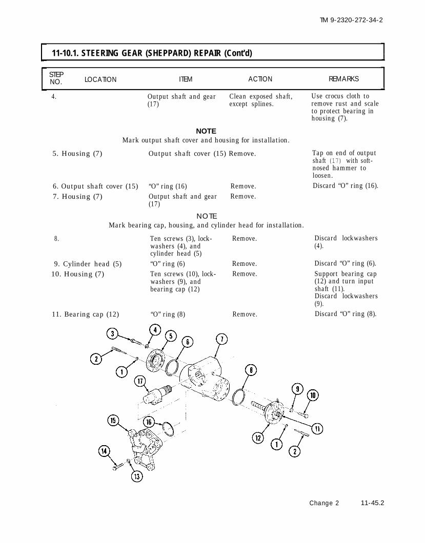
TM 9-2320-272-34-2
11-10.1. STEERING GEAR (SHEPPARD) REPAIR (Cont'd)
STEPNO. LOCATION ITEM ACTION REMARKS
4. Output shaft and gear Clean exposed shaft, Use crocus cloth to(17) except splines. remove rust and scale
to protect bearing inhousing (7).
NOTEMark output shaft cover and housing for installation.
5. Housing (7) Output shaft cover (15) Remove. Tap on end of outputshaft (17) with soft-nosed hammer toloosen.
6. Output shaft cover (15) “O” ring (16) Remove. Discard “O” ring (16).7. Housing (7) Output shaft and gear Remove.
(17)
NOTEMark bearing cap, housing, and cylinder head for installation.
8. Ten screws (3), lock- Remove.washers (4), andcylinder head (5)
9. Cylinder head (5) “O” ring (6) Remove.10. Housing (7) Ten screws (10), lock- Remove.
washers (9), andbearing cap (12)
11. Bearing cap (12) “O” ring (8) Remove.
Discard lockwashers(4).
Discard “O” ring (6).Support bearing cap(12) and turn inputshaft (11).Discard lockwashers(9).Discard “O” ring (8).
Change 2 11-45.2

TM 9-2320-272-34-2
11-10.1. STEERING GEAR (SHEPPARD) REPAIR (Cont'd)
STEP LOCATION ITEM ACTION REMARKSNO.I
12. Steering gear housing Piston and valve assem- Remove. Support piston (2)(1)
13. Side of piston (13)
14.
15. Piston (13)
16.17. Piston plug (3)
18. Piston (13)
19.
20.
21. Side of piston (13)
22. Valve positioningpin (21)
23. Piston (13)
24.
bly (2)Slipper seal (15), “O”- Remove.ring (14), and screen(19)Two backup rings (11) Remove.and “O” rings (12)Lockpin (23) Drill out.
Piston plug (3) Remove.Backup ring (4) and Remove.“O” ring (5)
NOTEMark adjusting nut and piston for installation.
Lockpin (22) Drill out.
Adjusting nut (7) Remove.
Two reversing springs Remove from piston (13).(8) and valve (9)Valve positioning pin Remove.(21)“O” ring (20) Remove.
11-45.3 Change 2
Do not disturb adjusting nut in bottom of piston after removingreversing springs. Centering ability of valve will be lost.
Two reversing springs Remove from piston (13).(10)Valve seat (16), check Remove.ball (17), spring (18),check ball (17), andvalve seat (24)
during removal.Discard slipper seal(15), “O” ring (14), andscreen (19).Discard backup rings(11) and “O” rings (12).Use 5/64 in. (2.0 mm)drill. Discard lockpin(23) remains.Use spanner type tool.Discard backup ring(4) and “O” ring (5).
Use 5/64 in. (2.0 mm)drill. Discard lockpin(22) remains.Nylon ball inserts (6)are not removed.Discard reversingsprings (8).
Discard “O” ring (20).
Discard reversingsprings (10).Discard check balls(17).

TM 9-2320-272-34-2
11-10.1. STEERING GEAR (SHEPPARD) REPAIR (Cont'd)
STEPNO. LOCATION ITEM ACTION REMARKS
Change 2 11-45.4

TM 9-2320-272-34-2
11-10.1. STEERING GEAR (SHEPPARD) REPAIR (Cont'd)
STEP LOCATION ITEM ACTION REMARKSNO.
Discard oil seal (14).25. Housing (13)26.27. Bearing cap (10)
28.29.
30.
31.32. Output shaft cover (12)
Oil seal (14)Bearing (15)Lockpin (6)
Bearing retainer (1)Input shaft (2) andbearing (3)
Seals (8) and (9),washer (5), andhigh pressureseal (4)Grease fitting (7)Bearing (11)
Remove.Remove.Drill out.
Remove.Press out of bearingcap (10).
Remove.
Remove.Remove.
Use bearing puller.Use 5/64 in. (2.0 mm)drill. Discard lockpin(6) remains.Use spanner type tool.Press splined endthrough bearing cap(10).Press out from outsidetoward inside. Discardseals (8), (9), and (4).Save washer (5).
Use bearing puller.
11-45.5 Change 2

TM 9-2320-272-34-2
11-10.1. STEERING GEAR (SHEPPARD) REPAIR [Cont'd)
STEPNO. LOCATION ITEM ACTION REMARKS
b. Cleaning, Inspection, and Repair
33.
●
●
34.
35.
36.
WARNING
Drycleaning solvent is flammable and will not be used near openflame. Use only in well-ventilated places. Failure to do so mayresult in injury to personnel.Compressed air source will not exceed 30 psi (207 kPa). Whencleaning with compressed air, eyeshields must be worn. Failure towear eyeshields may result in injury to personnel.
All steering gear Clean with solvent and Refer to para. 2-7.components dry with compressed air.
NOTELight polished areas of steering gear components indicate normalwear.Blue discoloration indicates overheating. Inspect carefully.Replace all blue parts.
Housing (13) Inspect for cracks, nicks,and pitted and scoredbore (21).
Input shaft (2) and a. Inspect for roughbearing (3) bearing (3) movement
and discoloration.b. Inspect for cracks,
breaks, chippedthreads (16), anddamaged splines (17).
Output shaft (18) Inspect for cracks, breaks.and damaged splines (19),gear (20), and threads.
Replace if pitted ormore than minorscoring.
Replace as oneassembly if damage isother than minornicks and burrs.Replace if damaged.
Change 2 11-45.6

TM 9-2320-272-34-2
11-10.1. STEERING GEAR (SHEPPARD) REPAIR (Cont'd)
STEP LOCATION ITEM ACTION REMARKSNO.
37. Piston (3) a. Inspect for cracks, Replace if damaged.breaks, chipped sealgrooves (2), anddamaged threads.
CAUTIONDo not disturb adjusting nut remaining in piston. Centering ability
38.
of valve will be lost.
b.
c.
Inspect valve bore(1) for pitting andscoring.Inspect oil passages
Replace if pitted ordamage is more thanminor scoring.Clean with com-
for blockages. - pressed air or soft wireif blocked.
Valve (4)
39. Two bearings (5)
40.
41.
Cylinder head (8), bear-ing cap (6), outputshaft cover (9)Spring (7)
Inspect for cracks,breaks, burrs, chippedlands, and chipped ordamaged thread.Inspect.
Replace if lands arebroken or chippedor thread is damaged.
Refer to TM 9-214.Replace if damaged.Inspect bore if bearing
Inspect for cracks,breaks, and damagedthreads.Inspect for bent orkinked coils, brokencheck ball ends, anddiscoloration.
is rejected.Replace if damage ismore than minor nicksand burrs.Replace if damaged.
11-45.7 Change 2

TM 9-2320-272-34-2
11-10.1. STEERING GEAR (SHEPPARD) REPAIR (Cont'd)
STEPLOCATIONNO. ITEM ACTION REMARKS
42. Bearing retainer (10)
43.
44.
45.
46.
Adjusting nut (11)
Piston plug (12)
Check valve seats (13)
All parts (except asnoted)
a.
b.
a.
b.
a.
b.
Remove lockpinremains.Inspect for cracksand damaged threads,Remove lockpinremains.Inspect for cracksand damaged threads.Inspect for cracks,chipped or broken"O" ring lips, anddamaged threads orspanner holes.Remove lockpin
Discard lockpin re-mains (refer to step 27).Replace if cracked orthreads are damaged.
Discard lockpin re-mains (refer to step 18).Replace if cracked orthreads are damaged.Replace if damaged.
Discard lockpin re-remains.
Inspect for nicks andburrs on seat surfaceand damaged slotsor threads.
a.
b.
c.
d.
Remove minor nicks,burrs, and scoringwith soft stone orcrocus cloth.
mains (refer to step 15).Remove minor nicksand burrs or replaceif otherwise damaged.
Replace all cracked,broken, or discoloredparts.Chipped seal or "O"-ring grooves require
part replacement.No repair to housingpiston bore can be
Refer to step 34.
made. Replace housing.
Change 2 11-45.8

TM 9-2320-272-34-2
11-10.1. STEERING GEAR (SHEPPARD) REPAIR (Cont'd)
STEP LOCATION ITEM ACTION REMARKSNO.
48.
49.
50.
51.
52.
53.
54.
NOTECoat all seals and "O" rings with GAA grease before assembly.
Bearing (1)
New oil seal (2)
Bearing (6)
Valve (23) and two newreversing springs (14)
New "O" ring (17)
Positioning pin (18)
Two new reversingsprings (24)
NOTE
Press into bore ofhousing (4).
Install in groove (3)of housing (4).Install in output shaftcover (5).
Seat bearing (1) flushwith inner surface ofhousing (4).
Seat bearing (6) onshoulder in bore.
a.
b.
c.
d.
Place springs (14) onlong nose (13) ofvalve (23).Hold piston (19) withlarge opening down.Aline slot (22) in valve(23) with positioningpin hole (16) in piston(19) and insert valve(23) vertically up intopiston (19) untilreversing springs (14)contact internaladjusting nut (15).Turn piston (19) over.
Install on positioningpin (18).a.
b.
Install in piston (19)with nose of position-ing pin (18) in slot(22) of valve (23).Adjust positioning Only move valve (23)pin (18) until there a small distance wheniS no radial free play, checking end free play.but valve (23) can Do not allow reversingmove in bore of springs (14) to comepiston (19). off nose of valve (23).
Place over short noseof valve (23).
Perform step 54 only if new adjusting nut is to be installed.
Three new nylon balls Press into recesses (11)(10) of adjusting nut (12).
11-45.9 Change 2

TM 9-2320-272-34-2
11-10.1. STEERING GEAR (SHEPPARD) REPAIR (Cont'd]
STEPNO. LOCATION ITEM ACTION REMARKS
55. Adjusting nut (12) Install shoulder side Refer to step 18. Valvedown in piston (19) to (23) should have norecorded position. end play.
56. New lockpin (20) Install in piston (19) Make sure tip of lock-and adjusting nut (12). pin (20) is below
surface of piston (19).NOTE
If old hole in piston and adjusting nut or plug do not line up, go toadjacent pin hole in piston and drill into adjusting nut or plug.Install new lockpin as in step 56.
57. New "O" ring (9) and Install on pistonnew backup ring (8) plug (7).
58. Piston plug (7) Install in piston (19).59. New lockpin (21) Install in piston (19)
and piston plug (7).
Use spanner type tool.Make sure tip of lock-pin (21) is belowsurface of piston (19).
Change 2 11-45.10

TM 9-2320-272-34-2
11-10.1. STEERING GEAR (SHEPPARD) REPAIR (Cont'd)
STEPLOCATIONNO. ITEM ACTION REMARKS
60.61.
62.
63.
64.
Valve seat (11) Install in piston (3).New check ball (7), Install in piston (3).spring (6), new check ball(5), and valve seat (4)Two new "O" rings (2) Install on piston (3).and new backup rings (1)New screen (9), new Install on piston (3).slipper seal (8), andnew "O" ring (10)Piston assembly (13) a.
b.
Install in housing Start from end(12). of housing ( 12)
marked "PA".As inner end of piston(3) comes to rear ofoutput shaft bore (14),guide "O" ring (2) andbackup ring (1) onpiston (3) to avoidpinching them onedge of bore (14).
11-45.11

TM 9-2320-272-34-2
11-10.1. STEERING GEAR (SHEPPARD) REPAIR (Cont'd)
STEP LOCATION ITEM ACTION REMARKSNO.
65. Mandrel (18)
66. New seal (16)
67. New seal (15)
68. Bearing cap (19) andnew high-pressureseal (23)
69. New "O" rings (20)and (22) and new high-
70.pressure sealRetainer (21)
Place on firm bed somandrel (18) isseated on shoulder(25) of bearing cap (19).Press into bore (17)of bearing cap ( 19).
Press into bore (17)of bearing cap ( 19).a. Turn bearing cap
(19) over, removemandrel (18), andplace bearing cap (19)on press bed withlarge end down.
b. Press high-pressureseal (23) into bore(24) and seat againstshoulder (25).
Position on retainer (21).
Install in bearing cap(19).
Seat against mandrel(18) with lip of seal(16) up.Seat against seal (16)with lip of seal up.If installing new typeseal (23), discardwasher saved fromdisassembly.
Washer side of high-pressure seal (23)must be down.
Seat against high-pressure seal (23).
Change 2 11-45.12

TM 9-2320-272-34-2
11-10.1. STEERING GEAR (SHEPPARD) REPAIR (Cont'd)
STEPNO. LOCATION ITEM ACTION REMARKS
NOTECoat splines of input shaft with GAA grease to protect seals during assembly.
71. Input shaft (2) and Press into bearing Seat bearing (3) onbearing (3) cap (6). shoulder (7) of
bearing cap (6).72. Bearing retainer (1) Install in bearing cap
(6) hub.73. Bearing cap (6) hub Aline lockpin (4) holes.
and retainer (1)74. New lockpin (4) Install in bearing cap Tip of lockpin (4) must
(6) and retainer (1). be below surface ofhub of bearing cap (6).
75. Grease fitting (5) Install in bearing cap(6).
76. New "O" ring (13) Install on cylinder head(12).
77. Cylinder head (12) Aline marks and installon housing (14) with tennew lockwashers (11) andscrews (10).
78. New "O" ring (8) Install on plunger (9).79. Plunger (8) Install in cylinder head (12).80. New "O" ring (16) Install on bearing cap (6).81. Bearing cap (6) Turn input shaft (2),
as necessary, into piston(15) and, alining marks,install on housing ( 14)with ten new lockwashers(17) and screws (18).
11-45.13 Change 2
Tighten screws (10)20-30 lb-ft (27-41 N·m).
Tighten screws (18)20-30 lb-ft (27-41 N·m).

TM 9-2320-272-34-2
11-10.1. STEERING GEAR (SHEPPARD) REPAIR (Cont'd]
STEPNO. LOCATION ITEM ACTION REMARKS
82. New "O" ring (20) Install on plunger (19).83. Plunger (19) Install in bearing cap (6).
CAUTION
Wrap splines on output shaft with paper or tape. Grease paper ortape. Seal could be damaged during assembly.
84. Output shaft and gear(25)
85. New "O" ring (24)86. Shaft cover (23)
Aline two timing marks(28) on sector shaft andgear (25) and mark (27)on rack gear (26) of pis-ton (15), and install inhousing (14).Install on shaft cover (23).Aline marks on shaftcover (23) and housing(14) and install on hous-ing (14) with eight newlockwashers (21) andscrews (22).
END OF TASK!FOLLOW-ON TASKS: ● Install steering gear (para. 11-9.1).
● Fill to proper oil level (LO 9-2320-272-12).● Bleed air from power steering system (TM 9-2320-272-20-2).● Perform final plunger adjustments (para. 11-13).
Tighten screws (22)85-95 lb-ft (115-129 N·m).
Change 2 11-45.14

TM 9-2320-272-34-2
b. Cleaning, Inspection, and Repair
11-11. POWER STEERING ASSIST CYLINDER REPAIRThis task covers:
a. Disassemble c. Reassemble
INITIAL SETUP:Equipment
Applicable ModelsAll
Test EquipmentNone
Special ToolsNone
Materials/PartsPower steering assist cylinder kitLubricating oil OE/HDO 10
(Appendix C, Item 16)Personnel RequiredWheeled vehicle repairman MOS 63W
Manual ReferencesTM 9-2320-272-20-2TM 9-2320-272-34PLO 9-2320-272-12
ConditionReference Condition Description
TM 9-2320-272-20-2 Power steering assist cylinder removed.
Special Environmental ConditionsNone
General Safety InstructionsKeep fire extinguisher nearby whenusing drycleaning solvent.
STEP LOCATION ITEM ACTION REMARKSNO.
WARNINGDrycleaning solvent is flammable and will not be used near openflame. Use only in well-ventilated places. Failure to do this mayresult in injury to personnel.
2. Steering assist cylinder(7)
11-46
Power steering assist Thoroughly clean exter-cylinder (7) ior with drycleaning
solvent.Piston rod (12) Hold ports downward
and push in and out toremove oil fromcylinder (7).
Refer to para. 2-7.
Have oil drainagecontainer ready tocatch oil.

TM 9-2320-272-34-2
11-11. POWER STEERING ASSIST CYLINDER REPAIR (Cont'd)
STEP LOCATION ITEM ACTION REMARKSNO.
3.
4.
5.
6.
7.8.
9.10.
Steering assist cylinder( 7 )
Top of steering assist Three screw-assembledcylinder (7) washers (4), end plate
retainer (3), seal (2),and end plate (1)Backup ring (5)
Cylinder gland (6),piston (8), and pistonrod (12)
Piston rod (12) Locknut (11)Piston (8)
Cylinder gland (6)Piston (8) Seal (10) and packing
Clamp in vise.
Remove.
Remove from top ofcylinder (7).
Remove as an assemblyfrom assist cylinder(7).Remove.
Remove.Remove.
Push cylinder gland (6)in to remove backupring (5).
Turn piston (8)counterclockwise toremove.
Discard seal (10) andring (9) packing ring (9).
TA 350821
11-47

I 11-11. POWER STEERING ASSIST CYLINDER REPAIR (Cont'd)
STEP LOCATION ITEM ACTION REMARKSNO.
11. Cylinder gland (2) Snapring (13), piston Remove. Discard piston rod sealrod seal retaining ring (11), gland backup ring(12), piston rod oil seal (8), and gland “O” ring(11), piston rod seal re- (7).taining ring (10), re-taining ring (9), glandbackup ring (8), andgland “O” ring (7)
12. Cylinder gland to Remove from cylinder Discard “O” ring (15)steering assist cylinder gland (2). and backup ring (14).“O” ring (15), andbackup ring (14)
13. Steering assist cylinder Two ball sockets (5) Remove.(3) and spring (4)
b. Cleaning, Inspection, and Repair
Drycleaning solvent is flammable and will not be used near openflame. Use only in well-ventilated places. Failure to do this mayresult in injury to personnel.
14. Steering cylinder (3) Clean with drycleaningand related parts solvent and let air dry.
15. Steering assist cylinder Inspect for scoring,(3), piston rod (1), cracks, nicks, orpiston (6), and breaks.cylinder gland (2)
16. Two ball sockets (5) Inspect for breaks andand spring (4) cracks.
Replace power steeringassist cylinder (3) if any of the parts arescored, cracked,nicked, or broken.Replace ball sockets(5) and spring (4) ifbroken or cracked.
11-48

TM 9-2320-272-34-2
11-11. POWER STEERING ASSIST CYLINDER REPAIR (Cont'd)
STEP LOCATION ITEM ACTION REMARKSNO.
TA 350822
11-49

TM 9-2320-272-34-2
I 11-11. POWER STEERING ASSIST CYLINDER REPAIR (Cont’d)
STEP LOCATION ITEM ACTION REMARKSNO.
NOTECoat all power steering assist cylinder components with cleanlubricating oil before reassembly.
17.
18.
19.
20.
21.
22.
23.
24.
25.
Spring (8) and two ballsockets (9)New backup ring (22)and new cylinder glandto steering assist cylin-der “O” ring (23)New gland “O” ring(15), new glandbackup ring (16),retaining rings (17)and (18), new pistonrod seal (19), and re-taining ring (20)New packing ring (11)and new seal (12)Piston (10)
Piston (10) and pistonrod (14)Cylinder gland (6)
Backup ring (5)
End plate (1), newplate seal (2), and endplate seal retainer (3)
Install into steeringassist cylinder (7).Install on cylindergland (6).
Install into cylindergland (6) with snap-ring (21).
Install on piston (10).
Install on piston rod Tighten nut (13).(14) with nut (13).
Install into steeringassist cylinder (7).Slide over piston rod Use care not to(14) and into steering damage seals whenassist cylinder (7) passing over threads
on piston rod (14).Install into top of Be sure backup ringsteering assist cylinder (5) is seated in groove.(7).
Install on cylindergland (6) with threescrew-assembledwashers (4).
11-50

TM 9-2320-272-34-2
11-11. POWER STEERING ASSIST CYLINDER REPAIR (Cont’d)
STEP LOCATION ITEM ACTION REMARKSN O .
END OF TASK!
FOLLOW-ON TASKS: ● Install power steering assist cylinder (TM 9-2320-272-20-2).● Lubricate power assist cylinder (LO 9-2320-272-12).
TA 350823
11-51

TM 9-2320-272-34-2
11-12. POWER STEERING PUMP TEST EQUIPMENT SETUPThis task covers:
a. Installation b. Removal
INITIAL SETUP:Equipment
Applicable ModelsConditionReference Condition Description
All TM 9-2320-272-10 Parking brake set.TM 9-2320-272-10 Left splash shield removed.
TM 9-2320-272-20-2 Steering gear stone shield removed.Test Equipment
Pressure gage kit 7010267Load (shutoff) valveFlow meterThermometer
Special ToolsNone
Materials/Parts
Special Environmental ConditionsNone
NonePersonnel Required
Wheeled vehicle repairman MOS 63WManual References
TM 9-2320-272-10TM 9-2320-272-20-2TM 9-2320-272-34PLO 9-2320-272-12
General Safety InstructionsNone
STEP LOCATION ITEM ACTION REMARKSNO.
NOTETest equipment setup is the same for Ross and Sheppard type steeringgears. This procedure covers Ross type steering gear.
a. Installation
1.
2.
3.
4.
11-52
Steering gear inlet Hydraulic pressure lineadapter elbow (11) (8)
Load shutoff valve (10)
Tee adapter (9)
Pressure gage (12)
Change 2
Disconnect. Have drainagecontainer ready tocatch oil.
Connect to steeringgear inlet adapterelbow (11).Connect to loadshutoff valve (10).Connect to tee adapter(9).

TM 9-2320-272-34-2
11-12. POWER STEERING PUMP TEST EQUIPMENT SETUP (Cont’d)
STEP LOCATION ITEM ACTION REMARKSNO.
5.
6.
7.
8.
9.
10.
Steering pumpreservoir return linetube (2)
Steering pump reser-voir (5)
Hydraulic pressure line(8)
Hydraulic return line(7)
Flow meter (1)
Hydraulic return line(7)
Filler neck cover (6)
Thermometer (3)
Connect to tee adapter(9).
Disconnect.
Connect to return linetube (2).
Connect to flow meter(1).
Remove.
Install in pump reser-voir filler neck (4).
Have drainage con-tainer ready to catchoil.
TA 350824
Change 2 11-53

TM 9-2320-272-34-2
11-12. POWER STEERING PUMP TEST EQUIPMENT SETUP (Cont’d)
STEP LOCATION ITEM ACTION REMARKSNO.
11. Steering pump reser-voir filler neck (4)
12.
13. Flow meter (1)
14. Steering pump reser-voir return line tube(2)
15.
16. Tee adapter (9)
17.
18. Load shutoff valve (11)
19. Steering gear inletadapter elbow (10)
20.
11-54
Thermometer (3)
Filler neck cover (6)
Hydraulic return line(7)
Flow meter (1)
Hydraulic return line(7)
Hydraulic pressure line(8)
Pressure gage (12)
Tee adapter (9)
Load shutoff valve (11)
Hydraulic pressure line(8)
Remove.
Install on pump reser-voir filler neck (4).Disconnect. Have drainage con-
tainer ready to catchoil.
Disconnect.
Connect to pump reser-voir return line tube(2).Disconnect. Have drainage con-
tainer ready to catchoil.
Disconnect from teeadapter (9).Disconnect.Disconnect.
Connect to steeringgear inlet adapterelbow (10).

TM 9-2320-272-34-2
11-12. POWER STEERING PUMP TEST EQUIPMENT SETUP (Cont’d)
STEPNO. LOCATION ITEM ACTION REMARKS
FOLLOW-ON TASKS: ●
●
●
END OF TASK!
Install steering gear stone shield (TM 9-2320-272-20-2).Install left splash shield (TM 9-2320-272-10).Fill power steering reservoir to proper oil level (LO 9-2320-272-12).
TA 350825
Change 2 11-55

TM 9-2320-272-34-2
11-13. POWER STEERING TESTS AND ADJUSTMENTS (ROSS)
This task covers:a. Steering Pump Pressure Test c. Steering Gear Internal Leakage Testb. Steering Pump Flow Test d. Poppet Adjustment
INITIAL SETUPEquipmentCondition
Applicable Models Reference Condition DescriptionAll TM 9-2320-272-10 Parking brake set.
Para. 11-12 Power steering test equipment installed.Power steering reservoir filled to proper
Test EquipmentLO 9-2320-272-12 oil level.
None
Special ToolsNone Special Environmental Conditions
Materials/PartsNone
Steel spacer
Personnel RequiredWheeled vehicle repairman MOS 63W (2)
Manual ReferencesTM 9-2320-272-10TM 9-2320-272-34PLO 9-2320-272-12
General Safety InstructionsPersonnel must be clear of vehicle whenvehicle engine is running.
STEP LOCATIONNO. ITEM ACTION REMARKS
WARNINGPersonnel must be clear of vehicle when vehicle engine is running.Vehicle could suddenly move and cause injury to personnel and/orequipment.
NOTEDo not begin this procedure before performing all preliminarymaintenance checks. Refer to paragraph 11-4.
I a. Steering Pump Pressure Test
1. Engine Start and warm up to Refer tooperating temperature. TM 9-2320-272-10.
Let engine runthrough durationof test.
11-56 Change 2

TM 9-2320-272-34-2
11-13. POWER STEERING TESTS AND ADJUSTMENTS (ROSS)
STEP LOCATION ITEM ACTION REMARKSNO.
CAUTIONAt no time allow power steering oil temperature to exceed 180°F(82°C). Run all tests at the prescribed temperature range of 125°-135°F (52°-57°C).
2. Steering gear inlet Load shutoff valve (5) Partially close valve (5)adapter elbow (4) until pressure gage
(6) reads 1000 psi(6895 kPa).
3. Power steering pump Thermometer (1) Observe temperature Temperature must bereservoir (2) reading. between 125°F (52°C)
and 135°F (57°C).
CAUTIONDo not keep the load valve closed for longer than 5 seconds to avoiddamaging pump. Closing the load valve causes the pump to operateat relief pressure and the power steering oil temperature toincrease rapidly.
4. Steering gear inlet Load shutoff valve (5) a. Open.adapter elbow (4)
b. Close and observepressure gage (6)reading.
If gage (6) reads below1360-1400 psi (9377-9929 kPa), repair orreplace pump (3).
c. Open.
TA 350826
Change 2 11-57

TM 9-2320-272-34-2
11-13. POWER STEERING TESTS AND ADJUSTMENTS (ROSS)
STEP LOCATION ITEM ACTION REMARKSNO.
b. Steering Pump Flow Test
5.
6.
7.
8.9 .
10.
11-58
Power steering pumpreservoir (4)
Power steering pumpreservoir return linetube (2)
Do not keep
Thermometer (3) With engine idling, Temperature must beobserve temperature 125°-135°F (52°-57°C).reading.
Flow meter (1) Observe flow rate. Flow rate should be5.5-6.5 gallons perminute (20.8 -24.6 litersper minute).
CAUTIONthe load valve closed for longer than 5 seconds to avoid
damaging pump. Closing the load valve causes the pump to operateat relief pressure and the power steering oil temperature toincrease rapidly.
Steering gear inlet Load shutoff valve (6) a.adapter elbow (5)
b.
Close and observepressure gage (7)and flow meter (1)readings.Immediately open
Pressure should be1360-1440 psi (9377-9929 kPa). Flow rateshould be zero.Flow rate should
load valve (6) andobserve flow meter(1) reading.
return to original read-ing of 5.5-6.5 gallonsper minute (20.8-24.6 liters per minute).If not, replace pump(4).
Engine Run at 1200 rpm.
Steering gear inlet Load shutoff valve (6) Fully close and observeadapter elbow (5) pressure gage (7) and
flow meter (1)readings.
Observe readings untilsteering pump (4)relief pressure isreached at 1360-1440psi (9377-9939 kPa).Flow rate should bezero.
Load shutoff valve (6) Immediately open.
Change 2
Flow rate shouldreturn to originalreading of 5.5-6.5 gallons per minute(20.8-24.6 liters perminute).

TM 9-2320-272-34-2
11-13. POWER STEERING TESTS AND ADJUSTMENTS (ROSS)
STEP LOCATION ITEM ACTION REMARKSNO.
TA 350827
Change 2 11-59

TM 9-2320-272-34-2
11-13. POWER STEERING TESTS AND ADJUSTMENTS (ROSS)
STEP LOCATION ITEM ACTION REMARKSNO.
c. Steering Gear Internal Leakage Test
CAUTIONDamage could result to steering gear if the steering gear does notallow wheels to reach axle stops. Poppets must be adjusted orsteering gear will not bleed itself internally.
11. Thermometer (5) Observe temperaturereading.
12. Axle stop (3) Steel spacer (2) Position between axle(1) and axle stop (3).
CAUTIONDo not hold steering wheel in full turn position for more than5-10 seconds. Pump damage could result.
NOTEAssistant will rotate steering wheel.
13. Steering wheel (8) Turn until axle stop(3) bottoms on spacerblock (2).
14. Pressure gage (7) and Observe readings.flow meter (4)
NOTERepeat steps 11 through 14 with wheels turned in oppositedirection.
Change 2
Temperature must be125°-135°F (52°-57°C).
To prevent operationof poppets.
Pressure should be1360-1440 psi (9377-9929 kPa). Flow rate 0-1 gallon per minute (0-4 liters per minute).
If greater than 1 gallonper minute (4 liters perminute), repairsteering gear (6).
11-60

TM 9-2320-272-34-2
11-13. POWER STEERING TESTS AND ADJUSTMENTS (ROSS)
STEP LOCATION ITEM ACTION REMARKSNO.
Change 2 11-61

TM 9-2320-272-34-2
11-13. POWER STEERING TESTS AND ADJUSTMENTS (ROSS)
STEP LOCATION ITEM ACTION REMARKSNO.
d. Poppet Adjustment
CAUTIONDo not hold steering wheel in full turn position for more than5-10 seconds. Pump damage could result.
NOTEAssistant will rotate steering wheel.
15.
16.
17.18.
19.
20.
21.
22.
23.
24.
Steering wheel (1)
Sector shaft (4)
Jamnut (7)Poppet adjusting screw(3)
Jamnut (7)
Steering wheel (1)
Sector shaft (4)
Jamnut (5)Poppet adjusting screw(2)
Jamnut (5)
Rotate full travel to theleft direction.Observe sector shaft(4) rotate clockwise.Loosen.a.
b.
Screw out untilpressure gage (6)reaches maximumpressure.Screw in until pres-sure gage (6) showsa 200-400 psi (1379-2758 kPa) drop inpressure.
Tighten 12-18 lb-ft(16-24 N·m).
Rotate full travel to theright direction.Observe sector shaft(4) rotate counter-clockwise.Loosen.a.
b.
Screw out untilpressure gage (6)reaches maximumpressure.
Screw in untilpressure gage (6)shows a 200-400 psi(1379-2758 kPa)drop in pressure.
Tighten 12-18 lb-ft(16-24 N·m).
11-62 Change 2

TM 9-2320-272-34-2
11-13. POWER STEERING TESTS AND ADJUSTMENTS (ROSS)
STEP LOCATION ITEM ACTION REMARKSNO.
25. Steering wheel (1) With engine running, This should remove allrotate steering wheel air from steering(1) from full left to full system.right several times.
END OF TASK!
FOLLOW-ON TASKS: ● Remove test equipment (para. 11-12).● Fill power steering reservoir to proper oil level (LO 9-2320-272-12).● Check steering gear mechanical adjustments (para. 11-14).● Start engine (TM 9-2320-272-10) and road test vehicle.
TA 350829
Change 2 11-63

TM 9-2320-272-34-2
11-13.1 ● POWER STEERING TESTS AND ADJUSTMENTS (SHEPPARD)
This task covers:a. Steering Pump Pressure Test c. Steering Gear Internal Leakage Testb. Steering Pump Flow Test d. Plunger Adjustment
INITIAL SETUP:Equipment
Applicable Models Condition
All Reference Condition Description
Test Equipment TM 9-2320-272-10 Parking brake set.
None Para. 11-12 Power steering test equipment
Special Tookinstalled.
LO 9-2320-272-12 Power steering reservoir filled toNone proper oil level.
Materials/PartsSteel spacer
Special Environmental ConditionsNone
Personnel RequiredWheeled vehicle repairman MOS 63W (2) General Safely Instructions
Manual References Personnel must be clear of vehicle
TM 9-2320-272-10 when vehicle engine is running.
TM 9-2320-272-34PLO 9-2320-272-12
STEPNO. LOCATION ITEM ACTION REMARKS
WARNING
Personnel must be clear of vehicle when vehicle engine is running.Vehicle could suddenly move and cause injury to personnel and/orequipment.
NOTEDo not begin this procedure before performing all preliminarymaintenance checks. Refer to paragraph 11-4.
I a. Steering Pump Pressure Test
1. Refer to para. 11-13, sub task a.
I b. Steering Pump Flow Test
2. Refer to para. 11-13, sub task b.
11-63.1 Change 2

TM 9-2320-272-34-2
11-13.1. POWER STEERING TESTS AND ADJUSTMENTS (SHEPPARD) (Cont'd)
STEPLOCATIONNO. ITEM ACTION REMARKS
c. Steering Gear Internal Leakage Test
CAUTION
Damage could result to steering gear if the steering gear does notallow wheels to reach axle stops. Poppets must be adjusted orsteering gear will not bleed itself internally.
3.
4. Ends of steeringgear (5)
5. Axle stop (3)
Thermometer (4) Observe temperature Temperature must bereading. 125°-135°F (52°-57°C).
Two plungers (6) Turn out to just below Do not turn out pastsurface of boss (7). edge of boss (7).
Steel spacer (2) Position between axle Spacers (2) must be(1) and axle stop (3). 0.125-0.187 in. (3.2-
4.8 mm) thick.
Change 2 11-63.2

TM 9-2320-272-34-2
11-13.1. POWER STEERING TESTS AND ADJUSTMENTS (SHEPPARD) (Cont'd)
STEP LOCATION ITEM ACTION REMARKSNO.
CAUTION
Do not hold steering wheel in full turn position for more than5-10 seconds. Pump damage could result.
NOTEAssistant will rotate steering wheel.
Steering wheel (1) Turn until axle stop(5) bottoms on spacerblock (6).
Pressure gage (3) and Observe readings. Pressure should beflow meter (2) 1360-1440 psi (9377-
9929 kPa). Flow rate0-1 gallon per minute(0-4 liters per minute).If greater than 1 gallonper minute (4 litersper minute), repairsteering gear (4).
NOTERepeat steps 5 through 7 with wheels turned in opposite direction.
11-63.3 Change 2

TM 9-2320-272-34-2
11-13.1. POWER STEERING TESTS AND ADJUSTMENTS (SHEPPARD) (Cont'd)
STEPLOCATION ITEM ACTION REMARKSNO.
d. Plunger Adjustment
Do not hold
CAUTION
steering wheel in full turn position for more than
8.
9.
5-10 seconds. Pump damage could result.
NOTEAssistant will rotate steering wheel.
Steering wheel (1) Rotate full travel tothe left direction.
Pitman arm (9) Observe that pitmanarm (9) rotates clockwise.
NOTETurning plungers "in" decreases power assisted turning angle.Turning plungers "out" increases power assisted turning angle.
10. Rear plunger (8) Turn clockwise untilhigh pressure hiss isheard.
Spacer blocks (6) mustbe in place betweenaxle (7) and axle stop(5).
Pressure gage (3)must show 200-400 psi(1379-2758 kPa) dropin pressure.
Change 2 11-63.4

TM 9-2320-272-34-2
11-13.1. POWER STEERING TESTS AND ADJUSTMENTS (SHEPPARD) (Cont'd)
STEP LOCATION ITEM ACTION REMARKSNO.
CAUTION
Do not hold steering wheel in full turn position for more than5-10 seconds. Pump damage could result.
NOTEAssistant will rotate steering wheel.
11. Steering wheel (1) Rotate full travel tothe right direction.
12. Pitman arm (3) Observe that pitmanarm (3) rotates counter-clockwise.
NOTETurning plungers "in" decreases power assisted turning angle.Turning plungers "out" increases power assisted turning angle.
13. Front plunger (4) Turn counterclockwiseuntil high pressure hissis heard.
11-63.5 Change 2
Spacer blocks (6) mustbe in place betweenaxle (7) and axle stop(5).
Pressure gage (2)must show 200-400 psi(1379-2758 kPa) dropin pressure.

TM 9-2320-272-34-2
11-13.1. POWER STEERING TESTS AND ADJUSTMENTS (SHEPPARD) (Contd)
STEPNO. LOCATION ITEM ACTION REMARKS
FOLLOW-ON TASKS: ●
●
●
END OF TASK!
Remove test equipment (para. 11-12).Fill power steering reservoir to proper oil level (LO 9-2320-272-12).Start engine (TM 9-2320-272-10) and road test vehicle.
Change 2 11-63.6

TM 9-2320-272-34-2
11-14. POWER STEERING GEAR ADJUSTMENT (ON VEHICLE)This task covers:
a. Sector Shaft Adjustment b. Wormshaft Adjustment
INITIAL SETUP:EquipmentCondition
Applicable Models Reference Condition DescriptionAll TM 9-2320-272-10 Parking brake set.
TM 9-2320-272-10 Left splash shield removed.TM 9-2320-272-20-2 Drag link removed.
Test EquipmentNone
Special Tools Special Environmental ConditionsNone None
Materials/PartsNone
Personnel Required General Safety InstructionsWheeled vehicle repairman MOS 63W (2) None
Manual ReferencesTM 9-2320-272-10TM 9-2320-272-20-2TM 9-2320-272-34P
STEP LOCATION ITEM ACTION REMARKSN O .
a. Sector Shaft Adjustment
1.
2.
3.
NOTEAssistant will rotate steering wheel.
Steering wheel (4) a. Rotate full travel inboth directions andnote halfway (mid-way) point.
b. Position to halfwaypoint.
Right side of steering Jamnut (2) Loosen.gear (1)
Sector shaft adjusting a.screw (3)
b.
Adjust. Tighten sector shaftadjusting screw (3) 10lb-ft (14 N·m).
Turn sector shaftadjusting screw (3)counterclockwiseone turn.
11-64

TM 9-2320-272-34-2
11-14. POWER STEERING GEAR ADJUSTMENT (ON VEHICLE) (Cont’d)
STEP LOCATION ITEM ACTION REMARKSNO.
4. Jamnut (2) Tighten. Tighten jamnut (2)40-45 lb-ft (54-61 N·m).
5. Steering wheel (4) Rotate lightly in both If pulsations are felt re-direction and check peat steps 1 through 5.
TA 350830
11-65

TM 9-2320-272-34-2
I 11-14. POWER STEERING GEAR ADJUSTMENT (ON VEHICLE) (Cont’d)
STEP LOCATION ITEM ACTION REMARKSNO.
b. Wormshaft Adjustment
6. Front of steering gear Jamnut (3) Loosen, and turn worm-(1) adjusting screw (2)
counterclockwise onefull turn.
7. Worm adjusting screw a. Tighten. Tighten wormshaft(2) adjusting screw (2)
5-6 lb-ft (7-8 N·m).b. Hold in place and Tighten jamnut (3) 70-
tighten jamnut (3) 80 lb-ft (95-109 N·m).to steering gear (1).
NOTEAssistant will rotate steering wheel.
8. Steering wheel (4) Rotate lightly in both If pulsations are felt re-directions and check peat steps 6 through 8.for pulsations.
END OF TASK!FOLLOW-ON TASKS: ● Install drag link (TM 9-2320-272-20-2).
● Install left splash shield (TM 9-2320-272-10).● Start engine (TM 9-2320-272-10) and road test vehicle.
11-66
TA 350831

TM 9-2320-272-34-2
CHAPTER 12
F R A M E M A I N T E N A N C E
Section I. DESCRIPTION AND DATA
12-1. DESCRIPTION AND DATA The M939 series vehicles use a heavily reinforced ladder-type frame on both the 167 inch and 179 inch wheelbase trucks. All supporting brackets and crossmembers are either bolted or riveted to the U-channel shapedframe rails. The front bumper is bolted directly to the top and bottom flanges attached to the frame rails.Rear bumperettes are bolted to the flat sides of the frame rails and to the flat face of the rear crossmember.
Section II. FRAME MAINTENANCE
12-2. GENERAL Refer to technical bulletin (TB 9-2300-247-40) for maintenance and repairs on frames used on the M939series vehicles. Refer to TM 9-2320-272-34P for authorized replacement parts used in frame repair.
Section Ill. REPAIR AND REPLACEMENT STANDARDS
I 12-3. REPAIR AND REPLACEMENT STANDARDSRepair and replacement standards are not covered in this manual for the M939 series vehicle frame. Refer toTB 9-2300-247-40, Tactical Wheeled Vehicles: “Repair of Frames”. Use the 5-ton truck repair section.
12-1 (12-2 blank)


TM 9-2320-272-34-2
CHAPTER 13FRONT SHEET METAL MAINTENANCE
Section I. DESCRIPTION
13-1. DESCRIPTIONa. The hood and forward part of the front fenders tilt forward to provide access to the engine
compartment. The hood is secured in the open position by a retaining safety latch engaging the bumper, andin the closed position by a tensioned latch on each side of the cab. The headlamps, blackout lamps, hoodhandle safety latch, and forward part of the front fenders are mounted on the hood.
1. Radiator brush guard 4. Front fenders2. Hood grab handle 5. Hood crossmember3. Hood 6. Torsion bar
Section Il. FRONT SHEET METAL MAINTENANCE
13-2. FRONT SHEET METAL MAINTENANCE TASK SUMMARY
TASKPARA. PROCEDURES PAGE
NO.
13-3. Hood Crossmember Bracket Maintenance 13-2
13-4. Hood Hinges Replacement 13-6
13-5. Torsion Bars and Crossmember 13-8Replacement
13-6. Front Fenders Replacement 13-10
13-7. Radiator Brush Guard Maintenance 13-12T A 3 5 0 3 6 5
13-1

TM 9-2320-272-34-2
13-3. HOOD CROSSMEMBER BRACKET MAINTENANCEThis task covers:
a. Removal c. Installationb. Cleaning and Inspection
INITIAL SETUP:EquipmentCondition
Applicable Models Reference Condition DescriptionAll TM 9-2320-272-20-2 Hood assembly removed.
Test EquipmentNone
Special Tools Special Environmental ConditionsNone None
Materials/PartsInsulatorLocknutTwo lockwashers
Personnel Required General Safety InstructionsWheeled vehicle repairman MOS 63W None
Manual ReferencesTM 9-2320-272-20-2TM 9-2320-272-34PLO 9-2320-272-12
STEP LOCATION ITEM ACTION REMARKSNO.
a . R e m o v a l
1. Hood crossmember (4) Two screws (9) and Remove.lockwashers (1), andtrunnion bracket (2)
2. Lower half trunnion Locknut (5) and Remove.bracket (6) and washer (3)through bolt (7)
3. Through bolt (7) and Remove.insulator (8)
I b. Cleaning and Inspection
NOTETrunnion bracket bushings are cleaned, inspected, and replaced inthe same way. Steps 4 and 5 cover the lower half trunnion bracketbushings only.
Discard lockwashers(1).
Discard locknut (5).
Use soft-faced hammerto remove bolt (7).
Discard insulator (8).
4. Lower half trunnion Two bushings (10) a.bracket (6)
Wipe clean and If cracked, broken, orinspect for cracks, chipped, replace bush-breaks, or chips. ings (10).
1 3 - 2

TM 9-2320-272-34-2
13-3. HOOD CROSSMEMBER BRACKET MAINTENANCE (Cont’d)
STEP LOCATION ITEM ACTION REMARKSN O .
TA 350366
13-3

TM 9-2320-272-34-2
I 13-3. HOOD CROSSMEMBER BRACKET MAINTENANCE (Cont’d)1
STEP LOCATION ITEM ACTION REMARKSNO.
NOTESteps 4b and 5 are performed only if bushings are to be replaced.
b. Drive out of lower Use steel drift andhalf trunnion hammer.bracket (6).
5. Two new bushings (12) Drive in lower half One bushing (12) istrunnion bracket (6) installed from insideuntil seated. bracket (6) on side
with stop (11). Theother bushing (12) isinstalled from outsideof bracket (6).
c. Installation
6.
7.
8.
13-4
New insulator (9) Position between frontside of trunnionbracket (2) and lowerhalf trunnion bracket(6).
Through bolt (7) Install throughbrackets (6) and (2)with washer (3) andnew locknut (5).
Trunnion bracket (2) Install on hood cross-member (4) with twoscrews (10) and newlockwashers (1).
Make sure slot (8) onthrough bolt (7) ispointing upward toensure proper positionof lubricating porthole.
Tighten locknut (5)96 lb-ft (130 N·m).

TM 9-2320-272-34-2
13-3. HOOD CROSSMEMBER BRACKET MAINTENANCE (Cont’d)
STEP LOCATIONNO. ITEM ACTION REMARKS
END OF TASK!FOLLOW-ON TASKS ● Lubricate through bolt (LO 9-2320-272-12).
● Install hood assembly (TM 9-2320-272-20-2).
13-5

TM 9-2320-272-34-2
I 13-4. HOOD HINGES REPLACEMENTThis task covers:
a. Removal b. Installation
INITIAL SETUP:EquipmentCondition
Applicable ModelsAll
Test EquipmentNone
Special ToolsNone
Materials/PartsCotter pin
Personnel RequiredWheeled vehicle repairman MOS 63W
Manual ReferencesTM 9-2320-272-10TM 9-2320-272-34P
Reference Condition DescriptionTM 9-2320-272-10 Parking brake set.
Special Environmental ConditionsNone
General Safety InstructionsNone
STEP LOCATION ITEM ACTION REMARKSNO.
NOTEBoth hood hinges are removed in the same way. This procedurecovers replacement of left hinge only.
2.
Hinge pin (3) Cotter pin (7) Remove. Discard cotter pin (7).NOTE
Make sure hood and crossmember are supported when hinge pinsare removed.
Hood (8) to cross- Hinge pin (3)member (5)
Hood (8) Three screw-assembledlockwashers (2) andupper hinge half (1)
Crossmember (5) Three screw-assembledlockwashers (4) andlower hinge half (6)
b. Installation
5. Lower hinge half (6)
Tap out of upper hingehalf (1) and lowerhinge half (6).Remove.
Remove.
Install on crossmember(5) with three screw-assembled lockwashers(4).
13-6

TM 9-2320-272-34-2
13-4. HOOD HINGES REPLACEMENT (Cont’d)
STEP LOCATION ITEM ACTION REMARKSNO.
6. Upper hinge half (1) Install on hood (8)
7. Hood (8)
with three screw-assembled lockwashers(2).
Position on cross-member (5) with hingehalves (1) and (6)alined and install withhinge pin (3) and newcotter pin (7).
TA 350368
13-7

TM 9-2320-272-34-2
I 13-5. TORSION BARS AND CROSSMEMBER REPLACEMENTThis task covers:
a. Removal b. Installation
INITIAL SETUP:EquipmentCondition
Applicable Models Reference Condition Description
All TM 9-2320-272-20-2 Hood assembly removed.
Test EquipmentNone
Special Tools Special Environmental Conditions
None None
Materials/PartsTwo cotter pinsFour locknutsGAA grease (Appendix C, Item 11)
Personnel RequiredWheeled vehicle repairman MOS 63W
General Safety InstructionsNone
Manual ReferencesTM 9-2320-272-20-2TM 9-2320-272-34P
STEP LOCATION ITEM ACTION REMARKSN O .
1. Two hinge pins (5)2. Two torsion bars (1) to
mounting brackets (8)and (10)
3. Hood (4)
4. Mounting brackets (8)and (10)
Two cotter pins (3) Remove. Discard cotter pins (3).
Two screws (2) and Remove from each Brackets (8) and (10)locknuts (7) torsion bar (1). are welded in place.
Discard locknuts (7).
Two hinge pins (5), Remove.and bracket (9)Two torsion bars (1) Remove.
b. Installation
5. Two torsion bars (1) a. Position in mountingbrackets (8) and(10).
b. Install on mountingbrackets (8) withtwo screws (2) andnew locknuts (7).
13-8

TM 9-2320-272-34-2
13-5. TORSION BARS AND CROSSMEMBER REPLACEMENT (Cont’d)
STEP LOCATION ITEM ACTION REMARKSNO.
6. Bracket (9) a. Position to hood (4) Coat hinges with GAAand aline hinges (6). grease.
b. Install with two Coat pins with GAAhinge pins (5) and grease.new cotter pins (3).
TA 350369
13-9
END OF TASK!
FOLLOW-ON TASK: Install hood assembly (TM 9-2320-272-20-2).

TM 9-2320-272-34-2
13-6. FRONT FENDERS REPLACEMENTThis task covers:
a. Removal b. Installation
INITIAL SETUP:EquipmentCondition
Applicable Models Reference Condition DescriptionAll TM 9-2320-272-10 Parking brake set.
TM 9-2320-272-20-1 Front light assembly removed.Test Equipment
NoneSpecial Tools Special Environmental Conditions
None None
Materials/PartsNone
Personnel RequiredWheeled vehicle repairman MOS 63W
Manual ReferencesTM 9-2320-272-10TM 9-2320-272-20-1TM 9-2320-272-34P
General Safety InstructionsNone
STEP LOCATION ITEM ACTION REMARKSNO.
1. Fender reinforcement(3) to hood (1)
2.
3. Fender (5) to brushguard (8)
4. Hood (1)
5.
Two screw-assembledwashers (2)
Screw-assembledwasher (4)
Two screw-assembledwashers (7)Eight screw-assembledwashers (6), andfender (5)
Fender (5)
Remove.
Remove.
Remove.
Remove.
a. Place on brushguard (8) and hood(1).
b. Install with thirteenscrew-assembledwashers (2), (4), (6),and (7).
Remove from hood (1)side.Remove through holein fender reinforce-ment (3).
1 3 - 1 0

TM 9-2320-272-34-2
13-6. FRONT FENDERS REPLACEMENT (Cont’d)
STEP LOCATION ITEM ACTION REMARKSN O .
END OF TASK!FOLLOW-ON TASK: Install front light assembly (TM 9-2320-272-20-1).
TA 350370
13-11

TM 9-2320-272-34-2
13-7. RADIATOR BRUSH GUARD MAINTENANCEThis task covers
a. Removal c. Installationb. Inspection and Repair
INITIAL SETUP:Equipment
Applicable ModelsConditionReference Condition Description
All TM 9-2320-272-20-2TM 9-2320-272-20-1
TM 9-2320-272-20-1Para. 13-5
Test EquipmentNone
Special ToolsNone
Materials/PartsFour locknuts
Personnel RequiredWheeled vehicle repairman MOS 63W
Manual ReferencesTM 9-2320-272-20-1TM 9-2320-272-20-2TM 9-2320-272-34PTM 9-237
TM 9-2320-272-20-2
Hood assembly removed.Blackout drive lamp beam unitsremoved.Service headlamp assemblies removed.Torsion bars and crossmemberremoved.Radiator baffles, seals, and platesremoved.
Special Environmental ConditionsNone
General Safety InstructionsNone
STEP LOCATION ITEM ACTION REMARKSNO.
1.
2.
3.
13-12
Left fender (10) to Three screw-assembled Remove.brush guard (3) washers (9)Wiring harness quick Four screws (5), Remove. Discard locknuts (8).disconnect (6) to washers (7), and lock-brush guard (3) nuts (8)
NOTEWiring harness clamps are installed with the same screw-assembledwashers as used in installing brush guard. When performing steps 3and 7, note location of clamps for installation.
Hood (2) to brush Twelve screw-assem- Remove. Six removed from rightguard (3) bled washers (4) and engine side of hood (2)
harness clamps (1) and six from left.

TM 9-2320-272-34-2
13-7. RADIATOR BRUSH GUARD MAINTENANCE (Cont’d)
STEP LOCATION ITEM ACTION REMARKSNO.
TA 350371
13-13

TM 9-2320-272-34-2
I 13-7. RADIATOR BRUSH GUARD MAINTENANCE (Cont’d)
STEP LOCATION ITEM ACTION REMARKSNO.
4. Two upper hinge Six screw-assembled Remove three fromhalves (2) to brush washers (3) each hinge half (2).guard (1)
5. Right fender (8) tobrush guard (1)
6. Brush guard (1)
7. Brush guard (1) tohood (10)
b. Inspection and Repair
8.
13-14
Three screw-assembled Remove.washers (9)
Four self-tapping Remove.screws (7), air ductclamp (5), air duct (6),and air inlet elbow (4)
Ten screw-assembled Remove.washers (11), andbrush guard (1)
Screws (11) areremoved from top ofbrush guard (1). Sixfrom engine side andfour from outside ofbrush guard (1).
Brush guard (1) Inspect for cracks and If cracked or broken,breaks. refer to TM 9-237 for
repair instructions.
TA 350372

TM 9-2320-272-34-2
13-7. RADIATOR BRUSH GUARD MAINTENANCE (Cont’d)
STEP LOCATION ITEM ACTION REMARKSNO.
TA 350373
13-15

TM 9-2320-272-34-2
13-7. RADIATOR BRUSH GUARD MAINTENANCE (Cont’d)
STEP LOCATION ITEM ACTION REMARKSNO.
c. Installation
9. Brush guard (5) andwiring harness (2)
10.
11.
12.
Fresh air inlet elbow(8)
Air duct (7)
Three screw-assembledwashers (11)
a.
b.
Position to hood (4)and aline harnessclamps (3).Install on hood (4)with ten screw-assembled washers(1).
Install on brush guard(5) with four self-tapping screws (9).Install on inlet elbow(8) with duct clamp(6).Install in right fender(10).
Clamps (3) are posi-tioned as noted whenremoved.Screws (1) areinstalled from top ofbrush guard (5). Sixscrews on engine sideand four screws on theoutside of brush guard(5).
TA 350374
13-16

TM 9-2320-272-34-2
13-7. RADIATOR BRUSH GUARD MAINTENANCE (Cont’d)
STEP LOCATION ITEM ACTION REMARKSNO.
TA 350375
13-17

TM 9-2320-272-34-2
I 13-7. RADIATOR BRUSH GUARD MAINTENANCE (Cont’d)
STEP LOCATION ITEM ACTION REMARKSNO.
13. Two upper hingehalves (2)
14. Hood (13) and wiringharness (11)
15. Wiring harness quickdisconnect (6)
16. Three screw-assembledwashers (9)
13-18
Install on brush guard Three screws (3) in(1) with six screw- each hinge half (2).assembled washers (3).
Aline harness clamps Six screws (4) on each(12) on hood (13) and side are installed frominstall on left and right engine side of hoodsides of brush guard (13).(1) with twelve screw-assembled washers (4).Install on brush guard(1) with four screws(5), washers (7), andnew locknuts (8).Install in left fender(10).
TA 350376
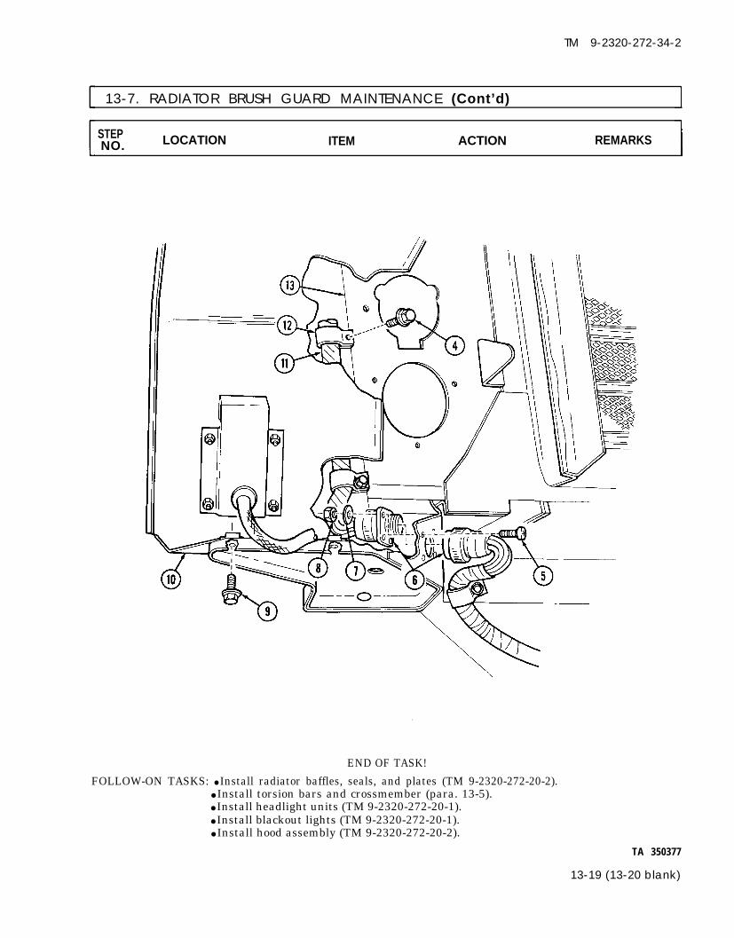
TM 9-2320-272-34-2
13-7. RADIATOR BRUSH GUARD MAINTENANCE (Cont’d)
STEP LOCATION ITEM ACTION REMARKSNO.
END OF TASK!
FOLLOW-ON TASKS: ● Install radiator baffles, seals, and plates (TM 9-2320-272-20-2).● Install torsion bars and crossmember (para. 13-5).● Install headlight units (TM 9-2320-272-20-1).● Install blackout lights (TM 9-2320-272-20-1).● Install hood assembly (TM 9-2320-272-20-2).
TA 350377
13-19 (13-20 blank)


TM 9-2320-272-34-2
CHAPTER 14CAB MAINTENANCE
Section I. DESCRIPTION AND DATA
14-1. DESCRIPTION – VEHICLE CABThe M939 series vehicle has a 3-member crew cab with canvas top. A hardtop kit is available for cold weatheroperation. Hardtop kit information is found in TM 9-2320-272-20-2.
Section Il. CAB AND CAB COMPONENTS MAINTENANCE
14-2. CAB AND CAB COMPONENTS MAINTENANCE TASK SUMMARY
TASKPARA. PROCEDURES
14-3. Cab Door Glass Replacement 14-214-4. Cab Windshield Glass Replacement 14-414-5. Retractable Window Glass and Van Door 14-8
Window Glass Replacement14-6. Engine Access Cover (in Cab) Replacement 14-1014-7. Winch Control Lever and Power Takeoff
Control Lever Replacement 14-1214-8. Transmission Control Console and 14-14
Winch Control Tower Maintenance
14-1

TM 9-2320-272-34-2
I 14-3. CAB DOOR GLASS REPLACEMENTThis task covers:
a. Removal b. Installation
INITIAL SETUP:Equipment
Applicable ModelsAll
Test EquipmentNone
Special ToolsNone
Materials/PartsRegulator channel fillerRegulator channel sealFrame filler/frame seal
Personnel RequiredWheeled vehicle repairman MOS 63W
Manual ReferencesTM 9-2320-272-10TM 9-2320-272-20-2TM 9-2320-272-34P
ConditionReference Condition Description
TM 9-2320-272-10 Parking brake set.TM 9-2320-272-20-2 Cab door glass assembly removed.
Special Environmental ConditionsNone
General Safety InstructionsEyeshields required when installing andremoving cab door glass.
STEP LOCATION ITEM ACTION REMARKSNO.
WARNINGUse eyeshields when removing and installing door glass. Glass couldshatter causing injury to personnel.
1. Regulator channel (4)to frame (2)
Four screws (3) Remove.
Regulator channel (4), Remove from frame Discard filler (5) andregulator channel filler (2). seal (6).(5), and regulatorchannel seal (6)Glass (7)Frame seal (1)
Slide out of frame (2).Remove from frame Discard seal (1).(2).
New frame seal (1) Place on top and bothsides of glass (7).
Glass (7) Place in frame (2).
1 4 - 2

TM 9-2320-272-34-2
14-3. CAB DOOR GLASS REPLACEMENT (Cont’d)
STEP LOCATION ITEM ACTION REMARKSNO.
7. New regulator channel Place on bottom ofseal (6) glass (7).
8. New regulator channel Place in regulatorfiller (5) channel (4).
9. Regulator channel (4) Position on glass (7)and install on frame(2) with four screws(3).
END OF TASK!FOLLOW-ON TASK: Install cab door glass assembly (TM 9-2320-272-20-2).
TA 350378
14-3

TM 9-2320-272-34-2
14-4. CAB WINDSHIELD GLASS REPLACEMENTThis task covers:
a. Removal b. Installation
INITIAL SETUP:EquipmentCondition
Applicable Models Reference Condition DescriptionAll TM 9-2320-272-10 Parking brake set.
TM 9-2320-272-20-2 Windshield removed.
Test EquipmentNone
Special ToolsNone
Materials/PartsFrame filler stripCrosspiece filler stripEight lockwashers
Special Environmental ConditionsNone
Personnel RequiredWheeled vehicle repairman MOS 63W
General Safety InstructionsEyeshields required when installing andremoving windshield glass.
Manual ReferencesTM 9-2320-272-10TM 9-2320-272-20-2TM 9-2320-272-34P
LOCATION ITEM ACTION REMARKS
WARNING
Use eyeshields when removing and installing windshield. Glasscould shatter causing injury to personnel.
1.
2.3.
4.
5.
6.
14-4
Crosspiece (2) towindshield frame (8)
Windshield frame (8)Crosspiece (2)
Windshield frame (8)
Windshield frame (8)
Two screws (5), lock-washers (4) and cap-nuts (3)Crosspiece (2)Filler crosspiece strip(1)
Four screws (7) andlockwashers (6)Two screws (11), lock-washers (13), andcapnuts (14), andlocking latch (12)Windshield glass (9)
Remove.
Remove.Remove.
Remove.
Remove.
Remove.and frame filler strip(10)
Discard lockwashers(4).
Discard filler strip (1).
Discard lockwashers(6).Discard lockwashers(13).
Discard filler strip(10).

TM 9-2320-272-34-2
14-4. CAB WINDSHIELD GLASS REPLACEMENT (Cont’d)
STEP LOCATION ITEM ACTION REMARKSNO.
14-5

TM 9-2320-272-34-2
I 14-4. CAB WINDSHIELD GLASS REPLACEMENT (Cont’d)
STEP LOCATION ITEM ACTION REMARKSNO.
7. New frame filler strip(3)
8. Windshield glass (1)
9. New crosspiece fillerstrip (2)
10. Crosspiece (9)
Position around newwindshield glass (1).Place in windshieldframe (8) and tapgently into position.
Position overwindshield glass (1).Place on windshieldglass (1) and gentlytap until screw holesare alined with wind-shield frame (8).
Do not overtighten crosspiece or windshield frame screws. Glassc o u l d b e d a m a g e d .
11. Crosspiece (9) andwindshield frame (8)
12. Windshield frame (8)and glass (1)
13. Locking latch (7)
14. Crosspiece filler strip(2) and frame tillerstrip (3)
Install with two screws(12), new lockwashers(11), and capnuts (10).Install with fourscrews (14) and newlockwashers (13).Position on windshieldframe (8) and installwith two screws (4),new lockwashers (5)and capnuts (6).Trim even with wind-shield frame (8) andcrosspiece (9) edges.
14-6

TM 9-2320-272-34-2
14-4. CAB WINDSHIELD GLASS REPLACEMENT (Cont’d)
STEP LOCATIONNO. ITEM ACTION REMARKS
END OF TASK!
FOLLOW-ON TASK: Install windshield (TM 9-2320-272-20-2).TA 350380
14-7

TM 9-2320-272-34-2
This task covers:
Equipment
14-5. RETRACTABLE WINDOW GLASS AND VAN DOOR WINDOW GLASSREPLACEMENT
a. Removal b. Installation
INITIAL SETUP:
Applicable ModelsConditionReference
M934, M935 TM 9-2320-272-10TM 9-2320-272-20-2TM 9-2320-272-20-2
Test EquipmentNone
Special ToolsNone
Materials/PartsNone
Personnel RequiredWheeled vehicle repairman MOS 63W
Manual ReferencesTM 9-2320-272-10
Condition DescriptionParking brake set.Retractable window removed.Van rear door and side door windowremoved.
TM 9-2320-272-20-2TM 9-2320-272-34P
STEP LOCATION ITEM ACTION REMARKSNO.
1. Window frame (1) Eighteen screws (4)and glass retainer (3)
2. Glass unit (2)
3. Two glass panes (5) Glass seal (6)
4. Glass seal (6)
5. Glass unit (2)
6. Glass retainer (3)
14-8
Special Environmental ConditionsNone
General Safety InstructionsNone
Remove.
Press out of windowframe (1).Remove.
Install on two glasspanes (5).
Press into window Plastic vent is placedframe (1). at top of frame (1).Install with eighteen Bracket is placed atscrews (4). bottom of frame (1).

TM 9-2320-272-34-2
14-5. RETRACTABLE WINDOW GLASS AND VAN DOOR WINDOW GLASSREPLACEMENT (Cont’d)
STEP LOCATION ITEM ACTION REMARKSNO.
END OF TASK!
FOLLOW-ON TASKS: ● Install retractable window (TM 9-2320-272-20-2).● Install van rear door and side door window (TM 9-2320-272-20-2).
TA 350381
14-9

TM 9-2320-272-34-2
14-6. ENGINE ACCESS COVER (IN CAB) REPLACEMENTThis task covers
a. Removal b. Installation
INITIAL SETUP:EquipmentCondition
Applicable ModelsAll
Test EquipmentNone
Special ToolsNone
Materials/PartsAdhesive (Appendix C, Item 1)
Personnel RequiredWheeled vehicle repairman MOS 63W
Manual ReferencesTM 9-2320-272-10TM 9-2320-272-20-1TM 9-2320-272-34P
Reference Condition DescriptionTM 9-2320-272-10 Parking brake set.
Para. 14-8 Transmission control console andwinch control tower removed.
TM 9-2320-272-20-1 Instrument cluster removed.
Special Environmental ConditionsNone
General Safety InstructionsNone
STEP LOCATION ITEM ACTION REMARKSNO.
1. Access cover (5) to fire-wall (1) and cab floor( 7 )
2.
3.
Cab floor insulation(6), firewall insulation(2), and access coverinsulation (4)Sixteen screw-assembled washers (3)Access cover (5)
Access cover (5)
Cab floor insulation(6), access cover insula-tion (4), and firewallinsulation (2)Cab floor insulation (6)
Access cover insulation(4)
Pull back until screw-assembled washers (3)are exposed.
Remove.
Remove.
Install with sixteenscrew-assembledwashers (3).Apply adhesive to backside before installation.
Push back in place tocab floor (7).Push back in place toaccess cover (5).
14-10

TM 9-2320-272-34-2
14-6. ENGINE ACCESS COVER (IN CAB) REPLACEMENT (Cont’d)
STEP LOCATIONNO. ITEM ACTION REMARKS
8. Firewall insulation (2) Push back in place tofirewall (1).
END OF TASK!
FOLLOW-ON TASKS: ● Install transmission control console and winch control tower (para. 14-8).● Install instrument cluster (TM 9-2320-272-20-1).
TA 350382
14-11

TM 9-2320-272-34-2
.
14-7. WINCH CONTROL LEVER AND POWER TAKEOFF CONTROL LEVERREPLACEMENT
This task covers:
a. Removal b. Installation
INITIAL SETUP:EquipmentCondition
Applicable Models Reference Condition DescriptionM925, M926, M928, TM 9-2320-272-10 Parking brake set.M930, M932, M936
Test EquipmentNone
Special ToolsNone
Materials/PartsTwo cotter pins
Personnel RequiredWheeled vehicle repairman MOS 63W
Special Environmental ConditionsNone
General Safety InstructionsNone
Manual ReferencesTM 9-2320-272-10TM 9-2320-272-34P
STEP LOCATION ITEM ACTION REMARKSNO.
a . R e m o v a l
1.
2.
3.
4.
Control tower (2) Six screws (12) andfront access cover (1)
Control lever (6) Cotter pin (10) washer(11), clevis pin (14),and cable clevis (13)
NOTE
Remove.
Remove. Discard cotter pin(10).
Power takeoff lever pin has two washers. The winch lever has onlyone washer.
Control tower (2) Cotter pin (8), washer Remove. Discard cotter pin (8).(7), lever pin (3) andcontrol lever (6)
Control lever (6) Two setscrews (4) and Remove.knob (5)
b. Installation
5. Knob (5) Install on control lever(6) with two setscrews(4).
14-12

TM 9-2320-272-34-2
14-7. WINCH CONTROL LEVER AND POWER TAKEOFF CONTROL LEVERREPLACEMENT (Cont’d)
STEP LOCATION ITEM ACTION REMARKSNO.
6. Control lever (6) Position to leverbracket (9) and installwith lever pin (3),washer (7), and newcotter pin (8).
7. Cable clevis (13) Connect to controllever (6) and installwith clevis pin (14),washer (11), and newcotter pin (10).
Front access cover (1) Install on controltower (2) with sixscrews (12).
8.
END OF TASK!
FOLLOW-ON TASKS: ● Start engine (TM 9-2320-272-10) and allow air pressure to build up to normaloperating range.
● Check winch control lever and power takeoff control lever for proper operation(TM 9-2320-272-10).
TA 350383
14-13

TM 9-2320-272-34-2
14-8. TRANSMISSION CONTROL CONSOLE AND WINCH CONTROL TOWERMAINTENANCE
This task covers
Applicable ModelsAll
Test EquipmentNone
Special ToolsNone
Materials/PartsFour locknuts
Personnel RequiredWheeled vehicle repairman MOS 63W
Manual ReferencesTM 9-2320-272-10TM 9-2320-272-34PTM 9-237
a. Removal c. Installationb. Inspection and Repair
INITIAL SETUP:EquipmentConditionReference Condition Description
TM 9-2320-272-10 Parking brake set.Para. 7-3 Transmission selector lever assembly
removed.Para. 14-7 Winch and power takeoff (PTO) control
levers removed (M925, M926, M928,M930, M932, and M936 only).
Special Environmental ConditionsNone
General Safety InstructionsNone
Control cable brackets(11)
Control tower (5) tocontrol console (1)Cover assembly (4)
Two screws (2), twoscrews (14), two shims(12), two locknuts (8),two locknuts (10), andcable clamps (7) and(13)Three screws (3)
Two screws (9),spacers (6), andcontrol tower (5)Two screws (15) andcontrol console (1)
STEP LOCATION ITEM ACTION REMARKSNO.
NOTESteps 1 through 4 apply only to models equipped with a winch.
1.
2.
3.
4.
14-14
Remove. Discard locknuts (8)and (10).
Remove.
Remove.
Remove.

TM 9-2320-272-34-2
14-8. TRANSMISSION CONTROL CONSOLE AND WINCH CONTROL TOWERMAINTENANCE (Cont’d)
STEP LOCATION ITEM ACTION REMARKSNO.
NOTEStep 5 applies to models not equipped with control tower.
5. Four screws (15) and Remove.control console (1)
TA 350384
14-15

TM 9-2320-272-34-2
14-8. TRANSMISSION CONTROL CONSOLE AND WINCH CONTROL TOWERMAINTENANCE (Cont’d)
STEP LOCATION ITEM ACTION REMARKSNO.
b. Inspection and Repair
6. Control console (1) Refer to TM 9-237 forand control tower (6) repair.
Control console (1) a. Install left side oncover assembly (2)with two screws (3).
NOTESteps 7b and 7C apply to models not equipped with control tower.Steps 8 and 9 apply to models equipped with control tower.
b. Install right side oncover assembly (2)with two screws (3).
c. Proceed to follow-ontasks.
Control tower (6) a. Install on coverassembly (2) withtwo spacers (7) andscrews (10).
b. Install on controlconsole (1) withthree screws (5).
PTO control cable (12) Install on control cableand winch control brackets (14) with PTOcable (11) cable clamp (16),
winch cable clamp (8),two screws (4), twoscrews (17), two shims(15), two new locknuts(9), and two new lock-nuts (13).
14-16

TM 9-2320-272-34-2
14-8. TRANSMISSION CONTROL CONSOLE AND WINCH CONTROL TOWERMAINTENANCE (Cont’d)
LOCATION ITEM ACTION REMARKS
END OF TASK!
FOLLOW-ON TASKS: ● Install winch and power takeoff (PTO) levers (M925, M926, M928, M930, M932, andM936 only) (para. 14-7).
● Install transmission selector lever assembly (para. 7-3).TA 350385
14-17 (14-18 blank)


TM 9-2320-272-34-2
CHAPTER 15CARGO BODY (M923, M924, M925, M926,
M927, AND M928) MAINTENANCE
Section I. DESCRIPTION AND DATA
15-1. DESCRIPTION – CARGO BODIES The M939 series vehicles include six cargo body models. The M924, M926, M927, and M928 models havewelded fixed-sides bodies. The M923 and M925 models have bodies with removable dropsides. Additional datafor each model can be found in table 15-1.
TA 350386
15-1

TM 9-2320-272-34-2
15-1. DESCRIPTION – CARGO BODIES (Cont’d)
M927 AND M928CARGO BODIES (EXTRA-LONG WHEELBASE)
Table 15-1. Cargo Bodies Dimensions and Weights
1. M924 and M926 CARGO BODYDimensions . . . . . . . . . . . . . . . . . . . . . . . . . . . . . . . . . . . . . . . . . . . . . . . . . . . . . . . . . . . . . . . . . . . . . . . . . . . . . .
Weight . . . . . . . . . . . . . . . . . . . . . . . . . . . . . . . . . . . . . . . . . . . . . . . . . . . . . . . . . . . . . . . . . . . . . . . . . . . . . . . . . . . .
M923 and M925 CARGO BODYDimensions . . . . . . . . . . . . . . . . . . . . . . . . . . . . . . . . . . . . . . . . . . . . . . . . . . . . . . . . . . . . . . . . . . . . . . . . . . . . . .
Weight . . . . . . . . . . . . . . . . . . . . . . . . . . . . . . . . . . . . . . . . . . . . . . . . . . . . . . . . . . . . . . . . . . . . . . . . . . . . . . . . . . . .
M927 and M928 CARGO BODYDimensions . . . . . . . . . . . . . . . . . . . . . . . . . . . . . . . . . . . . . . . . . . . . . . . . . . . . . . . . . . . . . . . . . . . . . . . . . . . . . .
Weight . . . . . . . . . . . . . . . . . . . . . . . . . . . . . . . . . . . . . . . . . . . . . . . . . . . . . . . . . . . . . . . . . . . . . . . . . . . . . . . . . . . .
168.25 x 96 in.(427.35 x 243.84 cm)
2050 lb(931 kg)
168.25 x 96 in.(427.35 x 243.84 cm)2150 lb(976 kg)
244 x 96 in.(619.76 x 243.84 cm)3000 lb(1362 kg)
TA 350387
15-2

TM 9-2320-272-34-2
Section Il. CARGO BODY COMPONENTS MAINTENANCE
15-2. CARGO BODY MAINTENANCE TASK SUMMARY
TASK PROCEDURES PAGEPARA. NO.
15-3. Cargo Body Assembly Maintenance 15-415-4. Cargo Body Frame Rail Sill Maintenance 15-14
TA 350388
15-3

TM 9-2320-272-34-2
15-3. CARGO BODY ASSEMBLY MAINTENANCEThis task covers
a. Removal c. Inspection and Repairb. Cleaning d. Installation
INITIAL SETUP:EquipmentCondition
Applicable Models Reference Condition DescriptionM923, M924, M925 TM 9-2320-272-10 Parking brake set.
M926, M927, M928 TM 9-2320-272-10 Wheels chocked.TM 9-2320-272-10 Cargo compartment canvas cover, front
Test Equipmentand side racks removed.
TM 9-2320-272-20-2 Cargo body cover bows removed.None TM 9-2320-272-20-2 Wheel splash guards and brackets
removed.
Special Tools Special Environmental ConditionsNone None
Materials/PartsTwo 3/4-inch utility chains
with hook endsEight locknuts
Wood (Appendix C, Item 33)Personnel Required
Wheeled vehicle repairman MOS 63W (3)
General Safety Instructions● All personnel must stand clear during
hoisting operations.● Fire extinguisher will be kept nearby
when drycleaning solvent is used.Manual References
TM 9-2320-272-10TM 9-2320-272-20-2TM 9-237TM 9-247TM 43-0139TM 9-2320-272-34P
STEP LOCATION ITEM ACTION REMARKSNO.
Two front upper Four outer support Remove. Discard locknuts (7).holddown brackets (1) springs (4), innerto lower holddown support springs (5),brackets (2) screws (3), washers (6),
and locknuts (7)
NOTEExtra-long wheelbase models (M927 and M928) utilize sixintermediate holddown brackets, twelve screws, and twelve nuts.
Four intermediate Four screws (10) and Remove. Discard locknuts (11).upper holddown locknuts (11)brackets (8) to lowerholddown brackets (9)
TA 350389
15-4

TM 9-2320-272-34-2
15-3. CARGO BODY ASSEMBLY MAINTENANCE (Cont’d)
STEP LOCATION ITEM ACTION REMARKSNO.
TA 350390
15-5

TM 9-2320-272-34-2
15-3. CARGO BODY ASSEMBLY MAINTENANCE (Cont’d)
STEP LOCATIONNO. ITEM ACTION REMARKS
3.
4.
5.
Left rear composite Four wires (5) Disconnect. Tag wires forlight (6) installation.Right rear composite Four wires (8) Disconnect. Tag wires forlight (7) installation.Cargo body (2) Eight nuts (1), screws Remove.
(4), and wire-clamps(3)
15-6

TM 9-2320-272-34-2
15-3. CARGO BODY ASSEMBLY MAINTENANCE (Cont’d)
STEP LOCATION ITEM ACTION REMARKSNO.
6. Two utility chains (9) Connect to cargo body Use wrecker or otherand (11) (12) as follows: hoisting device to hoist
a.
b.
cargo body (12).
Wrap chains (9) and(11) around sub-frame beam (13)and fasten hooks(14) over chains (9)and (11).
Hook center ofchains (9) and (11)in hoisting cablehook (10).
TA 350392
15-7

TM 9-2320-272-34-2
15-3. CARGO BODY ASSEMBLY MAINTENANCE (Cont’d)
STEP LOCATION ITEM ACTION REMARKSNO.
WARNING
8.
10.
All personnel must stand clear during hoisting operations. Asnapped cable, or shifting or swinging load may cause injury topersonnel.
Two guide lines (8) Connect guide line (9)and (9) to front lashing hook
(10) and guide line (8)to rear lashing hook(6).
Mechanic will handleone guide line anddirect hoistingoperation. Assistantwill handle other guideline. Second assistantwill operate liftingdevice.
Cargo body (4) Lift clear of frame (5)and place on four shopstands (7).
Hoisting cable hook (2) Disconnect from utilitychains (1) and (3).
WARNINGDrycleaning solvent is flammable and will not be used near openflame. Use only in well-ventilated places. Failure to do this mayresult in injury to personnel.
Cargo body (4) Clean with steam or Refer to TM 9-247.wire brush andapproved cleaningsolvent.
15-8
TA 350393

TM 9-2320-272-34-2
15-3. CARGO BODY ASSEMBLY MAINTENANCE (Cont’d)
STEP LOCATIONNO. ITEM ACTION REMARKS
c. Inspection and Repair
11. Cargo body (4) a.
b.
c.
d. Installation
Inspect for dents,cracks, breaks, andrust.Weld or straightenas necessary.
Clean and paint asnecessary.
Refer to TM 9-237.
Refer to TM 43-0139.
12. Hoisting cable hook (2) Attach to center ofboth utility chains (1)and (3).
Check position andsecurity of hooks (referto step 6).
WARNINGAll personnel must stand clear during hoisting operations. Asnapped cable, or shifting or swinging load may cause injury topersonnel.
TA 350394
15-9

TM 9-2320-272-34-2
15-3. CARGO BODY ASSEMBLY MAINTENANCE (Cont’d)
STEP LOCATION ITEM ACTION REMARKSNO.
NOTEMechanic will handle one guide line and direct hoisting operations.Assistant will handle the other guide line. Second assitant willoperate hoisting equipment.
13. Cargo body (4) Place on frame (5) asfollows:a. Hoist clear of shop
stands (10).
15-10
b. Lower on frame (5)with holddownbrackets (6), (7),(8), and (9) alined.
Use drift pins andtanker bar for aline-ment.
TA 350395

TM 9-2320-272-34-2
15-3. CARGO BODY ASSEMBLY MAINTENANCE (Cont’d)
STEP LOCATION ITEM ACTION REMARKSNO.
14. Four outer supportsprings (14)
a. Place over four innersupport springs(15).
b. Position under four Tighten until springlower holddown length is 6.75 in. ± 0.06brackets (9) and in. (171.45 mm ±install with four 1.5 mm).washers (16), newlocknuts (17), andscrews (13).
15.
Extra-long wheelbase models (M927 and M928) utilize sixintermediate holddown brackets, twelve screws and twelvewashers.
Four screws (18) Place through four Tighten 40-50 lb-ftintermediate upper (54-68 N·m).holddown brackets (6)and lower holddownbrackets (8) and installwith four new locknuts(19).
16. Two utility chains (1) Remove from hoistingand (3) cable hook (2) and
cargo body (4).17. Two guide lines (11) Remove.
and (12)
TA 350396
15-11

TM 9-2320-272-34-2
15-3. CARGO BODY ASSEMBLY MAINTENANCE (Cont’d)
STEP LOCATION ITEM ACTION REMARKSNO.
18. Four composite light Connect to right rearwires (3) composite light connec-
tors (4).Four composite light Connect to left rearwires (7) composite light connec-
tors (8).Eight wire clamps (6) Connect to cargo body
(1) and install witheight screws (5) andnuts (2).
TA 350397
15-12

TM 9-2320-272-34-2
15-3. CARGO BODY ASSEMBLY MAINTENANCE (Cont’d)
STEP LOCATION ITEM ACTION REMARKSNO.
FOLLOW-ON TASKS: ●
●
●
END OF TASK!
Install wheel splash guards and brackets (TM 9-2320-272-20-2).Install cargo body cover bows (TM 9-2320-272-20-2).Install front and side racks and cargo compartment canvas cover(TM 9-2320-272-10).
TA 350398
15-13

TM 9-2320-272-34-2
15-4. CARGO BODY FRAME RAIL SILL MAINTENANCE
This task covers:a. Removal c. Fabricationb. Inspection d. Installation
INITIAL SETUP:EquipmentCondition
Applicable Models Reference Condition DescriptionM923, M924, M925, Para. 15-3 Cargo body assembly removed.M926, M927, M928
Test EquipmentNone
Special Tools Special Environmental Conditions
None None
Materials/PortsTen lockwashersGreen 383 coating (Appendix C, Item 8)Wood (Appendix C, Item 33)Wood preservative (Appendix C, Item 35)
Personnel RequiredWheeled vehicle repairman MOS 63W
Manual ReferencesTM 43-0139
General Safety InstructionsNone
TM 9-2320-272-34P
STEP LOCATION ITEM ACTION REMARKSNO.
NOTEExtra-long wheelbase models (M927 and M928) utilize twenty bolts,lockwashers, and nuts to attach frame rail sills to cargo body.
1. Cargo body (1) Ten nuts (3), lock- Remove.washers (4), and bolts(5), and frame rail sill (2)
15-14 Change 2
Discard lockwashers (4).Clean frame rail sillarea.

15-4. CARGO BODY FRAME RAIL SILL MAINTENANCE (Cont'd]
STEPNO. LOCATION ITEM ACTION REMARKS
2. Frame rail sill (2) Inspect for rot, deteri- If defects are found,oration, cracks, or fabricate replacementsbreaks. (para. 15-4.c.).
Change 2 15-15
TM 9-2320-272-34-2

TM 9-2320-272-34-2
I 15-4. CARGO BODY FRAME RAIL SILL MAINTENANCE (Cont’d)
STEP LOCATION ITEM ACTION REMARKSNO.
c. Fabrication
3.
15-16
Step 3 appliescargo bodies.
NOTEto all except extra-long wheelbase (M927 and M928)
Frame rail sill (1) a.
b.
Cut to dimensionsand drill five coun-terbore bolt holes(2) and three framerest holes (3) asshown.Seal and paint. Refer to TM 43-0139.

TM 9-2320-272-34-2
15-4. CARGO BODY FRAME RAIL SILL MAINTENANCE (Cont’d)
STEP LOCATIONNO. ITEM ACTION REMARKS
4.
NOTEStep 4 applies to extra-long wheelbase (M927 and M928) cargobodies.
Front frame rail sill (4) a. Cut to dimensionsand rear sill (7) and drill ten coun-
terbore bolt holes(5) and three framerest holes (6) asshown.
b. Seal and paint. Refer to TM 43-0139.
TA 350401
15-17

TM 9-2320-272-34-2
I 15-4. CARGO BODY FRAME RAIL SILL MAINTENANCE (Cont'd)
STEPLOCATION ITEM ACTION REMARKSNO.
NOTEExtra-long wheelbase models (M927 and M928) utilize twenty bolts,lockwashers, and nuts to attach rail sills to cargo body.
Frame rail sill (2) a. Position on cargobody (1) with framerest holes (5) down.Install with ten bolts(6), new lockwashers(4), and nuts (3).
Make sure head of bolt(6) rests in sill of coun-terbore. Tighten 100-110 lb-in. (11-12 N·m).
END OF TASK!FOLLOW-ON TASK: Install cargo body assembly (para. 15-3).
15-18 Change 2

DUMP
TM 9-2320-272-34-2
CHAPTER 16BODY (M929 AND M930) MAINTENANCE
Section I. DESCRIPTION AND DATA
16-1. GENERAL Dump body welding instructions are not covered in this chapter. Refer to TM 9-237, Welding Theory andApplication. Additional general information can be found in TM 9-2320-272-10.
16-2. DESCRIPTION-DUMP BODYa. The M939 series vehicles include two dump body models. The M930 model is equipped with a front
winch and the M929 is not. Both models have the dump body and hoist assembly consisting of dump bodybed, subframe, hydraulic pump, control valve, control linkage, and hydraulic hoist cylinders mounted on therear of the chassis.
b. The hoist is controlled by a hand lever located in the vehicle cab, left of operator’s seat. Power to operatethe hoist is provided by the vehicle engine through a transmission power takeoff which drives a hydraulicpump.
M929 AND M930 DUMP BODY
Table 16-1. Dump Body Tabulated Data
Dimensions . . . . . . . . . . 125 in. long x 82 in. wide x 23 in. high (317.5 cm x 208.3 cm x 56.3 cm)Payload . . . . . . . . . . . . . . . . . . . . . . . . . . . . . . . . . . . . . . . . . . . . . . . . . . . . . . 5 cubic yards (3.835 cu. m.)Weight . . . . . . . . . . . . . . . . . . . . . . . . . . . . . . . . . . . . . . . . . . . . . . . . . . . . . . . . . . . . 2880 lbs (1307.53 kgs)
Section Il. DUMP BODY MAINTENANCE
16-3. DUMP BODY MAINTENANCE TASK SUMMARY
TASK PROCEDURES PAGEPARA. NO.
16-4.16-5.16-6.16-7.
16-8.16-9.16-10.16-11.
16-12.16-13.
16-14.
Dump Body MaintenanceDump Roller Arm MaintenanceDump Hoist Cylinder MaintenanceDump Safety Lock and CylinderReplacement
Dump Cab Protector Shield MaintenanceDump Safety Brace ReplacementDump Body Hydraulic Hose ReplacementDump Valve Cable and Shift LeverReplacementDump Subframe ReplacementDump Hydraulic Pump ReplacementDump Control Valve Replacement
16-216-1016-1416-30
16-3416-3816-40
16-44
16-52
16-6216-62
TA 350832
16-1

TM 9-2320-272-34-2
I 16-4. DUMP BODY MAINTENANCEThis task covers:
a. Removal c. Installationb. Inspection and Repair
INITIAL SETUP:Equipment
Applicable ModelsConditionReference Condition Description
M929, M930 TM 9-2320-272-10 Parking brake set.TM 9-2320-272-10 Wheels chocked.
Test EquipmentNone
Special Tools Special Environmental ConditionsNone None
Materials/PartsSixteen locknuts
Personnel Required GeneraI Safety InstructionsWheeled vehicle repairman MOS 63W (3) ●
Manual ReferencesTM 9-2320-272-10
●
TM 9-2320-272-34PTM 43-0139 ●
LO 9-2320-272-12
Position safety braces before workingunder raised dump body.Do not operate dump controls whendump body is removed.All personnel must stand clear duringhoisting operations.
STEP LOCATION ITEM ACTION REMARKSNO.
WARNING
Never work under dump body until safety braces are properlypositioned. Injury to personnel may result if dump body suddenlylowers.
Dump body (1) a.
b.
NOTE
Place in raised Refer to TM 9-2320-position. 272-10.
Place safety braces(6) in proper posi-tion.
Step 2 applies to both left and right thrust plates.
Thrust plate pin (4) to Screw (5) and locknut Remove. Discard locknut (3).thrust plate (2) (3)
1 6 - 2

TM 9-2320-272-34-2
16-4. DUMP BODY MAINTENANCE (Cont’d)
LOCATION ITEM ACTION REMARKS
3. Dump body (1) Remove safety brace Refer to TM 9-2320-(6) and place in lowest 272-10.position.
4. Two utility chains (7) a. Attach utility chainhooks (10) aroundsubframe beam (9)and install chains(7) over hoist hook(8).
b. Raise until slack is Use wrecker or otherremoved from hoisting device.chains (7).
TA 350833
16-3

TM 9-2320-272-34-2
16-4. DUMP BODY MAINTENANCE (Cont’d)
STEP LOCATION ITEM ACTION REMARKSNO.
WARNING
5.
6.7.
8.9.
10.
11.
12.
b. Inspection and Repair
13. Dump body (5)
1 6 - 4
Make sure dump control lever is in neutral and not moved. Injuryto personnel may result if lift cylinder is operated when notsecured.
NOTESteps 5 through 8 apply to both left and right sides.
Thrust plate (1) to Thrust plate pin (2) Remove.roller arm (3)Hinge bracket (7) Six locknuts (4) Remove.
Locknut (8), washer Remove.(9), and screw (10)
Hinge bracket (7) Remove.
Two guide lines (14) Connect to front andrear of dump body (5).
Discard locknuts (4).Discard locknut (8).
Mechanic will handleone guide line (14) anddirect hoisting oper-ation. One assistantwill handle other guideline (14). Anotherassistant will operatelifting device.
WARNING
All personnel must stand clear during hoisting operations. Asnapped cable, shifting, or swinging load may cause injury topersonnel.
Dump body (5) Lift clear of subframe(13) and place on shopstands.
Six screws (6) Remove.
Hoist hook (11) and Remove.utility chains (12)
a. Inspect for breaks, If breaks, dents, cracks,dents, cracks, and or rusted throughrust. areas are found, repair
(refer to TM 9-237).
b. Clean and paint as Refer to TM 43-0139.necessary.

TM 9-2320-272-34-2
16-4. DUMP BODY MAINTENANCE (Cont’d)
STEP LOCATIONNO. ITEM ACTION REMARKS
TA 350834
16-5

TM 9-2320-272-34-2
I 16-4. DUMP BODY MAINTENANCE (Cont’d)
STEP LOCATION ITEM ACTION REMARKSNO.
14.
15.
20.
Utility chains (3) and Attach to dump body Check position andhoist hook (2) (1). security of chain hook
ends (see step 4).Six screws (11) Install on left and right
side of dump body (1).
WARNING
All personnel must stand clear during hoisting operations. Asnapped cable, shifting, or swinging load may cause injury topersonnel.
Dump body (1)
Two brackets (5)
Two screws (14),washers (13), and newlocknuts (12)Two thrust plate pins(8)
Two guide lines (6)
a. Hoist clear of shopstands.
b. Place on subframe(4).
Install on screws (11)with twelve newlocknuts (10).Install on brackets (5).
Aline roller arms (9) tothrust plates (7) andinstall pins (8).
Remove.
Mechanic will handleone guide line (6) anddirect hoisting oper-ation. One assistantwill handle the otherguide line (6). Anotherassistant will operatelifting device.Tighten 240 lb-ft(325 N·m).
Tighten 35 lb-ft(48 N·m).
16-6

TM 9-2320-272-34-2
16-4. DUMP BODY MAINTENANCE (Cont’d)
STEP LOCATION ITEM ACTION REMARKSNO.
TA 350835
16-7

TM 9-2320-272-34-2
I 16-4. DUMP BODY MAINTENANCE (Cont’d)
STEP LOCATION ITEM ACTION REMARKSNO.
Two utility chains (3) Remove from hoistingcable hook (2) anddump body (1).
WARNINGNever work under dump body until safety braces are properly posi-tioned. Injury to personnel may result if dump body suddenlylowers.
Dump body (1) a. Place in raised Refer to TM 9-2320-position. 272-10.
b. Place safety braces(4) in properposition.
NOTEStep 23 applies to both left and right sides.Thrust plate pin (7) Install on each thrust Tighten 35 lb-ft
plate (5) with screw (48 N·m).(8) and new locknut(6).
TA 350836
16-8

TM 9-2320-272-34-2
16-4. DUMP BODY MAINTENANCE (Cont’d)
STEP LOCATION ITEM ACTION REMARKSNO.
FOLLOW-ON TASK:
END OF TASK!
Lubricate dump body (LO 9-2320-272-12).
TA 350837
16-9

TM 9-2320-272-34-2
16-5. DUMP ROLLER ARM MAINTENANCE IThis task covers
a. Removal d. Reassemblyb. Disassembly e. Installationc. Inspection and Repair
INITIAL SETUP:
Applicable ModelsM929, M930
Test EquipmentNone
Special ToolsNone
Materials/PartsGAA grease (Appendix C, Item 11)
Personnel RequiredWheeled vehicle repairman MOS 63W
Manual ReferencesTM 9-2320-272-10TM 9-2320-272-34P
EquipmentConditionReference Condition DescriptionPara. 16-4 Dump body removed.
Special Environmental ConditionsNone
General Safety InstructionsDo not operate dump controls whendump body is removed.
LO 9-2320-272-12
STEP LOCATION ITEM ACTION REMARKSNO.
WARNING
Make sure dump control lever is in neutral and not moved. Injuryto personnel may result if lift cylinder is operated when notsecured.
NOTEThis procedure applies to both left and right roller arms.
1. Hoist cylinder cross-head (5)
2. Roller pin (3) to rollerarm (2)
3.
4. Roller arm (2)
Roller arm (2) Remove.
Two pins (1) Remove.
Roller pin (3) Drive out of roller arm(2) and roller (4).
Roller (4) Remove.
Use soft-faced hammerto tap if necessary.
Use punch andhammer.Use brass drift andhammer.
1 6 - 1 0

TM 9-2320-272-34-2
16-5. DUMP ROLLER ARM MAINTENANCE (Cont’d)
STEPNO. LOCATION ITEM ACTION REMARKS
TA 350838
16-11

TM 9-2320-272-34-2
16-5. DUMP ROLLER ARM MAINTENANCE (Cont’d) ISTEPN O . LOCATION ITEM ACTION REMARKS
c. Inspection and Repair
Roller (6) and roller Inspect for cracks and Replace if cracked, orpin (5) deep grooves. deeply grooved.
Roller arm (3) Inspect for breaks and Replace if broken orcracks. cracked.
Roller arm (3) Two bushings (4) a. Inspect for breaks, Replace if broken,cracks, and out-of- cracked or out-of-round condition. round.
NOTESteps 7b and 8 are performed only if bushings are to be replaced.
b. Drive bushings (4)out of roller arm (3).
Two new bushings (4) Drive one in from eachside until flush withroller arm (3).
Roller (6)9. a.
b.
c.
Position in rollerarm (3).
Coat roller pin (5)with light film GAAgrease and positionthrough roller arm(3) and roller (6).
Install with two pins(2).
Roller arm (3) Install on hoistcylinder crossheadshaft (1).
Use brass drift andhammer.
Use wood block andhammer.
Use soft-faced hammerto tap pins in place.
16-12

TM 9-2320-272-34-2
16-5. DUMP ROLLER ARM MAINTENANCE (Cont’d)
STEPNO. LOCATION ITEM ACTION REMARKS
END OF TASK!FOLLOW-ON TASKS: • Install dump body (para. 16-4).
• Lubricate roller arms (LO 9-2320-272-12).TA 350839
16-13

TM 9-2320-272-34-2
16-6. DUMP HOIST CYLINDER MAINTENANCEThis task covers:
a. Removal d. Reassemblyb. Disassembly e. Installationc. Cleaning and Inspection
INITIAL SETUPEquipmentCondition
Applicable ModeIs Reference Condition DescriptionM929, M930 Para. 16-4 Dump body removed.
Para. 16-5 Dump roller arms removed.Test Equipment
Spring testerSpecial Tools Special Environmental Conditions
Ring compressor NoneMaterials/Parts
Twenty-two lockwashersPre-form packingCylinder head “O” ringTwo cotter pinsProtective cap-plugs (Appendix C, Item 5)Lint-free cloth (Appendix C, Item 7)
Personnel Required General Safety InstructionsWheeled vehicle repairman MOS 63W (2) Do not operate dump controls when
dump body is removed.Manual References
TM 9-2320-272-10TM 9-2320-272-34PLO 9-2320-272-12
STEP LOCATION ITEM ACTION REMARKSNO.
WARNING
Make sure dump control is in neutral and not moved. Injury topersonnel may result if lift cylinder is operated when not secured.
Subframe (5) Two hoist cylinders (4)and (10)
Two piston rods (7) Four screws (2) andlockwashers (1), twoupper crosshead re-tainers (6), lower cross-head retainers (8), andcrosshead (9)
Raise and place wood A 4x4 block of wood issupport (3) between recommended.subframe (5) and cylin-ders (4) and (10).Remove. Discard lockwashers
(1).
16-14

TM 9-2320-272-34-2
16-6. DUMP HOIST CYLINDER MAINTENANCE (Cont’d)
STEP LOCATION ITEM ACTION R E M A R K SNO.
TA 350840
16-15

TM 9-2320-272-34-2
Plug all hydraulic lines or openings to prevent dirt from enteringand damaging components.
NOTECross fitting to hoist cylinder hoses must be disconnected fromthe cross fittings first. Then hoses can be removed from hoistcylinders.Have drainage containers ready to catch oil.
Right cross fitting (8)
Left cross fitting (7)
Right and left cylinderports A (1) and (3)Right and left cylinderports B (2) and (4)
Two hydraulic hoses Disconnect. Tag for installation.(9) and (5)Two hydraulic hoses Disconnect. Tag for installation.(10) and (6)Two hydraulic hoses Disconnect. Tag for installation.(9) and (5)Two hydraulic hoses Disconnect. Tag for installation.(10) and (6)
16-6. DUMP HOIST CYLINDER MAINTENANCE (Cont’d)
16-16

TM 9-2320-272-34-2
16-6. DUMP HOIST CYLINDER MAINTENANCE (Cont’d)
STEP LOCATION ITEM ACTION REMARKSNO.
TA 350841
16-17

TM 9-2320-272-34-2
16-6. DUMP HOIST CYLINDER MAINTENANCE (Cont’d)
STEP LOCATION ITEM ACTION REMARKSNO.
7. Subframe (6) Eight screws (3) and Remove. Discard lockwasherslockwashers (4), four (4).bearing caps (2), andtwo hoist cylinders (5)and (1)
NOTEBoth hoist cylinders are disassembled and assembled in the sameway. Steps 8 through 37 apply only to the left hoist cylinder.
8. Cylinder base (7) Two square-head Remove and slide hingescrews (18) pin (19) out of cylinder
base (7).
9. Gland (12) to cylinder Three screws (11) Remove.head (14)
10. Gland (12) Tap free of cylinder Use soft-facedhead (14) and slide off hammer.piston rod (16).
11. Cylinder head (14) to Ten screws (10) and Remove. Discard lockwashershoist cylinder housing lockwashers (9) (9).(8)
12. Cylinder head (14) Tap free of cylinder (8) Use soft-facedand slide off piston rod hammer.(16).
13. Cylinder head (14) Packing (13) and “O” Remove. Discard packing (13)ring (15) and “O” ring (15).
NOTEUse care when performing step 14 to prevent damage to cylinderbore or piston.
14. Hoist cylinder housing Piston rod (16) and Pull straight out to(8) piston (17) remove.
16-18

TM 9-2320-272-34-2
16-6. DUMP HOIST CYLINDER MAINTENANCE (Cont’d)
TA 350842
16-19
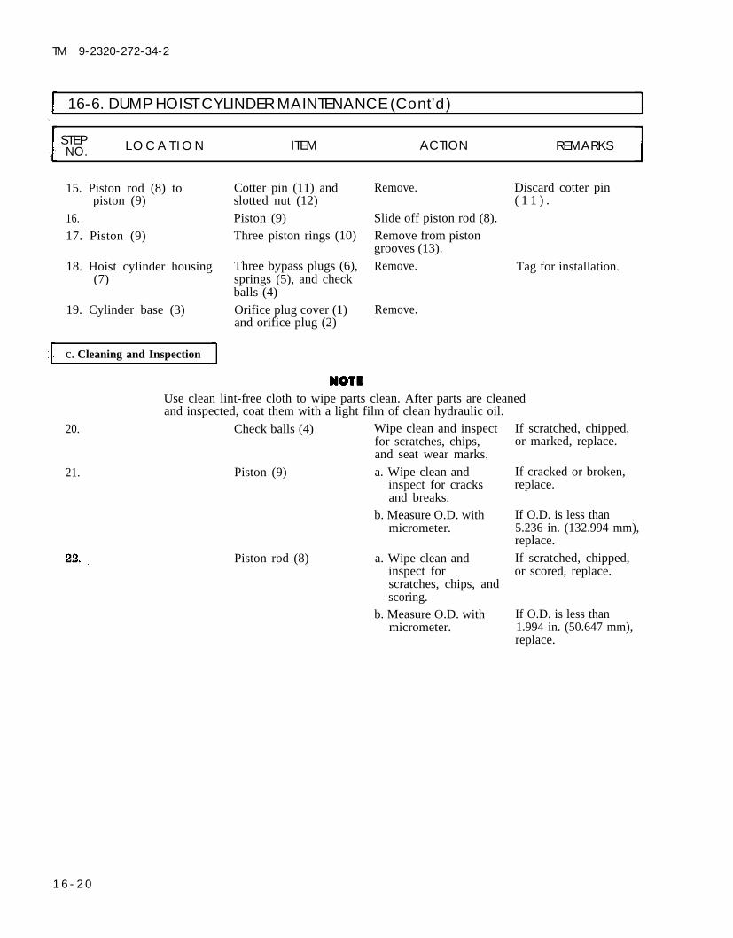
TM 9-2320-272-34-2
16-6. DUMP HOIST CYLINDER MAINTENANCE (Cont’d)
STEP L O C A T I O N ITEM ACTION REMARKSNO.
15. Piston rod (8) to Remove. Discard cotter pinpiston (9)
16.17. Piston (9)
18. Hoist cylinder housing(7)
Cotter pin (11) andslotted nut (12)Piston (9)Three piston rings (10)
Three bypass plugs (6),springs (5), and checkballs (4)Orifice plug cover (1)and orifice plug (2)
Slide off piston rod (8).Remove from pistongrooves (13).Remove.
Remove.
( 1 1 ) .
Tag for installation.
19. Cylinder base (3)
c. Cleaning and Inspection
Use clean lint-free cloth to wipe parts clean. After parts are cleanedand inspected, coat them with a light film of clean hydraulic oil.
20. Check balls (4) Wipe clean and inspect If scratched, chipped,for scratches, chips, or marked, replace.and seat wear marks.
21. Piston (9) a. Wipe clean and If cracked or broken,inspect for cracks replace.and breaks.
b. Measure O.D. withmicrometer.
Piston rod (8) a. Wipe clean andinspect forscratches, chips, andscoring.
b. Measure O.D. withmicrometer.
If O.D. is less than5.236 in. (132.994 mm),replace.If scratched, chipped,or scored, replace.
If O.D. is less than1.994 in. (50.647 mm),replace.
1 6 - 2 0

TM 9-2320-272-34-2
16-6. DUMP HOIST CYLINDER MAINTENANCE (Cont’d)
STEP LOCATIONNO. ITEM ACTION REMARKS
TA 350843
16-21

16-22
TM 9-2320-272-34-2
16-6. DUMP HOIST CYLINDER MAINTENANCE (Cont’d)
24.
Head (5) and gland (6)
Three bypass springs(1)
Three piston rings (9)
Orifice plug (2) andhoist cylinder walls (4)
Three piston rings (9)
Piston (10)
a. Wipe clean andinspect for cracksand breaks.
b. Measure I.D. of bothwith micrometer.
a. Measure free length.
b. With spring tester,compress to 15/16in. (23.81 2 mm)length.
Inspect for breaks.
Wipe clean and inspectfor scratches andchips.
Install on pistongrooves.Slide on piston rod (8)until seated and installwith slotted nut (12)and new cotter pin(11).
If cracked or broken,replace.
If less or more than2.010 in. (51.044 mm),replace.If less or more than1-1/4 in. (31.75 mm),replace.If torque reading is not10 lb-ft (14 N.m),replace.
If any ring (9) isbroken, replace allthree.If scratched orchipped, replace.
Use care when performing step 29 to prevent damage to cylinderbore or piston.
Piston (10) and piston Slide in cylinder Use ring compressor.rod (8) housing (3).
New “O” ring (7) Install on cylinderhead (5).

TM 9-2320-272-34-2
16-6. DUMP HOIST CYLINDER MAINTENANCE (Cont’d)
TA 350844
16-23

TM 9-2320-272-34-2
I 16-6. DUMP HOIST CYLINDER MAINTENANCE (Cont’d)
STEP LOCATION ITEM ACTION REMARKSNO.
3 1 . Cylinder head (17)
32. New packing (16)
33. Gland (15)
Orifice plug (2) andorifice plug cover (1)Two bypass check balls(7), springs (6), andplugs (5)One bypass check ball(10), spring (9), andplug (8)Hinge pin (21)
a. Slide over piston rod(18) and position oncylinder housing(19).
b. Install with ten newlockwashers (12)and screws (13).
Install around pistonrod (18) in cylinderhead (17).a. Slide over piston rod
(18) until seatedagainst packing(16).
b. Install on cylinderhead (17) with threescrews (14).
Install in cylinder base(3).Install in short bypasstube connector block(4).Install in long bypasstube connector block(11).a. Position in cylinder
base (3) until alinedwith screw (20)holes.
b. Install two square-head screws (20).
Tighten 8-10 lb-ft(11-14 N·m).
Use fingers to position.
Connector block (4) ismidway of cylinder(19).Connector block (11) isat head (17) end ofcylinder (19).
1 6 - 2 4

TM 9-2320-272-34-2
16-6. DUMP HOIST CYLINDER MAINTENANCE (Cont’d)
STEP LOCATION ITEM ACTION REMARKSNO.
TA 350845
16-25

TM 9-2320-272-34-2
16-6. DUMP HOIST CYLINDER MAINTENANCE (Cont’d)
STEP LOCATION ITEM ACTION REMARKSNO.
Installation steps 38 through 42 apply to both hoist cylinders.
Hoist cylinders (6) and a. Position on sub-(1) frame (7) with by-
pass tubes (5) facingdown.
b. Install each withtwo bearing caps(2), and four newlockwashers (4) andscrews (3).
NOTETo properly identify hose connection points, the cylinder port (10),with bypass tube (9) extending to midway of the cylinder, will beidentified as port B. The cylinder port (12), with bypass tube (8)extending full length of the cylinder, will be identified as port A.
Two hydraulic hoses Connect to left cylinder(13) port A (12), right
cylinder port A (12),and right cross fitting(15).
Two hydraulic hoses Connect to left cylinder(11) port B (10), right
cylinder port B (10),and left cross fitting(14).
1 6 - 2 6

TM 9-2320-272-34-2
16-6. DUMP HOIST CYLINDER MAINTENANCE (Cont’d)
STEP LOCATIONNO. ITEM ACTION REMARKS
TA 350846
16-27

TM 9-2320-272-34-2
16-6. DUMP HOIST CYLINDER MAINTENANCE (Cont’d)
STEP LOCATION ITEM ACTION REMARKSNO.
41. Crosshead (2) Position on piston rods
Two hoist cylinders (7)
(1) and (3) and installwith two upper cross-head retainers (8), twolower crosshead retain-ers (9), four new lock-washers (4), andscrews (5).
Raise and removewood support (6).
TA 350847
1 6 - 2 8

TM 9-2320-272-34-2
16-6. DUMP HOIST CYLINDER MAINTENANCE (Cont’d)
STEP LOCATION ITEM ACTION REMARKSNO.
FOLLOW-ON TASKS: ●
●
●
●
END OF TASK!Install dump roller arms (para. 16-5).Install dump body (para. 16-4).Fill hydraulic reservoir to proper oil level (LO 9-2320-272-12).Start engine (TM 9-2320-272-10) and operate dump through full range. Check for leaksand proper operation.
TA 350848
16-29

TM 9-2320-272-34-2
I 16-7. DUMP SAFETY LOCK AND CYLINDER REPLACEMENTThis task covers:
a. Removal b. Installation
INITIAL SETUP:EquipmentCondition
Applicable Models Reference Condition DescriptionM929, M930 TM 9-2320-272-10 Parking brake set.
Para. 16-4 Dump body removed.
Test EquipmentNone
Special Tools Special Environmental ConditionsNone None
Materials/PartsThree cotter pinsSix locknutsProtective cap-plugs (Appendix C, Item 5)
Personnel RequiredWheeled vehicle repairman MOS 63W
Manual ReferencesTM 9-2320-272-10TM 9-2320-272-34P
General Safety InstructionsDo not operate dump controls whendump body is removed.
STEP LOCATION ITEM ACTION REMARKSNO.
WARNING
Make sure dump control is in neutral and not moved. Injury topersonnel may result if lift cylinder is operated when not secured.
CAUTIONPlug all hydraulic lines or openings to prevent dirt from enteringand damaging components.
NOTEHave drainage container ready to catch oil.
1.
2.3.
4.
Right cross fitting (10) Hydraulic hose (8) Disconnect.
Left cross fitting (9) Hydraulic hose (7) Disconnect.Safety lock cylinder (6) Two hydraulic hoses Disconnect.
(7) and (8)Pin (15) Cotter pin (5) and Remove.
washer (3)Pin (15)
Tag for installation.Tag for installation.Tag for installation.
Discard cotter pin (5).
Release spring (14)tension and remove.
16-30

TM 9-2320-272-34-2
16-7. DUMP SAFETY LOCK AND CYLINDER REPLACEMENT (Cont’d)
STEP LOCATION ITEM ACTION REMARKSNO.
6. Safety hook (2) Cotter pin (5), pin Remove. Discard cotter pin (5).(13), and two spacerwashers (3)
7. Safety hook (2) Remove.8. Safety lock cylinder Cotter pin (5), pin (1), Remove. Discard cotter pin (5).
bracket (4) and five spacerwashers (3)
9. Safety lock cylinder (6) Remove.10. Frame rail (11) Six screws (17), Remove. Discard locknuts (12).
washers (16), locknuts(12), and safety lockcylinder bracket (4)
16-31

TM 9-2320-272-34-2
16-7. DUMP SAFETY LOCK AND CYLINDER REPLACEMENT (Cont’d)
STEP LOCATION ITEM ACTION REMARKSNO.
11. Cylinder bracket (4) Install on frame rail(11) with six washers(16), screws (17), andnew locknuts (12).
Safety hook (2)
Safety lock cylinder (6) Install on cylinderbracket (4) with fivespacer washers (3), pin(1), and new cotter pin(5).a. Install on cylinder
bracket (4) with pin(15), washer (3),new cotter pin (5),and spring (14).
b. Install on safety lockcylinder (6) withtwo spacer washers(3), pin (13), andnew cotter pin (5).
Two hydraulic hoses Connect to safety lock(7) and (8) cylinder (6).Hydraulic hose (7) Connect to left cross
fitting (9).Hydraulic hose (8) Connect to right cross
fitting (10).
1 6 - 3 2

TM 9-2320-272-34-2
I 16-7. DUMP SAFETY LOCK AND CYLINDER REPLACEMENT (Cont’d)
STEP LOCATION ITEM ACTION REMARKSNO.
END OF TASK!
FOLLOW-ON TASKS: ● Install dump body (para. 16-4). ● Fill hydraulic reservoir to proper oil level (LO 9-2320-272-12).
TA 350850
16-33

TM 9-2320-272-34-2
16-8. DUMP CAB PROTECTOR SHIELD MAINTENANCEThis task covers:
a. Removal c. Installationb. Inspection and Repair
INITIAL SETUP:
TM 9-2320-272-34PTM 9-237TM 43-0139
EquipmentCondition
Applicable Models Reference Condition DescriptionM929, M930 TM 9-2320-272-10 Parking brake set.
TM 9-2320-272-10 Wheels chocked.Test Equipment
NoneSpecial Tools
NoneMaterials/Parts
Nineteen locknutsPersonnel RequiredWheeled vehicle repairman MOS 63W (2)
Manual ReferencesTM 9-2320-272-10
General Safety InstructionsAll personnel must stand clear duringhoisting operations.
Special Environmental ConditionsNone
STEP LOCATION ITEM ACTION REMARKSNO.
1. Two eyebolts (9) Install each into upperrear hole (8) of cabprotector (5) withwasher (7) and nut(6).
2. Two utility chains (3) a.
b.
c.
Attach utility chainhooks (2) to eyebolts(9) and oppositeends of cabprotector front sup-port channel (1).
Attach utility chains(3) to hoist hook (4).
Raise until slack isremoved fromchains (3).
Use wrecker orhoisting device.Mechanic will directoperation whileassistant operateshoist.
16-34

TM 9-2320-272-34-2
16-8. DUMP CAB PROTECTOR SHIELD MAINTENANCE (Cont’d)
LOCATION ITEM ACTION REMARKS
3. Cab protector (5) to Seven screws (10), Remove. Discard locknuts (21).front dump body fourteen washers (11),channel (22) and seven locknuts
(21)4. Left and right side cab Eight screws (19), Remove. Discard locknuts (15).
protector (5) to dump washers (14), and lock-body extension bracket nuts (15)(20)
WARNINGAll personnel must stand clear during hoisting operations. Asnapped cable, shifting, or swinging load may cause injury topersonnel.
5. Cab protector (5) to Four locknuts (12), Remove and lift cab Discard locknuts (12).dump body side sup- washers (13), and two protector (5) clear ofport channel (16) screws (17) and (18) dump body.
6. Cab protector (5) Place on four shopstands and removeutility chains (3).
TA 350851
16-35

TM 9-2320-272-34-2
I 16-8. DUMP CAB PROTECTOR SHIELD MAINTENANCE (Cont’d)
STEP LOCATION ITEM ACTION REMARKSNO.
b. Inspection and Repair
7. Cab protector (3) a. Inspect for breaks, If breaks, dents, cracks,dents, and rust. or rusted-through
areas are found, repair(refer to TM 9-237).
b. Clean and paint as Refer to TM 43-0139.necessary.
8.
16-36
Hoist hook (18) Attach to center ofboth utility chains(17).
WARNINGAll personnel must stand clear during hoisting operations. Asnapped cable, shifting, or swinging load may cause injury topersonnel.
Cab protector (3) Place on dump body(6) as follows:
a.
b.
c.
d.
Hoist clear of fourshop stands andaline mounting holesin dump body (6).Install on left andright side dumpbody extensionbracket (10) witheight screws (9),washers (12), andnew locknuts (13).Install on left andright dump bodyside support chan-nel (7) with fourscrews (8), washers(5), and new lock-nuts (4).Install on dumpbody front channel(14) with sevenscrews (1), fourteenwashers (2), andseven new locknuts(11).
If chains (17) have notbeen positioned, seestep 1.
Use drift pins to aline.
One washer (2) underscrew (1) head andone washer (2) underlocknut (11).

TM 9-2320-272-34-2
16-8. DUMP CAB PROTECTOR SHIELD MAINTENANCE (Cont’d)
STEP LOCATION ITEM ACTION REMARKSNO.
10.
11.
Two utility chains (17) Remove from hoistand hooks (16) hook (18), cab pro-
tector front channel(15), and eyebolts (21).
Nut (19) and washer Remove from each(20) eyebolt (21) and
remove eyebolts (21).
END OF TASK!TA 350852
16-37

TM 9-2320-272-34-2
I 16-9. DUMP SAFETY BRACE REPLACEMENTThis task covers:
a. Removal b. Installation
INITIAL SETUP:EquipmentCondition
Applicable ModelsM929, M930
Test EquipmentNone
Special ToolsNone
Materials/PartsLockwasher
Personnel RequiredWheeled vehicle repairman MOS 63W
Manual ReferencesTM 9-2320-272-10TM 9-2320-272-34P
Reference Condition DescriptionTM 9-2320-272-10 Parking brake set.TM 9-2320-272-10 Dump body in lowered position.
Special Environmental ConditionsNone
General Safety InstructionsNone
STEP LOCATION ITEM ACTION REMARKSNO.
NOTEBoth left and right safety braces are removed in the same way. Thisprocedure applies to left brace only.
1. Safety brace hinge pin(1) to bracket (2)
2.
3.
4.
5.
Screw (3), lockwasher(4), and nut (5)Hinge pin (1)
Safety brace (6)
Safety brace (6)
Hinge pin (1)
Remove. Discard lockwasher(4).
Remove from bracket Use chisel and(2). hammer.Remove.
Position in bracket (2)with hinge pin (1) holealined.Position in bracket (2)through safety brace(6) and install withscrew (3), new lock-washer (4) and nut(5).
16-38

TM 9-2320-272-34-2
I 16-9. DUMP SAFETY BRACE MAINTENANCE (Cont’d)
STEP LOCATION ITEM ACTION REMARKSN O .
TA 350853
16-39

TM 9-2320-272-34-2
16-10. DUMP BODY HYDRAULIC HOSE REPLACEMENTThis task covers:
a. Removal b. Installation
INITIAL SETUP:EquipmentCondition
Applicable Models Reference Condition Description
M929, M930 TM 9-2320-272-10 Parking brake set.TM 9-2320-272-10 Dump body in lowered position.
Test EquipmentNone
Special Tools Special Environmental Conditions
None None
Materials/PartsProtective cap-plugs (Appendix C, Item 5)
Personnel Required General Safety Instructions
Wheeled vehicle repairman MOS 63W Position safety braces before workingunder raised dump body.
Manual ReferencesTM 9-2320-272-10TM 9-2320-272-34PLO 9-2320-272-12
STEP LOCATION ITEM ACTION REMARKSNO.
WARNING
Never work under dump body until safety braces are properlypositioned. Injury to personnel may result if dump suddenly lowers.
NOTE
All hydraulic hoses are removed the same way. This procedurecovers dump hoist cylinder and safety lock cylinder hoses only.
Dump body Raise and fasten in up Refer to TM 9-2320-position with safety 272-10.braces and place con- To prevent excessivetrol lever in neutral. loss of hydraulic oil, do
not move control leverout of neutral position
Plug all hydraulic lines or openings to prevent dirt from enteringand damaging components.
with hydraulic-hoseremoved.
16-40

TM 9-2320-272-34-2
16-10. DUMP BODY HYDRAULIC HOSE REPLACEMENT (Cont’d)
STEP LOCATION ITEM ACTION REMARKSNO.
2.
3.
4.
5.
6.
NOTE• Cross fitting to hoist cylinder hoses must be disconnected from
the cross fittings first. Then hoses can be removed from hoistcylinders.
• Have drainage container ready to catch oil.
• Drain hoses before plugging.• Tag hoses for installation.
Right cross fitting (11) Four hydraulic hoses Disconnect.(6), (10), (12), and(14)
Left cross fitting (8) Four hydraulic hoses Disconnect.(5), (7), (9), and (13)
Right and left cylinder, Two hydraulic hoses Disconnect.port A (1) and (2) (6) and (12)
Right and left cylinder, Two hydraulic hoses Disconnect.port B (4) and (15) (7) and (13)
Safety lock cylinder (3) TWO hydraulic hoses Disconnect.(5) and (14)
TA 350854
16-41

TM 9-2320-272-34-2
I 16-10. DUMP BODY HYDRAULIC HOSE REPLACEMENT (Cont’d)
STEP L O C A T I O N ITEM ACTION REMARKSNO.
7. Control valve (1) Two hoses (4) and (5) Disconnect.fittings (6) and (7)
8.
11.
13.
NOTEMake certain plugs are removed from all fittings before installation.Make certain no particles of plugging become trapped in dumpbody hydraulic system during installation of hoses and tubing.
Two hoses (4) and (5) a.
b.
NOTE
Connect to fittings(6) and (7) of con-trol valve (1).Connect to crossfittings (3) and (2).
To properly identify hose connection points, the cylinder port (18),with bypass tube (8) extending the full length of the cylinder, willbe identified as port A. The cylinder port (11) with bypass tube (9)extending midway of the cylinder, will be identified as port B.
Two hydraulic hoses(16)
Two hydraulic hoses(13)
Left cross fitting tosafety lock cylinderhose (12)
Right cross fitting tosafety lock cylinderhose (17)
Dump body
Connect to left cylin-der, port A (18) andright cylinder, port A(18) and right crossfitting (15).Connect to left cylin-der, port B (11), andright cylinder, port B(11) and left crossfitting (14).a.
b.
a.
b.
Connect to leftsafety lock cylinderport (10).Connect to left crossfitting (14).Connect to rightsafety lock cylinderport (19).Connect to rightcross fitting (15).
Remove safety braces Refer to TM 9-2320-and place in lowest 272-10.position.
16-42

TM 9-2320-272-34-2
16-10. DUMP BODY HYDRAULIC HOSE REPLACEMENT (Cont’d)
LOCATION ITEM ACTION REMARKS
FOLLOW-ON TASKS: ●
●
END OF TASK!Fill hydraulic reservoir to proper oil level (LO 9-2320-272-12).Start engine (TM 9-2320-272-10) and operate dump through full range. Check forleaks and proper operation.
TA 350855
16-43

TM 9-2320-272-34-2
I 16-11. DUMP VALVE CABLE AND SHIFT LEVER REPLACEMENTThis task covers:
a. Removal b. Installation and Adjustment
INITIAL SETUP:EquipmentCondition
Applicable Models Reference Condition DescriptionM929, M930 TM 9-2320-272-10 Parking brake set.
Test EquipmentNone
Special Tools Special Environmental ConditionsNone None
Materials/PartsFourteen locknutsTwo cotter pinsTiedown strap (Appendix C, Item 22)
Personnel RequiredWheeled vehicle repairman MOS 63W (2)
Manual ReferencesTM 9-2320-272-10TM 9-2320-272-34PLO 9-2320-272-12
General Safety InstructionsNone
STEP LOCATION ITEM ACTION REMARKSNO.
1.
2.
Cable clevis (11) toshift lever arm (2)
Two lever brackets (4)and shims (7) to cabfloor (14)Shift lever rod (6)Cab floor (14)
Shift lever rod (6)Cab floor (14)
Cotter pin (9), washer Remove.(10), and clevis pin(12)
Four screws (5), lock- Remove.nuts (8), and shiftlever (6)Woodruff key (18) Remove.Screw (1), locknut (3), Remove.and shift lever arm (2)Two lever brackets (4) Remove.Six screws (17) and Remove.locknuts (13) and seal(16) and retainer ring(15)
Cable clevis (11) isunder cab floor (14).
Discard cotter pin (9).Discard locknuts (8)located under cab floor(14).
Discard locknut (3).
Discard locknuts (13).
16-44

TM 9-2320-272-34-2
16-11. DUMP VALVE CABLE AND SHIFT LEVER REPLACEMENT (Cont’d)
STEP LOCATION ITEM ACTION REMARKSNO.
TA 350856
16-45

TM 9-2320-272-34-2
I 16-11. DUMP VALVE CABLE AND SHIFT LEVER REPLACEMENT (Cont’d)
STEP LOCATION ITEM ACTION REMARKSNO.
7.
8.
9.
Dump valve cable (20)
Cable conduit (13) torear cab floor leftbracket (7)
Cable conduit (13) tofront cab floor rightbracket (15)
Cable conduit (13)Cable clevis (1) to con-trol valve (5)Dump valve cable (20)valve endCable conduit (13) tolower bracket (23)
Cable clevis ( 10) andjamnut (9)
Two screws (11),clamp (12), shim (8),and two locknuts (14)
Screw (17), locknut(6), and clamp (16)
Tiedown strap (19)Cotter pin (4), washer(3), and clevis pin (2)
Cable clevis (1) andjamnut (26)Jamnut (25) andwasher (24)
Cable conduit (13)
Loosen and remove.
Remove.
Remove.
Remove.Remove.
Loosen and remove.
Remove from controlvalve (5) side only.
Pull through lowerbracket (23) andunderside of cab floor(18).
b. Installation and Adjustment
NOTEIf new cable is being installed use hardware from old cable.
15. Cable conduit (13) a. Install jamnut (21)and washer (22) onvalve cable (20), ifremoved.
Cable clevis (1)
b. Place valve cable(20) end throughlower bracket (23)and install withwasher (24) andjamnut (25).
Screw on valve end ofvalve cable (20) fourturns.
Bracket (7) is locatedunder cab floor (18).Discard locknuts (14).Bracket (15) is locatedunder cab floor (18).Discard locknut (6).Discard strap (19).Discard cotter pin (4).
It is not necessary toremove other washer(22) and jamnut (21).Tag for installation.
1 6 - 4 6

TM 9-2320-272-34-2
16-11. DUMP VALVE CABLE AND SHIFT LEVER REPLACEMENT (Cont’d)
STEP LOCATION ITEM ACTION REMARKSNO.
TA 350857
16-47

TM 9-2320-272-34-2
I 16-11. DUMP VALVE CABLE AND SHIFT LEVER REPLACEMENT (Cont’d)
STEP LOCATION ITEM ACTION REMARKSNO.
17. Cable conduit (13) Route under cab floor
18. Cable clevis (11)
Seal (18) and retainerring (17)
20. Two lever brackets (4)21. Woodruff key (20)
22. Shift lever rod (6)
Cable clevis (11)
(16).
Screw on cable shiftlever arm end (12)four turns.
Install on cab floor(16) with six screws(19) and new locknuts(15).Slide on lever rod (6).a. Position on rod (6)
and slide arm (2)over.
b. Install with screw(1) and new locknut(3).
Position to cab floor(16) and install withtwo brackets (4), shims(7), four screws (5),and new locknuts(8).
Install on lever arm (2)with clevis pin (14),washer (10), and newcotter pin (9).
1 6 - 4 8

TM 9-2320-272-34-2
16-11. DUMP VALVE CABLE AND SHIFT LEVER REPLACEMENT (Cont’d)
LOCATION ITEM ACTION REMARKS
TA 350858
16-49

TM 9-2320-272-34-2
16-11. DUMP VALVE CABLE AND SHIFT LEVER REPLACEMENT (Cont’d)
STEP LOCATION ITEM ACTION REMARKSNO.
24. Cable conduit (15) a.
25.
26.
Install on rear cabbracket (8) withshim (9), clamp(10), two screws(11), and new lock-nuts (12).Install on front cabfloor bracket (6)with clamp (13),screw (14), and newlocknut (7).
Shift lever Place in down position.
Valve shaft (3) Manually pull out untilseated.
NOTECable throw length can be adjusted with jamnuts.
Cable clevis (1) a.
b.
Aline clevis pin (2)hole with hole invalve shaft (3).Unscrew clevis (1)one turn and installon valve shaft (3)with clevis pin (2),washer (4), and newcotter pin (5).
Tiedown strap (16) Install.
Refer to TM 9-2320-272-10.Valve shaft (3) willstop when seated.
Use jamnuts (17) and(19) and two washers(18) for alinement.Tighten jamnut (20).
1 6 - 5 0

TM 9-2320-272-34-2
16-11. DUMP VALVE CABLE AND SHIFT LEVER REPLACEMENT (Cont’d)
STEP LOCATION ITEM ACTION REMARKSNO.
END OF TASK!
FOLLOW-ON TASKS: ● Lubricate shift lever (LO 9-2320-272-12). ● Test dump valve cable operation (TM 9-2320-272-10).
TA 350859
16-51

TM 9-2320-272-34-2
16-12. DUMP SUBFRAME REPLACEMENT IThis task covers:
a. Removal b. Installation
INITIAL SETUP:EquipmentCondition
Applicable Models Reference Condition DescriptionM929, M930 TM 9-2320-272-10 Parking brake set.
LO 9-2320-272-12 Hydraulic oil reservoir drained.Para. 16-4 Dump body removed.
Test EquipmentNone
Special Tools Special Environmental ConditionsNone None
Materials/PartsEight locknutsFour cotter pinsProtective cap-plugs (Appendix C, Item 5)
Personnel RequiredWheeled vehicle repairman MOS 63W (3)
Manual ReferencesTM 9-2320-272-10TM 9-2320-272-34PLO 9-2320-272-12
General Safety InstructionsAll personnel must stand clear duringhoisting operations.
STEP LOCATION ITEM ACTION REMARKSNO.
CAUTIONPlug all hydraulic lines or openings to prevent dirt form enteringand damaging components.
Pump to reservoir Disconnect from pump Have container readyhydraulic tube (2) adapter (3) and reser- to catch oil.
voir adapter (1).Filter to reservoir Disconnect from reser- Have container readyhydraulic hose (5) voir elbow (4) and to catch oil.
filter adapter (6).
16-52

TM 9-2320-272-34-2
16-12. DUMP SUBFRAME REPLACEMENT (Cont’d)
STEP LOCATION ITEM ACTION REMARKSNO.
TA 350860
16-53

TM 9-2320-272-34-2
16-12. DUMP SUBFRAME REPLACEMENT (Cont’d)
STEP LOCATION ITEM ACTION REMARKSNO.
NOTE
3.
• Cross fitting to hoist cylinder hoses must be disconnected fromthe cross fittings first. Then hoses can be removed from hoistcylinders. -
• Have container ready to catch oil.
Right cross fitting (9) Three hydraulic hoses(6), (10), and (12)
Left cross fitting (8) Three hydraulic hoses(5), (7), and (11)
Right and left cylinder Two hydraulic hosesport A (1) and (2) (6) and (10)Right and left cylinder Two hydraulic hosesport B (4) and (13) (7) and (11)Safety lock cylinder (3) Two hydraulic hoses
(5) and (12)
Disconnect. Tag for installation.
Disconnect. Tag for installation.
Disconnect. Tag for installation.
Disconnect. Tag for installation.
Disconnect. Tag for installation.
16-54

TM 9-2320-272-34-2
I 16-12. DUMP SUBFRAME REPLACEMENT (Cont’d)
STEP LOCATION ITEM ACTION REMARKSN O .
TA 350861
16-55

TM 9-2320-272-34-2
16-12. DUMP SUBFRAME REPLACEMENT (Cont’d)
LOCATION ITEM ACTION REMARKS
8. Discard locknuts (14).Remove.
11.
Two rear holddown Eight screws (15) andbrackets (13) to frame locknuts (14)(16)
Two utility chains (11)
Two front holddown Two cotter pins (8),brackets (5) to frame slotted nuts (7),(16) washers (6), springs
(3), screws (l), upperkeepers (2), and lowerkeepers (4)Two guide lines (18)
a.
b.
c.
Attach hook ends toopposite side offrame channels (12).
Attach utility chains(11) to hoist hook(lo).Raise until slack isremoved fromchains (11).
Remove from eachbracket (5).
Connect to front andrear of subframe (9).
WARNlNGAll personnel must stand clear during hoisting operations. Asnapped cable, shifting, or swinging load may cause injury topersonnel.
Subframe (9) Lift clear of frame (16)and place on two shopstands (17).
Hoist hook (10) Disconnect from utilitychains (11),
Use wrecker orhoisting device.
Discard cotter pins (8).
Mechanic will handleone guide line (18) anddirect hoisting oper-ation. One assistantwill handle other guideline (18), Anotherassistant will operatehoisting device.
16-56

TM 9-2320-272-34-2
16-12. DUMP SUBFRAME REPLACEMENT (Cont’d)
STEPNO. LOCATION ITEM ACTION REMARKS
TA 350862
16-57

TM 9-2320-272-34-2
I 16-12. DUMP SUBFRAME REPLACEMENT (Cont’d)
STEP LOCATION ITEM ACTION REMARKSNO.
Hoist hook (9) Attach to center ofboth utility chains(10).
WARNING
Check position andsecurity of chain hookends (11) (see step 9).
All personnel must stand clear during hoisting operations. Asnapped cable, shifting, or swinging load may cause injury topersonnel.
Subframe (8)
Two rear holddownbrackets (12)
Two utility chains (10)
Two front holddownbrackets (4)
Place on frame (15) asfollows:a. Hoist clear of shop
stands (16).b. Lower on frame (15)
with brackets (4)and (12) alined.
Install on frame (15)with four screws (14)and new locknuts (13)in each one.
Remove from hoisthook (9) and subframe(8).Install on frame (15)with two springs (3),four keepers (2), twoscrews (1), washers(5), slotted nuts (6),and new cotter pins(7) in each one.
Mechanic will handleone guide line (17) anddirect hoistingoperation. Assistantwill handle other guideline (17). Anotherassistant will operatelifting device.
16-58

TM 9-2320-272-34-2
16-12. DUMP SUBFRAME REPLACEMENT (Cont’d)
STEP LOCATIONNO. ITEM ACTION REMARKS
TA 350863
16-59

TM 9-2320-272-34-2
16-12. DUMP SUBFRAME REPLACEMENT (Cont’d)
STEP LOCATION ITEM ACTION REMARKSNO.
19.
24.
16-60
NOTETo properly identify hose connection points, the cylinder port (11),with bypass tube (1) extending the full length of the cylinder, willbe identified as port A. The cylinder port (4), with bypass tube (2)extending midway of the cylinder, will be identified as port B.
Two hydraulic hoses(9)
Two hydraulic hoses(6)
Left cross fitting tosafety lock cylinderhose (5)
Right cross fitting tosafety lock cylinderhose (10)
Filter to reservoirhydraulic hose (14)
Pump to reservoirhydraulic tube (17)
Connect to left cylin-der, port A (11) andright cylinder, port A(11) and right crossfitting (8).Connect to left cylin-der, port B (4) andright cylinder, port B(4) and left crossfitting (7).
a.
b.
a.
b.
Connect to leftsafety lock cylinderport (3).Connect to left crossfitting (7).Connect to rightsafety lock cylinderport (12).Connect to rightcross fitting (8).
Connect to reservoirelbow (13) and filteradapter (15).Connect to pumpadapter (18) andreservoir adapter (16).

TM 9-2320-272-34-2
16-12. DUMP SUBFRAME REPLACEMENT (Cont’d)
STEP LOCATIONNO. ITEM ACTION REMARKS
FOLLOW-ON TASKS: ● Install dump body (para. 16-4). ● Fill hydraulic reservoir to proper oil level (LO 9-2320-272-12). ● Start engine (TM 9-2320-272-10) and operate dump through full range. Check for
leaks and proper operation.
TA 350864
16-61

TM 9-2320-272-34-2
16-13. DUMP HYDRAULIC PUMP REPLACEMENTThe procedure for replacement of the dump hydraulic pump can be found in paragraph 19-8.
16-14. DUMP CONTROL VALVE REPLACEMENTThe procedure for replacement of the dump control valve can be found in paragraph 19-10.
16-62

TM 9-2320-272-34-2
CHAPTER 17FIFTH WHEEL MAINTENANCE
Section I. DESCRIPTION AND DATA
17-1. DESCRIPTION – FIFTH WHEELThe fifth wheel serves as the coupling and support for the semitrailer. The semitrailer to tractor couplingoperation can be found in TM 9-2320-272-10. Additional data for the fifth wheel can be found in table 17-1
Table 17-1. Fifth Wheel Tabulated Data
FIFTH WHEEL
Make . . . . . . . . . . . . . . . . . . . . . . . . . . . . . . . . . . . . . . . . . . . . . . . . . . . . . . . . . . . . . . . . . . . . . . . . . . . . Dayton-WaltherType . . . . . . . . . . . . . . . . . . . . . . . . . . . . . . . . . . . . . . . . . . . . . . . . . . . . . . . . . . . . . . . . . . . . . . . . . . . . . . Walking BeamSeries . . . . . . . . . . . . . . . . . . . . . . . . . . . . . . . . . . . . . . . . . . . . . . . . . . . . . . . . . . . . . . . . . . . . . . . . . . . . . . . . . . . .Twenty
Section Il. FIFTH WHEEL MAINTENANCE
17-2. FIFTH WHEEL MAINTENANCE TASK SUMMARY
TASKPARA. PROCEDURES PAGE
NO.
17-3. Fifth Wheel Maintenance 17-2
TA 350403
17-1

TM 9-2320-272-34-2
I 17-3. FIFTH WHEEL MAINTENANCE
This task covers:a. Disassembly c. Reassemblyb. Cleaning and Inspection
INITIAL SETUP:EquipmentCondition
Applicable Models Reference Condition DescriptionM931, M932 TM 9-2320-272-20-2 Fifth wheel removed.
Test EquipmentNone
Special ToolsNone Special Environmental Conditions
NoneMaterials/Parts
Fifth wheel rebuild service kit 50-023044Two 5/8-11 UNC, 3 in. (7.6 cm) long boltsThree lockwashers General safety Instructions
Two bushings ●
Personnel Required ●
Wheeled vehicle repairman MOS 63W (2)
Manual ReferencesTM 9-2320-272-20-2TM 9-2320-272-34PLO 9-2320-272-12
All personnel must stand clearduring hoisting operations.Keep fire extinguisher nearby whenusing drycleaning solvent.
STEPNO. LOCATION ITEM ACTION REMARKS
a. Disassembly
1.
2.
3.
4.
17-2
Fifth wheel housing (8) Two grease fittings (6) Remove.NOTE
Assistant will help with steps 2 through 6.
Utility chain (4) a. Install link ends (5)to holes in housing(8) with two screws(7), four washers (1),and two nuts (2).
b. Attach to liftingdevice.
Hoist hook (3) Raise until all slack isremoved from utilitychain (4).
Two fifth wheel Two hairpin clips (9) Remove.bushing pins (10)
Change 2
Make sure one washer(1) is between housing(8) and head of screw(7) and other washer(1) is between chainlink (5) and nut (2).

TM 9-2320-272-34-2
17-3. FIFTH WHEEL MAINTENANCE (Cont'd)
STEP LOCATION ITEM ACTION REMARKSNO.
5. Fifth wheel housing (8) Two fifth wheel Remove. Pull outward from fifthbushing pins (10) wheel housing (8)
using 5/8-11 bolts anda portable hydraulicjack unit.
Change 2 17-3

TM 9-2320-272-34-2
17-3. FIFTH WHEEL MAINTENANCE (Cont’d)
LOCATION ITEM ACTION REMARKS
6.
WARNING
All personnel must stand clear during hoisting operations. Ashifting or swinging load may cause injury to personnel.
Fifth wheel housing (1) a.
b.
Raise clear ofwalking beam (5).Lower and placeload-bearing side ontwo wood blocks (2)approximately 7 in.(17.7 cm) off floor.
7. Utility chain Remove.8. Two walking beam Two rubber bushings Remove.
posts (3) (4)Discard bushings (4).
TA 350405
17-4

TM 9-2320-272-34-2
17-3. FIFTH WHEEL MAINTENANCE (Cont’d)
STEP LOCATION ITEM ACTION REMARKSNO.
9. Two coupler jaw springpins (14)
10. Lock latch (12) tohousing eyelet (15)
11. Lock latch stud (13)and plunger bolt (11)
12. Lock latch stud (13)
13. Plunger bolt (11)
Jaw spring (10) Remove. Discard jaw spring(10).
Lock latch spring (16) Remove.
Lockwire (7) Cut and remove. Discard lockwire (7).
Locknut (6) and Remove. Discard locknut (6).washer (17)
Locknut (8) and Remove. Discard locknut (8).washer (9)
TA 350406
17-5
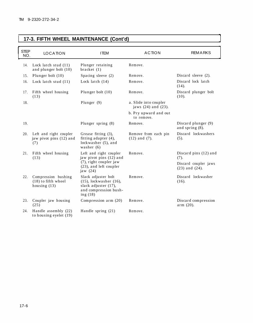
TM 9-2320-272-34-2
I 17-3. FIFTH WHEEL MAINTENANCE (Cont’d)
STEP LOCATION ITEM ACTION REMARKSNO.
14. Lock latch stud (11)and plunger bolt (10)
Plunger bolt (10)Lock latch stud (11)
Plunger retainingbracket (1)
Spacing sleeve (2)Lock latch (14)
Remove.
15.16.
17.
18.
Remove.Remove.
Discard sleeve (2).Discard lock latch(14).Discard plunger bolt(10).
Fifth wheel housing(13)
Plunger bolt (10) Remove.
Plunger (9) a. Slide into couplerjaws (24) and (23).
b. Pry upward and outto remove.
Remove.19.
20.
Plunger spring (8) Discard plunger (9)and spring (8).
Left and right couplerjaw pivot pins (12) and(7)
Discard lockwashers(5).
Grease fitting (3),fitting adapter (4),lockwasher (5), andwasher (6)
Remove from each pin(12) and (7).
21. Fifth wheel housing(13)
Discard pins (12) and(7).Discard coupler jaws(23) and (24).
Left and right couplerjaw pivot pins (12) and(7), right coupler jaw(23), and left couplerjaw (24)
Remove.
22. Compression bushing(18) to fifth wheelhousing (13)
Slack adjuster bolt(15), lockwasher (16),slack adjuster (17),and compression bush-ing (18)Compression arm (20)
Remove. Discard lockwasher(16).
23.
24.
Coupler jaw housing(25)Handle assembly (22)to housing eyelet (19)
Discard compressionarm (20).
Remove.
Remove.Handle spring (21)
17-6

TM 9-2320-272-34-2
17-3. FIFTH WHEEL MAINTENANCE (Cont’d)
STEP LOCATION ITEM ACTION REMARKSN O .
TA 350407
17-7

TM 9-2320-272-34-2
17-3. FIFTH WHEEL MAINTENANCE (Cont’d)
STEP LOCATION ITEM ACTION REMARKSNO.
25. Fifth wheel housing (1) Locknut (3), washer Remove. Discard locknut (3)(4), spacer (5), pinion and spacer (5).gear (6), and handleassembly (7)
26. Handle assembly (7) Locknut (2), washer Remove. Discard locknut (2),(9), bolt (8), and bolt (8), and pinionpinion gear (6) gear (6).
b. Cleaning and Inspection
WARNING
Drycleaning solvent is flammable and will not be used near openflame. Use only in well-ventilated places. Failure to do this mayresult in injury to personnel.
27. Fifth wheel housing (1)
28. Fifth wheel housing (1) Lock latch stud (10)
29. Two mounting bracketpins (11)
30. Two rubber bushings(12)
31. Fifth wheel baseassembly (13)
a.
b.
Clean with dryclean-ing solvent.Inspect for cracksand breaks.
Inspect for wear,breaks, cracks, anddamaged threads.Wipe clean and inspectfor wear, chips, anddamaged ends.Wipe clean and inspectfor wear and cracks.
a. Clean with dryclean-ing solvent.
b. Inspect for cracksand breaks.
If cracked or broken,replace fifth wheelhousing (1).
Replace if worn,broken, cracked, orthreads are damaged.Replace if worn,chipped, or if ends aredamaged.Replace if worn orcracked.
If cracked or broken,replace fifth wheelbase assembly (13).
17-8

TM 9-2320-272-34-2
17-3. FIFTH WHEEL MAINTENANCE (Cont’d)
STEP LOCATIONNO. ITEM ACTION REMARKS
17-9

TM 9-2320-272-34-2
17-3. FIFTH WHEEL MAINTENANCE (Cont’d)
STEP LOCATION ITEM ACTION REMARKSNO.
c. Reassembly
32. New pinion gear (5)
33. Handle spring (18)
34. New compression arm(17)
35. Slack adjuster (14)
36. Compression bushing(15)
37. New right coupler jaw(20)
38. New left coupler jaw(21)
39. Washer (23), new lock-washer (24), fittingadapter (10), andgrease fitting (11)
a.
b.
Install on handleassembly (6) withnew bolt (7), washer(9), and new lock-nut (1).Install on fifth wheelhousing bolt (8)with new spacer (4),washer (3), and newlocknut (2).
Install on handleassembly (6) and hous-ing eyelet (16).Place through couplerjaw housing opening(25) so hole in com-pression arm (17) isalined with left couplerjaw (21 ) pivot pin hole.Install in compressionbushing (15).Install on housing (19)with new lockwasher(13) and bolt (12).
a. Slide throughcoupler jaw housingopening (25) andposition over jawpivot pin hole.
b. Install with new jawpivot pin (22).
a. Slide through jaw
b.
housing opening(25) until alinedwith holes in com-pression arm (17)and housing (19).Install with new jawpivot pin (22).
Install on each jawpivot pin (22).
Spacer (4) must beinstalled first.
Make sure rubber padand flat on compres-sion arm (17) arealined.
17-10

TM 9-2320-272-34-2
17-3. FIFTH WHEEL MAINTENANCE (Cont’d)
LOCATION ITEM ACTION REMARKS
17-11

TM 9-2320-272-34-2
17-3. FIFTH WHEEL MAINTENANCE (Cont’d)
STEP LOCATION ITEM ACTION REMARKSNO.
40. Left and right coupler
41.
42.
43.
44.
45.
46.
47.
48.
49.
50.
jaws (11) and (5)New plunger bolt (9)
New plunger spring(18)New plunger (8)
New lock latch (3)
New spacing sleeve (4)
Plunger retainingbracket (2)
New lockwire (13)
Lock latch spring (23)
Coupler jaws (11) and(5)New jaw spring (16)
Place in closedposition.Place through top sideof fifth wheel housing(1).Slide onto plungershaft (6).
Insert shaft (6) intoguide hole (7) andforce plunger (8) downbetween coupler jaws(11) and (5).Position on lock latchstud (10).Position on plungerbolt (9).a.
b.
c.
d.
Install on plungerbolt (9) with washer(15) and new lock-nut (14).Tighten untillocknut (14) clearslockwire hole (19).Install on lock latchstud (10) withwasher (24) andnew locknut (12).Tighten until lock-nut (12) clears lock-wire hole (21).
Thread through holesin lock latch stud (10)and plunger bolt (9)and twist ends tight.Attach one end to locklatch (20) and otherend to housing eyelet(22).Place in open position.
Attach to each couplerjaw spring pin (17).
Do not overtightenlocknut (14).
Do not overtightenlocknut (12).
17-12

TM 9-2320-272-34-2
STEPNO. LOCATION ITEM ACTION REMARKS
17-3. FIFTH WHEEL MAINTENANCE (Cont’d)
TA 350410
17-13

TM 9-2320-272-34-2
17-3. FIFTH WHEEL MAINTENANCE (Cont'd)
STEPLOCATION ITEM ACTION REMARKSNO.
51. Two rubber bushings Place through each(11) walking beam post hole
(10).
NOTEAssistant will help with steps 52 through 56.
52. Hoist hook (2) Attach to utility chain(3).
WARNINGAll personnel must stand clear during hoisting operations. A shiftingor swinging load may cause injury to personnel.
53.
54.
57. Utility chain links (7)to fifth wheel housing(1)
58.
59. Two bushing pins (12)
Fifth wheel housing (1)
Two fifth wheelbushing pins (12)
Two hairpin clips (15)
Hoist hook (2)
Two screws (8), fourwashers (5), and twonuts (6)Two grease fittings(14)Two bolts (13)
Lift clear of woodblocks (4). Allowhousing (1) to turnover and position onwalking beam post (9).Install.
Install one in eachbushing pin (12).Disconnect from utilitychain (3).Remove.
Install in fifth wheelhousing (1).Remove.
Load bearing side willbe up.
Use portable hydraulicjack unit to press intoplace.
17-14 Change 2

TM 9-2320-272-34-2
17-3. FIFTH WHEEL MAINTENANCE (Cont'd)
STEPNO. LOCATION ITEM ACTION REMARKS
END OF TASK!FOLLOW-ON TASKS: ● Lubricate fifth wheel (LO 9-2320-272-12).
● Install fifth wheel (TM 9-2320-272-20-2).
Change 2 17-15 (17-16 blank)


TM 9-2320-272-34-2
CHAPTER 18WRECKER BODY (M936) MAINTENANCE
Section I. DESCRIPTION AND DATA
18-1. DESCRIPTION – WRECKER BODYa. The M936 is the wrecker body model in the M939 series. The vehicle body consists of a hydraulic crane,
and front and rear winch. The hydraulic system is powered by the vehicle engine. An extendable boom canrotate 360° and can be raised to approximately 45° elevation.
b. Each of the crane’s operating functions is dependent on hydraulic pressure supplied by the cranehydraulic pump. Functions are regulated by a control valve consisting of four two-way hydraulic valves. Eachvalve controls one of the crane’s operating functions. These include raising or lowering the boom, swinging theboom left or right, extending or retracting the boom, and winding or unwinding the hoist cable.
c. Tabulated data for the wrecker crane can be found in TM 9-2320-272-10.
M936 WRECKER BODY
Section Il. WRECKER BODY COMPONENTS REPLACEMENT
18-2. WRECKER BODY COMPONENTS REPLACEMENT TASK SUMMARY
TASK PROCEDURES PAGEPARA. NO.
18-3. Fuel Can Bracket Replacement 18-2
18-4. Hydraulic Oil Filter Housing Replacement 18-4
18-5. Hydraulic Oil Reservoir Replacement 18-6
18-6. Hydraulic Oil Reservoir Brackets and 18-8Straps Replacement
18-7. Hydraulic Hoist Winch Motor and Lines 18-10Replacement
18-8. Hoist Level Wind Replacement 18-12
18-9.18-10.
18-11.
18-12.18-13.18-14.18-15.18-16.
Hoist Winch ReplacementBoom Elevating Cylinder Replacement
Boom Elevating Cylinder PackingReplacementBoom Replacement
Inner Boom ReplacementExtension Cylinder ReplacementBoom Roller ReplacementElectrical Swivel Replacement
18-16
18-2018-24
18-2618-3018-3418-3618-38
TA 350706
18-1

TM 9-2320-272-34-2
18-2. WRECKER BODY COMPONENTS REPLACEMENT TASK SUMMARY (Cont'd)
TASK PROCEDURES PAGE
PARA NO.
18-17. Hydraulic Swivel Valve Replacement 18-42
18-18. Crane Hydraulic Swinger Motor 18-50Replacement
18-19. Crane Swinger Gearcase Replacement 18-52
18-20. Crane Control Valve Replacement 18-54
18-20.1. Regulator Flow Valve Replacement 18-61.1
18-21. Gondola Replacement 18-62
18-22. Turntable Replacement 18-68
18-23. Front Winch Hydraulic Pump Replacement 18-72
18-24. Front Winch Control Valve Replacement 18-72
18-3. FUEL CAN BRACKET REPLACEMENTThis task covers:
a. Removal b. Installation
INITIAL SETUP:EquipmentCondition
Applicable Models Reference
M936 TM 9-2320-272-10Test Equipment
NoneSpecial Tools
NoneMaterials/Parts
Two lockwashersEleven locknuts
Personnel Required
Wheeled vehicle repairman MOS 63WManual References
TM 9-2320-272-10TM 9-2320-272-34P
Condition Description
Parking brake set.
Special Environmental Conditions
None
General Safety Instructions
None
STEPN O . LOCATION ITEM A C T I O N REMARKS
1. Upper bracket (6)
2. Bracket (8) tohydraulic oil filter (10)
3. Bracket (6) to hydrau-lic oil reservoir (9)
18-2 Change 2
Four screws (1), lock-nuts (7), and fuel canholder (2)
Two screws (3),washers (5), and lock-washers (4)Seven screws (12 ) andlocknuts (11)
Remove. Discard locknuts (7).
Remove. Discard lockwashers(4).
Remove. Discard locknuts (11).

TM 9-2320-272-34-2
18-3. FUEL CAN BRACKET REPLACEMENT (Cont’d)
STEP LOCATION ITEM ACTION REMARKSNO.
4. Upper bracket (6) and Remove.lower bracket (8)
5. Lower bracket (8) and a.upper bracket (6)
b.
c.
Position to oil filter(10).Install with twoscrews (3), new lock-washers (4), andwashers (5).
Install on hydraulic
6.
oil reservoir (9) withseven screws (12)and new locknuts(11).
Fuel can holder (2) Install with four newlocknuts (7) andscrews (1).
END OF TASK!TA 350707
18-3

TM 9-2320-272-34-2
18-4. HYDRAULIC OIL FILTER HOUSING REPLACEMENTThis task covers:
a. Removal b. Installation
INITIAL SETUP:EquipmentCondition
Applicable Models Reference Condition Description
M936 TM 9-2320-272-10 Parking brake set.LO 9-2320-272-12 Hydraulic oil reservoir drained.
Para. 18-3 Fuel can bracket removed.
Test EquipmentNone
Special Tools Special Environmental Conditions
None None
Materials/PartsFour lockwashersFilter gasketProtective cap-plugs (Appendix C, Item 5)Sealing tape (Appendix C, Item 30)
Personnel RequiredWheeled vehicle repairman MOS 63W
General Safety InstructionsNone
Manual ReferencesTM 9-2320-272-10TM 9-2320-272-34PLO 9-2320-272-12
STEP LOCATION ITEM ACTION REMARKSNO.
CAUTIONWhen disconnecting hydraulic lines and hoses, plug all openings toprevent dirt from entering and causing internal parts damage.
1.
2.
3.
4.
18-4
NOTEHave drainage container ready to catch oil.
Front of hydraulic oil Flex hose (5) Disconnect from filterfilter housing (3) elbow (4).
Hydraulic oil filter Remove from filterelbow (4) housing (3).
Filter housing (3) to Four screws (7) and Remove.mounting flange (1) lockwashers (6)
Filter housing (3) and Remove.gasket (2)
Discard lockwashers(6).Discard gasket (2).Clean gasket remainsfrom mating surfaces.

TM 9-2320-272-34-2
18-4. HYDRAULIC OIL FILTER HOUSING REPLACEMENT (Cont’d)
STEP LOCATION ITEM ACTION REMARKSNO.
b. Installation
5.
6.
7.
New gasket (2) andfilter housing (3)
Filter elbow (4)
Flex hose (5)
Install on mountingflange (1) with fournew lockwashers (6)and screws (7).
Wrap with sealing tapeand install to hydraulicoil filter housing (3).
Install on hydraulic oilfilter elbow (4).
END OF TASK!FOLLOW-ON TASKS: ● Install fuel can bracket (para. 18-3).
● Fill hydraulic oil reservoir to proper oil level (LO 9-2320-272-12). ● Check hydraulic oil filter for proper operation (TM 9-2320-272-10).
TA 350708
18-5

TM 9-2320-272-34-2
18-5. HYDRAULIC OIL RESERVOIR REPLACEMENTThis task covers:
a. Removal b. Installation
INITIAL SETUP:EquipmentCondition
Applicable Models ReferenceM936 TM 9-2320-272-10
Para. 18-3Para. 18-4
TM 9-2320-272-20-1
Test EquipmentNone
Special ToolsNone
Materials/PartsTwo locknutsProtective cap-plugs (Appendix C, Item 5)
Personnel RequiredWheeled vehicle repairman MOS 63W (2)
Manual ReferencesTM 9-2320-272-10TM 9-2320-272-20-1TM 9-2320-272-34P
Condition DescriptionParking brake set.Fuel can bracket removed.Hydraulic oil filter housing removed.Floodlight assembly removed.
Special Environmental ConditionsNone
General Safety InstructionsNone
STEP LOCATION ITEM ACTION REMARKSNO.
CAUTIONWhen disconnecting hydraulic lines and hoses, plug all openings toprevent dirt from entering and causing internal parts damage.
Have drainage container ready to catch oil.1. Rear of hydraulic oil Hydraulic oil return Disconnect from reser-
reservoir (3) hose (7) voir adapter elbow (6).
2. Two reservoir retaining Two screws (2) and Remove, and separate Discard locknuts (1).straps (4) locknuts (1) retaining straps (4)
from hydraulic oilreservoir (3).
3. Two reservoir brackets Hydraulic oil reservoir Remove.(5) (3)
4. Hydraulic oil reservoir Position on two reser-(3) voir brackets (5).
18-6

TM 9-2320-272-34-2
18-5. HYDRAULIC OIL RESERVOIR REPLACEMENT (Cont’d)
STEP LOCATION ITEM ACTION REMARKSNO.
5. Two retaining straps Position around reser-(4) voir (3) and install
with two screws (2)and new locknuts (1).
6. Hydraulic oil return Install on reservoirhose (7) adapter elbow (6) at
rear of reservoir (3).
END OF TASK!Install floodlight assembly (TM 9-2320-272-20-1).Install hydraulic oil filter housing (para. 18-4).Install fuel can bracket (para. 18-3).
FOLLOW-ON TASKS: ●
●
●
● Start engine (TM 9-2320-272-10), operate boom, and check for leaks.TA 350709
18-7

TM 9-2320-272-34-2
18-6. HYDRAULIC OIL RESERVOIR BRACKETS AND STRAPS REPLACEMENTThis task covers:
a. Removal b. Installation
INITIAL SETUP:Equipment
Applicable ModelsConditionReference Condition Description
M936 TM 9-2320-272-10 Parking brake set.Para. 18-5 Hydraulic oil reservoir removed.
Test EquipmentNone
Special Tools Special Environmental ConditionsNone None
Materials/PartsFour locknutsEight lockwashers
Personnel RequiredWheeled vehicle repairman MOS 63W
Manual ReferencesTM 9-2320-272-10TM 9-2320-272-34P
General Safety InstructionsNone
STEP LOCATION ITEM ACTION REMARKSNO.
NOTEBoth hydraulic oil reservoir brackets are removed and installed the
a . R e m o v a l
1. Oil reservoir(1)
2.
3.
b. Installation
4.
5.6.
18-8
same way.
bracket Two screws (9), lock-nuts (2), straps (3)and (4), and insulatorstrip (5)Two bracket insulatorstrips (6)Four screws (7) andlockwashers (8), andbracket (1)
Bracket (1)
Two bracket strips (6)Straps (3) and (4)
Remove.
Remove.
Remove.
Install with four newlockwashers (8) andscrews (7).Install on brackets (1).Install with two screws(9) and new locknuts(2).
Discard locknuts (2).
Discard lockwashers(8).

TM 9-2320-272-34-2
18-6. HYDRAULIC OIL RESERVOIR BRACKETS AND STRAPS REPLACEMENT (Cont’d)
STEP LOCATION ITEM ACTION REMARKSNO.
7. Insulator strip (5) Place under straps (3)and (4) when installingon oil reservoir tank.
END OF TASK!
FOLLOW-ON TASK: Install hydraulic oil reservoir (para. 18-5).TA 350710
18-9

TM 9-2320-272 -34-2
18-7. HYDRAULIC HOIST WINCH MOTOR AND LINES REPLACEMENTThis task covers:
a. Removal b. Installation
INITIAL SETUP:EquipmentCondition
Applicable Models Reference Condition DescriptionM936 TM 9-2320-272-10 Parking brake set.
Test EquipmentNone
Special Tools Special Environmental ConditionsNone None
Materials/PartsFour lockwashersGasketFour locknutsProtective cap-plugs (Appendix C, Item 5)
Personnel RequiredWheeled vehicle repairman MOS 63W (2)
Manual ReferencesTM 9-2320-272-10TM 9-2320-272-34PLO 9-2320-272-12
General Safety InstructionsNone
STEP LOCATION ITEM ACTION REMARKSNO.
When disconnecting hydraulic lines and hoses, plug all openings toprevent dirt from entering and causing internal parts damage.
1.
2.
3.
4.
5.
18-10
Hoist motor elbows (1)
Two steel hydrauliclines (5)
Winch gearbox adapter(12)
NOTEHave drainage container ready to catch oil.Two steel hydraulic Disconnect. Tag for installation.lines (5)
Two hydraulic flex Disconnect. Tag for installation.hoses (9)Four locknuts (8), Remove. Discard locknuts (8).washers (7), andclamps (6)Two steel hydraulic Turn until clear of Permits removal oflines (5) hoist motor (2). hoist motor (2).
Four screws (10) and Remove. Discard lockwasherslockwashers (11), hoist (11).motor (2), and gasket(3)
Discard gasket (3).
Clean gasket remainsfrom mating surfaces.

TM 9-2320-272-34-2
18-7. HYDRAULIC HOIST WINCH MOTOR AND LINES REPLACEMENT (Cont’d)
STEP LOCATION ITEM ACTION REMARKSNO.
6. Gear shaft (14) Woodruff key (13) Remove.
b. Installation
7.
8.
9.
10.
Woodruff key (13) Position in slot on gearshaft (14).
Hoist motor (2) and Install on winch Tighten 60-70 lb-ftnew gasket (3) gearbox adapter (12) (81-95 N·m).
with four new lock-washers (11) andscrews (10).
Two steel hydraulic a. Connect to hoistlines (5) motor elbows (1) at
marked locations.b. Install on boom (4)
with four clamps(6), washers (7),and new locknuts(8).
c. Install on two hy-draulic flex hoses(9).
Two hydraulic flex Connect to two steelhoses (9) hydraulic lines (5).
END OF TASK!FOLLOW-ON TASKS ● Fill hydraulic oil reservoir to proper oil level (LO 9-2320-272-12).
● Check hoist winch motor for proper operation (TM 9-2320-272-10).TA 350711
18-11

TM 9-2320-272-34-2
18-8. HOIST LEVEL WIND REPLACEMENTThis task covers:
a. Removal c. Reassemblyb. Disassembly d. Installation
INITIAL SETUP:EquipmentCondition
Applicable Models Reference Condition DescriptionM936
Test EquipmentNone
Special ToolsNone
Materials/PartsEight locknutsTwo cotter pins
Personnel RequiredWheeled vehicle repairman MOS 63W
Manual ReferencesTM 9-2320-272-10TM 9-2320-272-34P
TM 9-2320-272-10 Parking brake set.
Special Environmental ConditionsNone
General Safety InstructionsNone
STEP LOCATION ITEM ACTION REMARKSNO.
1. Boom (1)
2.
3.4.5.6.
18-12
NOTEFront and rear roller braces are removed the same way.
Four screws (2) and Remove. Discard locknuts (8).locknuts (8)Two front roller braces Remove.(4)
NOTEFront and rear level wind rollers are disassembled the same way.
Cotter pin (3) Remove. Discard cotter pin (3).
Grease fitting (7) Remove.Level wind roller (5) Remove.Shaft (6) Remove.

TM 9-2320-272-34-2
18-8. HOIST LEVEL WIND REPLACEMENT (Cont’d)
STEP LOCATION ITEM ACTION REMARKSNO.
TA 350712
18-13

TM 9-2320-272-34-2
I 18-8. HOIST LEVEL WIND REPLACEMENT (Cont’d)
STEP LOCATION ITEM ACTION REMARKSNO.
7.
8.9.
10.
d. Installation
11.
NOTEFront and rear level wind rollers are assembled the same way.
Shaft (5) Install into level windroller (4).
Grease fitting (6) Install on shaft (5).
Level wind roller (4) Install into roller brace(3).
New cotter pin (2) Install.
NOTEFront and rear roller braces are installed the same way.
Two roller braces (3) Install with fourscrews (1) and newlocknuts (7).
18-14

TM 9-2320-272-34-2
18-8. HOIST LEVEL WIND REPLACEMENT (Cont’d)
STEP LOCATION ITEM ACTION REMARKSNO.
TA 350713
18-15

TM 9-2320-272-34-2
I 18-9. HOIST WINCH REPLACEMENTThis task covers:
a. Removal b. Installation
INITIAL SETUP:EquipmentCondition
Applicable Models Reference
M936 TM 9-2320-272-10TM 9-2320-272-20-2TM 9-2320-272-20-2
Test Equipment Para. 18-7
None Para. 18-8Special Tools
NoneMaterials/Parts
Twelve lockwashersPersonnel RequiredWheeled vehicle repairman MOS 63W (2)
Manual ReferencesTM 9-2320-272-10TM 9-2320-272-20-2TM 9-2320-272-34PLO 9-2320-272-12
Condition DescriptionParking brake set.Boom floodlight wire removed.Hoist winch cable removed.Hydraulic hoist winch motor and linesremoved.
Hoist level wind removed.
Special Environmental ConditionsNone
General Safety InstructionsAll personnel must stand clear duringhoisting operations.
STEP LOCATION ITEM ACTION REMARKSNO.
a. Removal
1.
2.
3.
WARNlNG
All personnel must stand clear during hoisting operations. Asnapped cable, shifting, or swinging load may cause injury topersonnel.
Bottom of hoist winch(5)
NOTEHave drainage container ready to catch oil.
Drainplug (6) a. Remove, and drainoil from hoist winch(5).
b. Install in hoistwinch (5).
Utility chain (2) Attach to hoist winch(5).
Hoist hook (1) Attach to utility chain(2) and raise untilslack is removed fromchain (2).
18-16

TM 9-2320-272-34-2
18-9. HOIST WINCH REPLACEMENT (Cont’d)
STEP LOCATION ITEM ACTION REMARKSNO.
NOTEAssistant will help with step 4.
4. Boom (7) Twelve screws (4) and Remove, and lower Discard lockwasherslockwashers (3), and hoist winch (5) to (3).hoist winch (5) wrecker bed.
5. Wrecker bed Hoist winch (5) Attach utility chain (2)to hoist hook (1), andremove.
Utility chain (2) Remove.6.
TA 350714
18-17

7.
8.
9 .
10.
All personnel must stand clear during hoisting operations. Asnapped cable, shifting, or swinging load may cause injury topersonnel.
NOTEAssistant will help with steps 7, 8, and 9.
TM 9-2320-272-34-2
I 18-9. HOIST WINCH REPLACEMENT (Cont’d)
STEP LOCATION ITEM ACTION REMARKSNO.
18-18
Utility chain (2) Attach to hoist winch(5).
Hoist hook (1) Attach to utility chain(2).
Hoist winch (5) a. Hoist into positionand aline with holesin boom (6).
b. Install with twelvenew lockwashers (3)and screws (4).
Hoist hook (1) and Remove.utility chain (2)

TM 9-2320-272-34-2
I 18-9. HOIST WINCH REPLACEMENT (Cont’d)
STEP LOCATION ITEM ACTION REMARKSNO.
END OF TASK!FOLLOW-ON TASKS: ● Install hoist level wind (para. 18-8).
● Install hydraulic hoist winch motor and lines (para. 18-7).● Install hoist winch cable (TM 9-2320-272-20-2).● Install boom floodlight wire (TM 9-2320-272-20-2).● Fill hoist winch to proper oil level (LO 9-2320-272-12).
TA 350715
18-19

TM 9-2320-272-34-2
I 18-10. BOOM ELEVATING CYLINDER REPLACEMENTThis task covers:
a. Removal b. Installation
INITIAL SETUP:EquipmentCondition
Applicable Models ReferenceM936 TM 9-2320-272-10
TM 9-2320-272-10LO 9-2320-272-12
Test EquipmentNone
Special ToolsNone
Materials/PartsLockwasherCotter pinProtective cap-plugs (Appendix C, Item 5)
Personnel RequiredWheeled vehicle repairman MOS 63W (2)
Manual ReferencesTM 9-2320-272-10TM 9-2320-272-34PLO 9-2320-272-12
Condition DescriptionParking brake set.Boom lowered.Hydraulic oil reservoir drained.
Special Environmental ConditionsNone
General Safety Instructions● All personnel must stand clear
during hoisting operations.● Elevating cylinder is heavy. Use
caution when removing or installingelevating cylinder.
STEP LOCATION ITEM ACTION REMARKSNO.
CAUTIONWhen disconnecting hydraulic lines and hoses, plug all openings toprevent dirt from entering and causing internal parts damage.
NOTEBoth left and right elevating cylinders are removed and installed inthe same way. Only the right elevating cylinder is covered in thisprocedure.
NOTEHave drainage container ready to catch oil.
1. Bottom of elevating Cylinder oil supply line Disconnect from Tag for installation.cylinder (9) (6) and return line (5) snubber valve (7) and
cylinder adapter fitting(8).
18-20

TM 9-2320-272-34-2
18-10. BOOM ELEVATING CYLINDER REPLACEMENT (Cont’d)
STEP LOCATION ITEM ACTION REMARKSNO.
All personnel must stand clear during hoisting operations. Asnapped cable, shifting, or swinging load may cause injury topersonnel.
2. Top of elevating Wrecker boom (1) Raise with liftingcylinder (9) device until boom
weight is fully sup-ported and upper re-taining pin (2) is free.
3. Elevating cylinder (9) Screw (4), lockwasher Remove. Discard lockwasherto boom (1) (3), and upper re- (3).
taining pin (2)
TA 350716
18-21

TM 9-2320-272-34-2
18-10. BOOM ELEVATING CYLINDER REPLACEMENT (Cont’d) 1STEP LOCATION ITEM ACTION REMARKSNO.
WARNING
The elevating cylinder is heavy. Remove with the aid of assistantand a lifting device, or injury to personnel may result.
4. Turntable (8) Cotter pin (7), lower Remove. Discard cotter pin (7).retaining pin (9), andelevating cylinder (12)
5. Wrecker boom (1) Raise with lifting Refer to TM 9-2320-device and install 272-10.braces.
b. Installation
6.
7.
8.
9.
10.
18-22
●
●
The elevating cylinder is heavy. Do not attempt to install thiscomponent without the aid of assistant and a lifting device, orinjury to personnel may result.All personnel must stand clear during hoisting operations. Asnapped cable, shifting, or swinging load may cause injury topersonnel.
Wrecker boom (1) Raise, and removeshipper braces.
Elevating cylinder (12) a.
b.
Install on turntable(8) with lower re-taining pin (9) andnew cotter pin (7).Install on boom (1)with upper retainingpin (2), new lock-washer (3), andscrew (4).
Cylinder oil supply line Install on snubber(6) valve (10).
Cylinder oil return line Install on cylinder(5) adapter fitting (11).Wrecker boom (1) Remove lifting device.
Refer to TM 9-2320-272-10.
Tighten screw (4)44-61 lb-ft (60-83 N·m).

TM 9-2320-272-34-2
18-10. BOOM ELEVATING CYLINDER REPLACEMENT (Cont’d)
LOCATION ITEM ACTION REMARKS
END OF TASK!
FOLLOW-ON TASKS: ● Fill hydraulic oil reservoir to proper oil level (LO 9-2320-272-12). ● Operate crane through full range (TM 9-2320-272-10) and
check for leaks at lines and cylinders.TA 350717
18-23

TM 9-2320-272-34-2
18-11. BOOM ELEVATING CYLINDER PACKING REPLACEMENTThis task covers:
a. Removal b. Installation
INITIAL SETUP:EquipmentCondition
Applicable Models Reference Condition Description
M936 TM 9-2320-272-10 Parking brake set.TM 9-2320-272-10 Boom lowered.
Test EquipmentNone
Special Tools Special Environmental ConditionsSpanner wrench 8747917 None
Materials/PartsPackingGAA grease (Appendix C, Item 11)
Personnel RequiredWheeled vehicle repairman MOS 63W (2)
General Safety InstructionsAll personnel must stand clear duringhoisting operations.
Manual ReferencesTM 9-2320-272-10TM 9-2320-272-34PLO 9-2320-272-12
STEP LOCATION ITEM ACTION REMARKSNO.
WARNING
All personnel must stand clear during hoisting operations. Asnapped cable, shifting, or swinging load may cause injury topersonnel.
1.
2.
3.
Wrecker boom (2) a.
b.
Place boom cylinder Refer to TM 9-2320-lever (7) in UP 272-10.position.
Raise with liftingdevice and installshipper braces.
Boom cylinder control Place in LOWERlever (7) position to release
pressure fromelevating cylinder (6).
Elevating cylinder (6) Packing nut (3) Loosen and slide up on Use spanner wrench.piston rod (1) toexpose packing (4).
18-24

TM 9-2320-272-34-2
18-11. BOOM ELEVATING CYLINDER PACKING REPLACEMENT (Cont’d)
STEP LOCATIONNO. ITEM ACTION REMARKS
CAUTIONUse care not to scratch piston rod surface when removing packing.
4. Elevating cylinder (6) Packing (4) Slide up piston rod (1) Discard packing (4).and remove.
b. Installation
5.
6.
New packing (4) a. Coat with GAAgrease.
b. Position aroundpiston rod (1) andslide down into cylin-der head (5), andinstall with packingnut (3).
Wrecker boom (2) Remove lifting device.
END OF TASK!
FOLLOW-ON TASK: Operate crane through full range (TM 9-2320-272-10) and check for leaks at cylinder.TA 350718
18-25

TM 9-2320-272-34-2
18-12. BOOM REPLACEMENTThis task covers:
a. Removal b. Installation
INITIAL SETUP: EquipmentCondition
Applicable Models Reference Condition Description
M936 TM 9-2320-272-10 Parking brake set.Test Equipment TM 9-2320-272-20-2 Boom floodlight wire removed.
None LO 9-2320-272-12 Hydraulic oil reservoir drained.
Special ToolsPara. 18-9 Hoist winch removed.
NoneMaterials/Parts Special Environmental Conditions
LocknutTwo lockwashers
None
Protective cap-plugs (Appendix C, Item 5)Personnel Required
Wheeled vehicle repairman MOS 63W (2)Manual References General Safety Instructions
TM 9-2320-272-10 ● All personnel must stand clear duringTM 9-2320-272-20-2 hoisting operations.TM 9-2320-272-34P ● Make sure inner boom is secured to
LO 9-2320-272-12 outer boom before hoisting.
STEP LOCATION ITEM ACTION REMARKSNO.
WARNINGAll personnel must stand clear during hoisting operations. Asnapped cable, shifting, or swinging load may cause injury topersonnel.
a . R e m o v a l
CAUTION
1.
2.
3.
4.
When disconnecting hydraulic lines and hoses, plug all openings toprevent dirt from entering and causing internal parts damage.
NOTEHave drainage container ready to catch oil.
Two boom adapter Extension cylinder Disconnect. Tag for installation.elbows (4) extension hose (6) and
retracting hose (5)Inner boom (1) Install to outer boom Prevents inner boom
(3) with utility chain (1) from moving.(18).
Two utility chains (2) Attach to outer boom(3).
Outer boom (3) Raise with liftingdevice until boom (3)weight is fully sup-ported and upperretaining pins (17)are free.
18-26

TM 9-2320-272-34-2
18-12. BOOM REPLACEMENT (Cont’d)
STEP LOCATION ITEM ACTION REMARKSNO.
5.
6.
7.
8.
9.
Two elevating cylinders Two screws (15) lock- Remove. Discard lockwashers(14) to outer boom (3) washers (16) and re- (16).
taining pins (17)
WARNINGBefore hoisting outer boom away from wrecker, make sure innerboom is properly secured to outer boom as outlined in step 2 toprevent injury to personnel.
Pivot pin (8) Grease fittings (7) and(13)
Turntable (9) Locknut (12), pivot pin(8), two bearing sleeves(10) and crane sheave(11)Outer boom (3)
Outer boom (3) Two utility chains (2)and utility chain (18)
Remove.
Remove.
With utility chains (2)installed on liftingdevice, remove andplace on jack stands.Remove.
Discard locknut (12).
TA 350719
18-27

TM 9-2320-272-34-2
18-12. BOOM REPLACEMENT (Cont’d) ISTEP LOCATION ITEM ACTION REMARKSNO.
b. Installation
WARNINGBefore hoisting outer boom to wrecker, make sure inner boom issecured to outer boom as outlined in step 10 to prevent injury topersonnel.
NOTEIf installing new boom assembly, use hardware from old boom.
10. Inner boom (1)
11. Two utility chains
12. Outer boom (3)
(2)
13. Crane sheave (11) andtwo bearing sleeves(10)
14. Outer boom (3)
15. Extension cylinderextension hose (6) andretracting hose (5)
16. Two utility chains (2)and utility chain (18)
Install on outer boom(3) with utility chain(18).
Attach to outer boom(3).Hoist and position onturntable (9).Aline with holes inouter boom (3) andturntable (9).a. Install on turntable
(9) with pivot pin(8), new locknut(12), and grease fit-
tings (7) and (13).b. Install two elevating
cylinders (14) withtwo retaining pins(17), new lock-washers (16), andscrews (15).
Connect to two boomadapter elbows (4).
Remove.
Prevents inner boom(1) from moving.
Tighten 800-1000 lb-ft(1085-1356 N·m).
Tighten 44-61 lb-ft(60-83 N·m).
18-28

TM 9-2320-272-34-2
18-12. BOOM REPLACEMENT (Cont’d)
LOCATION ITEM ACTION REMARKS
FOLLOW-ON TASKS: ●
●
●
●
●
END OF TASK!Install boom floodlamp lead (TM 9-2320-272-20-1).Fill hydraulic oil reservoir to proper oil level (LO 9-2320-272-12).Lubricate boom (LO 9-2320-272-12).Install hoist winch (para. 18-9).Operate boom through full range (TM 9-2320-272-10) and check for properoperation.
TA 350720
18-29

TM 9-2320-272-34-2
I 18-13. INNER BOOM REPLACEMENTThis task covers:
a. Removal b. Installation
INITIAL SETUP:
Applicable Models
EquipmentConditionReference Condition Description
M936 TM 9-2320-272-10 Parking brake set.Para. 18-12 Boom removed.
Test EquipmentNone
Special Tools Special Environmental ConditionsNone None
Materials/PartsEight lockwashersCotter pin
Personnel Required General Safety InstructionsWheeled vehicle repairman MOS 63W (2) ● All personnel must stand clear during
hoisting operations.● Inner boom must be properly
Manual Referencessupported.
TM 9-2320-272-10TM 9-2320-272-34P
STEP LOCATION ITEM ACTION REMARKSNO.
All personnel must stand clear during hoisting operations. Asnapped cable, shifting, or swinging load may cause injury topersonnel.
NOTEExtension cylinder will be removed and installed with the innerboom during this procedure.
1. Extension cylinder (6) Cotter pin (5) and Remove.to front of outer boom straight-head pin (4)(3)
2. Outer boom (3) Eight screws (7) and Remove.lockwashers (8), andtwo boom stops (9)
Discard cotter pin (5).
Discard lockwashers(8).
18-30

TM 9-2320-272-34-2
18-13. INNER BOOM REPLACEMENT (Cont’d)
STEP LOCATION ITEM ACTION REMARKSNO.
3.
4.
WARNINGInner boom must be supported at sheave to prevent tilting untilhoist chain can be properly positioned around inner boom, orinjury to personnel may result.
Hoist hook (1) Attach to boom sheave(11).
Inner boom (10) a.
b.
c.
Slowly pull out ofouter boom (3) untilutility chain (2) canbe installed.
Remove hoist hook(1) from sheave (11)and hoist innerboom (10) awayfrom outer boom (3)with lifting device.Place on jack
Keeps inner boom (10)from tilting duringremoval.
stands.
TA 350721
18-31

TM 9-2320-272-34-2
18-13. INNER BOOM REPLACEMENT (Cont’d) 1STEP LOCATION ITEM ACTION REMARKSNO.
b. Installation
5.
6.
7.
8.
9.
10.
11.
Inner boom must be supported at sheave to prevent tilting untilhoist chain can be properly positioned around inner boom, orinjury to personnel may result.
Utility chain (1)
Inner boom (9)
Hoist hook (11)
Inner boom (9)
Extension cylinder (2)
Hoist hook (11)
Two boom stops (8)
Attach around innerboom (9) as shown.Hoist into outer boom(3) as far as chain (1)placement will permit.Attach to inner boom Prevents inner boomsheave (10) and (9) from tilting duringremove chain (1). installation.Slide into outer boom(3) until extensioncylinder (2) alines toholes in front of outerboom (3).Install on outer boom(3) with straight-headpin (4) and new cotterpin (5).Remove from innerboom sheave (10).Install on outer boom(3) with eight new lock-washers (7) andscrews (6).
18-32

TM 9-2320-272-34-2
18-13. INNER BOOM REPLACEMENT (Cont’d)
STEP LOCATION ITEM ACTION REMARKSNO.
END OF TASK!FOLLOW-ON TASKS: ● Check boom roller lateral and vertical adjustment (para. 18-30).
● Install boom (para. 18-12).TA 350722
18-33

TM 9-2320-272-34-2
I 18-14. EXTENSION CYLINDER REPLACEMENTThis task covers:
a. Removal b. Installation
INITIAL SETUP:EquipmentCondition
Applicable Models Reference Condition DescriptionM936 TM 9-2320-272-10 Parking brake set.
Para. 18-13 Inner boom removed.Test Equipment
NoneSpecial Tools
NoneMaterials/Parts
Cotter pinPersonnel RequiredWheeled vehicle repairman MOS 63W (2)
Manual ReferencesTM 9-2320-272-10TM 9-2320-272-34P
Special Environmental ConditionsNone
General Safety InstructionsAll personnel must stand clear duringhoisting operations.
STEP LOCATIONNO. ITEM ACTION REMARKS
WARNING
All personnel must stand clear during hoisting operations. Asnapped cable, shifting, or swinging load may cause injury topersonnel.
Extension cylinder (3) Cotter pin (5)to inner boom (4)
2.
3.
4.
18-34
Utility chains (1)
Remove, and drive out Discard cotter pin (5).retaining pin (6) frominner boom (4) andcylinder (3).
Attach around exten-sion cylinder (3) andinstall on lifting device(2).
Extension cylinder (3) a. Slowly pull out ofinner boom (4) untilchains (1) can bepositioned.
b. Place on shop horsesor jack stands.
Utility chains (1) and Remove.lifting device (2)

TM 9-2320-272-34-2
18-14. EXTENSION CYLINDER REPLACEMENT (Cont’d)
STEP LOCATION ITEM ACTION REMARKSNO.
b. Installation
5. Utility chains (1) Attach around exten-sion cylinder (3) andinstall on lifting device(2).
WARNINGAll personnel must stand clear during hoisting operations. Asnapped cable, shifting, or swinging load may cause injury topersonnel.
Extension cylinder (3) a. Hoist to and installin inner boom (4).
b. Install retaining pin(6) and new cotterpin (5).
c. Remove chains (1).
END OF TASK!
FOLLOW-ON TASK: Install inner boom (para. 18-13). TA 350723
18-35

TM 9-2320-272-34-2
18-15. BOOM ROLLER REPLACEMENTThis task covers:
a. Removal b. Installation
INITIAL SETUP:EquipmentCondition
Applicable Models Reference Condition DescriptionM936 TM 9-2320-272-10 Parking brake set.
Para. 18-13 Inner boom removed.
Test EquipmentNone
Special ToolsNone
Materials/PartsSix lockwashers
Personnel RequiredWheeled vehicle repairman MOS 63W
Manual ReferencesTM 9-2320-272-10TM 9-2320-272-34P
Special Environmental ConditionsNone
General Safety InstructionsNone
STEP LOCATION ITEM ACTION REMARKSNO.
NOTEBoth boom rollers are removed in the same way with boom on oroff the vehicle. This procedure applies to the bottom boom rollerwith inner boom removed.
1. Outer boom (2) Six screws (3) and Remove. Discard lockwasherslockwashers (4), and (4).roller (1)
Boom roller (1) Install on outer boom(2) with six new lock-washers (4) andscrews (3).
18-36

TM 9-2320-272-34-2
18-15. BOOM ROLLER REPLACEMENT (Cont’d)
STEP LOCATION ITEM ACTION REMARKSNO.
END OF TASK!
FOLLOW-ON TASKS: ● Install inner boom (para. 18-13).● Check boom roller lateral and vertical adjustment (para. 18-30).
TA 350724
18-37

TM 9-2320-272-34-2
18-16. ELECTRICAL SWIVEL REPLACEMENTThis task covers:
a. Removal b. Installation
INITIAL SETUP:EquipmentCondition
Applicable ModelsM936
Test EquipmentNone
Special ToolsNone
Materials/PartsSix lockwashers
Personnel RequiredWheeled vehicle repairman MOS 63W
Reference Condition DescriptionTM 9-2320-272-10 Parking brake set.TM 9-2320-272-10 Boom raised.TM 9-2320-272-10 Shipper braces installed.
TM 9-2320-272-20-1 Battery ground cables disconnected.
Special Environmental ConditionsNone
General Safety InstructionsNone
Manual ReferencesTM 9-2320-272-10TM 9-2320-272-20-1TM 9-2320-272-34P
STEP LOCATION ITEM ACTION REMARKSNO.
a. Removal
1. Electrical swivel har-ness (7) to cranewiring harness (10)
2.
3.
4.
5.
6.
Frame (14)
Electrical swivel har-ness (16) to floodlightharness (19)Hydraulic swivelbracket (6)Electrical swivel (15)
Wires (8) and (9)
Two nuts (11), groundwire (12), and lock-washer (13)
Wires (17) and (20),and ground wire (18)
Four nuts (4) andlockwashers (5)Screw (3), lockwasher(2), and washer (1)Electrical swivel (15)
Disconnect.
Remove.
Disconnect.
Remove.
Remove.
Tag for installation.Disconnection is madefrom underside ofvehicle.
(2).Remove.
Tag for installation.Removal is made fromunderside of vehicle.Discard lockwasher(13).Tag for installation.
Discard lockwashers(5).Discard lockwasher
18-38

TM 9-2320-272-34-2
18-16. ELECTRICAL SWIVEL REPLACEMENT (Cont’d)
STEP LOCATION ITEM ACTION REMARKSNO.
TA 350725
18-39

TM 9-2320-272-34-2
18-16. ELECTRICAL SWIVEL REPLACEMENT (Cont’d)
STEP LOCATION ITEM ACTION REMARKSNO.
7. Electrical swivel studs Install two new lock- Install loosely.(4) washers (6) and nuts
(5).
8. Electrical swivel (15) a.
b.
Install on hydraulicswivel (14) withscrew (3) new lock-washer (2), andwasher (1).
Install on hydraulicswivel bracket (7)with four new lock-washers (6) andnuts (5).
9. Wires (16), (17), and Connect to floodlight(19) harness (18).
10. Wires (8) and (9) Connect to cranewiring harness (10).
11. Ground wire (12) Install with new lock-washer (13) and twonuts (11).
Connection is made atunderside of vehicle.Connection is made atunderside of vehicle.
18-40

18-16.
TM 9-2320-272-34-2
STEP LOCATION ITEM ACTION REMARKSNO.
END OF TASK!
FOLLOW-ON TASKS: ● Connect battery ground cables (TM 9-2320-272-20-1).● Remove shipper braces (TM 9-2320-272-10).● Lower boom (TM 9-2320-272-10).
TA 350726
18-41

TM 9-2320-272-34-2
18-17. HYDRAULIC SWIVEL VALVE REPLACEMENT IThis task covers:
a. Removal b. Installation
INITIAL SETUP:EquipmentCondition
Applicable Models Reference Condition DescriptionM936 TM 9-2320-272-10 Parking brake set.
Para. 18-12 Boom removed.Para. 18-16 Electrical swivel removed.
Test EquipmentNone
Special Tools Special Environmental ConditionsNone None
Materials/PartsSix lockwashersProtective cap-plugs (Appendix C, Item 5)
Personnel RequiredWheeled vehicle repairman MOS 63W (2)
General Safety InstructionsAll personnel must stand clear duringhoisting operations.
Manual ReferencesTM 9-2320-272-10TM 9-2320-272-34P
STEP LOCATION ITEM ACTION REMARKSNO.
WARNING
All personnel must stand clear during hoisting operations. Asnapped cable, shifting, or swinging load may cause injury topersonnel.
CAUTIONWhen disconnecting hydraulic lines and hoses, plug all openings toprevent dirt from entering and causing internal parts damage.
NOTE● Have drainage container ready to catch oil.● Tag all hydraulic lines and fittings for installation.
1. Lower end of hydraulic Hydraulic lines (4), (8), Disconnect.swivel valve (3) (11), and (13)
2. Adapter fittings (2), Remove.(6), (10), and (12).
3. Adapter fittings (5), Remove.(9), (7), and (1)
18-42

TM 9-2320-272-34-2
18-17. HYDRAULIC SWIVEL VALVE REPLACEMENT (Cont’d)
STEP LOCATIONNO. ITEM ACTION REMARKS
TA 350727
18-43

TM 9-2320-272-34-2
18-17. HYDRAULIC SWIVEL VALVE REPLACEMENT (Cont’d)
STEP LOCATION ITEM ACTION REMARKSNO.
4. Hydraulic swivel valve Hydraulic lines (5) and Disconnect.(1) (6)
5. Elevating cylinder tee Hydraulic tube (3) Disconnect.(2) and swivel valve(1)
6. Hydraulic swivel valve Adapter fittings (4) Remove.(1) and (7)
7.
8.
9.
18-44
Six screws (10) and Remove. Discard lockwasherslockwashers (11) (11).Utility chain (8) Install on hydraulic
swivel valve (1).NOTE
Assistant will help with step 9.Hoist hook (9) Attach to chain (8)
and lift valve (1) fromturntable (12).
TA 349712

TM 9-2320-272-34-2
18-17. HYDRAULIC SWIVEL VALVE REPLACEMENT (Cont’d)
STEP LOCATION ITEM ACTION REMARKSNO.
10. Utility chain (8) and Remove.lifting device.
TA 350728
18-45

TM 9-2320-272-34-2
18-17. HYDRAULIC SWIVEL VALVE REPLACEMENT (Cont’d)
STEP LOCATION ITEM ACTION REMARKSNO.
b. Installation
11. Utility chain (2) and Install to hydraulichoist hook (3) swivel valve (1).
WARNING
All personnel must stand clear during hoisting operations. Asnapped cable, shifting, or swinging load may cause injury topersonnel.
NOTEAssistant will help with step 12.
12. Swivel valve (1) Aline valve guide pins Tighten 44-61 lb-ft (60-(6) with slots in 83 N·m).turntable (7) andinstall with six newlockwashers (5) andscrews (4).
13. Hoist hook (3) and Remove.utility chain (2)
18-46

TM 9-2320-272-34-2
18-17. HYDRAULIC SWIVEL VALVE REPLACEMENT (Cont’d)
STEP LOCATION ITEM ACTION REMARKSNO.
TA 350729
18-47

TM 9-2320-272-34-2
18-17. HYDRAULIC SWIVEL VALVE REPLACEMENT (Cont’d)
STEP LOCATION ITEM ACTION REMARKSNO.
14. Adapter fittings (16) Install adapter fittingand (19) (16) on swivel valve (1)
and adapter fitting(19) onto adapterfitting (16).
15. Hydraulic tube (3) Connect to swivel valve(1) and elevatingcylinder tee (2).
16. Hydraulic lines (17) Connect.and (18)
17. Adapter fittings (5), Install.(6), (15), and (8)
18. Adapter fittings (7), Install.(10), (11), and (13)
19. Hydraulic lines (4), (9), Connect.(12), and (14)
18-48

TM 9-2320-272-34-2
18-17. HYDRAULIC SWIVEL VALVE REPLACEMENT (Cont’d)
STEP LOCATION ITEM ACTION REMARKSNO.
END OF TASK!
FOLLOW-ON TASKS: ● Install electrical swivel (para. 18-16).● Install boom (para. 18-12) and check for leaks.
TA 350730
18-49

TM 9-2320-272-34-2
18-18. CRANE HYDRAULIC SWINGER MOTOR REPLACEMENTThis task covers:
a. Removal b. Installation
INITIAL SETUP:EquipmentCondition
Applicable Models Reference Condition Description
M936 TM 9-2320-272-10 Parking brake set.
Test EquipmentNone
Special Tools Special Environmental Conditions
None None
Materials/PartsFour lockwashersProtective cap-plugs (Appendix C, Item 5)
Personnel Required General Safety Instructions
Wheeled vehicle repairman MOS 63W None
Manual ReferencesTM 9-2320-272-10TM 9-2320-272-34PLO 9-2320-272-12
STEP LOCATION ITEM ACTION REMARKSNO.
CAUTIONWhen disconnecting hydraulic lines, plug all openings to preventdirt from entering and causing internal parts damage.
NOTEHave drainage container ready to catch oil.
1.
2.
3.
4.
Swinger motor adapterelbows (3) and (4)Swinger motor (5) togearcase (8)
Swinger motor (5)
b. Installation I5.
6.
7.
18-50
Two hydraulic flex Disconnect.lines (1) and (2)Four screws (7) and Remove.lockwashers (6)Swinger motor (5) Remove.
Two adapter elbows Remove.(3) and (4)
Tag for installation.
Discard lockwashers(6).
Tag for installation.
Two adapter elbows Install on swinger(4) and (3) motor (5).
Swinger motor (5) Install on gearcase (8) Tighten 44-61 lb-ft (60-with four new lock- 83 N·m).washers (6) andscrews (7).
Two hydraulic flex Connect.lines (2) and (1)

TM 9-2320-272-34-2
18-18. CRANE HYDRAULIC SWINGER MOTOR REPLACEMENT (Cont’d)
STEP LOCATION ITEM ACTION REMARKSNO.
END OF TASK!FOLLOW-ON TASKS: ● Fill hydraulic oil reservoir to proper oil level (LO 9-2320-272-12).
● Operate swing control lever to check swinger motor for proper operation(TM 9-2320-272-10).
TA 350731
18-51

TM 9-2320-272-34-2
18-19. CRANE SWINGER GEARCASE REPLACEMENTThis task covers:
a. Removal b. Installation
INITIAL SETUP:EquipmentCondition
Applicable Models Reference Condition Description
M936 TM 9-2320-272-10 Parking brake set.Para. 18-18 Crane hydraulic swinger motor
Test Equipmentremoved.
None
Special ToolsNone
Materials/PartsSix lockwashers
Personnel RequiredWheeled vehicle repairman MOS 63W
Manual ReferencesTM 9-2320-272-10TM 9-2320-272-34P
Special Environmental ConditionsNone
General Safety InstructionsNone
STEP LOCATION ITEM ACTION REMARKSNO.
a. Removal
1. Crane swinger gear- Six screws (2) and lock-case (3) washers (1)
2. Turntable (4) Gearcase (3)
b. Installation
Remove.
Remove.
Discard lockwashers(1).
3.
18-52
Gearcase (3) Install with six newlockwashers (1) andscrews (2).

TM 9-2320-272-34-2
18-19. CRANE SWINGER GEARCASE REPLACEMENT (Cont’d)
STEP LOCATIONNO. ITEM ACTION REMARKS
END OF TASK!
FOLLOW-ON TASK: Install crane hydraulic swinger motor (para. 18-18).TA 350732
18-53

TM 9-2320-272-34-2
18-20. CRANE CONTROL VALVE REPLACEMENTThis task covers:
a. Removal b. Installation
INITIAL SETUP:EquipmentCondition
Applicable Models Reference Condition DescriptionM936 TM 9-2320-272-10 Parking brake set.
LO 9-2320-272-12 Hydraulic oil reservoir drained.
Test EquipmentNone
Special ToolsNone
Materials/PartsFour locknutsProtective cap-plugs (Appendix C, Item 5)
Personnel RequiredWheeled vehicle repairman MOS 63W
Manual ReferencesTM 9-2320-272-10TM 9-2320-272-20-2TM 9-2320-272-34P
Special Environmental ConditionsNone
General Safety InstructionsNone
LO 9-2320-272-12
STEP LOCATION ITEM ACTION REMARKSNO.
a . R e m o v a l
1. Gondola (3)
18-54
Five screws (1) and Remove.control valve cover (2)

TM 9-2320-272-34-2
18-20.
18-55

TM 9-2320-272-34-2
I 18-20. CRANE CONTROL VALVE REPLACEMENT (Cont’d)
STEP LOCATION ITEM ACTION REMARKSNO.
2.
3.
4.
5.
6.
7.
8.
9.
●
●
Control valve elbow (7)
Control valve adapter(1)Two control valveadapter fittings (13)Two control valveadapter fittings (12)Two control valve adap-ter fittings (11)
Control valve adapterfitting (2)
Hydraulic swivel valveflex line (4)Gondola (8)
NOTEHave drainage container ready to catch oil.Tag hydraulic lines for installation.
Hydraulic oil reservoircrossover tube (6)Control valve elbow (7)
Two hydraulic swingermotor flex lines (14)Two hydraulic crowdcylinder flex lines (15)Two hydraulic hoistmotor flex lines (16)Hydraulic elevatingcylinder crossover tube(5)Control valve tube (3)
Four screws (9) and
Disconnect.
Remove.
Disconnect.
Disconnect.
Disconnect.
Disconnect.
Remove.
Remove. Discard locknuts (17).
When disconnecting hydraulic lines, plug all openings to preventdirt from entering and causing internal parts damage.
locknuts (17), andcontrol valve (10)
18-56

TM 9-2320-272-34-2
18-20. CRANE CONTROL VALVE REPLACEMENT (Cont’d)
STEP LOCATION ITEM ACTION REMARKSNO.
18-57

TM 9-2320-272-34-2
I 18-20. CRANE CONTROL VALVE REPLACEMENT (Cont’d)
STEP LOCATION ITEM ACTION REMARKSNO.
b. Installation
●
●
10.
11.
12.
13.
NOTEIf new crane control valve is being installed, fittings from oldcrane control valve may be used. Two side control plates andbase may be used. Fittings must be cleaned and inspected forcracks and stripped threads.During installation, make sure all hydraulic lines are connectedat their marked locations.
Control valve (1)
Two hydraulic swingermotor flex lines (5)
Two hydraulic crowdcylinder flex lines (6)
Two hydraulic hoistmotor flex lines (7)
Install on gondola (10) Tighten 44-61 lb-ftwith four screws (9) (60-83 N·m).and new locknuts (8).
Install on two controlvalve adapter fittings(4).Install on two controlvalve adapter fittings(3).
Install on two controlvalve adapter fittings(2).
18-58

TM 9-2320-272-34-2
18-20. CRANE CONTROL VALVE REPLACEMENT (Cont’d)
STEP LOCATION ITEM ACTION REMARKSNO.
TA 350735
18-59

TM 9-2320-272-34-2
I 18-20. CRANE CONTROL VALVE REPLACEMENT (Cont’d)
STEP LOCATION ITEM ACTION REMARKSNO.
14. Control valve tube (4) Install on hydraulic
15.
16.
17.
Hydraulic elevatingcylinder crossover tube(6)Control valve elbow (8)
Hydraulic oil reservoircrossover tube (7)
swivel valve flex line(5) and hydraulic con-trol valve adapter (3).Install on control valveadapter (2).
Install on hydrauliccontrol valve adapter(1).
Install on control valveelbow (8).
TA 350736
18-60

TM 9-2320-272-34-2
18-20. CRANE CONTROL VALVE REPLACEMENT (Cont’d)
STEP LOCATION ITEM ACTION REMARKSNO.
18. Control valve cover Install on gondola (11)(10) with five screws (9).
END OF TASK!
FOLLOW-ON TASKS: ● Fill hydraulic oil reservoir to proper oil level (LO 9-2320-272-12).● Check pressure relief valve adjustment (TM 9-2320-272-20-2).
TA 350737
18-61

TM 9-2320-272-34-2
18-20.1. REGULATOR FLOW VALVE REPLACEMENT
This task covers:a. Removal b. Installation
INITIAL SETUP:EquipmentCondition
Applicable Models Reference
M936 TM 9-2320-272-10
Test EquipmentNone
Special ToolsNone
Materials/PartsCap and plug set (Appendix C, Item 5)Pipe sealant (Appendix C, Item 36)
Personnel RequiredWheeled vehicle repairman MOS 63W
Manual ReferencesTM 9-2320-272-10TM 9-2320-272-34PLO 9-2320-272-12
Condition DescriptionParking brake set.
Special Environmental ConditionsNone
General Safety InstructionsNone
STEPNO. LOCATION ITEM ACTION REMARKS
CAUTlON
When disconnecting hydraulic lines, plug all openings to preventdirt from entering and causing internal parts damage.
NOTEHave drainage container ready to catch oil.
1. Adapter elbow (3) Hydraulic hose (2) Disconnect.
2. Extension cylinder (1) Adapter elbow (3), Remove.regulator valve (4), andnipple (5)
CAUTION
Arrow marked on regulator flow valve must point away from exten-sion cylinder. Failure to do so may cause damage to equipment.
18-61.1 Change 2

TM 9-2320-272-34-2
18-20.1. REGULATOR FLOW VALVE REPLACEMENT (Cont'd)
STEPLOCATION ITEM ACTION REMARKSNO.
3.
4.
NOTEApply pipe sealant to all male threads before installation.
Nipple (5), regulator Install on extensionvalve (4), and adapter cylinder (1).elbow (3)
Hydraulic hose (2) Connect to adapterelbow (3).
FOLLOW-ON TASK:
Ensure arrow ofregulator valve (4)points away fromextension cylinder (1).
Fill hydraulic oil reservoir to proper level (LO 9-2320-272-12).
18-61.2

TM 9-2320-272-34-2
18-21. GONDOLA REPLACEMENTThis task covers:
a. Removal b. Installation
INITIAL SETUP:EquipmentCondition
Applicable Models ReferenceM936 TM 9-2320-272-10
Para. 18-20TM 9-2320-272-20-1
Test EquipmentNone
Special ToolsNone
Materials/PartsFifteen locknuts
Personnel RequiredWheeled vehicle repairman MOS 63W (2)
Condition DescriptionParking brake set.Crane control valve removed.Floodlight assembly removed.
Special Environmental ConditionsNone
General Safety InstructionsAll personnel must stand clear duringhoisting operations.
Manual ReferencesTM 9-2320-272-10TM 9-2320-272-20-1TM 9-2320-272-34P
STEP LOCATION ITEM ACTION REMARKSNO.
18-62
All personnel must stand clear during hoisting operations. Asnapped cable, shifting, or swinging load may cause injury topersonnel.
1. Elevating cylinder Hydrauliccrossover tee (8) andcontrol valve flex line
(3)2. Gondola (1)
3.
tube (2) Remove.
Three locknuts (6) and Remove.clamps (5), and sixhydraulic flex lines (7)
Hydraulic swivel valve Remove from gondolaflex line (4) (1).
Discard locknuts (6).
Tag lines (7) forinstallation.

TM 9-2320-272-34-2
18-21. GONDOLA REPLACEMENT (Cont’d)
STEP LOCATION ITEM ACTION REMARKSNO.
TA 350738
18-63

TM 9-2320-272-34-2
18-21. GONDOLA REPLACEMENT (Cont’d)
STEP LOCATION ITEM ACTION REMARKSNO.
4. Gondola (9) Gondola guard (2) Remove.5.
6.7.
Three screws (6) and Remove.clips (7)Two utility chains (10) Attach to gondola (9).Hoist hook (1) Attach to chains (10)
and raise until slack isremoved.
CAUTIONMake sure all hydraulic lines and wires are fastened clear ofgondola to avoid snagging during removal.
NOTEAssistant will help with step 8.
8.
9.
Turntable sideplate Twelve locknuts (4)(3)
Gondola (9)
10.11.
●
●
12.
13.
14.
15.
and screws (5)
Hoist hook (1) and twoutility chains (10)
Two utility chains (10)Hoist hook (1)
NOTEAssistant will help with step 12.
Remove, and hoist Discard locknuts (4).gondola (9) away fromsideplate (3).Remove.
Attach to gondola (9).Attach to two utilitychains (10).
When positioning gondola, guide all hydraulic lines throughopening.
Gondola (9)
Two utility chains (10)and hoist hook (1)Two wires (8)
Gondola guard (2)
Hoist to turntable side- Tighten 44-61 lb-ftplate (3) and install (60-83 N·m).with twelve screws (5)and new locknuts (4).Remove from gondola(9).Install with three clips(7) and screws (6).Install.
18-64
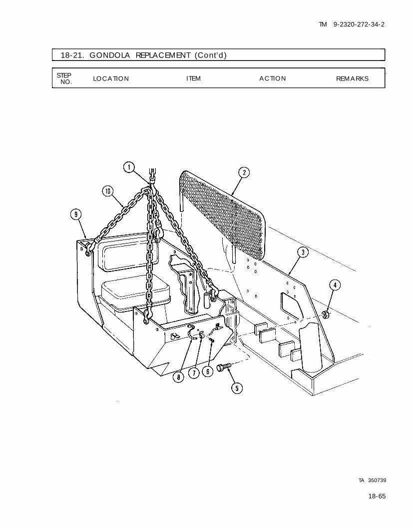
TM 9-2320-272-34-2
18-21. GONDOLA REPLACEMENT (Cont’d)
STEP LOCATION ITEM ACTION REMARKSNO.
TA 350739
18-65

TM 9-2320-272-34-2
18-21. GONDOLA REPLACEMENT (Cont’d)
STEP LOCATION ITEM ACTION REMARKSNO.
16. Hydraulic swivel valve Guide through gondolaflex line (4) (1).
17. Six hydraulic flex lines Install on gondola (1)(7) with three clamps (5)
and new locknuts (6).18. Hydraulic tube (2) Install on elevating
cylinder crossover tee(8) and control valveflex line (3).
18-66

TM 9-2320-272-34-2
18-21. GONDOLA REPLACEMENT (Cont’d)
STEP LOCATION ITEM ACTION REMARKSNO.
END OF TASK!
FOLLOW-ON TASKS: ● Install crane control valve (para. 18-20).● Install floodlight assembly (TM 9-2320-272-20-1).
TA 350740
18-67

TM 9-2320-272-34-2
18-22. TURNTABLE REPLACEMENTThis task covers:
a. Removal b. Installation
INITIAL SETUP:EquipmentCondition
Applicable Models Reference Condition DescriptionM936 TM 9-2320-272-10 Parking brake set.
Para. 18-5 Hydraulic oil reservoir removed.Para. 18-10 Boom elevating cylinders removed.Para. 18-17 Hydraulic swivel valve removed.Para. 18-19 Crane swinger gearcase removed.
Test EquipmentPara. 18-21 Gondola removed.
None
Special Tools Special Environmental ConditionsNone None
Materials/PartsEighteen locknuts
Personnel Required General Safety InstructionsWheeled vehicle repairman MOS 63W (2) All personnel must stand clear during
Manual References hoisting operations.
TM 9-2320-272-10TM 9-2320-272-34P
STEP LOCATION ITEM ACTION REMARKSNO.
WARNING
All personnel must stand clear during hoisting operations. Asnapped cable, shifting, or swinging load may cause injury topersonnel.
1.
2.
18-68
Turntable base plate Eighteen screws (5) Remove.(4) and locknuts (3), two
turntable sideplates(1), and crossovertubes (2)
Turntable gear bearing Eighteen screws (8) Remove.(9) to crane body (10)
Discard locknuts (3).
Turntable must berotated so access holeexposes each screw(8).

TM 9-2320-272-34-2
18-22. TURNTABLE REPLACEMENT (Cont’d)
NOTEAssistant will help with steps 3 and 4.
3. Two utility chains (6) Attach to turntable(4).
4. Hoist hook (7) Attach to chains (6)and hoist turntablebase plate (4) awayfrom crane body(10).
5. Turntable base date Two utility chains (6) Remove.
STEP LOCATION ITEM ACTION REMARKSNO.
and hoist hook (7)(4)
TA 350741
18-69
TM 9-2320-272-34-2
I 18-22. TURNTABLE REPLACEMENT (Cont’d)
STEPLOCATION ITEM ACTION REMARKSNO.
b. Installation
WARNING
All personnel must stand clear during hoisting operations. Asnapped cable, shifting, or swinging load may cause injury topersonnel.
NOTEAssistant will help with steps 6 and 7.
6. Two utility chains (2)
7. Hoist hook (1)
8. Two utility chains (2)and hoist hook (1)
9. Turntable gear bearing(5)
10. Turntable sideplates(7) and crossovertubes (8)
Attach to turntable(4).Attach to chains (2)and hoist turntable (4)onto crane body (6).Remove from turntable(4).Rotate to expose each Tighten 170-200 lb-ftscrew hole in turntable (231-271 N·m).(4) and install oncrane body (6) witheighteen screws (3).
Install on turntable (4) Tighten 170-200 lb-ftbase with eighteen (231-271 N·m).screws (10) and newlocknuts (9).
18-70

TM 9-2320-272-34-2
I 18-22. TURNTABLE REPLACEMENT (Cont’d)
STEP LOCATION ITEM ACTION REMARKSNO.
FOLLOW-ON TASKS: ●
END OF TASK!Install gondola (para. 18-21).Install crane swinger gearcase (para. 18-19).Install hydraulic swivel valve (para. 18-17).Install boom elevating cylinders (para. 18-10).Install hydraulic oil reservoir (para. 18-5).
18-71

TM 9-2320-272-34-2
I 18-23. FRONT WINCH HYDRAULIC PUMP REPLACEMENTThe procedure for replacement of the front winch hydraulic pump can be found in paragraph 19-8.
18-24. FRONT WINCH CONTROL VALVE REPLACEMENT The procedure for replacement of the front winch control valve can be found in paragraph 19-10.
Section Ill. WRECKER BODY COMPONENTS REPAIR
18-25. WRECKER BODY COMPONENTS REPAIR TASK SUMMARY
TASKPARA. PROCEDURES PAGE
NO.
18-26. Hydraulic Oil Reservoir Repair18-27. Hydraulic Hoist Winch Motor or
Swinger Motor Repair
18-28. Hoist Winch Repair
18-29. Boom Elevating Cylinder Repair
18-7218-74
18-8218-98
18-30. Boom Repair and Adjustment 18-102
18-31. Extension Cylinder Repair 18-108
18-32. Boom Roller Repair 18-112
18-33. Crane Swinger Gearcase Repair 18-116
18-34. Gondola Repair 18-124
18-35. Turntable Repair 18-126
18-36. Crane Control Valve Repair 18-128
18-26. HYDRAULIC OIL RESERVOIR REPAIRThis task covers:
a. Disassembly c. Reassemblyb. Cleaning, Inspection, and Repair
INITIAL SETUP:
Applicable ModelsM936
Test EquipmentNone
Special ToolsNone
Materials/PartsEleven locknutsSealing tape (Appendix C, Item 30)
Personnel RequiredWheeled vehicle repairman MOS 63W
Manual ReferencesTM 9-2320-272-34PTM 9-237
EquipmentConditionReference Condition DescriptionPara. 18-5 Hydraulic oil reservoir removed.
Special Environmental ConditionsNone
General Safety InstructionsKeep fire extinguisher nearby whenusing drycleaning solvent.
18-72

TM 9-2320-272-34-2
18-26. HYDRAULIC OIL RESERVOIR REPAIR (Cont’d)
STEP LOCATION ITEM ACTION REMARKSNO.
a. Disassembly
1. Top of oil reservoir (3) Oil gage (1) and filter Remove.screen (2)
2. Oil reservoir (3) Elbow (7), draincock Remove.(4), pipe plug (5), andpipe plug (6)
b. Cleaning, Inspection, and Repair
WARNINGDrycleaning solvent is flammable and will not be used near openflame. Use only in well-ventilated places. Failure to do this may
5.
6.
7.
8.
a. Steam clean exterior.b. Flush interior with
drycleaning solvent.Inspect for leaks andrepair as follows:
a.
b.
c.
d.
Two pipe plugs (5) and(6)Elbow (7)
Draincock (4)
Filter screen (2) andoil gage (1)
Plug all openingsexcept filter inlet.
Insert air hose ininlet hole and coveropening aroundhose.Coat exterior ofreservoir (3) withsoapy water.Apply 6 psi (41 kPa)air pressure for aminimum of twominutes and checkfor bubbles.
Install on reservoir (3).
Wrap threads with seal-ing tape and install.Wrap threads with seal-ing tape and install.Install.
Repair defective reser-voir (3) if any leaks arefound (refer to TM 9-237). Replace reservoir(3) if leaks cannot berepaired.
END OF TASK!
FOLLOW-ON TASK: Install hydraulic oil reservoir (para. 18-5).TA 350743
18-73

TM 9-2320-272-34-2
I 18-27. HYDRAULIC HOIST WINCH MOTOR OR SWINGER MOTOR REPAIRThis task covers:
a. Disassembly c. Reassemblyb. Cleaning, Inspection, and Repair
INITIAL SETUP:EquipmentCondition
Applicable Models Reference Condition Description
M936 Para. 18-7 Hydraulic hoist winch motor removedTest Equipment or
None Para. 18-18 Crane hydraulic swinger motor
Special Toolsremoved.
None
Materials/PartsFour snaprings
Special Environmental Conditions
Four oil seal adapters NoneFour inner “O” ringsFour outer “O” ringsEight lockwashersCrocus cloth (Appendix C, Item 6)Lint-free cloth (Appendix C, Item 7)
Personnel Required General Safety Instructions
Wheeled vehicle repairman MOS 63W Keep fire extinguisher nearby when
Manual References using drycleaning solvent.
TM 9-2320-272-34P
STEP LOCATION ITEM ACTION REMARKSN O .
●
●
NOTERepair procedures for the hoist winch motor and the swingermotor are identical. This procedure will cover the hoist winchmotor only.The following instructions apply to repairable type motors only.
a. Disassembly
1.
2.
3.
18-74
Hoist motor (1) Two adapter fittings(3)Front cover (6) andrear cover (2)
Front cover (6) and Eight screws (4) andrear cover (2) to motor lockwashers (5)body (9)
Remove.
Scribe alinementmarks between frontcover (6) and pumpbody (9), and betweenrear cover (2) andpump body (9).Remove. Discard lockwashers
(5).Covers (6) and (2) arenow held to motorbody (9) by two dowelpins (7).

TM 9-2320-272-34-2
18-27. HYDRAULIC HOIST WINCH MOTOR OR SWINGER MOTOR REPAIR (Cont’d)
STEP LOCATION ITEM ACTION REMARKSNO.
4.
CAUTIONAll metal wear plates are easily damaged. Use care not to damagewhen removing front cover and rear cover.
Front cover (6) and Gently tap inner edges Use soft-faced hammerrear cover (2) of each, and remove and alternately tap
from motor body (9). cover edges.5. Front and rear wear Gently tap inner edges Use soft-faced
plates (8) of each, and remove hammer.from motor body (9).
6. Drive gear shaft (11) Remove from motorand driven gear shaft body (9).(10)
T A 3 5 0 7 4 4
18-75

TM 9-2320-272-34-2
I 18-27. HYDRAULIC HOIST WINCH MOTOR OR SWINGER MOTOR REPAIR (Cont’d)
STEP LOCATION ITEM ACTION REMARKSNO.
7. Front cover (5) or rear Position in soft-jawedcover (1) vise (4).
NOTEBearings are removed from front cover and rear cover in the sameway. This procedure covers rear cover bearing removal only.
8. Front cover (5) or rear Two roller bearings (2) Remove. Use mechanical pullercover (1) (3).
9. Two oil seal adapters Remove. Discard all items(7), outer “O” rings (8), removed in this step. Itand inner “O” rings (9) is not necessary to
remove dowel pins (6)unless inspectionrequires replacement.
10. Drive gear shaft (12) Four snaprings (10), Remove.and driven gear shaft and spacers (11 )(13)
18-76
Discard snaprings (10).
TA 350745

TM 9-2320-272-34-2
18-27. HYDRAULIC HOIST WINCH MOTOR OR SWINGER MOTOR REPAIR (Cont’d)
STEP LOCATION ITEM ACTION REMARKSNO.
TA 350746
18-77

TM 9-2320-272-34-2
18-27. HYDRAULIC HOIST WINCH MOTOR OR SWINGER MOTOR REPAIR (Cont’d)
STEP LOCATION ITEM ACTION REMARKSNO.
b. Cleaning, Inspection, and Repair
WARNING
Drycleaning solvent is flammable and will not be used near openflame. Use only in well-ventilated places. Failure to do this mayresult in injury to personnel.
CAUTIONDo not spin-dry bearings with compressed air.
11. Four bearings (2),drive gear shaft (4),driven gear shaft (7),front cover (1), rearcover (6), and motorbody (5)
12. Motor body (5), frontcover (1), and rearcover (6)
13. Drive gear shaft (4)and driven gear shaft(7)
14.
15.
Wear plates (3)
Four bearings (2)
a. Clean with dry-cleaning solvent.
b. Dry thoroughly withlint-free cloth.
Inspect for cracks,pitting, and scoring.
Inspect for cracks,nicks, or burrs.
Inspect for nicks,burrs, dents, ordistortion.Inspect for scoring,pitting, or rough edgesaround race.
Replace if cracked,pitted, or scored.
Replace if cracked.Remove nicks andburrs with crocuscloth. If repairs cannotbe made, replace.
Replace if nicked,burred, dented, ordistorted.Replace if pitted,scored, or rough edgesare evident.
18-78

TM 9-2320-272-34-2
18-27. HYDRAULIC HOIST WINCH MOTOR OR SWINGER MOTOR REPAIR (Cont’d)
STEP LOCATION ITEM ACTION REMARKSNO.
TA 350747
18-79

TM 9-2320-272-34-2
18-27. HYDRAULIC HOIST WINCH MOTOR OR SWINGER MOTOR REPAIR (Cont’d)
STEP LOCATION ITEM ACTION REMARKSNO.
c. Reassembly
16.
17.
18.19.
20.
21.
22.
Two new oil seal adapt- Install in each coverers (3), new inner “O” (1) and (6).rings (5), and newouter “O” rings (4)
Two roller bearings (8) Install in each cover Use arbor press (7).(1) and (6).
Dowel pins (2) Install in cover (1). Only if removed.
Four spacers (13) Install on gear shafts(14) and (16) withfour new snaprings(15).
Gear shafts (14) and Position in body (10)(16) so they mesh.
NOTETo properly assemble wear plates (9), bronze sides should face eachother.
Two wear plates (9) Position one on bodydowel pins (2) and oneon motor body (10).
Covers (1) and (6) a. Position with aline-ment marks directlyopposite oneanother.
b. Install with eight Tighten 125 lb-ftnew lockwashers (170 N·m).(12) and screws(11).
TA 350748
18-80

TM 9-2320-272-34-2
18-27. HYDRAULIC HOIST WINCH MOTOR OR SWINGER MOTOR REPAIR (Cont’d)
STEP LOCATIONNO. ITEM ACTION REMARKS
END OF TASK!
FOLLOW-ON TASKS: Install hydraulic hoist winch (para. 18-7)
Install crane hydraulic swinger motor (para. 18-18).TA 350749
18-81

TM 9-2320-272-34-2
18-28. HOIST WINCH REPAIRThis task covers:
a. Disassembly c. Reassemblyb. Cleaning, Inspection, and Repair
INITIAL SETUP:EquipmentCondition
Applicable Models Reference Condition DescriptionM936 Para. 18-9 Hoist winch removed.
Test EquipmentNone
Special Tools Special Environmental ConditionsNone None
Materials/PartsThirty-six lockwashersFour hoist winch sealsFour bushingsSix gasketsSnapringExpansion plug“O” ringThree woodruff keysFour keysSealing tape (Appendix C, Item 30)
Personnel RequiredWheeled vehicle repairman MOS 63W
Manual ReferencesTM 9-2320-272-20-2TM 9-2320-272-34P
General Safety InstructionsKeep fire extinguisher nearby whenusing drycleaning solvent.
STEP LOCATION ITEM ACTION REMARKSNO.
a . Disassembly
1.
WARNINGDrycleaning solvent is flammable and will not be used near openflame. Use only in well-ventilated places. Failure to do this mayresult in injury to personnel.
Hoist winch (1)
2. Output side of drum Screw (7), lockwashershaft (17) (8), retaining washer
(9), shim (10), supportplate (6), drum (5),two thrust washers(12), and two keys (16)
Thoroughly clean exter-ior with drycleaningsolvent.Remove. Discard lockwasher (8)
and keys (16).
18-82

TM 9-2320-272-34-2
18-28. HOIST WINCH REPAIR (Cont'd)
STEPNO. LOCATION ITEM ACTION REMARKS
3. Support plate (6) Bushing (11)
4. Hoist drum (5) Cable setscrew (4)
5. Drum shaft (17) Screw (3) and drumsupport (2)
6. Gearcase housing (1) Bushing (14) and seal(15)
7. Drum support (2) Bushing (13)
Remove. Use arbor press andmandrel.
Discard bushing (11).
Remove.
Remove.
Remove. Use arbor press andmandrel.Discard bushing (14)and seal (15).
Remove. Use arbor press andmandrel.Discard bushing (13).
TA 350750
Change 2 18-83

TM 9-2320-272-34-2
18-28. HOIST WINCH REPAIR (Cont’d)
STEP LOCATION ITEM ACTION REMARKSNO.
8. Input side of drum Discard lockwashershaft (7) (13).
9. Gearcase (8)
10. Gearcase cover (2)
11. Gearcase housing (8)
12. Drum shaft (7)
18-84
Screw (14), lockwasher Remove.(13), and retainingwasher (12)Four screws (10), six Remove.screws (1), four lock-washers (9), gearboxcover (2), and gasket(3)Seal (11) and bushing Remove.(4)
Drum shaft (7) and Remove as one assem-hoist worm gear (5) bly.Hoist worm gear (5) Remove.and two keys (6)
NOTEScribe alinement marks on brake housing and gearcase for properinstallation during reassembly.
Discard lockwashers(9) and gasket (3).
Clean gasket remainsfrom mating surfaces.
Discard seal (11) andbushing (14).
Discard keys (6).
TA 350751

TM 9-2320-272-34-2
18-28. HOIST WINCH REPAIR (Cont’d)
STEP LOCATION ITEM ACTION REMARKSNO.
13. Brake housing (16)
14.
15. Hoist wormshaft (35)
16. Gearcase (8)
17. Brake housing (16)
Six screws (25) and Remove.lockwashers (24),housing cover (26),and gasket (27)Screw (34), lockwasher Remove.(33), “O” ring (32),spring (28), and brakeband (23)Screw (22), lockwasher Remove.(29), washer (21),brakedrum (30) andwoodruff key (18)
Four screws (20) and Remove.lockwashers (19),brake housing (16),and gasket (15)
Expansion plug (17) Remove.and seal (31)
Discard lockwashers(24) and gasket (27).
Discard lockwasher(33) and “O” ring (32).
Discard lockwasher(29).
Use puller for brake-drum (30) and discardwoodruff key (18).
Discard lockwashers(19) and gasket (15).Clean gasket remainsfrom mating surfaces.
Discard seal (31) andexpansion plug (17).
TA 350752
18-85

TM 9-2320-272-34-2
18-28. HOIST WINCH REPAIR (Cont’d)
STEP LOCATION ITEM ACTION REMARKSNO.
18. Input shaft (9) Coupler (1) Remove.
19. Input shaft cover (5) Four screws (26) and Remove. Discard lockwasherslockwashers (25), hoist (25) and gasket (24).motor adapter (2), and Clean gasket remainsgasket (24) from mating surfaces.
20. Input shaft (9) Woodruff key (7) Remove. Discard woodruff key(7).
NOTEDo not remove two input shaft cover dowel pins unless inspectionrequires cover replacement.
21. Input shaft gearcase(13)
22. Input shaft cover (5)
23. Input shaft gearcase(13)
24. Hoist wormshaft (17)
25. Gearcase housing (15)
26. Input shaft gearcase(13)
Ten screws (3) andlockwashers (4), inputshaft cover (5), andgasket (6)
Plug (23) and bearing(8)Input shaft (9), inputgear (10), and bearing(12)Snapring (22) drivegear (21), and wood-ruff key (11)
Four screws (19) andlockwashers (18), gear-case (13), and gasket(14)
Plug (16) and seal (20)
Remove. Discard lockwashers(4) and gasket (6).Clean gasket remainsfrom mating surfaces.
Remove. Use arbor press andmandrel.
Remove. Use puller.
Remove. Discard snapring (22).Use puller.
Discard woodruff key(11).
Remove. Discard lockwashers(18) and gasket (14).Clean gasket remainsfrom mating surfaces.Discard seal (20).
Remove.
18-86

TM 9-2320-272-34-2
18-28. HOIST WINCH REPAIR (Cont’d)
STEP LOCATION ITEM ACTION REMARKSNO.
TA 350753
18-87

TM 9-2320-272-34-2
18-28. HOIST WINCH REPAIR (Cont’d)
STEP LOCATION ITEM ACTION REMARKSNO.
27. Gearcase housing (6) Two wormshaft bear- a. Press wormshaft (1) Use arbor press andings (2) and worm- ends to remove bear- mandrel.shaft (1) ings (2).
b. Remove wormshaft(1).
28. Gearcase breather (3), Remove.two filler plugs (4), andmagnetic pipe plug (5)
b. Cleaning, Inspection, and Repair
29.
30.
31.
32.
33.
34.
18-88
WARNING
Drycleaning solvent is flammable and will not be used near openflame. Use only in well-ventilated places. Failure to do this mayresult in injury to personnel.
All hoist winch parts
Magnetic pipe plug (5)
Drum shaft gear (9),wormshaft (1), drumshaft (10), input gear(14), and drive gear(15)Wormshaft bearings(2) and bushing (8)
Gearcase cover (7),gearcase housing (6),breather (3), two plugs(4), and automaticbrake housing (11)Brakedrum (12) andbrake band (13)
Clean with drycleaningsolvent.Inspect for metalfilings and chips.
Inspect for breaks,chipped teeth, cracks,and burrs.
Inspect for cracks, pits,or out-of-roundcondition.Inspect for breaks,cracks, warping, orstripped threads.
Inspect for scoring oroil-soaked condition.
Refer to para. 2-7.
If metal filings arefound, gear wear isindicated.If metal chips arefound, damaged gearsare indicated.
If broken, chipped, orcracked, replace. Ifburred, remove burrswith crocus cloth.
If cracked, pitted, orout-of-round, replace.
If broken, cracked,warped, or if strippedthreads are evident,replace.
If brake band (13) isworn to rivets, or oil-soaked, replace. Ifdrum (12) is scored,replace.

TM 9-2320-272-34-2
I 18-28. HOIST WINCH REPAIR (Cont’d)
STEP LOCATION ITEM ACTION REMARKSNO.
18-89

TM 9-2320-272-34-2
18-28. HOIST WINCH REPAIR (Cont’d)
STEP LOCATION ITEM ACTION REMARKSNO.
c. Reassembly
NOTEMake sure alinement marks made during disassembly realineduring assembly.
Wormshaft (1) andtwo bearings (2)
35.
36.
Install in gearcasehousing (5).
Install bearings (2)with arbor press andmandrel.
Two filler plugs (4),gearcase breather (3),and magnetic pipe plug(6)
Plug (20) and new seal(21)
Install into gearcasehousing (5).
Wrap sealing tapearound filler plugs (4)and breather (3)before installation.
37.
38.
Install in input shaftgearcase (18).
Wrap sealing tapearound plug (20)before installation.
New input shaft gear-case gasket (19) andgearcase (18)
Install on gearcasehousing (5) with fournew lockwashers (22)and screws (23).
39. New woodruff key (24) Place in keyway onhoist wormshaft (1).
40. Drive gear (25) Place over hoist worm-shaft (1) and securewith new snapring(26).
41.
42.
43.
44.
Input shaft bearing(17)
Press in input shaftgearcase (18).
Use arbor press andmandrel.
Input shaft gear (16) Slide over input shaft(15).
Input shaft bearing(14)Input shaft (15) andgear (16)
Press into input shaftcover (11).
Use arbor press andmandrel.
Install in input shaftgearcase (18) until in-put shaft (15) bottomsagainst bearing (17).
45. New input shaft gear-case gasket (12) andcover (11 )
Install on input shaftgearcase (18) with tenscrews (9) and newlockwashers (10).
46.
47.
Plug (27) Install in input shaftcover (11).
Wrap sealing tapearound plug (27)before installation.
New woodruff key (13) Install in keyway ininput shaft (15).
18-90

TM 9-2320-272-34-2
18-28. HOIST WINCH REPAIR (Cont’d)
STEP LOCATION ITEM ACTION REMARKSNO.
48. New gasket (28) and Install on input shafthoist motor adapter gearcase cover (11)(8) with four new lock-
washers (29) andscrews (30).
49. Coupler (7) Slide over input shaft(15).
TA 350755
18-91

TM 9-2320-272-34-2
18-28. HOIST WINCH REPAIR (Cont’d)
STEP LOCATION ITEM ACTION REMARKSNO.
50. New gasket (2) and Install on gearcaseautomatic brake hous-ing (3)
51. New seal (18) andbrakedrum (17)
52. Brake band (8)
housing (1) with fournew lockwashers (5)and screws (6).
Install on hoist worm-shaft (22) with newwoodruff key (7), re-taining washer (16),new lockwasher (15),and screw (14).
Install as follows:
a.
b.
Position aroundbrakedrum (17)with spring (13)between brake band(8) and automaticbrake housing (3).
Install on brake
53. New gasket (12) andautomatic brake cover(11)
54. New expansion plug(4)
18-92
housing (3) withnew “O” ring (19),new lockwasher(20), and screw(21).
Install on brakehousing (3) with sixnew lockwashers (9)and screws (10).
Install in brakehousing (3).

TM 9-2326-272-34-2
18-28. HOIST WINCH REPAIR (Cont’d)
STEP LOCATIONNO. ITEM ACTION REMARKS
TA 350756
18-93

TM 9-2320-272-34-2
18-28. HOIST WINCH REPAIR (Cont’d)
STEP LOCATION ITEM ACTION REMARKSNO.
55. New gearcase housing Install in gearcase Make sure seal (3) iscover bushing (6) and housing cover (4). flush with outside edgenew seal (3) of cover (4).
56. Two new keys (7) and Install on drum shaft Make sure gear (10)hoist worm gear (10) (8). centers over new keys
(7).
must be checked and adjusted. End play will be checked at thedrum shaft and adjusted by adding gaskets to gearcase cover.
60. Drum shaft (8) a. Place dial indicator(15) against shaft(8) as shown.
b. Pull drum shaft (8)in and out severaltimes until readingon dial indicator
(15) is consistent.
If end day is less than0.005 in. (0.125 mm),add cover gaskets (5)until end play readsgreater than 0.005 in.(0.125 mm) but lessthan 0.015 in.(0.37 mm).
57. Hoist worm gear (10) Install in gearcaseand drum shaft (8) housing (9).
58. New gearcase housing Place over drum shaftcover gasket (5) and (8) and install on gear-cover (4) case housing (9) with
four new lockwashers(11), six screws (1),and four screws (12).
59. Retaining washer (2) Install on drum shaft(8) with new lock-washer (13) and screw(14).
NOTEBefore completing assembly of hoist winch, the worm gear end play
18-94

TM 9-2320-272-34-2
18-28. HOIST WINCH REPAIR (Cont’d)
STEPNO. LOCATION ITEM ACTION REMARKS
18-95
TM 9-2320-272-34-2
18-28. HOIST WINCH REPAIR (Cont'd)
STEPLOCATION ITEM ACTION REMARKSNO.
61. New bushing (14) and Make sure seal (15) isnew seal (15)
62. New drum supportbushing (13)
63. Drum support (2)
64. New support platebushing (10)
65. Two thrust washers(11), drum (12), andsupport plate (5)
65.1. Cable setscrew (4)66. Drum shaft (16)
Press in gearcasehousing (1).
Install in drumsupport (2).
Slide over drum shaft(16) and install on casehousing (1) with screw(3).Install in support plate(5).Position on drum shaft(16) and install withtwo new keys (17),shim (6), retainingwasher (7), new lock-washer (8), and screw(9).Install in drum (12).Check end play byinserting feeler gagebetween retainingwasher (7) and shim(6) and take reading.
flush with outside ofhousing (1).
Use arbor press andmandrel.
Use arbor press.
Use arbor press.
Make sure drum (12)seats over keys (17).
If reading is less than0.015 in. (0.381 mm),add an appropriatenumber of shims (6)until at least 0.015 in.(0.381 mm) is obtained.
18-96

TM 9-2320-272-34-2
18-28. HOIST WINCH REPAIR (Cont'd)
STEPNO. LOCATION ITEM ACTION REMARKS
END OF TASK!FOLLOW-ON TASKS: • Install hoist winch (para. 18-9).
• Check automatic brake adjustment (TM 9-2320-272-20-2).
Change 2 18-97

TM 9-2320-272-34-2
18-29. BOOM ELEVATING CYLINDER REPAIRThis task covers:
a. Disassembly c. Reassemblyb. Cleaning, Inspection, and Repair
INITIAL SETUP:Applicable Models
M936 EquipmentCondition
Test Equipment Reference Condition Description
None Para. 18-10 Boom elevating cylinder removed.
Special Tools
Bushing installer 3005319Handle 7010321
Special Environmental Conditions
Materials/Parts
Two seals“O” ringLockwireWiper stripPackingCrocus cloth (Appendix C, Item 6)Lint-free cloth (Appendix C, Item 7)
Personnel Required
Wheeled vehicle repairman MOS 63W
Manual References
TM 9-2320-272-34PLO 9-2320-272-12
None
General Safety Instructions
Keep fire extinguisher nearbyusing drycleaning solvent.
when
STEP LOCATION ITEM ACTION REMARKSNO.
1.
2.
3.
4.
5. .
6.
18-98
Elevating cylinder body(4)
Piston rod (2)
Cylinder head (3)
Piston (14)
Piston rod (2)
Cylinder body (4) andpiston rod (2)
Cylinder head (3) andpiston rod (2)
Lockwire (18), nut(19), washer (17), re-tainer (16), piston seal(15), piston (14),piston-to-piston rodseal (6), cylinder head(3), and wiper strip (9)
Packing nut (10), pack-ing (11), bushing (12),and “O” ring (13)
Two half rings (5)
Sleeve (8)
Two lubrication fittings(7)
Remove. Use spanner wrench(1) to remove cylinderhead (3).
Remove. Discard lockwire (18).
Discard piston seal(15) and piston-to-piston rod seal (6).
Discard wiper strip (9).
Remove. Discard “O” ring ( 13)and packing (11).
Remove.
Remove.
Remove.

TM 9-2320-272-34-2
18-29. BOOM ELEVATING CYLINDER REPAIR (Cont'd)
STEP LOCATIONN O . ITEM ACTION REMARKS
18-99

TM 9-2320-272-34-2
18-29. BOOM ELEVATING CYLINDER REPAIR (Cont’d)
STEP LOCATION ITEM ACTION REMARKSN O .
b. Cleaning, Inspection, and Repair
WARNINGDrycleaning solvent is flammable and will not be used near openflame. Use only in well-ventilated places. Failure to do this mayresult in injury to personnel.
7. All parts of elevating Clean with drycleaningcylinder solvent, and dry with
lint-free cloth.8. Piston rod (9) Inspect for burrs, scor-
ing, scratches, andstripped threads.
9. Piston (13) andcylinder body (1)
Inspect for scoring.
c. Reassembly
10.
11.
12.
13.
14.
15.
16.
Two lubrication fittings(2)
Sleeve (10)
Two half rings (3)Piston rod bushing (6)
New “O” ring (4), newpacking (7), packingnut (8), and new wiperstrip (11)
Cylinder head (5)
New piston-to-pistonrod seal (12), piston(13), new piston seal(14), retainer (15), andwasher (16)
Install in cylinder body(1) and piston rod (9).Install in piston rod(9).Install on piston (13).
Remove minorscratches and burrswith crocus cloth.If piston rod (9) isscored, scratched, or ifstripped threads areevident, replace.
If piston ( 13) is scored,replace.If cylinder body (1) isscored, replace elevat-ing cylinder.
Install in cylinder head Use bushing installer(5). and handle (19).
Install on cylinderhead (5).
Install on piston rod Use care not to(9). damage wiper strip
(11) when passing overthreads on piston rod(9).
Install on piston rod(9).
18-100

TM 9-2320-272-34-2
18-29. BOOM ELEVATING CYLINDER REPAIR (Cont’d)
STEP LOCATION ITEM ACTION REMARKSN O .
17.
18.
Piston rod nut (18) Install on piston rod(9) and secure nut(18) with new lockwire(17).
Piston rod (9) Slide into cylinder body(1) and install cylinderhead (5) to cylinderbody (1).
Use spanner wrench totighten cylinder head(5).
FOLLOW-ON TASKS: ●
●
END OF TASK!
Install boom elevating cylinder (para. 18-10).Lubricate elevating cylinder (LO 9-2320-272-12).
TA 350760
18-101

TM 9-2320-272-34-2
18-30. BOOM REPAIR AND ADJUSTMENTThis task covers:
a. Disassembly c. Reassemblyb. Cleaning, Inspection, and Repair d. Vertical Adjustment
INITIAL SETUP:EquipmentCondition
Applicable Models Reference Condition DescriptionM936 Para. 18-9 Hoist winch removed.
Test Equipment
Para.Para.Para.
None
Special ToolsNone
Materials/PartsTwo cotter pinsTwo locknutsTwenty-four lockwashersGM grease (Appendix C, Item 11)
Personnel RequiredWheeled vehicle repairman MOS 63W
Manual ReferencesTM 9-2320-272-34PTM 9-237
18-13 Inner boom removed.18-14 Extension cylinder removed.18-15 Boom rollers removed.
Special Environmental ConditionsNone
General Safety InstructionsKeep fire extinguisher nearby whenusing drycleaning solvent.
STEP LOCATION ITEM ACTION REMARKSNO.
a. Disassembly
Outer boom (14)
Crane sheave (12)
Inner boom (9)
Two cable sheaves (1)
Four boom tracks (8)to inner boom (9)
Cotter pin (10), crane Remove.sheave pin (13), andcrane sheave (12)Two bearings (11) Remove.
Two screws (16), lock- Remove.nuts (5), and spacers(4)Cotter pin (7), cable Remove.sheave pin (15), andtwo cable sheaves (1)Two sheave bushings Remove.(2), thrust washers (3),and spacer (17)One hundred and four Remove from innerscrews (6) and four boom (9).tracks (8)
Discard cotter pin(10).
Use arbor press andmandrel.Discard locknuts (5).
Discard cotter pin (7).
Use arbor press andmandrel.
18-102

TM 9-2320-272-34-2
18-30. BOOM REPAIR AND ADJUSTMENT (Cont’d)
STEP LOCATION ITEM ACTION REMARKSN O .
TA 350761
18-103

TM 9-2320-272-34-2
I 18-30. BOOM REPAIR AND ADJUSTMENT (Cont’d)
STEP LOCATION ITEM ACTION REMARKSN O .
b. Cleaning, Inspection, and Repair
WARNlNG
7.
8.
9.
10.
11.
Drycleaning solvent is flammable and will not be used near openflame. Use only in well-ventilated places. Failure to do this mayresult in injury to personnel.
All boom components
Inner boom (9) andouter boom (13)
Four boom tracks (8)
Crane sheave pin (12)and cable sheave pin(14)Two cable sheaves (1),cable sheave bushings(2), crane sheave (11),and crane sheave bear-ings (10)
Clean with drycleaningsolvent.Inspect for cracked orbroken welds andbends.
Inspect for cracks,breaks, and bends.
Inspect for breaks andout-of-round condition.
Inspect for breaks andout-of-round condition.
If welds are cracked orbroken, refer to TM 9-237. If inner boom (9)or outer boom (13) isbent, replace.If tracks (8) arecracked, broken, orbent, replace.If pins (12) and (14)are broken, or out-of-round, replace.
If broken or out-of-round, replace.
c . Reassembly
12. Four boom tracks (8) Install to inner boom(9) with one hundredand four screws (6)and coat with GAAgrease.
13.
14.
Two cable sheavebushings (2)Two cable sheavethrust washers (3) andspacer (16)
15. Two spacers (4)
Install into two cablesheaves (1).Aline with holes ininner boom (9) andinstall with cablesheave pin (14) andnew cotter pin (7).Position to inner boom(9) and install withtwo screws (15) andnew locknuts (5).
Use arbor press andmandrel.
18-104

TM 9-2320-272-34-2
18-30. BOOM REPAIR AND ADJUSTMENT (Cont’d)
STEP LOCATION ITEM ACTION REMARKSN O .
TA 350762
18-105

TM 9-2320-272-34-2
18-30. BOOM REPAIR AND ADJUSTMENT (Cont’d)
STEP LOCATION ITEM ACTION REMARKSNO.
16. Two crane sheave bear- Install into crane Use arbor press andings (3) sheave (4). mandrel.
17. Crane sheave (4) Aline with holes inouter boom (1) andinstall with cranesheave pin (5) and newcotter pin (2).
18. Boom rollers Install.
19. Extension cylinder Install.
20. Inner boom Install.
21. Hoist winch Install.
Refer to para. 18-15.Refer to para. 18-14.Refer to para. 18-13.Refer to para. 18-9.
d. Vertical Adjustment
NOTEVertical adjustment can be performed with boom assembly eitherinstalled or removed from wrecker body.
22. Four mounting caps Sixteen screws (10) Remove. Discard lockwashers(11) to lower boom and lockwashers (9) (9).roller assembly (8) andupper boom rollerassembly (7)
23. Lower boom roller Two mounting caps a. Turn so top edge ofassembly (8) (11) inner boom (6) and
top edge of outerboom (1) are approx-imately parallel.
b. Install mounting
24. Upper boom roller Two mounting caps a.assembly (7) (11)
b.
caps (11) on lowerboom roller assem-bly (8) with eightnew lockwashers (9)and screws (10).Turn until rollerassembly (7) strikesinner boom (6), thenturn back to nextscrew hole.Install two mountingcaps (11) to upperboom roller assem-bly (7) with eightnew lockwashers (9)and screws (10).
18-106

TM 9-2320-272-34-2
18-30. BOOM REPAIR AND ADJUSTMENT (Cont’d)
STEP LOCATION ITEM ACTION REMARKSNO.
25.
26.
27.
Inner boom (6) Manually extend andretract to verify thatlower edge clears outerboom (1).
NOTEOnly perform steps 26 and 27 if inner boom catches on upperboom roller assembly after adjustment is checked.
Two mounting caps Eight screws (10) and Remove and turn Discard lockwashers(11) to upper roller lockwashers (9) mounting cap (11) one (9).assembly (7) additional screw hole.
Two mounting caps Install on upper roller(11) (7) with eight new
lockwashers (9) andscrews (10).
T’A 350763
18-107

TM 9-2320-272-34-2
18-31. EXTENSION CYLINDER REPAIRThis task covers:
a. Disassemble c. Reassembleb. Cleaning, Inspection, and Repair
INITIAL SETUP:Equipment
Applicable ModelsConditionReference Condition Description
M936 Para. 18-14 Extension cylinder removed.
Test EquipmentNone
Special Tools Special Environmental ConditionsBushing installer 3005319 NoneHandle 7010321
Materials/PartsWiper stripLockwire“O” ringPackingCrocus cloth (Appendix C, Item 6)Lint-free cloth (Appendix C, Item 7)
Personnel RequiredWheeled vehicle repairman MOS 63W
Manual ReferencesTM 9-2320-272-34PLO 9-2320-272-12
General Safety InstructionsKeep fire extinguisher nearby whenusing drycleaning solvent.
STEP LOCATION ITEM ACTION REMARKSNO.
a. Disassembly
1.
2.
3.
4.
5.
18-108
Extension cylinderbody (4)
Piston rod nut (16) topiston rod (2)Piston rod (2)
Cylinder head (3)
Piston (12)
Cylinder head (3) andpiston rod (2)
Lockwire (15) and nut(16)
Washer (14), U-cup re-tainers (10), U-cups(11), piston (12), cylin-der head (3), andwiper strip (6)Packing nut (5),packing (7), “O” ring(9), and piston rodbushing (8)Two half rings (13)
Remove. Use spanner wrench(1) to remove cylinderhead (3).
Remove. Discard lockwire (15).
Remove. Discard wiper strip (6)
Remove.
Remove.
Discard “O” ring (9)and packing (7).

TM 9-2320-272-34-2
18-31. EXTENSION CYLINDER REPAIR (Cont’d)
STEP LOCATION ITEM ACTION REMARKSNO.
TA 350764
18-109

TM 9-2320-272-34-2
I 18-31. EXTENSION CYLINDER REPAIR (Cont’d)
STEP LOCATION ITEM ACTION REMARKSNO.
I b. Cleaning, Inspection, and Repair
WARNINGDrycleaning solvent is flammable and will not be used near open
6.
7.
8.
flame. Use only in well-ventilated places. Failure to do this mayresult in injury to personnel.
All extension cylindercomponents
Clean with drycleaningsolvent, and dry withlint-free cloth.
Refer to para. 2-7.
Piston rod (6) Inspect for burrs,scoring, scratches, andstripped threads.
Piston (11) andcylinder body (1)
Inspect for scoring.
Remove minorscratches and burrswith crocus cloth.If piston rod (6) isscored, or if strippedthreads are evident,replace.
If piston (11) is scored,replace.If cylinder body (1) isscored, replace.
c. Reassembly
9.1 0 .
Two half rings (12)Piston rod bushing (5)
Install on piston (11).Install in cylinder head(7).
Use bushing installerand handle (16).
11.
12.
13.
14.
15.
New “O” ring (8), newpacking (4), packingnut (2), and new wiperstrip (3)Cylinder head (7)
Two U-cup retainers(9), U-cups (10), piston(11) and washer (13)Piston rod nut (15)and new lockwire (14)
Piston rod (6)
Install on cylinderhead (7).
Install on piston rod(6).
Install on piston rod(6).
Secure to piston rod(6).Slide into cylinder body(1) and install cylinderhead (7) on cylinderbody (1).
Use care not todamage wiper strip (3)when passing overthreads on piston rod(6).
Use spanner wrench totighten cylinder head(7).
18-110

TM 9-2320-272-34-2
18-31. EXTENSION CYLINDER REPAIR (Cont’d)
STEP LOCATION ITEM ACTION REMARKSN O .
FOLLOW-ON TASKS: ● Lubricate extension cylinder (LO 9-2320-272-12).● Install extension cylinder (para. 18-14).
TA 350765
18-111

TM 9-2320-272-34-2
I 18-32. BOOM ROLLER REPAIRThis task covers:
a. Disassembly c. Reassemblyb. Cleaning, Inspection, and Repair
INITIAL SETUP:
Applicable ModelsM936
Test EquipmentNone
Special ToolsNone
Materials/PartsEight lockwashersTwo woodruff keys
Personnel RequiredWheeled vehicle repairman MOS 63W
Manual ReferencesTM 9-2320-272-34P
EquipmentConditionReference Condition DescriptionPara. 18-15 Boom roller removed.
Special Environmental ConditionsNone
General Safety InstructionsKeep fire extinguisher nearby whenusing drycleaning solvent.
STEP LOCATION ITEM ACTION REMARKSNO.
WARNING
Drycleaning solvent is flammable and will not be used near openflame. Use only in well-ventilated places. Failure to do this mayresult in injury to personnel.
1.
2.
3,
4.5.
6.
18-112
Left and right mount-ing caps (4) to boomroller frame (6)
Frame (6)
Roller shaft (10)Rollers (7)
Roller shaft (10)
Boom roller (1)
Eight screws (2) andlockwashers (3), leftand right mountingcaps (4), and fourshims (5)Two rollers (7) androller shaft (10)
Two rollers (7)Two roller bearings (8)
Two woodruff keys (9)
Thoroughly clean exter-ior with drycleaningsolvent.Remove.
Remove.
Remove.Remove.
Remove.
Discard lockwashers(3).
Use arbor press andmandrel.Discard woodruff keys( 9 ) .

TM 9-2320-272-34-2
18-32. BOOM ROLLER REPAIR (Cont’d)
STEPNO. LOCATION ITEM ACTION REMARKS
TA 350766
18-113

TM 9-2320-272-34-2
18-32. BOOM ROLLER REPAIR (Cont’d)
STEP LOCATION ITEM ACTION REMARKSNO.
b. Cleaning, Inspection, and Repair
WARNINGDrycleaning solvent is flammable and will not be used near openflame. Use only in well-ventilated places. Failure to do this mayresult in injury to personnel.
All boom roller parts Clean with drycleaning7. Refer to para. 2-7.solvent.
8. Roller bearings (7) androllers (6)
Inspect for pitting andscoring.
If pitted or scored,replace bearings (7) orrollers (6).If cracked, or threadsare damaged, replaceframe (5) or mountingcaps (3).If roller shaft (9) isbroken or scored,replace.
9. Boom roller frame (5)and mounting caps (3)
Inspect for cracks ordamaged threads.
10. Roller shaft (9) Inspect for scoring andbreaks.
11. Roller bearings (7) Install in rollers (6). Use arbor press andmandrel.
Two new woodruffkeys (8)Rollers (6) andbearings (7)Roller shaft (9) androllers (6)
Four shims (4), andleft and right mountingcaps (3)
Install on roller shaft(9).Install on roller shaft(9).Install in boom rollerframe (5).
a.
b.
Position to frame (5)and measureclearance betweenmounting caps (3)and rollers (6).Clearance should be If clearance is more.062-.125 in. than .062-.125 in.(1.6-3.2 mm). (1.6-3.2 mm) remove
shims (4). If clearance is less than.062-.125 in.(1.6-3.2 mm) addshims (4).
c. Install on frame (5)with eight new lock-washers (2) andscrews (l).
18-114

TM 9-2320-272-34-2
18-32. BOOM ROLLER REPAIR (Cont’d)
LOCATION ITEM ACTION REMARKS
FOLLOW-ON TASK: Install boom roller (para.END OF TASK!
18-15).
TA 350767
18-115

TM 9-2320-272-34-2
18-33. CRANE SWINGER GEARCASE REPAIRThis task covers:
a. Disassembly c. Reassemblyb. Cleaning, Inspection, and Repair
INITIAL SETUP:EquipmentCondition
Applicable Models Reference Condition DescriptionM936 Para. 18-19 Crane swinger gearcase removed.
Test EquipmentNone
Special ToolsNone
Special Environmental ConditionsNone
Materials/PartsThree gearcase gasketsGearcase sealFifteen lockwashersFive woodruff keys
Personnel RequiredWheeled vehicle repairman MOS 63W
General Safety InstructionsKeep fire extinguisher nearby whenusing drycleaning solvent.
Manual ReferencesTM 9-2320-272-34PLO 9-2320-272-12
STEP LOCATION ITEM ACTION REMARKSNO.
1.
WARNING
Drycleaning solvent is flammable and will not be used near openflame. Use only in well-ventilated places. Failure to do this mayresult in injury to personnel.
Crane swinger gear- Thoroughly clean exter- Refer to para. 2-7.case (13) ior with drycleaning
solvent.2. Crane swinger gear- Two drainplugs (8) Remove, and drain lub-
case (13) ricant from gearcase(13).
3. Shaft bearing cap (10) Four screws (11), lock- Remove.to gearcase (13) washers (12), shaft
bearing cap (10), andgasket (9)
Have drainage contain-er ready to catch oil.Reinstall drainplugs(8) after lubricant iscompletely drained.Discard lockwashers(12) and gasket (9).Clean gasket remainsfrom mating surfaces.
18-116

TM 9-2320-272-34-2
18-33. CRANE SWINGER GEARCASE REPAIR (Cont’d)
STEPN O . LOCATION ITEM ACTION REMARKS
4. Gearcase (13) Four screws (5) and Remove. Discard lockwasherslockwashers (4), gear- (4) and gasket (7).case motor mounting Clean gasket remainscap (6), and gasket (7) from mating surfaces.
5. Six screws (1) and lock- Remove. Discard lockwasherswashers (14), cover (14) and gasket (3).(2), and gasket (3) Clean gasket remains
from mating surfaces.
TA 350768
18-117

TM 9-2320-272-34-2
I 18-33. CRANE SWINGER GEARCASE REPAIR (Cont’d)
STEP LOCATION ITEM ACTION REMARKSNO.
6.
18-118
Gearcase (7) Gear shaft assembly(6)
Gear shaft assembly Screw (1), lockwasher(6) (12), and retaining
washer (11)Upper bearing (10),thrust washer (9), gear(8), gear washer (2),lower bearing (3), seal(4), and two woodruffkeys (5)
Shoulder shaft (23) Coupling (15) andwoodruff key (21)
Gearcase (7)
Shoulder shaft (23) Two bushings (18),springs (17), Spacers(16), washers (19), andwoodruff keys (22)
Shoulder shaft (23) Worm gear (20)
Remove.
Remove.
Remove.
Remove.
a.
b.
Press shoulder shaft(23) down until bear-ing (14) is removed.
Turn gearcase (7)over and press bear-ing (14) and shoul-der shaft (23) assem-bly from gearcase(7).
Remove.
Remove.
Use arbor press andmandrel (13).
Discard lockwasher(12).
Use puller for bearing(10) and gear (8), anddiscard woodruff keys(5).
Discard seal (4).
Use arbor press andmandrel (13) and dis-card woodruff key(21).Use arbor press andmandrel (13).
Discard woodruff keys(22).

TM 9-2320-272-34-2
18-33. CRANE SWINGER GEARCASE REPAIR (Cont’d)
STEP LOCATION ITEM ACTION REMARKSNO.
18-119

TM 9-2320-272-34-2
18-33. CRANE SWINGER GEARCASE REPAIR (Cont’d)
STEP LOCATION ITEM ACTION REMARKSNO.
b. Cleaning, Inspection, and Repair
WARNING
Drycleaning solvent is flammable and will not be used near openflame. Use only in well-ventilated places. Failure to do this mayresult in injury to personnel.
CAUTIONDo not spin-dry bearings with compressed air.
Clean with drycleaningsolvent.Replace bearings (5) ifscored, pitted, orbroken.Inspect for cracks andbreaks.
All gearcase (2)componentsInspect for scoring,pitting, and breaks
13.
14. Four bearings (5)
15. Gearcase (2), gearcasemotor mounting cap(3), shaft bearing cap(1), and gearcase cover(4)
Shoulder shaft (14),worm gear (11), andgearshaft (6)
Replace gearcase (2),caps (1) and (3), andgearcase cover (4) ifcracked or broken.
16. Inspect for cracks,breaks, chips, and out-of-round condition.
Replace shoulder shaft(14), worm gear (11),and gearshaft (6) ifbroken, cracked,chipped, or out-of-round.
c. Reassembly
17. Two new woodruffkeys (13), washers(10), spacers (7),springs (8), andbushing (9)Worm gear (11)
Install on shouldershaft (14).
18. Install on shouldershaft (14).
19. Shoulder shaftbearings (5)
a. Install on shouldershaft (14) and pressshoulder shaft (14)into gearcase (2)until bearing (5) isflush with end ofgearcase (2).
Use arbor press andmandrel.
Use arbor press andmandrel. Make sure
b. Turn gearcase (2)over and presssecond shouldershaft bearing (5)into gearcase (2).
bearing (5) is flushwith gearcase (2).
20. New woodruff key (12) Install on shouldershaft (14).
18-120

TM 9-2320-272-34-2
18-33. CRANE SWINGER GEARCASE REPAIR (Cont’d)
STEP LOCATION ITEM ACTION REMARKSNO.
18-121

TM 9-2320-272-34-2
18-33. CRANE SWINGER GEARCASE REPAIR (Cont’d)
STEP LOCATION ITEM ACTION REMARKSNO.
21. New seal (4)
Bearing (3)
Lower thrust washer(2), two new woodruffkeys (5), and gear (8)Upper thrust washer(9) and bearing (10)
Retaining washer (11),new lockwasher (12),and screw (13)New gasket (14) andgearcase cover (15)
New gasket (18) andshaft bearing cap (24)
Coupling (17)New gasket (18) andmounting cap (19)
Install on gear shaft(6).Press onto gear shaft(6).Install and press gear(8) onto gear shaft (6)over woodruff keys (5).
Install washer (9) andpress bearing (10) ontogear shaft (6).Install on gear shaft(6).
Install on gearcase (7)with six new lock-washers (16) andscrews (1).Install on gearcase (7)with four new lock-washers (23) andscrews (22).Install in gearcase (7).Install on gearcase (7)with four new lock-washers (20) andscrews (21 ).
Use arbor press andmandrel.Use arbor press andmandrel.
Use arbor press andmandrel.
Tighten screw (13)44-61 lb-ft (60-83 N·m).
Tighten screws (1)44-61 lb-ft (60-83 N·m).
Tighten screws (22)44-61 lb-ft (60-83 N·m).
Tighten screws (21)44-61 lb-ft (60-83 N·m).
1 8 - 1 2 2

TM 9-2320-272-34-2
18-33. CRANE SWINGER GEARCASE REPAIR (Cont’d)
STEP LOCATION ITEM ACTION REMARKSNO.
END OF TASK!FOLLOW-ON TASKS: • Fill gearcase with lubricant (LO 9-2320-272-12).
● Install crane swinger gearcase (para. 18-19).
18-123

TM 9-2320-272-34-2
I 18-34. GONDOLA REPAIRThis task covers:
a. Disassembly c. Reassemblyb. Cleaning, Inspection, and Repair
INITIAL SETUP:EquipmentCondition
Applicable Models Reference Condition DescriptionM936 Para. 18-21 Gondola removed.
Test EquipmentNone
Special ToolsNone
Materials/PartsSix lockwashers
Personnel RequiredWheeled vehicle repairman MOS 63W
Manual ReferencesTM 9-2320-272-34PTM 9-237
Special Environmental ConditionsNone
General Safety InstructionsKeep fire extinguisher nearby whenusing drycleaning solvent.
STEP LOCATION ITEM ACTION REMARKSNO.
a. Disassembly
1. Gondola (9) Twelve screws (6) and Remove.two access plates (5)
2. Two screws (1) and Remove.lockwashers (2), andseat backrest (3)
3. Four screws (7) and Remove.lockwashers (8), andseat cushion (4)
Discard lockwashers(2).
Discard lockwashers(8).
b. Cleaning, Inspection, and Repair
Drycleaning solvent is flammable and will not be used near openflame. Use only in well-ventilated places. Failure to do this mayresult in injury to personnel.
4. Gondola (9) a. Clean with dryclean- Refer to para. 2-7.ing solvent.
b. Inspect for breaks If broken or cracked,and cracked welds. refer to TM 9-237.
18-124

TM 9-2320-272-34-2
18-34. GONDOLA REPAIR (Cont’d)
STEP LOCATION ITEM ACTION REMARKSNO.
5. Seat backrest (3) and Inspect for tears orseat cushion (4) broken springs.
c. Reassembly
6.
7.
8.
Seat cushion (4)
Seat backrest (3)
Install on gondola (9)with four new lock-washers (8) andscrews (7).Install on gondola (9)with two new lock-washers (2) andscrews (1).
Two access plates (5) Install on gondola (9)with twelve screws (6).
END OF TASK!
FOLLOW-ON TASK: Install gondola (para. 18-21).
If torn, or if brokensprings are evident,replace.
TA 350772
18-125

TM 9-2320-272-34-2
18-35. TURNTABLE REPAIRThis task covers:
a. Disassembly c. Reassemblyb. Cleaning, Inspection, and Repair
INITIAL SETUPEquipmentCondition
Applicable Models Reference Condition DescriptionM936 Para. 18-22 Turntable removed.
Test EquipmentNone
Special Tools Special Environmental ConditionsNone None
Materials/PartsNone
Personnel Required General Safety InstructionsWheeled vehicle repairman MOS 63W (2) Keep fire extinguisher nearby when
using drycleaning solvent.
Manual ReferencesTM 9-2320-272-34PLO 9-2320-272-12TM 9-237
STEP LOCATION ITEM ACTION REMARKSNO.
I a. Disassembly
1. Turntable gear and Eighteen screws (2) Remove from under-bearing assembly (1) to and gear and bearing side of base plate (3).base plate (3) (1)
b. Cleaning, Inspection, and Repair
WARNINGDrycleaning solvent is flammable and will not be used near openflame. Use only in well-ventilated places. Failure to do this mayresult in injury to personnel.
Turntable base plate(3) and gear and bear-ing (1)Turntable base plate(3)Turntable gear andbearing assembly (1)
Clean with drycleaningsolvent.
Inspect for cracks andbreaks.Inspect for cracks, pits,scores, and brokenteeth.
Refer to para. 2-7.
If cracked or broken,refer to TM 9-237.If gear and bearing (1)are cracked, pitted,scored, or broken teethare evident, replace.
18-126

TM 9-2320-272-34-2
18-35. TURNTABLE REPAIR (Cont’d)
STEP LOCATION ITEM ACTION REMARKSNO.
c. Reassembly
5. Turntable gear and Install on underside of Tighten screws (2)bearing assembly (1) turntable base plate 170-200 lb-ft
(3) with eighteen (231-271 N·m).screws (2).
FOLLOW-ON TASKS:
END OF TASK!
Lubricate gear bearing (LO 9-2320-272-12).Install turntable (para. 18-22).
TA 350773
18-127

TM 9-2320-272-34-2
18-36. CRANE CONTROL VALVE REPAIRThis task covers:
a. Disassemblyb. Cleaning, Inspection, and Repair
c. Reassembly
INITIAL SETUP:EquipmentConditionReference Condition DescriptionPara. 18-20 Crane control valve removed.
Applicable ModelsM936
Test EquipmentNone
Special ToolsSeal retainer remover and
replacer Y-56205
Special Environmental ConditionsNone
Materials/PartsRelief valve kit 5704274Load check valve kit 5704273Eight snapringsConnector “O” ringFour lockwashersLint-free cloth (Appendix C, Item 7)
Personnel RequiredWheeled vehicle repairman MOS 63W
General Safety InstructionsKeep fire extinguisher nearby whenusing drycleaning solvent.
Manual ReferencesTM 9-2320-272-34P
STEP LOCATION ITEM ACTION REMARKSNO.
NOTEDo not perform this procedure unless relief valve kit and load checkvalve kit are available.
WARNING
Drycleaning solvent is flammable and will not be used near openflame. Use only in well-ventilated places. Failure to do this mayresult in injury to personnel.
Crane control valve (3) Thoroughly clean exter- Refer to para. 2-7.ior with drycleaningsolvent . -
Discard snaprings (5).Remove.Base (4) and control Eight pins (2) andvalve (3) snaprings (5), and four
handles (1)
18-128

TM 9-2320-272-34-2
18-36. CRANE CONTROL VALVE REPAIR (Cont’d)
STEP LOCATION ITEM ACTION REMARKSNO.
TA 350774
18-129

Control valve (3)
Nipple (18) to controlvalve (3)
Control valve (3)
Four screws (1), nuts(13), and lockwashers(14), two controlbrackets (15) and (7),and base (2)
Nipple adapter (17)and “O” ring (16)
Tube (6), connector
Remove.
a. Remove fromcontrol valve (3).
b. Remove nipple (18)from nipple adapter(17).
Remove.(5), and “O” ring (4)
Two elbows (10), threeadapters (11), and two“O” rings (12)
Four elbows (9) and“O” rings (8)
NOTE
Remove.
Remove.
TM 9-2320-272-34-2
18-36. CRANE CONTROL VALVE REPAIR (Cont’d)
STEP LOCATION ITEM ACTION REMARKSNO.
3. Discard lockwashers(14).
4.
5.
6.
7.
8.
9.
10.
18-130
Discard “O” ring (16).
Mark position andangle of tube (6).Discard “O” ring (4).Discard two “O” rings(12) and mark positionand angle of elbows(10).
Discard four “O” rings(8) and mark positionand angle of elbows(9).
All spring-centered spool valves in the control valve are removedand disassembled in the same way. Three spool valves are stampedwith a “D” (double action) on the shank of the spool valve. Thefourth is stamped with an “S” (single action) and is located next tothe oil outlet port in the control valve. Steps 8 through 11 will covera double-action valve only.
Control valve (3) Spool valve cap (20) Remove.and spool valve (19)Spool valve (19) Clamp in soft-jawed
vise.
Spool valve (19) Snapring (21), outer Remove. Use improvised com-spacer (22), spring pression tool to com-(23), travel limit press spring (23).washers (24), andinner spacer (25)

TM 9-2320-272-34-2
18-36. CRANE CONTROL VALVE REPAIR (Cont’d)
STEP LOCATION ITEM ACTION REMARKSNO.
18-131

TM 9-2320-272-34-2
18-36. CRANE CONTROL VALVE REPAIR (Cont’d)
STEP LOCATION ITEM ACTION REMARKSNO.
11. Control valve (7) Retainer (17), seal Remove. Use seal retainer(18), and “O” ring (19) remover and replacer
(20).
Discard seal (18) and“O” ring (19).
NOTEAll check valves in the control valve are removed and reassembledthe same way. Check valves located adjacent to valve spoolsmarked with a “D” (double action) are identical. The check valvelocated by the valve spool marked “S” (single action) contains onlyone spring and poppet. All other components are the same as the“D” type spools. Steps 12 and 13 cover a check valve adjacent to a“D” type spool.
12. Control valve (7) Two check valve caps Remove.(1), springs (10), andpoppets (6)
NOTEDo not remove check seat sleeve from control valve. Check valveparts should be identified so they maybe returned to their originalposition during reassembly.
13. Two check valve caps Backup ring (9), “O” Remove from each. Discard all items(1) ring (8), backup ring removed.
(5), backup ring (4),“O” ring (3), and “O”ring (2)
14. Control valve (7) Relief valve (16) Remove. Discard relief valve(16).
15. Seat retainer plug (11), Remove. Discard seat retainerdrain sleeve (13), and (12).seat retainer (12)
16. Poppet spring (15) and Remove. Discard poppetpoppet assembly (14) assembly (14) and
spring (15).
18-132

TM 9-2320-272-34-2
18-36. CRANE CONTROL VALVE REPAIR (Cont’d)
STEP LOCATION ITEM ACTION REMARKSNO.
T’A 350776
18-133

TM 9-2320-272-34-2
I 18-36. CRANE CONTROL VALVE REPAIR (Cont’d)
STEP LOCATIONNO. ITEM ACTION REMARKS
b. Cleaning, Inspection, and Repair
17.
18.
c . Reassembly
19.
20.
24.
Drycleaning solvent is flammable and will not be used near openflame. Use only in well-ventilated places. Failure to do this mayresult in injury to personnel.
All control valve Clean with drycleaningcomponents solvent and dry with
lint-free cloth.Spool valve (11) and Inspect for grooves,control valve (6) scratches, cracks, and
breaks.
Refer to para. 2-7.
If grooved, scratched,cracked, or broken, re-place crane controlvalve (6).
Drain sleeve should go into control valve far enough to leave two orthree full threads exposed. Installing seat retainer plug at this pointsets the seat retainer to the proper depth.
New seat retainer (13)and drain sleeve (14)
Seat retainer plug (12)
New poppet assembly(15) and poppet spring(16)
New relief valve (17)
New “O” ring (2) new“O” ring (3), new back-up ring (4), new back-up ring (5), new “O”ring (8), and new back-up ring (9)Two poppets (7),springs (10), and checkvalve caps (1)
NOTE
Install in control valve(6).
Install in control valve(6).
Install in control valve(6) so poppet assembly(15) points towardseat retainer (13).
Install on control valve( 6 ) .Install on each checkvalve cap (1).
Install into controlvalve (6).
The remaining check valve caps are reassembled in the same way.
WARNING
18-134

TM 9-2320-272-34-2
18-36. CRANE CONTROL VALVE REPAIR (Cont’d)
STEP LOCATION ITEM ACTION REMARKSNO.
TA 350777
18-135

TM 9-2320-272-34-2
18-36. CRANE CONTROL VALVE REPAIR (Cont’d)
STEP LOCATION ITEM ACTION REMARKSNO.
25. Spool valve (5) Clamp in soft-jawed
26. Inner spacer (11),travel limit washer(10), spring (9), andouter spacer (8)
27. Spool valve (5) andspool valve cap (6)
28. New “O” ring (3)retainer (1), and newseal (2)
vise.
Using improvised com-pression tool, compressspring (9) and installon spool valve (5) withnew snapring (7).
Install in control valve(4).Install on control valve Use seal retainer(4). remover and replacer
(12).
18-136
TA 350778

TM 9-2320-272-34-2
18-36. CRANE CONTROL VALVE REPAIR (Cont’d)
STEP LOCATION ITEM ACTION REMARKSNO.
29.
30.
31.
32.33.
34.
NOTEThe three remaining spool valves are reassembled into the controlvalve in the same way.
Four new “O” rings Install on control valve(19) and elbows (20) (4) in their marked
location and angle.Two new “O” rings (23), Install on control valvethree adapters (22), (4) in their markedand two elbows (21) location and angle.New “O” ring (15), Install on control valveconnector (16), and (4) in its markedtube (17) location and angle.
Nipple adapter (28) Install on nipple (29).New “O” ring (27) and Install on control valvenipple adapter (28) (4).
Right control bracket Install on control valve(18), left control (4) with four screwsbracket (26) and base (13), new lockwashers(14) (25), and nuts (24).
TA 350779
18-137

TM 9-2320-272-34-2
I 18-36. CRANE CONTROL VALVE REPAIR (Cont’d)
STEP LOCATION ITEM ACTION REMARKSNO.
35. Four operating handles a. Aline with holes in(1) base (4) and control
valve spools (3).b. Install with eight
pins (2) and newsnaprings (5).
END OF TASK!
FOLLOW-ON TASK: Install crane control valve (para. 18-20).
18-138
TA 350780

TM 9-2320-272-34-2
CHAPTER 18.1VAN BODY (M934, M934A1 , M935, M935A1) MAINTENANCE
Section I. DESCRIPTION AND DATA
18.1-1. DESCRIPTION - VAN BODY
a. The M934, M934A1, M935, M935A1 are the expansible van body models in the M939 series vehicles.The only difference between these models is that the M935 and M935A1 expansible vans have a hydraulicliftgate.
b. Tabulated data on the M934, M934A1, M935, and M935A1 expansible vans can be found inTM 9-2320-272-10.
Section Il. VAN BODY COMPONENTS MAINTENANCE
18.1-2. VAN BODY COMPONENTS MAINTENANCE TASK SUMMARY
TASK PROCEDURES PAGEPARA NO.
18.1-3.
18.1-4.18.1-5.18.1-6.18.1-7.
18.1-8.18.1-9.18.1-10.
18.1-11.
18.1-12.18.1-13.
Van Body Replacement
Retractable Beam Drive Shaft and Lock MaintenanceRetractable Beam Replacement
Retractable Beam Rollers ReplacementRear Doors Maintenance
Side Doors MaintenanceUnderframe Parts ReplacementHinged Floor Maintenance
Exterior Side Panel Maintenance
Rear Wall Interior Panels ReplacementHinged End Panel Maintenance
18.1-3
18.1-818.1-13
18.1-1618.1-22
18.1-32
18.1-3918.1-42
18.1-49
18.1-6018.1-64
Change 2 18.1-1

TM 9-2320-272-34-2
18.1-2. VAN BODY COMPONENTS MAINTENANCE TASK SUMMARY (Cont'd)
TASKPARA.
PROCEDURES PAGENO.
18.1-14.
18.1-15.18.1-16.
18.1-17.18.1-18.
18.1-19.18.1-20.
18.1-21.
Interior Side Panels and Latches Replacement
Ceiling and Frame MaintenanceHinged Roof Maintenance
Front Wall Registers Replacement
Ceiling Filler and Side Panels Replacement
Ceiling Rear Cover ReplacementCeiling Air Ducts Replacement
Ceiling Transition Maintenance
18.1-71
18.1-8418.1-9518.1-114
18.1-116
18.1-12018.1-122
18.1-12818.1-22. Ceiling Deflectors and Registers Replacement18.1-23. Rear Splice Plate Replacement18.1-24. Bonnet Frame Parts Replacement18.1-25. Bonnet Access Door Maintenance18.1-26. Bonnet Door Maintenance
18.1-13418.1-13618.1-138
18.1-14618.1-154
18.1-2 Change 2

TM 9-2320-272-34-2
18.1-3. VAN BODY REPLACEMENT
This task covers:
a. Removal b. Installation
INITIAL SETUP:
EquipmentCondition
Applicable Models Reference Condition Description
M934, M934A1, M935, M935A1 TM 9-2320-272-10 Parking brake set.TM 9-2320-272-10
Test EquipmentLadders removed.
None
Special ToolsNone
Materials/PartsTwenty-two locknuts
Personnel RequiredWheeled vehicle repairman MOS 63W (3)
Manual ReferencesTM 9-2320-272-10TM 9-2320-272-34P
Special Environmental ConditionsNone
General Safety InstructionsAll personnel must stand clear duringlifting operations.
STEPNO. LOCATION ITEM ACTION REMARKS
NOTE● M934, M935, M934A1, and M935A1 van bodies are replaced the
same way. This procedure covers the M934 and M934A1 vehicles.● Van body mounting hardware is removed and installed the same
way on left and right sides of vehicle. Left side of vehicle is shown.● One assistant will help with entire procedure.
Change 2 18.1-3

TM 9-2320-272-34-2
18.1-3. VAN BODY REPLACEMENT (Cont'd)
STEPNO. LOCATION ITEM ACTION REMARKS
1. Van body (2) and framebrackets (9)
2.
3. Van body (2)
4. Lifting device (1) andfront lifting brackets(21)
5. Lifting device (1) andrear lifting brackets(4)
Four locknuts (20),screws (16), washers(17), springs (18), andsprings (19)Eight locknuts (7) andscrews (14)Ten locknuts (5) andbevel washers (6)Chain (22)
Chain (3)
Remove. Discard locknuts (20).
Remove. Discard locknuts (7).
Remove. Discard locknuts (5).
Attach.
Attach.
WARNING
All personnel must stand clear during lifting operations. A swingingor shifting load may cause injury to personnel.
NOTESecond assistant will help with steps 6 and 7.
6. Frame (13) Van body (2) Raise clear of frame (13). Release parking brakeand remove vehicleonce van body (2) hascleared frame (13).
7. Van body (2) Lower onto four jack- Position four jack-stands. stands evenly under
van body (2).8. Frame brackets (9) Four blocks (8) Remove.
NOTESills and hardware will be in position for removal after van bodyhas been removed.
9. Frame (13) Ten screws (12), wash- Remove.ers (11), two sills (10),and two sills (15)
10. Front lifting brackets Chains (3) and (22) Remove.(21), rear lifting brack-ets (4), and lifting device(1)
18.1-4 Change 2

TM 9-2320-272-34-2
18.1-3. VAN BODY REPLACEMENT (Cont'd)
LOCATION ITEM ACTION REMARKS
1 8 . 1 - 5

TM 9-2320-272-34-2
18.1-3. VAN BODY REPLACEMENT (Cont'd)
STEPLOCATIONNO. ITEM ACTION REMARKS
b. Installation
11. Two sills (10) and (15)
12.
13.
14.
15.
16.
17.
18.
19.
Four blocks (8)
Chain (3)
Chain (22)
Install on van body (2)with ten washers (11),screws (12), bevel wash-ers (6), and new lock-nuts (5).Position on frame brack-ets (9).Attach to lifting device(1) and rear lifting brack-ets (4).Attach to lifting device (1)and front lifting brackets(21).
WARNING
All personnel must stand clear during hoisting operations. Aswinging or shifting load may cause injury to personnel.
NOTESecond assistant will help with steps 15 and 17.
Van body (2) a. Raise evenly from fourjackstands.
b. Remove jackstands.Vehicle Position under raised van
body (2) and set parkingbrake.
Van body (2) Lower slowly onto Aline holes of framevehicle and frame (13). brackets (9) and van
body (2).Van body (2) Install on frame brack- Tighten screws (14) and
ets (9) with eight screws locknuts (7) to 160-200(14) and new locknuts (7). lbs-ft (217-271 N·m.)
Van body (2) Install on frame brack- Tighten screws (16) andets (9) with four screws (16), locknuts (20) untilwashers (17), springs (18), spring length is 6.75 insprings (19) and new lock- plus or minus 0.06 innuts (20). (171.45 mm plus or
minus 1.5 mm).
18.1-6 Change 2
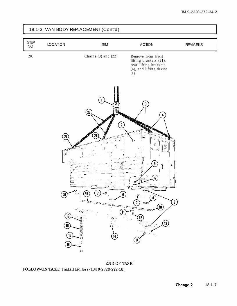
TM 9-2320-272-10
TM 9-2320-272-34-2
18.1-3. VAN BODY REPLACEMENT (Cont'd)
STEPNO. LOCATION ITEM ACTION REMARKS
20. Chains (3) and (22) Remove from frontlifting brackets (21),rear lifting brackets(4), and lifting device(1).
18.1-7

TM 9-2320-272-34-2
18.1-4. RETRACTABLE BEAM DRIVE SHAFT AND LOCK MAINTENANCE
This task covers:a. Removal c. Installationb. Cleaning, Inpection, and Repair
INITIAL SETUP:
EquipmentCondition
Applicable Models Reference Condition Description
M934, M934A1, M935, M935A1 TM 9-2320-272-10 Parking brake set.
Test EquipmentNone
Special ToolsNone
Materials/Parts
Special Environmental ConditionsVehicle must be on a level surface.
LocknutFive keysGAA grease (Appendix C, Item 11)
Personnel RequiredWheeled vehicle repairman MOS 63W (2)
Manual ReferencesTM 9-2320-272-10TM 9-2320-272-34PLO 9-2320-272-12
General Safety InstructionsNone
STEPNO. LOCATION ITEM ACTION REMARKS
NOTE● Left and right retractable beam drive shafts and locks are
removed and installed the same way. This procedure covers theleft retractable drive shaft and lock.
● Retractable beam drive shafts and locks are replaced the sameway on M934, M934A1, M935, and M935A1 vehicles. M934A1 isshown.
1. Underframe stud (9) Locknut (1) and lock (2) Remove. Discard locknut (1).
2. Underframe (5) at pawl Screw (4) Remove.(3)
3. Underframe (5) at Pawl (3) and lock (2) Remove.ratchet (8)
4. Underframe (5) Thirty screws (7) and Remove.five covers (6)
18.1-8 Change 2

TM 9-2320-272-34-2
18.1-4. RETRACTABLE BEAM DRIVE SHAFT AND LOCK MAINTENANCE (Cont'd)
STEPNO. LOCATION ITEM ACTION REMARKS
Change 2 18.1-9

TM 9-2320-272-34-2
18.1-4. RETRACTABLE BEAM DRIVE SHAFT AND LOCK MAINTENANCE (Cont'd)
STEPNO. LOCATION ITEM ACTION REMARKS
5. Four bushings (13) Setscrews (14) Loosen.6. Ratchet shaft (7) Remove all nicks, burrs,
and corrosion.
CAUTION
Do not bend or strain shaft during removal. Doing so may result indamage to equipment.
NOTE● Lubricate ratchet shaft for removal.● Assistant under van body will catch shaft components during
removal in step 7.
7. Underframe (6) Ratchet shaft (7), fivespacers (8), sprocketassemblies (9), spacers(10), nine bushings (11),and four bushings (13).
Slowly pull shaft (7) andremove.
b. Cleaning, Inspection, and Repair
8. All parts9. Five sprockets (5) Five keys (4) and
bushings (3)10. Bushings (3), (11),
and (13)11. Ratchet shaft (7)
12. Lock (1)
13. Five new keys (4) andbushings (3)
c. Installation
Clean.Remove.
Inspect for wear.
Inpsect for burrs, nicks,and corrosion.
Test spring action oflock plunger (2).Install in five sprockets(5).
Refer to para. 2-7.Discard keys (4).
Refer to para. 2-8.Replace if damaged.Repair with file oremery cloth ifdamaged.Replace lock (1) ifspring action is weak.
Do not bend or strain shaft during installation. Doing so may resultin damage to equipment.
18.1-10 Change 2

TM 9-2320-272-34-2
18.1-4. RETRACTABLE BEAM DRIVE SHAFT AND LOCK MAINTENANCE (Cont'd)
STEPNO. LOCATION ITEM ACTION REMARKS
14.
15.
16.
N O T E● Bevel forward end of ratchet shaft for installation.● Coat two feet of forward end of ratchet shaft with GAA grease for
installation.● Assistant under van body will install shaft components during
shaft installation in step 14.
Ratchet shaft (7), four Slowly insert ratchetbushings (13), nine shaft (7) into under-bushings (11), five flame (6) and install.spacers (10), sprocketassemblies (9), andspacers (8)Four setscrews (14) Install in four bushings
(13) in underframechannels (12).
Ratchet shaft (7) Lubricate with GAA Refer togrease. LO 9-2320-272-12.
Change 2 18.1-11

TM 9-2320-272-34-2
18.1-4. RETRACTABLE BEAM DRIVE SHAFT AND LOCK MAINTENANCE (Cont'd)
STEPLOCATION ITEM ACTION REMARKSNO.
17. Five covers (6) Install on underframe(5) with thirty screws (7).
18. Pawl (3) Install on ratchet (8) andunderframe (5) with screw(4).
19.
20.Lock (2) Install on pawl (3).
Lock (2) Install on underframestud (9) with new lock-nut (1).
18.1-12 Change 2
END OF TASK!

TM 9-2320-272-34-2
18.1-5. RETRACTABLE BEAM REPLACEMENT
This task covers:a. Removal b. Installation
INITIAL SETUP:
EquipmentCondition
Applicable Models ReferenceM934, M934A1, M935, M935A1 TM 9-2320-272-10
Test EquipmentTM 9-2320-272-10
None Para. 18.1-6
Special ToolsPara. 18.1-4
None
Materials/PartsTwo locknutsThree seals
Personnel RequiredWheeled vehicle repairman MOS 63W
Condition DescriptionParking brake set.Van body sides fully expanded andsecured.Retractable beam rollers removed.Retractable beam drive shaft and lockremoved.
Special Environmental ConditionsVehicle must be on a level surface.
General Safety InstructionsNone
Manual ReferencesTM 9-2320-272-10TM 9-2320-272-34PTM 9-237
STEPNO. LOCATION ITEM ACTION REMARKS
●
●
NOTEAll ten retractable beams are removed and installed the sameway. This procedure covers the left-rear retractable beam.Retractable beams are replaced the same way on M934, M934A1,M935, and M935A1 vehicles. M934A1 vehicle is shown.
Change 2 18.1-13

TM 9-2320-272-34-2
18.1-5. RETRACTABLE BEAM REPLACEMENT (Cont'd)
STEPNO. LOCATION ITEM ACTION REMARKS
a. Removal
1. Side panel (9) at side Retractable beam (7) Break welds between Refer to TM 9-237.panel support (8) side panel (9) and side
panel support (8) andremove.
CAUTION
Remove retractable beam slowly from underframe. Failure to do somay result in damage to equipment.
2. Underframe (1) at Retractable beam (7) Slide under side panelchannel (2) (9) and remove.
3. Underframe (1) Two locknuts (3), Remove. Discard locknuts (3)washers (4), screws(11), seven screws
and seals (13), (5) and(6).
(10), retainer (12),and seals (13), (5),and (6).
b. Installation
4. New seals (6), (5), and Install on underframe (1)(13) and retainer (12) with seven screws (10),
two screws (11), washers(4), and new locknuts (3).
CAUTION
Install retractable beam slowly into underframe. Failure to do somay result in damage to equipment.
5.
6.
Retractable beam (7) Slide under side panel (9)and install in underframe(1) at channel (2).
Retractable beam (7) Install by welding beam Refer to TM 9-237.(7) to side panel (9) andside panel support (8).
18.1-14 Change 2

TM 9-2320-272-34-2
18.1-5. RETRACTABLE BEAM REPLACEMENT (Cont'd)
STEPNO. LOCATION ITEM ACTION REMARKS
END OF TASK!FOLLOW-ON TASKS: ● Install retractable beam drive shaft and lock (para. 18. 1-4).
● Install retractable beam rollers (para. 18.1-6).● Retract van body sides (TM 9-2320-272-10).
Change 2 18.1-15

TM 9-2320-272-34-2
18.1-6. RETRACTABLE BEAM ROLLERS REPLACEMENT
This task covers:a. Support Roller Removal c. End Roller Removalb. Support Roller Installation d. End Roller Installation
INITIAL SETUP:
EquipmentCondition
Applicable ModelsM934, M934A1, M935, M935A1
Test EquipmentNone
Special ToolsNone
Reference Condition DescriptionTM 9-2320-272-10 Parking brake set.TM 9-2320-272-10 Van body sides fully expanded and
secured.
Special Environmental ConditionsVehicle must be on a level surface.
Materials/PartsFour cotter pins
General Safety InstructionsPersonnel Required NoneWheeled vehicle repairman MOS 63W
Manual ReferencesTM 9-2320-272-10TM 9-2320-272-34P
STEP LOCATION ITEM ACTION REMARKSNO.
NOTEThe left-rear cover mentioned in tasks a. and b. has seven screws.All other roller covers have eight screws.
I a. Support Roller Removal
NOTEAll ten support rollers are removed the same way. This procedurecovers the left-rear support roller.
1. Underframe (1) Seven screws (2) andcover (3)
2. Support roller shaft (6) Two cotter pins (4)
3. Under frame (1) Support roller shaft (6)and support roller (5)
Remove.
Remove. Discard cotter pins(4).
Remove.
18.1-16 Change 2

TM 9-2320-272-34-2
18.1-6. RETRACEABLE BEAM ROLLERS REPLACEMENT (Cont'd)
STEPNO. LOCATION ITEM ACTION REMARKS
Change 2 18.1-17

TM 9-2320-272-34-2
18.1-6. RETRACTABLE BEAM ROLLERS REPLACEMENT (Cont'd]
STEPNO. LOCATION ITEM ACTION REMARKS
b. Support Roller Installation
4.
5.
6.
NOTEAll ten support rollers are installed the same way. This procedurecovers the left-rear support roller.
Support roller (5) Install on underframe(1) with support roller
Two new cotter pins (4) Install in support rollershaft (6).
Cover (3) Install on underframe(1) with seven screws (2).
1 8 . 1 - 1 8

TM 9-2320-272-34-2
18.1-6. RETRACTABLE BEAM ROLLERS REPLACEMENT (Cont'd)
STEPNO. LOCATION ITEM ACTION REMARKS
Change 2 18.1-19

TM 9-2320-272-34-2
18.1-6 RETRACTABLE BEAM ROLLERS REPLACEMENT (Cont'd)
STEPNO. LOCATION ITEM ACTION REMARKS
c. End Roller Removal
NOTEAll ten end rollers are removed the same way. This procedure coversthe left-rear end roller.
7. Support roller Remove. Refer to task a.
8. End roller shaft (3) Two cotter pins (2) Remove. Discard cotter pins (2).
9. Underframe (1) End roller shaft (3) Remove.and end roller (4)
NOTEAll ten end rollers are installed the same way. This procedure coversthe left-rear end roller.
10. End roller (4) Install on underframe (1)with end roller shaft (3).
11. Two new cotter pins (2) Install in end roller shaft(3).
12. Support roller Install. Refer to task b.
18.1-20 Change 2

TM 9-2320-272-34-2
18.1-6. RETRACTABLE BEAM ROLLERS REPLACEMENT (Cont'd)
STEPNO. LOCATION ITEM ACTION REMARKS
END OF TASK!
FOLLOW-ON TASK: Retract van body sides (TM 9-2320-272-10).
Change 2 18.1-21

TM 9-2320-272-34-2
18.1-7. REAR DOORS MAINTENANCE
This task covers:a. Removal d. Assemblyb. Disassembly e. Installationc. Cleaning and Inspection
INITIAL SETUP:EquipmentCondition
Applicable Models Reference Condition Description
M934, M934A1, M935, M935A1 TM 9-2320-272-10 Parking brake set.TM 9-2320-272-10 Ladders removed. (M934, M934A1)
Test Equipment TM 9-2320-272-10 Liftgate lowered (M935, M935A1).None TM 9-2320-272-20-2 Rear door window removed.
Special ToolsNone
Special Environmental ConditionsMaterials/Parts Vehicle must be on a level surface.
Three cotter pinsTwo locknutsSix lockwashers General Safety Instructions
Gasket NoneTen rivetsWeathersealTwo sealsSealing compound (Appendix C, Item 37)Adhesive (Appendix C, Item 1)
Personnel RequiredWheeled vehicle repairman MOS 63W (2)
Manual ReferencesTM 9-2320-272-10TM 9-2320-272-20-2TM 9-2320-272-34PTB 43-0213
STEPNO. LOCATION ITEM ACTION REMARKS
NOTELeft and right rear doors are removed the same way. This procedurecovers the left rear door.
1. Van body (2) at door Cotter pin (6) and retain- Remove. Discard cotter pin (6).check (1) ing pin (3)
2. Van body (2) Fifteen screws (4) and Remove.door (5)
18.1-22 Change 2

TM 9-2320-272-34-2
18.1-7. REAR DOORS MAINTENANCE (Cont'd)
STEPNO. LOCATION ITEM ACTION
●
●
NOTELeft and right rear doors are disassembled the same way except.where indicated. Left door is shown.Steps 3 through 5 apply to M934 and M934A1 vehicles.
3.
4.
5.
Outer panel (7) Two screws (9) and Remove.angle brackets (8)Four screws (10), lock- Remove. Discard lockwasherswashers (11), and clamp (11)(12)
Four screws (14), two Remove. Discard locknuts (13).screws (16), washers(17), bushings (18),locknuts (13), and rack(15)
Change 2 18.1-23

TM 9-2320-272-34-2
18.1-7. REAR DOORS MAINTENANCE (Cont'd)
STEPNO. LOCATION ITEM ACTION REMARKS
6. Door frame (14)
7. Inner panel (26)
8. Outer panel (24)
9. Center case (18) andtwo bolt and caseassemblies (4)
10. Center case (18)
11. Inner panel (26)
12.
13. Door frame (14)
14. Inner panel (26)
15. Door frame (14)
16.
Seven rivets (23) and Remove. Discard rivets (23).seal (22)
NOTEStep 7 applies to left rear door.
Four screws (15), clip(16), six screws (17),
Remove.
and bracket (19)
NOTEStep 8 applies to right rear door.
Three rivets (35), handle Remove.(34), and gasket (33)Two cotter pins (10), Remove.screws (6), lockwashers(7), and rods (8)Pins (12) and (13) and Remove.handle (11)Four screws (9) and Remove.center case (18)Eight screws (5), two Remove.bolt and case assemblies(4), and spacer plates (3)Sixteen screws (31), Remove.retainer (30), seal(29), hinge (28), andseal (27)Moldings (l), (2), and (32) Break adhesive seal
and remove.
NOTESteps 15 and 16 apply to left rear door.
Weatherseal (25) Break adhesive seal Discard weathersealand remove. (25).
Thirty-five screws (20) Remove.and molding (21)
Discard gasket (33)and rivets (35).Discard cotter pins(10) and lockwashers(7).
Discard seals (27) and(29).
18.1-24 Change 2

TM 9-2320-272-34-2
18.1-7. REAR DOORS MAINTENANCE (Cont'd)
STEPNO. LOCATION ITEM ACTION REMARKS
17.
NOTEStep 17 applies to right rear door.
Thirty-four screws (20) Remove.and molding (21)
18.1-25

TM 9-2320-272-34-2
18.1-7. REAR DOORS MAINTENANCE (Cont'd)
STEPNO. LOCATION ITEM ACTION REMARKS
c. Cleaning and Inspection
18. All parts Clean. Refer to para. 2-7.
19. Center case (4) Inspect all movable Replace if damaged.parts for proper opera-tion.
20. Rods (3) Inspect for breaks and Replace if damaged.bends.
21. Moldings (1), (2), (8), Inspect for cracks and Replace if damaged.and (10) bends.
22.
23.
24.
25.
26.
All inside surfaces and Rustproof.boxed-in areas
NOTE● Apply sealing compound between exterior joints.● Apply adhesive to rubber and metal surfaces for installation.● Step 23 applies to right rear door.
Molding (8) Install on door frame(6) with thirty-fourscrews (7).
NOTESteps 24 and 25 apply to left rear door.
Molding (8) Install on door frame(6) with thirty-fivescrews (7).
New weatherseal (9) Install on door flame(6) with adhesive.
Moldings (1), (2), and Install on inner panel(10) (5) with adhesive.
Refer to TB 43-0213.
18.1-26 Change 2

TM 9-2320-272-34-2
18.1-7. REAR DOORS MAINTENANCE (Cont'd)
STEPNO. LOCATION ITEM ACTION REMARKS
18.1-27

TM 9-2320-272-34-2
18.1-7. REAR DOORS MAINTENANCE (Cont'd)
STEPNO. LOCATION ITEM ACTION REMARKS
27. New seal (10), hinge (9),new seal (8), and retain-er (7)
28. TWO spacer plates (16)and bolt and caseassemblies (17)
29. Center case (14)
30. Handle (2)
31. Two rods (15)
Install on door frame(12) with sixteen screws(6).Install on inner panel(11) with eight screws(18).Install on inner panel(11) with four screws (21).Install on center case (14)with pins (1) and (23).Install on center case (14)and two bolt and caseassemblies (17) with twonew cotter pins (22),screws (19), and new lock-washers (20).
NOTEStep 32 applies to right rear door.
32. New gasket (3) and Install on outer panelhandle (4) (29) with three new
rivets (5).
NOTEStep 33 applies to left rear door.
33. Clip (24) and bracket Install on inner panel (11)(26) with four screws (13) and
six screws (25).34. Seal (27) Install on door frame (12)
with seven new rivets (28).
18.1-28 Change 2

TM 9-2320-272-34-2
18.1-7. REAR DOORS MAINTENANCE (Cont'd]
STEPNO. LOCATION ITEM ACTION REMARKS
18.1-29

TM 9-2320-272-34-2
18.1-7. REAR DOORS MAINTENANCE (Cont'd)
STEP LOCATION ITEM ACTION REMARKSNO.
NOTESteps 35 through 37 apply to M934 and M934A1 vehicles.
35.
36.
37.
Rack (15) Install on outer panel(7) with four screws(14), two screws (16),washers (17), bushings(18), and new locknuts(13).
Clamp (12) Install on outer panel(7) with four screws (10)and new lockwashers (11).
Two angle brackets (8) Install on outer panel (7)with two screws (9).
NOTE● Left and right rear doors are installed the same way. This
procedure covers the left rear door.● Mine holes of door hinge with holes in van body for installation.● Assistant will help with step 38.
38.
39.
Door (5) Install on van body (2)with fifteen screws (4).
Door (5) Install on door check (1)with retaining pin (3)and new cotter pin (6).
18.1-30 Change 2

TM 9-2320-272-34-2
18.1-7. REAR DOORS MAINTENANCE (Cont'd)
STEPLOCATIONNO. ITEM ACTION REMARKS
END OF TASK!
FOLLOW-ON TASKS: ● Install rear door window (TM 9-2320-272-20-2).● Install ladders (M934, M934A1) (TM 9-2320-272-10).● Raise liftgate (M935, M935A1) (TM 9-2320-272-10).
Change 2 18.1-31

TM 9-2320-272-34-2
18.1-8. SIDE DOORS MAINTENANCE
This task covers:a. Removal d. Assemblyb. Disassembly e. Installationc. Cleaning and Inspection
INITIAL SETUP:
EquipmentCondition
Applicable Models Reference Condition DescriptionM934, M934A1, M935, M935A1 TM 9-2320-272-10 Parking brake set.
Test EquipmentTM 9-2320-272-10 Van body sides fully expanded and
secured.None TM 9-2320-272-20-2 Side door window removed.
Special ToolsNone
Special Environmental ConditionsMaterials/Parts Vehicle must be on a level surface.
Three cotter pinsFour lockwashersNineteen rivets General Safety Instructions
Gasket NoneTwo sealsAdhesive (Appendix C, Item 1)Sealing compound (Appendix C, Item 37)
Personnel RequiredWheeled vehicle repairman MOS 63W (2)
Manual ReferencesTM 9-2320-272-10TM 9-2320-272-20-2TM 9-2320-272-34PTB 43-0213
STEPNO. LOCATION ITEM ACTION REMARKS
NOTELeft and right side doors are maintained the same way on M934,M935, M934A1, and M935A1 vehicles. This procedure covers theleft side door on a M934A1 vehicle.
a . Removal
1. Door check (1)
2. Side panel (5)
Cotter pin (2) and Remove.retaining pin (6)
NOTEAssistant will help with step 2.
Fifteen screws (4) and Remove.door (3)
Discard cotter pin (2).
18.1-32 Change 2

TM 9-2320-272-34-2
18.1-8. SIDE DOORS MAINTENANCE (Cont'd)
STEPNO. LOCATION ITEM ACTION REMARKS
Change 2 18.1-33

TM 9-2320-272-34-2
18.1-8. SIDE DOORS MAINTENANCE (Cont'd)J
LOCATION ITEM ACTION REMARKS
b. Disassembly
3. Pocket (13) at outer panel (12)
4. Outer panel (12)
5. Center case (25) andbolt and case assemblies(2) and (21)
6. Center case (25)
7. Inner panel (27)
8.
9. Door frame (20)
10. Inner panel (27)
11.
Three rivets (16), handle(15), and gasket (14)Sixteen rivets (17) andpocket (13)
Two cotter pins (26),screws (22), lockwashers(23), and rods (24)Pin (29) and handle (28)
Four screws (30) andcenter case (25)Eight screws (1) andbolt and case assemb-lies (2) and (21)Fourteen screws (11),molding (10), seal (9),hinge (8), and seal (7)
Two moldings (6)
Two screws (19), screws(3), lockwashers (4),strike (5), and twomoldings (18).
Remove.
Remove.
Remove.
Remove.
Remove.
Remove.
Remove.
Break adhesive sealand remove.
Remove.
Discard rivets (16)and gasket (14).Discard rivets (17).
Discard cotter pins(26) and lockwashers(23).
Discard seals (7) and(9).
Discard lockwashers(4).
c. Cleaning and Inspection
12.
13.
14.
15.
16.
All parts
Center case (25) and boltand case assemblies (2)and (21)Rods (24)
Moldings (6) and (18)and pocket (13)
Outer panel (12), doorframe (20), and innerpanel (27)
Clean. Refer to para. 2-7.
Inspect all movable Replace if damaged.parts for properoperation.Inspect for breaks and Replace if damaged.bends.Inspect for cracks and Replace if damaged.bends.
Inspect for damage. Replace entire doorassembly if any partof assembly isdamaged.
18.1-34 Change 2

TM 9-2320-272-34-2
18.1-8. SIDE DOORS MAINTENANCE (Cont'd)
STEPNO. LOCATION ITEM ACTION REMARKS
18.1-35

TM 9-2320-272-34-2
18.1-8. SIDE DOORS MAINTENANCE (Cont'd]
STEPNO. LOCATION ITEM ACTION REMARKS
d. Assembly
17. All inside surfaces and Rustproof. Refer to TB 43-0213.boxed-in areas.
N O T EApply sealing compound to exterior joints for installation.
18. Two moldings (18)
19.
20.
21.
22.
23.
24.
25.
26.
Two moldings (6)
New seal (7), hinge(8), new seal (9), andmolding (10)
Bolt and case assemb-lies (2) and (21)
Center case (25)
Two rods (24)
Pocket (13)
New gasket (14) andhandle (15)
Handle (28)
Install on inner panel(27) with two screws(19), screws (3), newlockwashers (4), andstrike (5).Install on inner panel(27) with adhesive.
Install on door frame(20) with fourteenscrews (11).Install on inner panel(27) with eight screws(1).Install on inner panel(27) with four screws (30).Install on center case (25)and bolt and case assemb-lies (2) and (21) with twonew cotter pins (26), newlockwashers (23), andscrews (22).Install on outer panel (12)with sixteen new rivets(17).
Install on outer panel (12)and pocket (13) with threenew rivets (16).Install on center case (25)and handle (15) with pin(29).
18.1-36 Change 2

TM 9-2320-272-34-2
18.1-8. SIDE DOORS MAINTENANCE (Cont'd)
STEPNO. LOCATION ITEM ACTION REMARKS
18.1-37

TM 9-2320-272-34-2
18.1-8. SIDE DOORS MAINTENANCE (Cont'd)
STEPNO. LOCATION ITEM ACTION REMARKS
e. Installation
27.
28.
NOTEAssistant will help with step 27.
Door (3) Install on sidepanel (5) withfifteen screws (4).
Door (3) Install on door check(1) with retaining pin(6) and new cotter pin(2).
END OF TASK!
FOLLOW-ON TASKS: ● Install side door window (TM 9-2320-272-20-2).
18.1-38 Change 2
● Retract van body sides (TM 9-2320-272-10).

TM 9-2320-272-34-2
18.1-9. UNDERFRAME PARTS REPLACEMENT
This task covers:a. Underframe Parts Removal b. Underframe Parts Installation
INITIAL SETUP:
EquipmentCondition
Applicable Models Reference
M934, M934A1, M935, M935A1 TM 9-2320-272-10
Test Equipment
None
Special ToolsNone
Materials/PartsEight lockwashersTwo sealsThirty-two rivetsSealing compound (Appendix C, Item 37)
Personnel RequiredWheeled vehicle repairman MOS 63W (2)
Manuel ReferencesTM 9-2320-272-10TM 9-2320-272-34P
Condition DescriptionParking brake set.
Special Environmental ConditionsVehicle must be on a level surface.
General Safety InstructionsNone
STEPNO. LOCATION ITEM ACTION REMARKS
NOTEUnderframe parts are removed and installed the same way onM934, M935, M934A1, and M935A1 vehicles. This procedure coversparts replacement on a M934A1 vehicle.
Change 2 18.1-39

TM 9-2320-272-34-2
18.1-9. UNDERFRAME PARTS REPLACEMENT (Cont'd)
STEPNO. LOCATION ITEM ACTION REMARKS
I a. Underframe Parts Removal
N O T EAssistant will help with step 1.
1. Underframe (1) One hundred thirty-eightscrews (14), two retainers(15), channels (12), andseals (13)
2. Thirty-two screws (4) andfour covers (5)
3. Eight screws (7), nuts(3), lockwashers (2),and four plates (6)
4. Thirty-two rivets (8) andeight tiedowns (9)
5. Four screws (11) andangle bracket (10)
Remove.
Remove.
Remove.
Remove.
Remove.
Discard seals (13).
Discard lockwashers(2).
Discard rivets (8).
b. Underframe Parts Installation
6. Angle bracket (10)
7. Eight tiedowns (9)
Install on underframe(1) with four screws (11).Install on underframe(1) with thirty-two newrivets (8).
8. Four plates (6)
9.
10.
Install on underframe(1) with eight screws(7), new lockwashers(2), and nuts (3).
Four covers (5) Install on underframe(1) with thirty-two screws(4).
Apply sealing compound to exterior joints for installation.
Two retainers (15), Install on underframechannels (12), and new (1) with one hundredseals (13) thirty-eight screws (14).
18.1-40 Change 2

TM 9-2320-272-34-2
18.1-9. UNDERFRAME PARTS REPLACEMENT (Cont'd)
STEPNO. LOCATION ITEM ACTION REMARKS
END OF TASK!
Change 2 18.1-41

TM 9-2320-272-34-2
I 18.1-10. HINGED FLOOR MAINTENANCE
This task covers:
a. Removal d. Assemblyb. Disassembly e. Installationc. Cleaning and Inspection
INITIAL SETUP:EquipmentCondition
Applicable Models Reference
M934, M934A1, M935, M935A1 TM 9-2320-272-10
Test EquipmentTM 9-2320-272-10
None TM 9-2320-272-10
Special TealsNone
TM 9-2320-272-20-2
Materials/PartsFifty-six rivetsFive sealsAdhesive tape (Appendix C, Item 39)sealing compound (Appendix C, Item 37)
Personnel RequiredWheeled vehicle repairman MOS 63W (2)
Manual ReferencesTM 9-2320-272-10TM 9-2320-272-20-2TM 9-2320-272-34PTM 9-237
Condition DescriptionParking brake set.Van body sides fully expanded andsecured.Hinged end panel opened.Counterbalance removed.
Special Environmental ConditionsVehicle must be on a level surface.
GeneraI Safety InstructionsNone
STEPNO. LOCATION ITEM ACTION REMARKS
●
1. Hinge (4)
NOTELeft and right hinged floors are removed the same way. Thisprocedure covers the left hinged floor.Assistant will help with step 1.
Fifty-five screws (3), Remove.four screws (2), andhinged floor (1)
18.1-42 Change 2

TM 9-2320-272-34-2
18.1-10. HINGED FLOOR MAINTENANCE (Cont'd)
STEPNO. LOCATION ITEM ACTION REMARKS
Change 2 18.1-43

TM 9-2320-272-34-2
18.1-10. HINGED FLOOR MAINTENANCE (Cont'd)
STEPNO. LOCATION ITEM ACTION REMARKS
b. Disassembly
NOTELeft and right hinged floors are disassembled the same way. Thisprocedure covers the left hinged floor.
2. Hinged floor (14) Four screws (1) and two Remove.pivots (2)
3. Thirty screws (3), two Remove.retainers (4), four seals(5), and two channels (15)
4. Ten screws (12) and five Remove.pads (13)
5. Four screws (10) and Remove.handle (11)
6. Seal (6) Remove. Discard seal (6).
NOTE
Discard seals (5).
Perform step 7 only if hinge is to be replaced. See task c.
7. Underframe (7) Fifty-six rivets (8) and Remove. Discard rivets (8).hinge (9)
c. Cleaning and Inspection
8.9.
10.
11.
18.1-44 Change 2
All parts Clean. Refer to para. 2-7.Hinged floor (14) Inspect for cracked, Replace if damaged.
broken, and torn Refer to TM 9-237.floor plates
Retainers (4) and Inspect for bends and Replace if bent orchannels (15) breaks. broken.Hinge (9) Inspect for breaks, Replace if damaged.
cracks, and smoothoperation.

TM 9-2320-272-34-2
18.1-10. HINGED FLOOR MAINTENANCE (Cont'd)
STEPLOCATION ITEM ACTION REMARKSNO.
Change 2 18.1-45

TM 9-2320-272-34-2
18.1-10. HINGED FLOOR MAINTENANCE (Cont'd)
LOCATION ITEM ACTION REMARKS
●
●
●
●
12.
13.
14.
15.
16.
17.
18.1-46 Change 2
NOTELeft and right hinged floors are assembled the same way. Thisprocedure covers the left hinged floor.Seal exterior joints with sealing compound for installation.Insulate exterior joints and areas of metal-to-metal contact withadhesive tape.Perform step 12 only if hinge is to be replaced.
Hinge (9) Install on underframe(7) with fifty-six newrivets (8).
New seal (6) Install on hinged floor(14).
Handle (11) Install on hinged floor(14) with four screws (10).
Five pads (13) Install on hinged floor(14) with ten screws (12).
Two channels (15), Install on hinged floorfour new seals (5), (14) with thirty screws (3).and two retainers (4)Two pivots (2) Install on hinged floor (14)
with four screws (1).

TM 9-2320-272-34-2
18.1-10. HINGED FLOOR MAINTENANCE (Cont'd)
STEPNO. LOCATION ITEM ACTION REMARKS
Change 2 18.1-47

TM 9-2320-272-34-2
18.1-10. HINGED FLOOR MAINTENANCE (Cont'd)
STEP LOCATION ITEM ACTION REMARKSNO.
18.
NOTE● Left and right hinged floors are installed the same way. This
procedure covers the left hinged floor.● Assistant will help with step 18.
Hinged floor (1) Install on hinge (4)with fifty-five screws(3) and four screws (2).
FOLLOW-ON TASKS: ●
●
●
END OF TASK!
Install counterbalance (TM 9-2320-272-20-2).Close hinged end panel (TM 9-2320-272-10).Retract van body sides (TM 9-2320-272-10).
18.1-48 Change 2

TM 9-2320-272-34-2
18.1-11. EXTERIOR SIDE PANEL MAINTENANCE
This task covers:a. Disassembly c. Assemblyb. Cleaning and Inspection
INITIAL SETUP:EquipmentCondition
Applicable Models Reference
M934, M934A1, M935, M935A1 TM 9-2320-272-10
Test EquipmentTM 9-2320-272-10
None TM 9-2320-272-20-2
Special ToolsTM 9-2320-272-20-2TM 9-2320-272-20-2
None Para. 18.1-8
Materials/PartsChannel sealFour hundred sixty-one rivetsNine sealsAdhesive (Appendix C, Item 1)Sealing Compound (Appendix C, Item 37)
Personnel RequiredWheeled vehicle repairman MOS 63W (2)
Manual ReferencesTM 9-2320-272-10TM 9-2320-272-20-2TM 9-2320-272-34P
Condition DescriptionParking brake set.Van body sides fully expanded andsecured.Retractable window removed.Side panel front lock removed.Side panel rear lock removed.Side door removed.
Special Environmental ConditionsVehicle must be on a level surface.
General Safety InstructionsNone
STEPNO. LOCATION ITEM ACTION REMARKS
a. Disassembly
NOTELeft and right exterior side panels are disassembled the same way.This procedure covers the right exterior side panel.
Change 2 18.1-49

TM 9-2320-272-34-2
18.1-11. EXTERIOR SIDE PANEL MAINTENANCE (Cont'd)
STEPNO. LOCATION ITEM ACTION REMARKS
1.
2.
3.
4.
5.
Side panel frame (3) Sixty-nine screws (19),retainer (17), andretainer (20)
Seals (1), (16), and (18),and channel (2)
Seal (7) at side panel Thirty screws (15) andframe (3) five retainers (14)
Side panel frame (3) Sixty-two screws (9),retainers (4), (5), (6),and (8), two retainers(13), and seal (7)
Six screws (12), tworetainers (11), andseals (10)
Remove.
Remove.
Remove.
Remove.
Discard seals (1), (16),and (18).
Discard seal (7).
Remove. Discard seals (10).
18.1-50 Change 2

TM 9-2320-272-34-2
18.1-11. EXTERIOR SIDE PANEL MAINTENANCE (Cont'd)
STEPNO. LOCATION ITEM ACTION REMARKS
Change 2 18.1-51

TM 9-2320-272-34-2
18.1-11. EXTERIOR SIDE PANEL MAINTENANCE (Cont'd)
STEPLOCATION ITEM ACTION REMARKSNO.
6. Skins (6) and (9) at One hundred eighty-nine Remove. Discard rivets (3) andside panel frame (20) rivets (3), angle bracket seal (5).
(4), and seal (5)7. Side panel frame (20) Eighty-two screws (7), Remove. Discard seals (19).
nuts (17), four screws(16), two retainers (18),and seals (19)
8. Doorway of side panel Channel seal (10) Remove. Discard channel sealframe (20)
9.
●
●
(10).Nine screws (2) and Remove.molding (1)
NOTEPerform steps 10 through 12 only if skin is to be replaced. Seetask b.Assistant will help with steps 10 through 12.
10. Side panel frame (20) Two hundred forty- Remove.eight rivets (8) andskins (6) and (9)
11. Eight rivets (11), six- Remove.teen rivets (12), andlower skin (14)
12. Eight screws (13) and Remove.two ladder hangers (15)
Discard rivets (8).
Discard rivets (11)and (12).
18.1-52 Change 2

TM 9-2320-272-34-2
18.1-11. EXTERIOR SIDE PANEL MAINTENANCE (Cont'd)
STEP LOCATION ITEM ACTION REMARKSNO.
Change 2 18.1-53

TM 9-2320-272-34-2
18.1-11. EXTERIOR SIDE PANEL MAINTENANCE (Cont'd)
STEPNO. LOCATION ITEM ACTION REMARKS
b. Cleaning and Inspection
13.
14.
15.
16.
17.
18.
19.
18.1-54 Change 2
All partsFive retainers (9),retainers (3), (4), and(5), and (18), and tworetainers (8)
Angle bracket (1),retainers (2) and (6),and channel (7)
Two retainers (10) and(11)Molding (17) and twoladder hangers (15)
Skins (13) and (16) andlower skin (14)Side panel frame (12)
Clean.Inspect for cracks andbends.
Inspect for rust, corro-sion, and breaks.
Inspect for bends andbreaks.Inspect for cracks andwarpage.
Inspect for tears andpunctures.Inspect for cracks,
Refer to para. 2-7.
Replace if crackedor bent.
Replace if damaged.
Replace if bent orbroken.Replace if cracked orwarped.
Replace if damaged.
Replace entire sidebreaks, and warpage. panel assembly if
damaged.

TM 9-2320-272-34-2
18.1-11. EXTERIOR SIDE PANEL MAINTENANCE (Cont'd)
STEPNO. LOCATION ITEM ACTION REMARKS
Change 2 18.1-55

TM 9-2320-272-34-2
18.1-11. EXTERIOR SIDE PANEL MAINTENANCE (Cont'd)
STEPLOCATIONNO. ITEM ACTION REMARKS
NOTE● Left and right exterior side panels are assembled the same way.
This procedure covers the right exterior side panel.● Perform step 20 through 22 only if skin is to be replaced. See
task b.● Assistant will help with steps 20 through 22.
20.
21.
22.
23.
24.
25.
26.
Two ladder hangers (15)
Lower skin (14)
Skins (6) and (9)
Install on side panelframe (20) with eightscrews (13).Install on side panelframe (20) with eightnew rivets (11) andsixteen new rivets (12).Install on side panelframe (20) with two hun-dred forty-eight newrivets (8).
NOTE● Apply sealing compound to exterior joints for installation.● Apply adhesive to rubber and metal surfaces for installation.
Molding (1)
New channel seal (10)
Two new seals (19) andretainers (18)
New seal (5) and angle
Install on doorwayof side panel frame(20) with nine screws(2).Install on doorway ofside panel frame (20).Install on side panelframe (20) with eighty-two screws (7), nuts (17),and four screws (16).Install on skins (6) and
bracket (4) (9) and side panel frame(20) with eighty-nine newrivets (3).
18.1-56 Change 2

TM 9-2320-272-34-2
18.1-11. EXTERIOR SIDE PANEL MAINTENANCE (Cont'd)
STEPNO. LOCATION ITEM ACTION REMARKS
Change 2 18.1-57

TM 9-2320-272-34-2
18.1-11. EXTERIOR SIDE PANEL MAINTENANCE (Cont'd)
and retainers (11)
28. New seal (7), tworetainers (13), andretainers (4), (5), (6),and (8)
29. Five retainers (14)
30. New seals (1), (16), and(18), channel (2), retain-er (20), and retainer (17)
frame (3) with sixscrews (12).Install on side panelframe (3) with sixty-two screws (9).
Install on side panelframe (3) and seal (7)with thirty screws (15).
Install on side panelframe (3) with sixty-ninescrews (19).
18.1-58 Change 2

TM 9-2320-272-34-2
18.1-11. EXTERIOR SIDE PANEL MAINTENANCE (Cont'd)
STEPNO. LOCATION ITEM ACTION REMARKS
END OF TASK!
FOLLOW-ON TASKS: ● Install side panel rear lock (TM 9-2320-272-20-2).● Install side panel front lock (TM 9-2320-272-20-2).● Install retractable window (TM 9-2320-272-20-2).● Retract van body sides (TM 9-2320-272-10).● Install side door (para. 18.1-8).
Change 2 18.1-59

TM 9-2320-272-34-2
18.1-12. REAR WALL INTERIOR PANELS REPLACEMENT
This task covers:
a. Removal b. Installation
INITIAL SETUP:EquipmentCondition
Applicable Models Reference
M934, M934A1, M935, M935A1 TM 9-2320-272-10
Test EquipmentNone
Special Tools
TM 9-2320-272-10TM 9-2320-272-10
Para. 18.1-42
None Para. 18.1-44
Materials/Parts Para. 18.1-45Sealing compound (Appendix C, Item 37)
Personnel Required TM 9-2320-272-20-2
Wheeled vehicle repairmanMOS 63W (2)
TM 9-2320-272-20-2
Manual References TM 9-2320-272-20-2
TM 9-2320-272-10TM 9-2320-272-20-2
Para. 18.1-48
TM 9-2320-272-34P
Condition DescriptionParking brake set.Rear doors opened.Van body sides fully expanded andsecured.Electrical load center removed (leftside).Electrical junction box removed (leftside).Converter outlet box removed (leftside).Inside telephone jack post removed(right side).Blackout light switch removed (rightside).Fire extinguisher bracket removed(right side).Heater thermostat removed (rightside).
Special Environmental ConditionsVehicle must be on a level surface.
General Safety InstructionsNone
STEPNO. LOCATION ITEM ACTION REMARKS
NOTERear wall exterior panels are not serviceable and if damaged arereplaced as a unit with rear wall assembly.
a. Removal
1. Left panel (2) and Thirteen screws (4) and Remove.header (3) molding (1)
2. Right panel (7) and Thirteen screws (10) and Remove.header (6) molding (8)
NOTEAssistant will help with steps 3 and 4.
3. Header (3) Twenty-two screws (5) Remove.and left panel (2)
4. Header (6) Twenty-two screws (9) Remove.and right panel (7)
18.1-60 Change 2

TM 9-2320-272-34-2
18.1-12. REAR WALL INTERIOR PANELS REPLACEMENT (Cont'd)
STEPNO. LOCATION ITEM ACTION REMARKS
Change 2 18.1-61

TM 9-2320-272-34-2
18.1-12. REAR WALL INTERIOR PANELS REPLACEMENT (Cont'd)
STEP LOCATION ITEM ACTION REMARKSNO.
5. Skin (2) and underframe(1)
Eight screws (4) and two Remove.corner gussets (3)
NOTEApply sealing compound to exterior joints for installation.
6. Two corner gussets (3) Install on skin (2)and underframe (1)with eight screws (4).
NOTEAssistant will help with steps 7 and 8.
7. Right panel (11)
8. Left panel (6)
9. Molding (12)
10. Molding (5)
Install on header (10)with twenty-two screws(13).Install on header (7)with twenty-two screws(9).Install on right panel(11) and heater (10)with thirteen screws(14).Install on left panel(6) and header (7) withthirteen screws (8).
18.1-62 Change 2

TM 9-2320-272-34-2
18.1-12. REAR WALL INTERIOR PANELS REPLACEMENT (Cont'd)
STEPLOCATION ITEM ACTION REMARKSNO.
END OF TASK!FOLLOW-ON TASKS: ● Install heater thermostat (right side) (para. 18.1-48).
● Install fire extinguisher bracket (right side) (TM 9-2320-272-20-2).● Install blackout light switch (right side) (TM 9-2320-272-20-2).● Install inside telephone jack post (right side) (TM 9-2320-272-20-2).● Install converter outlet box (left side) (para. 18.1-45).● Install electrical junction box (left side) (para. 18.1-44).● Install electrical load center (left side) (para. 18.1-42).● Retract van body sides (TM 9-2320-272-10).● Close rear doors (TM 9-2320-272-10).
Change 2 18.1-63

TM 9-2320-272-34-2
18.1-13. HINGED END PANEL MAINTENANCE
This task covers:
a. Removal d. Assemblyb. Disassembly e. Installationc. Cleaning and Inspection
INITIAL SETUP:EquipmentCondition
Applicable Models Reference
M934, M934A1, M935, M935A1 TM 9-2320-272-10
Test EquipmentTM 9-2320-272-10
None
Special ToolsNone
Materiels/PartsThree sealsThirty rivetsSealing compound (Appendix C, Item 37)
Personnel RequiredWheeled vehicle repairman MOS 63W (2)
Manual ReferencesTM 9-2320-272-10TM 9-2320-272-34P
Condition DescriptionParking brake set.Van body sides fully expanded andsecured.
Special Environmental ConditionsVehicle must be on a level surface.
General Safety InstructionsNone
STEPNO. LOCATION ITEM ACTION REMARKS
NOTEAll hinged end panels are removed the same way. This procedurecovers the right rear hinged end panel.
1. Hinged end panel (2) Sixteen screws (3) Remove.and side panel (1)
NOTEAssistant will help with step 2.
2. Side panel (1) Hinged end panel (2) Remove.
18.1-64 Change 2

TM 9-2320-272-34-2
18.1-13. HINGED END PANEL MAINTENANCE (Cont'd)
STEPNO. LOCATION ITEM ACTION REMARKS
Change 2 18.1-65

TM 9-2320-272-34-2
18.1-13. HINGED END PANEL MAINTENANCE (Cont'd)
STEP LOCATION ITEM ACTION REMARKSNO.
NOTEAll hinged end panels are disassembled the same way. Thisprocedure covers the right rear hinged end panel.
3. Panel frame (7) andouter skin (12)
Sixteen screws (18),hinge (19), and seal (20)
4. Twenty-seven screws (8),retainer (10), and seal(9)
5. Channel (5) Ten screws (1), retainers(2) and (3), and seal (4)
6. Outer skin (12), panelframe (7), and innerskin (22)
7. Outer skin (12)
Eighteen rivets (6),twenty screws (17), andchannels (5) and (16)Two screws (15), strap(14), and spacer plate(13)
NOTE
Remove. Discard seal (20).
Remove. Discard seal (9).
Remove. Discard seal (4).
Remove. Discard rivets (6).
Remove.
● Perform steps 8 and 9 only if skins are to be replaced. See task c.● Assistant will help with steps 8 and 9.
8. Panel frame (7)
9.
Twelve rivets (11) and Remove.outer skin (12)Thirty screws (23), eight- Remove.teen screws (21), andinner skin (22)
Discard rivets (11).
c. Cleaning and Inspection
10.11.
12.
13.
All partsChannels (5) and (16)
Retainers (2), (3), and(10), spacer place (13),and strap (14)Hinge (19)
Clean.Inspect for cracks andbreaks.Inspect for bends andbreaks.
Inspect for cracks,breaks, corrosion,and proper operation.
Refer to para. 2-7.Replace if cracked orbroken.Replace if bent orbroken.
Replace entire hingedend panel if damaged.
18.1-66 Change 2

TM 9-2320-272-34-2
18.1-13. HINGED END PANEL MAINTENANCE (Cont'd)
STEPNO. LOCATION ITEM ACTION REMARKS
14. Inner skin (22) and Inspect for tears and Replace if torn orouter skin (12) punctures. punctured.
15. Panel frame (7) Inspect for cracks, Replace entire hingedbreaks, and warpage. end panel assembly if
damaged.
Change 2 18.1-67

TM 9-2320-272-34-2
18.1-13. HINGED END PANEL MAINTENANCE (Cont'd)
STEP LOCATION ITEM ACTION REMARKSNO.
NOTE● All hinged end panels are assembled the same way. This
procedure covers the right rear hinged end panel.● Seal all exterior joints with sealing compound.● Perform steps 16 and 17 only if skins are to be replaced.● Assistant will help with steps 16 and 17.
16.
17.
18.
19.
20.
21.
22.
Inner skin (22)
Outer skin (12)
Spacer plate (13) andstrap (14)Channels (5) and (16)
New seal (4) andretainers (2) and (3)New seal (9) and retain-er (10)
New seal (20) andhinge (19)
Install on panel frame(7) with thirty screws(23) and eighteen screws(21).Install on panel frame (7)with twelve new rivets (11).Install on outer skin (12)with two screws (15).Install on outer skin (12),panel frame (7), andinner skin (22) with eight-een new rivets (6) andtwenty screws (17).Install on channel (5)with ten screws (1).Install on outer skin (12)and panel frame (7) withtwenty-seven screws (8).Install on outer skin (12)and panel frame (7) withsixteen screws (18).
18.1-68 Change 2

TM 9-2320-272-34-2
18.1-13. HINGED END PANEL MAINTENANCE (Cont'd)
STEPLOCATIONNO. ITEM ACTION REMARKS
Change 2 18.1-69

TM 9-2320-272-34-2
18.1-13. HINGED END PANEL MAINTENANCE (Cont'd)
STEPNO. LOCATION ITEM ACTION REMARKS
e. Installation
23.
NOTEAll hinged end panels are installed the same way. This procedurecovers the right rear hinged end panel.
Hinged end panel (2) Install on side panel (1)with sixteen screws (3).
END OF TASK!FOLLOW-ON TASK: Retract van body sides (TM 9-2320-272-10).
18.1-70

TM 9-2320-272-34-2
18.1-14. INTERIOR SIDE PANELS AND LATCHES REPLACEMENT
This task covers:a. Removal b. Installation
INITIAL SETUP:
Applicable ModelsM934, M935, M934A1, M935A1
Test EquipmentNone
Special ToolsNone
Materials/PartsTwo cotter pinsGasketThree grommetsInsulationSix lockwashersTwo O-rings
EquipmentConditionReference
TM 9-2320-272-10TM 9-2320-272-10
Para. 18.1-13Para. 18.1-10Para. 18.1-16Para. 18.1-8
Condition DescriptionParking brake set.Van body sides fully expanded andsecured.Hinged end panels removed.Hinged floor removed.Hinged roof removed.Side doors removed.
Special Environmental ConditionsVehicle must be on a level surface.
General Safety Instructions
Four rubber bumpers NonePrimer (Appendix C, Item 38)Sealing compound (Appendix C, Item 37)Adhesive (Appendix C, Item 1)
Personnel RequiredWheeled vehicle repairman MOS 63W (3)
Manual ReferencesTM 9-2320-272-10TM 9-2320-272-34P
STEPNO. LOCATION ITEM ACTION REMARKS
Change 2 18.1-71

TM 9-2320-272-34-2
18.1-14. INTERIOR SIDE PANELS AND LATCHES REPLACEMENT (Cont'd)
STEPNO. LOCATION ITEM ACTION REMARKS
NOTELeft and right interior side panels are removed the same way. This
1.
2.
3.
4.
5.
18.1-72
procedure covers the right side.
Side panel frame (4) Six screws (1) andthree hooks (2)Six screws (6) andthree clips (3)Two screws (8) andstriker (7)
Door angle (15) Two screws (10), lock-washers (11), nuts (5),and door check assem-bly (9)
Side panel frame (4) Two screws (12), striker
Remove.
Remove.
Remove.
Remove.
Remove.
Discard lockwashers(11).
(13), and two spacerplates (14)
Change 2

TM 9-2320-272-34-2
18.1-14. INTERIOR SIDE PANELS AND LATCHES REPLACEMENT (Cont'd)
STEPNO. LOCATION ITEM ACTION REMARKS
Change 2 18.1-73

TM 9-2320-272-34-2
18.1-14. INTERIOR SIDE PANELS AND LATCHES REPLACEMENT (Cont'd)
STEP LOCATION ITEM ACTION REMARKSNO.
6. Side panel frame (5) Remove. Discard grommets (7).
7. Panel (16)
8. Panel (1)
9.
10.
11.
12.
13.
14. Side panel frame (5)
15.
16. Panel (1)
17.
18.1-74 Change 2
Two screws (6) andgrommets (7)Four screws (14) andtwo clips (15)Four screws (19),washers (20), and rub-ber bumpers (21)Eight screws (18) andfour wood spacers (29)Eight screws (22) andfour hangers (24)Two screws (23), twoscrews (25), and junc-tion box (26)Eight screws (10) andplate (11)Eleven screws (25) andmolding (27)
NOTE
Remove.
Remove. Discard rubberbumpers (21).
Remove.
Remove.
Remove.
Remove.
Remove.
Assistants will help with steps 14 and 15.
Thirty-three screws (13) Remove.and panel (16)Fifty-eight screws (12), Remove.molding (17), and panel(1)Moldings (28), (8), and Remove.(9)Two moldings (2), two Remove.moldings (3), and twomoldings (4)

TM 9-2320-272-34-2
18.1-14. INTERIOR SIDE PANELS AND LATCHES REPLACEMENT (Cont'd)
LOCATION ITEM ACTION REMARKS
Change 2 18.1-75

TM 9-2320-272-34-2
18.1-14. INTERIOR SIDE PANELS AND LATCHES REPLACEMENT (Cont'd)
STEPLOCATION ITEM ACTION REMARKSNO.
18. Panel (1) Eight screws (21) and Remove.
19. Side panel frame (8)
20. Shank (10) and latch(30)
21. Latch (30)
22.
23. Side panel frame (8)
24.
25. Flush bolt (7)26. Horizontal bar (27)27. Side panel frame (8)
28.
29.
plate (20)NOTE
Assistant will help with step 19.
Thirty-three screws(19), moldings (2), (3),(4), (18), (22), and (23),and panel (1)Nut (25) and washer(26)Two screws (11), plate(12), gasket (13), shank(10), and O-ring (9)Two cotter pins (29),pins (24), clevis (28),and clevis (31)Four nuts (17), lockwash-ers (16), and latch (30)Two screws (15) andretainer (14)Clevis (31)Clevis (28)Horizontal bar (27)and flush bolt (7)
Screw (5) and grommet(6)
Remove.
Remove.
Remove.
Remove.
Remove.
Remove.
Remove.Remove.Remove.
Repeat steps 18through 27 for removalof front latch assembly.Remove.
Discard O-ring (9)and gasket (13)
Discard cotter pins(29).
Discard lockwashers(16).
Discard grommet (6).
1 8 . 1 - 7 6

TM 9-2320-272-34-2
18.1-14. INTERIOR SIDE PANELS AND LATCHES REPLACEMENT (Cont'd)
STEP LOCATION ITEM ACTION REMARKSNO.
1 8 . 1 - 7 7

TM 9-2320-272-34-2
18.1-14. INTERIOR SIDE PANELS AND LATCHES REPLACEMENT (Cont'd)
STEP LOCATION ITEM ACTION REMARKSNO.
b. Installation
30.
31.
32.
33.34.
35.
36.
37.
38.
39.
NOTE● Left and right interior side panel latches are installed the same
way. This procedure covers the right side.● Insulate areas of dissimilar metal-to-metal contact with zinc
chromate primer.● Seal between exterior joints with sealing compound.● Apply adhesive to rubber and metal surfaces.
New grommet (6)
Horizontal bar (27)and flush bolt (7)Clevis (28)
Clevis (31)Retainer (14)
Latch (30)
Clevises (28) and (31)
New O-ring (9), shank(10), new gasket (13),and plate (12)Nut (25) and washer(26)
Install on side panelframe (8) with screw(5).Position in side panelframe (8).Install on horizontalbar (27).Install on flush bolt (7).Install on side panelframe (8) with twoscrews (15).Install on side panelframe (8) with four newlockwashers (16) andnuts (17).Install on latch (30)with two pins (24) andnew cotter pins (29).Install on latch (30)with two screws (11).
Install on shank (10)and latch (30).Repeat steps 30 through38 for installation offront latch assembly.
40.
41.
● Insulate entire structure with fibrous glass felt insulation.● Assistant will help with step 40.
Panel (1) and moldings Install on side panel(2), (3), (4), (18), (22), frame (8) with thirty-and (23) three screws (19).Plate (20) Install on panel (1) with
eight screws (21).
18.1-78 Change 2

TM 9-2320-272-34-2
18.1-14. INTERIOR SIDE PANELS AND LATCHES REPLACEMENT (Cont'd)
STEPNO. LOCATION ITEM ACTION REMARKS
Change 2 18.1-79

TM 9-2320-272-34-2
18.1-14. INTERIOR SIDE PANELS AND LATCHES REPLACEMENT (Cont'd)
STEPLOCATION ITEM ACTION REMARKSNO.
42. Two moldings (2), two Install on panel (1).moldings (3), and twomoldings (4)
43. Moldings (8), (9), and Install on panel (1).(28)
NOTE● Assistants will help with steps 44 and 45.● Insulate entire structure with fibrous glass felt insulation.
44. Panel (1) and molding Install on side panel(17) frame (5) with fifty-
eight screws (12).45. Panel (16) Install on side panel
frame (5) with thirty-three screws (13).
46. Molding (27) Install on panels (1) and(16) with eleven screws(25).
47. Plate (11) Install on panel (1) witheight screws (10).
48. Junction box (26) Install on panel (1) withtwo screws (23) and screws(25).
49. Four hangers (24) Install on panel (1) witheight screws (22).
50. Four wood spacers (29) Install on panel (1) witheight screws (18).
51. Four new rubber Install on panel (1) withbumpers (21) four screws (19) and
washers (20).52. Two clips (15) Install on panel (16) with
four screws (14).53. Two new grommets (7) Install on side panel
frame (5) with twoscrews (6).
18.1-80 Change 2

TM 9-2320-272-34-2
18.1-14. INTERIOR SIDE PANELS AND LATCHES REPLACEMENT (Cont'd)
STEP LOCATION ITEM ACTION REMARKSNO.
Change 2 18.1-81

TM 9-2320-272-34-2
18.1-14. INTERIOR SIDE PANELS AND LATCHES REPLACEMENT (Cont'd)
STEPLOCATION ITEM ACTION REMARKSNO.
54. Striker (13) and two Install on side panelspacer plates (14) frame (4) with two
screws (12).55. Door check assembly Install on door angle
(9) (15) with two screws(10), new lockwashers(11), and nuts (5).
56. Striker (7) Install on side panelframe (4) with twoscrews (8).
57. Three clips (3) Install on side panelframe (4) with sixscrews (6).
58. Three hooks (2) Install on side panelframe (4) with sixscrews (1).
18.1-82 Change 2

TM 9-2320-272-34-2
18.1-14. INTERIOR SIDE PANELS AND LATCHES REPLACEMENT (Cont'd)
STEP LOCATION ITEM ACTION REMARKSNO.
FOLLOW-ON TASKS: ●
●
●
●
●
END OF TASK!
Install side doors (para. 18.1-8).Install hinged roof (para. 18.1-16).Install hinged floor (para. 18.1-10).Install hinged end panels (para. 18.1-13).Retract van body sides (TM 9-2320-272-10).
Change 2 18.1-83

TM 9-2320-272-34-2
18.1-15. CEILING AND FRAME MAINTENANCE
This task covers:a. Removal c. Installationb. Cleaning and Inspection
INITIAL SETUP:EquipmentCondition
Applicable ModelsM934, M935, M934A1, M935A1
Test EquipmentNone
Reference
TM 9-2320-272-10TM 9-2320-272-10
Para. 18.1-20
Special ToolsPara. 18.1-18Para. 18.1-19
None Para. 18.1-21
Materials/PartsInsulationSix lockwashersSix-hundred twenty-three rivetsTwo sealsAdhesive (Appendix C, Item 1)Primer (Appendix C, Item 38)
Personnel RequiredWheeled vehicle repairman MOS 63W (2)
Manual ReferencesTM 9-2320-272-10TM 9-2320-272-34P
Para. 18.1-7
Condition DescriptionParking brake set.Van body sides fully expanded andsecured.Ceiling air ducts removed.Ceiling filler and side panels removed.Ceiling rear cover removed.Ceiling transition removed.Rear doors removed.
Special Environmental ConditionsVehicle must be on a level surface.
General Safety InstructionsNone
STEPNO. LOCATION ITEM ACTION REMARKS
NOTEAssistant will help with steps 1 through 4.
1. Roof frame (2) Ninety-three rivets (4), Remove. Discard rivets (4).ceiling panel (3), andtwo liner strips (1)
2. One-hundred two rivets Remove. Discard rivets (6).(6), ceiling panel (5),and two liner strips (1)
18.1-84 Change 2

TM 9-2320-272-34-2
18.1-15. CEILING AND FRAME MAINTENANCE (Cont'd)
STEPNO. LOCATION ITEM ACTION REMARKS
Change 2 18.1-85

TM 9-2320-272-34-2
18.1-15. CEILING AND FRAME MAINTENANCE (Cont'd)
STEP LOCATION ITEM ACTION REMARKSNO.
3. Roof frame (1) Ninety-two rivets (3), Remove. Discard rivets (3).ceiling panel (4), andtwo liner strips (2)
4. Seventy-six rivets (5), Remove. Discard rivets (5).ceiling panel (6), andthree liner strips (2)
18.1-86 Change 2

TM 9-2320-272-34-2
18.1-15. CEILING AND FRAME MAINTENANCE (Cont'd)
STEPNO. LOCATION ITEM ACTION REMARKS
NOTELeft and right side moldings are removed the same way. Thisprocedure covers the right side.
5. Fifty-nine screws (11), Remove.seal (9), molding (10),and molding (12)
6. Six screws (7), lock- Remove.washers (18), nuts(13), and two liftingbrackets (17)
NOTE● Perform steps 7 and 8 only if roof is damaged and is to be
removed. See task b.● Assistant will help with steps 7 and 8.
7. Roof panel (16) and One-hundred twenty-six Remove.roof frame (1) rivets (15), eighteen
rivets (14), and one-hundred sixteen rivets(8)
8. Roof frame (1) Roof panel (16) Remove.
Discard seal (9).
Discard lockwashers(18).
Discard rivets (8), (14),and (15).
Lift and place onsupports.
Change 2 18.1-87

TM 9-2320-272-34-2
18.1-15. CEILING AND FRAME MAINTENANCE (Cont'd)
STEPNO. LOCATION ITEM ACTION REMARKS
9. Van body (11)
10. Retainer (8)
11. Van body (11)
Twenty-three screws (2) Remove.and moldings (1), (3), and(4)Three screws (6) andangle bracket (7)Fifteen screws (5), seal(9), retainer (8), andwoodblock (10)
Remove.
Remove.
b. Cleaning and Inspection
12.13.
14.
15.
All partsMoldings (1), (3), and(4)Angle bracket (7) andretainer (8)Woodblock (10)
Clean.Inspect for bendsand breaks.Inspect for cracksand breaks.Inspect for breaks.
Discard seal (9).
Refer to para. 2-7.Replace if bent orbroken.Replace if cracked orbroken.Replace if broken.
18.1-88

TM 9-2320-272-34-2
18.1-15. CEILING AND FRAME MAINTENANCE (Cont'd)
STEPNO. LOCATION ITEM ACTION REMARKS
16. Moldings (13) and Inspect for bends, Replace if bent,(14) breaks, and warpage. broken, or warped.
17. Lifting bracket (12) Inspect for breaks Replace if broken orand cracks. cracked.
18. Roof panel (16) Inspect for tears and Replace if torn orpunctures. punctured.
19. Roof frame (15) Inspect for breaks, Replace entire roofwarpage, and broken assembly if damaged.bows.
Change 2 18.1-89

322
TM 9-2320-272-34-2
18.1-15. CEILING AND FRAME MAINTENANCE (Cont'd)
STEP LOCATION ITEM ACTION REMARKSNO.
20. Ceiling panels (1), (2), Inspect for cracks Replace if cracked or(3), and (4) and punctures. punctured.
c. Installation
21.
22.
23.
18.1-90 Change
NOTEApply adhesive for installation.Insulate areas of dissimilar metal-to-metal contact with zincchromate primer.
Wood block (13), new seal(12), and retainer (11)
Angle bracket (10)
Moldings (6), (7), and(15)
Install on van body Leave three center(14) with fifteen holes of retainer openscrews (8). for angle bracket (10)
installation.Install on retainer(11) with three screws(9).Install on van body(14) with twenty-fivescrews (5).
2

TM 9-2320-272-34-2
18.1-15. CEILING AND FRAME MAINTENANCE (Cont'd)
STEPNO. LOCATION ITEM ACTION REMARKS
Change 2 18.1-91

TM 9-2320-272-34-2
18.1-15. CEILING AND FRAME MAINTENANCE (Cont'd)
STEPLOCATION ITEM ACTION REMARKSNO.
NOTE● Perform step 24 only if roof panel is to be installed. See task b.● Insulate entire structure with fibrous glass felt insulation.● Assistant will help step 24.
24. Roof panel (11) a. Lift from supportsand position onroof frame (9).
b. Install on roof frame(9) with one-hundredsixteen new rivets(2), eighteen newrivets (8), and one-hundred twenty-sixnew rivets (10).
25. Two lifting brackets (12) Install on roof frame(9) with six screws (1),new lockwashers (13),and nuts (7).
NOTELeft and right side moldings are installed the same way. Thisprocedure covers the right side.
26. Molding (4), molding Install on roof frame(6), and new seal (3) (9) with fifty-nine
screws (5).
18.1-92 Change 2

TM 9-2320-272-34-2
18.1-15. CEILING AND FRAME MAINTENANCE (Cont'd)
STEPNO. LOCATION ITEM ACTION REMARKS
27.
28.
NOTEAssistant will help with steps 27 through 30.
Ceiling panel (18) and Install on roof framethree liner strips (15) (9) with seventy-six
new rivets (17).Ceiling panel (16) and Install on roof frametwo liner strips (15) (9) with ninety-two
new rivets (14).
Change 2 18.1-93

TM 9-2320-272-34-2
18.1-15. CEILING AND FRAME MAINTENANCE (Cont'd)
STEPNO. LOCATION ITEM ACTION REMARKS
29. Ceiling panel (5) and Install on roof frametwo liner strips (1) (2) with one-hundred
two new rivets (6).30. Ceiling panel (3) and Install on roof frame
two liner strips (1) (2) with ninety-threenew rivets (4).
FOLLOW-ON TASKS: ●
●
●
●
●
●
18.1-94 Change 2
END OF TASK!Install rear doors (para. 18.1-7).Install ceiling transition (para. 18.1-21).Install ceiling rear cover (para. 18.1-19).Install ceiling filler and side panels (para. 18.1-18).Install ceiling air ducts (para. 18.1-20).Retract van body sides (TM 9-2320-272-10).

TM 9-2320-272-34-2
18.1-16. HINGED ROOF MAINTENANCE
This task covers:a. Removal d. Assemblyb. Disassembly e. Installationc. Cleaning and Inspection
INITIAL SETUP: EquipmentCondition
Applicable Models Reference
M934, M935, M934A1, M935A1 TM 9-2320-272-10
Test EquipmentTM 9-2320-272-10
None TM 9-2320-272-20-2
Special Tools Para. 18.1-19None Para. 18.1-18
Materials/PartsThree cotter pinsTwo cushion padsGasketFive grommetsInsulationO-ringTwo-hundred thirty-three rivetsFive sealsPrimer (Appendix C, Item 38)Sealing compound (Appendix C, Item 37)Adhesive (Appendix C, Item 1)
Personnel RequiredWheeled vehicle mechanic MOS 63W (2)
Manual ReferencesTM 9-2320-272-10TM 9-2320-272-20-2TM 9-2320-272-34P
Condition DescriptionParking brake set.Van body sides fully expanded andsecured.Hinged roof-operated blackout circuitplungers removed.Ceiling rear cover removed.Ceiling filler and side panels removed.
Special Environmental ConditionsVehicle must be on a level surface.
General Safety InstructionsAll personnel must stand clear duringlifting operations.
STEPNO. LOCATION ITEM ACTION REMARKS
Change 2 18.1-95

TM 9-2320-272-34-2
18.1-16. HINGED ROOF MAINTENANCE (Cont'd)
STEP LOCATION ITEM ACTION REMARKSNO.
a. Removal
●
●
NOTELeft and right hinged roofs are removed the same way. This pro-cedure covers right side except where indicated.Tag leads for installation.
1.
2.
3.
4.
5.
6.
7.
8.
9.
10.
11.
Load center (13)
Neutral bus bar (14)and rear door black-out switch (5)
Relay (10) and reardoor blackout switch(5)Panel (21)
Harness (2) andcover (17)
Harness (2) andceiling truss (28)
Load center (13)
Six screws (20) and Remove.cover (19)
NOTEStep 2 applies to left side blackout harness.Setscrew (12) and Remove, and disconnectscrew (8) cables (9) and (11).
NOTEStep 3 applies to right side blackout harness.
Screws (4) and (7)
Six screws (22) andcover (17)Nut (18) and connector(16)
Two screws (25) andconnector (15)
Nut (27) and connector(26)
Two screws (23) andconnector (24)
Grommet (1)NOTE
Remove, and disconnectcables (3) and (6).
Remove.
Remove.
Remove.
Remove.
Remove.
Remove.
Mark position ofconnector (16) forinstallation.Mark position ofconnector (15) forinstallation.Mark position ofconnector (26) forinstallation.Mark position ofconnector (24) forinstallation.Discard grommet (1).
Step 10 applies to left side blackout harness.Harness (2) Pull through hole in
ceiling truss (28) andrear header (29) andremove.
NOTEStep 11 applies to right side blackout harness.
Harness (2) Pull through hole inceiling truss (28) andremove.
18.1-96 Change 2

TM 9-2320-272-34-2
18.1-16. HINGED ROOF MAINTENANCE (Cont'd)
STEPNO. LOCATION ITEM ACTION REMARKS
18.1-97

TM 9-2320-272-34-2
18.1-16. HINGED ROOF MAINTENANCE (Cont'd)
STEPNO. LOCATION ITEM ACTION REMARKS
12. Lifting device (1) Two chains (2) Attach. Remove slack fromand hinged roof (3) chains (2).
13. Hinged roof (3) Four screws (5), two Remove.angle brackets (4),and holding rods (6).
WARNINGAll personnel must stand clear during lifting operations. A swingingor shifting load may cause injury to personnel.
NOTEAssistant will help with step 14.
14. Van body (8) and Sixty-nine screws (7) a. Remove.hinged roof (3) b. Lift hinged roof (3)
and position onsupports.
15. Lifting device (1) Chains (2) Remove.and hinged roof(3)
18.1-98 Change 2

TM 9-2320-272-34-2
18.1-16. HINGED ROOF MAINTENANCE (Cont'd)
STEPNO. LOCATION ITEM ACTION REMARKS
Change 2 18.1-99

TM 9-2320-272-34-2
18.1-16. HINGED ROOF MAINTENANCE (Cont'd)
STEPNO. LOCATION ITEM ACTION REMARKS
b. Disassembly
NOTELeft and right hinged roofs are disassembled the same way. Thisprocedure covers the right side.
16. Hinged roof frame (1)
18. Panels (2) and (18)
19. Panel (2)
20.
21.
22. Panels (2) and (18)
23.
24.
25.
26. Hinged roof frame (1)
27.
Twelve screws (27) andthree clamps (28)Six screws (25) andthree holder assemblies(26)Thirty screws (5), threemoldings (4), (6), and (7)Four screws (11) andhandle (12)Ten screws (13) andcover (14)Six screws (9) andplate (8)Six screws (19) andthree bars (20)Six screws (21) andthree fillers (22)Two screws (16) andmolding (15)Moldings (3), (23), and(24)
NOTE
Remove.
Remove.
Remove.
Remove.
Remove.
Remove.
Remove.
Remove.
Remove.
Remove.
Assistant will help with steps 26 and 27.
Fifty-five screws (10) Remove.and panel (2)Forty-one screws (17) Remove.and panel (18)
18.1-100 Change 2

TM 9-2320-272-34-2
18.1-16. HINGED ROOF MAINTENANCE (Cont'd)
STEPNO. LOCATION ITEM ACTION REMARKS
Change 2 18.1-101

TM 9-2320-272-34-2
18.1-16. HINGED ROOF MAINTENANCE (Cont'd)
STEP LOCATION ITEM ACTION REMARKSNO.
28. Hinged roof frame (11) Remove. Discard seal (13).
29.
30.
31.
32.
33. Angle bracket (37)
34. Skin (7)
35. Handle (3) atshoulder bolt
36. Skin (7)
37. Latch (17)
38. Hinged roof frame(11)
39. Bars (15) and (25)40. Hinged roof frame
(11)41.
Sixty-eight screws (26),hinge (14), and seal(13)Twenty-four rivets (29),retainer (30), and seal(28)Cushion pads (12) and(27)Fifly-two rivets (32),retainer (34), and seal(35)Seals (31) and (33)
Padlock and chain (2)and chain hook (1)Three screws (38) andangle bracket (37)Cotter pin (24), nut (23),and washer (22)TWO screws (4), plate(5), handle (3), gasket(6), and O-ring (36)Two cotter pins (19)and pins (16)Four nuts (21), washers(20), and latch (17)Two clevises (18)Bars (15) and (25)
Four screws (9) andgrommets (10)
NOTE
Remove.
Remove.
Remove.
Remove.
Remove.
Remove.
Remove.
Remove.
Remove.
Remove.
Remove.Remove.
Remove.
● Perform step 42 only if skin is to be removed. See task c.● Assistant will help with step 42.
Discard seal (28) and.rivets (24).
Discard cushion pads(12) and (27).Discard rivets (32)and seal (35).
Discard seals (31) and(33).
Discard cotter pin(24).Discard O-ring (36)and gasket (6).
Discard cotter pins(19).
Discard grommets(lo).
42. One-hundred fifty-seven Remove. Discard rivets (8).rivets (8) and skin (7)
18.1-102 Change 2

TM 9-2320-272-34-2
18.1-16. HINGED ROOF MAINTENANCE (Cont'd)
STEPNO. LOCATION ITEM ACTION REMARKS
Change 2 18.1-103

TM 9-2320-272-34-2
18.1-16. HINGED ROOF MAINTENANCE (Cont'd)
STEP LOCATION ITEM ACTION REMARKSNO.
c. Cleaning and Inspection
43. All parts44. Panels (2) and (11)
45.
46.
47.
Moldings (3), (4), (5),(6), (10), (14), and (15)Plate (7), handle (8),cover (9), three bars(12), and fillers (13)Three clamps (17) andholder assemblies (16)
Clean.Inspect for cracksand breaks.Inspect for warpageand breaks.Inspect for bendsand breaks.
Inspect for breaksand proper operation.
18.1-104 Change 2
Refer to para. 2-7.Replace if cracked orbroken.Replace if warped orbroken.Replace if bent orbroken.
Replace if damaged.

TM 9-2320-272-34-2
18.1-16. HINGED ROOF MAINTENANCE (Cont'd)
STEPNO. LOCATION ITEM ACTION REMARKS
48. Hinge (23) Inspect for breaks Replace if damaged.and proper operation.
49. Retainers (28) and (29) Inspect for cracks Replace if cracked orand breaks. broken.
50. Angle bracket (18), pad- Inspect for breaks. Replace if broken.lock and chain (20), chainhook (21), and handle (19)
51. Bars (24) and (27), and Inspect for bends Replace if bent ortwo clevises (25) and breaks. broken.
52. Latch (26) Inspect for proper Replace if damaged.operation.
53. Skin (22) Inspect for tears Replace if torn orand punctures. punctured.
54. Frame (1) Inspect for breaks. Replace entire hinged
Change 2 18.1-105

TM 9-2320-272-34-2
18.1-16. HINGED ROOF MAINTENANCE (Cont'd)
STEPNO. LOCATION ITEM ACTION REMARKS
NOTE● Left and right hinged roofs are assembled the same way. This
procedure covers the right side.● Insulate areas of dissimilar metal-to-metal contact with zinc
chromate primer.● Seal between exterior joints with sealing compound.● Apply adhesive to both rubber and metal surfaces.● Perform step 55 only if skin is to be installed. See task c.
55.
56.
57.
58.
59.
60.
61.
62.
63.
64.
65.
66.
18.1-106
● Assistant will help with step 55.Skin (7)
Four new grommets (10)
Two clevises (18)
Latch (17)
Two clevises (18)
New O-ring (36), newgasket (6), plate (5),and handle (3)Handle (3)
Angle bracket (37)
Chain hook (1) andpadlock and chain (2)New seals (31) and (33)
New seal (35) andretainer (34)
New cushion pads (12)and (27)
Change 2
Install on hinged roofframe (11) with one-hundred fifty-sevennew rivets (8).Install on hinged roofframe (11) with fourscrews (9).Install on bars (15) and(25) and position inslots of hinged roofframe (11).Install on hinged roofframe (11) with fourwashers (20) and nuts(21).Install on latch (17) withtwo pins (16) and newcotter pins (19).Install on skin (7)with two screws (4).
Install on latch (17)with washer (22), nut(23), and new cotterpin (24).Install on skin (7)with three screws(38).Install on anglebracket (37).Install on hinged roofframe (11).Install on hinged roofframe (11) with fifty-two new rivets (32).Install on hinged roofframe (11).

TM 9-2320-272-34-2
18.1-16. HINGED ROOF MAINTENANCE (Cont'd)
STEPNO. LOCATION ITEM ACTION REMARKS
67. New seal (28) and Install on hinged roofretainer (30) frame (11) with twenty-
four new rivets (29).68. New seal (13) and Install on hinged roof
hinge (14) frame (11) with sixty-
Change 2 18.1-107

TM 9-2320-272-34-2
18.1-16. HINGED ROOF MAINTENANCE (Cont'd)
STEP LOCATION ITEM ACTION REMARKSNO.
NOTE● Insulate entire structure with fibrous glass felt insulation.● Assistant will help with steps 69 and 70.
69.
70.
71.
72.
73.
74.
75.
76.
77.
78.
79.
80.
Panel (18)
Panel (2)
Molding (15)
Moldings (3), (23), and(24)Three fillers (22)
Three bars (20)
Plate (8)
Cover (14)
Handle (12)
Three moldings (4),(6), and (7)
Three holder assemblies(26)
Three clamps (28)
Install on hinged roofframe (1) with forty-one screws (17).Install on hinged roofframe (1) with fifty-five screws (10).Install on panels (2)and (18) with twoscrews (16).Install on panels (2)and (18).Install on panels (2)and (18) with sixscrews (21).Install on fillers (22)with six screws (19).Install on panel (2)with six screws (9).Install on panel (2)with ten screws (13).Install on panel (2)with four screws (11).Install on panels (2)and (18) with thirtyscrews (5).Install on hinged roofframe (1) with sixscrews (25).Install on hinged roofframe (1) with twelvescrews (27).
18.1-108 Change 2

TM 9-2320-272-34-2
18.1-16. HINGED ROOF MAINTENANCE (Cont'd)
STEPNO. LOCATION ITEM ACTION REMARKS
18.1-109

TM 9-2320-272-34-2
I 18.1-16. HINGED ROOF MAINTENANCE (Cont'd)
STEP LOCATION ITEM ACTION REMARKSN O .
e. Installation
NOTELeft and right hinged roofs are installed the same way. This pro-cedure covers the right side except where indicated.
81. Two chains (2) Attach to lifting device(1) and hinged roof (3).
82.
83.
84.
WARNING
All personnel must stand clear during lifting operations. A swingingor shifting load may cause injury to personnel.
NOTEAssistant will help with step 82.
Hinged roof (3)
c.
Lift from supportsInstall on vanbody (8) with sixty-nine screws (7).Install on twoholding rods (6)and angle bracket(4) with four screws(5).
Chains (2) Remove from liftingdevice (1) and hingedroof (3).
NOTEHinged roof-operated blackout circuit plungers must be installedbefore side blackout harnesses are installed in load center.
Hinged roof-operated Install. Refer toblackout circuit plungers TM 9-2320-272-20-2.
18.1-110 Change 2

TM 9-2320-272-34-2
18.1-16. HINGED ROOF MAINTENANCE (Cont'd)
STEPLOCATION ITEM ACTION REMARKSNO.
Change 2 18.1-111

TM 9-2320-272-34-2
18.1-16. HINGED ROOF MAINTENANCE (Cont'd)-
STEP LOCATION ITEM ACTION REMARKSNO.
85. Connector (16) Install on cover(17) with nut (18).
86. Harness (2) Remove slack andslide through holein cover (17) andconnector (16).
87. Cover (17) Install on panel (21)with six screws (22).
88. Connector (15) Install on connector(16) and cover (17)with two screws (25).
89. New grommet (1) Install in hole inceiling truss (28).
90. Connector (26) Slide onto harness (2).91. Harness (2) a.
b.
c.
d.
92.
93.
94.
95.
96.
18.1-112 Change 2
Insert through holein ceiling truss (28)and guide to rearheader (29).Insert through holein ceiling truss (28)Install nut (27) onharness (2).Guide to load center(13) and removeslack.
Connector (26) Install on harness (2)and ceiling truss (28)with nut (27).
Connector (24) Install on harness (2)and connector (26)with two screws (23).
NOTEStep 94 applies to right side blackout harness.
Cables (3) and (6) a.
b.
Connect to rear doorblackout switch (5)with screw (4).Connect to relay(10) with screw (7).
NOTEStep 95 applies to left side blackout harness.Cables (9) and (11) a. Connect to rear door
blackout switch (5)with screw (8).
b. Connect to neutralbus bar (14) with
Coversetscrew (12).
Install on load center (13)with six screws (20).
Perform for left sideblackout harness only.
Perform for right sideblackout harness only.

TM 9-2320-272-34-2
18.1-16. HINGED ROOF MAINTENANCE (Cont'd)
STEPNO. LOCATION ITEM ACTION REMARKS
FOLLOW-ON TASKS: ●
●
Install ceiling filler and side panels (para. 18.1-18).Install ceiling rear cover (para. 18.1-19).Install hinged roof-operated blackout circuit plungers (TM 9-2320-272-20-2).Retract van body sides (TM 9-2320-272-10).
Change 2 18.1-113

TM 9-2320-272-34-2
18.1-17. FRONT WALL REGISTERS REPLACEMENT
This task covers:a. Removal b. Installation
INITIAL SETUP:
EquipmentCondition
Applicable Models Reference
M934, M935, M934A1, M935A1 TM 9-2320-272-10
Test EquipmentNone
Special ToolsNone
Materials/PartsNone
Personnel RequiredWheeled vehicle repairman MOS 63W
Condition DescriptionParking brake set.
Special Environmental ConditionsVehicle must be on a level surface.
General Safety Instructions
Manual ReferencesTM 9-2320-272-10TM 9-2320-272-34P
STEPNO. LOCATION ITEM ACTION REMARKS
NOTEAll four front wall registers are removed and installed the sameway. This procedure covers one register.
1. Front wall (1) Four screws (2) and Remove.register (3)
None
I b. Installation
2. Register (3) Install on front wall(1) with four screws(2).
18.1-114 Change 2

TM 9-2320-272-34-2
18.1-17. FRONT WALL REGISTERS REPLACEMENT (Cont'd)
STEPNO. LOCATION ITEM ACTION REMARKS
Change 2 18.1-115

TM 9-2320-272-34-2
18.1-18. CEILING FILLER AND SIDE PANELS REPLACEMENT
This task covers:
a. Removal b. Installation
INITIAL SETUP:EquipmentCondition
Applicable Models ReferenceM934, M935, M934A1, M935A1 TM 9-2320-272-10
Test EquipmentTM 9-2320-272-20-2
None TM 9-2320-272-20-2
Special Tools Para. 18.1-22None
Materials/Parts Para. 18.1-49
InsulationAdhesive (Appendix C, Item 1)
Para. 18.1-51
Primer (Appendix C, Item 38)Para. 18.1-23
Personnel RequiredWheeled vehicle repairman MOS 63W (2)
Manual ReferencesTM 9-2320-272-10TM 9-2320-272-20-2TM 9-2320-272-34P
Condition DescriptionParking brake setInside telephone jacks (ceiling)removed.Blackout light switches andreceptacles removed.Ceiling deflectors and registersremoved.Blackout and emergency light fixturesremoved.Fluorescent light fixtures removed.Rear splice plate removed.
Special Environmental ConditionsVehicle must be on a level surface.
General Safety InstructionsNone
STEPNO. LOCATION ITEM ACTION REMARKS
NOTE● Left and right ceiling filler and side panels are removed and
installed the same way. This procedure covers the left side.● Assistant will help with entire procedure.
1.
2.
3.
Lintel (6), air ducts Thirty screws (9) and(5) and (7), and filler
Remove.side panel (8)
panel (1)Filler angles (2) and Seven screws (10) and Remove.(3) at transition (4) filler panel (1)Lintel (6), rear header Forty-four screws (14) Remove.(13), and air ducts and side panel (15)(11) and (12)
18.1-116 Change 2

TM 9-2320-272-34-2
18.1-18. CEILING FILLER AND SIDE PANELS REPLACEMENT (Cont'd]
STEPNO. LOCATION ITEM ACTION REMARKS
Change 2 18.1-117

TM 9-2320-272-34-2
18.1-18. CEILING FILLER AND SIDE PANELS REPLACEMENT (Cont'd)
STEPLOCATION ITEM ACTION REMARKSNO.
4.
5.
6.
18.1-118
NOTE● Insulate areas of dissimilar metal-to-metal contact with zinc
chromate primer.● Apply adhesive to both rubber and metal surfaces.● Insulate entire structure with fibrous glass felt insulation.
Side panel (6) Install on lintel (3),rear header (4), andair ducts (1) and (2)with forty-fourscrews (5).
Filler panel (7) Install on fillerangles (8) and (9)and transition (10)with seven screws(15).
Side panel (13) Install on lintel (3),air ducts (11) and(12) and filler panel(7) with thirty screws(14).
Change 2

TM 9-2320-272-34-2
I 18.1-18. CEILING FILLER AND SIDE PANELS REPLACEMENT (Cont'd)
STEP LOCATION ITEM ACTION REMARKSNO.
END OF TASK!FOLLOW-ON TASKS: ● Install rear splice plate (para. 18. 1-23).
● Install fluorescent light fixtures (para. 18.1-51).● Install blackout and emergency light fixtures (para. 18.1-49).● Install blackout light switches and receptacles (TM 9-2320-272-20-2).● Install ceiling deflectors and registers (para. 18.1-22).● Install inside telephone jacks (ceiling) (TM 9-2320-272-20-2).
Change 2 18.1-119

TM 9-2320-272-34-2
I 18.1-19. CEILING REAR COVER REPLACEMENT
This task covers:a. Removal b. Installation
INITIAL SETUP:EquipmentCondition
Applicable Models Reference
M934, M935, M934A1, M935A1 TM 9-2320-272-10
Test EquipmentNone
Para. 18.1-23
Special ToolsNone
Materials/PartsInsulationAdhesive (Appendix C, Item 1)Primer (Appendix C, Item 38)
Personnel RequiredWheeled vehicle repairman MOS 63W (2)
Condition DescriptionParking brake setRear splice plate removed.
Special Environmental ConditionsVehicle must be on a level surface.
General Safety InstructionsNone
Manual ReferencesTM 9-2320-272-10TM 9-2320-272-34P
STEP LOCATIONNO. ITEM ACTION REMARKS
NOTEAssistant will help with entire procedure.
1. Rear header (2) and Eight screws (4), thir- Remove.air duct (1) teen screws (5), and rear
cover (3)
b. Installation
NOTE● Insulate areas of dissimilar metal-to-metal contact with zinc
chromate primer.● Apply adhesive to metal surfaces.● Insulate entire structure with fibrous glass felt insulation.
2. Rear cover (3) a. Install on rearheader (2) witheight screws (4).
b. Install on airduct (1) withthirteen screws(5).
18.1-120 Change 2

TM 9-2320-272-34-2
18.1-19. CEILING REAR COVER REPLACEMENT (Cont'd)
STEPNO. LOCATION ITEM ACTION REMARKS
END OF TASK!FOLLOW-ON TASK: Install rear splice plate (para. 18.1-23).
Change 2 18.1-121

TM 9-2320-272-34-2
18.1-20. CEILING AIR DUCTS REPLACEMENT
This task covers:a. Removal b. Installation
INITIAL SETUP:EquipmentCondition
Applicable Models Reference
M934, M935, M934A1, M935A1 TM 9-2320-272-10
Test EquipmentNone
Special Tools
TM 9-2320-272-10Para. 18.1-19Para. 18.1-18
Condition DescriptionParking brake set.Van sides fully expanded and secured.Ceiling rear cover removed.Ceiling filler and side panels removed.
None
Materials/PartsPrimer (Appendix C, Item 38)
Personnel RequiredWheeled vehicle repairman MOS 63W (2)
Manual ReferencesTM 9-2320-272-10TM 9-2320-272-34P
Special Environmental ConditionsVehicle must be on a level surface.
General Safety InstructionsNone
STEP LOCATION ITEM ACTION REMARKSNO.
NOTEAssistant will help with entire procedure.
a. Removal
1.
2.
3.
4.
5.
Air ducts (3) and (5) Fifty-two screws (6) and Remove.two enclosures (7)
Air ducts (3) and (5) Fourteen screws (4) Remove.and support (1)Ceiling (9) Forty-two screws (2) and Remove.
air duct (3)Eighteen screws (8) and Remove.air duct (5)Nine screws (10) and Remove.support (1)
18.1-122 Change 2

TM 9-2320-272-34-2
18.1-20. CEILING AIR DUCTS REPLACEMENT (Cont'd)
STEPNO. LOCATION ITEM ACTION REMARKS
change 2 18.1-123

TM 9-2320-272-34-2
18.1-20. CEILING AIR DUCTS REPLACEMENT (Cont'd)
STEPLOCATION ITEM ACTION REMARKSNO.
6. Air ducts (8) and (12) Fifty-two screws (11) and Remove.two enclosures (10)
7. Air duct (8) and Four screws (7) Remove.support (3)
8. Air ducts (8) and (12) Six screws (9) Remove.and support (1)
9. Ceiling (4) Twenty-six screws (6) and Remove.air ducts (8) and (12)
10. Ten screws (5) and Remove.support (3)
11. Seven screws (2) and Remove.support (1)
NOTEInsulate areas of dissimilar metal-to-metal contact with zincchromate primer.
12. Support (1)
13. Support (3)
14. Air ducts (8) and (12)
15. Air duct (12)
16. Air duct (8)
17. Two enclosures (10)
Install on ceiling (4) Position support (1)with seven screws (2). over center of roof
frame bow.Install on ceiling (4) Position support (3)with ten screws (5). over center of roof
frame bow.Install on ceiling (4)with twenty-sixscrews (6).Install on support (1)with six screws (9).Install on support (3)with four screws (7).Install on air ducts (8)and (12) with fifty-twoscrews (11).
18.1-124 Change 2

TM 9-2320-272-34-2
18.1-20. CEILING AIR DUCTS REPLACEMENT (Cont'd)
STEPNO. LOCATION ITEM ACTION REMARKS
Change 2 18.1-125

TM 9-2320-272-34-2
18.1-20. CEILING AIR DUCTS REPLACEMENT (Cont'd)
STEPNO. LOCATION ITEM ACTION REMARKS
18. Support (1) Install on ceiling (9) Position support (1)with nine screws (10). over bow of roof
frame.19. Air duct (5) Install on ceiling (9)
with eighteen screws(8).
20. Air duct (3) Install on ceiling (9)with forty-two screws(2).
21. Air duct (3) Install on support (1)with fourteen screws (4).
22. Two enclosures (7) Install on air ducts (3)and (5) with fifty-twoscrews (6).
18.1-126 Change 2

TM 9-2320-272-34-2
18.1-20. CEILING AIR DUCTS REPLACEMENT (Cont'd)
STEPNO. LOCATION ITEM ACTION REMARKS
FOLLOW-ON TASKS: ●
●
●
END OF TASK!Install ceiling filler and side panels (para. 18.1-18).Install ceiling rear cover (para. 18.1-19).Retract van body sides (TM 9-2320-272-10).
Change 2 18.1-127

TM 9-2320-272-34-2
18.1-21. CEILING TRANSITION MAINTENANCE
This task covers:a. Removal c. Assemblyb. Disassembly d. Installation
INITIAL SETUP:EquipmentCondition
Applicable Models Reference Condition DescriptionM934, M935, M934A1, M935A1 TM 9-2320-272-10 Parking brake set.
Test EquipmentTM 9-2320-272-10 Van sides fully expanded and secured.
Para. 18.1-18 Ceiling filler and side panels removed.None Para. 18.1-20 Ceiling air ducts removed.
Special ToolsNone Special Environmental Conditions
Materials/PartsVehicle must be on a level surface.
InsulationTwenty-four rivetsFour seals General Safety InstructionsAdhesive (Appendix C, Item 1) None
Personnel RequiredWheeled vehicle repairman MOS 63W (4)
Manual ReferencesTM 9-2320-272-10TM 9-2320-272-34P
STEP LOCATION ITEM ACTION REMARKSNO.
1. Support (8) at ceiling(1)
2. Ceiling (1)
3. Transition (3)
18.1-128 Change 2
Seven screws (4) Remove.
NOTEAssistants will help with step 2.
Thirty screws (2) and Remove.transition (3)
Seven rivets (6), retainer Remove.(7), seal (5), and support(8)
Discard rivets (6)and seal (5).

TM 9-2320-272-34-2
18.1-21. CEILING TRANSITION MAINTENANCE (Cont'd)
STEP LOCATION ITEM ACTION REMARKSNO.
Change 2 18.1-129

TM 9-2320-272-34-2
18.1-21. CEILING TRANSITION MAINTENANCE (Cont'd)
STEPLOCATION ITEM ACTION REMARKSNO.
4. Transition (1) Ten rivets (9), two retain- Remove. Discard seals (11) andrivets (9).
5.
6.
7.
8.
9.
10.
11.
ers (10), and seals (11)Seven rivets (7), retainer(8), and seal (6)
NOTE
Remove. Discard seal (6) andrivets (7).
Left and right filler panels are removed the same way. Thisprocedure covers the left side.
Four screws (2) and Remove.filler angle (3)Three screws (4) and Remove.filler angle (5)
NOTELeft and right filler panels are removed the same way. Thisprocedure covers the left side.
Filler angle (5) Install on transition Angle to be in line(1) with three screws with lower surface of(4). air ducts.
Filler angle (3) Install on transition Angle to be in line(1) with four screws with lower surface of(2). air ducts.
NOTEApply adhesive to both rubber and metal surfaces.
New seal (6) and Install on transitionretainer (8) (1) with seven new
rivets (7).Two new seals (11) Install on transitionand retainers (10) (1) with ten new rivets
(9).
18.1-130 Change 2

TM 9-2320-272-34-2
18.1-21. CEILING TRANSITION MAINTENANCE (Cont'd)
STEPNO. LOCATION ITEM ACTION REMARKS
Change 2 18.1-131

TM 9-2320-272-34-2
I 18.1-21. CEILING TRANSITION MAINTENANCE (Cont'd)
STEPLOCATION ITEM ACTION REMARKSNO.
12. Support (8), new seal Install on transition Aline support (8) with(5), and retainer (7) (3) with seven new flanges on transition
rivets (6). (3).
d. Installation
NOTE● Insulate inside of transition with duct lining insulation.● Assistants will help with steps 13 and 14.
13. Transition (3) Install on ceiling (1)with thirty screws (2).
14. Support (8) Install on ceiling (1)with seven screws (4).
18.1-132 Change 2

TM 9-2320-272-34-2
18.1-21. CEILING TRANSITION MAINTENANCE (Cont'd)
STEP LOCATION ITEM ACTION REMARKSNO.
END OF TASK!FOLLOW ON-TASKS: ● Install ceiling air ducts (para. 18.1-20).
● Install ceiling filler and side panels (para. 18.1-18).● Retract van body sides (TM 9-2320-272-10).
Change 2 18.1-133

TM 9-2320-272-34-2
18.1-22. CEILING DEFLECTORS AND REGISTERS REPLACEMENT
This task covers:a. Removal b. Installation
INITIAL SETUP:EquipmentCondition
Applicable Models Reference Condition DescriptionM934, M935, M934A1, M935A1 TM 9-2320-272-10 Parking brake set.
Test EquipmentNone
Special Tools Special Environmental ConditionsNone Vehicle must be on a level surface.
Materials/PartsNone
Personnel RequiredWheeled vehicle repairman MOS 63W
General Safety InstructionsNone
Manual ReferencesTM 9-2320-272-10TM 9-2320-272-34P
STEPNO. LOCATION ITEM ACTION REMARKS
1. Ceiling side panels(2) and eightdeflectors (6)
2. Air ducts (1) andceiling side panel (2)
3. Air ducts (1)
Sixteen screws (3) and Remove.eight registers (4)
Ninety-six screws (5) Remove.and eight deflectors (6)Four screws (8) and two Remove.registers (7)
b. Installation
4. Two registers (7) Install on air ducts(1) with four screws(8).
5. Eight deflectors (6) Install on air ducts(1) and ceiling sidepanel (2) with ninety-six screws (5).
6. Eight registers (4) Install on ceiling sidepanel (2) and eightdeflectors (6) withsixteen screws (3).
18.1-134 Change 2

TM 9-2320-272-34-2
18.1-22. CEILING DEFLECTORS AND REGISTERS REPLACEMENT (Cont'd)
STEP LOCATION ITEM ACTION REMARKSNO.
Change 2 18.1-135

TM 9-2320-272-34-2
18.1-23. REAR SPLICE PLATE REPLACEMENT
This task covers:a. Removal b. Installation
INITIAL SETUP:EquipmentCondition
Applicable Models Reference
M934, M935, M934A1, M935A1 TM 9-2320-272-10
Test EquipmentNone
Special ToolsNone
Materials/PartsNone
Personnel RequiredWheeled vehicle repairman MOS 63W
Manual ReferencesTM 9-2320-272-10TM 9-2320-272-34P
Condition DescriptionParking brake set.
Special Environmental ConditionsVehicle must be on a level surface.
General Safety InstructionsNone
STEPNO. LOCATION ITEM ACTION REMARKS
NOTELeft and right rear splice plates are removed and installed the sameway. This procedure covers the right side.
1. Side panel (1) andrear cover (2)
Four screws (4) and Remove.splice plate (3)
b. Installation
2. Splice plate (3) Install on side panel(1) and rear cover (2)with four screws (4).
18.1-136 Change 2

TM 9-2320-272-34-2
18.1-23. REAR SPLICE PLATE REPLACEMENT (Cont'd)
STEPNO. LOCATION ITEM ACTION REMARKS
18.1-137

TM 9-2320-272-34-2
18.1-24. BONNET FRAME PARTS REPLACEMENT
This task covers:a. Removal b. Installation
INITIAL SETUP: EquipmentCondition
Applicable Models Reference
M934, M935, M934A1, M935A1 TM 9-2320-272-10
Test EquipmentTM 9-2320-272-20-2TM 9-2320-272-20-2
None Para. 21-31
Special ToolsNone
Para. 18.1-25Para. 18.1-26
Materials/PartsInsulationTwo speed nutsThree-hundred fifty-one rivetsAdhesive (Appendix C, Item 1)Primer (Appendix C, Item 38)Sealing compound (Appendix C, Item 37)
Personnel RequiredWheeled vehicle repairman MOS 63W (2)
Manual ReferencesTM 9-2320-272-10TM 9-2320-272-20-2TM 9-2320-272-34P
Condition DescriptionParking brake set.Bonnet control rod removed.Van heater removed.Air conditioner (if equipped) removed.Bonnet access door removed.Bonnet door removed.
Special Environmental ConditionsVehicle must be on a level surface.
General Safety InstructionsNone
STEPNO. LOCATION ITEM ACTION REMARKS
1.
2.
3.
4.
5.
18.1-138 Change 2
Bonnet frame (12) Twenty-seven screws (2) Remove.and drip molding (1)Seventeen screws (11) Remove.and door panel (10)
Outer panel (15) and Four screws (13) and Remove.bonnet frame (12) plate (14)Bonnet frame (12) and Thirty-eight rivets (4), Remove. Discard rivets (4) andbonnet lower panel (9) twenty-four rivets (5), (5).
and outer panels (3) and(15)
NOTE● Left and right fillers are removed the same way. The left filler is
shown.● Assistant will help with step 5.
Bonnet frame (12) Sixty-four rivets (7), Remove. Discard rivets (7)thirty-one rivets (8), and (8).bonnet lower panel (9),and two fillers (6)

TM 9-2320-272-34-2
18.1-24. BONNET FRAME PARTS REPLACEMENT (Cont'd)
STEP LOCATION ITEM ACTION REMARKSNO.
Change 2 18.1-139

TM 9-2320-272-34-2
18.1-24. BONNET FRAME PARTS REPLACEMENT (Cont'd)
STEPLOCATION ITEM ACTION REMARKSNO.
NOTELeft and right heater duct assemblies are removed the same way.This procedure covers the right side.
6. Support (14) andheater duct (2)
7. support (14)
8. Front wall (15)
9. Bonnet floor (19)
10. Bonnet frame (6) andbonnet floor (19)
11. Bonnet floor (19)
12. Bonnet frame (6) andfront wall (15)
Two fasteners (4) Remove.
Four rivets (12) and two Remove. Discard rivets (12)speed nuts (13) and speed nuts (13).Three screws (11) and Remove.support (14)Thirty-six rivets (3), Remove. Discard rivets (3) andheater duct (2), and insulation (5).insulation (5)Sixteen rivets (7), twenty- Remove. Discard rivets (7), (8),four rivets (8), thirty-six rivets (10), innerpanel (9), and innerpanel (16)Three screws (20) andpost (1)
NOTE
and (10).
Remove.
Assistant will help with step 12.
Forty-three rivets (17), Remove. Discard rivets (17)thirty-five rivets (18), and (18).and bonnet floor (19)
18.1-140 Change 2
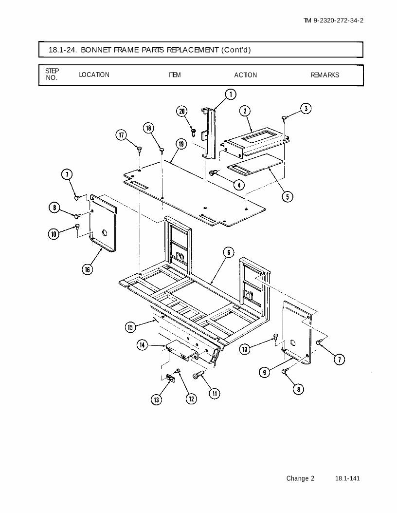
TM 9-2320-272-34-2
18.1-24. BONNET FRAME PARTS REPLACEMENT (Cont'd)
STEPNO. LOCATION ITEM ACTION REMARKS
Change 2 18.1-141

TM 9-2320-272-34-2
18.1-24. BONNET FRAME PARTS REPLACEMENT (Cont'd)
STEP LOCATIONNO.,
ITEM ACTION REMARKS
13.
14.
15.
16.
17.
18.
19.
NOTE• Insulate areas of dissimilar metal-to-metal contact with zinc chromate primer.• Seal between exterior joints with sealing compound.• Insulate all enclosed structure with fibrous glass felt insulation.• Assistant will help with step 13.
Bonnet floor (19)
Post (1)
Inner panels (9) and (16)
Install on bonnetframe (6) and frontwall (15) with forty-three new rivets (17),and thirty-five newrivets (18).Install on bonnetfloor (19) with threescrews (20).Install on bonnetframe (6) and bonnetfloor (19) with thirty-six new rivets (10),twenty-four new rivets(8), and sixteen newrivets (7).
NOTELeft and right heater duct assemblies are installed the same way.This procedure covers the right side.
New insulation (5) andheater duct (2)
Support (14)
Two new speed nuts (13)
Heater duct (2)
Install on bonnetfloor (19) with thirty-six new rivets (3).Install on front wall(15) with three screws(11).Install on support (14)with four new rivets(12).Install on support (14)with two fasteners (4).
18.1-142 Change 2

TM 9-2320-272-34-2
18.1-24. BONNET FRAME PARTS REPLACEMENT (Cont'd)
STEP LOCATION ITEM ACTION REMARKSNO.
Change 2 18.1-143

TM 9-2320-272-34-2
18.1-24. BONNET FRAME PARTS REPLACEMENT (Cont'd)
STEPLOCATIONNO. ITEM ACTION REMARKS
NOTE• Left and right fillers are installed the same way. The left filler is
shown.• Assistant will help with step 20.
20. Two fillers (6) andbonnet lower panel(9)
21.
22.
23.
24.
Outer panels (3) and(15)
Plate (14)
Door panel (10)
Drip molding (1)
Install on bonnetframe (12) with sixty-four new rivets (7)and thirty-one newrivets (8).Install on bonnetframe (12) and bonnetlower panel (9) withtwenty-four new rivets(5) and thirty-eightnew rivets (4).Install on outer panel(15) and bonnet frame(12) with four screws (13).Install on bonnetframe (12) with seven-teen screws (11).Install on bonnetframe (12) with twenty-seven screws (2).
18.1-144 Change 2

TM 9-2320-272-34-2
18.1-24. BONNET FRAME PARTS REPLACEMENT (Cont'd)
STEPNO. LOCATION ITEM ACTION REMARKS
END OF TASK!FOLLOW-ON TASKS: ● Install bonnet door (para. 18.1-26).
● Install bonnet access door (para. 18.1-25).● Install van heater (TM 9-2320-272-20-2).● Install air conditioner (if equipped) (para. 21-31).● Install bonnet control rod (TM 9-2320-272-20-2).
Change 2 18.1-145

TM 9-2320-272-34-2
18.1-25. BONNET ACCESS DOOR MAINTENANCE
This task covers:a. Removal d. Assemblyb. Disassembly e. Installationc. Cleaning and Inspection
INITIAL SETUP:EquipmentCondition
Applicable Models Reference Condition DescriptionM934, M935, M934A1, M935A1 TM 9-2320-272-10 Parking brake set.
TM 9-2320-272-20-2 Bonnet control rod removed.Test Equipment
None
Special ToolsNone
Materials/PartsInsulationSixty-six rivetsTwo sealsPrimer (Appendix C, Item 38)Sealing compound (Appendix C, Item 37)
Personnel RequiredWheeled vehicle repairman MOS 63W (2)
Manual ReferencesTM 9-2320-272-10TM 9-2320-272-20-2TM 9-2320-272-34P
Special Environmental ConditionsVehicle must be on a level surface.
General Safety InstructionsNone
STEP LOCATION ITEM ACTION REMARKSNO.
NOTEAssistant will help with step 1.
1. Bonnet frame (3) Twelve screws (2) and Remove.access door assembly(1)
Lift and position onsupports.
18.1-146 Change 2

TM 9-2320-272-34-2
18.1-25. BONNET ACCESS DOOR MAINTENANCE (Cont'd)
STEPNO. LOCATION ITEM ACTION REMARKS
18.1-147

TM 9-2320-272-34-2
18.1-25. BONNET ACCESS DOOR MAINTENANCE (Cont'd)
,STEP
LOCATION ITEM ACTION REMARKSNO.
2. Door frame (13)
3. Inner panel (18)
4.
5.
6. Door frame (13)
Twelve screws (9), hinge Remove. Discard seal (10).(8), and seal (10)Two screws (5) and angle Remove. Angle bracket (7) canbracket (7) be located on either
side of inner panel (18).Two screws (4) and rod Remove.assembly (3)Two screws (2) and Remove.holder bracket (1)
NOTEAssistant will help with step 6.
Thirty-three screws (16), Remove.nuts (17), outer panel(15), two retainers (12),retainer (14), and seal (11)
Discard seal (11).
NOTEPerform step 7 if inner panel is to be removed. See task c.
7. Discard rivets (6).Sixty-six rivets (6) and Remove.inner panel (18)
c. Cleaning and Inspection
8.9.
10.
11.
12.
13.
14.
All partsHinge (8)
Retainers (12) and (14)
Angle bracket (7), holderbracket (1), and rodassembly (3)Outer panel (15)
Inner panel (18)
Door frame (13)
Clean.Inspect for breaksand proper operation.Inspect for bends andbreaks.Inspect for cracks andbreaks.
Inspect for tears andpunctures.Inspect for tears andpunctures.Inspect for bend,cracks, and breaks.
Refer to para. 2-7.Replace if damaged.
Replace if bent orbroken.Replace if cracked orbroken.
Replace if torn orpunctured.Replace if torn orpunctured.Replace if bent,cracked, or broken.
18.1-148 Change 2

TM 9-2320-272-34-2
18.1-25. BONNET ACCESS DOOR MAINTENANCE (Cont'd)
STEPNO. LOCATION ITEM ACTION REMARKS
Change 2 18.1-149

TM 9-2320-272-34-2
18.1-25. BONNET ACCESS DOOR MAINTENANCE (Cont'd)
STEPLOCATION ITEM ACTION REMARKSNO.
d. Assembly
15.
16.
17.
18.
19.
20.
NOTE● Insulate areas of dissimilar metal-to-metal contact with zinc
chromate primer.● Seal between exterior joints with sealing compound.● Insulate all enclosed structure with fibrous glass felt insulation.● Perform step 15 only if inner panel is to be installed. See task c.● Assistant will help with steps 15 and 16.
18.1-150 Change 2
Inner panel (18)
New seal (11), retainer(14), two retainers (12),and outer panel (15)
Holder bracket (1)
Rod assembly (3)
NOTE
Install on door frame(13) with sixty-sixnew rivets (6).Install on door frame(13) with thirty-threescrews (16) and nuts(17).Install on inner panel(18) with two screws (2).Install on inner panel(18) with two screws (4).
Angle bracket can be installed on either side of door.
Angle bracket (7) Install on inner panel(18) with two screws(5).
New seal (10) and Install on doorframehinge (8) (13) with twelve screws
(9).

TM 9-2320-272-34-2
18.1-25. BONNET ACCESS DOOR MAINTENANCE (Cont'd)
STEPNO. LOCATION ITEM ACTION REMARKS
Change 2 18.1-151

TM 9-2320-272-34-2
18.1-25. BONNET ACCESS DOOR MAINTENANCE (Cont'd)
STEP LOCATION ITEM ACTION REMARKSNO.
e. Installation
21.
NOTEAssistant will help with step 21.
Access door assembly Install on bonnet(1) frame (3) with
twelve screws (2).
18.1-152 Change 2

TM 9-2320-272-34-2
18.1-25. BONNET ACCESS DOOR MAINTENANCE (Cont'd)
STEPNO. LOCATION ITEM ACTION REMARKS
END OF TASK!FOLLOW-ON TASK: Install bonnet control rod (TM 9-2320-272-20-2).
Change 2 18.1-153

TM 9-2320-272-34-2
18.1-26. BONNET DOOR MAINTENANCE
This task covers:a. Removal d. Assemblyb. Disassembly e. Installationc. Cleaning and Inspection
18.1-154 Change 2
Special Environmental ConditionsVehicle must be on a level surface.
General Safety InstructionsNone
INITIAL SETUP:EquipmentCondition
Applicable Models Reference Condition DescriptionM934, M935, M934A1, M935A1 TM 9-2320-272-10 Parking brake set.
Test EquipmentNone
Special ToolsNone
Materials/PartsFour channel sealsInsulationOne-hundred twenty-four rivetsThree sealsCork (Appendix C, Item 40)Primer (Appendix C, Item 38)Sealing compound (Appendix C, Item 37)
Personnel RequiredWheeled vehicle repairman MOS 63W (2)
Manual ReferencesTM 9-2320-272-10TM 9-2320-272-34P
STEP LOCATION ITEM ACTION REMARKSNO.
NOTELeft and right bonnet doors are removed the same way. Thisprocedure covers the left side.
1. Bonnet door (2) and Two screws (3) and Remove.bonnet (1) washers (4)
NOTEAssistant will help with step 2.
2. Bonnet (1) Seven screws (5) and Remove.bonnet door (2)
Position squarely onfour jackstands withouter panel facingupwards.

TM 9-2320-272-34-2
18.1-26. BONNET DOOR MAINTENANCE (Cont'd)
STEPNO. LOCATION ITEM ACTION REMARKS
Change 2 18.1-155

TM 9-2320-272-34-2
18.1-26. BONNET DOOR MAINTENANCE (Cont'd)
STEPLOCATION ITEM ACTION REMARKSNO.
NOTELeft and right bonnet doors are disassembled the same way. Thisprocedure covers the left side.
3. Frame (7) Six screws (16), seal (14), Remove. Discard seals (12) andspacer plate (15), hinge (14).(13), and seal (12)
4. Outer panel (10), Eighteen screws (11), Remove.frame (7), and nuts (28), and two re-seal (3) tainers (4)
NOTEAssistant will help with step 5.
5. Frame (7) Seventeen rivets (9) andouter panel (10)
6. Inner panel (2) Twenty-four rivets (27),intake assembly (17), andpreformed cork (1)
7. Intake assembly (17) Fourteen rivets (21), two
8.
9.
10. Frame (7)
11.
channels (18), channels(20) and channel seals(19)Ten rivets (22), two chan-nels (23), channels (25),and channel seals (24)
NOTEPerform step 9 only if intake assembly
Twentv-four rivets (27),
Remove. Discard rivets (9).
Remove. Discard rivets (27)and cork (1)
Remove. Discard rivets (21)and channel seals(19).
Remove. Discard rivets (22)and channel seals(24).
is not present on inner panel.
Remove. Discard rivets (27)intake panel (26), and pre- and cork (1).formed cork (1)Seven screws (8), nuts (5), Remove. Discard seal (3).retainer (6), and seal (3).
NOTEAssistant will help with step 11.
Thirty-three rivets (29), Remove.two rivets (30), and innerpanel (2)
Discard rivets (29)and (30).
18.1-156 Change 2

TM 9-2320-272-34-2
18.1-26. BONNET DOOR MAINTENANCE (Cont'd)
STEPNO. LOCATION ITEM ACTION REMARKS
Change 2 18.1-157

TM 9-2320-272-34-2
18.1-26. BONNET DOOR MAINTENANCE (Cont'd)
STEPNO. LOCATION ITEM ACTION REMARKS
All partsHinge (6)
Retainers (2) and (3)and spacer plate (7)Outer panel (1) andinner panel (5)
Intake assembly (8)
Intake panel (13)
Channels (9), (10), (11),and (12)Frame (4)
Clean.Inspect for breaks,corrosion, and properoperation.Inspect for bends andbreaks.Inspect for tears,cracks, and punc-tures.Inspect for cracksand bends.Inspect for bendsand breaks.Inspect for bendsand breaks.Inspect for bends,breaks, cracks, andwarpage.
Refer to para. 2-7.Replace if damaged.
Replace if bent orbroken.Replace if torn,cracked or punctured.
Replace if cracked orbent.Replace if bent orbroken.Replace if bent orbroken.Replace entire bonnetdoor assembly ifdamaged.
c. Cleaning and Inspection
12.13.
14.
15.
16.
17.
18.
19.
18.1-158 Change 2

TM 9-2320-272-34-2
18.1-26. BONNET DOOR MAINTENANCE (Cont'd)
STEP LOCATION ITEM ACTION REMARKSNO.
Change 2 18.1-159

TM 9-2320-272-34-2
18.1-26. BONNET DOOR MAINTENANCE (Cont'd)
STEPLOCATION ITEM ACTION REMARKSNO.
NOTE● Left and right bonnet doors are assembled the same way. This
procedure covers the left door.● Insulate areas of dissimilar metal-to-metal contact with zinc
chromate primer.● Seal between exterior joints with sealing compound.● Insulate all enclosed structure with fibrous glass felt insulation.● Assistant will help with step 20.
20. Inner panel (2) Install on frame (7)with thirty-three newrivets (29) and twonew rivets (30).
21. New seal (3) and retain- Install on frame (7)er (6) with seven screws
(8) and nuts (5).
22.
23.
24.
25.
26.
27.
28.
NOTEPerform step 22 only if intake assembly is not present on inner panel.
New preformed cork (1)and intake panel (26)
Two new channel seals(24), channels (23), andchannels (25)Two new channel seals(19), channels (18), andchannels (20)
Install on inner panel(2) with twenty-fournew rivets (27).Install on intakeassembly (17) withten new rivets (22).Install on intakeassembly (17) withfourteen new rivets(21).
Assistant will help with steps 25 and 26.
New preformed cork (1)and intake assembly (17)
Outer panel (10)
Two retainers (4)
New seal (12), hinge (13),spacer plate (15), andnew seal (14)
Install on inner panel(2) with twenty-fournew rivets (27).Install on frame (7)with seventeen newrivets (9).Install in seal (3) witheighteen screws (11)and nuts (28).Install on frame (7) Hinge must be flushwith six screws (16). with top of door.
18.1-160 Change 2

TM 9-2320-272-34-2
18.1-26. BONNET DOOR MAINTENANCE (Cont'd)
STEP LOCATION ITEM ACTION REMARKSNO.
Change 2 18.1-161

TM 9-2320-272-34-2
18.1-26. BONNET DOOR MAINTENANCE (Cont'd)
STEP LOCATIONNO. ITEM ACTION REMARKS
e. Installation
NOTE● Left and right bonnet doors are installed the same way. This
procedure covers the left door.● Assistant will help with step 24.
Bonnet door (2) Install on bonnet (1)with seven screws (5),two screws (3), andwashers (4).
Change 2
END OF TASK!
18.1-162

Section Ill. VAN BODY ELECTRICAL COMPONENTS
TM 9-2320-272-34-2
REPLACEMENT
18.1-27. VAN BODY ELECTRICAL COMPONENTS TASK SUMMARY
PARA. TITLE PAGENO. NO.
18.1-28.18.1-29.
18.1-30.18.1-31.
18.1-32.
18.1-33.
18.1-34.18.1-35.
18.1-36.18.1-37.18.1-38.
18.1-39.
18.1-40.
18.1-41.18.1-42.
18.1-43.18.1-44.
18.1-45.
18.1-46.
18.1-47.18.1-48.
18.1-49.18.1-50.
18.1-51.18.1-52.
18.1-53.18.1-54.
Main Wiring Harness Maintenance
Van Air Conditioner Wiring Harness Maintenance
Van Heater Wiring Harness MaintenanceHeater Fuel Pump Wiring Harness Maintenance
Electric Heater (10kW) Wiring Harness Maintenance
Blackout Bypass Wiring Harness Maintenance
Right and Left Side Blackout Harness MaintenanceCircuit Breaker Harness and Circuit Breaker MaintenanceEmergency Lamp Wiring Harness MaintenanceBlackout and Clearance Lights Wiring Harness Maintenance400 Hz Supply and Branched 400 Hz Receptacle WiringHarness MaintenanceTelephone Post Wiring Harness Maintenance
Entrance Receptacle 220V 3-Phase Wiring HarnessMaintenance
Flexible Converter Wiring Harness MaintenanceElectrical Load Center Box Maintenance
Electrical Box MaintenanceElectrical Junction Box Maintenance400 Hz Converter Outlet Box Replacement
400 Hz Converter Harness Conduit Replacement
Control Center Box MaintenanceHeater Thermostat and 10kW Heater ThermostatReplacementBlackout and Emergency Light Fixtures ReplacementAC Manual Starter Switches Replacement
Fluorescent Light Fixtures Maintenance400 Hz Converter Replacement
3-Phase Receptacle Wiring Harness MaintenanceElectrical Load Center Conduit Replacement
18.1-16418.1-168
18.1-172
18.1-180
18.1-18418.1-188
18.1-19218.1-196
18.1-20018.1-20618.1-210
18.1-218
18.1-220
18.1-22418.1-226
18.1-25018.1-252
18.1-25418.1-256
18.1-25818.1-264
18.1-26818.1-270
18.1-27418.1-278
18.1-28018.1-284
Change 2 18.1-163

TM 9-2320-272-34-2
1. Load center (8)2. Relay (10)
3. Neutral bus (11)4. 20 amp circuit
breaker (12)5. Plate (7) and wiring
harnesses (6)6. Van ceiling (18) and
wiring harness (20)7. Van side panel (17)8.
9. Van body (19)
18.1-28. MAIN WIRING HARNESS MAINTENANCE
This task covers:a. Removal c. Installationb. Repair
INITIAL SETUP:
EquipmentCondition
Applicable Models Reference Condition DescriptionM934, M934A1, M935, M935A1 TM 9-2320-272-10 Parking brake set.
Test EquipmentTM 9-2320-272-20-1 Battery ground cables disconnected.TM 9-2320-272-20-2 Fluorescent light tubes removed.
None TM 9-2320-272-20-2 Emergency lamp and blackout light
Special Toolsremoved.
TM 9-2320-272-20-2 Blackout light switch and 110-voltNone receptacle removed.
Materials/PartsNone
Personnel Required Special Environmental ConditionsWheeled Vehicle Repairman MOS 63W None
Manual ReferencesTM 9-2320-272-10 General Safety InstructionsTM 9-2320-272-20-1 NoneTM 9-2320-272-20-2TM 9-2320-272-34P
STEP LOCATION ITEM ACTION REMARKSNO.
NOTE● The left and right main wiring harnesses are replaced the same
way. This procedure covers the right main wiring harness.● Tag wires for installation.
a. Removal
Six screws (2) and cover (1)Three setscrews (9) andwires (3)Setscrew (15) and wire (16)Three screws (13) andfive wires (14)Screw (4) and clamp (5)
Twelve screws (22) andclamps (21)Grommet (23)Three screws (25) andwire clip (24)Main wiring harness (20)
Remove.Remove.
Remove.Remove.
Remove.
Remove.
Remove.Remove.
Remove.
18.1-164 Change 2

TM 9-2320-272-34-2
18.1-28. MAIN WIRING HARNESS MAINTENANCE (Cont'd)
STEPNO. LOCATION ITEM ACTION REMARKS
Change 2 18.1-165

TM 9-2320-272-34-2
18.1-28. MAIN WIRING HARNESS MAINTENANCE (Cont'd)
STEP LOCATION ITEM ACTION REMARKSNO.
For van wiring harness repair, refer to TM 9-2320-272-20-1.
10. Main wiring harness(20)
11. Wire clip (24)
12.13.
Grommet (23)Twelve clamps (21)
14.
15.
16.
17.
Clamp (5)
Five wires (14)
Wire (16)
Three wires (3)
Cover (1)
Position on van body(19).Install on side panel(17) with three screws(25).Install on side panel (17).Install on main harness(20) and van ceiling (18)with twelve screws (22).Install on harnesses (6) andplate (7) with screw (4).Install on 20 amp circuitbreaker (12) with threescrews (13).Install on neutral bus (11)with setscrew (15).Install on relay (10) withthree setscrews (9).Install on load center (8)with six screws (2).
18.
18.1-166 Change 2

TM 9-2320-272-34-2
18.1-28. MAIN WIRING HARNESS MAINTENANCE (Cont'd)
STEPNO. LOCATION ITEM ACTION REMARKS
FOLLOW-ON TASKS: ●
●
●
●
Install blackout light switch and 110-volt receptacle (TM 9-2320-272-20-2).Install emergency lamp and blackout light (TM 9-2320-272-20-2).Install fluorescent light tubes (TM 9-2320-272-20-2).Connect battery ground cables (TM 9-2320-272-20-1).
Change 2 18.1-167

TM 9-2320-272-34-2
18.1-29. VAN AIR CONDITIONER WIRING HARNESS MAINTENANCE
This task covers:a. Removal c. Installationb. Repair
INITIAL SETUP:EquipmentCondition
Applicable Models Reference
M934, M934A1, M935, M935A1 TM 9-2320-272-10
Test EquipmentTM 9-2320-272-20-1
Para. 18.1-18None
Special ToolsNone
Materials/PartsTwo lockwashers
Personnel RequiredWheeled Vehicle Repairman MOS 63W
Manual ReferencesTM 9-2320-272-10TM 9-2320-272-20-1TM 9-2320-272-34P
Condition DescriptionParking brake set.Battery ground cables disconnected.Ceiling filler and side panels removed.
Special Environmental ConditionsNone
General Safety InstructionsNone
STEPNO. LOCATION ITEM ACTION REMARKS
NOTETag cables for installation.
1.
2.3.
4.
5.
6.
7.
Wiring harness (6) andvan ceiling (1)Air conditioner (3)Load center (16)
Wiring harnesses (20)and (24) and plate (12)Load center (16)
30 amp circuit breaker(17)
Van body (23)
Twelve screws (4) and Remove.clamps (5)Plug (2) Disconnect.Six screws (22) Remove.and cover (21)Screw (7) and Remove.clamp (8)Nut (9), screw (15), Remove.two lockwashers (10),cable assembly (14),ground cable (13), andwiring harness cable (11)Three screws (18) and Remove.wiring harness cables(19)Wiring harness (20) Remove.
b . Repair
For van wiring harness repair, refer to TM 9-2320-272-20-1.
18.1-168 Change 2
Discard lockwashers(10).

TM 9-2320-272-34-2
18.1-29. VAN AIR CONDITIONER WIRING HARNESS MAINTENANCE (Cont'd)
STEPNO. LOCATION ITEM ACTION REMARKS
Change 2 18.1-169

TM 9-2320-272-34-2
18.1-29. VAN AIR CONDITIONER WIRING HARNESS MAINTENANCE (Cont'd)
STEPNO. LOCATION ITEM ACTION REMARKS
c. Installation
8.9.
10.
11.
12.
13.
14.
Wiring harness (20)Three wiring harnesscables (19)
Wiring harness cable(11), ground cable (13),and cable assembly (14)Clamp (8)
Cover (21)
Plug (2)
Twelve clamps (5)
Position on van body (23).Install on 30 amp circuitbreaker (17) with threescrews (18).Install on load center (16)with screw (15), two newlockwashers (10), and nut (9).Install on wiring harnesses (24)and (20), and plate (12) withscrew (7).Install on load center (16)with six screws (22).Connect to air conditioner(3).Install on wiring harness(6) and van ceiling (1) withtwelve screws (4).
18.1-170 Change 2

TM 9-2320-272-34-2
18.1-29. VAN AIR CONDITIONER WIRING HARNESS MAINTENANCE (Cont'd)
STEPNO. LOCATION ITEM ACTION REMARKS
FOLLOW-ON TASKS:END OF TASK!
● Install ceiling filler and side panels (para. 18.1-18).● Connect battery ground cable (TM 9-2320-272-20-1).
Change 2 18.1-171

TM 9-2320-272-34-2
18.1-30. VAN HEATER WIRING HARNESS MAINTENANCE
This task covers:a. Removal c. Installationb. Repair
INITIAL SETUP
Applicable ModelsM934, M934A1, M935, M935A1
EquipmentConditionReference
TM 9-2320-272-10Condition Description
Parking brake set.
Test EquipmentTM 9-2320-272-20-1 Battery ground cables disconnected.
Para. 18.1-18 Ceiling filler and side panels removed.None
Special Tools Special Environmental ConditionsNone None
Materials/PartsNone General Safety Instructions
Personnel RequiredNone
Wheeled vehicle repairman MOS 63W
Manual ReferencesTM 9-2320-272-10TM 9-2320-272-20-1TM 9-2320-272-34P
STEPNO. LOCATION ITEM ACTION REMARKS
NOTETag wires for installation.
1. Van ceiling (1) and Twelve screws (6) and Remove.wiring harness (5) clamps (7)
2. Two grommets (3) Remove.3. Heater (4) Two plugs (2) Disconnect.
18.1-172 Change 2

TM 9-2320-272-34-2
18.1-30. VAN HEATER WIRING HARNESS MAINTENANCE (Cont'd)
STEPNO. LOCATION ITEM ACTION REMARKS
Change 2 18.1-173

TM 9-2320-272-34-2
18.1-30. VAN HEATER WIRING HARNESS MAINTENANCE (Cont'd)
STEPNO. LOCATION ITEM ACTION REMARKS
4. Thermostat (6)5. Control center box (8)
6.
7.
8. Load center (12)
9. Wiring harnesses (18)a n d ( 1 9 )
10. Load center (12)
11. Van body (9)
Thermostat cover (5)Four screws (4) andthermostat (6)Two screws (2) andwires (3)Four screws (7) andupper cover (1)Six screws (17) andcover (16)Screw (10) and clamp(11)Setscrew (13), screw(14), and two wires (15)Wiring harness (18)
Remove.Remove.
Remove.
Remove.
Remove.
Remove.
Remove.
Remove.
b. Repair
For van wiring harness repair, refer to TM 9-2320-272-20-1.
18.1-174 Change 2

TM 9-2320-272-34-2
18.1-30. VAN HEATER WIRING HARNESS MAINTENANCE (Cont'd)
STEPLOCATIONN O . ITEM ACTION REMARKS
Change 2 18.1-175

TM 9-2320-272-34-2
18.1-30. VAN HEATER WIRING HARNESS MAINTENANCE (Cont'd)
STEP LOCATION ITEM ACTION REMARKS,
NO.
12. Wiring harness (18)
13. Two wires (15)
14. Clamp (11)
15. Cover (16)
16. Upper cover (1)
17. Wires (3)
18. Thermostat (6)
19. Thermostat cover (5)
18.1-176 Change 2
Position on vanbody (9).Install on load center(12) with screw (14)and setscrew (13).Place on wiring harnesses(18) and (19) and installon load center (12) withscrew (10).Install on load center (12)with six screws (17).Install on center controlbox (8) with four screws(7).Install on thermostat (6)with two screws (2).Install on upper cover (1)with two screws (4).Install on thermostat (6).

TM 9-2320-272-34-2
18.1-30. VAN HEATER WIRING HARNESS MAINTENANCE (Cont'd)
STEPLOCATION ITEM ACTION REMARKSNO.
Change 2 18.1-177

TM 9-2320-272-34-2
18.1-30. VAN HEATER WIRING HARNESS MAINTENANCE (Cont'd)
STEP LOCATION ITEM ACTION REMARKSNO.
20. Two plugs (2) Connect to heater (4).21. Two grommets (3) Install on wiring harness
(5) and van ceiling (1).22. Twelve clamps (7) Install on wiring harness
(5) and van ceiling (1) withtwelve screws (6).
18.1-178 Change 2

TM 9-2320-272-34-2
18.1-30. VAN HEATER WIRING HARNESS MAINTENANCE (Cont'd)
STEPNO. LOCATION ITEM ACTION REMARKS
END OF TASK!FOLLOW-ON TASKS: ● Install ceiling filler and side panels (para. 18.1-18).
● Connect battery ground cables (TM 9-2320-272-20-1).
Change 2 18.1-179

TM 9-2320-272-34-2
18.1-31. HEATER FUEL PUMP WIRING HARNESS MAINTENANCE
This task covers:a. Removal c. Installationb. Repair
INITIAL SETUP:
EquipmentCondition
Applicable Models Reference Condition DescriptionM934, M934A1, M935, M935A1 TM 9-2320-272-10 Parking brake set.
Test EquipmentTM 9-2320-272-20-1 Battery ground cables disconnected.
None
Special TookNone
Special Environmental ConditionsNone
Materials/Parts General Safety InstructionsNone None
Personnel RequiredWheeled Vehicle Repairman MOS 63W
Manual ReferencesTM 9-2320-272-10TM 9-2320-272-20-1TM 9-2320-272-34P
STEPNO. LOCATION ITEM ACTION REMARKS
NOTE● Perform steps 1 and 2 for M934 and M935 vehicles.● Tag wires for installation.
1. Fuel pump wiring har- Screw (1) and clamp (5) Remove.ness (3)
2. Fuel pump connector Wiring harness (3) Disconnect.plug (2)
NOTEPerform step 3 for M934A1 and M935A1 vehicles.
3. Fuel pump connector Wiring harness (3) Disconnect.plug (2)
4. Heater (6) Wiring harness (3) Disconnect.5. Van body (4) Wiring harness (3) Remove.
For van wiring harness repair, refer to TM 9-2320-272-20-1.
18.1-180 Change 2

TM 9-2320-272-34-2
18.1-31. HEATER FUEL PUMP WIRING HARNESS MAINTENANCE (Cont'd)
STEPLOCATION ITEM ACTION REMARKSNO.
Change 2 18.1-181

TM 9-2320-272-34-2
18.1-31. HEATER FUEL PUMP WIRING HARNESS MAINTENANCE (Cont'd)
STEP LOCATION ITEM ACTION REMARKSNO.
6.
7.
8.
9.
10.
Wiring harness (3) Position on van body(4).
Wiring harness (3) Connect to heater (6).
NOTEPerform step 8 for M934A1 and M935A1 vehicles.
Wiring harness (3) Connect to fuel pumpconnector plug (2).
NOTEPerform steps 9 and 10 for M934 and M935 vehicles.
Wiring harness (3) Connect to fuel pumpconnector plug (2).
Clamp (5) Install on wiring harness(3) with screw (1).
18.1-182 Change 2

TM 9-2320-272-34-2
18.1-31. HEATER FUEL PUMP WIRING HARNESS MAINTENANCE (Cont'd)
STEPLOCATION ITEM ACTION REMARKSNO.
END OF TASK!FOLLOW-ON TASK: Connect battery ground cables (TM 9-2320-272-20-1).
Change 2 18.1-183

TM 9-2320-272-34-2
18.1-32. ELECTRICAL HEATER (10kW) WIRING HARNESS MAINTENANCE
This task covers:a. Removal c. Installationb. Repair
INITIAL SETUP
EquipmentCondition
Applicable Models Reference
M934, M934A1, M935, M935A1 TM 9-2320-272-10
Test EquipmentNone
TM 9-2320-272-20-1Para. 18.1-18
Special ToolsNone
Materials/PartsThree insulated wires splicers
Personnel RequiredWheeled Vehicle Repairman MOS 63W
Manual ReferencesTM 9-2320-272-10TM 9-2320-272-20-1TM 9-2320-272-34P
Condition DescriptionParking brake set.Battery ground cables disconnected.Ceiling fillers and side panels removed.
Special Environmental ConditionsNone
General Safety InstructionsNone
STEPNO. LOCATION ITEM ACTION REMARKS
1.
2.3.4.5.
NOTETag wires for installation.
Van ceiling (3) and Twelve screws (6) and Remove.wiring harness (4) clamps (5)
Grommet (2) Remove.Heater (8) Two wires (1) and (7) Remove.Thermostat (13) Thermostat cover (12)Upper cover (15) Two screws (11) and
thermostat (13)
18.1-184 Change 2

TM 9-2320-272-34-2
18.1-32. ELECTRICAL HEATER (10kW) WIRING HARNESS MAINTENANCE (Cont'd)
STEPNO. LOCATION ITEM ACTION REMARKS
6. Wiring harness (1.6) and Three insulated wire Remove. Discard insulated wirethermostat leads (10) splicers (14) splicers (14).
7. Control center box (18) Four screws (9) and Remove.upper cover (15)
8. Load center (23) Six screws (19) and cover Remove.(30)
9. Screw (20), clamp (21) Remove.and wiring harnesses(16) and (29)
10. Neutral bus (22) Screw (28) and wire Remove.(27)
11. Three 20 amp circuit Screws (25) and cables Removebreakers (24) (26)
12. Van body (17) Wiring harness (16) Remove.
Change 2 18.1-185

TM 9-2320-272-34-2
18.1-32. ELECTRICAL HEATER (10kW) WIRING HARNESS MAINTENANCE (Cont'd)
STEP LOCATION ITEM ACTION REMARKSNO.
For van wiring harness repair, refer to TM 9-2320-272-20-1.
c. Installation
13.14.
15.
16.
17.
18.
19.
20.
21.22.
23.
24.
Wiring harness (8)Three wires (18)
Wire (19)
Clamp (13)
Cover (22)
Upper cover (7)
Thermostat leads (2)
Thermostat (5)
Thermostat cover (4)TwO cables (23) and(29)Grommet (24)
Twelve clamps (27)
Position on van body (9).Install on three 20 ampcircuit breakers (16) withthree screws (17).Install on neutral bus (14)with screw (20).Install on wiring harnesses (8)and (21) and load center (15)with screw (12).Install on load center (15)with six screws (11).Install on control centerbox (10) with four screws (1).Connect to wiring harness(8) with three new insulatedwire splicers (6).Install on upper cover (7)with two screws (3).Install on thermostat (5).Install on heater (30).
Install on wiring harness(26) and van ceiling (25).Install on wiring harness(26) and van ceiling (25) withtwelve screws (28).
18.1-186 Change 2

TM 9-2320-272-34-2
18.1-32. ELECTRICAL HEATER (10kW) WIRING HARNESS MAINTENANCE (Cont'd)
STEPLOCATIONNO. ITEM ACTION REMARKS
FOLLOW-ON TASKS: ● Install ceiling filler and side panels (para. 18.1-18).● Connect battery ground cables (TM 9-2320-272-20-1).
Change 2 18.1-187

TM 9-2320-272-34-2
18.1-33. BLACKOUT BYPASS WIRING HARNESS MAINTENANCE
This task covers:a. Removal c. Installationb. Repair
INITIAL SETUP:
Applicable ModelsM934, M934A1, M935, M935A1
Test EquipmentNone
Special ToolsNone
Materials/PartsNone
Personnel RequiredWheeled Vehicle Repairman MOS 63W
Manual ReferencesTM 9-2320-272-10TM 9-2320-272-20-1TM 9-2320-272-34P
STEPNO. LOCATION ITEM ACTION REMARKS
EquipmentConditionReference Condition Description
TM 9-2320-272-10 Parking brake set.TM 9-2320-272-20-1 Battery ground cables disconnected.
Special Environmental ConditionsNone
General Safety InstructionsNone
a. R e m o v a l
1.
2.
3.
4.
5.
6.
7.
Load center (6)
3-pole circuit breaker(5)30 amp circuit breaker(7)Switch (11)
Van body (16)
Switch (11)
Van body (16)
NOTETag wires for installation.
Six screws (1) and cover Remove.(2)Two setscrews (10) and Remove.wires (3)Screw (8) and wire (9) Remove.
Two screws (13) and Remove.cover (14)Two screws (12) and Remove.switch (11)Three screws (15) Loosen and remove
wires (3).Wiring harness (4) Remove.
For van wiring harness repair, refer to TM 9-2320-272-20-1.
18.1-188 Change 2

18.1-33.
TM 9-2320-272-34-2
STEPNo. LOCATION ITEM ACTION REMARKS
Change 2 18.1-189

TM 9-2320-272-34-2
18.1-33. BLACKOUT BYPASS WIRING HARNESS MAINTENANCE (Cont'd)
STEP LOCATION ITEM ACTION REMARKSNO.
8. Wiring harness (4) Position on van body(16).
9. Three wires (3) Install on switch (11)with three screws (15).
10. Switch (11) Install on van body (16)with two screws (12).
11. Cover (14) Install on switch (11)with two screws (13).
12. Wire (9) Install on 30 ampcircuit breaker (7) withscrew (8).
13. Two wires (3) Install on 3-pole circuitbreaker (5) with twosetscrews (10).
14. Cover (2) Install on load center(6) with six screws (1).
18.1-190 Change 2

18.1-33.
TM 9-2320-272-34-2
STEPLOCATIONNO. ITEM ACTION REMARKS
FOLLOW-ON TASK: Connect battery ground cables (TM 9-2320-272-20-1).
Change 2 18.1-191

TM 9-2320-272-34-2
18.1-34. RIGHT AND LEFT SIDE BLACKOUT HARNESS MAINTENANCE
This task covers:a. Removal c. Installationb. Repair
INITIAL SETUP:EquipmentCondition
Applicable Models Reference
M934, M934A1, M935, M935A1 TM 9-2320-272-10Test Equipment TM 9-2320-272-10
None TM 9-2320-272-20-2Special Tools
None
Materials/Parts
Condition DescriptionParking brake set.Van body sides fully expanded andsecured.Hinged roof-operated blackout circuitplungers removed.
NonePersonnel Required
Wheeled vehicle repairman MOS 63W
Special Environmental ConditionsNone
Manual References General Safety InstructionsTM 9-2320-272-10 NoneTM 9-2320-272-20-2TM 9-2320-272-34P
STEPNO. LOCATION ITEM ACTION REMARKS
NOTETag wires for installation.
1. Load center (15) Six screws (21) and Remove.cover (20)
2. Neutral bus (16) Screw (14) and wire (13) Remove.3. Relay (12) Screw (10) and wire (11) Remove.4. Rear door blackout Screws (5) and (9), and Remove.
switch (6) wires (7) and (8)
NOTEPerform steps 5 through 8 for left and right side of van body.
5. Van body (26) Six screws (24) and Remove.cover (22)
6. Van body (26) Grommet (4) Remove.7. Harness (23) and Nut (19), two screws (17) Remove.
cover (22) and two halves of con-nector (18)
8. Harness (23) and ceiling Nut (3), two screws (25) Remove.truss (2) and two halves of con-
nector (1)9. Load center (15) Harness (23) Pull through hole
in ceiling truss.
18.1-192 Change 2

TM 9-2320-272-34-2
18.1-34. RIGHT AND LEFT SIDE BLACKOUT HARNESS MAINTENANCE (Cont'd)
STEPLOCATIONNO. ITEM ACTION REMARKS
Change 2 18.1-193

TM 9-2320-272-34-2
18.1-34. RIGHT AND LEFT SIDE BLACKOUT HARNESS MAINTENANCE (Cont'd)
STEP LOCATION ITEM ACTION REMARKSNO.
NOTEFor van wiring harness repair, refer to TM 9-2320-272-20-1.
c. Installation
10.
11.
12.
13.
14.15.
16.
17.
18.
Harness (23) Push in through holein ceiling truss (2) andposition on load center(15).
NOTEPerform steps 11 through 14 for left and right side of van body.
Two halves of connector(1)
Cover (22)
Two halves of connector(18)
Grommet (4)Wires (7) and (8)
Wire (11)
Wire (13)
Cover (20)
Install on harness (23)and ceiling truss (2) withnut (3) and two screws (25).Install on van body (26) withsix screws (24).Install on harness (23) andcover (22) with nut (19) andtwo screws (17).Install on van body (26).Install on rear door blackoutswitch (6) with screws (5)and (9).Install on relay (12) withscrew (10).Install on neutral bus (16)with screw (14).Install on load center (15)with six screws (21).
18.1-194 Change 2

TM 9-2320-272-34-2
18.1-34. RIGHT AND LEFT SIDE BLACKOUT HARNESS MAINTENANCE (Cont'd)
STEPNO. LOCATION ITEM ACTION REMARKS
FOLLOW-ON TASKS: • Install hinged roof-operated blackout circuit plungers (TM 9-2320-272-20-2).• Retract van body sides (TM 9-2320-272-10).
Change 2 18.1-195

TM 9-2320-272-34-2
18.1-35. CIRCUIT BREAKER HARNESS AND CIRCUIT BREAKER MAINTENANCE
This task covers:a. Circuit Breaker Harness Removal d. Circuit Breaker Installationb. Circuit Breaker Removal e. Circuit Breaker Harness Installationc. Repair
INITIAL SETUP:EquipmentCondition
Applicable Models Reference Condition DescriptionM934, M934A1, M935, M935A1 TM 9-2320-272-10 Parking brake set.
Test EquipmentTM 9-2320-272-20-1 Battery ground cables disconnected.
None
Special Tools Special Environmental ConditionsNone None
Materials/PartsTwo locknutsLockwasher
General Safety InstructionsNone
Personnel RequiredWheeled Vehicle Repairman MOS 63W
Manual ReferencesTM 9-2320-272-10TM 9-2320-272-20-1TM 9-2320-272-34P
STEP LOCATION ITEM ACTION REMARKSNO.
a. Circuit Breaker Harness Removal
1. Circuit breaker (1)2. Wiring harness (15)
and van body (16)3. Spare tire carrier mount-
ing bracket (5)4.
5. Van body (16)6. Circuit breaker (1)
b. Circuit Breaker Removal
7. Van body (16)
18.1-196 Change 2
NOTETag wires for installation.
Wire (2) Disconnect.Two screws (4) and Remove.clamps (3)Locknut (10), screw (13), Remove.and clamp (14)Locknut (6), screw (12), Remove.washer (11), wires (8)and (9), and lockwasher(7)Wiring harness (15) Remove.Emergency lamp wiring Disconnect.harness (18).
Two screws (17) and Remove.and circuit breaker (1)
Discard locknut (10).
Discard locknut (6)and lockwasher (7).

TM 9-2320-272-34-2
18.1-35. CIRCUIT BREAKER HARNESS AND CIRCUIT BREAKER MAINTENANCE (Cont'd)
STEPNO. LOCATION ITEM ACTION REMARKS
Change 2 18.1-197

TM 9-2320-272-34-2
18.1-35. CIRCUIT BREAKER HARNESS AND CIRCUIT BREAKER MAINTENANCE (Cont'd)
STEP LOCATION ITEM ACTION REMARKSNO.
For van wiring harness repair, refer to TM 9-2320-272-20-1.
d. Circuit Breaker Installation
8. Circuit breaker (1) Install on van body(16) with two screws(17).
e. Circuit Breaker Harness Installation
9. Emergency lamp wiringharness (18)
10. Wires (9) and (8)
11. Clamp (14) andwiring harness (15)
12.
13.
Two clamps (3)
Wire (2)
Install on circuitbreaker (1).Install on spare tiremounting bracket (5)with screw (12),washer (11), newlockwasher (7), andnew locknut (6).Install on spare tirecarrier mountingbracket (5) withscrew (13), and newlocknut (10).Install on wiring harness(2) and van body (16) withtwo screws (4).Connect to circuit break-er (1).
18.1-198 Change 2

18.1-35.
TM 9-2320-272-34-2
STEP LOCATIONNO. ITEM ACTION REMARKS
FOLLOW-ON TASK: Connect battery ground cables (TM 9-2320-272-20-1).
Change 2 18.1-199

TM 9-2320-272-34-2
18.1-36. EMERGENCY LAMP WIRING HARNESS MAINTENANCE
This task covers:a. Removal c. Installationb. Repair
INITIAL SETUP:
Applicable ModelsM934, M934A1, M935, M935A1
Test EquipmentNone
EquipmentConditionReference Condition Description
TM 9-2320-272-10 Parking brake set.TM 9-2320-272-20-1 Battery ground cables disconnected.
Para. 18.1-18 Ceiling filler and side panels removed.
Special TookNone
Special Environmental ConditionsNone
Materials/PartsNone -
General Safety InstructionsPersonnel Required NoneWheeled vehicle repairman MOS 63W
Manual ReferencesTM 9-2320-272-10TM 9-2320-272-20-1TM 9-2320-272-34P
STEP LOCATIONNO. ITEM ACTION REMARKS
a. RemovaI
1.
2.
3.
4.
5.
6.7.
8.
9.
Van ceiling (1) andwiring harness (2)Switch (11)
Switch box (13)
Switch (11)
Van wall (16)
Switch box (13)Emergency lamp wiringharness lead (15)Van ceiling (1)
NOTETag wires for installation.
Twelve screws (4) and Remove.clamps (3)Two screws (9) and cover Remove.(8)Two screws (10) and Remove.switch (11)Two wires (7) and wire Disconnect.(12)Four screws (6) and box Remove.(13)Grommet (5) Remove.Emergency lamp wiring Disconnect.harness lead (14)Twelve screws (4) and Remove from wiringclamps (3) harness (17).Grommet (18) and Remove.wiring harness (17)
18.1-200 Change 2

TM 9-2320-272-34-2
18.1-36. EMERGENCY LAMP WIRING HARNESS MAINTENANCE (Cont'd)
STEPLOCATION ITEM ACTION REMARKSNO.
Change 2 18.1-201

TM 9-2320-272-34-2
18.1-36. EMERGENCY LAMP WIRING HARNESS MAINTENANCE (Cont'd)
STEPNO. LOCATION ITEM ACTION REMARKS
10. Circuit breaker (1) Lead (2) Disconnect.11. Wiring harness (3) and Two screws (5) and Remove.
van body (11) clamps (4)12. Two screws (10) and Remove
clamps (6).13. Spare tire carrier Screw (9), clamp (8), and Remove.
bracket (7) wiring harness (3)
14. Positive battery term- Nut (12) and wire (14) Remove.inal (13)
15. Van body (11) Lead (2) Remove.
b . R e p a i r
For van wiring harness repair, refer to TM 9-2320-272-20-1.
c. Installation
16. Wire (14) Install on positivebattery terminal (13)with nut (12).
17. Wiring harness (3) Install on spare tirecarrier bracket (7) withclamp (8) and screw (9).
18. Two clamps (6) Install on wiring harness(3) and van body (11) withtwo screws (10).
19. Two clamps (4) Install on wiring harness(3) and van body (11) withtwo screws (5).
20. Lead (2) Connect to circuit breaker(1).
18.1-202 Change 2

TM 9-2320-272-34-2
18.1-36. EMERGENCY LAMP WIRING HARNESS MAINTENANCE (Cont'd)
STEPNO. LOCATION ITEM ACTION REMARKS
Change 2 18.1-203

TM 9-2320-272-34-2
18.1-36. EMERGENCY LAMP WIRING HARNESS MAINTENANCE (Cont'd)
STEP LOCATION ITEM ACTION REMARKSNO.
21. Grommet (5) Install on van ceiling
22. Twelve clamps (2)
23.
24.25.
26.
27.
28.
29.
Emergency lamp wiringharness (6)Grommet (7)Two cables (9) andcable (14)Switch box (15)
Switch (13)
Cover (11)
Emergency lamp wiringharness (6)
(4) and wiring harness (3).Install on van ceiling(4) and wiring harness(3) with twelve screws(1).Connect to emergencylamp wiring harness (3).Install on switch box (15).Install on switch (13).
Install on van wall (16)with four screws (8).Install on switch box (15)with two screws (12).Install on switch (13)with two screws (10).Install on van ceiling (4)with twelve clamps (2)and screws (1).
18.1-204 Change 2

TM 9-2320-272-34-2
18.1-36. EMERGENCY LAMP WIRING HARNESS MAINTENANCE (Cont'd)
STEPNO. LOCATION ITEM ACTION REMARKS
FOLLOW-ON TASKS: ● Install ceiling filler and side panels (para. 18.1-18).• Connect battery ground cables (TM 9-2320-272-20-1).
Change 2 18.1-205

TM 9-2320-272-34-2
18.1-37. BLACKOUT AND CLEARANCE LIGHTS WIRING HARNESS MAINTENANCE
This task covers:a. Removal c. Installationb. Repair
INITIAL SETUP:EquipmentCondition
Applicable Models Reference
M934, M934A1, M935, M935A1 TM 9-2320-272-10
Test EquipmentNone
Special ToolsNone
Materials/PartsNone
Personnel RequiredWheeled vehicle repairman MOS 63W
Manual ReferencesTM 9-2320-272-10TM 9-2320-272-20-2TM 9-2320-272-34P
TM 9-2320-272-10TM 9-2320-272-20-2
Para. 18.1-12Para. 18.1-18Para. 18.1-20
Condition DescriptionParking brake set.Main power switch off.Clearance and blackout marker lightsremoved.Rear wall interior panels removed.Ceiling filler and side panels removed.Ceiling air ducts removed.
Special Environmental ConditionsNone
General Safety InstructionsNone
STEP LOCATION ITEM ACTION REMARKSNO.
NOTETag wires for installation.
1.
2.
3.
4.
5.
6.7.
Van body (3) and wiringharness (1)
Rear wiring harnessconnectors (5)Van ceiling (13) andwiring harness (1)
Van body (3)
Grommet (2)
Two screws (6) andclamps (7)Wiring harness connec-tors (4)Twelve screws (11) andclamps (12)Five screws (10) andclamps (9)Four grommets (8)Wiring harness (1)
18.1-206 Change 2
Remove.
Remove.
Disconnect.
Remove.
Remove.
Remove.Remove.

TM 9-2320-272-34-2
18.1-37. BLACKOUT AND CLEARANCE LIGHTS WIRING HARNESS MAINTENANCE (Cont'd)
STEPNO. LOCATION ITEM ACTION REMARKS
Change 2 18.1-207

TM 9-2320-272-34-2
18.1-37. BLACKOUT AND CLEARANCE LIGHTS WIRING HARNESS MAINTENANCE (Cont'd)
STEPNO. LOCATION ITEM ACTION REMARKS
NOTEFor van wiring harness repair, refer to TM 9-2320-272-20-1.
8.
9.
10.
11.
12.
13.
14.
Wiring harness (1)
Four grommets (8)
Five clamps (9)
Twelve clamps (12)
Wiring harness con-nectors (4)Two clamps (7)
Grommet (2)
Position on van body (3).
Install on van ceiling (13)and wiring harness (1).Install on van ceiling (13)and wiring harness (1)with five screws (10).Install on van ceiling (13)and wiring harness (1)with twelve screws (11).Connect to rear wiringharness connectors (5).Install on wiring harness(1) and van body (3) withtwo screws (6).Install on wiring harness(1) and van body (3).
18.1-208 Change 2

TM 9-2320-272-34-2
18.1-37. BLACKOUT AND CLEARANCE LIGHTS WIRING HARNESS MAINTENANCE (Cont'd)
STEPLOCATION ITEM ACTION REMARKSNO.
FOLLOW-ON TASKS: • Install ceiling air ducts (para. 18.1-20).Install ceiling filler and side panels (para. 18.1-18).Install rear wall interior panels (para. 18.1-12).Install clearance and blackout marker lights (TM 9-2320-272-20-2).Main power switch on (TM 9-2320-272-10).
Change 2 18.1-209

TM 9-2320-272-34-2
18.1-38. 400 Hz SUPPLY AND BRANCHED 400 Hz RECEPTACLE WIRING HARNESSMAINTENANCE
This task covers:a. Removal c. Installationb. Repair
INITIAL SETUP:
EquipmentCondition
Applicable Models Reference
M934, M934A1, M935, M935A1 TM 9-2320-272-10
Test EquipmentTM 9-2320-272-20-1
Para. 18.1-18None
Special ToolsNone
Materials/PartsSealing compound (Appendix C, Item 26)
Personnel RequiredWheeled vehicle repairman MOS 63W
Manual ReferencesTM 9-2320-272-10TM 9-2320-272-20-1TM 9-2320-272-34P
Condition DescriptionParking brake set.Battery ground cables removed.Ceiling filler and side panels removed.
Special Environmental ConditionsNone
General Safety InstructionsNone
STEP LOCATION ITEM ACTION REMARKSNO.
a . Removal
1. Control center (1)
2.
3. Terminal (13)
4.5. Circuit breaker (11)
6. Branched 400 Hzreceptacle harness (14)and van ceiling (17)
N O T ETag wires for installation.
Four screws (4) andupper cover (5)Four screws (9) andlower cover (8)Two screws (3) andwires (2)Screw (6) and wire (12)Three screws (7) andwires (10)Six screws (16) andclamps (15)
Remove.
Remove.
Remove.
Remove.Remove.
Remove.
18.1-210 Change 2

TM 9-2320-272-34-2
18.1-38. 400 Hz SUPPLY AND BRANCHED 400 Hz RECEPTACLE WIRING HARNESSMAINTENANCE (Cont'd)
STEPLOCATION ITEM ACTION REMARKSNO.
Change 2 18.1-211

TM 9-2320-272-34-2
18.1-38. 400 Hz SUPPLY AND BRANCHED 400 Hz RECEPTACLE WIRING HARNESSMAINTENANCE (Cont'd)
STEP LOCATION ITEM ACTION REMARKSNO.
7.8.
9.10.
11.
12.
Connectors (1) and (2)Electrical connector box(8)
Connector (2)Load center (13)
Two harnesses (12) andload center (13)Coupling (14)
Connectors (5) and (6) Disconnect.Eight screws (3) and Remove.electrical connector boxcover (4)Four wires (7) Disconnect.Six screws (16) and Remove.cover (9)Screw (10) and clamp Remove.(11)Wiring harness (15) Pull and remove from
load center (13) andelectrical connectorbox (8).
NOTEFor van wiring harness repair, refer to TM 9-2320-272-20-1.
18.1-212 Change 2

TM 9-2320-272-34-2
18.1-38. 400 Hz SUPPLY AND BRANCHED 400 Hz RECEPTACLE WIRING HARNESSMAINTENANCE (Cont'd)
STEPNO. LOCATION ITEM ACTION REMARKS
Change 2 18.1-213

TM 9-2320-272-34-2
18.1-38. 400 Hz SUPPLY AND BRANCHED 400 Hz RECEPTACLE WIRING HARNESSMAINTENANCE (Cont'd)
STEP LOCATION ITEM ACTION REMARKSNO.
13.
14.15.
16.
17.
18.
18.1-214 Change 2
Wiring harness (8) Push through coupling(6), electrical connectorbox (16), and load center (5).
Four wires (7)Clamp (3)
Connect to connector (11).Install on two harnesses(4) and load center (5)with screw (2).
Cover (1) Install on load center (5)with six screws (9).
NOTEApply sealing compound in step 17.
Electrical connector box Install on electricalcover (13) connector box (16)
with eight screws (12).Cables (14) and (15) Connect to connectors
(10) and (11).

TM 9-2320-272-34-2
18.1-38. 400 Hz SUPPLY AND BRANCHED 400 Hz RECEPTACLE WIRING HARNESSMAINTENANCE (Cont'd)
STEPNO. LOCATION ITEM ACTION REMARKS
1 8 . 1 - 2 1 5

TM 9-2320-272-34-2
18.1-38. 400 Hz SUPPLY AND BRANCHED 400 Hz RECEPTACLE WIRING HARNESSMAINTENANCE (Cont'd)
STEPNO. LOCATION ITEM ACTION REMARKS
19. Three wires (10) Install on circuit breaker(11) with three screws (7).
20. Wire (12) Install on terminal (13)with screw (6).
21. Two wires (2) Install on terminal (13)with two screws (3).
22. Lower cover (8) Install on control centerbox (1) with four screws (9).
23. Upper cover (5) Install on control centerbox (1) with four screws (4).
24. Six clamps (15) Install on branched 400 Hzreceptacle harness (14) andvan ceiling (17) with sixscrews (16).
18.1-216 Change 2

TM 9-2320-272-34-2
18.1-38. 400 Hz SUPPLY AND BRANCHED 400 Hz RECEPTACLE WIRING HARNESSMAINTENANCE (Cont'd)
STEPNO. LOCATION ITEM ACTION REMARKS
FOLLOW-ON TASKS: ● Install ceiling filler and side panels (para. 18.1-18).● Install battery ground cables (TM 9-2320-272-20-1).
Change 2 18.1-217

TM 9-2320-272-34-2
18.1-39. TELEPHONE POST WIRING HARNESS MAINTENANCE
This task covers:a. Removal c. Installationb. Repair
INITIAL SETUP:EquipmentCondition
Applicable Models Reference
M934, M934A1, M935, M935A1 TM 9-2320-272-10
Test EquipmentTM 9-2320-272-20-2
Para. 18.1-18None
Special ToolsNone
Materials/PartsNone
Personnel RequiredWheeled vehicle repairman MOS 63W
Condition DescriptionParking brake set.Inside telephone jack posts removed.Ceiling filler and side panels removed.
Special Environmental ConditionsNone
General Safety InstructionsNone
Manual ReferencesTM 9-2320-272-10TM 9-2320-272-20-2TM 9-2320-272-34P
STEPNO. LOCATION ITEM ACTION REMARKS
NOTETag wires for installation.
1. Wiring harness (4) and Six screws (2) and Remove.van ceiling (5) clamps (3)
2. Van body (1) Wiring harness (4) Remove.
NOTEFor van wiring harness repair, refer to TM 9-2320-272-20-1.
3. Six clamps (3) Install on wiring harness(4) and van ceiling (5) withsix screws (2).
18.1-218 Change 2

TM 9-2320-272-34-2
18.1-39. TELEPHONE POST WIRING HARNESS MAINTENANCE (Cont'd)
STEPNO. LOCATION ITEM ACTION REMARKS
END OF TASK!FOLLOW-ON TASKS: • Install ceiling filler and side panels (para. 18.1-18).
● Install inside telephone jack posts (TM 9-2320-272-20-2).
Change 2 18.1-219

TM 9-2320-272-34-2
18.1-40. ENTRANCE RECEPTACLE 220V 3-PHASE WIRING HARNESS MAINTENANCE
This task covers:a. Removal c. Installationb. Repair
INITIAL SETUP:
Applicable ModelsM934, M934A1, M935, M935A1
Test EquipmentNone
Special ToolsNone
Materials/PartsFour locknutsSafety wire (Appendix C, Item 36)
Personnel RequiredWheeled vehicle repairman MOS 63W
Manual ReferencesTM 9-2320-272-10TM 9-2320-272-20-1TM 9-2320-272-34P
EquipmentConditionReference Condition Description
TM 9-2320-272-10 Parking brake set.TM 9-2320-272-10 External power source removed.TM 9-2320-272-20-1 Battery ground cables disconnected.
Special Environmental ConditionsNone
General Safety InstructionsNone
STEP LOCATION ITEM ACTION REMARKSNO.
a. Removal NOTE
1.
2.
3.
4.
5.
6.
7.
Tag wires for installation.Load center box (5) Six screws (14) and Remove.
cover (1)Circuit breakers (6) Three screws (16) and Remove.
wires (17)Neutral bus bar (4) Setscrew (3) and wire Remove.
(2)Electrical box (13) Three screws (8) and Remove.
plate (7)Van body (12) Four screws (9), lock- Remove.
nuts (15), and receptacle(10)
Receptacle (10) Connector (11) Disconnect.NOTE
Safety wire will be used to route wires through van body.Van body (12) Wires (2) and (17) Remove from electrical
Discard locknuts (15).
box (13) and load center(5).
18.1-220 Change 2

TM 9-2320-272-34-2
18.1-40. ENTRANCE RECEPTACLE 220V 3-PHASE WIRING HARNESS MAINTENANCE (Cont'd)
STEPLOCATION ITEM ACTION REMARKSNO.
Change 2 18.1-221

TM 9-2320-272-34-2
18.1-40. ENTRANCE RECEPTACLE 220V 3-PHASE HARNESS MAINTENANCE (Cont'd)
STEPNO. LOCATION ITEM ACTION REMARKS
NOTEFor van wiring harness repair, refer to TM 9-2320-272-20.
c. Installation
8.
9.
10.
11.
12.
13.
18.1-222
Wires (2) and (17) Feed through electricalbox (13) into load center(5).
Receptacle (10) Place over connector (11)and install on van body(12) with four screws (9)and new locknuts (15).
Plate (7)
Wire (2)
Three wires (17)
Cover (1)
Change 2
Install on electrical box(13) with three screws (8).Install on neutral busbar (4) with setscrew (3).Install on circuit breakers(6) with three screws (16).Install on load center box(5) with six screws (14).

18.1-40
TM 9-2320-272-20-1
TM 9-2320-272-10
TM 9-2320-272-34-2
Change 2 18.1-223

TM 9-2320-272-34-2
18.1-41. FLEXIBLE CONVERTER WIRING HARNESS MAINTENANCE
This task covers:a. Removal c. Installationb. Repair
INITIAL SETUP:EquipmentCondition
Applicable Models Reference
M934, M934A1, M935, M935A1 TM 9-2320-272-10Condition Description
Parking brake set.
Test EquipmentNone Special Environmental Conditions
Special ToolsNone
Materials/PartsGasket Lockwasher
Personnel RequiredWheeled vehicle repairman MOS 63W
Manual ReferencesTM 9-2320-272-10TM 9-2320-272-20-1TM 9-2320-272-34P
None
General Safety Instructions
STEPNO. LOCATION ITEM ACTION REMARKS
a. Removal
NOTETag wires for installation.
Discard gasket (3).
Discard lockwasher(6).
None
1. Junction box (11)2. Converter (5)
3.
4. Van body (4)
Connector (10) Disconnect.Four screws (1), cover Remove.(2), and gasket (3)Three nuts (7), wires (8), Remove.and lockwasher (6)Wiring harness (9) Remove.
NOTEFor van wiring harness repair, refer to TM 9-2320-272-20-1.
18.1-224 Change 2

TM 9-2320-272-34-2
18.1-41. FLEXIBLE CONVERTER WIRING HARNESS MAINTENANCE (Cont'd)
STEPNO. LOCATION ITEM ACTION REMARKS
6.
7.
8.
Wiring harness (9) Position on van body(4).
Three wires (8) Install on converter (5)with three nuts (7) andnew lockwasher (6).
Cover (2) Install on converter (5)with new gasket (3) andfour screws (1).
Connector (10) Connect to junction box(11).
Change 2 18.1-225

TM 9-2320-272-34-2
18.1-42. ELECTRICAL LOAD CENTER BOX MAINTENANCE
This task covers:a. Removal c. Assemblyb. Disassembly d. Installation
INITIAL SETUP:
EquipmentCondition
Applicable Models Reference
M934, M934A1, M935, M935A1 TM 9-2320-272-10
Test EquipmentTM 9-2320-272-10TM 9-2320-272-20-1
None
Special ToolsNone
Materials/PartsThree lockwashersGasketSealing compound (Appendix C, Item 26)
Condition DescriptionParking brake set.External power source disconnected.Battery ground cables disconnected.
Special Environmental ConditionsNone
General Safety InstructionsNone
Personnel RequiredWheeled vehicle repairman MOS 63W
Manual ReferencesTM 9-2320-272-10TM 9-2320-272-20-1TM 9-2320-272-34PTM 9-237
STEP LOCATION ITEM ACTION REMARKSNO.
1. Load center (5)
2. Relay (4)
3. Neutral bus (6)4. Circuit breakers (7) and
(8)
5. Circuit breaker (9)6. Load center (5)
7. Relay (4)
8. Neutral bus (6)9. Circuit breaker (21)
10. Circuit breaker (22)
18.1-226 Change 2
NOTETag wires for installation.
Six screws (1) and cover Remove.(2)Three screws (18) and Remove.wires (3)Screw (16) and wire (17) Remove.Screws (12) and (11) Remove.and two wires (15) and(14)Screw (10) and wire (13) Remove.Main wiring harness Remove.(right) (19)Three screws (32) and Remove.wires (20)Screw (30) and wire (31) Remove.Screw (26) and wires (29) Remove.Screw (25) and wires (28) Remove.

TM 9-2320-272-34-2
18.1-42. ELECTRICAL LOAD CENTER BOX MAINTENANCE (Cont'd)
STEPNO. LOCATION ITEM ACTION REMARKS
11. Circuit breaker (23) Screw (24) and wire (27) Remove.12. Load center (5) Main wiring harness Remove.
(left) (33)
Change 2 18.1-227

TM 9-2320-272-34-2
18.1-42. ELECTRICAL LOAD CENTER BOX MAINTENANCE (Cont'd)
STEP LOCATIONNO. ITEM ACTION REMARKS
13.
14.15.
16.
17.
18.
Relay (4)
Circuit breaker (6)Load center (5)
Three circuit breakers(16)Load center (5)
Screw (1) and wires (2) Remove.and (9)
Screw (7) and wire (8) Remove.Blackout by-pass wiring Remove.harness (3)
Nut (12), screw (15), two Remove.washers (11), cableassembly (14), groundcable (13), and cable (10)
Three screws (17) andwires (18)Air conditioner wiring
Remove.
Remove.harness (19) -
18.1-228 Change 2

TM 9-2320-272-34-2
18.1-42. ELECTRICAL LOAD CENTER BOX MAINTENANCE (Cont'd)
STEPNO. LOCATION ITEM ACTION REMARKS
19. Neutral bus (21) Screw (26) and wire (25) Remove.20. Three circuit breakers Three screws (23) and Remove.
(22) wires (24)21. Load center (5) 10kW electric heater Remove.
wiring harness (20)22. Neutral bus (21) Screw (32) and wire (31) Remove.23. Circuit breaker (28) Screw (29) and wire (30) Remove.24. Load center (5) Electric heater wiring Remove.
harness (27)
Change 2 18.1-229

TM 9-2320-272-34-2
18.1-42. ELECTRICAL LOAD CENTER BOX MAINTENANCE (Cont'd)
STEP LOCATION ITEM ACTION REMARKSNO.
NOTESteps 25 through 27 are applicable to M935 and M935A1 vehicles only.
25. Connector (4)
26. Outlet box (7)
27. Connector (4)
28. Connectors (11) and(15)
29. Junction box (8)
30. Connectors (11) and(15)
Auxiliary pump connec-tor (2)Four screws (3), cover(1), and gasket (5)Auxiliary pump wiringharness leads (6)Cables (12) and (13)
Eight screws (14) andcover (16)Wires (9) and (10)
Disconnect.
Remove. Discard gasket (5).
Disconnect. Refer to TM 9-237.
Disconnect.
Remove.
Remove. Refer to TM 9-237.
18.1-230 Change 2

TM 9-2320-272-34-2
18.1-42. ELECTRICAL LOAD CENTER BOX MAINTENANCE (Cont'd)
I STEPNO. LOCATION ITEM ACTION REMARKS I
Change 2 18.1-231

TM 9-2320-272-34-2
18.1-42. ELECTRICAL LOAD CENTER BOX MAINTENANCE (Cont'd)
STEPNO. LOCATION ITEM ACTION REMARKS
31. Six circuit breakers (3) Six screws (5) and wires Remove.(6)
32. Load center (2) and Converter and auxiliary Remove.coupling (4) pump wiring harness (1)
33. Neutral bus (9) Screw (13) and wire (8) Remove.34. Three circuit breakers Three screws (11) and Remove.
(10)35. Load center (2)
wires (12)Wire (7) and entrance Remove.receptacle wiring harness(8)
18.1-232 Change 2

TM 9-2320-272-34-2
18.1-42. ELECTRICAL LOAD CENTER BOX MAINTENANCE (Cont'd)
STEPNO. LOCATION ITEM ACTION REMARKS
36. Relay (24)37. Switch (19)
38. Neutral bus (22)39. Load center (2)
40. Neutral bus (22)41. Three circuit breakers
(28)42. Load center (2)
Screw (15) and wire (25) Remove.Two screws (17) and Remove.wires (18) and (20)Screw (23) and wire (21) Remove.Right and left blackout Remove.harnesses (15) and (16)Screw (31) and wire (27) Remove.Three screws (29) and Remove.wires (30)3 phase receptacle (right) Remove.wiring harness (26)
Change 2 18.1-233

TM 9-2320-272-34-2
18.1-42. ELECTRICAL LOAD CENTER BOX MAINTENANCE (Cont'd)
LOCATION ITEM ACTION REMARKS
43. Neutral bus (4) Screw (1) and wire (3) Remove.44. Three circuit breakers (6) Three screws (7) and Remove.
wires (8)45. Load center (5) 3 phase receptacle (left) Remove.
wiring harness (2)46. Four screws (9) and Remove.
washers (10)47. Conduit (12) Special nut (13) Remove.48. Van body (11) Load center box (5) Remove.
18.1-234 Change 2

TM 9-2320-272-34-2
18.1-42. ELECTRICAL LOAD CENTER BOX MAINTENANCE (Cont'd)
STEPNO. LOCATION ITEM ACTION REMARKS
1 8 . 1 - 2 3 5

TM 9-2320-272-34-2
18.1-42. ELECTRICAL LOAD CENTER BOX MAINTENANCE (Cont'd)
STEPNO. LOCATION ITEM ACTION REMARKS
b. Disassembly
49.50.
51.
52.
53.
54.
55.56.
57.
58.
59.
60.
61.
62.63.
Load center cover (2)Relay (4)
Relay (4) and neutralbus (11)Neutral bus (11)
20 amp circuit breaker(26) and relay (4)Load center box (12)
Neutral bus (11)Load center (12)
Six plates (1)Two screws (32),jumper wire (31), andground B cable (29)Screws (33) and (28)and ground N cable (30)Screw (34) and ground Bcable (29)Screws (25) and (5)and relay cable (3)Three screws (6), lock-washers (7), and relay(4)Screw (27) and cable (8)Six screws (16) and in-sulators (17)Nine screws (24) and20 amp circuit breakers(26)Three screws (22) and30 amp circuit breaker(23)Three screws (20) and40 amp circuit breaker(21)Twelve screws (19) andfour 20 amp circuitbreakers (18)Three screws (15) and100 amp circuit breaker(14)Grommet (13)Two screws (10) andblackout door switch(9)
Remove.Remove.
Remove.
Remove.
Remove.
Remove.
Remove.Remove.
Remove.
Remove.
Remove.
Remove.
Remove.
Remove.Remove.
Discard lockwashers(7).
18.1-236 Change 2

TM 9-2320-272-34-2
18.1-42. ELECTRICAL LOAD CENTER BOX MAINTENANCE (Cont'd)
STEPLOCATIONNO. ITEM ACTION REMARKS
18.1-237

TM 9-2320-272-34-2
18.1-42. ELECTRICAL LOAD CENTER BOX MAINTENANCE (Cont'd)
STEP LOCATION ITEM ACTION REMARKSNO.
64. 100 amp circuit breaker(14)
65. Four 20 amp circuitbreakers (18)
66.
67.
68.
69.
70.
71.
72.
40 amp circuit breaker(21)30 amp circuit breaker(23)Nine 20 amp circuitbreakers (26)Six insulators (17)
Relay (4)
Cable (8)
Relay cable (3)
73. Ground B cable (29)
74. Ground N cable (30)
75. Jumper wire (31) andground B cable (29)
76. Six plates (1)
77. Blackout door switch(9)
78. Grommet (13)
18.1-238 Change 2
Install on load center(12) with three screws(15).Install on load center(12) with twelve screws(19).Install on load center (12)with three screws (20).Install on load center (12)with three screws (22).Install on load center (12)with nine screws (24).Install on load center (12)with six screws (16).Install on load center (12)with three screws (6) andnew lockwashers (7).Install on neutral bus (11)with screw (27).Install on 20 amp circuitbreaker (26) and relay (4)with two screws (25) and(5).Install on neutral bus (11)with screw (34).Install on relay (4) andneutral bus (11) with twoscrews (33) and (28).Install on relay (4) withtwo screws (32).Install on load center cover(2).Install on load center (12)with two screws (10).Install on load center (12).

TM 9-2320-272-34-2
18.1-42. ELECTRICAL LOAD CENTER BOX MAINTENANCE (Cont'd)
STEPLOCATION ITEM ACTION REMARKSNO.
Change 2 18.1-239

TM 9-2320-272-34-2
I 18.1-42. ELECTRICAL LOAD CENTER BOX MAINTENANCE (Cont'd)
STEP LOCATION ITEM ACTION REMARKSNO.
79. Load center box (5)
80.81.
Install on van body (11)with four screws (9) andwashers (10)
Special nut (13) Install on conduit (12).Three wires (8) and Install on circuit breaker3-phase receptacle (6) with three screws (7).(left) wiring harness(2)Wire (3) Install on neutral bus (4)
with screw (1).82.
18.1-240 Change 2

TM 9-2320-272-34-2
18.1-42. ELECTRICAL LOAD CENTER BOX MAINTENANCE (Cont'd)
STEPNO. LOCATION ITEM ACTION REMARKS
Change 2 18.1-241

TM 9-2320-272-34-2
18.1-42. ELECTRICAL LOAD CENTER BOX MAINTENANCE (Cont'd)
STEP LOCATION ITEM ACTION REMARKSNO.
83. Three wires (18) and Install on circuit3-phase receptacle(right) wiring harness(14)
84. Wire (15)
85. Wire (9) and right andleft blackout harnesses(2) and (3)
86. Two wires (6) and (8)
87. Wire (13)
18.1-242 Change 2
breakers (16) withthree screws (17).
Install on neutral bus(10) with screw (19).Install on neutral bus(10) in load center (4)with screw (11).Install on switch (7)with two screws (5).Install on relay (12)with screw (1).

TM 9-2320-272-34-2
18.1-42. ELECTRICAL LOAD CENTER BOX MAINTENANCE (Cont’d)
STEPLOCATION ITEM ACTION REMARKSNO.
88. Three wires (30) and400Hz branched wiringharness(25)
89.
90.
Wire (26)
Six wires (24) and con-verter and auxiliarypump wiring harness(20)
Install on circuitbreakers (28) in loadcenter (4) with threescrews (29).
Install on neutral bus(27) with screw (31).Install on circuitbreaker (21) in loadcenter (4) with sixscrews (23). Insertthrough coupling (22).
Change 2 18.1-243

TM 9-2320-272-34-2
18.1-42. ELECTRICAL LOAD CENTER BOX MAINTENANCE (Cont'd)
STEP L O C A T I O N ITEM ACTION REMARKSNO.
91. Wires (9) and (10) Install on connectors (11) Refer to TM 9-237.and (15).
NOTEApply sealing compound before performing step 92.
92. Cover (16) Install on junction box (8)with eight screws (14).
93. Cables (12) and (13) Install on connectors (11)and (15).
NOTEPerform steps 94 through 96 for M935 and M935A1 vehicles.
94. Auxiliary pump wiring Connect to connector (4). Refer to TM 9-237.harness (6)
95. Cover (1) Install on outlet box (7)with new gasket (5) andfour screws (3).
96. Auxiliary pump cable Connect to connector (4).(2)
18.1-244 Change 2

TM 9-2320-272-34-2
18.1-42. ELECTRICAL LOAD CENTER BOX MAINTENANCE (Cont'd)
STEPNO. LOCATION ITEM ACTION REMARKS
Change 2 18.1-245

TM 9-2320-272-34-2
18.1-42. ELECTRICAL LOAD CENTER BOX MAINTENANCE (Cont'd)
STEP LOCATION ITEM ACTION REMARKSNO.
97.
98.
Wires (12) and (13) and Install on circuit break-electric heater wiring er (10) in load centerharness (9) (2) and neutral bus (3)
with screws (11) and(14).
Wire (7), three wires Install on neutral bus(6), and 10kW (3) and circuit breakers (4)electrical heater with screw (8) andwiring harness(1) three screws (5).
18.1-246 Change 2

TM 9-2320-272-34-2
18.1-42. ELECTRICAL LOAD CENTER BOX MAINTENANCE (Cont'd)
STEPNO. LOCATION ITEM ACTION REMARKS
99. Three wires (30) andair conditioner wiringharness (31)
Cable assembly (26)ground cable (25) andcable (22)
Wires (15), (21), and(20), and blackout by-pass wiring harness (16)
Install on circuitbreaker (28) in loadcenter (2) with threescrews (29).Install on load center(2) with nut (24),screw (27), and twowashers (23).Install on relay (17)and circuit breaker(18) with screws (14)and (19).
18.1-247

TM 9-2320-272-34-2
18.1-42. ELECTRICAL LOAD CENTER BOX MAINTENANCE (Cont'd)
STEP LOCATION ITEM ACTION REMARKSNO.
102. Main wiring harness Position on load center(left) (33) (5).
103. Wire (27)
104. Wires (28)
105. Wires (29)
106. Wire (31)
107. Three wires (20)
108. Two wires (15) and(14), wire (13), andmain wiring harness(right) (19)
109. Wire (17)
110. Three wires (3)
111. Load center boxcover (2)
1 8 . 1 - 2 4 8 Change 2
Install on circuit breaker(23) with screw (24).Install on circuit breaker(22) with screw (25).Install on circuit breaker(21) with screw (26).Install on neutral bus (6)with screw (30).Install on relay (4) withthree screws (32).Install on three circuitbreakers (7), (8), and (9)with three screws (12),(11) and (10).Install on neutral bus (6)with screw (16).Install on relay (4) withthree screws (18).Install on load centerbox (5) with six screws (1).

TM 9-2320-272-34-2
18.1-42. ELECTRICAL LOAD CENTER BOX MAINTENANCE (Cont'd)
STEPNO. LOCATION ITEM ACTION REMARKS
FOLLOEND OF TASK!
W-ON TASKS: • Install battery ground cables (TM 9-2320-272-20-1). ● Connect external power source (TM 9-2320-272-10).
Change 2 18.1-249

TM 9-2320-272-34-2
18.1-43. ELECTRICAL BOX MAINTENANCE
This task covers:a. Disassembly c. Assemblyb. Inspection d. Installation
INITIAL SETUP:EquipmentCondition
Applicable Models Reference
M934, M934A1, M935, M935A1 TM 9-2320-272-10
Test EquipmentTM 9-2320-272-20-1
Para. 18.1-40None
Condition DescriptionParking brake set.Battery ground cables disconnected.Entrance receptacle 220V 3-phaseharness removed.
Special ToolsNone
Special Environmental ConditionsMaterials/Parts
None
Personnel RequiredWheeled vehicle repairman MOS 63W
Manual ReferencesTM 9-2320-272-10TM 9-2320-272-20-1TM 9-2320-272-34P
None
General Safety InstructionsNone
STEPNO. LOCATION ITEM ACTION REMARKS
I a. Disassembly
1. Electrical box (7) Six screws (2) and brack- Remove.et (3)
2. Grommet (1) Remove.3. Screw (5) and plate (6) Remove.
b. Inspection
4. Inspect all parts fordamage. Replace alldamaged parts.
5.
6.
Plate (6)
Bracket (3)
Install on electricalbox (7) with screw (5).Install on electrical box(7) with six screws (2).
18.1-250 Change 2

TM 9-2320-272-34-2
18.1-43. ELECTRICAL BOX MAINTENANCE (Cont'd)
STEPNO. LOCATION ITEM ACTION REMARKS
7. Electrical box (7)
8. Grommet (1)
Position on van bodyend panel (4).Install on electrical box(7).
END OF TASK!
FOLLOW-ON TASKS: ● Install entrance receptacle 220V 3-phase harness (para. 18.1-40).● Connect battery ground cables (TM 9-2320-272-20-1).
Change 2 18.1-251

TM 9-2320-272-34-2
18.1-44. ELECTRICAL JUNCTION BOX REPLACEMENT
This task covers:a. Removal b. Installation
INITIAL SETUP: EquipmentCondition
Applicable Models Reference Condition DescriptionM934, M934A1, M935, M935A1 TM 9-2320-272-10 Parking brake set.
Test EquipmentTM 9-2320-272-20-1 Battery ground cables disconnected.
None
Special ToolsNone
Materials/PartsEight locknutsGasketSealing compound (Appendix C, Item 26)
Personnel RequiredWheeled vehicle repairman MOS 63W
Special Environmental ConditionsNone
General Safety InstructionsNone
Manual ReferencesTM 9-2320-272-10TM 9-2320-272-20-1TM 9-2320-272-34TM 9-237
STEP LOCATION ITEM ACTION REMARKSNO.
1. Outlet box (6) Cable (1)2. Four screws (2)
NOTE
Disconnect.Remove and separatecover (3) from outletbox (6).
3. Cover (3)
4. Outlet box (6)5. Junction box (14)6.
7. Cover (12)
8.
18.1-252 Change 2
Tag wires for installation.Harness leads (5) Remove from connector Refer to TM 9-237.
(7).Cover (3) and gasket (4) Remove. Discard gasket (4).Cables (10) Remove.Eight screws (11) and Remove.cover (12)
NOTETag wires for installation.
Harness leads (13) Remove from connectors Refer to TM 9-237.and (15) (8).Eight locknuts (16), Remove. Discard locknuts (16).screws (9), and twoconnectors (8)

TM 9-2320-272-34-2
18.1-44. ELECTRICAL JUNCTION BOX REPLACEMENT (Cont'd)
STEPNO. LOCATION ITEM ACTION REMARKS
9. Junction box (14) Special nut (21), nut(22), adapter (20), andnut (19)
Loosen and remove.
Remove from conduits(17) and (18) and slideoff wires (13) and (15).
Change 2 18.1-252.1

TM 9-2320-272-34-2
18.1-44. ELECTRICAL JUNCTION BOX REPLACEMENT (Cont'd)
STEP LOCATION ITEM ACTION REMARKSNO.
11 . Junction box (14)
12. Nut (20)
13. Junction box (14)
14. Special nut (21)
15.
16.
17.
18.
19.
20.
21.
22.
18.1-252.2 Change 2
Two connectors (8)
Wires (13) and (15)
Cover (12)
Cables (10)
Cover (3)
Harness leads (5)
Cover (3)
Cable (1)
a.
b.
c.
Place nut (20) onconduit (17).Feed wires (13) and(15) through holesinjunction box (14).Position junction box(14) on conduits (17)and (18).
Install on junction box(14).Feed conduit (18) throughnut (19), adapter (20),junction box (14) andspecial nut (21).Install on junction box(14).Install on cover (12)with eight screws (9)and new locknuts (16).Connect to connectors(8).Coat edges with sealingcompound and installon junction box (14)with eight screws (11).Install on connectors(8).Position on outlet box(6) with new gasket (4).Connect to connector(7) on cover (3).Install on outlet box(6) with four screws (2).Install on outlet box(6).
Refer to TM 9-237.
Refer to TM 9-237.

TM 9-2320-272-34-2
18.1-44. ELECTRICAL JUNCTION BOX REPLACEMENT (Cont'd)
STEPNO. LOCATION ITEM ACTION REMARKS
FOLLOW-ON TASK: Connect battery ground cables (TM 9-2320-272-20-1).
Change 2 18.1-253

TM 9-2320-272-34-2
I 18.1-45. 400 Hz CONVERTER OUTLET BOX REPLACEMENT
This task covers:a. Removal b. Installation
INITIAL SETUP:
EquipmentCondition
Applicable Models Reference Condition DescriptionM934, M934A1, M935, M935A1 TM 9-2320-272-10 Parking brake set.
Test EquipmentTM 9-2320-272-20-1 Battery ground cables removed.
Special ToolsNone
Materials/PartsFour locknutsGasket
Personnel RequiredWheeled vehicle repairman MOS 63W
Manual ReferencesTM 9-2320-272-10TM 9-2320-272-20-1TM 9-2320-272-34PTM 9-237
Special Environmental ConditionsNone
General Safety InstructionsNone
STEP LOCATION ITEM ACTION REMARKSNO.
1.2.
3.
4.
5.
6.
Outlet box (6)Discard gasket (5).
Cover (4)
Outlet box (6)
Van body (7)
7.
Cable (1) Disconnect.Four screws (3), cover Remove.(4), and gasket (5)
NOTETag wires for installation.
Wires (8) Disconnect from con- Refer tonector (2). TM 9-237.
Four locknuts (12), Remove. Discard locknuts (12).screws (13), andconnector (2)Nut (11) Loosen and slide back
on conduit (9).Two screws (10) and Remove.outlet box (6)
Outlet box (6) Slide onto end of conduit(9) and install on van body(7) with two screws (10).
18.1-254 Change 2

TM 9-2320-272-34-2
18.1-45. 400 Hz CONVERTER OUTLET BOX REPLACEMENT (Cont'd)
STEPLOCATIONNO. ITEM ACTION REMARKS
8.
9.
10.
11.
12.
Conduit (9) Secure to outlet box(6) with nut (11).
Connector (2) Install on cover (4)with four screws (13)and new locknuts (12).
New gasket (5) and Slide new gasket (5) Refer towires (8) over wires (8) and TM 9-237.
connect wires (8) toconnector (2).
Cover (4) and new Aline on outlet boxgasket (5) (6) and install with
four screws (3).Cable (1) Connect to connector
(2) on outlet box (6).
END OF TASK!FOLLOW-ON TASK: Connect battery ground cables (TM 9-2320-272-20-1).
Change 2 18.1-255

TM 9-2320-272-34-2
18.1-46. 400 Hz CONVERTER HARNESS CONDUIT REPLACEMENT
This task covers:a. Removal b. Installation
INITIAL SETUP:
EquipmentCondition
Applicable Models Reference
M934, M934A1, M935, M935A1 TM 9-2320-272-10Condition Description
Parking brake set.Battery ground cables removed.400 Hz converter outlet box removed.Electrical junction box removed.
Test EquipmentNone
TM 9-2320-272-20-1Para. 18.1-45Para. 18.1-44
Special ToolsNone
Special Environmental ConditionsMaterials/Parts None
None
Personnel RequiredWheeled vehicle repairman MOS 63W General Safety Instructions
NoneManual References
TM 9-2320-272-10TM 9-2320-272-20-1TM 9-2320-272-34P
STEP LOCATION ITEM ACTION REMARKSNO.
1. Conduits (1) and (6) Six screws (4) andclamps (5)Nuts (2) and (7)Coupling (3)Conduits (1) and (6)
Remove.
2. Coupling (3)3. Conduits (1) and (6)4. Van body (8)
Remove.Remove.Remove.
b. Installation
5. Coupling (3)
Conduits (1) and (6)
Install on conduits (1)and (6).
6. Install on van body(8) with six screws (4)and clamps (5).Install on coupling (3).Nuts (2) and (7)7.
18.1-256 Change 2

TM 9-2320-272-34-2
18.1-46. 400 Hz CONVERTER HARNESS CONDUIT REPLACEMENT (Cont'd)
STEPNO. LOCATION ITEM ACTION REMARKS
END OF TASK!
FOLLOW-ON TASKS: • Connect battery ground cables (TM 9-2320-272-20-1).• Install 400 Hz converter outlet box (para. 18.1-45).• Install electrical junction box (para. 18.1-44).
Change 2 18.1-257

TM 9-2320-272-34-2
18.1-47. CONTROL CENTER BOX MAINTENANCE
This task covers:a. Removal c. Assemblyb. Disassembly d. Installation
INITIAL SETUP:EquipmentCondition
Applicable ModelsM934, M934A1, M935, M935A1
Test EquipmentNone
Special Tools
Reference Condition DescriptionTM 9-2320-272-10 Parking brake set.
Para. 18.1-48 Heater thermostat and 10kW heaterthermostat removed.
Para. 18.1-50 AC manual starter switches removed.
None Special Environmental ConditionsMaterials/Parts None
Four lockwashers
Personnel RequiredWheeled vehicle repairman MOS 63W General Safety Instructions
NoneManual References
TM 9-2320-272-10TM 9-2320-272-34P
STEP LOCATION ITEM ACTION REMARKSNO.
a . Removal
NOTETag wires for installation.
1.
2.
3.4.
5.
6.
Control center box (10) Eight screws (4) andcovers (5) and (8)
Terminal board (12) Two screws (3) andwires (2)Screw (6) and wire (1)
Circuit breaker (11) Three screws (7) andwires (9)
Control center box (10) Two wiring harnesses(17)
Control center box Four screws (13),(10) at van body (16) lockwashers (14),
and control centerbox (10)
Remove.
Remove.
Remove.Remove.
Pull through nipples (15).
Remove. Discard lockwashers(14).
18.1-258 Change 2

TM 9-2320-272-34-2
18.1-47. CONTROL CENTER BOX MAINTENANCE (Cont'd)
STEPNO. LOCATION ITEM ACTION
18.1-259

TM 9-2320-272-34-2
18.1-47. CONTROL CENTER BOX MAINTENANCE (Cont'd)
STEPNO. LOCATION ITEM ACTION REMARKS
b. Disassembly
7. Terminal board (2)
8. Circuit breaker (6)
9. Circuit breaker mount-ing base (9)
10. Control center box (1)
11.
12.
13.
14.
15.
16.
17.
18.
Three screws (4) andjumper cables (5)Three screws (7) andjumper cables (5)Circuit breaker (6)
Two screws (8) andcircuit breaker mount-ing base (9)Four screws (3) andterminal board (2)Two nuts (11) andnipples (10)
Two nipples (10)
Circuit breaker mount-ing base (9)
Termninal board (2)
Circuit breaker (6)
Three jumper cables (5)
Three jumper cables (5)
Remove.
Loosen screws andremove.Remove.
Remove.
Remove.
Remove.
Install on controlcenter box (1) withtwo nuts (11).Install on control centerbox (1) with two screws(8).Install on control centerbox (1) with four screws(3).Install on circuit breakermounting base (9).Install on terminal board(2) with three screws (4).Install on circuit breaker(6) and tighten three screws(7).
18.1-260 Change 2

TM 9-2320-272-34-2
18.1-47. CONTROL CENTER BOX MAINTENANCE (Cont'd)
STEPLOCATION ITEM ACTION REMARKSNO.
Change 2 18.1-261

TM 9-2320-272-34-2
18.1-47. CONTROL CENTER BOX MAINTENANCE (Cont'd)
STEP LOCATION ITEM ACTION REMARKSNO.
19. Control center box (4)
20. Wiring harness (5)
21. Three wires (13)
22. Wire (17)
23. Two wires (6)
24. Covers (9) and (12)
18.1-262 Change 2
Install on van body (1)with four new lock-washers (3) and screws(2).Push through nipples(14) in control centerbox (4).Install on circuit break-er ( 15) with three screws(11).Install on terminal board(16) with screw (10).Install on terminal board(16) with two screws (7).Install on control centerbox (4) with eight screws(8).

TM 9-2320-272-34-2
18.1-47. CONTROL CENTER BOX MAINTENANCE (Cont'd)
STEPNO. LOCATION ITEM ACTION REMARKS
END OF TASK!FOLLOW-ON TASKS: • Install AC manual starter switches (para. 18.1-50).
• Install heater thermostat and 10kW heater thermostat (para. 18.1-48).
Change 2 18.1-263

TM 9-2320-272-34-2
18.1-48. HEATER THERMOSTAT AND 10kW HEATER THERMOSTAT REPLACEMENT
This task covers:a. Heater Thermostat Removal c. 10kW Heater Thermostat Installationb. 10kW Heater Thermostat Removal d. Heater Thermostat Installation
INITIAL SETUP:EquipmentCondition
Applicable Models Reference Condition DescriptionM934, M934A1, M935, M935A1 TM 9-2320-272-10 Parking brake set.
TM 9-2320-272-20-1 Battery ground cables disconnected.Test Equipment
None
Special ToolsNone
Materials/PartsThree insulated wire splices
Personnel RequiredWheeled vehicle repairman MOS 63W
Special Environmental ConditionsNone
General Safety InstructionsNone
Manual ReferencesTM 9-2320-272-10TM 9-2320-272-20-1TM 9-2320-272-34P
STEPNO. LOCATION ITEM ACTION REMARKS
a. Heater Thermostat Removal
NOTETag wires for installation.
1. Thermostat (5) Cover (3) Remove.2. Control center box Two screws (4) and Remove.
cover (1) thermostat (5)3. Thermostat (5) Two screws (6) and Remove.
wires (2)4. Control center box Thermostat (5) Remove.
cover (1)
b. 10kW Heater Thermostat Removal
5. Thermostat (8) Cover (10) Remove.6. Control center box Two screws (9) and Remove.
cover (12) thermostat (8)7. Three insulated wire Three wires (7) and Disconnect. Discard insulated wire
splices (11) (13) splices (11).8. Control center box Thermostat (8) Remove.
cover (12)
18.1-264 Change 2

TM 9-2320-272-34-2
18.1-48. HEATER THERMOSTAT AND 10kW HEATER THERMOSTAT REPLACEMENT (Cont'd)
STEPNO. LOCATION ITEM ACTION REMARKS
Change 2 18.1-265

TM 9-2320-272-34-2
18.1-48. HEATER THERMOSTAT AND 10kW HEATER THERMOSTAT REPLACEMENT (Cont'd)
STEP LOCATION ITEM ACTION REMARKSNO.
c. 10kW Heater Thermostat Installation
9. Three wires (7) and Connect with three new One splice has two(13) insulated wire splices wires.
(11).10. Thermostat (8) Position on control
center box cover (12)and install with twoscrews (9).
11. Cover (10) Install on thermostat (8).
d. Heater Thermostat Installation
12. Two wires (2) Install on thermostat (5)with two screws (6).
13. Thermostat (5) Position on controlcenter box cover (1)and install with twoscrews (4).
14. Cover (3) Install on thermostat(5).
18.1-266 Change 2

TM 9-2320-272-34-2
18.1-48. HEATER THERMOSTAT AND 10kW HEATER THERMOSTAT REPLACEMENT (Cont'd)
STEPNO. LOCATION ITEM ACTION REMARKS
END OF TASK!FOLLOW-ON TASK: Install battery ground cables (TM 9-2320-272-20-1).
Change 2 18.1-267

TM 9-2320-272-34-2
18.1-49. BLACKOUT AND EMERGENCY LIGHT FIXTURES REPLACEMENT
This task covers:a. Removal b. Installation
INITIAL SETUP:
EquipmentCondition
Applicable Models Reference
M934, M934A1, M935, M935A1 TM 9-2320-272-10
Test EquipmentTM 9-2320-272-20-2
None TM 9-2320-272-20-1
Special ToolsNone
Materials/PartsNone
Personnel RequiredWheeled vehicle repairman MOS 63W
Condition DescriptionParking brake set.Emergency and blackout lampsremoved.Battery ground cables disconnected.
Special Environmental ConditionsNone
General Safety InstructionsNone
Manual ReferencesTM 9-2320-272-10TM 9-2320-272-20-1TM 9-2320-272-20-2TM 9-2320-272-34P
STEP LOCATION ITEM ACTION REMARKSN O .
NOTETag wires for installation.
1. Van ceiling (6) Four screws (5) and Remove.housing (4)
2. Housing (4) Four screws (2), two Remove.jumper cables (3), andwiring harness (1)
3.
4.
Two jumper cables (3) Install on housing (4)and wiring harness (1) with four screws (2).Housing (4) Install on van ceiling
(6) with four screws (5).
18.1-268 Change 2

TM 9-2320-272-34-2
18.1-49. BLACKOUT AND EMERGENCY LIGHT FIXTURES REPLACEMENT (Cont'd)
STEPNO. LOCATION ITEM ACTION REMARKS
FOLLOW-ON TASKS: • Install emergency and blackout lamps (TM 9-2320-272-20-2).● Connect battery ground cables (TM 9-2320-272-20-1).
Change 2 18.1-269

TM 9-2320-272-34-2
18.1-50. AC MANUAL STARTER SWITCHES REPLACEMENT
This task covers:a. Removal b. Installation
INITIAL SETUP:
EquipmentCondition
Applicable Models Reference
M934, M934A1, M935, M935A1 TM 9-2320-272-10
Test EquipmentTM 9-2320-272-20-1
None
Special ToolsNone
Materials/PartsTwelve insulated wire splices
Personnel RequiredWheeled vehicle repairman MOS 63W
Manual ReferencesTM 9-2320-272-10TM 9-2320-272-20-1TM 9-2320-272-34P
Condition DescriptionParking brake set.Battery ground cables disconnected.
Special Environmental ConditionsNone
General Safety InstructionsNone
STEPNO. LOCATION ITEM ACTION REMARKS
1.
2.
3.
4.5.6.7.
8.
AC manual starterswitch boxes (1) and (8)Six insulated wiresplices (2)Six insulated wiresplices (6)Two connectors (16)Two connectors (12)
Van body (15)
NOTETag wires for installation.
Covers (5) and (7) Remove.
Six wires (3) Disconnect. Discard insulatedsplices (2).
Six wires (4) Disconnect. Discard insulatedsplices (6).
Two nuts (10) Remove.Two nuts (11) Remove.Two nuts (13) Remove.Four screws (9) and Remove.manual starterswitch box (1)Four screws (14), Remove.manual starter switchbox (8) and two con-nectors (12).
wire
wire
18.1-270 Change 2

TM 9-2320-272-34-2
18.1-50. AC MANUAL STARTER SWITCHES REPLACEMENT (Cont'd)
STEPNO. LOCATION ITEM ACTION REMARKS
Change 2 18.1-271

TM 9-2320-272-34-2
18.1-50. AC MANUAL STARTER SWITCHES REPLACEMENT (Cont'd)
STEPNO. LOCATION ITEM ACTION REMARKS
9. Manual starter switchbox (1)
10. Manual starter switchbox (8)
11. Two nuts (10)
12. Two connectors (12)
13. Two nuts (11)
14. Two nuts (13)
15. Six cables (3)
16. Six cables (4)
17. Covers (5) and (7)
Install on van body(15) with four screws(9).Install on van body(15) with four screws(14).Install on two connectors(16).Install on two manualstarter switch boxes (1)and (8).Install on two connectors(12).Install on two connectors(12).Connect to six new insulatedwire splicers (2).Connect to six new insulatedwire splicers (6).Install on manual starterswitch boxes (1) and (8).
18.1-272 Change 2

TM 9-2320-272-34-2
18.1-50. AC MANUAL STARTER SWITCHES REPLACEMENT (Cont'd)
STEP LOCATION ITEM ACTION REMARKSNO.
FOLLOW-ON TASK: Connect battery ground cables (TM 9-2320-272-20-1).
Change 2 18.1-273

TM 9-2320-272-34-2
18.1-51. FLUORESCENT LIGHT FIXTURES MAINTENANCE
This task covers:a. Removal d. Assemblyb. Disassembly e. Installationc. Inspection
INITIAL SETUP:EquipmentCondition
Applicable Models Reference Condition DescriptionM934, M934A1, M935, M935A1 TM 9-2320-272-10 Parking brake set.
Test Equipment TM 9-2320-272-20-2 Fluorescent light tubes removed.
NoneSpecial Tools Special Environmental Conditions
None NoneMaterials/Parts
Two insulated wire splicesLockwasher
Personnel RequiredWheeled vehicle repairman MOS 63W
Manual ReferencesTM 9-2320-272-10TM 9-2320-272-20-2TM 9-2320-272-34P
General Safety InstructionsNone
STEPLOCATIONN O . ITEM ACTION REMARKS
NOTEAll eight fluorescent light fixtures are removed and installed thesame way. This procedure covers one flourescent light fixture.
1. Van ceiling (1)
2. Light fixture body (8)
3.
Twenty screws (7) andlight fixture body (8)Screw (9), nut (6),lockwasher (5), andwire (4)Two wires (3) and (10)and insulated wiresplices (2)
Remove.
Remove. Discard lockwasher(5).
Disconnect. Discard insulatedwire splices (2).
b. Disassembly
4. Light fixture body (8)
5. Light fixture (20)
6. Six sockets (14)
7.8. Harness (12)9. Light fixture (20)
18.1-274 Change 2
Four screws (19) andlight fixture (20)Six screws (18), nuts(17), and sockets (14)Twelve screws (16) andwires (13)Six starters (15)Grommet (11)Harness (12)
Remove.
Remove.
Remove.
Remove.Remove.Remove.

TM 9-2320-272-34-2
18.1-51. FLUORESCENT LIGHT FIXTURES MAINTENANCE (Cont'd)
STEPNO. LOCATION ITEM ACTION REMARKS
Change 2 18.1-275

TM 9-2320-272-34-2
18.1-51. FLUORESCENT LIGHT FIXTURES MAINTENANCE (Cont'd)
STEP LOCATION ITEM ACTION REMARKSN O .
10. Six sockets (14)
11.
12.
13.
14.15.
16.
17.
18.
18.1-276 Change 2
Six starters (15)
Six starters (15)
Twelve wires (13)
Six sockets (14)
Grommet (11)Light fixture (20)
Wire (4)
Two wires (3) and (10)
Light fixture body (8)
Inspect for burns or Replace if burnt ordamage. damaged.
Install on six sockets(14).Install on six sockets(14) with twelve screws(16).Install on light fixture(20) with six nuts (17)and screws (18).Install on harness (12).Install on light fixturebody (8) with fourscrews (19).
Install on light fixturebody (8) with nut (6),new lockwasher (5),and screw (9).Connect with two new insu-lated wire splices (2).Install on van ceiling(1) with twenty screws(7).

TM 9-2320-272-34-2
18.1-51. FLUORESCENT LIGHT FIXTURES MAINTENANCE (Cont'd)
STEPLOCATION ITEM ACTION REMARKSN O .
END OF TASK!FOLLOW-ON TASK: Install fluorescent light tubes (TM 9-2320-272-20-2).
Change 2 18.1-277

TM 9-2320-272-34-2
18.1-52. 400 Hz CONVERTER REPLACEMENT
This task covers:a. Removal b. Installation
INITIAL SETUP:EquipmentCondition
Applicable Models Reference Condition DescriptionM934, M934A1, M935, M935A1 TM 9-2320-272-10 Parking brake set.
TM 9-2320-272-20-1 Battery ground cablesTest Equipment
None
disconnected.
Special ToolsNone Special Environmental Conditions
NoneMaterials/Parts
Four locknutsGasket General Safety Instructions
NonePersonnel RequiredWheeled vehicle repairman MOS 63W
Manual ReferencesTM 9-2320-272-10TM 9-2320-272-20-1TM 9-2320-272-34P
STEP LOCATION ITEM ACTION REMARKSNO.
1. Converter (6) Four screws (1), cover Remove. Discard gasket (3).(2), and gasket (3)
2. Seven nuts (4) and Remove.wires (5)
3. Two locknuts (10) and Remove. Discard locknuts (10).wiring harnesses (8)and (9)
4. Support bracket (7) Four nuts (17), washers Remove.
5.(18), and screws (11)Converter (6) Remove.
6. Two locknuts (19), U-bolt Remove.(15), and two nuts (16)
7. Van body (12) Four nuts (13), screws Remove.(14), and support brack-et (7)
8.
9.
18.1-278 Change 2
Support bracket (7) Install on van body (12)with four nuts (13) andscrews (14).
U-bolt (15) Install on support bracket(7) with two nuts (16) andnew locknuts (19).
Discard locknuts (19).

TM 9-2320-272-34-2
18.1-52. 400 Hz CONVERTER REPLACEMENT (Cont'd)
STEPLOCATION ITEM ACTION REMARKSNO.
10. Converter (6) Install on supportbracket (7) with fourscrews (11), washers(18), and nuts (17).
11. Two wiring harnesses Install on converter (6)(9) and (8) with two new locknuts
(10).12. Seven wires (5) Install on converter (6)
with seven nuts (4).13. Cover (2) Install on converter (6)
with new gasket (3) and
FOLLOW-ON TASK: Connect battery ground cables (TM 9-2320-272-20-1).
Change 2 18.1-279

TM 9-2320-272-34-2
18.1-53. 3-PHASE RECEPTACLE WIRING HARNESS MAINTENANCE
This task covers:a. Removal c. Installationb. Repair
INITIAL SETUP:EquipmentCondition
Applicable Models Reference
M934, M934A1, M935, M935A1 TM 9-2320-272-10
Test EquipmentNone
Special ToolsNone
Materials/PartsNone
Personnel RequiredWheeled vehicle repairman MOS 63W
Manual ReferencesTM 9-2320-272-10TM 9-2320-272-20-1TM 9-2320-272-34P
TM 9-2320-272-20-1Para. 18.1-18
Condition DescriptionParking brake set.Battery ground cables disconnected.Ceiling filler and side panels removed.
Special Environmental ConditionsNone
General Safety InstructionsNone
STEPNO. LOCATION ITEM ACTION REMARKS
a. Removal
NOTETag wires for installation.
1.
2.
3.4.
5.
6.
Load center (7)
Wiring harness (3)and van body (6)Neutral bus (9)Circuit breakers (11)
Van ceiling (14) andwiring harness (3)Van body (6)
Six screws (2) and cover(1)Screw (4) and clamp (5)
Screw (10) and wire (8)Three screws (12) andwires (13)Twelve screws (16) andclamps (15)Wiring harness (3)
Remove.
Remove.
Remove.Remove.
Remove.
Remove.
18.1-280 Change 2

TM 9-2320-272-34-2
18.1-53. 3-PHASE RECEPTACLE WIRING HARNESS MAINTENANCE (Cont'd)
STEPNO. LOCATION ITEM ACTION REMARKS
●
Change 2 18.1-281

TM 9-2320-272-34-2
18.1-53. 3-PHASE RECEPTACLE WIRING HARNESS MAINTENANCE (Cont'd)
STEP LOCATION ITEM ACTION REMARKSNO.
Wiring harness (3)
Twelve clamps (15)
Three wires (13)
Wire (8)
Clamp (5)
Cover (1)with six screws (2).
18.1-282 Change 2
NOTEFor van wiring harness repair, refer to TM 9-2320-272-20-1.
7.
8.
9.
10.
11.
12.
Position on van body(6).Install on wiring harness(3) and van ceiling (14)with twelve screws (16).Install on circuit breakers(11) with three screws (12).Install on neutral bus (9)with screw (10).Install on wiring harness(3) and van body (6) withscrew (4).Install on load center (7)

TM 9-2320-272-34-2
18.1-53. 3-PHASE RECEPTACLE WIRING HARNESS MAINTENANCE (Cont'd)
STEPNO. LOCATION ITEM ACTION REMARKS
FOLLOW-ON TASKS: ● Install ceiling filler and side panels (para. 18.1-18).• Connect battery ground cables (TM 9-2320-272-20-1).
Change 2 18.1-283

TM 9-2320-272-34-2
18.1-54. ELECTRICAL LOAD CENTER CONDUIT REPLACEMENT
This task covers:a. Removal b. Installation
INITIAL SETUP:
EquipmentCondition
Applicable Models Reference
M934, M934A1, M935, M935A1 TM 9-2320-272-10
Test EquipmentNone
Special ToolsNone
Materials/PartsGasketLocknutSealing compound (Appendix C, Item 26)
Personnel RequiredWheeled vehicle repairman MOS 63W (2)
Manual ReferencesTM 9-2320-272-10TM 9-2320-272-34PTM 9-237
Condition DescriptionParking brake set.
Special Environmental ConditionsNone
General Safety InstructionsNone
STEP LOCATION ITEM ACTION REMARKSNO.
1. Connector (4)2. Outlet box (7)
3. Connector (4)
4. Connectors (11) and (15)5. Junction box (8)
6. Connectors (11) and (15)
1 8 . 1 - 2 8 4 Change 2
Auxiliary pump cable (2) Disconnect.Four screws (3), cover Remove.(1), and gasket (5)Auxiliary pump wiring Disconnect.harness (6)Cables (12) and (13) Remove.Eight screws (14) and Remove.cover (16)Wires (9) and (10) Disconnect.
Discard gasket (5).
Refer to TM 9-237.
Refer to TM 9-237.

TM 9-2320-272-34-2
18.1-54. ELECTRICAL LOAD CENTER CONDUIT REPLACEMENT (Cont'd)
STEPNO. LOCATION ITEM ACTION REMARKS
Change 2 18.1-285

TM 9-2320-272-34-2
18.1-54. ELECTRICAL LOAD CENTER CONDUIT REPLACEMENT (Cont'd)
STEP LOCATION ITEM ACTION REMARKSNO.
7. Load center (7)
8.
9. Load center (7) andconduit (11)
10. Conduit (8)
11. Van body (9)
b. Installation
12.13.
14.
15.
16.
18.1-286 Change 2
Six screws (1) and cover Remove.( 2 )Wiring harnesses (5) Pull out of conduit (11).and (6)Locknut (10), nipple (4), Remove.and nut (3)
NOTEAssistant will help with step 10.
Two nuts (3) and nipple Remove.(4)Conduit (11) Remove.
Conduit (11) Position on van body (9).Nipple (4) Install on conduit (8)
with two nuts (3).Nipple (4) Install on load center (7)
and conduit (11) withnut (3) and new lock-nut (10).
Wiring harnesses (5) Push through loadand (6) center (7) and conduit (11).Cover (2) Install on load center
(7) with six screws (1).
Discard locknut(10).

TM 9-2320-272-34-2
18.1-54. ELECTRICAL LOAD CENTER CONDUIT REPLACEMENT (Cont'd)
STEPLOCATION ITEM ACTION REMARKSNO.
18.1-287

TM 9-2320-272-34-2
18.1-54. ELECTRICAL LOAD CENTER CONDUIT REPLACEMENT (Cont'd)
STEPNO. LOCATION ITEM ACTION REMARKS
17. Wires (9) and (10) Install on connectors Refer to TM 9-237.(11) and (15).
NOTEApply sealing compound before performing step 18.
18.
19.
20.
21.
Cover (16)
Cables (12) and (13)
Auxiliary pump wiringharness (6)Cover (1)
22. Auxiliary pump cable(2)
Install on junction box(8) with eight screws (14).Install on connectors (11)and (15).Connect to connector (4). Refer to TM 9-237.
Install on outlet box (7) withnew gasket (5) and fourscrews (3).Connect to connector (4).
18.1-288 Change 2

TM 9-2320-272-34-2
18.1-54. ELECTRICAL LOAD CENTER CONDUIT REPLACEMENT (Cont'd)
STEP LOCATION ITEM ACTION REMARKSN O .
Change 2 18.1-289 (18.1-290 blank)


19-1.
TM 9-2320-272-34-2
CHAPTER 19WINCH MAINTENANCE
Refer to TM 9-2320-358-24&P for unique M939A2 maintenance procedures.
Section I. DESCRIPTION AND DATA
a. The front winch assembly is mounted on extensions bolted to the left and right frame side rails. Thefront winch is a worm gear, jaw clutch, horizontal drum type with an internal automatic brake and a drumdrag brake.
b. The automatic brake, which is attached to the front end of the drive (worm gear) shaft, sustains winchload whenever delivery of power to winch is interrupted.
c. The internally-mounted drag brake is in constant contact with the left end of winch drum. It preventsthe drum from spinning when unwinding cable.
d. The M936 winch is equipped with a level winding device bolted to the top of the end frame (left end ofwinch) and the gear case (right end of winch). When winding cable, tension of cable on sheave causes sheaveframe to travel on its wheels from side to side on the trolley track and wind the cable in tight, even coils andlayers on the drum.
e. The M936 winch is also equipped with a manually-operated cable tensioner mounted on the front of thewinch. The cable tensioner places tension or drag on the cable when being wound on the drum without aload.
f. Power for the front winch is supplied by the vehicle’s engine through a transmission power takeoff (PTO)which drives a hydraulic pump. Hydraulic pressure drives a hydraulic motor mounted on the rear of thewinch.
FRONT WINCH
1. End frame2. Gearcase3. Hydraulic motor adapter
TA 350865
Change 2 19-1

TM 9-2320-272-34-2
19-2. DESCRIPTION – REAR WINCHa. The rear winch assembly is mounted on the M936 wrecker body at the rear of the crane. The rear winch
is a worm geared, horizontal drum type with an internal automatic brake.b. The automatic brake, which is attached to the rear end of the drive (worm gear) shaft, sustains winch
load whenever delivery of power to winch is interrupted.c. All rear winches are equipped with a level wind that winds cable in tight, even layers.
d. The rear winch is equipped with a manually-controlled, pneumatically-operated cable tensioner. Thecable tensioner places tension, or drag on the cable when being wound on the drum without a load.
e. Power for the rear winch is supplied from the crane hydraulic system. Hydraulic pressure drives ahydraulic motor mounted on the front of the winch.
REAR WINCH
1. Level wind2. End frame3. Cable tensioner4. Gearcase
19-2

TM 9-2320-272-4-2
Table 19-1. Winch Tabulated Data.
1. FRONT WINCH
Model (M925, M926, M928, M930, M932) . . . . . . . . . . . . . . . . . . . . . . . . . . . . . . . . . . . . . . . . . . . . . . . . . . . . . DA 615Model (M936) . . . . . . . . . . . . . . . . . . . . . . . . . . . . . . . . . . . . . . . . . . . . . . . . . . . . . . . . . . . . . . . . . . . . . . . . . . DAS 615Capacity . . . . . . . . . . . . . . . . . . . . . . . . . . . . . . . . . . . . . . . . . . . . . . . . . . . . . . . . . . . . . . . . . . . . . . . 20,000 lb (9091 kg)Cable Size . . . . . . . . . . . . . . . . . . . . . . . . . . . . . . . . . . . . . . . . . . . . . . . . . . . . . . . . . . . . . . . . . . . . . 5/8 in. (15.875 mm)Drive . . . . . . . . . . . . . . . . . . . . . . . . . . . . . . . . . . . . . . . . . . . . . . . . . . . . . . . . . . . . . . . . . . . . . . . . . . . . Hydraulic MotorLocation . . . . . . . . . . . . . . . . . . . . . . . . . . . . . . . . . . . . . . . . . . . . . . . . . . . . . . . . . . . . . . . . . . . . . . . . . . Front of Vehicle
2. REAR WINCHModel (M936) . . . . . . . . . . . . . . . . . . . . . . . . . . . . . . . . . . . . . . . . . . . . . . . . . . . . . . . . . . . . . . . . . . . . . . . . . . ESA 716KCapacity . . . . . . . . . . . . . . . . . . . . . . . . . . . . . . . . . . . . . . . . . . . . . . . . . . . . . . . . . . . . . . . . . . . . . 45,000 lb (20,454 kg)Cable Size . . . . . . . . . . . . . . . . . . . . . . . . . . . . . . . . . . . . . . . . . . . . . . . . . . . . . . . . . . . . . . . . . . . . . . 3/4 in. (19.05 mm)Drive . . . . . . . . . . . . . . . . . . . . . . . . . . . . . . . . . . . . . . . . . . . . . . . . . . . . . . . . . . . . . . . . . . . . . . . . . . . . Hydraulic MotorLocation . . . . . . . . . . . . . . . . . . . . . . . . . . . . . . . . . . . . . . . . . . . . . . . . . . . . . . . . . . . . . . . . . . . . . . . . . . . Rear of Vehicle
Section II. FRONT WINCH COMPONENTS MAINTENANCE
I 19-3. FRONT WINCH MAINTENANCE TASK SUMMARY
TASK PROCEDURES PAGEPARA. NO.
19-4.19-5.19-6.19-7.19-8.19-9.
19-10.19-11.
Front Winch RepairFront Winch Cable Tensioner MaintenanceFront Winch Level Wind MaintenanceFront Winch Roller Assembly MaintenanceFront Winch Hydraulic Pump ReplacementFront Winch Control Valve CableReplacementFront Winch Control Valve ReplacementFront Winch Hydraulic Hose andTube Replacement
19-419-3019-4019-56
19-6619-70
19-7619-82
19-3

TM 9-2320-272-34-2
19-4. FRONT WINCH REPAIRThis task covers:
a. Disassembly into Subassemblies d. Reassembly of Subassembliesb. Disassembly of Subassemblies e. Reassembly of Winchc. Cleaning, Inspection, and Repair
INITIAL SETUP:EquipmentCondition
Applicable Models Reference Condition DescriptionM925, M926, M928, TM 9-2320-272-20-2 Winch removed from vehicle.M930, M932, M936 TM 9-2320-272-20-2 Left and right winch mounting plates
removed.LO 9-2320-272-12 Winch drained.
Para. 19-7 Winch roller removed.Para. 19-5 Winch cable tensioner removed.Para. 19-6 Front winch level wind removed
(if equipped).Test Equipment
None
Special Tools Special Environmental ConditionsNone None
Materials/PartsCotter pinTwo keysTwo woodruff keysFour sealsFive gasketsTwenty-one lockwashersGAA grease (Appendix C, Item 11)Wiping rag (Appendix C, Item 23)Sealing compound (Appendix C, Item 26)
Personnel RequiredWheeled vehicle repairman MOS 63W (2)
General Safety InstructionsThe front winch is a heavy component.Use hoist during repair to prevent injuryto personnel.
Manual ReferencesTM 9-2320-272-20-2TM 9-2320-272-34PLO 9-2320-272-12
STEP LOCATION ITEM ACTION REMARKSNO.
WARNINGThe M925, M926, M928, M930, and M932 vehicles’ front winchweight is 353 lbs (160 kg). The M936 front winch weight is 472 lbs(214 kg). Use hoist during repair to prevent injury to personnel.
19-4

TM 9-2320-272-34-2
19-4. FRONT WINCH REPAIR (Cont’d)
STEP LOCATION ITEM ACTION REMARKSNO.
1. Winch (1) Four screws (3) and Remove. Discard lockwasherslockwashers (4), and (4).top channel (2)
2. Four screws (6) and Remove. Discard lockwasherslockwashers (5), and (5).rear channel (7)
TA 350867
19-5

TM 9-2320-272-34-2
19-4. FRONT WINCH REPAIR (Cont’d)
STEP LOCATION ITEM ACTION REMARKSNO.
3. End frame (6) Drag brake adjustingscrew (4) and spring(5)
4. Tie rod (2) Nut (3)NOTE
Support drum with overhead hoist and chain.
5. End frame (6) Separate from drum(7) and shaft (8).
6. Drum shaft (8) Thrust washer (10) Remove.and clutch (9)
Remove.
Remove.
7. Gearcase (1) Tie rod (2) Remove.
TA 350868
19-6

TM 9-2320-272-34-2
19-4. FRONT WINCH REPAIR (Cont’d)
STEP LOCATION ITEM ACTION REMARKSNO.
8. Drum shaft (8) Two keys (11) Remove. Discard keys (11).
9. Thrust ring (12), drum Remove. Discard seal (13).(7), and seal (13)
TA 350869
19-7

TM 9-2320-272-34-2
19-4. FRONT WINCH REPAIR (Cont’d)
STEP LOCATION ITEM ACTION REMARKSNO.
b. Disassembly of Subassemblies
10. Gearcase (5)
11.
12. Winch motor adapter(14)
13. Worm gear shaft (11)
14.
15.
Four screws (8),screws (9), and lock-washers (10), endcover (7), and gasket(6)Four bolts (15) andlockwashers (16), andadapter (14)Adapter gasket (13)
Cotter pin (2), pin (1)and coupling (17)Seal retainer (12) andgasket (4)
Seal (3)
Remove.
Remove.
Remove.
Remove.
Remove.
Remove.
Discard gasket (6) andlockwashers (10).
Clean gasket remainsfrom mating surfaces.
Discard lockwashers(16).
Discard gasket (13).Clean gasket remainsfrom mating surfaces.Discard cotter pin (2).
Discard gasket (4).Clean gasket remainsfrom mating surfaces.Discard seal (3).
TA 350870
19-8

TM 9-2320-272-34-2
19-4. FRONT WINCH REPAIR (Cont'd)
STEP LOCATION ITEM ACTION REMARKSNO.
16. Automatic brake Six screw-assembled Remove. Discard gasket (21).housing (18) washers (19), automatic
brake cover (20), and Clean gasket remainsgasket (21) from mating surfaces.
17. Adjusting screw (26), Remove. Discard “O” ring (28).washer (27), and “O”ring (28)
18. Spring (29) and brake Remove.band (24)
19. Automatic brakedrum Screw (22), lockwasher Remove. Discard lockwasher(25) (23), and washer (30) (23).
Change 2 19-9

TM 9-2320-272-34-2
19-4. FRONT WINCH REPAIR (Cont’d)
STEP LOCATION ITEM ACTION REMARKSNO.
20. Worm gear shaft (2) Brake drum (3) and Remove. Use puller.woodruff key (1) Discard woodruff key
(1).NOTE
Make sure gearcase and brake housing are marked for reassembly.21. Gearcase (4) Four screws (7) and Remove. Discard lockwashers
lockwashers (8), and (8).brake housing (9)
22. Brake housing gasket Remove. Discard gasket (6).(6) Clean gasket remains
from mating surfaces.23. Brake housing seal (5) Remove. Discard seal (5).
TA 350872
1 9 - 1 0

TM 9-2320-272-34-2
19-4. FRONT WINCH REPAIR (Cont'd)
STEPNO. LOCATION ITEM ACTION REMARKS
NOTEMake sure a rag is placed in bottom of gearcase under worm gearduring removal.
24. Gearcase (15) Worm gear shaft (11)
25. Drum shaft (13) andworm gear (14)
25.1. Worm gear shaft (11)25.2. Worm gear shaft (11) Front bearing (12)
26. End frame (17) Drag brake (18)27. Bearing sleeve (16)
a.
b.
Tap with hammerat brake end andallow worm gearshaft (11) to drop tobottom of gearcase (15).Press bearing (10)from wormgearshaft (11).
Remove.
Remove.Remove.Remove.Remove.
Change 2 19-11

TM 9-2320-272-34-2
19-4. FRONT WINCH REPAIR (Cont’d)
STEP LOCATION ITEM ACTION REMARKSNO.
29. End frame (5) Pipe plug (7) Remove.30. Shifter fork (6) Setscrew (8) Remove.
31. End frame (5) Two nuts (1), poppet Remove.latch (2), nut (3), andpoppet assembly (4)
32. Shifter shaft (9) Woodruff key (14) Remove. Discard woodruff key(14).
33. End frame (5) Shifter shaft (9) Remove. Ball (11) and spring(10) will fall out duringremoval.
34. Oil seals (13) and (12) Remove. Discard oil seals (13)and (12).
19-12

TM 9-2320-272-34-2
19-4. FRONT WINCH REPAIR (Cont’d)
STEP LOCATION ITEM ACTION REMARKSNO.
c. Cleaning, Inspection, and Repair
35. Thrust ring
36.
37.
38.
39.
(15) Wipe clean, andinspect for cracks andwear.
Clutch (16)
Thrust ring (17)
Drum (18)
Wipe clean, andinspect for cracks orchips where clutch(16) engages drum(18).Wipe clean, andinspect for cracks andwear.
Inspect for breaks,cracks, and elongatedbolt holes.
Two bushings (19) a. Wipe clean andmeasure for wear.
NOTE
Measure thickness withmicrometer.Discard if cracked, or ifmeasurement is lessthan 0.049 in.(12.5 mm).Replace if cracked orchipped.
Steps 39b and 40 are performed only if bushings are to be replaced.
Measure thickness withmicrometer.
Discard if cracked, or ifmeasurement is lessthan 0.486 in.(12.3 mm).Replace if broken,cracked, or if holes areelongated. Drum (18)holes elongated lessthan 0.063 in.(1.59 mm) deep areaccept able.
Measure with micro-meter, and replace ifinner diameter exceeds2.136 in. (54.25 mm).
b. Remove from drum(18).
TA 350875
19-13

TM 9-2320-272-34-2
19-4. FRONT WINCH REPAIR (Cont’d)
STEP LOCATION ITEM ACTION REMARKSNO.
40. Two new bushings (4) Install in drum (1).
41. Drum shaft (2) Wipe clean, and Measure with micro-measure all five meter and replace ifbearing surfaces. outer diameter is
42. Drum shaft gear (3) a.
less than 2.123 in.(53.92 mm) at anybearing surface.
Wipe clean, and Replace if teeth areinspect for broken, broken, chipped, orchipped, or scored scored.teeth.
Steps 42b and 43 are performed only when shaft gear or drumshaft are to be replaced.
b. Place in arbor presswith mandrel, andpress shaft (2) outof gear (3).
NOTERemove drum shaft gear keys only if they are damaged. Discardkeys and install new keys.
43. New drum shaft gear Place in arbor press Shaft (2) is pressed(3) and drum shaft (2) and press shaft (2) through gear until keys
into gear (3). are centered in gear(3).
TA 350876
19-14

TM 9-2320-272-34-2
I 19-4. FRONT WINCH REPAIR (Cont’d)
STEP LOCATION ITEM ACTION REMARKSNO.
46.
47.
44. Winch motor adapter Wipe clean, and(5) inspect for breaks and
cracks.45. Worm gear shaft (7) Wipe clean, and
and worm gear inspect for rough orbearings (6) chipped ball bearings
and races.Gearcase (8) Inspect for breaks and
cracks.
Gearcase cover (9) Inspect for breaks andcracks.
Replace if broken orcracked.
Replace if ball bearingsor races are rough orchipped.
Replace if broken orcracked.
Replace if broken orcracked.
TA 350877
19-15

TM 9-2320-272-34-2
19-4. FRONT WINCH REPAIR (Cont’d)
LOCATION ITEM ACTION REMARKS
48. Automatic brake Inspect for cracks.housing (2)
49. Brakedrum (1) Inspect for cracks andgrooves.
50. Spring (3) a.
b.
c.
19-16
Inspect for crackedand collapsed coils.Measure free length.
Test spring (3) withspring tester andtorque wrench.
Replace if cracked.
Replace if cracked orgrooved.Discard if coils arecracked or collapsed.Discard if free length isless than 1.5 in.(38 mm).Discard if test readingis not 52 lb-ft (71 N·m)when compressed to1 in. (25.4 mm).
TA 350878

TM 9-2320-272-34-2
19-4. FRONT WINCH REPAIR (Cont’d)
S T E P LOCATION ITEM ACTION REMARKSNO.
51.
52.
53.
54.55.
56.
57.
58.
59.
End frame sleeve pin(8)
End frame (7)
Poppet springassembly (10)
Hinge (9)
Clutch shifter shaft(12) and woodruff key(11)
Clutch fork (6)
End frame sleeve (5)
Bushing (4)
Drag brake (13)
Inspect for wear, andmake sure pin (8)extends far enough tohold end frame sleeve(5) away from endframe (7).Inspect for breaks andcracks.Inspect for cracks andbends.
Inspect for breaks.Wipe clean, andinspect for bends andscoring on seal surface.Inspect for bends andcracks.Wipe clean, andinspect for cracks.Wipe clean, andmeasure for wear.
Inspect for breaks andcracks.
Replace pin (8) if itdoes not extend farenough to hold endframe sleeve (5) awayfrom end frame (7).
Replace if broken orcracked.Replace if cracked orbent.
Replace if broken.Replace if bent orscored.
Replace if bent orcracked.Replace if cracked.
Measure with micro-meter, and replace ifinner diameter exceeds2.136 in. (54 mm).
Replace if broken orcracked.
TA 350879
19-17

TM 9-2320-272-34-2
19-4. FRONT WINCH REPAIR (Cont’d)
STEP LOCATION ITEM ACTION REMARKSNO.
d. Reassembly of Subassemblies
NOTECoat outside diameter of seals with sealing compound beforereassembly.
60.
61.
62.
19-18
New oil seals (5) and Install in end frame(7) (4).
Clutch shifter shaft (1) a. Insert through seal(7) and then installnew woodruff key(8).
b. Position throughshifter fork (6) andinto end frame (4).
Install in end frame(4).
Shifter lever ball (3)and spring (2)
TA 350880

TM 9-2320-272-34-2
19-4. FRONT WINCH REPAIR (Cont’d)
STEPNO. LOCATION ITEM ACTION REMARKS
63. Setscrew (17) and Install on shifter shaftshifter fork (15) (1).
64. Pipe plug (16) Install on end frame(4).
65. Poppet assembly (12) Install with nut (11),latch (10), and twonuts (9).
66. Bearing sleeve (19) Install in end frame(4).
67. Drag brake (18) and a. Install with adjust-spring (14) ing screw (13).
b. Tighten adjustingscrew (13) all theway.
Tighten setscrew (17).
Coat threads of nut(11) with sealingcompound.
Adjustment is madeafter winch is installedon vehicle. Refer toTM 9-2320-272-20-2.
19-19

TM 9-2320-272-34-2
19-4. FRONT WINCH REPAIR (Cont'd)
STEPNO. LOCATION ITEM ACTION REMARKS
68.
69.
70.
71.
71.1.
Bearing (5) Install on worm gear Use arbor press.shaft (4). Either bearing could
be installed first.Worm gear shaft (4) Position in bottom of Do not install.and bearing (5) gearcase (2).
NOTEKeyway end of worm gear shaft must extend from the marked sideof gearcase.
Drum shaft and gear Install in gearcase(1) (2).Worm gear shaft (4) Install in gearcase ( 2). Tap shaft (4) with soft-and bearings (5) faced hammer until
bearings (5) are flushwith gearcase (2) andworm gear (3) meshes.
Bearing (5) Install on worm gear Use arbor press.
72.
73.
New brake housing seal Coat outside diameter(9) with sealing compound
and install in gearcase(2).
New gasket (10) Coat with light film ofgrease and position ongearcase (2).
NOTE
Use GAA grease to aidinstallation.
Match alinement marks.74. Brake housing (11) Install with four new
lockwashers (7) andscrews (6).
75. Key (8) Position on worm gearshaft (4).
TA 350882
19-20 Change 2

TM 9-2320-272-34-2
I 19-4. FRONT WINCH REPAIR (Cont’d)
STEP LOCATION ITEM ACTION REMARKSNO.
76. Brakedrum (12) Aline with key (8) andinstall with washer(13), new lockwasher(14), and screw (15).
TA 350883
19-21

TM 9-2320-272-34-2
19-4. FRONT WINCH REPAIR (Cont’d)
STEP LOCATION ITEM ACTION REMARKSNO.
77. New gasket (6) Coat with light film of Use GAA grease to aid
78. New seal (3)
79.
80.
81.
82.
Seal retainer (7)
Coupling (12)
New gasket (8)
Adapter (9)
grease and position on installation.gearcase (4). Number of gaskets will
vary with step 83.
Coat outside diameterwith sealing compoundand install on wormgear shaft (5).Position over wormgear shaft (5).
Aline holes and installwith pin (1) and newcotter pin (2).Coat with light film of Use GAA grease to aidgrease and position on installation.retainer (7).Aline all screw holesand install with fournew lockwashers (11)and screws (10).
TA 350884
19-22

TM 9-2320-272-34-2
19-4. FRONT WINCH REPAIR (Cont'd)
STEPNO. LOCATION ITEM ACTION REMARKS
83. Dial indicator (13) a.
b.
Install on gearcase Use washer or place(3) and measure scrap steel to bolt forend play of worm extension.gear shaft (5).
If end play is less than0.005 in. (0.127 mm),add gaskets (12) untilend play reads greaterthan 0.005 in.(0.127 mm) but lessthan 0.015 in.(0.37 mm).
Remove dial indica-tor (13) when properadjustment has beenobtained.
Change 2 19-23

TM 9-2320-272-34-2
19-4. FRONT WINCH REPAIR (Cont’d)
STEP LOCATION ITEM ACTION REMARKSNO.
84. Brake band (1)
85. Spring (6)
86. Screw (4) and washer(5)
87. New gasket (9)
88. Cover (8)
Install aroundautomatic brakedrum(3).
Install between hous-ing (2) and brake band(1).
a. Install through hous-ing (2), spring (6),and one end ofbrake band (1).
b. Screw into cagednut (7) until spring(6) is compressed1.125 to 1.187 in. (28to 30 mm) in length.
Coat with light film ofgrease and position onhousing (2).
Position over gasket(9) and install with sixscrew-assembledwashers (10).
Position cage nut (7)to the left.
Use GAA grease to aidassembly.
19-24

TM 9-2320-272-34-2
19-4. FRONT WINCH REPAIR (Cont’d)
STEP LOCATION ITEM ACTION REMARKSNO.
19-25

TM 9-2320-272-34-2
19-4. FRONT WINCH REPAIR (Cont’d)
STEP LOCATION ITEM ACTION REMARKSNO.
89. New oil seal (4) Coat outer diameter ofseal (4) with sealingcompound and installin drum (2).
90. Drum (2) Install on drum shaft(1).
NOTESupport drum with overhead hoist and chain.
91. Thrust washer (3) Install on drum shaft Make sure flat side is(1). against drum.
19-26
TA 350887

TM 9-2320-272-34-2
19-4. FRONT WINCH REPAIR (Cont’d)
STEP LOCATIONNO. ITEM ACTION REMARKS
92. Two new keys (5) a. Aline with thrust Inside ends of keys (5)washer (3). fit into thrust washer
(3).b. Install keys (5). Tap lightly with mallet
to seat keys (5) fully.
TA 350888
19-27

TM 9-2320-272-34-2
19-4. FRONT WINCH REPAIR (Cont’d)
STEP LOCATION ITEM ACTION REMARKSNO.
e. Reassembly of Winch
93. Clutch (3) and thrust Install on drum shaft Make sure clutch (3),washer (2) (5). engages the drum.
94. Tie rod (4) Screw into gearcase(11) as far as it will go.
95. End frame (1) Install on drum shaft Make sure clutch(5), and tie rod (4) shifter fork (6) engageswith tie rod nut (7). sliding clutch (3).
Do not tighten nut (7)until end play adjust-ment is made (steps 98and 99).
96. Rear channel (14) Position on winch (15), Do not tighten.and install with fourscrews (13) and newlockwashers (12).
97. Top channel (8) Position on winch (15) Do not tighten.and install with fourscrews (10) and newlockwashers (9).
98. Dial indicator (16) a. Mount on gearcase(15), and measureend play of drumshaft.
b. Adjust end play to Adjustment is made0.005-0.015 in. with nuts on tie rod(0.127-0.381 mm). (4).
99. Tie rod nuts (7) and Tighten tie rod nutsscrews (10) and (13) (7) and screws (10)
and (13) after properend play is obtained.
19-28

TM 9-2320-272-34-2
19-4. FRONT WINCH REPAIR (Cont’d)
STEP LOCATIONNO. ITEM ACTION REMARKS
100. New gasket (17) Coat both sides withsealing compound andposition on gearcase(15).Position on gearcase(15), and install with
101. Cover (18)
four screws (19),screws (20), andlockwashers (21).
END OF TASK!FOLLOW-ON TASKS: ● Install front winch level wind, if removed (para. 19-6).
• Install winch cable tensioner (para. 19-5).● Install winch roller (para. 19-7).● Install left and right winch mounting plates (TM 9-2320-272-20-2).• Install front winch (TM 9-2320-272-20-2).● Fill winch with lubricant (LO 9-2320-272-12).
TA 350890
19-29

TM 9-2320-272-34-2
19-5. FRONT WINCH CABLE TENSlONER MAINTENANCEThis task covers:
a. Removal d. Reassemblyb. Disassembly e. Installationc. Cleaning and Inspection
INITIAL SETUP:
Applicable ModelsM936
Test EquipmentNone
Special ToolsNone
Materials/PartsEight lockwashersFour felt washersGAA grease (Appendix C, Item 11)
Personnel RequiredWheeled vehicle repairman MOS 63W
Manual ReferencesTM 9-2320-272-10TM 9-2320-272-20-2TM 9-2320-272-34PLO 9-2320-272-12
EquipmentConditionReference Condition Description
TM 9-2320-272-20-2 Winch cable removed.
Special Environmental ConditionsNone
General Safety InstructionsNone
STEP LOCATION ITEM ACTION REMARKSNO.
1. Roller assembly (1) Four screws (4), nuts(2), and lockwashers(3), and cable ten-sioner (6)
b . Disassembly
2.3.
4.
5.
19-30
Cable tensioner (6) Two grease fittings (5)
Setscrew (8), lever (7),and poppet assembly(9)
Poppet assembly (9) Latch nut (10) andwinch poppet nut (14)Latch (11), spring (12)and poppet (13)
Remove.
Remove.Remove.
Remove.
Remove.
Discard lockwashers(3).

TM 9-2320-272-34-2
19-5. FRONT WINCH CABLE TENSlONER MAINTENANCE (Cont’d)
STEP LOCATION ITEM ACTION REMARKSNO.
TA 350891
19-31

TM 9-2320-272-34-2
I 19-5. FRONT WINCH CABLE TENSlONER MAINTENANCE (Cont’d) I1
STEP LOCATION ITEM ACTION REMARKSNO.
6. Frame (1) Four screws (11), and Remove. Discard lockwasherslockwashers (12) and (12).block assembly (9)
7. Shaft (7) Remove.8. Shaft (7) Bushing (6), key (8) Remove. Tag for installation.
and bushing (10)9. Frame (1) Sheave (5), two felt Remove. Discard felt washers
washers (3), and (3).thrust washers (2)
10. Sheave (5) Bearing (4) Remove.
19-32
TA 350892

19-5.
TM 9-2320-272-34-2
STEP LOCATION ITEM ACTION REMARKSNO.
11. Pin (19) Two snaprings (16) Remove.12. Frame (1) Pin (18) and pin (19) Remove.13. Sheave (17), two felt Remove. Discard felt washers
washers (14), and (14).thrust washers (13)Bearing (15) Remove.14. Sheave (17)
TA 350893
19-33

TM 9-2320-272-34-2
I 19-5. FRONT WINCH CABLE TENSlONER MAINTENANCE (Cont’d)
STEP LOCATION ITEM ACTION REMARKSNO.
c. Cleaning and Inspection
15.
16.
17.
18.
19.
19-34
Frame (4)
Tensioner sheave pin(5)
Sheave (3)
Bearing (2)
Two thrust washers(1)
Inspect for breaks andcracks.
Wipe clean, andinspect for pits, scor-ing, and wear.
Wipe clean, andinspect for breaks andcracks.Wipe clean, andinspect for cracks,chips, and broken cage.
Wipe clean, andinspect for cracks,chips, and wear.
Replace if broken orcracked.
Replace if scored,pitted, or if outsidediameter is less than0.9995 in. (25.39 mm).Replace if broken orcracked.
Replace if cracked,chipped, broken, or ifinner diameter exceeds1.000 in. (25.4 mm).Replace if cracked,chipped or if thicknessis less than 0.0615 in.(1.56 mm).
TA 350894

TM 9-2320-272-34-2
19-5. FRONT WINCH CABLE TENSlONER MAINTENANCE (Cont’d)
STEP LOCATION ITEM ACTION REMARKSNO.
20. Block (6) Wipe clean, andinspect for cracks andelongated screw holes.
21. Shaft (8) a.
b.
c.
Wipe clean, andinspect for cracks.
Measure cam outerdiameter.
Measure outer diam-eter of bearing sur-face.
22. Sheave (11) Wipe clean, andinspect for cracks andwear.
23. Two thrust washers Wipe clean, and(9) inspect for cracks and
wear.24. Bearing (10) Wipe clean, and
inspect for cracks,chips, and broken cage.
25. Two bushings (7) Wipe clean, andinspect for cracks,chips, and wear.
Replace if cracked orholes elongated.
Replace if cracked.
Replace if cam outerdiameter is less than0.748 in. (18.99 mm).Replace if outer diam-eter is less than0.748 in. (18.99 mm).Replace if cracked, orbroken.
Replace if cracked, or ifthickness is less than0.062 in. (1.56 mm).Replace if cracked,chipped, broken, or ifinner diameter exceeds1.000 in. (25.4 mm).
Replace if cracked,chipped, or if innerdiameter exceeds 0.754in. (19.15 mm).
TA 350895
19-35

TM 9-2320-272-34-2
19-5. FRONT WINCH CABLE TENSlONER MAINTENANCE (Cont’d)
STEP LOCATION ITEM ACTION REMARKSNO.
26. Latch (4) and lever (3) Wipe clean, and Replace if broken orinspect for breaks and cracked.cracks.
27. Poppet (1) Wipe clean, and Replace if bent orinspect for bends and broken.breaks.
28. Spring (2) Wipe clean, and Replace if coils areinspect for broken and broken or collapsed.collapsed coils.
19-36
TA 350896

TM 9-2320-272-34-2
19-5. FRONT WINCH CABLE TENSlONER MAINTENANCE (Cont’d)
STEP LOCATION ITEM ACTION REMARKSNO.
NOTEMake sure all bearings are packed with GAA grease before
29.
30.
31.
32.
33.
installation.
Bearing (7)
Pin (12)
Snapring (13)
Two new felt washers(6)
Sheave (8) and two
Install in sheave (8).
Drive into tensionersheave pin (11) untilseated.
Install on tensionersheave pin (11).Position felt sideagainst each end ofbearing (7).
a.thrust washers (5)
b.
Position sheave (8)in frame (10) withthrust washer (5) oneach side.Secure with ten-sioner sheave pin(11) and snapring(9).
Use arbor press.
Use hammer.
Pin (12) must engageslot (14) in frame (10).Grease fitting hole ofpin (11) must face torear of frame (10).
TA 350897
19-37

TM 9-2320-272-34-2
19-5. FRONT WINCH CABLE TENSlONER MAINTENANCE (Cont’d)
STEP LOCATION ITEM ACTION REMARKSNO.
34. Two bushings (8) and I n s t a l l i n c a b l e Use arbor press.(5)
35. Bearing (3)
36. Two new felt washers(2)
37.
38.
39.
40.
41.
42.
43.
e. Installation
44.
19-38
Sheave (4) and twothrust washers (1)
Block (11)
Lever (19)
Spring (14)
Latch (16)
Poppet assembly (21)
Two grease fittingadapters (17)
Cable tensioner (6)
tensioner frame (6).Install in sheave (4). Use arbor press.
Position felt side ofwashers (2) againsteach end of bearing(3).Position in cabletensioner frame (6),and secure with shaft(7).
Install on cabletensioner frame (6)over shaft (7) withfour bolts (9) and newlockwashers (10).Position over key (18)on shaft (7), andinstall with setscrew(20).
Position on poppet(15), and place inpoppet nut (13).Position on poppet(15), and install withlatchnut (12).Position in lever (19)and install with poppetnut (13).Install in cabletensioner frame (6).
Install on rollerassembly (22) withfour screws (23), newlockwashers (24), andnuts (25).

TM 9-2320-272-34-2
19-5. FRONT WINCH CABLE TENSlONER MAINTENANCE (Cont’d)
STEP LOCATION ITEM ACTION REMARKSNO.
END OF TASK!
FOLLOW-ON TASKS: • Install winch cable (TM 9-2320-272-20-2).• Lubricate tensioner assembly (LO 9-2320-272-12).
TA 350898
19-39

TM 9-2320-272-34-2
19-6. FRONT WINCH LEVEL WIND MAINTENANCEThis task covers:
a. Removal d. Reassemblyb. Disassembly e. Installationc. Cleaning, Inspection, and Repair
INITIAL SETUP:EquipmentCondition
Applicable Models Reference Condition Description
M936 TM 9-2320-272-10 Parking brake set.
Test EquipmentNone
Special ToolsNone
Materials/PartsThirteen lockwashersFive felt washersCotter pinTwo locknutsFelt sealBushingGAA grease (Appendix C, Item 11)Lubricating oil OE/HDO-30(Appendix C, Item 17)
Personnel RequiredWheeled vehicle repairman MOS 63W
Manual ReferencesLO 9-2320-272-12TM 9-2320-272-34P
Special Environmental ConditionsNone
General Safety InstructionsNone
STEP LOCATIONNO. ITEM ACTION REMARKS
1. Track (3)
2. Winch (10)
Four screws (8) and Remove.lockwashers (9)Track (3) and level Remove.wind (4)
Discard lockwashers(9).
b . Disassembly
3. Track (3)
NOTERectangular holes are provided for removing screws. Slide the levelwind backwards and forwards until screws are visible.
Four screws (1) and Remove. Discard lockwasherslockwashers (2), and (2).level wind (4)
19-40

TM 9-2320-272-34-2
19-6. FRONT WINCH LEVEL WIND MAINTENANCE (Cont’d)
STEP LOCATION ITEM ACTION REMARKSNO.
4. Two nuts (14), drum Remove.lock latch (13), nut(12), spring (11), andpoppet (7)
Outer nut (6), bolt (5), Remove.and inner nut (6)
5. Track (3)
TA 350899
19-41

TM 9-2320-272-34-2
I 19-6. FRONT WINCH LEVEL WIND MAINTENANCE (Cont’d)
STEP LOCATION ITEM ACTION REMARKSNO.
NOTEBoth sets of winch trolley wheels are removed the same.
6. Axle (2) Grease fitting (3) Remove.7. Bolt (4), and Remove.
lockwasher (5)8. Three flat washers (6), Remove.
wheel (8), two feltwashers (7), andthrust washer (10)
9. Level wind (1) Axle (2) Remove.10. Wheel (8) Bearing (9) Remove.
19-42
Discard lockwasher(5).Discard felt washers(7).
Use arbor press.Use arbor press.
TA 350900

TM 9-2320-272-34-2
I 19-6. FRONT WINCH LEVEL WIND MAINTENANCE (Cont’d)
STEP L O C A T I O N ITEM ACTION REMARKSNO.
11. Frame (21) Four bolts (15) and Remove. Discard lockwasherslockwashers (14), and (14).sheave guard (13)
12. Bolt (22) Grease fitting (23), Remove. Discard cotter pincotter pin (18), slotted (18).nut (19), and washer(20)
13. Frame (21) Bolt (22) and sheave Remove. Thrust washers (11)(24) will fall out.
14. Sheave (24) Two felt washers (12), Remove. Discard felt washerssleeve (17), and (12).bearing (16)
TA 350901
19-43

TM 9-2320-272-34-2
19-6. FRONT WINCH LEVEL WIND MAINTENANCE (Cont’d)
STEP LOCATION ITEM ACTION REMARKSNO.
15. Frame (1) Grease fitting (2), Remove. Discard locknut (3)locknut (3), washer and felt washer (5).(4), and felt washer (5)
16. Swivel (6) Remove. Use arbor press.
TA 350902
19-44

TM 9-2320-272-34-2
19-6. FRONT WINCH LEVEL WIND MAINTENANCE (Cont’d)
STEP LOCATION ITEM ACTION REMARKSNO.
17. Frame (1)
17.1.18. Swivel (6)
Bushing (13), felt seal Remove.(7), inner race (8),twenty-six ball bearings(11), and outer race (9)Bearing (10) Remove.
Locknut (14) and Remove.extension (12)
Use arbor press.
Discard felt seal (7)and bushing (13).
Use arbor press.Use arbor press.Discard locknut (14).
Change 2 19-45

TM 9-2320-272-34-2
19-6. FRONT WINCH LEVEL WIND MAINTENANCE (Cont’d)
STEP LOCATION ITEM ACTION REMARKSNO.
19. Track (1) Wipe clean, andinspect for cracks andchipped or nickedwheel surface.
20. Drum lock assembly(4)
a.
b.
c.
Wipe poppet (8)clean, and inspectfor cracks, bends,and damagedthreads.
Wipe spring (7)clean and inspectfor broken or col-lapsed coils.
Wipe nut (9) clean
Discard if cracked. Usefile to smooth wheelsurface if chipped ornicked.
Discard if cracked,bent, or threads aredamaged.
Discard if coils arebroken or collapsed.
Discard if threads are
21. Stop bolt (2) and nuts(3)
and inspect fordamaged threads.
d. Wipe latch (6) cleanand inspect forcracks.
e. Wipe nuts (5) cleanand inspect fordamaged threads.
Wipe clean and inspectfor bends and cracks,or damaged threads.
damaged.
Discard if cracked.
Discard if threads aredamaged.
Discard if bent orcracked, or threads aredamaged.
TA 350904
1 9 - 4 6

TM 9-2320-272-34-2
19-6. FRONT WINCH LEVEL WIND MAINTENANCE (Cont’d)
STEP LOCATION ITEM ACTION REMARKSNO.
23.
24.
22. Wheel (10) Wipe clean, andinspect for cracksdamaged rollersurface.
Bearing (11) Inspect for chips,
25.
and
cracks, and damagedcage.
Thrust washer (12) Wipe clean, andinspect for cracks andwear. Measure thick-ness.
Axle (13) Wipe clean, andinspect for cracks andscoring.
Discard if cracked, orroller surface is damaged.
Discard if chipped, orcage is damaged.
Discard if thickness isless than 0.058 in.(1.47 mm).
Discard if cracked orscored.
TA 350905
19-47

TM 9-2320-272-34-2
19-6. FRONT WINCH LEVEL WIND MAINTENANCE (Cont’d)
STEP LOCATION ITEM ACTION REMARKSNO.
26. Bolt (5) Wipe clean, and Discard if cracked,inspect for cracks, scored, or if threadsscoring, and damagedthreads.
27. Two thrust washers Wipe clean, and(1) inspect for cracks and
wear. Measure thick-ness.
28. Sheave (4) Wipe clean, andinspect for cracks.
29. Sleeve (3) Wipe clean, andinspect for cracks andscoring.
30. Bearing (2) Inspect for chips,cracks, and damagedcage.
are damaged.
Discard if cracked orthickness is less than0.058 in. (1.47 mm).
Discard if cracked.
Discard if cracked orscored.
Discard if chipped,cracked, or cage isdamaged.
19-48
TA 350906

TM 9-2320-272-34-2
19-6. FRONT WINCH LEVEL WIND MAINTENANCE (Cont’d)
STEP LOCATION ITEM ACTION REMARKSNO.
33.
34.
31. Bearing (10) Inspect for chips,cracks, and damagedcage,
32. Inner and outer race Wipe clean, and(6) and (8) inspect for pits, chips,
and cracks.
Twenty-six balls (7) Inspect for cracks,chips, and out-of-round condition.
Frame (9) Wipe clean, andinspect for cracks anddamaged threads.
Discard if chipped,cracked, or cage isdamaged.Discard if pitted,chipped, or cracked.
Discard if cracked,chipped, or out-of-round.
Discard if cracked orthreads are damaged.
TA 350907
19-49

TM 9-2320-272-34-2
19-6. FRONT WINCH LEVEL MAINTENANCE (Cont’d)
STEP LOCATION ITEM ACTION REMARKSNO.
35.
36.37.
38.
39.
40.41.
NOTE• Make sure all felt seals are soaked in oil before installation.• Make sure all bearings are packed with GAA grease before
installation.
Extension (9) and new Install into swivel (1).locknut (10)Outer race (4)Twenty-six ballbearings (7)Inner race (3)
New felt seal (8)
New bushing (2)Bearing (5)
Install into frame (6).Install into outer race(4).Install over ballbearings (7).Install over inner race(3).Install in frame (6).Install into frame (6).
Use arbor press.
Use arbor press.
Use arbor press.
Use arbor press.
TA 350908
19-50 Change 2

TM 9-2320-272-34-2
19-6. FRONT WINCH LEVEL WIND MAINTENANCE (Cont’d)
STEP LOCATION ITEM ACTION REMARKSNO.
42. Swivel (1) with Install into frame (6). Use arbor press.extension (9) installed
43. Frame (6) with swivel Install new felt washer(1) extension (9) (11), washer (14), newinstalled locknut (12), and
grease fitting (13).
TA 350909
19-51

TM 9-2320-272-34-2
19-6. FRONT WINCH LEVEL WIND MAINTENANCE (Cont’d)
LOCATION ITEM ACTION REMARKS
44.
45.
46.
47.
48.
49.50.
19-52
Bearing (7), sleeve (8),and two new feltwashers (2)Sheave (6)
Two thrust washers(1)Bolt (13)
New cotter pin (9)
Grease fitting (14)
Sheave guard (3)
Install in sheave (6).
Position in frame (12).Install one on eachside of sheave (6).Insert through frame(12) and sheave (6),and install with washer(11) and slotted nut(10).
Insert through hole innut (10) and bolt (13).Install in bolt (13).
Position over sheave(6), and install onframe (12) with fourbolts (5) and newlockwashers (4).
Tighten nut (10) socotter pin holes on nut(10) and bolt (13), arealined.
Bend ends of cotter pin(9) around nut (10).
TA 350910

TM 9-2320-272-34-2
19-6. FRONT WINCH LEVEL WIND MAINTENANCE (Cont’d)
STEP LOCATION ITEM ACTION REMARKSNO.
NOTEBoth sets of winch trolley wheels are installed the same.
51. Axle (23) Install in frame (24).52. Thrust washer (22) Install on axle (23).53. Bearing (21) Position in wheel (20).54. Wheel (20), with Install on axle (23)
bearing (21 ), and two with bolt (16), threenew felt washers (19) washers (18), and new
lockwasher (17).55. Grease fitting (15) Install in bolt (16).
Bolt (16), with holedrilled for greasefitting (15), goestoward front of winch.
TA 350911
19-53

TM 9-2320-272-34-2
I 19-6. FRONT WINCH LEVEL WIND MAINTENANCE (Cont’d)
STEP LOCATION ITEM ACTION REMARKSNO.
56. Spring (11) Position on poppet (7)shaft and install withnut (12).
57. Poppet (7) Install in track (3).58. Latch (13) Position on poppet (7)
shaft and install withtwo nuts (14).
59. Level wind assembly Position on track (3),(4) and install with four
screws (1) and newlockwashers (2).
60. Track (3) Install stop bolt (5) Level wind (4) mustwith two nuts (6). get final adjustment
when winch ismounted on vehicle.
61. Level wind assembly Install on winch (10)(4) and track (3) with four screws (8)
and new lock-washers (9).
19-54

TM 9-2320-272-34-2
I 19-6. FRONT WINCH LEVEL WIND MAINTENANCE (Cont’d)
STEP LOCATION ITEM ACTION REMARKSNO.
END OF TASK!
FOLLOW-ON TASK: Lubricate level wind assembly (LO 9-2320-272-12).TA 350912
19-55

TM 9-2320-272-34-2
19-7. FRONT WINCH ROLLER ASSEMBLY MAINTENANCEThis task covers:
a. Removal d. Reassemblyb. Disassembly e. Installationc. Cleaning, Inspection, and Repair
INITIAL SETUP:EquipmentCondition
Applicable Models Reference Condition DescriptionAll TM 9-2320-272-20-2 Front winch removed.
Test EquipmentNone
Special Tools Special Environmental ConditionsNone None
Materials/PartsSixteen lockwashersTwo felt washersGAA grease (Appendix C, Item 11)Lubricating oil OE/HDO 30(Appendix C, Item 17)
Personnel RequiredWheeled vehicle repairman MOS 63W
Manual ReferencesTM 9-2320-272-20-2TM 9-2320-272-34PLO 9-2320-272-12
General Safety InstructionsKeep fire extinguisher nearby whenusing drycleaning solvent.
STEP LOCATION ITEM ACTION REMARKSNO.
1. Winch roller assembly(1)
2.
3. Winch (2)
Eight screws (5) and Remove.lockwashers (3)Four screws (4) and Remove.lockwashers (3)Winch roller assembly Remove.(1)
Discard lockwashers( 3 ) .Discard lockwashers(3).
b. Disassembly
4. Roller shaft (9)
19-56
Two grease fittings (6), Remove.right roller bracket (7),and thrust washer (8)

TM 9-2320-272-34-2
19-6. FRONT WINCH LEVEL WIND MAINTENANCE (Cont’d)
STEP LOCATION ITEM ACTION REMARKSNO.
TA 350913
19-57

TM 9-2320-272-34-2
I 19-7. FRONT WINCH ROLLER ASSEMBLY MAINTENANCE (Cont’d)
STEP LOCATION ITEM ACTION REMARKSNO.
5.6.
7.8.
9.
10.11.12.
13.
14.
19-58
Roller shaft (5)Roller (3)
Roller shaft (5)
Left roller bracket (6)
Side roller shaft (13)Roller bracket (6)
Large side bracket (10)
Roller bracket (6)
Roller (3) Remove.
Two felt washers (1) Remove. Discard felt washersand bearings (2) (1).
Thrust washer (4) Remove.
Two setscrews (7) Remove. Both setscrews (7) arelocated in the samehole.
Shaft (5) Remove.
NOTEBoth side rollers are disassembled the same.
Grease fitting (12) Remove.
Pin (16) Remove.
Two thrust washers Remove.(14) and roller (15)Two screws (18) and Remove.lockwashers (19), andsmall side bracket (17)
Two bolts (11), nuts Remove.(8), and lockwashers(9), and large sidebracket (10)
Discard lockwashers(19).
Discard lockwashers(9).

TM 9-2320-272-34-2
19-7. FRONT WINCH ROLLER ASSEMBLY MAINTENANCE (Cont’d)
STEP LOCATION ITEM ACTION REMARKSNO.
TA 350914
19-59

TM 9-2320-272-34-2
19-7. FRONT WINCH ROLLER ASSEMBLY MAINTENANCE (Cont’d)
STEP LOCATION ITEM ACTION REMARKSNO.
c. Cleaning, Inspection, and Repair
WARNINGDrycleaning solvent is flammable and will not be used near openflame. Use only in well-ventilated places. Failure to do this mayresult in injury to personnel.
15. All items in steps 19 Clean with SD type 2through 23. cleaning solvent (para.
2-7).
16. Side roller shaft (4) a.
Bushings (6)17. a.b.
NOTE
Inspect for cracks.
Measure outer diam-eter with a micro-meter at bushingcontact area.Inspect for scoring.
Measure innerdiameter with amicrometer.
Steps 18 and 19 are performed only if bushings are to be replaced.18. Two bushings (6) Remove.
19. Two new bushings (6) Install in roller (7).
20. Thrust washers (5) a.b.
21. Roller shaft (3) a.
b.
22. Thrust washers (2) a.
23. Two bearings (1)
19-60
b.
Inspect for cracks.Measure thicknesswith a micrometer.Inspect for cracksand scoring.Measure outer diam-eter with a micro-meter where bearing(1) races contactshaft (3).
Inspect for chips,cracks, and scoring.
Measure thicknesswith a micrometer.
Inspect for chips,pitting, cracks, anddamaged cage.
Clean each item beforeinspecting.
Discard if cracked.Discard if outerdiameter is less than0.994 in. (25.25 mm).
Discard if scored.
Discard if innerdiameter is more than1.010 in. (25.65 mm).
Use arbor press andmandrel.
Discard if cracked.Discard if less than0.040 in. (1.02 mm).Discard if cracked orscored.Discard if outerdiameter is less than1.495 in. (37.97 mm).There are two bearings,one at each end ofshaft (3).Discard if chipped,cracked, or scored.Discard if less than0.051 in. (1.30 mm)thick.Discard if chipped,pitted, cracked, or cageis damaged.

TM 9-2320-272-34-2
19-7. FRONT WINCH ROLLER ASSEMBLY MAINTENANCE (Cont’d)
STEP LOCATION ITEM ACTION REMARKSNO.
19-61

TM 9-2320-272-34-2
I 19-7. FRONT WINCH ROLLER ASSEMBLY MAINTENANCE (Cont’d)
STEP LOCATION ITEM ACTION REMARKSNO.
d. Reassembly
24. Large side bracket (3)
25. Small side bracket (11)
26.
27.
28.
29.
30.
19-62
Two thrust washers(7)
Roller (8) and twothrust washers (7)Shaft (6)
Pin (9)
Grease fitting (5)
Position to rollerbracket (10), andinstall with two bolts(4), nuts (1), and newlockwashers (2).
Position to largebracket (3), and installwith two screws (13)and new lockwashers(12).Position one on eachend of roller (8).Install in roller bracket(10).Install in roller bracket Aline pin holes at(10) through roller (8). bottom.Install through rollerbracket (10) and shaft(6).Install in shaft (6).

TM 9-2320-272-34-2
19-7. FRONT WINCH ROLLER ASSEMBLY MAINTENANCE (Cont’d)
STEP LOCATION ITEM ACTION REMARKSNO.
TA 350916
19-63

TM 9-2320-272-34-2
I 19-7. FRONT WINCH ROLLER ASSEMBLY MAINTENANCE (Cont’d)
STEP LOCATION ITEM ACTION REMARKSNO.
31. Roller shaft (5)
32. Two setscrews (7)
33. Thrust washer (4)34. Two bearings (2)
35. New felt washer (1)
36. Roller (3)37. New felt washer (1)
38. Thrust washer (9) andright roller bracket (8)
39. Two grease fittings(10)
e. Installation
Install in roller bracket(6).Install in roller bracket(6), and tighten.
Install on shaft (5).Coat with GAA greaseand install in roller (3).Soak in oil, and installon roller (3) onbracket (6) end.Install on shaft (5).
Soak in oil and installon roller (3) right end.Install on shaft (5).
Install in shaft (5).
Aline setscrew hole.
Place steel side againstbearing (2).
Place steel side againstbearing (2).
40. Winch roller assembly(11)
Install on winch (12)with eight screws (15),four screws (14), andtwelve new lock-washers (13).
TA 350917
19-64

TM 9-2320-272-34-2
19-7. FRONT WINCH ROLLER ASSEMBLY MAINTENANCE (Cont’d)
STEP LOCATION ITEM ACTION REMARKSNO.
END OF TASK!FOLLOW-ON TASKS: ● Lubricate roller assembly (LO 9-2320-272-12).
• Install front winch (TM 9-2320-272-20).TA 350918
19-65

TM 9-2320-272-34-2
19-8. FRONT WINCH HYDRAULIC PUMP REPLACEMENTThis task covers:
a. Removal b. Installation
INITIAL SETUP:EquipmentCondition
Applicable Models Reference Condition DescriptionM925, M926, M928, M929, LO 9-2320-272-12 Hydraulic reservoir drained.M930, M932, M936
Test EquipmentNone
Special Toots Special Environmental ConditionsNone None
Materials/PartsTwo “O” ringsEight lockwashersTwo locknuts
Personnel RequiredWheeled vehicle repairman MOS 63W
Manual ReferencesTM 9-2320-272-10TM 9-2320-272-34PLO 9-2320-272-12
General Safety InstructionsNone
STEP LOCATION ITEM ACTION REMARKSNO.
Pump shaft (17) Setscrew (2) and drive Remove.shaft (1)
Tube (7) Four screws (8), four Remove.lockwashers (9), twopipe flange swivels (6),and “O” ring (10)
Tube (12) Four screws (13), lock- Remove.washers (14), two pipeflange swivels (11), and“O” ring (15)
Pump bracket (16) Two bolts (3), and Remove.locknuts (4), and hydraulic pump (5)
Discard lockwashers(9) and “O” ring (10).
Discard “O” ring (15)and lockwashers (14).
Discard locknuts (4).
19-66

TM 9-2320-272-34-2
19-8. FRONT WINCH HYDRAULIC PUMP REPLACEMENT (Cont’d)
STEP LOCATION ITEM ACTION REMARKSNO.
TA 350919
19-67

TM 9-2320-272-34-2
19-8. FRONT WINCH HYDRAULIC PUMP REPLACEMENT (Cont’d)
STEP LOCATION ITEM ACTION REMARKSNO.
5.
Tube (7)
Pump (5) Position to bracket(16) and install withtwo bolts (3) and newlocknuts (4).Position to pump (5)and install with new“O” ring (10), two pipeflange swivels (6), fournew lockwashers (9),and screws (8).
Tube (12)
Driveshaft (1)
Setscrew (2)
Position to pump (5),and install with new“O” ring (15), two pipeflange swivels (11),four new lockwashers(14), and screws (13).
Connect to pump shaft(17).Install in drive shaft(1) and tighten.
Make sure key ispositioned in keyway.
1 9 - 6 8

TM 9-2320-272-10
TM 9-2320-272-34-2
19-8. FRONT WINCH HYDRAULIC PUMP REPLACEMENT (Cont’d)
STEP LOCATION ITEM ACTION REMARKSNO.
TA 350920
19-69
END OF TASK!
FOLLOW-ON TASKS: • Fill hydraulic reservoir (LO 9-2320-272-12).

TM 9-2320-272-34-2
19-9. FRONT WINCH CONTROL VALVE CABLE REPLACEMENTThis task covers:
a. Removal b. Installation
INITIAL SETUP:EquipmentCondition
Applicable Models Reference Condition Description
M925, M926, M928, TM 9-2320-272-10 Parking brake set.M930, M932, M936
Test EquipmentNone
Special ToolsNone
Materials/PartsThree cotter pinsTiedown straps (Appendix C, Item 22)
Personnel Required General Safety Instructions
Wheeled vehicle repairman MOS 63W None
Manual ReferencesTM 9-2320-272-10TM 9-2320-272-34P
Special Environmental ConditionsNone
STEPNO. LOCATION ITEM ACTION REMARKS
a. Removal
NOTERemove tiedown straps as required.
1.
2.3.
4.
19-70
Clevis (3)
Cable (11)
Clevis pin (4), washer Remove.(5), and cotter pin (6)
Clevis (3) and nut (7) Remove.
Bracket (10)
Cable (11)
Nut (8), washer (9), Remove.and cable (11)Washer (2) and nut (1) Remove.
Discard cotter pin (6).

TM 9-2320-272-34-2
I 19-9. FRONT WINCH CONTROL VALVE CABLE REPLACEMENT (Cont’d)
STEP LOCATIONNO. ITEM ACTION REMARKS
TA 350921
19-71

TM 9-2320-272-34-2
19-9. FRONT WINCH CONTROL VALVE CABLE REPLACEMENT (Cont’d)
shift panel cover (17)Cable clevis (3) Clevis pin (1), cotter Remove. Discard cotter pin (4).
pin (4), and washer (2)
Lever (7) Cable clevis (3) Disconnect.
Shift panel (8) Cotter pin (9), washer Remove. Discard cotter pin (9).(5), pin (6), and lever(7)Two screws (15), nuts Remove.(10), clamp (14), shim(13), and cable (12)
NOTEGrommet may remain on cable during removal. Transfer grommetto new cable.
STEP LOCATION ITEM ACTION REMARKSNO.
5. Shift panel (8) Six screws (16) and Remove.
6.
7.8.
9.
10.
11.
12.
NOTEInstall tiedown straps as required.
Lever (7)
Cable (12)
Cable clevis (3)
Clamp (14)
Shift panel cover (17)
Install in shift panel(8) with pin (6),washer (5), and newcotter pin (9).Position on lever (7).
Connect to lever (7)with clevis pin (1),washer (2), and newcotter pin (4).Position on cable (12)and install on shiftpanel (8) with twoscrews (15), shim (13)and two nuts (10).Install on shift panel(8) with six screws(16).
Bend ends of cotter pin(9).
Make sure grommet(11) is positioned infirewall.Bend ends of cotter pin(4).
Place lever (7) in neutral position.
1 9 - 7 2

TM 9-2320-272-34-2
I 19-9. FRONT WINCH CONTROL VALVE CABLE REPLACEMENT (Cont’d)
STEP LOCATION ITEM ACTION REMARKSNO.
TA 350922
19-73

TM 9-2320-272-34-2
I 19-9. FRONT WINCH CONTROL VALVE CABLE REPLACEMENT (Cont’d)
STEP LOCATION ITEM ACTION REMARKSNO.
15. Nut (1) and washer (2) Install on cable (12) Do not tighten nut (1).and position cable (12)
16. Washer (10), nuts (9)and (8), and clevis (3)
17. Clevis (3)
18. Clevis pin (4), washer(6), and new cotter pin(7)
19. Nuts (8), (9), and (1)
19-74
through bracket (11).
Install on cable (12).
Position to valve (5)and adjust until pin(4) can be installed.
Install.
Tighten.
Bend ends of cotter pin(7).

TM 9-2320-272-34-2
19-9. FRONT WINCH CONTROL VALVE CABLE REPLACEMENT (Cont’d)
STEPNO. LOCATION ITEM ACTION REMARKS
END OF TASK!
FOLLOW-ON TASK: Start engine (TM 9-2320-272-10). Check winch control valve cable for proper operation.TA 350923
19-75

TM 9-2320-272-34-2
19-10. FRONT WINCH CONTROL VALVE MAINTENANCE
This task covers:a. Removal d. Assemblyb. Disassembly e. Installationc. C1eaning and Inspection
INITIAL SETUP: EquipmentCondition
Applicable ModelsM925, M926, M928,M930, M932, M936
Test Equipment
Reference
TM 9-2320-272-10LO 9-2320-272-12
Condition DescriptionParking brake set.Hydraulic oil reservoir drained.
None
Special ToolsNone
Materials/Parts
Special Environmental ConditionsNone
Two cotter pinsSeven locknutsControl valve parts kit 923080Protective cap-plugs (Appendix C, Item 5)
Personnel RequiredWheeled vehicle repairman MOS 63W
Manual ReferencesTM 9-2320-272-10TM 9-2320-272-34PLO 9-2320-272-12
General Safety InstructionsNone
STEP LOCATION ITEM ACTION REMARKSNO.
CAUTION
Plug hydraulic hoses to prevent dirt from entering.
NOTE• The front winch control valve and dump body control valve
are replaced the same way. This procedure covers the frontwinch control valve.
● All hoses and fittings must be tagged for installation.● All models have four hoses except M930 which has six.
a. Removal
1. Control valve (7) Hoses (1), (4), (5), and Disconnect. Tag for installation.(6)
19-76 Change 2

TM 9-2320-272-34-2
19-10. FRONT WINCH CONTROL VALVE MAINTENANCE (Cont’d)
STEPLOCATION ITEM ACTION REMARKSNO.
2.
3. Cable clevis (2)
4. Cable clevis (20)
NOTEStep 2 is for M930 only.
Hoses (16) and (17) Disconnect.Clevis pin (3), cotter Remove.pin (13), and washer(14)
NOTEStep 4 is for M930 only.
Clevis pin (15), cotter Remove.
Tag for installation.
Discard cotter pin (13).
Discard cotter pin (19).pin (19), and washer(18)
5. Bracket (11) Four bolts (10) and Remove. Discard locknuts (8).locknuts (8)
6. Control valve (7) Three bolts (9) and Remove. Discard locknuts (12).locknuts (12)
Change 2 19-77

TM 9-2320-272-34-2
19-10. FRONT WINCH CONTROL VALVE MAINTENANCE (Cont’d)
STEP LOCATION ITEM ACTION REMARKSNO.
7. Fittings (4) and (11) Elbow (5) and adapter Remove.(10)
8. Control valve (12) Fittings (2), (3), (4), and Remove. Tag fittings for(11) and four captive installation. Discard“O” rings (1) “O” rings (1).
9. Plug (6), spring (8), and Remove.relief valve (9)
10. Plug (6) “O” ring (7) Remove. Discard “O” ring (7).
NOTESteps 11 through 14 are for M930 only.
11. Fittings (15), (19), Elbows (16) and (20) Remove.and (26) and adapter (25)
12. Control valve (27) Fittings (14), (15), (17), Remove.
13.
14. Plug (21)
(18), (19), and (26) andsix captive “O” rings(13)
Tag fittings forinstallation. Discard“O” rings (13).
Plug (21), spring (23), Remove.and relief valve (24)“O” ring (22) Remove. Discard “O” ring (22).
19-78 Change 2
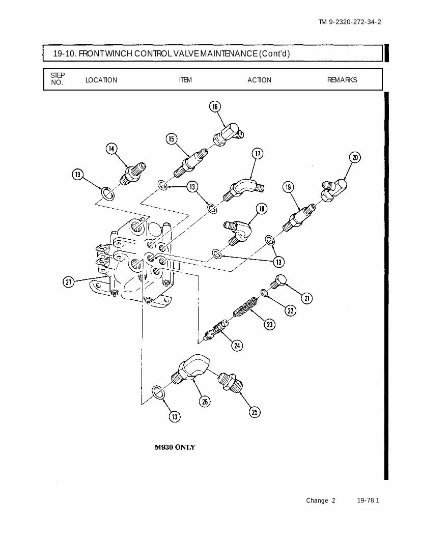
TM 9-2320-272-34-2
19-10. FRONT WINCH CONTROL VALVE MAINTENANCE (Cont'd)
STEPLOCATION ITEM ACTION REMARKSNO.
Change 2 19-78.1

TM 9-2320-272-34-2
I 19-10. FRONT WINCH CONTROL VALVE MAINTENANCE (Cont'd)
STEP LOCATION ITEM ACTION REMARKSNO.
b. Disassembly
15.
16.
17.
18.
19.20.21.
22.
23.24.
25.
26.
27.
28.29.30.
31.
32.33.
34.
Inlet housing (2) and Four nuts (7) and Remove.outlet housing (6) screws (1)Inlet housing (2) Four shims (8), three Remove. Discard shims (8),
“O” rings (9), and “O” rings (9), andretainer (5) retainer (5).Two screw-assembled Remove. Discard screw-assem-lockwashers (15) and bled lockwashers (15).retainer (17)
Retainer (17) Dust boot (16) and Remove.sleeve (18)
Sleeve (18) “O” ring (19) Remove. Discard “O” ring (19).Inlet housing (2) Valve spool (22) Remove.Valve spool (22) Two “O” rings (4) Remove. Discard “O” rings (4).
NOTEPerform step 22 only if spring or retainers require replacement.
Two retainers (20) and Remove.spring (21)
Inlet housing (2) Gasket (3) Remove. Discard gasket (3).Plug (14), spring (11), Remove.and ball (10)
Plug (14) “O” ring (12) and gasket Remove. Discard “O” ring (12)(13) and gasket (13).
NOTESteps 26 through 32 are for M930 only.
Outlet housing (23) Two screw-assembled Remove. Discard screw-assem-lockwashers (37) and bled lockwashers (37).retainer (38)
Retainer (38) Dust boot (34) and Remove.sleeve (35)
Sleeve (35) “O” ring (36) Remove. Discard “O” ring (36).Outlet housing (23) Valve spool (33) Remove.Valve spool (33) Two “O” rings (25) Remove. Discard “O” rings (25).
NOTEPerform step 31 only if spring or retainers require replacement.
Two retainers (31) and Remove.spring (32)
Outlet housing (23) Gasket (24) Remove. Discard gasket (24),
Plug (30)
Plug (30), spring (27), Remove.and ball (26)“O” ring (28) and gasket Remove.(29)
Discard “O” ring (28)and gasket (29).
19-78.2 Change 2

TM 9-2320-272-34-2
19-10. FRONT WINCH CONTROL VALVE MAINTENANCE (Cont'd)
STEPLOCATION ITEM ACTION REMARKSNO.
Change 2 19-78.3

TM 9-2320-272-34-2
19-10. FRONT WINCH CONTROL VALVE MAINTENANCE (Contd)
STEP LOCATION ITEM ACTION REMARKSNO.
c. Cleaning and Inspection
35.
36.
37.
Clean all control valveparts (para. 2-9).
Valve spools (13) and Inspect for burrs,(38) scoring, and damage.
Outlet housings (4) and Inspect for burrs,(25) and inlet housing (2) scoring, and damage.
d. Assembly
38.
39.
40.
41.
42.43.
44.
45.
46.
47.
48.
49.
NOTESteps 38 through 46 are for M930 only.Perform step 38 only if springs or retainers were removed.
Two retainers (14) andspring (15)Two new “O” rings (6)
New gasket (5)
Valve spool (13)
New “O” ring (19)Dust boot (16) andsleeve (18)Retainer (17)
New “O” ring (11) andnew gasket (10)Ball (8), spring (9), andplug (12)
NOTE
Install on valve spool(13).Install in grooves ofvalve spool (13).Install in bore of outlethousing (4).Install in bore of outlethousing (4).Install in sleeve (18).Install on retainer (17).
Install on outer housing(4) with two new screw.assembled lockwashers (22).Install on plug (12).
Install in outlet housing(4).
Perform step 47 only if spring or retainers were removed.
Two retainers (36) and Install on valve spoolspring (37) (38).Two new “O” rings (23) Install in grooves of valve
spool (38).New gasket (24) Install in bore of inlet
housing (2).
Remove burrs andscoring with a polishingstone or crocus cloth.Replace if excessivelyburred, scored, ordamaged.Remove burrs andscoring with a polishingstone or crocus cloth.Replace if excessivelyburred, scored, ordamaged.
19-78.4 Change 2

TM 9-2320-272-34-2
19-10. FRONT WINCH CONTROL VALVE MAINTENANCE (Cont'd)
STEPLOCATIONNO. ITEM ACTION REMARKS
50.
51.
52.
53.
54.
55.
56.
57.
Valve spool (38)
New “O” ring (35)
Dust boot (32) andsleeve (34)
Retainer (33)
New “O” ring (29) andnew gasket (28)
Ball (26), spring (27),and plug (30)
New retainer (3) andthree new “O” rings (20)Inlet housing (2) andoutlet housing (4) or(25)
Install in bore of inlethousing (2).Install in sleeve (34).
Install on retainer (33).
Install on inlet housing(2) with two new screw-assembled lockwashers (31).Install on plug (30).
Install in inlet housing(2).
Install in grooves ofinlet housing (2).
a.
b.
Position four newshims (21) on inlethousing (2).
Carefully place outlethousing (4) or (25)on inlet housing (2)and install with fourscrews (1) and nuts(7).
Coat threads of screws(1) with sealingcompound.
Tighten nuts (7)17 lb-ft (23 N·m).
Change 2 19-78.5

TM 9-2320-272-34-2
19-10. FRONT WINCH CONTROL VALVE MAINTENANCE (Cont'd)
STEP LOCATION ITEM ACTION REMARKSNO.
e. Installation N O T E
Steps 58 through 61 are for M930 only.58.59.
60.
61.
62.63.
64.
65.
New “O” ring (10) Install on plug (9).Relief valve (12), spring Install on control valve(11), and plug (9)Fittings (2), (3), (5), (6), Install on control valve(7), and (14) and six (15).new captive “O” rings (1)Two elbows (4) and (8) Install on fittings (3),and adapter (13) (7), and (14).New “O” ring (22) Install on plug (21).Relief valve (24), spring Install on control valve(23), and plug (21) (27).Fittings (17), (18), (19), Install on control valve(26) and four new (27).captive “O” rings (16)Elbow (20) and adapter Install on fittings (19)(25) and (26).
19-78.6 Change 2

TM 9-2320-272-34-2
19-10. FRONT WINCH CONTROL VALVE MAINTENANCE (Cont'd)
STEPLOCATIONNO. ITEM ACTION REMARKS
Change 2 19-79

TM 9-2320-272-34-2
19-10. FRONT WINCH CONTROL VALVE MAINTENANCE (Cont'd)
STEP LOCATION ITEM ACTION REMARKSNO.
66. Control valve (5)
67. Bracket (8)
68. Hoses (1), (2), (3), and(4)
and install with threebolts (6) and new lock-nuts (10).Install with four bolts(9) and new locknuts(7).Connect to controlvalve (5).
69.
70.
71.
Step 69 is for M930 only.Hoses (16) and (17) Connect to control
valve (5).Cable clevis (13) Install on control valve
(5) with clevis pin (14),washer (12), and newcotter pin (11).
NOTEStep 71 is for M930 only.
Cable clevis (20) Install on control valve(5) with clevis pin (15),washer (19), and newcotter pin (18).
Position to bracket (8)
19-80 Change 2

TM 9-2320-272-34-2
19-10. FRONT WINCH CONTROL VALVE MAINTENANCE (Cont'd)
STEPLOCATION ITEM ACTION REMARKSNO.
END OF TASK!
FOLLOW-ON TASK: Fill hydraulic oil reservoir (LO 9-2320-272-12).
Change 2 19-81

TM 9-2320-272-34-2
19-11. FRONT WINCH HYDRAULIC HOSE AND TUBE REPLACEMENTThis task covers:
a. Removal b. Installation
INITIAL SETUP:EquipmentCondition
Applicable Models Reference Condition DescriptionM925, M926, M928 M929, TM 9-2320-272-10 Parking brake set.M930, M932, M936 LO 9-2320-272-12 Hydraulic oil reservoir drained.
Test EquipmentNone
Special Tools Special Environmental ConditionsNone None
Materials/PartsTwo locknutsProtective cap-plugs (Appendix C, Item 5)Six tiedown straps (Appendix C, Item 22)Sealing tape (Appendix C, Item 30)
Personnel RequiredWheeled vehicle repairman MOS 63W
Manual ReferencesTM 9-2320-272-10TM 9-2320-272-34PLO 9-2320-272-12
General Safety InstructionsNone
STEP LOCATION ITEM ACTION REMARKSN O .
1.
2.
CAUTIONPlug all openings to prevent dirt from entering and damagingcomponents.
NOTE● Remove and discard tiedown straps holding hoses to vehicle.● Have drainage container ready to catch oil.
● Perform steps 1 through 4 for all vehicles except M936.Filter adapter (10) Hose nut (9) Disconnect. Hold filter adapter
(10) to prevent turn-ing.
Hydraulic reservoir (1) Nut (8), screw (4), and Remove from mountingclamp (5) bracket (6).
19-82

TM 9-2320-272-34-2
19-11. FRONT WINCH HYDRAULIC HOSE AND TUBE REPLACEMENT (Cont’d)
STEP LOCATION ITEM ACTION REMARKSNO.
3. Reservoir elbow (2)
4.5. Right frame rail (11)
and two hydraulichoses (16)
Hose nut (3)Hose (7)Two pairs of hoseclamps (14), twoscrews (13), and lock-nuts (15)
Disconnect.Remove.Remove. Discard locknuts (15).
Clamp brackets (12)remain attached toframe rail (11).
TA 350928
19-83

TM 9-2320-272-34-2
19-11. FRONT WINCH HYDRAULIC HOSE AND TUBE REPLACEMENT (Cont’d)
STEP LOCATION ITEM ACTION REMARKSNO.
NOTETag hoses for installation.
6. Four hoses (3) and two a. Position wrench Hold hose end (2)tubes (4) and (5) over hose end (2). firmly in place.
b. Loosen swivel flarenut (1).
c. Disconnect hoses ateach end.
d. Remove hoses (3).
TA 350929
19-84

TM 9-2320-272-34-2
19-11. FRONT WINCH HYDRAULIC HOSE AND TUBE REPLACEMENT (Cont’d)
STEP LOCATIONNO. ITEM ACTION REMARKS
TA 350930
19-85

TM 9-2320-272-34-2
I 19-11. FRONT WINCH HYDRAULIC HOSE AND TUBE REPLACEMENT (Cont’d)
STEP LOCATION ITEM ACTION REMARKSNO.
NOTEPerform steps 7 and 8 for all vehicles except M936.
7. Filter (3) Hose (1) Disconnect fromadapter (2).
8. Control valve (4) Hose (1) Remove.9. Hydraulic pump (5) Two tubes (8) and (9) Remove from adapters
(6) and (7).
10.
11.
19-86
Two tubes (8) and (9) Connect to adapters(6) and (7).
NOTE• Perform step 11 for all vehicles except M936.● Wrap all male pipe threads with sealing tape.
Hose (1) a. Connect to controlvalve (4).
b. Connect to adapter(2).
Use wrench to preventadapter (2) fromturning.

19-11.
TM 9-2320-272-34-2
19-87

TM 9-2320-272-34-2
19-11. FRONT WINCH HYDRAULIC HOSE AND TUBE REPLACEMENT (Cont’d)
STEP LOCATION ITEM ACTION REMARKSNO.
NOTEPerform steps 12 through 14 for all vehicles except M936.
12. Hydraulic hose (6)
13. Clamp (4)
14.
15.
16.
17.
18.
19.
Hose (16)
Hose (19)
Two hose ends (22)
Two hose ends (9)
Two pairs of clamps(12)
Six tiedown straps
a.
b.
a.
b.
Connect to elbow(2).
Connect to adapter(1).
Position on hose (6)and mountingbracket (5).
Install with screw(3) and nut (7).
Connect to elbow (15) Use care to avoidand tube (17). bending tube (17).
Connect to tube (18) Use care to avoidand control valve bending tube (18).elbow (20).Connect to two controlvalve elbows (21).
Connect to two elbows(8).a.
b.
Install on hoses(14).Install on twobrackets (10) withtwo screws (11) andnew locknuts (13).
Install as necessary totwo hoses (14).
TA 350932
19-88

TM 9-2320-272-34-2
19-11. FRONT WINCH HYDRAULIC HOSE AND TUBE REPLACEMENT (Cont’d)
FOLLOW-ON TASKS: ●●
END OF TASK!Fill hydraulic oil reservoir (LO 9-2320-272-12).Start engine (TM 9-2320-272-10). Operate winch and check for leaks and properoperation.
TA 350933
Change 1 19-89 (19-90 blank)


TM 9-2320-272-34-2
Section Ill. REAR WINCH COMPONENTS MAINTENANCE
I 19-12. REAR WINCH MAINTENANCE TASK SUMMARY
TASKPARA. PROCEDURES
19-13. Rear Winch Repair 19-9219-14. Rear Winch Cable Tensioner Repair 19-11419-15. Rear Winch Side Roller Repair 19-12219-16. Rear Winch Top and Bottom Roller Repair 19-12619-17. Rear Winch Hydraulic Motor Replacement 19-13019-18. Rear Winch Level Wind Maintenance 19-138
19-91

TM 9-2320-272-34-2
19-13. REAR WINCH REPAIRThis task covers:
a. Disassembly c. Reassemblyb. Cleaning and Inspection
INITIAL SETUP:EquipmentCondition
Applicable Models Reference Condition DescriptionM936 TM 9-2320-272-20-2 Rear winch removed from vehicle.
Para. 19-18 Rear winch level wind removed.Test Equipment
Spring tester
Special Tools Special Environmental ConditionsNone None
Materials/PartsFour cotter pinsTwenty-nine lockwashersFour gasketsFour sealsTwo bushingsTwo woodruff keys“O” ringBrake bandGAA grease (Appendix C, Item 11)Lubricating oil OE/HDO 30(Appendix C, Item 17)
Rags (Appendix C, Item 23)Sealing compound (Appendix C, Item 26)
Personnel Required General Safety InstructionsWheeled vehicle repairman MOS 63W (2) The rear winch is a heavy component.
Manual References Use hoists during repair to prevent
TM 9-2320-272-20-2 injury.
TM 9-2320-272-34PLO 9-2320-272-12
STEP LOCATION ITEM ACTION REMARKSNO.
1.
2.
3.
4.
Bracket (8) Four cotter pins (10), Remove. Discard cotter pinspin (9), pin (11), and (10).lever (7)
Bracket (15) Four bolts (16) and Remove. Discard lockwasherslockwashers (17) (17).
Tensioner frame (14) Two screws (18), nuts Remove. Discard lockwashers(20), and lockwashers (19).(19), and bracket (15)
Bracket (8) Two screws (6), lock- Remove. Discard lockwasherswashers (2), and nuts (2).(1), and tensionerframe (14)
19-92

TM 9-2320-272-34-2
19-13. REAR WINCH REPAIR (Cont’d)
STEP LOCATION ITEM ACTION REMARKSNO.
5. Rear winch (3) Four screws (13), two Remove. Discard lockwashersnuts (4) and lock- (5).washers (5), fourwashers (12), andbracket (8)
TA 350934
19-93

TM 9-2320-272-34-2
19-13. REAR WINCH REPAIR (Cont’d)
STEP LOCATION ITEM ACTION REMARKSNO.
6. Rear winch (1) Three screws (3) and Remove. Discard lockwasherslockwashers (2) (2).
7. Screw (4), nut (7), lock- Remove. Discard lockwasherwasher (6), and front (6).channel (5)
19-94
TA 350935

TM 9-2320-272-34-2
19-13. REAR WINCH REPAIR (Cont’d)
STEP LOCATION ITEM ACTION REMARKSNO.
NOTEAssistant will help with step 8.
8. Gearcase (11) Two screws (16), sixbolts (17) and lock-washers (18), endcover (19), and gasket(14)Thrust washer (13)9. Drum shaft (12)
10. Gearcase (11) Four screws (8) andlockwashers (9), inputshaft bearing cap (21),and gasket (10)
11. Bearing cap (21) Seal (20)
12. End cover (19) Bushing (15)
Remove.
Remove.
Remove.
Remove.Remove.
Discard lockwashers(18) and gasket (14).
Discard gasket (10)and lockwashers (9).
Discard seal (20).Discard bushing (15) ifinner diameter is morethan 3.150 in.(80.01 mm).
TA 350936
19-95

TM 9-2320-272-34-2
19-13. REAR WINCH REPAIR (Cont’d)
STEP LOCATION ITEM ACTION REMARKSNO.
NOTESupport drum with overhead hoist.
13. Gearcase assembly (1) End frame (6)
14. Drum shaft (3)
15. Automatic brakehousing (10)
16.
17.
18.
19. Gearcase (1)
Drum (5), seal (8),thrust washer (4), twokeys (2), and greasefitting (7)
Six screw-assembledwashers (16), housingcover (17), and gasket(18)Adjusting screw (24),“O” ring (22), andwasher (23)Brake band (15) andspring (19)
NOTE
Remove.
Remove.
Remove.
Remove.
Remove.
Assistant will help with step 18.
Screw (14), lockwasher, Remove.(20), washer (13), andbrakedrum (21)
Brake housing (10) Scribe alinementmarks (9) betweengearcase (1) andhousing (10).
Discard seal (8) andtwo keys (2).
Discard gasket (18).Clean gasket remainsfrom mating surfaces.
Discard “O” ring (22).
Discard brake band(15).
Discard lockwasher(20).Use puller to removebrakedrum (21).
Mark (9) is used forreassembly.
19-96
TA 350937

TM 9-2320-272-34-2
19-13. REAR WINCH REPAIR (Cont’d)
STEP LOCATION ITEM ACTION REMARKSNO.
20.
21. Brake housing (10)
22. Worm gear shaft (28)
Four screws (12) andlockwashers (11),brake housing (10),and gasket (27)
Seal (25)
Key (26)
Remove. Discard lockwashers(11) and gasket (27).Clean gasket remainsfrom mating surfaces.
Remove. Discard seal (25).Remove.
TA 350938
19-97

TM 9-2320-272-34-2
19-13. REAR WINCH REPAIR (Cont’d)
STEP LOCATION ITEM ACTION REMARKSNO.
23.
24.
25.
NOTEMake sure a rag is placed in bottom of gearcase under worm gear toprotect worm gear during removal.
Gearcase (4) Worm gear shaft (3) Tap with hammer atbrake end. Allow wormgear (5) to drop tobottom of gearcase (4).
Drum shaft (6) and Remove.gear (1)
Worm gear shaft (3) Remove.and thrust washer (2)
TA 350939
19-98

TM 9-2320-272-34-2
19-13. REAR WINCH REPAIR (Cont’d)
STEP LOCATIONNO. ITEM ACTION REMARKS
26. End frame (11) Seal (7), thrust washer Remove. Discard seal (7).(8), and sleeve (10)
27. Sleeve (10) Bushing (9) Remove. Discard bushing (9).
TA 350940
19-99

TM 9-2320-272-34-2
I 19-13. REAR WINCH REPAIR (Cont’d)
STEP LOCATION ITEM ACTION REMARKSNO.
b. Cleaning and Inspection
28. All thrust washers (1) a. Clean and inspect If cracked, replace.for cracks.
b. Measure with amicrometer (2).
29. Drum shaft (3) a. Clean and inspectfor cracks, chips,and straightness.
b. Measure all bearingsurfaces with amicrometer (2).
Discard if thicknessmeasures less than0.059 in. (1.50 mm).Discard if cracked,chipped, or bent.
Discard if diameteris less than 2.995 in.(76.07 mm).
19-100

TM 9-2320-272-34-2
19-13. REAR WINCH REPAIR (Cont’d)
STEP LOCATION ITEM ACTION REMARKSNO.
30. Three bushings (4); a.one in end frame, twoin gearcase
b.
Clean and inspect Discard if cracked,for cracks, chips, chipped, or scored.and scoring.
Measure inner diam- Discard if inner
31. Worm shaft (6)
eter with a telescop- diameter is more thaning gage (5). 3.010 in. (76.45 mm).
Clean and inspect for Discard if cracked,cracks, chips, scoring, chipped, scored, oror damaged bearings. bearings damaged.
19-101

TM 9-2320-272-34-2
19-13. REAR WINCH REPAIR (Cont’d)
STEP LOCATION ITEM ACTIONNO.
32. Spring (1) a.
b.
c.
33.
Clean and inspect Discard if distorted,for distortion, or cracked, or collapsed.cracked or collapsedcoils.
Measure free length. Discard if free length isnot 2.750 in.(69.85 mm).
Test spring (1) with Discard if test readingtester (2) and is different.torque wrench (3).When compressed to2 in. (50.8 mm),torque wrench (3)should read 97 lb-ft(131.5 N·m).
All housings, covers, Clean and inspect for Discard if cracked,and cases. cracks, broken parts, broken, or threads are
or damaged threads. damaged.
19-102
TA 350943

TM 9-2320-272-34-2
19-13. REAR WINCH REPAIR (Cont’d)
35.
36.
STEP LOCATION ITEM ACTION REMARKSNO.
34. Drum shaft gear (4) Clean and inspect for Discard if teeth arebroken, chipped, or broken, chipped, orscored teeth. scored.
NOTEIf drum shaft gear does not require replacement, go to step 37.
Drum shaft (5) Press shaft (5) out of Use arbor press andgear (4). mandrel.
NOTEDo not remove drum shaft keys if they are not damaged.If removed, install new keys.
New drum-shaft gear Press shaft (5) into Press shaft (5) through(4) or new shaft (5) gear (4). gear (4) until keys are
centered in gear (4).
Use arbor press andmandrel.
TA 350944
19-103

TM 9-2320-272-34-2
19-13. REAR WINCH REPAIR (Cont’d)
STEP LOCATION ITEM ACTION REMARKSNO.
c. ReassemblyNOTE
Apply light film of oil to all parts during assembly. Do not lubricatebrake band or drum.
37. Worm gear shaft (4) Position in gearcaseand gear (5) (3) and allow to rest
on the bottom of gear-case (3).
NOTE
Keyway end of worm gear shaft must extend from the side ofgearcase marked in step 19.
38. Thrust washer (2) Coat with GAA greaseand install over drumshaft (6).
Make sure locking tabis toward gearcasebushing.
39. Drum shaft (6) and a.gear (7)
b.
c.
Install part way intobushing.Position thrustwasher (2) againstgearcase (3).Install drum shaft
Make sure locking tabengages slot in gear-case (3).
(6) and gear (7).
40.
41.
42.
Worm gear (5) and Install.shaft (4)
Thrust washer (1) Install over shaft (6)and coat with GAAgrease.
Bushing (12) Install in end cover(10).
Position worm gearshaft (4) in case (3),making sure wormgear (5) engages drumshaft gear (7).Make sure locking tabis toward end cover(10).
TA 350945
19-104

TM 9-2320-272-34-2
19-13. REAR WINCH REPAIR (Cont’d)
STEP LOCATION ITEM ACTION REMARKSNO.
43. End cover (10) a.
b.
c.
Position on shaft (6)with locking tab onthrust washer (1)alined with slot incover (10).Measure clearancebetween gearcase(3) and cover (10)with feeler gage(14).
Do not install gasket(11).
If zero clearance,install gasket (11) andcover (10) and proceedto step 43c. If ameasurement is ob-tained, add one to fourgaskets (11). Thicknessof gaskets (11) must bemeasurement obtainedplus 0.005-0.015 in.(0.13-0.38 mm).
With proper clear- Coat gaskets (11) withante obtained, in- sealing compound.stall cover (10) withnew gaskets (11) togearcase (3) withtwo screws (13), sixbolts (8), and newlockwashers (9).
TA 350946
19-105

TM 9-2320-272-34-2
I 19-13. REAR WINCH REPAIR (Cont’d)
STEP LOCATION ITEM ACTION REMARKSNO.
44.
45.
46.
47.
48.
49.
New seal (15)
Brake housing (8) andnew gasket (7)
New seal (17)
Input shaft bearingcap (3) and new gasket(4)
Key (16)
Brakedrum (11)
Install in brakehousing (8).
Position on gearcase(5) and install withfour bolts (10) andnew lockwashers (9).
Install in input shaftbearing cap (3).
Position on gearcase(5) and install withfour screws (1) andnew lockwashers (2).
Install on shaft (6).
Position on shaft (6) Make sure key slot inand install with washer drum (11) engages key(14), bolt (12), and (16).new lockwasher (13).
TA 350947
19-106

TM 9-2320-272-34-2
19-13. REAR WINCH REPAIR (Cont’d)
STEP LOCATIONNO. ITEM ACTION REMARKS
50. Dial indicator (18) a.
b.
Install on gearcase If end play measures(5) and measure less than 0.005 in. (0.13end play of worm mm), add additionalgear shaft (6). new gaskets (4) until
proper end play isobtained.
Remove after properadjustment isobtained.
TA 350948
19-107

TM 9-2320-272-34-2
19-13. REAR WINCH REPAIR (Cont’d)
STEP LOCATION ITEM ACTION REMARKSNO.
51. New brake band (3) Position around drum Caged nut (12) goes to(2). the right.
52. Spring (8) Position between hous-ing (1) and brake band(3).
53. Flat washer (10) and Install on bolt (11).new “O” ring (9)
54. Bolt (11) Install through housing Tighten until spring (8)(1), spring (8), and measurement is 2.125-caged nut (12) on 2.187 in. (51-brake band (3). 52.5 mm).
55. Position on housing(1).
56. Position over gasket Screw-assembled(4) and install on hous- washers (5) areing (1) using two installed in top holesscrew-assembled and screw-assembled
New gasket (4)
Cover (7)
washers (5) and four washers (6) in bottomscrew-assembled holes of housing (1).washers (6).
19-108

TM 9-2320-272-34-2
19-13. REAR WINCH REPAIR (Cont’d)
LOCATION ITEM ACTION REMARKS
57. Sleeve (15) and Install in end frame Make sure slot in sleevebushing (14) (16). (15) slides over pin in
end frame (16).
58. Thrust washer (13) Install in end frame Make sure locktab(16). engages slot in end
frame (16).
59. New seal (12) Install in end frame(16).
TA 350950
19-109

TM 9-2320-272-34-2
19-13. REAR WINCH REPAIR (Cont’d)
STEP LOCATION ITEM ACTION REMARKSNO.
60. New seal (5) Install in drum (6).
61. Thrust washer (4) a. Coat with GAAgrease.
b. Install on shaft (3) Make sure locktaband position against engages slot in gear-gearcase (1). case (1).
62. Two new keys (2) Install in shaft (3). Tap lightly withhammer.
63. Drum (6) Aline keyways anddrive on shaft (3) untilseated.
64. Grease fitting (8) Install on end frame(7).
65. End frame (7) Install on shaft (3).
TA 350951
19-110
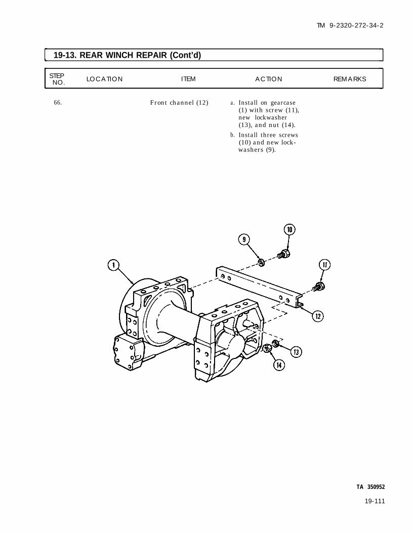
TM 9-2320-272-34-2
19-13. REAR WINCH REPAIR (Cont’d)
STEP LOCATION ITEM ACTION REMARKSNO.
66. Front channel (12) a.
b.
Install on gearcase(1) with screw (11),new lockwasher(13), and nut (14).Install three screws(10) and new lock-washers (9).
TA 350952
19-111

TM 9-2320-272-34-2
19-13. REAR WINCH REPAIR (Cont’d)
STEP LOCATION ITEM ACTION REMARKSNO.
67. Bracket (8) Install on rear winch(3) with four screws(13) and washers (12),and two new lock-washers (5) and nuts(4).
68. Tensioner frame (14) Install on bracket (8)with two screws (6),new lockwashers (2),and nuts (1).
69. Bracket (15) a.
b.
Install on tensionerframe (14), with twoscrews (18), newlockwashers (19),and nuts (20).Install on rear winch(3) with four screws(16) and new lock-washers (17).
70.
19-112
Lever (7) Install with pin (11),pin (9), and four newcotter pins (10).

TM 9-2320-272-34-2
19-13. REAR WINCH REPAIR (Cont’d)
STEP LOCATIONNO. ITEM ACTION REMARKS
END OF TASK!
FOLLOW-ON TASKS: ● Install rear winch level wind (para. 19-18).● Install rear winch (TM 9-2320-272-20-2).
TA 350953
19-113

TM 9-2320-272-34-2
19-14. REAR WINCH CABLE TENSlONER REPAIRThis task covers:
a. Disassembly c. Reassemblyb. Cleaning and Inspection
INITIAL SETUPEquipmentCondition
Applicable Models Reference Condition DescriptionM936 TM 9-2320-272-20-2 Rear winch cable removed.
Test EquipmentNone
Special Tools Special Environmental ConditionsNone None
Materials/PartsTen lockwashersSix cotter pinsFour felt washersGAA grease (Appendix C, Item 11)
Personnel Required General Safety InstructionsWheeled vehicle repairman MOS 63W None
Manual ReferencesTM 9-2320-272-20-2LO 9-2320-272-12
STEP LOCATION ITEM ACTION REMARKSNO.
1.
2.
3.
4.
5.
Bracket (8)
Bracket (15)
Tensioner frame (14)
Bracket (8)
Rear winch (3)
Four cotter pins (10), Remove.pin (9), pin (11), andlever (7)Four bolts (16) and Remove.lockwashers (17)Two screws (18), nuts Remove.(20), lockwashers (19),and bracket (15)
Two screws (6), lock- Remove.washers (2), and nuts(1), and tensionerframe (14)Four bolts (13), two Remove.nuts (4) and lock-washers (5), fourwashers (12), andbracket (8)
Discard cotter pins(10).
Discard lockwashers(17).Discard lockwashers(19).
Discard lockwashers(2).
Discard lockwashers(5).
19-114

TM 9-2320-272-34-2
19-14. REAR WINCH CABLE TENSIONER REPAIR (Cont’d)
LOCATION ITEM ACTION REMARKS
TA 350954
19-115

TM 9-2320-272-34-2
I 19-14. REAR WINCH CABLE TENSlONER REPAIR (Cont’d)
STEP LOCATION ITEM ACTION REMARKSNO.
6. Tensioner frame (2) Cotter pin (1), pin (7), Remove. Discard cotter pin (1).and grease fitting (8)
7. Sheave (5), two thrustwashers (3), and twofelt washers (4)
8. Sheave (5) Bearing (6)
9. Tensioner frame (2) Cotter pin (9), pin(15), and grease fitting(16)
10. Sheave frame (10) Sheave (13), twothrust washers (11),and two felt washers(12)
11. Sheave (13) Bearing (14)
12. Tensioner frame (2) Sheave frame (10)
Remove. Discard felt washers(4).
Remove.Remove. Discard cotter pin (9).
Remove. Discard felt washers(12).
Remove.Remove.
19-116
TA 350955

TM 9-2320-272-34-2
I 19-14. REAR WINCH CABLE TENSlONER REPAIR (Cont’d)
STEP LOCATIONNO. ITEM ACTION REMARKS
b. Cleaning and Inspection
13.
14.
15.
NOTEParts for both sheaves are inspected the same way.
Thrust washers (11) Clean and inspect forcracks or wear.
Bearing (14)
Pin (15)
Clean and inspect forchips, cracks, scoring,or damaged cage.
Clean and inspect forcracks or wear.
Measure with a micro-meter and discard ifthickness is less than0.055 in. (1.40 mm), orif cracked.Discard if chipped,cracked, scored, orcage is damaged.
Measure with a micro-meter, and discard ifouter diameter is lessthan 1.245 in. (31.63mm), or if cracked.
TA 350956
19-117

TM 9-2320-272-34-2
19-14. REAR WINCH CABLE TENSlONER REPAIR (Cont’d)
STEP LOCATION ITEM ACTION REMARKSNO.
16. Sheave frame (3)
17. Bearing (7)
18. Two new felt washers(5)
19. Sheave (6) and twothrust washers (4)
20. Grease fitting (9), pin
Position in tensionerframe (1).Coat with GAA grease,and install in sheave(6).Install one on eachside of bearing (7).
Position in sheaveframe (3).Install.
Place steel sides of feltwashers (5) next tobearing (7).
(8), and new cotter pin(2).
TA 350957
19-118

TM 9-2320-272-34-2
19-14. REAR WINCH CABLE TENSlONER REPAIR (Cont’d)
STEP LOCATION ITEM ACTION REMARKSNO.
21. Bearing (14) Coat with GAA greaseand install in sheave(13).
22. Sheave (13), two Install in tensioner Place steel sides of feltthrust washers (11), frame (1). washers (12) next toand new felt washers bearing (14).(12)
23. Grease fitting (16), pin Install.(15), and new cotterpin (10)
TA 350958
19-119

TM 9-2320-272-34-2
19-14. REAR WINCH CABLE TENSlONER REPAIR (Cont’d)
STEP LOCATION ITEM ACTION REMARKSNO.
24. Bracket (8) Install on rear winch(3) with four bolts (13)and washers (12), andtwo new lockwashers(5) and nuts (4).
25. Tensioner frame (14) Install on bracket (8)with two screws (6),new lockwashers (2),and nuts (1).
26.
27.
Bracket (15)
Lever (7)
a. Install on tensionerframe (14), with twoscrews (18), newlockwashers (19),and nuts (20).
b. Install on rear winch(3) with four bolts(16) and new lock-washers (17).
Install with pin (11),pin (9), and four newcotter pins (10).
19-120

TM 9-2320-272-34-2
19-14. REAR WINCH CABLE TENSlONER REPAIR (Cont’d)
STEP LOCATION ITEM ACTION REMARKSNO.
FOLLOW-ON TASKS: ●
●
END OF TASK!Lubricate rear winch tensioner (LO 9-2320-272-12).Install rear winch cable (TM 9-2320-272-20-2).
TA 350959
19-121

TM 9-2320-272-34-2
19-15. REAR WINCH SIDE ROLLER REPAIRThis task covers:
a. Disassembly c. Reassemblyb. Cleaning and Inspection
INITIAL SETUP:Equipment
Applicable ModelsConditionReference Condition Description
M936 TM 9-2320-272-10 Parking brake set.
Test EquipmentNone
Special Tools Special Environmental ConditionsNone None
Materials/PartsFour lockwashersTwo felt washersGAA grease (Appendix C, Item 11)Lubricating oil OE/HDO 30(Appendix C, Item 17)
Personnel RequiredWheeled vehicle repairman MOS 63W (2)
General Safety InstructionsKeep fire extinguisher nearby whenusing drycleaning solvent.
Manual ReferencesTM 9-2320-272-10TM 9-2320-272-34PLO 9-2320-272-12TM 9-214
STEP LOCATION ITEM ACTION REMARKSNO.
NOTERepair procedures for both side rollers are the same.
1.
6.
Bracket (3) Two screws (6) andlockwashers (7), andlockplate (8)
NOTE
Remove.
19-122
Assistant will help with steps 2 and 3.
Shaft (5) Remove.
Roller (12), two thrust Remove.washers (9) and feltwashers (10)
Roller (12) Two bearings (11) Remove.
Bracket (3) Two screws (1) and Remove.lockwashers (14), plate(2), and spacer (13)
Shaft (5) Two grease fittings (4) Remove.
Discard lockwashers(7).
Discard felt washers(10).
Discard lockwashers(14).

TM 9-2320-272-34-2
19-15. REAR WINCH SIDE ROLLER REPAIR (Cont’d)
STEP LOCATION ITEM ACTION REMARKSNO.
TA 350960
19-123

TM 9-2320-272-34-2
I 19-15. REAR WINCH SIDE ROLLER REPAIR (Cont’d)
STEP LOCATION ITEM ACTION REMARKSNO.
b. Cleaning and Inspection
WARNING
Drycleaning solvent is flammable and will not be used near openflame. Use only in well-ventilated places. Failure to do this mayresult in injury to personnel.
7. All roller (12) and Clean in drycleaningshaft (5) components solvent and allow to air
dry.
8. Shaft (5) a. Inspect for cracks.b. Measure bearing
surfaces.
9, Two thrust washers Inspect for cracks and(9) measure thickness.
10. Bearings (11)
11.
12.
13.
16.
17.
19-124
Two grease fittings (4)
Spacer (13)
Two bearings (11)
Two thrust washers(9) and new feltwashers (10)
NOTE
Inspect.
If cracked, replace.If outer diameter isless than 2.245 in.(57.02 mm), replace.If cracked, replace.
If thickness is less than0.055 in. (1.40 mm),replace.Refer to TM 9-214. Ifdamaged, replace.
Install one in each endof shaft (5).Install on bracket (3)with plate (2), two newlockwashers (14) andscrews (1).Pack with GAA grease Refer to TM 9-214.and install in roller(12).Position one of each on Soak new felt washerseach end of roller (12). (10) in lubricating oil
prior to installation.
Assistant will help with steps 15 and 16.Roller (12), bearings Slide into bracket (3).(11), felt washers (10),and thrust washers (9)Shaft (5) Install through bracket Make sure locking slot
(3) and roller (12). is at bottom.
Lockplate (8) Aline with shaft (5)and install with twonew lockwashers (7)and screws (6).

TM 9-2320-272-34-2
19-15. REAR WINCH SIDE ROLLER REPAIR (Cont’d)
STEP LOCATION ITEM ACTION REMARKSNO.
END OF TASK!
FOLLOW-ON TASK: Lubricate roller assembly (LO 9-2320-272-12).TA 350961
19-125

TM 9-2320-272-34-2
I 19-16. REAR WINCH TOP AND BOTTOM ROLLER REPAIRThis task covers:
a. Disassembly c. Reassemblyb. Cleaning and Inspection
INITIAL SETUP:Equipment
Applicable ModelsConditionReference Condition Description
M936 TM 9-2320-272-10 Parking brake set.Para. 19-15 Left side roller removed (for bottom
Test Equipmentroller repair only).
None
Special Tools Special Environmental Conditions
None None
Materials/PartsTwo lockwashersTwo felt washersGAA grease (Appendix C, Item 11)Lubricating oil OE/HDO 30(Appendix C, Item 17)
Personnel RequiredWheeled vehicle repairman MOS 63W (2)
Manual ReferencesTM 9-2320-272-10TM 9-2320-272-34PLO 9-2320-272-12TM 9-214
General Safety InstructionsKeep fire extinguisher nearby whenusing drycleaning solvent.
STEP LOCATION ITEM ACTION REMARKSNO.
NOTERepair procedures for top and bottom rollers are the same.
a. Disassembly
1. Shaft (8)
2. Bracket (12)
3. Roller (6)
4. Tensioner sheave shaft(1)
Two grease fittings (7)
Two screws (10) andlockwashers (11), andlockplate (9)Shaft (8)
Two grease fittings (2)
Remove.Remove.
Remove.
Remove.
Discard lockwashers(11).
Thrust washers (3)may fall out.
19-126

TM 9-2320-272-34-2
19-16. REAR WINCH TOP AND BOTTOM ROLLER REPAIR (Cont’d)
STEP LOCATION ITEM ACTION REMARKSNO.
5.
6.
NOTEAssistant will help with step 5.
Bracket (12) Roller (6) and two Remove.thrust washers (3)
Roller (6) Two felt washers (4) Remove. Discard felt washersand bearings (5) (4).
TA 350962
19-127

TM 9-2320-272-34-2
19-16. REAR WINCH TOP AND BOTTOM ROLLER REPAIR (Cont’d)
STEP LOCATION ITEM ACTION REMARKSNO.
b. Cleaning and Inspection
WARNING
Drycleaning solvent is flammable and will not be used near openflame. Use only in well-ventilated places. Failure to do this mayresult in injury to personnel.
7. All roller (6) and shaft Clean in drycleaning(8) components solvent and allow to air
dry.
8. Shaft (8) a. Inspect for cracks. If cracked, replace.b. Measure bearing If outer diameter is
surfaces. less than 2.245 in.(57.02 mm), replace.
9. Thrust washers (3) a. Inspect for cracks. If cracked, replace.
10.
11.
12.
13.
14.
15.
16.
17.
19-128
Bearings (5)
b. Measure thickness. If thickness is less than0.055 in. (1.397 mm),replace.
Inspect. Refer to TM 9-214. Ifdamaged, replace.
Two bearings (5) Pack with GAA grease Refer to TM 9-214.and install in roller (6).
Two new felt washers Position on each end of Soak new felt washers(4) and thrust washers roller (6). (4) in lubricating oil(3) prior to installation.
NOTEAssistant will help with steps 13 and 14.
Roller (6), bearings (5), Slide into bracket (12).felt washers (4), andthrust washers (3)Shaft (8) Install through bracket
(12) and roller (6).Lockplate (9) Aline with shaft (8)
and install with twonew lockwashers (11)and screws (10).
Two grease fittings (7) Install in each end ofshaft (8).
Two grease fittings (2) Install into tensionersheave shaft (1).

TM 9-2320-272-34-2
19-16. REAR WINCH TOP AND BOTTOM ROLLER REPAIR (Cont’d)
STEP LOCATION ITEM ACTION REMARKSNO.
END OF TASK!FOLLOW-ON TASKS: • Lubricate roller assembly (LO 9-2320-272-12).
● Install bottom roller if removed (para. 19-15).TA 350963
19-129

TM 9-2320-272-34-2
19-17. REAR WINCH HYDRAULIC MOTOR REPLACEMENTThis task covers:
a. Removal b. Installation
INITIAL SETUP:EquipmentCondition
Applicable Models Reference Condition DescriptionM936 TM 9-2320-272-10 Parking brake set.
LO 9-2320-272-12 Hydraulic oil drained.Test Equipment
None
Special Tools Special Environmental ConditionsNone None
Materials/PartsCotter pinFour “O” ringsFour locknutsFourteen lockwashersAdhesive sealant (Appendix C, Item 3)Sealing tape (Appendix C, Item 30)
Personnel RequiredWheeled vehicle repairman MOS 63W (2)
Manual ReferencesTM 9-2320-272-10TM 9-2320-272-34PLO 9-2320-272-12
General Safety InstructionsNone
STEP LOCATION ITEM ACTION REMARKSNO.
1.
4.5.
6.
19-130
Frame (8)
Front bracket (10) toframe (8)
Elbow (16)
Elbow (19)
Pipe nipple (18)
Discard locknuts (9).
Five screws (5), Remove. Discard lockwasherswashers (7), (6).lockwashers (6), andcover (4)Four screws (3) and Remove.washers (2) and floorplate (1)Two screws (12), Remove.washers (11), andlocknuts (9)
NOTEHave drainage container ready to catch oil.Hose connector (17) Disconnect.Elbow (16), adapter Remove.(21), and valve (20)
Elbow (19) Rotate upward.
Tag adapter (21) andvalve (20) for instal-lation.To allow removal offront bracket (10).

TM 9-2320-272-34-2
19-17. REAR WINCH HYDRAULIC MOTOR REPLACEMENT (Cont’d)
STEP LOCATION ITEM ACTION REMARKSNO.
7. Winch motor (15) Three screws (13) and Remove. Discardlockwashers (14), and (14).front bracket (10)
lockwashers
T A 3 5 0 9 6 4
19-131

TM 9-2320-272-34-2
19-17. REAR WINCH HYDRAULIC MOTOR REPLACEMENT (Cont’d)
STEP LOCATION ITEM ACTION REMARKSNO.
8. Winch motor (8) Remove.
9.
10.
11. Elbow (10) on winchmotor (8)
12. Winch motor (8)
13. Tee (32)
14. Coupling front hub(14)
15. Pipe nipple (6)
16. Frame crossmember(22) to rear bracket(27)
17. Frame crossmember(22)
18. Winch motor shaft(12)
19.
20.
21. Coupling rear hub (16)
22. Winch drive shaft (17)
19-132
Elbow (7) and pipenipple (6)Twelve screws (2) andwashers (4), and sixclamps (3)Three hydraulic hoses(1) and “O” rings (5)
Hydraulic hose (11)
Elbow (10) and “O”ring (9)Two hose connectors(30) and (31)Setscrew (25)
Tee (32), adapter (29),valve (28), and elbow(7)Two screws (20), fourwashers (21), and twolocknuts (26)
NOTE
Remove.
Remove.
Disconnect.
Remove.
Disconnect.
Loosen.
Remove.
Remove.
Assistant will help with step 17.Winch motor (8) andrear bracket (27)Key (13)
Six screws (23) andlockwashers (24), andrear bracket (27)Pipe nipple (6)
Cotter pin (18) andshear pin (19)Coupling (15)
Remove.
Remove.
Remove.
Remove.
Remove.
Remove.
Discard “O” rings (5).
Tag hoses (1) forinstallation.
Discard “O” ring (9).
Tag hoses (30) and(31) for installation.Loosen setscrew (25)until flush withcoupling front hub(14).Tag valve (28) forinstallation.
Discard locknuts (26).
Discard lockwashers(24).
Tag pipe nipple (6) forinstallation.
Discard cotter pin (18).

TM 9-2320-272-34-2
19-17. REAR WINCH HYDRAULIC MOTOR REPLACEMENT (Cont’d)
STEP LOCATIONNO. ITEM ACTION REMARKS
TA 350965
19-133

TM 9-2320-272-34-2
19-17. REAR WINCH HYDRAULIC MOTOR REPLACEMENT (Cont’d)
STEP LOCATION ITEM ACTION REMARKSNO.
23.
24.
Coupling (16) Install on winch driveshaft (18) with shearpin (20) and newcotter pin (19).
NOTEAll male pipe threads will be wrapped with sealing tape beforeinstallation.
Rear bracket (28) Install on winch motor(8) with six screws(24) and new lockwashers (25).
NOTEAssistant will help with step 25.
25. Winch motor (8) andkey (13)
26. Rear bracket (28)
27. Pipe nipple (6), elbow(7), valve (29), adapter(30), and tee (33)
28. Two hose connectors(31) and (32)
29. Setscrew (26)
30. Elbow (10)
31. Hydraulic hose (11)32. Three hydraulic hoses
(1)
Install on coupling(16) with key (13) inslot of winch driveshaft (12).Install on frame cross-member (23) with twoscrews (21), fourwashers (22), and twonew locknuts (27).
Install on winch motor(8).
Connect to tee (33).
Install on couplingfront hub (14).
Install on winch motor(8) with new “O” ring(9).Connect to elbow (10).Connect to winchmotor (8) with twelvescrews (2) andwashers (4), sixclamps (3), and threenew “O” rings (5).
Aline holes in rearcoupling hub (17) anddrive shaft (18).
Tighten 60-70 lb-ft(81-95 N·m).
Make sure key (13) isvisible through set-screw hole (15).
Tighten 60-70 lb-ft(81-95 N·m).
Apply adhesive sealantto threads of setscrew(26) before installing.
19-134

TM 9-2320-272-34-2
19-17. REAR WINCH HYDRAULIC MOTOR REPLACEMENT (Cont’d)
STEP LOCATION ITEM ACTION REMARKSNO.
TA 350966
19-135

TM 9-2320-272-34-2
19-17. REAR WINCH HYDRAULIC MOTOR REPLACEMENT (Cont’d)
STEP LOCATION ITEM ACTION REMARKSNO.
33. Pipe nipple (18) and Install on winch motor Position elbow (19)elbow (19) (15).
Front bracket (10) Install to winch motor(15) with three screws(13) and new lock-washers (14).
Valve (20), adapter Install on elbow (19).(21), and elbow (16)Hose connector (17) Connect to elbow (16).Front bracket (10) Install to frame (8)
with two screws (12),washers (11), and newlocknuts (9).Install with fourscrews (3) and wash-ers (2).
Floor plate (1)
Cover (4) Install with five screws(5), new lockwashers(6), and washers (7).
facing upward for easein installing bracket(10).
Tighten 60-70 lb-ft(81-95 N·m).Return elbow (19) tooriginal position.
Tighten 60-70 lb-ft(81-95 N·m).
Tighten 60-70 lb-ft(81-95 N·m).
Tighten 60-70 lb-ft(81-95 N·m).
19-136

19-17.
TM 9-2320-272-34-2
STEP LOCATION ITEM ACTION REMARKSNO.
FOLLOW-ON TASKS: ●
●
END OF TASK!
Fill hydraulic oil reservoir to proper level (LO 9-2320-272-12).Check rear winch hydraulic motor for proper operation (TM 9-2320-272-10).
TA 350967
19-137

TM 9-2320-272-34-2
19-18. REAR WINCH LEVEL WIND MAINTENANCEMaintenance procedures for rear winch level wind and front winch level wind are the same. Refer toparagraph 19-6.
Section IV. REPAIR AND REPLACEMENT STANDARDS
19-19. REPAIR AND REPLACEMENT STANDARDSa. This section provides repair and replacement standards for front winch, rear winch, and winch
components. Repair and replacement standards included give minimum, maximum, and key clearance of newor repaired parts. An asterisk (*) in the “wear limits” column indicates a part should be replaced when wornbeyond dimensions given in “size and fit of new parts” column.
b. Components covered by repair and replacement standards listed in table 19-2 are illustrated. To find thecomponent and its tolerance requirements, match the reference number identifying the component to thesame reference number listed to the extreme left in table 19-2.
Table 19-2. Repair and Replacement Standards for Front Winch, Rear Winch, and Winch Components
REF. POINTS OF MEASUREMENT SIZE AND FIT WEARNO. OF NEW PARTS LIMITS
FRONT WINCHThrust ring thickness
Drum shaft bearing inside diameter
Drum shaft outside diameter
Automatic brake spring free length
Load to compress brake spring to 1 in. (25.4 mm)
Worm shaft end play
Drum shaft end play
FRONT WINCH TENSIONERTensioner roller pin outside diameter
Tensioner thrust washer thickness
0.492-0.508 in.(12.396-12.903 mm)
2.127-2.130 in.(54.02-54.10 mm)
2.123-2.125 in.(53.924-53.975 mm)
1.5 in.(38.1 mm)
52 lb-ft(71 N·m)
0.005-0.015 in.(0.127-0.381 mm)
0.005-0.015 in.(0.127-0.381 mm)
0.9995-1.0000 in.(25.387-25.400 mm)
0.633-0.635 in.(16.078-16.129 mm)
0.486 in.(12.344 mm)
2.136 in.(54.254 mm)
2.121 in.(53.873 mm)
0.997 in.(25.323 mm)
0.630 in.(16.002 mm)
19-138
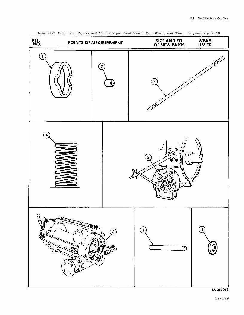
TM 9-2320-272-34-2
Table 19-2. Repair and Replacement Standards for Front Winch, Rear Winch, and Winch Components (Cont’d)
19-139

TM 9-2320-272-34-2
Table 19-2. Repair and Replacement Standards for Front Winch, Rear Winch, and Winch Components (Cont’d)
REF. POINTS OF MEASUREMENT SIZE AND FIT WEARNO. OF NEW PARTS LIMITS
1
2
3
4
5
6
7
8
9
FRONT WINCHTensioner roller shaft cam bearingsurface outside diameterTensioner roller shaft camoutside diameterTensioner roller shaft bushinginside diameter
FRONT WINCH LEVEL WINDLevel wind thrust washer thickness
FRONT WINCH ROLLERSide roller pin outside diameter
Side roller bushing inside diameter
Side roller thrust washer thickness
Roller shaft outside diameter
Roller shaft thrust washer thickness
0.748-0.750 in.(18.999-19.050 mm)
0.995-1.0000 in.(25.273-25.400 mm)
0.751-0.754 in.(19.075-19.151 mm)
0.0615-0.0635 in.(1.562-1.612 mm)
0.995-1.000 in.(25.273-25.400 mm)
1.001-1.004 in.(25.425-25.501 mm)
0.059-0.060 in.(1.498-1.524 mm)1.4995-1.5000 in.
(38.087-38.100 mm)0.0615-0.0655 in.
0.745 in.(18.923 mm)
0.994 in.(25.247 mm)
0.758 in.(19.253 mm)
0.058 in.(1.473 mm)
0.994 in.(25.247 mm)
1.008 in.(25.600 mm)
0.049 in.(1.244 mm)
1.495 in.37.973 mm)
0.051 in.(1.562-1.663 mm) (1.295 mm)
1 9 - 1 4 0

TM 9-2320-272-34-2
Table 19-2. Repair and Replacement Standards for Front Winch, Rear Winch, and Winch Components (Cont’d)
REF.NO. POINTS OF MEASUREMENT SIZE AND FIT WEAR
OF NEW PARTS LIMITS
19-141

TM 9-2320-272-34-2
Table 19-2. Repair and Replacement Standards for Front Winch, Rear Winch, and Winch Components (Cont’d)
REF. POINTS OF MEASUREMENT SIZE AND FIT WEARNO. OF NEW PARTS LIMITS
1
2
3
REAR WINCHThrust washer thickness
Drum shaft outside diameter
Drum shaft bushing inside diameter
Drum shaft end play
Worm shaft end play
Automatic brake spring free length
Load to compress spring to 2 in.(50.8 mm)
REAR WINCH TENSIONERTensioner thrust washer thickness
Tensioner roller pin outside diameter
0.0615-0.0655 in.(1.562-1.663 mm)
2.998-3.000 in.(76.149-76.200 mm)
3.005-3.007 in.(76.327-76.377 mm)
0.005-0.015 in.(0.127-0.381 mm)
0.059 in.(1.498 mm)
2.995 in.(76.073 mm)
2.995 in.(76.454 mm)
*
0.005-0.015 in.(0.127-0.381 mm)
2.750 in.(69.850 mm)
97 lb-ft(132 N·m)
0.0615-0.0655 in. 0.055 in.(1.562-1.663 mm) (1.397 mm)1.2495-1.2500 in. 1.245 in.
(31.737-31.750 mm) (31.623 mm)
19-142

TM 9-2320-272-34-2
Table 19-.2. Repair and Replacement Standards for Front Winch, Rear Winch, and Winch Components (Cont’d)
19-143

TM 9-2320-272-34-2
Table 19-2. Repair and Replacement Standards for Front Winch, Rear Winch, and Winch Components (Cont’d)
REF. POINTS OF MEASUREMENT SIZE AND FIT WEARNO. OF NEW PARTS LIMITS
REAR WINCH LEVEL WIND
1 Level wind axle outside diameter
2 Level wind shaft outside diameter
3 Level wind thrust washer thickness
4 Level wind sheave pin outside diameter
5 Thrust washer thickness
6 Sheave spacer thickness
7 Sheave spacer thickness
REAR WINCH TOP, BOTTOM, AND SIDE ROLLERS8 Side, top, and bottom roller shaft
outside diameter9 Side, top, and bottom roller thrust
washer thickness
1.995-2.000 in.(50.673-50.800 mm)
0.8745-0.8750 in.(22.212-22.225 mm)
0.0615-0.0655 in.(1.562-1.663 mm)2.7490-2.7496 in.
(69.824-69.839 mm)0.0615-0.0655 in.(1.562-1.663 mm)
0.087-0.090 in.(2.209-2.286 mm)
0.178-0.182 in.(4.521-4.622 mm)
2.2495-2.2500 in.(57.137-57.150 mm)
0.0615-0.655 in.(1.562-1.663 mm)
1.995 in.(50.673 mm)
0.870 in.(22.098 mm)
0.057 in.(1.448 mm)
2.744 in.(69.697 mm)
0.055 in.(1.397 mm)
0.093 in.(2.362 mm)
0.174 in.(4.419 mm)
2.245 in.(57.023 mm)
0.055 in.(1.397 mm)
19-144

TM 9-2320-272-34-2
Table 19-2. Repair and Replacement Standards for Front Winch, Rear Winch, and Winch Components (Cont’d)
19-145 (19-146 blank)


TM 9-2320-272-34-2
CHAPTER 20POWER TAKEOFF MAINTENANCE
NOTE
Refer to TM 9-2320-358-24&P for unique M939A2 maintenance procedures.
Section I. DESCRIPTION AND DATA
20-1. DESCRIPTION – TRANSFER CASE POWER TAKEOFF a. The M936 wrecker with crane and M935 van with hydraulic liftgate have a power takeoff mounted on
the rear of the transfer case. This power takeoff provides power to drive a hydraulic pump. It is pressurelubricated by an oil pump which also provides lubrication to the transfer case.
b. The power takeoff is a one-speed unit with output speed controlled and varied with engine rpm.Operator controls for the power takeoff are located in the cab.
TRANSFER CASE POWER TAKEOFF
TA 350997
Change 1 20-1

TM 9-2320-272-34-2
20-2. DESCRIPTION – TRANSMISSION POWER TAKEOFFa. The transmission power takeoff is mounted on the right side of the transmission. This power takeoff
provides power to drive a hydraulic pump which furnishes hydraulic pressure to operate the front winch anddump body.
b. The power takeoff, pressure lubricated by transmission oil, is a one-speed unit with output speedcontrolled and varied by engine rpm. Operator controls for the power takeoff are located in the cab.
1.
2.
20-2
TRANSMISSION POWER TAKEOFF
TRANSFER CASE POWER TAKEOFFMake . . . . . . . . . . . . . . . . . . . . . . . . . . . . . . . . . . . . . . . . . . . . . . . . . . . . . . . . . . . . . . . . . . . . . . . . .. RockwellModel . . . . . . . . . . . . . . . . . . . . . . . . . . . . . . . . . . . . . . . . . . . . . . . . . . . . . . . . . . . . . . . . . . . . . . . . . . . 4-34165Type . . . . . . . . . . . . . . . . . . . . . . . . . . . . . . . . . . . . . . . . . . . . . . . . . . . . . . . . . . . . . . . . . . . . . . . Single SpeedLocation . . . . . . . . . . . . . . . . . . . . . . . . . . . . . . . . . . . . . . . . . . . . . . . . . . . . . . . . . . . Rear of Transfer CaseTRANSMISSION POWER TAKEOFFMake . . . . . . . . . . . . . . . . . . . . . . . . . . . . . . . . . . . . . . . . . . . . . . . . . . . . . . . . . . . . . . . . . . . . . . . . . . . . . DanaModel . . . . . . . . . . . . . . . . . . . . . . . . . . . . . . . . . . . . . . . . . . . . . . . . . . . . . . . . . . . . . . . . . . . . . . A 22LL-C3-GType . . . . . . . . . . . . . . . . . . . . . . . . . . . . . . . . . . . . . . . . . . . . . . . . . . . . . . . . . . . . . . . . . . . . . . . Single SpeedLocation . . . . . . . . . . . . . . . . . . . . . . . . . . . . . . . . . . . . . . . . . . . . . . . . . . . . . . Right Side of Transmission
TA 350998

TM 9-2320-272-34-2
Section Il. TRANSFER CASE POWER TAKEOFFAND CONTROLS MAINTENANCE
20-3. TRANSFER CASE POWER TAKEOFF MAINTENANCE TASK SUMMARY
TASK PROCEDURES PAGEPARA. NO.
20-4. Transfer Case PTO Control Cable 20-4Replacement
20-5. Transfer Case PTO Cross-shaft 20-8(Control Lever) Replacement
20-6. Transfer Case Power Takeoff (PTO) 20-12Replacement
20-7. Transfer Case Power Takeoff (PTO) Repair 20-16
20-3

TM 9-2320-272-34-2
20-4. TRANSFER CASE PTO CONTROL CABLE REPLACEMENTThis task covers:
a. Removal b. Installation
INITIAL SETUP:EquipmentCondition
Applicable Models Reference Condition DescriptionM935 and M936 TM 9-2320-272-10 Parking brake set.
Test EquipmentNone
Special Tools Special Environmental ConditionsNone None
Materials/PartsFive locknutsCotter pinTiedown straps (Appendix C, Item 22)
Personnel Required General Safety InstructionsWheeled vehicle repairman MOS 63W None
Manual ReferencesTM 9-2320-272-10TM 9-2320-272-34P
STEP LOCATION ITEM ACTION REMARKSNO.
1. Transfer case PTOselect lever (1)
2. PTO cable bracket (8)
3. PTO cable (4)4. Front PTO cable
bracket (12)
5. Cross-shaft lever (18)
6. PTO cable (4)
2 0 - 4
NOTECut tiedown straps as required.
Cotter pin (10), clevis Remove.pin (2), and transferPTO cable clevis (3)Two screws (6) and Remove.locknuts (9), clamp (5)and shim (7)Clevis (3) Remove.Two screws (11) and Remove.locknuts (15), clamp(14) and shim (13)Locknut (19) and PTO Remove.cable swivel bolt (17)Swivel bolt (17) cable Remove.end (16)
Discard cotter pin(10).
Discard locknuts (9).
Discard locknuts (15).
Discard locknut (19).

TM 9-2320-272-34-2
20-4. TRANSFER CASE PTO CONTROL CABLE REPLACEMENT (Cont’d)
STEP LOCATION ITEM ACTION REMARKSNO.
20-5

TM 9-2320-272-34-2
20-4. TRANSFER CASE PTO CONTROL CABLE REPLACEMENT (Cont’d)
STEP LOCATION ITEM ACTION REMARKSNO.
NOTEInstall tiedown straps as required.
7. Clevis (3)
8. Transfer case PTOcable (4) (clevis end)
9. Swivel bolt (19) cableend (18)
10. Transfer case PTOcable (4) (swivel boltend)
11. Transfer case PTOcable swivel bolt (19)
Install on transfer casePTO cable (4) a fewturns.Install on PTO cablebracket (9) with clamp(6), shim (8), twoscrews (7), and newlocknuts (10).
Install on front of PTOcable (4).Install on front PTOcable bracket (13) withclamp (15), shim (14),two screws (12), andnew locknuts (16).Install on cross-shaftlever (20) with newlocknut (21).
NOTEThe transfer case PTO cable can be adjusted at two points.Adjustments can be made at the transfer case select lever cableclevis or at the transfer case PTO select lever cable collar.
12. Transfer case PTO a. Adjust forward untilcable clevis (3) alined with transfer
PTO select lever (1).b. Install on PTO select
lever (1) with pin(2) and new cotterpin (11).
20-6
Adjustment will bemade later.
Make sure shim (8) isbetween PTO cablebracket (9) and PTOcable collar (5).
Make sure shim (14)between PTO cablecollar (17) and PTOcable bracket (13).
is
If necessary, repositiontransfer PTO cable (4)at PTO cable collar(17).

TM 9-2320-272-34-2
20-4. TRANSFER CASE PTO CONTROL CABLE REPLACEMENT (Cont’d)
STEP LOCATIONNO. ITEM ACTION REMARKS
FOLLOW-ON TASK: Check transfer case PTO for proper operation (TM 9-2320-272-10).TA 351000
20-7

TM 9-2320-272-34-2
I 20-5. TRANSFER CASE PTO CROSS-SHAFT (CONTROL LEVER) REPLACEMENTThis task covers:
a. Removal b. Installation
INITIAL SETUP:EquipmentCondition
Applicable Models Reference Condition DescriptionM935 and M936 TM 9-2320-272-10 Parking brake set.
TM 9-2320-272-20-2 Driver’s seat removed.
Test EquipmentNone
Special Tools Special Environmental ConditionsNone None
Materials/PartsFifteen locknutsCotter pinGAA grease (Appendix C, Item 11)
Personnel RequiredWheeled vehicle repairman MOS 63W (2)
Manual ReferencesTM 9-2320-272-10TM 9-2320-272-20-2TM 9-2320-272-34P
General Safety InstructionsNone
STEP LOCATION ITEM ACTION REMARKSNO.
1. Cross-shaft lever (2)
2. Transfer case PTOcable bracket (9)
3. Cab floor (26)
4. Two cross-shaft retain-ing clamps (6)
Cross-shaft lever (2)
Discard locknuts (18).
Transfer case PTO Remove. Discard locknut (21).cable swivel bolt (22)and locknut (21)Two screws (8) and Remove. Discard locknuts (19).locknuts (19), shim(10), clamp (20), andtransfer case PTOcable (23) NOTE
Assistant will help with step 3.
Four screws (5) and Remove.locknuts (18), and twoshims (7), and cross-shaft retaining clamps(6)Two grease fittings (4) Remove.
NOTEPerform step 5 on M936 wrecker only.
Cotter pin (30), washer Remove. Discard cotter pin(31), and brake lock (30).control valve rod (24)Screw (1) and locknut Remove. Discard locknut (3).(3)
2 0 - 8

TM 9-2320-272-34-2
20-5. TRANSFER CASE PTO CROSS-SHAFT (CONTROL LEVER)REPLACEMENT (Cont’d)
STEP LOCATION ITEM ACTION REMARKSNO.
NOTEAssistant will help with step 7.
7. Cab floor (26) Six screws (29) and Remove. Lift cross-shaft leverlocknuts (25), rubber (2) from cab floor (26).seal (27), ring seal(28), and cross-shaft
Discard locknuts (25).
lever (2)
8. Cross-shaft (11) Woodruff key (17) Remove.
9. Two cross-shaft retain- Remove.ing clamps (6)
10. PTO lever (12) Locknut (13), washer Remove. Discard locknut (13).(14), helical spring(15), and PTO lever pin(16)
TA 351001
20-9

TM 9-2320-272-34-2
20-5. TRANSFER CASE PTO CROSS-SHAFT (CONTROL LEVER)REPLACEMENT (Cont’d)
STEP LOCATION ITEM ACTION REMARKSNO.
12.
13.
14.
PTO lever (12)
Two cross-shaft retain-ing clamps (6) andcross-shaft lever (2)Two grease fittings (4)
Woodruff key (17)
Cross-shaft (11)
Install with newlocknut (13), washer(14), helical spring(15), and PTO lever pin(16).Install on cross-shaft(11).
Install in retainingclamps (6).Install in cross-shaft(11).
a. Guide into cross-shaft lever (2) andinstall screw (1) andnew locknut (3) incross-shaft lever (2).
b. Lower to cab floor(26) so cross-shaftlever (2) and cross-shaft retainingclamps (6) are inposition for instal-lation.
NOTEAssistant will help with steps 16 and 17.
Cross-shaft lever (2)
Cross-shaft retainingclamps (6)
Install to cab floor (26)with, six screws (29),rubber seal (27), ringseal (28), and six newlocknuts (25).Install to cab floor (26)with four screws (5)and new locknuts (18),and two shims (7).
N O T EPerform step 18 on M936 wrecker only.
Small amount of greaseon rounded edge ofwoodruff key (17) willhold it in place oncross-shaft(11).
Make sure shims (7)are between cab floor(26) and clamps (6).
20-10

TM 9-2320-272-34-2
20-5. TRANSFER CASE PTO CROSS-SHAFT (CONTROL LEVER)REPLACEMENT (Cont’d)
STEP LOCATION ITEM ACTION REMARKSNO.
18.
19.
20.
Brake lock controlvalve rod (24)
PTO cable swivel bolt(22)
Transfer case PTOcable (23)
Guide into upper holeof cross-shaft lever (2)and install with washer(31) and new cotterpin (30).
Guide into lower holeof cross-shaft lever (2)and install with newlocknut (21).Install on transfer casePTO cable bracket (9)with screws (8) andnew locknuts (19),
END OF TASK!FOLLOW-ON TASKS: • Install driver’s seat (TM 9-2320-272-20-2).
● Check transfer case PTO for proper operation (TM 9-2320-272-10).TA 351002
20-11

TM 9-2320-272-34-2
I 20-6. TRANSFER CASE POWER TAKEOFF (PTO) REPLACEMENTThis task covers:
a. Removal b. Installation
INITIAL SETUP:EquipmentCondition
Applicable Models Reference Condition DescriptionM935 and M936 TM 9-2320-272-20-2 Transfer case PTO to hydraulic pump
propeller shaft removed.
Test EquipmentNone
Special ToolsNone
Materials/PartsPTO to transfer case gasketOil sealCotter pinAdhesive sealant (Appendix C, Item 2)Protective cap-plugs (Appendix C, Item 5)Sealing tape (Appendix C, Item 30)
Personnel RequiredWheeled vehicle repairman MOS 63W
Special Environmental ConditionsNone
General Safety InstructionsNone
Manual ReferencesTM 9-2320-272-10TM 9-2320-272-20-2TM 9-2320-272-34PLO 9-2320-272-12
STEP LOCATION ITEM ACTION REMARKSN O .
PTO select lever (5) Cotter pin (1), washer Remove.(2), clevis pin (4), andclevis (3)
NOTEHave drainage container ready to catch oil.
Adapter (11) Transfer case oil Disconnect fromreturn line (10) adapter (11).
Power takeoff (12) Adapter (11) Remove.
Transfer case (8) Six screws (6) and Remove.washers (7)Power takeoff (12) Remove.Gasket (9) Remove.
Discard cotter pin (1).
Plug opening of oilreturn line (10).Plug opening of powertakeoff (12).
Discard gasket (9).
Clean gasket remainsfrom mating surfaces.
20-12

TM 9-2320-272-34-2
20-6. TRANSFER CASE POWER TAKEOFF (PTO) REPLACEMENT (Cont’d)
STEP LOCATION ITEM ACTION REMARKSNO.
7. PTO oil pump drive Set screw (13) Remove.gear assembly (16)
8. Transfer case main PTO oil pump drive Slide off main inputinput shaft (14) gear assembly (16) shaft (14).
9. PTO oil pump drive Oil seal (15) Remove. Discard oil seal (15).gear assembly (16)
20-13

TM 9-2320-272-34-2
20-6. TRANSFER CASE POWER TAKEOFF (PTO) REPLACEMENT (Cont’d)
STEP LOCATION ITEM ACTIONNO.
10. New oil seal (3) Install on PTO oilpump drive gearassembly (4).
11. PTO oil pump drivegear assembly (4)
12. Setscrew (1)
New gasket (8) andpower takeoff (10)
NOTE
Install on transfer casemain input shaft (2).
Install in PTO oil pumpdrive gear assembly(4).
Install on transfer case(7) with six screws (5)and washers (6).
Male pipe threads must be wrapped with sealing tape beforeinstallation.
14. Adapter (11) Install on power take-off (10).
15. Transfer case oil Connect to adapterreturn line (9) (11).
REMARKS
Aline setscrew (1) holein gear assembly (4)with recess in maininput shaft (2).Apply adhesive sealantto threads of setscrew(1).Tighten 84-108 lb-in.(10-12 N·m).Tighten screws (5) 40-65 lb-ft (54-88 N·m).
PTO clevis (14) Install on PTO selectlever (16) with clevispin (15), washer (13),and new cotter pin(12).
TA 351004
2 0 - 1 4

20-6.
TM 9-2320-272-34-2
STEP LOCATION ITEM ACTION REMARKSNO.
END OF TASK!
FOLLOW-ON TASKS: • Adjust transfer case PTO cable (para. 20-4).● Install transfer case PTO to hydraulic pump propeller shaft (TM 9-2320-272-20-2).● Fill transfer case to proper oil level (LO 9-2320-272-12).• Check transfer case PTO for proper operation (TM 9-2320-272-10).
TA 351005
20-15

TM 9-2320-272-34-2
20-7. TRANSFER CASE POWER TAKEOFF (PTO) REPAIRThis task covers:
a. Disassembly c. Reassembly b. Cleaning and Inspection
INITIAL SETUP:Equipment
Applicable ModelsM935 and M936
Test EquipmentNone
Special ToolsNone
Materials/PartsAdapter plug gasketShifter shaft “O” ringBearing cap/oil sealTwo locknutsEight lockwashersCotter pinTwo snapringsWoodruff keyOil seal sleeveLint-free cloth (Appendix C, Item 7)
Personnel RequiredWheeled vehicle repairman MOS 63W
ConditionReference Condition Description
Para. 20-6 Transfer case PTO removed.
Special Environmental ConditionsNone
General Safety InstructionsKeep fire extinguisher nearby whenusing drycleaning solvent.
Manual ReferencesTM 9-2320-272-34PTM 9-214
STEP LOCATION ITEM ACTION REMARKSNO.
Oil pump housing (3) Oil line (2)and bearing cap (4)
Adapter elbows (1)and (5)
Oil pump adapter (8) Two locknuts (10),and PTO housing (9) four washers (7), and
two screws (6)
Bearing cap (4) and Four screws (15) andPTO housing (9) lockwashers (14)
Bearing cap (4), shims(13), outer bearingrace (12), and PTOshaft (11)
Remove from adapterelbows (1) and (5).Remove.
Remove from PTOhousing (9).
Remove.
Remove from PTOhousing (9).
Discard locknuts (10).
Discard lockwashers(14).
Tag shims (13) forinstallation.
2 0 - 1 6

TM 9-2320-272-34-2
20-7. TRANSFER CASE POWER TAKEOFF (PTO) REPAIR (Cont’d)
STEP LOCATION ITEM ACTION REMARKSNO.
20-17

TM 9-2320-272-34-2
20-7. TRANSFER CASE POWER TAKEOFF (PTO) REPAIR (Cont’d)
STEP LOCATION ITEM ACTION REMARKSNO.
6. PTO shift lever (5) and Cotter pin (7) and Remove. Discard cotter pin (7).shifter shaft (10) washer (6)
7. PTO shift lever (5) and Screw (8) and washerPTO housing (1) (9)
8. PTO housing (1) Four screws (4) andlockwashers (3) andplate (2)
9. Dowel (14), spring (15)and detent ball (16)
10. Shifter fork (12) Setscrew (13)11. Shifter shaft (10)12. Shifter shaft (10) “O” ring (11)13. PTO housing (1) Shifter fork (12)
14. Clutch collar (17)
Remove.
Remove. Discard lockwashers(3).
Tilt PTO housing (1)until items fall out.Remove.Remove.Remove.Remove.
Tilt PTO housing (1)until item falls out
Discard “O” ring (11).Mark position of shifterfork (12) forinstallation.
TA 351007
20-18

TM 9-2320-272-34-2
20-7. TRANSFER CASE POWER TAKEOFF (PTO) REPAIR (Cont’d)
STEP LOCATIONNO. ITEM ACTION REMARKS
20-19

TM 9-2320-272-34-2
20-7. TRANSFER CASE POWER TAKEOFF (PTO) REPAIR (Cont’d)
STEP LOCATION ITEM ACTION REMARKSNO.
15. PTO housing (6) Inner bearing race (5) Remove.
16. Oil pump adapter (9)
17. Pump shaft (14)18. Oil pump (12)
19. Oil pump shaft (14)
20. PTO shaft (3)
Access plug (16) and Remove.gasket (17)Outer snapring (18) Remove.
Three screws (13), oil Remove.pump adapter (9), anddrive gear (15)Inner snapring (10) Remove.and woodruff key (11 )
Outer and inner Remove.output shaft bearings(1) and (4)Oil seal sleeve (2) Remove.
PTO oil seal (8) Remove.
Discard gasket (17).
Discard snapring (18).
Discard snapring (10)and woodruff key (11).
Use arbor press andmandrel.
Discard oil seal sleeve(2).Discard PTO oil seal(8).
TA 351009
20-20

20-7.
TM 9-2320-272-34-2
20-21

TM 9-2320-272-34-2
20-7. TRANSFER CASE POWER TAKEOFF (PTO) REPAIR (Cont’d)
STEP LOCATION ITEM ACTION REMARKSNO.
b. Cleaning and Inspection
WARNING
23.
Drycleaning solvent is flammable and will not be used near openflame. Use only in well-ventilated places. Failure to do this mayresult in injury to personnel.
NOTE
Cleaning and inspection instructions include PTO oil pump drivegear and collar assembly removed from transfer case input shaft inparagraph 20-6.
All transfer case PTOcomponents
PTO shaft (3)
PTO housing (13)
Inner (4) and outer (2)shaft bearings and twobearing races (1) and(5)
PTO oil pump drivegear (8) and collar (7)
Oil pump adapter drivegear (11)
Oil pump adapter (12)Oil pump (9) and shaft(10)Bearing cap (6)
a. Clean withdrycleaning solvent.
b. Dry with lint-freecloth.
Inspect for pitting,galling, and scoring.Inspect for cracks, orpitting in bores and onmachined surfaces.
Inspect for cracking,pitting, scoring, anddiscoloration.
Inspect for cracks,pitting, scoring, ormissing teeth.Inspect for chipped,cracked, or missingteeth.Inspect for cracks.Inspect for cracks andscoring.Inspect for cracks.
Replace if pitted,galled, or scored.
Replace transfer casepower takeoff if hous-ing (13) is cracked orpitted in bores or onmachined surfaces.Discard if any matchedbearing (2) and (4) orraces (1) or (5) arepitted, cracked, scored,or discolored andreplace all four. Referto TM 9-214.Replace if cracked,pitted, scored, or teethare missing.Replace if chipped,cracked, or teeth aremissing.
Replace if cracked.Replace if cracked orscored.
Replace if cracked.
2 0 - 2 2

TM 9-2320-272-34-2
20-7. TRANSFER CASE POWER TAKEOFF (PTO) REPAIR (Cont’d)
STEP LOCATION ITEM ACTION REMARKSNO.
20-23

TM 9-2320-272-34-2
20-7. TRANSFER CASE POWER TAKEOFF (PTO) REPAIR (Cont’d)
STEP LOCATION ITEM ACTION REMARKSNO.
c. Reassembly
32. New snapring (12) andnew woodruff key (13)
33. Oil pump adapter (10)
34. New snapring (19)
Install on oil pumpshaft (16).
Position against oilpump (14), aline oilpump gear (11) on oilpump shaft (16), andinstall three screws(15).
Install on oil pumpshaft (16).
Tighten screws (15)9-11 lb-ft (12-15 N·m).
35. New adapter plug gas-ket (18) and adapterplug (17)
36. Inner bearing (5), andouter bearing (2), andnew oil seal sleeve (3)
37. Inner bearing race (6)
38. PTO shaft (4)
39. Outer bearing race (1)
Install on oil pumpadapter (10).
Install on PTO shaft(4).
Position over innerbearing (5) on PTOshaft (4).
Position into PTOhousing (9) throughbearing cap end (8) ofPTO housing (9).
Position into PTOhousing (9).
Tighten adapter plug(17) 80 lb-ft (108 N·m).
Use arbor press andmandrel. Refer toTM 9-214.
Make sure inner bear-ing race (6) seatssquarely in PTOhousing (9) bore onshoulder (7).
Make sure outer bear-ing race (1) seatssquarely in PTOhousing (9) bore.
TA 351012
2 0 - 2 4

TM 9-2320-272-34-2
20-7. TRANSFER CASE POWER TAKEOFF (PTO) REPAIR (Cont’d)
STEP LOCATIONNO. ITEM ACTION REMARKS
40. New oil seal (20) Install in bearing cap “OUTSIDE” stamping(21). must be up.
Use arbor press andmandrel.
TA 351013
20-25

TM 9-2320-272-34-2
20-7. TRANSFER CASE POWER TAKEOFF (PTO) REPAIR (Cont’d)
STEP LOCATION ITEM ACTION REMARKSNO.
NOTEStep 41 establishes starting shim pack thickness.
41. Bearing cap (3) a. Install on transfercase PTO (4) andtap alternatelyaround outer edgewith soft facedhammer.
b. Use feeler gage and Record measurement.measure clearancebetween cap (3) andPTO (4).
42. Transfer case PTO (4) Bearing cap (3) Remove.NOTE
Use measurement obtained in step 4 lb plus a .003 in. (.0762 mm)shim for starting shim pack thickness.
43. Starting shim pack (5)and bearing cap (3)
44.
45.
Dial indicator (6)
Install on transfer casePTO (4) with fourwashers (2) andscrews (1).
Position dial indicatorplunger (7) againstshaft (8).
Transfer PTO shaft (8) Check end play asfollows:a. Force shaft (8) to
rear of transfer casePTO (4).
b. Set dial indicator (6)to zero.
c. Force shaft (8) tofront of transfercase PTO (4).
d. Record readingshown on dial indi-cator (6).
Do not apply sealer tomating surfaces.Tighten 18-24 lb-ft (24-32 N·m).
End play should be.0001 -.005 in. (.00254-0.127 mm).
20-26

TM 9-2320-272-34-2
20-7. TRANSFER CASE POWER TAKEOFF (PTO) REPAIR (Cont’d)
STEP LOCATION ITEM ACTION REMARKSNO.
T A 3 5 1 0 1 4
20-27

TM 9-2320-272-34-2
20-7. TRANSFER CASE POWER TAKEOFF (PTO) REPAIR (Cont’d)
STEP LOCATION ITEM ACTION REMARKSNO.
46. Transfer case PTO (4) Four screws (1) and Remove.washers (2) and bear-ing cap (3)
NOTEUse reading obtained in step 45d for number or thickness of shims,to be removed or added, for transfer case PTO shaft adjustment.
Shims (5) Remove or add ifnecessary.
Shim pack (5) Remove.NOTE
Do not apply sealer to shims.Transfer case PTO (4) Apply a light coating of Do not coat shims (5)and bearing cap (3) sealer to mating with sealer.
surfaces.
Shim pack (5) and Install on transfer case Tighten 18-24 lb-ftbearing cap (3) PTO (4) with four new (24-32 N·m).
lockwashers (2) and
CAUTIONClutch collar and shifter must be properly installed to ensureproper PTO operation. Make sure clutch collar internal splines faceaway from PTO mounting flange and thick edge of shifter fork facesshifter shaft.
Clutch collar (18) Position splined end(23) over PTO shaft.
Shifter fork (11) Position finger ends(10) of fork (11) incenter groove (17) ofclutch collar (18).
New “O” ring (7) Install on shifter shaft(9).
Shifter shaft (9) Place through PTO Tighten setscrew (12)housing bore (16) and 7-9 lb-ft (10-12 N·m).fork (11) and installwith setscrew (12) intohole (8).
TA 351015
20-28

TM 9-2320-272-34-2
20-7. TRANSFER CASE POWER TAKEOFF (PTO) REPAIR (COnt’d)
STEP LOCATION ITEM ACTION REMARKSNO.
55. Detent ball (15), spring Place into PTO housing(14), and dowel (13) bore (6).
56. Cover plate (20) Install on PTO housing Tighten screws (22)(19) with four new 18-24 lb-ft (24-32 N·m).lockwashers (21) andscrews (22).
NOTEAt this point, check operation of PTO shifter shaft. Shifter shaftmust be able to be moved into two positions.
20-29

TM 9-2320-272-34-2
20-7. TRANSFER CASE POWER TAKEOFF (PTO) REPAIR (Cont’d)
STEP LOCATION ITEM ACTION REMARKSNO.
57. PTO shift lever (8)
58. Oil pump adapter (3)
59. Adapter elbows (14)and (15)
60. Oil line (13)
a.
b.
Install on shiftershaft (7) with wash-er (9) and new cot-ter pin (10).
Install on PTO hous-ing end (6) withwasher (12) andscrew (11).
Install on PTO housing Tighten 15-20 lb-ft (20-(4) with four washers 27 N·m).(2), two screws (1),and two new locknuts(5).Install.
Connect to PTOadapter elbows (14)and (15).
END OF TASK!FOLLOW-ON TASK: Install transfer case PTO (para. 20-6).
20-30
TA 351017

TM 9-2320-272-34-2
Section Ill. TRANSMISSION POWER TAKEOFFAND CONTROLS MAINTENANCE
I 20-8. TRANSMISSION POWER TAKEOFF MAINTENANCE TASK SUMMARY
TASK PROCEDURES PAGEPARA. NO.
20-9. Transmission Power Takeoff (PTO) Control 20-32Cable Replacement
20-10. Transmission Power Takeoff (PTO) 20-36Replacement
20-11. Transmission Power Takeoff (PTO) Repair 20-42
20-31

TM 9-2320-272-34-2
I 20-9. TRANSMISSION POWER TAKEOFF (PTO) CONTROL CABLE REPLACEMENTThis task covers:
a. Removal b. Installation
Applicable ModelsM925, M926, M928, M929,M930, M932, M936
Test EquipmentNone
Special ToolsNone
Materials/PartsTwo cotter pinsTwo locknuts
Personnel RequiredWheeled vehicle repairman MOS 63W
Manual ReferencesTM 9-2320-272-10TM 9-2320-272-34P
Reference Condition DescriptionTM 9-2320-272-10 Parking brake set.
Special Environmental ConditionsNone
General Safety InstructionsNone
INITIAL SETUP:EquipmentCondition
Inside cab Transmission dipstickaccess door (1)
PTO cable bracket (3) Two screws (5)and locknuts (2),clamp (6), andspacer (4)
PTO cable pin (8) Cotter pin (11) andwasher (10)
PTO cable (7) PTO cable pin (8)
Open. Refer to TM 9-2320-272-10.
Remove.
Remove and lift PTO Discard cotter pincable pin (8) free of (11).select lever (9).
Remove. Tag end of PTO cable(7) for installation.
STEP LOCATION ITEM ACTION REMARKSNO.
1.
2.
3.
4.
20-32

TM 9-2320-272-34-2
20-9. TRANSMISSION POWER TAKEOFF (PTO) CONTROL CABLEREPLACEMENT (Cont’d)
LOCATION ITEM ACTION REMARKS
TA 351018
20-33

TM 9-2320-272-34-2
20-9. TRANSMISSION POWER TAKEOFF (PTO) CONTROL CABLEREPLACEMENT (Cont’d)
STEP LOCATION ITEM ACTION REMARKSNO.
5. PTO control panel (1)
6.
7. PTO control lever (2)
8 . PTO control cable (12)
9. PTO control panel (1)
10.
11.
Six screws (9) andaccess cover (8)Two locknuts (7) andscrews (3), clamp (6),and spacer (5)Cotter pin (11), washer(13), and clevis pin(15)
Nut (10)
PTO control cable (12)
PTO control cable (12)
PTO cable clevis (14)
PTO control cable (12)
PTO control panel ac-cess cover (8)
PTO control cable (12)
Remove.
Remove. Discard locknuts (7).
Remove. Discard cotter pin(11). Pull end ofcontrol cable (12)clear of panel.
Loosen and removecable clevis (14).Pull through grommet Tag end of PTO cable(4) and into cab. (12) for installation.
Feed transmissionselect lever end ofcable through rear ofcontrol panel (1) andinto grommet (4).a. Attach to PTO
control panel end ofcable (12) with nut(10).
b. Install to PTOcontrol lever (2)with clevis pin (15),washer (13), andnew cotter pin (11).
Install to PTO controlpanel (1) with twoscrews (3), spacer (5),clamp (6), and twonew locknuts (7).Install to PTO controlpanel (1) with sixscrews (9).a. Pull down to PTO
b.
from enginecompartment.
12.
13.
14.
20-34
Install PTO cable pin(21) on end of PTOcontrol cable (12).

TM 9-2320-272-34-2
20-9. TRANSMISSION POWER TAKEOFF (PTO) CONTROL CABLEREPLACEMENT (Cont’d)
STEP LOCATION ITEM ACTION REMARKSNO.
16.
15. PTO cable pin (21) Connect to PTO selectlever (22) with washer(23) and new cotterpin (24).
PTO control cable (12) Attach to PTO cablebracket (17) withretainer strap (20),spacer plate (18), andtwo screws (19), andnuts (16).
FOLLOW-ON TASK: Start engine and check power takeoff (PTO) for proper operation (TM 9-2320-272-10).TA 351019
20-35

TM 9-2320-272-34-2
I 20-10. TRANSMISSION POWER TAKEOFF (PTO) REPLACEMENTThis task covers:
a. Removal b. Installation
INITIAL SETUP:EquipmentCondition
Applicable Models Reference
M925, M926, M928, M929, TM 9-2320-272-10M930, M932, M936 TM 9-2320-272-20-2
Test EquipmentNone
TM 9-2320-272-20-1
Special ToolsNone
Materials/PartsSeven lockwashersCotter pinLocknutGasketProtective cap-plugs (Appendix C, Item 5)Lubricating oil OE/HDO 10
(Appendix C, Item 16)Sealing tape (Appendix C, Item 30)
Personnel RequiredWheeled vehicle repairman MOS 63W (2)
Manual ReferencesTM 9-2320-272-10TM 9-2320-272-20-1TM 9-2320-272-34PLO 9-2320-272-12
STEP LOCATION ITEM ACTION REMARKSNO.
1. Inside cab Transmission dipstick Open. Refer to TM 9-2320-access door (1) 272-10.
2. PTO cable bracket (7) Two nuts (4) Remove.and screws (11),clamp (10), andspacer (9)
3. PTO cable pin (14) Cotter pin (19) and Remove and lift PTO Discard cotter pinwasher (18) cable pin (14) from (19).
select lever (17). Tie PTO cable (8) clearof work area.
4. PTO (5) Cable bracket (6) Remove. Discard lockwasherscrew (12), and lock- (13).washer (13)
5. PTO (5) and trans- Screw (15), lockwasher Remove. Discard lockwashersmission (2) (16), and two screws (16) and (4).
(3), and lockwashers(4)
Condition DescriptionParking brake set.Transmission PTO to hydraulic pumppropeller shaft removed.Transmission oil dipstick tube removed.
Special Environmental ConditionsNone
General Safety InstructionsNone
2 0 - 3 6

TM 9-2320-272-34-2
I 20-10. TRANSMISSION POWER TAKEOFF (PTO) REPLACEMENT (Cont’d)
STEP LOCATION ITEM ACTION REMARKSNO.
TA 351020
20-37

TM 9-2320-272-34-2
20-10. TRANSMISSION POWER TAKEOFF (PTO) REPLACEMENT (Cont’d)
STEP LOCATION ITEM ACTION REMARKSNO.
6. PTO oil hose adapter Oil hose (8) Plug end of hose (8).(7)
7. PTO (2) and trans- Two nuts (5) and lock-mission (1) washers (6)
Screw (3) and lock-washer (4)
9. Right frame rail (13) Screw (10) and lock-and bracket (11) nut (12)
10. PTO (2) and gasket (9)
PTO oil hose adapter(7)
12.
13.
14.
15.16.
17.
Disconnect and posi-tion clear of work area.
Remove.
Remove.
Remove.
Remove fromtransmission (1).
Remove.
Discard lockwashers(6).
Discard locknut (12).
Discard gasket (9).Clean gasket remainsfrom mating surfaces.
Plug orifice of PTO (2).
Male pipe threads must be wrapped with sealing tape beforeinstallation.
PTO oil hose adapter Install on PTO (2).(7)
Screw (3) and lock- Position in PTO (2).washer (4)New gasket (9) and Install on transmissionPTO (2) (1) with two new
lockwashers (6) andnuts (5).
Screw (3) Tighten.PTO oil hose (8) Connect to adapter
(7).Screw (10) and new Install on frame raillocknut (12) (13) and bracket (11).
Remove plug from PTO(2) if present.
Remove plug from oilhose (8).
2 0 - 3 8

TM 9-2320-272-34-2
20-10. TRANSMISSION POWER TAKEOFF (PTO) REPLACEMENT (Cont’d)
STEP LOCATION ITEM ACTION REMARKSNO.
TA 351021
20-39

TM 9-2320-272-34-2
20-10. TRANSMISSION POWER TAKEOFF (PTO) REPLACEMENT (Cont’d)
STEP LOCATION ITEM ACTION REMARKSNO.
Two new lockwashers(2), screws (1), andnew lockwasher (14),and screw (13)PTO cable bracket (4)
PTO cable (6) and PTOcable pin (12)
Clamp (8) and spacer(7)
Install.
Install to PTO (3) withnew lockwasher (11)and screw (10).Install to PTO selectlever (15) with washer(16) and new cotterpin (17).Install to PTO cablebracket (4) with twoscrews (9) and nuts(5).
20-40

TM 9-2320-272-34-2
20-10. TRANSMISSION POWER TAKEOFF (PTO) REPLACEMENT (Cont’d)
STEP LOCATION ITEM ACTION REMARKSNO.
FOLLOW-ON TASKS: ●
●
●
•
END OF TASK!Install transmission PTO to hydraulic pump propeller shaft (TM 9-2320-272-20-2).Install transmission dipstick tube (TM 9-2320-272-20-1).Fill transmission to proper oil level (LO 9-2320-272-12).Start engine, check for leaks, and proper operation of PTO (TM 9-2320-272-10).
TA 351022
20-41

TM 9-2320-272-34-2
20-11. TRANSMISSION POWER TAKEOFF (PTO) REPAIRThis task covers:
a. Disassembly c. Reassemblyb. Cleaning and Inspection
INITIAL SETUP: Equipment
Applicable ModelsM925, M926, M928, M929,M930, M932, M936,M939A2
Test EquipmentNone
Special ToolsNone
Materials/Parts
ConditionReference
Para. 20-10
TM 9-2320-358-24&P
Two shift cover gasketsTwo output bearing cap gasketsTwo input bearing cap gasketsTwo thrust washersOutput shaft oil sealSnapring“O” ringLockwasherWoodruff keyOil soluble grease (Appendix C, Item 19)
Condition DescriptionTransmission power takeoff removed.
Transmission power takeoff removed(M939A2).
Special Environmental ConditionsNone
General Safety Instructions
STEP LOCATION ITEM ACTION REMARKSNO.
1. PTO output drive shaft(8)
2. Shifter cover (2) andPTO housing (1)
Personnel Required ● Keep fire extinguisher nearby when
Wheeled vehicle repairman MOS 63Wusing drycleaning solvent.
● Compressed air source will not exceed
Manual References 30 psi (207 kPa).
TM 9-2320-272-34P• Eyeshields must be worn when
cleaning with compressed air.
4. PTO mating flange (12)
Woodruff key (7) Remove.
Four screws (3)
Shifter cover (2), twogaskets (4) and (6),and spacer (5)Setscrew (11) and pipeplug (13)Idler pin (10)
Remove.
Remove.
Remove.
Press completelythrough PTO housing(1).
Discard woodruff key(7).
Discard gaskets (4)and (6).
Use arbor press.Remove lube adapter(9), if present.
20-42

TM 9-2320-272-34-2
20-11. TRANSMISSION POWER TAKEOFF (PTO) REPAIR (Cont’d)
STEP LOCATIONNO. ITEM ACTION REMARKS
20-43

TM 9-2320-272-34-2
20-11. TRANSMISSION POWER TAKEOFF (PTO) REPAIR (Cont’d)
STEP LOCATION ITEM ACTION REMARKSNO.
6. PTO housing (1) Input gear (6), drive Remove. Discard thrust washersgear (5) and two (2).thrust washers (2)
7. Drive gear (5) Input gear (6) Slide off drive gear (5).
8.
9.
10.
11.
12.
13.
20-44
Thirty-eight needle Remove nineteen nee-bearings (3) dle bearings (3) from
each end of drive gear(5).
Spacer (4) Remove.
NOTE
. Before removing input bearing cap from PTO housing, mark capand housing to ensure proper power takeoff reassembly.
● Exact number of gaskets found when removing bearing caps mayvary.
Output bearing cap Four screws (22)(21) and PTO housing(1)
Output bearing cap(21) and gasket (20)
Input bearing cap (18) Four screws (17)and PTO housing (1)
Input bearing cap (18)and gasket (19)
Remove.
Remove. Discard gasket (20).
Remove.
Remove. Discard gasket (19).
TA 351024

TM 9-2320-272-34-2
20-11. TRANSMISSION POWER TAKEOFF (PTO) REPAIR (Cont’d)
STEP LOCATION ITEM ACTION REMARKSNO.
14. Shifter cover (11) Screw (7), lockwasher Remove. Discard lockwasher(8), lever (9), and (8).washer (10), and gear Scribe lever (9), shaftcontroller (14) (15), and shifter cover
(11) for installation.15. Poppet (13) and spring Remove. Scribe hole containing
(12) poppet (13) and spring(12) for installation.
16. Gear controller (14) “O” ring (16) Remove. Discard “O” ring (16).
20-45

bearing caps is the same.Remove.
TM 9-2320-272-34-2
20-11. TRANSMISSION POWER TAKEOFF (PTO) REPAIR (Cont’d)
STEP LOCATION ITEM ACTION REMARKSNO.
NOTEDisassembly of output and input
17. Bearing cap (1) Bearing cup (2)
20-46
Step
18. Bearing cap (1)
NOTE18 is performed only on the output bearing cap.Output shaft oil seal Remove. Discard seal (3).(3)
TA 351026

TM 9-2320-272-34-2
20-11. TRANSMISSION POWER TAKEOFF (PTO) REPAIR (Cont’d)
STEP LOCATION ITEM ACTION REMARKSNO.
19. Output shaft (5) Input bearing (4) Remove. Tag for installation.20. Snapring (6) Remove. Discard snapring (6).21. PTO housing (7) Output shaft (5) Remove. Spacer (8) and output
gear (10) will slide offshaft (5) when re-moved.
22. Output shaft (5) Output bearing (9) Remove. Tag for installation.
20-47

TM 9-2320-272-34-2
20-11. TRANSMISSION POWER TAKEOFF (PTO) REPAIR (Cont’d)
STEP LOCATION ITEM ACTION REMARKSNO.
b. Cleaning and Inspection
●
●
23.
24.
25.
26.
WARNINGDrycleaning solvent is flammable and will not be used near openflame. Use only in well-ventilated places. Failure to do this mayresult in injury to personnel.Compressed air source will not exceed 30 psi (207 kPa). Whencleaning with compressed air, eyeshields must be worn. Failureto wear eyeshields may result in injury to personnel.
Idler pin (9), inputgear (11), drive gear(10), output gear (4),and output shaft (5)
Thirty-eight needlebearings (8) inputbearing (2), andoutput bearing (6)
PTO housing (3)
Screw (18), lever (17),washer (16), shiftercover (15), spring (14),poppet (13), gear con-troller (12), and bear-ing caps (1) and (7)
a.
b.
a.
b.
a.
b.
c.
a.
b.
c.
Clean with dry clean-ing solvent.
Inspect for breaks,cracks, chips,pitting, and wear.Clean with dry-cleaning solvent.
Inspect for pits,scores, cracks, andchips.Clean with dry-cleaning solvent.Clean gasket re-mains from matingsurfaces.Inspect for cracksand chips.Clean with dry-cleaning solvent.Clean gasket re-mains from matingsurfaces.Inspect for pits,breaks, cracks,chips, and wear.
Refer to paragraph 2-7.
Replace if broken,cracked, chipped,pitted, or worn.Refer to paragraph 2-7.Do not dry bearings (2)and (6) with com-pressed air.
Replace if pitted,scored, cracked, orchipped.Refer to paragraph 2-7.
Replace if cracked orchipped.Refer to paragraph 2-7.Replace if pitted,broken, cracked,chipped, or worn.
20-48

TM 9-2320-272-34-2
20-11. TRANSMISSION POWER TAKEOFF (PTO) REPAIR (Cont’d)
STEP LOCATION ITEM ACTION REMARKSNO.
TA 351028
20-49

TM 9-2320-272-34-2
20-11. TRANSMISSION POWER TAKEOFF (PTO) REPAIR (Cont’d)
STEP LOCATION ITEM ACTION REMARKSNO.
c. Reassemble
NOTELubricate all power takeoff components with oil during reassembly.
27. Two bearing cups (2) Install one into outputbearing cap (3) andone into input bearingcap (1) using woodblock and hammer.
28.
29.
30.
20-50
PTO housing (7) Place on workbenchwith PTO to trans-mission flange (12)facing you.
Output gear (13) Place in right side ofPTO housing (7).
Mark on outputbearing cap side (8)must be to your right.
Flat edge of outputgear (13) must faceoutput shaft keyway(11).
Output shaft (10) Place through right(output) side (8) ofPTO housing (7) andoutput gear (13).
TA 349713

TM 9-2320-272-34-2
20-11. TRANSMISSION POWER TAKEOFF (PTO) REPAIR (Cont’d)
STEP LOCATION ITEM ACTION REMARKSNO.
31. Spacer (6) and new Slide over input side ofsnapring (5) output shaft (10).
32. Input bearing (4) Install to input side ofoutput shaft (10) untilbottomed at snapring(5).
Snapring must seat ingroove (9).
Use arbor press.
TA 351029
20-51

TM 9-2320-272-34-2
20-11. TRANSMISSION POWER TAKEOFF (PTO) REPAIR (Cont’d)
STEP LOCATION ITEM ACTION REMARKSNO.
33. Output bearing (1) Install on output side Use arbor press.of output shaft (2)until seated on outputgear (3).
34.
35.
20-52
TA 351030
NOTEFor correct bearing cap installation, make sure arrow on inputbearing cap points toward shifter cover opening. Once positioned,the output bearing cap can be correctly installed.
New gasket(s) (6) and Install on unmarked Tighten 8-10 lb-ftinput bearing cap (5) side of PTO housing (7) (11-14 N·m).
with four screws (4).
New gasket(s) (9) and Install on marked side Tighten 8-10 lb-ftoutput bearing cap of PTO housing with (11-14 N·m).(10) four screws (11).

TM 9-2320-272-34-2
20-11. TRANSMISSION POWER TAKEOFF (PTO) REPAIR (Cont’d)
STEP LOCATION ITEM ACTION REMARKSNO.
36. Output shaft (2) a. Check end play with Shaft (2) should turndial indicator (12). freely and end play
must not exceed .006in. (0.152 mm).
b. Adjust end play by Add gaskets (9) tousing pry bar increase end play.through hole (8) Remove gaskets (9) toand force shaft (2) decrease end play.up and down.
20-53

TM 9-2320-272-34-2
20-11. TRANSMISSION POWER TAKEOFF (PTO) REPAIR (Cont’d)
STEP LOCATION ITEM ACTION REMARKSNO.
37. New output shaft oil Install to output shaftseal (1) (2) until flush with out-
side edge of outputbearing cap (3).
38.
39.
20-54
Drive gear (7) a. Coat inside with oilsoluble grease.
b. Set flat on workbench.
Thirty-eight needle a. Insert first nineteenbearings (4) and (6) bearings (6) in drive
gear (7).b. Position spacer (5)
in drive gear (7)next to bearings (6).
c. Insert second nine-teen bearings (4) indrive gear (7) untilbottomed againstspacer (5).
Use oil soluble greaseto hold bearings (6) inplace.
Use oil soluble greaseto hold bearings (4) inplace.
TA 351032

TM 9-2320-272-34-2
20-11. TRANSMISSION POWER TAKEOFF (PTO) REPAIR (Cont’d)
STEP LOCATIONNO. ITEM ACTION REMARKS
40. Idler pin (9) Press through idler pin Use arbor press.hole (8) from outputbearing cap side of
Make sure idler pin slot
housing (11) until(10) will aline with
flush with inside wallscrew hole (12) whenidler pin (9) is pressed
of housing (11). through housing (11)during installation.
TA 351033
20-55

TM 9-2320-272-34-2
20-11. TRANSMISSION POWER TAKEOFF (PTO) REPAIR (Cont’d)
STEP LOCATION ITEM ACTION REMARKSNO.
41. Input gear (3) With large flange sidefirst, slide onto longside of drive gear (2).Position in PTO hous-ing (1) with short partof gear (2) meshingwith output gear.
New thrust washer (7) Place between input Use oil soluble grease
42.
44.
45.
Drive gear (2)
Idler pin (5)
gear (3) and idler pin to hold in place.hole (4) so tab (8) sitsin housing slot (6).
New thrust washer (7) Place between drive Use oil soluble greasegear (2) and idler pin to hold in place.hole (4) so tab (8) sitsin housing slot (6).Press completely Use arbor press.through PTO housing(1) until both ends ofidler pin (5) are flushwith housing (1).
43.
20-56

TM 9-2320-272-34-2
20-11. TRANSMISSION POWER TAKEOFF (PTO) REPAIR (Cont’d)
STEP LOCATION ITEM ACTION REMARKSNO.
46.47.
48.
49.
50.
51.
52.
53.
Lube adapter (18)Plug (21)
Screw (19)
New “O” ring (25)
Spring (23) and pop-pet (24)
Gear controller (15)
Two new gaskets (16),spacer (22), and shift-er cover (12)
New woodruff key (17)
Install in idler pin (5).Install in idler pin (5).Install in PTO to trans-mission flange (20).
Install on shaft of gearcontroller (15)Install in hole scribedfor installation inshifter cover (12).Install on shifter cover(12) using screw (9),new lockwasher (10),lever (13), and washer(11).
Install on PTO housing(1) using four screws(14).
Install.
Make sure screw (19)is alined with groove inidler pin (5).
Aline lever (13) toscribe marks. Ensurethat point (26) of con-troller (15) engagesdimple (27) in poppet(24).Tighten screws (14) to8-10 lb-ft (11-14 N·m).
Ensure that gear con-troller (15) engagesinput gear.
FOLLOW-ON TASKS: ● Install transmission power takeoff (PTO) (Para. 20-10).• For M939A2 vehicles, install power takeoff (PTO) (TM 9-2320-358-24&P.
TA 351035
Change 1 20-57 (20-58 blank)


TM 9-2320-272-34-2
CHAPTER 21SPECIAL PURPOSE KITS
Section I. ENGINE COOLANT HEATER KIT REPLACEMENT
21-1. DESCRIPTIONa. Installation instructions for the engine coolant heater kit can be found on drawing 12256431. The engine
coolant heater kit cannot be installed unless the personnel fuel burning heater kit is also installed. Bothheaters operate off the same electric fuel pump.
b. The engine coolant heater kit is designed to preheat coolant of diesel engines in preparation for startingat low temperatures. The preheated coolant is routed to warm in-cab batteries. In addition to heatingcoolant, heater’s exhaust gases are used to heat engine oil by exhausting gases into an oil pan shroud. Controlof heater operations are conducted from cab by use of a dash mounted control box.
ENGINE COOLANT HEATER
TA 350973
21-1

TM 9-2320-272-34-2
I 21-2. TABULATED DATATable 21-1. Engine Coolant Heater Tabulated Data
STANDARD METRICHeat output:
High heat . . . . . . . . . . . . . . . . . . . . . . . . . . . . . . . . . . . . . . . . . . . . . . . . . . . . . . . . . . . . 15,000 BTU/hrLow heat . . . . . . . . . . . . . . . . . . . . . . . . . . . . . . . . . . . . . . . . . . . . . . . . . . . . . . . . . . . . . . .8,000 BTU/hr
Fuel . . . . . . . . . . . . . . . . . . . . . . . . . . . . . . . . . . . . . . . . . . . . . . . . . . . . . . . . . . . . . . . . . . . . . . . . .. No. 2 dieselFuel pressure (at fuel inlet) . . . . . . . . . . . . . . . . . . . . . . . . . . . . . . . . . . . . . . . . . . . . . . . . 3 to 15 psi 20.6-103.4 kPa
Fuel consumption (nominal):High heat . . . . . . . . . . . . . . . . . . . . . . . . . . . . . . . . . . . . . . . . . . . . . . . . . . . . . . . . 0.026 ± .005 lb/min 0.01 ± .002 kgLow heat . . . . . . . . . . . . . . . . . . . . . . . . . . . . . . . . . . . . . . . . . . . . . . . . . . . . . . . . .0.011 ± .003 lb/min 0.005 ± .001 kg
Operating temperature range . . . . . . . . . . . . . . . . . . . . . . . . . . . . . . . . . . . . . . . . . . -65 to ± 100°F -54°C to +38°COverheat switch setting . . . . . . . . . . . . . . . . . . . . . . . . . . . . . . . . . . . . . . . . . . . . . . . . . . . . . . . . . . 245°F 118°CCycling switch setting . . . . . . . . . . . . . . . . . . . . . . . . . . . . . . . . . . . . . . . . . . . . . . . . . . . . . . . . . . . . 190°F 88°C
Electrical requirements:Nominal . . . . . . . . . . . . . . . . . . . . . . . . . . . . . . . . . . . . . . . . . . . . . . . . . . . . . . . . . . . . . . . . . . . . . . . 24 VDCRange . . . . . . . . . . . . . . . . . . . . . . . . . . . . . . . . . . . . . . . . . . . . . . . . . . . . . . . . . . . . . . . . . . . . . . . . . 20-28.5
Current consumption:Starting above 30°F (-1°C) . . . . . . . . . . . . . . . . . . . . . . . . . . . . . . . . . . . . . . . . . . . . . . . . . . 12 ampsStarting below 30°F (-1°C) . . . . . . . . . . . . . . . . . . . . . . . . . . . . . . . . . . . . . . . . . . . . . . . . . . 15 ampsRunning above 30°F (-1°C) . . . . . . . . . . . . . . . . . . . . . . . . . . . . . . . . . . . . . . . . . . . . . . . . . 1.5 ampsRunning below 30°F (-1°C) . . . . . . . . . . . . . . . . . . . . . . . . . . . . . . . . . . . . . . . . . . . . . . . . . 3.5 amps
Heater dimensions:Length . . . . . . . . . . . . . . . . . . . . . . . . . . . . . . . . . . . . . . . . . . . . . . . . . . . . . . . . . . . . . . . . . . . . . . . 15.31 in.Height . . . . . . . . . . . . . . . . . . . . . . . . . . . . . . . . . . . . . . . . . . . . . . . . . . . . . . . . . . . . . . . . . . . . . . . . 10.00 in.Width . . . . . . . . . . . . . . . . . . . . . . . . . . . . . . . . . . . . . . . . . . . . . . . . . . . . . . . . . . . . . . . . . . . . . . . . . . . 6.18 in.Weight . . . . . . . . . . . . . . . . . . . . . . . . . . . . . . . . . . . . . . . . . . . . . . . . . . . . . . . . . . . . . . . . . . . . . . . . . 15.0 lbs
38.8 cm25.4 cm15.7 cm
6.8 kg
21-2

TM 9-2320-272-34-2
21-3. ENGINE COOLANT HEATER KIT COMPONENT REPLACEMENTTASK SUMMARY
TASK PROCEDURES PAGEPARA. NO.
21-4. Engine Coolant Heater Control BoxReplacement
21-5. Engine Coolant Heater Pump Replacement21-6. Engine Coolant Heater Replacement
21-7. Engine Coolant Heater HarnessReplacement
21-8. Oil Pan Shroud and Exhaust TubeReplacement
21-9. Engine Coolant Battery Heater PadReplacement
21-10. Engine Coolant Heater Electric Fuel PumpReplacement
21-4
21-621-1021-14
21-18
21-20
21-22
21-3

TM 9-2320-272-34-2
21-4. ENGINE COOLANT HEATER CONTROL BOX REPLACEMENTThis task covers:
a. Removal b. Installation
INITIAL SETUP:EquipmentCondition
Applicable Models Reference Condition Description
All TM 9-2320-272-20-1 Battery ground cables disconnected.
Test EquipmentNone
Special Tools Special Environmental ConditionsNone None
Materials/PartsTwo lockwashers
Personnel RequiredWheeled vehicle repairman MOS 63W
Manual ReferencesTM 9-2320-272-10TM 9-2320-272-20-1TM 9-2320-272-34P
General Safety InstructionsNone
STEP LOCATION ITEM ACTION REMARKSNO.
a . R e m o v a l
1. Coolant heater controlbox (7)
2.
3. Control mountingbracket (3)
b. Installation
Coolant heater harness(4)Connector (5)
Two nuts (2) andlockwashers (1), andcoolant heater controlbox (7)
Disconnect.
Disconnect fromcontrol box wire (6).
Remove. Discard lockwashers(1).
4.
5.
6.
Coolant heater controlbox (7)
Connector (5)
Coolant heater harness(4)
Install on controlmounting bracket (3)with two new lock-washers (1) and nuts(2).Connect to control boxwire (6).
Connect to control box(7).
21-4

TM 9-2320-272-34-2
21-4. ENGINE COOLANT HEATER CONTROL BOX REPLACEMENT (Cont’d)
LOCATION ITEM ACTION REMARKS
END OF TASK!FOLLOW-ON TASKS: ● Connect battery ground cables (TM 9-2320-272-20-1).
● Check engine coolant heater for proper operation (TM 9-2320-272-10).TA 350974
21-5

TM 9-2320-272-34-2
21-5. ENGINE COOLANT HEATER PUMP REPLACEMENTThis task covers:
a. Removal b. Installation
INITIAL SETUP:EquipmentCondition
Applicable Models Reference Condition DescriptionAll TM 9-2320-272-10 Hood raised and secured.
Test EquipmentNone
Special Tools Special Environmental ConditionsNone None
Materials/PartsTwo lockwashers
Personnel RequiredWheeled vehicle repairman MOS 63W
Manual ReferencesTM 9-2320-272-10TM 9-2320-272-34P
General Safety InstructionsNone
STEP LOCATION ITEM ACTION REMARKSNO.
1.
2.3.
4.
5.
6.
7.
Heater pump elbow(16)Heater pump adapter(18)Front of heater pump(15)
Right side of heaterpump (15)
Water manifold drain-cock (1) and engine oilcooler draincock (2)Toolbox door (5)Two engine coolantheater draincocks (4)Manifold inlet hose(19) and clamp (17)Pump outlet hose (6)and clamp (3)Nut (7) andlockwasher (8)
Nut (14) andlockwasher (13)
Close.
Open.Close.
Remove.
Remove.
Remove from terminal Discard lockwasherstud (10) and (8).disconnect groundwire (9).Remove from terminal Discard lockwasherstud (11) and discon- (13).nect wire (12).
21-6

TM 9-2320-272-34-2
21-5. ENGINE COOLANT HEATER PUMP REPLACEMENT (Cont’d)
STEP LOCATION ITEM ACTION REMARKSNO.
21-7

TM 9-2320-272-34-2
21-5. ENGINE COOLANT HEATER PUMP REPLACEMENT (Cont’d)
STEP LOCATION ITEM ACTION REMARKSNO.
8. Pump bracket (1)
b. Installation
9.
10.
11.
12.
13.
14.
15.
16.
Clamp (2) and heater Remove.pump (3)
Heater pump (3)
Ground wire (12)
Wire (15)
Pump outlet hose (9)
Manifold inlet hose(20)
Two engine coolantheater draincocks (7)Water manifold drain-cock (4) and engine oilcooler draincock (5)Toolbox door (8)
Install against pumpbracket (1) with clamp(2).Install on terminalstud (13) with newlockwasher (11) andnut (10).Install on terminalstud (14) with newlockwasher (16) andnut (17).Install on heater pumpadapter (21) with hoseclamp (6).Install on heater pumpelbow (18) with hoseclamp (19).Open.
Open.
Close.
21-8

TM 9-2320-272-34-2
21-5. ENGINE COOLANT HEATER PUMP REPLACEMENT (Cont’d)
STEP LOCATION ITEM ACTION REMARKSNO.
FOLLOW-ON TASK: Check engine coolant heater for proper operation (TM 9-2320-272-10).TA 350976
21-9

TM 9-2320-272-34-2
21-6. ENGINE COOLANT HEATER REPLACEMENTThis task covers:
a. Removal b. Installation
INITIAL SETUP:Equipment
Applicable ModelsConditionReference Condition Description
All Para. 21-5 Engine coolant heater pump removed.
Test EquipmentNone
Special Tools Special Environmental ConditionsNone None
Materials/PartsCotter pinFour locknuts
Personnel RequiredWheeled vehicle repairman MOS 63W
Manual ReferencesTM 9-2320-272-34P
General Safety InstructionsNone
STEP LOCATIONNO. ITEM ACTION REMARKS
1.
2.
3.
4.
5.
6.
7.
8.9.
Engine coolant heater(5)
Engine coolant heaterfuel pump draincocktee (4)Engine coolant drain-cock (6)Toolbox (10)
Engine coolant heater(5) to two saddlebrackets (13)Engine coolantdraincock (9)Elbow (17)
Engine coolant heaterharness (1)
Cotter pin (19) andexhaust tube (18)Fuel line (3)
Hose clamp (2) andhose (11)Four screws (15) andlocknuts (20), bracket(14), and enginecoolant heater (5)
Two clamps (12)
Disconnect.
Remove.
Disconnect.
Remove.
Remove.
Hose clamp (8) and Remove.hose (7)Draincock pipe (16) Remove.
Elbow (17) and engine Remove.coolant heater (5)
Discard cotter pin(19).
Discard locknuts (20).
21-10

TM 9-2320-272-34-2
21-6. ENGINE COOLANT HEATER REPLACEMENT (Cont’d)
STEP LOCATION ITEM ACTION REMARKSNO.
21-11

TM 9-2320-272-34-2
I 21-6. ENGINE COOLANT HEATER REPLACEMENT (Cont’d)
STEP LOCATION ITEM ACTION REMARKSNO.
b. Installation
10.
11.
12.13.
14.
15.
16.
17.
18.
Engine coolant heater(2)
Elbow (8)
Draincock pipe (7)Coolant heater bracket(5)
Coolant outlet hose(20)
Fuel line (14)
Exhaust tube (9)
Engine coolant heaterharness (12)Pump outlet hose (17)
Install on saddlebrackets (4) with twoclamps (3).
Install on enginecoolant heater (2).Install on elbow (8).Install on toolbox (1)with four screws (6)and new locknuts (11).Install on draincock(16) with hose clamp(13).Install on enginecoolant heater fuelpump draincock tee(15).
Install on enginecoolant heater (2) withnew cotter pin (10).
Connect to engine cool-ant heater (2).Install on draincock(19) with hose clamp(18).
21-12

TM 9-2320-272-34-2
21-6. ENGINE COOLANT HEATER REPLACEMENT (Cont’d)
STEP LOCATION ITEM ACTION REMARKSNO.
FOLLOW-ON TASK: Install engine coolant heater pump (para. 21-5).TA 350978
21-13
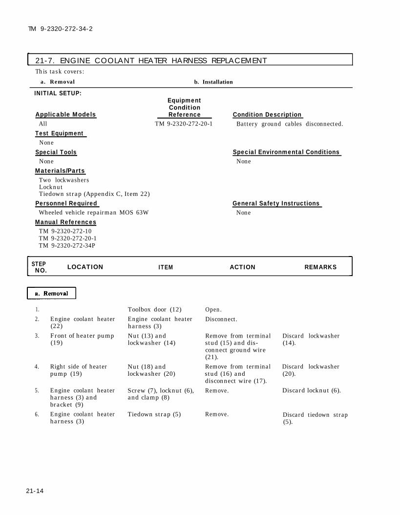
TM 9-2320-272-34-2
21-7. ENGINE COOLANT HEATER HARNESS REPLACEMENTThis task covers:
a. Removal b. Installation
INITIAL SETUP:EquipmentCondition
Applicable Models Reference Condition DescriptionAll TM 9-2320-272-20-1 Battery ground cables disconnected.
Test EquipmentNone
Special Tools Special Environmental ConditionsNone None
Materials/PartsTwo lockwashersLocknutTiedown strap (Appendix C, Item 22)
Personnel RequiredWheeled vehicle repairman MOS 63W
Manual ReferencesTM 9-2320-272-10TM 9-2320-272-20-1TM 9-2320-272-34P
General Safety InstructionsNone
STEP LOCATION ITEM ACTION REMARKSNO.
1.2.
3.
4.
5.
6.
21-14
Engine coolant heater(22)Front of heater pump(19)
Right side of heaterpump (19)
Engine coolant heaterharness (3) andbracket (9)Engine coolant heaterharness (3)
Toolbox door (12)Engine coolant heaterharness (3)Nut (13) andlockwasher (14)
Nut (18) andlockwasher (20)
Screw (7), locknut (6),and clamp (8)
Tiedown strap (5)
Open.Disconnect.
Remove from terminalstud (15) and dis-connect ground wire(21).Remove from terminalstud (16) anddisconnect wire (17).Remove.
Remove.
Discard lockwasher(14).
Discard lockwasher(20).
Discard locknut (6).
Discard tiedown strap(5).

TM 9-2320-272-34-2
21-7. ENGINE COOLANT HEATER HARNESS REPLACEMENT (Cont’d)
STEP LOCATION ITEM ACTION REMARKSNO.
7. Control box (1) Engine coolant heater Disconnect, and slideharness (3) through grommet (4)
in firewall (2) andgrommet (10) intoolbox (11) toremove.
21-15

TM 9-2320-272-34-2
21-7. ENGINE COOLANT HEATER HARNESS REPLACEMENT (Cont’d)
STEP LOCATION ITEM ACTION REMARKSNO.
8.
9.
10.
11.
21-16
Engine coolant heater a. Slide through grom-harness (3) met (4) in firewall
(2) and throughgrommet (10) intoolbox ( 11).
Wire (17)
b. Connect to heatercontrol box (1).
c. Install with new tie-down strap (5).
d. Install on bracket(9) with clamp (8),screw (7), and newlocknut (6).
e. Connect to enginecoolant heater (21).
Install on terminalstud (16) with newlockwasher (19) andnut (18).
Ground wire (20) Install on terminalstud (15) with nut (13)and new lockwasher(14).
Toolbox door (12) Close.

TM 9-2320-272-34-2
21-7. ENGINE COOLANT HEATER HARNESS REPLACEMENT (Cont’d)
STEP LOCATIONNO. ITEM ACTION REMARKS
FOLLOW-ON TASKS: ●
●
END OF TASK!
Connect battery ground cables (TM 9-2320-272-20-1).Check engine coolant heater for proper operation (TM 9-2320-272-10).
TA 350980
21-17

TM 9-2320-272-34-2
21-8. OIL PAN SHROUD AND EXHAUST TUBE REPLACEMENTThis task covers:
a. Removal b. Installation
INITIAL SETUP:EquipmentCondition
Applicable Models Reference Condition DescriptionAll TM 9-2320-272-10 Parking brake set.
Test EquipmentNone
Special Tools Special Environmental ConditionsNone None
Materials/PartsThree cotter pinsFour lockwashers
Personnel RequiredWheeled vehicle repairman MOS 63W
Manual ReferencesTM 9-2320-272-10TM 9-2320-272-34P
General Safety InstructionsNone
STEP LOCATIONNO. ITEM ACTION REMARKS
1.2. Engine coolant heater
(2) and oil pan shroud(5)
3. Oil pan (4)
b. installation
4.
5.
6.
Toolbox door (1)Three cotter pins (3),exhaust tube (8), andelbow (9)
Four nuts (7), lock-washers (6), and oilpan shroud (5)
Oil pan shroud (5)
Exhaust tube (8) andelbow (9)
Toolbox door (1)
Open.Remove.
Remove.
Discard cotter pins(3).Exhaust tube (8) andelbow (9) can beseparated.
Discard lockwashers(6).
Install on oil pan (4)with four nuts (7) andnew lockwashers (6).Install on engine Bend both sides ofcoolant heater (2) and cotter pins (3).oil pan shroud (5) withthree new cotter pins(3).
Close.
21-18

TM 9-2320-272-34-2
21-8. OIL PAN SHROUD AND EXHAUST TUBE REPLACEMENT (Cont’d)
STEP LOCATION ITEM ACTION REMARKSNO..
END OF TASK!TA 350981
21-19

TM 9-2320-272-34-2
21-9. ENGINE COOLANT BATTERY HEATER PAD REPLACEMENTThis task covers:
a. Removal b. Installation
INITIAL SETUP:Equipment
Applicable ModelsConditionReference
All TM 9-2320-272 -20-1Test Equipment
NoneSpecial Tools
NoneMaterials/Parts
NonePersonnel Required
Wheeled vehicle repairman MOS 63WManual References
TM 9-2320-272-20-1TM 9-2320-272-34P
Condition DescriptionBatteries removed.
Special Environmental ConditionsNone
General Safety InstructionsNone
STEP LOCATIONNO. ITEM ACTION REMARKS
1. Engine coolant heater Two hose clamps (2), Remove.pad (1) inlet hose (3), and
outlet hose (4)
2. Battery box (5) Engine coolant heater Remove.pad (1)
b. Installation
3.
4.
21-20
Engine coolant heater Install in battery boxpad (1) (5).Inlet hose (3) and Install on engineoutlet hose (4) coolant heater pad (1)
with two hose clamps(2).

TM 9-2320-272-34-2
21-9. ENGINE COOLANT BATTERY HEATER PAD REPLACEMENT (Cont’d)
STEP LOCATION ITEM ACTION REMARKSNO.
END OF TASK!
FOLLOW-ON TASK: Install batteries (TM 9-2320-272-20-1).TA 350982
21-21

TM 9-2320-272-34-2
21-10. ENGINE COOLANT HEATER ELECTRIC FUEL PUMP REPLACEMENTThe engine coolant heater and the personnel fuel burning heater operate off of the same electric fuel pump.
The removal and installation procedures for the personnel fuel burning heater electric fuel pump can befound in paragraph 21-16.
Section Il. PERSONNEL FUEL BURNING HEATER KIT REPLACEMENT
I 21-11. DESCRIPTIONa. The personnel fuel burning heater kit -55°F (-48°C) is designed to heat cab and defrost windshield of
vehicle. The fuel burning personnel heater utilizes two independent air systems: one for combustion, and onefor ventilation.
b. Installation instructions for the personnel fuel burning heater kit can be found on drawing 12256195.This section will cover description, data and replacement instructions of kit components only. To find aspecific replacement procedure, refer to the task summary in paragraph 21-13.
c. The combustion air system, in conjunction with fuel from vehicle fuel system, supplies flame for heatwhich is transmitted into ventilation air system by means of a heat exchanger. Once heated air is inventilation system, its intensity is controlled by a cable actuated baffle. Heated air, which is allowed to pass bythe baffle, is routed into the diverter assembly. The diverter allows heated air to be channeled directly intocab or through defroster vents by means of a second cable actuated baffle. Both cable actuated baffleassemblies have their control knobs mounted to the instrument panel. In addition to baffle controls, anelectrical control box is mounted to the instrument panel which starts heater and regulates HI and LO heatoperations.
21-12. TABULATED DATA
Table 21-2. Personnel Fuel Burning Heater Kit Replacement
STANDARD METRICHeat output: (ventilation air):
Rated output . . . . . . . . . . . . . . . . . . . . . . . . . . . . . . . . . . . . . . . . . . . . . . . . . . . . . . . . 30,000 BTU/hrHigh heat . . . . . . . . . . . . . . . . . . . . . . . . . . . . . . . . . . . . . . . . . . . . . . . . . . . . . . . . . . . . 27,000 BTU/hrLow heat . . . . . . . . . . . . . . . . . . . . . . . . . . . . . . . . . . . . . . . . . . . . . . . . . . . . . . . . . . . . . 15,000 BTU/hr
Fuel . . . . . . . . . . . . . . . . . . . . . . . . . . . . . . . . . . . . . . . . . . . . . . . . . . . . . . . . . . . . . . . . . . . . . . . . .. No. 2 dieselFuel pressure (at valve inlet) . . . . . . . . . . . . . . . . . . . . . . . . . . . . . . . . . . . . . . . . . . . . . . . 3 to 15 psi
Fuel consumption (nominal):High heat . . . . . . . . . . . . . . . . . . . . . . . . . . . . . . . . . . . . . . . . . . . . . . . . . . . . . . . . . . . . . . . 0.049 lb/minLow heat . . . . . . . . . . . . . . . . . . . . . . . . . . . . . . . . . . . . . . . . . . . . . . . . . . . . . . . . . . . . . . . . 0.031 lb/rein
Operating temperature range . . . . . . . . . . . . . . . . . . . . . . . . . . . . . . .-55°F ± 5°F to 70°F ± 5°F
Overheat switch setting . . . . . . . . . . . . . . . . . . . . . . . . . . . . . . . . . . . . . . . . . . . . . . . . 325°F to 475°FElectrical requirements:
Nominal . . . . . . . . . . . . . . . . . . . . . . . . . . . . . . . . . . . . . . . . . . . . . . . . . . . . . . . . . . . . . . . . . . . . . . . 24 VDCRange . . . . . . . . . . . . . . . . . . . . . . . . . . . . . . . . . . . . . . . . . . . . . . . . . . . . . . . . . . . . . . . . . . . . . . . . . . . 19-30
Current consumption:Starting above 30°F (-1°C) . . . . . . . . . . . . . . . . . . . . . . . . . . . . . . . . . . . . . . . . . . . . . . . . . . 12 ampsStarting below 30ºF (-1°C) . . . . . . . . . . . . . . . . . . . . . . . . . . . . . . . . . . . . . . . . . . . . . . . . . . 14 ampsRunning above 30°F (-1°C) . . . . . . . . . . . . . . . . . . . . . . . . . . . . . . . . . . . . . . . . . . . . . . . . . . 8 ampsRunning below 30°F (-1°C) . . . . . . . . . . . . . . . . . . . . . . . . . . . . . . . . . . . . . . . . . . . . . . . . . 10 amps
Heater dimensions:Length . . . . . . . . . . . . . . . . . . . . . . . . . . . . . . . . . . . . . . . . . . . . . . . . . . . . . . . . . . . . . . . . . . . . . . . . 17.25 in.Height . . . . . . . . . . . . . . . . . . . . . . . . . . . . . . . . . . . . . . . . . . . . . . . . . . . . . . . . . . . . . . . . . . . . . . . . 10.42 in.Width . . . . . . . . . . . . . . . . . . . . . . . . . . . . . . . . . . . . . . . . . . . . . . . . . . . . . . . . . . . . . . . . . . . . . . . . . . . 6.33 in.Weight . . . . . . . . . . . . . . . . . . . . . . . . . . . . . . . . . . . . . . . . . . . . . . . . . . . . . . . . . . . . . . . . less than 21 lbs
20.6-103.4 kPa
0.022 kg0.014 kg
-48°C ± -15°Cto 21°C ± -15°C163°C to 249°C
43.8 cm26.5 cm16.1 cm
less than 9.45 kg
21-22

TM 9-2320-272-34-2
21-13. PERSONNEL FUEL BURNING HEATER KIT COMPONENT REPLACEMENTTASK SUMMARY
TASK PROCEDURES PAGEPARA. NO.
21-14. Personnel Fuel Burning Heater Control Box 21-24Replacement
21-15. Personnel Fuel Burning Heater 21-26Replacement
21-16. Personnel Fuel Burning Heater Electric Fuel 21-28Pump Replacement
21-17. Personnel Fuel Burning Heater Harness 21-30and Cable 76 Replacement
21-18. Personnel Fuel Burning Heater Exhaust 21-34Tube Replacement
21-19. Personnel Fuel Burning Heater Circuit 21-36Breaker Replacement
21-23

TM 9-2320-272-34-2
21-14. PERSONNEL FUEL BURNING HEATER CONTROL BOX REPLACEMENTThis task covers:
a. R e m o v a l b. Installation
INITIAL SETUP:EquipmentCondition
Applicable Models Reference Condition Description
All TM 9-2320-272-20-1 Battery ground cables disconnected.
Test EquipmentNone
Special Tools Special Environmental Conditions
None None
Materials/PartsTwo lockwashers
Personnel RequiredWheeled vehicle repairman MOS 63W
Manual ReferencesTM 9-2320-272-10TM 9-2320-272-20-1TM 9-2320-272-34P
General Safety InstructionsNone
STEPNO. LOCATION ITEM ACTION REMARKS
a . R e m o v a l
1. Fuel burning heatercontrol box (7)
2.
3. Control mountingbracket (3)
4.
b. Installation
5.
6.
7.
21-24
Fuel burning heater Disconnect.harness (4)
Connector (5) Disconnect from con-trol box wire (6).
Two nuts (2) and Remove. Discard lockwasherslockwashers (1) (1).
Fuel burning heater Remove.control box (7)
Fuel burning heater Install on controlcontrol box (7) mounting bracket (3)
with two new lock-washers (1) and nuts(2).
Connector (5) Connect to control boxwire (6).
Fuel burning heater Connect to fuelharness (4) burning heater control
box (7).

TM 9-2320-272-34-2
21-14. PERSONNEL FUEL BURNING HEATER CONTROL BOXREPLACEMENT (Cont’d)
STEPNO. LOCATION ITEM ACTION REMARKS
END OF TASK!
FOLLOW-ON TASKS: ● Connect battery ground cables (TM 9-2320-272-20-1).• Check personnel fuel burning heater for proper operation (TM 9-2320-272-10).
TA 350983
21-25

TM 9-2320-272-34-2
21-15. PERSONNEL FUEL BURNING HEATER REPLACEMENTThis task covers:
a. Removal b. Installation
INITIAL SETUP:
Applicable Models
EquipmentConditionReference Condition Description
All TM 9-2320-272-10 Hood raised and secured.
Test EquipmentNone
Special Tools Special Environmental ConditionsNone None
Materials/PartsCotter pin
Personnel RequiredWheeled vehicle repairman MOS 63W
General Safety InstructionsNone
Manual ReferencesTM 9-2320-272-10TM 9-2320-272-34P
STEP LOCATIONNO. ITEM ACTION REMARKS
1. Fuel burning heater(3)
2. Left side of heater (3)
3. Exhaust tube (8) toheater (3)
4. Heater bracket (6)
Heater harness (4) Disconnect.
Fuel line (2) Disconnect fromheater elbow (1).
Cotter pin (7) Remove. Discard cotter pin (7).
Two clamps (5) Loosen, and slide fuelburning heater (3) outof clamps (5).
b. Installation
5.
6.
7.
8.
Fuel burning heater Install on heater(3) bracket (6) with two
clamps (5).
Exhaust tube (8) Install on fuel burningheater (3) with newcotter pin (7).
Fuel line (2) Connect to heaterelbow (1).
Heater harness (4) Connect to fuelburning heater (3).
21-26

TM 9-2320-272-34-2
21-15. PERSONNEL FUEL BURNING HEATER REPLACEMENT (Cont’d)
STEP LOCATIONNO. ITEM ACTION REMARKS
END OF TASK!
FOLLOW-ON TASK: Check personnel fuel burning heater for proper operation (TM 9-2320-272-10).T A 3 5 0 9 8 4
21-27

TM 9-2320-272-34-2
21-16. PERSONNEL FUEL BURNING HEATER ELECTRIC FUEL PUMP REPLACEMENT This task covers:
a. Removal b. Installation
INITIAL SETUP:EquipmentCondition
Applicable Models Reference Condition DescriptionAll TM 9-2320-272-20-1 Battery ground cables disconnected.
Test EquipmentNone
Special Tools Special Environmental ConditionsNone None
Materials/PartsTwo locknutsProtective cap-plugs (Appendix C, Item 5)
Personnel Required General Safety InstructionsWheeled vehicle repairman MOS 63W None
Manual ReferencesTM 9-2320-272-10TM 9-2320-272-20-1TM 9-2320-272-34P
STEP LOCATION ITEM ACTION REMARKSNO.
a. Removal
1.
2.
3.
Electric fuel pump wire Connector (3) Disconnect.(6)
CAUTIONWhen disconnecting lines and hoses from pump, immediately plugall open ports. Failure to do this can cause damage to pump.
Electric fuel pump (7)
Left-hand splash panel(9)
Fuel inlet line (8) andoutlet line (2)
Two screws (5) andlocknuts (1), andelectric fuel pump (7)
Disconnect from Tag for installation.adapter fittings (4). Plug fuel lines and fuel
pump ports.
Remove. Discard locknuts (1).
b. installation
4.
5.
Electric fuel pump (7)
Fuel outlet line (2) andinlet line (8)
Install on left-handsplash panel (9) withtwo screws (5) andnew locknuts (1).
Install on adapterfittings (4).
21-28

TM 9-2320-272-34-2
21-16. PERSONNEL FUEL BURNING HEATER ELECTRIC FUEL PUMPREPLACEMENT (Cont’d)
STEP LOCATION ITEM ACTION REMARKSNO.
6. Connector (3) Connect to electric fuelpump wire (6).
END OF TASK!
FOLLOW-ON TASKS: ● Connect battery ground cables (TM 9-2320-272-20-1).● Check personnel fuel burning heater electric fuel pump for proper operation(TM 9-2320-272-10).
TA 350985
21-29

TM 9-2320-272-34-2
21-17. PERSONNEL FUEL BURNING HEATER HARNESS AND CABLE 76REPLACEMENT
This task covers:
a. Removal b. Installation
INITIAL SETUP:EquipmentCondition
Applicable Models Reference Condition DescriptionAll TM 9-2320-272-10 Hood raised and secured.
TM 9-2320-272-20-1 Battery ground cables disconnected.
Test EquipmentNone
Special ToolsNone
Materials/PartsLockwasherLocknutSix tiedown straps (Appendix C, Item 22)
Personnel RequiredWheeled vehicle repairman MOS 63W
Manual References
Special Environmental ConditionsNone
General Safety InstructionsNone
TM 9-2320-272-10TM 9-2320-272-20-1TM 9-2320-272-34P
STEP LOCATION ITEM ACTION REMARKSNO.
1.
2.
3.4.
5.
6.7.
21-30
Fuel burning heater(22)Right underside ofdash
Heater control box (3)Electric fuel pump(12)Heater bracket (21)
Wire (6)Firewall (24)
Heater harness (4)
Connector (1)
Heater harness (4)
Connector (14)
Screw (7), nut (19),washer (20), and lock-washer (8)Six tiedown straps (5)Screw (11) and clamp(10)
Disconnect.
Disconnect fromheater control box con-nector (2).
Disconnect.Disconnect from wireconnector (13).Remove, and discon- Discard lockwashernect heater ground (8).wire (9).Remove. Discard straps (5).
Remove.

TM 9-2320-272-34-2
21-17. PERSONNEL FUEL BURNING HEATER HARNESS AND CABLE 76REPLACEMENT (Cent’d)
STEP LOCATION ITEM ACTION REMARKSNO.
8. Splash panel (16) Screw (18), locknut Remove. Discard locknut (15).(15) and clamp (17)
9. Wire (6) and heater Remove through grom-harness (4) met (23) in firewall
(24).
TA 350986
21-31

TM 9-2320-272-34-2
21-17. PERSONNEL FUEL BURNING HEATER HARNESS AND CABLE 76REPLACEMENT (Cont’d)
STEP LOCATION ITEM ACTION REMARKSNO.
b. Installation
10.
11.
12.
13.
14.
15.
21-32
Wire (6) and heaterharness (4)
Heater harness (4)
Connector (1)
Connector (14)
Heater harness (4)
Wire (6)
Install through grom-met (23) in firewall(24).Connect to heater con-trol box (3).Connect to heatercontrol box connector(2).Connect to wire con-nector (13) on electricfuel pump (12).a. Connect to fuel burn-
ing heater (22).
b. Install ground wire(9) to heater brack-et (21) with screw(7), new lockwasher(8), washer (20),and nut (19).
a. Install with six newtiedown straps (5).
b.
c.
Install to firewall(24) with screw (11)and clamp (10).Install to splashshield (16) withscrew (18), new lock-nut (15) and clamp(17).
Connection is madeunder right side ofdash.
Make sure ground wire(9) is installed betweenlockwasher (8) andbracket (21).

TM 9-2320-272-34-2
21-17. PERSONNEL FUEL BURNING HEATER HARNESS AND CABLE 76REPLACEMENT (Cont’d)
LOCATION ITEM ACTION REMARKS
END OF TASK!
FOLLOW-ON TASKS: ● Connect battery ground cables (TM 9-2320-272-20-1).• Check personnel fuel burning heater for proper operation (TM 9-2320-272-10).
TA 350987
21-33

TM 9-2320-272-34-2
21-18. PERSONNEL FUEL BURNING HEATER EXHAUST TUBE REPLACEMENTThis task covers:
a. Removal b. Installation
INITIAL SETUP:Equipment
Applicable ModelsAll
Test EquipmentNone
Special ToolsNone
Materials/PartsTwo cotter pinsTwo locknuts
Personnel RequiredWheeled vehicle repairman MOS 63W
Manual ReferencesTM 9-2320-272-10TM 9-2320-272-34P
ConditionReference Condition Description
TM 9-2320-272-10 Parking brake set.
Special Environmental ConditionsNone
General Safety InstructionsNone
STEP LOCATION ITEM ACTION REMARKSNO.
a. Removal
1. Exhaust elbow (1) andfuel burning heater (2)
2. Exhaust elbow (1) andexhaust tube (7)
3. Fuel burning heater(2) and splash panel(8)
4.
5.
Cotter pin (3)
Cotter pin (4)
Two screws (9), lock-nuts (6), and clamps(5), tube (7), and ex-haust elbow (1)
Exhaust elbow (1)
Exhaust tube (7)
Remove.
Remove.
Remove.
Install on heater (2)with new cotter pin(3).a. Install on exhaust el-
Discard cotter pin (3).
Discard cotter pin (4).
Discard locknuts (6).
bow (1) with newcotter pin (4).
b. Install on splashpanel (8) with twoclamps (5), screws(9), and new lock-nuts (6).
21-34

TM 9-2320-272-34-2
21-18. PERSONNEL FUEL BURNING HEATER EXHAUST TUBEREPLACEMENT (Cont’d)
STEP LOCATION ITEM ACTION REMARKSNO.
TA 350988
21-35

TM 9-2320-272-34-2
21-19. PERSONNEL FUEL BURNING HEATER CIRCUIT BREAKER REPLACEMENTThis task covers:
a. Removal b. Installation
INITIAL SETUP:EquipmentCondition
Applicable Models Reference Condition DescriptionAll TM 9-2320-272-20-1 Battery ground cables disconnected.
Test EquipmentNone
Special Tools Special Environmental ConditionsNone None
Materials/PartsNone
Personnel RequiredWheeled vehicle repairman MOS 63W
Manual ReferencesTM 9-2320-272-20-1TM 9-2320-272-34P
STEP LOCATION ITEM ACTION REMARKSNO.
NOTEAll circuit breakers on the M939 series vehicles are removed andinstalled the same way. This procedure covers the personnel fuel
General Safety InstructionsNone
burning heater circuit breaker only.
1. Left underside of dash(5)
2.
3.
4.
Connector (3) andconnector (4)
Two screws (2) andheater circuit breaker(1)
Heater circuit breaker(1)
Connector (4) andconnector (3)
Disconnect fromheater circuit breaker(1).Remove.
Install on left under-side of dash (5) withtwo screws (2).
Connect to heatercircuit breaker (1).
Connection is madeunder left side of dash(5).
21-36

TM 9-2320-272-34-2
21-19. PERSONNEL FUEL BURNING HEATER CIRCUIT BREAKERREPLACEMENT (Cont’d)
STEP LOCATION ITEM ACTION REMARKSNO.
END OF TASK!
FOLLOW-ON TASK: Connect battery ground cables (TM 9-2320-272-20-1).TA 350989
21-37

TM 9-2320-272-34-2
Section Ill. DEEPWATER FORDING KIT
21-20. DESCRIPTION
a. The deepwater fording kit provides component air venting and engine pressurization when crossingwater no greater than 6-1/2 ft (1.98 m) in depth. The power steering pump and engine crankcase arepressurized. Venting of other drive train components is accomplished through the air intake system.pressurization of components is provided by compressed air system at horn. The compressed air is thenregulated and directed to the various components by means of pressure and shutoff valves which arecontrolled from within the cab.
b. Installation instructions for the deepwater fording kit can be found on drawing 12302688. Thissection will cover description and replacement instructions of kit components only. To find a specificreplacement procedure, refer to the task summary in paragraph 21-21.
I 21-21. DEEPWATER FORDING KIT COMPONENT REPLACEMENT TASK SUMMARY
TASKPARA.
PROCEDURES PAGENO.
21-22. Deepwater Fording Hand Control and Cable Replacement 21-3821-23. Deepwater Fording Pressurization Valve Replacement 21-4221-24. Deepwater Fording Air Pressure Hoses Replacement 21-4621-24.1 Deepwater Fording Regulator Valve Replacement 21-50
21-22. DEEPWATER FORDING HAND CONTROL AND CABLE REPLACEMENT
This task covers:a. Removal b. Installation
INITIAL SETUP:EquipmentCondition
Applicable Models Reference Condition DescriptionAll TM 9-2320-272-10 Hood raised and secured.
Test EquipmentNone
Special Tools Special Environmental Conditions
None None
Materials/PortsFour locknuts General Safety Instructions
Lockwasher None
Personnel RequiredWheeled vehicle repairman MOS 63W
Manual ReferencesTM 9-2320-272-10TM 9-2320-272-34P
21-38 Change 2

TM 9-2320-272-34-2
21-22. DEEPWATER FORDING HAND CONTROL AND CABLE REPLACEMENT (Cont’d)
STEPLOCATION ITEM ACTION REMARKSNO.
a. Removal
1. Pressurization valve(3) and control cable(10)
2. Fording cable bracket(6)
3. Hand control (14) andcontrol cable (10)
4. Surge tank mountingbracket (8)
Screw (1) Loosen and removecontrol cable (10) fromnut (2).
Two locknuts (11), Remove.screws (4), clamp (5),and control cable (10)Nut (16) and lock- a.washer (17)
b.
Remove and slidedown control cable(10).Pull hand control(14) and control cable(10) from instrumentpanel (15) and grom-met (12) in firewall(13).
Two locknuts (9), Remove.screws (7), and fordingcable bracket (6)
Discard locknuts (11).
Discard lockwasher(17).
Discard locknuts (9).
Change 2 21-39

TM 9-2320-272-34-2
21-22. DEEPWATER FORDING HAND CONTROL AND CABLE REPLACEMENT (Cont'd)
STEP LOCATION ITEM ACTION REMARKSNO.
b. Installation
5. Fording cable bracket(10)
6. Control cable (1)
7. Hand control (5)
8. Control cable (1)
Install on surge tankmounting bracket (12)with two screws (11) andnew locknuts (13).
Insert through hole ininstrument panel (4),new lockwasher (3),nut (2), and grommet(17) on firewall (16).Install on instrumentpanel (4) with new lock-washer (3) and nut (2).
a. Slide through nut (15)on pressurization valve(7) and tighten screw (6).
b. Install on fording cablebracket (10) with clamp(9), two screws (8), andnew locknuts (14).
21-40 Change 2

TM 9-2320-272-34-2
21-22. DEEPWATER FORDING HAND CONTROL AND CABLE REPLACEMENT (Cont’d).
STEPLOCATIONNO. ITEM ACTION REMARKS
END OF TASK!
21-41Change 2

TM 9-2320-272-34-2
21-23. DEEPWATER FORDING PRESSURIZATION VALVE REPLACEMENTThis task covers:
a. Removal b. Installation
INITIAL SETUP:EquipmentCondition
Applicable Models Reference Condition DescriptionAll TM 9-2320-272-10 Hood raised and secured.
TM 9-2320-272-10 Air reservoirs drained.Test Equipment
None
Special TookNone
Materials/PartsThree locknutsLockwasherAntiseize tape (Appendix C, Item 30)
Personnel RequiredWheeled vehicle repairman MOS 63W
Special Environmental ConditionsNone
General Safety InstructionsDo not disconnect air lines beforedraining air reservoirs.
Manual ReferencesTM 9-2320-272-10TM 9-2320-272-34P
STEP LOCATIONNO. I T E M ACTION REMARKS
WARNING
Do not disconnect air lines before draining air reservoirs. Small parts underpressure may shoot out with high velocity causing injury to personnel.
1.
2.
3.
4.
5.
Fording cable bracket Two locknuts (25), Remove. Discard locknuts (25).(24) screws (18), and
clamp (19)Control cable (26) to Screw (29) Loosen and removepressurization valve (22) control cable (26) from
nut (28).Pressurization valve Supply hose (20) Disconnect.adapter (21)
NOTEPerform step 4 for vehicles equipped with positive crankcase ventilation system.
Pressurization valve Two clamps (33), hose Remove.elbow (34) (35), and crankcase vent
tube (32)Pressurization valve Two clamps (15), hose Remove.elbow (27) (16), and crankcase
breather tube (17)
21-42 Change 2

TM 9-2320-272-34-2
21-23. DEEPWATER FORDING PRESSURIZATION VALVE REPLACEMENT (Cont’d)
STEPNO. LOCATION ITEM ACTION REMARKS
6.
7.
8.
9.
10.
Pressurization valveconnectors (7)
Bracket (9) on radiatorsupport bracket (10)
Pressurization valveconnector (14)Pressurization valvebracket (23) and rockerlever cover (4)
Crankcase breather (3)
Pressurization hose (6) Disconnect. Tag for installation.and vent hose (5)
Locknut (8), screw (12), Remove. Discard locknut (8).clamp (11), and powersteering pump hose (13)
Power steering pump Disconnect.hose (13)
Screw (30) and lock- Remove. Discard lockwasherwasher (31) (31).
Two clamps (1) and Remove.and pressurization hose (2)
WITH POSITIVE CRANKCASEVENTILATION SYSTEM
Change 2 21-43

TM 9-2320-272-34-2
21-23. DEEPWATER FORDING PRESSURIZATION VALVE REPLACEMENT (Cont'd)
STEP LOCATION ITEM ACTION REMARKSNO.
NOTEAll male threads must be wrapped with antiseize tape before installation.
11. Pressurization valve(21)
12. Pressurization valvebracket (22)
13. Power steering pumphose (12)
14. Pressurization hose(6) and vent hose (5)
15. Crankcase breathertube (16)
Connect to crankcasebreather (3) with hose(2) and two clamps (1).Install on rocker levercover (4) with new lock-washer (30) and screw (29).a.
b.
Connect to pressuriza-tion valve connector (13).Install on bracket (9)with clamp (10), screw(11), and new locknut(8).
Connect to pressurizationvalve connectors (7).Install on pressurizationvalve elbow (26) with hose(15) and two clamps (14).
NOTEPerform step 16 for vehicles equipped with positive crankcase ventilation.
16. Crankcase vent tube Install on pressurization(31) valve elbow (33) with hose
(34) and two clamps (32).17. Supply hose (19) Connect to pressurization
valve adapter (20).18. Control cable (25) a.
b.
Insert through nut(27) on pressurizationvalve (21) and tightenscrew (28).Install on fording cablebracket (23) with clamp(18), two screws (17), andlocknuts (24).
21-44 Change 2

TM 9-2320-272-34-2
21-23. DEEPWATER FORDING PRESSURIZATION VALVE REPLACEMENT (Cont’d)
STEPLOCATION ITEMNO. ACTION REMARKS
FOLLOW-ON TASK:
WITH CLEAN AIR SYSTEM
END OF TASK!
Start engine (TM 9-2320-272-10) and allow air pressure to buildup to normaloperating range. Check for air leaks. Road test vehicle.
Change 2 21-45

TM 9-2320-272-34-2
21-24. DEEPWATER FORDING AIR PRESSURE HOSES REPLACEMENT
This task covers:a. Removal b. Installation
INITIAL SETUP:EquipmentCondition
Applicable Models Reference Condition DescriptionAll TM 9-2320-272-10 Hood raised and secured.
TM 9-2320-272-10 Air reservoirs drained.Test Equipment
None
Special TOOISNone
Materials/Parts
Special Environmental ConditionsNone
LocknutFive tiedown straps (Appendix C, Item 21)Antiseize tape (Appendix C, Item 30).
Personnel RequiredWheeled vehicle repairman MOS 63W
General Safety InstructionsDo not disconnect air lines beforedraining air reservoirs.
Manual ReferencesTM 9-2320-272-10TM 9-2320-272-34P
STEPNO. LOCATION ITEM ACTION REMARKS
W A R N I N G
Do not disconnect air lines before draining air reservoirs. Small parts underpressure may shoot out with high velocity causing injury to personnel.
1. Pressurization valve(3) and pressurizationvalve adapter (1)
2. Bracket (19)
3. Pressurization valveconnector (24) andadapter (17)
4. Pressure hose (4)and vent hose (5)
5. Pressurization valveconnector (28) andtee (13)
Supply hose (2)
Locknut (23), screw (21),clamp (22), and powersteering pump hose (26)Power steering pumphose (26)
Five tiedown straps (15)
Pressure hose (4)and bushing (14)
Disconnect.
Remove.
Disconnect.
Remove.
Remove.
Discard locknut (23).
Discard tiedown straps(15).
21-46 Change 2

TM 9-2320-272-34-2
21-24. DEEPWATER FORDING AIR PRESSURE HOSES REPLACEMENT (Cont'd)
STEPNO. LOCATION ITEM ACTION REMARKS
6. Pressurization valveconnector (27) andtee (11)
7. Shutoff valve (6) andalcohol evaporator (10)
8. Alcohol evaporator (10)
9. Power steering pump(18)
10. Air compressor (16)11. Radiator support
bracket (20)
Vent hose (5) and bush- Remove.ing (12)
Air line (7) Disconnect.
Drain valve (8) and Remove.elbow (9)Adapter (17) Remove.
Shutoff valve (6) Remove.Screw (25) and bracket Remove.(19)
Change 2 21-47

TM 9-2320-272-34-2
21-24. DEEPWATER FORDING AIR PRESSURE HOSES REPLACEMENT (Cont'd)
STEP LOCATION ITEM ACTION REMARKSNO.
12.
13.
14.
15.
16.
17.
18.
19.
20.
21-48 Change 2
NOTEWrap all male pipe threads with antiseize tape before installation.
Bracket (19)
Shutoff valve (6)
Elbow (9) and drainvalve (8)Air line (7)
Vent hose (5) andbushing (12)
Pressure hose (4) andbushing (14)
Five new tiedownstraps (15)Power steering pumphose (26) and adapter(17)
Supply hose (2)
Install on radiatorsupport bracket (20)with screw (25).Install on air compressor(16).Install on alcoholevaporator (10).Connect to shutoff valve(6) and alcohol evapo-rator (10).a.
b.
a.
b.
Install bushing (12)on tee (11).Connect vent hose (5)on bushing (12) andpressurization valveconnector (27).Install bushing (14)on tee (13).Connect pressure hose(4) on bushing (14) andpressurization valveconnection (28).
Install on pressure hose(4) and vent hose (5).a.
b.
c.
Install adapter (17)on power steeringpump (18).Connect power steeringpump hose (26) onadapter (17) andpressurization valveconnector (24).Install power steeringpump hose (26) onbracket (20) with clamp(22), screw (21), andnew locknut (23).
Install on pressurizationvalve adapter (1) andregulator valve (3).

21-24.
TM 9-2320-272-34-2
STEPNO. LOCATION ITEM ACTION REMARKS
FOLLOW-ON TASK:END OF TASK!
Start engine (TM 9-2320-272-10) and allow air pressure to build up to normaloperating range. Check for air leaks. Road test vehicle.
Change 2 21-49

TM 9-2320-272-34-2
21-24.1 DEEPWATER FORDING REGULATOR VALVE REPLACEMENT
This task covers:a. Removal b. Installation
INITIAL SETUP:EquipmentCondition
Applicable Models Reference Condition DescriptionAll TM 9-2320-272-10 Hood raised and secured.
Test EquipmentTM 9-2320-272-10 Air reservoirs drained.
Special ToolsNone
Materials/PartsAntiseize tape (Appendix C, Item 30)
Personnel RequiredWheeled vehicle repairman MOS 63W
Manual ReferencesTM 9-2320-272-10TM 9-2320-272-34P
Special Environmental ConditionsNone
General Safety InstructionsDo not disconnect air lines beforedraining air reservoirs.
STEP LOCATIONNO. ITEM ACTION REMARKS
WARNING
Do not disconnect air lines before draining air reservoirs. Small parts underpressure may shoot out with high velocity causing injury to personnel.
1. Regulator valve (6)2. Tee (2)3. Air horn solenoid (8)
Supply hose (7) Disconnect.Air line (4) and adapter (3) Remove.Regulator valve (6), Remove.nipple (5), tee (2), elbow(1), and reducer (9)
b. Installation
NOTEWrap all male pipe threads with antiseize tape before installation.
4. Reducer (9), elbow (1), Install on air horntee (2), nipple (5), and solenoid (8).regulator valve (6)
5. Air line (4) and adapter (3) Install on tee (2).6. Supply line (7) Install on regulator valve (6).
21-50 Change 2

TM 9-2320-272-34-2
21-24.1 DEEPWATER FORDING REGULATOR VALVE REPLACEMENT (Cont'd)
STEPNO. LOCATION ITEM ACTION REMARKS
END OF TASK!
Change 2 21-50.1 (21-50.2 blank)


TM 9-2320-272-34-2
Section IV. HAND AIRBRAKE KIT
21-25. DESCRIPTIONa. The hand airbrake kit is designed for use when braking force is required at wheels of a towed vehicle and
not at wheels of towing vehicle. The kit consists of valve assembly with hand control, bulkhead union, double-check valve, and tubing with appropriate fittings and clamps. Compressed air to power hand airbrake systemis drawn from air supply valve mounted on the side of firewall.
b. For removal and installation instructions for hand airbrake kit, refer to drawing 12256300. This kit isused on all M939 series vehicles.
Section
21-26. DESCRIPTION
V. RADIATOR AND HOOD COVER KIT
a. The radiator and hood cover kit consists of hood panel loops, radiator and hood cover assembly, hoodpanel screws, and a drilling instruction drawing. No component of this kit is removed and replaced as aseparate unit. The kit is the unit.
b. For further instruction on the removal and installation of the radiator and hood cover kit, refer todrawing 12256609. This kit is used on all M939 series vehicles.
21-27. RADIATOR AND HOOD COVER KIT REPLACEMENT TASK SUMMARY
TASK PROCEDURES PAGEPARA. NO.
21-28. Radiator and Hood Cover Kit Replacement 21-52
21-51

TM 9-2320-272-34-2
21-28. RADIATOR AND HOOD COVER KIT REPLACEMENTThis task covers:
a. Installation b. Removal
INITIAL SETUP:EquipmentCondition
Applicable Models Reference Condition DescriptionAll TM 9-2320-272-10 Parking brake set.
Test EquipmentNone
Special Tools Special Environmental ConditionsNone None
Materials/PartsNone
Personnel RequiredWheeled vehicle repairman MOS 63W
Manual ReferencesTM 9-2320-272-10TM 9-2320-272-34P
General Safety InstructionsNone
LOCATION ITEM ACTION
a. Installation
1. Radiator and hood a. Place over hood (4) Refer to drilling instruc-cover (5) and insert tiedown tion drawing for instal-
loops (1) through lation of tiedown loops.grommets (2).
b. Install by threadingtiedown strap (3)through each tie-down loop (1) andtying strap endstogether.
b . Remova l
2.
3.
NOTEOnce installed, it is not necessary to remove tiedown loops.
Tiedown strap (3) Untie ends and pullfrom eighteen tiedownloops (1).
Radiator and hoodcover (5) Remove from hood (4).
REMARKS
21-52

TM 9-2320-272-34-2
21-28. RADIATOR AND HOOD COVER KIT REPLACEMENT (Cont’d)
STEP LOCATION ITEM ACTION REMARKSNO.
END OF TASK!TA 350996
21-53 (21-54 blank)


Section IV. AIR CONDITIONER
TM 9-2320-272-34-2
KIT
21-29. DESCRIPTION
The air conditioner is used primarily in van type enclosures. The unit provides filtered, cooled or heatedair to maintain the service conditions necessaryor the efficient operation of electronic equipment in thevans. The air conditioner also provides for the comfort of operating personnel housed within the van.
21-30. TABULATED DATA
Table 21-3. Air Conditioner Tabulated Data.
1.
2.
STANDARD METRIC
DIMENSIONS AND WEIGHTLength . . . . . . . . . . . . . . . . . . . . . . . . . . . . . . . . . . . . . . . 38-1/16 in. 0.96 mWidth . . . . . . . . . . . . . . . . . . . . . . . . . . . . . . . . . . . . . . . 35-3/16 in. 0.89 mHeight . . . . . . . . . . . . . . . . . . . . . . . . . . . . . . . . . . . . . . . . 27-1/8 in. 0.68 mWeight . . . . . . . . . . . . . . . . . . . . . . . . . . . . . . . . . . . . . . . . . 434lbs 196.86 kgMax power requirement . . . . . . . . . . . . . . . . . . . . . . . . . . . . 13.5kw
SPECIFICATIONSCapacity . . . . . . . . . . . . . . . . . . . . . . . . . . . . . . . . . 36,000 BTU/HRVolts . . . . . . . . . . . . . . . . . . . . . . . . . . . . . . . . . . . . . . . . . . . ..208Hertz . . . . . . . . . . . . . . . . . . . . . . . . . . . . . . . . . . . . . . . . . ..50/60Phase . . . . . . . . . . . . . . . . . . . . . . . . . . . . . . . . . . . . . . . . . . . . . . 3
Change 2 21-55

TM 9-2320-272-34-2
21-31. AIR CONDITIONER KIT REPLACEMENT
THIS TASK COVERS:a. Removal b. Installation
INITIAL SETUP
EquipmentCondition
Applicable Models Reference
M934, M934A1, M935, M935A1 TM 9-2320-272-10
Test EquipmentTM 9-2320-272-10TM 9-2320-272-10
None TM 9-2320-272-10
Special ToolsTM 9-2320-272-10
NoneTM 9-2320-272-20-1TM 9-2320-272-20-2
Materials/PartsCotter pinTwenty-nine lockwashers
Personnel RequiredWheeled vehicle repairman MOS 63W (3)
Manual ReferencesTM 9-2320-272-10TM 9-2320-272-20-1TM 9-2320-272-20-2TM 9-2320-272-34P
Para. 18.1-26
Condition DescriptionParking brake set.Cab paulin and bows removed.Windshield lowered.Companion seat lowered.External power source disconnected.Ground cable disconnected.Air conditioner drain tube removed.Bonnet door removed.
Special Environmental ConditionsNone
General Safety InstructionsAll personnel must stand clear duringlifting operations.
STEPLOCATION ITEM ACTION REMARKSNO.
NOTEScrew quantity for steps 1, 2, and 4 may differ from vehicle tovehicle. Record quantity removed for installation.
1. Lower panel mounting Sixteen screws (7) Remove.angle (8) and two and lower anglemounting angles (5) bracket (6)
2. Bonnet (12) Twelve screws (10) Remove.and lower panelmounting angle (8)
3. Four screws (9) and Remove.two mounting angles(5)
4. Air conditioner (11) Fourteen screws (4), Remove.lockwashers (2),snap (3), and conden-ser guard (1)
21-56 Change 2
Discard lockwashers(2).

TM 9-2320-272-34-2
21-31. AIR CONDITIONER KIT REPLACEMENT (Cont'd)
STEP LOCATION ITEM ACTION REMARKSNO.
Change 2 21-57

TM 9-2320-272-34-2
21-31. AIR CONDITIONER KIT REPLACEMENT (Cont'd)
STEP LOCATION ITEM ACTION REMARKSNO.
5.
6.
7.
Bonnet (8) and airconditioner (7)
Sixteen screws (1) andtop enclosure (2)
Remove.
Remove.
Remove.
Remove.
Remove.
Remove.
Disconnect.
Remove.
Remove.
Remove.
Remove.
Seven screws (6) andbottom enclosure (5)
Left enclosure (13) Four screws (16),plate (15), and bellows(14)
Cotter pin (12) anddoor rod (10)
8.
9.
10.
11.12.
Swing arm (11)
Bonnet (8) and airconditioner (7)
Discard cotter pin (12).
Ten screws (9) andleft enclosure (13)Ten screws (3) andright enclosure (4)
Air conditioner (7) Power cable (21)
Screw (23), lockwasher(24), washer (25), groundcable (26), and lockwash-er (22)
Nut (30), lockwasher(29), washer (28), screw(20), ground cable (26),and lockwasher (27)
Discard lockwashers(24) and (22).
Discard lockwashers(29) and (27).
13. Mounting plate (18)and bonnet floor (32)
Five nuts (31), lock-washers (33), washers(34), and screws (19)Six screws (17) andlockwashers (36)
14.
15.
Discard lockwashers(33).
Discard lockwashersMounting plate (35)and bonnet floor (32) (36).
WARNING
All personnel must stand clear during lifting operations.or shifting load may cause injury or death to personnel.
A swinging
NOTETwo assistants will help with step 16.
16.
17.
Lifting device (40) and Chain (39) Attach.four lifting brackets (38)
Bonnet (8) Air conditioner (7) Remove. Position air conditioner(7) for access to bottomof unit.
18. Air conditioner (7) Six screws (37) and Remove.mounting plates (35)and (18)
21-58 Change 2

TM 9-2320-272-34-2
21-31. AIR CONDITIONER KIT REPLACEMENT (Cont'd)
STEPNO. LOCATION ITEM ACTION REMARKS
Change 2 21-59

TM 9-2320-272-34-2
21-31. AIR CONDITIONER KIT REPLACEMENT (Cont'd)
STEP LOCATION ITEM ACTION REMARKSNO.
19. Mounting plates (20) Install on air condition-and (2) er (19) with six screws
(24).
WARNING
20.
21.
22.
23.
24.
25.
26.
All personnel must stand clear during lifting operations. A swingingor shifting load may cause injury to personnel.
NOTETwo assistants will help with step 20.
Chain (22) Attach to lifting device(23) and four liftingbrackets (26).
Air conditioner (19) Position in bonnet(25).
Mounting plate (20) Install on bonnet floor(16) with six new lock-washers (21) and screws(1).
Ground cable (10) a.
b.
Install on mounting plate(2) and bonnet floor (16)with new lockwasher (11),screw (4), washer (12),new lockwasher (13), andnut (14).Install on air conditioner(19) with new lockwasher(6), washer (9), new lock-washer (8), and screw (7).
Mounting plate (2) Install on bonnet floor (16)with five screws (3), washers(18), new lockwashers (17),and nuts (15).
Power cable (5) Connect to air conditioner (19).
Air conditioner (19) Remove lifting device (23) andchain (22).
21-60 Change 2

TM 9-2320-272-34-2
21-31. AIR CONDITIONER KIT REPLACEMENT (Cont’d)
STEPNO. LOCATION ITEM ACTION REMARKS
Change 2 21-61

TM 9-2320-272-34-2
21-31. AIR CONDITIONER KIT REPLACEMENT (Cont’d)
STEPNO. LOCATION ITEM ACTION REMARKS
27. Right enclosure (3) Install on bonnet (7)and air conditioner (8)with ten screws (4).
28. Bellows (14) Install on left enclosure(12) with plate (15) andfour screws (16).
29. Door rod (9) Install on swing arm(10) with new cotterpin (11).
30. Left enclosure (12) Install on bonnet (7) Ensure door rod (9) isand air conditioner (8) positioned throughwith ten screws (13). bellows (14).
31. Bottom enclosure (5) Install on bonnet (7)and air conditioner (8)with seven screws (6).
32. Top enclosure (2) Install on bonnet (7)and air conditioner(1) with sixteen screws
21-62 Change 2

TM 9-2320-272-34-2
21-31. AIR CONDITIONER KIT REPLACEMENT (Cont'd)
STEPNO. LOCATION ITEM ACTION REMARKS
Change 2 21-63

TM 9-2320-272-34-2
21-31. AIR CONDITIONER KIT REPLACEMENT (Cont'd)
STEP LOCATION ITEM ACTION REMARKSNO.
31.
32.
33.
34.
NOTEScrew quantity for steps 31, 33, and 34 may differ from vehicle tovehicle. Install screws as recorded.
Condenser guard (1)
Two mounting angles(5)Lower panel mountingangle (8)
Lower angle bracket (6)
Install on air conditioner(11) with fourteen new lock-washers (2), snap (3),and fourteen screws (4).Install on bonnet (12)with four screws (9).Install on bonnet (12)and two mountingangles (5) with twelvescrews (10).Install on bonnet (12)and two mountingangles (5) with six-teen screws (7).
21-64 Change 2

TM 9-2320-272-34-2
21-31. AIR CONDITIONER KIT REPLACEMENT (Cont'd)
STEPLOCATIONNO. ITEM ACTION REMARKS
END OF TASK!
FOLLOW-ON TASKS: • Install bonnet door (para. 18.1-26).● Install air conditioner drain tube (TM 9-2320-272-20-2).● Connect ground cable (TM 9-2320-272-20-1).● Connect external power source (TM 9-2320-272-10).● Raise companion seat (TM 9-2320-272-10).● Raise windshield (TM 9-2320-272-10).● Install cab paulin and bows (TM 9-2320-272-10).
Change 2 21-65 (21-66 blank)


TM 9-2320-272-34-2
APPENDIX AREFERENCES
A-1. INDEXESThe following indexes should be consulted frequently for latest changes to, or revisions of, references given inthis appendix and for new publications or instructions relating to material covered in this manual.
a. Military Publications:
Consolidated Index of ArmyPublications and Blank Forms . . . . . . . . . . . . . . . . . . . . . . . . . . . . . . . . . . . . . . . . . . . . . . . . . . . . . . . . . . . . . . . . DA PAM 310-1
Index of Army Equipment Modification Work Orders . . . . . . . . . . . . . . . . . . . . . . . . . . . . . . . . . . . . . . DA PAM 310-10Equipment Improvement Report and Maintenance Digest . . . . . . . . . . . . . . . . . . . . . . . . . . . . . . . . . TB 43-0001-39
b. General References:
Authorized Abbreviations and Brevity Codes . . . . . . . . . . . . . . . . . . . . . . . . . . . . . . . . . . . . . . . . . . . . . . . . . . . . . . . AR 310-50Dictionary of United States Army Terms . . . . . . . . . . . . . . . . . . . . . . . . . . . . . . . . . . . . . . . . . . . . . . . . . . . . . . . . . . . . AR310-25Military Symbols . . . . . . . . . . . . . . . . . . . . . . . . . . . . . . . . . . . . . . . . . . . . . . . . . . . . . . . . . . . . . . . . . . . . . . . . . . . . . . . . . . . . . . . . . FM 21-30How to Prepare and Conduct Military Training . . . . . . . . . . . . . . . . . . . . . . . . . . . . . . . . . . . . . . . . . . . . . . . . . . . . . . . FM 21-6
A-2. SUPPLY CATALOGSThe following Department of the Army Supply Catalogs pertain to this manual:
Shop Equipment, Automotive Maintenance and Repair,Organizational: Common No. 2. (NSN 4910-00-754-0650) . . . . . . . . . . . . . . . . . . . . . . . . . . . . . SC 4910-95-CL-A72
Shop Equipment, Automotive Maintenance and Repair,Organizational: Common No. 1. (NSN 4910-00-754-0654) . . . . . . . . . . . . . . . . . . . . . . . . . . . . . . . SC 4910-95-CL-A74
Tool Set, Vehicle, Full Tracked, Organizational:Supplemental No. 2. (NSN 4940-00-754-0743) . . . . . . . . . . . . . . . . . . . . . . . . . . . . . . . . . . . . . . . . . . . . SC 4940-95-CL-A08
A-3. FORMSRefer to DA Pam 310-1 for index of blank forms. Refer to DA Pam 738-750 for pertinent maintenance formsand explanation on use.
DA Form 2028. Recommended Changes to PublicationsDA Form 2401. Organizational Control Record for EquipmentDA Form 2402. Exchange TagDA Form 2404. Equipment Inspection and Maintenance WorksheetDA Form 2405. Maintenance Request RegisterDA Form 2406. Materiel Condition Status ReportDA Form 2407. Maintenance RequestDA Form 2407-1. Maintenance Request - Continuation SheetDA Form 2408. Equipment Log Assembly (Records)DA Form 2408-9. Equipment Control RecordDA Form 2408-10. Equipment Component RegisterDA Form 2409. Equipment Maintenance Log - (Consolidated)DA Form 348. Equipment Operator’s Qualification Record (Except Aircraft)DA Form 285. U.S. Army Accident Investigation ReportDD Form 314. Preventive Maintenance Schedule and RecordDD Form 518. Accident - Identification CardDD Form 1397. Processing and Reprocessing Record for Shipment, Storage, and Issue of VehiclesStandard Form 46. U.S. Government Motor Vehicle Operator’s Identification CardStandard Form 91. Operator Report on Motor Vehicle AccidentsStandard Form 368. Quality Deficiency Report
A-1

TM 9-2320-272-34-2
A-4. OTHER PUBLICATIONSThe following publications contain information pertinent to major items, materiel, and associated equipment:
a. Vehicle
Direct and General Support RepairParts and Special Tools Lists . . . . . . . . . . . . . . . . . . . . . . . . . . . . . . . . . . . . . . . . . . . . . . . . . . . . . . . . . . . . TM 9-2320-272-34P
Lubrication Order-Truck, 5-Ton, 6x6, M939 Series . . . . . . . . . . . . . . . . . . . . . . . . . . . . . . . . . . . . LO 9-2320-272-12Organizational, Direct Support and General Support Maintenance IncludingRepair Parts and Special Tools List, Truck, 5-Ton, 6X6, M939A2 Series . . . . . . . . . . . TM 9-2320-358-24&POperator’s Manual-Truck, 5-Ton, 6x6, M939 Series . . . . . . . . . . . . . . . . . . . . . . . . . . . . . . . . TM 9-2320-272-10Organizational Maintenance Manual,
Truck, 5-Ton, 6x6, M939 Series . . . . . . . . . . . . . . . . . . . . . . . . . . . . . . . . . . . . . . . . . . . . . . . . . . . . . . . . TM 9-2320-272-20-1Organizational Maintenance Manual,
Truck, 5-Ton, 6x6, M939 Series . . . . . . . . . . . . . . . . . . . . . . . . . . . . . . TM 9-2320-272-20-2Organizational Maintenance Repair
Parts-Truck, 5-Ton, 6x6, M939 Series . . . . . . . . . . . . . . . . . . . . . . . . . . . . . . . . . . . . . . TM 9-2320-272-20PTransportability Guidance . . . . . . . . . . . . . . . . . . . . . . . . . . . . . . . . . . . . . . . . . . . . . . . . . . . . . . . . . . TM 55-2320-260-15-1
b. Camouflage
Camouflage, Field Manufacturing Techniques . . . . . . . . . . . . . . . . . . . . . . . . . . . . . . . . . . . . . . . . . . .TM 5-200Color, Marking, and Camouflage Painting of Military Vehicles,
Construction Equipment, and Materials Handling Equipment . . . . . . . . . . . . . . . . . . . TB 43-0209c. Decontamination
Chemical, Biological, and Radiological (CBR) Decontamination . . . . . . . . . . . . . . . . . . . . . . . . . . . . . . . . TM 3-220Chemical, Biological, Radiological, and Nuclear Defense . . . . . . . . . . . . . . . . . . . . . FM 21-40Decontamination Apparatus, Portable, DS2 . . . . . . . . . . . . . . . . . . . . . . . . . . . . . . . . . . . . . . . . . . . . TM 3-4230-204-12&P
d. General
Accident Reporting and Records . . . . . . . . . . . . . . . . . . . . . . . . . . . . . . . . . . . . . . . . . . . AR 385-40Administrative Storage of Equipment . . . . . . . . . . . . . . . . . . . . . . . . . . . . . . . . . . . . . . . . . . . . . . . . . . . . . . . . . TM 740-90-1Basic Cold Weather Manual . . . . . . . . . . . . . . . . . . . . . . . . . . . . . . . . . . . . . . . . . . . . . . . . . . . . . . . . . . . . . . . . . . . . . . . . . . . . FM 31-70Command Maintenance Management Inspections . . . . . . . . . . . . . . . . . . . . . . . . . . . . . . . . . . . . . . AR 750-8Cooling Systems, Tactical Vehicles . . . . . . . . . . . . . . . . . . . . . . . . . . . . . . . . . . . . . . . . . . . . . . . . . . . . . . . . . . . . . . . TM 750-254Deep Water Fording of Ordnance Materiel . . . . . . . . . . . . . . . . . . . . . . . . . . . . . . . . . . . . . . . . . . . . . . . . . . . . . . . . . . . . TM 9-238Destruction of Tank-Automotive Equipment
to Prevent Enemy Use . . . . . . . . . . . . . . . . . . . . . . . . . . . . . . . . . . . . . . . . . . . . . . . . . . . . . . . . . . . . . . . . TM 750-244-6Direct Support and General Support
Maintenance Manual . . . . . . . . . . . . . . . . . . . . . . . . . . . . . . . . . . . . . . . . . . . . . . . . . . . . . . . . . . . . . . . . . . . . . . . TM 9-2920-243-30Direct Support, General Support, and
Depot Maintenance Manual . . . . . . . . . . . . . . . . . . . . . . . . . . . . . . . . . . . . . . . . . . . . . . . . . . . . . . . . . . . . TM 9-2920-242-35Direct Support, General Support, and
Depot Maintenance Manual . . . . . . . . . . . . . . . . . . . . . . . . . . . . . . . . . . . . . . . . . . . . . . . . . . . . . TM 9-2920-248-35First Aid for Soldiers . . . . . . . . . . . . . . . . . . . . . . . . . . . . . . . . . . . . . . . . . . . . . . . . . . . . . . . . . . . . . . . . . . . . . . . . . . . . . . . . . . . FM 21-11Functional Grouping Codes . . . . . . . . . . . . . . . . . . . . . . . . . . . . . . . . . . . . . . . . . . . . . . . . . . . . . . . . . . . . . . . . . . . . . . . . TB 750-93-1General Repair for Clothing and Textiles . . . . . . . . . . . . . . . . . . . . . . . . . . . . . . . . . . . . . . . . . . FM 10-267Manual for the Wheeled Vehicle Driver . . . . . . . . . . . . . . . . . . . . . . . . . . . . . . . . . . . . . . . . . . . . . . . . . . . . . . . . . . . . . . FM 21-305Northern Operations . . . . . . . . . . . . . . . . . . . . . . . . . . . . . . . . . . . . . . . . . . . . . . . . . . . . . . . . . . . . . . . . . . . . . . . . . . . . . . . . . . . . FM 31-71Operation and Maintenance of Army Materiel in Extreme
Cold Weather (0°F to -65°F) . . . . . . . . . . . . . . . . . . . . . . . . . . . . . . . . . . . . . . . . . . . . . . . . . . . . . . . . . . . . . . . . . . . . . . . . . . FM 9-207Operator, Organizational, Direct Support and
General Support Maintenance Manual (IncludingRepair Parts and Special Tools List) . . . . . . . . . . . . . . . . . . . . . . . . . . . . . . . . . . . . . . . . . . . . . . . . TM 9-4910-387-14&P
Operator’s Manual:Grinding Machine, Valve Face, Bench Mounting . . . . . . . . . . . . . . . . . . . . . . . . . . . . . . . . . . . . . . . . . . . . TM 9-4910-484-10Painting Instructions for Field Use . . . . . . . . . . . . . . . . . . . . . . . . . . . . . . . . . . . . . . . . . TM 43-0139Petroleum Handling Equipment and Operations . . . . . . . . . . . . . . . . . . . . . . . . . . . . . . . . . FM 10-69Prevention of Motor Vehicle Accidents . . . . . . . . . . . . . . . . . . . . . . . . . . . . . . . . . . . . . . . . . . . . . . . . . . . . . . . . . . . . . . AR 385-55Principles of Automotive Vehicles . . . . . . . . . . . . . . . . . . . . . . . . . . . . . . . . . . . . . . . . . . . . . . . . . . . . . . . . . . . . . . . . TM 9-8000Warranty Procedures for Cummins Engine and Allison Transmission . . . . . . . . . . . . . TB 9-2300-295-15/21
A-2 Change 2

TM 9-2320-272-34-2
A-4. OTHER PUBLICATIONS (Cont’d)
e. Maintenance and Repair
Combat Vehicles and Tactical Support Vehicles:Metal Body Repair . . . . . . . . . . . . . . . . . . . . . . . . . . . . . . . . . . . . . . . . . . . . . . . . . . . . . . . . . . . . . . . . . . . . . . . . . . . . . . . . . . . . . . . . FM 43-2Tactical Wheeled Vehicles: Repair of Frames . . . . . . . . . . . . . . . . . . . . . . . . . . . . . . . . . . . . . . . . . . . . . . . TB 9-2300-247-40
General Supply:
f.
Care, Maintenance, and Repair of Pneumatic Tires,Inner Tubes, and Radial Tires . . . . . . . . . . . . . . . . . . . . . . . . . . . . . . . . . . . . . . . . . . . . . . . . . . . . . . . . . . . . . . TM 9-2610-200-20
Chemical Agent Alarm Maintenance . . . . . . . . . . . . . . . . . . . . . . . . . . . . . . . . . . . . . . . . . . . . . . . . . . . . . . . . TM 3-6665-225-12Decontaminating Apparatus Maintenance . . . . . . . . . . . . . . . . . . . . . . . . . . . . . . . . . . . . . . . . . . . . . . TM 3-4230-204-12&PDescription, Use, Bonding Techniques, and
Properties of Adhesives . . . . . . . . . . . . . . . . . . . . . . . . . . . . . . . . . . . . . . . . . . . . . . . . . . . . . . . . . . . . . . . . . . . . . . . . . . TB ORD 1032Generator Assembly . . . . . . . . . . . . . . . . . . . . . . . . . . . . . . . . . . . . . . . . . . . . . . . . . . . . . . . . . . . . . . . . . . . . . . . . . . . TM 9-2920-225-34Inspection and Classification of Tires . . . . . . . . . . . . . . . . . . . . . . . . . . . . . . . . . . . . . . . . . . . . . . . . . . . . . . . TM 9-2610-201-14Inspection, Care, and Maintenance of Antifriction Bearings . . . . . . . . . . . . . . . . . . . . . . . . . . . . . . . . . . . . . . . . TM 9-214Lead-Acid Storage Battery Maintenance . . . . . . . . . . . . . . . . . . . . . . . . . . . . . . . . . . . . . . . . . . . . . . . . . . . . TM 9-6140-200-14Load-Testing Vehicles Used to Handle Missiles and Rockets . . . . . . . . . . . . . . . . . . . . . . . . . . . . . . . . . . . . . . . . TB 9-352Mandatory Brake Hose Inspection and Replacement . . . . . . . . . . . . . . . . . . . . . . . . . . . . . . . . . . . . . . TB 9-2300-405-14Materials Used for Cleaning, Preserving, Abrading, and Cementing . . . . . . . . . . . . . . . . . . . . . . . . . . . . . . . . TM 9-247Operator’s Manual: Welding Theory and Application . . . . . . . . . . . . . . . . . . . . . . . . . . . . . . . . . . . . . . . . . . . . . . . . TM 9-237Safety Inspection and Testing of Lifting Devices . . . . . . . . . . . . . . . . . . . . . . . . . . . . . . . . . . . . . . . . . . . . . . . . . . . TB 43-0142Simplified Test Equipment for Internal Combustion Engines . . . . . . . . . . . . . . . . . . . . . . . . . TM 9-4910-571-12&PUse of Antifreeze Solutions and Cleaning Compounds in Engine Cooling Systems . . . . . . . . . . . . . TB 750-651Winterization Kits for Army Tank-Automotive Materiel . . . . . . . . . . . . . . . . . . . . . . . . . . . . . . . . . . . . . . . . . . . . . . . SB 9-16
Shipment and Limited Storage
Administrative Storage of Equipment . . . . . . . . . . . . . . . . . . . . . . . . . . . . . . . . . . . . . . . . . . . . . . . . . . . . . . . . . . . . TM 740-90-1Color and Marking of Army Materiel . . . . . . . . . . . . . . . . . . . . . . . . . . . . . . . . . . . . . . . . . . . . . . . . . . . . . . . . . . . . . . . TB 43-0209General Packing Instructions . . . . . . . . . . . . . . . . . . . . . . . . . . . . . . . . . . . . . . . . . . . . . . . . . . . . . . . . . . . . . . . . . . . . . . . . . TM 746-10Marking for Shipment and Storage . . . . . . . . . . . . . . . . . . . . . . . . . . . . . . . . . . . . . . . . . . . . . . . . . . . . . . . . . . . . . . . MIL-STD-129Methods of Preservation . . . . . . . . . . . . . . . . . . . . . . . . . . . . . . . . . . . . . . . . . . . . . . . . . . . . . . . . . . . . . . . . . . . . . . . . . . . . . . MIL-P-116Packaging of Materiel . . . . . . . . . . . . . . . . . . . . . . . . . . . . . . . . . . . . . . . . . . . . . . . . . . . . . . . . . . . . . . . . . . . . . . . . . . . . . . . . . AR 700-15Preparation for Shipment and Storage of Basic Issue Items . . . . . . . . . . . . . . . . . . . . . . . . . . . . . . . . . . . MIL-B-12841Preservation, Packaging, and Packing of Military
Supplies and Equipment . . . . . . . . . . . . . . . . . . . . . . . . . . . . . . . . . . . . . . . . . . . . . . . . . . . . . . . . TM 38-230-1 and TM 38-230-2Preservation, Packaging, and Packing of Materiels,
Supplies, and Equipment Used by the Army . . . . . . . . . . . . . . . . . . . . . . . . . . . . . . . . . . . . . . . . . . . . . . . . . . . . . . SB 38-100Rail Car Loading Procedures . . . . . . . . . . . . . . . . . . . . . . . . . . . . . . . . . . . . . . . . . . . . . . . . . . . . . . . . . . . . . . . . . . . . . . . . . TM 55-601Security of Tactical Wheeled Vehicles . . . . . . . . . . . . . . . . . . . . . . . . . . . . . . . . . . . . . . . . . . . . . . . . . . . . . . . TB 9-2300-422-20Shipment and Limited Storage . . . . . . . . . . . . . . . . . . . . . . . . . . . . . . . . . . . . . . . . . . . . . . . . . . . . . . . . . . . . . . . . . . . . . MIL-V-62038Softwood Lumber . . . . . . . . . . . . . . . . . . . . . . . . . . . . . . . . . . . . . . . . . . . . . . . . . . . . . . . . . . . . . . . . . . . . . . . . . . . . . . . . . . . . . . . MM-L-751Standards for Oversea Shipment and Domestic Issue
of Combat, Tactical, and Special Purpose Vehicles . . . . . . . . . . . . . . . . . . . . . . . . . . . . . . . . . . . . . . . TB 9-2300-281-35The Army Maintenance Management System (TAMMS) . . . . . . . . . . . . . . . . . . . . . . . . . . . . . . . . . . . . DA PAM 738-750
A-3 (A-4 blank)


TM 9-2320-272-34-2
APPENDIX B
REPAIR PARTS, SPECIAL TOOLS, AND EQUIPMENT
Repair parts, special tools, and equipment for direct support and general support maintenance are listed in TM9-2320-272-34P, which is the authority for requesting replacements.
B-1 (B-2 blank)


TM 9-2320-272-34-2
APPENDIX CEXPENDABLE/DURABLE SUPPLIES
AND MATERIALS LIST
Section I. INTRODUCTION
C - 1 . S C O P E
This appendix lists expendable/durable supplies and materials you will need to maintain M939 seriesvehicles.
C-2. EXPLANATION OF COLUMNS Ia. Item Number. This number is assigned to each entry in the listing and is referenced in applicable tasks
under the heading of “Materials/Parts”.
b. Level. This column identifies the lowest level of maintenance that requires the listed item. Codes used inthis column are:
C - Operator/CrewO - Organizational MaintenanceF - Direct Support Maintenance
c. National Stock Number. This is the national stock number assigned to the item. Use it to request orrequisition that item.
d. Description. Indicates the Federal item name and, if required, a description to identify the item. The lastline for each item listing indicates the Federal Supply Code of Manufacturer (FSCM) in parentheses followedby the part number.
e. Federal Supply Code for Manufacturer (FSCM).
Code0597219207585367293277247785007981980244813488134981755969069740398308
ManufacturerLoctite Corp.U.S. Army Tank-Automotive CommandFederal Commercial Item Description Promulgated by General Services Administration.Gulf Oil Corp.Permatex Co., IncRockwell Int. Corp.M.S. Ginn Co.General Services AdministrationFederal SpecificationsMilitary StandardsGeneral Dynamics Corp.Military StandardsU.S. Army Mobility Research and Development CenterBray Oil Co., Inc.
f. Unit of Measure (U/M). Indicates the measure used in performing the actual maintenance function. Thismeasure is expressed by an abbreviation; EA (each), OZ (ounce), GAL. (gallon). If the unit of measure differsfrom the unit of issue, requisition the lowest unit of issue that will satisfy your requirements.
C-1

TM 9-2320-272-34-2
Section Il. EXPENDABLE/DURABLE SUPPLIES AND MATERIALS LIST
NATIONALITEM STOCK
NUMBER LEVEL NUMBER DESCRIPTION U/M
1 O 8040-00-262-9005 ADHESIVE: synthetic rubber, GAL.MMM-A-1617, type II, 1 gallon can(79819) 1357
2 F 8030-01-135-0685 ADHESIVE SEALANT: anaerobic threadlock, MLmedium strength, MIL-S-46163, type II,grade N, Loctite 242, 50 ml(05972) 24231
3 F 8030-00-251-3980 ANTISEIZE COMPOUND: temperature resistant LBlubricant, MIL-A-907, Loctiteanti-seize, 2000°F, 1 lbcan with brush top(05972) 76764
4 F 6850-00-974-3738 CALIBRATING FLUID: gulf 45A, GAL.55 gallon drum(72932) 45A
5 O 5340-00-450-5718 CAP AND PLUG SET: SET(19207) 10935405
6 F 5350-00-221-0872 CLOTH: abrasive (crocus), PG9 in. x 11 in. sheets,50 sheets/package(58536) A-A-1206 type I
7 O 7920-00-044-9281 CLOTH: cleaning, lint-free, LBgeneral purpose, white, 10 lb box(81349) MIL-C-85043
8 O 8010-01-160-6741 COATING: aliphatic, polyurethane, GAL.chemical agent resistant, green 383,MIL-C-46168C, type II, 1 gallon can(19207) 5584154
9 F 9150-00-265-9406 CUTTING FLUID: 1 gallon can GAL.(81348) C-O-376
10 O 7930-00-282-9699 DETERGENT: nonsudsing, GAL.general purpose, liquid, 1 gallon(80244) MIL-D-16791 type I
11 O 9150-00-190-0905 GAA GREASE: automotive and LBartillery, (MIL-G-10924), 6-1/2 lb can(98308) BRAYCO TE610
C-2

TM 9-2320-272-34-2
Section Il. EXPENDABLE/DURABLE SUPPLIES AND MATERIALS LIST (Cont’d)
NATIONALITEM STOCK
NUMBER LEVEL NUMBER DESCRIPTION U/M
12 F 8040-00-664-4134 GASKET COMPOUND: shellac, heavy-bodied, OZhard setting, liquid sealant,2 ounce bottle with applicator(77247) 5J
13 O 5330-01-052-5759 GASKET SEALANT: silicone rubber, OZgeneral purpose, MIL-A-46106, type I,Silastic 732 RTV (black), 5 ounce tube(78500) 1199-T-3842
14 F 5350-00-271-5966 LAPPING AND GRINDING COMPOUND: LBvalve-grinding compound, grease-mixed,grit 120 coarse, 1 lb can(58536) A-A-1203 type I
15 F 5350-00-193-1341 LAPPING AND GRINDING COMPOUND: LBvalve-grinding compound, grease-mixed,grit 220 fine, 1 lb can(58536) A-A-1203 type I
16 C 9150-00-189-6727 OIL: lubricating, internal QTcombustion engine, tactical service,OE/HDO 10, 1 quart can(81349) MIL-L-2104
17 C 9150-00-186-6681 OIL: lubricating, internal QTcombustion engine, tactical service,OE/HDO 30, 1 quart can(81349) MIL-L-2104
18 C 9150-01-035-5392 OIL: lubricating, gear, QTGO 80/90, 1 quart can(81349) MIL-L-2105
19 F 9150-00-250-0933 PETROLATUM: technical, oil- soluble LBgrease (Vaseline) 7-1/2 lb can(81348) W-P-236
20 F 8010-00-247-4334 PIGMENT: iron, blue, oil base PT(substitute for prussian blue), 1/2 pint can(81348) TT-P-381
21 O 5975-00-111-3208 PLASTIC STRAP: tiedown, self-locking, EAtype I, class 1, 5 inches long(96906) MS3367-5-9
C-3

TM 9-2320-272-34-2
Section Il. EXPENDABLE/DURABLE SUPPLIES AND MATERIALS LIST (Cont’d)
NATIONALITEM STOCK
NUMBER LEVEL NUMBER DESCRIPTION U/M
22 O 5975-00-570-9598 PLASTIC STRAP: tiedown, self-locking, EAtype I, class 1, 10 inches long(96906) MS3367-7-9
23 O 7920-00-205-1711 RAG: wiping, unbleached cotton LBand cotton-synthetic, mixedcolors, 50 lb bale(58536) A-A-531
24 F 8030-00-111-6404 SEALING COMPOUND: anaerobic, MLretaining, MIL-R-46082, type II,Loctite RC/640, 50 ml(05972) 64031
25 F 8030-00-247-2525 SEALING COMPOUND: hardening, MIL-S-45180, OZtype 1, Permatex no. 1, 11 ounce tube(77247) FORMAGASKET 1
26 O 8030-00-252-3391 SEALING COMPOUND: nonhardening, MIL-S-45180, OZtype II, Permatex no. 2, 11 ounce tube(77247) FORMAGASKET 2
27 F 8030-00-656-1426 SEALING COMPOUND: nonhardening, MIL-S-45180, PTtype III, Permatex no. 3, 1 pint can(77247) FORMAGASKET 3
28 F 8030-00-503-0316 SEALING COMPOUND: nonhardening, OZPermatex no. 51H (pipe jointcompound), 4 ounce can(77247) 51H
29 O 3439-00-224-3567 SOLDER: rosin core, 60/40, LB0.094 in. dia., 5 lb spool(81348) QQ-S-571
30 O 8030-00-889-3535 TAPE: antiseizing, white, EAMIL-T-27730, 260 in. long x1/2 in. wide x 0.0035 in. thick,spool in snap-on shell(81755) P5025-2R
31 F 7510-00-290-2023 TAPE: masking, 60 yards/roll, 1/2 inch wide, EAmanila in color, A-A-883 type II(81348) PPP-T-42
32 O 4020-00-291-5901 TWINE: cotton (string) EA375 yds, 16 ply(81348) T-T-871 type 1
C-4

TM 9-2320-272-34-2
Section Il. EXPENDABLE/DURABLE SUPPLIES AND MATERIALS LIST [Cont'd]
NATIONALITEM STOCK
NUMBER LEVEL NUMBER DESCRIPTION U/M
33 F 5510-00-270-6031 WOOD: laminated, decking, red EAor white oak, MIL-W-3912, treatedwith preservative TT-W-572, 228 in. x11.5 in. x 1.12 in.(97403) 12319E0079
34 F 8010-00-239-5736 WHITE LEAD: basic carbonate, LBpaste in oil, 1 lb can(96906) MS35599-1 type B
35 F 8030-00-222-0503 WOOD PRESERVATIVE: 1 gallon can GAL.(81349) MIL-S-13518
36 F 9505-00-198-9125 WIRE: non-electric, iron, 1 lb roll LB(80244) 22-W-1642-125-36
37 F 8030-00-682-6745 SEALING COMPOUND: Type I SE(81349) MIL-C-18255
38 F 0010-00-145-8312 PRIMER: zinc chromate PT(81348) Spec TT-P-1757
39 F 0040-00-142-9193 TAPE: adhesive BX(81349) Spec MIL-A-46050
40 F 5330-00-069-3321 CORK: Type IB, Class 2 EA(81348) Spec HH-C-576
Change 2 C-5 (C-6 blank)


TM 9-2320-272-34-2
APPENDIX D
ILLUSTRATED LIST OF MANUFACTURED ITEMS
This appendix includes complete instructions for making items authorized to bemanufactured or fabricated at direct and general support maintenance levels.
NOTES:1. Fabricate from mild tool steel bar NSN 9510-00-043-1493.2. Make and finish per diagram above.3. All dimensions ± 0.030 in. (0.76 mm).
Figure 1. Flange Puller Standoff
Change 2 D-1 (D-2 blank)


TM 9-2320-272-34-2
APPENDIX E
TORQUE LIMITS
E-1 . GENERAL
This section provides general torque limits for screws used on the M939 series vehicles. Special torque limitsare indicated in the maintenance procedures for applicable components. The general torque limits given inthis appendix shall be used when specific torque limits are not indicated in the maintenance procedure.These general torque limits cannot be applied to screws that retain rubber components. The rubber compo-nents will be damaged before the correct torque limit is reached. If a special torque limit is not given in themaintenance instructions, tighten the screw or nut until it touches the metal bracket then tighten it one moreturn.
E-2. TORQUE LIMITS
Table F-1 lists dry torque limits. Dry torque limits are used on screws that do not have lubricants applied tothe threads. Table F-2 lists wet torque limits. Wet torque limits are used on screws that have high pressurelubricants applied to the threads.
E-3. HOW TO USE TORQUE TABLE
c.
d.
Under the heading SIZE, look down the left handcolumn until you find the diameter of the screw youare installing (there will usually be two lines beginningwith the same size).In the second column under SIZE, find the number ofthreads per inch that matches the number of threadsyou counted in step b.
CAPSCREW HEAD MARKINGS
Manufacturer’s marksa. Measure the diameter of the
screw you are installing.may vary. These areall SAE Grade 5(3-line).
e.
f.
To find the grade screw you are installing, match themarkings on the head to the correct picture ofCAPSCREW HEAD MARKINGS on the torque table. Look down the column under the picture you found instep e. until you find the torque limit (in lb-ft or N·m)for the diameter and threads per inch of the screwyou are installing.
b. Count the number ofthreads per inch.
TA 350781
E-1

TM 9-2320-272-34-2
Table E-1. Torque limits for Dry Fasteners
CAPSCREW HEAD MARKINGS
TORQUE
SIZE SAE GRADE SAE GRADE SAE GRADE SAE GRADENO. 1 or 2 NO. 5 NO. 6 or 7 NO. 8
DIA. MILLIMETERS POUND NEWTON POUND NEWTON POUND NEWTON POUND NEWTONINCHES PER INCH FEET METERS FEET METERS FEET METERS FEET METERS
1/4 20 6.35 5 6.78 8 10.85 10 13.56 12 16.27
1/4 28 6.35 6 8.14 10 13.56 – – 14 18.98
5/16 18 7.94 11 14.92 17 23.05 19 25.76 24 32.52
5/16 24 7.94 13 17.63 19 25.76 – — 27 36.61
3/8 16 9.53 18 24.41 31 42.04 34 46.10 44 59.66
3/8 24 9.53 20 27.12 35 47.46 — — 49 66.44
7/16 14 11.11 28 37.97 49 66.44 55 74.58 70 94.92
7/16 20 - 30 40.68 55 74.58 – – 78 105.77
1/2 13 12.70 39 52.88 75 101.70 85 115.26 105 142.38
1/2 20 - 41 55.60 85 115.26 – - 120 162.78
9/16 12 14.29 51 69.16 110 149.16 120 162.72 155 210.18
9/16 18 - 55 74.58 120 162.72 — – 170 230.52
5/8 11 15.88 63 85.43 150 203.40 167 226.45 210 284.76
5/8 18 - 95 128.82 170 230.52 – – 240 325.44
3/4 10 19.05 105 142.38 270 366.12 280 379.68 375 508.50
3/4 16 - 115 155.94 295 400.02 – — 420 596.52
7/8 9 22.23 160 216.96 395 535.62 440 596.64 605 820.38
7/8 14 - 175 237.30 435 589.86 – — 675 915.30
1 8 25.40 235 318.66 590 800.04 660 894.96 910 1233.96
1 14 - 250 339.00 660 894.96 – – 990 1342.44
1-1/8 - 25.58 – – 800- 1084.8 - – – 1280- 1735.7 -880 1193.3 1440 1952.8
1-1/4 - 31.75 – – – – – – 1820- 2467.9 -2000 2712.0
1-3/8 – 34.93 – – 1460- 1979.8 - – – 2380- 3227.3 -1680 2278.1 2720 3688.3
1-1/2 – 38.10 – – 1940- 2630.6 - – – 3160- 4285.0 -2200 2983.2 3560 4827.4
TA 350782
E-2

TM 9-2320-272-34-2
Table E-2. Torque Limits for Wet Fasteners
CAPSCREW HEAD MARKINGS
TORQUE
SIZE SAE GRADE SAE GRADE SAE GRADE SAE GRADENO. 1 or 2 NO. 5 NO. 6 or 7 NO. 8
DIA. MILLIMETERS POUND NEWTON POUND NEWTON POUND NEWTON POUND NEWTONINCHES PER INCH FEET METERS FEET METERS FEET METERS FEET METERS1/4 20 6.35 4.9 6.10 7.2 9.76 9.0 12.20 10.8 14.64
1/4 28 6.35 5.4 7.33 9.0 12.20 – - 12.6 17.08
5/16 18 7.94 9.9 13.34 15.3 22.54 17.1 23.18 21.6 29.27
5/16 24 7.94 11.7 15.87 17.1 23.18 - - 24.3 32.953/8 16 9.53 16.2 21.97 27.9 37.84 30.6 41.49 39.6 53.69
3/8 24 9.53 18.0 24.41 31.5 42.71 – - 44.1 59.80
7/16 14 11.11 25.2 34.17 44.1 59.80 49.5 67.12 63.0 85.42
7/16 20 - 27.0 36.61 49.5 67.12 - – 70.2 95.19
1/2 13 12.70 35.1 47.59 67.5 91.53 76.5 103.73 94.5 128.14
1/2 20 - 36.9 50.04 76.5 103.73 – – 108.0 146.509/16 12 14.29 45.9 62.24 99.0 134.24 108.0 146.45 139.5 189.169/16 18 - 49.5 67.12 108.0 146.45 – - 153.0 207.47
5/8 11 15.88 56.7 76.89 135.0 183.06 150.3 203.80 189.0 256.28
5/8 18 - 85.5 115.94 153.0 207.47 – – 216.0 296.90
3/4 10 19.05 94.5 128.14 243.0 329.51 252.0 341.71 337.5 457.65
3/4 16 - 103.5 140.35 265.5 360.02 – - 378.0 536.87
7/8 9 22.23 144.0 195.26 355.5 482.06 396.0 536.98 544.5 738.347/8 14 - 157.5 213.57 391.5 530.87 - - 607.5 823.77
1 8 25.40 211.5 286.79 531.0 720.04 594.0 805.46 819.0 1110.56
1 14 - 225.0 305.10 594.0 805.46 - – 891.0 1208.20
1-1/8 – 25.58 – – 720.0- 976.32- – –792.0 1073.97 1296.0 1757.52
1-1/4 - 31.75 – – – - – – - 2221.11-2440.80
1-3/8 - 34.93 – – 1314.0- 1781.82- - -1512.0 2050.29 2448.0 3319.47
1-1/2 - 38.10 – - 1746.0- 2367.54- - -1980.0 2684.88 3204.0 4344.66
TA 350783
E-3

TM 9-2320-272-34-2
APPENDIX E (Cont’d)
Tubing Application Tightening Assembly Instructions
Slide tubing over barbed insert until bottomed onfitting.
MINI-BARB
1. Slide nut and then sleeve on tubing. KNURL-ON
2. Slide I.D. of tubing onto fitting insert until itbottoms.
3. Assemble nut to fitting body.4. Tighten assembly finger tight to cover body
threads.
1. Slide nut and then sleeve on tubing. SELF-ALINE-PTF
2. Slide I.D. of tubing onto fitting insert until itbottoms.
3. Assemble nut to fitting body.4. Tighten nut finger tight. From that point, tighten
with a wrench two complete turns.
1.
2.
3.
Cut tubing to desired length. Make sure that theends are cut reasonably square.Slide tubing into the preassembled fitting and pushuntil tube bottoms.Tighten nut as indicated in chart. Another checkon proper assembly is dimension “A” when nut isfully tightened.
DISASSEMBLY - Remove nut and pull tubing out offitting body. Insert will remain in tubing.REASSEMBLY - Push tubing and insert into fittingbody until it bottoms. Thread nut onto fitting bodyand tighten as in step 3.
NYLON TUBINGFOR AIR BRAKE
TUBE O.D.1/43/81/25/83 /4
TIGHTEN NUT TO: A85 - 115 lb-in (10 - 13 N·m) .085/.10512 - 17 lb-ft (16 - 23 N·m) .125/.14525 - 33 lb-ft (34 - 45 N·m) .100/.12026 - 35 lb-ft (35 - 47 N·m) .115/.13538 - 50 lb-ft (52 - 68 N·m) .180/.200
TA 350784
E-4

TM 9-2320-272-34-2
1.
2.
3.4.
APPENDIX E (Cont’d)
Slide nut and then sleeve on tubing. Threaded endof nut (C) must face out.Insert tubing into fitting. Be sure tubing isbottomed on fitting shoulder.Thread nut onto fitting body until it is hand tight.From that point, tighten with a wrench thenumber of turns indicated right.
TUBE ADDITIONAL NUMBERSIZE OF TURNS FROM HAND TIGHT
1/4, 3/8 1-3/41/2, 5/8, 3/4 3-1/4
TA 350785
E-5 (E-6 blank)


TM 9-2320-272-34-2
I N D E X
Para
AAir compressor and brake systems
maintenance task summary . . . . 10-3Air compressor description . . . . . 10-1Air compressor maintenance:
Assembly . . . . . . . . . . . . . . . . . . . . . 10-4dCleaning . . . . . . . . . . . . . . . . . . . . . 10-4bDisassembly . . . . . . . . . . . . . . . . . 10-4aInspection and repair . . . . . . . . 10-4c
Air compressor replacement:Installation and timing . . . . . . 10-5bRemoval . . . . . . . . . . . . . . . . . . . . . . 10-5a
Air conditioner, van, wiring harnessmaintenance:
Page
10-510-1
10-2210-1410-610-15
10-3410-30
Installation . . . . . . . . . . . . . . . . . . 18.1-29cRemoval . . . . . . . . . . . . . . . . . . . . . . 18.1-29a 18.1-168Repair . . . . . . . . . . . . . . . . . . . . . . . . 18.1-29b 18.1-168
Air conditioner kit:Description. . . . . . . . . . . . . . . . . . . 21-29 21-55
Air conditioner kit replacement:Installation . . . . . . . . . . . . . . . . . . 21-31b 21-60Removal . . . . . . . . . . . . . . . . . . . . . . 21-31a 21-56
Air ducts, ceiling, replacement:Installation . . . . . . . . . . . . . . . . . . 18.1-20b 18.1-124
18.1-122Removal . . . . . . . . . . . . . . . . . . . . . 18.1-20a Air pressure hose replacement,
deepwater fording:Installation . . . . . . . . . . . . . . . . . . 21-24b 21-48Removal . . . . . . . . . . . . . . . . . . . . . . 21-24a 21-46
AC manual starter switches replacement:Installation . . . . . . . . . . . . . . . . . . 18.1-50b 18.1-272Removal . . . . . . . . . . . . . . . . . . . . . . 18.1-50a 18.1-270
18.1-170
18.1-1418.1-14
Appendix A - References:Forms . . . . . . . . . . . . . . . . . . . . . . . . A-3Indexes . . . . . . . . . . . . . . . . . . . . . . A-1Other Publications . . . . . . . . . . . A-4Supply Catalogs . . . . . . . . . . . . . . A-2
Appendix B - Repair parts,special tools, and equipment . .
Appendix C - Expendable/durable supplies and materialslist:
Explanation of columns . . . . . . C-2Scope . . . . . . . . . . . . . . . . . . . . . . . . . C-1
Appendix D - Illustrated list ofmanufactured items . . . . . . . . . . .
Appendix E - Torque limits:General . . . . . . . . . . . . . . . . . . . . . . E-1How to use torque table . . . . . . E-3Torque limits . . . . . . . . . . . . . . . . . E-2Torque limits for dry fasteners. T-E1Torque limits for wet fasteners. T-32
A-1A-1A-2A-1
B-1
C-1C-1
D-1
E-1E-1E-1E-2E-3
Assembly maintenance, cargobody:
Cleaning . . . . . . . . . . . . . . . . . . . . .Inspection and repair . . . . . . . .Installation . . . . . . . . . . . . . . . . . .Removal . . . . . . . . . . . . . . . . . . . . .
Assist cylinder repair, powersteering:
Para
15-3b15-3c15-3d15-3a
Cleaning, inspection and repair 11-11bDisassembly . . . . . . . . . . . . . . . . . 11-11aReassembly . . . . . . . . . . . . . . . . . . 11-11c
Axle leakage test:Corrective action . . . . . . . . . . . . . . 9-19bTest . . . . . . . . . . . . . . . . . . . . . . . . . . . .9-19a
Axle test and adjustment tasksummary . . . . . . . . . . . . . . . . . . . . . . .9-17
BBeam, retractable, replacement:
Page
15-815-915-915-4
11-4811-4611-50
9-1309-128
9-125
Installation . . . .. . . . . . . . . . . . . . . . 18.1-5b Removal . . . . . . . . . . . . . . . . . . . . . . . 18.1-5a
Beam rollers, retractable, replacement:End roller installation . . . . . . . . . 18.1-6d End roller removal . . . . . . . . . . . . 18.1-6c Support roller installation . . . . . 18.1-6b Support roller removal . . . . . . . . 18.1-6a
Blackout and clearance lightswiring harness maintenance:
Installation . . . . . . . . . . . . . . . . . . . . 18.1-37c Removal . . . . . . . . . . . . . . . . . . . . . . . 18.1-37a Repair . . . . . . . . . . . . . . . . . . . . . . . . . 18.1-37b
Blackout and emergency light fixturesreplacement:
Installation . . . . . . . . . . . . . . . . . . . . 18.1-49b Removal . . . . . . . . . . . . . . . . . . . . . . . 18.1-49 a
Blackout by-pass wiring harnessmaintenance:
Installation . . . . . . . . . . . . . . . . . . . . 18.1-33c Removal . . . . . . . . . . . . . . . . . . . . . . . 18.1-33a Repair . . . . . . . . . . . . . . . . . . . . . . . . . 18.1-33b
Blackout harness, right and left side,maintenance:
Installation . . . . . . . . . . . . . . . . . . . . 18.1-34c Removal . . . . . . . . . . . . . . . . . . . . . . . 18.1-34a Repair . . . . . . . . . . . . . . . . . . . . . . . . . 18.1-34b
Body, van, maintenance:Description and Data . . . . . . . . . . 18.1-1
Body, van, replacement:Installation . . . . . . . . . . . . . . . . . . . . 18.1-3b Removal . . . . . . . . . . . . . . . . . . . . . . . 18.1-3a
18.1-2018.1-2018.1-1818.1-16
18.1-20818.1-20618.1-208
18.1-26818.1-268
18.1-19018.1-18818.1-188
18.1-19418.1-19218.1-194
18.1-1
18.1-618.1-4
Change 2 Index 1

TM 9-2320-272-34-2
INDEX (Cont'd)
Para Page
Bonnet access door maintenance:Assembly . . . . . . . . . . . . . . . . . . . . . . 18.1-25d Cleaning and Inspection . . . . . . . 18.1-25c Disassembly . . . . . . . . . . . . . . . . . . . 18.1-25b Installation . . . . . . . . . . . . . . . . . . . . 18.1-25eRemoval . . . . . . . . . . . . . . . . . . . . . . . 18.1-25a
Bonnet door maintenance:Assembly . . . . . . . . . . . . . . . . . . . . . . 18.1-26d Cleaning and Inspection . . . . . . . 18.1-26c Disassembly . . . . . . . . . . . . . . . . . . . 18.1-26bInstallation . . . . . . . . . . . . . . . . . . . . 18.1-26e Removal . . . . . . . . . . . . . . . . . . . . . . . 18.1-26a
Bonnet frame parts replacement:Installation . . . . . . . . . . . . . . . . . . . . 18.1-24bRemoval . . . . . . . . . . . . . . . . . . . . . . . 18.1-24a
Boom elevating cylinder packingreplacement:
Installation . . . . . . . . . . . . . . . . . . . . 18-11b Removal . . . . . . . . . . . . . . . . . . . . . . . 18-11a
Boom elevating cylinder repair:Cleaning, inspection, and repair 18-29b Disassembly . . . . . . . . . . . . . . . . . . . 18-29a Reassembly . . . . . . . . . . . . . . . . . . . . 18-29c
Boom elevating cylinderreplacement:
Installation . . . . . . . . . . . . . . . . . . . . 18-10b Removal . . . . . . . . . . . . . . . . . . . . . . . 18-10a
Boom repair and adjustment:Cleaning, inspection, and repair 18-30b Disassembly . . . . . . . . . . . . . . . . . . . 18-30a Reassembly . . . . . . . . . . . . . . . . . . . . 18-30c Vertical adjustment . . . . . . . . . . . 18-30d
Boom replacement:Installation . . . . . . . . . . . . . . . . . . . . 18-12b Removal . . . . . . . . . . . . . . . . . . . . . . . 18-12a
Boom roller repair:Cleaning, inspection, and repair. 18-32b Disassembly . . . . . . . . . . . . . . . . . . . 18-32a Reassembly . . . . . . . . . . . . . . . . . . . 18-32c
18.1-15018.1-14818.1-14818.1-15218.1-146
18.1-25018.1-25018.1-25018.1-251
18.1-19018.1-18818.1-18818.1-33b
18.1-252.218.1-25218.1-160
18.1-15818.1-15618.1-16218.1-154
18.1-14218.1-138
18-2518-24
18-10018-9818-100
18-2218-20
18-10418-10218-10418-106
18-2818-26
18-11418-11218-114
Boom roller replacement:Installation . . . . . . . . . . . . . . . . . . . . 18-15b Removal . . . . . . . . . . . . . . . . . . . . . . . 18-15a
Box, control center, maintenance:Assembly . . . . . . . . . . . . . . . . . . . . . . 18.1-47c Disassembly . . . . . . . . . . . . . . . . . . . 18.1-47bInstallation . . . . . . . . . . . . . . . . . . . . 18.1-47dRemoval . . . . . . . . . . . . . . . . . . . . . . . 18.1-47a
Box, electrical load center, maintenance:Assembly . . . . . . . . . . . . . . . . . . . . . . 18.1-42c Disassembly . . . . . . . . . . . . . . . . . . . 18.1-42bInstallation . . . . . . . . . . . . . . . . . . . . 18.1-42dRemoval . . . . . . . . . . . . . . . . . . . . . . . 18.1-42a
Para Page
Box, electrical, maintenance:Assembly . . . . . . . . . . . . . . . . . . . . . . 18.1-43c Disassembly . . . . . . . . . . . . . . . . . . . 18.1-43a Inspection . . . . . . . . . . . . . . . . . . . . . 18.1-43b Installation . . . . . . . . . . . . . . . . . . . . 18.1-43d
Box, electrical junction, replacement:Installation . . . . . . . . . . . . . . . . . . . . 18.1-44bRemoval . . . . . . . . . . . . . . . . . . . . . . . 18.1-44a
Brake pedal (treadle) valverepair:
Cleaning and inspection . . . . . . . 10-8b 10-52Disassembly . . . . . . . . . . . . . . . . . . . 10-8a 10-50Reassembly . . . . . . . . . . . . . . . . . . . . 10-8c 10-52
Brakeshoes and systemcomponents, description . . . . . . . . 10-2 10-2
Brush guard maintenance,radiator:
Inspection and repair . . . . . . . . . . 13-7b 13-14Installation . . . . . . . . . . . . . . . . . . . . 13-7c 13-16Removal . . . . . . . . . . . . . . . . . . . . . . . 13-7a 13-12
Bypass, blackout, wiring harnessmaintenance:
Installation . . . . . . . . . . . . . . . . . . . . 18.1-33c Removal . . . . . . . . . . . . . . . . . . . . . . . 18.1-33a Repair . . . . . . . . . . . . . . . . . . . . . . .
CCab and cab components
maintenance task summary . . . . 14-2Cab door glass replacement:
Installation . . . . . . . . . . . . . . . . . . . . 14-3bRemoval . . . . . . . . . . . . . . . . . . . . . . . 14-3a
Cab protector shield maintenance,d u m p :
Inspection and repair . . . . . . . . . . 16-8bInstallation . . . . . . . . . . . . . . . . . . . . 16-8cRemoval . . . . . . . . . . . . . . . . . . . . . . . 16-8a
Cable tensioner maintenance,front winch:
Cleaning and inspection . . . . . . . 19-5cDisassembly . . . . . . . . . . . . . . . . . . . 19-5bInstallation . . . . . . . . . . . . . . . . . . . . 19-5eReassembly . . . . . . . . . . . . . . . . . . . . 19-5dRemoval . . . . . . . . . . . . . . . . . . . . . . . 19-5a
Cable tensioner, repair, rear winch:Cleaning and inspection . . . . . . . 19-14bDisassembly . . . . . . . . . . . . . . . . . . . 19-14aReassembly . . . . . . . . . . . . . . . . . . . . 19-14c
Cab windshield glass replacement:Installation . . . . . . . . . . . . . . . . . . . . 14-4bRemoval . . . . . . . . . . . . . . . . . . . . . . . 14-4a
14-1
14-214-2
16-3616-3616-34
18-3618-36
18.1-26018.1-26018.1-26218.1-258
19-3419-3019-3819-3719-30
18.1-23818.1-23618.1-24018.1-226
19-11719-11419-118
14-614-4
Index 2 Change 2

TM 9-2320-272-34-2
INDEX (Cont'd)
Para
Capacitor replacement, transfercase:
Installation . . . . . . . . . . . . . . . . . . . . 8-15bRemoval . . . . . . . . . . . . . . . . . . . . . . . 8-15a
Cargo bodies, description . . . . . . . . 15-1Cargo body assembly
maintenance:Cleaning . . . . . . . . . . . . . . . . . . . . . . . 15-3bInspection and repair . . . . . . . . . . 15-3cInstallation . . . . . . . . . . . . . . . . . . . . 15-3dRemoval . . . . . . . . . . . . . . . . . . . . . . . 15-3a
Cargo body frame rail sillmaintenance:
Fabrication . . . . . . . . . . . . . . . . . . . . 15-4cInspection . . . . . . . . . . . . . . . . . . . . . 15-4bInstallation . . . . . . . . . . . . . . . . . . . . 15-4dRemoval . . . . . . . . . . . . . . . . . . . . . . . 15-4a
Cargo body maintenance task
18.1-198
18.1-19618.1-19818.1-19618.1-198
21-3621-36
18.1-20818.1-20618.1-208
summary . . . . . . . . . . . . . . . . . . . . . . . 15-2Ceiling air ducts replacement:
Page
8-348-3215-1
15-815-915-915-4
15-1615-1515-1815-14
15-3
Circuit breaker harness andcircuit breaker maintenance:
Circuit breaker harnessinstallation . . . . . . . . . . . . . . . . 18.1-35e
Para Page
Circuit breaker harnessremoval . . . . . . . . . . . . . . . . . . . . . . 18.1-35a
Circuit breaker installation . . . 18.1-35dCircuit breaker removal . . . . . . . 18.1-35bRepair . . . . . . . . . . . . . . . . . . . . . . . . . 18.1-35c
Circuit breaker replacement,personnel fuel burning heater:
Installation . . . . . . . . . . . . . . . . . . . . 21-19b Removal . . . . . . . . . . . . . . . . . . . . . . . 21-19a
Clearance lights, blackout and, wiringharness maintenance:
Installation . . . . . . . . . . . . . . . . . . . . 18.1-37c Removal . . . . . . . . . . . . . . . . . . . . . . . 18.1-37a Repair . . . . . . . . . . . . . . . . . . . . . . . . . 18.1-37b
Components, van body, maintenancetask summary . . . . . . . . . . . . . . . . 18.1-2 18.1-1
Installation . . . . . . . . . . . . . . . . . . . . 18.1-20bRemoval . . . . . . . . . . . . . . . . . . . . . . . 18.1-20a
Ceiling and frame maintenance:Cleaning and inspection . . . . . . . 18.1-15bInstallation . . . . . . . . . . . . . . . . . . . . 18.1-15c Removal . . . . . . . . . . . . . . . . . . . . . . . 18.1-15a
Ceiling deflectors and registersreplacement:
Installation . . . . . . . . . . . . . . . . . . . 18.1-22bRemoval . . . . . . . . . . . . . . . . . . . . . . . 18.1-22a
Ceiling filler and side panelsreplacement:
Installation . . . . . . . . . . . . . . . . . . . . 18.1-18bRemoval . . . . . . . . . . . . . . . . . . . . . . . 18.1-18a
Ceiling rear cover replacement:Installation. . . . . . . . . . . . . . . . . . . 18.1-19bRemoval . . . . . . . . . . . . . . . . . . . . . . . 18.1-19 a
Ceiling transition maintenance:Assembly . . . . . . . . . . . . . . . . . . . . . . 18.1-21cDisassembly . . . . . . . . . . . . . . . . . . . 18.1-21bInstallation . . . . . . . . . . . . . . . . . . . . 18.1-21dRemoval . . . . . . . . . . . . . . . . . . . . . . . 18.1-21a
Circuit breaker, circuit breaker harness
18.1-12418.1-122 18.1-163
18.1-8818.1-9018.1-84
18.1-13418.1-134
18.1-28618.1-284
18.1-11818.1-116
18.1-12018.1-120 21-24
21-2418.1-13018.1-12818.1-13218.1-128
18.1-26018.1-26018.1-26218.1-258
and, maintenance:Circuit breaker harness
installation . . . . . . . . . . . . . . . . . .18.1-35e Circuit breaker harness
removal . . . . . . . . . . . . . . . . . . . . . . . . . . 18.1-35aCircuit breaker installation . . . 18.1-35dCircuit breaker removal . . . . . . 18.1-35bRepair . . . . . . . . . . . . . . . . . . . . . . . . . . . . 18.1-35c
Components, van body electrical,task summary . . . . . . . . . . . . . . . . . . 18.1-27
Compressed air and brakesystems maintenance:
Description - air compressor . 10-1 10-1Description - brakeshoes and
system components . . . . . . . . . . 10-2 10-2Conduit, electrical load center, replacement:
Installation . . . . . . . . . . . . . . . . . . . . 18.1-54bRemoval . . . . . . . . . . . . . . . . . . . . . . . 18.1-54a
Control box replacement, enginecoolant heater:
Installation . . . . . . . . . . . . . . . . . . . . 21-4b 21-4Removal . . . . . . . . . . . . . . . . . . . . . . . 21-4a 21-4
Control box replacement,personnel fuel burning heater:
Installation . . . . . . . . . . . . . . . . . . . . 21-14b Removal . . . . . . . . . . . . . . . . . . . . . . . 21-14a
Control center box maintenance:Assembly . . . . . . . . . . . . . . . . . . . . . . 18.1-47c Disassembly . . . . . . . . . . . . . . . . . . . 18.1-47b Installation . . . . . . . . . . . . . . . . . . . . 18.1-47d Removal . . . . . . . . . . . . . . . . . . . . . . . 18.1-47a
Control console and winch controltower maintenance, transmission:
Inspection and repair . . . . . . . . . . 14-8b 14-16Installation . . . . . . . . . . . . . . . . . . . . 14-8c 14-16Removal . . . . . . . . . . . . . . . . . . . . . . . 14-8a 14-14
Control replacement, deepwaterfording hand and cable:
Installation . . . . . . . . . . . . . . . . . . . . 21-22b
18.1-198
18.1-19618.1-19818.1-19618.1-198 21-40
Removal . . . . . . . . . . . . . . . . . . . . . . . . . . . 21-22a Control valve replacement, crane:
Installation . . . . . . . . . . . . . . . . . . . . 18-20bRemoval . . . . . . . . . . . . . . . . . . . . . . . 18-20a
21-39
18-5818-54
Change 2 Index 3

TM 9-2320-272-34-2
INDEX (Cont'd)
Para Page Para Page
Control valve replacement, dump 16-14 16-62Control valve replacement, front
winch . . . . . . . . . . . . . . . . . . . . . . . . . . . 18-24 18-72Control valve replacement, front
winch:Assembly . . . . . . . . . . . . . . . . . . . . . 19-10d Cleaning and Inspection . . . . . . 19-10c Disassembly . . . . . . . . . . . . . . . . . . 19-10b Installation . . . . . . . . . . . . . . . . . . . . 19-10e Removal . . . . . . . . . . . . . . . . . . . . . . . 19-10a
Converter, flexible, wiring harnessmaintenance:
Installation . . . . . . . . . . . . . . . . . . . . 18.1-41c Removal . . . . . . . . . . . . . . . . . . . . . . . 18.1-41a Repair . . . . . . . . . . . . . . . . . . . . . . . . . 18.1-41b
Converter, 400 Hz, replacement:Installation . . . . . . . . . . . . . . . . . . . . 18.1-52b Removal . . . . . . . . . . . . . . . . . . . . . . . 18.1-52a
Converter harness conduit, 400 Hz,replacement:
Installation . . . . . . . . . . . . . . . . . . . . 18.1-46b Removal . . . . . . . . . . . . . . . . . . . . . . . 18.1-46a
Converter outlet box, 400 Hz,replacement:
Installation . . . . . . . . . . . . . . . . . . . . 18.1-45bRemoval . . . . . . . . . . . . . . . . . . . . . . . 18.1-45a
Cover, ceiling rear, replacement:Installation . . . . . . . . . . . . . . . . . . . . 18.1-19b Removal . . . . . . . . . . . . . . . . . . . . . . . . 18.1-19a
Crane control valve repair:Cleaning, inspection, and repair 18-36b Disassembly . . . . . . . . . . . . . . . . . . . 18-36a Reassembly . . . . . . . . . . . . . . . . . . . . 18-36c
Crane hydraulic swinger motorreplacement:
Installation . . . . . . . . . . . . . . . . . . . . 18-18b Removal . . . . . . . . . . . . . . . . . . . . . . . 18-18a
Crane swinger gearcase repairCleaning, inspection, and repair 18-33bDisassembly . . . . . . . . . . . . . . . . . . . 18-33aReassembly . . . . . . . . . . . . . . . . . . . . 18-33c
Crane swinger gearcasereplacement:
Installation . . . . . . . . . . . . . . . . . . . . 18-19b Removal . . . . . . . . . . . . . . . . . . . . . . . 18-19a
Cross-shaft replacement, transfercase:
Installation . . . . . . . . . . . . . . . . . . . . 8-11b 8-21Removal . . . . . . . . . . . . . . . . . . . . . . . 8-11a 8-20
Cross tube replacement:Installation . . . . . . . . . . . . . . . . . . . . 9-16b 9-122Removal . . . . . . . . . . . . . . . . . . . . . . . 9-16a 9-122
DDeflectors and registers, ceiling,
replacement:Installation . . . . . . . . . . . . . . . . . . . . 18.1-22b Removal . . . . . . . . . . . . . . . . . . . . . . . 18.1 -22a
18.1-13418.1-134
19-78.410-78.419.78.219-78.619-76
21-4821-46
18.1-22518.1-22418.1-224
Deepwater fording air pressurehose replacement:
Installation . . . . . . . . . . . . . . . . . . . . 21-24b Removal . . . . . . . . . . . . . . . . . . . . . . . 21-24a
Deepwater fording control andcable replacement:
Installation . . . . . . . . . . . . . . . . . . . . 21-22b Removal . . . . . . . . . . . . . . . . . . . . . . . . . 21-22a
Deepwater fording kit:Description . . . . . . . . . . . . . . . . . . . . 21-20 21-38
Deepwater fording kit componentreplacement task summary. . . . . 21-21 21-38
Deepwater fording pressurizationvalve replacement:
Installation . . . . . . . . . . . . . . . . . . . . 21-23b Removal . . . . . . . . . . . . . . . . . . . . . . . 21-23a
Deepwater fording regulatorvalve replacement:
Installation . . . . . . . . . . . . . . . . . . . 21-24.1bRemoval . . . . . . . . . . . . . . . . . . . . . . 21-24.1a
21-4021-39
18.1-27818.1-278
18.1-25618.1-256
21-4421-42
18.1-25418.1-254
21-5021-50
18.1-12018.1-120
18-13418-12818-134
18-5018-50
18-12018-11618-120
Description - air compressor . . . . 10-1Description and data . . . . . . . . . . . . . 12-1Description - brakeshoes and
system components . . . . . . . . . . . . . 10-2Description - cargo bodies . . . . . . . 15-1Description - dump body . . . . . . . . 16-2Description - fifth wheel . . . . . . . . . 17-1Description - front and rear
axles . . . . . . . . . . . . . . . . . . . . . . . . . . . . 9-2Description - front winch . . . . . . . . 19-1Description - power steering
gear . . . . . . . . . . . . . . . . . . . . . . . . . . . . . 11-1Description - power steering
pump and reservoir . . . . . . . . . . . . . 11-2Description - rear winch . . . . . . . . 19-2Description - transfer case . . . . . . 8-2Description - transfer power
takeoff . . . . . . . . . . . . . . . . . . . . . . . . . . 20-1Description - transmission
power takeoff . . . . . . . . . . . . . . . . . . . 20-2Description - van body . . . . . . . . . . . 18.1-1Description - vehicle cab . . . . . . . . . 14-1Description - wrecker body . . . . . . 18-1Differential and differential
carrier maintenance:Cleaning, inspection, and repair 9-8bDisassembly . . . . . . . . . . . . . . . . . . . 9-8aReassembly and adjustment . . 9-8c
10-112-1
10-215-116-117-1
9-119-1
11-1
11-219-28-1
20-1
20-218.1-114-118-1
9-429-289-49
18-5218-52
Index 4 Change 2

Door, bonnet, maintenance:Assembly . . . . . . . . . . . . . . . . . . .
TM 9-2320-272-34-2
INDEX (Cont'd)
Para Page
. . . 18.1-26dCleaning and inspection . . . . . . . 18.1-26cDisassembly . . . . . . . . . . . . . . . . . . . 18.1-26bInstallation . . . . . . . . . . . . . . . . . . . . 18.1 -26eRemoval . . . . . . . . . . . . . . . . . . . . . . . 18.1-26a
Door, bonnet access, maintenance:Assembly . . . . . . . . . . . . . . . . . . . . . . 18.1-25dCleaning and inspection . . . . . . . 18.1-25cDisassembly . . . . . . . . . . . . . . . . . . . 18.1-25bInstallation . . . . . . . . . . . . . . . . . . . . 18.1-25eRemoval . . . . . . . . . . . . . . . . . . . . . . . 18.1-25a
Doors, rear, maintenance:Assembly . . . . . . . . . . . . . . . . . . . . . . 18.1-7dCleaning and inspection . . . . . . 18.1-7cDisassembly . . . . . . . . . . . . . . . . . . 18.1-7bInstallation . . . . . . . . . . . . . . . . . . . 18.1-7eRemoval . . . . . . . . . . . . . . . . . . . . . . 18.1-7a
Doors, side, maintenance:Assembly . . . . . . . . . . . . . . . . . . . . . 18.1-8dCleaning and inspection . . . . . . 18.1-8cDisassembly . . . . . . . . . . . . . . . . . . 18.1-8bInstallation . . . . . . . . . . . . . . . . . . . 18.1-8eRemoval . . . . . . . . . . . . . . . . . . . . . . 18.1-8a
Drive shaft and lock, retractable beam,maintenance:
Cleaning, inspection, andrepair . . . . . . . . . . . . . . . . . . . . . . . . 18.1-4b
Installation . . . . . . . . . . . . . . . . . . . 18.1-4cRemoval . . . . . . . . . . . . . . . . . . . . . . 18.1-4a
18.1-16018.1-15818.1-15618.1-16218.1-154
18.1-15018.1-14818.1-14818.1-15218.1-146
18.1-2618.1-2618.1-2318.1-3018.1-22
18.1-3618.1-3418.1-3418.1-3818.1-32
18.1-1018.1-1018.1-8
Dump body hydraulic hosereplacement:
Installation . . . . . . . . . . . . . . . . . . . . 16-10bRemoval . . . . . . . . . . . . . . . . . . . . . . . 16-10a
Dump body maintenance:Inspection and repair . . . . . . . . . . 16-4bInstallation . . . . . . . . . . . . . . . . . . . . 16-4cRemoval . . . . . . . . . . . . . . . . . . . . . . . 16-4a
Dump body (M929 and M930)maintenance:
Description - dump body . . . . . . 16-2General . . . . . . . . . . . . . . . . . . . . . . . . 16-1
Dump body maintenance tasksummary . . . . . . . . . . . . . . . . . . . . . . . 16-3
Dump cab protector shieldmaintenance:
Inspection and repair . . . . . . . . . . 16-8bInstallation . . . . . . . . . . . . . . . . . . . . 16-8cRemoval . . . . . . . . . . . . . . . . . . . . . . . 16-8a
Dump control valve replacement . 16-14Dump hoist cylinder maintenance:
Cleaning and inspection . . . . . . . 16-6cDisassembly . . . . . . . . . . . . . . . . . . . 16-6bInstallation . . . . . . . . . . . . . . . . . . . . 16-6eReassembly . . . . . . . . . . . . . . . . . . . . 16-6dRemoval . . . . . . . . . . . . . . . . . . . . . . . 16-6a
16-4216-40
16-416-616-2
16-116-1
16-1
16-3616-3616-3416-62
16-2016-1816-2616-2216-14
Para Page
Dump hydraulic pumpreplacement . . . . . . . . . . . . . . . . . . . . 16-13
Dump, roller arm maintenance:Disassembly . . . . . . . . . . . . . . . . . . . 16-5bInspection and repair . . . . . . . . . . 16-5cInstallation . . . . . . . . . . . . . . . . . . . . 16-5eReassembly . . . . . . . . . . . . . . . . . . . . 16-5dRemoval . . . . . . . . . . . . . . . . . . . . . . . 16-5a
Dump safety brace replacement:Installation . . . . . . . . . . . . . . . . . . . . 16-9bRemoval . . . . . . . . . . . . . . . . . . . . . . . 16-9a
Dump safety lock and cylinderreplacement:
Installation . . . . . . . . . . . . . . . . . . . . 16-7bRemoval . . . . . . . . . . . . . . . . . . . . . . . 16-7a
Dump subframe replacement:Installation . . . . . . . . . . . . . . . . . . . . 16-12bRemoval . . . . . . . . . . . . . . . . . . . . . . . 16-12a
Dump valve cable and shift leverreplacement:
Installation and adjustment . . . 16-11bRemoval . . . . . . . . . . . . . . . . . . . . . . . 16-11a
E
Electric fuel pump replacement,engine coolant heater. . . . . . . . . . . 21-10
Electric fuel pump replacement,personnel fuel burning heater:
Installation . . . . . . . . . . . . . . . . . . . . 21-16bRemoval . . . . . . . . . . . . . . . . . . . . . . . 21-16a
Electric heater (10kW) wiringharness maintenance:
16-62
16-1016-1216-1216-1216-10
16-3816-38
16-3216-30
16-5816-52
16-4616-44
21-22
21-2821-28
Installation . . . . . . . . . . . . . . . . . . . . 18.1-32cRemoval . . . . . . . . . . . . . . . . . . . . . . . 18.1-32aRepair . . . . . . . . . . . . . . . . . . . . . . . . . 18.1-32b
Electrical box maintenance:Assembly . . . . . . . . . . . . . . . . . . . . . . . 18.1-43cDisassembly . . . . . . . . . . . . . . . . . . . 18.1-43aInspection . . . . . . . . . . . . . . . . . . . . . . 18.1-43bInstallation . . . . . . . . . . . . . . . . . . . . 18.1-43d
Electrical junction box replacement:Installation . . . . . . . . . . . . . . . . . . . . 18.1-44bRemoval . . . . . . . . . . . . . . . . . . . . . . . . 18.1-44a
Electrical load center box maintenance:Assembly . . . . . . . . . . . . . . . . . . . . . . . 18.1-42cDisassembly . . . . . . . . . . . . . . . . . . . 18.1-42bInstallation . . . . . . . . . . . . . . . . . . . . 18.1-42dRemoval . . . . . . . . . . . . . . . . . . . . . . . . 18.1-42a
Electrical load center conduitreplacement:
Installation . . . . . . . . . . . . . . . . . . . . 18.1-54bRemoval . . . . . . . . . . . . . . . . . . . . . . . 18.1-54a
Electrical swivel replacement:Installation . . . . . . . . . . . . . . . . . . . . 18-16bRemoval . . . . . . . . . . . . . . . . . . . . . . . 18-16a
18.1-18618.1-18418.1-186
18.1-25018.1-25018.1-25018.1-251
18.1-252.118.1-252
18.1-23818.1-23618.1-24018.1-226
18.1-28618.1-284
18-4018-38
Change 2 lndex 5

TM 9-2320-272-34-2
INDEX (Cont'd)
Para Page
Elevating cylinder packingreplacement, boom:
Installation . . . . . . . . . . . . . . . . . . . . 18-11bRemoval . . . . . . . . . . . . . . . . . . . . . . . 18-11a
Elevating cylinder repair, boom:Cleaning, inspection, and repair 18-29bDisassembly . . . . . . . . . . . . . . . . . . . 18-29aReassembly . . . . . . . . . . . . . . . . . . . . 18-29c
Elevating cylinder replacement,boom:
Installation . . . . . . . . . . . . . . . . . . . . 18-10bRemoval . . . . . . . . . . . . . . . . . . . . . . . 18-10a
Emergency lamp wiring harnessmaintenance:
Installation . . . . . . . . . . . . . . . . . . . . 18.1-36cRemoval . . . . . . . . . . . . . . . . . . . . . . . 18.1-36aRepair . . . . . . . . . . . . . . . . . . . . . . . . . 18.1-36b
Emergency light fixtures, blackout and,replacement:
Installation . . . . . . . . . . . . . . . . . . . . 18.1-49bRemoval . . . . . . . . . . . . . . . . . . . . . . . 18.1-49a
18-2518-25
18.1-22218.1-22018.1-222
18-10018-9818-100 21-34
21-34
18-2218-20 18-110
18-10818-110
18.1-20218.1-20018.1-202
18-3518-34
18.1-26818.1-268
18.1-5618.1-5418.1-49
Engine access cover (in cab)replacement:
Installation . . . . . . . . . . . . . . . . . . . . 14-6bRemoval . . . . . . . . . . . . . . . . . . . . . . . 14-6a
Engine coolant battery heater padreplacement:
Installation . . . . . . . . . . . . . . . . . . . . 21-9bRemoval . . . . . . . . . . . . . . . . . . . . . . . 21-9a
Engine coolant heaterreplacement:
Installation . . . . . . . . . . . . . . . . . . . . 21-6bRemoval . . . . . . . . . . . . . . . . . . . . . . . 21-6a
Engine coolant heater controlbox replacement:
Installation . . . . . . . . . . . . . . . . . . . . 21-4bRemoval . . . . . . . . . . . . . . . . . . . . . . . . . 21-4a
Engine coolant heater electricfuel pump replacement . . . . . . . . . 21-10
Engine coolant heater harnessreplacement:Installation . . . . . . . . . . . . . . . . . . . . 21-7b
Removal . . . . . . . . . . . . . . . . . . . . . . 21-7aEngine coolant heater kit
component replacement tasksummary . . . . . . . . . . . . . . . . . . . . . . . 21-3
Engine coolant heater kitreplacement:
Description . . . . . . . . . . . . . . . . . . . 21-1Tabulated data . . . . . . . . . . . . . . . 21-2
Engine coolant heater pumpreplacement:
Installation . . . . . . . . . . . . . . . . . . . 21-5bRemoval . . . . . . . . . . . . . . . . . . . . . . 21-5a
14-1014-10
21-2021-20
21-1221-10
21-421-4
21-22
21-1621-14
21-3
21-121-2
21-821-6
Para Page
Entrance receptacle 220V 3-phasewiring harness maintenance:
Installation . . . . . . . . . . . . . . . . . . . 18.1-40cRemoval . . . . . . . . . . . . . . . . . . . . . . 18.1-40aRepair . . . . . . . . . . . . . . . . . . . . . . . . 18.1-40b
Exhaust tube replacement,personnel fuel burning heater:
Installation . . . . . . . . . . . . . . . . . . . 21-18bRemoval . . . . . . . . . . . . . . . . . . . . . . 21-18a
Extension cylinder repair:Cleaning, inspection, and
repair . . . . . . . . . . . . . . . . . . . . . . . . 18-31bDisassembly . . . . . . . . . . . . . . . . . . 18-31aReassembly . . . . . . . . . . . . . . . . . . . 18-3 1c
Extension cylinder replacement:Installation . . . . . . . . . . . . . . . . . . . 18-14bRemoval . . . . . . . . . . . . . . . . . . . . . . 18-14a
Exterior side panel maintenance:Assembly . . . . . . . . . . . . . . . . . . . . . 18.1-11cCleaning and inspection . . . . . . 18.1-11bDisassembly . . . . . . . . . . . . . . . . . . 18.1-11a
FFifth wheel, description . . . . . . . . . 17-1 17-1Fifth wheel maintenance:
Cleaning and inspection . . . . . . 17-3b 17-8Disassembly . . . . . . . . . . . . . . . . . 17-3a 17-2Reassembly . . . . . . . . . . . . . . . . . . . 17-3c 17-10
Fifth wheel maintenance tasksummary . . . . . . . . . . . . . . . . . . . . . . . 17-2 17-1
Filler and side panels, ceiling,replacement:
Installation . . . . . . . . . . . . . . . . . . . 18.1-18bRemoval . . . . . . . . . . . . . . . . . . . . . . 18.1-18a
Flexible converter wiring harnessmaintenance:
Installation . . . . . . . . . . . . . . . . . . . 18.1-41cRemoval . . . . . . . . . . . . . . . . . . . . . . . . . 18.1-41 aRepair . . . . . . . . . . . . . . . . . . . . . . . . 18.1-41b
Floor, hinged, ,maintenance:Assembly . . . . . . . . . . . . . . . . . . . . . 18.1-10dCleaning and inspection . . . . . . 18.1-10cDisassembly . . . . . . . . . . . . . . . . . . 18.1-10bInstallation . . . . . . . . . . . . . . . . . . . 18.1-10e Removal . . . . . . . . . . . . . . . . . . . . . . 18.1-10a
Fluorescent light fixtures maintenance:Assembly . . . . . . . . . . . . . . . . . . . . . 18.1-51dDisassembly . . . . . . . . . . . . . . . . . . 18.1-51bInspection . . . . . . . . . . . . . . . . . . . . 18.1-51cInstallation . . . . . . . . . . . . . . . . . . . 18.1-51eRemoval . . . . . . . . . . . . . . . . . . . . . . 18.1-51a
Forward - rear axle assemblyreplacement:
Installation . . . . . . . . . . . . . . . . . . . 9-11b 9-96
18.1-11818.1-116
18.1-22518.1-22418.1-224
18.1-4618.1-4418.1-4418.1-4818.1-42
18.1-27618.1-27418.1-27618.1-27618.1-274
Removal . . . . . . . . . . . . . . . . . . . . . . 9-11a 9-92
Index 6 Change 2

TM 9-2320-272-34-2
INDEX (Cont'd)
Para Page
400 Hz converter harness conduitreplacement:
Installation . . . . . . . . . . . . . . . . . . . 18.1-46bRemoval . . . . . . . . . . . . . . . . . . . . . . 18.1-46a
Para
Front brake actuator repairCleaning and inspection . . . . . . 10-6cDisassembly of adjustable
actuator . . . . . . . . . . . . . . . . . . . . . 10-6a18.1-25618.1-256
400 Hz converter outlet boxreplacement:
Installation . . . . . . . . . . . . . . . . . . . 18.1-45bRemoval . . . . . . . . . . . . . . . . . . . . . . 18.1-45a
400 Hz converter replacement:Installation . . . . . . . . . . . . . . . . . . . 18.1-52bRemoval . . . . . . . . . . . . . . . . . . . . . . 18.1-52a
400 Hz supply and branched 400 Hzreceptacle wiring harnessmaintenance:
Installation . . . . . . . . . . . . . . . . . . . 18.1-38cRemoval . . . . . . . . . . . . . . . . . . . . . . 18.1-38aRepair . . . . . . . . . . . . . . . . . . . . . . . . 18.1-38b
Frame, ceiling and, maintenance:Cleaning and inspection . . . . . . 18.1-15bInstallation . . . . . . . . . . . . . . . . . . . 18.1-15cRemoval . . . . . . . . . . . . . . . . . . . . . . 18.1-15a
Frame maintenance:Description and data . . . . . . . . . 12-1 12-1
18.1-25418.1-254
18.1-27818.1-278
18.1-21418.1-21018.1-212
18.1-8818.1-9018.1-84
18.1-11418.1-114Frame maintenance:
General . . . . . . . . . . . . . . . . . . . . . . . 12-2 12-1Frame parts, bonnet, replacement:
Installation . . . . . . . . . . . . . . . . . . . 18.1-24b Removal . . . . . . . . . . . . . . . . . . . . . . . . . 18.1-24a
18.1-14218.1-138
Frame rail sill maintenance,cargo body:
Fabrication . . . . . . . . . . . . . . . . . . . 15-4cInspection . . . . . . . . . . . . . . . . . . . . 15-4bInstallation . . . . . . . . . . . . . . . . . . . 15-4dRemoval . . . . . . . . . . . . . . . . . . . . . . 15-4a
Front and rear axles, description 9-2Front and rear axles maintenance:
General . . . . . . . . . . . . . . . . . . . . . . . 9-1Front axle assembly replacement:
Installation . . . . . . . . . . . . . . . . . . . 9-6bRemoval . . . . . . . . . . . . . . . . . . . . . . 9-6a
Front axle carrier differentialassembly maintenance:
Cleaning and inspection . . . . . 9-7bInstallation . . . . . . . . . . . . . . . . . . . 9-7cRemoval . . . . . . . . . . . . . . . . . . . . . . 9-7a
Front axle engagement aircylinder replacement, transfercase:
Installation . . . . . . . . . . . . . . . . . . . 8-7bRemoval . . . . . . . . . . . . . . . . . . . . . . 8-7a
Front axle engagement controlvalve replacement, transfer case:
Installation . . . . . . . . . . . . . . . . . . 8-8bRemoval . . . . . . . . . . . . . . . . . . . . . . 8-8a
Front axle maintenance tasksummary . . . . . . . . . . . . . . . . . . . . . . . 9-3
15-1615-1515-1815-149-1
9-1
9-209-16
9-259-269-24
8-128-12
8-158-14
9-3
Disassembly of stationaryactuator . . . . . . . . . . . . . . . . . . . . .
Reassembly of adjustableactuator . . . . . . . . . . . . . . . . . . . . .
Reassembly of stationaryactuator . . . . . . . . . . . . . . . . . . . . . .
Front differential oil sealreplacement:
Installation . . . . . . . . . . . . . . . . . . .Removal . . . . . . . . . . . . . . . . . . . . . .
Front fenders replacement:Installation . . . . . . . . . . . . . . . . . . .Removal . . . . . . . . . . . . . . . . . . . . . .
Front sheet metal maintenance:Descriptio n . . . . . . . . . . . . . . . . . .
Front sheet metal maintenancetask summary . . . . . . . . . . . . . . . . . .
Front wall registers replacement:
10-6b
10-6e
10-6d
9-14b9-14a
13-6b13-6a
13-1
13-2
Page
Installation . . . . . . . . . . . . . . . . . . . 18.1-17bRemoval . . . . . . . . . . . . . . . . . . . . . . 18.1-17a
Front winch cable tensionermaintenance:
Cleaning and inspection . . . . . . 19-5cDisassembly . . . . . . . . . . . . . . . . . . 19-5bInstallation . . . . . . . . . . . . . . . . . . . 19-5eReassembly . . . . . . . . . . . . . . . . . . . 19-5dRemoval . . . . . . . . . . . . . . . . . . . . . . 19-5a
Front winch control valvereplacement:
Assembly . . . . . . . . . . . . . . . . . . . . . 19-10dCleaning and Inspection . . . . . . 19-10cDisassembly . . . . . . . . . . . . . . . . . . 19-10bInstallation . . . . . . . . . . . . . . . . . . . 19-10eRemoval . . . . . . . . . . . . . . . . . . . . . . 19-10a
Front winch, description . . . . . . . . 19-2Front winch hydraulic hose and
tube replacement:Installation . . . . . . . . . . . . . . . . . . . 19-11bRemoval . . . . . . . . . . . . . . . . . . . . . . 19-11a
Front winch hydraulic pumpreplacement:Installation . . . . . . . . . . . . . . . . . . . . 19-8b
Removal . . . . . . . . . . . . . . . . . . . . . . 19-8aFront winch level windmaintenance:
Cleaning, inspection, andrepair . . . . . . . . . . . . . . . . . . . . . . . . 19-6c
Disassembly . . . . . . . . . . . . . . . . . . 19-6bInstallation . . . . . . . . . . . . . . . . . . . 19-6eReassembly . . . . . . . . . . . . . . . . . . . 19-6dRemoval . . . . . . . . . . . . . . . . . . . . . . 19-6a
10-40
10-38
10-39
10-42
10-40
9-1189-116
13-1013-10
13-1
13-1
19-3419-3019-3819-3719-30
19-78.419-78.419-78.219-78.619-7619-2
19-8619-82
19-6819-66
19-4619-4019-5419-5019-40
Change 2 Index 7
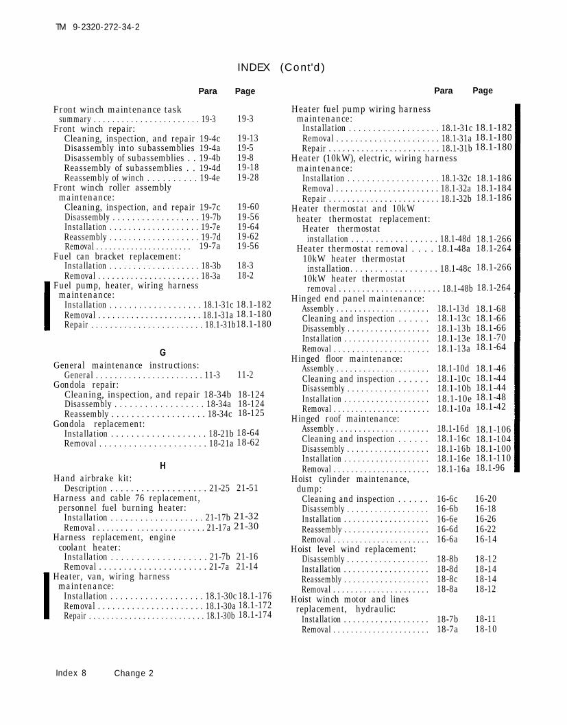
TM 9-2320-272-34-2
INDEX (Cont'd)
Para
Front winch maintenance tasksummary . . . . . . . . . . . . . . . . . . . . . . . 19-3
Front winch repair:Cleaning, inspection, and repair 19-4cDisassembly into subassemblies 19-4aDisassembly of subassemblies . . 19-4bReassembly of subassemblies . . 19-4dReassembly of winch . . . . . . . . . . 19-4e
Front winch roller assemblymaintenance:
Cleaning, inspection, and repair 19-7cDisassembly . . . . . . . . . . . . . . . . . . 19-7bInstallation . . . . . . . . . . . . . . . . . . . 19-7eReassembly . . . . . . . . . . . . . . . . . . . 19-7dRemoval . . . . . . . . . . . . . . . . . . . . . . 19-7a
Fuel can bracket replacement:
18.1-18218.1-18018.1-180
18.1-18618.1-18418.1-186
18.1-26618.1-264
18.1-266Installation . . . . . . . . . . . . . . . . . . . 18-3bRemoval . . . . . . . . . . . . . . . . . . . . . . 18-3a
Fuel pump, heater, wiring harnessmaintenance:
Installation . . . . . . . . . . . . . . . . . . . 18.1-31cRemoval . . . . . . . . . . . . . . . . . . . . . . 18.1-31aRepair . . . . . . . . . . . . . . . . . . . . . . . . 18.1-31b
Page
19-3
19-1319-519-819-1819-28
19-6019-5619-6419-6219-56
18-318-2
18.1-264
18.1-18218.1-18018.1-180
18.1-6818.1-6618.1-6618.1-7018.1-64G
General maintenance instructions:General . . . . . . . . . . . . . . . . . . . . . . . 11-3 11-2
Gondola repair:Cleaning, inspection, and repair 18-34bDisassembly . . . . . . . . . . . . . . . . . . 18-34aReassembly . . . . . . . . . . . . . . . . . . . 18-34c
Gondola replacement:Installation . . . . . . . . . . . . . . . . . . . 18-21bRemoval . . . . . . . . . . . . . . . . . . . . . . 18-21a
18.1-4618.1-4418.1-4418.1-4818.1-42
18-12418-12418-125
18-6418-62
18.1-10618.1-10418.1-10018.1-11018.1-96H
Hand airbrake kit:Description . . . . . . . . . . . . . . . . . . . 21-25 21-51
Harness and cable 76 replacement,personnel fuel burning heater:
Installation . . . . . . . . . . . . . . . . . . . 21-17bRemoval . . . . . . . . . . . . . . . . . . . . . . . 21-17a
Harness replacement, enginecoolant heater:
Installation . . . . . . . . . . . . . . . . . . . 21-7b 21-16Removal . . . . . . . . . . . . . . . . . . . . . . 21-7a 21-14
Heater, van, wiring harnessmaintenance:
Installation . . . . . . . . . . . . . . . . . . . 18.1-30cRemoval . . . . . . . . . . . . . . . . . . . . . . 18.1-30aRepair . . . . . . . . . . . . . . . . . . . . . . . . . . 18.1-30b
Para Page
Heater fuel pump wiring harnessmaintenance:
Installation . . . . . . . . . . . . . . . . . . . 18.1-31cRemoval . . . . . . . . . . . . . . . . . . . . . . 18.1-31aRepair . . . . . . . . . . . . . . . . . . . . . . . . 18.1-31b
Heater (10kW), electric, wiring harnessmaintenance:
Installation . . . . . . . . . . . . . . . . . . . 18.1-32cRemoval . . . . . . . . . . . . . . . . . . . . . . 18.1-32aRepair . . . . . . . . . . . . . . . . . . . . . . . . 18.1-32b
Heater thermostat and 10kWheater thermostat replacement:
Heater thermostatinstallation . . . . . . . . . . . . . . . . . . 18.1-48d
Heater thermostat removal . . . . 18.1-48a10kW heater thermostatinstallation. . . . . . . . . . . . . . . . . . 18.1-48c
10kW heater thermostatremoval . . . . . . . . . . . . . . . . . . . . . . 18.1-48b
Hinged end panel maintenance:Assembly . . . . . . . . . . . . . . . . . . . . .Cleaning and inspection . . . . . .Disassembly . . . . . . . . . . . . . . . . . .Installation . . . . . . . . . . . . . . . . . . .Removal . . . . . . . . . . . . . . . . . . . . .
Hinged floor maintenance:Assembly . . . . . . . . . . . . . . . . . . . . .Cleaning and inspection . . . . . .Disassembly . . . . . . . . . . . . . . . . . .Installation . . . . . . . . . . . . . . . . . . .Removal . . . . . . . . . . . . . . . . . . . . . .
Hinged roof maintenance:Assembly . . . . . . . . . . . . . . . . . . . . .Cleaning and inspection . . . . . .Disassembly . . . . . . . . . . . . . . . . . .Installation . . . . . . . . . . . . . . . . . . .Removal . . . . . . . . . . . . . . . . . . . . . .
21-3221-30
Hoist cylinder maintenance,dump:
Cleaning and inspection . . . . . .Disassembly . . . . . . . . . . . . . . . . . .Installation . . . . . . . . . . . . . . . . . . .Reassembly . . . . . . . . . . . . . . . . . . .Removal . . . . . . . . . . . . . . . . . . . . . .
Hoist level wind replacement:Disassembly . . . . . . . . . . . . . . . . . .Installation . . . . . . . . . . . . . . . . . . .Reassembly . . . . . . . . . . . . . . . . . . .Removal . . . . . . . . . . . . . . . . . . . . . .
Hoist winch motor and linesreplacement, hydraulic:
Installation . . . . . . . . . . . . . . . . . . .Removal . . . . . . . . . . . . . . . . . . . . . .
18.1-13d18.1-13c18.1-13b18.1-13e18.1-13a
18.1-10d18.1-10c18.1-10b18.1-10e18.1-10a
18.1-16d18.1-16c18.1-16b18.1-16e18.1-16a
16-6c16-6b16-6e16-6d16-6a
18-8b18-8d18-8c18-8a
18.1-17618.1-17218.1-174 18-7b
18-7a
16-2016-1816-2616-2216-14
18-1218-1418-1418-12
18-1118-10
Index 8 Change 2

TM 9-2320-272-34-2
INDEX Cont'd)
Para
Hoist winch motor or swingermotor repair, hydraulic:
Cleaning, inspection, and repair 18-27bDisassembly . . . . . . . . . . . . . . . . . . 18-27aReassembly . . . . . . . . . . . . . . . . . . .
Hoist winch repair:Cleaning, inspection, and
repair . . . . . . . . . . . . . . . . . . . . . . . .Disassembly . . . . . . . . . . . . . . . . . . .Reassembly..., . . . . . . . . . . . . . . . .
Hoist winch replacement:Installation . . . . . . . . . . . . . . . . . . .Removal . . . . . . . . . . . . . . . . . . . . . .
Hood crossmember bracketmaintenance:
Cleaning and inspection . . . . . .Installation . . . . . . . . . . . . . . . . . . .Removal . . . . . . . . . . . . . . . . . . . . . .
Hood hinges replacement:Installation . . . . . . . . . . . . . . . . . . .Removal . . . . . . . . . . . . . . . . . . . . . .
Hydraulic hoist winch motor andlines replacement:
Installation . . . . . . . . . . . . . . . . . . .Removal . . . . . . . . . . . . . . . . . . . . . .
Hydraulic hoist winch motor orswinger motor repair:
Cleaning, inspection and repairDisassembly . . . . . . . . . . . . . . . . . .Reassembly . . . . . . . . . . . . . . . . . . .
Hydraulic hose and tubereplacement, front winch:
Installation . . . . . . . . . . . . . . . . . . .Removal . . . . . . . . . . . . . . . . . . . . . .
Hydraulic hose replacement,dump body:
Installation . . . . . . . . . . . . . . . . . . .Removal . . . . . . . . . . . . . . . . . . . . . .
Hydraulic motor replacement,rear winch:
Installation . . . . . . . . . . . . . . . . . . .Removal . . . . . . . . . . . . . . . . . . . . .
Hydraulic oil filter housingreplacement:Installation . . . . . . . . . . . . . . . . . . .Removal . . . . . . . . . . . . . . . . . . . . . .
Hydraulic oil reservoir bracketsand straps replacement:
Installation . . . . . . . . . . . . . . . . . . .Removal . . . . . . . . . . . . . . . . . . . . . .
Hydraulic oil reservoir repair:Cleaning, inspection, and repairDisassembly . . . . . . . . . . . . . . . . . .Reassembly . . . . . . . . . . . . . . . . . . .
18-27c
18-28b18-28a18-28c
18-9b18-9a
13-3b13-3c13-3a
13-4b13-4a
18-7b18-7a
18.1-7818.1-72
18-27b18-27a18-27c
19-11b19-11a
16-10b16-10a
19-17b19-17a
21-6021-56
18-4b18-4a
18-6b18-6a
18.1-20218.1-20018.1-202
18-26b18-26a18-26c
Page
18-7818-7418-80
18-8818-8218-90
18-1818-16
13-213-413-2
13-613-6
18-1118-10
18-7818-7418-80
19-8619-82
16-4216-40
19-13419-130
18-518-4
18-818-8
18-7318-7318-73
Para
Hydraulic oil reservoirreplacement:
Installation . . . . . . . . . . . . . . . . . . . 18-5bRemoval . . . . . . . . . . . . . . . . . . . . . . 18-5a
Hydraulic pump replacement,dump . . . . . . . . . . . . . . . . . . . . . . . . . . . 16-13
Hydraulic pump replacement,front winch . . . . . . . . . . . . . . . . . . . . . 18-23
Hydraulic pump replacement,front winch:
Installation . . . . . . . . . . . . . . . . . . . 19-8bRemoval . . . . . . . . . . . . . . . . . . . . . . 19-8a
Hydraulic swivel valvereplacement:
Installation . . . . . . . . . . . . . . . . . . 18-17bRemoval . . . . . . . . . . . . . . . . . . . . . . 18-17a
IInner boom replacement:
Installation . . . . . . . . . . . . . . . . . . . . 18-13bRemoval . . . . . . . . . . . . . . . . . . . . . . . 18-13a
Interior side panels and latchesreplacement:
Page
18-618-6
16-62
18-72
19-6819-66
18-4618-42
18-3218-30
Installation . . . . . . . . . . . . . . . . . . . . 18.1-14bRemoval . . . . . . . . . . . . . . . . . . . . . . . 18.1-14a
Interlock air cylinder replacement,transfer case:
Installation . . . . . . . . . . . . . . . . . . . . 8-6b 8-11Removal . . . . . . . . . . . . . . . . . . . . . . . 8-6a 8-10
Interlock valve replacement,transfer case:
Installation . . . . . . . . . . . . . . . . . . . . 8-4b 8-6Removal . . . . . . . . . . . . . . . . . . . . . . . 8-4a 8-4
Interlock valve (M936)replacement, transfer case:
Installation . . . . . . . . . . . . . . . . . . . . 8-5b 8-8Removal . . . . . . . . . . . . . . . . . . . . . . 8-5a 8-8
KKit, air conditioner:
Description . . . . . . . . . . . . . . . . . . . . 21-29 21-55Kit, air conditioner, replacement:
Installation . . . . . . . . . . . . . . . . . . . . 21-31bRemoval . . . . . . . . . . . . . . . . . . . . . . . 21-31a
LLamp, emergency, wiring harness,
maintenance:Installation . . . . . . . . . . . . . . . . . . . . 18.1-36cRemoval . . . . . . . . . . . . . . . . . . . . . . . 18.1-36aRepair . . . . . . . . . . . . . . . . . . . . . . . . . . 18.1-36b
Change 2 Index 9

TM 9-2320-272-34-2
INDEX (Cont'd)
Para Page
Level wind maintenance, frontwinch:
Cleaning, inspection, and repair 19-6c 19-46Disassembly . . . . . . . . . . . . . . . . . . . 19-6b 19-40Installation . . . . . . . . . . . . . . . . . . . . 19-6e 19-54Reassembly . . . . . . . . . . . . . . . . . . . . 19-6d 19-50Removal . . . . . . . . . . . . . . . . . . . . . . . 19-6a 19-40
Level winch maintenance, rearwinch . . . . . . . . . . . . . . . . . . . . . . . . . . . 19-18 19-138
Level wind replacement, hoist:Disassembly . . . . . . . . . . . . . . . . . . . 18-8b 18-12Installation . . . . . . . . . . . . . . . . . . . . 18-8d 18-14Reassembly . . . . . . . . . . . . . . . . . . . . 18-8c 18-14Removal . . . . . . . . . . . . . . . . . . . . . . . 18-8a 18-12
Light fixtures, blackout and emergency,replacement:
Installation . . . . . . . . . . . . . . . . . . . . 18.1-49bRemoval . . . . . . . . . . . . . . . . . . . . . . . 18.1-49a
Light fixtures, fluorescent, maintenance:Assembly . . . . . . . . . . . . . . . . . . . . . . 18.1-51dDisassembly . . . . . . . . . . . . . . . . . . . 18.1-51bInspection . . . . . . . . . . . . . . . . . . . . . 18.1-51cInstallation . . . . . . . . . . . . . . . . . . . 18.1-51eRemoval . . . . . . . . . . . . . . . . . . . . . . . 18.1-51a
Limiting valve repair:Cleaning and inspection . . . . . . . 10-11bDisassembly . . . . . . . . . . . . . . . . . . . 10-11aReassembly . . . . . . . . . . . . . . . . . . . . 10-11c
Lock, retractable beam drive shaft and,maintenance:
Cleaning, inspection, andrepair . . . . . . . . . . . . . . . . . . . . . . . . 18.1-4b
Installation . . . . . . . . . . . . . . . . . . . . 18.1-4cRemoval . . . . . . . . . . . . . . . . . . . . . . . 18.1-4a
18.1-26818.1-268
18.1-27618.1-27418.1-27618.1-27618.1-274
10-6610-6410-68
18.1-1018.1-1018.1-8
Lower steering columnmaintenance:
Cleaning and inspection . . . . . . . 11-8c 11-10Disassembly . . . . . . . . . . . . . . . . . . . 11-8b 11-8Installation . . . . . . . . . . . . . . . . . . . . 11-8e 11-12Reassembly . . . . . . . . . . . . . . . . . . . . 11-8d 11-11Removal . . . . . . . . . . . . . . . . . . . . . . . 11-8a 11-8
18.1-5618.1-5418.1-49
MManual starter switches, AC, replacement:
Installation . . . . . . . . . . . . . . . . . . . . 18.1-50bRemoval . . . . . . . . . . . . . . . . . . . . . . . 18.1-50a
Main wiring harness maintenance:Installation . . . . . . . . . . . . . . . . . . . . 18.1-28cRemoval . . . . . . . . . . . . . . . . . . . . . . . 18.1-28aRepair . . . . . . . . . . . . . . . . . . . . . . . . . 18.1-28b
Maintenance check list,preliminary . . . . . . . . . . . . . . . . . . . . . 11-4 11-2
Para Page
Maintenance precautions . . . . . . . . 11-5 11-3Metric conversion table . . . . . . . . . . Inside back cover
OOil filter housing replacement,
hydraulic:Installation . . . . . . . . . . . . . . . . . . . . 18-4bRemoval . . . . . . . . . . . . . . . . . . . . . . . 18-4a
Oil pan shroud and exhaust tubereplacement:
Installation . . . . . . . . . . . . . . . . . . . . 21-8bRemoval . . . . . . . . . . . . . . . . . . . . . . . 21-8a
Oil pump replacement, transfercase:
Installation . . . . . . . . . . . . . . . . . . . . 8-17bRemoval . . . . . . . . . . . . . . . . . . . . . . . 8-17a
Oil reservoir brackets and strapsreplacement, hydraulic:
Installation . . . . . . . . . . . . . . . . . . . . 18-6bRemoval . . . . . . . . . . . . . . . . . . . . . . . 18-6a
Oil reservoir repair, hydraulic:Cleaning, inspection, and repair 18-26bDisassembly . . . . . . . . . . . . . . . . . . . 18-26aReassembly . . . . . . . . . . . . . . . . . . . . 18-26c
Oil reservoir replacement,hydraulic:
Installation . . . . . . . . . . . . . . . . . . . . 18-5bRemoval . . . . . . . . . . . . . . . . . . . . . . . 18-5a
Oil seal replacement, frontdifferential:
Installation . . . . . . . . . . . . . . . . . . 9-14bRemovaI . . . . . . . . . . . . . . . . . . . . . . . 9-14a
Oil seal replacement, reardifferential:
Installation . . . . . . . . . . . . . . . . . . . . 9-15bRemoval . . . . . . . . . . . . . . . . . . . . . . . 9-15a
PPanel, exterior side, maintenance:
18-518-4
21-1821-18
8-388-38
18-818-8
18-7318-7318-73
18-618-6
9-1189-116
9-1219-120
18.1-27218.1-270
Assembly . . . . . . . . . . . . . . . . . . . . . . 18.1-11cCleaning and inspection . . . . . . . 18.1-11bDisassembly . . . . . . . . . . . . . . . . . . . 18.1-11a
Panel, hinged end, maintenance:Assembly . . . . . . . . . . . . . . . . . . . . . . 18.1-13dCleaning and inspection . . . . . . . 18.1-13cDisassembly . . . . . . . . . . . . . . . . . . . 18.1-13bInstallation . . . . . . . . . . . . . . . . . . . . 18.1-13eRemoval . . . . . . . . . . . . . . . . . . . . . . . 18.1-13a
Panels, ceiling filler and side, replacement:Installation . . . . . . . . . . . . . . . . . . . . 18.1-18bRemoval . . . . . . . . . . . . . . . . . . . . . . . 18.1-18a
Panels, rear interior wall, replacement:Installation . . . . . . . . . . . . . . . . . . . . 18.1-12bRemoval . . . . . . . . . . . . . . . . . . . . . . . 18.1-12a
18.1-6818.1-6618.1-6618.1-7018.1-64
18.1-16618.1-16418.1-166
18.1-11818.1-116
18.1-6218.1-60
Index 10 Change 2

TM 9-2320-272-34-2
INDEX
Para Page
Panels and latches, interior side,replacement:
Installation . . . . . . . . . . . . . . . . . . . . 18.1-14bRemoval . . . . . . . . . . . . . . . . . . . . . . . 18.1-14a
Parts, underframe replacement:Underframe parts installation 18.1-9bUnderframe parts removal . . . . 18.1-9a
Personnel fuel burning heatercircuit breaker replacement:
Installation . . . . . . . . . . . . . . . . . . . 21-19bRemoval . . . . . . . . . . . . . . . . . . . . . . . . 21-19a
Personnel fuel burning heatercontrol box replacement:
Installation . . . . . . . . . . . . . . . . . . . 21-14bRemoval . . . . . . . . . . . . . . . . . . . . . . 21-14a
Personnel fuel burning heaterexhaust tube replacement:
Installation, . . . . . . . . . . . . . . . . . 21-18bRemoval . . . . . . . . . . . . . . . . . . . . . 21-18a
Personnel fuel burning heaterharness and cable 76replacement:
Installation . . . . . . . . . . . . . . . . . . . 21-17bRemoval . . . . . . . . . . . . . . . . . . . . . . . . 21-17a
Personnel fuel burning heater kitcomponent replacement tasksummary . . . . . . . . . . . . . . . . . . . . . 21-13 21-23
Personnel fuel burning heater kitreplacement:
Description . . . . . . . . . . . . . . . . . . . . 21-11 21-22Tabulated Data . . . . . . . . . . . . . . . . 21-12 21-22
Personnel fuel burning heaterreplacement:
Installation . . . . . . . . . . . . . . . . . . . 21-15bRemoval . . . . . . . . . . . . . . . . . . . . . . . . 21-15a
Plate, rear splice, replacement:Installation . . . . . . . . . . . . . . . . . . . . 18.1-23bRemoval . . . . . . . . . . . . . . . . . . . . . . . 18.1-23a
Post, telephone, wiring harnessmaintenance:
Installation . . . . . . . . . . . . . . . . . . . . 18.1-39cRemoval . . . . . . . . . . . . . . . . . . . . . . . . . 18.1-39a Repair . . . . . . . . . . . . . . . . . . . . . . . . . 18.1-39b
Power steering assist cylinder
18.1-7818.1-72
18.1-4018.1-40
21-3621-36
21-2421-24
21-3421-34
21-3221-30
21-2621-26
18.1-13618.1-136
18.1-21818.1-21818.1-218
repair:Cleaning, inspection, and repair 11-11bDisassembly . . . . . . . . . . . . . . . . . . . 11-11a
11-4811-4611-50Reassembly . . . . . . . . . . . . . . . . . . . . 11-11c
Power steering gear adjustment(on vehicle):
Sector shaft adjustment . . . . . . . 11-14aWormshaft adjustment . . . . . . . . 11-14b
Power steering gear - description . 11-1 11-1
(Cont'd)
Para
Power steering maintenance tasksummary . . . . . . . . . . . . . . . . . . . . . . . 11-6
Power steering pump andreservoir, description . . . . . . . . . . . 11-2
Power steering pump testequipment setup:
Installation . . . . . . . . . . . . . . . . . . . . 11-12aRemoval . . . . . . . . . . . . . . . . . . . . . . . 11-12b
Power steering tests andadjustments:
Poppet adjustment . . . . . . . . . . . . 11-13dSteering gear internal leakage
test . . . . . . . . . . . . . . . . . . . . . . . . . . . 11-13cSteering pump flow test . . . . . . . 11-13bSteering pump pressure test . . 11-l3a
Power takeoff (PTO) control cablereplacement, transmission:
Installation . . . . . . . . . . . . . . . . . . . . 20-9bRemoval . . . . . . . . . . . . . . . . . . . . . . . 20-9a
Power takeoff (PTO) repair,transfer case:
Cleaning and inspection . . . . . . . 20-7bDisassembly . . . . . . . . . . . . . . . . . . 20-7aReassembly . . . . . . . . . . . . . . . . . . . . 20-7c
Power takeoff (PTO) repair,transmission:
Cleaning and inspection . . . . . . . 20-11bDisassembly . . . . . . . . . . . . . . . . . . . 20-11aReassembly . . . . . . . . . . . . . . . . . . . . 20-11c
Power takeoff (PTO) replacement,transfer case:
Installation . . . . . . . . . . . . . . . . . . . . 20-6bRemoval . . . . . . . . . . . . . . . . . . . . . . . 20-6a
Power takeoff (PTO) replacement,transmission:
Installation . . . . . . . . . . . . . . . . . . . . 20-10bRemoval . . . . . . . . . . . . . . . . . . . . . . . 20-10a
Preliminary maintenance checklist . . . . . . . . . . . . . . . . . . . . . . . . . . . . . . 11-4
Pressurization valve replacement,deepwater fording:
Installation . . . . . . . . . . . . . . . . . . . . 21-23bRemoval . . . . . . . . . . . . . . . . . . . . . . . 21-23a
PTO control cable replacement,transfer case:
Installation . . . . . . . . . . . . . . . . . . . . 20-4bRemoval . . . . . . . . . . . . . . . . . . . . . . . 20-4a
PTO cross-shaft (control-lever)replacement, transfer case:
Installation . . . . . . . . . . . . . . . . . . . . 20-5bRemoval . . . . . . . . . . . . . . . . . . . . . . . 20-5a
Pump replacement, enginecoolant heater:
11-6411-66
Installation . . . . . . . . . . . . . . . . . . . . 21-5bRemoval . . . . . . . . . . . . . . . . . . . . . . . 21-5a
Change 2
Page
11-3
11-2
11-5211-54
11-62
11-6011-5811-56
20-3420-32
20-2220-1620-24
20-4820-4220-50
20-1420-12
20-3820-36
11-2
21-4421-42
20-620-4
20-1020-8
21-821-6
Index 11

TM 9-2320-272-34-2
INDEX (Cont'd)
Para Page
RRadiator and hood cover kit
replacement task summary . . . . . 21-27Radiator and hood cover kit
replacement:Installation . . . . . . . . . . . . . . . . . . . . 21-28aRemoval . . . . . . . . . . . . . . . . . . . . . . . 21-28b
Radiator brush guardmaintenance:
Inspection and repair . . . . . . . . . . 13-7bInstallation . . . . . . . . . . . . . . . . . . . . 13-7cRemoval . . . . . . . . . . . . . . . . . . . . . . . 13-7a
Rear axle carrier differentialassembly maintenance:
Cleaning and inspection . . . . . . . 9-12bInstallation . . . . . . . . . . . . . . . . . . . . 9-12cRemoval . . . . . . . . . . . . . . . . . . . . . . . 9-12a
Rear axle maintenance tasksummary . . . . . . . . . . . . . . . . . . . . . . . 9-9
Rear brake actuator repair:Cleaning and inspection . . . . . . . 10-7bDisassembly . . . . . . . . . . . . . . . . . . . 10-7aReassembly . . . . . . . . . . . . . . . . . . . . 10-7c
Rear differential oil sealreplacement:
Installation . . . . . . . . . . . . . . . . . . . . 9-15bRemoval . . . . . . . . . . . . . . . . . . . . . . . 9-15a
Rear doors maintenance:Assembly . . . . . . . . . . . . . . . . . . . . . . 18.1-7dCleaning and inspection . . . . . . . 18.1-7cDisassembly . . . . . . . . . . . . . . . . . . . 18.1-7bInstallation . . . . . . . . . . . . . . . . . . . . 18.1-7eRemoval . . . . . . . . . . . . . . . . . . . . . . . 18.1-7a
Rear-rear axle assemblyreplacement:
Installation . . . . . . . . . . . . . . . . . . . . 9-10bRemoval . . . . . . . . . . . . . . . . . . . . . . . 9-10a
Rear interior wall panelsreplacement:
21-51
21-5221-52
13-1413-1613-12
9-1049-1069-102
9-81
10-4610-4410-46
9-1219-120
18.1-2618.1-2618.1-2318.1-3018.1-22
9-869-82
19-13419-130
19-10019-9219-104
19-12419-12219-124
19-12819-12619-128
18.1-22218.1-22018.1-222
18.1-21418.1-21018.1-212
18.1-28218.1-28018.1-282
Installation . . . . . . . . . . . . . . . . . . . . 18.1-12bRemoval . . . . . . . . . . . . . . . . . . . . . . . 18.1-12a
Rear splice plate replacement:Installation . . . . . . . . . . . . . . . . . . . . 18.1-23bRemoval . . . . . . . . . . . . . . . . . . . . . . . 18.1-23a
Rear winch cable tensioner repair:Cleaning and inspection . . . . . . . 19-14bDisassembly . . . . . . . . . . . . . . . . . . . 19-14aReassembly . . . . . . . . . . . . . . . . . . . . 19-14c
Rear winch control valve cablereplacement:
Installation . . . . . . . . . . . . . . . . . . . . 19-9b 19-72Removal . . . . . . . . . . . . . . . . . . . . . . . 19-9a 19-70
Rear winch, description . . . . . . . . . . 19-2 19-2
Para Page
Rear winch hydraulic motorreplacement:
Installation . . . . . . . . . . . . . . . . . . . . 19-17bRemoval . . . . . . . . . . . . . . . . . . . . . . . 19-17a
Rear winch level windmaintenance . . . . . . . . . . . . . . . . . . . . 19-18 19-138
Rear winch maintenance tasksummary . . . . . . . . . . . . . . . . . . . . . . . 19-12 19-91
Rear winch repair:Cleaning and inspection . . . . . . . 19-13bDisassembly . . . . . . . . . . . . . . . . . . . 19-13aReassembly . . . . . . . . . . . . . . . . . . . . 19-13c
Rear winch side roller repair:Cleaning and inspection . . . . . . . 19-15bDisassembly . . . . . . . . . . . . . . . . . . . 19-15aReassembly . . . . . . . . . . . . . . . . . . . . 19-15c
Rear winch top and bottom rollerrepair:
Cleaning and inspection . . . . . . . 19-16bDisassembly . . . . . . . . . . . . . . . . . . . 19-16aReassembly . . . . . . . . . . . . . . . . . . . . 19-16c
Receptacle, entrance, 220V-3 phase wiringharness maintenance:
Installation . . . . . . . . . . . . . . . . . . . . 18.1-40cRemoval . . . . . . . . . . . . . . . . . . . . . . . 18.1-40aRepair . . . . . . . . . . . . . . . . . . . . . . . . . 18.1-40b
Receptacle, 400 Hz supply and branched400 Hz, wiring harness maintenance:
Installation . . . . . . . . . . . . . . . . . . . . 18.1-38cRemoval . . . . . . . . . . . . . . . . . . . . . . . 18.1-38aRepair, . . . . . . . . . . . . . . . . . . . . . . . . 18.1-38b
Receptacle, 3-Phase, wiring harnessmaintenance:
Installation . . . . . . . . . . . . . . . . . . . . 18.1-53cRemoval . . . . . . . . . . . . . . . . . . . . . . . 18.1-53aRepair . . . . . . . . . . . . . . . . . . . . . . . . . 18.1-53b
Registers, ceiling deflectors and,replacement:
Installation . . . . . . . . . . . . . . . . . . . . 18.1-22b18.1-13418.1-13418.1-62
18.1-6018.1-11418.1-11418.1-136
18.1-13618-61.118-61.119-117
19-11419-118
Removal . . . . . . . . . . . . . . . . . . . . . . . 18.1-22aRegisters, front wall, replacement:
Installation . . . . . . . . . . . . . . . . . . . . 18.1-17bRemoval . . . . . . . . . . . . . . . . . . . . . . . 18.1-17a
Regulator flow valve replacement:Installation . . . . . . . . . . . . . . . . . . . . 18-20.1bRemoval . . . . . . . . . . . . . . . . . . . . . . . 18-20.1a
Regulator valve, deepwaterfording, replacement:
Installation . . . . . . . . . . . . . . . . . . . . 21-24 .1bRemoval . . . . . . . . . . . . . . . . . . . . . . 21-24.1a
Relay valve repair:Cleaning andinspection . . . . . . . 10-10bDisassembly . . . . . . . . . . . . . . . . . . 10-10aReassembly . . . . . . . . . . . . . . . . . . . . 10-10c
21-5021-50
10-6010-5810-60
Index 12 Change 2

Para Page
Repair and replacementstandards . . . . . . . . . . . . . . . . . . . . . . . 12-3 12-1
Repair and replacementstandards . . . . . . . . . . . . . . . . . . . . . . . 19-19 19-138
Reporting of errors . . . . . . . . . . . . . . . iiRetractable beam drive shaft
and lock maintenance:Cleaning, inspection, and repair 18.1-4bInstallation . . . . . . . . . . . . . . . . . . . . 18.1-4cRemoval . . . . . . . . . . . . . . . . . . . . . . . 18.1-4a
Retractable beam replacement:Installation . . . . . . . . . . . . . . . . . . . . 18.1-5bRemoval . . . . . . . . . . . . . . . . . . . . . . . 18.1-5a
Retractable beam rollers replacement:End roller installation . . . . . . . . . 18.1-6dEnd roller removal . . . . . . . . . . . . 18.1-6cSupport roller installation . . . . . 18.1-6bSupport roller removal . . . . . . . . 18.1-6a
18.1-1018.1-1018.1-8
18.1-1418.1-14
18.1-2018.1-2018.1-1818.1-16
Retractable window glass andvan door window glassreplacement:
Installation . . . . . . . . . . . . . . . . . . . . 14-5b 14-8Removal . . . . . . . . . . . . . . . . . . . . . . . 14-5a 14-8
Right and left side blackoutharness maintenance:
Installation . . . . . . . . . . . . . . . . . . . . 18.1-34cRemoval . . . . . . . . . . . . . . . . . . . . . . . 18.1-34a
18.1-19418.1-19218.1-194Repair . . . . . . . . . . . . . . . . . . . . . . . . . . 18.1-34b
Roller arm maintenance, dump:Disassembly . . . . . . . . . . . . . . . . . . . 16-5b 16-10Inspection and repair . . . . . . . . . . 16-5c 16-12Installation . . . . . . . . . . . . . . . . . . . . 16-5e 16-12Reassembly . . . . . . . . . . . . . . . . . . . . 16-5d 16-12Removal . . . . . . . . . . . . . . . . . . . . . . . 16-5a 16-10
Roller assembly maintenance,front winch:
Cleaning, inspection, and repair 19-7c 19-60Disassembly . . . . . . . . . . . . . . . . . . . 19-7b 19-56Installation . . . . . . . . . . . . . . . . . . . . 19-7e 19-64Reassembly . . . . . . . . . . . . . . . . . . . . 19-7d 19-62Removal . . . . . . . . . . . . . . . . . . . . . . . 19-7a 19-56
Roller repair, boom:Cleaning, inspection, and repair 18-32bDisassembly . . . . . . . . . . . . . . . . . . . 18-32aReassembly . . . . . . . . . . . . . . . . . . . . 18-32c
Roller replacement, boom:Installation . . . . . . . . . . . . . . . . . . . . 18-15bRemoval . . . . . . . . . . . . . . . . . . . . . . . 18-15a
Roof, hinged, maintenance:Assembly . . . . . . . . . . . . . . . . . . . . . . . 18.1-16dCleaning and Inspection . . . . . . . 18.1-16cDisassemble . . . . . . . . . . . . . . . . . . . 18.1-16b
18-11418-11218-114
18-3618-36
18.1-27218.1-270
18.1-10618.1-10418.1-10018.1-11018.1-96
Installation . . . . . . . . . . . . . . . . . . . . 18.1-16eRemoval . . . . . . . . . . . . . . . . . . . . . . . 18.1-16a
TM 9-2320-272-34-2
INDEX (Cont'd)
Para
sSafety brace replacement, dump:
Installation . . . . . . . . . . . . . . . . . . . . 16-9bRemoval . . . . . . . . . . . . . . . . . . . . . . . 16-9a
Safety lock and cylinderreplacement, and dump:
Installation . . . . . . . . . . . . . . . . . . . . 16-7bRemoval . . . . . . . . . . . . . . . . . . . . . . . 16-7a
Service brake brakedrummaintenance . . . . . . . . . . . . . . . . . . . . 10-13
Shift lever maintenance, transfer case:Cleaning, inspection, and repair 8-9bInstallation . . . . . . . . . . . . . . . . . . . . 8-9cRemoval . . . . . . . . . . . . . . . . . . . . . . . 8-9a
Shift lever shift rod maintenance,transfer case:
Adjustment . . . . . . . . . . . . . . . . . . . . 8-10bInstallation . . . . . . . . . . . . . . . . . . . . 8-10cRemoval . . . . . . . . . . . . . . . . . . . . . . . 8-10a
Shift rod maintenance, transfercase:
Adjustment . . . . . . . . . . . . . . . . . . . . 8-12cCleaning, inspection, and repair 8-12bInstallation . . . . . . . . . . . . . . . . . . . . 8-12dRemoval . . . . . . . . . . . . . . . . . . . . . . . 8-12a
Side doors maintenance:
Page
16-3816-38
16-3216-30
10-70
8-168-178-16
8-188-188-18
8-248-228-248-22
Assembly . . . . . . . . . . . . . . . . . . . . . . 18.1-8dCleaning and inspection . . . . . . . 18.1-8cDisassembly . . . . . . . . . . . . . . . . . . . 18.1-8bInstallation . . . . . . . . . . . . . . . . . . . . 18.1-8eRemoval . . . . . . . . . . . . . . . . . . . . . . . 18.1-8a
Side roller repair, rear winch:Cleaning and inspection . . . . . . . 19-15bDisassembly . . . . . . . . . . . . . . . . . . . 19-15aReassembly . . . . . . . . . . . . . . . . . . . . 19-15c
Speedometer drive gear anddriven shaft replacement,transfer case:
Installation . . . . . . . . . . . . . . . . . . . . 8-13bRemoval . . . . . . . . . . . . . . . . . . . . . . . 8-13a
Spindle bearing sleeve maintenance:Inspection . . . . . . . . . . . . . . . . . . . . . 9-4aInstallation . . . . . . . . . . . . . . . . . . . . 9-4cRemoval . . . . . . . . . . . . . . . . . . . . . . . 9-4b
Starter switches, AC manual,replacement:
18.1-3618.1-3418.1-3418.1-3818.1-32
19-12419-12219-124
8-288-26
9-49-59-4
Installation . . . . . . . . . . . . . . . . . . . 18.1-50bRemoval . . . . . . . . . . . . . . . . . . . . . . 18.1-50a
Steering column maintenance,lower:
Cleaning and inspection . . . . . . . 11-8c 11-10Disassembly . . . . . . . . . . . . . . . . . . . 11-8b 11-8Installation . . . . . . . . . . . . . . . . . . . . 11-8e 11-12Reassembly . . . . . . . . . . . . . . . . . . . . 11-8d 11-11Removal . . . . . . . . . . . . . . . . . . . . . . . 11-8a 11-8
Change 2 Index 13

TM 9-2320-272-34-2
INDEX (Cont'd)
Para Page
Steering column replacement,upper:
Installation . . . . . . . . . . . . . . . . . . . . 11-7b 11-6Removal . . . . . . . . . . . . . . . . . . . . . . . 11-7a 11-4
Steering gear and mountingbracket replacement:
Installation . . . . . . . . . . . . . . . . . . . . 11-9b 11-16Removal . . . . . . . . . . . . . . . . . . . . . . . 11-9a 11-14
Steering gear repair:Cleaning, inspection, and repair 11-10bDisassembly . . . . . . . . . . . . . . . . . . . 11-10aFinal adjustments . . . . . . . . . . . . . 11-10dReassembly . . . . . . . . . . . . . . . . . . . . 11-10c
Steering knuckle assemblymaintenance:
Cleaning and inspection . . . . . . . 9-5b 9-8End play test . . . . . . . . . . . . . . . . . . 9-5d 9-14Installation . . . . . . . . . . . . . . . . . . . . 9-5c 9-11Removal . . . . . . . . . . . . . . . . . . . . . . . 9-5a 9-6
Steering stop adjustment:Turning angle adjustment . . . . . 9-18 9-126
Subframe replacement, dump:Installation . . . . . . . . . . . . . . . . . . . . 16-12bRemoval . . . . . . . . . . . . . . . . . . . . . . . 16-12a
Supply and branched 400 Hz receptaclewiring harness, 400 Hz, maintenance:
Installation . . . . . . . . . . . . . . . . . . . . 18.1-38cRemoval . . . . . . . . . . . . . . . . . . . . . . . 18.1-38aRepair . . . . . . . . . . . . . . . . . . . . . . . . . 18.1-38b
Swinger gearcase repair, crane:Cleaning, inspection, and repair 18-33bDisassembly . . . . . . . . . . . . . . . . . . . 18-33aReassembly . . . . . . . . . . . . . . . . . . . . 18-33c
Swinger gearcase replacement,crane:
Installation . . . . . . . . . . . . . . . . . . . . 18-19bRemoval . . . . . . . . . . . . . . . . . . . . . . . 18-19a
Swinger motor replacement,crane hydraulic:
Installation . . . . . . . . . . . . . . . . . . . . 18-18bRemoval . . . . . . . . . . . . . . . . . . . . . . . 18-18a
Switch replacement, transfer case:Installation . . . . . . . . . . . . . . . . . . . . 8-14bRemoval . . . . . . . . . . . . . . . . . . . . . . . 8-14a 8-30
Swivel valve replacement,hydraulic:
Installation . . . . . . . . . . . . . . . . . . . . 18-17bRemoval . . . . . . . . . . . . . . . . . . . . . . . 18-17a
11-3011-2011-4411-32
16-5816-52
18.1-21418.1-21018.1-212
18-12018-11618-20
18.1-21818.1-21818.1-218
18-5218-52
18.1-26618.1-264
18-5018-50
18.1-266
18.1-264
8-3011-62
11-6011-5811-5618-46
18-42
TTables:
Table 8-1. Transfer CaseTabulated Data . . . . . . . . . . . . . . . . 8-2 8-1
Para
Table 9-1. Front and Rear AxleTabulated Data . . . . . . . . . . . . . . . . 9-2
Table 10-1. Air CompressorTabulated Data . . . . . . . . . . . . . . . . 10-1
Table 11-1. Power SteeringSystem Data . . . . . . . . . . . . . . . . . . . 11-2
Table 15-1. Cargo BodiesDimensions and Weights . . . . . . 15-1
Table 16-1. Dump BodyTabulated Data . . . . . . . . . . . . . . . . 16-2
Table 17-1. Fifth WheelTabulated Data . . . . . . . . . . . . . . . . 17-1
Table 19-1. Winch TabulatedData . . . . . . . . . . . . . . . . . . . . . . . . . . . 19-2
Table 19-2. Repair and Replace-ment Standards for FrontWinch, Rear Winch, andWinch Components . . . . . . . . . . . . 19-19
Table 21-1. Engine CoolantHeater Tabulated Data . . . . . . . . 21-2
Table 21-2. Personnel Fuel BurningHeater Tabulated Data . . . . . . . . 21-12
Table 21-3. Air ConditionerTabulated Data . . . . . . . . . . . . . . . . 21-30
Table E-1. Torque Limits forDry Fasteners . . . . . . . . . . . . . . . . . E-3
Table E-2. Torque Limits forWet Fasteners . . . . . . . . . . . . . . . . . E-3
Telephone post wiring harnessmaintenance:
Page
9-2
10-2
11-2
15-2
16-1
17-1
19-3
19-138
21-2
21-22
21-55
E-2
E-3
Installation . . . . . . . . . . . . . . . . . . . 18.1-39cRemoval . . . . . . . . . . . . . . . . . . . . . . 18.1-39aRepair . . . . . . . . . . . . . . . . . . . . . . . . 18.1-39b
10kW heater thermostat, heaterthermostat and, replacement:
Heater thermostat installation 18.1-48dHeater thermostat removal . . . 18.1-48a10kW heater thermostatinstallation . . . . . . . . . . . . . . . . . . 18.1-48c
10kW heater thermostatremoval . . . . . . . . . . . . . . . . . . . . . . 18.1-48b
Tests and adjustments, powersteering
Poppet adjustment . . . . . . . . . . . . 11-13dSteering gear internal leakage
test . . . . . . . . . . . . . . . . . . . . . . . . . . 11-13cSteering pump flow test . . . . . . 11-13bSteering pump pressure test . . 11-13a
Thermostat and 10kW heater thermostat,heater, replacement:
Heater thermostat installation . 18.1-48dHeater thermostat removal . . . 18.1-48a10kW heater thermostatinstallation . . . . . . . . . . . . . . . . . . 18.1-48c
10kW heater thermostatremoval . . . . . . . . . . . . . . . . . . . . . . 18.1-48b
18.1-26618.1-264
18.1-266
18.1-264
Index 14 Change 2

TM 9-2320-272-34-2
INDEX (Cont'd)
Para Page
3-Phase receptacle wiring harnessmaintenance:
Installation . . . . . . . . . . . . . . . . . . . 18.1-53cRemoval . . . . . . . . . . . . . . . . . . . . . . 18.1-53aRepair . . . . . . . . . . . . . . . . . . . . . . . . 18.1-53b
18.1-28218.1-28018.1-282
Top and bottom roller repair,
Para
Transfer case oil pumpreplacement:Installation . . . . . . . . . . . . . . . . . . . 8-17bRemoval . . . . . . . . . . . . . . . . . . . . . . 8-17a
Transfer case power takeoff,description . . . . . . . . . . . . . . . . . . . . . 20-1
Transfer case power takeoffmaintenance task summary . . . 20-3
Transfer case power takeoff (PTO)repair:
Cleaning and inspection . . . . . . 20-7bDisassembly . . . . . . . . . . . . . . . . . . 20-7aReassembly . . . . . . . . . . . . . . . . . . . 20-7c
Transfer case power takeoff(PTO) replacement:
Installation . . . . . . . . . . . . . . . . . . . 20-6b
Page
8-388-38
20-1
20-3
20-2220-1620-24
20-14Removal . . . . . . . . . . . . . . . . . . . . . . 20-6a 20-12
Transfer case PTO control cable replacement:
rear winch:Cleaning and inspection . . . . . . 19-16bDisassembly . . . . . . . . . . . . . . . . . . 19-16aReassembly . . . . . . . . . . . . . . . . . . . 19-16c
Torsion bars and crossmemberreplacement:
Installation . . . . . . . . . . . . . . . . . . . 13-5bRemoval . . . . . . . . . . . . . . . . . . . . . . 13-5a
Transfer case capacitorreplacement:
Installation . . . . . . . . . . . . . . . . . . . . 8-15bRemoval . . . . . . . . . . . . . . . . . . . . . . . 8-15a
Transfer case, cross-shaftreplacement:
Installation . . . . . . . . . . . . . . . . . . . . 8-11bRemoval . . . . . . . . . . . . . . . . . . . . . . . 8-11a
Transfer case, description . . . . . . . 8-2Transfer case front axle engage-
ment air cylinder replacement:Installation . . . . . . . . . . . . . . . . . . . 8-7bRemoval . . . . . . . . . . . . . . . . . . . . . . 8-7a
Transfer case front axleengagement control valvereplacement . . . . . . . . . . . . . . . . . . . . 10-12
Transfer case front axle engage-ment control valve replacement:
Installation . . . . . . . . . . . . . . . . . . . 8-8bRemoval . . . . . . . . . . . . . . . . . . . . . . 8-8a
Transfer case interlock aircylinder replacement:
Installation . . . . . . . . . . . . . . . . . . . 8-6bRemoval . . . . . . . . . . . . . . . . . . . . . . 8-6a
Transfer case interlock valvereplacement:
Installation . . . . . . . . . . . . . . . . . . . 8-4bRemoval . . . . . . . . . . . . . . . . . . . . . . 8-4a
Transfer case interlock valve(M936) replacement:
Installation . . . . . . . . . . . . . . . . . . . 8-5bRemoval . . . . . . . . . . . . . . . . . . . . . . 8-5a
Transfer case maintenance:General . . . . . . . . . . . . . . . . . . . . . . . 8-1
Transfer case maintenance tasksummary . . . . . . . . . . . . . . . . . . . . . . . 8-3
19-12819-12619-128
13-813-8
8-348-32
8-218-208-1
8-128-12
10-70
8-158-14
8-118-10
8-68-4
8-88-8
8-1
8-3
Installation . . . . . . . . . . . . . . . . . . . 20-4bRemoval . . . . . . . . . . . . . . . . . . . . . . 20-4a
Transfer case PTO cross-shaft(Control lever) replacement:
Installation . . . . . . . . . . . . . . . . . . . 20-5bRemoval . . . . . . . . . . . . . . . . . . . . . . 20-5a
Transfer case repair:Cleaning and inspection . . . . . . 8-20bDisassembly . . . . . . . . . . . . . . . . . . 8-20aReassembly and adjustment . . 8-20c
Transfer case replacement:Installation . . . . . . . . . . . . . . . . . . . 8-18bRemoval . . . . . . . . . . . . . . . . . . . . . . 8-18a
Transfer case (M936)replacement:
Installation . . . . . . . . . . . . . . . . . . . 8-19bRemoval . . . . . . . . . . . . . . . . . . . . . . 8-19a
Transfer case shift lever maintenance:Cleaning, inspection, and repair 8-9bInstallation . . . . . . . . . . . . . . . . . . . 8-9cRemoval . . . . . . . . . . . . . . . . . . . . . . 8-9a
Transfer case shift lever shift rodmaintenance:
Adjustment . . . . . . . . . . . . . . . . . . . 8-10bInstallation . . . . . . . . . . . . . . . . . . . 8-10cRemoval . . . . . . . . . . . . . . . . . . . . . . 8-10a
Transfer case shift rodmaintenance:
Adjustment . . . . . . . . . . . . . . . . . . . 8-12cCleaning and inspection . . . . . . 8-12bInstallation . . . . . . . . . . . . . . . . . . . 8-12dRemoval . . . . . . . . . . . . . . . . . . . . . . 8-12a
Transfer case speedometer drive
20-620-4
20-1020-8
8-828-688-86
8-468-40
8-608-52
8-168-178-16
8-188-188-18
8-248-228-248-22
gear and driven shaftreplacement:
Installation . . . . . . . . . . . . . . . . . . . 8-13bRemoval . . . . . . . . . . . . . . . . . . . . . . 8-13a
8-288-26
Index 15Change 2

TM 9-2320-272-34-2
INDEX (Cont'd)
Para
Transfer case switch replacement:Installation . . . . . . . . . . . . . . . . . . . 8-14bRemoval . . . . . . . . . . . . . . . . . . . . . . 8-14a
Transfer case transorb diodereplacement:
Installation . . . . . . . . . . . . . . . . . . . 8-16bRemoval . . . . . . . . . . . . . . . . . . . . . . 8-16a
Page
8-308-30
8-368-36
18-61.118-61.1
Transition, ceiling, maintenance:Assembly . . . . . . . . . . . . . . . . . . . . . 18.1-21cDisassembly . . . . . . . . . . . . . . . . . . 18.1-21bInstallation . . . . . . . . . . . . . . . . . . . 18.1-21dRemoval . . . . . . . . . . . . . . . . . . . . . . 18.1-21a
16-4616-44
18.1-13018.1-12818.1-13218.1-128
Transmission control console andwinch control tower maintenance:
Inspection and repair . . . . . . . . . 14-8bInstallation . . . . . . . . . . . . . . . . . . . 14-8cRemoval . . . . . . . . . . . . . . . . . . . . . . 14-8a
Transmission power takeoff,description . . . . . . . . . . . . . . . . . . . . . 20-2
Transmission power takeoffmaintenance task summary . . . 20-8
Transmission power takeoff (PTO)control cable replacement:
Installation . . . . . . . . . . . . . . . . . . . 20-9bRemoval . . . . . . . . . . . . . . . . . . . . . . 20-9a
Transmission power takeoff (PTO)repair:
Cleaning and inspection . . . . . . 20-11bDisassembly . . . . . . . . . . . . . . . . . . 20-11aReassembly . . . . . . . . . . . . . . . . . . . 20-11c
Transmission power takeoff (PTO)
10-6610-6410-68
10-6010-5810-60
18.1-17018.1-16818.1-168
18.1-1
18.1-163
18.1-1replacement:Installation . . . . . . . . . . . . . . . . . . .Removal . . . . . . . . . . . . . . . . . . . . . .
Tubing application tighteningassembly instructions . . . . . . . . . .
Turntable repair:Cleaning, inspection, and repairDisassembly . . . . . . . . . . . . . . . . . .Reassembly . . . . . . . . . . . . . . . . . . .
Turntable replacement:Installation . . . . . . . . . . . . . . . . . . .Removal . . . . . . . . . . . . . . . . . . . . . .
18.1-618.1-4
18.1-17618.1-17218.1-174
UUnderframe parts replacement:
Underframe parts installationUnderframe parts removal . . .
Upper and lower torque rodrepair:
Assembly . . . . . . . . . . . . . . . . . . . . .Disassembly . . . . . . . . . . . . . . . . . .
Upper steering columnreplacement:
Installation . . . . . . . . . . . . . . . . . . .Removal . . . . . . . . . . . . . . . . . . . . . .
20-10b20-10a
E-3
18-35b18-35a18-35c
18-22b18-22a
18.1-9b18.1-9a
9-13b9-13a
11-7b11-7a
14-1614-1614-14
20-2
20-31
20-3420-32
20-4820-4220-50
20-3820-36
E-4
18-12618-12618-127
18-7018-68
18.1-4018.1-40
9-1089-108
11-611-4
Para Page
VValve, regulator flow, replacement:
Installation . . . . . . . . . . . . . . . . . . . 18-20.1bRemoval . . . . . . . . . . . . . . . . . . . . . . 18-20.1a
Valve cable and shift leverreplacement, dump:
Installation and adjustment . . 16-11b“
Removal . . . . . . . . . . . . . . . . . . . . . . 16-11aValve cable replacement, front
winch control:Installation . . . . . . . . . . . . . . . . . . . 19-9b 19-72Removal . . . . . . . . . . . . . . . . . . . . . . 19-9a 19-70
Valve repair, limiting:Cleaning and inspection . . . . . . 10-11bDisassembly . . . . . . . . . . . . . . . . . . 10-11aReassembly . . . . . . . . . . . . . . . . . . . 10-11c
Valve repair, relay:Cleaning and inspection . . . . . . 10-10bDisassembly . . . . . . . . . . . . . . . . . . 10-10aReassembly . . . . . . . . . . . . . . . . . . . 10-10c
Van air conditioner wiring harnessmaintenance:
Installation . . . . . . . . . . . . . . . . . . . 18.1-29cRemoval . . . . . . . . . . . . . . . . . . . . . . 18.1-29aRepair . . . . . . . . . . . . . . . . . . . . . . . . 18.1-29b
Van body components maintenancetask summary . . . . . . . . . . . . . . . . . . 18.1-2
Van body electrical componentstask summary . . . . . . . . . . . . . . . . . . 18.1-27
Van body maintenance:Description and data . . . . . . . . . 18.1-1
Van body replacement:Installation . . . . . . . . . . . . . . . . . . . 18.1-3bRemoval . . . . . . . . . . . . . . . . . . . . . . 18.1-3a
Van heater wiring harness maintenance:Installation . . . . . . . . . . . . . . . . . . . 18.1-30cRemoval . . . . . . . . . . . . . . . . . . . . . . 18.1-30aRepair . . . . . . . . . . . . . . . . . . . . . . . . 18.1-30b
Vehicle cab, description . . . . . . . . . . 14-1 14-1
WWarning summary . . . . . . . . . . . . . . Warning aWinch control level and power
takeoff control lever replacement:Installation . . . . . . . . . . . . . . . . . . . 14-7bRemoval . . . . . . . . . . . . . . . . . . . . . . 14-7a
Winch control valve replacement,front . . . . . . . . . . . . . . . . . . . . . . . . . . . 18-24
Winch hydraulic pumpreplacement, front . . . . . . . . . . . . . 18-23
Winch replacement, hoist:Installation . . . . . . . . . . . . . . . . . . . 18-9bRemoval . . . . . . . . . . . . . . . . . . . . . . 18-9a
14-1214-12
18-72
18-72
18-1818-16
Index 16 Change 2

TM 9-2320-272-34-2
INDEX (Cont'd)
Para Page
Windshield glass replacement,cab:
Installation . . . . . . . . . . . . . . . . . . . 14-4b 14-6Removal . . . . . . . . . . . . . . . . . . . . . . 14-4a 14-4
Wiring harness, main, maintenance:Installation . . . . . . . . . . . . . . . . . . . 18.1-28cRemoval . . . . . . . . . . . . . . . . . . . . . . 18.1-28aRepair . . . . . . . . . . . . . . . . . . . . . . . . 18.1-28b
Wrecker body components repairtask summary . . . . . . . . . . . . . . . . . . 18-25 18-72
Wrecker body components replace-merit task summary . . . . . . . . . . . . 18-2 18-1
18.1-16618.1-16418.1-166
Change 2 lndex 17 (lndex 18 blank)


By Order of the Secretaries of the Army and the Air Force:
JOHN A. WICKHAM, JR.General, United States Army
Chief of Staff
Official:
R.L. DILWORTHBrigadier General, United States Army
The Adjutant General
Official:
CHARLES A. GABRIEL, General, USAFChief of Staff
EARL T. O’LAUGHLINGeneral, USAF, Commander, Air Force
Logistics Command
Distribution:To be distributed in accordance with DA Form 12-38, Direct Support and General Support Maintenance
requirements for Truck, Diesel, 5-ton, 6x6, M939-series.
WJ. S. GOVERNMENT PRINTING OFFICE: 1986 641-025/20174