
Deliverables Template - Core LNGas hive
272
SOCIEDAD DE SALVAMENTO Y SEGURIDAD MARÍTIMA ASTILLEROS ARMÓN S.A. EV2 – NEW RESCUE BOAT POWERED BY LNG: POTENTIAL USE OF LNG AS AN ALTERNATIVE FUEL FOR THE MARITIME RESCUE FLEET Deliverable D3.2 – Feasibility and Technological development study on an LNG-powered rescue boat SASEMAR / ARMON
-
Upload
khangminh22 -
Category
Documents
-
view
0 -
download
0
Transcript of Deliverables Template - Core LNGas hive

SOCIEDAD DE
SALVAMENTO Y
SEGURIDAD
MARÍTIMA
ASTILLEROS ARMÓN S.A.
EV2 – NEW RESCUE BOAT POWERED BY
LNG: POTENTIAL USE OF LNG AS AN
ALTERNATIVE FUEL FOR THE MARITIME
RESCUE FLEET
Deliverable D3.2 – Feasibility and Technological
development study on an LNG-powered rescue
boat
SASEMAR / ARMON

FEASIBILITY AND TECHNOLOGICAL DEVELOPMENT
STUDY ON AN LNG-POWERED RESCUE BOAT
Page 2 Status: Submitted Version: 00 Date: 23/02/2018
Core Network Corridors and Liquefied Natural Gas
2014-EU-TM-0732-S
D3.2 – NATURAL GAS AS FUEL FOR
SASEMAR FLEET
Start of project: 01 January 2014 Duration: 60 Months
Lead Contractor for this deliverable: SASEMAR
Revision: 00
Dissemination level
PU Public
CO Confidential, only for members of the consortium (including the
Commission Services) X

FEASIBILITY AND TECHNOLOGICAL DEVELOPMENT
STUDY ON AN LNG-POWERED RESCUE BOAT
Page 3 Status: Submitted Version: 00 Date: 23/02/2018
Revision History
Deliverable Administration and summary
Project Acronym: CORE LNGas Hive INEA/CEF/TRAN/M2014/1026196
Document Identifier: D3.2 - NATURAL GAS AS FUEL FOR SASEMAR FLEET
Leading partner: SASEMAR
Report version: 00
Report preparation date: 18/01/2018
Classification:
Status Plan
Draft
Working
Final
X Submitted
Approved
The Core LNGas Hive consortium has addressed all comments received, making
changes as necessary. Changes to the document are detailed in the change log
table below.
Date Edited by Status Changes made

FEASIBILITY AND TECHNOLOGICAL DEVELOPMENT
STUDY ON AN LNG-POWERED RESCUE BOAT
Page 4 Status: Submitted Version: 00 Date: 23/02/2018
Copyright
This report is © CORE LNGas Hive Consortium 2015. Its duplication is allowed only
in the integral form for personal use or for the purposes of research and education.
Citation
SASEMAR 2018. Deliverable D3.2 – Natural gas as fuel for SASEMAR Fleet. CORE
LNGas Hive consortium, www.corelngashive.eu
Acknowledgements
The work presented in this document has been conducted in the context of the
action INEA/CEF/TRAN/M2014/1026196 CORE LNGas Hive. CORE LNGas HIVE is a
60 months project started on January 1st, 2014.
The Project consortium is composed by: Enagás Transporte, S.A.U. (Enagás),
Sociedad de Salvamento y Seguridad Marítima (SASEMAR), Universidad Politécnica
de Madrid (UPM), Universidad de Santiago de Compostela (USC), ENTE VASCO DE
LA ENERGÍA (EVE), Autoridad Portuaria de Barcelona - Port de Barcelona (APB),
Port Authority of Cartagena (PAC), AUTORIDAD PORTUARIA DE FERROL-SAN
CIBRAO (APF), Autoridad Portuaria de la Bahía de Algeciras (APBA), Port Authority
of Huelva (PAH), COMPAÑÍA ESPAÑOLA DE PETRÓLEOS S.A.U. (CEPSA),
Regasificadora del Noroeste, S.A. (RdN), HAM CRIOGENICA, S.L. (HAM), BUREAU
VERITAS IBERIA SLU (BVI), GUASCOR POWER SA (GP), IDIADA AUTOMOTIVE
TECHNOLOGY S.A (IAT), FLOTA SUARDIAZ, S.L. (Suardiaz), ITSAS GAS BUNKER
SUPPLY SL (ITSAS), COMPAÑIA DE REMOLCADORES IBAIZABAL, S.A. (IBAI),
TERMINAL DE CONTENIDORS DE BARCELONA, S.L. (TCB), Terminal Catalunya, S.A.
(TC), UTE REMOLCADORES DE BARCELONA-SAR, UNION TEMPORAL DEEMPRESAS,
LEY 18/1982 (URB), ASTILLEROS ARMON, S.A. (AA), GAS NATURAL SDG, S.A.
(GN), INSTITUTO ENERXÉTICO DE GALICIA (IEG), Fundación de la Comunidad
Valenciana para la Investigación, Promoción y Estudios Comerciales de Valenciaport
(Fundación Valenciaport) (FV), Planta de Regasificación de Sagunto, S.A. (PRS),
MOLGAS ENERGÍA, SAU (ME), Autoridad Portuaria de Valencia (APV), SEAPLACE SL
(Seaplace), BOLUDA CORPORACION MARITIMA S.L. (BCM), Autoridad Portuaria de
Bilbao (APBi), RENFE MERANCÍAS S.A. (Renfe), Puertos del Estado (PdE), Dirección
General de la Marina Mercante (DGMM), PORT AUTHORITY OF GIJON (PAG), Port
Authority of Melilla (PAM), Santander Port Authority (SPA), Port Authority of
Tarragona (PAT), Port Authority of Vigo (PAV), Port Authority of Santa Cruz de
Tenerife (PASCT) and REN Gasoductos, S.A. (RENG).
More Information
Public CORE LNGas HIVE reports and additional information related with the project
execution and results are available through CORE LNGas Hive public website at
www.corelngashive.eu

FEASIBILITY AND TECHNOLOGICAL DEVELOPMENT
STUDY ON AN LNG-POWERED RESCUE BOAT
Page 5 Status: Submitted Version: 00 Date: 23/02/2018
Table of contents
1. INTRODUCTION .................................................................................. 18
2. FEASIBILITY STUDY: GAS AS FUEL IN SASEMAR FLEET ............................ 19
2.1. Initial Hypothesis ............................................................................. 19
2.2. Use of LNG as an Alternative Fuel ....................................................... 21
2.3. Power Requirements ......................................................................... 30
2.3.1 Current situation ........................................................................ 30
2.3.2 Dual-fuel engines alternatives ...................................................... 33
2.4. Range Requirements ......................................................................... 36
2.4.1 Current situation ........................................................................ 36
2.4.2 Calculation of LNG capacity to achieve the required range ............... 38
2.5. LNG Logistics Chain (Response Time) ................................................. 48
2.5.1 Response time ........................................................................... 52
2.5.2 Available infrastructure in Spain ................................................... 53
2.6. LNG Technology Integration............................................................... 55
2.6.1 Main equipment associated with the use of LNG in ships ................. 55
2.6.2 Initial dimensioning of the equipment associated to the use of LNG .. 65
2.6.3 Regulatory aspects ..................................................................... 89
2.7. Conclusions ..................................................................................... 98
3. RETROFITTING OF A MULTIPURPOSE SALVAGE TUG .............................. 101
3.1. Operative Capacities ....................................................................... 105
3.1.1 Salvage and rescue .................................................................. 106
3.1.2 Anti-Pollution ........................................................................... 106
3.1.3 Fire fighting ............................................................................. 107
3.1.4 Support .................................................................................. 108
3.2. Propulsion plant and manoeuvrability ................................................ 108
3.3. Electric Power Production ................................................................ 109
3.4. General Layout .............................................................................. 110
3.5. Requirements to be fulfilled for the use of Natural gas as fuel .............. 112
3.6. Propulsion: initial characteristics and actions to be carried out for
adaptation to LNG on the current installation. ............................................. 113
3.6.1 Propulsive Power ...................................................................... 113

FEASIBILITY AND TECHNOLOGICAL DEVELOPMENT
STUDY ON AN LNG-POWERED RESCUE BOAT
Page 6 Status: Submitted Version: 00 Date: 23/02/2018
3.6.2 Main Engines ........................................................................... 114
3.6.3 Propellers ................................................................................ 115
3.6.4 Adaptation actions for LNG use .................................................. 118
3.6.5 Dual fuel main engines ............................................................. 119
3.6.6 Comparison current against dual fuel engines .............................. 122
3.6.7 List of actions for LNG use ......................................................... 125
3.7. Electric power plant: initial characteristics and actions to be carried out for
adaptation to LNG on the current installation. ............................................. 130
3.7.1 Main generating sets ................................................................ 130
3.7.2 Shaft generators/PTO ............................................................... 131
3.7.3 Emergency/Harbour generating set ............................................ 131
3.7.4 Adaptation actions for LNG use .................................................. 133
3.7.5 List of actions for LNG use ......................................................... 136
3.8. Sizing of LNG storage and processing equipment. Design alternatives ... 137
3.8.1 General characteristics .............................................................. 137
3.8.2 Calculations for 1st Operational mode ......................................... 142
3.8.3 Calculations for 2nd Operational mode ........................................ 152
3.8.4 Calculations for 3rd Operational mode ........................................ 160
3.8.5 Conclusions ............................................................................. 169
3.9. DESIGN ALTERNATIVE SELECTION ................................................... 170
3.9.1 Alternatives to evaluate ............................................................ 170
3.9.2 Parameters .............................................................................. 171
3.9.3 Conclusions and choosing of alternatives ..................................... 177
3.10. WORKS TO BE CARRIED OUT ........................................................ 178
3.11. CONCLUSIONS ............................................................................ 182
4. MANOEUBRAVILITY STUDY COMPARING DIESEL TUGBOAT TYPE “LUZ DE
MAR” AND DUAL FUEL DIESEL-LNG TUGBOAT ................................................ 185
4.1. SIMULATOR OF MANOEUVRING ........................................................ 187
4.1.1 APPROACH OF THE MANOEUVRES .............................................. 187
4.1.2 CONDITIONS OF HIGH SEA SIMULATIONS .................................. 189
4.1.3 ASSISTED VESSELS AND TOWSER ............................................. 190
4.2. SIMULATOR OF MANOEUVRING AND NAVIGATION ............................. 192
4.3. DEVELOPMENT OF THE MANOEUVRES ............................................... 196
4.4. RESULTS OF THE MANOEUVRES ....................................................... 197
EXT95104
Resaltado

FEASIBILITY AND TECHNOLOGICAL DEVELOPMENT
STUDY ON AN LNG-POWERED RESCUE BOAT
Page 7 Status: Submitted Version: 00 Date: 23/02/2018
4.5. CONCLUSIONS ............................................................................... 200
4.5.1 GENERAL CONCLUSIONS .......................................................... 200
4.5.2 CONCLUSIONS APPROACH AND TOWING MANOEUVRES ............... 201
4.5.3 CONCLUSIONS OF THE MANOEUVRES OF HOLD THE VESSEL TO DRIFT
201
4.5.4 CONCLUSIONS OF THE MANOEUVRES OF THE REVIVING THE VESSEL
TO THE DRIFT AND TOWING IT WITH SECURITY TO A SAFE AREA .............. 201
4.5.5 COMPARING THE TUGS ............................................................. 202
4.5.6 GRAPHICS RESULTS OF MANOEUVRES........................................ 203
5. NEW BUILDING DEFINITION ............................................................... 220
5.1. GENERAL....................................................................................... 220
5.1.1 Reference ship definition ........................................................... 220
5.1.2 New building main particulars .................................................... 221
5.1.3 Reference units ........................................................................ 221
5.2. NEW BUILDING MAIN PARTICULARS ................................................. 234
5.2.1 Operational profile .................................................................... 234
5.3. SHIP CONFIGURATION .................................................................... 235
5.3.1 Propulsion plant ....................................................................... 235
5.3.2 Bollard pull .............................................................................. 237
5.3.3 Propellers ................................................................................ 237
5.3.4 FIFI ........................................................................................ 238
5.3.5 Power plant configuration .......................................................... 239
5.3.6 Moonpool ................................................................................ 249
5.3.7 Helideck .................................................................................. 250
5.3.8 Cranes .................................................................................... 252
5.3.9 Towing Winch .......................................................................... 254
5.3.10 LNG storage tank ..................................................................... 255
5.4. CONCLUSIONS ............................................................................... 272

FEASIBILITY AND TECHNOLOGICAL DEVELOPMENT
STUDY ON AN LNG-POWERED RESCUE BOAT
Page 8 Status: Submitted Version: 00 Date: 23/02/2018
List of tables
Table 1. Rule 14 Annex VI of MARPOL for the limitation of the content of sulphur in
the fuels and date of entry into force. Source: IMO ........................................... 21
Table 2. Advantages and disadvantages on the use of dual-fuel engines. ............. 29
Table 3. Summary of the operational characteristics of the vessels of SASEMAR
fleet. ........................................................................................................... 30
Table 4. Summary of the characteristics of the main engines of the SASEMAR fleet
vessels. ....................................................................................................... 31
Table 5. Summary of the characteristics of the auxiliary engines of the SASEMAR
fleet vessels. ................................................................................................ 32
Table 6. Summary of the characteristics of the selected dual-fuel alternatives for
the main engines. ......................................................................................... 34
Table 7. Summary of the characteristics of the selected dual-fuel alternatives for
the auxiliary engines. .................................................................................... 34
Table 8. Feasibility analysis on the availability of dual-fuel alternatives. .............. 35
Table 9. Fuel capacity and range at the 80% of nominal power of the SASEMAR
vessels ........................................................................................................ 36
Table 10. Speed and consumes of the different types of ship in function of the main
engines regime. ........................................................................................... 37
Table 11. Calculation of the total consume of the main engines at 80% of nominal
power. ........................................................................................................ 38
Table 12. Calculation of the total consume of the auxiliary engines at 80% of
nominal power. ............................................................................................ 39
Table 13. Calculation of the total consume of fuel at 80% of nominal power. ....... 39
Table 14. Conventional fuel range, in hours, at 80% of nominal power. ............... 40
Table 15. Calculation of the LNG range requirements. ....................................... 41
Table 16. Calculation of the consumption of natural gas in the main engines. ....... 42
Table 17. Calculation of the consumption of natural gas in the auxiliary groups. ... 43
Table 18. Calculation of the consumption of LNG of the main engines at 80% of
nominal power (dual-fuel alternative).............................................................. 44
Table 19. Calculation of the consumption of LNG of the auxiliary engines at 80% of
nominal power (dual-fuel alternative).............................................................. 45
Table 20. LNG capacity to reach an range increase of 10%, 25% and 50%. ......... 46
Table 21. Preliminary analysis of the feasibility of the installation of tanks for a
certain increment of the currently range of the SASEMAR units. ......................... 47
Table 22. Summary of the advantages and disadvantages of the different types of
LNG bunkering processes. ............................................................................. 51

FEASIBILITY AND TECHNOLOGICAL DEVELOPMENT
STUDY ON AN LNG-POWERED RESCUE BOAT
Page 9 Status: Submitted Version: 00 Date: 23/02/2018
Table 23. Feasibility analysis on the bunkering alternatives regarding the vessel
type. (See page 19). ..................................................................................... 54
Table 24. Summary of advantages and disadvantages of the installation of tanks
depending on the different types. ................................................................... 58
Table 25. Summary of the LNG net volume required to increase a certain
percentage the current range of each type of vessel. ........................................ 66
Table 26. LNGPac Dimensions. Source: Wärtsilä ............................................... 67
Table 27. Calculation to obtain the required LNG capacity to increase the range at
10% in the different types of the vessels of the SASEMAR fleet. ......................... 69
Table 28. Calculation to obtain the required LNG capacity to increase the range at
25% in the different types of the vessels of the SASEMAR fleet. ......................... 70
Table 29. Calculation to obtain the required LNG capacity to increase the range at
50% in the different types of the vessels of the SASEMAR fleet. ......................... 71
Table 30. Summary of the selected alternatives for the configuration of the tanks.
.................................................................................................................. 72
Table 31. Characteristics of the engine Wärtsilä 20DF 6L20DF. Source: Wärtsilä ... 74
Table 32. Characteristics of the engine ABC 12 DZD. Source: ABC ...................... 75
Table 33. Characteristics of the engine Wärtsilä 34DF 8L34DF. Source: Wärtsilä ... 76
Table 34. Characteristics of the generating set Wärtsilä 20DF 9L20 DF Generating
Set. Source: Wärtsilä .................................................................................... 76
Table 35. Feasibility analysis of the installation of the main equipment for the use of
LNG on board. .............................................................................................. 88
Table 36. Feasibility analysis of the application of Rule 3.2.12 (IGF). .................. 90
Table 37. Feasibility analysis of the application of Rule 4.3 (IGF). ....................... 91
Table 38. Feasibility analysis of the application of Rule 5.3.3 (IGF). .................... 93
Table 39. Feasibility analysis of the application of Rule 6.7 (IGF). ....................... 95
Table 40. Feasibility analysis of the application of the Rule 13 (IGF). ................... 97
Table 41. Summary of the preliminary feasibility analysis on the use of LNG on
SASEMAR fleet units. .................................................................................... 98
Table 42 - Luz de Mar Main particulars .......................................................... 105
Table 43. Main engines characteristics. Source: Caterpillar .............................. 114
Table 44. Main engines dimensions and weight. Source: Caterpillar. ................. 115
Table 45. SRP Rudder propeller main characteristics. Source: SCHOTTEL .......... 116
Table 46. STT Transverse thruster main characteristics. Source: SCHOTTEL. ..... 117
Table 47. Dual fuel engines main features. Source: Mak .................................. 120
Table 48. Dual fuel engines specific fuel consumptions. Source: Mak ................. 120

FEASIBILITY AND TECHNOLOGICAL DEVELOPMENT
STUDY ON AN LNG-POWERED RESCUE BOAT
Page 10 Status: Submitted Version: 00 Date: 23/02/2018
Table 49. Fuel gas LHV and density data. Source: Mak .................................... 120
Table 50. Main dual fuel engines gas fuel consumptions. ................................. 121
Table 51. Main dual fuel engine dimensions. Source: Mak ................................ 121
Table 52. Main dual fuel engine. Source: Mak................................................. 121
Table 53. Main engines features comparisons. Source Mak. ............................. 122
Table 54. Main engines specific fuel and gas consumptions comparison. Source
Mak. ......................................................................................................... 123
Table 55. Main engines dimensions comparison. ............................................. 123
Table 56. Main generating sets dimensions and weight. Source: Caterpillar. ...... 131
Table 57. Harbour generating set diesel engine characteristics. Source: Caterpillar.
................................................................................................................ 132
Table 58. Harbour generating set diesel engine dimensions and weight. Source:
Caterpillar. ................................................................................................ 133
Table 59. Harbour generating set alternator characteristics. ............................. 133
Table 60. Dual fuel generating set main features. Source: Wärtsilä. .................. 133
Table 61. Dual fuel generating set specific consumptions. Source: Wärtsilä. ....... 134
Table 62. Dual fuel generating set gas fuel consumptions. Source: Wärtsilä. ...... 134
Table 63. Dual fuel generating set main dimensions. Source: Wärtsilä............... 135
Table 64. Current and dual fuel generating sets main features comparison. ....... 135
Table 65. Current and dual fuel generating sets consumptions comparison. ....... 135
Table 66. Current and dual fuel generating sets main dimensions comparison. ... 136
Table 67. Main requirements ........................................................................ 142
Table 68. Main and auxiliary motors characterestics. ....................................... 143
Table 69. Properties of the LNG. ................................................................... 143
Table 70. Capacity of LNG required for each condition. .................................... 144
Table 71. Dimensions for the Wärtsilä’s LNGPac. ............................................ 144
Table 72. Comparison between LNG tank and recoil tanks. .............................. 148
Table 73. Different MAN Cryo sizes provided by the company. .......................... 148
Table 74. Autonomy data for 2nd operational mode ......................................... 152
Table 75. Motors used in the ship. ................................................................ 152
Table 76. Characteristics of the LNG. ............................................................ 153
Table 77. Volumes of gas required. ............................................................... 153
Table 78. LNGPac tank characteristics. .......................................................... 153
Table 79. Different characteristics of MAN Cryo tanks. ..................................... 157

FEASIBILITY AND TECHNOLOGICAL DEVELOPMENT
STUDY ON AN LNG-POWERED RESCUE BOAT
Page 11 Status: Submitted Version: 00 Date: 23/02/2018
Table 80. MAN Cryo tank characteristics. ....................................................... 165
Table 81. Different autonomy values from different tanks of Wärtsila and MAN. . 169
Table 82. Main characteristics of the evaluated tanks. ..................................... 170
Table 83. Table about the adaptation of the tank inside the recoil tanks ............ 173
Table 84. Free space inside the recoil tanks. .................................................. 175
Table 85. Final results of the different parameters. ......................................... 176
Table 86. Alternatives ordered according different parameters. ........................ 177
Table 87. Comparison of advantages and disadvantages. ................................ 184
Table 88 - Meteorological conditions.................................................................. 189
Table 89 - Models used ............................................................................... 191
Table 90 – Simulator equipment ................................................................... 195
Table 91 – Summary table of manoeuvres ..................................................... 199
Table 92 – Tugs feasibility summary table ..................................................... 202
Table 93 - Characteristics MaK 6M 46DF ........................................................ 242
Table 94- Dimensions MaK 6M34DF .............................................................. 243
Table 95– Characteristics MaK 6M34DF ......................................................... 243
Table 96 - Dimensions 6L34DF ..................................................................... 243
Table 97 - Characteristics 6L34DF ................................................................ 244
Table 98 - Dimensions 6L34DF ..................................................................... 244
Table 99 - Characteristics 6L35/44DF ............................................................ 245
Table 100 - Dimensions 6L34DF ................................................................... 245
Table 101 - SASEMAR Helicopter fleet ........................................................... 250
Table 102 – Helideck characteristics .............................................................. 250
Table 103 – Estimated weekly fuel consumption for the reference vessel ........... 255
Table 104 – Estimated LNG requirements for the new building ......................... 255
Table 105 – Gas fuelled offshore supply vessels ............................................. 257
Table 106 - Chart Ferox LNG tank ................................................................. 258
Table 107 – Sizing alternatives based on target volume .................................. 259
Table 108 – MAN LNG Cryo, LNG type C Tanks ............................................... 260
List of figures
Figure 1 - Limit of the content of sulphur in the fuels and date of entry in force.
Source: IMO ................................................................................................ 22

FEASIBILITY AND TECHNOLOGICAL DEVELOPMENT
STUDY ON AN LNG-POWERED RESCUE BOAT
Page 12 Status: Submitted Version: 00 Date: 23/02/2018
Figure 2. Limits of NOx emissions for marine engines. Source: IMO .................... 23
Figure 3. Reduction of the emissions of a dual-fuel engine running with natural gas
respect to a conventional diesel motor. Source: Wärtsilä ................................... 23
Figure 4. Tendencies in ships and LNG demand. Source: DNV ............................ 25
Figure 5. Scheme of a power plant for the use of MGO + SCR. Source: Wärtsilä ... 26
Figure 6. Scheme of the power plant for the use of HFO/MGO + Emission reduction
systems (SCR/Scrubber). Source: Wärtsilä ...................................................... 27
Figure 7. Scheme of the power plant for the use of liquid fuels and LNG. Source:
Wärtislä ....................................................................................................... 28
Figure 8. Current available options for carrying out the LNG bunkering operation on
shisp. Source: Mobile LNG Pty Ltd (MLNG) ....................................................... 48
Figure 9. Examples of TST LNG bunkering operations. ....................................... 49
Figure 10. Examples of STS LNG bunkering operations. ..................................... 49
Figure 11. Standard tanks installed on deck. .................................................... 50
Figure 12. Distribution of the SASEMAR units throughout the Spanish coasts. ...... 52
Figure 13. Units and the estimated response time that a truck could take from the
consequent warning from the ship. ................................................................. 53
Figure 14. Basic scheme of the main equipment of the installation for the use of
LNG on ships. ............................................................................................... 55
Figure 15. Scheme of the main equipment for the use of LNG on ships. Source:
Wärtsilä ....................................................................................................... 56
Figure 16. Scheme of the connexions for type C tanks. ..................................... 59
Figure 17. Main scheme of the operation of the Main Gas Evaporator (MGE).
Source: Wärtsilä ........................................................................................... 60
Figure 18. Main scheme of the operation of the Pressure Build-up Evaporator (PBE).
Source: Wärtsilä ........................................................................................... 61
Figure 19. Main scheme of the operation of the LNG heating system. Source:
Wärtsilä ....................................................................................................... 61
Figure 20. Configuration of the Gas Valve Unit (GVU). ....................................... 62
Figure 21. Scheme of the operation of the Bunkering Station (BS). ..................... 63
Figure 22. Scheme of the filling of LNG tanks. .................................................. 64
Figure 23. Scheme and dimensions of the LNGPac. Source: Wärtsilä ................... 67
Figure 24. Dimensions of the Gas Valve Unit. Source: Wärtsilä ........................... 73
Figure 25. Scheme of the engine Wartsila 20DF 6L20DF. Source: Wärtsilä ........... 74
Figure 26. Scheme of the engine ABC 12 DZD. ................................................. 75
Figure 27. Scheme of the engine Wärtsilä 34DF 8L34DF. Source: Wärtsilä ........... 75

FEASIBILITY AND TECHNOLOGICAL DEVELOPMENT
STUDY ON AN LNG-POWERED RESCUE BOAT
Page 13 Status: Submitted Version: 00 Date: 23/02/2018
Figure 28. Scheme of the engine Wärtsilä 20DF 9L20DF. Source: Wärtsilä ........... 76
Figure 29. Dimensions required for the installation of the Bunkering Station (BS).
Source: Wärtsilä ........................................................................................... 77
Figure 30. Salvamares. Comparison of the size of tanks and equipment for the
alternative of one tank of 1.4 m3. .................................................................. 78
Figure 31. Salvamares. Comparison of the size of tanks and equipment for the
alternative of one tank of 3.7 m3. .................................................................. 78
Figure 32. Coast guards. Comparison of the size of tanks and equipment for the
alternative of one tank of 3.7 m3. .................................................................. 79
Figure 33. Guardamares. Comparison of the size of tanks and equipment for the
alternative of one tank of 8.8 m3. .................................................................. 80
Figure 34. High seas tug. Comparison of the size of tanks and equipment for the
alternative of one tank of 61.6 m3. ................................................................. 81
Figure 35. High seas tug. Comparison of the size of tanks and equipment for the
alternative of one LNGPac 145 (145 m3). ........................................................ 82
Figure 36. Multipurpose vessel category 1. Comparison of the size of tanks and
equipment for the alternative of one LNGPac 145 (145 m3). .............................. 83
Figure 37. Multipurpose vessel category 1. Comparison of the size of tanks and
equipment for the alternative of two LNGPac 194 (388 m3). .............................. 84
Figure 38. Multipurpose vessel category 2. Comparison of the size of tanks and
equipment for the alternative of two LNGPac 194 (388 m3). .............................. 85
Figure 39. Multipurpose vessel category 2. Comparison of the size of tanks and
equipment for the alternative of two LNGPac 440 (880 m3). .............................. 86
Figure 40. Regulated distances to the side and bottom of the fuel tank. .............. 92
Figure 41. Miguel de Cervantes and Luz de Mar operational areas. .................... 101
Figure 42. Operational profiles scheme of MULTIPURPOSE VESSELS CATEGORY 1.
................................................................................................................ 105
Figure 43. Towing operation. ........................................................................ 106
Figure 44. Rescue operation. ........................................................................ 106
Figure 45. Oil spill collection......................................................................... 107
Figure 46. Flotable arms on the deck. Figure 47. Crane moving one of the
arms. ........................................................................................................ 107
Figure 48. Fire-fighting system working demonstration. .................................. 108
Figure 49. General layout side view. ............................................................. 110
Figure 50. Main deck general layout. ............................................................. 110
Figure 51. Double bottom general layout. ...................................................... 111
Figure 52. Propulsion power plant scheme. .................................................... 113

FEASIBILITY AND TECHNOLOGICAL DEVELOPMENT
STUDY ON AN LNG-POWERED RESCUE BOAT
Page 14 Status: Submitted Version: 00 Date: 23/02/2018
Figure 53. Z-drive configuration. Source: Nanjing High Accurate Marine Equipment
Co.,Ltd. ..................................................................................................... 114
Figure 54. Main engines. Source: Caterpillar. ................................................. 114
Figure 55. Main engines dimensions. Source: Caterpillar. ................................ 115
Figure 56. Azimuth propellers installed on the stern. Source: SASEMAR (left) and
SCHOTTEL (right). ...................................................................................... 115
Figure 57. SRP Rudder propeller. Source: SCHOTTEL. ..................................... 116
Figure 58. STT Transverse thruster. Source: SCHOTTEL. ................................. 117
Figure 59. 360 degree turn demonstration. Source: SASEMAR. ........................ 117
Figure 60. Dual fuel main engines. Source: Mak ............................................. 119
Figure 61. Output-Speed engines curve comparison. ....................................... 124
Figure 62. Dual fuel main engine gas system. Source Mak ............................... 127
Figure 63. Auxiliary group. Source: Caterpillar. .............................................. 130
Figure 64. Main generating sets characteristics. Source: Caterpillar. ................. 130
Figure 65. Main generating sets dimensions. Source: Caterpillar. ...................... 131
Figure 66. Harbour generating set diesel engine. Source: Caterpillar. ................ 132
Figure 67. Harbour generating set diesel engine dimensions. Source: Caterpillar.
................................................................................................................ 132
Figure 68. Dual fuel generating set main dimensions. Source: Wärtsilä. ............ 134
Figure 69. View of the ship Cervantes. .......................................................... 137
Figure 70. Lateral view of the recoil tanks position. ......................................... 138
Figure 71. Top view of the recoil tanks position. ............................................. 139
Figure 72. Main dimensions of the LNGPac. (Image extracted from Wärtsilä’s
brochure). ................................................................................................. 140
Figure 73. View of the gas handling (extracted from Wärtsilä’s brochure). ......... 140
Figure 74. View of the LNG tanks MAN Cryo. .................................................. 141
Figure 75. Gas handling of MAN Cryo (extracted from MAN’s brochure). ............ 141
Figure 76. Sizes of the LNG tanks MAN Cryo. (Extracted from MAN’s brochure) .. 142
Figure 77. Lateral view of recoil tanks and LNGPac. (Dimensions in [m]). ......... 145
Figure 78. Top view of recoil tanks and LNGPac. (Dimensions in [m]). .............. 145
Figure 79. Front view of recoil tanks and LNGPac. (Dimensions in [m]). ............ 146
Figure 80. View of the tank in 3D ................................................................. 146
Figure 81. Comparison between tanks in 3D. ................................................. 146
Figure 82. Side view of comparison between LNGPac and ship. ........................ 147

FEASIBILITY AND TECHNOLOGICAL DEVELOPMENT
STUDY ON AN LNG-POWERED RESCUE BOAT
Page 15 Status: Submitted Version: 00 Date: 23/02/2018
Figure 83 . Top view of comparison between LNGPac and ship. ........................ 147
Figure 84. View of the MAN cryo tank in 3D. .................................................. 149
Figure 85. Side view of MAN Cryo tank. ......................................................... 149
Figure 86. Top view of MAN Cryo tank. .......................................................... 149
Figure 87. Front view of MAN Cryo tank. ........................................................ 150
Figure 88. Comparison between tanks ........................................................... 150
Figure 89. Side view of comparison between MAN Cryo and the ship. ................ 150
Figure 90. Top view of comparison between MAN Cryo and the ship. ................. 151
Figure 91. Top view of the tank .................................................................... 154
Figure 92. Side view of the tank ................................................................... 154
Figure 93. Front view of the tank .................................................................. 154
Figure 94. View of the tank in 3D. ................................................................ 155
Figure 95. Comparison between tanks. .......................................................... 155
Figure 96. Comparison between the tanks and the recoil tanks (side view). ....... 156
Figure 97. Comparison between the tanks and the recoil tanks (top view). ........ 156
Figure 98. Side view of the tank MAN cryo ..................................................... 157
Figure 99. Top view of the tank MAN cryo ...................................................... 158
Figure 100. Front view of the tank MAN cryo. ................................................. 158
Figure 101. Comparison between tanks. ........................................................ 158
Figure 102. Comparison between MAN cryo tank and recoil tanks (side view). .... 159
Figure 103. Comparison between MAN cryo tank and recoil tanks (top view). ..... 159
Figure 104. Comparison between MAN cryo tank and main deck (top view). ...... 160
Figure 105. Side and front view of LNGPac. .................................................... 160
Figure 106. Profile view of the LNG tank inside the recoil tanks space. .............. 161
Figure 107. Side view of the LNG tank inside the recoil tanks space. ................ 161
Figure 108. Lateral and front view of the LNG tank without coldbox attached. .... 162
Figure 109. Side view of the Wärtsilä tank inside the recoil tank ....................... 163
Figure 110. View of the Wärtsilä tank in 3D. .................................................. 163
Figure 111. Top and side view of the MAN cryo tank ....................................... 165
Figure 112. Side view of MAN cryo tank inside recoil tanks. ............................. 166
Figure 113. Side and front view of the tank. .................................................. 167
Figure 114. Side view of MAN cryo tank inside recoil tanks. ............................. 167
Figure 115. Top view of MAN tank inside recoil tanks. ..................................... 168

FEASIBILITY AND TECHNOLOGICAL DEVELOPMENT
STUDY ON AN LNG-POWERED RESCUE BOAT
Page 16 Status: Submitted Version: 00 Date: 23/02/2018
Figure 116. Navigation autonomy of the different alternatives. ......................... 171
Figure 117. Port autonomy of the different alternatives. .................................. 172
Figure 118 – Luz de Mar model .................................................................... 186
Figure 119 - Manoeuvres .............................................................................. 188
Figure 120 – Luz de Mar .............................................................................. 190
Figure 121 – Control room ........................................................................... 193
Figure 122 - Bridge ..................................................................................... 193
Figure 123 - Tugboat bridge ......................................................................... 194
Figure 124 – Manoeuvre 2 ........................................................................... 203
Figure 125– Manoeuvre 3 ............................................................................ 204
Figure 126– Manoeuvre 4 ............................................................................ 205
Figure 127– Manoeuvre 5 ............................................................................ 206
Figure 128– Manoeuvre 6 ............................................................................ 207
Figure 129– Manoeuvre 9 ............................................................................ 208
Figure 130– Manoeuvre 11 .......................................................................... 209
Figure 131– Manoeuvre 12 .......................................................................... 210
Figure 132– Manoeuvre 14 .......................................................................... 211
Figure 133– Manoeuvre 15 .......................................................................... 212
Figure 134– Manoeuvre 16 .......................................................................... 213
Figure 135– Manoeuvre 18 .......................................................................... 214
Figure 136– Manoeuvre 20 .......................................................................... 215
Figure 137– Manoeuvre 21 bis ..................................................................... 216
Figure 138– Manoeuvre 23 .......................................................................... 217
Figure 139– Manoeuvre 24 .......................................................................... 218
Figure 140– Manoeuvre 24 .......................................................................... 219
Figure 141 - k/v Turva ................................................................................ 223
Figure 142 - MAERSK MASTER ..................................................................... 224
Figure 143 - KL SALTFJORD ......................................................................... 225
Figure 144 - AYA707 ................................................................................... 226
Figure 145 - AHTS 200 ................................................................................ 227
Figure 146 - ASSO TRENTUNO ..................................................................... 228
Figure 147 - BOA JARL ................................................................................ 229
Figure 148 - LOKE VIKING ........................................................................... 230

FEASIBILITY AND TECHNOLOGICAL DEVELOPMENT
STUDY ON AN LNG-POWERED RESCUE BOAT
Page 17 Status: Submitted Version: 00 Date: 23/02/2018
Figure 149 - ABEILLE BOURBON ................................................................... 231
Figure 150 - SKANDI ATLANTIC .................................................................... 232
Figure 151 - SIEM PEARL ............................................................................. 233
Figure 152 – Propulsion plant configuration.................................................... 239
Figure 153- Dimensions MaK 6M34DF ........................................................... 242
Figure 154 – Dimensiones MaK 6M46DF ........................................................ 242
Figure 155– Dimensions MaK 6M34DF ........................................................... 243
Figure 156 - Dimensions 6L34DF .................................................................. 244
Figure 157 - Dimensions 6L35/44DF ............................................................. 244
Figure 158 - Dimensions 5L23/30 DF ............................................................ 245
Figure 159 - Characteristics 6L35/44DF ......................................................... 245
Figure 160 – Gas ramp Wärtsilä (GVU) .......................................................... 246
Figure 161 - Ramp gas Rolls-Royce (GRU) ..................................................... 246
Figure 162 – Ramp gas arrangement MAN ..................................................... 247
Figure 163 - GVU Wärtsilä ........................................................................... 248
Figure 164 - GRU RMG ................................................................................ 248
Figure 165 – Moonpool upper cover .............................................................. 249
Figure 166 – Lower cover operation .............................................................. 249
Figure 167 – Helideck ................................................................................. 251
Figure 168 – AHC operation. Source: MacGregor ............................................ 252
Figure 169 – Towing winch and moonpool deck arrangement ........................... 254
Figure 170 – Towing winch and moonpool profile arrangement ......................... 254
Figure 171 – LNG tank arrangement VS 489 design (Wärtsilä) ......................... 261
Figure 172 – LNG tank arrangement UT 776 design (Rolls Royce) ..................... 262
Figure 173 – Vertical tank arrangement - Profile ............................................. 264
Figure 174 – Vertical tank arrangement – Tank top / Tween deck ..................... 265
Figure 175 – LNG tank transversal aft - Profile ............................................... 267
Figure 176 - LNG tank transversal aft – Tank top / Tween deck ........................ 268
Figure 177 – LNG tank longitudinal center - Profile ......................................... 270
Figure 178 - LNG tank longitudinal center - Tank top / Tween deck ................... 271

FEASIBILITY AND TECHNOLOGICAL DEVELOPMENT
STUDY ON AN LNG-POWERED RESCUE BOAT
Page 18 Status: Submitted Version: 00 Date: 23/02/2018
1. INTRODUCTION
The Society of Salvage and Maritime Safety (hereinafter SASEMAR) and
Shipyards ARMÓN, S.A. (hereinafter ARMON), are partners in the consortium
formed for the development of the CORE LNGas hive Project. Both entities were
designed for the development of the EV2 sub-activity “Rescue boat powered by
LNG”.
The main objectives to be achieve with this activity are focused, within the policy of
reducing emissions from maritime transport, in developing an study about the use
of Liquefied Natural Gas (LNG) as alternative fuel in anti-pollution and salvage
vessels, since it is a viable alternative to the use of conventional fuels (MGO/MDO)
more harmful to the environment from the point of view of emissions.
Based on it, the application of LNG as fuel in salvage vessels requires a technical
analysis because of the particularities and the wide range of typologies that these
ships actually give service in the coasts of the world. Within the present study an
analysis of the state of the art in relation to the use of LNG will be carried out, as
well as a study on the feasibility of using in both existing and new building
SASEMAR fleet vessels. The global study to be developed along the project CORE
LNGas HIVE will also include a monitoring on the latest technological developments
in the use of LNG in ships in order to keep it up to the end of the EV2 sub-activity.

FEASIBILITY AND TECHNOLOGICAL DEVELOPMENT
STUDY ON AN LNG-POWERED RESCUE BOAT
Page 19 Status: Submitted Version: 00 Date: 23/02/2018
2. FEASIBILITY STUDY: GAS AS FUEL IN
SASEMAR FLEET
The feasibility study for the use of Natural Gas as fuel in anti-pollution and salvage
units is developed in the present section. The study considers the overall SASEMAR
fleet and pretends to categorize the most suitable units to be upgraded (if any),
such categorize is done by analysing each unit from a technical and operational
point of view:
Power requirements – engines
Range requirements – LNG capacity
LNG logistics chain
LNG technology on-board integration
SASEMAR fleet is divided into the following ship categories:
SALVAMARES: Fifty-five units with a range of total lengths between 15 and
meters and beams between 3.80 and 5.60 meters. These are quick response
rescue and salvage units with a certain towing capacity.
GUARDAMARES: Four units (Calíope, Concepción Arenal, Polimnia and Talía)
built in the 2008-2009 period, which are quick response vessels with towing
capacity, with a size of 31 meters in length and 7 meters of breadth.
OCEAN GOING TUGS: Seven units (María de Maeztu, María Pita, María
Zambrano, Marta Mata, SAR Gavia, SAR Mastelero and SAR Mesana)
delivered in the period of 2007-2010. They have a size of 39.7 meters in
length and 12.50 meters of breadth.
MULTIPURPOSE VESSELS CATEGORY 1: Two units (Luz de Mar y Miguel de
Cervantes) built in 2004 with a length overall of 56 meters and a breadth of
15 meters. They can perform, among other functions, towing and anti-
pollution Works, as well as rescue and salvage operations.
MULTIPURPOSE VESSELS CATEGORY 2: These are two units (Clara
Campoamor y Don Inda) built in the year 2002. They have a size of 80
meters in length and 18 meters of breadth, and are capable of develop a
wide range of operational functions.
For all of them, different aspects of each block will be analysed, in order to make an
analysis on the feasibility of its application in each vessel.
2.1. Initial Hypothesis
In order to carry out the present study, a series of requirements / hypotheses
have been previously established, with the objective of enable, in this first phase of
the feasibility analysis, calculations and estimates that allow reaching a series of
conclusions that, in turn, will serve as a starting point for the later stages of the
feasibility analysis. Fundamentally, these are the following:
The starting requirement to begin the study is that in no case the use of LNG
must imply a decrease in the operational performance capabilities in the
vessel units under analysis. Fundamentally this aspect refers to the fact that
total installed power and range reductions will not be contemplated, in order
to improve the operational performance capabilities currently offered by the
current SASEMAR units with the introduction of LNG as an alternative fuel.

FEASIBILITY AND TECHNOLOGICAL DEVELOPMENT
STUDY ON AN LNG-POWERED RESCUE BOAT
Page 20 Status: Submitted Version: 00 Date: 23/02/2018
Neither is there any limitation on the response time after a warning to any
of the ships, beyond the usual ones.
Regarding the configuration of the power plants it will be considered for all
the cases a configuration based on dual-fuel engines, based on the range of
powers currently installed.
Once the different alternatives of dual-fuel engines for each type of vessel
are selected, it will proceed to estimate the necessary volume of LNG to
provide the different ships with 10%, 25% and 50% more range than the
currently have working at 80% of the rated power. This would imply that
once the equipment and system that allow the use of LNG as an alternative
fuel are integrated, the vessels could operate for an additional time
operating with LNG in any of the functions, thus benefiting from all the
advantages that imply the use of this fuel for a percentage of the time of
their normal operation. Additionally this alternative contemplates the
entrance and exit from the port consuming LNG, which would reduce
considerably the pollution in port zones.
In relation to the equipment that are necessary to install on board to enable
the use of LNG it will be considered the following in this phase of the study:
Bunkering station, LNG tank, Tank Connection Space, Vent Mast, Gas Valve
Unit (GVU) and dual-fuel engines. All of them constitute, in this phase of the
study, the basic installation to analyse the feasibility on the integration of
this technology in the anti-pollution and salvage vessels that are being
studied.
For the analysis of the regulatory aspects it will be used as reference rule
the IGF Code, adopted by the IMO by resolution MSC.391(95) of 11 June
2015 and which becomes effective on 1 January 2017 for ships consuming gas and low-flashpoint fuels.
In each block of the present study where criteria for evaluating the feasibility on
the implementation of LNG on-board as an alternative fuel are analysed, it will be
finished with a conclusion based on the following colour code for the different types
of vessels:
Green: It is considered feasible to comply with the requirements imposed
on a particular ship category.
Orange: It is considered feasible to comply with the requirements imposed
on a particular ship category, although with caveats and several risks of not
meeting the requirements in a more exhaustive analysis which, if necessary,
will take place in later stages of the sub-activity EV2, when the feasibility
study is carried out in 2017
Red: It is not considered feasible to comply with the requirements imposed on a particular ship category.
These criteria are applied on Table 23.

FEASIBILITY AND TECHNOLOGICAL DEVELOPMENT
STUDY ON AN LNG-POWERED RESCUE BOAT
Page 21 Status: Submitted Version: 00 Date: 23/02/2018
2.2. Use of LNG as an Alternative Fuel
The need to reduce the pollutant emissions in which society is nowadays
immersed have a clear reflection in the international organizations responsible for
ensuring respect for the environment. In relation to the maritime traffic, a series of
criteria have been imposed that have been recently in force and will continue to be
implemented over the next few years.
In October 2008 the International Maritime Organization adopted the normative
MARPOL-Annex VI and the technical code of 2008, which came into force in July 1
2010. In that normative several changes where introduced, being one of the main
changes de progressive reductions of the SOx and NOx emissions, introducing some
areas where certain restrictions and emission control must be fulfilled. These
extensions are the ECA zones (Emission Control Areas). In the ECA zone will be
controlled the nitrogen oxides (NOx), sulphur oxides (SOx) and particles emissions
(PM) from the vessels.
Annex VI of the MARPOL Convention regulates the emission into the atmosphere of
gases from ships. In relation to the sulphur oxides the Rule 14 of the Annex VI
establishes maximum limits on the content of those substances in marine fuels:
Outside the zones of
limited SOx and
suspended particles
emissions
Inside the zones of
limited SOx and
suspended particles
emissions
4.5 % m/m before January
1, 2012
1.5% m/m before July 1,
2010
3.5% m/m after January 1,
2012
1.0% m/m before July 1,
2010
0.5 % m/m after January 1,
2020
0.1% m/m before January 1,
2015
Table 1. Rule 14 Annex VI of MARPOL for the limitation of the content of sulphur in the fuels and date of entry into force. Source: IMO

FEASIBILITY AND TECHNOLOGICAL DEVELOPMENT
STUDY ON AN LNG-POWERED RESCUE BOAT
Page 22 Status: Submitted Version: 00 Date: 23/02/2018
Based on the above table, the limits of sulphur content in the fuels are subject to a
series of staggered changes through the years that will come into force
successively, which are defined in the following figure:
Figure 1 - Limit of the content of sulphur in the fuels and date of entry in force. Source: IMO
On the other hand, with regard to the emissions of NOx it have also been
established certain emission limits for the new engines built after January 1 of
2011, in which has been named Tier II. Additionally level Tier III limits were
defined, which will come into force for engines installed from 2016 and that will be
applicable for vessel operating in ECA zones. For certain ship of small size
established in rule 13.5.2 it is only applicable the Tier III level in the ECA zones of
United States of America, so in the rest of ECA areas they may continue to apply
Tier II level.

FEASIBILITY AND TECHNOLOGICAL DEVELOPMENT
STUDY ON AN LNG-POWERED RESCUE BOAT
Page 23 Status: Submitted Version: 00 Date: 23/02/2018
Figure 2. Limits of NOx emissions for marine engines. Source: IMO
As can be seen in the following picture, the use of LNG is an alternative solution to
take into account due to its low emissions of NOx and greenhouse gases (CO2), as
well as his zero emissions of SOx and solid particles into the atmosphere.
Figure 3. Reduction of the emissions of a dual-fuel engine running with natural gas respect to a
conventional diesel motor. Source: Wärtsilä

FEASIBILITY AND TECHNOLOGICAL DEVELOPMENT
STUDY ON AN LNG-POWERED RESCUE BOAT
Page 24 Status: Submitted Version: 00 Date: 23/02/2018
In reference to the use of LNG as fuel in the naval industry, it should be pointed out
that according to the Shipping 2020 study carried out by DNV-GL in 2012, it is
estimated that by 2020 the marine fleets will consume in the world 7 million tons of
LNG, representing an approximate number of 1,000 vessels propelled by this fuel,
of which 2.2 million will correspond to Europe; while a market study prepared in
2011 by IHS CERA (an American entity specialized in consulting, on the energy
market and the industrial tendencies, to governments and private entities)
anticipates a market of LNG as marine fuel of 29 Mt/year from 2025, with a
possible increase to 65 in the year 2030, representing the 22% of the bunkering
market in the world. All this is showed in the following graphics and figures:

FEASIBILITY AND TECHNOLOGICAL DEVELOPMENT
STUDY ON AN LNG-POWERED RESCUE BOAT
Page 25 Status: Submitted Version: 00 Date: 23/02/2018
Figure 4. Tendencies in ships and LNG demand. Source: DNV

FEASIBILITY AND TECHNOLOGICAL DEVELOPMENT
STUDY ON AN LNG-POWERED RESCUE BOAT
Page 26 Status: Submitted Version: 00 Date: 23/02/2018
Considering the forecasts, there is and there will be a notable increase in orders for
gas-powered ships, generating the need to supply according to the requirements of
each zone.
Given this scenario, ship owners and ship operators are being forced to make a
crucial decision when facing new ship orders. To do this, each case requires a
detailed study of the different alternatives currently offered by the market,
considering the advantages and disadvantages of each of them in order to adopt
the most convenient solution.
The alternatives currently available that comply with the regulations for emissions
are explained below. From these, four have been selected due to their higher level
of development and deployment in ships and their current technical viability on the
application on the ships of SASEMAR fleet:
MGO + NOx emission reduction system (SCR) in ECA: The use of MGO may
involve, depending of the zone of operation of the vessel, the utilization of
NOx emission reduction systems. This systems are mostly based on the
selective catalytic reduction technology (SCR), which reduces NOx emissions
by using a catalyst, reaching a reduction of up to 95% allowing to comply
with the most demanding regulations currently in force (Tier III level) and
operate in any zone of the world.
Based on it each engine must be equipped in its exhaust system an element
of this type, being the rest of the installation common for the different
alternatives that are described in this section.
Figure 5. Scheme of a power plant for the use of MGO + SCR. Source: Wärtsilä

FEASIBILITY AND TECHNOLOGICAL DEVELOPMENT
STUDY ON AN LNG-POWERED RESCUE BOAT
Page 27 Status: Submitted Version: 00 Date: 23/02/2018
HFO/MGO + emission reduction system (SCR and scrubber in HFO mode):
This alternative provides the possibility of using HFO, which has a very
significant impact on the reduction of operating costs of the ship, reducing in
turn the emissions of sulphur practically to zero thanks to the system based
on scrubbers. Operating with MGO the system will work as in the previous
alternative using only the SCR system to comply with the Tier rules if being
necessary. With the use of scrubbers the proportion of CO2 does not
decrease, in addition to generating new waste due to the use of this
equipment that must be managed at the same time.
Figure 6. Scheme of the power plant for the use of HFO/MGO + Emission reduction systems (SCR/Scrubber). Source: Wärtsilä

FEASIBILITY AND TECHNOLOGICAL DEVELOPMENT
STUDY ON AN LNG-POWERED RESCUE BOAT
Page 28 Status: Submitted Version: 00 Date: 23/02/2018
Use of LNG: The use of LNG on board can be introduced installing dual-fuel
engines (DF): this type of engines has the possibility of operate with diverse
types of fuel (HFO, MDO or LNG), offering longer service periods and longer
component life than using only, for example, heavy fuels. With this type of
configuration the installation of emission reduction systems can be avoided
(SCR y scrubbers) as long as it is guaranteed that under any circumstance
the vessels will not exceed the emissions limits established (two stroke high
pressure engines do need additional equipment to comply with NOx),
depending of the zone where they are navigating. An scheme of this
configuration could be the following:
Figure 7. Scheme of the power plant for the use of liquid fuels and LNG. Source: Wärtislä
On the other hand, there is the option to opt for engines that only use gas
as fuel. The combustion process of the gas-air mixture is generally in the
Otto cycle, initiated by a spark plug. As main advantages are high energy
efficiency, lower noise level and low pollutant emissions that comply with the
IMO-Tier III levels in most engines of this type.
Based on it the option of install dual-fuel engines is considered as the most
advantageous. In the following table are analysed the most important
advantages/disadvantages of this configuration in comparison to the
conventional technology:

FEASIBILITY AND TECHNOLOGICAL DEVELOPMENT
STUDY ON AN LNG-POWERED RESCUE BOAT
Page 29 Status: Submitted Version: 00 Date: 23/02/2018
Advantages Disadvantages
Do not require exhaust gas
treatment:
- No Scrubber
- No SCR in general
- No caustic soda/urea
- No additional waste storage
Saving space and weight
Lower investment
Fuel selection flexibility
Intrinsic benefits of the LNG in
terms of emissions
Necessity to dispose a LNG intake on
board (bunkering station)
Higher investment because of the higher
number of equipment
Possible loss of space (to be evaluated in
each case)
Refuelling time
Availability of refuelling pints in the port
Relation range/volume of LNG storage
tanks
More frequent maintenance on a greater
number of equipment
Regulatory requirements not compatible
with compact vessel size
Table 2. Advantages and disadvantages on the use of dual-fuel engines.
Nowadays it seems that there is a clearly tendency in the market towards dual
engine solution, due to the advantages it brings and the economy of use, this
alternative is attractive from the point of view of ship owners and operators
because it:
1. Complies with the emissions regulations
2. Usually uses a low pressure gas installation.
3. Provides flexibility in fuel usage: Natural Gas, MDO, MGO y HFO depending
of the zone where the vessel is sailing, what finally have repercussions in a
reduction of the operating cost depending on the operating profile.

FEASIBILITY AND TECHNOLOGICAL DEVELOPMENT
STUDY ON AN LNG-POWERED RESCUE BOAT
Page 30 Status: Submitted Version: 00 Date: 23/02/2018
2.3. Power Requirements
2.3.1 Current situation
The main characteristics of these ships whose viability is analysed in this
document from the point of view of LNG utilization as an alternative fuel are
summarized in the following table:
Vessel type Lengt
h (m)
Breadt
h (m)
Dept
h (m)
Draug
ht (m)
Bollard
pull
(tons)
Maximum
speed
(knots)
Fuel
capacity
(m3)
SALVAMARES 15,0 3,8 1,1 0,8 --- 30,0 2,0
21,0 5,6 1,5 1,0 --- 38,0 4,6
GUARDAMARES 31,0 7,5 3,35 1,34 20,0 27,0 18
TUG FOR HIGH-SEAS 40,0 12,5 5,8 4,8 60,0 13,0 315
MULTIPURPOSE
VESSEL CAT. 1
56,0 15,0 7 5,9 128,5 15,8 588
MULTIPURPOSE
VESSEL CAT. 2
80,0 18,0 8 6,6 228,0 17,5 1.520
Table 3. Summary of the operational characteristics of the vessels of SASEMAR fleet.
Taking as a frame of reference the European fleet dedicated to provide salvage,
rescue and pollution control, the indicated ships correspond to the highest level
regarding fleet modernity, thus incorporating the latest trends in design and
applicable technology regarding to their types of ship and operational functions for
which they have been designed and equipped.
In all the typologies of ships the power plants respond to conventional
configurations based on engine-gearbox-propeller, independent auxiliary groups
and, in the case of multipurpose vessels and ocean going tugs, PTOs coupled by
gearboxes to the main engines in each of the two shaft lines they have.
In the following table are shown the characteristics of the main engines and the
engines of the auxiliary group installed in each typology of the previous ships,
through which they reach the speed and bollard pull performances indicated in the
table above.

FEASIBILITY AND TECHNOLOGICAL DEVELOPMENT
STUDY ON AN LNG-POWERED RESCUE BOAT
Page 31 Status: Submitted Version: 00 Date: 23/02/2018
Main Engines
Vessel type Model nº Unitary power
(kW)
Total power
(kW)
SALVAMARES
CATERPILLAR
3412E (type 1) 2 1,044 2,088
MTU
10V2000M92
(type 2)
2 1,015 2,030
GUARDAMARES MTU 12V-
4000M70 2 1,740 3,480
TUG FOR HIGH-
SEAS ABC 8DZC 2 1,872 3,744
MULTIPURPOSE
VESSEL CAT. 1 MAK 8M32C 2 3,840 7,680
MULTIPURPOSE
VESSEL CAT. 2
BERGEN DIESEL
TYPE B32:40L8P 4 4,000 16,000
Table 4. Summary of the characteristics of the main engines of the SASEMAR fleet vessels.

FEASIBILITY AND TECHNOLOGICAL DEVELOPMENT
STUDY ON AN LNG-POWERED RESCUE BOAT
Page 32 Status: Submitted Version: 00 Date: 23/02/2018
Auxiliary Engines
Vessel type Model nº Unitary power
(kW)
Total power
(kW)
SALVAMARES
Cummins Onan
MDKWB-
5732263
1 6 6
Cummins Onan
9.5 MDKM-
5872D
1 7 7
GUARDAMARES John Deere
6068TFM 2 89 178
TUG FOR HIGH-
SEAS
VOLVO D9 MG-
KC 2 239 478
MULTIPURPOSE
VESSEL CAT. 1 CAT 3508-B 2 856 1,712
MULTIPURPOSE
VESSEL CAT. 2
VOLVO PENTA
Gen Set 2 1,500 3,000
Table 5. Summary of the characteristics of the auxiliary engines of the SASEMAR fleet vessels.
The objective of this first block of the study is to evaluate the possibility of having
dual-fuel engines, capable of consume both conventional fuels (CF) and LNG, for
substitute the main engines and the auxiliary groups of the different ships. All in
order to provide the different units with an additional range to what they currently
have, providing them with ability to consume LNG as alternative fuel during a
certain time in all its operational profile.

FEASIBILITY AND TECHNOLOGICAL DEVELOPMENT
STUDY ON AN LNG-POWERED RESCUE BOAT
Page 33 Status: Submitted Version: 00 Date: 23/02/2018
2.3.2 Dual-fuel engines alternatives
Dual-fuel engines are those who are able to work with natural gas and liquid
fuels heavy fuel oil or marine diesel oil for this study. This technology is not new
since it has been used on gas vessels for a long time, in order to take advantage of
the losses due to evaporation of the cargo that suffered the tanks of these ships
during normal operation.
Nowadays the low prices of natural gas in addition to the regulatory restrictions on
pollutant emissions in certain navigation areas have made this technology
applicable to ships of all kinds, trying engine manufacturers to perfect the
technology to comply with the emission requirements, also using the smallest
amount of diesel possible keeping the efficiency. As for Dual fuel engine to operate
with gas it is necessary a specific injection system and the change on the
synchronization of the combustion and the proportion air-fuel. Although the dual-
fuel technology could facilitate a transition to natural gas, the significantly higher
cost of the natural gas engines and the actual lack of fuel supplying infrastructure
will make the generalized change slow down.
Based on the power data of the main and auxiliary engines of the current SASEMAR
fleet, it is proceed to search an engine with dual-fuel technology, allowing the
consumption of conventional fuels and LNG. For these they have been analysed the
currently available catalogue of the main manufacturers of dual-fuel marine
engines, in particular of the following brands:
ANGLO BELGIAN CORPORATION (ABC)
CAT & MAK (CATERPILLAR POWER PLANTS)
MAN DIESEL & TURBO
MTU FRIEDRICHSHAFEN
WÄRTSILÄ GUASCOR
The criterion of selection of engine alternatives with dual-fuel technology has been
based on the search of marine units with equivalent power ranges with respect to
the units currently installed in each type of vessel, in order not to vary the
configuration of the power plants. The main characteristics of the engines, both for
the case of the preselected main engines and the auxiliary groups are shown in the
following table:

FEASIBILITY AND TECHNOLOGICAL DEVELOPMENT
STUDY ON AN LNG-POWERED RESCUE BOAT
Page 34 Status: Submitted Version: 00 Date: 23/02/2018
Main Engines (Selected Dual-fuel Alternatives)
Vessel type Model nº Unitary power
(kW)
Total power
(kW)
SALVAMARES Wärtsilä 20DF
6L20DF 2 1,110 2,220
GUARDAMARES ABC 12DZD 2 2,000 4,000
TUG FOR HIGH-
SEAS ABC 12DZD 2 2,000 4,000
MULTIPURPOSE
VESSEL CAT. 1
Wärtsilä 34DF
8L34DF 2 4,000 8,000
MULTIPURPOSE
VESSEL CAT. 2
Wärtsilä 34DF
8L34DF 4 4,000 16,000
Table 6. Summary of the characteristics of the selected dual-fuel alternatives for the main engines.
In relation with the engines associated to the auxiliary groups, the search for dual-
fuel engine alternatives has yielded the following results:
Auxiliary Engines (Selected Dual-fuel Alternatives)
Vessel Type MODEL nº Unitary power
(kW)
Total power
(kW)
SALVAMARES No alternatives found
GUARDAMARES No alternatives found
TUG FOR HIGH-
SEAS No alternatives found
MULTIPURPOSE
VESSEL CAT. 1
Wärtsilä 20DF
6L20DF
generating set
2 960 1,920
MULTIPURPOSE
VESSEL CAT. 2
Wärtsilä 20DF
9L20DF
generating set
2 1,440 2,880
Table 7. Summary of the characteristics of the selected dual-fuel alternatives for the auxiliary engines.

FEASIBILITY AND TECHNOLOGICAL DEVELOPMENT
STUDY ON AN LNG-POWERED RESCUE BOAT
Page 35 Status: Submitted Version: 00 Date: 23/02/2018
As can be seen in the table, for the SALVAMARES, GUARDAMARES and HIGH SEAS
TUG cases, no marine engines with dual-fuel technology and a power equivalent to
the ones that are currently installed have been found. For this reason, for this type
of ships can only be considered within the study that the main engines will only be
able to consume LNG.
In the case of MULTIPURPOSE VESSELS, the engine associated to the auxiliary
group that has been found in the market with similar power, is the model
WÄRTSILÄ 9L20DF, that has a power slightly lower than the groups currently
installed, of the order of 40-60 kW. Taking into account that this difference is very
small, it is considered convenient the selection of this WÄRTSILÄ model, instead of
selecting a higher power group.
With all this and to conclude this point it follows that it seems viable the installation
of dual-fuel technology both as main engines and auxiliary groups in the two
categories of multipurpose vessels due to the configuration of their power plants
and the possibilities offered by the market with respect to this type of engines. In
the other side, dual-fuel alternatives have been found to integrate them as main
engines in the categories SALVAMARES, GUARDAMARES and HIGH SEAS TUG,
finding no dual-fuel alternatives to integrate them as auxiliary engines.
It must be taken into account that only the power of each of the engines currently
installed has been used as selection criteria, although not considering other very
important aspects for the integration of a new engine on a ship such as, among
others, the nominal revolutions and the elements and auxiliary services needed for
the running of the engine, which must be analysed in later phases of the study in
order to ascertain the feasibility of its installation on the different vessels.
The following table summarizes the conclusions that have been reached in this first
block, indicating also the alternatives found to replace the existing engines in each
one of the ships by units that integrate the dual-fuel technology.
Power Requirements (Dual-fuel Engines Installation)
Vessel type Main engines Auxiliary engines
SALVAMARES Wärtsilä 20DF 6L20DF No alternative found
GUARDAMARES ABC 12DZD No alternative found
TUG FOR HIGH-SEAS ABC 12DZD No alternative found
MULTIPURPOSE
VESSEL CAT. 1 Wärtsilä 34DF 8L34DF
Wärtsilä 20DF 6L20DF
generating set
MULTIPURPOSE
VESSEL CAT. 2 Wärtsilä 34DF 8L34DF
WÄrtsilä 20DF 9L20DF
generating set
Table 8. Feasibility analysis on the availability of dual-fuel alternatives.

FEASIBILITY AND TECHNOLOGICAL DEVELOPMENT
STUDY ON AN LNG-POWERED RESCUE BOAT
Page 36 Status: Submitted Version: 00 Date: 23/02/2018
2.4. Range Requirements
2.4.1 Current situation
The types of vessel studied have the following capacity of liquid fuel derived
from petroleum and a range at the 80% of the installed power:
Vessel type
Fuel
capacity
(m3)
Range at
80% of
nominal
power
(miles)
SALVAMARES 2 and 4,6 300 / 400
GUARDAMARES 18 1,300
TUG FOR HIGH-SEAS 315 6,000
MULTIPURPOSE VESSEL
CAT. 1 588 5,230
MULTIPURPOSE VESSEL
CAT. 2 1,520 8,143
Table 9. Fuel capacity and range at the 80% of nominal power of the SASEMAR vessels
All of this based on the next table of consumption as a function on the power
regime in which each unit is:

FEASIBILITY AND TECHNOLOGICAL DEVELOPMENT
STUDY ON AN LNG-POWERED RESCUE BOAT
Page 37 Status: Submitted Version: 00 Date: 18/01/2018
Vessel type MULTIPURPOSE
VESSEL CATEGORY 1
MULTIPURPOSE
VESSEL CATEGORY 2 HIGH SEAS TUG GUARDAMARES SALVAMARES (21m)
SALVAMARES
(15m)
RPM% V
(kn)
Diesel Oil
Consumption
(l/h)
V
(kn)
Diesel Oil
Consumption
(l/h)
V
(kn)
Diesel Oil
Consumption
(l/h)
V
(kn)
Diesel Oil
Consumption
(l/h)
V
(kn)
Diesel Oil
Consumption
(l/h)
V
(kn)
Diesel Oil
Consumption
(l/h)
100%
RESCUE
OPERATION
17.00 4,000.00 15.50 1,608.00 13.00 935.00 30.00 875.00 31.33 519.00 24.87 201.00
75% 14.00 2,500.00 12.00 960.00 10.00 445.00 23.30 572.50 25.03 412.50 18.47 132.80
50% 14.00 1,602.00 8.00 848.00 6.00 189.00 18.10 380.00 18.93 268.45 12.07 73.33
25% 5.20 630.00 5.00 475.00 3.29 131.29 9.20 135.00 9.85 80.00 7.93 34.00
SURVEILLANCE
MODE 5.20 630.00 5.00 475.00 6.00 380.00 11.45 162.50 16.91 239.63 14.90 101.73
Table 10. Speed and consumes of the different types of ship in function of the main engines regime.

FEASIBILITY AND TECHNOLOGICAL DEVELOPMENT
STUDY ON AN LNG-POWERED RESCUE BOAT
Page 38 Status: Submitted Version: 00 Date: 18/01/2018
2.4.2 Calculation of LNG capacity to achieve the required
range
As indicated in the beginning of these document, for the calculation of the LNG
needed capacity in each type of ship it will be evaluated in this section the
possibility of increase the range of each type of vessel in 10%, 25% and 50% by
the integration of the dual-fuel technology in the salvage and anti-pollution units,
keeping therefore the actual capacity for liquid fuel derived from petroleum in each
one of the units under study.
For this purpose it will be carried out a preliminary calculation of the volume of LNG
to be stored on each vessel to have an additional range equivalent to the 10% of
the conventional fuel range (CF) at 80% of the nominal power of the main engines
and the generator groups, and in the same way two more cases equivalent to 25%
and 50% of the range of conventional fuel, also to the 80% of the nominal power of
the engines installed on board.
Since the characteristics of the installed engines are known by the data provided by
the manufacturer, in first place it is calculated the conventional fuel consume for
each motor at 80% of nominal power.
Vessel type
%
Nomina
l power
Nº of
engin
es
Unitary power
(kW)
Total
consumption,
CF (l/h)
SALVAMARES
(motorization type 1) 80% 2 1,044 392.80
SALVAMARES
(motorization type 2) 80% 2 1,015 410.78
GUARDAMARES 80% 2 1,740 658.33
TUG FOR HIGH-SEAS 80% 2 1,872 680.09
MULTIPURPOSE VESSEL
CAT. 1 80% 2 3,840 1,279.40
MULTIPURPOSE VESSEL
CAT. 2 80% 4 4,000 2,770.82
Table 11. Calculation of the total consume of the main engines at 80% of nominal power.
In the case of the auxiliary groups, it is necessary consider that for some cases no
alternative with dual-fuel technology have been found, so it can not be taken into
account for the calculation of the LNG capacity. On the basis of this the following
results are obtained:

FEASIBILITY AND TECHNOLOGICAL DEVELOPMENT
STUDY ON AN LNG-POWERED RESCUE BOAT
Page 39 Status: Submitted Version: 00 Date: 18/01/2018
Vessel type
%
Nomina
l power
Nº of
engine
s
Unitary
power (kW)
Total
consumption,
CF (l/h)
SALVAMARES Not taken in account the consumption of the
auxiliary groups in these types of ship for the
calculation of the needed LNG volume, since there
have not been found dual-fuel engines of equivalent
power or their adaptation to the use of LNG.
GUARDAMARES
TUG FOR HIGH-SEAS
MULTIPURPOSE VESSEL
CAT. 1 80% 2 768 177.09
MULTIPURPOSE VESSEL
CAT. 2 80% 4 1,500 581.65
Table 12. Calculation of the total consume of the auxiliary engines at 80% of nominal power.
Therefore, the total consumes of conventional fuel of each tipology of ship in study,
are the result of the sum of main and auxiliary engines consume:
Vessel type
Consumption,
CL MMEE
(l/h)
Consumption,
CL AAEE
(l/h)
Total
consumption, CF
(l/h)
SALVAMARES (motorization
type 1) 392.80 n/a 392.80
SALVAMARES (motorization
type 2) 410.78 n/a 410.78
GUARDAMARES 658.33 n/a 658.33
TUG FOR HIGH-SEAS 680.09 n/a 680.09
MULTIPURPOSE VESSEL
CAT. 1 1,279.40 177.09 1,456.49
MULTIPURPOSE VESSEL
CAT. 2 2,770.82 581.65 3,352.47
Table 13. Calculation of the total consume of fuel at 80% of nominal power.

FEASIBILITY AND TECHNOLOGICAL DEVELOPMENT
STUDY ON AN LNG-POWERED RESCUE BOAT
Page 40 Status: Submitted Version: 00 Date: 18/01/2018
Considering the volume of fuel which the different categories of ships currently
have, it is determined below the range at 80% of nominal power of the installed
engines in each case with the possibility of an adaptation to the dual-fuel
technology:
Vessel type Total consumption, CL (l/h) Volume CF (l) Range (h)
SALVAMARES (motorization type 1) 392.80
2,000 5.09
4,600 1 11.71
SALVAMARES (motorization type 2) 410.78
2,000 4.87
4,600 11.20
GUARDAMARES 658.33 18,000 27.34
TUG FOR HIGH-SEAS 680.09 315,000 463.18
MULTIPURPOSE VESSEL CAT. 1 1,456.49 588,000 403.71
MULTIPURPOSE VESSEL CAT. 2 3,352.47 1,520,000 453.40
Table 14. Conventional fuel range, in hours, at 80% of nominal power.
1 The two types of motorizations (type1 and type 2) are studied for the volumes of
storage of the SALVAMARES of 15 m (2 m3) and 21 m (4,6 m3).

FEASIBILITY AND TECHNOLOGICAL DEVELOPMENT
STUDY ON AN LNG-POWERED RESCUE BOAT
Page 41 Status: Submitted Version: 00 Date: 18/01/2018
Therefore, the requirements of range used for the calculation of the required
volume of LNG are:
Vessel type
Range LNG
(h)
(10% CF)
Range LNG
(h)
(25% CF)
Range LNG
(h)
(50 % CF)
SALVAMARES (motorization
type 1)
0.51 1.27 2.55
1.17 2.93 5.86
SALVAMARES (motorization
type 2)
0.49 1.22 2.43
1.12 2.80 5.60
GUARDAMARES 2.73 6.84 13.67
TUG FOR HIGH-SEAS 46.32 115.80 231.59
MULTIPURPOSE VESSEL CAT. 1 40.37 100.92 201.86
MULTIPURPOSE VESSEL CAT. 2 45.34 113.35 226.70
Table 15. Calculation of the LNG range requirements.
For the calculation of the necessary volume of LNG to satisfy the range conditions
determined in the previous table, firstly the LNG consumption must be calculated,
taking into account the specific heat of the natural gas, the volumetric ratio
between the LNG and the natural gas in gaseous state, the power of each engine
and a regime of nominal power of the 80% in every case. Following this criteria, in
the following tables are shown the data obtained for the main and auxiliary
engines:

FEASIBILITY AND TECHNOLOGICAL DEVELOPMENT
STUDY ON AN LNG-POWERED RESCUE BOAT
Page 42 Status: Submitted Version: 00 Date: 18/01/2018
Vessel type
Dual-fuel
engine
type
nº
Unitary
power
(kW)
Total
power
(kW)
Natural gas
engine
consumption,
ISO standard
conditions2
(m3/h)
SALVAMARES
(motorization type 1)
Wärtsilä
20DF
6L20DF
2 1,110 2,220 289.76
SALVAMARES
(motorization type 2)
Wärtsilä
20DF
6L20DF
2 1,110 2,220 289.76
GUARDAMARES ABC
12DZD 2 2,000 4,000 380.22
TUG FOR HIGH-SEAS ABC
12DZD 2 2,000 4,000 380.22
MULTIPURPOSE VESSEL
CAT. 1
Wärtsilä
34DF
8L34DF
2 4,000 8,000 931.89
MULTIPURPOSE VESSEL
CAT. 2
Wärtsilä
34DF
8L34DF
4 4,000 16,000 931.89
Table 16. Calculation of the consumption of natural gas in the main engines.
2 The ISO conditions correspond to T=25ºC and P=101.3 kPa.

FEASIBILITY AND TECHNOLOGICAL DEVELOPMENT
STUDY ON AN LNG-POWERED RESCUE BOAT
Page 43 Status: Submitted Version: 00 Date: 18/01/2018
Vessel type Dual-fuel engine type nº
Unitary
power
(kW)
Total
power
(kW)
Natural gas
engine
consumption,
ISO standard
conditions
(m3/h)
SALVAMARES Not taken in account the consumption of the auxiliary groups
in these types of ship for the calculation of the needed LNG
volume, since there have not been found dual-fuel engines of
equivalent power or their adaptation to the use of LNG.
GUARDAMARES
TUG FOR HIGH-SEAS
MULTIPURPOSE VESSEL CAT. 1 Wärtsilä 20DF 9L20DF
generating set 2 1,440 2,880 367.37
MULTIPURPOSE VESSEL CAT. 2 Wärtsilä 20DF 9L20DF
generating set 2 1,440 2,880 367.37
Table 17. Calculation of the consumption of natural gas in the auxiliary groups.
In the above tables, the consumption of natural gas under standard ISO conditions
corresponds to natural gas in the gaseous state, at 80% MCR. To know the natural
gas in an equivalent liquid state, it is necessary to multiply these results by the
ratio between the liquid and gaseous state of the natural gas, which is 1/600.
Taking into account that the natural gas is stored in a liquid state, we must make
this equivalence to know the volume that is necessary to dispose in the tanks.

FEASIBILITY AND TECHNOLOGICAL DEVELOPMENT
STUDY ON AN LNG-POWERED RESCUE BOAT
Page 44 Status: Submitted Version: 00 Date: 18/01/2018
Vessel type Dual-fuel
engine type
Natural
gas
engine
consum
ption,
ISO
standar
d
conditio
ns
(m3/h)
Natural
gas in
liquid
state
engine
consum
ption
(m3/h)
Nº
of
engi
nes
Total
consum
ption of
LNG at
80%
nominal
power
(m3/h)
SALVAMARES
(motorization type
1)
Wärtsilä 20DF
6L20DF 289.76 0.48 2 0.97
SALVAMARES
(motorization type
2)
Wärtsilä 20DF
6L20DF 289.76 0.48 2 0.97
GUARDAMARES ABC 12DZD 380.22 0.63 2 1.27
TUG FOR HIGH-
SEAS ABC 12DZD 380.22 0.63 2 1.27
MULTIPURPOSE
VESSEL CAT. 1
Wärtsilä 34DF
8L34DF 931.89 1.55 2 3.11
MULTIPURPOSE
VESSEL CAT. 2
Wärtsilä 34DF
8L34DF 931.89 1.55 4 6.21
Table 18. Calculation of the consumption of LNG of the main engines at 80% of nominal power (dual-fuel alternative).

FEASIBILITY AND TECHNOLOGICAL DEVELOPMENT
STUDY ON AN LNG-POWERED RESCUE BOAT
Page 45 Status: Submitted Version: 00 Date: 18/01/2018
Vessel type Dual-fuel
engine type
Natural
gas
engine
consumpt
ion, ISO
standard
condition
s (m3/h)
Natural
gas in
liquid
state
engine
consumpt
ion
(m3/h)
Nº of
engin
es
Total
consumpt
ion of
LNG at
80%
nominal
power
(m3/h)
SALVAMARES Not taken in account the consumption of the auxiliary groups in
these types of ship for the calculation of the needed LNG
volume, since there have not been found dual-fuel engines of
equivalent power or their adaptation to the use of LNG.
GUARDAMARES
TUG FOR HIGH-SEAS
MULTIPURPOSE VESSEL
CAT. 1
Wärtsilä 20DF
9L20DF
generating set
367.37 0.61 2 1.22
MULTIPURPOSE VESSEL
CAT. 2
Wärtsilä 20DF
9L20DF
generating set
367.37 0.61 2 1.22
Table 19. Calculation of the consumption of LNG of the auxiliary engines at 80% of nominal power (dual-fuel alternative).
With the consumption data obtained, and the range requirements for the three
assumptions studied (10%, 25% and 50%), it is calculated the net volume of LNG
that would be needed to be carried on board each units to comply with the
requirement of increase the 10%, 25% and 50% of range with respect to the
current capacities using conventional fuels, obtaining the following results shown in
the table:

FEASIBILITY AND TECHNOLOGICAL DEVELOPMENT
STUDY ON AN LNG-POWERED RESCUE BOAT
Page 46 Status: Submitted Version: 00 Date: 18/01/2018
Vessel type
Total consumption
of LNG at 80%
nominal power
(m3/h)
LNG volume (m3)
10 % 25 % 50 %
SALVAMARES
(motorization type 1) 0.97
0.49 1.23 2.46
1.13 2.83 5.66
SALVAMARES
(motorization type 2) 0.97
0.47 1.18 2.35
1.08 2.70 5.41
GUARDAMARES 1.27 3.47 8.67 17.33
HIGH SEAS TUG 1.27 58.70 146.7
6 293.52
MULTIPURPOSE
CATEGORY 1 4.33 137.41 343.5
2 687.04
MULTIPURPOSE
CATEGORY 2 7.44 337.20
0
843.0
0
1,686.0
0
Table 20. LNG capacity to reach an range increase of 10%, 25% and 50%.
Regarding the LNG volume values obtained it is considered as excessive the
capacity resulting from the additional 50% of LNG range for all types of vessels. In
the case of HIGH SEAS TUG and MULTIPURPOSE vessels (categories 1 and 2) even
the capacity required for reach an increase of 25% of range is considered very
high.

FEASIBILITY AND TECHNOLOGICAL DEVELOPMENT
STUDY ON AN LNG-POWERED RESCUE BOAT
Page 47 Status: Submitted Version: 00 Date: 18/01/2018
These aspects will be analysed in more detail in the item corresponding to the
sizing of equipment, where the dimensions of an LNG tank are taken into account in
relation to the necessary net volume of LNG, starting from the data obtained in this
section. On the basis of all this, a summary table with the first viability results of
this point is included below:
Vessel type
LNG net volume needed to increase a percentage
the current range of each type of vessel (m3)
10 % 25 % 50 %
SALVAMARES 0.49 / 1.13 1.18 / 2.83 2.35 / 5.66
GUARDAMARES 3.47 8.67 17.33
TUG FOR HIGH-SEAS 58.70 146.76 293.52
MULTIPURPOSE VESSEL
CAT. 1 137.41 343.52 687.04
MULTIPURPOSE VESSEL
CAT. 2 337.200 843.00 1,686.00
Table 21. Preliminary analysis of the feasibility of the installation of tanks for a certain increment of the currently range of the SASEMAR units.

FEASIBILITY AND TECHNOLOGICAL DEVELOPMENT
STUDY ON AN LNG-POWERED RESCUE BOAT
Page 48 Status: Submitted Version: 00 Date: 18/01/2018
2.5. LNG Logistics Chain (Response Time)
One of the most important aspects when assessing the viability of the use of
natural gas on ships is the analysis of supplying alternatives within their areas of
operation. Nowadays, there are four options regarding the supply of LNG to ships,
the main aspects of each of them are briefly discussed below:
Figure 8. Current available options for carrying out the LNG bunkering operation on shisp. Source:
Mobile LNG Pty Ltd (MLNG)
Option 1: Supply by land bunkering - TPS (“Terminal/Pipeline to Ship
Transfer”): The ships arrive at a shoreline facility designed to supply LNG as
a fuel for ships. Fixed cranes and arms dedicated to bunkering are used for
the management of fuel supply hoses, and their connection to the ship is
made by the use of manifolds. It should be noted that the gas supply operation must comply with certain
procedural and hazardous area regulations and can therefore significantly
affect the normal operation of ships in port.
The advantages of this method of supply compared to the other options lie
in the availability and possibility of supplying large volumes of LNG, as well
as a fast fuelling process. The main disadvantages are a high infrastructure
cost, a dedicated area that obliges the ships to always dock in the same
zone which can lead to problems of occupation of the pier or to move the
vessel between two berths and also a detailed study of the hazardous zones
in the dock.

FEASIBILITY AND TECHNOLOGICAL DEVELOPMENT
STUDY ON AN LNG-POWERED RESCUE BOAT
Page 49 Status: Submitted Version: 00 Date: 18/01/2018
Option 2: Supply by tanker trucks - TST (“Truck Ship Transfer”): It simply
consists of the use of a tanker truck. The mobile installation arrives at its
location and through the use of hoses connects to the ship moored in the
dock.
Regarding the TPS operation, this option coincides with the limitations of the
need to enter the port to perform the bunkering operation and the detailed
study of the dangerous zones in the port.
This option represents a great advantage as far as flexibility and operation
costs and investment is concerned, however, this alternative represents a
big problem in the capacity of the cisterns. This limitation has an increase in
time when having to carry out the supply operation with more than one
truck. On average, it is estimated that the time (compared to the supply at a
land terminal) will increase in 2.5 hours, although of course it will depend on
the volume of LNG that needs to be supplied.
Figure 9. Examples of TST LNG bunkering operations.
Option 3: Supply by ship to ship - STS (“Ship to Ship”): It consists of
carrying out the bunkering operation by a LNG supply vessel that is rigged
to the ship to be supplied, thanks to this type of supply a vessel can perform
the bunkering operation both in and out of port.
Figure 10. Examples of STS LNG bunkering operations.
The main limitation to apply this process is the lack of ships that actually
realize these services in the coasts of Spain, although there are several
ships under construction in Spanish shipyard that will solve this deficiency.
This way of supply has the advantage of providing a higher flexibility,
allowing the supply of larger volumes of cargo than a tanker truck, and a
high loading speed, in addition to allowing the possibility of supplying the

FEASIBILITY AND TECHNOLOGICAL DEVELOPMENT
STUDY ON AN LNG-POWERED RESCUE BOAT
Page 50 Status: Submitted Version: 00 Date: 18/01/2018
fuel on the high seas without the need for the vessel to enter to port, which
is a substantial operational advantage over other systems. The main
disadvantages are that the supply vessel is very expensive and there may
be supply limitations due to the position of the relative manifold of the two
ships and the length.
Option 4: Supply by standard containers - CTS (“Container to Ship”): There
is a fourth alternative consisting of the use of standard LNG tanks that can
be installed/uninstalled from ships in a fast a simple way. The process
consists in replacing at the port the empty tank of the vessel with a
previously filled one in a LNG terminal, for which is simply needed a simple crane that allows the handling of these containers.
Figure 11. Standard tanks installed on deck.
Nowadays it does not exist infrastructure or companies in the Spanish ports
that realizes this kind of bunkering services, and also it is necessary to enter
in port in order to realize the operation as it happened in the options TPS
and TST.
From the point of view of time for small volumes is considered an optimal
solution since the supply process can be done in less than an hour and also
the necessary means to dispose in port are very simple and economic once
the infrastructure of logistics of standardized containers is created. The main
drawbacks are that there are certain risks of impact on the movement of
tanks as well as the connection/disconnection operation and the need to
develop specific ship designs for this concept, since the LNG tankers as well
as their connections to the distribution system, must be easily accessible
from the outside in order to be able to perform the bunkering operation
quickly and safely.

FEASIBILITY AND TECHNOLOGICAL DEVELOPMENT
STUDY ON AN LNG-POWERED RESCUE BOAT
Page 51 Status: Submitted Version: 00 Date: 18/01/2018
Below it can be seen a table summarizing the advantages and disadvantages of
each of the available alternatives:
Way of supply Advantages Disadvantages
TPS
(Terminal/Pipeline to
Ship)
Availability
Large volumes
Short time of fuel
intake
High infrastructure costs
Dedicated zone in the port
Need to move the ship
between two docks
Detailed study of dangerous
zones
Need to enter to port
TTS
(Tanker Truck to Ship)
Flexibility
Low infrastructure costs
Small volumes
Increase of the bunkering
operation time
Need to enter to port
STS
(Ship To Ship)
Flexibility
Large volumes
Short time of fuel
intake without the
need to enter to
port
High infrastructure costs
Possible limitations regarding
the position of the manifold
relative to both ships
Possible problems of manoeuvrability in the port
CTS
(Container To Ship)
Short time for small
volumes
Low infrastructure
costs
Lack of actual infrastructure
Adaptation of the ship design
Risk of impact when moving
the tanks and
connect/disconnect the
system
Need to install the tanks in accessible zones of the vessel
Table 22. Summary of the advantages and disadvantages of the different types of LNG bunkering processes.

FEASIBILITY AND TECHNOLOGICAL DEVELOPMENT
STUDY ON AN LNG-POWERED RESCUE BOAT
Page 52 Status: Submitted Version: 00 Date: 18/01/2018
2.5.1 Response time
The SASEMAR fleet is distributed throughout the entire coastal territory of Spain
as indicated schematically in the following image:
Figure 12. Distribution of the SASEMAR units throughout the Spanish coasts.
The bunkering needs of these vessels are currently covered by the supply points
distributed by the different ports, which allows to comply with the current service
parameters imposed for each of the units.
In relation to the response times are immediate, i.e. when receiving the call of the
rescue tower must start the engines and go immediately to the emergency point so
that the fuel tanks must be prepared with sufficient foresight to respond
immediately. In relation to the quick intervention units (SALVAMARES) the
overnight time is established in approximately 20 minutes.

FEASIBILITY AND TECHNOLOGICAL DEVELOPMENT
STUDY ON AN LNG-POWERED RESCUE BOAT
Page 53 Status: Submitted Version: 00 Date: 18/01/2018
2.5.2 Available infrastructure in Spain
Currently in Spain the only option to reach all the base points where
SASEMAR has ships is by tanker truck, which should be loaded in any of the 6
actually active plants and the consequent movement to the various vessels by road.
Based on this data it has been elaborated the following graph where are shown all
the units and the estimated response time that a truck could take from the
consequent warning from the ship.
Figure 13. Units and the estimated response time that a truck could take from the consequent warning
from the ship.

FEASIBILITY AND TECHNOLOGICAL DEVELOPMENT
STUDY ON AN LNG-POWERED RESCUE BOAT
Page 54 Status: Submitted Version: 00 Date: 18/01/2018
As a final conclusion to this section it is established the following viability analysis
for each one of the typologies of vessels under study regarding each alternative for
the bunkering realization, taking into account the present available infrastructure in
Spain:
LNG bunkering supply requirements – Present logistics chain in Spain
Vessel type Supply by
tanker
trucks
(TTS)
Supply by
bunkering
vessels
(STS)
Supply by
terminals or fixed
supply points on
land (TPS)
Supply by
standard
containers
(CTS)
SALVAMARES
GUARDAMARES
TUG FOR HIGH-SEAS
MULTIPURPOSE VESSEL
CAT. 1
MULTIPURPOSE VESSEL
CAT. 2
Table 23. Feasibility analysis on the bunkering alternatives regarding the vessel type. (See page 19).

FEASIBILITY AND TECHNOLOGICAL DEVELOPMENT
STUDY ON AN LNG-POWERED RESCUE BOAT
Page 55 Status: Submitted Version: 00 Date: 18/01/2018
2.6. LNG Technology Integration
2.6.1 Main equipment associated with the use of LNG in
ships
The installation of a power plant with LNG as fuel makes it necessary to adapt
the design of the ship to a specific set of needs, having to install equipment and
arrange spaces that would not be necessary in case of a conventional propulsion.
A basic scheme of the layout of the main equipment that take part in the reception
system (Bunkering Station “BS”), filling, treatment (Tank Connection Space “TCS”
and Gas Valve Unit “GVU”) and consumption by the LNG engine is shown below:
Figure 14. Basic scheme of the main equipment of the installation for the use of LNG on ships.
Tanque GNL
Motor Grupo auxiliar
TCS
GVU GVU
BS
Vent Mast

FEASIBILITY AND TECHNOLOGICAL DEVELOPMENT
STUDY ON AN LNG-POWERED RESCUE BOAT
Page 56 Status: Submitted Version: 00 Date: 18/01/2018
A more detailed scheme is shown below:
Figure 15. Scheme of the main equipment for the use of LNG on ships. Source: Wärtsilä
The storage tank is filled with LNG through the bunkering station. This LNG will be
evaporated in the MGE (Main Gas Evaporator), located in the Tank Connection
Space and lead to the engines for its fuelling, being the pressure controlled in the
tank by the evaporator PBE (Pressure Build-up Evaporator). The evaporation of LNG
is achieved by a system that works through a mixture of water and glycol (GW).
Below are briefly described the systems and main equipment of the LNG system,
which includes the phases of reception, filling of tanks, processing and engine
fuelling.
2.6.1.1 Tanks
There are different types of available tanks for the LNG storage on board ships,
classified the types of systems defined by the IMO, which are shown below:
Structural tanks
Structural tanks are part of the structure of the vessel hull and are subjected in
the same way as the adjacent structure of the ship to the effort imposed by the
loads acting on it.
Membrane tanks
Membrane tanks are those that do not have self-support and are formed by a
thin layer (membrane) to which, through the insulation, supports the adjacent
structure of the hull. The membrane has been designed so that the thermal and
other types of dilations and contractions are compensated without this imposing an
excessive effort.

FEASIBILITY AND TECHNOLOGICAL DEVELOPMENT
STUDY ON AN LNG-POWERED RESCUE BOAT
Page 57 Status: Submitted Version: 00 Date: 18/01/2018
Semi membrane tanks
Semi membrane tanks are those that do not have self-support when containing
cargo and are formed by a layer to some of whose parts support, through its
insulation, the adjacent structure of the hull. Its rounded parts, that join said parts
with the support, have been designed to also accept the thermal and any other
types of dilations and contractions.
Independent tanks
Independent tanks are self-sustaining tanks that do not form part of the vessel
hull and are not essential to the strength of the hull. Three types can be
distinguished:
Independent tanks type A: Those which are designed primary in accordance
with recognized standards of classical methods of structural analysis of the
ship. When these tanks consist mainly of flat surfaces (gravity tanks), the
designed vapour pressure must be lower than 0.7 bar.
Independent tanks type B: Those designed with the help of test models and
advanced instruments and analytical methods to determine stress levels,
fatigue strength and crack propagation characteristics. When these tanks
are built mainly with flat surfaces (gravity tanks), the draft vapour pressure
must be lower than 0.7 bar.
Independent tanks type C: Also called pressure containers and whose vapour pressure is not lower than 2 bar.

FEASIBILITY AND TECHNOLOGICAL DEVELOPMENT
STUDY ON AN LNG-POWERED RESCUE BOAT
Page 58 Status: Submitted Version: 00 Date: 18/01/2018
Below is shown, schematically, the main advantages and disadvantages which are
derived from the installation of each of these types of tanks:
Tank type Advantages Disadvantages
Structural Maximum use of the cargo
volume: Being tanks that are
part of the hull structure, they
adapt to the geometry of it and
optimize the existing cargo
volume.
Low design pressure: lower than 0.25 bar,
although increasing the scantlings of the hull,
could increase that value, always being kept
lower than 0.7 bar.
Boiling point of the cargo: The structural
tanks may be used for the transport of
products, if the boiling point of the cargo is
not lower than -10 ºC.
Membrane or
semi
membrane
Maximum use of the cargo
volume: Being tanks that are
part of the hull structure, they
adapt to the geometry of it and
optimize the existing cargo
volume.
Low design pressure: lower than 0.25 bar,
although increasing the hull scantlings it
could be increased, always keeping it under
0.7 bar.
Independent
type A
Maximum use of the cargo
volume: Can be adapted to the
forms of the hull.
The design pressure must be kept lower than
0.7 bar
The venting system is very voluminous due
the low pressure that must be kept
Independent
type B
Maximum use of the cargo
volume: Can be adapted to the
forms of the hull.
The design pressure must be kept lower than
0.7 bar
The venting system is very voluminous due
the low pressure that must be kept
Independent
type C
Possibility of mounting outdoors
without having to place it in a
confined space: The same
external structure of the tank
that forms the secondary barrier
with the inner chamber, is the
structure that limits the tank
from the ourside.
Ability to withstand pressure
increases: The rest of tanks work
in pressure ranges below 0.7 bar,
while types C allow higher
pressures.
No need of maintenance and no
possibility of leaks
Poor use of space on board: This aspect is
very important for ships carrying the tank
integrated in the structure, as they allow to
adapt to the geometry of the structure and
optimize the use of cargo volume.
Limitation of storage capacity: Nowadays,
this type of tanks are manufactured in semi-
series with a capacity range of up to 500-700
m3, and working pressures up to 10 bar.
The volume of the required space is
between 3-4 times more than for the case of
MGO or MDO
Table 24. Summary of advantages and disadvantages of the installation of tanks depending on the different types.

FEASIBILITY AND TECHNOLOGICAL DEVELOPMENT
STUDY ON AN LNG-POWERED RESCUE BOAT
Page 59 Status: Submitted Version: 00 Date: 18/01/2018
Based on the above, it is considered that the tank type C option is the best
alternative for the vessels under study and it is the alternative that is being used
nowadays in the projects of this type, this mainly due to the following causes:
Due to their nature, they are small in size. The fact that this type C can be
arranged both indoors and outdoors allows a great versatility and
alternatives when designing a new construction or to make a transformation
of a current unit.
Taking into account that the stored LNG is going to be used only to self-
consumption, and not to transport or provision as in the case of other type
of vessels, the negative aspect of poor utilization of cargo capacity is not
applicable in this situation, although space for the development of other
functions is lost. For the same reason above, the advantage of the maximum
utilization of the cargo in other types of tanks do not bring any positive
aspect in this case.
The type C tanks are capable of withstand pressure increases. This
characteristic allows maintaining the tank with load and no consumption,
while more than 15 days without significative boil-off generation.
It is not necessary a high maintenance and there is no possibility of gas
leaks, so it is a tanks whit a high safety factor.
The storage tanks of type IMO C have double walls, vacuum insulation and
perlite. The space between the double walls is where the insulation is
arranged. Both the inside and the outside of the tank are made of stainless
steel, and a vacuum safety device is provided on the outer plate to prevent
any accumulation of pressure between the two plates. This vacuum system
of the tank has two connections, one to provide vacuum and another to its
measure.
Figure 16. Scheme of the connexions for type C tanks.
In addition to the vacuum insulation, it can also be provided in this a polyurethane
barrier.
From the regulatory point of view, the requirements imposed by the
different standards are much less demanding for this type of tanks since
they inherently carry a higher level of safety and therefore a lower level of
risk of accidents.
Possibility of having custom tanks, adapting the designs to the available
space in each unit, although of course this alternative would increase the
cost with respect to designs of tanks of standard dimensions.

FEASIBILITY AND TECHNOLOGICAL DEVELOPMENT
STUDY ON AN LNG-POWERED RESCUE BOAT
Page 60 Status: Submitted Version: 00 Date: 18/01/2018
1.1.1.1. Tank connection space (TCS)
All equipment and systems for normal operation and LNG processing are
installed inside the TCS. It is a closed, gas-tight enclosure, with independent
ventilation from the other spaces, made of stainless steel, which acts as a second
barrier in a way that prevents a possible LNG leak from affecting the hull of the
vessel.
The equipment installed inside the TCS is designed to operate continuously and
controlled remotely, so it is not necessary to access its interior under normal
operating conditions. The main equipment housed inside this space are described
below:
Main Gas Evaporator (MGE): The main evaporator converts the LNG into
gas, providing it to the Gas Valve Unit, which is located before the engine.
In this unit, the LNG is vaporized and heated to a suitable temperature by
the heat provided by a water-glycol mixture. This main evaporator works
every time the engine consumes gas as fuel.
Figure 17. Main scheme of the operation of the Main Gas Evaporator (MGE). Source: Wärtsilä
The MGE receives LNG from the bottom of the storage tank, although gas
from the top of the tank can also feed the engines through the MGE, in case
the tank pressure is too high. The MGE system includes connections to the
vent mast, and to the inert gas system, in addition to a pressure relief valve
and temperature sensors.

FEASIBILITY AND TECHNOLOGICAL DEVELOPMENT
STUDY ON AN LNG-POWERED RESCUE BOAT
Page 61 Status: Submitted Version: 00 Date: 18/01/2018
Pressure Build-up Evaporator (PBE): Its mission is to increase the pressure
in the LNG tank to the optimum level, to compensate the loss of pressure
suffered in the tank when supplying gas to the engines. This way the gas is
always at the correct pressure to feed the motors, which must be at least 5
bars. Therefore, the PBE maintains the tank at the appropriate pressure by
intermittently raising the pressure to compensate for the losses arising from
the feed to the motors. As in the case of the MGE, in the PBE the LNG is
heated by a water-glycol circuit that provides heat, resulting in the LNG
vaporization. The vaporized natural gas is returned to the reservoir causing the pressure to increase.
Figure 18. Main scheme of the operation of the Pressure Build-up Evaporator (PBE). Source: Wärtsilä
The PBE evaporator system includes the corresponding connections to the
vent mast and the inertization system, and contains a pressure relief valve
and sensors for the monitoring of the temperature.
Glycol water mixture - Heating System: As previously mentioned, LNG is
evaporated in the PBE and the MGE by a mixture of glycol, which provides
heat. This heat supply system has circulating pumps, heat exchangers and expansion tank as its main components, as shown in the figure.
Figure 19. Main scheme of the operation of the LNG heating system. Source: Wärtsilä

FEASIBILITY AND TECHNOLOGICAL DEVELOPMENT
STUDY ON AN LNG-POWERED RESCUE BOAT
Page 62 Status: Submitted Version: 00 Date: 18/01/2018
1.1.1.2. Gas valve unit (GVU)
Before the gas is supplied to the engine, it passes through a set of equipment
forming the GVU, so that the gas at the outlet of the TCS passes through this unit
before it reaches the engine. The mission of the GVU is to adjust the gas pressure
according to the load of the engine, so that it is supplied at all times with the gas at
the correct pressure. To do this, the GVU pressure control valve is operated by the
engine control system. This unit includes a gas pressure control valve, a series of
blocking and drain valves, manual shut-off valve, connection to the inerting system,
filters that prevent the gas supplied to the engine from impurities, ventilation
valves, pressure transmitters, temperature transmitters, etc.
Figure 20. Configuration of the Gas Valve Unit (GVU).
It is required a GVU for each engine, and it must be situated as closed of the
corresponding engine as possible in order to guarantee the engine response to the
transitory conditions. The maximum length of the fuel gas pipe between the GVU
and the engine inlet is as a general rule of 10 metres.
1.1.1.3. Engine
As mentioned before, the engines that are taken into account in this study have
dual-fuel technology, capable of operate with natural gas and liquid fuels derived
from the petroleum, MGO/MDO fundamentally. These engines have been selected
according to the current power installed on each ship and according to the current
possibilities offered by the market. The space where the engines are installed shall
be defined as
In the mode of operating with LNG, the gas reaches the engine to be consumed as
fuel, which has the conditions required by the manufacturer in term of pressure and
temperature, which are provided by the GVU as explained in the previous point.

FEASIBILITY AND TECHNOLOGICAL DEVELOPMENT
STUDY ON AN LNG-POWERED RESCUE BOAT
Page 63 Status: Submitted Version: 00 Date: 18/01/2018
1.1.1.4. Bunkering station (BS)
The filling of the LNG tanks is carried out through the BS, for which the station
has a tank filling line or pipe, in addition to having connections with the
corresponding external supply line and with the inertization system and nitrogen
purge. In addition to the local pressure indicators, the BS includes a pressure
transmitter for the remote monitoring of the pressure in the filling line. On the
other hand, there are provided relief systems whose mission is to protect the
bunkering station from a possible overpressure.
To ensure the protection of the hull, protective covers and stainless steel drip trays
must be installed, below the fuel line connections and where LNG leaks may occur.
During bunkering operations, the drip tray directs the LNG to the outside of the
vessel and a layer of water prevents any LNG dripping damages the hull.
Figure 21. Scheme of the operation of the Bunkering Station (BS).
The LNG is transferred from the BS to the storage tank through the double wall
pipes. The filling is done by adding LNG to the bottom of the storage tank or by
spraying through nozzles in the top of the tanks, using the top filling line for the
control of the pressure during the supply. The fundamental scheme is shown in the
following image:

FEASIBILITY AND TECHNOLOGICAL DEVELOPMENT
STUDY ON AN LNG-POWERED RESCUE BOAT
Page 64 Status: Submitted Version: 00 Date: 18/01/2018
Figure 22. Scheme of the filling of LNG tanks.
Once the fuel intake operation is finished, the fuel supply line is inertized, for which
the nitrogen system is connected to the bunkering station and to the filling lines.
1.1.1.5. Valves
The flow of natural gas in the gaseous state is controlled by several automatic
valves located in each TCS:
Master isolating valve: This isolation valve should be located as close as
possible to the outside of the tank. In this case, it is disposed directly at the
bottom outlet of the LNG tank and has a remote closing device.
Manual isolating valves: These manual isolation valves are necessary to
safely perform maintenance work when working inside the tank connection
space.
Remote controlled valves: All the valves located inside the tank connection
space are remote controlled.
Combined manual and pneumatic valve: One of them is located at the
entrance of the LNG fuel pipe of the bunkering station, and another one in
the tank connection space, after the MGE.
Safety valves: Safety and pressure relief valves are installed to reduce
excessive pressure in the storage tank or in the pipes. The safety valves are
connected to the vent mast, by which the let the excess gas escape, thus
relieving the pressure. These valves cannot be used under normal operating
conditions; they can only be used in emergency situations. These valves
cannot be used under normal operating conditions; they can only be used in emergency situations.
In the case of the LNG tank, two safety valves of the same size are disposed,
capable of relief the excess gas that can be in the tank by a LNG heating due, for
example, an outside fire.
The tank relief valves are designed with respect to the tank design pressure
(MARVS) and the rest of the relief valves with respect to the design pressure of the
system element for which they are arranged.

FEASIBILITY AND TECHNOLOGICAL DEVELOPMENT
STUDY ON AN LNG-POWERED RESCUE BOAT
Page 65 Status: Submitted Version: 00 Date: 18/01/2018
1.1.1.6. Vent mast
From the TCS, all the safety valves and pressure relief valves are connected to
an aeration point called Vent Mast or venting tower that discharges the vapours
relative to possible overpressures of the system to a safe place. These aeration
points must be at a certain height from the main deck by normative criteria as the
space around the point of release to the atmosphere is considered a potentially
hazardous area due to the risk of explosion, as indicated in the part of the study
dedicated to regulatory aspects.
2.6.2 Initial dimensioning of the equipment associated to
the use of LNG
As indicated in the previous point, the main equipment or systems involved in
the use of LNG as fuel are:
Tanks
Tank connection space
GVU
Engines / Auxiliary groups Bunkering station
A pre-dimensioning of the tanks for each type of vessel will then be carried out in
order to assess the size requirements on board according to the LNG capacity
calculated before. For the dimensioning of the rest of equipment are taken the data
from the manufacturer WÄRTSILÄ.

FEASIBILITY AND TECHNOLOGICAL DEVELOPMENT
STUDY ON AN LNG-POWERED RESCUE BOAT
Page 66 Status: Submitted Version: 00 Date: 18/01/2018
1.1.1.7. Tanks and tank connection spaces
Based on the necessary volumes of LNG to provide the different categories of
ship with an additional range of 10%, 25% and 50% using only natural gas as
alternative fuel, and that are summarized in the following table:
Type of vessel
Net volume required to increase a certain percentage
the current range of each type of vessel (m3)
10 % 25 % 50 %
SALVAMARES 0.47 / 1.13 1.18 / 2.83 2.35 / 5.66
GUARDAMARES 3.47 8.67 17.33
HIGH SEAS TUG 58.70 146.76 293.52
MULTIPURPOSE
CATEGORY 1 137.41 343.52 687.04
MULTIPURPOSE
CATEGORY 2 337.200 843.00 1,686.00
Table 25. Summary of the LNG net volume required to increase a certain percentage the current range of each type of vessel.

FEASIBILITY AND TECHNOLOGICAL DEVELOPMENT
STUDY ON AN LNG-POWERED RESCUE BOAT
Page 67 Status: Submitted Version: 00 Date: 18/01/2018
At this point, the total volume of the LNG storage tanks and the Tank Connection
Spaces are predefined, using as a reference the data from the LNGPac of
WÄRTSILÄ, which integrates both equipment in order to make the on board
installation as compact as possible. The information supplied by the manufacturer is
indicated below:
Figure 23. Scheme and dimensions of the LNGPac. Source: Wärtsilä
Table 26. LNGPac Dimensions. Source: Wärtsilä
From this data, it is made the calculation to establish the number of tanks and the
total volume of each of them in order to verify if it is possible their installation in
the different categories of vessels.

FEASIBILITY AND TECHNOLOGICAL DEVELOPMENT
STUDY ON AN LNG-POWERED RESCUE BOAT
Page 68 Status: Submitted Version: 00 Date: 18/01/2018
This calculation has been made making into account the standardized sizes offered
by this manufacturer. For the cases in which there is no standard size, the sizes
have been estimated according to rest of the data. Regarding the layout of the
Tank Connection Spaces, this first analysis will assume one for each tank although
this aspect could be optimized in later stages of development in the case of having
more than one tank, in order to optimize the cost. In the following table the
calculations are indicated, presenting several alternatives regarding the volume and
size of the tanks for each ship category.

FEASIBILITY AND TECHNOLOGICAL DEVELOPMENT
STUDY ON AN LNG-POWERED RESCUE BOAT
Page 69 Status: Submitted Version: 00 Date: 18/01/2018
10% OF RANGE
Type of vessel
Volume
of LNG
(m3)
LNGPac A B C D E F Vol.
(m3)
Weig
ht
(ton)
nº
Total
volume
(m3)
SALVAMARES (type 1
motorization)
1.131 N/A N/A 2.50 1.00 N/A N/A N/A 1.37 N/A 1 1.37
0.492 N/A N/A 1.50 1.00 N/A N/A N/A 0.82 N/A 1 0.82
SALVAMARES (type 2
motorization)
1.082 N/A N/A 2.50 1.00 N/A N/A N/A 1.37 N/A 1 1.37
0.470 N/A N/A 1.50 1.00 N/A N/A N/A 0.82 N/A 1 0.82
GUARDAMARES 3.465 N/A N/A 3.00 1.50 N/A N/A N/A 3.71 N/A 1 3.71
HIGH SEAS TUG 58.703 N/A N/A 7.00 4.00 N/A N/A N/A 61.58 N/A 1 61.58
MULTIPURPOSE VESSEL
CATEGORY 1 137.407 LNGPac 145 19.40 16.90 4.00 2.50 4.00 4.00 145 62 1 145.00
MULTIPURPOSE VESSEL
CATEGORY 2 337.2
LNGPac 194 21.80 19.10 4.30 2.70 4.00 4.00 194 77 2 388.00
LNGPac 339 26.50 23.50 5.00 3.00 4.00 4.00 339 119 1 339.00
Table 27. Calculation to obtain the required LNG capacity to increase the range at 10% in the different types of the vessels of the SASEMAR fleet.

FEASIBILITY AND TECHNOLOGICAL DEVELOPMENT
STUDY ON AN LNG-POWERED RESCUE BOAT
Page 70 Status: Submitted Version: 00 Date: 18/01/2018
25% OF RANGE
Type of vessel Volume of
LNG (m3) LNGPac A B C D E F
Vol.
(m3)
Weight
(ton) nº
Total
volume (m3)
SALVAMARES (type 1
motorization)
2.828 N/A N/A 3.00 1.50 N/A N/A N/A 3.71 N/A 1 3.71
1.229 N/A N/A 2.50 1.00 N/A N/A N/A 1.37 N/A 1 1.37
SALVAMARES (type 2
motorization)
2.704 N/A N/A 3.00 1.50 N/A N/A N/A 3.71 N/A 1 3.71
1.176 N/A N/A 2.50 1.00 N/A N/A N/A 1.37 N/A 1 1.37
GUARDAMARES 8.663 N/A N/A 4.00 2.00 N/A N/A N/A 8.80 N/A 1 8.80
HIGH SEAS TUG 146.756 LNGPac 145 19.4 16.9 4.00 2.5 4.00 4.00 145 62 1 145.00
MULTIPURPOSE VESSEL
CATEGORY 1 343.518
LNGPac 339 26.5
0 23.50 5.00 3.00 4.00 4.00 339 119 1 339.00
LNGPac 402 30.5
0 27.50 5.00 3.00 4.00 4.00 402 135 1 402.00
LNGPac 194 21.8
0 19.10 4.30 2.70 4.00 4.00 194 77 2 388.00
MULTIPURPOSE VESSEL
CATEGORY 2 842.999 LNGPac 440
26.8
0 23.80 5.60 3.00 4.00 4.00 440 152 2 880.00
Table 28. Calculation to obtain the required LNG capacity to increase the range at 25% in the different types of the vessels of the SASEMAR fleet.

FEASIBILITY AND TECHNOLOGICAL DEVELOPMENT
STUDY ON AN LNG-POWERED RESCUE BOAT
Page 71 Status: Submitted Version: 00 Date: 18/01/2018
50% OF RANGE
Type of vessel Volume of
LNG (m3) LNGPac A B C D E F
Vol.
(m3)
Weight
(ton) nº
Total
volume (m3)
SALVAMARES (type 1
motorization)
5.655 N/A N/A 5.00 1.50 N/A N/A N/A 6.19 N/A 1 6.19
2.459 N/A N/A 2.50 1.50 N/A N/A N/A 3.09 N/A 1 3.09
SALVAMARES (type 2
motorization)
5.408 N/A N/A 5.00 1.50 N/A N/A N/A 6.19 N/A 1 6.19
2.351 N/A N/A 2.50 1.50 N/A N/A N/A 3.09 N/A 1 3.09
GUARDAMARES 17.326 N/A N/A 5.50 2.50 N/A N/A N/A 18.90 N/A 1 18.90
HIGH SEAS TUG 293.513
LNGPac 284 30.10 27.10 4.30 3.00 4.00 4.00 284.00 104 1 284.00
LNGPac 308 26.40 23.40 4.80 3.00 4.00 4.00 308.00 113 1 308.00
MULTIPURPOSE VESSEL
CATEGORY 1 687.036
LNGPac 402 30.50 27.50 5.00 3.00 4.00 4.00 402 135 2 804.00
LNGPac 194 21.80 19.10 4.30 2.70 4.00 4.00 194 77 4 776.00
MULTIPURPOSE VESSEL
CATEGORY 2 1,685.998 LNGPac 440 26.80 23.80 5.60 3.00 4.00 4.00 440 152 4 1,760.00
Table 29. Calculation to obtain the required LNG capacity to increase the range at 50% in the different types of the vessels of the SASEMAR fleet.

FEASIBILITY AND TECHNOLOGICAL DEVELOPMENT
STUDY ON AN LNG-POWERED RESCUE BOAT
Page 72 Status: Submitted Version: 00 Date: 18/01/2018
In relation to the sizes of the Tank Connection Spaces for non-standards tanks, a
proportional size is taken based on the standard size data provided by the
manufacturer.
In view of the results, it is not contemplated to evaluate the configuration
alternatives required to achieve the 50% of the current range of each vessel
because it is considered an excessive capacity, as deduce in section 5.2. With
respect to the cases of 10% and 25%, the alternatives with smaller length and with
smaller number of tanks are selected, in this order of preference.
Configuration of LNG tanks needed to reach an equivalent percentage of
the current range
Vessel type 10 % 25 % 50 %
SALVAMARES 1 Tank of 1.4 m3 1 Tank of 3.7 m3
Not
viable
GUARDAMARES 1 Tank of 3.7 m3 1 Tank of 8.8 m3
Not
viable
HIGH SEAS TUG 1 Tank of 61.6 m3
1 LNGPac 145 of
145 m3
Not
viable
MULTIPURPOSE CATEGORY 1 1 LNGPac 145 of
145.0 m3
2 LNGPac 194 of
388.0 m3
Not
viable
MULTIPURPOSE CATEGORY 2 2 LNGPac 194 of
388.0 m3
2 LNGPac 440 of
880.0 m3
Not
viable
Table 30. Summary of the selected alternatives for the configuration of the tanks.
For all these tank alternatives it is necessary to carry out a preliminary positioning
of them, taking into account also the regulatory requirements, so that a first trial
can be carried out and conclusions can be drawn about the feasibility of its
installation on board the different units.

FEASIBILITY AND TECHNOLOGICAL DEVELOPMENT
STUDY ON AN LNG-POWERED RESCUE BOAT
Page 73 Status: Submitted Version: 00 Date: 18/01/2018
1.1.1.8. Gas valve unit (GVU)
Based on what was explained in previous point, each engine would need to have
a GVU. For simplification in this phase of the study it is estimated that the size of
GVU is the same regardless the type of the engine. To size this equipment it is
taken as a reference the WÄRTSILÄ data, as shown in the following image:
Figure 24. Dimensions of the Gas Valve Unit. Source: Wärtsilä

FEASIBILITY AND TECHNOLOGICAL DEVELOPMENT
STUDY ON AN LNG-POWERED RESCUE BOAT
Page 74 Status: Submitted Version: 00 Date: 18/01/2018
1.1.1.9. Engines / Auxiliary groups
Regarding the dual-fuel engines found in section 4.2, the manufacturer offers
the following data with respect to their dimensions and weights. It is considered
that the sizes are equivalent to the currently installed so at this point it is
considered viable its installation on board in each case.
1.1.1.9.1. Wärtsilä 20DF 6L20DF
Figure 25. Scheme of the engine Wartsila 20DF 6L20DF. Source: Wärtsilä
Main
dimensions
(m) and
weights
(tons)
A B C D E F1 F2 G H
3.108 1.706 1.69 1.8 0.325 0.624 0.824 2.08 0.155
I K M N P R S T Weight
0.718 0.98 0.95 0.663 0.971 0.328 0.762 0.339 9.4
Table 31. Characteristics of the engine Wärtsilä 20DF 6L20DF. Source: Wärtsilä

FEASIBILITY AND TECHNOLOGICAL DEVELOPMENT
STUDY ON AN LNG-POWERED RESCUE BOAT
Page 75 Status: Submitted Version: 00 Date: 18/01/2018
1.1.1.9.2. ABC 12DZD
Figure 26. Scheme of the engine ABC 12 DZD.
Main
dimensions (m)
and weights
(tons)
A A * B C D E
4.896 5.053 1.900 1.780 1.060 0.250
F G H I (º) J Weight
1.425 0.925 0.925 45 1.95 18.2
Table 32. Characteristics of the engine ABC 12 DZD. Source: ABC
1.1.1.9.3. Wärtsilä 34DF 8L34DF
Figure 27. Scheme of the engine Wärtsilä 34DF 8L34DF. Source: Wärtsilä

FEASIBILITY AND TECHNOLOGICAL DEVELOPMENT
STUDY ON AN LNG-POWERED RESCUE BOAT
Page 76 Status: Submitted Version: 00 Date: 18/01/2018
Main
dimensions
(m) and
weights
(tons)
LE1 HE1 WE1 HE2 HE4 HE3 LE2 LE4
5.96 2.55 2.61 2.345 0.5 1.155 4.23 0.25
WE2 WE5 LE3 HE5 HE6 WE6 LE5 WE3 Weight
1.35 1.65 1.285 1.718 0.607 1.34 0.705 0.88 44
Table 33. Characteristics of the engine Wärtsilä 34DF 8L34DF. Source: Wärtsilä
1.1.1.9.4. Wärtsilä 20DF 9L20DF Generating Set
Figure 28. Scheme of the engine Wärtsilä 20DF 9L20DF. Source: Wärtsilä
Main
dimensions
(m) and
weights (tons)
A* B C* D* E* F* G*
6.535 0.731 5.4 2.58 0.75 1.075-1.125 1.57-1.8
H* I K* L* M* Weight
2.07-
2.3 1.8
1.88-
2.11
2.781-
2.831 1.390 23.9
Table 34. Characteristics of the generating set Wärtsilä 20DF 9L20 DF Generating Set. Source: Wärtsilä

FEASIBILITY AND TECHNOLOGICAL DEVELOPMENT
STUDY ON AN LNG-POWERED RESCUE BOAT
Page 77 Status: Submitted Version: 00 Date: 18/01/2018
1.1.1.10. BUNKERING STATION
Finally, the last system to be dimensioned is the bunkering station. This station,
from which the LNG tanks are filled, must be disposed on one side of the vessel and
on the main deck. WÄRTSILÄ provides minimum approximate dimensions for the
bunkering station, although these dimensions must be adapted to each vessel
taking into account the available space. To simplify this phase of the study, the
same dimensions of the bunkering station will be taken for the different vessels,
although this aspect should be studied deeper in the following stages of the sub
activity. The minimum dimension that are taken as reference are indicated in the
following image:
Figure 29. Dimensions required for the installation of the Bunkering Station (BS). Source: Wärtsilä
A comparative analysis of the dimensions of the equipment and the layouts of the
various vessels has been made to assess the feasibility of integrating them on
board of the existing ships. Since in this first analysis it is not contemplated the
possibility of reducing the range of conventional fuels currently available to ships
and therefore does not change the layout of the tanks for these fuels, the LNG
tanks must be integrated above the principal deck.
The following images show, for each type of ship, a view of the side and the main
and upper decks, including a series of sketches with the size of the equipment that
it is needed to be installed according to the estimated dimensions for each one of
them at this point. In addition, in these images have been marked the limits where
it is not possible to dispose the tanks, as established in rule 5.3.3 of the IGF code,
which will be analysed in section 1.1.1.13 of this document.
EXT95104
Resaltado

FEASIBILITY AND TECHNOLOGICAL DEVELOPMENT
STUDY ON AN LNG-POWERED RESCUE BOAT
Page 78 Status: Submitted Version: 00 Date: 18/01/2018
SALVAMARES
Figure 30. Salvamares. Comparison of the size of tanks and equipment for the alternative of one tank of 1.4 m3.
Figure 31. Salvamares. Comparison of the size of tanks and equipment for the alternative of one tank of 3.7 m3.

FEASIBILITY AND TECHNOLOGICAL DEVELOPMENT
STUDY ON AN LNG-POWERED RESCUE BOAT
Page 79 Status: Submitted Version: 00 Date: 18/01/2018
GUARDAMARES
Figure 32. Coast guards. Comparison of the size of tanks and equipment for the alternative of one tank of 3.7 m3.

FEASIBILITY AND TECHNOLOGICAL DEVELOPMENT
STUDY ON AN LNG-POWERED RESCUE BOAT
Page 80 Status: Submitted Version: 00 Date: 18/01/2018
Figure 33. Guardamares. Comparison of the size of tanks and equipment for the alternative of one tank of 8.8 m3.

FEASIBILITY AND TECHNOLOGICAL DEVELOPMENT
STUDY ON AN LNG-POWERED RESCUE BOAT
Page 81 Status: Submitted Version: 00 Date: 18/01/2018
OCEAN GOING TUGS
Figure 34. High seas tug. Comparison of the size of tanks and equipment for the alternative of one tank of 61.6 m3.

FEASIBILITY AND TECHNOLOGICAL DEVELOPMENT
STUDY ON AN LNG-POWERED RESCUE BOAT
Page 82 Status: Submitted Version: 00 Date: 18/01/2018
Figure 35. High seas tug. Comparison of the size of tanks and equipment for the alternative of one LNGPac 145 (145 m3).

FEASIBILITY AND TECHNOLOGICAL DEVELOPMENT
STUDY ON AN LNG-POWERED RESCUE BOAT
Page 83 Status: Submitted Version: 00 Date: 18/01/2018
MULTIPURPOSE VESSEL CATEGORY 1
Figure 36. Multipurpose vessel category 1. Comparison of the size of tanks and equipment for the alternative of one LNGPac 145 (145 m3).

FEASIBILITY AND TECHNOLOGICAL DEVELOPMENT
STUDY ON AN LNG-POWERED RESCUE BOAT
Page 84 Status: Submitted Version: 00 Date: 18/01/2018
Figure 37. Multipurpose vessel category 1. Comparison of the size of tanks and equipment for the alternative of two LNGPac 194 (388 m3).

FEASIBILITY AND TECHNOLOGICAL DEVELOPMENT
STUDY ON AN LNG-POWERED RESCUE BOAT
Page 85 Status: Submitted Version: 00 Date: 18/01/2018
MULTIPURPOSE VESSEL CATEGORY 2
Figure 38. Multipurpose vessel category 2. Comparison of the size of tanks and equipment for the alternative of two LNGPac 194 (388 m3).

FEASIBILITY AND TECHNOLOGICAL DEVELOPMENT
STUDY ON AN LNG-POWERED RESCUE BOAT
Page 86 Status: Submitted Version: 00 Date: 18/01/2018
Figure 39. Multipurpose vessel category 2. Comparison of the size of tanks and equipment for the alternative of two LNGPac 440 (880 m3).

FEASIBILITY AND TECHNOLOGICAL DEVELOPMENT
STUDY ON AN LNG-POWERED RESCUE BOAT
Page 87 Status: Submitted Version: 00 Date: 18/01/2018
The volumes of LNG required to increase a certain percentage the range of each
type of vessel are generally very high, particularly in relation to the larger vessels.
This is also due to the fact that these ships currently have a high range which is
required by the type of operations and service they make.
On the basis of dimensional analysis, the alternatives to the increase the range a
25% are discarded because the resulting gas capacity remains too high for the
vessels under analysis.
Regarding the case of increasing the range of 10% in relation to the current one, it
is not considered feasible to install the necessary equipment in the smaller ships
(SALVAMARES, GUARDAMARES and OCEAN GOING TUGS) since even ir there could
exist physical space for its installation, It would interfere with the rest of the
functions (towing, rescue areas, cranes, etc), especially in relation to the tanks.
This is why at this point, the study discards the possibility of introducing LNG as
fuel in these ships maintaining their current conventional fuel capacities.
In relation to MULTIPURPOSE VESSELS it is considered that it may become viable to
install these equipment since, although a priori all the space on the main deck is
optimized for the proper functions of each ship, if it is considered feasible the
installation of the equipment rethinking the distribution of certain spaces and the
operation of certain equipment. With the results obtained, it is obtained as an
important conclusion that the increase of range that can occur must be less than
10% with respect to the current one, since otherwise the volumes of the LNG tanks
are too large even for vessels of the category 2.
Therefore, the net volume of LNG needed to increase the range by 10% that has
been obtained for the MULTIPURPOSE VESSELS CATEGORY 1 and 2 correspond
respectively to 66% and 59% of the current volume of conventional fuel available.
The volume that is needed on board increases significantly with respect to this net
value since the LNG tanks have a very low filling percentage compared to liquid fuel
tanks and additional equipment for the consumption of LNG (Tank Connection
Space, Bunkering Station or Gas Valve Unit) are needed also. This is clearly a major
disadvantage that becomes much more important in compact vessels with a large
number of functions, such as the ships under study.
As a summary of what is discussed in this point, the following table is included,
where the feasibility of installing different equipment is assessed for each case
based on its size for each type of vessel:
EXT95104
Resaltado
EXT95104
Resaltado

FEASIBILITY AND TECHNOLOGICAL DEVELOPMENT
STUDY ON AN LNG-POWERED RESCUE BOAT
Page 88 Status: Submitted Version: 00 Date: 18/01/2018
Sizing of the main equipment for the use on LNG as fuel for each vessel category
Vessel type
LNG Tanks and Tank Connection Space
for the different increases of range GVU
L x B x h
(m3)
Engines /
Auxiliary
Groups
Bunkering
Station
L x B x h
(m3) 10 % 25% 50%
SALVAMARES 1 Tank of
1.4 m3 Not viable Not viable
1.2 x 1.9
x 2.3
Wärtsilä
6L20DF 3 x 1.5 x 2
GUARDAMARES 1 Tank of
3.7 m3 Not viable Not viable
1.2 x 1.9
x 2.3 ABC 12DZD 3 x 1.5 x 2
HIGH SEAS TUG 1 Tank of
61.6 m3 Not viable Not viable
1.2 x 1.9
x 2.3 ABC 12DZD 3 x 1.5 x 2
MULTIPURPOSE
CATEGORY 1
1 LNGPac
145 of
145.0 m3
Not viable Not viable 1.2 x 1.9
x 2.3
Wärtsilä
8L34DF
Wärtsilä
9L20DF
generating
set
3 x 1.5 x 2
MULTIPURPOSE
CATEGORY 2
2 LNGPac
194 of
388.0 m3
Not viable Not viable 1.2 x 1.9
x 2.3
Wärtsilä
8L34DF
Wärtsilä
20DF 9L20DF
generating
set
3 x 1.5 x 2
Table 35. Feasibility analysis of the installation of the main equipment for the use of LNG on board.

FEASIBILITY AND TECHNOLOGICAL DEVELOPMENT
STUDY ON AN LNG-POWERED RESCUE BOAT
Page 89 Status: Submitted Version: 00 Date: 18/01/2018
2.6.3 Regulatory aspects
Until the appearance of the first guidelines and drafts of the International Safety
Code for the vessels that use gas or other low-flash point fuels (IGF Code)
developed by IMO, the installations fuelled by gas had to comply with the
requirements of the international code for the construction and equipment of
vessels carrying liquefied fuel in bulk (IGC Code or Gas Vessels Code). Regarding
the Classification Societies, the first specific regulation for installations with gas
powered engines was the regulation published by the DNV in 2001. Nowadays, each
Classification Society has specific rules for vessels with gas propulsion.
As indicated in the introduction of this document, the reference regulation that will
be used for the study of the regulatory aspects is the IGF Code, adopted by the
IMO through the resolution MSC.391(95) of 11 June 2015, which shall take effect
on 1 January 2017 for vessels of more than 500 tonnes of gross tonnage that use
gas or other low-flash point fuels.
For new constructions, the code is applicable the indicated ships whose contract
was awarded on or after 1 January 2017 or later, whose keel is laid on or after 1
July 2017 or delivered on 1 January 2021 or later. In relation to transformations,
the code establishes that every vessel regardless of its date of construction,
including those built before 1 January 2009, which becomes a ship using low-flash
point fuels on 1 January 2017 or later, it shall be considered to be a ships that uses
low-flash point fuels on the date on which the conversion began.
On the basis of the foregoing, the IGF Code establishes mandatory provisions for
the indicated ships with respect to the layout, installation, control and surveillance
of machinery, equipment and systems that consume low-flash point fuels in order
to minimize the risks to the ship, the crew and the environment, taking into
account the nature of the used fuels.
In the present study it has been analysed the aspects that have been considered
relative to the first stages of a ship design, at conceptual development level for the
case of LNG as an alternative fuel, and which are the following:
Objective and functional prescriptions
General prescriptions
Specific prescriptions concerning vessels that consume LNG as fuel
- Design and layout of the vessel
- Fuel containment system
- Explosion prevention - Ventilation
It will be analysed in the following pages the parameters indicated in the
regulations to be complied with by the vessels in each one of these blocks for each
one of the categories of vessels to analyse, so that a preliminary analysis of the
feasibility of the use of LNG from the normative or regulatory point of view can be
made. For this, it is taken as a reference the size of the tanks for increase the
range a 10% depending on the results obtained in the previous point.
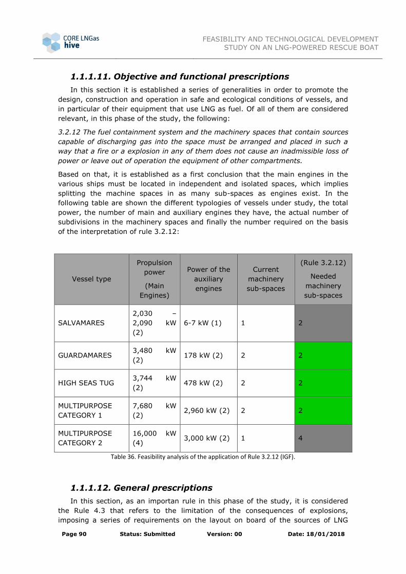
FEASIBILITY AND TECHNOLOGICAL DEVELOPMENT
STUDY ON AN LNG-POWERED RESCUE BOAT
Page 90 Status: Submitted Version: 00 Date: 18/01/2018
1.1.1.11. Objective and functional prescriptions
In this section it is established a series of generalities in order to promote the
design, construction and operation in safe and ecological conditions of vessels, and
in particular of their equipment that use LNG as fuel. Of all of them are considered
relevant, in this phase of the study, the following:
3.2.12 The fuel containment system and the machinery spaces that contain sources
capable of discharging gas into the space must be arranged and placed in such a
way that a fire or a explosion in any of them does not cause an inadmissible loss of
power or leave out of operation the equipment of other compartments.
Based on that, it is established as a first conclusion that the main engines in the
various ships must be located in independent and isolated spaces, which implies
splitting the machine spaces in as many sub-spaces as engines exist. In the
following table are shown the different typologies of vessels under study, the total
power, the number of main and auxiliary engines they have, the actual number of
subdivisions in the machinery spaces and finally the number required on the basis
of the interpretation of rule 3.2.12:
Vessel type
Propulsion
power
(Main
Engines)
Power of the
auxiliary
engines
Current
machinery
sub-spaces
(Rule 3.2.12)
Needed
machinery
sub-spaces
SALVAMARES
2,030 –
2,090 kW
(2)
6-7 kW (1) 1 2
GUARDAMARES 3,480 kW
(2) 178 kW (2) 2 2
HIGH SEAS TUG 3,744 kW
(2) 478 kW (2) 2 2
MULTIPURPOSE
CATEGORY 1
7,680 kW
(2) 2,960 kW (2) 2 2
MULTIPURPOSE
CATEGORY 2
16,000 kW
(4) 3,000 kW (2) 1 4
Table 36. Feasibility analysis of the application of Rule 3.2.12 (IGF).
1.1.1.12. General prescriptions
In this section, as an importan rule in this phase of the study, it is considered
the Rule 4.3 that refers to the limitation of the consequences of explosions,
imposing a series of requirements on the layout on board of the sources of LNG

FEASIBILITY AND TECHNOLOGICAL DEVELOPMENT
STUDY ON AN LNG-POWERED RESCUE BOAT
Page 91 Status: Submitted Version: 00 Date: 18/01/2018
discharge and ignition, which must not interfere in the event of an explosion in an
equipment or systems located in other spaces different than the one where the
event happened, interfere with another essential systems, damage the vessel so
that there is a flood below the main deck o damage work areas or people
accommodation.
Naturally, complying with this provisions is less feasible the smaller the size of the
vessel, despite this it is not considered in this phase of the study that these
requirements are limiting in any case, since it will always be possible to rethink the
current layout of the spaces and equipment of all ships and/or adopt technical
solutions for explosion isolation in the different equipment and systems indicated in
this part of the regulation. The following table summarizes the feasibility
assessment of compliance with both rules:
Vessel type Rule 4.3
SALVAMARES Yes
GUARDAMARES Yes
HIGH SEAS TUG Yes
MULTIPURPOSE VESSEL CATEGORY 1 Yes
MULTIPURPOSE VESSEL CATEGORY 2 Yes
Table 37. Feasibility analysis of the application of Rule 4.3 (IGF).
1.1.1.13. Specific prescriptions concerning vessels that
consume LNG as fuel
Design and layout of the vessel
The purpose of this chapter of the regulation is to establish provisions for safe
emplacement, adequate space distribution and mechanic protection of power
generation equipment, the fuel storage system, the fuel supply equipment and the
systems of refuelling.
The first important provision that is considered applicable to this phase of the study
regarding the equipment placement appears in the Rule 5.3.3, which refers to the
minimum distance that must be kept between the tank and the limits of the hull, as
indicated as follows:
5.3.3 The tank or the tanks of fuel will be protected from outside failures caused
by collision or stranding in the following manner:
.1 Fuel tanks shall be located at a minimum distance of B/5 or 11.5 m, if
it is less, measured from the side of the vessel perpendicular to the
longitudinal axis at the draft level of the summer load line;

FEASIBILITY AND TECHNOLOGICAL DEVELOPMENT
STUDY ON AN LNG-POWERED RESCUE BOAT
Page 92 Status: Submitted Version: 00 Date: 18/01/2018
.4 In no case the fuel tank limit will be placed at a distance from the liner
plates or the lower end of the ship which is less than the following:
.2 In the case of bulkcarriers:
.1 For Vc lower or equal to 1,000 m3, 0.8 m; being Vc the gross
design volume of the fuel tank at 20 ºC, including archs and
appendages.
.5 The lowest limit of the tank or tanks of fuel will be situated above a
minimum distance of B/15 o 2,0 m, if lower, to be measured from the
moulded line of the bottom shell plating at centerline.
.7 The fuel tank or tanks shall be aft of a transverse plane, at a distance
of 0.08 L, measured from the forward perpendicular, in accordance
with the rule II-1/8.1 of the SOLAS Convention for passenger ships,
and astern of the collision bulkhead for the bulkcarriers.
There is a statistical method for the calculation of these values, although in this
phase of the study will be used only the deterministic rules indicated above because
of their greater ease of calculation, in order to obtain an estimative value for each
one of the vessel types in function of the size of the tanks calculated in the section
7.2. In the following figure can be clearly seen the different distances referred to in
the code according to the rules indicated above:
Figure 40. Regulated distances to the side and bottom of the fuel tank.
The following table presents a summary of the various calculations and parameters
by type of ship and then it is evaluated the feasibility of on-board installation based
on these requirements:

FEASIBILITY AND TECHNOLOGICAL DEVELOPMENT
STUDY ON AN LNG-POWERED RESCUE BOAT
Page 93 Status: Submitted Version: 00 Date: 18/01/2018
Vessel type
LNG
capacity –
Total in
tanks
Tank
dimensions
LxBxD (m)
Lpp x B
(m)
Distance to
side – stern
extreme -
bottom – bow
perpendicular
(m)
(Rule 5.3.3)
Feasibility of
installation
of LNG
tanks
SALVAMARES 1 x 1.4 m3 2.5 x 1.0 x
1.0
16.8/15
x 5.6/3.8
1.1/0.8
0.8
0.4/0.3
1.3/1.2
Yes
GUARDAMARES 1 x 3.7 m3 3.0 x 1.5 x
1.5
29.8 x
7.5
1.5
0.8
0.5
2.4
Yes
HIGH SEAS TUG 2 x 61.6 m3 7.0 x 4.0 x
4.0
34.5 x
12.5
2.5
0.8
0.8
2.8
Yes
MULTIPURPOSE
CATEGORY 1
1 x 145 m3 16.9 x 4.0 x
4.0
48 x 15 3.0
0.8
1.0
3.8
Yes
MULTIPURPOSE
CATEGORY 2
2 x 194 m3 19.10 x 4.3
x 4.3
70.1 x 18 3.6
0.8
1.2
5.6
Yes
Table 38. Feasibility analysis of the application of Rule 5.3.3 (IGF).

FEASIBILITY AND TECHNOLOGICAL DEVELOPMENT
STUDY ON AN LNG-POWERED RESCUE BOAT
Page 94 Status: Submitted Version: 00 Date: 18/01/2018
Fuel containment system
The objective of this chapter is to ensure that the gas storage is adequate to
minimize the risks to the crew, the vessel and the environment at a level that is
equivalent to that of traditional vessels consuming liquid fuels:
6.7.1.1 All fuel storage tanks shall be provided with a pressure relief system
appropriate to the design characteristic of the fuel containment system
and the fuel to be transported. The fuel storage spaces, the interbarriers,
the tank connection spaces and the cofferdams that may be subjected to
pressures higher than their design characteristics shall also have an
adequate pressure relief system. The pressure control system specified in
6.9 shall be independent of pressure relief systems.
6.7.2.7 Any pressure relief valve installed in a liquefied gas fuel tank shall be
connected to a venting system, which shall be:
.1 constructed so that the pressure is freely discharged and is directed
vertically upwards;
.2 arranged in such a way as to minimize the possibility of water or
snow entering the inside; and
.3 arranged in such a way that the height of the venting outlets is
normally not less than B/3 or 6 m, if this is higher, above the weather
deck and 6 m above the work areas and walkways. However, the
venting masts may be limited to a lower value according to a special
consideration given by the Administration.
6.7.2.8 Normally, the outlet of the pressure relief valves shall be located, at
least, 10 m from:
.1 the air intake, the air outlet or the opening to accommodation, air
intake, service and control spaces, or any other non-potentially
hazardous area which is nearest; and
.2 the exhaust outlet of the nearest machine facility.
All this indicates the necessity of having a vent mast where they would discharge
the different pressure relief systems, imposing in addition a series of requirements
in reference to its position with regard to the arrangement of other elements of the
vessel, such as the air outlets or openings of the areas of accommodation, service
and control, hazardous areas or the exhaust outlets of machinery installations. In
the following it is shown the needed calculations to evaluate the compliance of
these rules by each of the analysed units:

FEASIBILITY AND TECHNOLOGICAL DEVELOPMENT
STUDY ON AN LNG-POWERED RESCUE BOAT
Page 95 Status: Submitted Version: 00 Date: 18/01/2018
Vessel type Breadth (m)
(Rule
6.7.2.7)
Vent height
from the
base line
(Rule
6.7.2.7)
Vent height
from the
upper deck
(Rule
6.7.2.8)
10 m from
certain areas
SALVAMARES 5.6/3.8 10.8 m. 9.3 m No
GUARDAMARES 7.5 13.8 m. 10.5 m. No
HIGH SEAS TUG 12.5 22.8 m. 17.0 m. Yes
MULTIPURPOSE
VESSEL CATEGORY
1
15.0 27.0 m. 20.0 m. Yes
MULTIPURPOSE
VESSEL CATEGORY
2
18.0 28.2 m. 21.3 m. Yes
Table 39. Feasibility analysis of the application of Rule 6.7 (IGF).
The height in the case of SALVAMARES and GUARDAMARES is considered excessive
and may affect the venting mast to some of the functions they develop, although
this aspect should be studied in detail in later phases of the project.
Explosion prevention
The objective of this chapter is to guarantee the prevention of explosions and
limit their effects, for which it is established in the regulation an analysis and
classification method for the zones of the vessel in which explosive gas
atmospheres can be generated. Based on that, the areas that are potentially
dangerous are divided in emplacements 0, 1 and 2, according to the indications
given by the following rules of the code:
12.5 Locations of potentially hazardous areas
12.5.1 Locations 0 of potentially hazardous areas:
This locations include, but are not limited to, the inside of the fuel tanks
and all pressure relief pipes ot other venting systems of the fuel tanks
and the pipes and equipment that contain fuel.
12.5.2 Locations 1 of potentially hazardous areas: These emplacements
include, but are not limited to:
.1 the spaces of the tank connections, the spaces of fuel storage and the
spaces interbarriers;

FEASIBILITY AND TECHNOLOGICAL DEVELOPMENT
STUDY ON AN LNG-POWERED RESCUE BOAT
Page 96 Status: Submitted Version: 00 Date: 18/01/2018
.2 the fuel preparation rooms with ventilation means stipulated 13.6;
.3 exposed deck areas, or half-enclosed spaces, situated at less than 3
m of any fuel tank outlet or any fuel or steam outlet, fuel collector
valves, other fuel valves, fuel pipe flanges, outlet venting of the fuel
preparation room and pressure relief openings of the fuel tank
disposed in order to allow the flow of small volumes of gas or vapour
mixtures caused by the thermal variation;
.4 the zones of exposed areas of half-enclosed spaces within less than
1.5 m of the fuel preparation room entries, ventilation inlets for fuel
preparation rooms and other openings leading to location 1 spaces;
.5 the exposed deck areas within spillage coamings surrounding gas fuel
intake collector valves and 3 m beyond them, up to a height of 2.4 m
above the deck;
.6 closed or half-closed in which the pipes that contain fuel are located;
for example, ducts located around fuel lines, half-enclosed fuel ports,
etc.;
.7 machinery spaces protected by emergency deactivation are
considered to be non-hazardous areas during normal operation, but
in order to be certified as suitable for locations 1, they must be
equipped with the equipment required to operate after detecting a
gas leak;
.8 the spaces protected by pneumatic locks are considered to be non-
hazardous areas during normal operation but, in order to be certified
as suitable for locations 1, require the equipment prescribed for
operate after a differential pressure loss between the protected space
and the potentially hazardous area; and
.9 with the exception of type C tanks, any area situated at less than 2.4
m of the outside surface of a containment fuel system, if that surface
is exposed to the elements.
12.5.3 Locations 2 of potentially hazardous areas:
12.5.3.1 These emplacements include, but are not limited to, areas
situated at less than 1.5 m around open or half-open locations 1.
12.5.3.2 The spaces that have hatches with pins for the spaces of the
connections of the tanks.
All this is evaluated in this phase of the preliminary feasibility study in order to
propose the layout of the ventilation elements, the arrangement of which is directly
related to the classification of the zones as will be seen in the following point.

FEASIBILITY AND TECHNOLOGICAL DEVELOPMENT
STUDY ON AN LNG-POWERED RESCUE BOAT
Page 97 Status: Submitted Version: 00 Date: 18/01/2018
Ventilation
The purpose of this chapter is to ensure that the ventilation is adequate for the safe
operation of the gas machinery and equipment. The code establishes a series of
requirements that must be complied by the ventilation equipment with respect to
its design and operation. In relation to the study carried out in this document the
provisions of the following rules are considered relevant:
13.3.5 The air intakes that serve to enclosed spaces that are potentially
hazardous will allow air from areas that are not potentially hazardous
before installing such intakes. The air intakes that serve to enclosed
spaces that are non-potentially hazardous will allow air from zones non-
potentially hazardous and shall be located at least 1.5 m from the limits
of any potentially hazardous zone. In the cases where the intake conduit
passes through a potentially more hazardous space, the conduit will be
gas tight and will has an overpressure compare to the pressure in that
space.
13.3.6 The air outlets of non-potentially hazardous spaces shall be located
outside of potentially hazardous areas.
13.3.7 The air outlets of potentially hazardous closed spaces shall be located in
an open area which, before installing the air outlet, would have a
potential hazard level equal or lower than the ventilated space.
These rules are, of course, more difficult to comply the smaller the size of the
vessel. A detailed analysis of the location of LNG equipment giving rise to
hazardous areas of different categories must be carried out on the vessel to which
the feasibility study design actions are applied. At this stage of the analysis it is
estimated that it might be possible to comply with this part of the code depending
on the location of the different equipment on board.
Vessel type (Rule
13.3.5)
(Rule
13.3.6)
(Rule
13.3.7)
SALVAMARES Yes Yes Yes
GUARDAMARES Yes Yes Yes
HIGH SEAS TUG Yes Yes Yes
MULTIPURPOSE VESSEL
CATEGORY 1 Yes Yes Yes
MULTIPURPOSE VESSEL
CATEGORY 2 Yes Yes Yes
Table 40. Feasibility analysis of the application of the Rule 13 (IGF).

FEASIBILITY AND TECHNOLOGICAL DEVELOPMENT
STUDY ON AN LNG-POWERED RESCUE BOAT
Page 98 Status: Submitted Version: 00 Date: 18/01/2018
2.7. Conclusions
Based on the analysis carried out throughout this section, a series of
conclusions and data are summarized below, for each of the blocks in which the
study has been divided:
POWER REQUIREMENTS / AVAILABLE
LNG ENGINES
RANGE REQUIREMENTS / CALCULATED
VOLUME
Dual main engine alternatives have
been found for all the ship categories
in the current power ranges. Regarding
the auxiliary groups only dual
alternatives have been found for the
multipurpose vessels. The analysis of
this point has yielded the following
preliminary feasibility results:
SALVAMARES
GUARDAMARES
HIGH SEAS TUG
MULTIPURPOSE CATEGORY 1
MULTIPURPOSE CATEGORY 2
It is calculated the required volume of LNG
to reach the 10%, 25% and 50% of the
range. In a first analysis, it is not possible
to evaluate the volumes corresponding to
the 50% because they are considered
excessive. The rest of the calculations are
evaluated once the tanks are dimensioned
in the section of technology integration.
SALVAMARES
GUARDAMARES
HIGH SEAS TUG
MULTIPURPOSE CATEGORY 1
MULTIPURPOSE CATEGORY 2
SUPPLY CHAIN / RESPONSE TIME LNG TECHNOLOGY INTEGRATION ON
BOARD / AVAILABLE SPACE
It is evaluated the state of the LNG
supply infrastructures in Spain,
although the results of the horizontal
activities of the CORE LNGas HIVE
project regarding the current and
planned infrastructure os LNG supply
points are awaited. The following
conclusions based on the current
requirements of the SASEMAR fleet are
obtained:
SALVAMARES
GUARDAMARES
HIGH SEAS TUG
MULTIPURPOSE CATEGORY 1
MULTIPURPOSE CATEGORY 2
The preliminary dimensioning of the
different equipment and a first analysis on
the integration of these equipment into the
current provisions of the ships are carried
out at this point. Also a series of
requirements imposed by the IMO in
relation to the location of tanks and the
classification of spaces are analysed. The
following results are obtained:
SALVAMARES
GUARDAMARES
HIGH SEAS TUG
MULTIPURPOSE CATEGORY 1
MULTIPURPOSE CATEGORY 2
Table 41. Summary of the preliminary feasibility analysis on the use of LNG on SASEMAR fleet units.

FEASIBILITY AND TECHNOLOGICAL DEVELOPMENT
STUDY ON AN LNG-POWERED RESCUE BOAT
Page 99 Status: Submitted Version: 00 Date: 18/01/2018
The implementation of power plants based on dual engines is technically complex
since it involves the installation of additional systems and equipment, having in
addition to comply with demanding requirements regarding their disposal on board,
which are imposed by regulation. The versatility of the vessels under study greatly
complicates this work since the normal operation of the new equipment cannot
interfere in any way with the missions/operations that they develop. This will
require a detailed analysis of the location of each element as well as the study of
hazardous areas and escape routes, in accordance with the applicable regulations.
The on board volume requirements needed by the gas equipment are very high,
since in addition to occupying more space than the equivalent technology of oil-
based liquid fuels, require significant regulatory distances, which further
complicates the feasibility of installation on board.
The preliminary feasibility study addressed in this section has resulted in the
integration of LNG technology could become possible in the MULTIPURPOSE
VESSELS, since they have a larger space and therefore offer greater possibilities in
terms of generating alternatives for the integration of the necessary equipment for
the consumption of LNG on board.
As the feasibility study concludes that the implementation of gas as fuel in
SASEMAR fleet must be accomplished on the categories of MULTIPURPOSE
VESSELS, the following actions are carried out in the following sections.
Feasibility study of the transformation of MULTIPURPOSE VESSELS
CATEGORY 1. The reasons for this are several: on one hand the LNG volume
requirements are lower than in category 2 and therefore there is more
versatility in the generation of alternatives, since both the tanks and other
associated LNG equipment will be more easily adaptable to the disposal of a
given vessel the lower the capacity and requirements imposed by the
system.
On the other hand, in the case of carrying out the transformation once the
study has been completed and with the conclusions obtained from it, it is
considered that is less complex and more economical to make the pertinent
modifications regarding the layout of spaces and equipment on board in this
category than in category 2.
The operational profile of these units fits better with the possibility of having
a small percentage of their range using LNG as a fuel, since in principle the
missions of these ships will require less time and range than those of
category 2, having therefore a higher resupply capacity than category 1
vessels.
The feasibility study on a new building with equivalent characteristics to the
MULTIPURPOSE VESSELS CATEGORY 2 will be carried out in the section 4 of
the present document. The new building will allow the optimization of the
design of a gas fuelled vessel from the beginning instead of being tied to an existing vessel.
It is necessary to point out that the implementation of LNG technology on board
ships in addition to the additional volume (space) to be taken into account, it
requires a very significant increase in weight that must be considered. This aspect
is particularly important in the case of the feasibility study concerning the
transformation of MULTIPURPOSE VESSELS CATEGORY 1 since the solution initially

FEASIBILITY AND TECHNOLOGICAL DEVELOPMENT
STUDY ON AN LNG-POWERED RESCUE BOAT
Page 100 Status: Submitted Version: 00 Date: 18/01/2018
proposed is to arrange the gas equipment on board complementing those currently
installed on this type of vessels.
Once the feasibility study on the implementation of LNG as an alternative fuel in
life-saving and pollution control units shown in the present section is completed,
the following studies will be included in the following sections:
Feasibility study of the transformation of MULTIPURPOSE VESSELS
CATEGORY 1
New building definition with equivalent characteristics to the MULTIPURPOSE VESSELS CATEGORY 2

FEASIBILITY AND TECHNOLOGICAL DEVELOPMENT
STUDY ON AN LNG-POWERED RESCUE BOAT
Page 101 Status: Submitted Version: 00 Date: 18/01/2018
3. RETROFITTING OF A MULTIPURPOSE
SALVAGE TUG
As per the conclusions on the previous section, the vessel more suitable for the
retrofitting is the MULTIPURPOSE VESSELS CATEGORY 1, based on the twin ships
Luz de Mar and Miguel de Cervantes. This kind of ship is capable of carrying out
numerous operations, even in adverse weather conditions. As ships working under
the instructions and authority of SASEMAR, they operate in Spanish coasts.
Specifically, the vessel Miguel de Cervantes’ influence zone is the Canary Islands,
while Luz de Mar’s is the South of the Iberian Peninsula and the Strait of Gibraltar.
Figure 41. Miguel de Cervantes and Luz de Mar operational areas.
Its main dimensions are 56.00 m of length, 15.00 m of beam and 7.00 m of depth
to main deck, with a range of 5,230 nm and a crew composed of 18 people,
expandable with 8 more for auxiliary services. Descriptions of the main
characteristics of the vessels are shown in the following table:

FEASIBILITY AND TECHNOLOGICAL DEVELOPMENT
STUDY ON AN LNG-POWERED RESCUE BOAT
Page 102 Status: Submitted Version: 00 Date: 18/01/2018
Main Particulars Name Miguel de Cervantes / Luz de Mar
Vessel Type Multipurpose Salvage and Rescue Tug, Oil Spill
Response Vessel
Length Overall 56.00 m
Length Between Perpendiculars 48.00 m
Beam 15.00 m
Depth To Main Deck 7.00 m
Draft Design 5.50 m
Net Tonnage 534
Gross Tonnage 1,780
Displacement (at summer draft) 2,940 t
Deadweight 483/1,190 t
Hull Material Steel
Speed Maximum 16.40 knots
Cruise 13 knots
Back 15.80 knots
Range (80% MCR) 6,000 nm
Bollard Pull 100% MCR 128.5 t
80% MCR 107.0 t
Crew Standard 14
Maximum 18
Technicians And Auxiliary
Services 8
Registration and
P&I Flag Spain (CSR)
Port of Registry Santa Cruz de Tenerife
Current P&I Club Britannia Steam Ship Inc Assoc

FEASIBILITY AND TECHNOLOGICAL DEVELOPMENT
STUDY ON AN LNG-POWERED RESCUE BOAT
Page 103 Status: Submitted Version: 00 Date: 18/01/2018
Classification Classification Society Bureau Veritas
Class
I HULL MACH, Fire Fighting Ship, Tug, Water
Spraying-1, Unrestricted Navigation, AUT-
UMS, Dynypos-R, IG
Propellers Bow Propellers Manufacturer SCHOTTEL Gmbh
Model SRP 3040 CP
Diameter 4,300 mm
Number of Blades 4
Speed SRP 600 RPM
SRP Gear Reduction 3.246:1
Turn Rate 15 s / 180°
Stern Thruster Manufacturer SCHOTTEL
Model STT 330 LK CP
Power 400 kW
Rotatory Speed 1.470 RPM
Reduction Rate 3,54:1
Propeller Diameter 1.490 mm
Number of Blades 4
Blades Type Variable Pitch
Nominal Push 68 kN

FEASIBILITY AND TECHNOLOGICAL DEVELOPMENT
STUDY ON AN LNG-POWERED RESCUE BOAT
Page 104 Status: Submitted Version: 00 Date: 18/01/2018
Engines Main Engines Manufacturer MAK
Model 8M32C
Number of Engines 2
Power 5,222.40 CV /
3,870.00 kW
Rotatory Speed 600 RPM
Gearbox Kumera
4FGCCC500/525
Fuel Consumption 214 g/kW at
2,400 RPM
Number of Shafts 2
Generators Auxiliary Manufacturer CATERPILLAR
Model 3508B
Rotatory Speed 1500 RPM
Power 1.480 kW / 2.013
HP at 1.500 RPM
Fuel Consumption 206 g/kW
Fuel Gas-Oil
Generator CATERPILLAR
Power 1.000 kVA / 800
kW
Voltage 400 V
Frequency 50 Hz

FEASIBILITY AND TECHNOLOGICAL DEVELOPMENT
STUDY ON AN LNG-POWERED RESCUE BOAT
Page 105 Status: Submitted Version: 00 Date: 18/01/2018
Harbour Generator Manufacturer CATERPILLAR
(Emergency Generator) Model CATERPILLAR
3406
Power 307 kW / 494 HP
Consumption 204 g/kWh
Power 440 kVA / 352
kW
Voltage 400 V
Units 1
Tail Shaft Generator Generator Satmfor
Power 1.000 kVA / 800
kW
Voltage 400 V
Frequency 50 Hz
Table 42 - Luz de Mar Main particulars
3.1. Operative Capacities
As a multipurpose vessel, it can operate in many different scenarios, with
can be resumed in the following scheme:
Figure 42. Operational profiles scheme of MULTIPURPOSE VESSELS CATEGORY 1.
Each of these situations requires different specialized equipment in order to
complete the missions with the maximum efficiency possible, what makes this kind
of ships highly technological instruments.
Operational Profiles
Salvage and Rescue Anti-Pollution Fire Fighting Support

FEASIBILITY AND TECHNOLOGICAL DEVELOPMENT
STUDY ON AN LNG-POWERED RESCUE BOAT
Page 106 Status: Submitted Version: 00 Date: 18/01/2018
3.1.1 Salvage and rescue
Includes operations to assist ships in danger of sinking or to people who are
drifting. With a bollard pull of 107 t at 80% of MCR (128.50 t at 100%) it can tow
vessels much bigger tan it. For these salvage actions it uses 3 main tow machines
and 2 auxiliary.
Figure 43. Towing operation.
It has also a rescue zone, which serves as point of shipment for those people in
danger.
Figure 44. Rescue operation.
3.1.2 Anti-Pollution
One of the main problems associated with salvage operations, that
sometimes imply the existence of a damaged vessel, is the contamination of the
water. For fight the oil spills, the ship is equipped with two flotable arms, positioned
obliquely to the forward direction in the aft half. A suction pump at the end near the
hull discharges the waste to the tanks. These residues are poured into the aft recoil
tanks that can be used individually or together and, by decantation, separate the
water from the oil. Another pump discharges the tanks to land or to other systems
or ships. The aft deck can stow and transport additional portable tanks which,

FEASIBILITY AND TECHNOLOGICAL DEVELOPMENT
STUDY ON AN LNG-POWERED RESCUE BOAT
Page 107 Status: Submitted Version: 00 Date: 18/01/2018
together with structural ones, increase the waste storage capacity. It also has
dispersant equipment, an oil boom and an inert gas system.
Figure 45. Oil spill collection.
The arms are operated by two cranes, each one for each arm. When they are not
being used they are left on the stern extreme of the deck.
Figure 46. Flotable arms on the deck. Figure 47. Crane moving one of the arms.
3.1.3 Fire fighting
The third main mission to be complete by the vessel is the fire fighting
operations, many times related with maritime accidents. In order to respond to this
type of situations it has an exterior fire fighting system, composed of 2 pumps each
one with a capacity of 1,500 m3/h, and enough power to impulse the water (or
foam) 120 m away and 50 m high from two monitors.

FEASIBILITY AND TECHNOLOGICAL DEVELOPMENT
STUDY ON AN LNG-POWERED RESCUE BOAT
Page 108 Status: Submitted Version: 00 Date: 18/01/2018
Figure 48. Fire-fighting system working demonstration.
It also has an auto protection system which covers the hull by means of water
diffusers, protecting the vessel and the crew from the flames and high
temperatures.
3.1.4 Support
It can also be used as a support platform for external equipment, such as
divers, or as a support for machinery and personnel. A set of two hydraulically
driven towing pins and jaws allows it for anchor and buoy handling on the high
seas.
3.2. Propulsion plant and manoeuvrability
The power for propulsion is obtained from two main diesel engines model
MAK 8M32C manufactured by Caterpillar.
These produced of 3,840 kW at 600 RPM, and each one is connected to two shaft
lines in order to increase security and do not compromise the navigation in case of
breakdown.
In relation with propellers, MULTIPURPOSE VESSELS CATEGORY 1 have azimuth aft
propulsion with two variable pitch thrusters that rotate 360 degrees and, together
with the bow thruster, give it full manoeuvrability at any regimen.
More technical details about the current ship propulsion plant will be presented in
section 3.6 of this document.

FEASIBILITY AND TECHNOLOGICAL DEVELOPMENT
STUDY ON AN LNG-POWERED RESCUE BOAT
Page 109 Status: Submitted Version: 00 Date: 18/01/2018
3.3. Electric Power Production
Operational conditions in which the ship has to work, create a big necessity
of electrical power supply. This is achieved through three different types of
generators:
Main auxiliary groups: two units providing 910 kW
Shaft generators / PTO
Emergency generator: One unit, it provides 214 kW.
More technical details about the current ship propulsion plant will be presented in
section 3.6 of this document.

FEASIBILITY AND TECHNOLOGICAL DEVELOPMENT
STUDY ON AN LNG-POWERED RESCUE BOAT
Page 110 Status: Submitted Version: 00 Date: 18/01/2018
3.4. General Layout
The vessel has 4 decks, including the bridge, as it can be appreciated in the
side view below:
Figure 49. General layout side view.
One of the most important decks is the main deck. In it are found the cranes,
winches, windlasses and oil spill recovery floatable arms, and also a part of the
accommodation and several laboratories..
Figure 50. Main deck general layout.
Below the main deck is the double bottom, where is situated the engine room, the
steering room, and several tanks (water, ballast, fuel, etc).

FEASIBILITY AND TECHNOLOGICAL DEVELOPMENT
STUDY ON AN LNG-POWERED RESCUE BOAT
Page 111 Status: Submitted Version: 00 Date: 18/01/2018
Figure 51. Double bottom general layout.

FEASIBILITY AND TECHNOLOGICAL DEVELOPMENT
STUDY ON AN LNG-POWERED RESCUE BOAT
Page 112 Status: Submitted Version: 00 Date: 18/01/2018
3.5. Requirements to be fulfilled for the use of
Natural gas as fuel
In this section SASEMAR requirements are defined. The retrofitted vessel shall fulfil
such requirements as the vessel cannot reduce its present operational capabilities.
The current range should be maintained operating with diesel at 85% of the
MCR.
The current arrangement of fuel tanks should not be modified.
The range will be approximately two days operating with LNG as fuel in a
MCR range of 70% -85% (10-12 knots).
Range in port will be ten days only using LNG as fuel.
Current Bureau Veritas class notations will be maintained: I + HULL + MACH
TUG, FIRE FIGHTING SHIP 1 WATER SPRAY, SPECIAL SERVICE, OIL
RECOVERY SHIP, UNRESTRICTED NAVIGATION, + AUT-UMS, + DYNAPOS-
AM-R Adding necessary requirements to the introduction of LNG as on-board
as a fuel.
It will be necessary to calculate the towing capacity reduction (From bow
and stern) after retrofitting, in both cases using diesel and LNG as fuels. Do
not miss more than 10% capacity in both cases.
It will be necessary to calculate the ship speed reduction after retrofitting at
different engine speeds and propeller pitches, do not miss more than more
than 10% of the ship speed at any operational situation.
It will be necessary to calculate the response time increments related to
power demand and propulsion response at any operational situation.
It will be necessary to calculate downtime due to LNG bunkering operations.
If necessary, it would admit a loss of oil recovery capacity up to two thirds
for LNG tanks installation.
Rescue area, towing deck and towing operation area must be kept without
obstacles.

FEASIBILITY AND TECHNOLOGICAL DEVELOPMENT
STUDY ON AN LNG-POWERED RESCUE BOAT
Page 113 Status: Submitted Version: 00 Date: 18/01/2018
3.6. Propulsion: initial characteristics and
actions to be carried out for adaptation to LNG on
the current installation.
The engine room is located at the middle of the length, and it is equipped
with two main engines and two generating sets, all of them designed to work with
gasoil.
3.6.1 Propulsive Power
The propulsive power is produced by two main diesel engines (model MAK
8M32C). From these engines two power-take-off are driven: The main shaft of each
one is connected to an azimuthal thruster, SRP 3040 type, situated on the stern,
providing the means of propulsion. On the other hand, each engine has another
power-take-off to the bow which connects with a gearbox (Kumera
4FGCCC500/525). Each gearbox delivers power to a FI-FI pump and a shaft
generator. A scheme of this configuration can be seen below:
In these vessels the propeller is lower than the engine. This type of arrangement
Thruster Engine Gearbox
FI-FI
PTO
To To bow
Figure 52. Propulsion power plant scheme.

FEASIBILITY AND TECHNOLOGICAL DEVELOPMENT
STUDY ON AN LNG-POWERED RESCUE BOAT
Page 114 Status: Submitted Version: 00 Date: 18/01/2018
Figure 53. Z-drive configuration. Source: Nanjing High Accurate Marine Equipment Co.,Ltd.
3.6.2 Main Engines
The power for propulsion is obtained from two main diesel engines model
MAK 8M32C manufactured by Caterpillar, working with gasoil. These produce 3,840
kW at 600 RPM. From each main engine it is derived a power-take-off to the bow, a
FI-FI system and a shaft alternator.
Figure 54. Main engines. Source: Caterpillar.
The characteristics of these engines are shown in the following table:
Model Ouput
(kW/mhp)
Speed
(rpm)
Mean
eff.
Pressure
(bar)
Mean
piston
speed
(m/s)
Bore
(mm)
Stroke
(mm)
Specific fuel
consumption
(g/kW*h)
100%
MCR
85%
MCR
8M32C 3,840/5,220 600 24.9 9.6 320 480 177 176
Table 43. Main engines characteristics. Source: Caterpillar

FEASIBILITY AND TECHNOLOGICAL DEVELOPMENT
STUDY ON AN LNG-POWERED RESCUE BOAT
Page 115 Status: Submitted Version: 00 Date: 18/01/2018
The dimensions of the engines as per manufacturer information are as follows:
Figure 55. Main engines dimensions. Source: Caterpillar.
L1
(mm)
L2
(mm)
L3
(mm)
L4
(mm)
H1
(mm)
H2
(mm)
H3
(mm)
W1
(mm)
W2
(mm)
Weight
(t)
7,298 1,044 852 1,472 2,969 1,052 550 2,229 262 49.0
Table 44. Main engines dimensions and weight. Source: Caterpillar.
3.6.3 Propellers
The propulsion system does not depend of the vessel electrical energy. It
consist of two azimuth aft propulsion (or rudder propellers) with two variable pitch
thrusters that rotate 360 degrees, type SRP 3040 CP, manufactured by SCHOTTEL.
Due to the duplicity of the equipment, the failure of a thruster will maintain
operative the navigation of the vessel without restrictions for its return to the port.
Also, these systems have three main operating modes: tug, free operation and FI-
FI.
Figure 56. Azimuth propellers installed on the stern. Source: SASEMAR (left) and SCHOTTEL (right).

FEASIBILITY AND TECHNOLOGICAL DEVELOPMENT
STUDY ON AN LNG-POWERED RESCUE BOAT
Page 116 Status: Submitted Version: 00 Date: 18/01/2018
The blades of the propellers and their hubs are made of high quality CuAl10Ni, and
surrounding each propeller there is coupled a nozzle. A more detailed picture of the
thruster and its main characteristics can be seen in the figure and the table below.
Figure 57. SRP Rudder propeller. Source: SCHOTTEL.
Model
Propeller Rotatory
direction Rotatory
speed
(RPM)
Gear
reduction Turn rate
Diameter
(mm)
Nº of
blades Type Br Er
SRP
3040
CP
4,300 4 Controllable
pitch CCW CW 600 3.246:1 15s/180°
Table 45. SRP Rudder propeller main characteristics. Source: SCHOTTEL
Upper
gearbox
Underwater
gearbox
Vertical power
transmission
Steering
Power
input
Installation
flange
Nozzle
Propeller
shaft

FEASIBILITY AND TECHNOLOGICAL DEVELOPMENT
STUDY ON AN LNG-POWERED RESCUE BOAT
Page 117 Status: Submitted Version: 00 Date: 18/01/2018
There is also installed a transverse thruster situated in the bow (type STT 330 LK
CP) which main characteristics and parts are shown below:
Figure 58. STT Transverse thruster. Source: SCHOTTEL.
Model Power
(kW)
Propeller Nominal
Thrust
(kN)
Rotatory
speed
(RPM)
Reduction
rate Diameter
(mm)
Nº of
blades Type
STT 330
LK CP 400 1,490 4
Controllable
pitch 68 1,470 3.54:1
Table 46. STT Transverse thruster main characteristics. Source: SCHOTTEL.
Together with the azimuth thrusters, this equipment gives full manoeuvrability at
any regimen. This gives to It the capacity to realise a whole turn in 30 seconds, or
39 seconds in the case of using only one propeller.
Figure 59. 360 degree turn demonstration. Source: SASEMAR.
It addition, It has a dynamic positioning system DYNAPOS AM of type DP2 to
maintain the position.
Prime
mover
foundation
Wearing ring
Steering
Stiffening
ring
Propeller

FEASIBILITY AND TECHNOLOGICAL DEVELOPMENT
STUDY ON AN LNG-POWERED RESCUE BOAT
Page 118 Status: Submitted Version: 00 Date: 18/01/2018
3.6.4 Adaptation actions for LNG use
For the installation of the LNG system, there are some things to take into account.
The most important fact is to find a place with enough capacity to contain the LNG
tank. As commented before, the storage tank is an independent (type C) tank. This
type of tank has much possibilities of installation on board, due to its portability,
being only necessary an empty space which fulfil the safety restrictions imposed by
the IGF code.
A key factor for the success of a gas conversion is finding sufficient space for
storing the gas on board the vessel. The LNG storage location can be freely selected
on board the vessel, and either vertical or horizontal tanks, on open deck or below
deck, can be selected. When storage is above deck, the requirements set by the
classification societies are slightly lower. In addition, for this case it is necessary to
install the storage tank below deck, due to it is necessary to keep the deck clean
from obstacles during operations. The LNG storage tanks and any additional steel
structures may have an impact on the vessel’s stability.
Apart from the storage tank, there are some necessary equipment shall be installed
on board, always regarding the fulfilment of the IFG code in order to keep the
safety operation of the vessel. This equipment is:
GVUs
TCS
Vent mast
Inert gas system
Drip tray
Glycol-water heating system
Bunkering station
Single and double walled pipes
Gas detection/ Fire suppression system
All this equipment is related with the LNG system. However, the auxiliary systems
may suffer any modification in order to adapt to the new dual fuel engines. The
modifications needed, can be obtained from comparing the Project Guides of both
engines. The comparison is detailed further in the document.
Another important fact, is the installation of the bunkering stations. These modules
are the link between the land gas installation and the vessel when bunkering. These
operations use to be a critical situation due to the potential risks this operation
involves. Apart from the installation of the station, including all necessary pipes, it
is important to take into account that a drip tray must be installed. Drip trays shall
be fitted where leakage may occur which can cause damage to the ship structure or
where limitation of the area which is affected from a spill is necessary. The drip tray
shall also be thermally insulated from the ship's structure so that the surrounding
hull or deck structures are not exposed to unacceptable cooling, in case of leakage
of liquid fuel. Finally, drip trays must be fitted with a drain valve for rain water. All
these facts are important to take into account when installing on deck.
The installation of GVUs is also an important fact, due to there is one GVU per
engine and because the necessity of operating in safety conditions. These units
must be located in gas safe spaces and as close as possible of the engines, being

FEASIBILITY AND TECHNOLOGICAL DEVELOPMENT
STUDY ON AN LNG-POWERED RESCUE BOAT
Page 119 Status: Submitted Version: 00 Date: 18/01/2018
the maximum pipe length allowed 10 meters. For this reason, it is necessary to
have space enough in the engine room for the disposition of these units.
In general terms, the installation shall satisfy the IGF code, so it is necessary to
modify any system or equipment in order to keep satisfying the IGF restrictions.
There is also needed an upgrade in automation and control systems, and a specific
training for the vessel crew in order to a correct operation of the vessel in safety
terms.
3.6.5 Dual fuel main engines
For using the LNG as fuel, it is necessary to replace / upgrade the current main
engines by dual fuel engines. These engines are capable of operating on both LNG
and conventional fuels, without sacrificing their marine engines features. In order
not to modify the configuration of the current power plants, the selected engines
must be similar to the current installed in power range and dimensions terms.
Additionally, the ship owner wanted a main engine manufactured by Mak, so it
becomes easier the selection of the dual fuel engines. Finally, the engines selected
are a Mak 8 M 34DF, which develops 4000 kW at 720/750 rpm, depending if it is
using diesel or gas as fuel.
Taking into account that the current engines speed is 600 rpm, there is a speed
difference which means that propellers and power-take-off units will not be working
in the same conditions, inducing to some problems which will be mentioned in
further sections.
Figure 60. Dual fuel main engines. Source: Mak

FEASIBILITY AND TECHNOLOGICAL DEVELOPMENT
STUDY ON AN LNG-POWERED RESCUE BOAT
Page 120 Status: Submitted Version: 00 Date: 18/01/2018
The main features of this engine are shown below:
Type Output (kW)
Revolutions
Diesel/Gas
(rpm)
Bore
(mm)
Stroke
(mm)
BMEP
Diesel/Gas
(bar)
Mean piston
speed
Diesel/Gas
(m/s)
8M34DF 4000 720/750 340 460 19,9/19,1 11,0/11,5
Table 47. Dual fuel engines main features. Source: Mak
The specific consumptions are specified in a different table, in which values are
given separately depending on the diesel or gas working mode and for the different
working engine loads.
% Load Diesel
(g/kWh)
Gas
(KJ/kWh)
100 188 7665
85 187 7777
75 189 7925
50 195 8290
Table 48. Dual fuel engines specific fuel consumptions. Source: Mak
To obtain the gas consumption in tonnes or cubic meter per hour it is necessary to
know the LHV (Lower Heating Value) and the density of the fuel gas. Depending on
the composition of the gas, these properties may have different values. However,
the variation range is so small than it can be taken medium values from these
ranges in order to have a certain estimation of the specific fuel consumption. These
values are specified in the next table:
Lower Calorific
value (KJ/g)
Density
(t/m3)
49,5 0,45
Table 49. Fuel gas LHV and density data. Source: Mak

FEASIBILITY AND TECHNOLOGICAL DEVELOPMENT
STUDY ON AN LNG-POWERED RESCUE BOAT
Page 121 Status: Submitted Version: 00 Date: 18/01/2018
Using these values, it is simple to express the fuel gas consumption in terms of
tonnes or cubic meters per hour, which are easier to manage than kilo joules per
kilo watt and hour, and it is simpler to make an idea of the fuel consumption rates.
These rates appear in the table below:
% Load Gas (t/h) Gas (m3/h)
100 0,619 1,376
85 0,534 1,187
75 0,480 1,067
50 0,335 0,744
Table 50. Main dual fuel engines gas fuel consumptions.
The data provided by this table is presented in a more suitable way to make an idea
of the fuel gas consumption and the tank capacities needed for the LNG storing.
The engine dimensions are defined below,
Table 51. Main dual fuel engine dimensions. Source: Mak
Dimensions (mm) Weight
L1 L2 L3 L4 H1 H2 H3 H4 W1 W2 (t)
6980 6550 852 7410 2925 1052 550 2995 2460 190 49
Table 52. Main dual fuel engine. Source: Mak

FEASIBILITY AND TECHNOLOGICAL DEVELOPMENT
STUDY ON AN LNG-POWERED RESCUE BOAT
Page 122 Status: Submitted Version: 00 Date: 18/01/2018
The main conclusion can be obtained from this part is the disadvantage that
suppose the difference between the engines speed. As commented on previous
sections, there are some elements in the power plant which are fed from the engine
speed as the azimuth propellers, the PTOs, the gearbox and the FI-FI pumps. These
elements have been designed for a 600 rpm speed, so with the dual fuel engine
speed of 720/750 rpm, some modifications could be required to fit the new rpm.
3.6.6 Comparison current against dual fuel engines
For the feasibility study it is important to analyse the previously shown features of
both main engines in order to make an idea of the changes that could happen in
the general lay out, operation ranges, auxiliary machinery, etc. when the
retrofitting is done.
To compare both engine models, the features have been divided in three parts. On
the first part, the main features of each engine are set, to make sure the output
power delivered by each engine are the same, or at least, in a similar power range.
The second part just shows the specific fuel consumptions for each engine (and for
both types of fuel in case of dual fuel engine) for each load engine power range.
Finally, the third part relates the dimensions of each engine. Mentioned parts are
shown in the tables below:
Type Working
mode
Output
(kW)
Revolutions
(rpm)
Bore
(mm)
Stroke
(mm)
BMEP
(bar)
Mean piston
speed (m/s)
8M32C - 4000 600 320 480 25,9 9,6
8M34DF Diesel
4000 720
340 460 19,9 11
Gas 750 19,1 11,5
Table 53. Main engines features comparisons. Source Mak.
As expected, both output powers are the same, so all of these values are more or
less the same for the both engine models, excepting their revolutions. This speed
variation between both engines has an important impact on the vessel power plant.
On the one hand, the propellers are designed for a 600 rpm speed, so changes in
this feature means changes in the propeller operative conditions. These variations
must be studied with care to determine the negative effect of the speed variation in
the propeller and its impact on the ship operative capacities.

FEASIBILITY AND TECHNOLOGICAL DEVELOPMENT
STUDY ON AN LNG-POWERED RESCUE BOAT
Page 123 Status: Submitted Version: 00 Date: 18/01/2018
The second part of the comparison consists of the specific fuel consumptions of
each engine and for different load power ranges. The consumptions are given in the
next table:
8M32C 8M34DF
% Load
Diesel
(g/kWh) Diesel (t/h)
Diesel
(g/kWh) Diesel (t/h) Gas (t/h)
100 177 0,708 188 0,752 0,619
85 176 0,5984 187 0,6358 0,534
75 177 0,531 189 0,567 0,480
50 185 0,37 195 0,39 0,335
Table 54. Main engines specific fuel and gas consumptions comparison. Source Mak.
As all consumptions are given with the same units, it is simple to make a
comparison between both engines. It is important to take account that, the dual
fuel engine has a higher diesel consumption than the current installed engine. It is
a negative point for the dual fuel, which, when working with diesel, would consume
more than the current engine so the range (working with diesel) would decrease.
This diesel-working decreasing range, even when the LNG provides a global range
increment, also means a rising costs when bunkering operations in comparison with
the actual costs.
In the end, the third part of the comparison shows the weight and main dimensions
of each engine, which is an important fact due to the weight and space restrictions
on board.
Type Dimensions (mm)
Weight (t) Length Width Height
8M32C 7293 2460 4119 49
8M34DF 7410 2460 4047
Table 55. Main engines dimensions comparison.
As can be seen, both engines are basically the same in terms of dimensions and
weight, but it is important to note that in this comparison has been only taken into
account the dimensions of each engine, but not all the auxiliary machinery and devices
needed for each option. Regarding, the dual fuel engine needs additional equipment
and services whose weights and space necessities has not been taken into account for
this comparison. This point would be studied and mentioned on further sections.

FEASIBILITY AND TECHNOLOGICAL DEVELOPMENT
STUDY ON AN LNG-POWERED RESCUE BOAT
Page 124 Status: Submitted Version: 00 Date: 18/01/2018
The main fact in this part is the engine speed differences, both output-speed engine
curves are shown in the figure below:
Figure 61. Output-Speed engines curve comparison.
Being, red curve for the current engine and blue curve for the dual fuel engine. As
can be seen, for the same MCR, the dual fuel engine will work in a 20% higher
speed, approximately. This speed increase directly affects to some equipment like
PTOs, FI-FI pumps, gearbox and thrusters. Obviously, all this equipment may not
work with the same efficiency as before, due to they were selected for working at
600 rpm. This is an important disadvantage in the feasibility of the retrofitting.

FEASIBILITY AND TECHNOLOGICAL DEVELOPMENT
STUDY ON AN LNG-POWERED RESCUE BOAT
Page 125 Status: Submitted Version: 00 Date: 18/01/2018
The optimum point of the dual motors is at 720/750 rpm, however, the propeller is
designed to work at 600 rpm. This performance will suppose an incorrect
performance of the propeller. To solve this problem, there are three alternatives:
Make the motor to work at 600 rpm (although it is designed for 720/750
rpm), this situation will suppose that the motor won’t work on its optimum
point, jeopardizing its efficiency, resulting in more consumption, more cost
and more contamination.
Other option could be to replace the gearbox to an appropriated one. But
here appears another problem; there will be a worst towing performance,
which is very negative, especially when we are talking about a tugboat.
To adjust the propeller pitch in order to obtain the same thrust with the new
engine speed. It would be an expensive option, and would variate the operational features of the thrusters.
Estimations provided by the shipyard indicate that there would be a speed loss of
0,5 knots and between 9 and 10 tons of pulling power.
Related with these points, appears another problem apart from the propeller: in the
case of the PTOs, the engine speed is intimately linked with the PTO working mode,
so it would be also necessary and adjustment to keep the output features invariant
even though the speed variation produced by the retrofitting.
3.6.7 List of actions for LNG use
Before the engine replacement, there are some actions that must be taken to carry
out the engines retrofitting. At first, an auxiliary services review has to be done in
order to check if this equipment could be used for the new engines or if it is
necessary to replace any component.
By comparing the engines Project Guide a list of non-supported equipment could be
done. As the output engine power is equal for both types, most of the auxiliary
services does not have to be replaced, being only different the engine driven pumps
and the modifications needed for the retrofitting does not have significant
importance in the feasibility study. This is an important advantage for taking into
account, due to the cost of the all auxiliary equipment installation would be so high
that the feasibility will probably turn down.
For dual operation of the engine, it is required a gas feed system. The fuel gas
system on the engine comprises the following built-on equipment:
Low-pressure fuel gas common rail pipe
Gas admission valve for each cylinder
Safety filters at each gas admission valve
Common rail pipe venting valve
Double wall gas piping
The gas common rail pipe delivers fuel gas to each admission valve. The common
rail pipe is a fully welded double wall pipe, with a large diameter, also acting as a
pressure accumulator. Feed pipes distribute the fuel gas from the common rail pipe
to the gas admission valves located at each cylinder.

FEASIBILITY AND TECHNOLOGICAL DEVELOPMENT
STUDY ON AN LNG-POWERED RESCUE BOAT
Page 126 Status: Submitted Version: 00 Date: 18/01/2018
The gas admission valves (one per cylinder) are electronically controlled and
actuated to feed each individual cylinder with the correct amount of gas. The gas
admission valves are controlled by the engine control system to regulate engine
speed and power. The valves are located on the intake duct of the cylinder head.
The gas admission valve is a direct actuated solenoid valve. The valve is closed by
a spring (positive sealing) when there is no electrical signal. With the engine control
system it is possible to adjust the amount of gas fed to each individual cylinder for
load balancing of the engine, while the engine is running. The gas admission valves
also include safety filters (80 μm).
The venting valve of the gas common rail pipe is used to release the gas from the
common rail pipe when the engine is transferred from gas operating mode to diesel
operating mode. The valve is pneumatically actuated and controlled by the engine
control system.
In addition, for using gas fuel it is necessary a pilot fuel injection system. This pilot
fuel injection system is used to ignite the air-gas mixture in the cylinder when
operating the engine in gas mode. The pilot fuel system comprises the following
built-on equipment:
● Pilot fuel oil filter
● Common rail high pressure pump
● Common rail piping
● Pilot fuel oil injection valve for each cylinder
The pilot fuel filter is a full flow duplex unit preventing impurities entering the pilot
fuel system.
The high pressure pilot fuel pump is an engine-driven pump located at the driving
end of the engine. The fuel oil pressure is elevated by the pilot pump to required
level. The engine control system monitors and controls the pressure level during
engine run.
Pressurized pilot fuel is delivered from the pump unit into a small diameter common
rail pipe. The common rail pipe delivers pilot fuel to each injection valve and acts as
a pressure accumulator against pressure pulses. The high pressure piping is of
double wall shielded type and well protected inside the hot box. The feed pipes
distribute the pilot fuel from the common rail to the injection valves.
The pilot fuel oil injection valve needle is actuated by a solenoid, which is controlled
by the engine control system. The pilot diesel fuel is admitted through a high
pressure connection screwed in the nozzle holder. When the engine runs in diesel
mode the pilot fuel injection is also in operation to keep the needle clean.

FEASIBILITY AND TECHNOLOGICAL DEVELOPMENT
STUDY ON AN LNG-POWERED RESCUE BOAT
Page 127 Status: Submitted Version: 00 Date: 18/01/2018
The next figure shows the pilot fuel pipe marked in red:
Figure 62. Dual fuel main engine gas system. Source Mak
The external fuel gas system, observed in the previous figure, is explained below:
Liquid gas tank
Type C tanks are considered leak proof, and no secondary barrier is required. The
outer shell of the tank is a low temperature resistant material, typically stainless
steel. It consists in cylindrical pressure vessels with dish ends.
The installation is easier than other systems and requires little maintenance. One of
the advantages is that they allow pressure increase.
Gas handling plant
It is also known as tank connection space. It involves all the equipment and
systems needed for normal operation of LNG as fuel. The main equipment
contained in this unit are the Main Gas Evaporator (MGE), Pressure Build-up
Evaporator (PBE) and the heating system.
The MGE function is a heat exchanger where the gas fuel and a water-glycol
mixture flow in opposite senses in order to increase the gas temperature until it
vaporizes.
The PBU is used for increasing the pressure in the LNG storage tank, to compensate
the decreasing pressure suffered when supplying fuel gas to the engines. This unit
allows to keep the pressure in the storage tank at a fixed value-
The heating system is used, as commented before, to increase the LNG
temperature using a water-glycol mixture to heat it. This mixture flows by the
action of the circulating pumps in a close circuit.

FEASIBILITY AND TECHNOLOGICAL DEVELOPMENT
STUDY ON AN LNG-POWERED RESCUE BOAT
Page 128 Status: Submitted Version: 00 Date: 18/01/2018
This gas handling plant shall be fitted with effective mechanical ventilation system,
providing a ventilation capacity of at least 30 air changes per hour.
Ventilation unit
Gas piping system should be arranged with double wall piping. The space between
the gas fuel piping and the wall of the outer pipe or duct should be equipped with
mechanical under pressure ventilation.
Ventilation air inlet is located at the engine and the outside of the tank connection
space at the end of the double wall piping. Ventilation air is recommended to be
taken from the outside of the engine room and safe area and equipped with a valve
to regulate the air flow. The requirement of air exchange in double piping system is
minimum 30 air changes per hour, this number is based on classification societies.
Air flowing will be supplied to Gas Valve Unit room or to the enclosure of the gas
valve unit. From the enclosure of the gas valve unit, the air will be ventilated by
using ventilation fans and the air will be supplied to the safe area. Also, the
ventilated air outlet should be placed in a position where no flammable gas and air
mixture may be ignited and should be installed the gas detector to control any
losses of the required ventilating capacity.
Gas Valve Unit
Before the gas is supplied to the engine it passes through a Gas Valve Unit (GVU).
The GVU include a gas pressure control valve and a series of block and bleed valves
to ensure reliable and safe operation on gas.
The unit includes a manual shut-off valve, inerting connection, filter, fuel gas
pressure control valve, shut-off valves, ventilating valves, pressure
transmitters/gauges, a gas temperature transmitter and control cabinets.
The filter is a full flow unit preventing impurities from entering the engine fuel gas
system. The pressure drop over the filter is monitored and an alarm is activated
when pressure drop is above permitted value due to dirty filter.
The fuel gas pressure control valve adjusts the gas feed pressure to the engine
according to engine load. The pressure control valve is controlled by the engine
control system. The system is designed to get the correct fuel gas pressure to the
engine common rail pipe at all times.
Readings from sensors on the GVU as well as opening and closing of valves on the
gas valve unit are electronically or electro-pneumatically controlled by the GVU
control system.
The two shut-off valves together with gas ventilating valve (between the shut-off
valves) form a double-block-and-bleed function. The block valves in the double-
block-and-bleed function effectively close off gas supply to the engine on request.
The solenoid operated venting valve in the double-block-and-bleed function will
relief the pressure trapped between the block valves after closing of the block

FEASIBILITY AND TECHNOLOGICAL DEVELOPMENT
STUDY ON AN LNG-POWERED RESCUE BOAT
Page 129 Status: Submitted Version: 00 Date: 18/01/2018
valves. The block valves and inert gas valve are operated as fail-to-close, i.e. they
will close on current failure. Venting valves are fail-to-open, they will open on
current failure. There is a connection for inerting the fuel gas pipe with nitrogen.
The inerting of the fuel gas pipe before double block and bleed valves in the GVU is
done from gas storage system. Gas is blown downstream the fuel gas pipe and out
via vent valve on the GVU when inerting from gas storage system.
During a stop sequence of DF-engine gas operation (i.e. upon gas trip, pilot trip,
stop, emergency stop or shutdown in gas operating mode, or transfer to diesel
operating mode) the GVU performs a gas shut-off and ventilation sequence. Both
block valves on the gas valve unit are closed and ventilation valve between block
valves is opened. Additionally on emergency stop ventilation valve will open and on
certain alarm situations the will inert the gas pipe between GVU and the engine.
The gas valve unit will perform a leak test procedure before engine starts operating
on gas. This is a safety precaution to ensure the tightness of valves and the proper
function of components.
One GVU is required for each engine. The GVU has to be located close to the engine
to ensure engine response to transient conditions. The maximum length of fuel gas
pipe between the GVU and the engine gas inlet is 10 m.
Inert gas
In gas valve unit system, there is a gas inert connection where before maintenance
work is commenced on the engine and/or the GVU, it is required that any remaining
natural gas is removed by substituting the natural gas with an inert gas, for
example nitrogen.
The GVU inerting process ensures that natural gas cannot leak to the surrounding
areas, thus eliminating potential risks. If there is a failure of fuel gas supply
system, block valve will be automatically closed and vent valve will be automatically
opened. During this situation, the piping will be automatically purged with inert gas
system, therefore on the dual fuel engine, an inert gas valve should be installed. In
case the nitrogen purging system fails, the gas pipe is once purged with charge air
and a gas blocking is set. Thus an explosive atmosphere can only occur seldom and
for short periods. Operation in gas mode is only possible if nitrogen pressure is
available and gas blocking alarm has been reset by operator.

FEASIBILITY AND TECHNOLOGICAL DEVELOPMENT
STUDY ON AN LNG-POWERED RESCUE BOAT
Page 130 Status: Submitted Version: 00 Date: 18/01/2018
3.7. Electric power plant: initial characteristics
and actions to be carried out for adaptation to LNG
on the current installation.
All the equipment this type of vessel has, and the different operational conditions in
which it has to work, creates a large requirement of electrical power supply. The
equipment has four alternator of equal power that allows, in navigation, to use one
alternator that can give full service to the vessel and by the use of two, three or the
four alternators connected in parallel, give service in special conditions as can be
the electrical supply to other ships.
3.7.1 Main generating sets
Each main generating set must be able to attend the necessary services on
navigation or moving. There are two units of this type installed, which are diesel-
electric generators. This means that they are composed by a diesel engine (internal
combustion engine) and an alternator that is power by that engine, providing 910
ekW. The model of these generators is the CAT 3508B manufactured by Caterpillar,
and their characteristics can be seen below:
Figure 63. Auxiliary group. Source: Caterpillar.
Model Output
(ekW/kVA)
Diesel
engine
power
(kW)
Engine
speed
(rpm)
Mean
piston
speed
(m/s)
Bore
(mm)
Stroke
(mm)
Specific fuel consumption
(l/h)
100%
Load
75%
Load
50%
Load
3508
B 910/1,138 968 1,800 11.4 170 190 234 179 125
Figure 64. Main generating sets characteristics. Source: Caterpillar.

FEASIBILITY AND TECHNOLOGICAL DEVELOPMENT
STUDY ON AN LNG-POWERED RESCUE BOAT
Page 131 Status: Submitted Version: 00 Date: 18/01/2018
Figure 65. Main generating sets dimensions. Source: Caterpillar.
1 - Length
(mm)
2 – Width
(mm)
3 - Height
(mm) Weight (t)
4,031 1,784 2,048 12.475
Table 56. Main generating sets dimensions and weight. Source: Caterpillar.
3.7.2 Shaft generators/PTO
Two units model HCM-7E, manufactured by STAMFORD, that provide 800 kW
of power, using the power from the main engines to generate electricity. With the
use of both alternators the vessel service is covered for navegation and special
operations.
Because of the equipment of this type of generators it is able, with the propulsion
operative, to work all the systems of the vessel, even give service to other ships
having the main generating sets disconnected or damaged.
3.7.3 Emergency/Harbour generating set
There is only one unit of this type, fitted on the main deck. The model is
3406, and is composed by a diesel engine manufactured by Caterpillar and an
alternator manufactured by Leroy Somer, and providing 352 kW of electric power.
The characteristics of these components are:

FEASIBILITY AND TECHNOLOGICAL DEVELOPMENT
STUDY ON AN LNG-POWERED RESCUE BOAT
Page 132 Status: Submitted Version: 00 Date: 18/01/2018
Figure 66. Harbour generating set diesel engine. Source: Caterpillar.
Model
Maximum
output
(kW/bhp)
Maximum
rotatory
speed
(rpm)
Bore
(mm)
Stroke
(mm)
Specific fuel
consumption at
100% MCR
(g/kW*h)
3406C 533/715 2,100 145 183 223.9
Table 57. Harbour generating set diesel engine characteristics. Source: Caterpillar.
Figure 67. Harbour generating set diesel engine dimensions. Source: Caterpillar.

FEASIBILITY AND TECHNOLOGICAL DEVELOPMENT
STUDY ON AN LNG-POWERED RESCUE BOAT
Page 133 Status: Submitted Version: 00 Date: 18/01/2018
1 - Length
(mm)
2 – Width
(mm)
3 - Height
(mm) Weight (t)
1,854 1,134 1,300 1.95
Table 58. Harbour generating set diesel engine dimensions and weight. Source: Caterpillar.
Model Output
(kVA/kW) Voltage (V)
47.1 L 10 440/352 400
Table 59. Harbour generating set alternator characteristics.
If the port where the vessel berths has available electrical connection, it is used
instead of this generator. This prevents air pollution during the large periods of
ready for emergency harbour operation.
3.7.4 Adaptation actions for LNG use
3.7.4.1 Dual fuel generating sets:
The current power plant consists of two diesel-electric sets, which supply the
electrical power needed to attend all the vessel operation modes. To fulfill the new
requirements of using LNG as fuel for electrical power generation the selection
criteria must be in terms of power equality. Attending to these criteria, the selected
engines correspond with the 6L20DF genset manufactured by Wärtsilä, which
provides an output power of 960 kW. As the output power of both engine types are
similar, the number of auxiliary engines does not differ, so the power plant keeps
the same distribution in terms of engine disposition.
The main features of these genset are shown in the table below:
Model Engine output (kW)
Generator
output
(ekW/kVA)
Revolutions (rpm) BMEP (bar)
6L20DF 960 920/1150 1000 21,8
Table 60. Dual fuel generating set main features. Source: Wärtsilä.

FEASIBILITY AND TECHNOLOGICAL DEVELOPMENT
STUDY ON AN LNG-POWERED RESCUE BOAT
Page 134 Status: Submitted Version: 00 Date: 18/01/2018
In the following table are presented the different specific fuel consumptions
depending on the working engine load in both diesel and gas working modes:
% Load Diesel
(g/kWh)
Gas
(KJ/kWh)
100 195 8048
75 169 8326
50 207 8862
Table 61. Dual fuel generating set specific consumptions. Source: Wärtsilä.
As the same as before, using the LHV and density values the specific consumptions
could be presented in terms of tonnes and cubic meters per hour, as the next table
shows:
% Load Gas consumption
(t/h) (m3/h)
100 0,156 0,347
75 0,121 0,269
50 0,086 0,191
Table 62. Dual fuel generating set gas fuel consumptions. Source: Wärtsilä.
The engine dimensions are detailed in the following sketch and table:
Figure 68. Dual fuel generating set main dimensions. Source: Wärtsilä.

FEASIBILITY AND TECHNOLOGICAL DEVELOPMENT
STUDY ON AN LNG-POWERED RESCUE BOAT
Page 135 Status: Submitted Version: 00 Date: 18/01/2018
Dimensions (mm) Weight
(tonnes) Engine type A* B C* D* E* F* G* H* I K* L* M*
W 6L20DF 5325 663 4575 2300 725 895 1270 1770 1800 1580 2605 1299 16,9
Table 63. Dual fuel generating set main dimensions. Source: Wärtsilä
All the dimensions marked with an (*) may differ from the values given depending
on the generator and flexible coupling.
3.7.4.2 Current and LNG generation sets comparison:
As it has been made with the main engines, in this part are going to be compared
the auxiliary groups main features. The comparison between auxiliary engines
follows the same scheme as the main engines done. It is divided in three parts,
being the first for the main features, the second for fuel consumptions and the third
for dimensions and weight.
Type Engine output (kW) Generator output (kVA) Revolutions (rpm) BMEP (bar)
C350 8B 958 1138 1800 18,51
6L20DF 960 1150 1000 21,8
Table 64. Current and dual fuel generating sets main features comparison.
As power was the main criteria for selecting an appropriate auxiliary engine, both
engine outputs are practically the same, so the engine selected may be a suitable
option for replacing the current auxiliary engines. In this case, the speed difference
between engines is not an important fact, due to there is not any restriction about
the engines speed as in the main engines case.
The next table shows the specific fuel consumption at some engine power loads:
C350 8B 6L20DF
% Load Diesel (t/h) Diesel (t/h) Gas (t/h)
100 0,196 0,187 0,156
75 0,150 0,122 0,121
50 0,105 0,099 0,086
Table 65. Current and dual fuel generating sets consumptions comparison.

FEASIBILITY AND TECHNOLOGICAL DEVELOPMENT
STUDY ON AN LNG-POWERED RESCUE BOAT
Page 136 Status: Submitted Version: 00 Date: 18/01/2018
As can be seen, the diesel fuel consumptions are in the same range for both
engines, specifically the dual fuel engine has lower fuel consumption than the other,
and the gas consumption is also in a similar range. So in consumptions terms, the
dual fuel auxiliary engine seems a suitable choice.
Finally, the table below shows the engine dimensions and weight:
Type Dimensions (mm)
Weight (t) Length Width Height
C350 8B 4031 1784 2048 12,75
6L20DF 5325 1770 2695 16,9
Table 66. Current and dual fuel generating sets main dimensions comparison.
As it was predictable, the engine dimensions are practically the same for both
cases, so, at first, there will not be any problem on the engines replacing in space
capacity terms.
It is important to note that in this comparison has not been taken into account all
the LNG necessary services for the dual fuel engine installation, which involves
some limitations that will be explained in other sections.
3.7.5 List of actions for LNG use
In contrast to the main engines case, the dual fuel gensets are not from the same
manufacturer as the current ones. It means a not compatibility as in the main
engines case achieved. However, for the generation sets, compatibility is not as
important as for the main engines, due to the most important fact is to achieve a
similar power generation and frequency, independently of the speed or other
features, and because in generation sets most of the auxiliary services are
integrated within them.
The most important fact is the installation of the gas system, which allows using
LNG as fuel. The gas fuel is stored in the same tank as the gas fuel for the main
engines, but it is necessary to install a Gas Valve Unit for each engine and the pipe
and vent lines.
The fuel gas feed system is the same as for the main engines, explained on
previous points. So, the actions to carry out the retrofitting are practically the
same, excepting the installation of the GVU for each engine.

FEASIBILITY AND TECHNOLOGICAL DEVELOPMENT
STUDY ON AN LNG-POWERED RESCUE BOAT
Page 137 Status: Submitted Version: 00 Date: 18/01/2018
3.8. Sizing of LNG storage and processing
equipment. Design alternatives
In this chapter there will be studied the gas needs to feed the different motor
alternatives chosen from different companies, therefore, there will be a calculation
of how much gas does need these motors to provide an acceptable performance
given by SASEMAR. Once these calculations are done, it is necessary to find a tank,
and check if it fits within the volume provided.
3.8.1 General characteristics
3.8.1.1 Location and requirements
It is necessary to find an optimal location for the tanks, two alternatives will be
discussed: to install it on the main deck of the ship or inside the recoil tanks,
choosing the most suitable locations and capacity.
Figure 69. View of the ship Cervantes.

FEASIBILITY AND TECHNOLOGICAL DEVELOPMENT
STUDY ON AN LNG-POWERED RESCUE BOAT
Page 138 Status: Submitted Version: 00 Date: 18/01/2018
Location on main deck
According to SASEMAR, it is possible to use two of the three recoil tanks, because
only this space can be used to house the LNG tanks.
At this type of ships, one alternative is to install the tanks on the main deck, this
solution has a lot of advantages, because it allows a lot of space for the tank, even
being large.
So, it could be a possibility, but there are some reasons why it is not possible:
The main reason is that this ship needs a free deck to assure its effectiveness
during the different labours she can develop. To put a big tank in the deck would
provoke big problems for the crew to carry out the different works for that this ship
was built. Specially it would be very negative for the rescue, towing and recoil
labours, as it will be shown in the following points, this location would not let the
ship to work, so, this alternative will not be further studied.
Location inside the recoil tanks:
Another possibility would be to install the LNG tank inside the two of the three
recoil tanks located at the stern of the ship because it is the only space feasible to
be used without jeopardizing the operations on board. They are the tanks marked
in red in the following image:
Figure 70. Lateral view of the recoil tanks position.

FEASIBILITY AND TECHNOLOGICAL DEVELOPMENT
STUDY ON AN LNG-POWERED RESCUE BOAT
Page 139 Status: Submitted Version: 00 Date: 18/01/2018
Figure 71. Top view of the recoil tanks position.
3.8.1.2 Suppliers
Tanks from many suppliers have been reviewed, but the information about gas
handling, sizes, dimensions, and systems integrated into the tanks from Wärtsilä
and MAN suppliers is available, for this reason in this report these two companies
have been chosen to continue looking into the possibility of installing LNG tanks
inside the recoil tanks.
Wärtsilä supplier
The first alternative for gas storage is the LNGPac, designed according to Type C
requirements of the IMO’s IGF code. The different sizes provided by the company
are as follows:

FEASIBILITY AND TECHNOLOGICAL DEVELOPMENT
STUDY ON AN LNG-POWERED RESCUE BOAT
Page 140 Status: Submitted Version: 00 Date: 18/01/2018
Figure 72. Main dimensions of the LNGPac. (Image extracted from Wärtsilä’s brochure).
This system provides a safe way to handle the gas in a simpler way, according with
IGC code (and according to IMO guidelines, would be a Type C tank) and IMO
resolution MSC.285(86). It is specially design to fit with Wärtsilä’s products,
although it can be used with other motor brands.
These tanks are pressurized and composed by two vessels: a stainless-steel vessel,
which is main designed to resist the pressure of the gas. Adding to this vessel,
there is another external one composed of stainless steel or carbon steel. The
ability to withstand pressure of the Type C tanks allows flexibility in the operation.
Figure 73. View of the gas handling (extracted from Wärtsilä’s brochure).
Inside the coldbox are the PBU and product evaporator. The circulation to the PBU
evaporator is achieved by the hydrostatic pressure difference between the top and
the bottom of the tank (the evaporated gas will return to the top of the tank). This
is a very important aspect because inside the system there is no cryogenic pumps
or compressor.
There is a product evaporator, it consists of:
Insulated pipe
Evaporator
Single wall pipe
Valves Sensors
The evaporator converts LNG into gas. Then this gas will be delivered to the Gas
Valve Units (GVU) and then it will be used in the engine.

FEASIBILITY AND TECHNOLOGICAL DEVELOPMENT
STUDY ON AN LNG-POWERED RESCUE BOAT
Page 141 Status: Submitted Version: 00 Date: 18/01/2018
MAN supplier
Figure 74. View of the LNG tanks MAN Cryo.
The second alternative will be the tanks MANcryo, provided by MAN company.
These tanks follow the safety measures and the IMO codes according to the
vacuum insulated C-Type tanks. It has a cold box attached, with a system fully
automated, this coldbox contains the Vaporiser Unit, and the Pressure Build-up
Unit. The work pressure inside these tanks is between 6 and 9 bar.
Figure 75. Gas handling of MAN Cryo (extracted from MAN’s brochure).
The table below shows the different sizes offered by this company. As it is shown,
there are many of them, the aim will be to find the one that fits the best with the

FEASIBILITY AND TECHNOLOGICAL DEVELOPMENT
STUDY ON AN LNG-POWERED RESCUE BOAT
Page 142 Status: Submitted Version: 00 Date: 18/01/2018
gas needed, and check if it is possible to fit it inside the old recoil tanks, taking care
of the rules about handling gas as a fuel, and the space considered by SASEMAR.
Figure 76. Sizes of the LNG tanks MAN Cryo. (Extracted from MAN’s brochure)
So, these sizes will be taken into account to work with MAN supplier tanks,
choosing the smallest as possible to fit it in the different operational modes that will
be described in the following items.
The tank sizes shown are the standard ones. In case that specific size is required, it
could be required to the suppliers.
3.8.2 Calculations for 1st Operational mode
First of all, it is necessary to perform calculations to know the gas needs of the
different motors, so, the alternatives are as follows, and main requirements, in
which these calculations are based.
Autonomy data
Required nav. Days 2
Required days port 10
Speed [Knots] 13,4
Miles 643,2
Main Motors 2xMAK 8M34DF
Auxiliary Motors 2xWärtsilä 6L20DF
Table 67. Main requirements

FEASIBILITY AND TECHNOLOGICAL DEVELOPMENT
STUDY ON AN LNG-POWERED RESCUE BOAT
Page 143 Status: Submitted Version: 00 Date: 18/01/2018
3.8.2.1 Gas calculations
There are two situations:
In port is necessary to use an auxiliary motor during 10 days. As the
auxiliary genset will be used with the power requirements of the port
generator.
In navigation situation, it will be necessary to provide gas to the two main motors to work 2 days at the 85% of the power load.
The data of the main and auxiliary engines, were extracted from the project guides
of the manufacturers:
Type of
motors ENGINE LOAD (%) MCR (kW)
FUEL COMPSUMPTION
(KJ/kWh)
Main MAK 8M34DF 85 4000 7777
Auxiliary Wärtsilä 6L20DF 74 453 8048
Table 68. Main and auxiliary motors characterestics.
And the values of the LNG that will be taken into account:
Density [t/m3] LOWER HEATING VALUE (MJ/kg)
0,45 49,5
Table 69. Properties of the LNG.
Some calculations have been performed to figure out the quantity of LNG that these
motors will need to work in this operational mode:
NAVIGATION (two main motors working at 85% of power load):
Calculations for main motors:
(𝐿𝑜𝑎𝑑[%] ∙ 𝑀𝐶𝑅[𝑘𝑊] ∙ 𝐶𝑜𝑚𝑝. [𝐾𝐽/𝑘𝑊ℎ]
𝐿𝐻𝑉[𝐾𝑗/𝑘𝑔]) = (
3400 ∙ 7777
49,5x10³) = 534,2 [𝑘𝑔/ℎ]
And the volume of gas needed:
𝑁𝑚𝑜𝑡𝑜𝑟𝑠 ∙𝑁𝑎𝑣. 𝑡𝑖𝑚𝑒[ℎ] ∙ 𝐶𝑜𝑛𝑠𝑢𝑚𝑝𝑡𝑖𝑜𝑛 [
𝑡
ℎ]
𝐷𝑒𝑛𝑠𝑖𝑡𝑦 𝐿𝑁𝐺 [𝑡
𝑚3]= 2 ∙
48 ∙ 0,5342
0,45= 𝟏𝟏𝟑, 𝟗𝟔[𝒎𝟑]
PORT (auxiliary motor working at 100% of power load):
Auxiliary motor (consume per unit), the calculations will follow the same path:
(𝑀𝐶𝑅[𝑘𝑊] ∙ 𝐶𝑜𝑚𝑝. [𝐾𝐽/𝑘𝑊ℎ]
𝐿𝐻𝑉[𝐾𝐽/𝑘𝑔]) = (
453 ∙ 8048
49,5x10³) = 73,6 [𝑘𝑔/ℎ]

FEASIBILITY AND TECHNOLOGICAL DEVELOPMENT
STUDY ON AN LNG-POWERED RESCUE BOAT
Page 144 Status: Submitted Version: 00 Date: 18/01/2018
And the volume of gas needed:
𝑃𝑜𝑟𝑡. 𝑡𝑖𝑚𝑒[ℎ] ∙ 𝐶𝑜𝑛𝑠𝑢𝑚𝑝𝑡𝑖𝑜𝑛 [𝑡
ℎ]
𝐷𝑒𝑛𝑠𝑖𝑡𝑦 𝐿𝑁𝐺 [𝑡
𝑚3]=
240 ∙ 0,0736
0,45= 𝟑𝟗, 𝟐𝟖[𝒎𝟑]
As a result, the volume of LNG needed, with a margin of 5%, will be:
Condition Capacity of LNG required
(m3)
Navigation 119,7
Port 39,28
Table 70. Capacity of LNG required for each condition.
3.8.2.2 Wärtsilä supplier
The capacity of both volumes would be 159 m3, for the purpose of the present
study, and considering the size of the vessel, it is going to be taken the maximum
volume which is 119,66 m3. So, a tank with enough volume for this situation will be
considered, the different choices are shown in the following points:
Type Units LNGPac
105
LNGPac
145
LNGPac
194
Geometric Volume [m3] 105 145 194
Net Volume (90%) [m3] 95 131 175
Diameter (C) [m] 3,5 4 4,3
Tank length (B) [m] 16,7 16,9 19,1
Tank room (D) [m] 2,5 2,5 2,7
Total length (A) [m] 19,2 19,4 21,8
Table 71. Dimensions for the Wärtsilä’s LNGPac.

FEASIBILITY AND TECHNOLOGICAL DEVELOPMENT
STUDY ON AN LNG-POWERED RESCUE BOAT
Page 145 Status: Submitted Version: 00 Date: 18/01/2018
The LNGpac 145 is the one which fits the best with the requirements of 119,66 m3
of net volume with its 131 m3. The tanks have been modelated in Rhinoceros 3D
program:
The tank must fit inside the old recoil tanks located at the stern of the ship. The
shipowner allows to eliminate two of three of these tanks. However, as can be seen
in the following image, the size of the LNGPac, is extremely large comparing to the
container tank at the stern.
Figure 77. Lateral view of recoil tanks and LNGPac. (Dimensions in [m]).
Figure 78. Top view of recoil tanks and LNGPac. (Dimensions in [m]).

FEASIBILITY AND TECHNOLOGICAL DEVELOPMENT
STUDY ON AN LNG-POWERED RESCUE BOAT
Page 146 Status: Submitted Version: 00 Date: 18/01/2018
Figure 79. Front view of recoil tanks and LNGPac. (Dimensions in [m]).
Figure 80. View of the tank in 3D
Figure 81. Comparison between tanks in 3D.

FEASIBILITY AND TECHNOLOGICAL DEVELOPMENT
STUDY ON AN LNG-POWERED RESCUE BOAT
Page 147 Status: Submitted Version: 00 Date: 18/01/2018
Figure 82. Side view of comparison between LNGPac and ship.
Figure 83 . Top view of comparison between LNGPac and ship.
.

FEASIBILITY AND TECHNOLOGICAL DEVELOPMENT
STUDY ON AN LNG-POWERED RESCUE BOAT
Page 148 Status: Submitted Version: 00 Date: 18/01/2018
The problem can be identified at a glance. The LNGPac has a huge size comparing
to the recoil tanks, and it is impossible to house the LNG tank inside it. For this
reason, in this operational mode, there is not a satisfactory solution.
Comparison
Recoil tanks LNGPac
Length [m] 9,5 Length [m] 19,4
Breadth [m] 5,4 Breadth [m] 4
Table 72. Comparison between LNG tank and recoil tanks.
In conclusion, according to the volume calculation and the standard tank
dimensions available, it is not feasible to do the retrofitting labours, because the
tanks are too large in comparison with the available space, which makes it
impossible to storage enough LNG to satisfy the requirements for this operational
mode.
3.8.2.3 MAN supplier
In this case the products of supplier MAN will be used to check if it is possible to fit
their gas tanks MANcryo inside the recoil tanks, according to the gas needs
calculated at the beginning of the point.
The horizontal C-Type tanks available are the following ones:
Volume [m3] Diameter [m] Length including
coldbox [m]
Weight [tons]
30 3.6 8.8 26
75 3.6 14.8 40
115 4.2 14.5 50
125 3.6 19.9 55
201 5.3 15.5 80
Table 73. Different MAN Cryo sizes provided by the company.

FEASIBILITY AND TECHNOLOGICAL DEVELOPMENT
STUDY ON AN LNG-POWERED RESCUE BOAT
Page 149 Status: Submitted Version: 00 Date: 18/01/2018
Figure 84. View of the MAN cryo tank in 3D.
The smallest tank that is capable of contain the 120m3 of gas needed, is the one
highlighted in bold. So, this tank will be modelated in 3D to compare its dimensions
with the tank.
The views of the tank are as follows:
Figure 85. Side view of MAN Cryo tank.
Figure 86. Top view of MAN Cryo tank.

FEASIBILITY AND TECHNOLOGICAL DEVELOPMENT
STUDY ON AN LNG-POWERED RESCUE BOAT
Page 150 Status: Submitted Version: 00 Date: 18/01/2018
Figure 87. Front view of MAN Cryo tank.
Figure 88. Comparison between tanks
And the comparison between the recoil tanks, the main deck and the MANCryo
tank, is as showed in the following images:
Figure 89. Side view of comparison between MAN Cryo and the ship.

FEASIBILITY AND TECHNOLOGICAL DEVELOPMENT
STUDY ON AN LNG-POWERED RESCUE BOAT
Page 151 Status: Submitted Version: 00 Date: 18/01/2018
Figure 90. Top view of comparison between MAN Cryo and the ship.
As shown, the MAN Cryo tank do not fit in the recoil tanks.

FEASIBILITY AND TECHNOLOGICAL DEVELOPMENT
STUDY ON AN LNG-POWERED RESCUE BOAT
Page 152 Status: Submitted Version: 00 Date: 18/01/2018
3.8.3 Calculations for 2nd Operational mode
It is clear that the tanks aforementioned doesn’t fit in the recoil tanks. So, it is
necessary to study another alternative to find one that could be carried out.
For this reason, it is convenient to study the 2nd operational mode in accordance
with SASEMAR, which consists in providing gas for the engines for the 50% of the
requirements that can be checked in 1st operational mode. This will require less
quantity of gas, and therefore the space needed will reduce.
First of all, the following table shows:
Autonomy data
Required nav. Days 1
Required days port 5
Speed [Knot] 13,4
Miles 643,2
Main Motors MAK 8M34DF
Auxiliary Motors Wärtsilä
6L20DF
Table 74. Autonomy data for 2nd
operational mode
Type of
motors ENGINE LOAD (%) MCR (kW)
FUEL COMPSUMPTION
(KJ/kWh)
Main MAK 8M34DF 85 4000 7777
Auxiliary Wärtsilä 6L20DF 100 960 8048
Table 75. Motors used in the ship.

FEASIBILITY AND TECHNOLOGICAL DEVELOPMENT
STUDY ON AN LNG-POWERED RESCUE BOAT
Page 153 Status: Submitted Version: 00 Date: 18/01/2018
And the the values of the LNG that will be taken in account, (the same than
operational mode):
Density [t/m3] LOWER HEATING VALUE (MJ/kg)
0,45 49,5
Table 76. Characteristics of the LNG.
3.8.3.1 Gas calculations
The new needs of gas can be calculated easily dividing in two the volumes of the
point 6.2.1:
Condition Capacity of LNG required (m3)
Navigation 57
Port 41,6
Table 77. Volumes of gas required.
3.8.3.2 Wärtsilä supplier
To be chosen the largest result of both, which is 60 m3 of gas needed. This volume
requires the use of the smallest size of the LNGPac found, which is LNGPac 105,
with data as follows, (see, to check dimensions):
Type Units LNGPac 105
Geometric Volume [m3] 105
Net Volume (90%) [m3] 95
Diameter (C) [m] 3,5
Tank length (B) [m] 16,7
Tank room (D) [m] 2,5
Total length (A) [m] 19,2
Table 78. LNGPac tank characteristics.

FEASIBILITY AND TECHNOLOGICAL DEVELOPMENT
STUDY ON AN LNG-POWERED RESCUE BOAT
Page 154 Status: Submitted Version: 00 Date: 18/01/2018
So, it is necessary to modelate this tank and check if it fits inside the recoil tanks:
Figure 91. Top view of the tank
Figure 92. Side view of the tank
Figure 93. Front view of the tank

FEASIBILITY AND TECHNOLOGICAL DEVELOPMENT
STUDY ON AN LNG-POWERED RESCUE BOAT
Page 155 Status: Submitted Version: 00 Date: 18/01/2018
Figure 94. View of the tank in 3D.
Figure 95. Comparison between tanks.
As can be seen, the volume of the LNG tank is huge comparing to the recoil tank
that has to house it. So, in this operational mode is not possible to fit the tank
inside this space.

FEASIBILITY AND TECHNOLOGICAL DEVELOPMENT
STUDY ON AN LNG-POWERED RESCUE BOAT
Page 156 Status: Submitted Version: 00 Date: 18/01/2018
Figure 96. Comparison between the tanks and the recoil tanks (side view).
Figure 97. Comparison between the tanks and the recoil tanks (top view).

FEASIBILITY AND TECHNOLOGICAL DEVELOPMENT
STUDY ON AN LNG-POWERED RESCUE BOAT
Page 157 Status: Submitted Version: 00 Date: 18/01/2018
3.8.3.3 MAN supplier
In this there will be used the same data extracted from MAN:
Volume [m3] Diameter [m] Length including
coldbox [m]
Weight [tons]
30 3.6 8.8 26
75 3.6 14.8 40
115 4.2 14.5 50
125 3.6 19.9 55
201 5.3 15.5 80
Table 79. Different characteristics of MAN Cryo tanks.
The smaller tank that fits the best with specifications is the one with 75 m3 of
capacity. So, there will be modelled to check if it is possible to install inside the
recoil tanks or on the deck.
The tank dimensions are as shown in the following images:
Figure 98. Side view of the tank MAN cryo

FEASIBILITY AND TECHNOLOGICAL DEVELOPMENT
STUDY ON AN LNG-POWERED RESCUE BOAT
Page 158 Status: Submitted Version: 00 Date: 18/01/2018
Figure 99. Top view of the tank MAN cryo
Figure 100. Front view of the tank MAN cryo.
Figure 101. Comparison between tanks.

FEASIBILITY AND TECHNOLOGICAL DEVELOPMENT
STUDY ON AN LNG-POWERED RESCUE BOAT
Page 159 Status: Submitted Version: 00 Date: 18/01/2018
Figure 102. Comparison between MAN cryo tank and recoil tanks (side view).
Figure 103. Comparison between MAN cryo tank and recoil tanks (top view).

FEASIBILITY AND TECHNOLOGICAL DEVELOPMENT
STUDY ON AN LNG-POWERED RESCUE BOAT
Page 160 Status: Submitted Version: 00 Date: 18/01/2018
As it is shown in the images, the tank is very big again to be fitted inside the recoil
tanks, for this reason, it is impossible to install them.
Figure 104. Comparison between MAN cryo tank and main deck (top view).
3.8.4 Calculations for 3rd Operational mode
As the previous operational modes are not feasible regarding tank installations, 3rd
operational mode consists in finding a tank that fits inside the recoil tanks and
calculate how much autonomy would the ship had in this case and comment the
viability of this option.
First, it is necessary to gather the different tank dimensions that suppliers offer,
and choose the one that fits the best with the maximum quantity of LNG.
3.8.4.1 Wärtsilä supplier
This company provides tanks of less volume than used in other points of this
chapter. In this case, there will be used a tank that is shown below, it includes the
tank itself connected with the cold box.
Figure 105. Side and front view of LNGPac.
The aim is the same as in the last points: fit this tanks inside the recoil tanks space
to feed the dual motors. It is necessary to put the cold box oriented to the bow,
because the closer to the motors it is, the best it will be for gas handling.

FEASIBILITY AND TECHNOLOGICAL DEVELOPMENT
STUDY ON AN LNG-POWERED RESCUE BOAT
Page 161 Status: Submitted Version: 00 Date: 18/01/2018
This situation has been modelled on Rhinoceros program. The results were as
follows:
Figure 106. Profile view of the LNG tank inside the recoil tanks space.
As can be seen, this type of tank doesn’t fit inside the space, so, it will be
necessary to find alternatives, in this case, there are two of them:
1. Choosing a smaller tank
2. Choose a different configuration without cold box.
SMALLER TANK
Figure 107. Side view of the LNG tank inside the recoil tanks space.
In this alternative, the tank fits inside the space, and its situation is according the
IGF Code.
Navigation situation:
𝑁𝑎𝑣. 𝑡𝑖𝑚𝑒[ℎ] =𝑉𝑜𝑙𝑢𝑚𝑒[𝑚3] ∙ 𝐷𝑒𝑛𝑠𝑖𝑡𝑦 [
𝑡
𝑚3]
𝑁𝑚𝑜𝑡𝑜𝑟𝑠 ∙ 𝐶𝑜𝑛𝑠𝑢𝑚𝑝𝑡𝑖𝑜𝑛 [𝑡
ℎ]
=22 ∙ 0,45
2 ∙ 0,5342= 𝟗, 𝟑[𝒉]

FEASIBILITY AND TECHNOLOGICAL DEVELOPMENT
STUDY ON AN LNG-POWERED RESCUE BOAT
Page 162 Status: Submitted Version: 00 Date: 18/01/2018
Port situation:
𝑃𝑜𝑟𝑡 𝑡𝑖𝑚𝑒[ℎ] =𝑉𝑜𝑙𝑢𝑚𝑒[𝑚3] ∙ 𝐷𝑒𝑛𝑠𝑖𝑡𝑦 [
𝑡
𝑚3]
𝑁𝑚𝑜𝑡𝑜𝑟𝑠 ∙ 𝐶𝑜𝑛𝑠𝑢𝑚𝑝𝑡𝑖𝑜𝑛 [𝑡
ℎ]
=22 ∙ 0,45
1 ∙ 0,156= 𝟔𝟑, 𝟒[𝒉]
TANK WITHOUT COLDBOX
In this situation the chosen alternative will be a 30m3 of capacity tank. It doesn’t have a cold box attached to the tank but it shall be installed in a specific enclose location inside the engine room.
The image below shows the tank dimensions:
Figure 108. Lateral and front view of the LNG tank without coldbox attached.

FEASIBILITY AND TECHNOLOGICAL DEVELOPMENT
STUDY ON AN LNG-POWERED RESCUE BOAT
Page 163 Status: Submitted Version: 00 Date: 18/01/2018
And below, this tank inside the recoil tanks:
Figure 109. Side view of the Wärtsilä tank inside the recoil tank
Figure 110. View of the Wärtsilä tank in 3D.

FEASIBILITY AND TECHNOLOGICAL DEVELOPMENT
STUDY ON AN LNG-POWERED RESCUE BOAT
Page 164 Status: Submitted Version: 00 Date: 18/01/2018
In this case, the tank fits inside the space provided. Then, the next step will be to
calculate the amount of gas provided by the tank compared with motors
consumption. This motor (as it is said at the beginning of the point) has 38m3 of
gas, so:
Navigation situation:
𝑁𝑎𝑣. 𝑡𝑖𝑚𝑒[ℎ] =𝑉𝑜𝑙𝑢𝑚𝑒[𝑚3] ∙ 𝐷𝑒𝑛𝑠𝑖𝑡𝑦 [
𝑡
𝑚3]
𝑁𝑚𝑜𝑡𝑜𝑟𝑠 ∙ 𝐶𝑜𝑛𝑠𝑢𝑚𝑝𝑡𝑖𝑜𝑛 [𝑡
ℎ]
=38 ∙ 0,45
2 ∙ 0,5342= 𝟏𝟔[𝒉]
Port situation:
𝑃𝑜𝑟𝑡 𝑡𝑖𝑚𝑒[ℎ] =𝑉𝑜𝑙𝑢𝑚𝑒[𝑚3] ∙ 𝐷𝑒𝑛𝑠𝑖𝑡𝑦 [
𝑡
𝑚3]
𝑁𝑚𝑜𝑡𝑜𝑟𝑠 ∙ 𝐶𝑜𝑛𝑠𝑢𝑚𝑝𝑡𝑖𝑜𝑛 [𝑡
ℎ]
=38 ∙ 0,45
1 ∙ 0,156= 𝟏𝟎𝟗, 𝟔[𝒉]

FEASIBILITY AND TECHNOLOGICAL DEVELOPMENT
STUDY ON AN LNG-POWERED RESCUE BOAT
Page 165 Status: Submitted Version: 00 Date: 18/01/2018
3.8.4.2 MAN supplier
In this case, the objective is to do the same as in the last point, choosing a tank to
fit into the space, and check if it provides enough gas to develop a good operational
mode for the ship. In this case, two situations will be taken into account: tank with
attached coldbox, and tank without it.
MAN TANK WITH COLDBOX
As it was mentioned some point before, MAN provider gives different sizes for its
tanks, the smaller one is the one with the following size:
Type Volume [m3] Diameter [m] Length [m]
Horizontal 25 3.6 8
Table 80. MAN Cryo tank characteristics.
The image of the tank is as follows:
Figure 111. Top and side view of the MAN cryo tank

FEASIBILITY AND TECHNOLOGICAL DEVELOPMENT
STUDY ON AN LNG-POWERED RESCUE BOAT
Page 166 Status: Submitted Version: 00 Date: 18/01/2018
Figure 112. Side view of MAN cryo tank inside recoil tanks.
This tank contains 25 m3 of LNG, so, the autonomy for each situation would be as
follows:
Navigation situation:
𝑁𝑎𝑣. 𝑡𝑖𝑚𝑒[ℎ] =𝑉𝑜𝑙𝑢𝑚𝑒[𝑚3] ∙ 𝐷𝑒𝑛𝑠𝑖𝑡𝑦 [
𝑡
𝑚3]
𝑁𝑚𝑜𝑡𝑜𝑟𝑠 ∙ 𝐶𝑜𝑛𝑠𝑢𝑚𝑝𝑡𝑖𝑜𝑛 [𝑡
ℎ]
=25 ∙ 0,45
2 ∙ 0,5342= 𝟏𝟎, 𝟓[𝒉]
Port situation:
𝑃𝑜𝑟𝑡 𝑡𝑖𝑚𝑒[ℎ] =𝑉𝑜𝑙𝑢𝑚𝑒[𝑚3] ∙ 𝐷𝑒𝑛𝑠𝑖𝑡𝑦 [
𝑡
𝑚3]
𝑁𝑚𝑜𝑡𝑜𝑟𝑠 ∙ 𝐶𝑜𝑛𝑠𝑢𝑚𝑝𝑡𝑖𝑜𝑛 [𝑡
ℎ]
=25 ∙ 0,45
1 ∙ 0,156= 𝟕𝟐[𝒉]

FEASIBILITY AND TECHNOLOGICAL DEVELOPMENT
STUDY ON AN LNG-POWERED RESCUE BOAT
Page 167 Status: Submitted Version: 00 Date: 18/01/2018
MAN TANK WITHOUT COLDBOX
As in the last section, now a tank without coldbox will be used to check whether it
fits inside the recoil tanks and the volume it can contain, the tank measures are as
follows:
Figure 113. Side and front view of the tank.
And the tank inside the recoil tanks is as follows:
Figure 114. Side view of MAN cryo tank inside recoil tanks.

FEASIBILITY AND TECHNOLOGICAL DEVELOPMENT
STUDY ON AN LNG-POWERED RESCUE BOAT
Page 168 Status: Submitted Version: 00 Date: 18/01/2018
Figure 115. Top view of MAN tank inside recoil tanks.
This tank can contain 40 m3 of LNG, knowing this, the calculus for the autonomy it
would provide to the ship are as follows:
Navigation situation:
𝑁𝑎𝑣. 𝑡𝑖𝑚𝑒[ℎ] =𝑉𝑜𝑙𝑢𝑚𝑒[𝑚3] ∙ 𝐷𝑒𝑛𝑠𝑖𝑡𝑦 [
𝑡
𝑚3]
𝑁𝑚𝑜𝑡𝑜𝑟𝑠 ∙ 𝐶𝑜𝑛𝑠𝑢𝑚𝑝𝑡𝑖𝑜𝑛 [𝑡
ℎ]
=40 ∙ 0,45
2 ∙ 0,5342= 𝟏𝟔, 𝟖[𝒉]
Port situation:
𝑃𝑜𝑟𝑡 𝑡𝑖𝑚𝑒[ℎ] =𝑉𝑜𝑙𝑢𝑚𝑒[𝑚3] ∙ 𝐷𝑒𝑛𝑠𝑖𝑡𝑦 [
𝑡
𝑚3]
𝑁𝑚𝑜𝑡𝑜𝑟𝑠 ∙ 𝐶𝑜𝑛𝑠𝑢𝑚𝑝𝑡𝑖𝑜𝑛 [𝑡
ℎ]
=40 ∙ 0,45
1 ∙ 0,156= 𝟏𝟏𝟓, 𝟒[𝒉]

FEASIBILITY AND TECHNOLOGICAL DEVELOPMENT
STUDY ON AN LNG-POWERED RESCUE BOAT
Page 169 Status: Submitted Version: 00 Date: 18/01/2018
3.8.5 Conclusions
The table below, gathers the different data calculated along this point:
Supplier Coldbox attached Net volume [m3] Nav. Autonomy [h] Port autonomy
[h]
Wärtsilä
YES 22 9,3 63,4
NO 38 16 109,6
MAN
YES 25 10,5 72
NO 40 16,8 115,4
Table 81. Different autonomy values from different tanks of Wärtsila and MAN. As it is shown, the results are very far from SASEMAR objectives (2 days of navigation and 10 days at port), and they not even match with the second operative profile of 50% of these requirements. For that reason, this operational mode, although is plausible because the tanks can be storage inside the space of the old recoil tanks, doesn’t provide enough gas to perform a good operational profile, due to it gives a very low autonomy to this ship.
There is no a satisfactory autonomy for each situation, it is very far from the
original specifications, and this autonomy is not within an acceptable range.
EXT95104
Resaltado
EXT95104
Resaltado
EXT95104
Resaltado
EXT95104
Resaltado
EXT95104
Resaltado
EXT95104
Resaltado
EXT95104
Resaltado
EXT95104
Nota adhesiva
ni 24 horas de navegacion en ninguno de los casos en los que el tanque fit en el hueco

FEASIBILITY AND TECHNOLOGICAL DEVELOPMENT
STUDY ON AN LNG-POWERED RESCUE BOAT
Page 170 Status: Submitted Version: 00 Date: 18/01/2018
3.9. DESIGN ALTERNATIVE SELECTION
The aim of this chapter is to select, the best tank or tanks to be installed in the
ship. Also, it will be necessary to say whether it is plausible for the ship to use
them, giving correct values for ship’s operation.
3.9.1 Alternatives to evaluate
The following table gathers the different tanks provided in previous sections. The
aim is to show the different tanks evaluated and the main data which will be very
important to discard some of them.
Operational
mode
Alternative
number Supplier
Net volume
[m3]
Coldbox
attached
Length
[m]
Beam
[m]
1 1 Wärtsilä 131 YES 19,4 4
2 MAN 125 YES 19,9 4
2 3 Wärtsilä 95 YES 19,2 3,5
4 MAN 75 YES 14,8 4
3
5 Wärtsilä 30 YES 9,65 3,25
6 Wärtsilä 22 YES 8,8 2,8
7 Wärtsilä 38 NO 8 3,5
8 MAN 25 YES 8 3,6
9 MAN 40 NO 8 3,6
Table 82. Main characteristics of the evaluated tanks.
The operational modes, are as follows:
1st operational mode: In port is necessary to use an auxiliary motor
during 10 days at 100% of power load. In navigation situation, it will be
necessary to provide gas to the two main motors to work 2 days at the 85%
of the power load.
2nd operational mode: consists in providing gas for the engines for the
50% of the requirements that can be checked in 1st operational mode.
3rd operational mode: consists in finding a tank that fits inside the recoil tanks.

FEASIBILITY AND TECHNOLOGICAL DEVELOPMENT
STUDY ON AN LNG-POWERED RESCUE BOAT
Page 171 Status: Submitted Version: 00 Date: 18/01/2018
3.9.2 Parameters
To select the tank, it is necessary to define some parameters to check if it is a
feasible option and explain the final decisions:
The parameters to be considered will be:
Autonomy given by the tank compared with the requirements.
Size of the tank compared with the space inside the ship.
Free space for coldbox and valves, pipes, etc.
Relationship between net volume and total length.
Autonomy given by the tank in navigation and port situation:
In the following graphics the different values calculated have been gathered to
compare the different values obtained to support the final discussion and the end of
this point. Both graphics shows the autonomy given by each alternative, showing
the navigation autonomy in hours and the port autonomy in days:
Figure 116. Navigation autonomy of the different alternatives.

FEASIBILITY AND TECHNOLOGICAL DEVELOPMENT
STUDY ON AN LNG-POWERED RESCUE BOAT
Page 172 Status: Submitted Version: 00 Date: 18/01/2018
Figure 117. Port autonomy of the different alternatives.
In these figures, the different operational modes have been divided in colours.
Being, green colour for the operational mode 1, yellow for the operational mode 2
and blue colours the third mode. It can also be seen that the autonomy for each
alternative is expressed in hours, for navigation, and in days for the port.
For the operational mode 1, both alternatives fulfil satisfactorily with the
requirements of 2 days in navigation and 10 days in port, being the alternative
number 1 the one which more widely satisfy these requirements.
For operational mode 2, also both alternatives bring the navigation autonomy of 1
day and 5 days in port even with a wide margin of hours.
As for the operational mode 3 there is not an autonomy value to satisfy, the best
alternatives are those that give the widest number of hours in navigation and port.
For this case, the alternatives 7 and 9 are the best options.
It is important to comment that there is an important parameter which has not
been taken into account in these considerations, being it, the space required for
these alternatives. This fact is considered in the next points, being all of these
parameters included in a table where the best option is chosen, at the end of this
part.

FEASIBILITY AND TECHNOLOGICAL DEVELOPMENT
STUDY ON AN LNG-POWERED RESCUE BOAT
Page 173 Status: Submitted Version: 00 Date: 18/01/2018
Size of the tank compared with the space inside the ship.
In this point there will be a discussion about a critical parameter, which is whether
the tank fits inside the old recoil tanks or not, because a tank that has a very good
performance in lots of areas is not useful if it doesn't fit inside the space provided.
For this reason, in the following table the different tanks are gathered, in the right
column is write if the tank is able to be install inside the recoil tanks:
Number of
alternative
Fits inside the recoil
tanks?
Supplier
1 NO Wärtsilä
2 NO MAN
3 NO Wärtsilä
4 NO MAN
5 NO Wärtsilä
6 YES Wärtsilä
7 YES Wärtsilä
8 YES MAN
9 YES MAN
Table 83. Table about the adaptation of the tank inside the recoil tanks
As it is shown, only the last four alternatives are able to be installed inside the
recoil tanks. So this is a reason to discard the options 1 to 5, as will be said later in
the last point. In the point 6 is possible to see large and concrete explanations
about why is it possible or not to fit the different tanks inside the space allowed.

FEASIBILITY AND TECHNOLOGICAL DEVELOPMENT
STUDY ON AN LNG-POWERED RESCUE BOAT
Page 174 Status: Submitted Version: 00 Date: 18/01/2018
Free space to install coldbox and valves, pipes etc.
This parameter refers to the possibility for the different tanks, that fit inside the
recoil tanks (these are alternatives 6, 7, 8 and 9), to let a free space that will be
useful to put valves, pipes, and provide and easier installation in the shipyard. In
case there would be two or more possible options to be installed, there will be given
a priority to these tanks.
To quantify the free extra space that different tanks allow, it has been indicated by
the following markers:
Lower: the space is minimum, it will be very difficult to attach the different
valves, pipes and sensors. Also, the installation and maintenance operations
in the shipyard would be more complicated.
Medium: the space provided is not minimum, but it would still be
complicated to make operations with it, although it will be easier to deal
with this tank than with lower alternatives.
Higher: it provides more space, giving a higher margin for maintenance and
installation of gas handling stuff.

FEASIBILITY AND TECHNOLOGICAL DEVELOPMENT
STUDY ON AN LNG-POWERED RESCUE BOAT
Page 175 Status: Submitted Version: 00 Date: 18/01/2018
In the following table, there is a comparison between the different tanks that fit
inside recoil tanks:
Alternative
number
Coldbox
attached Supplier
FREE
EXTRA
SPACE
TANK FIGURE
6 YES Wärtsilä Low
7 NO Wärtsilä Medium
8 YES MAN Low
9 NO MAN Low
Table 84. Free space inside the recoil tanks.

FEASIBILITY AND TECHNOLOGICAL DEVELOPMENT
STUDY ON AN LNG-POWERED RESCUE BOAT
Page 176 Status: Submitted Version: 00 Date: 18/01/2018
As it has been shown, there is no alternative that provides free space enough to
operate with convenience, but there is an alternative (number 7), that gives more
space than the others and has more net volume than alternatives 8 and 6.
Final results in different parameters
In the following table are gathered the different results shown in the last points:
Alternative
number
Autonomy Free extra
space Navigation
[h]
Port
[days]
1 55,2 15,8 NONE
2 52,6 15 NONE
3 40 11,4 NONE
4 31,6 9 NONE
5 12,6 3,6 NONE
6 9,3 2,6 Lower
7 16 4,6 Medium
8 10,5 3 Lower
9 16,8 4,8 Lower
Table 85. Final results of the different parameters.
*The rows marked in red are discarded alternatives because they don’t fit inside
recoil tanks.

FEASIBILITY AND TECHNOLOGICAL DEVELOPMENT
STUDY ON AN LNG-POWERED RESCUE BOAT
Page 177 Status: Submitted Version: 00 Date: 18/01/2018
3.9.3 Conclusions and choosing of alternatives
In the following table, the different alternatives are prioritized in function of the
different parameters shown in last points:
Best altertatives according parameters
Free extra space Autonomy
Best alternative
Worst alternative
7 9
6 7
9 8
8 6
Table 86. Alternatives ordered according different parameters.
It is necessary to remember that the five first alternatives were absolutely
discarded because they don’t fit inside the recoil tanks, is for this reason that they
had not been included in the last decision round.
As it is shown, only two parameters are now taken on account, the best alternative
according to them would be the alternative number 7. It gives more free space,
which would be very interesting for installation and maintenance operations.
The alternative number 7 gives 16 hours of autonomy in navigation situation and
109,6 hours in port situation. This autonomy is a real low value comparing to the
initial main requirements given by SASEMAR, which is 2 navigation days and 10 in
port.
It doesn’t even fit with the requirements of the second operational mode, which are
1 navigation day and 5 port days. For this reason, even though it fits inside the
space provided, and it has better results than other tanks according the different
parameters. It is not a plausible option to develop such a big change for these poor
results of autonomy.
EXT95104
Resaltado

FEASIBILITY AND TECHNOLOGICAL DEVELOPMENT
STUDY ON AN LNG-POWERED RESCUE BOAT
Page 178 Status: Submitted Version: 00 Date: 18/01/2018
3.10. WORKS TO BE CARRIED OUT
In this section the different works to carry out to install the new gas systems are
shown in different work groups.
DISMOUNT MAIN ENGINES
Separate the starboard engine from all the supplying pipes of each system.
Systems: fuel, lube oil, water cooling, compressed air, exhaust, etc.
Separate the port side engine from all the system supplying pipes. Systems:
fuel, lube oil, water cooling, compressed air, exhaust, etc.
Separate the starboard engine from all the equipment connected: shafts,
gearboxes, PTO, FI-FI pump.
Separate the port side engine from all the equipment connected: shafts,
gearboxes, PTO, FI-FI pump .
Disconnect the electrical and electronic systems from the starboard engine.
Separate the starboard engine from the electric, automatization and control
systems.
Disconnect the electrical and electronic systems from the port side engine.
Separate the port side engine from the electric, automatization and control
systems.
Remove the fluids inside the engines and fix the moving parts of the
starboard engine.
Remove the fluids inside the engines and fix the moving parts of the port
side engine.
Remove all the equipment and systems from the interior starboard bulkhead
between frames 43 and 59.
Remove all the equipment and systems from the interior port side bulkhead
between frames 43 and 59. Dismount the ventilation ducts of the Engine
Room.
Dismount the electrical cable-ttrays of the Engine Room.
Dismount secondary electric switchboards and starters of the Engine Room.
Dismount pipes and equipment in the double bottom area between main
engines.
Empty the wing and double bottom tanks in between frames 43 to 59.
Dismount all floors and outfitting steel elements above the double bottom
deck.
Inert wing and double bottom tanks between frames 43 to 59.
Starboard hull cutting from 43 + 200 mm to 59 – 200 mm frames. Double
bottom +350 mm and -350 mm below the main deck. Remove and throw off the main engines.

FEASIBILITY AND TECHNOLOGICAL DEVELOPMENT
STUDY ON AN LNG-POWERED RESCUE BOAT
Page 179 Status: Submitted Version: 00 Date: 18/01/2018
DISMOUNT AUXILIARY ENGINES
Separate the auxiliary engine from all the supplying pipes of each system.
Systems: fuel, lube oil, water cooling, compressed air, exhaust, etc.
Disconnect the electrical and electronic systems from the auxiliary engine.
Separate the auxiliary engine from the electric, automatization and control
systems.
Remove the fluids inside and fix the moving parts of the engine.
Remove all the equipment and systems of the bulkheads in frames 66 and
67.
Dismount the ventilation ducts of the Auxiliary Engine Room.
Dismount the electrical cable-trays of the Auxiliary Engine Room.
Dismount secondary electric switchboards and starters of the Auxiliary
Engine Room.
Dismount pipes and equipment in the double bottom area between auxiliary
engines.
Dismount all floors and outfitting steel elements above the double bottom
deck.
Remove and throw off the auxiliary engine.
REMOVE THE RECOIL TANKS OF FRAMES 15 TO 33
Inert Recoil tanks.
Disconnect al pipes connected to the tanks (the filling, drain, vent
(pressure/vacuum), sounding, inerting and thermal oil heating pipes into
recoil tanks.
Disconnect the instrumentation from recoil tanks.
Disconnect all the system’s pipes below the deck which may affect to the
recoil tanks disassembling.
Remove the electrical raceways which run through the adjacent area to the
recoil tanks.
Remove the recoil tanks bulkheads between frames 15 to 33.
Move the machinery support beams and add all the required elements below
the deck for transferring the surface load.
Dispose the support beams for the tug machinery installed on the upper
deck due to the removal of the recoil tank bulkheads.
Dismount the cardan shafts for the propellers driving.
Strengthen the LNG tank support areas below the double bottom deck.

FEASIBILITY AND TECHNOLOGICAL DEVELOPMENT
STUDY ON AN LNG-POWERED RESCUE BOAT
Page 180 Status: Submitted Version: 00 Date: 18/01/2018
TYPE C LNG TANK
Install the LNG tank on its position.
Install below deck the different system pipes which may affect to the
disassembling of the recoil tanks.
Install the electrical cabe-trays which run through the adjacent area to the
recoil tanks.
Fit the cardan shafts for the propellers driving.
Install the new LNG pipes.
Install the new ventilation systems.
Dispose the LNG bunkering stations above deck.
Modify the space entrances according to the study of the hazardous areas.
Dispose the separation bulkheads and the accesses between the type C LNG
tank space and the other spaces in order to reduce the explosion risks according to the risk assessment.
ASSEMBLY OF THE NEW DUAL FUEL AUXILIARY ENGINE
Install the new group
Install all the auxiliary engine supplying pipes. Systems: fuel, LNG, lube oil,
water cooling, exhaustion, etc.
Connect the electrical and electronic systems.
Install the LNG pipes in the auxiliary engines room.
Install the equipment and systems of the bulkheads between frames 66 to
67.
Fit the ventilation ducts in Auxiliary Engines Room.
Fit the electrical raceways in Auxiliary Engines Room.
Fit the secondary electric switchboards and starters.
Fit the equipment and pipes in the double bottom area between auxiliary
engines.
Assemble the floors and the boiler-work above the double bottom deck.
Adequate the entries, ventilation outlets, etc., according to the hazardous areas assessment.

FEASIBILITY AND TECHNOLOGICAL DEVELOPMENT
STUDY ON AN LNG-POWERED RESCUE BOAT
Page 181 Status: Submitted Version: 00 Date: 18/01/2018
ASSEMBLY OF THE NEW DUAL MAIN ENGINES
Install the new dual fuel main engines.
Connect the starboard main engine to all the supplying pipes. Systems: fuel,
LNG, lube oil, water cooling, compressed air, etc.
Connect the port side main engine to all the supplying pipes. Systems: fuel,
LNG, lube oil, water cooling, compressed air, etc.
Connect the starboard main engine to the shafts, gearbox, etc.
Connect the port side main engine to the shafts, gearbox, etc.
Connect the starboard main engine electrical and electronic systems.
Connect the port side main engine electrical and electronic systems.
Fit the equipment and systems from the interior starboard bulkhead
between frames 43 and 59.
Fit the equipment and systems from the interior port side bulkhead between
frames 43 and 59.
Fit the ventilation ducts in the Engine Room.
Fit the electric cable-trays in the Engine Room.
Install the secondary electric switchboards and starters in Engine Room.
Fit the pipes and equipment in the double bottom area between the main
engines.
Adequate inlets and ventilation outlets according to the hazardous areas
assessment.
Assemble the floors and the boiler-work above the double bottom deck.
Assemble the starboard hull from frame 43+200 mm to frame 59-200 mm. Double bottom +350 mm and -350 mm below main deck.

FEASIBILITY AND TECHNOLOGICAL DEVELOPMENT
STUDY ON AN LNG-POWERED RESCUE BOAT
Page 182 Status: Submitted Version: 00 Date: 18/01/2018
3.11. CONCLUSIONS
In this last chapter, there will be provided the final results about the retrofitting
operation, explaining in brief all the points that have been explained in the last
pages, unifying the conclusions that were taken according the different data,
calculations and comparatives exposed.
It is clear that the Natural gas engines have a lot of advantages relating with
environmental aspects, reducing emissions of CO2 and even almost making
disappear others like SOX and particulates. This aspect could be very beneficial for
the environment, and was the main reason to think about making this change in
the ship of SASEMAR, because it could be a flag project to be an example to others,
in accordance with the international trends of looking for solutions to reduce
emissions, (not only in maritime environment).
Other very important aspects to go for LNG system is that there are some very
developed rules at different stages like IMO and different Class Societies. Indeed,
along the document have been explained that these systems are widely known, and
the main maritime engineering supplier brands also have different solutions to
provide for any type of ship which had been exposed along this document (specially
from MAN and Wärtsilä). These solutions have been utilized by many shipyards
along the world, and have a proven efficiency and performance, making them
suitable for the project exposed.
Also, it is necessary to add that there are different forms of bunkering that are
safe, and Spain has a correct infrastructure to provide gas to these ships, and, in
this aspect it could be plausible to use dual motors, even more when the LNG gas is
becoming an option to a lot of ships to comply with the rules about emissions.
Also, it was decided to develop the analysis taking into account the type C tanks to
storage LNG gas, because is widely use in the maritime field, and is an advanced
technology that has proven a good efficiency in maritime systems.
For the reasons outlined above, the LNG was a good alternative focusing in
environmental aspects but the main problems found along this project are mainly
technical aspects. Different criteria were exposed at the beginning of each part;
their size, autonomy given by the net volume of gas, and the complexity of
installing and maintaining them in the future.
As exposed previously, the biggest disadvantage of LNG in the current project is
that it needs a huge space to provide enough autonomy. This made impossible to
install the tank inside the recoil tanks at the stern of the ships and it was not
possible to change the length and beam of these tanks. In the alternative analysis,
there were explored the tanks of suppiers MAN and Wärtsilä, trying to check if it
would be possible to install tanks reducing the operative requirements given at the
beginning. Even with lower requirements, the problem persisted; the tanks were
too large to be introduced inside the recoil tanks.
To install the LNG tanks in the main deck was not a feasible option, because it
would conflict the normal operation of the ship, fact that would become the vessel
useless.
EXT95104
Resaltado
EXT95104
Resaltado
EXT95104
Resaltado
EXT95104
Resaltado
EXT95104
Resaltado
EXT95104
Resaltado
EXT95104
Resaltado
EXT95104
Resaltado
EXT95104
Resaltado
EXT95104
Resaltado
EXT95104
Resaltado
EXT95104
Resaltado

FEASIBILITY AND TECHNOLOGICAL DEVELOPMENT
STUDY ON AN LNG-POWERED RESCUE BOAT
Page 183 Status: Submitted Version: 00 Date: 18/01/2018
In addition to what has been outlined above, some smaller tanks (smaller enough
to fit inside recoil tanks) were studied to calculate the autonomy that could give to
the ship. The results were far away from initial requirements, and they were not in
acceptable range.
In these terms, it should be emphasized the logistic problem of the size of the LNG
tanks, and it must be taken into account in every retrofitting project of the same
characteristics, although other parameters could be quite positive in different
ranges.
Another interesting aspect shown along this document is the relevance of the
different compulsory works needed for the effective retrofitting, which is necessary
to comply with valid regulations, such as IGF code. This is very important and
makes it necessary to study and check if the costs of this aspects make it profitable
comparing with the final result obtained.
There is an important disadvantage affecting to the propulsion. Dual fuel main
engines run in a different speed that the current main engines do. This difference
affects to all the components and systems which are powered by the engines
shafts, as the propellers, the gearbox, the PTOs and the FI-FI system in their
properly operation. So, in these terms, the retrofitting implies an operation mode
out of the optimized designed range values of all these equipment.
Estimations provided by the shipyard indicate that there would be a speed loss
between 0,5-0,75 knots and between 10-12 tons of bollard pull.
EXT95104
Resaltado
EXT95104
Resaltado
EXT95104
Resaltado
EXT95104
Resaltado
EXT95104
Resaltado
EXT95104
Resaltado
EXT95104
Resaltado

FEASIBILITY AND TECHNOLOGICAL DEVELOPMENT
STUDY ON AN LNG-POWERED RESCUE BOAT
Page 184 Status: Submitted Version: 00 Date: 18/01/2018
In the following table the different advantages and disadvantages are gathered:
RETROFITTING COMPARISON
ADVANTAGES DISADVANTAGES
less emissions during short period
of time
Increase fuel consumption due to
the higher MDO specific
consumption of the new engines
More contamination in MDO
operational mode
High retroffiting cost compared to
the residual value of the vessel
Loss of recoil capacity
Oversized boiler
Loss of ship speed due to new
dual main engines characteristics.
Loss of ship bollard pull due to
new dual main engines characteristics.
Table 87. Comparison of advantages and disadvantages.
EXT95104
Resaltado

FEASIBILITY AND TECHNOLOGICAL DEVELOPMENT
STUDY ON AN LNG-POWERED RESCUE BOAT
Page 185 Status: Submitted Version: 00 Date: 18/01/2018
4. MANOEUBRAVILITY STUDY COMPARING
DIESEL TUGBOAT TYPE “LUZ DE MAR” AND
DUAL FUEL DIESEL-LNG TUGBOAT The main objective of this study is to compare the operation in emergency towing
of a maritime rescue unit with the current diesel propulsion and a possible dual
propulsion LNG - Diesel. These ship manoeuvres have been carried out using the
most advanced tools in this field.
To do this we have used the set of Polaris simulators: Simulator ship manoeuvring
Jovellanos Integral Maritime Center for being the tools that offer more realism and
reliability available today.
Given the diversity of the types of accidents that can occur to a ship in emergency
situations, the severity of the consequences that the management of them can
cause on the lives of people on board and on the environment, the variability of the
coast and changing both its ocean-weather and its terrain, it has proceeded to
study a simulated ship damaged and requires rescue is intact, drifting without
propulsion or government and it is towed with a ¨Luz de Mar¨ type unit. In case
the vessel had limited propulsion or reduced government the conditions of handling
of it would be less demanding and would improve the manoeuvrability of the
vessel-tug boat.
The multipurpose ships modelled have been the Luz de Mar and the Luz de Mar LNG
propulsion. They have been handled with the maximum level of realism that the
simulator allows and has had the experience of one of the Captains of the SASEMAR
Fleet that was are responsible of the unit Miguel de Cervantes twin of Luz de Mar.
The developed models correspond to specific numerical models with six freedoms
degrees that integrate not only the movements of the tugboat but also the
behaviour of the towing cable and the propulsive system of the afore mentioned
units.
The basic difference between both tugs has been exemplified taking into account
the variation of the response time of the main engines in the face of a demand for
variable power, as can be deduced from the manufacturer's project guides.
To compare both tugs, the shunting have been repeated twice in each weather
condition and assisted vessel, the first towing with the current engine and the
second towing with the model of dual fuel engines operating with LNG onwards.

FEASIBILITY AND TECHNOLOGICAL DEVELOPMENT
STUDY ON AN LNG-POWERED RESCUE BOAT
Page 186 Status: Submitted Version: 00 Date: 18/01/2018
Figure 118 – Luz de Mar model
The development of these models has been possible thanks to the development of
the company ENRED that was responsible of do it, with the collaboration of Armón
Shipyards, constructor of the twin multi-purpose ships Miguel de Cervantes and Luz
de Mar and that are operated by Maritime Rescue, and the manufacturer of the
engines of the MAK units, which have provided all the technical information
necessary to model the possible dual fuel engine for manoeuvring behaviour.
The towed vessels have consisted of very large vessels chosen after the study of
the current trends of the world fleet, the result of the collaboration between
Maritime Rescue, Armón Shipyards and SOERMAR.

FEASIBILITY AND TECHNOLOGICAL DEVELOPMENT
STUDY ON AN LNG-POWERED RESCUE BOAT
Page 187 Status: Submitted Version: 00 Date: 18/01/2018
4.1. SIMULATOR OF MANOEUVRING
4.1.1 APPROACH OF THE MANOEUVRES
Of all the extensive casuistry of incidents that could happen to a needy ship of help,
it has been chosen that the ship is adrift without propulsion or government, as a
very demanding case within the possible ones, with the ship intact and upright.
Firstly, and on the high seas, the approach of the salvage vessel to the drifting
vessel is simulated so that the captain can evaluate the best way to give the tow.
When the approach makes it possible to pass the towing rope of the rescue vessel
to the drifting vessel, the connection of the towing cable is simulated. The towing
unit moves away from the drifting vessel to be able to run the trailer safely. Once
the trailer is made firm, the rescue unit must hold the towed vessel, understanding
to hold the trailer as the operation of reducing its drift speed. In the next phase of
the manoeuvre, the viability of the offshore towing manoeuvre is evaluated. If it
can be counteracted, it will be towed to a safer area and where the sea allows its
repair or towing by port units to a secure dock.
Therefore, the general program of manoeuvres proposed consists basically in the
performance of various type manoeuvres executed in different meteorological
conditions. Specifically the manoeuvres are those described below:

FEASIBILITY AND TECHNOLOGICAL DEVELOPMENT
STUDY ON AN LNG-POWERED RESCUE BOAT
Page 188 Status: Submitted Version: 00 Date: 18/01/2018
Figure 119 - Manoeuvres
WIND WAVE
Speed(knots) H(m)
1 25 3
2 37 4
3 48 6
4 25 3
5 37 4
6 48 6
7 25 3
8 37 4
9 48 6
10 25 3
11 37 4
12 48 6
13 25 3
14 37 4
15 48 6
16 25 3
17 37 4
18 48 6
19 25 3
20 37 4
21 48 6
22 25 3
23 37 4
24 48 6
Approach to
towed
vessel,
hitch, start
of towing
and towing
LUZ DE MAR GAS
CONTAINER SHIPS
TANKER
GAS CARRIER
CRUISER
CONTAINER SHIPS
MANOEUVRE TUG TOWED VESSEL DESCRIPTION
TANKER
GAS CARRIER
CRUISER
LUZ DE MAR

FEASIBILITY AND TECHNOLOGICAL DEVELOPMENT
STUDY ON AN LNG-POWERED RESCUE BOAT
Page 189 Status: Submitted Version: 00 Date: 18/01/2018
4.1.2 CONDITIONS OF HIGH SEA SIMULATIONS
The simulations conditions are the following:
4.1.2.1 BATHTIMETRY
The bathymetry considered in all simulations of the high seas corresponds to a flat
bottom at the level -100 m, since from the point of view of the manoeuvrability of
the ships; this is representative of deep waters.
4.1.2.2 METEOROLOGICAL CONDITIONS
The studied meteorological conditions coincide with severe sea conditions from the
point of view of the tugboat, waves of 3, 4 and 6 m of maximum wave height have
been simulated with winds of the same direction of 25, 37 and 42 knots
respectively , and they are those specified in Table 2.
WIND WAVE
DIRECTION DISPERSION SPEED
(knots) High max (m)
Peak period
Tp (s) DIRECTION
360º +/- 10 º 25 3 13 360º
360º +/- 10 º 37 4 13 360º
360º +/- 10 º 48 6 15 360º
Table 88 - Meteorological conditions.
In all the simulations it has been considered that the wind and the waves came
from the same direction. The waves of the simulator are irregular and reproduce at
each point a spectrum of Pierson-Moskowitz. The significant height of the upper
range has been considered to leave manoeuvres on the side of safety. The
modelled wind has a random directional dispersion of 10 ° with respect to the
central direction.

FEASIBILITY AND TECHNOLOGICAL DEVELOPMENT
STUDY ON AN LNG-POWERED RESCUE BOAT
Page 190 Status: Submitted Version: 00 Date: 18/01/2018
4.1.3 ASSISTED VESSELS AND TUGS
The vessels analysed in the present study have been two Luz de Mar type tugboats,
the first modelled in their behaviour to the use of diesel and the second analogous
to the previous one but modifying their behaviour to diesel-LNG propulsion. In all
simulation conditions it has been assumed that this second tug was operating by
feeding the main engines with LNG.
Figure 120 – Luz de Mar
The towed units correspond to 4 types of very large boats of different types to be
able to study the behaviour of vessels of volume or weight, which will affect the
wind or wave component, respectively.

FEASIBILITY AND TECHNOLOGICAL DEVELOPMENT
STUDY ON AN LNG-POWERED RESCUE BOAT
Page 191 Status: Submitted Version: 00 Date: 18/01/2018
The model´s data used can be seen below in the following table.
NAME IMAGE TYPE LENGTH BEAM DRAUGHT PROPULSION
VLCC07F
FULL LOAD TANKER 342 53 11,4
FIXED PITCH
PROPELLER
GAS 05 L
GAS CARRIER QMAX 333 54 12 2 FIXED PITCH
PROPELLER
CNTNR28L
CONTAINER SHIP 332 43 14,5 FIXED PITCH
PROPELLER
EUROPA
CRUISER 225,3 26,7 6,5 AZIPOD
LUZ DE
MAR
OCEAN GOING TUG
VESSEL DIESEL ENGINE 56 48 5,9 2 SCHOTTEL
LUZ DE
MAR GAS
OCEAN GOING TUG
VESSEL DUAL DIESEL
LNG ENGINE
56 48 5,9 2 SCHOTTEL
Table 89 - Models used

FEASIBILITY AND TECHNOLOGICAL DEVELOPMENT
STUDY ON AN LNG-POWERED RESCUE BOAT
Page 192 Status: Submitted Version: 00 Date: 18/01/2018
4.2. SIMULATOR OF MANOEUVRING AND
NAVIGATION
POLARIS ship´s bridge simulator, built by the Norwegian leader in marine
simulation KONGSBERG, has been installed in December 2009 in the Center
Jovellanos. The Simulator has a classification Class A from the DNV, which means it
can simulate navigation environments and realistic manoeuvres to all competition
rules prescribed by the table relating to navigation training IMO code (STCW-95).
The movements of the image correspond to a mathematical model that calculates
the trajectory of the vessel, course, speed, etc., through resolution of the equations
of movement longitudinal, transverse and torque of the ship with the six freedom
degrees. The model takes into account the influence of the wind, waves and
currents. Environmental data are stored along with the stage and cover the entire
geographical area of exercise.
Orders shipped from the navigating bridge to the rudder and the machine are input
to the computer during the simulation. Hydrodynamic forces acting on the vessel
depend only on the relative movements of the same with respect to water. The
calculated forces result in corresponding changes in the position of the vessel on
the stage and in readings of instruments.
During the simulation it is recorded and prints the path of the ship in real time.
Take samples of significant variables and stored on disk for recording data, graphic
representations and analysis.

FEASIBILITY AND TECHNOLOGICAL DEVELOPMENT
STUDY ON AN LNG-POWERED RESCUE BOAT
Page 193 Status: Submitted Version: 00 Date: 18/01/2018
The Simulator works in real time and its main components are:
Jobs instructor: located in the control room from where ships in transit are handled
and tugs that interact with the model, programmed environmental conditions and
the data are collected for further treatment.
Figure 121 – Control room
A main bridge: a full navigation bridge (Full Mission Bridge) with current equipment
of navigation and government, including controls for Azi-Pods, Navtex, and Doppler
systems among others. It has a visual system of 360 ° which are projected onto a
space circular of 8 meters in diameter.
Figure 122 - Bridge

FEASIBILITY AND TECHNOLOGICAL DEVELOPMENT
STUDY ON AN LNG-POWERED RESCUE BOAT
Page 194 Status: Submitted Version: 00 Date: 18/01/2018
Two tugboat bridges: with 360 ° display and all navigation and towing, teams
prepared to simulate both azimuth propulsion and Voith-Schneider, as well as work
with tug wire.
Figure 123 - Tugboat bridge
Two small bridges: can be used also with own hydrodynamic model.
RADAR Simulator: capable of generating digital signals from radar that interact with
interference and environmental and meteorological distortions.
Debriefing room: for further analysis to the realization of the exercise, complete
with projector and printing equipment.

FEASIBILITY AND TECHNOLOGICAL DEVELOPMENT
STUDY ON AN LNG-POWERED RESCUE BOAT
Page 195 Status: Submitted Version: 00 Date: 18/01/2018
Main components simulator “Polaris” • Wheel house controls • Wheel house bracket • Instrument panels • Radar ARPA • ECDIS • Visual system • Debriefing room • 2 Tugs bridge • 1 Puente de nave de gran velocidad • 2 Puentes reducidos
Software applications • Escenarios (Multigen) • Parameters manoeuvre (SetGet/OCTOPUS) • Hydrodynamic models (HDMT) • Evaluation systems
Resources to training and research • Planning and making a journey • Maintaining a safe navigation guard • Using the radar and ARPA to safely navigate • Responding to emergencies • Responding to messages and distress signals at sea • Manoeuvre to other vessels • Determine position and its precision with all types of media • Determine and correct needle errors • Coordinate search and rescue operations • Establish procedures for wheel house guards • Maintain safe navigation with the use of radar, ARPA and modern Navigation systems that facilitate correct decision making • Manoeuvre and handle a ship in any condition
Equipment of navigation bridge The Polaris Simulator's navigation bridge has a similar design and equipment of a current vessel, taking into account the latest requirements in this regard as well as a modern and professional design. The Training Agreement (STCW) requires that the simulators used for training and evaluation of competition must be approved by a maritime administration Det Norske Veritas (DNV) established the requirements for such approval. The Polaris Simulator is a DNV approved model for A, B, C and X category simulators.
Table 90 – Simulator equipment

FEASIBILITY AND TECHNOLOGICAL DEVELOPMENT
STUDY ON AN LNG-POWERED RESCUE BOAT
Page 196 Status: Submitted Version: 00 Date: 18/01/2018
4.3. DEVELOPMENT OF THE MANOEUVRES
The set of manoeuvres was carried out at the Jovellanos Maritime Rescue Integral
Center, on May 18 and 19 to review the numerical models and prepare the
manoeuvring scenarios. After carrying out the modifications of the numerical
models by the company ENRED, which was in charge of the development of the
same, all the simulations were carried out on July 11, 12 and 12, 2017.
All of the manoeuvres were carried out by an expert captain in emergency towing
and who served as captain of the unit Miguel de Cervantes, twin of Luz de Mar, and
is currently Captain of tugboat SAR Mesana.
The manoeuvres have been developed using the vessels and tugboats with the
maximum realism that the Polaris manoeuvring simulator allows. The Luz de Mar
tugboat has been manoeuvred in real time with the implementation of the bridge
with azimuthal instrumentation (Schottel) while the towed vessel was being
modelled on the main bridge. The towed vessels have assumed no propulsion or
government and with the rudder to the road. In total, 24 simulations of
manoeuvres were considered as a result of the combination of the storms with the
different tug configurations used.
At the start of the manoeuvres, the tugboats set off on the approach course to the
ships drifting without propulsion or government, as already indicated.
Annex I shows the graphs of the trajectory followed by the tugboat and the towed
classified according to the manoeuvre number. In section 5 the tables of the results
of the manoeuvres in terms of their viability and based on the expert criteria of the
Captain are shown, adding in the field of observations any peculiarity of the
manoeuvre considered to be reviewed.

FEASIBILITY AND TECHNOLOGICAL DEVELOPMENT
STUDY ON AN LNG-POWERED RESCUE BOAT
Page 197 Status: Submitted Version: 00 Date: 18/01/2018
4.4. RESULTS OF THE MANOEUVRES
1. The results of the manoeuvres are those that are reflected below in the
following table in terms of viability:
2. HITCH: in the first phase of the manoeuvre the approach and hooking of
the tug to the towed is made.
3. HOLD: the second phase of the manoeuvre consists of reducing the drift
speed of the towed vessel.
4. REVOLVING AND TOWING: the third phase of the manoeuvre consists in
checking the possibility of turning the vessel and towing it to take it to the
shelter zone.
5. RESULT: In the last column we can observe the joint result of the
manoeuvre, that is to say it will be viable in those cases in which it has been
in all the phases previously described.

FEASIBILITY AND TECHNOLOGICAL DEVELOPMENT
STUDY ON AN LNG-POWERED RESCUE BOAT
Page 198 Status: Submitted Version: 00 Date: 18/01/2018
WIND WAVE
Speed(knots) H(m)
1 25 3Not necessary for being viable in a higher
conditionfeasible feasible feasible feasible
2 37 4Viable manoeuvre, in hook, maintaining the
boat and change course feasible feasible feasible feasible
3 48 6
For the hold it would be necessary to throwing,
with projectile. The sea sweeps the bow of the
tanker, making it difficult to manoeuvre in the
bita´s tug. With this condition of sea the tanker
derives between 1 and 3 of a knots towards
earth. The approach is risky. The movements of
both units are abrupt. By the existing swell the
approximation and separation must be quick
and precise, to avoid the collision of the
tugboat with the tanker. After getting the hook
if this is feasible, and against the wind the tug
is able to stop the starting from 1 to half a knot,
with tensions of up to 106 ton and full machine.
The turn of the tanker is not viable, it a lot the
tension with all the picht and the tanker does
not follow the tug but it drags it, so you can´t
running the manoeuvre safely and is
terminated.
feasible feasible Unfeasible Unfeasible
4 25 3feasible the hook and mainting gas carrier. Not
possible to turn it.feasible feasible feasible feasible
5 37 4 feasible feasible Unfeasible Unfeasible Unfeasible
6 48 6
The reaction to the wind of the LNG is more
noticeable than with the tanker the
approximation is very complex. The tug is not
able to drag the gas carrier or carry out the turn.
Unfeasible Unfeasible Unfeasible Unfeasible
7 25 3Not necessary for being viable in a higher
conditionfeasible feasible feasible feasible
8 37 4 feasible feasible feasible feasible feasible
9 48 6feasible the hook and mainting gas carrier. If
possible to turn it.feasible feasible Unfeasible Unfeasible
10 25 3Not necessary for being viable in a higher
conditionfeasible feasible feasible feasible
11 37 4 feasible feasible feasible feasible feasible
12 48 6feasible the hook and mainting gas carrier. If
possible to turn it.feasible feasible Unfeasible Unfeasible
TURN AND
TOWING
OVERALL
RESULTS HOOK MAINTAININGCAPTAIN´S COMMENTSMANOEUVRE TUG TOWED VESSEL DESCRIPTION
LUZ DE MAR
TANKER
Approach to
towed
vessel, hitch,
start of
towing and
towing
GAS CARRIER
CRUISER
CONTAINER SHIPS

FEASIBILITY AND TECHNOLOGICAL DEVELOPMENT
STUDY ON AN LNG-POWERED RESCUE BOAT
Page 199 Status: Submitted Version: 00 Date: 18/01/2018
Table 91 – Summary table of manoeuvres
WIND WAVE
Speed(knots
)H(m)
13 25 3Not necessary for being viable in a higher
conditionfeasible feasible feasible feasible
14 37 4Viable manoeuvre, in hook, maintaining the
boat and change coursefeasible feasible feasible feasible
15 48 6
For the hook it would be necessary to
throwing, with projectile. The sea sweeps
the bow of the tanker, making it difficult to
manoeuvre in the bita´s tug. With this
condition of sea the tanker derives between
1 and 3 of a knots towards earth. The
approach is risky.The response of this gas-
engine unit is slower. However this can be
saved by climbing the PICTH to 100% and
manoeuvring with the rotation of the
thrusters. In this case it decreases the safety
margin of the manoeuvre by having less
angle availability. It should be noted that in
case of failure of the gas plant, during the
change to diesel both boats would be adrift.
The movements of both units are abrupt. By
the existing swell the approximation and
separation must be quick and precise, to
avoid the collision of the tugboat with the
tanker. After getting the hitch if this is
feasible, and against the wind the tug is able
to stop the starting from 1 to half a knot, with
tensions of up to 106 ton and full engine. The
turn of the tanker is unfeasible, it raises a lot
the tension with all the picht and the tanker
does not follow the tugboat but it drags it., so
you can´t running the manoeuvre safely and
is terminated.
Unfeasible feasible Unfeasible Unfeasible
16 25 3feasible the hook and mainting gas carrier. If
possible to turn it.feasible feasible feasible feasible
17 37 4 feasible feasible Unfeasible Unfeasible Unfeasible
18 48 6
This manoeuvre isn´t feasible for sure. The
approximation for the hold requires greater
agility of response. It continues manoeuvre
simulating hold and turn is unfeasible
neither
Unfeasible Unfeasible Unfeasible Unfeasible
19 25 3Not necessary for being viable in a higher
conditionfeasible feasible feasible feasible
20 37 4 feasible feasible Unfeasible Unfeasible Unfeasible
21 48 6
Viable but with many reserves, first to
proceed to hook. You miss speed from the
machine. Once hooked you can maintening
the position of the towed ship and even
change the bow and carry it towed. The
problem arises when making the turn
because the effect of wind and sea which
would lead to undesirable situations for the
tug.
Unfeasible feasible Unfeasible feasible
22 25 3Not necessary for being viable in a higher
conditionfeasible feasible feasible feasible
23 37 4 feasible feasible feasible feasible feasible
24 48 6feasible the hook and mainting gas carrier.
Not possible to turn it.feasible feasible Unfeasible Unfeasible
MAINTAININ
G
TURN AND
TOWING
OVERALL
RESULTS
LUZ DE MAR
GAS
TANKER
Approach to
towed
vessel, hook,
start of
towing and
towing
GAS
CARRIER
CRUISER
CONTAINER
SHIPS
MANOEUVRE TUGTOWED
VESSELDESCRIPTION CAPTAIN´S COMMENTS HOOK

FEASIBILITY AND TECHNOLOGICAL DEVELOPMENT
STUDY ON AN LNG-POWERED RESCUE BOAT
Page 200 Status: Submitted Version: 00 Date: 18/01/2018
4.5. CONCLUSIONS
The present study reflects very realistic conditions from the point of view of the
manoeuvrability of ships, since each of the boats involved responds to a
mathematical model of six specific freedom degrees and has been manoeuvred, in
real time, by a Captain with great experience in the real tugboat.
The tugboat´s towing manoeuvre to tugged has been assumed to be effective from
the moment the captain has given a towing order. This aspect would be desirable if
the simulator was more adjusted to reality since in real manoeuvres while passing
the ropes to make the wire firm, the tugboat must be held very close to the towing
and avoiding over stresses in this first part of the tow line to prevent breakage of
the connecting bridge until the wire is firmly in the towing towboat. These details
can´t be modelled at present.
In the major storms with winds of 48 knots in reality it would be necessary to use
auxiliary means to pass the tow line as rocket launchers.
In the event of a fall of the Gas plant due to emergency, the tug would remain
without propulsion for an indefinite period of time until it was rearmed with diesel.
This aspect can´t be modelled realistically in the ship manoeuvre simulator.
4.5.1 GENERAL CONCLUSIONS
The potential response to the effective tugboat´s pull once the trailer is delivered
does not differ between the operation with engines powered by diesel, or natural
gas.
The conditions of simulation have been very harsh although they contemplate the
casuistry of tow in emergency from the aspect of the limitation of the viability of
the rescue for this type of unit.
The change of fuel type has not affected the manoeuvres of drag and revolt
although it has affected at the time of coupling. Although the way to manoeuvre
the propulsion has varied in this cases between having diesel fuel or Natural Gas. In
the first case, the pitch of the propellers was modified, and in the second case, the
propellers were rotated at an angle of rotation.
With winds of 25 knots coupled to 3 meter waves, the result of all the manoeuvres
is positive regardless of the type of propulsion.
With winds of 37 knots coupled to waves of 4 meters, there are differences that
affect the operation of the tugboats analysed during the rescue operation.
With winds of 48 knots coupled to 6-meter waves, there are also differences that
affect the operation of the tugboats analysed during the rescue operation.
For tougher storms the manoeuvres are not considered operationally viable, so they
have not been analysed.

FEASIBILITY AND TECHNOLOGICAL DEVELOPMENT
STUDY ON AN LNG-POWERED RESCUE BOAT
Page 201 Status: Submitted Version: 00 Date: 18/01/2018
4.5.2 CONCLUSIONS APPROACH AND TOWING
MANOEUVRES
The approach and towing manoeuvres are one of the most critical phases of the
towing manoeuvre of ships in emergency, since the connection operation between
tug and towed forces the tugboat to keep its stern very close to the towed unit
while the tow line passes and it becomes firm. In these conditions, the tugboat
needs an agile and powerful response from its propulsion system to avoid collision
with the ship in emergency.
The change in the response time of engines powered by natural gas to variable
power demands has negatively affected the approach and towing manoeuvre.
In the manoeuvres of approach and engagement with the toughest storms the
Captain has accused the lack of speed of response of the unit to avoid undesirable
situations from the point of view of safety.
With winds of 48 knots coupled to waves of 6 meters in theory you can hook the
cruise ships and the tanker with the tugboat operating with diesel but the viability
of the coupling is very doubtful operating with LNG. In the case of the gas carrier,
the coupling is not feasible. Although if in the case of the container ship.
4.5.3 CONCLUSIONS OF THE MANOEUVRES OF HOLD THE
VESSEL TO DRIFT
Once the trailer is towed and with the vessel at a sufficient distance from the
towing, no differences in the type of propulsion are observed with respect to the
effect of holding the towing.
With winds of 37 knots coupled to waves of 4 meters, the gas ship can´t stand,
although the rest of the ships do.
With winds of 48 knots coupled to waves of 6 meters, the gas ship can´t stand,
although the rest of the ships do.
4.5.4 CONCLUSIONS OF THE MANOEUVRES OF THE
REVIVING THE VESSEL TO THE DRIFT AND TOWING IT
WITH SECURITY TO A SAFE AREA
With winds of 37 knots coupled to waves of 4 meters you can´t turn the gas ship
but the rest of the ships do.
With winds of 48 knots coupled to 6 meter waves, none of the studied vessels can
be turned independently of the propulsion. In these conditions it would be advisable
to hold the towed waiting for the storm to subside in cases where this has been
viable, or wait for a towing unit of greater size and power.

FEASIBILITY AND TECHNOLOGICAL DEVELOPMENT
STUDY ON AN LNG-POWERED RESCUE BOAT
Page 202 Status: Submitted Version: 00 Date: 18/01/2018
4.5.5 COMPARING THE TUGS
As previously shown, the only differences that have been observed that affect the
operation of the two tugboat models have been in the phase of towing and for
storms greater than 25 knots of wind.
TUG TOWED VESSEL WIND SPEED
(kn) WAVE
HEIGHT (m) HOOK MAINTAINING TURN AND TOWING
LUZ DE MAR CRUISE 25 3 feasible feasible feasible
LUZ DE MAR GAS CRUISE 25 3 feasible feasible feasible
LUZ DE MAR GAS CARRIER 25 3 feasible feasible feasible
LUZ DE MAR GAS GAS CARRIER 25 3 feasible feasible feasible
LUZ DE MAR OIL TANKER 25 3 feasible feasible feasible
LUZ DE MAR GAS OIL TANKER 25 3 feasible feasible feasible
LUZ DE MAR CONTAINER SHIP 25 3 feasible feasible feasible
LUZ DE MAR GAS CONTAINER SHIP 25 3 feasible feasible feasible
LUZ DE MAR CRUISE 37 4 feasible feasible feasible
LUZ DE MAR GAS CRUISE 37 4 feasible feasible feasible
LUZ DE MAR GAS CARRIER 37 4 feasible Unfeasible Unfeasible
LUZ DE MAR GAS GAS CARRIER 37 4 Unfeasible Unfeasible Unfeasible
LUZ DE MAR OIL TANKER 37 4 feasible feasible feasible
LUZ DE MAR GAS OIL TANKER 37 4 feasible feasible feasible
LUZ DE MAR CONTAINER SHIP 37 4 feasible feasible feasible
LUZ DE MAR GAS CONTAINER SHIP 37 4 feasible feasible feasible
LUZ DE MAR CRUISE 48 6 feasible feasible Unfeasible
LUZ DE MAR GAS CRUISE 48 6 Unfeasible feasible Unfeasible
LUZ DE MAR GAS CARRIER 48 6 Unfeasible Unfeasible Unfeasible
LUZ DE MAR GAS GAS CARRIER 48 6 Unfeasible Unfeasible Unfeasible
LUZ DE MAR OIL TANKER 48 6 feasible feasible Unfeasible
LUZ DE MAR GAS OIL TANKER 48 6 Unfeasible feasible Unfeasible
LUZ DE MAR CONTAINER SHIP 48 6 feasible feasible Unfeasible
LUZ DE MAR GAS CONTAINER SHIP 48 6 feasible feasible Unfeasible
Table 92 – Tugs feasibility summary table

FEASIBILITY AND TECHNOLOGICAL DEVELOPMENT
STUDY ON AN LNG-POWERED RESCUE BOAT
Page 203 Status: Submitted Version: 00 Date: 18/01/2018
4.5.6 GRAPHICS RESULTS OF MANOEUVRES
Figure 124 – Manoeuvre 2

FEASIBILITY AND TECHNOLOGICAL DEVELOPMENT
STUDY ON AN LNG-POWERED RESCUE BOAT
Page 204 Status: Submitted Version: 00 Date: 18/01/2018
Figure 125– Manoeuvre 3

FEASIBILITY AND TECHNOLOGICAL DEVELOPMENT
STUDY ON AN LNG-POWERED RESCUE BOAT
Page 205 Status: Submitted Version: 00 Date: 18/01/2018
Figure 126– Manoeuvre 4

FEASIBILITY AND TECHNOLOGICAL DEVELOPMENT
STUDY ON AN LNG-POWERED RESCUE BOAT
Page 206 Status: Submitted Version: 00 Date: 18/01/2018
Figure 127– Manoeuvre 5

FEASIBILITY AND TECHNOLOGICAL DEVELOPMENT
STUDY ON AN LNG-POWERED RESCUE BOAT
Page 207 Status: Submitted Version: 00 Date: 18/01/2018
Figure 128– Manoeuvre 6

FEASIBILITY AND TECHNOLOGICAL DEVELOPMENT
STUDY ON AN LNG-POWERED RESCUE BOAT
Page 208 Status: Submitted Version: 00 Date: 18/01/2018
Figure 129– Manoeuvre 9

FEASIBILITY AND TECHNOLOGICAL DEVELOPMENT
STUDY ON AN LNG-POWERED RESCUE BOAT
Page 209 Status: Submitted Version: 00 Date: 18/01/2018
Figure 130– Manoeuvre 11

FEASIBILITY AND TECHNOLOGICAL DEVELOPMENT
STUDY ON AN LNG-POWERED RESCUE BOAT
Page 210 Status: Submitted Version: 00 Date: 18/01/2018
Figure 131– Manoeuvre 12

FEASIBILITY AND TECHNOLOGICAL DEVELOPMENT
STUDY ON AN LNG-POWERED RESCUE BOAT
Page 211 Status: Submitted Version: 00 Date: 18/01/2018
Figure 132– Manoeuvre 14

FEASIBILITY AND TECHNOLOGICAL DEVELOPMENT
STUDY ON AN LNG-POWERED RESCUE BOAT
Page 212 Status: Submitted Version: 00 Date: 18/01/2018
Figure 133– Manoeuvre 15

FEASIBILITY AND TECHNOLOGICAL DEVELOPMENT
STUDY ON AN LNG-POWERED RESCUE BOAT
Page 213 Status: Submitted Version: 00 Date: 18/01/2018
Figure 134– Manoeuvre 16

FEASIBILITY AND TECHNOLOGICAL DEVELOPMENT
STUDY ON AN LNG-POWERED RESCUE BOAT
Page 214 Status: Submitted Version: 00 Date: 18/01/2018
Figure 135– Manoeuvre 18

FEASIBILITY AND TECHNOLOGICAL DEVELOPMENT
STUDY ON AN LNG-POWERED RESCUE BOAT
Page 215 Status: Submitted Version: 00 Date: 18/01/2018
Figure 136– Manoeuvre 20

FEASIBILITY AND TECHNOLOGICAL DEVELOPMENT
STUDY ON AN LNG-POWERED RESCUE BOAT
Page 216 Status: Submitted Version: 00 Date: 18/01/2018
Figure 137– Manoeuvre 21 bis

FEASIBILITY AND TECHNOLOGICAL DEVELOPMENT
STUDY ON AN LNG-POWERED RESCUE BOAT
Page 217 Status: Submitted Version: 00 Date: 18/01/2018
Figure 138– Manoeuvre 23

FEASIBILITY AND TECHNOLOGICAL DEVELOPMENT
STUDY ON AN LNG-POWERED RESCUE BOAT
Page 218 Status: Submitted Version: 00 Date: 18/01/2018
Figure 139– Manoeuvre 24

FEASIBILITY AND TECHNOLOGICAL DEVELOPMENT
STUDY ON AN LNG-POWERED RESCUE BOAT
Page 219 Status: Submitted Version: 00 Date: 18/01/2018
Figure 140– Manoeuvre 24

FEASIBILITY AND TECHNOLOGICAL DEVELOPMENT
STUDY ON AN LNG-POWERED RESCUE BOAT
Page 220 Status: Submitted Version: 00 Date: 18/01/2018
5. NEW BUILDING DEFINITION
The purpose of the present section is to develop the technical requirements of a
new building vessel using gas as fuel. As mentioned at the beginning of the
document, LNG have several environmental advantages in comparison with
traditional fossil fuels, therefore ships using gas as fuel fulfill new regulations in
Emission Control Areas (ECA). On the other hand, the storage and handling of a
cryogenic fluid presents several challenges to be taken into account during the
design phase.
5.1. GENERAL
The scope of the definition of the New Building will contain several technical and
operational requirements that will define the feasibility of the unit.
Selection of the reference unit to be defined. Base case scenario
Requirements and operational profile
Preliminary dimensioning of the vessel
Technology review for the present unit
Rules and regulations
New Building feasibility
5.1.1 Reference ship definition
The reference ship to be considered is the MULTIPURPOSE CATEGORY 2 of the
SASEMAR fleet. In this case the vessels are Clara Campoamor and her sistership
Don Inda. This two vessels are the largest in SASEMAR fleet and their versatility is
focused in three main operational scenarios:
Salvage, tugging and fire fighting
Diving support operations
Oil recovery
The new unit must fulfill the same operational scenarios implementing the new
technological developments allowing the improvement and optimization of the
operative.

FEASIBILITY AND TECHNOLOGICAL DEVELOPMENT
STUDY ON AN LNG-POWERED RESCUE BOAT
Page 221 Status: Submitted Version: 00 Date: 18/01/2018
5.1.2 New building main particulars
The new building ship must fulfill, as a mínimum, with the same operational
capabilities of the present ships from SASEMAR fleet. The following characteristics
shall be considered:
Speed 100%: 18 knots
Bollard pull (stern): 235 tons
Range (80%): 9.000 nm
DP2 (DYNAPOS AM/AT R)
Oil recovery: Approx. 50% of Clara Campoamor capacity ( about 875m³).
Portable equipment to be fitted on main deck
FIFI-II + Water Spray
Natural gas as fuel
Helideck
Moonpool
Clean Design
5.1.3 Reference units
Prior to the unit definition, and initial survey of the world fleet is done, with similar
characteristics to the unit to be developed. At present, only k/v Turva has a similar
operational profile. k/v Turva is a coastguard vessel from the Finish Army which
main operations are patrol, salvage, oil recovery and diving operations. The ship
uses gas as fuel and is provided with Helideck. Unfortunately there is limited
available information of this ship.
On the other hand, with conventional propulsion (diesel), there is a vast amount of
designs and vessels than can be used as starting point of the new unit. In the
following pages, it is shown the main particulars of some of them that fits with the
requirements of our unit.

FEASIBILITY AND TECHNOLOGICAL DEVELOPMENT
STUDY ON AN LNG-POWERED RESCUE BOAT
Page 222 Status: Submitted Version: 00 Date: 18/01/2018
Clara Campoamor / Don Inda:
Length overall: 80,00 m
Length between perpendiculars: 69,30 m
Beam: 18,00 m
Height to main deck: 8,25 m
Design draft: 6,00 m
Speed 100%: 18 kn
Aft bollard pull: 234 t
Fwd bollard pull: 100 t
Range (80%): 9.000 nm
Crew: 18 + 7
Rescue people on board: 29 personas
Propulsion:
Main Engines: 4 x 4.000 kW a 750 rpm
Electrical power:
Gensets: 2x1265 kW
PTO: 2x2200 kW
Port genset: 1x425 kW
DP2 (DYNAPOS AM/AT R)
Oil recovery: 1.748,40 m3
FIFI 2 + Water Spray
Rescue boat: 34 kn
Working boat: 2 t – 15 kn
Aux. cranes: 2 x 20 t @ 15 m

FEASIBILITY AND TECHNOLOGICAL DEVELOPMENT
STUDY ON AN LNG-POWERED RESCUE BOAT
Page 223 Status: Submitted Version: 00 Date: 18/01/2018
k/v Turva:
Length overall: 95,90 m
Beam: 17,40 m
Design draft: 5,00 m
Speed 100%: 18 kn
Aft bollard pull: 100 t
Range (80%): 9.000 nm
Crew: 18 + 7
Rescue people on board: 29 personas
Propulsion:
Main engines: 3 x Wärtsilä 34DF
1 x 12V34DF (6400 kW)
Gensets: 2x6L34DF (2x3000 kW)
Two azimuth thrusters (diesel –electric) + main engine coupled to a central
shaft
DP2 (DYNAPOS AM/AT R)
Oil recovery: 1.000 m3
FIFI 2
Rescue boat
Helideck
Figure 141 - k/v Turva

FEASIBILITY AND TECHNOLOGICAL DEVELOPMENT
STUDY ON AN LNG-POWERED RESCUE BOAT
Page 224 Status: Submitted Version: 00 Date: 18/01/2018
MAERSK MASTER
Length overall: 95,00 m
Length between perpendiculars: 81,5 m
Beam: 25,00 m
Height to main deck: 11 m
Scantling draft: 8,7 m
Accommodation 52
Bollard pull: 252 t
Propulsion:
Main engines: 2 x 4.000 kW más 2x 3000 kW
Gensets: 1x1800 kW
DP2
FIFI 1
Oil Recovery 1500 m³
Moonpool: No
Helideck: No
Figure 142 - MAERSK MASTER

FEASIBILITY AND TECHNOLOGICAL DEVELOPMENT
STUDY ON AN LNG-POWERED RESCUE BOAT
Page 225 Status: Submitted Version: 00 Date: 18/01/2018
AKER AH12 - KL SALTFJORD
Length overall: 95,00 m
Length between perpendiculars: 84,8 m
Beam: 24,00 m
Height to main deck: 9,8 m
Draft: 7,8 m
Bollard pull: 350 t
Propulsion:
Main engines: 2 x 8.000 kW Wartsila 16v32
Gensets: 5x2200 kW
PTI: Hybrid propulsion
DP2
Moonpool: No
Helideck: No
Figure 143 - KL SALTFJORD

FEASIBILITY AND TECHNOLOGICAL DEVELOPMENT
STUDY ON AN LNG-POWERED RESCUE BOAT
Page 226 Status: Submitted Version: 00 Date: 18/01/2018
AKER AH04 – AYA707
Length total: 108,00 m
Length between perpendiculars: 99 m
Beam: 24,00 m
Height to main deck: 9,8 m
Draft: 7,8 m
Speed 100%: - kn
Bollard pull: 170 t
Accommodation: 90 people on board
Propulsion:
Main engines: 2 x 16v32 (2X7680Kw)
Gensets: 4x8L26 (4x2600 kW)
Port Generator: 1x220 kW
DP3 (DYNAPOS AUTRQ)
Rescue boat
Moonpool: Yes
Helideck: Yes
Figure 144 - AYA707

FEASIBILITY AND TECHNOLOGICAL DEVELOPMENT
STUDY ON AN LNG-POWERED RESCUE BOAT
Page 227 Status: Submitted Version: 00 Date: 18/01/2018
DAMEN AHTS 200
Length overall: 89,10 m
Beam: 22,00 m
Height to main deck: 9,1 m
Draft: 7,0 m
Speed: 16,4 kn
Bollard pull: 200 t
Crew: 21 people
Rescued people on board: 60 personas
Propulsion:
Main engines: 4 x MAN9L27/38 (
Gensets: 2Xcat c32 (2x715 kWe)
PTO: 2x1600 ekW
Port genset: 1x238 kWe
DPAA (DP2)
FIFI 2
Oil recovery
Moonpool: No
Helideck: No
Figure 145 - AHTS 200

FEASIBILITY AND TECHNOLOGICAL DEVELOPMENT
STUDY ON AN LNG-POWERED RESCUE BOAT
Page 228 Status: Submitted Version: 00 Date: 18/01/2018
ASSO TRENTUNO
Length overall: 79,90 m
Beam: 19,20 m
Height to main deck: 8,30 m
Draft: 6,30 m
Speed 100%: 17,5 kn
Bollard pull: 220 t
Crew: 32 personas
Propulsion:
Main engines: 2 x 4.000 kW Wartsila 8L32
Gensets: 2x515 kW
PTO: 2x3000 kva
Port genset: 1x515 kW
DP2
Oil recovery: 910,0 m3
FIFI 2
Figure 146 - ASSO TRENTUNO

FEASIBILITY AND TECHNOLOGICAL DEVELOPMENT
STUDY ON AN LNG-POWERED RESCUE BOAT
Page 229 Status: Submitted Version: 00 Date: 18/01/2018
BOA JARL
Length overall: 91,00 m
Length between perpendiculars: 81,93 m
Beam: 22,00 m
Height to main deck: 9,60 m
Draft: 7,00 m
Speed 100%: 18 kn
Bollard pull: 267 t
Crew: 39 personas
Propulsion:
Main engines: 2 x 8.000 kW Wartsila w32V16
Gensets: 2x2335Kva
PTI: 2x1500 kW
PTO: 2x3335 kva
Port genset: 1x5131kva
Dynpos-AUTR (DP2)
ORO Prepared for NOFO 2006 oil recovery equipment
FIFI 2
Moonpool: No
Helideck: No
Figure 147 - BOA JARL

FEASIBILITY AND TECHNOLOGICAL DEVELOPMENT
STUDY ON AN LNG-POWERED RESCUE BOAT
Page 230 Status: Submitted Version: 00 Date: 18/01/2018
LOKE VIKING
Length overall: 85,20 m
Length between perpendiculars: 76,20 m
Beam: 22,00 m
Height to main deck: 9,60 m
Draft: 7,60 m
Speed 100%: 17 kn
Bollard pull: 220 t
Crew: 45 personas
Propulsion:
Main engines: 2 x 4.000 kW + 2x 3000 kW
Gensets: 2x720 Kw
PTO: 2x2700 kw
Port genset: 1x501 kw
Dynpos-AUTR (DP2)
Oil recovery: 1650,0 m3
Moonpool: No
Helideck: No
Figure 148 - LOKE VIKING

FEASIBILITY AND TECHNOLOGICAL DEVELOPMENT
STUDY ON AN LNG-POWERED RESCUE BOAT
Page 231 Status: Submitted Version: 00 Date: 18/01/2018
ABEILLE BOURBON
Length overall: 80,00 m
Length between perpendiculars: 68,60 m
Beam: 16,50 m
Height to main deck: 8,00 m
Draft: 5,60 m
Speed 100%: 19,80 kn
Bollard pull: 201 t
Accommodation: 14+ 8 personas
Propulsion:
Main engines: 4 x 4.000 kW
Gensets: 3x615 Kw
PTO: 2x2400 kw
Dynpos-AM/AT
FIFI 2
Moonpool: No
Helideck: No
Figure 149 - ABEILLE BOURBON

FEASIBILITY AND TECHNOLOGICAL DEVELOPMENT
STUDY ON AN LNG-POWERED RESCUE BOAT
Page 232 Status: Submitted Version: 00 Date: 18/01/2018
SKANDI ATLANTIC
Length overall: 75,00 m
Length between perpendiculars: 68,00 m
Beam: 17,40 m
Height to main deck: 8,50 m
Draft: 7,00 m
Speed 100%: 15 kn
Bollard pull: 180 t
Crew: 27 personas
Propulsion:
Main engines: 2 x 6.000 kW
Gensets: 2x370 Kw
PTO: 2x2400 kw
DP2
FIFI 2
Moonpool: No
Helideck: No
Figure 150 - SKANDI ATLANTIC

FEASIBILITY AND TECHNOLOGICAL DEVELOPMENT
STUDY ON AN LNG-POWERED RESCUE BOAT
Page 233 Status: Submitted Version: 00 Date: 18/01/2018
SIEM PEARL
Length overall: 91,00 m
Length between perpendiculars: 79,35 m
Beam: 22,00 m
Height to main deck: 9,60 m
Speed 100%: 18 kn
Bollard pull: 285 - 310 t
Accommodation: 60 personas
Propulsion:
Main engines: 2 x 8.000 kW Wartsila 16V32
Gensets: 2x2100 Kw cat 3516
PTI: 2x1600 kW
PTO: 2x3400 kw
DP2
Oil recovery: 973,4 + 1296,5 m3
FIFI 2
Moonpool: No
Helideck: No
Figure 151 - SIEM PEARL

FEASIBILITY AND TECHNOLOGICAL DEVELOPMENT
STUDY ON AN LNG-POWERED RESCUE BOAT
Page 234 Status: Submitted Version: 00 Date: 18/01/2018
Among the different ships of the database, the following characteristics are
highlighted:
Only k/v Turva use Gas as fuel
Lengths around 90 m
Beams around 20 m
No moonpool
No helideck
For the new building, the LNG tank(s) will impact significantly to the main
dimensions.
5.2. NEW BUILDING MAIN PARTICULARS
5.2.1 Operational profile
Based on the operational requirements and characteristics of the new unit, it is
defined the following operational profiles operating in Natural gas:
Salvage: Due to the specific requirements during tug and considering the safety
measures that are considered in an emergency tug, the use of natural gas in
salvage is limited. Tugging will be done in Diesel mode3
Transit: Natural gas
Port: Natural gas
Diving support: Natural gas
Oil recovery: Natural gas
3 Ref. Section 4 “Manoeuvrability study comparing diesel tugboat type “luz de mar”
and dual fuel diesel-lng tugboat

FEASIBILITY AND TECHNOLOGICAL DEVELOPMENT
STUDY ON AN LNG-POWERED RESCUE BOAT
Page 235 Status: Submitted Version: 00 Date: 18/01/2018
5.3. SHIP CONFIGURATION
Along the following sections, it is going to be developed the main configuration of
the ship that will define the unit:
Propulsion plant
Bollard pull
Propellers
LNG tank
Moonpool
Helideck
Active Heave Compensated Crane
Towing winch
5.3.1 Propulsion plant
The propulsion plant shall be dimensioned according to the requirements of the
unit. The present ship has three main power requirements:
Bollard pull: 235 t
Speed: 18 kn
DP2
Three configuration of the propulsion plant are considered:
a) Standard configuration AHTS with large bollard pull: Main engines directly
coupled to shaft and control pitch propellers with kort nozzle. Transversal
propellers at bow and stern with the potential installation of retractile
thrusters to improve the DP operation.
b) Diesel-electric propulsion plant with three azimuth thrusters at stern.
Transversal tunnels fore where retractile thrusters could be installed to
improve the DP operation.
c) Diesel electric propulsion plant with two azimuth thrusters at stern and one
main engine directly coupled to shaft and propellers. The main engine could
be electric or diesel. Tunnel thrusters fore where retractile thrusters could be
installed to improve the DP operation.
Among the different configurations, only the first one is already installed on an
existing ship complying with the minimum bollard pull requirements. B and C
options, even already operational on existing ships, do not provide enough bollard
pull (B configuration installed in the Seven Atlantic 3x2950kW / Bourbon Evolution
800 with 70 tons of bollard pull. C configuration installed in the k/v turva with
maximum bollard pull of 100 tons and in the skandi aker))

FEASIBILITY AND TECHNOLOGICAL DEVELOPMENT
STUDY ON AN LNG-POWERED RESCUE BOAT
Page 236 Status: Submitted Version: 00 Date: 18/01/2018
The operational profile of the new building shall be defined. The following
operational modes are considered:
Transit: The vessel sails between ports or operational areas. Transit is done at
economical speed.
Tugging: The vessel has all the power available during tug operation
DP: The vessel is able to maintain position under certain environmental conditions
FIFI: The vessel is operating as firefighting ship
Low speed: The vessel sails at a very low speed
Port maneuvering: The vessels enters in port areas and berthing operations
Port: The vessels is moored, electrical power is used for hotel

FEASIBILITY AND TECHNOLOGICAL DEVELOPMENT
STUDY ON AN LNG-POWERED RESCUE BOAT
Page 237 Status: Submitted Version: 00 Date: 18/01/2018
5.3.2 Bollard pull
Bollard pull is dependent on the thrust of the propellers, such thrust vary with the
diameter, type of propeller (FPP or CPP) and power delivered.
At the conceptual design, the bollard pull can be estimated using the following
formulae for tugs:
Vessel equipped with fix pitch propeller: BHPx0.9x1.10/100= (t)
Vessel equipped with fixed pitch propeller and kort-nozzle: BHPx0.9x1.20/100= (t)
Vessel equipped with controllable pitch propeller: BHPx0.9x1.25/100= (t)
Vessel equipped with controllable pitch propeller and kort-nozzle:
BHPx0.9x1.40/100= (t)
As the bollard pull requirement is 234 tons, the power requirements are around
14.000 kw for controllable pitch and kort-nozzle.
As per the database, vessels with similar bollard pull capacity have between 15.000
and 17.000 kw installed.
5.3.3 Propellers
Propellers definition is done according to two main characteristics:
Bollard pull
DP operation
The bollard pull will define the dimension and characteristics of the propulsion
propellers. Based on the reference unit and the above section, the vessel will be
fitted with two propulsion propellers of 4,1 m of diameter.
The propellers related with DP operation are the transverse tunnels (bow and
stern). Taken into account that the vessel will be a DP2, there is no need to include
redundancy as it will be required in a DP3.
DP requirements are dependent on the environmental design conditions and the
size of the vessel. Increase in length and draft have huge impact in the power
requirements, on the other hand increment in beam have less impact.
The base case for the new unit at concept design stage will be the installation of 4
transversal propellers (two fore and two aft) each of them with 900 kw of power.
One of the fore propellers will be retractile allowing sailing at a very low speed
without using aft propellers (or even safe return to port operation in emergency).
In further design phases, the power shall be reviewed and calculated according the
environmental forces in order to validate the initial estimation

FEASIBILITY AND TECHNOLOGICAL DEVELOPMENT
STUDY ON AN LNG-POWERED RESCUE BOAT
Page 238 Status: Submitted Version: 00 Date: 18/01/2018
5.3.4 FIFI
FIFI-II requirements implies the installation of two pumps with the following
capacity: 3.900 m³/h @ 16 bar (approx.. 2.000 kW each). The power plant
configuration of the vessel allows two different configurations of the FIFI pumps:
a) FIFI pumps directly coupled to the auxiliary engines. In this case the
alternator will be driven at one end of the engine and the FIFI pump at the
other end. The present configuration has some limitations / requirements:
The minimum power of the auxiliary engines shall be 2.000 kW as per FIFI
requirement, additionally electrical generation on board shall be done by
other mean or increase the power.
Similar to the describe arrangement, FIFI pumps could be attached to the
main engines. Having in mind that the selected configuration is PTO driven
fore and PTI aft with gearbox, the implementation of a FIFI pump will
overload the area, the operation and the failure mode will be critical in case
of main engine maintenance.
b) FIFI pumps attached to electrical engines. Electrical power could be provided
by any genset or PTO on board. This configuration provides flexibility in the
auxiliary engines power, number and location.
Considering both alternatives, it is selected the first one as the elements on board
is lower with the same operational redundancy and simplifying the power plant.

FEASIBILITY AND TECHNOLOGICAL DEVELOPMENT
STUDY ON AN LNG-POWERED RESCUE BOAT
Page 239 Status: Submitted Version: 00 Date: 18/01/2018
5.3.5 Power plant configuration
Based on the above mentioned operational profile, and taken into account the
vessel requirements, the following power plant configuration is selected:
Figure 152 – Propulsion plant configuration
The propulsion plant configuration is as follows:
Two main engines directly coupled through gearbox to two shafts attached to two
control pitch propellers. Two alternators driven fore of the main engines. Two
electric engines (PTI) coupled to the gearbox.
Two auxiliary engines for electrical generation, each with a FIFI pump attached.
Based on the operational modes, the operation of the vessel, from the power plant
point of view is as follow:
Transit: The main engines provide the propulsion power and the electrical power
through the fore alternators. If sailing at low speed, the power can be generated by
the auxiliary engines and the propellers will be moved through the PTI.
Tug operation: Main engines and PTI providing propulsion power. Auxiliary engines
providing electrical power to the ship and to the PTI.
DP: Transversal thrusters in operation. The vessel has available power to maintain
position.
FIFI: FIFI pumps directly coupled to the auxiliary engines. Electrical power
generated through the main engines alternators

FEASIBILITY AND TECHNOLOGICAL DEVELOPMENT
STUDY ON AN LNG-POWERED RESCUE BOAT
Page 240 Status: Submitted Version: 00 Date: 18/01/2018
Low speed navigation: Auxiliary engines supplies the electrical power for the vessel
and for the retractile thruster fore. As an alternative, the main propellers can be
used through the PTI.
Port manoeuvring: Auxiliary engines provides enough power to the PTI and to the
transversal thrusters
Port: The port generator supplies electric power for the electrical load. In case that
higher electrical demand, an auxiliary engine could be used.
Power requirements of the propulsion plant are as follows:
2 main engines 5.500 kW each
2 PTO 2.000 kW each
2 PTI 3.000 kW each
2 Auxiliary engines of 3.000 kW each
Port generator of 600 kW
Regarding the available manufacturers, it is revised the different alternatives in the
market. The only criteria to exclude a manufacturer / technology is the pure gas
engines. Due to the characteristics of the vessel and the operational profile it is
considered that the unit has to have two fuels (Gas plus diesel). This requirement
not only maximizes the operational flexibility and also guarantee the availability of
the vessel in emergency tug and salvage operations independent of the fuel used.
The following manufacturers have been reviewed:
Wärtsilä
MAN
Caterpillar / Mak
Mitsubishi
ABC
Rolls Royce
MTU

FEASIBILITY AND TECHNOLOGICAL DEVELOPMENT
STUDY ON AN LNG-POWERED RESCUE BOAT
Page 241 Status: Submitted Version: 00 Date: 18/01/2018
In the following pages, the selection of the different equipment is done:
Main engines:
Wärtsilä:
8V31DF – 4.880 kW
10V31DF – 6.100 kW
6L50DF – 5.850 kW
MAN:
9L35/44DF – 4.770 kW
10L35/44DF – 5.300 kW
MaK:
6M46DF – 5.400 kW
Rolls Royce:
B35:44V12PG – 5.700 kW *
Auxiliary engines:
Wärtsilä:
6L34DF – 3.000 kW
MAN:
6L35/44DF – 3.180 kW
MaK:
6M34DF – 3.000 kW
Port generator:
MAN:
5L23/30DF – 625 kW
Mitsubishi:
GS12R-MPTK – 676 kW *
ABC:
6DZD – 750 kW
* These engines uses pure gas technology, therefore based on the criteria, are not
going to be considered.

FEASIBILITY AND TECHNOLOGICAL DEVELOPMENT
STUDY ON AN LNG-POWERED RESCUE BOAT
Page 242 Status: Submitted Version: 00 Date: 18/01/2018
The power plant selected is as follows:
Main engines: MaK 6M46DF - 5.400 kW
Modelo L1
(mm)
L2
(mm)
L3
(mm)
L4
(mm)
H1
(mm)
H2
(mm)
H3
(mm)
W1
(mm)
W2
(mm)
Peso
(t)
6 M 46 DF 8330 1086 1255 1723 3734 1396 750 2961 2961 96
Figure 153- Dimensions MaK 6M34DF
Figure 154 – Dimensiones MaK 6M46DF
Modelo Potencia
(kW) RPM PME (bar)
Velocidad
pistón
media
(m/s)
Consumo
específico
Fuel
100%
(g/kWh)
Consumo
específico
Fuel
85%
(g/kWh)
Consumo
energético
total gas
100%
(kJ/kWh)
Consumo
energético
total gas
85%
(kJ/kWh)
6 M 46 DF 5400 500/514 21.3/20.7 10.2/10.5 186 185 7441 7524
Table 93 - Characteristics MaK 6M 46DF

FEASIBILITY AND TECHNOLOGICAL DEVELOPMENT
STUDY ON AN LNG-POWERED RESCUE BOAT
Page 243 Status: Submitted Version: 00 Date: 18/01/2018
Auxiliary engines:
Option 1: MaK 6M34DF - 3.000 kW
Modelo L1
(mm)
L2
(mm)
L3
(mm)
H1
(mm)
H2
(mm)
W1
(mm)
W2
(mm)
Peso
(t)
6 M 34
DF 9566 9094 8672 2749 1800 2600 127 71
Table 94- Dimensions MaK 6M34DF
Figure 155– Dimensions MaK 6M34DF
Modelo Potencia
(kW)
Potencia
eléctrica
(kVA)
PME
(bar) RPM
Velocidad
pistón
media
(m/s)
Consumo
específico
Fuel
100%
(g/kWh)
Consumo
específico
Fuel
85%
(g/kWh)
Consumo
energético
total gas
100%
(kJ/kWh)
Consumo
energético
total gas
85%
(kJ/kWh)
6 M 46 DF
60 Hz 3060 3672 20.3 720 11.0 188 187 7520 7680
6 M 46 DF
50 Hz 3180 3816 20.2 750 11.5 188 187 7520 7680
Table 95– Characteristics MaK 6M34DF
Option 2: Wärtsilä 6L34DF – 3.000 kW
Modelo LA1
(mm)
LA2
(mm)
LA3
(mm)
WA1
(mm)
WA2
(mm)
WA3
(mm)
HA1
(mm)
HA2
(mm)
HA3
(mm)
HA4
(mm)
Peso
(t)
6L34DF 8765 6900 1215 2290 1910 1600 4000 2345 1450 1055 60
Table 96 - Dimensions 6L34DF

FEASIBILITY AND TECHNOLOGICAL DEVELOPMENT
STUDY ON AN LNG-POWERED RESCUE BOAT
Page 244 Status: Submitted Version: 00 Date: 18/01/2018
Figure 156 - Dimensions 6L34DF
Modelo Potencia
(kW)
Potencia
eléctrica
(kVA)
PME
(bar) RPM
Velocidad
pistón
media
(m/s)
Consumo
específico
Total
75%
(kJ/kWh)
Consumo
específico
Fuel
50%
(g/kWh)
6L34DF 3000 3600 22 750 11.0 7850 8600
Table 97 - Characteristics 6L34DF
Alternativa 3: MAN 6L35/44 DF – 3.180 kW
Modelo A
(mm)
B
(mm)
C
(mm)
W
(mm)
H
(mm)
Peso
(t)
6L35/44DF 6270 3900 10170 2958 4631 85
Table 98 - Dimensions 6L34DF
Figure 157 - Dimensions 6L35/44DF

FEASIBILITY AND TECHNOLOGICAL DEVELOPMENT
STUDY ON AN LNG-POWERED RESCUE BOAT
Page 245 Status: Submitted Version: 00 Date: 18/01/2018
Modelo Potencia
(kW) RPM PME (bar)
Consumo
específico Gas
100% (kJ/kWh)
Consumo
específico Gas
85% (kJ/kWh)
6L35/44DF 3180 750 20 7470 7515
Table 99 - Characteristics 6L35/44DF
Grupo de puerto: MAN 5L23/30DF – 625 kW
Modelo A
(mm)
B
(mm)
C
(mm)
H
(mm)
Peso
(t)
5L23/30DF 3469 2202 5671 2685 17.4
Table 100 - Dimensions 6L34DF
Figure 158 - Dimensions 5L23/30 DF
Modelo Potencia
(kW) RPM PME (bar)
6L35/44DF 625 750 17.1
Figure 159 - Characteristics 6L35/44DF

FEASIBILITY AND TECHNOLOGICAL DEVELOPMENT
STUDY ON AN LNG-POWERED RESCUE BOAT
Page 246 Status: Submitted Version: 00 Date: 18/01/2018
The use of Natural Gas in engines requires the installation of a control unit
providing (gas ramp) that the gas supply is done at a defined pressure and
temperature (as per manufacturer’s specifications). These units also have safety
operation allowing the system to vent and purge
In the following figures, the control unit of two different manufacturers is shown
and the arrangement of another manufacturer:
Figure 160 – Gas ramp Wärtsilä (GVU)
Figure 161 - Ramp gas Rolls-Royce (GRU)

FEASIBILITY AND TECHNOLOGICAL DEVELOPMENT
STUDY ON AN LNG-POWERED RESCUE BOAT
Page 247 Status: Submitted Version: 00 Date: 18/01/2018
Figure 162 – Ramp gas arrangement MAN
The dimensions of the ramp gas are dependent on the manufacturers technology
and the power of the engines (gas supply flow and pressure)

FEASIBILITY AND TECHNOLOGICAL DEVELOPMENT
STUDY ON AN LNG-POWERED RESCUE BOAT
Page 248 Status: Submitted Version: 00 Date: 18/01/2018
Based on the manufacturers technologies, two different configurations are
considered for the gas ramp. The standard one extrapolated for large gas carriers
are equipment installed in a specific room. The other configuration is the
installation of the gas ramp inside a gastight equipment. The last configuration has
the same operability of the first one and the advantage of the reduction of a
dedicated room on board. In the following figures, two manufacturers technology
are shown:
Figure 163 - GVU Wärtsilä
Figure 164 - GRU RMG
The gas ramps shall be installed one per engine. The configuration selected on
board is to bundle two ramps per room (one main engine and one auxiliary engine).
The arrangement on board of the ramp gas is critical due to the limitation of the
pipe length between the gas ramp and the engines (less than 10 m).

FEASIBILITY AND TECHNOLOGICAL DEVELOPMENT
STUDY ON AN LNG-POWERED RESCUE BOAT
Page 249 Status: Submitted Version: 00 Date: 18/01/2018
5.3.6 Moonpool
One of SASEMAR additional requirement to be consider for the conceptual design is
the implementation of a moonpool to improve the diving operations. The diving
operation in the present fleet is done on the side of the ship and the moonpool
allows a shelter area safer for the operation.
The size of the moonpool is dependant on the equipment to be deployed. The
preliminary size selected is 4.2mx4.2m
To be taken into account that the open moonpool implies an increase in the overall
drag of the vessel between 5% to 10%.
The arrangement of the moonpool clashes with the longitudinal arrangement of the
LNG tank (considered the most suitable arrangement).
In case of installation, the moonpool will be fitted with a upper cover allowing the
stow of cargo on deck. A lower cover (dismountable) can be fitted.
Figure 165 – Moonpool upper cover
Figure 166 – Lower cover operation

FEASIBILITY AND TECHNOLOGICAL DEVELOPMENT
STUDY ON AN LNG-POWERED RESCUE BOAT
Page 250 Status: Submitted Version: 00 Date: 18/01/2018
5.3.7 Helideck
The present fleet of SASEMAR do not have a helideck available. It is considered for
the new building the installation of a Helideck. The Helicopter fleet of SASEMAR that
could operate in the helideck is shown in the following table:
Table 101 - SASEMAR Helicopter fleet
Taking into account the helicopters, and knowing that the helideck sizing is
dependent on the maximum capacity of the helicopter that could operate, it is
consider reasonable the use of the AW139 helicopter as base case.
At conceptual design is not consider helicopter refuelling.
According to CAP 437, the following table show the main characteristics of the
helidecks associated to the helicopter fleet of SASEMAR:
TYPE D-Value
(m) Perimeter mark "D"
Rotor diameter
(m)
Maximum weight (kg)
"t" value Net
diameter
AW139 16,66 17 13,8 6400 6,4 Medium
EC225 19,5 20 16,2 11000 11 Medium
S61N 22,2 22 18,9 9298 9,3 Large
Table 102 – Helideck characteristics

FEASIBILITY AND TECHNOLOGICAL DEVELOPMENT
STUDY ON AN LNG-POWERED RESCUE BOAT
Page 251 Status: Submitted Version: 00 Date: 18/01/2018
Taking into account the required dimensions for AW139 helideck, in the following
figure it is shown the installed helideck:
Figure 167 – Helideck

FEASIBILITY AND TECHNOLOGICAL DEVELOPMENT
STUDY ON AN LNG-POWERED RESCUE BOAT
Page 252 Status: Submitted Version: 00 Date: 18/01/2018
5.3.8 Cranes
In order to improve the vessel capabilities in operation, the vessel is provided with
an Active Heave Compensated crane. This crane can be used not only during load
transfer between vessels but also in diving support operations widen the
operational envelope.
When operating in compensation mode, the crane compensates for relative vertical
movement between the crane vessel and secondary vessel regardless of where the
crane or load is positioned. The system calculates the necessary winch
compensation to minimise hook movement in relation to the load or landing zone
on the secondary vessel.
The main benefits of the AHC are:
Safe transfer of loads between vessels
Widened operational envelope
Time-saving for complete lift operations
Precise and accurate motion-compensation
Maximum use of load capacity
Figure 168 – AHC operation. Source: MacGregor

FEASIBILITY AND TECHNOLOGICAL DEVELOPMENT
STUDY ON AN LNG-POWERED RESCUE BOAT
Page 253 Status: Submitted Version: 00 Date: 18/01/2018
Regarding the capacity required, the preliminary lifting capacity will be around 200
t. Based on that, according to MacGregor product sheet the lifting capacity could be
of 150 tons @15 m or 250 tons @ 19 m.
Additional to the lifting capacity, there are other parameter that is paramount in the
selection of the crane that is the winch location. The Winch can be located on the
crane or under deck. Considering both alternatives, and having in mind the space
limitation under deck, the winch will be located on crane.
The main characteristics of the selected crane are.
Crane type: MacGregor 3568
Shipboard Capacity: LKO 30T-35m (150T -15m)
Offshore capacity: LKO 25T-35m (150T-11m)
List/Trim: 5/2
Outreach: 35 m
Wire diameter: 77mm
Power consumption: 4x550 Kw
Foundation height: 5m
Total Weight: 370 ton
Winch type: On crane
Hook travel: 3000 m
Hoisting Speed 1 (Stepless on middle layer): 0-50T // 0-80m/min
Hoisting Speed 2 (Stepless on middle layer): 50-100T // 0-80-40m/min
Hoisting Speed 1 (Stepless on middle layer): 100-150T // 0-40-20m/min

FEASIBILITY AND TECHNOLOGICAL DEVELOPMENT
STUDY ON AN LNG-POWERED RESCUE BOAT
Page 254 Status: Submitted Version: 00 Date: 18/01/2018
5.3.9 Towing Winch
One of the main particulars of the vessel is the towing capacity. As the towing
capacity of the New Building is the same as the reference ship, similar towing winch
is considered. The main elements to be considered in the towing operation are:
Towing Winch: 310 tons @ 8 m/min
Brake holding: 550 tons 1st layer
Tugger Winch: 2x 10 tons @ 16,5 m/min
Towing pins: 300 tons
One of the potential limitations of the use of the towing winch is the compatibility
with the moonpool arrangement and the diving support operation on deck.
In the following figures it can be seen that the moonpool shall be located aft the
towing hook. As the moonpool will have a deck cover, no additional space is
required.
Figure 169 – Towing winch and moonpool deck arrangement
Figure 170 – Towing winch and moonpool profile arrangement

FEASIBILITY AND TECHNOLOGICAL DEVELOPMENT
STUDY ON AN LNG-POWERED RESCUE BOAT
Page 255 Status: Submitted Version: 00 Date: 18/01/2018
5.3.10 LNG storage tank
In order to define the minimum LNG volume on board, it is calculated the fuel
consumption in the reference power plant (Clara Campoamor) and the energy
requirement is extrapolated.
Transit Tug /
salvage DP FIFI
Low speed sailing (Retractile)
Port manoeuvring
Port
MMPP (kW) 6800 13600 3840 7840
600
MMAA (kW)
800 700 700 1340 1900
Port (kW)
380
Weekly operation (h)
20 4 10 6 40 6 82
Estimated fuel consumption (ton)
29.44 12.53 9.97 11.25 12.67 3.48 7.84
Table 103 – Estimated weekly fuel consumption for the reference vessel
According to the operational profile, the weekly fuel consumption is about 87 tons4
that mean an equivalent energetic value of 145 m³ of LNG.
Taking into account the vessel power plant described in section 4.3.5, similar
operational profile implies the following LNG requirements:
Transit Tug /
salvage DP FIFI
Low speed sailing (Retractile)
Port manoeuvring
Port
MMPP (kW) 6800 8500 4685 4585
MMAA (kW)
5900
4135 1340 2200
Puerto (kW)
380
Weekly operation (h)
20 4 10 6 40 6 82
Estimated consumption LNG (m³)
40.89 17.37 14.09 15.814 16.24 4.55 10.61
Table 104 – Estimated LNG requirements for the new building
According to the operational profile and the installed power plant, the LNG
requirements on board will be about 120 m³5.
485 tons per week shall be compared with real consumption. Annual average of 330
days of operation mean 4.000 tons of fuel per year
5 Calculations have been simplified as the specific fuel consumption is considered
constant.
EXT95104
Resaltado

FEASIBILITY AND TECHNOLOGICAL DEVELOPMENT
STUDY ON AN LNG-POWERED RESCUE BOAT
Page 256 Status: Submitted Version: 00 Date: 18/01/2018
In order to compare the LNG volume requirements suitability, it is compared with
the LNG installed in existing units. The comparison will provide a third input.
As the k/v turva has limited available information there is no input from this vessel.
On the other hand it is known some information of the gas fuel Offshore patrol
boats Barentshav class (KV Barentshav, KV Bergen y KV Sortland) similar in size as
the k/v turva. The Barentshav class have installed one LNG tank of about 200m³
(net – 90%)
Additionally to the Barentshav class patrol boats, it is used as reference the gas fuel
offshore supply vessels:

FEASIBILITY AND TECHNOLOGICAL DEVELOPMENT
STUDY ON AN LNG-POWERED RESCUE BOAT
Page 257 Status: Submitted Version: 00 Date: 18/01/2018
Vessel name Type Owner Building
year Main particulars
Stril Pioneer OSV Simon Møkster 2003 LOA 94.9 m / B= 20.4
Viking Energy
OSV Eidesvik Offshore
2003 LOA = 94.9 m / Lpp = 83 m / B=20.4
LNG 1 x 234 m3
Viking Lady OSV Eidesvik Offshore
2008 LOA = 92.2 m / Lpp = 84.8 / B=21
Viking Queen
OSV Eidesvik Offshore
2008 LOA 92.2 / Lpp = 84.8 / B=21
LNG 1 x 234 m3
Normand Artic
OSV Solstad
Offshore 2011
L=94.3 / B=20 LNG 213 m3
Skandi Gamma
OSV DOF ASA 2011 LOA=94.9 m / B=20 m
MV Island Crusader
PSV Island Offshore 2012 L=96 / B=20
2 x LNG Capacidad total neta 200m³
MV Island Contender
PSV Island Offshore 2012 L=96 / B=20
2 x LNG Capacidad total neta 200m³
Rem Eir OSV Remoy
Shipping 2014 L=92.5 m
Viking Prince
OSV Eidesvik Offshore
2012 LOA=89.6 / Lpp = 79.2 / B=21
233 m3LNG
Viking Princess
OSV Eidesvik Offshore
2012 LOA=89.6 / Lpp = 79.2 / B=21
LNG 233 m3
Harvey Energy
PSV Harvey Gulf 2015 L=94.5 m / B= 19.5 m / T=7.5 m
LNG 295.3 m³
Harvey Power
PSV Harvey Gulf 2015 L=94.5 m / B= 19.5 m / T=7.5 m
LNG 295.3 m³
Siem Symphony
PSV Siem offshore 2014 L=89 / B=19 LNG 230 m³
Siem Pride PSV Siem offshore 2015 L=89 / B=19 LNG 230 m³
Stril Barents PSV Simon Møkster
Shipping 2015
L=94 m / B=20 m LNG 200 m³
Table 105 – Gas fuelled offshore supply vessels

FEASIBILITY AND TECHNOLOGICAL DEVELOPMENT
STUDY ON AN LNG-POWERED RESCUE BOAT
Page 258 Status: Submitted Version: 00 Date: 18/01/2018
As can be seen in the previous table, the LNG tank capacity for the units of that
size is around 200 m³.
Taken into account the operational profile and the reference vessels, it is
established a minimum LNG capacity requirement of about 120 m³, being the
target LNG capacity of 200m³. The arrangement of the LNG tank will maximize the
amount of LNG on board.
It shall be highlighted that all the LNG tanks of the reference vessels are cylindrical
Type C tanks. Taken into account the operation of the vessel, type C tank is
considered the most suitable option as it provides with operational flexibility.
Regarding the insulation technologies (vacuum and polyurethane foam), vacuum
insulation is selected as it provides higher holding time and therefore there is
margin in case of low gas consumption on board (i.e. long port stays)
At present, several manufacturers in the market are available able to supply the
LNG tank: Chart Ferox, Furiase, MAN Cryo LNG, Wärtsilä, Viafin V7, etc
Among the different options, it is used for the present study the type c vacuum
insulated LNG tanks from Chart Ferox. The manufacture is able to supply tanks of
standard size but also specific sizes according to the project requirements. In the
following table the standard tank sizes are shown. The conceptual design of the
vessel will consider different tank lengths but maintaining the standard diameters
as it is considered a critical dimension.
Type Unit LNGTank 105 LNGTank 145 LNGTank 194 LNGTank 239 LNGTank 284 LNGTank 280
Geometric
Volume [m3] 105,00 145,00 194,00 239,00 284,00 280,00
Net
Volume
(90%)
[m3] 94,50 130,50 174,60 215,10 255,60 252,00
External
diameter
(D)
[m] 3,50 4,00 4,30 4,30 4,30 4,80
Tank
Length (A) [m] 16,70 16,90 19,10 23,10 27,10 21,30
Table 106 - Chart Ferox LNG tank
EXT95104
Resaltado
EXT95104
Resaltado
EXT95104
Resaltado
EXT95104
Resaltado
EXT95104
Resaltado
EXT95104
Resaltado
EXT95104
Resaltado
EXT95104
Resaltado
EXT95104
Resaltado
EXT95104
Resaltado
EXT95104
Resaltado
EXT95104
Resaltado

FEASIBILITY AND TECHNOLOGICAL DEVELOPMENT
STUDY ON AN LNG-POWERED RESCUE BOAT
Page 259 Status: Submitted Version: 00 Date: 18/01/2018
Type LNGTank 308 LNGTank 339 LNGTank 402 LNGTank 440 LNGTank 465 LNGTank 520 LNGTank
527
Geometric
Volume 308,00 339,00 402,00 440,00 465,00 520,00 527,00
Net Volume
(90%) 277,20 305,10 361,80 396,00 418,50 468,00 474,30
External
diameter (D) 4,80 5,00 5,00 5,60 5,00 5,60 5,00
Tank Length
(A) 23,40 23,50 27,50 23,80 31,50 27,80 35,50
The reference tank to be considered will be the LNGTank 239 for dimensional
purposes. Extrapolating the dimensions of the standard tanks, it is calculated the
different tanks dimensions with 200 m³ of capacity. In the following table it is
shown a preliminary sizing of the tank including length, external diameter and net
volume.
Characteristics Units LNGTank
239 Alt. 1 239
Alt. 2 239
Alt. 1 200
Alt. 2 200
Geometric volume [m3] 239 239 239 200 200
Net volume (90%)6 [m3] 215.1 215.1 215.1 180 180
External diameter7 [m] 4.3 5 5.6 5 5.6
Tank length [m] 23.1 16.3 12.5 13.6 10.7
Table 107 – Sizing alternatives based on target volume
As a reference, it is included in the following table the LNG tanks supplied by MAN
Cryo LNG. As can be seen, the geometry is similar for both manufacturers.
6Net volume is dependent of the tank maximum pressure (MAWP) 7Maximum external diameter shall be checked with the manufacturer

FEASIBILITY AND TECHNOLOGICAL DEVELOPMENT
STUDY ON AN LNG-POWERED RESCUE BOAT
Page 260 Status: Submitted Version: 00 Date: 18/01/2018
Table 108 – MAN LNG Cryo, LNG type C Tanks

FEASIBILITY AND TECHNOLOGICAL DEVELOPMENT
STUDY ON AN LNG-POWERED RESCUE BOAT
Page 261 Status: Submitted Version: 00 Date: 18/01/2018
Based on the LNG tank size, several arrangements of the LNG tank on board will be
assessed. To be taken into account that length/diameter ratio can be adjusted
according to the requirements.
Taken into account the low volumetric efficiency of the tank on board, only one
tank will be installed on board maximizing the LNG volume.
Minimum holding time of the tank per rules is 15 days. The selection of vacuum
insulated tanks implies that the holding time is significantly increased fulfilling
regulations requirements.
Once the target volume is defined, different tank arrangements shall be considered.
Taking into account the ship geometry, the operational profile and other ships used
as reference, it must be highlighted that the most used arrangement is horizontal –
longitudinal aft the engine room. In the following figure it is shown the
arrangement:
Figure 171 – LNG tank arrangement VS 489 design (Wärtsilä)
EXT95104
Resaltado
EXT95104
Resaltado
EXT95104
Resaltado
EXT95104
Resaltado
EXT95104
Resaltado
EXT95104
Resaltado

FEASIBILITY AND TECHNOLOGICAL DEVELOPMENT
STUDY ON AN LNG-POWERED RESCUE BOAT
Page 262 Status: Submitted Version: 00 Date: 18/01/2018
Figure 172 – LNG tank arrangement UT 776 design (Rolls Royce)
Considering the size of the LNG tank and the target volume of 200m³, the following
configurations are considered:
Vertical located forward
Horizontal – transverse aft
Horizontal - longitudinal centre

FEASIBILITY AND TECHNOLOGICAL DEVELOPMENT
STUDY ON AN LNG-POWERED RESCUE BOAT
Page 263 Status: Submitted Version: 00 Date: 18/01/2018
5.3.10.1 Vertical located forward
The arrangement of the LNG tank vertical forward, has the following considerations:
The arrangement of the LNG tank vertical implies the movement of the
auxiliary engines aft reducing the free space in the engine room
The significant weight increase mean that it shall be compensated with
ballast aft
The vertical arrangement implies the modification on the arrangement of the
accommodation block backwards
The location of the tank allows the installation of a moonpool. The
dimensions of the moonpool are 4.8x4.8 m, allowing the use of diving bells
Aft the moonpool specific tanks for oil recovery are considered. In the
present arrangement the maximum oil recovery capacity will be about 930
m³ (complying with the minimum capacity required of 875 m³)
In the following page it is shown the vertical tank arrangement.

FEASIBILITY AND TECHNOLOGICAL DEVELOPMENT
STUDY ON AN LNG-POWERED RESCUE BOAT
Page 264 Status: Submitted Version: 00 Date: 18/01/2018
Figure 173 – Vertical tank arrangement - Profile

FEASIBILITY AND TECHNOLOGICAL DEVELOPMENT
STUDY ON AN LNG-POWERED RESCUE BOAT
Page 265 Status: Submitted Version: 00 Date: 18/01/2018
Figure 174 – Vertical tank arrangement – Tank top / Tween deck

FEASIBILITY AND TECHNOLOGICAL DEVELOPMENT
STUDY ON AN LNG-POWERED RESCUE BOAT
Page 266 Status: Submitted Version: 00 Date: 18/01/2018
5.3.10.2 Horizontal - Transversal aft
The arrangement of the LNG tank horizontal - transversal aft, have the following
considerations:
The arrangement of the LNG tank transversal implies that the tank shall be
raised not to clash with the propulsion shafts.
The vessel movements in that area are lower, but the transversal
arrangement of the tank implies that the roll has higher impact in sloshing.
The arrangement allows the route from the engine room to the aft spaces
through the tank room
Gas ramps are located further to the engines increasing the pipe length
between the gas ramps and the engines. In case that the length exceeds the
manufacturer requirement (10 m) the gas ramps shall be moved forward
Aftward the tank room a moonpool can be arranged. The dimensions of the
moonpool are 4.8x4.8 m, allowing the use of diving bells
Aft the moonpool specific tanks for oil recovery are considered. In the
present arrangement the maximum oil recovery capacity will be about 930
m³ (complying with the minimum capacity required of 875 m³)
The Fuel Oil tanks are reduced significantly
In the following page it is shown the horizontal-transversal tank arrangement.

FEASIBILITY AND TECHNOLOGICAL DEVELOPMENT
STUDY ON AN LNG-POWERED RESCUE BOAT
Page 267 Status: Submitted Version: 00 Date: 18/01/2018
Figure 175 – LNG tank transversal aft - Profile

FEASIBILITY AND TECHNOLOGICAL DEVELOPMENT
STUDY ON AN LNG-POWERED RESCUE BOAT
Page 268 Status: Submitted Version: 00 Date: 18/01/2018
Figure 176 - LNG tank transversal aft – Tank top / Tween deck

FEASIBILITY AND TECHNOLOGICAL DEVELOPMENT
STUDY ON AN LNG-POWERED RESCUE BOAT
Page 269 Status: Submitted Version: 00 Date: 18/01/2018
5.3.10.3 Horizontal - Longitudinal centre
The arrangement of the LNG tank longitudinal centre, have the following
considerations:
The vessel movements in that area are lower with less impact in the fluid
movements and therefore less sloshing.
The arrangement allows the route from the engine room to the aft spaces
without going through the tank room
Gas ramps are located close to the tank and to the engines reducing the
pipe length.
Aft area can be used for the installation specific tanks for oil recovery is
considered. In the present arrangement the maximum oil recovery capacity
will be about 895 m³ (complying with the minimum capacity required of 875
m³)
The main drawback of this option is that it does not allow the installation of
a moonpool
In the following page it is shown the horizontal-longitudinal tank arrangement.

FEASIBILITY AND TECHNOLOGICAL DEVELOPMENT
STUDY ON AN LNG-POWERED RESCUE BOAT
Page 270 Status: Submitted Version: 00 Date: 18/01/2018
Figure 177 – LNG tank longitudinal center - Profile

FEASIBILITY AND TECHNOLOGICAL DEVELOPMENT
STUDY ON AN LNG-POWERED RESCUE BOAT
Page 271 Status: Submitted Version: 00 Date: 18/01/2018
Figure 178 - LNG tank longitudinal center - Tank top / Tween deck

FEASIBILITY AND TECHNOLOGICAL DEVELOPMENT
STUDY ON AN LNG-POWERED RESCUE BOAT
Page 272 Status: Submitted Version: 00 Date: 18/01/2018
5.4. CONCLUSIONS
New Building gas fuelled ship definition is done as per SASEMAR compromise with
environmentally sustainable operations. The preliminary development is based on
the present operation of the vessels Clara Campoamor and Don Inda plus additional
capabilities in order to provide SASEMAR with the latest technology available
improving the present operability.
In previous sections have been analysed the potential retrofitting of the overall
fleet. Preliminary conclusion was that even when in some cases the retrofitting was
feasible, there are several limitations of the installation of new engines and LNG
tanks.
The New Building allows to design on purpose the unit with the specifications and
requirements overcoming limitations.
At present there is only one existing vessel (k/v Turva) with similar capabilities and
operating in gas fuel mode. On the other hand sixteen platform support vessels
(and growing number) with similar size are in operation in gas fuel mode.
The market review regarding technology development of main engines (dual fuel)
and LNG tanks show that at present, the technology is mature enough to go ahead
with the construction of a new unit using gas as fuel and provides sufficient
flexibility to operate in different modes (Transit, Port, Diving, Oil recovery).
Preliminary design for a new building shows three different alternatives in the
general arrangement based on the operational requirements. All of them are
feasible but with some limitations. The implementation of the LNG tank means the
reduction on the oil recovery storage capacity. Such limitation is not of paramount
importance as the installation of separation equipment on deck reduces the need
for available volume. The main drawback is the potential incompatibility of the LNG
tank arrangement with the installation of a moonpool required for diving and ROV
operations.
Further development will be needed in order to define the most suitable option to
be developed and selected to move forward in the inclusion of a Gas fuelled vessel
in SASEMAR fleet.
EXT95104
Resaltado
EXT95104
Resaltado
EXT95104
Resaltado
EXT95104
Resaltado
EXT95104
Resaltado
EXT95104
Resaltado
EXT95104
Resaltado
EXT95104
Resaltado
EXT95104
Resaltado
EXT95104
Resaltado
EXT95104
Resaltado
EXT95104
Resaltado
EXT95104
Resaltado