Chapter 2 - Auditing Standards - Defense Contract Audit Agency
Upload
khangminh22Category
view
0download
0
A California Non-Profit
Consortium Developing
Advanced Transportation
Technologies
Board of Directors
Mr. David Abel ABL, Inc.
Dr. Stephen D. Ban Gas Research Institute
Dr. Lon E. Bell Amerigon Incorporated
Mr. Richard Cromwell SunLine Transit Agency
Dr. Malcolm R. Currie Project California
Mr. Vincent B. Fiore Gas Research Institute
Mr. Michael J. Gage CALSTART, Inc.
Mr. Gary Gleason Santa Barbara MTD
Mr. Eric Haley Riverside County
Transportation Commission
Mr. Norman Mineta Lockheed Martin
Mr. Syed Hussain IMPCO
Dr. Chiung Liu South Coast Air Quality
Management District
Mr. Rick Morrow Southern California Gas Company
Ms. Gail Ruderman Feuer Natural Resource Defense Council
Mr. Erwin Tomash Chairman Emeritus
Dataproducts Corporation
DEFENSE ADVANCED RESEARCH PROJECTS AGENCY
ELECTRIC AND HYBRID ELECTRIC VEHICLE TECHNOLOGIES
COOPERATIVE AGREEMENT MDA972-95-2-00X1 and Modifications through PÖ0016
QUARTERLY REPORT
OCTOBER 1 THROUGH DECEMBER 31,1998
Best Available Copy
DTTC QUALITY
DISTRIBUTION STATEMENT A Approved for Public Release
Distribution Unlimited
oraPEerBD
3360 E. Foothill Boulevard, Pasadena, California 91107 Phone: 626 744-5600 Fax: 626 744-5610 E-mail: [email protected] Web: http://www.calstart.org

DEFENSE ADVANCED RESEARCH PROJECTS AGENCY ELECTRIC AND HYBRID ELECTRIC VEHICLE TECHNOLOGIES COOPERATIVE AGREEMENT MDA972-95-2-0011 and
Modifications through P00016
Quarterly Report: October 1 through December 31,1998
TABLE OF CONTENTS
Page
HEAVY DUTY HYBRID EMMISSIONS STUDY CS-AR94-O? 1 Natural Resources Defense Council
ADVANCED TRANSPORTATION INDUSTRY WEBSITE CS-DARO-04 3 CALSTART
HEAVY DUTY VEHICLE INDUSTRY ANALYSIS CS-AR97-12 11 CALSTART
DARPA INTERNET-BASED E/HEV PROJECT LISTINGS CS-AR97-14 13 CALSTART
FLYWHEEL LIFE CYCLE TESTING CS-AR95-02 15 FLYWHEEL SHOCK TESTING CS-AR97-05 17 COMPOSITE ROTOR CYCLE TEST PROGRAM CS-AR98-02 19
U.S. Flywheel Systems
COMPACT, RUGGED, LOW COST CIRCUIT BREAKERS FOR ELECTRIC AND HYBRID ELECTRIC VEHICLES CS-AR95-03 20 Coriolis
ADVANCED HYBRID RECONNAISSANCE VEHICLES CS-AR95-06A/B 23 PROPULSION SYSTEM FOR ADVANCED
HYBRID RECONNAISSANCE VEHICLES CS-AR96-09A/B 29 JOINT TACTICAL ELECTRIC VEHICLE
- FUEL EFFICIENCY TESTING PROCEDURE CS-AR97-OI 46 - HYBRID ALGORITHM REFINEMENT TESTING CS-AR97-02 48 - PERIPHERALS DEVELOPMENT CS-AR97-03 50
ACTIVE DAMPING SUSPENSION TESTING AND OPTIMIZATION CS-AR98-04 51
Rod Millen Special Vehicles & AeroVironment
TURBO-GENERATOR FOR THE MÖLLER ROTAPOWER ENGINE CS-AR97-OS 52
Möller International
07/01/99 CALSTART

DEFENSE ADVANCED RESEARCH PROJECTS AGENCY ELECTRIC AND HYBRID ELECTRIC VEHICLE TECHNOLOGIES COOPERATIVE AGREEMENT MDA972-95-2-0011 and
Modifications through P00016
Quarterly Report: October 1 through December 31,1998
TABLE OF CONTENTS
Page
QUICK CHARGING SYSTEM WITH FLYWHEEL ENERGY STORAGE CS-AR96-OI 53
MOBILE FLYWHEEL POWER MODULE CS-AR97-04 55 HIGH PERFORMANCE FLYWHEEL MOTOR-GENERATOR
FOR MOBILE FLYWHEEL POWER cs-AR98-oi 57 Trinity Flywheel Battery
HYBRID ELECTRIC PROTOTYPE TRUCK (HEPT) cs-AR96-05 58 SAN BERNARDINO HIGH POWER HYBRID-ELECTRIC
TRANSIT DEMONSTRATION PROGRAM cs-AR97-i5 65 ISE Research
ENGINEERING IMPROVEMENTS FOR PURPOSE-BUILT EVCS-AR96-O? 66 Clean Intelligent Transportation Incorporated (PIVCO)
HIGH POWER CHARGING SYSTEM FOR ELECTRIC VEHICLES CS-AR97-O? 72 General Motors Advanced Technology Vehicles
NOVEL, COMPACT AND EFFICIENT TESLA GAS TURBINE ENGINE CS-AR97-09 74 FAS Engineering
DEVELOPMENT AND DEMONSTRATION OF A HYBRID-ELECTRIC TRANSIT BUS CS-AR97-IO 78 Foothill Transit/Gillig
ASSESSMENT OF ADVANCED ENGINE TECHNOLOGIES FOR UAV AND HEV APPLICATIONS CS-DARO-02 79
FEV Engine Technology
ASSESSMENT OF ADVANCED ENGINE TECHNOLOGIES FOR UAV AND HEV APPLICATIONS Phase II Fuel Injector CS-DARO-05 83
FEV Engine Technology
HEAVY FUEL ENGINE TEST PROGRAM CS-DARO-01 85 General Atomics Aeronautical Systems, Inc.
07/01/99 CALSTART

DEFENSE ADVANCED RESEARCH PROJECTS AGENCY ELECTRIC AND HYBRID ELECTRIC VEHICLE TECHNOLOGIES COOPERATIVE AGREEMENT MDA972-95-2-0011 and
Modifications through P00016 Quarterly Report: October 1 through December 31,1998
TABLE OF CONTENTS Page
HIGH-CURRENT, BACK-EMF BRUSHLESS DC MOTOR CONTROLLER CS-AR98-03 89
Glacier Bay, IBM
IMPROVED PROTON EXCHANGE MEMBRANES FOR DIRECT METHANOL FUELS CS-AR98-05 91
TPL
PROGRAM MANAGEMENT AND ADMINISTRATION 92 CALSTART
APPENDIX 95 COST REPORTING SUMMARY AND DETAIL 96 FINAL REPORTS
FAS ENGINEERING
FEV
AEROVIRONMENT/ROD MILLEN 1995 271
AEROVIRONMENT/ROD MILLEN 1996 279
COMPLETED PROJECTS 285 CANCELED PROJECTS 297
NOTE: The Poster Presentations for the Bi-Annual DARPA review will be included in the next quarterly report.
113 200
07/01/99 CALSTART

CfllSTIHT
DEFENSE ADVANCED RESEARCH PROJECTS AGENCY ELECTRIC AND HYBRID ELECTRIC VEHICLE TECHNOLOGIES COOPERATIVE AGREEMENT MDA972-95-2-0011 and
Modifications through P00016 Quarterly Report: October 1 through December 31,1998
HEAVY-DUTY HYBRID ELECTRIC VEHICLE EMISSIONS STUDY Project Manager: Natural Resources Defense Council CS-AR94-07
The goal of the project is to assess the impact of heavy-duty hybrid vehicles on reducing the emissions of greenhouse gases and criteria pollutants associated with internal combustion engines. The study will also quantify the fuel economy benefits of various hybrid configurations.
Stephan Unasch of Arcadis did attend the November 1 through November 4, 1998,^Ä~w DARPA Electric and Hybrid Electric Program Review in Austin, Texas, and presented the results of the study to date.
OCTOBER-DECEMBER, 1998
CALSTART did not receive the final report during the quarter. The NRDC's contractor, Arcadis, is revising its report based on input from NRDC. CALSTART expects to receive the final report during the next quarter.
JULY - SEPTEMBER, 1998
Natural Resources Defense Council (NRDC) subcontractor Arcadis submitted a draft of the study to NRDC for review in September. At the close of the quarter, NRDC was readying comments on the draft study for Arcardis. The project continues to lag behind schedule. However, it appears that CALSTART may receive a final report during the next quarter or the quarter following. CALSTART will conduct a detailed review of the study once it is submitted with the final report from NRDC.
06/30/99 CALSTART

DEFENSE ADVANCED RESEARCH PROJECTS AGENCY ELECTRIC AND HYBRID ELECTRIC VEHICLE TECHNOLOGIES COOPERATIVE AGREEMENT MDA972-95-2-0011 and
Modifications through P00016 Quarterly Report: October 1 through December 31,1998
HEAVY-DUTY HYBRID ELECTRIC VEHICLE EMISSIONS STUDY Project Manager-Natural Resources Defense Council CS-AR94-07
MILESTONES DARPA MATCH QTR DATE DUE COMPLETE MATCH FUNDS
EXPENDED:
DARPA FUNDS EXPENDED
1 Refine study desiqn.
20,000 20,000 1 8/1/95 12/30/95 13,500
2 Data collection 16,000 16,000 2 11/1/95 9/30/96 16,000
3 Data Evaluation 16,000 16,000 3 2/1/96 12/30/96 23,500 63,000
4 Scientific review 16,000 16,000 4 5/1/96 ■■****~J
5 Draft study 16,000 16,000 5 8/1/96
6 Final report/study 16,000 16,000 6 11/1/96
TOTAL 100,000 100,000 ■' 63,000 "63,000
06/30/99 CALSTART

CRLSTBRT
DEFENSE ADVANCED RESEARCH PROJECTS AGENCY ELECTRIC AND HYBRID ELECTRIC VEHICLE TECHNOLOGIES COOPERATIVE AGREEMENT MDA972-95-2-0011 and
Modifications through P00016 Quarterly Report: October 1 through December 31,1998
ADVANCED TRANSPORTATION INDUSTRY WEBSITE Project Manager: CALSTART CS-DARO-04
Program Goal: Offer services on CALSTART's web site that help companies quickly locate each other's products, explore partnering opportunities, raise their profile, and receive value-added advanced transportation industry information.
OCTOBER -DECEMBER, 1998 ---^«sss«
During this reporting period, CALSTART wrote 203 new news briefs to its NewsNotes website. It also distributed these news items via its web site, facsimile, hard copy and electronic formats.
Also during this period, CALSTART continued to update its vehicle catalog records and its database of Frequently Asked Questions. .
JULY - SEPTEMBER, 1998
CALSTART has added more than 190 news briefs to its NewsNotes website, and disseminated them to the advanced transportation audience via the web, fascimile, hard copy and electronic mail formats. CALSTART has also made its new NewsNotes database available to Internet users. This database allows users to search through all news items within the last three years by keyword and by date.
CALSTART has also raised the profile of Kummerow Corporation, a Northern California Hatchery member, by creating company banners and informational web pages.
06/30/99 CALSTART

CiSIflßl
DEFENSE ADVANCED RESEARCH PROJECTS AGENCY ELECTRIC AND HYBRID ELECTRIC VEHICLE TECHNOLOGIES COOPERATIVE AGREEMENT MDA972-95-2-0011 and
Modifications through P00016 Quarterly Report: October 1 through December 31,1998
ADVANCED TRANSPORTATION INDUSTRY WEBSITE Project Manager: CALSTART CS-DARO-04
MILESTONES DARPA MATCH QTR DATE DUE COMPLETE MATCH FUNDS
EXPENDED
DARPA >FUNDS .
EXPENDED
1 Upgrade CALSTART web server
30,000 30,000
2 Expand Vehicle Catalog
20,000 20,000
3 Develop component catalog
20,000 . 20,000
4 Develop AT Industry FAQ
20,000 20,000
90,000 0 90,000
06/30/99 CALSTART
CALSTART - News Notes Page 1 of 2
The latest information on electric, natural gas, hybrid electric vchjdesand intelligent tansptortation technologies*:
■ vtfostStart <*m W!L 1 CALSTART J.ST
SJLJULLXJ...
These News Headlines Met Your Query
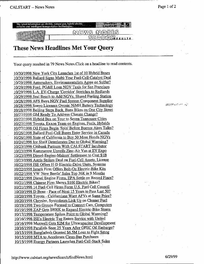
Your query resulted in 79 News Notes.Click on a headline to read contents.
10/30/1998 New York Citv Launches 1st of 10 Hybrid Buses 10/30/1998 Ballard Signs Multi-Year Fuel-Cell-Catalvst Deal 10/29/1998 Automakers. Environmentalists Agree on Sulfur? 10/29/1998 Ford. PG&E Loan NGV Taxis for San Francisco 10/29/1998 L.A. EV-Charge 'Corridor' Stretches to Redlands 10/29/1998 Seal Beach to Add NGVs. Shared Fueling Station 10/28/1998 AFS Buys NGV Fuel System Component Supplier 10/28/1998 Sanyo Licenses Ovonic NiMH Battery Technology 10/28/1998 Beijing Steps Back. Bans Bikes on One Citv Street 10/27/1998 GM Ready To Address Climate Change? 10/27/1998 Hybrid Bus on Tour to Seven Tennessee Cities 10/27/1998 Toyota. Exxon Team on Engines. Fuels. Hybrids 10/27/1998 Oil Firms Begin 'Spin' Before Buenos Aires Talks? 10/26/1998 Ballard Fuel-Cell Buses Enter Service in Canada 10/26/1998 State of California to Buy 50 More Honda NGVs 10/24/1998 Ice Shelf Deteriorates Due to Global Warming? 10/23/1998 Citibank Partners With CALSTART Incubator 10/23/1998 Kummerow Unveils Zinc-Air Van at EV Expo 10/23/1998 Diesel-Engine-Makers' Settlement to Cost $1B 10/23/1998 Astris Strikes Deal on Fuel-Cell Assets. License 10/22/1998ISE Offers H-D Electric-Drive Units. Systems 10/22/1998 Israeli Firm Offers Bolt-On Electric-Bike Kits 10/22/1998 VW 'New Beetle' Sales Top 36K in 9 Months 10/22/1998 Diesel Engine Firms. EPA Settle on Record Fines? 10/21/1998 Chinese Firm Shows $160 Electric Bikes? 10/21/1998 14 Fuel-Cell Firms Form U.S. Fuel Cell Council 10/20/1998 D-Benz - Pace of Next 15 Years to Pass Last 50? 10/20/1998 Toyota - Californians Want AFVs at Same Price? 10/20/1998 Chrysler. Syntroleum Link Up on Cleaner Fuel 10/19/1998 Two Groups Formed to Connect Cars. Computers 10/19/1998 ZAP Gets $800K to Expand Electric-Bike Stores 10/17/1998 Temperature Spikes Point to Global Warming? 10/16/1998 ISE's Electric Tug Enters Service with United 10/16/1998 Maxwell Gets $2M for Ultracapacitor Development 10/16/1998 Parallels Seen 25 Years After OPEC Oil Embargo? 10/15/1998 Bangladesh Granted S6.5M Loan to Fight Smog 10/15/1998 MTA to Accelerate Clean-Bus Purchases 10/15/1998 Energy Partners Launches Fuel-Cell-Stack Sales
http://www.calstart.org/newsSearch/findNews.html 6/29/99

CALSTART--News Notes Page 2 of 2
10/15/1998 Alameda EV Expo Set for Oct. 24-25 10/14/1998 CvberTran to Demo System Oct. 21 at Alameda 10/14/1998 New Catalyst Cuts Fuel-Cell Contamination 10/14/1998 DRI and Team to Develop Fuel-Cell Scooter 10/13/1998 AeroVironment Drives EV 777 Miles in 24 Hours 10/13/1998 New Chip Developed Could Greatly Benefit EVs? 10/13/1998 SoCal Gas Sells NGV Ecotrans to Investor Group 10/13/1998 Few U.S. Buyers Choose Fuel-Efficient Cars. Trucks 10/12/1998 Daimler-Benz Joins Conductive-Charger Group 10/12/1998 'Smart' Car Sales Begin. Tinv Car Gets 50 MPG 10/12/1998 Toyota 'Prius' Hybrid Gets 50 MPG In U.S. EPA Tests 10/12/1998 Salt Lake Citv Police Open Electric-Bike School 10/09/1998 Govt. Report - Gasoline. Electric Costs to Soar 10/09/1998 ECD to Get DOE Funds for Hydrogen Scooters. PV 10/09/1998 Judge Says AOMD. CARB Are Stalling Smog Cuts 10/08/1998 CALSTART Industry Conference Set for Oct. 22 10/08/1998 Automakers' Suppliers Gearing up for AFVs 10/08/1998 USPJRG - U.S. has Bad Air 3 out of Every 4 Days 10/08/1998 VW. Ford. Chrysler to Offer LPG Cars in Mexico 10/08/1998 EU OKs Auto Industry Plan to Curb CQ2 Emissions 10/07/1998 Mexico Citv Bans 40% of Cars in Smog Siege 10/07/1998 New Hawk Electric Retro Bike is Rolling Sculpture' 10/07/1998 Saft Offers Lithium-Ion EV. Hybrid EV Battery Line 10/07/1998 UCLA Campus Police Adds 7 Electric Patrol Bikes 10/06/1998 Renault Fuel-Cell Car Shown at EVS-15 ■., 10/06/1998 AeroVironment Sells 9 EV Fast-Chargers to Hawaii 10/06/1998 Solectria. Singapore Technologies Form EV Team 10/05/1998 PIVCO Unveils New 2-Passenger 'Think' EV 10/05/1998 Honda Shows Family of Shareable 'ICVS' EVs 10/05/1998 VW Shows 200-HP EV. Uses AC Propulsion Drive 10/02/1998 Warming Ended Ice Age in Less Than 60 Years? 10/02/1998 Diesel Emissions Kill 300 Annually in Tel Aviv 10/02/1998 Mercedes-Benz Launches its 'Hybrid Bike' 10/02/1998 Giant Unveils its Own Electric Bike, the 'LaFree' 10/02/1998 Sanyo Grants Euro Sales Rights for Bike Motors 10/01/1998 Survey Finds No Clear Environmental Leader Among Automakers 10/01/1998 Italy Pushes For Cleaner Mopeds and Scooters 10/01/1998 China E-Bikes Are the Real 'Sleeper' to Watch? 10/01/1998 E-Bikes Show Dramatic Increase in Reliability 10/01/1998 European E-Bike Makers Seek Common Standard 10/01/1998 GM Unveils Its First Driveable Fuel-Cell Vehicle
,i00u: ■-'-.'
SmnCH CALSTART SITS % Go back to Search
© Copyright 1996-1999 CALSTART, Inc. All Rights Reserved. Please send comments and suggestions to: [email protected]
http://www.calstart.org/newsSearch/findNews.html 6/29/99

CALSTART - News Notes Page 1 of 2
The latest information on electric, natural gas, hybrid, electric vchlcles.andintelligent transportation tcinno logics.
I WestSt I CALSTART
<*.•''. ':*/; ri, ^'i-crff-l _ J i_ B.I..SU IT S
These News Headlines Met Your Query
;ss£3&,,"'~fer*"--*
Your query resulted in 60 News Notes.Click on a headline to read contents.
11/30/1998 Conductive-Charge Group Sets Press Conference 11/30/1998 Capstone Turbine. AVS Pair on Hybrid Buses 11/30/1998 Exxon. Mobil May Merge in $80 Billion Deal 11/30/1998 Human Activity Responsible for Global Warming 11/27/1998 SunLine CEO Appointed to NGV Advisory Board 11/25/1998 EV1 With NiMH Batteries to be Previewed Dec. 5 11/24/1998 EVs to Play Part in Hollywood Xmas Parade 11/24/1998 ZAP Expands EV Lineup. Adds 'Z-Bike' 11/24/1998 Fleet Tests Slated for Pure Energy's 'OxvDiesel' 11/23/1998 Cairo Launches 5-Year. Pollution-Cutting Program 11/23/1998 Business Journal - LNG 'Shows Great Promise' 11/23/1998 Peugeot - Diesels in 1 of 3 European Cars in 2005 11/23/1998 BMW Opens Silicon Valley Technology Office 11/21/1998 Forbes Ranks JJV1PCO in Top 200 Firms in Country 11/20/1998 Gov. Wilson Appoints New CARB Chairman 11/19/1998 Edison Unit to Mate Fuel Cell With Microturbine 11/19/1998 UC Berkeley. Westport Launch 1st Converted Bus 11/19/1998 Euro Group - Wind to be 'Fuel of the Future'? 11/18/1998 TransTeq Completes its 1st Hybrid Bus for Denver 11/18/1998 Texas Tech to Build Fuel-Cell Chew Lumina 11/18/1998 Gasoline's Real Cost May be $15.14 per Gallon? 11/18/1998 DFW Airport Turns to AFVs. Electrics to Cut Smog 11/17/1998 FAA - Environment is Aviation's No. 1 Challenge 11/17/1998 UC Study - MTBE Not Needed. Pollutes Water 11/17/1998 Ethanol Industry Spent $5.6M-Plus on Lobbying 11/17/1998 DaimlerChrysler to Combine AFV Research 11/16/1998 L.A. OKs LAX Van Contracts. Requires AFVs 11/16/1998 Electric Bike-Maker ZAP 03 Sales up 145% vs. '97 11/16/1998 Energy Partners' PEM Fuel Cell Uses Natural Gas 11/16/1998 Two Scottish City Centers Closing to All But AFVs? 11/14/1998 AlliedSignal Units Testedbv McDonald's.Others 11/13/1998 EV-Maker PIVCO Restructures, to Reopen Nov. 16 11/13/1998 Three So. Calif. Airports May Have EV Rentals? 11/13/1998 Flywheel Power System Receives UL Certification 11/13/1998 For 10th Year. Lead Battery Recycling Leads List 11/12/1998 Aussie Tests - Old Cars Can Pollute 100X More? 11/12/1998 SCAOMD to Send Pager Alerts on Smoggv Days 11/12/1998 Mitsubishi to Have Fuel-Cell EV Ready bv 2005?
http://www.calstart.org/newsSearch/findNews.html 6/29/99

CALSTART - News Notes Page 2 of 2
11/12/1998 Isetta-Makers' Son May Launch New EV Version? 11/11/1998 Aussie Olympics May See 'Solar-Sailing' Ferry? 11/11/1998 Alcan. GM Sign 10-Year Aluminum-Supply Deal 11/11/1998 NABI to Build 132 LNG Buses for Orange County 11/11/1998 Global Oil Demand to Outstrip Supply in 2020? 11/10/1998 Phoenix Ballpark Installs EV-Charging Stations 11/10/1998 Groups Suing Over New Atlanta Roads, Smog? 11/09/1998 Emissions Trading Ducked at Buenos Aires 11/09/1998 Honda Increases LEV/ULEV Production 11/07/1998 Propane School Buses a Success in Portland 11/06/1998 CARB to Allow ZEV Credits for Gasoline Vehicles 11/06/1998 CARB Tightens Smog Rules. Hits SUVs and Diesels 11/05/1998 Santa Clara Police to Use ZAP Electric Bikes 11/05/1998 CNNfn - Hybrids a Factor in 'Smart' Car Buyout? 11/04/1998 CARB to Require SUVs to Meet Car Smog Rules? 11/03/1998 Electric Fuel. Others in $4M Zinc-Air Bus Project 11/03/1998 Lab Builds Thinner. Cheaper Fuel-Cell Electrode 11/03/1998 Ford -10% of its '99 U.S. Production to be FFVs 11/03/1998 Hong Kong. Battling Smog. May Require LPG Taxis 11/02/1998 PIVCO Halts Production. In Talks With Investors 11/02/1998 Toyota Developing Driverless. Clean-Fuel Buses 11/02/1998 CALSTART Open House to Also Feature New AFVs
S«^3>S5~
-5£AH;CAtSra$&.SilS§
Go back to Search
© Copyright 1996-1999 CALSTART, Inc. All Rights Reserved. Please send comments and suggestions to: feedback©calstart. ors
http://www.calstart.org/newsSearch/findNews.html 6/29/99

CALSTART - News Notes Page 1 of 2
The tatest information on electric, natural gas, hybrid electric vehicles and ijitcllfncnt transportation fathnolagieSi
*J;. .:.»'.. > *>M J J $ # ■#* <
RiSULTS
These News Headlines Met Your Query
ij*A^pi.r
Your query resulted in 64 News Notes.Click on a headline to read contents.
12/26/1998 Edison's Rose Parade Float is 'World's Largest EV 12/24/1998 Mail-Order Shopping Saves Pollution. Accidents 12/23/1998 USPS Pledges to Increase Use of EVs. AFVs 12/23/1998 Smoggy Cars Going Undiagnosed in New Tests 12/22/1998 Professor Develops Lighter Hydrogen Tank 12/22/1998 Smoggy Mexico City Orders Half its Cars Parked 12/22/1998 Toyota 'Prius' Hybrid EV Sales Pass 16.000 12/22/1998 ZAP Receives $500K Order from CSW Total EV 12/21/1998 Honda Unveils Hybrid EV. to Offer in Fall 1999 12/21/1998 Firm to Test Systems with Radio. Electron 'Bombs' 12/19/1998 Los Alamos. Sandia National Labs May Lease EVs 12/18/1998 Nissan Announces Altra EV Pricing. Availability 12/18/1998 U.S.. EU. Japan to Discuss Common ITS Standards 12/17/1998 Arizona University Unveils EV-Charging Kiosk 12/17/J998 DaimlerChrysler to Unveil 'Cleaner' Diesel Truck 12/17/1998 Mary Nichols Named to Calif. Environmental Post 12/17/1998 Federal Board Says Diesel Exhaust Carcinogenic 12/16/1998 Honda Issues 'EV Plus' Electric Car Recall'V 12/16/1998 Samsung Motors Closing Calif. Design Studio 12/16/1998 Chinese City to Require Retrofits for Motorcycles 12/16/1998 New Zealand City Launches Three Electric Buses 12/15/1998 11 States Ask EPA for Tougher Sulfur. SUV Laws 12/15/1998 Nissan Developing Simpler. Lower-Cost Hybrid EV 12/15/1998 Iran's Smog Crisis Leads to 10 Deaths. Car Ban 12/15/1998 Mission Viejo to Add Two More NGVs. Fuel Station 12/14/1998 Smog More Carcinogenic to Men. Less to Women 12/14/1998 Battery Rent Not Included in Citroen Van EV Price 12/11/1998 Low-Emission Rotary May be Ideal for Watercraft? 12/11/1998 CARB Aims at Watercraft. Motorcycle Pollution 12/11/1998 Malaysian Firm Sells Electric Go-Karts 12/10/1998 'Cycle' Aims For '99 Electric Motorcycle Launch 12/10/1998 ZAP Awarded Patent on Folding Electric Scooter 12/10/1998 Central Tehran Bans Cars During Smog Siege 12/10/1998 EVI Now Has Y2K-Safe. UL-Listed EV Charger 12/09/1998 BMW Aims to Power All its Forklifts WithFuel CeUs 12/09/1998 Ventura County OKs EVs-and-Chargers Funding 12/09/1998 Malaysian Utility Seeks Partner to Build EVs 12/09/1998 Rental EVs From Six Automakers Now at LAX
http://www.calstart.org/newsSearch/findNews.html 6/29/99

CALSTART - News Notes Page 2 of 2
12/08/1998 AeroVironment Sells Industrial-EV Fast-Chargers 12/08/1998 Electric Fuel. Edison SpA to Add 10 More Test EVs 12/08/1998 Samsung to Swap Car Biz for Daewoo Electronics 12/08/1998 Headlight Glare Another Strike Against SUVs 12/07/1998 Mexico Citv Suffers During Three-Dav Smog Siege 12/07/1998 Nissan. Hitachi to Join on Technology. ITS Projects 12/07/1998 Ford. Baker Electromotive Building 10 EVs for USPS 12/07/1998 AeroVironment Announces Fuel-Cell Test Station 12/05/1998 Edison EV Offers Solar 'Chargeport' for EVs 12/04/1998 SUV Sales Surpass Car Sales. Trend to Continue? 12/04/1998 New York State Buys 50 Honda Civic NGVs 12/03/1998 AeroVironment Fast-Charger Receives UL Listing 12/03/1998 Solectria. GM Forge 'Glider'-Supplv Agreement 12/03/1998 DaimlerChrysler to Provide NiMH EVs to Dealers 12/03/1998 GM's '99 EVls Sport Dramatic. Subtle Changes 12/03/1998 Ford Ranger EV Lease Drops bv $100 Per Month 12/03/1998 GM Unveils Longer-Range. NiMH-Batterv EV1 12/03/1998 China - EVs. AFVs Important to Country's Future 12/02/1998 Exxon. Mobil Announce Record $75.3B Merger .m@~&:rz: 12/02/1998 Mercedes Fuel-Cell Buses to be Tested in Mexico 12/02/1998 Ford. Others to Open AFV Showcase in San Diego
' 12/02/1998 Swindler Sentenced for EV Scam 12/01/1998 Fueling Delays Spur Cut in Georgia NGV Fleet 12/01/1998 New Fiat EV Goes on Sale in Europe 12/01/1998 Nissan Diesel to Expand CNG Truck Lineup 12/01/1998 EV-Building High School Students Build Light Rail
SEABCWCAISTOET SITE! Go back to Search
© Copyright 1996-1999 CALSTART, Inc. All RightsReserved. Please send comments and suggestions to: feedback© calstart. org
http://www.calstart.org/newsSearch/fmdNews.html 6/29/99

DEFENSE ADVANCED RESEARCH PROJECTS AGENCY ELECTRIC AND HYBRID ELECTRIC VEHICLE TECHNOLOGIES COOPERATIVE AGREEMENT MDA972-95-2-0011 and
Modifications through P00016 Quarterly Report: October 1 through December 31,1998
HEAVY-DUTY VEHICLE INDUSTRY ANALYSIS Project Manager: CALSTART CS-AR97-12
Program Goal: CALSTART, under contact agreement with the Defense Advanced Research Project Agency is performing a market assessment of the heavy-duty hybrid-electric (HDHEV) industry. The study will evaluate the viability of commercial heavy-duty hybrid systems and determine how an established market could complement military objectives. The study is of particular interest since both DARPA and the U.S. Army have identified many potential benefits associated with these technologies. Electric drive systems are ,*--ife'":''■'"/■ recognized as a "critical technology" in the Army and Technology Master Plan and are strongly supported in the Strategic Technologies for the Army of the 21s' Century Plan.
OCTOBER-DECEMBER, 1998
The database for the hybrid-electric and competing technologies was completed. The interfaces were designed for optimum ease of use by the end user.
In order to illustrate the.aggregate effects of efficiency gains resulting from economies of scale, technological advances in production, improved product design, revised production methods, and overall "learning" process, experience curves were developed by CALSTART. Experience curves were derived to estimate component and heavy-duty hybrid-electric vehicle prices based on manufacturing trends and the evolutionary behavior of past technologies. This methodology can be used as a general guide for predicting the rate of price decline for the heavy-duty hybrid-electric technologies.
JULY - SEPTEMBER, 1998
CALSTART completed the collection of technical reports and data on a global basis for hybrid-electric technologies. Interviews with manufacturers of hybrid-electric vehicles and related components were also performed during this quarter.
06/30/99 11 CALSTART

CßLSTIIBI
DEFENSE ADVANCED RESEARCH PROJECTS AGENCY ELECTRIC AND HYBRID ELECTRIC VEHICLE TECHNOLOGIES COOPERATIVE AGREEMENT MDA972-95-2-0011 and
Modifications through P00016 Quarterly Report: October 1 through December 31,1998
HEAVY-DUTY VEHICLE INDUSTRY ANALYSIS Project Manager: CALSTART CS-ÄR97-I2
Global data collection on the competing heavy-duty technologies continued. To date, the competing market that has been identified that could potentially affect the penetration of hybrid-electric technology into the heavy-duty arena includes: natural gas (compressed and liquefied), new diesel technologies, biodiesel, synthetic diesel, and dimethyl ether. In conjunction with the data collection, barriers are being identified that could influence the success of the various technologies in the heavy-duty market. These barriers can be categorized into political, economic, and technological areas of focus. «ssg^i--
'Also during this quarter, the framework of the database was developed. During the next quarter, the spreadsheets that have been used for data collection will be imported into the database. •
' MILESTONES DARPA- MATCH QTR DATE DUE COMPLETE MATCH. FUNDS v
EXPENDED
DARPA FUNDS EXPENDED
1 Compilation of existing data/Update EHVTP database
40,000 1 3/30/98 3/31/97 40,000
2 Analysis of Technology transfer to military applications
20,000 2 7/30/98 6/30/98 20,610
3 Evaluation of competing technologies
25,000 3 8/30/98 25,000
4 Assessment of market development factors
55,000 4 9/30/98 75,000
5 Final report 41,829 5 12/30/98
TOTAL 181,829 160,610
06/30/99 12 CALSTART

DEFENSE ADVANCED RESEARCH PROJECTS AGENCY ELECTRIC AND HYBRID ELECTRIC VEHICLE TECHNOLOGIES COOPERATIVE AGREEMENT MDA972-95-2-0011 and
Modifications through P00016 Quarterly Report: October 1 through December 31,1998
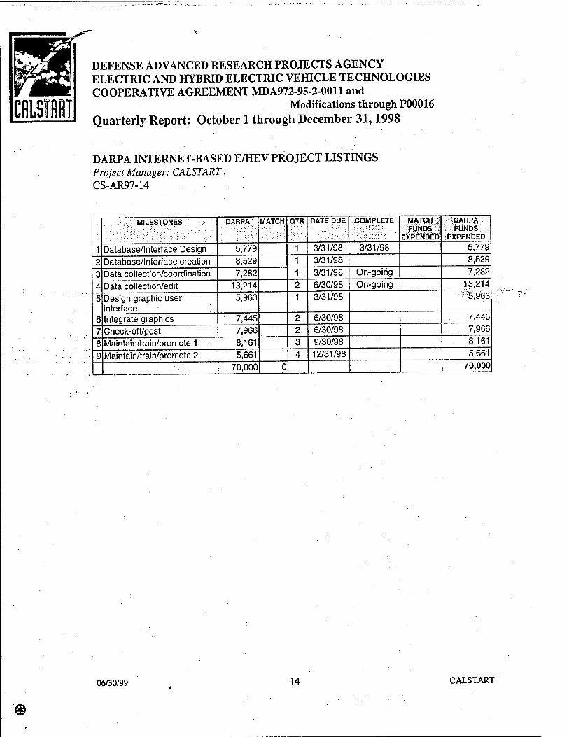
DARPA INTERNET-BASED E/HEV PROJECT LISTINGS Project Manager: CALSTART CS-AR97-14
Program Goal: To provide an easy-tG-use, publicly accessible database on the World Wide Web that allows Internet users to search for DARPA-funded electric and hybrid-electric advanced transportation projects nationwide. •
OCTOBER - DECEMBER, 1998
The database for the hybrid-electric and competing technologies was completed. The .interfaces were designed for optimum ease of use by the end user.
Tn order to illustrate the aggregate effects of efficiency gains resulting from economies of ; scale, technological advances in production, improved product design, revised production ; methods, and overall ■'learning"- process, experience curves were developed by • CALSTART. Experience'curves were derived to estimate component and heavy-duty hybrid-electric vehicle prices based on manufacturing trends and the evolutionary behavior of past technologies. This methodology can be used as a general guide for predicting the rate of price decline for the heavy-duty hybrid-electric technologies.
JULY - SEPTEMBER, 1998
CALSTART has sent a follow-up letter with supporting materials to each consortium member to aid them in submitting their updated project listings. It has printed out all projects from the SPC database for consortium members to easily edit and return. So far three consortia have responded and CALSTART is in the process of updating these records on the web database. It is working with the remaining consortium members to obtain their project updates.
CALSTART has experienced problems obtaining a copy of the SPC database that does not cut off field information. SPC has acknowledged that this is a problem and has tried several times to fix it, and has concluded that its own database does not contain the complete field information for several fields, including the Brief Description field. CALSTART and SPC will continue to try to resolve this problem. The initial design of the database has been completed and can be viewed at www.darpaehev.com.
06/30/99 13 CALSTART
DEFENSE ADVANCED RESEARCH PROJECTS AGENCY ELECTRIC AND HYBRID ELECTRIC VEHICLE TECHNOLOGIES COOPERATIVE AGREEMENT MDA972-95-2-0011 and
Modifications through P00016 Quarterly Report: October 1 through December 31,1998
DARPA INTERNET-BASED E/HEV PROJECT LISTINGS Project Manager: CALSTART CS-AR97-14
MILESTONES DARPA MATCH QTR DATE DUE COMPLETE MATCH FUNDS
EXPENDED
DARPA FUNDS
EXPENDED
1 Database/Interface Design 5,779 1 3/31/98 3/31/98 5,779
2 Database/Interface creation 8,529 1 3/31/98 8,529
3 Data collection/coordination 7,282 1 3/31/98 On-going 7,282
4 Data collection/edit 13,214 2 6/30/98 On-going 13,214
5 Design graphic user interface
5,963 1 3/31/98 ;**5^963
6 Integrate graphics 7,445 2 6/30/98 7,445
7 Check-off/post 7,966 2 6/30/98 7,966
8 Maintain/train/promote 1 8,161 3 9/30/98 8,161
9 Maintain/train/promote 2 5,661 4 12/31/98 5,661
70,000 0 70,000
06/30/99 14 CALSTART

DEFENSE ADVANCED RESEARCH PROJECTS AGENCY ELECTRIC AND HYBRID ELECTRIC VEHICLE TECHNOLOGIES COOPERATIVE AGREEMENT MDA972-95-2-0011 and
Modifications through P00016 Quarterly Report: October 1 through December 31,1998
FLYWHEEL LIFECYCLE TESTING Project Manager: U.S. Flywheel Systems CS-AR95-02
Program Goal: The purpose of this program is to conduct lifecycle tests of the flywheel module system in order to spot a frailty in any of the operating components. This system includes every subsystem that comprises a mechanical battery, except for the power and electronic controls. ■■
-S-'.
Jack Bitterly of U.S. Flywheel Systems (USFS) presented on this project to Dr. Robert Rosenfeld and other members of the DARPA E/HEV Program at the Semi-Annual review in Austin, Texas. -
OCTOBER-DECEMBER, 1998
USFS has continued to work on the reliability of the magnetic bearing system at the design speed of 40,000 rpm. USFS has also been developing plans to increase the design speed to 60,000 rpm.
As of the end of the quarter, the hardware is complete and the drive electronics and magnetic bearing control are in the final acceptance testing phase. USFS has confirmed the ability to spin the 50 pound rotors to over 40,000 rpm. In addition, USFS has demonstrated shaft speeds alternately to over 60,000 rpm in the test facility. USFS expects to begin the first phase of actual life cycle testing in January 1999. USFS still projects project completion by June 1999. ...
JULY - SEPTEMBER, 1998
U.S. Flywheel Systems (USFS) continued work on Task F, system checkout. The data acquisition systems are installed and working and are currently being calibrated now that the flywheel module has been installed in the test chamber. USFS has completed the design of sufficiently robust magnetic bearings in-house. USFS has also completed the test facility and is working on establishing reliable, consistent operation. When this has been demonstrated, USFS will begin life cycle testing.
06/30/99 15 CALSTART

DEFENSE ADVANCED RESEARCH PROJECTS AGENCY ELECTRIC AND HYBRID ELECTRIC VEHICLE TECHNOLOGIES COOPERATIVE AGREEMENT MDA972-95-2-0011 and
Modifications through P00016 Quarterly Report: October 1 through December 31,1998
FLYWHEEL LIFECYCLE TESTING Project Manager: U.S. Flywheel Systems CS-AR95-02
USFS has accomplished magnetic levitation speeds for 50 pound rotors to over 40,000 rpm. USFS believes that shaft speeds to over 60,000 rpm are possible with their technology. USFS predicts that the first target life cycle of .10,000 charge/discharge cycles could be accomplished in 3-4 months on a 24 hour/day uninterrupted program once the test system reliability is sufficient.
USFS still plans to complete the contract statement of work by mid-1999 with no additional cost to CALSTART or DARPA. USFS is currently billing only for the cost of completing the quarterly report.: The additional cost to develop the in-house magnetic bearings has been born entirely by USFS.
...MILESTONE < DARPA . MATCH QTR DATE DUE COMPLETE MATCH . FUNDS
EXPENDED
DARPA FUNDS
EXPENDED
1 Detail plan 900,000 1 7/7/96 7/16/96
2 Fabricate flywheels 230,000 300,000 2 9/7/96 7/16/96 1,129,267 195,200
3 Design, prog. & fabricate DAS
90,000 140,000 3 9/7/96 12/2/96 318,126 171,057
4 Design/Install containment chambers
50,000 80,000 4 9/7/96 12/30/96
5 Install modules/check system
60,000 5 10/7/96
6 Cycle tests/statistical analysis
20,000 80,000 6 3/7/97
7 Final report 10,000 40,000 7 6/7/97 ■ -
400,000 1,600,000 1,447,393 366,257
06/30/99 16 CALSTART

CfiLSTflRT
DEFENSE ADVANCED RESEARCH PROJECTS AGENCY ELECTRIC AND HYBRID ELECTRIC VEHICLE TECHNOLOGIES COOPERATIVE AGREEMENT MDA972-95-2-0011 and
Modifications through P00016 Quarterly Report: October 1 through December 31,1998
FLYWHEEL SHOCK TESTING Project Manager: US Flywheel Systems, Inc. CS-AR97-05
Program Goal: The purpose of this program is to characterize flywheel energy storage systems on both magnetically levitated and mechanical bearings subject to typical vibration spectrums encountered by hybrid vehicles. '
Jack Bitterly of U.S. Flywheel Systems (USFS) presented on this project to Dr. Robert Rosenfeld and other members of the DARPA E/HEV Program at the Semi-Annual review in Austin, Texas.
OCTOBER-DECEMBER, 1998
USFS has continued to work on the development of the mechanical- and magnetic bearing modules to greater than the respectivetarget speeds of 40,000 rpmand 60,000 rpm. USFS is still working on improving system reliability and will commence the shock and vibration testing as soon as the reliability goals are met. USFS is currently projecting completion of this program for June 1999.
JULY - SEPTEMBER, 1998
US Flywheel Systems (USFS) has not made a great deal of progress specifically on this project. USFS has focused most of its effort on the development of reliable magnetic bearings for use in its flywheel systems. As a result of that effort, USFS has not made much progress on this program. USFS plans to resume work on the shock and vibration testing program as soon as the magnetic bearings are operational. USFS is currently billing only for the cost of completing the quarterly report. CALSTART will work with USFS to establish a new timeline for program completion.
06/30/99 17 CALSTART

CRLSTRRT
DEFENSE ADVANCED RESEARCH PROJECTS AGENCY ELECTRIC AND HYBRID ELECTRIC VEHICLE TECHNOLOGIES COOPERATIVE AGREEMENT MDÄ972-95-2-0011 and
Modifications through P00016 Quarterly Report: October 1 through December 31,1998
FLYWHEEL SHOCK TESTING Project Manager: US Flywheel Systems, Inc. CS-AR97-05
MILESTONES DARPA MATCH QTR DATE DUE COMPLETE MATCH FUNDS
EXPENDED
DARPA FUNDS
EXPENDED
1 Test Data Collection 45,000 45,000 1 12/31/97 12/31/97 45,000 45,000
2 Establish test parameters and profile
33,000 52,000 2 3/31/98 12/31/97 33,000 52,000
3 Report on desiqns/fabrication
5,000 10,000 3 6/30/98
4 Shock testing. Design/fab mounting system
235,000 255,000 4. 9/30/98 12/31/97 157,530 57,000
5 Prepare for testing 5,000 10,000 5 12/31/98 12/31/98 6,345
6 Testing at Aberdeen. Final Report
82,000 78,000 6 3/31/99
450,000 450,000 6/30/99 235,530 160,345
06/30/99 18 CALSTART

CISTIT
DEFENSE ADVANCED RESEARCH PROJECTS AGENCY ELECTRIC AND HYBRID ELECTRIC VEHICLE TECHNOLOGIES COOPERATIVE AGREEMENT MDA972-95-2-0011 and
Modifications through P00016 Quarterly Report: October 1 through December 31,1998
COMPOSITE ROTOR CYCLE TEST PROGRAM Project Manager: US Flywheel Systems, Inc. CS-AR98-03
OCTOBER-DECEMBER, 1998
CALSTART and USFS have not yet finalized the contract for this project, although work continues on setting firm and achievable milestones. CALSTART has not pressured USFS to sign this contract due to the present difficulties with the other two programs. If all proceeds on schedule, CALSTART hopes to put USFS under contract prior to thenext^ DARPA meeting.
06/30/99 19 CALSTART

DEFENSE ADVANCED RESEARCH PROJECTS AGENCY ELECTRIC AND HYBRID ELECTRIC VEHICLE TECHNOLOGIES COOPERATIVE AGREEMENT MDA972-95-2-0011 and
Modifications through P00016 Quarterly Report: October 1 through December 31,1998
COMPACT, RUGGED, LOW COST CIRCUIT BREAKERS FORELECTRIC AND HYBRID ELECTRIC VEHICLES Project Manager. Coriolis Corporation CS-AR95-03
Project Goal: The goal of the project is the development and demonstration of a circuit breaker comprising a new class of low cost switchgear suitable for use on the customer and utility side of the transformer, as well as in electric and hybrid electric vehicles.
OCTOBER -DECEMBER, 1998 ■■■■■.m&-Z
During the quarter, CALSTART sent a letter to Mr. Arthur Iversen, President of Coriolis Corporation; indicating that if the required match funding .were not secured by December 4,1998, the project would be cancelled. Tn a phone conversation with CALSTART staff in early December, Mr. Iversen indicated that he would not be able to secure the match funding. Therefore, CALSTART intends, to cancel this project and request that the funding be reallocated to other projects with the consent of DARPA. A copy of CALSTART's October 30,1998, letter to Mr. Iversen is included.
JULY - SEPTEMBER, 1998
No progress was made during the quarter, as this project is not under contract. Art Iversen of Coriolis did indicate that he was pursuing other potential sources of cost-share funding for this project, so CALSTART has not yet formally notified Coriolis that the funding will be withdrawn. If these latest potential sources of cost-share for the project do not materialize, during the next quarter CALSTART will notify Coriolis of the intent to cancel the project. -
06/30/99 20 CALSTART

DEFENSE ADVANCED RESEARCH PROJECTS AGENCY ELECTRIC AND HYBRID ELECTRIC VEHICLE TECHNOLOGIES COOPERATIVE AGREEMENT MDA972-95-2-0011 and
Modifications through P00016 Quarterly Report: October 1 through December 31,1998
COMPACT, RUGGED, LOW COST CIRCUIT BREAKERS FOR ELECTRIC AND HYBRID ELECTRIC VEHICLES
Project Manager: Coriolis Corporation CS-AR95-03
MILESTONES DARPA MATCH QTR DATE DUE COMPLETE MATCH FUNDS
EXPENDED
DARPA FUNDS
EXPENDED
1 Final draft of electrical test station desiqn
5,307 5,400 1 TBD :a»-?—j
2 Select mechanical design team. Complete design.
33,708 34,292 2 TBD
3 Design modifications to . circuit breaker. Construct/debug test station. Fabricate circuit breaker components.
30,238 30,762 3 TBD
4 Test guillotine circuit breakers.
19,217 20,171 4 TBD
5 Final guillotine circuit breaker design.
11,530 9,375 5 TBD
| 100,000 100,000
06/30/99 21 CALSTART

CRLSTRRT A California Ndn-Profit
Consortium Developing
Advanced Transportation
Technologies
Board of Directors
Dr. Stephen D. Ban Gas Research Institute
Dr. Lon E. Bell Amerigon Incorporated
Mr. Robert H. Bridenbecker Southern California Edison
Dr. Malcolm R. Currie Project California
Mr. R. Thomas Decker Bank of America
, Mr. Donald E. Felsinger ■Diego Gas & Electric Company
Mr. Michael J. Gage CALSTART, Inc.
Dr. Richard F. Härtung Lockheed Martin IMS
Mr. Charles R. Imbrecht California Energy Commission
Ms. Veronica Kun Natural Resources Defense Council
Mr. Warren I. Mitchell Southern California Gas Company
Mr. Michael Peevey Chairman of the Board
Mr. James Quillin California Conference of Machinists
Mr. Benjamin M. Rosen Rosen Motors
October 30, 1998
Arthur H. Iversen President Coriolis Corporation 15315 SobeyRoad Saratoga, CA 95070
RE: Development of Compact, Rugged, Low Cost Circuit Breakers for Electric and Hybrid Electric Vehicles
Dear Mr. Iversen:
This letter serves as formal notification that CALSTART intends to withdraw^ the offer of $100,000 in funding from the Defense Advanced Research Projects Agency (DARPA) Electric and Hybrid Electric Vehicle (EHEV) Program for the above-referenced project unless you can secure the required $100,000 in cost-share by December 4, 1998. This funding was allocated from fiscal year 1995 EHEV Program funds.
We appreciate the difficulties you have encountered in attempting to secure this cost-share funding and regret that we must now take this step. However, DARPA requires that the EHEV Program funds be spent in a timely fashion. This notice is in no way a reflection of the quality of the Coriolis proposal and technology.
If you have any questions on this matter, please contact me at (510) 864-3005, or Mark Kragen of my staff at (510) 864-3003.
/John Boesel Executive Vice President
Mr. Mitchell S. Rouse SuperShuttle International, Inc.
Ms. Jan Schori Sacramento Municipal Utility District
Mr. Dennis Tito City of Los Angeles
Department of Water & Power
Dr. W. Scott Walker Hughes Electronics
Mr. Richard A. White San Francisco Bay Area
Rapid Transit District
Hangar 20, Naval Air Station, 1889 First Street, Alameda, California 94501 Phone: 510 864-3000 Fax: 510 864-3010 E-mail: [email protected] Web: http://www.calstart.org <s

DEFENSE ADVANCED RESEARCH PROJECTS AGENCY ELECTRIC AND HYBRID ELECTRIC VEHICLE TECHNOLOGIES COOPERATIVE AGREEMENT MDA972-95-2-0011 and
Modifications through P00016 Quarterly Report: October 1 through December 31,1998
ADVANCED HYBRID RECONNAISSANCE VEHICLES .Project Managers: AeroVironment and Rod Millen Special Vehicles (RMSV) CS-AR95-06A and B
The goal of this project is the design of a suspension system for advanced hybrid reconnaissance vehicles, and the design and analysis of a variety of components for advanced hybrid reconnaissance vehicles, including an inverter and a DC-DC converter.
John McGinnis and Chris Shaw of AeroVironment attended the November 1 through November 4, 1998, DARPA Electric and Hybrid Electric Vehicle Program RevievMftd "^ presented the results of projects to date. __ ■ •
OCTOBER - DECEMBER, 199S
The individual reports:completed under this project were summarized in last quarter's report and were included with previous quarterly reports. An overall summary of this project is provided in the Appendix.
JULY - SEPTEMBER, 1998
AeroVironment submitted a final report for this project, which is included in the Appendix. The final report merely summarizes the work of the various tasks associated with this project. During the course of the work, AeroVironment completed more-detailed task reports for each task completed. Those task reports are summarized below.
Rod Millen Special Vehicles had completed its design work for an active differential system and submitted a final report during the first quarter of 1997. The final Rod Millen report was approximately 80 pages plus appendices, totaling nearly 300 pages in all. The report was sent to DARPA on August 6,1997. In its report, Rod Millen concluded that its active differential system has the potential to improve JTEV performance under traction- limited conditions.
06/30/99 23 CALSTART

DEFENSE ADVANCED RESEARCH PROJECTS AGENCY ELECTRIC AND HYBRID ELECTRIC VEHICLE TECHNOLOGIES COOPERATIVE AGREEMENT MDA972-95-2-0011 and
Modifications through P00016 Quarterly Report: October 1 through December 31,1998
ADVANCED HYBRID RECONNAISSANCE VEHICLES Project Managers: AeroVironment and Rod Millen Special Vehicles (RMSV) CS-AR95-06A and B
Summaries of the following AeroVironment task reports appear below: • 6kW Bi-Directional DC-DC Converter Development Report • Battery Pack Mechanical Design Report • Electric Pumps and Peripheral Component Development Report • Battery Management System Upgrade Report • Battery Pack Cell Specification Report • Quiet Gears Final Report ■:&■*,?.-..—.- • Inverter Packaging Report
6kW Bi-Directional DC-DC Converter Development Report AeroVironment designed a bi-directional power supply that is capable of running onboard equipment, providing a float charge to the 24-voIt bus from the.high-voltage bus for charging the'.124-volt battery on the JTEV, providing charging from an external 24-volt power source to the high-voltage bus and providing auxiliary power unit starting power to the high-voltage bus from the 24-volt bus in the event of main battery depletion or failure. However, it was not possible to design the converter to fit within the allocated space on the JTEV and still perform each of the functions detailed above. The design is complete, but it would be necessary to redesign the JTEV to accommodate the converter. This work has not been authorized.
06/30/99 24 CALSTART

ciLSim
DEFENSE ADVANCED RESEARCH PROJECTS AGENCY ELECTRIC AND HYBRID ELECTRIC VEHICLE TECHNOLOGIES COOPERATIVE AGREEMENT MDA972-95-2-0011 and
Modifications through P00016 Quarterly Report: October 1 through December 31,1998
ADVANCED HYBRID RECONNAISSANCE VEHICLES Project Managers: AeroVironment and Rod Millen Special Vehicles (RMSV) CS-AR95-06AandB
Battery Pack Mechanical Design Report In conjunction with its cell specification work, AeioVironment redesigned the JTEV battery pack housing to incorporate nickel-cadmium'batteries. Because of the compact nature of the JTEV, AeroVironment determined that any new battery chemistry utilized would need to fit into the existing space allocated for the original lead acid battery pack. The redesign involved ensuring that a nickel-cadmium battery pack would be adequately' secured and cooled within the space.: AeroVironment successfully completed the-redesign. However, nickel-cadmium batteries were never procured.
Electric Pumps and Peripheral Component Development Report This task involved upgrading the cooling system and power steering system with larger pumps and radiators fans to improve performance of these components. Testing of the JTEV with the original cooling components proved those components to be inadequate. Based on axomputer model of radiator behavior, AeroVironment increased the size of the cooling fans and identified other necessary components to upgrade the system. The new system has been installed on the JTEV. The JTEV originally had an undersized power steering pump from a Toyota MR-2 vehicle due to availability constraints. AeroVironment and Rod Millen Special Vehicles developed specifications for a new power steering pump and identified a contractor to develop it. The new pump has been successfully installed on the JTEV and appears to be more tolerant to the severe use of the JTEV. It also provides better steering response under vigorous use than the initial power steering unit. AeroVironment completed this task in September 1996.
06/30/99 25 CALSTART

CBISTIT
DEFENSE ADVANCED RESEARCH PROJECTS AGENCY ELECTRIC AND HYBRID ELECTRIC VEHICLE TECHNOLOGIES COOPERATIVE AGREEMENT MDA972-95-2-0011 and
Modifications through P00016 Quarterly Report: October 1 through December 31,1998
ADVANCED HYBRID RECONNAISSANCE VEHICLES Project Managers: AeroVironment and Rod Mitten Special Vehicles (RMSV) CS-AR95-06A and B
Battery Management System Upgrade Report . The purpose of this work task was to enhance the longevity of the battery pack used in the JTEV. To accomplish this, AeroVironment installed the latest version of its SmartGuard® battery management system on the JTEV. As part of this task, a new preventative maintenance schedule was implemented for the batteries in September 1996. The battery management system is performing reliably and communicates module-level voltage and temperature to a central controller and eliminates problems associatedÄh-^r- deep cycling of the battery packs.
Battery Pack Cell Specification Report This task involved the development of specifications for nickel-cadmium batteries for use in the JTEV and a comparison' of the :nickel-cadmium batteries to the JTEVs existing lead acid batteries. AeroVironment tested a ten-cell module of nickel-cadmium batteries, but not enough useful data was gathered due to problems with thermal management (the cells exploded). Difficulty in procuring a replacement module resulted in no further testing of nickel-cadmium cells. Based on limited test data and specification work done by AeroVironment, it appears that nickel-cadmium batteries would offer little if any improvement in energy density, but significant gains in power density. With the limited data, AeroVironment concluded that the limited performance improvements from a nickel- cadmium battery were likely not worth the time and effort required to build and install the new pack.
06/30/99 26 CALSTART

DEFENSE ADVANCED RESEARCH PROJECTS AGENCY ELECTRIC AND HYBRID ELECTRIC VEHICLE TECHNOLOGIES COOPERATIVE AGREEMENT MDA972-95-2-0011 and
Modifications through P00016 Quarterly Report: October 1 through December 31,1998
ADVANCED HYBRID RECONNAISSANCE VEHICLES Project Managers: AeroVironment and Rod Mitten Special Vehicles (RMSV) CS-AR95-06A and B
Quiet Gears Final Report Rod Millen Special Vehicles and AeroVironment incorporated a helical gear train in the JTEV and conducted testing to demonstrated low noise operations capabilities. The original JTEV had "straight cut" gears that generated a significant noise signature. The helical gear train reduced noise at idle and speed, as shown in the table below. The table indicates sound readings for electric-only operation and for operation with the auxiliary ., power unit functioning. Rod Millen Special Vehicles and Aero Vironment completed this work in September 1996.
Exterior Sound Levels (measured Transmission
Straight cut gears Helical cut gears
per SAE Highway Standard J366) Stationary Sound
Level (electric/APU) 87 dB/91dB 75 dB/87dB
Sound Level at 20 mph (electric/APU)
89dB/93dB 76/dB/86dB
Sound Level at 30 mph (electric/APU)
90db/unavailable 76dB/84dB
Inverter Packaging Report AeroVironment repackaged the inverters and accomplished the two main goals of this task: 1) easier inverter maintenance; and 2) increased seat clearance, allowing more room for the driver and passenger. Additionally, the repackaging relocated cable connections into the inverters, allowing greater driver visibility out of the rear of the vehicle.
Fiscal year 1995 funding was also allocated for a sizing'feasibility study and a gear ratio selection study for a two-speed transmission design. These tasks were completed in December 1996. Additional funds were allocated in fiscal year 1996 for the manufacture and installation of the design into the JTEV. The goal of the two-speed transmission work was to increase the top speed of the vehicle and realize greater hill-climb ability. Results of this task will be reported under the fiscal year 1996 funding.
06/30/99 27 CALSTART

CflLSTll
DEFENSE ADVANCED RESEARCH PROJECTS AGENCY ELECTRIC AND HYBRID ELECTRIC VEHICLE TECHNOLOGIES COOPERATIVE AGREEMENT MDA972-95-2-0011 and
Modifications through P00016 Quarterly Report: October 1 through December 31,1998
ADVANCED HYBRID RECONNAISSANCE VEHICLES Project Managers: AeroVironment and Rod Mitten Special Vehicles (RMSV) CS-AR95-06A and B
MILESTONES DARPA MATCH QTR DATE DUE COMPLETE : MATCH FUNDS
EXPENDED
DARPA FUNDS
EXPENDED
RMSV CS-AR95-06A
1 Initiate work 75,000 1 4/1/96 4/3/96 75,000
2 Suspension/ Differential Dev
60,287 2 4/30/96 . .. 6/30/96 13,881
3 Design review . 60,287 3 6/30/96 6/30/96 59,688
4 Suspension design 60,287 4 9/30/96 9/30/96 75,894
5 Project Report 5 12/31/96 : 1/2/97 60,071
G Algorithm dev. Final report
60,288 6 2/28/97 31,615
TOTAL 316,149 0 316,149
AeroVironment CS-AR95-06B
1 Battery Mgmt Final rpt Inverter repkg final Low Acoustic Trans rpt. Peripherals rpt
309,974 53,972 1 9/31/96 9/31/96 53,972 309,974
2 DC-DC converter Design
215,495 37,520 2 12/31/96 12/31/96 37,520 215,490
3 Final Report 32,717 0 3 3/30/97 -' -
TOTAL 558,181 91,492 91,492 525,464
06/30/99 28 CALSTART

CISTBII
DEFENSE ADVANCED RESEARCH PROJECTS AGENCY ELECTRIC AND HYBRID ELECTRIC VEHICLE TECHNOLOGIES COOPERATIVE AGREEMENT MDA972-95-2-0011 and
Modifications through P00016 Quarterly Report: October 1 through December 31,1998
PROPULSION SYSTEM FOR ADVANCED HYBRID RECONNAISSANCE VEHICLES
Project Manager: Rod Mitten Special Vehicles and AeroVironment CS-AR96-09AandB
Project Goal: The goal of this project is to improve the propulsion system for hybrid electric reconnaissance vehicles.
OCTOBER - DECEMBER, 1998 ^ »
On December 16,1998, CALSTART sent a letter to Dr. Robert Rosenfeld of DARPA requesting reallocation of the remaining funds for this project. That letter is included. AeroVironment submitted a report documenting the work completed on this project. That report is included in the Appendix.
JULY - SEPTEMBER, 1998
During the quarter, CALSTART and AeroVironment worked to detail expenditures to date on this program. The goal of this work was to identify the exact amount that could be reallocated to new JTEV-related projects. During the next quarter, CALSTART expects to requests a reallocation of these funds to JTEV repair in conjunction with the fuel efficiency testing and hybrid algorithm refinement projects funded in fiscal year 1997. CALSTART will also request that some fiscal year 1996 funds be reallocated to the Rod Millen Special Vehicles Semi-Active Suspension project approved in the fiscal year 1998 funding cycle. . _
If DARPA approves the reallocations, a final report covering work completed on the fiscal year 1996 funding will be submitted to DARPA.
06/30/99 29 CALSTART

DEFENSE ADVANCED RESEARCH PROJECTS AGENCY ELECTRIC AND HYBRID ELECTRIC VEHICLE TECHNOLOGIES COOPERATIVE AGREEMENT MDA972-95-2-0011 and
Modifications through P00016 Quarterly Report: October 1 through December 31,1998
PROPULSION SYSTEM FOR ADVANCED HYBRID RECONNAISSANCE VEHICLES
Project Manager: Rod Mitten Special Vehicles and AeroVironment CS-AR96-09A and B
MILESTONES DARPA MATCH QTR DATE DUE COMPLETE MATCH FUNDS
EXPENDED
DARPA FUNDS
EXPENDED
AeroVironment CS-AR96-09A
1 Initiate Work 69,282 0 12/31/96 12/31/96 68,424
2 Pack Mechanical Design Report
72,727 1 3/30/97 13,113
3 Battery Progress Report
92,727 2 6/30/97 7,722
4 2 Speed Trans report 74,066 3 9/30/97
7 Final Report 17,018 4 12/31/97 180,343 0 89,259
RODMILLEN CS-AR96-09B
1 Initiate work 38,614 1 9/30/96 9/30/96 38,614
2 Test platform support 38,615 2 12/31/96 12/31/96 8,361
3 ADC fabrication 38,615 3 3/30/97 6,000 42,962
4 ADC testing 38,615 10,000 4 6/30/97 18,505
5 ADC integrated JTEV 38,615 10,000 5 9/30/97 24,154
6 Algorithms refined 38,615 10,000 6 12/31/97 110,603
7 Test complete/Final report
11,510 6,000 7 3/30/98
243,199 36,000 6,000 243,199
06/30/99 30 CALSTART

^o27Io7sFlPs3<!r!l^
CBLS11HI A California Non-profit
Consortium Developing
Advanced Transportation
Tcchnologiaa
Bond ot Directors
Mr. David Auul ABL Inc.
Or. Stapfisn p, Ban Gas Research Institut*
Or. Lou E. Bell Arr.erljon Incorporated
Mr. RiuhuriJ Cromwsll Sunllne Transit Agency
Dr. Malcolm R. Currl» Projuct California
Mr. Vlncunr 8. Fiorc Css Raeaarcn Inr.ritiitn
Mr. Michael J. ßage MI.START, Inc.
Mr. G?ry Gleason Sanb Barbara MTD
Mr. Eric Haley RlwsrElds County
Transportation Commission
Mr. Norman Mlnctg Lockhasd Martin
Mr. Sycd HU33aln IMKil)
Dr. CMung Liu Eoutn Coast Air Oimlily
Manaoenient Dfslrfct
Mr. Rick Morrow Southern California Gas Company
M3. Gail Rudarman FiKier Natural Hcsourco Dersns« Council
Mr, F.rwin Torna3n Chairman Emeritus
Dataproducts Corporation
December 16,1998
Dr. Robert Rosenfeld Program Manager Defense Advanced Research Projects Agency 3701 North Fairfax Drive Arlington, VA 22203-1714
RE: Rcallocation of Joint Tactical Electric Vehicle Funds for AeroVironment and Rod Millen Special Vehicles
Dear Dr. Rosenfeld:
We are requesting further reallocation of funds from the various AeroVironment and Rod Millen Special Vehicles projects which are referenced in this letter. If approved, this reallocation and authorization would compliment the rcallocations you approved per our letter of May 15,1998, and authorize additional rcallocations. These projects involve work on the Joint Tactical Electric Vehicle (JTEV) Program and other related items. The specific reallocations and authorizations requested are detailed below.
In December 1997, Jeff Bradel of the Naval Surface Warfare Center (NSWC) at Carderock requested that AeroVironment and Rod Millen Special Vehicles cease working on the JTEV projects detailed below. This cessation was based on NSWC Carderock's desire to reallocate these funds for AeroVironment to repair the JTEV and conduct, in conjunction with the Aberdeen Proving Grounds, fuel efficiency testing on the JTEV. NSWC Carderock also wished for some funds to be redirected toward semi-active suspension development work by Rod Millen Special Vehicles. AeroVironment and Rod Millen Special Vehicles worked with Mr. Bradel to develop the revised projects that are the subject of this reallocation and authorization request.
The table below indicates the funding amounts previously awarded to AeroVironment under the Defense Advanced Research Projects Agency (DARPA) Electric and Hybrid Electric Vehicle (EHEV) development program for work on the JTEV program and related efforts.
3360 E. Foothill Boulevard, Pasadena. California gnO? Phone: S2fi 7<ld-<;Rnn Cav r;9K7^.cRin

roi-w&te^5^#^
TABLE 1 - AEROVIRONMENT FUNDING
tnPjöjÄitNmSbeV-^-';- ;Prujecl.'Ta[lc:;;;L;„r.ir-j ^tjqMM^WOTdcd;!: ;|:j:;;-;;L:Anrö!WKL"::;:;.:::::-^ i'MffiSffl?SÄt:HSl?l: -,II.I*II:I-JI~. i;r:;!C...... _..::;.. J...
CS-AR95-06B Advanced Hybrid Reconnaissance
Vehicles
$583,849 S558.176.034 $25,672.97
CS-AR-96-09A Propulsion System for Advanced Hybrid Reconnaissance Vehicles
$359,712 $105391.50" $254,320.50
CS-AR-97-01 JTEV Fuel Efficiency Testing Procedure
$100,920C SO S 100,920
CS-AR-97-02 JTEV Hybrid Algorithm Refinement Testing
$76,300° SO $76.300
TOTALS: $1,120.781 $663.567.53 $457.213.47
The work for this project is complete. CALSTART will authorize payment upon approval of the final report, which AeroVironment has submitted, The remaining funds result from the prüjccl
being completed under budget. b Includes $16,132.23 not yet paid to AeroVironment. This funding is being withheld by CALSTART at AeroVironment's request pending completion of an audit at AeroVironment. c CALSTART has received an invoice for payment of a portion of the 1997 funds for these two projects. However, we have not yet paid AeroVironment and will do so upon approval of this requested reallocation/reaiuhorization.
AeroVironment has completed the CS-AR95-06B project under budget. Some work was completed on CS-AR96-09A prior to the stop work order from Carderock, including an assessment of battery technologies. AeroVironment has prepared a final report detailing this work, which CALSTART will submit with its next quarterly report. The two 1997 projects will be completed and are included in the attached scope of work along with JTEV repairs.
Table 1 indicates that a total of $457,213.47 in. unspent funds is available from awards to AeroVironment, Attachment 1 is a scope of work and budget from AeroVironment that incorporates CS-AR-97-01, CS-AR-97-02, plus additional funds for necessary repairs to the JTEV. The budget for this scope of work is $275,343.
Of this $275,343, $177,220 is available from the two FY97 awards to AeroVironment that support the scope of work as shown in Attachment 1. Therefore, CALSTART requests that you approve a reauthorization of $98,123 in funding, with $25,672.97 coming from CS-AR-95-06B and $72,450.03 coming from CS-AR-96-09A.

.rÄ^2/iu/yy.*^±ri:?-aö»^^
If you approve the reauthorization and additional allocation toward the scope of work as described in Attachment 1, an additional $181,870.47 in unspent funds is available, as indicated in Table 2. These unspent funds constitute the remaining balance of CS-AR-96-09A.
TABLE 2 - UNSPENT FUNDS BALANCE
!f^:!3:;:S2..;";'F:':;^;sf:!:s!iiE!c:;t-s;,; --:--:t;i-:ii^i:i^;;^: !!!Ättacnmen[;:l::;;;:2!!!:™:»:l;i::!:,:^;!,...^i;„j=!ic;
siJJfitijSsrft^
$457,213.47 $275,343 $181,870.47
Of the $181,870.47, we are requesting that you reallocate $106,894.99 toward RodMillen Special Vehicles'Active Damping Suspension System Testing and Optimization (Active Damping) project approved under the Fiscal Year 1998 funding cycle (CS-AR-93-04). The approved FY98 proposal for the Active Damping project anticipated the reallocation of a total of $175,000 in funds from prior year JTEV projects. This reallocation of funds is outlined in Table 3.
TABLE 3 - REALLOCATION TO ACTIVE DAMPING PROJECT
Project 0)^ ( wi
CS-AR-96-09A Propulsion System für Advanced Hybrid Reconnaissance Vehicles
$106,894.949
CS-AR-96-09B Propulsion System for Advanced Hybrid Reconnaissance Vehicles
S27.105.011
CS-AR-97-03 JTEV-Peripherals Development
£41,000.00
Total: S175.000.00
" The total project award for CS-AR-96-0913 was 5270,304, Prior to the Naval Surface Warfare Center, Carderock, issuing a stop work order, Rod Millen Special Vehicles had expended $243,198.99 of these funds. The amount shown in the table is unspent and proposed for reallocation.
With your approval of the reallocations and additional authorizations detailed in this letter, there will be an additional $74,975.48 in unspent funds from CS-AR- 96-09A. We would appreciate the opportunity to discuss the reallocation of these funds toward new projects. CALSTART will forward you several project ideas under separate cover in the near future.
If you approve, CALSTART would appreciate a letter from DARPA authorizing these reallocations. Upon your approval, AeroVironment and Rod Millen Special Vehicles will complete final reports for the previous JTEV projects discussed in

|^^|^^p^f^^^g^^^^^^^^^^^^ESTp^^l^^^^^p^siaKl^^^f^^1§^*SS®^
this letter, and those projects will be subsequently closed. If you have any questions on this matter, please do not hesitate to contact me at (510) 864-3005, or Mark Kragen at (510) 864-3003.
/%
i Boesel Executive Vice President
Realiocation/Authorization Request Approved:
Dr. Robert Rosenfeld Program Manager Defense Advanced Research Projects Agency
Date

BKp^i#l9lti^r^
ATTACHMENT 1
JTEV FUEL EFFICIENCY TESTING, HYBRID ALGORTIHM
REFINEMENT, AND REPAIR
SCOPE OF WORK &
BUDGET
9

JTEV FUEL CONSUMPTION TEST PROGRAM
Aberdeen Proving Ground, Maryland
Statement of Work
Task Descriptions
1. Return JTEV to AeroVironment
Under this effort, JTEV will be returned to AV by truck from its current location at MAPC.
2. Repair and Refurbishment
AV will repair an refurbish JTEV as necessary to restore the vehicle to proper operational condition.
This effort will include:
• The repair of the current known inverter failure • Improvement of integrated circuit-socket integrity • Inspection of batteries and replace as required and
• Inspection of all other items and repair or refurbish as necessary
3. Hybrid Algorithm Refinement
4. Contract with Aberdeen Proving Grounds
A. Prepare JTEV for the testing.
instrumentation anticipated for installation will be: 9 The
• Fuel flow measuring equipment, provided by APG • Strain gauged half-shafts for measuring propulsion torque
■ Äxsssr(bus v*bus current' ™tw—< >to <•*»»*» • Add mounting provisions for a 5,h wheel speed/distance recorder • Include appropriate recording instrumentation to collect the data.
B. Test Configuration
!lthn perf°'mancf of the test ** vehicle will receive an increase in weight to represent a fullv laden condition. Increase the weight of the vehicle by adding 2 00o riI nh,2 appropnately to maintain an acceptable center of gravity, /TEV has' I^ÄSJSS
Rev 5-12-98 rr/jm -,

^^027107991^1Z f 59 ^^PQsVO'S643010■•W^^MB^^^W^B&W^MM
the addition of 1,500 pounds without adverse effect The addition of another 10% is not viewed as a problem, although it will result in the vehicle propulsion system being additionally loaded. The weight will be installed by APG. AeroVironment shall assess any issues regarding the structure and placement of the weights and make mounting provisions, if necessary.
C. Vehicle Shipment to APG
The vehicle will be shipped to APG from AeroVironment upon completion of repairs, refurbishment and preparation for the test.
D. Vehicle return to AV after testing
After completion of the test and restoration of the vehicle, it will be returned to an appropriate location for either continued test and evaluation or demonstration. It Is preferred that it be returned to AeroVironment for continued performance evaluation, test data verification and evaluation and removal of specific instrumentation. The duration of this activity is currently undetermined and will be at the convenience of the Government.
Test Description
APG will receive the vehicle prepared as described. APG will operate the vehicle, using APG operators over the Munson fuel test course, following the mission scenario as described in the SCD ( System Capability Document) appendix E ( modified ).
It is anticipated that the testing will require two days of actual operation and data acquisition, however the test, preparation and disassembly will require a week. AeroVironment will provide on-site technical support for the training of the operators and support of the vehicle during this one-week period.
Project Deliverables
As a result of this activity, AeroVironment will provide a Hybrid Algorithm Refinement Final Report and a report formalizing the fuel consumption testing at APG and other data acquired relative to vehicle performance, efficiencies and system operation.
Schedule
Attached is the proposed schedule for the performance of this effort identified as the Milestone Billing Schedule.
Rev 5-12-98 rr/jm

5^|^p^pff£^pfi|^
£ O: r- r- tr<. c» <n ^S r-; o.: e>
s o O" V5 NO - n e? f- •* c^ o t~- r-- — 40 t>"> CO.r
nn «1
_J y»
V« l/i . v. rC o ■^ -r T H i: U 1 *-J|
S .,:.:: "~ "-T '
■4 :::'-;::!'!; c~ »-» "iri'l v. C^r«! m o M >t:rr- trt in
-> r*> **N 'Cl." VS
in.;-,'» M 6» '.ys:;.; >* .f?!;©" '» IS
'!' ;'■;!'»' • :;i io ^j« «* t-
5»
• !'!■■»!- ..»■
:■■...,:]
z _». _ — ———■— •— :^7^— — — >- —!w ^ «- — — — fc _ s ::.;:■;.''L c? ..'ojij 'o"! !■> T . '^T'4 '■»■"
E ••■C
— ^'1' is-». ... ;■(
in
a''"1'Vi'.'i Itjcimu'ii
4> ö .iovrJ o o ^1
IN
"1 — r-C „rrfj't o «Jo fj" il"!:J:.!" .1 «ft Vt ; ui.'_: iste ^ a
e\ -I'M Ij s.uv;.? il'.?1:!-,;-. .!•.::*■ '. »i
1/1 "~"T*-''-" j'—li— — — - TSST — — — — — fl ^^jt. i> '_es'l- «!
r» .:WJ> *si! E i ^j V)
VO .<fi{ r- rr t- o
Step
— 0_ j;W»! ^f so
09
-> e a
i. i% StKil ii'äÖ
CO 5 "fvS Sat
— <_ |S|
_ — C' te p
Ä SI £2 xrisffl
&■•■■
CJ <<? i® o /Ispiif— r% so 3* t a <- a?
o 3
.y.:»:i
so
«4
äs 9
VI
_n -1 &W <= Itss fe'ft
''fei* 3*8 X tei$
111 feii I« 4»
m i2 Sis* 0< OQ tooS ^ ■«. to
—^Py iVW—' o ■-> 00*c?\ eß o> joe'Jtn &♦ F- r^
n o »o !:g}:"
CO
■=1
is» pi
■"! c O B — ».Wal
Si ISSIÜ
\l,rfllHI
en
7 CO as «5
£ tu »it] »IE»
has. lug PS I'- ll
•*> a w
o
| B en
□
WBXt :•» IM ««ill.-.
•iliVTl'J
as? 1 S AisV
» 0
i m i II 1 >
O $&i Q tej T3 ■§ «;& o^lsiS o
tel* o ! e o o
•a llW 91
< <
:,;;.Y, J.)?:i'.-r.
H H

5W271Ö759 '-^13:0(^;^lSÖ5i0^^*,Klfc^ ^^^^^^''^^iAKdj^BQJ«?^*^^^^ ^^JSHSSOV-i^fPS'
o
e.
on B
V O» C» rJ » vi ;n c» n 3
Ö
<"i: — *s se •7»- — -*■ — »*■; vi (*«> <o UVj '.O —" — ISA t/">
v% w-i tr> o
■a> a
1^:;::;::
ili^ij"
es, uii«irii|,-;|.
;'*•;<■
lIKffl
111
*i;inj;!
öS
m
»«"!
Äs
—• rs t "'
|p. o IS?!
l'f*i:,| oo loo w 5 Wim ** läj
tgif '
mi r~ O r> ^T rs r~ c> O t*i so ro (N' VI -r V3 </J 64
—! (5*1*
o oo too:,? v> vn ii-Oi",*
fei!
tri vi O vi ri rj ri — >0 —« c-i r4
Hi
o
p he
a.
Ik i MM 0i m Vp£»\r»u
-tr m *r r* N n r^ ri (N) lX —' -f
ssxg
•a s
d a
« rr
ms s fen <?
t. !EQ:I.
w 5Co"i
(2
iJi.liKT
(££:
i i SS< ^ ,■= O
f-feo Ott _} BO
^1

ppg^p£päJä|f^^ H?^
G
x
s
C5
Jg'' •«• !-• <?•
c \o o
:rAsL?i
'ni'11'^*,
!.;»;«;H
;;■;,;:.;,
■"•;'■ ?vi
.. - J.V|,
" T:.''.'•'■
fS* ff;>Lrv!f
™*-
'"003.
r-1 G^ *0
O O
-3- -» ■ • ■.
51Ä5 fas
DO C-C
{*jCjB
Jpg id» ....... j.).
sie
Ü
££ _
IJPSH5! *
.§äsL_. ii| <= (.■'liwir;?1* rjirji"*'."! Jtr,..!..-,!
m »fei
IS* p! •E; V«'
III ~0t
pi
o *a —L f-t ö* C*
«<* to
;J.;.,irwit U.iK-14
SS
S3;
' ÜjäSi" j'.o.n
toi; jbSj S!ffi
«N r-
J-l (N
too!, O O tN jiWj; sc> p< ^r prüf- w» >o
•W. Sf °" ■ste
•pi || $i
a u S d
.§ 'S
1-1
Q X Ja ■9 *i
5« „MUft.l mm.
SfiBg S S -..i-V *-; i* r*
rt s -d
I»
?«■ -C
!!33 o tu
lilii ^^
-il§ "'^3 —
3
d o y f2i
K;;i3'^ ^ n ■*. ?:s.o..« _il - - ü&S,
m i WO"
fei
'S l-W.!»
3 2-3 o a: E
"2
a

'-^tizriO. 0J"^n:Pl:-^^S"^1 n-ft«Jam-ft.-- .- ^*y~-.-»«.-CALSIAK1 int:^~w*i^ÄL^*ft^^^
< O E-
1 o D
\a O *ri CS VD *t f) >-\ r-i **> [J' uo
«a ' !--"• o» r-» ra OJ 'r-t- — vc. r>J ^ !Tr*' '^ eft r*i
-^ Q0'1 rn ~1 v"
.;.■;■ ea p e> ....-■■ r* o T
p o. o; ■■wm 'iH'
Nov
-98
152
'S Q
K
I --
i:m'^i:.:!l -*r «o .-•1.- .--.;■ ^ _^
. .:;;::.: u* —> ''■■ 'J\ **
:.'■::;!!";;! o p
Ml'!'!-!'.-'!' es oo
,"'-MJ!.;ICI
r- CO ' v;;{ 1— v3
- tn r»
—- ,k^;
O on ^ vj — — ig.:; r->. r-i r- ' rl;; r*i r-,
UT'.\' °°
2
W9
OS
1 *
s
c X
--
-"■■'ii!';« -q- t- v. •v:"!";-.i vo n — ,.: .►,,,;., « o -
w.riij-!',; w
iftilS' o o o jäa^l « ^ «'
r- cc 3'fe o
JA
!it;;....;
IS« P«IFll"Jl
Jfrt'; ^ O !-%
«5
00
« Ö Q
s a
--
f||| s g - Esfe ** 3- v,
;..t*n-;,.|
Silili s§2 W N s °°
WA™',
vn — ■(■ei'-!:' r- o
(S r-i" ii'irvlv <^> o "> ^|Bf« -
ft'-«!
O (On
li
"^ iÖVi — =0 ^ CN m oo —- (S — i!(?i!, r^ £/.• «ö
'■(■
«0
to a Q Q
o X
--
Sä a tea
_ |*f<5a __ — _. pip's o~ ' Sfl « Hi«*
Bfc!.,B
a am \t;MW
Ö lot oo »Mi
.; ,v„
Jss! n *» g
■[«fei ■t it(.i*i)
■woo,,. -'■ ' 1,
«0
2 S! a —>
1 'S Q
B a
2J
--
ml ö ill spaa _Ä:.;:i.v _ — _ — — _ —
iifelf ° °.
III
-. N.Ml
oo poä sis? -:l 'T
«ft rj, as M
gi "" 5S
ttSHB! _ — ■*. S» 3 S £ fete es vi 3 o *ii!s
a »is.-.' v« CSri
"11 tft» o >o -to BÄO o (^ fc52rH «?
Aer
oVir
onm
ent
Ava
ilabl
e H
ours
per
Mon
th
sed
Mat
eria
l
gps?
J5
on o.
sly W3 W W
;
PI 2 ■a ES^i
lit! tex-o <* S^
11 ^^ c
Is? S
—T 'Aft ' J *-. W
HBSO U £ E SS
1 .-.»■:>u:
S5;:;;.
1« O
H
Ö 2 V.</.^*)':
o § sSjj Ü a. a .ft • - fc;.;:
o •& °.
7 s
Si

"02/10/99 ; 13:02 ^ltT^3ÖTÖ^ ^^CAt^Ä^^i^-^^-» '^ÄL1STÄRTPÄS:«*tt^^X£MM!
— s
..'■ • ■ ■■■. =» ;«5» m w r-i
_ in
K n
I
| s 5 I
IFi- $Z § iS S.. •:■..' ■■ ''",* in !'wi. ^o —"
_. — (--:-4_. ____, — — __,_■____ — _ — — — — __._.__ _» — __ — -- — -__.____ i._,i:iic" ;.-'■■•- ;;.:, ■ "" I:'.:II;I- ™* "" — *~ .•...■■ ~" ™' ™" "
■,. . • • '■■■
■O es
a to
-
c C
w L
C 3
!!=;;■ sis:; g ;:g;g s
".'1*'» ■- •■'vi1'.1 ^^ ''^"., t*7 trt
- — — — — liWi:^i «,_« — _ — — — _ _ — — _ — __ — _—. _*. ""'fil .■.«.___ —'''Ü — — •
I:BI.III." |;-II,..- .-ji."'
o
in
fa ifrav ;'"5''i' W '.»■■ D — TS fe*. 'SS « '-c£!n. o Q B3.I-:., !:.:,««,■ g 'S" 5 S
* all • p| ill * 5 If II iii
5 «Stfi'' HS'? '.KÄS = äifc- SS £jn
SHff; j„ß r.'fia •.fv;)."!*» ■* l^-wai i.W1.'
—4
• S3-
§ Ite Site § "ieSS o
te m i ^^_ III fit
feg äifelS ;!;i:ä SIB ifS äs:;;
oo
«9
? fej,Cs ■ K*t 'lab
teil ^;S:Si; j;:«:
Jgpir- — — — — — —— — — — — — — — — — — — — — _____ ___ _j|_ _____ _ _ _f_r— — — — — -
S Ä'K-' t&;Ä ,•■''-': s fiijtijis.' j'.-ivi'.i" rn;fi
§mm mi »h
-■
1- § fife: S$3 i^üS 8 ^ 1 pSg «5^ _S5o-
»fei: i/i*( .iii*;;
1 _
1 1 = B 2 _}
-g n
21 •_ ■_ 5 S ! 8
Ulli v S8SIE „
»Hl _
JA ^ Sfai
(tlt!_-i
j i •S c Äi ajft __n t- iföii
fl 15.W WBI
«is? •*V;i IIICTJ1II ly^.xi
:!•
O «> H'fe'jO ü £ E
■a
1
_.'S- J 1 s
! ä i'iuil
na
c c c a
vo 1
<_ u o ■ ■
V-l t V i -) rt 1 p. <

ftS^/lÖ?^*13t02^M?"i®oT0S64301<r ^ÄESfÄRT Iiic. CÄT5TÄRTPÄSÄBENÄ~
H O
'ff*' ■ r-» m r~ in: o <N T T r* un r--
a — CN St- to'.l v>
'©..
Q O
■e
£
«3
et,
«5
.Tn»:;:
\D —■
b -4*y
_ _ _ jn-g .
SSISI
ww5
;\*" so <i *o
its»
lü!&
,ia.;.
ffl|'>'H
lpi'm
.-"-'■' ,;
t.*:.L.r„
Px-. IJSSS
"7 -T'CJi;
oo Sä!
■'**„: n <7 o l:cC — o* cc :ao!i «a —* rtlft "> w
l.'.'J.'
II is?
p ö
-7 "*
r*' <-| >0 <7\ :..*V! — VI U Ö5j OD —
•m II ■TO
»: Ä
ffiSÖl Hill«
A»
fen
o
sä
.^ü
m
vote™! —' Ä
teil
5-*G "*° «.* v; Wi o
o i^GS
PS o •2 = I .5 t. fe
f-
!.Mf, J3 o
o u
«'S r5
!::;riä

"^QWWQP^^OZ ®^ö _8643oio?^^w:5m ^rn: a 015
JTEV Fuel Efficiency Test Estimate for non-labor items (ODC)
Item
1. Purchased Material 2. APG Subcontract 3. RMSV Subcontract 4. Travel to APG
5. Vehicle shipping
Basis for Estimate Estimated Cost
Engineering Judgment $500 Proposal less video production $41,160 Proposal with reduced scope $41,000 3 round trips, 4 days each, 2 pers. $14,388 LAX-BWI (Baltimore), car rental Firm price , LA-APG $6,542 and return
Total Material & ODC $103,590

;Ö2/lÖ/99 ^13:03 ■ V ©510*8643010 CALSTAKT Inc. ■•*■*•* V,AL5iAK'l'fASAÜEPW^r*-*^*r«ayie
JTEV FUEL EFFICIENCY TEST PROJECT MILESTONE BILLING SCHEDULE
MILESTONE MILESTONE DESCRIPTION
1.
2.
Complete repair/refurbish
Complete algorithm design and establish contract with APG
Complete test preparation and algorithm validation,
DATE
I Aug. 1998
1 Oct. 1998
BILLING AMT.
$43,000
$120,000
15 Oct. 1998 $40,000
Complete APG test, submit final report
1 Nov., 1998 $72.343
TOTAL $275,343

DEFENSE ADVANCED RESEARCH PROJECTS AGENCY ELECTRIC AND HYBRID ELECTRIC VEHICLE TECHNOLOGIES COOPERATIVE AGREEMENT MDA972-95-2-0011 and
Modifications through P00016 Quarterly Report: October 1 through December 31,1998
JOINT TACTICAL ELECTRIC VEHICLE PROCEDURE
r:;. Project Manager: Aero Vironment ■CS-AR97-01
FUEL EFFICIENCY TESTING
Project Goal:' The goal of this project is to develop and demonstrate a fuel efficiency testing procedure that will be applicable to a wide variety of light- to medium-weight military hybrid electric vehicles. The test procedure will be refined using the Joint Tactical Electric Vehicle in real-world driving conditions. -
:i-sr.-'i-t*z5~Z,.-l-
John McGinnis and Chris Shaw of Aero Vironment attended the November 1 through November 4, 1998, DARPA Electric and Hybrid Electric Vehicle Program Review and presented the results of the project to date.
OCTOBER - DECEMBER, 1998
During the quarter, the JTEV; was tested at the Aberdeen Proving Grounds for fuel efficiency. Test results are not yet available, but should be included in the next quarterly report. Their poster session presentation at the DARPA review combined this project and the Hybrid Algorithm Refinement project.
JULY - SEPTEMBER, 1998
Aero Vironment continues to make progress on this project. During the quarter, Aero Vironment executed a contract with the Aberdeen Proving Grounds for the performance testing. Aero Vironment also installed the necessary instrumentation for fuel efficiency testing and shipped the vehicle to Aberdeen. Aero Vironment personnel met in Aberdeen with Aberdeen Proving Grounds personnel to assist in vehicle operation and finalize instrumentation installation. Testing of the vehicle had begun by the end of the quarter. No test results are available at this time.
06/30/99 46 CALSTART

DEFENSE ADVANCED RESEARCH PROJECTS AGENCY ELECTRIC AND HYBRID ELECTRIC VEHICLE TECHNOLOGIES COOPERATIVE AGREEMENT MDA972-95-2-0011 and
Modifications through P00016 Quarterly Report: October 1 through December 31,1998
JOINT TACTICAL ELECTRIC VEHICLE - FUEL EFFICIENCY TESTING PROCEDURE ... Project Manager: AeroVironment
CS-AR97-01
MILESTONES DARPA MATCH QTR DATE DUE COMPLETE , MATCH FUNDS
EXPENDED
DARPA FUNDS
EXPENDED
1 Modify JTEV to collect data for analysis
54,500 TBD
2 Perform test plan/analyze. . data
36,500 TBD ~~^ö?E?f
3 Final report 9,920 TBD .100,920 0
06/30/99 47 CALSTART

CHLSTBHT
DEFENSE ADVANCED RESEARCH PROJECTS AGENCY ELECTRIC AND HYBRID ELECTRIC VEHICLE TECHNOLOGIES COOPERATIVE AGREEMENT MDA972-95-2-0011 and
Modifications through P00016 Quarterly Report: October 1 through December 31,1998
JOINT TACTICAL ELECTRIC VEHICLE -. HYBRID ALGORITHM REFINEMENT TESTING
Project Manager: AeroVironment CS-AR97-02
Project Goal: The algorithms used in the Joint Tactical Electric Vehicle (JTEV) are based on a series of input values which are affected by a set of gain values, and are limited by a series of bounds. The goal of this project is to develop and demonstrate a procedure to systematically relate a change in each value in the hybrid algorithm to the behavior of the vehicle. This will serve to create a procedure for better understanding transient behaviors . of this class of series hybrid vehicle.
John McGinnis and Chris Shaw of AeroVironment attended the November 1 through November 4, 1998, DARPA Electric and Hybrid Electric Vehicle Program Review and presented the results of the project to date. ___
OCTOBER-DECEMBER, 1998
During the quarter, the JTEV was tested at the Aberdeen Proving Grounds in order to gain information on the hybrid algorithms. Test results are not yet available, but should be included in the next quarterly report.
JULY - SEPTEMBER, 1998
AeroVironment continues to make progress on this project. During the quarter, AeroVironment completed the design of the enhanced algorithm and delivered the vehicle to the Aberdeen Proving Grounds for testing. Testing had begun by the end of the quarter, but no test data is yet available.
06/30/99 48 CALSTART
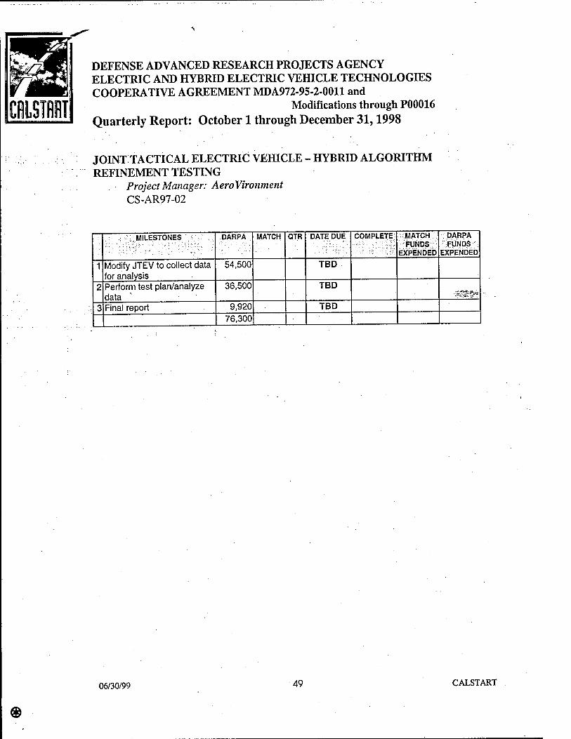
ClSIfllT
DEFENSE ADVANCED RESEARCH PROJECTS AGENCY ELECTRIC AND HYBRID ELECTRIC VEHICLE TECHNOLOGIES COOPERATIVE AGREEMENT MDA972-95-2-0011 and
Modifications through P00016 Quarterly Report: October 1 through December 31,1998
JOINT TACTICAL ELECTRIC VEHICLE - HYBRID ALGORITHM REFINEMENT TESTING
Project Manager: AeroVironment CS-AR97-02
MILESTONES DARPA MATCH QTR DATE DUE COMPLETE MATCH FUNDS
EXPENDED
DARPA FUNDS
EXPENDED
1 Modify JTEV to collect data for analysis
54,500 TBD
2 Perform test plan/analyze data
36,500 TBD ■-i£^s;~^e''
3 Final report 9,920 TBD 76,300
06/30/99 49 CALSTART

DEFENSE ADVANCED RESEARCH PROJECTS AGENCY ELECTRIC AND HYBRID ELECTRIC VEHICLE TECHNOLOGIES COOPERATIVE AGREEMENT MDA972-95-2-0011 and
Modifications through P00016 Quarterly Report: October 1 through December 31,1998
JOINT TACTICAL ELECTRIC VEHICLE (JTEV)-PERIPHERALS DEVELOPMENT
.....:■:• Project Manager: Rod Mitten Special Vehicles CS-AR97-03
Project Goal: The goal of this project is to develop an improved steering system for the Joint Tactical Electric Vehicle.
OCTOBER - DECEMBER, 1998
On December 16,1998, CALSTART sent a letter to Dr. Robert Rosenfeld of DARPA" .requesting reallocation of the remaining funds for this project.
JULY - SEPTEMBER, 1998
.During the; next quarter,'CALSTART-will request that the funding for this project be reallocated per the Rod. Mi lien Special Vehicles fiscal year 1998 Semi-Active Suspension proposal, which was reviewed and approved by DARPA. Once this reallocation is approved, this project will be formally cancelled.
MILESTONES DARPA MATCH QTR DATE DUE COMPLETE MATCH FUNDS
EXPENDED
„DARPA*- SFÜNÖS:;X EXPENDED
1 Characterize JTEV steering 5,000 5,000 TBD
2 Redesign system 10,000 22,000 TBD
4 fabricate new system 15,000 TBD
5 test new system 8,000 5,000 TBD
6 Final report 3,000 TBD 41,000 32,000
06/30/99 50 CALSTART

DEFENSE ADVANCED RESEARCH PROJECTS AGENCY ELECTRIC AND HYBRID ELECTRIC VEHICLE TECHNOLOGIES COOPERATIVE AGREEMENT MDA972-95-2-0011 and
Modifications through P00016
Quarterly Report: October 1 through December 31,1998
ACTIVE DAMPING SUSPENSION SYSTEM TESTING AND OPTIMIZATION
Project Manager: Rod Mitten Special Vehicles ' ■:. . CS-AR98-04
OCTOBER ^DECEMBER, 1998
CALSTART's December 16,1998, letter to Dr. Robert Rosenfeld addressed the reallocation of funding for prior Rod Millen Special Vehicles and AeroVironment projects to this and other projects. The proposal for this project, approved by DARPA, indicated that reallocated funding would be used in part for the completion of this project. Theg^*> December 16,1998, letter merely clarifies the sources and amounts of the funding reallocation. If DARPA appioves: the reallocation as proposed in that letter, then CALSTART will,work wifh Rod Millen Special Vehicles to develop a contract and authorize commencement of work during the next quarter.
JULY-SEPTEMBER, 1998
CALSTART received written authorization dated September 24,1998 from DARPA to move forward with this project. CALSTART has contacted RMSV and will work with them to establish a formal program statement of work and place the program under contract during the next quarterly reporting period.
06/30/99 51 CALSTART

DEFENSE ADVANCED RESEARCH PROJECTS AGENCY ELECTRIC AND HYBRID ELECTRIC VEHICLE TECHNOLOGIES COOPERATIVE AGREEMENT MDA972-95-2-0011 and
Modifications through P00016 Quarterly Report: October 1 through December 31,1998
TURBO-GENERATOR FOR THE MOLLER ROTAPOWER ENGINE Project Manage}" Möller CS-AR97-08
Project Goal: The goal of this project is to study the advances that can be made by creating a compound engine utilizing the Moller rotapower engine. The project will quantify the energy in the exhaust and result in the design of an appropriate turbo- generator system. '
OCTOBER - DECEMBER, 1998 F»^
CALSTART intends to cancel this project and request that funding be re-allocated to other projects; CALSTART.will work with DARPA to determine acceptable projects to which to reallocate the funds.
JULY-SEPTEMBER, 1998
This project is not under contract. CALSTART will likely cancel the project and request that DARPA reallocate the funds to an as yet unidentified project. Freedom Motors (Möller) has put forth a project concept that would utilize this funding. CALSTART is evaluating the Freedom Motors proposal.
MILESTONES DARPA MATCH QTR DATE DUE COMPLETE MATCH FUNDS
EXPENDED
DARPA FUNDS
EXPENDED
1 Prepare for testing/heat study
17,500 17,500 TBD
2 Turbine/Motor results 12,500 12,500 TBD
3 Design/Final report 20,000 20,000 TBD 50,000 50,000 TBD
06/30/99 52 CALSTART

CRLST1T
DEFENSE ADVANCED RESEARCH PROJECTS AGENCY ELECTRIC AND HYBRID ELECTRIC VEHICLE TECHNOLOGIES COOPERATIVE AGREEMENT MDA972-95-2-0011 and
Modifications through P00016 Quarterly Report: October 1 through December 31,1998
QUICK CHARGING SYSTEM WITH FLYWHEEL ENERGY STORAGE Project Manager: Trinity Flywheel Power CS-AR96-01
Program Goal: The goal of this program is to develop and integrate a flywheel into a rapid charging system (RCS) for electric vehicles. > :
Don Bender of Trinity Flywheel Power (Trinity) presented on this project to Dr. Robert Rosenfeld and other members of the DARPA E/HEV Program at the Semi-Annual review in Austin, Texas. -SSlMiKF;
-Don Bender of Trinity Flywheel attended a meeting in Alameda with Dr. Robert Rosenfeld on December 1, 1998.
OCTOBER-DECEMBER, 1998
During the quarter, Trinity pursued the development of the flywheel system to be used in the demonstration which will conclude the project. Trinity has concluded that the original system, while meeting the basic technical requirements of the program would not satisfy the objective of being commercializable at the conclusion of the project. Trinity did so without billing CALSTART or DARPA or accruing cost to be used for cost share later. Don Bender of Trinity presented information on this project to Dr. Robert Rosenfeld at a program review conducted at CALSTART's Alameda Point facility on December 1,1998.
Trinity expects to submit a schedule next quarter for completion of all of the tasks of this project.
06/30/99 53 CALSTART

»START
DEFENSE ADVANCED RESEARCH PROJECTS AGENCY ELECTRIC AND HYBRID ELECTRIC VEHICLE TECHNOLOGIES COOPERATIVE AGREEMENT MDA972-95-2-0011 and
Modifications through P00016 Quarterly Report: October 1 through December 31,1998
QUICK CHARGING SYSTEM WITH FLYWHEEL ENERGY STORAGE Project Manager: Trinity Flywheel Power CS-AR96-01
MILESTONES DARPA MATCH QTR DATE DUE COMPLETE MATCH FUNDS
EXPENDED
DARPA FUNDS
EXPENDED
0 Initiate work 64,085 7,200 1/30/97 1/30/97 7,200 64,085
1 Flywheel/Interface/ FESS/ÜU Specifications
119,298 45,600 1 3/30/97 3/30/97 45,600 45,600
2 Design review/initial testing
116,791 88,400 2 6/30/97 6/30/97 48,211 88,400
3 Manufacture/Phase 1 testing
37,835 320,146 3 9/30/97 263,247 67,634
4 Installation drawings/program review
.137,618 .28,800 4 12/31/97 105,193
5 Integration and initial cheek-out
33,000 5 3/30/98
6 Final report 77,401 32,550 6 6/30/98
TOTALS 553,088 556,596 364,258 370,912
06/30/99 54 CALSTART

DEFENSE ADVANCED RESEARCH PROJECTS AGENCY ELECTRIC AND HYBRID ELECTRIC VEHICLE TECHNOLOGIES COOPERATIVE AGREEMENT MDA972-95-2-0011 and
Modifications through P00016 Quarterly Report: October 1 through December 31,1998
MOBILE FLYWHEEL POWER MODULE Project Manager: Trinity Flywheel Power CS-AR97-04
Program Goal: The goal of this program is to develop'and demonstrate a compact power module with a rugged design.
Don Bender of Trinity Flywheel Power (Trinity) presented on this project to Dr. Robert Rosenfeld and other members of the DARPA E/HEV Program at the Semi-Annual feWw in Austin, Texas.
Don Bender of Trinity Flywheel attended a meeting in Alameda With Dr. Robert Rosenfeld on December 1,1998.
OCTOBER-DECEMBER, 1998
Trinity received all of the system components, with the exception of the electronics during this quarter. The electronics contract was issued ahead of schedule and the system specification and design review were completed early in the previous quarter.
Trinity continued to work on the flywheel rotors and containment structure and had completed about 50% of the system at the close of this quarter. Trinity expects to continue to make progress on the construction of the rotors and containment structure during the next quarter, as well as commencing the test plan and progressing on the electronics system. The project remains on schedule.
Don Bender of Trinity also made an in-depth presentation on this project as well as Trinity's other efforts, including one to improve the performance of this unit, to Dr. Robert Rosenfeld on December 1,1998 at CALSTART's Alameda Point office.
06/30/99 55 CALSTART

DEFENSE ADVANCED RESEARCH PROJECTS AGENCY ELECTRIC AND HYBRID ELECTRIC VEHICLE TECHNOLOGIES COOPERATIVE AGREEMENT MDA972-95-2-0011 and
Modifications through P00016 Quarterly Report: October 1 through December 31,1998
MOBILE FLYWHEEL POWER MODULE Project Manager: Trinity Flywheel Power CS-AR97-04
MILESTONES DARPA MATCH QTR DATE DUE COMPLETE MATCH FUNDS
EXPENDED
; DARPA FUNDS
EXPENDED
1 Conceptual Design 100,000 65,000 1 3/31/98 3/31/98 68,732 100,000
2 Detailed design 115,000 100,000 2 6/30/98 6/28/98 100,000 llÄSöft 3 Manufacturing 130,000 125,000 3 9/30/98 125,000 85,435
4 Assembly and Checkout 100,000 180,000 4 12/31/98 147,176
5 Testing and final report 50,000 100,000 5 3/31/99 495,000 570,000 440,908 300,435
06/30/99 56 CALSTART

DEFENSE ADVANCED RESEARCH PROJECTS AGENCY ELECTRIC AND HYBRID ELECTRIC VEHICLE TECHNOLOGIES COOPERATIVE AGREEMENT MDA972-95-2-0011 and
Modifications through P00016 Quarterly Report: October 1 through December 31,1998
HIGH PERFORMANCE FLYWHEEL MOTOR-GENERATOR FOR MOBILE FLYWHEEL POWER MODULE
Project Manager: Trinity Flywheel Power CS-AR98-01
Don Bender of Trinity Flywheel attended a meeting in Alameda with Dr. Robert Rosenfeld on December 1,1998.
OCTOBER-DECEMBER, 1998 ■■■<&%&&■■
CALSTART and Trinity continued to work on refining the milestones for this project during the quarter... Some delays in other projects have prompted CALSTART and Trinity to put the refinement of milestones on hold for the present. CALSTART hopes to fully define the milestones during the next quarterly reporting period and place the program under contract either kite next quarter or early in the following quarter.
06/30/99 57 CALSTART

CHLSTII
DEFENSE ADVANCED RESEARCH PROJECTS AGENCY ELECTRIC AND HYBRID ELECTRIC VEHICLE TECHNOLOGIES COOPERATIVE AGREEMENT MDA972-95-2-0011 and
Modifications through P00016 Quarterly Report: October 1 through December 31,1998
HYBRID-ELECTRIC PROTOTYPE TRUCK (HEPT) PROJECT : Project Manager: ISE Research
CS-AR96-05
Program Goal: The goal of this program is to develop a hybrid-electric drivetrain for heavy-duty vehicles and integrate into a Class 8 heavy-duty truck, and demonstrate it in regular service.
Michael Simon of ISE Research presented on the status project to Dr. Robert Rosenfeld of DARPA at the Semi-Annual Program Review in Austin, Texas.
Michaer Simon-of ISE Research attended a site visit hosted by CALSTART's Alameda office on December 1,1998. Dr. Robert Rosenfeld conducted the meeting.
OCTOBER-DECEMBER, 1998
During the quarter, ISER completed the construction and preliminary testing of the first ■Hybrid-Electric Prototype Truck (HEPT). ISER has completed most of the initial goals of the HEPT program; However, the HEPT is not yet operational over all duty cycles due to the complex nature of the advanced drive system chosen by ISER. ISER will refine the system as part of a Phase 2 project that involves the completion of the second HEPT. ISER intends to submit a final report outlining the completion of that project to all participants in both phases. ISER has submitted a final report on the Phase 1 activity outlining the progress of the project to date and detailing the accomplishments of the HEPT program. The final report will be included in the quarterly report for January through March, 1999.
As mentioned above, the HEPT is not yet fully operational over all duty cycles. However, the extended duration of this project, as well as a number of milestones which have been met by ISER, has led CALSTART and ISER to submit the final report based on the "Phase 1" effort. Specifically, this phase of the project has resulted directly in development of four major new subsystems, which have market potential in their own right as stand-alone products. These were:
• An integrated "EVControl" vehicle control subsystem developed under Task 2, System Controller Development.
• An integrated auxiliary power unit (APU) subsystem developed under Task 3, APU Testing and Integration.
• An integrated motive drive subsystem developed under Task 4, Motor and Motor Controller Development.
• An integrated electric battery subsystem developed under Task 5, Battery Subsystem Development.
06/30/99 58 CALSTART

CaiSTIT
DEFENSE ADVANCED RESEARCH PROJECTS AGENCY ELECTRIC AND HYBRID ELECTRIC VEHICLE TECHNOLOGIES COOPERATIVE AGREEMENT MDA972-95-2-0011 and
Modifications through P00016 Quarterly Report: October 1 through December 31,1998
HYBRID-ELECTRIC PROTOTYPE TRUCK (HEPT) PROJECT Project Manager: ISE Research CS-AR96-05
The original scope of the HEPT project was divided into eight technical tasks: a design task, the four subsystem development tasks just listed, two tasks relating to vehicle integration, a test and evaluation task, and a program management task.
ISE Research built on work completed in a prior Medium and Heavy Duty Hybrid Truck Feasibility Study to develop a final drive system that integrates all major subsystems into a
, Kenworth T-800 Class 8 truck. During the course of the project, ISE Research made .Ä~^. . numerous specific changes to the design to accommodate unplanned enhancements to key components such as the main drive motor, motor controller, and battery subsystem.
; During the HEPT project, ISER made the decision to utilize an advanced distributed network ; architecture for its vehicle system controller, based on Echelon Corp.'s LonWorks™ distributed control technology. In this configuration, every major vehicle subsystem has its
-: own dedicated control computer, referred to as a network "node," interconnected via a ;; distributed network. An initial set of nodes essential for achievement of basic vehicle
operation were successfully built and demonstrated during the project. The open architecture of the ISER control system will enable development and seamless integration of additional vehicle nodes that can help achieve the full potential of the ISER hybrid-electric drive technology.
ISER successfully built and demonstrated a 75 kW APU, combining a General Motors Vortec V-6 engine, converted to run on compressed natural gas (CNG), with a 75 kW permanent magnet alternator-generator developed with assistance from Fisher Electric Technology. ISER validated the system using a load bank, and subsequently verified the results through actual vehicle operation. ISER also achieved basic capability for automated control of the APU, using vehicle bus voltage to determine when the APU is needed. ISER also developed an APU "load-following" technique to tailor APU power output to vehicle power requirements.
06/30/99 59 CALSTART

CflLSTlT
DEFENSE ADVANCED RESEARCH PROJECTS AGENCY ELECTRIC AND HYBRID ELECTRIC VEHICLE TECHNOLOGIES COOPERATIVE AGREEMENT MDA972-95-2-0011 and
Modifications through P00016 Quarterly Report: October 1 through December 31,1998
HYBRID-ELECTRIC PROTOTYPE TRUCK (HEPT) PROJECT Project Manager: ISE Research CS-AR96-05
The motor and motor controller development was one of the areas most changed from the original HEPT proposal. ISER originally planned to purchase one or more high-power AC induction motors from an existing motor supplier such as Westinghouse, General Electric, or Kaman. With assistance from CALST ART, ISER identified a promising new motor technology developed by United Defense LP (UDLP), a former division of FMC Corporation. Following a thorough analysis of this technology, ISER negotiated a series of agreements^ith UDLP to adapt this motor to the HEPT application and to obtain license to manufacture and market this motor for vehicle applications. One of the first working prototypes was installed
-into the Kenworth HEPT truck and successfully demonstrated during the fourth quarter of 1998. The motor is controlled by a unique modular motor controller ISER developed under
, and R&D partnership with Siemens. The lSER-Siemens controller supplies up to 300 kW continuous power, is smaller and lighter in weight than other equivalent power output controllers, and can be replicated commercially at a lower cost than similar capacity
.controllers offered by competitors.
ISER successfully integrated two sets of 48 batteries into the HEPT. The number of batteries was initially reduced from 56 to 48 to reduce operating voltage, pending receipt of a higher voltage Siemens motor control module in 1999. However, in operational testing, the batteries were shown to generate sufficient voltage to supply 261 kW of power to the main drive motor. When augmented by the output of the APU, this enables the vehicle to run at power levels in excess of 400 horsepower, the peak power limit of the diesel-powered equivalent. Based on use of a similar battery pack in ISER's all-electric Sparklett's delivery truck, ISER estimates the HEPT will have an all-electric driving range of 15-50 miles, depending on cargo and driving conditions. The Kenworth truck was also equipped with ISER's onboard charging system, which uses an advanced "constant power" charging technology developed by Coherent Power Ltd. ISER also formed a strategic alliance with Coherent Power during the course of the project to pursue joint development and commercial marketing of advanced electric and hybrid-electric vehicle charging systems.
ISER developed plans for integration of the drive system into the hybrid truck prior to installation, including generation of drawings and development of a work breakdown structure (WBS) listing all drive system elements. In addition to contributing to the successful integration of the first prototype hybrid truck, these plans will facilitate replication of the drive system for future vehicles. -
®
06/30/99 60 CALSTART

CfiLSTfflT
DEFENSE ADVANCED RESEARCH PROJECTS AGENCY ELECTRIC AND HYBRID ELECTRIC VEHICLE TECHNOLOGIES COOPERATIVE AGREEMENT MDA972-95-2-0011 and
Modifications through P00016 Quarterly Report: October 1 through December 31,1998
HYBRID-ELECTRIC PROTOTYPE TRUCK (HEPT) PROJECT Project Manager: ISE Research CS-AR96-05
ISER accomplished the integration of the hybrid-electric drive system into the HEPT over a period of about 18 months, beginning in the spring of 1997 and concluding the fall of 1998. The first subsystem to be integrated was the APU, followed by the CNG fuel system, main drive motor, motor controller, battery racks, batteries, electrically driven accessories and vehicle control subsystem, approximately in that order. No significant obstacles were encountered that would limit integration of hybrid drive systems into future vehicles.
ISER partially accomplished the operational testing goals during the project. ISER conducted initial road testing in the vicinity of its prototype production facility, validating the basic roadworthiness of the vehicle. Professional truck drivers invited to "test drive" the vehicle were very impressed with its rapid acceleration and smoothness. A two-day series of dynamometer tests was performed at a local Peterbilt truck center, resulting in generation of a substantial database on vehicle and motor performance. Based on this and subsequent tests, ISER projects a 50% reduction in fuel consumption and a 90-95% reduction in harmful exhaust emissions. The phase of operational testing has been deferred to mid-1999 so ISER can improve the motor and motor controller systems and take advantage of an offer from PACCAR Corp., the parent company of Kenworth and Peterbilt, to test the vehicle at the PACCAR Technical Center in Washington state. Following this test, the vehicle will enter into regular operational service with Crown Disposal, as originally planned.
The various additional accomplishments, including the improved vehicle control subsystem, motive drive system, and battery subsystem, necessitated some tradeoffs and sacrifices in other areas. ISER expended much greater resources during this phase than originally budgeted and completion of the first HEPT was delayed by a year to accommodate all of the unplanned technology advances. This delayed testing of the truck in operational service to beyond the time frame of the original DARPA/CALSTART contract. In addition, the vehicle control and motive drive systems, employing newer and less proven technologies than initially planned, will take longer to perfect and make reliable than if the original plan had been adhered to and proven "off the shelf components were used. Also, the additional time spent building future growth capabilities into these subsystems left less time available for testing and fine tuning of some basic vehicle capabilities, such as automated control of the APU.
06/30/99 61 CALSTART

flLSTlT
DEFENSE ADVANCED RESEARCH PROJECTS AGENCY ELECTRIC AND HYBRID ELECTRIC VEHICLE TECHNOLOGIES COOPERATIVE AGREEMENT MDA972-95-2-0011 and
Modifications through P00016 Quarterly Report: October 1 through December 31,1998
HYBRID-ELECTRIC PROTOTYPE TRUCK (HEPT) PROJECT Project Manager: ISE Research CS-AR96-05
ISER plans to complete all of these activities as part of the "Phase 2" effort mentioned previously, as well as construct a second HEPT vehicle. ISER is collaborating with Peterbilt Motors Company, which is supplying a Peterbilt 320 truck model for this purpose. ISER plans to continue development of this technology on further projects.
The HEPT project has provided a springboard for numerous other ISER projects, includigg,a. : hybrid-electric bus program with the Los Angeles Department of Transportation; a heavy- '■ duty hybrid-electric bus program with San Bernardino County Transit; and a hybrid-electric ; tow tractor program with the U.S. Air Force.
JULY - SEPTEMBER, 1998
TSE Research (ISER) has nearly completed work on the first Hybrid-Electric Prototype Truck (HEPT). However, ISER encountered a problem during initial testing of the main drive motor that has resulted in a two month delay in bringing the vehicle to operational status. Specifically, the following tasks were accomplished.
Siemens delivered the key components for the first modular AC motor control system for use in the HEPT to ISER in July. ISER installed the motor control system into the first HEPT in late July. ISER initiated testing of the main drive motor for HEPT vehicle #1. A short circuit developed in the motor resulting in a two-month delay for motor replacement.
ISER used motor parts originally targeted for the second HEPT vehicle to build a replacement motor for the first vehicle instead. This should enable motor testing to resume in early October.
ISER completed the 50 lead-acid battery, subsystem for the first HEPT and successfully installed it on the vehicle. ISER continued to develop improved battery management and battery charging systems and continued final wiring of the first HEPT.
06/30/99 62 CALSTART

CHLSTflHT
DEFENSE ADVANCED RESEARCH PROJECTS AGENCY ELECTRIC AND HYBRID ELECTRIC VEHICLE TECHNOLOGIES COOPERATIVE AGREEMENT MDA972-95-2-0011 and
Modifications through P00016 Quarterly Report: October 1 through December 31,1998
HYBRID-ELECTRIC PROTOTYPE TRUCK (HEPT) PROJECT Project Manager: ISE Research CS-AR96-05
ISER demonstrated various elements of the vehicle control system intended for use in the HEPTs on two other vehicles: an all-electric Sparkletts water truck and a hybrid-electric military tow tractor. The Sparkletts truck entered operational service in September using an electronic pedal control system similar to the one being installed into the HEPT vehicles.
ISER requested a no-cost one quarter extension to accommodate the project delays S^&i •described. CALSTART expects to extend the project completion deadline until December 31,1998.
ISER expects to complete the first HEPT vehicle by the end of October and submit a final report next quarter. Following completion, the first HEPT vehicle will be sent to PACCAR, the parent company of Kenworth, for testing. CALSTART is in discussion with ISER. to continue monitoring the HEPT during its planned testing with PACCAR during 1999. Completion of the second HEPT, not a part of the original program, has been delayed until 1999 to allow ISER to focus on the first vehicle.
ISER is also working on a contract to provide five hybrid-electric buses to the Los Angeles Department of Transportation. The buses use much of the same technology as the HEPT and ISER is iteratively advancing its technology as it develops the vehicles.
06/30/99 63 CALSTART
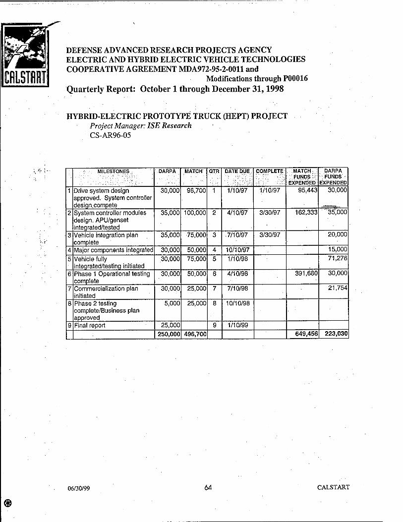
DEFENSE ADVANCED RESEARCH PROJECTS AGENCY ELECTRIC AND HYBRID ELECTRIC VEHICLE TECHNOLOGIES COOPERATIVE AGREEMENT MDA972-95-2-0011 and
Modifications through P00016 Quarterly Report: October 1 through December 31,1998
HYBRID-ELECTRIC PROTOTYPE TRUCK (HEPT) PROJECT Project Manager: ISE Research CS-AR96-05
MILESTONES DARPA MATCH QTR DATE DUE COMPLETE MATCH FUNDS
EXPENDED
DARPA FUNDS
EXPENDED
1 Drive system design approved. System controller design.compete
30,000 96,700 1 1/10/97 1/10/97 95,443 30,000
2 System controller modules design. APU/genset integrated/tested
35,000 100,000 2 4/10/97 3/30/97 162,333 3:5;öoo
3 Vehicle integration plan complete .
35,000 75,000 3 7/10/97 3/30/97 20,000
4 Major components integrated 30,000 50,000 4 10/10/97 15,000
5 Vehicle fully integrated/testing initiated
30,000 75,000 5 1/10/98 71,276
6 Phase 1 Operational testing complete
30,000 50,000 6 4/10/98 391,680 30,000
7 Commercialization plan initiated
30,000 25,000 7 7/10/98 21,754
8 Phase 2 testing complete/Business plan approved
5,000 25,000 8 10/10/98
9 Final report 25,000 9 1/10/99 250,000 496,700 649,456 223,030
06/30/99 64 CALSTART

CfiLSIiT
DEFENSE ADVANCED RESEARCH PROJECTS AGENCY ELECTRIC AND HYBRID ELECTRIC VEHICLE TECHNOLOGIES COOPERATIVE AGREEMENT MDA972-95-2-0011 and
Modifications through P00016 Quarterly Report: October 1 through December 31,1998
SAN BERNARDINO HIGH POWER HYBRID-ELECTRIC TRANSIT DEMONSTRATION PROGRAM
Project Manager: ISE Research CS-AR97-15
CALSTART received modification P00016 after December 23,1998 approving this project. CALSTART anticipates executing the agreement immediately with reporting beginning in the next quarter. a
06/30/99 65 CALSTART
DEFENSE ADVANCED RESEARCH PROJECTS AGENCY ELECTRIC AND HYBRID ELECTRIC VEHICLE TECHNOLOGIES COOPERATIVE AGREEMENT MDA972-95-2-0011 and
Modifications through P00016 Quarterly Report: October 1 through December 31,1998
ENGINEERING IMPROVEMENTS FOR PURPOSE-BUILT EV Project Manager: PIVCO CS-AR96-07
Program Goal: The purpose of this program is to prepare a low-cost, purpose-built electric vehicle for the U.S. market. In specific, CALSTART and PIVCO will work together to make key engineering improvements and conduct market analysis' that would move the PIVCO electric vehicle closer to production in the United States.
^saafefr-.-
OCTOBER - DECEMBER, 1998
As of November 1998, the Market Assessment task's were added to the DARPA "Engineering Improvements for Purpose-Built EV" project as a follow-on to the engineering improvements of PrVCO's 4th generation vehicle called the THINK.
The marketing aspects will consist of the following: • Product Concept • Market Research on potential target groups, including institutional and consumer
segments, using both focus group studies and surveys • Market Analysis • Analysis of sales, distribution, and servicing • Analysis of marketing programs
Product Concept
To help adapt the THINK product concept to the needs of potential U.S. customers, CALSTART® researched the product concept of other similar vehicles in Europe and the U.S. using them as benchmarks and to generate new product concept ideas. CALSTART then devised several product concept options that would be amenable to U.S. customers. Finally, CALSTART®'s consultant, Fairbanks, Maslin, Maullin & Associates, conducted a consumer market research study which included one hundred participants and had them rank their preferences in relation to each product concept presented.
06/30/99 66 CALSTART

DEFENSE ADVANCED RESEARCH PROJECTS AGENCY ELECTRIC AND HYBRID ELECTRIC VEHICLE TECHNOLOGIES COOPERATIVE AGREEMENT MDA972-95-2-0011 and
Modifications through P00016 Quarterly Report: October 1 through December 31,1998
ENGINEERING IMPROVEMENTS FOR PURPOSE-BUILT EV Project Manager: PIVCO CS-AR96-07
Market Research
CALSTART® helped to conduct two sets of market surveys on behalf of the PIVCO project. The first set of surveys was prepared and carried out solely by CALSTART . One survey concentrated on the consumer markets; and the other focused on the fleet markets. With its experience in tracking the advanced transportation industry, CALSTART® prepared a survey with consumers' preferences and attitudes in mind. This '^^^-- consumer survey was conducted at the Ride & Drive of the Electric Vehicle Expo (EV Expo) in Alameda, California, on October 24 and October 25,1998. At the EV Expo, CALSTART® was able to collect 214 surveys, which it reviewed and analyzed to capture the thoughts of potential THINK customers.
On the fleet side, CALSTART® conducted several Ride & Drives inviting fleet planners and operators to test drive the TH!NK. The first one was done in conjunction with CALSTART®'s Adanced Transportation Industry Conference conducted on October 22, 1998. The second survey was conducted at CALSTART®'s Pasadena facilities in Southern California. In addition to these Ride & Drives, CALSTART® sent out hundreds of mailings v/ith specification sheets and photos to fleet planners and operators who could not attend the Ride & Drives. The total responses CALSTART® received equaled 67 surveys.
The second set of market studies were focus group/survey studies conducted by CALSTART®'s consultant, Fairbanks, Maslin, Maullin, & Associates in Alameda and Pasadena, California at CALSTART®'s facilities. These focus group studies were intended to reflect the attitudes and perceptions of the general population of California. Fairbanks et al conducted the Alameda focus group study on October 24,1998 with 50 participants, and the one in Pasadena was done on October 31,1998 with another 50 participants, reflecting the Northern and Southern California markets. CALSTART® worked closely with Fairbanks, et al in devising the survey questions and carrying out the logistics of running the focus group studies.
06/30/99 67 CALSTART

DEFENSE ADVANCED RESEARCH PROJECTS AGENCY ELECTRIC AND HYBRID ELECTRIC VEHICLE TECHNOLOGIES COOPERATIVE AGREEMENT MDA972-95-2-0011 and
Modifications through P00016 Quarterly Report: October 1 through December 31,1998
ENGINEERING IMPROVEMENTS FOR PURPOSE-BUILT EV Project Manager: PIVCO CS-AR96-07
CALSTART®'s consumer and fleet market studies coupled with the focus group studies conducted by Fairbanks, Maslin, Maullin, & Associates will present a solid representation of the market potential for the THINK. The final report from the focus group studies by Fairbank, Maslin, Maullin & Associates is still pending, however.
Market Analysis
Upon receiving the results from CÄLSTART®'s consumer and fleet surveys, CALSTART® compiled.the data in a spreadsheet, snalyzed.it, and generated descriptive statistics, such as percentage break downs and cross tabulations. Preliminary results were obtained for wdtenips forthe Customer Analysis and Market Opportunities sections:
Analysis of Sales and Distribution
To analyze the sales opportunities for PIVCO's THINK vehicle, CALSTART® undertook a literature review of sales trends of similar vehicles in the advanced transportation industry. Since historical data is still developing for the industry, CALSTART® undertook a Delphi Forecasting Method, developed by Rand Corporation to tap the experiences of CALSTART®'s senior staff. This process had three iterations in which a panel of 6 senior staff participated in an attempt to quantify their managerial judgement and experience. They projected the market share and growth of mini-vehicles like the THINK based on new cars sales figures in California. The panelists also projected the sales units expected to be sold by PIVCO for both the consumer and fleet markets respectively and aggregately combined. Each panelist made projections for the 1999-2004 period.
CALSTART® also contacted several potential distributors of the THINK vehicles. There was a total of 5 potential distributors and dealers, who showed strong interest in distributing the vehicle and several other distributors who showed some interest. CALSTART® analyzed the result of both fleet and consumer surveys pertaining to distribution of the THINK, and based on these survey results, CALSTART® devised preliminary distribution channel strategies for the THINK.
06/30/99 68 CALSTART

DEFENSE ADVANCED RESEARCH PROJECTS AGENCY ELECTRIC AND HYBRID ELECTRIC VEHICLE TECHNOLOGIES COOPERATIVE AGREEMENT MDA972-95-2-0011 and
Modifications through P00016 Quarterly Report: October 1 through December 31,1998
ENGINEERING IMPROVEMENTS FOR PURPOSE-BUILT EV Project Manager: PIVCO CSrAR9.6-07
JULY - SEPTEMBER, 1998
During this quarter, CALSTART worked with PIVCO to develop a plan to analyze the U.S. market for the launch of the re-engineered PIVCO vehicle, name the THINK. PIVCO agreed to contract with CALSTART to conduct the marketing analysis.
-täfiSSJNiv
The marketing aspects will consist of the following: « . Market Analysis *; Market Research on potential target groups, including institutional and consumer
segments, using both focus group studies and surveys * .-..Analysis of .sales, distribution, and servicing * . Analysis of marketing programs
During this period, PIVCO also continued to make significant engineering improvements to its vehicle. These design and engineering activties will be discussed more fully in a future report.
A more detailed discussion of the marketing analysis activity follows.
Market Analysis
Members of the PTVCO Project began the project with a meeting to discuss and delegate tasks that needed to be undertaken within the short time frame. As a result of the meeting, work on the preliminary budget was developed to manage the resources required to accomplish the tasks above. Finally, PIVCO team members met with CALSTART®'s Senior Management to examine milestones for the project.
06/30/99 69 CALSTART

DEFENSE ADVANCED RESEARCH PROJECTS AGENCY ELECTRIC AND HYBRID ELECTRIC VEHICLE TECHNOLOGIES COOPERATIVE AGREEMENT MDA972-95-2-0011 and
Modifications through P00016 Quarterly Report: October 1 through December 31,1998
ENGINEERING IMPROVEMENTS FOR PURPOSE-BUILT EV Project Manager: PIVCO CS-AR96-07
Market Analysis:
The bulk of the work within this quarter was to analyze the market and market-related issues., One of PIVCO's specific requests was to conceive a product concept for its THINK vehicle. After researching and reviewing various secondary sources of data, several topics were discussed and developed for both ;fleet and consumer applications^ such as the "Shared-Vehicle" concept and various uses as utility vehicles.
In addition to developing.a product concept for PIVCO's THINK, the project required research to be done on the market, and sales and distribution strategies. The former dealt with several components, which included: Aggregate Market Factors, Competitor Analysis; Customer Analysis; and Environmental Factors Analysis.
Market Research:
Upon completion of the preliminary Market Analysis, a more detailed market researched ensued. Several research studies were performed in order to better understand the Community Electric Vehicle (CEV) market, with a focus on customers.
The research projects involved the following activities:
Meetings and discussion were initiated about subcontracting with Fairbanks, Maullin, Maslin & Associates, a market research organization. This company's task will be to analyze customers in attitude/perceptions, price points, and sales projections between 1999-2004. Customers for THINKs will be analyzed in both the northern and southern markets to consider regional similarities and differences.
06/30/99 70 CALSTART

C1STÜT
DEFENSE ADVANCED RESEARCH PROJECTS AGENCY ELECTRIC AND HYBRID ELECTRIC VEHICLE TECHNOLOGIES COOPERATIVE AGREEMENT MDA972-95-2-0011 and
Modifications through P00016 Quarterly Report: October 1 through December 31,1998
ENGINEERING IMPROVEMENTS FOR PURPOSE-BUILT EV Project Manager: PIVCO CS-AR96-07
CALSTART interviewed 10 California Clean Cities Coordinators to assess the future likelihood of community electric vehicles and other small electric vehicles in California. The findings were such that not too many people, even in the Clean Cities program, knew what the future of these vehicles would be.
Another primary research project was initiated to research actual OEM dealershiDjycyy.se as benchmarks for services offered to EV lessees. One Saturn dealership was visited to determine how customer service was provided and what actual service benefits, such as insurance and on-road assistance, were offered to potential EV customers. The same activities were done at a Honda Dealership.
Finally, potential distributors and dealers were researched in-house and via the Internet for : contact information. Approximately, 15 dealers were discovered and CALSTART is in the process of determining the profit margins on purchased and leased vehicles and services offered from these dealers or distributors.
Market Opportunity Analysis:
Market Opportunity Analysis: Researched different markets, such as household markets, markets for NEVs and CEVS, car-sharing markets, station car applications, and utility vehicles.
06/30/99 71 CALSTART

CflLST!
DEFENSE ADVANCED RESEARCH PROJECTS AGENCY ELECTRIC AND HYBRID ELECTRIC VEHICLE TECHNOLOGIES COOPERATIVE AGREEMENT MDA972-95-2-0011 and
Modifications through P00016 Quarterly Report: October 1 through December 31,1998
HIGH POWER CHARGING SYSTEM FOR ELECTRIC VEHICLES Project Manager: General Motors Advanced Technology Vehicle CS-AR97-07
Program Goal: The purpose of this program is to engineer and fabricate a 50 kW high power charger using inductive charging components. '____
Dr. Lawrence Wnuk of General Motors Advanced Technology Vehicles (GMATV}?««- . presented on this project, to Dr. Robert Rosenfeld and other members of the DARPA E/HEV Program at the Semi-Annual review in Austin, Texas.
OCTOBER-DECEMBER, 1998
As mentioned last quarter, GMATV unveiled the high-power charge system at a press event at Southern California Edison's Roscrnead facility on September 10,1998. Southern California Edison (SCE) began using the high-power system in conjunction with specially outfitted Chevrolet S-10 electric pickup trucks. GMATV and SCE continued to gather data on the operation of the vehicles during this quarter. GMATV has indicated to CALSTART an intention to request an extension, possibly with additional funding from some source, for the purpose of gaining more data on the vehicle operation and use patterns. CALSTART continues to work with GMATV, SCE and the other project partners in an effort to extract as much valuable information from the project as possible.
JULY - SEPTEMBER, 1998
General Motors ATV submitted its quarterly report for the previous quarter in late September, 1998.
GMATV has completed the main enclosure design and received the first chassis. The design and drawings were also completed for the new SCM steel chassis, which was also delivered to GMATV. The design and drawings were completed for the Master Controller Module (MCM) chassis and the first article was delivered to GMATV. GMATV has also completed the Power Bus Raceway and Bus Bar design, fabricated both systems and installed them in the main enclosure. GMATV has also received the cooling system consisting of a pump, radiator with fan, flow sensor, hoses and flood box.
06/30/99 72 CALSTART

ILSTflBI
DEFENSE ADVANCED RESEARCH PROJECTS AGENCY ELECTRIC AND HYBRID ELECTRIC VEHICLE TECHNOLOGIES COOPERATIVE AGREEMENT MDA972-95-2-0011 and
Modifications through P00016 Quarterly Report: October 1 through December 31,1998
HIGH POWER CHARGING SYSTEM FOR ELECTRIC VEHICLES Project Manager: General Motors Advanced Technology Vehicle CS-AR97-07
GMATV also installed the stir fan in the Main Enclosure of the EVS-14 charger to provide additional cooling determined to be necessary as a result Df thermal testing that was conducted. GMATV covered the UIM and Cost display openings and integrated the message window display, processor and power supply. The main circuit breakers were rotated 180 degrees to accommodate the new design. GMATV also replaced the PAO flow sensor and respective lines, modified the plenum to allow air flow circulation and.: minimize solar loading effects. The radiator fan air flow direction was verified and GMATV completed thermal characterization of the 50 kW conversion box.
MILESTONES DARPA MATCH QTR DATE DUE COMPLETE -MATCH FUNDS
EXPENDED
DARPA FUNDS
EXPENDED
1 System Requirements 31,790 178,388 1 9/30/97 12/30/971 178,388 31,790
2 Charger Fabrication 58,582 328,730 2 12/31/97 12/30/97 _^328,730 58,582
3 Charger Test/CP/CV Fabrication
94,681 531,300 3 3/31/98 3/31/98 531,300 94,663
4 Installation of operational hardware/software
119,815 672,388 4 6/30/98
5 Charger Installed 28,540 160,149 5 9/30/98
6 Charger System Test 26,549 149,243 6 12/31/98
7 Analysis and Test results 40,043 72,352 7 2/1/99 400,000 2,092,550 1,038,418 185,053
06/30/99 73 CALSTART

DEFENSE ADVANCED RESEARCH PROJECTS AGENCY ELECTRIC AND HYBRID ELECTRIC VEHICLE TECHNOLOGIES COOPERATIVE AGREEMENT MDA972-95-2-0011 and
Modifications through P00016 Quarterly Report: October 1 through December 31,1998
NOVEL, COMPACT AND EFFICIENT TESLA GAS TURBINE HEAT ENGINE Project Manager: FAS
. CS-AR97-09
Program Goal: The goal of this program is the development and design of a compact and efficient gas turbine engine with application for hybrid electric vehicles.
OCTOBER - DECEMBER, 1998
No one from FAS attended the DARPA semi-annual review in Austin,.Texas. CALSTART made it clear to FAS that the lack of attendance would reflect poorly on the project. CALSTART has insisted that representatives from FAS attend the next DARPA review in May to present their findings.
FAS completed the project during the quarter and has submitted a final report. Specifically, during the quarter, FAS developed detailed design drawings of the key components of the
: proposed engine. In addition, FAS analyzed and improved the sealing and vibration characteristics of the engine, and analyzed the materials and manufacturing issues. FAS has also designed the control system for the engine, and described the analytical, design, manufacturing and operational evaluations.
FAS expects this work to lead to the development of a turbine with twice the efficiency of similar size systems. FAS expects overall efficiencies in the 40 to 50 percent range. The system, as designed, is small in size and can produce up to 20 kW of electricity. Hardware manufacturing has been simplified to reduce material costs. FAS has designed novel water- cooled porous rotors in the compressor, which have contributed to the improvement in thermal efficiency of this heat engine.
Another significant improvement is the application of etched perforated grooved rotor plates, a unique method of supplying the cooling water to the rotor through the compressor shaft, three-stage combustion to achieve a higher pressure ratio, and a complete hardware design.
06/30/99 74 CALSTART

DEFENSE ADVANCED RESEARCH PROJECTS AGENCY ELECTRIC AND HYBRID ELECTRIC VEHICLE TECHNOLOGIES COOPERATIVE AGREEMENT MDA972-95-2-0011 and
Modifications through P00016 Quarterly Report: October 1 through December 31,1998
NOVEL, COMPACT AND EFFICIENT TESLA GAS TURBINE HEAT ENGINE Project Manager: FAS CS-AR97-09
The rotor consists of a multitude of thin (0.008 inches thick) perforated and etched plates. The perforated plates will have high open area (60%) to permit the gas to move radially and axially through the perforations in the plates in addition to the conventional tangential flow. FAS's computer calculations show the rotor efficiency will be about 95 percent. FAS has recommended making the thin plates of titanium because of its high strength to weight ratio, and its ability to handle corrosive fluids such as combustion gases. ,;-^^«i.--
FAS has already communicated with companies capable of making titanium perforated plates to the specifications laid out in this project. In addition, FAS has made initial inquiries relating to the other system components, including the heat exchangers, and found companies capable of building most of the systems to their specifications. FAS believes the engine to be manufacturable and is seeking initial funding for the construction of the compressor, which they believe to be the most innovative piece of the system.
A comprehensive final report, complete with design drawings and potential supplier information, is attached.
JULY - SEPTEMBER, 1998
FAS has done extensive thermodynamic analysis of the Advanced Tesla Turbine Heat Engine (ATTHE) and conventional available small size gas turbine heat engines. FAS's analysis shows that the conventional gas turbine heat engines with regenerative heat exchanger only have overall efficiency of about 20 percent. On the other hand, the ATTHE operating in the same temperature range using regenerative heat exchanger, compressor cooling and stage combustion will have an overall efficiency of about 45 percent.
06/30/99 75 CALSTART

CBLSIRRT
DEFENSE ADVANCED RESEARCH PROJECTS AGENCY ELECTRIC AND HYBRID ELECTRIC VEHICLE TECHNOLOGIES COOPERATIVE AGREEMENT MDA972-95-2-0011 and
Modifications through P00016 Quarterly Report: October 1 through December 31,1998
NOVEL, COMPACT AND EFFICIENT TESLA GAS TURBINE HEAT ENGINE Project Manager: FAS CS-AR97-09
FAS has learned that cooling in the compressor keeps .the specific volume of the gas as low as possible during compression, thus dramatically reducing and saving on the needed compression power supplied to the compressor to compress the gas. FAS has learned that with the relatively small thickness of the rotor, one side water filled disc cooling is very effective in reducing the temperature of the air being compressed. Also, higher
• efficiencies of porous Tesla rotors are achieved through the use of anisotropic porosity in the tangential and radial directions of the rotors. The use of higher pressure ratios (30 bars) contributes to better efficiencies of heat engine components. FAS also found that
'using staged combustion between turbine expansion stages keeps ihe temperature and specific volume of the gas as high as possible during expansion in the turbine to achieve higher thermal efficiency.
FAS also expects the ATTHE to be about half the volume of the conventional engine for the same application. FAS has determined that there needs to be a compromi-sc between the pressure ratio (which relates directly to the thermal efficiency) and the net work output. With less work output per cycle, a larger mass flow rate (thus a larger system) is needed to maintain the same power output, which may not be economical. FAS's analysis shows that the optimum pressure ratio is 30 bar.
FAS's calculations have shown that it is not necessary to include both stationary and rotating blades at the compressor exit or at the turbine inlet. FAS's calculations showed minimal improvement by putting both the stationary and rotating blades as the system was originally designed.
FAS intends to use perforated stainless steel and has found an appropriate provider which can meet their requirements. FAS has also gathered information on heat exchanger manufacturers who can provide the type of heat exchanger which their analysis has identified.
06/30/99 76 CALSTART

DEFENSE ADVANCED RESEARCH PROJECTS AGENCY ELECTRIC AND HYBRID ELECTRIC VEHICLE TECHNOLOGIES COOPERATIVE AGREEMENT MDA972-95-2-0011 and
Modifications through P00016 Quarterly Report: October 1 through December 31,1998
NOVEL, COMPACT AND EFFICDiNT TESLA GAS TURBINE HEAT ENGINE Project Manager: FAS CS-AR97-09
Next quarter, FAS plans to develop detailed design drawings of the key components of the proposed engine, analyze and improve the sealing and vibration characteristics of the engine, analyze the material and manufacturing issues, design the control system for the overall engine and document analytical, design, manufacturing, and operational evaluations. FAS also plans to provide a comprehensive final report discussing the advantages and qualifying the project results. ■■•..-.-.-..
FAS is currently on schedule and on budget to complete the project by the end of the next quarterly reporting period.
, M1LF.3T0NES ,; DAHPA MATCH QTR DATE DUE COMPLETE MATCH FUNDS
EXPENDED
DARPA FUNDS
EXPENDED
1 Acquire/adapt computer codes
30,000 30,000 1 12/31/97 12/31/97 21,466 30,000
2 Evaluation/derive improved heat exchanger
40,000 44,000 2 3/31/98 3/31/98 22,961 40,000
3 Detailed design 40,000 42,000 3 6/30/98 24,390 25,500
4 Final report 15,000 9,000 4 9/30/98
125,000 125,000 68,817 95,500
06/30/99 77 CALSTART

DEFENSE ADVANCED RESEARCH PROJECTS AGENCY ELECTRIC AND HYBRID ELECTRIC VEHICLE TECHNOLOGIES COOPERATIVE AGREEMENT MDA972-95-2-0011 and
Modifications through P00016 Quarterly Report: October 1 through December 31,1998
DEVELOP AND DEMONSTRATE A HYBRID-ELECTRIC TRANSIT BUS Project Manager: Foothill Transit CS-AR97-10
Program Goal: The goal of this program is the development and demonstration of an improved hybrid- electric^transitbusinipgularroutejem
OCTOBER-DECEMBER, 1998
CALSTART continues to receive no notification from Foothill Transit regarding the status of this project. CALSTART has notified Foothill of its intent to reprogram the funds unless progress is made relating to the contract. Foothill Transit has experienced considerable employee turn-over. CALSTART is seeking to identify a third point of contact for Foothill Transit for this program.
06/30/99 78 CALSTART

DEFENSE ADVANCED RESEARCH PROJECTS AGENCY ELECTRIC AND HYBRID ELECTRIC VEHICLE TECHNOLOGIES COOPERATIVE AGREEMENT MDA972-95-2-0011 and
Modifications through P00016 Quarterly Report: October 1 through December 31,1998
ASSESSMENT OF ADVANCED ENGINE TECHNOLOGIES FOR UAV AND HEV APPLICATIONS
Project Manager: FEV Engine Technology CS-DARO-02
Project Goal: The goat of this project is to support the development and evaluation of advanced, high efficiency, high specific power concepts for use in Unmanned Air Vehicles and Hybrid Electric Vehicle applications. Specifically, FEV Engine Technology will evaluate Engine Corporation of America's Thermal Electric Compound Engine (TECE) and will compare TECE performance results with advanced 2- and 4-stroke high performance diesel concept engines being developed by FEV.
Stefan Keppler of FEV attended the bi-annual DARPA conference held in Austin, November 1-4,1998.
OCTOBER - DECEMBER, 1998
During the quarter, FEV submitted its final report on the initial portion of this work. This final report, summarized below, is included in its entirety in the Appendix. Work authorized in a subsequent amendment to this project, involving the assessment of the Engine Coiporation of America (ECA) advanced high-pressure fuel injection system, is on-going and is described in the report following the one.
The goal of the initial portion of this project was to assess the ECA Turbo-Electric Compound Engine (TECE), as well as compare that engine to more conventional 2- and 4- stroke engine designs for unmanned air vehicle (UAV) and hybrid electric vehicle (HEV) applications. The results of the investigation indicate that the TECE requires less space than conventional engines with a power density up to 40 percent higher than state-of-the- art direct injection engines. The TECE shows a high thermal efficiency (47 to 48 percent at full load, medium speed (1800 rpm) and approximately 44 percent at rated power (4200 rpm). .
06/30/99 79 CALSTART

DEFENSE ADVANCED RESEARCH PROJECTS AGENCY ELECTRIC AND HYBRID ELECTRIC VEHICLE TECHNOLOGIES COOPERATIVE AGREEMENT MDA972-95-2-0011 and
Modifications through P00016 Quarterly Report: October 1 through December 31,1998
ASSESSMENT OF ADVANCED ENGINE TECHNOLOGIES FOR UAV AND HEV APPLICATIONS
■;: ■' Project Manager: FEV Engine Technology CS-DARO-02
Due to their better power-to-weight ratio, FEV states that the conventional engine designs evaluated are better-suited for UAV applications. However, FEV states that the TECE is preferred for HEV applications, as it achieves its highest thermal efficiency at maximum torque and achieves 90 percent of its best thermal efficiency at rated conditions. A table summarizing the performance characteristics of theengines evaluated is shown below.
TECE 4-Stroke 2-Stroke Maximum power density @ speed kW/liter
rpm 116 4200
80.2 4200
62.5 4300
Soecific power lbs/hp 1.5 1.35 1.25 'Thermal efficiency at max. power % 44 .32.5 26 Maximum thermal efficiency @ speed
%
rpm 47 1800
42 2500
40 2800
06/30/99 80 CALSTART

CflLSIfiRT
DEFENSE ADVANCED RESEARCH PROJECTS AGENCY ELECTRIC AND HYBRID ELECTRIC VEHICLE TECHNOLOGIES COOPERATIVE AGREEMENT MDA972-95-2-0011 and
Modifications through P00016 Quarterly Report: October 1 through December 31,1998
ASSESSMENT OF ADVANCED ENGINE TECHNOLOGIES FOR UAV AND HEV APPLICATIONS
Project Manager: FEV Engine Technology CS-DARO-02
FEV did identify a number of development issues associated with further development of the TECE, including 1) a suitable concept for sufficient cooling of the pistons and cylinder liner; 2) sufficient lubrication of the spherical piston bearing; 3) suitable sealing of cylinder pressures beyond 200 bar; 4) availability of a high-pressure injection system; and 5) a turbocompound system. Additionally, FEV's assessment did not consider engine emissions.
An amendment to this project will allow FEV to evaluate.a high-pressure injection system being developed by EGA for the TECE. That project is described in another section of this report.
JULY -r SEPTEMBER, 1998
The final report for this project has not yet been submitted. On August 5,1998, CALSTART's Mark Kragen conducted a site visit at FEV Engine Technology to review progress-to-date on this project and the second phase project involving testing of the Engine Corporation of America advanced high pressure fuel injector. At that site visit, FEV indicated that an internal draft of the final report is complete and will be submitted in the near future. Again, we expect to submit the final report with the next quarterly report.
06/30/99 81 CALSTART

1LSTRHT
DEFENSE ADVANCED RESEARCH PROJECTS AGENCY ELECTRIC AND HYBRID ELECTRIC VEHICLE TECHNOLOGIES COOPERATIVE AGREEMENT MDA972-95-2-0011 and
Modifications through P00016 Quarterly Report: October 1 through December 31,1998
ASSESSMENT OF ADVANCED ENGINE TECHNOLOGIES FOR UAV AND HEV APPLICATIONS
Project Manager: FEV Engine Technology CS-DARO-02
MILESTONES DARPA MATCH QTR DATE DUE DATE COMPLETE
MATCH FUNDS
EXPENDED
DARPA FUNDS
EXPENDED
1 TECE Thermo/Mech Assessment
50,000 50,000 1 9/30/97 9/30/97 50,000 50,000
2 2/4 Stroke Concept Assessment
250,000 470,000 2 12/30/97 12/30/97 470,000 250,000
3 2.4 Stroke Demo. Final Report
700,000 480,000 3 3/30/98 638,902 700,000
TOTAL 1,000,000 1,000,000 1,158,902 1,000,000
06/30/99 82 CALSTART

jr'.l DEFENSE ADVANCED RESEARCH PROJECTS AGENCY ELECTRIC AND HYBRID ELECTRIC VEHICLE TECHNOLOGIES COOPERATIVE AGREEMENT MDA972-95-2-0011 and
Modifications through P00016 Quarterly Report: October 1 through December 31,1998
ASSESSMENT OF ADVANCED ENGINE TECHNOLOGIES FOR UAV AND HEV APPLICATIONS, Phase II, Fuel Injector
Project Manager: FEV Engine Technology CS-DARO-05
Project Goal: The goal of the project is the development and evaluation of a universally adaptable advanced, high-pressure fuel injection system for direct injection engines. Engine Corporation of America will develop the fuel injection system, and FEV Engine Technology will evaluate its performance.
Stefan Keppeler of FEV attended the bi-annual DARPA conference held in Austin, November 1-4,1998.
OCTOBER -DECEMBER, 1998
During the quarter, EC A continued to work on the fabrication of the injection system. However, the system has yet to be delivered to FEV. .EGA indicates that the degree of precision required for fabrication of the injectors is resulting in its contractor demanding additional funding for completion of the work. ECA has indicated that it cannot afford this addition cost unless additional funding is authorized. CALSTART has requested a more detailed explanation of the current situation from FEV and will continue to work to move this project forward during the next quarter.
JULY - SEPTEMBER, 1998
Last quarter, FEV Engine Technology indicated that it expected to complete the project by the close of this quarter. However, procurement and technical problems experienced by Engine Corporation of America (ECA) have set the project schedule back by at least one more quarter.
ECA experienced difficulties in procuring necessary components from a supplier to complete its advanced fuel injector. FEV and ECA indicate that these difficulties have been resolved. However, this caused a delay. ECA has also had to spend more time than expected resolving technical issues with the injector design. FEV has yet to receive the injector from ECA.
06/30/99 83 CALSTART

DEFENSE ADVANCED RESEARCH PROJECTS AGENCY ELECTRIC AND HYBRID ELECTRIC VEHICLE TECHNOLOGIES COOPERATIVE AGREEMENT MDA972-95-2-0011 and
Modifications through P00016 Quarterly Report: October 1 through December 31,1998
ASSESSMENT OF ADVANCED ENGINE TECHNOLOGIES FOR UAV AND HEV APPLICATIONS, Phase II, Fuel Injector
Project Manager: FEV Engine Technology CS-DARO-05
On August 5, 1998, CALSTART's Mark Kragen conducted a site visit at FEV Engine Technology. During this site visit, Mr. Kragen inspected the Cummins 1SB 5.9 direct injection diesel engine that FEV will utilize to test the ECA injector. He also inspected the engine test cell. Once FEV receives the injector from ECA, they will install it in one of the six cylinders of the Cummins engine. Prior to installation, FEV will gather baseline data from operation in the test cell of the Cummins engine as it is currently equipped. FEV has completed integration of measuring instrumentation in the engine.
: Based on progress to date and remaining work, CALSTART expects this project to be : completed during the first quarter of 1999.
'■-'.: MILESTONES DARPA MATCH QTR DATE DUE DATE COMPLETE
MATCH FUNDS
EXPENDED
DARPA FUNDS
EXPENDED
1 INJECTOR Assembly
120,000 120,000 1 11/5/98 120,000 120,000
2 Injector Assessment
200,000 200,000 2 11/5/98
TOTAL 320,000 320,000 120,000 . 120,000
06/30/99 84 CALSTART
DEFENSE ADVANCED RESEARCH PROJECTS AGENCY ELECTRIC AND HYBRID ELECTRIC VEHICLE TECHNOLOGIES COOPERATIVE AGREEMENT MDA972-95-2-0011 and
Modifications through P00016 Quarterly Report: October 1 through December 31,1998
HEAVY FUEL ENGINE (HFE) TEST PROGRAM Project Manager: General Atomics Aeronautical Systems, Inc. CA-DARO-01
Project Goal: The goal of this project is the successful development and baseline performance testing of a 150 horsepower, 3-cylinder opposed piston engine weighing 300 pounds or less.
Cliff Manzke of General Atomics attended the November 1-4,1998 DARPA review in Austin, Texas.
OCTOBER - DECEMBER, 1998
During the quarter, General Atomics worked to resolve the issues detailed in the last quarterly report. Because of these issues, CALSTART granted General Atomics a six- month contract extension to June 30,1999. Highlights of activities accomplished during this quarter include:
• achievement of a brake specific fuel consumption of 0.435 pounds per horsepower hour on December 4 - the best to date with the fully integrated engine;
• engine testing with the propeller occurred for this first time on December 8,1998. • achievement of 150 horsepower output on December 18,1998.
Significant progress was made this quarter on the torsional vibration issue due to changes in hardware. General Atomics added two viscous dampers to the engine, effectively doubling the total engine inertia. Also, the Autorotor OA2089 supercharge was replaced with the lighter Eaton M45 supercharger, which has about one-half the rotating mass of the Autorotor. Finally, the original output quill was replaced with one that is about three times stiffer, thereby raising the first mode natural frequency and greatly increasing the "flywheel effect" of the propeller because it is more rigidly coupled to the engine.
Remaining activities for this project include sea level engine mapping, altitude testing to 15,000-foot conditions and propeller stand engine testing.
06/30/99 85 CALSTART
AIST1M
DEFENSE ADVANCED RESEARCH PROJECTS AGENCY ELECTRIC AND HYBRID ELECTRIC VEHICLE TECHNOLOGIES COOPERATIVE AGREEMENT MDA972-95-2-0011 and
Modifications through P00016 Quarterly Report: October 1 through December 31,1998
HEAVY FUEL ENGINE (HFE) TEST PROGRAM . Project Manager: General Ato?nics Aeronautical Systems, Inc. CA-DARO-01
JULY - SEPTEMBER, 1998
General Atomics continues to make progress toward the completion of the project, but is also encountering a number of problems. The two major concerns are the supercharger and the electronic fuel injector. These are reviewed in detail below.
Supercharger
Two alternative superchargers have been identified to replace the original hydraulic unit. The first is an Autorotor OA2089, a positive displacement supercharger with a displacement of 0.89 liters per revolution and a weight of 18 pounds. The second unit is an Eaton M45 roots type supercharger. Testing of the Autorotor unit indicates good volumetric efficiency (87 percent or better). However, when the unit was integrated and tested with the engine, there was severe torsional vibration. At 1100 revolutions per minute (rpm), the vibration sheared a drive key on the supercharger pulley.
The Eaton unit has not yet been bench tested. One possible benefit compared to the Autorotor is its lower rotation mass (4.9 pounds per square inch versus 10.8 pounds per square inch for the Autorotor). Thus it has the possibility to reduce or eliminate the vibration problems. General Atomics will continue to evaluate the superchargers during the next quarter.
Electronic Fuel Injection
Lack of vendor delivery and support of hardware for the electronic fuel injector is causing delays in the overall project. The vendor is nearly nine months behind schedule in delivering some of the required hardware modifications for the injector. Based on recent discussions with the vendor, General Atomics is confident that the remaining hardware will be delivered during the next quarter. The electronic fuel injector is key to obtaining specified engine performance.
06/30/99 86 CALSTART

C1STRIT
DEFENSE ADVANCED RESEARCH PROJECTS AGENCY ELECTRIC AND HYBRID ELECTRIC VEHICLE TECHNOLOGIES COOPERATIVE AGREEMENT MDA972-95-2-0011 and
Modifications through P00016 Quarterly Report: October 1 through December 31,1998
HEAVY FUEL ENGINE (HFE) TEST PROGRAM Project Manager: General Atomics Aeronautical Systems, Inc. CA-DARO-01
General Atomics has explored other fuel injection systems: They reviewed the Bosch common rail system, a high-pressure, electronically controlled fuel injector. While General. Atomics believes the system would perform well with its engine, Bosch is not making it available for custom applications. General Atomics also tested a mechanical fuel injector with the engine, but it did not function well enough to warrant long-term consideration.
General Atomics continues to make progress on other milestones.. General Atomics : expects to complete the low altitude simulation system and the test facility/propeller stand during the next quarter. Other milestones, such as. propeller stand integration and engine mapping are dependent upon resolution of the supercharger and electronic fuel injector issues.
06/30/99 87 CALSTART

CRLS1M
DEFENSE ADVANCED RESEARCH PROJECTS AGENCY ELECTRIC AND HYBRID ELECTRIC VEHICLE TECHNOLOGIES COOPERATIVE AGREEMENT MDA972-95-2-0011 and
Modifications through P00016 Quarterly Report: October 1 through December 31,1998
HEAVY FUEL ENGINE (HFE) TEST PROGRAM Project Manager: General Atomics Aeronautical Systems, Inc. CA-DARO01
■■ MILESTONES DARPA MATCH I QTR DATE DUE DATE COMPLETE
MATCH FUNDS
EXPENDED
DARPA FUNDS
EXPENDED
1 Progress of sub-system testing, review of engine test facilities and plan for testing of advanced powerplant subsystem.
0 50,000 1 50,000
2 Powerplant integrated to existing dynamometer. Subsystem test complete.
0 75,000 2 75,000
3 Completion of low altitude simulation system. Completion of renovations. Commissioning of new propeller stand facility. Systems function - basic series. Systems optimization completed for baseline. Sea level mapping complete.
300,000 300,000 3 109,741
4 Powerplant integrated to propeller test stand. Low altitude simulation mapping complete. Propstand limited durability demonstrated.
50,000 75,000 4
5 Continued Progress 50,000 0 5
6 Continued Progress 50,000 0 6 7 Demonstrated fuel injection
durability maturation. 50,000 0 7
TOTAL $500,000 $500,000 $125,000 $109,741
06/30/99 88 CALSTART

DEFENSE ADVANCED RESEARCH PROJECTS AGENCY ELECTRIC AND HYBRID ELECTRIC VEHICLE TECHNOLOGIES COOPERATIVE AGREEMENT MDA972-95-2-0011 and
Modifications through P00016 Quarterly Report: October 1 through December 31,1998
HIGH-CURRENT, BACK-EMF BRUSHLESS DC MOTOR CONTROLLER
Project Manager: Glacier Bay, IBM CA-AR98-03
The goal of this program is a joint effort between Glacier Bay and IBM to develop a Back- EMF brushless DC motor drive controller capable of handling higher power and greater torque fluctuations than any such device currently available. Glacier Bay projects the improvements will reduce the system's weight, size and cost while improving reliability.
Kevin Alston of Glacier Bay, Inc., attended the November 1 through November 4,1998, DARPA Electric and Hybrid Electric Vehicle Program Review and presented and overview of the project. A copy of their poster session presentation is included in the Appendix.
Kevin Alston of Glacier Bay attended the December 1,1998 site visit by Dr. Robert Rosenfeld held at CALSTART's Alameda office.
OCTOBER-DECEMBER, 1998
CALSTART executed its contract with Glacier Bay for this project during the quarter. During the quarter, Glacier Bay performed a detailed technical and financial analysis to identify and quantify the specific design changes required in the IBM Motor Drive Card that is being incorporated into the controller. Glacier Bay also began testing of individual components and sub-assemblies. The project is on schedule and the bulk of the work is expected to be completed during the next quarter.
JULY - SEPTEMBER, 1998
CALSTART received written authorization from DARPA dated September 24,1998 to move forward with this project. CALSTART has contacted Kevin Alston and will work with them to establish a formal program statement of work and place the program under contract during the next quarterly reporting period.
06/30/99 89 CALSTART

CflLSlM
DEFENSE ADVANCED RESEARCH PROJECTS AGENCY ELECTRIC AND HYBRID ELECTRIC VEHICLE TECHNOLOGIES COOPERATIVE AGREEMENT MDA972-95-2-0011 and
Modifications through P00016 Quarterly Report: October 1 through December 31,1998
HIGH-CURRENT, BACK-EMF BRUSHLESS DC MOTOR CONTROLLER
Project Manager: Glacier Bay, IBM CA-AR98-03
MILESTONES DARPA MATCH QTR DATE DUE DATE COMPLETE
MATCH FUNDS
EXPENDED
DARPA FUNDS
EXPENDED
1 Detailed Engineering planning
65,571 65,571 1 12/31/98 12/31/98 65,571 65,571
2 Complete board layout and assembly
137,432 137,432 2 3/31/99
3 Complete testing of prototype
60,000 60,000 2 6/30/99
4 Test and document performance Final report
56,997 56,997 4 9/30/99
TOTAL 320,000 320,000 65,571 65,571
06/30/99 90 CALSTART

DEFENSE ADVANCED RESEARCH PROJECTS AGENCY ELECTRIC AND HYBRID ELECTRIC VEHICLE TECHNOLOGIES COOPERATIVE AGREEMENT MDA972-95-2-0011 and
Modifications through P00016 Quarterly Report: October 1 through December 31,1998
IMPROVED PROTON EXCHANGE MEMBRANES FOR DIRECT METHANOL FUEL CELLS
Project. Manager: TPL CA-AR98-05
The goal of this project is to develop a new class of proton exchange membrane (PEM) material based on carbon-silicon ionomers for direct methanol fuel cells. TPL will synthesize and evaluate partially flourinated, acid-coated, nano-sized ionomers as new PEM materials.
OCTOBER - DECEMBER, 1998
CALSTART and TPL have continued to work together to find appropriate match funds for the completion of this project CALSTART has sent a letter in writing to TPL stating that unless they find sufficient match funding, the funds for this program will be reallocated. TPL has notified CALSTART of its intention to continue with the project and has asked
> for an extension to June to obtain sufficient match funds from an alternative source.
06/30/99 91 CALSTART

DEFENSE ADVANCED RESEARCH PROJECTS AGENCY ELECTRIC AND HYBRID ELECTRIC VEHICLE TECHNOLOGIES COOPERATIVE AGREEMENT MDA972-95-2-0011 and
Modifications through P00016 Quarterly Report: October 1 through December 31,1998
PROGRAM MANAGEMENT AND ADMINISTRATION Program Manager: CALSTART
During this quarter CALSTART staff worked to : organize presentations on its DARPAprograms for the program review in Austin. Attending the program review in Austin were CEO Mike Gage, Executive Vice President John Boesel, Senior Program Manager MarkKragen, and Program Manager John Tripp.
On December 1, 1999, CALSTART hosted an on.site program review at its Alameda, California facility. Dr. Rosenfeld of DARPA and Danny Jordan, consultant to DARPA, attended the briefing. In addition to CALSTART, four program participants presented to DARPA. Attached is an agenda; indicating which firms presented to DARPA on that date.
During this period CALSTART was also actively involved in identifying promising new technologies and firms for the FY99 program. CALSTART conducted a wide search for new technologies throughout the Western United States. Over 140 White Paper concepts were reviewed and critiqued by CALSTART staff in November and December.
06/30/99 92 CALSTART

CflLSTflm
DEFENSE ADVANCED RESEARCH PROJECTS AGENCY ELECTRIC AND HYBRID ELECTRIC VEHICLE TECHNOLOGIES COOPERATIVE AGREEMENT MDA972-95-2-0011 and
Modifications through P00016 Quarterly Report: October 1 through December 31,1998
PROGRÄM MANAGEMENT AND ADMINISTRATION Program Manager: CALSTART
Milestones DARPA MATCH QTR DATE DUE : COMPLETE DARPA .; FUNDS
EXPENDED
94 Program Management 369,000 369,000
CS-AR94-08 369,000 0 369,000
95 Program Management CALSTART
203,394 203,394
CS-AR95-99 203,394 0 203,394
86 Program Management CALSTART
188,502 173,502
CS-AR96-10 188,502 0 173,502
Mod 8
Program Management CAL.S f ART
53,000 34,450
CS-AR97A-99 53,000 0 34,450
Mod 9
Piogram Management CALSTART
124,500 124,500
CS-AR97-99 124,500 0 124,500
Mod 11
Program Management CALSTART
50,000 15,000
CSAR97A-99 50,000 15,000
Mod 12
Program Management CALSTART
256,700 176,000
CS-AR97A-99 256,700 0 176,000
Mod 14
Program Management CALSTART
30,000 30,000
CS-DARO-99 30,000 0 30,000
Mod 15
Program Management CALSTART
-127,953
CS-AR98-99 127,953 0
06/30/99 93 CALSTART

4> • WH
S3 S- OX) o Si
PH u
»■H s-
•-
B u 0)
5HuH
«« ."
S3'S
s es u t- o 4>
s -<
R
I
>> c CS C.
£ o U ex fi
■*-» c
OH
< H
< U
pq i-i
'o 03
o
c o 4-» O0
« U
WH
(U H-* a m 'S
'£
H
1—1 H W pq 00
1
w 00
WH
O ■4-i
Pw
u '5b o
"o c
J2 ü (D H 4-*
c o E *->
<
< PH P4 <
1 H 00
< u.
& o H
s es t- W) o 1-
PH
00
s
ÖJD C
E o
1-1 ü
'S b c o U
W M ü
es u < >
>, o
'5
w bß
e
H o WH o
WH
o CL,
1 -C 00
s a 41 IM
w
c .2
WH '-*-*
PH O "ö3 E ■c P
EL. ä
•o * <ä ° o O WH T3
xi es
^ "3
'3 £ J3
S s
J3 +-»
4-H •c Ü
CL,
o 5 H o •c o <u W T3 •c f. u &
o 4-»
2 PH
JA es 4>
P5
> w
WH
PQ c o
»—1 1
E 3
■4—>
3
1) (—1
ü
> WH a on 0) 4~»
'Ö0 o
1 O u u o i >
<
_o 'öo 00 =3 O 00
s & 3
&
4)
£
in
00
1 o
00
o <r> 6\
l m
66
in
ö *—* l
o
o m ö i—i
1 m -*-H
ö i—i
m
H
1 o m ö i—1
o o
1 m
i—1
O O
l o o
in Tt- c4
1 o o es
o o cn
1 in
o o
1 o o cn
o o in
1 o o 4^
O CO
in
1
o o in
OS
o
o

DEFENSE ADVANCED RESEARCH PROJECTS AGENCY ELECTRIC AND HYBRID ELECTRIC VEHICLE TECHNOLOGEES COOPERATIVE AGREEMENT MDA972-95-2-0011 and
Modifications through P00016 Quarterly Report: October 1 through December 31,1998
APPENDIX
COST REPORTING SUMMARY AND DETAIL
FINAL REPORTS
COMPLETED PROJECTS
CANCELED PROJECTS
06/30/99 95 CALSTART

DEFENSE ADVANCED RESEARCH PROJECTS AGENCY ELECTRIC AND HYBRID ELECTRIC VEHICLE TECHNOLOGIES COOPERATIVE AGREEMENT MDA972-95-2-0011 and
Modifications through P00016 Quarterly Report: October 1 through December 31,1998
COST REPORTING SUMMARY AND DETAIL
® 06/30/99 96 CALSTART

DA
RP
A
FUN
DS
E
XP
EN
DE
D 0
0 0 0 0 1^
0 0 0
CM
CO to LO of CM
0 0 0 0 m (M
0 0 0 0
0 0 CO
0 0 0
CO" CO
0 0 0 of CO CO
0 0 0 0" in
0 0 0 eo"
CO CO 10
co" o> 0 CM"
0 0 0 0" a
0 0 0 0" m CM
O O O O O •*
cn M- CO
co" CM T-
10 CM
co" CO CO
0 0 0 iff CO
CO in
co" 1—
o>
co"
CO
s 10" CM m
in m CO
CM* CO CM
■* 05 CO CO* 0 CM
CM
to" 0 0 CM*
l- m UJ
55! Q S
O ü
r-- g> T-
0
to cn 0
cn 0
1^
CM
in 0
1*- g>
JO CO
m c»
5 03 0
UJ 3 Q UJ 1- < Q
O)
JO CO O
CD gs 0
1 CO en 0
CO cn T- $3 T-
00 cn 0 £0 CO 0
CO O)
p in 0
00 cn 0 S2 CO 0
CO cn 0 £0 05 O
c» CO
0
m
oS 0 0
1- o X X X X X X X X X X X X X X
0 1- < s
O
00" o> 0 4
0 0 0
h-"
CM
CO 10 00 of
0 0 0
v in" 00 •>*
0 O O O
O O CO
0 0 0 0" 0
CO CO «M 0"
CM in
0 0 0
10 CO
O O O m" CO
CO
co" CM
0 0 0
0" 0 CD_
0 0 0 0" 0
CO v—
5 in
0 0 0 co" 00
CM 05 •>* 0)
0 CM CO
CM
05 r- LO of cn
co"
< Q. DC < Q
0 0 0 0* 0
O O O
N T-
00 CO ID of CM
0 0 0
0 CO eg
0 0 0 0
0" 0 CO
0 0 0 0 0
0 0 0
of CO CO
0 0 0 0" m
0 0 0 00"
in 0 w 0 CO
0 0 0 co" in
0 0 0
0" cn
r- CM o> co" cn T-
0 0 0
0 in m
O O O
O in
0 0 0
0" m CM
0 0 0
0" 0
CO
co" CM
O O O
O" O
0 0 0 0" 0
0 0 0 in CO
0 0 in of in CM
05
co"
CO
CO
CÖ" in m
in in CO CM" CO CM
LO O tn 0 CO
■
■* cn CO
CO 0 CM
CO
CO
in" CM
CO OS O
co" LO CM CN*
■6 .
co 0 0 0
CO 0 0 0
■*
0 0 0 0 D.
•* O O O O a.
0 0 0 0 D_
■<*
0 0 0 0
s 0 0 0 Q.
0 0 0 0 D.
0 0 0 0 a.
s 0 0 0 a.
CM y O O O 0-
0 0 0 0 a
N
O O O a
in _i 1- P 1- 0 UJ -3 O DC Q.
c 0 2 0 E <
(0 V) (0 CO JC ü
c c c 3 ce
c 0 u 1. CU 9= 0 -3
O
s c 0 ü ■0 0) 1. 0) 0
0) §
°S 'S "° O 0) 2 E ü E 0 s
§&
O Ü a < CD CO
c
2 cu > a 0
« UJ
"C
> X O X
n
E e
CO g.
V (0
§ E «s cu
cc uj -c ^ ° Z 73 CU S a> iZ O 3 In Tr
a x ac
£ Ü CU 1- k. CD
■a
0 03
E a
5. to > k. cu
€ CD > UJ X
CO 3
GO. O
'LT +■* Ü CU
UJ
•O "C J3 s»
8 (A 3 n E 0
0 0 « c
38 CO CO 0 0
>» ■a 3 4^ CO c 0 w Cfl
E UJ
}£ UJ £ a
Ul§ 20 *S >.0C X Z
H DC <
< Ü
*-• c cu E CD Ol CO c CO
s E CO 1- 01
s 0.
1- cc
CO -1
< Ü
1 '3 "5 a u < CO
CO D
a>
0 4-» c
ü g 0 i E < CU CO
c 01 CO 3 s 5 &o S>o V -J
= a UJ Q
_CD
Ö 5
T3 O
CM T-
O
_c
CD
^3 Ü O
(0 1
CD DC
2 Q. >. c
'1—
H CO
73 O
B CM
•a 0
c 73 CD 13 Ü O
« cb
DC
73 O
c
73 CD
13 Ü O
■ CD
DC
CM T-
73 O
Q CM
73 O
C
73 CD to Ü O
M 1
CD DC
1- cc
CO _l < 0
JE ■c 0 Z
t 0
JC
X 4-« 0 V "o a
H OC
S < o
■•-•
c CO
a a c c c CO
E CO < z
z 0 0 > <
c
CO cu m c
2 in in 0 _j
01 CO
E
0 JC
1 E
ce CO D) c
CO
cu
0 <b_ a= « -1 cu _ JC cu a
JC £
%Ui LL 3
v>
*c 0 Ü
w >. CO
"53 DC ♦4 CO O Ü
3 0
13 a E 0 O
0 E cu Q u M E 3 CU
O w S > C CO
"5> c c 0 "J w
-I *% cc a. a 73 c cu
3 g
< <
w cu
1 CO
15 u c CO
JC u cu E .
1 O
#>■ O = <D O
UJ|
5 0 15 0 CO DC
■0 0
DC
E cu in > (0 c 0
_to 3 o. 2 a or 0 0 « a
DC co
2 0
>.s
* = 5i
E 8 S.
CO c 0 10 3 a S a e 0
CC cu 2 E S § = > > S 73 CU < <
15 c
■2 CM
2§ k. O O O
11 73 CU
e co
□) = C CO
UJ 10 I. 0 CD LO S 0 O CO a.«y CO r- of
DC ""
"* 73 O E E 0 i_ <•- c 0
1 ü 0
? 0) cc
c cu E 0> 01 CO c CO
s E 2
S a
73 0 E s c 0 !Ci CO 0 0
■? cu cc
O Z
Ö" k-
DL.
5 4 05
< 1
co 0
CM 0
■
cn DC < CÖ ü
CO 0
4 O) cc <
1
CO Ü
0 4 o> DC < co 0
in 0
a> DC < CO Ü
CO 0
4 o> cc
CO Ü
O 1
o> DC <r. CO o
CO 0
4 cn DC <F CO 0
CM
■
O) DC <
I CO 0
CO
4 cn DC <
1
CO Ü
O) 1
O) DC < CO Ü
CM 05
1
cn DC «? CO
Ü
CO o> 4 o> DC
CO 0
o> ■
O) OC <
I CO Ü n
cn 0 ■ cn DC <f CO Ü
0 I •*
cn OC <£ CO Ü N
O • in o> oc < CO 0
CM O
■ 10 cn DC
CO Ü
CO 0
1
10 Ol DC f CO Ü
0 • in 05 DC < CO Ü
m 0 ■ in 05 DC
•? CO Ü
< CO 0
1
10 05 DC < CO Ü
m CO 0
1
in 05 DC < CO Ü
■ in cn OC <
1
CO 0
0 1
m 05 DC >a: CO ü
cn 05
in 05 DC <: CO Ü
00 05
1
LO 05 CC < CO Ü B
t -fr 05 OS
■tf o> o> O) O) cn O) 0>
•<* cn O) cn o> o> .2
0)
CO
i m •* o> m
o>
in cn
10 o> 05
in 05
m 05
m OS
in cn
LO 05
in en
LO 05
LO 05 .2
LO Ol
< 0. DC < Q
i <
ai o

uj o
ft
DA
RP
A
FUN
DS
E
XP
EN
DE
D o
o o in" co
o CO o CO" CM CM
o o o o
co CM
r-
o o o o o CM
01 in CM
01 CO
Ol 01 T-
co ■tf CM
m co" X>
CM
co" CO ■*
T-
CM
0) 0"
CO
00 ■tf
5 0 CO 0
in 5
UJ \-
UJ Ul
a E o ü
1U 3 Q UI
Q
CO OJ
c5
•tf" o
CO
l o
CO
I o o
CO jn o JO
CO o
00 J» 0 £0 CO O
H O
X X X X X X X X
CO en in CO in in
X
s
o o o o a>
o o I-- co" 01 ■tf
o o o o
O o o o" to CO
o o o co" CM
o o o CO" CO
O O r-.
co_
CO Ol in co" m in
< a oc < o
o o o in CO CM
o o o o CO CM
o o o o
T-
o o o tf in
O O O
o in
3 CO
o CO
Ol 01
co" ■tf CM
CM O vo co" 00
o o o o" o CM
s "tf co" o CM
00
u> eo 1«- 0
CM
00 00 0 co" m m
0 0 0
co" in
1
0 0 0
CO m
CO 00 0 CO 10 in
■a .
ii o o o o a.
o o o o a.
1^- o o o o a.
o o o o a.
o o o o o_
o o o o 0-
o o o o a.
I*« o o o o a.
o o o o 0-
o o o o 0-
CO
o o o 0.
CO 0 0 0 0 0.
CM T— O O O a.
CM
0 0 0 0-
UJ -i i- F
t> UJ
o DC a.
c c o 'i- '■v c o o i. < > o c a c
UJ S. c X
> IS 03
mm
0 ID
5
H CC
. _J
£ 2 2 s tS IB
B c 03
E > UJ
UJ CO
-. Ü 3
1- Ü 'E o w
UJ
im A > X o a > s s a.
c o
'3> 3 a o Im a. ü <
mm
CU ■a c V
UJ « SI c is
OC > Ul
o s ä
Ol _c 'E 0) 0) c "5i c
UJ > Ul
3 03 o w o a i_ 3 a
S c >. c is
E| S o 1« O « jg
§ 5 *- u g j Ul -c
Ät-g 3 «) !r xi v £
i»E _2 3 < Q X OC
4- C 0) E c S > s <
J= V > c o
8 X Ul X > <
c «
I ■a o a. _= 0) > c o o a> X Ul X > <
1- X
CO -1 < o 4- c 0) E CO Ol IB c ID s E 2
s a.
CM
■o o E c
■o o 4- 10 u o
75 & CC
10
■o o E c
■a V
o o
■5 i. X
M
E S
O) c 5) k. 03 C
"i> 11
CM T-
■O O
E c
< X
E S •*- c 0
H ü 0
"5 0 X
K- X
I < Ü
1
c 0) E <u Ol IS c IS E E 2 Ol
s a.
o z
k. a
CM O
i 10 en X <
1
CO Ü
■*
o • CO en X <
1
to Ü
in o CO 0) DC < CO Ü
CO o
■ CO Ol DC <
1
CO Ü
o CO 01 DC < CO o
00 o
1
CO Ol DC < CO Ü
< 01 o CO 01 x <. CO Ü
m Ol o
i CO Ol DC
■? CO Ü
o ■
CO Ol X < CO O
CO Ol
CO 01 X <. CO O
in 01 CO Ol X f CO Ü W
0 CO 01 X < CO Ü
01 01
CO Ol X *F CO Ü
01 01 • CO 01 X <
1
CO Ü p
>■ u.
CO Ol
CO 0)
CO 01
CO Ol
CO Ol
CO 01
CO Ol
CO 01
CO 01
CO Ol
CO Ol .2
CO 01
00 CO 01
CO
CO 01
CO
CC 01
\- 00 CO en
ss
Ü
B 'S
< a.

DA
RP
A
FUN
DS
E
XP
EN
DE
D in
CO ■<*
0 0 CO
in •«a- co 0 CO
CO m 0 in CO
0 0 m in" en
0 5 ö 10
O O O O" N
en CM in" CM CM
CM r-~" CO
m in iu
a E o o UJ 3 □ UJ
Q
cc H o
X X X X
X o 1- < s
o o o o o CM* CO
0 0 0
0 0 0 0
0 m
■<*"
CO 1^
0 0 in CM" en 0 CM"
O O O O m
0 0 0 in CM
0 0 0 in" in
0 0 0 in
0 O 0 0 in CM
CO (S
< a cc < a
o o o 0 0 0 in" o>
0 0 0 0 w
0 0 0 0 0" 0
0 0 0 0" m
0 0 0 in CM
0 0 0 0" 0 CM
0 0 0 in
cn CM 00
5 T-
O O O O"
0 0 0 0" 0 CM
CM en CO en
CO en ^~ 00"
CM
0 0 0 0 0 CM
0 0 0 CM" 0
0 0 f- co" in CM
CO cn
to CM
■a .
ii CM
O O O a.
CM
o o o a.
CM
O O O a.
CM
5 O O a.
CM 1—
0 0 0 a.
CM ^— O O O 0-
CM
5 O O 0-
CM
O O O 0-
CM
0 0 0 0.
CM
O O O a.
CM
O O O a.
CM
O O O 0.
CM T— O O O a.
CM ^-~ O O O 0.
CM
5 O O Q_
CM
O O O a.
CM T— 0 0 0 0_
CM v— 0 0 0 a.
CM T— 0 0 0 0.
Ul -i i- i-
& Ul T o cc a
>- u z Ul Ü ü u. UJ _l UJ 1} LL
i > UJ
-1 < Ü
5 H Z 5
c a E c s > s <
o z
UJ 1-
E X 1- E o (D _i < Q s m >- X :> Ul -i < ~ o c
§i 2 2 I! O «J -9 <
> UI a co _i < cc Ul X
S| a ■*" "±S Ul _ _i s < 8 o a H w 9 <= < ffl
-9 CC
Ul _i 3 Q O S CC Ul
O a. -i Ul Ul
5 « 5t UL > UJ LL
if si
O z
UI H * Ü O X w _ _l « ÜJ « if ? LL
-" £2 LL 3
cc
e < «> SJ Z O eo 111 Ü a
•a 9 igen ;* 0 co O = 3
x"§8
1
5 Ul 1-
? CO 0 z 5 cc < X Ü > Ul cc Ul •a
II X O
OE Ul v. -1 V
ii cc 0 LL uj CC z 0 5
clj" Ul cc ZS UJ «5 0 0 O a CQ <
3 O H CC
Ul z 0 z Ul
£ Ul X Ul z £3 CC D) 3 £ *- O co a> < B (3 01 <£ 0) to UI < H U.
CO 3 m H CO z < CC
a "to
S i x = o£
if Ul = 0 0
c 0
i a 0
ä -J CO <
ü ö P cc UJ Ul Z E 0 s < 0 s 0
CO CO > _l < z < a z X Ul
ii > to < d Ul < X Ü
H CC
E cS
CO (3 z
Ü "j
In z cc Ul H z < 0. cc
2
!■*
■O O E E 2 «*- c 0 ^p 10 Ü 0 75
CC
en < CC
E 0
«*- c 0 *3 (0 Ü O
1 CC
CO
■0 0 E 0 c 0 *3 (B O O
! cc
10 T-
XI 0 s 0 c 0 *3 (S Ü 0
I cc
c 0 *3 IS O O
« 1
V CC O) c "5 c a a
1- OC
? CO -1 < u
Ul E Ul a < z < S s
0 0 DC a
o z "o a
o ri en CC < CO Ü
CM O
■
en CC < CO Ü
CO O
fi. O) cc <
I CO Ü
s O) cc < ■ CO Ü
w 0 • o> CC <. CO ü
(0 0 ri. en CC <. CO Ü
0
en CC <
1
CO Ü
00 0
en CC < CO Ü
en 0
1
en CC <. CO Ü
0 1
en CC f CO Ü
T-
hi. en CC < CO Ü
CM
en CC
CO Ü
•*
en CC
*? CO Ü
cn ti en CC < CO Ü
00 en ri en CC < CO Ü
CO en
1
en CC *? CO Ü
in O)
cn CC <
I CO Ü
en ■
en CC «? CO Ü
en en
en CC *? CO Ü "5
N cn
>- u.
e'- en
e'- en
1*. 03 O) en 0) en en cn en O) O) en
1^ en en
1^ en 0) en
< a. cc < Q
<
< O

Sr B °
DA
RP
A
FUN
DS
E
XP
EN
DE
D o
o o o o o_
O o o lO
CM
o o to
CM
O O to en CO CO
5! en o T—
O O o O en
o N
o"
CM
en en CO CM
o o o o CM
O O O
O CO
O O o o to
1«. in in to
CO in en
CM
in CO en
o en en r- <o CO in en
UJ H
in UJ 1- -J
Q S O U
W 3 Q UI
a
i- o
X X X X X X X X
X Ü t- < S
o o o
o
o o o IO
CM
o o o IO
CM
o o o o" o 10
o o o o o to
o o o to en to CM
o m CO
in en CM
o o o o" CM CO
12 CO
en o CM
en CM en CO CO CM
m en CO CO CO
r-
o in
CO
o
CO
< a x < a
o o o o* o o_
O O o to
CM
O o to ■*"
CM
O O in en" CD co_
o o o o o IO
o o o o en
o o o o en
■
o o o o to
o o o o" to to
o o o o CM CO
o o o o CO
o o o o to 10
o o IO CO
CM
o to CO to" en CM
o o o o CM CO
O en CM en CO CO CM
CO
CO
CO to en r--" CM
CO en t
o
o o o o" o CM
o o o o o CM
o co en
o en 00 co
•D .
iZ
Ol o o o o Q.
CD O O O O a.
o> o o o o X
o o o X
o o o a.
o o o a.
o o o X
•<r o o o X
■«*
o o o X
IO
o o o X
to
o o o X
to
o o o X
to
o o o X
to
o o o X
to
o o o X
CO
o o o X
CM
o o o X
Ul -1 1-
F
t> UJ -3
o x D.
« c C c
UJ
■o S) ü c «0 > ■D < «■- 0 *■*
c ai E Ul V) 0 (I 0 <
I > Ü UJ UJ X H
■a UJ c z "5 <UJ -" > O UJ ■s u.
f o o <o c £
o £ a> & £ <
0) c Ö) c
UJ
> UJ X ■o
CD o
= 1 O o *■ o
o ■= S-2 ■E-2 £ o _ a. 3 o u. ü
1- X
CO _J
< o e 0>
E o O) (0 c n
E 2 OI
S a.
(A o E s < 2 a c a>
C3 ■
in a
eo c "5 c UJ
u 3 IL
n V X
1- X <
<
i O) o a. 4-»
c <5 c
c o ■3 IS Ü o "5 A X
1- X
g < Ü
1
c « E «> O) n c a £
E 2 Ol
s x
UJ z 5 z UJ > UJ U.
o *•* o 0) c 05 3 X
o c 0) E (A V) «1 W w <
1- X
E -1 < Ü
1
*■*
c o E a> O) n c a 2
E 2 Ol
2
0)
hi E « _ o OJ £ a 3 s !• XÄ a> .o o o
E o £
"5. C T3 Ö) 0 0
X O S
■ E 2 O) o X V)
i= 0) Ö > Ü
o X
0 g-co E x O CO Ü 3
Ü a V) Ul a>
O v. U. 0) s 1 UJ —
u ■ CO v. m «
1§
O) ^
X 2
E 0)
10
II <fl . Sc a o in s 3 ID
CO N
g>£
E° » 08 Q O) §.= £ -M ■K •>
< 1=
o in 0) c 2 ja E _i CO Q,
E l- «J ' en w
2 o ü —
Ul 3 et S o O c
C CO
°-B ■a o »S 2 8 |I £ Q
e o **- CO o o
! X
1- X
E _J < u i
c V E V D) CS c CS
E E 2 Ol
s X
o *-• Ü V
UJ I
>» X
a ui S co o - x c ■c £ of «a
|i E E 10 s>
£Q a> a 03 <o
(0 k W 1-
CM
■o o E E S c o CO Ü o
V X
o z
a.
CM O
Ö < o CO Ü
CO o Ö X < a
t CO Ü
00 en • O X < a CO o 3
8 Si
o ■
o X < a <: o
o Ö X < a «i ü
o 1
O X < a ■4 o
en en • O X
CO o S
to o Ö X
$ CO ü
en i
O X < o
1
CO Ü 3
o 1-
cc
o 1
CO en X < CO Ü
1
00 en X <. CO Ü
CO o ■ 00 en X <
1
CO Ü
o 1
CO en X «f CO Ü
10 o ob en X <
I CO Ü
CO o
1
CO en X < CO Ü
en en • CO en X < CO ü
CO en
co ■
CO en X < CO Ü
en ob en X
CO Ü
1 o l- 10
en
1- ■o c 2 a
> u. 8 co
o S CO CO I CO CO
CO CO
CO o>
CO en
CO en
00 en
CO en
00 en
CO en
CO en
to
1^ en
IO
en
a o
< o.
Ü

CO
3 o Z ui 3 Q "■ 2 < UJ D. a. CC X < 1U o
o o o in
CM CM CM
CO O
o o o o CM
o o o co- co
CO 0 0 0 ■«*-
T-
0 0 0 Ö" 0
0 0 0 CM" 1^
0 0 0 in" CO
0 0 CO co- in
0 0 r»_
CM
0 0 0
CM
CO CO in en" CM
CO CO in en" CM
111
UJ Ul t- -J
Q S o u
in en g>
CM
CO g> go
CO cn o CO CD
CO g>
CO
CM
g> 0 JO TT
en
1^
in en m CM
0
CO g>
CO gj
CO g> 0 CM
cn
111 D a Ul
a
m gs
in g>
CM
CO g>
JO CO
co gj o CO CO
CO cn o CO en
CO
en T— JO CM
g> 0 JO CO
1^ jn 0 JO CO
in en 0
0
CO g> 0
CO g> 0
m g> in T—
iB
CC i- o T— CM CO Tl- in CO 1— CM CO •* X
a z X u
E
«
0 T—
co" cn 0
0
co" en 0
0 0 0 0" CO
0 0 0
co
0 0 0
O O O
CM
CO in CO en"
CO in CD en"
2 cc < a
o o o o" o CM
O O O
in
o o o in CM
o o o o
o O 0 0 0 0 o" co
0 0 0 o* 0 1^
0 0 0 CM"
0 0 0 in- to
0 0 0
m
0 0 0 0" co
O O O
CM
CO CO in of CM
CO CD in en" CM
ui ia
Z Q Z < Ul -1 1- F t> Ul
O QC a o
CO
"c
c" '2 CO > -Q CO
*- E
.i8 to CO CD D. "O 10
"Eö o w
•c co- rn « X) CO
o O .CO D) Q..E
o§ ü a
CO to > CO
DC
to ■c CO a. CO a. & o 2 Q.
> UJ CO
o3
tug « & o R -O to CO CD U- -a
CD CO > CO
oc
to ■•-»
CO CD
CO CJ
> LU CO
To CO
■*-•
CD
6§
CO *-» CO CO
LU 03 03 a. E o Ü
> LU
"5 T3 ■5 XI CO
■55 a E 0 Ü
■O CO N c 0
■■s => •0 2 0.
"c? to CD *-" 'c "o> CD XJ,
CO c •53 2 Q. **
E § 0 -E Ü -a
•a c CO
CO '55 .
CO LU
£m *- .S2 C CO co co E« 0) ■§
LU a co .g
:l § u- 2 CD *-
S C
O CD Ü -a
52
CM (B O. > N E
05 S R
S = .!2 c-o » >< P >> "So.« 0 c Ü Ul S 5 to s 5 S •- « -Q 55
sit sl8 2 a. a> « E « ;s| •5 2U
S!; «I a
E "o S -s Ü 5 ^ ^
CD
a. E 0 o c O)
'co CD Q
« c 0
'"CO v. CD Q. O
•a CO 0 m o a
0. Ü
B
2 c 0 0
CO a.
a.
2
0 a. CD
"co c
LL
-a CO
0 a c CO 0
E 2 O) 0 V- Q.
CD C O 4-* CO a>
I 0 z
II *^ CM CO Ti- in CO h- CO
3 0
O ■
en CC < CO Ü
T^ CM CO "<t
3 0 H
CM O
<* O) a <
1
CO Ü
I CO 0 ■
cn CC < ■ CO Ü
o z
0.
o ■
en CE < CO Ü
O i
oc < to Ü
r— O
i "<fr O) cc <
1
CO Ü
o 1
Tf 05 cc <£ CO Ü
T— O
1 T* CD OC < CO Ü
0 1
■>*
en DC <f CO 0
0 ■ <* en DC < CO Ü
O 1
O) DC
*f CO Ü
CM O
1
en DC < CO O
CM O
1
en DC < CO Ü
CM O
1
en DC <f CO Ü
CM O
4 en OC "? CO Ü
CO 0
4 en CC <f CO ü
>■ LU
•si- cn
Tf cn
Ti- en
Tt- Cn
Ti- en
0* en en en en en en
Ti- en en
< a. cc <
1 _J <

CO g Q z ui 3 Q "- Z < Ul Q. a a X < Ul a
o o o o m
o o o Ö in
o o o o" in
O O O
o" in CM
O o o o co" CO
o in CM CM" CD
O O O O* in
O o o o" CD
O in
CO
O O O
o" O CO
O O O
co" CD
O O O
co" CO
o o o Cft" co CO
u iu ui
a 5 o ü
co
§ CO
CO
CO Cft
o CO
CO en
1 Is-
§ CO
CO
in CD
in
cvi
CO CD
y—
g> CD
o £0 CO
in CD o JO CM
CO CD
O CO
CD
CO CD
O
UJ
D
Ul
St a
CO cft o CO
CO
CO CD
o CO
CD
CO CD
T—
CO
CM
Is- CD
O £0 CO
in CD
o £0 CO
m CD
I CO CD
r- CO
CM
Cft
o CO
CO
Is- CD O CM CO
CD
O CO
CD
in CD
S3
in CD CO
CD CO CD
iS
CO Cft
oo
CD Cft
i—
CC - CM CO Ti- in - CM CO ■>+ - CM CO Tl- in CO
o z X
5
o o o o" in
o o o o" in
o o o o" Is- co
o o o in
o o o in CO TJ-
O o o o o ■>*■
o o m CM" o
O o o o in
O o o o" co
O O O o" CM
o o m ex.*
O O O
o" O CO
o o o o" CM
o o o co"
o o o co"
o o o co"
o o o co"
o o o co"
o o o o" o
o o o Cft" CO CO
< a DC
o o o ö CO
o o o o" CO
o o o o" r--
o o o o" in
o o o o" Is-
o o o o in CM
O o o o o"
o o in CM" o
o o o c5 in
o o o o" 00
O O O
CD CM
o o in Is-"
o o o o" o CO
O O O
o" CM
o o o co"
o o o co"
o o o co"
o o o co"
o o o co"
o o o o" o
EC Ul DO s 3 Z
O z < Ul _l
F
t> Ul
o cc 0.
s c o Ü
o
'S. CD Ü
?p. CD 0) oc = < "5 -o O £ £ si* W E co . £ cö o"5 5 .2 D-E 03 o CO OOCr
CD
E E CD
o
f CD c
CD ■o
CD V.
CO
o CO
o co a. CD
_Q. '■♦-»
3 E o c o 'to C >- CD CD
II Q. C £ °
s> © 05 to CD S> Q co
E
to >. CO
CD D) i_ co sz o c o •o 03
75 M c
"s JO
CO
2 8 ii § LL ü
■o CD o> ~9 = g- 2 3 .9- CDJD 3 Q.k. CT 3 CD
8^ £
■of" S fc: CD CD XI ~ Q.
S §-E CD cö ü
■o CD
CD O c CO o
E 2 g Q. i
CD C o 4-« w 03
I o
o
CD
.'S c
ir +-• CO 0) 1- sz
Ö c o
CD ■*-«
CO 3 n E o Ü
S? 3 SI c <D XI c co >
(0 c U)
'co CD Q
"cö o
ts CD
til
CO
■a i— CO I
c o
'to V. CJ! CD ** _c
03 Ü !c CD >
c o
? D) 03 C
E 03
to >. CO
■c o D. CD
.g UL
C D)
'co 03 T3 >
3 to 03 C
© OC
c o •5 ö CJ
CO
to a
c o
to • 3
CD
CO
to a
5 CD > £ Ü *^ *-» c CD
-u CO
>> ■a 3 to
'S D
1 Q. 03
"5 c k.
1- oc
CO _l < Ü
c CD
E CD O) CO c co
E CO 1_ 03 2 a.
0) .
T- CM CO Ti- m
3 <* o 4 CD CC <
1
CO Ü
in o
I
CD OC < CO Ü
5
in o
en OC <t
1
CO Ü
o T— T~ CM CO •*
o
(O o 4 O) DC <
1
CO Ü
CM CO ■* in CD
o K- r-. o 4 en oc <
■ CO Ü
CO o
1
CD oc <■ CO Ü
o z
i 0.
o 1
OC < CO Ü
O
4 en oc «a: CO ü
o 1
Ti- CD cc < CO Ü
Ti- o
1 Ti- Cft oc
CO Ü
o ■ Tt- CD CC < CO Ü
CD o
1
CD oc < CO Ü
CO o
1
•<* O) oc
CO Ü
CO O
1
CD OC
CO Ü
CO O i
CD OC < CO Ü
co o 4 CD OC < CO Ü
CO O
1
CD OC
CO Ü
Is- o
1
CD OC < CO Ü
Is- o
1
CD oc 1= CO Ü
o ■
CD OC
*F CO o
Is- o
1
CD OC
<■ CO Ü
Is- o
I
CD OC < CO o
Is- cp 4 Cft oc
CO ü
>- U.
Ti- eft
Ti- eft
Ti- CD
Ti- CD
Ti- CD CD CD CD CD CD CD CD CD CD
Ti- eft CD CD Cft
< a. a: <
§
<

V) o a Z iu 3 Q
o o o
is. no fs. o is. o o o o o o o CO o o o o 3 CO o CO o CM "St T- cn is. n n [s. o m o r> r> CO 3 3 o o u o CM CM CO CO CM C»J •st CM O) CO o rs. CO o o o in O O o o u l^. CM CM T- ■*- T- l^s CO
cn CO CO
CO m o Tf is. o CO CO to O O o o o N CO 1— in CM o CO CD u-z < Ul
CM m CM CM m i—
T— CO o m
T— ITS
CM LO CM
m T— Oi T- T~ T" CM T—
o. a CM EC X < Ul Q
ui
ui lü in in tn CO CO CO hs i^- CD
cn CO CD
hs rs. CO 00 CO o> O) CD cn cn cn O) co cn cn cn cn CD
m i- J o T— n o n T— o (_> S
o o Y— I— T-
< & CO CO CO CO CO CO CO CJ J CO CO CO CO CO D S
O O
CD CXI c5 co" cn cvl CO cS o CO" CD CO CO" cr5 o o o o o o
Ul in in CO CO CO CO i-s. 1^- CO CO cn rs. rs. rs. rs.
cn 00 00 3 CD o> cn cn cn o> cn cn (T) cn gj CD CD cn Q o i— o o o I— o o O
§ o o ü
§ T— o
Ul ro ro CO CO CO CO CO CO CO CO CO CO CO £? V- cvl 5 O) CM CO CO CD CJ O) CD C) CD OJ PJ CO
Q o o o o 1— o o
O - CM CO ■st in CO rs. CO - CM CO ■st in CO rs. CO
o o o o o o o to o O O o CO O o O CO o o in cn to o O o o CM rs. O T"™ c_> o CO ■st
(3 CM o O o hs CM <5t CD CO CD oo CO CO z o m in in rs. CO 00 CO CO CO CM o CD X CO CO CO CO ^ CM T— T— CM
1 s
CM
IO T— T—
o o o
O o CO (-1
fs. )s.
CO m n o o in in o o o o h- rs. o o o O O o CO o o O CM "St rs. o cn
CJ C\l
CO |s. o o o o o o o o o CM CM o Ü o O O o o CM CO CO CU CM o> o o
< o CO o CO CO o o o m m O o o o o> en o o o O O o i^- CM "r~ ' „ T— T— |s.
CD CD CO
CD T—
o o CM
Tf fO fM o OD OD o o CO CO o o CD CO ■st o o O O o rs- CD o in CM o CJ T— CM
CD CM
< m CO T- CO CO in in cn cn cn OH O
in U) m U)
CM CM o •st
CJ T~ T— T— T" D "T— T~ CO
CO •n CD ^
CO
a.
co o XJ
a.
o o
c o
IS
1_
©
Ö
D_
c cc co CO cn •*-« > "t~
to
i2 c O)
'co ©
Ul CD s 3 Z
a z < Ul
5 ■a
CO o XJ c
o
CD
io D) O CO c <
u.
1 CO o
'"ro
to c
CO
CO < Q Ü
c o Ü ■*-•
E o>
O
o *-* CM
00 ■o o
o CM i—
CM
■a o
o CM
CO
'£ CO c CO
Ü
E CO c
to ©
o
C '\— co © X)
D) _l 1- F
o D)
c o O
o X
E CD
C CD c UJ CO CD
m
n O o •o O
a c g CO
& Ul
o
> ■o 3
C CO 3 O X
CD C
©
o OQ *-» CO CD
Ü CO
CD
CO CD h-
rri
CD
CD
a. E
2
■n ■n
2
■a
2 c
■a t o
05 C
CO
Q_ ♦^ CO © 1- D. O ©
© a
"S o o
to o *k. XJ CO
co T3 C CO *-•
© m "E CO
■c o a. CD
tö c LL
cc to r h- t ü
■a c o Ü CD
CO
f -i © © © © T' r CO ■o a. ><
s CO CO u.
o
'-co E ©
Ü CO
x: .w XJ CO
■*-»
CO UJ
CD
CO
■o
cö X
CD > C o Ü Ü a
ü o
C
t/5 a
o a CD v.
"cö c a.
I c3 ü _i UJ Q
to ü o
"cö ©
DC
to ü o to
1 ©
DC
to o o tö
1 ©
DC
to u o tö
1 ©
© SI Ü to X
c CO
a. CO <
©
Q.
E o Ü
©
© a. E
©
to Ü
-fc- XJ CO u.
c co
CO 4-" CO ©
© ■o o E
T- CM CO "St in CO l^- 00 y- CM CO ■st m co Is- 00
PS 3 o n *>* a o
n o
To *■» o
n o
a <** o 1-
(0 *^ o 1-
a i2
CO 4-» o
00 o CM CM CM CM CM CM CM CM CM CO to T—
O) CM en
CM CD
CO en
m cn
■st cn CO
o> o
O) o o
T— O r O o o O o o o o o ■
z
"5
4 CO IT
■st CD DC <
i
CD IT <
1 •st CD DC <
i •st en DC <
l
cn or
1 ■st o» nr
1 ■st cn rr
■st cn nr
cn (£
■st cn rr
XT O) DC
■st
rr cn DC
■st cn rr
4 cn DC
■st cn m
CO DC
■st cn DC
CO DC
■st cn DC
'S- cn DC
Tt o> DC
CO CC
m cn DC
m en DC
in CD DC
in CD DC
in CD DC
in CD DC
in CD DC
in CD DC <
1
IO CO a. <
CO
< 0. < < <: < < < < < < < < < < < < < < < < <
<■ "* <. < l
< 1
< I
a. ir
1
CO Ü
(n (f) en CO rn en <n rn (0 CO (0 CO (0 CO CO CO (0 CO CO CO CO CO CO CO CO CO CO CO CO CO Ü
CO o
CO Ü
< O O ü O ü O O ü Ü Ü Ü o u Ü Ü o Ü Ü Ü u o <J u
n
w
o Ü <J Ü o Ü 1 £ >■
■st "St CD
•st ■st CD
■st CD
■st cn cn
■st cn
■st cn
•st cn
"St cn
■st cn cn o
1- •>* 0)
cn in cn
in CD
in CD
in cn
in cn
m CD
in CD
u. *t u\ CO OI J <
u

to a o z U 3 Q "-Z < UJ a a. EC X < UJ a
o o CM
in en v—
iv m <q
v
iv m CM
co" CO CO
0 0 0 0 in" CO
0 0 0 m" CO
CM
■tf
co" CO
CO CO ■tf
r-" en
■tf 0 co"
■tf rv 1—
•tf
CO m
co" rv
0 0 O in" |V
00 CO 00" 1—
CO CO CD
cn in
•tf cn CO
in |v
CO 00 CO,
cn
cn •tf T-
co"
00
UJ
UJ UJ
H a E o o
CO en CO
iv
CO CD en o
CD en
'i UJ 3 a UJ
a
to cn
CO en
en
CO en
t: en
CO en
en
CO en
|
iv en
t: CO
tv en
co
a co i-
a m h-
Q ca
a CO h-
Q CO
CO en
1 en 0 CO
CO
en 0 CO
CO
CD en 0 JO en
CO en
tf1
CD cn 0 £0 •tf
CO cn 0 CO
CO
CO cn 0 £0 cn
|V cn CO CM
CM
cc - CM CO ■tf in CO iv T— CM co tf m 1— - CM 00 tf - CM CO •tf CO
(5 z X Ü
2
o o o o o
o o o o* o CO
o o o o" •tf
o o o o" CO
o o o o" CO
o o o CO co
o o o o ■tf
o o o o" o co_
o o •tf m"
CM en CM
>tf" CO
CM CO rv o" CO
T—
T—
ö CM
in
CO en"
0 0 0 0* 0
CO
■tf_
00 in
00
tf
in
0 0 0 CM" 10 in
O O O
iv
0 0 0
tv" rv
0 0 0 iv IV
O O O co" 00 |V
0
< a. a
o o o Ö 00 CM
o o o o" en
o o o tf in
o o o o" CM
o o o o" T—
o o o o" o "tf
iv o CO
in
CO o IV
co" CO
CO CO CM
o" CO
CM
en" i—
o CO in
0 0 0 0" 0
0 0 0 in" CO
0 0 0 in CO
0 0 0 0" m
0 0 0 in" iv
0 0 0 CD 0
0 0 in •tf" CO
0 0 m en m CM
0 0 0 in" |v
|v CO CM
O" CO
|V CO CM
0" CO
|v CO CM
0" CO
CO CO CM
0" CO
cn •tf
co" y—
CO
DC Ul m E 3 Z a z < UJ _l 1-
& Ul
3 QC a. c
CO
a
'cö 0 Q
CO
CO CO sz 1 0 to o Si co Li.
CO < Q CO
to g .o
if a
c
'co CO Q
CO V. CO
E CO sz u c CO
E c 'to c o Ü
"to +-• CO c
"c cr
'co CO Q
E CO *-» in >> CO
XL O CO sz .o in CO 3
O E
« to c
CO 'co >. ca c CO
« CO
'•Jo +-« JO
CO ■*-»
CO CO 4-»
CO
O
o a £ CO
.£=
c O)
'co 0 •o c o
'■s to CO CO
"cö o 'v- 4-» o a> CO
o
15 c u.
CO
ex E o Ü
E co CD
■•-»
c CO
'co CD
■o
10 Ü
C CO sz o CO
E .
p CO CD CO T3
. CO *- *?i 0 CO J* Ü CO -E CD JD
■° U-
e § s ü '-a c
2 « St o S E
to »8
E i i2 c 2 -° »to? co c 5 0 o c: Quo
CO
0
co 0
SZt
o 0 _c
o
'5 CE
•*-» CO 0 H
c: U) 'in 0 ■o
0
CO 0 V-
SZ>
■5
2 0 0 _c
'5 cr CO c u.
c 0
■*-»
in c 0 E 0 •0
CO Z3 Si 0 c > •a 1— zs
<
c O)
'co 0 •O D) C
c 0 E c
'& c 0 Ü
c 0
'■co .0
Si aj
CD c
'i— +-» c 0 E c
'CO
c 0 0
■♦-» CO 0
Z3
O 0
SZ Ü > Si E 0 CO CO <
t: 0 a 0 1—
1Ö c u.
0
0
•1 c
> 0 O
15 '■*-•
c 0 k_ 0
b
0 'co c 0 a CO
CO
5 0 '> 0 k.
c a
"co 0 O
c CJ)
'co 0
■Ü
c 0 'to c 0 a
s CO •tf
■c 0 a 0 1-
10 c LL in
PS I— CM CO ■tf in CO rv
o
T— CM CO ■tf m
,o
■tf cp in en CE <■ CO Ü
n 0
<* 0 ■ in en CE < CO Ü
CM CO •tf 73
O IÖ cn CE < CO Ü
CM CO •tf in
1 < CO cp If) cn CE < CO Ü
o z
8 a.
CM O
i in en CE
<f CO o
CM O ■ in
CE < CO O
CM O
i in en DC <£ CO Ü
CM o
1 in en CE < CO O
CM o
i in en CE < CO Ü
CM O
i in en CE
<£ CO Ü
CM o ■ in en CE < CO Ü
h- CM o
1 m en CE < CO O
CO o
1 in en CE < CO Ü
CO o
1 m en CE < CO Ü
CO o ■ in en CE
CO o
CO o ■ m en CE <■ CO Ü
CO 0
■ m en CE < CO O
eo 0 ■ in en CE < ■ CO 0
in 0 ■ in en CE <■ CO Ü
in cp in en CE
CO Ü
m 0 in en CE < CO Ü
m 0 ■ in en CE
CO Ü
< CO 0
1 in O) CE < CO Ü
< CO CD
ib cn CE < CO O
< CO 0
1 in O) CE < CO O
< CD O
1 in 05 CE < CO ü
< CO 0
1 in cn CE < CO O
>■ LL
in en
in cn
m en
in en
in en
in en
in en
in en
in en
m en
m en
in en
in en
in en
in en
in en
m en
in cn
in cn
m O)
in cn
m cn
< a. a. <
cc
i < o
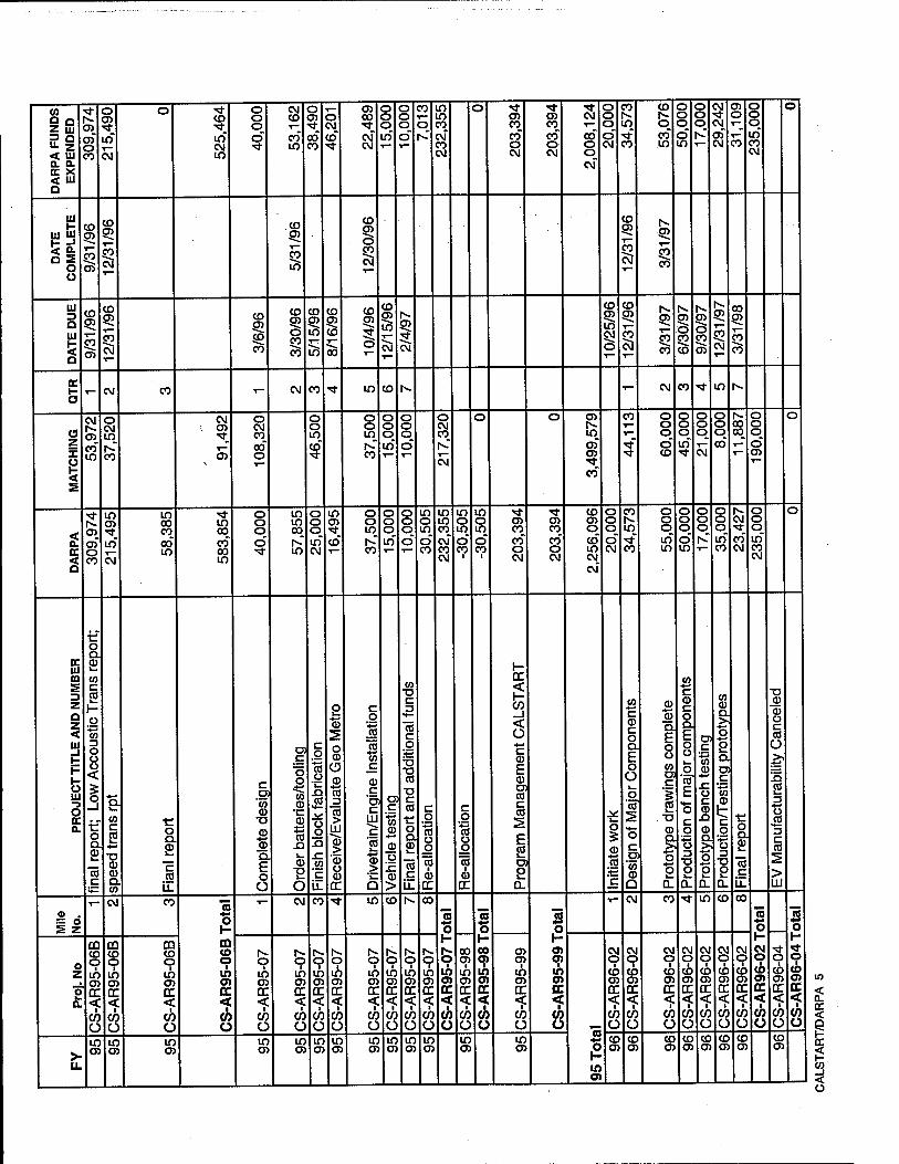
to a a Z UJ 3 Q "- z < UJ Q. a CC X <t UI Q
o> co" o CO
o CO
in
cvi
o CO
in CM in
o o o
CM CO T—
co" in
o CO
co- co
o CM
Co"
O) 00
CM- CM
o o o m"
o o o o"
CO
o m in CO CM" co CM
o en CO
co- co CM
en CO
co" o CM
CM
co" o o CM"
o o o o" CM
CO
in •*" CO
CO
o CO in
o o o o" in
o o o
CM
CM,
cn CM
en o
CO
o o o in- co CM
o
UI
UJ ui
a £ O o
CD en T— CO
CO
CD
1 CO en
CO
in
CD
92 O
eo 92
1 92 i— CO
CO
UI 3 Q Ul
a
CD co
co
CD CO
CM
CD
CO
CO
CO
o CO
CO
CD
92 in
u5
CO
92 CO
o5
CD
92 ;* o
CD
92 m
1 CD
92 in CM
o
CO
92
CM
en
JO CO
92 o JO
CD
en o JO
en
1^ en
CO
CM
00 92 CO
CO
oc o - CM CO T— CM CO M- m CD >■ - CM CO t m h-
(5 z X
1 s
CM
co CO m
o CM m
CO
CM CO
T- 05
o CM CO
co" o
o o in to"
o o in
co
O O O in T—
o o o o
o CM CO
CM
o o CO
in co" CO
eo"
CO
■*"
O O O
o" CD
o o o in"
o o CD
CM
o o o oo"
00 CO
o o o CD- en
o
< a.
CO
of o CO
in co
in CM
in 00 CO
00 in
in 00 co- co in
o o o o"
m in 00
in
o o o in CM
in 05
co"
o o m
co
o o o in
o o o Ö
m o in o co
m in CO CM- CO CM
in o in o" CO
m o in o" CO
l
en CO
co" o CM
CO CO
co" o CM
CO en o co" m CM
CM"
o o o o" CM
CO
m -*" CO
O O O in" in
o o o o" m
O O O
T-
o o o in" CO
1^ CM
CO- CM
o o o in" CO CM
o
CC 1U ffl E
Z
a z < UJ _l
& UJ
o CC 0.
if o Q.
£ CO c 2 1- o
O Ü o <
3 tf o Q.
£ CO c
CO c 2 -a a ffl Q. CO
o
£ c cd
c OJ
'to CD •a 4-» CD
a E o Ü
c Ö o
©
ffl cS n CD
"S O
c o
ts o
£> CO **-
o o .Q
.c CO
'c u.
2 'S
o ffl O ffl
■s 3
CO >
UJ ffl >
■ffl Ü ffl
DC
c o
1 CO
+-» CO c
ffl c 'ai c
UJ ^ 'co 1—
ffl >
a
I W
d> o
ffl >
to T3 C
To c o
■a CO
c CO
■c o a. CD
c
c o
"'S o o
"cö 1
ffl DC
c o '■s o o 15
l ffl
DC
1- DC
CO _1 < Ü
c ffl E ffl Öl CO C CO
2 E £ a 2 a.
o
ffl s c
(0 ■•-»
c ffl c o a. E o ü o
'co"
o c
'to ffl Q
ffl CD
a. E o o CO D) C
1 ■a (D a >
■5
1 a.
CO +-» c ffl c o D.
E o a i— .° CO
E •s c g o Z3
■a
2 a.
D) C
w ffl x: o c ffl £> ffl a > o *-• 2
CO CD CL >>
2 a. en c
"■*-•
CO ffl t: c g o
■D
2 0.
o a CD
"cö c Li.
-a CD CD o c co Ü >*
£
1J CO *^- C CO
> LU
V- CM CO «5 *-■ o m CD O i
to O) OC < ■ CO o
1— CM CO •tf m CD 1^ CO
n % y-
O ■
m CO DC < <h O
oo CO
1 in en DC
-s CO Ü
3 o
00 CO ■ m CO CC <
1
(/> Ü
5 o 1- co CO
■ in CO oc <
1
(0 Ü
T— CM CO ■* in co 00
75 o
CM O
CO CO OC <
1
CO o
O i
CD CO DC < CO O
5 o 1-
o 1
10 en OC <
■
o
o Z
8 a.
CO CD O
1 m co cr < CO ü
CO CO o
1 in O) DC <
1
CO Ü
CO CO o tö co oc < CO Ü
o I
m co CC < cö O
1^ O ■ in CO DC < CO Ü
o I
in en DC
<£ CO o
O i
m
DC <? CO Ü
o I
m CO DC < CO Ü
O i
in DC < CO O
o in en DC «£ CO Ü
1^. o
1 m o> DC -? CO Ü
co en
■ in en DC < CO Ü
CM o CO O) DC < CO Ü
CM O
1 CO en DC
CO Ü
CM o
1 CO en DC
CO Ü
CM O i
CD en DC < CO Ü
CM o cö en DC <■ CO Ü
CM O
i CO O) DC <
1
CO Ü
CM O i
CO en OC
"? CO Ü
>- u.
in CO
in o>
in O)
in CO
in CO
in CO
in O)
in CO
m O)
in O)
in en
m O)
m en o
y- m CO
CD en
CO en
CD en
CO en
CO en
CO en
CO en
CO en
< a. CC <
s- -I < Ü

CO Q Q Z ui 3 D "• Z < 111 a a. oc X < UJ Q
o o o o CO
o o o in" CO
o o o in" CO
0 0 0
CD CO
0 0 0
0" CO
CO Is- CNJ_
T—
0 0 0
0" CO
in Is-,
CM
0 CO 0
co" CM CM
0 0 0
in
0 0 0 CM" Is-
0 0 0
0" CO
0 0 0 Is-" T—
0 0 0
0" Is-
Is- 00 CM Is-* 1— 1—
0 0 0
0" 0 CM
0 0 0
0" 0 CM
CM
CO" CO
CO
co" 1^
CM CM Is-
Is-"
cn in CM
en" 00
UI
LU In
a s o o
Is- en o
Is- jn o CO
CO
Is-
0 CO
CO
Is- cn
CM
CO cn 0 CO
CO
CO cn T— £0 CM
UJ 3 D
Ul
D
gj o
T—
en o
Is- en 0
Is- en 0
O
CO en 0 T—
CO en 0
CO en 0
pi
CO en 0
c5
en en 0
Is- cn 0
cn 0
Is- cn 0
Pi
Is- cn 0
CD" T—
CO
1 CO cn 0
Is- en 0 £0 CD
Is-
CD CO
en
CO cn
CM 1—
Is- cn 0
CO
Is- cn 0 £0 CO
Is- cn 0 CO
cn
Is- cn
1 DC
c5 - CM CO "* in CO Is- CO cn T— CM CO ■* in CO T— CM CO ■^r in CO •I— CM CO ■* in
(3 Z X Ü
E
O o r- to
o o o o" o
0 0 0 in" Is-
O O O O m
0 0 0 m" Is-
0 0 0 0" in
0 0 0 in" CM
0 0 0 m" CM
O O Is-
co" cn
O O O
Is-" m
O O O co" m
0 0 0 m" CM
O O O 1—
0 0 0 m"
0 0 0 cn"
0 0 0
0" Is-
0 0 0 tf CO
0 0 0 in" en
0 0 0 0"
0 0 0 in" CO
0 0 0 0" in CO
0 0 0 00" 0 T—
0 0 0 in"
0 0 0
co" CM
0
EC < D
o o o o" CO
o o o in" CO
0 0 0 in" CO
0 0 0
0" CO
0 0 0
0" CO
0 0 0 0" CO
0 0 0 0" CO
0 0 0
m"
0 0 0 in CM
0 0 0
CD in CM
0 0 CD
m
0 0 0 CM" Is-
0 0 0
CM" CM
O O O
CO"
O O O
co"
0 0 0 cn"
0 0 0
0" r-- T—
O O O
CD 00
0 0 0 0"
0 0 0 in
0 0 0 in
0 0 0 0" m
O O O
O" O CM
O O O O" in
0 0 0 0" in CM
CM 00 CM
en" CO
Is- CM Is-
CM" Is-
Is- CM Is-
CM" cn
CO CO 0
Is-
0 T- en 0" m
CM
cn" m CO
CC UJ m E 3 z a z < UJ _l 1- F
& UJ
s OC a
3 75 Q.
E o o c O)
'co CD •o
©
2 c o o
T3 ©
■*-»
CO CD
4r* T3 a> to V-
CD
s CO C CD
Q. <
CD 'S ex E 0 0 c CO
D.
C O
'Is CD ■+-• C
!s a
CD >
■a CD
73 en CD
c w
4-» c CD c 0 Q.
E 0 0
0 'tö' 2
■a 0
1 en c to CD
CD
en CD
c
CD Ü !c CD >
0 'S CX
E 0 0
CO c
°4-* CO 0
75 c 0
75 © CL O
0 CO CO £
■0 0
1 'E
c CO
ex c 0
73 N
"cö
"e 0 E E 0 O
0 ex a CO
0 a 0
re c il
©
© ex E 0 0 > T3 3 "co C CT
'55 © a
■D 0 t> 3 L. 4-» CO c 0 0
E 0 4-» CO >. CO
O) c
'cn v. CO x: 0
© a
-a 0
* © c
'cn c ©
©
Ö 2
0 s ex E 0 o c 0
0
©
S a E 0 o
CO ©
0 ex 0
re c Ü.
CO +-* CO 0 ■I-»
s D
"S 3
CO
0
CO 4-*
3 CO 0
OC
to' c ©
E ©
'3 cr
to © ex >. 0
2 ^. O)
_c
© © c 'cn c ©
2 0 0 ■0 ©
S ex E 0 Ü
O O
•O © CO re ©
© OC
CO ©
Ü re ex •ien © .E ^ 3 CO 4=
0 re
•0 c CO « co E la
CO 4-» CO 0
4-» 4-»
ex E 1—
.2 <D 4-» c
© Ü C O Ü
© ■a re 1—
a> ex 3
CO
UJ 0
■b" 2 3 cr u re
0 ex 0
"re c
LL
c 0
■5 0
© CO
©
75 ^3
tf 0 ex 0 k_
>. © t re 3 a
co 'CO >. re c re c 0
"55 CO
'E CO c 2 H
■c 0 ex ©
CO CO © L. en 2
©
0 ex 0 w
CO c 2 *-*
■D ©
8. CO
CM 1
0 ex 2 To 0
4-«
I? ©
73 m
CM CO "* in CO Is- CO cn To +4 0 V- U) 0 ■ CO cn CC <
1
CO Ü
,*— CM CO •<fr in CO
75 0 1- (O 0 cö cn OC <
1
CO Ü
T— CM CO •* 73 0 H Is- O
■ CO en CC < CO Ü
in CO
75 +■« 0
00 O cö cn DC <
1
CO Ü
CM CO ** in 75 0 K- < cn 0
■ CD cn OC < CO O
o z
"5 a
in o CO O) OC < CO Ü
in o ■ CO O) OC < CO Ü
m 0
■ CO en OC < CO Ü
in 0
cö en OC < CO Ü
in 0
1 CO en OC < CO Ü
in 0 ■ CD en OC
CO Ü
in 0 cö en OC < CO Ü
in 0 ■ CO en OC < CO Ü
in cp CD en OC < CO Ü
CO 0
1 CO cn OC < CO ü
CO cp CO cn OC < CO Ü
CO 0
1 CO cn OC «f CO Ü
CO 0
cö cn OC < CO Ü
co 0
1 CO en OC < CO Ü
CO 0
1 CO cn CC
<? CO Ü
Is- O
1 CO O) OC < CO Ü
Is- O
1 CO cn OC
<? CO Ü
Is- 0
1 CO cn OC
CO Ü
Is- 0
1 CO cn OC <£ CO Ü
00 0 cö en OC <$ CO Ü
00 0
1 CO cn CC <: CO ü
< cn 0
■ CO cn OC <
1
CO Ü
< cn 0
■ CO cn OC < CO Ü
< cn 0
■ CO cn OC < CO Ü
< cn 0
■ CO cn OC < CO Ü
< en 0
■ CO cn OC < CO Ü
>- u.
CO O)
CO cn
CO en
CO en
CO en
CO en
CO en
CO en
CO cn
CO cn
CO en
CO en
CO cn
CO cn
CO cn
CO cn
CO cn
CO en
CO cn
CO cn
CO cn
CO en
CO en
CO cn
CO en
CO cn
< 0-
<
< Ü

CO Q Q Z ui
<rf CM in Tf T— CM cn CM CM o iv in o o 00 cn CM 00 00 o o o o CO CO o .n N. r) j) 3 3 N 30 o c_> 00 cj T— "* *tf CO
CO CO O) in i^ 1— ■* T-* in in CM o CO ■* CM in O) •"^ T— o P Q rr> 00 CM 00 ■sf T— O) CO CO 00 CO ■* in 00 00 ** o ■* ■* m "■ Z < u CO ■* T— CM ■* CO
CM CO 00 CO CO •* CO |v O) IV
CO ■<*
,* ■*
a a T_ DC X < Ui a
CO O)
CO cn g)
iv CT)
rv jn
a s o o
c5 CO
CT> 1 o CO
o JO CO
o JO CO
ui a UI
a
CO CT> o CO
CO rv
o £0 CO
|V
o JO CO
|v cn o eo cn
|V cn
CM y
00 cn o CO
CO
iv cn o JO T-
iv g> o JO CO
|V jn o JO CO
|V jn o £2 cn
IV jn T— JO CM
CO jn o JO CO
00 g> o £2 cn
a.
o 1- CM CO ■*■ m CO IV - CM CO ■* in cn
o o o o O o o o o o O CO <3 o o cn o o CD o o o o o o o o o n O o o o O TT Ü o m cn O) o o
a o o o o O fv CM CO ■* T— CO cn in i» Ui o o z o o o cn to m rv in CO o 00 CO CM cn CO CM CM X CO CO •*!■ CO CM CM CO CO U) Ui CO CO
E
co T—
CO u; Ui
■* in in in in m m o
CM o
CM O
o o
o o
CO r—
m CO
00 CD cn
in cn
CO o
CO 00
o o
O O
o CO 00
o CM
o CM
CO IV
CO |V
o o
o o
< CO CO CO CO CO CO CO CO in m o o in o CM |V 00 CO ■* Ü o c_> c_> U) U) CM CM <_» o
00 ro
00 CO
00 00 m no m o cn 00 o o CO M- O) CO IV |v rv CO CO CO CO o O CO CD T— T—
c CO CO CO CO CO IV CO 00 o o iv CO T— T-* CO CO |v m Ui U) Ui <_> (_> |v |v M ■^t < CM T— I— CM CM o T— T~ T- Ui
1 Ui
1
D CM
CO c o
15
Ui H
Ü
'5 5 CD 1-
m rr CD > u. 3 £
u. CO
CD
E ■*-«
3 f5 Z CO -) cn O Ui a z ■c
_i < _l c
c ■♦-• CO CD +-
CD CO CO sz a. "a> k. Z3
Ü CO
*♦— Z) c CO
£5 m o
_l <
< Ui _l 1- H
& Ui -s O £C a o
CD
o Q. a.
CO
E o
ts a *-» CO CD 1-
c o "5 o
'v- XI CO "*- Ü Q <
CO CD *-» Ü Q
> UJ
■a CD
cr CD
■»-» c
Ü n
■D CD c
1 sz *->
o a
o D. £ ca c y_ "35 4-» CD
a. E o o *-* CO o 1-
o *-» c CD
E CD Oi CO C co
E CO i_ cr P
c o
to o o 75 m
o
CD
w CO LL1 u. "o5 u CO t CD *-< c
CD
I
to CD
'c.
CD > £ c CO
'co a)
2 .a. CO
c
1 ■a c o
s CO
•♦-• CO
CD SZ Ü
I c
■a c CO
c o
"to cr CD
o a £ 75 c
u c CD
E CD D) CO c CO
E CO
cr £
c o
■■§ u o 75
1 CD >; >
> CO 2
C < < < 0. CC C LL a :> _t_ JL. Li- a. DC < < LL
— o
T~ CM CO •«* in CO tv 75 o
1~ 75
T~ s
o i^ CM CO t in en
3 1—
75 4-»
1—
8 " s 75 £ z
m CD O
o T—
o co O)
o H CO cn o O) o O
CM O
u
CM O
CO o
o 1- eo o
m Oi o
CQ O) O
m O) o
CO
o
CQ cn o
CQ cn o
CO cn o o o o o o o o
cn cn
cn cn
z 1 CO Oi DC <
i CO Oi DC <
1 CD CO fO (O en CO cn CO CO CO CO CO CO CO CO cn cn CO cn CO CO |V |v |v |v
O) |v
O) CC < ■
CD DC
O) m m a> Ol a> cn CD Ol a CJ5 o: Ol 03 a: a: O) o: o: u> u> U) Ui ÜJ
o DC IT rr rr DC rr CC rr CC CC DC DC DC DC DC DC DC CC DC 1£ tx IL LL IL LL a < < < < < < < < < < < i: < <: < < < < f < < < < < <
1
CO o
CO o
1
CO CO CO m (D (0 cn CO CO CO CO CO CO CO CO CO CO (0 Ui CO CO s CO CO CO CO CO CO Ü Ü O O o Ü o Ü ü O Ü Ü o Ü Ü Ü o Ü (J O Ü (J o <J u (J o
en CO CO CO CO CO CO cn CO +J CO 00 oo CO CO 00 00 CO 00 y- r^ |v cn
rv cn
>■ 05 O) O) O) O) cn cn O) OJ 0 en cn CO CO CO CO eo CO CO 00 05 cn cn cn cn CT CT CT CT
IL (0 en
CO cn
<
<
I < Ü

CO Q Q Z ui 3 Q "■ 2 < UJ a. o. oc X < Ul D
o o o o" o
o o o in"
in CO
in CO
m CO
0 0 CO
0 0 0 in
0 0 0 CM" in
0 0 0
Is»" in
m
CO
co"
in CO
0" CO
0 0 en
T—
CO
CM CO m co" in
CO CO
■>*"
en
CO in 0 in" CO
0 m CO CO
Is-"
CO Is-
CM" CM
0 en CO
■*" CM
T- CO CO
0* CO
0 0 in in en
0 0
UJ
Ul 111
a E o o
Is- en
1 1^
CO en
CO
CO en 0 CO
CD
Ul 3 D UI
5 Q
1^ en 0 CO
en
1^ en
CM
CO en r— JO CO
CO en 0 £0 CO
CO
I CO
en
CO en
T—
en en
Is- en
1 CO en
CO
00 en 0 £0 CO
CO en 0 CO
a H O
T- CM CO Tf in CO Is- T— CM CO ■*
a z X u
E
o o o m" CO
o o o o" o
0 0 0
in CM
0 0 0
0" CO
0 0 0 0" 0
0 0 0
0 Is» m
0 0 0 in
0 0 0
CM m
0 0 0 0"
0 0 0 in in CM
0 0 0 0"
0 0 0 co" 1^
O O O
O" m
0 in
■*"
CO 1^
0 in
^" CO
CO CO CO
co"
O CO
co" CM CO
0 0 co_ T— CO in
CO 00 CO CM"
CO
en
0" CO
CO
CM
en"
CM in 00 CM"
O in in CM" en 0 CM"
0 0 in Is-"
0 0 m CM" T—
0 0 0
0" CM
0 0 0 0" m
O O O
O" CO
0 0 0
0 0 0
CM"
0 0 0
en"
0 0 0 in" CM
0 0 0 m" in -si-
0 0 0 in m
0 0 0 in Is-
0 0 0 in" Is-
s CC < a
o o o o" o
o o o in
O O O
O" CO
0 0 0
0 0
O O O
in
0 0 0 m" O) •>*
0 0 0 in
0 0 0 co" CO
0 0 0 in
0 0 0
0" 00 CM
0 0 0 in
0 0 0 CM" CO
0 0 0 0" m
0 0 0
CM" 0 CO
0 0 0
CM" 0 CO
0 en i\
CO
CM CO m co" in
CO CO
■*"
en
in CO
en"
T-
O >* m 00" CM
en
in co" CM
CO
0
0"
0 0 0 0" 0
0 0 m Is-" T-
O O in CM"
O O O
O" CM
0 0 0 0" in
0 0 0
0" CO
0 0 0
0"
0 0 0 0"
0 0 0 m"
0 0 0
m" CM
CD 0 0 0" 0 CM
0 0 0
0" 0 CM
0 0 0 in"
0 0 0 in" Is-
Ul m s 3 Z
a z < Ul _l
1-
13 Ul -3 o a. a.
c Ol
■»
CD Q
15 3 *-» Q. CD O C o Ü
C DJ
"co © ■D
©
4-« 03 a
a: c
:5 ■s
"5 c ca 2
■«-»
3 O J£ O a x: 0
■a c CO
> xi E CD CO CO <
0 a. CD
CC
c Ü. 03 c CO CD
c .0
o ©
0 o CO
To TJ ■*-»
CO CD h-
©
0 1— D.
•a c ca
2 CD
■M CD
E CO 1» CO a. to CD
■+-»
£Z .52
CO
CO UJ
c 0
'■§ .0
jQ as
"co c 01
'co CD
TJ c 0
■c 0 a. CD
CC
E
CO
O) c.
c 3 O
E JQ CO
c D)
'co CD a D) C
"■#-«
CO CD
0 0
JZ CO
c CO CD
■*-•
0 **— <D
CO a £ a.
c CD CD
"2 CD
<
c "lo CD 1-
■0 CD
CD 0 c CO Ü
CD C O
CO a CO Ü
CO *-* c CD
E CD 1-
3 CT CD
DC
E CD *-* CO >
CO
c 0
"■a '\- £) CO U. v. CD
e> CO JZ 0
c 0
'15 Ü
*l— XI CO
LL
> Ü
CO CD h-
CO
E" CO x: Ü
2 CO
1 0
■JO
£
"E CO x: *^- 0
c 0
"Jo CO ^-« CO
■0
«5 c
0
E CO sz 0
^-» CO CD 1-
E CD
■*-<
CO > CO l_
CD ex V.
CO x: O
0 a. S CO c jZ i2 3 CO CD
« CD
'S
ca c <
>- ■O 3
■*-*
CO
la CD
=5 C33 C
'+-* CO CD
■4-» k- O
CD i_ CO a £ a.
CO
3 CD
O
O
© c 'xl 3
O a CD
DC
« c LL "c a
'co CD Q
CO CD
■O O Ü i_ CD *-* 3 Q.
E 0 0
H. CO ■0 .CO
CD
'3 C7 Ü <
1_
CD O) c CO x:
CD *-< CO CD JZ
■0
> 0 k. D.
E
> 'v. <D Q
O
"Jo 3
CO >
111
c a>
'cö CD ■a
'8 ■*-*
0 a
0 a 0
DC
10 c u.
0 0 LL
c 0
1 11
T- CM CO ■«* m
1 H *t O ■
Is»
OC <
1
(0 Ü
T_ CM CO *fr m co To
in 0 ii 0 OC <
1
CO Ü
1—
CO 0
1 l~- 0 DC < CO Ü
"3
CO cp
at OC < CO ü
^
CM CO •* in CO Is-
5 0
Is- O ■ Is» O» OC < CO 0
T— CM CO
3 0
co cp Is» en OC <
1
CO 0
T— CM CO ■*
n 4-*
en 0
Is» en OC <
1
CO Ü
O 1
Is» en DC < CO 0
75
0 T-
Is» cn OC < ■ CO u
T—
Is- cn DC < CO Ü
<** 0
T- T"
1 Is» cn OC < ■ CO Ü
o z
8 Q.
cp Is»
OC <■
CO o
■<* 0
1 Is- cn CC < cö 0
0
Is- Cn CC <■
CO Ü
cp
DC < CO Ü
0 ■
Is» a> CC <■
CO 0
in 0 ■ Is» 05 CC < CO Ü
in 0
1
Is- cn CC < CO Ü
in 0
1 Is» O) CC < CO Ü
in 0 ■ Is- OJ DC < CO Ü
m 0 ■
05 DC < CO Ü
m cp
en cc
CO ü
O 1
O) DC < CO Ü
0 1
en DC <■
CO Ü
1^ cp
cn CC < CO Ü
0 1
Is- en cc < CO ü
Is- cp
en DC
<F CO 0
Is- 0
1 Is- cn CC < CO Ü
Is- 0
1 Is- cn DC <. CO Ü
00 0
1
Is- cn DC < CO Ü
00 O
1 Is- cn DC < CO Ü
CO 0
1 Is- cn DC < CO Ü
0 1
Is- cn DC < CO Ü
en 0
1 Is- en DC < CO Ü
en 0
1
cn DC <■
CO Ü
en 0
1 Is- en DC
*f CO Ü
>■ U.
Is- cn
Is- C7) o>
Is- O)
Is- Is- O)
Is- Is» O) O) O) O) en en
1^ en
1s- en en
Is- en
Is- cn cn
Is- cn
Is- cn
Is- cn
Is- en en en
Is- en en
< a. oc <
i < o

CO o o o o o O en O) CM ■* CO in CO ^ T— o o o T— ■r- ■<t
Z Ui 7? D
o T— o o o rv CM CO CO ■* CO CO CO o en cn CO
o CO
o o in"
o in
o o"
5 o"
|V
in m co"
CM
|v"
CM
co" O) m" iv"
O) rv" oo"
CO
m" o ö
CM in"
CM
in CM iv
"• Z M- CM CM in CM CO T- (v CM CM en < UJ T— CM CM ■^
a o. T— DC X < UJ a
UI
ui &J 1- X1
< 2: Q E O O
UI 3 D UI
* Q
DC
S o o o o o o
o CO (3
Z *f X CO o CO
5 »* E
o O o o O) en O) o> CM -f CO m CO T- T- o o o o
o o
rv CM O)
CM en
o o CO o O o o CM CM IV CM CO T— CO ■* CO co CO o o o 0) o O o o CO_ 00 |V in CM CM O) •^r O) ■^ CO o rv rv |v_
CD Ö CM
in CM
in m
T— 00
in co" iv" co" in" tv" iv 00 in" o" rv o
o CM,
o" o CM
co" at
co" O)
co" in CM
co" m CM
CO CM
a ^ i£
T—
QL CO
£ ^ o
CO X CO 111 +± CO
er UI CO I CD
'co c 0)
CO s 3 Z D Z < UI _l 1-
Co ■D
o o E Q. l_ o a.
■o
CD C
CD
CO c 2 ■*-»
>% CO o o c sz o CD
- g ° o CO -£3 co fö
CO Q.
5 a < CO
c .E O ©
CO c CD
o
CD ■o +-» CO
c CO 'co CD Q
c o
CO
o
o to c
CD o CO t CD
o a. CD
DC
rv "O o 2
< DC
«3 UI
o EC a.
to
CD
o c o to ■Q.
E o
CD CO CO n CO
co T3
Q.
E o o
**— o c o
5
CO
E o 4-» c CD
E CO CO CD CO CO
o Q. CD V-
15 c
CD Ü CO t CD 4-» c
"35 CO CO n CO
■co
CD
t CD
C
"35 CO CO -Q co to
o o
.JJ c g 4-» o o Ö o CO
to
c o
*■*-•
o o o Ü
CO
to
CD CO
Ü IE Q. CO 1— CO
c DI
'co CD
CO o
Q.
ex CO
to & CD
■*-•
CO o f o
o CD x:
c '2 c
'co c
"CO
15 c LL
c 'CO
"c 'S 4-* c
'CO
E o
»♦—
c o to Ü o to
1 CD
E S »*- c o to u o tö
1 CD
H DC
CO _J <
Ü w < u. Q Q Q Q Q _c Ü 2 2 DC DC Ü i— CM CO ^t m T- CM CO •* in CO rv 00 OS
<o T5 75 « n 75 = o *s 4^ «- ♦^ 4-« s z o
l- o o
1- o o
1-
o z
CM CM CM CM CM CM •* -tf ■<t •* ** ■<t ** ■* ■* t rv IV a>
00 cp
CO a>
en en
cn 9 1
[V i
|v i
N. 1 l
tv fi. IV |v |V IV (v IV IV IV |v IV rv fi |V |V IV ti O) O) 05 O) en CO Oi O) O) Oi en O) O) O) O) O) O) a> OS en cn en
■p DC DC OC DC DC DC DC <r GC en CC DC DC DC DC CC DC OC DC CC DC OC a < < <£ < < < «f < < < < <p <■ < < < <. «f *f < 1 •* <
CO CO CO CO CO (/> CO CO CO CO CO CO CO CO CO CO CO CO CO CO CO CO Ü Ü Ü Ü Ü Ü Ü ü Ü Ü Ü Ü Ü Ü Ü Ü Ü ü Ü Ü Ü Ü
o 1- rv
fv. [V |v iv |v rv IV (v IV tv rv |V rv rv rv rv |v
>■ LL
O) O) O) en O) Oi O) O) O) CD o> O) O) O) en O) cn
en
< 0. a: <
g < o

tn o o O o o o O o o o
Z in o O
CO o o
o o
o m
O m
O O
o in
o in
o m
r? Q o o CO o CM* CM" m" ■*" ^* of "■ z o o o o CM CM ■* CM CM CO < UJ T— CM r*- o_ r— T— CM *^ T— CO a o. CC x T— T-
< UI Q
111
ui tu H =• < S: Q E
O U
UJ 3 Q UJ 1- < a
cc i- o
o O o o o o o o o o o o o o o o
(3 o O o o o o o z o CD o o lO in in" X o O o o ■sf ■<t ■*
g CM N- o_ CM CM CM_ T- t~
E
o o o o o O o o o o o o o o o o O o o o o o
2 o CO o
o CO
o o" CM"
in CM"
o in"
o o"
m ■*"
in <*
m o>
cc o CM 00 o CM CM -tf O) CM CO h- < CO CM ■^ o_ T— T— CM ' T~ CM_ □ 1—
1—
E t- c
2 r- i" *= 5 -— c ü O) „ o 2 o o o © -5 3 *■!= •¥"
DC III m c
CD C
Q.
O c
C (OIL 0.1= H DC <
3 Z a
£ in tn
CO
E CO
o 'co CO
^ Ö - S -D co _I
z < <D CO
CO CO E
r- • - C CO el in
CO < CO
CO <
O CO
•Jo CO UJ CO "D CD "W U- 3 k Q ^x: "- o
c CO
Ul ■5 O CC
ü CD
E
a. CO ü c o Ü
o E CO Q
c cc c o
CD
o « --g CM ü
c?i2? &w m 5.S§E =5 CJ _ Ä © $ Ö ü u § 5
ö-i-§€ 81 CO «o CO « >
T -C C ™r CO CD
c o
E CO DI CO c CO
E
a 2
a sz \- LU ü HI
CO
s CO
CD
o
CO 5
Q.
E o W c O CO
"■a o o
"co 1
CD
h- CM ?vl T^ Q ^ K_ < c < DC GC D_ T- CM CO i— CM mrm
u . i CO § IS o o I—
o
00 cv CM CM CM CO CO CO CO 00 o co O o o o o o> a> en
o z
1 o ö Ö 6 Ö Ö 6 Ö 6 6 DC DC DC DC DC DC DC DC DC DC
C < < < < < < < < < < 1- a. Q 9 O o 9 9 Q 9 9 Q
CO CO CO CO CO CO CO CO CO CO Ü Ü O Ü Ü ü Ü Ü ü Ü co CO CD 05 CO o> CO
q c O c c c c l- >- rs! r«; r>- 1^ 1^ fc fc 0) LL to en co co a> CO CO e
N at
< a. cc <
< ü

0) Q Q Z UJ 3 Q "■ z < UJ a a
Q
CM
h- CD" o
CM ■<*
03* o 1—
Ul
u EZJ
□ s o Ü
Ul 3 a Ul
a
cc
o o o o" o in
Ö o o o o m
a z i
g E
o o o o in
o o o in
o o o o" o CO
o o o in 1^
o o o
< a
o o o o o o" o CO
o o o o" m
o o o o" m
o o o o" in
o o o Ö m
cc Ul m E
Z Q Z < Ul _J 1- F
Ö Ul -3 o a
is 1 a . CJ3.2 03 .£ C CO CO « £"
El 3 <D CO +i ^~* c
n = o co rt g
oto£ 8S| £ c S
0- CD CO
3 03 Q. E o
CO <■)
■B ts W CD
.— ■♦--
o E 0 3
CO TJ >< © cq CO 3 O)C0 Q> .
= 1 co E 9-1 1 2
i ™ 1 ? .+_. .— CO *-
I o g 1 1 M w E E §■ C CO 03 *=: P
IS § >> U CO
CO . •= CO CD
5 O H-
ill s£ 03 o iS "£ CD 5 c to CD w g CD ^. CO JO
0 o © 'w CD
H> JP. > 5 CD CD g- g- 1 -2 Q. Q. 1 1 «= c E E R R *- § ° ° ü Ü O £ O O
co © "d 03 0) 03
to g-2 03 E ■« — o £ *- o fe CD O = O) c 8 •£ ©
2|S o E •=
VJ O *- Sl = C?E 03 C '» £
■^ 03 =
iS 3 c
CD CO CO
5 > o O o *- Q. _J a.
CO CO
2 D) 2
CL T3 CD
_c c o Ü
CO CO CD k_
o Q.
03 3
c o o
>?
!5 2 3
TJ c o '■S CD
'c
3 *^- XJ 03
is <D CO
Q E
11
T~ CM w ■* in CD h- To o H r o
1 o DC < a CO Ü
o z
a
O 1
O CC < a CO ü
T— o
I o DC < o <h o
T— o
1
o < 9 to Ü
o ■ o cc < 9 CO Ü
o 1
o < 9 CO Ü
T— o
1 o cc < 9 CO Ü
o ■ o cc < 9 CO Ü
u. £ **-
T—
£ T—
r-' £ CD
T-
< a cc <
f < Ü

w
Z Ui 3 Q U- 2 < HI a a. cc X < Ui o
o o o in
o o o in
o o o o~ CD
o r- IT"
o"
o Is-
o
CM
CD
CD CO CM
N in in CD
CO in CD
Is-" N
o o o o" CM
o o o o o" CO
o o o o CO
o o o o" in T—
CD CD
CO* CO in
CD*
IU
U] 111
H Q E O Ü
UI 3 Q
UJ
D
CC 1- o - CM CO •>* in
(5 z X
o o o o" CO
o o o in
O o o in
-
o O O O
in in
o o o 00 00
O O in
o o in co" CO
o o o CM" •«*
o o in CD" CM
o o in CD* CO CM
o CM CO
CM
o CO Is-
CO* CM
o CO 1^
co" CM
o
•t co" CM
o CO
oo"
o
CM
CM* CM
o in CO
m* Oi CM
in in" CO
CM CO ■sf
Is«." CO
o o o Ö CO
r«- CD CD
co" in
o o o o" CM CO
in CM CO
«*" CO
CD CM CD
oo" CO CM
o CD
oo" 00 CM_
T-
o o o o m ■«* CO
o" 00
oo"
en
o o o o" CO
o o o o" CM
O O O
ö CM
O O o o CM
o o o o" CD
o o o o" m
o o o o in
o o o o" CO
o o CM
CO in
o o
a>" in
o o CO
CO Is-
o o CM
in CO
o o Is-
■*" CM
o o in oo"
CM
o CM C0_
T— CM
o CO Is-
co" CM
o CO
co" CM
o
co" CM
o co T—
00*
T—
o CM
CM* CM
o in CO
in" CD CM
in m" CO
CM CO
1«-" CO
o o o o" CO
Is-
CD
co" m
o o o o" CM CO
CO «* co" Is-
CD CM CD
oo" CO CM
CO m CD
r«-" CM T—
o «5f in CD" Is- CM_
o o o o CM CO
o o o o* CM CO
o o o o" CM CO
o o o o" CO
o o o o" CO
o o o Ö in CO
CO CD ■«t
o" O) co co" T-
DC UJ m s 3 Z
D Z < UI -1 1- F & UI -s O CC a
©
£ 0 CO
d>
H cc
co _l
< o CD
a ID
O
CO
to Ü
CD
Ü
lc CD
> ■a c CO a X
UJ
o CO
CO o
c CD c o Q.
E o Ü
a o CD
a
a < UL
03 3
■o c
!< a o CD > CD
a
H CC < 1- co _l
< Ü ■*-»
c CD
E CD O) CO c CO
E CO l- C7 g 0-
To o
CC Q Ü
CC Q u.
3 o o CD
JZ o "O c CO
> X)
E CD CO CO
<
c CO
a. CO CD
H <D CO CO CD
CD
CC
o a CD
CC
ÖS c
u_
© ■D o E 1- o
c CO
o. a o CD > CD
Q
CO CD
'•e CD a. o I— D.
tö 0 to E O) _c "■& CO
X CO
0 N
CO E E 3
CO
CO
'co « c < ■♦-• c 0 E 0 0 0
'E E
CO o o
CC
to 0 1- 0 1— CO a £
0_ •a c CO
0
to Ü
h CO LL
D3 c to
|2 0
o o o
CC
o a 0
CC
75 c E
c CO
0_ 03 c
0 0 c
'cc c
UJ
©
'cö ■*-•
0 a
> X)
E 0 CO CO CO
T3 c CO
1 _{0
"S CO o
JQ
0
0
Q.
E o Ü
0 a.
o o a
o D3 c » 0
■•-»
0 0 a E o Ü
o a 0
CC
to c
© u c CO
E o t 0 a.
c ©
E 3 Ü o Q is CO ©
1-
> tu
~3
_l 0. 1-
1- oc <
_l
< Ü
c ©
E 0 O) CO c CO
E CO
cr o
o n 0
'ET ■© 3
< Ü LU CO CO © CO CO
<
4-< c ©
E 0 o CO c CO
-> E CO l_ CO
2 a.
3 o Is- cn
Ö DC < Q
1
CO Ü
cd en
"5 o H ■o c CO
C3
v .
II T— CM CO •*
To o
1— CM CO «* in
1 o 1-
o ■
00 en CC <
1
CO Ü
" CM CO •* in CO
1 1- CM o
■ 00 en DC < CO Ü
CM CO «*
CO o ■
00 en DC <
1
CO Ü
3 o U) o
■
o DC < a
1
CO o
o z E a
o 1
o cc < a CO o
O
Ö oc < 9 CO o
"3" O
Ö GC < 9 CO Ü
O i
O CC < 9 cö o
r~
O i
O CC < a CO ü
CD
Ö < 9 CO ü
r— CO en
6 CC < a i
CO Ü
o 1
CO CD CC < CO Ü
T- o ■ 00 CD CC
CO ü
o i
CO CD CC < CO Ü
o 1
00 CD CC < CO Ü
o 1
CO CO CC < CO Ü
CM o
1 CO CD CC < CO Ü
CM o ■ 00 O) CC
<F CO Ü
CM o 1
00 O) CC < CO Ü
CM o
1 00 CD CC < CO Ü
CM o oo CD CC
CO Ü
CM o 1
00 O) CC < CO Ü
CO o 1
00 O) CC
CO Ü
CO o 1
CO CD CC < CO Ü
CO o
1 00 CD CC < CO Ü
CO o
1 CO O) en <f CO Ü
■«* o
1 00 CD CC
CO o
m o 00 CD CC < CO Ü
03 o>
1 CO en CC
CO Ü
in o 1
o CC < 9 CO Ü
cc
a en
Is- o>
■
o DC < 9 CO Ü
oo 0) >■
u. co en 1- £ £ CO O)
CO O)
00 en
CO CD
00 CD
00 CD
oo O)
00 CD
CO CD
00 CD
00 03
00 CD
00 CD
CO CD
00 CD
CO CD
CO O)
CO CD
■is o 1- 00 en
< a. cc <
<
< ü
DEFENSE ADVANCED RESEARCH PROJECTS AGENCY ELECTRIC AND HYBRID ELECTRIC VEHICLE TECHNOLOGIES COOPERATIVE AGREEMENT MDA972-95-2-0011 and
Modifications through P00016 Quarterly Report: October 1 through December 31,1998
FINAL REPORTS
07/01/99 CALSTART

DEFENSE ADVANCED RESEARCH PROJECTS AGENCY ELECTRIC AND HYBRID ELECTRIC VEHICLE TECHNOLOGIES COOPERATIVE AGREEMENT MDA972-95-2-0011 and
Modifications through P00016 Quarterly Report: October 1 through December 31,1998
FAS ENGINEERING
07/01/99 113 CALSTART

FINAL REPORT
TITLE: NOVEL, COMPACT, AND EFFICIENT ADVANCED TESLA GAS TURBINE HEAT ENGINE (ATTHE)
PRINCIPLE INVESTIGATOR: DR. GRACIO FABRIS
REPORTING ENTITY: FAS ENGINEERING, INC. 2039 DUBLIN DRIVE, GLENDALE, CA 91206
TEL: (818) 952-0217
DATE: MARCH 15,1999
DARPA GRANT NO.: MDA972-95-1-0011
Distribution Statement B: Distribution authorized to U.S. Government agencies only to protect information not owned by the U S Government by a contractor's "limited rights" statement, or received with the understanding that it not be routinely transmitted outside the U.S. Government. Other requests for this document shall be referred to DARPA/Technical Information Officer.
(Note: This Report Contains Proprietary Information.)

CONTENTS
I INTRODUCTION.
II ACCOMPLISHMENTS.
III DEVIATIONS TO PLAN.
IV PROJECTIONS.
V FINANCIALS.
VI CONCLUSION
ATTACHMENTS
• Turbine Drawings
• Compressor Drawings
• STI Technologies
• ORBIT Manufacturing
• VACCO Industries
• TODD Combustion
• Sample Fortran Programming for Computing Turbine Rotor Efficiency
• Sample Derivation of Fluid Mechanics Formula that Incorporates into the CFD Interface

I INTRODUCTION.
The innovative design (phase I) of a novel, compact, and efficient advanced Tesla Gas Turbine Heat Engine (ATTHE) has been successfully completed. It is expected to lead to two times higher efficiency than currently available similar size gas turbine heat engines. Expected achievable overall efficiencies are in the 40 to 50 % range. It is compact in size and can produce 20 kW of electricity. Hardware manufacturing has been simplified to reduce material costs. An ingeniously designed water-cooled porous rotors in the compressor has substantially contributed to the improvement of thermal efficiency of this gas turbine heat engine. The original idea was based on the famous inventor Nikola Tesla's patented Tesla turbine and Tesla pump. The principle investigator, Dr. Gracio Fabris, with his prior similar work in Japan and expertise in fluid mechanics and thermal sciences, was able to redesign and incorporate several significant improvements into this heat engine. Other significant improvements are the applications of etched perforated grooved rotor plates, unique method of supplying cooling water to the rotor through the compressor shaft, three-stage combustion to achieve higher pressure ratio, and a well thought hardware design. The detail of this heat engine is presented in the subsequent section. This heat engine will have a wide range of applications for small ground and air vehicles, commercial applications, as well as for DOD uses.
II ACCOMPLISHMENTS.
Several important improvements have been achieved in this project. First is the rotor. The rotor consists of multitude of thin (0.008 inches thick) perforated and etched plates. The perforated plates will have high open area (60%). This will permit the gas, in addition to its tangential flow, to move both radially and axially through the multitude of perforations in the plates, i.e. through the rotor. In the same time there will be very effective transfer of energy from the fluid to the turbine rotor via friction and drag in the thin passages and the perforations. As a matter of fact this energy exchange will be considerably more effective and more efficient than in any other previously designed Tesla type rotors. Due to thinness of the flow passages and presence of multitude of perforations (which provide effective additional distributed impact and drag) the tangential velocity slip between the fluid and the adjacent part of rotor will be very small, therefore the efficiency of the rotor will be very high. The computer calculations show that the rotor efficiency will be about 95%.
The perforated plates of thickness 0.008 inches of will be made of titanium. The titanium has high strength to weight ratio. Therefore it is very suitable material for high speed rotors. The titanium is also very good material to handle corrosive fluid such as combustion gasses. We have already talked with companies which have capabilities to make titanium perforated plates per our specifications.
Recently we have come up with additional very considerable improvements in fabrication and fluid dynamic performance of these perforated plates, and therefore of

rotors, for both turbines and compressors, for this substantially more efficient heat engine (ATTHE). Mr. Mat Mitchell, of Berkeley California has been working on Stirling heat pumps for the DOD for number of years. We had met and talked with him in the past. Actually, Dr. Drazen Fabris, son of the PI, has been working for Mr. Mitchell for several years. Via Dr. D. Fabris we were recently made aware that Mr. Mitchell has a patent on fabrication of very effective regenerative heat exchangers for Stirling heat pumps and engines.
Mr. Mitchell's method consists of etching organized straight groves in thin metallic plates or foils. These plates or foils are then sandwiched into multitude of layers of plates which contain these thin passages. In such a way an inexpensive regenerative heat exchanger is created which has low flow resistance and excellent heat transfer effectiveness.
We can easily adapt Mr. Mitchell's method to create our turbine and compressors rotors of superior performance. Namely thin solid unperforated plates can be used to start with. These plates can be etched to contain straight radial groves, about 0.004 inches deep as well as perforations all the way through the plates. Open of these plates could be much lower, i.e. on the average about 25%, then in the earlier (above) proposed fabrication method. Furthermore the axial open area can be easily made higher at small radii in order to allow for gas flow to exit with lower resistance. If lower open area is used, then the structural strength of the plates will be higher allowing higher rotational speeds and higher energy exchange per one stage.
We have already talked with vendors in the Los Angeles area who are experienced in etching titanium and would be glad to undertake this task per our specifications.
Our calculations, both of the energy exchange and of the stresses, are based on the rotor tip speeds of 600 m/s. These speeds are well within speeds which are already used with titanium turbine rotors. The bulk the centrifugal forces loading of the rotor will be carried by a single solid tapered disc.
Individual perforated plates have varying outer diameters and are stacked and bolted to the single tapered disc on one side. In such a way mixed flow turbine and compressor rotors are created. Such geometry will have acceptable rotational stresses.
In the case of the compressors the end unperforated thick disc (hub) is hollow and it will be filled and continuously cooled with water. The water is introduced and taken out through the hollow rotating shaft.
Other more conventional components are regenerative heat exchanger (which is about five time smaller than for other small similar size gas turbine heat engines), small staged combustor, and heat rejection water radiator. These conventional components can be ordered from a few manufacturers per our specifications.

Improved fluid sealing is included in the design wherever possible. In the design of sealing followed established good engineering practices. We have also followed recommendations in the book "Handbook of Fluid Sealing" edited by Brink, Czernik and Horve.
Sealing between stationary parts has been achieved in most cases by utilizing O-rings of various sizes.
For the rotating shaft and other rotating parts extensive use of non- contacting labyrinth seals has been used. Use of mechanical face seals is also possible. Their cost is considerably higher.
In order to further minimized leaks of air, combustion gases and cooling water under the labyrinth seals so called wind-back sealing method is also used. The wind-back method means that some of the labyrinth seal raised faces were machined in form of screws and scroll. The screw shaped raised labyrinth seals will be on cylindrical rotating surfaces while the scrolled shaped ones will be on flat rotation surfaces. The raised faces are machined in such a way that due to rotation will create a "wind-back" flow minimizing actual fluid leaks.
The vibration of shafts with rotating discs usually could be a problem in cantilever type shaft which have supporting bearing only on one side of a rotating disc. In our case we have three main bearings on a single shaft. One bearing in in-between the turbine and the compressor. Other two bearings are on the other sides of the turbine and the compressor. In addition we have nine places distributed about along the shaft length where labyrinth sealing or mechanical face seals are also used. This will prevent any excessive increase in the vibrations of the shaft.
One should remember that natural vibrations of a shaft occur only at certain specific resonant frequencies. It is a standard turbine operating practice to start up in increase rotating speeds right through those natural frequencies and then establish steady state operations at RPM corresponding to considerably higher frequencies. It is also known that amplitudes of vibrations of higher order natural frequencies are substantially smaller than of the first natural frequency variations.
We have also attended a workshop given by STI Technologies of Rochester, New York. They specialize in extensive computer software for analyzing stresses in complex multi- bladed rotors. They also have computer codes to calculate natural frequencies of complex rotating systems. At this time there is no need, justification and budget to employ such code to our system.
Rotators, both in the turbine and the compressor, will be made out of titanium. This is due to the highstress to specific weight ratio of titanium. In this way the rotors will be able to withstand high rotational speed and achieve high tip speed needed for high

energy exchange per single stage. The titanium is able to resist corrosive environment of the combustion gases passing through the turbine.
The shaft will be made of stainless steel. In that way the shaft will be able to carry higher torque than it would be the case with titanium shaft.
Stationary housings, for both the turbine and the compressor, will be made of stainless steel.
Manufacturing considerations and analysis has been continuously incorporated into design of the turbine and the compressor. We have consulted a manufacturing shop about manufacturing issues. We also had free advise about manufacturing issues from Dr. Neda Fabris who has very substantial expertise and experience in manufacturing. She is very active in the Society of Manufacturing Engineers in the Los Angeles area. She has been named outstanding manufacturing educator for the South-Western USA.
The fact that the electrodynamic generator of the ATTHE will produce high frequency high voltage alternating electricity. This electricity then will be rectified into direct current and then it will be inverted into alternating electricity of desired fixed frequency (for example 60 Hz) and desired voltage level. This means that the actual frequency of the electricity coming out of the electrodynamic generator is not important, what is important is the total electrical power output.
The basic control philosophy is relatively simple, i.e. if more electrical power output is needed than the amount of fuel injection has to be increased and the amount of air ingested should be increased to maintain the air to fuel ration within required bounds.
There are of course a number of other less important control issues. These include maintenance of temperature in all three combustor stages within certain bounds, protection from over-speeds of the rotor, protection from overpressures, etc. These control issues will also be properly taken in account.
Analytical, design, manufacturing and operational issues have been continuously taken in account during the design of the key components and the system. These items are very numerous that it would be exhausting and misuse of time and it is unnecessary to go into numerous details.
As described in the earlier quarterly reports detailed fluid dynamics, energy exchange, and heat transfer in the rotors has been studied using very large computer code. Close to 100 computer runs have been done with this code.
Thermodynamic of the gross energy exchange has been analyzed employing well known equations in textbooks on Thermodynamics and Turbomachinery. These

equations are well know. Results giving fluid state properties at all important points of the thermal cycle have been already incorporated in our earlier quarterly reports.
Stress analysis of the rotating and stationary components have been carried our using well known equations in text books on the Strength of Materials. Especially extensive stress analysis has been done of the high speed rotors. This was the reason why we had made changes in design of the rotors and are now using titanium for the rotors. Use of only one solid disc tapered hub to attach the perforated plates on helps to decrease the rotational stresses considerably.
Detailed resolutions of manufacturing issues were continuously incorporated into the designs.
We have talked to companies that specialize in fabrication of small combustor system including their controls. Per our specifications they would design and build needed small staged combustor for the ATTHE.
We have also talked with companies which are in business of fabricating small compact gas to gas heat exchangers with extended surfaces on both fluid sizes. They will fabricate the regenerative heat exchanger per our specifications.
Ill DEVIATION TO PLAN.
There were no significant deviations to plan that would have altered the goal of this project. The only deviations made were to further improve the design of this engine.
IV PROJECTIONS.
There is no further funding of this project (phase II) at this time. A white paper has been submitted to propose for building a prototype of the compressor for this two times more efficient and compact heat engine for hybrid vehicle applications. The compressor is the most important innovative part of this heat engine.
V FINANCIALS.
The project is within the approved budget.

VI CONCLUSION.
The overall progress of this project has been successful as most of the major tasks were accomplished properly within the time period and budget. Two attachments have been enclosed with this final report; one is the turbine drawings and the other is the compressor drawings. The plans for the future (phase II) would be to look for funding for our company to build a prototype of the heat engine based on phase I design.
Our engineering team is especially thankful to DARPA for giving us this opportunity to work on this project that would otherwise be difficult to accomplish with a limited amount of matching funds. Our engineering team believes that this two times more efficient gas turbine heat engine could make a great impact on the commercial market.

•
fit
its* 15 *«

ÜJ zu i— i—
CD
O
o CD ö O
O
O
CD
O 00

•
C/7 fcd
t/2
c
E 3 I- <D 3 E
3
u CU
E
O J3 <U C3 <U u, ,i E 3 -~
u. 4>
a-
-t-> c c a;
E E 4> u u, 3 "1 on r/i CO «i a; 4J E E
4)
CO >
ü — O S* O is. i- •> +J 3 c/5 *e C tm 3 D. <U ID " o E &.S fe..Si "
"" -6 E > (uOfLjOÖ-SpOSp^ H > « a. " O < fc U H U fc
o J 5T O Ed 03 Ü s W >* J Cfl
a> s

ETCHED PERFORATED GROOVED ROTOR DISC PLATES
Un-etched part of the plate
Original thickness of the plates (0.008 inches)
Etched radial and tangential grooves

U OVERALL EFFICIENCIES OF 20kW ATTHE HEAT ENGINE
TOP FLUID TEMPERATURE IS 1000 DEGREE CELSIUS
^
o CD
o
50 -
40
30 -
20
10 -
0 -
ATTHE, compressor cooling, stoged combustion, iymB=0.85, i]roviij-0.75
A
ATTHE, compressor cooling, T]TRR=0.X5.'rim.Mi>=0.75
ATTHE, no compressor cooling, ryrRBO.85, I'ICO'MP-0.7
(REFER TO JUSTIFICATION FOR USE OF COMPRESSOR EFFICIENCY
OF 75% FOR POROUS ROTOR COMPRESSORS)
Conventional, with regenerative heat exchanger, ,
T|TRB=0.75. 1]COMP=0.65
10 30
Pressure Ratio
60
Figure 1

temperature (K)
1273
293
Both Diagrams On
The Same Scale
••Regenerative Heat Exchanger
Entropy (J/kgK)
B) ATTHE with Compressor Cooling and Staged Combustion, Pr=30
Temperature (K)
1273
343
293
Staged Combustion
5 8 11
Regenerative
• Heat Exchanger
Entropy (J/kgK)
Fluid Parameters
.'Stote - Temp(K)/Press(Bor)
I- 293/1
3-343/30
4- 745/30
5- 1273/30
7- 899/9.16
8- 1273/9.16
■10- 900/2.83
II- 1273/2.83
13- 945/1
14- 543/1
Figure 3

•
FLUID STATE PARAMETERS
Mass Flow Rate = 0.03811 kg/s
State Temperature(K) Pressure(Bar) Comment
1 293 1 Compressor Inlet
2 343 13.25 Compressor Rotor Exit
3 343 30 Compressor Exit
4 745 30 Regenerator Exit # 1
5 1273 30 1st Stage Inlet
6 1071 16.36 1st Stator Exit
7 899 9.16 1st Stage Exit
8 1273 9.16 2nd Stator Inlet
9 1071 4.99 2nd Stator Exit
10 900 2.83 2nd Stage Exit
11 1273 2.83 3rd Stator Inlet
12 1071 1.55 3rd Stator Exit
13 945 1 3rd Staee Exit
14 543 1 Regenerator Exit # 2
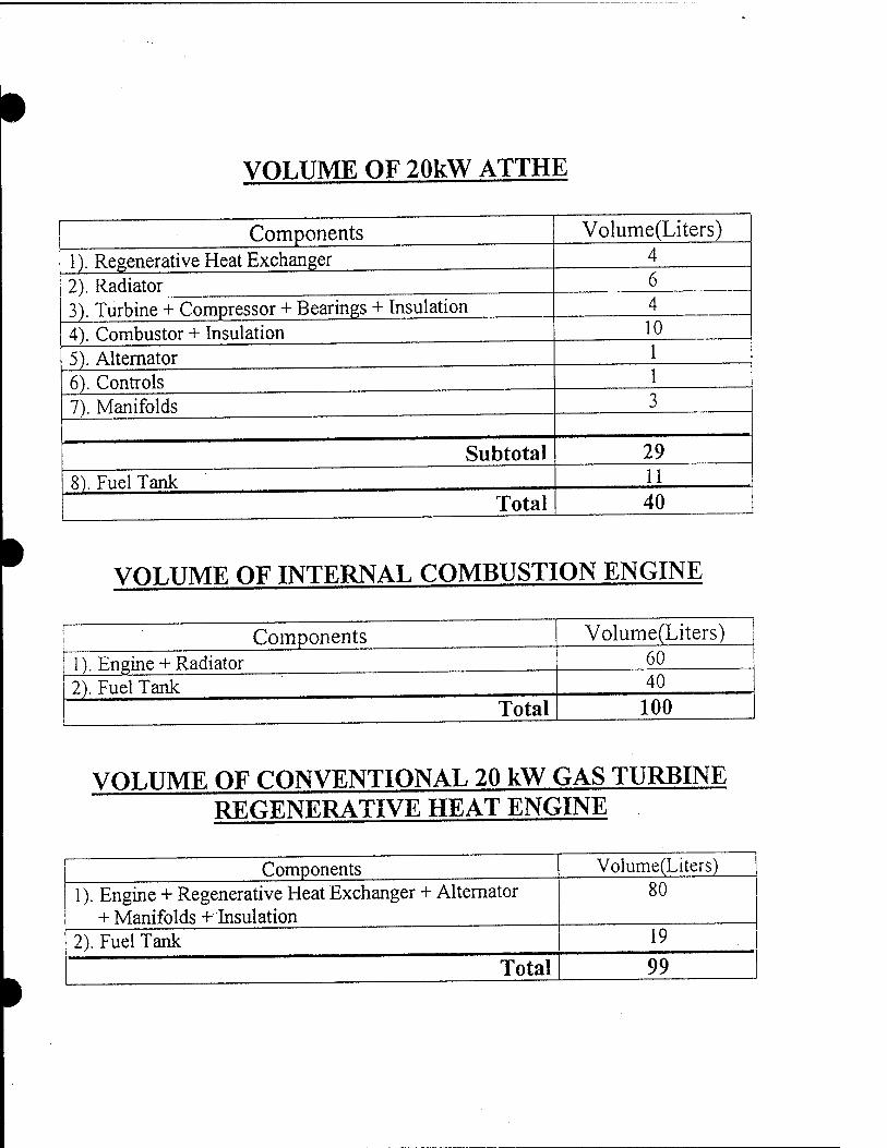
VOLUME OF 20kW ATTHE
Components 1). Regenerative Heat Exchanger 2). Radiator 3). Turbine + Compressor + Bearings + Insulation 4). Combustor + Insulation 5). Alternator 6). Controls 7). Manifolds
Subtotal 8). Fuel Tank
Total
Volume(Liters)
6
10
29 11 40
VOLUME OF INTERNAL COMBUSTION ENGINE
Components 1). Engine + Radiator 2). Fuel Tank
Total
Volume(Liters) 60 40
100
VOLUME OF CONVENTIONAL 20 kW GAS TURBINE REGENERATIVE HEAT ENGINE
Components 1). Engine + Regenerative Heat Exchanger + Alternator
+ Manifolds + Insulation 2). Fuel Tank ~~ ~~Z~
Total
Volume(Liters) 80
19
99"

TURBINE

CO
("fes-ä
S^^S OJ
J2.
8910'T
■e en
CO
[T2T] 3 co
§ rf
Q
I
O
1. is
i
1 fc
§

CO
I
|t3-3
OJ

CO
I IM

nJUUUUU JOOOOOOOOOO 10000000000000000000
JO0 0000 00000 0000 00000000 0 .JOOOOOOOOOOOOOO0000000000000
.JOOOOOOOOOOOOOOOOOOOOOOOOOOOOOO JO00000000000000000000000000000000
JOOO000000000000000000000000000000000 ('OOOOOOOOOOOOOOOOOOOOOOOOOOOOOOOOOOOOOOOO
.00000000000000000000000000000000000000000 JOOOOOOOOOOOOOOOOOOOOOOOOOOOOOOOOOOOOOOOOOOO
_ JOOO00000000000000000000000000000000000000000 -000000000000000000000000000000000000000000000000 rooooooooooooooooooooooooooooooooooooooooooooooooo
«000000000000000000 0000000000000000000000000000 0000 Jo00000000000000000000000000000000000 0 0 0 0 0 0 0 0 0 0 000 op 10000000000000000000000000000000000000000000000000000 ooooooooooooooooooooooooooooooooooooooooooooooooooooo JOOOOOOOOOOOOOOOOOOOOOOOOOOOOOOOOOOOOOOOOOOOOOOOOOOOOO
- 00000000 00000 000000000 00000 0000 00000 00000 0000 00000 0000 0 OOOOOOOOOOOOOOOOOOOOOOOOOOOOOOOOOOOOOOOO00000000000000000( 00000000000000000000000000000 00000 0000 0 0000 0000 0000 0 0000 00 10000000000000000000000000000000000000000 000000000 00000000 < 0 0 0000000000000000000000000000000 0 000000000000 00 000 0 0000 0 00 000 00000000000000000000000000000 000 000000000000000 0 0000 000 0 0 00000000000000000000000000000000000000000000000000000oooooooe JOOOO0OO00OOO00OOO00OO00O0OOOOOOOOO00OOOO00O000OOO0OOOO00OO00O JOOOOOOOOOOOOOOOOOOOOOOOOOOOOOAO-ODOOOOOOOOOOOOOOOOOOOOOOO 00000 0'
JOioioioioioioioioio10iofeiioioi o o o o o o o o o o o OJ>--^^^^-^P 0 oooooooooooooooooooooooooc fo 000000000000000000000000 Oy^ ^^PppOOOJ3JiJiJ>pJ)J)OO0J)J>J}J>J>J)J>J>J>_
OOOOOOOOOOOOOOOOOOOOOOOO .000000000000000000000000' OOOOOOOOOOOOOOOOOOOOOOOO' 00000000000000000000000'
.00000000000000000000000' 0000000000000000000000oc 50000000000000000000000 O, OOOOOOOOO00000000000000( 30000000000000000000000 0 oooooooooooooooooooooooe )00000000000000000000000\ OOOOOOOOOOOOOOOOOOOOOOOO
OOOOOOOOOOOOOOOOOOOOOOOO OOOOOOOOOOOOOOOOOOOOOOOO
>O00OO0OOO00OOO00OOO00OO OOOOOOOOOOOOOOOOOOOOOOOO oooooooooooooooooooooooe 0000000000000000 00000 0 0 ooooooooooooooooooooooc ooooooooooooooooooooooo ooooooooooooooooooooooc ooooooooooooooooooooooo ooooooooooooooooooooooc oooooooooooooooooooooor ooooooooooooooooooooooo
. oooooooooooooooooooooot ooooooooooooooooooooooor
.OOOOOOOOOOOOOOOOOOOOOOOO OOOOOOOOOOOOOOOOOOOOOOOOO'
_O0000O000OO000O000O00000O' 0 0 ö"Otra-C"0 0 00000000000000000000000000" JOOOOOOOOOOOOOOOOOOOOOOOOOOOOOOOOOOO ooooooooooooooooooooooooooooooooooot JOOOOOOOOOOOOOOOOOOOOOOOOOOOOOOOOOOO OOOOOOOOOOOOOOOOOOOOOOOOOOOOOOOOOOO' JOOOOOOOOOOOOOOOOOOOOOOOOOOOOOOOOOO' 0000000000000000000000000000000000' JOOOOOOOOOOOOOOOOOOOOOOOOOOOOOOOOO' OOOOOOOOOOOOOOOOOOOOOOOOOOOOOOOOO" looooooooooooooooooooooooooooooor' oooooooooooooooooooooooooooooooo 10000000000000000000000000000000' 0000000000000000000000000000000' joooooooooooooooooooooooooooooq' OOOOOOOOOOOOOOOOOOOOOOOOOOOOO" JOOOOOOOOOOOOOOOOOOOOOOOOOOOO' 0000000000 000000000 00000 0 0 00' oooooooooooooooooooooooooo*'
0 0 0 00000000000000000000000' JOOOOOOOOOOOOOOOOOOOOOOOO"' OOOOOOOOOOOOOOOOOOOOOOOO" 9000000000000000000000 OS ooooooooooooooooooooo 00000000 0 0000 0 00 0 0 0,"' OOOOOOO000O0OOO0 ~ 000000000000000, 0000000000 0 0, »fin n n nno.

1
in CO
T—1
OJ
" >2Z>'0
CO
o CD CO
* 80Z/0
o |\ in Ö
1
x—i
CO
1
" 998'0
o o / ' n . , O O Z. U
J ' c39£2'0
^v" ' 80Z'0
of
pa Q
i D
co
Ü
CO < fo
8 W
P
en
i CO
73
I DO

00 8
«s Eh o
JWV9 a
I 2 Q
0^
LT) o
598e'5
eS9T"0
?
80^'0
IBS if»-
■■HID
6£C2'0
OJ OJ
2
a.

26t6'0
1

00
es 0
g
P
1
vq rn
en
<zi
1
££Z2'6

COMPRESSOR

8!
i 5*

8!
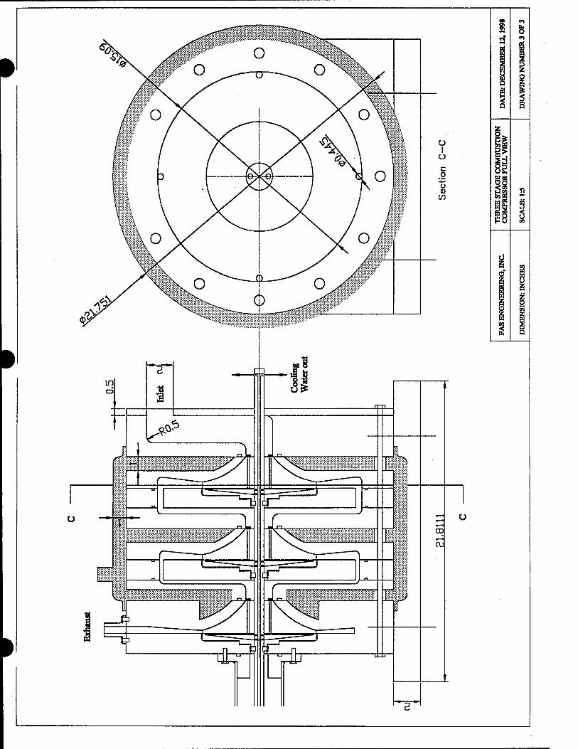

8!
a
1
4
£ 5
8
1 1
s
g
t-

I
ico—sr
CO' r
\3vL'0
fi
*®im$
xx 7—c
CO CD
tBt f
LO OJ CD
m
CD
80Z'0
00
El
I
5
5?
1
es
8
SS
a
3

•
□ L
+» d
CS
p
1
pH
So
O co
Ö CS
n
u CO
CO
Qj +» Ö > CD C
"6 o u

00
tS
0»2
O O U

STI Technologies

111 ■ ". ' ■ ——-——..—-.. .,...-- ,.,._. ,..--«.
::-i ,■ '- ■.: i / ;: , ' : ' . . , . ' .' ' V'i V: 't ', !'" - ■ /
•"' ■ j '■ ;!•''' J ', ' . •■' ': ! \
■■ «• .'•'::. i- >■ ■
■ \ ...
•■■'.'': - ' ■■''•'. ■ ..
^ipMerAnalysü Software
MfJ&?,:
Vt'liaj
'J. ;:,:;:i\-v, V Generation \ pe(Hccti0]fyst-PrQcessirig* Integrated'Analysis''£&■"'.; Integ^xied LißMgmtiims
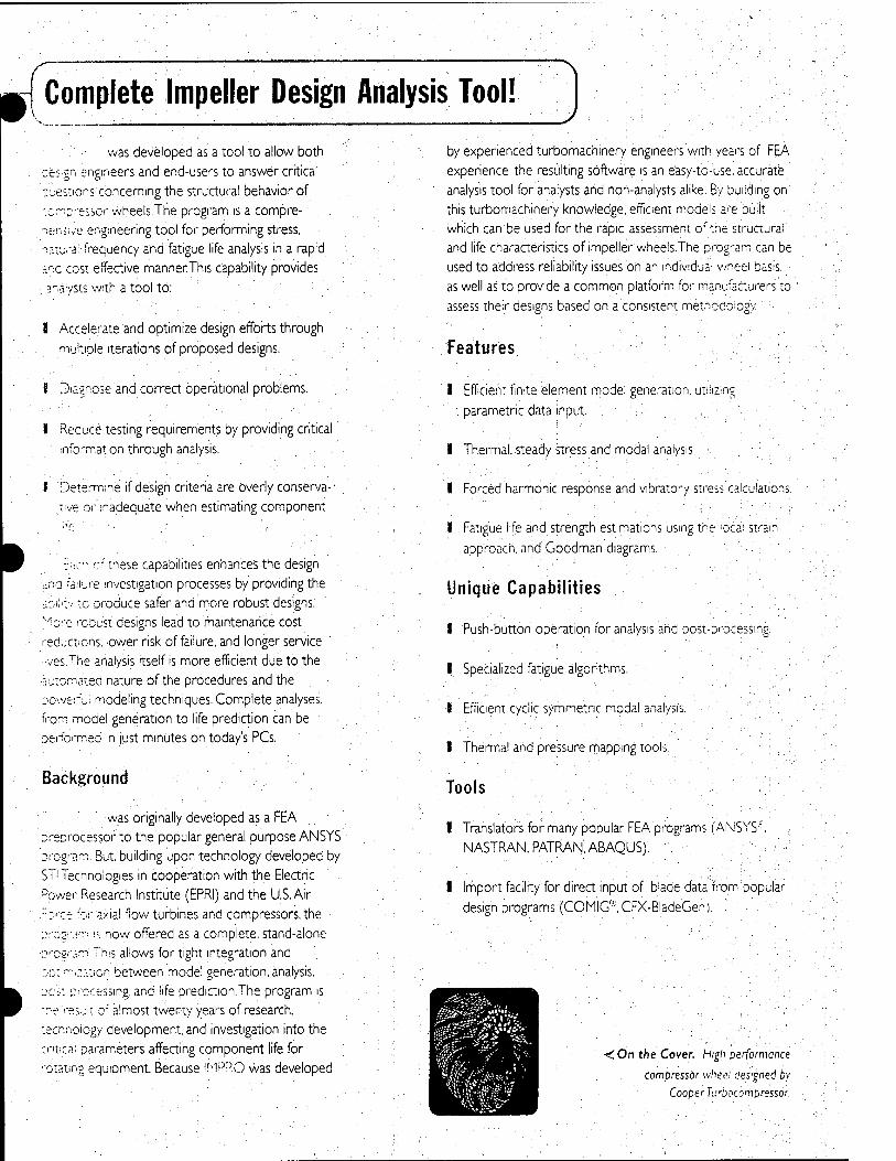
was developed as a tool to allow both
■oes.gn engineers and end-users to answer critical
questions concerning the structural behavior of
'.o.-r.preiior wheels.The program is a compre- nerü.'e engineering tool for performing stress,
natural- frequency and fatigue life analysis in a rapid ana cost effective mannerThis capability provides
■ analysts with a tool to:
1 Accelerate and optimize design efforts through
multiple iterations of proposed designs.
f Diagnose and correct operational problems.
I Reduce testing requirements by providing critical
information through analysis'.
f Determine if design criteria are overly conserva- ■ jive or inadequate when estimating component
:Yo~ rj these capabilities enhances the design
>:no failure investigation processes by providing the
ibii'ty to produce safer and more robust designs.
'■^ore rcDu'st designs lead to maintenance cost
reductions, lower risk of failure, and longer service
'■ves.The analysis itself is more efficient due to the automated nature of the procedures and the
Dowen'ui modeling techniques. Complete analyses,
from moael generation to life prediction can be
performed m just minutes on today's PCs.
Background
was originally developed as a FEA oreorocessor to the popular general purpose ANSYS
Drogram. But. building upon technology developed by
STi Technologies in cooperation with the Electric
Power Research Institute (EPRI) and the U.S.Air
"cce 'or axial flow turbines and compressors, the
ore-gram is now offered as a complete, stand-alone ■■0'"cgram. This allows for tight integration and
:.D::--".;:.':Tjcn between model generation, analysis.
:x'£t-;xccessmg. and life prediction.The program is
•"•«'result of almost twenty years of research,
technology development, and investigation into the
critical parameters affecting component life for
. ■•otatmg equipment. Because IMPRO was developed
by experienced turbomachmery engineers with years of FEA
experience, the resulting software is an easy-to-use. accurate
analysis tool for analysts and non-analysts alike. By building on
this turbomachinery knowledge, efficient models are ouiit which can be used for the rapid assessment of the structural'
and life characteristics of impeller wheels.The program can be
used to address reliability issues on an individual wnee! basis,
as well as to provide a common platform for manufacturers to
assess their designs based on a consistent methodology. :
Features
I Efficient finite element model generation, utilizing
parametric data input.
I Thermal, steady stress and modal analysis.
I Forced harmonic response and vibratory stress calculations.
I Fatigue life and strength estimations using the local strain
approach, and Goodman diagrams.
Unique Capabilities
I Push-button operation for analysis and post-processing.
I Specialized fatigue algorithms. "
I Efficient cyclic symmetric modal analysis.
1 Thermal and pressure mapping tools.
Tools
I Translators for many popular FEA programs (ANSYS'. ■ ,, ■ NASTRAN, PATRAN, ABAQUS).
I Import facility for direct input of blade data from popular
design programs (COMIG'YCFX-BladeGen). Y
;On the Cover. High performance
compressor wheel designed by
Cooper Turbocompressor

Model Generation
i'he :- '^.0 pre-processor provides the user with a
comprehensive method of generating three-dimensional
'"mite element models, suitable for analysis. Parametric
mput through the user interface, direct import from
popular design packages, or a combination of both
methods can be used for providing input to the pro-
gram.The finite element pre-processor generates a 3D
structured grid, complete with all boundary conditions
and loading necessary for analysis. And while we believe
that the real value of IMPRO is in its integrated ap- oroach to model generation, solution, and post-process-
ing, it can be used as just a pre-processor to other
Popular FEA programs.
Modeling Capabilities
I Both open and closed (shrouded) impellers.
1 Splitter blades, with splitter geometry independent of
mam blade geometry. ■ ■•■.
rHub (disk) geometries with arbitrary back-plane
'Dtiles'. ■ ■
Uj^.^,.—MMMM
EälH^H&ffiHHl
i ) 1 ;../ i
■ 1 1
■/ /
■ r" ■ ■'■ !
'(■
1 l~. W^^i^^f^W0^M^&^^^
A Input example showing blade station
data and shroud and hub profiles.
WIVDIIMII
I Variable blade fillet radii at both
hub and shroud locations. :
Balance rings.
I User control of mesh densities.
I Both smgle sector and full wheel
models.
Because of the analysis tech-
niques employed, all analyses can
oe performed on a single 3D sector
insisting of one blade (or two, in
the case of a splitter) plus a :orresponding one-pitch section of
disk.There is no need for a less- accurate 2D axisymmetric model.The full wheel model option would only be needed on the
rare occasion that the boundary conditions or loading was not the same for all blades on the
Bieel. Elements are grouped by component type, (i.e. shroud, blade, hub, ring), for ease of ection when viewing the model or post-processing results. In addition to these components
' defined during model generation, all exterior surfaces are identified and categorized for
streamlined application of loading conditions. The loading conditions are applied to the "topol-
ogy." and then interpolated to the surfaces of the finite element model.
0 fcloL*i
r A Example of shrouded impeller. (Courtesy ofDemag Delaval)
Mesh Density Control: Because the mesh density can
be controlled independently of the geometry definition, the mesh can be tailored for efficient, accurate analysis, depending on the requirements of a particular
analysis.
m All
While the coarse-mesh blade model in the upper figure may be
suitable for a modal analysis, the
more refined mesh of the lower figure will lead to more accurate
stress calculations.

Analysis } Analysis Capabilities
I Thermal analysis (transient and steady state heat
convection and conduction).
f Steady stress (centrifugal, thermal, and aerodynamic
loading). ■ ■ \ ■■
I Natural frequency and Modeshape calculation.
I Forced harmonic response and dynamic stress
(vibratory).
I Fatigue life and strength estimations using the local strain
approach, and Goodman diagrams.
Finite Element Analysis
Analysis to support design and root cause
investigations is provided by IMPRO. Finite element
analysis serves to provide temperature distributions,
steady and dynamic stresses and natural frequencies
and mode shapes, while multiple life models are
available that utilize these results.
If desired, thermal analyses can be used to solve
for convection and conduction to provide a tempera-
ture map for given conditions.This map is then
automatically applied during the stress and modal
analyses, either to calculate the thermal effects on
the stress state, or just to provide the correct temperature state for material property calculation.
Steady stress analysis is used to calculate the - response due to steady loading (centrifugal, thermal
and aerodynamic).
. Modal analysis calculates the natural frequencies
and mode shapes of the structure for any operating
speed. Using cyclic symmetry, complex wheel mode
shapes of varying nodal diameter are calculated. :
These results can then be used in calculating vibratory
stresses. Since the calculations are highly automated,
there is very little user interaction needed.
The life models include crack initiation via the local strain approach, or the Goodman diagram, as
well as an interface to a fracture mechanics program.
■ All the analysis procedures in IMPRO are set up to be
push-button operations requiring no FEA experience. :
Life Estimation
IMPRO provides two life estimation models for the user
to choose from.
The local strain approach is an accurate method of estimating the low-and high-cycle fatigue life for a given
operation.The elastic stress calculated during the finite :■ element phase is used in developing a strain-based profile.
Rainflow counting is then used to compute constant
amplitude cycles and the life per cycle is calculated from a
strain-life curve. Finally, Miner's law is applied to estimate the
total life. The results of these damage calculations can be dis-
played on a contour plot of the finite element model.
The Goodman diagram is another popular life estima-
tion tool. IMPRO takes the classic Goodman approach and
improves upon it by calculating a factor-of-safety parameter
based on the distance from the Goodman line for each :
node in the model.These values are then displayed on a
contour plot, immediately indicating to the user the loca-
'Ui—\<~»a* ■!■■'■. p.i.i. ji'"iyr-
liillli^iFill
A Thermal boundary conditions and pressure loading are applied
using spatial mapping techniques.
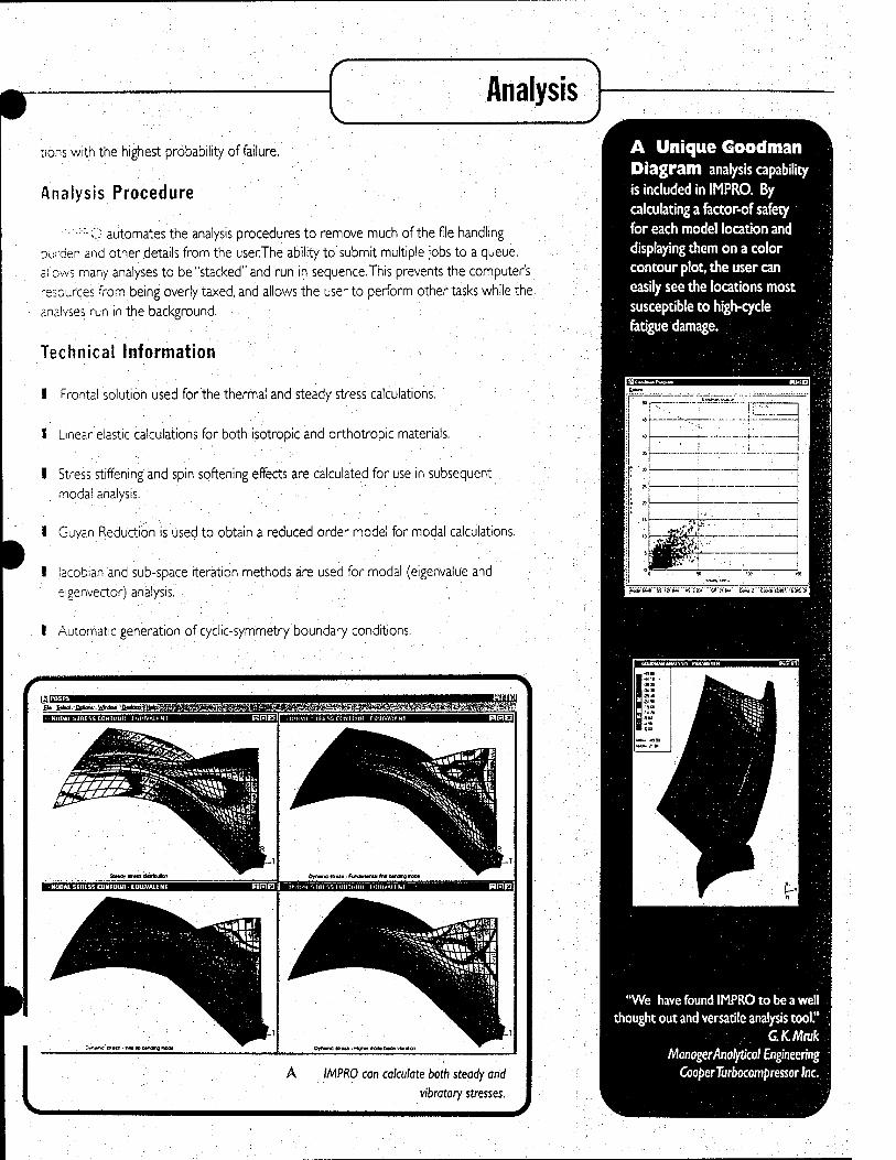
Analysis
lions with the highest probability of failure.
Analysis Procedure
■'■'••'"O automates the analysis procedures to remove much of the file handling
burden and other details from the userThe ability to submit multiple jobs to a queue,
aiiows many analyses to be "stacked" and run in sequence.This prevents the computer's
resources from being overly taxed, and allows the user to perform other tasks while the
analyses run in the background.
Technical Information
A Unique Goodman Diagram analysis capability
is included in IMPRO. By
calculating a fector-of safety for each model location and displaying them on a color contour plot, the user can
easily see the locations most
susceptible to high-cycle fatigue damage.
I Frontal solution used for the thermal and steady stress calculations.
i Linear elastic calculations for both isotropic and orthotropic .materials.
I Stress stiffening and spin softening effects are calculated for use in subsequent
modal analysis.
I Guyan Reduction is used to obtain a reduced order model for modal calculations.
I lacobian and sub-space iteration methods are used for modal (eigenvalue and
eigenvector) analysis.
I Automatic generation of cyclic-symmetry boundary conditions.
"We have found IMPRO to be a well thought out and versatile analysis tool."
CKMruk Manager Analytical Engineering
CooperTurbocompressorlnc.

Post-processing is one of the most important aspects of
the analysis procedure - It allows the user to view the
analysis results and make engineering judgements based on
the data.
Contour Plotting
Many aspects of an IMPRO analysis are viewed using
contour plots. These allow the variation of the calculated
values'to be displayed on the finite element model. Stresses,
temperatures, and displacements are the typical quantities,
while other parameters such as fatigue damage and
Goodman safety factors can also be displayed'.
The IMPRO contour plotting program has a variety of features that allow the user to display results.
I Multiple windows can be simultaneously displayed, each
with an independent view, element set, analysis value,
and analysis case.
I Clicking the mouse on the desired location displays the
element or nodai quantities of the model geometry and
analysis results.
I The model can be easily rotated using the mouse. ,
I The deformed shaped can be supenmposed on the
displayed model. :
I Mesh lines can be displayed or removed for easier
viewing.
I An error estimation contour is available allowing the user
to quantify the accuracy of the analysis.
Each of these features has been developed specifically
with the analyst in mind, in order to provide the necessary
capabilities for thoroughly reviewing the results.
. NUDAL STHESS CON1 OUR - EtllJIVAlLNT
»PRO btede geometry from COMIC
. CONTOUR-RESULTANT
A Multiple windows showing different scalar quantities and different views are possible.
(Image Courtesy ofNREQ
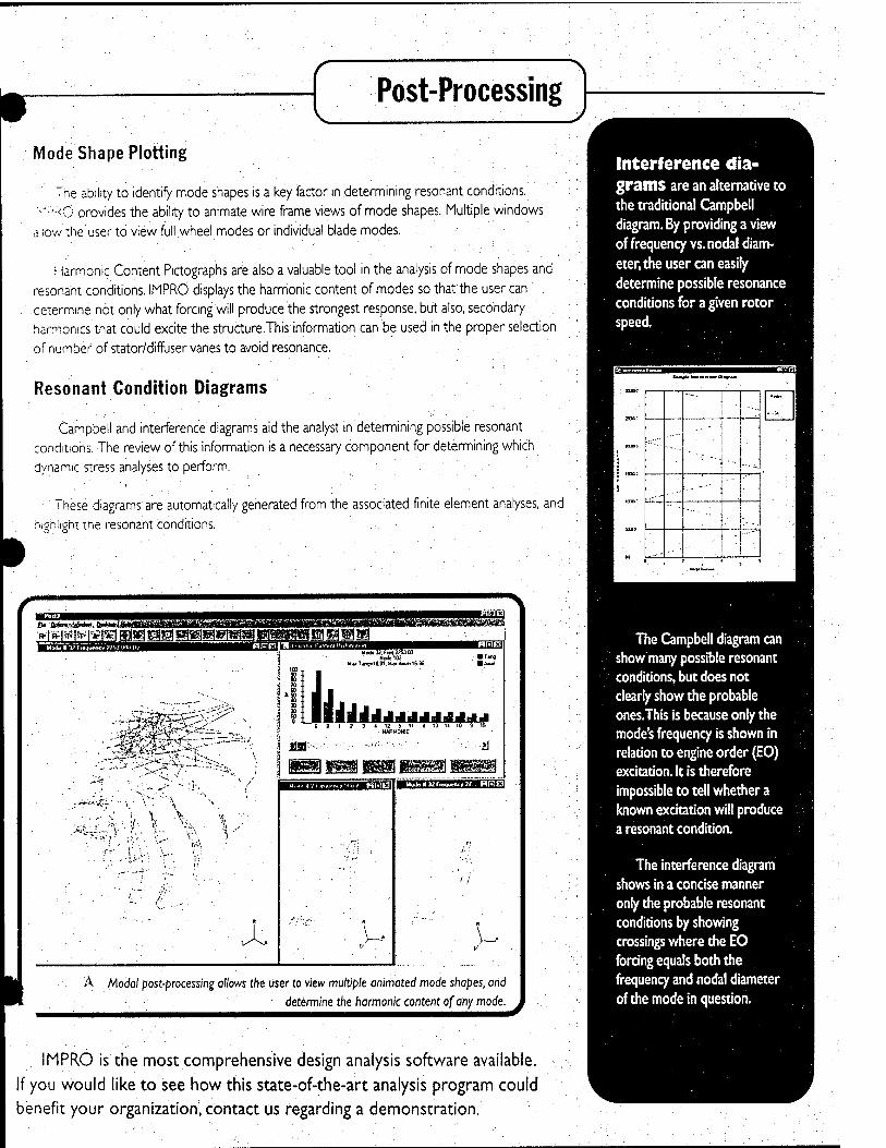
Mode Shape Plotting
The ability to identify mode shapes is a key factor in determining resonant conditions.
'-':i:<ö provides the ability to animate wire frame views of mode shapes. Multiple windows
aiiow the user to view full wheel modes or individual blade modes.
Harmonic Content Pictographs are also a valuable tool in the analysis of mode shapes and
resonant conditions. IMPRÖ displays the harmonic content of modes so that the user can
determine not only what forcing will produce the strongest response, but also, secondary
harmonics that could excite the structure.This information can be used in the proper selection
of number of stator/diffuser vanes to avoid resonance.
Resonant Condition Diagrams
Campbell and interference diagrams aid the analyst in determining possible resonant
conditions. The review of this information is a necessaty component for determining which
dynamic stress analyses to perform.
These diagrams are automatically generated from the associated finite element analyses, and
highliehi'tne resonant conditions.
■M,m,»j;iiW,wmiii!iiiii]
'SZ-T-~-:~"^JI
;**"J<-? \
;,, V . V
X
\i Mod« 32. Fix) 275100
Node ICC M».Tvig-10.01.MwA«M&.K
UiA JliJJJJJdiJ
JÜB
\ >
Mode I 32 Fieduenc» 21.. HRE
Ä Modal post-processing allows the user to view muttipk animated mode shapes, arid determine the harmonic content of any mode.
Interference dia- grams are an alternative to the traditional Campbell diagram. By providing a view
of frequency vs. nodal diam-
eter, the user an easily
determine possible resonance conditions for a given rotor speed.
: setts
■ ixma
!
vat
Wa^t* iMikitMi Ola(fHt
! i
,<: --■-
:
.-■-'-
1 ' . ■ * t
The Campbell diagram can show many possible resonant conditions, but does not clearly show the probable ones.This is because only the mode's frequency is shown in relation to engine order (EO) excitation. It is therefore impossible to tell whether a known excitation will produce a resonant condition.
The interference diagram
shows in a concise manner only the probable resonant conditions by showing crossings where the EO forcing equals both the frequency and nodal diameter
of the mode in question.
IMPRO is the most comprehensive design analysis software available.
If you would like to see how this state-of-the-art analysis program could
benefit your organization, contact us regarding a demonstration.

rfLADb-Cjl ^lade Life Analysis and Design Evaluation
*>*«y%^,:
üHHI
experience^mtc '-/,4V[!SJ."-I"-V.
^Efficient Finite Element Model Generation * > Dedicated Post-Processing
'•> Integrated Life Algorithms
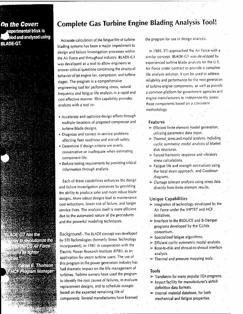
On the Coven experimental blisk is bled and analyzed using
BLADE-GT.
I ■
m
wm aB
&¥s?®
"X&i i&
:0i%m
Ä5H3B&
ifflipatem Wm
Complete Gas Turbine Engine Blading Analysis Tool!
Accurate calculation of the fatigue life of turbine
blading systems has been a major impediment to
design and failure investigation processes within
the Air Force and throughout industry. BLADE-CT
was developed as a tool to allow engineers to
answer critical questions concerning the structural
behavior of jet engine fan, compressor, and turbine
stages. The program is a comprehensive
engineering tool for performing stress, natural
frequency and fatigue life analysis in a rapid and
cost effective manner. This capability provides
analysts with a tool to:
• Accelerate and optimize design efforts through
multiple iterations of proposed compressor and
turbine blade designs.
• Diagnose and correct in-service problems
affecting fleet readiness and aircraft safety.
• Determine if design criteria are overly
conservative or inadequate when estimating
component life.
• Reduce testing requirements by providing critical
information through analysis.
Each of these capabilities enhances the design
and failure investigation processes by providing
the ability to produce safer and more robust blade
designs. More robust designs lead to maintenance
cost reductions, lower risk of failure, and longer
service lives. The analysis itself is more efficient
due to the automated nature of the procedures
and the powerful modeling techniques.
Background - The BLADE concept was developed
by STI Technologies (formerly Stress Technology
Incorporated), in 1981 in cooperation with the
Electric Power Research Institute (EPRI), as an
application for steam turbine users. The use of
this program in the power generation industry has
had dramatic impact on the life management of
turbines. Turbine owners have used the program
to identify the root causes of failures, to evaluate
replacement designs, and to schedule outages
based on the expected remaining life of
m components. Several manufacturers have licensed
the program for use in design analysis.
In 1989, STI approached the Air Force with a
similar concept. BLADE-CT was developed by
experienced turbine blade analysts tor the U.S.
Air Force under contract to provide a complete
life analysis solution. It can be used to address
reliability and performance for the next generation
of turbine engine components, as well as provide
a common platform for government agencies and
engine manufacturers to independently assess
these components based on a consistent
methodology. .
Features > Efficient finite element model generation,
utilizing parametric data input.
> Thermal, stress and modal analysis, including
cyclic symmetric modal analysis of bladed
disk structures. > Forced harmonic response and vibratory
stress calculations.
> Fatigue life and strength estimations using
the local strain approach, and Goodman
diagrams. > Damage tolerant analysis using stress data
directly from finite element results.
Unique Capabilities > Integration of technology developed by the
Air Force under the IHPTET and HCF
initiatives.
> Interface to the REDUCE and B-Damper
programs developed by the GUIde
consortium.
> Specialized fatigue algorithms.
> Efficient cyclic symmetric modal analysis.
> Root-to-disk and shroud-to-shroud interface
analysis. > Thermal and pressure mapping tools.
Tools > Translators for many popular FEA programs. > Import facility for manufacturer's airfoil
definition data formats.
> Internal material database, for both
mechanical and fatigue properties.
*,£#.*.* BRSS8
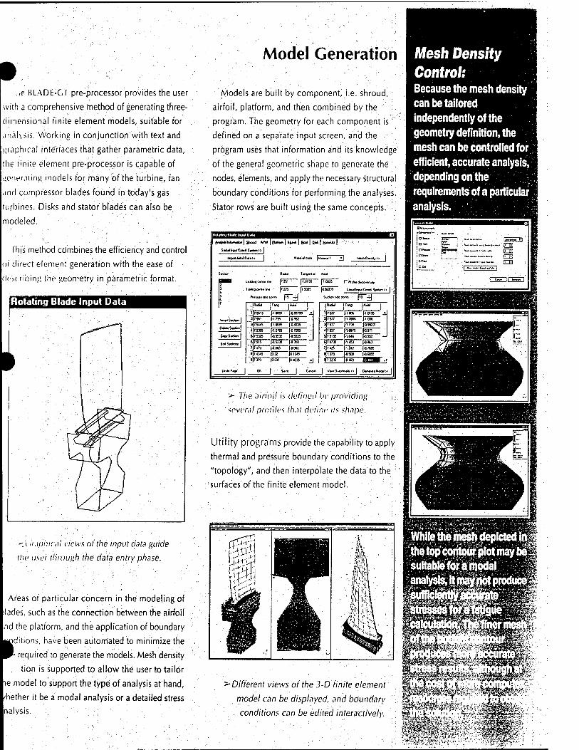
•
..e HLADE-GT pre-processor provides the user
with a comprehensive method of generating three-
dimensional finite element models, suitable for
nalysis. Working in conjunction with text and
raphical interfaces that gather parametric data,
the finite element pre-processor is capable of
.e-neuting models for many of the turbine, fan
and compressor blades found in today's gas
turbines. Disks and stator blades can also be
modeled.
This method combines the efficiency and control
of direct element generation with the ease of
describing the geometry in parametric format.
Rotating Blade Input Data
■.'-.'( iuphical views of the input data guide
the user through the data entry phase.
Areas of particular concern in the modeling of
•lades, such as the connection between the airfoil
nd the platform, and the application of boundary
jUjditions, have been automated to minimize the
W' required to generate the models. Mesh density
tion is supported to allow the user to tailor
ie model to support the type of analysis at hand,
/hether it be a modal analysis or a detailed stress
nalysis.
Model Generation
Models are built by component, i.e. shroud,
airfoil, platform, and then combined by the
program. The geometry for each component is
defined on a separate input screen, and the
program uses that information and its knowledge
of the general geometric shape to generate the ,
nodes, elements, and apply the necessary structural
boundary conditions for performing the analyses.
Stator rows are built using the same concepts.
GloMWwCood 5t«t«*» |
Malay cod.
j* | H«.!* |
M*in0vuiy>> |
1
>l
IirpotWolO«*» | 1»*«" d
Swilon ' ■ H«M TtnQBrt«! ' A-J
r Pi d» dncortrut,,
LecJ Irpa Ccatd S^twn »
■Ü ;L**dr4c«>« W |7SS1 } 1.9195 [100*
3 4 5 6
li*ngc**t<hrw [7.225 [1S09S
Pm*j. tOe porti |is' -TJ
1096039
Sudan rtc PC
..[fl«M |T«1» |*Hl I-. .[*«" I*« |AMI j
hi«) Steten |
CwyStdon |
$M5*ctionj |
1J7.55>9 2)7 551
3|7.544S
4J7.S355
5J7.S3K
6)7515
l-l »91 J49S799 £.
1-1.739 |0953
I-1.S695 149225
(-1.2765 (4 7206
I-Ö9S» (45525
|45235 (4318
1J7 537
2)7.537 ■1.805 j-1.0135 ^ ■1.7855 1-1008
3(7 537
*|7.537 ■1.738 1-039271
-16875 1-0371
5)7.5155
6j 7.1735
■1.646 (4353 -J
1453 (4363
1)7 4345
3)7,179
1-0068 i-aou 7|7 4« 1.242 J47685
|0S ]0 IMS
10699 |0.40» _-j
8(7.373 4938 146055
3J7 3Z35 4469 RSH *
Undo Ptga | Of. | S*vt | C*nc*f | Vwm G«c*- -**» | G*—.Mc^>
> The airfoil is defined bv providing
several profiles that define its shape.
Utility programs provide the capability to apply
thermal and pressure boundary conditions to the
"topology", and then interpolate the data to the
surfaces of the finite element model.
-Different views of the 3-D finite element
model can be displayed, and boundary
conditions can be edited interactively.
Mesh Density Control: Because the mesh density can be tailored independently of the geometry definition, the mesh can be controlled for efficient, accurate analysis, depending on the requirements of a particular analysis.
While the mesh depicted in iyb(|
suitable for a modal -$''M,
-.-•;, 4

Interface Analysis jvs the effects of a
'(Ay" bearing surface on he steady and vibratory Presses of a fan blade. High »pots on the bearing surface lue to manufacturing jroblems were analyzed by tumerically varying the nterference between the äotörid disk, instead of Tiod'rfying the geometry j^Triisjillowed many scenarios to be examined
Analysis
Analysis to support design and failure
investigation initiatives is provided by BLADE-GT.
Finite element analysis serves to provide
temperature distributions, steady and dynamic
stresses and natural frequencies and mode shapes,
while a variety of life models are available that
utilize these results.
• • '?s
''•=>; .-■?
The interface analysis option (also called gap'
analysis or friction analysis) simplifies performing
the analysis of complicated root-disk and shroud-
shroud contact problems. The gap definition
program visually leads the user through the steps
necessary to set up the analysis.
M.-nwi'ii r
The life models include crack
initiation via the local strain
approach or the Goodman diagram,
as well as interfaces to several
crack propagation programs.
All the analysis procedures in
BLADE-GT are set up to be easy to
run, requiring minimal input from the
user to control the sequence of events.
w,i,Bni,nmwn
Finite Element Analysis
This provides the basis for evaluating
the structural integrity of a particular design.
Thermal analysis solves for convection
and conduction to provide the temperature :
map for given conditions. This map is then applied
during the stress and modal analyses, either to
calculate the thermal effects on the stress state,
or just to provide the correct temperature state for
material property calculation.
Steady stress analysis is used to calculate the
response due to steady loading (centrifugal, thermal
and pressures).
Modal analysis calculates the natural frequencies
and mode shapes of the structure. Since the blade
and disk are both modeled, the complex bladed
$ disk mode shapes are calculated. The results can
H then be used in calculating vibratory stresses.
i These calculations are highly automated, so the *£■ ■■■■.■■ H program needs little user interaction.
TTTIET
■ .i»M
«r»i.M«i!'m..iwi.i
' ßl.ADF.'-CT v,H.'\.i/n)7cW hot. itc'.trlv .)')(/1 !■■■'.iu>r\" <rresst'-
Life Estimation - BLADE-GT uses several life
estimation models to provide the analyst with the
correct method for a given problem/
The local strain approach is an accurate method
of estimating the low- and high-cycle fatigue life
for a given mission. This analysis uses the elastic
stress calculated during the finite element phase
to determine a strain-based mission profile. - ".;.
Rainflow counting is then used to compute
constant amplitude cycles and the life per cycle
is calculated from a strain-life curve: Finally,
Miner's law is applied to estimate the total life.
The results of these damage calculations can be
displayed as a contoured scalar quantity,
superimposed on the finite element model.

•
Analysis
. ,it.' Goodman diagram is another popular life
^timauon tool. BLADE-CT takes the classic
Goodman approach and improves upon it by
: olculating a factor-of-safety parameter based on
he distance from the Goodman line tor each node
;i the model. These values are then displayed on
i contour plot, identifying the locations with the
highest probability'of failure.
Damage tolerant methods are also being
evplopecl, as'well as interfaces to popular crack
ruu-th programs. These interfaces enable the user
;o export data directly from the finite element
V.IVHS performed in BLADE-CT.
■ • \ •■■ ~ j-^iw f.'fhire - BLADE-CT automates
n' .ii-.iKsis procedures to remove much of the
Bnandling burden and other details from the
The ability to submit multiple jobs to a queue,
.\ith each one running in turn allows many
inalvses to be "stacked" and run in sequence. This
prevents the computer's resources from being
>verlv taxed, and allows the user to perform other
.York while the analyses run in the background.
- The analysis status window shows ■ 'hr progress of the current analysis.
Technical Ihiönn.ition
Frontal solution used for the thermal and steady
stress calculations.
Linear elastic calculations for both isotropic
and orthotropic materials.
Stress stiffening and spin softening effects
are calculated for subsequent modal analysis.
Guyan Reduction used to obtain a reduced order
"model for modal calculations and interference
analysis.
Jacobian and sub-space iteration methods for
modal (eigenvalue and eigenvector) analysis.
Automatic generation of cyclic-symmetry :
boundary conditions.
Modal superposition to obtain the vibratory
response for an input forcing function.
'Verification • Numerous uses of the program in
real world scenarios have proven the system's
model generation and analysis concepts. :
(STATUS-Tesl Requestor-le3<M00cO HHE3I Progiam funning ELEM
Errois 0 Warnings i
First EHOI
Status ELEMENT FORMULATION
i '■'■
View tog J Advanced | Lower | P.^it-.'
1 ■ 1 Aboil |
A unique Goodman diagram analysis capability is included in BLADE-GT. By calculating a factor-of-safety for each
model location and displaying them on a color
: contour plot, the user can easily see the locations ; most susceptible to fatigue damage^^ • r "; ",^
SM"i^^""^^""^""i ■-IDIXI
Detail View log Hold j Release j Stop Queue | Delete |
10 Q JobName State Status
49 L Ie3d.110l2_4 completed success
52 L fe3d110(2_4 completed success
58 L ipie3d.100c4_1 : running
59 .1 fe3d.100c4_1 waiting
¥
-The analysis manager allows users to manage the computer's resources while running BLADE-GT analyses.
'Mtmm
-SV9S
-,v-..- ■'■■- . i

Vigh-cycle fatigue Is Involves many S of BLADE-GT. First,
ä finite element model is generated using the geometric data of the blade and disk. A steady stress and modal analysis are ^rfS^andthe analyst |Sm?a Campbell or ^||wncediagramto determine anyprobable resonant conditions that should be further analyzed. fti|§tory stress; analyses pl^ni^rfbrmedatthe
iant conditions,
|ft|^1inite element
iheälguelifeof
JolMmodels.
WVi
■'■.i.iy
ocessingofthe j^ijritegralpartof
CrJ provides trie
"* lj|f Structural ^Imiibnehtsf "^"■jn^ght^g
:more':Ä 4'^0mi
Post-Processing
Post-processing is one of the most important
aspects of the analysis procedure - It allows the
user to view the analysis results and make
engineering judgements based on the data.
Contour Plotting - Many aspects of a
BLADE-CT life analysis are viewed using contour
plots. These allow the variations of the calculated
values to be displayed on the finite element
model. Stresses, temperatures, and displacements
are the typical quantities, while other parameters
such as fatigue damage and Goodman safety
factors can also be displayed.
The BLADE-GT contour plotting module has
a variety of features that allow the user to display
results.
Multiple windows can be simultaneously
displayed, each with an independent view,
element set, analysis value, and analysis case.
Clicking the mouse on the desired location
displays the element or nodal quantities of
the model geometry and analvsis results.
Contour options can vary the number of
colors from six to over 100. Contour lines
can also be plotted.
Mesh lines can be displayed or removed for
easier viewing. .
An error estimation contour is available ;
allowing the user to quantity the accuracy
of the analysis.
Each of these features has been developed
specifically with the blade analyst in mind, in
order to provide the necessary capabilities for
thoroughly reviewing the results.
•: ■ ? -^IM
■"■'■;?>v?ai
mm*
"! P0SI5- I:\TEST\GeomW100 BeVS.«!*» ...Qp&n« 'aiidow:.E«»klop tM?.,:
NODAL STRESS CONTOUR -lOUWAUMT HHCII NODAL STRESS CONTOUR - EQUIVALENT HHE
Contour plots can c//>/>/.n <!rr<>: temperan.
displacvniem. am,i tati»ue re si;
■.XiSäH'iiSWv

■■■'■ui •■■'■.!!" i'iuiting - The ability to identify
mode shapes is a key factor in determining resonant
conditions' HLADE-CT provides the ability to
animate wireframe views of mode shapes. Multiple
windows allow the user to view full wheel modes,
individual blade modes or any combination of
blades.
Post-Processing
Harmonic: content pictographs are also a
valuable tool in the analysis of mode shapes and
resonant conditions. BLADE-GT displays the
harmonic content of modes so that the user can
determine not only what forcing will produce the
strongest response, but also secondary harmonics
that could excite the blade.
£*t Qpfa» tfwto» ft«*W B»
Wg|H»M-ll«NHa|M|P||a||T <';a:.!;^iiaa^.Uir,rai^;;^.i>^'pi^^
^'Modal post-
processing allows the
user to view multiple
animated mode
shapes, and
: determine the
h:umoni( content
ol any mode.
■'M»iM:i! Condition Diagrams - Campbell
and interference diagrams aid the analyst in
determining possible resonant conditions in an
engine. The review of this information is a
necessary component for determining the dynamic
stress analyses to perform. '
These diagrams are automatically generated
from the associated finite element analyses, and
highlight the resonant conditions. Selecting a
mode in this view takes the user to the mode shape
iw window.
'.'■'
1.» J^"1^ ^
.•*"' ^ts**"^'
"■'"" s^**^ -*"■"" <•»• ,% «■-*' .'" .«--*" --■■: ■— "■■- *~
) <^iÄiii . >■ Campbell diagrams are essential for
determining possible resonant conditions.
BLADE-GT has been used to solve blading problems for the Air Force, Navy, and industry. If you
would like to see how the state-of-the-art blade analysis program for gas turbine engines could help
your organization, contact us and we can get you started.
Interference diagrams are an alternative to the traditional Campbell diagram. By providing a view of frequency vs. nodal diameter, the user can easily determine possible resonance conditions for a given rotor speed.
Forabladeddisk.the Campbell diagram can show many possible resonant conditions, but does not . ■ clearly show the pre ones. This Is because the nodal diameter shape of thfj mode Is r& showr^ on ttie diagrarn;- only the | mode's frequency Is show|| tt is, trterefore, Impossible I to tell wl :|
.order (^y^^io^wlll'l^^
%*&■/■,.
igf;»!':'.'-'.-< W,>; t' ■ (■.;»#.'.■!*.'':■.;.
-V» '•■: M&^^-^-:r-_lvS^ ,T :..

LH nneering Services
MACHINERY PERFORMANCE
STI conducts performance assessments and upgrades. We special-
ize in axial-flow steam turbines, combining experimental and CFD-based
analysis techniques to understand flows in the low-pressure section. Our
unique approach to component development results in improved blade
and exhaust hood elements, which we experimentally qualify for both
aero-thermal performance and structural reliability.
Our services include: I Axial steam turbine throughflow analysis
I Computational fluid dynamics analysis of stages (rotor-stator combinations) and exhaust hoods
I Field tests of low-pressure turbines for performance assessment
l Exhaust hood design upgrades and blading profile optimization
; of axiahflow elements ■';.
f At-speed telemetry strain measurements of rotating low-pres- . k sure turbine blades and disks ' ■ .
" I Custom test system development for power plant applications
Pi w h frV' ff Tl y\ !l^!'
V* ' .
w / ''■■'' w w vi \v~ \h
MACHINERY SYSTEMS ANALYSIS
STI provides a full range of health monitoring and diagnostic
services for all types and sizes of machines and turbomachines, from
pumps to gas turbine engines. Using state-of-the-art equipment and
customized software, we monitor and diagnose the onset of mechanical/
vibration faults, performance degradation, and component remaining life
in real-time! When necessary, we assess the economic and safety-related
impact on maintenance costs and reliability. ■.
Our services include:
I Condition monitoring and diagnostics
. I Root cause failure analysis ''.■"•■':
I Prediction of machinery life to failure based on
operating parameters
I Telemetry field testing for strain, applied loads, stress
and vibration
I Experimental modal analysis
r On-site machinery testing and diagnosis
l Probabilistic analysis and component remaining life assessment

, ► Right: Modal stress distribution for a
steam turbine last stage blade. Jivwi-'sa»
STRUCTURAL ANALYSIS
Our structural analysis group offers a wide variety of
FE analysis services such as mechanical stress and vibration,
thermal stress, fatigue and fracture, and remaining life analysis.
Drawing on a knowledge base of several hundred failure
investigations over two decades, we have developed specialties
in turbomachinery failure analysis and design reviews.
i STI also specializes in life assessment of components
that are subjected to FOD, HCF, LCF, SCC and SPE. In addi-
tion, we are experienced In addressing complex heat transfer
problems (conduction, convection and radiation) as well as
coupled field problems involving heat transfer and fluid ■ \
flow analysis.
' Our services include:
I Stress, vibration, heat transfer and life analysis ;
problems in all aspects of rotating machinery
I Failure investigations and design reviews for /
turbomachinery blading and other components . 1 I Application of probabilistic fatigue and fracture :
; mechanic analysis for life assessment of components :
subjected to HCF, LCF, SCC, FOD and SPE
I Dynamic characterization and response analysis of industrial
machines and structures
I Rotor-bearing dynamic analysis for critical speed, stability and
foundation misalignment
ROTORDYNAMICS
STI has the technology to fully analyze the complex behavior of
small to very large rotating machinery systems. With our own finite
element-based rotordynamic analysis software, STI can model the
rotor-bearing system, including the detailed foundation effects. We use
such simulation to provide more accurate results (unbalanced response,
misalignment, critical modes, Bode diagrams, for example) than are
achievable with commonly-used "beam model" analyses. ';■■■/;
For more details on these services, please access our Website at
www.sti-tech.com
turning experience into value

■■S*fc,'#*a j?® s» A» *!<$■&• :. a- %0 |J* «.-. «a. «fc. "*£ te.. * **. r»^ ä'^vfcCIi^i
October, 1998
STI Technologies announces new compressor wheel analysis software.
Rochester, NY- October 21,1998 - STI Technologies, Inc., a world leader in providing turbomachinery software and analysis services, announces the Windows NT release of IMPRO™, a complete standalone finite element analysis (FEA) package for the design analysis of radial flow compressor wheels. IMPRO is a structural analysis software package that includes integrated model generation, analysis, and post-processing spe-
cific to the evaluation of compressor wheel designs. It is believed to be the only com- pressor wheel analysis software available that does not rely on third party software for the
FEA solutions. The product was unveiled recently at the 27th Turbomachinery Symposium that was attended by over 2000 people and 350 exhibitors.
The program features efficient model generation utilizing parametric input, push-button operation for analysis and post-processing, and fatigue and life estimations. The analysis capabilities include: thermal analysis (tran- sient and steady-state heat conduction and convection), steady stress, natural frequency, forced harmonic response and vibratory stress. Separately, a fatigue life analysis using either a local strain approach or a Goodman diagram is an integrated part of the package. The program also features an internal material data- base for mechanical, thermal, and fatigue properties.
IMPRO includes an import facility for the direct input of blade data from popular design programs (CFX- BladeGen and COMIG™), and has the ability to translate model information to-and-from popular FEA pro- grams (ANSYS™, NASTRAN, PATRAN, ÄBAQUS). ."
In addition to the IMPRO software, STl Technologies has developed the award-winning BLADE™ software under sponsorship of EPRI (Electric Power Research Institute) and the U.S. Air Force for the analysis of axial flow blading (compressors, steam turbines, gas turbines, expanders).
As an introductory offer, fora limited time, STI Technologies is offering to perform freedesign analysis reviews of customer's compressor wheels.
STI Technologies, Inc., founded in 1979, is a technology supplier to the energy, industrial, and aerospace industries. Services are provided in the areas of structural and performance analysis, as well as performance and reliability testing of industrial equipment. STI has developed systems for health monitoring using ad- vanced prognostic and diagnostic techniques, as well as probabilistic systems for critical component lifing and maintenance cost optimization.
For more information contact:
Mark Redding STI Technologies 1800 Brighton-Henrietta Townline Road Rochester, NY 14623
_ (716) 424-2010, Fax: (716)272-7201 turning -~^ tiptrlcrxt Inlo value WWW.Stl-teCh.COm

ORBIT Manufacturing

önJ^TPttu^^ lac.
■ ÖRß/T*
'*«icti«t^
Prototype Design - Machining Flat Lapping - Lap Fitting - Honing 616 Irving Ave, G-lendale CA 91201 (213)849-2747 * (818)956-1383
FAX (818)956-8319

Öi&it M<im4<ictmU^ 1*n.
I
This brochure is to introduce you to the world döniil l^<uu<^tanUi^ -Inc.-, a leader in modern technology. We specialize in the following
services. :
RESEARCH AND DEVELOPMENT CYLINDRICAL LAPPING HONING SPHERICAL LAPPING LAPFITTING I.D./O.D. LAPPING ;
PROTOTYPE DESIGN AND MFG. FLAT LAPPING AUTOMATED MACHINES
Our expertise in honing includes hydraulic valves, actuators, relief valves and special items of your design. This service includes machine lapping of the cylinder's O.D.. :
In spherical lapping we have over 30 years of experience in O.D. and I.D. lapping, plus the knowledge to design and manufacture machines for the production lapping of I.D. races and O.D. of balls.
We can offer "on time" scheduling and delivery at competitive prices. We have performed both commercial and government work for over seventeen years as a small business.
öiiU 7K<uu(^utunl*t^ Inc. will emphasize quality, fast turn-around, pick-up and delivery, and prices that are extremely competitive.
For an immediate response and quality service, please call or fax our office.

VACGO Industries

http://www.vacco.com
Offering a Diversified Range of Advanced Products and Services for
Customers Worldwide
10350 Vacco Street South El Monte, CA 91733 (626)443-7121 Fax:(626)442-6943
an Ccfct7 company
Copyright © 1998 VACCO Industries. All rights reserved. Click here for condition of use
1/19/99 4:32 PM

VACCO Industries, a wholly owned subsidiary of ESCO Electronics Corporation, is a diversified manufacturer of commercial and defense products and systems sold to customers worldwide.
VACCO was founded in 1954 as Vacuum and Air Components Company of America, which was later changed to VACCO Industries. Since its inception, VACCO's extensive product development has diversified the company's products to better serve its customers.
The company is organized into three product groups:
Space Products - Valves and Filters for the Space Applications
Photofabrication - Precision Photochemical Etching
Navy Products - Valves, Filters, and Manifolds for Quiet and Non-Quiet Applications
VACCO's Precision Photochemical Etching offers many advantages to multiple applications looking for specific benefits in the design and production of thin (.0005" to .090") metal components. These benefits include:
Integrity of Metal Properties
Fine Line Configuration Detail
Wide Range of Etchable Metals
Prototype to High Volume Capability
Inexpensive Tooling and Design Modifications
ISO 9002 / QS 9000 Registered
In addition, VACCO's engineering staff can provide assistance in the development of your product with material and design options unique to VACCO's Photofabrication capability.
Please visit the rest of VACCO's web site to see a wide range of precision product examples, helpful design guidelines for etched components, unique added value process capabilities, and a step-by-step walk through of the etching process!
Typical Manufacturing Process
Step #1

CAD Artwork Via customer's blueprint, modem, or floppy disk, VACCO's photographic artwork is laser plotted to exacting specifications.
Step #2
Imaging Panels : Microprocessor controlled UV exposure ensures exact image transfer from the precision photographic artwork to the panel of material.
Step #3
Metal Etching : As one of the largest commercial etching facilities in the U.S., VACCO's multiple etching lines offer both high volume capacity and prototype flexibility. Etch operators employ SPC on all products.
Step #4
Photo-Resist Removal: Proprietary formulations are often used on critical applications. Pictured is a multi-laminate copper panel being sprayed with a customized resist removal solution.
Step #5
Inspection : Visual inspection, assembly, testing and other operations are performed in a dust controlled environment.
Step #6
Water and Air Treatment: VACCO remains proactive on environmental responsibility. An automated wastewater facility is supported by our on-site staffed chemical analysis laboratory.

TODD Combustion

"V®
.;;&'' ß*
TODD Combustion
*:.'■: ".v-. v- *'.-•.; ■'- '.*

.
VARIFLAME™ LOW NOx HIGH! A Low NOx High Efficiency Burner Featuring: 1. Venturi Air Register
•Lou Inchon Losses - Venturi Design • Known Flame Geometry - Axial Flow Technology • High Turndown Ratios • l-i. INK- Stability -For Staged Air Combustion • l.iiw Atomizing Steam or Air Consumption
• I ligh Quality Construction • Rugged Design • Hiuli-m Safety features • K'.R Kates l p To 50'/;
To Provide You With:
• \()\ Reductions Up To W/r • l.(>u ('U Emissions • Staged Fuel and Air Combustion • l.iHV.er Fan Horsepower Requirements • Reduction in Hack End Corrosion • i .iiu'er Fuel (osis • \ ersaiility ol Firing Various Types of Fuels • Simultaneous Gas/Oil Firing
^ • Reliable Automatic Operation ^ I.ov. Maintenance Downtime and Costs ;
- I .linger Kelraclory Life
I ii,\hin-nl-ilic-(in ctwihiisiion rcchrioluf'y proven hy hitiulrals <>] in. . e\\!ii! cippliciltitiils:
Primary Secondary • Air
Flue Gas Recirculation
From 20 To 300 Million BTUs/HR.
^ A Wide Range of Proprietary Devices H • Automatic Purge and Cooling Complex
Pneumatic Roll-On Air Slide
• Piezometer Ring - For Accurate Air Flow Measurement
• Metallic Throat • Safety Interlock Coupling Block
Aerodynamically designed, the Venturi Air Register produces
turbulent-free axial air flow with low friction loss and assures . uniform flow patterns and proper mixing at near stoichiometric conditions.
2. Tertiary Air Register Terliarv air is delivered through a secondary register to provide'air staging within the flame envelope.
3. Integral FGR Plenum On single burner applications an integral flue gas recirculation (FGR) plenum is fitted to the venturi register. FGR is introduced to the flame envelope between the air Zones thus minimizing peak flame temperature and substantially reducing thermal NOx forma- tion. The special plenum design minimizes system II^H^ lowering FGR fan horsepower requirements.
4. Air Slide Onlv required on multiple burner applications, this pnciimalically- opcrated "air slide" closes the air inlet when the burner is off. A ruggedly designed rail and roller assembly provides smooth, reliable operation.
5. Piezometer For improved control at low 'load operation, a Piezometer ring can be installed on the venturi. This allows accurate air flow measure- ment through the burner for combustion control, u it ha large differ- ential pressure transmitter span and no additional system resistance.
6. Diffuser A rotational effect in the primary combustion air /one is produced creating the necessary vortex for flame stability. The results of this action is optimum fuel and air mixing over a wide range of air velocities that produce low excess air combustion contl itions through- out the entire operating range. A reverse How in the form of a self- generating annular vortex occures also causing a recirculation of hot
gases within the flame pattern. The recirculated flame creates an even heat flux in the combustion chamber, minimizing hot spots within the furnace area.
7. Low Steam Atomizer The shape of the atomizer Spray and its position at the hub of the diffuser results in suspended flame combustion. Flame stability is maintained over the full operating range which can be as high as 15:1. The atomizei outlets are drilled to produce a finely atomized oil spray with economical use of atomizing steam. Steam consumption at maximum burner capacity can be as low as 0.025 pounds of steam per pound of oil burned. The atomizing steam pressure is maintained at a constant 100 PSIG over the entire operating range.

•
ivJIENCY VENTURI REGISTER BURNER
VABilÄ
8. Oil Gun I'lu' nil LiLin remains in ihe firing position when ihe burner is off. A
-mall i.|u;m('itv nl atomizing steam is allowed lo pass continuously
through the oil gun for nozzle cooling. Built into the coupling block
a-scmhK arc oil and steam shut-off valves and a mechanical
'interlock system which only allows the valves to remain open when
.the burner is in the operating position. A gas Hap assembly prevents
^irnace gases escaping into the boiler room when the oil gun is
^B'Hived.
9. Gas Burner The gas burner is supplied from an expansion reservoir located
outside the burner front plate and is of the multi-spud injector type,
[•ach o\' the multiple spuds terminates in a stainless steel injector.
drilled to suit the gas flow required forthat particular burner appli-
cation. The injectors are adjusted such that the gas enters the
primary anil secondary air flow stream and produces a suspended
flame ahead of the diffuser. Proprietary injector orientation pro-
vides fuel staging within the'flame envelope thus reducing thermal
NOx formation. A coaxial center fire injector can also lie offered.
10. Throat In order to provide an aerodynamically stabilized flame.: the throat
exit shape has to be properly matched with the register and diffuser
design. The burner throat is generally made of standard refractory
material. Standard for down fired burners are easily installed air
cooled metallic throats which are optional for front fired or corner
fired units.

£ COST EFFECTIVELY
I IK- RMIi's axial swirl vanes, which are attached liv gas reservoir, have hollow bases that are drilled
•.ras inicciion. Thus, the swirl vanes actually are the - injectors, producing rapid mixing at the burner's exit ir to any combustion. A variety of gaseous fuels can ired by the RMB with similar results.
Fuel oil can be fired through a standard imi/.er gun assembly, down the center of the rner. TODD's advanced atomizer tip designs nbined with FOR provide NOx levels isistent with iventional low )\ oil burners.
Wind box ■\ir Connection
/or '-Oil Gun
:4*:' RAPID MIX BURNER (RMB™)
OPERATION PRINCIPLE
tin iiLiliair ■ ■ZII'IH:
:...:..;- internal K'i •<■//•( uLitioii
Zonu
Swirl Vanes and Gas Injectors
Oil Gun Carrier
Fuel Gas Inlet/Reservoir
FULL LOAD AT 3PPM, 10PPM, 75PPM NOx LEVELS (Left to Right)
^^'

DYNAS Wl RL LOW EXCESS Al R HIGH
Featuring: Low Friction Losses"— Venturi Design Known Flame Geometry—Axial Flow Technology High Turndown Ratios — to 20:1 Flame Stability — At Low Excess Air Levels low Atomizing Steam or Air Consumption (High Quality Construction
" Reliable Automatic Operation Lower Maintenance Downtime and Costs Longer Refractory Life Lower Fan Horsepower Requirements Reductions in Back End Corrosion Reduced Emission Levels Lower Fuel Costs Versatility of Firing Various Types of Fuels Simultaneous Cas/Oil Firing
The state-of-the-art combustion technology proven by .hundreds of successful applications.
IC'.MTION POINT FIXED ' 1 AT All TIMES IIOOIS \ Nül VAKY WITH LOAD
-••^..mJU"-^"'"-
::Ä1^7£Z7Fz>.
SPINNEK VANE ■
FLAME HAS A ■—' KNOWN MAXIMUM WIDTH AND LENGTH
TheTodd Dynaswirl Burner is actually a system of four (4) interdependent modules designed to function as a total system.
Provides turbulent-free axial air flow for precise control. Even air distribution assures uniform flow patterns and proper mixing at near stoichiometric conditions.
Imparts a rotational effect in the primary combustion air zone, creating the necessary vortex for flame stability and thoroughly mixing the fuel and air to achieve complete combustion.
A reverse flow in the form of a self-generating annular vortex also occurs causing a recirculation of hot gases within the flame pattern.
The recirculated flame creates an even heat flux in the combustion chamber, thus minimizing hot spots within the furnace area.
Oil or gas is injected directly into the vortex recirculated zone to assure proper mixing and simultaneous firing.
In order to provide an aerödynamically stabilized flame, the throat exit shape has to be properly matched with the register and diffuser design.
A Wide Range of Proprietary Devices Comvalve™ Purge and Cooling Complex Pneumatic Roll-On Air Slide Piezometer Ring— For Accurate Air Flow Measurement Metallic Throat Safety Interlock Coupling Block
The venturi-shape aerodynamic design produces turbulent-free axial flow that results in low friction losses and maximum air flow with minimum fan horsepower:

I IC I ENCY VE IM TU Rl REGISTER BURN ER
\ pneumatically-operated "air slide" closes the air inlet vhen the burner is off. This slide is only required on nultiple burner applications.
\ piezometer ring can be installed on the venturi. This Hows total accurate air flow measurement through the Rirner for combustion control, with a large differential pressure transmitter span and no additional system re- stance. This will normally result in a reduction in total in horsepower.
he dynamic air swirl produced by the diffuser is carefully pitched to the venturi air register through wind tunnel
Bmg. This results in optimum fuel and air mixing, over e range of air velocities, producing low excess air
oinbustion conditions throughout the entire operat- ic range.
The shape of the atomizer and its position at the hub of the diffuser results in suspended flame combustion. Flame stability is maintained over the full operating range which can be as high as 20:1. The atomizer outlets are drilled to form a hollow cone of atomized fuel oil. The atomizer design incorporates a long skewed mixing chamber which produces finely atomized oil with eco- nomical use of atomizing steam. Steam consumption at maximum burner capacity can be as low as 0.025 pounds of steam per pound of oil burned. The atomizing steam pressure is maintained at a constant 100 PSIG over the entire operating range.
The oilgun remains in the firing position when the burner is off. The facility is available for steam to pass continuously through the oil gun for nozzle cooling. Fixed lines replace the conventional flexible hoses which supply the oil and atomizing steam to the gun. Built into the coupling block assembly are oil and steam shut-off valves and a mechanical interlock system which only al- lows the valves to remain open when the burner is in the operating position. A gas flap assembly prevents furnace gases escaping into the boiler room when the oil gun- is removed.
The gas burner is of the multi-spud injector type, supplied from an expansion reservoir located outside the burner front plate. Each of the six spuds terminates in a stainless steel injector, drilled to suit the gas flow required for that particular burner application.
The injectors are adjusted such that the gas enters the primary air flow stream and produces a suspended flame ahead of the diffuser in the same manner as the oil atomizer. A coaxial center fire injector can also be offered.
The burner throat is generally made of standard refractory material. Easily installed air cooled metallic throats are used for down fired burners, and are optional for front fired or corner fired units.

»
Sample Fortran Programming for Computing Turbine Rotor
Efficiency

TURBINE ROTOR
c Subroutine: mulvis & include statements 1 c
subroutine mulvis(taul I,tau22,tau33,taul2,taul3,tau23,vis, idmjdm,kdm)
include 'strmcmn.h' include 'cmnvar.h' include'cmnprp.h' include 'cmnopt.h' parameter (imax=100jmax=100,kmax=100) real taul l(irnaxjroax,kmax),tau22(irnaxjmax,kmax),
tau3 3(imaxjmax,kmax), taul2(imaxjmax,kmax),taul3(imaxjrnax,kmax), tau23(iniaxjmax,kmax),tau(imaxjmax,kmax), vis(idm jdm,kdm),kinetic 1 ,mass 1 ,kinetic2,mass2,L,kk
c c Compute transformation matrix, "tau" & "totaltorque" 2 c
smalltorque=0 Itorqueofa single cell. totaltorque=0 Itotal torque in i= 1 region. totaltau=0 Itotal tau in i=l region. omega=6000 f^/5 iangular velocity of wall. regions=idm !# of regions in circumferencial dir. disks=l Itotal disks in tesla turbine k= 1 !k=cells in z-dir.( l=nearest to wall). i=(idm+l)/2 !i=cells in x-dir. or tangential dir.
c do 100j=ljdm !j=cells in y or radial direction
index=(k-l)*idm*jdm+(j-l)*idm+i Idata storage locations(3D to W-array) c
x=w((index-1 )+kxcc) ! x-coordinales in cartesian sys. y=w((index-1 )+kycc) !y-coordinates in cartesian sys. vx=w((index-l)+kvar(2)) !x-velocity component. vy=w((index-l)+kvar(3)) !y-velocity component. rr=((x**2)+(y**2))**0.5 (resultant of x,y by pythagoras.
c c vr=(l/rr)*((vx*y)+(vy*x)) !Not ready yet c omega=vr/rr !Not ready yet c
vlO=(l/rr)*((vx*y)-(vy*x)) Ifluid velocity v20=0 !wall velocity dv=vl0-v20 dz=w((index-l)+kzcc) [distance from wall to center of 1st cell
c indexl=(kdm-l)*idm*jdm+(l-l)*idm+i gap=w((indexl-l)+kzcc) !
c dynamic=w(kvisl) tauu=dynamic*(dv/dz) Ismall tau due to a cell
c c print * j,y,vl0,v20,dv,dz,tauu c print *,gap,dynamic c
totaltau=totaltau+tauu c smalltorque=Force*Radius=(tau*area)*radius
smalltorque=tauu*w((index-l>4-kharea)*iT totaltorque=totaltorque+smalltorque

c 100 continue
c w(kvar(8))=totaltorque ! stored totaltorque in w(kvar(8))
c c Compute "Power" 3 c
power=totaltorque*regions*omega*disks w(kvar(9))=power
c print *,power,dynamic,gap c c . Power Due to Porous c
kk=0.00000001 dymu=w(kvisl) pforcetotal=0 ptorquetotal=0 i=(idm+l)/2
do 150j=ljdm dol50k=l,kdm
index=(k-l)*idm*jdm+(j-l)*idm+i x=w((index-1 )+kxcc) y=w((index-1 )+kycc) rr=((x**2)+(y**2))**0.5 pvx=w((index-l)+kvar(2)) !x-velocity (Cartesian) pvy=w((index-l)+kvar(3)) !y-velocity (Cartesian) pvt=l/rr*((pvx*y)-(pvy*x)) [tangential velocity pvol=w((index-l)+kvol) Icell volume coeff=dymu/kk
c print *j,pvol,pvx,dymu,kk,coeff pforce=(coeffKpvt)*pvol Ismail force ptorque=pforce*rr Ismail torque pforcetotal=pforcetotal+pforce ptorquetotal=ptorquetotal+ptorque
c 150 continue
c power2=ptorquetotal*regions*omega*disks pow=power+power2
c print *,power,power2,pow c c Inlet= 1 Extract inlet temperature & pressure at i j,k 4 c
R=297 !Gas constant, J/kgK Cp=1004 IJ/kgK
c i=(idm+l)/2 j=jdm !ij,k is an arbitrary cell at inlet k=l index=(k-l)*idm*jdm+(j-l)*idm+i temperaturel=w((index-l)+kvar(7)) linlet temperature at ij,k pressurel=w((index-l)+kvar(l)) linlet pressure at ij,k
c w(kvar( 10))=temperature 1 w(kvar(l l))=pressurel
c print *)pressurel,temperaturel c c Compute inlet mass flow rate and kinetic energy 5

c c totalmassl=rho*Vr*2*pi*radius*gap
totalmassl=1.1767*6*2*3.1416*0.1*0.0005 c 10025=resultant of vx & vy, (620)**2+(6)**2
totalKEl=0.5*totalmassl*384436 w(kvar( 12))=totalmass 1 w(kvar(13))=totalKEl
c print *,totalmassl,totalKEl c c totalKEl=0 c totalmassl=0 c totalareal=0 c j=jdm c do 200 i=l,idm c do200k=l,kdm c c index=(k-l)*idm*(jdm+l)+(j-l)*idm+i+idm c w(kvar(0)+index-l-idm)=index c c areal=w((index-l)+knarea) linlet surface area (north face) c w(kvar(0)+index-l-idm-(k-l)*idm)=areal {modified due to (jdm+1) c totalareal=totalareal+areal c c rhol=w((index-l)+kden) Ifluid density c uul=w((index-l)+kvar(2)) linlet tangential velocity c wl=w((index-l)+kvar(3)) linlet radial velocity c c x=w((index-l-idra-(k-l)*idm)+kxcc) !transformation to cyl coord, c y=w((index-l-idm-(k-l)*idm)+kycc) [transformation to cyl coord. c vxl=w((index-l-idm-(k-l)*idm)+kvar(2)) Itransformation to cyl coord. c vyl=w((index-l-idm-(k-l)*idm)+kvar(3)) Itransformation to cyl coord, c rrl=((x**2)+(y**2))**0.5 Itransformation to cylindrical coord, c vrl=(l/rrl)*((vxl*x)+(vyl*y)) c print *,vrl c w(kvar(25)+(index-l-idm-(k-l)*idm))=vrl c c massl=rhol*areal*vrl Ismail mass flow rate at inlet c print *,ij,k,vxl,vyl,rrl,vrl c c totalmassl=totalmassl+massl Itotal mass flow rate at inlet c resultantl=(uul**2)+(wl**2) (resultant velocity squared,pythagoras c kineticl=abs(massl*(resultantl/2)) Ismail kinetic energy at inlet c totalKEl=totalKEl+kineticl Itotal kinetic energy at inlet c200 continue c w(kvar(12))=totalmassl c w(kvar(13))=totalKEl c print *,totalareal,totalmassl !totalareal=2*pi*radius*thickness(gap) c c Outlet=2 Extract outlet temperature & pressure 6 c c
i=(idm+l)/2 j=l k=l index=(k-l)*idm*ö'dm+l)+(j-l)*idm+i temperature2=w((index-l)+kvar(7)) loutlet temperature at ij,k pressure2=w((index-l)+kvar(l)) loutlet pressure at i j,k w(kvar(14))=temperature2

w(kvar( 15))=pressure2 print *)pressure2,temperarure2
-Compute temperature2S,h2S & hlS-
ratio=pressure2/pressure 1 expo=(w(kganimas)-l)/w(kgammas) temperature2S=temperaturel*(ratio**0.2857) h2S=Cp*(temperature2+10) hlS=Cp*temperaturel print *,ratio)temperature2S,h2S,hlS w(kvar(16))=temperature2S w(kvar(17))=h2S w(kvar(18))=hlS
Compute outlet mass flow rate & kinetic energy--
totalKE2=0 totalmass2=0 totalarea2=0
j=l i=8
do 300 i=l,idm do300k=l,kdm
üsentropic temp, at outlet üsentropic enthalpy at outlet üsentropic enthalpy at inlet
index=(k-l)*idm*(jdm+l)+(j-l)*idm+i area2=w((index-1 )+knarea) totalarea2=totalarea2+area2
rho2=w((index-l)+kden)
x=w((index-1 -(k- l)*idm)+kxcc) y=w((index-l-(k-l)*idm)+kycc) vx22=w((index-l-0c-l)*idm)+kvar(2)) vx2=(vx22+(omega*y)) vy22=w((index-l-(k-l)*idm)+kvar(3)) vy2=(vy22-(omega*x)) rr2=((x**2)+(y**2))**0.5 vr2=(l/rr2)*((vx22*x)+(vy22*y))
mass2=rho2*area2*vr2 print *,ij,k,rho2,area2,vr2,mass2
if(i.eq.8) then print *,y,k,rho2,area2,vr2
print *,y,k,x,y,rr2,vx2,vy2,vr2 endif
totalmass2=totalmass2+mass2 resultant2=(vx2**2)+(vy2**2) kinetic2=abs(mass2*(resultant2/2)) totalKE2=totalKE2+kinetic2
! outlet surface area(circumferential)
Ifluid density
Ismail mass flow rate at outlet
Itotal mass flow rate at outlet [resultant velocity squared Ismail kinetic energy at outlet
itotal kinetic energy at outlet
300 continue
w(kvar( 19))=totalmass2 w(kvar(20))=totalKE2
!totalarea2=2*pi*radius*thickness(gap) prmt*,totalmassl,totalmass2,totalarea2,totalKEl,totalKE2

C print *,pressurel,pressure2 C print *,ratio,temperature2S,h2S,hlS C print *,power,power2,pow c c Compute total enthalpy at inlet, outlet and turbine efficiency- c
hl=abs(totalmassl*hlS+totalKEl) h22=abs(-l *totalmass2*h2S+totalKE2) h2=(h22/abs(totalmass2))*totalmassl dh=hl-h2 efficiency=(pow/dh)* 100 w(kvar(21))=hl w(kvar(22))=h2 w(kvar(23))=dh w(kvar(24))=efficiency print *,hl,h2,dh,efßciency
print *,power,power2,pow
return end

FAS ENGINEERING, INC.
fllLSTIMT
COMPUTER CALCULATIONS FOR A TURBINE' S POROUS ROTOR
Half of porous disc thickness = 0.5 mm
Tangential Velocity=620 m/s, Radial Velocity=6 m/s
POWER 719.235 W
TEMPERATURE1 1200 K
PRESSURE1 445000 Pa
TOTALMASS1 0.002218 kg/s
TOTALKE1 426.346 J
TEMPERATURE2
PRESSURE2
H2S (Static)
HIS (Static)
TOTALMASS2
TOTALKE2
HI (Stagnation)
H2 (Stagnation)
DH=H1-H2
915 K
100000 Pa
914000 J/kg
1201000 J/kg
-0.002355 kg/s
58.475 J
3091.158 J
2304.900 J
786.258 J

LU O z < I- co Q
<
Q <
O Z g o 2:
IL.
<
< >-
o o -J LU >
<
z LU O
: iS«*^
{■■::
m mm
I
9
Q.
L
3 o •a!
■ ■ mux?.
L
SI iJü pi:
! 1 »:
;<£ 1
I m ". u
—
J "g/ «> mm k 5 ö ä
:,8'
is 113
^V«V#~*1H
CO •?; CD .is
CD;:« CD i'^i CD 58
CD lä; CD | CD ifj
iiiiii
~i ■ t
t i t t i 1
; X
s ;:mi
% i '■& -1
" -k K->£:-:-::i. s *äfc »
.Si ' J IP m
b. ^ i gj ■/
:r^-jgjj'■>:■:' * j#55#i£ - \
C
3 'I lii m
(s/w) A1Ü013A TVI1N33NV1

Sample Derivation of Fluid Mechanics Formula that
Incorporates into the CFD Interface

A) Transformation Matrix from Cartesian to Cylindrical Coordinate System
1) Radial Velocity Transformation: Vr
ab=VySin(6)
ab=Vy- r
ac=Vx-Cos(0)
ac=Vx-
2 2 r=A,lx + y
► X
Vr= ab + ac
Vr=VySin(9) +- VxCos(0)

Tangential Velocity Transformation: V 6
* Vx
ab=Vy-Cos(0)
ab=Vy-X
r
bc=Vx-Sin(G)
bc=Vx-
I 2 2 r=<\/x - y
► X
Vg=ab 1 be
Ve=-VyCos(0) + VxSin(G)

^ B) Body Forces Due to Porous Material
1) Body Force in Tangential Direction: 0
W 0 Is Relative Velocity
k0 Is Permeability
F6 Is Body Force
F0y=F0Cos(0)
A

2) Body Force in Radial Direction: r
W r Is Relative Velocity
kr is Permeability
Fr Is Body Force
Fry=FrSin(6)
Fr=— Wr kr r
*► Frx=FrCos(G)
► X

Resolving W 6 into x and y components
ab=-VyCos(6)
ab=-Vy-
bc=Vx-Sin(9)
bc=Vx
fe> Vx
Wg=ab t- be
Wfl=Vx>f VyX- r r "(1)

Resolving Wr Into x And y Components
bc=-Vx-Cos(0)
bc=-Vx- r
ac=-VySin(0)
ac=-Vy-
* X
Wr=ac + be
Wr=-Vy-^- Vx- r r
-(2)

Summation of Forces in x-Direction
»
Fx=F0x + Frx
Fx= F0Sin(0) + FrCos(0)
^"We y n-Wrx Fx= +
k0 r kr r
Substituting Equations (1) and (2 ) into Fx, Simplified, and We get:
u Vx-y - Vyx \i Vx-x t Vy-y Fx= ; r—y 7 r—x
k6 (x2 + y2) k' (x2 + y21
Summation of Forces in y-Direction
Fy=F0y + Fry
Fy=F9Cos(9) -t- FrSin(0)
^W9x |i-Wr y Fy
k0 r kr r
Substituting Equations (1) and (2 ) into Fx, Simplified, and We get:
H Vx- y - Vy- x \i Vx- x - Vy- y y = S' (x2 + y2) 'X"fa"(x2 + y2) "y
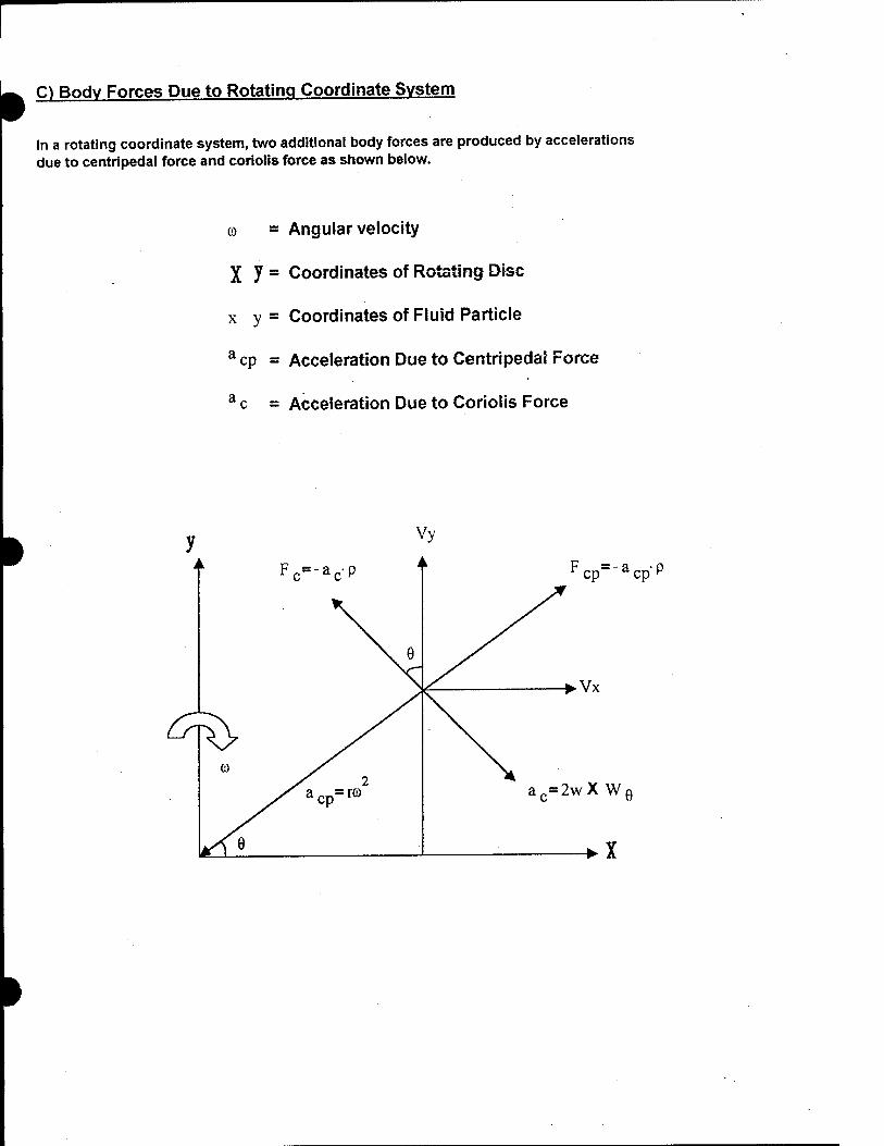
C) Body Forces Due to Rotating Coordinate System
In a rotating coordinate system, two additional body forces are produced by accelerations due to centripedal force and coriolis force as shown below.
© = Angular velocity
X y = Coordinates of Rotating Disc
x y = Coordinates of Fluid Particle
a cp = Acceleration Due to Centripedal Force
a c = Acceleration Due to Coriolis Force
Fcp=-acpP
► Vx
ac=2wX Wg

• The Right Hand Rule
©
W
1) Resolving Coriolis Acceleration, a c , into x And y Components
ac=2wXW,

a=2wXW0=2wX(iWx + jWy)
a =2wXiWx+ 2wXjWy
Apply the right hand rule, we get
a =i(2wWy)+j(-2wWx) -(3)
Resolving Centripedal Acceleration, a cp , into x And y Components
acpx=-acpCos(6)
acpy=-acpSin(e)

/
» a cp= a cpx + a cpy
acp=-acp-Cos(0)-acp.Sin(0)
a„ =i(-ro2-Cos(9)) + j(-rö)2-Sin(9)
a cp= i i- o2- x) + j (- o2- y, ( 4 )
Combine the i and j components of equations ( 3 ) and (4) to givea c as follows:
a=ac+acp
a=H2wWy - xco2) + j(-2wWx - ye>
Express in terms of force, we have:
F=-p--(il.2wWy - xco ) +• jU2wWx - yco
Or in terms of force components:
Fx=p ^-2wWy + xco
Fy=p-\2wWx+ yco

DEFENSE ADVANCED RESEARCH PROJECTS AGENCY ELECTRIC AND HYBRID ELECTRIC VEHICLE TECHNOLOGIES COOPERATIVE AGREEMENT MDA972-95-2-0011 and
Modifications through P00016 Quarterly Report: October 1 through December 31,1998
FEV ENGINE TECHNOLOGY
07/01/99 200 CALSTART

Engine Technology Report FEV216F
Assessment of Advanced Engine Technologies for UAV and
HEV Applications
FINAL REPORT
Distribution Statement B: Distribution authorized to U.S. Government agencies only to protect information not owned by the U S Government by a contractor's "limited rights" statement, or received with the understanding that it not be routinely transmitted outside the U.S. Government. Other requests for this document shall be referred to DARPA/Technical Information Officer.
Submitted by:
FEV Engine Technology, Inc. 4554 Glenmeade Lane Auburn Hills, Ml 48326
#
December 18,1998

Assessment of Advanced Technologies for UAV and HEV Applications Final Report MDA972-95-2-0011
December 18, 1998 Page
Table of Contents
A. Executive Summary 1
B. Introduction and Program Objectives 9
C. Accomplishments 11
C.1 Task 1: Assessment of ECA TECE Engine 11
C.1.1 Thermodynamic Assessment 11
C.l.1.1 Boundary Conditions and Assumptions: 11
C.l.1.2 Preliminary Optimization of Gas Exchange 13
C.l.1.3 Evaluation of TECE Potentials for ISFC and Power 16
C.l.1.4 Comparison of TECE Engine to 4 Stroke Engines 22
C.l.1.5 Port Timing Variation 25
C.l.1.6 Engine Characteristics at Higher Speed 26
C. 1.1.7 Variation of Compression Ratio 27
C.l.1.8 Turbocharger Efficiency 27
C.l.1.9 Full Engine Speed Characteristics 29
C.l.1.10 Optimum Fuel Consumption of Conventional Engine 30
C.l.1.11 Seiliger Cycle Analysis 31
C.1.2 Assessment of Scavenging Behavior 36
C.1.3 Mechanical Assessment 39
C.2 Task 27 Task 3: Conventional, Highly Boosted, 2- and 4-Stroke Engines 41
C.2.1 2-Stroke Engine * 41
C.2.1.1 Experimental Investigations 41
C.2.1.2 Calculations 46
C.2.2 4-Stroke Engine 52
C.2.2.1 Experimental investigations .^ 52
C.2.2.1.1 Impact of Nozzle Geometry 54
C.2.2.1.2 Impact of Load on Friction 54
Proprietary and Confidential

Assessment of Advanced Technologies for UAV and HEV Applications Final Report MDA972-95-2-0011
December 18, 1998 Page iii
C.2.2.1.3 Initial Testing of 4-Valve Engine 55
C.2.2.1.4 Lowered Boost Pressure 55
C.2.2.1.5 Long Intake Manifold 55
C.2.2.1.6 Impact of Friction 56
C.2.2.1.7 Comparison to Today's Four-Stroke Engines 57
C.2.2.1.8 Conclusions 57
C.2.2.2 Calculations 57
D. Conclusions 65
/
Proprietary and Confidential

Assessment of Advanced Engine Technologies for UAV and HEV Applications
A. Executive Summary
Under the DARO/DARPA funded project, summarized in this final report, FEV conducted an assessment of the ECA Turbo-Electric Compound Engine (TECE). Based upon FEV's analyses, a summary of this assessment is included below. Details of the thermodynamic assessment are also presented to provide the technical insight into FEV's conclusions.
The ECA TECE engine incorporates many unique features which are summarized here for reference. These characteristics include:
1) Single cylinder 2-stroke cycle combustion chamber design ("monocylinder") with two (2) opposed pistons. This concept eliminates the need for a cylinder head, but an increase in the number of cranktrain components per cylinder exists.
2) Counter rotating, completely balanced mechanism with two (2) connecting rods per piston, each driving separate crankshafts; the output power of which are combined through a gear train.
3) Annular air intake/exhaust scavenging with rotary valves, intended to provide uniflow scavenging of the exhaust gas (from one set of slotted ports to the other), followed by cross scavenging near the end of the exhaust stroke.
4) Advanced, very high pressure fuel injection to support short injection duration when large quantities of fuel are injected, due to the very high peak firing pressures and very high power density.
5) Unique turbocharging system (Turbo-Electric Compound) in which the compressor is driven by an electric motor and the separate turbine drives an electric generator.
6) Superior thermal efficiency, compared to conventional 2-stroke and 4- stroke engines of similar size and displacement.
During the quarter ending June 1998, FEV completed the assessment of advanced engine technologies for UAV and HEV applications. These analysis was divided into three major parts: /
• Assessment of the ECA TECE engine

Assessment of Advanced Technologies for UAV and HEV Applications Final Report MDA972-95-2-0011
December 18, 1998 Page 2
• Analytical comparison of the TECE engines performance with advanced, more conventional 2 - and 4-stroke highly boosted engine concepts.
• Demonstration of advanced 2- and 4-stroke high performance diesel concepts.
Based upon these analyses, a summary of the evaluation is presented below.
1) ECA believes that a single cylinder ("monocylinder") concept with two opposed pistons which has no cylinder head and can support very high combustion pressures, is essential for high thermal efficiency and high power density. ECA further believes that configuration is well suited for UAV and HEV applications because it has the potential to develop high specific power density (from 100 hp/liter to over 200 hp/liter) and very low specific fuel consumption (0.20 lb./hp-hr to 0.35 lb./hp-hr). As a result, low specific weights - on the order of 1.5 lb./hp can be achieved with the use of the light weight materials.
Result of FEV's assessment:
FEV agrees that the elimination of the cylinder head and cylinder head gasket reduces the number of components that may fail due to the anticipated high cylinder pressures, which are essential for improved thermal efficiency. Based upon FEV's analyses, which incorporate algorithms empirically calibrated through the analysis of hundreds of engines, an indicated efficiency of up to 51% and a thermal efficiency of 47 - 48% (0.3 lbs/hp-hr) is achievable with the TECE engine. Although this value is lower than the thermal efficiency anticipated by ECA through the application of its cycle-based codes, it represents a roughly 10% higher thermal efficiency than state-of-the-art DI diesel engines of similar size.
With the very optimistic assumptions concerning the scavenging process and the turbocharger efficiencies used for the assessment, a BMEP of nearly 15 bar @4200 rpm is possible. This is equivalent to a power output of 116 kW out of 1 liter swept volume. Operating with this large power the engine still provided a thermal efficiency of more than 44%. Reason for this superior power density and efficiency are major two effects:
• high peak pressures of up to 310 bar
• low engine heat losses due to a missjpgfcylinder head
However, one major concern of this engine will be the cooling of piston and cylinder liner as will be shown later in this summary.
Proprietary and Confidential

Assessment of Advanced Technologies for UAV and HEV Applications Final Report MDA972-95-2-0011
December 18, 1998 Page 3
Although some pressure-critical components are eliminated, the piston and piston rings still represent, in FEV's opinion, significant challenges to bring the TECE into mass production. Although ECA believes in the basic design layout, questions associated with the high cylinder pressures, remain and require further evaluation and testing:
• Is the piston ring layout sufficient to ensure proper sealing of the combustion gases without significant piston ring friction and wear? The ECA-proposed piston ring design appears promising, however long term operation in a diesel-fueled engine must be proven through additional structural analysis and testing.
• It is difficult to assure lubrication of the spherical piston bearing under two- stroke operation since there is no true exhaust/intake stroke transition (as in a 4-stroke engine), where the piston could lift-off the bearing due to gravity forces in the absence of in-cylinder gas pressure. Such lift-off would allow low pressure oil lubrication of the spherical bearing. FEV believes that design solutions can be developed to address this concern, however additional analysis and testing are necessary to resolve this issue.
• The results of FEV's calculations suggest that an increase in the peak cylinder pressure from 200 to 300 bar (3000 to 4500 psi) for a constant X provides increasingly small improvements in thermal efficiency (1-2%). Therefore, it appears that a tradeoff between peak pressure, structural integrity and incremental improvement in efficiency should be evaluated.
2) ECA suggests that a counter rotating mechanism with two connecting rods per piston, each driving a separate crank shaft permits the elimination of the piston side force which classically limits the peak combustion pressures needed for high thermal efficiencies. A major source of internal friction and heat load is also eliminated. All dynamic components (pistons, rods and crankshafts) move in exact opposition such that both the inertial loads and the pressure loads balance and thereby eliminate of piston side force and operation at low RPM largely precludes the major source of cylinder liner wear.
Results of FEV's assessment:
FEV agrees that the counter rotating mechanism with two connecting rods is a key engine characteristic that allows engine operation at very high cylinder pressures. The mechanical assessment of the TECE engine, jjtfnducted by FEV during this program, shows low engine friction compared with state-of-the-art DI diesel engines. However, the tradeoff between peak pressure, structural integrity and incremental gain in efficiency must be evaluated.
Proprietary and Confidential

Assessment of Advanced Technologies for UAV and HEV Applications Final Report MDA972-95-2-0011
December 18, 1998 Page 4
3) Annular air intake/exhaust scavenging: In ECA's design, the entire circumference of the cylinder contains both the intake and exhaust ports. ECA suggests that this fully ported intake periphery maximizes the intake volumetric efficiency, minimizes the intake pressure loss and pumping work, and allows very lean mixtures (and low emissions). ECA also contends that the fully ported exhaust periphery maximizes the expansion ratio and minimizes the pressure losses during the scavenging process, thus further increasing thermal efficiency and providing a flatter SFC curve over the power range.
Result of FEV's assessment:
FEV has conducted 3-dimensional CFD analyses of the periphery, ports, combustion chamber and rotary valve arrangement. As a result of theses analyses, FEV draws the following conclusions:
• The uniflow scavenging (from one end of the cylinder to the other when the ports are uncovered by the pistons) is the best approach for highest scavenging efficiency with 2-stroke combustion concepts. However, based upon the anticipated engine speed and very high power densities being considered, the scavenging efficiency will be limited. The cross flowing strategy during the end of the gas exchange shows no significant benefits predicted through analysis.
• In the actual configuration it can be stated that the scavenging efficiency of the TECE engine is relatively low. At the end of scavenging still 37-38% of the exhaust gas remain in the cylinder. There is potential to improve the scavenging behavior by later timing of both rotational valves or the removal of one rotational valve. This would however increase fuel consumption. To further improve scavenging behavior intake and exhaust slots have to be enlarged. An increase of scavenging pressure difference also can help improving the scavenging behavior, but this can make it necessary to use a additional engine driven supercharger.
4) Advanced fuel injection: ECA correctly states that high pressure direct cylinder injection is necessary to achieve atomization and dispersion for high levels of combustion efficiency. Within ECA's proposed system, multiple (2-4) electronically controlled injectors are used to enable efficient operation over the full load range from part power (nominal UAV/HEV idle and1' low speeds) to maximum power (acceleration, steep grades, and take-off). T
Proprietary and Confidential

Assessment of Advanced Technologies for UAV and HEV Applications Final Report MDA972-95-2-0011
December 18, 1998 Page 5
Results of FEV's assessment:
The assessment of the EC A fuel injection system will be objective of an amendment to the existing contract. However, based upon FEV's experience it can be stated that high injection pressures up to 2000 bar are proven to be essential for high thermal efficiency and low emissions for DI diesel engines. Therefore, an important boundary condition to achieve the targets of the TECE engine is the availability of a suitable fuel injection system.
If the result gained from modern diesel engines in the range of 2000 bar (30,000 psi) peak injection pressure and 170 - 200 bar (2500 - 3000 psi) peak cylinder pressure are extrapolated, there appears sufficient justification for an injection system with a pressure capability of 3000 bar (45,000) and more. However, a flexible and reliable fuel injection system with such pressure capabilities are currently not commercially available and the development cost of such a system would be extremely high.
In addition, the strict extrapolation of results gained from currently developed diesel engines may be misleading, based upon the analyses which suggest that minimal gains in efficiency are predicted with peak pressures in excess of 200 bar (3000 psi), as identified above.
5) Turbocharging: ECA states that the TECE design utilizes a Garrett single stage turbocharger that has been de-coupled (turbine and compressor on separate shafts) to create an independently operating "electro-compressor" (electric motor driving an alternator). Each is independently controlled by the engine computer. The compressor normally runs at a constant boost pressure under sea level engine load conditions. This approach ensures that the engine core always receives maximum breathing and fuel oxygenation, even during power and rapid acceleration conditions - typically the conditions where conventional diesel engines product excessive smoke due to turbocharger lag, and the associated rich mixture and unburned fuel. ECA also states that the part load efficiency is correspondingly improved due to the maintenance of high cycle pressures. Engine power is varied simply by fuel injection.
The turbogenerator extracts the residual energy from the exhaust and returns it in electrical form, via a power management system, to the engine shaft - driven alternator/motor. Thus ECA states that the TECE has fully integrated the engine thermodynamic cycle with the electricaj/'cycle for improved overall energy management, reduced fuel consumption ana increased power density while resolving one of the classical emission difficulties of the diesel engine.
Proprietary and Confidential

Assessment of Advanced Technologies for UAV and HEV Applications Final Report MDA972-95-2-0011
December 18, 1998 Page 6
Results of FEV's assessment:
The approach to de-couple compressor and turbine for higher overall efficiency is well- known and would be very useful for any automotive application. Unfortunately, no de- coupled turbocharger is currently commercially available. The biggest technical challenge is the development of an electric motor and an alternator, which are capable to run very high speeds (up to 150,000 rpm), while maintaining a reasonable efficiency, however several companies are currently working in this field.
The major advantage of such a concept for steady state operation is the possibility to run turbine and compressor with different speeds, each one with its optimum efficiency for a certain pressure ratio. Nevertheless, turbine and compressor must fulfill power equilibrium. At full load the power equilibrium is reached, i.e. the turbine produces exactly the power that is required by the compressor to boost the engine to the specified boost pressure.
For both FEV's and ECA's approach the obtainable exhaust gas energy at part load is not sufficient for suitable scavenging. The reason is the lack of exhaust gas temperature due to very lean combustion. So, for sufficient scavenging at part load the turbocharger has to be assisted by a mechanically driven compressor (blower or supercharger). Since the required blower needs to be driven by the engine, the thermal efficiency drops for part load conditions. This results in a thermal efficiency of « 30% at 4 bar BMEP, which is comparable with state-of-the-art DI diesel engines.
Since the assumptions for the turbocharging as well as for the scavenging made herein were very optimistic, a additional supercharger may be necessary even for full load.
6) Thermal Efficiency: The synergistic effect of the preceding design innovations is an unprecedented level of thermodynamic efficiency across the operating range. An unprecedented brake efficiency of 68.6 % is predicted, resulting in an equivalent specific fuel consumption of 0.201 lb./hp-hr.
Results of FEV's assessment:
As already mentioned under Section 1, FEV'^, analyses predict that an indicated efficiency of up to 51% and a thermal efficienc/of approximately 47 - 48% is achievable with the TECE engine. Based upon FEV's calculations, which are based upon extensive experience with different state-of-the-art DI diesel engines, a thermal efficiency of 68.6%, such as claimed by ECA, will not be achievable with this engine concept. However, even
Proprietary and Confidential

Assessment of Advanced Technologies for UAV and HEV Applications Final Report MDA972-95-2-0011
December 18, 1998 Page 7
the estimated improvement of 5 to 10% in thermal efficiency makes this engine concept very interesting for several engine applications.
7) Power Density: a direct consequence of the high thermodynamic efficiency is a high power density. This attribute, in conjunction with an efficient mechanical arrangement and load path, results in low engine system specific weights. EC A estimates that 1.43 lb./hp is achievable in the near term, and approximately 0.85 lb./hp in an HEV engine, with operation at higher RPM and peak pressures and the use of advanced materials.
Results of FEV's assessment:
Current production DI diesel engines for automotive application have a power density down to below 3 lb./hp. Since the TECE engine with it's four connecting rods and the two crankshafts will not be significantly lighter than conventional diesel engines, the power density has to be improved by significantly higher power output. The specific power output for the TECE engine, estimated in these calculations, was up to 116kW/liter @ 4200 rpm. Associated with this, the predicted power density of 1.5 lb./hp appears reasonable.
However, as already stated above, the here stated high power densities for a two-stroke engine require significant heat transfer from the pistons and the cylinder liner. As of today, it is unclear, how to ensure sufficient heat transfer from the pistons. It will definitely be necessary to use oil cooling, as a means to reduce piston temperature, which will make oil consumption control very difficult. In addition, FEV calculated the required heat transfer coefficient for the cylinder liner in order to transfer the heat to the coolant. The calculated heat transfer coefficient is much higher than achievable with conventional cooling methods and therefore is questionable. A increase of relative AFR, which on the other hand means a reduction of injected fuel mass and therefore power output, can reduce the averaged temperature in cylinder and thermal load.
Results of FEV's assessment of more conventional 2- and 4-stroke engines:
To compare the potential of the ECA TECE engine to more conventional 2 - and 4-stroke engines FEV conducted simulations and proved the evaluated potential by engine tests.
Proprietary and Confidential

Assessment of Advanced Technologies for UAV and HEV Applications Final Report MDA972-95-2-0011
December 18, 1998 Page 8
The following table summarizes the results of the simulation work:
TECE 4-stroke 2-stroke
Maximum power density
@ speed
kW/liter
rpm
116
4200
80.2
4200
62.5
4300
Specific Power lbs/hp 1.5 1.35 1.25
Thermal efficiency at max. power % 44 32.5 26
Maximum thermal efficiency
@ speed
%
rpm
47
1800
42
2500
«40
2800
The very low thermal efficiency of the 2-stroke engine concept is due to the very large supercharger work which was necessary to build up a sufficient scavenging pressure difference. Different to the assessment of the TECE engine for which only an overall TC- efficiency was assumed, for the 2-stroke (and the 4-stroke) engine, the charging system was built by given compressor and turbine maps which leads to significantly lower TC- efficiencies than used for the TECE assessment. Since the achieved power density and thermal efficiency of the conventional 2-stroke engine is lower than for the TECE engine it is not the preferred solution for an HEV concept. Due to the low specific power value it is, however, a competitive alternative for UAV applications.
Highly boosted, conventional 4-stroke DI diesel engines can provide power densities of up to 80 kW/liter and a maximum thermal efficiency of approximately 42 %. The power density, achieved with a prototype engine as part of this assessment is significantly larger than for current of-state-of-the-art DI diesel engines. BMW newly announced a 2.0 liter DI diesel engine with a power of 100 kW @ 4000 rpm (power density = 50 kW/liter) for series production and adapted a engine for race application with 150 kW @ 4500 rpm (75 kW/liter). These values for 4-stroke engines can be realized with state-of-the-art technologies. However, ECA's TECE engine provides a power density which is roughly 40% larger than the one of more conventional 4-stroke engines with a thermal efficiency which is 5 - 10% higher than for conventional 4-stroke engines at rated conditions. This improvement potential is very significant and makes the TECE engine very attractive in particular for HEV application.
#"'
Proprietary and Confidential
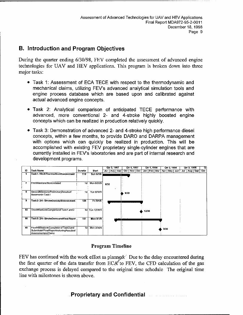
Assessment of Advanced Technologies for UAV and HEV Applications Final Report MDA972-95-2-0011
December 18, 1998 Page 9
B. Introduction and Program Objectives
During the quarter ending 6/30/98, FEV completed the assessment of advanced engine technologies for UAV and HEV applications. This program is broken down into three major tasks:
• Task 1: Assessment of ECA TECE with respect to the thermodynamic and mechanical claims, utilizing FEV's advanced analytical simulation tools and engine process database which are based upon and calibrated against actual advanced engine concepts.
• Task 2: Analytical comparison of anticipated TECE performance with advanced, more conventional 2- and 4-stroke highly boosted engine concepts which can be realized in production relatively quickly.
• Task 3: Demonstration of advanced 2- and 4-stroke high performance diesel concepts, within a few months, to provide DARO and DARPA management with options which can quickly be realized in production. This will be accomplished with existing FEV proprietary single-cylinder engines that are currently installed in FEV's laboratories and are part of internal research and development programs.
ID Task Name Duratio Start Qtr3,1997 Qtr4, 1997 Qtr 1,1998 Qtr 2,1998 Qtr 3, 1998 a
Jul j Aug I Sep Oct I Nov I Dec Jan | Feb | Mar Apr | May | Jun Jul I Aug I Sep Oct 1 Taskl: TECEThermo/M eel-Assessment 110 Sun 6/1/9
6/30
^ 9/30
7 FirstMilestoneWorklnitiated 1d Mon 6/30/9
8 SecondMilestonePreliminaryResultsof Assementin Taskl
1d Tue 9/30/9
9 Task2:2/4 - StrokeConceptAssessment 108 Fri 8/1/9
4
f
► 12/30 15 Third MilestoneCompletiorof Task 1 and 2 1d Tue 12/30/9
16 Task3:2/4-StrokeDemoand Final Repor 151 Mon 9/1/9
4
f
y 3/30 40 FourthMiIestoneCompletiorofTask3and Submittatof Final ReportlncludingResultsof Assessmenland Demo
1d Mon 3/30/9
Program Timeline
FEV has continued with the work effort as planne.de Due to the delay encountered during the first quarter of the data transfer from ECAfto FEV, the CFD calculation of the gas exchange process is delayed compared to the original time schedule The original time line with milestones is shown above.
Proprietary and Confidential

Assessment of Advanced Technologies for UAV and HEV Applications Final Report MDA972-95-2-0011
December 18, 1998 Page 10
As a result of the delay, CALSTART agreed to extend the current contract until the end of June 1998. FEV was able to conduct the final investigations within this given time frame.
Proprietary and Confidential

Assessment of Advanced Technologies for UAV and HEV Applications Final Report MDA972-95-2-0011
December 18, 1998 Page 11
C. Accomplishments
C.1 Task 1: Assessment of ECA TECE Engine
C.1.1 Thermodvnamic Assessment
The thermodynamic assessment of the TECE engine was conducted with the FEV cycle simulation tool EPOS. It was conducted in the following steps:
• Ina first step a rough optimization of the gas exchange process was conducted.
• In a second step high pressure cycle simulations were conducted. In this step, the TECE engines potentials for power and ISFC were conducted as well as the influences of turbocharger efficiency, compression ratio and engine speed were evaluated and the TECE engine compared to a 4-stroke engine.
• Finally ideal cycle simulations were conducted.
C.l.1.1 Boundary Conditions and Assumptions:
The following table summarizes the geometrical engine data, which were either handed over from ECA or measured out of 3-D model:
Bore mm 87 Stroke mm 2*84 Compression ratio 23.5 geometrical Clearance distance between pistons at geometrical TDC mm 1 Con rod length mm 145 Piston pin offset mm -56
Intake slots: Number -T- 18 Height mm 8.0 Width mm 10.6 Distance of upper edge of slot to piston position at TDC mm 83.8 Max. Geometrical area of intake slots cm2 15.2 Flow Coefficient (assumed) + 0.85
*2*
Proprietary and Confidential

Assessment of Advanced Technologies for UAV and HEV Applications Final Report MDA972-95-2-0011
December 18, 1998 Page 12
Exhaust slots: Number ~- 2*7 Height mm 10.9 Width mm 12.2 Distance of upper edge of slot to piston position at TDC mm 80.9 Max. Geometrical area of exhaust slots cm2 9.3 Flow Coefficient (assumed) -=- 0.85
Crank angle as used herein is defined as:
Valve timing according to these definitions is:
Geometrical TDC Geometrical BDC Intake slots:
Intake slot opens Intake slot closes
Exhaust slots:
Exhaust slot opens Exhaust slot closes
°CA 17.4 °CA 212.9
°CA 172 °CA 249
°CA 165 °CA 249
Figure 1.1.1-1
This timing is neither symmetric to normal TDC / BDC (180°CA / 360°CA) nor to the geometrical TDC / BDC. In Figure 1.1.1-2 the cylinder-volume vs. Crank angle of the TECE engine is shown compared to the cylinder-volume of a conventional engine without piston pin offset. It can be seen, that the maximum piston stroke of the TECE engine is larger than the one of a engine with conventional crank train and that the duration of the TECE engines compression stroke is shorter than the duration of the expansion stroke.
In the basic layout, as seen at the 3-D model, the rotational valves switch the exhaust slots to intake slots. /
Proprietary and Confidential

Assessment of Advanced Technologies for UAV and HEV Applications Final Report MDA972-95-2-0011
December 18, 1998 Page 13
rotating valve 1
The basic timing for the switches is:
First exhaust slot closes °CA 174 First exhaust slot opens as intake °CA 184 Second exhaust slot closes °CA 224 Second exhaust slot opens as int. °CA 234
Figure 1.1.1-3
One possible application of the TECE engine is a hybrid electrical vehicle (HEV). To ensure maximum performance under engine operation in an HEV, the following representative operation point was chosen:
Engine speed rpm
IMEP bar
BMEP (assumed mechanical efficiency r\m = 92.3 %) bar
Max. allowed peak combustion pressure bar
Compression ratio (geometric)
Turbocharging bar
1800 20.2
18.7
-310 (appr. 4490 psi)
23.5
3
Because of expected higher scavenging efficiency at lower speeds the calculations were conducted at 1800 rpm instead of 3000 rpm, which is the maximum engine speed. The influence of engine speed on engine behavior will be shown later.
C.l.1.2 Preliminary Optimization of Gas Exchange
To assess the TECE engines power and fuel consumption potential, calculations at the high pressure cycle are necessary but not sufficient. It is well known that piston work is only influenced very little by intake and exhaust pressure fluctuations, because volume change is very small, but the purity of the cyljn'der charge and therefore the amount of fuel that can be burned is, especially for 2-strö'ke engines, strongly influenced by the gas exchange and gas dynamics in the intake and exhaust system. Since no information available about intake and exhaust system is available, a very rough optimization of the
Proprietary and Confidential

Assessment of Advanced Technologies for UAV and HEV Applications Final Report MDA972-95-2-0011
December 18, 1998 Page 14
gas exchange process is conducted. This covers the timing of switching the exhaust slots to intake, but does not contain a optimization of slot position and therefore opening and closure of the slots.
For a rough optimization of the gas exchange process the following assumptions were made:
• Perfect displacement-type-scavenging was assumed, which represents the optimum for the scavenging process.
• The switch of the exhaust slots to intake is performed without any time delay. Also the slot area always is the flow-restricting area. This means, the area opened by the rotational valves always is larger than the area opened by the slots. A more detailed analysis will follow by using 3D calculations.
• Calculations are conducted with constant boost and exhaust pressure.
First scavenging investigations were conducted with a constant crank angle offset between the switches of exhaust slot 1 and 2 of 50°CA. This offset is taken from the 3-D- models, which were provided to FEV by ECA. It was necessary to charge the engine with a boost pressure of 3.8 bar at an exhaust back pressure of 3.0 bar to ensure sufficient scavenging of the engine, if gas dynamic effects are neglected.
Figure 1.1.2-1 depicts the in-cylinder-pressure and mass flow vs. crank angle. The black line shows perfect displacement scavenging without any switch. The in-cylinder pressure drops to a value of 3.2 bar within 30°CA after exhaust valve opens and stays nearly constant. This shows, that the intake slots are the limiting flow area for this gas exchange and the switching of exhaust slots to intake slots represents one method to improve scavenging as can be seen by the diagram.
However, a significant back flow of exhaust gas into the intake ports can be observed. This gas is pushed back into the cylinder at the beginning of the scavenging process and limits the fresh air flow. This process appears in the curve as a sharp bend in mass flow at a level of approximately 0.02 kg/s. This bend shows when the exhaust gas back flow has been pumped into the cylinder again and when fresh air starts to flow into the cylinder. The reason for this bend is, that the exhaust gas has a lower density. Volumetric intake flow is approximately constant and as soon as the density of the in-fiow gas increases, also the mass flow increases. This shows, that ap/earlier exhaust valve opening (EVO) or a later intake valve opening (IVO) could improve gas exchange, but this could only be investigated , if gas dynamics are considered. Modified port timing was not considered for the following calculations.
Proprietary and Confidential

Assessment of Advanced Technologies for UAV and HEV Applications Final Report MDA972-95-2-0011
December 18, 1998 Page 15
Further calculations were conducted with the designed switch timing, taken form the 3-D- drawing as well as different switch timings of 5 and 10° CA earlier, and 5,10,15,20, and 25°CA later than taken from the 3-D-drawing.
After switching the first exhaust port to intake, the in-cylinder-pressure increases to approximately 3.6 bar. Based on increased inflow area, the mass flow shows a peak and the in cylinder pressure rises. Now the exhaust slots are the limiting flow area. As soon as the second exhaust slot also switches to intake, in-cylinder-pressure rises to the level of boost pressure and based on piston movement back flow occurs again, which shows, that it should be proven by gas dynamic calculations whether the second exhaust slot should be switch to intake at all.
The earlier the first exhaust slot switches to intake, the larger the exhaust gas back flow into intake port. However, later switch increases fresh air flow. Figure 1.1.2-2 shows the overall volumetric efficiency by variation of switch timing. Volumetric efficiency for 2 - stroke engines normally is related to volume, temperature and pressure at intake valve closing (IVC). Since these values were not constant within the variation, the volumetric efficiency in Figure 1.1.2-2 is related to swept volume, boost pressure and temperature.
The highest volumetric efficiency is achieved without any switch, based on perfect displacement scavenging, but achieves only 56%. Therefore, the exhaust ports should be switched to Intake ports as late as possible.
This calculation results show, that it is necessary to optimize the timing of the first exhaust/intake switch with the second exhaust valve continuously open to exhaust.
This optimization can be seen in Figure 1.1.2-3. Here only one exhaust slot was switched to intake. Before the switch of the exhaust slot to intake, the intake slots are the limiting flow area (in-cylinder-pressure is closer to exhaust pressure than to intake pressure), after the switch the exhaust slots are the limiting flow area. No back flow can be observed at the end of the gas exchange process. Figure 1.1.2-4 depicts the volumetric efficiency vs. crank angle of the switch. The maximum volumetric efficiency is shown for a switch at 240 °CA. The value for a switch at 250 °CA is equal to uniflow scavenging, which means no switch at all.
For 2-stroke engines the in-cylinder pressure at exhaust valve opening (EVO) has a strong influence on gas exchange and volumetric efficiency. Therefore, the same investigation was conducted for a higher power output -^see Figure 1.1.2-5. Here the optimum volumetric efficiency has moved from a switch at 240°CA to 230°CA. Because the target in IMEP is even higher (20.2 bar chosen), for all further investigations the switch from exhaust to intake was set to 220°CA.
Proprietary and Confidential

Assessment of Advanced Technologies for UAV and HEV Applications Final Report MDA972-95-2-0011
December 18, 1998 Page 16
The results of the initial calculations can be summarized as follows:
• Under the boundary condition of perfect displacement, scavenging efficiencies at 1800 rpm don't achieve high values.
• The rotating valves don't improve scavenging efficiency significantly. During 3D calculations it will be investigated whether the usage of the rotating valves is beneficial at all.
• The results show that scavenging pressure has to be enlarged ( power that is absorbed by the supercharging system) when higher power is needed. The used boost pressure level of 3.8 bar requires expensive „non production" single stage turbocharger components or a two-stage boosting system.
• Scavenging efficiency will decrease with higher engine speeds.
C.l.1.3 Evaluation of TECE Potentials for ISFC and Power
The next step of the TECE assessment was to evaluate the potential of ISFC and max. power output of the engine.
Boundary conditions were assumed:
• Perfect displacement scavenging
• Combustion: Vibe: shape factor: m = 0.313
Combustion duration: 65 °CA
• Port area is not influenced by rotating valve
• Heat transfer: equation by Woschni: -10.8
0.2 0.8^-0.53 a = 130 £TUi pü*T c\ c„, + C2 VhTx
PxVx (P-Po)
or ( maximum) c, cm + 2 c, c; V )
-0.2
D
P /
T
cm
= Bore
= Cylinder Pressure in bar
= Cylinder Temperature in K
= mean piston speed in m/s
Proprietary and Confidential

Assessment of Advanced Technologies for UAV and HEV Applications Final Report MDA972-95-2-0011
December 18, 1998 Page 17
Vh = swept volume
..1 = values at a defined CA before TDC
..0 = value without combustion
C1,C2 = constants
assumed surface temperatures:
• piston: 600 K • Cylinder liner:
Distance from TDC [mm]
Temperature [K]
0 30 90
580 480 420
Figure 1.1.3-1
Initially, the potential in ISFC dependent on the maximum cylinder pressure was evaluated. Therefore, a matrix of calculations was performed with compression ratios from 19.5 up to 27.5 and max. cylinder pressures of 250 up to 390 bar. IMEP was kept constant at 20.2 bar, boost pressure was 4.0 bar and exhaust pressure was set 3.0 bar. With these values, at the base point a relative air/fuel ratio (rel. AFR) of 1.45 could be realized, which should be suitable for required low soot emissions. To reach a boost pressure of 4.0 bar in combination with a exhaust pressure of 3.0 bars and exhaust temperature of approximately 600 - 650 °C an overall turbocharger efficiency of approximately 57% is necessary. This is a value which can be reached with a advanced 2- stage intercooled turbocharger. With a single stage turbocharger this value can not be reached and therefore additional power to run the boosting system is necessary..
The result of these investigations is shown in Figure. 1.1.3-2. Indicated specific fuel consumption (ISFC) vs. combustion induced pressure rise is shown. Combustion induced pressure rise is defined as the ratio of maximum cylinder pressure with combustion to max. cylinder pressure without combustion. The dashed lines connect points of constant max. cylinder pressure, solid lines points of same compression ratio. For each value of the max. cylinder pressure a minimum of ISFC and therefore an optimum compression
Proprietary and Confidential

Assessment of Advanced Technologies for UAV and HEV Applications Final Report MDA972-95-2-0011
December 18, 1998 Page 18
ratio can be found. All of the minimums are in between a combustion induced pressure rise of 1.3 and 1.4 which is well known for conventional combustion characteristics. For the TECE engines max. cylinder pressure of 310 bar (4450 psi) the optimum compression ratio is approximately 22.5. The value of 23.5 is very near to the optimum and promises slight advantages for part load conditions compared to the optimum value. This shows, that the TECE engines layout is close to optimum.
The minimum ISFC which can be reached with a certain max. cylinder pressure is shown in Figure 1.1.3-3. The optima of ISFC of each max. cylinder pressure are shown vs. the max. cylinder pressure. The minimum indicated fuel consumption for the assumed boundary conditions is 171 - 172 g/kWh. For lower max. cylinder pressure the minimum ISFC is increasing exponentially, which shows the potential of high cylinder pressures for minimum fuel consumption. For higher max. cylinder pressure the gain in ISFC is getting smaller. For an increase in ISFC of only 5 g/kWh it is necessary to raise max. cylinder pressure by 70 bar from 270 up to 340 bar. This shows, that the max. cylinder pressure of the TECE engine is on a level, which does not provide significant advantages to a level of 250 bar which is not so far away from a level that can be reached with more conventional engines.
In Figure 1.1.3-4 the influence of combustion duration on ISFC is shown for the base point of the investigations (boost pressure = 4.0 bar, exhaust pressure = 3.0 bar, compression ratio = 23.5, max. cylinder pressure = 310 bar). Starting with a realistic value of 65°CA, which was measured on a 1.9 liter DI diesel engine with common rail injection, a reduction in combustion duration improves ISFC by approximately 4 g/kWh. For this improvement in fuel consumption a combustion duration of 30°CA has to be assumed. To realize such a short combustion duration the injection pressure has to be increased significantly which also increases fuel injection system drive power and therefore friction losses.
To evaluate the potential of the TECE engine at part load, a variation of IMEP was conducted from IMEP = 25 bar down to 5.0 bar in 2.5 bar steps. For each load, boost pressure and exhaust pressure were assumed, that the overall turbocharger efficiency changes from the very advanced value of approximately 58% at 25 bar down to a value of 51%. It is questionable, whether these values can be reached in reality. The relative AFR was assumed to stay at a constant value of 1.45.
Figure 1.1.3-5 shows, that each engine load riches its lowest fuel consumption at a defined peak pressure. This defined peak pressure represents the best BOI for this load. More advanced BOI will result in higher peak pressure, but the combustion related pressure increase before TDC will reduce efficiency and therefore will increase fuel
Proprietary and Confidential

Assessment of Advanced Technologies for UAV and HEV Applications Final Report MDA972-95-2-0011
December 18, 1998 Page 19
consumption. The ratio of peak pressure to indicated mean effective pressure (IMEP) for best efficiency is between 24 (low IMEP) and 18 ( higher IMEP). An IMEP of 20.2 bar can not be operated with best efficiency, because peak pressure would be in the range of 360 to 370 bar, which is higher than the 310 bar, the engine is designed for. The lowest ISFC at 1800 rpm will be in the range of 170 g/kWh if peak pressure is limited to 310 bar. The lowest fuel consumption is being reached for a IMEP of 17.5 bar. For reaching a larger IMEP of 20.2 bar under this peak pressure limit, a disadvantage in fuel consumption of approximately. 2 g/kWh has to be accepted. A further increase in peak pressure could only provide minor advantages in fuel consumption for 20.2 bar IMEP.
In this figure it also can be estimated how large the TECE engines potential in ISFC is due to the peak pressure of 310 bar. If the BOI-swing for IMEP of 20.2 bar is extrapolated to peal pressure values of 180 bars, ISFC reaches values of approximately. 185 - 190 g/kWh. This means, that the increasing of the peak pressure from 180 bar to 310 bar has a potential in ISFC of approximately. 13-18 g/kWh.
For each operating point a BOI - swing was done to examine the optimum BOI with respect to fuel economy and achieved peak pressure level. Figure 1.1.3-6 summarizes the results of the optimum fuel consumption points under consideration of the peak pressure limit of 310 bar. Due to the peak pressure limit the operating points with IMEP larger than 20.2 bar were not taken into account here. Under the chosen boundary condition of constant relative AFR the ISFC increases with reduced engine load. Boost (intake) and exhaust pressure show a nearly linear reduction with decreasing IMEP, scavenging pressure difference ( boost pressure minus exhaust pressure) is reduced with decreased engine load. This is a result of the power equilibrium between turbine and compressor of the turbocharger. The assumed TC-efficiency is shown in the upper right diagram. The exhaust gas temperature and therefore the exhaust gas energy, which are not shown in the diagram, are diminished with decreasing load. As a result, boost pressure and scavenging differential pressure are reduced.
The lower scavenging pressure results in a more incomplete scavenging process and the residual gas fraction increases. The residual gas fractions shown in the upper right diagram are very high at lower engine loads and will result in increased combustion duration and therefore higher fuel consumption, which is not taken into account.
The lower left diagram shows ISFC versus IMEP and BSFC versus BMEP. While ISFC shows a minimum at 17.5 bar IMEP (ISFC at 2ß?lbar IMEP is slightly higher due to the limited and therefore not optimum peak pressure - see right lower diagram), BSFC increases with lower BMEP due to constant engine friction and therefore reduced mechanical efficiency. The used FMEP was taken from the mechanical assessment (1.01
Proprietary and Confidential

Assessment of Advanced Technologies for UAV and HEV Applications Final Report MDA972-95-2-0011
December 18, 1998 Page 20
bar at 1800 rpm) plus an assumed FMEP of 0.4 bar for the fuel injection pump drive power. FMEP is considered to be only dependent on engine speed but independent on engine load.
The relative AFR used for the calculations was chosen by 1.45, because this AFR is sufficient for a reasonable combustion process (no visible smoke). Beside that, power output of any engine is limited by the amount of air trapped in the cylinder. Figure 1.1.3- 7 depicts the influence of a increasing relative Air fuel ratio on fuel consumption at full load (IMEP = 20.2 bar). In order to increase the relative AFR the boost pressure must be raised. As long as the engine uses a conventional turbocharging system, where the turbine runs the compressor, exhaust pressure rises stronger than boost pressure because exhaust temperature drops due to the higher relative AFR. Therefore scavenging pressure difference is reduced, which leads to a higher residual gas fraction.
Due to reduced combustion induced pressure rise (lower right diagram) the BOC must be retarded to fulfill the peak pressure limit of 310 bar. Because of the later combustion, ISFC increases. A relative AFR larger than 1.62 is not possible in the base operating point because otherwise the peak pressure without combustion already exceeds 310 bar. This could be changed of course, if port flow area and timing are further optimized, that means, its not a fundamental drawback.
The following information can be summarized:
• At full load the smallest possible AFR should be chosen as the best compromise of BMEP, fuel consumption and peak pressure.
• A higher relative AFR ratio could be chosen if the compression ratio is reduced.
• The high compression ratio of 23.5 does not allow an optimized BOI setting for IMEP=20.2 bar and peak pressure of 310 bar. (When port flow area and port timing are optimized, this will be different).
• Higher relative AFR result in poorer scavenging efficiency based on increasing exhaust pressure.
Under part load conditions and relative AFR of 1.45, the peak pressure is lower than maximum peak pressure and therefore BOI can be-set for minimum fuel consumption (no NOx limitation assumed). Therefore it has to ,be studied whether an increasing relative AFR leads to lower fuel consumption under'part load conditions if the remaining peak pressure potential is used. The following simulations are conducted with constant boost and exhaust pressure over the whole examined operating range from 20.2 bar down to 5
Proprietary and Confidential
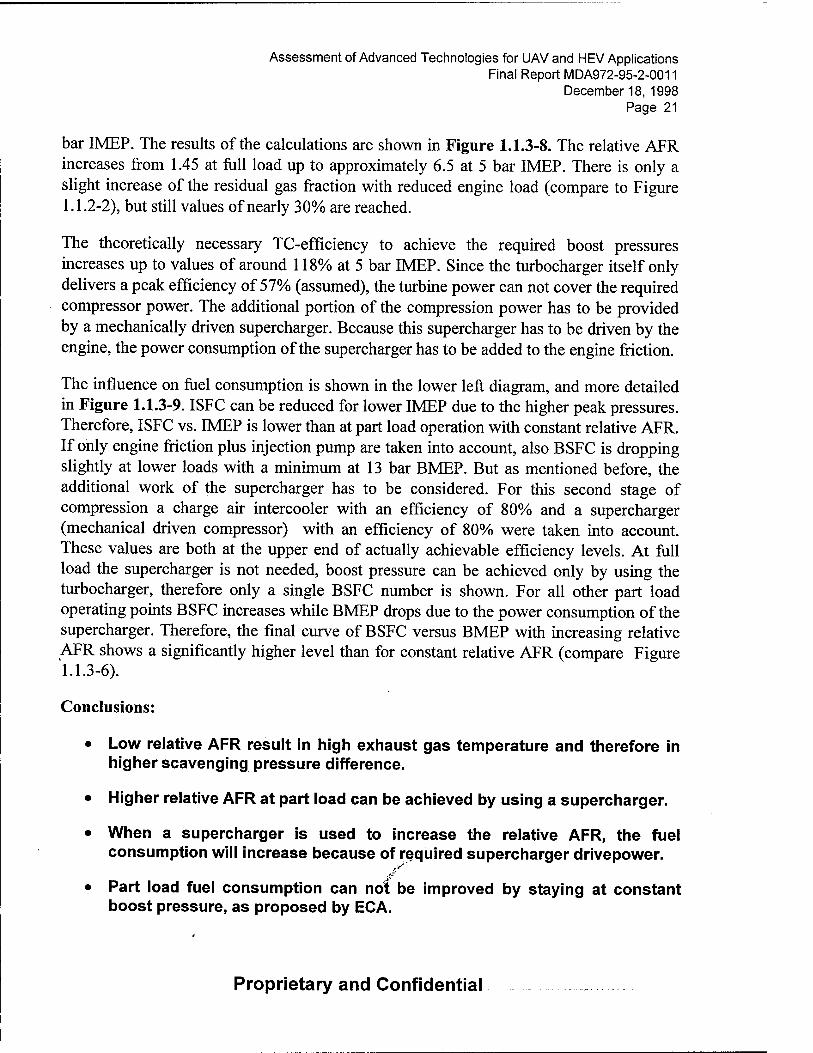
Assessment of Advanced Technologies for UAV and HEV Applications Final Report MDA972-95-2-0011
December 18, 1998 Page 21
bar IMEP. The results of the calculations are shown in Figure 1.1.3-8. The relative AFR increases from 1.45 at full load up to approximately 6.5 at 5 bar IMEP. There is only a slight increase of the residual gas fraction with reduced engine load (compare to Figure 1.1.2-2), but still values of nearly 30% are reached.
The theoretically necessary TC-efficiency to achieve the required boost pressures increases up to values of around 118% at 5 bar IMEP. Since the turbocharger itself only delivers a peak efficiency of 57% (assumed), the turbine power can not cover the required compressor power. The additional portion of the compression power has to be provided by a mechanically driven supercharger. Because this supercharger has to be driven by the engine, the power consumption of the supercharger has to be added to the engine friction.
The influence on fuel consumption is shown in the lower left diagram, and more detailed in Figure 1.1.3-9. ISFC can be reduced for lower IMEP due to the higher peak pressures. Therefore, ISFC vs. IMEP is lower than at part load operation with constant relative AFR. If only engine friction plus injection pump are taken into account, also BSFC is dropping slightly at lower loads with a minimum at 13 bar BMEP. But as mentioned before, the additional work of the supercharger has to be considered. For this second stage of compression a charge air intercooler with an efficiency of 80% and a supercharger (mechanical driven compressor) with an efficiency of 80% were taken into account. These values are both at the upper end of actually achievable efficiency levels. At full load the supercharger is not needed, boost pressure can be achieved only by using the turbocharger, therefore only a single BSFC number is shown. For all other part load operating points BSFC increases while BMEP drops due to the power consumption of the supercharger. Therefore, the final curve of BSFC versus BMEP with increasing relative AFR shows a significantly higher level than for constant relative AFR (compare Figure 1.1.3-6).
Conclusions:
• Low relative AFR result in high exhaust gas temperature and therefore in higher scavenging pressure difference.
• Higher relative AFR at part load can be achieved by using a supercharger.
• When a supercharger is used to increase the relative AFR, the fuel consumption will increase because of required supercharger drivepower.
• Part load fuel consumption can not be improved by staying at constant boost pressure, as proposed by ECA.
Proprietary and Confidential

Assessment of Advanced Technologies for UAV and HEV Applications Final Report MDA972-95-2-0011
December 18, 1998 Page 22
C.l.1.4 Comparison of TECE Engine to 4 Stroke Engines
One major characteristic of the TECE engine is the 2-stroke operating mode, which allows high specific engine power. To evaluate the potential of the 2-stroke opposed - piston engine compared to a 4-stroke engine, a virtual engine that provides the same power output than the TECE-engine is modeled. The main data are summarized in the following table:
Geometry
bore
stroke
con rod length
piston pin displacement
compression ratio
Base operating point
speed
boost pressure
TC efficiency
IMEP
max. cylinder pressure
relative AFR
number of cylinders (same power output)
mm 87
mm 2*84
mm 145
mm -56
- 23.5
rpm 1800
bar 4.0
% 57
bar 20.2
bar 310
- 1.45
)ower - 1
Table 1.1.4. - 1
TECE engine 4-stroke engine
87
84
145
0
23.5
1800
57
20.2
310
1.45
4
Initially, the optimum peak pressures versus IMEP for an assumed relative AFR of 1.45 is examined for the 4-stroke engine. A BOI/BOC - swing for each IMEP from 20.2 down to 7.5 bar was calculated. It is assumed that combustion characteristics and thermal engine conditions, like surface temperatures of all components (liner, piston, etc.) are comparable. Valve flow area and valve timing are taken out of FEV's data base of existing 4 valve DI diesel engines. The results, depicted in Figure 1.1.4-1, show that for the 4-stroke engine at an IMEP of 20.2 bar a pealc pressure of 235 bar is sufficient.
Figure 1.1.4-2 shows the comparison of most interesting engine data, of 2-stroke opposed piston engine and comparable 4-stroke engine. Because the 4-stroke engine has a forced
Proprietary and Confidential

Assessment of Advanced Technologies for UAV and HEV Applications Final Report MDA972-95-2-0011
December 18, 1998 Page 23
gas exchange, the volumetric efficiency and the residual gas concentration are nearly independent of pressure difference between intake and exhaust system as long as the valve overlap is very small, as it is here. Based on the higher volumetric efficiency of the 4-stroke engine, the required boost pressure to bring in the air for the selected relative AFR and IMEP is lower. Beside the lower boost pressure also the peak pressure is much lower for the 4-stroke engine. For the base operation point, ISFC of the 4-stroke engine is approximately 10 g/kWh higher than for the TECE - engine. An optimized port timing of the TECE engine shows a potential of 7 - 8 g/kWh. This improved operation point is a result of Figure 1.1.5-5, which is discussed later.
Under part load conditions the difference in fuel consumption grows up to 20 g/kWh at 7.5 bar IMEP. The difference in fuel consumption mainly is due to the lower wall heat losses of the TECE - engine compared to the 4-stroke engine which has a much larger surface to volume ratio than the TECE - engine. The main difference is the missing cylinder head area for heat exchange.
The lower wall heat losses compared to a 4-stroke engine are advantageous from the thermodynamic standpoint, however, one of the mayor problems of the TECE-engine will be the cooling of the pistons and the liner, because the heat flux per surface area is much larger than for the 4-stroke engine. Especially the part of the liner at TDC seems to be the most critical part. This is shown in the following table:
Base operating point: = 20.2 bar
57 % IMEP boost pressure relative AFR
= 20.2 bar = 4.0 bar (2.25bar), TC-efficiency = = 1.45
TECE - engine 4-stroke - engine
relative AFR - max. cyl. pressure average gas temperature in cyl.
bar K
1.45 310 1465
1.45 235 1269
wall temperatures (gas side; assumptions): wall temperature piston K 600 600 wall temp, liner (upper position) K 520 520 coolant temperature K 363 363
Proprietary and Confidential

Assessment of Advanced Technologies for UAV and HEV Applications Final Report MDA972-95-2-0011
December 18, 1998 Page 24
heat exchange coefficients: piston W/m2K 2175/46000 667/2338 liner (top position) W/m2K 2175/72300 667/3965
overall heat flux per cylinder kW 27.45 8.42
In order to achieve the same combustion chamber wall temperatures, the TECE - engine requires a much more intensive cooling. This is shown by the theoretically necessary heat exchange coefficients on the water side of piston and cylinder liner (upper position).
One possibility to reduce the heat flux to combustion chamber walls is to increase the relative AFR. For the TECE - engine this means an enlargement of the intake and exhaust port area and optimized port timings, to improve the volumetric efficiency.
The calculations also show very high residual gas concentrations, especially under part load conditions. Therefore, the higher volumetric efficiency will reduce the EGR fraction and therefore the averaged gas temperature. A lower averaged gas temperature will also result in lower heat flow to the walls and therefore reduced thermal loading of all engine components.
This further optimization can not be done be using the currently used computer program, because there is still a perfect displacement scavenging assumed and there is no 1-D gas dynamic taken into account. The quality of the scavenging process is shown by the 3-D- CFD-calculations.
Conclusions:
• Compared to a 4-stroke engine without limited peak pressure, the TECE engine provides a fuel consumption advantage of approximately. 17 g/kWh @ 1800 rpm.
• This advantage is mainly due to lower wall heat losses of the TECE engine.
• Large cylinder wail temperatures will be one of the mayor concerns of the TECE engine. If the very large heat transfer coefficients assumed in this calculations are not reached in the test bench, scavenging behavior must be improved or the power output of this engine may have to be reduced.
Proprietary and Confidential

Assessment of Advanced Technologies for UAV and HEV Applications Final Report MDA972-95-2-0011
December 18, 1998 Page 25
C.l.1.5 Port Timing Variation
To show the potential of the TECE engine, a short port timing optimization was be conducted, because the comparable 4-stroke engine has already optimized flow coefficient and valve timing.
Due to the large back flow of exhaust gas into intake manifold when intake opened, the exhaust slot height was increased (see Figure 1.1.5-1) to achieve a longer 'pre-exhaust'. This leads to a significantly lower in-cylinder-pressure when intake opens and to a reduced back flow. It also leads to higher intake mass flows after switching of one of the exhaust slots to intake, roughly at 570° CA. Short after this switch the cylinder pressure rises, and intake mass flow shows a short peak while exhaust mass flow shows a short minimum. Later, intake and exhaust mass flows decrease due to the decreasing slot area which is limited by piston movement. At the end of the scavenging process cylinder pressure increases due to compression while the port area is too small to allow outflow out of the cylinder. For the highest exhaust port, exhaust mass flow shows a small bend at about 605°CA. At this point all exhaust gas is swept out of the cylinder, fresh air is scavenging to exhaust. Due to the lower temperature and higher density of the intake air, the mass flow increases while the volumetric flow is nearly constant. From this moment on, cylinder pressure also rises. Shortly before the slots close a very small back flow from cylinder into intake due to compression can be detected.
In Fig. 1.1.5-2 the intake slots are varied. With increasing intake slot height back flow at the beginning of the scavenging increases. Nevertheless the larger flow area in later crank angle (560 - 600°CA) results in a larger mass flow and therefore volumetric efficiency rises. Short before intake valve closure with larger intake slot height back flow increases. A intake slot height of approximately 10 mm is chosen.
Figure 1.1.5-3 shows the volumetric efficiency as a result of the variations shown in Figure 1.1.5-1 and -2. In this figure, pressure and temperature at IVC and total displacement are taken as reference conditions for calculation of the volumetric efficiency. With the chosen intake (9.96mm) and exhaust slot height (15.9mm) a volumetric efficiency of 1.0 can be reached. Because the volume at IVC is smaller than swept volume and perfect scavenging was assumed, the slot height from which on residual gas content is zero (only fresh air in the cylinder) is already reached at a slot height between 14.0 and 14.5 mm. At this point a slight bend in the volumetric efficiency curve is obvious.
Figure 1.1.5-4 shows the influence of the gas exchange optimization on the combustion chamber wall temperature. In the diagram the heat transfer coefficient is shown which would be necessary to keep the temperature of the liner in the upper position on a
Proprietary and Confidential

Assessment of Advanced Technologies for UAV and HEV Applications Final Report MDA972-95-2-0011
December 18, 1998 Page 26
constant level of 520 K. It can be seen, that with increasing exhaust slot height and therefore a relative AFR increasing from 1.45 to roughly 1.95 the heat transfer coefficient drops by nearly 70%.
Because of the improved gas exchange process, boost and exhaust pressure as well as relative AFR will change too in the base operating point. Therefore a further variation of relative AFR was done. Results can be seen in Figure 1.1.5-5. The evaluation was carried out at the base operating point of 1800 rpm, IMEP = 20.2 bar, peak pressure of 310 bar and a TC-efficiency of 57%. With increasing boost pressure peak pressure without combustion increases (lower line ), peak pressure has to stay constant based on retarded fuel injection and therefore combustion induced pressure rise will drop. With increasing boost pressure relative AFR will increases till the increasing fuel consumption will result in an constant relative AFR. The larger relative AFR becomes the smaller the scavenging pressure difference becomes because of the falling exhaust temperature. This leads to a rising residual gas fraction. Optimum fuel consumption is reached with a boost pressure of approximately 3.4 bar and a relative AFR of approximately 1.83. lower than with the smaller slot height. This is due to the combustion induced pressure rise which is closer to the optimum value and to the lower wall heat losses because of the higher AFR and lower average temperature in cylinder the heat losses become much smaller.
The main results can be summarized as follows:
• Optimization of the port timing can improve the characteristics of a 2- stroke engine significantly
• Fuel consumption can be reduced in combination with
• lower boost pressure (lower cost and complexity of the charging system)
• lower EGR fraction, and therefore more stable combustion
• lower thermal loading of the engine components (which is still very high)
C.l.1.6 Engine Characteristics at Higher Speed
The same optimization was also conducted for a speed of 3000 rpm with a IMEP of 20.2 bar and a TC-efficiency of 57% (see Figure 1.1.6-1). Here the optimum ISFC is reached at a boost pressure of approximately 3.8 bar with"a combustion induced pressure rise of approximately 1.4 and a relative AFR of approximately 1.52. The minimum in ISFC is slightly higher than at 1800 rpm. It was not taken into account, that the combustion duration normally rises with increased engine speed, which would increase fuel consumption for the high engine speeds.
Proprietary and Confidential

Assessment of Advanced Technologies for UAV and HEV Applications Final Report MDA972-95-2-0011
December 18, 1998 Page 27
C.l.1.7 Variation of Compression Ratio
The following investigations were conducted to evaluate, whether the chosen compression ratio is still the optimum value for the base operating point after gas exchange optimization. Since peak pressure is defined and combustion induced pressure rise is near the optimum value the compression ratio is varied. Boost pressure for each compression ratio is chosen for peak cylinder pressure of 310 bar and compression end pressure of 210 bar. The results are shown in Figure 1.1.7-1. Optimum specific fuel consumption is reached with a compression ratio of approximately 24. The used value of 23.5 is very close to the optimum and there is no need to change it for the further calculations. This compression ratio seems to be very high for conventional engines. Single cylinder research projects have shown that compression ratios higher than 21 show no further increase in engine efficiency. Even for the opposed piston engine it has to be tested whether fuel injection, charge motion and piston clearance can be optimized at this very high compression ratios. With higher boost pressure scavenging pressure difference drops. Due to this, residual gas fraction increases and volumetric efficiency decreases. Relative AFR shows a maximum value at about a compression ratio of 20. With smaller compression ratios reel. AFR drops slowly due to lower volumetric efficiency though density of trapped air increases (boost pressure increases). With higher compression ratios up to 25 relative AFR decreases since the reduction of air density is larger than the gain in volumetric efficiency. For compression ratios larger than 25 (or boost pressure smaller than 3.0 bar) volumetric efficiency (related to p, V, T @ intake closure) is larger than 1.0 and relative AFR drops due to decreasing air density.
C.l.1.8 Turbocharger Efficiency
For all calculations up to now a TC efficiency of 57% was assumed. This value is at the upper range of achievable TC-efficiencies with state of art turbochargers when two stage turbocharging is taken into account. In Figure 1.1.8-1 the influence of the TC-efficiency on fuel consumption is examined. The smaller the TC-efficiency becomes, the higher exhaust back pressure must become to fulfill the power-equilibrium between turbine and compressor:
m
c
nT 'Tta,7' 'Tlm,r 'Cp,Ex ' lb befT 1- ( \
PaftT Kex
\Pbefr) ™C^is,C "'Hm.C * Cp,air ' ^befC 1-
PaftC
\PbejCj
Proprietary and Confidential

Assessment of Advanced Technologies for UAV and HEV Applications Final Report MDA972-95-2-0011
December 18, 1998 Page 28
Due to the lower scavenging pressure difference residual gas fraction increases and volumetric efficiency as well as relative AFR decreases (constant fuel mass was assumed). Therefore, exhaust gas temperature increases. The fuel consumption shows an increasing trend when turbocharger efficiency becomes worth. This is a result of the lower combustion induced pressure rise ( later combustion) because of increasing cylinder pressure after scavenging ( nearly middle of boost and exhaust pressure), and an increasing heat flow to the cylinder walls because of higher averaged gas temperature because of higher EGR fractions.
To demonstrate, which TC-efficiency could be reached with commercially available compressors and turbines, a rough TC matching shall be conducted. For this matching the two optimum operating points for speeds of 1800 rpm and 3000 rpm will be used. The numbers are:
Speed rpm 1800 3000
IMEP bar 20.2 20.2 relative AFR - 1.84 1.52 Boost pressure bar 3.4 3.8 Exhaust pressure bar 2.95 2.85 Pressure before compressor bar 1.0 1.0 Pressure after turbine bar 1.0 1.0 Compressor mass flow g/s 81 111 Exhaust temperature K 795 910
First of all, two turbines, which could fit to the TECE-engine are examined. After the TECE engine concept uses the turbine to drive a generator, the turbine speed can be chosen so, that in each operating point the maximum turbine efficiency for a certain pressure ratio is reached. In Figure 1.1.8-2 the maximum turbine efficiencies are shown versus pressure ratio. These turbines are normally used for automotive applications where average peak pressure ratios of around 3 can be found but mostly the engines operate with pressure ratios of 2, where these units show good efficiencies. For the herein used pressure ratios of 2.85 and 2.95 the turbine efficiency is slightly below 70%. The value of 70% that will be used for the following investigations is therefore an optimistic assumption.
Figure 1.1.8-3 and -4 show two compressors which could be used for a first and a second stage of a two stage turbocharger for the assessed engine. The two optimum operating points for 1800 and 3000 rpm are marked in,the maps. It can be seen, that actual compressors of the necessary size show a optimiim efficiency at pressure ratios of 1.5 up to 1.7. This is due to their main use in automotive applications where 2 bar boost pressure normally is not exceeded. Also the design of this compressors limited the speed of the compressor wheel, and therefore limit the boost pressure to levels lower than roughly 3
Proprietary and Confidential

Assessment of Advanced Technologies for UAV and HEV Applications Final Report MDA972-95-2-0011
December 18, 1998 Page 29
bar. For other, e.g. truck applications, larger turbochargers are available on the market where a pressure ratio of up to 4 is achievable (see Figure 1.1.8-5), but these compressors are designed for much larger mass flows. The two operation points are marked in the map. For pressure ratios larger than 3 there are no compressors available in the necessary size which means that for the TECE - engine two stage turbocharging is necessary ( except fully machined and/or titanium compressors are planed to be used, which can increase the cost by more than 100%).
Figure 1.1.8-6 shows the maximum turbocharger efficiency for the 3 compressors from Figure 1.1.8-3 to -5, calculated with a assumed turbine efficiency of 70% and a mechanical efficiency of 100% ( mostly the mechanical efficiency is included in the turbine efficiency). A fourth line shows the efficiency of a two stage turbocharging using the two compressors from Figure 1.1.8-3 and -4 for the first and second stage. This curve was calculated taking a charge air intercooler with a efficiency of 80% and a pressure drop of 30 mbar into account. For pressure ratios larger than 2.0 two stage turbocharging shows better efficiencies than a single stage turbocharging system. The TC-efficiency of 57%, which was assumed for the calculations can be theoretically reached with all the positive assumptions shown before.
C.l.1.9 Full Engine Speed Characteristics
Finally a calculation was conducted for a speed range of 1000 up to 4200 rpm to examine which power output the TECE - engine can achieve (see Figure 1.1.9-1 and -2). Assumed was a constant TC-efficiency of 57 % over the whole speed range and a boost pressure rising linearly from 3.1 bar @1000 rpm up to 4.2 bar @4200 rpm. This pressure trace was chosen so, that for 1800 rpm and 3000 rpm the optimum values (see Figure 1.1.5-5 and 1.1.6-1) are reached. Peak pressure was assumed to be 310 bar constant over the whole speed range. Power target was 20.2 bar IMEP over the whole speed range. The lower left diagram in Figure 1.1.9-1 shows, that the IMEP - target can be fulfilled up to a speed of approximately 3000 - 3500 rpm. For higher speeds, relative AFR would fall below a value of 1.45 which was assumed to be necessary for a sufficient combustion within the smoke limit. Therefore IMEP was reduced for speeds of 3500 rpm and higher.
Although boost pressure rises linearly with speed, exhaust back pressure drops up to 3000 rpm. This is due to the increase in exhaust temperature, shown in the lower right diagram. As soon as IMEP has to be reduced and relative AFR is kept constant, exhaust temperature rises only slightly and exhaust bad pressure has to increase to fulfill the power equilibrium of turbine and compressor. Because of the rising boost pressure, peak pressure without combustion also rises and combustion induced pressure rise drops with increasing speed.
Proprietary and Confidential

Assessment of Advanced Technologies for UAV and HEV Applications Final Report MDA972-95-2-0011
December 18, 1998 Page 30
As a result of these calculations a power output of more than 100 kW (up to 116 kW) seems to be possible (Figure 1.1.9-2). BSFC shows a minimum of approximately 175 g/kWh around a speed of 1800 rpm and stays below 190 g/kWh in the whole speed range.
Volumetric efficiency drops continuously from 1000 rpm up to 4200 rpm due to the shorter time for scavenging process, slightly influenced by the scavenging pressure difference. For all speeds larger than 1000 rpm, volumetric, efficiency is lower than 100% and Therefore, residual gas content is larger than 0. As it was shown in Figure 1.1.5-4, an improved gas exchange process can also help decreasing the combustion chamber wall temperatures. This can not be calculated because the real scavenging quality is not know.
C.l.1.10 Optimum Fuel Consumption of Conventional Engine
To be able to assess the fuel consumption advantage of the TECE opposed piston engine, it was evaluated, what fuel consumption values can be reached with the best conventional 4-stroke engines. It is well known, that large, slow running ship engines show the lowest fuel consumption from all 4-stroke engines. Therefore a conventional 4 - stroke diesel engine with a target IMEP of 16 bar, a mean piston speed of 12 m/s, a peak pressure of 160 bar and a compression ratio of 19.5 was calculated. To have it better connected to the TECE engine, there was calculated a variation of the swept volume per cylinder from the half value of the TECE engine (0.5 liter/cylinder) up to 300 liter/cylinder which is approximately the swept volume per cylinder of the Wärtsilä engine which is (by announcement of Wärtsilä) the worlds first engine reaching a thermal efficiency of 50%.
It is well known, that the larger engines reach better fuel consumption due to three mayor effects:
• faster combustion (in crank angle scale) due to lower engine speed.
• better TC efficiency due to lower gap losses in turbine and compressor.
• lower wall heat losses due to a lower ratio of wall surface to swept volume per cylinder.
So a variation of the swept volume per cylinder was calculated.
Figure 1.1.10-1 shows the results of a variation of the swept volume per cylinder from 0.5 up to 300 liter/cylinder. In the here shown example, the speed drops from a speed of approximately 4300 rpm at 0.5 liter/cylinder to approximately 500 rpm at a swept volume of 300 liter/cylinder. ISFC then drops by approximately 10 g/kWh from 190 to 180 g/kWh. This is due to the lower wall heat losses and the larger combustion induced
Proprietary and Confidential

Assessment of Advanced Technologies for UAV and HEV Applications Final Report MDA972-95-2-0011
December 18, 1998 Page 31
pressure rise. Combustion induced pressure rise increases slightly with larger swept volume, because a little reduction in ISFC reduces the air mass flow necessary for a constant APR. By this, BOI can be moved to earlier crank angles. The large squares in the diagrams show a realistic combustion and TC-efficiency for the largest and for the smallest engine. For the 0.5 liter/cylinder engine this means a combustion duration of 106 °CA and a TC efficiency of 45% and for the 300 liter/cylinder engine a combustion duration of 46 °CA and a TC efficiency of 60%. It helps to reduce ISFC by further 15 g/kWh which are split up to approximately 12 g/kWh for the improved combustion and approximately 3 g/kWh for the improved TC efficiency. The finally reached indicated fuel consumption is approximate. 165 g/kWh which is equivalent to a indicated thermal efficiency of approximately. 51%, a value which in a good correspondence to the values announced by Wärtsilä.
C. 1.1.11 Seiliger Cycle Analysis
Discussion of "Ideal Cycle" and "Real Cycle" Efficiencies
The operating cycles or phases of an internal combustion engine can be broken down into a sequence of the following processes:
1. Intake
2. Compression
3. Combustion
4. Expansion
5. Exhaust
Before powerful computers and software tools were available, simple models were developed to understand the interaction of different boundary conditions and operation strategies as well as engine performance of the internal combustion engine. For each engine cycle, a different model for the fluid thermodynamic properties has to be developed. Ideal cycle models use a simple ideal gas model with constant specific heat for the entire cycle. Also is it assumed that the engine is a closed system without mass exchange. The temperature change of the cylinder charge is not influenced by heat exchange during compression and expansion. The combustion is substituted by an external heat flow into or out of the system without any species changes of the working fluid. Based on that the ideal cycle model that is,commonly used for diesel engine is the limited pressure cycle, Figure 1.1.11-1.
The cycle can be broken down into the following steps:
Proprietary and Confidential

Assessment of Advanced Technologies for UAV and HEV Applications Final Report MDA972-95-2-0011
December 18, 1998 Page 32
1 -> 2: Adiabatic and reversible compression
2 -> 3: Constant volume combustion, external heat exchange (fuel energy)
3 -> 3' : Constant pressure combustion (limited pressure)
complete combustion ( 100% fuel conversion)
3' -> 4: Adiabatic and reversible expansion
4 -> 1: Gas exchange substituted by heat exchange at constant volume
The equation of the constant pressure cycle is as follows:
T1,A - 1 - . 1
I Pi ) + -£-±-
sPl
K
iPl) [pj
K-l
- 1
. qB mBHu 1
CpT\ mcyc,e CpTX
Hu
*• LS, Cp Tl
by using the following variables:
mB = Fuel mass
Hu = Lower h eating va lue
cp = Specific heat at constant pressure
T, = Temperature at BDC
P! = Pressure at bottom dead center ( assumed to be boost pressure )
p2 = Pressure at top dead center, before combustion starts
p3 = Peak cylinder pressure
s = Compression ratio
X = Relative AFR
K = Isentropic exponent f
Proprietary and Confidential

Assessment of Advanced Technologies for UAV and HEV Applications Final Report MDA972-95-2-0011
December 18, 1998 Page 33
Influence of reel. AFR
The basis is a naturally aspirated cycle having a peak pressure limitation of 100 bar, which is a high level for naturally aspirated engines. Other boundary conditions:
Hu = Lower heating value = 42700 kJ/kg
Tj = Temperature at BDC = 298 K
K = Isentropic exponent = 1.4
The highest compression ratio is 28. At that compression ratio the compression pressure has reached 100 bar, and therefore, the combustion has to be a constant pressure combustion, Figure 1.1.11-2. The ideal efficiencies that can be reached are in the region of63to71%.
Figure 1.1.11-3 shows that highest efficiency doesn't necessarily results in high power output. Leaner combustion results in higher efficiency but also lower power output of the engine. In addition, for high power diesel engines the lowest achievable relative AFR will depend on level of:
• Particulate emission
• Exhaust gas temperature at turbine entry
• Thermal loading of engine components
• Fuel composition ( heavy fuel operation )
The lowest level for heavy duty engines is today about 1.5.
Influence on peak pressure
For this "power" related relative AFR of 1.5, the principle influence of peak pressure is depicted in Figure 1.1.11-4.
The following conclusions can be made:
• The internal efficiency increases with increasing peak pressure
• Even for peak pressures of 300 bar, the ideal cycle efficiency is lower than 76.2 %.
• The efficiency increase is becoming smaller as higher the peak pressure gets. Example:
Proprietary and Confidential

Assessment of Advanced Technologies for UAV and HEV Applications Final Report MDA972-95-2-0011
December 18, 1998 Page 34
• 50bar -» 100bar: efficiency: 56.6% -» 65.7%,rel.increase 16.10 %
• 200bar ^ 250bar: efficiency: 72.7%-» 74.7%,rel.increase 2.75%
• High peak pressure requires extremely high compression ratios ( C.R.). A C.R. increase however is limited by realizing a combustion chamber bowl geometry that combines good air motion, high k-Factors and well matched free spray length. Higher C.R. than 25 are not noticed today.
• High compression ratios and high peak pressure result in high loading and in increased friction. Therefore, the positive influence of internal efficiency increase could be compensated by reduced mechanical efficiency and therefore result in comparable or even lower effective efficiency.
• The IMEP for the shown peak pressure range and constant pressure combustion is in the range of 11.1-15.2 bar, and therefore low.
Influence on boost pressure
For a constant peak pressure of 300 bar, the influence of boost pressure (increasing p,) is shown in Figure 1.1.11-5. The boundary conditions are defines as followed:
Hu = Lower heating value = 42700 kJ/kg
T, = Temperature at BDC = 313+ 5/6 (TAC-273) K , TAC = 323 K = Temp. After charge air cooler ( T{ is assumed based on an empirical equation and a defined temperature TAC )
K = Isentropic exponent = 1.4
As shown before, the IMEP has to be taken into account and is presented in Figure 1.1.11-6. The following conclusions can be made:
• With increasing boost pressures, the overall level of ideal cycle efficiency is reduced, and the IMEP is increased
• High power engines ( downsizing concepts ) have to make compromises in internal efficiency, but will benefit from higher mechanical efficiency, therefore effective efficiency will stay constant or can be improved.
Conclusion ,>-'"
Based on the presented diagrams the following statement is made:
Proprietary and Confidential

Assessment of Advanced Technologies for UAV and HEV Applications Final Report MDA972-95-2-0011
December 18, 1998 Page 35
• A high power output engine based on a boost pressure level of approx. 4 bar and having a peak pressure limitation of 300 bar has "ideal cycle efficiencies" lower than 63%.
• Therefore real cycle efficiencies have to be much lower than that number.
• Efficiencies higher than 63% are definitely not possible.
Comparison to Publications of WÄRTSILÄ
Wärtsilä is the Worlds leading producer of high power engines for generator sets and ship propulsion. Wärtsilä has developed the largest and most powerful 4 stroke engine, and also is the first company in the world that announced end of 1997 to have reached a 50% effective efficiency with a 4 stroke trunk piston engine. Up to that time these efficiency levels were only reached by large low speed two stroke cross head engines. Wärtsilä made a presentation during the 1993 CIMAC conference about ideal cycle and real cycle efficiency levels. All details of the boundary conditions were not presented, therefore FEV will guide the reader by their own defined boundary conditions to the ideal cycle diagram that will be compared with the Wärtsilä diagram.
The following assumptions will be made, Figure 1.1.11-7:
Relative AFR = 2.1 , that's a common level for large engines and heavy fuel operation
Vol. efficiency = 0.98
TAC = 323 Kelvin
Hu = 42700 kJ/kg , LST = 14.5
Assuming in effective efficiency of 50%, and taking the allowed tolerances of ( 5%) into account, the BSFC will be around
Rwr - ins - 111 S
kWh JJkjl K*> — l.VJJ —
Tl H
BMEP —x\eX Hu PB°
05'
Proprietary and Confidential

Assessment of Advanced Technologies for UAV and HEV Applications Final Report MDA972-95-2-0011
December 18, 1998 Page 36
Therefore a BMEP level of 25 bar requires a boost pressure level of 3.65 bar. For these boundary conditions, the ideal cycle efficiency diagram looks as shown in Figure 1.1.11- 8.
Figure 1.1.11-9 is the Wärtsilä provided diagram. It is obvious, that also the world leader in high efficient 4 stroke engines calculates ideal cycle efficiencies comparable to FEV.
C.1.2 Assessment of Scavenging Behavior
3-D calculations of the TECE opposed piston engine were conducted to evaluate the scavenging behavior of this engine.
Figure 1.2-1 shows the computational mesh, used for the 3-CFD-calculations. In the center the cylinder volume can be found. The mesh is shown for a crank angle of 213°CA, which is the maximum distance of the piston position from TDC. On the left side, the intake system is seen. The top as well as the bottom cross cut section is connected via a pipe with constant area (not shown herein) to a plenum. The pressure at the entrance to this plenum is set to a constant value of 4 bar, which is the value taken from the thermodynamic cycle calculations (however, the first thermodynamic calculations were carried out with 3.8 bar). From the upper and the lower side of the intake system a coupled junction leads via a large volume to the rotational valves on the right side of the engine. The upper rotational valve connects in the shown position the upper exhaust port to the intake system. The lower rotational valve connects the lower exhaust port to the lower exhaust manifold. The two exhaust manifold pipes finally lead via pipes (not shown herein) into a chamber, where the pressure in the exit is set to 3 bar constant.
Since the 3-D-calculations only should be used for assessment of the scavenging behavior, the combustion was not calculated in detail. It was calculated the compression of the in-cy linder gas, at TDC this gas was heated up with a energy which is equivalent to the heat release of approximately 90 mg fuel (mass taken from thermodynamic cycle calculations). At the same time the in-cylinder gas mass is set to "exhaust gas" and expanded later. The calculation was conducted for 3 cycles to guarantee full convergence.
Figures 1.2-2 to 1.2-7 show the scavenging behavior of the TECE engine; shown is the residual gas fraction. The color red signifies 100% residual gas, and blue represents pure fresh air. Figure 1.2-2 shows a crank angle position shortly after "exhaust opens". Both rotational valves are connected to the exhaust manifold. The upper rotational valve is filled with a gas mixture containing approximately 25% exhaust gas.
Proprietary and Confidential

Assessment of Advanced Technologies for UAV and HEV Applications Final Report MDA972-95-2-0011
December 18, 1998 Page 37
Figure 1.2-3 shows a crank angle position shortly after "intake opens". Scavenging begins through the intake slots. Exhaust is flowing through the lower rotational valve, but the upper rotational valve is still not yet filled with pure exhaust gas and there is in very little exhaust gas flowing into the exhaust manifold.
Figure 1.2-4 shows a crank angle position shortly after the upper rotational valve has opened to the intake side. Fresh air is forced into the rotational valve, but the port is still filled with exhaust gas of concentrations between 80 and 100%. This exhaust gas must be scavenged back into the cylinder before fresh air can enter the cylinder via this port. Therefore, approximately 50% of the in-cylinder mass is pure exhaust gas. Fresh air mainly spreads along the cylinder liner due to the swirl induced by the intake ports.
Figure 1.2-5 shows a crank angle position shortly before the lower rotational valve also switches to the intake side. Now nearly all the exhaust gas is swept out of the upper exhaust port. There is some fresh air scavenged into the cylinder via this port and some cross scavenging occurs. Nevertheless, with the current rotational valve timing, this rotational valve and port are mainly dead volumes which store exhaust gas. Unfortunately, scavenging in the cylinder is already so far underway that the first small amount of fresh air is able to reach the lower exhaust port. Therefore, cooling the right piston by cross scavenging as stated by ECA, is working, but with a very poor efficiency concerning scavenging.
Figure 1.2-6 shows a crank angle position where the lower rotational valve closes off the exhaust post and opens the port to the intake system. From now on no gas can flow into the exhaust manifold. Now the cylinder pressure which was up to now on a level between intake and exhaust pressure, (the level itself depends on slot areas which connect the cylinder to intake and to exhaust) rises very quickly to the boost pressure value. Then due to compression, cylinder mass is pushed back into the intake system. Although there are only very small areas left in the cylinder with pure exhaust gas, there are still large areas with exhaust gas concentrations of 50% and greater.
Figure 1.2-7 shows a crank angle position just before the exhaust slots close. Due to compression, exhaust gas was pushed via the rotational valve back into the intake system. There is no mass flow into the cylinder through the lower rotational valve..
Figure 1.2-8 shows the cross sections used for mass flow analysis which are shown in the Figures 1.2-9 and -10. Figure 1.2-9 shows the/rriass flows via the intake ports and the pressure in the cross section. Positive mass flow means a flow into the cylinder; negative, out of the cylinder. The intake port opens at approximately 150 °CA. Initially a short back flow takes place because cylinder pressure is still larger than the pressure in the
Proprietary and Confidential

Assessment of Advanced Technologies for UAV and HEV Applications Final Report MDA972-95-2-0011
December 18, 1998 Page 38
intake system, a few crank angles later scavenging begins. Approximately 15°CA after BDC (213°CA) the mass flow is reduced to zero, and there is a small back flow. The lower rotational valve is now closed and scavenging is complete. Due to the long pipes in the intake system there remains pressure fluctuation after the slots are closed.
Figure 1.2-10 shows the exhaust mass flows and pressure in the cross section. As soon as the rotational valves connect the exhaust ports to the exhaust manifold the pressure drops to the exhaust pressure of 3.0 bar. As soon as the exhaust slots are opened exhaust gas flows out of the cylinder. Through the upper rotational valve (solid line) only a very small amount of exhaust gas can flow out since the exhaust port is already closed at 180°CA. After this event mass must flow back into the cylinder. Exhaust gas is flowing through the lower rotational valve (dashed line), until approximately. 195 °CA at which this valve also closes to exhaust and opens to intake. Then due to compression, further mass (mixed exhaust gas and fresh air) is pushed out of the cylinder and back into the intake system.
Following the scavenging event 37-38% of the exhaust gas still remains in the cylinder. Therefore, it can be stated that the scavenging behavior of the TECE engine is poor in this configuration. There is however some potential to improve the scavenging behavior by retarding the timing of both rotational valves. It must be checked, in a detailed engine layout, whether the lower rotational valve is effective or should be removed. An increase of scavenging pressure difference can also help to improve scavenging behavior, but this can make it necessary to use an additional engine driven supercharger. This would increase fuel consumption. An other possibility to improve scavenging behavior is to enlarge intake and exhaust slots.
In Figure 1.2-11 the scavenging behavior calculated by the 3-D CFD and the zero - dimensional process calculations are compared. Shown are plots of scavenging efficiency versus volumetric efficiency. Scavenging efficiency is the volumetric fraction of fresh air trapped in cylinder at IVC, volumetric efficiency is the volumetric fraction of fresh air that has passed the intake ports.
Thermodynamic cycle calculations include three different rotational valve timings; as measured from 3-D-drawing and two cases further retarded 10 and 20°CA. Because of the perfect scavenging assumed for the thermodynamic cycle calculations, scavenging efficiency is equal to the volumetric efficiency as long as volumetric efficiency is than 1. These calculations, which can also be found in fig. 1.1.2 -1, were carried out with a scavenging pressure difference of 0.8 bar. 3-D "calculations were carried out for three unique scavenging pressure differences. It can be seen that the scavenging of the TECE engine is very near to perfect scavenging for volumetric efficiencies lower than 0.7, above this the differences increase. The results of the thermodynamic cycle calculation,
Proprietary and Confidential

Assessment of Advanced Technologies for UAV and HEV Applications Final Report MDA972-95-2-0011
December 18, 1998 Page 39
which was calculated with a scavenging pressure difference of 0.8 bar, are right between the 0.5 and 1.0 scavenging pressure differences found through the 3-D calculations. The results obtained from each calculation method show very good correspondence.
C.1.3 Mechanical Assessment
For the DARPA opposed piston engine the friction losses of the complete engine and its components have been estimated and benchmarks in the FEV scatter ranges. These scatter ranges are based on measurements taken from state-of-the-art 4-stroke engines used in passenger car applications. For determination of component frictional losses the FEV strip-method is used.
Boundary conditions for the measurements and estimation are 90°C oil and coolant temperatures at motored operation.
The engines components can be partitioned into the following subassemblies:
• crank train, including crankshaft, piston, connecting rod
• valve train, the DARPA engine equipped with two rotary valves
• accessories including oil pump, water pump, alternator, injection pump
For each of these components the frictional losses have been estimated.
Crankshaft:
The DARPA engine requires 4 separate crankshafts (2 shafts per piston). It was assumed that each shaft was equipped with two roller bearings. The estimated friction of the four crankshafts is at the lower limit of the FEV scatter range. The advantage of roller bearings over plain bearings is partly compensated by the number of bearings needed in comparison to a conventional engine.
Piston group:
The DARPA engine is an opposed piston engine employing two connecting rods for each piston, resulting in low side acting forces on the piston. This design allows for reduced influence of gas and mass forces on the friction losses of the engine. Unfortunately the piston has a relatively heavy design with large striking areas which leads to friction losses on a fairly high level. The estimated FMEP is located at the upper limit of the FEV scatter range, showing a smaller gradient versus engine speed than conventional engines due to the lower influence of the piston side forces.
Proprietary and Confidential

Assessment of Advanced Technologies for UAV and HEV Applications Final Report MDA972-95-2-0011
December 18, 1998 Page 40
Crank train:
The crank train uses a complex gear drive to connect the four crankshafts resulting in additional power losses. The complete crank train FMEP is in the middle of the FEV scatter range for modern diesel engines.
Valve train:
The DARPA engine uses two rotary valves, the prediction of FMEP for these components without the knowledge of the final design, forces, and material specifications is hardly possible. The estimation must be viewed in this context.
Accessories:
The oil pump friction losses exceed the FEV scatter range. This is due to oil flow and pressure demands of an engine which reaches it's maximum performance at a relatively low 2500 rpm. For sufficient piston cooling an oil flow of at least 10 1/min is expected at rated power.
Similar to the oil system, maximum cooling is also required at 2500 rpm. This again causes the estimated friction losses to exceed the FEV scatter range. Rated power at a more typical engine speed (approximately 4500 rpm for a typical diesel engine) would result in a water pump FMEP in the middle of FEV's scatter range.
The alternator FMEP depends on the required currency for engine operation as well as the alternator design and speed. The estimation used here is based on the idling alternator FMEP of a conventional diesel engine, however consideration of DARPA's lower engine displacement resulted in the current estimate for alternator FMEP.
Complete engine:
The sum of the engine component FMEPs leads to an estimate for complete engine friction which is at the upper limit of the FEV scatter range.
The piston group shows potential for friction by minimizing reduced striking areas.
Proprietary and Confidential

Assessment of Advanced Technologies for UAV and HEV Applications Final Report MDA972-95-2-0011
December 18, 1998 Page 41
C.2 Task 2 / Task 3: Conventional, Highly Boosted, 2- and 4-Stroke Engines
C.2.1 2-Stroke Engine
C.2.1.1 Experimental Investigations
In this part of the program, FEV has refocused its internal test efforts with modern 2- stroke, 2- and 4-valve 4-stroke engines to evaluate the improvements in specific power and fuel consumption possible in the absence of NOx limits. The engine testing was used to calibrate the analyses conducted in Task 2.
These tests were conducted with already existing components to provide the most effective program to the government. A listing of the hardware is included below:
Cylinder Head
The cylinder head, which was originally designed for use in a 250 ccm four-stroke DI diesel engine, is configured with four valves and a central injector port. Port length and valve diameter for the intake and exhaust has little influence on the efficiency of the gas exchange process.
Camshaft
Each camshaftA is designed for an open duration of 120° crank angle for speeds up to 4200 rpm, and a maximum valve lift of 6.5 mm. Figure 2.1.1-1 depicts the performance of the camshaft used.
Bottom End
The bottom end consists of one cylinder block with a roller bearing crankshaft and one additional drive. The crankshaft in the bottom end has a radius of 44.25 mm and is equipped with an oil passage in the crank pin.
Cylinder Liner Carrier
The cylinder liner carrier is made of steel and serves as the connection between the cylinder head, liner, and the bottom end. In addition, it functions as part of the intake port and cooling jacket. /
f
Proprietary and Confidential

Assessment of Advanced Technologies for UAV and HEV Applications Final Report MDA972-95-2-0011
December 18, 1998 Page 42
Cylinder Liner
The cylinder liner is made from a cast iron alloy, with the lower portion of the liner containing 16 angled slots allowing for intake around the radius of the liner. The location and height of the ports allows them to be opened 60° CA before bottom dead center (BBDC) and closed 60° CA after bottom dead center (ABDC). The dimensions of the liner and position of the intake ports are shown in Figure 2.1.1-2.
Piston
The piston is designed for a bore of 68 mm and incorporates a full skirt design. The distance from the piston top to the pin is 90 mm, enabling the piston to open and close the intake port. The dimensions and position of the ring grooves is shown in Figure 2.1.1-3. Two pistons were fabricated with unique piston bowl designs, Figure 2.1.1-4.
Connecting Rod
The connecting rod has a length of 177 mm and an oil passage that connects the crankshaft oil supply to the piston pin. This passage delivers oil to the piston pin needle bearing and supplies oil for cooling the piston. A picture of the hardware is shown in Figure 2.1.1-5.
Testing Boundary Conditions
The boundary conditions for the Advanced 2-Stroke DI Diesel Concept are the same as those defined in task 2. Figure 2.1.1-6 depicts the setup of the test cell. The specifics of the fuel injection system are:
Pump Type Bosch VP34 Distributor Style DI Diesel Injection Pump Electronic Control of Beginning of Injection Pump Type (BOI)
Injection Quantity Control Electronic Control of Injection Quantity
Nozzle Holder Type 14 mm, 2 Spring Nozzle Holder
Opening Pressure 1 250 bar
Opening Pressure 2 340 bar f
Needle lift 1st stage 0.06 mm
Total needle lift 0.25 mm
Proprietary and Confidential
■*>*

Assessment of Advanced Technologies for UAV and HEV Applications Final Report M DA972-95-2-0011
December 18, 1998 Page 43
For the first investigations no adequate 2-stroke injection system was available. The injection system for a two stroke engine must inject every other engine revolution and therefore runs twice the speed of a 4-stroke fuel injection system. The first tests were conducted with the above mentioned VP34 which was converted for two stroke operation. In order to limit the mechanical load of the pump and to increase the engine speed the distributor pump ran at half the engine speed. Two injection lines were connected via a shuttle valve to the injection nozzle holder to insure one injection every cycle.
Combustion Chamber Swirl
In-cylinder charge motion is vital for sufficient mixture formation. To obtain the best possible performance of the Advanced 2-Stroke DI Diesel Concept, FEV started the investigation with an optimization of combustion chamber swirl. FEV fabricated several cylinder liners and swirl controlling devices (swirl rings) to cover a wide range of swirl levels. These configurations were tested under full load conditions which is defined by a smoke limit of 3.5 Bosch Units. The results of the best configurations are shown in Figure 2.1.1-7. The best mixture formation was reached with the lowest combustion chamber swirl, which resulted in the highest indicated mean effective pressure, and correspondingly, the lowest indicated specific fuel consumption. In the following tests no swirl ring was used and the swirl ratio was 0.7.
Friction and Compressor Losses
In order to compare the results of the single cylinder engine to the output of a multi- cylinder engine, FEV calculated the effective power and the effective fuel consumption with assumed frictional losses and compressor power needed for the scavenging process. Figure 2.1.1-8 shows the distribution of the compressor, frictional and effective power at full load.
For the calculations the following equations were used:
Effective Power = Indicated Power - Frictional Power - Compressor Power
Compressor Power = Air-Mass Flow * Specific Isentropic Compressor Work * Overall Efficiency
The frictional power or the friction mean effective pressure, was assumed and based upon FEV's experience with modern high speed dieseJ^engines.
Piston Bowl Design
Proprietary and Confidential

Assessment of Advanced Technologies for UAV and HEV Applications Final Report MDA972-95-2-0011
December 18, 1998 Page 44
In the next step the impact of the piston bowl design was examined. The scavenging of the piston bowl is one of the main problems which plaques two stroke engines. The main direction of the intake flow is parallel to the piston surface which leads to a poor scavenging of the piston bowl. High residual gas concentration in the piston bowl results in heavy smoke formation, especially at high loads. To realize high power output the scavenging process must be optimized. During the initial tests conducted by FEV two bowl designs showed the best full load performance potential for the existing engine. FEV investigated the impact of the piston bowl design on the scavenging process using these two piston bowls. Figure 2.1.1-4 depicts the two different piston bowl designs. The pistons have equal bowl volumes, resulting in identical compression ratios. Piston bowl 1 is a design similar to those typically used in modern 4-stroke engines. Through the re- entrant bowl a maximum air motion is induced at the beginning of injection. Unfortunately the scavenging process is disturbed by this re-entrant bowl design. Piston bowl 2 is of a wide open shape allowing a better scavenging of the bowl but inducing only a relatively low air motion into the bowl. Similar bowls are typically used in heavy duty engines where the very high injection pressure leads to good mixture formation.
During these initial tests the injection nozzle and its protrusion were optimized for the two piston bowls. The test results for both bowls under constant smoke emissions are summarized in Figure 2.1.1-9. With piston bowl 2 higher BMEP and a lower fuel consumption can almost be reached over the complete speed range. This proves the importance of scavenging in the two stroke engine.
Fuel Injection System
The tests completed with the two piston bowls indicated that the injection pressure was to low to realize the power output which was desired for this program. The scavenging process demands a low in-bowl swirl level, thus the mixture formation depends strongly on the injection pressure. However the maximum injection pressure achieved with the VP 34 was only 600 bar. Additionally, the VP34 showed unacceptable cycle to cycle variations in terms of both timing and quantity. To evaluate the benefits of an improved injection system FEV first tested with a 4-stroke distributor pump. For these test the engine speed had to be limited to 2000 rpm. Figure 2.1.1-10 depicts the results obtained with this configuration. A remarkable improvement in BMEP and BSFC is reached with the higher injection pressure. This is a result of a mixture formation which is, as expected, greatly improved.
Encouraged by these results, FEV decided to continue investigations and equip the engine with an advanced common rail injection system. The advantage of such an injection
Proprietary and Confidential

Assessment of Advanced Technologies for UAV and HEV Applications Final Report MDA972-95-2-0011
December 18, 1998 Page 45
system is the great flexibility, mainly characterized by the feature to choose the injection pressure freely for each engine map point.
First tests with the new injection system showed that the valve timing needed to be adjusted. For engine speeds above 2500 rpm at high load the exhaust back pressure remained above 6 bar leading to backpurging. The valve timing was modified to improve the gas exchange process.
The first results obtained with the new injection system and the modified valve timing is shown in Figure 2.1.1-11. The modifications increased BMEP significantly to values above 10 bar, compared to 6 bar from the previous engine configuration. Since the maximum cylinder pressure was limited to 150 bar, determined by the engine design, FEV could only run the engine up to a speed of approximately 3000 rpm. In contrast to a 4-stroke engine, the injection timing could not be adapted to reduce the maximum cylinder pressure. Retarding the timing to reduce the pressure under 150 bar leads to a deteriorated gas exchange. However, reduced smoke numbers at the higher engine speeds indicates the remaining power potential of the engine.
Reduction of Effective Compression Ratio
In order to reach a higher engine speed FEV reduced the effective compression ratio from 19.5 to approximately 14.5. After this adaptation it was possible to run the engine with a maximum speed of 3500 rpm. Figure 2.1.1-12 and -13 depict the results with the reduced compression ratio. With this modified engine FEV achieved the best power over the entire engine speed range. BMEP at low speed was a remarkable 7.6 bar. The maximum power output is about 18 kW, equivalent to a specific power of 56 kW/1.
Comparison to Today's Two-Stroke Engines
The only current published Two-Stroke Concept is from AVL, Graz. This engine is a full sized 0.98 1 engine with 4 exhaust valves, a turbocharger used in combination with an auxiliary blower, and a common rail fuel injection system. This engine achieves 48 kW/liter at a EURO III emission level. This is in comparison to FEV's Advanced Two- Stroke DI Diesel concept which increases output by 7 kW/liter, an improvement of 12.5 %. It needs to be mentioned that FEV's high power concept does not fulfill EURO III emission requirements. No high power output concepts for two stroke engines have been published so far. *s
Proprietary and Confidential

Assessment of Advanced Technologies for UAV and HEV Applications Final Report MDA972-95-2-0011
December 18, 1998 Page 46
C.2.1.2 Calculations
The single cylinder GT-power 2-stroke engine model was used to match the main program parameters to the test bench results. The target of these calculations was to evaluate the scavenging curve for this engine. The boundary conditions, especially boost, exhaust pressure, and injected fuel mass were duplicated from the single cylinder test bench. Figure 2.1.2-1 shows the results obtained through the engine model, included are: BMEP, BSFC, peak pressure, air mass flow, and volumetric efficiency. Combustion was matched in such a way that the maximum cylinder pressure of the measurement could be reached in the calculation. Volumetric efficiency shows a significant oscillation with maximum values occurring at approximately 1000, 2000, and 3000 rpm. This oscillation also can be found in the measured values but with a lower amplitude. The increased oscillations found in the calculation are well known and due to a strictly one-dimensional calculation while the real engine displays three dimensional effects such as bends or velocity profiles which damp these oscillations. Nevertheless, the calculation shows the peak oscillations occurring at the same speeds as the measurement and averaged it also shows the approximately same values at larger speeds. Therefore, the scavenging model sufficiently describes the behavior of the engine.
Figure. 2.1.2-2 shows the scavenging model described by the GT power 2-stroke engine model. Shown is the exhaust residual gas ratio versus the in-cylinder residual gas ratio. At the beginning of the scavenging process the in cylinder residual gas ratio is 1.0. So the scavenging process in the diagram runs from the upper right edge of the diagram to the left side. In addition to the scavenging model, further calculations were completed using two idealistic cases which are shown below:
• perfect scavenging. This is a idealistic case to which large, slow running, uniflow scavenged 2-stroke engines come close (e.g. MAN or Sulzer engines with speeds of 60 - 72 rpm, stroke often larger than 2 meters).
• perfect mixing. This is a idealistic case to which very small, reverse scavenged 2- stroke engines come close (e.g. engines used for chain saws or garden equipment).
The realistic scavenging curve examined shows a near to the perfect scavenging behavior for the first part of the scavenging process. After scavenging approximately 60% of the residual gas out of the cylinder, gas ratios drop quickly to lower than 0.1 suggesting short-cut scavenging. This is common behavic/ior uniflow scavenged cylinder with a piston bowl in which residual gas may be trapped.
Proprietary and Confidential

Assessment of Advanced Technologies for UAV and HEV Applications Final Report MDA972-95-2-0011
December 18, 1998 Page 47
Based on these assumptions a four cylinder 2-stroke boxer engine was modeled. The model is shown in Figure 2.1.2-3. The first calculations were conducted without the detailed charging system to evaluate the influence of the intake and exhaust system pipe geometry. For these calculations exhaust and boost pressure were assumed in correlation to the single cylinder test bench. For maximum speed the measured values were taken carry over (boost pressure 2.8 bar, exhaust pressure 2.0 bar at 3500 rpm) and from these values for the lower engine speeds, a pressure versus speed characteristic was assumed. Unlike the single cylinder calculations, where a certain injected fuel mass was assumed, a minimum air-fuel-ratio of 1.3 was used. The calculations showed only a minor influence of the intake and exhaust system geometry on the gas exchange quality of the engine.
Using the same calculation model the valve timing was optimized. For 2-stroke engines intake and exhaust valve timing have a strong influence on each other. Values of major importance are; pre-exhaust or crank-angle-delay between EVO and IVO, scavenging duration (crank angle while both intake and exhaust are open), and post-exhaust or crank angle delay between IVC and EVC.
As an example Figure 2.1.2-4 shows the effective flow area of the intake slots and exhaust valves for a variation of EVO timing. The effective flow area must be shown since slots and valves are compared. The short plateau present at the opening and closing of the intake slots is due to a first 'pre-opening' of the intake takes place as soon as the upper piston ring reveals the slot and gas is able to flow through the radial piston clearance.
Of the different variations only variation of the pre-exhaust (variation of EVO) as in Figure 2.1.2-4 is shown herein. The results in Figure 2.1.2-5 show delivery ratio versus volumetric efficiency. This is a common way to evaluate the efficiency of the gas exchange of two-stroke engines. Delivery ratio is a measure of the success of the scavenging process; fresh air mass in the cylinder at end of scavenging process related to the theoretical maximum possible in-cylinder mass. Volumetric efficiency on the other hand is a measure of the effort necessary for the scavenging process; fraction of fresh air supplied via the intake port related to the theoretical in-cylinder mass. For 2-stroke engines the air density, used to find the theoretical in-cylinder mass (m^ = VH * p), is normally calculated using the pressure and temperature at the end of scavenging, IVC or EVC. The scavenging process is better if a high scavenging efficiency can be accomplished with a minimum fresh air.
This variation shows, that with increasing pre-exhaust delivery ratio as well as volumetric efficiency drops. Looking to the delivery ratio, the earliest EVO was found to be best and therefore this timing was used in further optimization work. For each curve one point
Proprietary and Confidential

opening: 122°CA
closing: 238°CA
opening: 93°CA
closing: 229°CA
Assessment of Advanced Technologies for UAV and HEV Applications Final Report MDA972-95-2-0011
December 18, 1998 Page 48
does not fit to a square root function, that being the 1000 rpm point. For this speed volumetric efficiency drops significantly due to a low scavenging pressure difference. Optimum valve timings were found to be:
Intake:
Exhaust:
These timings are shorter than those of the single cylinder layout.
The next step was to add the full charging system to the engine, consisting of a VNT turbine and compressor as well as an additional mechanical supercharger which was added to be sure the scavenging pressure difference is large enough for all operating conditions. The model is shown in Figure 2.1.2-6. An arrangement was chosen in such a way that the VNT turbocharger supplies the first stage of compression, followed by a charge air intercooler. A mechanical supercharger then completes the second stage of compression, and is again followed by a charge air cooler. This sequence of turbocharger then supercharger provides better fuel economy due to lower compression work needed at the supercharger.
Figure 2.1.2-7 shows the first results obtained with this configuration. It can be seen that the gas exchange is worse than before due to the lower scavenging pressure difference (boost pressure minus exhaust back pressure) resulting from the realistic charging system. The maximum IMEP reached in this configuration was only 12 bar at a speed of 3500 rpm compared to approximately 14 bar at a speed of 3000 rpm with the externally supercharged model. This is due to the reduction of fresh air trapped in the cylinder. To reach a larger IMEP, either the quality of the scavenging process can be improved or the gear ratio of the supercharger can be increased so that the supercharger gives a larger pressure ratio, therefore increasing the scavenging pressure difference. Unfortunately a larger gear ratio increases the compressor work of the supercharger and therefore increases fuel consumption:
To evaluate this drop in IMEP it was first looked to the scavenging process in detail (see Figure 2.1.2-8). Although the calculation uses two intake slot packs and two pairs of exhaust valves, only one of each type is shown toJ<;eep the diagram clear. Pressure and mass flow traces for the two intake slot packs a^ the two pairs of exhaust valves do not differ significantly. Pressure waves exist in the exhaust system which disturb the scavenging process. At a speed of 3500 rpm, these pressure waves lead to a mass flow of
Proprietary and Confidential

Assessment of Advanced Technologies for UAV and HEV Applications Final Report MDA972-95-2-0011
December 18, 1998 Page 49
nearly zero at a crank angle of 180°, at the time at which the intake slots and exhaust valves are fully opened.
Hence, before changing the compressor gear ratio an increase in scavenging efficiency was attempted through an optimization of the exhaust system geometry. Several exhaust system configurations were investigated along with variations of length and diameter. A variation of exhaust runner length, is shown in Figure 2.1.2-9. It can be seen that the exhaust runner length, in the range varied here, has only minor influence on the gas exchange process. For all runner lengths the pressure at the exhaust valve follows the pressure in the intake slot between 155 and 215 °CA with very little offset, resulting in a small scavenging pressure difference.
In addition to variations in length (in the range which is possible by practical design restrictions), a V-configuration with an angle of 90° was investigated for advantages to the scavenging process. With the boxer style engine scavenging of the two cylinders opposite each other takes place at the same time. In the V90 engine cylinder scavenging is separated by 90°CA and therefore should provide a more regular distribution of the exhaust pressure pulses.
Figure 2.1.2-10 shows trapping ratio, residual gas fraction, volumetric efficiency, and IMEP. The V90 engine shows improvements in volumetric efficiency over the boxer configuration for speeds of 2500 rpm and higher. The V90 engine shows only slight advantages in trapping ratio for speeds of 1000 to 2000 rpm. Advantages in volumetric efficiency and in trapping ratio lead to a lower residual gas fraction over nearly the entire speed range. Lower residual gas fraction results in a larger fresh air mass in the cylinder and therefore a larger IMEP. Therefore, further investigations only involved the V90 engine configuration.
Even with the V-90 configuration the scavenging process is disturbed by a reflected pressure pulse. Therefore the influence of several exhaust configurations on the gas exchange process were investigated. These configurations along with the exhaust system configuration of the boxer engine, are shown in Figure 2.1.2-11. In addition to the base configuration with relatively long exhaust pipes, two configurations with a central exhaust chamber and short pipes were studied. One of them uses a conventional cross flow cylinder head as derived from a 4-stroke engine (referred to here as overhead exhaust system) while the other has two Siamese ports leading to one side of the cylinder head (referred to as spider exhaust system). Fofeach exhaust system the overall volume was held constant. This was necessary to receive comparable transient behavior for each configuration. Nevertheless, the base configuration represents a pulse turbocharging
Proprietary and Confidential

Assessment of Advanced Technologies for UAV and HEV Applications Final Report MDA972-95-2-0011
December 18, 1998 Page 50
system while the other two systems, with a plenum chamber, represent a pressure turbocharging system.
The results from these three exhaust systems are compared in Figure 2.1.2-12. Shown are the same four parameters as above in Figure 2.1.2-10. The main differences are between the pulse turbocharging system (base exhaust system) and the two pressure turbocharging systems (exhaust systems with plenum chamber). The larger volume used to damp a single pulse allows the gas exchange process to be improved. Volumetric efficiency drops for nearly all speeds but rises again at a speed of 3500 rpm. Due to lower pressure pulses, scavenging efficiency increases and residual gas fraction drops significantly over nearly the entire speed range. Also a larger fresh air mass trapped in cylinder results in an increase in IMEP (constant air/fuel ratio was assumed). Within the two pressure turbocharging systems the one with even shorter pipes, the spider exhaust system, showed slight advantages compared to the overhead exhaust system. Therefore further investigations were carried out using this exhaust system.
The above investigation shows that with the current engine the scavenging process is improved when less gas dynamics are present in the exhaust system. This is due to the relatively low speeds of this diesel engine, compared to small SI 2-stroke engines which would lead to very long exhaust pipes if resonance effects should be used. Consequently this would lead to a large exhaust plenum chamber. This was not taken into account due to the dynamic engine response which is getting worse with increases in exhaust volume.
With the optimization of the exhaust geometry, engine configuration, and scavenging process complete, the charging system now must also be optimized. Two major parameters are available; gear ratio of the second stage supercharger and the amount of opening at the VNT. An increased gear ratio at the supercharger helps to increase the scavenging pressure difference but also increases fuel consumption due to larger compressor work. Therefore as much boost pressure and scavenging pressure difference as possible shall be obtained by the VNT turbocharger. Opening the VNT helps to decrease the exhaust back pressure but also creates a drop in boost pressure. Therefore the complete charging system must be optimized with respect to the distribution of charging between the supercharger and the turbocharger.
Since the single cylinder engine was only measured up to a maximum speed of approximately 3100 rpm (see Figure 2.1.1-5 of the .quarterly progress report for the third quarter 1997), up to now the calculations were^only carried out for speeds up to 3500 rpm. To show the true potential of the uniflow scavenged 2-stroke engine the speed shall be increased to 4300 rpm. At this speed the engine is no longer limited by the scavenging or by the adaptation of a 4-stroke injection pump but limited by diesel combustion.
Proprietary and Confidential
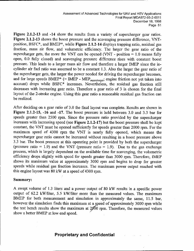
Assessment of Advanced Technologies for UAV and HEV Applications Final Report MDA972-95-2-0011
December 18, 1998 Page 51
Figure 2.1.2-13 and -14 show the results from a variety of supercharger gear ratios. Figure 2.1.2-13 shows the boost pressure and the scavenging pressure difference, VNT- position, BSFC*, and BMEP*, while Figure 2.1.2-14 displays trapping ratio, residual gas fraction, mass air flow, and volumetric efficiency. The larger the gear ratio of the supercharger gets, the more the VNT can be opened (VNT - position = 1.0 means fully open, 0.0 fully closed) and scavenging pressure difference rises with constant boost pressure. This leads to a larger mass air flow and therefore a larger IMEP since the in- cylinder air fuel ratio was assumed to be a constant 1.3. Also the larger the gear ratio of the supercharger gets, the larger the power needed for driving the supercharger becomes, and for large speeds BMEP* (= IMEP - MEPsupercharger; engine friction not yet taken into account) drops while BSFC* increases. Nevertheless, the residual gas fraction still decreases with increasing gear ratio. Therefore a gear ratio of 3 is chosen for the final layout of the 2-stroke engine. Using this gear ratio a reasonable residual gas fraction can be realized.
After deciding on a gear ratio of 3.0 the final layout was complete. Results are shown in Figure 2.1.2-15, -16 and -17. The boost pressure is held between 3.0 and 3.3 bar for speeds greater than 2500 rpm. Since the pressure ratio provided by the supercharger increases with increasing speed (see Figure 2.1.2-17) but the boost pressure shall be kept constant, the VNT must be opened sufficiently for speeds greater than 2000 rpm. For the maximum speed of 4300 rpm the VNT is nearly fully opened, which means the supercharger gear ratio cannot be increased without resulting in a boost pressure above 3.3 bar. The boost pressure at this operating point is provided by both the supercharger (pressure ratio = 1.9) and the VNT (pressure ratio = 1.9). Due to the gas exchange process, which is largely dependent on the available time for scavenging, the volumetric efficiency drops slightly with speed for speeds greater than 3000 rpm. Therefore, IMEP shows its maximum value at approximately 3000 rpm and begins to drop for greater speeds while residual gas fraction increases. The maximum power output reached with this engine layout was 80 kW at a speed of 4300 rpm.
Summary:
A swept volume of 1.3 liters and a power output of 80 kW results in a specific power output of 62.2 kW/liter, 5.5 kW/liter more than the measured values. The maximum BMEP for both measurement and simulation in approximately the same, 11.5 bar, however the simulation finds this maximum at a speed of approximately 3000 rpm while the test bench results show the maximum at 2/00 rpm. Therefore, the measured values show a better BMEP at low end speed.
Proprietary and Confidential

Assessment of Advanced Technologies for UAV and HEV Applications Final Report MDA972-95-2-0011
December 18, 1998 Page 52
C.2.2 4-Stroke Engine
C.2.2.1 Experimental investigations
Tests were conducted with two 1.9 liter DI Diesel engines. For the initial testing a 2- Valve 1.9 liter engine was used, then afterwards the engine was equipped with a four valve cylinder head, termed "Dieselfuture". This head is a unique FEV design and has been successfully tested in the past. The following engine components were changed in order to conduct these tests:
Piston A piston with a bowl volume which is 5.7 cm3 larger than in a conventional engine was used. This results in a compression ratio of approximately 16.
Nozzle
Nozzles with high flow rates were installed to ensure reasonable injection duration at full load. Since the main focus of this program is high power output, two sets of nozzles with flow rates of 600 cm3/30s and 730 cm3/30s were used.
Turbocharger Two variable turbine geometry (VNT) turbochargers were used. First the VNT 15, which is also installed in the serial production engine, and then the larger VNT 20 to raise the level of turbocharging.
Testing Boundary Conditions
Injection System:
Pump Type: Bosch VP44 Distributor DI Diesel Injection Pump
Injection Timing Control: Electronic Diesel Control (EDC)
Injection Quantity Control: Accelerator Pedal Position Sensor
Nozzle Holder: 17 mm, 1 Spring
Opening Pressure: 250 bar
Needle Lift: 0.25 mm /
Proprietary and Confidential

Assessment of Advanced Technologies for UAV and HEV Applications Final Report MDA972-95-2-0011
December 18, 1998 Page 53
Testbench Setup:
Figure 2.2.1-1 depicts the setup for the testing of the 1.9 Liter engine.
Boost and BOI Optimization for 2-Valve Engine
Tests were carried out in the absence of NOx limits and with a maximum smoke level of 3.5 Bosch Units. Figure 2.2.1-2 through -6 show the influence of injection timing and boost pressure. Both variables are adjusted to reach maximum torque output. The initial values have been chosen from results obtained through internal research and development work at FEV. Through the optimization of the beginning of injection and boost pressure the maximum torque can be raised by approximately 60 Nm, Figure 2.2.1-2. Rated power however cannot be increased since the boost level is equal for both variants. The rated power is 100 kW and is reached at 3500 rpm. The engine, in this configuration, has a power output of 52.6 kW/liter, although the fuel consumption increases for the high boost levels. When the boost pressure is increased the injection timing must be retarded, Figure 2.2.1-3, since the maximum cylinder pressure is limited to 160 bar. A retarded injection timing leads to a lower indicated efficiency. To realize the higher boosting level, a higher pressure drop, exhaust back pressure minus boost pressure Figure 2.2.1-4, is necessary due to decreased turbocharger efficiency. Both of the above lead to disadvantages in fuel consumption.
Impact of Injection System and Turbocharger for 2-Valve Engine
For the next phase of testing a larger turbocharger was adopted along with an upgraded injection system. The analysis of the first test results show that the stiffness of the pump drive was not optimized, since the injection pressure in the pipe did not exceed 1000 bar. An improved belt was mounted and the injection pressure was increased especially at high speed, Figure 2.2.1-8. A pressure increase of approximately 1000 bar was found at 2500 rpm. Figure 2.2.1-7 through -11 show comparisons of the VNT 15 and the VNT 20 turbocharger. At low speeds the maximum torque decreases, Figure 2.2.1-7. This is due to the fact that the VNT 20 is designed for an increased air flow. At low speeds the mass air flow is to small to operate the charger at high boost pressure levels. Boost pressure reached with the VNT 20 remains below values of the VNT 15for speeds up to 2500 rpm. Accordingly the engine torque obtained with the VNT 20 at these speeds is lower. Above 2500 rpm however, a high boost level of 2.8 bar can be reached. The torque, and correspondingly the rated power, increases significantly. Power output at 4200 rpm is more than 15 kW higher with the VNT 20. The specific power output is 62.6 kW/liter which is almost 20 % higher. Fuel consumption remains on the same level for the larger turbocharger. At high speed two effects neutralize each others advantages. The higher
Proprietary and Confidential

Assessment of Advanced Technologies for UAV and HEV Applications Final Report MDA972-95-2-0011
December 18, 1998 Page 54
boost pressure requires a retarded beginning of injection, thus leading to a lower indicated efficiency. On the other hand the turbocharger runs with a higher efficiency which improves the fuel consumption. The higher efficiency of the charger is obvious in the pressure drop across the engine. The larger VNT has a lower or equal pressure drop through the entire speed range. At high engine speeds a very high exhaust back pressure is needed for a high level of boosting due to the decreased turbocharger efficiency. The drop is still lower in comparison to the smaller turbocharger.
C.2.2.1.1 Impact of Nozzle Geometry
Analysis of the results achieved with a nozzle flow rate of 630 cm3/30s at 100 bar showed that the injection duration at high speeds is very long. To shorten the duration nozzles with a hole diameter of 0.25 mm and a flow rate of over 700 cm3/30s at 100 bar were installed. The results from the nozzle change are shown in Figure 2.2.1-12 through - 16. The maximum torque was increased to almost 350 Nm at 3000 rpm. In comparison to other diesel engines the speed of the maximum torque is rather high. This is due to the turbocharger which is optimized for high power output. The effective power was also raised by using the larger nozzles, resulting in a maximum power of 125 kW at 4200 rpm. In this configuration the engine has a specific power output of 66 kW/liter which is an increase of over 25 % when compared to the first configuration. Typical modern DI- Diesel engines reach specific power levels of approximately 45 kW/liter. Thus the output of the test engine is 40 % above those in mass production.
A further increase of the nozzle flow rates over 700 cm3/30s at 100 bar is likely to lead to an even better full load performance, but idle stability prevents the use of a much higher flow rate.
C.2.2.1.2 Impact of Load on Friction
Figure 2.2.1-17 presents a test series concerning the influence of load on friction. Calculations done by FEV for this engine are based on the indicated pressure traces. A comparison to the effective values retrieved from the test bench is only possible if the friction mean effective pressure is known. Until now no examinations have been carried out with regard to the friction at very high loads. Figure 2.2.1-17 shows that for 2000 and 4000 rpm the FMEP is in the upper load range. The level of friction for this engine is low, with 1.9 bar at 4000 rpm and 1.25 at 2000 rpm. The,friction slightly increases for the high loads. At 2000 rpm and mean effective prepare levels over 17.5 bar, the friction increases by 0.25 bar. This is also obvious in the slight reduction in fuel consumption.
Proprietary and Confidential

Assessment of Advanced Technologies for UAV and HEV Applications Final Report MDA972-95-2-0011
December 18, 1998 Page 55
C.2.2.1.3 Initial Testing of 4-Valve Engine
For tests with the 4-valve engine new boundary conditions had to be defined. Tests with the 2-valve engine showed that a maximum exhaust gas temperature of 950 °C in combination with the high boosting levels leads to critical conditions for the turbocharger. For the test series using the 4-valve cylinder head a speed sensing device was also adapted. Turbocharger speed and exhaust gas temperature was limited to 210,000 rpm and 900°C respectively, while the maximum cylinder pressure was restricted to 150 bar. The nozzles for the 4-valve testing had a higher flow rate of 60 mm3/30s at 100 bar.
Figure 2.2.1-18 through -22 depict the results of the initial test series using the 4-valve cylinder head. The maximum power output of approximately 125 kW for the 4-valve cylinder head is comparable to the results achieved with the 2-valve head. Specific power output is correspondingly equal at 66 kW/liter. Figure 2.2.1-21 displays the lower boost pressure and lower exhaust gas temperature during the 4-valve testing. The higher volumetric efficiency, Figure 2.2.1-20, as is expected with a 4-valve cylinder head counteracts the stricter boundary conditions set forth in these tests. Injection duration, Figure 2.2.1-19, is lower due to the higher flow rate nozzles.
C.2.2.1.4 Lowered Boost Pressure
In the next test series the impact of lowered boost pressure was examined. Analysis on the initial tests showed that a lowered boost pressure would lead to higher turbocharger efficiency. The boost pressure was lowered at all engine speeds by 0.1 or 0.2 bar. The results are shown in Figure 2.2.1-23 to -27. The lower boost pressures were compensated by earlier injection timings, Figure 2.2.1-24. The test results show that a reduction in boost pressure does not result in a lower torque output. Exhaust gas back pressure is approximately 0.4 bar lower than the boost pressure. The combination of earlier injection timing and decreased exhaust gas pressure leads to significant improvements in fuel consumption, Figure 2.2.1-23. At an engine speed of 2000 rpm the fuel consumption is decreased by over 10 g/kWh or 4.5 %. Further reductions in boost pressure can not be compensated by earlier injection timing since the conditions for good mixture formation is no longer established.
C.2.2.1.5 Long Intake Manifold
An analysis of the test results revealed the following limitations for higher power output:
• maximum cylinder pressure of 150 bar
• maximum exhaust gas temperature of 900°C
Proprietary and Confidential

Assessment of Advanced Technologies for UAV and HEV Applications Final Report MDA972-95-2-0011
December 18, 1998 Page 56
• maximum smoke number
• maximum turbocharger speed
The problem was, that none of the limits could be raised without endangering components of the engine. First calculation results pointed to a different, longer manifold. The longer manifold should increase the volumetric efficiency at engine speeds above 2000 rpm, thus leading to a higher mass air flow. A higher mass air flow decreases the possibility of reaching the maximum exhaust gas temperature since the thermal capacity of the cylinder charge is increased. On the other hand, a larger mass of air requires a retarded beginning of injection, resulting in a reduction of the fuel consumption improvement. To counteract this a new set of pistons with an even larger piston bowl were mounted to decrease the compression ratio to 14.5.
Figure 2.2.1-28 to -32 depict the results obtained with the long intake manifold. In particular, Figure 2.2.1-30 shows the volumetric efficiency can be significantly improved for engine speeds larger than 2500 rpm. At rated power speed the increase is more than 10% without noticeable drawbacks for engine speeds down to 2000 rpm. The intake mass air flow increases correspondingly to the higher volumetric efficiency. Unfortunately, the relative air to fuel ratio also increases, resulting in a deteriorated air utilization. The distributor pump, a Bosch VP 44, reaches its limit at this point. The amount of fuel does increase, Figure 2.2.1-31, but the pressure in the injection pipe decreases pumpside and nozzleside. To utilize the air gained by the longer intake manifold it would be necessary to modify the injection pump. The pump is designed for fuel quantities of approximately 50 - 60 mm3/stroke. For quantities above 90. mm3/stroke, a different cam ring profile would be necessary. Due to the lack of time a new cam profile was not implemented and the test for high power output was complete.
The tests conducted with the 4-stroke engine showed that with the latest available engine technology and in the absence of a NOx limit a very high increase of power and torque is possible with only minor modifications. Compared to modern production engines with a specific power output of 45 to 50 kW/liter an increase of over 30% to 66 kW/liter is possible.
Even higher power output seems possible through the use of a modified fuel injection pump. For the high power output the fuel consumption is very low, almost comparable to the values of mass production engines. J^
/
C.2.2.1.6 Impact of Friction
Proprietary and Confidential

Assessment of Advanced Technologies for UAV and HEV Applications Final Report MDA972-95-2-0011
December 18, 1998 Page 57
In the last test series with the 4-valve cylinder head the influence of the load on friction was examined. The 2-valve cylinder head showed almost no impact of load on friction. Figure 2.2.1-33 depicts the impact for the 2-valve and 4-valve cylinder head. The friction level for the 4-valve is slightly higher at both engine speeds. It should be mentioned that the friction level of the 2-valve head is the lowest when compared to other DI diesel engines. For the 4-valve at 2000 rpm load has no impact, corresponding to the behavior of the 2-valve cylinder head. At 4000 rpm the 4-valve head shows a greater increase in friction than the 2-valve.
C.2.2.1.7 Comparison to Today's Four-Stroke Engines
Lately, high power output DI diesel engines have been very popular for racing cars participating in long distance races. The reason for this is the superior fuel consumption and very competitive torque characteristics of DI diesel engines. Most recently Volkswagen published the performance of the popular 1.9 1 TDI in race trim, and BMW released data on the new 1.95 1 engine with high power output. Both engines were tuned in absence of a NOx limit, comparable to the tests performed by FEV. The 1.9 1 TDI reaches a maximum power output of 140 kW or 74 kW/liter and a maximum torque of 350 Nm. The BMW engine reaches similar power output values, 145 kW or 74.3 kW/liter. In contrast to FEVs engine, the TDI and BMW engines have been modified to allow higher maximum cylinder pressures of 175 and 185 bar, respectively. Both engines have only been tested under transient conditions to reduce the stress on the material or allow higher exhaust gas temperatures.
C.2.2.1.8 Conclusions
Both concepts, two and four stroke, showed high power potential utilizing readily available engine technologies. It is FEVs belief that for short term applications the four stroke concept is favorable due to the larger experience with production techniques and combustion process. FEVs four stroke engine demonstrated a specific power value of 66 kW/liter with only slight engine modifications. With more modification values above 70 kW/liter have been obtained and adapted in a vehicle.
C.2.2.2 Calculations
Simulation work was carried out to pre-optimize intake and exhaust manifold configuration on the 2 - valve 4 - stroke engine^ well as valve timing for the 4-valve 4- stroke engine.
Proprietary and Confidential

Assessment of Advanced Technologies for UAV and HEV Applications Final Report MDA972-95-2-0011
December 18, 1998 Page 58
The GT-power model (see Figure 2.2.2-1) shall be described here briefly. It contains test bench air conditioner as ambient and models all pipes between air conditioner and engine in detail including; air cleaner, compressor, intercooler, and intake manifold. On the exhaust side the manifold is modeled in great detail. The exhaust system after the turbine is not so important for the engine behavior, therefore it was only modeled as a pipe which ends at the muffler. The muffler is then assumed to be exhausted to the ambient.
This model was mapped to the measurements obtained at the engine test bench. The results are shown in Figure 2.2.2-2 to 2.2.2-5. Ambient pressure and temperature were given as boundary conditions to the model. Boost pressure is being controlled by VNT- rack-position and could only be incorrect by means of pressure drop in the charge air cooler and connected pipes. The charge air cooler map was matched to measured temperatures after the cooler.
Mass air flow (Figure 2.2.2-3) values resulting from calculations show good agreement to the measured values. At the high speeds, 4000 and 4300 rpm, the calculated mass flow is slightly low. Calculated volumetric efficiency also shows reasonable agreement with the measured values, although some small inaccuracies occur in the mid-speed range. Relative AFR behaves similarly to the volumetric efficiency. Therefore, the differences found between the calculation and measurement of mass air flow and volumetric efficiency are in the range of normal inaccuracies found between measurement and calculation. Residual gas content drops from over 5 to 4.5% at 3000 rpm before it rises again to nearly 6%. This increase is due to the very high exhaust back pressures measured.
BMEP and rated power (Figure 2.2.2-4) show good correspondence to the measured values with slightly high values at speeds higher than 3000 rpm. Since the measured fuel mass per cycle was an input to the model, lower fuel consumption was found at the same speed range. Peak pressure also shows a very good agreement.
The exhaust system after turbine was only modeled fairly, exhaust pressure after the turbine (Figure 2.2.2-5) was defined as a boundary condition. Pressure before the turbine is at a very high level due to the design of the production exhaust manifold which is very compact for packaging reasons. This production manifold has very sharp 90° bends for the exhaust flow, increasing flow losses significantly at higher mass flows (see Figure below), especially for cylinders 2 and 3. It has been found through similar designs that for very high flow rates flow separation can occu^c'ausing only a portion of the geometric area utilized for actual flow. <*
Proprietary and Confidential

Assessment of Advanced Technologies for UAV and HEV Applications Final Report MDA972-95-2-0011
December 18, 1998 Page 59
To take this effect into account an orifice was mounted between the exhaust manifold and the turbine. Because the exhaust back pressure was measured right in the bend, for the calculated exhaust pressure the average value of the pressure before and after the bend (orifice) is shown in the diagram. Considering the uncertainties expected when measuring a pressure in the area of a bend, where flow separation can occur, the measured and calculated values fit sufficiently. Exhaust temperature before the turbine also shows good correspondence between the measured and calculated values.
Even at rated speed the VNT does not reach its fully open position. Since the main goal of this project was high power output at rated speed, the turbine was matched properly, because the VNT-turbine shows their maximum efficiencies at medium rack positions, Figure 2.2.2-6. Therefore maximum turbine efficiency, approximately 60%, is maintained for speeds from 3000 up to 4300 rpm, Figure 2.2.2-5. At lower engine speeds and associated smaller rack positions efficiency drops significantly, down to values of 20% at 1000 rpm. This can be seen in Figure 2.2.2-6, transient behavior of turbine efficiency is show versus the blade tip speed ratio (u/cs). Since the GT-power model interpolated between different turbine speeds and also between different rack positions, the maps shown in Figure 2.2.2-6 do not exactly fit to the operation conditions of the turbine shown in the diagrams. They are shown her to provide an indication of the turbine operation. Small blade tip speed ratios are equivalent to high pressure ratios. It can be seen that the operation is just left of the maximum. This means, that the parts of the cycle where high pressure ratios (small u/cs) and higher mass flows occur, are used with decreasing efficiencies. Therefore a even larger turbine could show better efficiencies and smaller exhaust back pressure at high speeds. On the other hand, the efficiency would drop for slower engine speeds due to smaller rack positions and there is no smaller turbine chosen.
Compressor efficiency is in the range of 60% over nearly the whole speed range, see Figure 2.2.2-5. This is due to the very high boost pressure which is already used at a speed of 1500 rpm, see. Figure 2.2.2-7, an operation point which is already left of the compressor surge line. Due to pressure and mafs flow fluctuations within one cycle, operation reaches from surge area of the compressor map into normal operation area. Since surge line is created under steady state testing, transient operation may be extended into this area without encountering surge. Near rated engine speed compressor efficiency
Proprietary and Confidential

Assessment of Advanced Technologies for UAV and HEV Applications Final Report MDA972-95-2-0011
December 18, 1998 Page 60
begins to drop due to operation near the turbocharger speed limit, Figure 2.2.2-5. Figure 2.2.2-7 shows the compressor map data given by the turbocharger manufacturer. For normal operation with pressure ratios up to 2.5 this data is sufficient. However, for the highly boosted operation necessary for this project, the compressor map had to be extrapolated. Although the extrapolation was carried out with maximum accuracy, the slight differences in air mass flow and volumetric efficiency between measurement and calculation may have resulted from this technique, Figure 2.2.2-3.
Once the geometry of the exhaust manifold was identified as a limitation for higher power output, advantages which could be reached with better flow in the exhaust manifold, reached by improved flow guidance from exhaust valve to turbine inlet, were examined. This was modeled by opening the in build orifice area. The results are shown in Figure 2.2.2-8 and -9. As described above, for matching the calculation to the measured values, an orifice was necessary in the exhaust manifold (diameter 33 mm). The diameter of the orifice was varied from 21 mm up to the geometrical value of 33 mm at the full load operating point. With increasing orifice diameter mass air flow increases by approximately 2.5 %, therefore increasing volumetric efficiency as well. Exhaust pressure (between valve and orifice) drops from nearly 6.5 bar to 5 bar, which is still a significant exhaust back pressure. By assuming a constant relative AFR, a higher mass air flow allows combustion of a larger fuel mass while less exhaust back pressure leads to lower pumping losses. Both allow an improvement in BMEP, power (approximately lOkW), and fuel consumption. With the help of an optimized exhaust manifold it should be possible to reach a power of nearly 140 kW from just 1.9 liters, a power density of 73.5 kW/1. In light of these results, a new exhaust manifold was designed for the 4-stroke 4- valve engine.
With help from the 2-valve 4-stroke engine model which was matched to measurement, the 4-valve 4-stroke engine was modeled to allow for some optimization work to be completed in advance. This model is shown in Figure 2.2.2-10. The intake system, up to the charge air cooler, was carried over from the 2-valve engine. The intake manifold was designed with long runners since the goal was to achieve maximum power output. Long runners can improve volumetric efficiency at a given speed with a degradation of pumping losses and therefore a slight increase of fuel consumption. For each valve a single port and a single runner is used. The improved flow coefficients and larger total valve area of the 4-valve cylinder head were also taken into account. The exhaust port is also modeled in detail. Inside the cylinder head^jthe two exhaust ports connect and flow together into the manifold. The exhaust manifold is designed and modeled more aerodynamically than that of the 2-valve engine. A junction for the EGR pipe is also modeled. Although the EGR valve is closed at full load operation, oscillations in this pipe have an influence on pressure conditions in the exhaust manifold. Beyond the manifold,
Proprietary and Confidential
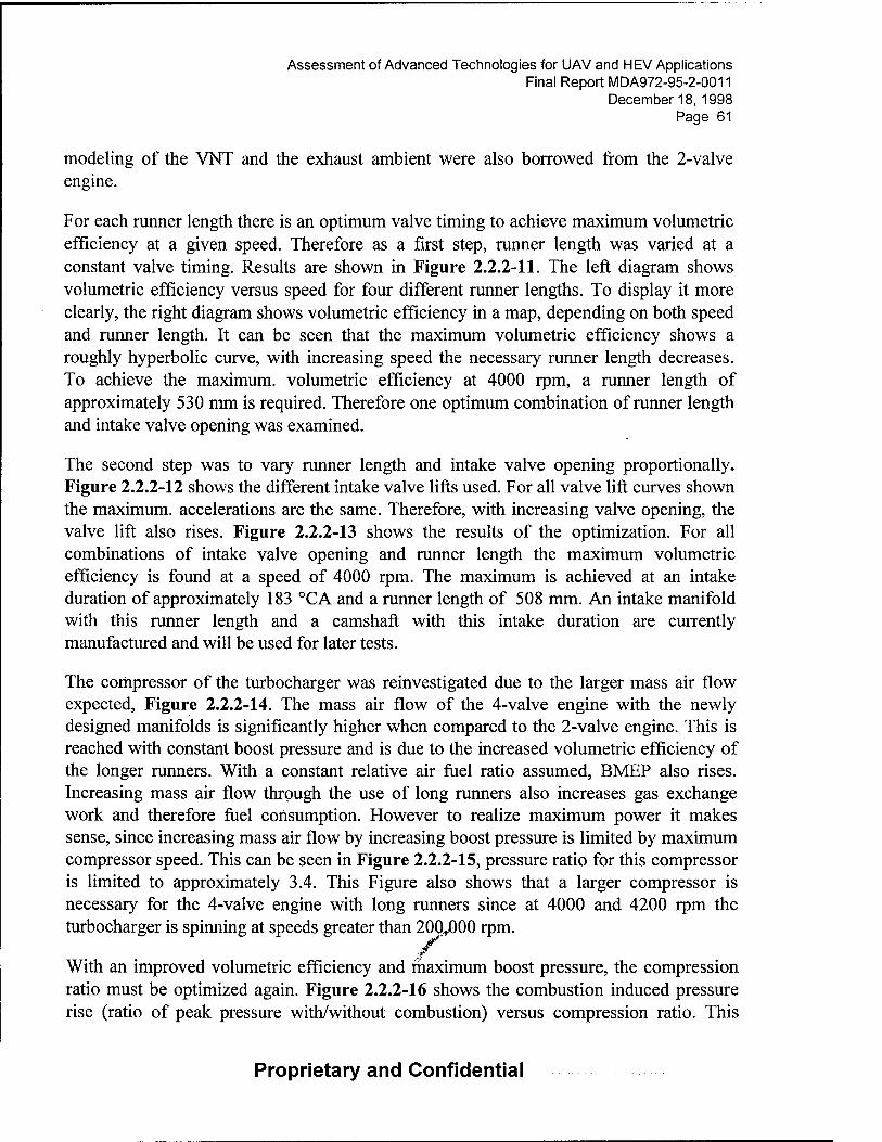
Assessment of Advanced Technologies for UAV and HEV Applications Final Report MDA972-95-2-0011
December 18, 1998 Page 61
modeling of the VNT and the exhaust ambient were also borrowed from the 2-valve engine.
For each runner length there is an optimum valve timing to achieve maximum volumetric efficiency at a given speed. Therefore as a first step, runner length was varied at a constant valve timing. Results are shown in Figure 2.2.2-11. The left diagram shows volumetric efficiency versus speed for four different runner lengths. To display it more clearly, the right diagram shows volumetric efficiency in a map, depending on both speed and runner length. It can be seen that the maximum volumetric efficiency shows a roughly hyperbolic curve, with increasing speed the necessary runner length decreases. To achieve the maximum, volumetric efficiency at 4000 rpm, a runner length of approximately 530 mm is required. Therefore one optimum combination of runner length and intake valve opening was examined.
The second step was to vary runner length and intake valve opening proportionally. Figure 2.2.2-12 shows the different intake valve lifts used. For all valve lift curves shown the maximum, accelerations are the same. Therefore, with increasing valve opening, the valve lift also rises. Figure 2.2.2-13 shows the results of the optimization. For all combinations of intake valve opening and runner length the maximum volumetric efficiency is found at a speed of 4000 rpm. The maximum is achieved at an intake duration of approximately 183 °CA and a runner length of 508 mm. An intake manifold with this runner length and a camshaft with this intake duration are currently manufactured and will be used for later tests.
The compressor of the turbocharger was reinvestigated due to the larger mass air flow expected, Figure 2.2.2-14. The mass air flow of the 4-valve engine with the newly designed manifolds is significantly higher when compared to the 2-valve engine. This is reached with constant boost pressure and is due to the increased volumetric efficiency of the longer runners. With a constant relative air fuel ratio assumed, BMEP also rises. Increasing mass air flow through the use of long runners also increases gas exchange work and therefore fuel consumption. However to realize maximum power it makes sense, since increasing mass air flow by increasing boost pressure is limited by maximum compressor speed. This can be seen in Figure 2.2.2-15, pressure ratio for this compressor is limited to approximately 3.4. This Figure also shows that a larger compressor is necessary for the 4-valve engine with long runners since at 4000 and 4200 rpm the turbocharger is spinning at speeds greater than 20Q^)00 rpm.
/ With an improved volumetric efficiency and maximum boost pressure, the compression ratio must be optimized again. Figure 2.2.2-16 shows the combustion induced pressure rise (ratio of peak pressure with/without combustion) versus compression ratio. This
Proprietary and Confidential

Assessment of Advanced Technologies for UAV and HEV Applications Final Report MDA972-95-2-0011
December 18, 1998 Page 62
configuration was utilized for the precious evaluation of maximum mass air flow for peak pressures of 160 and 180 bar (speed = 4000 rpm, volumetric efficiency = 1.02, boost pressure = 2.77 bar). As compression ratio decreases, the larger the combustion induced pressure rise is able to increase. From FEV's experience with high speed DI diesel engines a combustion induced pressure rise of approximately 1.4 is optimum for low fuel consumption and high power output. For a peak pressure of 160 bar this value can be reached with a compression ratio of approximately 13. On the test bench reduction of compression ratio through the increase of piston bowl size was limited by the pistons wall thickness. Therefore the minimum compression ratio possible was 14.5.
Calculation work was postponed until the new intake and exhaust manifolds were manufactured, a larger turbocharger was delivered, and the first tests were carried out on the test bench.
The next step was to match the calculation to the test bench results obtained from the 4- valve engine with long intake runners. The results are shown in Figure 2.2.2-17 to -19. The calculated and measured volumetric efficiency agree very well. Therefore the mass air flow also shows good correspondence. Relative air fuel ratio was taken as boundary condition for the calculation so that it must be identical. By varying the rack position of the VNT turbocharger the boost pressure is regulated to the measured value (Figure 2.2.2-18). For speeds larger than 3000 rpm the pressure drops to values lower than 3.0 bar. Boost temperature is regulated to the measured values through the charge air intercooler characteristics. The exhaust back pressure only shows good accuracy at speeds of 4000 rpm and greater. Several effects may be responsible for such inaccuracies. Firstly, errors may result from exhaust pressure measurement location, since a static pressure is measured (and calculated). Three dimensional effects can occur which cannot be represented in a one dimensional calculation. A second possible source of error may be the efficiencies delivered by the turbocharger suppliers, which normally cannot be obtained in reality since they are measured on a test bench under steady state conditions. In reality heat from the turbine is conducted to the compressor, reducing compressor efficiency. This causes an increase in the turbine work necessary and therefore exhaust back pressure increases. Exhaust temperature with respect to engine speed shows good correspondence between calculation and measurement. Absolute values are different due to the time averaged static temperature used in the calculation while in reality the temperature sensor is affected additionally by gas speed and heat conduction to the exhaust manifold wall. .s
/ Figure 2.2.2-19 shows a comparison of measurement and calculation values for power, BMEP, fuel consumption, and peak pressure. The overall accuracy of these values is good. The fuel consumption is fairly large for speeds larger than 2500 rpm. This is due to
Proprietary and Confidential

Assessment of Advanced Technologies for UAV and HEV Applications Final Report MDA972-95-2-0011
December 18, 1998 Page 63
the fact that the injected fuel mass is too large for the injection pump used for this project. To match calculated power and fuel consumption to the measured values, heat release rate had to be deteriorated significantly as compared to normal cases which we have experience.
Figure 2.2.2-20 shows measured and calculated pressure traces versus crank angle for 4000 rpm under full load conditions. It can be seen that these values fit together quite well over the whole cycle, with only differences in the range from 150 to 210°CA. In this range the exhaust valve opens. Since the valve train of the engine used was not designed for the power outputs and therefore not for the pressures at EVO which are found here the valve has to be opened against a large pressure and opens later. This can be described as a larger valve lash at EVO than at EVC. To reach such an accurate correspondence, a very poor combustion profile had to be used, proving that this is the reason for the high fuel consumption measured.
After matching the calculation model to the measurements, all points which were not found to be optimum were improved. These were:
• peak cylinder pressure could be increased up to a value of 180 bar.
• Taking into account a injection pump modified for the evaluated engine, the combustion profile could be improved significantly. Further, relative air fuel ratios of approximately 1.3 should then be sufficient for combustion with soot emissions lower than Bosch number of 3.0.
• Boost pressure at high speeds was increased to values of approximately 3.0 bar.
The results are shown in Figure 2.2.2-21 to -24. Volumetric efficiency is constant relative to the measurement since it was maximized before relative air fuel ratio is given. The VNT - rack position is regulated so a boost pressure of nearly 3.0 bar can be reached for speeds of 3000 rpm and greater. In Figure 2.2.2-22 it can be seen that for speeds lower than 3000 rpm boost pressure must be limited by opening the VNT rack position, because the compressors operation would otherwise reach into surge. Boost temperature reaches a maximum value of approximately 70 °C at 4200 rpm, Figure 2.2.2-23. This value is carried over from measurement. Dependent on weight, cost, and volume restrictions this value could be reduced by some degree, but since boost temperature behind compressor already reaches 190 °C this value is realistic. Exhaust pressure shows values between 3.0 and 4.0 bar through most of the operating range/fhis is a result of the VNT turbine which helps to decrease exhaust pressure especially in the high speed range. Due to the decreased relative air fuel ratio, exhaust temperature reaches values of up to 850°C. This is a typical value for turbines without water cooled housings.
Proprietary and Confidential

Assessment of Advanced Technologies for UAV and HEV Applications Final Report MDA972-95-2-0011
December 18, 1998 Page 64
With this optimized engine concept a maximum power of approximately 152.5 kW, or 207 hp, can be reached representing a specific power output of 80.3 kW/liter or 109 hp/liter. A maximum torque value of nearly 408 Nm is reached at a relatively high speed of 3000 rpm. At the same speed the minimum fuel consumption of approximately 223 g/kWh is obtained.
Proprietary and Confidential

Assessment of Advanced Technologies for UAV and HEV Applications Final Report MDA972-95-2-0011
December 18, 1998 Page 65
D. Conclusions
Under the current program FEV conducted an assessment of ECA's advanced engine technology for UAV and HEV application. FEV compared three different engine concepts; The TECE opposed piston engine, a highly boosted 2-stroke, and a highly boosted 4-stroke engine.
The comparison can be summarized as follows:
• The TECE engine requires less space than conventional engines, with a power density is up to 40% higher than the state-of-the-art Dl diesel engines. However, the high peak cylinder pressures of up to 300 bar require a more robust design which results in a lower specific power (1.5 lbs/hp) than conventional 4-stroke- engines (1.35 lbs/hp) and conventional 2-stroke- engines (1.25 lbs/hp).
• The TECE engine shows lower mechanical friction than conventional HSDI engines
• The TECE engine shows a high thermal efficiency of approximately 47-48% (0.3 lbs/hp-hr) at full load, medium speed (1800 rpm) and approximately 44% (0.32 lbs/hp-hr) at rated power (4200 rpm). This is 5 - 10% better than more conventional 4-stroke engines.
• The TECE engine achieves its highest thermal efficiency at maximum torque, and achieves 90% of its best thermal efficiency at rated conditions. This makes the TECE engine the preferred engine for HEV applications.
• Due to their better power-to-weight ratio, conventional engines are recommended for UAV application. This is particularly true for UAV application because the best thermal efficiency is required at part load. Conventional HSDI concepts show better thermal efficiency over the TECE engine at part load.
The good thermodynamic concept and the unique design features make the TECE engine an interesting alternative to conventional DI diesel engines. However, several technical challenges still exist and could not be investigated during this assessment.
• A suitable concept for sufficient cooling.-of the pistons and cylinder liner would need to be developed. This problem would be resolved, so that the relative AFR must not be increased, resulting in a lower power density.
• Sufficient lubrication of spherical piston bearing may not be possible without additional design features that must be developed. The piston forces always
Proprietary and Confidential

•
Assessment of Advanced Technologies for UAV and HEV Applications Final Report MDA972-95-2-0011
December 18, 1998 Page 66
point in one direction due to the 2-stroke concept, and therefore do not allow the build-up of an oil film which is necessary for lubrication.
Suitable sealing of cylinder pressures beyond 200 bar remains a technical challenge. ECA has a concept which addresses this issue, however, suitable function still must be proven.
The availability of high pressure, high speed fuel injection system will become a major factor for engine operation up to 300 bar. ECA's concept will be assessed under an amendment to this contract.
• A turbocompound system, as proposed by ECA, still needs to be developed. Since this concept also has some advantages for conventional engine concepts, suitable hardware may be available in the near future.
• Two-stroke concepts require special attention for control of oil consumption.
• The current assessment did not consider engine emissions. The unique combustion system with side injectors requires a unique combustion system layout. Since ECA has never tested an engine with two opposed pistons, significant effort is necessary to develop a suitable combustion system for this application.
Although several technical challenges remain for the TECE engine, it shows high potential for applications where high power densities are required. In addition, there is a significant potential for improvement in thermal efficiency and therefore makes the dual opposed piston concept interesting for HEV application in particular. The assessment, however, also shows that the current design can be significantly improved. Optimization of valve timing, development of the optimum intake and exhaust slot height, and the existence and timing of the rotary valves are areas of potential improvement for this engine.
Proprietary and Confidential

DEFENSE ADVANCED RESEARCH PROJECTS AGENCY ELECTRIC AND HYBRID ELECTRIC VEHICLE TECHNOLOGIES COOPERATIVE AGREEMENT MDA972-95-2-0011 and
Modifications through P00016 Quarterly Report: October 1 through December 31,1998
AEROVIRONMENT 1995
07/01/99 271 CALSTART

AeroVironment Inc.
(3sd A/\\A\fi~^ SPECIAL VEHICLES
JOINT TACTICAL ELECTRIC VEHICLE
FISCAL YEAR 1995 FUNDING FINAL REPORT
CALSTART PROPULSION SYSTEM DEVELOPMENT PROJECT FOR ADVANCED
HYBRID RECONNAISSANCE VEHICLES
Distribution Statement B: Distribution authorized to U.S. Government agencies only to protect information not owned by the U.S. Government by a contractor's "limited rights" statement, or received with the understanding that it not be routinely transmitted outside the U.S. Government. Other requests for this document shall be referred to DARPA/Technical Information Officer.
AEROVIRONMENT INC. 825 S. MYRTLE AVENUE
MONROVIA, CA 91016 (818) 357-9983
ROD MILLEN SPECIAL VEHICLES 7575 REYNOLDS CIRCLE
HUNTINGTON BEACH, CA 92647 (714) 847-2111
Distribution Statement B: Distribution authorized to U.S. Government agencies only to protect information not owned by the U.S. Government by a contractor's "limited rights" statement, or received with the understanding that it not be routinely transmitted outside the U.S. Government. Other requests for this document shall be referred to DARP A/Technical Information Officer.

INTRODUCTION
AeroVironment Inc. and Rod Millen Special Vehicles(RMSV) as part of the Propulsion System Development for Advanced Hybrid Reconnaissance Vehicles project under the aegis of CALSTART/DARPA performed several development and support programs associated with the Joint Tactical Electric Vehicle (JTEV). Funding for these programs was spread out over two fiscal year allocations by DARPA. This report deals with the programs funded or partially funded under the FY 1995 funding cycle.
The goal of this report is to summarize the work performed under the FY 1995 funding and allow the closure of this part of the subcontract between AeroVironment and CALSTART/DARPA. This report is not intended to provide great detail for any of the programs discussed. This detail can be found in previously submitted task reports and quarterly reports.
The programs that were funded under FY 1995 funds included a Bi-directional DC-DC Power Supply design, Advanced Battery Pack development, Battery Management System Development, Inverter Repackaging and Vehicle Demonstrations, Low Acoustic Signature Transmission installation, Two Speed Transmission Design Study, and an Upgrade of Pumps and Peripherals.
Page 1

TASK BREAKDOWN AND REVIEW
The following tasks were identified to be completed as part of the FY 1995 funding. The scheduled report deliveries and milestones appear in the financial section of this report. This section will briefly review the purpose and results these tasks. It will also identify when tasks were completed via the submital of a task report and which tasks were extended under the FY 1996 funding.
Task 1 - Bi-directional DC-DC Power Supply Development
This task focused on the design of a bi-directional DC-DC converter that could be incorporated on to the JTEV. The original construction of JTEV included a DC-DC converter capable of down conversion from the high voltage battery voltage to the 24 V bus at a power level of 4 kW. It was determined that a bi-directional design incorporating a slightly higher down conversion power level of 6 kW and a conversion stage to produce high voltage from the 24 V system at a 4 kW power level would provide additional desired capabilities. The design effort for this bi-directional converter was performed by AeroVironment. The original intent of installing actual hardware in JTEV was re-evaluated as the design was more complicated than first expected. This task was completed in December 1996 with the submission of the DC-DC converter design report which covered the scope agreed upon in a modification of the original statement of work.
Task 2 - Battery Pack Development
This task focused on the identification and specification of an advanced battery option for potential incorporation into the JTEV. This task actually extended into the FY 1996 funding. The aspects intended for completion under the FY 1995 funding included the identification and specification of appropriate batteries. In addition, preliminary testing of these cells was to be performed and a design for potentially incorporating these cells in to the JTEV was to be completed. The specification and initial battery testing was completed in December 1996 with the submission of the Cell Specification Report. Due to a long series of delays and questions about the continuation of this effort under the FY 1996 funding, the Pack Mechanical Design Report was not submitted until July 1998. This report mainly identified work that was completed in the earlier parts of this program but was never reported on. However, this report has now been submitted and this task is considered completed for all FY 1995 funding. This report mainly identified work that was completed in the earlier parts of this program but was never reported on. The outcome of the portions of the program covered under FY 1996 funding, including further pack level testing, is covered under the summary for that funding.
Task 3 - Battery Management System Upgrade
The objective of the Battery Management System Upgrade effort was to install the latest generation SmartGuard® battery management system, with improved reliability and user interface, onto the JTEV battery pack and investigate their ability to monitor and aid in maintenance of the vehicle's lead acid battery pack. Investigation of the potential of SmartGuards modified with high current bypass capability to maintain an old and damaged pack was originally considered, but was not performed due to programmatic conflicts. This installation effort was completed and a new preventative maintenance
Page 2

schedule was implemented for the batteries. A final report for this task was submitted in September 1996.
Task 4 - Inverter Repackaging and Vehicle Demonstrations
This task was modified to contain two parts during the contract statement of work modification initiated in the middle of this contract. The inverter repackaging was undertaken with a goal of decreasing the package size of the traction inverters and the APU inverter. This resulted in two main advantages, easier inverter maintenance and increased seat clearance to allow more room for driver and passenger. In addition, this repackaging relocated the cable connections into the inverters allowing for greater driver visibility out the rear of the vehicle. This portion of the task was completed in September 1996 with the submission of the Inverter Repackaging Final Report.
The vehicle demonstration support part of this task was intended to provide funding to prepare the vehicle for demonstration, ship the vehicle to demonstrations, provide support for the vehicle at the demonstrations, and to repair any failures that occurred during shipment or demonstration. These funds were used to support several demonstrations for DARPA and by prior agreement for the Naval Surface Warfare Center at Carderock (NSWC-Carderock). These demonstrations included the presentation of the vehicle at the biannual DARPA conference in Washington D.C. in May 1996 and the Marine Corp League show at Quantico Va. in September 1996. A significant failure of the APU alternator at the May 1996 demonstration required significant funding for repair. This task was completed with the submission of the September 1996 Quarterly Report as no other report was required in the statement of work.
Task 5 - Low Acoustic Signature Transmission
The purpose of this task was to incorporate a helical gear train in the JTEV transmissions as opposed to the straight cut gears originally used in order to quite general operating noise of the vehicle. The JTEV vehicle was intended to demonstrate low noise operational capabilities and the noise level from the transmission prevented this demonstration mission. A helical gear train was purchased and incorporated into JTEV and a study was performed to show the decrease in noise produced by the vehicle. This task was completed in September 1996 with the submission of the Low Acoustic Transmission Report.
Task 6 - Two speed transmission design
The purpose of this task was to demonstrate the extended operating range possible by incorporating a two speed transmission in to JTEV. It was identified as desirable to demonstrate a higher top speed than JTEV currently was capable of reaching as well as even greater hill climb capability. The portion of this task that was covered under the FY 1995 funding only included as sizing feasibility study and a gear ratio selection study. The overwhelming concern was whether a two speed transmission could be made to fit on the JTEV. Additional funding under the FY 1996 funds was allocated for the manufacture and incorporation of this design into JTEV. The FY 1995 portion of this task was completed in December 1996 with the submission of the Two Speed Transmission Progress report covering these aspects of the program. The outcome of the portions of the program covered under FY 1996 funding is covered under the summary for that funding
Page 3

Task 7 - Pumps and Peripherals
The purpose of this task was to upgrade several of the JTEV peripheral pumps and fans in order to provide a more robust vehicle for demonstration purposes. The major focus of this program was the improvement of the cooling system and the power steering system. The original design of JTEVs cooling system was not powerful enough to provide adequate cooling in very hot conditions or continuous hard operations. This system was upgraded with large pumps and radiator fans. In addition, the power steering pump was upgraded to provide better steering assistance and increased reliability for continuous operations. This task was completed in September 1996 with the submission of the Peripherals Report.
Page 4

FlNANCIALS
The following table shows the date of report submissions and the payment of funds from the FY 1995 funds. This table also shows the 10% withheld from each billing and shows the payment of that withholding upon receipt of this final report and final invoice which accompanies it.
Date Task/Milestone DARPA 95 95 Match 10% Withheld 9/30/96 95-3 Battery mgmt final report
95-4a Inverter repkg final report 95-4b Sept 96 quarterly report & Demos 95-5 Low Acoustic Transmission report 95-7 Peripherals report
$327,119 $53,972 ($32,712)
12/31/96 95-1 DC-DC converter design report 95-2a Cell Specifications report 95-6 2 speed transmission progress report
$256,.730 $37,520 ($25,673)
7/24/98 95-2b Pack Mechanical Design report 7/24/98 FY 1995 Final Report (10% of total funds) $58,385
Totals $ 583,849 $ 91,492 $ -
Page 5

CONCLUSIONS
All of the tasks described above have supported the further demonstration of the JTEV as a viable example of hybrid electric drivetrain technology. Many of the technologies incorporated are the direct result of developments in the commercial sector, and lessons learned during the developments achieved through this CALSTART/DARPA program may at some point flow back into the commercial sector, as well as into the RST-V program. Several of the efforts have resulted in a more robust vehicle which has been demonstrated by NSWC-Carderock at several armed forces facilities. These demonstrations have furthered the understanding and interest in using hybrid electric drivetrains in military vehicles.
While the contract between AeroVironment and CALSTART/DARPA for the FY 1995 funds has gone through some modifications all the agreed upon tasks have been completed with the submission of the final Battery Pack Mechanical Design Report. This report has summarized the tasks accomplished under this funding and identified the completion points of various tasks. With the submission of this report and the payment of the 10% withholdings, this section of the contract can be closed.
Paae 6

DEFENSE ADVANCED RESEARCH PROJECTS AGENCY ELECTRIC AND HYBRID ELECTRIC VEHICLE TECHNOLOGIES COOPERATIVE AGREEMENT MDA972-95-2-0011 and
Modifications through P00016 Quarterly Report: October 1 through December 31,1998
AERVIRONMENT 1996
07/01/99 279 CALSTART
% AeroVironment. Inc.
ßsd /Vwvu^ SPECIAL VEHICLES
JOINT TACTICAL ELECTRIC VEHICLE
FISCAL YEAR 1996 FUNDING FINAL REPORT
CALSTART PROPULSION SYSTEM DEVELOPMENT PROJECT FOR ADVANCED
HYBRID RECONNAISSANCE VEHICLES
Distribution Statement B: Distribution authorized to U.S. Government agencies only to protect information not owned by the U.S. Government by a contractor's "limited rights" statement, or received with the understanding that it not be routinely transmitted outside the U.S. Government. Other requests for this document shall be referred to DARPA/Technical Information Officer.
AEROVIRONMENT INC. 825 S. MYRTLE AVENUE
MONROVIA, CA 91016 (818) 357-9983
ROD MILLEN SPECIAL VEHICLES 7575 REYNOLDS CIRCLE
HUNTINGTON BEACH, CA 92647 (714) 847-2111
Distribution Statement B: Distribution authorized to U.S. Government agencies only to protect information not owned by the U.S. Government by a contractor's "limited rights" statement, or received with the understanding that it not be routinely transmitted outside the U.S. Government. Other requests for this document shall be referred to DARPATechnical Information Officer.

INTRODUCTION
AeroVironment Inc. and Rod Millen Special Vehicles (RMS V) as part of the Propulsion System Development for Advanced Hybrid Reconnaissance Vehicles project under the aegis of CALSTART/DARPA performed several development and support programs associated with the Joint Tactical Electric Vehicle (JTEV). Funding for these programs was spread out over two fiscal year allocations by DARPA. This report deals with the programs funded or partially funded under the FY 1996 funding cycle.
The goal of this report is to summarize the work tasks falling under the FY 1996 funding. Due to the potential desire to redirect funds from FY 1996 allocations, this report will summarize the state of the tasks and worked performed to date. The object of this report is to close out the existing tasks so that payment of the 10% invoice witholdings can be made and the remaining funds can be redirected as determined by a collaboration of CALSTART, AeroVironment, and the Naval Surface Warfare Center at Carderock (NSWC-Carderock) with the approval of DARPA.
The programs that were funded under FY 1996 funds included a continuation of the advanced battery design and testing, a continuation of the two speed transmission design effort, and JTEV demonstration support and program management.
Page 1

TASK BREAKDOWN AND REVIEW
The following task were to be completed under the FY 1996 funding. This section reviews the intent of the task as it was intended and the level to which work has been completed.
Task 1 - Two Speed Transmission
This task was a continuation of the effort under the FY 1995 funding and called for the completion of the two speed transmission design for installation into JTEV and fabrication of the transmission. The portions of this program falling under the FY 1995 funding were completed by December 1996. This work was not continued because of the limited availability of JTEV which was required to complete this design effort. Since JTEV was constructed as a single prototype, a limited amount of drawing documentation is available and therefore presence of the vehicle was required to determine the exact interaction of the transmission. As shown below in the financial section, no work has been performed on this task under the FY 1996 funding.
Task 2 - Battery Pack Development
This task focused on the identification and specification of an advanced battery option for potential incorporation into the JTEV. This task began under FY 1995 funding. The aspects intended for completion under the FY 1995 funding included the identification and specification of appropriate batteries. In addition, preliminary testing of these cells was to be performed and a design for potentially incorporating these cells in to the JTEV was to be completed. The work to be completed under the FY 1996 funding was the purchase of a full set of Ni-Cd cells for pack level testing in the Energy Storage Lab at AeroVironment. This work was not completed due to significant lead time in acquiring the Ni- Cd cells from Eagle Pitcher (EP) and the lack of resolution on the proposal to redirect the effort from Ni- Cd batteries to Nickel Metal Hydride (NiMH) batteries. As show below in the financial section, no work has been performed on this task under the FY 1996 funding.
Task 3 - JTEV Demonstration Support and Program Management
The vehicle demonstration support part of this task was intended to provide funding to prepare the vehicle for demonstration, ship the vehicle to demonstrations, provide support for the vehicle at the demonstrations, and to repair any failures that occurred during shipment or demonstration. In addition, some funding was used to keep the vehicle in general repair so that demonstrations could be performed in a timely fashion. A large portion of the demonstration funds were spent during the summer of 1996 to repair and maintain the vehicle for the Marine Corp League Show in September 1996 at Quantico Va.
The program management part of this task provides funding for AeroVironment personnel to prepare for and attend the biannual DARPA reviews as well as prepare all quarterly status reports. The funding for this portion of this task has been used only to the extend absolutely necessary to perform these functions. The funds spent on the two parts of this task number are indicated in the financial section below.
Page 2

FlNANCIALS
The following table shows the budgeted for each task in the FY 1996 funding and the amount spent to date up to the end of fiscal June 1998. Some small expenditures incurred during the current month, July 1998, under the program management task, will be invoiced at the close of fiscal July 1998. The budget values shown are those agree upon at the time that the contract was modified in March 1997.
Task Milestones/Deliverables Revised Budged Spent To Date % Complete 96-1: Two Speed Transmission Construction 96-1: Two speed transmission report $ 92,439 $ - 0% 96-2: Battery Purchase and test 96-2a: Battery Progress Report $ 100,000 $ - 0%
96-2b: Battery Test Report 0% 96-3: JTEV Support and management 96-3a,b,c,d,e: Quarterly Reports $ 167,272 $ 129,827
JTEV Support Program Management
$ $
93,674 73,598
$ $
55,517 43,660
60% 60%
Total $ 359,711 $ 99,177
The following table shows the quarterly reports that were submitted and funded by FY 1996 funds and the amounts billed at each quarter. The totals listed are through fiscal June 1998. An additional invoice will be sent with the expenditures from fiscal July 1998 with no withholdings made.
Date Task/Milestone DARPA 96 10% Withheld 12/31/96 3/31/97 6/30/97 9/30/97
12/31/97 3/31/98 6/30/98
96-3a Dec 96 quarterly report 96-3b Mar 97 quarterly report 96-3c Jun 97 quarterly report 96-3d Sept 97 quarterly report 96-3e Dec 97 quarterly report 96-3f Mar 98 quarterly report 96-3g Jun 98 quarterly report
$36,942 $39,085 $14,570
$- $2,997
$- $5,583
($3,694) ($3,908) ($1,457)
$ - ($300)
$- ($558)
7/24/98 FY 1996 Final Report (10% of total funds billed) $9,917 Totals $99,177 $ -
It needs to be understood that all numbers listed here and invoiced were based on the provisional rates established at the beginning of the contract and that rate adjustments may still be required to finally close out this contract.
Pace 3

CONCLUSIONS
The majority of the funding approved by CALSTART/DARPA for FY 1996 was intended to fund continuing efforts started under FY 1995 funding. For a variety of reasons the majority of these funds were not spent and two of the tasks were not completed. Based on changing interests at NSWC- Carderock and DARPA it has been decided that rather and complete these tasks as originally contracted to close this existing contract at this point and redirect the funds into programs producing more desired information.
This report is intended to summarize the present state of the tasks under the FY 1996 funding and the financial standing. It is the intention for this to serve as the final report for this contract so that these books can be closed and a new contract drafted and carried out for any of the redirected funds. As stated above, only as small amount of expenditure directed toward this contract still remain for expenses incurred in July 1998. These expenses will be billed promptly at the close of the fiscal month.
Pase4

DEFENSE ADVANCED RESEARCH PROJECTS AGENCY ELECTRIC AND HYBRID ELECTRIC VEHICLE TECHNOLOGIES COOPERATIVE AGREEMENT MDA972-95-2-0011 and
Modifications through P00016 Quarterly Report: October 1 through December 31,1998
COMPLETED PROJECTS
07/01/99 285 CALSTART

DEFENSE ADVANCED RESEARCH PROJECTS AGENCY ELECTRIC AND HYBRID ELECTRIC VEHICLE TECHNOLOGIES COOPERATIVE AGREEMENT MDA972-95-2-0011 and
Modifications through P00016
Quarterly Report: October 1 through December 31,1998
PROGRAMMABLE DC CONTROLLER Project Manager: Jefferson Programmed Power CS-AR94-02
The goal of this project was to build a prototype controller, a programmable "brain" for an electric vehicle that is low cost with regenerative braking, high-output power and built-in charger capability.
MILESTONES
Design complete CPU Logic Board operational 1 st prototype controller test Final report
CS-AR94-02 TOTALS
DARPA
72,000 65,000 50,000 30,000
217,000
MATCH
80,000 60,000 77,000
217,000
QTR DATE DUE
10/10/95 1/10/96 4/10/96 6/30/96
COMPLETE
10/25/95 1/11/96 4/17/96 9/20/96
DARPA FUNDS EXPENDED
72,000 65,000 58,300 21,700
217,000
SAFE ELECTROMECHANICAL BATTERIES FOR EVS Project Manager: Rocketdyne CS-AR95-05
The goal of this project was to scale Rocketdyne's successfully demonstrated flywheel containment design to fit an existing EMB flywheel sized for heavy-duty hybrid electric vehicle applications and verify system safety.
MILESTONES DARPA MATCH QTR DATE DUE COMPLETE MATCH FUNDS
EXPENDED
DARPA FUNDS
EXPENDED
1 Containment ring design 50,000 552,000 1 12/31/96 12/31/96 552,000 63,472
2 Containment ring fabrication
75,000 77,000 2 3/30/97 3/30/97 77,000 97,463
3 Assembly checkout/test 100,000 77,000 3 6/30/97 12,221
4 Final report 34,500 77,000 4 9/30/96
259,500 783,000 629,000 173,156
07/01/99 286 CALSTART

DEFENSE ADVANCED RESEARCH PROJECTS AGENCY ELECTRIC AND HYBRID ELECTRIC VEHICLE TECHNOLOGIES COOPERATIVE AGREEMENT MDA972-95-2-0011 and
Modifications through P00016 Quarterly Report: October 1 through December 31,1998
RUNNING CHASSIS II Project Manager: Amerigon Incorporated CS-AR94-01
The goal of this project was to develop and bring into production electric vehicles that can be produced for low costs at relatively low volumes.
MILESTONES DARPA MATCH QTR DATE DUE COMPLETE MATCH FUNDS
EXPENDED
DARPA FUNDS
EXPENDED
1 Initiate work 200,000 460,000 1 11/14/95 11/21/95 75,000
2 Complete breadboard designs of drive train, running chassis, steel space frame
175,000 200,000 2 12/31/95 12/15/95 103,222
3 Fabricate EV4 & BEV prototype parts. Complete build of EV4
125,000 0 3 3/31/96 270,000
4 Complete all BEV tests. Revise tools for EV4 and BEV
40,000 15,000 4 6/30/96 7/8/96
5 Complete build EV4. Complete EV4 vehicle tests.
0 0 5 9/30/96 9/30/96
6 Complete and begin tests 1st
productionized drive train. 0 0 12/31/96 12/31/96 36,000
7 Complete finite element Analysis. Complete design BEV runninq chassis.
0 0 3/30/97 4/30/97 71,778
8 Complete build/test 4 alumn BEV's w/o body panels - 2 w/welded & bonded frames. Build/test 5 productionized drive trains. Complete comparative chassis analysis and final report.
160,000 45,000 6 6/30/97 7/30/97 144,000
700,000 720,000 4,098,410 700,000
Match funds were not fully reported during the project. Byron Kwan, Controller, closed the project accounting records with Amerigon's costs at $4,098,410.
07/01/99 287 CALSTART

DEFENSE ADVANCED RESEARCH PROJECTS AGENCY ELECTRIC AND HYBRID ELECTRIC VEHICLE TECHNOLOGIES COOPERATIVE AGREEMENT MDA972-95-2-0011 and
Modifications through P00016 Quarterly Report: October 1 through December 31,1998
NAVAL AIR STATION ALAMEDA: PROJECT HATCHERY NORTH Project Manager: CALSTART CS-AR94-09A
The goal of this program was to develop a business incubator to encourage the growth of companies producing advanced transportation technologies.
NAVAL AIR STATION ALAMEDA: CLUSTER PLANNING Project Manager: CALSTART CS-AR94-09B
The goal of this project was to build on the incubator efforts by developing other advanced transportation businesses at the Naval Air Station Alameda. This effort is intended to build a strong regional alliance of companies serving as a network of high quality suppliers for the military and commercial sector.
MILESTONES DARPA MATCH QTR DATE DUE COMPLETE DARPA FUNDS EXPENDED
Contract Award. Initiate Site Analysis Purchase Equipment
125,000 40,000 0 7/24/95 7/24/95 125,000
Final lease negotiations. Open Incubator.
75,000 15,000 1 12/30/95 7/23/96 75,000
Complete Required facility Up-fits. 75,000 10,000 2 3/30/96 3/30/97 75,000
Develop strategic marketing materials.
50,000 20,000 3 6/30/96 1/30/97 50,000
Complete NAS facilities Assessment.
50,000 15,000 4 9/30/96 On-going from 95
50,000
Facilitate lease arrangements with Cluster firms
50,000 25,000 5 12/30/96 12/30/96 50.000
Final Report 0 25,000 6 3/30/97 9/30/97 400,000 150,000 400,000
07/01/99 288 CALSTART

DEFENSE ADVANCED RESEARCH PROJECTS AGENCY ELECTRIC AND HYBRID ELECTRIC VEHICLE TECHNOLOGIES COOPERATIVE AGREEMENT MDA972-95-2-0011 and
Modifications through P00016 Quarterly Report: October 1 through December 31,1998
HEAVY FUEL INJECTOR Project Manager: Engine Corporation of America CA-DARO-03
The goal of this project was to work with FEV to evaluate and compare the performance of ECA's fuel injection concept against other options available commercially. Also, in working with FEV, an analysis will be completed of a real gas thermal cycle for verification of thermodynamic performance of ECA's engine concept. __
MILESTONES DARPA MATCH QTR DATE DUE
COMPLETE MATCH FUNDS
EXPENDED
DARPA FUNDS
EXPENDED
1 1.0 Completion and submission of program plan
122,500 0 1 3/30/97 7/1/97 122,500
2 1.1 Overall Engine Design, 1.2 Engine Thermal Cycle Analysis,1.1 Coordination of Analytical Effort with FEV, 2.1 ECA Fuel Injector Design,2.2 Fuel Injector Options Assessment, 2.3 Coordinated Fuel Injection Review
122,500 245,000 2 6/30/97 9/30/97 245,000 122,500
TOTAL 245,000 245,000 245,000 245,000
07/01/99 289 CALSTART

DEFENSE ADVANCED RESEARCH PROJECTS AGENCY ELECTRIC AND HYBRID ELECTRIC VEHICLE TECHNOLOGIES COOPERATIVE AGREEMENT MDA972-95-2-0011 and
Modifications through P00016 Quarterly Report: October 1 through December 31,1998
ELECTRIC VEHICLE LONG RANGE EXTENDING GENERATOR Project Manager: AC Propulsion CS-AR96-06
The goal of this project was to design, develop and test an efficient, high specific output charging system dedicated to RXG (range extending generators) applications. This design has the potential to lower the cost of commercialized units and increase adaptability to various ev designs.
MILESTONES DARPA MATCH QTR DATE DUE COMPLETE MATCH FUNDS EXPENDED
DARPAFUNDS EXPENDED
1 Design study complete
51,000 57,000 1 1/10/97 1/10/97 52,211 51,000
2 Prototype charging system constructed
72,000 53,000 2 4/10/97 3/30/97 46,600 72,000
3 Möller engine delivered
22,000 25,000 3 7/10/97 8/30/97 25,000 30,000
4 Integration complete 8,000 11,000 4 10/10/97 9/30/97 11,000
5 Testing complete 8,000 15,000 5 1/10/98 12/31/97 15,000
6 Final report 9,000 9,000 6 4/10/98 3/5/98 9,000 17,000
TOTALS 170,000 170,000 170,000 170,000
07/01/99 290 CALSTART

DEFENSE ADVANCED RESEARCH PROJECTS AGENCY ELECTRIC AND HYBRID ELECTRIC VEHICLE TECHNOLOGIES COOPERATIVE AGREEMENT MDA972-95-2-0011 and
Modifications through P00016 Quarterly Report: October 1 through December 31,1998
ELECTRIC AND HYBRID ELECTRIC VEHICLE DATA ACQUISITION SYSTEM
Project Manager: CALSTART CS-AR94-12
The goal of this program was to develop a data acquisition system to monitor 21 different parameters including battery current and voltage, motor current and voltage, vehicle and motor speed, accessory draw, inclination, acceleration and various temperatures.
MILESTONE DARPA MATCH DATE DUE COMPLETE DARPAFUNDS EXPENDED
1 Feasibility Study 50,001 9/30/95 9/30/95 16,271 2 Schematic /housing
for keypad/display 16,271 12/31/95 12/31/95 9,957
3 Establish Internet Connection
20,608 3/30/96 2/96 20,608
4 Hardware Test Box for Analog/digital boards
54,077 6/30/96 5/96 54,077
5 DC Converter Schematics Build Prototype.
16,666 9/30/96 12/96 21,700
6 Second PCB Testing CDAS and Installation
51,750 12/31/96 PCB-10/96 Test Begun
11/96
27,387
7 Testing 3/30/97 Not completed 8 Final Report 6/30/97 3/31/97
TOTAL 150,000 0 150,000
07/01/99 291 CALSTART

DEFENSE ADVANCED RESEARCH PROJECTS AGENCY ELECTRIC AND HYBRID ELECTRIC VEHICLE TECHNOLOGIES COOPERATIVE AGREEMENT MDA972-95-2-0011 and
Modifications through P00016 Quarterly Report: October 1 through December 31,1998
ALTURDYNE ROTARY ENGINE APU TRANSIT BUS DEMONSTRATION Project Manager: APS Systems CS-AR95-04
Program Goal: The goal of this program is to demonstrate the use of the Alturdyne Rotary Engine as an auxiliary power unit (APU) in a full-size 40-foot transit bus. The Alturdyne Rotary Engine was incorporated into a purpose-built, hybrid-electric transit bus from APS Systems that will be undergoing testing in regular transit service.
MILESTONES DARPA MATCH QTR DATE DUE COMPLETE MATCH FUNDS
EXPENDED
DARPA FUNDS
EXPENDED
1 Alturdyne bus demonstration
65,000 386,418 1 3/31/98 386,418 65,000
65,000 386,418 386,418 65,000 Note: Actual project cost: $1,311,288,23. Match funds for DARPA funds contributed by APS systems in the form of actual labor, overhead and G&A expenditures.
ENVIRONMENTAL CONTROL SYSTEM FOR ELECTRIC AND HYBRID VEHICLES
Project Manager: Glacier Bay CS-AR96-02
COOPERATIVE TESTING Project Manager: Glacier Bay with EVermont
The goal of this project was to demonstrate dramatically reduced energy consumption, reduce the weight and space requirement and to improve reliability and heat output on the Glacier Bay Environmental Control System for electric vehicles.
MILESTONES DARPA MATCH QTR DATE DUE COMPLETE MATCH FUNDS
EXPENDED
DARPA FUNDS
EXPENDED
1 Initiate work 20,000 10/25/96 20,000
2 Design of Major Components 34,573 44,113 1 12/31/96 12/31/96 44,113 34,573
3 Prototype drawings complete 55,000 60,000 2 3/31/97 3/31/97 60,000 53,076
4 Production of major components
50,000 45,000 3 6/30/97 6/30/97 45,000 50,000
5 Prototype bench testing 17,000 21,000 4 9/30/97 9/30/97 21,000 17,000
6 Production/Testing prototypes 35,000 8,000 5 12/31/97 12/31/97 29,242
8 Final report 23,427 11,887 7 3/31/98 3/31/98 35,586 31,109
235,000 190,000 205,699 235,000
07/01/99 292 CALSTART

DEFENSE ADVANCED RESEARCH PROJECTS AGENCY ELECTRIC AND HYBRID ELECTRIC VEHICLE TECHNOLOGIES COOPERATIVE AGREEMENT MDA972-95-2-0011 and
Modifications through P00016 Quarterly Report: October 1 through December 31,1998
PROGRAM TO MINIMIZE LOSSES IN MECHANICAL BATTERIES FOR ELECTRIC VEHICLES Project Manager: Avcotl CS-AR95-01
Program Goal: The purpose of this program is to characterize the rotational losses of homopolar permanent magnet bias (HPMB) magnetic bearings and to determine if design innovations could further reduce the low losses of this bearing type. A secondary objective is to set guidelines for predicting magnetic bearing parasitic losses in real energy storage flywheel (ESF) systems.
MILESTONE DARPA MATCH DUE DATE COMPLETE MATCH FUNDS
EXPENDED
DARPA ■ FUNDS
EXPENDED
1 1 Develop Computer Model 2 Begin Rotordynamic Analysis 3 Develop Test Plan 4 Design Test Rig
37,706 37,706 9/30/96 9/30/96 37,706 37,706
2 Complete Rotordynamic Analysis
16,220 16,220 12/31/96 12/31/96 16,220 16,220
3 Complete Test Plan 5 Begin Fabrication of Test Rig
10,160 8,470 3/30/97 3/30/97 10,160 36,276
4 Complete Fabrication of Test Rig
15,160 8,600 6/30/97 9/30/97 31,226 15,160
5 6 Fabricate Standard Bearings 7 Design Optimized Bearings 8 Fabricate Optimized Bearings
12,182 23,618 9/30/97 3/31/98 12,182 12,182
6 9 Test Standard Bearing 10,124 8,600 12/31/97 3/31/98 10,124 10,124
7 10 Test Optimized Bearing 11 Iterate Computer
Model
3,797 12,800 3/31/98 3/31/98 24,792 3,731
8 Final Report 21,000 10,335 6/30/98 3/31/98 36,147
$126,349 $126,349 178,557 126,349
07/01/99 293 CALSTART

DEFENSE ADVANCED RESEARCH PROJECTS AGENCY ELECTRIC AND HYBRID ELECTRIC VEHICLE TECHNOLOGIES COOPERATIVE AGREEMENT MDA972-95-2-0011 and
Modifications through P00016 Quarterly Report: October 1 through December 31,1998
HYBRID ELECTRIC BUS DEMONSTRATION Project Manager: Capstone Turbine Corporation CS-AR94-06
Program Goal: The goal of this program is to demonstrate the 30 kW MicroTurbine developed by Capstone Turbine Corporation in commercial service in a 22-foot electric shuttle bus.
MILESTONES DARPA MATCH QTR DATE DUE COMPLETE MATCH FUNDS EXPENDED
DARPA FUNDS
EXPENDED
1 Initiate Work 40,000 40,000 8/30/95 12/15/95 112,811 36,000
2 Vandenburg Combustor/Monolith Test rig
102,500 102,500 12/31/96 1/11/96 102,932 92,250
1 Hardware/Electrical Design
50,000 50,000 1 12/31/96 1/11/97 50,000 50,000
2 Vehicle Integration 82,000 82,000 2 . 3/30/97 3/30/97
3 System Integration 20,000 20,000 3 6/30/97 3/30/97 107,310 90,000
4 Final report 7,500 5,000 4 9/30/97 6/30/98 175,186
TOTAL 300,000 300,000 548,239 268,250
07/01/99 294 CALSTART

DEFENSE ADVANCED RESEARCH PROJECTS AGENCY ELECTRIC AND HYBRID ELECTRIC VEHICLE TECHNOLOGIES COOPERATIVE AGREEMENT MDA972-95-2-0011 and
Modifications through P00016 Quarterly Report: October 1 through December 31,1998
DISTRIBUTED ENERGY MANAGEMENT SYSTEM (DEMS) DEVELOPMENT AND DEMONSTRATION Project Manager: Raytheon (FKA: Hughes Technical Services Center) CS-AR96-08 and CS-AR94-04
Project Goal: The goal of this project is to develop, fabricate and demonstrate an effective, on-vehicle integrated battery management system that protects and enhances battery life, is easily adaptable to multiple vehicle platforms, is cost effective and supports the safe and effective use of high power charging. The battery management system should be capable of controlling multiple battery strings and controlling within strings at the battery module level. __
MILESTONES CS-AR94-04
DARPA MATCH QTR DATE DUE COMPLETE MATCH FUNDS
EXPENDED
DARPA FUNDS
EXPENDED
1 Requirements defined. Concept for controller hardware defined
30,000 50,000 1 6/30/96 6/30/96 281,022 50,000
2 Software defined and programmed.
30,000 50,000 2 9/30/96 9/30/96 150,979 50,000
3 Design/Implementation of multiple pack system controller
70,000 370,000 3 12/31/96 12/31/96 15,474 150,000
4 Software installed on 25kW Inductive Opportunity Charge system.
50,000 15,000 4 3/30/97 3/30/97 146,051
5 Bluebird buses equipped Field data acquired
70,000 5 6/30/97
250,000 485,000 593,526 250,000
MILESTONES CS-AR96-08
DARPA MATCH QTR DATE DUE COMPLETE MATCH FUNDS
EXPENDED
DARPA FUNDS
EXPENDED
5 Task continued: DEMS upgrade concept complete/controller built
200,000 108,000 5 6/30/97 3/30/98 200,000
6 Final report. 50,000 15,000 6 9/30/97
250,000 123,000 200,000
GRAND TOTAL 500,000 608,000 450,000
07/01/99 295 CALSTART

DEFENSE ADVANCED RESEARCH PROJECTS AGENCY ELECTRIC AND HYBRID ELECTRIC VEHICLE TECHNOLOGIES COOPERATIVE AGREEMENT MDA972-95-2-0011 and
Modifications through P00016
Quarterly Report: October 1 through December 31,1998
ROTARY ENGINE AUXILIARY POWER UNIT DEMONSTRATION Project Manager: Aerobotics, Inc. a division of Möller International CS-AR95-07
Program Goal: The goal of this project is the demonstration of the Moller rotapower engine in a hybrid electric vehicle. The rotapower engine is expected to deliver a maximum horsepower of 30, and demonstrate emissions equivalent to a zero emission vehicle when operating continuously at 15 horsepower.
MILESTONES DARPA MATCH QTR DATE DUE COMPLETE MATCH FUNDS
EXPENDED
DARPA FUNDS
EXPENDED
1 Complete design 40,000 108,320 1 3/6/96 5/31/96 112,793 40,000
2 Order batteries/tooling 57,855 2 3/30/96 5/31/96 15,125 53,162
3 Finish block fabrication
25,000 46,500 3 5/15/96 12/30/96 6,188 38,490
4 Receive/Evaluate Geo Metro
16,495 4 8/16/96 8/25/96 23,531 46,201
5 Drivetrain/Engine Installation
37,500 37,500 5 10/4/96 12/96 30,000 22,489
6 Vehicle testing 23,492 15,000 6 12/15/96 3/30/97
7 Final report 32,013 10,000 7 2/4/97 8/26/98 225,358 32,013
TOTAL 232,355 217,320 412,995 232,355
07/01/99 296 CALSTART

DEFENSE ADVANCED RESEARCH PROJECTS AGENCY ELECTRIC AND HYBRID ELECTRIC VEHICLE TECHNOLOGIES COOPERATIVE AGREEMENT MDA972-95-2-0011 and
Modifications through P00016 Quarterly Report: October 1 through December 31,1998
CANCELED PROJECTS
07/01/99 297 CALSTART

DEFENSE ADVANCED RESEARCH PROJECTS AGENCY ELECTRIC AND HYBRID ELECTRIC VEHICLE TECHNOLOGIES COOPERATIVE AGREEMENT MDA972-95-2-0011 and
Modifications through P00016 Quarterly Report: October 1 through December 31,1998
OPTIMIZED 30kW TURBINE/FLYWHEEL HYBRID ELECTRIC VEHICLE Project Manager: Rosen Motors
ALUMINUM RUNNING CHASSIS FOR CIVILIAN USE (RCP-4C) Project Manager: Amerigon Incorporated
ALUMINUM RUNNING CHASSIS FOR MILITARY USE (ARC4-M) Project Manager: Amerigon Incorporated
HYBRID ELECTRIC BATTERY Project Manager: Bolder Technologies CS-AR94-05
HEAVY-DUTY HYBRID ELECTRIC DRIVE TRAINS Project Manager: Santa Barbara Air Pollution Control District CS-AR94-03
MILESTONE DAR PA MATCH DARPA FUNDS EXPENDED
CS-AR94-03 No milestone - program canceled
29,568 9,856 29,568
29,568 9,856 29,568
07/01/99 298 CALSTART

DEFENSE ADVANCED RESEARCH PROJECTS AGENCY ELECTRIC AND HYBRID ELECTRIC VEHICLE TECHNOLOGIES COOPERATIVE AGREEMENT MDA972-95-2-0011 and
Modifications through P00016
Quarterly Report: October 1 through December 31,1998
ELECTRIC AIRPORT SHUTTLE BUSES Project Manager: Santa Barbara Air Pollution Control District
ENERGY MANAGEMENT CONTROLLER Project Manager: Delco Electronics CS-AR94-13
DARPA MATCH DARPA FUNDS
EXPENDED
CS-AR94-13 18,000 18,000
18,000 0 18,000
E/HEV MANUFACTURABILITY ASSISTANCE PROGRAM Project Manager: CALSTART CS-AR96-04
HYBRID VEHICLE TURBOGENERATOR WITH LIQUID FUELED CATALYTIC COMBUSTOR
Project Manager: Capstone CS-AR97-06
MAGNETIC BEARING COMMERCIALIZATION PLAN Project Manager: AVCON CS-AR97-11
07/01/99 299 CALSTART
Copyright © 2022 FDOKUMEN