Blockchain Technology and Inter-organizational Relationships
Upload
khangminh22Category
view
1download
0
sensors
Article
Continuous Delivery of Blockchain Distributed Applications
Tomasz Górski
�����������������
Citation: Górski, T. Continuous
Delivery of Blockchain Distributed
Applications. Sensors 2022, 22, 128.
https://doi.org/10.3390/s22010128
Academic Editor: Marimuthu
Palaniswami
Received: 19 November 2021
Accepted: 23 December 2021
Published: 25 December 2021
Publisher’s Note: MDPI stays neutral
with regard to jurisdictional claims in
published maps and institutional affil-
iations.
Copyright: © 2021 by the author.
Licensee MDPI, Basel, Switzerland.
This article is an open access article
distributed under the terms and
conditions of the Creative Commons
Attribution (CC BY) license (https://
creativecommons.org/licenses/by/
4.0/).
Department of Computer Science, Polish Naval Academy of the Heroes of Westerplatte (PNA),Smidowicza 69, 81-127 Gdynia, Poland; [email protected]
Abstract: Ensuring a production-ready state of the application under development is the imminentfeature of the Continuous Delivery (CD) approach. In a blockchain network, nodes communicateand store data in a distributed manner. Each node executes the same business application butoperates in a distinct execution environment. The literature lacks research focusing on continuouspractices for blockchain and Distributed Ledger Technology (DLT). Specifically, it lacks such workswith support for both design and deployment. The author has proposed a solution that takes intoaccount the continuous delivery of a business application to diverse deployment environments inthe DLT network. As a result, two continuous delivery pipelines have been implemented using theJenkins automation server. The first pipeline prepares a business application whereas the second onegenerates complete node deployment packages. As a result, the framework ensures the deploymentpackage in the actual version of the business application with the node-specific up-to-date versionof deployment configuration files. The Smart Contract Design Pattern has been used when buildinga business application. The modeling aspect of blockchain network installation has required usingUnified Modeling Language (UML) and the UML Profile for Distributed Ledger Deployment. The refinedmodel-to-code transformation generates deployment configurations for nodes. Both the businessapplication and deployment configurations are stored in the GitHub repositories. For the sake ofverification, tests have been conducted for the electricity consumption and supply managementsystem designed for prosumers of renewable energy.
Keywords: blockchain; continuous delivery; 1+5 architectural views model; model-driven development
1. Introduction
The fundamental principle of the Agile Manifesto underlines the importance of earlyand continuous delivery of software that meets the needs of the customer [1]. The authorhas distinguished, and provided abbreviations for, the following notions: continuousintegration (CI), continuous delivery (CD), and continuous deployment (CDT). CI prac-tice involves that software is integrated continuously during development. The practiceencompasses automation of software builds and testing. The basis for a CI is a versioncontrol environment. The most popular is GitHub. The service ensures the source codeversion control in a distributed manner using Git. The Git distributed version controlhas its own branching model [2]. Generally, developers frequently merge their code withrelease or main branches [3]. The new or changed code is incorporated into a build andchecked by automated tests. Test automation ensures checking that the application workscorrectly in case a new commit is merged into the release branch. The practice raises teamproductivity by frequent releases. Iterative automated testing elevates software quality inthe CI approach. The CD approach goes even further in software development automa-tion. It aims to enable on-demand software release. The practice employs a set of stagesincluding the acceptance tests and release process. Both those stages are automated. Therelease process and automated acceptance tests allow for application under development ofon-demand deployment. Humble and Farley [4] present the comprehensive description ofthe continuous delivery process. They have defined the notion of the deployment pipelineas an automated process of tasks, which is responsible for producing release. CD practice
Sensors 2022, 22, 128. https://doi.org/10.3390/s22010128 https://www.mdpi.com/journal/sensors
Sensors 2022, 22, 128 2 of 18
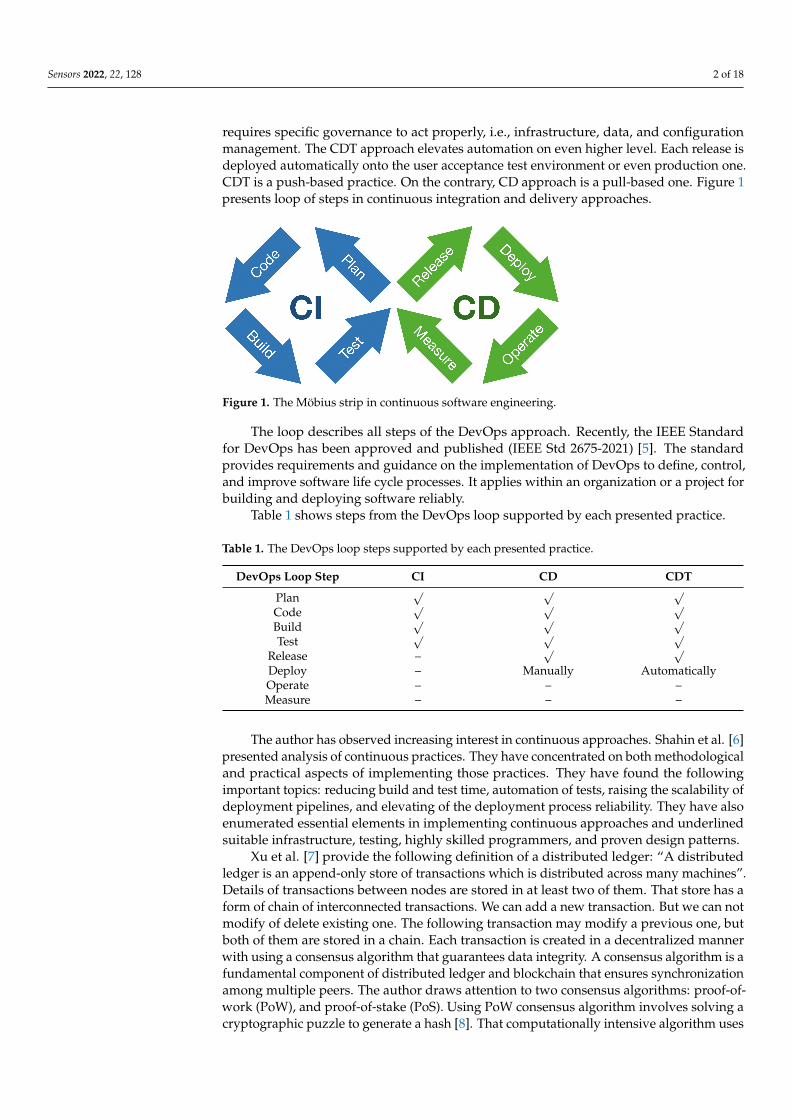
requires specific governance to act properly, i.e., infrastructure, data, and configurationmanagement. The CDT approach elevates automation on even higher level. Each release isdeployed automatically onto the user acceptance test environment or even production one.CDT is a push-based practice. On the contrary, CD approach is a pull-based one. Figure 1presents loop of steps in continuous integration and delivery approaches.
Figure 1. The Möbius strip in continuous software engineering.
The loop describes all steps of the DevOps approach. Recently, the IEEE Standardfor DevOps has been approved and published (IEEE Std 2675-2021) [5]. The standardprovides requirements and guidance on the implementation of DevOps to define, control,and improve software life cycle processes. It applies within an organization or a project forbuilding and deploying software reliably.
Table 1 shows steps from the DevOps loop supported by each presented practice.
Table 1. The DevOps loop steps supported by each presented practice.
DevOps Loop Step CI CD CDT
Plan√ √ √
Code√ √ √
Build√ √ √
Test√ √ √
Release –√ √
Deploy – Manually AutomaticallyOperate – – –Measure – – –
The author has observed increasing interest in continuous approaches. Shahin et al. [6]presented analysis of continuous practices. They have concentrated on both methodologicaland practical aspects of implementing those practices. They have found the followingimportant topics: reducing build and test time, automation of tests, raising the scalability ofdeployment pipelines, and elevating of the deployment process reliability. They have alsoenumerated essential elements in implementing continuous approaches and underlinedsuitable infrastructure, testing, highly skilled programmers, and proven design patterns.
Xu et al. [7] provide the following definition of a distributed ledger: “A distributedledger is an append-only store of transactions which is distributed across many machines”.Details of transactions between nodes are stored in at least two of them. That store has aform of chain of interconnected transactions. We can add a new transaction. But we can notmodify of delete existing one. The following transaction may modify a previous one, butboth of them are stored in a chain. Each transaction is created in a decentralized mannerwith using a consensus algorithm that guarantees data integrity. A consensus algorithm is afundamental component of distributed ledger and blockchain that ensures synchronizationamong multiple peers. The author draws attention to two consensus algorithms: proof-of-work (PoW), and proof-of-stake (PoS). Using PoW consensus algorithm involves solving acryptographic puzzle to generate a hash [8]. That computationally intensive algorithm uses
Sensors 2022, 22, 128 3 of 18
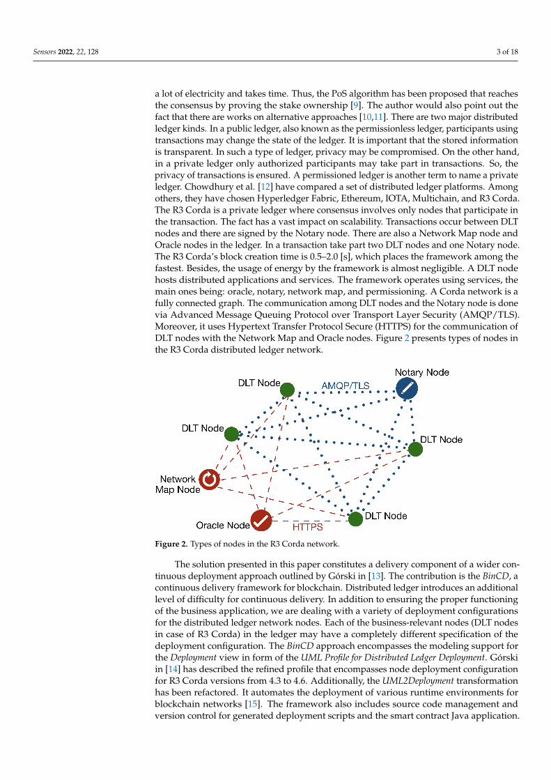
a lot of electricity and takes time. Thus, the PoS algorithm has been proposed that reachesthe consensus by proving the stake ownership [9]. The author would also point out thefact that there are works on alternative approaches [10,11]. There are two major distributedledger kinds. In a public ledger, also known as the permissionless ledger, participants usingtransactions may change the state of the ledger. It is important that the stored informationis transparent. In such a type of ledger, privacy may be compromised. On the other hand,in a private ledger only authorized participants may take part in transactions. So, theprivacy of transactions is ensured. A permissioned ledger is another term to name a privateledger. Chowdhury et al. [12] have compared a set of distributed ledger platforms. Amongothers, they have chosen Hyperledger Fabric, Ethereum, IOTA, Multichain, and R3 Corda.The R3 Corda is a private ledger where consensus involves only nodes that participate inthe transaction. The fact has a vast impact on scalability. Transactions occur between DLTnodes and there are signed by the Notary node. There are also a Network Map node andOracle nodes in the ledger. In a transaction take part two DLT nodes and one Notary node.The R3 Corda’s block creation time is 0.5–2.0 [s], which places the framework among thefastest. Besides, the usage of energy by the framework is almost negligible. A DLT nodehosts distributed applications and services. The framework operates using services, themain ones being: oracle, notary, network map, and permissioning. A Corda network is afully connected graph. The communication among DLT nodes and the Notary node is donevia Advanced Message Queuing Protocol over Transport Layer Security (AMQP/TLS).Moreover, it uses Hypertext Transfer Protocol Secure (HTTPS) for the communication ofDLT nodes with the Network Map and Oracle nodes. Figure 2 presents types of nodes inthe R3 Corda distributed ledger network.
Figure 2. Types of nodes in the R3 Corda network.
The solution presented in this paper constitutes a delivery component of a wider con-tinuous deployment approach outlined by Górski in [13]. The contribution is the BinCD, acontinuous delivery framework for blockchain. Distributed ledger introduces an additionallevel of difficulty for continuous delivery. In addition to ensuring the proper functioningof the business application, we are dealing with a variety of deployment configurationsfor the distributed ledger network nodes. Each of the business-relevant nodes (DLT nodesin case of R3 Corda) in the ledger may have a completely different specification of thedeployment configuration. The BinCD approach encompasses the modeling support forthe Deployment view in form of the UML Profile for Distributed Ledger Deployment. Górskiin [14] has described the refined profile that encompasses node deployment configurationfor R3 Corda versions from 4.3 to 4.6. Additionally, the UML2Deployment transformationhas been refactored. It automates the deployment of various runtime environments forblockchain networks [15]. The framework also includes source code management andversion control for generated deployment scripts and the smart contract Java application.
Sensors 2022, 22, 128 4 of 18
To achieve this, the GitHub distributed version control environment has been used. Theapproach encompasses checking the consistency between generated deployment scriptsand the UML Deployment model. Besides, deployment pipelines have been designedthat automate the release process for the distributed application and node deploymentconfiguration scripts. The Jenkins open source automation servers have been used. Forverifying smart contracts, both unit and integration tests have been included in the Javaapplication deployment pipeline.
The paper is arranged as follows. Section 2 discusses the related work. Section 3presents the design of the BinCD solution that provides up-to-date deployment scriptsand smart contracts application (Java) for DLT nodes configuration. The section encom-passes a description of continuous delivery pipelines designed in the Jenkins open sourceautomation server. Moreover, in that section, it have been also presented design of refinedUML2Deployment transformation. Section 4 introduces the method of validation of thecontinuous delivery solution that allows for checking the consistency between generateddeployment scripts and source models. The section also outlines tests of the distributedapplication. Section 5 presents discussion. Section 6 concludes the paper and showsdirections for further work.
2. Related Work
This work focuses on the Continuous Delivery practice, blockchain technology, UML,and the Model-Driven Development (MDD) methodology. Therefore, the search hasconsidered articles on these four topics and divided the results of the literature review intocorresponding paragraphs. The first one presents papers that discuss recent developmentsin continuous practices. The second paragraph discusses articles which show the recentdevelopments in blockchain technology. Special attention has been paid to the matter ofblockchain solutions for the renewable energy sector. The next paragraph encloses studiesthat show the newest applications of UML. The last one focuses on the research advancesin employing MDD. Emphasis has been put on finding such uses in blockchain solutions.
There are approaches and best practices of continuous delivery described in the litera-ture [4]. Nevertheless, the implementation can be difficult in practice. Laukkanen et al. [16]have selected papers considering continuous delivery adoption problems, causes, andsolutions. Integration and testing problems have been the most often reported ones. Systemdesign and testing problems have been revealed as the most critical ones. Particularly,testing in continuous integration is proliferating in the literature. Prado Lima et al. [17]present papers devoted to prioritization of test cases in continuous integration. In thatfield, Yang et al. [18] show that a reward function based on historical data can elevate theefficiency of such prioritization. Moreover, Yu et al. [19] reviewed papers that show theusing of a continuous integration environment for non-functional requirements testing.Abdalkareem et al. [20] have shortened the execution time of the continuous integrationprocess by identifying commits that can be omitted. The proposed prototype tool workswith Git repositories. Debroy and Miller [21] showed actions to overcome challenges in im-plementing continuous practices. They used custom images for building agents to handlemicroservice dependencies. They introduced orchestration to manage resources in orderto keep infrastructure costs low. Finally, keeping build and release times short requiredemploying an orchestrator, such as Kubernetes, to handle scaling. Gallaba et al. [22] haveproposed a tool to analyze feature misuse of Travis CI. The same environment, Travis CI,has been used by Saidani et al. [23] to analyze refactoring practices in continuous integra-tion. In the work, the Jenkins open-source automation server has been used, which iswidely used by the community and researchers [24,25]. Recently, Leite et al. [26] haveexamined continuous delivery practice. They have analyzed the structure of DevOps teamsand communication between them. So the work seems to be timely.
Blockchain is one of the most disruptive technologies. Both papers, by Monrat et al. [27],and Al-Jaroodi et al. [28] examine the benefits and difficulties of using the technologyfor business applications. The work has only focused on a few of them. Blockchain is
Sensors 2022, 22, 128 5 of 18
widely used for the management of healthcare data [29]. An example of the ElectronicHealth Record system that applies blockchain has been presented by Shahnaz et al. [30].Blockchain finds a lot of uses in the energy sector. Especially, distributed energy systemsof prosumers employ the technology to manage the flow of electricity. Saxena et al. [31]have developed a blockchain-based residential energy trading system that takes into ac-count the preferences of prosumers so as to reduce the demand for energy. They haveused permissioned Hyperledger Fabric [32]. Jamil et al. [33] have introduced a predic-tive energy trading system that helps in scheduling energy generation from renewablesources. Researchers and practitioners use various blockchain frameworks. An extensivecomparison of permissioned and permissionless blockchain frameworks have been doneby Chowdhury et al. [12].
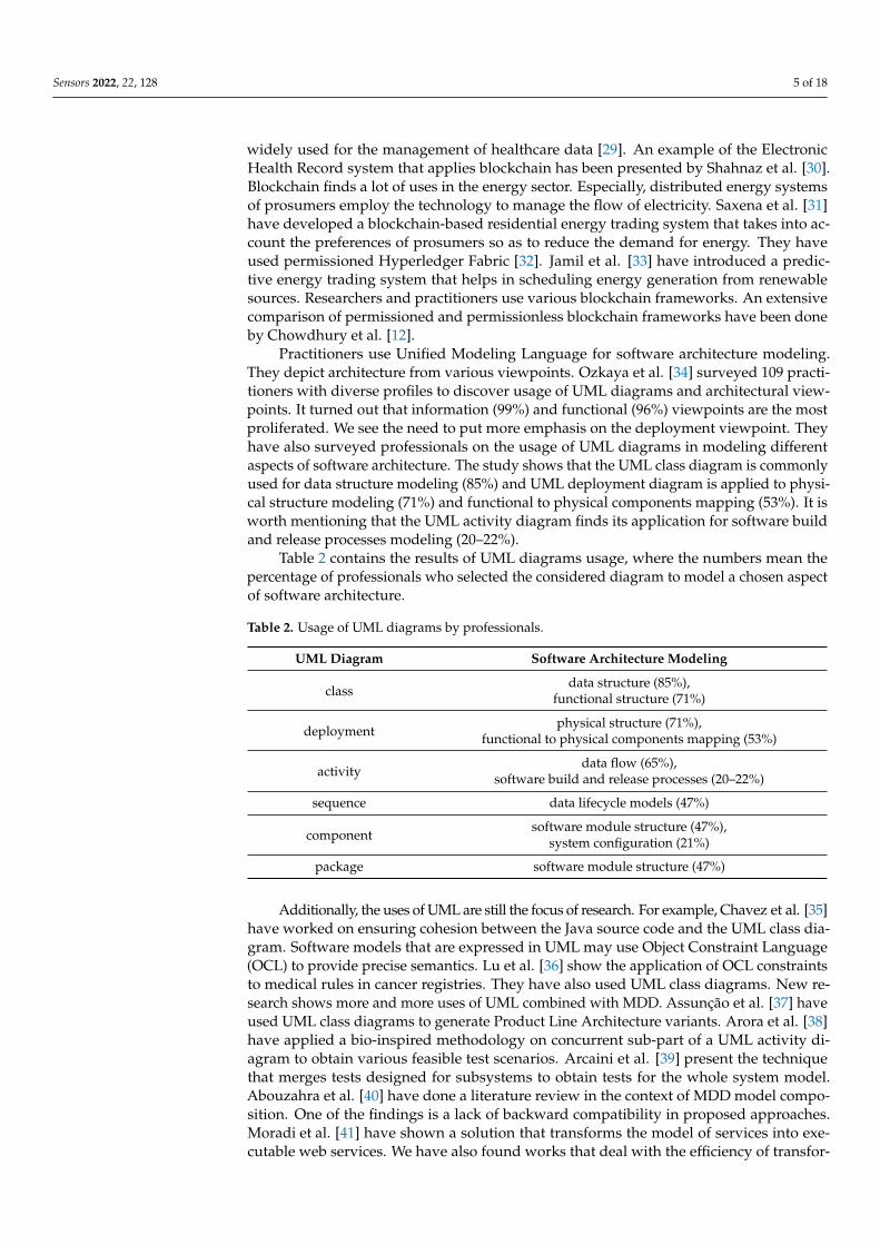
Practitioners use Unified Modeling Language for software architecture modeling.They depict architecture from various viewpoints. Ozkaya et al. [34] surveyed 109 practi-tioners with diverse profiles to discover usage of UML diagrams and architectural view-points. It turned out that information (99%) and functional (96%) viewpoints are the mostproliferated. We see the need to put more emphasis on the deployment viewpoint. Theyhave also surveyed professionals on the usage of UML diagrams in modeling differentaspects of software architecture. The study shows that the UML class diagram is commonlyused for data structure modeling (85%) and UML deployment diagram is applied to physi-cal structure modeling (71%) and functional to physical components mapping (53%). It isworth mentioning that the UML activity diagram finds its application for software buildand release processes modeling (20–22%).
Table 2 contains the results of UML diagrams usage, where the numbers mean thepercentage of professionals who selected the considered diagram to model a chosen aspectof software architecture.
Table 2. Usage of UML diagrams by professionals.
UML Diagram Software Architecture Modeling
classdata structure (85%),
functional structure (71%)
deploymentphysical structure (71%),
functional to physical components mapping (53%)
activitydata flow (65%),
software build and release processes (20–22%)
sequence data lifecycle models (47%)
componentsoftware module structure (47%),
system configuration (21%)
package software module structure (47%)
Additionally, the uses of UML are still the focus of research. For example, Chavez et al. [35]have worked on ensuring cohesion between the Java source code and the UML class dia-gram. Software models that are expressed in UML may use Object Constraint Language(OCL) to provide precise semantics. Lu et al. [36] show the application of OCL constraintsto medical rules in cancer registries. They have also used UML class diagrams. New re-search shows more and more uses of UML combined with MDD. Assunção et al. [37] haveused UML class diagrams to generate Product Line Architecture variants. Arora et al. [38]have applied a bio-inspired methodology on concurrent sub-part of a UML activity di-agram to obtain various feasible test scenarios. Arcaini et al. [39] present the techniquethat merges tests designed for subsystems to obtain tests for the whole system model.Abouzahra et al. [40] have done a literature review in the context of MDD model compo-sition. One of the findings is a lack of backward compatibility in proposed approaches.Moradi et al. [41] have shown a solution that transforms the model of services into exe-cutable web services. We have also found works that deal with the efficiency of transfor-
Sensors 2022, 22, 128 6 of 18
mations. Basciani et al. [42] show reusability capabilities of existing transformations bychaining them for designing new ones. Besides, Panach et al. [43] report that the qualityof the software developed following MDD is significantly better than the code writtenmanually only for complex problems.
The new field of application of model-driven development is also blockchain tech-nology. One of the key elements in a blockchain is a smart contract. Zou et al. [44]conducted an analysis to discover the actual obstacles that developers have to overcomewhile developing smart contracts. Results revealed that the source code of smart contractsis compromised as far as security is concerned. Besides, existing frameworks are rudimen-tary and there are many limitations in programming languages. Górski [14] has shown theflexible manner for designing smart contracts in a permissioned distributed ledger. He hasproposed the Smart Contract Design Pattern. As far as MDD is concerned, Xu et al. [7] out-line two transformations applied to blockchain technology. The first one uses cooperatingbusiness processes and generates a smart contract for them. The second transformationgenerates blockchain registries for commodities, digital assets, and ownership titles. Theyhave used the Ethereum blockchain. Górski and Bednarski [15] describe the model-to-codetransformation, which creates deployment configuration files for blockchain nodes byusing the UML Deployment model. The model employs extensibility mechanisms fromUML Profile for Distributed Ledger Deployment [14]. Moreover, Gao et al. [45] propose a toolprototype to automatically detect bugs and validate smart contracts.
It is worth emphasizing that Laukkanen et al. [16] in their survey pointed out that thesystem design and build design topics had the least reported solutions in the ContinuousDelivery domain. Support for modeling has been incorporated into the BinCD solution.Smart contracts are the main focus of current research results on blockchain. These are theprimary element of distributed applications. Besides, blockchain nodes constitute the de-ployment environment. The deployment environment, which is properly configured, hostsdistributed applications. Ozkaya et al. [34] claim that the functional and information viewsare the most popular views in software architecture modeling. The paper has concentratedmore on the deployment (UML Profile for DLT Deployment). But, it have been also includeddesign assistance for smart contracts (Smart Contract Design Pattern). Continuous practicesinvolve the automation of tasks in software development and IT operations. Thus, thepaper pays attention to employing the MDD approach (UML2Deployment transformation)to the Deployment view of a blockchain system. The imminent element of continuousdelivery is also version control. There have been used Git distributed version controland GitHub service. Zou et al. [44] claim that the development support of blockchainapplications in existing tools is still incomplete. Thus, the Visual Paradigm modeling toolhas been incorporated into the framework. Besides, the Jenkins automation server has beenused for automated build release. The whole CD pipeline has been integrated, from theUML deployment model to the deployment package for each node in the distributed ledgernetwork. Additionally, a parallel pipeline has been provided that builds Java distributedapplication and places it in every deployment package. As a result, a solution, which usesUML and MDD, has been obtained that provides deployment-ready packages for eachdistributed ledger node with the actual version of the Java distributed application andup-to-date deployment configuration.
3. The BinCD Framework Design
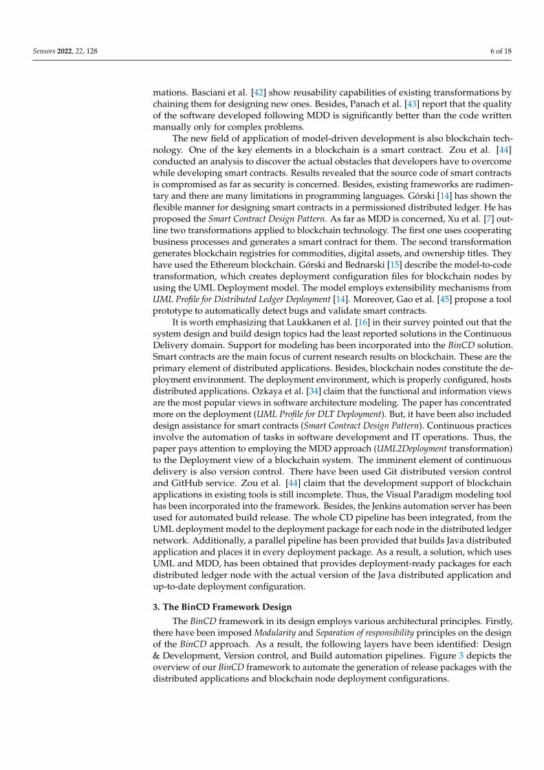
The BinCD framework in its design employs various architectural principles. Firstly,there have been imposed Modularity and Separation of responsibility principles on the designof the BinCD approach. As a result, the following layers have been identified: Design& Development, Version control, and Build automation pipelines. Figure 3 depicts theoverview of our BinCD framework to automate the generation of release packages with thedistributed applications and blockchain node deployment configurations.
Sensors 2022, 22, 128 7 of 18
Figure 3. The BinCD framework overview.
In the Design & Development layer, the UML Deployment model of the blockchainnetwork has been placed. The model uses, as previously mentioned, the profile and thetransformation plugin. The second module is a Java distributed application that realizesthe Sell energy smart contract. The first module is designed in Visual Paradigm whereasthe second one is developed in IntelliJ IDEA. GitHub repositories have been placed inthe Version control layer. The first one encompasses the source code of the smart contractapplication and Corda’s actual version execution environment. The second repositoryconsists of deployment configuration files for nodes. Both Jenkins pipelines have been putin the Build automation pipelines layer. The first one automates the generation of the smartcontract application. The second pipeline automates the generation of the complete ZIPfile that consists of the application, Coda runtime, and deployment configuration files forDLT nodes. Deployment packages for nodes are kept by the Jenkins server.
Next, elements of the BinCD framework have been presented. Firstly, the currentversion of the UML Profile for Distributed Ledger Deployment has been briefly outlined. Thenthe UML2Deployment transformation has been presented. The transformation has beenadapted to store files in GitHub repositories. Lastly, delivery pipelines have been outlinedthat generate releasable deployment packages for distributed ledger nodes.
3.1. UML Profile for DLT Deployment
The author has previously thoroughly refined the profile [14]. In the design of theprofile, he has applied the Adjust the level of abstraction architectural principle. The profileis defined at the Platform Specific Model (PSM) level to express the precise deploymentconfiguration of the R3 Corda framework. But, it has been configured flexibly enoughfor modeling various versions of Corda (currently from 4.3 to 4.6). Unified ModelingLanguage offers constraints, tagged values, and stereotypes to extend its semantics [46].Stereotypes have been employed to mark nodes, services, and communication protocolsspecific to the R3 Corda framework. The framework defines deployment parameters foreach type of node. In the profile, the deployment parameter is represented by the tagged

Sensors 2022, 22, 128 8 of 18
value. Tagged values are coupled with stereotypes of nodes. Stereotypes and taggedvalues, from the profile, have been used in the UML Deployment model of the ECSMsystem. Usually, various deployment environments are modeled, e.g., test, uat, staging,prod. UML package groups nodes and represents the deployment environment. SeparateUML Deployment diagrams depict deployment environments. The profile can be foundin the GitHub repository [47]. Figure 4 depicts the UML Deployment diagram of the testdeployment environment defined for a part of the ECSM system.
Figure 4. The test deployment environment in the UML Deployment diagram.
3.2. UML2Deployment Transformation Design
The continuous delivery framework incorporates model-to-code transformation forgenerating blockchain deployment scripts [15]. Figure 5 outlines the overview of theextended transformation (new or redesigned components are marked in green).
Figure 5. Overview of the transformation.
The source of the transformation is a UML Deployment model. The current versionof the UML profile has been used. The second vital change in the design of the transfor-mation is the ability to store generated deployment scripts at GitHub under Git versioncontrol. Having the modularity architectural principle in mind, the design of the trans-formation has been split into two main components: the UML Deployment model andthe Object-oriented model. Following the separation of responsibility architectural principle,the transformation has been designed as two distinct Java applications. The main Java
Sensors 2022, 22, 128 9 of 18
application generates configuration files using the content of a UML Deployment model.The application uses configuration files templates. The second application is designedas the Visual Paradigm plug-in that uses the transformation. The current version of thetransformation incorporates the possibility of storing generated deployment scripts atGitHub service under Git distributed version control. The Visual Paradigm plugin has beenconfigured to work in two modes: LOCAL and GIT. The first one was left for the sake ofbackward compatibility. When the plugin is set up for LOCAL mode, the application forcesthe user to select a local path to save generated files. With GIT mode turned on, generateddeployment configuration files are automatically committed and pushed to the specifiedrepository. The specification of work mode for the plugin is done with a dedicated propertyfile, plugin-config.properties.
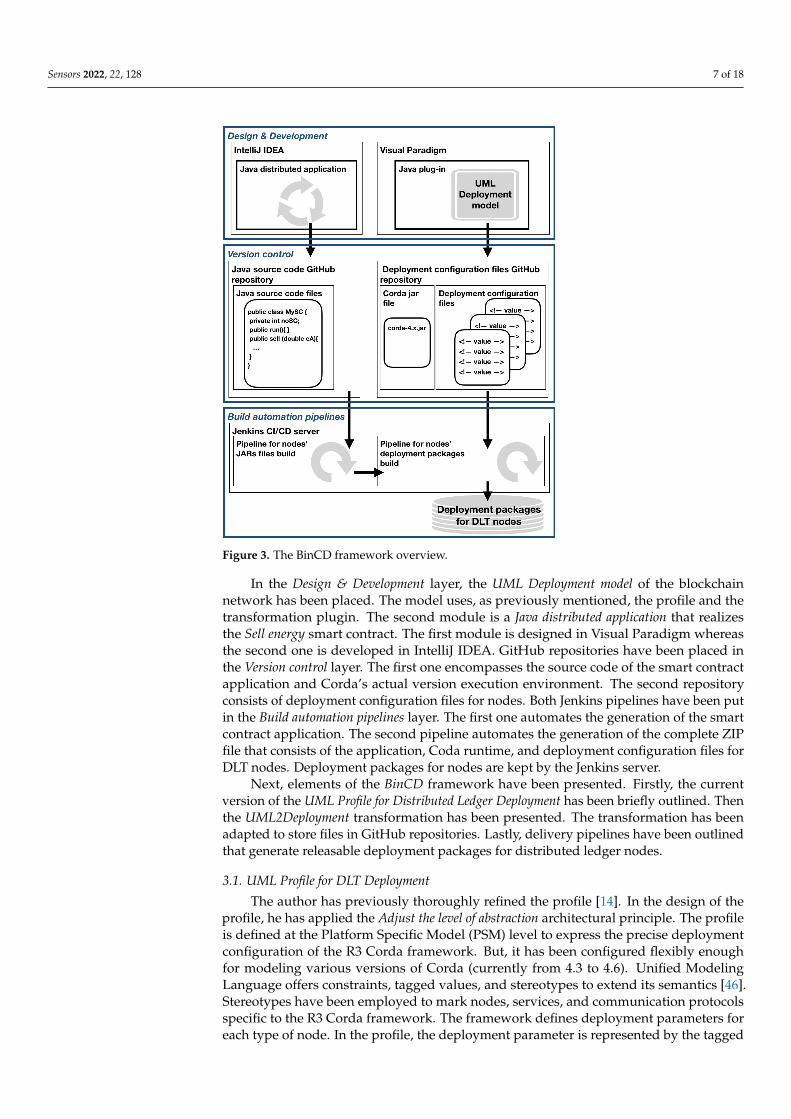
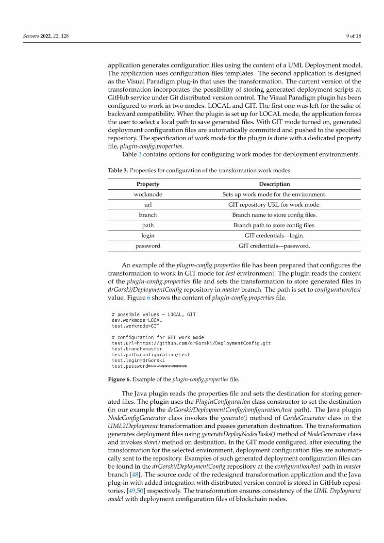
Table 3 contains options for configuring work modes for deployment environments.
Table 3. Properties for configuration of the transformation work modes.
Property Description
workmode Sets up work mode for the environment.
url GIT repository URL for work mode.
branch Branch name to store config files.
path Branch path to store config files.
login GIT credentials—login.
password GIT credentials—password.
An example of the plugin-config.properties file has been prepared that configures thetransformation to work in GIT mode for test environment. The plugin reads the contentof the plugin-config.properties file and sets the transformation to store generated files indrGorski/DeploymentConfig repository in master branch. The path is set to configuration/testvalue. Figure 6 shows the content of plugin-config.properties file.
Figure 6. Example of the plugin-config.properties file.
The Java plugin reads the properties file and sets the destination for storing gener-ated files. The plugin uses the PluginConfiguration class constructor to set the destination(in our example the drGorski/DeploymentConfig/configuration/test path). The Java pluginNodeConfigGenerator class invokes the generate() method of CordaGenerator class in theUML2Deployment transformation and passes generation destination. The transformationgenerates deployment files using generateDeployNodesTasks() method of NodeGenerator classand invokes store() method on destination. In the GIT mode configured, after executing thetransformation for the selected environment, deployment configuration files are automati-cally sent to the repository. Examples of such generated deployment configuration files canbe found in the drGorski/DeploymentConfig repository at the configuration/test path in masterbranch [48]. The source code of the redesigned transformation application and the Javaplug-in with added integration with distributed version control is stored in GitHub reposi-tories, [49,50] respectively. The transformation ensures consistency of the UML Deploymentmodel with deployment configuration files of blockchain nodes.
Sensors 2022, 22, 128 10 of 18
3.3. Deployment Pipelines
At this stage, the source codes of the application and implementation configurationsare managed in the version control system. The platform documentation describes thecontent of the node deployment package [51]:
• Corda run-time environment — corda-4.6.jar,• All needed Cordapps JARs in /cordapps subdirectory:
– cordapp-ecsm-contracts-0.1.jar,– cordapp-ecsm-workflows-0.1.jar,
• Node deployment configuration file — node.config.
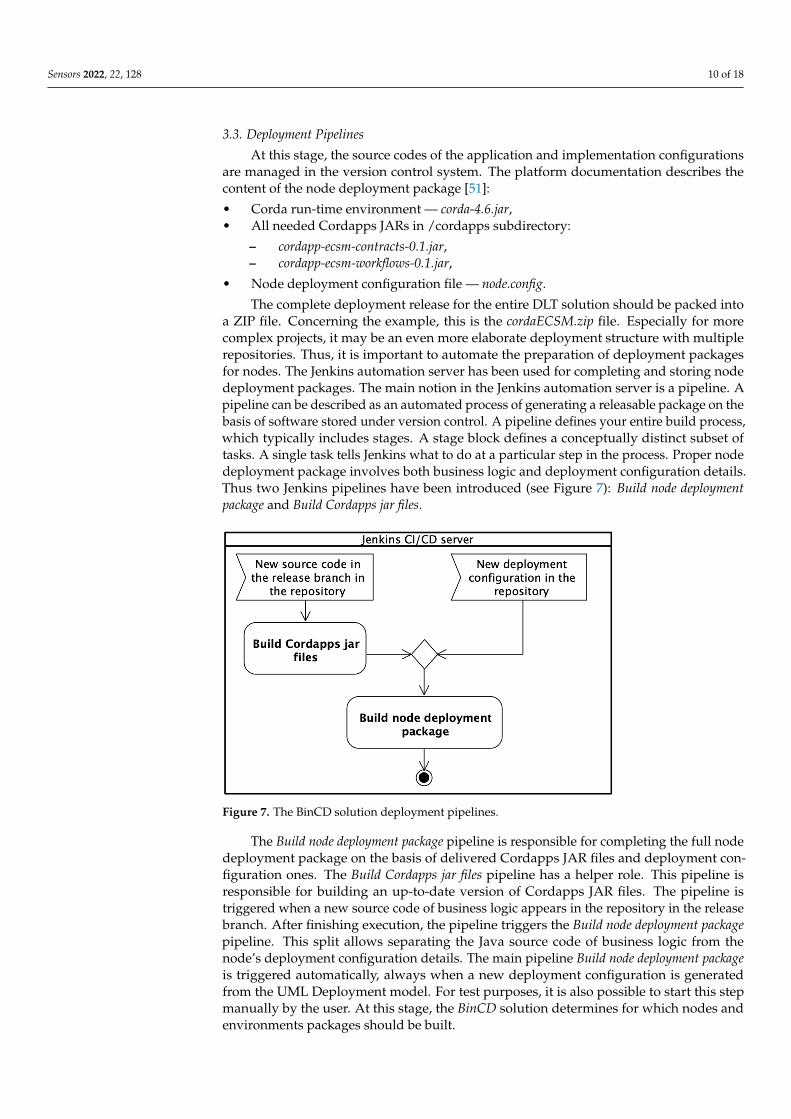
The complete deployment release for the entire DLT solution should be packed intoa ZIP file. Concerning the example, this is the cordaECSM.zip file. Especially for morecomplex projects, it may be an even more elaborate deployment structure with multiplerepositories. Thus, it is important to automate the preparation of deployment packagesfor nodes. The Jenkins automation server has been used for completing and storing nodedeployment packages. The main notion in the Jenkins automation server is a pipeline. Apipeline can be described as an automated process of generating a releasable package on thebasis of software stored under version control. A pipeline defines your entire build process,which typically includes stages. A stage block defines a conceptually distinct subset oftasks. A single task tells Jenkins what to do at a particular step in the process. Proper nodedeployment package involves both business logic and deployment configuration details.Thus two Jenkins pipelines have been introduced (see Figure 7): Build node deploymentpackage and Build Cordapps jar files.
Figure 7. The BinCD solution deployment pipelines.
The Build node deployment package pipeline is responsible for completing the full nodedeployment package on the basis of delivered Cordapps JAR files and deployment con-figuration ones. The Build Cordapps jar files pipeline has a helper role. This pipeline isresponsible for building an up-to-date version of Cordapps JAR files. The pipeline istriggered when a new source code of business logic appears in the repository in the releasebranch. After finishing execution, the pipeline triggers the Build node deployment packagepipeline. This split allows separating the Java source code of business logic from thenode’s deployment configuration details. The main pipeline Build node deployment packageis triggered automatically, always when a new deployment configuration is generatedfrom the UML Deployment model. For test purposes, it is also possible to start this stepmanually by the user. At this stage, the BinCD solution determines for which nodes andenvironments packages should be built.
Sensors 2022, 22, 128 11 of 18
The BinCD has two paths of selection:
• When config files are added/changes it will build new packages only for thechanged/added nodes,
• In case of changing the source code of Cordapps, new JAR files are built and all pack-ages for nodes and environments are prepared with existing deployment configurationbut new business logic.
Next, it has been shown the design of both pipelines.
3.3.1. Build Node Deployment Package Pipeline
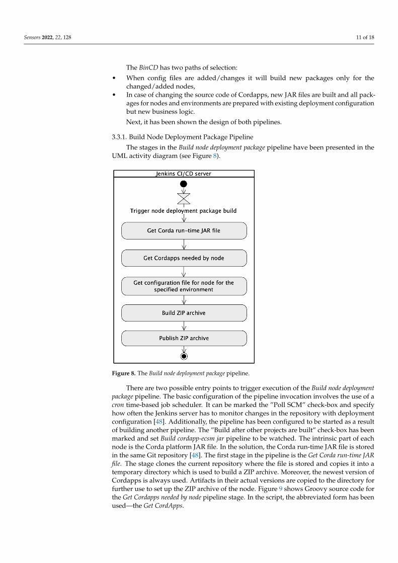
The stages in the Build node deployment package pipeline have been presented in theUML activity diagram (see Figure 8).
Figure 8. The Build node deployment package pipeline.
There are two possible entry points to trigger execution of the Build node deploymentpackage pipeline. The basic configuration of the pipeline invocation involves the use of acron time-based job scheduler. It can be marked the ”Poll SCM” check-box and specifyhow often the Jenkins server has to monitor changes in the repository with deploymentconfiguration [48]. Additionally, the pipeline has been configured to be started as a resultof building another pipeline. The ”Build after other projects are built” check-box has beenmarked and set Build cordapp-ecsm jar pipeline to be watched. The intrinsic part of eachnode is the Corda platform JAR file. In the solution, the Corda run-time JAR file is storedin the same Git repository [48]. The first stage in the pipeline is the Get Corda run-time JARfile. The stage clones the current repository where the file is stored and copies it into atemporary directory which is used to build a ZIP archive. Moreover, the newest version ofCordapps is always used. Artifacts in their actual versions are copied to the directory forfurther use to set up the ZIP archive of the node. Figure 9 shows Groovy source code forthe Get Cordapps needed by node pipeline stage. In the script, the abbreviated form has beenused—the Get CordApps.
Sensors 2022, 22, 128 12 of 18
Figure 9. Groovy source code for Get CordApps pipeline stage.
When the configuration files are stored in the Git repository they can be used by thepipeline during the node package build process. The configuration files are copied to theproper directory for further use to create a ZIP archive. Figure 10 depicts Groovy sourcecode for the Get configuration file for node for the specified environment pipeline stage. In thescript, the abbreviated form has been used – the Get config.
Figure 10. Groovy source code for the Get config stage in the pipeline.
At this stage, all needed files are collected and located in proper directories and thefinal ZIP package is compressed and archived for usage during node deployment. Figure 11presents Groovy source code for Build ZIP archive and Publish ZIP archive pipeline stages.
Figure 11. Groovy source code for Archive and publish node directory stages.
3.3.2. Build Cordapps Jar Files Pipeline
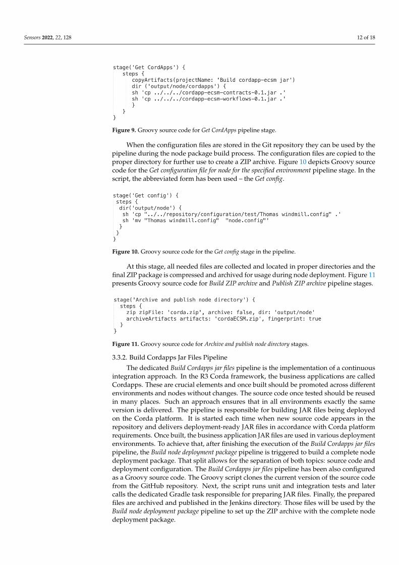
The dedicated Build Cordapps jar files pipeline is the implementation of a continuousintegration approach. In the R3 Corda framework, the business applications are calledCordapps. These are crucial elements and once built should be promoted across differentenvironments and nodes without changes. The source code once tested should be reusedin many places. Such an approach ensures that in all environments exactly the sameversion is delivered. The pipeline is responsible for building JAR files being deployedon the Corda platform. It is started each time when new source code appears in therepository and delivers deployment-ready JAR files in accordance with Corda platformrequirements. Once built, the business application JAR files are used in various deploymentenvironments. To achieve that, after finishing the execution of the Build Cordapps jar filespipeline, the Build node deployment package pipeline is triggered to build a complete nodedeployment package. That split allows for the separation of both topics: source code anddeployment configuration. The Build Cordapps jar files pipeline has been also configuredas a Groovy source code. The Groovy script clones the current version of the source codefrom the GitHub repository. Next, the script runs unit and integration tests and latercalls the dedicated Gradle task responsible for preparing JAR files. Finally, the preparedfiles are archived and published in the Jenkins directory. Those files will be used by theBuild node deployment package pipeline to set up the ZIP archive with the complete nodedeployment package.
Sensors 2022, 22, 128 13 of 18
Figure 12 shows the flow of events of the Build Cordapps jar files pipeline.
Figure 12. The UML activity diagram shows the Build Cordapps jar files pipeline.
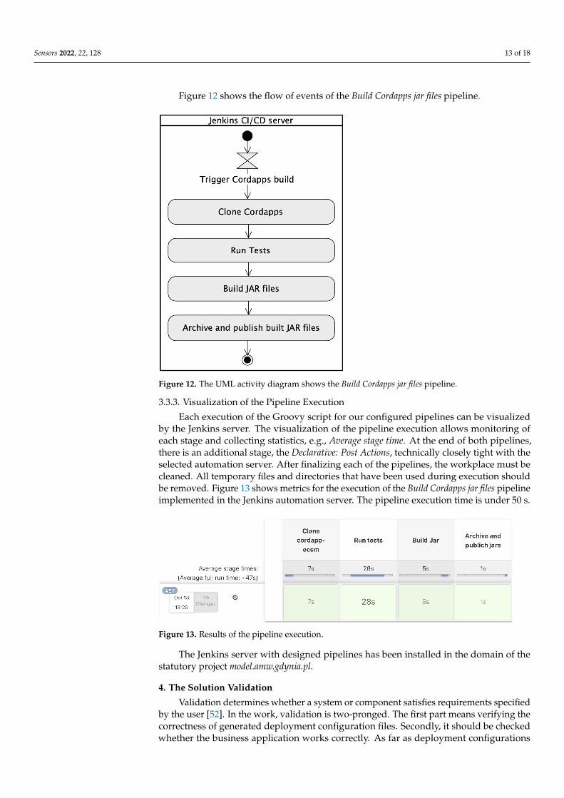
3.3.3. Visualization of the Pipeline Execution
Each execution of the Groovy script for our configured pipelines can be visualizedby the Jenkins server. The visualization of the pipeline execution allows monitoring ofeach stage and collecting statistics, e.g., Average stage time. At the end of both pipelines,there is an additional stage, the Declarative: Post Actions, technically closely tight with theselected automation server. After finalizing each of the pipelines, the workplace must becleaned. All temporary files and directories that have been used during execution shouldbe removed. Figure 13 shows metrics for the execution of the Build Cordapps jar files pipelineimplemented in the Jenkins automation server. The pipeline execution time is under 50 s.
Figure 13. Results of the pipeline execution.
The Jenkins server with designed pipelines has been installed in the domain of thestatutory project model.amw.gdynia.pl.
4. The Solution Validation
Validation determines whether a system or component satisfies requirements specifiedby the user [52]. In the work, validation is two-pronged. The first part means verifying thecorrectness of generated deployment configuration files. Secondly, it should be checkedwhether the business application works correctly. As far as deployment configurations

Sensors 2022, 22, 128 14 of 18
are concerned, the consistency of deployment scripts with the UML Deployment modelshould be verified. A single deployment configuration file and the corresponding UMLnode are considered. The UML node comprises tagged values, t ∈ T. The script containsdeployment configuration parameters, d ∈ D. The intersection of the two sets D and Tis denoted by D ∩ T, and is the set containing all elements of D that also belong to T orsimilarly, all elements of T that also belong to D. It means checking that the intersectionmeets the following Equation (1).
D ∩ T = D = T. (1)
The cardinality of both sets should be the same. The deployment configurationparameter d is an ordered pair, d = (nd, vd), where: nd is the name, and vd is the value of d.The tagged value t is an ordered pair, t = (nt, vt), where: nt is the name, and vt is the valueof t. For each d ∈ D must be t ∈ T with the same name and value (2).∧
d∈D
∨t∈T
(nd = nt) ∧ (vd = vt). (2)
Similarly, for each t ∈ T must be d ∈ D with the same name and value (3).∧t∈T
∨d∈D
(nt = nd) ∧ (vt = vd). (3)
In the current version, the functionality of the verification has been expanded bychecking the accordance of the ZIP package of deployment configuration files with theUML Deployment model. Figure 14 shows a source code that determines, which validationmode should be used.
Figure 14. Source code with the selection of validation mode.
The actual version recognizes what type of file was provided as input. In the case ofproviding the ZIP package, the validation application tries to find inside the archive thenode.config file, and validation is run against the extracted file. When the input is recognizedas a single configuration file, validation is run directly on the selected file. Ten test scenariosof the ECSM model have been designed to confirm the correctness of the transformation.Apart from verifying deployment configuration files, tests for the business application havebeen designed. The validation of the business application involves two kinds of tests: unitand integration. Unit tests are designed for individual methods in the business application,and integration tests verify the operation of the business application in blockchain nodesoperating in the test environment, e.g., selling energy between two nodes. A dedicated

Sensors 2022, 22, 128 15 of 18
the IOUContractTest class has been implemented for unit tests to verify rules in the smartcontract. Figure 15 depicts the test case for one of the smart contract verification rules.
Figure 15. The source code of the positive test case.
Integration tests go one step further and verify the end-to-end scenarios. The Driver-BasedTest class has been implemented for integration tests. During an integration test, twoblockchain nodes are configured and run. Next, the transaction is executed and committed.The test verifies whether the vaults of blockchain nodes store proper values of energysold/bought. Both unit and integration tests have been prepared and run for the ECSMsystem [53]. As a result of tests, the BinCD approach proved to work properly. Boththe model-to-code transformation and designed pipelines function as was intended. Theredesigned validation application has been stored in the GitHub repository [54].
5. Discussion and Limitations
The author has noticed that in the field of Continuous Delivery, there is a limitedamount of work done on the system design and build design [16]. Especially, distributedledger and blockchain technologies are new spheres for the introduction of ContinuousDelivery. Hence, modeling support has been incorporated into the BinCD solution forR3 Corda distributed ledger. Górski in [14] has focused on the Platform Specific Modelto represent the exact deployment configuration of the R3 Corda framework. Such anapproach lets the transformation rules be simpler and less prone to errors. On the otherhand, the profile is configured in such an elastic fashion that it embraces versions of theCorda platform from 4.3 to 4.6. Therefore, in the transformation, file templates have beenupdated by adding new deployment parameters. The approach is open for handling theconsecutive Corda platform versions. In the current work, version 4.6 of the Corda platformhas been used. In course of further work, the solution will be upgraded to encompassversions up to 4.8.
Applying the simplicity architectural principle has been aimed at gaining linearorder-of-growth of running time of our transformation. The complete running time of aprogram depends on two main metrics. These are the execution time of a statement and thefrequency of its invocation. The first is the feature of the operating environment, but thelatter is a property of the algorithm. As far as the frequency of executing each statementis concerned, the algorithm has been constructed to be a simple sequence of statements.One-dimensional dynamic collections like ArrayList as data structures have been used.As a consequence, it has been applied at most as a single for loop as a repetition controlstructure. Multi-dimensional data structures have been excluded to avoid nested repetitioncontrol structures. As a result, quadratic, cubic, or even exponential orders-of-growth havebeen eluded. In the current work, the number of tagged values in distributed ledger nodesdoubled. So, the doubling hypothesis has also been verified. The running time of theUML2Deployment transformation still is under one second. Another factor is the numberof DLT nodes. The performance analysis on bigger networks is still ahead. However,the estimation can be made. The distributed ledger network of the ECSM system, fortesting purposes, has five nodes and generation takes approximately one second. So, for
Sensors 2022, 22, 128 16 of 18
1000 DLT nodes, it may take about 3 min. As far as memory usage is concerned, localreference variables to objects of classes from Java and Corda packages have been mainlyused. So, the scope of visibility of those objects is very limited and quickly they becomethe interest of the garbage collector mechanism. The size of the Java collection to generatethe deployment configuration of each node has also been estimated. The String objectuses 40 bytes (object overhead, reference, hash, and padding) + (2c + 24) bytes for chararray, where c is the number of chars in the string. It was assumed that each tagged valueis 10 chars long. Reference to String object uses another 8 bytes. Thus it was obtainedestimation of 8 + 40 + 20 + 24 = 92 bytes per one tagged value. There are 107 taggedvalues in the DLT node so it is needed 9844 bytes for each node. It should be added another24 bytes for the collection object itself. The result is 9868 bytes for the data structure forstoring tagged values for a single node.
The runtime environment of the Corda platform corda-4.6.jar is needed to run Cor-dapps. The mentioned file can be downloaded from Corda’s official webpage, but thedecision has been made to store it on project internal resources to avoid any performanceor availability issues. The file should be hosted by a dedicated resource on which thereis control. It has been decided to not increase the technological stack and selected Gitrepository as a place to store and host Corda platform JAR for the CD pipeline purposes.But, it should be remembered that Git is not optimized for the storage of large binary files.It would be worth considering using a dedicated tool like Artifactory to store and hostsuch files. That may speed up the single pipeline execution.
6. Conclusions and Future Work
The paper introduces the continuous delivery approach for generating completenode deployment packages for a blockchain system. Moreover, the solution offers UMLmodeling support for the Deployment architectural view. The work uses UML Profile forDistributed Ledger Deployment at the Platform Specific Model for R3 Corda distributed ledgerin version 4.6. The modeling support in the continuous delivery process has been included.The generation of complete deployment packages for the R3 Corda distributed ledger hasbeen automated. Both smart contract application and deployment configuration files areplaced in GitHub repositories under version control. The transformation application hasbeen integrated with the Jenkins open source automation server, which uses deploymentconfiguration files and the smart contract application stored in GitHub repositories. It isplanned to expand the continuous delivery approach. Currently, the framework is ableto generate releasable deployment packages. Additionally, it concentrates mainly on theDeployment view of the distributed ledger design. It is planned to enhance the solution byenabling the selection of the blockchain platform. The considered platform for inclusion inthe approach is the HyperLedger Fabric. More attention is going to be put to the sourcecode and test generation for smart contracts.To achieve that, the modeling support for thebusiness application should also be added. This work moves toward the complete solutionthat will combine elements from all perspectives of the 1+5 architectural views model.
Funding: The research has been conducted within the Architectural views model of cooperating IT systemsproject, financed by the statutory funds of the Department of Computer Science, PNA.
Data Availability Statement: Not applicable.
Conflicts of Interest: The author declares no conflict of interest.
References1. The Agile Manifesto. Principles behind the Agile Manifesto. Available online: agilemanifesto.org/principles.html (accessed on
18 November 2021).2. A Successful Git Branching Model. Available online: nvie.com/posts/a-successful-git-branching-model/ (accessed on
18 November 2021).3. Powell, R.; Stahnke, M. The 2020 State of Software Delivery. Available online: circleci.com/resources/2020-state-of-software-
delivery/ (accessed on 18 November 2021).
Sensors 2022, 22, 128 17 of 18
4. Humble, J.; Farley, D. Continuous Delivery: Reliable Software Releases through Build, Test, and Deployment Automation, 1st ed.;Addison-Wesley Professional: Crawfordsville, IN, USA, 2010.
5. IEEE Std 2675-2021; IEEE Standard for DevOps: Building Reliable and Secure Systems Including Application Build, Package, andDeployment; IEEE: New York, NY, USA, 2021; pp. 1–91. Available online: https://ieeexplore.ieee.org/servlet/opac?punumber=9415474 (accessed on 18 November 2021). [CrossRef]
6. Shahin, M.; Babar, M.A.; Zhu, L. Continuous Integration, Delivery and Deployment: A Systematic Review on Approaches, Tools,Challenges and Practices. IEEE Access 2017, 5, 3909–3943. [CrossRef]
7. Xu, X.; Weber, I.; Staples, M. Architecture for Blockchain Applications; Springer: Cham, Switzerland, 2019; pp. 5–7. [CrossRef]8. Gramoli, V. From blockchain consensus back to Byzantine consensus. Future Gener. Comput. Syst. 2020, 107, 760–769. [CrossRef]9. Nguyen, C.T.; Hoang, D.T.; Nguyen, D.N.; Niyato, D.; Nguyen, H.T.; Dutkiewicz, E. Proof-of-Stake Consensus Mechanisms for
Future Blockchain Networks: Fundamentals, Applications and Opportunities. IEEE Access 2019, 7, 85727–85745. [CrossRef]10. Oyinloye, D.P.; Damilare, P.; Teh, J.S.; Jamil, N.; Moatsum, A. Blockchain Consensus: An Overview of Alternative Protocols.
Symmetry 2021, 13, 1363. [CrossRef]11. Ma, J.; Jo, Y.; Park, C. PeerBFT: Making Hyperledger Fabric’s Ordering Service Withstand Byzantine Faults. IEEE Access 2020, 8,
217255–217267. [CrossRef]12. Chowdhury, M.J.M.; Ferdous, M.S.; Biswas, K.; Chowdhury, N.; Kayes, A.S.M.; Alazab, M.; Watters, P. A Comparative Analysis
of Distributed Ledger Technology Platforms. IEEE Access 2019, 7, 167930–167943. [CrossRef]13. Górski, T. Towards Continuous Deployment for Blockchain. Appl. Sci. 2021, 11, 11745. [CrossRef]14. Górski, T. The 1+5 Architectural Views Model in Designing Blockchain and IT System Integration Solutions. Symmetry 2021, 13,
2000. [CrossRef]15. Górski, T.; Bednarski, J. Applying Model-Driven Engineering to Distributed Ledger Deployment. IEEE Access 2020, 8, 118245–
118261. [CrossRef]16. Laukkanen, E.; Itkonen, J.; Lassenius, C. Problems, causes and solutions when adopting continuous delivery—A systematic
literature review. Inf. Softw. Technol. 2017, 82, 55–79. [CrossRef]17. Lima, J.A.P.; Vergilio, S.R. Test Case Prioritization in Continuous Integration environments: A systematic mapping study. Inf.
Softw. Technol. 2020, 121, 106268. [CrossRef]18. Yang, Y.; Pan, C.; Li, Z.; Zhao, R. Adaptive Reward Computation in Reinforcement Learning-Based Continuous Integration
Testing. IEEE Access 2021, 9, 36674–36688. [CrossRef]19. Yu, L.; Alégroth, E.; Chatzipetrou, P.; Gorschek, T. Utilising CI environment for efficient and effective testing of NFRs. Inf. Softw.
Technol. 2020, 117, 106199. [CrossRef]20. Abdalkareem, R.; Mujahid, S.; Shihab, E.; Rilling, J. Which Commits Can Be CI Skipped? IEEE Trans. Softw. Eng. 2021, 47, 448–463.
[CrossRef]21. Debroy, V.; Miller, S. Overcoming Challenges With Continuous Integration and Deployment Pipelines: An Experience Report
From a Small Company. IEEE Softw. 2020, 37, 21–29. [CrossRef]22. Gallaba, K.; McIntosh, S. Use and Misuse of Continuous Integration Features: An Empirical Study of Projects That (Mis)Use
Travis CI. IEEE Trans. Softw. Eng. 2020, 46, 33–50. [CrossRef]23. Saidani, I.; Ouni, A.; Mkaouer, M.W.; Palomba, F. On the impact of Continuous Integration on refactoring practice: An exploratory
study on TravisTorrent. Inf. Softw. Technol. 2021, 138, 106618. [CrossRef]24. Seth, N.; Khare, R. ACI (automated Continuous Integration) using Jenkins: Key for successful embedded Software development.
In Proceedings of the 2015 2nd International Conference on Recent Advances in Engineering & Computational Sciences (RAECS),Chandigarh, India, 21–22 December 2015; pp. 1–6. [CrossRef]
25. Mysari, S.; Bejgam, V. Continuous Integration and Continuous Deployment Pipeline Automation Using Jenkins Ansible. InProceedings of the 2020 International Conference on Emerging Trends in Information Technology and Engineering (ic-ETITE),Vellore, India, 24–25 February 2020; pp. 1–4. [CrossRef]
26. Leite, L.; Pinto, G.; Kon, F.; Meirelles, P. The organization of software teams in the quest for continuous delivery: A groundedtheory approach. Inf. Softw. Technol. 2021, 139, 106672. [CrossRef]
27. Monrat, A.A.; Schelén, O.; Andersson, K. A Survey of Blockchain From the Perspectives of Applications, Challenges, andOpportunities. IEEE Access 2019, 7, 117134–117151. [CrossRef]
28. Al-Jaroodi, J.; Mohamed, N. Blockchain in Industries: A Survey. IEEE Access 2019, 7, 36500–36515. [CrossRef]29. Ismail, L.; Materwala, H.; Zeadally, S. Lightweight Blockchain for Healthcare. IEEE Access 2019, 7, 149935–149951. [CrossRef]30. Shahnaz, A.; Qamar, U.; Khalid, A. Using Blockchain for Electronic Health Records. IEEE Access 2019, 7, 147782–147795. [CrossRef]31. Saxena, S.; Farag, H.E.Z.; Brookson, A.; Turesson, H.; Kim, H. A Permissioned Blockchain System to Reduce Peak Demand in
Residential Communities via Energy Trading: A Real-World Case Study. IEEE Access 2021, 9, 5517–5530. [CrossRef]32. Hyperlegder Fabric. Available online: www.hyperledger.org/use/fabric (accessed on 18 November 2021).33. Jamil, F.; Iqbal, N.; Imran; Ahmad, S.; Kim, D. Peer-to-Peer Energy Trading Mechanism Based on Blockchain and Machine
Learning for Sustainable Electrical Power Supply in Smart Grid. IEEE Access 2021, 9, 39193–39217. [CrossRef]34. Ozkaya, M.; Erata, F. A survey on the practical use of UML for different software architecture viewpoints. Inf. Softw. Technol.
2020, 121, 106275. [CrossRef]

Sensors 2022, 22, 128 18 of 18
35. Chavez, H.M.; Shen, W.; France, R.B.; Mechling, B.A.; Li, G. An Approach to Checking Consistency between UML Class Modeland Its Java Implementation. IEEE Trans. Softw. Eng. 2016, 42, 322–344. [CrossRef]
36. Lu, H.; Wang, S.; Yue, T.; Ali, S.; Nygård, J.F. Automated Refactoring of OCL Constraints with Search. IEEE Trans. Softw. Eng.2019, 45, 148–170. [CrossRef]
37. Assunção, W.K.G.; Vergilio, S.R.; Lopez-Herrejon, R.E. Automatic extraction of product line architecture and feature models fromUML class diagram variants. Inf. Softw. Technol. 2020, 117, 106198. [CrossRef]
38. Arora, V.; Singh, M.; Bhatia, R. Orientation-based Ant colony algorithm for synthesizing the test scenarios in UML activitydiagram. Inf. Softw. Technol. 2020, 123, 106292. [CrossRef]
39. Arcaini, P.; Gargantini, A.; Riccobene, E. Decomposition-Based Approach for Model-Based Test Generation. IEEE Trans. Softw.Eng. 2019, 45, 507–520. [CrossRef]
40. Abouzahra, A.; Sabraoui, A.; Afdel, K. Model composition in Model Driven Engineering: A systematic literature review. Inf.Softw. Technol. 2020, 125, 106316. [CrossRef]
41. Moradi, H.; Zamani, B.; Zamanifar, K. CaaSSET: A Framework for Model-Driven Development of Context as a Service. FutureGener. Comput. Syst. 2020, 105, 61–95. [CrossRef]
42. Basciani, F.; D’Emidio, M.; Ruscio, D.D.; Frigioni, D.; Iovino, L.; Pierantonio, A. Automated Selection of Optimal ModelTransformation Chains via Shortest-Path Algorithms. IEEE Trans. Softw. Eng. 2020, 46, 251–279. [CrossRef]
43. Panach, J.I.; Dieste, Ó.; Marín, B.; España, S.; Vegas, S.; Pastor, Ó.; Juristo, N. Evaluating Model-Driven Development Claims withRespect to Quality: A Family of Experiments. IEEE Trans. Softw. Eng. 2021, 47, 130–145. [CrossRef]
44. Zou, W.; Lo, D.; Kochhar, P.S.; Le, X.D.; Xia, X.; Feng, Y.; Chen, Z.; Xu, B. Smart Contract Development: Challenges andOpportunities. IEEE Trans. Softw. Eng. 2021, 47, 2084–2106. [CrossRef]
45. Gao, Z.; Jiang, L.; Xia, X.; Lo, D.; Grundy, J. Checking Smart Contracts with Structural Code Embedding. IEEE Trans. Softw. Eng.2020, 47, 2874–2891. [CrossRef]
46. Pender, T. Customizing UML Using Profiles. In UML Bible; Wiley Publishing, Inc.: Indianapolis, IN, USA, 2003; pp. 687–723.47. Repository of the UML Profile for Distributed Ledger Deployment. Available online: github.com/drGorski/UMLProfileForDLT
(accessed on 18 November 2021).48. Repository of the Deployment Configuration. Available online: github.com/drGorski/DeploymentConfig (accessed on 18
November 2021).49. Repository of the project of the UML2Deployment Transformation. Available online: github.com/drGorski/UML2Deployment
(accessed on 18 November 2021).50. Repository of the UML2Deployment Plugin Transformation. Available online: github.com/drGorski/UML2DeploymentPlugin
(accessed on 18 November 2021).51. Documentation for Corda Enterprise 4.6 Version. Available online: https://docs.corda.net/docs/corda-enterprise/4.6.html
(accessed on 18 November 2021).52. IEEE Std 610.12-1990; IEEE Standard Glossary of Software Engineering Terminology; IEEE: New York, NY, USA, 1990; pp. 1–84.
Available online: ieeexplore.ieee.org/servlet/opac?punumber=2238 (accessed on 18 November 2021). [CrossRef]53. Repository of the ECSM Implementation. Available online: github.com/drGorski/renewableEnergyBlockchain (accessed on
18 November 2021).54. Repository of the Transformation Validation Project. Available online: github.com/drGorski/UML2DeploymentCheck (accessed
on 18 November 2021).
Copyright © 2022 FDOKUMEN