Continuous cell washing and mixing driven by an ultrasound standing wave within a microfluidic...
7
Continuous cell washing and mixing driven by an ultrasound standing wave within a microfluidic channel{{ Jeremy J. Hawkes,* a Robert W. Barber, b David R. Emerson b and W. Terence Coakley c a School of Chemical Engineering and Analytical Science, The University of Manchester, PO Box 88, Sackville Street, Manchester, UK M60 1QD. E-mail: [email protected]; Tel: 144 161 306 8884 b Centre for Microfluidics and Microsystems Modelling, CCLRC Daresbury Laboratory, Daresbury, Warrington, Cheshire, UK WA4 4AD. E-mail: [email protected]; [email protected]; Tel: 144 1925 603221 c School of Biosciences, Cardiff University, Cardiff, UK CF10 3TL. E-mail: [email protected]; Tel: 144 29 20874287 Received 2nd June 2004, Accepted 6th September 2004 First published as an Advance Article on the web 27th September 2004 Ultrasound standing wave radiation force and laminar flow have been used to transfer yeast cells from one liquid medium to another (washing) by a continuous field-flow fractionation (FFF) approach. Two co-flowing streams, a cell-free suspending phase (flow rate w 50% of the total flow-through volume) and a yeast suspension, were introduced parallel to the nodal plane of a 3 MHz standing wave resonator. The resonator was fabricated to have a single pressure nodal plane at the centre line of the chamber. Laminar flow ensured a stable interface was maintained as the two suspending phases flowed through the sound field. Initiation of the ultrasound transferred cells to the cell-free phase within 0.5 s. This particle transfer procedure circumvents the pellet formation and re-suspension steps of centrifuge based washing procedures. In addition, fluid mixing was demonstrated in the same chamber at higher sound pressures. The channel operates under negligible back- pressure (cross-section, 0.25 6 10 mm) and with only one flow convergence and one flow division step, the channel cannot be easily blocked. The force acting on the cells is small; less than that experienced in a centrifuge generating 100g. The acoustically-driven cell transfer and mixing procedures described may be particularly appropriate for the increasingly complex operations required in molecular biology and microbiology and especially for their conversion to continuous flow processes. 1 Introduction 1.1 Cell washing and mixing applications Cell washing and mixing procedures are required in many molecular biology and microbiology protocols. Taking a plasmid DNA extraction as a typical example, the procedure includes seven medium changes with most steps requiring centrifugation for up to 10 min and pellet re-suspension or surface binding/ washing treatments using multiple media with mixing or exchange. 1 While significant attention has been directed towards the problem of mixing in microfluidic channels, 2 progress towards micro-scale procedures and non-robotic-automation for analytical and processing technology is slowed by the different handling needs of fluids at the macro- and micro-scales. We report here on a technology that takes full advantage of the laminar flow properties of micro-scale fluidics and combines this with ultrasound to create a system for either washing cells or mixing fluids, of potential application to many fields. 1.2 Ultrasound cell manipulation In an ultrasound standing wave, cells or particles in suspension experience a number of forces. In the present paper, we focus on the principle acoustic force, F us (eqn. (1)), which generally drives cells towards the pressure nodal plane. As described by Gould and Coakley, 3 the principle acoustic force is given by: F us ~{ P 2 0 V p b f p 2l 5r p {2r f 2r p zr f { b p b f ! sin 4pz l (1) where P 0 is the peak sound pressure, r p and r f are the particle and suspending fluid densities, respectively, b p and b f are the compressibilities of the particle and fluid, l is the wavelength of sound in the suspending phase, V p is the particle volume and z is the distance normal to the pressure node. Single half-wavelength continuous flow filtration and separation systems have been developed by Mandralis and Feke 4 and Yasuda. 5 Unlike larger multi-wavelength filters, 6,7 which operate by forming clumps, half-wavelength filters produce a single focused band of particles (without the use of hydrodynamic focusing techniques 8 ) in highly controllable laminar flow conditions that even allow filtration of a single particle. This methodology has been further advanced by Hawkes et al. 9,10 to produce a smaller system operating at higher frequencies to avoid the potentially destructive effects of cavitation. The approach is now incorporated into a silicon- based system. 11 An alternative use of the high frequency methodology has been utilised by Gherardini et al. 12 to position cells within a gel. In the present paper, experimental and CFD results introduce two further developments of the half-wavelength approach; in the first, cells are transferred from one liquid medium to another without the need for a concentration (pellet { Electronic supplementary information (ESI) available: movie of cell washing showing experimental visualisation of cell transfer, pdf showing CFD predictions of sodium fluorescein diffusion across the channel at a high and low flow rate. See http://www.rsc.org/suppdata/ lc/b4/b408045a/ { The contents of this paper include material subject to Crown Copyright 2004 Dstl. DOI: 10.1039/b408045a 446 Lab Chip , 2004, 4 , 446–452 This journal is ß The Royal Society of Chemistry 2004 MINIATURISATION FOR CHEMISTRY, BIOLOGY & BIOENGINEERING
-
Upload
independent -
Category
Documents
-
view
2 -
download
0
Transcript of Continuous cell washing and mixing driven by an ultrasound standing wave within a microfluidic...
Continuous cell washing and mixing driven by an ultrasound
standing wave within a microfluidic channel{{
Jeremy J. Hawkes,*a Robert W. Barber,b David R. Emersonb and W. Terence Coakleyc
a School of Chemical Engineering and Analytical Science, The University of Manchester,
PO Box 88, Sackville Street, Manchester, UK M60 1QD.
E-mail: [email protected]; Tel: 144 161 306 8884b Centre for Microfluidics and Microsystems Modelling, CCLRC Daresbury Laboratory,
Daresbury, Warrington, Cheshire, UK WA4 4AD. E-mail: [email protected];
[email protected]; Tel: 144 1925 603221c School of Biosciences, Cardiff University, Cardiff, UK CF10 3TL.
E-mail: [email protected]; Tel: 144 29 20874287
Received 2nd June 2004, Accepted 6th September 2004
First published as an Advance Article on the web 27th September 2004
Ultrasound standing wave radiation force and laminar flow have been used to transfer yeast cells from one
liquid medium to another (washing) by a continuous field-flow fractionation (FFF) approach. Two co-flowing
streams, a cell-free suspending phase (flow rate w 50% of the total flow-through volume) and a yeast
suspension, were introduced parallel to the nodal plane of a 3 MHz standing wave resonator. The resonator
was fabricated to have a single pressure nodal plane at the centre line of the chamber. Laminar flow ensured a
stable interface was maintained as the two suspending phases flowed through the sound field. Initiation of the
ultrasound transferred cells to the cell-free phase within 0.5 s. This particle transfer procedure circumvents the
pellet formation and re-suspension steps of centrifuge based washing procedures. In addition, fluid mixing was
demonstrated in the same chamber at higher sound pressures. The channel operates under negligible back-
pressure (cross-section, 0.25 6 10 mm) and with only one flow convergence and one flow division step, the
channel cannot be easily blocked. The force acting on the cells is small; less than that experienced in a
centrifuge generating 100g. The acoustically-driven cell transfer and mixing procedures described may be
particularly appropriate for the increasingly complex operations required in molecular biology and
microbiology and especially for their conversion to continuous flow processes.
1 Introduction
1.1 Cell washing and mixing applications
Cell washing and mixing procedures are required in manymolecular biology and microbiology protocols. Taking a plasmidDNA extraction as a typical example, the procedure includesseven medium changes with most steps requiring centrifugationfor up to 10 min and pellet re-suspension or surface binding/washing treatments using multiple media with mixing orexchange.1 While significant attention has been directed towardsthe problem of mixing in microfluidic channels,2 progresstowards micro-scale procedures and non-robotic-automationfor analytical and processing technology is slowed by thedifferent handling needs of fluids at the macro- and micro-scales.We report here on a technology that takes full advantage of thelaminar flow properties of micro-scale fluidics and combines thiswith ultrasound to create a system for either washing cells ormixing fluids, of potential application to many fields.
1.2 Ultrasound cell manipulation
In an ultrasound standing wave, cells or particles in suspensionexperience a number of forces. In the present paper, we focus
on the principle acoustic force, Fus (eqn. (1)), which generallydrives cells towards the pressure nodal plane. As described byGould and Coakley,3 the principle acoustic force is given by:
Fus~{P2
0Vpbf p
2l
� �5rp{2rf
� �2rpzrf
� � {bp
bf
!sin
4pz
l
� �(1)
where P0 is the peak sound pressure, rp and rf are the particleand suspending fluid densities, respectively, bp and bf are thecompressibilities of the particle and fluid, l is the wavelength ofsound in the suspending phase, Vp is the particle volume andz is the distance normal to the pressure node.
Single half-wavelength continuous flow filtration andseparation systems have been developed by Mandralis andFeke4 and Yasuda.5 Unlike larger multi-wavelength filters,6,7
which operate by forming clumps, half-wavelength filtersproduce a single focused band of particles (without the useof hydrodynamic focusing techniques8) in highly controllablelaminar flow conditions that even allow filtration of a singleparticle. This methodology has been further advanced byHawkes et al.9,10 to produce a smaller system operating athigher frequencies to avoid the potentially destructive effectsof cavitation. The approach is now incorporated into a silicon-based system.11 An alternative use of the high frequencymethodology has been utilised by Gherardini et al.12 toposition cells within a gel.
In the present paper, experimental and CFD resultsintroduce two further developments of the half-wavelengthapproach; in the first, cells are transferred from one liquidmedium to another without the need for a concentration (pellet
{ Electronic supplementary information (ESI) available: movie of cellwashing showing experimental visualisation of cell transfer, pdfshowing CFD predictions of sodium fluorescein diffusion across thechannel at a high and low flow rate. See http://www.rsc.org/suppdata/lc/b4/b408045a/{ The contents of this paper include material subject to CrownCopyright 2004 Dstl.D
OI:
10
.10
39
/b4
08
04
5a
4 4 6 L a b C h i p , 2 0 0 4 , 4 , 4 4 6 – 4 5 2 T h i s j o u r n a l i s � T h e R o y a l S o c i e t y o f C h e m i s t r y 2 0 0 4
M I N I A T U R I S A T I O N F O R C H E M I S T R Y , B I O L O G Y & B I O E N G I N E E R I N G
formation) step, as required during centrifugal washingprocedures. In the second, cells are efficiently mixed withinthe suspending fluid.
Ultrasonic mixing is an established macro-scale techniquethat uses cavitation effects produced by low frequencyultrasound (v1 MHz) to mix the fluids. Similar techniquescan also be applied to micro-systems. For example, Yanget al.13 employed a frequency of 60 kHz to provide fluid mixingin a micro-chamber. However, cavitation produces celldisruption and therefore low frequencies are generallyinappropriate for delicate manipulation of cell suspensions.Yasuda14 has reported the use of 3.5 MHz sound to mix asuspension of red blood cells with a cell-free liquid andobserved negligible cell disruption. He also observed mixing oftwo fluids while holding cells at the nodes of a standing wave.We have seen similar fluid mixing in our chamber at highvoltages and extended measurements to lower voltages wherewe identified a power dependent switch between mixing andseparating conditions.
1.3 Cell washing: principle of operation
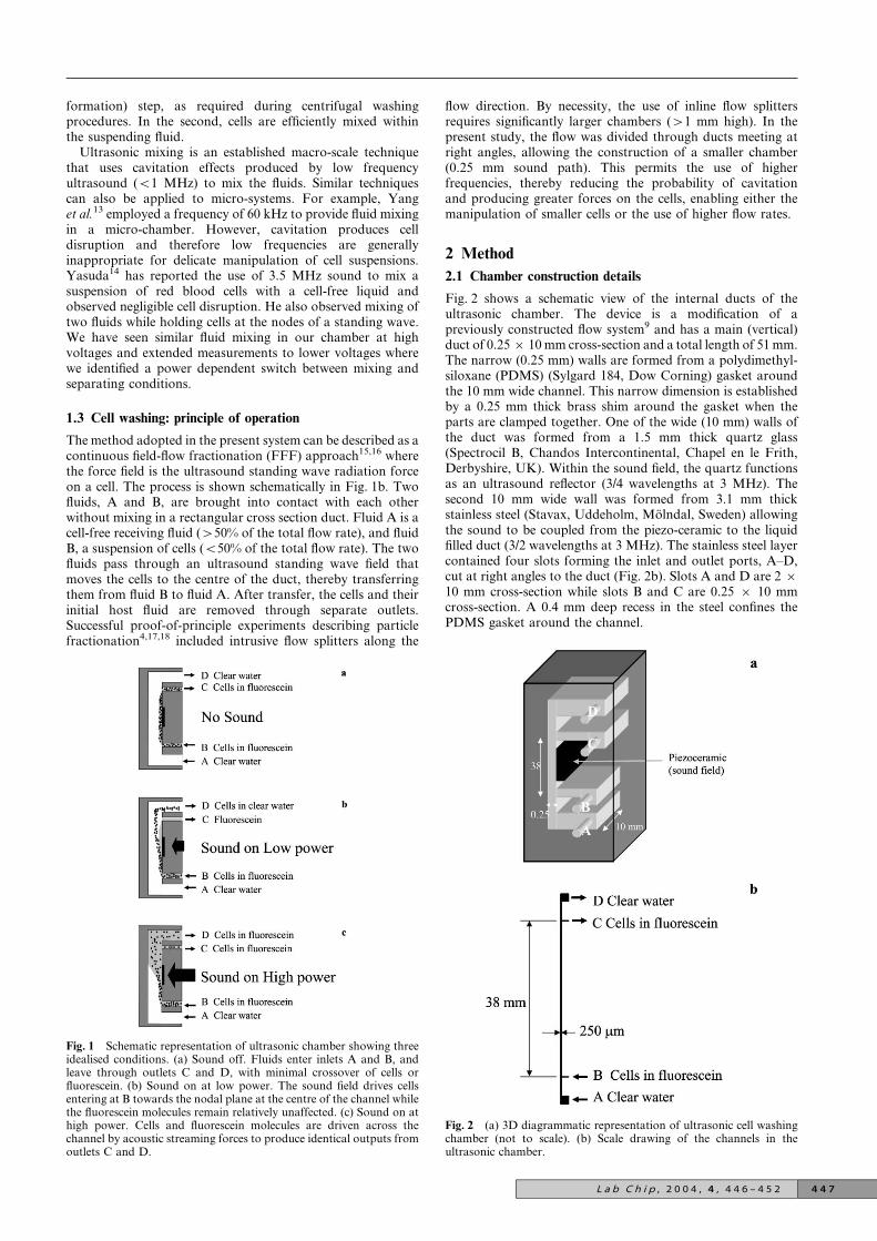
The method adopted in the present system can be described as acontinuous field-flow fractionation (FFF) approach15,16 wherethe force field is the ultrasound standing wave radiation forceon a cell. The process is shown schematically in Fig. 1b. Twofluids, A and B, are brought into contact with each otherwithout mixing in a rectangular cross section duct. Fluid A is acell-free receiving fluid (w50% of the total flow rate), and fluidB, a suspension of cells (v50% of the total flow rate). The twofluids pass through an ultrasound standing wave field thatmoves the cells to the centre of the duct, thereby transferringthem from fluid B to fluid A. After transfer, the cells and theirinitial host fluid are removed through separate outlets.Successful proof-of-principle experiments describing particlefractionation4,17,18 included intrusive flow splitters along the
flow direction. By necessity, the use of inline flow splittersrequires significantly larger chambers (w1 mm high). In thepresent study, the flow was divided through ducts meeting atright angles, allowing the construction of a smaller chamber(0.25 mm sound path). This permits the use of higherfrequencies, thereby reducing the probability of cavitationand producing greater forces on the cells, enabling either themanipulation of smaller cells or the use of higher flow rates.
2 Method
2.1 Chamber construction details
Fig. 2 shows a schematic view of the internal ducts of theultrasonic chamber. The device is a modification of apreviously constructed flow system9 and has a main (vertical)duct of 0.25 6 10 mm cross-section and a total length of 51 mm.The narrow (0.25 mm) walls are formed from a polydimethyl-siloxane (PDMS) (Sylgard 184, Dow Corning) gasket aroundthe 10 mm wide channel. This narrow dimension is establishedby a 0.25 mm thick brass shim around the gasket when theparts are clamped together. One of the wide (10 mm) walls ofthe duct was formed from a 1.5 mm thick quartz glass(Spectrocil B, Chandos Intercontinental, Chapel en le Frith,Derbyshire, UK). Within the sound field, the quartz functionsas an ultrasound reflector (3/4 wavelengths at 3 MHz). Thesecond 10 mm wide wall was formed from 3.1 mm thickstainless steel (Stavax, Uddeholm, Molndal, Sweden) allowingthe sound to be coupled from the piezo-ceramic to the liquidfilled duct (3/2 wavelengths at 3 MHz). The stainless steel layercontained four slots forming the inlet and outlet ports, A–D,cut at right angles to the duct (Fig. 2b). Slots A and D are 2 610 mm cross-section while slots B and C are 0.25 6 10 mmcross-section. A 0.4 mm deep recess in the steel confines thePDMS gasket around the channel.
Fig. 1 Schematic representation of ultrasonic chamber showing threeidealised conditions. (a) Sound off. Fluids enter inlets A and B, andleave through outlets C and D, with minimal crossover of cells orfluorescein. (b) Sound on at low power. The sound field drives cellsentering at B towards the nodal plane at the centre of the channel whilethe fluorescein molecules remain relatively unaffected. (c) Sound on athigh power. Cells and fluorescein molecules are driven across thechannel by acoustic streaming forces to produce identical outputs fromoutlets C and D.
Fig. 2 (a) 3D diagrammatic representation of ultrasonic cell washingchamber (not to scale). (b) Scale drawing of the channels in theultrasonic chamber.
L a b C h i p , 2 0 0 4 , 4 , 4 4 6 – 4 5 2 4 4 7
Sound was produced by a PZ26 piezo-ceramic plate(Ferroperm, Krisgard, Denmark) with dimensions 30 630 6 0.67 mm (i.e. 3 MHz fundamental resonance thickness).Electrodes on the piezo-ceramic were etched9 to reduce theactive area to 10 6 20 mm. The transducer was then attachedby epoxy resin to the outer face of the stainless steel layerhalfway between slots B and C (see Fig. 1 and 2).
2.2 Electrical drive
A sinusoidal voltage of 18 Vp–p (unless otherwise stated) wasapplied from an amplifier (Model 240L, ENI, Rochester, NY)to the piezo-ceramic at a frequency of 2.96 MHz produced by asignal generator (Hewlett Packard 3326A). The phase anglebetween current and voltage, measured with an Agilent(54621A) oscilloscope, was a minimum at this frequency.
2.3 Sample preparations
De-gassed water was produced by boiling for 2 min, sealing inan airtight screw cap bottle and leaving to cool to roomtemperature before use. Although not essential, degassed waterwas used to reduce the possibility of bubble formation causedby temperature gradients at the walls of the tubing. Dried yeast(Boots, Nottingham, UK) was reconstituted in degassed watercontaining 1 mM sodium fluorescein (MW 376; approximately0.45 nm radius) (Sigma). The absence of nutrients preventedyeast cell budding and division, thus maintaining an averagecell radius close to 2.5 mm.7 Microscope observations suggestthere is little variation in the radius of the cells, with most beingbetween 2 and 3 mm. The suspension was constantly stirred tomaintain homogeneity and break up any clumps.
2.4 Flow system
The system is usually orientated so that the flow direction isvertically upwards. In this orientation, gravity cannot transportcells from the nodal line and any bubbles that enter will easilypass through the system without becoming trapped. The devicehas two inlets (A and B) which meet the main duct at rightangles allowing the fluids to converge and pass 38 mm along themain duct where they are exposed to the sound field (20 mmlong). The fluid is then divided and leaves through two outletducts (C and D). In order to obtain an output from D that wasapparently clear of sodium fluorescein by visual inspection, theflow rate through D was reduced to y90% of the inflow at A.
Fluid was transported through the chamber with near pulse-free-flow using a combination of peristaltic pumps (GilsonMini-puls 3) and air-damped pulse smoothing consisting ofpipettes and narrow tubing as described previously by Hawkesand Coakley.9 The following flow rates were used unless statedotherwise, but in all cases the ratio of flow rates betweenchannels remained constant. Pumps were placed on outlet C(flow rate, FRC ~ 2.6 ml min21), outlet D (FRD ~7.6 ml min21) and inlet B (FRB ~ 1.7 ml min21). Inlet Awas connected without a pump to a reservoir of cell-free water(fluid A) (FRA ~ 8.5 ml min21). The total volumetric flow ratethrough the sound field was 10.2 ml min21. This corresponds toa Reynolds number of approximately 37 (see Section 3.2) andtherefore laminar flow will occur throughout the entire system.The interface between the 17% of the total flow volume enteringinlet B and the 83% entering inlet A is found (when theparabolic flow profile is taken into account) to be approxi-mately 65 mm from the wall. The interface between the flowleaving through outlet C (25.5% of the total flow) and outlet D(74.5% of the total flow) is 83 mm from the wall. At a flow rateof 10.2 ml min21, fluid at this distance from the wall will passthrough the sound field in 0.22 s. The yeast cells, however, takeslightly longer as they travel from the slower flow at the side ofthe channel towards the centreline.
2.5 Measurement of yeast and fluorescein concentrations
The separation efficiency of the device was determined bymeasuring the concentrations of yeast cells and sodiumfluorescein in 20 ml samples collected from the peristalticpumps drawing from outlet ducts, C and D (Fig. 2). To reducethe influence of the outlet dead volume (y2 ml), sampling wasonly carried out after 20 ml had passed through outletC. Control samples were collected with the sound off for eachflow rate and cell concentration used.
Yeast concentrations in both samples were determinedfrom cell counts on a Neubauer improved haemacytometer(Assistent, Germany). The samples were then centrifuged (500 g,10 min) and the sodium fluorescein levels were obtained fromsupernatant absorbance measurements at 485 nm (ShimadzuUV-2401PC spectrophotometer).
2.6 Transfer and separation calculations
The number of yeast cells passing through each port per secondwas obtained from the product of the flow rate andconcentration (for example, FRC.[C]yeast). The percentage ofyeast transferred, T (%), from inlet B to outlet D was estimatedfrom the measured number of cells leaving outlets C and D:
T %ð Þ~100FRD D½ �yeast
FRD D½ �yeastzFRC C½ �yeast
(2)
A similar approach was used to calculate the transfer of sodiumfluorescein.
The transfer percentages can then be used to define theseparation (or relative transfer) between the yeast and sodiumfluorescein:
Separation~T %ð Þyeast
T %ð Þfluorescein
(3)
3 Computer simulations
3.1 Basic methodology
Computational fluid dynamics (CFD) simulations were used toprovide a better understanding of the flow characteristics of theultrasonic washing chamber and to provide quantitativeestimates of the expected level of diffusion between inlet Band outlet D. The numerical simulations employed thecommercial computational fluid dynamics solver, CFD-ACE 1 (CFD Research Corporation, Huntsville, USA19).The computer model uses a finite-volume algorithm to solve thenon-linear Navier–Stokes equations governing the conserva-tion of mass and momentum within the fluid. In addition, thesoftware solves the advection–diffusion equation to predict theflow and mixing of a user defined scalar species.
3.2 Reynolds number
The total volumetric flow rate through the system was10.2 ml min21, corresponding to a mean velocity of 0.068 m s21
in the 0.25 6 10 mm cross-section. When considering non-circular ducts, the Reynolds number is traditionally defined usingthe hydraulic diameter, Dh, as the characteristic length scale:20
Dh~4|area
wetted perimeter~
4Wd
2 Wzdð Þ~2Wd
Wzdð Þ (4)
where W is the width and d is the depth of the channel. TheReynolds number can then be defined as follows:
Re~rf vavDh
g(5)
where rf is the fluid density (kg m23), vav is the average velocity
4 4 8 L a b C h i p , 2 0 0 4 , 4 , 4 4 6 – 4 5 2
through the duct (m s21) and g is the dynamic viscosity of thefluid (kg m21s21). For a total flow rate of 10.2 ml min21, theReynolds number is approximately 37, well below the transitionto turbulence, implying the flow within the system is laminar.
3.3 Computational details
Since the cell washing system employs a high aspect ratio flowchannel (0.25 6 10 mm cross-section), the fully-developedvelocity profile will be parabolic across the smaller (0.25 mm)dimension but almost uniform across the wider (10 mm)dimension. A two-dimensional grid composed of approxi-mately 105 000 grid points was employed in the numericalsimulations giving run times to convergence of approximately2 h on a Compaq Alpha Server ES40 computer (667 MHzEV67 64-bit processor).
The diffusion coefficients for sodium fluorescein (approxi-mately 0.45 nm radius21) and yeast (approximately 2.5 mmradius7) were specified to be 5.3 6 10210 m2 s21 and 9.7 610214 m2 s21, respectively. These values were estimated usingthe Stokes–Einstein equation:
D~kT
6pRg(6)
where k is Boltzmann’s constant (1.380662 6 10223 J K21), Tis the temperature (K), g is the fluid viscosity (kg m21s21) andR is the radius of the particle (m).
Temperature effects were incorporated into the numericalmodel by defining the density, viscosity and diffusioncoefficients as functions of temperature, T .
4 Results
4.1 Fluid separation in the absence of sound
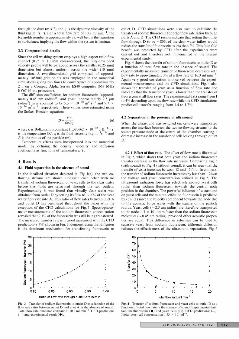
In the idealised situation depicted in Fig. 1(a), the two co-flowing streams are shown alongside each other with notransfer of sodium fluorescein or yeast cells to the clear waterbefore the fluids are separated through the two outlets.Experimentally, it was found that visually clear water wasobtained from outlet D by setting its flow to y90% of the clearwater flow rate into A. This ratio of flow rates between inlet Aand outlet D has been used throughout the paper with theexception of the CFD calculations for Fig. 3. Spectrophoto-meter measurements of the sodium fluorescein concentrationrevealed that 9.1% of the fluorescein was still being transferred.The measured transfer rate is in good agreement with the CFDprediction (8.7%) shown in Fig. 3, demonstrating that diffusionis the dominant mechanism for transferring fluorescein to
outlet D. CFD simulations were also used to calculate thetransfer of sodium fluorescein for other flow rate ratios throughports A and D. The CFD results indicate that setting the outletflow through D to be y80% of the clear water inflow wouldreduce the transfer of fluorescein to less than 2%. This four-foldbenefit was predicted by CFD after the experiments werecarried out and therefore not implemented in the presentexperimental study.
Fig. 4 shows the transfer of sodium fluorescein to outlet D asa function of total flow rate in the absence of sound. Theexperimentally measured transfer of fluorescein decreases withflow rate to approximately 5% at a flow rate of 16.3 ml min21.Again very good correlation is observed between the experi-mental measurements and the CFD simulations. Fig. 4 alsoshows the transfer of yeast as a function of flow rate andindicates that the transfer of yeast is lower than the transfer offluorescein at all flow rates. The experimental data range from 1to 4% depending upon the flow rate while the CFD simulationspredict cell transfer ranging from 1.4 to 1.7%.
4.2 Separation in the presence of ultrasound
When the ultrasound was switched on, cells were transportedacross the interface between the two co-flowing streams to thesound pressure node at the centre of the chamber causing adramatic increase in the number of cells leaving through outletD.
4.2.1 Effect of flow rate. The effect of flow rate is illustratedin Fig. 5, which shows that both yeast and sodium fluoresceintransfer decrease as the flow rate increases. Comparing Fig. 5(with sound) to Fig. 4 (without sound), it can be seen that thetransfer of yeast increases between 18 and 42 fold. In contrast,the transfer of sodium fluorescein increases by less than 1.2% atthe voltage and yeast concentration utilised in Fig. 5. Theultrasound radiation force has selectively moved yeast cellsrather than sodium fluorescein towards the central nodeposition in the chamber. The powerful influence of ultrasoundon yeast cells and the minimal effect on fluorescein is predictedby eqn. (1) since the velocity component towards the node dueto the acoustic force scales with the square of the particleradius. Yeast cells (y2.5 mm radius) are therefore transportedto the node y3 6 107 times faster than the sodium fluoresceinmolecules (y0.45 nm radius), provided other acoustic proper-ties are equal. This difference in velocities can be used toseparate yeast from sodium fluorescein, although diffusionreduces the effectiveness of the ultrasound separation. Fig. 5
Fig. 3 Transfer of sodium fluorescein to outlet D as a function of theflow rate ratio between outlet D and inlet A in the absence of sound.Total flow rate remained constant at 10.2 ml min21. CFD predictions(—) and experimental result ($).
Fig. 4 Transfer of sodium fluorescein and yeast cells to outlet D as afunction of total flow rate in the absence of sound. Experimental data:Sodium fluorescein ($) and yeast cells (%). CFD predictions: (—).Initial yeast cell concentration 1.53 6 107 ml21.
L a b C h i p , 2 0 0 4 , 4 , 4 4 6 – 4 5 2 4 4 9
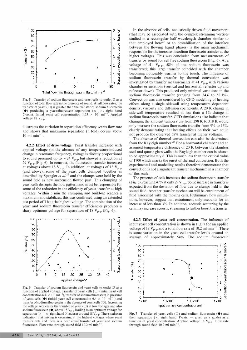
illustrates the variation in separation efficiency versus flow rateand shows that maximum separation (5 fold) occurs above10 ml min21.
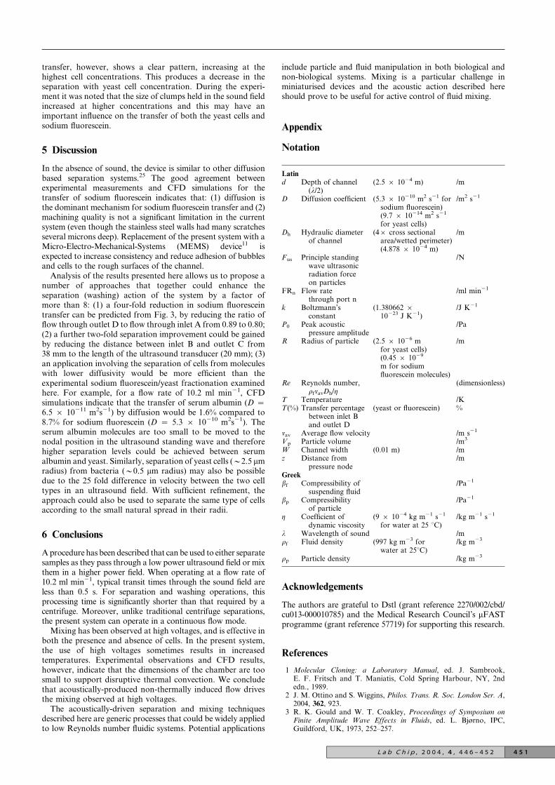
4.2.2 Effect of drive voltage. Yeast transfer increased withapplied voltage (in the absence of any temperature-inducedchange in resonance frequency, voltage is directly proportionalto sound pressure) up to y24 Vp–p but showed a reduction at29 Vp–p (Fig. 6). In contrast, the fluorescein transfer increasedat voltages above 18 Vp–p. In addition, at voltages of 18 Vp–p
(and above), some of the yeast cells clumped together asdescribed by Spengler et al.22 and the clumps were held by thesound field as new suspension flowed past. This clumping ofyeast cells disrupts the flow pattern and must be responsible forsome of the reduction in the efficiency of yeast transfer at highvoltages. Within 3 min the clumping and build-up reaches amaximum and stabilizes; this was confirmed using an extendedtest period of 3 h at the highest voltage. The combination of theyeast and sodium fluorescein transfer efficiencies produces asharp optimum voltage for separation of 18 Vp–p (Fig. 6).
In the absence of cells, acoustically-driven fluid movement(that may be associated with the complex streaming vorticesstudied in a rectangular half wavelength chamber similar tothat employed here23 or to destabilisation of the interfacebetween the flowing liquid phases) is the main mechanismresponsible for the increase in sodium fluorescein transfer at thehigher voltages. This was concluded from measurements oftransfer by sound for cell free sodium fluorescein (Fig. 6). At avoltage of 41 Vp–p, 58% of the sodium fluorescein wastransferred; this large transfer coincided with the chamberbecoming noticeably warmer to the touch. The influence ofsodium fluorescein transfer by thermal convection wasinvestigated by transfer measurements at 41 Vp–p with variouschamber orientations (vertical and horizontal, reflector up andreflector down). This produced only minimal variations in thesodium fluorescein transfer (ranging from 54.6 to 58.1%).Convection was also considered by CFD modelling of heatingeffects along a single sidewall using temperature dependentdensity, viscosity and diffusion coefficients. A 20 K change inside-wall temperature resulted in less than a 1% change insodium fluorescein transfer. CFD simulations also indicate thatchanging the ambient temperature from 298 K to 318 K wouldonly increase the sodium fluorescein transfer from 9% to 13%,clearly demonstrating that heating effects on their own couldnot produce the observed 58% transfer at higher voltages.
The absence of thermal convection can also be determinedfrom the Rayleigh number.24 For a horizontal chamber and anassumed temperature difference of 20 K between the stainlesssteel and quartz glass walls, the Rayleigh number can be shownto be approximately 6. This is much less than the critical valueof 1700 which marks the onset of thermal convection. Both theexperimental and modelling results therefore demonstrate thatconvection is not a significant transfer mechanism in a chamberof this scale.
The presence of cells increases the sodium fluorescein transfer(Fig. 6), reaching 47% at only 29 Vp–p. Some increase in transfer isexpected from the deviation of flow due to clumps held in thesound field. Another transfer mechanism will be entrainment offluid associated with the moving cells. Preliminary flow simula-tions, however, suggest that entrainment only accounts for anincrease of less than 3%. In addition, acoustic scattering by thecells may increase acoustic streaming to further boost the transfer.
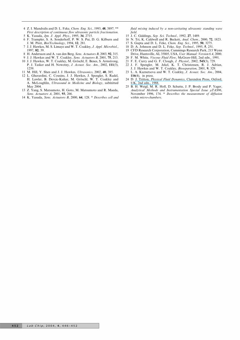
4.2.3 Effect of yeast cell concentration. The influence ofinput yeast cell concentration is shown in Fig. 7 for an appliedvoltage of 18 Vp–p and a total flow rate of 10.2 ml min21. Thereis some variation in the yeast cell transfer levels around anaverage of approximately 54%. The sodium fluorescein
Fig. 5 Transfer of sodium fluorescein and yeast cells to outlet D as afunction of total flow rate in the presence of sound. At all flow rates, thetransfer of yeast (%) is greater than the transfer of sodium fluorescein($) producing a yeast:fluorescein separation (6—6, right handY-axis). Initial yeast cell concentration 1.53 6 107 ml21. Appliedvoltage 18 Vp–p.
Fig. 6 Transfer of sodium fluorescein and yeast cells to outlet D as afunction of applied voltage. Transfer of yeast cells (%) (initial yeast cellconcentration 6.4 6 107 ml21), transfer of sodium fluorescein in presenceof yeast cells ($) (initial yeast cell concentration 6.4 6 107 ml21) andtransfer of sodium fluorescein in the absence of yeast cells (#). Increasingthe voltage accelerates the transfer of yeast (%) at low voltages and alsosodium fluorescein ($) above 18 Vp–p leading to an optimum voltage forseparation (6—6, right hand Y-axis) at around 18 Vp–p. There is also anindication that mixing is occurring at the highest voltages where yeasttransfer falls and there is a near equal transfer of yeast and sodiumfluorescein. Flow rate through sound field 10.2 ml min21.
Fig. 7 Transfer of yeast cells (%) and sodium fluorescein ($) andtheir separation (6, right hand Y-axis, — given as a guide) as afunction of yeast concentration. Applied voltage 18 Vp–p. Flow ratethrough sound field 10.2 ml min21.
4 5 0 L a b C h i p , 2 0 0 4 , 4 , 4 4 6 – 4 5 2
transfer, however, shows a clear pattern, increasing at thehighest cell concentrations. This produces a decrease in theseparation with yeast cell concentration. During the experi-ment it was noted that the size of clumps held in the sound fieldincreased at higher concentrations and this may have animportant influence on the transfer of both the yeast cells andsodium fluorescein.
5 Discussion
In the absence of sound, the device is similar to other diffusionbased separation systems.25 The good agreement betweenexperimental measurements and CFD simulations for thetransfer of sodium fluorescein indicates that: (1) diffusion isthe dominant mechanism for sodium fluorescein transfer and (2)machining quality is not a significant limitation in the currentsystem (even though the stainless steel walls had many scratchesseveral microns deep). Replacement of the present system with aMicro-Electro-Mechanical-Systems (MEMS) device11 isexpected to increase consistency and reduce adhesion of bubblesand cells to the rough surfaces of the channel.
Analysis of the results presented here allows us to propose anumber of approaches that together could enhance theseparation (washing) action of the system by a factor ofmore than 8: (1) a four-fold reduction in sodium fluoresceintransfer can be predicted from Fig. 3, by reducing the ratio offlow through outlet D to flow through inlet A from 0.89 to 0.80;(2) a further two-fold separation improvement could be gainedby reducing the distance between inlet B and outlet C from38 mm to the length of the ultrasound transducer (20 mm); (3)an application involving the separation of cells from moleculeswith lower diffusivity would be more efficient than theexperimental sodium fluorescein/yeast fractionation examinedhere. For example, for a flow rate of 10.2 ml min21, CFDsimulations indicate that the transfer of serum albumin (D ~6.5 6 10211 m2s21) by diffusion would be 1.6% compared to8.7% for sodium fluorescein (D ~ 5.3 6 10210 m2s21). Theserum albumin molecules are too small to be moved to thenodal position in the ultrasound standing wave and thereforehigher separation levels could be achieved between serumalbumin and yeast. Similarly, separation of yeast cells (y2.5 mmradius) from bacteria (y0.5 mm radius) may also be possibledue to the 25 fold difference in velocity between the two celltypes in an ultrasound field. With sufficient refinement, theapproach could also be used to separate the same type of cellsaccording to the small natural spread in their radii.
6 Conclusions
A procedure has been described that can be used to either separatesamples as they pass through a low power ultrasound field or mixthem in a higher power field. When operating at a flow rate of10.2 ml min21, typical transit times through the sound field areless than 0.5 s. For separation and washing operations, thisprocessing time is significantly shorter than that required by acentrifuge. Moreover, unlike traditional centrifuge separations,the present system can operate in a continuous flow mode.
Mixing has been observed at high voltages, and is effective inboth the presence and absence of cells. In the present system,the use of high voltages sometimes results in increasedtemperatures. Experimental observations and CFD results,however, indicate that the dimensions of the chamber are toosmall to support disruptive thermal convection. We concludethat acoustically-produced non-thermally induced flow drivesthe mixing observed at high voltages.
The acoustically-driven separation and mixing techniquesdescribed here are generic processes that could be widely appliedto low Reynolds number fluidic systems. Potential applications
include particle and fluid manipulation in both biological andnon-biological systems. Mixing is a particular challenge inminiaturised devices and the acoustic action described hereshould prove to be useful for active control of fluid mixing.
Appendix
Notation
Latind Depth of channel
(l/2)(2.5 6 1024 m) /m
D Diffusion coefficient (5.3 6 10210 m2 s21 forsodium fluorescein)
/m2 s21
(9.7 6 10214 m2 s21
for yeast cells)Dh Hydraulic diameter
of channel(46 cross sectional
area/wetted perimeter)/m
(4.878 6 1024 m)Fus Principle standing
wave ultrasonicradiation forceon particles
/N
FRn Flow ratethrough port n
/ml min21
k Boltzmann’sconstant
(1.380662 610223 J K21)
/J K21
P0 Peak acousticpressure amplitude
/Pa
R Radius of particle (2.5 6 1026 mfor yeast cells)
/m
(0.45 6 1029
m for sodiumfluorescein molecules)
Re Reynolds number,rfvavDh/g
(dimensionless)
T Temperature /KT(%) Transfer percentage
between inlet Band outlet D
(yeast or fluorescein) %
vav Average flow velocity /m s21
Vp Particle volume /m3
W Channel width (0.01 m) /mz Distance from
pressure node/m
Greekbf Compressibility of
suspending fluid/Pa21
bp Compressibilityof particle
/Pa21
g Coefficient ofdynamic viscosity
(9 6 1024 kg m21 s21
for water at 25 uC)/kg m21 s21
l Wavelength of sound /mrf Fluid density (997 kg m23 for
water at 25uC)/kg m23
rp Particle density /kg m23
Acknowledgements
The authors are grateful to Dstl (grant reference 2270/002/cbd/cu013-000010785) and the Medical Research Council’s mFASTprogramme (grant reference 57719) for supporting this research.
References
1 Molecular Cloning: a Laboratory Manual, ed. J. Sambrook,E. F. Fritsch and T. Maniatis, Cold Spring Harbour, NY, 2ndedn., 1989.
2 J. M. Ottino and S. Wiggins, Philos. Trans. R. Soc. London Ser. A,2004, 362, 923.
3 R. K. Gould and W. T. Coakley, Proceedings of Symposium onFinite Amplitude Wave Effects in Fluids, ed. L. Bjørno, IPC,Guildford, UK, 1973, 252–257.
L a b C h i p , 2 0 0 4 , 4 , 4 4 6 – 4 5 2 4 5 1
4 Z. I. Mandralis and D. L. Feke, Chem. Eng. Sci., 1993, 48, 3897. **First description of continuous flow ultrasonic particle fractionation.
5 K. Yasuda, Jpn. J. Appl. Phys., 1995, 34, 2715.6 F. Trampler, S. A. Sonderhoff, P. W. S. Pui, D. G. Kilburn and
J. M. Piret, Bio/Technology, 1994, 12, 281.7 J. J. Hawkes, M. S. Limaye and W. T. Coakley, J. Appl. Microbiol.,
1997, 82, 39.8 H. Andersson and A. van den Berg, Sens. Actuators B, 2003, 92, 315.9 J. J. Hawkes and W. T. Coakley, Sens. Actuators B, 2001, 75, 213.
10 J. J. Hawkes, W. T. Coakley, M. Groschl, E. Benes, S. Armstrong,P. J. Tasker and H. Nowotny, J. Acoust. Soc. Am., 2002, 111(3),1259.
11 M. Hill, Y. Shen and J. J. Hawkes, Ultrasonics, 2002, 40, 385.12 L. Gherardini, C. Cousins, J. J. Hawkes, J. Spengler, S. Radel,
H. Lawler, B. Devcic-Kuhar, M. Groschl, W. T. Coakley andA. McLoughlin, Ultrasound in Medicine and Biology, submittedMay 2004.
13 Z. Yang, S. Matsumoto, H. Goto, M. Matsumoto and R. Maeda,Sens. Actuators A, 2001, 93, 266.
14 K. Yasuda, Sens. Actuators B, 2000, 64, 128. * Describes cell and
fluid mixing induced by a non-cavitating ultrasonic standing wavefield.
15 J. C. Giddings, Sep. Sci. Technol., 1992, 27, 1489.16 N. Tri, K. Caldwell and R. Beckett, Anal. Chem., 2000, 72, 1823.17 S. Gupta and D. L. Feke, Chem. Eng. Sci., 1995, 50, 3275.18 D. A. Johnson and D. L. Feke, Sep. Technol., 1995, 5, 251.19 CFD Research Corporation, Cummings Research Park, 215 Wynn
Drive, Huntsville, AL 35805, USA, User Manual: Version 6.4, 2000.20 F. M. White, Viscous Fluid Flow, McGraw-Hill, 2nd edn., 1991.21 F. E. Curry and G. F. Clough, J. Physiol., 2002, 543(3), 729.22 J. F. Spengler, M. Jekel, K. T. Christensen, R. J. Adrian,
J. J. Hawkes and W. T. Coakley, Bioseparation, 2001, 9, 329.23 L. A. Kuznetsova and W. T. Coakley, J. Acoust. Soc. Am., 2004,
116(4), in press.24 D. J. Tritton, Physical Fluid Dynamics, Clarendon Press, Oxford,
UK, 2nd edn., 1988.25 B. H. Weigl, M. R. Holl, D. Schutte, J. P. Brody and P. Yager,
Analytical Methods and Instrumentation Special Issue mTAS96,November 1996, 174. * Describes the measurement of diffusionwithin micro-chambers.
4 5 2 L a b C h i p , 2 0 0 4 , 4 , 4 4 6 – 4 5 2