Choreography Modeling Compliance for Timed Business Processes
15
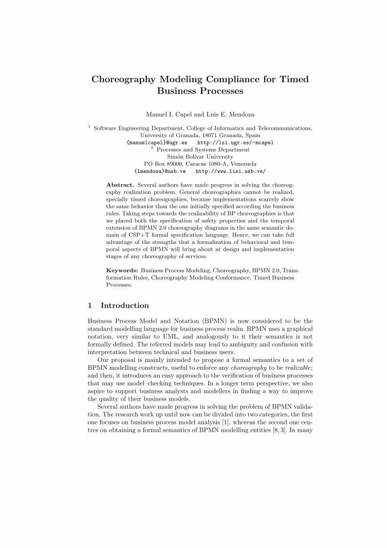
Choreography Modeling Compliance for Timed Business Processes Manuel I. Capel and Luis E. Mendoza 1 Software Engineering Department, College of Informatics and Telecommunications, University of Granada, 18071 Granada, Spain {manuelcapel}@ugr.es http://lsi.ugr.es/ ~ mcapel 2 Processes and Systems Department Sim´onBol´ ıvar University PO Box 89000, Caracas 1080-A, Venezuela {lmendoza}@usb.ve http://www.lisi.usb.ve/ Abstract. Several authors have made progress in solving the choreog- raphy realization problem. General choreographies cannot be realized, specially timed choreographies, because implementations scarcely show the same behavior than the one initially specified according the business rules. Taking steps towards the realizability of BP choreographies is that we placed both the specification of safety properties and the temporal extension of BPMN 2.0 choreography diagrams in the same semantic do- main of CSP+T formal specification language. Hence, we can take full advantage of the strengths that a formalization of behavioral and tem- poral aspects of BPMN will bring about at design and implementation stages of any choreography of services. Keywords: Business Process Modeling, Choreography, BPMN 2.0, Trans- formation Rules, Choreography Modeling Conformance, Timed Business Processes. 1 Introduction Business Process Model and Notation (BPMN) is now considered to be the standard modelling language for business process realm. BPMN uses a graphical notation, very similar to UML, and analogously to it their semantics is not formally defined. The referred models may lead to ambiguity and confusion with interpretation between technical and business users. Our proposal is mainly intended to propose a formal semantics to a set of BPMN modelling constructs, useful to enforce any choreography to be realizable ; and then, it introduces an easy approach to the verification of business processes that may use model–checking techniques. In a longer term perspective, we also aspire to support business analysts and modellers in finding a way to improve the quality of their business models. Several authors have made progress in solving the problem of BPMN valida- tion. The research work up until now can be divided into two categories, the first one focuses on business process model analysis [1], whereas the second one cen- tres on obtaining a formal semantics of BPMN modelling entities [8, 3]. In many
Transcript of Choreography Modeling Compliance for Timed Business Processes
Choreography Modeling Compliance for Timed
Business Processes
Manuel I. Capel and Luis E. Mendoza
1 Software Engineering Department, College of Informatics and Telecommunications,University of Granada, 18071 Granada, Spain
[email protected] http://lsi.ugr.es/~mcapel2 Processes and Systems Department
Simon Bolıvar UniversityPO Box 89000, Caracas 1080-A, Venezuela
[email protected] http://www.lisi.usb.ve/
Abstract. Several authors have made progress in solving the choreog-raphy realization problem. General choreographies cannot be realized,specially timed choreographies, because implementations scarcely showthe same behavior than the one initially specified according the businessrules. Taking steps towards the realizability of BP choreographies is thatwe placed both the specification of safety properties and the temporalextension of BPMN 2.0 choreography diagrams in the same semantic do-main of CSP+T formal specification language. Hence, we can take fulladvantage of the strengths that a formalization of behavioral and tem-poral aspects of BPMN will bring about at design and implementationstages of any choreography of services.
Keywords: Business Process Modeling, Choreography, BPMN 2.0, Trans-formation Rules, Choreography Modeling Conformance, Timed BusinessProcesses.
1 Introduction
Business Process Model and Notation (BPMN) is now considered to be thestandard modelling language for business process realm. BPMN uses a graphicalnotation, very similar to UML, and analogously to it their semantics is notformally defined. The referred models may lead to ambiguity and confusion withinterpretation between technical and business users.
Our proposal is mainly intended to propose a formal semantics to a set ofBPMN modelling constructs, useful to enforce any choreography to be realizable;and then, it introduces an easy approach to the verification of business processesthat may use model–checking techniques. In a longer term perspective, we alsoaspire to support business analysts and modellers in finding a way to improvethe quality of their business models.
Several authors have made progress in solving the problem of BPMN valida-tion. The research work up until now can be divided into two categories, the firstone focuses on business process model analysis [1], whereas the second one cen-tres on obtaining a formal semantics of BPMN modelling entities [8, 3]. In many

of the analyzed cases, a model cannot be verified because its representation inan executable environment does not show the same behaviour as observed in theoriginal model,i.e., it does not reacts to external events in the same way. Thelack of verification exhibited by the aforementioned approaches, in our opinion,it is mainly due to semantic and syntactic problems caused by incorrect integra-tion of (1)business properties formalization and (2)the corresponding BP–taskmodel.
We therefore propose here, (a)a set of transformation rules from a subsetof BPMN temporal analysis constructs into Communicating Sequential Pro-cesses+Time (CSP+T) calculus, (b)an easy verification approach for task modelsdesigned with BPMN. Differently from other authors [15, 4], by an early for-malization of behavioural and temporal aspects of BPMN models our, methodintends to merge the verification process of properties with the design of any BPmodel. Our aim is to facilitate the description of a BP model as a collection ofverified software components, thereby allowing their complete verification withstate–of–the–art model checking tools.
The paper is organized as follows. In the following section the formal back-ground behind BPMN 2.0 choreography formalization and the verification methodis presented. And thus, the proposal of temporal semantics for BPMN constructsis detailed together with a set of transformation rules into CSP+T. Then, wepresent the application of our proposal to the Hospital–Pharmacy Logistics ex-ample. The last section discusses the main conclusions to our work.
Fig. 1. Graphical representation of BPMN elements.
2 BPMN Choreographies Formalization
Business Process Model and Notation (BPMN) [10] is an standardized graphicalnotation that provides modelling elements for Business Process (BP) descriptionwith an emphasis on control–flow. A Business Process Diagram (BPD) is aspecific type of flowchart that incorporates graphical constructs tailored to modelBPMN elements, such as: (a)gateways, (b) events start, (c)tasks, and (d)controlflows. A BPD diagram is easy to use and understand by non–technical personnel,usually management–oriented, for modeling BPs. Notwithstanding, a BPD offersthe expressiveness necessary to model very complex BPs and it can be mapped
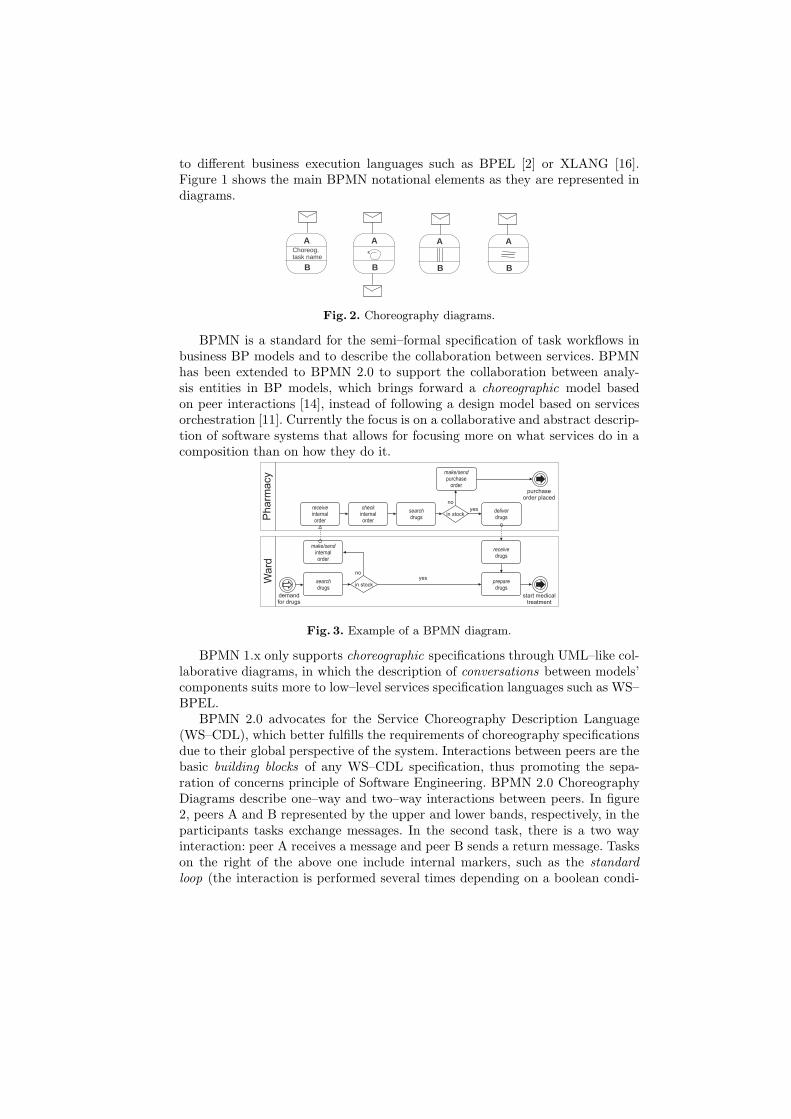
to different business execution languages such as BPEL [2] or XLANG [16].Figure 1 shows the main BPMN notational elements as they are represented indiagrams.
Choreog. task name
A
B
A
B
A
B
A
B
Fig. 2. Choreography diagrams.
BPMN is a standard for the semi–formal specification of task workflows inbusiness BP models and to describe the collaboration between services. BPMNhas been extended to BPMN 2.0 to support the collaboration between analy-sis entities in BP models, which brings forward a choreographic model basedon peer interactions [14], instead of following a design model based on servicesorchestration [11]. Currently the focus is on a collaborative and abstract descrip-tion of software systems that allows for focusing more on what services do in acomposition than on how they do it.
Fig. 3. Example of a BPMN diagram.
BPMN 1.x only supports choreographic specifications through UML–like col-laborative diagrams, in which the description of conversations between models’components suits more to low–level services specification languages such as WS–BPEL.
BPMN 2.0 advocates for the Service Choreography Description Language(WS–CDL), which better fulfills the requirements of choreography specificationsdue to their global perspective of the system. Interactions between peers are thebasic building blocks of any WS–CDL specification, thus promoting the sepa-ration of concerns principle of Software Engineering. BPMN 2.0 ChoreographyDiagrams describe one–way and two–way interactions between peers. In figure2, peers A and B represented by the upper and lower bands, respectively, in theparticipants tasks exchange messages. In the second task, there is a two wayinteraction: peer A receives a message and peer B sends a return message. Taskson the right of the above one include internal markers, such as the standardloop (the interaction is performed several times depending on a boolean condi-

tion), multi–instance parallel loops (the interactions are performed by severalinstances of the choreography task), which can execute the actions in parallel‖ |or sequentially ≡.
2.1 Example
Consider, for instance, the simple example of an Hospital Pharmacy logisticprocess shown in Figure 3. The BPD depicts the message flows between twoparticipants, the Ward and the Pharmacy, which are independent BP and mayhave been constructed separately. Clearly, the synchronization between bothparticipants is a necessary behavioural property for successful collaboration.
For example, from the pharmacy participant’s perspective, drugs deliveringmust be guaranteed by sending a message to the ward participant prior a pur-chase order would be made or sent; while from the ward participant’s perspective,by sending a message to the pharmacy participant with enough time in advanceto have the required drugs to begin medical treatment. The specification infigure 4 shows the interaction between the peers(customer, ward, pharmacy,db)translated from the business process Hospital Pharmacy diagram in Figure 3,which represent the behaviour of tasks within the pools Ward and Pharmacy.In this specification, we can firstly see that the customer interacts with theward (connect), then sends the prescription to the pharmacy (request) andeventually receives a response when the drug is available. On the contrary, thepharmacy makes an order (purchase order) and when the drug is available, itdelivers the drug to the ward (received). In the later case, the prescription willbe prepared and given to the customer (delivered), thereby terminating thecomplete protocol.
Searchdrug
Customer
xxxxxxxxxxxxxxxxxxxxxxxxxxxxxxxxxxxxxxxxxxxxxxxxxxxxxxxxxxxxxxxxxxxxxxxxxxxxx
xxxxxxxxxxxxxxx
xxxxxxxxxxxxxxxxxx
Send internalorder
Ward
Ward
Pharmacy
request
Ward
Pharmacy
DB
Pharmacy
Ward
CustomerPrepare
drug
Ward
Pharmacy
Ward
Pharmacy
xxxxxxxxxxxxxxxxxxxxxxxxxxxxxxxxxxxxxxxxxxxxxxxxxxxxxxxxxxxxxxxxxxxxxxxxxxxxxxxxxxxxxxxxxxxxxxxxxxxxxxxxxxxxxxxxxxxxxxxxxxxxxxxxxxxxxxxxxxxxxxx
xxxxxxxxxxxxxx xxxxxxxxxxxxxxx Searchdrug
Prepareorder
Deliverdrug
Make purch.order
received
purchaseorder placed
xxxxxxxxxxxxxxxxxxxxxxxxxxxxxxxxxxxxxxxxxxxxxxxxxxxxxxxxxxxx
xxxxxxxxxxxxxxxxxx
xxxxxxxxxxxxxxxxxxxx
delivered
connect
Fig. 4. BPMN 2.9 Choreography Diagram–Ward-Pharmacy Example.
2.2 CSP+T
CSP+T [18] is a real–time specification language which extends CommunicatingSequential Processes (CSP) allowing the description of complex event timings,within a single sequential process, for use in the behavioural specification of anycritical communicating process. A CSP+T process term P is defined as a tuple(αP ,P), where αP = Comm act(P)∪Interface(P) is the communication alphabetof P .
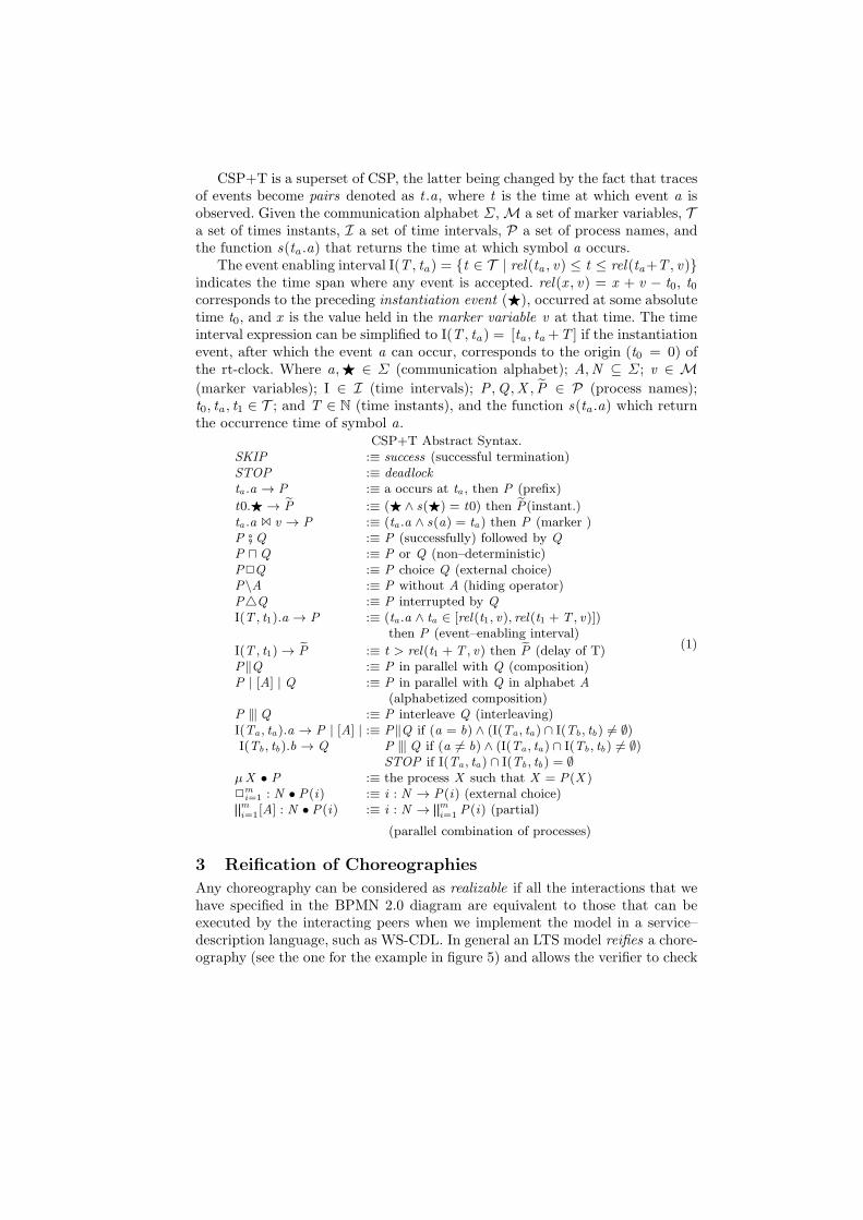
CSP+T is a superset of CSP, the latter being changed by the fact that tracesof events become pairs denoted as t .a, where t is the time at which event a isobserved. Given the communication alphabet Σ, M a set of marker variables, Ta set of times instants, I a set of time intervals, P a set of process names, andthe function s(ta .a) that returns the time at which symbol a occurs.
The event enabling interval I(T , ta) = t ∈ T | rel(ta , v) ≤ t ≤ rel(ta+T , v)indicates the time span where any event is accepted. rel(x , v) = x + v − t0, t0corresponds to the preceding instantiation event (⋆), occurred at some absolutetime t0, and x is the value held in the marker variable v at that time. The timeinterval expression can be simplified to I(T , ta ) = [ta , ta +T ] if the instantiationevent, after which the event a can occur, corresponds to the origin (t0 = 0) ofthe rt-clock. Where a,⋆ ∈ Σ (communication alphabet); A,N ⊆ Σ; v ∈ M
(marker variables); I ∈ I (time intervals); P ,Q ,X , P ∈ P (process names);t0, ta , t1 ∈ T ; and T ∈ N (time instants), and the function s(ta .a) which returnthe occurrence time of symbol a.
CSP+T Abstract Syntax.SKIP :≡ success (successful termination)STOP :≡ deadlockta .a → P :≡ a occurs at ta , then P (prefix)
t0.⋆ → P :≡ (⋆ ∧ s(⋆) = t0) then P(instant.)ta .a 1 v → P :≡ (ta .a ∧ s(a) = ta ) then P (marker )P # Q :≡ P (successfully) followed by QP ⊓Q :≡ P or Q (non–deterministic)P2Q :≡ P choice Q (external choice)P\A :≡ P without A (hiding operator)PQ :≡ P interrupted by QI(T , t1).a → P :≡ (ta .a ∧ ta ∈ [rel(t1, v), rel(t1 + T , v)])
then P (event–enabling interval)
I(T , t1) → P :≡ t > rel(t1 +T , v) then P (delay of T)P‖Q :≡ P in parallel with Q (composition)P | [A] | Q :≡ P in parallel with Q in alphabet A
(alphabetized composition)P 9 Q :≡ P interleave Q (interleaving)I(Ta , ta ).a → P | [A] | :≡ P‖Q if (a = b) ∧ (I(Ta , ta ) ∩ I(Tb , tb) 6= ∅)I(Tb , tb).b → Q P 9 Q if (a 6= b) ∧ (I(Ta , ta ) ∩ I(Tb , tb) 6= ∅)
STOP if I(Ta , ta ) ∩ I(Tb , tb) = ∅µX • P :≡ the process X such that X = P(X )2
mi=1 : N • P(i) :≡ i : N → P(i) (external choice)fmi=1
[A] : N • P(i) :≡ i : N →fmi=1
P(i) (partial)
(parallel combination of processes)
(1)
3 Reification of Choreographies
Any choreography can be considered as realizable if all the interactions that wehave specified in the BPMN 2.0 diagram are equivalent to those that can beexecuted by the interacting peers when we implement the model in a service–description language, such as WS-CDL. In general an LTS model reifies a chore-ography (see the one for the example in figure 5) and allows the verifier to check

its realizability w.r.t. the model of the system composed of interacting peers.If the two models mentioned above are behaviorally equivalent, it means thatthe peer generation exactly satisfies the BPMN communication requirements.On the contrary, if the peers do not generate the same interactions as the onesspecified in the choreography, we can say that this choreography is unrealizable.
connectsearchdrug
sendinternalorder
prepareorder
purchaseorder
found
deliveredprepare
drug
Fig. 5. LTS model of the Ward–Pharmacy Example.
3.1 Behavioural Equivalence
We place both, the choreography reification and the interacting peers model, inthe same semantic domain, that of CSP+T process calculus. In this way we cantake full advantage of the strengths that a formalization of behavioural aspectsof BPMN models provide to the analysis, both at design and run–time.
The proposed procedure consists of the following integrated steps,
1. The choreography reification (LTS) derived from the CSP+T encoding isgenerated.
2. The peers’ behaviour are extracted from of the initial BPMN–CD by theapplication of a proposed transformation rules set.
3. The system model is built, structured as the extracted interacting peers.4. By applying 1, the choreography reification is model–checked. to prove be-
havioural equivalence with the peer-based and distributed system model.
Theorem 1 System compositional verification. Let the choreography reifi-cation C be structured into several components working in parallel, C =
fi:1..n
Ci .For a set of LTS(Ci) describing the behaviour of components Ci , propertiesφi , invariants ψi , and deadlock δ, with
⋂i:1..n
Σi = ∅,⋂
i:1..nΩi = ∅, and⋂
i:1..nL(TBA(Ci)) = ∅, the following condition holds:
LTS(C) (φ ∧ ψ ∧ ¬δ) ⇔n
i:1..n
LTS(Ci) ∧
i:1..n
(φi ∧ ψi) ∧ ¬δ, (2)
where LTS(C) = ‖i:1..n
LTS(Ci).
Proof. We assume that the component’s behaviour Ci can be described by aLTS(Ci), and the peers behaviour by the LTS(C), respectively. Moreover, wecan associate a process term P(Ci) and P(C) of some process calculus (i.e.,CSP, CCS, LOTOS, etc.) that implements the behaviour of the component Ci
and the system C, respectively, so that:
P(Ci) |= (φi ∧ ψi) ∧ ¬δ ⇒ LTS(Ci) |= (φi ∧ ψi) ∧ ¬δ, and
P(C) |= φ ∧ ψ ∧ ¬δ ⇒ LTS(C) |= φ ∧ ψ ∧ ¬δ .
By the process calculus parallel composition operator, the following relationmust be satisfied:
P(C) =n
i:1..n
P(Ci) .
If the LTS(Ci) fulfills,
(1)⋂
i:1..nΣi = ∅ and
⋂i:1..n
Ωi = ∅, and (2)⋂
i:1..nL(TBA(Ci)) = ∅,
we can affirm that LTS(Ci) are “composable” and we write:n
i:1..n
LTS(Ci) |=∧
i:1..n
(φi ∧ ψi) ∧ ¬δ
Given that the satisfaction relation is closed w.r.t. the conjunction operator,we conclude
∧i:1..n
φi ⇒ φ,∧
i:1..nψi ⇒ ψ, and therefore:
P(C) |= φ ∧ ψ ∧ ¬δ ⇔n
i:1..n
P(Ci) |=∧
i:1..n
(φi ∧ ψi) ∧ ¬δ . (3)
The sufficient condition, i.e., φ ⇒∧
i:1..nφi , ψ ⇒
∧i:1..n
ψi , can be provenby considering that even in the case where all the components Ci presenteda different behavior, φ and ψ could be defined as the conjunction of everycomponent’s local properties (φi , ψi).
The practical application of relation (2) includes performing an inductive‘satisfaction checking’ process on the range of the components number (i :1, . . . , n) of the system of peers to be checked .
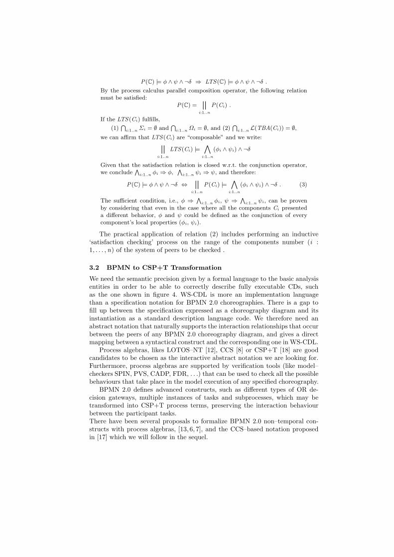
3.2 BPMN to CSP+T Transformation
We need the semantic precision given by a formal language to the basic analysisentities in order to be able to correctly describe fully executable CDs, suchas the one shown in figure 4. WS-CDL is more an implementation languagethan a specification notation for BPMN 2.0 choreographies. There is a gap tofill up between the specification expressed as a choreography diagram and itsinstantiation as a standard description language code. We therefore need anabstract notation that naturally supports the interaction relationships that occurbetween the peers of any BPMN 2.0 choreography diagram, and gives a directmapping between a syntactical construct and the corresponding one in WS-CDL.
Process algebras, likes LOTOS–NT [12], CCS [8] or CSP+T [18] are goodcandidates to be chosen as the interactive abstract notation we are looking for.Furthermore, process algebras are supported by verification tools (like model–checkers SPIN, PVS, CADP, FDR, . . .) that can be used to check all the possiblebehaviours that take place in the model execution of any specified choreography.
BPMN 2.0 defines advanced constructs, such as different types of OR de-cision gateways, multiple instances of tasks and subprocesses, which may betransformed into CSP+T process terms, preserving the interaction behaviourbetween the participant tasks.There have been several proposals to formalize BPMN 2.0 non–temporal con-structs with process algebras, [13, 6, 7], and the CCS–based notation proposedin [17] which we will follow in the sequel.
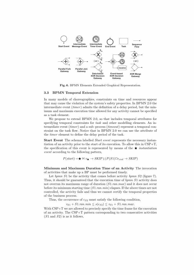
Fig. 6. BPMN Elements Extended Graphical Representation.
3.3 BPMN Temporal Extension
In many models of choreographies, constraints on time and resources appearthat may cause the violation of the system’s safety properties. In BPMN 2.0 theintermediate event (timer) admits the definition of a delay period, but the min-imum and maximum execution time allowed for any activity cannot be specifiedas a task element.
We propose to extend BPMN 2.0, so that includes temporal attributes forspecifying temporal constraints for task and other modelling elements. An in-termediate event (timer) and a sub–process (timeout) represent a temporal con-straint on the task flow. Notice that in BPMN 2.0 we can use the attribute ofthe timer element to define the delay period of the task.
Start Event The schema labelled Start event represents the necessary instan-tiation of an activity prior to the start of its execution. To allow this in CSP+T,the specification of this event is represented by means of the ⋆ instantiationevent according to the following pattern,
P(start) =⋆ 1 v⋆ → SKIP # (P(S1)2ǫend → SKIP)
Minimum and Maximum Duration Time of an Activity The invocationof activities that make up a BP must be performed timely.
Let bpmn S1 be the activity that comes before activity bpmn S2 (figure 7).Thus, it should be guaranteed that the execution time of bpmn S1 activity doesnot overrun its maximum range of duration (S1.ran.max ) and it does not occurbefore its minimum starting time (S1.ran.min) elapses. If the above times are notcontrolled, the activity fails and thus we cannot certify the temporal propertiesof the business process.
Thus, the occurrence of ǫS2 must satisfy the following condition,
vS1 + S1.ran.min ≤ s(ǫS2) ≤ vS1 + S1.ran.max .
With CSP+T we are allowed to precisely specify the time frame for the executionof an activity. The CSP+T pattern corresponding to two consecutive activities(S1 and S2) is as it follows,
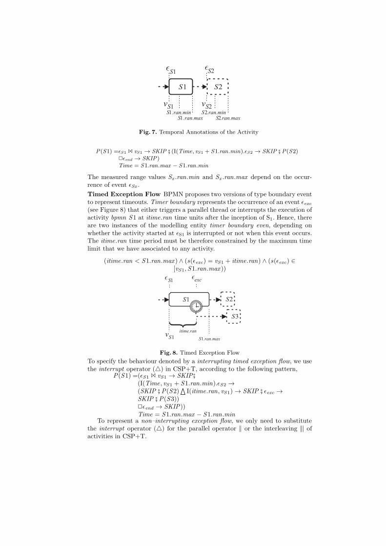
Fig. 7. Temporal Annotations of the Activity
P(S1) =ǫS1 1 vS1 → SKIP # (I(Time, vS1 + S1.ran.min).ǫS2 → SKIP # P(S2)2ǫend → SKIP)Time = S1.ran.max − S1.ran.min
The measured range values Sx .ran.min and Sx .ran.max depend on the occur-rence of event ǫSx .
Timed Exception Flow BPMN proposes two versions of type boundary eventto represent timeouts. Timer boundary represents the occurrence of an event ǫexc(see Figure 8) that either triggers a parallel thread or interrupts the execution ofactivity bpmn S1 at itime.ran time units after the inception of S1. Hence, thereare two instances of the modelling entity timer boundary even, depending onwhether the activity started at ǫS1 is interrupted or not when this event occurs.The itime.ran time period must be therefore constrained by the maximum timelimit that we have associated to any activity.
(itime.ran < S1.ran.max ) ∧ (s(ǫexc) = vS1 + itime.ran) ∧ (s(ǫexc) ∈[vS1, S1.ran.max ))
Fig. 8. Timed Exception Flow
To specify the behaviour denoted by a interrupting timed exception flow, we usethe interrupt operator () in CSP+T, according to the following pattern,
P(S1) =(ǫS1 1 vS1 → SKIP #(I(Time, vS1 + S1.ran.min).ǫS2 →(SKIP # P(S2)
aI(itime.ran, vS1) → SKIP # ǫexc →
SKIP # P(S3))2ǫend → SKIP))Time = S1.ran.max − S1.ran.min
To represent a non–interrupting exception flow, we only need to substitutethe interrupt operator () for the parallel operator ‖ or the interleaving 9 ofactivities in CSP+T.
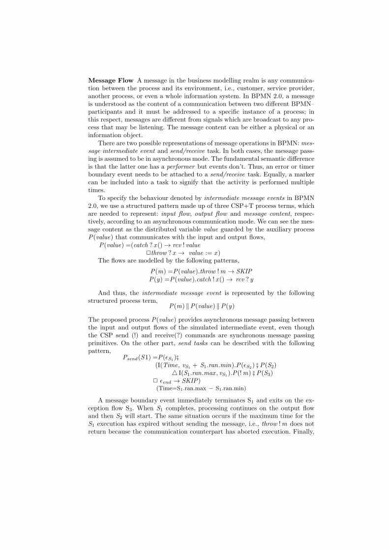
Message Flow A message in the business modelling realm is any communica-tion between the process and its environment, i.e., customer, service provider,another process, or even a whole information system. In BPMN 2.0, a messageis understood as the content of a communication between two different BPMN–participants and it must be addressed to a specific instance of a process; inthis respect, messages are different from signals which are broadcast to any pro-cess that may be listening. The message content can be either a physical or aninformation object.
There are two possible representations of message operations in BPMN: mes-sage intermediate event and send/receive task. In both cases, the message pass-ing is assumed to be in asynchronous mode. The fundamental semantic differenceis that the latter one has a performer but events don’t. Thus, an error or timerboundary event needs to be attached to a send/receive task. Equally, a markercan be included into a task to signify that the activity is performed multipletimes.
To specify the behaviour denoted by intermediate message events in BPMN2.0, we use a structured pattern made up of three CSP+T process terms, whichare needed to represent: input flow, output flow and message content, respec-tively, according to an asynchronous communication mode. We can see the mes-sage content as the distributed variable value guarded by the auxiliary processP(value) that communicates with the input and output flows,
P(value) =(catch ? x () → rcv ! value2throw ? x → value := x )
The flows are modelled by the following patterns,
P(m) =P(value).throw !m → SKIPP(y) =P(value).catch ! x () → rcv ? y
And thus, the intermediate message event is represented by the followingstructured process term,
P(m) ‖P(value) ‖P(y)
The proposed process P(value) provides asynchronous message passing betweenthe input and output flows of the simulated intermediate event, even thoughthe CSP send (!) and receive(?) commands are synchronous message passingprimitives. On the other part, send tasks can be described with the followingpattern,
Psend (S1) =P(ǫS1)#
(I(Time, vS1+ S1.ran.min).P(ǫS2
) # P(S2) I(S1.ran.max , vS1
).P(!m) # P(S3)2 ǫend → SKIP)(Time=S1.ran.max − S1.ran.min)
A message boundary event immediately terminates S1 and exits on the ex-ception flow S3. When S1 completes, processing continues on the output flowand then S2 will start. The same situation occurs if the maximum time for theS1 execution has expired without sending the message, i.e., throw !m does notreturn because the communication counterpart has aborted execution. Finally,
if S1 execution does not finish by the maximum execution time assigned to thistask, the error condition is enabled and the entire process aborts after ǫend.
A receive task has an analogous pattern to the send task, except from thethrow !m command is substituted by the sequence catch ! x () → rcv ?m. Simi-larly as in the case of intermediate event, both tasks receive and send need to becomposed with process P(value) and the parallel operator to have asynchronousmessage passing mode.
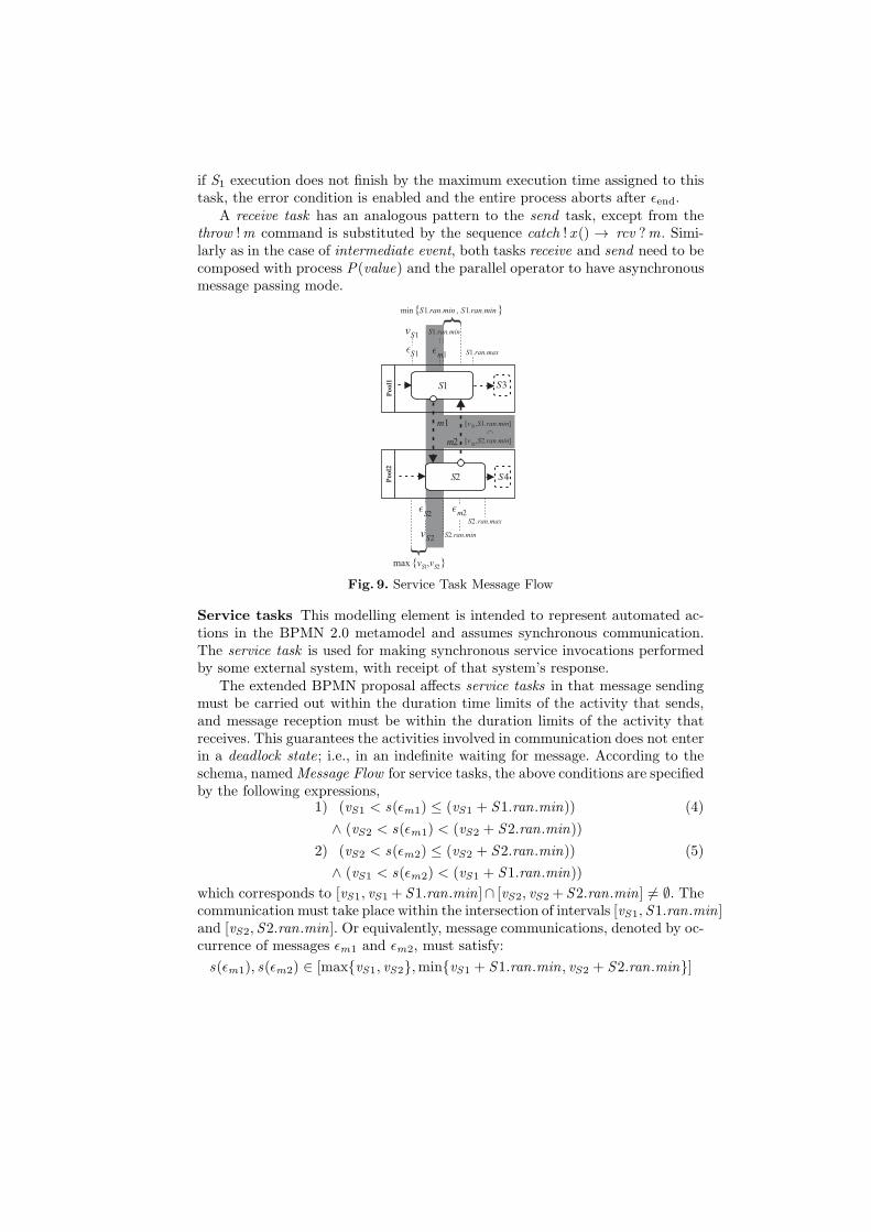
Fig. 9. Service Task Message Flow
Service tasks This modelling element is intended to represent automated ac-tions in the BPMN 2.0 metamodel and assumes synchronous communication.The service task is used for making synchronous service invocations performedby some external system, with receipt of that system’s response.
The extended BPMN proposal affects service tasks in that message sendingmust be carried out within the duration time limits of the activity that sends,and message reception must be within the duration limits of the activity thatreceives. This guarantees the activities involved in communication does not enterin a deadlock state; i.e., in an indefinite waiting for message. According to theschema, namedMessage Flow for service tasks, the above conditions are specifiedby the following expressions,
1) (vS1 < s(ǫm1) ≤ (vS1 + S1.ran.min)) (4)
∧ (vS2 < s(ǫm1) < (vS2 + S2.ran.min))
2) (vS2 < s(ǫm2) ≤ (vS2 + S2.ran.min)) (5)
∧ (vS1 < s(ǫm2) < (vS1 + S1.ran.min))
which corresponds to [vS1, vS1 + S1.ran.min]∩ [vS2, vS2 +S2.ran.min] 6= ∅. Thecommunication must take place within the intersection of intervals [vS1, S1.ran.min]and [vS2, S2.ran.min]. Or equivalently, message communications, denoted by oc-currence of messages ǫm1 and ǫm2, must satisfy:
s(ǫm1), s(ǫm2) ∈ [maxvS1, vS2,minvS1 + S1.ran.min, vS2 + S2.ran.min]
The schemas of process terms that include communication between the ac-tivities bpmn S1 and bpmn S2 must therefore guarantee that rules (4) and (5)are always satisfied, according to the following patterns,
P(S1) = P(ǫS1)#(I(MI ,MA).P(!(m1, s(ǫS1))) # I(MI ,MA).P(?(y , vS2))#I(Time, vS1 + S1.ran.min).P(ǫS3) # P(S3)
2P(ǫend.1))
P(S2) = P(ǫS2)#(I(MI ,MA).P(?(x , vS1)) # I(MI ,MA).P(!(m2, s(ǫS2)))#I(Time, vS2 + S2.ran.min).P(ǫS4) # P(S4)
2P(ǫend.2))(MI = minS1.ran.min, S2.ran.min, and
MA = maxvS1, vS2Time = S1.ran.max − S1.ran.min)
4 Choreography Model CheckingFor each participant in the BPMN-CD, we specify a parallel composition ofparallel CSP+T processes, thereby we can define a bijection between processesand diagram states. The proposed formal specification abstracts the internalinteraction between the individual peer states and only represents the sequenceof task initializations and terminations that occur in the choreography model,and thus a compact model susceptible of being transformed into an LTS, andthen verified by an automatic tool, is obtained.
4.1 CSP+T Transformation of the Choreography Model
The states of each two interacting peers in figure 4 are represented by the fol-lowing CSP+T process pattern,
bpmnname = (Y | α(Pi) | X ) hide connect .Customer
Y = ‖i=mi=1 Tasks • α(Pi ) P(i)
name= (Customer | Ward | Pharmacy | DB); (peers)Tasks = (Search drug | Send internal order
|Prepare order) | Search drug | Deliver drug|Purchase order | Prepare drug);
The parallel composition of CSP+T P(i) processes is mechanically obtainedby applying the transformation rules in section 3.2.
bpmnWardYWard = (P(connect)‖P(search drug)‖Pxgate.1())Pxgate.1(2,P(send internal order)‖Psend.1(request),P(prepare drug)‖Preceive(received)‖P(end)))
Hence, Hospital–Pharmacy peers behaviour specification becomes,
bpmnPharmacyYPharmacy = (Preceive(request)‖P(prepare order)‖P(search drug)‖Pxgate.2())Pxgate.2(2,P(purchase order)‖Psend.2(place order)P(abort),P(deliver drug))
The other peers (DB and Customer) have trivial CSP+T specifications.

4.2 Choreography Reification
The LTS reification of the choreography in figure 5 must have an equivalentbehaviour as the one shown by the peers–based model of the Ward-Pharmacy.The CSP+T specification (P(System) = Ward ‖Pharmacy, ‖Customer ‖DB)should be checked against the choreography–LTS before starting the implementa-tion of the distributed system. This verification can be carried out automaticallywith FDR2 model–checker [5] if the LST is transformed into a CSP+T process,
T (LTS) = t0.⋆ → T (connect)T (connect) = I((b − 6)− a, a).init .Ward .search drug
→ T (search drug)T (search drug) = I((b − 4)− (a + 2), a + 2).init .Ward .xgate.1
→ T (xgate.1))T (xgate.1) = I((b − 3)− (a + 3), a + 3).init .Ward .send internal order→ T (send internal order)T (send internal order) = I((b − 2)− (a + 4), a + 4).init .Pharmacy .prepare order → T (prepare order)T (prepare order) = I((b − 1)− (a + 5), a + 5).init .Ward .purchase order
2purchased → T (send found)T (send found) = I(b − (a + 6), a + 6).init .Ward .delivered → T (prepare drug)T (prepare drug) = I(b − (a + 6), a + 6).init .Ward .End1 → T (prepare drug)T (End .1) = SKIP
0 1 2
3
4
6
5
7
8
9
[a,b-8]connect
[a+1,b-7]searchdrug
[a+2, b-6]send
internalorder
[a+3, b-5]prepare
order
[a+4, b-4]make
purchaseorder
[a+5, b-3]timeout
[a+5, b-3]found
[a+2, b-5]prepare
drug
[a+6, b-2]delivered
[a+7,b-1]prepare
drug
[a+8, b]done
[a+3,b-4]done
Fig. 10. Timed LTS model of the Ward-Pharmacy
4.3 Verification
The reification of the choreography is realizable if the set of interactions spec-ified by the above process term T (LTS ) and those executed by the interact-ing peers in the target distributed system, specified by the process PBPMN =Customer ‖Ward‖bpmn ‖DB are the same. Thus, according to traces and fail-ures semantics of CSP, it must be ascertained that the following refining assertionis true,
T (LTS ) ⊑F PBPMN (6)
However, the FDR2 returned false since the trace < connect, search drug,
send order, prepare order, deliver, prepare drug > appears in both models,but the trace < connect, search drug,send order,prepare order, deliver,
prepare drug, purchaseorder,abort > is present in the peers–based distributedsystem and not in the LTS of the choreography.
The solution to this error in the LTS model is to make explicit an extra statein which the LTS is waiting for completing the purchase of the drug and add atimeout to this state If that time period expires then the LTS will reach an abort
state signifying that the purchase is cancelled, since probably the distributor’sstock has been exhausted. The new LTS can be seen in figure 10.
5 CONCLUSIONS
In order to enforce the realization of feasible choreographies within the realmof business proceses, we have presented a feasible formalization of BPMN 2.0constructs. Checking the behavioural equivalence between an LTS, which spec-ifies the possible behaviour of a highly interactive system, against the actualbehaviour of a peer–based distributed applicationis very complex. Since to solvethe realizability problem is of great importance to develop predictable and safeapplications. We have solved that problem by transformation of the LTS and thepeer–system model into a proces calculus named CSP+T. In this way, we cananalyze and automatically verify the conformance of the defined choreographyfor services that communicate through messages in a general, distributed, andhighly parallel system.
References
1. W. Aalst. Challenges in business process analysis. In: Enterprise Information Sys-tems. Lecture Notes in Business Information Processing, v. 12: 27–42. Heidelberg:Springer, 2009.
2. A. Arkin, S. Askary, B. Bloch, F. Curbera, Y. Goland, N. Kartha, C. K. Liu, S.Thatte, P. Yendluri, and A. Yiu, editors. Web Services Business Process ExecutionLanguage Version 2.0. Committee Draft. WS-BPEL TC OASIS, 2005.
3. A. Cerone. From Process Algebra to Visual Language. In Proceedings of the Con-ference on Application and Theory of Petri Nets: Formal Methods in Software En-gineering and Defence Systems, v. 12, Adelaide, 2002.
4. B. Dongen, W. Aalst. Multi–phase process mining: Building instance graphs. In:Conceptual Modeling–ER 2004. Lecture Notes in Computer Science, v. 3288:362–376. Heidelberg:Springer, 2004.
5. Formal Systems Europe Ltd. Failures–Divergence Refinement – FDR2 User Manual.Formal Systems Europe Ltd., Oxford, 2005
6. S. Ma, L. Zhang, J. He. Towards formalization and verification of unified businessprocess model based on Pi calculus. Proceedings ACIS International. Conference onSoftware Engineering Research, Management and Applications 1, 2008.
7. L.E. Mendoza, M.I. Capel, M.A. Perez. Conceptual framework for business processescompositional verification. Information and Software Technology,54,149:161, 2012.
8. Milner, R. (1989). Communication and Concurrency. International Series in Com-puter Science, 1989. ISBN 0-13-115007-3
9. Web Services Business Process Execution Language Version 2.0, 2007. http://docs.oasis-open.org/wsbpel/2.0/wsbpel-v2.0.pdf
10. OMG. Business Process Model and Notation (BPMN) -version 2.0.11. C. Peltz.Web Services Orchetration and Choreography. IEEE Computer, 36(10),
pp.46–52, 2003.12. P. Poizat, G. Salaun.Checking the realizability of BPMN 2.0 choreographies. Pro-
ceedings 27th Simposium of Applied Computing, 1927:1934, Riva del Garda(Italy),March 25-29, ACM,2012.
13. F. Puhlmann. Soundness Verification of Business Processes Specified in the Pi-calculus. Lecture Notes in Computer Science, no.4803: 6-23.
14. Z. Qiu et al. Towards the Theoretical Foundation of Choreography. Proceedingsof the 16th international conference on World Wide Web (WWW’07), pp.973–982,2007.
15. A. Rozinat, W. Aalst. Conformance testing: Measuring the fit and appropriatenessof event logs and process models. In: Business Process Management Workshops.Lecture Notes in Computer Science, 2006.
16. S. Thatte. XLANG: Web Services for Business Process Design. Microsoft Corpo-ration, 2001. http://www.gotdotnet.com/team/xml/wsspace/xlang-c
17. P.Y.H.Wong, J. Gibbons. A Process Semantics for BPMN. 10th International Con-ference on Formal Engineering Methods, ICFEM 2008 (Kitakyushu-City), Japan,October 27-31, 2008. In Lecture Notes in Computer Science 5256, 355:374, Heidel-berg:Springer, 2008.
18. J. Zic. Time–Constrained Buffer Specifications in CSP+T and Timed CSP. ACMTOPLAS,16(6), 1661:1674,1994