
Proteomics of Chlamydomonas reinhardtii Light-Harvesting Proteins
Upload
khangminh22Category
view
1download
0
UPTEC X 15 002
Examensarbete 30 hpJanuari 2015
Relation between hydrogen production and photosynthesis in the green algae Chlamydomonas reinhardtii
Alex Basu

Degree Project in Molecular Biotechnology Masters Programme in Molecular Biotechnology Engineering, Uppsala University School of Engineering
UPTEC X 15 002 2015-01 Author
Alex Basu Title (English) Relation between hydrogen production and photosynthesis in the
green algae Chlamydomonas reinhardtii Title (Swedish) Abstract The modernized world is over-consuming low-cost energy sources that strongly contributes to pollution and environmental stress. As a consequence, the interest for environmentally friendly alternatives has increased immensely. One such alternative is the use of solar energy and water as a raw material to produce biohydrogen through the process of photosynthetic water splitting. In this work, the relation between H2-production and photosynthesis in the green algae Chlamydomonas reinhardtii was studied with respect to three main aspects: the establishment of prolonged H2-production, the involvement of PSII in H2-production and the electron pathways associated with PSII during H2-production. For the first time, this work reveals that PSII plays a crucial role throughout the H2-producing phase in sulfur deprived C. reinhardtii. It further reveals that a wave-like fluorescence decay kinetic, before only seen in cyanobacteria, is observable during the H2-producing phase in sulfur deprived C. reinhardtii, reflecting the presence of cyclic electron flows also in green algae. Keywords Chlamydomonas reinhardtii, photosynthetic water oxidation, biohydrogen, sulfur deprivation, cyclic electron flow Supervisors
Associate Professor Fikret Mamedov Uppsala University
Scientific reviewer Professor Stenbjörn Styring
Uppsala University Project name Sponsors Language
English Security
ISSN 1401-2138 Classification
Supplementary bibliographical information Pages 40
Biology Education Centre Biomedical Center Husargatan 3, Uppsala Box 592, S-751 24 Uppsala Tel +46 (0)18 4710000 Fax +46 (0)18 471 4687


Relation between hydrogen production and photosynthesis in the green algae Chlamydomonas reinhardtii
Alex Basu
Populärvetenskaplig sammanfattning Idag inkluderar den främsta energikällan naturens egna råmaterial såsom kol, olja och naturgas. Dessa råmaterial erbjuder billig energi och tenderar därför att utnyttjas maximalt utan större tanke på konsekvenser av bruket. Allteftersom dagens moderniserade samhälle kräver mer energi, skapas en större efterfråga som leder till människans oro om sinande tillgångar. Tillsammans med denna oro vaknar en debatt om hur utvinnandet av energi kan göras miljövänligt. I forskarnas sökande efter alternativa energikällor har de länge vänt sig mot den absolut största tillgången vi har, nämligen solen. Solenergi associeras traditionellt med solceller och dess generering av elektricitet. Detta är dock mindre optimalt i länder som Sverige där solen lyser mycket under sommaren och mindre under vintern. Sedan finns det länder med fler soltimmar och andra med färre. Dessa stora skillnader i tillgänglighet av solsken bidrar till solcellers största nackdel: den erbjuder temporär generering. I ett försök att utnyttja solenergi och samtidigt kringgå de begränsningar solceller har, har produktionen av solbränslen genom diverse processer blivit mer och mer intressant. Solbränslen är precis vad det låter, alltså bränslen som lagrar solenergi. Främst talas det om vätgas, eftersom detta kan skapas med vatten som råmaterial och innehåller närmare 3 gånger så mycket energi per massa än bensin. En naturlig process som tillåter framställning av vätgas från vatten är växternas fotosyntes. I detta examensarbete studeras grönalgers förmåga att producera vätgas. Detta görs genom att låta algerna växa i en trivsam miljö, för att sedan ta bort vissa näringsämnen, där svältandet av algerna gör att de producerar vätgas istället för syrgas. Under projektets gång har jag lyckats sätta upp protokoll som tillåter reproducerbar tillverkning av vätgas från alger, som använder ljus som energikälla och vatten som råmaterial. Jag har också, i överenskommelse med tidigare studier, genom komplicerade biokemiska mätningar påvisat vilka intracellulära komplex och metaboliska vägar som avgör algernas förmåga att producera vätgas. Resultaten från det här examensarbetet kan därför hjälpa forskare att studera hur grönalger vidare kan manipuleras för ökad vätgasproducerande effektivitet. Resultaten från arbetet kan också komma att bidra till hur grönalgers vätgasproducerande komplex kan återskapas i ett icke-biologiskt system, vilket öppnar upp helt nya avenyer för framtidens energiforskning.
Examensarbete 30 hp
Civilingenjörsprogrammet i molekylär bioteknik
Uppsala Universitet, januari 2015


Table of Contents REPRINTED SECTIONS ................................................................................................................... 6 ABBREVIATIONS .............................................................................................................................. 6 1. INTRODUCTION ........................................................................................................................... 7 1.1. PROJECT DESCRIPTION ............................................................................................................................. 7 1.2. TODAY’S ENERGY PROBLEM .................................................................................................................... 7 1.3. SOLAR FUELS .............................................................................................................................................. 8 1.4. GREEN ALGAE AND BIOFUELS ................................................................................................................. 8 1.5. PHOTOSYNTHESIS ..................................................................................................................................... 9 1.6. PHOTOSYSTEM II ..................................................................................................................................... 11 1.7. SULFUR DEPRIVATION ............................................................................................................................ 12
2. MATERIALS AND METHODS .................................................................................................. 15 2.1. STRAIN, MEDIA AND CULTURE MAINTENANCE .................................................................................. 15 2.2. CELL ACTIVITY MEASUREMENTS .......................................................................................................... 15 2.2.1. Cell count and chlorophyll content ........................................................................................ 15 2.2.2. Oxygen evolution and respiration rates ............................................................................... 17 2.2.3. Hydrogen evolution ...................................................................................................................... 18
2.3. SULFUR DEPRIVATION PROCEDURE ..................................................................................................... 19 2.4. DCMU INHIBITION OF PSII .................................................................................................................. 20 2.5. FLASH-‐INDUCED VARIABLE FLUORESCENCE DECAY ......................................................................... 21
3. RESULTS AND DISCUSSION .................................................................................................... 23 3.1. CULTURE GROWTH AND ACTIVITY ....................................................................................................... 23 3.2. SULFUR DEPRIVATION ............................................................................................................................ 24 3.3. DCMU INHIBITION OF PSII .................................................................................................................. 26 3.4. FLASH-‐INDUCED VARIABLE FLUORESCENCE DECAY ......................................................................... 28
4. CONCLUSIONS ............................................................................................................................ 32 5. ACKNOWLEDGEMENT ............................................................................................................. 33 6. BIBLIOGRAPHY ......................................................................................................................... 34 7. SUPPLEMENTS ........................................................................................................................... 37 SUPPLEMENT 1: TAP-‐MEDIUM .................................................................................................................... 37 SUPPLEMENT 2: NORMALIZED FLASH-‐INDUCED FLUORESCENCE DECAY DATA .................................. 38

6
Reprinted sections Section 1.4, 1.5 and 2.2.1 are, to a high degree, resembling literature written by me in association with a research training course taken at Uppsala University (Basu, 2014).
Abbreviations ATP adenosine triphosphate ADP adenosine diphosphate cyt b6f cytochrome b6f DCMU 3-(3,4-dichlorophenyl)-1,1-dimethylurea dO2 dissolved oxygen F0 initial fluorescence Fmax maximal fluorescence Fv variable fluorescence GC gas chromatograph LHC light-harvesting complex (antenna) NADPH2 dihydronicotinamide adenine dinucleotide phosphate
PAR photosynthetic active radiation PQ plastoquinone PSI photosystem I PSII photosystem II QA primary quinone acceptor in PSII QB secondary quinone acceptor in PSII ROS reactive oxygen species RuBisCo ribulose bisphospate carboxylase/oxygenase TAP medium TRIS-Acetate-Phosphate medium WT wild type

7
1. Introduction
1.1. Project description This thesis deals with setting up and evaluating a photobiological system, where the ultimate goal is to further understand the ways of producing biohydrogen using green algae. Biochemical, biophysical and spectroscopic methods were used to study the contribution of the photosynthetic electron transport originated in Photosystem II (PSII) to the hydrogen (H2) producing enzyme [FeFe]-hydrogenase in Sulfur (S) deprived Chlamydomonas reinhardtii cultures. The contribution of electrons from PSII is previously reported to be high (Volgusheva et al., 2013), rendering PSII a vital part of the photosynthetic H2-production. In this project, the focus was to determine how PSII’s contribution to H2-production changed with time. Ultimately, this project aimed at investigating the link between photosynthetic water oxidation and H2-production throughout the S-deprivation procedure, in an attempt to bring the solar-fuel-research field one step closer to sustainable solar-fuel production.
1.2. Today’s energy problem Energy is, to most of us, a trivial aspect of our day-to-day life. When something is taken for granted, it is easy to not think twice about it. In places of the world where energy is scarce, people suffer material and economical poverty. At the same time, the modernized world is over-consuming low-cost energy sources that strongly contributes to pollution and environmental stress (Ghirardi et al., 2007). These energy sources are deposits of oil and natural gases that are cheaply exploited and continuously done so by the motivation of monetary costs. As innovations in the energy sector progresses and new solutions permit improved distribution of energy, the demand will drastically increase, in turn resulting in further damaging of the environment (Holdren, 1991). In such a scenario, saving by reducing the energy consumption at an individual level will not help, instead new solutions involving “green” energy sources are crucial. Green energy is constrained by strict conditions stating that they should be free from CO2-emissions and not contribute to the global climate change. These green energy sources must also be sustainable in such a way that they produce sufficient amounts of energy to meet the increasing demand. Hence, the research and development of such energy sources is very important and requires extensive resources and investments (Styring, 2012). Considering the advancement into environmentally friendly energy, bioenergy is currently a very attractive field of research that introduces many interesting ideas regarding sustainable biofuels. Another issue that is frequently raised is the storage of energy. Electricity production can be done in many ways but currently only very limited approaches exist to store energy in a sustainable manner. As around two thirds of the energy consumed globally is stored energy, the development of sustainable fuels is under heavy pressure (Carrieri et al., 2006).
8
1.3. Solar fuels A very promising and abundant renewable energy source is solar energy. It is estimated that more solar energy reaches us in one hour than we consume in one year. An already common method of exploiting solar energy is the use of silicon based photovoltaic panels, which by current technology reaches a maximum energy conversion efficiency of 20% (Mehmood et al., 2014). However, these are limited to producing electricity, which again, is difficult to store. Another approach is to directly convert solar energy into what is commonly referred to as solar fuels. Solar fuels have the advantageous properties of being environmentally friendly, energy rich and storable (Styring, 2012). The ability to store solar energy would solve the issue of very unreliable harvesting of solar energy. The unreliability lies in the spatial variation as well as timely fluctuation of incoming sun irradiation. Solar energy is available all over the planet, which gives it the benefit of being easy to distribute to places with suffering infrastructure. Except for the solar energy itself, a suitable raw material for the production of fuels needs to be identified. Scientists believe that water is the most suitable option, whereas the process of oxidizing it can provide fuels. Water is also seen as an abundant element, just like solar energy, which further encourages the use of it as raw material. The major end product of oxidizing water is hydrogen. Hydrogen is a very capable fuel as it contains a very large energy density mass compared to hydrocarbon and nitrogen based fuels (Cook et al., 2010). However, hydrogen is a highly flammable gas, which leads to new technological challenges regarding the storage, distribution and usage of it. These aspects will ultimately result in a slow and high-cost transition into a hydrogen-driven society. The foremost leading science regarding solar fuels, and more specifically solar hydrogen, is based on photobiological and artificial photosynthetic systems. These systems offer a direct pathway of hydrogen production. The goal of artificial photosynthetic systems is to learn from nature and apply the knowledge in more practical man-made systems (Hammarström & Hammes-Shiffer, 2009). Photobiological systems however, are often based on green algae and cyanobacteria, which through photosynthetic water oxidation are able to produce hydrogen (Antoni et al., 2007). These systems are especially appealing because they can be directly adopted from nature, whereas artificial photosynthetic systems require much research and higher production costs before they can be set up.
1.4. Green algae and biofuels Algae are water living eukaryotic organisms that provide roughly half (Roach, 2004) of earth’s oxygen through photosynthesis, therefore playing an important role in the land and aquatic life’s ecosystem. Microalgae refers to algae at a microscopic level (Andersen & Lewin, 2012). Microalgae has been used throughout the history but the leap forward in microalgal biotechnology is more recent. Today, there are many commercial applications including nutrition, aquaculture, health foods and renewable

9
energy (Spolaore et al., 2006). Microalgae holds the advantageous properties of growing fast and being very metabolically flexible (Floume et al., 2011). Green algae are part of the Chlorophyta phylum and are phototrophic cells that get their green color from the high proportion of chlorophyll a and b (Guiry, 2014). Through photosynthesis, they are able to convert carbon dioxide (CO2) to oxygen (O2) and biomasses. By modifying the environmental conditions and ways of processing them, they can also provide many valuable biofuels like methane, diesel and hydrogen (Chisti, 2007). Because of the sturdy properties of many green algae, it is possible to cultivate them in bioreactors, which allows for a reliable handling where scientists can disregard from complicated factors like contamination and environmental variances. In this project, the single-celled green algae Chlamydomonas reinhardtii is used. It has a diameter of ~10 µm and possesses two anterior flagella used for motility and reproduction. C. reinhardtii is widely used as a model organisms for various biological research, including the study of photosynthesis, structure and the function of flagella. It is especially suitable for photosynthetic studies because of its ability to grow in the dark, while still maintaining a working photosynthetic apparatus (Merchant et al., 2007). C. reinhardtii has recently also become one of the main green algae for bioremediation and bioenergy purposes.
1.5. Photosynthesis Photosynthesis is the distinctive process of how phototrophic organisms produce energy for their own growth, by converting light energy and inorganic compounds into chemical energy (Staehelin, 1986). Higher photosynthetic organisms contain chloroplasts, which function as the “energy production plant”. Within the chloroplast are three membrane systems: the outer membrane, the inner membrane and the thylakoid membrane. The outer and inner membranes work as walls that shield the chloroplast, while the thylakoid membrane contains the complexes for the light dependent reactions of photosynthesis. Surrounding the thylakoid membrane is the stroma where CO2 is fixated. Photosynthetic organisms have several pigments that are used to capture incoming light. The most common pigments in green algae and land plants are chlorophyll a and b. Chlorophyll a can capture incoming light at wavelengths between 662 and 430 nm, while chlorophyll b captures light at wavelengths between 643 and 454 nm (Taiz & Zeiger, 2007), thus defining the photosynthetic active radiation (PAR) range of 400-700 nm. Photosynthesis is, more thermodynamically described, an endothermic redox reaction that converts inorganic compounds like CO2, H2O and minerals into organic compounds like glucose and O2. This reaction transforms carbon from a low-energy state into an energy-rich state and thus requires additional energy in order to do so. This is where light energy plays its role. The primary end product of photosynthesis is glucose, which gets further metabolized into lipids, starch or proteins. The overall reaction of photosynthesis can be described by equation 1 (Berg et al., 2002).

10
6 𝐶𝑂! + 12 𝐻!𝑂 !! 𝐶!𝐻!"𝑂! + 6 𝐻!0+ 6 𝑂! + ℎ𝑒𝑎𝑡 (1)
The photosynthetic reaction of conversion of light energy into chemical energy is split into two parts: the light dependent reactions and the light independent reactions (Richmond, 2004). The primary function of the light reactions is to provide the dark reactions with energy in form of NADPH2 and ATP. Within the thylakoid membranes are 4 key complexes: PSII, cyt b6f, PSI and the ATP-synthase complex. See figure 1 for an overview of the light dependent reactions within the thylakoid membrane.
Figure 1: An overview of the thylakoid membrane. The light dependent reactions consist of 4 major complexes: PSII, cyt b6f, PSI and the ATP-synthase complex. Their main function is to provide the dark reactions with NADPH2 and ATP. Figure modified from Tredici, 2010.
The linear light-driven electron transport through the thylakoid membrane starts at the light-harvesting pigment molecules, chlorophyll a and b, which absorb photons from a light source. The absorbed photons are directed into the reaction center of PSII, where they excite the primary electron donor P680 leading to the primary charge separation of 1.83 V (Dau & Zaharieva, 2009). Consequently, the primary electron acceptor Pheophytin a is reduced and rapidly re-oxidized by QA, forming QA
-. From here electrons are transported to QB and further into the reaction center of PSI via an electron transportation chain. In the reaction center of PSI, incoming photons excite P700 and electrons are further transported through the complex. As a last step, the electrons are further transported into the Ferredoxin-NADP reductase complex to reduce NADP+ to NADPH2. Because one electron only is enough to form ½ NADPH2, two electrons are always transported simultaneously for the purpose of forming NADPH2. During the entire light reaction, protons are transported from the stroma into the thylakoid space creating a pH gradient. This pH gradient is used to drive ATP synthesis, which is catalyzed by the protein complex ATPase (Richmond, 2004).
H2O ½ O2+2H+
Photon Photon H+
H+
P680
Pheo
QA
QB
PQH2
Cyt b6
FeS
Cyt f
FeS
A
P700
PC
PQ
PSII Cyt b6f PSI
e- e-
H+ ADP ATP
ATP- synthase
H+
FD
FNR
NADP NADPH
e- Stroma
Lumen

11
In the light independent reactions, NADPH2 and ATP are used to fixate CO2 and form glucose. As implicated by the name, no light energy is needed for these reactions. Another name for the light independent reactions is the Calvin cycle (Bassham, 2003). The fixation of CO2 and formation of glucose takes place in four distinctive stages, which form the Calvin cycle. Below is an explanation of the four stages, according to Richmond: The carboxylation phase: CO2 is added to the 5-carbon sugar, ribulose bisphosphate, to form two phosphoglycerate molecules. This reaction is catalysed by the enzyme ribulose bisphospate carboxylase/oxygenase (RuBisCo) (Richmond, 2004). The reduction phase: In order to convert phosphoglycerate to 3-carbon products, the energy must be added in the form of ATP and NADPH2 in two steps: phosphorylation of phosphoglycerate to form diphosphoglycerate and ADP, and secondly, reduction of diphosphoglycerate to phosphoglyceraldehyde by NADPH2 (Richmond, 2004). The regeneration phase: Ribulose phosphate is regenerated for further CO2 fixation in a complex series of reactions combining 3-, 4-, 5-, 6- and 7-carbon sugar phosphates. The task of generating 5-carbon sugars from 6-carbon and 3-carbon sugars is accomplished by the enzymes transketolase and aldolase (Richmond, 2004). The production phase: Primary end products of photosynthesis are considered to be carbohydrates, but fatty acids, amino acids and organic acids are also synthesized in photosynthetic CO2 fixation. Various end products can be formed under different conditions of light intensity, CO2, O2 and nutrition concentrations (Richmond, 2004).
1.6. Photosystem II In section 1.5, PSII was introduced as a complex acting in the linear light-driven electron transport in the thylakoid membrane. For this project, PSII is especially important to understand due to its relevance for O2-evolution and the results discussed in section 2.4 and 2.5. This section is therefore dedicated for the deeper insight into PSII and its water oxidizing mechanism. PSII has been shown to consist of many proteins, of which around 40 have been identified today (Sjöholm, 2012). The core of PSII consists of two similar subunits, D1 and D2, together with CP43 and CP47 and a few additional smaller subunit proteins (Havelius et al., 2006). PSII and belonging cofactors can be divided into an acceptor side and a donor side, separated by the primary electron donor P680. Like explained in section 1.5, incoming light excite P680, forming P680
-. As electrons quickly move to the primary quinone acceptor QA, P680 is left in the oxidized state P680
+ (Havelius et al., 2006). The resulting primary charge separation provides the driving force for reactions in the donor side of PSII responsible for the oxidation of water into molecular O2, electrons and protons, and is the underlying mechanism for O2-evolution. The water oxidation occurs in the metal cluster CaMn4 and follows a

12
cyclic pattern. This pattern is commonly illustrated by the S-state cycle (often also referred to as the Kok cycle) (Sjöholm, 2012), see figure 2.
Figure 2. The S-state cycle. The S-state cycle shows the different S states (S0-S4). One photon is needed to advance between the oxidation steps in the S-state cycle. S0 is the least reduced state and at S4 enough oxidation power has been stored for the spontaneous production of O2. Figure modified from Haumann et al., 2005.
The S-state cycle essentially consist of four oxidation steps of the CaMn4 cluster, where one photon is used for one oxidation step. Each oxidation steps leads to a different redox state, resulting in a total of five states (S0-S4). The S1 state is commonly referred to as the dark stable state, as roughly 75% of the reaction centers are in the S1 state and around 25% are in the S0 state after shorter dark adaption. After longer dark adaption however, almost 100% of the reaction centers are in the S1 state (Sjöholm, 2012). By providing three photons (in experiments often by three short flashes), reaction centers should be in the S4 state and enough oxidation power has been stored for a spontaneous release of O2. As O2 is released, the cycle returns to its most reduced state (S0) (Mamedov et al., 2010).
1.7. Sulfur deprivation In green algae, light induced H2-production is maintained via a reaction catalyzed by the [FeFe]-hydrogenase. However, this enzyme is very sensitive to O2 and is therefore easily inhibited under normal photosynthetic activity. The [FeFe]-hydrogenases’ extreme sensitivity to oxygen is believed to be caused by O2 binding to an open coordination site of the enzyme, which blocks protons from binding to the same site. The level of O2-sensitivity differs amongst organisms and remains one of the major issues delaying the development of applied algal H2-production systems (Ghirardi et al., 2007). The ability of C. reinhardtii to produce H2 was first discovered in 1941 by the German scientists Hans Gaffron (Homann, 2003). However, it took another 60 years until Melis and coworkers reported that sulfur deprivation was a promising way of triggering C. reinhardtii to initiate and maintain H2-evolution (Melis et al., 2000).
S0
S4’
S1
S4
S3
S2
e-
e-
e-
e- O2
H+
YZ
P680+
2nd Photon
3rd Photon
4th Photon
1st Photon

13
When organic sulfur is removed from a C. reinhardtii culture, a series of metabolic realignments such as ceasing of cell division, accumulation of starch and disruption of photosynthetic processes in the thylakoid membrane and stroma occur. Inactivation of the very energy consuming cell-division process is presumably the cause of the accumulation of unconsumed carbohydrates. It has been reported that as much as 10 times the normal concentration of starch is present in the chloroplast after 24 h of S-depletion (Antal et al., 2010). The disruption of the normal photosynthetic processes is assumed to be a consequence of inhibited repair of PSII caused by damaging release of reactive oxygen species and the partial transfer of LHCII to PSI (Antal et al., 2010). When PSII functions under normal capacity, the rate of photosynthetic O2-evolution decreases below the rate of O2-respiration. This leads to self-induced anaerobic conditions, which is essential for the activation of the [FeFe]-hydrogenase and subsequent H2-production. Under S-deprived conditions, the electron transport contributing to the H2-production can be divided into PSII-dependent and PSII-independent pathways. The PSII-dependent pathway includes the forward electron transportation to PSI seen during normal photosynthesis, whereas the PSII-independent pathway contributes with electrons originating from organic reserves in the stroma. In figure 3, schematics depicting the electron flow during normal photosynthesis and during H2-production in C. reinhardtii are shown, and underlying differences are pointed out (Hemscheimer et al., 2009).
Figure 3. Electron transport during H2-production. Schematic of the electron transport during normal photosynthesis (a) and H2-production (b). S-deprivation causes disruption of PSII (marked by dotted line) and partial transfer of LHCII to PSI. Under anaerobiosis caused by higher O2-consumption than O2-evolution, the [FeFe]-hydrogenase (HYD) is activated and H2 is evolved. Organic reserves are also involved in the contribution of electrons for H2-production. Figure modified from Hemscheimer et al., 2009.
LHC II
PS II
PS I
LHC I
ADP+Pi ATP
H+
ATPase
PC
Fdx
PQ Cyt b6f
O2 H2O
PTOX
O2 H2O NAD(P)H FNR
NAD(P)H
Cell Growth
NDH
Stroma
Lumen
(a)
LHC II
PS II
PS I
LHC I
ADP+Pi ATP
H+
ATPase
PC
Fdx
PQ Cyt b6f
O2 H2O
PTOX
O2 H2O NAD(P)H
HYD
Cell Maintenance
NDH
Stroma
Lumen
(b)
?
Organic Reserves
LHC II
H+ H2
14
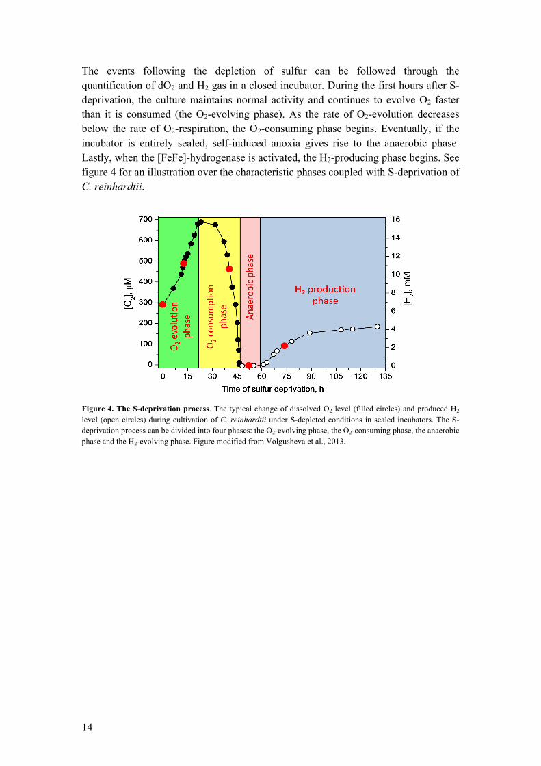
The events following the depletion of sulfur can be followed through the quantification of dO2 and H2 gas in a closed incubator. During the first hours after S-deprivation, the culture maintains normal activity and continues to evolve O2 faster than it is consumed (the O2-evolving phase). As the rate of O2-evolution decreases below the rate of O2-respiration, the O2-consuming phase begins. Eventually, if the incubator is entirely sealed, self-induced anoxia gives rise to the anaerobic phase. Lastly, when the [FeFe]-hydrogenase is activated, the H2-producing phase begins. See figure 4 for an illustration over the characteristic phases coupled with S-deprivation of C. reinhardtii.
Figure 4. The S-deprivation process. The typical change of dissolved O2 level (filled circles) and produced H2 level (open circles) during cultivation of C. reinhardtii under S-depleted conditions in sealed incubators. The S-deprivation process can be divided into four phases: the O2-evolving phase, the O2-consuming phase, the anaerobic phase and the H2-evolving phase. Figure modified from Volgusheva et al., 2013.

15
2. Materials and methods
2.1. Strain, media and culture maintenance The wild type strain of C. reinhardtii was photoheterotrophically grown and maintained under sterile conditions in 500 mL Erlenmeyer flasks containing 350 mL TAP medium (Gorman & Levine, 1965), adjusted to pH 7.0. See supplement 1 for recipe. Liquid components (salt solution, phosphate buffer and Hutner’s trace components) and the medium were autoclaved before use to reduce the risk of contamination. The cultures were grown under constant white illumination of 120 µEm-2s-1 in temperature-regulated shaking incubators set at 25 °C. To maintain a steady stock of active cultures, they were transferred to fresh medium weekly.
2.2. Cell activity measurements
2.2.1. Cell count and chlorophyll content It is crucial to monitor the microalgal cell growth in systems where the maximization of a product yield is of importance. Two prominent ways of characterizing the cell growth activity is by counting the number of cells and measuring the chlorophyll content in a culture. In this subsection, these two methods are introduced. In microalgal fed-batch cultivations, a clear pattern of growth is characterized by 5 distinct phases (Lavens & Sorgeloos, 1996), see figure 5.
Figure 5: Growth curve of microalgae. The characteristic relation between the number of cells (N) and time during microalgal cultivations. Figure modified from Lavens & Sorgeloos, 1996.
The first phase, called “lag phase”, starts at the point of inoculation and is the timespan where the microalgae is adapting to the new environment. The length of the lag phase depends on factors like the reactor volume, the amount of inoculum used and at which phase of growth the inoculum was. No noticeable growth will be detected during the lag phase. Following the lag phase is the “exponential phase”. Now the microalgae has adapted to the new environment and grows at their maximum growth rate. The growth rate differs depending on factors like pH, light intensity, temperature and present nutrients. In the exponential phase, nutrients are quickly
1
2
3
4
5
1. Lag phase 2. Exponential phase 3. Diminishing growth phase 4. Stationary phase 5. Death phase
Time
ln N
16
consumed and the microalgal population rapidly increases, which drastically affects the light transmission. This self-induced environmental change will eventually lead to the “diminishing growth phase”. As a result, the growth rate starts to decrease. Eventually the growth rate and the natural rate of decay will be equivalent leading to a overall balanced cell density. This is called the “stationary phase”. Here the cultivation has reached its maximal cell density capacity. As all nutrients are consumed, the growth rate will drop under the rate of decay. Now the “death phase” starts and the cultivation is coming to its end (Lavens & Sorgeloos, 1996). The growth rate at the exponential phase is of greatest interest when investigating how factors like nutrition, light and temperature affects the cell activity. Through empirical data, microbial growth during the exponential phase has been fitted to an exponential function. See equation 2 (Lavens & Sorgeloos, 1996), 𝐶! = 𝐶!×𝑒!" (2) where 𝐶! and 𝐶! are the cell concentrations at time 0 and t respectively, and 𝜇 equals the specific growth rate. The specific growth rate 𝜇 can also be calculated though equation 3 (Anon., 2014),
𝜇 = ln!!
!!!!!!!
(3)
where 𝑁! and 𝑁! are the amount of cells at time point 𝑡! and 𝑡!, respectively, during the exponential phase. During this project the cells were counted using a Neubauer-Improved counting chamber (Paul Marienfeld GmbH, Lauda-Königshofen, Germany) and a phase-contrast light microscope (Carl Zeiss AG, Oberkochen, Germany), where the cells had been immobilized by diluting the culture 1:1 with 20% ethanol prior to the counting. To determine the chlorophyll content of a culture, the following procedure was used:
1. Collect 3 x 1 mL samples in Eppendorf tubes 2. Spin down for 2 min at 14100 rcf using MiniSpin plus centrifuge (Eppendorf
AG, Hamburg, Germany) 3. Remove the supernatant, leaving the pellet of volume ~20 µL 4. Add 980 µL 80% acetone (filling up to the initial 1 mL) 5. Vortex to re-suspend the pellet 6. Incubate at 4 °C for 20 min 7. Spin down 2 min at 14100 rcf using MiniSpin plus centrifuge (Eppendorf AG,
Hamburg, Germany)

17
8. Measure OD663 and OD645 of the supernatant using a UV/Vis-spectrophotometer (Varian Medical Systems, Palo Alto, USA)
9. If needed, adjust the concentration of the sample to 0.4 < OD663 < 0.9 10. Calculate the chlorophyll content using equation 4 (Arnon, 1949),
𝐶ℎ𝑙 𝑚𝑔 𝑚𝑙!! = 8.02 × 𝑂𝐷!!" + 20.2 × 𝑂𝐷!"# ×
!"#$!!"# !"""
(4)
2.2.2. Oxygen evolution and respiration rates The measurements of oxygen evolution and respiration rates are key for determining the activity of a culture. If the culture is harvested for S-deprivation when the cellular activity is low, the electron contribution to the hydrogenase via the PSII-dependent pathway will be less, resulting in suffering H2-production. Maximizing H2-production is of great importance for this project and therefore also the investigation of cellular activity from one growth phase to another. A Clark-type electrode can be used to polarographically detect consumed or produced oxygen (Clark, 1956). A characteristic Clark electrode contains a platinum cathode and a silver anode linked by an electrolyte, typically potassium chloride (KCl). A filter paper, which soaks the electrolyte, creates a homogenous connective layer between the cathode and anode. An oxygen-permeable membrane is placed above the filter paper to protect the electrode. When applying an over potential of 600-700mV across the anode and cathode, oxygen diffusing through the membrane is reduced to hydrogen peroxide (H2O2) at the cathode. A current then flows to the silver anode where silver is oxidized, forming silver chloride (AgCl) (see figure 6). The current that is generated is stoichiometrically correlated to the oxygen consumed at the cathode and can in turn be converted to a signal readable by an electrode control unit (Walker, 1987).
Figure 6. The principle of a Clark electrode. When applying a small voltage across the electrodes, oxygen diffusing through the membrane is reduced to hydrogen peroxide (H2O2) at the cathode and a current then flows to the silver anode where silver is oxidized, forming silver chloride (AgCl). This current is stoichiometrically correlated to the O2-consumption. Figure modified from Walker, 1987.
–" +"
KCl bridge
Cathode (Pt)
O2
Membrane
+++++++++" Anode (Ag)
KCl electroyte
O2 + 2H2O + 2e- ! H2O2 + 2OH-
H2O2 + 2e- !2OH-
4Ag ! 4Ag+ + 4e- 4Ag+ + 4Cl- ! 4AgCl
" 4e-
0,6 - 0,7v
18
In these experiments, the O2-evolution and respiration rates were measured by placing 1 mL samples of culture in the Clark electrode chamber (Hansatech Instruments Ltd., Norfolk, England) connected to an electrode control unit with a computer interface. After 2 min of dark adaptation, the rate of O2-respiration was measured in the dark for 5 min. Consequently, the O2-evolution was recorded upon illumination with white light for 5 min. The rates were normalized towards the chlorophyll content of the sample using equation 5. 𝑟𝑎𝑡𝑒 !!"# !!
!" !" !!! × ! = !!"# !!/!"# × !"##
!" !!! × !" (5)
2.2.3. Hydrogen evolution The produced H2-gas is relevant to measure during sulfur deprivation as it is essential for the photosystem II inhibition experiments performed in this project. H2-gas quantifications were done using a Clarus 500 Gas Chromatograph (PerkinElmer Instruments, Waltham, USA) with a Molecular Sieve 5A 60/80 Mesh column (PerkinElmer Instruments, Waltham, USA), configured according to table 1. A sample volume of 100 µL was used for all measurements. To decrease the risk of oxygen contamination upon collecting gas samples, the syringe was flushed with Argon (Ar) prior to the sampling. Table 1. Gas chromatograph configuration. The following configuration of the gas chromatograph was used for hydrogen measurements.
Parameter Configuration TCD Detector temperature 80 °C Injector temperature 100 °C Oven temperature 80 °C Carrier gas Argon Gas flow 35 mL/min A calibration curve was established in order to quantify the amount of H2 in a sample. Pure H2 and Ar was used to make gas mixes with H2 concentrations of 0% - 3% with 0.5% intervals. The following calibrations curve (figure 7) was created and used for all H2-quantifications during the course of this degree project.

19
Figure 7. GC calibration curve. Calibration curve used for quantifying the amount of H2 in a sample.
2.3. Sulfur deprivation procedure The importance of sulfur deprivation and the underlying metabolic changes it induces are explained in section 1.7. S-deprivation was initiated by transferring a culture from sulfur replete to sulfur depleted media. Two main aspects that have to be taken into account when S-depriving a culture is the thoroughness and the minimization of cell loss. These two aspects are prioritized differently between laboratories, leading to different approaches of how to change to an S-depleted media. More specifically, the difference lies in deciding how many times to wash a culture to get rid of the sulfur as opposed to how many times to wash to not kill too many cells. In this project, the cultures were taken for S-deprivation at a chlorophyll concentration of 30-35 µg/mL (mid-late exponential phase, see figure 5) and suspended into 300 mL conical flasks (bioreactors) at a final concentration of ~ 16 µg/mL. Because of the high initial chlorophyll concentration, a total of three washing steps were chosen. The following procedure was used to S-deplete the cultures maintained according to section 2.1:
1. Harvest 300 mL culture at mid-exponential phase (30-35 µg Chl/mL, typically after 90-95h of growth)
2. Fill culture into 6 × 50 mL falcon tubes 3. Centrifuge for 2 min at 1620 rcf (3000 rpm) using Centrifuge 5804 R
(Eppendorf AG, Hamburg, Germany) 4. Throw away supernatant and gently re-suspend the pellet in 50 mL TAP-S
medium 5. Repeat step 3 and 4 two times 6. Fill two conical flasks (bioreactors) each with 150 mL of the newly S-depleted
culture 7. Add an additional 150 mL TAP-S medium to each flask to reach a final
volume of 300 mL
y = 116245x -‐ 458.89
0.0E+00
1.0E+05
2.0E+05
3.0E+05
4.0E+05
0 0.5 1 1.5 2 2.5 3 3.5
GC peak area (a.u)
H2 (%)
20
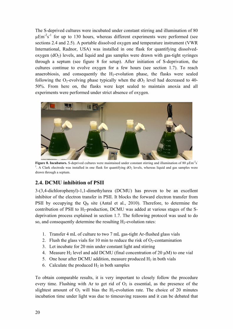
The S-deprived cultures were incubated under constant stirring and illumination of 80 µEm-2s-1 for up to 130 hours, whereas different experiments were performed (see sections 2.4 and 2.5). A portable dissolved oxygen and temperature instrument (VWR International, Radnor, USA) was installed in one flask for quantifying dissolved-oxygen (dO2) levels, and liquid and gas samples were drawn with gas-tight syringes through a septum (see figure 8 for setup). After initiation of S-deprivation, the cultures continue to evolve oxygen for a few hours (see section 1.7). To reach anaerobiosis, and consequently the H2-evolution phase, the flasks were sealed following the O2-evolving phase typically when the dO2 level had decreased to 40-50%. From here on, the flasks were kept sealed to maintain anoxia and all experiments were performed under strict absence of oxygen.
Figure 8. Incubators. S-deprived cultures were maintained under constant stirring and illumination of 80 µEm-2s-
1. A Clark electrode was installed in one flask for quantifying dO2 levels, whereas liquid and gas samples were drawn through a septum.
2.4. DCMU inhibition of PSII 3-(3,4-dichlorophenyl)-1,1-dimethylurea (DCMU) has proven to be an excellent inhibitor of the electron transfer in PSII. It blocks the forward electron transfer from PSII by occupying the QB site (Antal et al., 2010). Therefore, to determine the contribution of PSII to H2-production, DCMU was added at various stages of the S-deprivation process explained in section 1.7. The following protocol was used to do so, and consequently determine the resulting H2-evolution rates:
1. Transfer 4 mL of culture to two 7 mL gas-tight Ar-flushed glass vials 2. Flush the glass vials for 10 min to reduce the risk of O2-contamination 3. Let incubate for 20 min under constant light and stirring 4. Measure H2 level and add DCMU (final concentration of 20 µM) to one vial 5. One hour after DCMU addition, measure produced H2 in both vials 6. Calculate the produced H2 in both samples
To obtain comparable results, it is very important to closely follow the procedure every time. Flushing with Ar to get rid of O2 is essential, as the presence of the slightest amount of O2 will bias the H2-evolution rate. The choice of 20 minutes incubation time under light was due to timesaving reasons and it can be debated that

21
this period must be increased to fully let the culture adapt to the new environment. However, too long time will result in negative effects on the production rate, as H2 quickly accumulates in the small headspace. It is also important to flush the DCMU and gas-sample syringes with Ar before penetrating the septa, due to the risk of bringing O2 in to the glass vials.
2.5. Flash-induced variable fluorescence decay Flash-induced variable decay measurements were done to study the electron pathways and transport rates in PSII during the S-deprivation process. The decay measurements are normally done after the sample has been dark adapted for 5 minutes. In darkness, the first electron acceptor of PSII, QA (see section 1.5, figure 1), will be fully oxidized due to the lack of incoming electrons from light. The resulting initial fluorescence state is called the F0 state and reflects the state of PSII before electrons migrate to the CaMn4-cluster, P680 and QA (Papageorgiou & Govindjee, 2004; Sjöholm, 2012). This state can be monitored by regular weak measuring flashes, which are not inducing the charge separation in PSII (Walker, 1987). When applying a bright actinic flash to the sample, the primary charge separation in PSII takes place and an initial rise in fluorescence reflecting the reduction of the CaMn4-cluster, P680 and QA can be seen. By studying this rise, called Fv or variable fluorescence, and the consequent decay of it, conclusions can be drawn on how electrons leave QA
- (Papageorgiou & Govindjee, 2004). The normal electron flow from QA
- is forward to QB, which is extremely fast and efficient, and then further through the electron transport chain leading to PSI (see section 1.5). The variable fluorescence reflecting a forward electron transfer from QA
- to QB is seen as a steep drop immediately after the Fv rise (in the µs scale). Except for the fast decay phase, a middle phase (ms scale) and a slow phase (s scale) can be observed. These reflect two additional paths of which QA
- can be re-oxidized after reduction from P680
-. The middle phase reflects the re-oxidation of QA by
plastoquinone that binds to QB, and the slow phase by the charge recombination with the S2 state of the CaMn4-cluster (Deák et al., 2014). By blocking the QB site with the inhibitor DCMU (see section 2.4), the fluorescence decay characteristics are drastically changed. Because of the occupied QB site, recombination between QA
- and the S2 state of the water oxidizing complex (see section 1.6) is the dominating route of electrons, resulting in a decay kinetics consisting mainly of the slow phase. As QA is believed to exist in quasi-equilibrium with the PQ pool, conclusions of the redox level of the PQ pool can also be examined through flash-induce fluorescence measurements (Walker, 1987). In figure 9, the typical decay traces in the presence and absence of DCMU is shown.

22
Figure 9. Flash-induced chlorophyll fluorescence decays. The blue trace reflects the normal chlorophyll fluorescence decay of a functioning electron transport between the reaction centers. The red trace reflects the electron transport when the QB site is occupied by DCMU. The arrow indicates point of actinic flash.
0
0.2
0.4
0.6
0.8
1
1.2
1.E-‐04 1.E-‐03 1.E-‐02 1.E-‐01 1.E+00 1.E+01 1.E+02
Fluo
resc
ence
(a.u
)
Time (log s)
No addition DCMU added

23
3. Results and discussion
3.1. Culture growth and activity The growth curve is essential for the establishment of culture growth and activity in relation to a time scale. The characteristics of a microalgal growth curve are defined in section 2.2.1 and in figure 10 the growth curve corresponding the WT strain of C. reinhardtii grown in TAP medium is displayed. The growth curve follows the general trend (shown in figure 5), only showing minor exceptions such as a sharp transition from the exponential phase to the stationary phase and a quick transition into the death phase. These exceptions can be due to errors when counting, or due to an abrupt depletion of nutrients at around 100 hours causing starvation and the fast decreasing cell growth.
Figure 10. Growth curve of C. reinhardtii. Determined through the procedure explained in section 2.2.1. The arrows indicate points of both O2-respiration and O2-evolution rate measurements.
By fitting an exponential function to the exponential phase (hours 20 to 80 in figure 10), the growth rate was calculated according to the equations in section 2.2.1. The resulting growth rate is µμ = 1.32 𝑑!!, which corresponds to the lower range of growth rates reported in previous literature (Vítová et al., 2011). The relatively slower growth rate may be caused by differences in media used, light intensities as well as temperature. Also, the geometry of vessel in which they are grown can drastically affect the exponential growth rate. The measurement of O2-respiration and O2-evolution rates are two useful indicators for diagnosing the activity of the culture at a given time point (explained in section 2.2.2). The rates were measured at time 42, 66, 90 and 114 h after inoculation (see figure 10) and the results are presented in table 2.
0.0E+00
4.0E+06
8.0E+06
1.2E+07
1.6E+07
2.0E+07
0 20 40 60 80 100 120 140 160 180
Cells/m
L
Time (h)

24
Table 2. O2-respiration and O2-evolution rates throughout C. reinhardtii life cycle. Measured by a Clark–type electrode through the procedure explained in section 2.2.2.
Time (h)
O2-respiration rate µμ𝒎𝒐𝒍 𝑶𝟐𝒎𝒈 𝑪𝒉𝒍×𝒉
O2-evolution rate µμ𝒎𝒐𝒍 𝑶𝟐𝒎𝒈 𝑪𝒉𝒍×𝒉
42 42.2 81.4 66 28.0 82.5 90 20.1 40.3 114 5.6 37.8
As seen in table 2, the O2-respiration and O2-evolution rates vary greatly depending on the life-cycle phase the culture is in. In early exponential phase (42 h), the activity is maximal, whereas consequent measurements indicate a systematically decreased activity. This decrease reflects the culture’s transition into the stationary phase and consequently to the death phase. A high activity is sought for when S-depriving a culture, which leads to the conclusion that the culture should be harvested in the early exponential phase. However, at this stage the culture density is still low, presenting another issue which should be taken into account when deciding an optimal harvest time. This will be further handled in section 3.2.
3.2. Sulfur deprivation The procedure of how to initiate a S-deprivation experiment is explained in section 2.3. As discussed in section 3.1, the activity of a culture growing in TAP media is high during early exponential phase. However, at this point the culture density is low which results in a low H2-production per liter of culture, if harvested at this point. Therefore, during the course of this project, the cultures were always harvested during the mid-late exponential phase (90 h after inoculation, see figure 10), when the activity remained high and the chlorophyll content was 30-35 µg chl/mL (determined according to the procedure in section 2.2.1). The initial S-deprivation experiments raised issues of preserving anaerobiosis in the incubators, where O2 prevented prolonged H2-production. The issue of maintaining anaerobiosis presumably occurred due to leakage in the septum after repeated gas probing. Figure 11 illustrates the typical S-deprivation experiment when leakage caused a failed prolonged H2-production. Around 80 hours after initiation of the experiment, H2 started leaking out and soon after the culture was exposed to O2 (hour 100 and forward). However, if the leakage is disregarded and figure 11 is compared with figure 4, which demonstrates an earlier S-deprivation experiment (Volgusheva et al., 2013), the similarities are many. For instance, the experiment shown in figure 11 undergoes the four distinct phases of S-deprivation (the O2-evolving phase, the O2-consuming phase, the anaerobic phase and the H2-evolving phase) introduced in section 1.7, indicating a successful execution of the protocol for initiating S-deprivation.

25
Figure 11. Initial S-deprivation experiment. The figure illustrates a typical initial S-deprivation experiment prone to failure as a consequence of leakage. The blue line reflects dO2 levels of the culture (measured with a Clark electrode), while the red line is the accumulated H2 in the headspace (measured with GC).
By improving the sealing procedure, prolonged H2-production was accomplished. Improvements included the usage of two septa, where one acted as safety if the other one was punctured. By introducing the additional septum, the leakage problem instantly disappeared. To further ensure successful experiments, the GC syringe and liquid probing syringe were flushed with Ar prior to any sampling. Also, the headspaces of the conical flasks were flushed daily with Ar to diminish the high accumulation of H2, which previously could have lead to product inhibition and a consequent decrease of H2-evolution. Observations made early in the project indicated that a gas outlet used for releasing over-pressure during the H2-producing phase introduced problems of O2-contamination as well as altering of headspace volume. Another improvement was therefore the removal of this gas outlet. This modification was possible to do because over-pressure instead was dealt with by the daily flushing of the headspace. The gas outlet was an especially likely source of error when drawing samples, as the created under-pressure in the headspace would force in air through the outlet. Figure 12 displays the positive result of the precautionary steps that ultimately lead to an efficient and prolonged H2-production. Comparing figure 12 to figure 11, one notable thing is the faster onset of anaerobiosis. Also, the beginning of the H2-producing phase was shifted backwards from ~60 h to ~ 30 h. When comparing figure 12 to the earlier project from Volgusheva and coworkers (figure 4), it is noted that the final H2-yield of the two projects are roughly the same (about 4 mmol H2/L of culture), demonstrating good reproducibility and consistently obtained maximum yield of H2. The time-line established in the experiment shown in figure 12 was used during the remaining experiments presented in section 3.3 and 3.4.
0.0
0.2
0.4
0.6
0.8
1.0
0
200
400
600
800
1000
1200
0 20 40 60 80 100 120 140
mmol H
2/L culture
[O2] (µM)
S deprivation (h)
dO2
H2

26
Figure 12. Final S-deprivation experiment. The figure is illustrating the positive results of precautionary measures done to ensure an effective and prolonged H2-production. The blue line reflects dO2 levels of the culture (measured with a Clark electrode), while the red line is the accumulated H2 in the headspace (measured with GC).
In terms of actual volume gas produced, at the end of the experiment (136 h) an approximate of 25 mL H2 had been collected. This accounts for 8.3% of the volume of the H2-producing culture (300 mL). If instead a continuous photobioreactor (continual inflow of fresh S-deprived cells and outflow of old) were to be used to keep the process at a constant early H2-producing phase, this yield could be substantially increased. To further improve the amount of H2 produced, the use of C. reinhardtii mutants should be considered. For instance, the stm6 mutant has shown to produce 3.5 times more hydrogen as the wild type strain used in this project, under the same time frame of 5 days (Volgusheva et al., 2013). By designing a system capable of automatically recording dO2, H2, pH and optical density, the execution of S-deprivation experiments can be additionally improved with minimal errors and high reproducibility as results. Such a system would allow for the completing of the experiment without manually drawing samples in order to follow the S-deprivation process, thus eliminating the major source of error explained earlier. Berggren and coworkers recently introduced an interesting idea regarding H2-production using the same [FeFe]-hydrogenase found in C. reinhardtii (Berggren et al., 2013). Their method, however, is substantially different from the photobiological system used in this project. They want to isolate the hydrogenase complex alone and assemble it to a maturation enzyme in an attempt to create a bioelectrode that can be applied in photoelectrolysers or fuel cells. Their idea opens up new avenues regarding biotechnological H2-production and might very well be the future system that both simplifies the process and increases the yield of H2-production.
3.3. DCMU inhibition of PSII The complete DCMU experiments (performed over the entire H2-producing phase) were performed three times, each time following the protocol explained in section 2.4.
0
2
4
6
8
0 100 200 300 400 500 600 700 800 900
0 20 40 60 80 100 120 140
mmol H
2/L culture
[O2] (µM)
S deprivation (h)
dO2
H2
27
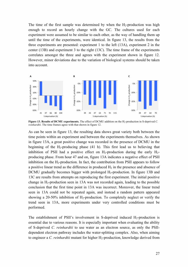
The time of the first sample was determined by when the H2-production was high enough to record an hourly change with the GC. The cultures used for each experiment were assumed to be similar to each other, as the way of handling them up until the time of the experiments, were identical. In figure 13, the results from the three experiments are presented: experiment 1 to the left (13A), experiment 2 in the center (13B) and experiment 3 to the right (13C). The time frame of the experiments correlates amongst the three and agrees with the experiment shown in figure 12. However, minor deviations due to the variation of biological systems should be taken into account.
Figure 13. Results of DCMU experiments. The effect of DCMU addition on the H2-production in S-deprived C. reinhardtii. The time frames agree with that shown in figure 12.
As can be seen in figure 13, the resulting data shows great variety both between the time points within an experiment and between the experiments themselves. As shown in figure 13A, a great positive change was recorded in the presence of DCMU in the beginning of the H2-producing phase (41 h). This first lead us to believing that inhibition of PSII had a positive effect on H2-production during the early H2-producing phase. From hour 47 and on, figure 13A indicates a negative effect of PSII inhibition on the H2-production. In fact, the contribution from PSII appears to follow a positive linear trend as the difference in produced H2 in the presence and absence of DCMU gradually becomes bigger with prolonged H2-production. In figure 13B and 13C are results from attempts on reproducing the first experiment. The initial positive change in H2-production seen in 13A was not recorded again, leading to the possible conclusion that the first time point in 13A was incorrect. Moreover, the linear trend seen in 13A could not be repeated again, and instead a random pattern appeared showing a 20-50% inhibition of H2-production. To completely neglect or verify the trend seen in 13A, more experiments under very controlled conditions must be performed. The establishment of PSII’s involvement in S-deprived induced H2-production is essential due to various reasons. It is especially important when evaluating the ability of S-deprived C. reinhardtii to use water as an electron source, as only the PSII-dependent electron pathway includes the water-splitting complex. Also, when aiming to engineer a C. reinhardtii mutant for higher H2-production, knowledge derived from
!50%%
!35%%
!20%%
!5%%
39% 47% 64% 70%
Change%in%H
2%produ
c:on
%
S%depriva:on%(h)%
!50%%
!35%%
!20%%
!5%%
39% 43% 47% 63% 71% 91% 115%
Change%in%H
2%produ
c:on
%
S%depriva:on%(h)%
!50%%
!30%%
!10%%
10%%
30%%
50%%
41% 47% 66% 80% 104%
Change%in%H
2%produ
c:on
%
S%depriva:on%(h)%
A" C"B"

28
this project is important. From experiments on the effects of PSII inhibition on H2-production, scientists can draw conclusions whether they want an enhanced PSII complex or not. By further studying the contribution of PSII throughout the entire S-deprivation process, the long-term involvement can be established, which is useful knowledge when determining if such a mutational change has a sustainable value. By looking at figure 13, even though values are highly fluctuating, PSII appears to be an essential contributor of electrons throughout the H2-producing phase, as between 20% and 50% of the production disappears in the presence of DCMU. Therefore, judging from the results of this and earlier projects, PSII should be considered as a target for mutational manipulations to increase the overall H2-yield in S-deprived C. reinhardtii. The maximum contribution of PSII to H2-production was however lower than what is reported in earlier projects (20-85%) (Volgusheva et al., 2013; Scomaa et al., 2012; Antal et al., 2009; Kruse et al., 2005). Although great caution was maintained when performing the DCMU experiments, the [FeFe]-hydrogenase’s extreme sensitivity to O2 and the small quantities of H2 measured, leads to high probabilities of experimental differences. For example, when taking the two samples from the incubators to perform a DCMU experiment, O2 might contaminate one or both samples, leading to differences in H2-evolution. Additionally, H2 may escape through the septum of the sampling vial, especially if the septum is worn out. When drawing gas samples for the GC, a sampling error is introduced as H2 easily retains from being homogenously mixed in the headspace of the sample vial. These errors associated with H2-quantifications are difficult to deal with, but perhaps would a completely gas tight system, with the capability of measuring H2 without the need for manual sampling, be a good way to reduce measurement errors. Another way of eliminating disturbances caused by probing would be to directly add DCMU to the main S-deprived culture, instead of to the samples drawn from it. Perhaps will such a procedure allow a better experimental reproducibility? Downsides with that approach is instead that an additional main culture is needed as a control, which requires the need of more material as well as adds a new source of error due to differences between cultures.
3.4. Flash-induced variable fluorescence decay The perhaps most interesting result of this degree project is what was achieved through the flash-induced variable fluorescence decay measurements. Remarkable is the observation of a wave-like decay kinetics associated with anaerobiosis and the H2-producing phase during S-deprivation, previously only seen in cyanobacteria (Deák et al., 2014). The establishment of the fluorescence wave in C. reinhardtii is important because it can help scientists understand the complicated role of photosynthetic complexes, PSII in particular, and what the electron pathways and transport rates look like between them. It may be of further importance when building an understanding of the redox level regulation of the PQ pool under various environmental conditions (such as anaerobiosis). The procedure of which the flash-induced fluorescence decay was determined and the underlying mechanism of the method are explained in section
29
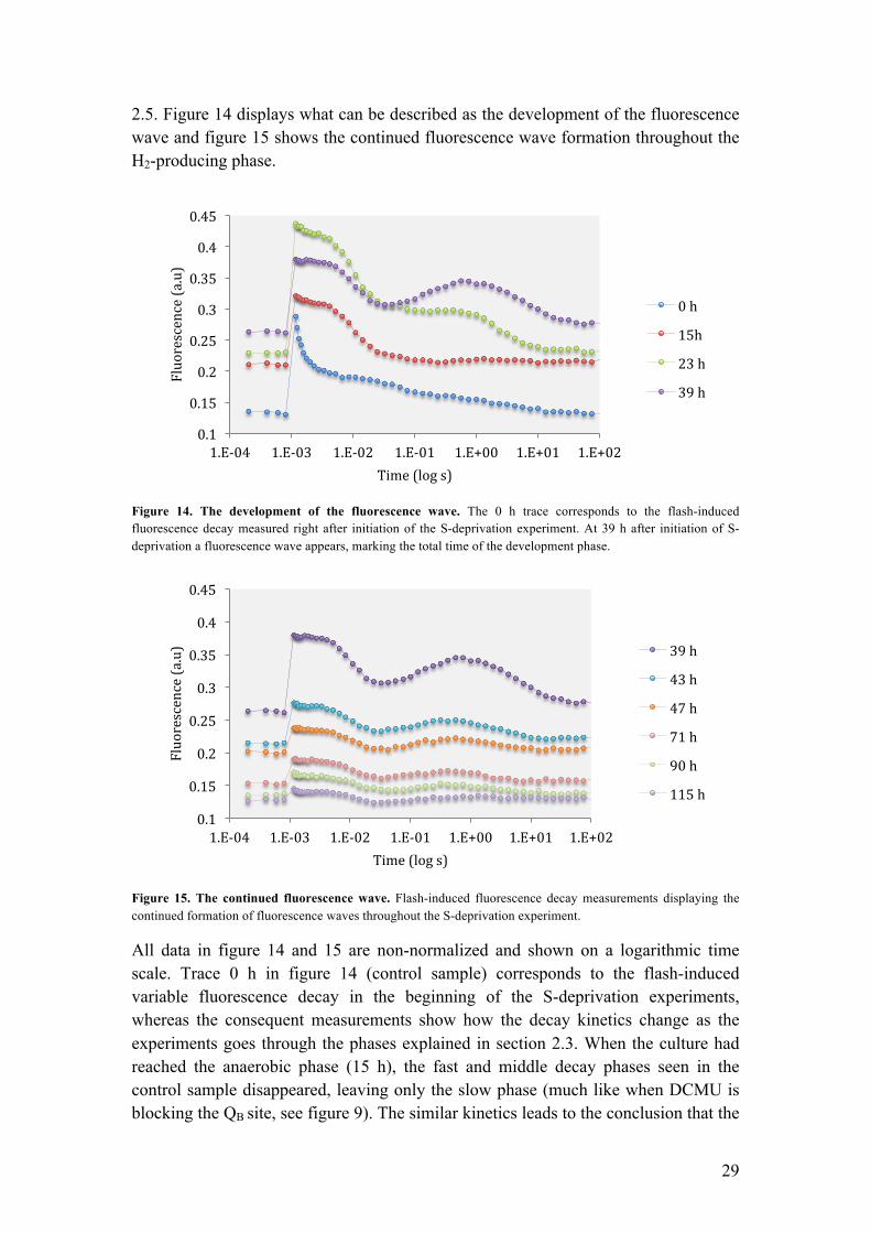
2.5. Figure 14 displays what can be described as the development of the fluorescence wave and figure 15 shows the continued fluorescence wave formation throughout the H2-producing phase.
Figure 14. The development of the fluorescence wave. The 0 h trace corresponds to the flash-induced fluorescence decay measured right after initiation of the S-deprivation experiment. At 39 h after initiation of S- deprivation a fluorescence wave appears, marking the total time of the development phase.
Figure 15. The continued fluorescence wave. Flash-induced fluorescence decay measurements displaying the continued formation of fluorescence waves throughout the S-deprivation experiment.
All data in figure 14 and 15 are non-normalized and shown on a logarithmic time scale. Trace 0 h in figure 14 (control sample) corresponds to the flash-induced variable fluorescence decay in the beginning of the S-deprivation experiments, whereas the consequent measurements show how the decay kinetics change as the experiments goes through the phases explained in section 2.3. When the culture had reached the anaerobic phase (15 h), the fast and middle decay phases seen in the control sample disappeared, leaving only the slow phase (much like when DCMU is blocking the QB site, see figure 9). The similar kinetics leads to the conclusion that the
0.1
0.15
0.2
0.25
0.3
0.35
0.4
0.45
1.E-‐04 1.E-‐03 1.E-‐02 1.E-‐01 1.E+00 1.E+01 1.E+02
Fluorescence (a.u)
Time (log s)
0 h
15h
23 h
39 h
0.1
0.15
0.2
0.25
0.3
0.35
0.4
0.45
1.E-‐04 1.E-‐03 1.E-‐02 1.E-‐01 1.E+00 1.E+01 1.E+02
Fluorescence (a.u)
Time (log s)
39 h
43 h
47 h
71 h
90 h
115 h

30
forward electron transfer from QA- is blocked during the anaerobic phase. This further
indicates that the PQ pool is fully reduced during anaerobiosis. 23 h into the experiment, just as the culture was approaching the H2-producing phase, the decay kinetic changed again. In the moments after Fmax the middle phase reappeared once again indicating a forward, although limited, electron flow from QA
- to QB, most probably reflecting the binding of QB to the PSII complex. Reportedly, this also indicates the opening of the forward electron transport to the [FeFe]-hydrogenase (Volgusheva et al., 2013). 39 h into the experiment, when the H2-production was fully initiated, the fluorescence wave was clearly observable and continued to show during the remaining of the S-deprivation experiment (see figure 15). The wave is further discussed later in this chapter. Another observation is the gradual increase of the F0 level from 0 h until formation of the wave at 39 h (figure 14). Because the F0 level reflects the minimal fluorescence in a sample and directly correlates to the redox level of QA, this rise of F0 reveals a transition of PSII centers from a photochemically active state with oxidized QA (open PSII centers), to an inactive state with reduced QA (closed PSII centers) as anaerobiosis is established (Antal et al., 2010). This consequently shows that S-deprivation and anoxia results in more closed PSII centers that are unable to perform stable charge separation (Krause & Weis, 1991), which ultimately leads to decreased H2-yields from S-deprived green algae. Finding a solution to minimizing the inactivation of PSII centers (such as a mutant less sensitive against O2) could be a way of improving the yield of produced H2. During the continued wave phase shown in figure 15, the F0 level of the individual waves slowly decreases to levels close to the F0 level of the control sample, indicating a gradual re-activation of PSII centers with prolonged H2-production. This has previously been reported and is thought to be an effect of expressed [FeFe]-hydrogenase activity leading to the re-oxidation of the photosynthetic electron transport chain (Antal et al., 2010). In addition to studying the change in F0, the change in Fv (Fmax-F0) over the course of the H2-producing phase reveals the altering activity level of open PSII centers (Maxwell & Johnson, 2000; Krause & Weis, 1991). As seen in figure 14, it is clear that Fv decreases during the H2-producing phase. This is therefore interpreted as a decrease in PSII activity with the progression of the S-deprivation experiment. An alternative, albeit related interpretation is that the amount of PSII centers actually decrease as a culture is deprived of sulfur. This cannot be concluded from studying Fv alone, but has been previously supported by spectrometric measurements (Wykoff et al., 1998; Volgusheva et al., 2013). The relative oscillation of the waves remained strong throughout the H2-producing phase although the decreased Fv made it harder to observe. To better see the wave phenomenon, the fluorescence data was normalized to the initial amplitude of 1 at Fmax. In figure 16 the trace corresponding to hour 39 is displayed, whereas the remaining normalized fluorescence kinetics can be found in supplement 2.

31
Figure 16. Normalized flash-induced fluorescence decay kinetics at 39 h. The decay trace was normalized to values between 0 (at F0) and 1 (at Fm).
While the formation of oscillations in the decay kinetics is not completely understood in green algae, it highly resembles the wave phenomenon very recently reported in cyanobacteria (Deák et al., 2014). The overshoot of fluorescence occurs at 1 s after the actinic flash in both organisms, leading to the likelihood that the underlying mechanisms are similar. By investigating the presence of fluorescence waves in the cyanobacteria Synechosystis containing type-1 NADH dehydrogenase (NDH-1) and in mutants lacking NDH-1, Deák et al. concluded that the appearance of the fluorescence wave is due to re-reduction of the PQ pool from stromal components via the NDH-1 complex (Deák et al., 2014). The same conclusion cannot be drawn in this project due to the lack of the NDH-1 complex in C. reinhardtii. Instead, Desplats et al. propose an alternate source of cyclic electron flow that resembles the one associated with cyanobacteria’s NDH-1 complex (Desplats et al., 2009). By studying the genome of WT C. reinhardtii, their study revealed that genes coding for NDH-1 are absent and instead a type II NAD(P)H dehydrogenase (NDH-2) was found in the chloroplast compartment. Just like NDH-1 in cyanobacteria, the NDH-2 complex in C. reinhardtii is believed to account for the non-photochemical reduction of the PQ pool (Mus et al., 2005), therefore providing the feasible explanation that the fluorescence waves seen in this work is a result of electrons flowing backwards from stromal components via the NDH-2 complex to the PQ pool. Desplats et al. concludes that the NDH-2 complex is important for H2-production in C. reinhardtii, as non-photochemical reduction of the PQ pool plays an essential role in the PSII-independent pathway (see section 1.7) (Desplats et al., 2009). Due to their conclusions and this work’s observation of a fluorescence wave throughout the H2-producing phase, the NDH-2 complex proves to be an interesting target for testing this hypothesis and consequently for modifications, in order to enhance the photochemical H2-production in green algae.
0
0.2
0.4
0.6
0.8
1
1.2
1.E-‐04 1.E-‐03 1.E-‐02 1.E-‐01 1.E+00 1.E+01 1.E+02 1.E+03
Fluorescence [a.u]
Time [log s]
39 h
32
4. Conclusions In this work, three different topics of H2-production in green algae were examined: the establishment of prolonged S-deprivation induced H2-production, the contribution of PSII in H2-production and the involvement of other electron pathways during S-deprivation. Results connected to each of these main points were obtained and discussed around, in an effort to bring the science of solar fuel forward. To conclude this thesis work I want to emphasize some important findings connected to the three aforementioned topics. As the H2-production in green algae is extremely sensitive to O2, a very fundamental albeit important knowledge on how to establish prolonged H2-production is associated with how to maintain anaerobiosis in a culture. One cannot expect to achieve prolonged H2-production without implementing precautionary steps to keep O2 out from the incubators. Critical precautionary measures implemented in this work included the usage of double septa at the gas-probe outlet, the careful flushing of all instruments in contact with the culture with Ar gas and also the daily flushing of the incubators headspaces with Ar gas. Additionally, it is important to realize that by implementing a system that is as simple as possible for succeeded experiment, which also incorporates automated probing, the amount of measurement errors can be kept to a minimum. The involvement of PSII in H2-production and the associated electron pathways is however a much less understood science. Findings form the PSII inhibition experiments of this work largely agrees with previous reports and suggest that up to 50% of the electrons used for the H2-production in S-deprived C. reinhardtii originates from the water splitting of PSII (PSII-dependent pathway), whereas the remaining electrons presumably come from reduced stromal components via the NDH-2 complex (PSII-independent pathway). Unique in this work however is the discovery that PSII’s electron contribution to H2-production remains crucial throughout the entire H2-producing phase. Another novel result is the first observation and characterization of the wave-phenomenon in C. reinhardtii, which further reveals that NDH-2 plays an important role in the non-photochemical reduction of the PQ pool throughout the H2-producing phase. Therefore, I believe that by targeting both the PSII complex and the NDH-2 complex of C. reinhardtii for engineering, it might be possible to attain a green algal strain with superior H2-producing characteristics. These new observations are important because they provide useful knowledge on how to improve green algal H2-production, both through experimental implementations and by pointing out interesting and relevant intracellular targets. They further point out the potential of using green alga to produce H2 with water as a raw material, which would be a truly environmentally friendly and sustainable source of a future biofuel.

33
5. Acknowledgement First of all, I would like to thank Fikret Mamedov and Stenbjörn Styring for arranging this exciting and educational project and giving me the opportunity to partake in it. This project has not only introduced me to the production of the energy of the future, but in the process of learning I have come to many important insights that I am sure will help me throughout my career. I also want to thank the rest of the research group for the great Monday meetings promoting helpful discussions, and for the guidance through my experiments. Finally, I want to show my sincere gratitude to my family for always supporting and guiding me, and my girlfriend for showing great patience at times when work has occupied my mind.

34
6. Bibliography Andersen, R.A. & Lewin, R.A., 2012. Encyclopedica Britannica Online. [Online] Available at: http://www.britannica.com.ezproxy.its.uu.se/EBchecked/topic/14828/algae [Accessed 27 October 2014]. Anon., 2014. CSIRO MARINE AND ATMOSPHERIC RESEARCH. [Online] Available at: http://www.marine.csiro.au/microalgae/methods/Growth%20rate.htm [Accessed 30 May 2014]. Antal, T.K., Volgusheva, A.A., Krendeleva, G.P.K.T.E. & Rubin, A.B., 2009. Relationships between H2 photoproduction and different electron transport pathways in sulfur-deprived Chlamydomonas reinhardtii. International journal of hydrogen energy , 34, pp.9087–94. Antal, T.K., Krendeleva, T.E. & Rubin, A.B., 2010. Acclimation of green algae to sulfur deficiency: underlying mechanisms and application for hydrogen production. Applied Microbiology and Biotechnology. Antoni, D., Zverlov, V.V. & Schwarz, W.H., 2007. Biofuels from microbes. Applied Microbiology and Biotechnology, 77, pp.23-35. Arnon, D.I., 1949. COPPER ENZYMES IN ISOLATED CHLOROPLASTS. POLYPHENOLOXIDASE IN BETA VULGARIS. Plant Physiology, 24(1), pp.1-15. Bassham, J.A., 2003. Photosynthesis Research , 76, pp.35-52. Basu, A., 2014. Cultivation of microalgae in a novel horizontal bioreactor. Research training. Uppsala: Uppsala University. Berg, J.M., Tymoczko, J.L. & Stryer, L., 2002. Biochemistry 5th Edition. New York: W H Freeman. Berggren, G., Adamska, A., Lambertz, C., Simmons, T.R., Esselborn, J., Atta, M., Gambarelli, S., Mouesca, J.M., Reijerse, E., Lubitz, W., Happe, T., Artero, V. & Fontecave, M., 2013. Biomimetic assembly and activation of [FeFe]-hydrogenases. Nature, 499, pp.66-70. Carrieri, D., Kolling, D., Ananyev, G. & Dismukes, G.C., 2006. Prospecting for biohydrogen fuel. Industrial Biotechnology, 2(2), pp.133-37. Chisti, Y., 2007. Biodiesel from microalgae. Biotechnology advances, 25, pp.294-306. Clark, L.C., 1956. Monitor and control of blood and tissue oxygen tensions. American Society for Artificial Internal Organs, 2(1), pp.41-48. Cook, T.R., Dogutan, D.K., Reece, S.Y., Surendranath, Y, Teets, T.S. & Nocera, D.G., 2010. Solar Energy Supply and Storage for the Legacy and Nonlegacy Worlds. American Chemical Society , 110, pp.6474-502. Dau, H. & Zaharieva, I., 2009. Principles, Efficiency, and Blueprint Character of Solar-Energy Conversion in Photosynthetic Water Oxidation. Accounts of Chemical Research, 42(12), pp.1861-1870. Deák, Z., Sass, L., Kiss, E. & Vass, I., 2014. Characterization of wave phenomena in the relaxation of flash-induced chlorophyll fluorescence yield in cyanobacteria. Biochimica et Biophysica Acta, 1837, pp.1522-32. Desplats, C., Mus, F., Cuiné, S, Billon, E., Cournac, L. & Peltier, G., 2009. Characterization of Nda2, a Plastoquinone-reducing Type II NAD(P)H Dehydrogenase in Chlamydomonas Chloroplasts. The Journal of BIological Chemistry, 284(7), pp.4148-57. Floume, T., Coquil, T. & Sylvestre, J., 2011. Microalgae Photonics. SPIE Eco-Photonics 2011 , 8065.

35
Ghirardi, M.L., Posewitz, M.C., Maness, P., Dubini, A., Yu, J. & Siebert, M., 2007. Hydrogenases and Hydrogen Photoproduction in Oxygenic Photosynthetic Organisms. Annual Review of Plant Biology, 58, pp.71-79. Gorman, D.S. & Levine, R.P., 1965. Cytochrome F and plastocyanin: Their sequence in the photosynthetic electron transport chain of Chlamydomonas reinhardi. Harvard University. Guiry, M., 2014. The Seaweed site. [Online] Available at: http://www.seaweed.ie/algae/chlorophyta.php [Accessed 12 December 2014]. Hammarström, L. & Hammes-Shiffer, S., 2009. Artificial Photosynthesis and Solar Fuels. Accounts of Chemical Research, 42(12), pp.1859-60. Haumann, M., Liebisch, P., Miller, C., Barra, M., Grabolle M. & Dau, H., 2005. Photosynthetic O2 Formation Tracked by Time-Resolved X-ray Experiments. Science, 310, pp.1019-2021. Havelius, K.G.V., Su, J., Feyziyev, Y., Mamedov, F. & Styring, S., 2006. Spectral Resolution of the Split EPR Signals Induced by Illumination at 5 K from the S1, S3, and S0 States in Photosystem II. Biochemistry, 45, pp.9279-90. Hemscheimer A., Melis, A. & Happe, T., 2009. Analytical approaches to photobiological hydrogen production in unicellular green algae. Photosynthesis research, 102(2-3), pp.523-40. Holdren, J.P., 1991. Population and the Energy Problem. Population and Environment: A Journal of Interdisciplinary Studies , 12(3). Homann, P.H., 2003. Hydrogen metabolism of green algae: discovery and early research – a tribute to Hans Gaffron and his coworkers. Photosynthesis Research, 76(1-3), pp.93-103. Krause, G.H. & Weis, E., 1991. CHLOROPHYLL FLUORESCENCE AND PHOTOSYNTHESIS: The Basics. Annu. Rev. Plant Physiol. Plant Mol. Biol., 42, pp.313-49. Kruse, O., Rupprecht, J, Bader, K., Thomas-Hall, S., Schenk, P.M., Finazzi, G. & Hankamer, B., 2005. Improved Photobiological H2 Production in Engineered Green Algal Cells. The Journal of Biological Chemistry, 280, pp.34170-77. Lavens, P. & Sorgeloos, P., 1996. Manual on the production and use of live food for aquaculture. FAO Fisheries Technical Paper. Mamedov, M.D., Kurashov, V.N., Cherepanov, D.A. & Semenov, A.Y., 2010. Photosysem II: where does the light-induced voltage come from? Frontiers in Bioscience, 15, pp.1007-17. Maxwell, K. & Johnson, G.N., 2000. Chlorophyll flourescence - a practical guide. Journal of Experimental Botany, 51(345), pp.659-68. Mehmood, U., Rahman, S., Harrabi, K., Hussein, I. & Reddy, B.V.S., 2014. Recent Advances in Dye Sensitized Solar Cells. Advances in Materials Science and Engineering , 2014, p.12. Melis, A., Zhang, L., Forestier, M., Ghirardi, M.L. & Siebert, M., 2000. Sustained Photobiological Hydrogen Gas Production upon Reversible Inactivation of Oxygen Evolution in the Green Alga Chlamydomonas reinhardtii. American Society of Plant Physiologists, 122, pp.127-35. Merchant, S.S., Prochnik, S.E., Vallon, O., Harris, E.H., Karpowicz, S.J., Witman, G.B., Terry, A., Salamov, A., Fritz-Laylin, L.K., Maréchal-Drouard, L., Marshall, W.F., Qu, L.H., Nelson, D.R., Sanderfoot, A.A., Spalding, M.H., Kapitonov, V.V., Ren, Q., Ferris, P., Lindquist, E., Shapiro, H., Lucas, S.M., Grimwood, J., Schmutz, J., Griogoriev, I.V., Rokhsar, D.S. & Grossman, A.R., 2007. The Chlamydomonas Genome Reveals the Evolution of Key Animal and Plant Functions. Science, 318(5848), pp.245-251.

36
Mus, F., Cournac, L., Cardettini, V., Caruana, A. & Peltier, G., 2005. Inhibitor studies on non-photochemical plastoquinone reduction and H2 photoproduction in Chlamydomonas reinhardtii. Biochimica et Biophysica Acta , 1708, pp.322-32. Papageorgiou, G.C. & Govindjee, 2004. Chapter 1 - Chlorophyll Fluorescence. In Chlorophyll a Fluorescence. Dordrecht: Springer. pp.1-42. Richmond, A., ed., 2004. Handbook of Microalgal Culture: Biotechnology and Applied Phycology. Oxford: Blackwell Science Ltd. Roach, J., 2004. Source of Half Earth's Oxygen Gets Little Credit. [Online] Available at: http://news.nationalgeographic.com/news/2004/06/0607_040607_phytoplankton.html [Accessed 27 October 2014]. Scomaa, A., Krawietzc, D., Faralonia, C., Giannellia, L., Happec, T. & Torzillo, G., 2012. Sustained H2 production in a Chlamydomonas reinhardtii D1 protein mutant. Journal of Biotechnology, 157, pp.613-19. Sjöholm, J., 2012. Trapping Tyrozine Z. Dissertation. Uppsala University. Spolaore, P., Jonnais-Cassan, C., Duran, E. & Isambert, A., 2006. Commercial Applications of Microalgae. Journal of Bioscience and Bioengineering, 101(2), pp.87-96. Staehelin, A., 1986. Photosynthesis III. Photosynthetic membranes and light-hravesting systems. New York : Springer Verlag. Styring, S., 2012. Solar Fuels: Vision and Concepts. AMBIO, 41, pp.156-62. Taiz, L. & Zeiger, E., 2007. Plant Physiology 4th Edition. Spektrum Akademischer Verlag. Tredici, M.R., 2010. Photobiology of microalgae mass cultures: understanding the tools for the next green revolution. Biofuels, pp.143-62. Vítová, M., Binová, K., Hlavová, M., Kawano, S., Zachleder, V. & Bíqková, M., 2011. Chlamydomonas reinhardtii: duration of its cell cycle and phases at growth rates aVected by temperature. Planta, 234, pp.599-608. Volgusheva, A., Styring, S. & Mamedov, F., 2013. Increased photosystem II stability promotes H2 production in sulfur-deprived Chlamydomonas reinhardtii. PNAS, 110(18), pp.7223-28. Walker, D., 1987. The use of the oxygen electrode and fluorescence probes in simple measurements of photosynthesis. Chichester: Oxygraphics Limited. Wykoff, D.D., Davies, J.P., Melis, A. & Grossman, A.R., 1998. The Regulation of Photosynthetic Electron Transport during Nutrient Deprivation in Chlamydomonas reinhardtii. Plant Physiology, 117, pp.129-39.
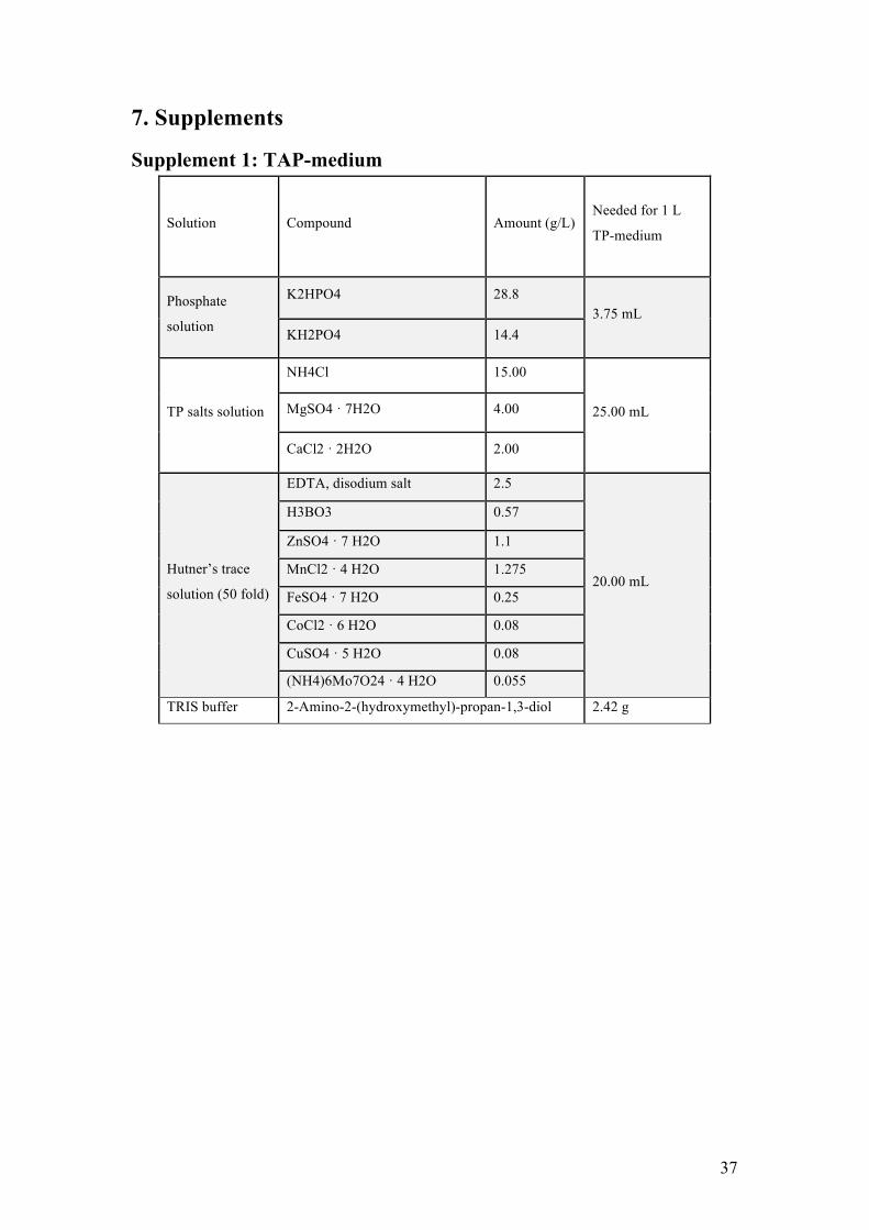
37
7. Supplements
Supplement 1: TAP-medium
Solution Compound Amount (g/L) Needed for 1 L
TP-medium
Phosphate
solution
K2HPO4 28.8 3.75 mL
KH2PO4 14.4
TP salts solution
NH4Cl 15.00
25.00 mL MgSO4 · 7H2O 4.00
CaCl2 · 2H2O 2.00
Hutner’s trace
solution (50 fold)
EDTA, disodium salt 2.5
20.00 mL
H3BO3 0.57
ZnSO4 · 7 H2O 1.1
MnCl2 · 4 H2O 1.275
FeSO4 · 7 H2O 0.25
CoCl2 · 6 H2O 0.08
CuSO4 · 5 H2O 0.08
(NH4)6Mo7O24 · 4 H2O 0.055
TRIS buffer 2-Amino-2-(hydroxymethyl)-propan-1,3-diol 2.42 g

38
Supplement 2: Normalized flash-induced fluorescence decay data
0
0.2
0.4
0.6
0.8
1
1.2
1.E-‐04 1.E-‐02 1.E+00 1.E+02
Fluorescence (a.u)
Time (log s)
0 h normalized
0
0.2
0.4
0.6
0.8
1
1.2
1.E-‐04 1.E-‐02 1.E+00 1.E+02
Fluorescence (a.u)
Time (log s)
15 h normalized
0
0.2
0.4
0.6
0.8
1
1.2
1.E-‐04 1.E-‐02 1.E+00 1.E+02
Fluorescence (a.u)
Time (log s)
23 h normalized

39
0
0.2
0.4
0.6
0.8
1
1.2
1.E-‐04 1.E-‐02 1.E+00 1.E+02
Fluorescence (a.u)
Time (log s)
39 h normalized
0
0.2
0.4
0.6
0.8
1
1.2
1.E-‐04 1.E-‐02 1.E+00 1.E+02
Fluorescence (a.u)
Time (log s)
43 h normalized
0
0.2
0.4
0.6
0.8
1
1.2
1.E-‐04 1.E-‐02 1.E+00 1.E+02
Fluorescence (a.u)
Time (log s)
71 h normalized
0
0.2
0.4
0.6
0.8
1
1.2
1.E-‐04 1.E-‐02 1.E+00 1.E+02
Fluorescence (a.u)
Time (log s)
90 h normalized

40
-‐0.2
0
0.2
0.4
0.6
0.8
1
1.2
1.E-‐04 1.E-‐02 1.E+00 1.E+02
Fluorescence (a.u)
Time (log s)
115 h normalized
Copyright © 2022 FDOKUMEN